FULL TILT NDT MANUAL 1 SECTION 5 NDT GENERAL INFORMATION TABLE OF CONTENTS GENERAL INFORMATION ...................................................................................................................................... 1 TABLE OF CONTENTS ............................................................................................................................................. 1 INTRODUCTION .......................................................................................................................................................... 2 INTRODUCTION ........................................................................................................................................................ 2 SPECIAL CONDITIONS ............................................................................................................................................ 2 DEFINITIONS.............................................................................................................................................................. 2 GENERAL .................................................................................................................................................................... 4 EVALUATIONS & INTERPRETATIONS .............................................................................................................. 8 RECORD KEEPING.................................................................................................................................................... 9 ANNUAL SAFETY CRITICAL INSPECTION .................................................................................................... 10 CRITICAL INSPECTION AREAS .......................................................................................................................... 11 SAFETY CRITICAL AREAS .................................................................................................................................... 12 ANNUAL INSPECTION & MAINTENANCE - GENERAL.............................................................................. 13 STRUCTURAL EXAMINATION ........................................................................................................................... 14 MECHANICAL EXAMINATION .......................................................................................................................... 15 ELECTRICAL EXAMINATION – 240V & 415V A.C.......................................................................................... 16 HYDRAULIC EXAMINATION .............................................................................................................................. 18 TEST PROCEDURE ................................................................................................................................................... 19 BI-ANNUAL INSPECTION ....................................................................................................................................... 20 TWO YEARLY INSPECTIONS (N.D.T.) ............................................................................................................... 20 N.D.T. INSPECTION................................................................................................................................................. 21 SPECIFIC AREAS TO BE CHECKED................................................................................................................... 22

Welcome message from author
This document is posted to help you gain knowledge. Please leave a comment to let me know what you think about it! Share it to your friends and learn new things together.
Transcript

FULL TILT NDT MANUAL
1
SECTION 5 NDT
GENERAL INFORMATION
TABLE OF CONTENTS
GENERAL INFORMATION ...................................................................................................................................... 1 TABLE OF CONTENTS ............................................................................................................................................. 1
INTRODUCTION .......................................................................................................................................................... 2 INTRODUCTION ........................................................................................................................................................ 2 SPECIAL CONDITIONS ............................................................................................................................................ 2 DEFINITIONS .............................................................................................................................................................. 2 GENERAL .................................................................................................................................................................... 4 EVALUATIONS & INTERPRETATIONS .............................................................................................................. 8 RECORD KEEPING .................................................................................................................................................... 9
ANNUAL SAFETY CRITICAL INSPECTION .................................................................................................... 10 CRITICAL INSPECTION AREAS .......................................................................................................................... 11
SAFETY CRITICAL AREAS .................................................................................................................................... 12
ANNUAL INSPECTION & MAINTENANCE - GENERAL .............................................................................. 13 STRUCTURAL EXAMINATION ........................................................................................................................... 14 MECHANICAL EXAMINATION .......................................................................................................................... 15 ELECTRICAL EXAMINATION – 240V & 415V A.C. ......................................................................................... 16 HYDRAULIC EXAMINATION .............................................................................................................................. 18
TEST PROCEDURE ................................................................................................................................................... 19
BI-ANNUAL INSPECTION ....................................................................................................................................... 20 TWO YEARLY INSPECTIONS (N.D.T.) ............................................................................................................... 20 N.D.T. INSPECTION ................................................................................................................................................. 21
SPECIFIC AREAS TO BE CHECKED ................................................................................................................... 22

FULL TILT NDT MANUAL
2
INTRODUCTION
INTRODUCTION The purpose of this text is to establish guidelines covering methods, techniques and procedures for the application of Nondestructive Testing (NDT) methods and the inspection of the ‘Full Tilt’ Amusement Ride manufactured by A.R.M. (U.S.), Inc. The specification is intended to improve quality assurance during manufacturing, assist customers of A.R.M. in meeting safety and compliance requirements, and finally, they shall be implemented where standards or specifications do not exist.
SPECIAL CONDITIONS This text contains proprietary trade secret information. These specifications and its contents are disclosed only to our customer, who is hereby bound to keep the contents of this text confidential. Disclosure of the contents of these specifications cannot be made without our written and specific authorization. Failure to treat this text, its contents, and format as proprietary, will result in criminal and/or civil prosecution.
DEFINITIONS a. Manufacturer: A.R.M. (U.S.), Inc. 1506 Fernwood Road Wintersville, OH 43953 Phone 740.264.6599
b. Design Engineer: A.R.M. (U.S.), Inc. c. Structure or Test Specimen: “Full Tilt” Amusement Ride d. Owner:
e. Manufacture Date:
f. Serial Number: g. Independent Inspection Consultant (IIC):
FULL TILT NDT MANUAL
3
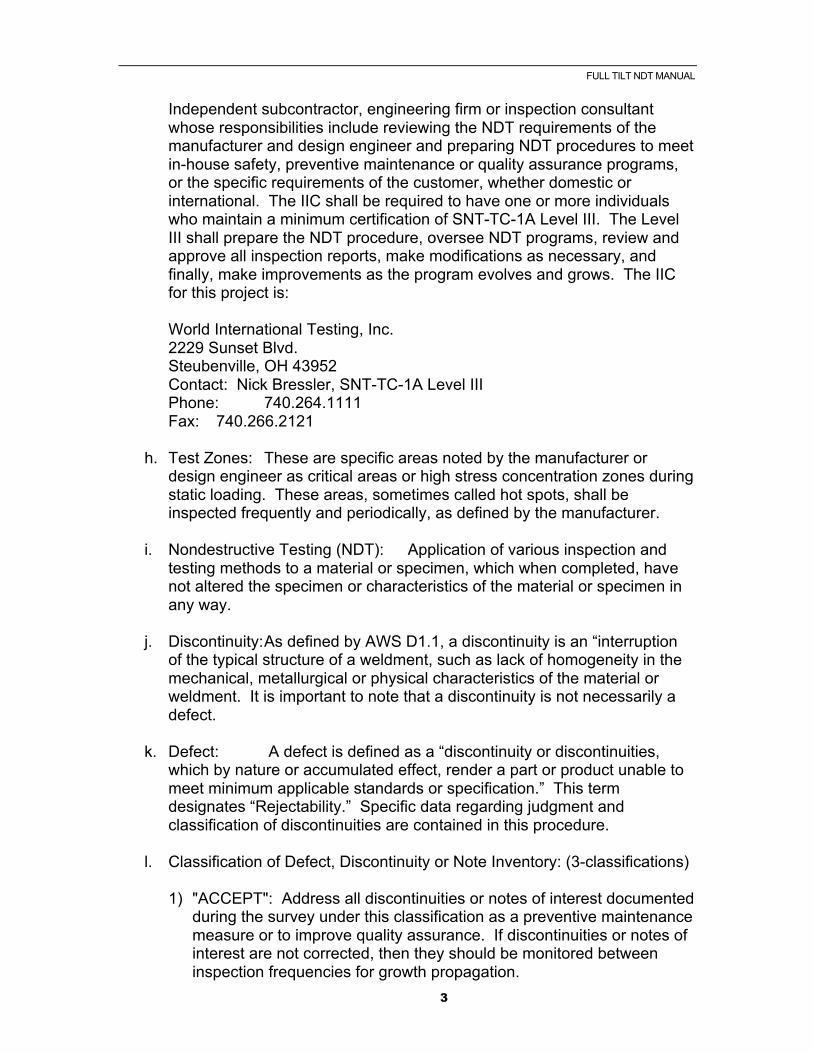
Independent subcontractor, engineering firm or inspection consultant whose responsibilities include reviewing the NDT requirements of the manufacturer and design engineer and preparing NDT procedures to meet in-house safety, preventive maintenance or quality assurance programs, or the specific requirements of the customer, whether domestic or international. The IIC shall be required to have one or more individuals who maintain a minimum certification of SNT-TC-1A Level III. The Level III shall prepare the NDT procedure, oversee NDT programs, review and approve all inspection reports, make modifications as necessary, and finally, make improvements as the program evolves and grows. The IIC for this project is:
World International Testing, Inc. 2229 Sunset Blvd. Steubenville, OH 43952 Contact: Nick Bressler, SNT-TC-1A Level III Phone: 740.264.1111 Fax: 740.266.2121
h. Test Zones: These are specific areas noted by the manufacturer or design engineer as critical areas or high stress concentration zones during static loading. These areas, sometimes called hot spots, shall be inspected frequently and periodically, as defined by the manufacturer.
i. Nondestructive Testing (NDT): Application of various inspection and testing methods to a material or specimen, which when completed, have not altered the specimen or characteristics of the material or specimen in any way.
j. Discontinuity: As defined by AWS D1.1, a discontinuity is an “interruption of the typical structure of a weldment, such as lack of homogeneity in the mechanical, metallurgical or physical characteristics of the material or weldment. It is important to note that a discontinuity is not necessarily a defect.
k. Defect: A defect is defined as a “discontinuity or discontinuities, which by nature or accumulated effect, render a part or product unable to meet minimum applicable standards or specification.” This term designates “Rejectability.” Specific data regarding judgment and classification of discontinuities are contained in this procedure.
l. Classification of Defect, Discontinuity or Note Inventory: (3-classifications) 1) "ACCEPT": Address all discontinuities or notes of interest documented during the survey under this classification as a preventive maintenance measure or to improve quality assurance. If discontinuities or notes of interest are not corrected, then they should be monitored between inspection frequencies for growth propagation.
FULL TILT NDT MANUAL
4
a) Other Alternate Acceptance Criteria:
i. (AWS D1.1, Section 1.1.2) - “suitability for service using past experience, experimental evidence or engineering analysis, considering material type, service load effects and environmental factors.”
ii. (AWS D1.1, Commentary 1.1.1)
- “what is achievable” - “should not be considered as a boundary for suitability for
service.”
2) "REJECT": Address all defects noted during the survey under this classification without hesitation and prior to placing the item back in service. If the defect is not corrected, it should be monitored daily until the defect is corrected. However, defects under this classification by nature or accumulated effect render a part or product unable to meet minimum applicable acceptance standards or specifications.
3) "FRACTURE CRITICAL": Address all defects noted during the survey without hesitation and prior to use. Not addressing the defect could pose immediate threat to life and property.
GENERAL Establishing specifications for inspection and compiling the final inspection report for our customer will require careful consideration to manufacturing processes, types of services involved, stress, areas to be inspected, methods of inspection and frequency of testing. The total program will require some refinement as the inspection programs progress and are repeated. Certain methods may not be feasible under existing conditions in which case adjustments will have to be made, and this will require close cooperation of both the inspector and client supervision. The following specification and components have been written by WIT for A.R.M. (U.S.), Inc. and are derived in accordance with appropriate specifications and codes of leading American Societies including the guidelines of ASNT-TC-1A, and with instruments calibrated and certified by independent laboratories, in conformity with the Bureau of Standards, Washington, D.C. In addition to the said standards, inspection specifications include utilization of the IIW-2 calibration block, Alcoa “A” blocks and sectional parts involved in actual failures. Qualified inspectors will be required to hold a minimum of a NDT Level II status or higher, in accordance with the American Society of Nondestructive Testing (ASNT) Recommended Practice No. SNT-TC-1A, A.R.M. (U.S.), Inc. or designated IIC. However, there are many variables that enter the picture in field testing applications, such as material composition, alloy content, temperatures and geometrics of the part, all of which affect the multiple NDT methods
FULL TILT NDT MANUAL
5
employed or specified. Complete cooperation will be appreciated when adjustments are necessary in the questionable areas, where resolution for the most suitable method of testing and inspection of areas of interest must be determined. NDT is the use of physical methods for evaluating materials without impairing their usefulness. NDT test methods are simple in principle, yet play an important role in daily operations in almost all aspects of industry. However, success in their use depends heavily upon intelligent application and discriminating interpretation of the results. They are easily applied cure-alls, but they can be instrumental in assuring improved reliability, safety and productivity when applied as an efficient and effective NDT program. NDT tests must be designed, specified, and scheduled for validity and reliability on each individual application. These specifications, and mainly the test areas and points themselves, are specific for a particular problem or potential failure area. There is no such thing as a general or universal NDT test applicable to every kind of material part or structure, nor to all their function or operating conditions. Each of the specifications in this text have been based upon the best understanding of the nature and function of the material or part being tested and the conditions of its service. Any drawings and service data furnished to the inspector will enhance the inspection reliability. This information is a necessary prerequisite to a NDT test in correlating material properties, type of service and “Accept”, “Reject” or “Fracture Critical” criteria. Failure in not having this information before applying and depending upon a NDT test can be costly. It’s absence can create an element of doubt with the inspector, and as a result, they will tend to be highly conservative. In many cases, this could result in parts being rejected because indications of discontinuities or relevant indications that would not actually be detrimental to its operation. In order for your NDT program to operate more effectively and with meaningful results, certain basic elements will be incorporated into your present system. These elements referred to as standards are (1) test specifications, (2) test methods, and (3) a reference standard. A discussion of each of these elements and their relation to our overall program follows: a. Specification: Specifications may be either performance or design, and in the WIT program, they will relate to performance. It will be the end use of the equipment and the type of service to which it will be exposed that will govern the “Accept”, “Reject” or “Fracture Critical” limits on the discontinuities or relevant indications. Specification must include a description of an acceptable quality level, and this level must be defined in terms of, or related to, performance standards, which can be understood by persons performing the inspection or by persons responsible for interpreting the test results. There are certain areas of the test specimen, due to geometrics, that will not permit us to establish definite “Accept”, “Reject” or “Fracture Critical” criteria
FULL TILT NDT MANUAL
6
based on standard reference blocks. However, guidelines will be established for these situations, whereby an evaluation will be made of the discontinuity or relevant indication at the time. Also, realizing it is an inescapable necessity that the specifications covering NDT tests define the limits of acceptable quality, we will attempt to minimize situations where an “on the spot” evaluation will have to be made regarding a discontinuity or relevant indication.
Whenever possible, a sample specimen will be sectioned and artificial discontinuities or flaws in the form of holes or notches will be introduced into the sample, to serve as a basis for comparison with discontinuities found in the actual test specimen. From these studies, WIT will determine an acceptance level, which will establish the number and magnitude of discontinuities or relevant indications allowed in the item being tested. There is an explanation for the general and non-committal definition of acceptable quality levels in NDT specifications. It must be understood that NDT tests in general, are not tests, but rather measurements, in that the results of an NDT operation offer an indication of discontinuity or relevant indication size rather than measure its size absolutely. This applies to the four- (4) methods most frequently implemented in our NDT programs, namely, Visual (VT), Ultrasonic (UT), Magnetic Particle (MT), and Liquid Penetrant (PT).
b. Designated Inspection Areas: 1) General: Based on design requirements and specific loading calculations, which have determined where specific stress concentrations exist during normal loading, there are a minimum of xxx (X) areas identified for annual inspection frequencies. This does not relieve owners or operators from the responsibility of conducting additional inspections in these areas and outside the designated zones. The xxx areas are located on the following xxx (x) components:
c. Methods of Testing and Inspection:
1) General: Based on design, fabrication, specific loading calculations, accessibility and limitation, the NDT methods recommended for the specified test zones are as follows:
a) Areas 1, 2, 3, 4, 5, 6 & 7 (VT) All of these areas shall be visually inspected for surface discontinuities, particularly in welded details. Once in service, these areas should be inspected frequently and periodically for damage, defects and any discontinuities.
b) Area 3 (MT) All of these test zones shall be inspected by magnetic particle testing for surface and near surface discontinuities, particularly in welded details. Once in service, these areas should be inspected frequently and periodically for damage, defects and any discontinuities.
FULL TILT NDT MANUAL
7
2) For surface testing, A.R.M. (U.S.), or designated IIC will utilize two- (2) methods. They include VT and MT. A.R.M. (U.S.) reserves the right to implement other NDT methods in conjunction with these two- (2) methods if additional evaluations or interpretations are required. When using these methods, the length of the discontinuity or relevant indication in the surface is fairly-well defined. However, the depth can only be estimated, unless the geometry of the part permits us to use another NDT method to determine the depth of penetration, in which case A.R.M. (U.S.) shall utilize UT. When using UT, the actual size of an indication or relevant indication is not an absolute measure, even with the best techniques, and taking into account all of the variables that may influence test results. When selecting an NDT method, it should be kept in mind that the various methods may supplement each other, and that several methods are capable of performing the same task. The methods to be selected on a particular piece of equipment was arrived at through close consideration of part geometry, type of discontinuity sought, type of material, application or service, manufacturer’s recommendations, feasibility, level of acceptability desired, and accessibility. All of these factors are based on years of research and hundreds of inspection programs.
3) For sub-surface testing, A.R.M. (U.S.), or designated IIC will utilize one- (1) method, UT. There are two- (2) other methods available to supplement the above, should A.R.M. (U.S.) elect to use them. Eddy Current (ET) could be used to supplement the surface testing, and radiography (RT) could be used for the detection of sub-surface defects at varying depths. The use of RT would be limited to laboratory or in-house inspections, since field testing would require extreme safety controls involving large area isolation, which would not be feasible in most of our customer’s daily operations.
We will not attempt to set reference standards or specifications for the surface-testing portion of the program. However, we will establish procedures and protocol formulated from analysis of the test specimen, review of past history and experience with similar items. These procedures will be outlined in more detail under the respective section for each of the methods.
A.R.M. (U.S.), or designated IIC has incorporated into the UT method of the program certain rules governing standard references and calibration of the test equipment based on standard references blocks and sectioned parts of actual equipment which have failed in service. These set-ups will vary, depending upon the specimen and the area of interest.
d. Frequency of Inspection and Testing:
Shall meet or exceed all federal, state and local regulatory agencies. Inspection frequencies shall comply with the manufacturer’s
FULL TILT NDT MANUAL
8
recommended guidelines and latest bulletins and shall meet the Owner or manufacturer’s specific safety, PM, and operating procedures. Many other variables may affect the actual periodic or frequent inspection requirements. The minimum inspection frequency for nondestructive testing to the test zones identified in this procedure is “Annually.” Note: Any repairs, damage or discontinuities noted in these areas will result in more frequent testing and inspection frequencies.
EVALUATIONS & INTERPRETATIONS In evaluating NDT test methods, it is necessary to discriminate between the reliability of the test method and the reliability of the judgment of the inspector. Lack of specific data, inadequate operating experience or bad judgment may seriously influence the inspector’s conclusions. The combination of accurate test data with good judgment and intelligence is essential to the success of the overall program. The designated IIC, should assure that inspectors, technicians and associates performing the work are trained and certified for their designated responsibilities and will not change, modify, or deviate from this standard in any way. The methods that we have selected in our specifications for each of the items, is based on the type of defect that we are looking for, and the most accurate way to reveal it. Any data available such as drawings, material specifications,, and historical data including previous inspection information, that is furnished to the inspectors will be essential in achieving a thorough and valid test and will improve the quality of your NDT program. Failure to furnish said information may result in inaccurate interpretations and may compromise the test results, particularly during the classification segment of the report. Cooperation in this matter will be deeply appreciated.

FULL TILT NDT MANUAL
9
RECORD KEEPING Documentation and record keeping is of major importance to the success and operation of any quality assurance or NDT program. Those items in the program will require identification. Historical data will be collected and should be maintained for each item. This will permit us to duplicate test conditions, and enable us to plot crack progression and recommend corrective maintenance work prior to failure. This type of record keeping is necessary in maintaining realistic “Accept”, “Reject” or “Fracture Critical” criteria.
The Following Information is required on N.D.T. Report: 1) Date of examination. 2) Technicians name and qualification. 3) Details of N.D.T. technique. 4) Parts examined and which elements comprised part of sample. 5) Parts unavailable for examination, if any. 6) Results of examination.

FULL TILT NDT MANUAL
10
ANNUAL SAFETY CRITICAL INSPECTION
1) Safety critical areas must be examined periodically by N.D.T. 2) The maximum time period between examinations of these areas is not to exceed 1 year
3) The areas designated safety critical by the manufacturer are depicted on FIGURE X
4) These safety critical areas are to undergo an N.D.T. inspection of the
parent metal in the direct vicinity of the joint weldment. The joint weldment must also be given an N.D.T. inspection.
The inspection is to examine the complete length of these joints.
5) The manufacture also recommends that bolts and nuts in the following areas are discarded at this time to accommodate bolt damage and inadvertent fatigue from incorrect bolt torque etc.
Designated areas requiring new bolts and nuts Counterbalance arm hinge bolts/nuts Tower joint bolts/nuts Gondola to main arm fixing bolts/nuts
FULL TILT NDT MANUAL
11
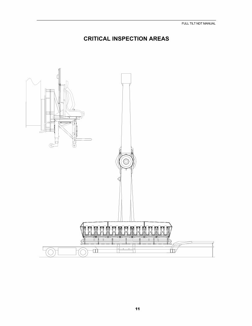
CRITICAL INSPECTION AREAS

FULL TILT NDT MANUAL
12
SAFETY CRITICAL AREAS
‘A’ i Counterweight to arm joint ii Counterweight gussets to arm joint ‘B’ i Counterbalance arm to drive centre joint ii Gondola arm to drive centre joint iii Hinge gussets to drive centre and arm joint iiii Tower top to main tower joint ‘C’ i Slewing ring mounting plate to gondola lower arm joint ii Gondola mounting plate assembly iii gondola mounting bolt blocks joints ‘D’ i Gondola framework joints Ii Gondola diagonal brace extreme end joints
FULL TILT NDT MANUAL
13
ANNUAL INSPECTION & MAINTENANCE - GENERAL
Every twelve months the machine must undergo a thorough examination by an appointed person who is an independent examiner suitably qualified to undertake this task and preferably having experience of non-destructive testing (N.D.T.) on steel fabrications. To aid this examination, all weldments not visible by virtue of being masked by other structures must be made visible and reasonable access provided by appropriate dismantling, in part, or whole, of the relevant sub-assemblies. The following are the major areas of the machine to be examined using the appropriate procedure and working to the relevant checklist in a methodical manner. Structural Examination Mechanical Examination Electrical Examination Hydraulic Examination Pneumatic Examination Any defects found, to be noted, and the implications for the structural the machines safe operation to be noted. Any serious structural defects must be communicated to the manufacturer at the earliest opportunity so that suitable rectification methods may be formulated and any necessary design modifications may be incorporated in future machines. If satisfactory, sign the logbook and issue an inspection certificate. If not, replace unsatisfactory members and test machine as relevant checklist.

FULL TILT NDT MANUAL
14
STRUCTURAL EXAMINATION 1) Check all structures for gross deformation and signs of impact. 2) Check all connecting pins and bolts for deformation, cracks, surface
fretting and correct material grade. If in doubt, discard. 3) Check slewing ring securing bolts for defects and correct material grade.
Must be grade 8.8. 4) Check structure for corrosion and cracking of parent metal or weldment
especially in highly stressed regions in the vicinity of securing and retaining bolts or pins. If in doubt, use N.D.T. such as dye penetrant test to corroborate findings.
5) Check deck plates for damage and cracks. If in doubt, discard. 6) Check any timber fabric for security and damp rot. If in doubt, discard. 7) Check any superficial covers for security. 8) Check general level of upkeep and comment in writing. 9) Check general condition of paint finish and corrosion i.e. superficial or
deep corrosion. 10) Check for general correctness of assembly, with particular attention to
securing pins, i.e. positioned correctly or incorrectly. 11) Check bolts for correct torque and grade, i.e. grade 8.8. Note: Prior to examination of 1 to 3 inclusive, degrease and clean thoroughly. Prior to examination of 1 to 4 inclusive, remove any paint or corrosion and clean thoroughly.
FULL TILT NDT MANUAL
15
MECHANICAL EXAMINATION 1) Check slewing ring for roughness in operation, also check for play between races.
2) Check slewing rings for adequate greasing and any corrosion.
3) Check slewing ring drive gears for pitting, flaking and backlash. 4) Check slewing ring bolts for correct grade and torque. 5) Check both drive motor pinions for lubrication and corrosion. 6) Check both drive motor pinions for pitting, flaking, corrosion and correct backlash. 7) Check all bearings for lubrication and corrosion. 8) Check all bearings for pitting and movement between races. 9) Check all bolted connections for correct torque and grade. 10) Check all friction drives for wear, splits and residual material. 11) Check all drive shafts for straightness, cracks and corrosion. 12) Check all stabilizer legs for correct operation and security. 13) Check all passenger restraint devices for lubrication and corrosion. 14) Check al passenger restraint devices for wear and operation. 15) Check all passenger restraint devices locking mechanism for security and correct operation. Check any back up systems and interlocks for security and operation. 16) Check all “R” clips or securing pins for correct material specification and damage. If in doubt, discard. 17) Check all bolts used for erection purposes for correct material grade, thread damage and straightness. If in doubt, discard.
FULL TILT NDT MANUAL
16
ELECTRICAL EXAMINATION – 240V & 415V A.C. 1) Check all generator terminals – Single or three phase are enclosed. 2) Check all sockets and connectors are of industrial type L.E. BS.4343. 3) Check that all neutral of conductors are connected to the metal enclosure of all the equipment and where possible are connected to an earth electrode via a protective conductor. The connection to earth should be made at one point i.e. the generator. 4) Check no switches are inserted in any protective conductor and no single pole switch inserted in any neutral conductor. 5) Check if a rotary inverter is used to produce AC from DC. Earthing requires special consideration. 6) Check residual current circuit breakers for max setting of 30 m.a. 7) Check residual current circuit breakers are installed in the conductors between earth reference point and the distribution equipment. 8) Check all metallic parts of the ride carrying electrical equipment should be Bonded and connected to the protective conductors. 9) Check where the ride is on hard standing;; it may not be possible to earth. It is imperative that protective bonding is checked regularly. 10) Check all cables are flexible multi-core with correct rating. 11) Check any flexible armouring is connected to system protective conductors. 12) Check all cable joints and terminations are mechanically protected and provided with the appropriate strain relief. 13) Check that any 13 amp domestic fitting is weatherproofed and properly supported. 14) Check that all motor starters are provided with overload and short-circuit protection and where restarting alter power loss may cause danger ensure the starter is fitted with a device which opens the starter switch on loss of power. 15) Check all A.C. motors are fully enclosed. 16) Check that where 3 phase supplies are used for lighting the separate phases
FULL TILT NDT MANUAL
17
are at least 2 metres apart and clearly identified. 17) Check all fuses and circuit breakers are correctly rated. 18) Check all cables, couplers or plugs and sockets are connected so that live pins cannot be exposed. 19) Check neon lights are inaccessible and the transformer and cables are out of reach and weatherproofed. 20) Check that if A.C. and D.C. lighting is used, plugs and sockets are not to be Cable or cross connected. 21) Check all parts of the system for earth leakage and remedy faults. 22) Check continuity of protective conductors. Max voltage 50 volts max current 25 amps. Check the measured value of resistance low enough to protect the system by removal of the supply in the event of a short circuit to metal parts. 23) Check insulation resistance. Max test voltage 500 V D.C. The measured resistance to be not less than 1 megohm. Ensure test voltage is not applied across electronic components that may be damaged. 24) Check residual circuit breakers with suitable RCCB instrument. They should trip to the rated current. Also check the test button to ensure tripping mechanism is free. 25) Check all electrical enclosures are properly secured to prevent unauthorized access. Check where such enclosures are accessible to the public, they should be fitted with lockable handles so a tool is necessary to gain access. 26) Check interlocking control systems with wiring diagram to ensure system integrity is maintained after any modifications. The devices should be examined for mechanical wear and deterioration of insulation resistance between conductors and also check for correct operation.

FULL TILT NDT MANUAL
18
HYDRAULIC EXAMINATION 1) Check hydraulic pump for smooth operation with no signs of cavitations, noise or leakage. 2) Check shaft drive coupling for wear and security (if not close coupled). 3) Check for hoses or fitting leaking and kinked or damaged pipes. 4) Check any indicators on oil filters (where provided) for evidence of Sludging or material build up. 5) Check oil filler cap is not slugged and tank is open to atmospheric pressure. 6) Check oil is not heavily contaminated, sludged or carburized. 7) Check any bundy tubing is not pitted or corroded. 8) Check drive motor for jerky running or loss of power (leakage). 9) Check setting of any relief or cross over relief valves. 10) Listen for squealing noises from valves. 11) Check control linkage for smooth consistent operation.
FULL TILT NDT MANUAL
19
TEST PROCEDURE
1) Request all parts found defective are replaced. 2) When satisfied that the ride is erected in the correct manner, request that the ride is operated unladen to its maximum design speed. 3) Observe ride in unladen operating condition. 4) If satisfied, request that the ride be loaded to its maximum design specification. 5) Request that the ride be operated to its maximum design speed. 6) Observe the ride in fully laden operating condition. 7) Request that the ride is unloaded and re-examine as in Structural check list . . . . . . . . . . Page 13 Mechanical check list . . . . . . . . . Page 14 Hydraulic check list . . . . . . . . . . . Page 15 8) If satisfactory, issue certificate and sign logbook. 9) If the second examination reveals defects, downrate the ride and repeat examination. The nature of the defects should be communicated to the manufacturer for their dissemination and appraisal.
FULL TILT NDT MANUAL
20
BI-ANNUAL INSPECTION
TWO YEARLY INSPECTIONS (N.D.T.) Every two years the machine should be submitted to non-destructive testing (N.D.T.) of its structural components. This should be carried out by an appointed person who is an independent examiner (as in the annual inspection) and an N.D.T. technician certified to appropriate in a nationally recognized certification scheme, viz:- 1) PCN – (Personal Certification in N.D.T.) 2) ASNT – (American Society of N.D.T.) The appropriate level for evaluation of results is level 2. It is the responsibility of the appointed person to verify the technician is suitably qualified and agree the test method and technique to be used. The appointed person must distinguish between original manufacturing flaws and ones developed during use. Also he must distinguish between significant and insignificant flaws. It is advised that the appointed person consults expert opinion as appropriate in the following disciplines: - 1) N.D.T. 2) Stress Analysis 3) Welding Technology See check list for N.D.T. of machine structure.

FULL TILT NDT MANUAL
21
N.D.T. INSPECTION Recommended Methods of N.D.T.: 1) Dye Penetrant Test DPT For surface cracks 2) Magnetic Particle Test MPT For surface cracks 3) Ultrasonic Testing UT For flaws and thickness Applications checklist: 1) Check for surface cracks in parent metal at weld toes, edges of holes and any flame-cut edges, in general terms in the vicinity of any stress raisers. 2) Check for cracks in the surface of weldments. These should appear along the throats of weldments. 3) Check for cracks in drive shafts in the vicinity of keyways, holes, changes
in diameter or any other geometrical discontinuity. 4) Check for reduction in wall thickness in hollow sections caused by internal
corrosion, also check for serious external corrosion (this is less likely). This is important on thin walled hollow sections in the vicinity of weldments and high stress areas.
Note: Use DPT / MT for 1 to 3 after thorough surface preparation and degreasing of structural surface. Use UT for 1 to 4. Remove paint and thoroughly clean, coat with grease to give a good acoustic coupling. On completion of testing, repaint all surfaces.

FULL TILT NDT MANUAL
22
SPECIFIC AREAS TO BE CHECKED
1) Check main arm joint weldment (at mid position). 2) Check main arm to centre weldment. 3) Check gondola mounting blocks and gondola frame weldments. 4) Check tower bolt blocks weldment. 5) Check tower to trailer weldment. 6) Check gondola slewing ring mounting plate to main arm weldment. Note: These Are All Areas of Maximum Stress Other areas to be checked are at the discretion of the appointed person. The machine is to be dismantled as in the annual inspection to allow sufficient access for the N.D.T. technician and equipment.
Related Documents