FSC FSTD - IOS – Instructor manual IOS FSC, Flight Simulation Company Instructor manual

Welcome message from author
This document is posted to help you gain knowledge. Please leave a comment to let me know what you think about it! Share it to your friends and learn new things together.
Transcript
FSC FSTD - IOS – Instructor manual
IOS FSC, Flight Simulation Company
Instructor manual

FSC FSTD - IOS – Instructor manual
WELCOME-1
Welcome
The information contained within this document is believed to be accurate at the time of publication. However, it is subject to change without notice and does not represent a commitment on the part of Flight Simulation Company (FSC). Flight Simulation Company assumes no responsibility or liability for any errors or inaccuracies that may appear in this document.
Except as permitted by the user’s license, no part of this publication may be reproduced, stored in a retrieval system, or transmitted in any form or by any means without prior written permission from FSC.
FSC and FSC logos are registered trademarks. All rights reserved.
Boeing and Boeing 747-400 are registered trademarks of Boeing Company. All other trademarks mentioned herein are the property of their respective owners. All rights reserved.
No rights or claims can be derived from data in this document.
Contact information
Flight Simulation Company B.V.
Office address: Fokkerweg 300, 1D 1438 AN Schiphol, Oude meer The Netherlands
Office: +31 (0)20 304 3200 [email protected] Fax: +31 (0)20 304 3201
Website: www.fsctraining.com

FSC FSTD - IOS – Instructor manual
REV 1.2 0–1
0 Index
0 WELCOME........................................................................................................................................ 1
CONTACT INFORMATION ................................................................................................................................ 1 DOCUMENT OWNER ........................................................................... ERROR! BOOKMARK NOT DEFINED. REVISION HISTORY ............................................................................. ERROR! BOOKMARK NOT DEFINED.
1 INDEX .......................................................................................................................................... 0–1
2 OVERVIEW AND SAFETY CONSIDERATIONS ................................................................................... 1–4
2.1 ABOUT THIS MANUAL ........................................................................................................................ 1–4 2.2 REFERENCED DOCUMENTS ................................................................................................................. 1–4 2.3 GENERAL SAFETY CONSIDERATIONS.................................................................................................... 1–4
2.3.1 Applicable procedures ............................................................................................................... 1–4 2.3.2 Emergency shutdown ................................................................................................................
1–4 2.4 CAUTIONS OR WARNINGS .................................................................................................................. 1–4 2.5 GENERAL EQUIPMENT OPERATING CONSIDERATIONS ......................................................................... 1–4
3 STARTUP AND SHUTDOWN .......................................................................................................... 2–1
3.1 SIMULATOR STARTUP ........................................................................................................................ 2–1 3.2 SIMULATOR SHUTDOWN ............................................................ ERROR! BOOKMARK NOT DEFINED.
4 IOS DESIGN AND BASICS ............................................................................................................... 3–1
4.1 HARDWARE SETUP ............................................................................................................................. 3–1 4.1.1 Simulator Control Panel .............................................................................................................
3–1 4.1.2 IOS Control Panel ....................................................................................................................... 3–1 4.1.3 IOS touch screen........................................................................................................................
3–1 4.2 SCREEN LAYOUT ................................................................................................................................. 3–2 4.2.1 Screen layout ............................................................................................................................ 3–2 4.2.2 Main Page Control Panel ............................................................................................................ 3–2 4.2.3 EXECUTE / CANCEL buttons ........................................................................................................ 3–3 4.2.4 A/C State bar ............................................................................................................................. 3–4 4.2.5 Environment bar ........................................................................................................................ 3–4 4.2.7 MAP panel ................................................................................................................................ 3–5 4.2.8 Failures Status Panel .................................................................................................................. 3–6 4.2.9 Freezes panel ............................................................................................................................ 3–6
4.3 COLOR LOGIC ..................................................................................................................................... 3–7 4.4 SELECTION POP-UPS ........................................................................................................................... 3–7
5 NORMAL OPERATION ................................................................................................................... 4–1
5.1 SESSION CONTROL ............................................................................................................................. 4–1 5.1.1 Session control basics ................................................................................................................ 4–1 5.1.2 Starting a session ....................................................................................................................... 4–1 5.1.3 Ending a session ........................................................................................................................ 4–2
5.2 SETTING THE AIRCRAFT STATE ............................................................................................................ 4–3 5.2.1 General ..................................................................................................................................... 4–3 5.2.2 Aircraft weight and CG ............................................................................................................... 4–3 5.2.3 Fuel .......................................................................................................................................... 4–4 5.2.4 Doors ........................................................................................................................................ 4–6 5.2.5 Quick starts ............................................................................................................................... 4–6

FSC FSTD - IOS – Instructor manual
REV 1.2 0–2
5.2.6 Services .................................................................................................................................... 4–7 5.2.7 Fluids ........................................................................................................................................ 4–7
5.3 POSITIONING THE AIRCRAFT ............................................................................................................... 4–8 5.3.1 Positioning basics ...................................................................................................................... 4–8 5.3.2 Repositioning ............................................................................................................................ 4–9 5.3.3 Repositioning progress ............................................................................................................... 4–9 5.3.4 Selecting a reference airport .................................................................................................... 4–10 5.3.5 Repositioning based on a reference runway .............................................................................. 4–11 5.3.6 Repositioning based on a reference ground position .................................................................. 4–12 5.3.7 Repositioning using an airwork scenario .................................................................................... 4–13 5.3.8 Repositioning using the map cursor .......................................................................................... 4–13 5.3.9 Repositioning by recalling a stored position ............................................................................... 4–13 5.3.10 Repositioning by setting flight path parameters manually ........................................................... 4–14 5.3.11 Slewing the aircraft .................................................................................................................. 4–14 5.3.12 Pushback ................................................................................................................................ 4–15
5.4 SETTING THE WEATHER AND ENVIRONMENT .................................................................................... 4–16 5.4.1 General ................................................................................................................................... 4–16 5.4.2 Time of day / season ................................................................................................................ 4–16 5.4.3 Wind ...................................................................................................................................... 4–17 5.4.4 Visibility and fog ...................................................................................................................... 4–18 5.4.5 Clouds .................................................................................................................................... 4–20 5.4.6 Ambient temperature and pressure .......................................................................................... 4–21 5.4.7 Weather presets ...................................................................................................................... 4–22 5.4.8 Precipitation, turbulence and icing ............................................................................................ 4–22 5.4.9 Runway conditions .................................................................................................................. 4–23 5.4.10 Airport lighting ........................................................................................................................ 4–23
5.5 DEBRIEF MANAGER .......................................................................................................................... 4–24 5.5.1 General ................................................................................................................................... 4–24 5.5.2 Takeoff profile plot .................................................................................................................. 4–25 5.5.3 Non-precision approach plot .................................................................................................... 4–26 5.5.4 ILS approach plot ..................................................................................................................... 4–27
5.6 AIRCRAFT FAILURES ......................................................................................................................... 4–28 5.6.1 Failure pages ........................................................................................................................... 4–28 5.6.2 Failure activation logic ............................................................................................................. 4–29 5.6.3 Resetting failures ..................................................................................................................... 4–31 5.6.4 Crashes ................................................................................................................................... 4–32
5.7 STORING / RECALLING AIRCRAFT OR FMC STATE ............................................................................... 4–33 5.7.1 Storing aircraft of FMS state ..................................................................................................... 4–33 5.7.2 Quick store aircraft state .......................................................................................................... 4–33
5.8 AUDIO COMMUNICATION ................................................................................................................ 4–33 5.8.1 Intercom system ...................................................................................................................... 4–33 5.8.2 ATC system ............................................................................................................................. 4–34
5.9 MAINTENANCE ................................................................................................................................ 4–34 5.9.1 Overview ................................................................................................................................ 4–34 5.9.2 Visual system settings .............................................................................................................. 4–34 5.9.3 Audio system settings .............................................................................................................. 4–34 5.9.4 Crashes ................................................................................................................................... 4–35
6 ABNORMAL OPERATION ............................................................................................................. 5–36
6.1 EMERGENCY PROCEDURES ............................................................................................................... 5–36 6.1.1 Emergency control loading shutoff ............................................................................................ 5–36 6.1.2 Emergency simulator shutdown ................................................................................................ 5–36 6.1.3 Simulator evacuation ............................................................................................................... 5–36
6.2 SIMULATOR MALFUNCTIONS ............................................................................................................ 5–37 6.2.1 Initial response ........................................................................................................................ 5–37

FSC FSTD - IOS – Instructor manual
REV 1.2 0–3
6.2.2 Troubleshooting ...................................................................................................................... 5–37 6.2.3 Resetting components ............................................................................................................. 5–37

FSC FSTD - IOS – Instructor manual
REV 1.2 1–4
1 Overview and Safety Considerations
1.1 About this manual
This manual was created to offer instructors an easy reference to topics concerning the safety and operation of the
FSC FSTD. Every effort has been made to ensure the accuracy of the manual. Above all, FSC wants to emphasize the importance of using safe procedures when operating or handling FSC products.
1.2 Referenced documents
Referenced documents supplied with the FSC FSTD include:
• FSC FSTD Certification Manual – Master Validation Document
• FSC FSTD Certification Manual – Subjective Tests
• FSTD Type-specific Failures document
• FSC Technical Manual – System Management
1.3
1.3.1.1
General safety considerations
Applicable procedures It is imperative that users of the FSC FSTD follow procedures set forth by FSC and by the operator and prevalent authorities. Failure to adhere to procedures may result in property damage, physical injury, other damages and invalidation of insurance or warranties.
1.3.2 Emergency shutdown Emergency shutdown of the FSC FSTD should only be used during an actual situation where an emergency shutdown is the only safe manner of shutting down the FSTD, except for required testing or certification requirements.
1.4 Cautions or warnings
This manual contains cautions and warnings, which must be followed to reduce the risk of improper maintenance, equipment damage or personal injury. Read and follow all instruction notes. A description of these terms is as follows:
CAUTION: Contains information on practices, which could lead to equipment damage or data loss.
WARNING: Contains information on hazards or practices, which could lead to personal injury or death!
1.5 General equipment operating considerations
Equipment damage, personal injury, or death may result if this equipment is operated or maintained by untrained personnel. Operators and service personnel must be familiar with the location and function of all controls and the inherent dangers of the equipment before operating or maintaining it. FSC shall not be liable for any damages, including incidental and/or consequential damages, regardless of the legal theory asserted, including negligence and/or strict liability.
FSC FSTD - IOS – Instructor manual
REV 1.2 1–5
Observe the following operating parameters to reduce the risk of equipment damage and personal injury:
Read and understand all information in this manual and the referenced manuals before attempting tooperate or maintain your FSC system.
Before using any of the materials or components specified in this manual, be aware of and follow therecommended handling, storage, and disposal precautions.
Do not remove or bypass any safety items or electrical circuits.
Do not modify or change any component on this system without authorization from FSC. Replacement partsmust be original equipment manufacturer (OEM) specified replacement parts. Modification or use ofequipment for other than its intended use may cause severe bodily injury and/or component damage and istherefore strictly prohibited.
Obey all danger, warning or caution signs and labels mounted on the equipment. Do not remove any of thesesigns or labels. Replace any missing or hard-to-read signs or labels promptly.
FSC FSTD - IOS – Instructor manual
REV 1.2 2–1
2 Startup and Shutdown
2.1 Simulator startup
To start the FSTD, perform the following procedure:
1. Press the green START button on the Simulator Control Panel2. Wait until all servers and controls are operational and the IOS displays its normal screens.3. Check that the air conditioning system is operational by checking output air
WARNING: Before starting the FSTD, ensure that no person is operating on, under or in the FSTD and that all flight controls are clear.
WARNING: Authorized personnel may only perform the simulator startup. Improper procedure may result in equipment damage, loss of warranty or personal injury.
Depending on your FSTD configuration, session control may be active. If this is the case, the FSTD can only be used for flight when a correct login procedure is performed. For more information on session control, see the section
FSC FSTD - IOS – Instructor manual
REV 1.2 3–1
3 IOS Design and Basics
3.1
3.1.1
Hardware setup
Simulator Control Panel
The Simulator Control Panel (SCP) is located in one of two locations, depending on the version of your FSC FSTD. These are the possible locations:
1. Integrated in the IOS control panel and in the side wall near the FSTD entry door2. In the side wall near the FSTD entry door
The SCP provides the following controls:
• Startup and shutdown control
• Flight In Progress lighting
• Ceiling lighting
3.1.2 IOS Control Panel
The IOS Control Panel is located close by the IOS touch screen and provides the following controls:
• Ceiling lighting
• IOS flood lighting
• Emergency Stop Main Power
• Emergency Stop Control Loading
3.1.3 IOS touch screen The IOS consists of one touch-screen which provides all instructor controls needed during a training flight.
FSC FSTD - IOS – Instructor manual
REV 1.2 3–2
3.2 Screen layout
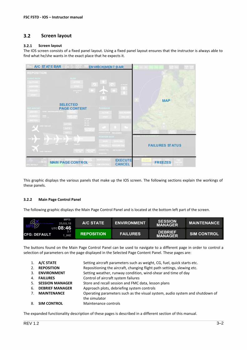
3.2.1 Screen layout The IOS screen consists of a fixed panel layout. Using a fixed panel layout ensures that the instructor is always able to find what he/she wants in the exact place that he expects it.
This graphic displays the various panels that make up the IOS screen. The following sections explain the workings of these panels.
3.2.2 Main Page Control Panel
The following graphic displays the Main Page Control Panel and is located at the bottom left part of the screen.
The buttons found on the Main Page Control Panel can be used to navigate to a different page in order to control a selection of parameters on the page displayed in the Selected Page Content Panel. These pages are:
1. A/C STATE2. REPOSITION3. ENVIRONMENT4. FAILURES5. SESSION MANAGER6. DEBRIEF MANAGER7. MAINTENANCE
8. SIM CONTROL
Setting aircraft parameters such as weight, CG, fuel, quick starts etc. Repositioning the aircraft, changing flight path settings, slewing etc. Setting weather, runway condition, wind-shear and time of day Control of aircraft system failures Store and recall session and FMC data, lesson plans Approach plots, debriefing system controls Operating parameters such as the visual system, audio system and shutdown of the simulator Maintenance controls
The expanded functionality description of these pages is described in a different section of this manual.

FSC FSTD - IOS – Instructor manual
REV 1.2 3–3
Pressing a page button will display the selected page in the Selected Page Content Panel. The selected page button will become green.
Left of the buttons, the following information is displayed:
FSTD identifier
Date
UTC time
Software version being used
3.2.3 EXECUTE / CANCEL buttons
The main EXECUTE / CANCEL buttons are present at all times at the center-bottom of the screen. They have two conditions:
1. Ghosted Not pressable, when no prompt-condition is present
2. Prompt Both pressable, when prompt-condition is present
The prompt-condition is activated whenever a change is made in certain settings requiring confirmation before the change is activated.
The following changes activate the prompt-condition:
Any change in weather state
Any change in aircraft position / attitude due to repositioning except slew or push back
Any change in aircraft weight / CG / fuel status except fuel freeze
Any initiation or modification of a failure (with extra conditions) except clearing failure
Placing / clearing a storm
Placing / clearing TCAS target(s)
The following changes do NOT activate the prompt-condition:
Direct slewing
Pushback
Doors opening / closing, unless as a failure
Quick starts of engines / APU
Any failure reset, including refilling of fluids, resetting IDGs etc.
Airport lighting
All freezes (flight freeze, position freeze, fuel freeze etc)
FSC FSTD - IOS – Instructor manual
REV 1.2 3–4
Removing a storm
Removing TCAS target(s)
When navigating away from a page where changes requiring confirmation were made, the changes still need to be confirmed by selecting the EXECUTE button.
Multiple changes requiring confirmation can be made on the same page (unless a toggle situation is present). When pressing EXECUTE after multiple changes, ALL changes are executed. Similarly, when pressing CANCEL, ALL changes are discarded.
After pressing EXECUTE or CANCEL, the EXECUTE / CANCEL buttons return to a ghosted state.
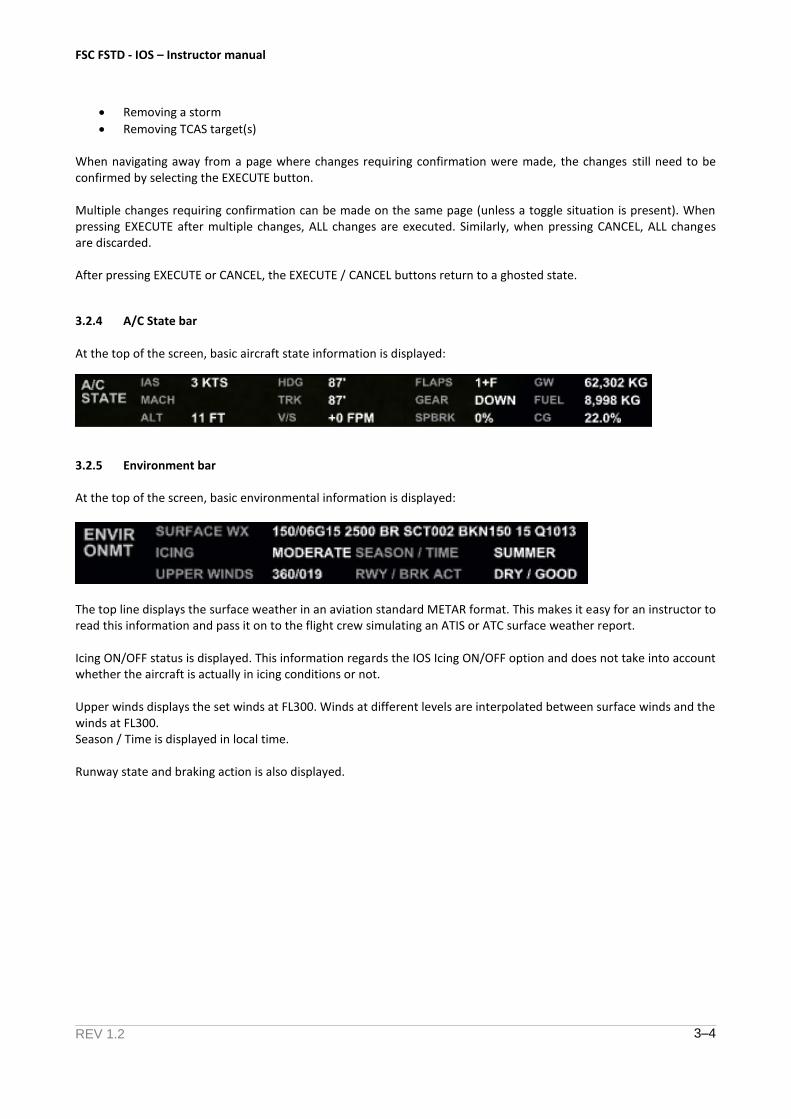
3.2.4 A/C State bar
At the top of the screen, basic aircraft state information is displayed:
3.2.5 Environment bar
At the top of the screen, basic environmental information is displayed:
The top line displays the surface weather in an aviation standard METAR format. This makes it easy for an instructor to read this information and pass it on to the flight crew simulating an ATIS or ATC surface weather report.
Icing ON/OFF status is displayed. This information regards the IOS Icing ON/OFF option and does not take into account whether the aircraft is actually in icing conditions or not.
Upper winds displays the set winds at FL300. Winds at different levels are interpolated between surface winds and the winds at FL300. Season / Time is displayed in local time.
Runway state and braking action is also displayed.
FSC FSTD - IOS – Instructor manual
REV 1.2 3–5
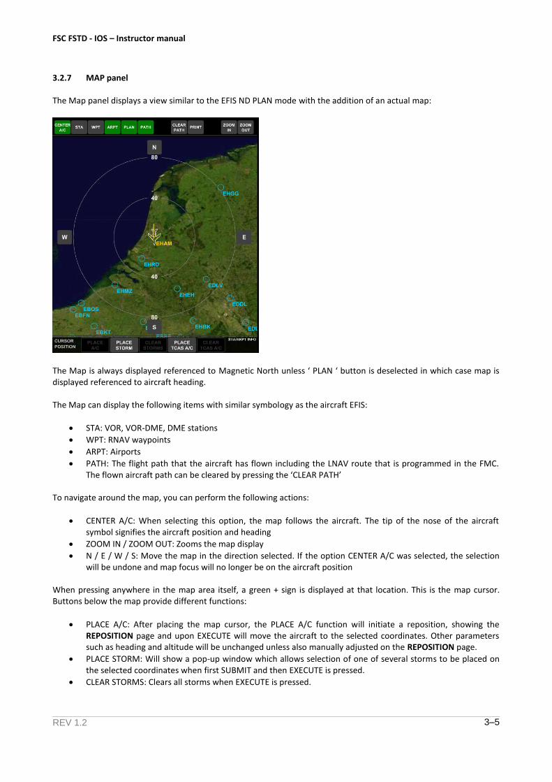
3.2.7 MAP panel
The Map panel displays a view similar to the EFIS ND PLAN mode with the addition of an actual map:
The Map is always displayed referenced to Magnetic North unless ‘ PLAN ‘ button is deselected in which case map is displayed referenced to aircraft heading.
The Map can display the following items with similar symbology as the aircraft EFIS:
STA: VOR, VOR-DME, DME stations
WPT: RNAV waypoints
ARPT: Airports
PATH: The flight path that the aircraft has flown including the LNAV route that is programmed in the FMC.The flown aircraft path can be cleared by pressing the ‘CLEAR PATH’
To navigate around the map, you can perform the following actions:
CENTER A/C: When selecting this option, the map follows the aircraft. The tip of the nose of the aircraftsymbol signifies the aircraft position and heading
ZOOM IN / ZOOM OUT: Zooms the map display
N / E / W / S: Move the map in the direction selected. If the option CENTER A/C was selected, the selectionwill be undone and map focus will no longer be on the aircraft position
When pressing anywhere in the map area itself, a green + sign is displayed at that location. This is the map cursor. Buttons below the map provide different functions:
PLACE A/C: After placing the map cursor, the PLACE A/C function will initiate a reposition, showing theREPOSITION page and upon EXECUTE will move the aircraft to the selected coordinates. Other parameterssuch as heading and altitude will be unchanged unless also manually adjusted on the REPOSITION page.
PLACE STORM: Will show a pop-up window which allows selection of one of several storms to be placed onthe selected coordinates when first SUBMIT and then EXECUTE is pressed.
CLEAR STORMS: Clears all storms when EXECUTE is pressed.
FSC FSTD - IOS – Instructor manual
REV 1.2 3–6
PLACE TCAS A/C: Will show a pop-up window which allows selection of one of several conflict scenarios withan aircraft starting its flight path at the selected coordinates when SUBMIT and then EXECUTE is pressed.
CLEAR TCAS A/C: Clears all TCAS traffic when EXECUTE is pressed.
Depending on the level of your FSTD, some functions may not be available.
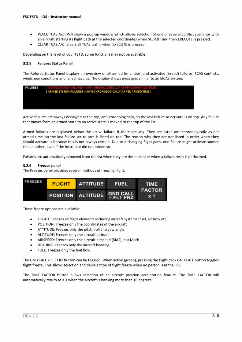
3.2.8 Failures Status Panel
The Failures Status Panel displays an overview of all armed (in amber) and activated (in red) failures, TCAS conflicts, windshear conditions and failed navaids. The display shows messages similar to an EICAS system.
FAILURES [ ACTIVE SYSTEM FAILURES – ANTI-CHRONOLOGICALLY AS PER ACTIVATION TIME ] [ ARMED SYSTEM FAILURES – ANTI-CHRONOLOGICALLY AS PER ARMED TIME ]
Active failures are always displayed at the top, anti-chronologically, so the last failure to activate is on top. Any failure that moves from an armed state to an active state is moved to the top of the list.
Armed failures are displayed below the active failure, if there are any. They are listed anti-chronologically as per armed time, so the last failure set to arm is listed on top. The reason why they are not listed in order when they should activate is because this is not always certain. Due to a changing flight path, one failure might activate sooner than another, even if the instructor did not intend so.
Failures are automatically removed from the list when they are deselected or when a failure reset is performed.
3.2.9 Freezes panel The Freezes panel provides several methods of freezing flight.
These freeze options are available:
FLIGHT: Freezes all flight elements including aircraft systems (fuel, air flow etc)
POSITION: Freezes only the coordinates of the aircraft
ATTITUDE: Freezes only the pitch, roll and yaw angle
ALTITUDE: Freezes only the aircraft altitude
AIRSPEED: Freezes only the aircraft airspeed (KIAS), not Mach
HEADING: Freezes only the aircraft heading
FUEL: Freezes only the fuel flow
The GND CALL = FLT FRZ button can be toggled. When active (green), pressing the flight deck GND CALL button toggles flight freeze. This allows selection and de-selection of flight freeze when no person is at the IOS.
The TIME FACTOR button allows selection of an aircraft position acceleration feature. The TIME FACTOR will automatically return to X 1 when the aircraft is banking more than 10 degrees.
FSC FSTD - IOS – Instructor manual
REV 1.2 3–7
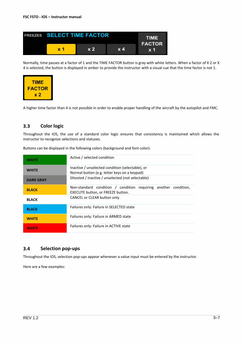
Normally, time passes at a factor of 1 and the TIME FACTOR button is gray with white letters. When a factor of X 2 or X 4 is selected, the button is displayed in amber to provide the instructor with a visual cue that the time factor is not 1.
A higher time factor than 4 is not possible in order to enable proper handling of the aircraft by the autopilot and FMC.
3.3 Color logic
Throughout the IOS, the use of a standard color logic ensures that consistency is maintained which allows the instructor to recognize selections and statuses.
Buttons can be displayed in the following colors (background and font color):
WHITE Active / selected condition
WHITE Inactive / unselected condition (selectable), or Normal button (e.g. letter keys on a keypad)
DARK GRAY Ghosted / inactive / unselected (not selectable)
BLACK Non-standard condition / condition requiring another condition, EXECUTE button, or FREEZE button.
BLACK CANCEL or CLEAR button only
BLACK Failures only: Failure in SELECTED state
WHITE Failures only: Failure in ARMED state
WHITE Failures only: Failure in ACTIVE state
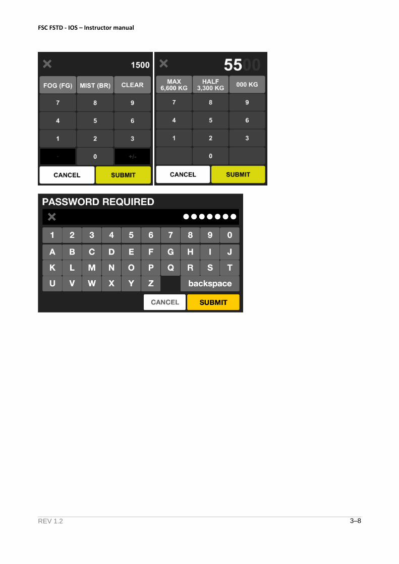
3.4 Selection pop-ups
Throughout the IOS, selection pop-ups appear whenever a value input must be entered by the instructor.
Here are a few examples:
FSC FSTD - IOS – Instructor manual
REV 1.2 3–8
FSC FSTD - IOS – Instructor manual
REV 1.2 4–1
4 Normal Operation
4.1 Session control
4.1.1 Session control basics
Depending on the configuration of your FSTD, session control may be used to control and track simulator usage.
If session control is disabled, the simulator can be used by anyone at any time. Session time tracking is not available. When the simulator is started, the simulator will display the IOS A/C STATE page after startup is completed.
If session control is enabled, the simulator can be used only after successful user account login.
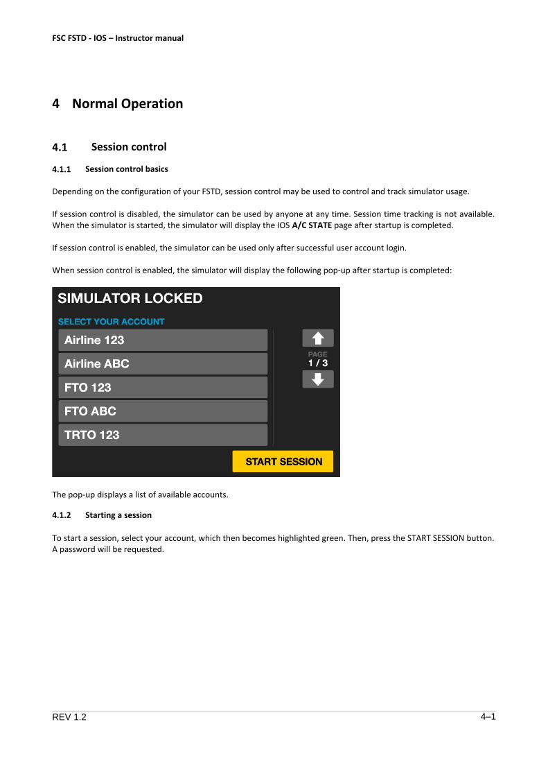
When session control is enabled, the simulator will display the following pop-up after startup is completed:
The pop-up displays a list of available accounts.
4.1.2 Starting a session
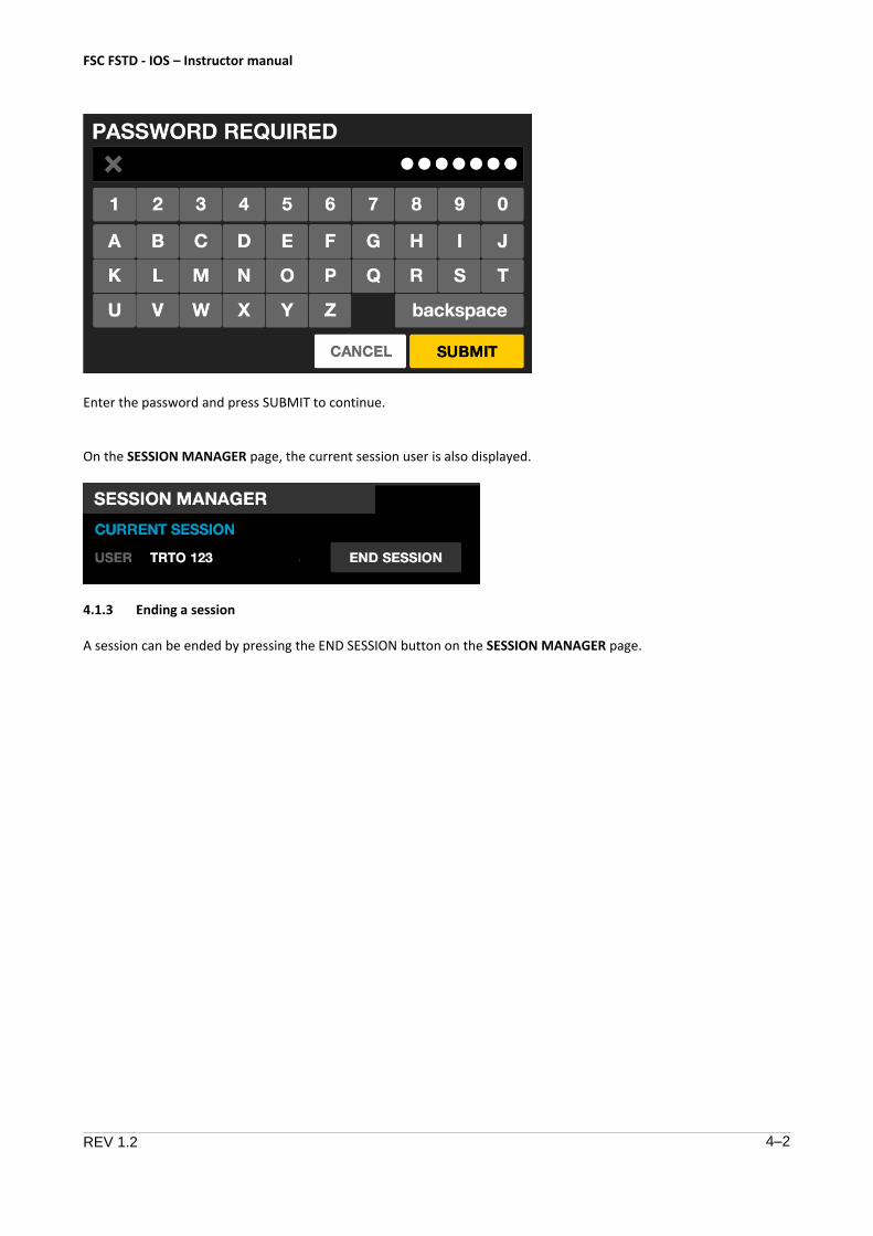
To start a session, select your account, which then becomes highlighted green. Then, press the START SESSION button. A password will be requested.
FSC FSTD - IOS – Instructor manual
REV 1.2 4–2
Enter the password and press SUBMIT to continue.
On the SESSION MANAGER page, the current session user is also displayed.
4.1.3 Ending a session
A session can be ended by pressing the END SESSION button on the SESSION MANAGER page.
FSC FSTD - IOS – Instructor manual
REV 1.2 4–3
4.2 Setting the aircraft state
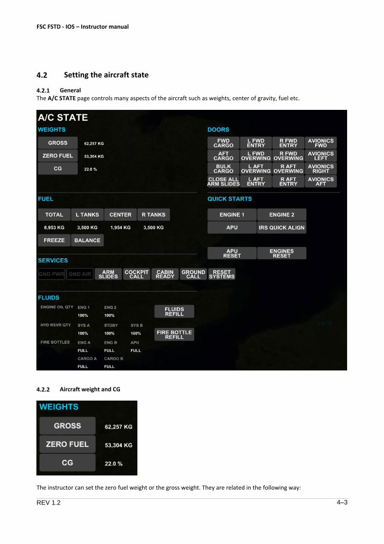
4.2.1 General The A/C STATE page controls many aspects of the aircraft such as weights, center of gravity, fuel etc.
4.2.2 Aircraft weight and CG
The instructor can set the zero fuel weight or the gross weight. They are related in the following way:
FSC FSTD - IOS – Instructor manual
REV 1.2 4–4
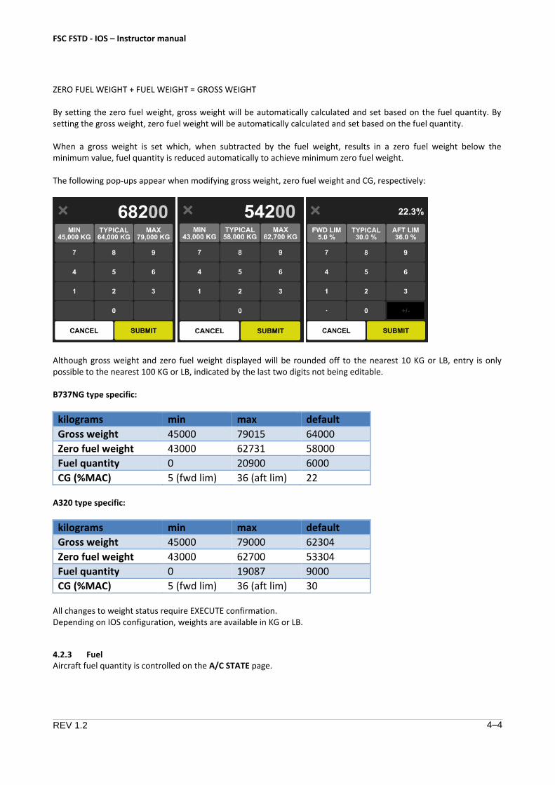
ZERO FUEL WEIGHT + FUEL WEIGHT = GROSS WEIGHT
By setting the zero fuel weight, gross weight will be automatically calculated and set based on the fuel quantity. By setting the gross weight, zero fuel weight will be automatically calculated and set based on the fuel quantity.
When a gross weight is set which, when subtracted by the fuel weight, results in a zero fuel weight below the minimum value, fuel quantity is reduced automatically to achieve minimum zero fuel weight.
The following pop-ups appear when modifying gross weight, zero fuel weight and CG, respectively:
Although gross weight and zero fuel weight displayed will be rounded off to the nearest 10 KG or LB, entry is only possible to the nearest 100 KG or LB, indicated by the last two digits not being editable.
B737NG type specific:
kilograms min max default
Gross weight 45000 79015 64000
Zero fuel weight 43000 62731 58000
Fuel quantity 0 20900 6000
CG (%MAC) 5 (fwd lim) 36 (aft lim) 22
A320 type specific:
kilograms min max default
Gross weight 45000 79000 62304
Zero fuel weight 43000 62700 53304
Fuel quantity 0 19087 9000
CG (%MAC) 5 (fwd lim) 36 (aft lim) 30
All changes to weight status require EXECUTE confirmation. Depending on IOS configuration, weights are available in KG or LB.
4.2.3 Fuel Aircraft fuel quantity is controlled on the A/C STATE page.
FSC FSTD - IOS – Instructor manual
REV 1.2 4–5
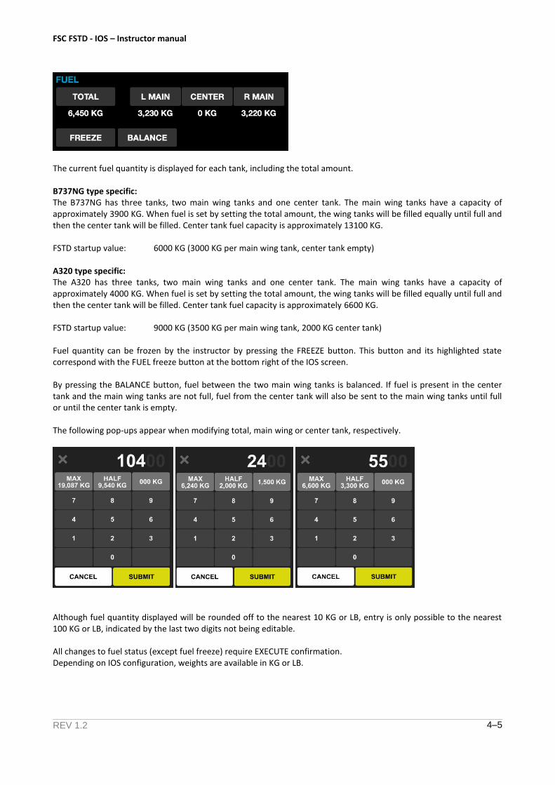
The current fuel quantity is displayed for each tank, including the total amount.
B737NG type specific: The B737NG has three tanks, two main wing tanks and one center tank. The main wing tanks have a capacity of approximately 3900 KG. When fuel is set by setting the total amount, the wing tanks will be filled equally until full and then the center tank will be filled. Center tank fuel capacity is approximately 13100 KG.
FSTD startup value: 6000 KG (3000 KG per main wing tank, center tank empty)
A320 type specific: The A320 has three tanks, two main wing tanks and one center tank. The main wing tanks have a capacity of approximately 4000 KG. When fuel is set by setting the total amount, the wing tanks will be filled equally until full and then the center tank will be filled. Center tank fuel capacity is approximately 6600 KG.
FSTD startup value: 9000 KG (3500 KG per main wing tank, 2000 KG center tank)
Fuel quantity can be frozen by the instructor by pressing the FREEZE button. This button and its highlighted state correspond with the FUEL freeze button at the bottom right of the IOS screen.
By pressing the BALANCE button, fuel between the two main wing tanks is balanced. If fuel is present in the center tank and the main wing tanks are not full, fuel from the center tank will also be sent to the main wing tanks until full or until the center tank is empty.
The following pop-ups appear when modifying total, main wing or center tank, respectively.
Although fuel quantity displayed will be rounded off to the nearest 10 KG or LB, entry is only possible to the nearest 100 KG or LB, indicated by the last two digits not being editable.
All changes to fuel status (except fuel freeze) require EXECUTE confirmation. Depending on IOS configuration, weights are available in KG or LB.

FSC FSTD - IOS – Instructor manual
REV 1.2 4–6
4.2.4 Doors Aircraft doors may be opened on the ground from the A/C STATE page. The door control panel is inhibited when the aircraft is not on the ground. Opening of doors or setting door annunciators is then controlled from the FAILURES page (AIRPLANE GENERAL subpage).
The following doors can be found on the B737NG FSTD:
The following doors can be found on the A320 FSTD:
Selecting a door open will physically open the door, which will impact pressurization when becoming airborne. Pressurization with a door open is not possible.
Any open door is highlighted in amber.
Opening or closing a door from the A/C STATE page does not need EXECUTE confirmation.
4.2.5 Quick starts
Available quick starts are:
• Engines
• APU
• IRS
Brings the selected engine to running state instantly provided the cockpit is
properly configured (i.e. fuel status, failure status, engine start levers)
Brings the APU to running state provided the cockpit is properly configured
Eliminates the IRS alignment cycle and instantly aligns both IRSs
FSC FSTD - IOS – Instructor manual
REV 1.2 4–7
An APU RESET and Engine RESET buttons are available to reset all failures and states from either the APU or Engine.
Quick starts and resets do not need EXECUTE confirmation.
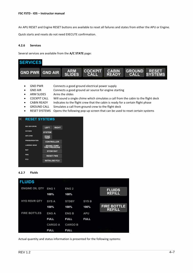
4.2.6 Services
Several services are available from the A/C STATE page:
• GND PWR
• GND AIR
• ARM SLIDES
• COCKPIT CALL
• CABIN READY
Connects a good ground electrical power supply
Connects a good ground air source for engine starting
Arms the slides
Will sound a single chime which simulates a call from the cabin to the flight deck
Indicates to the flight crew that the cabin is ready for a certain flight phase
• GROUND CALL Simulates a call from ground crew to the flight deck
• RESET SYSTEMS Opens the following pop-up screen that can be used to reset certain systems
4.2.7 Fluids
Actual quantity and status information is presented for the following systems:
FSC FSTD - IOS – Instructor manual
REV 1.2 4–8
• Engine oil quantities
• Hydraulic reservoir fluid quantities
• Fire bottle contents for both engines, APU and cargo compartments
Pressing the REFILL buttons will refill the respective systems.
Refilling systems does not need EXECUTE confirmation.
4.3 Positioning the aircraft
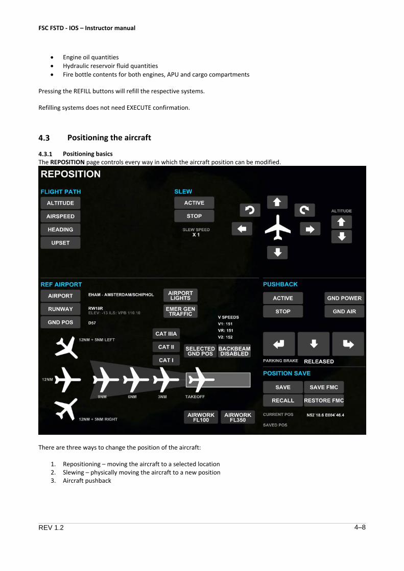
4.3.1 Positioning basics The REPOSITION page controls every way in which the aircraft position can be modified.
There are three ways to change the position of the aircraft:
1. Repositioning – moving the aircraft to a selected location2. Slewing – physically moving the aircraft to a new position3. Aircraft pushback
FSC FSTD - IOS – Instructor manual
REV 1.2 4–9
4.3.2 Repositioning Repositioning allows the instructor to move the aircraft to a selected location. This location may be on the ground or in the air and can be specified in the following ways:
1. Selecting a ground or air position based on a reference airport2. Selecting an airwork scenario3. Selecting a ground or air position by using the map cursor4. Recalling a position stored in memory5. Setting aircraft flight path manually (altitude, airspeed, heading, pitch, bank)
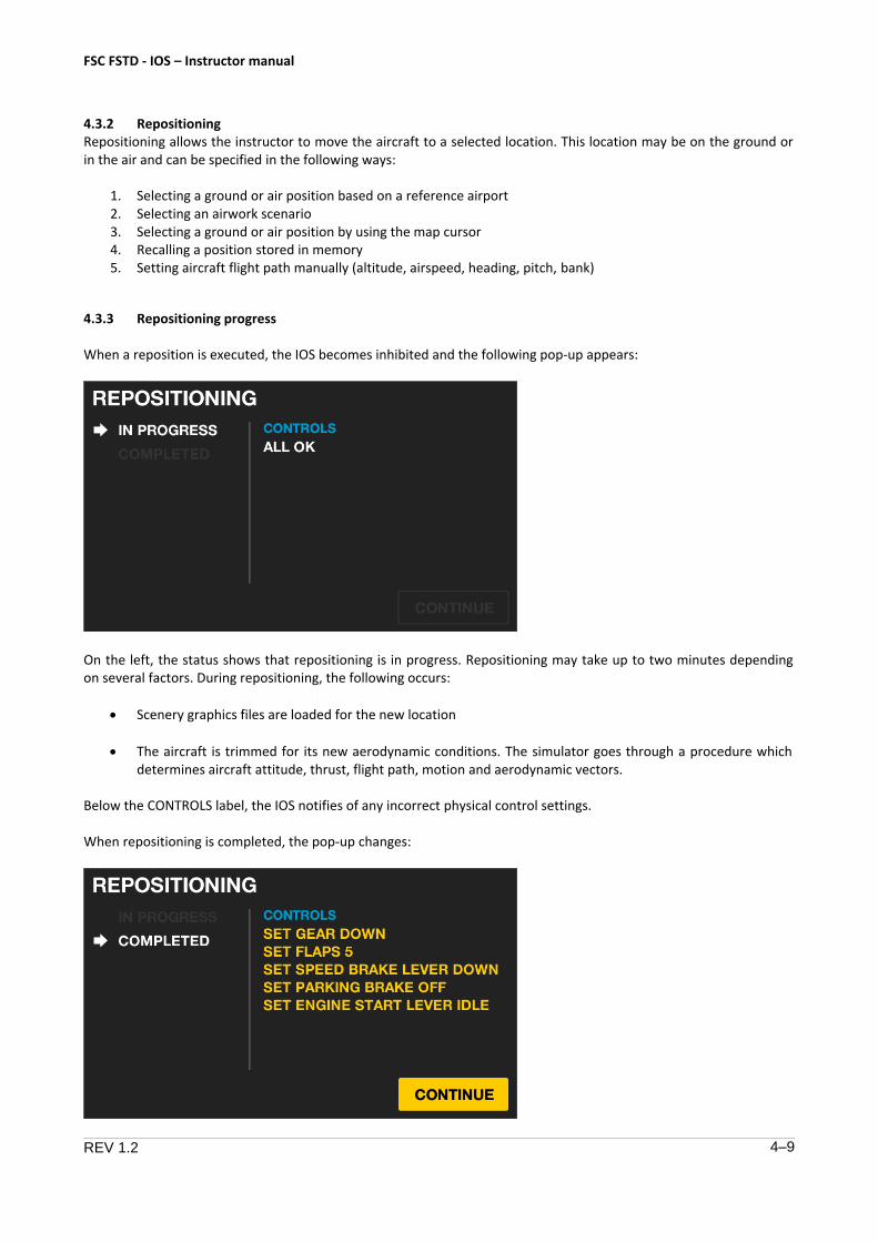
4.3.3 Repositioning progress
When a reposition is executed, the IOS becomes inhibited and the following pop-up appears:
On the left, the status shows that repositioning is in progress. Repositioning may take up to two minutes depending on several factors. During repositioning, the following occurs:
• Scenery graphics files are loaded for the new location
• The aircraft is trimmed for its new aerodynamic conditions. The simulator goes through a procedure which determines aircraft attitude, thrust, flight path, motion and aerodynamic vectors.
Below the CONTROLS label, the IOS notifies of any incorrect physical control settings.
When repositioning is completed, the pop-up changes:
FSC FSTD - IOS – Instructor manual
REV 1.2 4–10
Repositioning status changes to “completed” and the CONTINUE button becomes available. After pressing CONTINUE, the IOS will become available again but the system will remain in FLIGHT FREEZE until manually deselected.
In this screenshot, several examples of incorrect physical control settings are shown. The instructor can choose to override this by pressing CONTINUE, but the aircraft will have been trimmed with the preset conditions and may react in an unexpected manner when flight freeze is deselected.
When displayed control settings are corrected, the respective message is automatically removed.
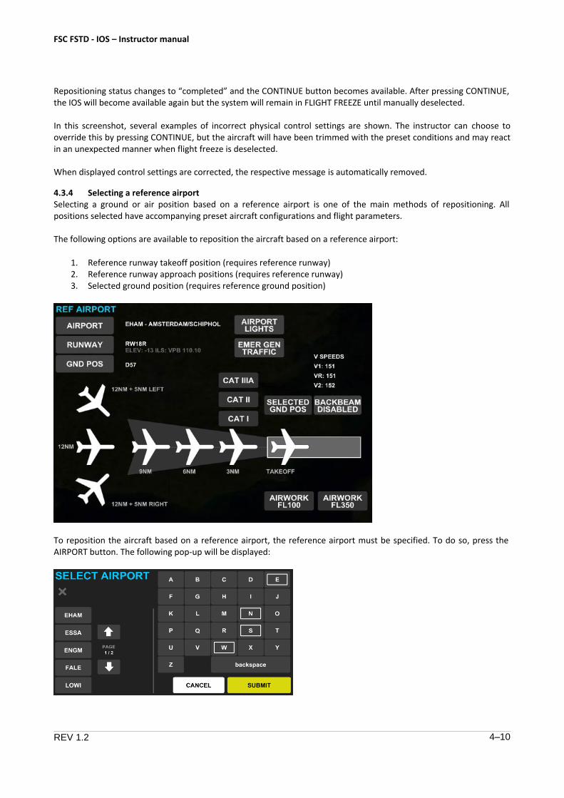
4.3.4 Selecting a reference airport Selecting a ground or air position based on a reference airport is one of the main methods of repositioning. All positions selected have accompanying preset aircraft configurations and flight parameters.
The following options are available to reposition the aircraft based on a reference airport:
1. Reference runway takeoff position (requires reference runway)2. Reference runway approach positions (requires reference runway)3. Selected ground position (requires reference ground position)
To reposition the aircraft based on a reference airport, the reference airport must be specified. To do so, press the AIRPORT button. The following pop-up will be displayed:
FSC FSTD - IOS – Instructor manual
REV 1.2 4–11
A list of modeled airports is displayed with page arrows to navigate through the list. Alternatively, the airport of choice can be entered manually. If so configured, a generic airport may be available.
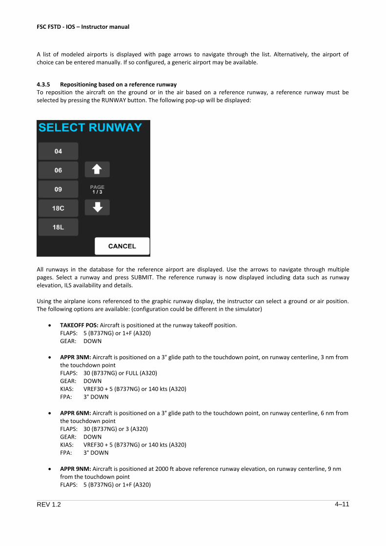
4.3.5 Repositioning based on a reference runway To reposition the aircraft on the ground or in the air based on a reference runway, a reference runway must be selected by pressing the RUNWAY button. The following pop-up will be displayed:
All runways in the database for the reference airport are displayed. Use the arrows to navigate through multiple pages. Select a runway and press SUBMIT. The reference runway is now displayed including data such as runway elevation, ILS availability and details.
Using the airplane icons referenced to the graphic runway display, the instructor can select a ground or air position. The following options are available: (configuration could be different in the simulator)
• TAKEOFF POS: Aircraft is positioned at the runway takeoff position.FLAPS: 5 (B737NG) or 1+F (A320)GEAR: DOWN
• APPR 3NM: Aircraft is positioned on a 3° glide path to the touchdown point, on runway centerline, 3 nm from the touchdown pointFLAPS: 30 (B737NG) or FULL (A320)GEAR: DOWNKIAS: VREF30 + 5 (B737NG) or 140 kts (A320)FPA: 3° DOWN
• APPR 6NM: Aircraft is positioned on a 3° glide path to the touchdown point, on runway centerline, 6 nm from the touchdown pointFLAPS: 30 (B737NG) or 3 (A320)GEAR: DOWNKIAS: VREF30 + 5 (B737NG) or 140 kts (A320)FPA: 3° DOWN
• APPR 9NM: Aircraft is positioned at 2000 ft above reference runway elevation, on runway centerline, 9 nm from the touchdown pointFLAPS: 5 (B737NG) or 1+F (A320)

FSC FSTD - IOS – Instructor manual
REV 1.2 4–12
GEAR: UP KIAS: FPA:
VREF40 + 35 kts (B737NG) or 185 kts (A320) 0°
• APPR 12NM: Aircraft is positioned at 3000 ft above reference runway elevation, on runway centerline, 12 nm from the touchdown pointFLAPS: 5 (B737NG) or 1+F (A320)GEAR: UPKIAS: 200 kts (B737NG & A320)FPA: 0°
• APPR 12NM + 1NM LEFT/RIGHT: Aircraft is positioned at 3000 ft above reference runway, 1 nm left / right from the runway centerline at a 30° track intercept angle, 12 nm from the touchdown pointFLAPS: 5 (B737NG) or 1+F (A320)GEAR: UPKIAS: 200 kts (B737NG & A320)FPA: 0°
• CAT I/II/IIIA: Aircraft is positioned on a 3° glide path to the touchdown point, on runway centerline in CAT I/II or IIIA condition. Environment fog will be set accordingly.
When selecting a position, the selected position will be highlighted. Press EXECUTE to perform the reposition.
4.3.6 Repositioning based on a reference ground position
To reposition the aircraft on the ground based on a reference ground position, a reference ground position must be selected by pressing the SELECTED GND POS button. The following pop-up will be displayed:
All ground positions in the database for the reference airport are displayed. Use the arrows to navigate through multiple pages. Some airports may not have any specified ground positions. The following ground positions types exist:
o Gateso Holding points (indicated by HP## indicating the runway and the taxiway designation)o Platform positions
Press the SELECTED GND POS button to select the preselected ground position for repositioning. Press EXECUTE to perform the reposition.
FSC FSTD - IOS – Instructor manual
REV 1.2 4–13
4.3.7 Repositioning using an airwork scenario
There are two selectable airwork scenarios, which are not related to a reference airport, runway or ground position. Both scenarios contain specific aircraft configurations and flight paths but the aircraft position is based on the last position coordinates.
1. AIRWORK FL100: ALTITUDE: AIRSPEED: ATTITUDE: CONFIG:
2. AIRWORK FL350: ALTITUDE: AIRSPEED: ATTITUDE: CONFIG:
10,000 ft (based on standard atmosphere) 265 KIAS level flight, wings level flaps UP, gear UP
35,000 ft (based on standard atmosphere) Mach 0.741 level flight, wings level flaps UP, gear UP
To select an airwork scenario, press the respective button, which will be highlighted. Press EXECUTE to perform the reposition.
4.3.8 Repositioning using the map cursor
To reposition the aircraft using the map cursor, press the desired location on the map and verify the white + sign, or map cursor, is displayed at that location. Press the PLACE A/C button below the map, verify that the white map cursor turns green, and press EXECUTE to perform the reposition.
The aircraft will move to the selected location without changing current aircraft configuration or flight path settings. This may occur on the ground or in the air.
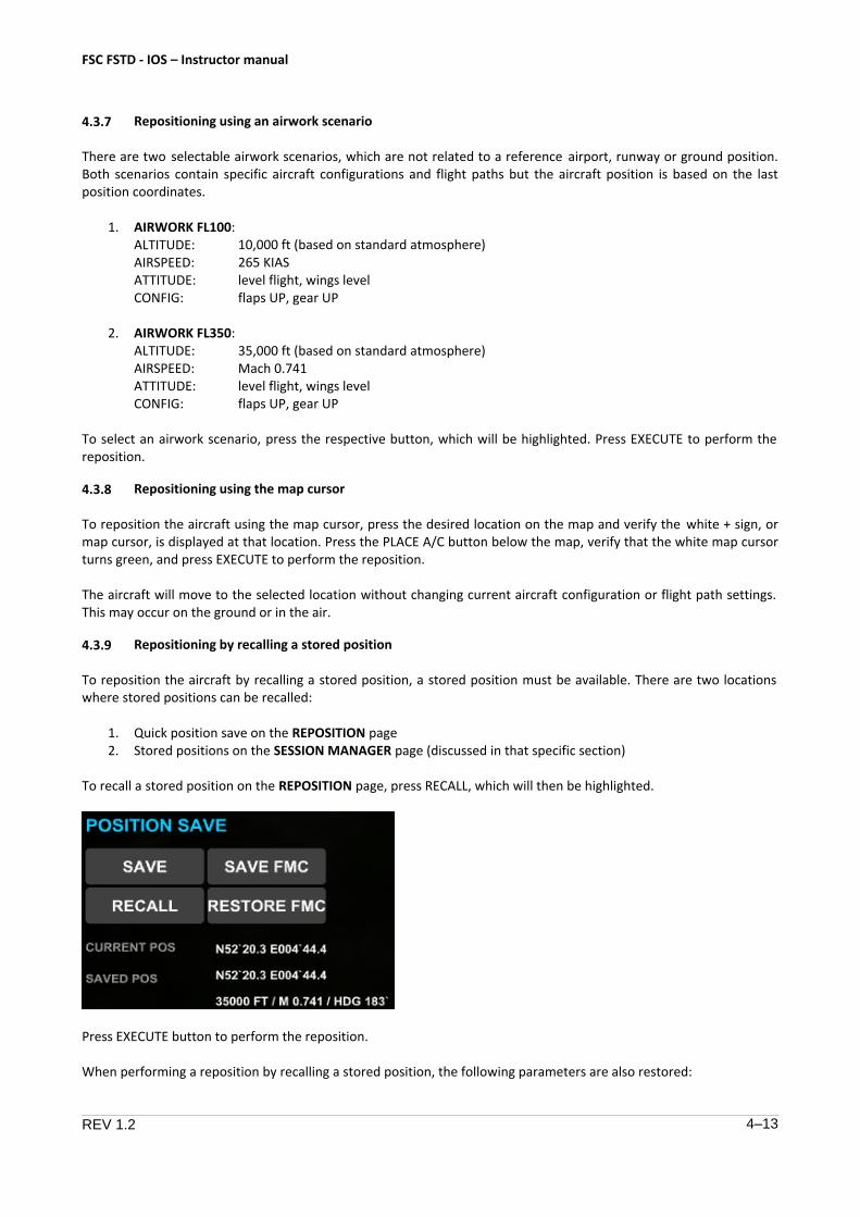
4.3.9 Repositioning by recalling a stored position
To reposition the aircraft by recalling a stored position, a stored position must be available. There are two locations where stored positions can be recalled:
1. Quick position save on the REPOSITION page2. Stored positions on the SESSION MANAGER page (discussed in that specific section)
To recall a stored position on the REPOSITION page, press RECALL, which will then be highlighted.
Press EXECUTE button to perform the reposition.
When performing a reposition by recalling a stored position, the following parameters are also restored:
FSC FSTD - IOS – Instructor manual
REV 1.2 4–14
• Airplane attitude (pitch, roll, yaw)
• Airspeed / Mach
• Altitude
• Heading
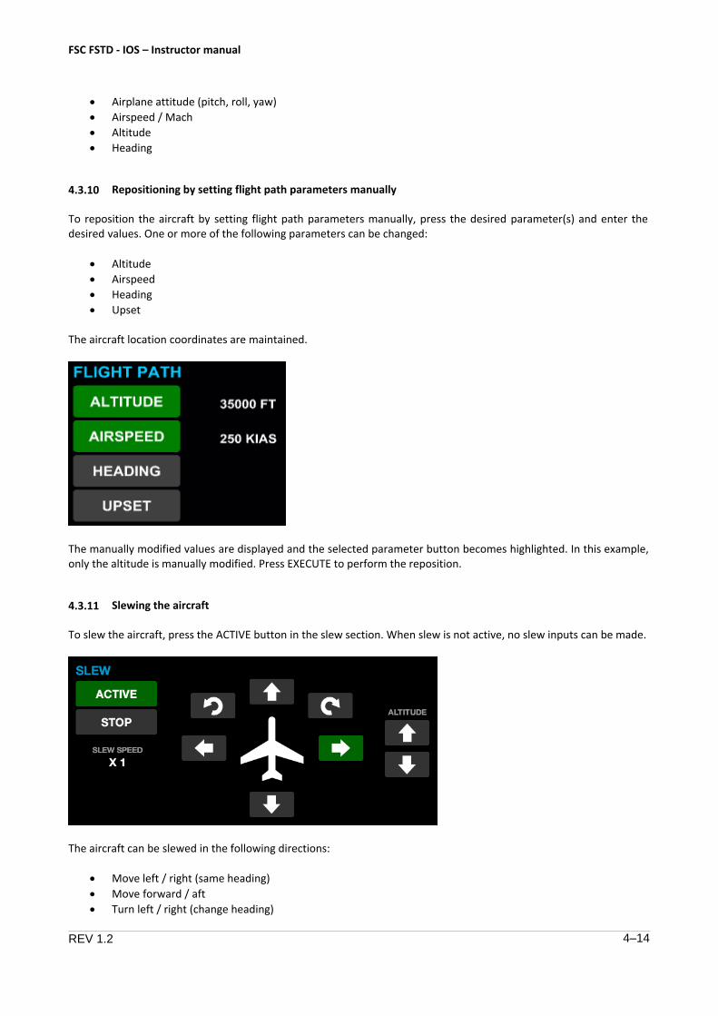
4.3.10 Repositioning by setting flight path parameters manually
To reposition the aircraft by setting flight path parameters manually, press the desired parameter(s) and enter the desired values. One or more of the following parameters can be changed:
• Altitude
• Airspeed
• Heading
• Upset
The aircraft location coordinates are maintained.
The manually modified values are displayed and the selected parameter button becomes highlighted. In this example, only the altitude is manually modified. Press EXECUTE to perform the reposition.
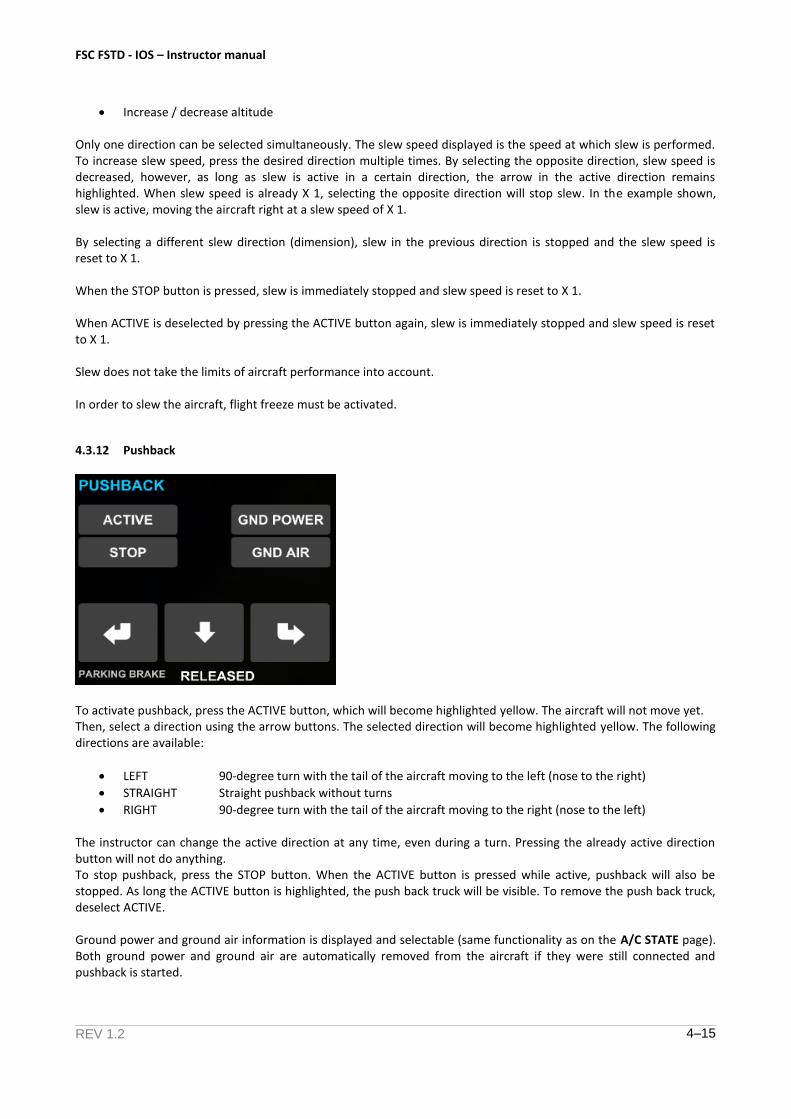
4.3.11 Slewing the aircraft
To slew the aircraft, press the ACTIVE button in the slew section. When slew is not active, no slew inputs can be made.
The aircraft can be slewed in the following directions:
• Move left / right (same heading)
• Move forward / aft
• Turn left / right (change heading)
FSC FSTD - IOS – Instructor manual
REV 1.2 4–15
Increase / decrease altitude
Only one direction can be selected simultaneously. The slew speed displayed is the speed at which slew is performed. To increase slew speed, press the desired direction multiple times. By selecting the opposite direction, slew speed is decreased, however, as long as slew is active in a certain direction, the arrow in the active direction remains highlighted. When slew speed is already X 1, selecting the opposite direction will stop slew. In the example shown, slew is active, moving the aircraft right at a slew speed of X 1.
By selecting a different slew direction (dimension), slew in the previous direction is stopped and the slew speed is reset to X 1.
When the STOP button is pressed, slew is immediately stopped and slew speed is reset to X 1.
When ACTIVE is deselected by pressing the ACTIVE button again, slew is immediately stopped and slew speed is reset to X 1.
Slew does not take the limits of aircraft performance into account.
In order to slew the aircraft, flight freeze must be activated.
4.3.12 Pushback
To activate pushback, press the ACTIVE button, which will become highlighted yellow. The aircraft will not move yet. Then, select a direction using the arrow buttons. The selected direction will become highlighted yellow. The following directions are available:
LEFT 90-degree turn with the tail of the aircraft moving to the left (nose to the right)
STRAIGHT Straight pushback without turns
RIGHT 90-degree turn with the tail of the aircraft moving to the right (nose to the left)
The instructor can change the active direction at any time, even during a turn. Pressing the already active direction button will not do anything. To stop pushback, press the STOP button. When the ACTIVE button is pressed while active, pushback will also be stopped. As long the ACTIVE button is highlighted, the push back truck will be visible. To remove the push back truck, deselect ACTIVE.
Ground power and ground air information is displayed and selectable (same functionality as on the A/C STATE page). Both ground power and ground air are automatically removed from the aircraft if they were still connected and pushback is started.
FSC FSTD - IOS – Instructor manual
REV 1.2 4–16
4.4 Setting the weather and environment
4.4.1 General
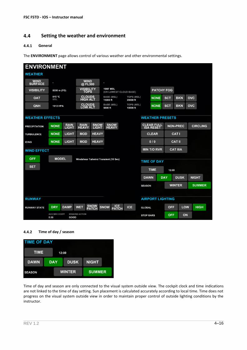
The ENVIRONMENT page allows control of various weather and other environmental settings.
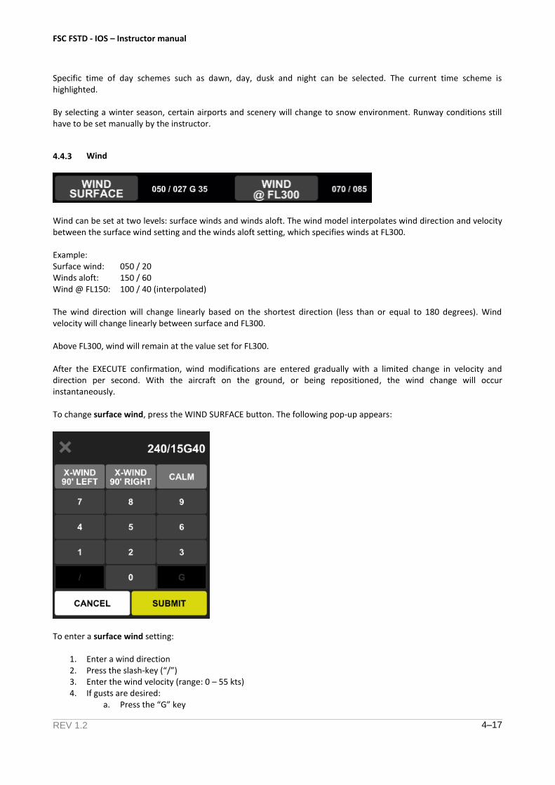
4.4.2 Time of day / season
Time of day and season are only connected to the visual system outside view. The cockpit clock and time indications are not linked to the time of day setting. Sun placement is calculated accurately according to local time. Time does not progress on the visual system outside view in order to maintain proper control of outside lighting conditions by the instructor.
FSC FSTD - IOS – Instructor manual
REV 1.2 4–17
Specific time of day schemes such as dawn, day, dusk and night can be selected. The current time scheme is highlighted.
By selecting a winter season, certain airports and scenery will change to snow environment. Runway conditions still have to be set manually by the instructor.
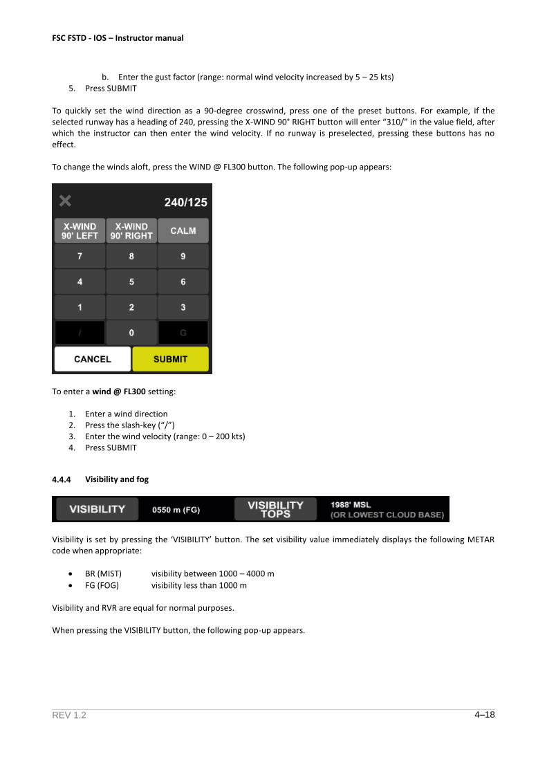
4.4.3 Wind
Wind can be set at two levels: surface winds and winds aloft. The wind model interpolates wind direction and velocity between the surface wind setting and the winds aloft setting, which specifies winds at FL300.
Example: Surface wind: 050 / 20 Winds aloft: 150 / 60 Wind @ FL150: 100 / 40 (interpolated)
The wind direction will change linearly based on the shortest direction (less than or equal to 180 degrees). Wind velocity will change linearly between surface and FL300.
Above FL300, wind will remain at the value set for FL300.
After the EXECUTE confirmation, wind modifications are entered gradually with a limited change in velocity and direction per second. With the aircraft on the ground, or being repositioned, the wind change will occur instantaneously.
To change surface wind, press the WIND SURFACE button. The following pop-up appears:
To enter a surface wind setting:
1. Enter a wind direction2. Press the slash-key (“/”)3. Enter the wind velocity (range: 0 – 55 kts)4. If gusts are desired:
a. Press the “G” key
FSC FSTD - IOS – Instructor manual
REV 1.2 4–18
b. Enter the gust factor (range: normal wind velocity increased by 5 – 25 kts)5. Press SUBMIT
To quickly set the wind direction as a 90-degree crosswind, press one of the preset buttons. For example, if the selected runway has a heading of 240, pressing the X-WIND 90° RIGHT button will enter “310/” in the value field, after which the instructor can then enter the wind velocity. If no runway is preselected, pressing these buttons has no effect.
To change the winds aloft, press the WIND @ FL300 button. The following pop-up appears:
To enter a wind @ FL300 setting:
1. Enter a wind direction2. Press the slash-key (“/”)3. Enter the wind velocity (range: 0 – 200 kts)4. Press SUBMIT
4.4.4 Visibility and fog
Visibility is set by pressing the ‘VISIBILITY’ button. The set visibility value immediately displays the following METAR code when appropriate:
BR (MIST) visibility between 1000 – 4000 m
FG (FOG) visibility less than 1000 m
Visibility and RVR are equal for normal purposes.
When pressing the VISIBILITY button, the following pop-up appears.

FSC FSTD - IOS – Instructor manual
REV 1.2 4–19
When visibility is set as less than 1000 m, it is treated as fog. In this case, the value entered at the VISIBILITY TOPS becomes relevant. Automatically, a value of 5000 ft MSL is entered. This will cause the aircraft to fly into clear sky when the visibility tops altitude is reached.
Visibility range: 0 – 20000 m and clear (unlimited)
When pressing the VISIBILITY TOPS button, the following pop-up appears.
The visibility tops range is 50 – 10000 ft and is calculated MSL, not AGL.
If the lowest cloud base (in this case, also SCT clouds) is lower than the visibility tops value, the lowest cloud base will override the visibility tops value.
FSC FSTD - IOS – Instructor manual
REV 1.2 4–20
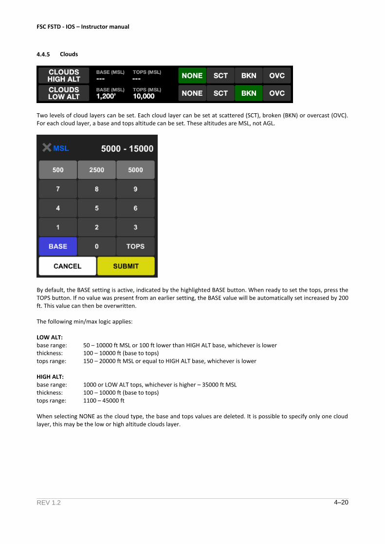
4.4.5 Clouds
Two levels of cloud layers can be set. Each cloud layer can be set at scattered (SCT), broken (BKN) or overcast (OVC). For each cloud layer, a base and tops altitude can be set. These altitudes are MSL, not AGL.
By default, the BASE setting is active, indicated by the highlighted BASE button. When ready to set the tops, press the TOPS button. If no value was present from an earlier setting, the BASE value will be automatically set increased by 200 ft. This value can then be overwritten.
The following min/max logic applies:
LOW ALT: base range: 50 – 10000 ft MSL or 100 ft lower than HIGH ALT base, whichever is lower thickness: 100 – 10000 ft (base to tops) tops range: 150 – 20000 ft MSL or equal to HIGH ALT base, whichever is lower
HIGH ALT: base range: 1000 or LOW ALT tops, whichever is higher – 35000 ft MSL thickness: 100 – 10000 ft (base to tops) tops range: 1100 – 45000 ft
When selecting NONE as the cloud type, the base and tops values are deleted. It is possible to specify only one cloud layer, this may be the low or high altitude clouds layer.
FSC FSTD - IOS – Instructor manual
REV 1.2 4–21
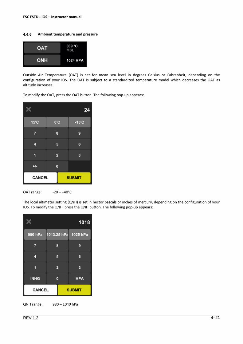
4.4.6 Ambient temperature and pressure
Outside Air Temperature (OAT) is set for mean sea level in degrees Celsius or Fahrenheit, depending on the configuration of your IOS. The OAT is subject to a standardized temperature model which decreases the OAT as altitude increases.
To modify the OAT, press the OAT button. The following pop-up appears:
OAT range: -20 – +40°C
The local altimeter setting (QNH) is set in hector pascals or inches of mercury, depending on the configuration of your IOS. To modify the QNH, press the QNH button. The following pop-up appears:
QNH range: 980 – 1040 hPa
FSC FSTD - IOS – Instructor manual
REV 1.2 4–22
After EXECUTE confirmation, OAT and QNH modifications are subject to a maximum rate change when the aircraft is not on the ground, which results in a more gradual change and effects on the aircraft. When the aircraft is on the ground or being repositioned, the changes are instantaneously.
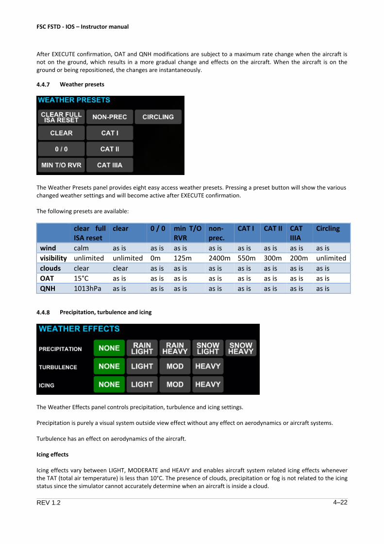
4.4.7 Weather presets
The Weather Presets panel provides eight easy access weather presets. Pressing a preset button will show the various changed weather settings and will become active after EXECUTE confirmation.
The following presets are available:
clear full ISA reset
clear 0 / 0 min T/O RVR
non-prec.
CAT I CAT II CAT IIIA
Circling
wind calm as is as is as is as is as is as is as is as is
visibility unlimited unlimited 0m 125m 2400m 550m 300m 200m unlimited
clouds clear clear as is as is as is as is as is as is as is
OAT 15°C as is as is as is as is as is as is as is as is
QNH 1013hPa as is as is as is as is as is as is as is as is
4.4.8 Precipitation, turbulence and icing
The Weather Effects panel controls precipitation, turbulence and icing settings.
Precipitation is purely a visual system outside view effect without any effect on aerodynamics or aircraft systems.
Turbulence has an effect on aerodynamics of the aircraft.
Icing effects
Icing effects vary between LIGHT, MODERATE and HEAVY and enables aircraft system related icing effects whenever the TAT (total air temperature) is less than 10°C. The presence of clouds, precipitation or fog is not related to the icing status since the simulator cannot accurately determine when an aircraft is inside a cloud.
FSC FSTD - IOS – Instructor manual
REV 1.2 4–23
For example, it may be possible that with Icing Effects MODERATE selected and a failed Captain’s pitot heater, the Captain’s airspeed indication may show erroneous data even when no clouds or fog are selected. Vice versa, it is possible that with Icing Effects NONE selected, an aircraft will fly through icing conditions in clouds without any icing effects.
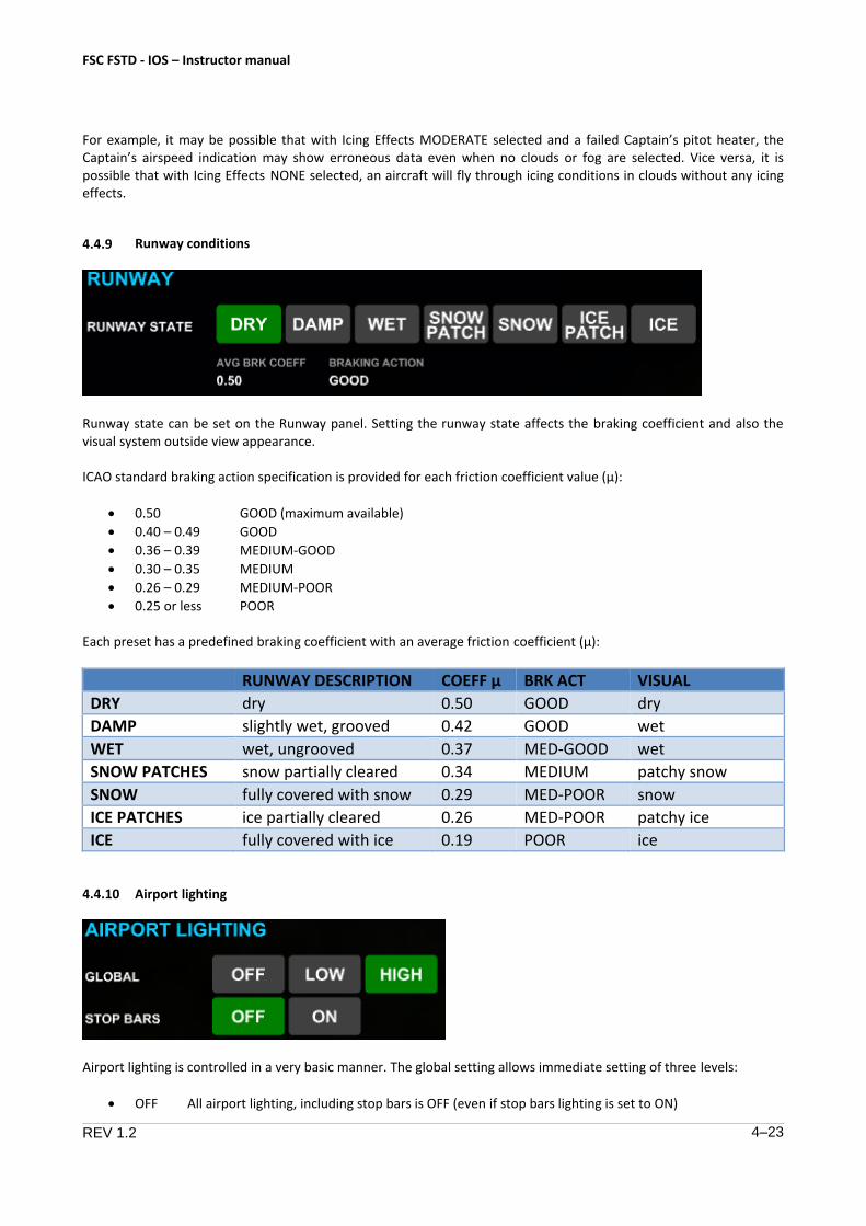
4.4.9 Runway conditions
Runway state can be set on the Runway panel. Setting the runway state affects the braking coefficient and also the visual system outside view appearance.
ICAO standard braking action specification is provided for each friction coefficient value (µ):
• 0.50
• 0.40 – 0.49
• 0.36 – 0.39
• 0.30 – 0.35
• 0.26 – 0.29
• 0.25 or less
GOOD (maximum available)
GOOD
MEDIUM-GOOD
MEDIUM
MEDIUM-POOR
POOR
Each preset has a predefined braking coefficient with an average friction coefficient (µ):
RUNWAY DESCRIPTION COEFF µ BRK ACT VISUAL
DRY dry 0.50 GOOD dry
DAMP slightly wet, grooved 0.42 GOOD wet
WET wet, ungrooved 0.37 MED-GOOD wet
SNOW PATCHES snow partially cleared 0.34 MEDIUM patchy snow
SNOW fully covered with snow 0.29 MED-POOR snow
ICE PATCHES ice partially cleared 0.26 MED-POOR patchy ice
ICE fully covered with ice 0.19 POOR ice
4.4.10 Airport lighting
Airport lighting is controlled in a very basic manner. The global setting allows immediate setting of three levels:
• OFF All airport lighting, including stop bars is OFF (even if stop bars lighting is set to ON)

FSC FSTD - IOS – Instructor manual
REV 1.2 4–24
LOW All airport lighting is set at an intermediate intensity
HIGH All airport lighting is set at the maximum intensity
Lighting elements include:
All runway edge, centerline, touchdown zone, start/end lights
All approach light systems
Taxiway edge and centerline lights
Other airport lighting
It is not possible to vary lighting intensity for individual elements, runways or taxiways. In fact, this setting is applicable to all airports in the modeled airport database during flight.
Stop bars can be individually controlled by selecting them ON or OFF. Changing visibility or time of day settings may cause airport lighting to default to a different value than previously set.
4.5 Debrief Manager
4.5.1 General
The profile plotter can show three different plots: takeoff, non-precision approach and ILS approach. Plots are always referenced to the reference runway set on the REPOSITION page. This runway is also displayed here. The grey runway symbol does not depict the actual length of the runway.
The plotter always makes a plot of the last takeoff or last approaches, even if the plotter page is not displayed. Plot data will automatically be cleared when the reference runway is changed.
To clear the last drawn track lines, press the CLEAR button.
To print the currently viewed plot data using the simulator printer, press the PRINT button.

FSC FSTD - IOS – Instructor manual
REV 1.2 4–25
4.5.2 Takeoff profile plot
The takeoff profile plot contains the following elements:
Altitude profile from runway elevation up to 2100 ft AGL, 7 nm distance
Lateral profile from runway centerline up to 1500 ft left and right, 7 nm distance
Airspeed relative to V2 (-10 up to +30 kts), 7 nm distance
The zero-point on the graph is the beginning of the takeoff reference runway.
FSC FSTD - IOS – Instructor manual
REV 1.2 4–26
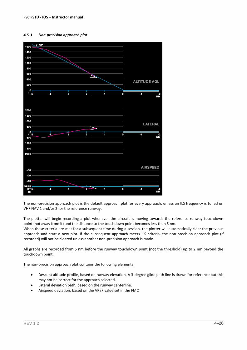
4.5.3 Non-precision approach plot
The non-precision approach plot is the default approach plot for every approach, unless an ILS frequency is tuned on VHF NAV 1 and/or 2 for the reference runway.
The plotter will begin recording a plot whenever the aircraft is moving towards the reference runway touchdown point (not away from it) and the distance to the touchdown point becomes less than 5 nm. When these criteria are met for a subsequent time during a session, the plotter will automatically clear the previous approach and start a new plot. If the subsequent approach meets ILS criteria, the non-precision approach plot (if recorded) will not be cleared unless another non-precision approach is made.
All graphs are recorded from 5 nm before the runway touchdown point (not the threshold) up to 2 nm beyond the touchdown point.
The non-precision approach plot contains the following elements:
Descent altitude profile, based on runway elevation. A 3-degree glide path line is drawn for reference but thismay not be correct for the approach selected.
Lateral deviation path, based on the runway centerline.
Airspeed deviation, based on the VREF value set in the FMC
FSC FSTD - IOS – Instructor manual
REV 1.2 4–27
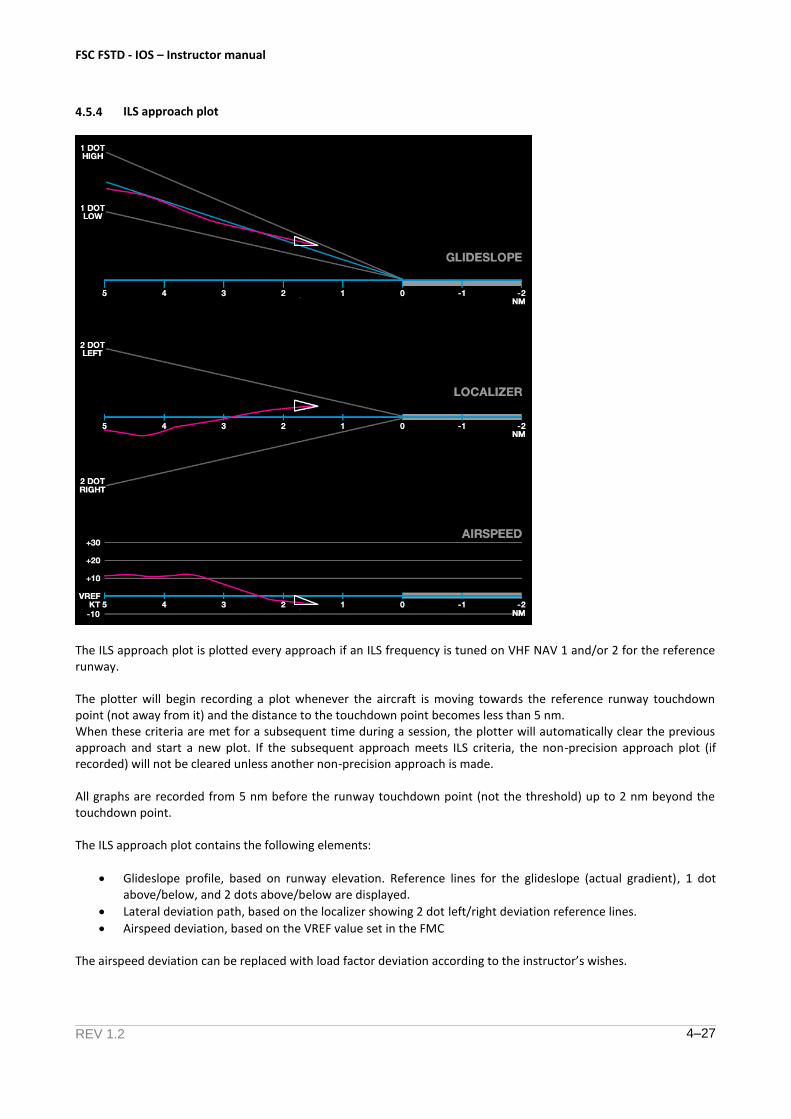
4.5.4 ILS approach plot
The ILS approach plot is plotted every approach if an ILS frequency is tuned on VHF NAV 1 and/or 2 for the reference runway.
The plotter will begin recording a plot whenever the aircraft is moving towards the reference runway touchdown point (not away from it) and the distance to the touchdown point becomes less than 5 nm. When these criteria are met for a subsequent time during a session, the plotter will automatically clear the previous approach and start a new plot. If the subsequent approach meets ILS criteria, the non-precision approach plot (if recorded) will not be cleared unless another non-precision approach is made.
All graphs are recorded from 5 nm before the runway touchdown point (not the threshold) up to 2 nm beyond the touchdown point.
The ILS approach plot contains the following elements:
Glideslope profile, based on runway elevation. Reference lines for the glideslope (actual gradient), 1 dotabove/below, and 2 dots above/below are displayed.
Lateral deviation path, based on the localizer showing 2 dot left/right deviation reference lines.
Airspeed deviation, based on the VREF value set in the FMC
The airspeed deviation can be replaced with load factor deviation according to the instructor’s wishes.
FSC FSTD - IOS – Instructor manual
REV 1.2 4–28
4.6 Aircraft failures
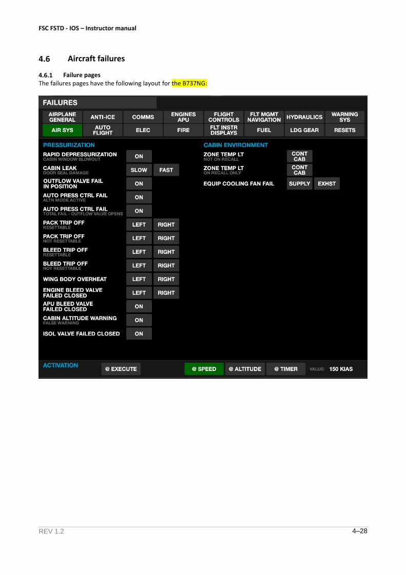
4.6.1 Failure pages The failures pages have the following layout for the B737NG:
FSC FSTD - IOS – Instructor manual
REV 1.2 4–29
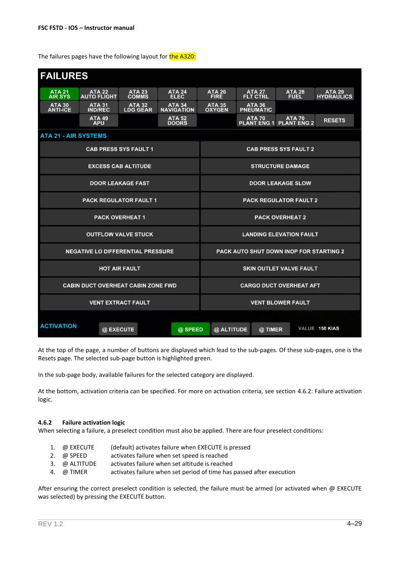
The failures pages have the following layout for the A320:
At the top of the page, a number of buttons are displayed which lead to the sub-pages. Of these sub-pages, one is the Resets page. The selected sub-page button is highlighted green.
In the sub-page body, available failures for the selected category are displayed.
At the bottom, activation criteria can be specified. For more on activation criteria, see section 4.6.2: Failure activation logic.
4.6.2 Failure activation logic When selecting a failure, a preselect condition must also be applied. There are four preselect conditions:
1. @ EXECUTE (default) activates failure when EXECUTE is pressed 2. @ SPEED activates failure when set speed is reached 3. @ ALTITUDE activates failure when set altitude is reached 4. @ TIMER activates failure when set period of time has passed after execution
After ensuring the correct preselect condition is selected, the failure must be armed (or activated when @ EXECUTE was selected) by pressing the EXECUTE button.
FSC FSTD - IOS – Instructor manual
REV 1.2 4–30
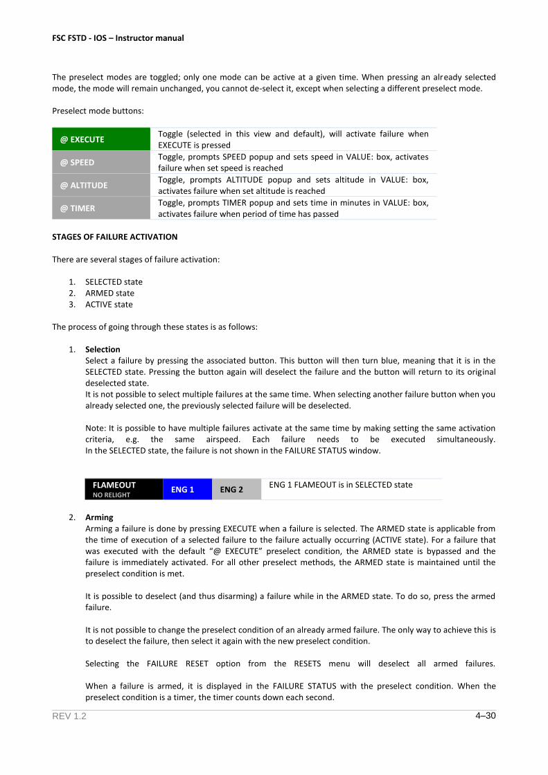
The preselect modes are toggled; only one mode can be active at a given time. When pressing an already selected mode, the mode will remain unchanged, you cannot de-select it, except when selecting a different preselect mode.
Preselect mode buttons:
@ EXECUTE Toggle (selected in this view and default), will activate failure when EXECUTE is pressed
@ SPEED Toggle, prompts SPEED popup and sets speed in VALUE: box, activates failure when set speed is reached
@ ALTITUDE Toggle, prompts ALTITUDE popup and sets altitude in VALUE: box, activates failure when set altitude is reached
@ TIMER Toggle, prompts TIMER popup and sets time in minutes in VALUE: box, activates failure when period of time has passed
STAGES OF FAILURE ACTIVATION
There are several stages of failure activation:
1. SELECTED state2. ARMED state3. ACTIVE state
The process of going through these states is as follows:
1. SelectionSelect a failure by pressing the associated button. This button will then turn blue, meaning that it is in theSELECTED state. Pressing the button again will deselect the failure and the button will return to its originaldeselected state.It is not possible to select multiple failures at the same time. When selecting another failure button when youalready selected one, the previously selected failure will be deselected.
Note: It is possible to have multiple failures activate at the same time by making setting the same activation criteria, e.g. the same airspeed. Each failure needs to be executed simultaneously. In the SELECTED state, the failure is not shown in the FAILURE STATUS window.
FLAMEOUT NO RELIGHT
ENG 1 ENG 2 ENG 1 FLAMEOUT is in SELECTED state
2. ArmingArming a failure is done by pressing EXECUTE when a failure is selected. The ARMED state is applicable fromthe time of execution of a selected failure to the failure actually occurring (ACTIVE state). For a failure thatwas executed with the default “@ EXECUTE” preselect condition, the ARMED state is bypassed and thefailure is immediately activated. For all other preselect methods, the ARMED state is maintained until thepreselect condition is met.
It is possible to deselect (and thus disarming) a failure while in the ARMED state. To do so, press the armed failure.
It is not possible to change the preselect condition of an already armed failure. The only way to achieve this is to deselect the failure, then select it again with the new preselect condition.
Selecting the FAILURE RESET option from the RESETS menu will deselect all armed failures.
When a failure is armed, it is displayed in the FAILURE STATUS with the preselect condition. When the preselect condition is a timer, the timer counts down each second.
FSC FSTD - IOS – Instructor manual
REV 1.2 4–31
FLAMEOUT NO RELIGHT
ENG 1 ENG 2 ENG 1 FLAMEOUT is in ARMED state
FAILURES ENG 1 FLAMEOUT armed @ 150 KTS R IDG LOW OIL PRESSURE armed @ 1:34
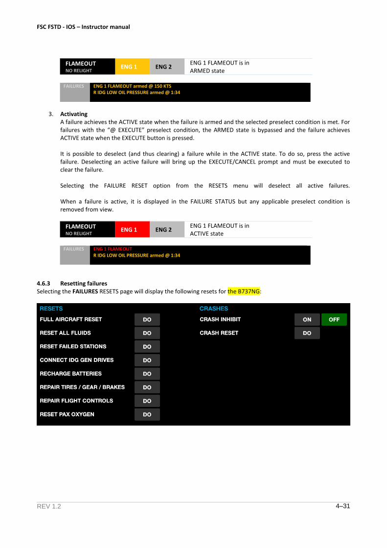
3. ActivatingA failure achieves the ACTIVE state when the failure is armed and the selected preselect condition is met. Forfailures with the “@ EXECUTE” preselect condition, the ARMED state is bypassed and the failure achievesACTIVE state when the EXECUTE button is pressed.
It is possible to deselect (and thus clearing) a failure while in the ACTIVE state. To do so, press the activefailure. Deselecting an active failure will bring up the EXECUTE/CANCEL prompt and must be executed toclear the failure.
Selecting the FAILURE RESET option from the RESETS menu will deselect all active failures.
When a failure is active, it is displayed in the FAILURE STATUS but any applicable preselect condition isremoved from view.
FLAMEOUT NO RELIGHT
ENG 1 ENG 2 ENG 1 FLAMEOUT is in ACTIVE state
FAILURES ENG 1 FLAMEOUT R IDG LOW OIL PRESSURE armed @ 1:34
4.6.3 Resetting failures Selecting the FAILURES RESETS page will display the following resets for the B737NG:
FSC FSTD - IOS – Instructor manual
REV 1.2 4–32
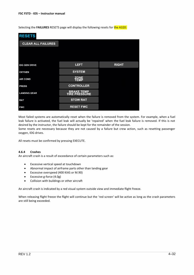
Selecting the FAILURES RESETS page will display the following resets for the A320:
Most failed systems are automatically reset when the failure is removed from the system. For example, when a fuel leak failure is activated, the fuel leak will actually be ‘repaired’ when the fuel leak failure is removed. If this is not desired by the instructor, the failure should be kept for the remainder of the session. Some resets are necessary because they are not caused by a failure but crew action, such as resetting passenger oxygen, IDG drives.
All resets must be confirmed by pressing EXECUTE.
4.6.4 Crashes An aircraft crash is a result of exceedance of certain parameters such as:
• Excessive vertical speed at touchdown
• Abnormal impact of airframe parts other than landing gear
• Excessive overspeed (400 KIAS or M.90)
• Excessive g-force (4.0g)
• Collision with buildings or other aircraft
An aircraft crash is indicated by a red visual system outside view and immediate flight freeze.
When releasing flight freeze the flight will continue but the ‘red screen‘ will be active as long as the crash parameters are still being exceeded.
FSC FSTD - IOS – Instructor manual
REV 1.2 4–33
4.7 Storing / Recalling aircraft or FMC state
4.7.1 Storing aircraft of FMS state To save time and enable a crew to return to the exact conditions used earlier quickly, it is possible to store the aircraft state and FMC state.
When the aircraft state is stored or recalled, the following parameters are included:
• Airplane attitude (pitch, roll, yaw)
• Aircraft position
• Airspeed / Mach
• Altitude
• Heading
When the FMC state is stored or recalled, all performance and route data in the FMC are stored or recalled.
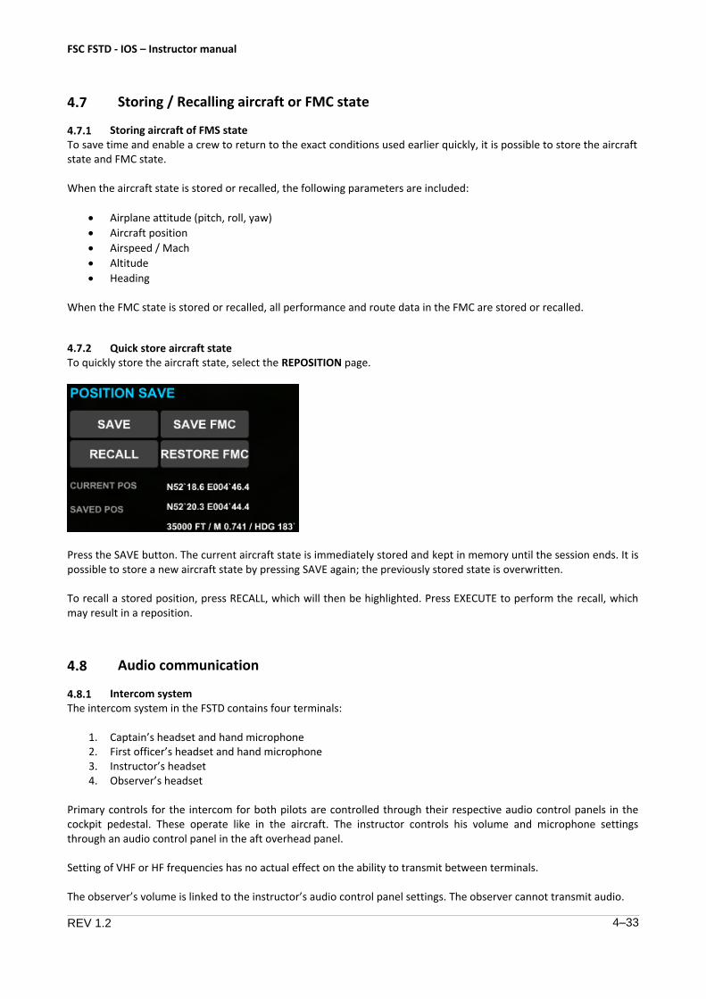
4.7.2 Quick store aircraft state To quickly store the aircraft state, select the REPOSITION page.
Press the SAVE button. The current aircraft state is immediately stored and kept in memory until the session ends. It is possible to store a new aircraft state by pressing SAVE again; the previously stored state is overwritten.
To recall a stored position, press RECALL, which will then be highlighted. Press EXECUTE to perform the recall, which may result in a reposition.
4.8 Audio communication
4.8.1 Intercom system The intercom system in the FSTD contains four terminals:
1. Captain’s headset and hand microphone2. First officer’s headset and hand microphone3. Instructor’s headset4. Observer’s headset
Primary controls for the intercom for both pilots are controlled through their respective audio control panels in the cockpit pedestal. These operate like in the aircraft. The instructor controls his volume and microphone settings through an audio control panel in the aft overhead panel.
Setting of VHF or HF frequencies has no actual effect on the ability to transmit between terminals.
The observer’s volume is linked to the instructor’s audio control panel settings. The observer cannot transmit audio.
REV 1.2 4–34
FSC FSTD - IOS – Instructor manual
The instructor has a separate R/T (radio) and I/C (intercom) transmission button.
4.8.2 ATC system
Depending on your IOS configuration, an ATC system may be installed.
4.9 Maintenance
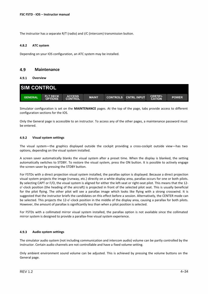
4.9.1 Overview
Simulator configuration is set on the MAINTENANCE pages. At the top of the page, tabs provide access to different configuration sections for the IOS.
Only the General page is accessible to an instructor. To access any of the other pages, a maintenance password must be entered.
4.9.2 Visual system settings
The visual system—the graphics displayed outside the cockpit providing a cross-cockpit outside view—has two options, depending on the visual system installed.
A screen saver automatically blanks the visual system after a preset time. When the display is blanked, the setting automatically switches to STDBY. To restore the visual system, press the ON button. It is possible to actively engage the screen saver by pressing the STDBY button.
For FSTDs with a direct projection visual system installed, the parallax option is displayed. Because a direct projection visual system projects the image (runway, etc.) directly on a white display area, parallax occurs for one or both pilots. By selecting CAPT or F/O, the visual system is aligned for either the left-seat or right-seat pilot. This means that the 12-o’-clock position (the heading of the aircraft) is projected in front of the selected pilot seat. This is usually beneficial for the pilot flying. The other pilot will see a parallax image which looks like flying with a strong crosswind. It is suggested that the instructor briefs the candidates on this effect before a session. Alternatively, the CENTER mode can be selected. This projects the 12-o’-clock position in the middle of the display area, causing a parallax for both pilots. However, the amount of parallax is significantly less than when a pilot position is selected.
For FSTDs with a collimated mirror visual system installed, the parallax option is not available since the collimated mirror system is designed to provide a parallax-free visual system experience.
4.9.3 Audio system settings
The simulator audio system (not including communication and intercom audio) volume can be partly controlled by the instructor. Certain audio channels are not controllable and have a fixed volume setting.
Only ambient environment sound volume can be adjusted. This is achieved by pressing the volume buttons on the General page.

FSC FSTD - IOS – Instructor manual
REV 1.2 4–35
The following sounds are part of the ambient environment sound:
• Engine sound
• Environment sound
The following sounds cannot be adjusted:
• Aural warnings (GPWS, TCAS, autopilot disconnect etc)
4.9.4 Crashes
Crashes can be configured to be inhibited. In order to do so, the CRASH INHIBIT function is added to the settings. This function can be turned ON or OFF.
FSC FSTD - IOS – Instructor manual
REV 1.2 5–36
5 Abnormal Operation
5.1 Emergency procedures
5.1.1 Emergency control loading shutoff The simulator contains at least two Emergency Control Loading Shutoff Switches. One is placed at the aft wall of the cockpit pedestal, within easy reach of the flight crew. The other is placed on the Simulator Control Panel or on the IOS Panel, depending on your configuration.
Actuating either emergency control loading shutoff switch will immediately remove all electrical power from the control loading system.
WARNING: Only use the emergency control loading shutoff function when a hazardous situation arises. Notify maintenance personnel after occurrence. Do not attempt to restart the simulator without maintenance approval. Failure to do so may result in personal injury.
Always ensure that the location of shutoff switches is known to all occupants of the FSTD before use!
5.1.2 Emergency simulator shutdown The simulator contains one Emergency Main Power Shutoff Switch. The switch is placed on the Simulator Control Panel or on the IOS Panel, depending on your configuration.
Actuating the emergency main power shutoff switch will immediately remove all electrical power from the entire FSTD.
WARNING: Only use this emergency main power shutoff function when a hazardous situation arises. Notify maintenance personnel after occurrence. Do not attempt to restart the simulator without maintenance approval. Failure to do so may result in personal injury.
Always ensure that the location of shutoff switches is known to all occupants of the FSTD before use!
5.1.3 Simulator evacuation In certain emergencies, it may be necessary to evacuate the FSTD. The only evacuation route is via the FSTD entry door. Do not attempt to exit through cockpit windows as they cannot be opened.
In case of evacuation, consider performing the following actions:
1. Ensure that both flight crew are able to discard their seat harnesses and leave their seats2. Open the FSTD entry door3. If available and necessary, pick up the nearest flashlight4. If necessary, pick up the nearest fire extinguisher5. Activate the Emergency Main Power Shutoff Switch6. Leave the FSTD through the entry door7. Alert emergency services
WARNING: It is the operator’s responsibility to ensure that emergency equipment such as flashlights, fire extinguishers, appropriate power supplies and evacuation routes are available and properly accessible.
An emergency light unit is installed which will provide lighting inside the FSTD cabin in case of a total power failure.
FSC FSTD - IOS – Instructor manual
REV 1.2 5–37
5.2 Simulator malfunctions
5.2.1 Initial response In case of any malfunction in the FSTD, small or large, please alert maintenance or office personnel. Do NOT attempt to perform corrective action.
WARNING: Maintenance on the FSTD is only permitted by authorized personnel. Any attempt to perform corrective action by an unauthorized person may result in equipment damage, loss of warranty or personal injury.
5.2.2 Troubleshooting Troubleshooting a problem or malfunction in the FSTD by any person is allowed as long as only normal controls and actions are used. Use of maintenance controls or accessing physical parts of the FSTD not used in normal operation are prohibited unless performed by authorized personnel.
Use of any tools, such as screw drivers or wrenches, is prohibited unless used by authorized personnel.
WARNING: Improper maintenance action, even by authorized personnel may result in equipment damage, loss of warranty or personal injury.
5.2.3 Resetting components Resetting failed components is only allowed by authorized personnel after consultation with FSC technical staff.

TABLE OF CONTENTS
Section/Title Page
1.1. Instructor Manual 1
1.1.1. General 1
1.1.2. Copyright 1
1.1.3. Contact details 1
1.2. List Of Terms And Abbreviations 2
B747-400 Flight Simulator Instructor Manual Chapter 1 - General
31 feb 2016 Page : 1
1.1. Instructor Manual
1.1.1. General
This Instructor Manual is valid for the B747-400 simulator and provides only an overview of the available simulator features, including Malfunctions and Visual Scenes. As the Instructor Manual is a “Non Maintained” document, an up-to-date overview of the available Malfunctions and Visual Scenes can be obtained through the service department. The available JAR-STD Certified Visual Scenes can be referenced via the Instructor Station, through the Airport Selection page.
1.1.2. Copyright
No part of this manual or its extracts may be reproduced in any form, by print, photocopy, microfilm or any other means, without written permission of FSC.
1.1.3. Contact details
Please note that all relevant and up to date information can be found on our website: www.fsctraining.com
Location: Flight Simulation Company B.V. Fokkerweg 300, 1D 1438 AN Oude Meer The Netherlands.

B747-400 Flight Simulator Instructor Manual Chapter 1 - General
31 feb 2016 Page : 2
1.2. List Of Terms And Abbreviations
AC Alternating Current ACARS Aircraft Communications Addressing
and Reporting System ACIP AC Input ACOP AC Output ADC Analog-to-Digital Converter ADF Automatic Direction Finder ADIO Analog/Digital Input/Output AI Analog Inputs AIM Acknowledgment, ISO Alphabet no. 5
and Maintenance AIO Analog Input/Output AIOI ARINC 429 input/output interface AIP Analog Input AIRO Analog Input Reference Output AM Amplitude Modulated Amp Ampere AOM Analog Output Module AOP Analog Output ASCII American Standard Code for
Information Exchange ATC Air Traffic Control ATIS Automated Terminal Information
Service ATO Address Time-Out A/W Accessway
BCD Binary Coded Decimal BFO Beat Frequency Oscillator BI Bus Identification BPS beats per second BU Buffer Unit B/W Black and White
CAL Instrument Calibration Utility CAPT Computer Assisted Procedures
Trainer CB Circuit Breaker CCD Charge Coupled Device CCU C-Bus Check UtilityCCW Counter ClockwiseCDB Common DatabaseCMS Central Monitoring SystemCO2 Carbon DioxideComp. ComputersCorp. CorporationCPU Central Processing UnitCRA Coefficient RAM AddressCS Card SelectCSMA/CD Carrier Sense Multiple Access with
Collision DetectionCSS Cockpit Simulator SystemCTS Computerized Test SystemCVR Cockpit Voice RecorderCW ClockwiseCWE CAELIB Working Environment
DAC Digital-to-Analog Converter DACW DAC Write DASIU Digital Audio System Interface Unit
DAST Direct Analog Storage Technology DC Direct Current DCB Data Control Block DCR Data Control Register DFC Digital Flight Controls DIN Deutsche Industrie Normen DIO Digital Input/Output DIO-CB Digital Input/Output Circuit Breaker DIP Digital Input DMC Datapath® C Microprocessor
Controller DMM Digital Multi-Meter DN1 Digital Control Cabinet DOP Digital Output DOP Discrete Output DOR Digital Output Relay DPA Dual Power Amplifier DRA Data RAM Address DSG Digital Signal Generator DSP Digital Signal Processor DTO Data Time-Out DV Digital Voice DVM Digital Voltmeter
EFIS Electronic Flight Control System EGPWS Enhanced Ground Proximity Warning
System EICAS Engine Instrument and Crew Alert
System EL Electroluminescent Elec. Electronics EMI Electromagnetic Interference ESU Electronic Service Unit
F/C Flight Compartment FC Flight Compartment FDCC Fiber-Optic Digital Chassis Controller FDDI Fiber-Optic Distributed Digital
Interface FFIOS Forward-Facing Instructor Operating
System FFS Full Flight Simulator FIFO First-In, First-Out FIR Finite Impulse Response FIRCTL FIR Control FMAST Flight Management and System
Trainer FMC Flight Management Computer FOV Field of View FP Feature Processor FPMC Floating Point Motion Controller FSK Frequency Shift Keying FTD Flight Training Device FWS Flight Warning System
GAL Generic Array Logic GB Giga Byte GBYTE Giga Byte GPWS Ground Proximity Warning System
B747-400 Flight Simulator Instructor Manual Chapter 1 - General
31 feb 2016 Page : 3
HPS Hydraulic Power Supply HP Hewlett Packard HPU Hydraulic Power Unit HS High Speed Hz Hertz
I/O Input/Output IATA International Air Transport
Association IC Integrated Circuit ID Identification IDS Integrated Diagnostic System IGW Increased Gross Weight Int’l International IOS Instructor Operating System IP Internet Protocol IPE Integral Position Equipment
KYBD Keyboard
LAN Local Area Network LCD Liquid Crystal Display LED Light Emitting Diode LRU Line Replaceable Unit LSB Least Significant Bit LVOS Light-to-Voltage Optical Sensor
MA Mechanical Assembly MAC MaxVue™ Autocal Controller MAIB MaxVue™ Autocal Integrated Board MCL Motion and Control Loading MCU Master Control Unit Misc. Miscellaneous MMU Memory Management Unit MOB Multiple Output Board MOS Metal-Oxide Semi-conductor MSB Most Significant Bit MSV Main Switch-Visual MTFAA Motion Test FAA MTP Motion Test Program
NMI Non-Maskable Interrupt
OEM Original Equipment Manufacturer OSI Open System Interconnection
PA Public Address
PAL Programmable Array Logic PC Programmable Controller PC Personal Computer PCB Printed Circuit Board PCP Programmable Control Panel PCU Portable Control Unit PDM Pulse Duration Modulation PE Position Error PHU Projector Head Unit PIC Programmable Interrupt Controller PIT Programmable Interval Timer PP2 Pixel Processor type 2 PROM Programmable Read Only Memory PSC Parallel-to-Serial Converter PSCD Procurement Specification Control
Drawing PTT Press-to-Talk
QTG Qualification Test Guide
RACU Remote Alignment and Control Unit RAM Rapid Access Maintenance RCP Radio Control Panel RPM Rotations per minute RTD Resistance Temperature Detector
SAH Sample and Hold SC-bus Super Chassis Bus SOP synchro output Spec. Specification
TCP Transmission Control Protocol Temp. Temperature TOP Torquer Output TPD Technical Publications Department TSD Time-Shared Data
UPS Uninterruptible Power Supply
V Volts Vac Volts of alternating current VAE Voice Alteration Effect VCP Video Cassette Player VCR Video Cassette Recorder Vdc Volts of direct current VHF Very High Frequency VHS Very High Speed VOR VHF Omni-Range VP Vocal Player VPC Video Player Card

B747-400 Flight Simulator Instructor Manual Chapter 2 – Safety Instruction
31 feb 2016 Page : 1
This Chapter has been replaced by the “Safety Instructions Handout”, which can be found at the Operator desk and in every Briefing Room.

B747-400 Flight Simulator Instructor Manual Chapter 3 – Simulator Checklist
31 feb 2016
TABLE OF CONTENTS
Section/Title Page
3. Simulator Instructor Station Checklist 1
3.1. Pre-flight Checks 1
3.2. Postflight Checks 1
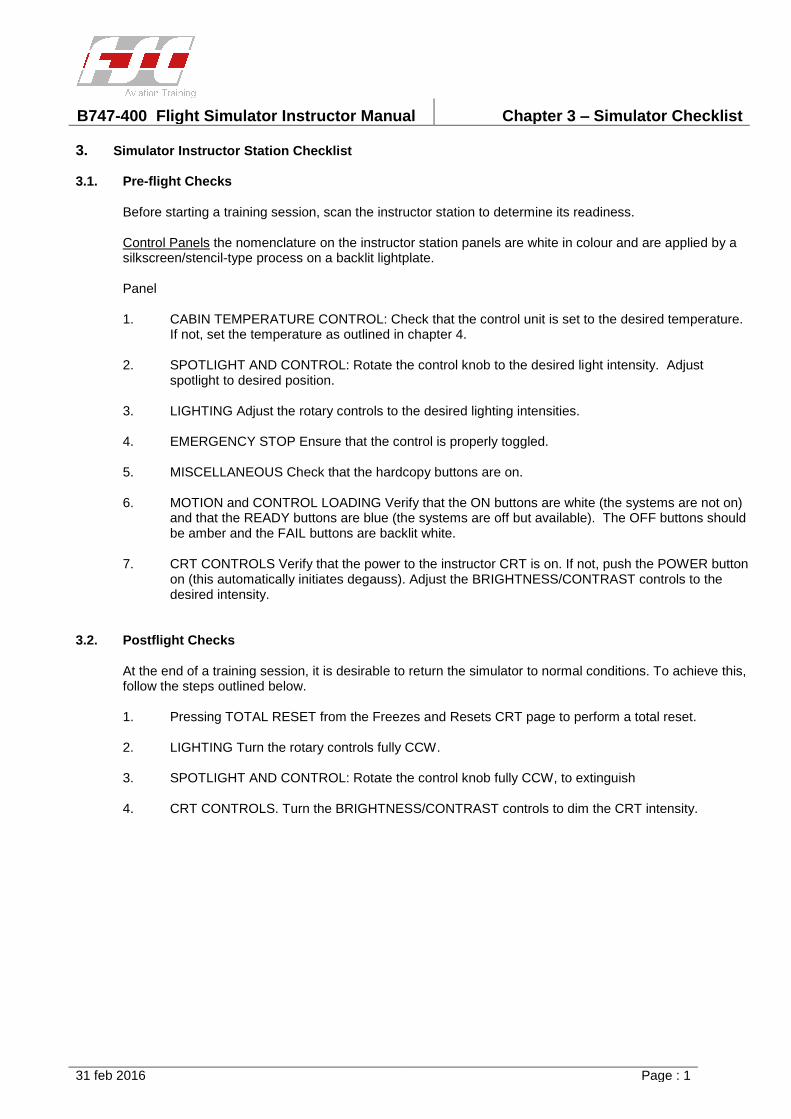
B747-400 Flight Simulator Instructor Manual Chapter 3 – Simulator Checklist
31 feb 2016 Page : 1
3. Simulator Instructor Station Checklist
3.1. Pre-flight Checks
Before starting a training session, scan the instructor station to determine its readiness.
Control Panels the nomenclature on the instructor station panels are white in colour and are applied by a silkscreen/stencil-type process on a backlit lightplate.
Panel
1. CABIN TEMPERATURE CONTROL: Check that the control unit is set to the desired temperature.If not, set the temperature as outlined in chapter 4.
2. SPOTLIGHT AND CONTROL: Rotate the control knob to the desired light intensity. Adjustspotlight to desired position.
3. LIGHTING Adjust the rotary controls to the desired lighting intensities.
4. EMERGENCY STOP Ensure that the control is properly toggled.
5. MISCELLANEOUS Check that the hardcopy buttons are on.
6. MOTION and CONTROL LOADING Verify that the ON buttons are white (the systems are not on)and that the READY buttons are blue (the systems are off but available). The OFF buttons shouldbe amber and the FAIL buttons are backlit white.
7. CRT CONTROLS Verify that the power to the instructor CRT is on. If not, push the POWER buttonon (this automatically initiates degauss). Adjust the BRIGHTNESS/CONTRAST controls to thedesired intensity.
3.2. Postflight Checks
At the end of a training session, it is desirable to return the simulator to normal conditions. To achieve this, follow the steps outlined below.
1. Pressing TOTAL RESET from the Freezes and Resets CRT page to perform a total reset.
2. LIGHTING Turn the rotary controls fully CCW.
3. SPOTLIGHT AND CONTROL: Rotate the control knob fully CCW, to extinguish
4. CRT CONTROLS. Turn the BRIGHTNESS/CONTRAST controls to dim the CRT intensity.

B747-400 Flight Simulator Instructor Manual Chapter 4 – IOS panel description
31 feb 2016 Page : i
TABLE OF CONTENTS
Section/Title Page
Section/Title Page
4. IOS Panel Description 1
4.1. General 1
4.2. Cabin Temperature Control Panel 2
4.3. Spotlight and Control Panel 2
4.4. Lighting Panel 3
4.5. Motion and Control Loading Panel 4
4.6. Communications Jacking Facility 5
4.7. CRT Controls 6
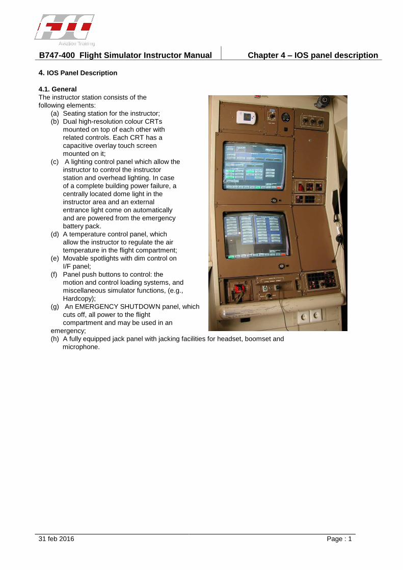
B747-400 Flight Simulator Instructor Manual Chapter 4 – IOS panel description
31 feb 2016 Page : 1
4. IOS Panel Description
4.1. General
The instructor station consists of the
following elements:
(a) Seating station for the instructor;
(b) Dual high-resolution colour CRTs
mounted on top of each other with
related controls. Each CRT has a
capacitive overlay touch screen
mounted on it;
(c) A lighting control panel which allow the
instructor to control the instructor
station and overhead lighting. In case
of a complete building power failure, a
centrally located dome light in the
instructor area and an external
entrance light come on automatically
and are powered from the emergency
battery pack.
(d) A temperature control panel, which
allow the instructor to regulate the air
temperature in the flight compartment;
(e) Movable spotlights with dim control on
I/F panel;
(f) Panel push buttons to control: the
motion and control loading systems, and
miscellaneous simulator functions, (e.g.,
Hardcopy);
(g) An EMERGENCY SHUTDOWN panel, which
cuts off, all power to the flight
compartment and may be used in an
emergency;
(h) A fully equipped jack panel with jacking facilities for headset, boomset and
microphone.
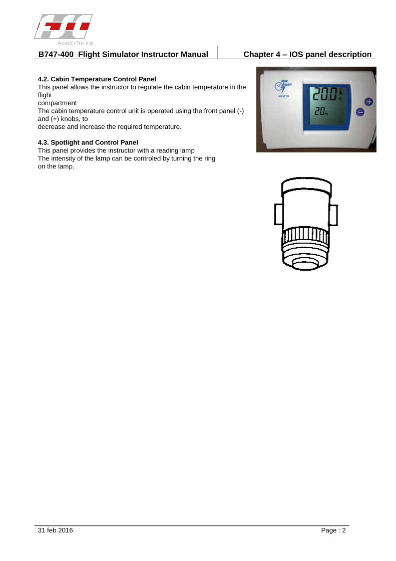
B747-400 Flight Simulator Instructor Manual Chapter 4 – IOS panel description
31 feb 2016 Page : 2
4.2. Cabin Temperature Control Panel
This panel allows the instructor to regulate the cabin temperature in the
flight
compartment
The cabin temperature control unit is operated using the front panel (-)
and (+) knobs, to
decrease and increase the required temperature.
4.3. Spotlight and Control Panel
This panel provides the instructor with a reading lamp
The intensity of the lamp can be controled by turning the ring
on the lamp.
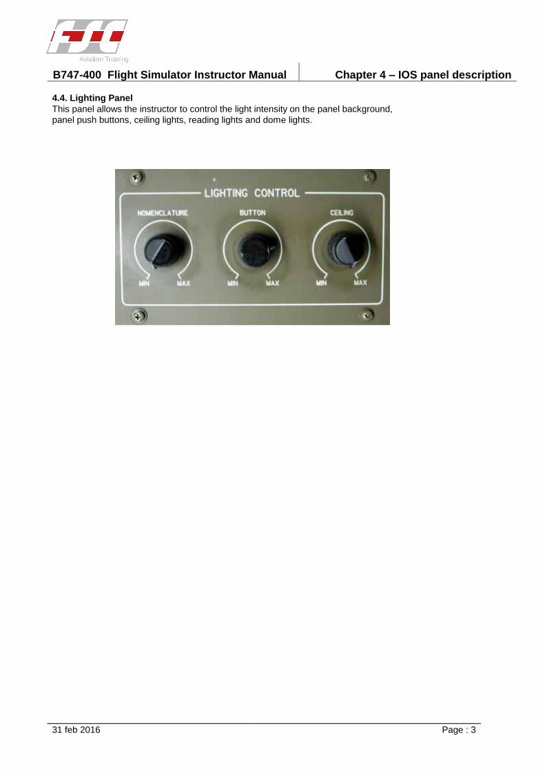
B747-400 Flight Simulator Instructor Manual Chapter 4 – IOS panel description
31 feb 2016 Page : 3
4.4. Lighting Panel
This panel allows the instructor to control the light intensity on the panel background,
panel push buttons, ceiling lights, reading lights and dome lights.
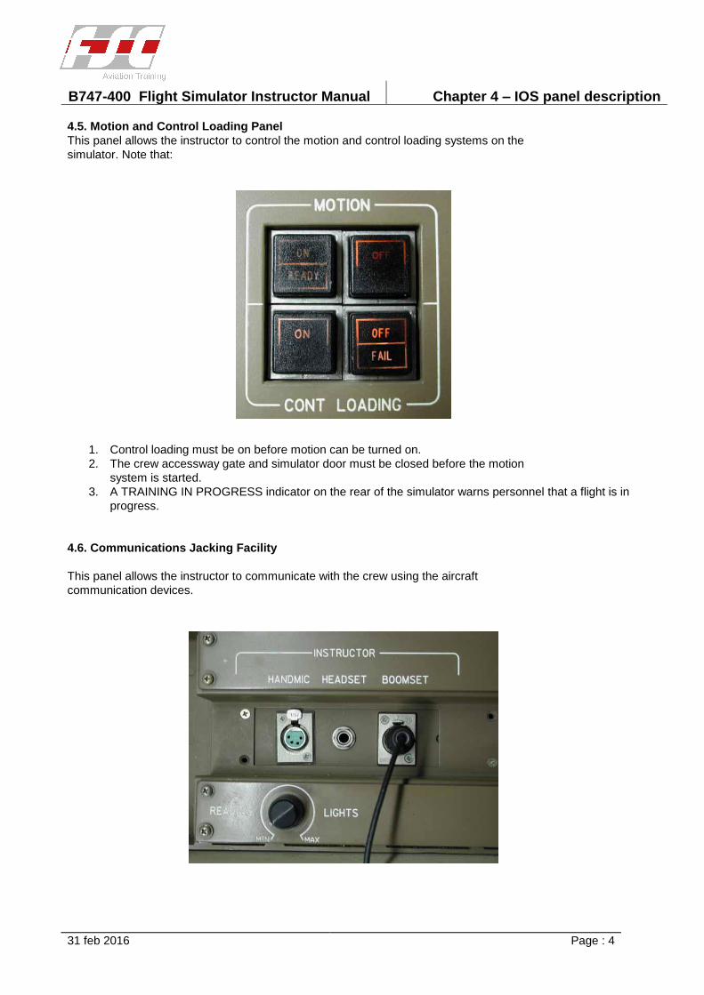
B747-400 Flight Simulator Instructor Manual Chapter 4 – IOS panel description
31 feb 2016 Page : 4
4.5. Motion and Control Loading Panel
This panel allows the instructor to control the motion and control loading systems on the
simulator. Note that:
1. Control loading must be on before motion can be turned on.
2. The crew accessway gate and simulator door must be closed before the motion
system is started.
3. A TRAINING IN PROGRESS indicator on the rear of the simulator warns personnel that a flight is in
progress.
4.6. Communications Jacking Facility
This panel allows the instructor to communicate with the crew using the aircraft
communication devices.

B747-400 Flight Simulator Instructor Manual Chapter 4 – IOS panel description
31 feb 2016 Page : 5
4.7. CRT Controls
The upper/lower CRT controls allow the instructor to take a hard copy of the upper/lower CRT
displays
The control panel allows to control the power, contrast, brightness and backlight brightness of the
upper/lower CRT displays.
B747-400 Flight Simulator Instructor Manual Chapter 5 – Data Entry Procedures
31 feb 2016
TABLE OF CONTENTS
Section/Title Page
5. Data Entry Procedures 1
5.1. Keypads 1
5.2. Activation/Deactivation of a Discrete Function 1
5.3. Slider Data Entry 2
5.4. Keypad Data Entry 2
5.5. Activation of a Discrete Malfunction 3
5.6. Activation of a Variable Malfunction 3
5.7. Deactivation of a Malfunction 3
5.8. Preselection of a Malfunction 3
5.9. Reposition of the Aircraft on the Map 4
5.10. Station Fail from the Map 4
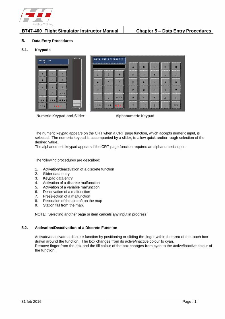
B747-400 Flight Simulator Instructor Manual Chapter 5 – Data Entry Procedures
31 feb 2016 Page : 1
Numeric Keypad and Slider Alphanumeric Keypad
5. Data Entry Procedures
5.1. Keypads
The numeric keypad appears on the CRT when a CRT page function, which accepts numeric input, is
selected. The numeric keypad is accompanied by a slider, to allow quick and/or rough selection of the
desired value.
The alphanumeric keypad appears if the CRT page function requires an alphanumeric input
The following procedures are described:
1. Activation/deactivation of a discrete function
2. Slider data entry
3. Keypad data entry
4. Activation of a discrete malfunction
5. Activation of a variable malfunction
6. Deactivation of a malfunction
7. Preselection of a malfunction
8. Reposition of the aircraft on the map
9. Station fail from the map.
NOTE: Selecting another page or item cancels any input in progress.
5.2. Activation/Deactivation of a Discrete Function
Activate/deactivate a discrete function by positioning or sliding the finger within the area of the touch box
drawn around the function. The box changes from its active/inactive colour to cyan.
Remove finger from the box and the fill colour of the box changes from cyan to the active/inactive colour of
the function.
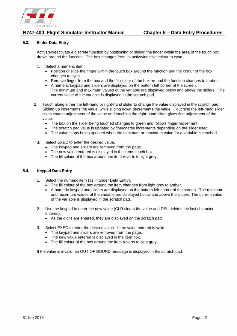
B747-400 Flight Simulator Instructor Manual Chapter 5 – Data Entry Procedures
31 feb 2016 Page : 2
5.3. Slider Data Entry
Activate/deactivate a discrete function by positioning or sliding the finger within the area of the touch box
drawn around the function. The box changes from its active/inactive colour to cyan.
1. Select a numeric item.
Position or slide the finger within the touch box around the function and the colour of the box
changes to cyan.
Remove finger from the box and the fill colour of the box around the function changes to amber.
A numeric keypad and sliders are displayed on the bottom left corner of the screen.
The minimum and maximum values of the variable are displayed below and above the sliders. The
current value of the variable is displayed in the scratch pad.
2. Touch along either the left-hand or right-hand slider to change the value displayed in the scratch pad.
Sliding up increments the value, while sliding down decrements the value. Touching the left-hand slider
gives coarse adjustment of the value and touching the right-hand slider gives fine adjustment of the
value.
The box on the slider being touched changes to green and follows finger movement.
The scratch pad value is updated by fine/coarse increments depending on the slider used.
The value stops being updated when the minimum or maximum value for a variable is reached.
3. Select EXEC to enter the desired value.
The keypad and sliders are removed from the page.
The new value entered is displayed in the items touch box.
The fill colour of the box around the item reverts to light grey.
5.4. Keypad Data Entry
1. Select the numeric item (as in Slider Data Entry).
The fill colour of the box around the item changes from light grey to amber.
A numeric keypad and sliders are displayed on the bottom left corner of the screen. The minimum
and maximum values of the variable are displayed below and above the sliders. The current value
of the variable is displayed in the scratch pad.
2. Use the keypad to enter the new value (CLR clears the value and DEL deletes the last character
entered).
As the digits are entered, they are displayed on the scratch pad.
3. Select EXEC to enter the desired value. If the value entered is valid:
The keypad and sliders are removed from the page.
The new value entered is displayed in the item box.
The fill colour of the box around the item reverts to light grey.
If the value is invalid, an OUT OF BOUND message is displayed in the scratch pad.
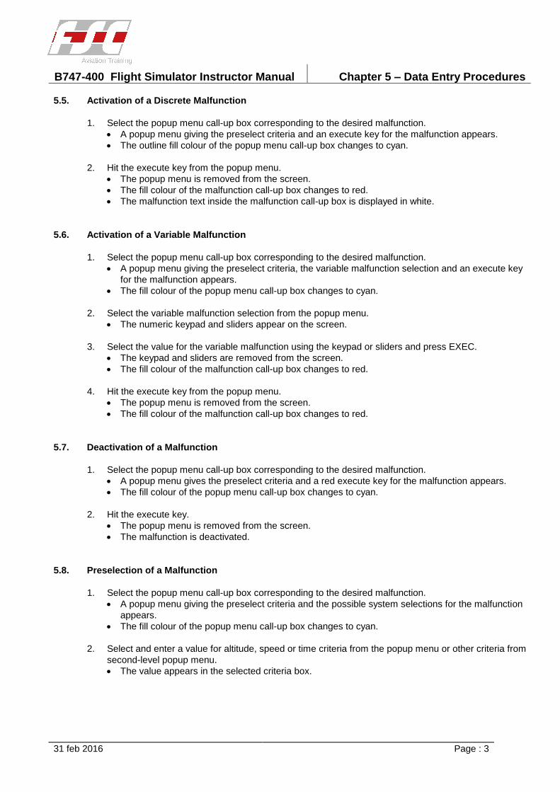
B747-400 Flight Simulator Instructor Manual Chapter 5 – Data Entry Procedures
31 feb 2016 Page : 3
5.5. Activation of a Discrete Malfunction
1. Select the popup menu call-up box corresponding to the desired malfunction.
A popup menu giving the preselect criteria and an execute key for the malfunction appears.
The outline fill colour of the popup menu call-up box changes to cyan.
2. Hit the execute key from the popup menu.
The popup menu is removed from the screen.
The fill colour of the malfunction call-up box changes to red.
The malfunction text inside the malfunction call-up box is displayed in white.
5.6. Activation of a Variable Malfunction
1. Select the popup menu call-up box corresponding to the desired malfunction.
A popup menu giving the preselect criteria, the variable malfunction selection and an execute key
for the malfunction appears.
The fill colour of the popup menu call-up box changes to cyan.
2. Select the variable malfunction selection from the popup menu.
The numeric keypad and sliders appear on the screen.
3. Select the value for the variable malfunction using the keypad or sliders and press EXEC.
The keypad and sliders are removed from the screen.
The fill colour of the malfunction call-up box changes to red.
4. Hit the execute key from the popup menu.
The popup menu is removed from the screen.
The fill colour of the malfunction call-up box changes to red.
5.7. Deactivation of a Malfunction
1. Select the popup menu call-up box corresponding to the desired malfunction.
A popup menu gives the preselect criteria and a red execute key for the malfunction appears.
The fill colour of the popup menu call-up box changes to cyan.
2. Hit the execute key.
The popup menu is removed from the screen.
The malfunction is deactivated.
5.8. Preselection of a Malfunction
1. Select the popup menu call-up box corresponding to the desired malfunction.
A popup menu giving the preselect criteria and the possible system selections for the malfunction
appears.
The fill colour of the popup menu call-up box changes to cyan.
2. Select and enter a value for altitude, speed or time criteria from the popup menu or other criteria from
second-level popup menu.
The value appears in the selected criteria box.
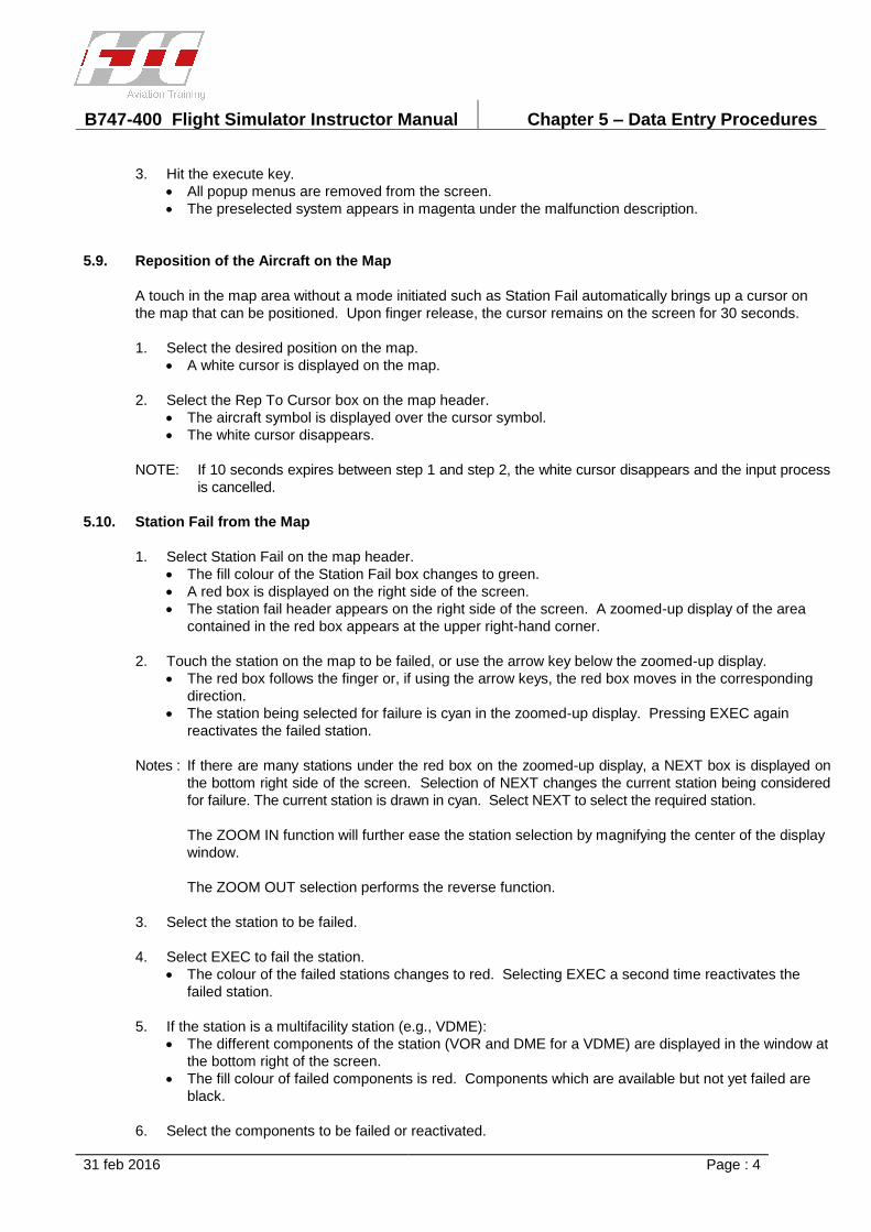
B747-400 Flight Simulator Instructor Manual Chapter 5 – Data Entry Procedures
31 feb 2016 Page : 4
3. Hit the execute key.
All popup menus are removed from the screen.
The preselected system appears in magenta under the malfunction description.
5.9. Reposition of the Aircraft on the Map
A touch in the map area without a mode initiated such as Station Fail automatically brings up a cursor on
the map that can be positioned. Upon finger release, the cursor remains on the screen for 30 seconds.
1. Select the desired position on the map.
A white cursor is displayed on the map.
2. Select the Rep To Cursor box on the map header.
The aircraft symbol is displayed over the cursor symbol.
The white cursor disappears.
NOTE: If 10 seconds expires between step 1 and step 2, the white cursor disappears and the input process
is cancelled.
5.10. Station Fail from the Map
1. Select Station Fail on the map header.
The fill colour of the Station Fail box changes to green.
A red box is displayed on the right side of the screen.
The station fail header appears on the right side of the screen. A zoomed-up display of the area
contained in the red box appears at the upper right-hand corner.
2. Touch the station on the map to be failed, or use the arrow key below the zoomed-up display.
The red box follows the finger or, if using the arrow keys, the red box moves in the corresponding
direction.
The station being selected for failure is cyan in the zoomed-up display. Pressing EXEC again
reactivates the failed station.
Notes : If there are many stations under the red box on the zoomed-up display, a NEXT box is displayed on
the bottom right side of the screen. Selection of NEXT changes the current station being considered
for failure. The current station is drawn in cyan. Select NEXT to select the required station.
The ZOOM IN function will further ease the station selection by magnifying the center of the display
window.
The ZOOM OUT selection performs the reverse function.
3. Select the station to be failed.
4. Select EXEC to fail the station.
The colour of the failed stations changes to red. Selecting EXEC a second time reactivates the
failed station.
5. If the station is a multifacility station (e.g., VDME):
The different components of the station (VOR and DME for a VDME) are displayed in the window at
the bottom right of the screen.
The fill colour of failed components is red. Components which are available but not yet failed are
black.
6. Select the components to be failed or reactivated.

B747-400 Flight Simulator Instructor Manual Chapter 5 – Data Entry Procedures
31 feb 2016 Page : 5
7. Select EXEC to fail or reactivate the selected components.
The colour of the failed station changes to red. The colour of the reactivated station reverts to
black.
NOTES: 1. Selecting CANCEL terminates the station fail procedure without failing any station and the red
box disappears.
2. Failed stations may be cleared by selecting TOTAL RESET or FAIL STATIONS RESET from
the FREEZE/RESETS page, or by selecting the station in the MALF SUMMARY page

B747-400 Flight Simulator Instructor Manual Chapter 6 – PCU and PCP
31 feb 2016 Page : i
TABLE OF CONTENTS
Section/Title Page
6. PCU and PCP 1
6.1. Page Layout 1
6.2. Status Page 3
6.3. Repos Page 4
6.4. Miscellaneous Page 5
6.5. Reference Runway Page 6
6.6. Atmosphere Page 7
6.7. Malfunctions 1 Page 8
6.8. Malfunctions 2 Page 9
6.9. Freezes Page 10
6.10. Reset Page 11
6.11. Lessons Control Page 12
6.12. Numeric Keypad 13
6.13. Alphanumeric Keypad 14
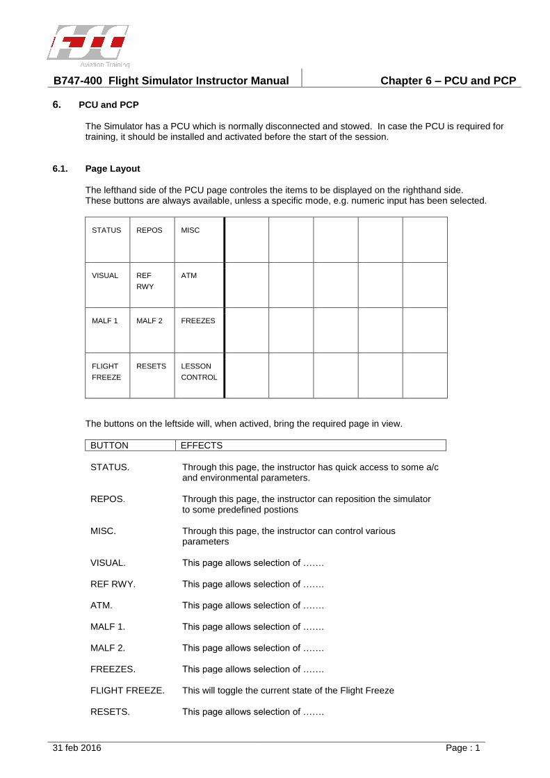
B747-400 Flight Simulator Instructor Manual Chapter 6 – PCU and PCP
31 feb 2016 Page : 1
6. PCU and PCP
The Simulator has a PCU which is normally disconnected and stowed. In case the PCU is required fortraining, it should be installed and activated before the start of the session.
6.1. Page Layout
The lefthand side of the PCU page controles the items to be displayed on the righthand side. These buttons are always available, unless a specific mode, e.g. numeric input has been selected.
STATUS REPOS MISC
VISUAL REF
RWY
ATM
MALF 1 MALF 2 FREEZES
FLIGHT
FREEZE
RESETS LESSON
CONTROL
The buttons on the leftside will, when actived, bring the required page in view.
BUTTON EFFECTS
STATUS. Through this page, the instructor has quick access to some a/c and environmental parameters.
REPOS. Through this page, the instructor can reposition the simulator to some predefined postions
MISC. Through this page, the instructor can control various parameters
VISUAL. This page allows selection of …….
REF RWY. This page allows selection of …….
ATM. This page allows selection of …….
MALF 1. This page allows selection of …….
MALF 2. This page allows selection of …….
FREEZES. This page allows selection of …….
FLIGHT FREEZE. This will toggle the current state of the Flight Freeze
RESETS. This page allows selection of …….

B747-400 Flight Simulator Instructor Manual Chapter 6 – PCU and PCP
31 feb 2016 Page : 2
LESSON CONTROL.
This page allows selection of …….
When a page is selected, the corresponding selection button is highlightened.
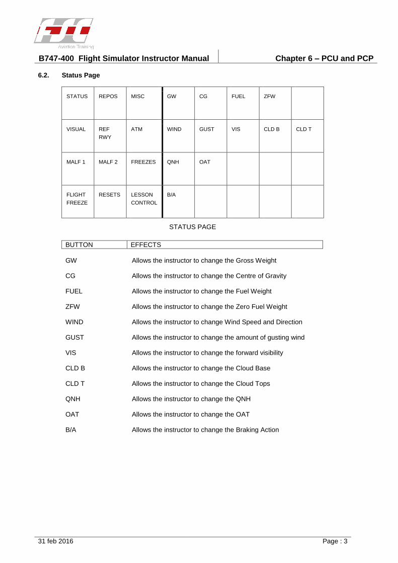
B747-400 Flight Simulator Instructor Manual Chapter 6 – PCU and PCP
31 feb 2016 Page : 3
6.2. Status Page
STATUS REPOS MISC GW CG FUEL ZFW
VISUAL REF
RWY
ATM WIND GUST VIS CLD B CLD T
MALF 1 MALF 2 FREEZES QNH OAT
FLIGHT
FREEZE
RESETS LESSON
CONTROL
B/A
STATUS PAGE
BUTTON EFFECTS
GW Allows the instructor to change the Gross Weight
CG Allows the instructor to change the Centre of Gravity
FUEL Allows the instructor to change the Fuel Weight
ZFW Allows the instructor to change the Zero Fuel Weight
WIND Allows the instructor to change Wind Speed and Direction
GUST Allows the instructor to change the amount of gusting wind
VIS Allows the instructor to change the forward visibility
CLD B Allows the instructor to change the Cloud Base
CLD T Allows the instructor to change the Cloud Tops
QNH Allows the instructor to change the QNH
OAT Allows the instructor to change the OAT
B/A Allows the instructor to change the Braking Action
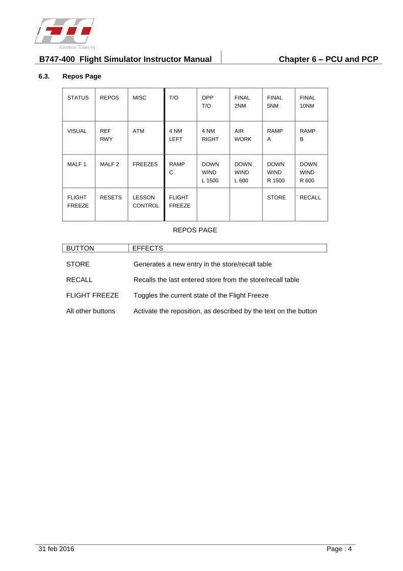
B747-400 Flight Simulator Instructor Manual Chapter 6 – PCU and PCP
31 feb 2016 Page : 4
6.3. Repos Page
STATUS REPOS MISC T/O OPP
T/O
FINAL
2NM
FINAL
5NM
FINAL
10NM
VISUAL REF
RWY
ATM 4 NM
LEFT
4 NM
RIGHT
AIR
WORK
RAMP
A
RAMP
B
MALF 1 MALF 2 FREEZES RAMP
C
DOWN
WIND
L 1500
DOWN
WIND
L 600
DOWN
WIND
R 1500
DOWN
WIND
R 600
FLIGHT
FREEZE
RESETS LESSON
CONTROL
FLIGHT
FREEZE
STORE ` RECALL
REPOS PAGE
BUTTON EFFECTS
STORE Generates a new entry in the store/recall table
RECALL Recalls the last entered store from the store/recall table
FLIGHT FREEZE Toggles the current state of the Flight Freeze
All other buttons Activate the reposition, as described by the text on the button
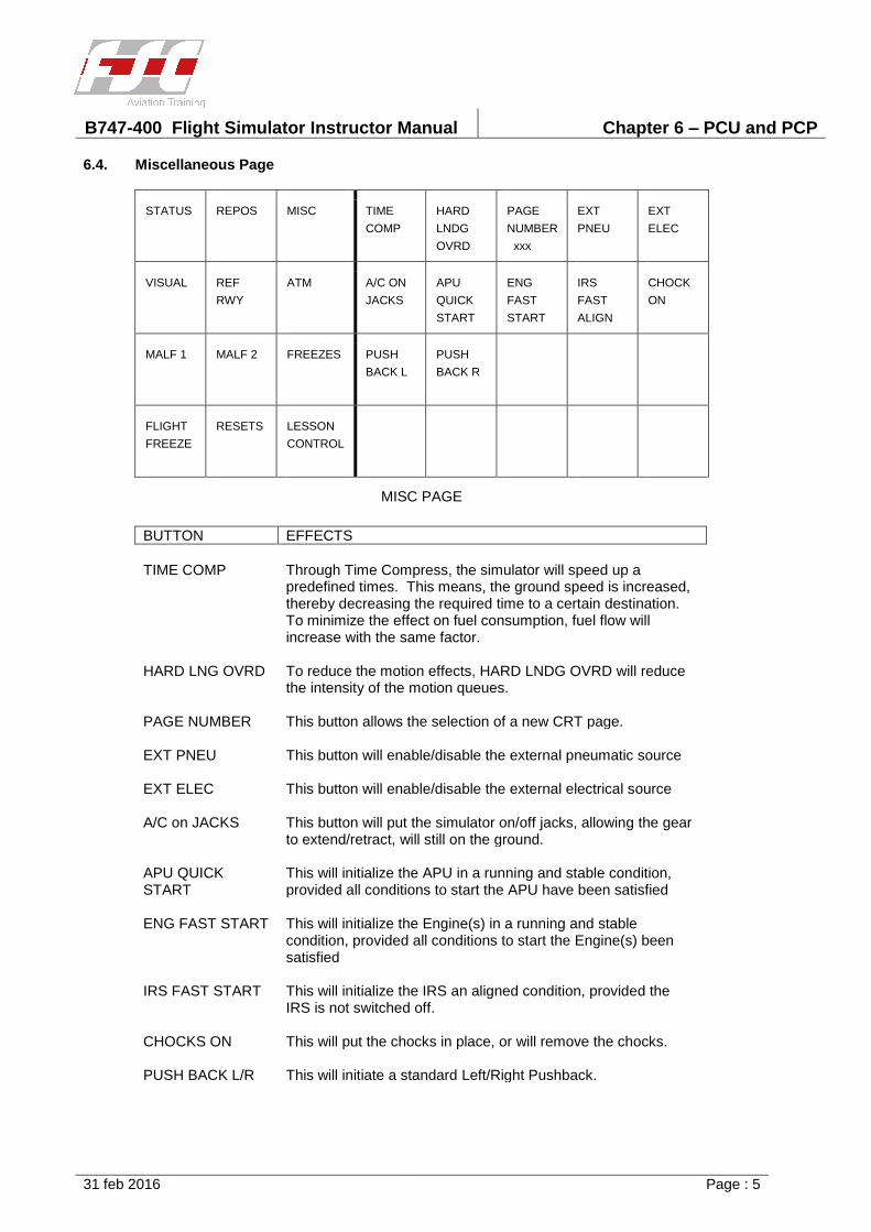
B747-400 Flight Simulator Instructor Manual Chapter 6 – PCU and PCP
31 feb 2016 Page : 5
6.4. Miscellaneous Page
STATUS REPOS MISC TIME
COMP
HARD
LNDG
OVRD
PAGE
NUMBER
xxx
EXT
PNEU
EXT
ELEC
VISUAL REF
RWY
ATM A/C ON
JACKS
APU
QUICK
START
ENG
FAST
START
IRS
FAST
ALIGN
CHOCK
ON
MALF 1 MALF 2 FREEZES PUSH
BACK L
PUSH
BACK R
FLIGHT
FREEZE
RESETS LESSON
CONTROL
MISC PAGE
BUTTON EFFECTS
TIME COMP Through Time Compress, the simulator will speed up a predefined times. This means, the ground speed is increased, thereby decreasing the required time to a certain destination. To minimize the effect on fuel consumption, fuel flow will increase with the same factor.
HARD LNG OVRD To reduce the motion effects, HARD LNDG OVRD will reduce the intensity of the motion queues.
PAGE NUMBER This button allows the selection of a new CRT page.
EXT PNEU This button will enable/disable the external pneumatic source
EXT ELEC This button will enable/disable the external electrical source
A/C on JACKS This button will put the simulator on/off jacks, allowing the gear to extend/retract, will still on the ground.
APU QUICK START
This will initialize the APU in a running and stable condition, provided all conditions to start the APU have been satisfied
ENG FAST START This will initialize the Engine(s) in a running and stable condition, provided all conditions to start the Engine(s) been satisfied
IRS FAST START This will initialize the IRS an aligned condition, provided the IRS is not switched off.
CHOCKS ON This will put the chocks in place, or will remove the chocks.
PUSH BACK L/R This will initiate a standard Left/Right Pushback.
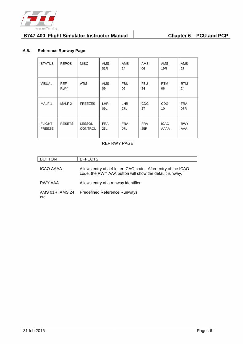
B747-400 Flight Simulator Instructor Manual Chapter 6 – PCU and PCP
31 feb 2016 Page : 6
6.5. Reference Runway Page
STATUS REPOS MISC AMS
01R
AMS
24
AMS
06
AMS
19R
AMS
27
VISUAL REF
RWY
ATM AMS
09
FBU
06
FBU
24
RTM
06
RTM
24
MALF 1 MALF 2 FREEZES LHR
09L
LHR
27L
CDG
27
CDG
10
FRA
07R
FLIGHT
FREEZE
RESETS LESSON
CONTROL
FRA
25L
FRA
07L
FRA
25R
ICAO
AAAA
RWY
AAA
REF RWY PAGE
BUTTON EFFECTS
ICAO AAAA Allows entry of a 4 letter ICAO code. After entry of the ICAO code, the RWY AAA button will show the default runway.
RWY AAA Allows entry of a runway identifier.
AMS 01R, AMS 24 etc
Predefined Reference Runways
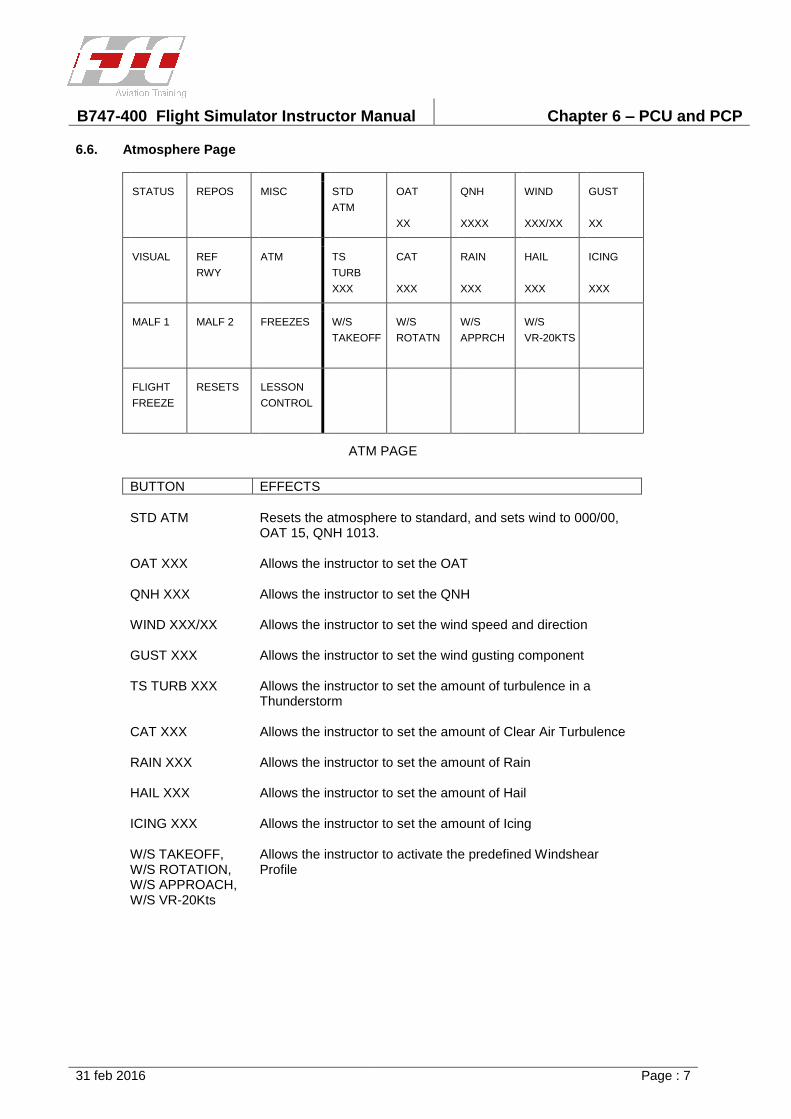
B747-400 Flight Simulator Instructor Manual Chapter 6 – PCU and PCP
31 feb 2016 Page : 7
6.6. Atmosphere Page
STATUS REPOS MISC STD
ATM
OAT
XX
QNH
XXXX
WIND
XXX/XX
GUST
XX
VISUAL REF
RWY
ATM TS
TURB
XXX
CAT
XXX
RAIN
XXX
HAIL
XXX
ICING
XXX
MALF 1 MALF 2 FREEZES W/S
TAKEOFF
W/S
ROTATN
W/S
APPRCH
W/S
VR-20KTS
FLIGHT
FREEZE
RESETS LESSON
CONTROL
ATM PAGE
BUTTON EFFECTS
STD ATM Resets the atmosphere to standard, and sets wind to 000/00, OAT 15, QNH 1013.
OAT XXX Allows the instructor to set the OAT
QNH XXX Allows the instructor to set the QNH
WIND XXX/XX Allows the instructor to set the wind speed and direction
GUST XXX Allows the instructor to set the wind gusting component
TS TURB XXX Allows the instructor to set the amount of turbulence in a Thunderstorm
CAT XXX Allows the instructor to set the amount of Clear Air Turbulence
RAIN XXX Allows the instructor to set the amount of Rain
HAIL XXX Allows the instructor to set the amount of Hail
ICING XXX Allows the instructor to set the amount of Icing
W/S TAKEOFF, W/S ROTATION, W/S APPROACH, W/S VR-20Kts
Allows the instructor to activate the predefined Windshear Profile

B747-400 Flight Simulator Instructor Manual Chapter 6 – PCU and PCP
31 feb 2016 Page : 8
6.7. Malfunctions 1 Page
STATUS REPOS MISC ENG 1
FIRE
ENG 2
FIRE
ENG 1
FLAME
OUT
ENG 2
FLAME
OUT
VISUAL REF
RWY
ATM ENG 1
SEIZURE
ENG 2
SEIZURE
ENG 1
HOT
START
ENG 2
HOT
START
MALF 1 MALF 2 FREEZES
FLIGHT
FREEZE
RESETS LESSON
CONTROL
MALF 1 PAGE
BUTTON EFFECTS
ENG 1(2) FIRE Allows the instructor to activate the Eng 1 (2) Fire Malfunction
ENG 1(2) FLAME OUT
Allows the instructor to activate the Eng 1 (2) Flame Out Malfunction
ENG 1(2) SEIZURE
Allows the instructor to activate the Eng 1 (2) Seizure Malfunction
ENG 1(2) HOT START
Allows the instructor to activate the Eng 1 (2) Hot Start Malfunction
Note : Descriptions of the above mentioned malfunctions, can be found in chapter 9.
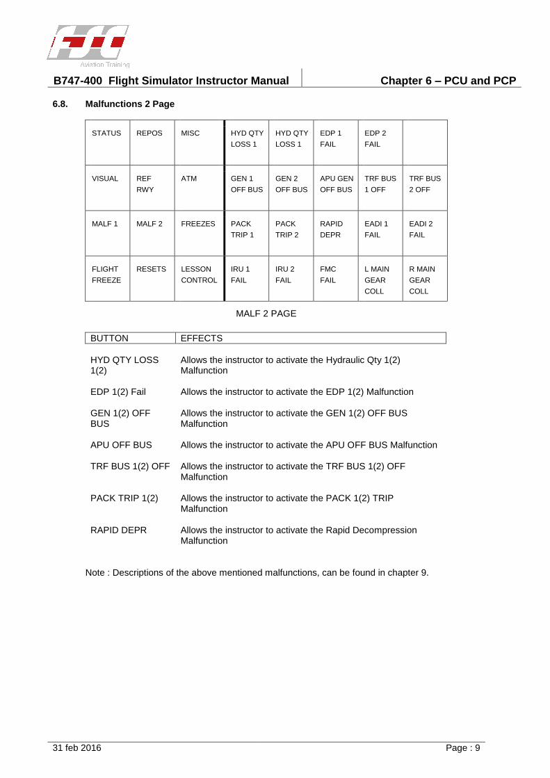
B747-400 Flight Simulator Instructor Manual Chapter 6 – PCU and PCP
31 feb 2016 Page : 9
6.8. Malfunctions 2 Page
STATUS REPOS MISC HYD QTY
LOSS 1
HYD QTY
LOSS 1
EDP 1
FAIL
EDP 2
FAIL
VISUAL REF
RWY
ATM GEN 1
OFF BUS
GEN 2
OFF BUS
APU GEN
OFF BUS
TRF BUS
1 OFF
TRF BUS
2 OFF
MALF 1 MALF 2 FREEZES PACK
TRIP 1
PACK
TRIP 2
RAPID
DEPR
EADI 1
FAIL
EADI 2
FAIL
FLIGHT
FREEZE
RESETS LESSON
CONTROL
IRU 1
FAIL
IRU 2
FAIL
FMC
FAIL
L MAIN
GEAR
COLL
R MAIN
GEAR
COLL
MALF 2 PAGE
BUTTON EFFECTS
HYD QTY LOSS 1(2)
Allows the instructor to activate the Hydraulic Qty 1(2) Malfunction
EDP 1(2) Fail Allows the instructor to activate the EDP 1(2) Malfunction
GEN 1(2) OFF BUS
Allows the instructor to activate the GEN 1(2) OFF BUS Malfunction
APU OFF BUS Allows the instructor to activate the APU OFF BUS Malfunction
TRF BUS 1(2) OFF Allows the instructor to activate the TRF BUS 1(2) OFF Malfunction
PACK TRIP 1(2) Allows the instructor to activate the PACK 1(2) TRIP Malfunction
RAPID DEPR Allows the instructor to activate the Rapid Decompression Malfunction
Note : Descriptions of the above mentioned malfunctions, can be found in chapter 9.
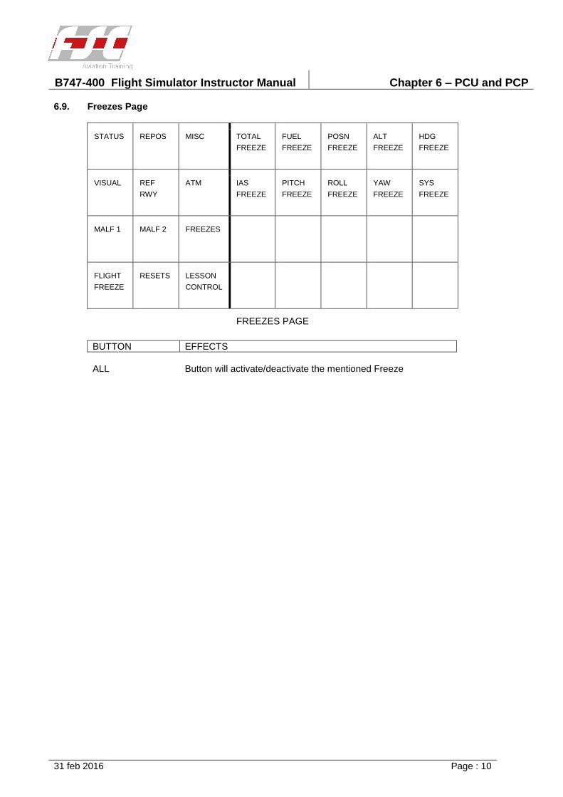
B747-400 Flight Simulator Instructor Manual Chapter 6 – PCU and PCP
31 feb 2016 Page : 10
6.9. Freezes Page
STATUS REPOS MISC TOTAL
FREEZE
FUEL
FREEZE
POSN
FREEZE
ALT
FREEZE
HDG
FREEZE
VISUAL REF
RWY
ATM IAS
FREEZE
PITCH
FREEZE
ROLL
FREEZE
YAW
FREEZE
SYS
FREEZE
MALF 1 MALF 2 FREEZES
FLIGHT
FREEZE
RESETS LESSON
CONTROL
FREEZES PAGE
BUTTON EFFECTS
ALL Button will activate/deactivate the mentioned Freeze
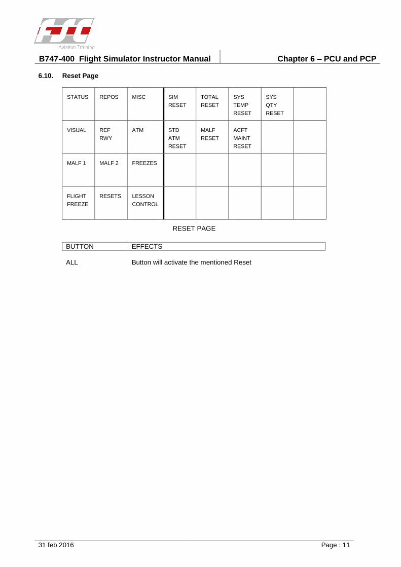
B747-400 Flight Simulator Instructor Manual Chapter 6 – PCU and PCP
31 feb 2016 Page : 11
6.10. Reset Page
STATUS REPOS MISC SIM
RESET
TOTAL
RESET
SYS
TEMP
RESET
SYS
QTY
RESET
VISUAL REF
RWY
ATM STD
ATM
RESET
MALF
RESET
ACFT
MAINT
RESET
MALF 1 MALF 2 FREEZES
FLIGHT
FREEZE
RESETS LESSON
CONTROL
RESET PAGE
BUTTON EFFECTS
ALL Button will activate the mentioned Reset
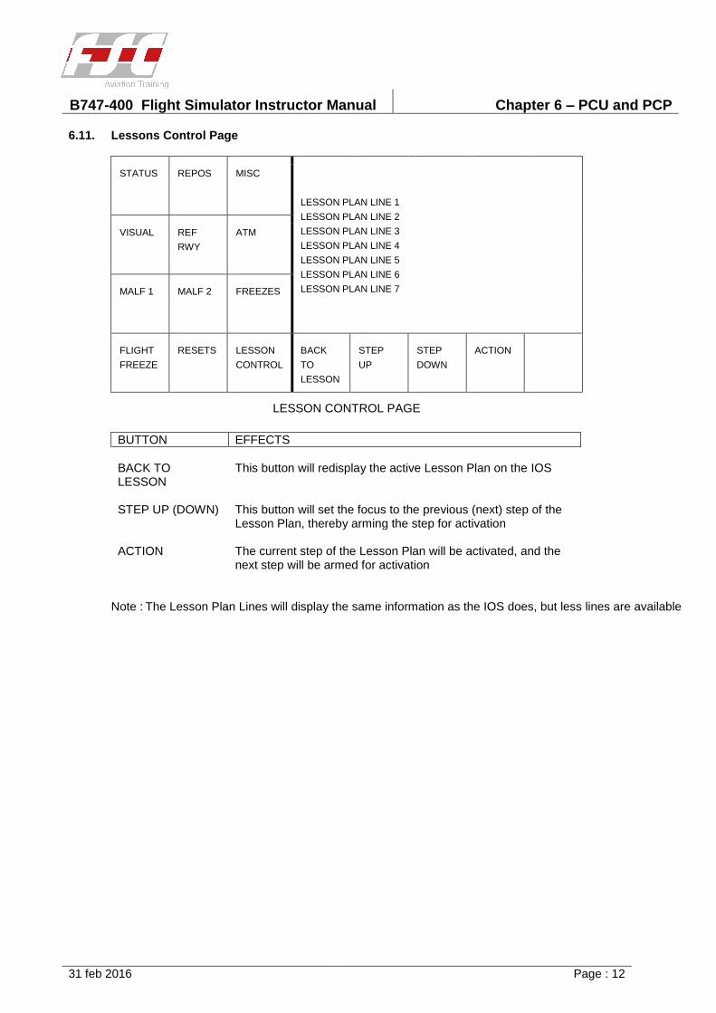
B747-400 Flight Simulator Instructor Manual Chapter 6 – PCU and PCP
31 feb 2016 Page : 12
6.11. Lessons Control Page
STATUS REPOS MISC
LESSON PLAN LINE 1
LESSON PLAN LINE 2
LESSON PLAN LINE 3
LESSON PLAN LINE 4
LESSON PLAN LINE 5
LESSON PLAN LINE 6
LESSON PLAN LINE 7
VISUAL REF
RWY
ATM
MALF 1 MALF 2 FREEZES
FLIGHT
FREEZE
RESETS LESSON
CONTROL
BACK
TO
LESSON
STEP
UP
STEP
DOWN
ACTION
LESSON CONTROL PAGE
BUTTON EFFECTS
BACK TO LESSON
This button will redisplay the active Lesson Plan on the IOS
STEP UP (DOWN) This button will set the focus to the previous (next) step of the Lesson Plan, thereby arming the step for activation
ACTION The current step of the Lesson Plan will be activated, and the next step will be armed for activation
Note : The Lesson Plan Lines will display the same information as the IOS does, but less lines are available
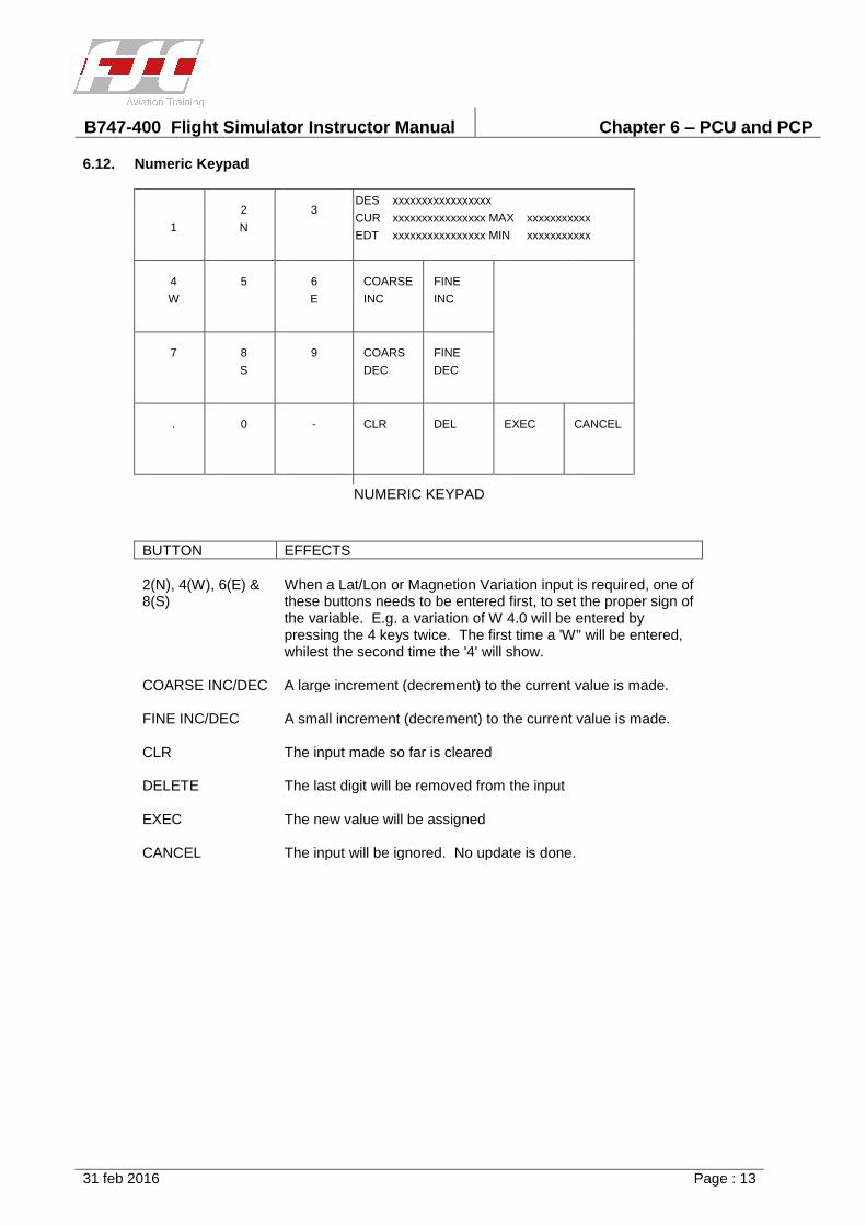
B747-400 Flight Simulator Instructor Manual Chapter 6 – PCU and PCP
31 feb 2016 Page : 13
6.12. Numeric Keypad
DES xxxxxxxxxxxxxxxxx
CUR xxxxxxxxxxxxxxxx MAX xxxxxxxxxxx
EDT xxxxxxxxxxxxxxxx MIN xxxxxxxxxxx 1
2
N
3
4
W
5 6
E
COARSE
INC
FINE
INC
7 8
S
9 COARS
DEC
FINE
DEC
. 0 - CLR DEL EXEC CANCEL
NUMERIC KEYPAD
BUTTON EFFECTS
2(N), 4(W), 6(E) & 8(S)
When a Lat/Lon or Magnetion Variation input is required, one of these buttons needs to be entered first, to set the proper sign of the variable. E.g. a variation of W 4.0 will be entered by pressing the 4 keys twice. The first time a 'W" will be entered, whilest the second time the '4' will show.
COARSE INC/DEC A large increment (decrement) to the current value is made.
FINE INC/DEC A small increment (decrement) to the current value is made.
CLR The input made so far is cleared
DELETE The last digit will be removed from the input
EXEC The new value will be assigned
CANCEL The input will be ignored. No update is done.
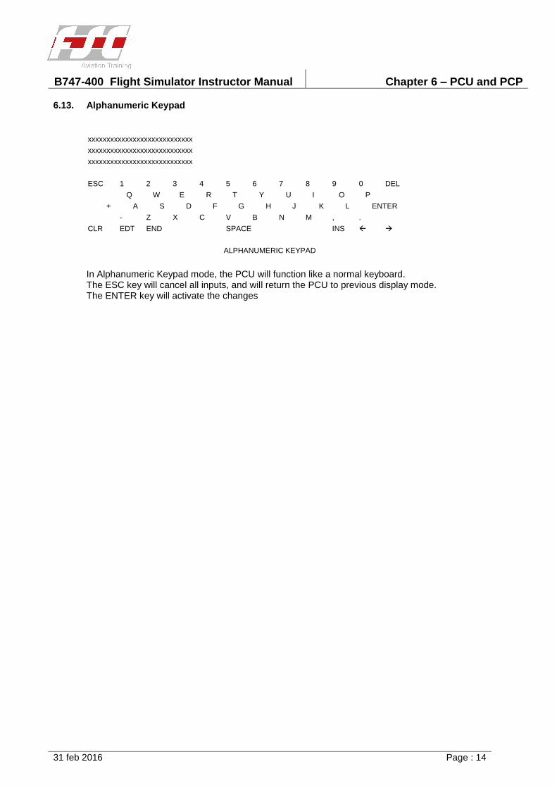
B747-400 Flight Simulator Instructor Manual Chapter 6 – PCU and PCP
31 feb 2016 Page : 14
6.13. Alphanumeric Keypad
xxxxxxxxxxxxxxxxxxxxxxxxxxxx
xxxxxxxxxxxxxxxxxxxxxxxxxxxx
xxxxxxxxxxxxxxxxxxxxxxxxxxxx
ESC 1 2 3 4 5 6 7 8 9 0 DEL
Q W E R T Y U I O P
+ A S D F G H J K L ENTER
- Z X C V B N M , .
CLR EDT END SPACE INS
ALPHANUMERIC KEYPAD
In Alphanumeric Keypad mode, the PCU will function like a normal keyboard. The ESC key will cancel all inputs, and will return the PCU to previous display mode. The ENTER key will activate the changes

B747-400 Flight Simulator Instructor Manual Chapter 7 – IOS Pages
31 feb 2016 Page : i
TABLE OF CONTENTS
Section/Title Page
7 IOS Pages 1
7.1 CRT Pages General 1
7.1.1 Types of CRT Pages 2
7.1.2 CRT Pages Colour Logic 2
7.1.3 Data Entry on CRT 2
7.2 CRT Footer Page 3
7.3 Header Pages 6
7.3.1 A/C Status Header 6
7.3.2 Map Header 7
7.4 Index Pages 8
7.4.1 Master Index 8
7.4.2 Lessonplan Index 9
7.4.3 Malfunction Index 10
7.4.4 Circuit Breaker Index 16
7.4.5 TMA Station Index 18
7.4.6 A-Z Radio Station Index 21
7.4.7 Maintenance Index 23
7.5 Control Pages 24
7.5.1 Aircraft Control 24
7.5.2 Reposition / Reference Runway Page 28
7.5.3 Environmental Control 31
7.5.4 Visual Control 37
7.5.5 Freezes and Resets Page 42
7.5.6 Doors 44
7.5.7 Simulator Control 45
7.5.8 DELETED 44
7.5.9 Pushback Control 47
7.6 Miscellaneous Pages 48
7.6.1 Malfunction Summary and CB Status 48
7.6.2 Failed Stations 49
7.6.3 Weather Fronts Control 50
7.6.4 Windshear Control 53
7.6.5 Microburst Control 54
7.6.6 TCAS 56
7.6.7 ATIS Control And Construction 58
7.6.8 VOLMET Control And Construction 64
7.6.9 MAP Page 65
7.6.10 ILS (Approach) Plot Page 73
7.6.11 RTO Monitor 74
7.6.12 Circling Monitor Plot 76
7.6.13 Store Recall 77
7.6.14 Record and Playback 78
7.6.15 Setup Recall 79

B747-400 Flight Simulator Instructor Manual Chapter 7 – IOS Pages
31 feb 2016 Page : ii
7.6.16 Graphic Recorder 80
7.6.17 Actual TMA Stations 83
7.7 Special Pages 84
7.7.1 Lesson Plan Pages 84
7.7.2 Controls Not In Agreement (CNIA) 86

B747-400 Flight Simulator Instructor Manual Chapter 7 – IOS Pages
31 dec 2015 Page : 1
7 IOS Pages
7.1 CRT Pages General
There are two physically identical CRTs at the instructor station.
The CRT can be divided into 3 area's :
a. Main Page Area,
b. Page Header Area
c. CRT Footer Area.
The CRT layout of these areas is shown below.
The Main Page Area is used to display the requested CRT page, and can be 80 columns in
width, or 56 columns including a Page Header on the Right Hand Side.
The Page Header Area is used to display a special page, which contains a set of standard
information. There are 3 Header Pages defined. A/C Status Header, Map Header and Graphic
Recorder Header.
The CRT Footers Area contains controls to call CRT pages, such as malfunction reset and
freezes pages, and/or miscellaneous controls to the screen.
The CRTs are used to display the following:
(a) CRT pages, containing graphic text and numerical data.
(b) Graphic pages, consisting of navigation station symbols, aircraft track, glide slope and
localizer deviations, and runway plotting.
(c) Graphic recorder data consisting of plots of up to 16 variables at a time usually appearing
on the upper CRT.
In addition to displaying information, the capability to change information through the CRT is
provided. For that reason , a touch layer is attached on to the CRT. Touching the item that
B747-400 Flight Simulator Instructor Manual Chapter 7 – IOS Pages
31 dec 2015 Page : 2
needs to be changed, will bring into view a keyboard, or popup page, so new values can be
inserted.
7.1.1 Types of CRT Pages
CRT pages are divided into the following groups:
(a) CRT Footer page. The CRT footer is displayed on each of the CRTs. It consists of
commonly used functions and is displayed at the bottom of the CRT in
the Footer Area.
(b) Header pages The A/C status header is the default display header page.
The Map header appears on the CRT when the map, approach plot or
runway plot are pages are used.
(c) Index pages All pages can be accesed via the index page. An index page lists by
type, function or system, page selections are accomplished by
touching the appropriate buttons.
(d) Control pages These pages allow the instructor to control and monitor the simulated
aircraft configuration and environment.
(e) Malfunction pages All available malfunctions, including discrete malfunctions, variable
malfunctions and certain circuit breakers are listed on these pages.
Malfunctions are grouped by system.
(f) Lesson Plan pages These pages contain preprogrammed training sequences, which may
be manually activated step-by-step or automatically stepped through.
(g) Maintenance pages. These pages display the value of various simulation system
parameters and are for integration purposes.
Note : Maintenance pages are not explained in this manual.
7.1.2 CRT Pages Colour Logic
Colors are used on the CRT page, to give extra information on a function. If applicable, an
explanation of the color and its function is given with the page.
7.1.3 Data Entry on CRT
When a button is activated, a certain action is being performed. The selection of a new page,
will bring the page into view, but sometimes, information from the instructor is required,
before an action can be started. Information from the instructor can be achieved through:
(a) Popup Pages
(b) Keyboard Pages
(c) Sliders
Popup pages will be handled within the paragraph of the page, the keyboard and sliders are
covered in paragraph 5.1 and 5.3
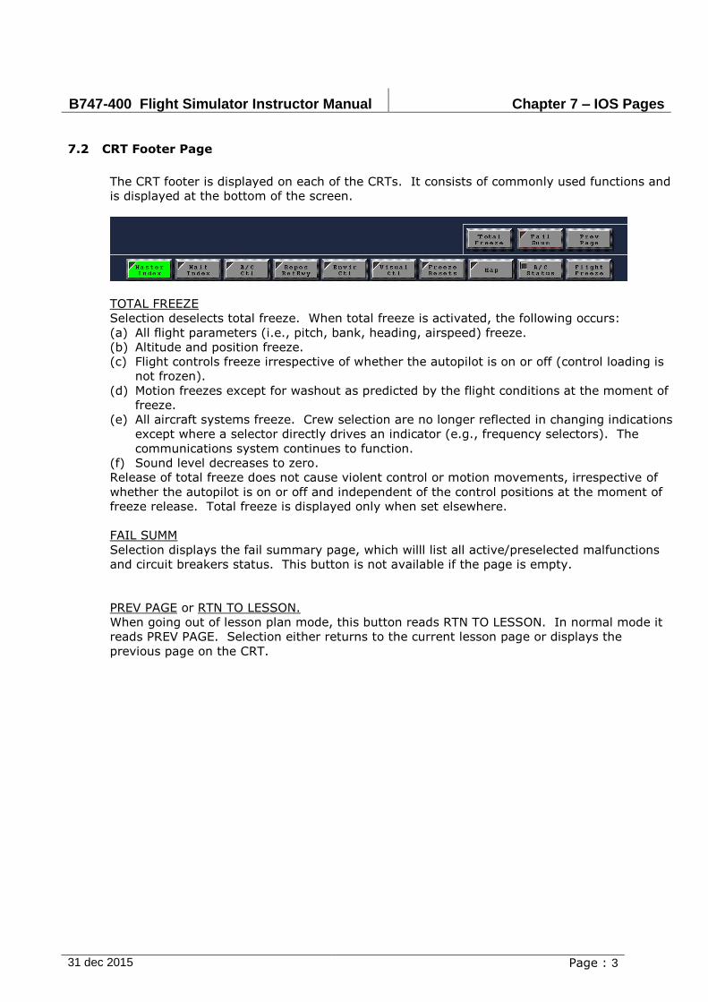
B747-400 Flight Simulator Instructor Manual Chapter 7 – IOS Pages
31 dec 2015 Page : 3
7.2 CRT Footer Page
The CRT footer is displayed on each of the CRTs. It consists of commonly used functions and
is displayed at the bottom of the screen.
TOTAL FREEZE
Selection deselects total freeze. When total freeze is activated, the following occurs:
(a) All flight parameters (i.e., pitch, bank, heading, airspeed) freeze.
(b) Altitude and position freeze.
(c) Flight controls freeze irrespective of whether the autopilot is on or off (control loading is
not frozen).
(d) Motion freezes except for washout as predicted by the flight conditions at the moment of
freeze.
(e) All aircraft systems freeze. Crew selection are no longer reflected in changing indications
except where a selector directly drives an indicator (e.g., frequency selectors). The
communications system continues to function.
(f) Sound level decreases to zero.
Release of total freeze does not cause violent control or motion movements, irrespective of
whether the autopilot is on or off and independent of the control positions at the moment of
freeze release. Total freeze is displayed only when set elsewhere.
FAIL SUMM
Selection displays the fail summary page, which willl list all active/preselected malfunctions
and circuit breakers status. This button is not available if the page is empty.
PREV PAGE or RTN TO LESSON.
When going out of lesson plan mode, this button reads RTN TO LESSON. In normal mode it
reads PREV PAGE. Selection either returns to the current lesson page or displays the
previous page on the CRT.
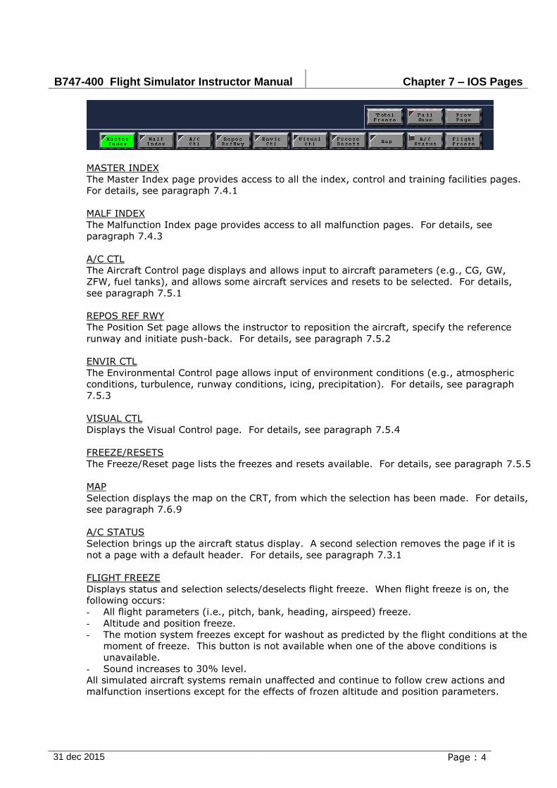
B747-400 Flight Simulator Instructor Manual Chapter 7 – IOS Pages
31 dec 2015 Page : 4
MASTER INDEX
The Master Index page provides access to all the index, control and training facilities pages.
For details, see paragraph 7.4.1
MALF INDEX
The Malfunction Index page provides access to all malfunction pages. For details, see
paragraph 7.4.3
A/C CTL
The Aircraft Control page displays and allows input to aircraft parameters (e.g., CG, GW,
ZFW, fuel tanks), and allows some aircraft services and resets to be selected. For details,
see paragraph 7.5.1
REPOS REF RWY
The Position Set page allows the instructor to reposition the aircraft, specify the reference
runway and initiate push-back. For details, see paragraph 7.5.2
ENVIR CTL
The Environmental Control page allows input of environment conditions (e.g., atmospheric
conditions, turbulence, runway conditions, icing, precipitation). For details, see paragraph
7.5.3
VISUAL CTL
Displays the Visual Control page. For details, see paragraph 7.5.4
FREEZE/RESETS
The Freeze/Reset page lists the freezes and resets available. For details, see paragraph 7.5.5
MAP
Selection displays the map on the CRT, from which the selection has been made. For details,
see paragraph 7.6.9
A/C STATUS
Selection brings up the aircraft status display. A second selection removes the page if it is
not a page with a default header. For details, see paragraph 7.3.1
FLIGHT FREEZE
Displays status and selection selects/deselects flight freeze. When flight freeze is on, the
following occurs:
- All flight parameters (i.e., pitch, bank, heading, airspeed) freeze.
- Altitude and position freeze.
- The motion system freezes except for washout as predicted by the flight conditions at the
moment of freeze. This button is not available when one of the above conditions is
unavailable.
- Sound increases to 30% level.
All simulated aircraft systems remain unaffected and continue to follow crew actions and
malfunction insertions except for the effects of frozen altitude and position parameters.
B747-400 Flight Simulator Instructor Manual Chapter 7 – IOS Pages
31 dec 2015 Page : 5
Release of flight freeze does not cause violent control or motion movements, irrespective of
whether the autopilot is on or off and independent of the control positions at the moment of
unfreeze.
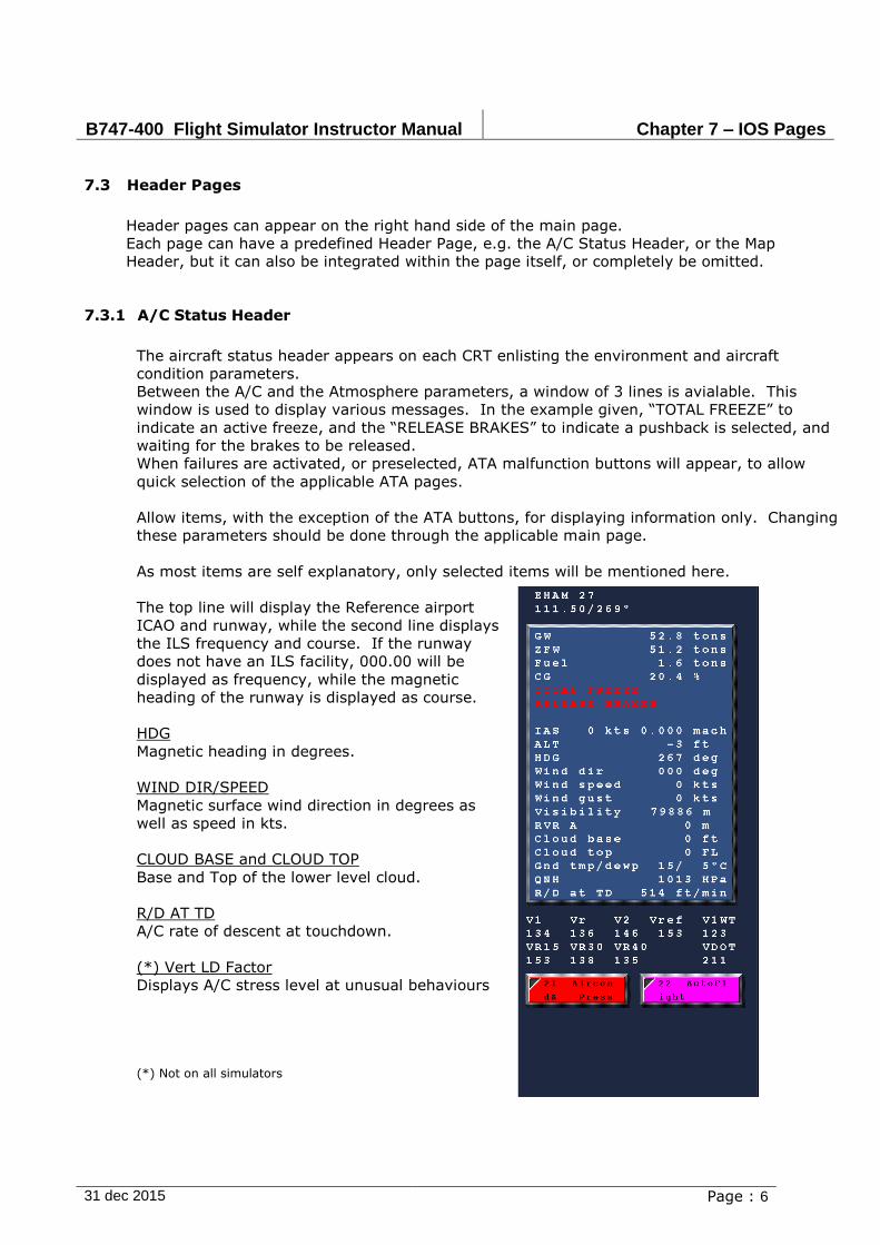
B747-400 Flight Simulator Instructor Manual Chapter 7 – IOS Pages
31 dec 2015 Page : 6
7.3 Header Pages
Header pages can appear on the right hand side of the main page.
Each page can have a predefined Header Page, e.g. the A/C Status Header, or the Map
Header, but it can also be integrated within the page itself, or completely be omitted.
7.3.1 A/C Status Header
The aircraft status header appears on each CRT enlisting the environment and aircraft
condition parameters.
Between the A/C and the Atmosphere parameters, a window of 3 lines is avialable. This
window is used to display various messages. In the example given, “TOTAL FREEZE” to
indicate an active freeze, and the “RELEASE BRAKES” to indicate a pushback is selected, and
waiting for the brakes to be released.
When failures are activated, or preselected, ATA malfunction buttons will appear, to allow
quick selection of the applicable ATA pages.
Allow items, with the exception of the ATA buttons, for displaying information only. Changing
these parameters should be done through the applicable main page.
As most items are self explanatory, only selected items will be mentioned here.
The top line will display the Reference airport
ICAO and runway, while the second line displays
the ILS frequency and course. If the runway
does not have an ILS facility, 000.00 will be
displayed as frequency, while the magnetic
heading of the runway is displayed as course.
HDG
Magnetic heading in degrees.
WIND DIR/SPEED
Magnetic surface wind direction in degrees as
well as speed in kts.
CLOUD BASE and CLOUD TOP
Base and Top of the lower level cloud.
R/D AT TD
A/C rate of descent at touchdown.
(*) Vert LD Factor
Displays A/C stress level at unusual behaviours
(*) Not on all simulators
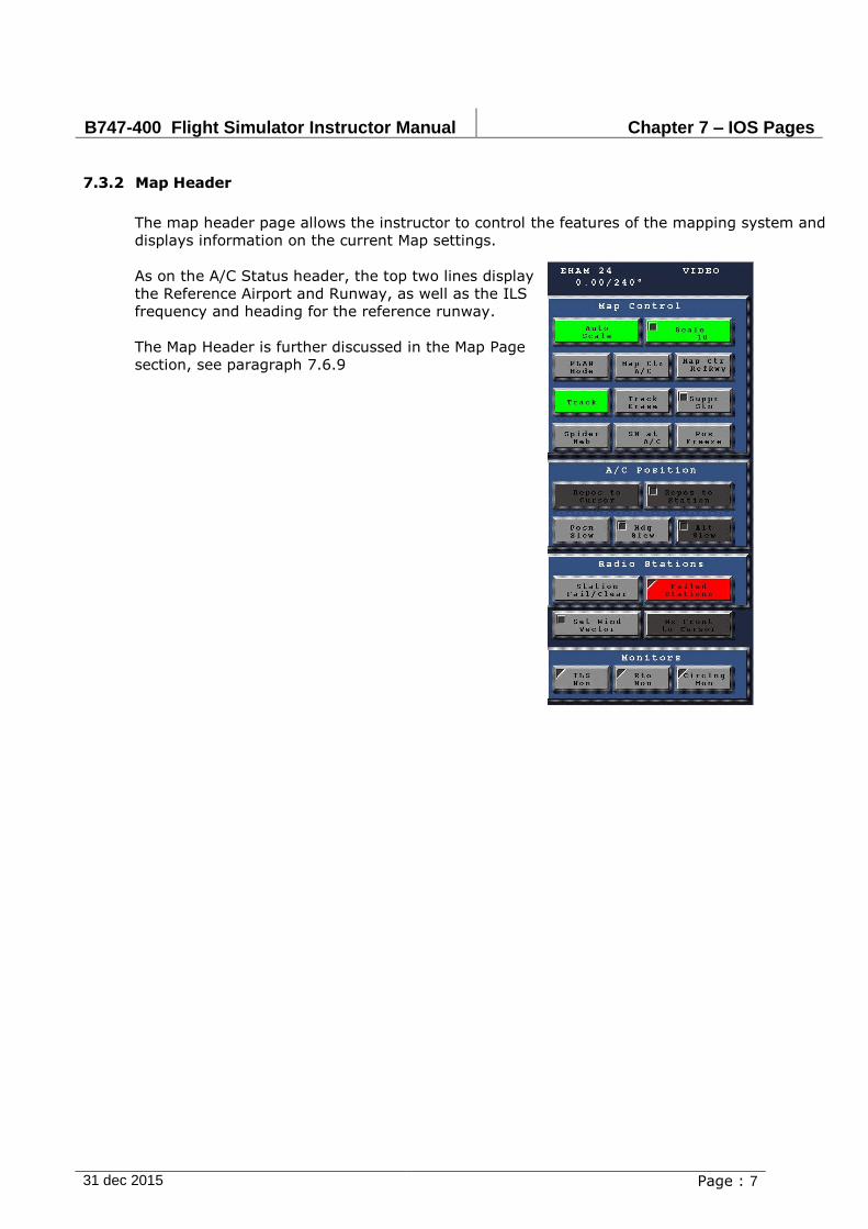
B747-400 Flight Simulator Instructor Manual Chapter 7 – IOS Pages
31 dec 2015 Page : 7
7.3.2 Map Header
The map header page allows the instructor to control the features of the mapping system and
displays information on the current Map settings.
As on the A/C Status header, the top two lines display
the Reference Airport and Runway, as well as the ILS
frequency and heading for the reference runway.
The Map Header is further discussed in the Map Page
section, see paragraph 7.6.9
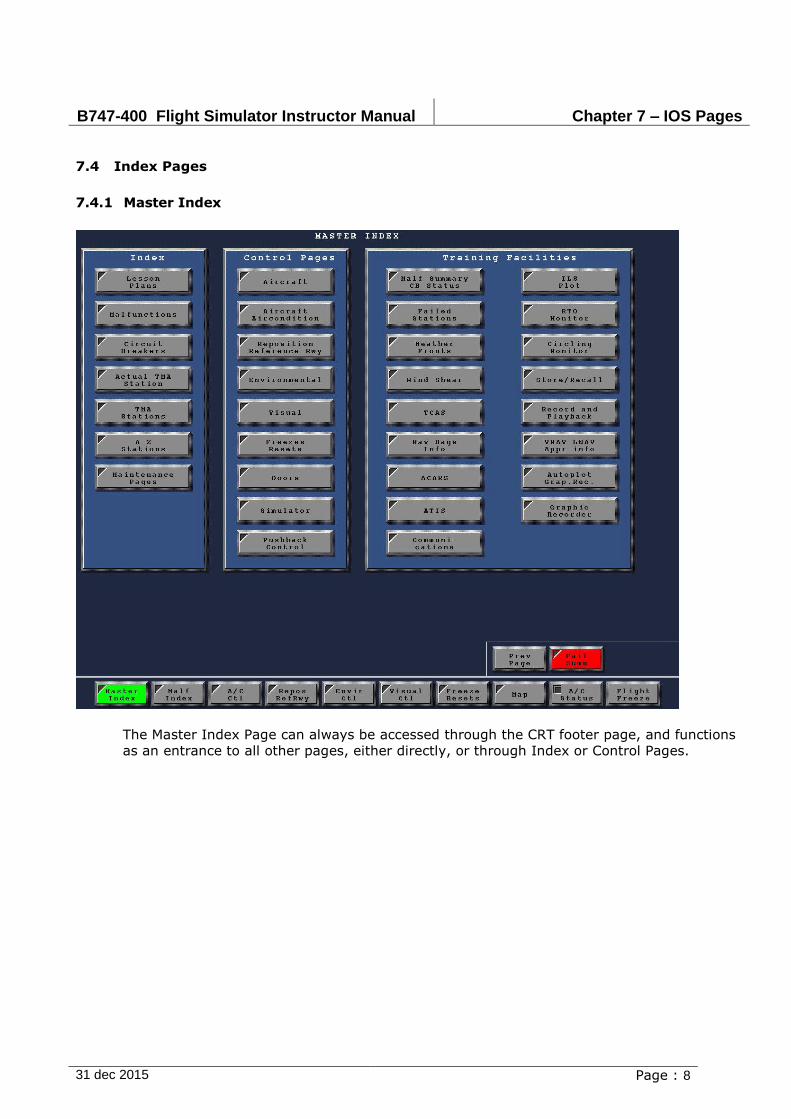
B747-400 Flight Simulator Instructor Manual Chapter 7 – IOS Pages
31 dec 2015 Page : 8
7.4 Index Pages
7.4.1 Master Index
The Master Index Page can always be accessed through the CRT footer page, and functions
as an entrance to all other pages, either directly, or through Index or Control Pages.
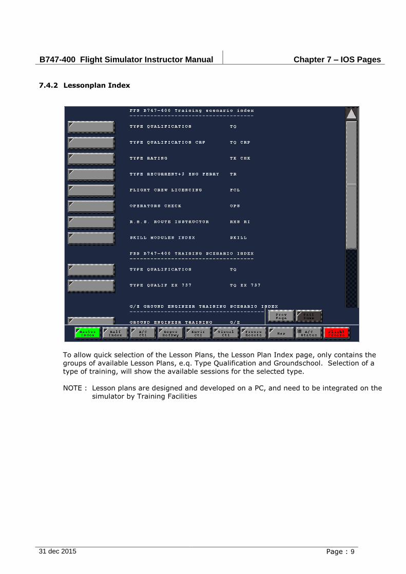
B747-400 Flight Simulator Instructor Manual Chapter 7 – IOS Pages
31 dec 2015 Page : 9
7.4.2 Lessonplan Index
To allow quick selection of the Lesson Plans, the Lesson Plan Index page, only contains the
groups of available Lesson Plans, e.q. Type Qualification and Groundschool. Selection of a
type of training, will show the available sessions for the selected type.
NOTE : Lesson plans are designed and developed on a PC, and need to be integrated on the
simulator by Training Facilities
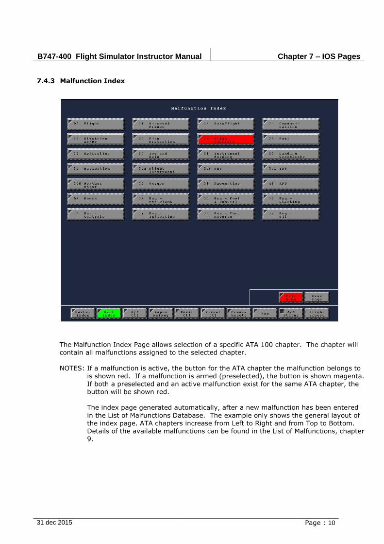
B747-400 Flight Simulator Instructor Manual Chapter 7 – IOS Pages
31 dec 2015 Page : 10
7.4.3 Malfunction Index
The Malfunction Index Page allows selection of a specific ATA 100 chapter. The chapter will
contain all malfunctions assigned to the selected chapter.
NOTES: If a malfunction is active, the button for the ATA chapter the malfunction belongs to
is shown red. If a malfunction is armed (preselected), the button is shown magenta.
If both a preselected and an active malfunction exist for the same ATA chapter, the
button will be shown red.
The index page generated automatically, after a new malfunction has been entered
in the List of Malfunctions Database. The example only shows the general layout of
the index page. ATA chapters increase from Left to Right and from Top to Bottom.
Details of the available malfunctions can be found in the List of Malfunctions, chapter
9.
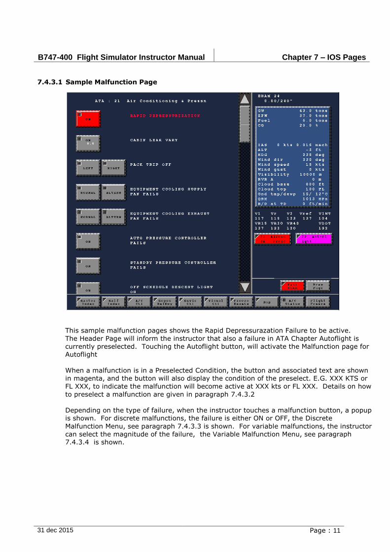
B747-400 Flight Simulator Instructor Manual Chapter 7 – IOS Pages
31 dec 2015 Page : 11
7.4.3.1 Sample Malfunction Page
This sample malfunction pages shows the Rapid Depressurazation Failure to be active.
The Header Page will inform the instructor that also a failure in ATA Chapter Autoflight is
currently preselected. Touching the Autoflight button, will activate the Malfunction page for
Autoflight
When a malfunction is in a Preselected Condition, the button and associated text are shown
in magenta, and the button will also display the condition of the preselect. E.G. XXX KTS or
FL XXX, to indicate the malfunction will become active at XXX kts or FL XXX. Details on how
to preselect a malfunction are given in paragraph 7.4.3.2
Depending on the type of failure, when the instructor touches a malfunction button, a popup
is shown. For discrete malfunctions, the failure is either ON or OFF, the Discrete
Malfunction Menu, see paragraph 7.4.3.3 is shown. For variable malfunctions, the instructor
can select the magnitude of the failure, the Variable Malfunction Menu, see paragraph
7.4.3.4 is shown.
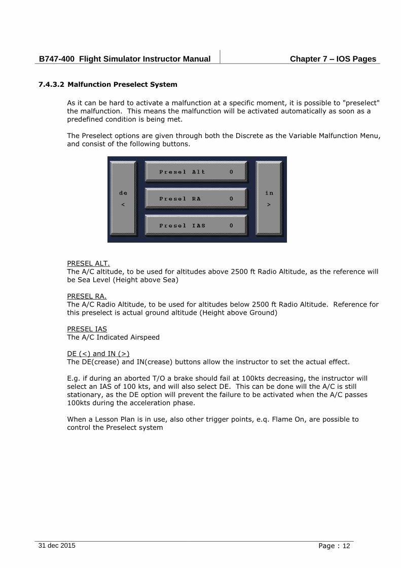
B747-400 Flight Simulator Instructor Manual Chapter 7 – IOS Pages
31 dec 2015 Page : 12
7.4.3.2 Malfunction Preselect System
As it can be hard to activate a malfunction at a specific moment, it is possible to "preselect"
the malfunction. This means the malfunction will be activated automatically as soon as a
predefined condition is being met.
The Preselect options are given through both the Discrete as the Variable Malfunction Menu,
and consist of the following buttons.
PRESEL ALT.
The A/C altitude, to be used for altitudes above 2500 ft Radio Altitude, as the reference will
be Sea Level (Height above Sea)
PRESEL RA.
The A/C Radio Altitude, to be used for altitudes below 2500 ft Radio Altitude. Reference for
this preselect is actual ground altitude (Height above Ground)
PRESEL IAS
The A/C Indicated Airspeed
DE (<) and IN (>)
The DE(crease) and IN(crease) buttons allow the instructor to set the actual effect.
E.g. if during an aborted T/O a brake should fail at 100kts decreasing, the instructor will
select an IAS of 100 kts, and will also select DE. This can be done will the A/C is still
stationary, as the DE option will prevent the failure to be activated when the A/C passes
100kts during the acceleration phase.
When a Lesson Plan is in use, also other trigger points, e.q. Flame On, are possible to
control the Preselect system
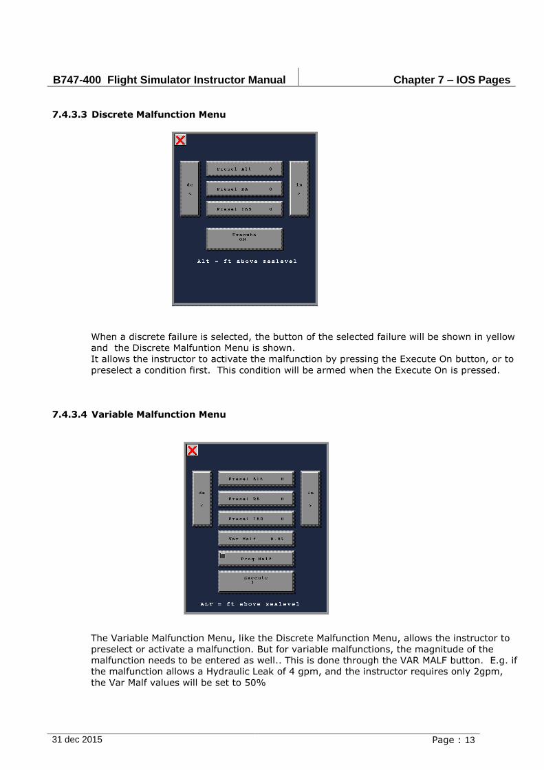
B747-400 Flight Simulator Instructor Manual Chapter 7 – IOS Pages
31 dec 2015 Page : 13
7.4.3.3 Discrete Malfunction Menu
When a discrete failure is selected, the button of the selected failure will be shown in yellow
and the Discrete Malfuntion Menu is shown.
It allows the instructor to activate the malfunction by pressing the Execute On button, or to
preselect a condition first. This condition will be armed when the Execute On is pressed.
7.4.3.4 Variable Malfunction Menu
The Variable Malfunction Menu, like the Discrete Malfunction Menu, allows the instructor to
preselect or activate a malfunction. But for variable malfunctions, the magnitude of the
malfunction needs to be entered as well.. This is done through the VAR MALF button. E.g. if
the malfunction allows a Hydraulic Leak of 4 gpm, and the instructor requires only 2gpm,
the Var Malf values will be set to 50%

B747-400 Flight Simulator Instructor Manual Chapter 7 – IOS Pages
31 dec 2015 Page : 14
It is also possible to select special effects on Variable Malfunctions, like a cyclecal variation.
This is done through the "Prog Malf" button, see paragraph 7.4.3.5
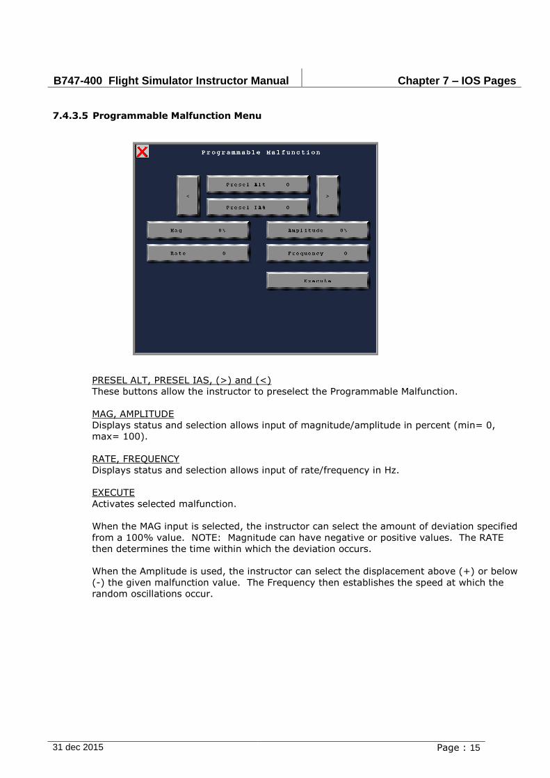
B747-400 Flight Simulator Instructor Manual Chapter 7 – IOS Pages
31 dec 2015 Page : 15
7.4.3.5 Programmable Malfunction Menu
PRESEL ALT, PRESEL IAS, (>) and (<)
These buttons allow the instructor to preselect the Programmable Malfunction.
MAG, AMPLITUDE
Displays status and selection allows input of magnitude/amplitude in percent (min= 0,
max= 100).
RATE, FREQUENCY
Displays status and selection allows input of rate/frequency in Hz.
EXECUTE
Activates selected malfunction.
When the MAG input is selected, the instructor can select the amount of deviation specified
from a 100% value. NOTE: Magnitude can have negative or positive values. The RATE
then determines the time within which the deviation occurs.
When the Amplitude is used, the instructor can select the displacement above (+) or below
(-) the given malfunction value. The Frequency then establishes the speed at which the
random oscillations occur.
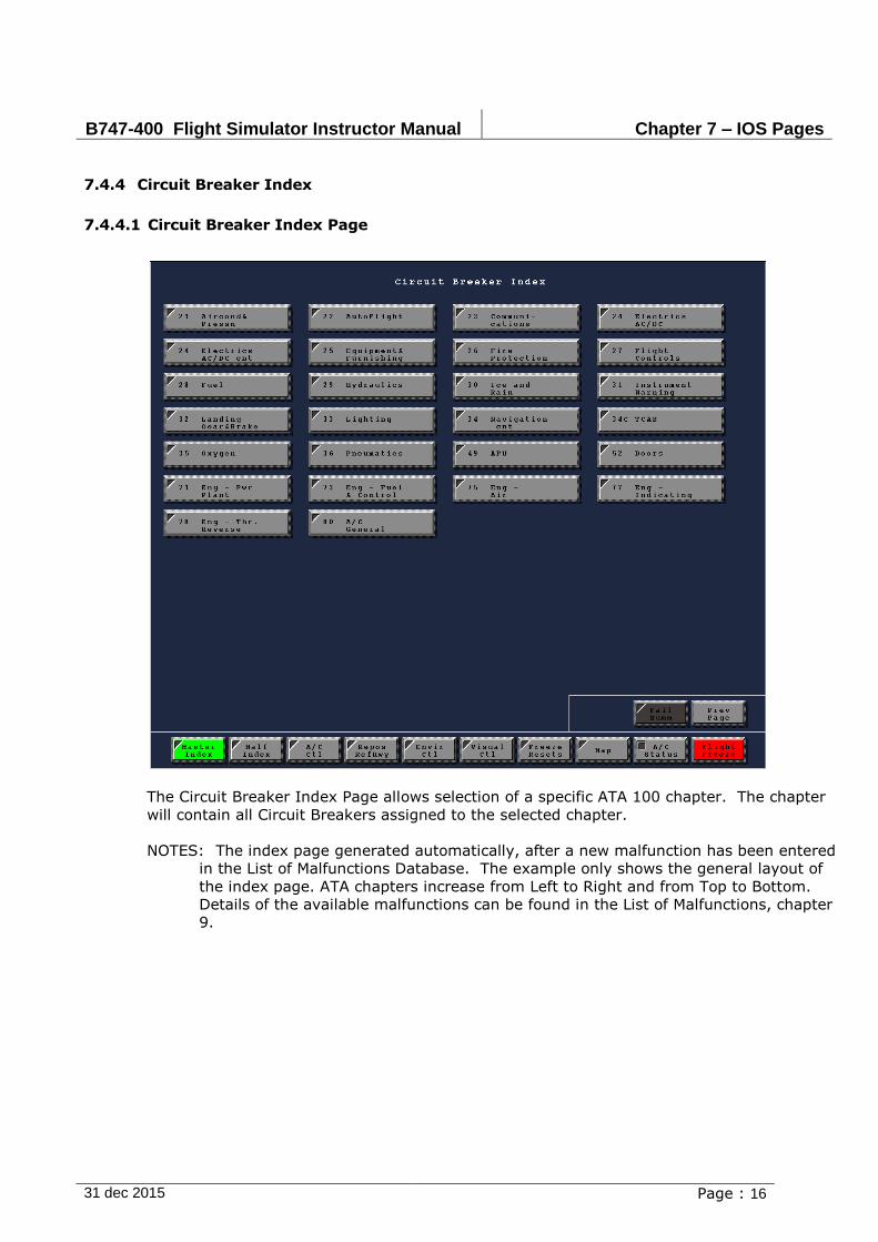
B747-400 Flight Simulator Instructor Manual Chapter 7 – IOS Pages
31 dec 2015 Page : 16
7.4.4 Circuit Breaker Index
7.4.4.1 Circuit Breaker Index Page
The Circuit Breaker Index Page allows selection of a specific ATA 100 chapter. The chapter
will contain all Circuit Breakers assigned to the selected chapter.
NOTES: The index page generated automatically, after a new malfunction has been entered
in the List of Malfunctions Database. The example only shows the general layout of
the index page. ATA chapters increase from Left to Right and from Top to Bottom.
Details of the available malfunctions can be found in the List of Malfunctions, chapter
9.
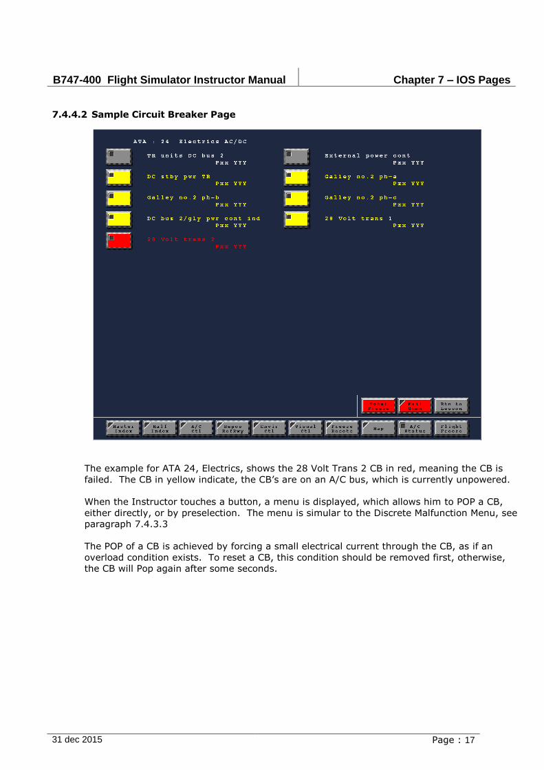
B747-400 Flight Simulator Instructor Manual Chapter 7 – IOS Pages
31 dec 2015 Page : 17
7.4.4.2 Sample Circuit Breaker Page
The example for ATA 24, Electrics, shows the 28 Volt Trans 2 CB in red, meaning the CB is
failed. The CB in yellow indicate, the CB’s are on an A/C bus, which is currently unpowered.
When the Instructor touches a button, a menu is displayed, which allows him to POP a CB,
either directly, or by preselection. The menu is simular to the Discrete Malfunction Menu, see
paragraph 7.4.3.3
The POP of a CB is achieved by forcing a small electrical current through the CB, as if an
overload condition exists. To reset a CB, this condition should be removed first, otherwise,
the CB will Pop again after some seconds.
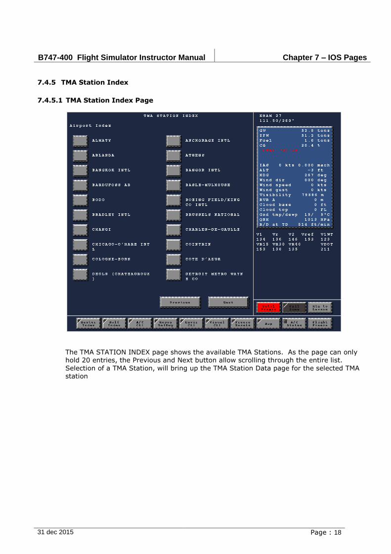
B747-400 Flight Simulator Instructor Manual Chapter 7 – IOS Pages
31 dec 2015 Page : 18
7.4.5 TMA Station Index
7.4.5.1 TMA Station Index Page
The TMA STATION INDEX page shows the available TMA Stations. As the page can only
hold 20 entries, the Previous and Next button allow scrolling through the entire list.
Selection of a TMA Station, will bring up the TMA Station Data page for the selected TMA
station

B747-400 Flight Simulator Instructor Manual Chapter 7 – IOS Pages
31 dec 2015 Page : 19
7.4.5.2 TMA Station Data
The TMA STATION DATA page displays information on the Radio Stations in the selected
TMA. The selected TMA is indicated above the Repos to Station button. In the example
shown, Brussels National
The Previous and Next button allow scrolling through the list, as only the page can display
20 stations. For each station, the type of station, frequency and name is given. For stations
related to a runway, the ICAO code and runway designator are given.
REPOS TO STATION
When a Radio Station is selected, the button of the selected station is green, touching the
Repos to Station button, will show a Repos to Station Popup Page. This page allows quick
repositioning, and is described in paragraph 7.4.5.3
RESET/FAIL STATION
When a Radio Station is selected, the button of the selected station is green, touching the
Reset/Fail Station button, will show a Station Fail/Reset Popup Page. This page allows the
instructor to fail or reset parts of the select station, as described in paragraph 7.4.5.4
TMA INDEX
Touching this buttons brings the TMA Index page back into view.
FAILED STNS
Touching this buttons will displays the Failed Stations page. See paragraph 7.6.2

B747-400 Flight Simulator Instructor Manual Chapter 7 – IOS Pages
31 dec 2015 Page : 20
7.4.5.3 Reposition to Station
Pressing a button on the Reposition to Station popup, allows the instructor to setup a new
altitude, airspeed and heading. These values will become active, when the execute button
is pressed.
7.4.5.4 Station Reset/Fail Menu
Pressing a button on the Station Reset/Fail popup, allows the instructor to reset/fail the
facility, as mentioned on the button itself. E.g. for the Brussels VDME the VOR and the DME
can be failed seperately, or the complete Station (STN FAIL BUTTON) can be failed.

B747-400 Flight Simulator Instructor Manual Chapter 7 – IOS Pages
31 dec 2015 Page : 21
7.4.6 A-Z Radio Station Index
7.4.6.1 A-Z Radio Station Index Page
The Radio Stations are stored in a data file. As this is a very large file, the index page
display ranges of stations, sorted alphabetically. Scrolling through the list is possible
through the Previous and Next buttons.
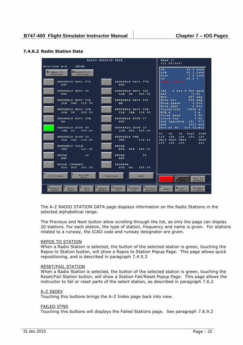
B747-400 Flight Simulator Instructor Manual Chapter 7 – IOS Pages
31 dec 2015 Page : 22
7.4.6.2 Radio Station Data
The A-Z RADIO STATION DATA page displays information on the Radio Stations in the
selected alphabetical range.
The Previous and Next button allow scrolling through the list, as only the page can display
20 stations. For each station, the type of station, frequency and name is given. For stations
related to a runway, the ICAO code and runway designator are given.
REPOS TO STATION
When a Radio Station is selected, the button of the selected station is green, touching the
Repos to Station button, will show a Repos to Station Popup Page. This page allows quick
repositioning, and is described in paragraph 7.4.5.3
RESET/FAIL STATION
When a Radio Station is selected, the button of the selected station is green, touching the
Reset/Fail Station button, will show a Station Fail/Reset Popup Page. This page allows the
instructor to fail or reset parts of the select station, as described in paragraph 7.6.2
A-Z INDEX
Touching this buttons brings the A-Z Index page back into view.
FAILED STNS
Touching this buttons will displays the Failed Stations page. See paragraph 7.6.9.2
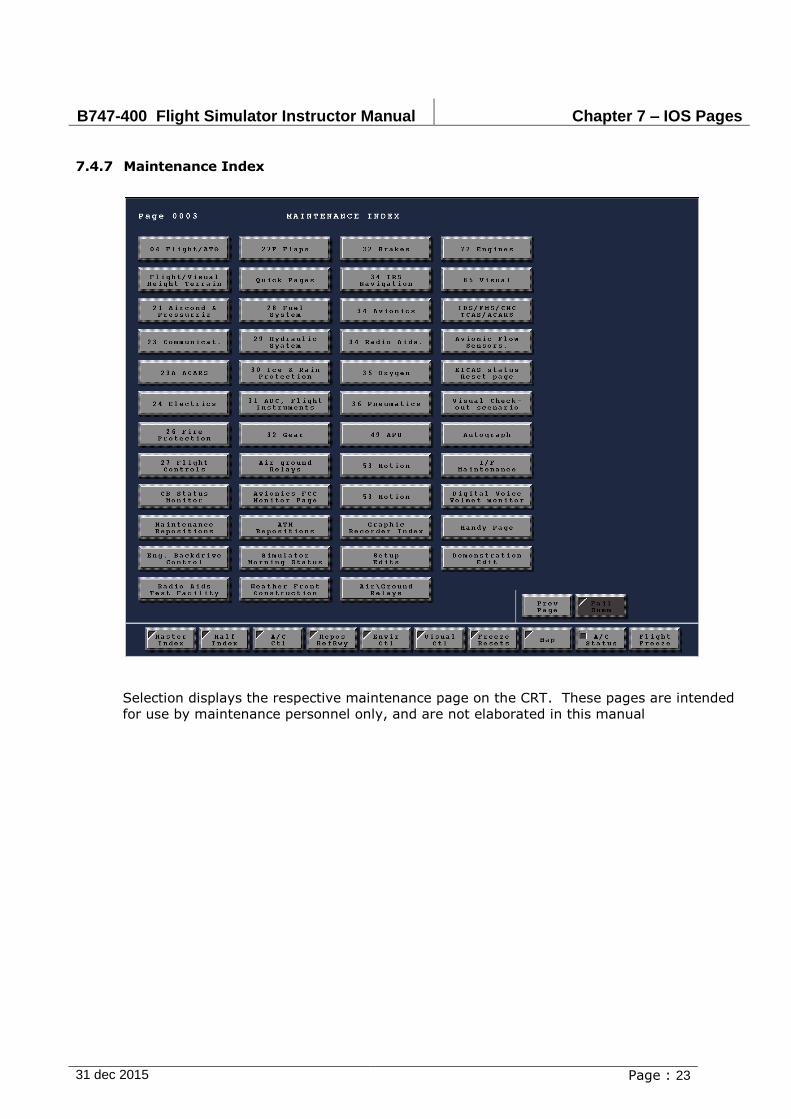
B747-400 Flight Simulator Instructor Manual Chapter 7 – IOS Pages
31 dec 2015 Page : 23
7.4.7 Maintenance Index
Selection displays the respective maintenance page on the CRT. These pages are intended
for use by maintenance personnel only, and are not elaborated in this manual
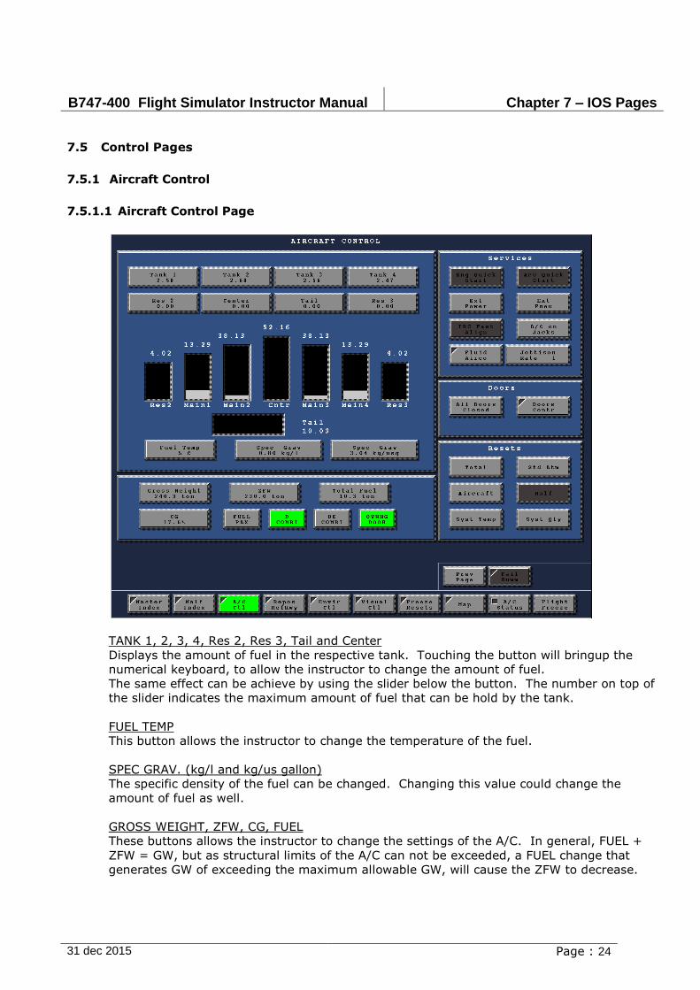
B747-400 Flight Simulator Instructor Manual Chapter 7 – IOS Pages
31 dec 2015 Page : 24
7.5 Control Pages
7.5.1 Aircraft Control
7.5.1.1 Aircraft Control Page
TANK 1, 2, 3, 4, Res 2, Res 3, Tail and Center
Displays the amount of fuel in the respective tank. Touching the button will bringup the
numerical keyboard, to allow the instructor to change the amount of fuel.
The same effect can be achieve by using the slider below the button. The number on top of
the slider indicates the maximum amount of fuel that can be hold by the tank.
FUEL TEMP
This button allows the instructor to change the temperature of the fuel.
SPEC GRAV. (kg/l and kg/us gallon)
The specific density of the fuel can be changed. Changing this value could change the
amount of fuel as well.
GROSS WEIGHT, ZFW, CG, FUEL
These buttons allows the instructor to change the settings of the A/C. In general, FUEL +
ZFW = GW, but as structural limits of the A/C can not be exceeded, a FUEL change that
generates GW of exceeding the maximum allowable GW, will cause the ZFW to decrease.
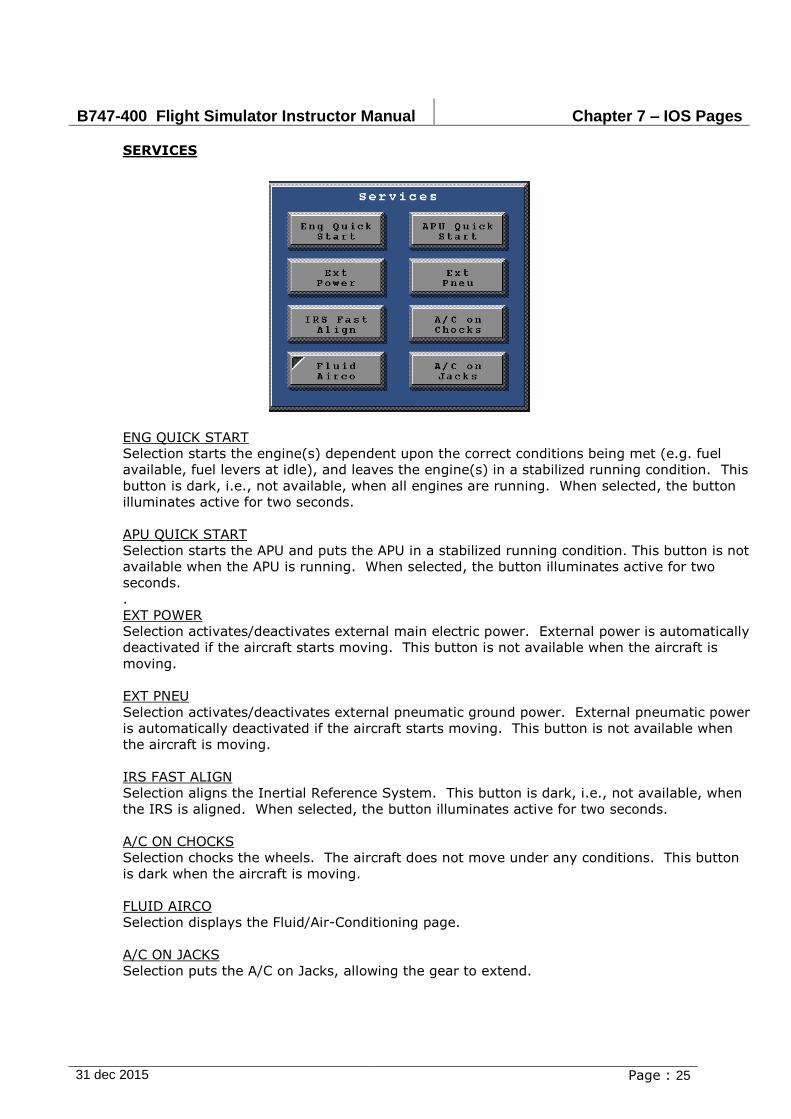
B747-400 Flight Simulator Instructor Manual Chapter 7 – IOS Pages
31 dec 2015 Page : 25
SERVICES
ENG QUICK START
Selection starts the engine(s) dependent upon the correct conditions being met (e.g. fuel
available, fuel levers at idle), and leaves the engine(s) in a stabilized running condition. This
button is dark, i.e., not available, when all engines are running. When selected, the button
illuminates active for two seconds.
APU QUICK START
Selection starts the APU and puts the APU in a stabilized running condition. This button is not
available when the APU is running. When selected, the button illuminates active for two
seconds.
.
EXT POWER
Selection activates/deactivates external main electric power. External power is automatically
deactivated if the aircraft starts moving. This button is not available when the aircraft is
moving.
EXT PNEU
Selection activates/deactivates external pneumatic ground power. External pneumatic power
is automatically deactivated if the aircraft starts moving. This button is not available when
the aircraft is moving.
IRS FAST ALIGN
Selection aligns the Inertial Reference System. This button is dark, i.e., not available, when
the IRS is aligned. When selected, the button illuminates active for two seconds.
A/C ON CHOCKS
Selection chocks the wheels. The aircraft does not move under any conditions. This button
is dark when the aircraft is moving.
FLUID AIRCO
Selection displays the Fluid/Air-Conditioning page.
A/C ON JACKS
Selection puts the A/C on Jacks, allowing the gear to extend.

B747-400 Flight Simulator Instructor Manual Chapter 7 – IOS Pages
31 dec 2015 Page : 26
DOORS
ALL DOORS CLSD/AUTO
Selection closes all aircraft doors and activates the automatic mode.
DOORS CONTR
Selection displays the Doors page. See for more details paragraph 7.5.6
RESETS
TOTAL RESET
Selection resets the following parameters as indicated:
Aircraft reset ON
Icing conditions OFF
Radio stations reset ON
Runway conditions NORMAL
Aircraft on jacks OFF
Standard atmosphere SET
System controllers ON
Visibility CAVOK
Time of day DUSK.
STD ATMOSPHERE
Selection resets atmosphere to ICAO standard condition as follows
Sea level barometric pressure = 1013.2 Hpa
Sea level temperature = +15C
Temperature lapse rate = -1.98C/1,000ft
Airfield wind speed = 0.0 knots
Airfield wind direction = 0.0
Intermediate temperature = -4.8C
Intermediate altitude = 10,000 feet
Intermediate wind speed = 0.0 knots
Intermediate wind direction = 0
Tropopause altitude = 36,089 feet
Tropopause temperature = -56.5C
Tropopause wind speed = 0.0 knots
Tropopause wind direction = 0
Turbulence intensity = 0
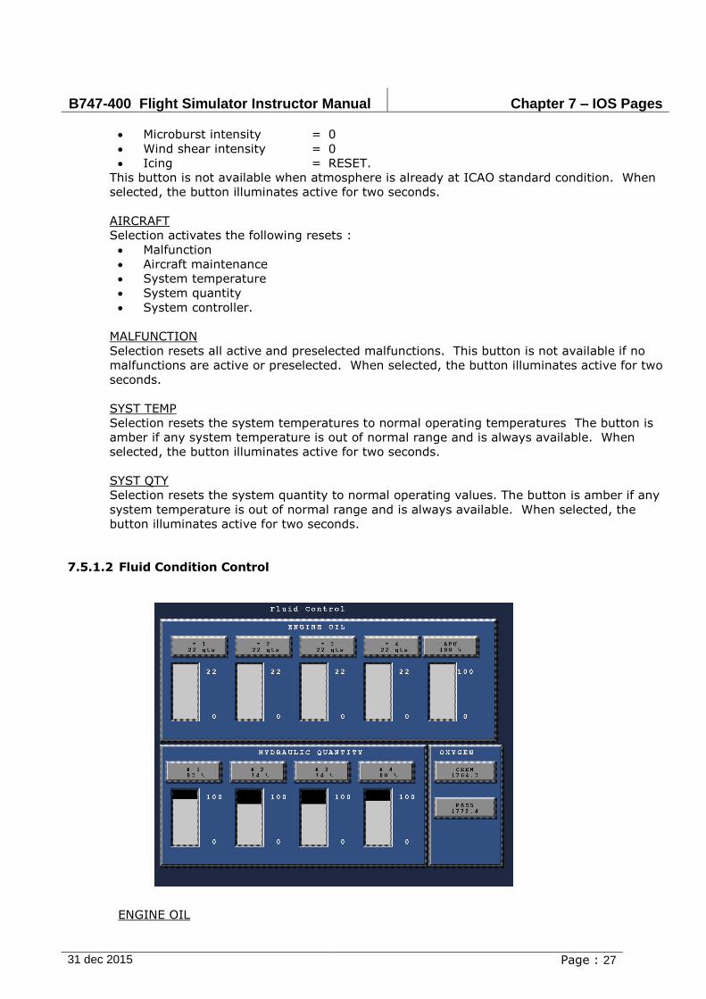
B747-400 Flight Simulator Instructor Manual Chapter 7 – IOS Pages
31 dec 2015 Page : 27
Microburst intensity = 0
Wind shear intensity = 0
Icing = RESET.
This button is not available when atmosphere is already at ICAO standard condition. When
selected, the button illuminates active for two seconds.
AIRCRAFT
Selection activates the following resets :
Malfunction
Aircraft maintenance
System temperature
System quantity
System controller.
MALFUNCTION
Selection resets all active and preselected malfunctions. This button is not available if no
malfunctions are active or preselected. When selected, the button illuminates active for two
seconds.
SYST TEMP
Selection resets the system temperatures to normal operating temperatures The button is
amber if any system temperature is out of normal range and is always available. When
selected, the button illuminates active for two seconds.
SYST QTY
Selection resets the system quantity to normal operating values. The button is amber if any
system temperature is out of normal range and is always available. When selected, the
button illuminates active for two seconds.
7.5.1.2 Fluid Condition Control
ENGINE OIL
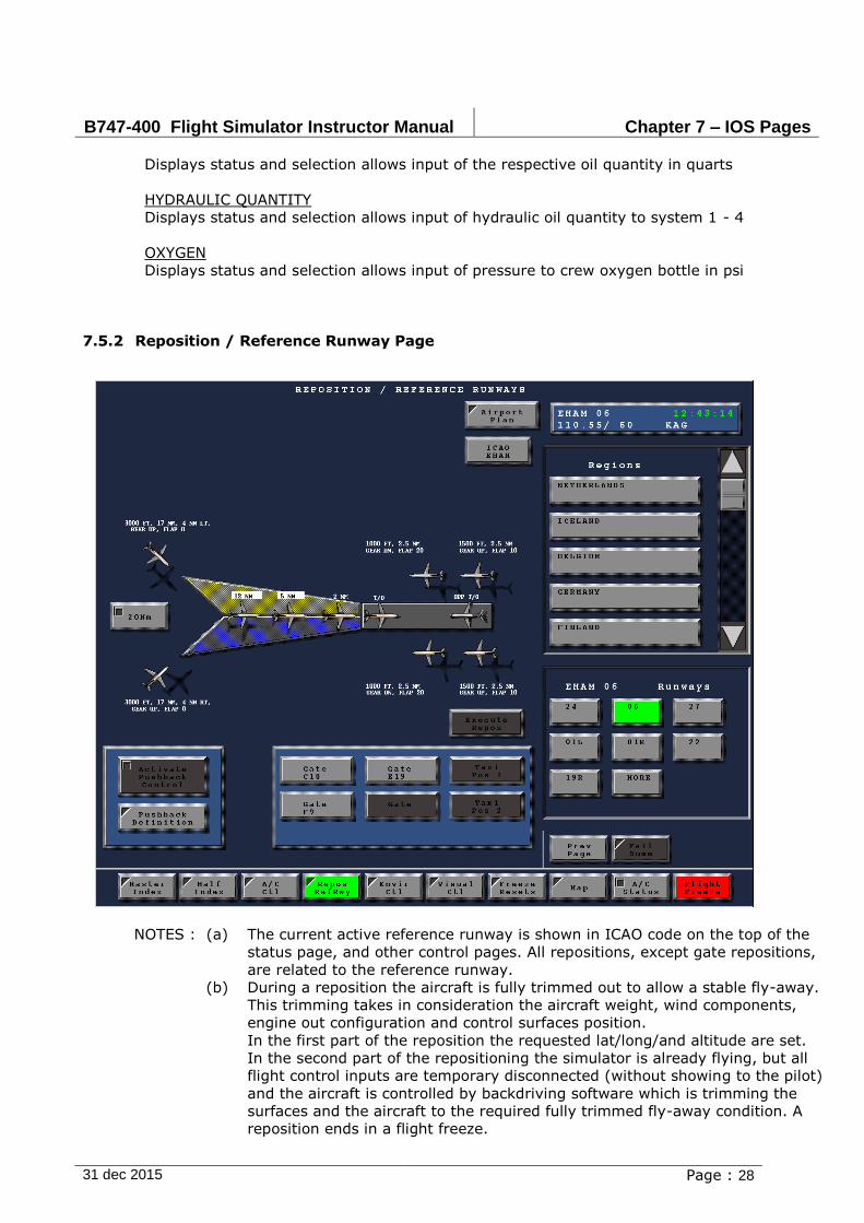
B747-400 Flight Simulator Instructor Manual Chapter 7 – IOS Pages
31 dec 2015 Page : 28
Displays status and selection allows input of the respective oil quantity in quarts
HYDRAULIC QUANTITY
Displays status and selection allows input of hydraulic oil quantity to system 1 - 4
OXYGEN
Displays status and selection allows input of pressure to crew oxygen bottle in psi
7.5.2 Reposition / Reference Runway Page
NOTES : (a) The current active reference runway is shown in ICAO code on the top of the
status page, and other control pages. All repositions, except gate repositions,
are related to the reference runway.
(b) During a reposition the aircraft is fully trimmed out to allow a stable fly-away.
This trimming takes in consideration the aircraft weight, wind components,
engine out configuration and control surfaces position.
In the first part of the reposition the requested lat/long/and altitude are set.
In the second part of the repositioning the simulator is already flying, but all
flight control inputs are temporary disconnected (without showing to the pilot)
and the aircraft is controlled by backdriving software which is trimming the
surfaces and the aircraft to the required fully trimmed fly-away condition. A
reposition ends in a flight freeze.
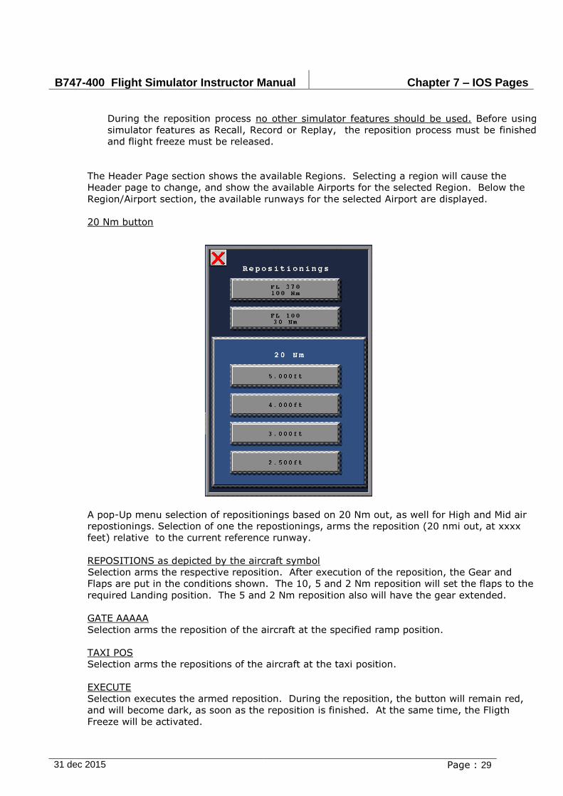
B747-400 Flight Simulator Instructor Manual Chapter 7 – IOS Pages
31 dec 2015 Page : 29
During the reposition process no other simulator features should be used. Before using
simulator features as Recall, Record or Replay, the reposition process must be finished
and flight freeze must be released.
The Header Page section shows the available Regions. Selecting a region will cause the
Header page to change, and show the available Airports for the selected Region. Below the
Region/Airport section, the available runways for the selected Airport are displayed.
20 Nm button
A pop-Up menu selection of repositionings based on 20 Nm out, as well for High and Mid air
repostionings. Selection of one the repostionings, arms the reposition (20 nmi out, at xxxx
feet) relative to the current reference runway.
REPOSITIONS as depicted by the aircraft symbol
Selection arms the respective reposition. After execution of the reposition, the Gear and
Flaps are put in the conditions shown. The 10, 5 and 2 Nm reposition will set the flaps to the
required Landing position. The 5 and 2 Nm reposition also will have the gear extended.
GATE AAAAA
Selection arms the reposition of the aircraft at the specified ramp position.
TAXI POS
Selection arms the repositions of the aircraft at the taxi position.
EXECUTE
Selection executes the armed reposition. During the reposition, the button will remain red,
and will become dark, as soon as the reposition is finished. At the same time, the Fligth
Freeze will be activated.

B747-400 Flight Simulator Instructor Manual Chapter 7 – IOS Pages
31 dec 2015 Page : 30
PUSHBACK DEFININTION
Selection calls up the Pushback Control page. See paragraph 7.5.9

B747-400 Flight Simulator Instructor Manual Chapter 7 – IOS Pages
31 dec 2015 Page : 31
7.5.3 Environmental Control
7.5.3.1 Environmental Control Page
NOTES :
(a) Adjustable atmosphere
Beside the airfield wind selections the adjustable atmosphere defines two more winds:
Intermediate wind and Tropopause wind. The altitudes, temperatures, wind
directions and wind speeds are selectable by the instructor. The altitude default is for
intermediate wind 10.000 ft and for tropopause wind 35.000 ft.
As the computer software linearly interpolates between the three inserted winds, in
direction, speed and temperature, the instructor has the possibility to create a wind
profile in the entire atmosphere.
(b) Atmoshpere Graph
Displays the atmospheric selection graphically. The lower limits for intermediate altitude
and tropopause altitude are 100 ft and 200 ft. This gives the instructor the possibility to
specify a low altitude wind-profile or with other words a simple wind shear profile.
(c) Advise tailwind
If strong tailwinds are required the use of the adjustable atmosphere wind speeds is
recommended above time compression. The reason for this is, that wind values are faded
in and out slowly. The wind changes are therefore accepted more easy by the FMC's .
(d) Temperature profile
When only the airfield temperature is selected the software extrapolates a temperature
profile, which can result in an unrealistic low OAT at high altitudes. This can be the
B747-400 Flight Simulator Instructor Manual Chapter 7 – IOS Pages
31 dec 2015 Page : 32
reason of a fuel temp low warnings.
A correct tropopause temperature selection is then required.
(e) Gust
Gust is defined as the addition on top of the speed value, with a max. gust value
of 20 kts.
The way a gust value is entered on the instructor station is as a pilot would hear a wind
report from the tower or the approach controller. E.g. " wind 270 at 21 gusty to 35" is
entered on the page or header as: wind direction 270, speed 21, gust 35. This means the
average wind is blowing at 21 kts, with additional gust values of (35 minus 21 equals) 14
kts, which is within the 20 kts maximum gust value.
ATMOSPHERE
A/C: ALT, TEMP, WINDDIR, WINDSPD
Displays current aircraft altitude, OAT, magnetic wind direction and speed.
UPPER ALT, TEMP, WINDDIR, WINDSPD
Allows the instructor to change the tropopause altitude (ft), temperature (deg C),
tropopause wind direction (0-360 deg) and speed (0-250 kts).
INTERMED ALT, TEMP, WINDDIR, WINDSPD
Allows the instructor to change the intermediate altitude (ft), temperature (deg C),
intermediate wind direction (0-360 deg) and speed (0-250 kts).
FIELD ELEVATION
Displays reference airport elevation in feet.
FIELD TEMP
Allows the instructor to change field temperature (deg C)
FIELD WINDDIR, WINDSPD and GUST
Allows the instructor to change the field wind direction (0-360 deg) and speed (0-250 kts)
and gusting speed. Gusting is the amount that will be added to the steady wind speed.
QNH
Selection allows input of barometric pressure in Hectopascals (min= 949, max= 1070).
DEWPNT
Selection allows input of dew point temperature in degrees Celsius (min= -55, max= +50).
ATMOSPHERE GRAPH
Selection displays the Atmosphere Graph popup menu, see paragraph Error! Reference
source not found..
STD ATMOSPHERE
This button will reset the atmosphere to standard.
TURBULENCE
CLEAR AIR TURBULENCE
Allows the instructor to set the amount of Clear Air Turbulence.
TURBULENCE RESET
Resets the amount of Turbulence to normal.
RUNWAY CONDITIONS
RUNWAY CONTAMINATION
B747-400 Flight Simulator Instructor Manual Chapter 7 – IOS Pages
31 dec 2015 Page : 33
Displays type and amount of runway contamination. Selection displays the Runway
Contamination popup menu and effects on visual.
BRAKING ACT
Displays a respective braking action (good, medium, poor, etc.), and selection displays the
Braking Action popup menu. See paragraph 7.5.3.3
RWY ROUGHNESS
Displays runway roughness (0-5) and selection displays the Runway Roughness popup
menu. See paragraph 7.5.3.4
ICING
PROBES, WING/ENG
Selection allows input of icing quantity specific to the selected button (0-100%).
ICING RESET
Selection resets the icing quantity for all systems to zero.
PRECIPITATION
T-STORM
Selection activates/deactivates thunderstorm turbulence.
RAIN, HAIL
Selection allows input of the selected rain or hail sound effect (0-100%). Selection of rain
also allows input of visual effects.
WEATHER FRONT CONTR
Selection displays the WEATHER FRONT CONTROL page. See paragraph 7.6.3. for more
details
MICROBURST CONTR
Selection displays the MICROBURST CONTROL page. See paragraph 7.6.5 for more details
WINDSHEAR CONTR
Selection displays the WINDSHEAR CONTROL page on the CRT. See paragraph 7.6.4 for
more details

B747-400 Flight Simulator Instructor Manual Chapter 7 – IOS Pages
31 dec 2015 Page : 34
7.5.3.2 DELETED
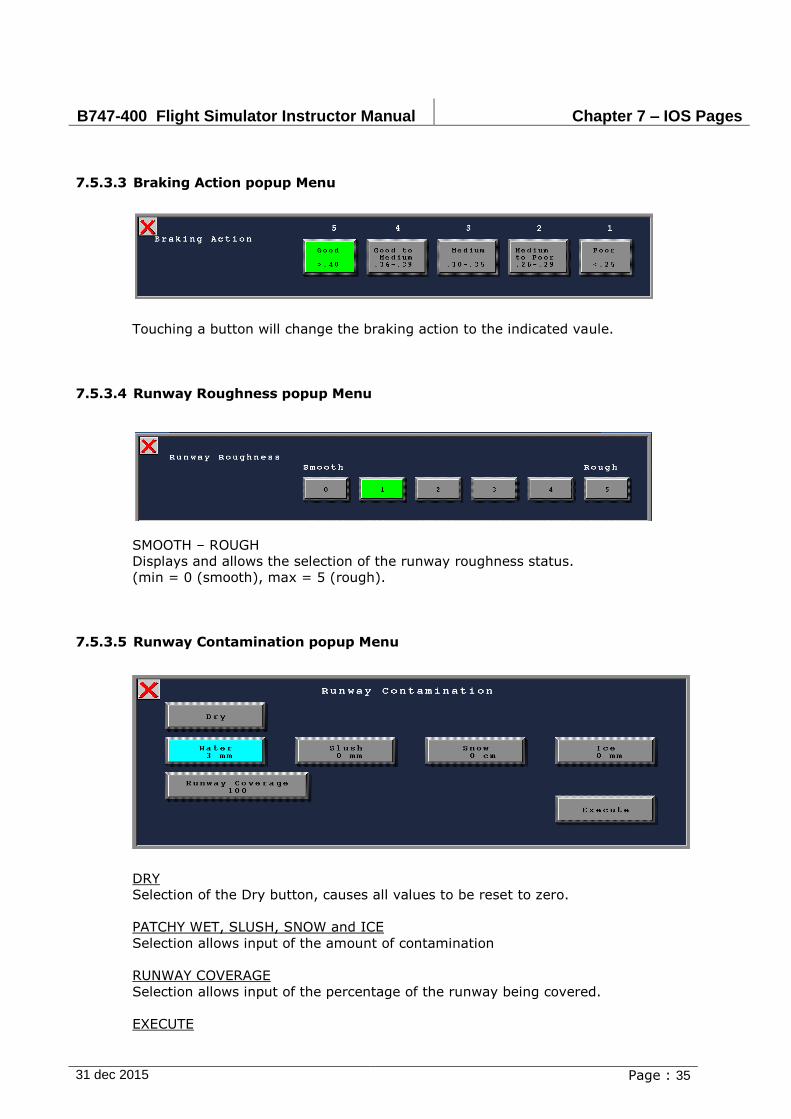
B747-400 Flight Simulator Instructor Manual Chapter 7 – IOS Pages
31 dec 2015 Page : 35
7.5.3.3 Braking Action popup Menu
Touching a button will change the braking action to the indicated vaule.
7.5.3.4 Runway Roughness popup Menu
SMOOTH – ROUGH
Displays and allows the selection of the runway roughness status.
(min = 0 (smooth), max = 5 (rough).
7.5.3.5 Runway Contamination popup Menu
DRY
Selection of the Dry button, causes all values to be reset to zero.
PATCHY WET, SLUSH, SNOW and ICE
Selection allows input of the amount of contamination
RUNWAY COVERAGE
Selection allows input of the percentage of the runway being covered.
EXECUTE

B747-400 Flight Simulator Instructor Manual Chapter 7 – IOS Pages
31 dec 2015 Page : 36
Selection executes the armed runway contamination. If possible, the changes will be
reflected by the visual.
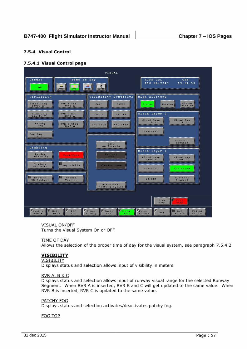
B747-400 Flight Simulator Instructor Manual Chapter 7 – IOS Pages
31 dec 2015 Page : 37
7.5.4 Visual Control
7.5.4.1 Visual Control page
VISUAL ON/OFF
Turns the Visual System On or OFF
TIME OF DAY
Allows the selection of the proper time of day for the visual system, see paragraph 7.5.4.2
VISIBILITY
VISIBILITY
Displays status and selection allows input of visibility in meters.
RVR A, B & C
Displays status and selection allows input of runway visual range for the selected Runway
Segment. When RVR A is inserted, RVR B and C will get updated to the same value. When
RVR B is inserted, RVR C is updated to the same value.
PATCHY FOG
Displays status and selection activates/deactivates patchy fog.
FOG TOP
B747-400 Flight Simulator Instructor Manual Chapter 7 – IOS Pages
31 dec 2015 Page : 38
Displays status and selection allows input of fog top in feet (min = 0, max = 9000). Fog
top defaults to 1000 ft, when a RVR greater than 0m. is entered
SCUDDED CLOUDS
Changes the type of clouds to "Scudded"
CLOUDS (2 layers)
CLOUD BASE 1
Displays status and selection allows input of lower layer of cloud base level in feet
CLOUD TOPS 1
Displays status and selection allows input of lower layer of cloud top level in feet.
CLOUD BASE 2
Displays status and selection allows input of lower layer of cloud base level in feet
CLOUD TOPS 2
Displays status and selection allows input of lower layer of cloud top level in feet.
RAIN
Enables raining conditions for visual.
LIGHTNING
If applicable
LIGHTING
STROBE/REIL, PAPI/VASI, RANDOM INTENSITY, CENTER LN LIGHTS,TAXI LIGHTS &
DOCKING DIRECTOR
Displays status and selection activates/deactivates the appropriate lighting source(s).
VISIBILITY CONDITIONS
Only one of the following weather conditions can be activated at the time: CAVOK, CAT I,
CAT II, CAT III
CAVOK
Displays status and selection activates CAVOK conditions on the visual display. CAVOK is
defined as follows:
Visibility = maximum
RVR = maximum
Ceiling = maximum
Cloud Top = maximum
CAT I, CAT II & CAT III
Displays status and selection activates CAT III conditions on the visual display.
SNOW ON TERRAIN
Displays status and selection of a snow covered scene. If a snow model is available of the
current visual model, visual will become dark momentarily and the scenery will change.
GROUND TRAFFIC
Displays the Ground Traffic popup menu, see paragraph 7.5.4.3
GENERIC DATABASE CTL
Displays the Generic Database Control popup menu, see paragraph 7.5.4.4

B747-400 Flight Simulator Instructor Manual Chapter 7 – IOS Pages
31 dec 2015 Page : 39
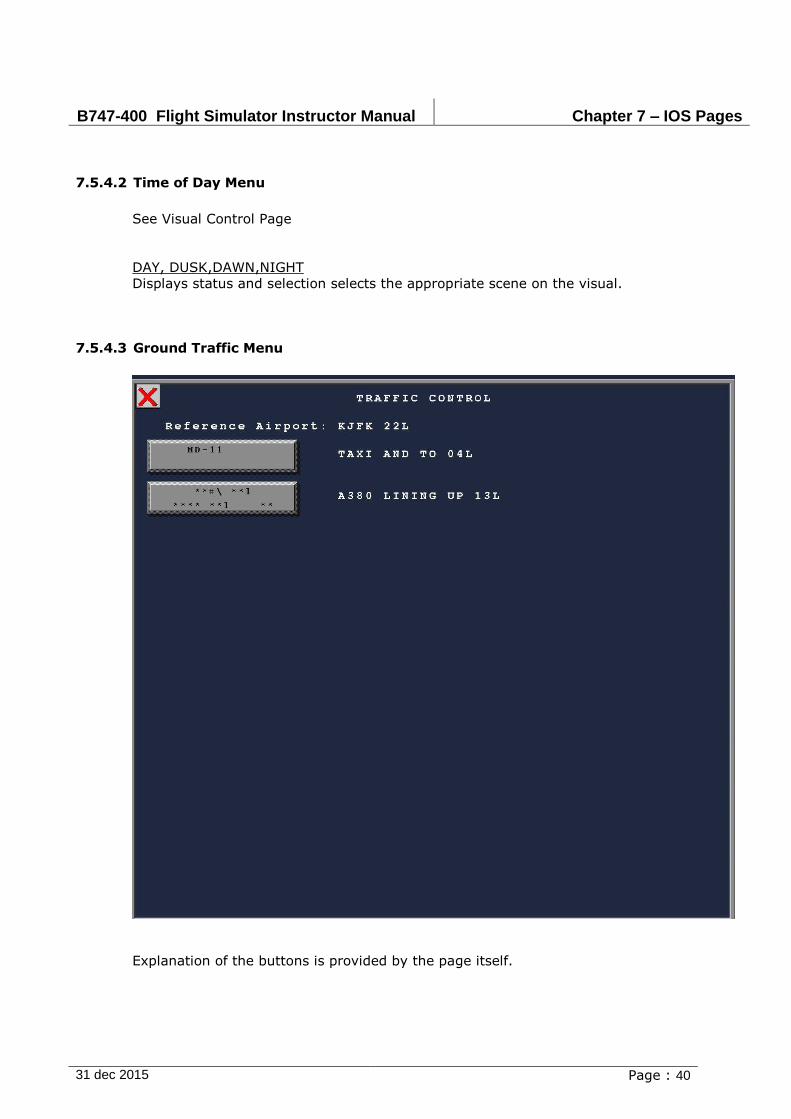
B747-400 Flight Simulator Instructor Manual Chapter 7 – IOS Pages
31 dec 2015 Page : 40
7.5.4.2 Time of Day Menu
See Visual Control Page
DAY, DUSK,DAWN,NIGHT
Displays status and selection selects the appropriate scene on the visual.
7.5.4.3 Ground Traffic Menu
Explanation of the buttons is provided by the page itself.
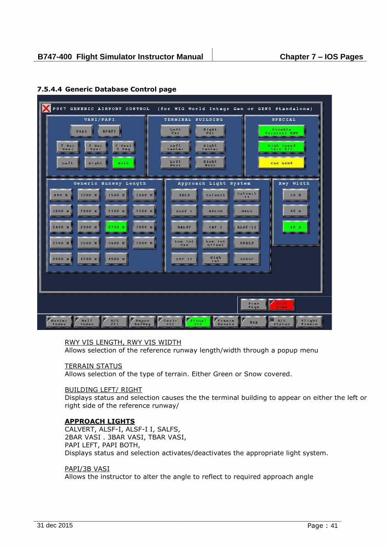
B747-400 Flight Simulator Instructor Manual Chapter 7 – IOS Pages
31 dec 2015 Page : 41
7.5.4.4 Generic Database Control page
RWY VIS LENGTH, RWY VIS WIDTH
Allows selection of the reference runway length/width through a popup menu
TERRAIN STATUS
Allows selection of the type of terrain. Either Green or Snow covered.
BUILDING LEFT/ RIGHT
Displays status and selection causes the the terminal building to appear on either the left or
right side of the reference runway/
APPROACH LIGHTS
CALVERT, ALSF-I, ALSF-I I, SALFS,
2BAR VASI . 3BAR VASI, TBAR VASI,
PAPI LEFT, PAPI BOTH,
Displays status and selection activates/deactivates the appropriate light system.
PAPI/3B VASI
Allows the instructor to alter the angle to reflect to required approach angle
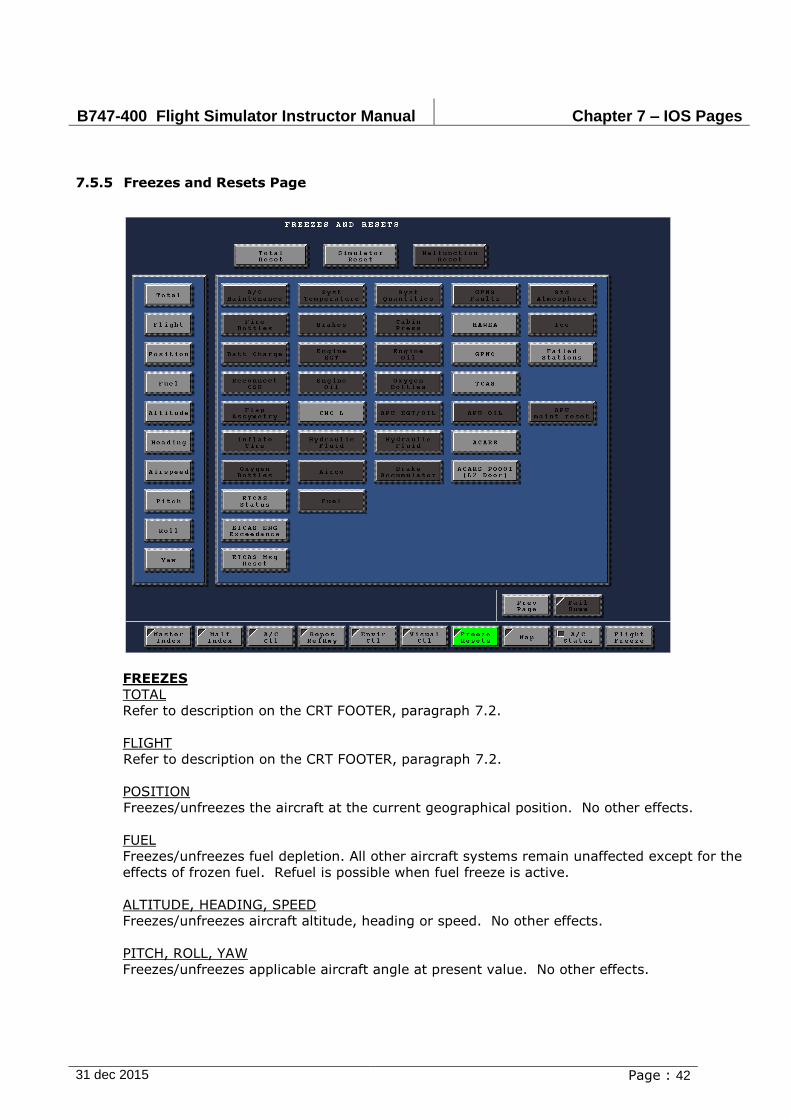
B747-400 Flight Simulator Instructor Manual Chapter 7 – IOS Pages
31 dec 2015 Page : 42
7.5.5 Freezes and Resets Page
FREEZES
TOTAL
Refer to description on the CRT FOOTER, paragraph 7.2.
FLIGHT
Refer to description on the CRT FOOTER, paragraph 7.2.
POSITION
Freezes/unfreezes the aircraft at the current geographical position. No other effects.
FUEL
Freezes/unfreezes fuel depletion. All other aircraft systems remain unaffected except for the
effects of frozen fuel. Refuel is possible when fuel freeze is active.
ALTITUDE, HEADING, SPEED
Freezes/unfreezes aircraft altitude, heading or speed. No other effects.
PITCH, ROLL, YAW
Freezes/unfreezes applicable aircraft angle at present value. No other effects.
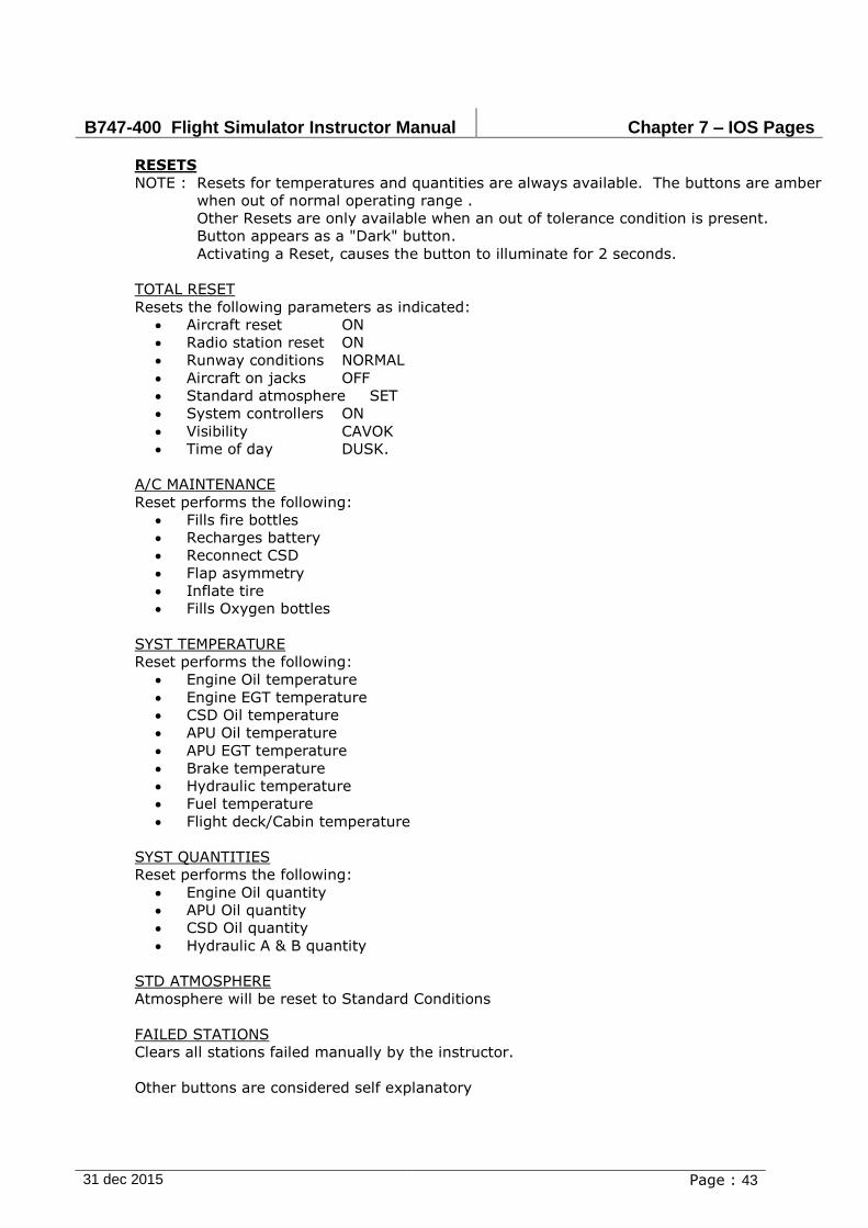
B747-400 Flight Simulator Instructor Manual Chapter 7 – IOS Pages
31 dec 2015 Page : 43
RESETS
NOTE : Resets for temperatures and quantities are always available. The buttons are amber
when out of normal operating range .
Other Resets are only available when an out of tolerance condition is present.
Button appears as a "Dark" button.
Activating a Reset, causes the button to illuminate for 2 seconds.
TOTAL RESET
Resets the following parameters as indicated:
Aircraft reset ON
Radio station reset ON
Runway conditions NORMAL
Aircraft on jacks OFF
Standard atmosphere SET
System controllers ON
Visibility CAVOK
Time of day DUSK.
A/C MAINTENANCE
Reset performs the following:
Fills fire bottles
Recharges battery
Reconnect CSD
Flap asymmetry
Inflate tire
Fills Oxygen bottles
SYST TEMPERATURE
Reset performs the following:
Engine Oil temperature
Engine EGT temperature
CSD Oil temperature
APU Oil temperature
APU EGT temperature
Brake temperature
Hydraulic temperature
Fuel temperature
Flight deck/Cabin temperature
SYST QUANTITIES
Reset performs the following:
Engine Oil quantity
APU Oil quantity
CSD Oil quantity
Hydraulic A & B quantity
STD ATMOSPHERE
Atmosphere will be reset to Standard Conditions
FAILED STATIONS
Clears all stations failed manually by the instructor.
Other buttons are considered self explanatory
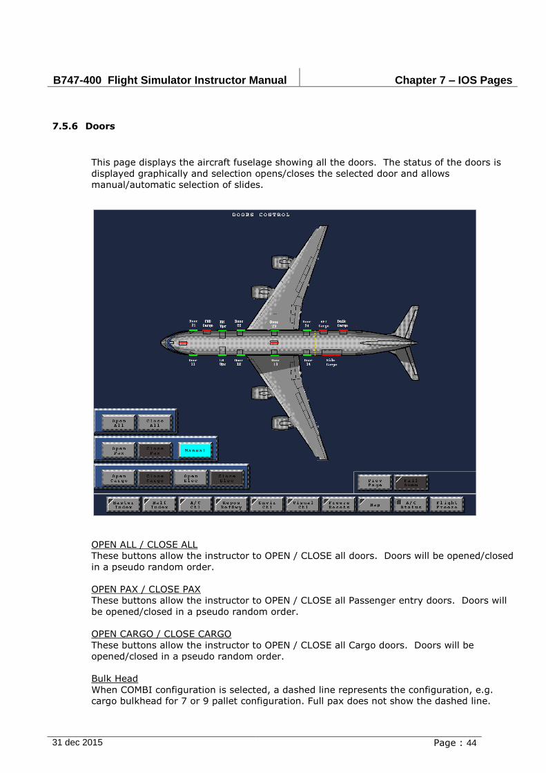
B747-400 Flight Simulator Instructor Manual Chapter 7 – IOS Pages
31 dec 2015 Page : 44
7.5.6 Doors
This page displays the aircraft fuselage showing all the doors. The status of the doors is
displayed graphically and selection opens/closes the selected door and allows
manual/automatic selection of slides.
OPEN ALL / CLOSE ALL
These buttons allow the instructor to OPEN / CLOSE all doors. Doors will be opened/closed
in a pseudo random order.
OPEN PAX / CLOSE PAX
These buttons allow the instructor to OPEN / CLOSE all Passenger entry doors. Doors will
be opened/closed in a pseudo random order.
OPEN CARGO / CLOSE CARGO
These buttons allow the instructor to OPEN / CLOSE all Cargo doors. Doors will be
opened/closed in a pseudo random order.
Bulk Head
When COMBI configuration is selected, a dashed line represents the configuration, e.g.
cargo bulkhead for 7 or 9 pallet configuration. Full pax does not show the dashed line.

B747-400 Flight Simulator Instructor Manual Chapter 7 – IOS Pages
31 dec 2015 Page : 45
7.5.7 Simulator Control
DATA DUMPER DUMP
Generates a Data Dump of the A/C conditions to hard disk, to be used by Engineering for
debugging failure conditions. The dump number reflects the revision number of the dump file
made.
PLOT DEVICE
BLACK/WHITE
Disables color hardcopies of the display. All hardcopies will be in gray tones.
COLOUR
Enables the printer to make a color hardcopy of the display.
IOS MISC
PCU ON/OFF
Initializes the PCU. The PCU is normally not connected, so the communication with the
simulator will be (re)established.
CONFIGURATION
Several options are available. Mode changes are only possible on ground, with engines not
running. Customer options, include the setting of proper FMS options.
HARD LANDING OVERRIDE

B747-400 Flight Simulator Instructor Manual Chapter 7 – IOS Pages
31 dec 2015 Page : 46
Puts the motion system in a 'Reduced' queing mode. Motion bumps will be less pronounced,
as if a smooth landing was performed.
7.5.8 DELETED
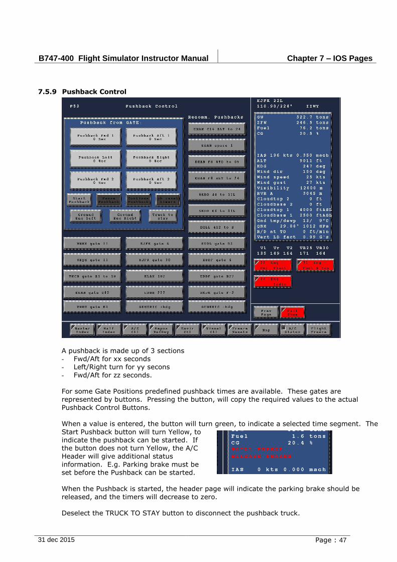
B747-400 Flight Simulator Instructor Manual Chapter 7 – IOS Pages
31 dec 2015 Page : 47
7.5.9 Pushback Control
A pushback is made up of 3 sections
- Fwd/Aft for xx seconds
- Left/Right turn for yy secons
- Fwd/Aft for zz seconds.
For some Gate Positions predefined pushback times are available. These gates are
represented by buttons. Pressing the button, will copy the required values to the actual
Pushback Control Buttons.
When a value is entered, the button will turn green, to indicate a selected time segment. The
Start Pushback button will turn Yellow, to
indicate the pushback can be started. If
the button does not turn Yellow, the A/C
Header will give additional status
information. E.g. Parking brake must be
set before the Pushback can be started.
When the Pushback is started, the header page will indicate the parking brake should be
released, and the timers will decrease to zero.
Deselect the TRUCK TO STAY button to disconnect the pushback truck.
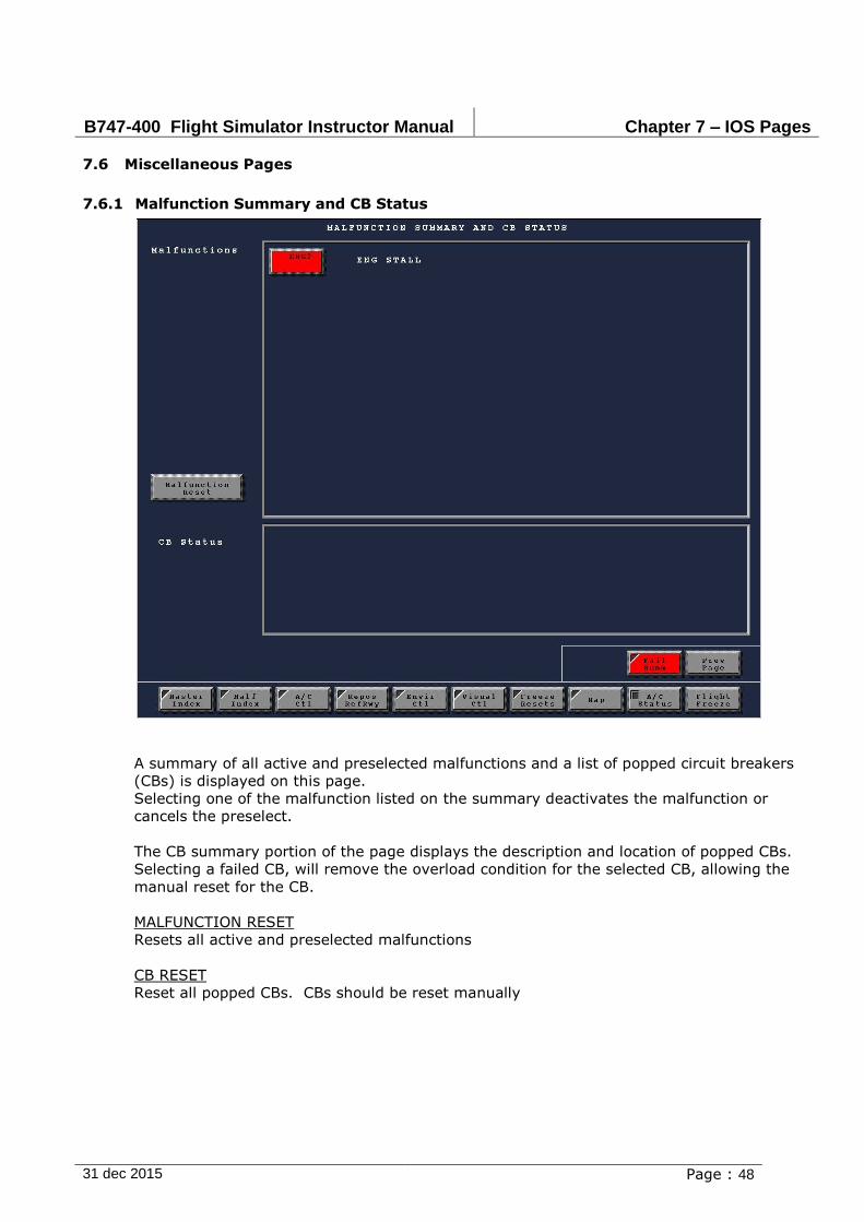
B747-400 Flight Simulator Instructor Manual Chapter 7 – IOS Pages
31 dec 2015 Page : 48
7.6 Miscellaneous Pages
7.6.1 Malfunction Summary and CB Status
A summary of all active and preselected malfunctions and a list of popped circuit breakers
(CBs) is displayed on this page.
Selecting one of the malfunction listed on the summary deactivates the malfunction or
cancels the preselect.
The CB summary portion of the page displays the description and location of popped CBs.
Selecting a failed CB, will remove the overload condition for the selected CB, allowing the
manual reset for the CB.
MALFUNCTION RESET
Resets all active and preselected malfunctions
CB RESET
Reset all popped CBs. CBs should be reset manually
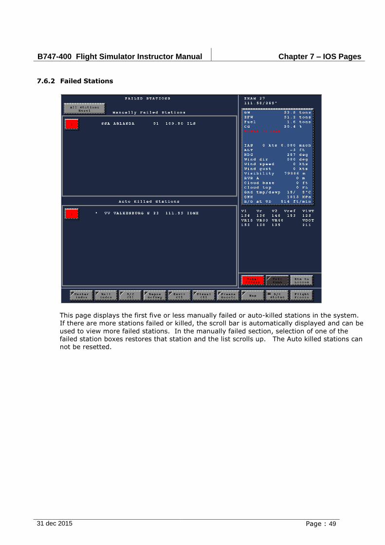
B747-400 Flight Simulator Instructor Manual Chapter 7 – IOS Pages
31 dec 2015 Page : 49
7.6.2 Failed Stations
This page displays the first five or less manually failed or auto-killed stations in the system.
If there are more stations failed or killed, the scroll bar is automatically displayed and can be
used to view more failed stations. In the manually failed section, selection of one of the
failed station boxes restores that station and the list scrolls up. The Auto killed stations can
not be resetted.
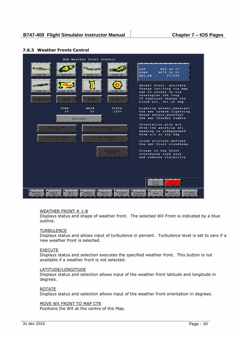
B747-400 Flight Simulator Instructor Manual Chapter 7 – IOS Pages
31 dec 2015 Page : 50
7.6.3 Weather Fronts Control
WEATHER FRONT # 1-8
Displays status and shape of weather front. The selected WX Front is indicated by a blue
outline.
TURBULENCE
Displays status and allows input of turbulence in percent. Turbulence level is set to zero if a
new weather front is selected.
EXECUTE
Displays status and selection executes the specified weather front. This button is not
available if a weather front is not selected.
LATITUDE/LONGITUDE
Displays status and selection allows input of the weather front latitude and longitude in
degrees.
ROTATE
Displays status and selection allows input of the weather front orientation in degrees.
MOVE WX FRONT TO MAP CTR
Positions the WX at the centre of the Map.

B747-400 Flight Simulator Instructor Manual Chapter 7 – IOS Pages
31 dec 2015 Page : 51

B747-400 Flight Simulator Instructor Manual Chapter 7 – IOS Pages
31 dec 2015 Page : 52
MOVE WITH WIND
Enables/disables the effects of the surface wind on the movement of the weather front
selected.
T-STORM SOUND
Displays status and selection activates/deactivates thunderstorm sound.
LIGHTNING
Displays status and selection activates/deactivates lightning simulation (visual and sound
effects).
LIGHTNING STRIKE
Selection activates flashlight and sound of lightning strike will occur once.
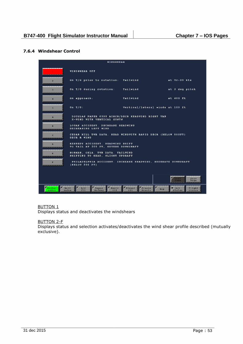
B747-400 Flight Simulator Instructor Manual Chapter 7 – IOS Pages
31 dec 2015 Page : 53
7.6.4 Windshear Control
BUTTON 1
Displays status and deactivates the windshears
BUTTON 2-F
Displays status and selection activates/deactivates the wind shear profile described (mutually
exclusive).
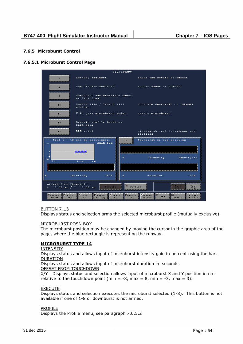
B747-400 Flight Simulator Instructor Manual Chapter 7 – IOS Pages
31 dec 2015 Page : 54
7.6.5 Microburst Control
7.6.5.1 Microburst Control Page
BUTTON 7-13
Displays status and selection arms the selected microburst profile (mutually exclusive).
MICROBURST POSN BOX
The microburst position may be changed by moving the cursor in the graphic area of the
page, where the blue rectangle is representing the runway.
MICROBURST TYPE 14
INTENSITY
Displays status and allows input of microburst intensity gain in percent using the bar.
DURATION
Displays status and allows input of microburst duration in seconds.
OFFSET FROM TOUCHDOWN
X/Y Displays status and selection allows input of microburst X and Y position in nmi
relative to the touchdown point (min = -8, max = 8, min = -3, max = 3).
EXECUTE
Displays status and selection executes the microburst selected (1-8). This button is not
available if one of 1-8 or downburst is not armed.
PROFILE
Displays the Profile menu, see paragraph 7.6.5.2
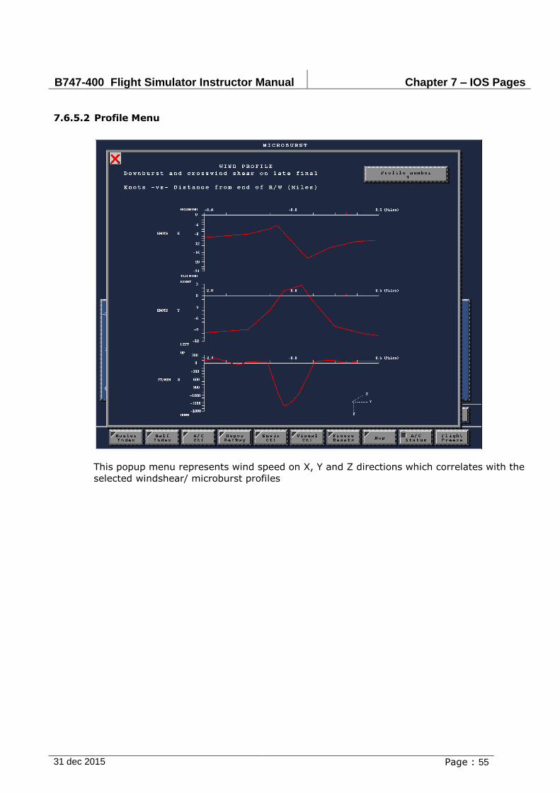
B747-400 Flight Simulator Instructor Manual Chapter 7 – IOS Pages
31 dec 2015 Page : 55
7.6.5.2 Profile Menu
This popup menu represents wind speed on X, Y and Z directions which correlates with the
selected windshear/ microburst profiles
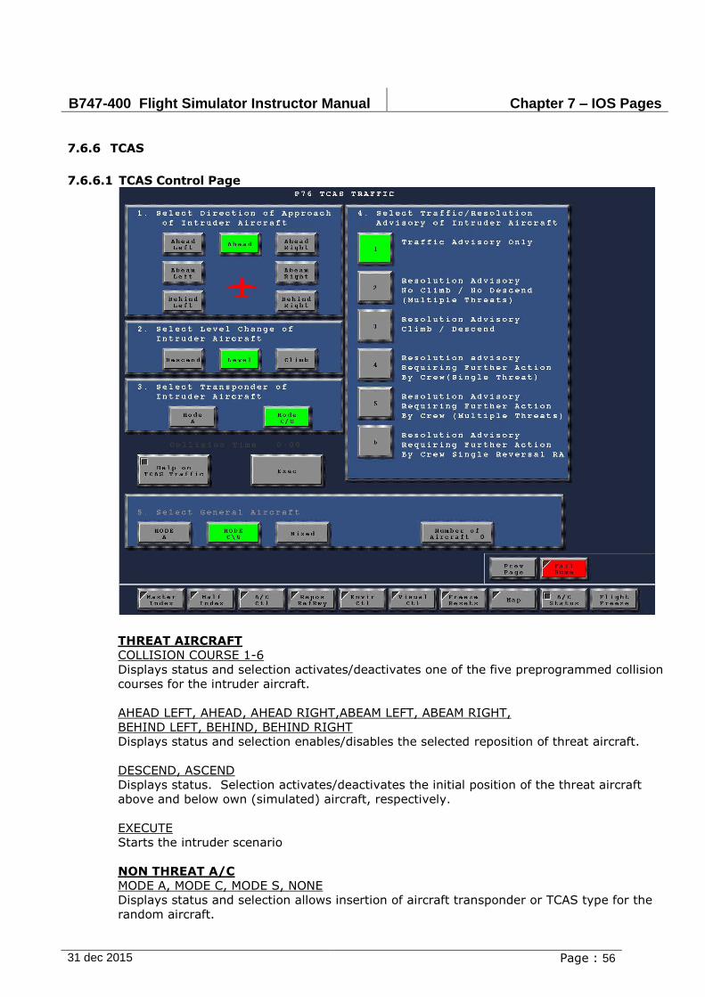
B747-400 Flight Simulator Instructor Manual Chapter 7 – IOS Pages
31 dec 2015 Page : 56
7.6.6 TCAS
7.6.6.1 TCAS Control Page
THREAT AIRCRAFT
COLLISION COURSE 1-6
Displays status and selection activates/deactivates one of the five preprogrammed collision
courses for the intruder aircraft.
AHEAD LEFT, AHEAD, AHEAD RIGHT,ABEAM LEFT, ABEAM RIGHT,
BEHIND LEFT, BEHIND, BEHIND RIGHT
Displays status and selection enables/disables the selected reposition of threat aircraft.
DESCEND, ASCEND
Displays status. Selection activates/deactivates the initial position of the threat aircraft
above and below own (simulated) aircraft, respectively.
EXECUTE
Starts the intruder scenario
NON THREAT A/C
MODE A, MODE C, MODE S, NONE
Displays status and selection allows insertion of aircraft transponder or TCAS type for the
random aircraft.
B747-400 Flight Simulator Instructor Manual Chapter 7 – IOS Pages
31 dec 2015 Page : 57
NUMBER OF AIRCRAFT
Allows input of the number of intruder aircraft.
DISPLAY TCAS ON MAP
Displays status and selection enables/disables the TCAS display on the map. All six aircraft
may be displayed on the map. The intruder aircraft is displayed in red.
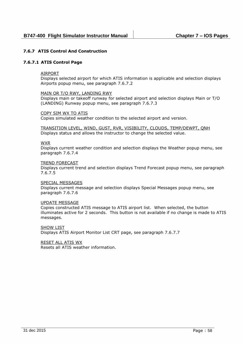
B747-400 Flight Simulator Instructor Manual Chapter 7 – IOS Pages
31 dec 2015 Page : 58
7.6.7 ATIS Control And Construction
7.6.7.1 ATIS Control Page
AIRPORT
Displays selected airport for which ATIS information is applicable and selection displays
Airports popup menu, see paragraph 7.6.7.2
MAIN OR T/O RWY, LANDING RWY
Displays main or takeoff runway for selected airport and selection displays Main or T/O
(LANDING) Runway popup menu, see paragraph 7.6.7.3
COPY SIM WX TO ATIS
Copies simulated weather condition to the selected airport and version.
TRANSITION LEVEL, WIND, GUST, RVR, VISIBILITY, CLOUDS, TEMP/DEWPT, QNH
Displays status and allows the instructor to change the selected value.
WXR
Displays current weather condition and selection displays the Weather popup menu, see
paragraph 7.6.7.4
TREND FORECAST
Displays current trend and selection displays Trend Forecast popup menu, see paragraph
7.6.7.5
SPECIAL MESSAGES
Displays current message and selection displays Special Messages popup menu, see
paragraph 7.6.7.6
UPDATE MESSAGE
Copies constructed ATIS message to ATIS airport list. When selected, the button
illuminates active for 2 seconds. This button is not available if no change is made to ATIS
messages.
SHOW LIST
Displays ATIS Airport Monitor List CRT page, see paragraph 7.6.7.7
RESET ALL ATIS WX
Resets all ATIS weather information.
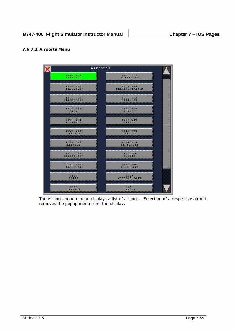
B747-400 Flight Simulator Instructor Manual Chapter 7 – IOS Pages
31 dec 2015 Page : 59
7.6.7.2 Airports Menu
The Airports popup menu displays a list of airports. Selection of a respective airport
removes the popup menu from the display.

B747-400 Flight Simulator Instructor Manual Chapter 7 – IOS Pages
31 dec 2015 Page : 60
7.6.7.3 Runway Menu
This popup menu displays runways available for a selected airport.
The Title of the menu depends on the request for a "Main or T/O runway" or a "Landing
runway" is required, the Selection of a respective runway selects that main or takeoff
runway and removes the popup menu from the display.
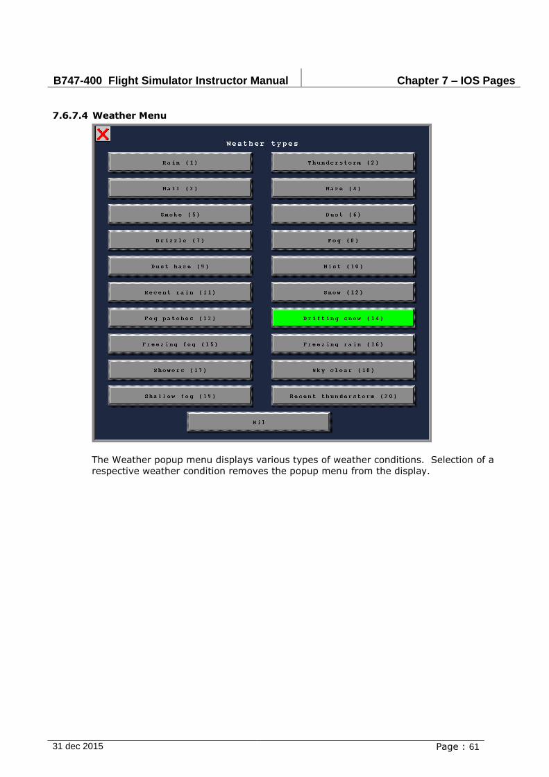
B747-400 Flight Simulator Instructor Manual Chapter 7 – IOS Pages
31 dec 2015 Page : 61
7.6.7.4 Weather Menu
The Weather popup menu displays various types of weather conditions. Selection of a
respective weather condition removes the popup menu from the display.
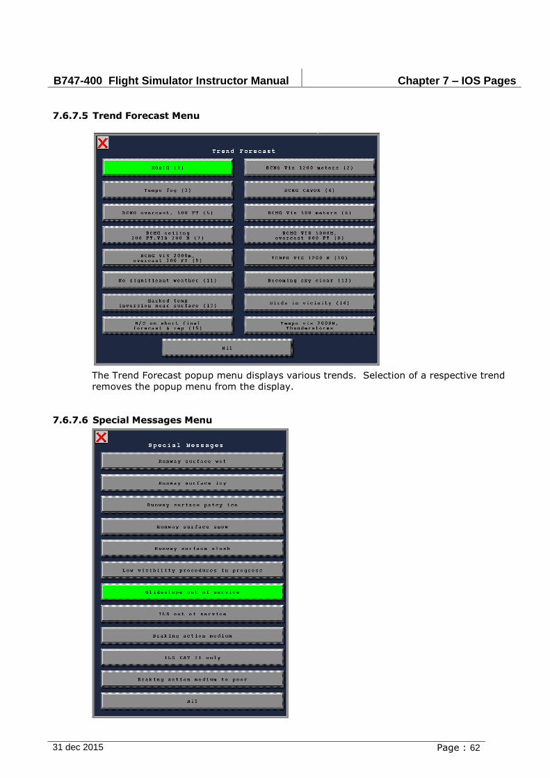
B747-400 Flight Simulator Instructor Manual Chapter 7 – IOS Pages
31 dec 2015 Page : 62
7.6.7.5 Trend Forecast Menu
The Trend Forecast popup menu displays various trends. Selection of a respective trend
removes the popup menu from the display.
7.6.7.6 Special Messages Menu
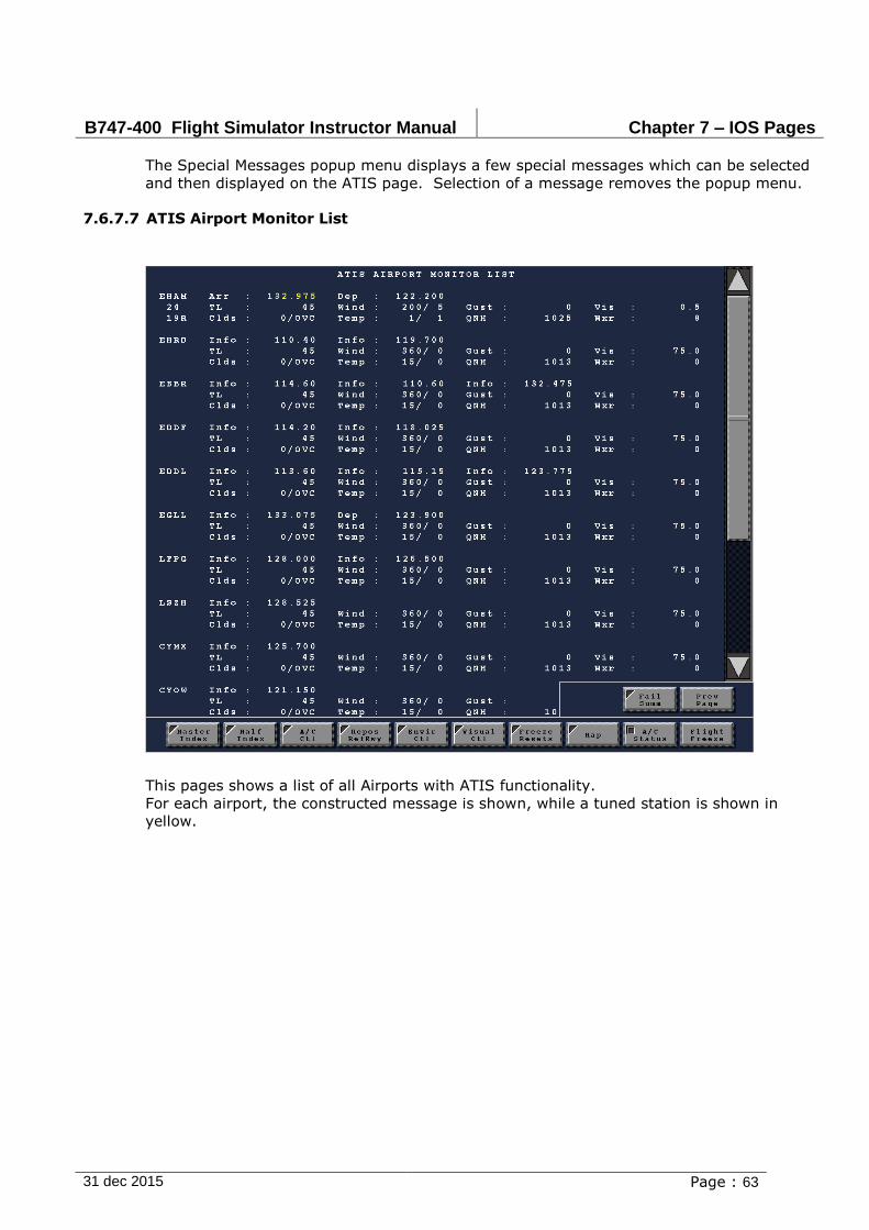
B747-400 Flight Simulator Instructor Manual Chapter 7 – IOS Pages
31 dec 2015 Page : 63
The Special Messages popup menu displays a few special messages which can be selected
and then displayed on the ATIS page. Selection of a message removes the popup menu.
7.6.7.7 ATIS Airport Monitor List
This pages shows a list of all Airports with ATIS functionality.
For each airport, the constructed message is shown, while a tuned station is shown in
yellow.
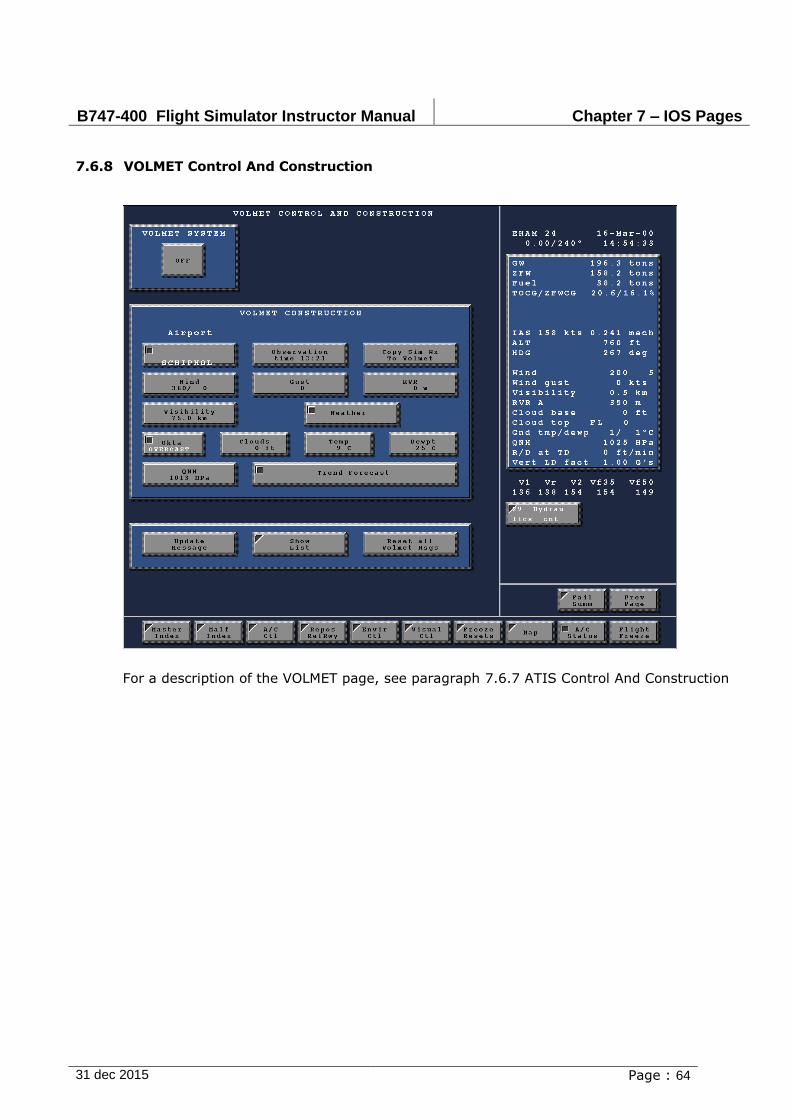
B747-400 Flight Simulator Instructor Manual Chapter 7 – IOS Pages
31 dec 2015 Page : 64
7.6.8 VOLMET Control And Construction
For a description of the VOLMET page, see paragraph 7.6.7 ATIS Control And Construction
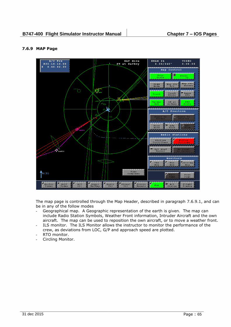
B747-400 Flight Simulator Instructor Manual Chapter 7 – IOS Pages
31 dec 2015 Page : 65
7.6.9 MAP Page
The map page is controlled through the Map Header, described in paragraph 7.6.9.1, and can
be in any of the follow modes
- Geographical map. A Geographic representation of the earth is given. The map can
include Radio Station Symbols, Weather Front information, Intruder Aircraft and the own
aircraft. The map can be used to reposition the own aircraft, or to move a weather front.
- ILS monitor. The ILS Monitor allows the instructor to monitor the performance of the
crew, as deviations from LOC, G/P and approach speed are plotted.
- RTO monitor.
- Circling Monitor.
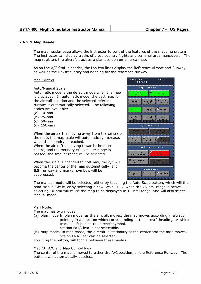
B747-400 Flight Simulator Instructor Manual Chapter 7 – IOS Pages
31 dec 2015 Page : 66
7.6.9.1 Map Header
The map header page allows the instructor to control the features of the mapping system.
The instructor can display tracks of cross country flights and terminal area maneuvers. The
map registers the aircraft track as a plan position on an area map.
As on the A/C Status header, the top two lines display the Reference Airport and Runway,
as well as the ILS frequency and heading for the reference runway.
Map Control
Auto/Manual Scale
Automatic mode is the default mode when the map
is displayed. In automatic mode, the best map for
the aircraft position and the selected reference
runway is automatically selected. The following
scales are available:
(a) 10-nmi
(b) 25-nmi
(c) 50-nmi
(d) 150-nmi
When the aircraft is moving away from the centre of
the map, the map scale will automaticaly increase,
when the boundry is reached.
When the aircraft is moving towards the map
centre, and the boundry of a smaller range is
passed, the smaller range will be selected.
When the scale is changed to 150-nmi, the a/c will
become the center of the map automatically, and
ILS, runway and marker symbols will be
suppressed.
The manual mode will be selected, either by touching the Auto Scale button, which will then
read Manual Scale, or by selecting a new Scale. E.G. when the 25-nmi range is active,
selecting 10-nmi will cause the map to be displayed in 10-nmi range, and will also select
Manual mode.
Plan Mode.
The map has two modes:
(a) plan mode In plan mode, as the aircraft moves, the map moves accordingly, always
pointing in a direction which corresponding to the aircraft heading. A white
track is left behind the aircraft symbol.
Station Fail/Clear is not selectable.
(b) map mode. In map mode, the aircraft is stationary at the center and the map moves.
Staion Fail/Clear can be selected.
Touching the button, will toggle between these modes.
Map Ctr A/C and Map Ctr Ref Rwy
The center of the map is moved to either the A/C position, or the Reference Runway. The
buttons will automatically deselect.
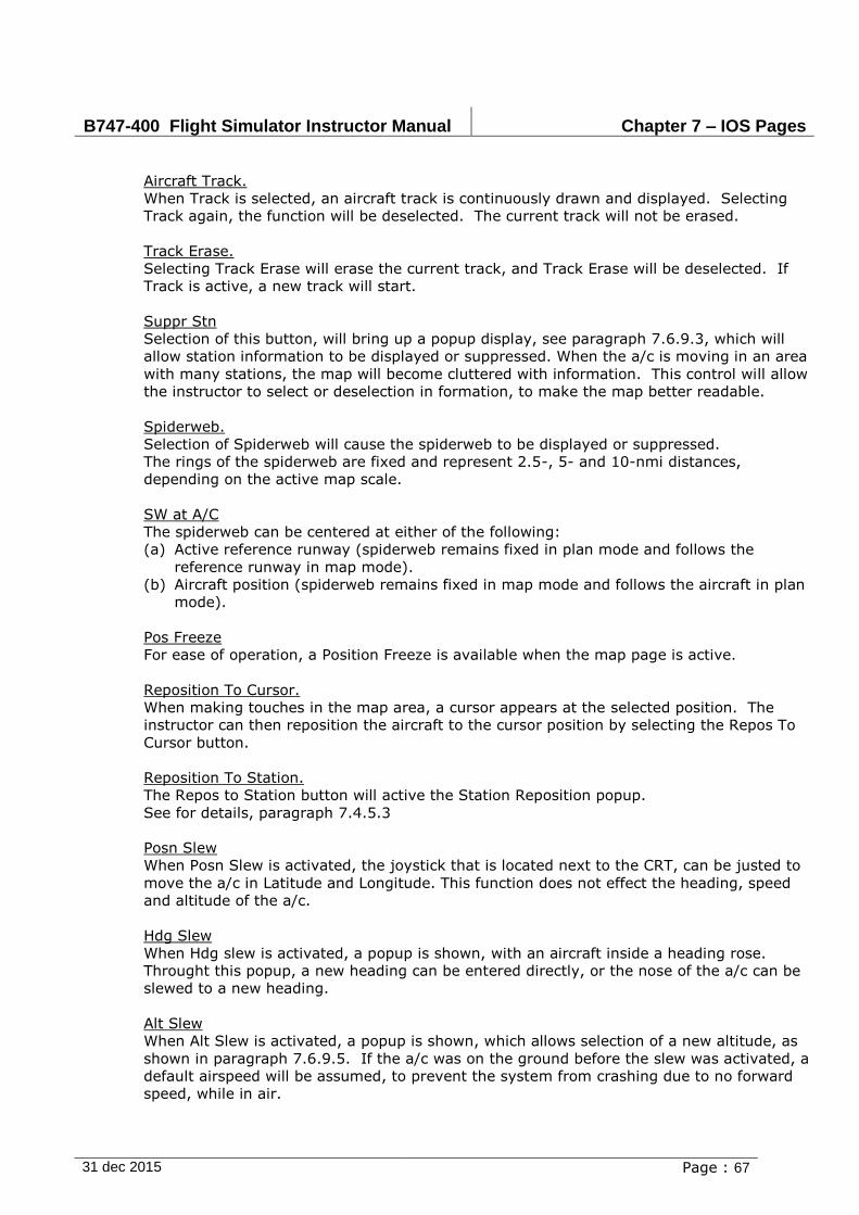
B747-400 Flight Simulator Instructor Manual Chapter 7 – IOS Pages
31 dec 2015 Page : 67
Aircraft Track.
When Track is selected, an aircraft track is continuously drawn and displayed. Selecting
Track again, the function will be deselected. The current track will not be erased.
Track Erase.
Selecting Track Erase will erase the current track, and Track Erase will be deselected. If
Track is active, a new track will start.
Suppr Stn
Selection of this button, will bring up a popup display, see paragraph 7.6.9.3, which will
allow station information to be displayed or suppressed. When the a/c is moving in an area
with many stations, the map will become cluttered with information. This control will allow
the instructor to select or deselection in formation, to make the map better readable.
Spiderweb.
Selection of Spiderweb will cause the spiderweb to be displayed or suppressed.
The rings of the spiderweb are fixed and represent 2.5-, 5- and 10-nmi distances,
depending on the active map scale.
SW at A/C
The spiderweb can be centered at either of the following:
(a) Active reference runway (spiderweb remains fixed in plan mode and follows the
reference runway in map mode).
(b) Aircraft position (spiderweb remains fixed in map mode and follows the aircraft in plan
mode).
Pos Freeze
For ease of operation, a Position Freeze is available when the map page is active.
Reposition To Cursor.
When making touches in the map area, a cursor appears at the selected position. The
instructor can then reposition the aircraft to the cursor position by selecting the Repos To
Cursor button.
Reposition To Station.
The Repos to Station button will active the Station Reposition popup.
See for details, paragraph 7.4.5.3
Posn Slew
When Posn Slew is activated, the joystick that is located next to the CRT, can be justed to
move the a/c in Latitude and Longitude. This function does not effect the heading, speed
and altitude of the a/c.
Hdg Slew
When Hdg slew is activated, a popup is shown, with an aircraft inside a heading rose.
Throught this popup, a new heading can be entered directly, or the nose of the a/c can be
slewed to a new heading.
Alt Slew
When Alt Slew is activated, a popup is shown, which allows selection of a new altitude, as
shown in paragraph 7.6.9.5. If the a/c was on the ground before the slew was activated, a
default airspeed will be assumed, to prevent the system from crashing due to no forward
speed, while in air.

B747-400 Flight Simulator Instructor Manual Chapter 7 – IOS Pages
31 dec 2015 Page : 68
7.6.9.2 STATION FAIL/CLEAR.
Selection of Station Fail/Clear button on the map page, will change the header page and will
show a red square on the map. Touching the map will move the red square to the required
station and will show the station in the small window.
Position slew on the header can be used for position fine tuning. Zoom in-out capability can
be used to differentiate between stations close to each other. When the zoom is active it will
show an inner red box on the map. The selected facilities of the station can be failed or
reactivated by use of the respective buttons followed by the execute button. The failed
stations are shown in red on the map, the small window however does not show any status
change of a failed station.
Restrictions:
The map must be in map mode, in plan mode selection of station fail/clear is not
possible.
Changing map scale due to aircraft position change -with auto scale active- will result
in scale difference and position control loss. In this case restart the station kill process
and reselect via the map the Station Fail/Clear button.

B747-400 Flight Simulator Instructor Manual Chapter 7 – IOS Pages
31 dec 2015 Page : 69
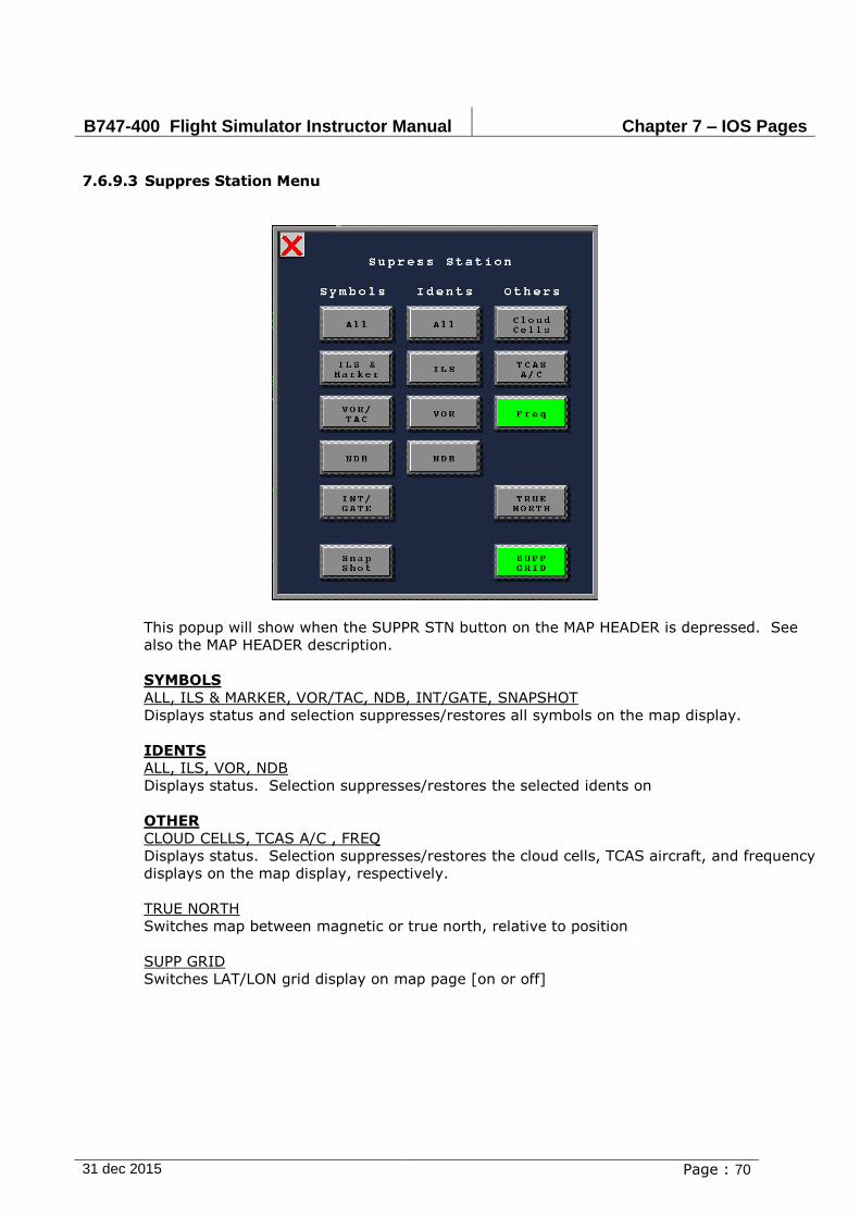
B747-400 Flight Simulator Instructor Manual Chapter 7 – IOS Pages
31 dec 2015 Page : 70
7.6.9.3 Suppres Station Menu
This popup will show when the SUPPR STN button on the MAP HEADER is depressed. See
also the MAP HEADER description.
SYMBOLS
ALL, ILS & MARKER, VOR/TAC, NDB, INT/GATE, SNAPSHOT
Displays status and selection suppresses/restores all symbols on the map display.
IDENTS
ALL, ILS, VOR, NDB
Displays status. Selection suppresses/restores the selected idents on
OTHER
CLOUD CELLS, TCAS A/C , FREQ
Displays status. Selection suppresses/restores the cloud cells, TCAS aircraft, and frequency
displays on the map display, respectively.
TRUE NORTH
Switches map between magnetic or true north, relative to position
SUPP GRID
Switches LAT/LON grid display on map page [on or off]

B747-400 Flight Simulator Instructor Manual Chapter 7 – IOS Pages
31 dec 2015 Page : 71
7.6.9.4 Repos to Station Menu
STATION
Displays the station selected via MAP/TMA page. The station can be selected before or after
REPOS TO STATION button. If no station is entered, the present latitude and longitude are
maintained.
ALTITUDE
Displays status. Selection allows input of aircraft altitude in feet (min= VHG, max=
45,000). If no value is entered:
(a) With aircraft in air - present altitude is maintained
(b) With aircraft on ground and engines running ( 1) - altitude = 10,000 ft.
(c) With aircraft on ground and no engines running - aircraft remains on the ground.
AIRSPEED
Displays status. Selection allows input of aircraft indicated airspeed in knots. If no value is
entered:
(a) With aircraft in air - present value is maintained
(b) With aircraft on ground and engines running ( 1): 250 knots
(c) With aircraft on ground and no engines running: 0 knots (only latitude/longitude
change).
HEADING
Displays status. Selection allows input of aircraft heading in degrees. If no value is
entered, present value is maintained.
EXECUTE
Displays status. Selection activates repositioning with the selected values. If no values are
entered:
(a) With aircraft - present values are maintained
(b) With aircraft on ground and engines running ( 1): 10,000 feet, 250 knots, actual
heading
(c) With aircraft on ground and no engines running: actual values are maintained (only
latitude/longitude change).
Reposition ends with a trimmed aircraft in current configuration.
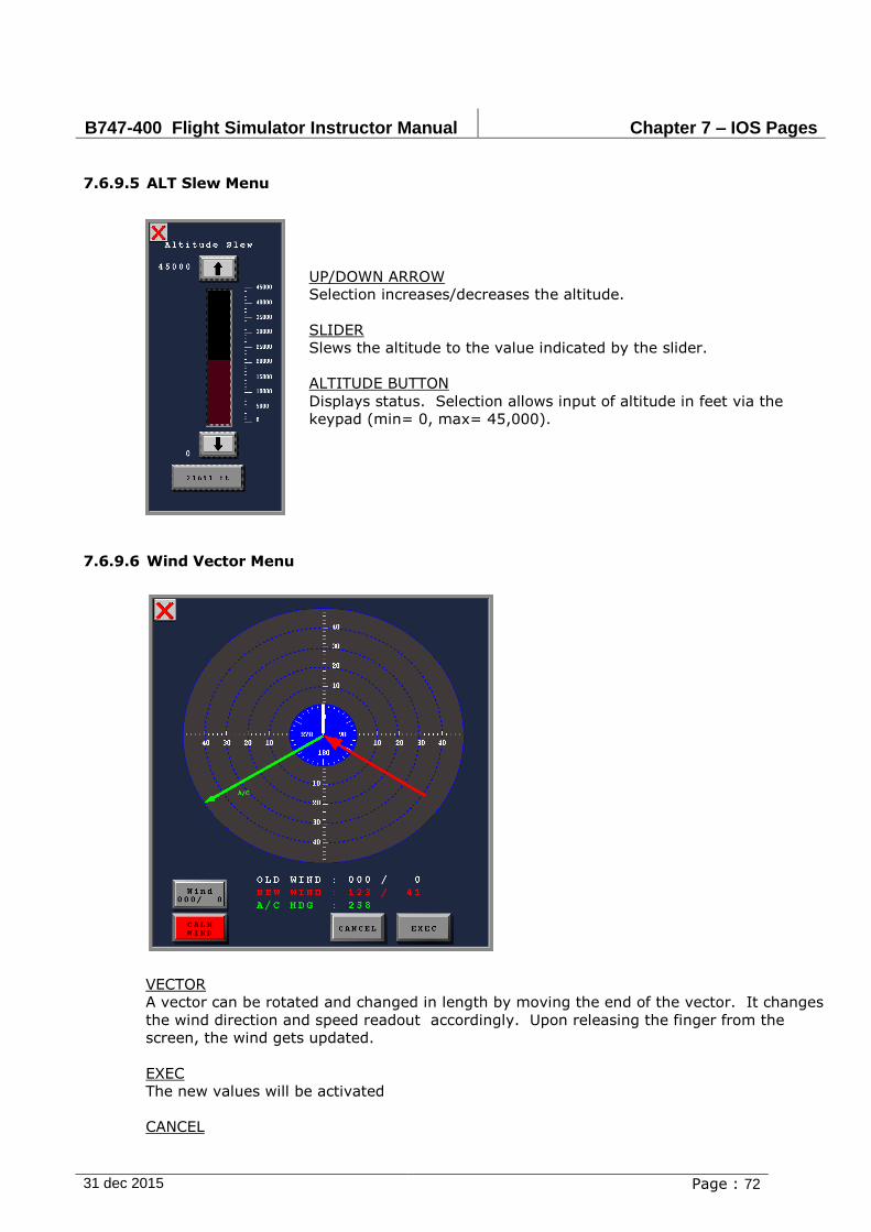
B747-400 Flight Simulator Instructor Manual Chapter 7 – IOS Pages
31 dec 2015 Page : 72
7.6.9.5 ALT Slew Menu
UP/DOWN ARROW
Selection increases/decreases the altitude.
SLIDER
Slews the altitude to the value indicated by the slider.
ALTITUDE BUTTON
Displays status. Selection allows input of altitude in feet via the
keypad (min= 0, max= 45,000).
7.6.9.6 Wind Vector Menu
VECTOR
A vector can be rotated and changed in length by moving the end of the vector. It changes
the wind direction and speed readout accordingly. Upon releasing the finger from the
screen, the wind gets updated.
EXEC
The new values will be activated
CANCEL
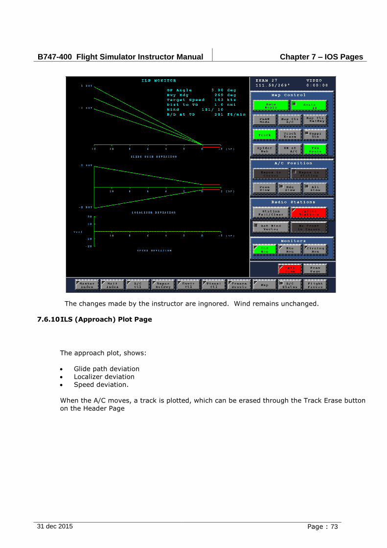
B747-400 Flight Simulator Instructor Manual Chapter 7 – IOS Pages
31 dec 2015 Page : 73
The changes made by the instructor are ingnored. Wind remains unchanged.
7.6.10 ILS (Approach) Plot Page
The approach plot, shows:
Glide path deviation
Localizer deviation
Speed deviation.
When the A/C moves, a track is plotted, which can be erased through the Track Erase button
on the Header Page
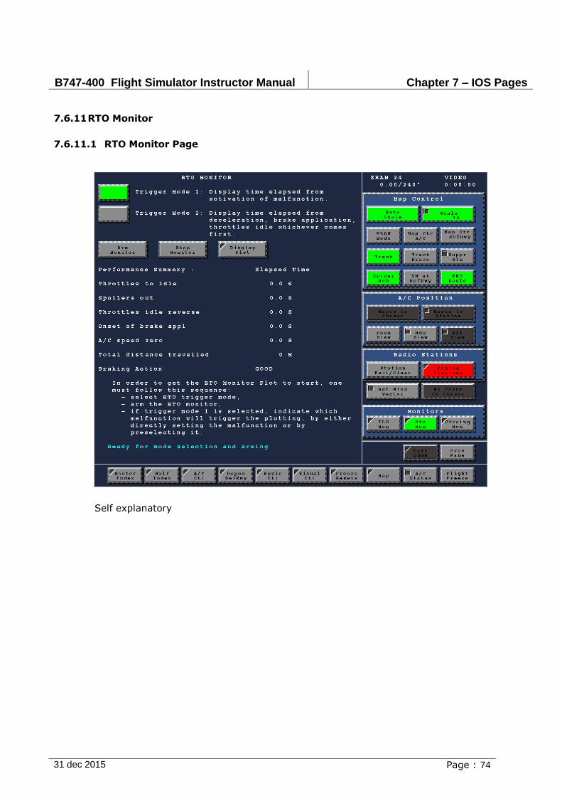
B747-400 Flight Simulator Instructor Manual Chapter 7 – IOS Pages
31 dec 2015 Page : 74
7.6.11 RTO Monitor
7.6.11.1 RTO Monitor Page
Self explanatory

B747-400 Flight Simulator Instructor Manual Chapter 7 – IOS Pages
31 dec 2015 Page : 75
7.6.11.2 RTO Monitor Plot
Self explanatory
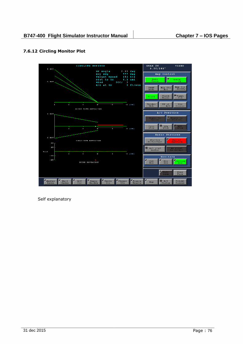
B747-400 Flight Simulator Instructor Manual Chapter 7 – IOS Pages
31 dec 2015 Page : 76
7.6.12 Circling Monitor Plot
Self explanatory
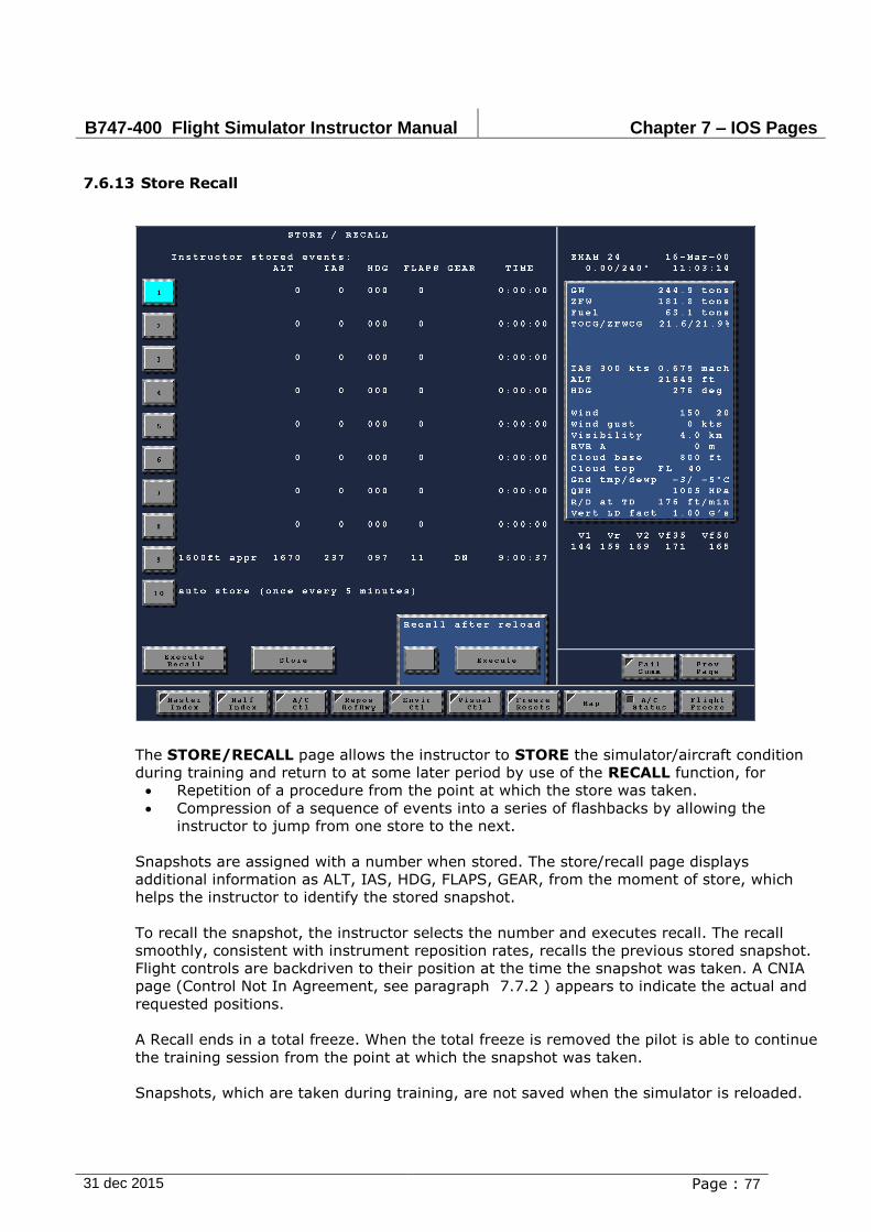
B747-400 Flight Simulator Instructor Manual Chapter 7 – IOS Pages
31 dec 2015 Page : 77
7.6.13 Store Recall
The STORE/RECALL page allows the instructor to STORE the simulator/aircraft condition
during training and return to at some later period by use of the RECALL function, for
Repetition of a procedure from the point at which the store was taken.
Compression of a sequence of events into a series of flashbacks by allowing the
instructor to jump from one store to the next.
Snapshots are assigned with a number when stored. The store/recall page displays
additional information as ALT, IAS, HDG, FLAPS, GEAR, from the moment of store, which
helps the instructor to identify the stored snapshot.
To recall the snapshot, the instructor selects the number and executes recall. The recall
smoothly, consistent with instrument reposition rates, recalls the previous stored snapshot.
Flight controls are backdriven to their position at the time the snapshot was taken. A CNIA
page (Control Not In Agreement, see paragraph 7.7.2 ) appears to indicate the actual and
requested positions.
A Recall ends in a total freeze. When the total freeze is removed the pilot is able to continue
the training session from the point at which the snapshot was taken.
Snapshots, which are taken during training, are not saved when the simulator is reloaded.
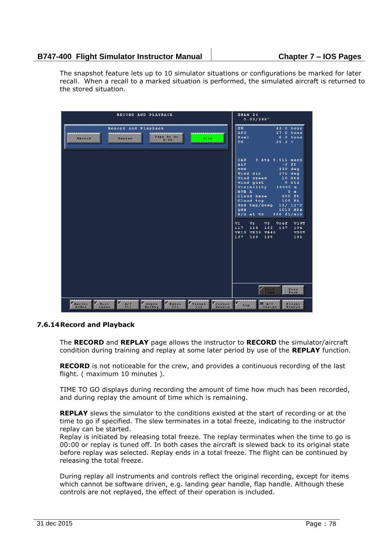
B747-400 Flight Simulator Instructor Manual Chapter 7 – IOS Pages
31 dec 2015 Page : 78
The snapshot feature lets up to 10 simulator situations or configurations be marked for later
recall. When a recall to a marked situation is performed, the simulated aircraft is returned to
the stored situation.
7.6.14 Record and Playback
The RECORD and REPLAY page allows the instructor to RECORD the simulator/aircraft
condition during training and replay at some later period by use of the REPLAY function.
RECORD is not noticeable for the crew, and provides a continuous recording of the last
flight. ( maximum 10 minutes ).
TIME TO GO displays during recording the amount of time how much has been recorded,
and during replay the amount of time which is remaining.
REPLAY slews the simulator to the conditions existed at the start of recording or at the
time to go if specified. The slew terminates in a total freeze, indicating to the instructor
replay can be started.
Replay is initiated by releasing total freeze. The replay terminates when the time to go is
00:00 or replay is tuned off. In both cases the aircraft is slewed back to its original state
before replay was selected. Replay ends in a total freeze. The flight can be continued by
releasing the total freeze.
During replay all instruments and controls reflect the original recording, except for items
which cannot be software driven, e.g. landing gear handle, flap handle. Although these
controls are not replayed, the effect of their operation is included.

B747-400 Flight Simulator Instructor Manual Chapter 7 – IOS Pages
31 dec 2015 Page : 79
Records, which are taken during training, are not saved when the simulator is reloaded.
During the REPLAY process no other simulator features should be used.
Before using simulator features as Store, Recall, Reposition, and Record the
Replay process must be finished and total freeze must be released.
7.6.15 Setup Recall
Setup Recall functions like Store / Recall, but the data stored can be made available to other
users. This is done through Setup Edit, which will protect the Store from being erased. E.g.
if for specific training a setup has been made, this setup can be stored at location 9. Each
additional crew can then perform a recall to setup 9, even after the simulator has been
reloaded, and will find the simulator ready in the stored setting.
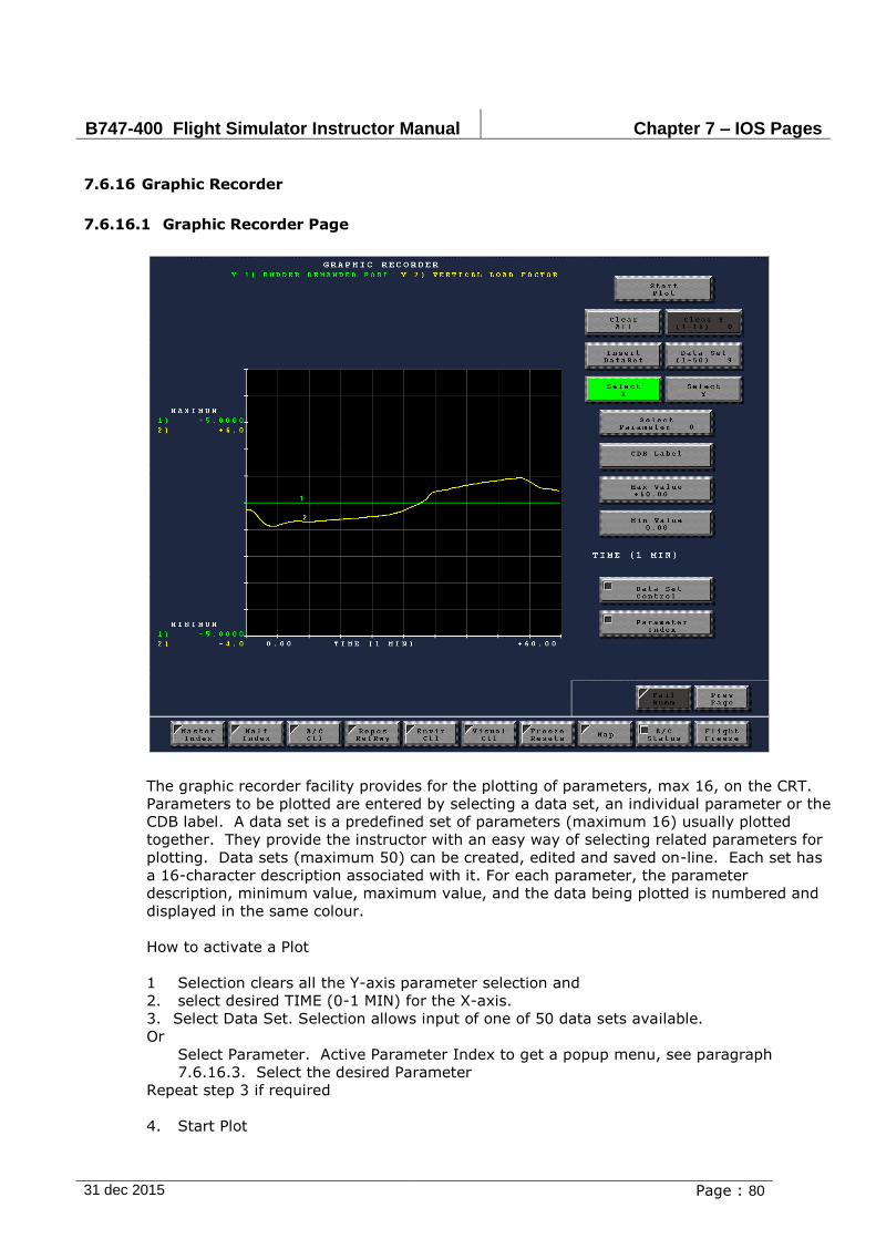
B747-400 Flight Simulator Instructor Manual Chapter 7 – IOS Pages
31 dec 2015 Page : 80
7.6.16 Graphic Recorder
7.6.16.1 Graphic Recorder Page
The graphic recorder facility provides for the plotting of parameters, max 16, on the CRT.
Parameters to be plotted are entered by selecting a data set, an individual parameter or the
CDB label. A data set is a predefined set of parameters (maximum 16) usually plotted
together. They provide the instructor with an easy way of selecting related parameters for
plotting. Data sets (maximum 50) can be created, edited and saved on-line. Each set has
a 16-character description associated with it. For each parameter, the parameter
description, minimum value, maximum value, and the data being plotted is numbered and
displayed in the same colour.
How to activate a Plot
1 Selection clears all the Y-axis parameter selection and
2. select desired TIME (0-1 MIN) for the X-axis.
3. Select Data Set. Selection allows input of one of 50 data sets available.
Or
Select Parameter. Active Parameter Index to get a popup menu, see paragraph
7.6.16.3. Select the desired Parameter
Repeat step 3 if required
4. Start Plot
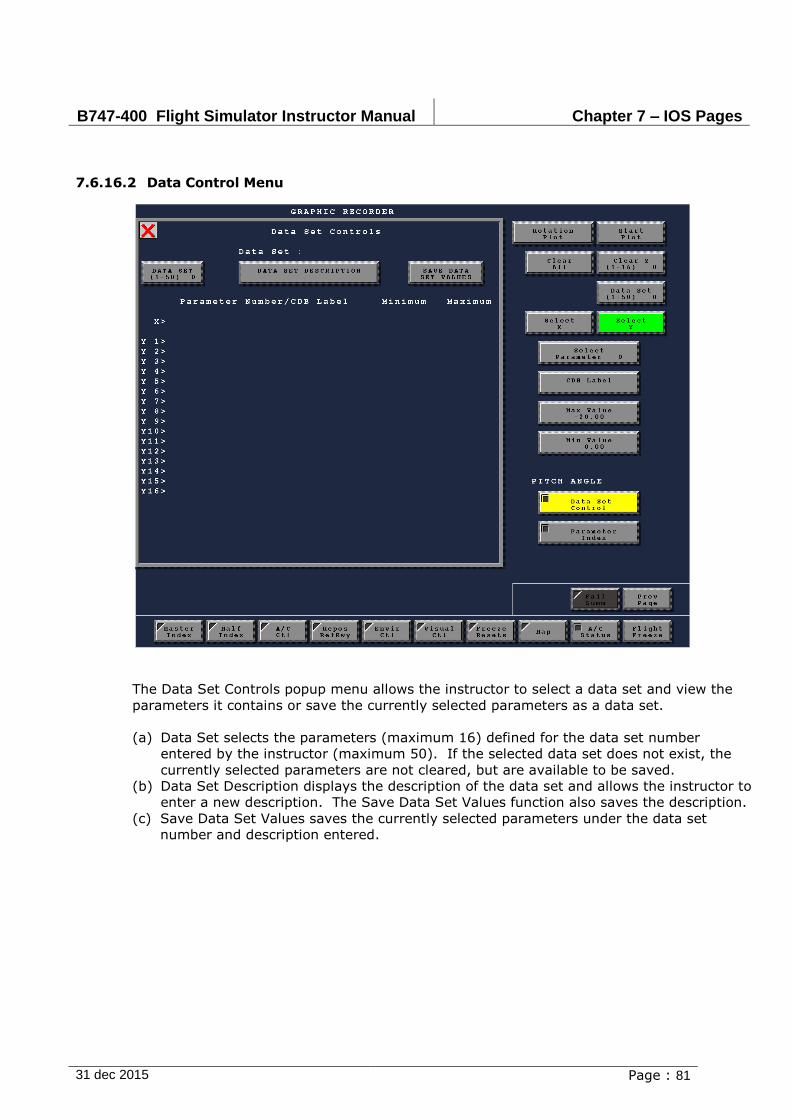
B747-400 Flight Simulator Instructor Manual Chapter 7 – IOS Pages
31 dec 2015 Page : 81
7.6.16.2 Data Control Menu
The Data Set Controls popup menu allows the instructor to select a data set and view the
parameters it contains or save the currently selected parameters as a data set.
(a) Data Set selects the parameters (maximum 16) defined for the data set number
entered by the instructor (maximum 50). If the selected data set does not exist, the
currently selected parameters are not cleared, but are available to be saved.
(b) Data Set Description displays the description of the data set and allows the instructor to
enter a new description. The Save Data Set Values function also saves the description.
(c) Save Data Set Values saves the currently selected parameters under the data set
number and description entered.
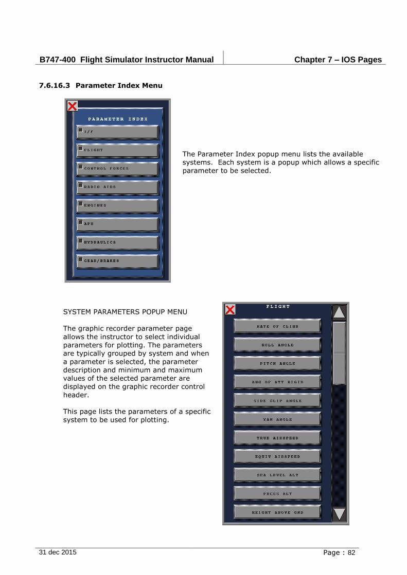
B747-400 Flight Simulator Instructor Manual Chapter 7 – IOS Pages
31 dec 2015 Page : 82
7.6.16.3 Parameter Index Menu
The Parameter Index popup menu lists the available
systems. Each system is a popup which allows a specific
parameter to be selected.
SYSTEM PARAMETERS POPUP MENU
The graphic recorder parameter page
allows the instructor to select individual
parameters for plotting. The parameters
are typically grouped by system and when
a parameter is selected, the parameter
description and minimum and maximum
values of the selected parameter are
displayed on the graphic recorder control
header.
This page lists the parameters of a specific
system to be used for plotting.

B747-400 Flight Simulator Instructor Manual Chapter 7 – IOS Pages
31 dec 2015 Page : 83
7.6.17 Actual TMA Stations
Rev chapter 7.4.5
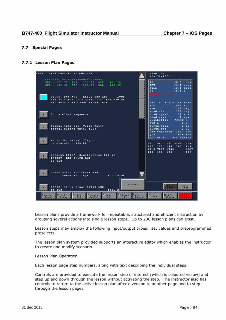
B747-400 Flight Simulator Instructor Manual Chapter 7 – IOS Pages
31 dec 2015 Page : 84
7.7 Special Pages
7.7.1 Lesson Plan Pages
Lesson plans provide a framework for repeatable, structured and efficient instruction by
grouping several actions into single lesson steps. Up to 200 lesson plans can exist.
Lesson steps may employ the following input/output types: set values and preprogrammed
preselects.
The lesson plan system provided supports an interactive editor which enables the instructor
to create and modify scenario.
Lesson Plan Operation
Each lesson page step numbers, along with text describing the individual steps.
Controls are provided to execute the lesson step of interest (which is coloured yellow) and
step up and down through the lesson without activating the step. The instructor also has
controls to return to the active lesson plan after diversion to another page and to step
through the lesson pages.

B747-400 Flight Simulator Instructor Manual Chapter 7 – IOS Pages
31 dec 2015 Page : 85
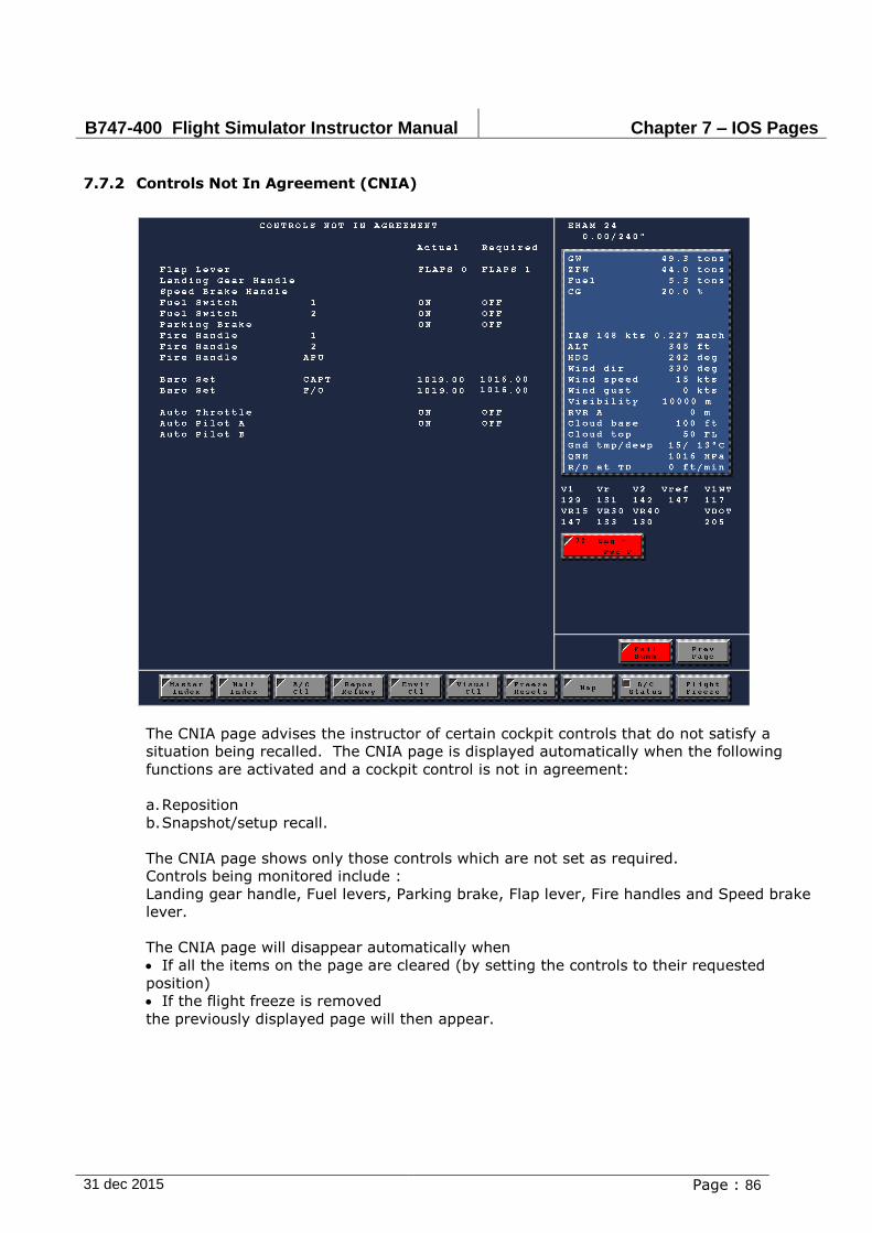
B747-400 Flight Simulator Instructor Manual Chapter 7 – IOS Pages
31 dec 2015 Page : 86
7.7.2 Controls Not In Agreement (CNIA)
The CNIA page advises the instructor of certain cockpit controls that do not satisfy a
situation being recalled. The CNIA page is displayed automatically when the following
functions are activated and a cockpit control is not in agreement:
a. Reposition
b. Snapshot/setup recall.
The CNIA page shows only those controls which are not set as required.
Controls being monitored include :
Landing gear handle, Fuel levers, Parking brake, Flap lever, Fire handles and Speed brake
lever.
The CNIA page will disappear automatically when
If all the items on the page are cleared (by setting the controls to their requested
position)
If the flight freeze is removed
the previously displayed page will then appear.

B747-400 Flight Simulator Instructor Manual Chapter 8 –Available Visual Models
31 dec 2015 Page : 1
TABLE OF CONTENTS
Section/Title Page
8. Available Visual Models 2
8.1. Visual Specific Scenes, JAR-STD 1A regulations 2
8.2. Models by ICAO (typical) 2
B747-400 Flight Simulator Instructor Manual Chapter 8 –Available Visual Models
31 dec 2015 Page : 1
8. Available Visual Models
8.1. Visual Specific Scenes, JAR-STD 1A regulations
On a yearly base 6 models, so called Visual Specific Scenes (VSS), will be checked for anomalies and updated if necessary. These models are therefore the only models that are qualified to meet training requirements for the OPS/FCL and ZFT part of training. These, with a maximum of 6, VSS models have been chosen in concert with the Training Manager. Reference JAR-STD 1A for more detailed information.
All other models are to be accepted as is, and will not be updated as agreed upon. Check for the latest status and availability of the models via the ref-runway repositioning page. A button located on top of the screen called VSS AIRP INFO will present the mentioned page.
Instructor shall check prior of using a visual model the current status, in order to judge if the model is suitable for his or her type of training.
Note A: beware topics 8.2 and 8.3 only show available airports for selection, but do not necessary reflect current airport situation. Use of a non-VSS visual model is the responsibility of the instructor and/or Training manager. Complaints and suggested improvements will not be incorporated.
Note B: according JAR-STD 1A regulations at least a minimum of 3 models should have ground traffic, e.g. taxiing, landing or take-off. Check VSS AIRP INFO for traffic availability.
Note C: for non-VSS models please be aware that EGPWS terrain relation cannot be assured.
8.2. Models by ICAO (typical)
For a complete and up to-date list of models, please contact our service department at
+31(0)20 304 3200
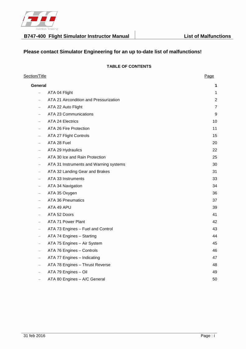
B747-400 Flight Simulator Instructor Manual List of Malfunctions
31 feb 2016 Page : i
Please contact Simulator Engineering for an up to-date list of malfunctions!
TABLE OF CONTENTS
Section/Title Page
General 1
– ATA 04 Flight 1
– ATA 21 Aircondition and Pressurization 2
– ATA 22 Auto Flight 7
– ATA 23 Communications 9
– ATA 24 Electrics 10
– ATA 26 Fire Protection 11
– ATA 27 Flight Controls 15
– ATA 28 Fuel 20
– ATA 29 Hydraulics 22
– ATA 30 Ice and Rain Protection 25
– ATA 31 Instruments and Warning systems 30
– ATA 32 Landing Gear and Brakes 31
– ATA 33 Instruments 33
– ATA 34 Navigation 34
– ATA 35 Oxygen 36
– ATA 36 Pneumatics 37
– ATA 49 APU 39
– ATA 52 Doors 41
– ATA 71 Power Plant 42
– ATA 73 Engines – Fuel and Control 43
– ATA 74 Engines – Starting 44
– ATA 75 Engines – Air System 45
– ATA 76 Engines – Controls 46
– ATA 77 Engines – Indicating 47
– ATA 78 Engines – Thrust Reverse 48
– ATA 79 Engines – Oil 49
– ATA 80 Engines – A/C General 50
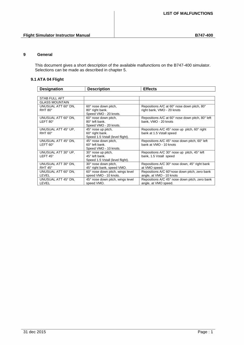
LIST OF MALFUNCTIONS
Flight Simulator Instructor Manual B747-400
31 dec 2015 Page : 1
9 General
This document gives a short description of the available malfunctions on the B747-400 simulator. Selections can be made as described in chapter 5.
9.1 ATA 04 Flight
Designation Description Effects
STAB FULL AFT
GLASS MOUNTAIN
UNUSUAL ATT 60° DN, RHT 80°
60° nose down pitch, 80° right bank. Speed VMO - 20 knots.
Repositions A/C at 60° nose down pitch, 80° right bank, VMO - 20 knots
UNUSUAL ATT 60° DN, LEFT 80°
60° nose down pitch, 80° left bank. Speed VMO - 20 knots.
Repositions A/C at 60° nose down pitch, 80° left bank, VMO - 20 knots
UNUSUAL ATT 45° UP, RHT 60°
45° nose up pitch, 60° right bank. Speed 1.5 Vstall (level flight).
Repositions A/C 45° nose up pitch, 60° right bank at 1.5 Vstall speed
UNUSUAL ATT 45° DN, LEFT 60°
45° nose down pitch, 60° left bank. Speed VMO - 10 knots.
Repositions A/C 45° nose down pitch, 60° left bank at VMO - 10 knots
UNUSUAL ATT 30° UP, LEFT 45°
30° nose up pitch, 45° left bank. Speed 1.5 Vstall (level flight).
Repositions A/C 30° nose up pitch, 45° left bank, 1.5 Vstall speed
UNUSUAL ATT 30° DN, RHT 45°
30° nose down pitch, 45° right bank, speed VMO.
Repositions A/C 30° nose down, 45° right bank at VMO speed.
UNUSUAL ATT 60° DN, LEVEL
60° nose down pitch, wings level speed VMO - 10 knots.
Repositions A/C 60°nose down pitch, zero bank angle, at VMO - 10 knots
UNUSUAL ATT 45° DN, LEVEL
45° nose down pitch, wings level speed VMO.
Repositions A/C 45° nose down pitch, zero bank angle, at VMO speed.
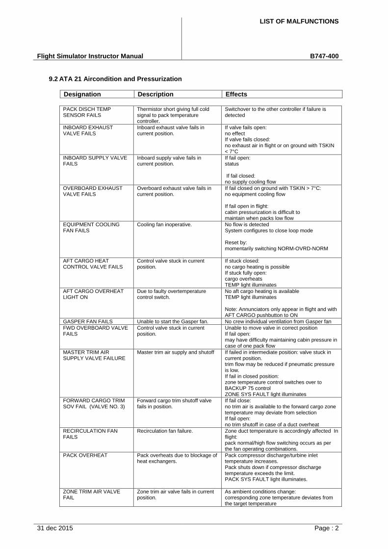
LIST OF MALFUNCTIONS
Flight Simulator Instructor Manual B747-400
31 dec 2015 Page : 2
9.2 ATA 21 Aircondition and Pressurization
Designation Description Effects
PACK DISCH TEMP SENSOR FAILS
Thermistor short giving full cold signal to pack temperature controller.
Switchover to the other controller if failure is detected
INBOARD EXHAUST VALVE FAILS
Inboard exhaust valve fails in current position.
If valve fails open: no effect If valve fails closed: no exhaust air in flight or on ground with TSKIN < 7°C
INBOARD SUPPLY VALVE FAILS
Inboard supply valve fails in current position.
If fail open: status
If fail closed: no supply cooling flow
OVERBOARD EXHAUST VALVE FAILS
Overboard exhaust valve fails in current position.
If fail closed on ground with TSKIN > 7°C: no equipment cooling flow
If fail open in flight: cabin pressurization is difficult to maintain when packs low flow
EQUIPMENT COOLING FAN FAILS
Cooling fan inoperative. No flow is detected System configures to close loop mode
Reset by: momentarily switching NORM-OVRD-NORM
AFT CARGO HEAT CONTROL VALVE FAILS
Control valve stuck in current position.
If stuck closed: no cargo heating is possible If stuck fully open: cargo overheats TEMP light illuminates
AFT CARGO OVERHEAT LIGHT ON
Due to faulty overtemperature control switch.
No aft cargo heating is available TEMP light illuminates
Note: Annunciators only appear in flight and with AFT CARGO pushbutton to ON
GASPER FAN FAILS Unable to start the Gasper fan. No crew individual ventilation from Gasper fan
FWD OVERBOARD VALVE FAILS
Control valve stuck in current position.
Unable to move valve in correct position If fail open: may have difficulty maintaining cabin pressure in case of one pack flow
MASTER TRIM AIR SUPPLY VALVE FAILURE
Master trim air supply and shutoff If failed in intermediate position: valve stuck in current position. trim flow may be reduced if pneumatic pressure is low. If fail in closed position: zone temperature control switches over to BACKUP 75 control ZONE SYS FAULT light illuminates
FORWARD CARGO TRIM SOV FAIL (VALVE NO. 3)
Forward cargo trim shutoff valve fails in position.
If fail close: no trim air is available to the forward cargo zone temperature may deviate from selection If fail open: no trim shutoff in case of a duct overheat
RECIRCULATION FAN FAILS
Recirculation fan failure. Zone duct temperature is accordingly affected In flight: pack normal/high flow switching occurs as per the fan operating combinations.
PACK OVERHEAT Pack overheats due to blockage of heat exchangers.
Pack compressor discharge/turbine inlet temperature increases. Pack shuts down if compressor discharge temperature exceeds the limit. PACK SYS FAULT light illuminates.
ZONE TRIM AIR VALVE FAIL
Zone trim air valve fails in current position.
As ambient conditions change: corresponding zone temperature deviates from the target temperature
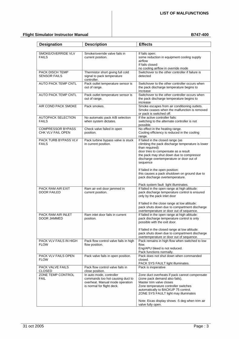
LIST OF MALFUNCTIONS
Flight Simulator Instructor Manual B747-400
Designation Description Effects
31 oct 2005 Page : 3
SMOKE/OVERRIDE VLV FAILS
Smoke/override valve fails in current position.
If fails open: some reduction in equipment cooling supply airflow If fails closed: no cooling airflow in override mode
PACK DISCH TEMP SENSOR FAILS
Thermistor short giving full cold signal to pack temperature controller.
Switchover to the other controller if failure is detected
AUTO PACK TEMP CNTL Pack outlet temperature sensor is out of range.
Switchover to the other controller occurs when the pack discharge temperature begins to increase
AUTO PACK TEMP CNTL Pack outlet temperature sensor is out of range.
Switchover to the other controller occurs when the pack discharge temperature begins to increase
AIR COND PACK SMOKE Pack smokes. Smoke escapes from air conditioning outlets. Smoke ceases when the malfunction is removed or pack is switched off.
AUTOPACK SELECTION FAILS
No automatic pack A/B selection when system dictates.
If the active controller fails: switching to the alternate controller is not possible.
COMPRESSOR BYPASS CHK VLV FAIL OPEN
Check valve failed in open position.
No effect in the heating range. Cooling efficiency is reduced in the cooling range.
PACK TURB BYPASS VLV FAILS
Pack turbine bypass valve is stuck in current position.
If failed in the closed range (as climbing the pack discharge temperature is lower than required): door tries to compensate as a result the pack may shut down due to compressor discharge overtemperature or door out of sequence
If failed in the open position: this causes a pack shutdown on ground due to pack discharge overtemperature.
Pack system fault light illuminates.
PACK RAM AIR EXIT DOOR FAILED
Ram air exit door jammed in current position.
If failed in the open range at high altitude: pack discharge temperature control is ensured only by the pack inlet door
If failed in the close range at low altitude: pack shuts down due to compartment discharge overtemperature or door out of sequence.
PACK RAM AIR INLET DOOR JAMMED
Ram inlet door fails in current position.
If failed in the open range at high altitude: pack discharge temperature control is only possible with the exit door.
If failed in the closed range at low altitude: pack shuts down due to compartment discharge overtemperature or door out of sequence.
PACK VLV FAILS IN HIGH FLOW
Pack flow control valve fails in high flow position.
Pack remains in high flow when switched to low flow. Eng/APU bleed is not reduced. Pack functions normally.
PACK VLV FAILS OPEN FLOW
Pack valve fails in open position. Pack does not shut down when commanded closed. PACK SYS FAULT light illuminates.
PACK VALVE FAILS CLOSED
Pack flow control valve fails in close position.
Pack is inoperative
ZONE TEMP CONTROL FAIL
In auto mode, controller commands too hot causing duct to overheat. Manual mode operation is normal for flight deck.
Zone duct overheats if pack cannot compensate (zone pack demand also fails). Master trim valve closes Zone temperature controller switches automatically to BACKUP 75 control. ZONE SYS FAULT light may illuminates
Note: Eicas display shows -5 deg when trim air valve fully open.

LIST OF MALFUNCTIONS
Flight Simulator Instructor Manual B747-400
Designation Description Effects
31 oct 2005 Page : 4
AUTO PRESS CONTROLLER DISAGREE FMS
Disagreement between FMS landing altitude and controller target altitude.
CPC uses default value 2,000 ft)
LAV-GALLEY FAN FAILS Failure due to a fan motor overheat.
If one fan fails: no effects only CMC If both fans fail status messages:
FWD CARGO HEATER FAILS
Failure of electric cargo heating system due to an electrical short circuit.
Forward cargo zone takes a longer time to heat up
FWD CARGO GND EXH FAN FAIL
Forward cargo ground exhaust fan motor fails.
In flight: no effects On ground with FWD cargo A/C on: reduced outflow through ground exhaust valves
FWD CARGO EXHAUST VALVE FAILS
Cargo exhaust valve stuck in position due to a mechanical failure.
If fail closed: In air: no effects On ground: pressure may build up in forward cargo If fail open: On ground: no effects In air: backup valve closes
FWD CARGO A/C VLV Valve failed in position due to mechanical failure.
If failed open: unable to shutdown cargo A/C If failed closed: cargo A/C flow schedule reduced
CPCS BACKUP SENSOR FAILS
Cabin altitude backup signals differ by more than 800 ft.
CPCS AIR/GROUND SIGNALS DISAGREE
CPCS primary and alternate air/ground signal disagreement.
CARGO A/C SELECTOR FAILS
Cargo temperature selector fails out of range.
Cargo temperature control fails if cargo A/C is selected ON Pack 3 outlet temperature follows demand
CARGO A/C CARD FAILS Loss of output signal from the cargo A/C card.
SOVs A and B and cargo trim SOV close Cabin SOV opens No A/C flow to cargo regardless of flow setting
CARGO A/C CABIN SOV FAILS
FWD cargo A/C cabin SOV fails in position due to a mechanical failure.
If stuck closed: flow from pack 3 is unavailable to cabin even if cargo A/C flow rate is selected OFF or LOW Cargo A/C valve B remains open If stuck open: flow from pack 3 to cabin even if cargo A/C flow rate is selected at MED or HIGH in flight
CACTCS AIR/GROUND SIGNALS DISAGREE
PTC-A primary and alternate air/ground signals disagree.
Control operates normally
AFT CGO OVRD VLV FAIL AFT cargo override valve fails in position due to a mechanical failure.
If failed open: no overheat protection in case of a temperature control valve failure If failed closed: aft cargo heat unavailable
BYPASS VALVE FAILS Bypass valve fails in current position.
If fail closed: no effect ehen in normal equipment cooling configuration If fail open: increased cooling air supply temperature
OUTFLOW VALVE POSITION INDICATOR FAILS
No output from outflow valve position transducer.
Outflow valve position indicator shows outflow valve is fully closed. Press controller operates normally
E6/E9 VALVE FAILS E6/E9 valve fails in current position.
If fail in open position no effect If fail in closed position: no cooling to the E9 rack is available
AUTO PRESS CTRL NO ARINC BUS DATA
No ADC ARINC bus data received by auto pressure controller.
With one failed controller:

LIST OF MALFUNCTIONS
Flight Simulator Instructor Manual B747-400
Designation Description Effects
31 oct 2005 Page : 5
AUTO PRESSURIZATION CONTROLLER FAIL
Controller sends unscheduled closing signal to outflow valves.
If cabin ROC exceeds the rate limit: the other controller takes over

LIST OF MALFUNCTIONS
Flight Simulator Instructor Manual B747-400
Designation Description Effects
31 oct 2005 Page : 6
OUTFLOW VALVE DC MOTOR FAILS
Outflow valve dc motor fails. Pressurization manual control is lost Automatic control is operating correctly
OUTFLOW VALVE AC MOTOR FAILS
Outflow valve ac motor fails. Pressurization auto control is lost. Manual control is still available.
RAPID DEPRESSURIZATION
Cabin window blow out, rate of climb may be 10000 ft/min until deltaP = .5 psid.
Cabin depressurizes Aural and light warnings occur when cabin altitude rises above 10,000 ft Outflow valves close
CABIN LEAK VARY Abnormal structural leak 100% leak = 1 outflow valve capacity. 40 % leak provides cabin leak without noticeable sound effect.
Cabin depressurizes warning as above. Outflow valve may compensate
MISC EQUIP CARD FAILS No ARINC 429 output from card.
LOW FLOW SENSOR FAILS
Faulty low flow sensor causing false warning.
Equipment cooling false warning
EQUIPMENT COOLING OVERHEAT TEMP SW FAILS
Equipment cooling overheat temp causing false warning.
Equipment cooling overheat false warning. switch fails in closed position
EQUIPMENT COOLING CARD FAILS
Faulty equipment cooling card. Equipment cooling performs correctly
EQUIPMENT SMOKE Smoke is detected in equipment cooling air exhaust.
Smoke/override valve opens
FWD CGO OVBD VLV FAIL Valve stuck in position due to mechanical failure.
Outflow maybe too high or too low, depending on forward cargo flow rate setting and pack configuration
ICU CHANNEL FAILS SYS Outflow valve interface control unit channel fails.
Affected outlfow valve remains in position Switchover to the other controller brings back control
Note CPCS failure
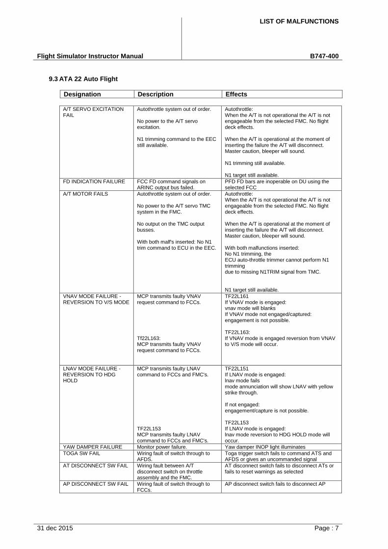
LIST OF MALFUNCTIONS
Flight Simulator Instructor Manual B747-400
31 dec 2015 Page : 7
9.3 ATA 22 Auto Flight
Designation Description Effects
A/T SERVO EXCITATION FAIL
Autothrottle system out of order.
No power to the A/T servo excitation.
N1 trimming command to the EEC still available.
Autothrottle: When the A/T is not operational the A/T is not engageable from the selected FMC. No flight deck effects.
When the A/T is operational at the moment of inserting the failure the A/T will disconnect. Master caution, bleeper will sound.
N1 trimming still available.
N1 target still available.
FD INDICATION FAILURE FCC FD command signals on ARINC output bus failed.
PFD FD bars are inoperable on DU using the selected FCC
A/T MOTOR FAILS Autothrottle system out of order.
No power to the A/T servo TMC system in the FMC.
No output on the TMC output busses.
With both malf's inserted: No N1 trim command to ECU in the EEC.
Autothrottle: When the A/T is not operational the A/T is not engageable from the selected FMC. No flight deck effects.
When the A/T is operational at the moment of inserting the failure the A/T will disconnect. Master caution, bleeper will sound.
With both malfunctions inserted: No N1 trimming, the ECU auto-throttle trimmer cannot perform N1 trimming due to missing N1TRIM signal from TMC.
N1 target still available.
VNAV MODE FAILURE - REVERSION TO V/S MODE
MCP transmits faulty VNAV request command to FCCs.
Tf22L163: MCP transmits faulty VNAV request command to FCCs.
TF22L161 If VNAV mode is engaged: vnav mode will blanks If VNAV mode not engaged/captured: engagement is not possible.
TF22L163: If VNAV mode is engaged reversion from VNAV to V/S mode will occur.
LNAV MODE FAILURE - REVERSION TO HDG HOLD
MCP transmits faulty LNAV command to FCCs and FMC's.
TF22L153 MCP transmits faulty LNAV command to FCCs and FMC's.
TF22L151 If LNAV mode is engaged: lnav mode fails mode annunciation will show LNAV with yellow strike through.
If not engaged: engagement/capture is not possible.
TF22L153 If LNAV mode is engaged: lnav mode reversion to HDG HOLD mode will occur.
YAW DAMPER FAILURE Monitor power failure. Yaw damper INOP light illuminates
TOGA SW FAIL Wiring fault of switch through to AFDS.
Toga trigger switch fails to command ATS and AFDS or gives an uncommanded signal
AT DISCONNECT SW FAIL Wiring fault between A/T disconnect switch on throttle assembly and the FMC.
AT disconnect switch fails to disconnect ATs or fails to reset warnings as selected
AP DISCONNECT SW FAIL Wiring fault of switch through to FCCs.
AP disconnect switch fails to disconnect AP
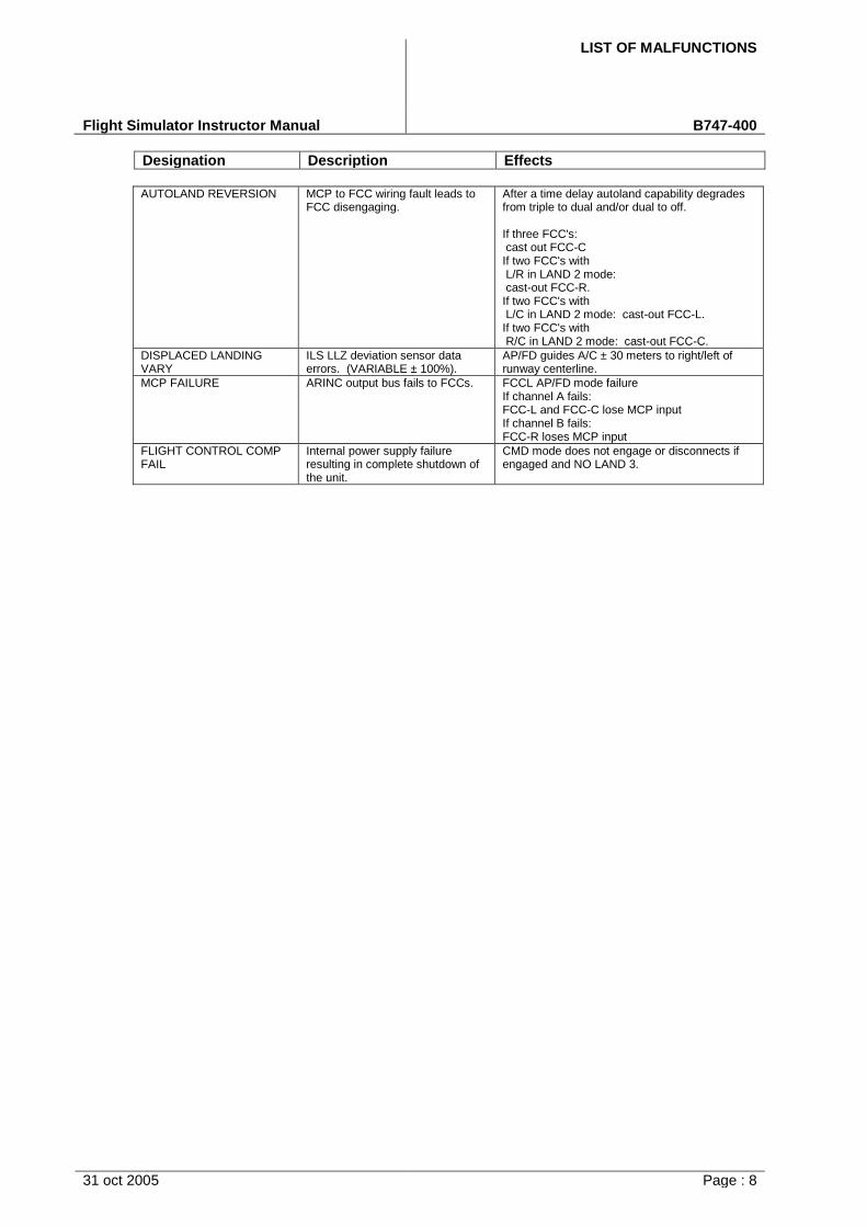
LIST OF MALFUNCTIONS
Flight Simulator Instructor Manual B747-400
Designation Description Effects
31 oct 2005 Page : 8
AUTOLAND REVERSION MCP to FCC wiring fault leads to FCC disengaging.
After a time delay autoland capability degrades from triple to dual and/or dual to off.
If three FCC's: cast out FCC-C If two FCC's with L/R in LAND 2 mode: cast-out FCC-R. If two FCC's with L/C in LAND 2 mode: cast-out FCC-L. If two FCC's with R/C in LAND 2 mode: cast-out FCC-C.
DISPLACED LANDING VARY
ILS LLZ deviation sensor data errors. (VARIABLE ± 100%).
AP/FD guides A/C ± 30 meters to right/left of runway centerline.
MCP FAILURE ARINC output bus fails to FCCs. FCCL AP/FD mode failure If channel A fails: FCC-L and FCC-C lose MCP input If channel B fails: FCC-R loses MCP input
FLIGHT CONTROL COMP FAIL
Internal power supply failure resulting in complete shutdown of the unit.
CMD mode does not engage or disconnects if engaged and NO LAND 3.
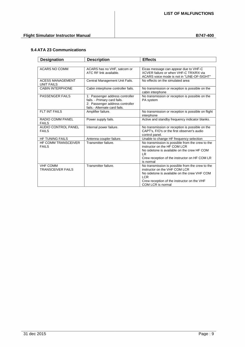
LIST OF MALFUNCTIONS
Flight Simulator Instructor Manual B747-400
31 dec 2015 Page : 9
9.4 ATA 23 Communications
Designation Description Effects
ACARS NO COMM ACARS has no VHF, satcom or ATC RF link available.
Eicas message can appear due to VHF-C XCVER failure or when VHF-C TRX/RX via ACARS voice mode is not in "LINE-OF-SIGHT"
ACESS MANAGEMENT UNIT FAILS
Central Management Unit Fails. No effects on the simulated area
CABIN INTERPHONE Cabin interphone controller fails. No transmission or reception is possible on the cabin interphone
PASSENGER FAILS 1: Passenger address controller fails. - Primary card fails. 2: Passenger address controller fails.- Alternate card fails.
No transmission or reception is possible on the PA system
FLT INT FAILS Amplifier failure. No transmission or reception is possible on flight interphone
RADIO COMM PANEL FAILS
Power supply fails. Active and standby frequency indicator blanks.
AUDIO CONTROL PANEL FAILS
Internal power failure. No transmission or reception is possible on the CAPT's, F/O's or the first observer's audio control panel.
HF TUNING FAILS Antenna coupler failure. Unable to change HF frequency selection
HF COMM TRANSCEIVER FAILS
Transmitter failure. No transmission is possible from the crew to the instructor on the HF COM LCR No sidetone is available on the crew HF COM LR Crew reception of the instructor on HF COM LR is normal
VHF COMM TRANSCEIVER FAILS
Transmitter failure. No transmission is possible from the crew to the instructor on the VHF COM LCR No sidetone is available on the crew VHF COM LCR Crew reception of the instructor on the VHF COM LCR is normal
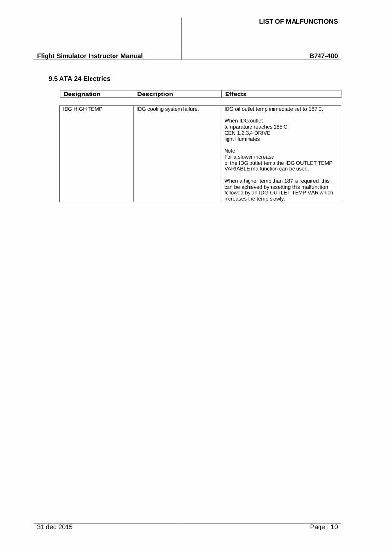
LIST OF MALFUNCTIONS
Flight Simulator Instructor Manual B747-400
31 dec 2015 Page : 10
9.5 ATA 24 Electrics
Designation Description Effects
IDG HIGH TEMP IDG cooling system failure. IDG oil outlet temp immediate set to 187'C.
When IDG outlet temparature reaches 185'C: GEN 1,2,3,4 DRIVE light illuminates
Note: For a slower increase of the IDG outlet temp the IDG OUTLET TEMP VARIABLE malfunction can be used.
When a higher temp than 187 is required, this can be achieved by resetting this malfunction followed by an IDG OUTLET TEMP VAR which increases the temp slowly.
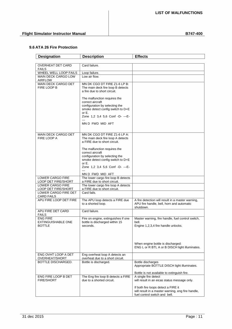
LIST OF MALFUNCTIONS
Flight Simulator Instructor Manual B747-400
31 dec 2015 Page : 11
9.6 ATA 26 Fire Protection
Designation Description Effects
OVERHEAT DET CARD FAILS
Card failure.
WHEEL WELL LOOP FAILS Loop failure.
MAIN DECK CARGO LOW AIRFLOW
Low air flow.
MAIN DECK CARGO DET FIRE LOOP B
MN DK CGO DT FIRE Z1-6 LP B: The main deck fire loop B detects a fire due to short circuit.
The malfunction requires the correct aircraft configuration by selecting the smoke detect config switch to D+E or E. Zone 1,2 3,4 5,6 Conf -D- ---E---- MN D FWD MID AFT
MAIN DECK CARGO DET FIRE LOOP A
MN DK CGO DT FIRE Z1-6 LP A: The main deck fire loop A detects a FIRE due to short circuit.
The malfunction requires the correct aircraft configuration by selecting the smoke detect config switch to D+E or E. Zone 1,2 3,4 5,6 Conf -D- ---E---- MN D FWD MID AFT
LOWER CARGO FIRE LOOP DET FIRE/SHORT
The lower cargo fire loop B detects a FIRE due to short circuit.
LOWER CARGO FIRE LOOP DET FIRE/SHORT
The lower cargo fire loop A detects a FIRE due to short circuit.
LOWER CARGO FIRE DET CARD FAILS
Card fails.
APU FIRE LOOP DET FIRE The APU loop detects a FIRE due to a shorted loop.
A fire detection will result in a master warning, APU fire handle, bell, horn and automatic shutdown.
APU FIRE DET CARD FAILS
Card failure.
ENG FIRE EXTINGUISHABLE ONE BOTTLE
Fire on engine, extinguishes if one bottle is discharged within 15 seconds.
Master warning, fire handle, fuel control switch, bell. Engine 1,2,3,4 fire handle unlocks.
When engine bottle is discharged: ENG L or R BTL A or B DISCH light illuminates.
ENG OVHT LOOP A DET OVERHEAT/SHORT
Eng overheat loop A detects an overheat due to a short circuit.
BOTTLE DISCHARGED. Bottle is discharged. Bottle discharges Appropriate BOTTLE DISCH light illuminates.
Bottle is not available to extinguish fire.
ENG FIRE LOOP B DET FIRE/SHORT
The Eng fire loop B detects a FIRE due to a shorted circuit.
A single fire detect will result in an eicas status message only.
If both fire loops detect a FIRE it will result in a master warning, eng fire handle, fuel control switch and bell.
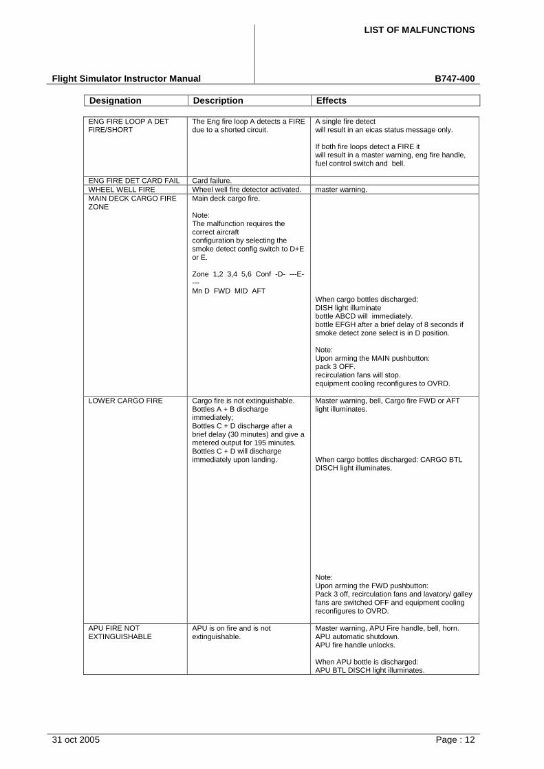
LIST OF MALFUNCTIONS
Flight Simulator Instructor Manual B747-400
Designation Description Effects
31 oct 2005 Page : 12
ENG FIRE LOOP A DET FIRE/SHORT
The Eng fire loop A detects a FIRE due to a shorted circuit.
A single fire detect will result in an eicas status message only.
If both fire loops detect a FIRE it will result in a master warning, eng fire handle, fuel control switch and bell.
ENG FIRE DET CARD FAIL Card failure.
WHEEL WELL FIRE Wheel well fire detector activated. master warning.
MAIN DECK CARGO FIRE ZONE
Main deck cargo fire.
Note: The malfunction requires the correct aircraft configuration by selecting the smoke detect config switch to D+E or E.
Zone 1,2 3,4 5,6 Conf -D- ---E---- Mn D FWD MID AFT
When cargo bottles discharged: DISH light illuminate bottle ABCD will immediately. bottle EFGH after a brief delay of 8 seconds if smoke detect zone select is in D position.
Note: Upon arming the MAIN pushbutton: pack 3 OFF. recirculation fans will stop. equipment cooling reconfigures to OVRD.
LOWER CARGO FIRE Cargo fire is not extinguishable. Bottles A + B discharge immediately; Bottles C + D discharge after a brief delay (30 minutes) and give a metered output for 195 minutes. Bottles C + D will discharge immediately upon landing.
Master warning, bell, Cargo fire FWD or AFT light illuminates.
When cargo bottles discharged: CARGO BTL DISCH light illuminates.
Note: Upon arming the FWD pushbutton: Pack 3 off, recirculation fans and lavatory/ galley fans are switched OFF and equipment cooling reconfigures to OVRD.
APU FIRE NOT EXTINGUISHABLE
APU is on fire and is not extinguishable.
Master warning, APU Fire handle, bell, horn. APU automatic shutdown. APU fire handle unlocks.
When APU bottle is discharged: APU BTL DISCH light illuminates.
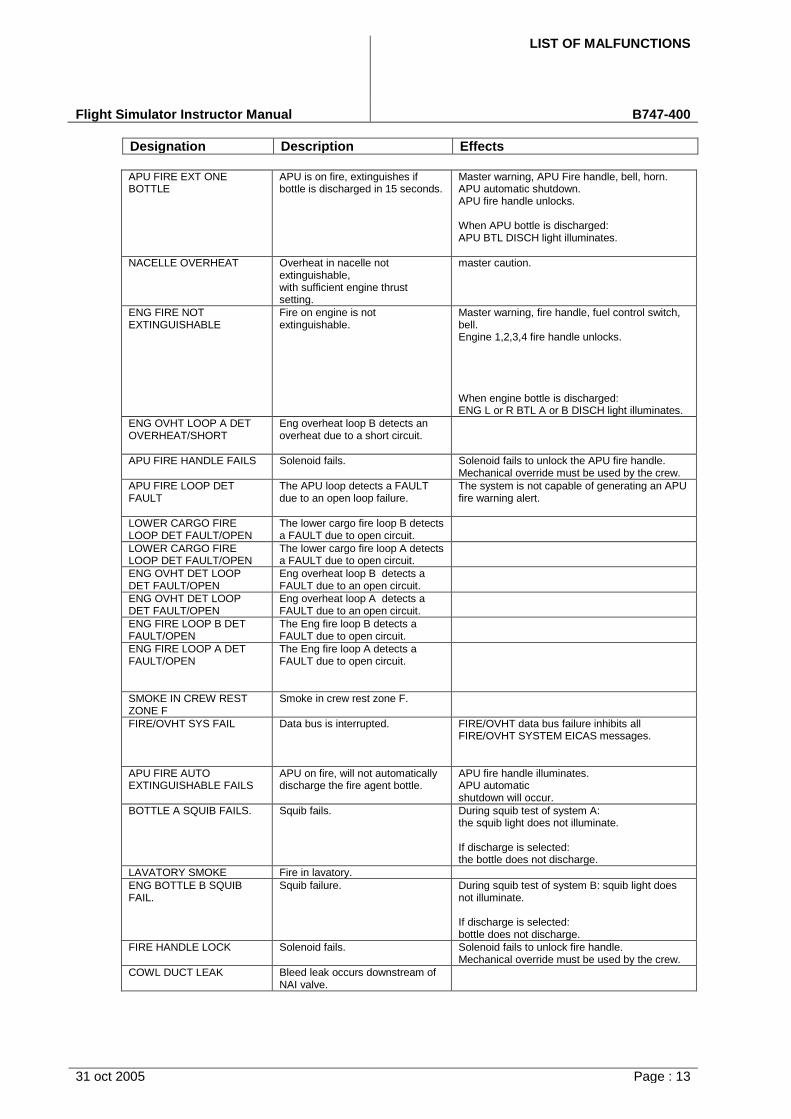
LIST OF MALFUNCTIONS
Flight Simulator Instructor Manual B747-400
Designation Description Effects
31 oct 2005 Page : 13
APU FIRE EXT ONE BOTTLE
APU is on fire, extinguishes if bottle is discharged in 15 seconds.
Master warning, APU Fire handle, bell, horn. APU automatic shutdown. APU fire handle unlocks.
When APU bottle is discharged: APU BTL DISCH light illuminates.
NACELLE OVERHEAT Overheat in nacelle not extinguishable, with sufficient engine thrust setting.
master caution.
ENG FIRE NOT EXTINGUISHABLE
Fire on engine is not extinguishable.
Master warning, fire handle, fuel control switch, bell. Engine 1,2,3,4 fire handle unlocks.
When engine bottle is discharged: ENG L or R BTL A or B DISCH light illuminates.
ENG OVHT LOOP A DET OVERHEAT/SHORT
Eng overheat loop B detects an overheat due to a short circuit.
APU FIRE HANDLE FAILS Solenoid fails. Solenoid fails to unlock the APU fire handle. Mechanical override must be used by the crew.
APU FIRE LOOP DET FAULT
The APU loop detects a FAULT due to an open loop failure.
The system is not capable of generating an APU fire warning alert.
LOWER CARGO FIRE LOOP DET FAULT/OPEN
The lower cargo fire loop B detects a FAULT due to open circuit.
LOWER CARGO FIRE LOOP DET FAULT/OPEN
The lower cargo fire loop A detects a FAULT due to open circuit.
ENG OVHT DET LOOP DET FAULT/OPEN
Eng overheat loop B detects a FAULT due to an open circuit.
ENG OVHT DET LOOP DET FAULT/OPEN
Eng overheat loop A detects a FAULT due to an open circuit.
ENG FIRE LOOP B DET FAULT/OPEN
The Eng fire loop B detects a FAULT due to open circuit.
ENG FIRE LOOP A DET FAULT/OPEN
The Eng fire loop A detects a FAULT due to open circuit.
SMOKE IN CREW REST ZONE F
Smoke in crew rest zone F.
FIRE/OVHT SYS FAIL Data bus is interrupted. FIRE/OVHT data bus failure inhibits all FIRE/OVHT SYSTEM EICAS messages.
APU FIRE AUTO EXTINGUISHABLE FAILS
APU on fire, will not automatically discharge the fire agent bottle.
APU fire handle illuminates. APU automatic shutdown will occur.
BOTTLE A SQUIB FAILS. Squib fails. During squib test of system A: the squib light does not illuminate.
If discharge is selected: the bottle does not discharge.
LAVATORY SMOKE Fire in lavatory.
ENG BOTTLE B SQUIB FAIL.
Squib failure. During squib test of system B: squib light does not illuminate.
If discharge is selected: bottle does not discharge.
FIRE HANDLE LOCK Solenoid fails. Solenoid fails to unlock fire handle. Mechanical override must be used by the crew.
COWL DUCT LEAK Bleed leak occurs downstream of NAI valve.
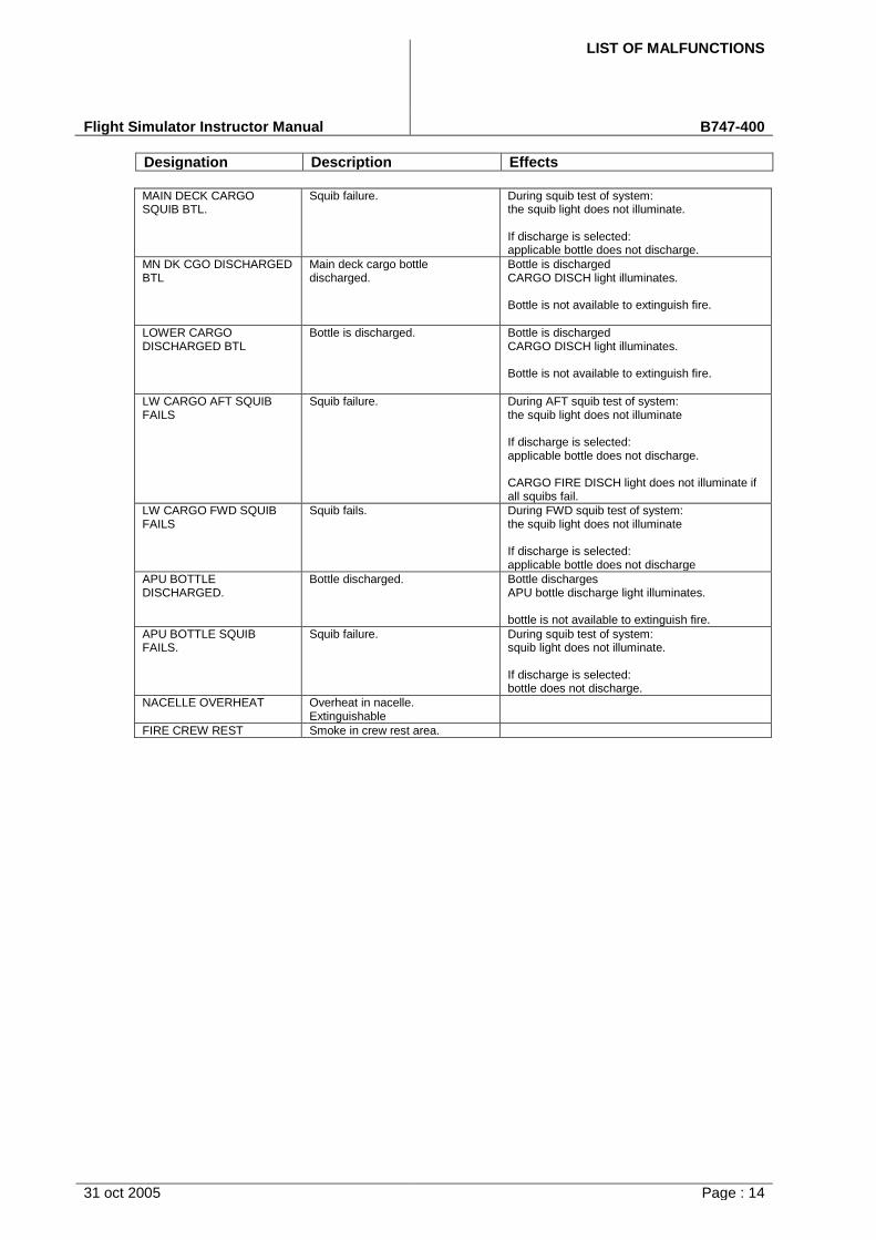
LIST OF MALFUNCTIONS
Flight Simulator Instructor Manual B747-400
Designation Description Effects
31 oct 2005 Page : 14
MAIN DECK CARGO SQUIB BTL.
Squib failure. During squib test of system: the squib light does not illuminate.
If discharge is selected: applicable bottle does not discharge.
MN DK CGO DISCHARGED BTL
Main deck cargo bottle discharged.
Bottle is discharged CARGO DISCH light illuminates.
Bottle is not available to extinguish fire.
LOWER CARGO DISCHARGED BTL
Bottle is discharged. Bottle is discharged CARGO DISCH light illuminates.
Bottle is not available to extinguish fire.
LW CARGO AFT SQUIB FAILS
Squib failure. During AFT squib test of system: the squib light does not illuminate
If discharge is selected: applicable bottle does not discharge.
CARGO FIRE DISCH light does not illuminate if all squibs fail.
LW CARGO FWD SQUIB FAILS
Squib fails. During FWD squib test of system: the squib light does not illuminate
If discharge is selected: applicable bottle does not discharge
APU BOTTLE DISCHARGED.
Bottle discharged. Bottle discharges APU bottle discharge light illuminates.
bottle is not available to extinguish fire.
APU BOTTLE SQUIB FAILS.
Squib failure. During squib test of system: squib light does not illuminate.
If discharge is selected: bottle does not discharge.
NACELLE OVERHEAT Overheat in nacelle. Extinguishable
FIRE CREW REST Smoke in crew rest area.

LIST OF MALFUNCTIONS
Flight Simulator Instructor Manual B747-400
31 dec 2015 Page : 15
9.7 ATA 27 Flight Controls
Designation Description Effects
SPOILER PANEL FAILURE Spoiler panel jammed in current position.
Appropriate spoiler fails in the last position. Adverse roll effects. No deflection of spoiler position indicator occurs if #4 or #12 are selected.
FLT CONT POS IND (ELEV) Control surface position transmitter fails.
Surfaces move normally but indicators disappear.
STAB TRIM SW FAILS (F/O)
Electrical input to stabilizer control module fails.
Failed switch has no effect. Stabilizer can operate using another ARM or CONTROL switch.
STAB TRIM SW FAILS (CAPT)
Electrical input to stabilizer control module fails.
Failed switch has no effect. Stabilizer can operate using another ARM or CONTROL switch.
STABILIZER TRIM SECONDARY BRAKE FAILS
Stabilizer trim secondary brake jammed in current position.
If one fails: stab trim is 1/2 rate.
STAB TRIM 2/3 if trimming with thumb switches or ALTN switches.
JAMMED STABILIZER Stabilizer is jammed in current position due to faulty primary brake.
There is no reaction to stabilizer control inputs. No autopilot or manual input is possible. >AUTOPILOT message shown when autopilottries to trim.>STAB TRIM 2/3 message is shown whendeflecting thumb switches only.
STAB RUNAWAY (IN AUTOPILOT MODE)
Auto stab trim A electrically fails open.
Stabilizer will continues moving in last demanded a/p direction.
Runaway stops after 1.0 degree of travel.
Runaway stopped by moving the column in the opposite direction or through corresponding CUTOFF switches.
Alternate trim overrides the SRM A/P runaway command to the SCM and continues if A/P is disengaged.
Manual electric trim disengaged A/P but does not move the stabilizer.
If A/P disengagement: further manual electric trim attempts cause STAB TRIM 2/3 message to display on eicas.
If CUTOFF switches are in AUTO: Auto shutdown occurs after 1 degree of travel. STAB TRIM 2/3 displays on EICAS.
If CUTOFF switches are in ON: STAB TRIM UNSCHD is displays on EICAS.
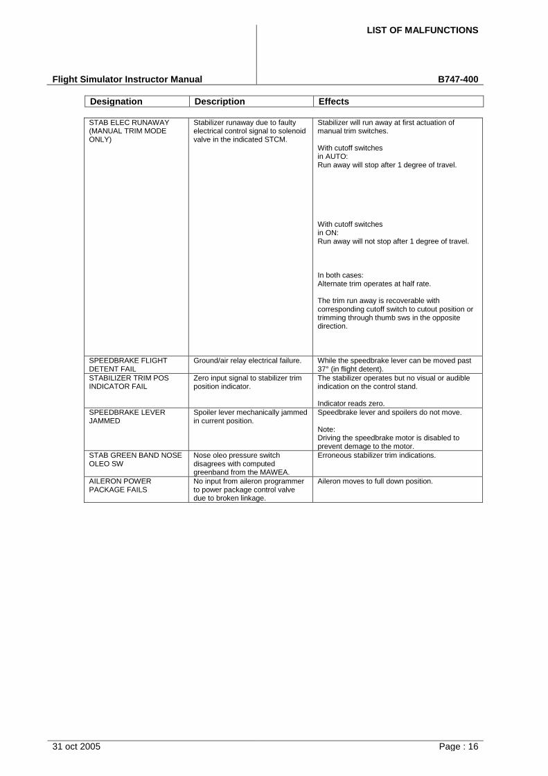
LIST OF MALFUNCTIONS
Flight Simulator Instructor Manual B747-400
Designation Description Effects
31 oct 2005 Page : 16
STAB ELEC RUNAWAY (MANUAL TRIM MODE ONLY)
Stabilizer runaway due to faulty electrical control signal to solenoid valve in the indicated STCM.
Stabilizer will run away at first actuation of manual trim switches.
With cutoff switches in AUTO: Run away will stop after 1 degree of travel.
With cutoff switches in ON: Run away will not stop after 1 degree of travel.
In both cases: Alternate trim operates at half rate.
The trim run away is recoverable with corresponding cutoff switch to cutout position or trimming through thumb sws in the opposite direction.
SPEEDBRAKE FLIGHT DETENT FAIL
Ground/air relay electrical failure. While the speedbrake lever can be moved past 37° (in flight detent).
STABILIZER TRIM POS INDICATOR FAIL
Zero input signal to stabilizer trim position indicator.
The stabilizer operates but no visual or audible indication on the control stand.
Indicator reads zero.
SPEEDBRAKE LEVER JAMMED
Spoiler lever mechanically jammed in current position.
Speedbrake lever and spoilers do not move.
Note: Driving the speedbrake motor is disabled to prevent demage to the motor.
STAB GREEN BAND NOSE OLEO SW
Nose oleo pressure switch disagrees with computed greenband from the MAWEA.
Erroneous stabilizer trim indications.
AILERON POWER PACKAGE FAILS
No input from aileron programmer to power package control valve due to broken linkage.
Aileron moves to full down position.
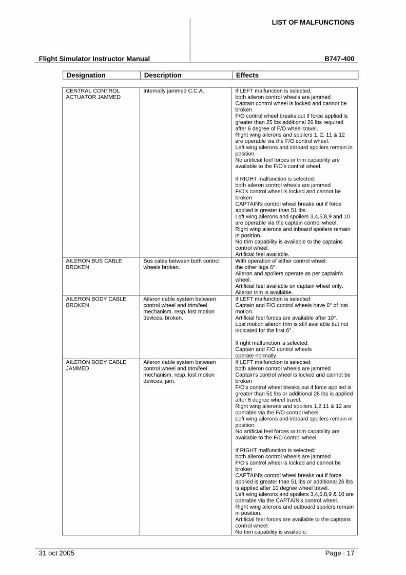
LIST OF MALFUNCTIONS
Flight Simulator Instructor Manual B747-400
Designation Description Effects
31 oct 2005 Page : 17
CENTRAL CONTROL ACTUATOR JAMMED
Internally jammed C.C.A. If LEFT malfunction is selected: both aileron control wheels are jammed Captain control wheel is locked and cannot be broken F/O control wheel breaks out if force applied is greater than 25 lbs additional 26 lbs required after 6 degree of F/O wheel travel. Right wing ailerons and spoilers 1, 2, 11 & 12 are operable via the F/O control wheel. Left wing ailerons and inboard spoilers remain in position. No artificial feel forces or trim capability are available to the F/O's control wheel.
If RIGHT malfunction is selected: both aileron control wheels are jammed F/O's control wheel is locked and cannot be broken CAPTAIN's control wheel breaks out if force applied is greater than 51 lbs. Left wing ailerons and spoilers 3,4,5,8,9 and 10 are operable via the captain control wheel. Right wing ailerons and inboard spoilers remain in position. No trim capability is available to the captains control wheel. Artificial feel available.
AILERON BUS CABLE BROKEN
Bus cable between both control wheels broken.
With operation of either control wheel: the other lags 6°. Aileron and spoilers operate as per captain's wheel. Artificial feel available on captain wheel only. Aileron trim is available.
AILERON BODY CABLE BROKEN
Aileron cable system between control wheel and trim/feel mechanism, resp. lost motion devices, broken.
If LEFT malfunction is selected: Captain and F/O control wheels have 6° of lost motion. Artificial feel forces are available after 10°. Lost motion aileron trim is still available but not indicated for the first 6°.
If right malfunction is selected: Captain and F/O control wheels operate normally.
AILERON BODY CABLE JAMMED
Aileron cable system between control wheel and trim/feel mechanism, resp. lost motion devices, jam.
If LEFT malfunction is selected: both aileron control wheels are jammed Captain's control wheel is locked and cannot be broken F/O's control wheel breaks out if force applied is greater than 51 lbs or additional 26 lbs is applied after 6 degree wheel travel. Right wing ailerons and spoilers 1,2,11 & 12 are operable via the F/O control wheel. Left wing ailerons and inboard spoilers remain in position. No artificial feel forces or trim capability are available to the F/O control wheel.
If RIGHT malfunction is selected: both aileron control wheels are jammed F/O's control wheel is locked and cannot be broken CAPTAIN's control wheel breaks out if force applied is greater than 51 lbs or additional 26 lbs is applied after 10 degree wheel travel. Left wing ailerons and spoilers 3,4,5,8,9 & 10 are operable via the CAPTAIN's control wheel. Right wing ailerons and outboard spoilers remain in position. Artificial feel forces are available to the captains control wheel. No trim capability is available.
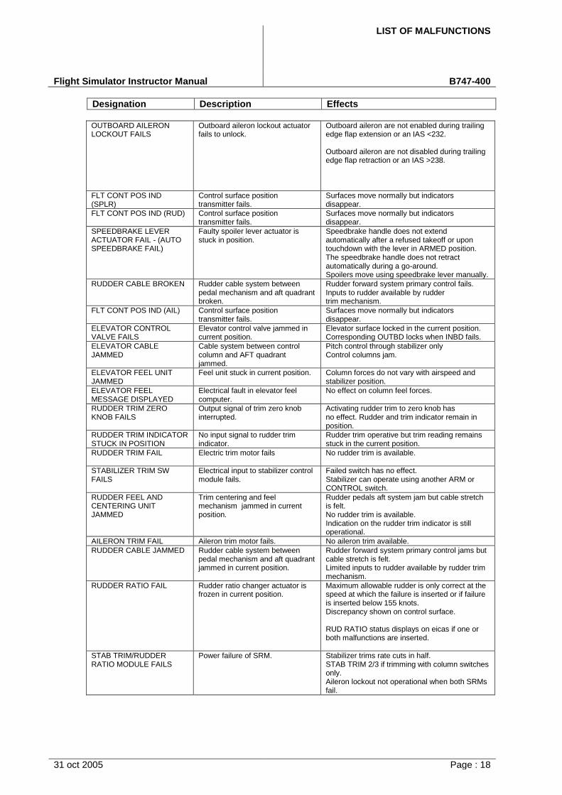
LIST OF MALFUNCTIONS
Flight Simulator Instructor Manual B747-400
Designation Description Effects
31 oct 2005 Page : 18
OUTBOARD AILERON LOCKOUT FAILS
Outboard aileron lockout actuator fails to unlock.
Outboard aileron are not enabled during trailing edge flap extension or an IAS <232.
Outboard aileron are not disabled during trailing edge flap retraction or an IAS >238.
FLT CONT POS IND (SPLR)
Control surface position transmitter fails.
Surfaces move normally but indicators disappear.
FLT CONT POS IND (RUD) Control surface position transmitter fails.
Surfaces move normally but indicators disappear.
SPEEDBRAKE LEVER ACTUATOR FAIL - (AUTO SPEEDBRAKE FAIL)
Faulty spoiler lever actuator is stuck in position.
Speedbrake handle does not extend automatically after a refused takeoff or upon touchdown with the lever in ARMED position. The speedbrake handle does not retract automatically during a go-around. Spoilers move using speedbrake lever manually.
RUDDER CABLE BROKEN Rudder cable system between pedal mechanism and aft quadrant broken.
Rudder forward system primary control fails. Inputs to rudder available by rudder trim mechanism.
FLT CONT POS IND (AIL) Control surface position transmitter fails.
Surfaces move normally but indicators disappear.
ELEVATOR CONTROL VALVE FAILS
Elevator control valve jammed in current position.
Elevator surface locked in the current position. Corresponding OUTBD locks when INBD fails.
ELEVATOR CABLE JAMMED
Cable system between control column and AFT quadrant jammed.
Pitch control through stabilizer only Control columns jam.
ELEVATOR FEEL UNIT JAMMED
Feel unit stuck in current position. Column forces do not vary with airspeed and stabilizer position.
ELEVATOR FEEL MESSAGE DISPLAYED
Electrical fault in elevator feel computer.
No effect on column feel forces.
RUDDER TRIM ZERO KNOB FAILS
Output signal of trim zero knob interrupted.
Activating rudder trim to zero knob has no effect. Rudder and trim indicator remain in position.
RUDDER TRIM INDICATOR STUCK IN POSITION
No input signal to rudder trim indicator.
Rudder trim operative but trim reading remains stuck in the current position.
RUDDER TRIM FAIL Electric trim motor fails No rudder trim is available.
STABILIZER TRIM SW FAILS
Electrical input to stabilizer control module fails.
Failed switch has no effect. Stabilizer can operate using another ARM or CONTROL switch.
RUDDER FEEL AND CENTERING UNIT JAMMED
Trim centering and feel mechanism jammed in current position.
Rudder pedals aft system jam but cable stretch is felt. No rudder trim is available. Indication on the rudder trim indicator is still operational.
AILERON TRIM FAIL Aileron trim motor fails. No aileron trim available.
RUDDER CABLE JAMMED Rudder cable system between pedal mechanism and aft quadrant jammed in current position.
Rudder forward system primary control jams but cable stretch is felt. Limited inputs to rudder available by rudder trim mechanism.
RUDDER RATIO FAIL Rudder ratio changer actuator is frozen in current position.
Maximum allowable rudder is only correct at the speed at which the failure is inserted or if failure is inserted below 155 knots. Discrepancy shown on control surface.
RUD RATIO status displays on eicas if one or both malfunctions are inserted.
STAB TRIM/RUDDER RATIO MODULE FAILS
Power failure of SRM. Stabilizer trims rate cuts in half. STAB TRIM 2/3 if trimming with column switches only. Aileron lockout not operational when both SRMs fail.

LIST OF MALFUNCTIONS
Flight Simulator Instructor Manual B747-400
Designation Description Effects
31 oct 2005 Page : 19
STAB CUTOUT Automatic stabilizer shutdown inoperative.
Auto shutdown inoperative during runaway.
Note: after inserting STAB CUTOUT you need to insert also a runaway malfunction in order to see any effects.
NOSEWHEEL STEERING ELECTRICAL ACTUATOR FAIL
Nosegear steering electrical Rudder pedal steering is inoperative. Actuator fails in disengaged. Tiller input is unaffected position. No effect if inserted during rollout.
NOSEWHEEL STEERING CABLE JAM
Cable between tiller and control valve is jammed in current position.
Tiller jams at the last position. There is no nosewheel or body gear steering available. Nosewheel castors within valve dead band.
STAB TRIM SOLENOID FAILS
Respective solenoid valve fails. Stabilizer trim rate cuts in half in either UP or DOWN direction. STAB TRIM 2/3 if trimming with column thumb switches only.
BODY GEAR STEERING FAILS
Input signal to solenoid valve interrupted.
No body gear steering is available.
RUDDER PEDAL STEERING JAMMED
Steering control rod jammed current position.
Nose wheel steering is impossible via the rudder pedals.
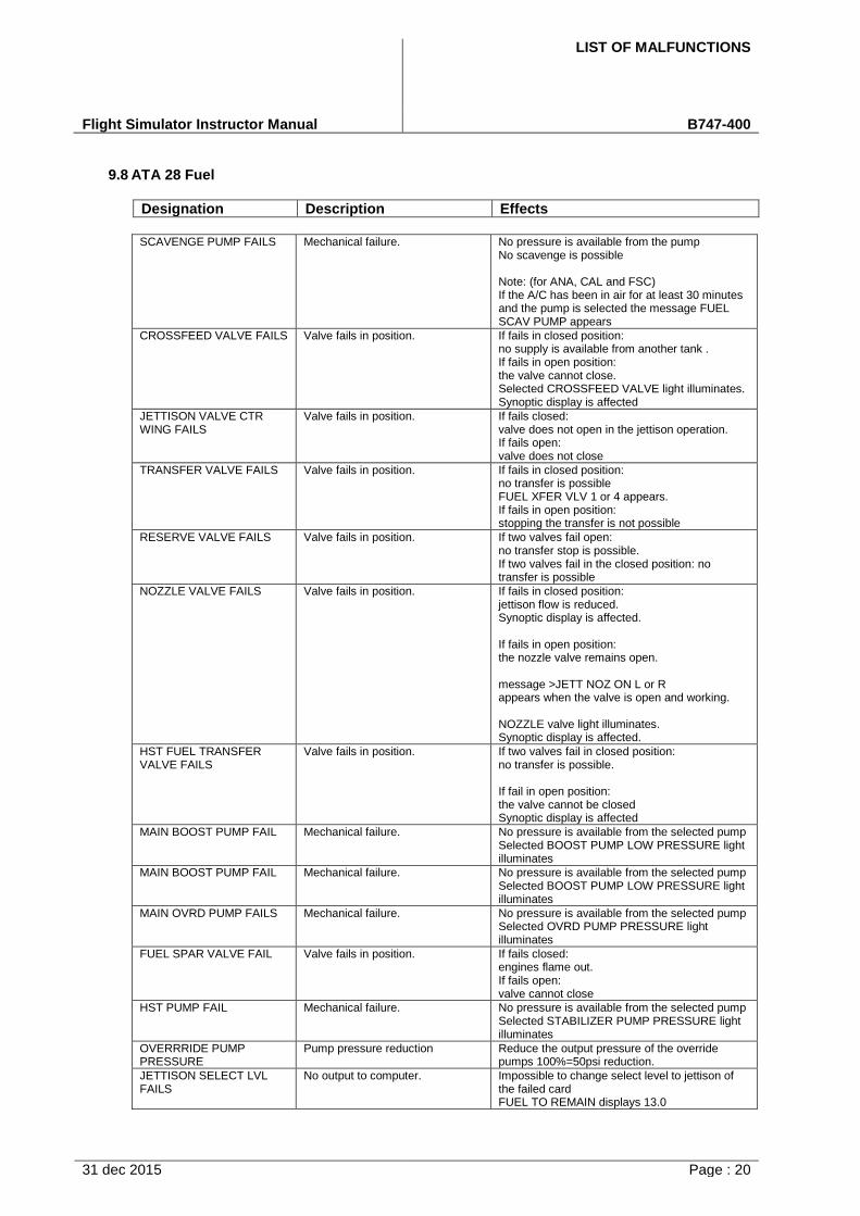
LIST OF MALFUNCTIONS
Flight Simulator Instructor Manual B747-400
31 dec 2015 Page : 20
9.8 ATA 28 Fuel
Designation Description Effects
SCAVENGE PUMP FAILS Mechanical failure. No pressure is available from the pump No scavenge is possible
Note: (for ANA, CAL and FSC) If the A/C has been in air for at least 30 minutes and the pump is selected the message FUEL SCAV PUMP appears
CROSSFEED VALVE FAILS Valve fails in position. If fails in closed position: no supply is available from another tank . If fails in open position: the valve cannot close. Selected CROSSFEED VALVE light illuminates. Synoptic display is affected
JETTISON VALVE CTR WING FAILS
Valve fails in position. If fails closed: valve does not open in the jettison operation. If fails open: valve does not close
TRANSFER VALVE FAILS Valve fails in position. If fails in closed position: no transfer is possible FUEL XFER VLV 1 or 4 appears. If fails in open position: stopping the transfer is not possible
RESERVE VALVE FAILS Valve fails in position. If two valves fail open: no transfer stop is possible. If two valves fail in the closed position: no transfer is possible
NOZZLE VALVE FAILS Valve fails in position. If fails in closed position: jettison flow is reduced. Synoptic display is affected.
If fails in open position: the nozzle valve remains open.
message >JETT NOZ ON L or R appears when the valve is open and working.
NOZZLE valve light illuminates. Synoptic display is affected.
HST FUEL TRANSFER VALVE FAILS
Valve fails in position. If two valves fail in closed position: no transfer is possible.
If fail in open position: the valve cannot be closed Synoptic display is affected
MAIN BOOST PUMP FAIL Mechanical failure. No pressure is available from the selected pump Selected BOOST PUMP LOW PRESSURE light illuminates
MAIN BOOST PUMP FAIL Mechanical failure. No pressure is available from the selected pump Selected BOOST PUMP LOW PRESSURE light illuminates
MAIN OVRD PUMP FAILS Mechanical failure. No pressure is available from the selected pump Selected OVRD PUMP PRESSURE light illuminates
FUEL SPAR VALVE FAIL Valve fails in position. If fails closed: engines flame out. If fails open: valve cannot close
HST PUMP FAIL Mechanical failure. No pressure is available from the selected pump Selected STABILIZER PUMP PRESSURE light illuminates
OVERRRIDE PUMP PRESSURE
Pump pressure reduction Reduce the output pressure of the override pumps 100%=50psi reduction.
JETTISON SELECT LVL FAILS
No output to computer. Impossible to change select level to jettison of the failed card FUEL TO REMAIN displays 13.0
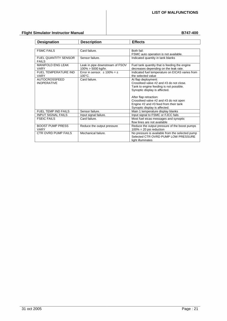
LIST OF MALFUNCTIONS
Flight Simulator Instructor Manual B747-400
Designation Description Effects
31 oct 2005 Page : 21
FSMC FAILS Card failure. Both fail: FSMC auto operation is not available.
FUEL QUANTITY SENSOR FAILS
Sensor failure. Indicated quantity in tank blanks
MANIFOLD ENG LEAK VARY
Leak in pipe downstream of FSOV 100% > 5000 kg/hr.
Fuel tank quantity that is feeding the engine decreases depending on the leak rate.
FUEL TEMPERATURE IND VARY
Error in sensor. ± 100% = ± 100°C.
Indicated fuel temperature on EICAS varies from the selected value
AUTOCROSSFEED INOPERATIVE
Card failure. At flap deployment: Crossfeed valve #2 and #3 do not close. Tank to engine feeding is not possible. Synoptic display is affected.
After flap retraction: Crossfeed valve #2 and #3 do not open Engine #2 and #3 feed from their tank Synoptic display is affected.
FUEL TEMP IND FAILS Sensor failure. Main 1 temperature display blanks
INPUT SIGNAL FAILS Input signal failure. Input signal to FSMC or FJCC fails
FSEIC FAILS Card failure. Most fuel eicas messages and synoptic flow lines are not available
BOOST PUMP PRESS VARY
Reduce the output pressure Reduce the output pressure of the boost pumps 100% = 20 psi reduction
CTR OVRD PUMP FAILS Mechanical failure. No pressure is available from the selected pump Selected CTR OVRD PUMP LOW PRESSURE light illuminates
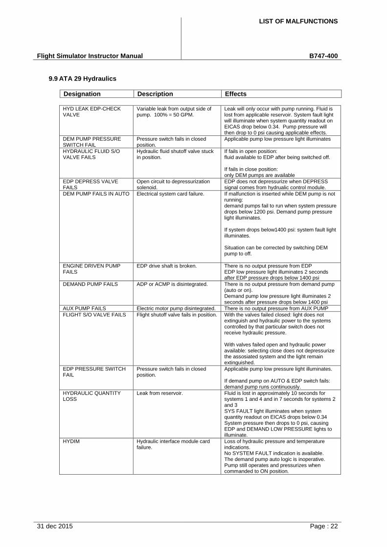
LIST OF MALFUNCTIONS
Flight Simulator Instructor Manual B747-400
31 dec 2015 Page : 22
9.9 ATA 29 Hydraulics
Designation Description Effects
HYD LEAK EDP-CHECK VALVE
Variable leak from output side of pump. 100% = 50 GPM.
Leak will only occur with pump running. Fluid is lost from applicable reservoir. System fault light will illuminate when system quantity readout on EICAS drop below 0.34. Pump pressure will then drop to 0 psi causing applicable effects.
DEM PUMP PRESSURE SWITCH FAIL
Pressure switch fails in closed position.
Applicable pump low pressure light illuminates
HYDRAULIC FLUID S/O VALVE FAILS
Hydraulic fluid shutoff valve stuck in position.
If fails in open position: fluid available to EDP after being switched off.
If fails in close position: only DEM pumps are available
EDP DEPRESS VALVE FAILS
Open circuit to depressurization solenoid.
EDP does not depressurize when DEPRESS signal comes from hydrualic control module.
DEM PUMP FAILS IN AUTO Electrical system card failure. If malfunction is inserted while DEM pump is not running: demand pumps fail to run when system pressure drops below 1200 psi. Demand pump pressure light illuminates.
If system drops below1400 psi: system fault light illuminates.
Situation can be corrected by switching DEM pump to off.
ENGINE DRIVEN PUMP FAILS
EDP drive shaft is broken. There is no output pressure from EDP EDP low pressure light illuminates 2 seconds after EDP pressure drops below 1400 psi
DEMAND PUMP FAILS ADP or ACMP is disintegrated. There is no output pressure from demand pump (auto or on). Demand pump low pressure light illuminates 2 seconds after pressure drops below 1400 psi
AUX PUMP FAILS Electric motor pump disintegrated. There is no output pressure from AUX PUMP
FLIGHT S/O VALVE FAILS Flight shutoff valve fails in position. With the valves failed closed: light does not extinguish and hydraulic power to the systems controlled by that particular switch does not receive hydraulic pressure.
With valves failed open and hydraulic power available: selecting close does not depressurize the assosiated system and the light remain extinguished.
EDP PRESSURE SWITCH FAIL
Pressure switch fails in closed position.
Applicable pump low pressure light illuminates.
If demand pump on AUTO & EDP switch fails: demand pump runs continuously.
HYDRAULIC QUANTITY LOSS
Leak from reservoir. Fluid is lost in approximately 10 seconds for systems 1 and 4 and in 7 seconds for systems 2 and 3 SYS FAULT light illuminates when system quantity readout on EICAS drops below 0.34 System pressure then drops to 0 psi, causing EDP and DEMAND LOW PRESSURE lights to illuminate.
HYDIM Hydraulic interface module card failure.
Loss of hydraulic pressure and temperature indications. No SYSTEM FAULT indication is available. The demand pump auto logic is inoperative. Pump still operates and pressurizes when commanded to ON position.
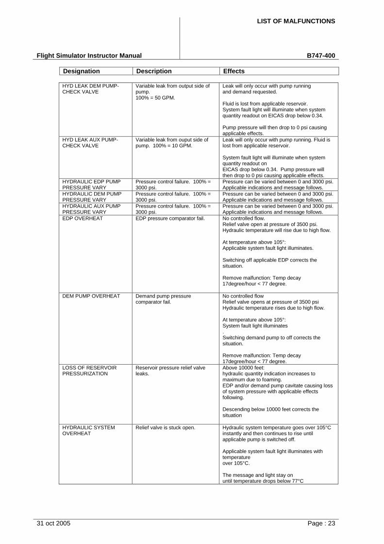
LIST OF MALFUNCTIONS
Flight Simulator Instructor Manual B747-400
Designation Description Effects
31 oct 2005 Page : 23
HYD LEAK DEM PUMP-CHECK VALVE
Variable leak from output side of pump. 100% = 50 GPM.
Leak will only occur with pump running and demand requested.
Fluid is lost from applicable reservoir. System fault light will illuminate when system quantity readout on EICAS drop below 0.34.
Pump pressure will then drop to 0 psi causing applicable effects.
HYD LEAK AUX PUMP-CHECK VALVE
Variable leak from ouput side of pump. 100% = 10 GPM.
Leak will only occur with pump running. Fluid is lost from applicable reservoir.
System fault light will illuminate when system quantity readout on EICAS drop below 0.34. Pump pressure will then drop to 0 psi causing applicable effects.
HYDRAULIC EDP PUMP PRESSURE VARY
Pressure control failure. 100% = 3000 psi.
Pressure can be varied between 0 and 3000 psi. Applicable indications and message follows.
HYDRAULIC DEM PUMP PRESSURE VARY
Pressure control failure. 100% = 3000 psi.
Pressure can be varied between 0 and 3000 psi. Applicable indications and message follows.
HYDRAULIC AUX PUMP PRESSURE VARY
Pressure control failure. 100% = 3000 psi.
Pressure can be varied between 0 and 3000 psi. Applicable indications and message follows.
EDP OVERHEAT EDP pressure comparator fail. No controlled flow. Relief valve open at pressure of 3500 psi. Hydraulic temperature will rise due to high flow.
At temperature above 105°: Applicable system fault light illuminates.
Switching off applicable EDP corrects the situation.
Remove malfunction: Temp decay 17degree/hour < 77 degree.
DEM PUMP OVERHEAT Demand pump pressure comparator fail.
No controlled flow Relief valve opens at pressure of 3500 psi Hydraulic temperature rises due to high flow.
At temperature above 105°: System fault light illuminates . Switching demand pump to off corrects the situation.
Remove malfunction: Temp decay 17degree/hour < 77 degree.
LOSS OF RESERVOIR PRESSURIZATION
Reservoir pressure relief valve leaks.
Above 10000 feet: hydraulic quantity indication increases to maximum due to foaming. EDP and/or demand pump cavitate causing loss of system pressure with applicable effects following.
Descending below 10000 feet corrects the situation
HYDRAULIC SYSTEM OVERHEAT
Relief valve is stuck open. Hydraulic system temperature goes over 105°C instantly and then continues to rise until applicable pump is switched off.
Applicable system fault light illuminates with temperature over 105°C.
The message and light stay on until temperature drops below 77°C

LIST OF MALFUNCTIONS
Flight Simulator Instructor Manual B747-400
Designation Description Effects
31 oct 2005 Page : 24
SYSTEM FAULT LIGHT ON System pressure switch gives false warning.
SYS FAULT light illuminates
Pressure indication turns amber on EICAS synoptic page
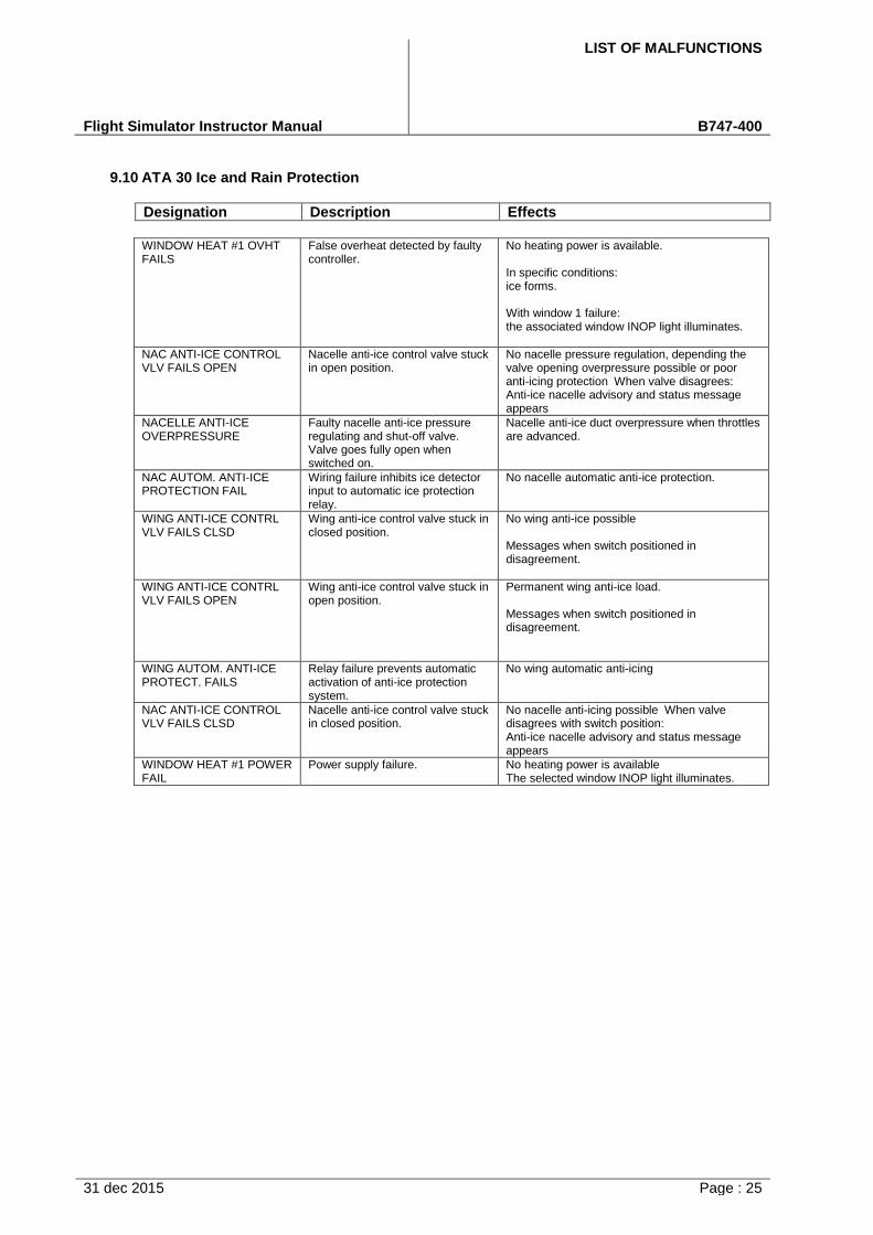
LIST OF MALFUNCTIONS
Flight Simulator Instructor Manual B747-400
31 dec 2015 Page : 25
9.10 ATA 30 Ice and Rain Protection
Designation Description Effects
WINDOW HEAT #1 OVHT FAILS
False overheat detected by faulty controller.
No heating power is available.
In specific conditions: ice forms.
With window 1 failure: the associated window INOP light illuminates.
NAC ANTI-ICE CONTROL VLV FAILS OPEN
Nacelle anti-ice control valve stuck in open position.
No nacelle pressure regulation, depending the valve opening overpressure possible or poor anti-icing protection When valve disagrees: Anti-ice nacelle advisory and status message appears
NACELLE ANTI-ICE OVERPRESSURE
Faulty nacelle anti-ice pressure regulating and shut-off valve. Valve goes fully open when switched on.
Nacelle anti-ice duct overpressure when throttles are advanced.
NAC AUTOM. ANTI-ICE PROTECTION FAIL
Wiring failure inhibits ice detector input to automatic ice protection relay.
No nacelle automatic anti-ice protection.
WING ANTI-ICE CONTRL VLV FAILS CLSD
Wing anti-ice control valve stuck in closed position.
No wing anti-ice possible
Messages when switch positioned in disagreement.
WING ANTI-ICE CONTRL VLV FAILS OPEN
Wing anti-ice control valve stuck in open position.
Permanent wing anti-ice load.
Messages when switch positioned in disagreement.
WING AUTOM. ANTI-ICE PROTECT. FAILS
Relay failure prevents automatic activation of anti-ice protection system.
No wing automatic anti-icing
NAC ANTI-ICE CONTROL VLV FAILS CLSD
Nacelle anti-ice control valve stuck in closed position.
No nacelle anti-icing possible When valve disagrees with switch position: Anti-ice nacelle advisory and status message appears
WINDOW HEAT #1 POWER FAIL
Power supply failure. No heating power is available The selected window INOP light illuminates.
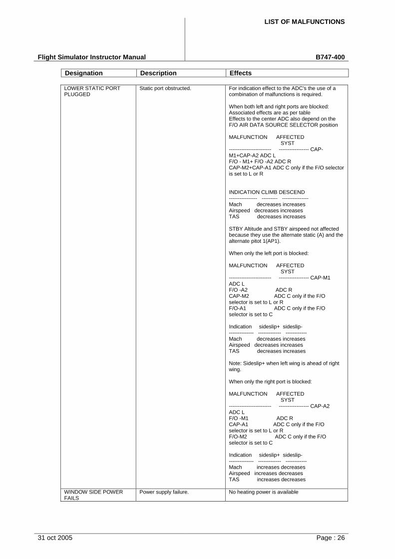
LIST OF MALFUNCTIONS
Flight Simulator Instructor Manual B747-400
Designation Description Effects
31 oct 2005 Page : 26
LOWER STATIC PORT PLUGGED
Static port obstructed. For indication effect to the ADC's the use of a combination of malfunctions is required.
When both left and right ports are blocked: Associated effects are as per table Effects to the center ADC also depend on the F/O AIR DATA SOURCE SELECTOR position
MALFUNCTION AFFECTED SYST
------------------------ ----------------- CAP-M1+CAP-A2 ADC L F/O - M1+ F/O -A2 ADC R CAP-M2+CAP-A1 ADC C only if the F/O selector is set to L or R
INDICATION CLIMB DESCEND ---------------- --------- --------------- Mach decreases increases Airspeed decreases increases TAS decreases increases
STBY Altitude and STBY airspeed not affected because they use the alternate static (A) and the alternate pitot 1(AP1).
When only the left port is blocked:
MALFUNCTION AFFECTED SYST
------------------------ ----------------- CAP-M1 ADC L F/O -A2 ADC R CAP-M2 ADC C only if the F/O selector is set to L or R F/O-A1 ADC C only if the F/O selector is set to C
Indication sideslip+ sideslip- -------------- ------------- ------------ Mach decreases increases Airspeed decreases increases TAS decreases increases
Note: Sideslip+ when left wing is ahead of right wing.
When only the right port is blocked:
MALFUNCTION AFFECTED SYST
------------------------ ----------------- CAP-A2 ADC L F/O -M1 ADC R CAP-A1 ADC C only if the F/O selector is set to L or R F/O-M2 ADC C only if the F/O selector is set to C
Indication sideslip+ sideslip- -------------- ------------- ------------ Mach increases decreases Airspeed increases decreases TAS increases decreases
WINDOW SIDE POWER FAILS
Power supply failure. No heating power is available
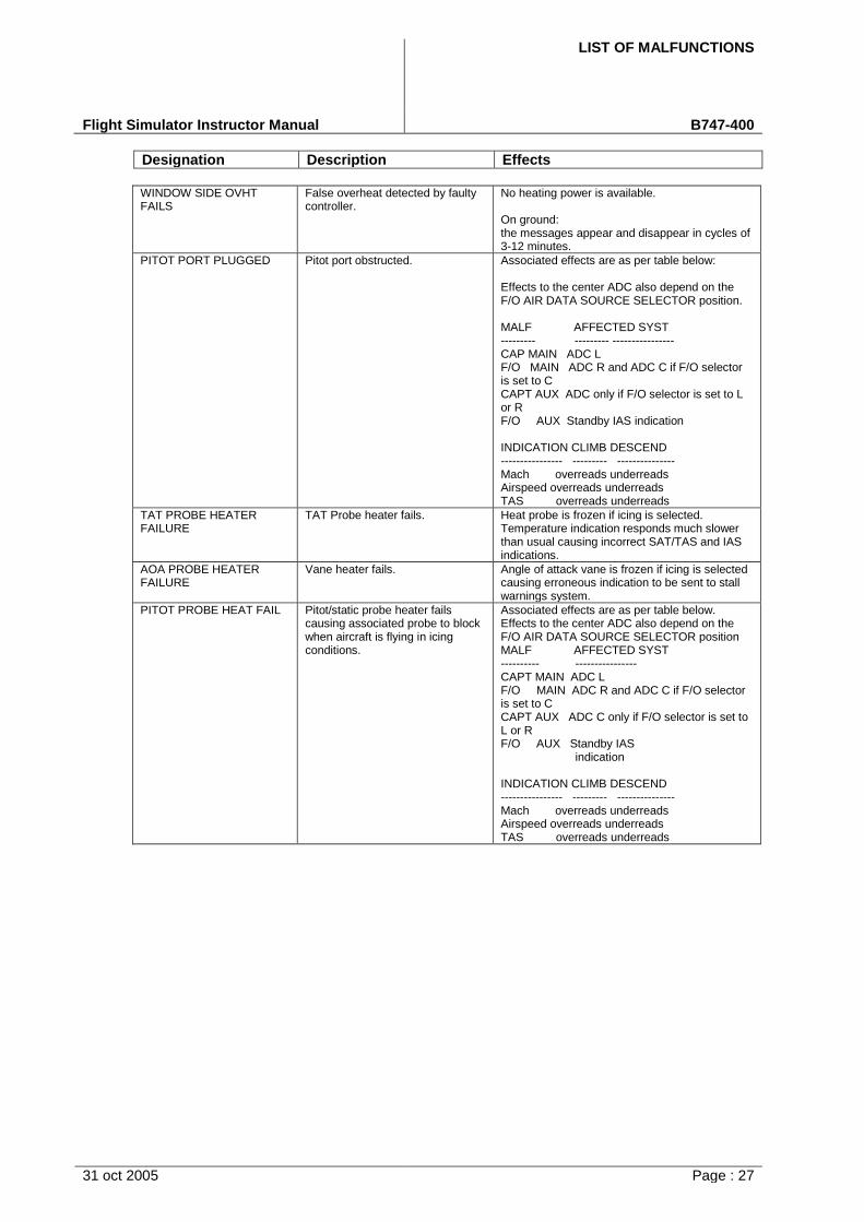
LIST OF MALFUNCTIONS
Flight Simulator Instructor Manual B747-400
Designation Description Effects
31 oct 2005 Page : 27
WINDOW SIDE OVHT FAILS
False overheat detected by faulty controller.
No heating power is available.
On ground: the messages appear and disappear in cycles of 3-12 minutes.
PITOT PORT PLUGGED Pitot port obstructed. Associated effects are as per table below:
Effects to the center ADC also depend on the F/O AIR DATA SOURCE SELECTOR position.
MALF AFFECTED SYST --------- --------- ---------------- CAP MAIN ADC L F/O MAIN ADC R and ADC C if F/O selector is set to C CAPT AUX ADC only if F/O selector is set to L or R F/O AUX Standby IAS indication
INDICATION CLIMB DESCEND ---------------- --------- --------------- Mach overreads underreads Airspeed overreads underreads TAS overreads underreads
TAT PROBE HEATER FAILURE
TAT Probe heater fails. Heat probe is frozen if icing is selected. Temperature indication responds much slower than usual causing incorrect SAT/TAS and IAS indications.
AOA PROBE HEATER FAILURE
Vane heater fails. Angle of attack vane is frozen if icing is selected causing erroneous indication to be sent to stall warnings system.
PITOT PROBE HEAT FAIL Pitot/static probe heater fails causing associated probe to block when aircraft is flying in icing conditions.
Associated effects are as per table below. Effects to the center ADC also depend on the F/O AIR DATA SOURCE SELECTOR position MALF AFFECTED SYST ---------- ---------------- CAPT MAIN ADC L F/O MAIN ADC R and ADC C if F/O selector is set to C CAPT AUX ADC C only if F/O selector is set to L or R F/O AUX Standby IAS
indication
INDICATION CLIMB DESCEND ---------------- --------- --------------- Mach overreads underreads Airspeed overreads underreads TAS overreads underreads
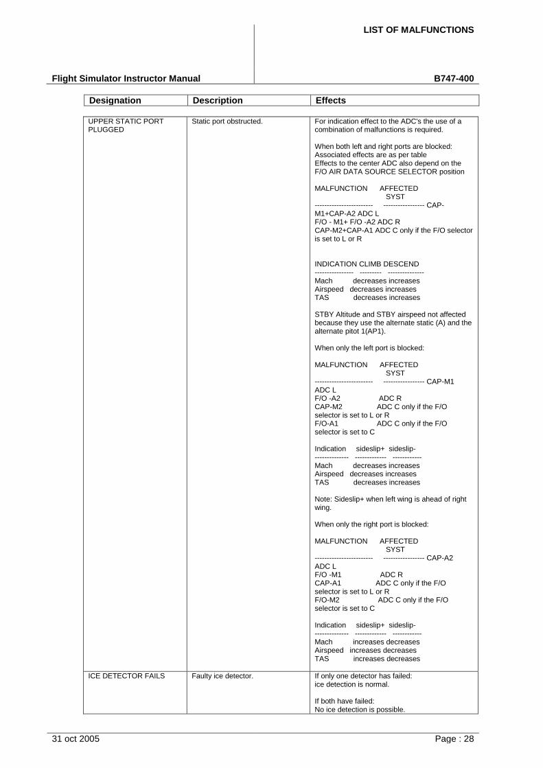
LIST OF MALFUNCTIONS
Flight Simulator Instructor Manual B747-400
Designation Description Effects
31 oct 2005 Page : 28
UPPER STATIC PORT PLUGGED
Static port obstructed. For indication effect to the ADC's the use of a combination of malfunctions is required.
When both left and right ports are blocked: Associated effects are as per table Effects to the center ADC also depend on the F/O AIR DATA SOURCE SELECTOR position
MALFUNCTION AFFECTED SYST
------------------------ ----------------- CAP-M1+CAP-A2 ADC L F/O - M1+ F/O -A2 ADC R CAP-M2+CAP-A1 ADC C only if the F/O selector is set to L or R
INDICATION CLIMB DESCEND ---------------- --------- --------------- Mach decreases increases Airspeed decreases increases TAS decreases increases
STBY Altitude and STBY airspeed not affected because they use the alternate static (A) and the alternate pitot 1(AP1).
When only the left port is blocked:
MALFUNCTION AFFECTED SYST
------------------------ ----------------- CAP-M1 ADC L F/O -A2 ADC R CAP-M2 ADC C only if the F/O selector is set to L or R F/O-A1 ADC C only if the F/O selector is set to C
Indication sideslip+ sideslip- -------------- ------------- ------------ Mach decreases increases Airspeed decreases increases TAS decreases increases
Note: Sideslip+ when left wing is ahead of right wing.
When only the right port is blocked:
MALFUNCTION AFFECTED SYST
------------------------ ----------------- CAP-A2 ADC L F/O -M1 ADC R CAP-A1 ADC C only if the F/O selector is set to L or R F/O-M2 ADC C only if the F/O selector is set to C
Indication sideslip+ sideslip- -------------- ------------- ------------ Mach increases decreases Airspeed increases decreases TAS increases decreases
ICE DETECTOR FAILS Faulty ice detector. If only one detector has failed: ice detection is normal.
If both have failed: No ice detection is possible.

LIST OF MALFUNCTIONS
Flight Simulator Instructor Manual B747-400
Designation Description Effects
31 oct 2005 Page : 29
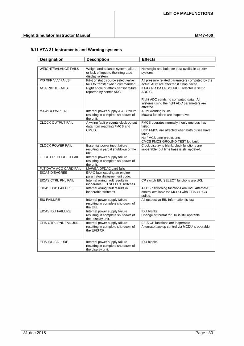
LIST OF MALFUNCTIONS
Flight Simulator Instructor Manual B747-400
31 dec 2015 Page : 30
9.11 ATA 31 Instruments and Warning systems
Designation Description Effects
WEIGHT/BALANCE FAILS Weight and balance system failure or lack of input to the integrated display system.
No weight and balance data available to user systems.
P/S XFR VLV FAILS Pitot or static source select valve fails to transfer when commanded.
All pressure related parameters computed by the actual ADC are affected if it has failed.
AOA RIGHT FAILS Right angle of attack sensor failure reported by center ADC.
If F/O AIR DATA SOURCE selector is set to ADC C
Right ADC sends no computed data. All systems using the right ADC parameters are affected.
MAWEA PWR FAIL Internal power supply A & B failure resulting in complete shutdown of the unit.
Aural warning is U/S Mawea functions are inoperative
CLOCK OUTPUT FAIL A wiring fault prevents clock output data from reaching FMCS and CMCS.
FMCS operates normally if only one bus has failed. Both FMCS are affected when both buses have failed. No FMCS time predictions. CMCS FMCS GROUND TEST log fault.
CLOCK POWER FAIL Essential power input failure resulting in partial shutdown of the unit.
Clock display is blank, clock functions are inoperable, but time base is still updated.
FLIGHT RECORDER FAIL Internal power supply failure resulting in complete shutdown of the unit.
FLT DATA ACQ CARD FAIL MAWEA DFDAC card fails
EICAS DISAGREE EIU-C fault causing an engine parameter disagreement code.
EICAS CTRL PNL FAIL Internal wiring fault results in inoperable EIU SELECT switches.
CP switch EIU SELECT functions are U/S.
EICAS DSP FAILURE Internal wiring fault results in inoperable switches.
All DSP switching functions are U/S. Alternate control available via MCDU with EFIS CP CB pulled.
EIU FAILURE Internal power supply failure resulting in complete shutdown of the EIU.
All respective EIU information is lost
EICAS IDU FAILURE Internal power supply failure resulting in complete shutdown of the display unit.
IDU blanks Change of format for DU is still operable
EFIS CTRL PNL FAILURE. Internal power supply failure resulting in complete shutdown of the EFIS CP.
EFIS CP functions are inoperable Alternate backup control via MCDU is operable
EFIS IDU FAILURE Internal power supply failure resulting in complete shutdown of the display unit.
IDU blanks
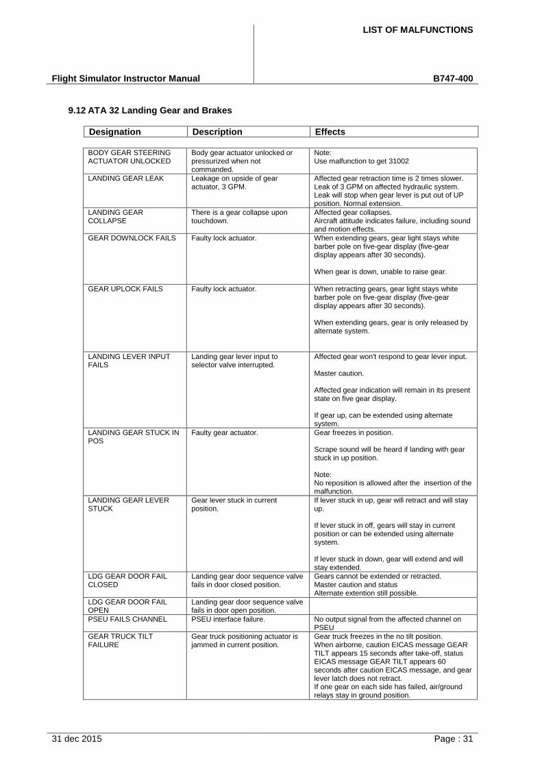
LIST OF MALFUNCTIONS
Flight Simulator Instructor Manual B747-400
31 dec 2015 Page : 31
9.12 ATA 32 Landing Gear and Brakes
Designation Description Effects
BODY GEAR STEERING ACTUATOR UNLOCKED
Body gear actuator unlocked or pressurized when not commanded.
Note: Use malfunction to get 31002
LANDING GEAR LEAK Leakage on upside of gear actuator, 3 GPM.
Affected gear retraction time is 2 times slower. Leak of 3 GPM on affected hydraulic system. Leak will stop when gear lever is put out of UP position. Normal extension.
LANDING GEAR COLLAPSE
There is a gear collapse upon touchdown.
Affected gear collapses. Aircraft attitude indicates failure, including sound and motion effects.
GEAR DOWNLOCK FAILS Faulty lock actuator. When extending gears, gear light stays white barber pole on five-gear display (five-gear display appears after 30 seconds).
When gear is down, unable to raise gear.
GEAR UPLOCK FAILS Faulty lock actuator. When retracting gears, gear light stays white barber pole on five-gear display (five-gear display appears after 30 seconds).
When extending gears, gear is only released by alternate system.
LANDING LEVER INPUT FAILS
Landing gear lever input to selector valve interrupted.
Affected gear won't respond to gear lever input.
Master caution.
Affected gear indication will remain in its present state on five gear display.
If gear up, can be extended using alternate system.
LANDING GEAR STUCK IN POS
Faulty gear actuator. Gear freezes in position.
Scrape sound will be heard if landing with gear stuck in up position.
Note: No reposition is allowed after the insertion of the malfunction.
LANDING GEAR LEVER STUCK
Gear lever stuck in current position.
If lever stuck in up, gear will retract and will stay up.
If lever stuck in off, gears will stay in current position or can be extended using alternate system.
If lever stuck in down, gear will extend and will stay extended.
LDG GEAR DOOR FAIL CLOSED
Landing gear door sequence valve fails in door closed position.
Gears cannot be extended or retracted. Master caution and status Alternate extention still possible.
LDG GEAR DOOR FAIL OPEN
Landing gear door sequence valve fails in door open position.
PSEU FAILS CHANNEL PSEU interface failure. No output signal from the affected channel on PSEU
GEAR TRUCK TILT FAILURE
Gear truck positioning actuator is jammed in current position.
Gear truck freezes in the no tilt position. When airborne, caution EICAS message GEAR TILT appears 15 seconds after take-off, status EICAS message GEAR TILT appears 60 seconds after caution EICAS message, and gear lever latch does not retract. If one gear on each side has failed, air/ground relays stay in ground position.
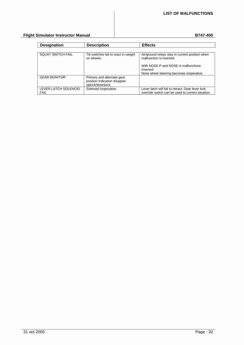
LIST OF MALFUNCTIONS
Flight Simulator Instructor Manual B747-400
Designation Description Effects
31 oct 2005 Page : 32
SQUAT SWITCH FAIL Tilt switches fail to react to weight on wheels.
Air/ground relays stay in current position when malfunction is inserted.
With NOSE-P and NOSE-A malfunctions inserted: Nose wheel steering becomes inoperative.
GEAR MONITOR Primary and alternate gear position indication disagree uplock/downlock.
LEVER LATCH SOLENOID FAIL
Solenoid inoperative. Lever latch will fail to retract. Gear lever lock override switch can be used to correct situation.

LIST OF MALFUNCTIONS
Flight Simulator Instructor Manual B747-400
31 dec 2015 Page : 33
9.13 ATA 33 Instruments
Designation Description Effects
N/A
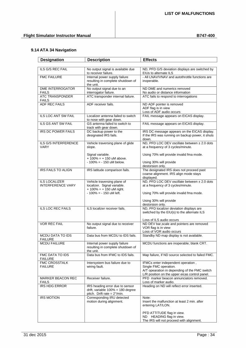
LIST OF MALFUNCTIONS
Flight Simulator Instructor Manual B747-400
31 dec 2015 Page : 34
9.14 ATA 34 Navigation
Designation Description Effects
ILS G/S REC FAIL No output signal is available due to receiver failure.
ND, PFD G/S deviation displays are switched by EIUs to alternate ILS
FMC FAILURE Internal power supply failure resulting in complete shutdown of the unit.
- All LNAV/VNAV and autothrottle functions areinoperable.
DME INTERROGATOR FAILS
No output signal due to an interrogator failure.
ND DME and numerics removed No audio or distance information
ATC TRANSPONDER FAILS
ATC transponder internal failure. ATC fails to respond to interrogations
ADF REC FAILS ADF receiver fails. ND ADF pointer is removed ADF flag is in view Loss of ADF audio occurs
ILS LOC ANT SW FAIL Localizer antenna failed to switch to nose with gear down.
FAIL message appears on EICAS display.
ILS GS ANT SW FAIL GS antenna failed to switch to track with gear down.
FAIL message appears on EICAS display.
IRS DC POWER FAILS DC backup power to the designated IRS fails.
IRS DC message appears on the EICAS display. If the IRS was running on backup power, it shuts down.
ILS G/S INTERFERENCE VARY
Vehicle traversing plane of glide slope.
Signal variable. + 100% = + 150 uM above.- 100% = - 150 uM below.
ND, PFD LOC DEV oscillate between ± 2.0 dots at a frequency of 3 cycles/minute.
Using 70% will provide invalid fma mode.
Using 30% will provide destorsion only.
IRS FAILS TO ALIGN IRS latitude comparison fails. The designated IRS does not proceed past coarse alignment. IRS align mode stays displayed.
ILS LOCALIZER INTERFERENCE VARY
Vehicle traversing plane of localizer. Signal variable. + 100% = + 150 uM right.- 100% = - 150 uM left.
ND, PFD LOC DEV oscillate between ± 2.0 dots at a frequency of 3 cycles/minute.
Using 70% will provide invalid fma mode.
Using 30% will provide destorsion only.
ILS LOC REC FAILS ILS localizer receiver fails. ND, PFD localizer deviation displays are switched by the EIU(s) to the alternate ILS
Loss of ILS audio occurs
VOR REC FAIL No output signal due to receiver failure.
ND DEV bar,scale and pointers are removed VOR flag is in view Loss of VOR audio occurs
MCDU DATA TO IDS FAILURE
Data bus from MCDU to IDS fails. Standby ND map display is not available.
MCDU FAILURE Internal power supply failure resulting in complete shutdown of the unit.
MCDU functions are inoperable; blank CRT.
FMC DATA TO IDS FAILURE
Data bus from IFMC to IDS fails. Map failure, if ND source selected to failed FMC.
FMC CROSSTALK FAILURE
Intersystem bus failure due to wiring fault.
IFMCs enter independent operation , Single FMC operation. A/T opearation in depending of the FMC switch L/R position on the upper eicas control panel.
MARKER BEACON REC FAILS
Receiver failure. PFD marker beacon annunciators removed. Loss of marker audio.
IRS HDG ERROR IRS heading error due to sensor drift, variable 100% = 180 degree pitch. Drift rate = 2°/min.
Heading on ND will reflect error inserted.
IRS MOTION Corresponding IRU detected motion during alignment.
Note: Insert the malfunction at least 2 min. after entering LAT/LON.
PFD ATTITUDE flag in view. ND HEADING flag in view. The IRS will not proceed with alignment.
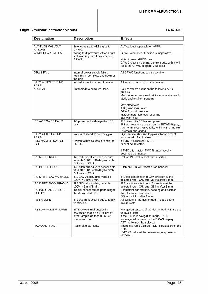
LIST OF MALFUNCTIONS
Flight Simulator Instructor Manual B747-400
Designation Description Effects
31 oct 2005 Page : 35
ALTITUDE CALLOUT FAILURE
Erroneous radio ALT signal to GPWC.
ALT callout inoperable on APPR.
WINDSHEAR SYS FAIL Wiring fault prevents left and right stall warning data from reaching GPWS.
GPWS wind shear function is inoperative.
Note: to reset GPWS use GPWS reset on general control page, which will reset the GPWS in approx. 40 sec's.
GPWS FAIL Internal power supply failure resulting in complete shutdown of the unit.
All GPWC functions are inoperable.
STBY ALTIMETER IND FAILS
Indicator stuck in current position. Altimeter pointer freezes in position.
ADC FAIL Total air data computer fails. Failure effects occur on the following ADC outputs: Mach number, airspeed, attitude, true airspeed, static and total temperature.
May effect also: ATC, windshear alert, GPWS grond prox alert, altitude alert, flap load relief and stall warnings.
IRS AC POWER FAILS AC power to the designated IRS fails.
IRS reverts to DC backup power. IRS ac message appears on the EICAS display. After 5 minutes, IRS C fails, while IRS L and IRS R remain operational.
STBY ATTITUDE IND FAILS
Failure of standby horizon gyro. Gyro decelerates and topples after approx. 9 minutes with flag in view.
FMC MASTER SWITCH FAIL
Switch failure causes it to stick to FMC R.
If FMC R is master, FMC L cannot be selected.
If FMC L is master, FMC R automatically becomes the master.
IRS ROLL ERROR IRS roll error due to sensor drift, variable 100% = 90 degree pitch. Drift rate = 2°/min.
Roll on PFD will reflect error inserted.
IRS PITCH ERROR IRS pitch error due to sensor drift, variable 100% = 90 degree pitch. Drift rate = 2°/min.
Pitch on PFD will reflect error inserted.
IRS DRIFT, E/W VARIABLE IRS E/W velocity drift, variable 100% = 3 nmi/5 min.
IRS position drifts in a E/W direction at the selected rate. G/S error 36 kts after 5 min.
IRS DRIFT, N/S VARIABLE IRS N/S velocity drift, variable 100% = 3 nmi/5 min.
IRS position drifts in a N/S direction at the selected rate. G/S error 36 kts after 5 min.
IRS INERTIAL SENSOR FAILURE
Inertial sensor failure pertaining to the designated IRS.
Simulataneous attitude, heading and position drift due to sensor failure. G/S error 8 kts after 1 min.
IRS FAILURE IRS overheat occurs due to faulty ventilation.
All outputs of the designated IRS are set to invalid state.
IRS NAV MODE FAILURE BITE detects malfunction in navigation mode only (failure of either amplitude test or 3500V power supply).
Navigation outputs of the designated IRS are set to invalid state. If the IRS is in navigation mode, FAULT message will appear on the EICAS display. ATT mode must be selected.
RADIO ALT FAIL Radio altimeter fails. There is a radio altimeter failure indication on the PFD. CMC RA self-test failure message appears on MCDUs.
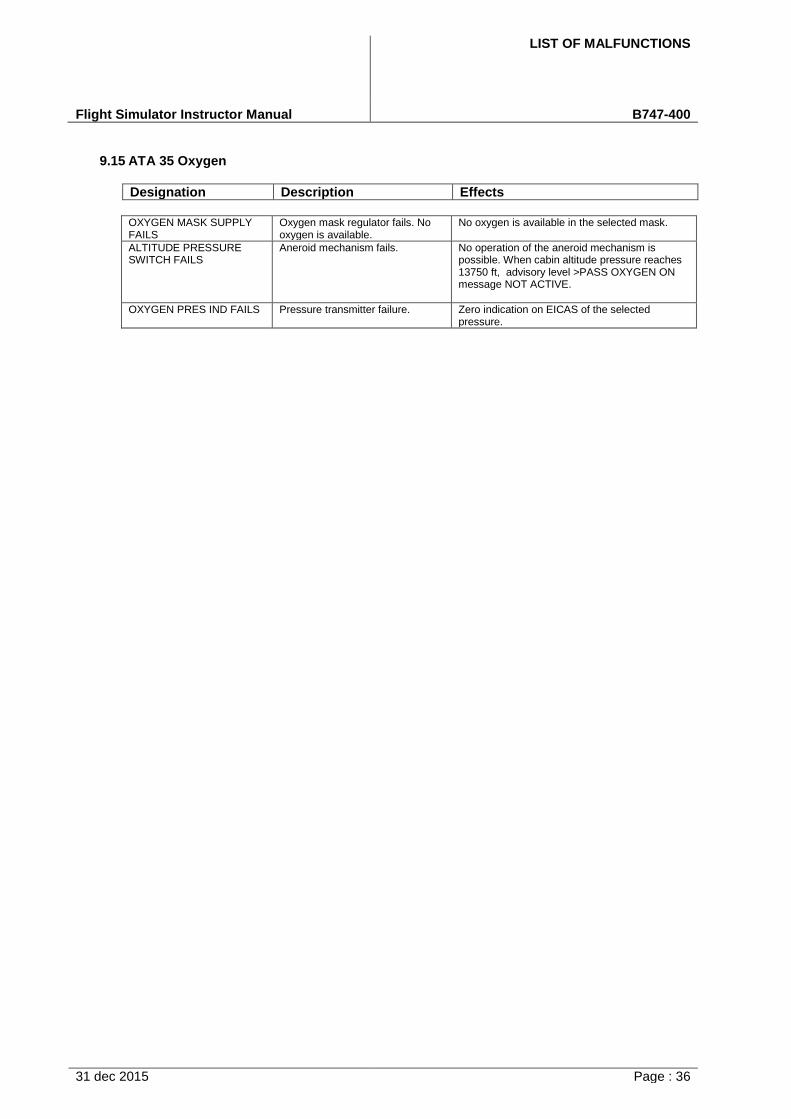
LIST OF MALFUNCTIONS
Flight Simulator Instructor Manual B747-400
31 dec 2015 Page : 36
9.15 ATA 35 Oxygen
Designation Description Effects
OXYGEN MASK SUPPLY FAILS
Oxygen mask regulator fails. No oxygen is available.
No oxygen is available in the selected mask.
ALTITUDE PRESSURE SWITCH FAILS
Aneroid mechanism fails. No operation of the aneroid mechanism is possible. When cabin altitude pressure reaches 13750 ft, advisory level >PASS OXYGEN ON message NOT ACTIVE.
OXYGEN PRES IND FAILS Pressure transmitter failure. Zero indication on EICAS of the selected pressure.
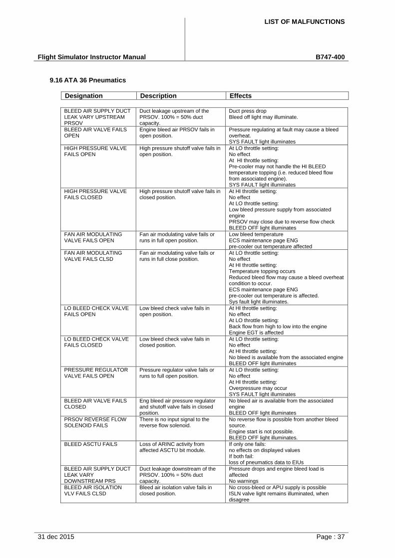
LIST OF MALFUNCTIONS
Flight Simulator Instructor Manual B747-400
31 dec 2015 Page : 37
9.16 ATA 36 Pneumatics
Designation Description Effects
BLEED AIR SUPPLY DUCT LEAK VARY UPSTREAM PRSOV
Duct leakage upstream of the PRSOV. 100% = 50% duct capacity.
Duct press drop Bleed off light may illuminate.
BLEED AIR VALVE FAILS OPEN
Engine bleed air PRSOV fails in open position.
Pressure regulating at fault may cause a bleed overheat. SYS FAULT light illuminates
HIGH PRESSURE VALVE FAILS OPEN
High pressure shutoff valve fails in open position.
At LO throttle setting: No effect At HI throttle setting: Pre-cooler may not handle the HI BLEED temperature topping (i.e. reduced bleed flow from associated engine). SYS FAULT light illuminates
HIGH PRESSURE VALVE FAILS CLOSED
High pressure shutoff valve fails in closed position.
At HI throttle setting: No effect At LO throttle setting: Low bleed pressure supply from associated engine PRSOV may close due to reverse flow check BLEED OFF light illuminates
FAN AIR MODULATING VALVE FAILS OPEN
Fan air modulating valve fails or runs in full open position.
Low bleed temperature ECS maintenance page ENG pre-cooler out temperature affected
FAN AIR MODULATING VALVE FAILS CLSD
Fan air modulating valve fails or runs in full close position.
At LO throttle setting: No effect At HI throttle setting: Temperature topping occurs Reduced bleed flow may cause a bleed overheat condition to occur. ECS maintenance page ENG pre-cooler out temperature is affected. Sys fault light illuminates.
LO BLEED CHECK VALVE FAILS OPEN
Low bleed check valve fails in open position.
At HI throttle setting: No effect At LO throttle setting: Back flow from high to low into the engine Engine EGT is affected
LO BLEED CHECK VALVE FAILS CLOSED
Low bleed check valve fails in closed position.
At LO throttle setting: No effect At HI throttle setting: No bleed is available from the associated engine BLEED OFF light illuminates
PRESSURE REGULATOR VALVE FAILS OPEN
Pressure regulator valve fails or runs to full open position.
At LO throttle setting: No effect At HI throttle setting: Overpressure may occur SYS FAULT light illuminates
BLEED AIR VALVE FAILS CLOSED
Eng bleed air pressure regulator and shutoff valve fails in closed position.
No bleed air is available from the associated engine BLEED OFF light illuminates
PRSOV REVERSE FLOW SOLENOID FAILS
There is no input signal to the reverse flow solenoid.
No reverse flow is possible from another bleed source. Engine start is not possible. BLEED OFF light illuminates.
BLEED ASCTU FAILS Loss of ARINC activity from affected ASCTU bit module.
If only one fails: no effects on displayed values If both fail: loss of pneumatics data to EIUs
BLEED AIR SUPPLY DUCT LEAK VARY DOWNSTREAM PRS
Duct leakage downstream of the PRSOV. 100% = 50% duct capacity.
Pressure drops and engine bleed load is affected No warnings
BLEED AIR ISOLATION VLV FAILS CLSD
Bleed air isolation valve fails in closed position.
No cross-bleed or APU supply is possible ISLN valve light remains illuminated, when disagree
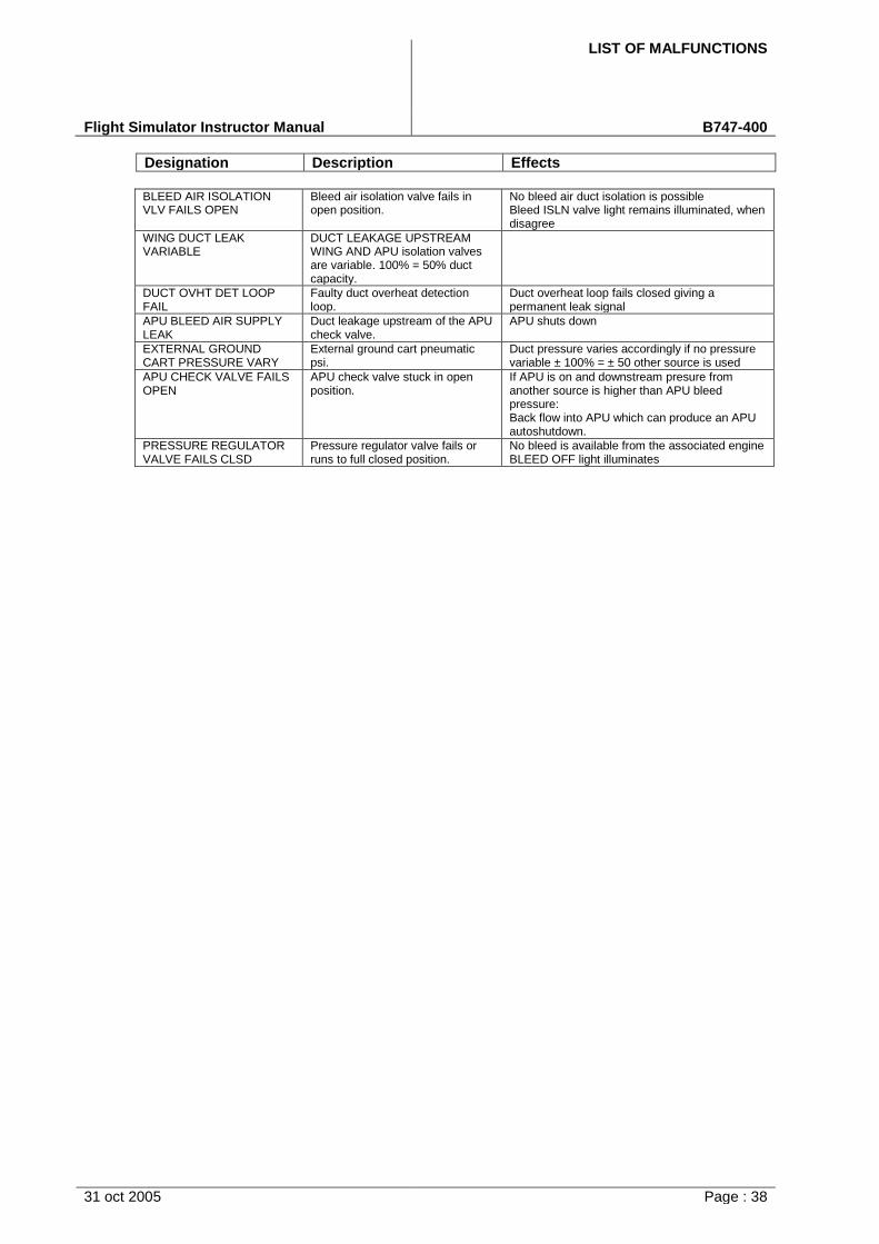
LIST OF MALFUNCTIONS
Flight Simulator Instructor Manual B747-400
Designation Description Effects
31 oct 2005 Page : 38
BLEED AIR ISOLATION VLV FAILS OPEN
Bleed air isolation valve fails in open position.
No bleed air duct isolation is possible Bleed ISLN valve light remains illuminated, when disagree
WING DUCT LEAK VARIABLE
DUCT LEAKAGE UPSTREAM WING AND APU isolation valves are variable. 100% = 50% duct capacity.
DUCT OVHT DET LOOP FAIL
Faulty duct overheat detection loop.
Duct overheat loop fails closed giving a permanent leak signal
APU BLEED AIR SUPPLY LEAK
Duct leakage upstream of the APU check valve.
APU shuts down
EXTERNAL GROUND CART PRESSURE VARY
External ground cart pneumatic psi.
Duct pressure varies accordingly if no pressure variable ± 100% = ± 50 other source is used
APU CHECK VALVE FAILS OPEN
APU check valve stuck in open position.
If APU is on and downstream presure from another source is higher than APU bleed pressure: Back flow into APU which can produce an APU autoshutdown.
PRESSURE REGULATOR VALVE FAILS CLSD
Pressure regulator valve fails or runs to full closed position.
No bleed is available from the associated engine BLEED OFF light illuminates
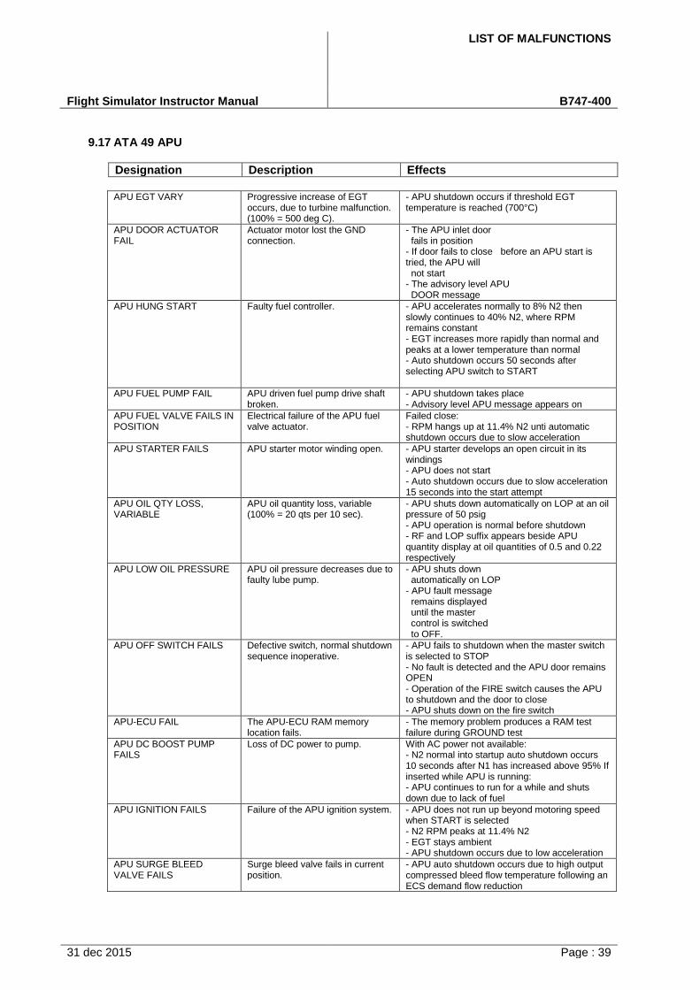
LIST OF MALFUNCTIONS
Flight Simulator Instructor Manual B747-400
31 dec 2015 Page : 39
9.17 ATA 49 APU
Designation Description Effects
APU EGT VARY Progressive increase of EGT occurs, due to turbine malfunction. (100% = 500 deg C).
- APU shutdown occurs if threshold EGTtemperature is reached (700°C)
APU DOOR ACTUATOR FAIL
Actuator motor lost the GND connection.
- The APU inlet doorfails in position
- If door fails to close before an APU start istried, the APU will
not start- The advisory level APU
DOOR message
APU HUNG START Faulty fuel controller. - APU accelerates normally to 8% N2 thenslowly continues to 40% N2, where RPMremains constant- EGT increases more rapidly than normal andpeaks at a lower temperature than normal- Auto shutdown occurs 50 seconds afterselecting APU switch to START
APU FUEL PUMP FAIL APU driven fuel pump drive shaft broken.
- APU shutdown takes place- Advisory level APU message appears on
APU FUEL VALVE FAILS IN POSITION
Electrical failure of the APU fuel valve actuator.
Failed close: - RPM hangs up at 11.4% N2 unti automaticshutdown occurs due to slow acceleration
APU STARTER FAILS APU starter motor winding open. - APU starter develops an open circuit in itswindings- APU does not start- Auto shutdown occurs due to slow acceleration15 seconds into the start attempt
APU OIL QTY LOSS, VARIABLE
APU oil quantity loss, variable (100% = 20 qts per 10 sec).
- APU shuts down automatically on LOP at an oilpressure of 50 psig- APU operation is normal before shutdown- RF and LOP suffix appears beside APUquantity display at oil quantities of 0.5 and 0.22respectively
APU LOW OIL PRESSURE APU oil pressure decreases due to faulty lube pump.
- APU shuts downautomatically on LOP
- APU fault messageremains displayeduntil the mastercontrol is switchedto OFF.
APU OFF SWITCH FAILS Defective switch, normal shutdown sequence inoperative.
- APU fails to shutdown when the master switchis selected to STOP- No fault is detected and the APU door remainsOPEN- Operation of the FIRE switch causes the APUto shutdown and the door to close- APU shuts down on the fire switch
APU-ECU FAIL The APU-ECU RAM memory location fails.
- The memory problem produces a RAM testfailure during GROUND test
APU DC BOOST PUMP FAILS
Loss of DC power to pump. With AC power not available: - N2 normal into startup auto shutdown occurs10 seconds after N1 has increased above 95% Ifinserted while APU is running:- APU continues to run for a while and shutsdown due to lack of fuel
APU IGNITION FAILS Failure of the APU ignition system. - APU does not run up beyond motoring speedwhen START is selected- N2 RPM peaks at 11.4% N2- EGT stays ambient- APU shutdown occurs due to low acceleration
APU SURGE BLEED VALVE FAILS
Surge bleed valve fails in current position.
- APU auto shutdown occurs due to high outputcompressed bleed flow temperature following anECS demand flow reduction
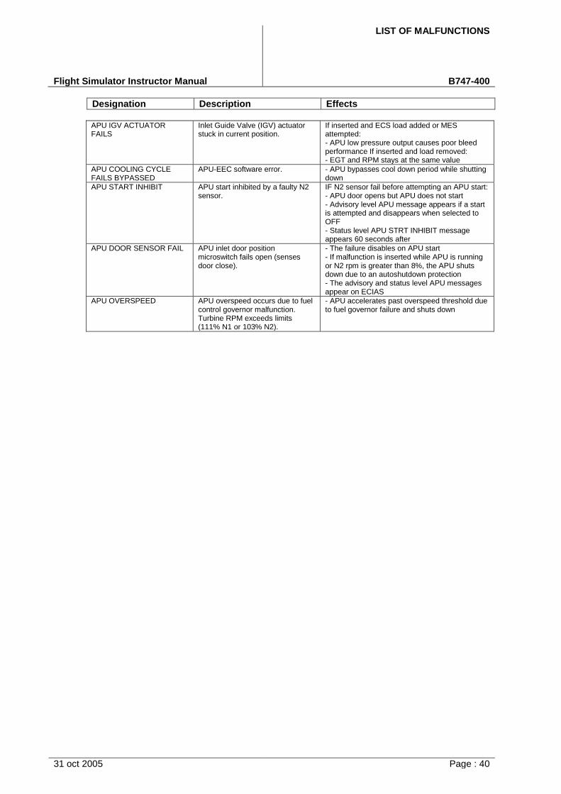
LIST OF MALFUNCTIONS
Flight Simulator Instructor Manual B747-400
Designation Description Effects
31 oct 2005 Page : 40
APU IGV ACTUATOR FAILS
Inlet Guide Valve (IGV) actuator stuck in current position.
If inserted and ECS load added or MES attempted: - APU low pressure output causes poor bleedperformance If inserted and load removed:- EGT and RPM stays at the same value
APU COOLING CYCLE FAILS BYPASSED
APU-EEC software error. - APU bypasses cool down period while shuttingdown
APU START INHIBIT APU start inhibited by a faulty N2 sensor.
IF N2 sensor fail before attempting an APU start: - APU door opens but APU does not start- Advisory level APU message appears if a startis attempted and disappears when selected toOFF- Status level APU STRT INHIBIT messageappears 60 seconds after
APU DOOR SENSOR FAIL APU inlet door position microswitch fails open (senses door close).
- The failure disables on APU start- If malfunction is inserted while APU is runningor N2 rpm is greater than 8%, the APU shutsdown due to an autoshutdown protection- The advisory and status level APU messagesappear on ECIAS
APU OVERSPEED APU overspeed occurs due to fuel control governor malfunction. Turbine RPM exceeds limits (111% N1 or 103% N2).
- APU accelerates past overspeed threshold dueto fuel governor failure and shuts down
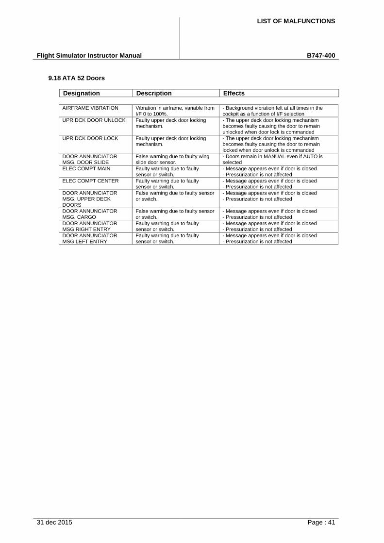
LIST OF MALFUNCTIONS
Flight Simulator Instructor Manual B747-400
31 dec 2015 Page : 41
9.18 ATA 52 Doors
Designation Description Effects
AIRFRAME VIBRATION Vibration in airframe, variable from I/F 0 to 100%.
- Background vibration felt at all times in thecockpit as a function of I/F selection
UPR DCK DOOR UNLOCK Faulty upper deck door locking mechanism.
- The upper deck door locking mechanismbecomes faulty causing the door to remainunlocked when door lock is commanded
UPR DCK DOOR LOCK Faulty upper deck door locking mechanism.
- The upper deck door locking mechanismbecomes faulty causing the door to remainlocked when door unlock is commanded
DOOR ANNUNCIATOR MSG. DOOR SLIDE
False warning due to faulty wing slide door sensor.
- Doors remain in MANUAL even if AUTO isselected
ELEC COMPT MAIN Faulty warning due to faulty sensor or switch.
- Message appears even if door is closed- Pressurization is not affected
ELEC COMPT CENTER Faulty warning due to faulty sensor or switch.
- Message appears even if door is closed- Pressurization is not affected
DOOR ANNUNCIATOR MSG. UPPER DECK DOORS
False warning due to faulty sensor or switch.
- Message appears even if door is closed- Pressurization is not affected
DOOR ANNUNCIATOR MSG. CARGO
False warning due to faulty sensor or switch.
- Message appears even if door is closed- Pressurization is not affected
DOOR ANNUNCIATOR MSG RIGHT ENTRY
Faulty warning due to faulty sensor or switch.
- Message appears even if door is closed- Pressurization is not affected
DOOR ANNUNCIATOR MSG LEFT ENTRY
Faulty warning due to faulty sensor or switch.
- Message appears even if door is closed- Pressurization is not affected

LIST OF MALFUNCTIONS
Flight Simulator Instructor Manual B747-400
31 dec 2015 Page : 42
9.19 ATA 71 Power Plant
Designation Description Effects
N/A
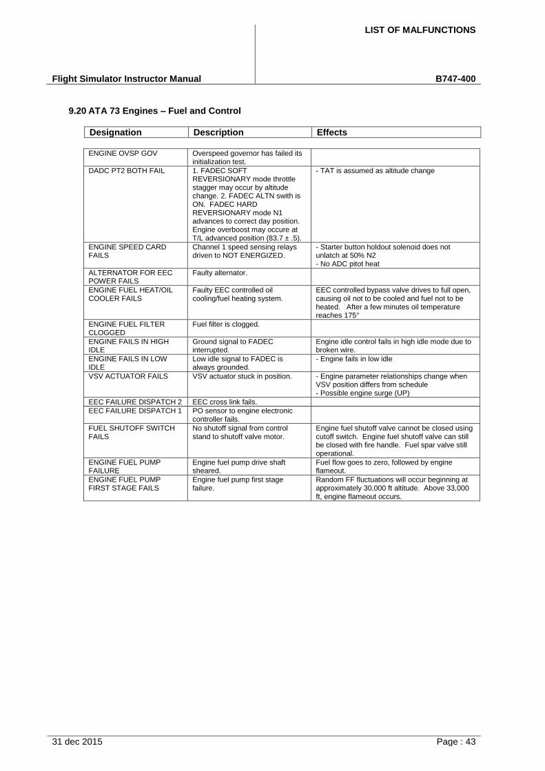
LIST OF MALFUNCTIONS
Flight Simulator Instructor Manual B747-400
31 dec 2015 Page : 43
9.20 ATA 73 Engines – Fuel and Control
Designation Description Effects
ENGINE OVSP GOV Overspeed governor has failed its initialization test.
DADC PT2 BOTH FAIL 1. FADEC SOFTREVERSIONARY mode throttlestagger may occur by altitudechange. 2. FADEC ALTN swith isON. FADEC HARDREVERSIONARY mode N1advances to correct day position.Engine overboost may occure atT/L advanced position (83.7 ± .5).
- TAT is assumed as altitude change
ENGINE SPEED CARD FAILS
Channel 1 speed sensing relays driven to NOT ENERGIZED.
- Starter button holdout solenoid does notunlatch at 50% N2- No ADC pitot heat
ALTERNATOR FOR EEC POWER FAILS
Faulty alternator.
ENGINE FUEL HEAT/OIL COOLER FAILS
Faulty EEC controlled oil cooling/fuel heating system.
EEC controlled bypass valve drives to full open, causing oil not to be cooled and fuel not to be heated. After a few minutes oil temperature reaches 175°
ENGINE FUEL FILTER CLOGGED
Fuel filter is clogged.
ENGINE FAILS IN HIGH IDLE
Ground signal to FADEC interrupted.
Engine idle control fails in high idle mode due to broken wire.
ENGINE FAILS IN LOW IDLE
Low idle signal to FADEC is always grounded.
- Engine fails in low idle
VSV ACTUATOR FAILS VSV actuator stuck in position. - Engine parameter relationships change whenVSV position differs from schedule- Possible engine surge (UP)
EEC FAILURE DISPATCH 2 EEC cross link fails.
EEC FAILURE DISPATCH 1 PO sensor to engine electronic controller fails.
FUEL SHUTOFF SWITCH FAILS
No shutoff signal from control stand to shutoff valve motor.
Engine fuel shutoff valve cannot be closed using cutoff switch. Engine fuel shutoff valve can still be closed with fire handle. Fuel spar valve still operational.
ENGINE FUEL PUMP FAILURE
Engine fuel pump drive shaft sheared.
Fuel flow goes to zero, followed by engine flameout.
ENGINE FUEL PUMP FIRST STAGE FAILS
Engine fuel pump first stage failure.
Random FF fluctuations will occur beginning at approximately 30,000 ft altitude. Above 33,000 ft, engine flameout occurs.
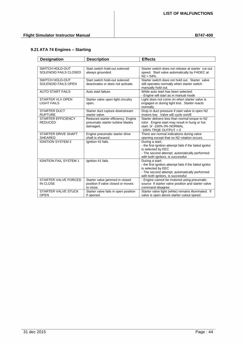
LIST OF MALFUNCTIONS
Flight Simulator Instructor Manual B747-400
31 dec 2015 Page : 44
9.21 ATA 74 Engines – Starting
Designation Description Effects
SWITCH HOLD-OUT SOLENOID FAILS CLOSED
Start switch hold-out solenoid always grounded.
Starter switch does not release at starter cut-out speed. Start valve automatically by FADEC at N2 > 54%.
SWITCH HOLD-OUT SOLENOID FAILS OPEN
Start switch hold-out solenoid deactivates or does not activate.
Starter switch does not hold out. Starter valve still operates normally when starter switch manually hold out.
AUTO START FAILS Auto start failure. While auto start has been selected: - Engine will start as in manual mode
STARTER VLV OPEN LIGHT FAILS
Starter valve open light circuitry open.
Light does not come on when starter valve is engaged or during light test. Starter reacts normally.
STARTER DUCT RUPTURE
Starter duct rupture downstream starter valve.
Drop in duct pressure if start valve is open N2 motors low. Valve will cycle on/off.
STARTER EFFICIENCY REDUCED
Reduced starter efficiency. Engine pneumatic starter turbine blades damaged.
Starter delivers less than normal torque to N2 rotor. Engine start may result in hung or hot start. 0/ -100% 0% NORMAL -100% TRQE OUTPUT = 0
STARTER DRIVE SHAFT SHEARED
Engine pneumatic starter drive shaft is sheared.
There are normal indications during valve opening except that no N2 rotation occurs.
IGNITION SYSTEM 2 Ignition #2 fails. During a start; - the first ignition attempt fails if the failed ignitoris selected by EEC- The second attempt, automatically performedwith both ignitors, is successful
IGNITION FAIL SYSTEM 1 Ignition #1 fails. During a start: - the first ignition attempt fails if the failed ignitoris selected by EEC- The second attempt, automatically performedwith both ignitors, is successful
STARTER VALVE FORCED IN CLOSE
Starter valve jammed in closed position if valve closed or moves to close.
- Engine cannot be motored using pneumaticsource If starter valve position and starter valvecommand disagree:
STARTER VALVE STUCK OPEN
Starter valve fails in open position if opened.
Starter valve light (white) remains illuminated. If valve is open above starter cutout speed:
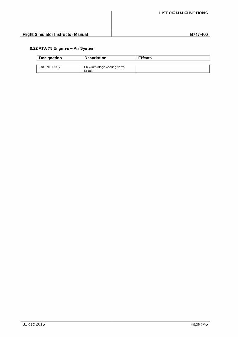
LIST OF MALFUNCTIONS
Flight Simulator Instructor Manual B747-400
31 dec 2015 Page : 45
9.22 ATA 75 Engines – Air System
Designation Description Effects
ENGINE ESCV Eleventh stage cooling valve failed.

LIST OF MALFUNCTIONS
Flight Simulator Instructor Manual B747-400
31 dec 2015 Page : 46
9.23 ATA 76 Engines – Controls
Designation Description Effects
N/A

LIST OF MALFUNCTIONS
Flight Simulator Instructor Manual B747-400
31 dec 2015 Page : 47
9.24 ATA 77 Engines – Indicating
Designation Description Effects
ENGINE/PYLON VIBRATION
Engine vibrates due to unbalanced rotor. 100% = 10 * normal
vibration.
Unbalance phase angle is set to pre-fixed valve Amplitude vary with the malfunction severity. If amplitude is high enough:
FUEL PRESSURE INDICATION VARY
Fuel flow sensor drift occurs. 100% = 100 PSI change.
Fuel flow indication is higher/lower than normal. There are no performance effects.
FUEL FLOW INDICATION LOST
No fuel flow indication due to faulty flow transmitter.
Fuel flow indication drives to 0. Analog and digital signals lost.
ENG N2 VIBRATION INDICATION FAILS
No output signal from compressor rear frame accelerometer.
N2 and LPT vibration indications read 0
FUEL FLOW INDICATION VARY
Fuel flow indication variation. ± 100% = ± 10,000 kg/hr.
Fuel flow variation on indication only
VARIABLE BYPASS VLV ACTUATOR FAIL
VBV actuator stuck in position.
ENG N1 VIBRATION INDICATION FAILS
No output signal from #1 bearing accelerometer.
Fan vibration indication reads 0
N2 VIBRATION INDICATION VARY
Variable compressor rear frame accelerometer offset. ±100% = 10X/zero output.
Faulty LPT and N2 vibration indications.
N1 VIBRATION INDICATION VARY
Engine fan accelerometer drift occurs.
Increase in N1 vibration indications
EGT INDICATION FAILS Loss of signal from EGT sensors. Loss of EGT display
EGT INDICATION VARY Engine EGT thermocouple drift. ± 100% = ± 500 degrees C deviation.
Faulty EGT indication
N2 TACH TRANSMITTER FAILS
Loss of signal from N2 transmitter. N2 indicates 0. FACEC uses synthesized N2 to control engine
N1 TACH TRANSMITTER FAILS
Loss of signal from N1 transmitter. N1 indicates 0 FADEC uses synthesized N1 to control engine
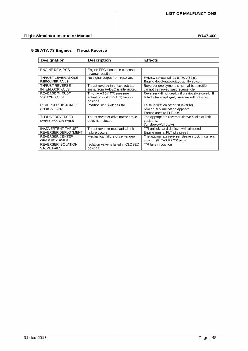
LIST OF MALFUNCTIONS
Flight Simulator Instructor Manual B747-400
31 dec 2015 Page : 48
9.25 ATA 78 Engines – Thrust Reverse
Designation Description Effects
ENGINE REV. POS Engine EEC incapable to sense reverser position.
THRUST LEVER ANGLE RESOLVER FAILS
No signal output from resolver. FADEC selects fail-safe TRA (36.9). Engine decelerates/stays at idle power.
THRUST REVERSE INTERLOCK FAILS
Thrust reverse interlock actuator signal from FADEC is interrupted.
Reverser deployment is normal but throttle cannot be moved past reverse idle.
REVERSE THRUST SWITCH FAILS
Throttle ASSY T/R pressure actuation switch (S101) fails in position.
Reverser will not deploy if previously stowed. If failed when deployed, reverser will not stow.
REVERSER DISAGREE (INDICATION)
Position limit switches fail. False indication of thrust reverser. Amber REV indication appears. Engine goes to FLT idle.
THRUST REVERSER DRIVE MOTOR FAILS
Thrust reverser drive motor brake does not release.
The appropriate reverser sleeve sticks at limit positions. (full deploy/full stow)
INADVERTENT THRUST REVERSER DEPLOYMENT
Thrust reverser mechanical link failure occurs.
T/R unlocks and deploys with airspeed Engine runs at FLT idle speed
REVERSER CENTER GEAR BOX FAILS
Mechanical failure of center gear box.
The appropriate reverser sleeve stuck in current position (EICAS EPCS' page).
REVERSER ISOLATION VALVE FAILS
Isolation valve is failed in CLOSED position.
T/R fails in position
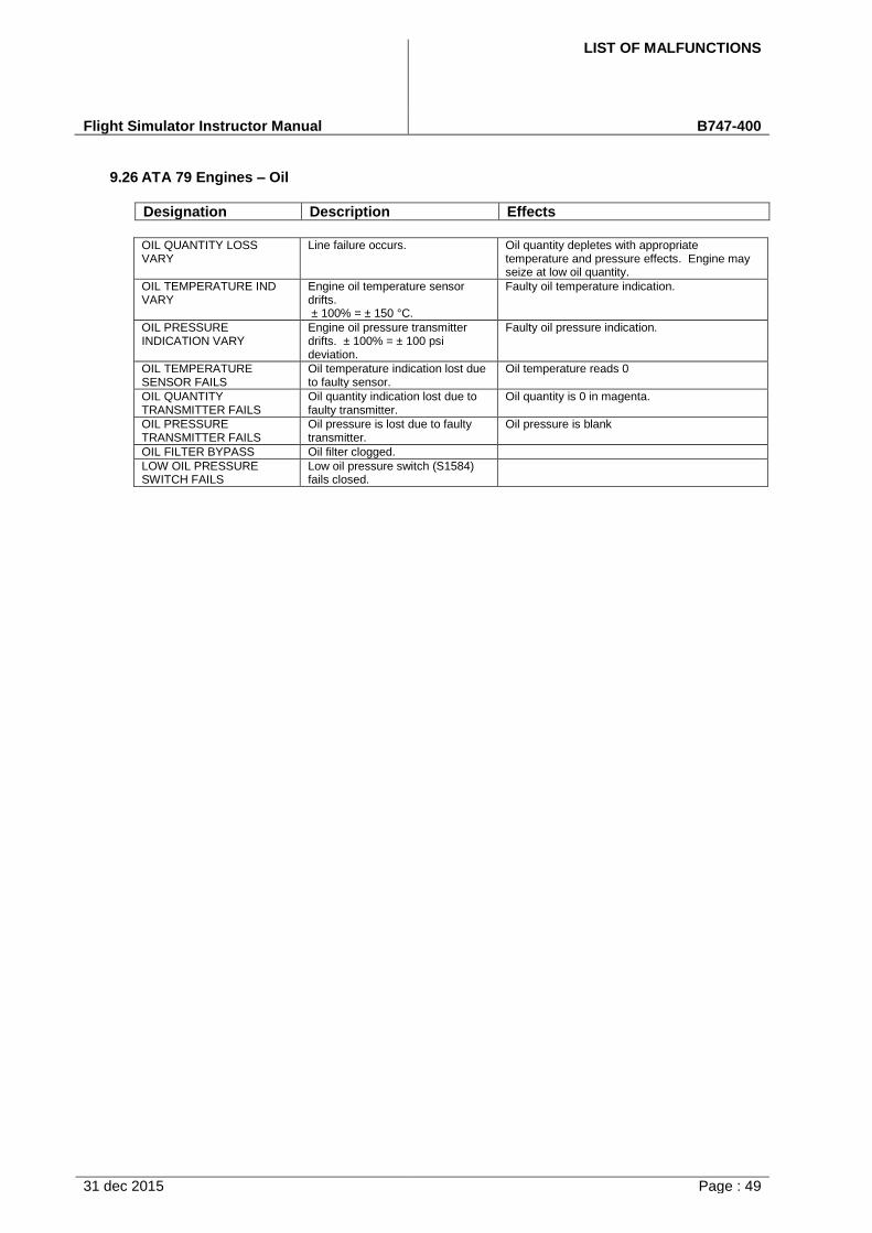
LIST OF MALFUNCTIONS
Flight Simulator Instructor Manual B747-400
31 dec 2015 Page : 49
9.26 ATA 79 Engines – Oil
Designation Description Effects
OIL QUANTITY LOSS VARY
Line failure occurs. Oil quantity depletes with appropriate temperature and pressure effects. Engine may seize at low oil quantity.
OIL TEMPERATURE IND VARY
Engine oil temperature sensor drifts. ± 100% = ± 150 °C.
Faulty oil temperature indication.
OIL PRESSURE INDICATION VARY
Engine oil pressure transmitter drifts. ± 100% = ± 100 psi deviation.
Faulty oil pressure indication.
OIL TEMPERATURE SENSOR FAILS
Oil temperature indication lost due to faulty sensor.
Oil temperature reads 0
OIL QUANTITY TRANSMITTER FAILS
Oil quantity indication lost due to faulty transmitter.
Oil quantity is 0 in magenta.
OIL PRESSURE TRANSMITTER FAILS
Oil pressure is lost due to faulty transmitter.
Oil pressure is blank
OIL FILTER BYPASS Oil filter clogged.
LOW OIL PRESSURE SWITCH FAILS
Low oil pressure switch (S1584) fails closed.

LIST OF MALFUNCTIONS
Flight Simulator Instructor Manual B747-400
31 dec 2015 Page : 50
9.27 ATA 80 Engines – A/C General
Designation Description Effects
N/A
Related Documents