SRX 5800 and SRX 5600 Services Gateway Services Processing Card Installation Instructions August 2008 Part Number: 530-026084-01 Revision 01 This document describes how to remove and replace a Services Processing Card (SPC) on Juniper Networks SRX 5800 and SRX 5600 services gateways. The illustrations in this document show the SRX 5600 services gateway, but the instructions apply to all SRX 5800 and SRX 5600 services gateways. Contents Services Processing Cards ...............................................................................2 SPC Components ......................................................................................3 Handling and Storing Cards .............................................................................4 Holding a Card ..........................................................................................5 Storing a Card ...........................................................................................7 Replacing SPCs ................................................................................................8 Powering Off the Services Gateway ..........................................................8 Removing an SPC .....................................................................................8 Installing an SPC .....................................................................................10 Preventing Electrostatic Discharge Damage ..................................................12 Electrostatic Discharge Point .........................................................................13 List of Technical Publications ........................................................................14 Requesting Technical Support .......................................................................15 Revision History ............................................................................................16 ■ 1

Welcome message from author
This document is posted to help you gain knowledge. Please leave a comment to let me know what you think about it! Share it to your friends and learn new things together.
Transcript

SRX 5800 and SRX 5600Services GatewayServices Processing CardInstallation Instructions
August 2008Part Number: 530-026084-01Revision 01
This document describes how to remove and replace a Services Processing Card(SPC) on Juniper Networks SRX 5800 and SRX 5600 services gateways. Theillustrations in this document show the SRX 5600 services gateway, but theinstructions apply to all SRX 5800 and SRX 5600 services gateways.
Contents Services Processing Cards ...............................................................................2SPC Components ......................................................................................3
Handling and Storing Cards .............................................................................4Holding a Card ..........................................................................................5Storing a Card ...........................................................................................7
Replacing SPCs ................................................................................................8Powering Off the Services Gateway ..........................................................8Removing an SPC .....................................................................................8Installing an SPC .....................................................................................10
Preventing Electrostatic Discharge Damage ..................................................12Electrostatic Discharge Point .........................................................................13List of Technical Publications ........................................................................14Requesting Technical Support .......................................................................15Revision History ............................................................................................16
■ 1

Services Processing Cards
Services Processing Cards (SPCs) provide the processing power to run integratedservices such as firewall, IPsec and IDP (see Figure 1 on page 2). All traffic traversingthe services gateway is passed to an SPC to have services processing applied to it.Traffic is intelligently distributed by SPCs to SPCs for service processing. Each SPCis comprised of two or more Services Processing Units (SPUs).
The services gateway must have at least one SPC installed. You can install additionalSPCs to increase services processing throughput.
The services gateway has a total of 12 slots. You can install SPCs in any of the slotsnumbered 0 though 5 on an SRX 5600 services gateway, and 0 though 5, 2/6 , and7 though 11 on an SRX 5800 services gateway, top to bottom. The slots at the bottomof the card cage numbered 0 and 1 are reserved for SCBs.
SPCs install in the front of the device (see Figure 2 on page 3).
If a slot is not occupied by a card, a blank panel must be installed to shield the emptyslot and to allow cooling air to circulate properly through the device.
Figure 1 on page 2 shows a typical SPC supported on the SRX 5800 and SRX 5600services gateways.
Figure 1: Typical SPC
2 ■ Services Processing Cards
SRX 5800 and SRX 5600 Services Gateway Services Processing Card Installation Instructions

Figure 2: SPCs Installed Horizontally in the SRX 5600 Services Gateway
SPC Components
Each SPC consists of the following components:
■ SPC cover, which functions as a ground plane and a stiffener.
■ Two Chassis Cluster Control ports for connecting multiple devices into a redundantchassis cluster. Refer to the JUNOS Software Security Configuration Guide for moreinformation about connecting and configuring redundant chassis clusters.
■ Fabric interfaces.
■ Two Gigabit Ethernet interfaces that allow control information, route information,and statistics to be sent between the Routing Engine and the CPU on the SPCs.
■ Two interfaces from the SCBs that enable the boards to be powered on andcontrolled.
■ Physical SPC connectors.
■ Midplane connectors and power circuitry.
■ Processor subsystem, which includes a 1.2-GHz CPU, system controller, and1 GB of SDRAM.
■ LEDs on the faceplate indicate the SPC status (see Table 1 on page 3).
Table 1: SPC LEDs
DescriptionStateColorLabel
SPC is functioning normally.On steadilyGreenOK/FAIL
SPC has failed.On steadilyRed
Services Processing Cards ■ 3
Services Processing Cards

Table 1: SPC LEDs (continued)
DescriptionStateColorLabel
SPU is offline. If both SPUs are offline it is safe to removethe SPC from the chassis.
OffOffSTATUS
SPU is operating normally.On steadilyGreen
SPU is initializing.On steadilyAmber
SPU has an error or failure.On steadilyRed
Service is not running on the SPU.OffOffSERVICE
Service is running on the SPU under acceptable load.On steadilyGreen
Service on the SPU is overloaded.On steadilyAmber
All cluster members and monitored links are available.On steadilyGreenHA
A cluster member is missing or unreachable, or the othernode is no longer part of a cluster because it has beendisabled by the dual membership and detection recoveryprocess in reaction to a control link or fabric link failure.
On steadilyRed
All cluster members are present, but one or moremonitored links are down.
On steadilyAmber
The node is not configured for clustering or it has beendisabled by the dual membership and detection recoveryprocess in reaction to a control link or fabric link failure.
OffUnlit
Chassis Cluster Control port link is active.On steadilyGreenLINK/ACT
No link.Off
The Chassis Cluster Control port is enabled.On steadilyGreenENABLE
The Chassis Cluster Control port is disabled.Off
Two LEDs, located on the craft interface above the SPC, display the status of the SPCand are labeled OK and FAIL. For more information on the SPC LEDs located on thecraft interface, see the SRX 5800 Services Gateway Hardware Guide or the SRX 5600Services Gateway Hardware Guide.
Handling and Storing Cards
This section explains how to avoid damaging the cards (IOCs, SPCs, and hostsubsystems) that you install into the services gateway. Many components on thecards are fragile.
4 ■ Handling and Storing Cards
SRX 5800 and SRX 5600 Services Gateway Services Processing Card Installation Instructions

CAUTION: Failure to handle cards as specified in this document can cause irreparabledamage.
This section discusses how to hold cards in both the vertical and horizontal positions.Regardless of orientation, this section uses the same terms for all four edges of thecard (see Figure 3 on page 5):
■ Faceplate—Edge of the card that has connectors to which you connect cables orsockets for SFP or XFP transceivers
■ Connector edge—Edge opposite the faceplate; this edge has the connectors thatattach to the midplane
■ Top edge—Edge at the top of the card when it is vertical
■ Bottom edge—Edge at the bottom of the card when it is vertical
NOTE: The instructions in this section apply to all card types.
Figure 3: Card Edges
Holding a Card
When you carry a card, you can hold it either vertically or horizontally.
Handling and Storing Cards ■ 5
Handling and Storing Cards

NOTE: A card weighs up to 13.1 lb (5.9 kg). Be prepared to accept the full weight ofthe card as you lift it.
To hold a card vertically:
1. Orient the card so that the faceplate faces you. To verify orientation, confirmthat the text on the card is right-side up and the electromagnetic interference(EMI) strip is on the right-hand side.
2. Place one hand around the card faceplate about a quarter of the way down fromthe top edge. To avoid deforming the EMI shielding strip, do not press hard onit.
3. Place your other hand at the bottom edge of the card.
If the card is horizontal before you grasp it, place your left hand around the faceplateand your right hand along the bottom edge.
To hold a card horizontally:
1. Orient the card so that the faceplate faces you.
2. Grasp the top edge with your left hand and the bottom edge with your right hand.
You can rest the faceplate of the card against your body as you carry it.
As you carry the card, do not bump it against anything. Card components are fragile.
Never hold or grasp the card anywhere except places that this document indicates.In particular, never grasp the connector edge, especially at the power connector inthe corner where the connector and bottom edges meet (see Figure 4 on page 6).
Figure 4: Do Not Grasp the Connector Edge
6 ■ Handling and Storing Cards
SRX 5800 and SRX 5600 Services Gateway Services Processing Card Installation Instructions

Never carry the card by the faceplate with only one hand.
Do not rest any edge of a card directly against a hard surface (seeFigure 5 on page 7).
Do not stack cards.
Figure 5: Do Not Rest the Card on an Edge
If you must rest the card temporarily on an edge while changing its orientationbetween vertical and horizontal, use your hand as a cushion between the edge andthe surface.
Storing a Card
You must store a card as follows:
■ In the device chassis
■ In the container in which a spare card is shipped
■ Horizontally and sheet metal side down
When you store a card on a horizontal surface or in the shipping container, alwaysplace it inside an antistatic bag. Because the card is heavy, and because antistaticbags are fragile, inserting the card into the bag is easier with two people. To do this,one person holds the card in the horizontal position with the faceplate facing thebody, and the other person slides the opening of the bag over the card connectoredge.
Handling and Storing Cards ■ 7
Handling and Storing Cards

If you must insert the card into a bag by yourself, first lay the card horizontally ona flat, stable surface, sheet metal side down. Orient the card with the faceplate facingyou. Carefully insert the card connector edge into the opening of the bag, and pullthe bag toward you to cover the card.
Never stack a card under or on top of any other component.
Replacing SPCs
SPCs are installed in the front of the services gateway. Before you remove or installan SPC, you must power off the services gateway (see “Powering Off the ServicesGateway” on page 8). To replace an SPC, use the following procedures:
■ Powering Off the Services Gateway on page 8
■ Removing an SPC on page 8
■ Installing an SPC on page 10
Powering Off the Services Gateway
Before installing or removing SPCs you must power off the services gateway::
1. On the external management device connected to the Routing Engine, issue therequest system halt operational mode command. The command shuts down theRouting Engine cleanly, so its state information is preserved.
user@host> request system halt
Wait until a message appears on the console confirming that the operating systemhas halted. For more information about the command, see the JUNOS SystemBasics and Services Command Reference.
2. Attach an electrostatic discharge (ESD) grounding strap to your bare wrist andconnect the strap to one of the ESD points on the chassis. For more informationabout ESD, see “Preventing Electrostatic Discharge Damage” on page 12.
3. On an AC-powered services gateway, switch the circuit breaker in the chassisabove each power supply to the off position (O). On a DC-powered servicesgateway, switch the circuit breaker on each power supply faceplate to the offposition (OFF).
Removing an SPC
An SPC weighs up to 13.1 lb (5.9 kg). Be prepared to accept its full weight.
8 ■ Replacing SPCs
SRX 5800 and SRX 5600 Services Gateway Services Processing Card Installation Instructions

To remove an SPC (see Figure 6 on page 10):
1. Have ready a replacement SPC or blank panel and an antistatic mat for the SPC.Also have ready rubber safety caps for each SPC you are removing that uses anoptical interface.
2. Attach an electrostatic discharge (ESD) grounding strap to your bare wrist andconnect the strap to one of the ESD points on the chassis. For more informationabout ESD, see “Preventing Electrostatic Discharge Damage” on page 12.
3. If you have not already done so, power-off the device as described in “PoweringOff the Services Gateway” on page 8.
4. Label the cables connected to each port on the SPC so that you can later reconnectthe cables to the correct ports.
5. Disconnect the cables from the SPC. If the SPC uses fiber-optic cable, immediatelycover each transceiver and the end of each cable with a rubber safety cap.Arrange the disconnected cables in the cable management system to preventthe cables from developing stress points.
WARNING: Do not look directly into a fiber-optic transceiver or into the ends offiber-optic cables. Fiber-optic transceivers and fiber-optic cable connected to atransceiver emit laser light that can damage your eyes.
CAUTION: Do not leave a fiber-optic transceiver uncovered except when insertingor removing cable. The safety cap keeps the port clean and prevents accidentalexposure to laser light.
CAUTION: Avoid bending fiber-optic cable beyond its minimum bend radius. An arcsmaller than a few inches in diameter can damage the cable and cause problemsthat are difficult to diagnose.
6. Simultaneously turn both of the ejector handles counterclockwise to unseat theSPC.
7. Grasp the handles and slide the SPC straight out of the card cage halfway.
8. Place one hand around the front of the SPC and the other hand under it to supportit. Slide the SPC completely out of the chassis, and place it on the antistatic mator in the electrostatic bag.
CAUTION: The weight of the SPC is concentrated in the back end. Be prepared toaccept the full weight—up to 13.1 lb (5.9 kg)—as you slide the SPC out of the chassis.
When the SPC is out of the chassis, do not hold it by the ejector handles, bus bars,or edge connectors. They cannot support its weight.
Replacing SPCs ■ 9
Replacing SPCs
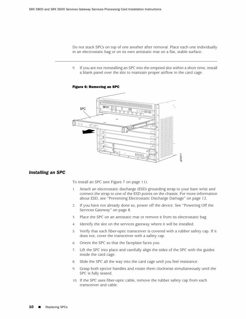
Do not stack SPCs on top of one another after removal. Place each one individuallyin an electrostatic bag or on its own antistatic mat on a flat, stable surface.
9. If you are not reinstalling an SPC into the emptied slot within a short time, installa blank panel over the slot to maintain proper airflow in the card cage.
Figure 6: Removing an SPC
Installing an SPC
To install an SPC (see Figure 7 on page 11):
1. Attach an electrostatic discharge (ESD) grounding strap to your bare wrist andconnect the strap to one of the ESD points on the chassis. For more informationabout ESD, see “Preventing Electrostatic Discharge Damage” on page 12.
2. If you have not already done so, power off the device. See “Powering Off theServices Gateway” on page 8.
3. Place the SPC on an antistatic mat or remove it from its electrostatic bag.
4. Identify the slot on the services gateway where it will be installed.
5. Verify that each fiber-optic transceiver is covered with a rubber safety cap. If itdoes not, cover the transceiver with a safety cap.
6. Orient the SPC so that the faceplate faces you.
7. Lift the SPC into place and carefully align the sides of the SPC with the guidesinside the card cage.
8. Slide the SPC all the way into the card cage until you feel resistance.
9. Grasp both ejector handles and rotate them clockwise simultaneously until theSPC is fully seated.
10. If the SPC uses fiber-optic cable, remove the rubber safety cap from eachtransceiver and cable.
10 ■ Replacing SPCs
SRX 5800 and SRX 5600 Services Gateway Services Processing Card Installation Instructions

WARNING: Do not look directly into a fiber-optic transceiver or into the ends offiber-optic cables. Fiber-optic transceivers and fiber-optic cable connected to atransceiver emit laser light that can damage your eyes.
11. Insert the appropriate cables into the cable connector ports on each SPC (seeFigure 8 on page 12). Secure the cables so that they are not supporting theirown weight. Place excess cable out of the way in a neatly coiled loop, using thecable management system. Placing fasteners on a loop helps to maintain itsshape.
CAUTION: Do not let fiber-optic cable hang free from the connector. Do not allowfastened loops of cable to dangle, which stresses the cable at the fastening point.
CAUTION: Avoid bending fiber-optic cable beyond its minimum bend radius. An arcsmaller than a few inches in diameter can damage the cable and cause problemsthat are difficult to diagnose.
12. Switch the circuit breaker or toggle switch for each power supply to the ONposition to start the device. The OK LED on the power supply faceplate shouldblink, then light steadily.
For detailed instructions on powering-on the device see the SRX 5600 ServicesGateway Hardware Guide or the SRX 5800 Services Gateway Hardware Guide.
13. Verify that the SPC is functioning correctly by issuing the show chassis fpc andshow chassis fpc pic-status commands, as described in the JUNOS System Basicsand Services Command Reference.
Figure 7: Installing an SPC
Replacing SPCs ■ 11
Replacing SPCs

Figure 8: Attaching a Cable to an SPC
Preventing Electrostatic Discharge Damage
Many services gateway hardware components are sensitive to damage from staticelectricity. Some components can be impaired by voltages as low as 30 V. You caneasily generate potentially damaging static voltages whenever you handle plastic orfoam packing material or if you move components across plastic or carpets. Observethe following guidelines to minimize the potential for electrostatic discharge (ESD)damage, which can cause intermittent or complete component failures:
■ Always use an ESD wrist strap or ankle strap, and verify that it is in direct contactwith your skin.
CAUTION: For safety, periodically check the resistance value of the ESD strap. Themeasurement should be in the range of 1 to 10 Mohms.
■ When handling any component that has been removed from the chassis, verifythat the equipment end of your ESD strap is attached to one of the ESD pointson the chassis, which are shown in Figure 10 on page 13 andFigure 11 on page 14.
■ Avoid contact between the component and your clothing. ESD voltages emittedfrom clothing can still damage components.
■ When removing or installing a component, always place it component-side upon an antistatic surface, in an antistatic card rack, or into an electrostatic bag(see Figure 9 on page 13). If you are returning a component, place it into anelectrostatic bag before packing it.
12 ■ Preventing Electrostatic Discharge Damage
SRX 5800 and SRX 5600 Services Gateway Services Processing Card Installation Instructions
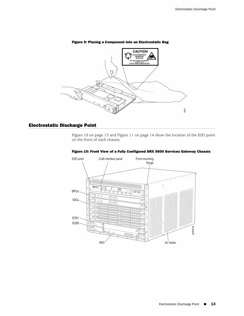
Figure 9: Placing a Component into an Electrostatic Bag
Electrostatic Discharge Point
Figure 10 on page 13 and Figure 11 on page 14 show the location of the ESD pointon the front of each chassis.
Figure 10: Front View of a Fully Configured SRX 5600 Services Gateway Chassis
Electrostatic Discharge Point ■ 13
Electrostatic Discharge Point

Figure 11: Front View of a Fully Configured SRX 5800 Services Gateway Chassis
List of Technical Publications
Table 2 on page 14 lists the hardware guides and release notes for Juniper NetworksSRX–series services gateways and describes the contents of each document. Alldocuments are available at http://www.juniper.net/techpubs/.
Table 2: Technical Documentation for Supported Devices
DescriptionBook
Hardware Documentation
Describes how to install, maintain, and troubleshoot the servicesgateway and components. Each services gateway type has its ownhardware guide.
SRX 5600 Services Gateway Hardware Guide orSRX 5800 Services Gateway Hardware Guide
Release Notes
14 ■ List of Technical Publications
SRX 5800 and SRX 5600 Services Gateway Services Processing Card Installation Instructions
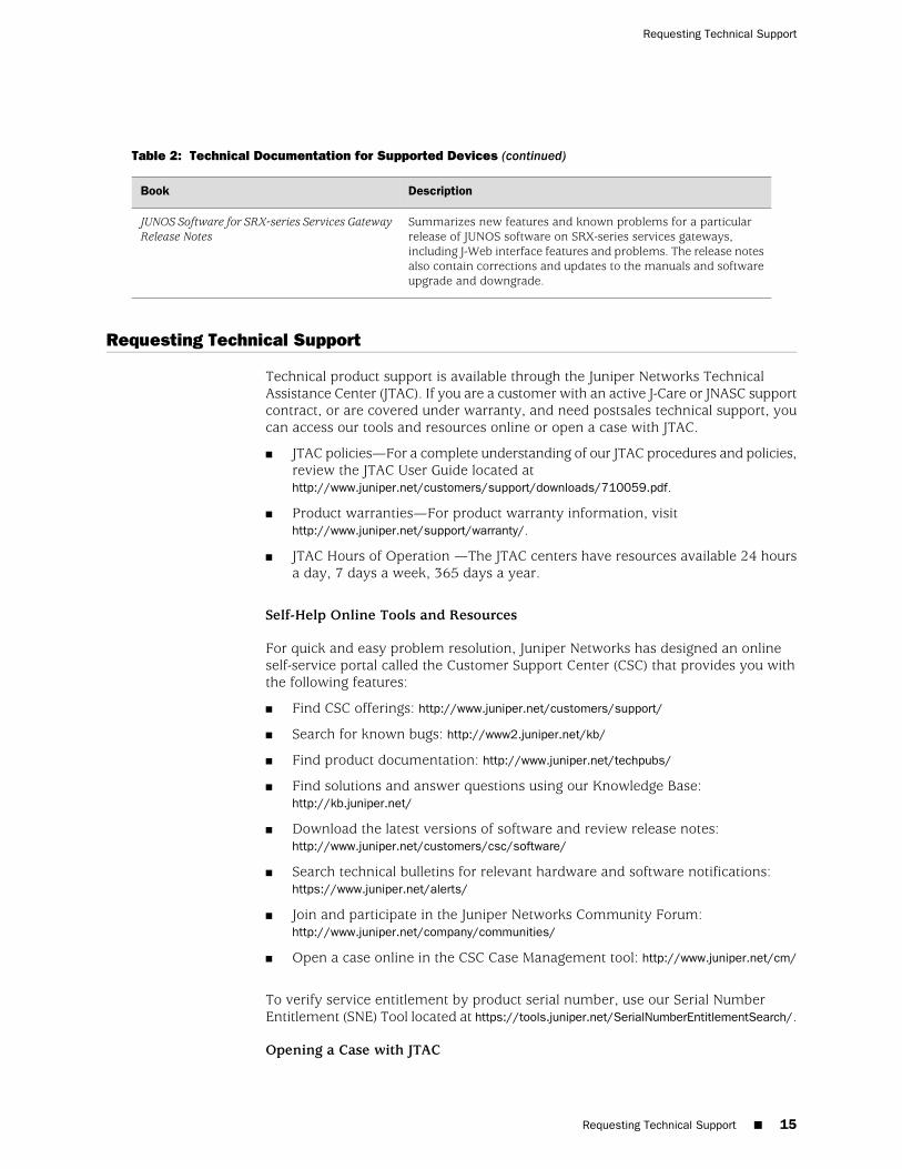
Table 2: Technical Documentation for Supported Devices (continued)
DescriptionBook
Summarizes new features and known problems for a particularrelease of JUNOS software on SRX-series services gateways,including J-Web interface features and problems. The release notesalso contain corrections and updates to the manuals and softwareupgrade and downgrade.
JUNOS Software for SRX-series Services GatewayRelease Notes
Requesting Technical Support
Technical product support is available through the Juniper Networks TechnicalAssistance Center (JTAC). If you are a customer with an active J-Care or JNASC supportcontract, or are covered under warranty, and need postsales technical support, youcan access our tools and resources online or open a case with JTAC.
■ JTAC policies—For a complete understanding of our JTAC procedures and policies,review the JTAC User Guide located athttp://www.juniper.net/customers/support/downloads/710059.pdf.
■ Product warranties—For product warranty information, visithttp://www.juniper.net/support/warranty/.
■ JTAC Hours of Operation —The JTAC centers have resources available 24 hoursa day, 7 days a week, 365 days a year.
Self-Help Online Tools and Resources
For quick and easy problem resolution, Juniper Networks has designed an onlineself-service portal called the Customer Support Center (CSC) that provides you withthe following features:
■ Find CSC offerings: http://www.juniper.net/customers/support/
■ Search for known bugs: http://www2.juniper.net/kb/
■ Find product documentation: http://www.juniper.net/techpubs/
■ Find solutions and answer questions using our Knowledge Base:http://kb.juniper.net/
■ Download the latest versions of software and review release notes:http://www.juniper.net/customers/csc/software/
■ Search technical bulletins for relevant hardware and software notifications:https://www.juniper.net/alerts/
■ Join and participate in the Juniper Networks Community Forum:http://www.juniper.net/company/communities/
■ Open a case online in the CSC Case Management tool: http://www.juniper.net/cm/
To verify service entitlement by product serial number, use our Serial NumberEntitlement (SNE) Tool located at https://tools.juniper.net/SerialNumberEntitlementSearch/.
Opening a Case with JTAC
Requesting Technical Support ■ 15
Requesting Technical Support

You can open a case with JTAC on the Web or by telephone.
■ Use the Case Management tool in the CSC at http://www.juniper.net/cm/ .
■ Call 1-888-314-JTAC (1-888-314-5822 toll-free in the USA, Canada, and Mexico).
For international or direct-dial options in countries without toll-free numbers, visitus at http://www.juniper.net/support/requesting-support.html.
Revision History
August 2008—530-026084-01. Revision 01 Initial release.
Copyright © 2009, Juniper Networks, Inc. All rights reserved.
Juniper Networks, the Juniper Networks logo, JUNOS, NetScreen, ScreenOS, and Steel-Belted Radius are registered trademarks of Juniper Networks, Inc. inthe United States and other countries. JUNOSe is a trademark of Juniper Networks, Inc. All other trademarks, service marks, registered trademarks, orregistered service marks are the property of their respective owners.
Juniper Networks assumes no responsibility for any inaccuracies in this document. Juniper Networks reserves the right to change, modify, transfer, orotherwise revise this publication without notice.
Products made or sold by Juniper Networks or components thereof might be covered by one or more of the following patents that are owned by or licensedto Juniper Networks: U.S. Patent Nos. 5,473,599, 5,905,725, 5,909,440, 6,192,051, 6,333,650, 6,359,479, 6,406,312, 6,429,706, 6,459,579, 6,493,347,6,538,518, 6,538,899, 6,552,918, 6,567,902, 6,578,186, and 6,590,785.
16 ■ Requesting Technical Support
SRX 5800 and SRX 5600 Services Gateway Services Processing Card Installation Instructions
Related Documents