Front Facing Series Framing Combustible Framing Non-Combustible Framing Dimension A: Rough Combustible Framing Opening Height Dimension B: Rough Framing Opening Width Dimension C: Framing Depth Dimension D: Firestop Opening Dimension E: Non-combustible Framing Zone Dimension A: Rough Framing Opening Height Dimension B: Rough Framing Opening Width Dimension C Framing Depth Dimension D: Firestop Opening WARNING – MAINTAIN AIR FLOW CLEARANCE: Firebox top vent must have minimum 4” of clearance to any material achieve sufficient airflow. Failure to do so could result in improper fireplace operation, property damage, or physical injury. Review Installation Manual to ensure all clearances are followed. Model Framing Dimension A Dimension B Dimension C Dimension D Dimension E 40H70 F Combustible 55 3 /8” 24 5 /8” 18 1 /8” Refer to pipe manufacturer’s firestop dimensions 14 1 /4” Non-Combustible 41 1 /4” N/A 75 F Combustible 45 1 /8” 37 3 /4” 18” 15 3 /8” Non-Combustible 29 7 /8” N/A 75x65 F Combustible 53 3 /8” 38 3 /8” 18” 15 1 /8” Non-Combustible 38 3 /8” N/A 60x80 F Combustible 57” 29 3 /8” 18 1 /8” 14 5 /8” Non-Combustible 42 1 /2” N/A 110 F Wilderness 44 F Combustible 41 5 /8” 51 7 /8” 18 1 /8” 14 1 /8” Non-Combustible 27 1 /2” N/A 110H F Combustible 49 1 /2” 51 7 /8” 18 1 /8” 14 1 /8” Non-Combustible 35 3 /8” N/A 130 F Wilderness 52 F Combustible 41 5 /8” 58 5 /8” 18 1 /8” 14 1 /8” Non-Combustible 27 1/ 2” N/A 130H F Combustible 49 1 /2” 58 5 /8” 18 1 /8” 14 1 /8” Non-Combustible 35 3 /8” N/A 150 F Wilderness 60 F Combustible 41 5 /8” 68 1 /2” 18 1 /8” 14 1 /8” Non-Combustible 27 1 /2” N/A 150H F Combustible 49 1 /2” 68 1 /2” 18 1 /8” 14 1 /8” Non-Combustible 35 3 /8” N/A 170 F Combustible 41 5 /8” 76 3 /8” 18 1 /8” 14 1 /8” Non-Combustible 27 1 /2” N/A 170H F Combustible 49 1 /2” 76 3 /8” 18 1 /8” 14 1 /8” Non-Combustible 35 3 /8” N/A 200 F Combustible 41 5 /8” 85 3 /4” 18 1 /8” 14 1 /8” Non-Combustible 27 1 /2” N/A 200H F Combustible 49 1 /2” 85 3 /4” 18 1 /8” 14 1 /8” Non-Combustible 35 3 /8” N/A 250 F Combustible 43 5 /8” 104 3 /8” 18 1 /8” 14 Non-Combustible 29 5 /8” N/A 250H F Combustible 49 1 /2” 104 3 /8” 18 1 /8” 14 1 /8” Non-Combustible 35 3 /8” N/A This framing guide is a quick reference for a typical Ortal Front Facing Series fireplace installation. This list is not exhaustive and does not supplement thorough review of the installation manual.

Welcome message from author
This document is posted to help you gain knowledge. Please leave a comment to let me know what you think about it! Share it to your friends and learn new things together.
Transcript

Front Facing Series Framing Combustible Framing Non-Combustible Framing
Dimension A: Rough Combustible Framing Opening Height Dimension B: Rough Framing Opening Width Dimension C: Framing Depth Dimension D: Firestop Opening Dimension E: Non-combustible Framing Zone
Dimension A: Rough Framing Opening Height Dimension B: Rough Framing Opening Width Dimension C Framing Depth Dimension D: Firestop Opening
WARNING – MAINTAIN AIR FLOW CLEARANCE: Firebox top vent must have minimum 4” of clearance to any material achieve sufficient airflow. Failure to do so could result in improper fireplace operation, property damage, or physical injury. Review Installation Manual to ensure all clearances are followed.
Model Framing Dimension A Dimension B Dimension C Dimension D Dimension E
40H70 F Combustible 55 3/8”
24 5/8” 18 1/8”
Refer to pipe manufacturer’s
firestop dimensions
14 1/4” Non-Combustible 41 1/4” N/A
75 F Combustible 45 1/8”
37 3/4” 18” 15 3/8”
Non-Combustible 29 7/8” N/A
75x65 F Combustible 53 3/8”
38 3/8” 18” 15 1/8”
Non-Combustible 38 3/8” N/A
60x80 F Combustible 57”
29 3/8” 18 1/8” 14 5/8”
Non-Combustible 42 1/2” N/A
110 F Wilderness 44 F
Combustible 41 5/8” 51 7/8” 18 1/8”
14 1/8” Non-Combustible 27 1/2” N/A
110H F Combustible 49 1/2”
51 7/8” 18 1/8” 14 1/8”
Non-Combustible 35 3/8” N/A
130 F Wilderness 52 F
Combustible 41 5/8” 58 5/8” 18 1/8”
14 1/8” Non-Combustible 27 1/2” N/A
130H F Combustible 49 1/2”
58 5/8” 18 1/8” 14 1/8”
Non-Combustible 35 3/8” N/A
150 F Wilderness 60 F
Combustible 41 5/8” 68 1/2” 18 1/8”
14 1/8” Non-Combustible 27 1/2” N/A
150H F Combustible 49 1/2”
68 1/2” 18 1/8” 14 1/8”
Non-Combustible 35 3/8” N/A
170 F Combustible 41 5/8”
76 3/8” 18 1/8” 14 1/8”
Non-Combustible 27 1/2” N/A
170H F Combustible 49 1/2”
76 3/8” 18 1/8” 14 1/8”
Non-Combustible 35 3/8” N/A
200 F Combustible 41 5/8”
85 3/4” 18 1/8” 14 1/8”
Non-Combustible 27 1/2” N/A
200H F Combustible 49 1/2”
85 3/4” 18 1/8” 14 1/8”
Non-Combustible 35 3/8” N/A
250 F Combustible 43 5/8”
104 3/8” 18 1/8” 14
Non-Combustible 29 5/8” N/A
250H F Combustible 49 1/2”
104 3/8” 18 1/8” 14 1/8”
Non-Combustible 35 3/8” N/A
This framing guide is a quick reference for a typical Ortal Front Facing Series fireplace installation. This list is not exhaustive and does not supplement thorough review of the installation manual.
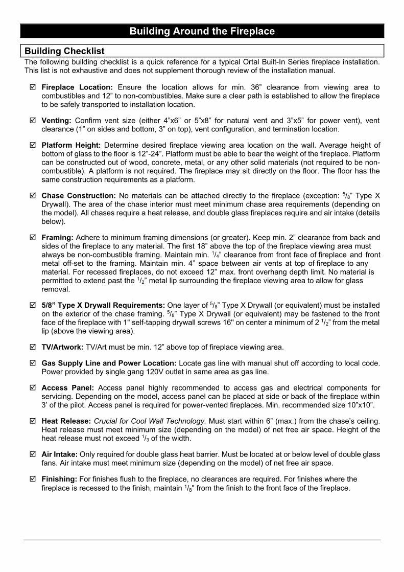
Building Around the Fireplace
Building Checklist The following building checklist is a quick reference for a typical Ortal Built-In Series fireplace installation. This list is not exhaustive and does not supplement thorough review of the installation manual.
Fireplace Location: Ensure the location allows for min. 36” clearance from viewing area to combustibles and 12” to non-combustibles. Make sure a clear path is established to allow the fireplace to be safely transported to installation location.
Venting: Confirm vent size (either 4”x6” or 5”x8” for natural vent and 3”x5” for power vent), vent clearance (1” on sides and bottom, 3” on top), vent configuration, and termination location.
Platform Height: Determine desired fireplace viewing area location on the wall. Average height of bottom of glass to the floor is 12”-24”. Platform must be able to bear the weight of the fireplace. Platform can be constructed out of wood, concrete, metal, or any other solid materials (not required to be non-combustible). A platform is not required. The fireplace may sit directly on the floor. The floor has the same construction requirements as a platform.
Chase Construction: No materials can be attached directly to the fireplace (exception: 5/8” Type X Drywall). The area of the chase interior must meet minimum chase area requirements (depending on the model). All chases require a heat release, and double glass fireplaces require and air intake (details below).
Framing: Adhere to minimum framing dimensions (or greater). Keep min. 2” clearance from back and sides of the fireplace to any material. The first 18” above the top of the fireplace viewing area must always be non-combustible framing. Maintain min. 1/4” clearance from front face of fireplace and front metal off-set to the framing. Maintain min. 4” space between air vents at top of fireplace to any material. For recessed fireplaces, do not exceed 12” max. front overhang depth limit. No material is permitted to extend past the 1/2” metal lip surrounding the fireplace viewing area to allow for glass removal.
5/8” Type X Drywall Requirements: One layer of 5/8” Type X Drywall (or equivalent) must be installed on the exterior of the chase framing. 5/8” Type X Drywall (or equivalent) may be fastened to the front face of the fireplace with 1" self-tapping drywall screws 16'' on center a minimum of 2 1/2” from the metal lip (above the viewing area).
TV/Artwork: TV/Art must be min. 12” above top of fireplace viewing area.
Gas Supply Line and Power Location: Locate gas line with manual shut off according to local code. Power provided by single gang 120V outlet in same area as gas line.
Access Panel: Access panel highly recommended to access gas and electrical components for servicing. Depending on the model, access panel can be placed at side or back of the fireplace within 3’ of the pilot. Access panel is required for power-vented fireplaces. Min. recommended size 10”x10”.
Heat Release: Crucial for Cool Wall Technology. Must start within 6” (max.) from the chase’s ceiling. Heat release must meet minimum size (depending on the model) of net free air space. Height of the heat release must not exceed 1/3 of the width.
Air Intake: Only required for double glass heat barrier. Must be located at or below level of double glass fans. Air intake must meet minimum size (depending on the model) of net free air space.
Finishing: For finishes flush to the fireplace, no clearances are required. For finishes where the fireplace is recessed to the finish, maintain 1/8" from the finish to the front face of the fireplace.
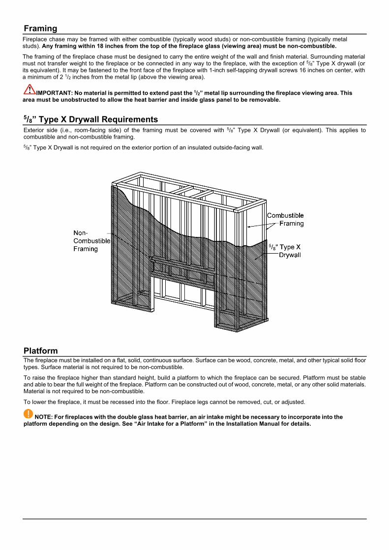
Fireplace chase may be framed with either combustible (typically wood studs) or non-combustible framing (typically metal studs). Any framing within 18 inches from the top of the fireplace glass (viewing area) must be non-combustible.
The framing of the fireplace chase must be designed to carry the entire weight of the wall and finish material. Surrounding material must not transfer weight to the fireplace or be connected in any way to the fireplace, with the exception of 5/8” Type X drywall (or its equivalent). It may be fastened to the front face of the fireplace with 1-inch self-tapping drywall screws 16 inches on center, with a minimum of 2 1/2 inches from the metal lip (above the viewing area).
IMPORTANT: No material is permitted to extend past the 1/2” metal lip surrounding the fireplace viewing area. This area must be unobstructed to allow the heat barrier and inside glass panel to be removable.
5/8” Type X Drywall Requirements Exterior side (i.e., room-facing side) of the framing must be covered with 5/8” Type X Drywall (or equivalent). This applies to combustible and non-combustible framing. 5/8” Type X Drywall is not required on the exterior portion of an insulated outside-facing wall.
Platform The fireplace must be installed on a flat, solid, continuous surface. Surface can be wood, concrete, metal, and other typical solid floor types. Surface material is not required to be non-combustible.
To raise the fireplace higher than standard height, build a platform to which the fireplace can be secured. Platform must be stable and able to bear the full weight of the fireplace. Platform can be constructed out of wood, concrete, metal, or any other solid materials. Material is not required to be non-combustible.
To lower the fireplace, it must be recessed into the floor. Fireplace legs cannot be removed, cut, or adjusted.
NOTE: For fireplaces with the double glass heat barrier, an air intake might be necessary to incorporate into the platform depending on the design. See “Air Intake for a Platform” in the Installation Manual for details.
Framing

General Clearances Viewing Area Clearances The viewing area clearance zone is an area that extends perpendicular from the fireplace viewing area. The depth of the viewing area clearance zone depends on the combustibility of the material in question. Distance is measured from the fireplace heat barrier.
Non-Combustible Materials Must be minimum 12 inches from fireplace viewing area. Combustible Materials Must be minimum 36 inches from fireplace viewing area.
Materials (including combustible flooring and combustible finish material) are permitted below and around the viewing area clearance zone.
IMPORTANT NOTE: When placing material near the glass, take care to consider fireplace serviceability. It is strongly recommended that any items/materials placed in front of the front (long) glass be movable for easy access to the fireplace during servicing.
Firebox Clearance Maintain a 2-inch clearance from the back and sides of the fireplace to any material.
Clearance to Ceiling Maintain a 12-inch clearance from the top of the fireplace viewing area to the lowest point of the ceiling or to any building materials.
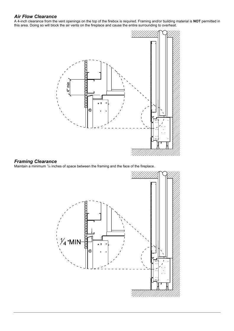
Air Flow Clearance A 4-inch clearance from the vent openings on the top of the firebox is required. Framing and/or building material is NOT permitted in this area. Doing so will block the air vents on the fireplace and cause the entire surrounding to overheat.
Framing Clearance Maintain a minimum 1/4 inches of space between the framing and the face of the fireplace.
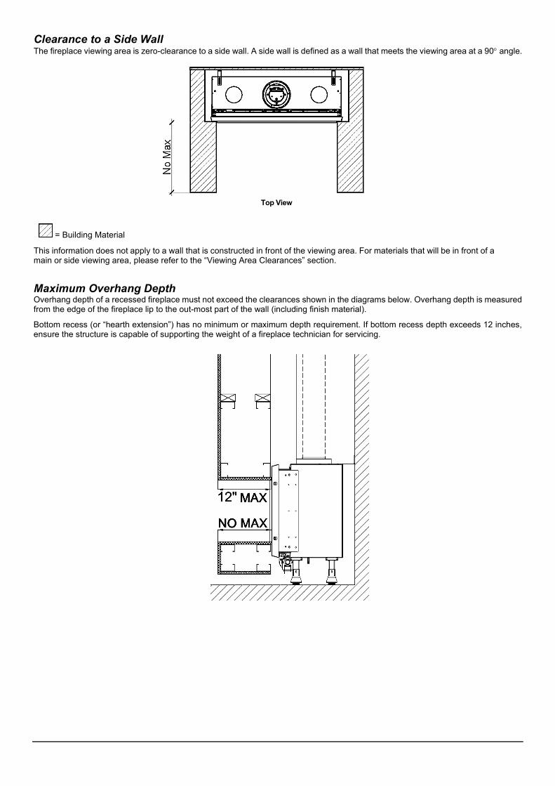
Clearance to a Side Wall The fireplace viewing area is zero-clearance to a side wall. A side wall is defined as a wall that meets the viewing area at a 90° angle.
Top View
= Building Material
This information does not apply to a wall that is constructed in front of the viewing area. For materials that will be in front of a main or side viewing area, please refer to the “Viewing Area Clearances” section.
Maximum Overhang Depth Overhang depth of a recessed fireplace must not exceed the clearances shown in the diagrams below. Overhang depth is measured from the edge of the fireplace lip to the out-most part of the wall (including finish material).
Bottom recess (or “hearth extension”) has no minimum or maximum depth requirement. If bottom recess depth exceeds 12 inches, ensure the structure is capable of supporting the weight of a fireplace technician for servicing.
Heat Release
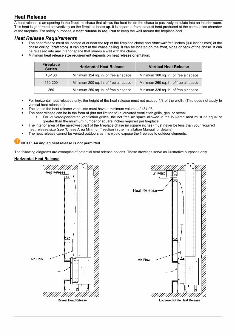
The heat release must be located at or near the top of the fireplace chase and start within 6 inches (0-6 inches max) of the chase ceiling (draft stop). It can start at the chase ceiling. It can be located on the front, sides or back of the chase. It can be released into any interior space that shares a wall with the chase.
Minimum heat release size requirement depends on heat release orientation:
Fireplace Series Horizontal Heat Release Vertical Heat Release
40-130 Minimum 124 sq. in. of free air space Minimum 160 sq. in. of free air space
150-200 Minimum 200 sq. in. of free air space Minimum 260 sq. in. of free air space
250 Minimum 250 sq. in. of free air space Minimum 325 sq. in. of free air space
For horizontal heat releases only, the height of the heat release must not exceed 1/3 of the width. (This does not apply to vertical heat releases.)
The space the heat release vents into must have a minimum volume of 184 ft3. The heat release can be in the form of (but not limited to) a louvered ventilation grille, gap, or reveal.
For louvered/perforated ventilation grilles, the net free air space allowed in the louvered area must be equal orgreater than the minimum number of square inches required per fireplace.
The interior area of the narrowest part of the fireplace chase (in square inches) must never be less than your required heat release size (see “Chase Area Minimum” section in the Installation Manual for details).
The heat release cannot be vented outdoors as this would expose the fireplace to outdoor elements.
NOTE: An angled heat release is not permitted.
The following diagrams are examples of potential heat release options. These drawings serve as illustrative purposes only.
Horizontal Heat Release
Reveal Heat Release Louvered Grille Heat Release
A heat release is an opening in the fireplace chase that allows the heat inside the chase to passively circulate into an interior room. This heat is generated convectively as the fireplace heats up. It is separate from exhaust heat produced at the combustion chamber of the fireplace. For safety purposes, a heat release is required to keep the wall around the fireplace cool.
Heat Release Requirements
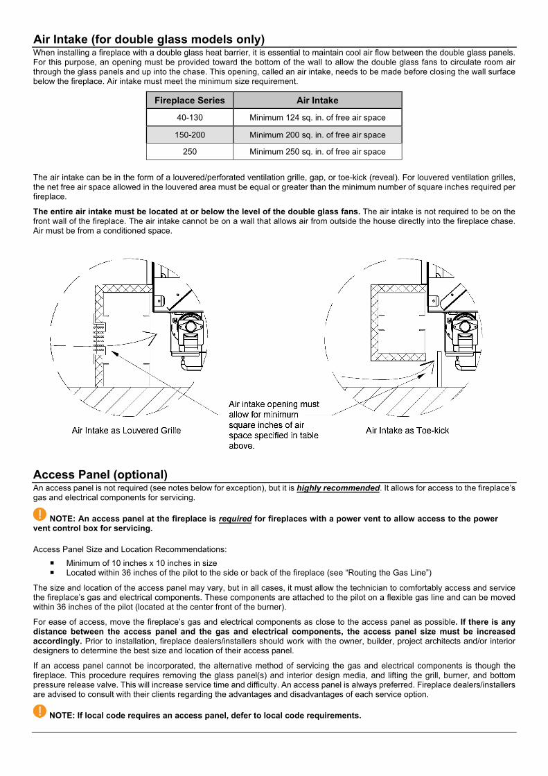
Air Intake (for double glass models only)When installing a fireplace with a double glass heat barrier, it is essential to maintain cool air flow between the double glass panels. For this purpose, an opening must be provided toward the bottom of the wall to allow the double glass fans to circulate room air through the glass panels and up into the chase. This opening, called an air intake, needs to be made before closing the wall surface below the fireplace. Air intake must meet the minimum size requirement.
Fireplace Series Air Intake
40-130 Minimum 124 sq. in. of free air space
150-200 Minimum 200 sq. in. of free air space
250 Minimum 250 sq. in. of free air space
The air intake can be in the form of a louvered/perforated ventilation grille, gap, or toe-kick (reveal). For louvered ventilation grilles, the net free air space allowed in the louvered area must be equal or greater than the minimum number of square inches required per fireplace.
The entire air intake must be located at or below the level of the double glass fans. The air intake is not required to be on the front wall of the fireplace. The air intake cannot be on a wall that allows air from outside the house directly into the fireplace chase. Air must be from a conditioned space.
Access Panel (optional)
Minimum of 10 inches x 10 inches in size Located within 36 inches of the pilot to the side or back of the fireplace (see “Routing the Gas Line”)
The size and location of the access panel may vary, but in all cases, it must allow the technician to comfortably access and service the fireplace’s gas and electrical components. These components are attached to the pilot on a flexible gas line and can be moved within 36 inches of the pilot (located at the center front of the burner).
For ease of access, move the fireplace’s gas and electrical components as close to the access panel as possible. If there is any distance between the access panel and the gas and electrical components, the access panel size must be increased accordingly. Prior to installation, fireplace dealers/installers should work with the owner, builder, project architects and/or interior designers to determine the best size and location of their access panel.
If an access panel cannot be incorporated, the alternative method of servicing the gas and electrical components is though the fireplace. This procedure requires removing the glass panel(s) and interior design media, and lifting the grill, burner, and bottom pressure release valve. This will increase service time and difficulty. An access panel is always preferred. Fireplace dealers/installers are advised to consult with their clients regarding the advantages and disadvantages of each service option.
NOTE: If local code requires an access panel, defer to local code requirements.
An access panel is not required (see notes below for exception), but it is highly recommended. It allows for access to the fireplace’s gas and electrical components for servicing.
NOTE: An access panel at the fireplace is required for fireplaces with a power vent to allow access to the power vent control box for servicing.
Access Panel Size and Location Recommendations:
Related Documents