HAL Id: tel-00438183 https://tel.archives-ouvertes.fr/tel-00438183 Submitted on 2 Dec 2009 HAL is a multi-disciplinary open access archive for the deposit and dissemination of sci- entific research documents, whether they are pub- lished or not. The documents may come from teaching and research institutions in France or abroad, or from public or private research centers. L’archive ouverte pluridisciplinaire HAL, est destinée au dépôt et à la diffusion de documents scientifiques de niveau recherche, publiés ou non, émanant des établissements d’enseignement et de recherche français ou étrangers, des laboratoires publics ou privés. Front-End Electronics in calorimetry: from LHC to ILC C. de la Taille To cite this version: C. de la Taille. Front-End Electronics in calorimetry : from LHC to ILC. Micro et nanotechnolo- gies/Microélectronique. Université Paris Sud - Paris XI, 2009. tel-00438183

Welcome message from author
This document is posted to help you gain knowledge. Please leave a comment to let me know what you think about it! Share it to your friends and learn new things together.
Transcript
HAL Id: tel-00438183https://tel.archives-ouvertes.fr/tel-00438183
Submitted on 2 Dec 2009
HAL is a multi-disciplinary open accessarchive for the deposit and dissemination of sci-entific research documents, whether they are pub-lished or not. The documents may come fromteaching and research institutions in France orabroad, or from public or private research centers.
L’archive ouverte pluridisciplinaire HAL, estdestinée au dépôt et à la diffusion de documentsscientifiques de niveau recherche, publiés ou non,émanant des établissements d’enseignement et derecherche français ou étrangers, des laboratoirespublics ou privés.
Front-End Electronics in calorimetry : from LHC to ILCC. de la Taille
To cite this version:C. de la Taille. Front-End Electronics in calorimetry : from LHC to ILC. Micro et nanotechnolo-gies/Microélectronique. Université Paris Sud - Paris XI, 2009. �tel-00438183�

REMERCIEMENTS
1
• 1

INTRODUCTION
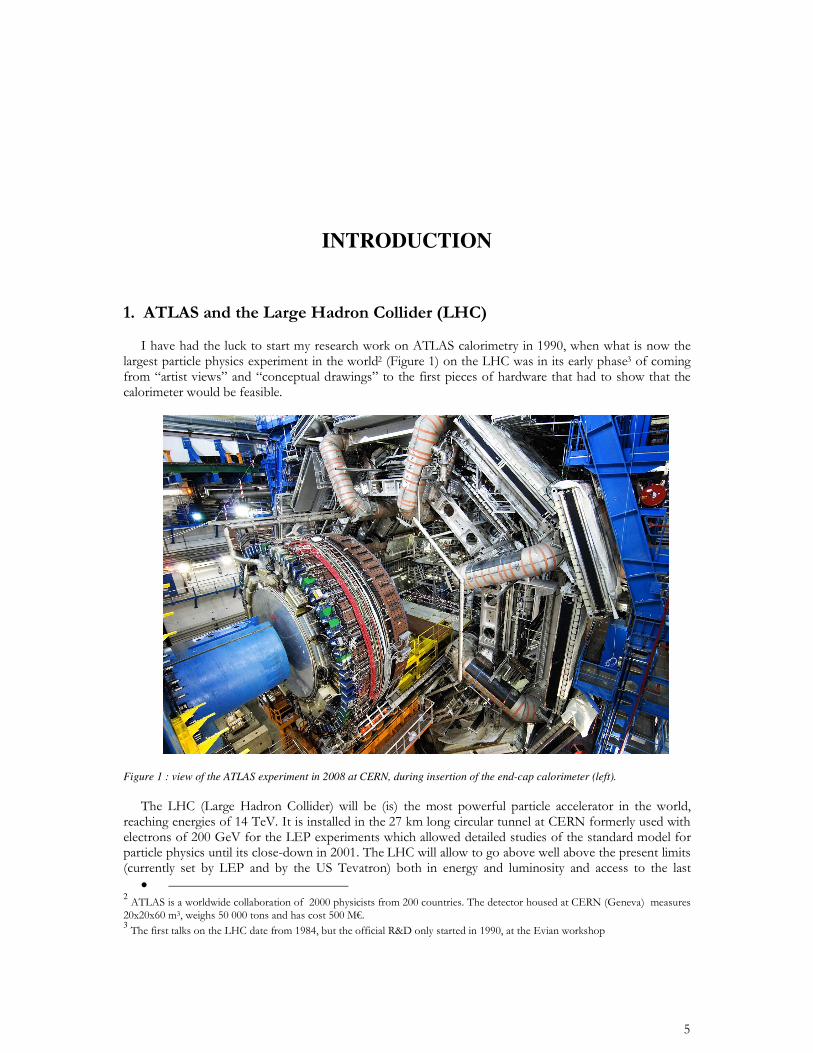
Figure 1 : view of the ATLAS experiment in 2008 at CERN, during insertion of the end-cap calorimeter (left).
• 23
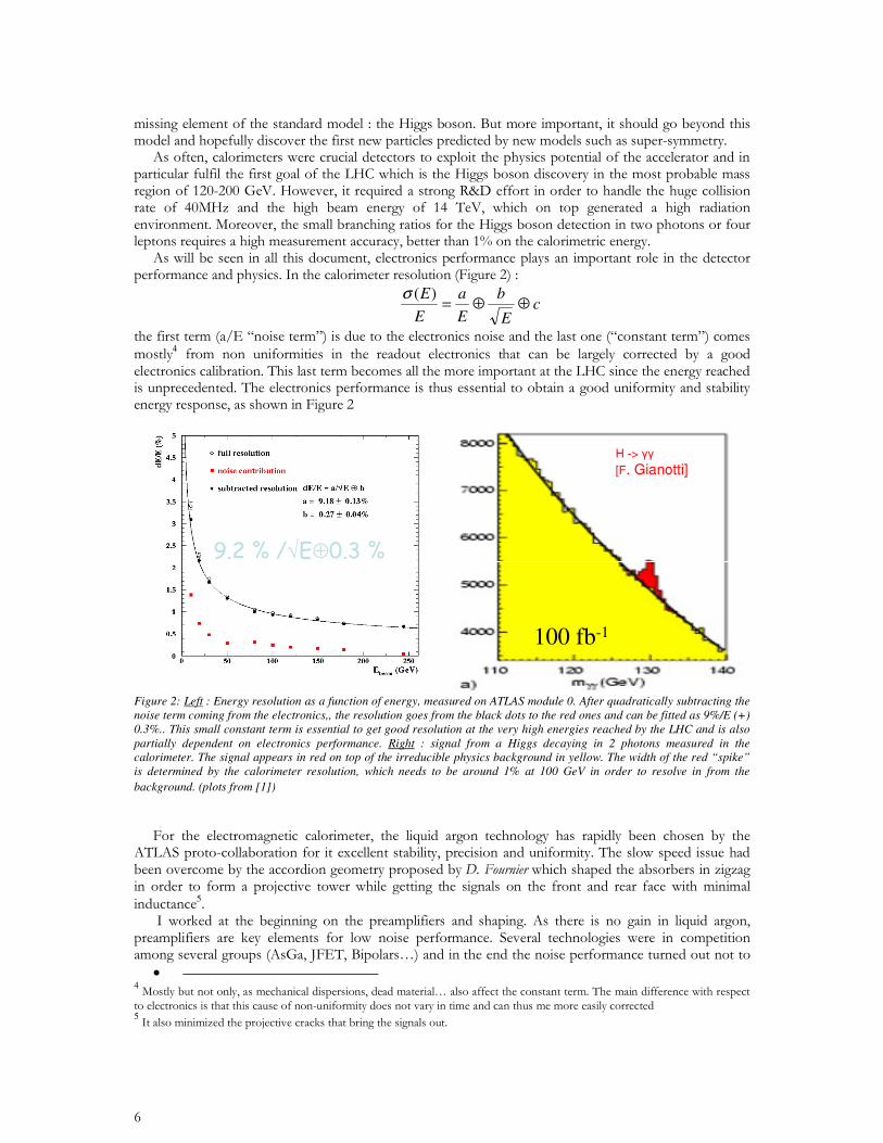
cE
b
E
a
E
E!!=
)("
4
#!
100 fb-1
H -> [F. Gianotti]
#!
100 fb-1
H -> [F. Gianotti]
100 fb-1
H -> [F. Gianotti]
Figure 2: Left : Energy resolution as a function of energy, measured on ATLAS module 0. After quadratically subtracting the noise term coming from the electronics,, the resolution goes from the black dots to the red ones and can be fitted as 9%/E (+) 0.3%.. This small constant term is essential to get good resolution at the very high energies reached by the LHC and is also partially dependent on electronics performance. Right : signal from a Higgs decaying in 2 photons measured in the calorimeter. The signal appears in red on top of the irreducible physics background in yellow. The width of the red “spike” is determined by the calorimeter resolution, which needs to be around 1% at 100 GeV in order to resolve in from the
background. (plots from [1])
5
• 45
6
• 6
7
• 7
CHAPTER 1
ATLAS FRONT-END ELECTRONICS
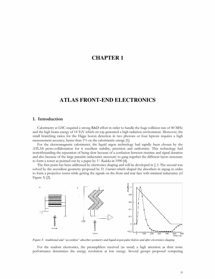
Figure 3: traditional and “accordion” absorber geometry and liquid argon pulse before and after electronics shaping
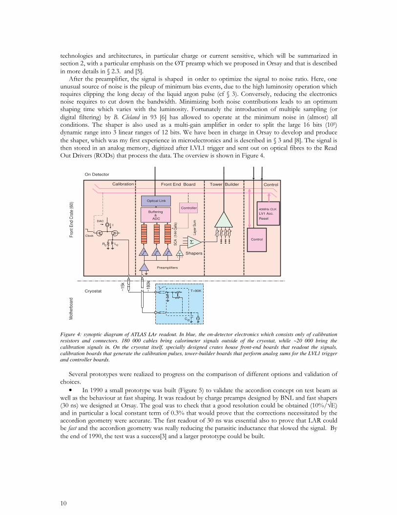
Figure 4: synoptic diagram of ATLAS LAr readout. In blue, the on-detector electronics which consists only of calibration resistors and connectors. 180 000 cables bring calorimeter signals outside of the cryostat, while ~20 000 bring the calibration signals in. On the cryostat itself, specially designed crates house front-end boards that readout the signals, calibration boards that generate the calibration pulses, tower-builder boards that perform analog sums for the LVL1 trigger and controller boards.
•
Laye
r S
um
Shapers
Calibration
DAC
LcRc
Clock
I
Preamplifiers
$
Buffering & ADC
Optical Link
T=90K
Cd
Front End Board Tower Builder Control
40MHz CLK
LV1 Acc.
Control
Reset
~180
k
~15k
$
Cryostat
On Detector
Fro
nt E
nd C
rate
(60
)M
othe
rboa
rd
Controller
SC
A (
144
Cel
ls)
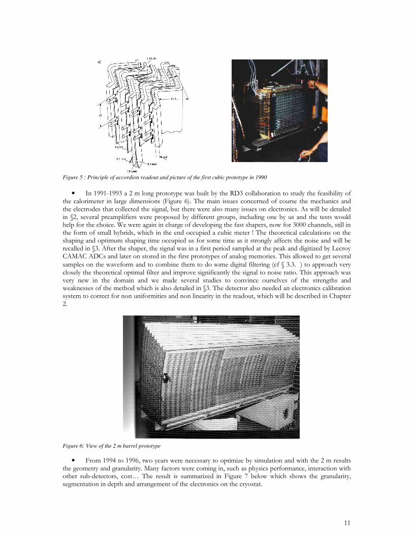
Figure 5 : Principle of accordion readout and picture of the first cubic prototype in 1990 •
Figure 6: View of the 2 m barrel prototype
•
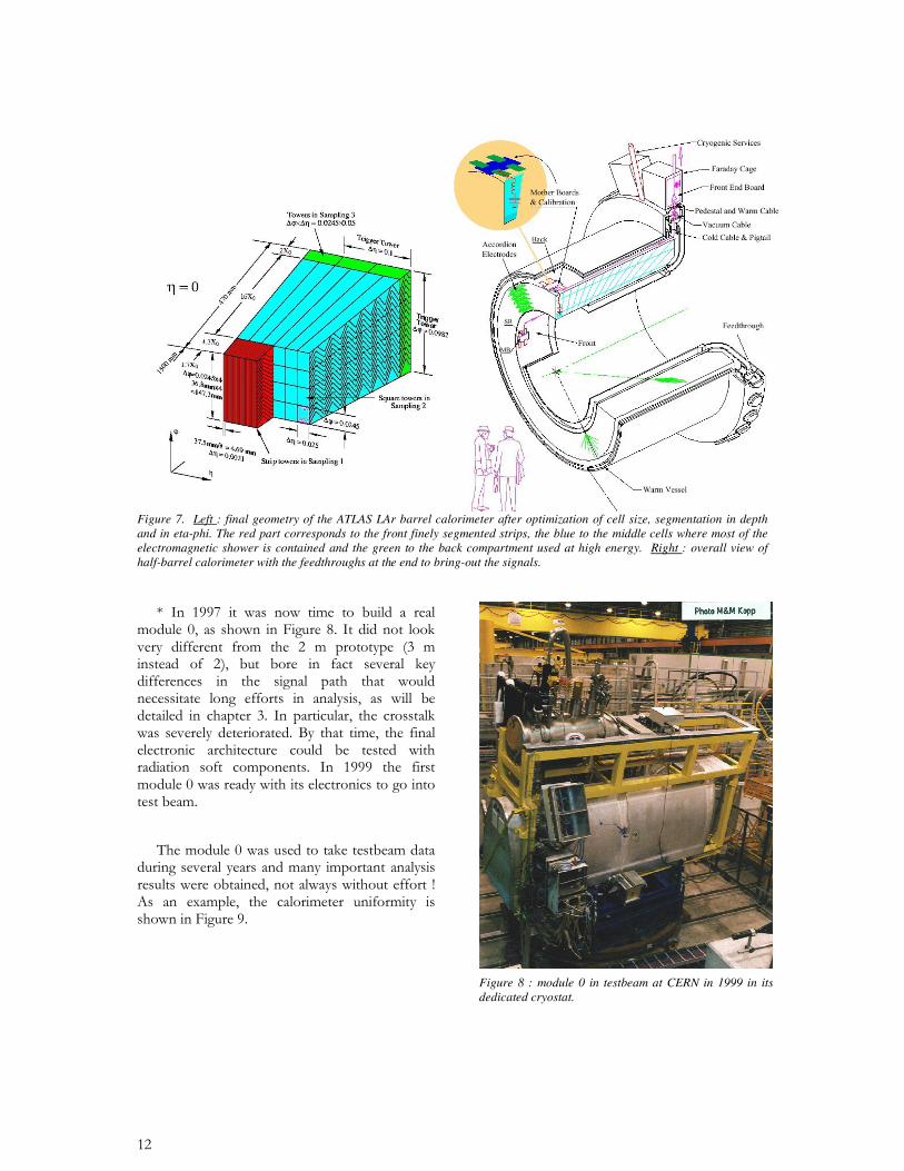
Figure 7. Left : final geometry of the ATLAS LAr barrel calorimeter after optimization of cell size, segmentation in depth and in eta-phi. The red part corresponds to the front finely segmented strips, the blue to the middle cells where most of the electromagnetic shower is contained and the green to the back compartment used at high energy. Right : overall view of half-barrel calorimeter with the feedthroughs at the end to bring-out the signals.
Figure 8 : module 0 in testbeam at CERN in 1999 in its dedicated cryostat.
0.96
0.98
1
1.02
1.04
0 0.5 1 1.5 20
2
4
6
8
10
%
No
rm.
Av
. E
ner
gie
s+2 %
+1 %
-1 %
-2 %
OV
ER
LA
P
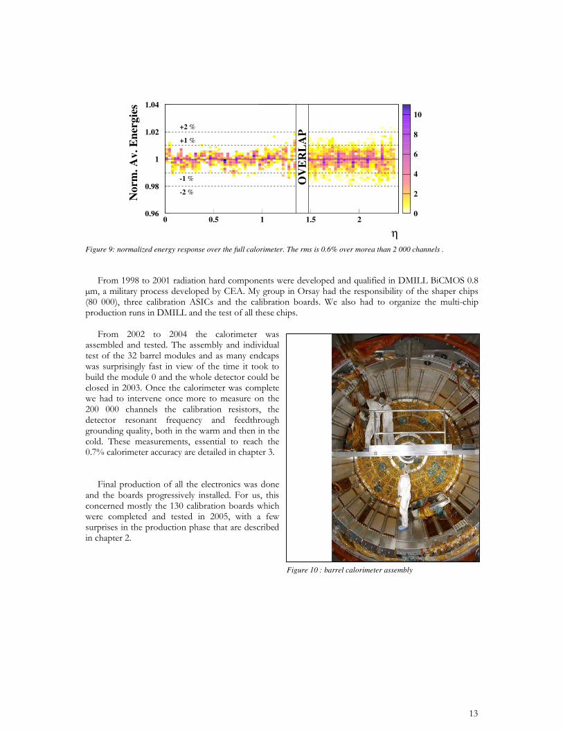
Figure 9: normalized energy response over the full calorimeter. The rms is 0.6% over morea than 2 000 channels .
Figure 10 : barrel calorimeter assembly
•
•
• • 8
9
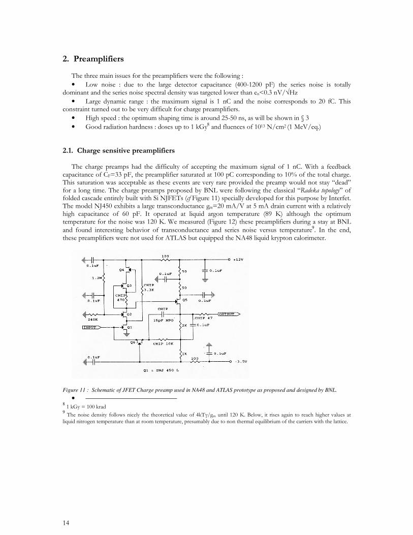
Figure 11 : Schematic of JFET Charge preamp used in NA48 and ATLAS prototype as proposed and designed by BNL.
• 89
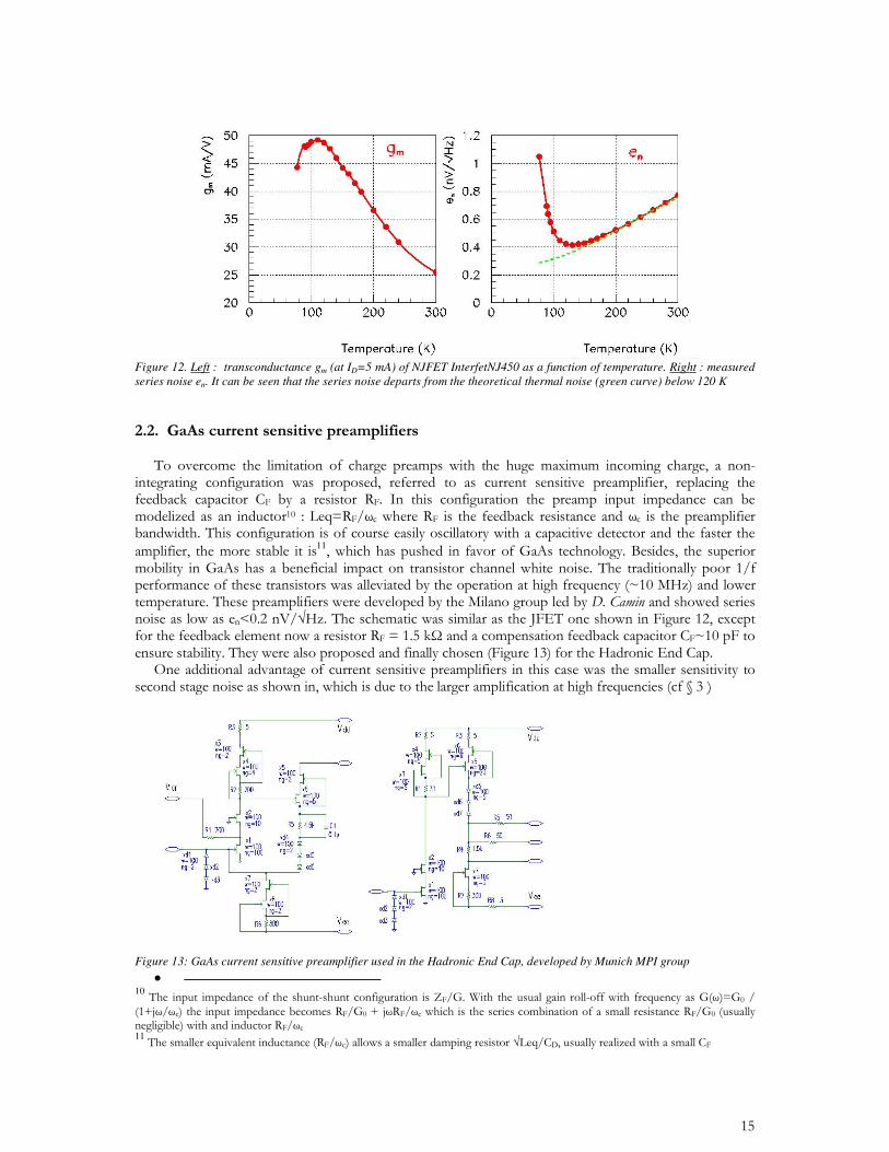
Figure 12. Left : transconductance gm (at ID=5 mA) of NJFET InterfetNJ450 as a function of temperature. Right : measured series noise en. It can be seen that the series noise departs from the theoretical thermal noise (green curve) below 120 K
11
Figure 13: GaAs current sensitive preamplifier used in the Hadronic End Cap, developed by Munich MPI group
• 10 11
Cdd
ddC
RtjCj
tCRZ
/.tan.
.tan.1
&&&&
+'
=
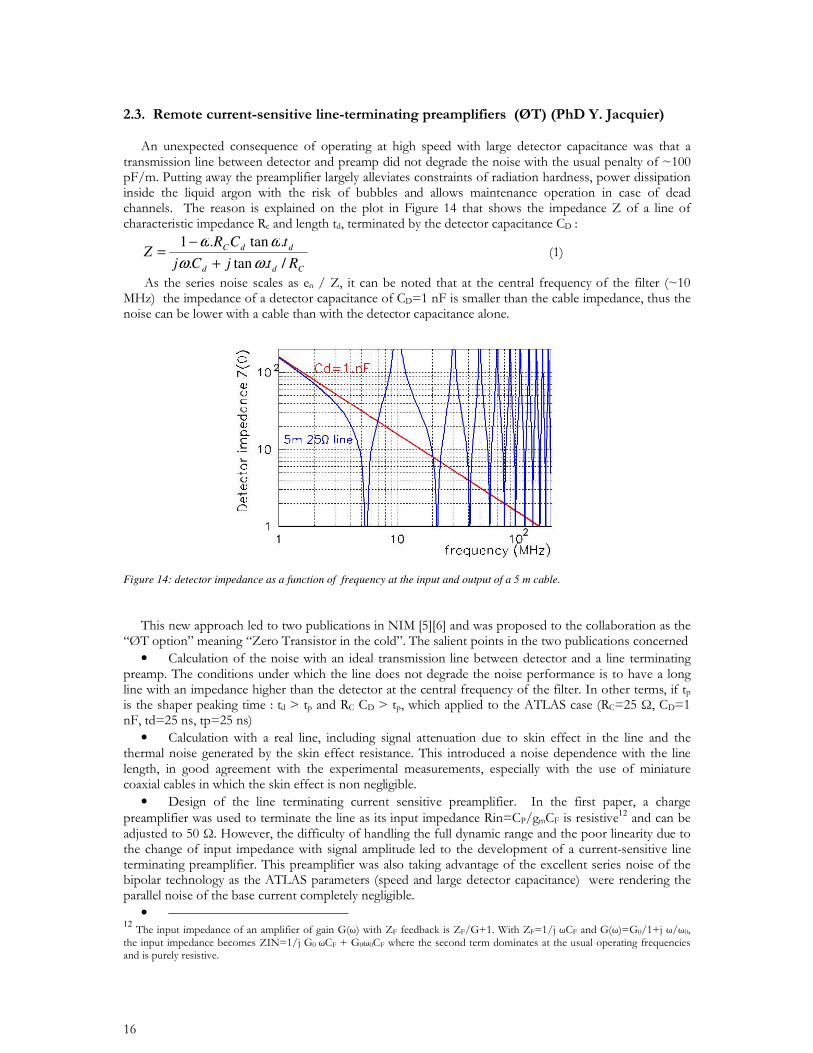
Figure 14: detector impedance as a function of frequency at the input and output of a 5 m cable.
•
•
• 12
• 12
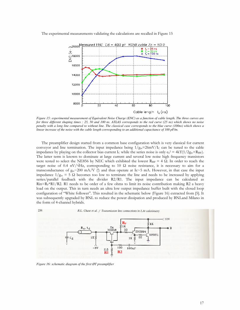
Figure 15: experimental measurement of Equivalent Noise Charge (ENC) as a function of cable length. The three curves are for three different shaping times : 25, 50 and 100 ns. ATLAS corresponds to the red curve (25 ns) which shows no noise penalty with a long line compared to without line. The classical case corresponds to the blue curve (100ns) which shows a linear increase of the noise with the cable length corresponding to an additional capacitance of 100 pF/m.
Figure 16: schematic diagram of the first ØT preamplifier
13
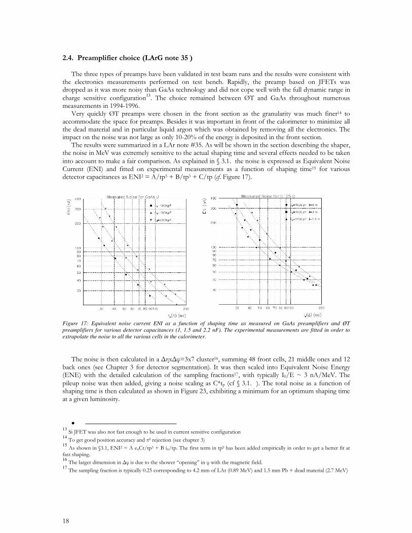
Figure 17: Equivalent noise current ENI as a function of shaping time as measured on GaAs preamplifiers and ØT preamplifiers for various detector capacitances (1, 1.5 and 2.2 nF). The experimental measurements are fitted in order to extrapolate the noise to all the various cells in the calorimeter.
•
1314151617
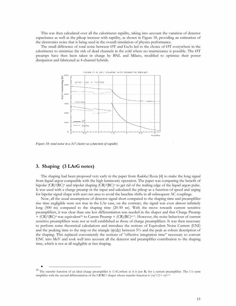
Figure 18: total noise in a 3x7 cluster as a function of rapidity
• 18
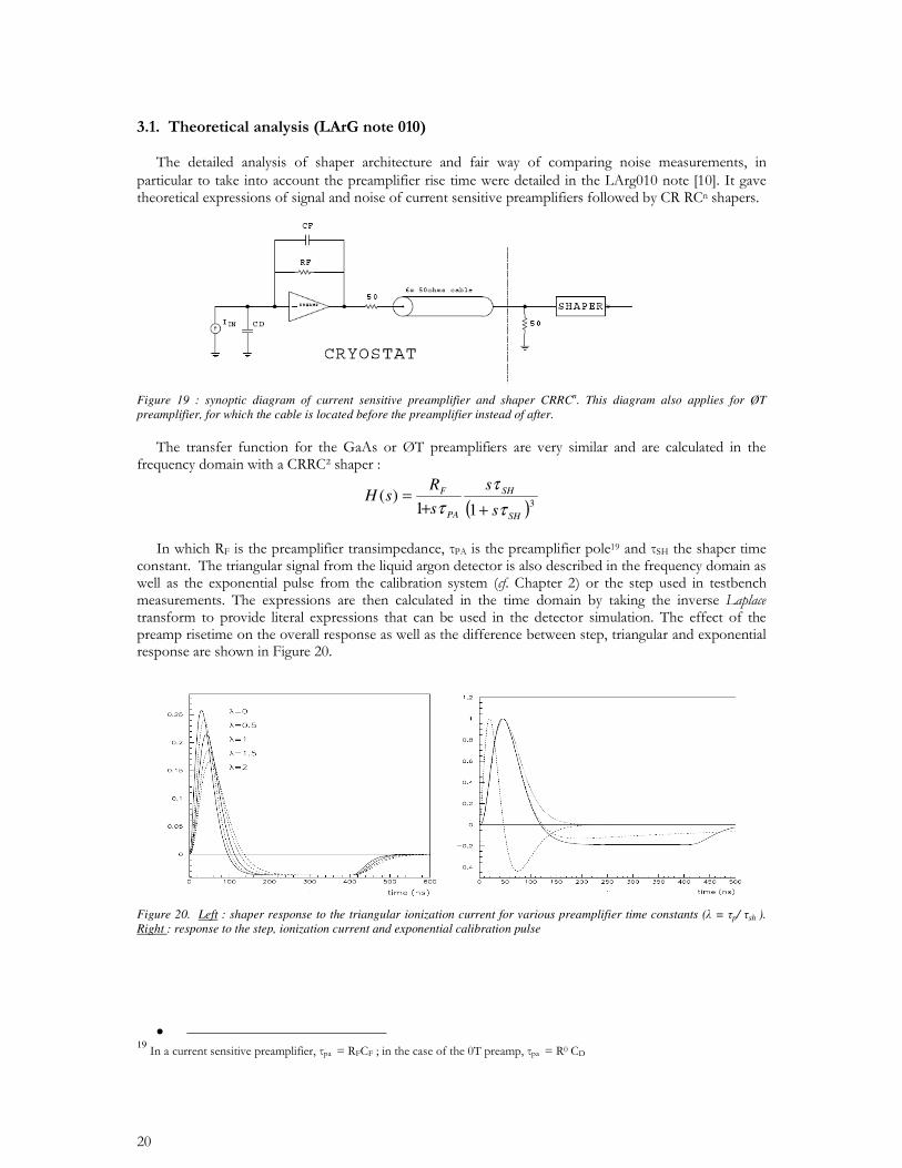
Figure 19 : synoptic diagram of current sensitive preamplifier and shaper CRRCn. This diagram also applies for ØT preamplifier, for which the cable is located before the preamplifier instead of after.
( )311
)(SH
SH
PA
F
s
s
s
RsH
((
( ++=
Figure 20. Left : shaper response to the triangular ionization current for various preamplifier time constants ( = p/ sh ). Right : response to the step, ionization current and exponential calibration pulse
•
19
( )( )( )
( ) ( )( )( )
( )))
+++
++=
0
32222
222
0
32222
4
3
222
2
211211 *&(
(&(&
&((*
&(
(&(&
&((
SH
SHpaSH
fn
SHpa
SH
SH
fdn
n
dRidRCev
2/1max
2/3max ))((
)(
))((
)(
SH
n
SH
Dnh
Jbi
h
JaCeENI
(++
(++
,!
,=
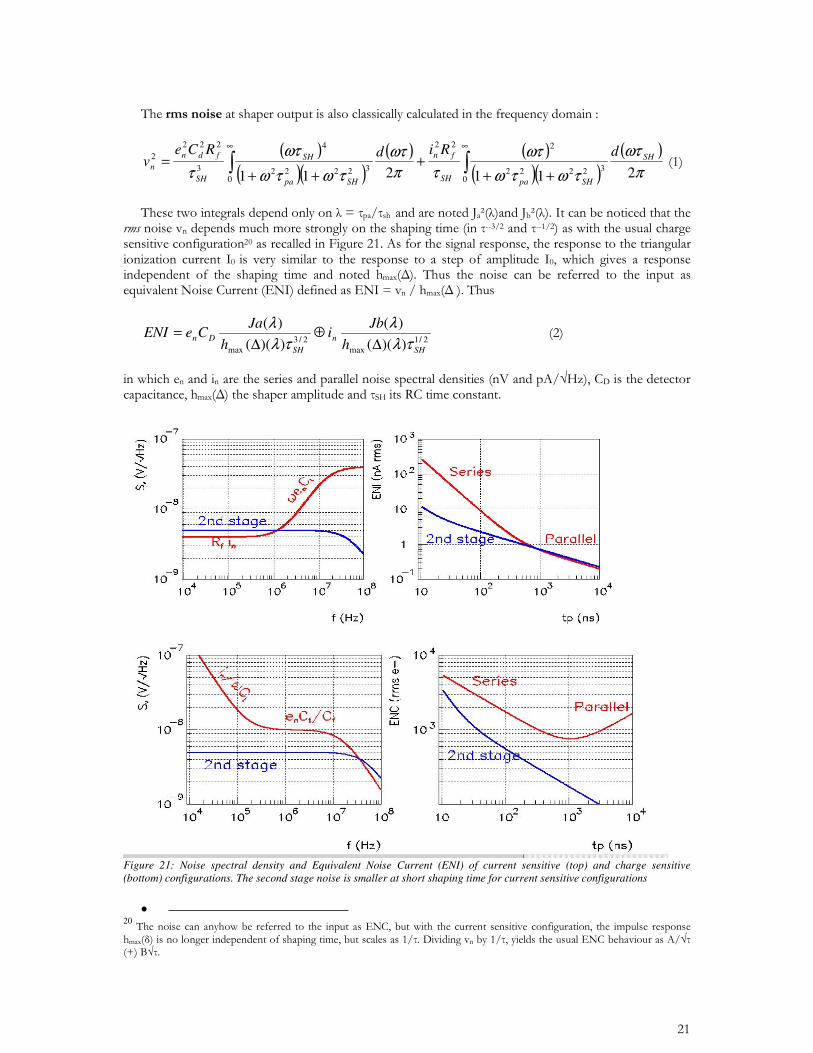
Figure 21: Noise spectral density and Equivalent Noise Current (ENI) of current sensitive (top) and charge sensitive (bottom) configurations. The second stage noise is smaller at short shaping time for current sensitive configurations
•
20
)()( 2/12/3 ,!
,=
p
n
p
dnt
Bpi
t
BsCeENI
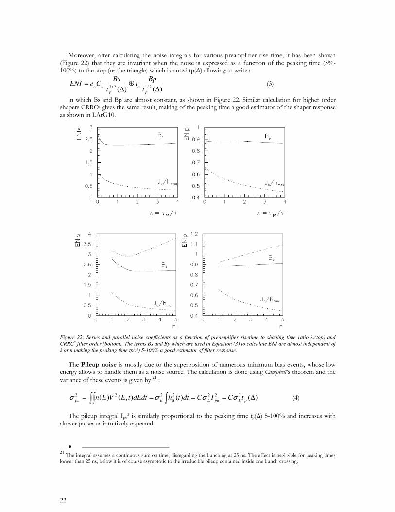
Figure 22: Series and parallel noise coefficients as a function of preamplifier risetime to shaping time ratio .(top) and CRRCn filter order (bottom). The terms Bs and Bp which are used in Equation (3) to calculate ENI are almost independent of or n making the peaking time tp() 5-100% a good estimator of filter response.
21
)()( ),()( 2222222 ,==== , pEpuEEpu tCICdtthdEdttEVEn """"
•
21
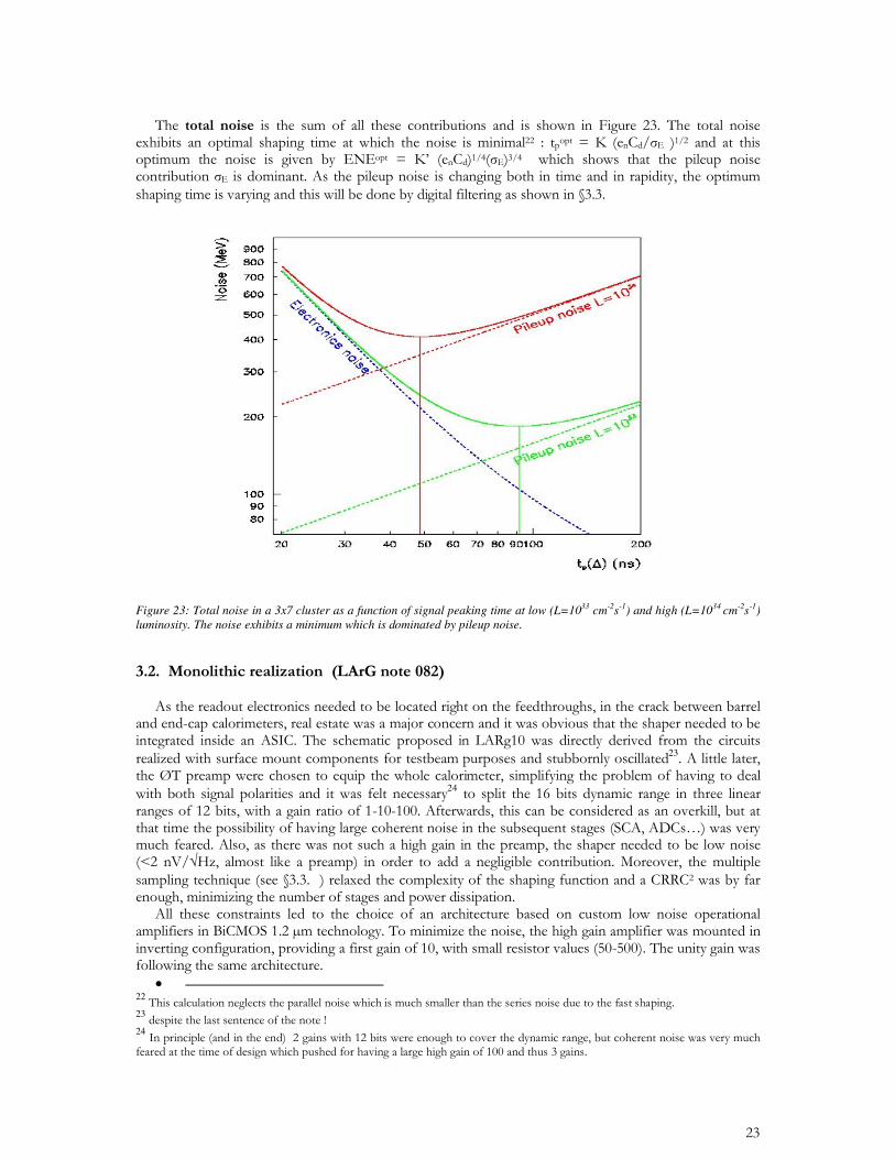
Figure 23: Total noise in a 3x7 cluster as a function of signal peaking time at low (L=1033 cm-2s-1) and high (L=1034 cm-2s-1) luminosity. The noise exhibits a minimum which is dominated by pileup noise.
23 24
• 222324
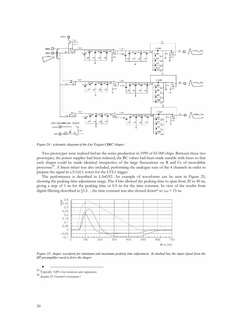
Figure 24 : schematic diagram of the LAr Trigain CRRC! shaper.
25
Figure 25: shaper waveform for minimum and maximum peaking time adjustment. .In dashed line the input signal from the ØT preamplifier used to drive the shaper
•
2526
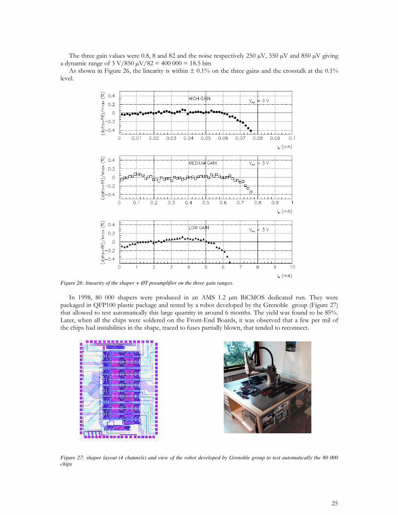
Figure 26: linearity of the shaper + ØT preamplifier on the three gain ranges.
Figure 27: shaper layout (4 channels) and view of the robot developed by Grenoble group to test automatically the 80 000 chips
27
• • • • • • • •
=
=n
iii SaA
1
=
'=n
jjiji gRa
1
1
• 27
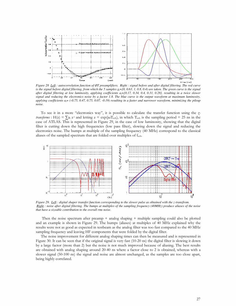
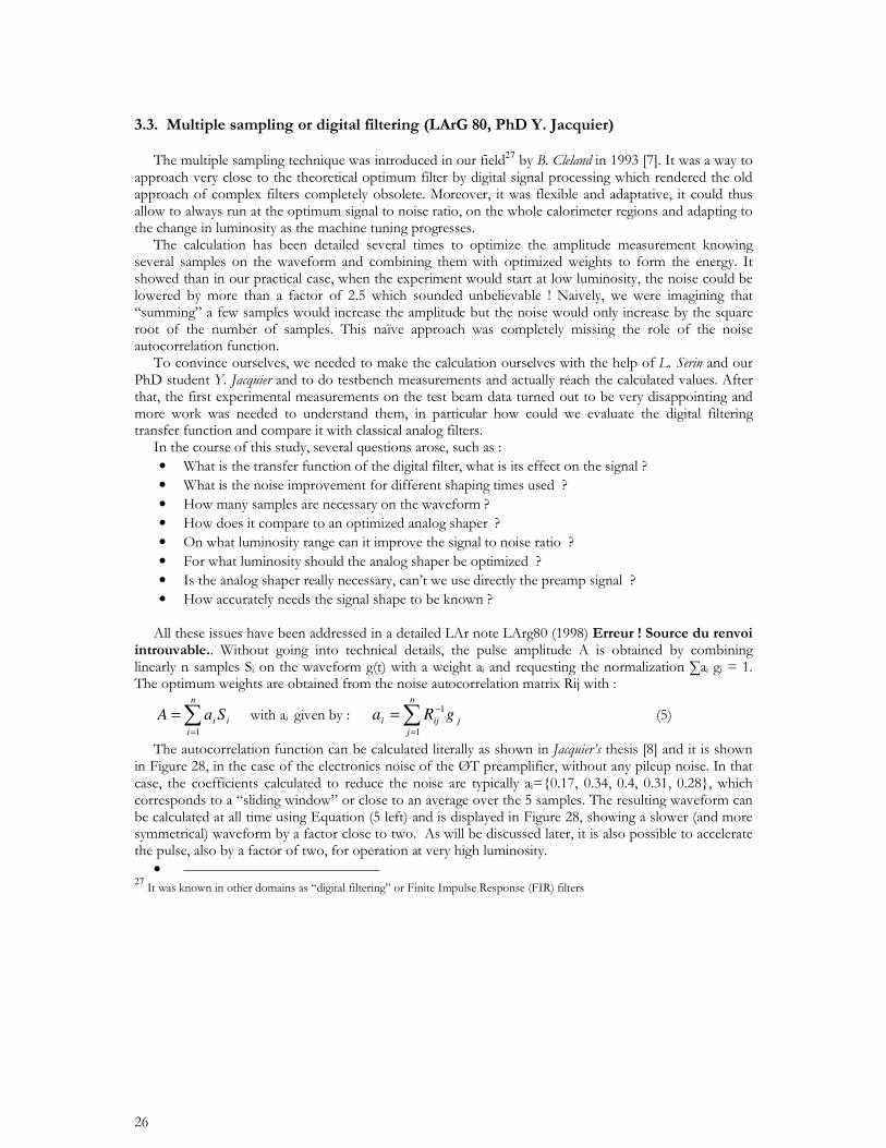
Figure 28 Left : autocorrelation function of ØT preamplifiers. Right : signal before and after digital filtering. The red curve is the signal before digital filtering, from which the 5 samples gi={0, 0.63, 1, 0.8, 0.4) are taken. The green curve is the signal after digital filtering at low luminosity, applying coefficients ai={0.17, 0.34, 0.4, 0.31, 0.28}, resulting in a twice slower signal and reducing the electronics noise by a factor 1.8. The blue curve is the output waveform at maximum luminosity, applying coefficients ai= (-0.75, 0.47, 0.75, 0.07, -0.19) resulting in a faster and narrower waveform, minimizing the pileup noise.
Figure 29. Left : digital shaper transfer function corresponding to the slower pulse as obtained with the z-transfrom. Right : noise after digital filtering. The bumps at multiples of the sampling frequency (40MHz) produce aliases of the noise that have a sizeable contribution to the overall rms noise.
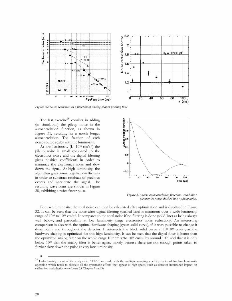
Figure 30: Noise reduction as a function of analog shaper peaking time
28
Figure 31: noise autocorrelation function : solid line : electronics noise, dashed line : pileup noise.
• 28
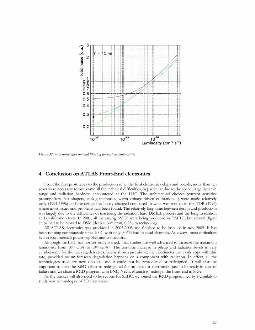
Figure 32: total noise after optimal filtering for various luminosities

CHAPTER 2
ATLAS ELECTRONIC CALIBRATION
• • •
• •
V =Vo
2
1 + x
(1 + x / 2)2
-Vo
21 '
x2
4
• 29
45 46 47 48 49 50 51 520.996
0.997
0.998
0.999
1
1.001
1.002
1.003
td/C
Co
rrec
ted
Am
pli
tud
e
Harnesses 913 and 982: Corrected Amplitude vs td/C 300K and 77K
300K77K
Zc = 49.3 . ± 0.8 rms
rms
0.1
1%
45 46 47 48 49 50 51 520.996
0.997
0.998
0.999
1
1.001
1.002
1.003
td/C
Co
rrec
ted
Am
pli
tud
e
Harnesses 913 and 982: Corrected Amplitude vs td/C 300K and 77K
300K77K
Zc = 49.3 . ± 0.8 rms
rms
0.1
1%
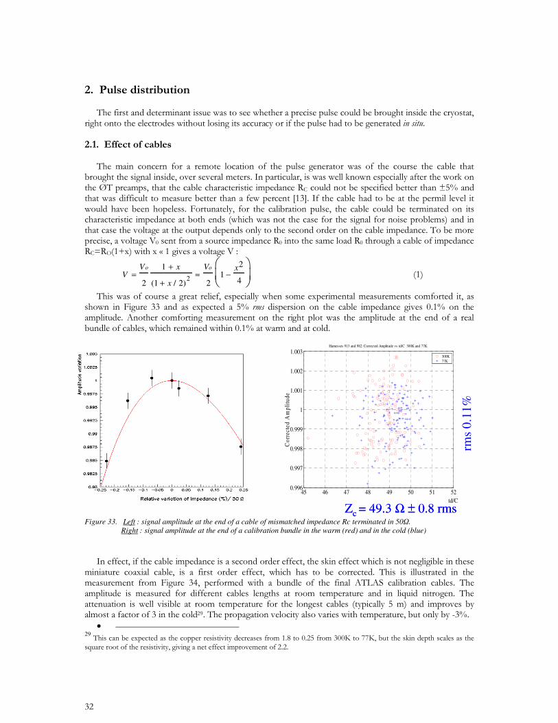
Figure 33. Left : signal amplitude at the end of a cable of mismatched impedance Rc terminated in 50. Right : signal amplitude at the end of a calibration bundle in the warm (red) and in the cold (blue)
• •
0 20 40 60 80 100 120 1400.94
0.95
0.96
0.97
0.98
0.99
1
1.01
Channel number
Am
pli
.
Calib. harnesses 913 and 982
300K measurement77K meas.
1 1.5 2 2.5 3 3.5 4 4.5 5 5.50.94
0.95
0.96
0.97
0.98
0.99
1
1.01
L (m)
Am
pli
tud
e
Harnesses 913 et 982- Amplitude vs L @300K and 77K
300KFit 1.007-0.01184*L77KFit 1.007-0.00485*L
Harness ‘A’ Pigtail ‘B’ Vacuum ‘C’ Warm cable ‘D’
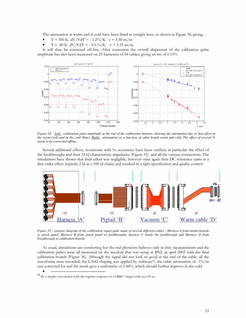
Figure 35 : synoptic diagram of the calibration signal path, made of several different cables : Harness A from motherboards to patch panel, Harness B form patch panel to feedthroughs, harness C inside the feedthrough and Harness D from Feedthrough to calibration boards
• 30
Figure 34. Left : calibration pulse amplitude at the end of the calibration harness, showing the attenuation due to skin effect in the warm (red) and in the cold (blue). Right : attenuation as a function of cable length warm and cold. The effect of several % needs to be corrected offline.
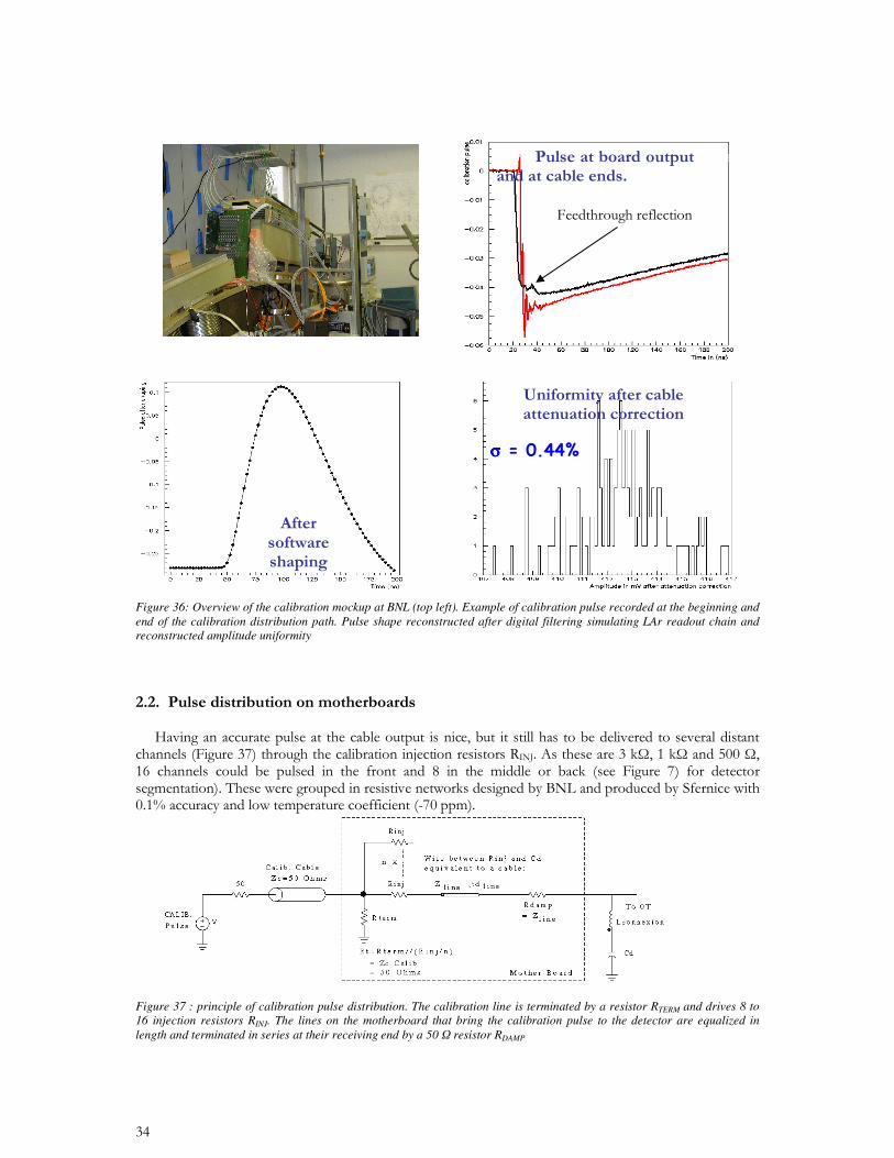
Figure 36: Overview of the calibration mockup at BNL (top left). Example of calibration pulse recorded at the beginning and end of the calibration distribution path. Pulse shape reconstructed after digital filtering simulating LAr readout chain and reconstructed amplitude uniformity
Figure 37 : principle of calibration pulse distribution. The calibration line is terminated by a resistor RTERM and drives 8 to 16 injection resistors RINJ. The lines on the motherboard that bring the calibration pulse to the detector are equalized in length and terminated in series at their receiving end by a 50 resistor RDAMP
""""
31
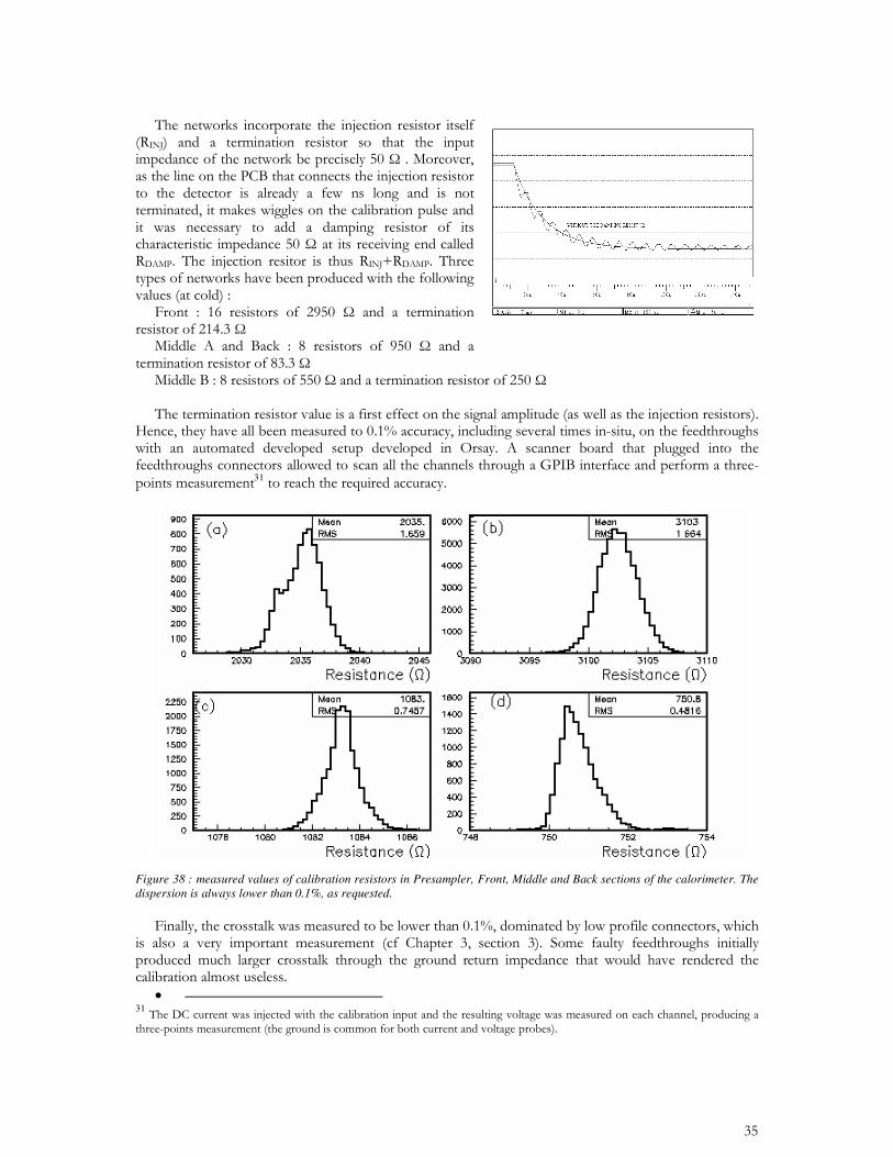
Figure 38 : measured values of calibration resistors in Presampler, Front, Middle and Back sections of the calorimeter. The dispersion is always lower than 0.1%, as requested.
• 31
• •
• • • • •
• 32
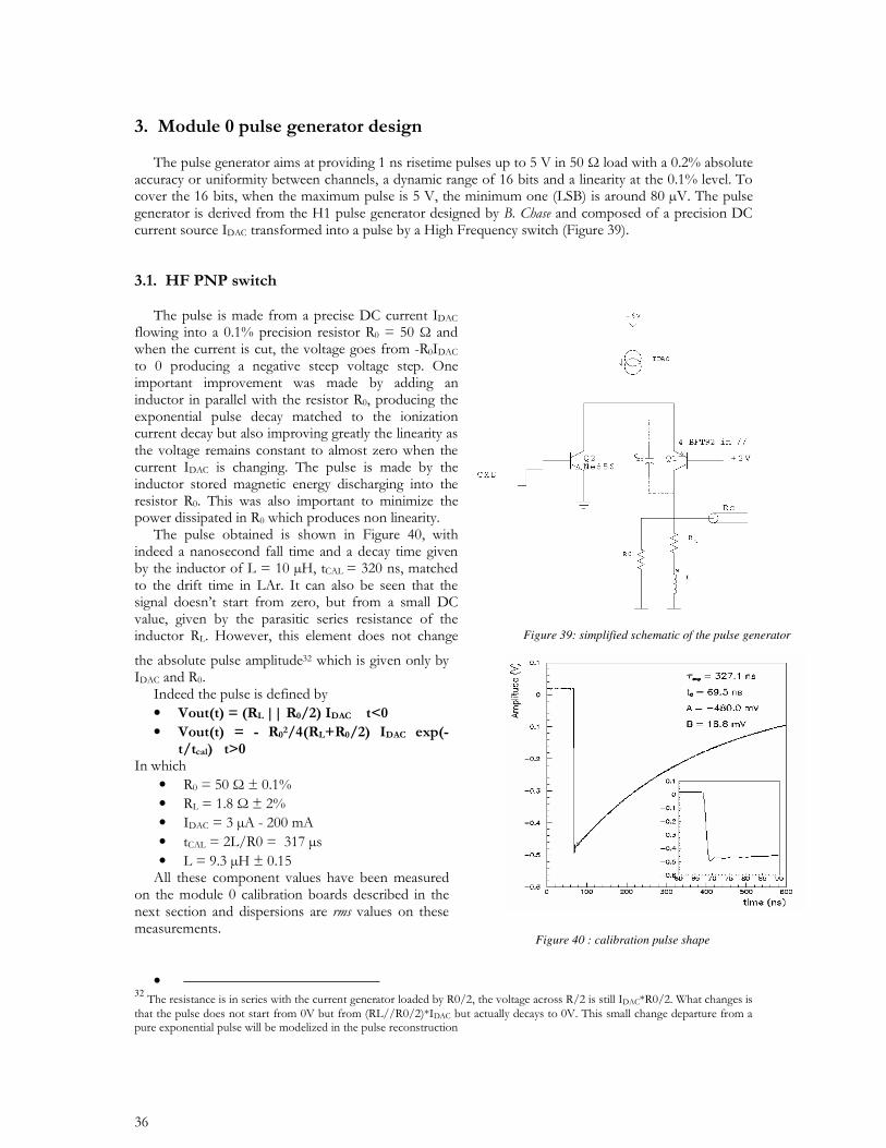
Figure 40 : calibration pulse shape
Figure 39: simplified schematic of the pulse generator
33
• 33
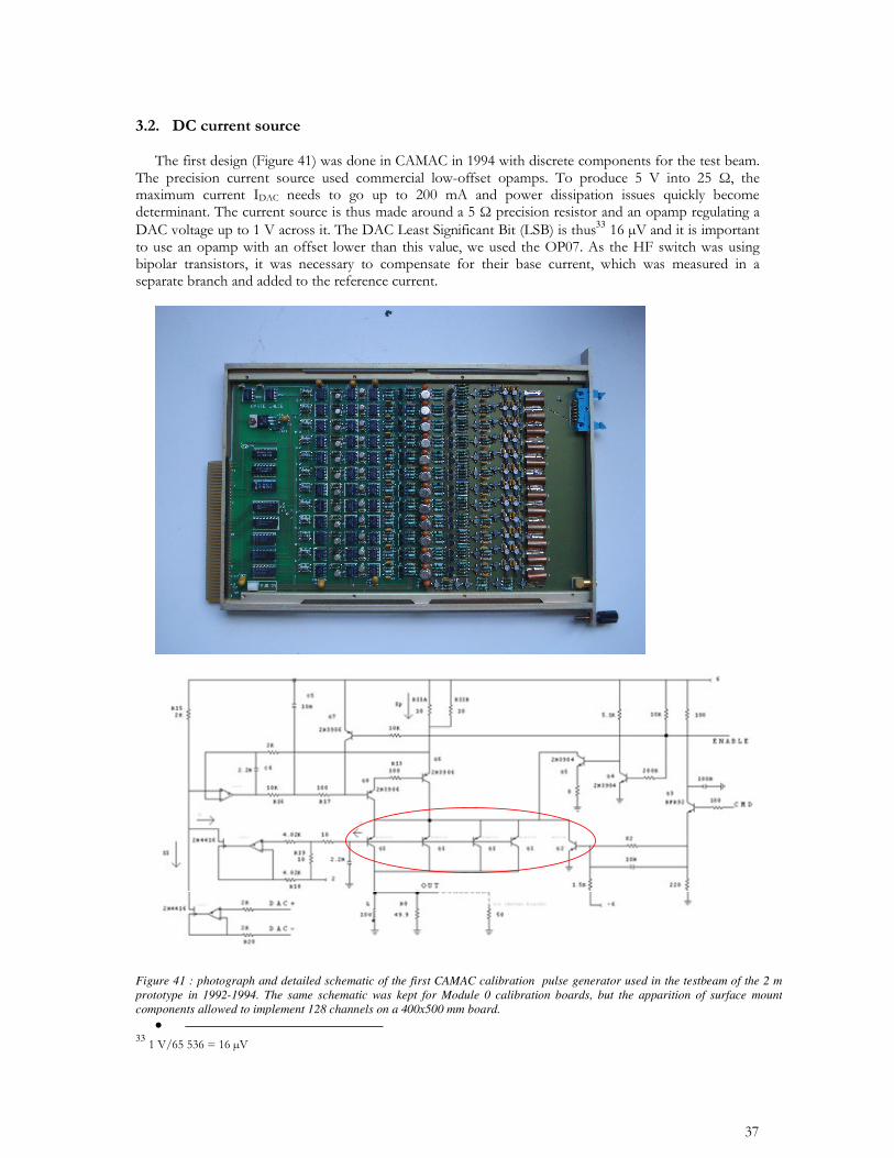
Figure 41 : photograph and detailed schematic of the first CAMAC calibration pulse generator used in the testbeam of the 2 m prototype in 1992-1994. The same schematic was kept for Module 0 calibration boards, but the apparition of surface mount components allowed to implement 128 channels on a 400x500 mm board.
•
•
•
3435
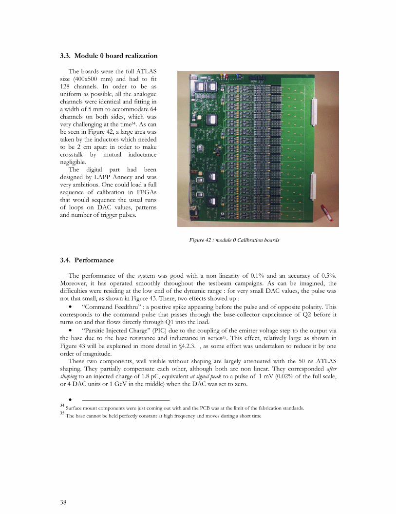
Figure 42 : module 0 Calibration boards
CMD feedthru
PIC : ParasiticInjected Charge
CMD feedthru
PIC : ParasiticInjected Charge
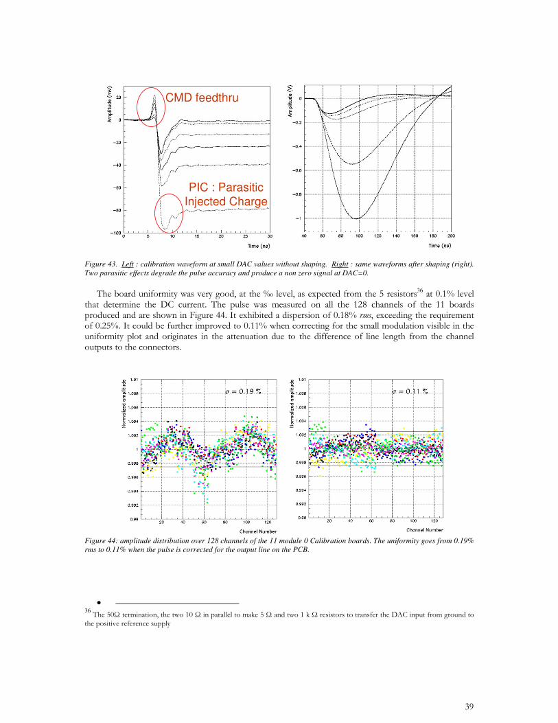
Figure 43. Left : calibration waveform at small DAC values without shaping. Right : same waveforms after shaping (right). Two parasitic effects degrade the pulse accuracy and produce a non zero signal at DAC=0.
36
Figure 44: amplitude distribution over 128 channels of the 11 module 0 Calibration boards. The uniformity goes from 0.19% rms to 0.11% when the pulse is corrected for the output line on the PCB.
•
36
•
•
•
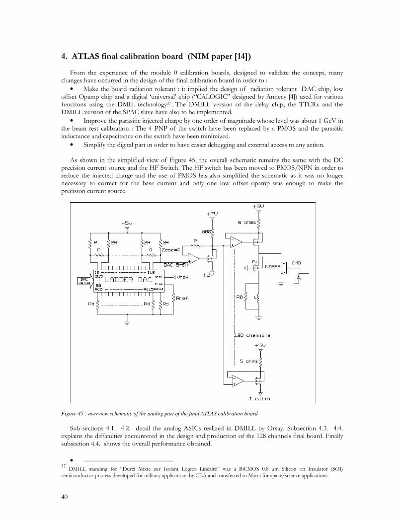
Figure 45 : overview schematic of the analog part of the final ATLAS calibration board
•
37
.
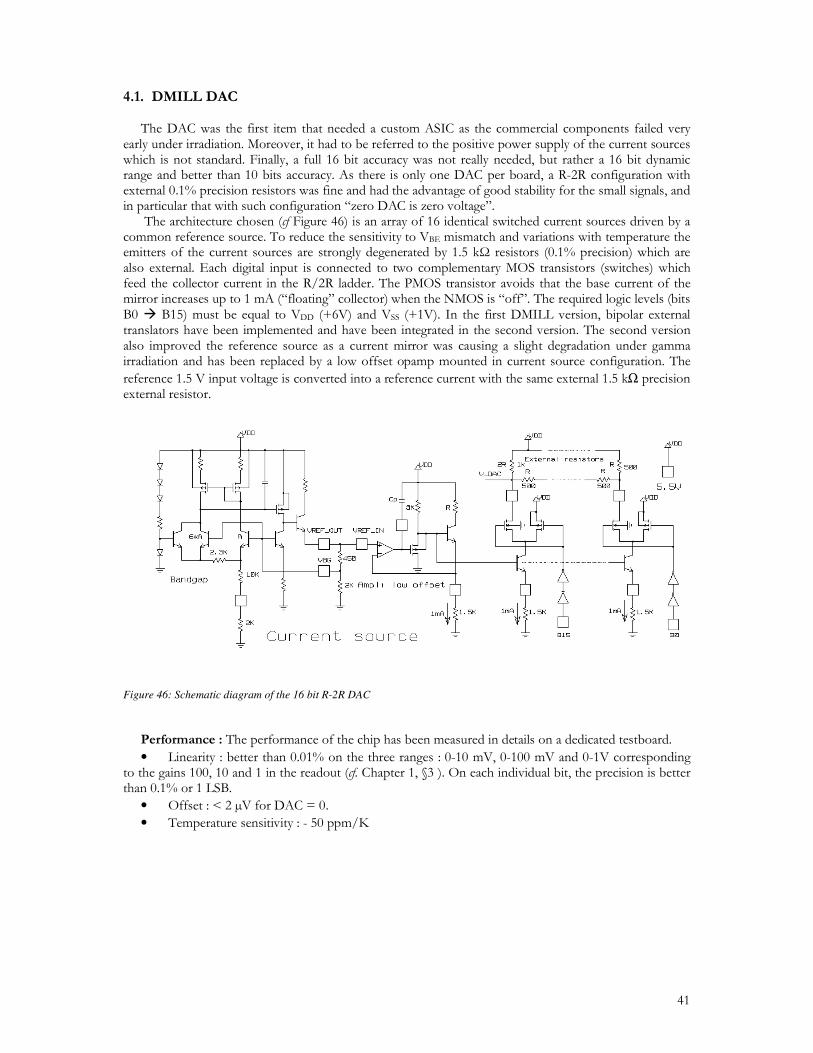
Figure 46: Schematic diagram of the 16 bit R-2R DAC •
• •
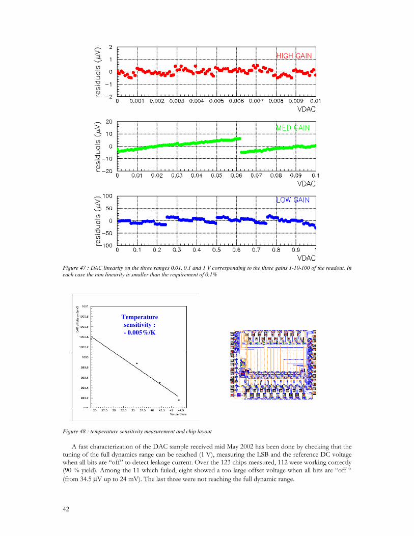
Figure 47 : DAC linearity on the three ranges 0.01, 0.1 and 1 V corresponding to the three gains 1-10-100 of the readout. In each case the non linearity is smaller than the requirement of 0.1%
Temperaturesensitivity : - 0.005%/K
Temperaturesensitivity : - 0.005%/K
Figure 48 : temperature sensitivity measurement and chip layout
µ
. µ
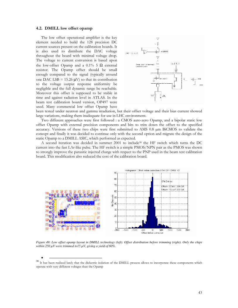
Figure 49: Low offset opamp layout in DMILL technology (left). Offset distribution before trimming (right). Only the chips within 250 µV were trimmed to15 µV, giving a yield of 60%.
• 38
.±µ
±µ±µ
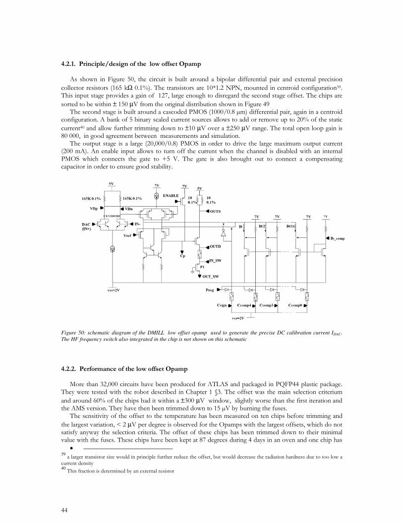
Figure 50: schematic diagram of the DMILL low offset opamp used to generate the precise DC calibration current IDAC. The HF frequency switch also integrated in the chip is not shown on this schematic
±µ
µ
• 3940
µ
µ
25 V
RTCTID
25 V
RTCNIEL
Death of mux
readout
25 V
RTCTID
25 V
RTCTID
25 V
RTCNIEL
Death of mux
readout
25 V
RTCNIEL
Death of mux
readout
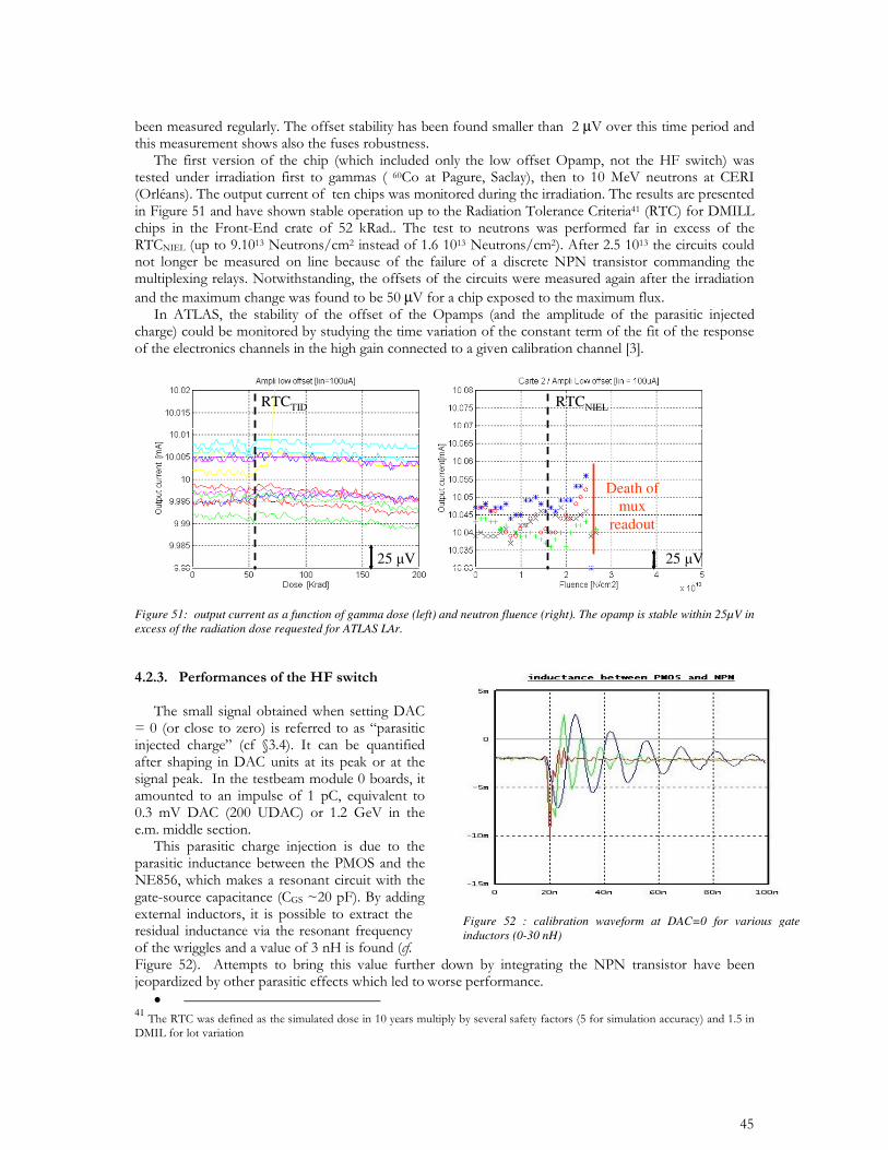
Figure 51: output current as a function of gamma dose (left) and neutron fluence (right). The opamp is stable within 25µV in excess of the radiation dose requested for ATLAS LAr.
• 41
Figure 52 : calibration waveform at DAC=0 for various gate inductors (0-30 nH)
Opamps& switch
DAC
Calolgic
TTCRx
Delay
SPAC2
8 outputs Opamps& switch
DAC
Calolgic
TTCRx
Delay
SPAC2
8 outputs
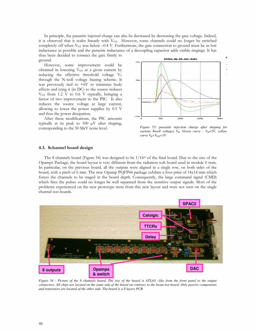
Figure 54 : Picture of the 8 channels board. The size of the board is ATLAS –like from the front panel to the output connectors. All chips are located on the same side of the board on contrary to the beam test board. Only passive components and transistors are located of the other side. The board is a 8 layers PCB.
Figure 53: parasitic injection charge after shaping for various Nwell voltages VB. Green curve : VB=5V, yellow curve VB=VDS=1V
•
•
•
•
•
•
• 42.
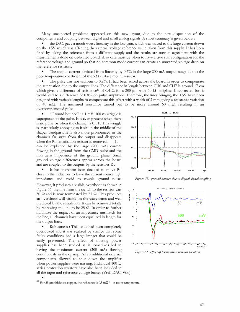
Figure 55: ground bounce due to digital signal coupling
Figure 56: effect of termination resistor location
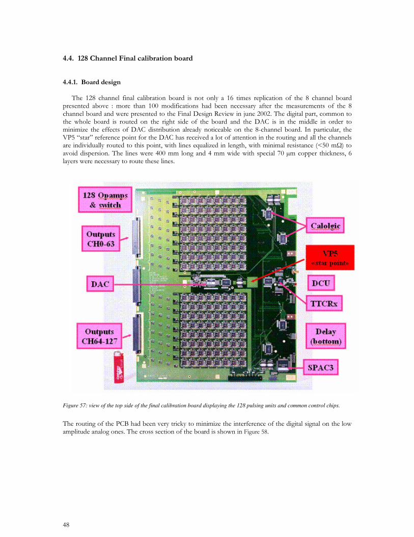
Figure 57: view of the top side of the final calibration board displaying the 128 pulsing units and common control chips.
Layer 1
Layer 2
Output connector Analog part Digital part
GND routing routing
Layer 3
Layer 4
outputs
GND
Layer 5
Layer 6
outputs
GND
Layer 7
Layer 8
GND
Inductors
GND
GND
outputs
GND
outputs
GND
GND
GND
GND
enables
VP5
GND
VP5
routing
GND
GND
enables
VP5
VP5
VP5
routing
GND
VP5
outputs
Layer 1
Layer 2
Output connector Analog part Digital part
GND routing routing
Layer 3
Layer 4
outputs
GND
Layer 5
Layer 6
outputs
GND
Layer 7
Layer 8
GND
Inductors
GND
GND
outputs
GND
outputs
GND
GND
GND
GND
enables
VP5
GND
VP5
routing
GND
GND
enables
VP5
VP5
VP5
routing
GND
VP5
outputs
Figure 58 : cross section of the printed circuit board showing the layer assignment on the various areas
•
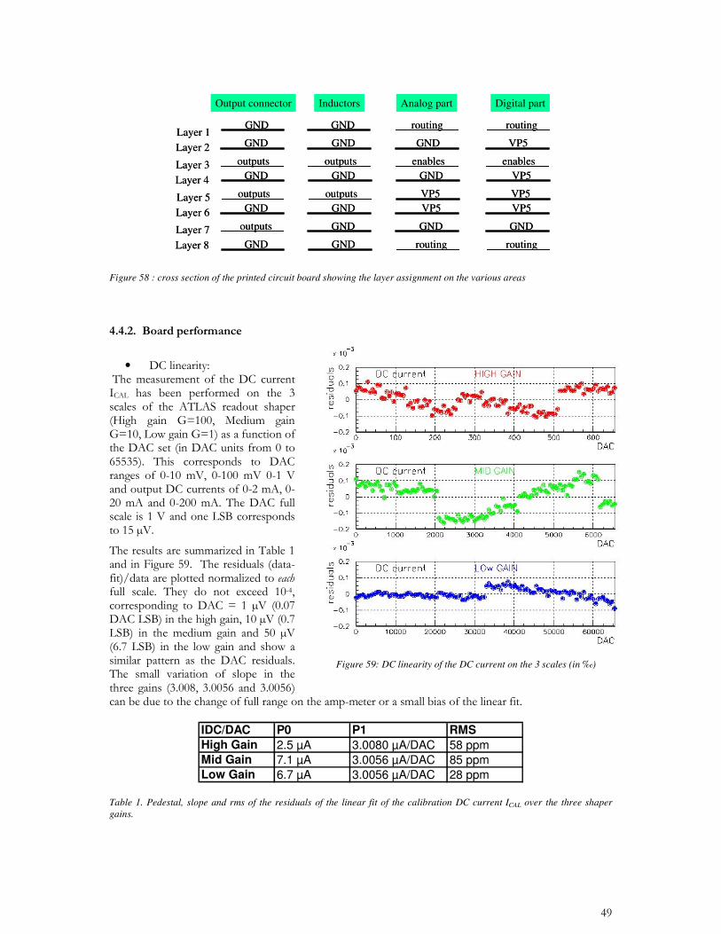
Table 1. Pedestal, slope and rms of the residuals of the linear fit of the calibration DC current ICAL over the three shaper gains.
Figure 59: DC linearity of the DC current on the 3 scales (in ‰)
IDC/DAC P0 P1 RMSHigh Gain 2.5 µA 3.0080 µA/DAC 58 ppmMid Gain 7.1 µA 3.0056 µA/DAC 85 ppmLow Gain 6.7 µA 3.0056 µA/DAC 28 ppm
•
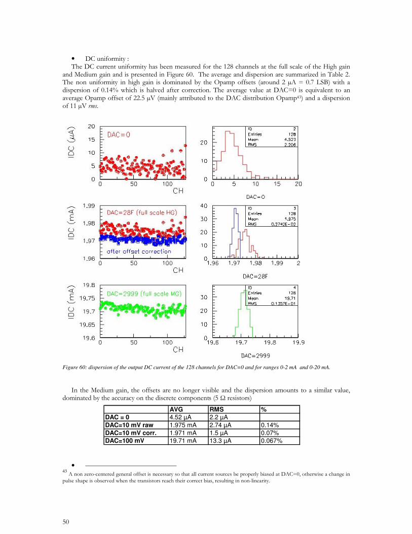
Figure 60: dispersion of the output DC current of the 128 channels for DAC=0 and for ranges 0-2 mA and 0-20 mA.
• 43
AVG RMS %DAC = 0 4.52 µA 2.2 µA DAC=10 mV raw 1.975 mA 2.74 µA 0.14%DAC=10 mV corr. 1.971 mA 1.5 µA 0.07%DAC=100 mV 19.71 mA 13.3 µA 0.067%
•
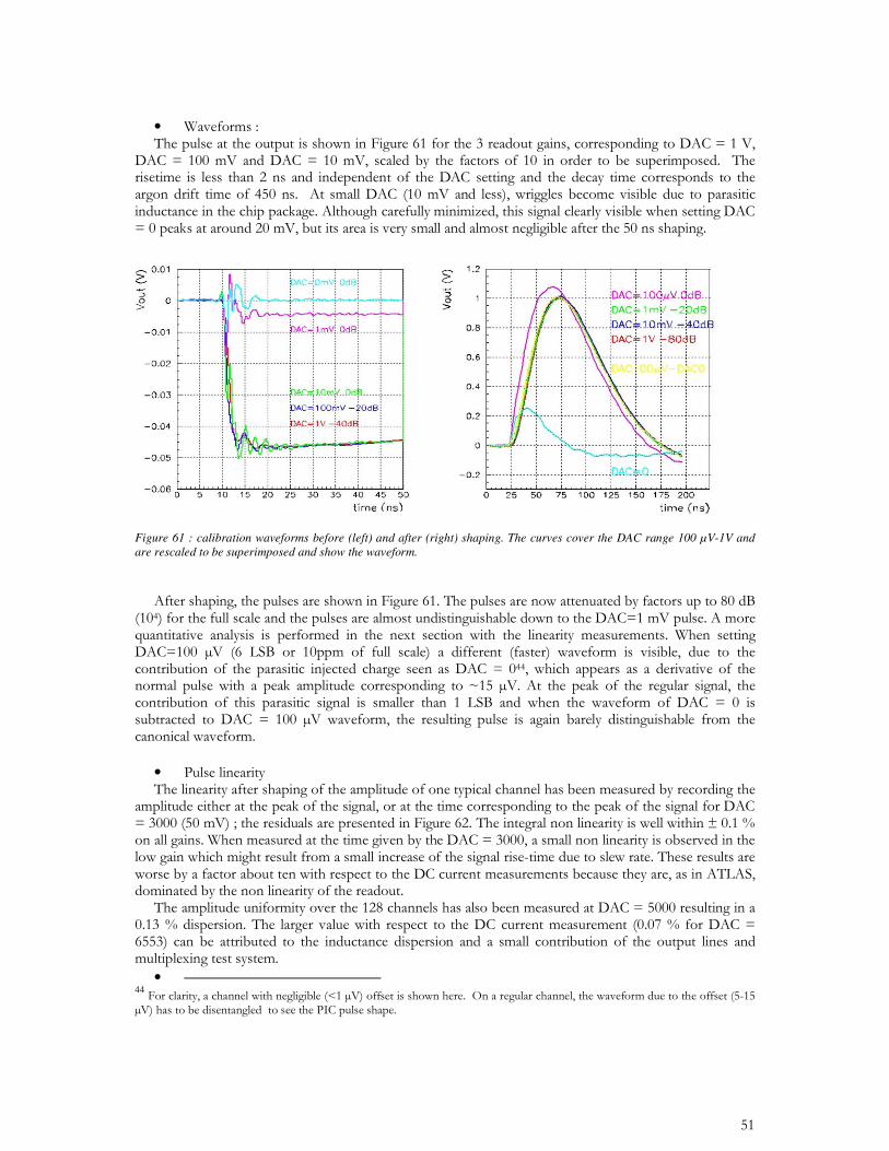
Figure 61 : calibration waveforms before (left) and after (right) shaping. The curves cover the DAC range 100 µV-1V and are rescaled to be superimposed and show the waveform.
•
• 44
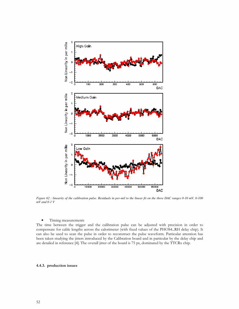
Figure 62 : linearity of the calibration pulse. Residuals in per-mil to the linear fit on the three DAC ranges 0-10 mV, 0-100 mV and 0-1 V
•
•
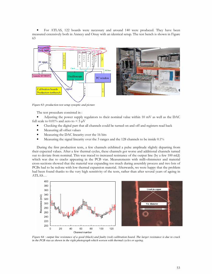
Figure 63: production test setup synoptic and picture
•
• • • •
Figure 64 : output line resistance of a good (black) and faulty (red) calibration board. The larger resistance is due to crack in the PCB vias as shown in the right photograph which worsen with thermal cycles or ageing.
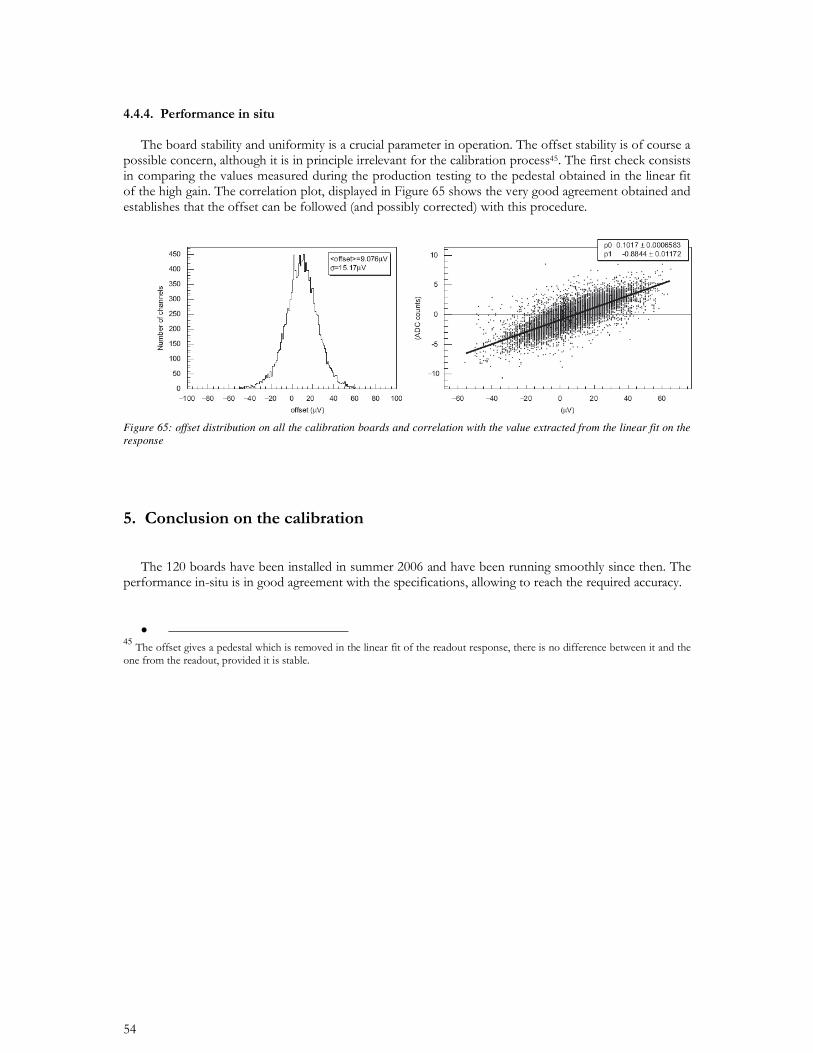
Figure 65: offset distribution on all the calibration boards and correlation with the value extracted from the linear fit on the response
•
45
CHAPTER 3
ATLAS DETECTOR CHARACTERIZATION
• 46
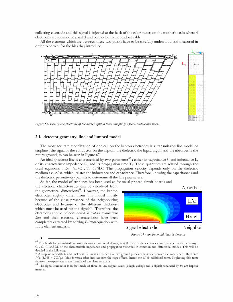
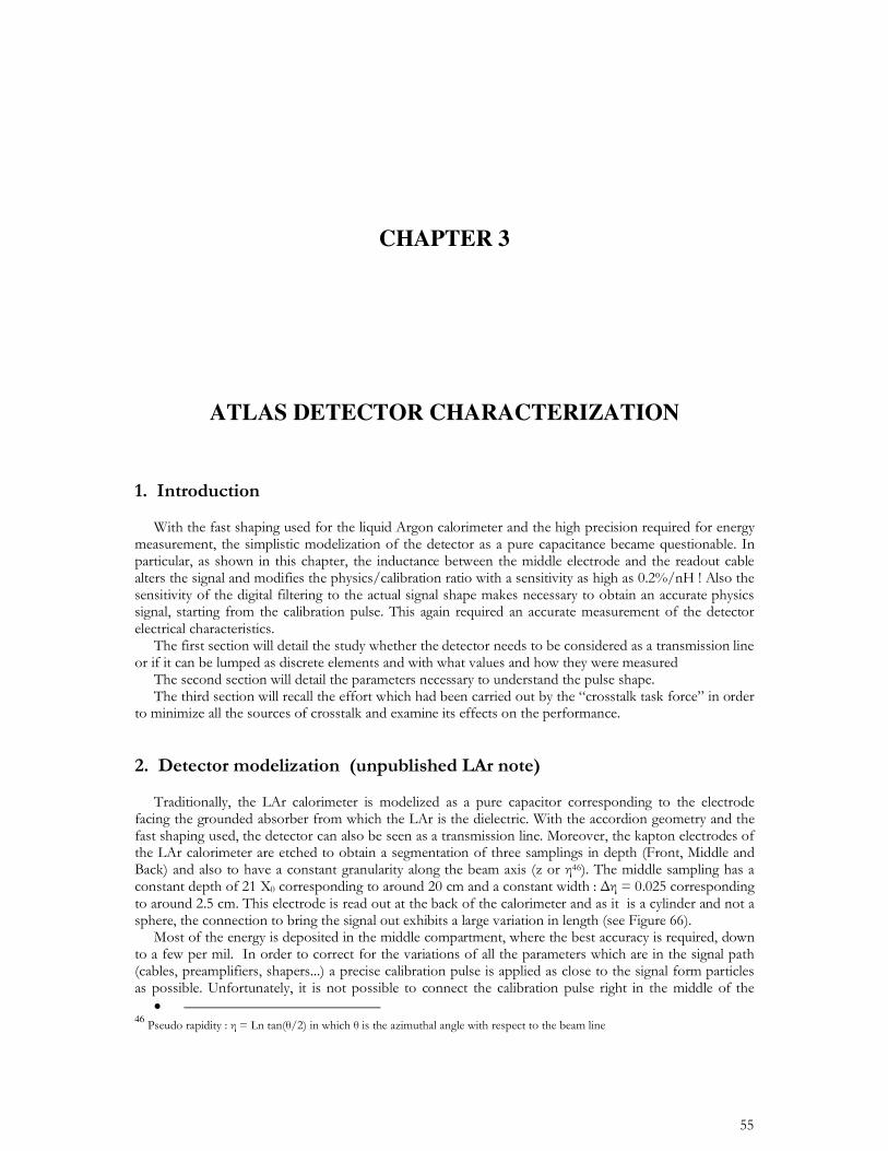
Figure 66: view of one electrode of the barrel, split in three samplings : front, middle and back.
47
48
•
47 49
Figure 67 : equipotential lines in detector
• • •
•
50 51
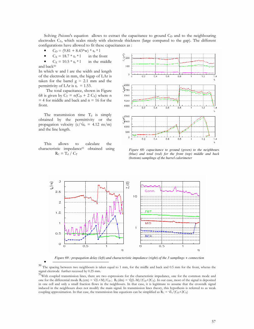
Figure 69 : propagation delay (left) and characteristic impedance (right) of the 3 samplings + connection
Figure 68: capacitance to ground (green) to the neighbours (blue) and total (red) for the front (top) middle and back (bottom) samplings of the barrel calorimeter
52
•
52
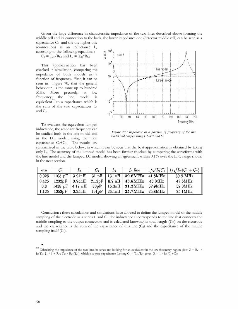
Figure 70 : impedane as a function of frequency of the line model and lumped using C1+C2 and L2
54
• 5354
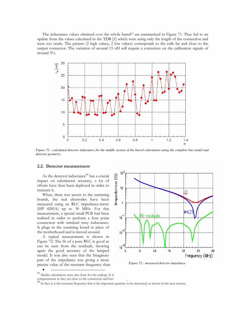
Figure 72 : measured detector impedance
Figure 71 : calculated detector inductance for the middle section of the barrel calorimeter using the complete line model and detector geometry.
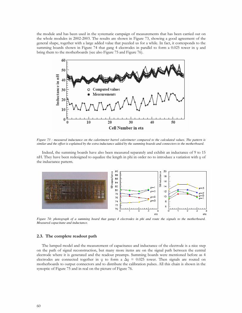
Figure 73 : measured inductance on the calorimeter barrel calorimeter compared to the calculated values. The pattern is similar and the offset is explained by the extra inductance added by the summing boards and connectors to the motherboard.
Figure 74: photograph of a summing board that gangs 4 electrodes in phi and route the signals to the motherboard. Measured capacitane and inductance.
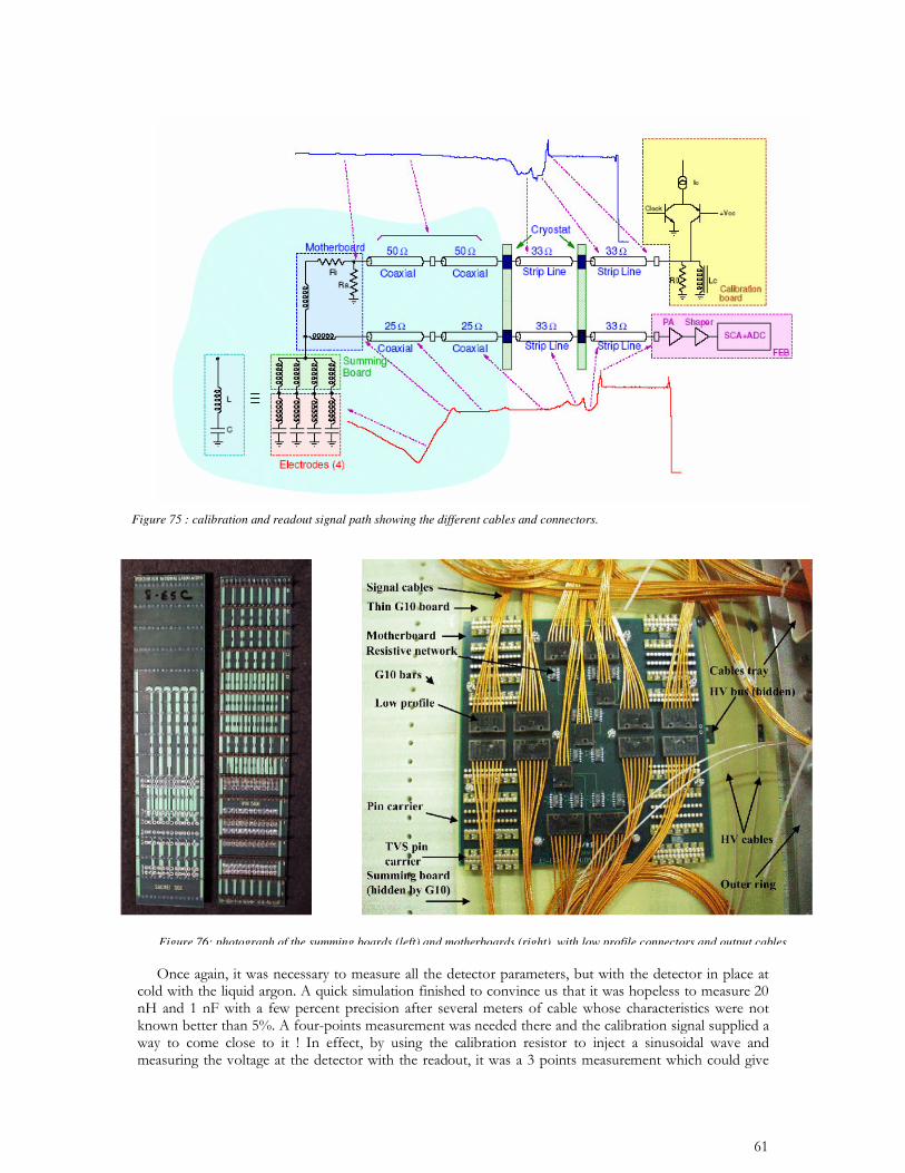
Figure 75 : calibration and readout signal path showing the different cables and connectors.
Figure 76: photograph of the summing boards (left) and motherboards (right) with low profile connectors and output cables
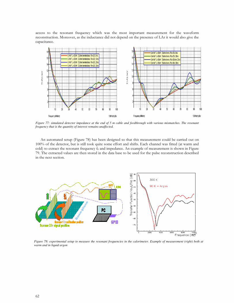
Figure 77: simulated detector impedance at the end of 5 m cable and feedthrough with various mismatches. The resonant frequency that is the quantity of interest remains unaffected.
Figure 78: experimental setup to measure the resonant frequencies in the calorimeter. Example of measurement (right) both at warm and in liquid argon
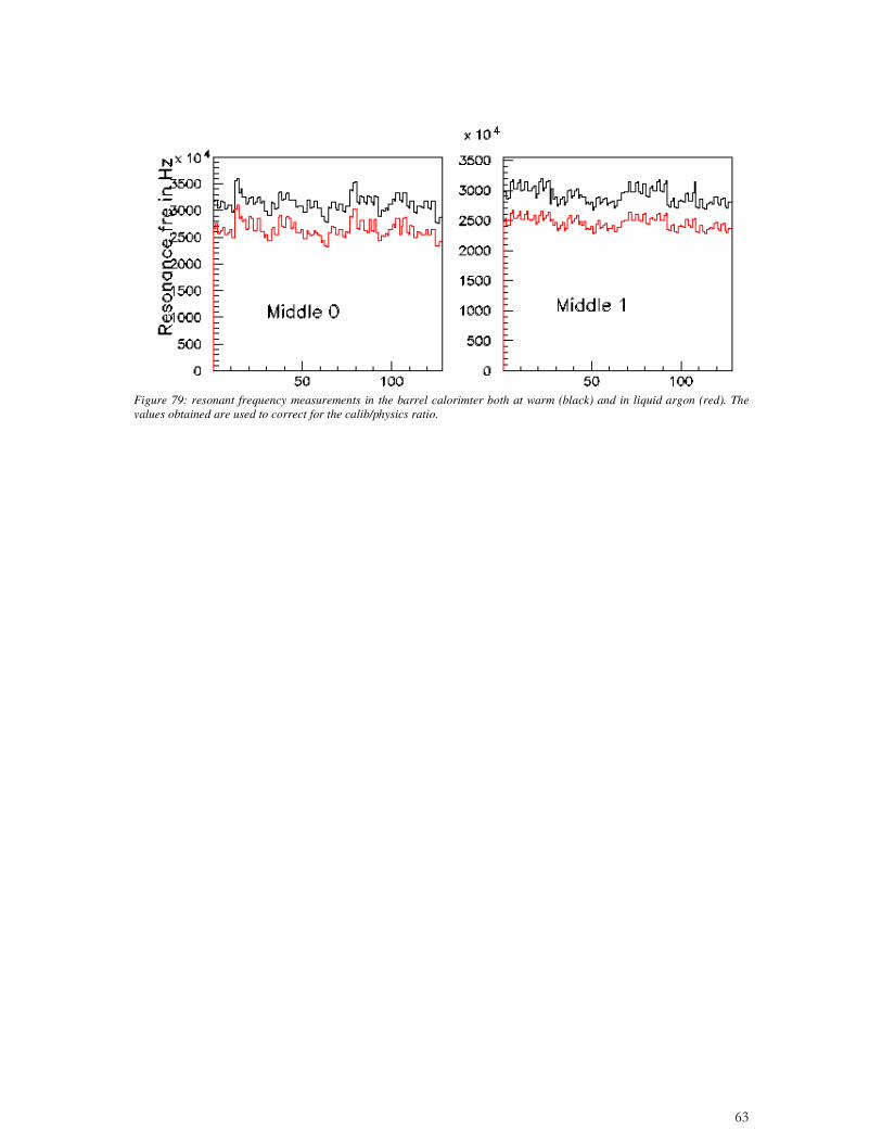
Figure 79: resonant frequency measurements in the barrel calorimter both at warm (black) and in liquid argon (red). The values obtained are used to correct for the calib/physics ratio.
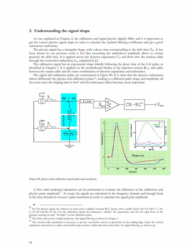
Figure 80: physics and calibration signal paths and waveforms
57•
55 5657
( )320.1
.
./1
./1)exp(1)(
s
sR
CssLR
Cs
Tds
sTdsTdIsV F
DD
DPHY (
(+++
'+'=
( )320.1
.
./1
./1.1)(
s
sR
CssLR
CssL
ssf
sIsV F
DD
DD
CALstep
CALCAL (
((
(+++
++
+=
++'+'
+
=CALstep
CAL
DDCAL
PHY
sf
s
Tds
sTdsTd
CLssV
sV
((
.
.1
.
)exp(1
1
1
)(
)(2
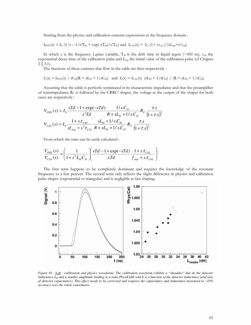
Figure 81. Left : calibration and physics waveforms. The calibration waveform exhibits a “shoulder” due do the detector inductance LD and a smaller amplitude leading to a ratio Phys/Calib which is a function of the detector inductance (and also of detector capacitance). This effect needs to be corrected and requires the capacitance and inductance measured to ~10% accuracy over the whole calorimeter.
•
•
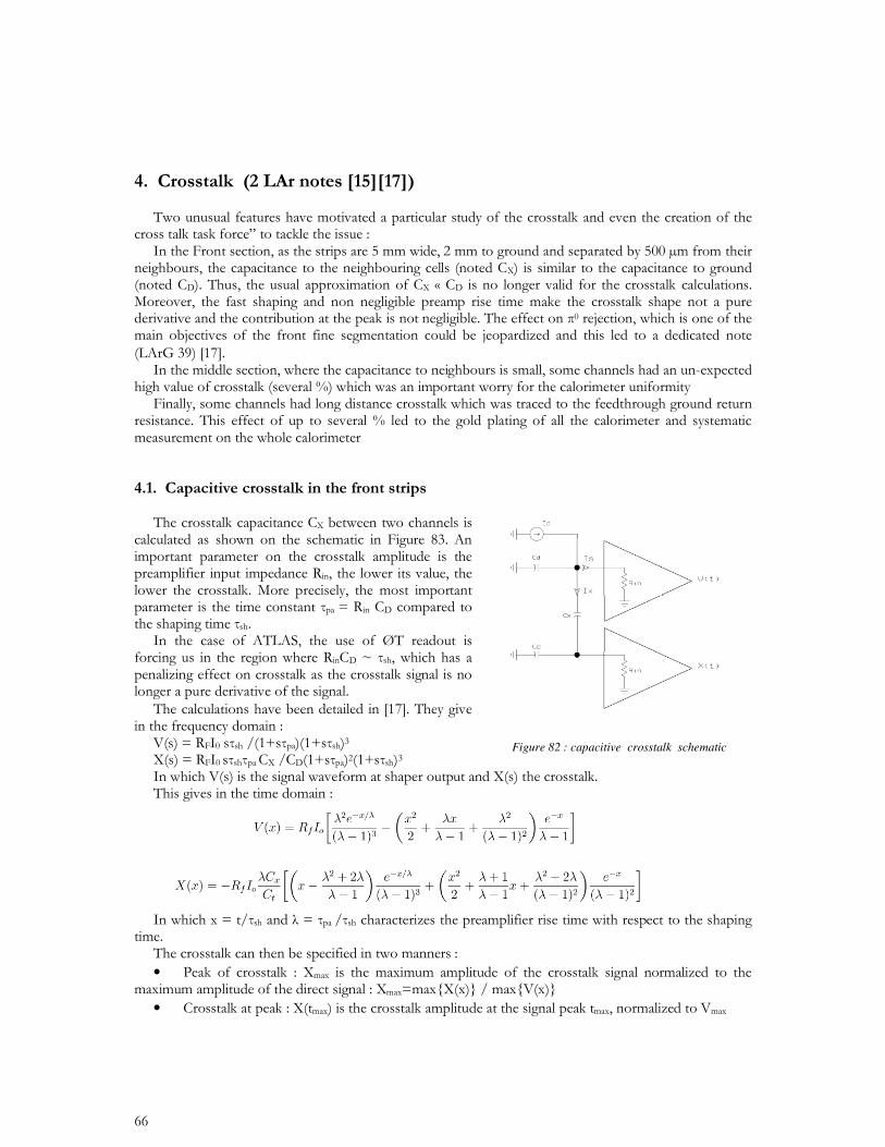
Figure 82 : capacitive crosstalk schematic
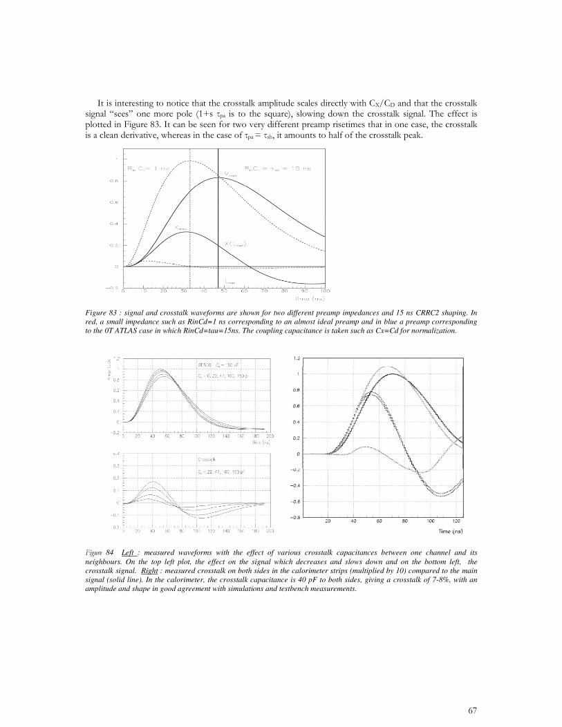
Figure 83 : signal and crosstalk waveforms are shown for two different preamp impedances and 15 ns CRRC2 shaping. In red, a small impedance such as RinCd=1 ns corresponding to an almost ideal preamp and in blue a preamp corresponding to the 0T ATLAS case in which RinCd=tau=15ns. The coupling capacitance is taken such as Cx=Cd for normalization.
84 Left : measured waveforms with the effect of various crosstalk capacitances between one channel and its neighbours. On the top left plot, the effect on the signal which decreases and slows down and on the bottom left, the crosstalk signal. Right : measured crosstalk on both sides in the calorimeter strips (multiplied by 10) compared to the main signal (solid line). In the calorimeter, the crosstalk capacitance is 40 pF to both sides, giving a crosstalk of 7-8%, with an amplitude and shape in good agreement with simulations and testbench measurements.
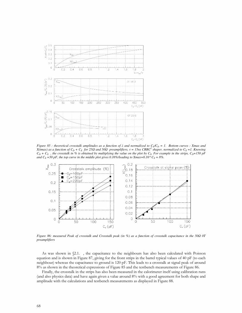
Figure 85 : theoretical crosstalk amplitudes as a function of and normalized to CX/CD = 1. Bottom curves : Xmax and X(tmax) as a function of CD + CX for 25 and 50 preamplifiers, = 15ns CRRC2 shaper, normalized to CX =1. Knowing CD + CX , the crosstalk in % is obtained by multiplying the value on the plot by CX. For example in the strips, CD=150 pF and CX =50 pF, the top curve in the middle plot gives 0.16%/leading to Xmax=0.16* CX = 8%.
Figure 86: measured Peak of crosstalk and Crosstalk peak (in %) as a function of crosstalk capacitance in the 50 0T preamplifiers
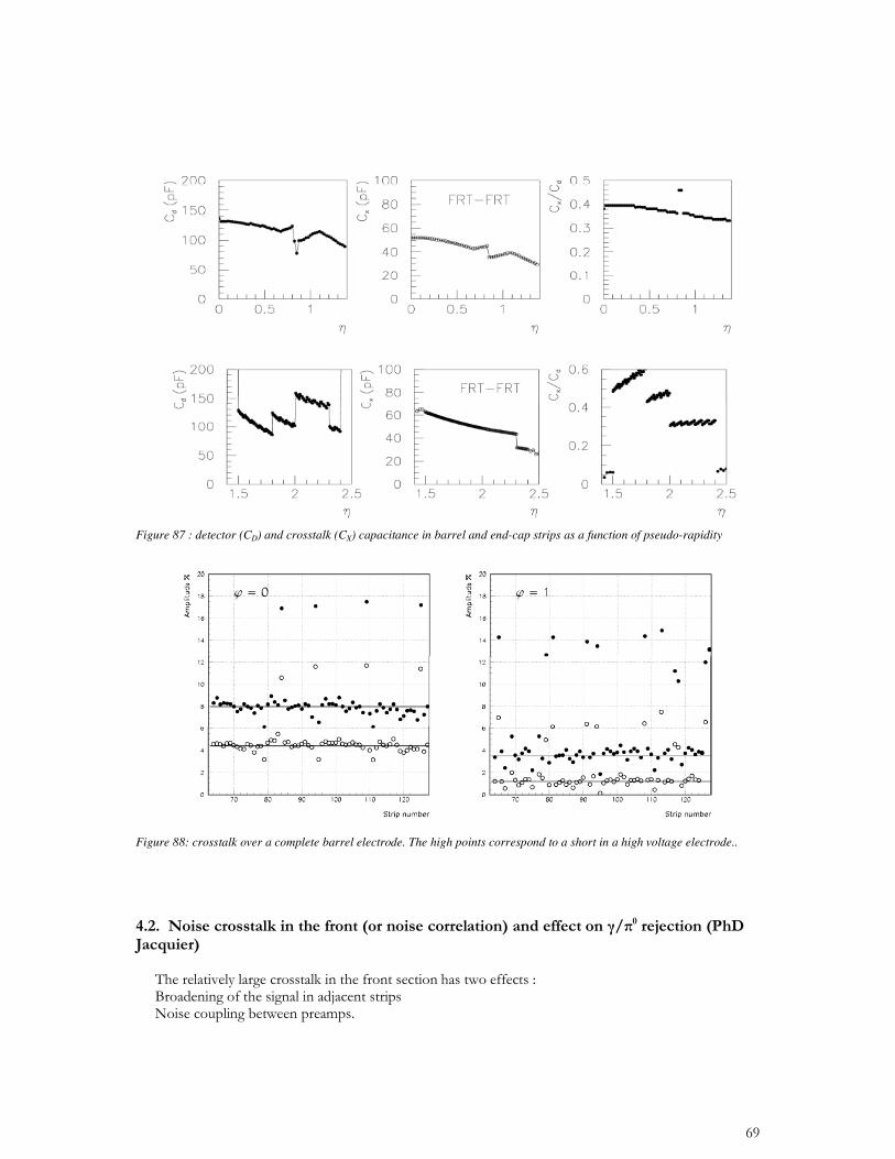
Figure 87 : detector (CD) and crosstalk (CX) capacitance in barrel and end-cap strips as a function of pseudo-rapidity
Figure 88: crosstalk over a complete barrel electrode. The high points correspond to a short in a high voltage electrode..
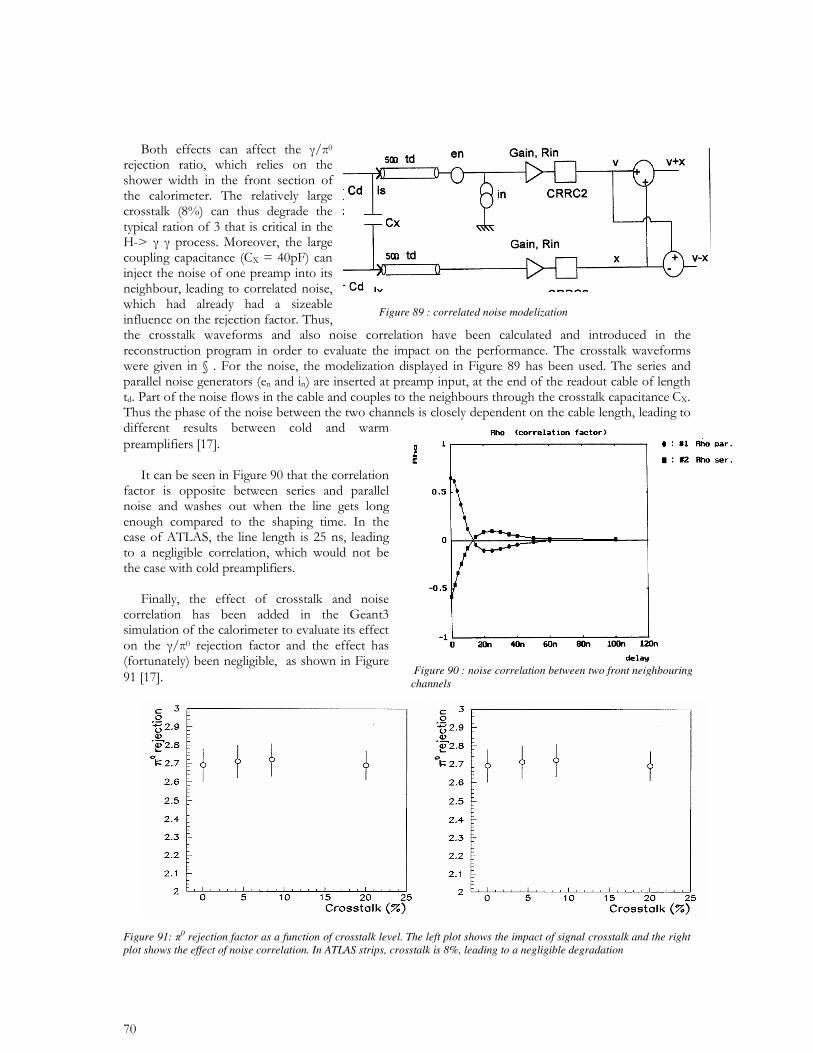
Figure 91: 0 rejection factor as a function of crosstalk level. The left plot shows the impact of signal crosstalk and the right plot shows the effect of noise correlation. In ATLAS strips, crosstalk is 8%, leading to a negligible degradation
Figure 89 : correlated noise modelization
Figure 90 : noise correlation between two front neighbouring channels
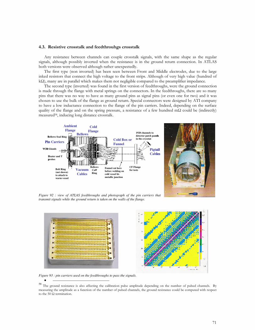
Figure 92 : view of ATLAS feedthroughs and photograph of the pin carriers that transmit signals while the ground return is taken on the walls of the flange.
Figure 93 : pin carriers used on the feedthroughs to pass the signals.
• 58
VCR Glands
Heater and T probes
Ambient Flange
Bolt Ring (not shown) to attach to warm vessel
Bellows Seal Ring
Pin Carriers
Bellows
Bellows Cuff Ring
Vacuum Cables
Cold Flange
Cold Box or Funnel
Pigtail Cables
1920 channels to detector patch panels in the cryostat
CF Flange for tests
Funnel cut here before welding on cold vessel bi-metallic junction
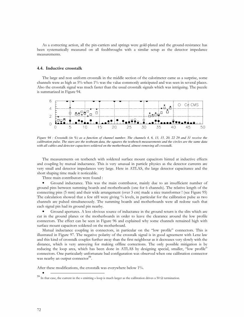
Figure 94 : Crosstalk (in %) as a function of channel number. The channels 4, 6, 13, 15, 20, 22 29 and 31 receive the calibration pulse. The stars are the testbeam data, the squares the testbench measurements and the circles are the same data with all cables and detector capacitors soldered on the motherboard, almost removing all crosstalk.
•
•
59
•
59
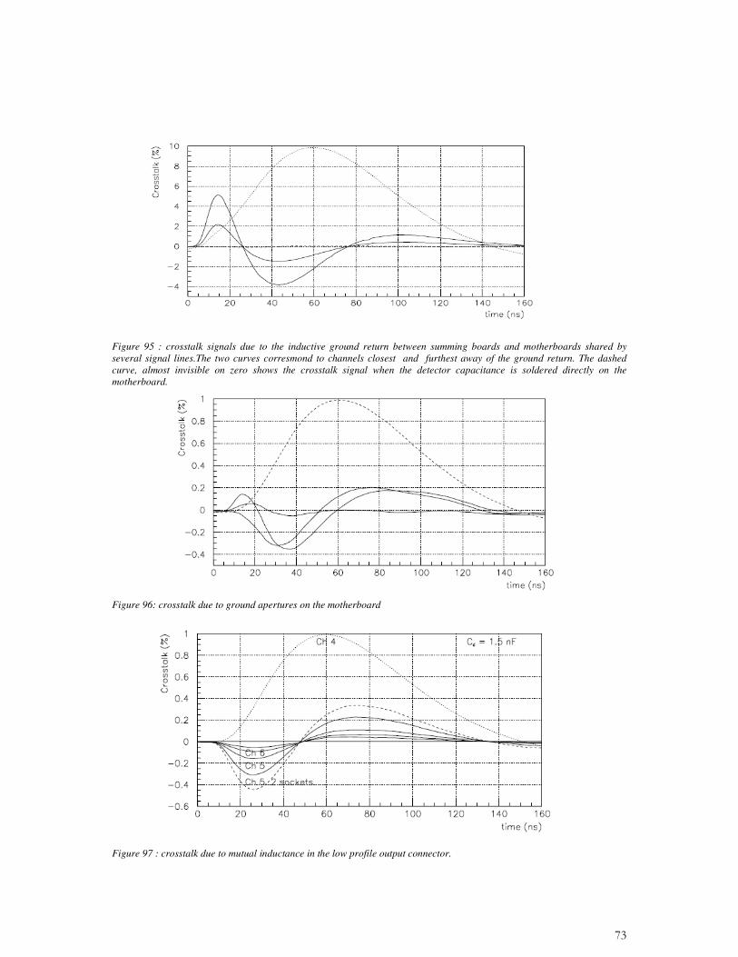
Figure 95 : crosstalk signals due to the inductive ground return between summing boards and motherboards shared by several signal lines.The two curves corresmond to channels closest and furthest away of the ground return. The dashed curve, almost invisible on zero shows the crosstalk signal when the detector capacitance is soldered directly on the motherboard.
Figure 96: crosstalk due to ground apertures on the motherboard
Figure 97 : crosstalk due to mutual inductance in the low profile output connector.
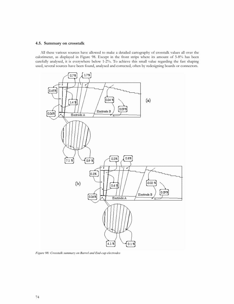
Figure 98: Crosstalk summary on Barrel and End-cap electrodes
CHAPTER 4
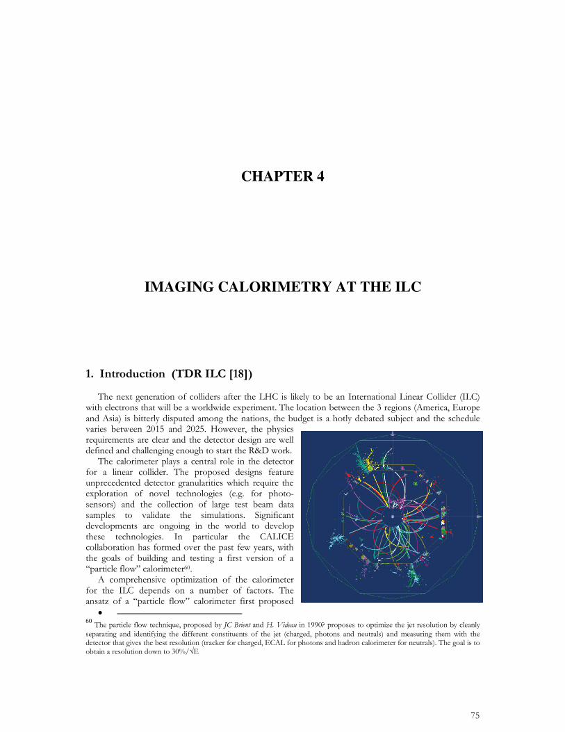
IMAGING CALORIMETRY AT THE ILC
• 60
•
•
TCMTAHCAL
beam
ECAL
90 c
m 120
cm
SiW ECALW/Sci SiPM ECALSci SiPM AHCAL
RPC DHCAL
TCMTAHCAL
beam
ECAL
90 c
m 120
cm
TCMTAHCAL
beam
ECAL
90 c
m 120
cm
SiW ECALW/Sci SiPM ECALSci SiPM AHCAL
RPC DHCAL
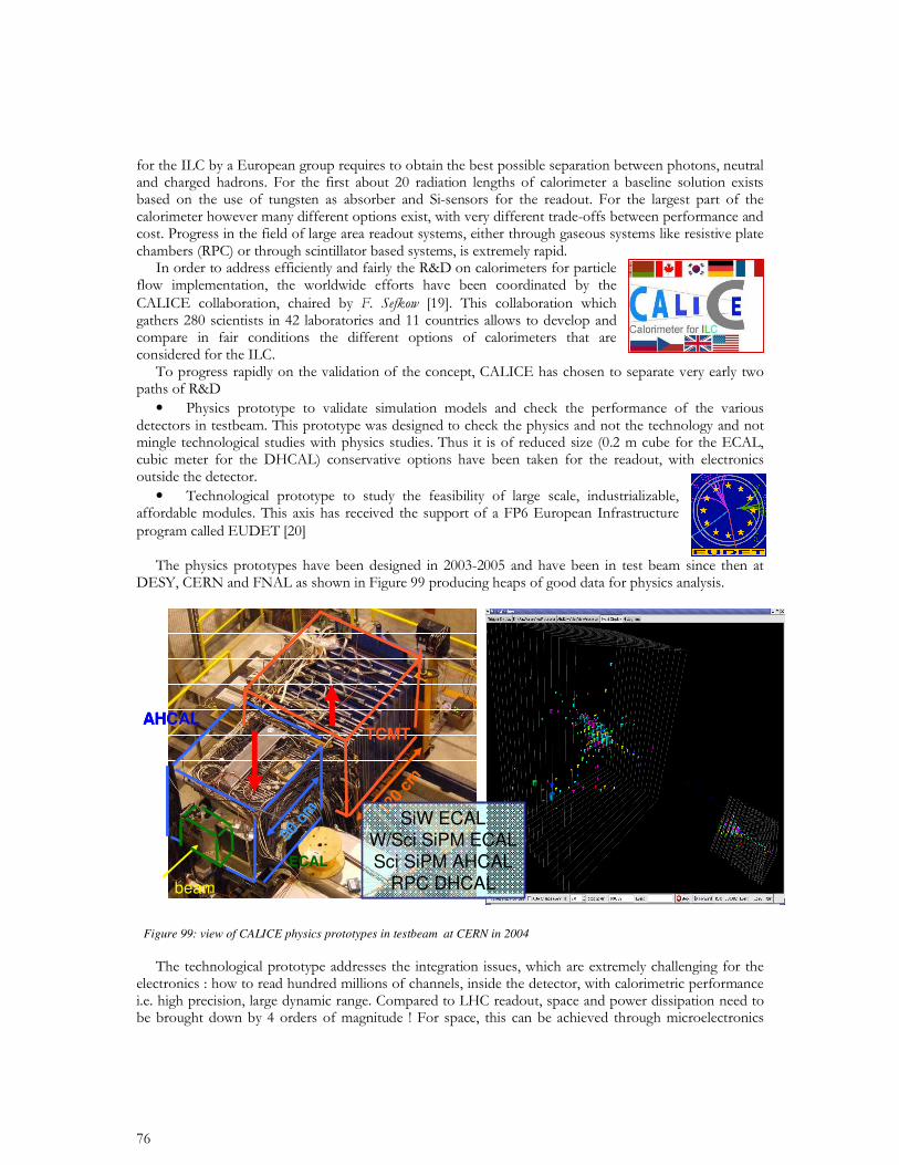
Figure 99: view of CALICE physics prototypes in testbeam at CERN in 2004
61
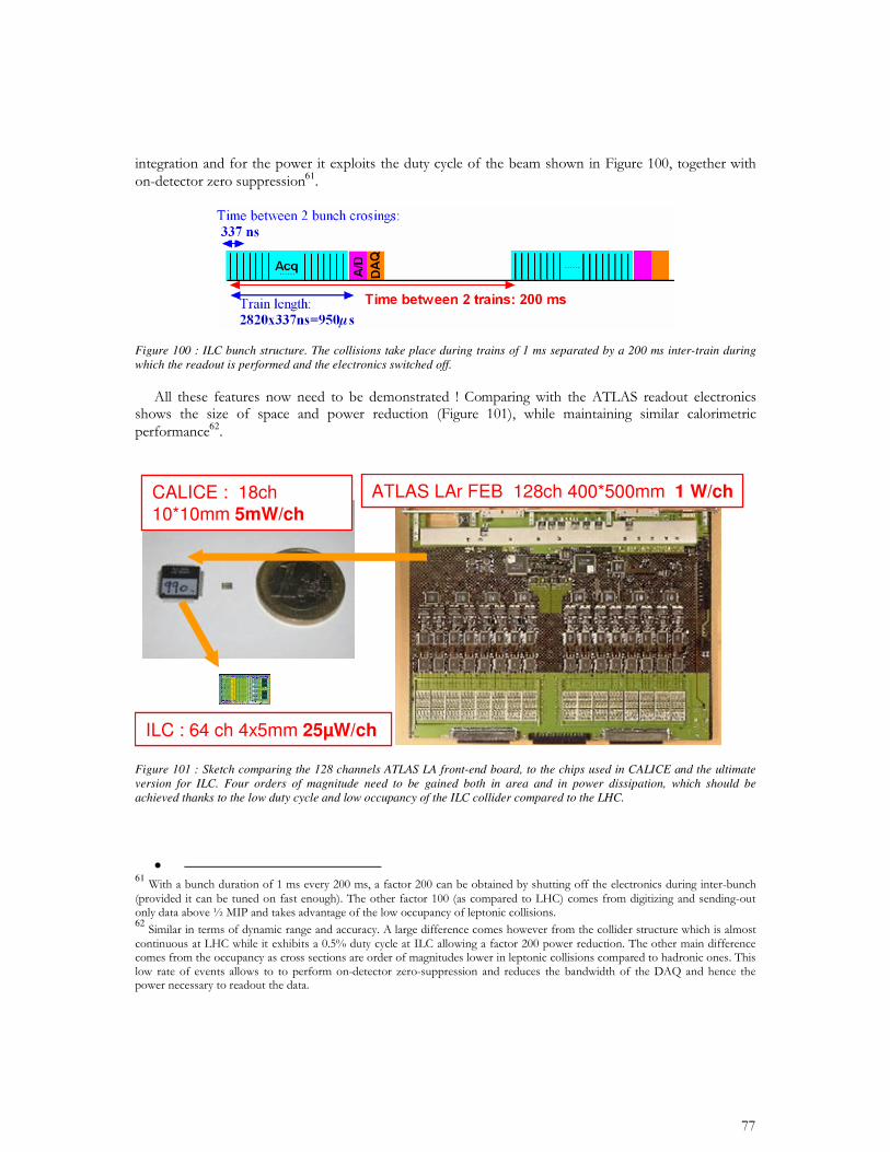
Figure 100 : ILC bunch structure. The collisions take place during trains of 1 ms separated by a 200 ms inter-train during which the readout is performed and the electronics switched off.
62
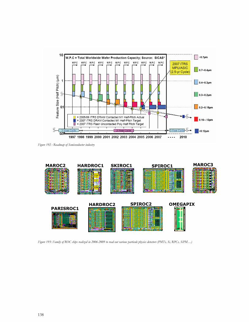
ATLAS LAr FEB 128ch 400*500mm 1 W/chCALICE : 18ch 10*10mm 5mW/ch
ILC : 64 ch 4x5mm 25µW/ch
ATLAS LAr FEB 128ch 400*500mm 1 W/chCALICE : 18ch 10*10mm 5mW/ch
ILC : 64 ch 4x5mm 25µW/ch
Figure 101 : Sketch comparing the 128 channels ATLAS LA front-end board, to the chips used in CALICE and the ultimate version for ILC. Four orders of magnitude need to be gained both in area and in power dissipation, which should be achieved thanks to the low duty cycle and low occupancy of the ILC collider compared to the LHC.
• 6162
63
• 63
Charged pads
photons
e+e- / W+W– at #s = 800 GeV
Reconstruction
Display of the reconstructed event
Charged pads
photons
e+e- / W+W– at #s = 800 GeV
Reconstruction
Display of the reconstructed event
Front End electronics zone
Silicon wafer
Shielding PCB
SCSI connector
Carbon Fiber
Tungsten
Detector slab
Front End electronics zone
Silicon wafer
Shielding PCB
SCSI connector
Carbon Fiber
Tungsten
Front End electronics zone
Silicon wafer
Shielding PCB
SCSI connector
Carbon Fiber
Tungsten
Detector slab
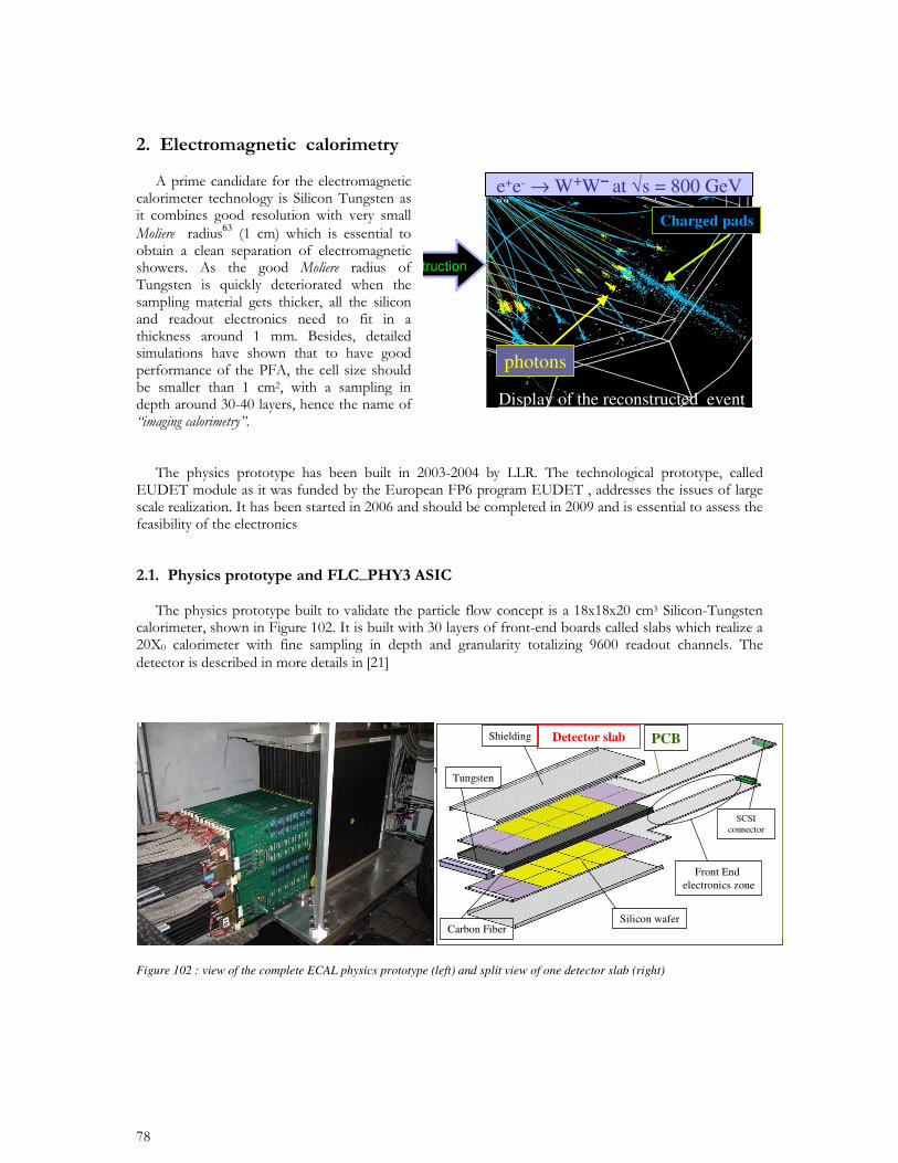
Figure 102 : view of the complete ECAL physics prototype (left) and split view of one detector slab (right)
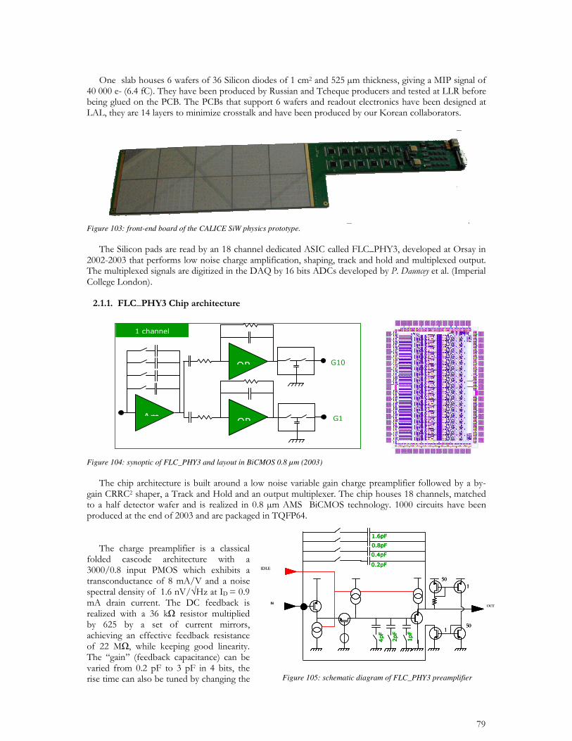
Figure 103: front-end board of the CALICE SiW physics prototype.
Figure 104: synoptic of FLC_PHY3 and layout in BiCMOS 0.8 µm (2003)
IN
IN
Figure 105: schematic diagram of FLC_PHY3 preamplifier
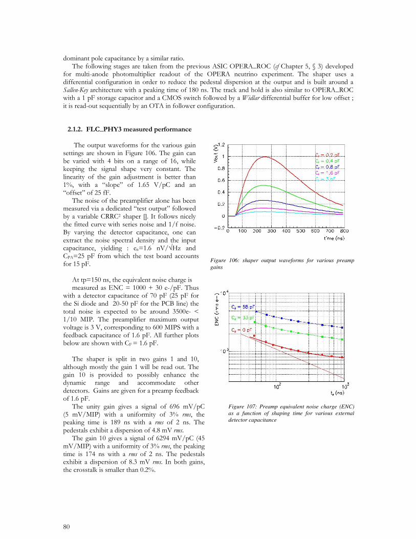
Figure 106: shaper output waveforms for various preamp gains
Figure 107: Preamp equivalent noise charge (ENC) as a function of shaping time for various external detector capacitance
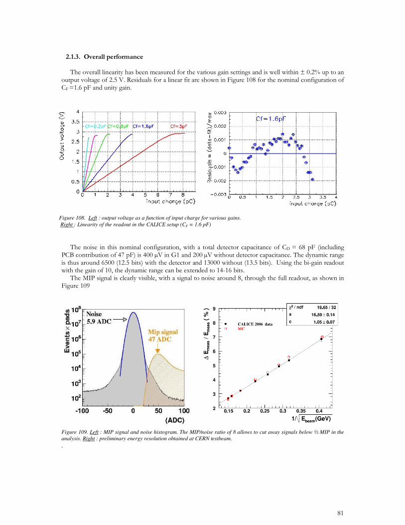
Figure 109. Left : MIP signal and noise histogram. The MIP/noise ratio of 8 allows to cut away signals below " MIP in the analysis. Right : preliminary energy resolution obtained at CERN testbeam.
Figure 108. Left : output voltage as a function of input charge for various gains. Right : Linearity of the readout in the CALICE setup (CF = 1.6 pF)
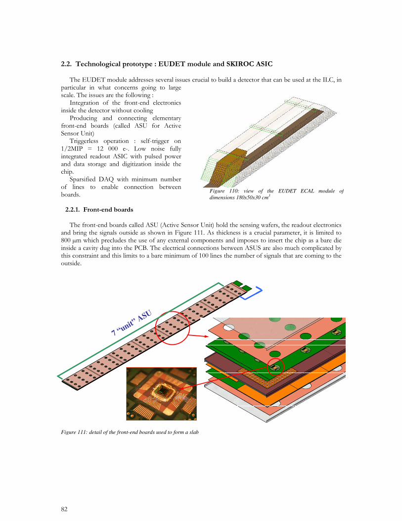
Figure 110: view of the EUDET ECAL module of dimensions 180x50x30 cm3
7 “unit”ASU
7 “unit”ASU
Figure 111: detail of the front-end boards used to form a slab
64
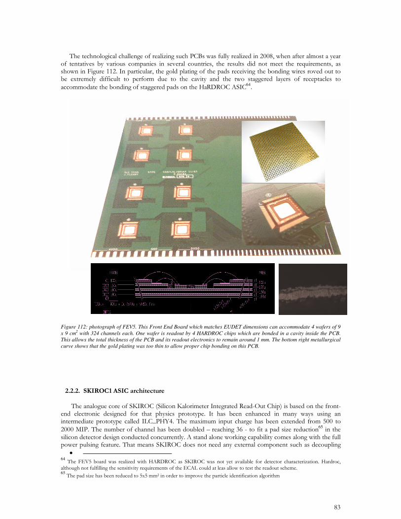
Figure 112: photograph of FEV5. This Front End Board which matches EUDET dimensions can accommodate 4 wafers of 9 x 9 cm2 with 324 channels each. One wafer is readout by 4 HARDROC chips which are bonded in a cavity inside the PCB. This allows the total thickness of the PCB and its readout electronics to remain around 1 mm. The bottom right metallurgical curve shows that the gold plating was too thin to allow proper chip bonding on this PCB.
65
• 64 65
20M
1M 200ns
G=10
G=1
200ns
Analog Memory
Depth = 5
Analog Memory
Depth = 5
G=100G=5
12 bits
ADC
Gain selection
0=>6pF
3-bit thresholdadjustment
10-bit DAC
Common to the
36Channels
T100ns
DAC output
Q
HOLD
Preamp
Ampli
Slow Shaper
Slow Shaper
Fast Shaper
Trigger
Charge measurement
3pF
Calibration input
input
SKIROC1
SiGe 0.35µm
October 2006
20M
1M 200ns
G=10
G=1
200ns
Analog Memory
Depth = 5
Analog Memory
Depth = 5
G=100G=5
12 bits
ADC
Gain selection
0=>6pF
3-bit thresholdadjustment
10-bit DAC
Common to the
36Channels
T100ns
DAC output
Q
HOLD
Preamp
Ampli
Slow Shaper
Slow Shaper
Fast Shaper
Trigger
Charge measurement
3pF
Calibration input
input
SKIROC1
SiGe 0.35µm
October 2006
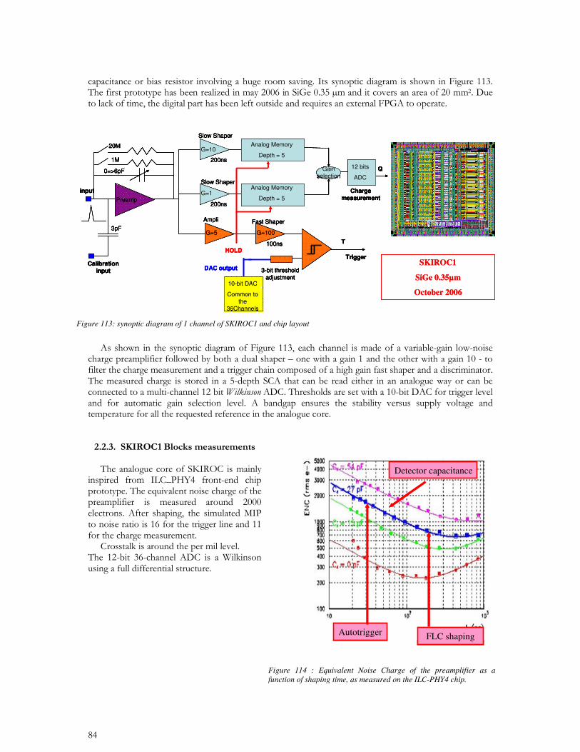
Figure 113: synoptic diagram of 1 channel of SKIROC1 and chip layout
FLC shaping
Detector capacitance
Autotrigger FLC shaping
Detector capacitance
Autotrigger
Figure 114 : Equivalent Noise Charge of the preamplifier as a function of shaping time, as measured on the ILC-PHY4 chip.
66
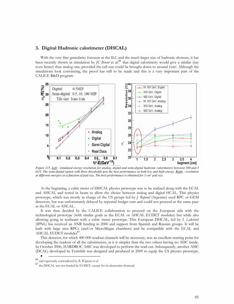
Figure 115. Left : simulated energy resolution for analog, digital and semi-digital hadronic calorimeters between 100 and 3 GeV. The semi-digital option with three thresholds gets the best performance at both low and high energy. Right : resolution at different energies as a function of pad size. The best performance is obtained for 1 cm2 pad size.
67
• 6667
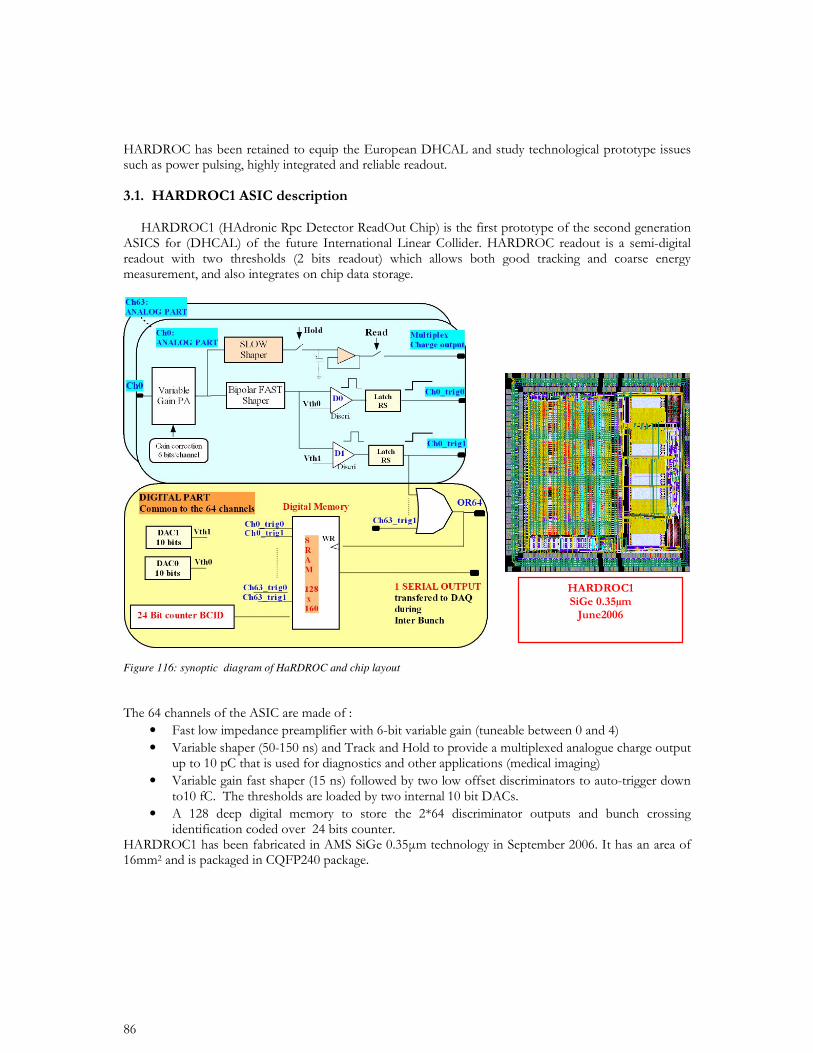
Figure 116: synoptic diagram of HaRDROC and chip layout
• •
•
•
68
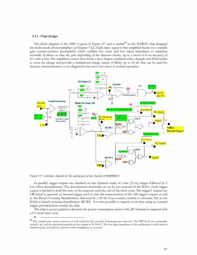
Figure 117: schematic diagram of the analog part of one channel of HARDROC1
•
68
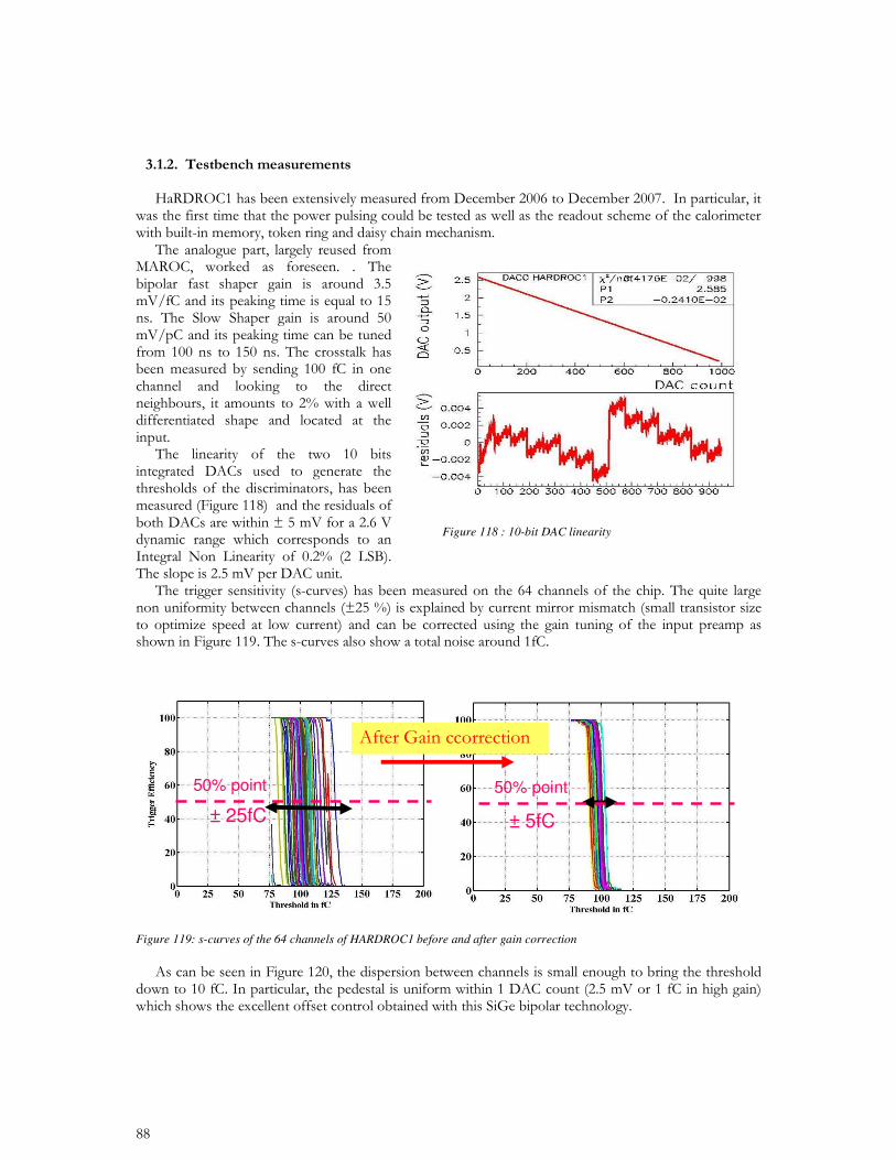
Figure 119: s-curves of the 64 channels of HARDROC1 before and after gain correction
50% point
± 5fC ± 25fC
50% point
Figure 118 : 10-bit DAC linearity
30 fC
10 fC
Pedestal
Dac u
nit
Channel number
1pC
100 fC
piedestal
Low gain : DAC Unit 3 fCHigh gain : DAC Unit 1 fC
30 fC
10 fC
Pedestal
Dac u
nit
Channel number
30 fC
10 fC
Pedestal
30 fC
10 fC
Pedestal
Dac u
nit
Channel number
1pC
100 fC
piedestal
Low gain : DAC Unit 3 fCHigh gain : DAC Unit 1 fC
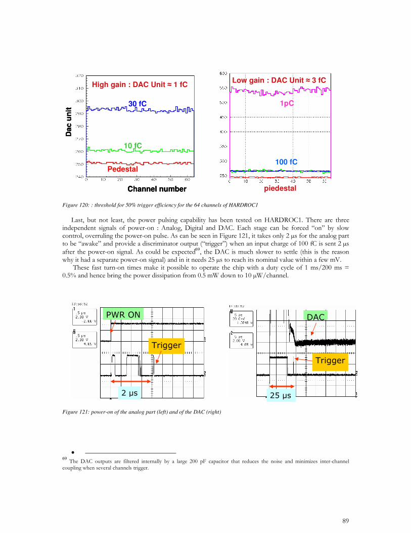
Figure 120: : threshold for 50% trigger efficiency for the 64 channels of HARDROC1
69
Figure 121: power-on of the analog part (left) and of the DAC (right)
• 69
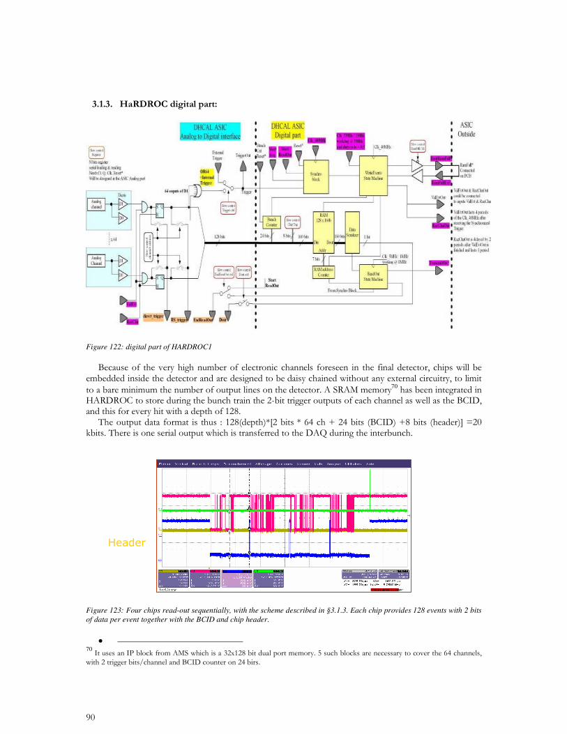
Figure 122: digital part of HARDROC1
70
Figure 123: Four chips read-out sequentially, with the scheme described in §3.1.3. Each chip provides 128 events with 2 bits of data per event together with the BCID and chip header.
•
70
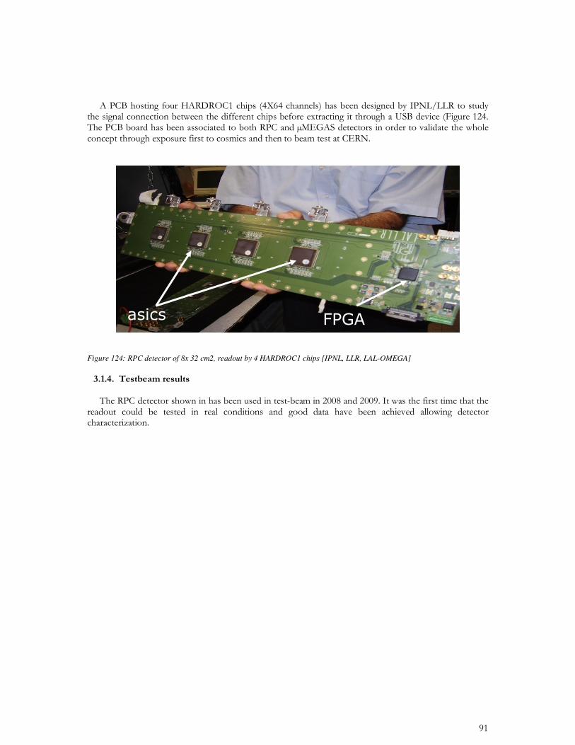
Figure 124: RPC detector of 8x 32 cm2, readout by 4 HARDROC1 chips [IPNL, LLR, LAL-OMEGA]
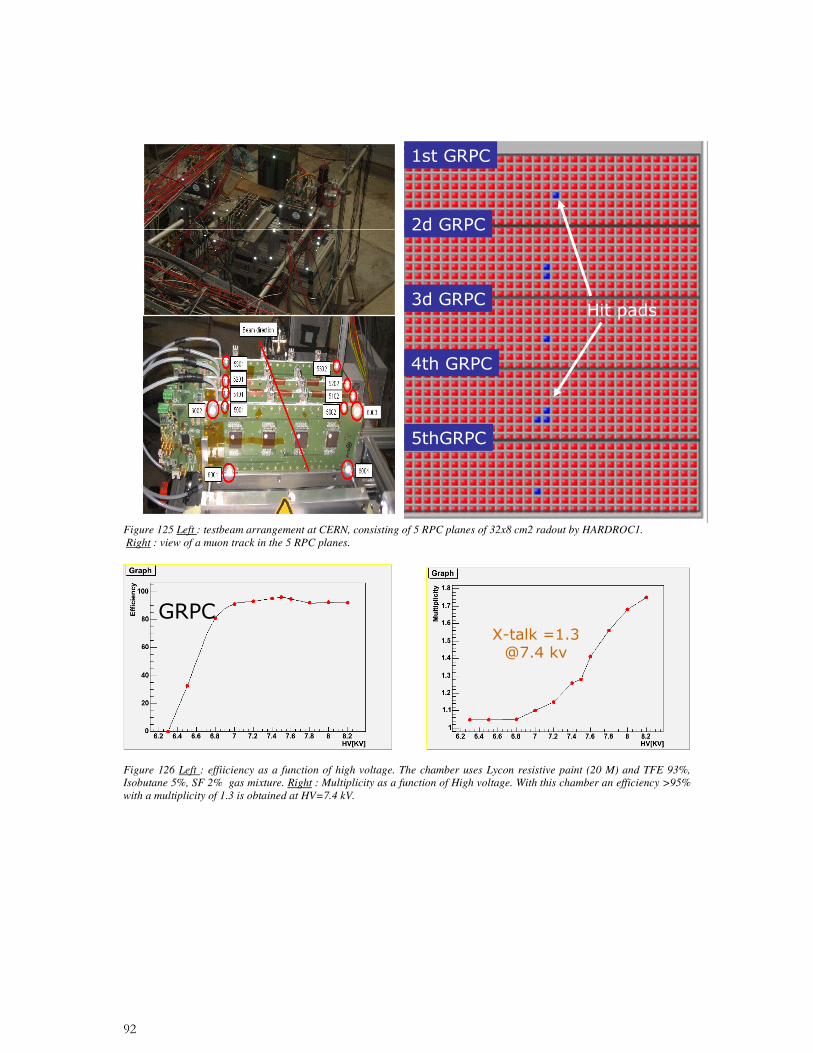
Figure 125 Left : testbeam arrangement at CERN, consisting of 5 RPC planes of 32x8 cm2 radout by HARDROC1. Right : view of a muon track in the 5 RPC planes.
Figure 126 Left : effiiciency as a function of high voltage. The chamber uses Lycon resistive paint (20 M) and TFE 93%, Isobutane 5%, SF 2% gas mixture. Right : Multiplicity as a function of High voltage. With this chamber an efficiency >95% with a multiplicity of 1.3 is obtained at HV=7.4 kV.
•
•
•
71
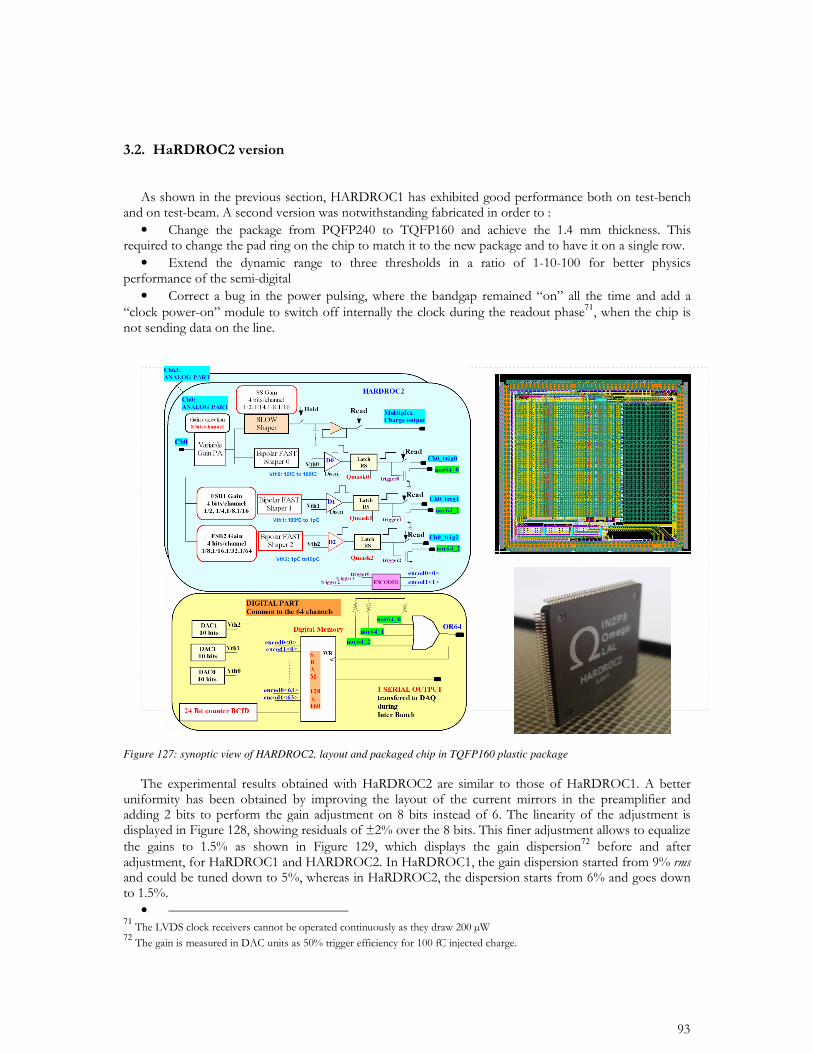
Figure 127: synoptic view of HARDROC2, layout and packaged chip in TQFP160 plastic package
72
• 7172
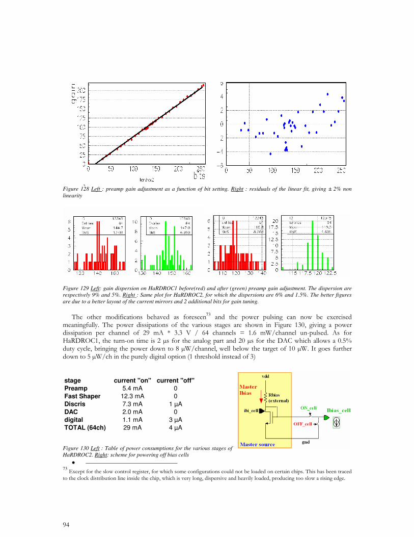
Figure 128 Left : preamp gain adjustment as a function of bit setting. Right : residuals of the linear fit, giving ± 2% non linearity
Figure 129 Left: gain dispersion on HaRDROC1 before(red) and after (green) preamp gain adjustment. The dispersion are respectively 9% and 5%. Right : Same plot for HaRDROC2, for which the dispersions are 6% and 1.5%. The better figures are due to a better layout of the current mirrors and 2 additional bits for gain tuning.
73
stage current "on" current "off"Preamp 5.4 mA 0Fast Shaper 12.3 mA 0Discris 7.3 mA 1 µADAC 2.0 mA 0digital 1.1 mA 3 µATOTAL (64ch) 29 mA 4 µA Figure 130 Left : Table of power consumptions for the various stages of HaRDROC2. Right: scheme for powering off bias cells
• 73
74
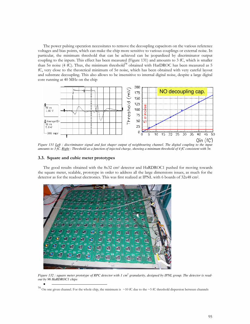
Figure 131 Left : discriminator signal and fast shaper output of neighbouring channel. The digital coupling to the input amounts to 3 fC. Right : Threshold as a function of injected charge, showing a minimum threshold of 4 fC consistent with 5.
Figure 132 : square meter prototype of RPC detector with 1 cm2 granularity, designed by IPNL group. The detector is read-out by 96 HaRDROC1 chips
• 74
NO decoupling cap.
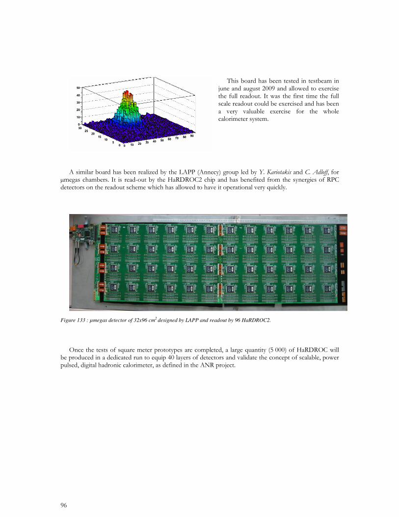
Figure 133 : µmegas detector of 32x96 cm2 designed by LAPP and readout by 96 HaRDROC2.
75 •
•
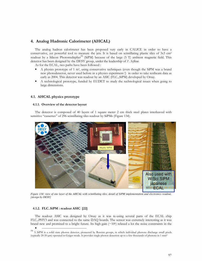
Figure 134: view of one layer of the AHCAL with scintillating tiles, detail of SiPM implementation and electronics readout. [design by DESY]
• 75
Also used with W/Sci SiPM
japanese ECAL
with MPPCs
• 76
100nF
10pF
12k
4k 24pF
12pF
3pF
in
8pF 4pF 2pF 1pF
40k
8-bit
DAC
0-5V
ASIC
Rin =
10k50
100M2.4pF
1.2pF
0.6pF
0.3pF
0.1pF
0.2pF
0.4pF
0.8pF
6pF 100nF
10pF
12k
4k 24pF
12pF
3pF
in
8pF 4pF 2pF 1pF
40k
8-bit
DAC
0-5V
ASIC
Rin =
10k50
100M2.4pF
1.2pF
0.6pF
0.3pF
0.1pF
0.2pF
0.4pF
0.8pF
6pF
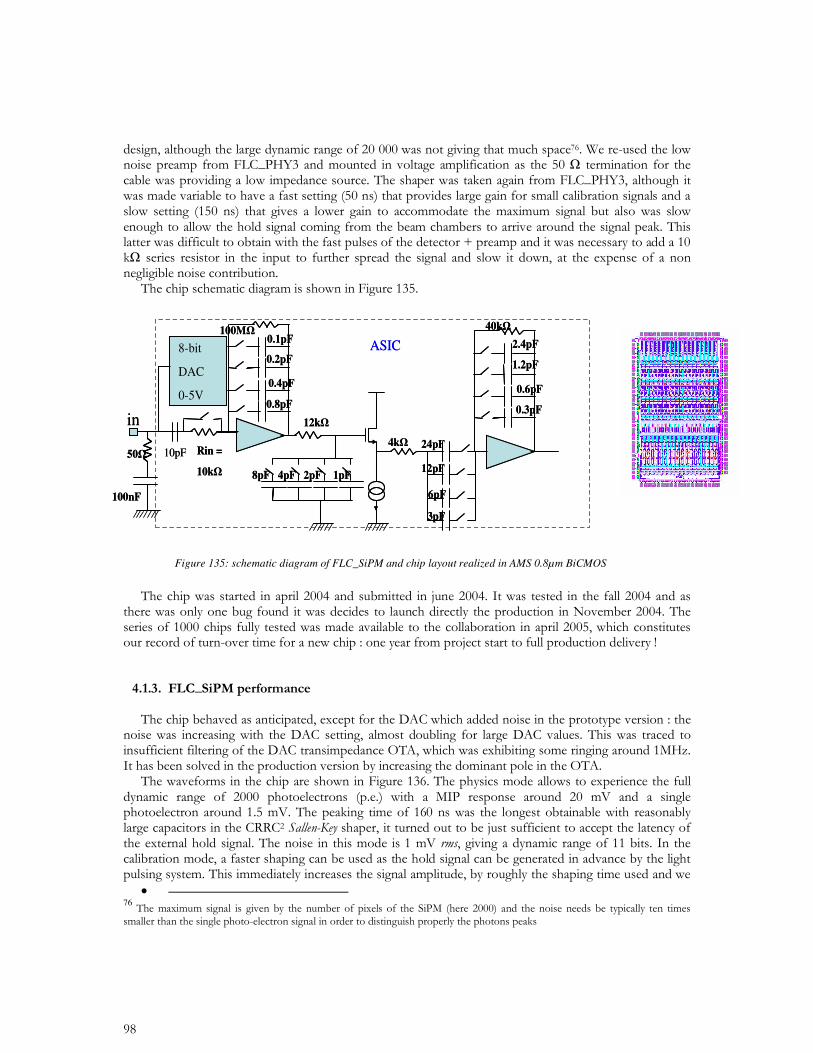
Figure 135: schematic diagram of FLC_SiPM and chip layout realized in AMS 0.8µm BiCMOS
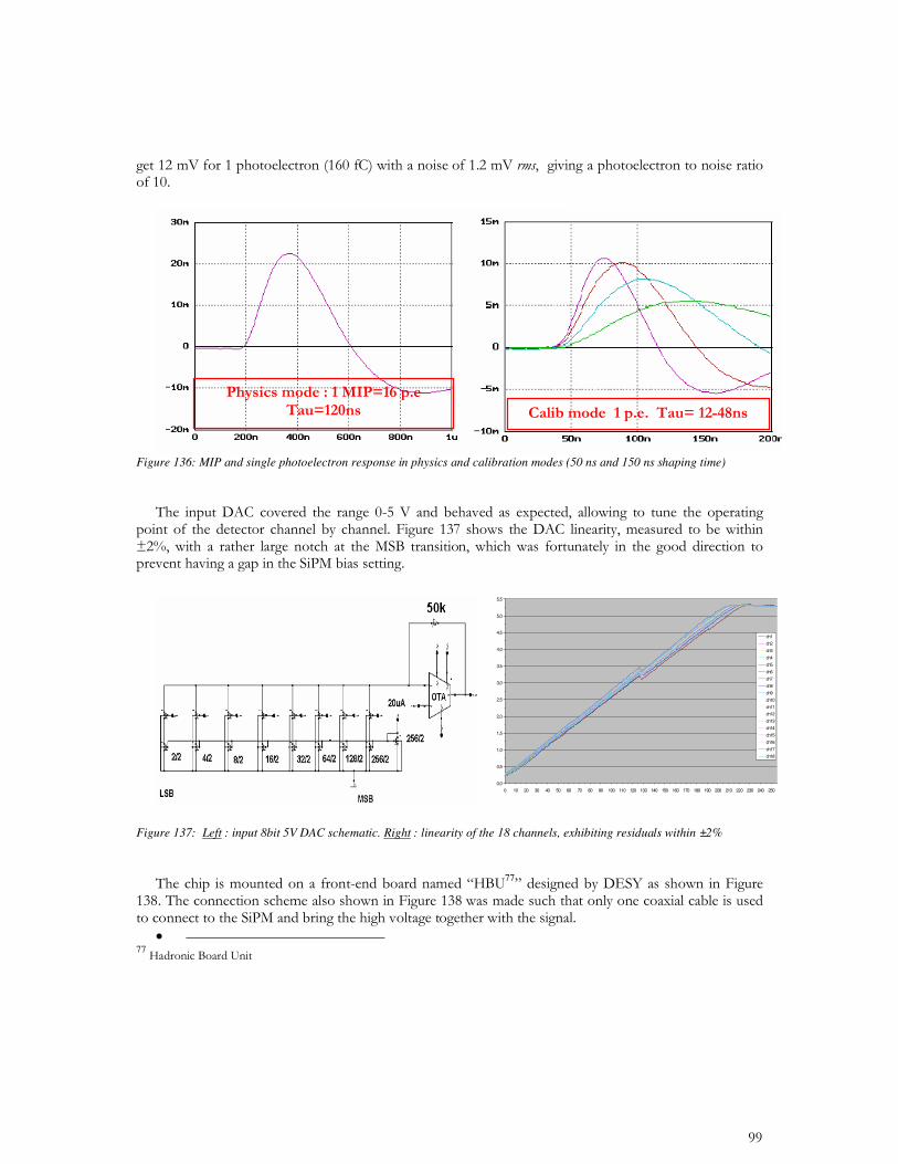
Figure 136: MIP and single photoelectron response in physics and calibration modes (50 ns and 150 ns shaping time)
Figure 137: Left : input 8bit 5V DAC schematic. Right : linearity of the 18 channels, exhibiting residuals within ±2%
77
• 77
0,0
0,5
1,0
1,5
2,0
2,5
3,0
3,5
4,0
4,5
5,0
5,5
0 10 20 30 40 50 60 70 80 90 100 110 120 130 140 150 160 170 180 190 200 210 220 230 240 250
ch1
ch2
ch3
ch4
ch5
ch6
ch7
ch8
ch9
ch10
ch11
ch12
ch13
ch14
ch15
ch16
ch17
ch18
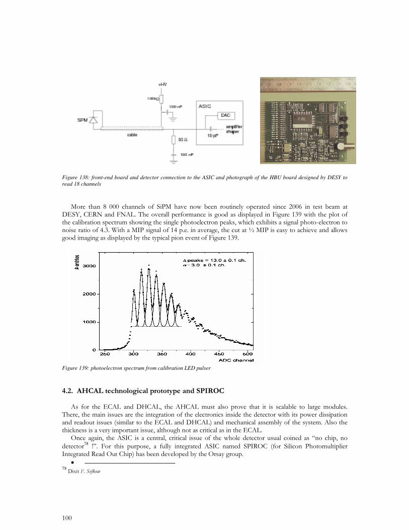
Figure 138: front-end board and detector connection to the ASIC and photograph of the HBU board designed by DESY to read 18 channels
Figure 139: photoelectron spectrum from calibration LED pulser
78
• 78
79
• 79
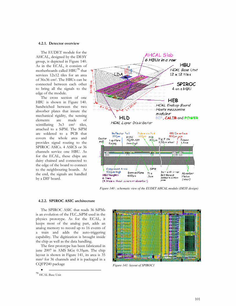
Figure 141: layout of SPIROC1
Figure 140 : schematic view of the EUDET AHCAL module (DESY design)
80
81
• 8081
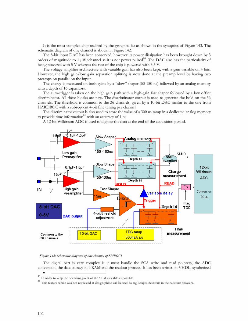
Figure 142: schematic diagram of one channel of SPIROC1
DAQASIC
Chip ID register 8 bits
gain
Trigger discri Output
Wilkinson ADC Discri output
gain
Trigger discri Output
Wilkinson ADC Discri output
..…
OR36
EndRamp (Discri ADC Wilkinson)
36
36
36
TM (Discri trigger)
ValGain (low gain or high Gain)
ExtSigmaTM (OR36)
Channel 1
Channel 0
ValDimGray 12 bits
…
Acquisition
readout
Conversion ADC
+
Ecriture RAM
RAM
FlagTDC
ValDimGray
12
8
ChipID
Hit channel register 16 x 36 x 1 bits
TDC rampStartRampTDC
BCID 16 x 8 bits
ADC rampStartrampb(wilkinson
ramp)
16
16ValidHoldAnalogb
RazRangN
16ReadMesureb
Rstb
Clk40MHz
SlowClock
StartAcqt
StartConvDAQb
StartReadOut
NoTrig
RamFull
TransmitOn
OutSerie
EndReadOut
Chipsat
DAQASIC
Chip ID register 8 bits
gain
Trigger discri Output
Wilkinson ADC Discri output
gain
Trigger discri Output
Wilkinson ADC Discri output
gain
Trigger discri Output
Wilkinson ADC Discri output
gain
Trigger discri Output
Wilkinson ADC Discri output
..…
OR36
EndRamp (Discri ADC Wilkinson)
36
36
36
TM (Discri trigger)
ValGain (low gain or high Gain)
ExtSigmaTM (OR36)
Channel 1
Channel 0
ValDimGray 12 bits
…
Acquisition
readout
Conversion ADC
+
Ecriture RAM
Conversion ADC
+
Ecriture RAM
RAMRAM
FlagTDC
ValDimGray
12
8
ChipID
Hit channel register 16 x 36 x 1 bits
TDC rampStartRampTDC
BCID 16 x 8 bits
ADC rampStartrampb(wilkinson
ramp)
16
16ValidHoldAnalogb
RazRangN
16ReadMesureb
Rstb
Clk40MHz
SlowClock
StartAcqt
StartConvDAQb
StartReadOut
NoTrig
RamFull
TransmitOn
OutSerie
EndReadOut
Chipsat
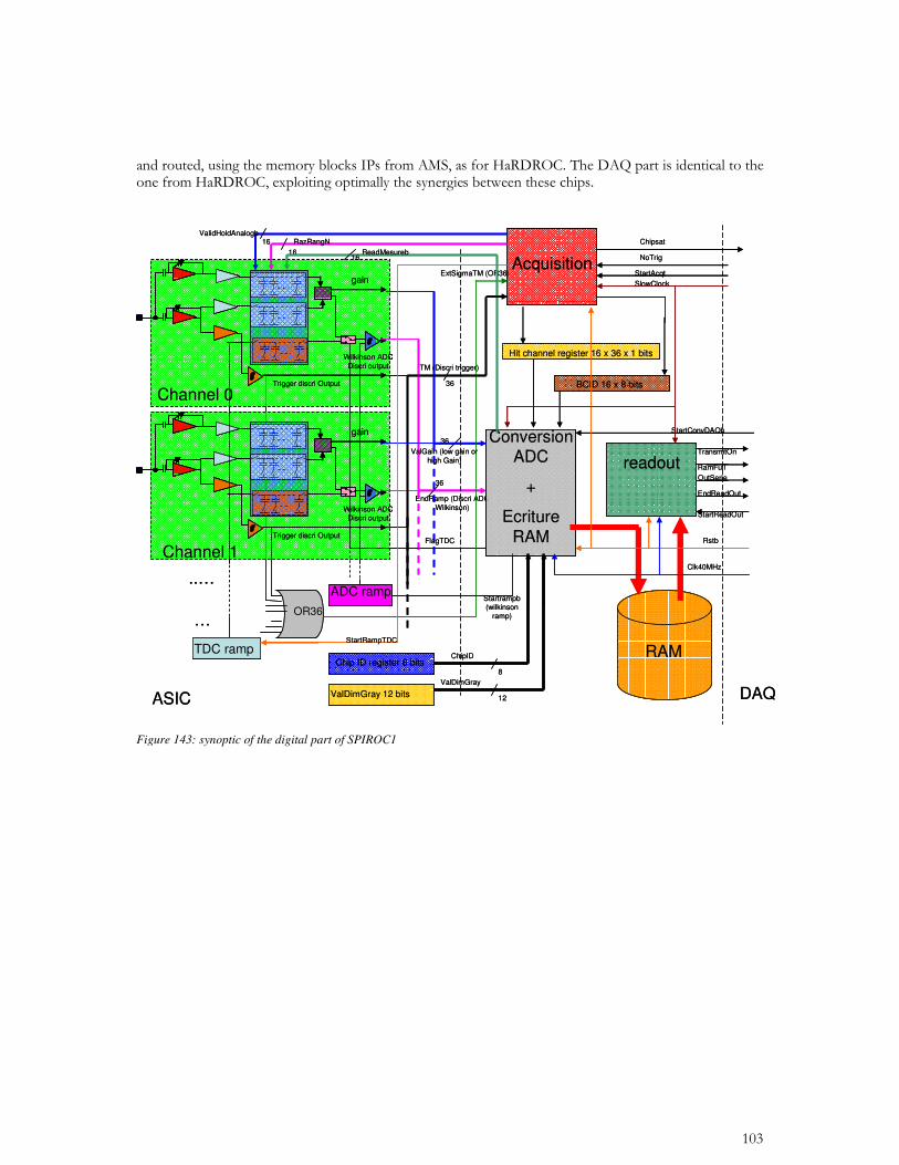
Figure 143: synoptic of the digital part of SPIROC1
• 83
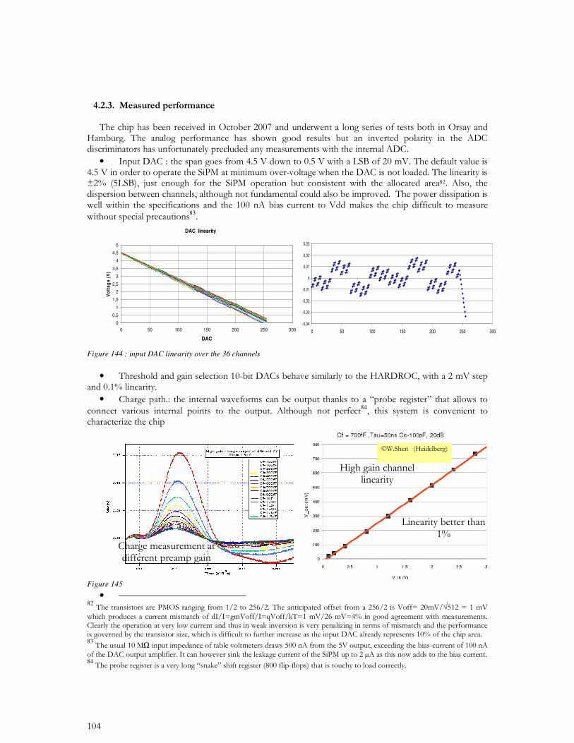
Figure 144 : input DAC linearity over the 36 channels
•
•
84
Figure 145
• 82 8384
DAC linearity
0
0,5
1
1,5
2
2,5
3
3,5
4
4,5
5
0 50 100 150 200 250 300
DAC
Vo
lta
ge
(V
)
-0,04
-0,03
-0,02
-0,01
0
0,01
0,02
0,03
0 50 100 150 200 250 300
•
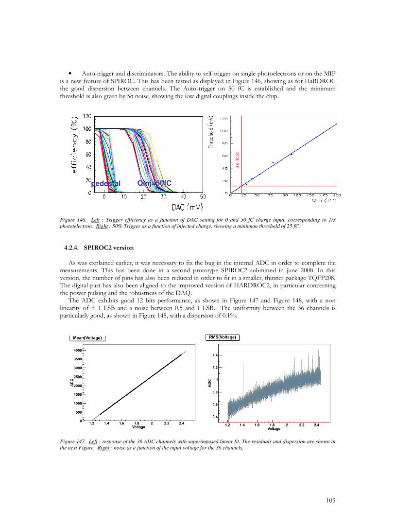
Figure 146. Left : Trigger efficiency as a function of DAC setting for 0 and 50 fC charge input, corresponding to 1/3 phototelectron. Right : 50% Trigger as a function of injected charge, showing a minimum threshold of 25 fC.
Figure 147. Left : response of the 36 ADC channels with superimposed linear fit. The residuals and dispersion are shown in the next Figure. Right : noise as a function of the input voltage for the 36 channels.
pedestal Qinj=50fC
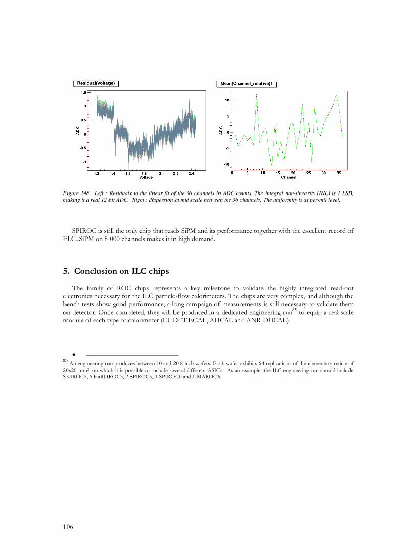
Figure 148. Left : Residuals to the linear fit of the 36 channels in ADC counts. The integral non-linearity (INL) is 1 LSB, making it a real 12 bit ADC. Right : dispersion at mid scale between the 36 channels. The uniformity is at per-mil level.
85
• 85
CHAPTER 5
MULTIANODE PHOTOMULTIPLIER READOUT
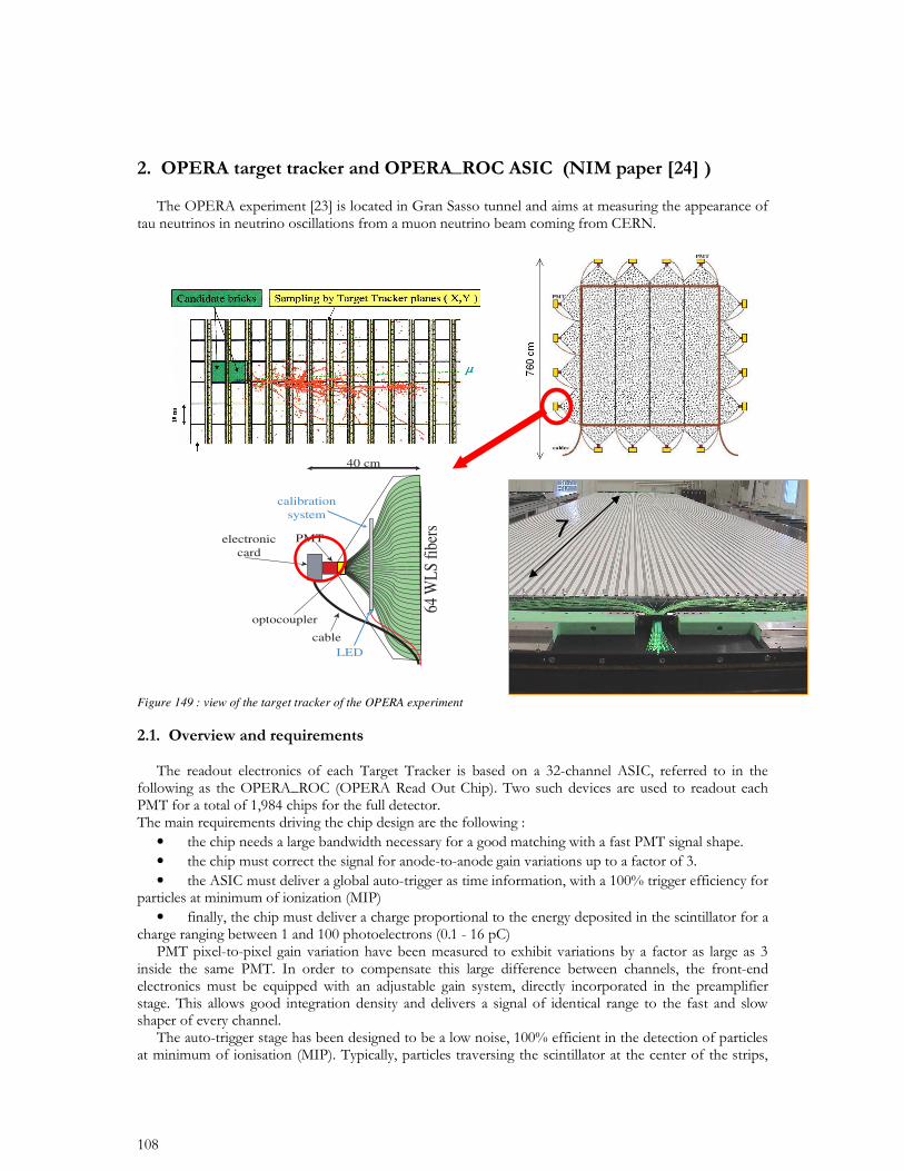
Figure 149 : view of the target tracker of the OPERA experiment
• • •
•
PMT
40 cm
electroniccard
optocoupler
calibrationsystem
cable
LED
64 W
LS
fibe
rs
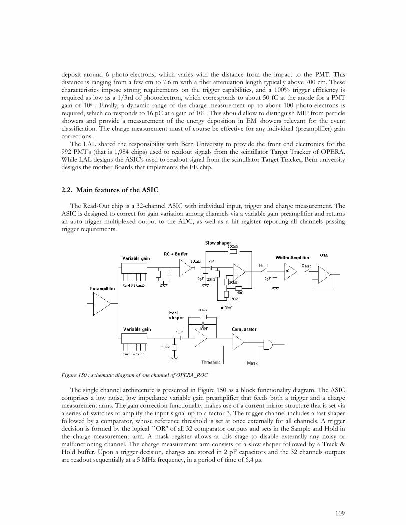
Figure 150 : schematic diagram of one channel of OPERA_ROC
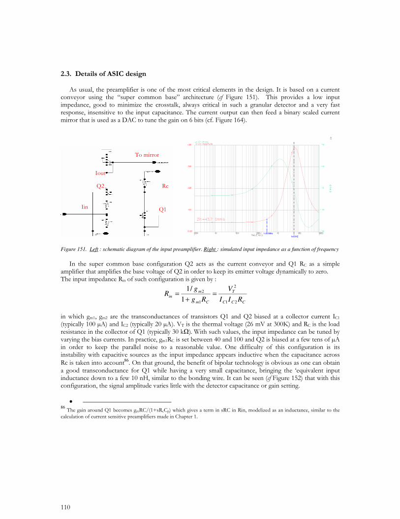
Figure 151. Left : schematic diagram of the input preamplifier. Right : simulated input impedance as a function of frequency
CCC
T
Cm
min
RII
V
Rg
gR
21
2
1
2
1
/1=
+=
86
• 86
f=6GHZ
f=300MHz
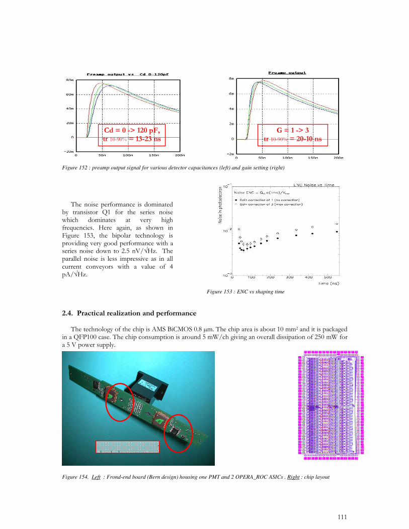
Figure 152 : preamp output signal for various detector capacitances (left) and gain setting (right)
Figure 154. Left : Frond-end board (Bern design) housing one PMT and 2 OPERA_ROC ASICs . Right : chip layout
Figure 153 : ENC vs shaping time
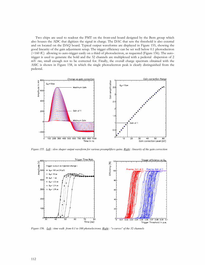
Figure 155. Left : slow shaper output waveform for various preamplifiers gains. Right : linearity of the gain correction
Figure 156. Left : time walk from 0.1 to 100 photoelectrons. Right : "s-curves" of the 32 channels
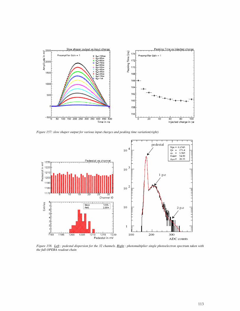
Figure 157: slow shaper output for various input charges and peaking time variation(right)
Figure 158. Left : pedestal dispersion for the 32 channels. Right : photomultiplier single photoelectron spectrum taken with the full OPERA readout chain
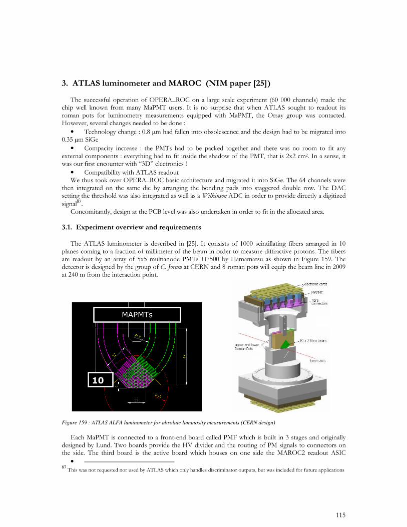
•
•
•
87
Figure 159 : ATLAS ALFA luminometer for absolute luminosity measurements (CERN design)
• 87
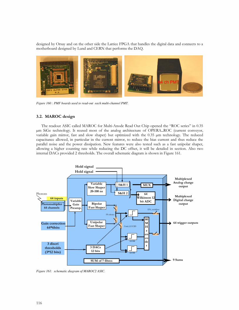
Figure 160 : PMF boards used to read-out each multi-channel PMT.
Figure 161: schematic diagram of MAROC2 ASIC.
64 ch PMT
•
•
•
Variable Gain
cmd 0 à cmd 5
input
Preamplifier
Fast Shaper opera
3 Comparators
Buffer RC Slow Shaper
out_Gain
charge
Thre shold1
trigger
20pF 15k.
Vdd
Thre shold2
Thre shold3
Vdd
Vss
Fast Shaper OTA
OTA
Widlar buffer
Hold Read
Vss
2k.
T Z
OTA
x 1
30fF
50k.
30k.
100k.3pF
100fF
150.15k.
3k.
3k.
3k.
2pF
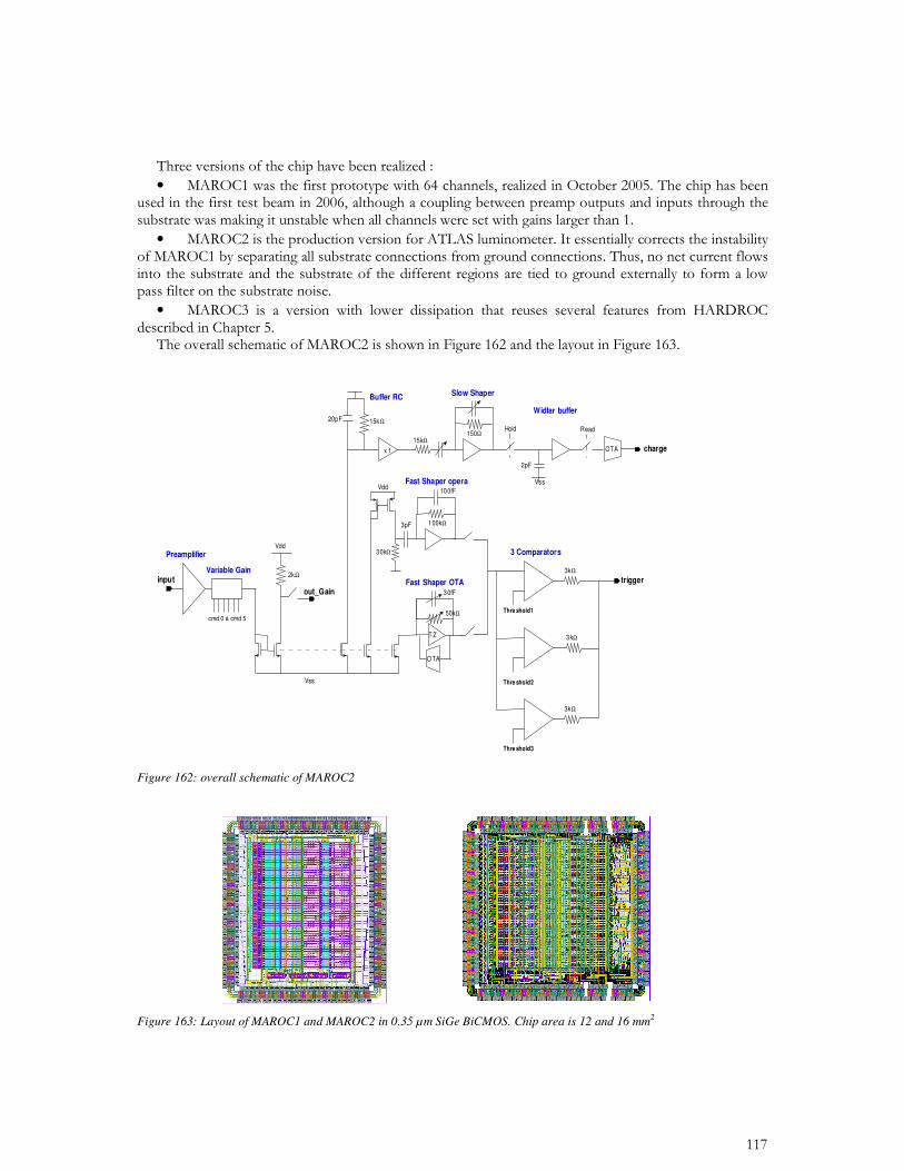
Figure 162: overall schematic of MAROC2
Figure 163: Layout of MAROC1 and MAROC2 in 0.35 µm SiGe BiCMOS. Chip area is 12 and 16 mm2
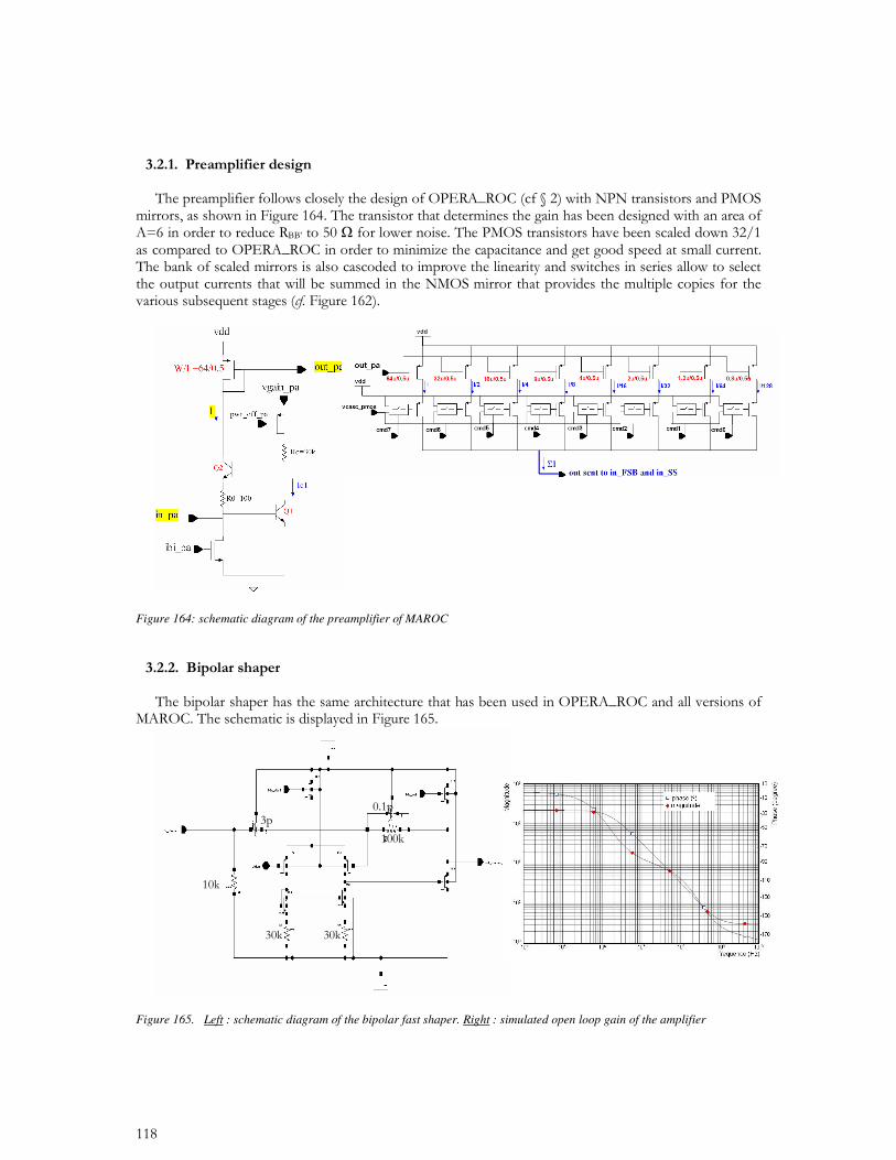
Figure 164: schematic diagram of the preamplifier of MAROC
Figure 165. Left : schematic diagram of the bipolar fast shaper. Right : simulated open loop gain of the amplifier
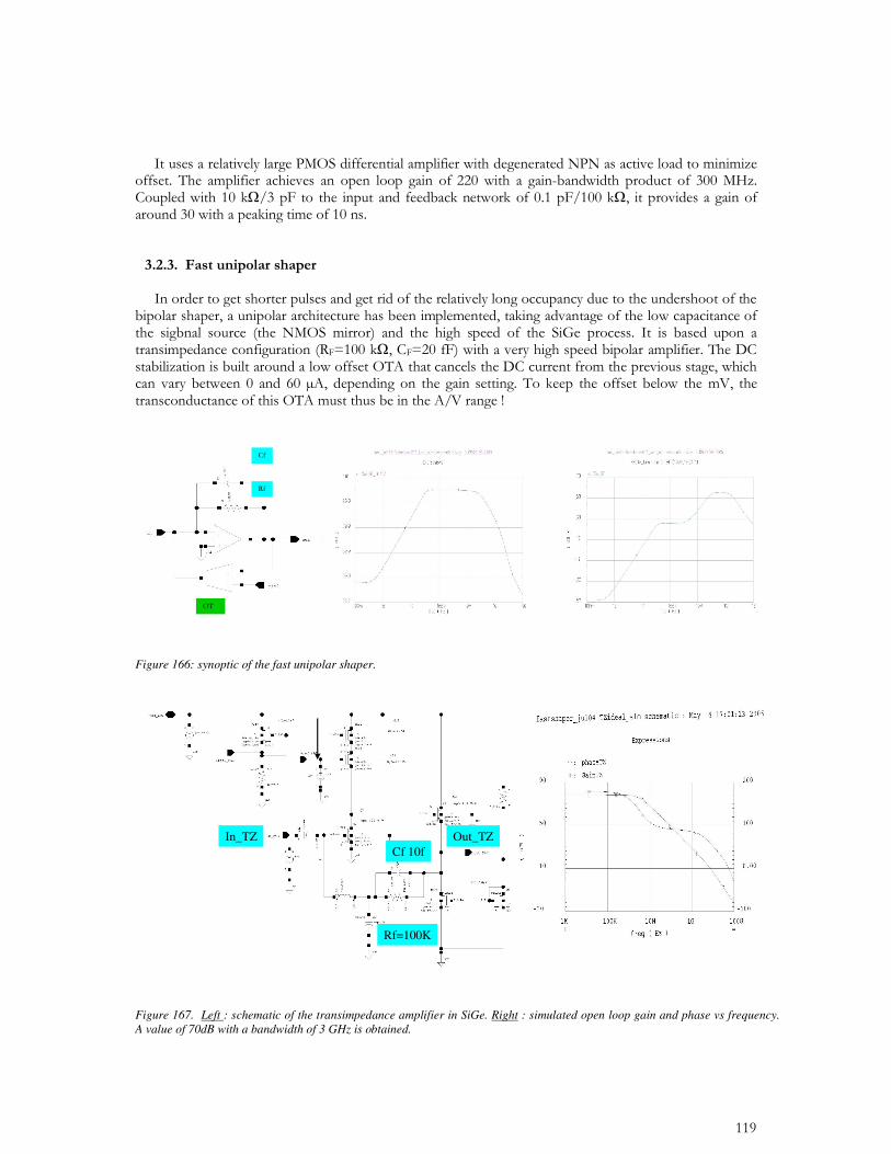
Figure 166: synoptic of the fast unipolar shaper.
Out_TZIn_TZ
Rf=100K
Cf 10f
Out_TZIn_TZ
Rf=100K
Cf 10f
Figure 167. Left : schematic of the transimpedance amplifier in SiGe. Right : simulated open loop gain and phase vs frequency. A value of 70dB with a bandwidth of 3 GHz is obtained.
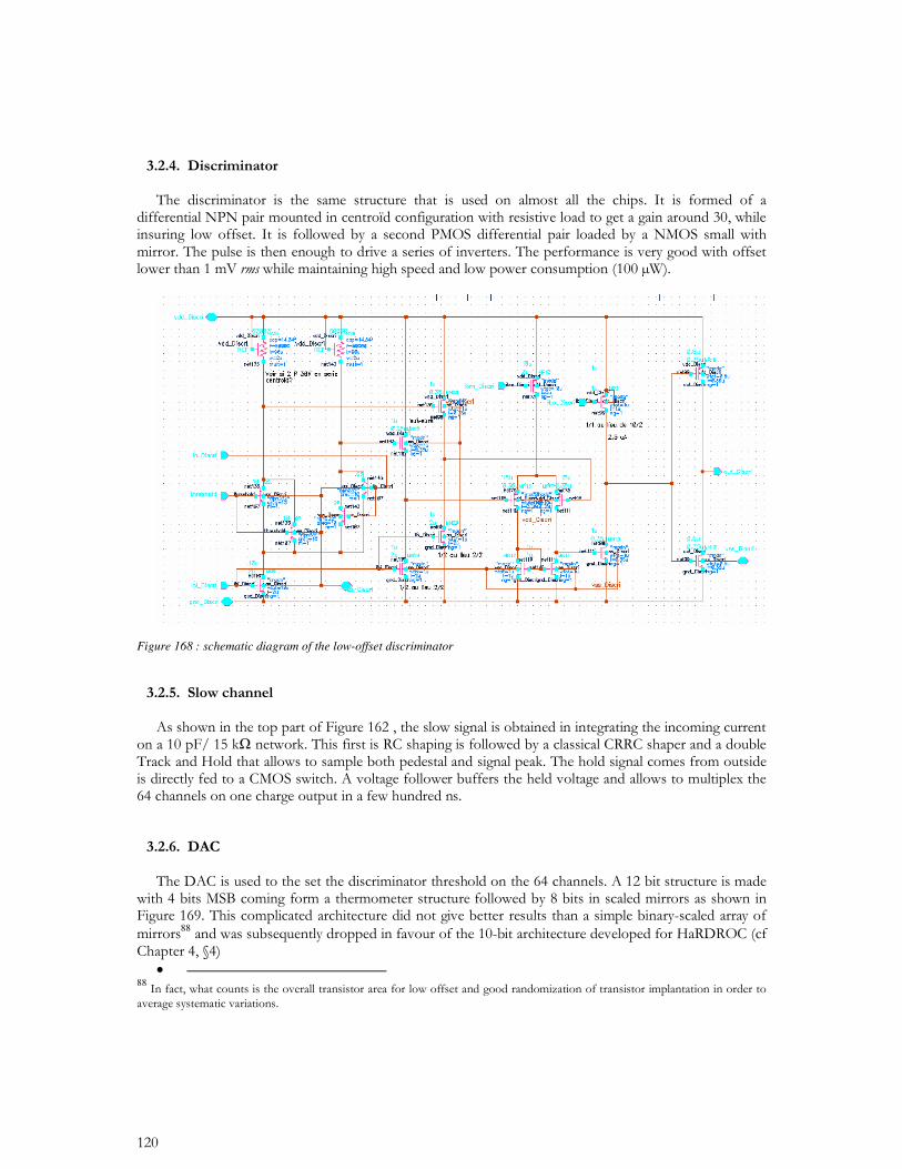
Figure 168 : schematic diagram of the low-offset discriminator
88
• 88
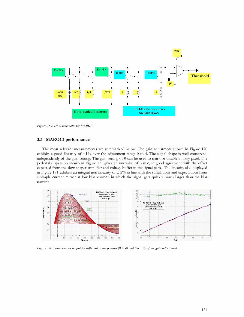
Figure 169: DAC schematic for MAROC
Figure 170 : slow shaper output for different preamp gains (0 to 4) and linearity of the gain adjustment
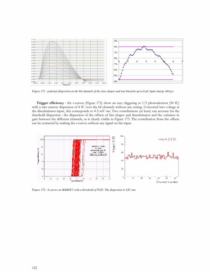
Figure 171 : pedestal dispersion on the 64 channels of the slow shaper and non linearity up to 6 pC input charge (40 pe)
Figure 172 : S-curves on MAROC1 with a threshold of 50 fC. The dispersion is 4 fC rms
-4%
-3%
-2%
-1%
0%
1%
2%
3%
0 1 2 3 4 5 6 7
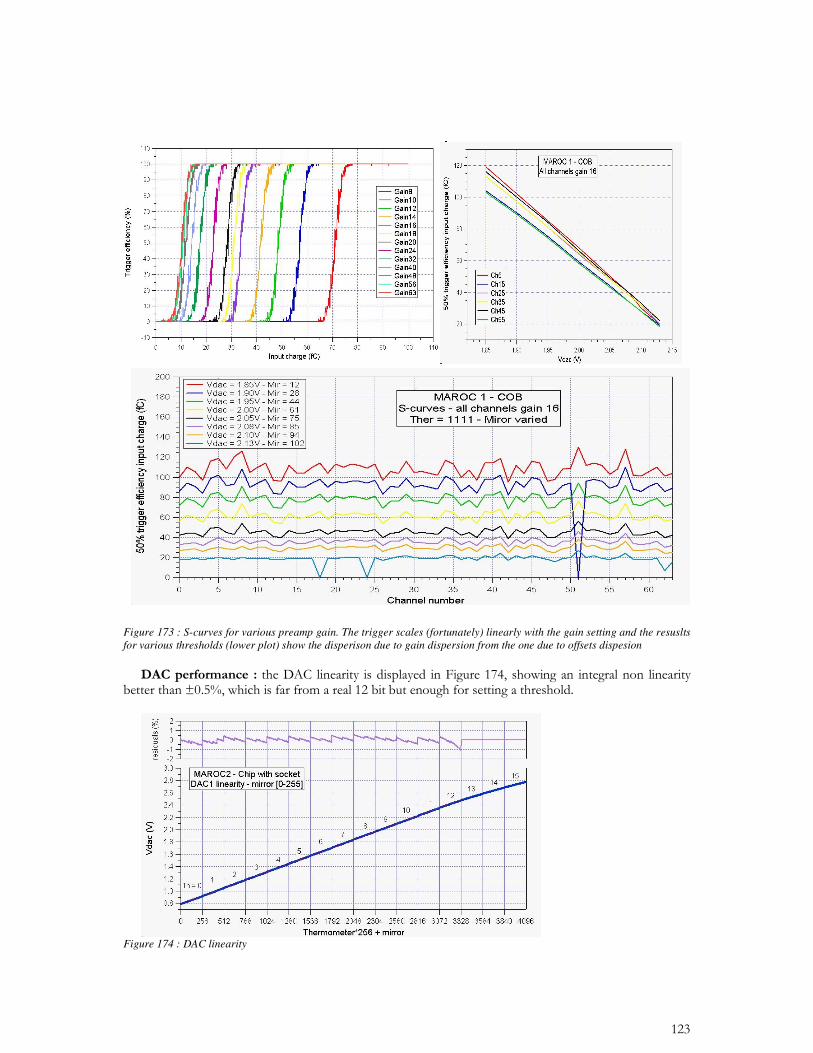
Figure 173 : S-curves for various preamp gain. The trigger scales (fortunately) linearly with the gain setting and the resuslts for various thresholds (lower plot) show the disperison due to gain dispersion from the one due to offsets dispesion
Figure 174 : DAC linearity
Variable gain I mirrors
G max = 4
Rsubstrate
Vin=
1V AC
vss1 vss2
Q1
SBC
vdd1
out_Gain
M5S1
IN
2.5V2.5V
W=32u
L=1u
M2
20 uA
Q2
W=64u
L=1u
M1
cmd0
M3 M4
vdd2
vcasc
Variable gain I mirrors
G max = 4
RsubstrateRsubstrate
Vin=
1V AC
vss1 vss2vss1vss1 vss2vss2
Q1
SBC
vdd1
out_Gain
M5S1
IN
2.5V2.5V
W=32u
L=1u
M2
20 uA
Q2
W=64u
L=1u
M1
cmd0
M3 M4
vdd2
vcasc
vdd1
out_Gain
M5S1
IN
2.5V2.5V
W=32u
L=1u
M2
20 uA
Q2
W=64u
L=1u
M1
cmd0
M3 M4
vdd2
vcasc
vdd1
out_Gain
M5S1
IN
2.5V2.5V
W=32u
L=1u
M2
20 uA
Q2
W=64u
L=1u
M1
cmd0
M3 M4
vdd2
vcasc
•
89 90
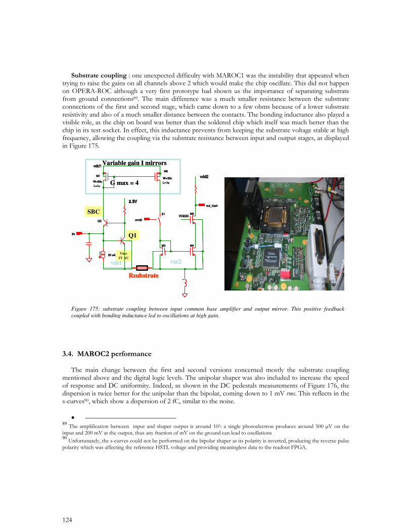
Figure 175: substrate coupling between input common base amplifier and output mirror. This positive feedback coupled with bonding inductance led to oscillations at high gain.
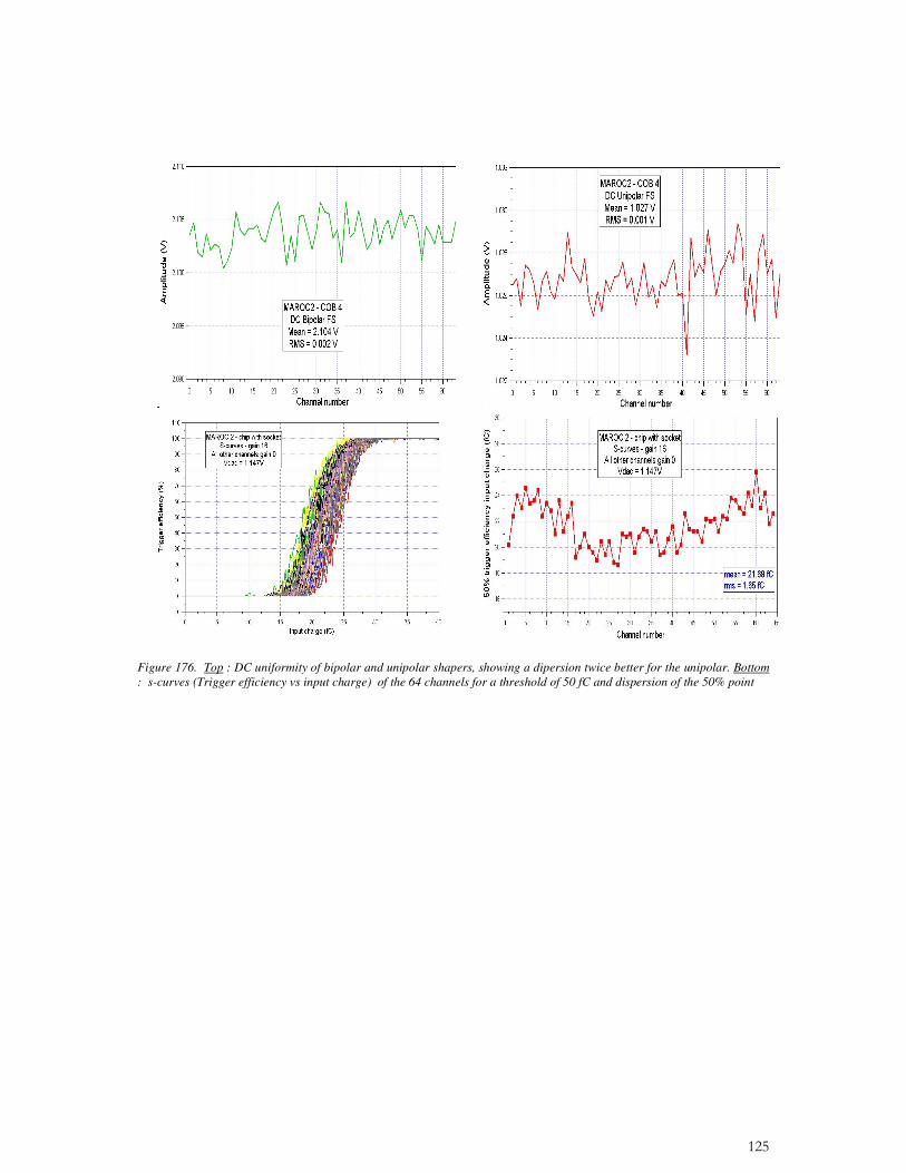
Figure 176. Top : DC uniformity of bipolar and unipolar shapers, showing a dipersion twice better for the unipolar. Bottom : s-curves (Trigger efficiency vs input charge) of the 64 channels for a threshold of 50 fC and dispersion of the 50% point
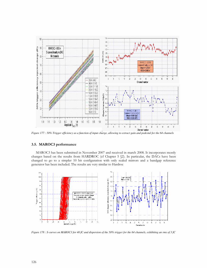
Figure 177 : 50% Trigger efficiency as a function of input charge, allowing to extract gain and pedestal for the 64 channels
Figure 178 : S-curves on MAROC3 for 40 fC and dispersion of the 50% trigger for the 64 channels, exhibiting an rms of 3 fC
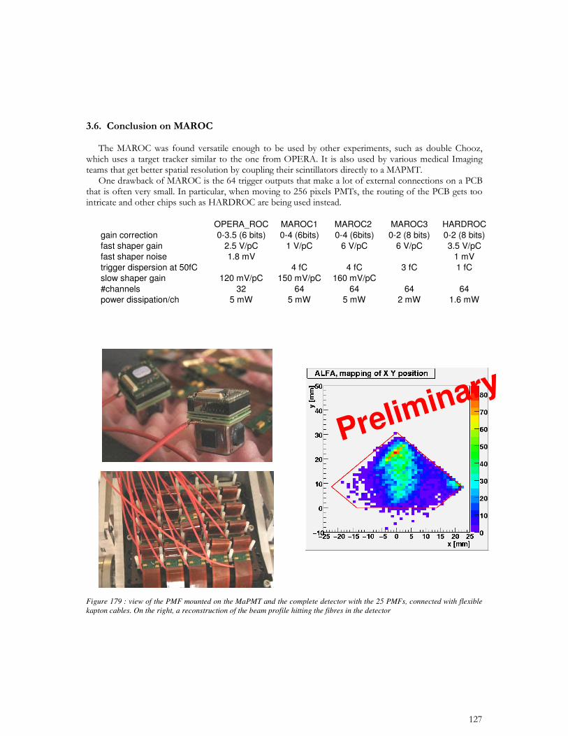
OPERA_ROC MAROC1 MAROC2 MAROC3 HARDROCgain correction 0-3.5 (6 bits) 0-4 (6bits) 0-4 (6bits) 0-2 (8 bits) 0-2 (8 bits)fast shaper gain 2.5 V/pC 1 V/pC 6 V/pC 6 V/pC 3.5 V/pCfast shaper noise 1.8 mV 1 mVtrigger dispersion at 50fC 4 fC 4 fC 3 fC 1 fCslow shaper gain 120 mV/pC 150 mV/pC 160 mV/pC#channels 32 64 64 64 64power dissipation/ch 5 mW 5 mW 5 mW 2 mW 1.6 mW
Preliminary
Preliminary
Figure 179 : view of the PMF mounted on the MaPMT and the complete detector with the 25 PMFs, connected with flexible kapton cables. On the right, a reconstruction of the beam profile hitting the fibres in the detector
91
•
•
• • • •
•
• 91
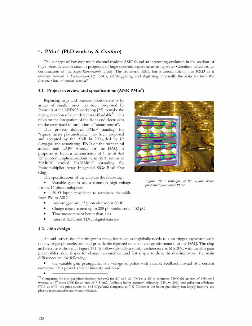
Figure 180 : principle of the square meter photomultiplier array PMm2
•
•
•
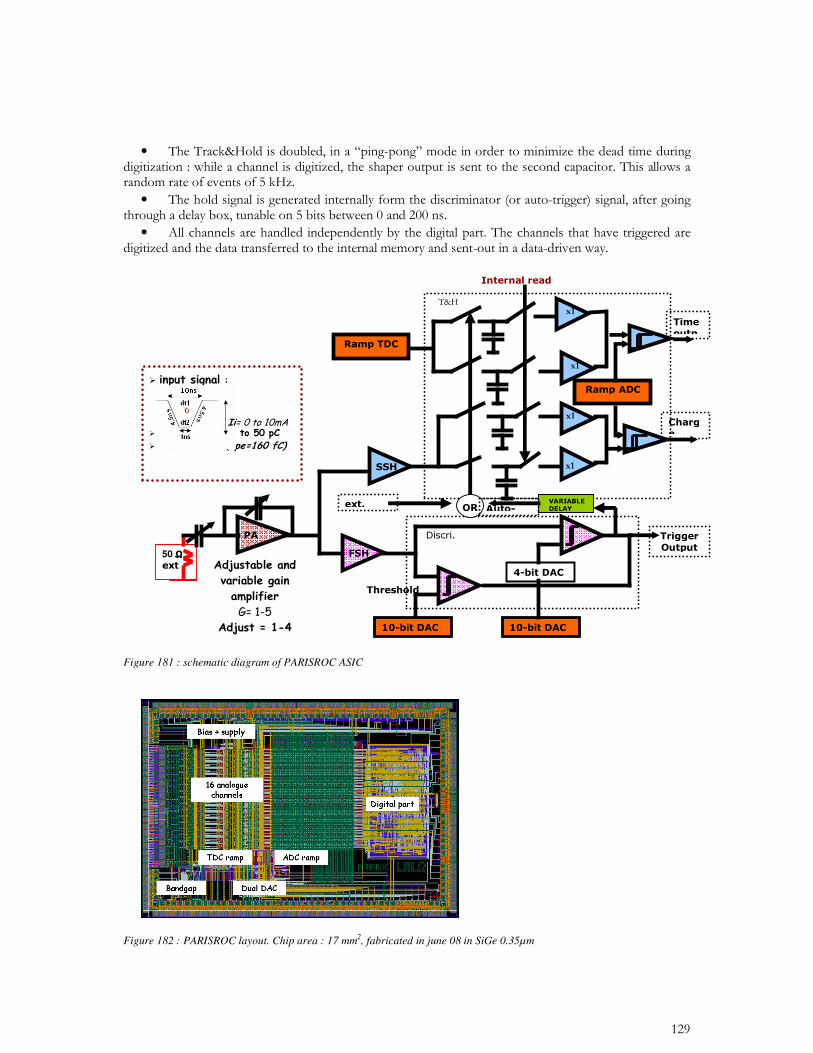
Figure 181 : schematic diagram of PARISROC ASIC
Figure 182 : PARISROC layout. Chip area : 17 mm2, fabricated in june 08 in SiGe 0.35µm
50 ....
92
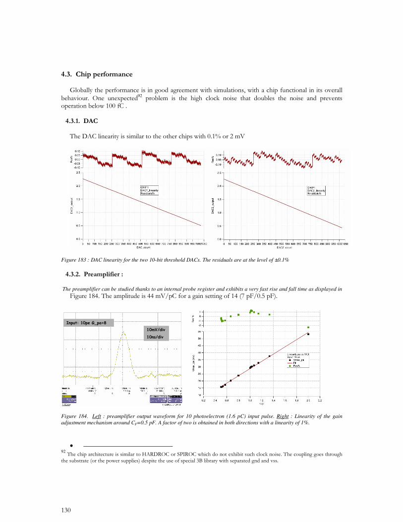
Figure 183 : DAC linearity for the two 10-bit threshold DACs. The residuals are at the level of ±0.1%
The preamplifier can be studied thanks to an internal probe register and exhibits a very fast rise and fall time as displayed in
Figure 184. Left : preamplifier output waveform for 10 photoelectron (1.6 pC) input pulse. Right : Linearity of the gain adjustment mechanism around CF=0.5 pF. A factor of two is obtained in both directions with a linearity of 1%.
•
92
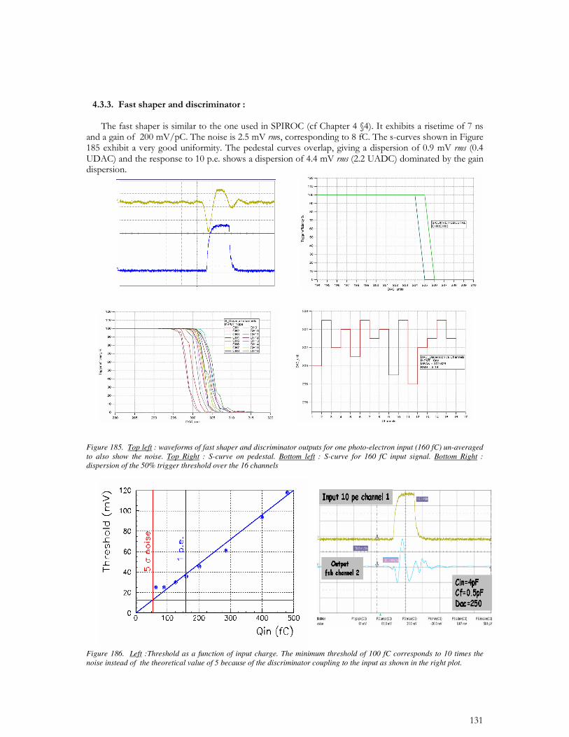
Figure 185. Top left : waveforms of fast shaper and discriminator outputs for one photo-electron input (160 fC) un-averaged to also show the noise. Top Right : S-curve on pedestal. Bottom left : S-curve for 160 fC input signal. Bottom Right : dispersion of the 50% trigger threshold over the 16 channels
Figure 186. Left :Threshold as a function of input charge. The minimum threshold of 100 fC corresponds to 10 times the noise instead of the theoretical value of 5 because of the discriminator coupling to the input as shown in the right plot.
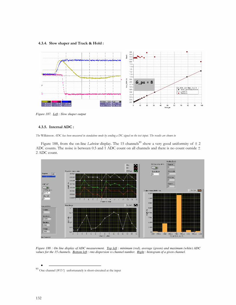
Figure 187. Left : Slow shaper output
93
Figure 188 : On line display of ADC measurement. Top left : minimum (red), average (green) and maximum (white) ADC values for the 15 channels. Bottom left : rms dispersion vs channel number. Right : histogram of a given channel.
•
93
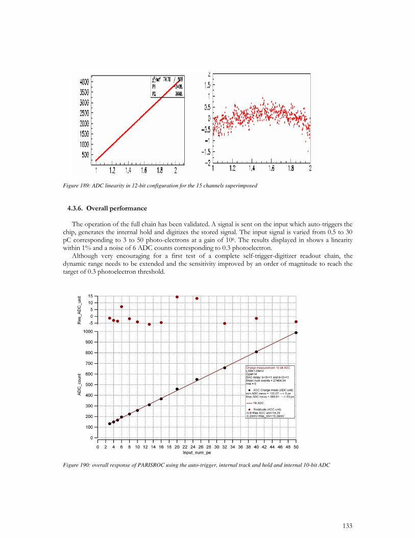
Figure 189: ADC linearity in 12-bit configuration for the 15 channels superimposed
Figure 190: overall response of PARISROC using the auto-trigger, internal track and hold and internal 10-bit ADC
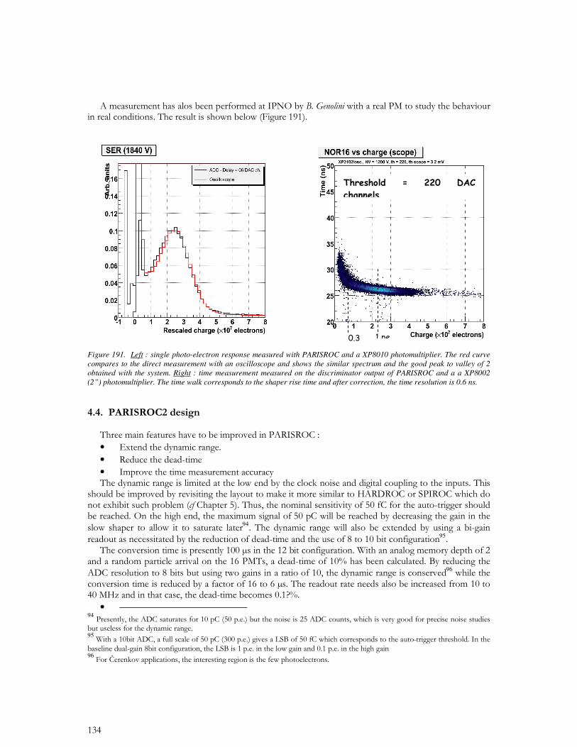
Figure 191. Left : single photo-electron response measured with PARISROC and a XP8010 photomultiplier. The red curve compares to the direct measurement with an oscilloscope and shows the similar spectrum and the good peak to valley of 2 obtained with the system. Right : time measurement measured on the discriminator output of PARISROC and a a XP8002 (2”) photomultiplier. The time walk corresponds to the shaper rise time and after correction, the time resolution is 0.6 ns.
• • •
94 95
96
• 949596
97
• 97

CONCLUSION
“acta est fabula98”
99
•
9899
REFERENCES
ANNEX 1
Publications au 31 dec 2008
1. Design and implementation of the Front End Board for the readout of the ATLAS liquid argon calorimeters. N.J. Buchanan et al. 2008. Published in JINST 3:P03004,2008.
2. Construction, assembly and tests of the ATLAS electromagnetic end-cap calorimeters. By ATLAS Collaboration (M. Aleksa et al.). 2008. Published in JINST 3:P06002,2008.
3. The ATLAS Experiment at the CERN Large Hadron Collider. By ATLAS Collaboration (G. Aad et al.). 2008. 437pp. Published in JINST 3:S08003,2008.
4. Electronics calibration board for the ATLAS liquid argon calorimeters. J. Colas et al. 2008. 23pp. Published in Nucl.Instrum.Meth.A593:269-291,2008.
5. ILC Reference Design Report Volume 4 - Detectors. By ILC Collaboration (Ties Behnke, (Ed.) et al.). FERMILAB-APC, Dec 2007. e-Print: arXiv:0712.2356 [physics.ins-det]
6. 6) HARDROC, HAdronic Rpc Detector ReadOut Chip. Christophe de la Taille (Orsay, LAL) . Sep 2007. Published in *Prague 2007, Electronics for particle physics* 30
7. ILC Reference Design Report: ILC Global Design Effort and World Wide Study.By ILC Collaboration (James Brau, (Ed.) et al.). FERMILAB-APC, Aug 2007. 147pp. e-Print: arXiv:0712.1950 [physics.acc-ph]
8. CALICE Report to the Calorimeter R&D Review Panel. By CALICE Collaboration (C. Adloff et al.). ILC-DET-2007-024, Jul 2007. 77pp. e-Print: arXiv:0707.1245 [physics.ins-det]
9. Hadron beam test of a scintillating fibre tracker system for elastic scattering and luminosity measurement in ATLAS. F. Anghinolfi et al. Jun 2007. 12pp. Published in JINST 2:P07004,2007. e-Print: arXiv:0706.3316 [physics.ins-det]
10. The Beam and detector for the NA48 neutral kaon CP violations experiment at CERN. By NA48 Collaboration (V. Fanti et al.). May 2007. 40pp. Published in Nucl.Instrum.Meth.A574:433-471,2007.
11. The OPERA experiment target tracker. T. Adam et al. Jan 2007. 25pp. Published in Nucl.Instrum.Meth.A577:523-539,2007. e-Print: physics/0701153
12. Front-end ASICs development for W-Si calorimeter at ILC. By CALICE Collaboration (Julien Fleury et al.). 2007. 5pp. Prepared for 10th Pisa Meeting on Advanced Detectors: Frontier Detectors for Frontier Physics, La Biodola, Elba, Italy, 21-27 May 2006. Published in Nucl.Instrum.Meth.A572:371-375,2007.
13. First events from the CNGS neutrino beam detected in the OPERA experiment. By OPERA Collaboration (R. Acquafredda et al.). Nov 2006. 12pp. Published in New J.Phys.8:303,2006. e-Print: hep-ex/0611023
14. Luminosity measurement at ATLAS: Development, construction and test of scintillating fibre prototype detectors. S. Ask et al. May 2006. 16pp. Published in Nucl.Instrum.Meth.A568:588-600,2006. e-Print: physics/0605127
15. A large dynamic range integrated front-end for photomultiplier tubes. B. Genolini, L. Raux, C. de la Taille, J. Pouthas, V. Tocut (Orsay, IPN & Orsay, LAL) . 2006. 5pp. Prepared for 4th International Conference on New Developments in Photodetection (BEAUNE 2005): From Infra Red to Gamma Rays, Beaune, France, 19-24 Jun 2005. Published in Nucl.Instrum.Meth.A567:209-213,2006.
16. Dedicated very front-end electronics for an ILC prototype hadronic calorimeter with SiPM readout. S. Blin et al. LC-DET-2006-007, 2006. 12pp.
17. Integrated electronic for SIPM and MPPC. Pierre Barrillon, Sylvie Blin, Frederic Dulucq, Julien Fleury, Gisele Martin, Ludovic Raux, Nathalie Seguin, Christophe de la Taille (Orsay, LAL) . 2006. 19pp. Published in PoS PD07:025,2006.
18. The Upgraded D0 detector. By D0 Collaboration (V.M. Abazov et al.). FERMILAB-PUB-05-341-E, Jul 2005. 142pp. Published in Nucl.Instrum.Meth.A565:463-537,2006. e-Print: physics/0507191
19. Construction, assembly and tests of the ATLAS electromagnetic barrel calorimeter. By ATLAS Electromagnetic Barrel Liquid Argon Calorimeter Group (B. Aubert et al.). CERN-PH-EP-2005-034, Jul 2005. 77pp. Published in Nucl.Instrum.Meth.A558:388-418,2006.
20. Position resolution and particle identification with the ATLAS EM calorimeter. By ATLAS Liquid Argon Calorimeter Collaboration (J. Colas et al.). May 2005. 32pp. Published in Nucl.Instrum.Meth.A550:96-115,2005. e-Print: physics/0505127
21. Front-end Electronic for the Calice ECAL Physics Prototype. Julien Fleury, Christophe de la Taille, Gisele Martin-Chassard (Orsay, LAL) . LCWS-2005-0902, Mar 2005. In the Proceedings of 2005 International Linear Collider Workshop (LCWS 2005), Stanford, California, 18-22 Mar 2005. In the Proceedings of 2005 International Linear Collider Workshop (LCWS 2005), Stanford, California, 18-22 Mar 2005, pp 0902.
22. FLC_SIPM: Front-End Chip for SIPM Readout for ILC Analog HCAL. C. de la Taille, Gisele Martin-Chassard, L. Raux (Orsay, LAL) . LCWS-2005-0916, Mar 2005.
In the Proceedings of 2005 International Linear Collider Workshop (LCWS 2005), Stanford, California, 18-22 Mar 2005. In the Proceedings of 2005 International Linear Collider Workshop (LCWS 2005), Stanford, California, 18-22 Mar 2005, pp 0916.
23. Dedicated front-end electronics for the next generation of linear collider electromagnetic calorimeter. By the FLC Collaboration Proxy and FLC Collaboration (S. Manen et al.). Jan 2005. 3pp. Contributed to 10th Workshop on Electronics for LHC and Future Experiments, Boston, Massachusetts, 13-17 Sep 2004. e-Print: physics/0501063
24. Development and construction of large size signal electrodes for the ATLAS electromagnetic calorimeter. B. Aubert et al. CERN-PH-EP-2004-019, May 2004. 43pp. Published in Nucl.Instrum.Meth.A539:558-594,2005.
25. Introducing FLC_PHY3 low noise front-end chip for FLC W-Si electromagnetic calorimeter physics prototype. Julien Fleury, Christophe de la Taille, Gisele Martin-Chassard (Orsay, LAL & Orsay) . Apr 2004. 9pp. Prepared for International Conference on Linear Colliders (LCWS 04), Paris, France, 19-24 Apr 2004. Published in *Paris 2004, Linear colliders* 819-827
26. Extended joint ECFA/DESY study on physics and detector for a linear e+ e- collider. Proceedings, Summer Colloquium, Amsterdam, Netherlands, April 4, 2003. K. Ackermann et al. DESY-PROC-2004-01, DESY-04-123, DESY-04-123G, Mar 2004. 140pp. Prepared for 4th ECFA / DESY Workshop on Physics and Detectors for a 90-GeV to 800-GeV Linear e+ e- Collider, Amsterdam, The Netherlands, 1-4 Apr 2003.
Performance of the Liquid Argon final calibration board.C. de la TailleN. Seguin-MoreauL. SerinOrsay, LALN. Dumont-DayotI. Wingerter-SeezAnnecy, LAPP
28. Performance of a low noise readout ASIC for the W-Si calorimeter physics prototype for the future linear collider. J. Fleury, C. de la Taille, G. Martin-Chassard (Orsay, LAL) . Mar 2004. 5pp. Prepared for 11th International Conference on Calorimetry in High-Energy Physics (Calor 2004), Perugia, Italy, 28 Mar - 2 Apr 2004. Published in *Perugia 2004, Calorimetry in particle physics* 191-195
29. A front-end read out chip for the OPERA scintillator tracker. A. Lucotte, S. Bondil, K. Borer, J.E. Campagne, A. Cazes, M. Hess, C. de La Taille, G. Martin-Chassard, L. Raux, J.P. Repellin (Orsay, LAL & Bern U.) . 2004. 15pp. Published in Nucl.Instrum.Meth.A521:378-392,2004.
30. An adaptable fast and compact DAQ for the luminosity measurement at HERA II. V. Boudry, F. Moreau, A.E. Specka (Ecole Polytechnique) , R. Chiche, C. de la Taille (Orsay) ,
P. Bailly, E. Barrelet, H. Lebbolo, A. Vallereau (Paris U., VI-VII) , C. Renard (SUBATECH, Nantes) . 2004. 5pp. Prepared for 13th IEEE - NPSS Real Time Conference (RT 2003), Montreal, Canada, 18-23 May 2003. Published in IEEE Trans.Nucl.Sci.51:425-429,2004.
31. Performance of the ATLAS electromagnetic calorimeter barrel module 0. By ATLAS Electromagnetic Liquid Argon Calorimeter Group (B. Aubert et al.). CERN-EP-2002-087, Nov 2002. 48pp. Published in Nucl.Instrum.Meth.A500:202-231,2003, Erratum-ibid.A517:399-402,2004.
32. Performance of the ATLAS electromagnetic calorimeter end-cap module 0. By The ATLAS Electromagnetic Liquid Argon Calorimeter Group (B. Aubert et al.). CERN-EP-2002-104, Nov 2002. 31pp. Published in Nucl.Instrum.Meth.A500:178-201,2003.
33. Calibration boards for the ATLAS LAr calorimeters. N. Dumont-Dayot et al. Sep 2002. Prepared for 8th Workshop on Electronics for LHC Experiments, Colmar, France, 9-13 Sep 2002. Published in *Colmar 2002, Electronics for LHC experiments* 347-352
34. Front end electronics for a silicon tungsten calorimeter. S. Manen, G. Bohner, J. Lecoq (Clermont-Ferrand U.) , J. Fleury, C. de la Taille, G. Martin (Orsay, LAL) . Aug 2002. 4pp. Prepared for International Workshop on Linear Colliders (LCWS 2002), Jeju Island, Korea, 26-30 Aug 2002. Published in *Seogwipo 2002, Linear colliders* 577-580
35. The electronics of the new H1 luminosity system. V. Boudry, F. Moreau, A.E. Specka, C. Renard (Ecole Polytechnique) , E. Barrelet, P. Bailly, H. Lebbolo, A. Vallereau (Paris U., VI-VII) , R. Chiche, C. de la Taille (Orsay, LAL) . Mar 2002. 6pp. Prepared for 10th International Conference on Calorimetry in High Energy Physics (CALOR 2002), Pasadena, California, 25-30 Mar 2002. Published in *Pasadena 2002, Calorimetry in particle physics* 652-657
36. Status of ATLAS LAr DMILL chips. C. de la Taille (Orsay, LAL) . Sep 2001. Prepared for 7th Workshop on Electronics for LHC Experiments, Stockholm, Sweden, 10-14 Sep 2001. Published in *Stockholm 2001, Electronics for LHC experiments* 289-294
37. Hadron energy reconstruction for the ATLAS calorimetry in the framework of the nonparametrical method. By ATLAS Collaboration (S. Akhmadalev et al.). Apr 2001. 33pp. Published in Nucl.Instrum.Meth.A480:508-523,2002. e-Print: hep-ex/0104002
38. Silicon diode, readout and front end electronics of the proposed w-si ecal. A. Karar, Ch. de la Taille . LC-DET-2001-059, Feb 2001. In *2nd ECFA/DESY Study 1998-2001* 2286-2297.
39. Overview of ATLAS LAr radiation tolerance. C. de la Taille (Orsay, LAL) . Sep 2000. Prepared for 6th Workshop on Electronic for LHC Experiments, Cracow, Poland, 11-15 Sep 2000. Published in *Cracow 2000, Electronics for LHC experiments* 265-269
40. Results from a new combined test of an electromagnetic liquid argon calorimeter with a hadronic scintillating-tile calorimeter. By ATLAS Collaboration (S. Akhmadalev et al.). Jul 2000. 17pp. Published in Nucl.Instrum.Meth.A449:461-477,2000.
41. Front end electronics in fast calorimetry. C. de la Taille (Orsay, LAL) . LAL-RT-00-03, May 2000. 11pp. Hardcopy at DESY. Prepared for 8th International Conference on Calorimetry in High-Energy Physics (CALOR 99), Lisbon, Portugal, 13-19 Jun 1999. Published in *Lissabon 1999, Calorimetry in high energy physics* 557-569
42. The NA48 LKr calorimeter readout electronics. By NA48 Collaboration (A. Gianoli et al.). 2000. Prepared for 11th IEEE NPSS Real Time Conference (Santa Fe 99), Santa Fe, New Mexico, 14-18 Jun 1999. Published in IEEE Trans.Nucl.Sci.47:136-141,2000.
43. Radiation hard micro-coaxial cables for the ATLAS liquid argon calorimeters. W. Bonivento, E. Collet, P. Imbert, C. de la Taille (Orsay, LAL & Orsay) . 2000. Published in Nucl.Instrum.Meth.A451:492-505,2000.
44. The ATLAS calorimeter calibration board: Test of a first set of boards new developments. J. Colas, N. Dumont-Dayot, M. Moynot, P. Perrodo, G. Perrot, I. Wingerter-Seez (Annecy, LAPP) , C. de La Taille, G. Martin-Chassard, N. Seguin-Moreau, L. Serin (Orsay, LAL & Orsay) . 1999. Prepared for 5th Workshop on Electronics for the LHC Experiments (LEB 99), Snowmass, Colorado, 20-24 Sep 1999. In *Snowmass 1999, Electronics for LHC experiments* 265-269.
45. An automated test bench for the ATLAS shapers and SCAs. J.P. Richer, C. de la Taille, R. Bernier, D. Breton (Orsay, LAL) , A. Patti, D. Dzahini, J. Collot (LPSC, Grenoble) , E. Delagnes (DAPNIA, Saclay) . 1999. Prepared for 5th Workshop on Electronics for the LHC Experiments (LEB 99), Snowmass, Colorado, 20-24 Sep 1999. In *Snowmass 1999, Electronics for LHC experiments* 561-563.
46. Performance of the ATLAS LAr calibration board. J. Colas, M. Moynot, P. Perrodo, G. Perrot, I. Wingerter-Seez (Annecy, LAPP) , J.P. Coulon, C. de La Taille, G. Martin-Chassard, N. Seguin-Moreau, L. Serin (Orsay, LAL & Orsay) . 1998. Given at 4th Workshop on Electronics for LHC Experiments (LEB 98), Rome, Italy, 21-25 Sep 1998. In *Rome 1998, Electronics for LHC experiments* 213-217.
47. A Low noise transceiver for the NA48 liquid krypton calorimeter. C. de la Taille, G. Martin-Chassard, N. Seguin-Moreau (Orsay, LAL) . LAL-RT-97-05, Dec 1997. 14pp. Prepared for 6th International Conference on Calorimetry in High-energy Physics (ICCHEP 96), Rome, Italy, 8-14 Jun 1996. Published in *Frascati 1996, Calorimetry in high energy physics* 799-805
48. Test beam results of a stereo preshower integrated in the liquid argon accordion calorimeter.By RD3 Collaboration (R.A. Davis et al.). CERN-PPE-97-133, Aug 1997. 35pp. Published in Nucl.Instrum.Meth.A411:313-329,1998.
49. Overview of the front end electronics for the ATLAS LAr calorimeter. By ATLAS LArG Collaboration (C. de la Taille for the collaboration). 1997. Given at 3rd Workshop on Electronics for LHC Experiments, London, England, 22-26 Sep 1997. In *London 1997, Electronics for LHC experiments* 186-191.
50. ATLAS computing technical proposal. By ATLAS Collaboration (A. Airapetian et al.). CERN-LHCC-96-43, Dec 1996. 100pp.
51. ATLAS calorimeter performance Technical Design Report. By ATLAS Collaboration (A. Airapetian et al.). CERN-LHCC-96-40, Dec 1996. 189pp.
52. Results from a combined test of an electromagnetic liquid argon calorimeter with a hadronic scintillating tile calorimeter. By ATLAS Collaboration (Z. Ajaltouni et al.). CERN-PPE-96-178, Nov 1996. 28pp. Published in Nucl.Instrum.Meth.A387:333-351,1997.
53. Performance of an endcap prototype of the ATLAS accordion electromagnetic calorimeter. By RD3 Collaboration (D.M. Gingrich et al.). CERN-PPE-96-175, Oct 1996. 26pp. Published in Nucl.Instrum.Meth.A389:398-408,1997.
54. Construction and test of a fine grained liquid argon preshower prototype. By RD3 Collaboration (R.A. Davis et al.). CERN-PPE-96-123, Jul 1996. 19pp. Published in Nucl.Instrum.Meth.A385:47-57,1997.

55. A quad-gain monolithic shaper for fast LAr calorimetry. R.L. Chase, C. de La Taille, G. Martin-Chassard, J.P. Richer, N. Seguin-Moreau (Orsay, LAL & Orsay) . 1996. Given at 2nd Workshop on Electronics for LHC Experiments, Balatonfured, Hungary, 23-27 Sep 1996. In *Balatonfuered 1996, Electronics for LHC experiments* 66-69.
56. Performance of a large scale prototype of the ATLAS accordion electromagnetic calorimeter. By RD3 Collaboration (D.M. Gingrich et al.). CERN-PPE-95-035, CERN-PPE-95-35, Mar 1995. 39pp. Published in Nucl.Instrum.Meth.A364:290-306,1995.
57. 57) A Fast monolithic shaper for the atlas E.M. calorimeter. R.L. Chase, C. de la Taille, J.P. Richer, N. Seguin-Moreau (Orsay, LAL) . LAL-RT-95-04, LARG-10-1995, Mar 1995. 28pp. Presented at 5th International Conference on Calorimetry in High Energy Physics, Upton, NY, 25 Sep - 1 Oct 1994. Published in Calorimetry in HEP 1994:0410-418 (QCD201:I38:1994)
58. ATLAS: Technical proposal for a general-purpose p p experiment at the Large Hadron Collider at CERN. By ATLAS Collaboration (W.W. Armstrong et al.). CERN-LHCC-94-43, Dec 1994. 289pp.
59. Performance of a liquid argon accordion hadronic calorimeter prototype. By RD3 Collaboration (D.M. Gingrich et al.). CERN-PPE-94-127, Aug 1994. 43pp. Published in Nucl.Instrum.Meth.A355:295-307,1995.
60. 60) RD-3: Status report. D.M. Gingrich et al. CERN-DRDC-94-18, May 1994. 31pp.
61. Performance of the liquid argon electromagnetic and hadronic accordion calorimeter for the LHC. A. Cravero et al. 1994. Published in Nucl.Instrum.Meth.A344:39-46,1994.
62. Transmission line connections between detector and front end electronics in liquid argon calorimetry. R.L. Chase, C. de La Taille, N. Seguin (Orsay, LAL) , S. Rescia (Brookhaven) . 1993. Published in Nucl.Instrum.Meth.A330:228-242,1993.
63. Performance of cable-coupled preamplifiers (0T). R.L. Chase, C. de la Taille, N. Seguin-Moreau (Orsay, LAL & Orsay) . 1993. Given at 4th International Conference on Calorimetry in High-energy Physics, La Biodola, Italy, 19-25 Sep 1993. In *La Biodola 1993, Calorimetry in high energy physics* 148-153.
64. Performance of a liquid argon preshower detector integrated with an accordion calorimeter. By RD3 Collaboration (B. Aubert et al.). CERN-PPE-92-206, Nov 1992. 28pp. Published in Nucl.Instrum.Meth.A330:405-415,1993.
65. Automated system for equivalent noise charge measurements from 10-ns to 10-microseconds. C. de La Taille (Orsay, LAL) . LAL-RT-92-10, Jul 1992. 11pp. Presented at 3rd Int. Conf. on Advanced Technology and Particle Physics, Como, Italy, Jun 22-26, 1992. Published in Nucl.Phys.Proc.Suppl.32:449-459,1993.
66. Performance of a liquid argon electromagnetic calorimeter with a cylindrical accordion geometry. B. Aubert et al. CERN-PPE-92-129, Jul 1992. 29pp. Published in Nucl.Instrum.Meth.A325:116-128,1993.
67. Performance of a liquid argon accordion calorimeter with fast readout. B. Aubert et al. CERN-PPE-92-046, Feb 1992. 29pp. Published in Nucl.Instrum.Meth.A321:467-478,1992.
68. Liquid argon calorimetry with LHC performance specifications. F. Gianotti et al. 1992. Published in Nucl.Instrum.Meth.A315:285-293,1992.
69. Low-energy calorimetry in a multiwire chamber filled with tetramethylsilane. B. Degrange, J. Guillon, F. Moreau, U. Nguyen-Khac, C. de la Taille, S. Tisserant, M. Verderi (Ecole Polytechnique) . 1991. Published in Nucl.Instrum.Meth.A311:539-547,1992.
70. Calibration of liquid argon calorimeters at high luminosity. R.L. Chase, C. de la Taille, N. Seguin (Orsay, LAL) , L. Rogers (Brookhaven) . 1991. Prepared for 2nd International Conference on Calorimetry in High-energy Physics, Capri, Italy, 14-18 Oct 1991. In *Capri 1991, Calorimetry in high energy physics* 442-444.
71. Liquid argon calorimetry with LHC performance specifications. R & D proposal. D. Fournier et al. Oct 1990. Prepared for ECFA Large Hadron Collider (LHC) Workshop: Physics and Instrumentation, Aachen, Germany, 4-9 Oct 1990. Published in *Aachen 1990, Large Hadron Collider, vol. 3* 368-369
ANNEX2
OMEGA CONSTITUTION
• • • • • •
• • • • • • • • • •

Related Documents