51598/599/600/603 pg 1 Rev. A 0198 WARNING This product is designed primarily to enhance the appear- ance of the vehicle and to shield the occupants from ordinary weather conditions. Do not rely in any way on the components of this product to contain occupants within the vehicle, or to protect against injury or death in the event of an accident. This top will not protect the occupants from falling objects. Never operate vehicle in excess of manufacturer’s specifications. WEAR SEAT BELTS AT ALL TIMES Read and follow, precisely, all installation instructions provided when installing top. Failure to do so may result in a poor fitting top and could place occupants of the vehicle in a potentially dangerous situation. Installation Tips Before you begin installing this top assembly, read all instructions thoroughly. Below are a few tips to make this installation easier. For a smooth fit: For ease in installation, the top should be installed at temperatures above 72° F. Below this temperature, the top may contract an inch or more, making it difficult to fit to the vehicle. It is normal for a top to contract and wrinkle when stored in the shipping carton. Within a few days after the installation, the top will relax and the wrinkles will disappear. Supertop Installation Instructions For: CJ7 (1976-1986) and Wrangler/YJ (All) Part Number: 51598 CJ7 (1976-1986) and Wrangler/YJ (Hard Door Models) Part Number: 51599 CJ7 (1980-1986) 1988-1995 Wrangler (with Steel Half Doors) Part Number: 51600 Special Note: This door may be installed on 1986-1987 vehicles. However, the door retainer in step XXXXX must first be purchased from your dealer. The door in this kit is not compatible with factory installed soft tops. CJ7 (1980-1986) and Wrangler (All) Part Number: 51603 Rotary Latch Paddle Handle

Welcome message from author
This document is posted to help you gain knowledge. Please leave a comment to let me know what you think about it! Share it to your friends and learn new things together.
Transcript
51598/599/600/603 pg 1
Rev. A 0198
WARNING
This product is designed primarily to enhance the appear-ance of the vehicle and to shield the occupants fromordinary weather conditions. Do not rely in any way on thecomponents of this product to contain occupants withinthe vehicle, or to protect against injury or death in theevent of an accident. This top will not protect the occupantsfrom falling objects. Never operate vehicle in excess ofmanufacturer’s specifications.
WEAR SEAT BELTS AT ALL TIMES
Read and follow, precisely, all installation instructionsprovided when installing top. Failure to do so may result ina poor fitting top and could place occupants of thevehicle in a potentially dangerous situation.
Installation Tips
Before you begin installing this top assembly,read all instructions thoroughly. Below are a fewtips to make this installation easier.
For a smooth fit:For ease in installation, the top should beinstalled at temperatures above 72° F. Belowthis temperature, the top may contract an inchor more, making it difficult to fit to the vehicle.
It is normal for a top to contract and wrinklewhen stored in the shipping carton. Within afew days after the installation, the top will relaxand the wrinkles will disappear.
Supertop
Installation Instructions For: CJ7 (1976-1986) and Wrangler/YJ (All) Part Number: 51598
CJ7 (1976-1986) and Wrangler/YJ (Hard Door Models) Part Number: 51599 CJ7 (1980-1986) 1988-1995 Wrangler (with Steel Half Doors) Part Number: 51600Special Note: This door may be installed on 1986-1987 vehicles. However, the door retainer in step XXXXX must first be purchasedfrom your dealer. The door in this kit is not compatible with factory installed soft tops. CJ7 (1980-1986) and Wrangler (All) Part Number: 51603 Rotary Latch Paddle Handle

51598/599/600/603 pg 2
Rev. A 0198
Part Number 51598 Parts List and Hardware Identification #8 x 1/2" Pan Head Washer Screw -Black, Qty - 13, Part Number 200.48
#10 x 1/2" Pan Head Sheet MetalScrew, Qty - 4, Part Number 1.92
Windshield Retainer - Right,Qty - 1, Part Number 225.42
Corner Belt Rail, Right, Qty - 1,Part Number 288.33
Corner Belt Rail, Left, Qty - 1,Part Number 288.34
Side Belt Rail - Right, Qty - 1,Part Number 225.04
Side Belt Rail - Left, Qty - 1,Part Number 225.05
Windshield Retainer - Left,Qty - 1, Part Number 225.43
Door Striker - Left, Qty - 1,Part Number 212.88
Door Striker - Right, Qty - 1,Part Number 212.87
Bow Assembly - Right, Qty - 1,Part Number 246.56
Bow Assembly - Left, Qty - 1,Part Number 246.57
Vertical Retainer Mount, Left,Qty - 1, Part Number 229.25
Vertical Retainer Mount, Right,Qty - 1, Part Number 229.24
#10-24 Truss Head Machine Screw -Black, Qty - 12, Part Number 195.92
5/16" Black Washer,Qty - 16, Part Number233.04 #10-24 Locknut, Qty - 12,
Part Number 195.93
5/16-18 Tapping Plate, Qty - 16,Part Number 200.50
5/16-18 x 1" Phillips Head Bolt,Qty - 16, Part Number 236.20
Paddle Handle Assembly,Qty - 2, Part Number 245.46
Windshield Bracket - Right,Qty - 1, Part Number 137.96
Windshield Bracket - Left, Qty - 1,Part Number 137.97
Tailgate Bar, Qty - 1, PartNumber 288.75
Top Fabric Qty - 1Quarter Window, Right Qty - 1Quarter Window, Left Qty - 1Rear Window Qty - 1Door, Upper - Right Qty - 1Door, Upper - Left Qty - 1Door, Lower - Right Qty - 1Door, Lower - Left Qty - 1

51598/599/600/603 pg 3
Rev. A 0198
#8 x 1/2" Pan Head Washer Screw -Black, Qty - 13, Part Number 200.48
#10 x 1/2" Pan Head Sheet MetalScrew, Qty - 4, Part Number 1.92
Bow Assembly - Right, Qty - 1,Part Number 246.56
Bow Assembly - Left, Qty - 1,Part Number 246.57
Windshield Retainer - Right,Qty - 1, Part Number 225.42
Windshield Retainer - Left,Qty - 1, Part Number 225.43
Tailgate Bar, Qty - 1, PartNumber 288.75
Vertical Retainer Mount, Left,Qty - 1, Part Number 229.25
Vertical Retainer Mount, Right,Qty - 1, Part Number 229.24
Windshield Bracket - Right,Qty - 1, Part Number 137.96
Windshield Bracket - Left, Qty - 1,Part Number 137.97
Top Fabric Qty - 1Quarter Window, Rt. Qty - 1Quarter Window, Lt. Qty - 1Rear Window Qty - 1
5/16" Black Washer, Qty - 16,Part Number 233.04
5/16-18 x 1" Phillips Head Bolt,Qty - 16, Part Number 236.20
5/16-18 Tapping Plate, Qty - 16,Part Number 200.50
Side Belt Rail - Left, Qty - 1,Part Number 225.05
Side Belt Rail - Right, Qty - 1,Part Number 225.04
Corner Belt Rail, Right, Qty - 1,Part Number 288.33
Corner Belt Rail, Left, Qty - 1,Part Number 288.34
Part Number 51599 Parts List and Hardware Identification

51598/599/600/603 pg 4
Rev. A 0198
Windshield Retainer - Right,Qty - 1, Part Number 225.42
Windshield Retainer - Left,Qty - 1, Part Number 225.43
Bow Assembly - Right, Qty - 1,Part Number 246.56
Bow Assembly - Left, Qty - 1,Part Number 246.57
Top Fabric Qty - 1Quarter Window, Right Qty - 1Quarter Window, Leftt Qty - 1Rear Window Qty - 1Door, Upper - Right Qty - 1Door, Upper - Left Qty - 1
Windshield Bracket - Right,Qty - 1, Part Number 137.96
Windshield Bracket - Left, Qty - 1,Part Number 137.97
#8 x 1/2" Pan Head Washer Screw -Black, Qty - 13, Part Number 200.48
Side Belt Rail - Right, Qty - 1,Part Number 225.04
Side Belt Rail - Left, Qty - 1,Part Number 225.05
Vertical Retainer Mount, Left,Qty - 1, Part Number 229.25
Vertical Retainer Mount, Right,Qty - 1, Part Number 229.24
Corner Belt Rail, Right, Qty - 1,Part Number 288.33
Corner Belt Rail, Left, Qty - 1,Part Number 288.34
5/16" Black Washer,Qty - 16, Part Number233.04
5/16-18 Tapping Plate, Qty - 16,Part Number 200.50
5/16-18 x 1" Phillips Head Bolt,Qty - 16, Part Number 236.20
#10 x 1/2" Pan Head Sheet MetalScrew, Qty - 4, Part Number 1.92
Part Number 51600 Parts List and Hardware Identification
Tailgate Bar, Qty - 1, PartNumber 288.75
51598/599/600/603 pg 5
Rev. A 0198
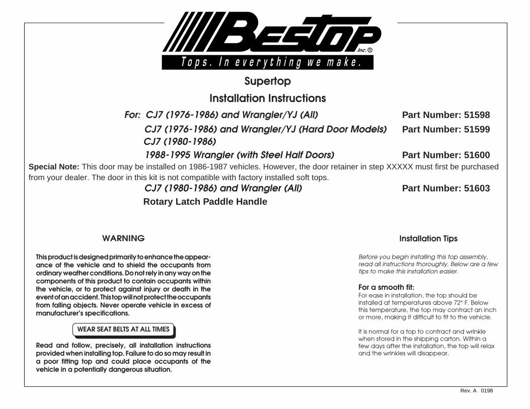
Part Number 51603 Parts List and Hardware Identification#8 x 1/2" Pan Head Washer Screw -Black, Qty - 13, Part Number 200.48
Windshield Retainer - Right,Qty - 1, Part Number 225.42
Corner Belt Rail, Right, Qty - 1,Part Number 288.33
Windshield Retainer - Left,Qty - 1, Part Number 225.43
Corner Belt Rail, Left, Qty - 1,Part Number 288.34
Tailgate Bar, Qty - 1, PartNumber 288.75
Side Belt Rail - Right, Qty - 1,Part Number 225.04
Side Belt Rail - Left, Qty - 1,Part Number 225.05
Rotary Latch Paddle Handle,Right, Qty - 1, Left, Qty - 1,Part Number 275.92
Bow Assembly - Right, Qty - 1,Part Number 246.56
Bow Assembly - Left, Qty - 1,Part Number 246.57
Windshield Bracket - Right,Qty - 1, Part Number 137.96
Windshield Bracket - Left, Qty - 1,Part Number 137.97
Top Fabric Qty - 1Quarter Window Rt. Qty - 1Quarter Window Lt. Qty - 1Rear Window Qty - 1Door, Upper - Right Qty - 1Door, Upper - Left Qty - 1Door, Lower - Right Qty - 1Door, Lower - Left Qty - 1Spacer Kit Qty - 1
#10 x 1/2" Pan Head Sheet MetalScrew, Qty - 4, Part Number 1.92
5/16-18 x 1" Phillips Head Bolt,Qty - 16, Part Number 236.20
5/16-18 Tapping Plate, Qty - 16,Part Number 200.50
#10-24 Truss Head Machine Screw -Black, Qty - 8, Part Number 195.92
#10-24 Locknut, Qty - 8,Part Number 195.93
5/16" Black Washer,Qty - 16, Part Number233.04
Vertical Retainer Mount, Left,Qty - 1, Part Number 229.25
Vertical Retainer Mount, Right,Qty - 1, Part Number 229.24

51598/599/600/603 pg 6
Rev. A 0198
Front
MeasurementDetail
Top lip ofwindshield
Tape Measure
75 1/8"
#10 x 1/2" Pan HeadSheet Metal Screws
Sun Visor Mount - #20Torx bolt
Windshield Bracket
Rear point of measure-ment on body
Warning: Improper windshieldadjustment will result in poor fittingtop and doors, causing looseness orundue strain on the top.
Please noteIf you are replacing an old soft top, be certain that allparts of the old top are removed, including thewindshield retainer. Old metal parts are not compatiblewith the new Supertop. Using parts other than thoseprovided in your Supertop kit can result in personalinjury and/or damage to the vehicle and soft top.
Windshield MeasurementBefore installing the top, check the windshield measure-ment. The distance from the top lip of the windshield tothe top outer edge of the body must be 75 1/8" on bothsides of the vehicle. Measure 4"-6" inside the doors.
CJ7 Windshield AdjustmentIf necessary, loosen the two screws in the WindshieldClamps at the base of the windshield on each sideof the vehicle. Adjust the windshield forward orback, use a shim if needed to position thewindshield, and tighten the screws.
Adjusting Screws -Some Models mayrequire a #40 Torx
WindshieldClamp Detail
Tools Needed
1/8", 5/32", 7/32", 3/8" Drill Bits Flat Screwdriverand Drill Motor Phillips ScrewdriverCenter Punch Hammer#20 Torx - Optional Pencil#40 Torx - Optional Adjustable WrenchRatchet 10' Tape Measure
Step OneCJ7: After adjusting the windshield, install the Windshield Brackets. If presentremove the outboard sun visor fasteners on both sides of the windshield frame.Place the Windshield Brackets flush with the frame on the upper corners of thewindshield. Use the bracket as a template to mark, center punch and drill two5/32" holes for each bracket. Mount each bracket to the windshield frameusing two #10 x 1/2" Pan Head Sheet Metal Screws. Reinstall sun visor brackets.
CJ7 Only - Wrangler Adjustment on next page

51598/599/600/603 pg 7
Rev. A 0198
Wrangler Adjustment Tools Needed
1/8", 7/32", 3/8" Drill Bits Flat Screwdriverand Drill Motor Phillips ScrewdriverCenter Punch HammerPencil Adjustable Wrench#40 Torx - Optional 10' Tape Measure#20 Torx Ratchet#45 Torx - Optional
75 1/8"
Rear point of measure-ment on body
Windshield
Sun Visor
Sun Visor Mount - #20Torx bolt
Remove #40 TORX Bolts
Horizontal Sport Bar
Front
MeasurementDetail
Top lip ofwindshield
Tape Measure
Warning: Improper windshieldadjustment will result in poor fittingtop and doors, causing looseness orundue strain on the top.
Warning: Reinstall the bolts that secure the Horizontal Sport Bars to the windshieldwith a torque of 17.0 ft. lbs. each. If you do not have a torque wrench these boltsshould be tested by a qualified mechanic using a torque wrench. Failure to tightenand test the torque of these bolts can result in personal injury or loss of life to the driverand occupants of the vehicle in the event of an accident.
Please NoteUnder most circumstances, the windshield of theWrangler will not require any adjustment. If yourWrangler windshield should require adjustment, thisadjustment should be performed only by an authorizedautomotive mechanic using a special "Tamper-Proof"Torx head tool.
Windshield MeasurementBefore installing the top, check the windshield measure-ment. The distance from the top lip of the windshield tothe top outer edge of the body must be 75 1/8" on bothsides of the vehicle. Measure 4"-6" inside the doors.
Step OneWrangler/YJ: Use a #20 Torx to remove the outboardsun visor fasteners on both sides of the windshieldframe. Remove the two #40 Torx head bolts thatsecure the horizontal sport bar to the windshieldframe. Slide the Windshield Brackets between thewindshield and the horizontal sport bar mounts.
Reinstall the Torx head bolts, starting each in theframe with your fingers. After the Torx head boltsare started by hand tighten with your rachet andTorx drive tool. Do not lay this tool aside until bothbolts are completely tightened. If you tightenone of these bolts and the telephone rings - LET ITRING. NEVER LAY THIS TOOL ASIDE OR INTERUPTTHIS PROCEDURE. This procedure should befollowed carefully on both sides of the vehicle.
#40 TORX Bolts
#45 TORX Bolt
WindshieldBracket
Slide WindshieldBracket betweenWindshield and theSport Bar Mount
Wrangler/YJ WindshieldAdjustment: If necessary,loosen the #40 TORXbolts in the windshieldclamps to loosen thewindshield in order to slipthe bracket under thehorizontal tube.

51598/599/600/603 pg 8
Rev. A 0198
Step TwoPosition the two piece Windshield Retainer on topof windshield frame. Use retainer pieces astemplates to mark, center punch and drill eleven1/8" holes. Install with eleven #8 x 1/2" Pan HeadScrews.
Warning: A loose Windshield Retainer mayallow the top to disengage from the wind-shield, causing damage to the top andpossible injury to the occupants of the vehicle.
Make certain that the Windshield Retainer issecurely fastened to the windshield duringinstallation and at all other times bychecking the tightness of the mountingscrews every three months.
Windshield
Windshield Retainer (2 pieces)
Use retainer pieces as guide to mark,center punch and drill 11 1/8"diameter holes. Install retainer pieceswith 11 #8 x 1/2" Phillips Head Screws.
Windshield Retainer DetailCross Section
Windshield FrameFront of Vehicle
WindshieldRetainer
#8 x 1/2" PanHead Screw
Caution: When drilling in the top edge of thevehicle body, check underneath for wiringfor the rear lights. Pull the wiring out of theway before drilling.
Body Panel
Drill 1 hole between thetwo retainer pieces.
Do not use any drill size otherthan 1/8". Failure to use thecorrect size may cause theWindshield Retainer to loosen.
Step ThreeInstall the Left and Right Side Belt Rails on eachside of the vehicle. Use the Belt Rails as templatesto mark, center punch and drill six 3/8" holesalong the top edge of the body on each side ofthe vehicle. Some vehicles may already have fourof these holes. Secure the two rear holes in therails with two 5/16" Phillips Head Bolts, two 5/16"Washers and two 5/16" Tapping Plates. Do nottighten the bolts yet.
Tapping Plate
Side Belt Rail
Inside of Vehicle
5/16" Phillips Head Bolt
5/16" WashersSide Belt Rail DetailCross Section
SportBar
Front
Tapping PlateDetail
TappingPlate
Side Belt Rail
5/16" Washer
5/16" Phillips Head Bolt
Vehicle Body
Front of Vehicle
SportBar
5/16" PhillipsHead Bolt
Side Belt Rail

51598/599/600/603 pg 9
Rev. A 0198
Rear CornerBelt Rail
Tapping Plate
Inside of Vehicle
Body Panel
5/16" Washer
Rear Corner Belt Rail DetailCross Section
Caution: When drilling in the top edge of thevehicle body, check underneath for wiringfor the rear lights. Pull the wiring out of theway before drilling.
Rear CornerBelt Rail
Note: There may be a small gap of+/- 1/4" between the Corner BeltRails and the Side Belt Rails.
Front
SportBar
SportBar
5/16" Phillips Head Bolts
5/16" PhillipsHead Bolt
Tapping PlateDetail
TappingPlate
Corner BeltRail
5/16" Washer
5/16" Phillips Head Bolt
Vehicle Body
Step FourInstall the Left and Right Rear Corner Belt Rails on each side ofthe vehicle. Notice that the Corner Belt Rails do not butt-upagainst the Side Belt Rails installed in Step 3, this is normal. Usethe Corner Belt Rails as templates to mark, center punch anddrill two 3/8" holes in the top edge of the vehicle body. Somevehicles may already have some of these holes. Install theCorner Belt Rails with two 5/16" Phillips Head Bolts, two 5/16"Washers and two 5/16" Tapping Plates. At the location of theremaining hole in the Corner Belt Rail, next to the tailgate, mark,center punch and drill a 1/8" hole. Install a #8 x 1/2" Pan HeadScrew. Do not tighten the bolts yet.
#8 x 1/2" PanHead Screw

51598/599/600/603 pg 10
Rev. A 0198
Step FiveFor CJ-5 only, see video. All other installations continue on toStep 6.
Step SixInstall the Vertical Retainer Mounts on top of the SideBelt Rails, just behind the door openings. Secure them inplace with two 5/16-18 x 1" Phillips Head Bolts, two 5/16"Washers and two 5/16" Tapping Plates. Do not tightenthe bolts yet.
Sport Bow
Side Belt Rail
Vertical RetainerMount
5/16-18 x 1" PhillipsHead Bolts
Front
Outside of Vehicle
Tapping PlateDetail
TappingPlate
Vehicle Body
Vertical RetainerMount
Side BeltRail
5/16" Washer
5/16" Phillips Head Bolt

51598/599/600/603 pg 11
Rev. A 0198
Step SevenLay the bow halves on top of the body with the holes in the BowMounts over the third and fourth holes in the Side Belt Rails.
It is important that the white packaging tape remain on the bowassemblies until the forward bolt is tightened on both sides.
Secure the FRONT hole in the Bow Mount with a 5/16-18 x 1" PhillipsHead Bolt, a 5/16" Washer and a 5/16" Tapping Plate. Once thefront hole is secure, cut the packing tape.
Start the male end of the Top (Front) Bow into the female end. Pushforward on the bow until the two sides snap together. Slide thefoam pieces on the bow together.
Once the Bow Mounts are secure, tighten all of the bolts on the BeltRails.
Leave packing tape on BowAssemblies until front holes of BowMounts are secure
Bow
Front
Side Belt Rail
Secure front holefirst - inside mount
5/16-18 x 1" PhillipsHead Bolt
5/16 Tapping Plate -under ledge
5/16 Washer
Tapping PlateDetail
TappingPlate
Bow Mount
Side BeltRail
5/16" Phillips Head Bolt
5/16" Washer
Vehicle Body
Bow Mount

51598/599/600/603 pg 12
Rev. A 0198
Step EightRelease the small metal rods from the plastic clips on both sides of the vehicle.
Lift the Top (Front) Bow and start the male end of the Bottom (Rear) Bow into the femaleend. Push forward on the bow until the two sides snap together.
Slide the Bottom (Rear) Bow up on the Top (Front) Bow to access the rear bolt position inthe Bow Mount. Install and tighten the REAR bolt in the Bow Mount on both sides of thevehicle.
Raise the Top (Front) Bow Assembly, holding the small rods in an upright position, andinsert the Vertical Rods into the hole in the Vertical Retainer Mount. Attach the HorizontalRod to the Windshield Bracket using the Bailhead Stud. The pin on the Bailhead Stud willonly turn clockwise because of the prongs on the edges of the opening in the WindshieldBracket. Slip the pin through the opening and turn the Bailhead Stud a quarter turnclockwise so that the flanges on the pin are secure between the prongs.
Bow
Front
Side Belt Rail
5/16 Washer
5/16-18 x 1" PhillipsHead Bolt
5/16 Tapping Plate -under ledge
Bow Mount
Secure rear hole
Vertical Rod
Front
Vertical RetainerMount
Outside of Vehicle
Vertical Rod
Horizontal RodWindshieldBracket
Horizontal Rod
Turn Bailhead Stud 1/4 turnclockwise to secure in place
Sport Bar
WindshieldBracket
Horizontal Rod
Turn Bailhead Stud 1/4 turnclockwise so pin catchesbetween prongs on bracket
View from underneath -looking up

51598/599/600/603 pg 13
Rev. A 0198
Plastic Strip Fabric
Windshield Driver's Side of Vehicle
Step NineLocate the top and orient it on the vehicle. Drape the top over the bows andinsert the plastic strip sewn along the front of the top into windshield retainer.Do not catch the fabric in the retainer. Center the front of the deck on thevehicle so that it is an equal distance from the top of the windshield flange onboth sides.
View from inside top
Snap to bow
Bow
Step TenSnap the flaps inside the top to thesix studs on the rear bow.
View from front
Make sure space betweentop fabric and windshieldflange is equal on both sides
Note: For best possible installation,check to make sure that the soft top isperfectly centered on the vehicle.
Windshield Retainer
Make sure that only PlasticStrip is in retainer
Note: If the snaps don’t appear to line up,push the rear bow forward to relieve thepressure on the bow. This will allow the snapsto line up more easily.

51598/599/600/603 pg 14
Rev. A 0198
Step TwelveSlide the Rear Bow up on the Front Bow and insertthe small bent tab into one of the four holes in theFront Bow.
Rear Bow
Front Bow
Note: If the top is extremely tight, slipthe tab into the bottom hole. The topwill loosen up after a few hours in thesun. Then the tab may be inserted intoa higher hole position.
Insert tab into oneof the four holes
Black PlasticStrip
Rear CornerRetainer
Fabric
Step ElevenInsert the black plastic strips at rear cornersof top into Corner Belt Rails. There is a plasticreinforcement sewn into the corner of thetop, in addition to the plastic strip.
Make sure that the reinforcement is notcaught under the Corner Belt Rail.
Plastic Reinforcement
Do not use this hole!!

51598/599/600/603 pg 15
Rev. A 0198
Step FourteenSlip the plastic strip on the bottom of the sidecurtain into the side retainer. Close the topand rear zippers on the side curtain.
Side Retainer
Fabric
Plastic Strip
Start at one end of the strip andwork along it to the other end.
Close Zippers
Step ThirteenStart top and rear zippers on sidecurtain 6 inches.
Start top andrear zippers
Zipper under flaps
View from inside vehicle -Driver's Side
Sport Bar
Hook and LoopFastener
Front Bow
VerticalRetainer
Step FifteenWrap fabric flap on the front of theside curtain around the Vertical Rod(not the front bow) and fasten thehook and loop strips to each other.
Note: If necessary, release the BowCoupler and slide the top around theCorner Belt Rail towards the windowto make it easier to start the zippers onthe Side Curtains.
Side Curtain
51598/599/600/603 pg 16
Rev. A 0198
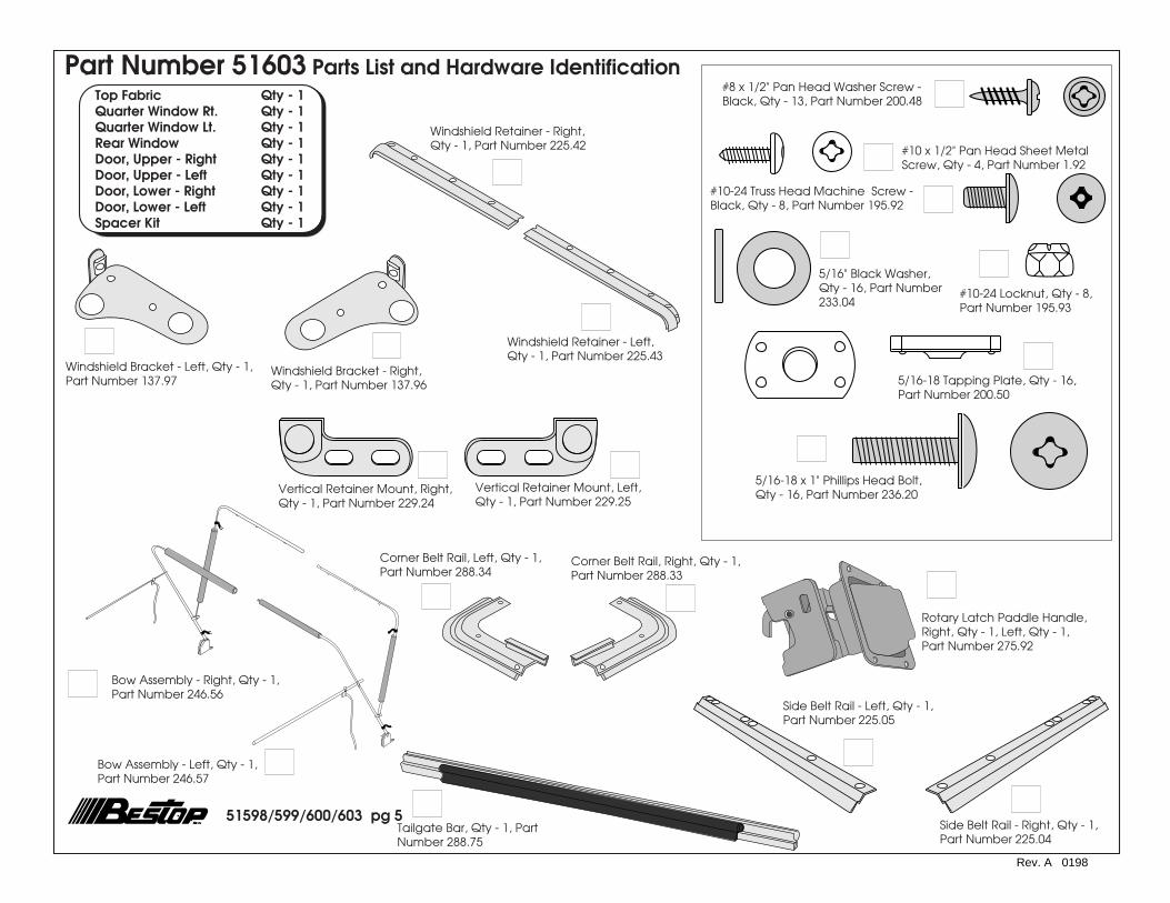
Step SixteenWrap the flap, sewn to the top above each door,around the Horizontal Rod and fasten the hook andloop strips to each other. The foam pillow with the flatsurface must be on the inside of the horizontal rod forfull, steel door use.
Windshield
Wrap Flap aroundHorizontal RetainerFront
Plastic Strip
Rear CurtainSlip Plastic Strip underCorner Retainer
Rear CornerRetainer
Tailgate must be open
Slide groove in RearCurtain Retainer onto tubeon inside of Rear Curtain.Push it into TailgateRetainer.
Rear Curtain Retainer
Rear Corner Retainer
Step SeventeenOpen the tailgate. Orient the Rear CurtainRetainer with the rubber bulb facing down, inorder to form a seal with the top of the tailgate.Slide the groove in the Rear Curtain Retaineronto the tube inside the bottom of the RearCurtain. Roll the Rear Curtain Retainer into thetop of the Corner Belt Rail. Slip the plastic on thebottom of the corners under the bottom of theCorner Belt Rail. Close the rear curtain zippers.
Tube on inside ofRear Curtain
Rear Curtain Retainer -Oriented with RubberBulb Down

51598/599/600/603 pg 17
Rev. A 0198
Note: Now that your soft top is fully installed,there are some final Metal Door adjustmentsthat may need to be made to give you thebest weather seal possible.
Step EighteenThe Vertical Retainer mount may be loosened and movedeither forward of to the rear of the vehicle to tighten theseal or to allow more clearance.
Sport Bow
Side Belt Rail
Vertical RetainerMount
5/16-18 x 1" PhillipsHead Bolts
Front
Outside of Vehicle
Warning: If any of these adjustments are made,make sure that each area has been retightened.
Each area should be rechecked within a week toassure proper fit and function.

51598/599/600/603 pg 18
Rev. A 0198
Step OneIf your vehicle has Hard Door Strikers, it will be necessaryto remove them before installing the Doors. Use a #20Torx to remove the four bolts in the door striker assembly.
View of Driver's Side DoorOpening from inside vehicle
Hard Door StrikerAssembly
#20 Torx Bolts
Sport Bar
Vertical Rod
Warning:The doors in this product are designed only for protection againstthe elements. Do not rely on the doors to contain occupants withinthe vehicle or to protect against injury during an accident. Doorhandles are only designed to aid in door closure. Door and handlewill not support a person's weight.
Part Number 51598 Door Installation
51598/599/600/603 pg 19
Rev. A 0198
Paddle HandleAssembly#10-24 Truss Head
Machine Screws and#10-24 Locknuts
Rear of Door
Paddle HandleLatch Bolt
Mounting Plate
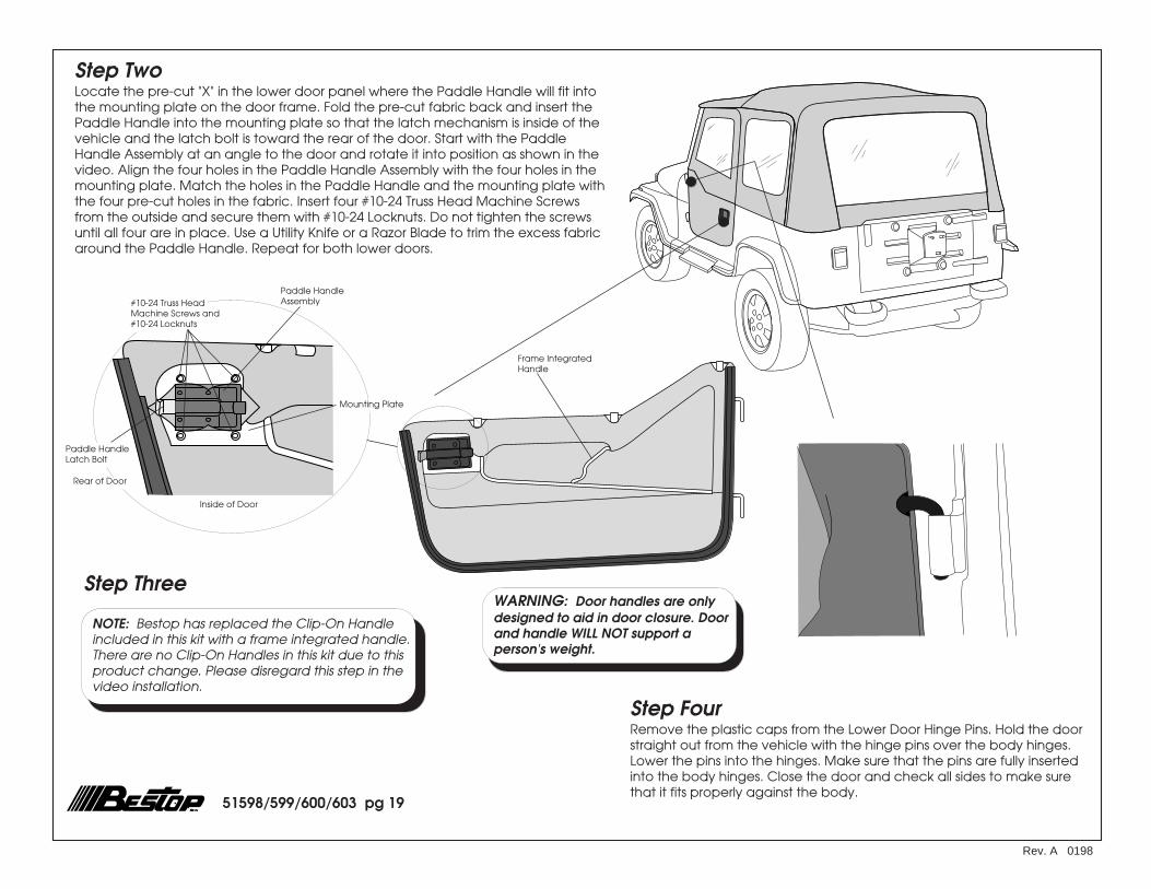
Step TwoLocate the pre-cut "X" in the lower door panel where the Paddle Handle will fit intothe mounting plate on the door frame. Fold the pre-cut fabric back and insert thePaddle Handle into the mounting plate so that the latch mechanism is inside of thevehicle and the latch bolt is toward the rear of the door. Start with the PaddleHandle Assembly at an angle to the door and rotate it into position as shown in thevideo. Align the four holes in the Paddle Handle Assembly with the four holes in themounting plate. Match the holes in the Paddle Handle and the mounting plate withthe four pre-cut holes in the fabric. Insert four #10-24 Truss Head Machine Screwsfrom the outside and secure them with #10-24 Locknuts. Do not tighten the screwsuntil all four are in place. Use a Utility Knife or a Razor Blade to trim the excess fabricaround the Paddle Handle. Repeat for both lower doors.
Inside of Door
Step Three
NOTE: Bestop has replaced the Clip-On Handleincluded in this kit with a frame integrated handle.There are no Clip-On Handles in this kit due to thisproduct change. Please disregard this step in thevideo installation.
Step FourRemove the plastic caps from the Lower Door Hinge Pins. Hold the doorstraight out from the vehicle with the hinge pins over the body hinges.Lower the pins into the hinges. Make sure that the pins are fully insertedinto the body hinges. Close the door and check all sides to make surethat it fits properly against the body.
Frame IntegratedHandle
WARNING: Door handles are onlydesigned to aid in door closure. Doorand handle WILL NOT support aperson's weight.

51598/599/600/603 pg 20
Rev. A 0198
Step FiveLocate the Lower Hinge Pin Adjustment Plate on the Lower Door frame. If the LowerDoor needs to be adjusted for a better fit against the body, use a 7/16" Wrench toloosen the two nuts in the adjustment plate. Slide the Hinge Pin backward or forwardas necessary for the best fit. Tighten the nuts.
Hinge Pin
Nuts
Hinge PinAdjustmentPlate
Detail of Door Strike
Screws
Door Strike
LocknutsStep SixClose the door against the body and place the Door Striker behind thePaddle Handle Latch with the flat surface to the inside of the vehicleand with the raised end toward the top. Mark, center punch and drilltwo 7/32" holes. Install the Door Striker with two #10-24 Truss HeadMachine Screws and two #10-24 Locknuts. The Door Striker may beadjusted in or out until you are satisfied with the way the door shuts andopens. Repeat on both sides of the vehicle.

51598/599/600/603 pg 21
Rev. A 0198
Step SevenRemove the plastic caps from the Upper Door Pins and install theupper door into the lower door. Starting with the front pin, slip thepins into the sockets in the lower door. Make sure that the pins arewell seated in the sockets. Close the door to check that it fitsproperly against the body. If necessary, use a 1/8" Allen Wrench toloosen the Collars on the front and rear upper door pins. The Collarswill slide up or down as needed to provide the best fit of the UpperDoor against the windshield and the Horizontal Rod plastic. Attachthe loop strip on the bottom of the upper door to the hook strip onthe top of the lower door. If necessary for proper door fit, bend thedoor slightly inward (see Video). Once the doors close and sealproperly, cut off the excess rubber seal at the front of the door.
AdjustmentCollarPin
Once the door fitsproperly - trimexcess rubber seal
Note: Lubricating the upper door pins with alight weight oil will make it easier to install andremove the upper door.

51598/599/600/603 pg 22Rev. A 0198
AdjustmentCollarPin
Collars
Grommets
Pins
Steel Door
Special Note: This door may be installedon 1986-1987 vehicles, however, the doorretainer in Step Nineteen must first bepurchased from your dealer.
Snap Fabric to Door
Plastic Strip
Step TwoSlip plastic strip on the bottom of thesoft door into the Door Retainer on thesteel door. Fasten the snap at front ofupper door.
Door Retainer
Fabric
Plastic Strip
Warning:The doors in this product are designed only for protection againstthe elements. Do not rely on the doors to contain occupants withinthe vehicle or to protect against injury during an accident. Doorhandles are only designed to aid in door closure. Door and handlewill not support a person's weight.
Step OneInstalling the upper door into the lower steel door, start with the front pin and slip the pins into thesockets in the lower door. Make sure that the pins are well seated in the sockets. Close the door tocheck that it fits properly against the body. If necessary, use a 1/8" Allen Wrench to loosen theCollars on the front and rear upper door pins. The Collars will slide up or down as needed to providethe best fit of the Upper Door against the windshield and the Horizontal Rod plastic.
Part Number 51600 Door Installation

Rev. A 0198
51598/599/600/603 pg 23
Paddle HandleAssembly#10-24 Truss Head
Machine Screws and#10-24 Locknuts
Rear of Door
Rotary LatchMechanism
Inside of Door
Step TwoStep ThreeRemove the plastic caps from the Lower Door Hinge Pins. Hold the doorstraight out from the vehicle with the hinge pins over the body hinges.Lower the pins into the hinges. Make sure that the pins are fully insertedinto the body hinges. Close the door and check to make sure that thedoor latches securely to the hard door striker pin.
Frame IntegratedHandle
MountingPlate
NOTE: Bestop has replaced the Clip-On Handleincluded in this kit with a frame integrated handle.There are no Clip-On Handles in this kit due to thisproduct change. Please disregard this step in thevideo installation.
Step OneDetermine the left and right Rotary Latch Paddle Handles. Locate the pre-cut "X" in the lowerdoor panel where the Paddle Handle will fit into the mounting plate on the door frame. Fold thepre-cut fabric back and insert the Paddle Handle into the mounting plate so that the latchmechanism is inside of the vehicle and the Rotary Latch Mechanism is toward the rear of thedoor. Start with the Rotary Latch Paddle Handle at an angle to the door and rotate it intoposition as shown in the video. Align the four holes in the Paddle Handle Assembly with the fourholes in the mounting plate. Match the holes in the Paddle Handle and the mounting plate withthe four pre-cut holes in the fabric. Insert four #10-24 Truss Head Machine Screws from theoutside and secure them with #10-24 Locknuts. Do not tighten the screws until all four are inplace. Use a Utility Knife or a Razor Blade to trim the excess fabric around the Paddle Handle.Repeat for both lower doors.
Part Number 51603 Door Installation
Warning:The doors in this product are designed only for protection againstthe elements. Do not rely on the doors to contain occupants withinthe vehicle or to protect against injury during an accident. Doorhandles are only designed to aid in door closure. Door and handlewill not support a person's weight.
51598/599/600/603 pg 24
Rev. A 0198
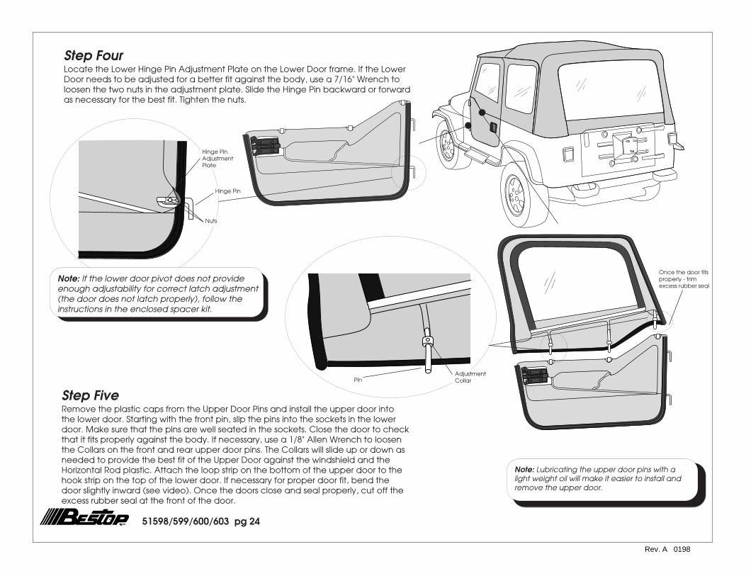
Step FourLocate the Lower Hinge Pin Adjustment Plate on the Lower Door frame. If the LowerDoor needs to be adjusted for a better fit against the body, use a 7/16" Wrench toloosen the two nuts in the adjustment plate. Slide the Hinge Pin backward or forwardas necessary for the best fit. Tighten the nuts.
Note: Lubricating the upper door pins with alight weight oil will make it easier to install andremove the upper door.
Hinge Pin
Nuts
Hinge PinAdjustmentPlate
Note: If the lower door pivot does not provideenough adjustability for correct latch adjustment(the door does not latch properly), follow theinstructions in the enclosed spacer kit.
Step FiveRemove the plastic caps from the Upper Door Pins and install the upper door intothe lower door. Starting with the front pin, slip the pins into the sockets in the lowerdoor. Make sure that the pins are well seated in the sockets. Close the door to checkthat it fits properly against the body. If necessary, use a 1/8" Allen Wrench to loosenthe Collars on the front and rear upper door pins. The Collars will slide up or down asneeded to provide the best fit of the Upper Door against the windshield and theHorizontal Rod plastic. Attach the loop strip on the bottom of the upper door to thehook strip on the top of the lower door. If necessary for proper door fit, bend thedoor slightly inward (see video). Once the doors close and seal properly, cut off theexcess rubber seal at the front of the door.
AdjustmentCollarPin
Once the door fitsproperly - trimexcess rubber seal

Rev. A 0198
51598/599/600/603 pg 25
Warning: When operating thevehicle without the Side Curtains,the Rear Curtain should be rolledup for proper ventilation.
Curtain Down
Strap
Detail of RearCurtain
Rear Window
Side View
Curtain Up
Fabric
Adjusting the Top
Side Curtains
To remove the Side Curtains. Unzip the rear and top zippers.Release the plastic strip from the retainer. Release the Hook andLoop Fasteners from around the Vertical Retainer.
Removal of Soft Top for Open Air DrivingWhen operating the vehicle with the fabric top removed, it is very importantthat the supporting hardware system be disconnected from the windshieldbracket and folded flat to the rear of the vehicle. The vertical and horizontalrods should be snapped into the plastic clips located on the inside of bothbow mount brackets. Wrap the elastic straps around the bows and insert theplastic strip into the side belt rail. Never operate the vehicle with the fabricremoved and the hardware in the fully erected position.
Folding the Top Down
Open the zippers at the rear of the Side Curtains. Pull the plastic strip on the bottom of theSide Curtains out of the Belt Rails. Leave the rear corners of the top attached to theCorner Belt Rails. Unfasten the hook and loop strips at the front of the Side Curtains,releasing the Side Curtains from the Vertical Retainer. Fold the Side Curtains up onto thetop and release the hook and loop fasteners on the flaps, above the doors. Unsnap thetop from the rear bow.
Release the locking tabs on the Bow Releases from the holes in the bow and slide the rearbow down to the Bow Mounts. Release the Horizontal Rod from the Windshield Bracket.Remove the Vertical Rod from the Vertical Retainer Mount and lay the bow assemblydown on the rear of the vehicle.
Unfasten the top from the windshield and lay it down on the body. Make sure that therear corners of the top are tucked under the rear bow. Fold the top in half from front toback and continue folding until the top is about 1 foot wide at the rear of the vehicle.Secure the top by clipping the Bow Tie Downs into the Side Belt Rails.
Rear Curtain
To roll up the Rear Curtain, remove the Rear Curtain Retainerand start at the bottom rolling it to the inside. Avoid wrinkles inthe fabric and window. Secure it in place with the curtain strapsinside of the top.
51598/599/600/603 pg 26
Rev. A 0198
Care and Maintenance of your Bestop Top
Your top is made of the finest materials available. To keep it looking new and for themaximum possible wear, it will need periodic cleaning and maintenance.
Washing: The top fabric should be washed often using soap, warm water and a softbristle brush. Rinse with clear water to remove all traces of soap.
Windows: Keep windows clean to avoid scratching. DO NOT use a brush on thewindows! Wash with a watersoaked cloth or sponge and a mild dishwashing deter-gent. NEVER WIPE THE WINDOWS WHEN THEY ARE DRY. Be careful when cleaningsnow or frost from the vinyl windows since they are easily scratched and may crack atlow temperatures. DO NOT roll the sides or rear window in cold weather. The windowsbecome stiff and will crack.
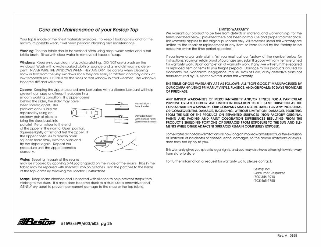
Zippers: Keeping the zipper cleaned and lubricated with a silicone lubricant will helpprevent damage and keep the zippers in asmooth working condition. If a zipper opensbehind the slider, the slider may havebeen spread apart. Thisproblem can usually berepaired by using anordinary pair of pliers tobring the sides back intoparallel. Return slider to the endof the zipper in the normal Open position.Squeeze lightly at first and test the zipper. Ifthe zipper continues to remain opensqueeze more firmly with the pliers andtry the zipper again. Repeat thisprocedure until the zipper operatescorrectly.
Water: Seeping through at the seamsmay be stopped by applying 3-M Scotchgard on the inside of the seams. Rips in thefabric may be repaired with Bondex iron on patches. Iron the patches to the Insideof the top, carefully following the Bondex instructions.
Snaps: Keep snaps cleaned and lubricated with silicone to help prevent snaps fromsticking to the studs. If a snap does become stuck to a stud, use a screwdriver andGENTLY pry apart to prevent permanent damage to the snap or the top fabric.
LIMITED WARRANTYWe warrant our product to be free from defects in material and workmanship, for theterms specified below, provided there has been normal use and proper maintenance.This warranty applies to the original purchaser only. All remedies under this warranty arelimited to the repair or replacement of any item or items found by the factory to bedefective within the time period specified.
If you have a warranty claim, first you must call our factory at the number below forinstructions. You must retain proof of purchase and submit a copy with any items returnedfor warranty work. Upon completion of warranty work, if any, we will return the repairedor replaced item or items to you freight prepaid. Damage to our products caused byaccidents, fire, vandalism, negligence, misuse, Acts of God, or by defective parts notmanufactured by us, is not covered under this warranty.
THE TERMS OF OUR WARRANTY ARE AS FOLLOWS: ALL “SOFT GOODS” MANUFACTURED BYOUR COMPANY (USING PRIMARILY VINYLS, PLASTICS, AND/OR FOAM): 90 DAYS FROM DATEOF PURCHASE.
ANY IMPLIED WARRANTIES OF MERCHANTABILITY AND/OR FITNESS FOR A PARTICULARPURPOSE CREATED HEREBY ARE LIMITED IN DURATION TO THE SAME DURATION AS THEEXPRESS WRITTEN WARRANTY. OUR COMPANY SHALL NOT BE LIABLE FOR ANY INCIDENTALOR CONSEQUENTIAL DAMAGE, INCLUDING, WITHOUT LIMITATION, DAMAGES RESULTINGFROM THE USE OF THE PRODUCT ON REPAINTED SURFACES (NON-FACTORY ORIGINALPAINT) AND FADING AND PAINT COLORATION DIFFERENCES RESULTING FROM THEPRODUCT’S SHIELDING PORTIONS OF SURFACES FROM EXPOSURE TO THE SUN AND ELE-MENTS WHILE OTHER ADJACENT SURFACES REMAIN COMPLETELY EXPOSED.
Some states do not allow limitations on how long an implied warranty lasts, or the exclusionor limitation of incidental or consequential damages, so the above limitations or exclu-sions may not apply to you.
This warranty gives you specific legal rights, and you may also have other rights which varyfrom state to state.
For further information or request for warranty work, please contact:
Bestop Inc.Consumer Response(800)346-3910(303)465-1755
Normal Slider -Jaws Parallel
Damaged Slider -Jaws Spread Apart(sometimes broken)
Related Documents