From Watching Planes in the Sky to Making Turbines More Efficient K. A. Thole, Distinguished Professor Department of Mechanical Engineering, Penn State Gas turbines are the engines that propel virtually all aircraft through the skies. Gas turbines are also the machines that generate power to meet about 40 percent of our electricity. My passion is to improve their efficiencies. For both propulsion and power generation, the efficiencies of such engines dictate how much fuel, predominantly fossil fuels, is used. Increasing the efficiencies of gas turbines lowers the amount of fuel which ultimately reduces our carbon footprint. How much? A one-percent increase in turbine efficiencies corresponds to a reduction of carbon dioxide that is equivalent to removing two million cars from the road. The geared turbofan, which is a recent technological breakthrough for gas turbines on aircraft, provides a great illustration on just how much fuel can be saved. A plane like the Boeing 747 uses about 1 gallon of fuel every second, which corresponds to 3600 gallons per hour [1]. The highly efficient geared turbofan engines, manufactured by Pratt & Whitney, have been shown to save 100 gallons of fuel per hour, which is nearly a 3% reduction of burned fuel [2]. The three main components of a gas turbine as illustrated in Figure 1 are the compressor, the combustor, and the turbine. Conventional gas turbines use the thermodynamic Brayton cycle with air as the working fluid whereby higher combustor temperatures lead to high efficiencies. The heart of my work lies in the desire to component temperatures below their melting point as combustor exit temperatures increase. For that to occur, sophisticated strategies are needed to cool the turbine parts because the temperatures of the gases in the engine are already hundreds of degrees hotter than the melting temperatures of the turbine components. For narrow-body aircraft, gas turbines achieve approximately 50% thermal efficiencies during cruise. Since 1970, improvements in turbine designs have resulted in increases in thermal efficiencies by 0.4 percent per year [3]. Two paths lead to higher thermal efficiencies: (1) advancing materials and coatings to make sure turbine components can withstand increasingly higher temperatures; and (2) reducing turbine cooling air flow to reduce the thermodynamic cycle penalty associated with re-routing the cooling flows from the compressor to the turbine components. It is advancing cooling technologies to reduce the needed Figure 1. Illustration of a gas turbine engine manufactured by Pratt & Whitney.

Welcome message from author
This document is posted to help you gain knowledge. Please leave a comment to let me know what you think about it! Share it to your friends and learn new things together.
Transcript
From Watching Planes in the Sky to Making Turbines More Efficient K. A. Thole, Distinguished Professor
Department of Mechanical Engineering, Penn State
Gas turbines are the engines that propel virtually all aircraft through the skies. Gas turbines are
also the machines that generate power to meet about 40 percent of our electricity. My passion is
to improve their efficiencies.
For both propulsion and power generation, the efficiencies of such engines dictate how
much fuel, predominantly fossil fuels, is used. Increasing the efficiencies of gas turbines lowers
the amount of fuel which ultimately reduces our carbon footprint. How much? A one-percent
increase in turbine efficiencies corresponds to a reduction of carbon dioxide that is equivalent to
removing two million cars from the road. The geared turbofan, which is a recent technological
breakthrough for gas turbines on aircraft, provides a great illustration on just how much fuel can
be saved. A plane like the Boeing 747 uses about 1 gallon of fuel every second, which
corresponds to 3600 gallons per hour [1]. The highly efficient geared turbofan engines,
manufactured by Pratt & Whitney, have been shown to save 100 gallons of fuel per hour, which
is nearly a 3% reduction of burned fuel [2].
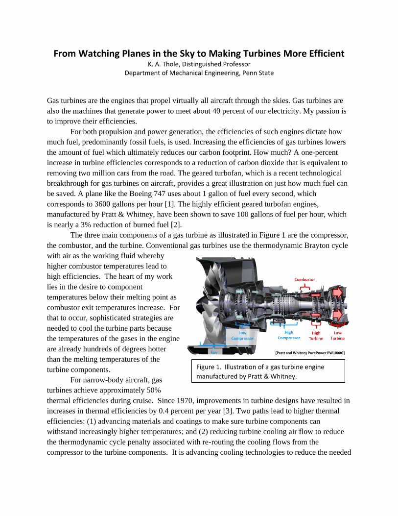
The three main components of a gas turbine as illustrated in Figure 1 are the compressor,
the combustor, and the turbine. Conventional gas turbines use the thermodynamic Brayton cycle
with air as the working fluid whereby
higher combustor temperatures lead to
high efficiencies. The heart of my work
lies in the desire to component
temperatures below their melting point as
combustor exit temperatures increase. For
that to occur, sophisticated strategies are
needed to cool the turbine parts because
the temperatures of the gases in the engine
are already hundreds of degrees hotter
than the melting temperatures of the
turbine components.
For narrow-body aircraft, gas
turbines achieve approximately 50%
thermal efficiencies during cruise. Since 1970, improvements in turbine designs have resulted in
increases in thermal efficiencies by 0.4 percent per year [3]. Two paths lead to higher thermal
efficiencies: (1) advancing materials and coatings to make sure turbine components can
withstand increasingly higher temperatures; and (2) reducing turbine cooling air flow to reduce
the thermodynamic cycle penalty associated with re-routing the cooling flows from the
compressor to the turbine components. It is advancing cooling technologies to reduce the needed
Figure 1. Illustration of a gas turbine engine
manufactured by Pratt & Whitney.
coolant flow that I have studied since starting my doctoral work at the University of Texas at
Austin.
In my area, I have achieved success. For instance, in the past 30 years, I have brought in
more $35 million of research funding from both industry and government to support our
research. That funding has supported the building many experiments, including one of the
world’s most sophisticated research turbine facility. Even more important, that funding has
supported over 75 graduate students, who have graduated and now work in the industry, federal
agencies and academia. The funding has led me to publish more than 280 articles. In fact, in the
area of turbine research reported in the Journal of Turbomachinery, I have more publications
than anyone in the world. Perhaps most important, though, that funding has allowed me and my
research team to influence the way that gas turbines are designed—both for propulsion and
power generation. Since becoming a faculty member, the research results that my group has
achieved have impacted the shape of turbine airfoils, have provided an understanding of complex
flowfield physics in turbines, and have provided correlations needed to predict turbine heat
transfer. Our work has received recognition through my laboratory being awarded a Center of
Excellence by two major gas turbine manufacturers, by winning nine best paper and presentation
awards, and by earning several professional society awards.
Like so many, my professional path to where I am now was not straight. Seemingly small
acts of support from others resulted in important turns on that path. However, my story begins
with watching airplanes in the backseat of our family’s Ford LTD with my parents and brother at
Lambert Field in St. Louis.
My Education and My Father’s Profound Influence
Growing up on a farm in a southern Illinois town of fewer than a thousand people
provided me with a closely-knit family and strong work ethic. However, the experience did not
provide me with a particularly wide vision about how I could contribute to the world. The
choices seemed to be either a farmer or a teacher. As a farmer, my father was progressive,
despite having only an eighth-grade education. His openness to change likely resulted from his
service in the army during the Korean War. Fascinated about how things worked, he drove our
family on Sunday afternoons to an airport about 50 miles away to watch the planes take off and
land. His fascination became my fascination.
I was the oldest child in a small family. Although farms are traditionally passed from
father to son, my parents expected me to work in the fields, milk the cows twice per day, and
sometimes help repair broken parts. By the time I was 10 years old, I was driving tractors, and
my summers were filled with hard work.
When it was time to go college, my parents were supportive, but they had no idea how to
advise me. It was my first year in college when I was walking to my apartment from chemistry
that a classmate told me that I should become an engineer. After that first semester, I called
McDonnell Douglas, in St. Louis, which was the closest large city to my farm, to ask whether
they had any engineers working there. After some laughter, the operator put me through to one of
their male engineers who answered my question about what an engineer’s typical day was like.
What I learned was that no day was “typical”—engineers were called upon to solve a host of
different problems. It was then that I decided to pursue engineering. However, when I told my
parents that I wanted to be an engineer, they stated matter-of-factly that I was not smart enough.
Despite their response, or perhaps because of it, I made up my mind that I would try.
Engineering was challenging, but I earned my bachelor’s in mechanical engineering at
the University of Illinois. I continued on to my master’s there and later pursued my doctorate at
the University of Texas. In doing so, I knew one thing: my research had to be aimed at
contributing to propulsion.
My master’s research at the University of Illinois was related to rockets, and I had the
opportunity to work with a world-renowned expert in base pressure flows, Professor Helmet
Korst, who was originally from Austria. Although I learned important fundamentals from him,
what I learned most from him was how to be a better person. Professor Korst showed
tremendous interest in me both as a future researcher and as a person. Sometimes this support
came by way of a trip to Baskin-Robbins in which he would build back my confidence. I had
setbacks in my research (as everyone has), but I also had detractors (which most engineers do
not). For instance, one male graduate student told me that I should not be there because I was
taking the place of a male who would need to support his family,
After completing my masters work, I accepted a job at Lawrence Livermore National
Laboratory. Two life-changing events occurred. Although the position there was very good, I
had left my research passion of propulsion. Second, and most important, I met my husband,
Michael Alley, who gave me confidence to return to a university to get a PhD. Without his
support at that time and continued support since, I would not have had the confidence to pursue
and continue an academic career. He has been my inspiration and my rock in many difficult
times.
It was during my doctoral research at the University of Texas with Professor David
Bogard that I learned to conduct thorough experiments and to explain my results starting at the
most fundamental level. Moreover, it was at the University of Texas where I learned about the
challenges related to turbine cooling from a fundamental perspective. The research I did was to
evaluate how high levels of turbulence affected heat transfer, which was critical to know for
predicting how much heat transfer a turbine blade experienced. As an example, miss-predicting
turbine blade temperatures by as much as 25F means that the blade lifespan would be reduced
by a factor of two in a turbine engine. Considering the gas flow passing through the turbine is on
the order of 3000F and the “coolant” flow temperatures passing through the blades is on the
order of 1000F, a miss-prediction of only 25F is quite small. My research found that the
turbulence levels on the order of 20% exiting the combustor increased convective heat transfer
by as much as 20%, which led to new predictive correlations for turbine heat transfer.
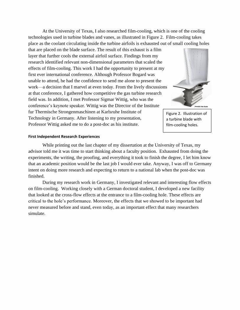
At the University of Texas, I also researched film-cooling, which is one of the cooling
technologies used in turbine blades and vanes, as illustrated in Figure 2. Film-cooling takes
place as the coolant circulating inside the turbine airfoils is exhausted out of small cooling holes
that are placed on the blade surface. The result of this exhaust is a film
layer that further cools the external airfoil surface. Findings from my
research identified relevant non-dimensional parameters that scaled the
effects of film-cooling. This work I had the opportunity to present at my
first ever international conference. Although Professor Bogard was
unable to attend, he had the confidence to send me alone to present the
work—a decision that I marvel at even today. From the lively discussions
at that conference, I gathered how competitive the gas turbine research
field was. In addition, I met Professor Sigmar Wittig, who was the
conference’s keynote speaker. Wittig was the Director of the Institute
fur Thermische Strongenmaschinen at Karlsruhe Institute of
Technology in Germany. After listening to my presentation,
Professor Wittig asked me to do a post-doc as his institute.
First Independent Research Experiences
While printing out the last chapter of my dissertation at the University of Texas, my
advisor told me it was time to start thinking about a faculty position. Exhausted from doing the
experiments, the writing, the proofing, and everything it took to finish the degree, I let him know
that an academic position would be the last job I would ever take. Anyway, I was off to Germany
intent on doing more research and expecting to return to a national lab when the post-doc was
finished.
During my research work in Germany, I investigated relevant and interesting flow effects
on film-cooling. Working closely with a German doctoral student, I developed a new facility
that looked at the cross-flow effects at the entrance to a film-cooling hole. These effects are
critical to the hole’s performance. Moreover, the effects that we showed to be important had
never measured before and stand, even today, as an important effect that many researchers
simulate.
Figure 2. Illustration of
a turbine blade with
film-cooling holes.
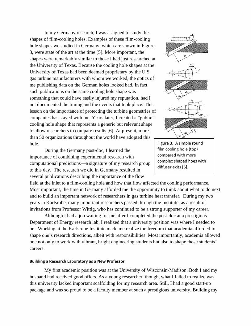
In my Germany research, I was assigned to study the
shapes of film-cooling holes. Examples of these film-cooling
hole shapes we studied in Germany, which are shown in Figure
3, were state of the art at the time [5]. More important, the
shapes were remarkably similar to those I had just researched at
the University of Texas. Because the cooling hole shapes at the
University of Texas had been deemed proprietary by the U.S.
gas turbine manufacturers with whom we worked, the optics of
me publishing data on the German holes looked bad. In fact,
such publications on the same cooling hole shape was
something that could have easily injured my reputation, had I
not documented the timing and the events that took place. This
lesson on the importance of protecting the turbine geometries of
companies has stayed with me. Years later, I created a “public”
cooling hole shape that represents a generic but relevant shape
to allow researchers to compare results [6]. At present, more
than 50 organizations throughout the world have adopted this
hole.
During the Germany post-doc, I learned the
importance of combining experimental research with
computational predictions—a signature of my research group
to this day. The research we did in Germany resulted in
several publications describing the importance of the flow
field at the inlet to a film-cooling hole and how that flow affected the cooling performance.
Most important, the time in Germany afforded me the opportunity to think about what to do next
and to build an important network of researchers in gas turbine heat transfer. During my two
years in Karlsruhe, many important researchers passed through the Institute, as a result of
invitations from Professor Wittig, who has continued to be a strong supporter of my career.
Although I had a job waiting for me after I completed the post-doc at a prestigious
Department of Energy research lab, I realized that a university position was where I needed to
be. Working at the Karlsruhe Institute made me realize the freedom that academia afforded to
shape one’s research directions, albeit with responsibilities. Most importantly, academia allowed
one not only to work with vibrant, bright engineering students but also to shape those students’
careers.
Building a Research Laboratory as a New Professor
My first academic position was at the University of Wisconsin-Madison. Both I and my
husband had received good offers. As a young researcher, though, what I failed to realize was
this university lacked important scaffolding for my research area. Still, I had a good start-up
package and was so proud to be a faculty member at such a prestigious university. Building my
Figure 3. A simple round
film cooling hole (top)
compared with more
complex shaped hoes with
diffuser exits [5].
lab from the ground up was both exciting and daunting. The experience was like placing a bet—I
placed all of my start-up funds on turbine heat transfer research. On the negative side, the field
was competitive, and I was starting with nothing. In addition, to work in the field of turbine
cooling, it was essential to collaborate with industry. Using my precious little travel money, I
attended an Advanced Gas Turbine Systems Research meeting that was sponsored by the
Department of Energy (DOE). Not only was this meeting tied to a call for research proposals but
it was also well attended by those from industry. At this meeting, one company representative
told me that academics were not really interested in working on real-world problems. A
representative from another company told me that they were not interested in my ideas. Yet a
third company simply ignored me. Later, after submitting my first proposal to the program then
learning that it was not funded, the program manager at the time told me, “You did pretty good
for a girl.”
When beginning my research program, my strongest competition naturally would be my
doctoral advisor; however, he also became my strongest supporter. In those first days, we talked
about how we might parse out the various regions of a turbine airfoil and how we would each
stay in those swim lanes. He agreed, but only until I got tenure which was more than fair. After
failing in my first six proposals, I thought that tenure would never arrive. Proposal writing is a
skill, but in the end requires some luck. Most experienced academics know this point, but that
does not soften the blows from rejection. Like most academics, I have my stories in which the
proposal reviews seemed unfair, inconsistent, or wrong.
As mentioned, I placed my bets (start-up money) on the importance of turbine heat
transfer. Building an experimental lab with the capabilities to do meaningful research takes time,
particularly given the quality of data expected by the heat transfer community. Because the time
for building experiments is slow and does not create any papers needed for tenure, I also invested
time into computations, which can produce results much more quickly. In doing so, I focused on
three-dimensional computational fluid dynamics (CFD) simulations. To lead this effort, I hired
one my former University of Texas lab mates, Dr. Atul Kohli, as a post-doc. Dr. Kohli’s role was
critical in moving our lab in an important direction; however, his influence did not end when the
post-doc ended. Afterwards, he took a position at Pratt & Whitney, where he is now a Technical
Fellow. Over the years, he has had a constant presence in guiding and supporting our research
through a journey of three universities. Dr. Kohli has been instrumental in my successes.
After the failure of my sixth proposal, my former PhD advisor, Dr. Bogard, came to the
rescue by supporting my case to be included in a CFD competition that was being conducted by
one of the major turbine manufacturers, Pratt & Whitney. This project was my first one funded at
a total of $30K. At the time, that amount seemed like a goldmine, especially since I was
considering taking out a personal loan to support my graduate students. Being part of the project
was the good news. The bad news was that my competition consisted of well-respected
researchers who focused solely on CFD development. Whereas each of them had about 30years
of experience and constructed their own codes, I had about two months of experience and was
using a commercial CFD code. My only strength was that I understood both how the problem
needed to be modeled and what results to expect.
Given the push to publish as an untenured faculty, it is common that new faculty work
their first few graduate students particularly hard, and that was an understatement for Cheryl
Martin, my first student. Cheryl was bright and, fortunately, hard-working. In the end, we were
successful in using our chosen commercial CFD code to predict within reason the experimental
data measured in another laboratory. We presented this work to the community along with the
others who in the competition performed state-of-the art CFD modelling [7]. In this study, Pratt
& Whitney did an extraordinary job in building a collaborative group—a collaboration due in
large part to one the Pratt & Whitney engineers, Fred Soechting, who also became a strong
supporter.
In my new laboratory at UW-Madison, the first experimental program, which was also
funded by Pratt & Whitney, investigated the secondary flow structures in the endwall region of a
turbine vane. As mentioned, relevant turbine geometries are difficult for a university researcher
to obtain. However, Pratt & Whitney was willing to provide us one. Having this “public” vane
geometry that was relevant to modern turbines set my research group apart. In 1996, my
research group started using this vane and
continued to do so until 2011. The amount of data
and number of studies using this vane resulted in
20 theses and dissertations as well as 70
publications.
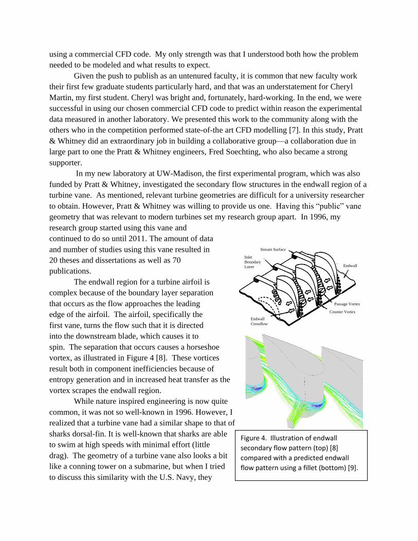
The endwall region for a turbine airfoil is
complex because of the boundary layer separation
that occurs as the flow approaches the leading
edge of the airfoil. The airfoil, specifically the
first vane, turns the flow such that it is directed
into the downstream blade, which causes it to
spin. The separation that occurs causes a horseshoe
vortex, as illustrated in Figure 4 [8]. These vortices
result both in component inefficiencies because of
entropy generation and in increased heat transfer as the
vortex scrapes the endwall region.
While nature inspired engineering is now quite
common, it was not so well-known in 1996. However, I
realized that a turbine vane had a similar shape to that of
sharks dorsal-fin. It is well-known that sharks are able
to swim at high speeds with minimal effort (little
drag). The geometry of a turbine vane also looks a bit
like a conning tower on a submarine, but when I tried
to discuss this similarity with the U.S. Navy, they
Stream Surface
Inlet
Boundary
Layer
Endwall
Crossflow
Counter Vortex
Passage Vortex
Endwall
Figure 4. Illustration of endwall
secondary flow pattern (top) [8]
compared with a predicted endwall
flow pattern using a fillet (bottom) [9].
abruptly cut off the conversation—apparently, I was treading into what was classified
information at the time. Suspecting now that I was onto something, I noticed that a big difference
between the dorsal-fin of a shark and the vane of a gas turbine engine was that the shark’s fin
had a nice filet between its body and the protruding fin. So, in hopes of developing this idea, I
began working with a bright student named Gary Zess. (Interestingly, months later after his
graduation, he became my Pratt & Whitney project monitor.) The plan was for Zess to do CFD
simulations and then ultimately test a viable concept in the wind tunnel. While we were not able
to see the complete formation of the passage vortex, we did show that we could eliminate the
leading-edge horseshoe vortex through the use of a fillet. What we developed in our laboratory is
the basis of what is being used in designing turbine airfoils today [9, 10].
The most significant result from my first funded research project, which was the CFD
study previously discussed, was not so much our findings, but our initiation into working with
Pratt & Whitney, which was an innovative turbine company, and having Fred Soechting as a
champion for my work. This relationship in 1995 was significant, because Pratt & Whitney has
since funded every single year of my career. This research support, which followed me to three
different universities, funding nearly 100 graduate and undergraduate students and allowed my
team to publish nearly 300 papers. In addition, the support led to the building of two turbine heat
transfer labs: one focused on large-scale stationary studies known as the Experimental and
Computational Convection Lab (ExCCL) and one focused on a one-scale test turbine lab known
as the Steady thermal Aero Research Turbine (START). In 2007, Pratt & Whitney raised the
level of collaboration with my laboratories to the status of becoming a Center of Excellence.
After that first $30K proposal to Pratt & Whitney was successful, I became better at
writing proposals, but equally as important, I started to build my reputation in the field. My next
ten proposals were funded, including an NSF CAREER award in 1995. In 1999, while still at
UW-Madison, I realized what I had not seen when beginning as a faculty member here—namely,
that this institution lacked important scaffolding for me to succeed as a researcher in my field.
When I took the position, it had not occurred to me as to the importance of the University’s (or,
specifically, the Department’s) commitment to my particular research area. Like many
institutions, UW-Madison has a strong reputation, which they have built by supporting particular
research strengths. Unfortunately, gas turbines was not such a focus and, along with not having
an aerospace department in the College, I was limited in campus collaborators. Moreover, few
opportunities existed for my students to learn advanced material. After suggesting that the
institution should invest more into my field, I was told that the College considered gas turbine
heat transfer to be a dead field. Rather than return to my cubby hole and accept that my research
program would always be small, I took the College’s stance as a sign that I should move to a
school in which my research area was a strength. This move came with strong support from my
industry sponsors given it was becoming increasingly difficult to negotiate an industry contract
at UW-Madison, Pratt & Whitney and my other industry sponsors supported this move. The
school I chose was Virginia Tech.
Expanding My Research at Virginia Tech
Although moving my laboratory and my students from UW-Madison to Virginia Tech
was difficult, it was a game-changer for my career. Not only did Virginia Tech have a long
history of researching gas turbines but it also had something that, up to that point, was not on my
radar: a network of successful alumni working as engineers at gas turbine companies. These
alumni, who had immense pride in having graduated from Virginia Tech, wanted to remain
connected with the institution. Many such alumni had passed through the classrooms and
research labs of the school’s faculty who were respected by the gas turbine community—
professors such as John Moore, Felix Pierce, Joseph Schetz, Wing Ng, William Davenport,
Roger Simpson, and the Department
Head who hired me, Walter O’Brien.
In starting over at a new
university, I had the opportunity to
address mistakes made when I had first
set up my laboratory. Moreover, I was
able to add to our lab’s capabilities.
Through the turbine studies that our
group previously did, we had learned the
importance of simulating an engine-
representative velocity and temperature
field upstream of the turbine vane. We
also had identified the importance of
the inlet conditions through CFD
studies conducted by Kristina
Hermanson [11]. When we had
presented these results to Pratt &
Whitney, we had hoped that they
would be willing to support our first
study at Virginia Tech. They were
willing, and that study was to build a
non-combusting simulator upstream
of our turbine vane test section in the
wind tunnel that provided a relevant
combustor-exit flowfield.
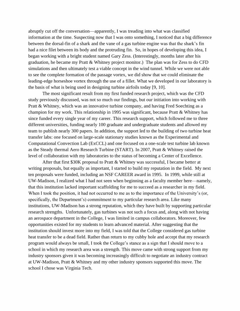
The combustor simulator,
which is illustrated in Figure 5, was
placed upstream of the corner test
section that contained three large-scale
turbine vanes [12]. The exiting flow
and thermal fields (illustrated in
Figure 5. Low speed wind tunnel with a combustor
simulator upstream of the corner test section
containing turbine vanes.
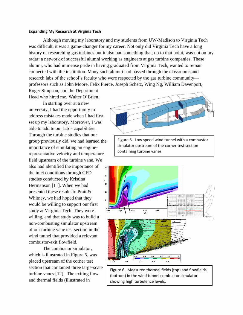
Figure 6. Measured thermal fields (top) and flowfields
(bottom) in the wind tunnel combustor simulator
showing high turbulence levels.
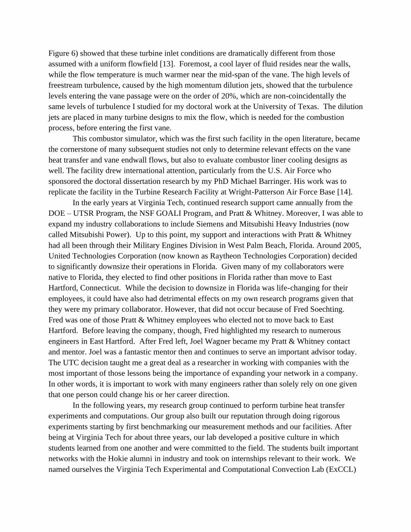
Figure 6) showed that these turbine inlet conditions are dramatically different from those
assumed with a uniform flowfield [13]. Foremost, a cool layer of fluid resides near the walls,
while the flow temperature is much warmer near the mid-span of the vane. The high levels of
freestream turbulence, caused by the high momentum dilution jets, showed that the turbulence
levels entering the vane passage were on the order of 20%, which are non-coincidentally the
same levels of turbulence I studied for my doctoral work at the University of Texas. The dilution
jets are placed in many turbine designs to mix the flow, which is needed for the combustion
process, before entering the first vane.
This combustor simulator, which was the first such facility in the open literature, became
the cornerstone of many subsequent studies not only to determine relevant effects on the vane
heat transfer and vane endwall flows, but also to evaluate combustor liner cooling designs as
well. The facility drew international attention, particularly from the U.S. Air Force who
sponsored the doctoral dissertation research by my PhD Michael Barringer. His work was to
replicate the facility in the Turbine Research Facility at Wright-Patterson Air Force Base [14].
In the early years at Virginia Tech, continued research support came annually from the
DOE – UTSR Program, the NSF GOALI Program, and Pratt & Whitney. Moreover, I was able to
expand my industry collaborations to include Siemens and Mitsubishi Heavy Industries (now
called Mitsubishi Power). Up to this point, my support and interactions with Pratt & Whitney
had all been through their Military Engines Division in West Palm Beach, Florida. Around 2005,
United Technologies Corporation (now known as Raytheon Technologies Corporation) decided
to significantly downsize their operations in Florida. Given many of my collaborators were
native to Florida, they elected to find other positions in Florida rather than move to East
Hartford, Connecticut. While the decision to downsize in Florida was life-changing for their
employees, it could have also had detrimental effects on my own research programs given that
they were my primary collaborator. However, that did not occur because of Fred Soechting.
Fred was one of those Pratt & Whitney employees who elected not to move back to East
Hartford. Before leaving the company, though, Fred highlighted my research to numerous
engineers in East Hartford. After Fred left, Joel Wagner became my Pratt & Whitney contact
and mentor. Joel was a fantastic mentor then and continues to serve an important advisor today.
The UTC decision taught me a great deal as a researcher in working with companies with the
most important of those lessons being the importance of expanding your network in a company.
In other words, it is important to work with many engineers rather than solely rely on one given
that one person could change his or her career direction.
In the following years, my research group continued to perform turbine heat transfer
experiments and computations. Our group also built our reputation through doing rigorous
experiments starting by first benchmarking our measurement methods and our facilities. After
being at Virginia Tech for about three years, our lab developed a positive culture in which
students learned from one another and were committed to the field. The students built important
networks with the Hokie alumni in industry and took on internships relevant to their work. We
named ourselves the Virginia Tech Experimental and Computational Convection Lab (ExCCL)
and that branding still remains, albeit now with Penn State’s
name. The lab identity and branding not only became known
to those working in turbine heat transfer but also became
important to building the pride of my students.
Our work continued in the endwall region to
improve the endall cooling and also in our simulations of
film-cooling as shown in Figure 7. Rather than being on a
flat plate, as I had worked on during my doctoral and post-
doctoral studies, our work was on curved surfaces relevant
to a turbine vane. The CFD simulation of a fully cooled
vane is shown on the right. We achieved thermal imaging
methods and computational methods that provided us the
opportunity to evaluate cooling hole placement and hole
shape studies. The work of my PhD student Will Colban
resulted in evaluating a wide range of publicly available
film-cooling studies with a range of hole shapes that
eventually led to a correlation that is used now as a first-
level design tool [16]. Years later, my group saw this correlation firsthand when we began
designing the cooling design for Penn State’s National Experimental Turbine (NExT).
While growing my research at Virginia Tech, I was also able to see the importance of
academic administration. After being courted by the Department of Mechanical Engineering at
Penn State, I applied for the position as Department Head and was selected. Much to the dismay
of Pratt & Whitney, I accepted the position and consented to abandon my research program and
become a full-time administrator. After announcing that decision and then not being able to
sleep for several nights, I called my new boss, Dean David Wormley to request whether I could
continue my research. Although giving up one’s research was the norm for Department Heads at
Penn State at that time, Dean Wormley saw the value of me continuing my research and
supported my request. For the five years that I worked with him, Dean Wormley was an
incredible supporter whom I am grateful to and still admire. While the choice to leave Virginia
Tech was difficult, I could not pass on both having a prestigious Department Head position and
continuing research at another school also with a strong history in gas turbine research.
Taking on Risk: Moving My Research to Penn State
For the move from Virginia Tech to Penn State at the end of 2006, my research team
packed up the big blue wind tunnel and all the equipment that went with it. Our caravan
consisted of two 50-foot transport trucks plus and a smaller truck moving everything in the lab
from Virginia Tech to Penn State. Fortunately, most of my graduate students decided to move as
well. Several outstanding students from our lab had just completed their master degrees and
were just starting their doctoral work: Seth Lawson, Michael Lawson (not related to Seth), Alan
Thrift, Steve Lynch, and Jason Ostanek. Also coming was the key individual who has been with
Figure 7. CFD predictions of a
cooled first vane showing the film-
cooling effectiveness levels [16].
my group since January 1999, which is the day I moved to
Virginia Tech and is still a leader in my group today:
Associate Research Professor Michael Barringer. While I
learned how to be a Department Head, Dr. Barringer was
instrumental in setting up the lab, now called Penn State
ExCCL, and in assisting with the students’ research.
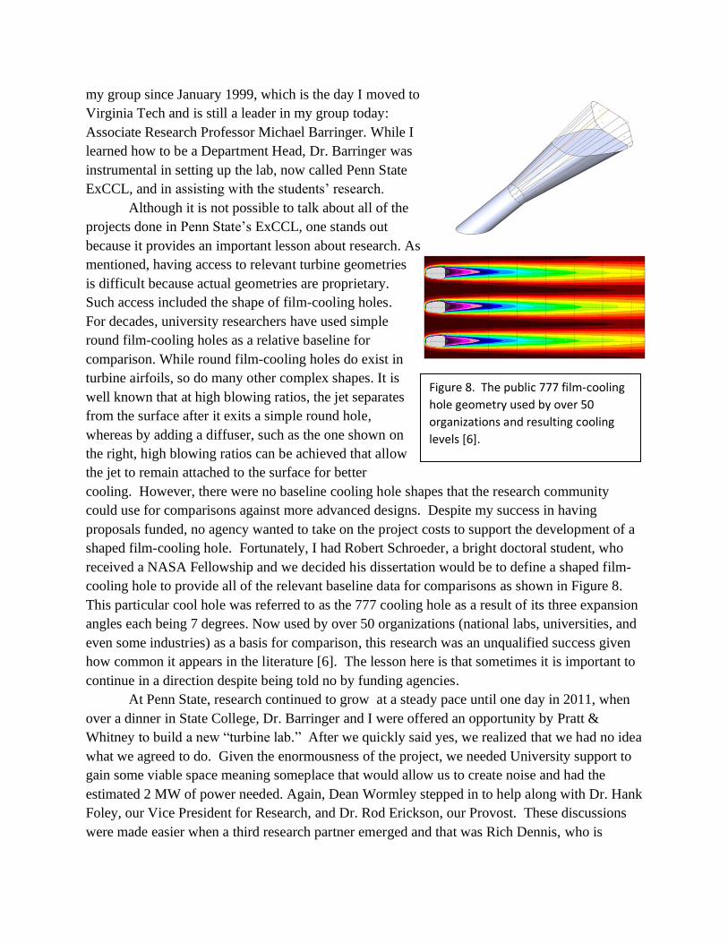
Although it is not possible to talk about all of the
projects done in Penn State’s ExCCL, one stands out
because it provides an important lesson about research. As
mentioned, having access to relevant turbine geometries
is difficult because actual geometries are proprietary.
Such access included the shape of film-cooling holes.
For decades, university researchers have used simple
round film-cooling holes as a relative baseline for
comparison. While round film-cooling holes do exist in
turbine airfoils, so do many other complex shapes. It is
well known that at high blowing ratios, the jet separates
from the surface after it exits a simple round hole,
whereas by adding a diffuser, such as the one shown on
the right, high blowing ratios can be achieved that allow
the jet to remain attached to the surface for better
cooling. However, there were no baseline cooling hole shapes that the research community
could use for comparisons against more advanced designs. Despite my success in having
proposals funded, no agency wanted to take on the project costs to support the development of a
shaped film-cooling hole. Fortunately, I had Robert Schroeder, a bright doctoral student, who
received a NASA Fellowship and we decided his dissertation would be to define a shaped film-
cooling hole to provide all of the relevant baseline data for comparisons as shown in Figure 8.
This particular cool hole was referred to as the 777 cooling hole as a result of its three expansion
angles each being 7 degrees. Now used by over 50 organizations (national labs, universities, and
even some industries) as a basis for comparison, this research was an unqualified success given
how common it appears in the literature [6]. The lesson here is that sometimes it is important to
continue in a direction despite being told no by funding agencies.
At Penn State, research continued to grow at a steady pace until one day in 2011, when
over a dinner in State College, Dr. Barringer and I were offered an opportunity by Pratt &
Whitney to build a new “turbine lab.” After we quickly said yes, we realized that we had no idea
what we agreed to do. Given the enormousness of the project, we needed University support to
gain some viable space meaning someplace that would allow us to create noise and had the
estimated 2 MW of power needed. Again, Dean Wormley stepped in to help along with Dr. Hank
Foley, our Vice President for Research, and Dr. Rod Erickson, our Provost. These discussions
were made easier when a third research partner emerged and that was Rich Dennis, who is
Figure 8. The public 777 film-cooling
hole geometry used by over 50
organizations and resulting cooling
levels [6].
Advanced Turbine Program Director at the Department of Energy-National Energy Technology
Lab. The three-way partnership among Penn State, Department of Energy, and Pratt & Whitney
was critical at the beginning of this project and continues to be important.
After realizing the enormousness of what we agreed to build, I had to relinquish ExCCL
to someone else if I wanted both laboratories to be successes. Dr. Barringer took on the lead in
building the new “turbine lab,” while our Department was supportive in hiring one of my former
Virginia Tech doctoral students, Dr. Steve Lynch, to lead ExCCL. Diving the laboratories in this
way was the logical choice since it would have been too risky to have Dr, Lynch (who needed to
secure tenure) involved in building the new lab. Although leaving ExCCL was harder than I had
anticipated, it was the right thing to do, and I knew that Dr. Lynch, who has since become a
tenured Associate Professor in Mechanical Engineering at Penn State, would make sure ExCCL
remained successful in addressing important fundamental turbine heat transfer studies.
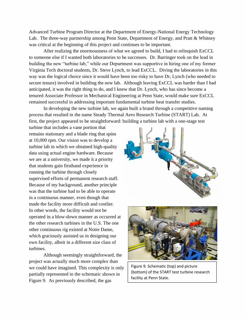
In developing the new turbine lab, we again built a brand through a competitive naming
process that resulted in the name Steady Thermal Aero Research Turbine (START) Lab. At
first, the project appeared to be straightforward: building a turbine lab with a one-stage test
turbine that includes a vane portion that
remains stationary and a blade ring that spins
at 10,000 rpm. Our vision was to develop a
turbine lab in which we obtained high-quality
data using actual engine hardware. Because
we are at a university, we made it a priority
that students gain firsthand experience in
running the turbine through closely
supervised efforts of permanent research staff.
Because of my background, another principle
was that the turbine had to be able to operate
in a continuous manner, even though that
made the facility more difficult and costlier.
In other words, the facility would not be
operated in a blow-down manner as occurred at
the other research turbines in the U.S. The one
other continuous rig existed at Notre Dame,
which graciously assisted us in designing our
own facility, albeit in a different size class of
turbines.
Although seemingly straightforward, the
project was actually much more complex than
we could have imagined. This complexity is only
partially represented in the schematic shown in
Figure 9. As previously described, the gas
Figure 9. Schematic (top) and picture
(bottom) of the START test turbine research
facility at Penn State.
turbine engine consists of three parts: a compressor, a combustor, and a turbine section. In our
facility, serving as the compressor portion were two industrial compressors that produce 25
lbm/sec of air. Serving as the combustor portion was a natural gas combustor that heats up the
mainstream flow. Next comes the turbine portion, which includes a vane and a spinning blade.
So many auxiliary units are also needed including a heat exchanger to cool the coolant injected
into the turbine components; a magnetic bearing that controls the position of the turbine shaft;
and a dynamometer to dissipate the turbine power. The positioning capability of the shaft is
extremely important because the spinning ring of turbine blades has razor thin clearances with
the outer casing. In addition to these auxiliary units, numerous secondary systems were needed
such as motor starters for the compressors, an air and oil cooling system for the compressors, and
two deep wells associated with the dynamometer. The complexity of the instrumentation
associated with the test turbine also required sophisticated wiring and electronics.
Aside from the components and instruments, we needed a highly talented permanent
research staff to maintain the systems, build testing and sensors, manage the various projects,
and, most of all, operate in a safe manner. To give you a sense of the safety challenges, if a
turbine blade, which is about half the size of a clenched fist, were to break off while spinning at
10,000 rpm, it could fly more than a mile (unless it were to strike something or someone). In
addition to Dr. Barringer, the research staff members in START included Assistant Research
Professor Reid Berdanier who has led the instrumentation development, Mr. Jeremiah Bunch
who has maintained the equipment and ensures safe operations, and Mr. Scott Fishbone who has
been our Project Manager working to make sure we meet our budgets and timeline constraints.
After four years of construction and initial testing and much support and guidance from
Pratt & Whitney, we achieved an operational test turbine [17, 18]. Resulting from this effort, the
START Lab is the only lab in the U.S. with a state-of-the-art turbine that both contains actual
engine hardware and operates in a continuous mode. START has four primary goals: (1) advance
novel turbine cooling technologies; (2) validate sensors in rotating environments; and (3)
develop additive manufacturing for turbine cooling and (4) use the benefits of additive
manufacturing for sensor integration.
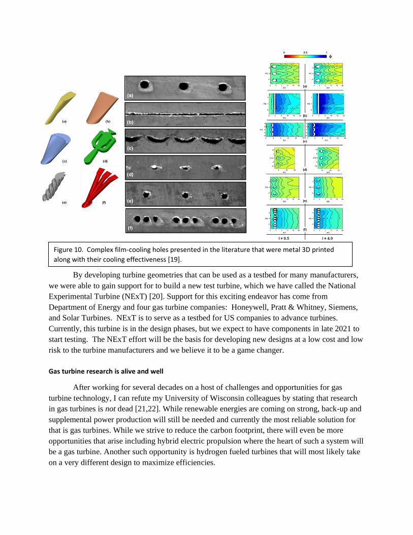
The additive manufacturing research of our lab has focused on constructing complex
cooling designs. We have become world leaders in these efforts by using direct laser metal
sintering (DMLS) to 3D print parts. Our work has revealed an expansive design space, reduced
cost and time to make a part, and shown the importance of the many manufacturing processes on
the part quality. Although much of this research has been at lower levels of technology readiness,
the research directly feeds into how we make components for the test turbine. An illustration of
how the design space has opened is shown in Figure 10, which depicts a wide variety of shaped
film cooling holes [19]. The complex hole shapes that can be achieved through additive
manufacturing are much more sophisticated than the simple, expanded cooling hole shapes that I
initially studied in Germany during my post-doctoral research.
By developing turbine geometries that can be used as a testbed for many manufacturers,
we were able to gain support for to build a new test turbine, which we have called the National
Experimental Turbine (NExT) [20]. Support for this exciting endeavor has come from
Department of Energy and four gas turbine companies: Honeywell, Pratt & Whitney, Siemens,
and Solar Turbines. NExT is to serve as a testbed for US companies to advance turbines.
Currently, this turbine is in the design phases, but we expect to have components in late 2021 to
start testing. The NExT effort will be the basis for developing new designs at a low cost and low
risk to the turbine manufacturers and we believe it to be a game changer.
Gas turbine research is alive and well
After working for several decades on a host of challenges and opportunities for gas
turbine technology, I can refute my University of Wisconsin colleagues by stating that research
in gas turbines is not dead [21,22]. While renewable energies are coming on strong, back-up and
supplemental power production will still be needed and currently the most reliable solution for
that is gas turbines. While we strive to reduce the carbon footprint, there will even be more
opportunities that arise including hybrid electric propulsion where the heart of such a system will
be a gas turbine. Another such opportunity is hydrogen fueled turbines that will most likely take
on a very different design to maximize efficiencies.
Figure 10. Complex film-cooling holes presented in the literature that were metal 3D printed
along with their cooling effectiveness [19].
Development of new gas turbine concepts is slow relative to fields such as micro-
processors, for example. The high degree of accuracy in gas turbines arises because of safety for
both power production (imagine a power plant going out during a cold front) and for propulsion
(if the engines failed, our planes would fall). The ability to cast single crystal turbine blades for
development engines adds to the difficulty in which advances can be made. This level of
difficulty is also why research in gas turbines is not dead. Advanced manufacturing methods and
new high temperature materials such as ceramic matrix composites will lead to more efficient
engines. In addition, new tools for gas turbine research included sensors integrated into the
turbine blades and machine learning for controls and maintenance.
I continue to be excited to do research in my chosen field and am very grateful to the
many students and many supporters I have had along the way. Without my supporters, including
my father who told me that engineering was difficult, my research successes in gas turbines
would not have been possible.
References
[1]https://science.howstuffworks.com/transport/flight/modern/question192.htm#:~:text=A%20pl
ane%20like%20a%20Boeing,(12%20liters%20per%20kilometer)
[2] https://www.forbes.com/sites/lorenthompson/2020/12/02/pratt--whitneys-geared-turbofan-is-
poised-to-emerge-from-the-pandemic-in-great-shape/?sh=56ca1bb41655
[3] National Academies of Sciences, Engineering, and Medicine, 2016, Commercial Aircraft
Propulsion and Energy Systems Research: Reducing Global Carbon Emissions, The
National Academies Press, Washington, D.C.
[4] Thole, K. A., and Bogard, D. G., 1995, “Enhanced Heat Transfer and Skin Friction due to
High Freestream Turbulence,” Journal of Turbomachinery, vol. 117, no. 3, pp. 418-424.
[5] Thole, K. A., Gritsch, M., Schulz, A., Wittig, S., 1997, “Effects of a Crossflow at the
Entrance to a Film-Cooling Hole,” Journal of Fluids Engineering, vol. 119, no. 3, pp. 533-
540.
[6] Schroeder, R. P., and Thole, K. A., “Adiabatic Effectiveness Measurements for a Baseline
Shaped Film Cooling Hole,” International Gas Turbine and Aeroengine Congress and
Exposition, Dusseldorf, Germany, GT2014-25992.
[7] Martin, C., and Thole, K. A., 1997, "A CFD Benchmark Study: Leading Edge Film Cooling
with Compound Angle Injection," presented to The International Gas Turbine and
Aeroengine Congress and Exposition, Orlando, Florida, 97-GT-297.
[8] Langston, L. S., Nice, M. L., and Hooper, R. M., 1977, “Three-Dimensional Flow Within a
Turbine Cascade Passage,” ASME Journal of Engineering for Power, vol. 99, pp 21-28.
[9] Zess, G. A. and Thole, K. A., 2002, “Computational Design and Experimental Evaluation of
Using a Leading Edge Fillet on a Gas Turbine Vane,” Journal of Turbomachinery, vol.
124, no. 2, pp. 167-175.
[10] Apparatus and Method for Inhibiting Radial Transfer of Core Gas Flow within a Core Gas
Flow Path of a Gas Turbine Engine, US Patent 6,419,446
[11] Hermanson, K. and Thole, K. A., 2002, “Effect on Non-Uniform Inlet Conditions on
Endwall Secondary Flows,” Journal of Turbomachinery, vol. 124, pp. 623-631.
[12] Barringer, M. D., Richard, O. T., Walter, J. P., Stitzel, S. M., and Thole, K. A., 2002, “Flow
Field Simulations of a Gas Turbine Combustor,” Journal of Turbomachinery, vol. 124, pp.
508-516.
[13] Vakil, S. and Thole, K. A., 2005, “Flow and Thermal Field Measurements in a Combustor
Simulator Relevant to a Gas Turbine Aero-Engine,” Journal of Engineering for Gas
Turbines and Power, vol. 127, pp. 257-26730.
[14] Barringer, M. D., Thole, K. A., and Polanka, M. D., 2007, “Experimental Evaluation of an
Inlet Profile Generator for High-Pressure Turbine Tests,” Journal of Turbomachinery, vol.
129, pp. 382-393.
[15] Colban, W., Thole, K. A., and Haendler, M., 2007, “Experimental and Computational
Comparisons of Fan-Shaped Film-Cooling on a Turbine Vane Surface,” Journal of
Turbomachinery, vol. 129, pp. 23-31.
[16] Colban, W., Thole, K. A., Bogard, D., 2011, “A Film Cooling Correlation for Shaped Holes
on a Flat-Plate Surface,” Journal of Turbomachinery, vol. 133, pp. 011002.
[17] Barringer, M. D., Coward, A. C, Clark, K., Thole, K. A., Schmitz, J., Wagner, J., Alvin, M.
A., Burke, P., Dennis, R., “Development of a Steady Aero Thermal Research Turbine
(START) for Studying Secondary Flow Leakages and Airfoil Heat Transfer,” International
Gas Turbine and Aeroengine Congress and Exposition, Dusseldorf, Germany, GT2014-
25570.
[18] Berdanier, R. A., Monge-Concepcion, I., Knisely, B. F., Barringer, M., Thole, K. A.,
Grover, E., 2019, “Scaling Sealing Effectiveness in a Stator-Rotor Cavity for Differing
Blade Spans,” Journal of Turbomachinery, Vol. 141 (5), pp. 051007.
[19] Snyder, J. C. and Thole, K. A., 2020, “Performance of Public Film Cooling Geometries
Produced through Additive Manufacturing” Journal of Turbomachinery, vol. 142(5), pp.
051009.
[20] Karen A. Thole, Michael D. Barringer, Reid A. Berdanier, Scott Fishbone, and Joel H.
Wagner, Richard Dennis, James Black, Patcharin Burke, and Doug Straub, Frank O’Neill,
Curtis, K. Stimpson, Ardeshir Riahi, Andrew Aggarwalla, Sean Bradshaw, Atul Kohli,
Dominic Mongillo, Thomas Praisner, Jose Rodriguez, Michael Fox, and Yong Kim,
2021,Defining a Testbed for the U.S. Turbine Industry: The National Experimental
Turbine (NExT), under review.
[21] Commercial Aircraft Propulsion and Energy Systems Research: Reducing the Global
Carbon Emissions, National Academies of Sciences, Engineering, Medicine, committee
member, https://sites.nationalacademies.org/DEPS/ASEB/DEPS_161178
[22] Advanced Technologies for Gas Turbines, National Academies of Sciences, Engineering,
Medicine, committee co-chair,
https://sites.nationalacademies.org/DEPS/ASEB/DEPS_190328
Related Documents