33.3 Friction optimization on hydraulic piston rod seals Thomas Papatheodorou Parker Hannifin GmbH Prädifa Packing-Division Arnold-Jäger-Str. 1, D-74321 Bietigheim-Bissingen Walter Igers Parker Hannifin GmbH Prädifa Packing-Division Arnold-Jäger-Str. 1, D-74321 Bietigheim-Bissingen ABSTRACT Everywhere, where high forces have to be transmitted and linear movements have to be performed, the use of hydraulic cylinders is a common praxis. In this case the so called “characteristics of convenience” are getting more and more important for the operators of modern hydraulic systems. In first line the friction performance of rod and piston seals has to be stated. High friction forces will cause a higher use of energy connected with a worse degree of efficiency. High friction can create also a higher wear on the used seals and this will result into a significant reduction in life time of the hydraulic system. INTRODUCTION Friction and wear of rod seals and rod sealing systems have a significant influence on efficiency and life time of a hydraulic cylinder or hydraulic system. As long as sufficiently high hydraulic power of the pump is available, the influence of seal friction will be of minor importance regarding the effectiveness of the hydraulic system. In this case, the primary task of the seals and scrapers installed in a hydraulic cylinder is to prevent leakage and the prevention of intrusion of dirt into the hydraulic cylinder system. In many applications, though, this type of functional performance is no longer sufficient. Particularly with regard to positioning accuracy in cylinder applications or defined control behavior with small hysteresis, the friction behavior of a hydraulic rod seal can be of crucial importance. In this case, not only the absolute friction level is of interest but also the sealing behavior in terms of stick-slip, with the total friction band width depending on such conditions as pressure, velocity, temperature and mating rod surface. A too high sticking friction and also a too high sliding friction will have a negative impact on the wear behavior of the used seals within a hydraulic cylinder and can result into stick-slip effects or into undesirable too high break-off friction after longer still stand periods, for example over a longer weekend. This effect is also known as so called “Monday morning effect”. Inappropriate friction characteristics are furthermore the reason for seal noises, like squeaking and groans, which will result into a formidable noise exposure for the environment. Due to this reason nearly all seal suppliers were more and more involved into new product developments to full-fill the requirements of the producers of hydraulic cylinders and their end customers in development of friction optimized sealing solutions. The focus of the product developments is mainly addressed to the development of new piston rod seal designs, where critical lubrication boundary conditions can occur and where high requirements regarding leakage free applications exist. BASICS Depending on the areal dimensions different tribological effects can be distinguished. These parameters are as follows: Surface effects Tribomutations Material effects Fluid effects and Construction All these parameters as shown in the illustration below have a significant influence on the behavior of the sealing partners from the “nm” to the “mm” scale range and are important in terms of friction, wear and abrasion on the mating contact partners. Figure 1 shows the major influences – surface and lubrication - on the tribological system seal. The “nm” scale at the upper end of the pyramid shows the atomic boundary of the seal body as it will be characterized by effects of the surface physics. The next level shows the effects of tribomutation in the scale of “nm” to “μm”. Here the changes on the seal surface in the contact area can be considered, which occur during the use of the seal by the generated friction forces and therefore the temperature generation between seal surface and piston rod surface. In the last level at the 833

Friction_Optimization_on_Hydraulic_Piston_Rod_Seals.pdf
Apr 08, 2016
Welcome message from author
This document is posted to help you gain knowledge. Please leave a comment to let me know what you think about it! Share it to your friends and learn new things together.
Transcript
33.3
Friction optimization on hydraulic piston rod seals
Thomas Papatheodorou Parker Hannifin GmbH Prädifa Packing-Division
Arnold-Jäger-Str. 1, D-74321 Bietigheim-Bissingen
Walter Igers Parker Hannifin GmbH Prädifa Packing-Division
Arnold-Jäger-Str. 1, D-74321 Bietigheim-Bissingen
ABSTRACT
Everywhere, where high forces have to be transmitted and linear movements have to be performed, the use of hydraulic cylinders is a common praxis. In this case the so called “characteristics of convenience” are getting more and more important for the operators of modern hydraulic systems. In first line the friction performance of rod and piston seals has to be stated. High friction forces will cause a higher use of energy connected with a worse degree of efficiency. High friction can create also a higher wear on the used seals and this will result into a significant reduction in life time of the hydraulic system.
INTRODUCTION
Friction and wear of rod seals and rod sealing systems have a significant influence on efficiency and life time of a hydraulic cylinder or hydraulic system. As long as sufficiently high hydraulic power of the pump is available, the influence of seal friction will be of minor importance regarding the effectiveness of the hydraulic system. In this case, the primary task of the seals and scrapers installed in a hydraulic cylinder is to prevent leakage and the prevention of intrusion of dirt into the hydraulic cylinder system.
In many applications, though, this type of functional performance is no longer sufficient. Particularly with regard to positioning accuracy in cylinder applications or defined control behavior with small hysteresis, the friction behavior of a hydraulic rod seal can be of crucial importance. In this case, not only the absolute friction level is of interest but also the sealing behavior in terms of stick-slip, with the total friction band width depending on such conditions as pressure, velocity, temperature and mating rod surface. A too high sticking friction and also a too high sliding friction will have a negative impact on the wear behavior of the used seals within a hydraulic cylinder and can result into stick-slip effects or into undesirable too high break-off friction after longer still stand periods, for example over a longer weekend. This effect is also known as so called “Monday morning effect”. Inappropriate friction characteristics are
furthermore the reason for seal noises, like squeaking and groans, which will result into a formidable noise exposure for the environment.
Due to this reason nearly all seal suppliers were more and more involved into new product developments to full-fill the requirements of the producers of hydraulic cylinders and their end customers in development of friction optimized sealing solutions. The focus of the product developments is mainly addressed to the development of new piston rod seal designs, where critical lubrication boundary conditions can occur and where high requirements regarding leakage free applications exist.
BASICS
Depending on the areal dimensions different tribological effects can be distinguished. These parameters are as follows:
Surface effects Tribomutations Material effects Fluid effects and Construction All these parameters as shown in the illustration below have a significant influence on the behavior of the sealing partners from the “nm” to the “mm” scale range and are important in terms of friction, wear and abrasion on the mating contact partners. Figure 1 shows the major influences – surface and lubrication - on the tribological system seal.
The “nm” scale at the upper end of the pyramid shows the atomic boundary of the seal body as it will be characterized by effects of the surface physics. The next level shows the effects of tribomutation in the scale of “nm” to “µm”. Here the changes on the seal surface in the contact area can be considered, which occur during the use of the seal by the generated friction forces and therefore the temperature generation between seal surface and piston rod surface. In the last level at the
833
ground of the pyramid the friction behavior of the sealing material will be defined depending on the composition of the rubber compound and the processing of the material, the structural design of the seal with the values pressure activation, pre-stress and tolerances. Parallel the lubrication characteristics of the used fluid are of importance at this level of pyramid.
The significance of the rod surface treatment is shown in the centre part of the pyramid. The rod surface can be described by surface texture parameters, like mean roughness, roughness depth and material ratio.
Figure 1 Pyramid of influences on the sealing systems with seal design – lubrication and counter surface
CONCEPTS / STATE OF THE ART TECHNICS
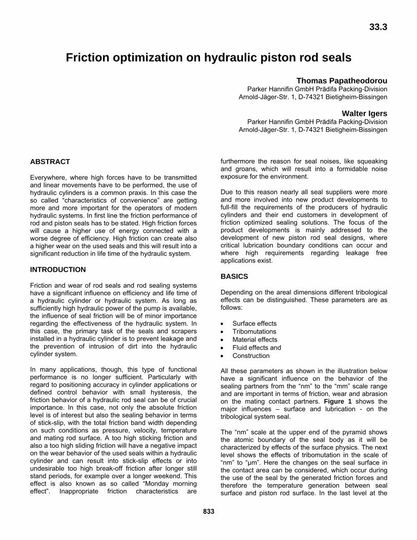
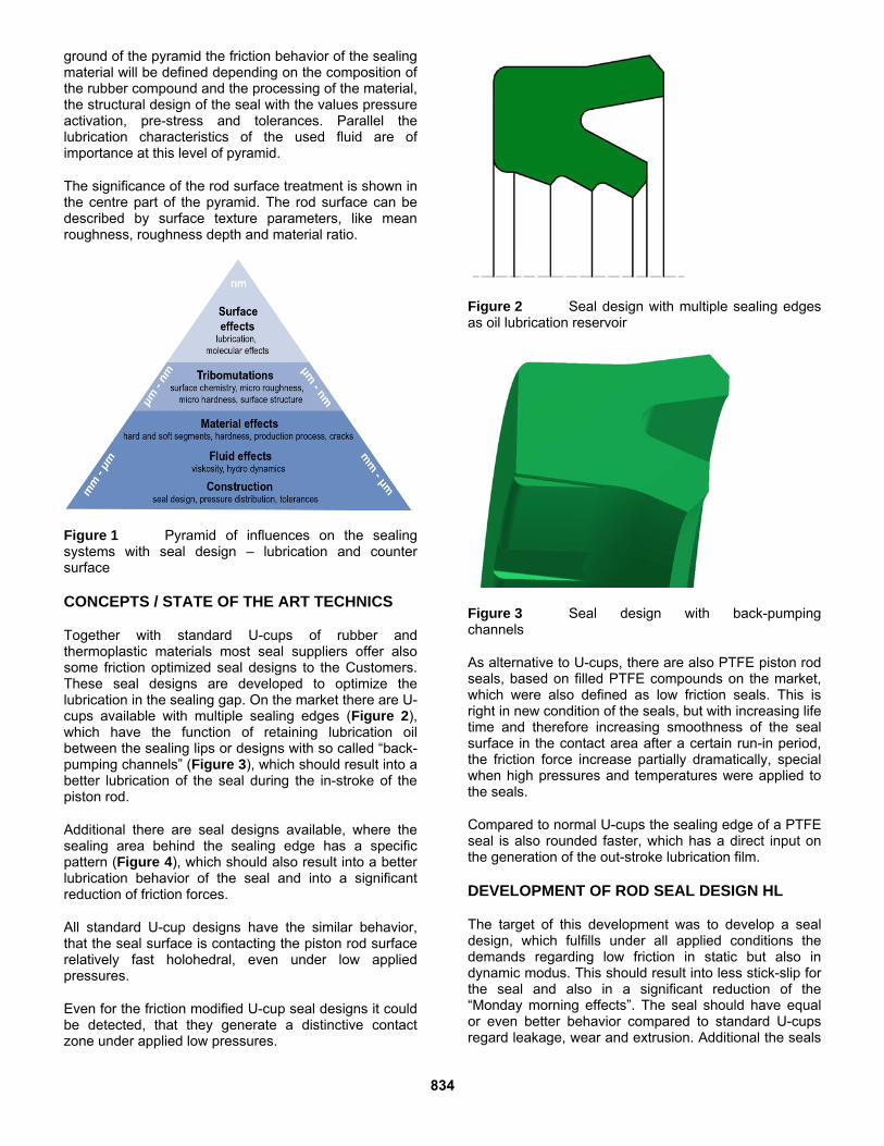
Together with standard U-cups of rubber and thermoplastic materials most seal suppliers offer also some friction optimized seal designs to the Customers. These seal designs are developed to optimize the lubrication in the sealing gap. On the market there are U-cups available with multiple sealing edges (Figure 2), which have the function of retaining lubrication oil between the sealing lips or designs with so called “back-pumping channels” (Figure 3), which should result into a better lubrication of the seal during the in-stroke of the piston rod.
Additional there are seal designs available, where the sealing area behind the sealing edge has a specific pattern (Figure 4), which should also result into a better lubrication behavior of the seal and into a significant reduction of friction forces.
All standard U-cup designs have the similar behavior, that the seal surface is contacting the piston rod surface relatively fast holohedral, even under low applied pressures.
Even for the friction modified U-cup seal designs it could be detected, that they generate a distinctive contact zone under applied low pressures.
Figure 2 Seal design with multiple sealing edges as oil lubrication reservoir
Figure 3 Seal design with back-pumping channels
As alternative to U-cups, there are also PTFE piston rod seals, based on filled PTFE compounds on the market, which were also defined as low friction seals. This is right in new condition of the seals, but with increasing life time and therefore increasing smoothness of the seal surface in the contact area after a certain run-in period, the friction force increase partially dramatically, special when high pressures and temperatures were applied to the seals.
Compared to normal U-cups the sealing edge of a PTFE seal is also rounded faster, which has a direct input on the generation of the out-stroke lubrication film.
DEVELOPMENT OF ROD SEAL DESIGN HL
The target of this development was to develop a seal design, which fulfills under all applied conditions the demands regarding low friction in static but also in dynamic modus. This should result into less stick-slip for the seal and also in a significant reduction of the “Monday morning effects”. The seal should have equal or even better behavior compared to standard U-cups regard leakage, wear and extrusion. Additional the seals
834

should be able to be installed into grooves defined under DIN ISO standard 5597.
Figure 4 Seal design with micro structured pattern on the sealing surface behind the sealing edges
Required performance parameters for the new seal design Pressure [bar] <= 250 Temperature [°C] -35 to 110 Piston rod speed <= 1 pv-value <= 50 (bar * m/s) Fluids All kind of mineral
based oils and PAO´s Due to their significantly high physical performance data regarding wear, abrasion, high pressure and extrusion resistance, rod and piston seals based on thermoplastic Polyurethane materials were common used in all areas of hydraulic applications. One of the main elements of the new seal development of type HL was the development of the new Polyurethane material P6030, which adds optimized friction characteristics to the above mentioned attributes. This especially for the hydraulic market developed seal material consists of a very good fluid resistance and is also characterized by an increased temperature capability, a higher wear resistance and a lower compression set. Test Standard Dimension Result
Hardness DIN 53505 Shore A 93 ±5
Spec. gravity DIN 53479 g/cm3 1,2 ±0,02
Modulus 100 % DIN 53504 N/mm2 >10
Modulus 300 % DIN 53504 N/mm2 >18
Ulitimate elongation
DIN 53504 % >400
Ultimate tensile strength
DIN 53504 N/mm2 >50
Rebound resilience
DIN 53512 % >40
Tear propagation strength
DIN 53515 N/mm >80
Low temperature properties TR10
ASTM D 1329
°C -33
Compression set
70 h / 70 °C
24 h / 70 °C
DIN ISO 815 7.5.1
%
≤28
≤25
Together with the material P6030 a seal geometry has to be developed, which will reduce the generated friction values in the contact zone together with a optimal sealing function of the piston rod seal under nearly all applied performance conditions. For the function of a U-cup the pressure activation is of importance. In the pressure-less condition both sealing lips, inner dynamic and outer static sealing lip were activated by the radial pre-stress due to the overlap of the sealing lips with the groove dimensions. By applying pressure the inner dynamic sealing lip will be activated on the inner faces of the radial groove. This will generate a higher pre-stress at both sealing lips against their counter surfaces (Figure 5).
Figure 5 Pressure activation of a piston rod U-cup seal
At the dynamic sealing lip this will result into a higher friction force. Together with the pressure activation, the pre-stress of the dynamic sealing lip and the size of the
835
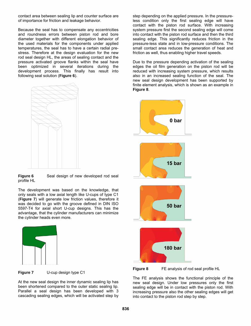
contact area between sealing lip and counter surface are of importance for friction and leakage behavior. Because the seal has to compensate any eccentricities and roundness errors between piston rod and bore diameter together with different elongation behavior of the used materials for the components under applied temperatures, the seal has to have a certain radial pre-stress. Therefore at the design evaluation for the new rod seal design HL, the areas of sealing contact and the pressure activated groove flanks within the seal have been optimized in several iterations during the development process. This finally has result into following seal solution (Figure 6).
Figure 6 Seal design of new developed rod seal profile HL
The development was based on the knowledge, that only seals with a low axial length like U-cups of type C1 (Figure 7) will generate low friction values, therefore it was decided to go with the groove defined in DIN ISO 5597-T4 for axial short U-cup designs. This has the advantage, that the cylinder manufacturers can minimize the cylinder heads even more.
Figure 7 U-cup design type C1
At the new seal design the inner dynamic sealing lip has been shortened compared to the outer static sealing lip. Parallel a seal design has been developed with 3 cascading sealing edges, which will be activated step by
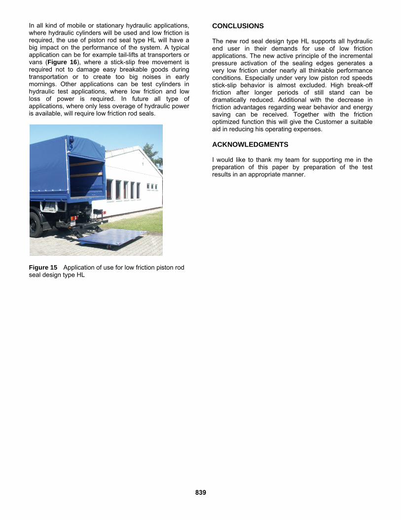
step depending on the applied pressure. In the pressure-less condition only the first sealing edge will have contact with the piston rod surface. With increasing system pressure first the second sealing edge will come into contact with the piston rod surface and then the third sealing edge. This significantly reduces friction in the pressure-less state and in low-pressure conditions. The small contact area reduces the generation of heat and friction as well, thus enabling higher travel speeds. Due to the pressure depending activation of the sealing edges the oil film generation on the piston rod will be reduced with increasing system pressure, which results also in an increased sealing function of the seal. The new seal design development has been supported by finite element analysis, which is shown as an example in Figure 8.
Figure 8 FE analysis of rod seal profile HL
The FE analysis shows the functional principle of the new seal design. Under low pressures only the first sealing edge will be in contact with the piston rod. With increasing pressure also the other sealing edges will get into contact to the piston rod step by step.
836

TEST EQUIPMENT
All dynamic seal tests were performed on the universal hydraulic test rigs for rod seals and rod sealing systems. The test rig shown in Figure 9 allows friction measurements on piston rod seals, depending on applied pressure, oil temperature and velocity. Typical parameters for friction tests are: Pressure 0, 50, 100, 150, 200, 250 and 300 bar Rod velocity 0.1, 0.5, 1, 1.5, 2, 2.5, 3, 3.5 and 4
m/min Oil Mineral oil Fuchs Renolin MRX 46 Temperature 30, 60 and 80 °C Rod diameter 36 mm Stroke length 250 mm Each pv-value is applied for a minimum of 3 cycles, starting at low pressure with incremental increases in speed. These friction tests, performed at oil temperatures of 30, 60 and 80 °C, are followed by a short endurance test over 72 hours at 20 MPa and 4 m/min. After the short endurance test, the friction tests are repeated to determine the influence of wear as well as the profile changes between seals in a run-in state and new seals.
Figure 9 Hydraulic friction test rig for rod seals The hydraulic endurance tester (Figure 10) allows the performance of seal tests according to ISO 7986 specifications. In this case, these specifications refer to testing at 0 to 30 MPa, depending on stroke direction, for 1,000,000 cycles at a stroke of 300 mm and an oil temperature of 65 °C. Test results obtained at this test rig are leakage, rod wear as well as deformation and wear of seals or complete sealing systems.
Figure 10 Hydraulic endurance test rig for rod sealing systems In the leakage endurance test following test parameters were used: Pressure 0 to 200 bar, depending on stroke
direction Rod velocity 0.15 m/s Oil Mineral oil Fuchs Renolin MRX 46 Temperature 65 °C Rod diameter 36 mm Stroke length 250 mm The dimensions of the test seals were evaluated before and after the test according to ISO 7986 specifications. The test rods, as well, were evaluated before and after the test. All tests have been performed on hard chrome plated rods (Figure 11), but also on alternative treated piston rod surfaces.
Figure 11 Typical hard chrome plated piston rod surface for the sealing tests RESULTS OF INTERNAL TESTS
The endurance tests performed with the new piston rod seal design showed after the performed test cycles only
837

very few wear marks in the sealing surfaces and absolutely no abrasion on the mating piston rod surface. At the sealing edges and sealing surfaces there was no wear detectable. After the performed endurance test all seals were in the same condition as they were new. No colorization was detectable on the mating sealing surfaces as normally be detectable on standard U-cup seal designs performing under the same test conditions. All tested seals showed only a slight compression set. None of the tested seals showed a significant extrusion. The seals showed a loss of pre-stress less than 25%. Standard U-cups showed under this applied conditions normally a loss of pre-stress in the range between 35 and 45%. The comparison of friction forces of the new U-cup geometry compared to standard U-cup designs shows a significant reduction in the measured friction forces. Compared to standard U-cup design a reduction of up to 80% (Figure 12 and 13) can be retrieved and compared to also friction optimized U-cup seals a reduction of around 60%. The reduction of friction forces for the new profile HL has also result in the advantage of less risk regarding development of stick-slip in a hydraulic cylinder application and this throughout all tested temperature and pressure areas.
Figure 12 Comparison of friction forces of different U-cup designs depending of applied test pressure
Figure 13 Comparison of friction forces of different U-cup designs depending of applied test speed Especially in the low areas of speed travel the new piston rod seal profile type HL shows a significant
reduction in friction values versus standard U-cup seal designs. INSTALLATION AND APPLICATION EXAMPLES
The piston rod seal type HL can be used in different seal configurations. In a standard sealing system the HL can be used as single element together with a scraper or wiper and a guiding element (Figure 14).
Figure 14 U-cup HL in a single seal configuration In applications with higher pressures a double sealing system will be recommended, in this case the U-cup profile HL can be used as secondary rod seal together with a buffer seal, for example a PTFE slipper seal (Figure 15).
Figure 15 Piston rod seal HL in a double sealing system configuration together with a slipper PTFE piston rod seal
838
In all kind of mobile or stationary hydraulic applications, where hydraulic cylinders will be used and low friction is required, the use of piston rod seal type HL will have a big impact on the performance of the system. A typical application can be for example tail-lifts at transporters or vans (Figure 16), where a stick-slip free movement is required not to damage easy breakable goods during transportation or to create too big noises in early mornings. Other applications can be test cylinders in hydraulic test applications, where low friction and low loss of power is required. In future all type of applications, where only less overage of hydraulic power is available, will require low friction rod seals.
CONCLUSIONS
The new rod seal design type HL supports all hydraulic end user in their demands for use of low friction applications. The new active principle of the incremental pressure activation of the sealing edges generates a very low friction under nearly all thinkable performance conditions. Especially under very low piston rod speeds stick-slip behavior is almost excluded. High break-off friction after longer periods of still stand can be dramatically reduced. Additional with the decrease in friction advantages regarding wear behavior and energy saving can be received. Together with the friction optimized function this will give the Customer a suitable aid in reducing his operating expenses.
ACKNOWLEDGMENTS
I would like to thank my team for supporting me in the preparation of this paper by preparation of the test results in an appropriate manner.
Figure 15 Application of use for low friction piston rod seal design type HL
839

840