FRICTION STIR WELDING PROCESS OPTIMIZATION: EXPERIMENTAL METHODS Stefano Ferretti DIEM, University of Bologna Via Risorgimento, 2 – 40136 Bologna [email protected] Introduction The Friction Stir Welding (FSW) process is an innovative technique to join metals in the plasticity field, thus not reaching the melting temperature and consequently the liquid state as it happen in traditional welding processes. This feature of the FSW proved an enhancement of the fatigue behaviour and strength of the joints, leading some companies to adopt the process for the manufacturing of airplanes fuselages and cryogenic tanks for Space launch vehicles. To optimize this solid state process it is relevant to determine the kinematics and dynamics of the flow, creating a theoretical model and validating it with experiments. Methods and tools as temperature measurements and tracers experiments, are presented and the results are discussed. Methods and tools The Friction Stir Welding process join two work pieces of material using a pin of a shouldered tool plunged into the section and rotated at high speed. The friction between the pin tool and the material creates a plasticized flow around the pin, then as the pin moves forward in the joint, it stirs the plasticized material, creating a forged weld. Fig. 1 – Friction Stir Welding During all these operations there are no welding fumes, radiations, high voltage, liquid metals, or arcing, and only few variables must be controlled. In fact a traditional fusion welding depends upon several parameters like purge gas, voltage, amperage, wire feed, travel speed, shield gas and arc gap, while the Friction Stir Welding process can be controlled with rotation speed, travel speed, pin tool pressure and eventually other minor variables. An equipment furnished with data acquisition capabilities helps bolster statistical-process control applying methods like the Design of Experiment (DoE) to improve the quality and the efficiency by monitoring and optimizing weld parameters. Moreover since 1991, when The Welding Institute (TWI) patented the process, the need to create a theoretical model was identified to describe the kinematics of the plastic flow during the welding. Many efforts have been spent by several research centres applying computational tool like finite elements (FEM), computational fluid dynamics (CFD) and digital image correlation (DIC). Theoretical studies predicted the trajectories of the particles flowing in the proximity of the pin tool, and were used to determine the forces acting and the temperatures reached by the tool during the process, creating the background for optimization. The data coming out of simulations have been compared with the ones obtained during the experiments, correlating the model with the process. Now they can be used for the design of innovative pin tools, simplified joint geometries and more cost effective machines lay out. The theoretical model The model considers a cylindrical flow of material that match the surface speed of the rotating pin-tool at the pin surface and extends out to some radius at which the flow stops. The generation of heat requires a leak out radially into the work piece balanced by the mechanical work. When the steady state is reached, the torques on a ring element, cut out of the swirl, would balance to zero. A simple system of equations can be written to model the distribution of angular velocity throughout the deformation zone. The stress on the outside of a ring element has the advantage over that on the inner surface. The area is bigger and the moment arm is longer, thus for equilibrium the flow stress has to decrease with increasing radius.

Welcome message from author
This document is posted to help you gain knowledge. Please leave a comment to let me know what you think about it! Share it to your friends and learn new things together.
Transcript
FRICTION STIR WELDING PROCESS OPTIMIZATION: EXPERIMENTAL METHODS
Stefano Ferretti DIEM, University of Bologna
Via Risorgimento, 2 – 40136 Bologna [email protected]
Introduction The Friction Stir Welding (FSW) process is an innovative technique to join metals in the plasticity field, thus not reaching the melting temperature and consequently the liquid state as it happen in traditional welding processes. This feature of the FSW proved an enhancement of the fatigue behaviour and strength of the joints, leading some companies to adopt the process for the manufacturing of airplanes fuselages and cryogenic tanks for Space launch vehicles. To optimize this solid state process it is relevant to determine the kinematics and dynamics of the flow, creating a theoretical model and validating it with experiments. Methods and tools as temperature measurements and tracers experiments, are presented and the results are discussed. Methods and tools
The Friction Stir Welding process join two work pieces of material using a pin of a shouldered tool plunged into the section and rotated at high speed. The friction between the pin tool and the material creates a plasticized flow around the pin, then as the pin moves forward in the joint, it stirs the plasticized material, creating a forged weld.
Fig. 1 – Friction Stir Welding
During all these operations there are no welding fumes, radiations, high voltage, liquid metals, or arcing, and only few variables must be controlled. In fact a traditional fusion welding depends upon several parameters like purge gas, voltage, amperage, wire feed, travel speed, shield gas and arc gap, while the Friction Stir Welding process can be controlled with rotation speed, travel speed, pin tool pressure and eventually other minor variables. An equipment furnished with data acquisition capabilities helps bolster statistical-process control applying methods like the Design of Experiment (DoE) to improve the quality
and the efficiency by monitoring and optimizing weld parameters. Moreover since 1991, when The Welding Institute (TWI) patented the process, the need to create a theoretical model was identified to describe the kinematics of the plastic flow during the welding. Many efforts have been spent by several research centres applying computational tool like finite elements (FEM), computational fluid dynamics (CFD) and digital image correlation (DIC). Theoretical studies predicted the trajectories of the particles flowing in the proximity of the pin tool, and were used to determine the forces acting and the temperatures reached by the tool during the process, creating the background for optimization. The data coming out of simulations have been compared with the ones obtained during the experiments, correlating the model with the process. Now they can be used for the design of innovative pin tools, simplified joint geometries and more cost effective machines lay out. The theoretical model
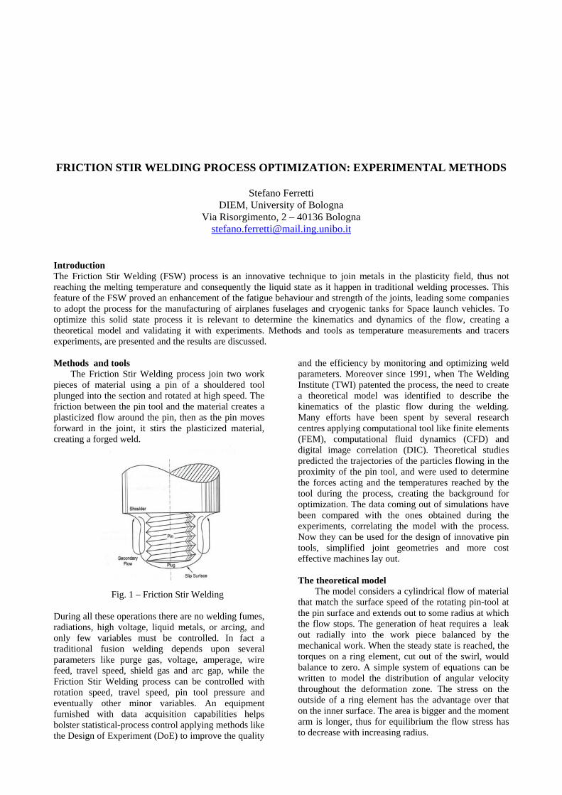
The model considers a cylindrical flow of material that match the surface speed of the rotating pin-tool at the pin surface and extends out to some radius at which the flow stops. The generation of heat requires a leak out radially into the work piece balanced by the mechanical work. When the steady state is reached, the torques on a ring element, cut out of the swirl, would balance to zero. A simple system of equations can be written to model the distribution of angular velocity throughout the deformation zone. The stress on the outside of a ring element has the advantage over that on the inner surface. The area is bigger and the moment arm is longer, thus for equilibrium the flow stress has to decrease with increasing radius.
For metals the flow stress is not greatly affected by shearing rate, but mainly by temperature, hence the temperature must increase with radius. The heat generated from the plastic flow has to flow backwards down the temperature gradient into the tool. But with an insulated tool backflow of heat and the required temperature rise with radius could not occur. This consequence of the plasticity of the metal during welding leads to a dynamic anomaly, which is solved adopting a slip discontinuity, like an envelope of metal rotating solid with the tool. To validate this model it has been conducted an experimental campaign, obtaining measurements of the temperature gradients and of the particles trajectories.
Fig.2 – FSW computed trajectories.
Experimental methods
The approach which is considered takes advantage of the studies and experiments conducted to determine the temperature and the position of the particles in the plastic flow. The temperature can be measured using thermocouples displaced on both specimens and spaced at some intervals depending on the sensitivity of the instrumentation and on the conductivity of the materials. To determine the overall heat flux it is important to measure the temperature gradient of the pin tool, which is an information particularly useful for having a successful Friction Stir Welding. The temperature field of the pin tool is measured with an Infrared sensor placed on the welding tower, in view of the tool on its advancing side and of the top surface of the specimens. A complete and good understanding of the heat transfer is relevant to validate the theoretical model and to simulate precisely the forces acting on the machine tools. Then it is important to focus on the most simple and cost effective way to visualize the trajectories of the particles during the Friction Stir Welding. A solution has been found using tracers inserted in the specimens
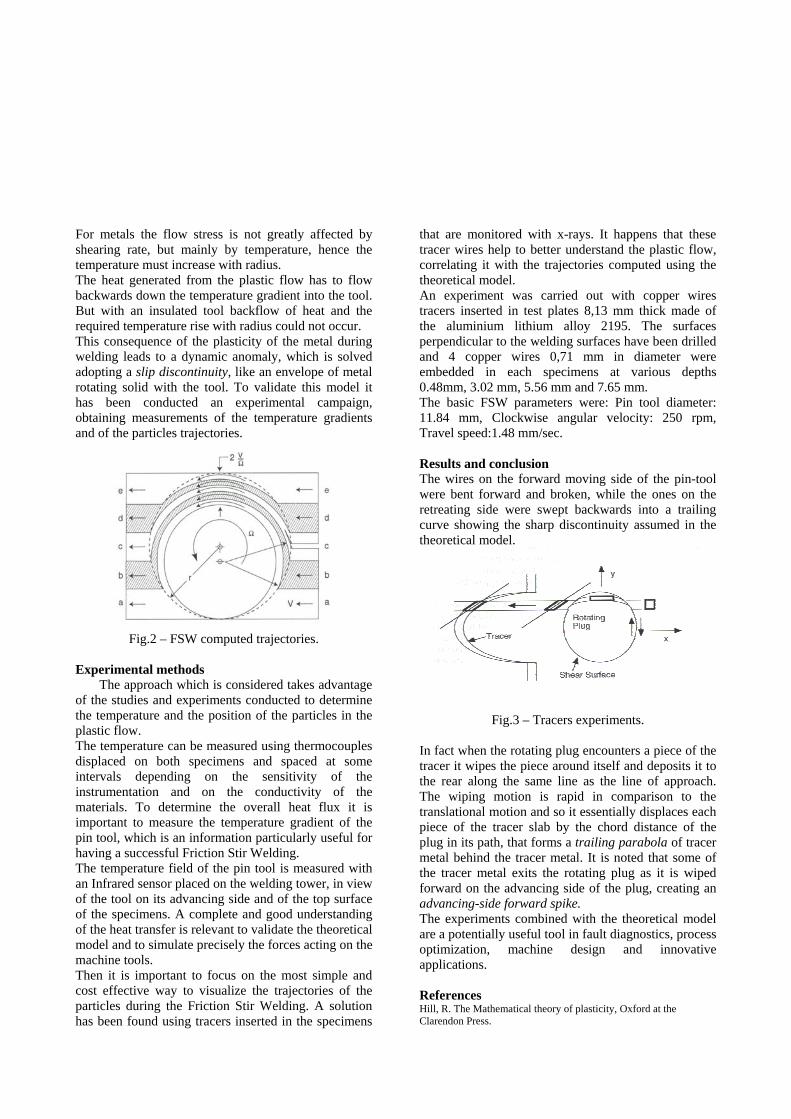
that are monitored with x-rays. It happens that these tracer wires help to better understand the plastic flow, correlating it with the trajectories computed using the theoretical model. An experiment was carried out with copper wires tracers inserted in test plates 8,13 mm thick made of the aluminium lithium alloy 2195. The surfaces perpendicular to the welding surfaces have been drilled and 4 copper wires 0,71 mm in diameter were embedded in each specimens at various depths 0.48mm, 3.02 mm, 5.56 mm and 7.65 mm. The basic FSW parameters were: Pin tool diameter: 11.84 mm, Clockwise angular velocity: 250 rpm, Travel speed:1.48 mm/sec. Results and conclusion The wires on the forward moving side of the pin-tool were bent forward and broken, while the ones on the retreating side were swept backwards into a trailing curve showing the sharp discontinuity assumed in the theoretical model.
Fig.3 – Tracers experiments.
In fact when the rotating plug encounters a piece of the tracer it wipes the piece around itself and deposits it to the rear along the same line as the line of approach. The wiping motion is rapid in comparison to the translational motion and so it essentially displaces each piece of the tracer slab by the chord distance of the plug in its path, that forms a trailing parabola of tracer metal behind the tracer metal. It is noted that some of the tracer metal exits the rotating plug as it is wiped forward on the advancing side of the plug, creating an advancing-side forward spike. The experiments combined with the theoretical model are a potentially useful tool in fault diagnostics, process optimization, machine design and innovative applications. References Hill, R. The Mathematical theory of plasticity, Oxford at the Clarendon Press.
Related Documents