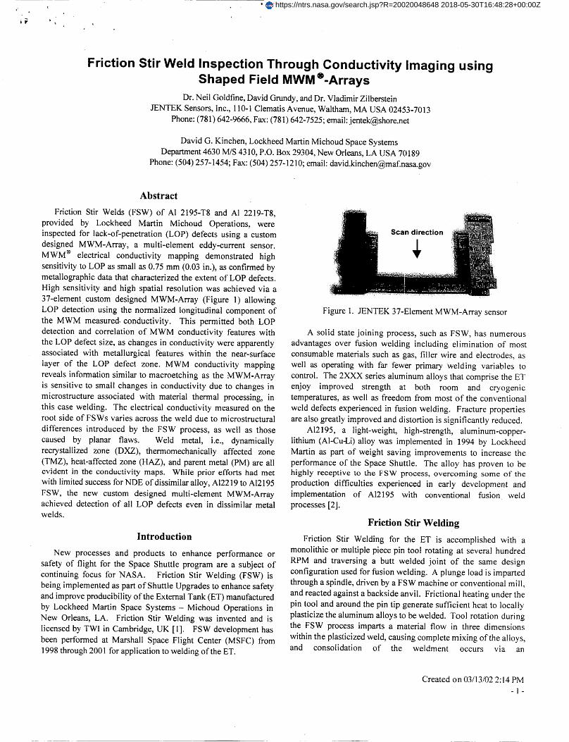
i Friction Stir Weld Inspection Through Conductivity Imaging using Shaped Field MWM®-Arrays Dr. Nell Goldfine, David Grundy, and Dr. Vladimir Zilberstein JENTEK Sensors, Inc., 110-1 Clematis Avenue, Waltham, MA USA 0245:3-7013 Phone: (781) 642-9666, Fax: (781) 642-7525; email: [email protected] David G. Kinchen, Lockheed Martin Michoud Space Systems Department 4630 M/S 4310, P.O. Box 29304, New Orleans, LA USA 70189 Phone: (504) 257-1454; Fax: (504) 257-1210; email: [email protected] Abstract Friction Stir Welds (FSW) of AI 2195-T8 and AI 2219-T8, provided by Lockheed Martin Michoud Operations, were inspected for lack-of-penetration (LOP) defects using a custom designed MWM-Array, a multi-element eddy-current sensor. MWM ® electrical conductivity mapping demonstrated high sensitivity to LOP as small as 0.75 mm (0.03 in.), as confirmed by metallographic data that characterized the extent of LOP defects. High sensitivity and high spatial resolution was achieved via a 37-element custom designed MWM-Array (Figure 1) allowing LOP detection using the normalized longitudinal component of the MWM measured, conductivity. This permitted both LOP detection and correlation of MWM conductivity features with the LOP defect size, as changes in conductivity were apparently associated with metallurgical features within the near-surface layer of the LOP defect zone. MWM conductivity mapping reveals information similar to macroetching as the MWM-Array is sensitive to small changes in conductivity due to changes in microstructure associated with material thermal processing, in this case welding. The electrical conductivity measured on the root side of FSWs varies across the weld due to microstructural differences introduced by the FSW process, as well as those caused by planar flaws. Weld metal, i.e., dynamically recrystallized zone (DXZ), thermomechanically affected zone (TMZ), heat-affected zone (HAZ), and parent metal (PM) are all evident in the conductivity maps. While prior efforts had met with limited success for NDE of dissimilar alloy, A12219 to AI2195 FSW, the new custom designed multi-element MWM-Array achieved detection of all LOP defects even in dissimilar metal welds. Introduction New processes and products to enhance performance or safety of flight for the Space Shuttle program are a subject of continuing focus for NASA. Friction Stir Welding (FSW) is being implemented as part of Shuttle Upgrades to enhance safety and improve producibility of the External Tank (ET) manufactured by Lockheed Martin Space Systems- Michoud Operations in New Orleans, LA. Friction Stir Welding was invented and is licensed by TWI in Cambridge, UK [1]. FSW development has been performed at Marshall Space Flight Center (MSFC) from 1998 through 2001 for application to welding of the ET. Figure 1. JENTEK 37-Element MWM-Array sensor A solid state joining process, such as FSW, has numerous advantages over fusion welding including elimination of most consumable materials such as gas, filler wire and electrodes, as well as operating with far fewer primary Welding variables to control. The 2XXX series aluminum alloys that comprise the ET enjoy improved strength at both room and cryogenic temperatures, as well as freedom from most of the conventional weld defects experienced in fusion welding. Fracture properties are also greatly improved and distortion is significantly reduced. A12195, a light-weight, high-strength, aluminum-copper- lithium (AI-Cu-Li)alloy was implemented in 1994 by Lockheed Martin as part of weight saving improvements to increase the performance of the Space Shuttle. The alloy has proven to be highly receptive to the FSW process, overcoming some of the production difficulties experienced in early development and implementation of A12195 with conventional fusion weld processes [2]. Friction Stir Welding Friction Stir Welding for the ET is accomplished with a monolithic or multiple piece pin tool rotating at several hundred RPM and traversing a butt welded joint of the same design configuration used for fusion welding. A plunge load is imparted through a spindle, driven by a FSW machine or conventional mill, and reacted against a backside anvil. Frictional heating under the pin tool and around the pin tip generate sufficient heat to locally plasticize the aluminum alloys to be welded. Tool rotation during the FSW process imparts a material flow in three dimensions within the plasticized weld, causing complete mixing of the alloys, and consolidation of the weldment occurs via an Created on 03/13/02 2:14 PM " I - https://ntrs.nasa.gov/search.jsp?R=20020048648 2018-05-30T16:48:28+00:00Z

Welcome message from author
This document is posted to help you gain knowledge. Please leave a comment to let me know what you think about it! Share it to your friends and learn new things together.
Transcript
i
Friction Stir Weld Inspection Through Conductivity Imaging usingShaped Field MWM®-Arrays
Dr. Nell Goldfine, David Grundy, and Dr. Vladimir Zilberstein
JENTEK Sensors, Inc., 110-1 Clematis Avenue, Waltham, MA USA 0245:3-7013
Phone: (781) 642-9666, Fax: (781) 642-7525; email: [email protected]
David G. Kinchen, Lockheed Martin Michoud Space Systems
Department 4630 M/S 4310, P.O. Box 29304, New Orleans, LA USA 70189
Phone: (504) 257-1454; Fax: (504) 257-1210; email: [email protected]
Abstract
Friction Stir Welds (FSW) of AI 2195-T8 and AI 2219-T8,
provided by Lockheed Martin Michoud Operations, were
inspected for lack-of-penetration (LOP) defects using a custom
designed MWM-Array, a multi-element eddy-current sensor.
MWM ® electrical conductivity mapping demonstrated high
sensitivity to LOP as small as 0.75 mm (0.03 in.), as confirmed by
metallographic data that characterized the extent of LOP defects.
High sensitivity and high spatial resolution was achieved via a
37-element custom designed MWM-Array (Figure 1) allowing
LOP detection using the normalized longitudinal component of
the MWM measured, conductivity. This permitted both LOP
detection and correlation of MWM conductivity features with
the LOP defect size, as changes in conductivity were apparently
associated with metallurgical features within the near-surface
layer of the LOP defect zone. MWM conductivity mapping
reveals information similar to macroetching as the MWM-Array
is sensitive to small changes in conductivity due to changes in
microstructure associated with material thermal processing, in
this case welding. The electrical conductivity measured on the
root side of FSWs varies across the weld due to microstructural
differences introduced by the FSW process, as well as those
caused by planar flaws. Weld metal, i.e., dynamically
recrystallized zone (DXZ), thermomechanically affected zone
(TMZ), heat-affected zone (HAZ), and parent metal (PM) are all
evident in the conductivity maps. While prior efforts had met
with limited success for NDE of dissimilar alloy, A12219 to AI2195
FSW, the new custom designed multi-element MWM-Array
achieved detection of all LOP defects even in dissimilar metal
welds.
Introduction
New processes and products to enhance performance or
safety of flight for the Space Shuttle program are a subject of
continuing focus for NASA. Friction Stir Welding (FSW) is
being implemented as part of Shuttle Upgrades to enhance safety
and improve producibility of the External Tank (ET) manufactured
by Lockheed Martin Space Systems- Michoud Operations in
New Orleans, LA. Friction Stir Welding was invented and is
licensed by TWI in Cambridge, UK [1]. FSW development has
been performed at Marshall Space Flight Center (MSFC) from
1998 through 2001 for application to welding of the ET.
Figure 1. JENTEK 37-Element MWM-Array sensor
A solid state joining process, such as FSW, has numerous
advantages over fusion welding including elimination of most
consumable materials such as gas, filler wire and electrodes, as
well as operating with far fewer primary Welding variables to
control. The 2XXX series aluminum alloys that comprise the ET
enjoy improved strength at both room and cryogenic
temperatures, as well as freedom from most of the conventional
weld defects experienced in fusion welding. Fracture properties
are also greatly improved and distortion is significantly reduced.
A12195, a light-weight, high-strength, aluminum-copper-
lithium (AI-Cu-Li)alloy was implemented in 1994 by Lockheed
Martin as part of weight saving improvements to increase the
performance of the Space Shuttle. The alloy has proven to be
highly receptive to the FSW process, overcoming some of the
production difficulties experienced in early development and
implementation of A12195 with conventional fusion weld
processes [2].
Friction Stir Welding
Friction Stir Welding for the ET is accomplished with a
monolithic or multiple piece pin tool rotating at several hundred
RPM and traversing a butt welded joint of the same design
configuration used for fusion welding. A plunge load is imparted
through a spindle, driven by a FSW machine or conventional mill,
and reacted against a backside anvil. Frictional heating under the
pin tool and around the pin tip generate sufficient heat to locally
plasticize the aluminum alloys to be welded. Tool rotation during
the FSW process imparts a material flow in three dimensions
within the plasticized weld, causing complete mixing of the alloys,
and consolidation of the weldment occurs via an
Created on 03/13/02 2:14 PM
" I -
https://ntrs.nasa.gov/search.jsp?R=20020048648 2018-05-30T16:48:28+00:00Z
s_ i'h
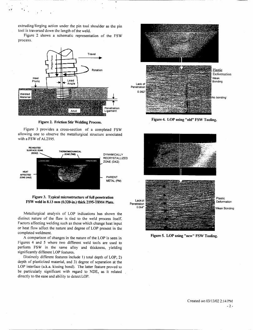
extruding/forging action under the pin tool shoulder as the pintool is traversed'down the length of the weld.
Figure 2 shows a schematic representation of the FSWprocess.
Travel
Heel
Pluncl
Rotation
PenetrationLigament
Figure 2. Friction Stir Welding Process.
Figure 3 provides a cross-section of a completed FSWallowing one to observe the metallurgical structure associatedwith a FSW orAL2195.
RE-HEATED
SURFACE ZONE THERMOMECHANICAL
(SDXZ) ZONE ('rMz) DYNAMICALLY
' RECRYSTALLIZED
ZONE (DXZ)
HEAT
AFFECTED
ZONE (HAZ)PARENT
METAL (PM)
Figure 3. Typical microstructure of full penetrationFSW weld in 8.13 mm (0320-in.) thick 2195-T8M4 Plate.
Metallurgical analysis of LOP indications has shown the
distinct nature of the flaw is tied to the weld process itself.Factors affecting welding such as those which change heat input
or heat flow affect the nature and degree of LOP present in thecompleted weldment.
A comparison of changes in the nature of the LOP is seen inFigures 4 and 5 where two different weld tools are used to
perform FSW in the same alloy and thickness, yieldingsignificantly different LOP features.
Distinctly different features include 1) total depth of LOP, 2)
depth of plasticized material, and 3) degree of separation at theLOP interface (a.k.a. kissing bond). The latter feature proved to
be particularly significant with regard to NDE, as it relateddirectly to the ease and ability to detect LOP.
,_ Deformation
_ Weak
;_" i Bonding
Lack of its,"Penetration
0.062"
_._ ..... _No bonding"
Figure 4. LOP using "old" FSW Tooling.
LackotPenetration
0.064"
Figure 5. LOP using "new" FSW Tooling.
Plastic
Deformation
Weak Bonding
Created on 03/13/02 2:14 PM
-2-

FSW Nondestructive Evaluation
Commensurate with accomplishing weld process
development, selection of appropriate NDE techniques is
required to implement production Friction Stir Welding.Selection of NDE techniques requires consideration of CriticalInitial Flaw Size(s) (CIFS), type(s) of potential flaws, and the
maturity and production capability of candidate NDE techniques.
Assessment of FSW mechanical properties and fractureproperties has been completed to determine the basis for
requirements [2]. In the development and selection of NDE for
FSW a wide variety of NDE methods have been explored [3]including multiple liquid penetrants, several types of ultrasonic
techniques, radiography, and both conventional eddy currentand the newer MWM conductivity methods.
The promising results of conductivity methods paid off afterboth independent work by JENTEK Sensors, Inc. and a contract
with JENTEK to adapt the MWM-Array technology specifically
to the ET FSW application. This work provides significant risk
mitigation for the ultrasonic, liquid penetrant and radiographicinspection techniques that will all be used in early ET productionN-DE
JENTEK Sensors MWM-Array Conductivity
Measurement and Imaging
Reliable detection of relevant lack of penetration (LOP) during
automated post weld inspection of Friction Stir Welds (FSWs) is
critical to the integrity of the External Tank (ET) for the SpaceShuttle. JENTEK Sensors, Inc. has worked with Lockheed Martin
and NASA since 1998 to adapt their technology for ET FSWinspection. The most recent success in that effort has been the
completion of design and demonstration of a custom sensor and
inspection technique for detection of 1.25 mm (0.050-in.)anddeeper LOP in A12195-to-A12195 and A12219-to-A12195 FSWs.
Figure 6 shows a laboratory setup used for demonstration of
MWM-Array conductivity measurements as a means of FSWinspection including LOP detection and characterization as wellas detection of planar flaws. The key components of the
JENTEK system shown are: a Laptop computer with GridStationSoftware (1), Multi-channel impedance instrument (2) and
MWM-Array probe with MWM-Array sensor tip (3). For the
purposes of scanning the numerous FSW test panels used toevaluate the MWM technique, an automated Scanner (4) andcustom, patented MWM-Array probe were used.
The goals during development of the JENTEK system,
beyond the obvious detection capability, have been to provide asystem that is practical and easy to use, robust in normal
operation, rapid in automated scan mode, and capable of bothautomatic and manual scanning. To achieve these results,system calibration is initiated with air calibration and a multi-
channel probe is used allowing up to 37 channels of data to be
processed. Operation • was based on automated scanning, butpreserved with the ability to add a manual probe with encoders.
_-_ _,, ;,_._-_: _ _ .... _i'_i__
Figure 6. JENTEK MWM Inspection System.
The MWM-Array designed for this FSW application is a
modification of a shaped-field array with multiple sensing
elements. The position, number and arrangement of theindividual sensing elements were customized within the MWM-
Array for optimum detection. Figure 7 shows the details for the
specific arrangement of the 37 sensing elements in order to
achieve the resolution and accuracy required for inspection ofFSW for LOP.
Scan path
1_ width 1.1 in.
Figure 7. Detail view of elements in MWM-Array sensor.
Created on 03/13/02 2:14 PM
-3-
The MWM-Array provides the capability to measure
absolute electrical conductivity of the material. The electrical
conductivity measured on the root side of the panels with FSWs
varies across the weld due to microstructural differences
introduced by the FSW process.
Both longitudinal and transverse scans were made for most
panels in the study to assure complete coverage of the FSW and
identify the optimum inspection technique. Conductivity images
are based on the scanned data and processed to generate both
C-scan images and profiles as shown in Figures.8 through 11.
The C-scan view presents the inspection data as a top down
view of the Friction Stir Weld on the weld root side. The weld in
Figure 8 extends from left to right and exhibits a circular region on
the right edge of the image. The light band region in the center
indicates the FSW weld nugget (DXZ), with the circular end
region being the terminus of the weld.
patterns as illustrated in Figure 9. This FSW specimen contained
1.14 mm (0.045-in.) deep LOP and exhibits minimal DXZ, as well as
several planar flaw indications.
Comparison of the profile in Figure 9 to that of Figure 8
reveals differences in conductivity values and their distribution,
observed as changes in the shape of the profile. The presence of
planar flaws is also noted as severe reductions (drop off) in the
conductivity profile (at the center of the weld).
_ R_./ed Conduct M_of Panel CCI-I in %IACS
_/" 2s 5o zn; 100 1_Planar Flaws Longitudinal_n Die.nee in mm
.S _9 _5, 23: _;5 24
E Rescaled _nductMty_i Panel::AA1 In%IACS .
E 5; Weld Profile!of PtmeI.C_l-1
i .
25 50 75_ :100 125 i_!:_7__/i_24 ...?. :_ii!: - ..-::_: .: : _: .... , ..
LongR'udinal _n _noe in mm "_._F 'i_ ........ .
21.5 22 22i5: .... 23 " 23,.5 " '24: '_: :' ..... : :....... :
:_: 23:5 ..............................
=!_ . 21:5' i '_ -- Pt:nar Flaw._. :23; ...... ; ,:t
5 ' lo 15 20 25
_:: " " Tra_e: Positionin mm
8z_: _ F_gure 9. C-Scan image (rap) and condmtMty pmt_e (bottom)
. for similar metal FSW with 1.14 mm (0.045-in.) LOP._.: z Dissimilar alloy FSWs yield quite different patterns of
•_1 conductivity via the JENTEK MWM-Array technique, in part,
2! .5I_ DXZ rl
. . 1 I . I I i
" 5: .... 1o. ......... .iS::: ........ :20 ........ _: .......• ....
:TransVerse Position in mm
Figure 8. C-Scan image (top) and conductivity profile (bottom) of
an acceptable similar metal FSW.
The conductivity profiles in Figures 8 and 9 are cross-section
views of the inspection data for the similar metal FSWs. The
location of the DXZ is indicated in the conductivity profile
shown in Figure 8. Peaks in conductivity on either side of the
DXZ profile indicate changing conductivity values associated
with changes in the area of the weld, in this case, the TMZ and
HAZ. The TMZ and HAZ in Figure 8 appear as relatively narrow
zones alongside the FSW DXZ as viewed in the C-Scan.
LOP, the failure of the FSW to fully penetrate the joint
thickness, presents itself as significantly different conductivity
due to the large differences in parent material conductivity.
AI2219-T8 exhibits a typical conductivity of 34% IACS, while
conductivity of A12195-T8 is 20% IACS. Dissimilar metal FSWs
free of LOP flaws appear as shown in Figure 10.
The C-Scan image in Figure 10 shows the weld extending left
to right, however the extent of the FSW DXZ is not as easily
seen as for similar alloy FSW like that of Figure 8. The
conductivity profile is needed to assess the extent of the DXZ.
The profile shows the high conductivity A12219, to the left
of the profile, decreasing rapidly as the conductivity drops into
the DXZ area. The DXZ is bounded on either side by slight
peaks in conductivity indicating a transition from the TMZ to theHAZ.
Created on 03/13/02 2:14 PM
-4-

" ,-E • .... " ...... R_al_d_i!_iPane!i_+:_n _! ......
'-liS'_-_2s .....
2s ,:_ 75, loo 125:LongitudinallScan D!s_nceinmm
38
_32
:8;28
826
.I'Y
24:
22 24 26 28- _30 :32 34. 36
Weld_Profile,of Panel FFI:
.... .....
• ,i ........ i........ t : • ....... i • .J_ .....
5,: 101 i5 20 25_TransverseiPosifion_in mm
Figure 10. C-Scan image (top) and conductivity profile(bottom) for an acceptable dissimilar metal FSW.
An example of LOP in dissimilar alloy FSW is provided inFigure 11. The FSW for this example contained 1.45 mm (0.057-
in.) deep LOP. Comparison of Figure 11 with Figure 10 provides
visible differences that prove to be the key to developing criteriafor detection of LOP. The differences affecting the shape of the
conductivity map include a sharp increase in the slope (rate ofdecrease) of conductivity on the A12219 side of the FSW andsignificantly reduced the extent of the conductivity minimum in
the center of the weld.
Inspection data can be observed in different locations alongthe weld, allowing isolation of particular areas of interest. Note
that the C-Scan image in Figure 11 indicates the presence of a
planar flaw; however the conductivity profile (for a differentregion of the same weld) illustrates an area of typical LOP that is
free of planar flaws. A profile isolated to this planar flaw regionyielded the same sharp conductivity dropoff as that seen earlier
in Figure 9 indicating a planar flaw.
•E: ,,,_......___of_,e! _!:.J":_, ......
LongitudinalSoanDi_ance in rnm Planar Flaw
22 24. 26 28 30 32 34 36 38
3e
3_
_.30
¢Y
24
Weld Proflleof Panel •HH1
.....' -_: " __::_' 'Y,,:_'I..... ,.......... : : : :
AI2219-T8 AI2191-T8
5 10 1 Zl) 25
TransvemePosition in. mm
Figure II. C-Scan image (top) and conductivity profile (bottom)
for a dissimilar metal FSW wilh]AS-emn(0.057-in.) LOP.
Such discrete planar flaws can be detected by other NDE
methods as well. Evaluation of the MWM-Array inspection data
reveals additional benefits, including information critical for
assessment of the FSW quality and estimation of the depth ofLOP detected. Figure 12 provides a correlation between LOPdepth data and MWM measured midsection wi dth, a weld feature
identified in the evaluation algorithms.
0.1
0.08
._ 0.06a_o. 0.04
0.02
0
I
B
0 5 10 15
Midsection Width, rnm
Figure 12. Correlation between midseetiom width and LOP
depth.
Created ox_03/13/02 2:14 PM
-5-

Summary
NASA and Lockheed Martin are pursuing implementation of
Friction Stir Welding (FSW) for improved safety and
producibility of the Space Shuttle External Tank (ET). FSW has
been developed and demonstrated high strength, toughness, and
defect-free welds in the 2XXX aluminum and aluminum-lithium
alloys of the ET.
NDE inspection techniques for production use include
multiple conventional methods such as liquid penetrant,
radiography and ultrasonics. Innovative techniques, newly
developed by JENTEK Sensors, have been completed to assure
risk mitigation for ET inspection via demonstrating an MWM
conductivity mapping technique and completing the adaptation
of a custom 37-element MWM-Array sensor specific for ET FSW
inspection.
JENTEK Sensors has demonstrated MWM-Array
technology as an effective tool for FSW inspection, specifically
for LOP defects. Detection of LOP as small as 0.75 mm
(0.030-in.) deep LOP is possible in A12195 FSW. Conductivity
maps and GridStation software algorithms allow estimation of
weld features and their correlation to LOP size.
Acknowledgments
Lockheed Martin Space Systems - Michoud Operations and
JENTEK Sensors, Inc. accomplished this work under NASA and
internally funded JENTEK Sensors and Lockheed Martin efforts.
Acknowledgment and thanks are given to both NASA and
Lockheed Martin personnel at the NASA Marshall Space Flight
Center (MSFC) and to the staff at JENTEK Sensors, Inc. for
conducting and/or supporting this effort.
References
1. W.M. Thomas. et al.: "Friction Stir Butt Welding",
International Patent Appl. No. PCT/GB92/02203 and GB
Patent Appl. No. 9125978.8, Dec. 1991, U.S. Patent No.
5,460,317
2. William Arbegast, Paula Hartley: "Friction Stir Weld
Technology Development at Lockheed Martin Michoud
Space Systems -An Overview," AEROMAT, June 1998.
3. David G. Kinchen, Glynn P. Adams: "Lack Of Penetration in
Friction Stir Welds: Effects on Mechanical Properties and
NDE Feasibility," AEROMAT, June 2000.
4. Neil Goldfine, William Arbegast, et al.: "Friction Stir Weld
LOP Defect Detection Using New High-Resolution MWM-
Array and Eddy-Current Sensors," AEROMAT, June 2001.
5. Neil J. Goldfine, et al., "Magnetometers for Improved
Characterization in Aerospace Applications," Materials
Evaluation, 51 (3), pp. 396, March 1993.
6. Tom Yentzer, Steve Kramer, Neil J. Goldfine., et al., "High-
Resolution Eddy-Current Sensor Arrays for Detection of
Hidden Damage including Corrosion and Fatigue
Cracks, " NASA/FAA/DoD Conference on Aging Aircraft,
Kissimmee, FL, 2001.
Created on 03/13/02 2:14 PM
-6-
Related Documents


![Maximizing Strength of Friction Stir Spot Welded ...d.researchbib.com/f/8nnKOup2bho3WaY0yWFx1SY1... · recent times to weld aluminum alloys [5], [6], [7]. Friction stir spot welding](https://static.cupdf.com/doc/110x72/5f099a157e708231d4279dfb/maximizing-strength-of-friction-stir-spot-welded-d-recent-times-to-weld-aluminum.jpg)