This article appeared in a journal published by Elsevier. The attached copy is furnished to the author for internal non-commercial research and education use, including for instruction at the authors institution and sharing with colleagues. Other uses, including reproduction and distribution, or selling or licensing copies, or posting to personal, institutional or third party websites are prohibited. In most cases authors are permitted to post their version of the article (e.g. in Word or Tex form) to their personal website or institutional repository. Authors requiring further information regarding Elsevier’s archiving and manuscript policies are encouraged to visit: http://www.elsevier.com/copyright

Welcome message from author
This document is posted to help you gain knowledge. Please leave a comment to let me know what you think about it! Share it to your friends and learn new things together.
Transcript
This article appeared in a journal published by Elsevier. The attachedcopy is furnished to the author for internal non-commercial researchand education use, including for instruction at the authors institution
and sharing with colleagues.
Other uses, including reproduction and distribution, or selling orlicensing copies, or posting to personal, institutional or third party
websites are prohibited.
In most cases authors are permitted to post their version of thearticle (e.g. in Word or Tex form) to their personal website orinstitutional repository. Authors requiring further information
regarding Elsevier’s archiving and manuscript policies areencouraged to visit:
http://www.elsevier.com/copyright
Author's personal copy
Wear 268 (2010) 1537–1541
Contents lists available at ScienceDirect
Wear
journa l homepage: www.e lsev ier .com/ locate /wear
Short communication
Fretting-corrosion mapping of CP-Ti in Ringer’s solution
Satendra Kumara, B. Sivakumara, T.S.N. Sankara Narayanana,∗, S. Ganesh Sundara Ramanb, S.K. Seshadrib
a National Metallurgical Laboratory, Madras Centre, CSIR Complex, Taramani, Chennai 600113, Indiab Department of Metallurgical and Materials Engineering, Indian Institute of Technology Madras, Chennai 600036, India
a r t i c l e i n f o
Article history:Received 9 June 2009Received in revised form 27 January 2010Accepted 27 January 2010Available online 4 February 2010
Keywords:FrettingCorrosion–wearElectrochemistryMappingJoint prostheses
a b s t r a c t
Fretting corrosion is a complex phenomena and a variety of factors such as load, contact area, frequency,number of fretting cycles, extent of damage of the fretted zone, trapping of debris between the contactingsurfaces, corrosivity of the medium, etc., will determine the fretting-corrosion behaviour. The presentpaper aims to develop a fretting-corrosion map of commercially pure Ti (CP-Ti) based on its fretting-corrosion behaviour in Ringer’s solution under various combinations of load, frequency and number offretting cycles. Based on the fretting-corrosion behaviour and restoration ability, a fretting-corrosion mapof CP-Ti in Ringer’s solution is developed for the first time. The fretting-corrosion map of CP-Ti in Ringer’ssolution enables identification of various regimes depending on the nature of predominant phenomenonfor a given set of conditions. Since fretting corrosion is the dominant phenomenon at lesser duration offretting at 5 and 10 Hz for a load of 3 and 5 N, the safer use of CP-Ti, particularly for hip and knee implants,is a major concern.
© 2010 Elsevier B.V. All rights reserved.
1. Introduction
Fretting corrosion is the deterioration of a material that occursat the interface of two contacting surfaces due to small oscilla-tory movements in presence of a corrosive medium. Orthopaedicimplants, particularly hip and knee implants, exposed to the physi-ological medium, suffer a lot due to fretting corrosion that leads to areduction in the life time of such prosthesis. A variety of factors suchas load, contact area, frequency, number of fretting cycles, extentof damage of the fretted zone, trapping of debris between the con-tacting surfaces, corrosivity of the medium, etc., could influencethe fretting-corrosion behaviour [1–6]. Wear mechanism mapswere developed in the past to understand the complex phenomenainvolved in tribological contacts. Lim [7] has reviewed the develop-ment of wear mechanism maps for metals, ceramics, metal–matrixcomposites, polymers, coatings, fretting and erosion. Williams [8]has pointed out that there is no universal mechanism of wear andno simple correlation could be established between rates of wearor surface degradation and values of friction coefficient. Accordingto him, development of wear maps would enable identification ofthe possible modes of surface damage and any transition betweenmild and severe regimes of wear [8]. The development of wear mapfor gray cast iron, titanium nitride coated high speed steel and thesliding wear behaviour of dissimilar metallic interfaces and its rel-
∗ Corresponding author. Tel.: +91 44 2254 2077; fax: +91 44 2254 1027.E-mail address: [email protected] (T.S.N. Sankara Narayanan).
evance to understand the wear mechanism is established by manyresearchers [9–12]. Stack and co-workers [13–17] have devel-oped tribocorrosion maps to understand the erosion–corrosion andmicro-abrasion corrosion behaviour of metals, coatings and com-posites. Wellman and Nicholls [18] have presented an overviewof high-temperature erosion–oxidation mechanisms, maps andmodels.
The concept of fretting maps is introduced by Vingsbo andSöderberg [19] to determine the relevant fretting regimes such asstick regime, mixed stick-slip regime and gross-slip regime. Elleuchet al. [20] have developed the fretting maps for anodized aluminiumalloys. Running condition fretting maps for WC–Co and TiN coat-ings have been constructed by Carton et al. [21] and Wei et al. [22]. Amap detailing the various damage mechanisms sustained by silver-plated copper contacts is proposed by Kassman and Jacobson [23].Sankara Narayanan et al. [24] and Park et al. [25] have proposedthe fretting-corrosion maps for tin plated electrical connector con-tacts. The development of fretting corrosion maps of titanium fororthopaedic implant application has not been attempted earlier. Inthis context, the present paper aims to develop a fretting-corrosionmap of commercially pure Ti (CP-Ti) based on its fretting-corrosionbehaviour in Ringer’s solution.
2. Experimental details
The fretting-corrosion behaviour of CP-Ti was studied using afretting-corrosion test assembly (Wear and Friction Tech., Chen-nai, India), which is similar to those described by Barril et al.
0043-1648/$ – see front matter © 2010 Elsevier B.V. All rights reserved.doi:10.1016/j.wear.2010.01.026
Author's personal copy
1538 S. Kumar et al. / Wear 268 (2010) 1537–1541
Table 1Test conditions used to study the fretting-corrosion behaviour of CP-Ti in Ringer’ssolution.
Amplitude (�m) 180Load (N) 3, 5, 7 and 10Frequency (Hz) 3, 5, 7 and 10Number of fretting cycles 1500, 3000, 4500, 9000, 18,000, 36,000
[26] and Berradja et al. [27]. The details of the fretting-corrosiontest assembly were described in our earlier papers [28,29]. Sincefretting-corrosion behaviour of titanium is influenced by many fac-tors such as frequency, amplitude, normal load, number of frettingcycles, etc., the fretting-corrosion experiments were conductedusing several combinations of these variables to understand thebehaviour. The test conditions employed in this study are listed inTable 1. Ringer’s solution, having a chemical composition (in kg/m3)of 9 NaCl, 0.24 CaCl2, 0.43 KCl and 0.2 NaHCO3 (pH 7.8), was used asthe electrolyte solution. Before performing the fretting-corrosionstudies, the CP-Ti discs (20 mm diameter and 2 mm thick) weremechanically polished using various grades of SiC paper followedby 0.3 �m alumina paste to a mirror-like finish (Ra = 0.02 �m) andrinsed with deionized water. Subsequently, they were pickled usinga mixture of 35 vol.%, HNO3–5 vol.% HF–60 vol.% H2O at 313 K for60–70 s, thoroughly rinsed with deionized water and dried usinga stream of compressed air. The cleaned CP-Ti discs subjected tofretting corrosion formed the working electrode while a saturatedcalomel electrode (SCE) and a graphite rod served as the referenceand auxiliary electrodes, respectively. These electrodes were placedin the fretting-corrosion cell in such a way that only 2 cm2 areaof the working electrode was exposed to the Ringer’s solution. Aball-on-flat contact configuration that involves an 8 mm Ø aluminaball (G 10 finish; hardness: 1365 HV) moving against the station-ary CP-Ti disc was chosen so that large contact stresses could beachieved under very low loads. The alumina ball/CP-Ti flat con-tact was arranged in such a way that they were totally immersedin the Ringer’s solution. The fretting-corrosion cell was connectedto a potentiostat/galvanostat/frequency response analyzer of ACMinstruments (model: Gill AC). The fretting-corrosion experimentswere performed under conditions involving free (open circuit)potential and no additional potential was imposed by the poten-tiostat. The change in free corrosion potential (FCP) (i.e., potentialof CP-Ti measured after immersion in Ringer’s solution in opencircuit conditions) measured as a function of time was used toevaluate the performance of CP-Ti under fretting conditions. Beforeperforming the fretting-corrosion experiment, the CP-Ti was keptin Ringer’s solution and allowed to stabilize for 1 h. The fretting-corrosion experiments were repeated at least three times to checkthe reproducibility of the test results. It is important to main-tain uniformity in mechanical polishing using various grades ofSiC paper and alumina paste, surface finish (Ra = 0.02 �m), etchingusing HNO3–HF–H2O mixture at the recommended temperatureand time, rinsing using deionized water, drying and stabiliza-tion by immersing the sample in Ringer’s solution for 1 h, toensure reproducibility of the test results. The variation in FCP ofCP-Ti measured as a function of time and, the restoration abil-ity after the fretting motion ceases, were used to develop thefretting-corrosion map.
3. Results and discussion
3.1. Change in FCP as a function of time
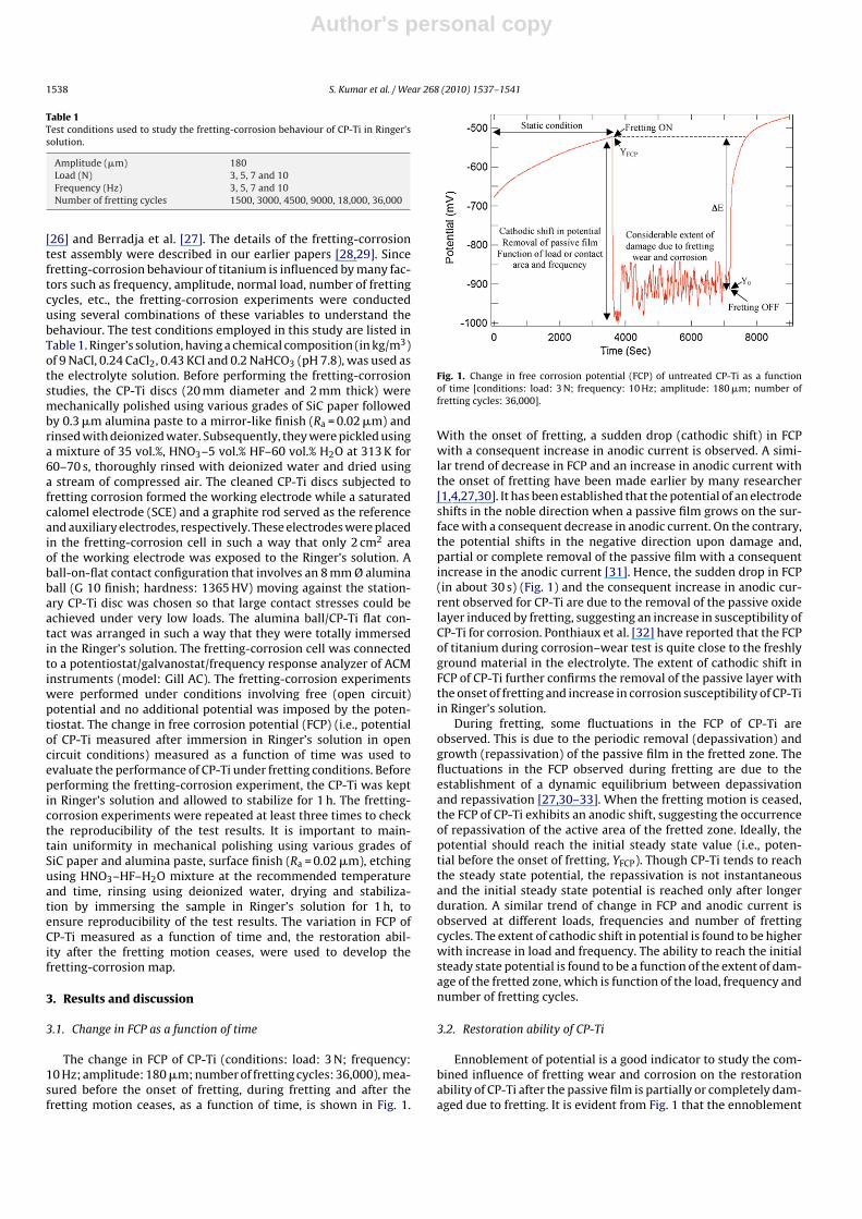
The change in FCP of CP-Ti (conditions: load: 3 N; frequency:10 Hz; amplitude: 180 �m; number of fretting cycles: 36,000), mea-sured before the onset of fretting, during fretting and after thefretting motion ceases, as a function of time, is shown in Fig. 1.
Fig. 1. Change in free corrosion potential (FCP) of untreated CP-Ti as a functionof time [conditions: load: 3 N; frequency: 10 Hz; amplitude: 180 �m; number offretting cycles: 36,000].
With the onset of fretting, a sudden drop (cathodic shift) in FCPwith a consequent increase in anodic current is observed. A simi-lar trend of decrease in FCP and an increase in anodic current withthe onset of fretting have been made earlier by many researcher[1,4,27,30]. It has been established that the potential of an electrodeshifts in the noble direction when a passive film grows on the sur-face with a consequent decrease in anodic current. On the contrary,the potential shifts in the negative direction upon damage and,partial or complete removal of the passive film with a consequentincrease in the anodic current [31]. Hence, the sudden drop in FCP(in about 30 s) (Fig. 1) and the consequent increase in anodic cur-rent observed for CP-Ti are due to the removal of the passive oxidelayer induced by fretting, suggesting an increase in susceptibility ofCP-Ti for corrosion. Ponthiaux et al. [32] have reported that the FCPof titanium during corrosion–wear test is quite close to the freshlyground material in the electrolyte. The extent of cathodic shift inFCP of CP-Ti further confirms the removal of the passive layer withthe onset of fretting and increase in corrosion susceptibility of CP-Tiin Ringer’s solution.
During fretting, some fluctuations in the FCP of CP-Ti areobserved. This is due to the periodic removal (depassivation) andgrowth (repassivation) of the passive film in the fretted zone. Thefluctuations in the FCP observed during fretting are due to theestablishment of a dynamic equilibrium between depassivationand repassivation [27,30–33]. When the fretting motion is ceased,the FCP of CP-Ti exhibits an anodic shift, suggesting the occurrenceof repassivation of the active area of the fretted zone. Ideally, thepotential should reach the initial steady state value (i.e., poten-tial before the onset of fretting, YFCP). Though CP-Ti tends to reachthe steady state potential, the repassivation is not instantaneousand the initial steady state potential is reached only after longerduration. A similar trend of change in FCP and anodic current isobserved at different loads, frequencies and number of frettingcycles. The extent of cathodic shift in potential is found to be higherwith increase in load and frequency. The ability to reach the initialsteady state potential is found to be a function of the extent of dam-age of the fretted zone, which is function of the load, frequency andnumber of fretting cycles.
3.2. Restoration ability of CP-Ti
Ennoblement of potential is a good indicator to study the com-bined influence of fretting wear and corrosion on the restorationability of CP-Ti after the passive film is partially or completely dam-aged due to fretting. It is evident from Fig. 1 that the ennoblement
Author's personal copy
S. Kumar et al. / Wear 268 (2010) 1537–1541 1539
of potential is not instantaneous and the initial potential is reachedonly after longer duration. While correlating the restoration abilitywith the ennoblement of potential, two important factors, namely,the extent and the rate of ennoblement of potential should be con-sidered. The extent of ennoblement of potential is related to theextent of repair of the damaged (active) area while the rate of enno-blement of potential is related to the competition between rate ofcorrosion and rate of passive film formation. Calculation of the timeto reach the initial steady state potential and extent of ennoblementof potential indicate no reasonable correlation with the experimen-tal variables. It might probably due to the variation in the potentialrange for different experiments, which warrants normalization ofpotential. The normalization of the potential was performed usingthe following equation:
Y ′t = Yt − YFCP
�E
where Y ′t is the normalized potential; Yt is the measured poten-
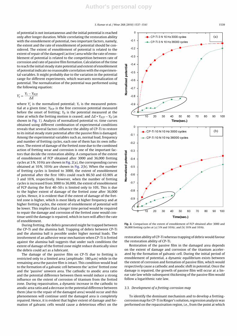
tial at a given time; YFCP is the free corrosion potential measuredbefore the onset of fretting; Y0 is the potential measured at thetime at which the fretting motion is ceased; and �E = YFCP − Y0 (asshown in Fig. 1). Analysis of normalized potential vs. time curvesobtained using different combination of experimental conditionsreveals that several factors influence the ability of CP-Ti to restoreto its initial steady state potential after the passive film is damaged.Among the experimental variables such as, normal load, frequencyand number of fretting cycles, each one of them has its own influ-ence. The extent of damage of the fretted zone due to the combinedaction of fretting wear and corrosion is one of the important fac-tors that decide the restoration ability. A comparison of the extentof ennoblement of FCP obtained after 3000 and 36,000 frettingcycles at 3 N, 10 Hz are shown in Fig. 2(a), the corresponding curvesobtained at 10 N, 10 Hz are shown in Fig. 2(b). When the numberof fretting cycles is limited to 3000, the extent of ennoblementof potential after the first 100 s could reach 86.50 and 63.90% at3 and 10 N, respectively. However, when the number of frettingcycles is increased from 3000 to 36,000, the extent of ennoblementof FCP during the first 40–50 s is limited only to 10%. This is dueto the higher extent of damage of the fretted zone after 36,000cycles. Hence, it is evident that if the extent of damage of the fret-ted zone is higher, which is most likely at higher frequency and athigher fretting cycles, the extent of ennoblement of potential willbe lower. This implies that a longer time period would be requiredto repair the damage and corrosion of the fretted zone would con-tinue until the damage is repaired, which in turn will affect the rateof ennoblement.
During fretting, the debris generated might be trapped betweenthe CP-Ti and the alumina ball. Trapping of debris between CP-Tiand the alumina ball is possible under higher normal loads. Theinvolvement of an adhesive wear mechanism when CP-Ti is frettedagainst the alumina ball suggests that under such conditions theextent of damage of the fretted zone might reduce drastically sincethe debris could act as a lubricant.
The damage of the passive film on CP-Ti due to fretting isrestricted only to a limited area (amplitude: 180 �m) while in theremaining area the passive film is intact. This condition would leadto the formation of a galvanic cell between the ‘active’ fretted zoneand the ‘passive’ unworn area. The cathodic to anodic area ratioand the potential difference between them would induce a stronginfluence on the extent of corrosion of titanium from the frettedzone. During repassivation, a dynamic increase in the cathodic toanodic area ratio and a decrease in the potential difference betweenthem (due to the repair of the damaged area) would occur and thisphenomenon will continue until the damaged area is completelyrepaired. Hence, it is evident that higher extent of damage and for-mation of galvanic cells would cause a deleterious effect on the
Fig. 2. Comparison of the extent of ennoblement of FCP obtained after 3000 and36,000 fretting cycles at (a) 3 N and 10 Hz; and (b) 10 N and 10 Hz.
restoration ability of CP-Ti whereas trapping of debris would favourthe restoration ability of CP-Ti.
Restoration of the passive film in the damaged area dependson the extent of damage and corrosion of the titanium acceler-ated by the formation of galvanic cell. During the initial period ofennoblement of potential, a dynamic equilibrium exists betweenthe extent of corrosion and formation of passive film, which wouldrespectively cause a cathodic and anodic shift in potential. Once thedamage is repaired, the growth of passive film will occur at a lin-ear rate law while subsequent thickening of the passive film wouldfollow a logarithmic rate law.
3.3. Development of a fretting-corrosion map
To identify the dominant mechanism and to develop a fretting-corrosion map for CP-Ti in Ringer’s solution, regression analysis wasperformed on the repassivation region, i.e., from the point at which
Author's personal copy
1540 S. Kumar et al. / Wear 268 (2010) 1537–1541
the fretting motion is ceased (Y0) until the free-corrosion potential(YFCP) is reached. For each experiment, a sample of the measuredpotential data with sampling duration varied from 0 to 1000 s wasconsidered for analysis. The model used for regression analysis isY = K1 × ln(X) + K2; where Y denotes the potential; X denotes theduration to repassivate; K1 indicates the extent of corrosion resis-tance; and K2 indicates the extent of damage of the fretted zone. Themodel used to study the repassivation/regeneration of the passivefilm on Ti and Ti–6Al–4V alloy was already reported by Hanawa etal. [34] and Komotori et al. [35]. The regression analysis performedon the repassivation region of all the experiments carried out usingvarious combinations of experimental conditions indicate that K1values range from 0.16 to 0.34 whereas K2 values range from −0.90to −1.67. The larger the K1 value and the less negative the K2 value,the higher the repassivation capability. Based on the ratio of theextent of damage (K2) to the extent of corrosion resistance (K1),denoted as ‘(K2/K1)’, the dominance of fretting wear and frettingcorrosion for a given set of experimental conditions are assessed.The values of (K2/K1) ranging from −4.20 to −6.88 are rated in thescale of 1–10 using the following relation:
Ranking of(
K2
K1
)=
[{Kn − Kmin
Kmax − Kmin
}× 9
]+ 1
where Kn is the nth value of (K2/K1); Kmax is the maximum valueof (K2/K1); and Kmin is the minimum value of (K2/K1). The higherthe (K2/K1) value, the greater the extent of fretting wear com-pared to fretting corrosion. Fretting wear and fretting corrosionare interrelated and they occur simultaneously. However, duringfretting-corrosion test, for a given set of experimental conditions,fretting wear, fretting corrosion or a combination of both could pre-dominate. Hence, segmentation of the various regimes becomesnecessary for the construction of the fretting-corrosion maps. The
fretting-corrosion regimes are defined as follows:
1 ≤(
K2
K1
)< 3 Fretting corrosion dominated
3 ≤(
K2
K1
)< 5.5 Fretting corrosion-Fretting wear
5.5 ≤(
K2
K1
)< 7 Fretting wear-Fretting corrosion
7 ≤(
K2
K1
)≤ 10 Fretting wear dominated
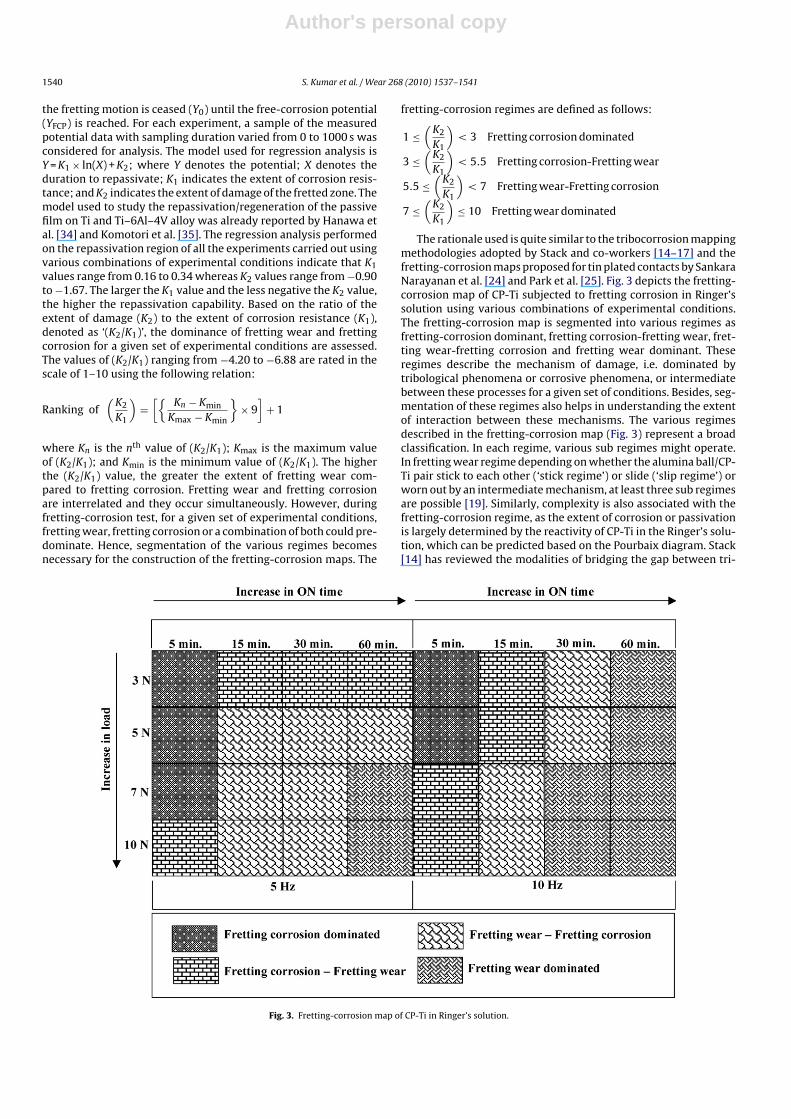
The rationale used is quite similar to the tribocorrosion mappingmethodologies adopted by Stack and co-workers [14–17] and thefretting-corrosion maps proposed for tin plated contacts by SankaraNarayanan et al. [24] and Park et al. [25]. Fig. 3 depicts the fretting-corrosion map of CP-Ti subjected to fretting corrosion in Ringer’ssolution using various combinations of experimental conditions.The fretting-corrosion map is segmented into various regimes asfretting-corrosion dominant, fretting corrosion-fretting wear, fret-ting wear-fretting corrosion and fretting wear dominant. Theseregimes describe the mechanism of damage, i.e. dominated bytribological phenomena or corrosive phenomena, or intermediatebetween these processes for a given set of conditions. Besides, seg-mentation of these regimes also helps in understanding the extentof interaction between these mechanisms. The various regimesdescribed in the fretting-corrosion map (Fig. 3) represent a broadclassification. In each regime, various sub regimes might operate.In fretting wear regime depending on whether the alumina ball/CP-Ti pair stick to each other (‘stick regime’) or slide (‘slip regime’) orworn out by an intermediate mechanism, at least three sub regimesare possible [19]. Similarly, complexity is also associated with thefretting-corrosion regime, as the extent of corrosion or passivationis largely determined by the reactivity of CP-Ti in the Ringer’s solu-tion, which can be predicted based on the Pourbaix diagram. Stack[14] has reviewed the modalities of bridging the gap between tri-
Fig. 3. Fretting-corrosion map of CP-Ti in Ringer’s solution.
Author's personal copy
S. Kumar et al. / Wear 268 (2010) 1537–1541 1541
bology and corrosion by establishing a correlation between wearmaps to Pourbaix diagram.
It is evident from the fretting-corrosion map that at 5 Hz, fret-ting corrosion is the dominant phenomenon at 3, 5 and 7 N and atlesser duration of fretting (5 min) whereas the mechanism is tend-ing towards fretting corrosion-fretting wear at 10 N as well as withan increase in duration of fretting to 15, 30 and 60 min. At 10 Hz,fretting corrosion is the dominant phenomenon at 3 and 5 N and atlesser duration of fretting (5 min.) whereas the mechanism is tend-ing towards fretting corrosion-fretting wear at 7 and 10 N as wellwith an increase in duration of fretting to 15 min at 3 and 5 N. Thepredominance of fretting corrosion under conditions mentionedabove raises concern for the safer use of CP-Ti, particularly for hipand knee implants, where the occurrence of fretting corrosion isprevalent.
Scanning electron micrographs of the fretted zone of CP-Ti aftersubjecting it to fretting corrosion in Ringer’s solution at 3 N, 5 Hz,180 �m for 18,000 fretting cycles reveal severe damage due to theextensive shear deformation and the ploughing action of the alu-mina ball, suggesting the involvement of adhesive galling as thepredominant wear mechanism [28,29]. Further work is required tocorrelate the morphological features of the fretted zone with thefretting-corrosion map.
4. Conclusions
Based on the fretting-corrosion behaviour and restoration abil-ity under various combinations of load, frequency and number offretting cycles, a fretting-corrosion map of CP-Ti in Ringer’s solutionis developed. The fretting-corrosion map is segmented into variousregimes as fretting-corrosion dominant, fretting corrosion-frettingwear, fretting wear-fretting corrosion and fretting wear dominant,depending on the nature of predominant phenomenon for a givenset of conditions. The dominance of fretting corrosion observed at5 and 10 Hz for lesser duration of fretting (5 min) at 3 and 5 N raisesconcern on the safer use of CP-Ti, particularly for hip and kneeimplants, where the occurrence of fretting corrosion is prevalent.
Acknowledgement
The authors express their sincere thanks to Director, NationalMetallurgical Laboratory, Jamshedpur, for his keen interest andpermission to publish this paper.
References
[1] S. Barril, S. Mischler, D. Landolt, Electrochemical effects on the fretting corro-sion behaviour of Ti6Al4V in 0.9% sodium chloride solution, Wear 259 (2005)282–291.
[2] S. Hiromoto, S. Mischler, The influence of proteins on the fretting–corrosionbehaviour of a Ti6Al4V alloy, Wear 261 (2006) 1002–1011.
[3] A.C. Vieira, A.R. Ribeiro, L.A. Rocha, J.P. Celis, Influence of pH and corrosioninhibitors on the tribocorrosion of titanium in artificial saliva, Wear 261 (2006)994–1001.
[4] M. Azzi, J.A. Szpunar, Tribo-electrochemical technique for studying tribocorro-sion behavior of biomaterials, Biomolecular Engineering 24 (2007) 443–446.
[5] Y. Yan, A. Neville, D. Dowson, Tribo-corrosion properties of cobalt-based med-ical implant alloys in simulated biological environments, Wear 263 (2007)1105–1111.
[6] P. Henry, J. Takadoum, P. Bercot, Tribocorrosion of 316L stainless steel andTA6V4 alloy in H2SO4 media, Corrosion Science 51 (2009) 1308–1314.
[7] S.C. Lim, Recent developments in wear-mechanism maps, Tribology Interna-tional 31 (1998) 87–97.
[8] J.A. Williams, Wear modelling: analytical, computational and mapping: a con-tinuum mechanics approach, Wear 225–229 (1999) 1–17.
[9] S. Wilson, A.T. Alpas, Wear mechanism maps for TiN-coated high speed steel,Surface and Coatings Technology 120–121 (1999) 519–527.
[10] S.C. Lim, The relevance of wear-mechanism maps to mild-oxidational wear,Tribology International 35 (2002) 717–723.
[11] A.R. Riahi, A.T. Alpas, Wear map for grey cast iron, Wear 255 (2003) 401–409.[12] I.A. Inman, S.R. Rose, P.K. Datta, Development of a simple ‘temperature versus
sliding speed’ wear map for the sliding wear behaviour of dissimilar metallicinterfaces, Wear 260 (2006) 919–932.
[13] M.M. Stack, B.D. Jana, Modelling particulate erosion–corrosion in aqueous slur-ries: some views on the construction of erosion–corrosion maps for a range ofpure metals, Wear 256 (2004) 986–1004.
[14] M.M. Stack, Bridging the gap between tribology and corrosion: from wear mapsto Pourbaix diagrams, International Materials Reviews 50 (2005) 1–17.
[15] M.M. Stack, H. Jawan, M.T. Mathew, On the construction of micro-abrasionmaps for a steel/polymer couple in corrosive environments, Tribology Interna-tional 38 (2005) 848–856.
[16] M.M. Stack, T.M. Abd El-Badia, Some comments on mapping the com-bined effects of slurry concentration, impact velocity and electrochemicalpotential on the erosion–corrosion of WC/Co–Cr coatings, Wear 264 (2008)826–837.
[17] M.T Mathew, M.M. Stack, B. Matijevic, L.A. Rocha, E. Ariza, Micro-abrasion resis-tance of thermochemically treated steels in aqueous solutions: mechanisms,maps, materials selection, Tribology International 41 (2008) 141–149.
[18] R.G. Wellman, J.R. Nicholls, High temperature erosion–oxidation mechanisms,maps and models, Wear 256 (2004) 907–917.
[19] O. Vingsbo, S. Söderberg, On fretting maps, Wear 126 (1988) 131–147.[20] K. Elleuch, S. Fouvry, Ph. Kapsa, Fretting maps for anodised aluminium alloys,
Thin Solid Films 426 (2003) 271–280.[21] J.F. Carton, A.B. Vannes, L. Vincent, Y. Berthier, M.C. Dubourg, M. Godet, Fretting:
a mechanical and material approach, in: Y.S. Jin (Ed.), Proceedings of the Inter-national Symposium on Tribology, International Academic Publishers, Beijing,1993, pp. 1110–1119.
[22] J. Wei, S. Fouvry, P. Kapsa, J. Vincent, Fretting behaviour of TiN coating, in:T.S. Sudarshan, K.A. Khor, M. Jeandin (Eds.), Proceedings of the 10th Interna-tional Conference on Surface Modification Technologies, SMT-10, The Instituteof Materials, London, 1997, pp. 24–36.
[23] A. Kassman, S. Jacobson, Surface damage, adhesion and contact resistance ofsilver plated copper contacts subjected to fretting motion, Wear 165 (1993)227–230.
[24] T.S.N. Sankara Narayanan, Y.W. Park, K.Y. Lee, Fretting-corrosion mapping oftin-plated copper alloy contacts, Wear 262 (2007) 228–233.
[25] Y.W. Park, T.S.N. Sankara Narayanan, K.Y. Lee, Fretting corrosion of tin-platedcontacts, Tribology International 41 (2008) 616–628.
[26] S. Barril, N. Debaud, S. Mischler, D. Landolt, A tribo-electrochemical apparatusfor in vitro investigation of fretting–corrosion of metallic implant materials,Wear 252 (2002) 744–754.
[27] A. Berradja, F. Bratu, L. Benea, G. Willems, J.-P. Celis, Effect of sliding wear ontribocorrosion behaviour of stainless steels in a Ringer’s solution, Wear 261(2006) 987–993.
[28] S. Kumar, T.S.N. Sankara Narayanan, S. Ganesh Sundara Raman, S.K. Seshadri,Fretting corrosion behaviour of thermally oxidized CP-Ti in Ringer’s solution,Corrosion Science 52 (2010) 711–721.
[29] S. Kumar, T.S.N. Sankara Narayanan, S. Ganesh Sundara Raman, S.K.Seshadri, Evaluation of fretting corrosion behaviour of CP-Ti for orthopaedicimplant applications, Tribology International (2009), doi:10.1016/j.triboint.2009.12.007.
[30] B. Tang, P.Q. Wu, A.L. Fan, L. Qin, H.J. Hu, J.-P. Celis, Improvement of corrosion-wear resistance of Ti-6Al-4V alloy by plasma Mo-N surface modification,Advanced Engineering Materials 7 (2005) 232–238.
[31] Z. Quan, P. Wu, L. Tang, J.-P. Celis, Corrosion-wear monitoring of TiN coated AISI316 stainless steel by electrochemical noise measurements, Applied SurfaceScience 253 (2006) 1194–1197.
[32] P. Ponthiaux, F. Wenger, D. Drees, J.P. Celis, Electrochemical techniques forstudying tribocorrosion processes, Wear 256 (2004) 459–468.
[33] P.Q. Wu, J.-P. Celis, Electrochemical noise measurements on stainless steel dur-ing corrosion–wear in sliding contacts, Wear 256 (2004) 480–490.
[34] T. Hanawa, K. Asami, K. Asaoka, Repassivation of titanium and surface oxide filmregenerated in simulated bioliquid, Journal of Biomedical Materials Research40 (1998) 530–538.
[35] J. Komotori, N. Hisamori, Y. Ohmori, The corrosion/wear mechanisms ofTi–6Al–4V alloy for different scratching rates, Wear 263 (2007) 412–418.
Related Documents