Wear 267 (2009) 1702–1708 Contents lists available at ScienceDirect Wear journal homepage: www.elsevier.com/locate/wear Fretting and fretting corrosion behavior of novel micro alloyed rail steels Bijayani Panda, R. Balasubramaniam ∗ , Sujata Mahapatra, Gopal Dwivedi Department of Materials and Metallurgical Engineering, Indian Institute of Technology, Kanpur 208016, India article info Article history: Received 28 September 2007 Received in revised form 11 April 2009 Accepted 18 June 2009 Available online 26 June 2009 Keywords: Fretting Steel Tribo-electro-chemical mechanism Electron microscopy abstract The fretting behavior of two novel rail steels of composition Cu–Ni and Cr–Cu–Ni has been studied and compared with that of C–Mn and Cu–Mo rail steels. The rail steels were fretted in dry condition and in 3.5% NaCl solution. All the four rail steels exhibited similar fretting behavior in dry condition. The mor- phological features of the wear scar surface indicated delamination process as the main wear mechanism. The wear damage in 3.5% NaCl was lower compared to that in dry condition for all the rail steels due to lubricating effect of the solution. Fretting in presence of 3.5% NaCl resulted in lower wear volume for Cu–Ni and Cr–Cu–Ni rail steels. The friction coefficient for Cr–Cu–Ni rail steel was lower than that of C–Mn, Cu–Mo and Cu–Ni rail steels. Scanning electron microscopy (SEM) showed better adherence of tribo-electro-chemical layers formed on Cu–Ni and Cr–Cu–Ni rail steel than the C–Mn and Cu–Mo rail steels. This has been related to the improved fretting corrosion behavior of Cu–Ni and Cr–Cu–Ni rail steels. © 2009 Elsevier B.V. All rights reserved. 1. Introduction High carbon (∼0.7 wt%)–high manganese (∼1.2 wt%) steels are used as rail steels in railway systems of several countries because of their superior mechanical properties, which is the primary require- ment for withstanding heavy traffic loads. This is achieved by controlling the processing parameters (and composition) to obtain a fully pearlitic microstructure. However, rail steels are adversely affected under severe corrosive environments, for example, near coastal areas. This is because high amount of cementite (Fe 3 C) in steel is detrimental to its corrosion performance [1,2]. In the case of India, which possesses a large railway network as well as a large coastline, the economic implications of corrosion of rail steels are significant. As per Indian Railway Permanent Way specifications, a 60 kg/m rail section should be able to withstand 800 gross metric tons of load before it fails. This works to approximately 12–13 years under normal traffic conditions in India. However, the life of the rails is reduced to nearly half the expected life due to corrosion. The corroded rails have to be replaced frequently, disturbing traffic as well as resulting in economic loss. Moreover, sudden failure of rails is a major safety concern. Apart from general corrosion, crevice corrosion between the liner and rail foot is a major cause for localized corrosion. The rail foot possesses the thinnest cross-section and is corroded due to the accumulation of corrosive media, emanating from various sources. Apart from contaminants from atmosphere, the discharge ∗ Corresponding author. Tel.: +91 512 2597089; fax: +91 512 2597134. E-mail address: [email protected] (R. Balasubramaniam). from open lavatories of the Indian passenger coaches is of great concern. It is easy for the corrosive media, flowing along the rail head and rail web, to finally get accumulated at the rail foot region, due to the presence of rail fixtures. These fixtures act as barriers to the flow of the corrosive media. Fig. 1 shows the typical thinning of the rail foot region of a rail laid in a coastal location in India. The figure shows the rail foot location with the fixtures (mild steel liner and the elastic rail clip) removed. Severe localized corrosion of rails at the rail foot location is also expected to be assisted by damage due to fretting. By nature of their application, rail steels are subjected to small amplitude oscillatory vibrations when trains move over the rail tracks. As a result of this, fretting takes place between the contacting points of the rail and the rail fixtures. Due to accumulation of corrosive media, combined action of fretting and corrosion (fretting corrosion) takes place in the rail foot region. The total damage due to fretting and corrosion is known to increase only when there is synergism between the two [3]. Reduction in either wear or corrosion could decrease the total damage [3]. For example, though stainless steel possesses excel- lent corrosion resistance in absence of wear, it readily wears when abrasive particles remove the passive film formed on the stainless steel surface [3,4]. In absence of an electrolyte, fretting involves damage due to mechanical interaction and oxidational process. In case of fretting corrosion, an additional electrochemical corrosion component also becomes a part of the fretting process [5,6]. The corrosion attack at the fretting contact zone takes place by crevice corrosion mechanism because of the differential aeration between the fretting contact zone and the surrounding area [7]. Moreover, the continuous removal of corrosion products from the metal sur- face at the contact zone generally accelerates the crevice corrosion 0043-1648/$ – see front matter © 2009 Elsevier B.V. All rights reserved. doi:10.1016/j.wear.2009.06.035

Welcome message from author
This document is posted to help you gain knowledge. Please leave a comment to let me know what you think about it! Share it to your friends and learn new things together.
Transcript
F
BD
a
ARRAA
KFSTE
1
utmcaacsocs6turTar
lrts
0d
Wear 267 (2009) 1702–1708
Contents lists available at ScienceDirect
Wear
journa l homepage: www.e lsev ier .com/ locate /wear
retting and fretting corrosion behavior of novel micro alloyed rail steels
ijayani Panda, R. Balasubramaniam ∗, Sujata Mahapatra, Gopal Dwivediepartment of Materials and Metallurgical Engineering, Indian Institute of Technology, Kanpur 208016, India
r t i c l e i n f o
rticle history:eceived 28 September 2007eceived in revised form 11 April 2009ccepted 18 June 2009vailable online 26 June 2009
a b s t r a c t
The fretting behavior of two novel rail steels of composition Cu–Ni and Cr–Cu–Ni has been studied andcompared with that of C–Mn and Cu–Mo rail steels. The rail steels were fretted in dry condition and in3.5% NaCl solution. All the four rail steels exhibited similar fretting behavior in dry condition. The mor-phological features of the wear scar surface indicated delamination process as the main wear mechanism.
eywords:rettingteelribo-electro-chemical mechanismlectron microscopy
The wear damage in 3.5% NaCl was lower compared to that in dry condition for all the rail steels due tolubricating effect of the solution. Fretting in presence of 3.5% NaCl resulted in lower wear volume forCu–Ni and Cr–Cu–Ni rail steels. The friction coefficient for Cr–Cu–Ni rail steel was lower than that ofC–Mn, Cu–Mo and Cu–Ni rail steels. Scanning electron microscopy (SEM) showed better adherence oftribo-electro-chemical layers formed on Cu–Ni and Cr–Cu–Ni rail steel than the C–Mn and Cu–Mo railsteels. This has been related to the improved fretting corrosion behavior of Cu–Ni and Cr–Cu–Ni rail steels.
. Introduction
High carbon (∼0.7 wt%)–high manganese (∼1.2 wt%) steels aresed as rail steels in railway systems of several countries because ofheir superior mechanical properties, which is the primary require-
ent for withstanding heavy traffic loads. This is achieved byontrolling the processing parameters (and composition) to obtainfully pearlitic microstructure. However, rail steels are adversely
ffected under severe corrosive environments, for example, nearoastal areas. This is because high amount of cementite (Fe3C) inteel is detrimental to its corrosion performance [1,2]. In the casef India, which possesses a large railway network as well as a largeoastline, the economic implications of corrosion of rail steels areignificant. As per Indian Railway Permanent Way specifications, a0 kg/m rail section should be able to withstand 800 gross metricons of load before it fails. This works to approximately 12–13 yearsnder normal traffic conditions in India. However, the life of theails is reduced to nearly half the expected life due to corrosion.he corroded rails have to be replaced frequently, disturbing traffics well as resulting in economic loss. Moreover, sudden failure ofails is a major safety concern.
Apart from general corrosion, crevice corrosion between the
iner and rail foot is a major cause for localized corrosion. Theail foot possesses the thinnest cross-section and is corroded dueo the accumulation of corrosive media, emanating from variousources. Apart from contaminants from atmosphere, the discharge∗ Corresponding author. Tel.: +91 512 2597089; fax: +91 512 2597134.E-mail address: [email protected] (R. Balasubramaniam).
043-1648/$ – see front matter © 2009 Elsevier B.V. All rights reserved.oi:10.1016/j.wear.2009.06.035
© 2009 Elsevier B.V. All rights reserved.
from open lavatories of the Indian passenger coaches is of greatconcern. It is easy for the corrosive media, flowing along the railhead and rail web, to finally get accumulated at the rail foot region,due to the presence of rail fixtures. These fixtures act as barriers tothe flow of the corrosive media. Fig. 1 shows the typical thinningof the rail foot region of a rail laid in a coastal location in India. Thefigure shows the rail foot location with the fixtures (mild steel linerand the elastic rail clip) removed.
Severe localized corrosion of rails at the rail foot location is alsoexpected to be assisted by damage due to fretting. By nature of theirapplication, rail steels are subjected to small amplitude oscillatoryvibrations when trains move over the rail tracks. As a result of this,fretting takes place between the contacting points of the rail andthe rail fixtures. Due to accumulation of corrosive media, combinedaction of fretting and corrosion (fretting corrosion) takes place inthe rail foot region. The total damage due to fretting and corrosionis known to increase only when there is synergism between the two[3]. Reduction in either wear or corrosion could decrease the totaldamage [3]. For example, though stainless steel possesses excel-lent corrosion resistance in absence of wear, it readily wears whenabrasive particles remove the passive film formed on the stainlesssteel surface [3,4]. In absence of an electrolyte, fretting involvesdamage due to mechanical interaction and oxidational process. Incase of fretting corrosion, an additional electrochemical corrosioncomponent also becomes a part of the fretting process [5,6]. The
corrosion attack at the fretting contact zone takes place by crevicecorrosion mechanism because of the differential aeration betweenthe fretting contact zone and the surrounding area [7]. Moreover,the continuous removal of corrosion products from the metal sur-face at the contact zone generally accelerates the crevice corrosion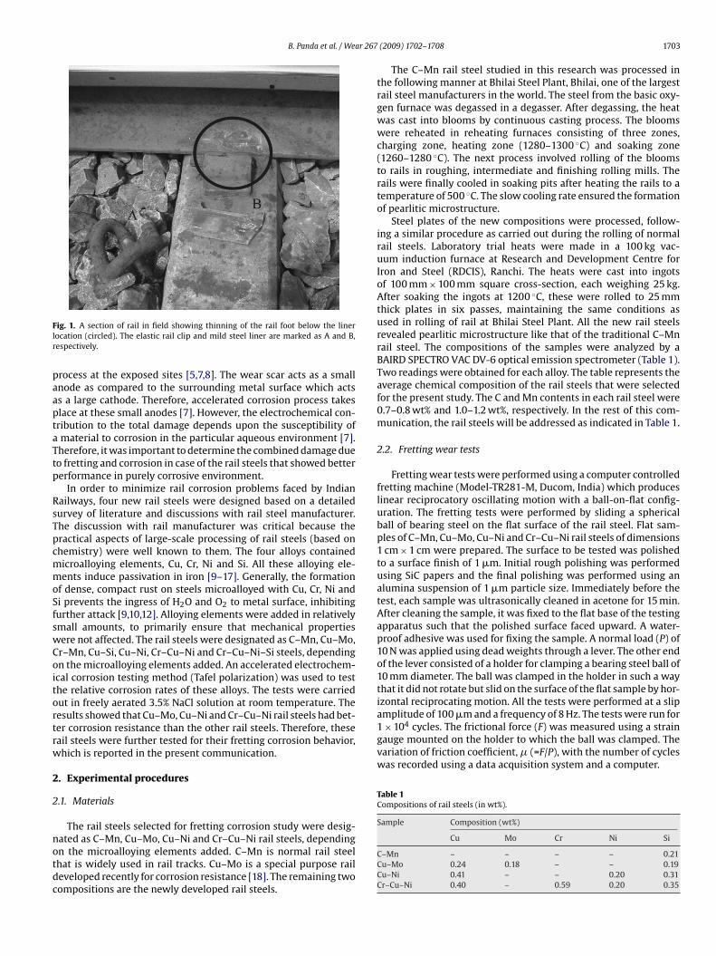
B. Panda et al. / Wear 267
Flr
paaptaTtp
RsTpcmmoSfswCoitortrw
2
2
notdc
amplitude of 100 �m and a frequency of 8 Hz. The tests were run for1 × 104 cycles. The frictional force (F) was measured using a straingauge mounted on the holder to which the ball was clamped. Thevariation of friction coefficient, � (=F/P), with the number of cycleswas recorded using a data acquisition system and a computer.
Table 1Compositions of rail steels (in wt%).
Sample Composition (wt%)
ig. 1. A section of rail in field showing thinning of the rail foot below the linerocation (circled). The elastic rail clip and mild steel liner are marked as A and B,espectively.
rocess at the exposed sites [5,7,8]. The wear scar acts as a smallnode as compared to the surrounding metal surface which actss a large cathode. Therefore, accelerated corrosion process takeslace at these small anodes [7]. However, the electrochemical con-ribution to the total damage depends upon the susceptibility ofmaterial to corrosion in the particular aqueous environment [7].herefore, it was important to determine the combined damage dueo fretting and corrosion in case of the rail steels that showed bettererformance in purely corrosive environment.
In order to minimize rail corrosion problems faced by Indianailways, four new rail steels were designed based on a detailedurvey of literature and discussions with rail steel manufacturer.he discussion with rail manufacturer was critical because theractical aspects of large-scale processing of rail steels (based onhemistry) were well known to them. The four alloys containedicroalloying elements, Cu, Cr, Ni and Si. All these alloying ele-ents induce passivation in iron [9–17]. Generally, the formation
f dense, compact rust on steels microalloyed with Cu, Cr, Ni andi prevents the ingress of H2O and O2 to metal surface, inhibitingurther attack [9,10,12]. Alloying elements were added in relativelymall amounts, to primarily ensure that mechanical propertiesere not affected. The rail steels were designated as C–Mn, Cu–Mo,r–Mn, Cu–Si, Cu–Ni, Cr–Cu–Ni and Cr–Cu–Ni–Si steels, dependingn the microalloying elements added. An accelerated electrochem-cal corrosion testing method (Tafel polarization) was used to testhe relative corrosion rates of these alloys. The tests were carriedut in freely aerated 3.5% NaCl solution at room temperature. Theesults showed that Cu–Mo, Cu–Ni and Cr–Cu–Ni rail steels had bet-er corrosion resistance than the other rail steels. Therefore, theseail steels were further tested for their fretting corrosion behavior,hich is reported in the present communication.
. Experimental procedures
.1. Materials
The rail steels selected for fretting corrosion study were desig-
ated as C–Mn, Cu–Mo, Cu–Ni and Cr–Cu–Ni rail steels, dependingn the microalloying elements added. C–Mn is normal rail steelhat is widely used in rail tracks. Cu–Mo is a special purpose raileveloped recently for corrosion resistance [18]. The remaining twoompositions are the newly developed rail steels.(2009) 1702–1708 1703
The C–Mn rail steel studied in this research was processed inthe following manner at Bhilai Steel Plant, Bhilai, one of the largestrail steel manufacturers in the world. The steel from the basic oxy-gen furnace was degassed in a degasser. After degassing, the heatwas cast into blooms by continuous casting process. The bloomswere reheated in reheating furnaces consisting of three zones,charging zone, heating zone (1280–1300 ◦C) and soaking zone(1260–1280 ◦C). The next process involved rolling of the bloomsto rails in roughing, intermediate and finishing rolling mills. Therails were finally cooled in soaking pits after heating the rails to atemperature of 500 ◦C. The slow cooling rate ensured the formationof pearlitic microstructure.
Steel plates of the new compositions were processed, follow-ing a similar procedure as carried out during the rolling of normalrail steels. Laboratory trial heats were made in a 100 kg vac-uum induction furnace at Research and Development Centre forIron and Steel (RDCIS), Ranchi. The heats were cast into ingotsof 100 mm × 100 mm square cross-section, each weighing 25 kg.After soaking the ingots at 1200 ◦C, these were rolled to 25 mmthick plates in six passes, maintaining the same conditions asused in rolling of rail at Bhilai Steel Plant. All the new rail steelsrevealed pearlitic microstructure like that of the traditional C–Mnrail steel. The compositions of the samples were analyzed by aBAIRD SPECTRO VAC DV-6 optical emission spectrometer (Table 1).Two readings were obtained for each alloy. The table represents theaverage chemical composition of the rail steels that were selectedfor the present study. The C and Mn contents in each rail steel were0.7–0.8 wt% and 1.0–1.2 wt%, respectively. In the rest of this com-munication, the rail steels will be addressed as indicated in Table 1.
2.2. Fretting wear tests
Fretting wear tests were performed using a computer controlledfretting machine (Model-TR281-M, Ducom, India) which produceslinear reciprocatory oscillating motion with a ball-on-flat config-uration. The fretting tests were performed by sliding a sphericalball of bearing steel on the flat surface of the rail steel. Flat sam-ples of C–Mn, Cu–Mo, Cu–Ni and Cr–Cu–Ni rail steels of dimensions1 cm × 1 cm were prepared. The surface to be tested was polishedto a surface finish of 1 �m. Initial rough polishing was performedusing SiC papers and the final polishing was performed using analumina suspension of 1 �m particle size. Immediately before thetest, each sample was ultrasonically cleaned in acetone for 15 min.After cleaning the sample, it was fixed to the flat base of the testingapparatus such that the polished surface faced upward. A water-proof adhesive was used for fixing the sample. A normal load (P) of10 N was applied using dead weights through a lever. The other endof the lever consisted of a holder for clamping a bearing steel ball of10 mm diameter. The ball was clamped in the holder in such a waythat it did not rotate but slid on the surface of the flat sample by hor-izontal reciprocating motion. All the tests were performed at a slip
Cu Mo Cr Ni Si
C–Mn – – – – 0.21Cu–Mo 0.24 0.18 – – 0.19Cu–Ni 0.41 – – 0.20 0.31Cr–Cu–Ni 0.40 – 0.59 0.20 0.35
1 ar 267 (2009) 1702–1708
tit
2
iovsb3if
V
wflo
flc(ia
2
uGd
3
3
nri
Fd
704 B. Panda et al. / We
All the fretting tests were conducted at room temperature. Theests were performed in two conditions; in dry condition (air) andn 3.5% NaCl solution. In order to duplicate the tests, at least twoests were performed for each rail steel composition.
.3. Wear volume determination
Immediately after the fretting test, each sample was ultrason-cally cleaned in acetone for about 10 min. The wear scar wasbserved under the optical microscope for determining the wearolume. It was important to clean the samples so that the wearcar was free of any loose wear debris such that wear volume coulde easily calculated. Moreover, for samples fretted in presence of.5% NaCl, further attack by the chloride ions was prevented by
mmediate ultrasonic cleaning. Wear volume was calculated by theollowing empirical equation [19,20].
=[
�d2av
8+ 4Adav
3
](d2
av8R
)(1)
here dav is the measured transverse dimension of the scar on theat specimen, R the radius of the ball (10 mm) and A the amplitudef vibration (100 �m).
The empirical formula determines the volumetric wear of theat specimen, when fretted with a ball of radius R. dav wasalculated at different magnifications in an optical microscopeModel-Axio Imager A1M, Carl Zeiss, Germany) attached with anmaging software (Axio Vision 4). Measurements were performedt different magnifications for better accuracy.
.4. Electron microscopy
After frictional tests, the wear scar morphology was studiedsing a scanning electron microscope (Model-EVO50, Carl Zeiss,ermany) to understand the morphological nature of the surfaceamage.
. Results and discussion
.1. Fretting in dry condition
The variation of friction coefficient in dry condition versus theumber of fretting cycles for C–Mn, Cu–Mo, Cu–Ni and Cr–Cu–Niail steels is shown in Fig. 2. In all cases, the friction showed annitial sudden rise followed by a small decrease, before it attained
ig. 2. Variation of friction coefficient as a function of number of fretting cycles inry condition.
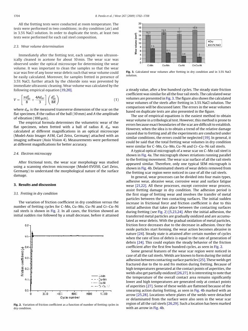
Fig. 3. Calculated wear volumes after fretting in dry condition and in 3.5% NaClsolution.
a steady value, after a few hundred cycles. The steady state frictioncoefficient was similar for all the four rail steels. The calculated wearvolumes are presented in Fig. 3. The figure also shows the calculatedwear volumes of the steels after fretting in 3.5% NaCl solution. Thecomparison will be discussed later. The errors in the wear volumesbased on duplicate tests are also presented in the figure.
The use of empirical equations is the easiest method to obtainwear volume in a tribological test. However, this method is prone toerrors because exact boundaries of the scar are difficult to establish.However, when the idea is to obtain a trend of the relative damagecaused due to fretting and all the experiments are conducted undersimilar conditions, the errors could be neglected [19]. In general, itcould be said that the total fretting wear volumes in dry conditionwere similar for C–Mn, Cu–Mo, Cu–Ni and Cr–Cu–Ni rail steels.
A typical optical micrograph of a wear scar on C–Mn rail steel isshown in Fig. 4a. The micrograph shows striations running parallelto the fretting movement. The wear scar surface of all the rail steelsappeared similar. Therefore, only one typical SEM micrograph isshown in Fig. 4b. Delaminated sheets of wear debris removed fromthe fretting scar region were noticed in case of all the rail steels.
In general, wear processes can be divided into four main types,adhesive wear, abrasive wear, corrosive wear and surface fatiguewear [21,22]. All these processes, except corrosive wear process,assist fretting damage in dry condition. The adhesion period isthe first stage of fretting wear and involves the transfer of metalparticles between the two contacting surfaces. The initial suddenincrease in frictional force and friction coefficient is due to thisinitial adhesion that takes place between the contacting surfacesduring fretting (see Fig. 2) [5,23,24]. After the initial adhesion, thetransferred metal particles are gradually oxidized and are accumu-lated as wear debris. With the gradual oxidation of metal particles,friction force decreases due to the decrease in adhesion. Once theoxide particles start forming, the wear action becomes abrasive innature [24]. Steady state is attained after certain number of cycleswhen the rate of loss of debris is equal to the rate of generation ofdebris [24]. This could explain the steady behavior of the frictioncoefficient after the first few hundred cycles, as seen in Fig. 2.
Some general features of the wear scar region were noticed incase of all the rail steels. Welds are known to form during the initialadhesion between contacting surface particles [25]. These welds getfractured due to the to and fro motion during fretting. Because ofhigh temperatures generated at the contact points of asperities, thewelds also get partially oxidized [26,27]. It is interesting to note thatthe temperature of the overall contact area remains significantlylower and high temperatures are generated only at contact pointsof asperities [27]. Some of these welds are flattened because of thesmearing action during fretting, as seen in Fig. 4b marked with an
arrow [25,28]. Locations where plates of the welds were detachedor delaminated from the surface were also seen in the wear scarregion of all the rail steels [26,29]. Such a location has been markedwith an arrow in Fig. 4b.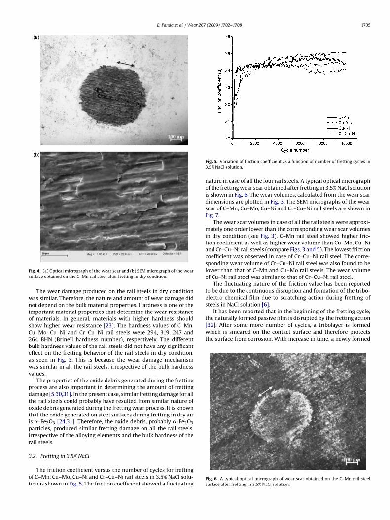
B. Panda et al. / Wear 267 (2009) 1702–1708 1705
Fs
wniosC2beawv
pdtotipir
3
ot
It has been reported that in the beginning of the fretting cycle,the naturally formed passive film is disrupted by the fretting action[32]. After some more number of cycles, a tribolayer is formedwhich is smeared on the contact surface and therefore protectsthe surface from corrosion. With increase in time, a newly formed
ig. 4. (a) Optical micrograph of the wear scar and (b) SEM micrograph of the wearurface obtained on the C–Mn rail steel after fretting in dry condition.
The wear damage produced on the rail steels in dry conditionas similar. Therefore, the nature and amount of wear damage didot depend on the bulk material properties. Hardness is one of the
mportant material properties that determine the wear resistancef materials. In general, materials with higher hardness shouldhow higher wear resistance [23]. The hardness values of C–Mn,u–Mo, Cu–Ni and Cr–Cu–Ni rail steels were 294, 319, 247 and64 BHN (Brinell hardness number), respectively. The differentulk hardness values of the rail steels did not have any significantffect on the fretting behavior of the rail steels in dry condition,s seen in Fig. 3. This is because the wear damage mechanismas similar in all the rail steels, irrespective of the bulk hardness
alues.The properties of the oxide debris generated during the fretting
rocess are also important in determining the amount of frettingamage [5,30,31]. In the present case, similar fretting damage for allhe rail steels could probably have resulted from similar nature ofxide debris generated during the fretting wear process. It is knownhat the oxide generated on steel surfaces during fretting in dry airs �-Fe2O3 [24,31]. Therefore, the oxide debris, probably �-Fe2O3articles, produced similar fretting damage on all the rail steels,
rrespective of the alloying elements and the bulk hardness of theail steels.
.2. Fretting in 3.5% NaCl
The friction coefficient versus the number of cycles for frettingf C–Mn, Cu–Mo, Cu–Ni and Cr–Cu–Ni rail steels in 3.5% NaCl solu-ion is shown in Fig. 5. The friction coefficient showed a fluctuating
Fig. 5. Variation of friction coefficient as a function of number of fretting cycles in3.5% NaCl solution.
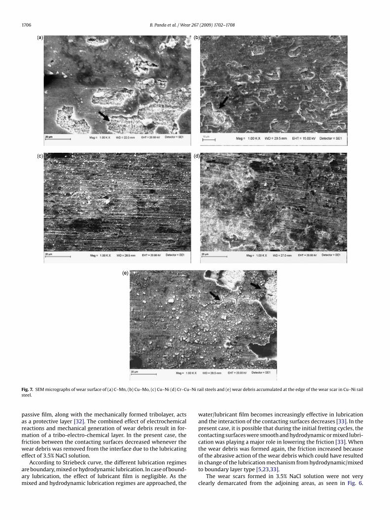
nature in case of all the four rail steels. A typical optical micrographof the fretting wear scar obtained after fretting in 3.5% NaCl solutionis shown in Fig. 6. The wear volumes, calculated from the wear scardimensions are plotted in Fig. 3. The SEM micrographs of the wearscar of C–Mn, Cu–Mo, Cu–Ni and Cr–Cu–Ni rail steels are shown inFig. 7.
The wear scar volumes in case of all the rail steels were approxi-mately one order lower than the corresponding wear scar volumesin dry condition (see Fig. 3). C–Mn rail steel showed higher fric-tion coefficient as well as higher wear volume than Cu–Mo, Cu–Niand Cr–Cu–Ni rail steels (compare Figs. 3 and 5). The lowest frictioncoefficient was observed in case of Cr–Cu–Ni rail steel. The corre-sponding wear volume of Cr–Cu–Ni rail steel was also found to belower than that of C–Mn and Cu–Mo rail steels. The wear volumeof Cu–Ni rail steel was similar to that of Cr–Cu–Ni rail steel.
The fluctuating nature of the friction value has been reportedto be due to the continuous disruption and formation of the tribo-electro-chemical film due to scratching action during fretting ofsteels in NaCl solution [6].
Fig. 6. A typical optical micrograph of wear scar obtained on the C–Mn rail steelsurface after fretting in 3.5% NaCl solution.
1706 B. Panda et al. / Wear 267 (2009) 1702–1708
F u–Ni rs
parmfwe
aam
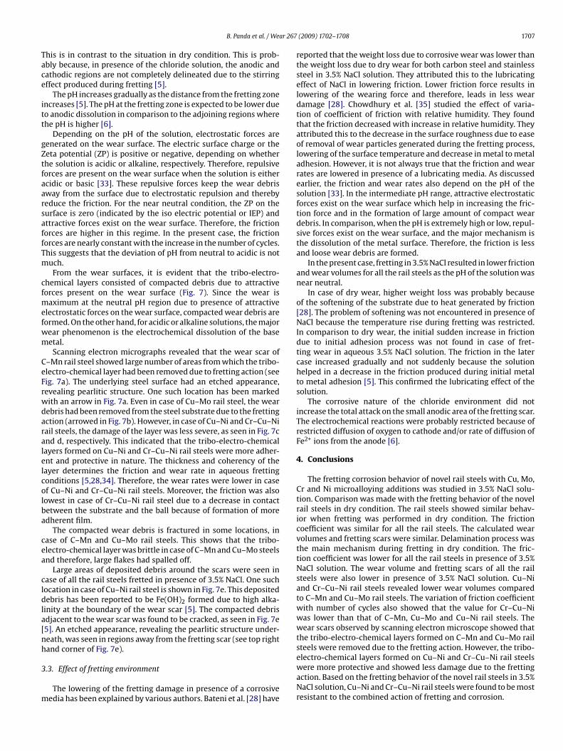
ig. 7. SEM micrographs of wear surface of (a) C–Mn, (b) Cu–Mo, (c) Cu–Ni (d) Cr–Cteel.
assive film, along with the mechanically formed tribolayer, actss a protective layer [32]. The combined effect of electrochemicaleactions and mechanical generation of wear debris result in for-ation of a tribo-electro-chemical layer. In the present case, the
riction between the contacting surfaces decreased whenever theear debris was removed from the interface due to the lubricating
ffect of 3.5% NaCl solution.According to Striebeck curve, the different lubrication regimes
re boundary, mixed or hydrodynamic lubrication. In case of bound-ry lubrication, the effect of lubricant film is negligible. As theixed and hydrodynamic lubrication regimes are approached, the
ail steels and (e) wear debris accumulated at the edge of the wear scar in Cu–Ni rail
water/lubricant film becomes increasingly effective in lubricationand the interaction of the contacting surfaces decreases [33]. In thepresent case, it is possible that during the initial fretting cycles, thecontacting surfaces were smooth and hydrodynamic or mixed lubri-cation was playing a major role in lowering the friction [33]. Whenthe wear debris was formed again, the friction increased because
of the abrasive action of the wear debris which could have resultedin change of the lubrication mechanism from hydrodynamic/mixedto boundary layer type [5,23,33].The wear scars formed in 3.5% NaCl solution were not veryclearly demarcated from the adjoining areas, as seen in Fig. 6.
r 267
Tace
itt
gZtfaarsaffTm
cfmefwm
CeFrwdaralelcolba
cea
cldla[nh
3
m
B. Panda et al. / Wea
his is in contrast to the situation in dry condition. This is prob-bly because, in presence of the chloride solution, the anodic andathodic regions are not completely delineated due to the stirringffect produced during fretting [5].
The pH increases gradually as the distance from the fretting zonencreases [5]. The pH at the fretting zone is expected to be lower dueo anodic dissolution in comparison to the adjoining regions wherehe pH is higher [6].
Depending on the pH of the solution, electrostatic forces areenerated on the wear surface. The electric surface charge or theeta potential (ZP) is positive or negative, depending on whetherhe solution is acidic or alkaline, respectively. Therefore, repulsiveorces are present on the wear surface when the solution is eithercidic or basic [33]. These repulsive forces keep the wear debrisway from the surface due to electrostatic repulsion and therebyeduce the friction. For the near neutral condition, the ZP on theurface is zero (indicated by the iso electric potential or IEP) andttractive forces exist on the wear surface. Therefore, the frictionorces are higher in this regime. In the present case, the frictionorces are nearly constant with the increase in the number of cycles.his suggests that the deviation of pH from neutral to acidic is notuch.From the wear surfaces, it is evident that the tribo-electro-
hemical layers consisted of compacted debris due to attractiveorces present on the wear surface (Fig. 7). Since the wear is
aximum at the neutral pH region due to presence of attractivelectrostatic forces on the wear surface, compacted wear debris areormed. On the other hand, for acidic or alkaline solutions, the majorear phenomenon is the electrochemical dissolution of the baseetal.Scanning electron micrographs revealed that the wear scar of
–Mn rail steel showed large number of areas from which the tribo-lectro-chemical layer had been removed due to fretting action (seeig. 7a). The underlying steel surface had an etched appearance,evealing pearlitic structure. One such location has been markedith an arrow in Fig. 7a. Even in case of Cu–Mo rail steel, the wearebris had been removed from the steel substrate due to the frettingction (arrowed in Fig. 7b). However, in case of Cu–Ni and Cr–Cu–Niail steels, the damage of the layer was less severe, as seen in Fig. 7cnd d, respectively. This indicated that the tribo-electro-chemicalayers formed on Cu–Ni and Cr–Cu–Ni rail steels were more adher-nt and protective in nature. The thickness and coherency of theayer determines the friction and wear rate in aqueous frettingonditions [5,28,34]. Therefore, the wear rates were lower in casef Cu–Ni and Cr–Cu–Ni rail steels. Moreover, the friction was alsoowest in case of Cr–Cu–Ni rail steel due to a decrease in contactetween the substrate and the ball because of formation of moredherent film.
The compacted wear debris is fractured in some locations, inase of C–Mn and Cu–Mo rail steels. This shows that the tribo-lectro-chemical layer was brittle in case of C–Mn and Cu–Mo steelsnd therefore, large flakes had spalled off.
Large areas of deposited debris around the scars were seen inase of all the rail steels fretted in presence of 3.5% NaCl. One suchocation in case of Cu–Ni rail steel is shown in Fig. 7e. This depositedebris has been reported to be Fe(OH)2 formed due to high alka-
inity at the boundary of the wear scar [5]. The compacted debrisdjacent to the wear scar was found to be cracked, as seen in Fig. 7e5]. An etched appearance, revealing the pearlitic structure under-eath, was seen in regions away from the fretting scar (see top rightand corner of Fig. 7e).
.3. Effect of fretting environment
The lowering of the fretting damage in presence of a corrosiveedia has been explained by various authors. Bateni et al. [28] have
(2009) 1702–1708 1707
reported that the weight loss due to corrosive wear was lower thanthe weight loss due to dry wear for both carbon steel and stainlesssteel in 3.5% NaCl solution. They attributed this to the lubricatingeffect of NaCl in lowering friction. Lower friction force results inlowering of the wearing force and therefore, leads in less weardamage [28]. Chowdhury et al. [35] studied the effect of varia-tion of coefficient of friction with relative humidity. They foundthat the friction decreased with increase in relative humidity. Theyattributed this to the decrease in the surface roughness due to easeof removal of wear particles generated during the fretting process,lowering of the surface temperature and decrease in metal to metaladhesion. However, it is not always true that the friction and wearrates are lowered in presence of a lubricating media. As discussedearlier, the friction and wear rates also depend on the pH of thesolution [33]. In the intermediate pH range, attractive electrostaticforces exist on the wear surface which help in increasing the fric-tion force and in the formation of large amount of compact weardebris. In comparison, when the pH is extremely high or low, repul-sive forces exist on the wear surface, and the major mechanism isthe dissolution of the metal surface. Therefore, the friction is lessand loose wear debris are formed.
In the present case, fretting in 3.5% NaCl resulted in lower frictionand wear volumes for all the rail steels as the pH of the solution wasnear neutral.
In case of dry wear, higher weight loss was probably becauseof the softening of the substrate due to heat generated by friction[28]. The problem of softening was not encountered in presence ofNaCl because the temperature rise during fretting was restricted.In comparison to dry wear, the initial sudden increase in frictiondue to initial adhesion process was not found in case of fret-ting wear in aqueous 3.5% NaCl solution. The friction in the latercase increased gradually and not suddenly because the solutionhelped in a decrease in the friction produced during initial metalto metal adhesion [5]. This confirmed the lubricating effect of thesolution.
The corrosive nature of the chloride environment did notincrease the total attack on the small anodic area of the fretting scar.The electrochemical reactions were probably restricted because ofrestricted diffusion of oxygen to cathode and/or rate of diffusion ofFe2+ ions from the anode [6].
4. Conclusions
The fretting corrosion behavior of novel rail steels with Cu, Mo,Cr and Ni microalloying additions was studied in 3.5% NaCl solu-tion. Comparison was made with the fretting behavior of the novelrail steels in dry condition. The rail steels showed similar behav-ior when fretting was performed in dry condition. The frictioncoefficient was similar for all the rail steels. The calculated wearvolumes and fretting scars were similar. Delamination process wasthe main mechanism during fretting in dry condition. The fric-tion coefficient was lower for all the rail steels in presence of 3.5%NaCl solution. The wear volume and fretting scars of all the railsteels were also lower in presence of 3.5% NaCl solution. Cu–Niand Cr–Cu–Ni rail steels revealed lower wear volumes comparedto C–Mn and Cu–Mo rail steels. The variation of friction coefficientwith number of cycles also showed that the value for Cr–Cu–Niwas lower than that of C–Mn, Cu–Mo and Cu–Ni rail steels. Thewear scars observed by scanning electron microscope showed thatthe tribo-electro-chemical layers formed on C–Mn and Cu–Mo railsteels were removed due to the fretting action. However, the tribo-
electro-chemical layers formed on Cu–Ni and Cr–Cu–Ni rail steelswere more protective and showed less damage due to the frettingaction. Based on the fretting behavior of the novel rail steels in 3.5%NaCl solution, Cu–Ni and Cr–Cu–Ni rail steels were found to be mostresistant to the combined action of fretting and corrosion.
1 ar 267
A
wDiGSCrfp
R
[
[
[
[
[
[
[
[
[[
[[[[
[
[
[
[[
[
[
708 B. Panda et al. / We
cknowledgements
The authors would like to thank the Technology Mission for Rail-ay Safety (TMRS) under the aegis of Ministry of Human Resourcesevelopment and Ministry of Railways, India for financial support
n research work. The authors would also like to thank Ms. Fieldun Factory, Kanpur, for carrying out compositional analysis; Mr.. Srikanth and Dr. A. Bhattacharyya of Research and Developmententre for Iron and Steel, Ranchi, for supplying the specially rolledail steel plates of new compositions and Bhilai Steel Plant, Bhilaior supplying the C–Mn and Cu–Mo rail steels and Dr. B. Basu forermitting us to use the fretting testing machine.
eferences
[1] Y.Y. Chen, H.J. Tzeng, L.I. Wei, L.H. Wang, J.C. Oung, H.C. Shih, Corrosionresistance and mechanical properties of low-alloy steels under atmosphericconditions, Corros. Sci. 47 (2005) 1001–1021.
[2] H.H. Uhlig, Corrosion and Corrosion Control, John Wiley & Sons, New York, 1971,p. 120.
[3] S.W. Watson, F.J. Friedersdorf, B.W. Madsen, S.D. Cramer, Methods of measuringwear-corrosion synergism, Wear 181–183 (1995) 476–484.
[4] Y. Yahagi, Y. Mizutani, Corrosive wear of carbon and austenitic stainless steelsin NaCl solution, Wear 110 (1986) 401–408.
[5] B.R. Pearson, P.A. Brook, R.B. Waterhouse, Fretting in aqueous media, particu-larly of roping steels in seawater, Wear 106 (1985) 225–260.
[6] R. Smallwood, B.R. Pearson, P.A. Brook, The influence of dissolved oxygenin seawater on the fretting corrosion of roping steel, Wear 125 (1988) 97–106.
[7] R.B. Waterhouse, D.E. Taylor, The initiation of fatigue cracks in a 0.7% carbonsteel by fretting, Wear 17 (1971) 139–147.
[8] M.P. Sherwin, D.E. Taylor, R.B. Waterhouse, An electrochemical investigation offretting corrosion in stainless steel, Corros. Sci. 11 (1971) 419–429.
[9] T. Misawa, T. Kyuno, W. Suëtaka, S. Shimodaira, The mechanism of atmosphericrusting and the effect of Cu and P on the rust formation of low alloy steels,Corros. Sci. II (1971) 35–48.
10] T. Misawa, K. Asami, K. Hashimoto, S. Shimodaira, The mechanism of atmo-spheric rusting and the protective amorphous rust on low alloy steel, Corros.
Sci. 14 (1974) 279–289.11] K. Inouye, K. Ichimura, K. Kaneko, T. Ishikawa, The effect of copper (II) on theformation of �-FeOOH, Corros. Sci. 16 (1976) 507–517.
12] M. Kimura, H. Kihira, N. Ohta, M. Hashimoto, T. Senuma, Control of Fe(O,OH)6
nano-network structures of rust for high atmospheric-corrosion resistance,Corros. Sci. 47 (2005) 2499–2509.
[
[
[
(2009) 1702–1708
13] M. Stratmann, K. Bohnenkamp, T. Ramachandran, The influence of copper uponthe atmospheric corrosion of iron, Corros. Sci. 27 (1987) 905–926.
14] T. Ishikawa, A. Maeda, K. Kandori, A. Tahara, Characterization of rust on Fe-Cr,Fe-Ni and Fe-Cu binary alloys by Fourier transform infrared and N2 adsorption,Corrosion 62 (2006) 559–567.
15] M. Yamashita, H. Miyuki, Y. Matsuda, H. Nagano, T. Misawa, The long termgrowth of the protective rust layer formed on weathering steel by atmosphericcorrosion during quarter of a century, Corros. Sci. 36 (1994) 283–299.
16] K. Asami, M. Kikuchi, In-depth distribution of rusts on a plain carbon steel andweathering steels exposed to coastal-industrial atmosphere for 17 years, Corros.Sci. 45 (2003) 2671–2688.
[17] M. Itagaki, R. Nozue, K. Watanabe, H. Katayama, K. Noda, Electrochemicalimpedance of thin rust film of low alloy steels, Corros. Sci. 46 (2004) 1301–1310.
[18] S. Srikanth, V.K. Singh, A. Bhattacharyya, U.P. Singh, B. Roy, K.B. Mishra, S. Jha,Corrosion resistant rails – effect of Cu and Cu-Mo alloying additions on themicrostructure and properties of pearlitic rail steels, in: Conference Proceed-ings, CORCON 2004 NACE International India Section, New Delhi, December2–4, 2004.
19] M. Kalin, J. Vizintin, Use of equations for wear volume determination in frettingexperiments, Wear 237 (2000) 39–48.
20] D. Klaffke, Fretting wear of ceramics, Tribol. Int. 22 (1989) 89–101.21] E. Rabinowicz, Friction and Wear of Materials, John Wiley, New York, 1965, p.
113.22] R.B. Waterhouse, Tribology and electrochemistry, Tribology 3 (1970) 158–162.23] R.B. Waterhouse, Fretting Corrosion, Pergamon Press, Oxford, 1972, p. 119.24] P.L. Hurricks, The mechanism of fretting—a review, Wear 15 (1970) 389–409.25] R.B. Waterhouse, The role of adhesion and delamination in the fretting wear of
metallic materials, Wear 45 (1977) 355–364.26] R.B. Waterhouse, D.E. Taylor, Fretting debris and the delamination theory of
wear, Wear 29 (1974) 337–344.27] M. Kalin, J. Vizintin, A tentative explanation for the tribochemical effects in
fretting wear, Wear 250 (2001) 681–689.28] M.R. Bateni, J.A. Szpunar, X. Wang, D.Y. Li, Wear and corrosion wear of medium
carbon steel and 304 stainless steel, Wear 260 (2006) 116–122.29] N.P. Suh, An overview of the delamination theory of wear, Wear 44 (1977) 1–16.30] S. Hogmark, O. Vingsbo, Mechanism of dry wear of some martensitic steels,
Wear 31 (1975) 39–61.31] T. Kayaba, A. Iwabuchi, Effect of the hardness of hardened steels and the action
of oxides on fretting wear, Wear 66 (1981) 27–41.32] A.C. Vieira, A.R. Ribeiro, L.A. Rocha, J.P. Celis, Influence of pH and corrosion
inhibitors on the tribocorrosion of titanium in artificial saliva, Wear 261 (2006)994–1001.
33] M. Kalin, S. Novak, J. Vizintin, Surface charge as a new concept for boundarylubrication of ceramics with water, Phys. D: Appl. Phys. 39 (2006) 3138–3149.
34] B. Bethune, R.B. Waterhouse, Electrochemical studies of fretting corrosion, Wear12 (1968) 27–34.
35] M.A. Chowdhury, Md.M. Helali, The effect of frequency of vibration and humid-ity on the coefficient of friction, Tribol. Int. 39 (2006) 958–962.
Related Documents