FREQUENCY MODULATION (FM) SYNTHESIS + phase distortion (PD) Electronic musical instruments

Welcome message from author
This document is posted to help you gain knowledge. Please leave a comment to let me know what you think about it! Share it to your friends and learn new things together.
Transcript
FREQUENCY
MODULATION (FM)
SYNTHESIS
+ phase distortion (PD)
Electronic musical instruments
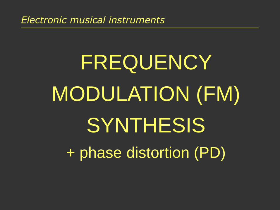
Frequency modulation (FM)
FM – frequency modulation, used since 1920s to transmit radio waves:
• transmitted signal (modulator) – e.g. radio broadcast
• carrier signal – high frequency sine (e.g. 99.8 MHz)
• amplitude of the transmitted signal modulatesinstantaneous frequency of the carrier
• modulated signal is transmitted on air
• the received signal is demodulated
• we obtain the original signal
source: http://slidedeck.io/jsantell/dsp-with-web-audio-presentation

FM in sound synthesis
1973 – John Chowning published a paper:
„The Synthesis of Complex Audio Spectraby Means of Frequency Modulation”.
• If the two signals have specific frequencies,a harmonic signal is obtained.
• Changes in modulator amplitude modify the timbre.
• Multiple modulations may be performed.
• Easy and cheap method of digital sound synthesis.
• Patented in 1975-1995 by Chowning and Yamaha.

FM in sound synthesis
Let’s simplify the problem to two sine oscillators:
• carrier signal (C)
xc(t) = A sin(t)
• modulating signal (M)
xm(t) = I sin(t)
The modulator changes (modulates)the instantaneous frequencyof the carrier signal:
x(t) = A sin[t + xm(t)]
x(t) = A sin[t + I sin(t)]

Frequency modulation in sound
What effect does FM produce?
• Low modulating frequency (<1 Hz): slow wobbling of the pitch (just like LFO in the subtractive synthesis).
• Modulating frequency in 1 Hz – 20 Hz range:an increasing vibrato effect.
• Frequency above 20 Hz: an inharmonic sound is produced, it sounds very rough.
• In some configurations, e.g. if both frequencies are the same, we get a nice sounding harmonic signal!

Synthetic spectrum components
Peaks in the spectrum of a modulated sound:
fc k fm (k = 0, 1, 2, ...)
In FM terms: lower and upper band (below and above fc )
For example, fc = 500 Hz, fm = 100 Hz:…, 100, 200, 300, 400, 500, 600, 700, 800, 900, …
Reflection of spectral components
• What about components with negative frequencies?For example, for fc = 400 Hz, fm = 100 Hz, we obtain:fc – 5fm = 400 – 500 = -100 Hz
• We know that: sin(–x) = –sin(x)
• Therefore:
– a “negative” component is reflected to a positive frequency (an absolute value is taken),
– phase of the reflected component is inversed,
– if another component is present at this frequency, amplitudes are summed up (with phase).

Reflection of spectral components
amplituda
f
f
f
f
c
Spectrum with a“negative” component
The component is reflected, its sign changes.
The components aresummed, taking theirphase into account
Absolute values of the amplitude are taken.

Modulation ratio
Modulation ratio wm – a ratio of modulating frequency to the carrier frequency.
• In order to obtain a harmonic signal, the modulation ratio has to be expressed as a ratio of integers N2 and N1.
• In practice, low integers are used, e.g.: 1:1, 2:1, 3:1, 3:2.
1
2
N
N
f
fw
c
mm ==

Modulation ratio
Typical values of the modulation ratio(spectral frequencies are calculated for fc = 400 Hz):
• 1:1 – all spectral components are present400, 800, 1200, 1600, 2000, …
• 2:1 – only even numbered components (k = 0,2,4,...)400, 1200, 2000, 2800, …
• 3:1 – every third component is missing400, 800, 1600, 2000, 2800, …
Example of an inharmonic spectrum:
• wm = 2 : 1

Modulation ratio and fundamental frequency
Warning: this is a common mistake.
Carrier frequency does not have to be equal to the fundamental frequency! The latter is determined by the first peak in the harmonic series.
• fc = 500 Hz, fm = 500 Hz → f0 = 500 Hz(for modulation ratio 1:1, both frequencies are the same)
• fc = 500 Hz, fm = 100 Hz → f0 = 100 Hz(the first peak is at 100 Hz: 500 – 4 x 100)
• fc = 200 Hz, fm = 300 Hz → f0 = 100 Hz (!!!)…, -700, -400, -100, 200, 500, 800, … (reflection:)100, 200, 400, 500, 700, 800, …
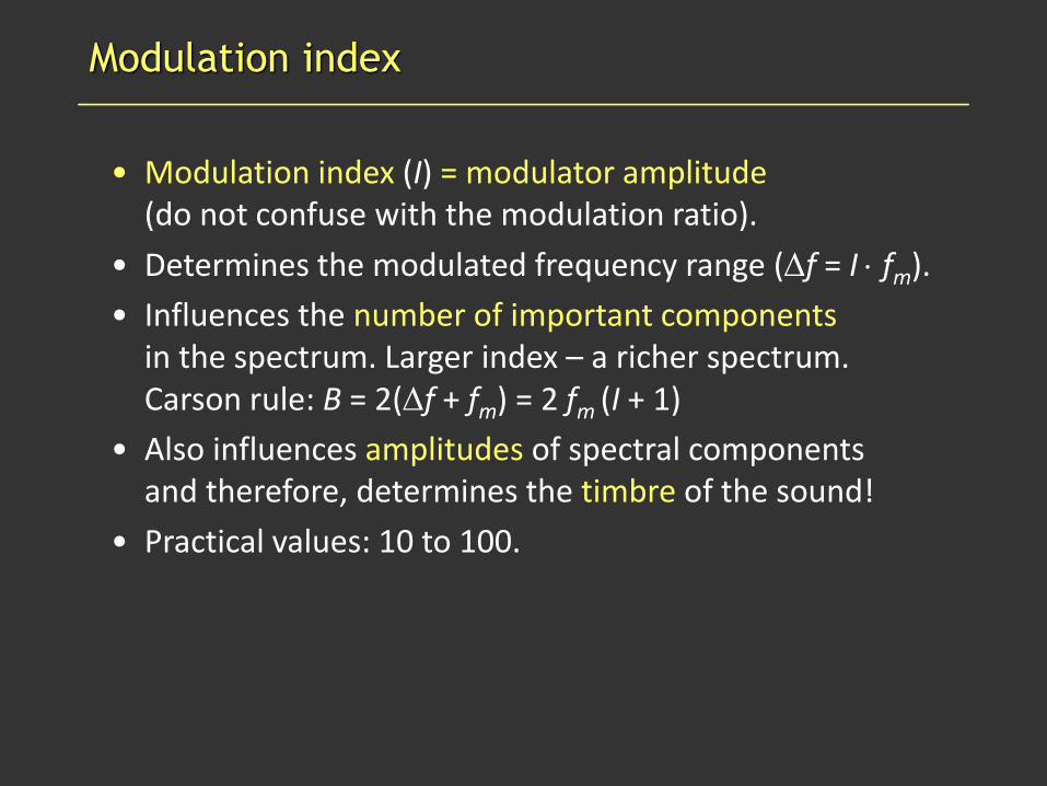
Modulation index
• Modulation index (I) = modulator amplitude(do not confuse with the modulation ratio).
• Determines the modulated frequency range (f = I fm).
• Influences the number of important componentsin the spectrum. Larger index – a richer spectrum.Carson rule: B = 2(f + fm) = 2 fm (I + 1)
• Also influences amplitudes of spectral componentsand therefore, determines the timbre of the sound!
• Practical values: 10 to 100.

Influence of the modulation index
Carrier frequency: 220 Hz, modulation: 440 Hz
Time signals Spectra
0.1
1
10
100

Amplitude of spectral components
Amplitudes of spectral components are given by:
}............................................................
])3sin( )3sin([ )(
])2sin( )2sin([ )(
])sin( )sin([ )(
)sin( )({ )(
3
2
1
0
+
−−++
−+++
−−++
=
nTnTIJ
nTnTIJ
nTnTIJ
nTIJAnx
mcmc
mcmc
mcmc
c
Minus dla nieparzystych prążków wstęgi dolnej!
Note: odd numbered components in the lower band have inversed phase – negative sign.
Jn(I): n-th order Bessel functions, argument: modulation idx.

Bessel functions (J)
fc
fc fm
fc 2fm fc 5fm
fc 4fm
fc 3fm

Influence of modulation index on spectrum
f
amplituda
f
f
f
f
c
c
c
c
c
c+mc-m c+3mc-3m
c+2mc-2m
c-4m c+4m
c-5m c+5m
I=0
I=1
I=2
c-4m c+4m
I=3
I=4
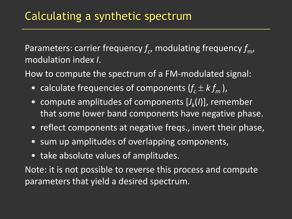
Calculating a synthetic spectrum
Parameters: carrier frequency fc, modulating frequency fm, modulation index I.
How to compute the spectrum of a FM-modulated signal:
• calculate frequencies of components (fc k fm ),
• compute amplitudes of components [Jk(I)], remember that some lower band components have negative phase.
• reflect components at negative freqs., invert their phase,
• sum up amplitudes of overlapping components,
• take absolute values of amplitudes.
Note: it is not possible to reverse this process and compute parameters that yield a desired spectrum.

FM synthesis parameters
• Frequencies: carrier (fm) and modulating (fm) determine the location of spectral components:
– they determine if the sound is harmonic,
– if it is, they determine the sound pitch.
• Modulation index (I) determines amplitudes of spectral components (and, indirectly, the number of components)
– decide on the sound timbre,
– modulation index has to be changed during a sound synthesis in order to introduce dynamic timbre changes and make the sound alive.

Operator
Operator is a basic building block of FM synthesis.
It consists of:
• sine oscillator (OSC)
• amplifier (VCA)
• envelope generator (EG)
freq – fixed frequency
mod – modulating frequency
OSC generates a sine with instantaneousfrequency = freq + mod
OSC
VCA EG
modfreq
amp

FM algorithm
A connection of two or more operators creates a FM synthesis algorithm.
• Two operators (Simple FM, 2-op FM): one carrier and one modulator. The simplest algorithm possible, not sufficient to obtain useful effects.
• In practice, more operators (usually 6) are used, many algorithms are possible.
• The same operators with the same settings, but connected in a different algorithm, produce completely different sound!

Examples of 6-op algorithms
M – modulator, C – carrier
Stack
C
M
M
M
M
M
Additive
C C C C C C
Pairs
M
C
M
C
M
C
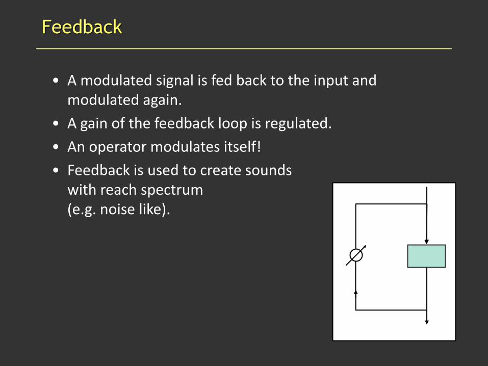
Feedback
• A modulated signal is fed back to the input and modulated again.
• A gain of the feedback loop is regulated.
• An operator modulates itself!
• Feedback is used to create soundswith reach spectrum(e.g. noise like).

Setting the synthesis parameters
• In an EMI, a pressed key fixes the fundamental frequency.
• For each operator, a frequency multiplier is set. The operator generates freq.: fundamental * multiplier.
• Output amplitude in each operator is controlled by EG.
• Amplitudes of carriers (output operators) determine the output level (loudness), EGs control the sound envelope.
• Amplitudes of modulators determine the sound timbre,EGs control modulation index changes.

Setting the synthesis parameters
Sound timbre is controlled with modulation indices – amplitudes of signals generated by modulating operators.
Modulation index may be controlled by:
• envelope generators in the modulators – we can modify the timbre, especially in the attack phase,
• LFO blocks – modulation during the sustain phase,
• other controllers, e.g. a modulation wheel.
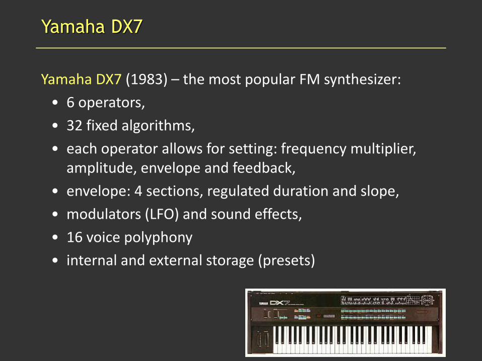
Yamaha DX7
Yamaha DX7 (1983) – the most popular FM synthesizer:
• 6 operators,
• 32 fixed algorithms,
• each operator allows for setting: frequency multiplier, amplitude, envelope and feedback,
• envelope: 4 sections, regulated duration and slope,
• modulators (LFO) and sound effects,
• 16 voice polyphony
• internal and external storage (presets)

Yamaha DX7
Envelope
Operator
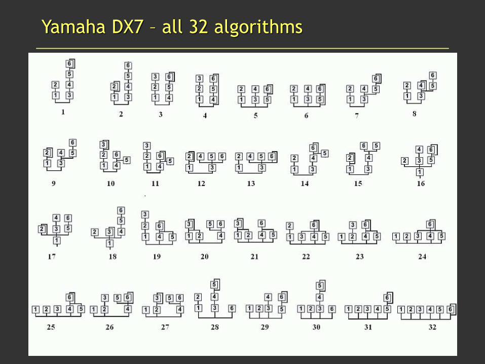
Yamaha DX7 – all 32 algorithms
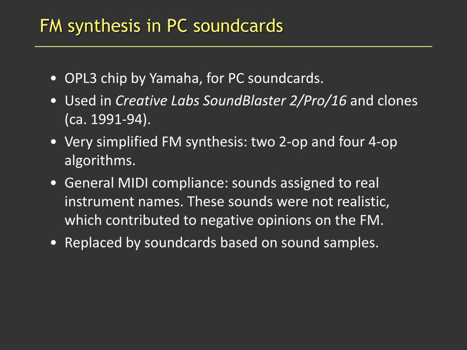
FM synthesis in PC soundcards
• OPL3 chip by Yamaha, for PC soundcards.
• Used in Creative Labs SoundBlaster 2/Pro/16 and clones(ca. 1991-94).
• Very simplified FM synthesis: two 2-op and four 4-op algorithms.
• General MIDI compliance: sounds assigned to real instrument names. These sounds were not realistic, which contributed to negative opinions on the FM.
• Replaced by soundcards based on sound samples.

Software FM synthesis
Software FM synthesizers – emulation of hardware synthesizers (NI FM7 i FM8) or custom implementations.
They retain all advantages of the classic FM method.
New functions:
• operators can generate more complex signals than sines, it changes the sound significantly,
• modulation matrices- creating customalgorithms
• additional modules(effects, modulators)

Summary of FM synthesis
Pros:
• interesting and novel sounds (in early 1980s),
• easy and cheap implementation, compared with analogue synthesizers,
• stable pitch,
• many possibilities of sound creation.
Cons:
• relation between the parameters and the sound is not intuitive,
• for some people, the sound is too artificial (“plastic”).

PHASE DISTORTION SYNTHESIS (PD)
• PD synthesis method was developed by Casio and used in their CZ series instruments (1985-1988).
• Digital, “mathematic” synthesis, similarly to FM.
• Very “synthetic” sounds, almost toy-like.
• The concept: dynamic changes in phase of a sine signal introduce harmonic distortion into the signal and create a sound with a dynamic (changing) timbre.
• The sine signal is read from memory.
• Phase distortion is introduced by varying the speed of reading sine samples from the memory.

An illustration of phase distortion

Practical phase distortion
• In practice, timbre changes were achieved by changing the distortion coefficient in 0 to 1 range:
– 0: pure sine,
– 1: target signal, e.g. a square wave,
– between 0 and 1: something in between.
• The distortion coefficient is regulated by envelope generators.
• A “timbre morphing”effect is achieved.
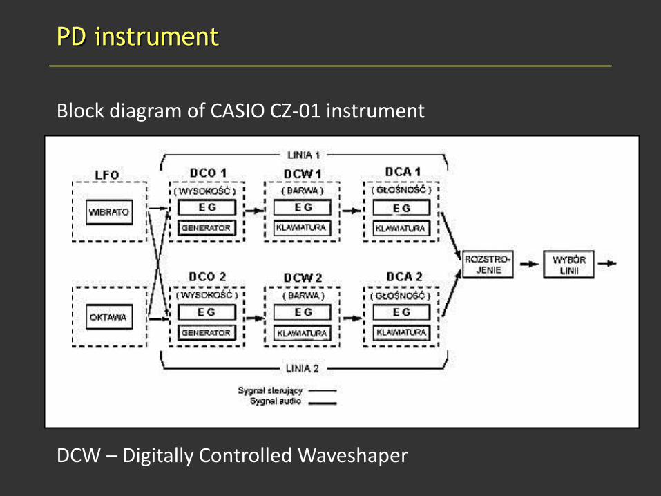
PD instrument
Block diagram of CASIO CZ-01 instrument
DCW – Digitally Controlled Waveshaper

PD instrument
• 8 target wave shapes, stored in memory.
• These shapes can be combined in pairs.
• A total of 33 wave shapes are possible.
• Envelope controls the phase distortion coefficient.

DCW – Digitally controlled waveshaper
• Envelope controls the phase distortion:
– 0: sine (no distortion),
– 99: target wave (full distortion).
• Key follow: max distortion depends on the key number.
• Velocity: max distortion depends on the strength of key press.

Casio CZ instruments
CZ-101 (1985)
CZ-5000 (1985)
CZ-1 (1986)

Summary of PD synthesis
Pros:
• possibility of creation of new, interesting sounds,
• easy to implement and cheap,
• easy to use (small number of parameters).
Cons:
• spectrum cannot be controlled directly,
• FM gives more possibilities of sound creation,
• produces synthetic, “toy like” sounds (but many musicians liked CZ instruments just because of this).

Bibliography
• J. Chowning: The Synthesis of Complex Audio Spectra by Means of Frequency Modulation. Journal of Audio Engineering Society, Vol. 21, No. 7, pp. 526-534.
• Yamaha DX7 – manual and other: https://homepages.abdn.ac.uk/d.j.benson/pages/html/dx7.html
• NI FM8 – a commercial FM software synthesizer: http://www.native-instruments.com/index.php?id=fm8
• Dexed – simple FM synthesizer: https://asb2m10.github.io/dexed/
• Casio CZ-1 Operation Manual: http://www.synthzone.com/midi/casio/cz1/
• Casio Sound Synthesis Handbook: https://physics-astronomy-manuals.wwu.edu/Casio%20CZ-Series%20Sound%20Synthesis%20Handbook.pdf
• Vintage Synthe Explorer: https://www.vintagesynth.com
• Wikipedia: FM synthesis
Related Documents