1 Frequency Electronics, Inc. Frequency Electronics, Inc. Tutorial Precision Frequency Generation Utilizing OCXO and Rubidium Atomic Standards with Applications for Commercial, Space, Military, and Challenging Environments IEEE Long Island Chapter March 18, 2004 Olie Mancini Vice President, New Business Development Tel: +516-357-2464 email: [email protected] Acknowledgement: Some of the following slides are provided courtesy of Dr. John R. Vig, U.S. Army Communications-Electronics Command

Welcome message from author
This document is posted to help you gain knowledge. Please leave a comment to let me know what you think about it! Share it to your friends and learn new things together.
Transcript
1
Frequency Electronics, Inc.Frequency Electronics, Inc.Tutorial
Precision Frequency Generation Utilizing OCXO and Rubidium Atomic Standards with
Applications forCommercial, Space, Military, and Challenging
Environments
IEEE Long Island ChapterMarch 18, 2004
Olie ManciniVice President, New Business Development
Tel: +516-357-2464 email: [email protected]
Acknowledgement:Some of the following slides are provided courtesy of Dr. John R. Vig,
U.S. Army Communications-Electronics Command

2
AgendaAgendaSection 1: Quartz Oscillator TechnologySection 2: Atomic Frequency StandardsSection 3: Applications– Commercial– Space– GPS– Radar
Section 4: Breakthrough in Vibration Effects on Clocks Stabilities and Side Bands--Vibration Insensitive Oscillators???Reference Charts
3
Section 1Section 1
Quartz TechnologyQuartz Technology
4
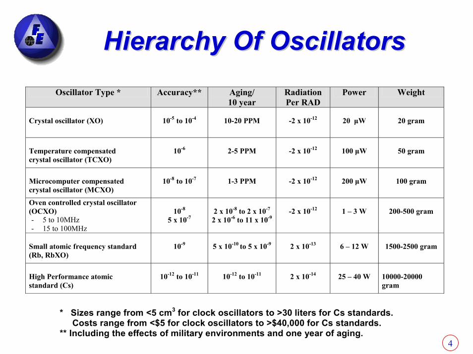
Hierarchy Of OscillatorsHierarchy Of OscillatorsOscillator Type * Accuracy** Aging/
10 year Radiation Per RAD
Power Weight
Crystal oscillator (XO)
10-5 to 10-4
10-20 PPM
-2 x 10-12
20 µW
20 gram
Temperature compensated crystal oscillator (TCXO)
10-6
2-5 PPM
-2 x 10-12
100 µW
50 gram
Microcomputer compensated crystal oscillator (MCXO)
10-8 to 10-7
1-3 PPM
-2 x 10-12
200 µW
100 gram
Oven controlled crystal oscillator (OCXO) - 5 to 10MHz - 15 to 100MHz
10-8
5 x 10⁻⁷
2 x 10⁻⁸ to 2 x 10⁻⁷
2 x 10⁻⁶ to 11 x 10-9
-2 x 10-12
1 – 3 W
200-500 gram
Small atomic frequency standard (Rb, RbXO)
10-9
5 x 10⁻¹⁰ to 5 x 10⁻⁹
2 x 10-13
6 – 12 W
1500-2500 gram
High Performance atomic standard (Cs)
10-12 to 10-11
10-12 to 10-11
2 x 10-14
25 – 40 W
10000-20000 gram
* Sizes range from <5 cm3 for clock oscillators to >30 liters for Cs standards. Costs range from <$5 for clock oscillators to >$40,000 for Cs standards. ** Including the effects of military environments and one year of aging.
5
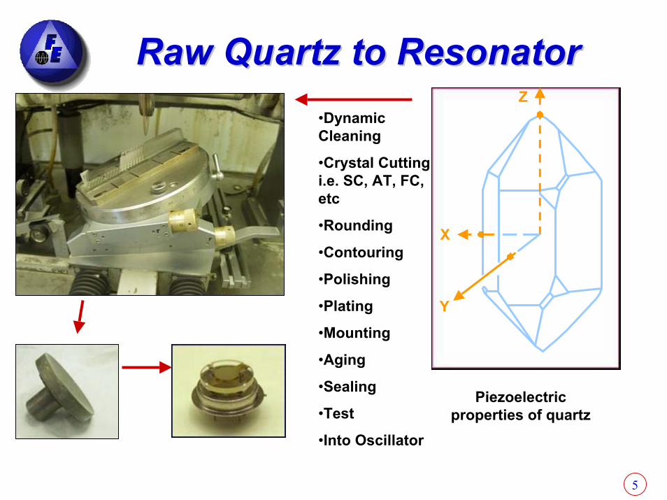
Raw Quartz to ResonatorRaw Quartz to Resonator
X
Y
Z•Dynamic Cleaning
•Crystal Cutting i.e. SC, AT, FC, etc
•Rounding
•Contouring
•Polishing
•Plating
•Mounting
•Aging
•Sealing
•Test
•Into Oscillator
Piezoelectric properties of quartz
6
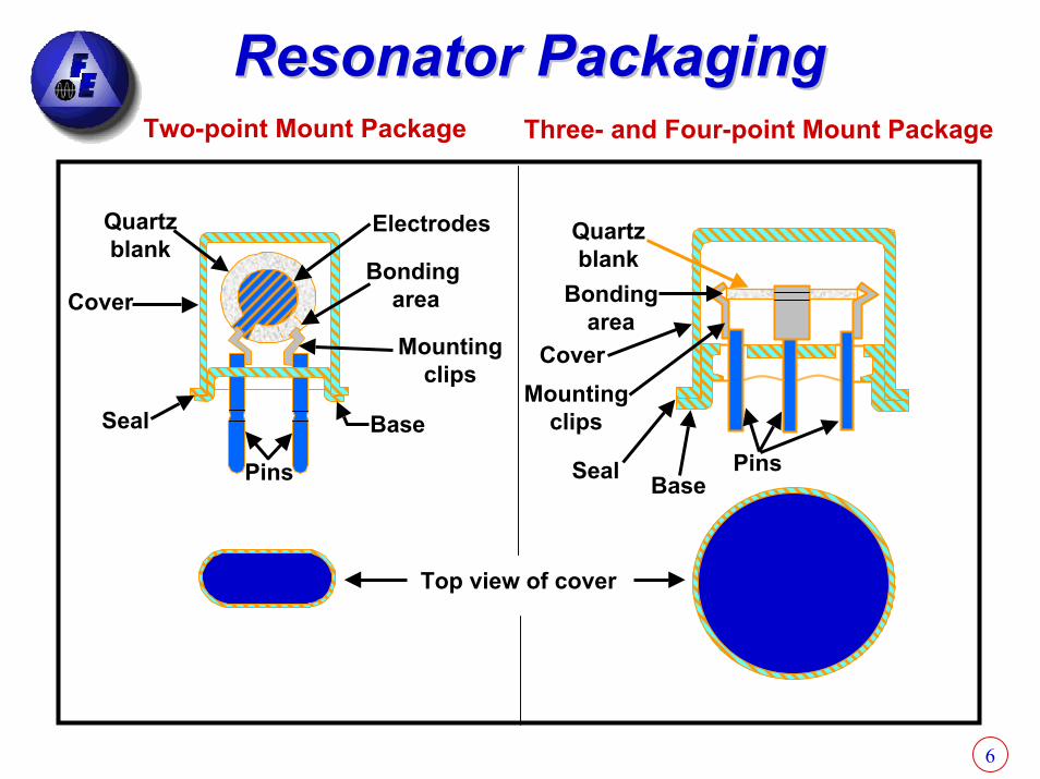
Resonator PackagingResonator PackagingTwo-point Mount Package Three- and Four-point Mount Package
Base
Mountingclips
Bondingarea
ElectrodesQuartzblank
Cover
Seal
Pins
Quartzblank
Bondingarea
CoverMounting
clips
Seal BasePins
Top view of cover
7
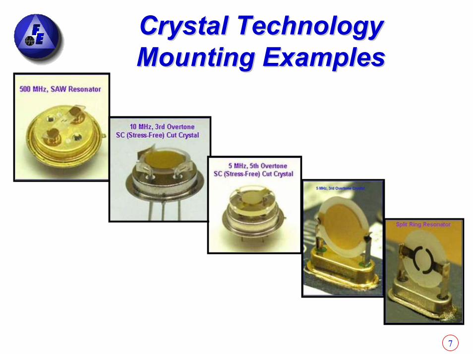
Crystal TechnologyCrystal TechnologyMounting ExamplesMounting Examples
8
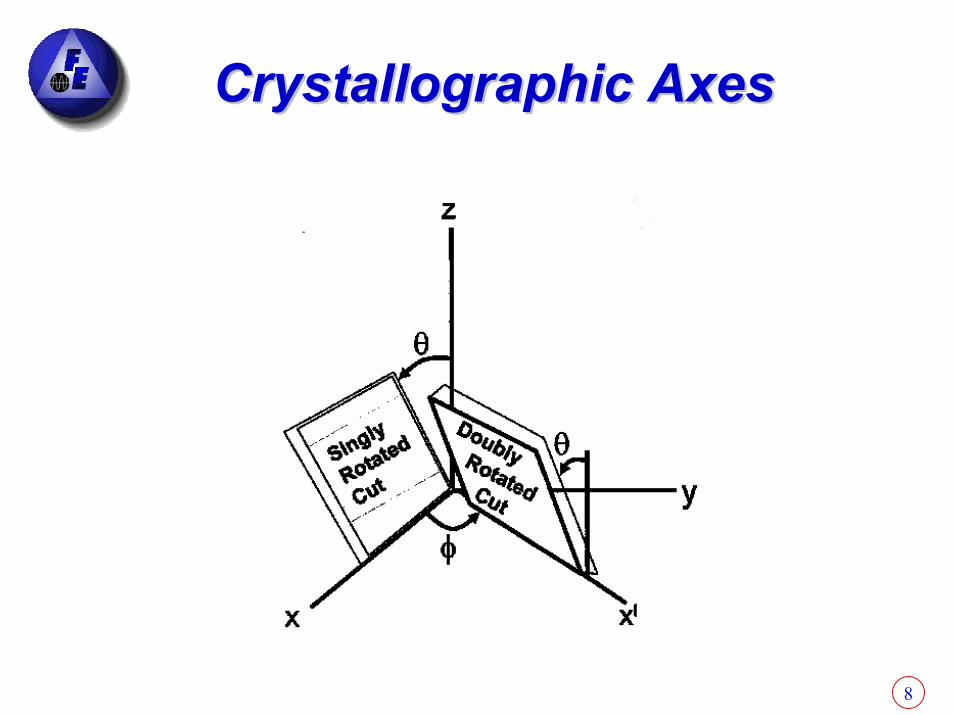
Crystallographic AxesCrystallographic Axes

9
SCSC--Cut 21.93Cut 21.93oo
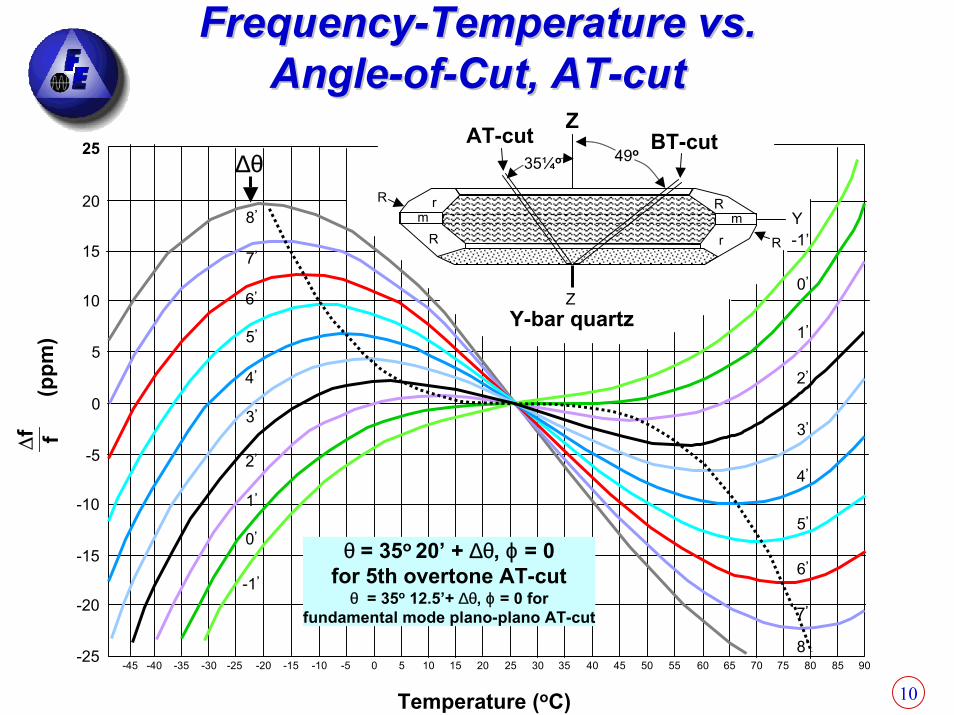
FrequencyFrequency--Temperature vs. Temperature vs. AngleAngle--ofof--CutCut
∆θ∆θ
10
FrequencyFrequency--Temperature vs. Temperature vs. AngleAngle--ofof--Cut, ATCut, AT--cutcut
rm
R
R
R
Rrm Y
ZAT-cut BT-cut49o
35¼o
-1’
0’
1’
2’
3’
4’
5’
6’
7’
8’
-1’
0’
1’
2’
3’
4’
5’
6’
7’
8’
∆θ
Y-bar quartzZ
25
20
15
10
5
0
-5
-10
-15
-20
-25-45 -40 -35 -30 -25 -20 -15 -10 -5 0 5 10 15 20 25 30 35 40 45 50 55 60 65 70 75 80 85 90
∆f f(p
pm)
Temperature (oC)
θ = 35o 20’ + ∆θ, ϕ = 0for 5th overtone AT-cut
θ = 35o 12.5’+ ∆θ, ϕ = 0 forfundamental mode plano-plano AT-cut
11
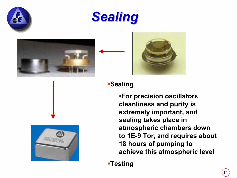
SealingSealing
Sealing
•For precision oscillators cleanliness and purity is extremely important, and sealing takes place in atmospheric chambers down to 1E-9 Tor, and requires about 18 hours of pumping to achieve this atmospheric level
Testing
12
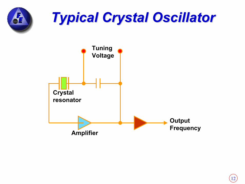
Typical Crystal OscillatorTypical Crystal Oscillator
TuningVoltage
Crystalresonator
Amplifier
OutputFrequency
13
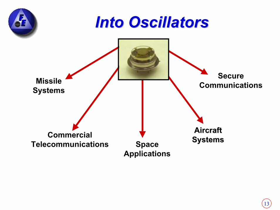
Into OscillatorsInto Oscillators
Missile Systems
Secure Communications
Commercial Telecommunications Space
Applications
Aircraft Aircraft SystemsSystems
14
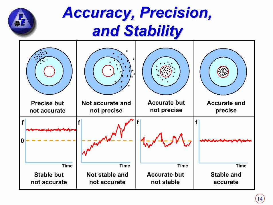
Precise butnot accurate
Not accurate andnot precise
Accurate butnot precise
Accurate andprecise
Time TimeTimeTime
Stable butnot accurate
Not stable andnot accurate
Accurate butnot stable
Stable andaccurate
0
f fff
Accuracy, Precision, Accuracy, Precision, and Stabilityand Stability

15
Oscillator StabilityOscillator StabilityDefinitions:– 1x10-10 = 1E-10 = 1e-10 = 1/10,000,000,000 =
.000 000 000 1 or 0.1x10-9 = 0.1ppb. – Example: An Accuracy of 1x10⁻¹⁰ at 10MHz affects
the frequency as shown on a sensitive freq meter
What Affects Oscillator Stability?– Aging– Temperature– Radiation– Vibrations
10,000,000.0010,000,000.0011 Note that the milliNote that the milli--Hertz position is affected Hertz position is affected

16
Typical Aging BehaviorsTypical Aging Behaviors
A(t) = 5 ln(0.5t+1)
Time
A(t) +B(t)
∆f/f
B(t) = -35 ln(0.006t+1)

17
Aging MechanismsAging MechanismsMass transfer due to contamination
Since f ∝ 1/t, ∆f/f = -∆t/t; e.g., f5MHz ≈ 106 molecular layers,therefore, 1 quartz-equivalent monolayer ⇒ ∆ f/f ≈ 1 ppm
Stress relief in the resonator's: mounting and bonding structure, electrodes, and in the quartz (?)
Other effectsQuartz outgassingDiffusion effectsChemical reaction effectsPressure changes in resonator enclosure (leaks and outgassing)Oscillator circuit aging (load reactance and drive level changes)Electric field changes (doubly rotated crystals only)Oven-control circuitry aging

18
QUARTZ CRYSTAL THICKNESS QUARTZ CRYSTAL THICKNESS AS A FUNCTION OF CUTAS A FUNCTION OF CUT
f = AK/t f = Frequency in MHzA = Overtone (1, 3, 5, 7)
t = AK/f K = A constant (Mils)t = Thickness in Mils
KAT = 65.5 MilsKFC = 68 MilsKSC = 72.3 Mils
e.g.: t = 1 x 65.5 = 65.5 mils thick for an AT cut Fundamental 1MHz crystal 1
•• THICKNESS SHEAR QUARTZ RESONATORS ARE PREDOMINANTELY USEDFOR MOST HIGH PRECISION QUARTZ APPLICATIONS.
• THE MOST USEFUL QUARTZ CRYSTAL CUTS ARE THE AT, FC AND SC.
• THE THICKEST QUARTZ BLANK SHOULD BE USED AT THE HIGHESTPRACTICAL OVERTONE FOR BEST AGING AND RETRACE PERFORMANCE.

19

20
Typical Aging Plot Typical Aging Plot
Aging Plot
-5.00E-09-4.50E-09-4.00E-09-3.50E-09-3.00E-09-2.50E-09-2.00E-09-1.50E-09-1.00E-09-5.00E-100.00E+005.00E-101.00E-091.50E-092.00E-092.50E-093.00E-093.50E-094.00E-094.50E-095.00E-09
0 1 2 3 4 5 6 7 8 9 10 11 12 13 14 15 16 17 18 19 20 21 22 23 24 25
WEEKS
Del
taF/
F in
5pp
e-10
/ di
v.
163
Aging per day
18x10-10/21weekx7days
≈1.2x10⁻¹¹
Aging after 10 years linear approximation
(1.2x10⁻¹¹)(365days)(10year)
≈4.38x10⁻⁸
τ1/2 ≈ (4.38x10⁻⁸)/2 ≈ 2x10⁻⁸
21
Temperature EffectsTemperature EffectsCrystal must be maintained at constant temperature over entire operating range– Operating range may be from –40C to +85C– The more precise is the oven the better is the
temperature coefficient
Precision ovens are constructed around the resonator and insulation is added around the oven to maintain a more uniform temperature gradient
Ovens come in different sizes and shapes– Single oven– Double oven– Ovens in Dewar Flasks for super precision
22
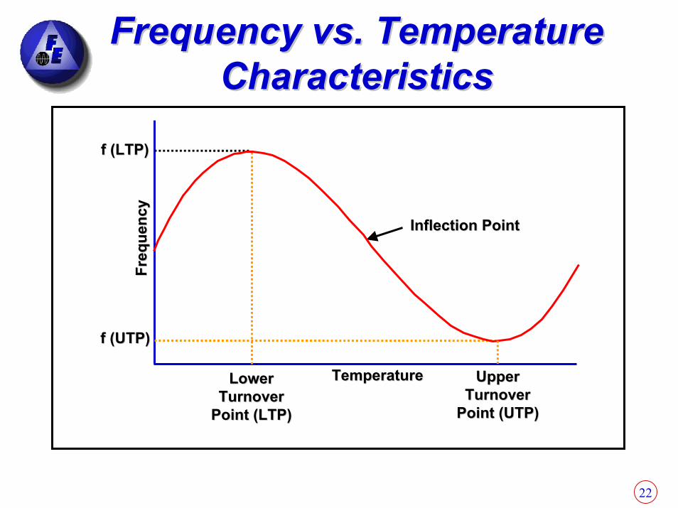
Frequency vs. Temperature Frequency vs. Temperature CharacteristicsCharacteristics
Inflection PointInflection Point
TemperatureTemperatureLowerLowerTurnoverTurnover
Point (LTP)Point (LTP)
UpperUpperTurnoverTurnover
Point (UTP)Point (UTP)
f (UTP)f (UTP)
f (LTP)f (LTP)Fr
eque
ncy
Freq
uenc
y

23
Example of Super Precise Example of Super Precise Double Oven OCXO Double Oven OCXO
(FE(FE--205A Series)205A Series)
2”W x 2”L x 1.5”HFor Through Hole Package
3”W x 3’’L x 1.4”HFor Rubidium Package
24
Example:Example:Effects of Aging and Effects of Aging and
Temperature on a Temperature on a 10 MHz Quartz Oscillator10 MHz Quartz Oscillator

25
Example: Stability vs. AgingExample: Stability vs. Aging
Example: Aging Rate or Drift – 10 MHz oscillator ages at ±5.1x10⁻⁹/day (oscillator
frequency may be expected to change by that amount per day times the number of days involved…WORSE CASE)
– The measured frequency output after 1 days of operation could read: (10,000,000)(±5.1x10⁻⁹)(1 days) = ±0.051 Hz of 10 MHz or between 10,000,000 +0.051 =10,000,000.051 Hz and10,000,000 – 0.051 = 9,999,999.049 Hz
26
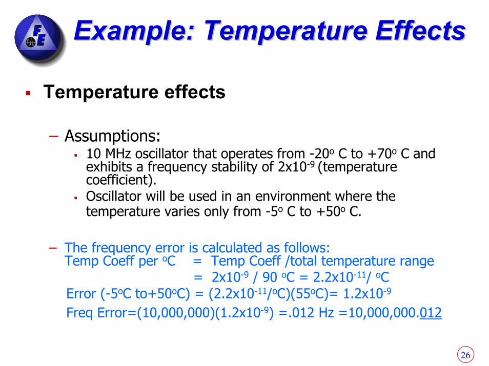
Example: Temperature EffectsExample: Temperature Effects
Temperature effects
– Assumptions: 10 MHz oscillator that operates from -20o C to +70o C and exhibits a frequency stability of 2x10⁻⁹ (temperature coefficient).Oscillator will be used in an environment where the temperature varies only from -5o C to +50o C.
– The frequency error is calculated as follows: Temp Coeff per oC = Temp Coeff /total temperature range
= 2x10⁻⁹ / 90 oC = 2.2x10⁻¹¹/ oCError (-5oC to+50oC) = (2.2x10⁻¹¹/oC)(55oC)= 1.2x10⁻⁹
Freq Error=(10,000,000)(1.2x10⁻⁹) =.012 Hz =10,000,000.012

27
Total Error Due to Total Error Due to Aging and TemperatureAging and Temperature
Total Error: Two major components– Linear Drift (fractional frequency drift rate per day or F’) =0.051– Temperature (fractional frequency offset or ∆f/f) =0.012– Total Frequency error 0.063 Hz
Or calculate a one day error as follows:Drift (F’) 5.1x10⁻⁹
Temp(∆f/f) 1.2x10⁻⁹
Total Error at end of 24 hrs 6.3x10⁻⁹
Effect on Freq: (10,000,000)(6.3x10⁻⁹)=0.063 Hz=10,000,000.063Translate into accumulated time error:For Linear Drift Rate ∆t (in µsec) =(4.32x10¹⁰)(F’ per day)(Days)2
=(4.32x10¹⁰)(5.1x10⁻⁹)(1)2= 220 µsecFor Linear Temper ∆t (in µsec) =(8.64x10¹⁰)(∆f/f)(Days)
=(8.64x10¹⁰)(1.2x10⁻⁹)(1)= 103 µsecTotal accumulated time error in a day = 220 + 103 = 323 µsec
See Charts at end of presentation to easily determine accumulated time error
28
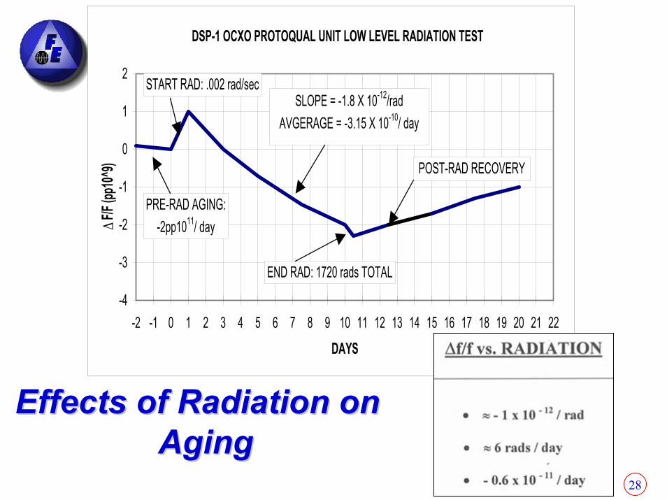
DSP-1 OCXO PROTOQUAL UNIT LOW LEVEL RADIATION TEST
-4
-3
-2
-1
0
1
2
-2 -1 0 1 2 3 4 5 6 7 8 9 10 11 12 13 14 15 16 17 18 19 20 21 22DAYS
∆F/F
(pp1
0^9)
SLOPE = -1.8 X 10⁻¹²/radAVGERAGE = -3.15 X 10⁻¹⁰/ day
POST-RAD RECOVERY
START RAD: .002 rad/sec
END RAD: 1720 rads TOTAL
PRE-RAD AGING:-2pp1011/ day
Effects of Radiation on Effects of Radiation on AgingAging

29
OCXO RetraceOCXO Retrace
OVENOFF
(a)
14 days
14 days
OSCILLATOROFF
OSCILLATOR ON (b)
OVEN ON
∆f f
0
15
X 10
-9
15
10
5
10
5
0
In (a), the oscillator was kept on continuously while the oven was cycled off and on. In (b), the oven was kept on continuously while the oscillator was cycled off and on.
30
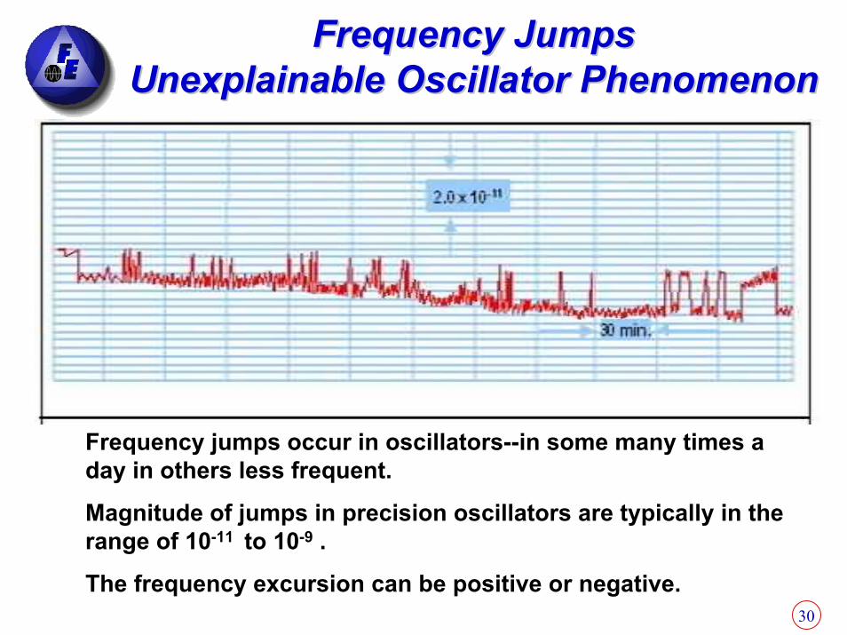
Frequency JumpsFrequency JumpsUnexplainable Oscillator PhenomenonUnexplainable Oscillator Phenomenon
Frequency jumps occur in oscillators--in some many times a day in others less frequent.
Magnitude of jumps in precision oscillators are typically in therange of 10-11 to 10-9 .
The frequency excursion can be positive or negative.

31
Noise in Crystal OscillatorsNoise in Crystal Oscillators
The resonator is the primary noise source close to the carrier; the oscillator sustaining circuitry is the primary source far from the carrier.
Frequency multiplication by N increases the phase noise by N2 (i.e., by 20log N, in dB's).
Vibration-induced "noise" dominates all other sources of noise in many applications
(acceleration effects discussed later).
32
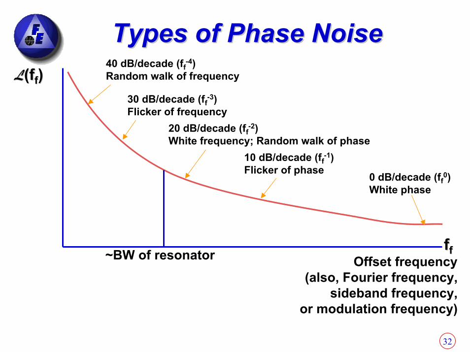
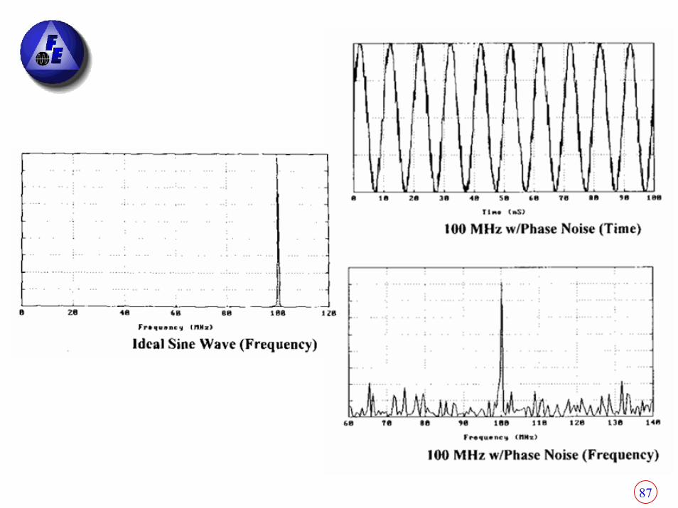
Types of Phase NoiseTypes of Phase Noise40 dB/decade (ff
-4)Random walk of frequency
30 dB/decade (ff-3)
Flicker of frequency20 dB/decade (ff
-2)White frequency; Random walk of phase
10 dB/decade (ff-1)
Flicker of phase 0 dB/decade (ff0)
White phase
ffff~BW of resonator Offset frequency(also, Fourier frequency,
sideband frequency,or modulation frequency)
LL(f(fff))
33
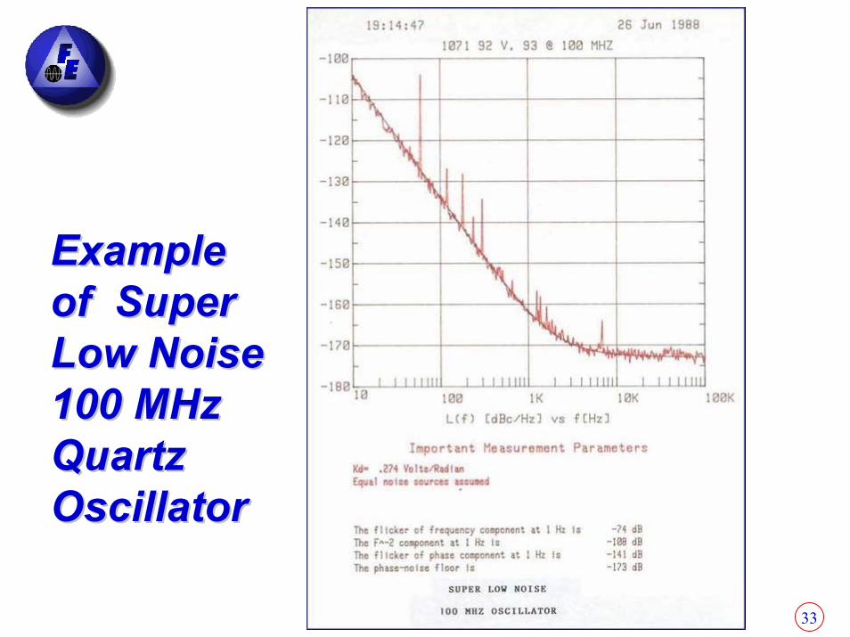
Example Example of Super of Super Low Noise Low Noise 100 MHz 100 MHz Quartz Quartz OscillatorOscillator
34
Section 2Section 2
Atomic Frequency Atomic Frequency StandardsStandards
35
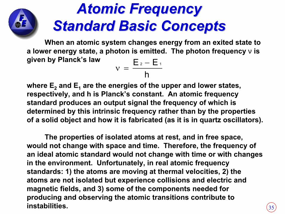
When an atomic system changes energy from an exited state to a lower energy state, a photon is emitted. The photon frequency ν is given by Planck’s law
where E2 and E1 are the energies of the upper and lower states, respectively, and h is Planck’s constant. An atomic frequency standard produces an output signal the frequency of which is determined by this intrinsic frequency rather than by the properties of a solid object and how it is fabricated (as it is in quartz oscillators).
The properties of isolated atoms at rest, and in free space, would not change with space and time. Therefore, the frequency of an ideal atomic standard would not change with time or with changes in the environment. Unfortunately, in real atomic frequency standards: 1) the atoms are moving at thermal velocities, 2) theatoms are not isolated but experience collisions and electric and magnetic fields, and 3) some of the components needed for producing and observing the atomic transitions contribute to instabilities.
hEE 12 −
=ν
Atomic Frequency Atomic Frequency Standard Basic ConceptsStandard Basic Concepts
36
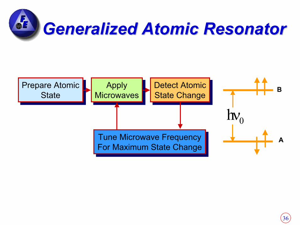
Generalized Atomic ResonatorGeneralized Atomic Resonator
Prepare AtomicState
Prepare AtomicState
ApplyMicrowaves
ApplyMicrowaves
Detect AtomicState Change
Detect AtomicState Change
B
Tune Microwave FrequencyFor Maximum State ChangeTune Microwave FrequencyFor Maximum State Change
0hνA

37
Atomic Frequency StandardAtomic Frequency StandardBlock DiagramBlock Diagram
AtomicResonatorAtomic
ResonatorFeedbackFeedback
MultiplierMultiplier QuartzCrystal
Oscillator
QuartzCrystal
Oscillator
5 MHzOutput
38
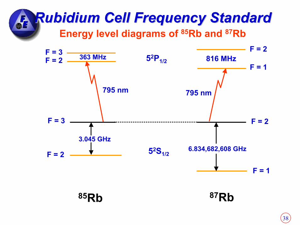
Energy level diagrams of 85Rb and 87Rb Rubidium Cell Frequency StandardRubidium Cell Frequency Standard
F = 2F = 3F = 2 363 MHz
795 nm
3.045 GHz
52P1/2 816 MHzF = 1
795 nm
F = 3 F = 2
6.834,682,608 GHz52S1/2F = 2
85Rb 87Rb
F = 1

39
Atomic resonator schematic diagramRubidium Cell Frequency StandardRubidium Cell Frequency Standard
“C-Field”
87Rblamp
rflamp
exciter
Power suppliesfor lamp, filterand absorptioncell thermostats
85Rb+ buffer
gas
Cavity
Photocell Detector
output
C-fieldpowersupply
Frequencyinput
6.834,685 GHz
Rb-87+ buffer
gasLight
Magnetic shield
Absorptioncell
FilterCell

40
Rubidium Atomic StandardsRubidium Atomic Standards
Wireline and Wireless Applications
Space Time Keeping
Airborne and Ground-Base
Radar Applications
41
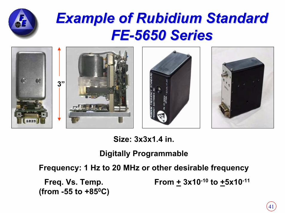
Example of Rubidium Standard Example of Rubidium Standard FEFE--5650 Series5650 Series
3”
Size: 3x3x1.4 in.
Digitally Programmable
Frequency: 1 Hz to 20 MHz or other desirable frequency
Freq. Vs. Temp. From + 3x10⁻¹⁰ to +5x10-11
(from -55 to +850C)

42
Example of Rubidium Standard Example of Rubidium Standard FEFE--5680 Series5680 Series
.98″Side View

43
Rubidium CapabilitiesRubidium CapabilitiesFrequency Typical 5 MHz, 10MHz, 20 MHz Aging 10 Year No Adjustment Operation <1 x 10⁻⁹/ 10YearsSettability (1.5 x 10⁻¹² Steps) Range: 2 x 10⁻⁷
Allan Variance 5 x 10-12/√τInput Voltage ≤4 x 10-12
SensitivityFrequency Vs 1 x 10⁻¹⁰ to 7 x 10-11 (-55°C - +85°C) Temperature 1 x 10⁻¹⁰ (-55°C To +95°C) Temperature Compensated
with TEC
Input Voltage Standard Voltages (+15 V To +50v) (-15v To –70v)Packaging Configurable Package Size Various
44
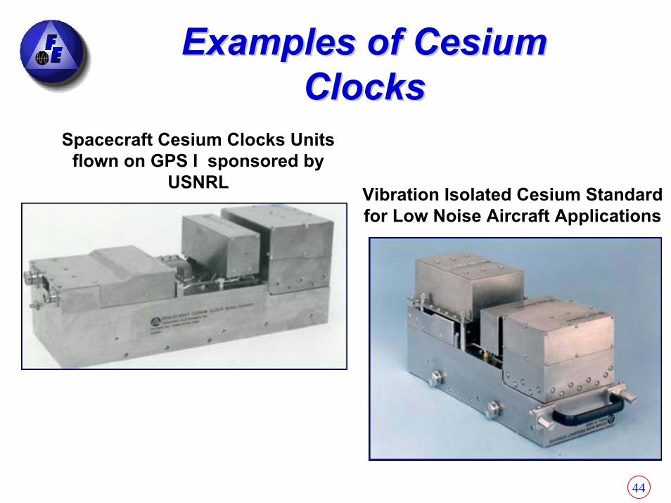
Examples of Cesium Examples of Cesium ClocksClocks
Spacecraft Cesium Clocks Units flown on GPS I sponsored by
USNRL Vibration Isolated Cesium Standard for Low Noise Aircraft Applications
45
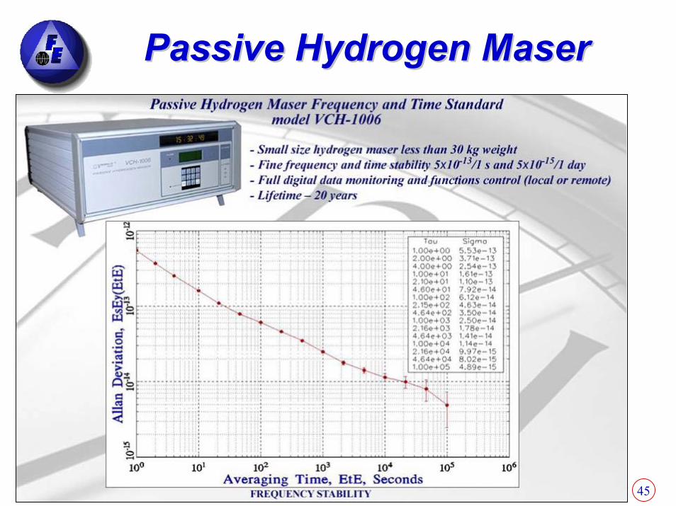
Passive Hydrogen MaserPassive Hydrogen Maser
46
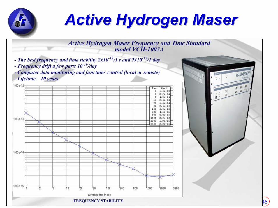
Active Hydrogen MaserActive Hydrogen Maser

47
Summary: Precision Summary: Precision Frequency StandardsFrequency Standards
Quartz crystal resonator-based (f ~ 5 MHz, Q ~ 106)
Atomic resonator-based
Rubidium cell (f0 = 6.8 GHz, Q ~ 107)
Cesium beam (f0 = 9.2 GHz, Q ~ 108)
Hydrogen maser (f0 = 1.4 GHz, Q ~ 109)
Cesium fountain (f0 = 9.2 GHz, Q ~ 5 x 10¹¹)

48
Section 3Section 3
ApplicationsApplications

49
Commercial Commercial ApplicationsApplications
New Quartz New Quartz TechnologyTechnology
FE-205A
FE-405A
FE-505A
(Poor Man’s Rubidium)
50
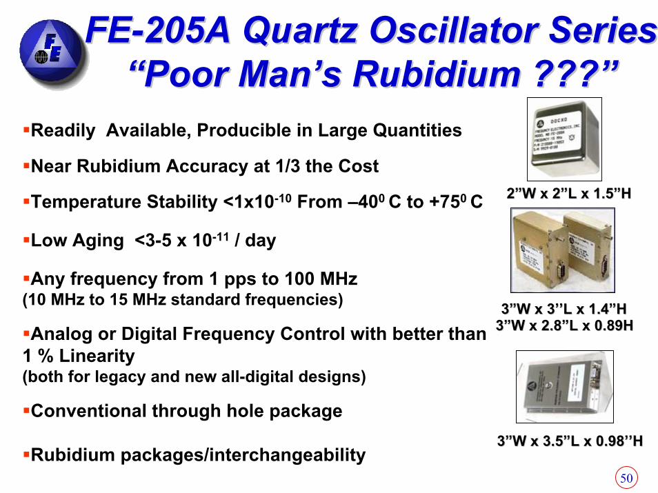
FEFE--205A Quartz Oscillator Series205A Quartz Oscillator Series“Poor Man’s Rubidium ???”“Poor Man’s Rubidium ???”
Near Rubidium Accuracy at 1/3 the Cost
Conventional through hole package
Rubidium packages/interchangeability
Analog or Digital Frequency Control with better than 1 % Linearity(both for legacy and new all-digital designs)
Any frequency from 1 pps to 100 MHz(10 MHz to 15 MHz standard frequencies)
Low Aging <3-5 x 10-11 / day
3”W x 3’’L x 1.4”H3”W x 3’’L x 1.4”H3”W x 2.8”L x 0.89H3”W x 2.8”L x 0.89H
Temperature Stability <1x10⁻¹⁰ From –400 C to +750 C
Readily Available, Producible in Large Quantities
2”W x 2”L x 1.5”H2”W x 2”L x 1.5”H
3”W x 3.5”L x 0.98’’H3”W x 3.5”L x 0.98’’H

51
FEFE--205A Series OCXO 205A Series OCXO CharacteristicsCharacteristics
SC-cut 5th overtone resonator with good aging and excellent short-term stability.Thermal control electronics with inner oven stability of ±1 x 10⁻³ oC over a change in ambient temperature of 115o CStability of internal reference clock electronic circuit is better than 3x10-11 over ambient temperature of –40oC to +75oC and with a change in Supply Voltage of ±5% High-resolution DDS ≈ 2x10-14
Microprocessor ControlledLess than 1x10-12 with load variation of ±10%

52
System Block DiagramSystem Block Diagram
DoubleOven
Reference5 MHz
SC-cut 5thOvertone
ThermalControl
Electronics
VCXO
DDS
Microprocessor
A/D
Digital
Analog
OUTPUT
VCOVCO
INPUTSINPUTS
(Patented Design)(Patented Design)
53
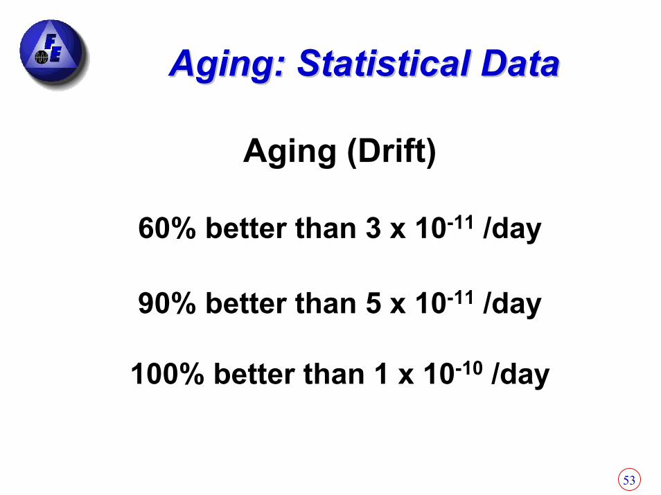
Aging: Statistical DataAging: Statistical Data
Aging (Drift)
60% better than 3 x 10-11 /day
90% better than 5 x 10-11 /day
100% better than 1 x 10⁻¹⁰ /day
54
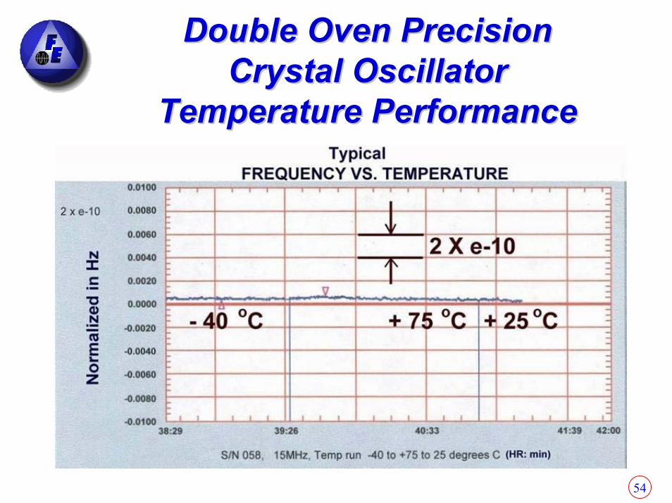
Double Oven Precision Double Oven Precision Crystal OscillatorCrystal Oscillator
Temperature PerformanceTemperature Performance

55
Statistical DataStatistical Data Frequency Stability vs. Ambient Temperature
(-40oC to +75oC)
0
10
20
30
40
0 2 4 6 8 10
Delta Frequency in e -11 p-p (Typical unit < 5 e-13/ oC)
Perc
ent o
f Pro
duct
ion
Uni
ts

56
Comparison of Oscillators Comparison of Oscillators Stabilities vs. TemperatureStabilities vs. Temperature
Oscillator Type Frequency Stability (In severe temperature environments e.g. –40oC to +75 oC , and high slew rates)
Crystal Oscillator (X O) 1x10⁻⁴ to 1x10⁻⁵ Temperature Compensated Crystal Oscillators (TCX O)
1x10⁻⁶
M icrocomputer Compensated Crystal Oscillators (M CX O)
1x10⁻⁷ to 2x10⁻⁸
Oven Controlled Crystal Oscillators (OCX O)
1x10⁻⁸ to 3x10⁻¹⁰
FE-205A Series H igh-Precision D ouble O ven Crystal O scillator (DO C XO )
1x10⁻¹⁰
Rubidium Atomic Frequency Standards (Rb) [–10oC to +60 oC]
3x10⁻¹⁰ to 7x10-11
Cesium Atomic Standard (Cs) [0oC to +50 oC]
3x10-11 to 3x10-12
Poor Man’s Rubidium ???

57
Retrace DataRetrace Data
Retrace: After 24 hours of shut off frequency stabilizes within 30 minutes after turn-on to 1 x 10⁻¹⁰ of the previous frequency
Typical Frequency Retrace of 15 MHz Device
Typical Warm-Up of 10 MHz Device
58
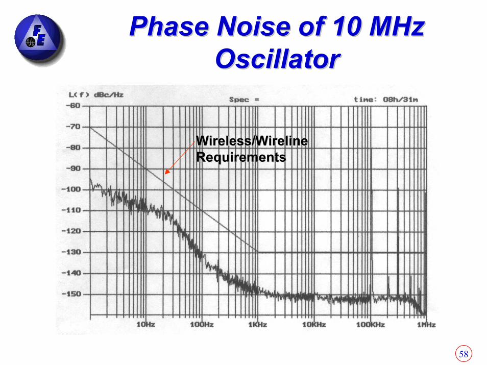
Phase Noise of 10 MHz Phase Noise of 10 MHz OscillatorOscillator
Wireless/Wireline Wireless/Wireline RequirementsRequirements

59
Comparison ChartComparison Chart
1 x 10⁻¹⁰
in 1 Hr1 x 10-10
in 48-96 Hrs
Warm upFrom Cold Storage
(off for a long period)
3.3 x 10⁻¹⁰ { 7 x 10-11 }5 x 10-11Temperature(-5oC to +50oC)
1 - 2 x 10-11
1 x 10-11 { 5 x 10-12 }<1 x 10⁻⁹
1 - 2 x 10-12
3 x 10-11
2 - 5 x 10⁻⁸
Drift/Aging1 Sec1 Day
10 Years
100K - 200K500K / 1,000KMTBF (Hrs)
1 - 15 W1 - 2 WPower (w)
RubidiumQuartzCharacteristic
60
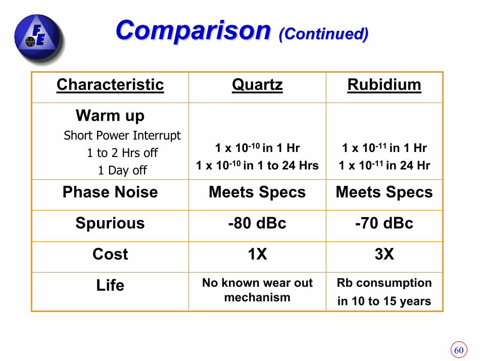
Comparison Comparison (Continued)(Continued)
Rb consumption in 10 to 15 years
No known wear out mechanism
Life
3X1XCost
-70 dBc-80 dBcSpurious
Meets SpecsMeets SpecsPhase Noise
1 x 10-11 in 1 Hr1 x 10-11 in 24 Hr
1 x 10⁻¹⁰ in 1 Hr1 x 10-10 in 1 to 24 Hrs
Warm up Short Power Interrupt
1 to 2 Hrs off1 Day off
RubidiumQuartzCharacteristic

61
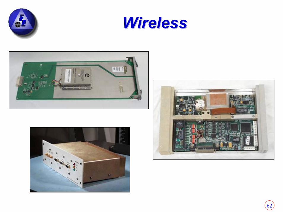
Synchronization for Wireless Base Stations Synchronization for Wireless Base Stations CDMA, UMTS, WCDMA, UMTS, W--CDMA, TDMA CDMA, TDMA
Plug in AssembliesPlug in AssembliesPrecision OCXO
GPS Receiver
Rubidium Atomic Frequency Standard
•GPS disciplined Rubidium/Quartz•Customized packaging•Optimized for extreme temperature swings•Excellent aging and temperature stability•Hot swappable with glitch free operation
Rubidium Frequency Atomic Standard module directly interchangeable with OCXO module
62
WirelessWireless

63
SPACE APPLICATIONSSPACE APPLICATIONS
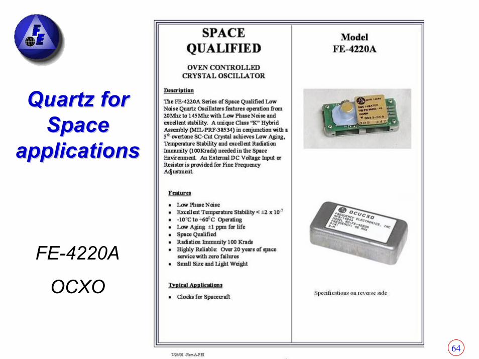
64
Quartz for Quartz for Space Space
applicationsapplications
FE-4220A
OCXO
65
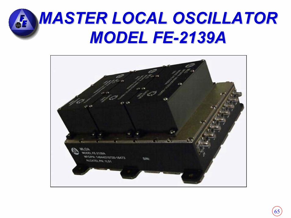
MASTER LOCAL OSCILLATORMASTER LOCAL OSCILLATORMODEL FEMODEL FE--2139A2139A
66
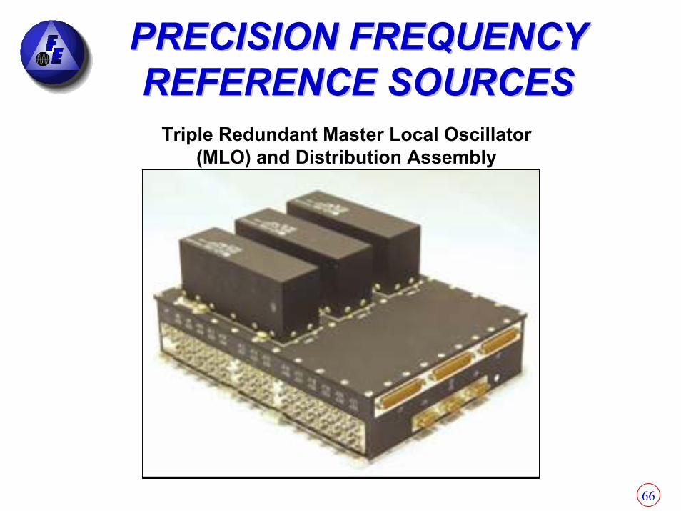
PRECISION FREQUENCY PRECISION FREQUENCY REFERENCE SOURCESREFERENCE SOURCES
Triple Redundant Master Local Oscillator (MLO) and Distribution Assembly
67
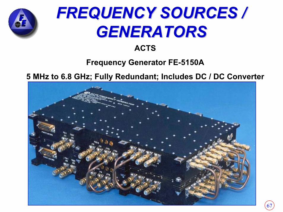
FREQUENCY SOURCES / FREQUENCY SOURCES / GENERATORSGENERATORS
ACTS
Frequency Generator FE-5150A
5 MHz to 6.8 GHz; Fully Redundant; Includes DC / DC Converter
68
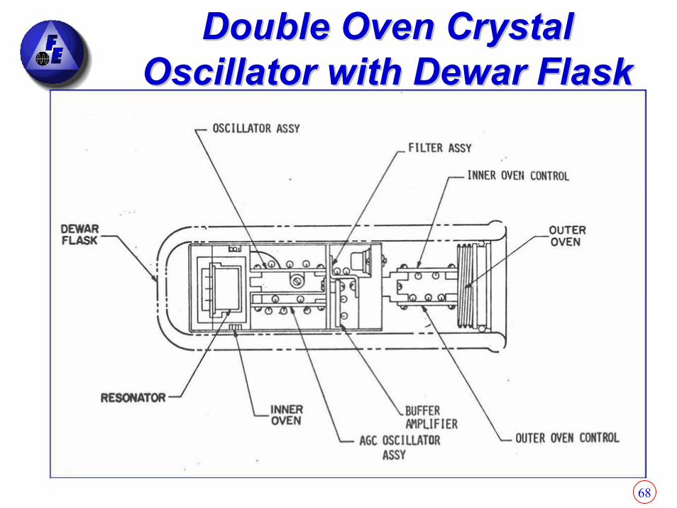
Double Oven Crystal Double Oven Crystal Oscillator with Dewar FlaskOscillator with Dewar Flask

69
MLO AssemblyMLO Assembly
Master Oscillator Assembly
DC to DC Converter

70
Milstar Today
SLAVE CLOCK
SMCS Satellite Mission Control Subsystem
MASTER CLOCK
FLT-2 Rb Atomic Clock
(6 Nov. ‘95) FLT-1
Crystal Clock (7 Feb. ‘94)
United States Naval Observatory
UTC Timekeeping
Data
MASC Milstar Auxiliary Support Center
FLT-4 Rb Atomic Clock
(2000)
MILSTAR TIMEKEEPING MILSTAR TIMEKEEPING With FEI Supplied ClocksWith FEI Supplied Clocks

71
RUBIDIUM PRECISION FREQUENCY RUBIDIUM PRECISION FREQUENCY REFERENCE SOURCESREFERENCE SOURCES
MILSTAR
Rubidium Master Oscillator SN 003
Total of 19 systems delivered to MILSTARExcellent
performance
in space
Aging Rate:
≈ 7x10-14/day
72
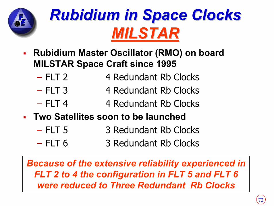
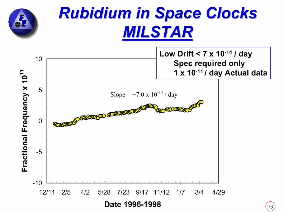
Rubidium in Space Clocks Rubidium in Space Clocks MILSTARMILSTAR
Rubidium Master Oscillator (RMO) on board MILSTAR Space Craft since 1995 – FLT 2 4 Redundant Rb Clocks– FLT 3 4 Redundant Rb Clocks– FLT 4 4 Redundant Rb Clocks
Two Satellites soon to be launched– FLT 5 3 Redundant Rb Clocks– FLT 6 3 Redundant Rb Clocks
Because of the extensive reliability experienced in FLT 2 to 4 the configuration in FLT 5 and FLT 6 were reduced to Three Redundant Rb Clocks
73
Rubidium in Space ClocksRubidium in Space ClocksMILSTARMILSTAR
-10
-5
0
5
10
12/11 2/5 4/2 5/28 7/23 9/17 11/12 1/7 3/4 4/29
Date 1996-1998
Frac
tiona
l Fre
quen
cy x
1011
Slope = +7.0 x 10⁻¹⁴ / day
Low Drift < 7 x 10-14 / day Spec required only 1 x 10-11 / day Actual data

74
GPS APPLICATIONSGPS APPLICATIONSCommercial Military i.e. SAASM

75
Oscillator’s Impact on GPSOscillator’s Impact on GPS
Satellite oscillator’s (clock’s) inaccuracy & noise are major sources of navigational inaccuracy. Receiver oscillator affects GPS performance, as follows:
Oscillator Parameter GPS Performance ParameterWarmup time Time to first fixPower Mission duration, logistics costs (batteries)Size and weight Manpack size and weightShort term stability ∆ range measurement accuracy, acceleration(0.1 s to 100 s) performance, jamming resistanceShort term stability Time to subsequent fix(~15 minute)Phase noise Jamming margin, data demodulation, trackingAcceleration sensitivity See short term stability and phase noise effects

76
Building Blocks of a Time/Frequency SystemBuilding Blocks of a Time/Frequency System
GPS-SAASML1/L2-P(Y)Mil RCVR
FrequencyTimeNetworkOutputs
Outputs
Displays ControlsDiagnostics
L1 or L1/L2
GPS L1-C/ACom’l RCVR
Inputs
External Inputs from
CESIUM STDS
or other
OR
OR
1PPSPrecision
OSCsTime and Freq Gen
GPSDisc.
Module
Osc. Disc.Algorithms
Displays Controls
Redundancy
Oscillators and Circuitry
VariousCategories of Qz & Rb Osc.& possiblyCs Stds
RS-232
77
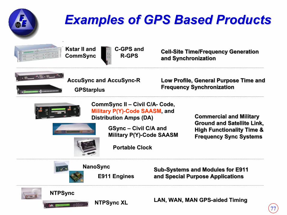
Examples of GPS Based ProductsExamples of GPS Based Products
––--
–– Civil C/ACivil C/A-- Code, Code, Military P(Y)Military P(Y)--
Commercial and Military Commercial and Military Ground and Satellite Link, Ground and Satellite Link, Ground and Satellite Link, Ground and Satellite Link, High Functionality Time & High Functionality Time & Frequency Sync SystemsFrequency Sync Systems
E911 EnginesE911 EnginesNanoSyncNanoSync SubSubSubSub----Systems and Modules for E911 Systems and Modules for E911 Systems and Modules for E911 Systems and Modules for E911
and Special Purpose Applicationsand Special Purpose Applicationsand Special Purpose Applicationsand Special Purpose Applications
AccuSyncAccuSync and and AccuSyncAccuSync--RRGPStarplusGPStarplus
Low Profile, General Purpose Time and Low Profile, General Purpose Time and Low Profile, General Purpose Time and Low Profile, General Purpose Time and Frequency SynchronizationFrequency SynchronizationFrequency SynchronizationFrequency Synchronization
GSyncGSync Civil C/A and Civil C/A and Military P(Y)Military P(Y) Code SAASMCode SAASM
Portable ClockPortable Clock
CommSync II CommSync II Code SAASMCode SAASM, and , and
Distribution Amps (DA)Distribution Amps (DA) Commercial and Military Commercial and Military
High Functionality Time & High Functionality Time & Frequency Sync SystemsFrequency Sync Systems
KstarKstar II and II and CommSyncCommSync
CC--GPS and GPS and RR--GPSGPS CellCellCellCell----Site Time/Frequency Generation Site Time/Frequency Generation Site Time/Frequency Generation Site Time/Frequency Generation
and Synchronizationand Synchronizationand Synchronizationand Synchronization
NTPSyncNTPSyncNTPSync XLNTPSync XL LAN, WAN, MAN GPSLAN, WAN, MAN GPS--aided Timingaided Timing

78
Redundant SAASM CommSync II Modular Time & Redundant SAASM CommSync II Modular Time & Frequency System (3U)Frequency System (3U)
Imbedded Trimble Force-22 SAASM
Receiver
OR
Atomic Oscillators
Qz OscillatorsOR
Plug-In Output
Modules
CommSync II GTF Module
Commercial C/A-Code
GPS RCVRs
79
Radar ApplicationsRadar Applications

80
Effect of Noise in Effect of Noise in Doppler Radar SystemDoppler Radar System
TransmitterTransmitter
fD
ReceiverStationary
ObjectStationary
Object
MovingObject
MovingObject
ffD
Doppler Signal
Decorrelated Clutter Noise
A
Echo = Doppler-shifted echo from moving target + large "clutter" signal
(Echo signal) - (reference signal) --› Doppler shifted signal from target
Phase noise of the local oscillator modulates (decorrelates) the clutter signal, generates higher frequency clutter components, and thereby degrades the radar's ability to separate the target signal from the clutter signal.

81
5
0
10
15
20
25
30
40
10 100 1K 10K 100K 1M
Rad
ar F
requ
ency
(GH
z)
4km
/h -
Man
or S
low
Mov
ing
Vech
ile
100k
m/h
-Ve
hicl
e, G
roun
d or
Air
700k
m/h
-Su
bson
ic A
ircra
ft2,
400
km/h
-M
ach
2 Ai
rcra
ft
X-Band RADAR
Doppler ShiftsDoppler Shifts
Doppler Shift for Target Moving Toward Fixed Radar (Hz)Doppler radar require low-phase-noise oscillators. For example to detect slow-moving targets the noise close to the carrier must be low

82
Section 4Section 4
Breakthrough in Vibration Breakthrough in Vibration Effects on Clocks Stabilities Effects on Clocks Stabilities
and Side Bandsand Side Bands
Vibration Insensitive Vibration Insensitive Oscillators???Oscillators???

83
Single Side Band Phase Single Side Band Phase Noise Resulting From Noise Resulting From
Vibrations Will Significantly Vibrations Will Significantly Affect Oscillator Affect Oscillator
PerformancePerformance

84
Frequency shift is a function of the magnitude and direction of the acceleration, and is usually linear with magnitude up to at least 50 g’s.
Crystalplate
Supports
ff∆
X’X’
Y’Y’
Z’Z’
GOO
Acceleration vs. Frequency Acceleration vs. Frequency ChangeChange
85
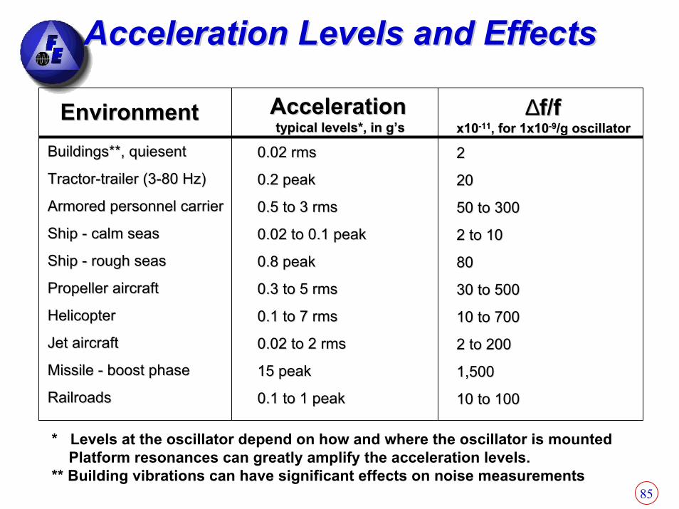
Acceleration Levels and EffectsAcceleration Levels and Effects
EnvironmentEnvironmentBuildings**, quiesentBuildings**, quiesent
TractorTractor--trailer (3trailer (3--80 Hz)80 Hz)
Armored personnel carrierArmored personnel carrier
Ship Ship -- calm seascalm seas
Ship Ship -- rough seasrough seas
Propeller aircraftPropeller aircraft
HelicopterHelicopter
Jet aircraftJet aircraft
Missile Missile -- boost phaseboost phase
RailroadsRailroads
AccelerationAccelerationtypical levels*, in g’stypical levels*, in g’s
0.02 rms0.02 rms
0.2 peak0.2 peak
0.5 to 3 rms0.5 to 3 rms
0.02 to 0.1 peak0.02 to 0.1 peak
0.8 peak0.8 peak
0.3 to 5 rms0.3 to 5 rms
0.1 to 7 rms0.1 to 7 rms
0.02 to 2 rms0.02 to 2 rms
15 peak15 peak
0.1 to 1 peak0.1 to 1 peak
∆∆f/ff/fx10x10--1111, for 1x10, for 1x10--99/g oscillator/g oscillator
22
2020
50 to 30050 to 300
2 to 102 to 10
8080
30 to 50030 to 500
10 to 70010 to 700
2 to 2002 to 200
1,5001,500
10 to 10010 to 100
* Levels at the oscillator depend on how and where the oscillator is mountedPlatform resonances can greatly amplify the acceleration levels.
** Building vibrations can have significant effects on noise measurements

86
Crystal GCrystal G--Sensitivity (Gamma)Sensitivity (Gamma)ZZ
XX
YY
Γ is G sensitivity in Hz/GΓ= (X2 + Y2 + Z2)1/2
Γ= (32+ 32+32)1/2 = 5.2 x 10⁻¹⁰
87
88
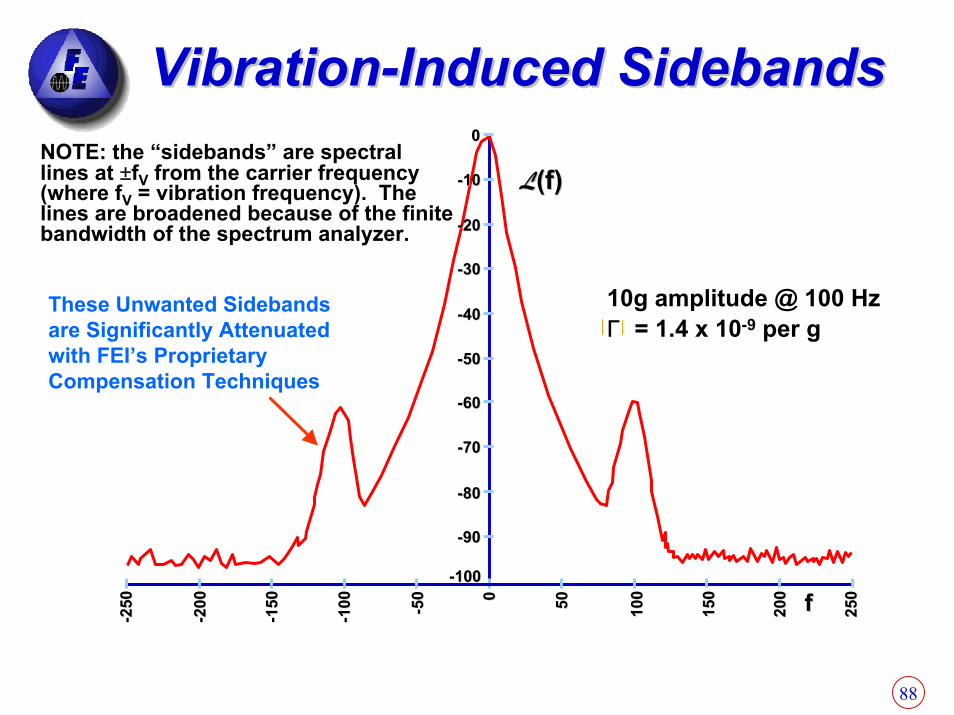
VibrationVibration--Induced SidebandsInduced Sidebands
LL(f)(f)
10g amplitude @ 100 HzΓ = 1.4 x 10⁻⁹ per g
00
--1010
--2020
--3030
--4040
--5050
--6060
--7070
--8080
--9090
--100100
-- -- -- --
00 5050
NOTE: the “sidebands” are spectrallines at ±fV from the carrier frequency(where fV = vibration frequency). Thelines are broadened because of the finitebandwidth of the spectrum analyzer.
These Unwanted Sidebands are Significantly Attenuated with FEI’s Proprietary Compensation Techniques
250
250
200
200
150
150
100
100
-- 5050 100
100
150
150
200
200
250
250ff

89
VibrationVibration--Induced SidebandsInduced SidebandsAfter Frequency MultiplicationAfter Frequency Multiplication
0
-10
-20
-30
-40
-50
-60
-70
-80
-90
-100
0 0 0 0 0 50 100
150
200 f
L(f) Each frequency multiplicationby 10 increases the sidebandsby 20 dB.
10X
1X
250
-50
-25
-20
-15
-10

90
VibrationVibration--Induced Phase ExcursionInduced Phase Excursion
The phase of a vibration modulated signal is
When the oscillator is subjected to a sinusoidal vibration, the peakphase excursion is
Example: if a 10 MHz, 1 x 10⁻⁹/g oscillator is subjected to a 10 Hzsinusoidal vibration of amplitude 1g, the peak vibration-induced phaseexcursion is 1 x 10⁻³ radian. If this oscillator is used as the referenceoscillator in a 10 GHz radar system, the peak phase excursion at10GHz will be 1 radian. Such a large phase excursion can be catastrophic to the performance of many systems, such as those which employ phase locked loops (PLL) or phase shift keying (PSK).
( ) ( )tf2sinfftf2tφ v
v0 π
+π=
∆
( )v
0
vpeak f
fAffφ •==Γ∆∆

91
Sine VibrationSine Vibration--Induced Phase NoiseInduced Phase Noise
Sinusoidal vibration produces spectral lines at ±fv from the carrier, where fv is the vibration frequency.
e.g., if Γ = 1 x 10⁻⁹/g and f0 = 10 MHz, then even if theoscillator is completely noise free at rest, the phase “noise”i.e., the spectral lines, due solely to a sine vibration level of 1g will be;
( )
•Γ=
v
0v f2
fAlog20f'L
Vibr. freq., fv, in Hz110100
1,00010,000
-46-66-86
-106-126
L’(fv), in dBc
92
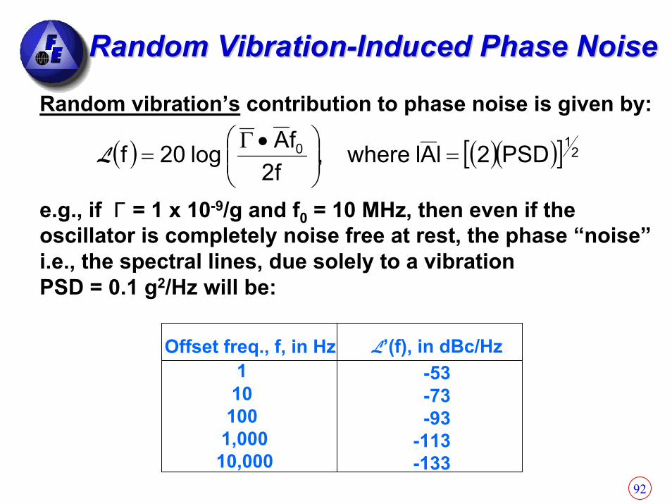
Random VibrationRandom Vibration--Induced Phase NoiseInduced Phase Noise
Random vibration’s contribution to phase noise is given by:
e.g., if Γ = 1 x 10⁻⁹/g and f0 = 10 MHz, then even if theoscillator is completely noise free at rest, the phase “noise”i.e., the spectral lines, due solely to a vibration PSD = 0.1 g2/Hz will be:
( ) ( )( )[ ] 210 PSD2lAlwhere,
f2fAlog20f =
•Γ=L
Offset freq., f, in Hz110100
1,00010,000
L’(f), in dBc/Hz-53-73-93
-113-133

93
Typical Aircraft RandomTypical Aircraft Random--VibrationVibration--Induced Phase NoiseInduced Phase Noise
Phase noise under vibration is for Γ = 1 x 10⁻⁹ per g and f = 10 MHz
10 Mhz Random Vibration Single Sideband Phase Noise Utilizing 1E-9/g Csrystal
-170-160-150-140-130-120-110-100
-90-80-70
1 10 100 1,000 10,000Frequency (Hz)
Phas
e No
ise
(dBc
/Hz)
L(f) No Vibration L(f) With Shown Vibration
Typical Aircraft Random Vibration Envelope
0
0.05
0.1
1 10 100 1000 10000
Frequency (Hz)
Vibr
atio
n g^
2/H
z
Vib freq Vib densHz g^2/Hz
5 05 0.04
300 0.04350 0.07
1000 0.072000 0
94
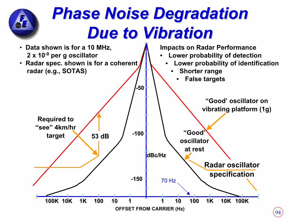
Required to“see” 4km/hr
target “Good’oscillator
at rest
“Good’ oscillator onvibrating platform (1g)
Radar oscillatorspecification
--5050
--100100
--150150
53 dB
dBc/HzdBc/Hz
100K100K 10K10K 1K1K 100100 1010 11 11 1010 100100 1K1K 10K10K 100K100K
Impacts on Radar Performance• Lower probability of detection
• Lower probability of identification• Shorter range
• False targets
• Data shown is for a 10 MHz,2 x 10-9 per g oscillator
• Radar spec. shown is for a coherentradar (e.g., SOTAS)
Phase Noise Degradation Phase Noise Degradation Due to VibrationDue to Vibration
70 Hz
OFFSET FROM CARRIER (Hz)
95
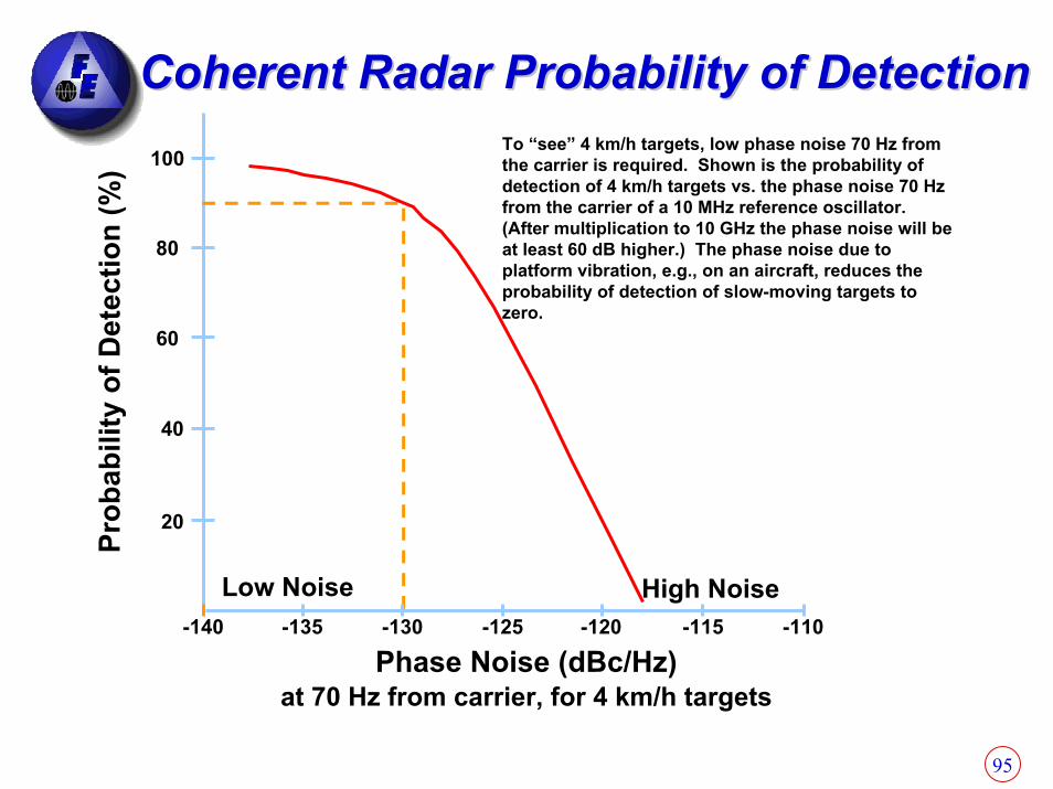
Coherent Radar Probability of DetectionCoherent Radar Probability of DetectionTo “see” 4 km/h targets, low phase noise 70 Hz from the carrier is required. Shown is the probability of detection of 4 km/h targets vs. the phase noise 70 Hz from the carrier of a 10 MHz reference oscillator. (After multiplication to 10 GHz the phase noise will be at least 60 dB higher.) The phase noise due to platform vibration, e.g., on an aircraft, reduces the probability of detection of slow-moving targets to zero.
100
80
60
40
20
-140 -135 -130 -125 -120 -115 -110High NoiseLow Noise
Phase Noise (dBc/Hz)at 70 Hz from carrier, for 4 km/h targets
Prob
abili
ty o
f Det
ectio
n (%
)
96
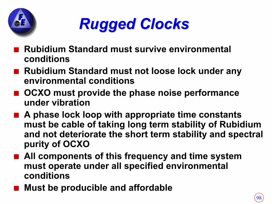
Rugged ClocksRugged Clocks
Some applications require Rubidium Atomic StandardsOther applications require only Crystal OscillatorsEvery Rubidium atomic Standard contains a crystal oscillator that determines its single side band phase noise under vibration
97
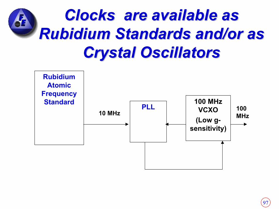
Rubidium Atomic
Frequency Standard PLL
100 MHz VCXO
(Low g-sensitivity)
10 MHz100 MHz
Clocks are available as Clocks are available as Rubidium Standards and/or as Rubidium Standards and/or as
Crystal OscillatorsCrystal Oscillators
98
Rugged ClocksRugged ClocksRubidium Standard must survive environmental conditionsRubidium Standard must not loose lock under any environmental conditionsOCXO must provide the phase noise performance under vibrationA phase lock loop with appropriate time constants must be cable of taking long term stability of Rubidium and not deteriorate the short term stability and spectral purity of OCXOAll components of this frequency and time system must operate under all specified environmental conditionsMust be producible and affordable
99
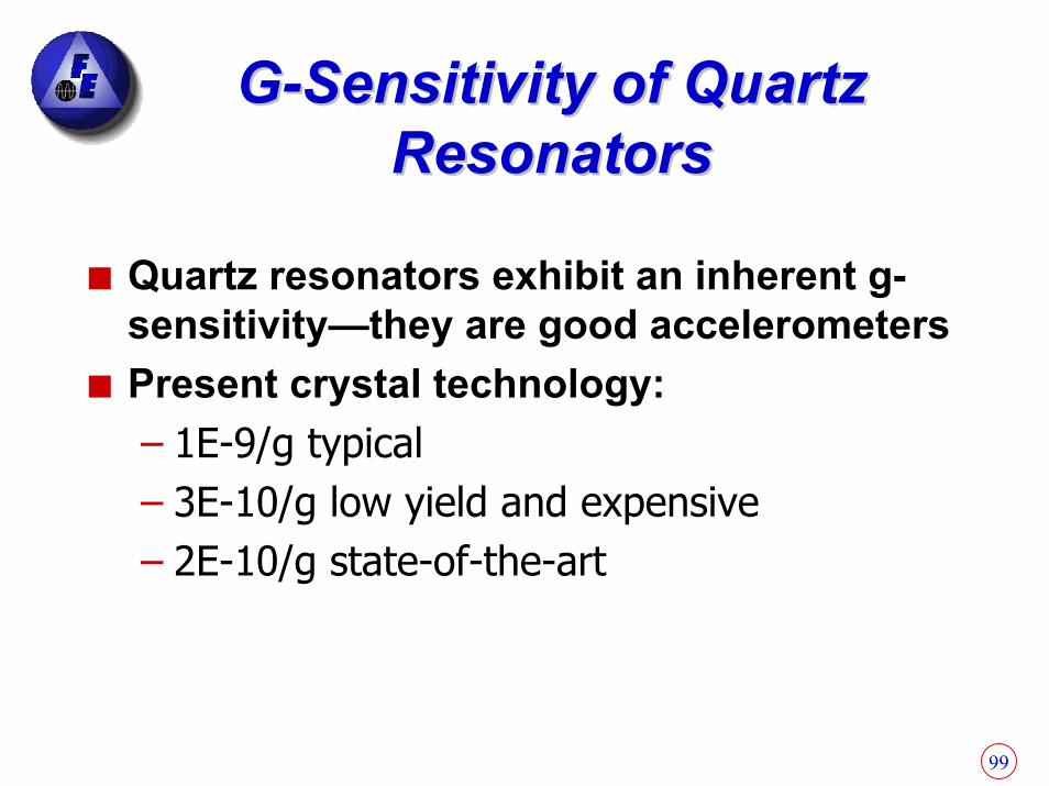
GG--Sensitivity of Quartz Sensitivity of Quartz ResonatorsResonators
Quartz resonators exhibit an inherent g-sensitivity—they are good accelerometersPresent crystal technology:– 1E-9/g typical– 3E-10/g low yield and expensive– 2E-10/g state-of-the-art
100
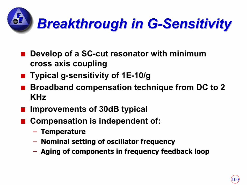
Breakthrough in GBreakthrough in G--SensitivitySensitivity
Develop of a SC-cut resonator with minimum cross axis couplingTypical g-sensitivity of 1E-10/gBroadband compensation technique from DC to 2 KHzImprovements of 30dB typicalCompensation is independent of:– Temperature– Nominal setting of oscillator frequency– Aging of components in frequency feedback loop

101
ObjectivesObjectives
Achieve:– 2E-12/g– Economies in manufacturability– Small package ≈ 3 in3
Combination of low g-sensitivity technology with vibration isolators to accomplish above performance from DC to 2 KHzThe technology is also applicable to Rubidium Standards in moving/vibrating platforms (vibration induced errors in Rb standards is solely due to crystals imbedded in the Rb design)
102
ApplicationsApplicationsFEI’s recent breakthrough in highly reproducible low-G sensitivity oscillators that are virtually insensitive to acceleration/vibration has resulted in a host of applications:– Precision Navigation– Radar for helicopters and other challenging platforms– Commercial and Secure communications– Space exploration– Target acquisition– Munitions and Missile guidance– SATCOM terminals– All other applications where the effects of acceleration
or vibration effect the output signal of the oscillator

103

104
Uncompensated
Compensated
Vibration Profile: 4 g RMS total, Random; 0.08g2/Hz 10 to 200 Hz
Approximate Sensitivity per g10 Hz 50 Hz 100 Hz
Uncompensated 1.1 x 10⁻⁹ 7.9 x 10⁻¹⁰ 8.9 x 10⁻¹⁰
Compensated 6.3 x 10⁻¹² 2.2 x 10⁻¹¹ 4.0 x 10⁻¹¹

105
Uncompensated
Compensated
Vibration Profile: 4 g RMS total, Random; 0.08g2/Hz 10 to 200 Hz
Approximate Sensitivity per g10 Hz 50 Hz 100 Hz
Uncompensated 2.2 x 10⁻¹¹ 2.8 x 10⁻¹¹ 2.2 x 10⁻¹¹
Compensated 2.8 x 10⁻¹² 2.5 x 10⁻¹² 5.0 x 10⁻¹²
106
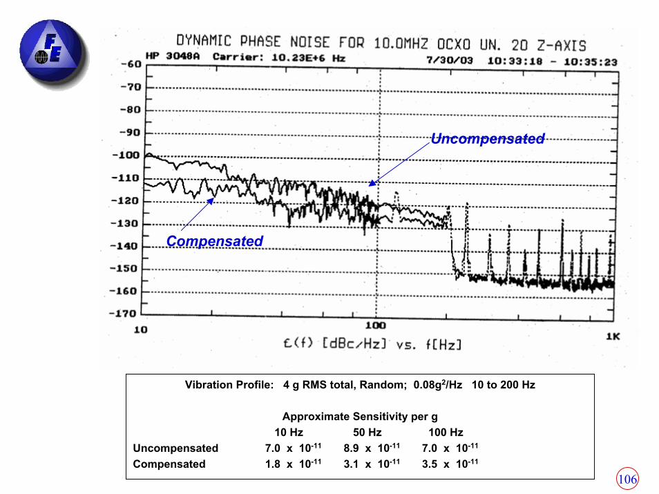
Compensated
Uncompensated
Vibration Profile: 4 g RMS total, Random; 0.08g2/Hz 10 to 200 Hz
Approximate Sensitivity per g10 Hz 50 Hz 100 Hz
Uncompensated 7.0 x 10⁻¹¹ 8.9 x 10⁻¹¹ 7.0 x 10⁻¹¹
Compensated 1.8 x 10⁻¹¹ 3.1 x 10⁻¹¹ 3.5 x 10⁻¹¹
107
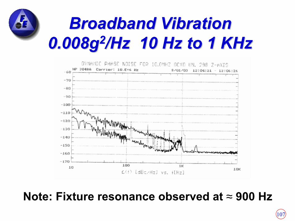
Broadband VibrationBroadband Vibration0.008g0.008g22/Hz 10 Hz to 1 KHz/Hz 10 Hz to 1 KHz
Note: Fixture resonance observed at ≈ 900 Hz

108
Typical Aircraft RandomTypical Aircraft Random--VibrationVibration--Induced Phase NoiseInduced Phase NoisePhase noise under vibration is for Γ = 1 x 10⁻⁹ per g , Γ = 1 x 10⁻¹⁰ per g, Γ = 2 x 10-12 per g and f = 10 MHz.
10 MHz Random Vibration Single Sideband Phase
-170-160-150-140-130-120-110-100
-90-80-70
1 10 100 1,000 10,000Frequency (Hz)
Phas
e No
ise
(dB
c/Hz
)
L(f) No VibrationL(f) With Shown Vibration and Crystal Gamma of 1E-9/gL(f) With Shown Vibration and Crystal Gamma of 1E-10/gL(f) With Shown Vibration and Crystal Gamma of 2E-12/g
Typical Aircraft Random Vibration Envelope
0
0.05
0.1
1 10 100 1000 10000
Frequency (Hz)
Vibr
atio
n g^
2/H
z
Vib freq Vib densHz g^2/Hz
5 05 0.04
300 0.04350 0.07
1000 0.072000 0

109
10 Mhz Random Vibration Single Sideband Phase Noise
-150
-140
-130
-120
-110
-100
-90
-80
10 100 1,000 10,000Frequency (Hz)
Phas
e No
ise
(dB
c/Hz
)
L(f) Spec Requirement Under Vibration for 10 MHzL(f) With Shown Vibration Crystal Gamma of 5E-11/gL(f) With Shown Vibration Crystal Gamma of 1E-9/g
Phase noise under vibration is for Γ = 1 x 10⁻⁹ per g , Γ = 5 x 10-11 per g and f = 10 MHz. To meet the specification a Γ = 5 x 10-12 per g or better is required. Close to carrier noise is reduced using FEI’s low-g sensitivity breakthrough, and above 200 Hz vibration isolationis required(see next slide).
Typical Helicopter Random Vibration Envelope
00.5
11.5
22.5
33.5
44.5
5
10 100 1000
Frequency (Hz)
Vibr
atio
n g^
2/Hz
Typical Helicopter Random Vibration Envelope
0
0.1
0.2
0.3
0.4
0.5
10 100 1000Frequency (Hz)
Vibr
atio
n g^
2/Hz
Typical Helicopter RandomTypical Helicopter Random--VibrationVibration--Induced Phase NoiseInduced Phase Noise
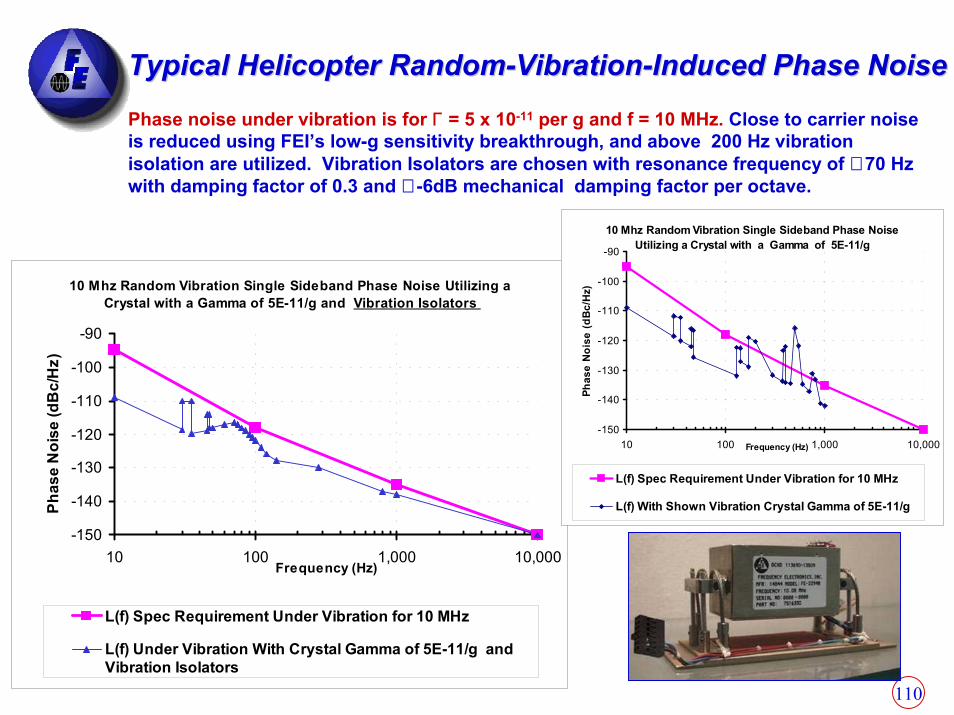
110
Typical Helicopter RandomTypical Helicopter Random--VibrationVibration--Induced Phase NoiseInduced Phase NoisePhase noise under vibration is for Γ = 5 x 10-11 per g and f = 10 MHz. Close to carrier noise is reduced using FEI’s low-g sensitivity breakthrough, and above 200 Hz vibration isolation are utilized. Vibration Isolators are chosen with resonance frequency of ≅ 70 Hz with damping factor of 0.3 and ≅ -6dB mechanical damping factor per octave.
10 Mhz Random Vibration Single Sideband Phase Noise Utilizing a Crystal with a Gamma of 5E-11/g and Vibration Isolators
-150
-140
-130
-120
-110
-100
-90
10 100 1,000 10,000Frequency (Hz)
Phas
e N
oise
(dB
c/H
z)
L(f) Spec Requirement Under Vibration for 10 MHz
L(f) Under Vibration With Crystal Gamma of 5E-11/g andVibration Isolators
10 Mhz Random Vibration Single Sideband Phase Noise Utilizing a Crystal with a Gamma of 5E-11/g
-150
-140
-130
-120
-110
-100
-90
10 100 1,000 10,000Frequency (Hz)
Phas
e N
oise
(dBc
/Hz)
L(f) Spec Requirement Under Vibration for 10 MHz
L(f) With Shown Vibration Crystal Gamma of 5E-11/g

111
Summary: Clocks for Summary: Clocks for Challenging EnvironmentsChallenging Environments
Low G-Sensitivity Clocks- Internal FEI proprietary compensation techniques to reduce g-sensitivity
- Vibration isolation mounts may be required
Related Documents