FRENEMIES: OPM AND SYSML TOGETHER IN AN MBSE MODEL Matthew Hause Engineering Fellow, MBSE Specialist October, 2018

Welcome message from author
This document is posted to help you gain knowledge. Please leave a comment to let me know what you think about it! Share it to your friends and learn new things together.
Transcript
FRENEMIES: OPM AND SYSML TOGETHER IN AN MBSE MODEL
Matthew HauseEngineering Fellow, MBSE Specialist
October, 2018

22
AGENDA• Introduction
• MBSE
• SysML
• OPM
• An OPM Profile in a SysML tool
• Conclusions
• Questions and Answers?

3
4
• OPM and SysML are different means of achieving MBSE, each with their own benefits, issues, supporters and detractors.
• But first, let’s look at some definitions.
WHAT IS A FRENEMY?
fren·e·my/ˈfrenəmi/nounINFORMAL
noun: frenemy; plural noun: frenemiesa person with whom one is friendly despite a fundamental dislike or rivalry.(Note: In this case more rivalry than dislike.)
Origin
1950s: blend of friend and enemy.

5
• The NDIA defines Model-Based Systems Engineering (MBSE) as “an approach to engineering that uses models as an integral part of the technical baseline that includes the requirements, analysis, design, implementation, and verification of a capability, system, and/or product throughout the acquisition life cycle.” – There are a variety of methods in use
– Some are standards based and others are proprietary
– Different tools can be used at different points in the lifecycle and for different purposes.• Like mechanical tools, no single MBSE tool is best for all purposes• A mix of tools may be necessary for a single task
MODEL-BASED SYSTEMS ENGINEERING (MBSE)

6
• Diagrams for system requirements, behavior, structure and parametric relationships. – Used to define high-level abstract systems down to detailed physical systems.
• Developed by the Object Management Group (OMG) and INCOSE. – Organizations from industry, academia, government, standards organizations, etc.
– Many books on its basic notation and how to use SysML in large complex systems.
– More than 10 commercial implementations of SysML tools are available, as well as freeware and shareware.
• Integrations between SysML tools and other SE tools such as Matlab, requirements engineering tools, PLM tools, process tools, etc. – Open System Lifecycle Collaboration (OSLC) has provided a standardized means
of connecting tools that do not require point to point integrations.
– Mandated for the development of many different military systems.
• SysML V2 is under development now.
THE SYSTEMS MODELING LANGUAGE (SYSML)

7
• “Conceptual modeling language and methodology for capturing knowledge and designing systems. – Based on a minimal universal ontology of stateful objects and processes that
transform them
– OPM can be used to formally specify the function, structure, and behavior of artificial and natural systems in a large variety of domains.
– A software package called OPCAT, for generating OPD and OPL, is freely available.
– OPCAT is the only OPM tool, and integration with other SE tools is limited. • (Note: I am happy to be corrected on this point.)
OBJECT PROCESS METHODOLOGY (OPM)
8
• OPM is used in systems engineering graduate courses at both the California Institute of Technology (CalTech) and the Massachusetts Institute of Technology (MIT).– Students graduating from these institutions are struggling to integrate the differing
styles, philosophies, concepts and processes of SysML and OPM.
• A literature search reveals some papers that contrast SysML and OPM, but none that describe how the two can work together.
• This presentation discusses a synergy rather than promoting one language over another.
MOTIVATION FOR THE PAPER
Ref: Systems Modeling Languages: OPM Versus SysML
Yariv Grobshtein, Valeriya Perelman, Eliyahu Safra, Dov Dori

9
OPM

10
• OPM model represents the system under design or study in graphics and text for improved representation, understanding, communication, and learning. – In OPM, an object is a thing that exists, or might exist, physically or informatically.
– A process is a thing that transforms an object by creating or consuming it, or by changing its state.
• The main author of OPM is Dov Dori
• OPM is bimodal; it is expressed both visually/graphically in Object-Process Diagrams (OPD) and verbally/textually in Object-Process Language (OPL), a set of automatically-generated sentences in a subset of English.
• OPM is an ISO standard OPM ISO 19450
• OPM is being further developed
OBJECT PROCESS METHODOLOGY (OPM)

Leadership, Innovation, Systems Thinking
Canonical Architecture Representation with OPD
• Architecture is made up of operands + processes (functions) plus instrument objects (form)
• Examples:– Image is captured by digital camera
– Homeowner is sheltered by a house
– Traveler is safeguarded by evacuation instructions
– Vehicle is supported (in transit) by bridge
11
ProcessingInstrument
ObjectOperand
Function Form
610

Leadership, Innovation, Systems Thinking
(Basic) OPM Cheat Sheet
Object
Process
Object
State 1 State 2
Structural LinksObject-Object
(don’t forget to label)
Decomposition/Aggregation Specialization/Generalization (Seen in concepts)
Enabling Links(Object-Process)
Agent (who/what is doing it)
Instrument (what is required)
There is more to it! Additional Resources (for those interested):• https://en.wikipedia.org/wiki/Object_Process_Methodology• ISO 19450 (New!)• Dov Dori’s book (available at libraries.mit.edu)
Transforming (Procedural) Link
Object-Process(no need to label)
Exhibition/Characterization Classification/Instantiation
+ Remember to always indicate the system boundary

© Ed Crawley 2016 Leadership, Innovation, Systems Thinking
Two Common languages for modeling: SysML v/s OPM (notations)
OPM SysML OPM SysML OPM SysML
Elem
ent
Rel
atio
nsh
ips
Object ProcessingObject
State 1 State 2
State
part
Assembly
part
part
Str
uctu
ral
link
processing
object
instrument
BehaviorStructure
Use Case
States
Aggregation
Object/Behavior Link
Structure LinksInterface/Flow
processing
object
instrument
ProvidedRequired

© Ed Crawley 2016 Leadership, Innovation, Systems Thinking
Two Common languages for modeling SysML v/s OPM (notations)OPM SysML OPM SysML OPM SysML
Rel
atio
nsh
ips
Rel
atio
nsh
ips
part
part
Str
uctu
ral
link
Behavior Aggregation
Structure LinksInterface/Flow
«activity»
Activity1
«activity»
Activity2Processing
Processing
«block»
Block1
«block»
Block2
Generalization/ Specialization
part
Type«activity»
Activity1
«activity»
Activity2Processing
Processing Use Case
Use Case 2
Generalization/ Specialization
Use Case
Use Case 2
«include»
Processing
Part
Process – Part Flow
«block»
values«BlockProperty» Name : String
Block3
Attribute
Attribute
Type
«block»
Block4
«block»
Block5
«activity»
Activity3Use Case1
«dependency»«dependency»
A link between the behavior and structure could only be done via the dependency

15
COMBINING THE TWO
16
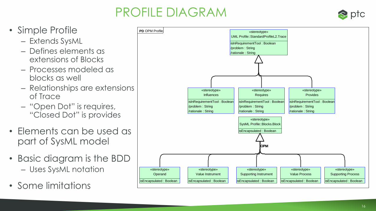
• Simple Profile– Extends SysML
– Defines elements as extensions of Blocks
– Processes modeled as blocks as well
– Relationships are extensions of Trace
– “Open Dot” is requires, “Closed Dot” is provides
• Elements can be used as part of SysML model
• Basic diagram is the BDD– Uses SysML notation
• Some limitations
PROFILE DIAGRAM
«stereotype»
Operand
isEncapsulated : Boolean
«stereotype»
Value Instrument
isEncapsulated : Boolean
«stereotype»
Supporting Instrument
isEncapsulated : Boolean
«stereotype»
SysML Profile::Blocks.Block
isEncapsulated : Boolean
«stereotype»
Influences
isInRequirementTool : Boolean
/problem : String
/rationale : String
«stereotype»
Value Process
isEncapsulated : Boolean
«stereotype»
Supporting Process
isEncapsulated : Boolean
«stereotype»
Requires
isInRequirementTool : Boolean
/problem : String
/rationale : String
«stereotype»
Provides
isInRequirementTool : Boolean
/problem : String
/rationale : String
«stereotype»
UML Profile::StandardProfileL2.Trace
isInRequirementTool : Boolean
/problem : String
/rationale : String
OPMOPMOPMOPMOPM
PD OPM Profile
17
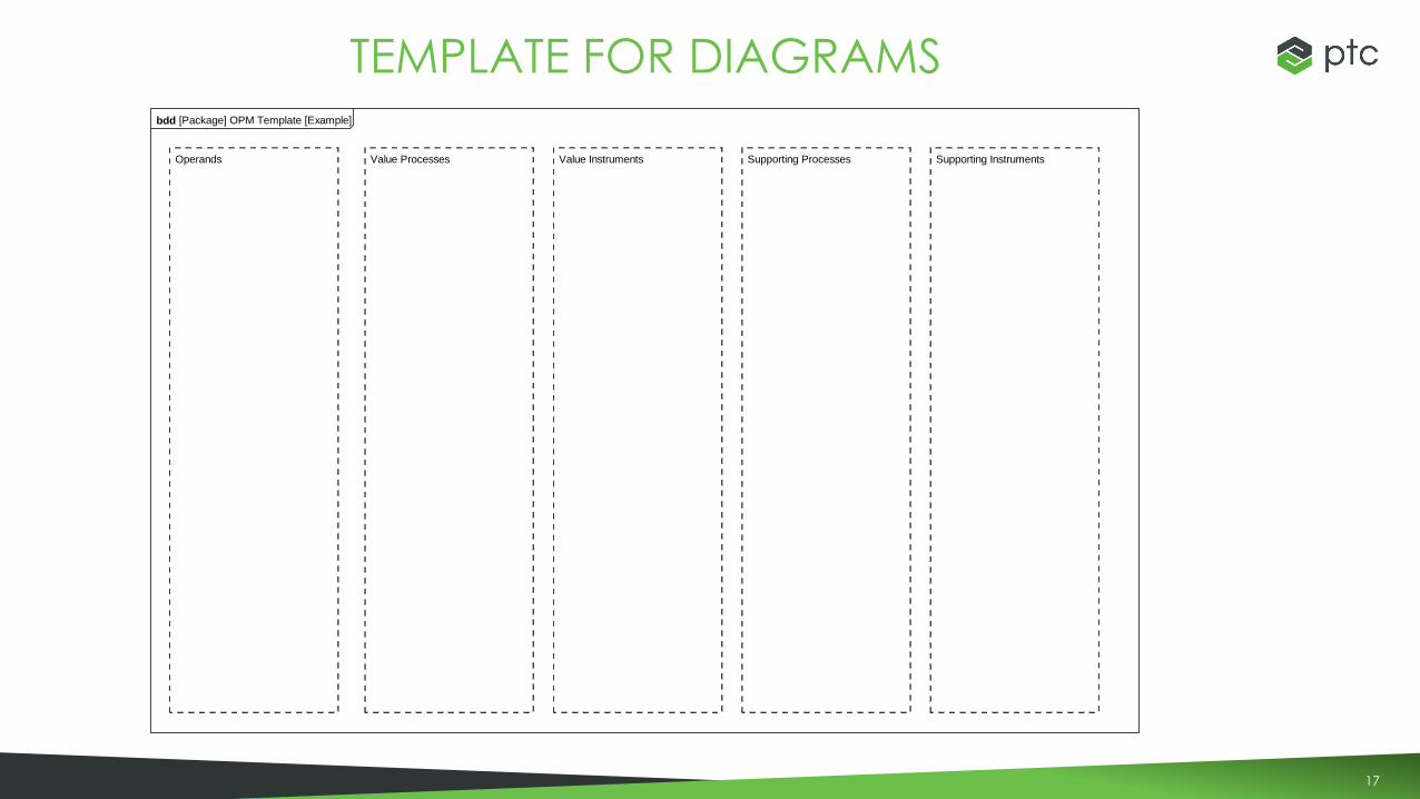
TEMPLATE FOR DIAGRAMSbdd [Package] OPM Template [Example]
Operands Value Processes Supporting InstrumentsValue Instruments Supporting Processes
18
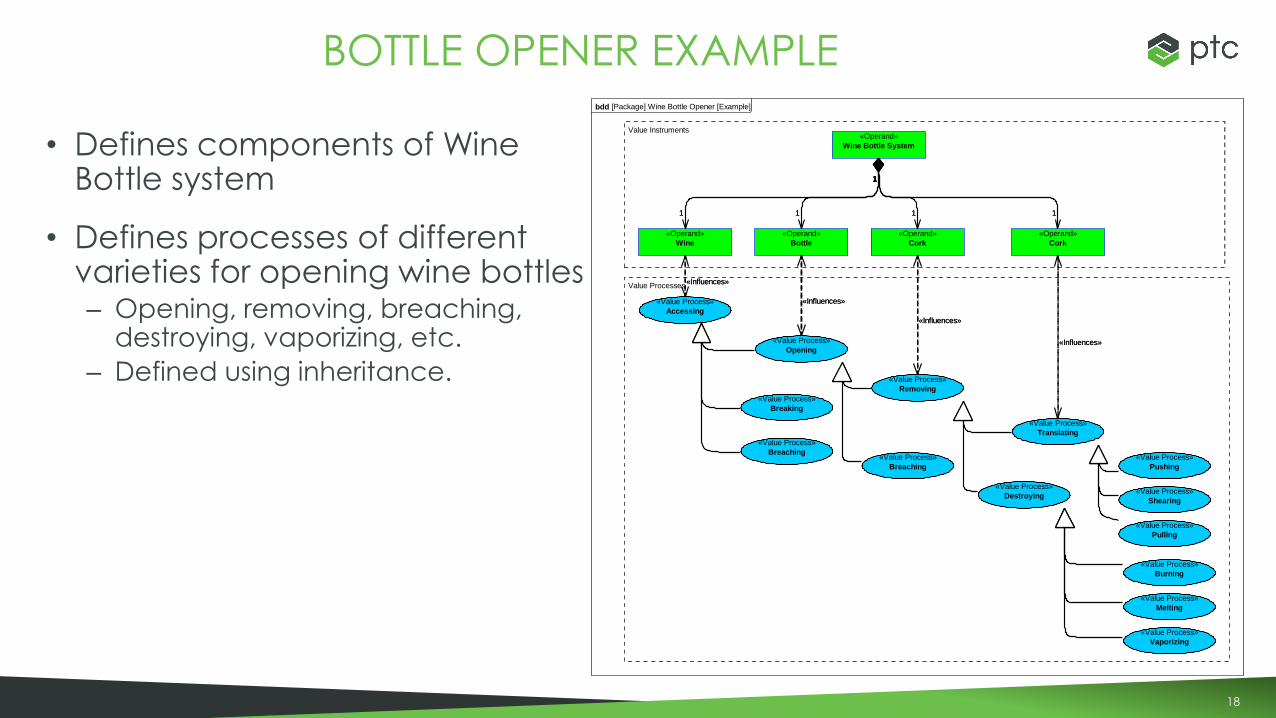
• Defines components of Wine Bottle system
• Defines processes of different varieties for opening wine bottles– Opening, removing, breaching,
destroying, vaporizing, etc.
– Defined using inheritance.
BOTTLE OPENER EXAMPLE
1
1
1
1
1
1
1
1
bdd [Package] Wine Bottle Opener [Example]
«Value Process»
Accessing
«Value Process»
Opening
«Value Process»
Breaking
«Value Process»
Breaching
«Value Process»
Removing
«Value Process»
Translating
«Value Process»
Destroying
«Value Process»
Pushing
«Value Process»
Shearing
«Value Process»
Pulling
«Value Process»
Burning
«Value Process»
Melting
«Value Process»
Vaporizing
«Value Process»
Breaching
«Operand»
Wine Bottle System
«Operand»
Wine
«Operand»
Bottle
«Operand»
Cork
«Operand»
Cork
1
1
1
1
1
1
1
1
«Influences»«Influences»
«Influences»«Influences»
«Influences»«Influences»
«Influences»«Influences»
Value Processes
Value Instruments

19
• Defines the Fluid operand and methods of energizing it
• Defines Value Instruments for achieving processes
FLUID ENERGIZING EXAMPLE
bdd [Package] Fluid Energizing [Example]
«Operand»
Fluid
«Value Process»
Energizing
«Value Process»
Pressurizing
«Value Process»
Accelerating
«Value Process»
Displacing
«Value Instrument»
Pressurizer
«Value Instrument»
Accelerator
«Value Instrument»
Displacer
«Value Instrument»
Centrifugal
«Value Instrument»
Axial
«Value Instrument»
Centrifugal Accelerator
«Value Instrument»
Jet
«Value Instrument»
Rotary
«Value Instrument»
Reciprocating
«Influences»
«Influences»
«Requires»
«Requires»
«Requires»
Operands Value Processes Value Instruments
© Ed Crawley 2016 Leadership, Innovation, Systems Thinking
Lockingnut
O-ringScrews
Cover
WaterSlinger
Housing
Seal
Motor
Impeller
MotorShaft
Inflowing
Guide &contain
Accelerating
Diffusing
Outflowing
ExternalLow pflow
InternalLow pflow
InternalHigh vflow
InternalHigh p
flow
Externalhigh pflow
Containing
Containing
Supporting
Driving
Supporting
Driving
Supporting
DeflectingWaterleakage
Pipe
Pipe
Powersupply
Mounting
Powering
Supporting
Product/system boundary
Measuring
Pressure measurement
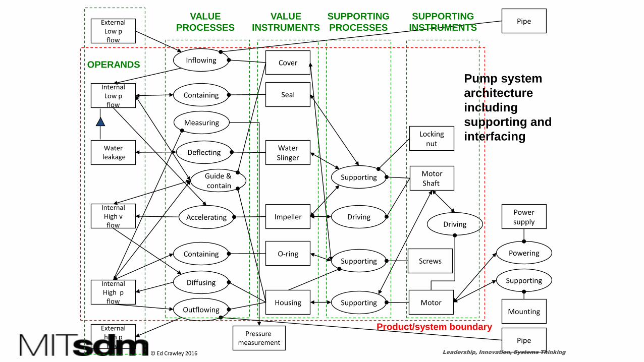
Pump system
architecture
including
supporting and
interfacing
OPERANDS
VALUE
PROCESSES
VALUE
INSTRUMENTS
SUPPORTING
PROCESSES
SUPPORTING
INSTRUMENTS

21
PUMP SYSTEM EXAMPLE
1
1
bdd [Package] Pump System [Example]
«Operand»
External Low p Flow
«Operand»
Internal Low p Flow
«Operand»
Water Leakage
«Operand»
Internal High V Flow
«Operand»
Internal High P Flow
«Operand»
External High P Flow
«Value Process»
Inflowing
«Value Process»
Containing
«Value Process»
Measuring
«Value Process»
Deflecting
«Value Process»
Guida & Contain
«Value Process»
Accelerating
«Value Process»
Difusing
«Value Process»
Outflowing
«Value Instrument»
Cover
«Value Instrument»
Seal
«Value Instrument»
Water Slinger
«Value Instrument»
Impeller
«Value Instrument»
O-Ring
«Value Instrument»
Housing
«block»
Pressure Measurement
«Supporting Process»
Supporting
«Supporting Process»
Driving
«Supporting Instrument»
Locking Nut
«Supporting Instrument»
Motor Shaft
«Supporting Instrument»
Screws
«Supporting Instrument»
Motor
«block»
Pipe
«block»
Power Supply
«block»
Mounting
«Value Process»
Containing
«Supporting Process»
Supporting
«Supporting Process»
Supporting
«Supporting Process»
Driving
«block»
Pipe
«activity»
Powering
«activity»
Supporting Motor
1
1
«Influences»
«Influences»
«Influences»
«Influences»
«Influences»
«Influences»
«Influences»
«Influences»
«Influences»
«Influences»
«Influences»
«Influences»
«Influences»
«Influences»
«Influences»
«Influences»
«Influences»«Influences»
«Influences»
«Influences»
«Influences»
«Provides»
«Provides»
«Provides»
«Provides»
«Provides»
«Provides»
«Provides»
«Provides»
«Influences»
«Influences»
«Influences»
«Influences» «Influences»
«Influences»«Influences»
«Influences»«Influences»
«Influences»«Influences»
«Provides»
«Provides»
«Provides»
«Provides»
«Provides»
«Provides»
«Provides»
«Provides»
«Provides»
«Provides»
«Provides»
Operands Value Processes Supporting InstrumentsValue Instruments Supporting Processes
Product/System Boundary
22
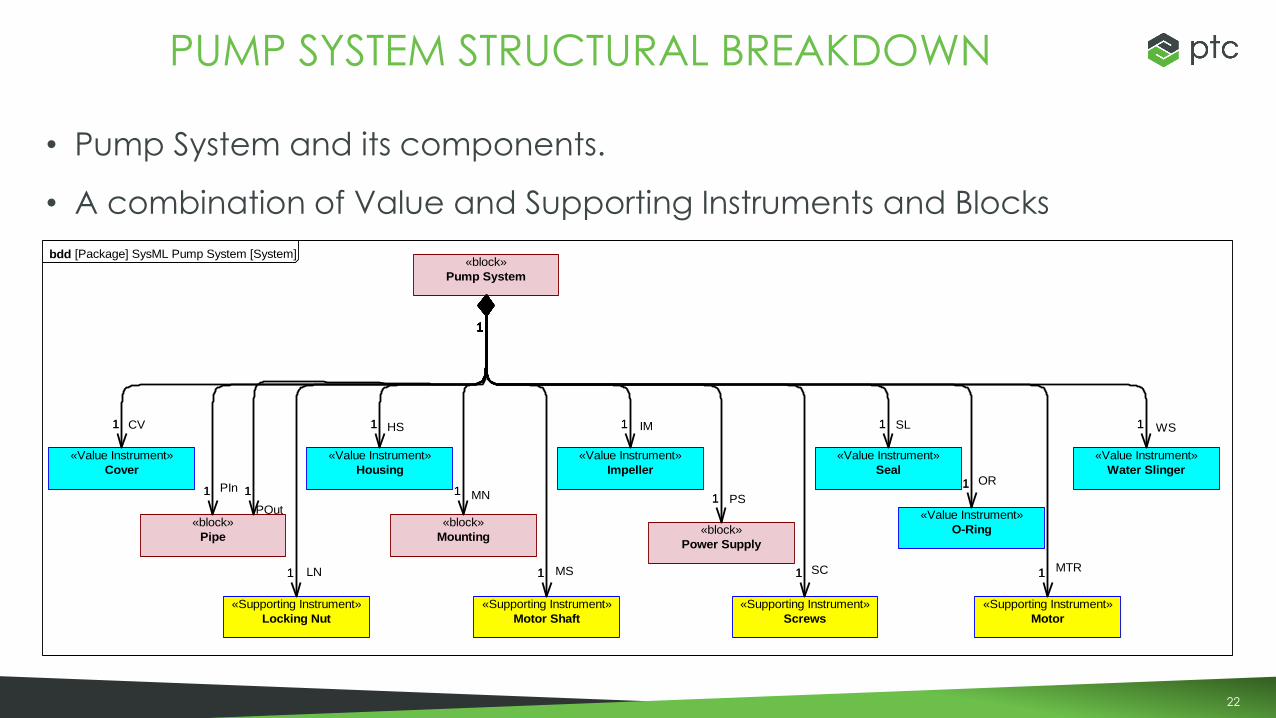
• Pump System and its components.
• A combination of Value and Supporting Instruments and Blocks
PUMP SYSTEM STRUCTURAL BREAKDOWN
1
1
1
1
1
1
1
1
1
1
1
1
1
1
1
1
1
1
1
1
1
1
1
1
1
1
1
1
bdd [Package] SysML Pump System [System]«block»
Pump System
«Value Instrument»
Cover
«Value Instrument»
Housing
«Value Instrument»
Impeller
«Value Instrument»
Seal
«Value Instrument»
Water Slinger
«Value Instrument»
O-Ring
«Supporting Instrument»
Locking Nut
«Supporting Instrument»
Motor
«Supporting Instrument»
Motor Shaft
«Supporting Instrument»
Screws
«block»
Mounting
«block»
Pipe«block»
Power Supply
1
1
CV 1
1
HS 1
1
IM 1
1
SL
1
1
OR
1
1
WS
1
1
PIn 1
1
MN 1
1
PS
1
1
MS 1
1
MTR1
1
SC1
1
LN
1
1
POut
23
PUMP SYSTEM STRUCTURAL BREAKDOWN W/GRAPHICS
24
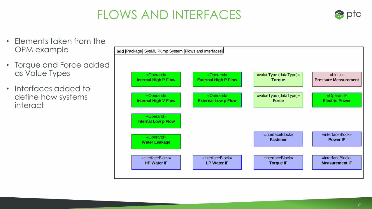
• Elements taken from the OPM example
• Torque and Force added as Value Types
• Interfaces added to define how systems interact
FLOWS AND INTERFACES
bdd [Package] SysML Pump System [Flows and Interfaces]
«Operand»
Internal High P Flow
«Operand»
Internal High V Flow
«Operand»
Internal Low p Flow
«Operand»
Water Leakage
«Operand»
External High P Flow
«Operand»
External Low p Flow
«interfaceBlock»
HP Water IF
«interfaceBlock»
LP Water IF
«interfaceBlock»
Power IF
«Operand»
Electric Power
«valueType (dataType)»
Force
«interfaceBlock»
Fastener
«interfaceBlock»
Torque IF
«valueType (dataType)»
Torque
«block»
Pressure Measurement
«interfaceBlock»
Measurement IF
25
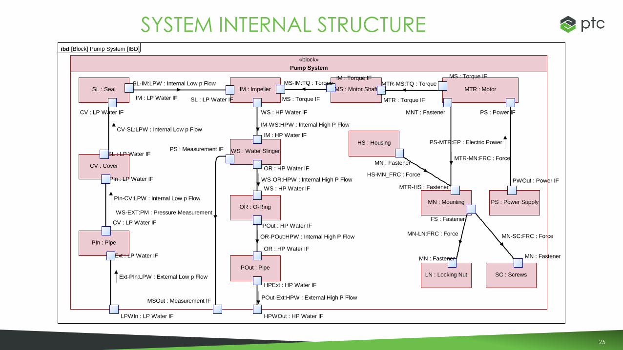
SYSTEM INTERNAL STRUCTUREibd [Block] Pump System [IBD]
«block»
Pump System
CV : Cover
PIn : LP Water IF
SL : LP Water IF
HS : Housing
MN : Fastener
IM : Impeller
MS : Torque IFSL : LP Water IF
WS : HP Water IF
SL : Seal
CV : LP Water IF
IM : LP Water IF
OR : O-Ring
WS : HP Water IF
POut : HP Water IF
WS : Water Slinger
IM : HP Water IF
OR : HP Water IF
PS : Measurement IF
PIn : Pipe
CV : LP Water IF
Ext : LP Water IF
MN : Mounting
MTR-HS : Fastener
FS : Fastener
PS : Power Supply
PWOut : Power IF
MS : Motor Shaft
MTR : Torque IF
IM : Torque IF
MTR : Motor
PS : Power IF
MS : Torque IF
MNT : Fastener
SC : Screws
MN : Fastener
LN : Locking Nut
MN : Fastener
POut : Pipe
OR : HP Water IF
HPExt : HP Water IF
LPWIn : LP Water IF HPWOut : HP Water IF
MSOut : Measurement IF
PS-MTR:EP : Electric Power
MTR-MN:FRC : Force
MTR-MS:TQ : TorqueMS-IM:TQ : Torque
IM-WS:HPW : Internal High P Flow
Ext-PIn:LPW : External Low p Flow
PIn-CV:LPW : Internal Low p Flow
CV-SL:LPW : Internal Low p Flow
SL-IM:LPW : Internal Low p Flow
POut-Ext:HPW : External High P Flow
MN-LN:FRC : Force MN-SC:FRC : Force
WS-OR:HPW : Internal High P Flow
OR-POut:HPW : Internal High P Flow
HS-MN_FRC : Force
WS-EXT:PM : Pressure Measurement
26
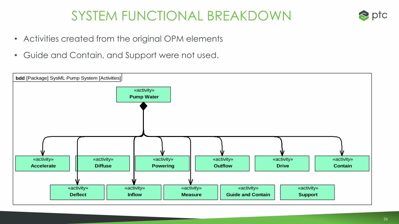
• Activities created from the original OPM elements
• Guide and Contain, and Support were not used.
SYSTEM FUNCTIONAL BREAKDOWN
bdd [Package] SysML Pump System [Activities]
«activity»
Pump Water
«activity»
Accelerate
«activity»
Deflect
«activity»
Contain
«activity»
Support
«activity»
Outflow
«activity»
Diffuse
«activity»
Guide and Contain
«activity»
Measure
«activity»
Inflow
«activity»
Drive
«activity»
Powering
27
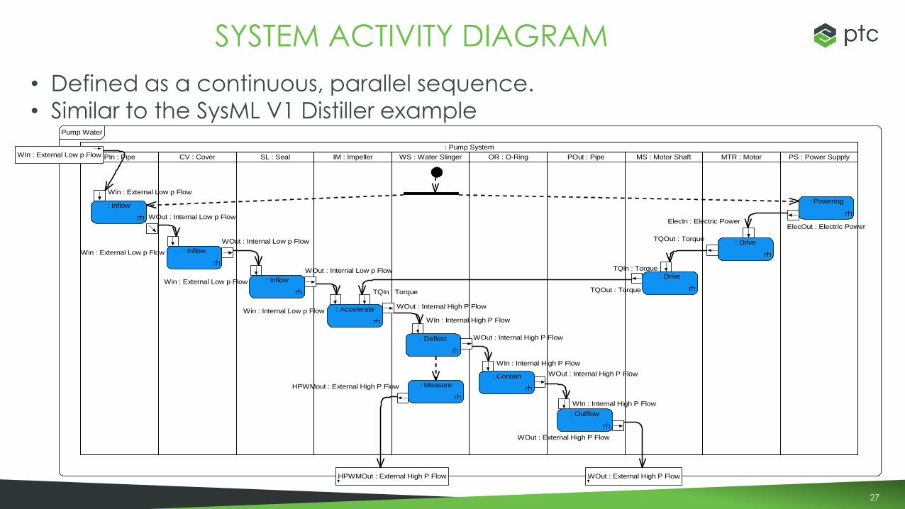
• Defined as a continuous, parallel sequence.
• Similar to the SysML V1 Distiller example
SYSTEM ACTIVITY DIAGRAM
: Pump System
PIn : Pipe CV : Cover SL : Seal IM : Impeller WS : Water Slinger OR : O-Ring POut : Pipe MS : Motor Shaft MTR : Motor PS : Power Supply
Win : External Low p Flow
WOut : Internal Low p Flow
: Inflow
Win : External Low p Flow
WOut : Internal Low p Flow
: Inflow
Win : External Low p Flow
WOut : Internal Low p Flow
: Inflow
Win : Internal Low p FlowWOut : Internal High P Flow
TQIn : Torque
: Accelerate
WIn : Internal High P Flow
WOut : Internal High P Flow: Deflect
HPWMout : External High P Flow : Measure
WIn : Internal High P Flow
WOut : Internal High P Flow: Contain
WIn : Internal High P Flow
WOut : External High P Flow
: Outflow
TQIn : Torque
TQOut : Torque
: Drive
TQOut : Torque
ElecIn : Electric Power
: Drive
ElecOut : Electric Power
: Powering
WIn : External Low p Flow
WOut : External High P FlowHPWMOut : External High P Flow
Pump Water
28
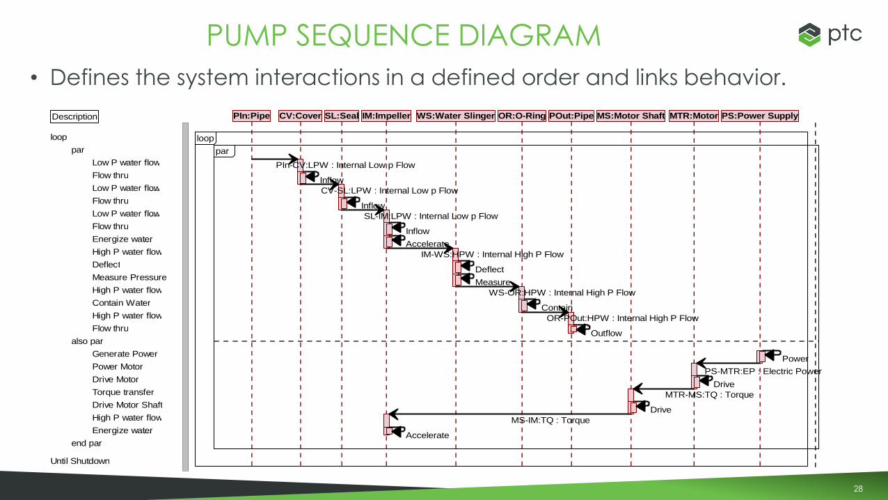
• Defines the system interactions in a defined order and links behavior.
PUMP SEQUENCE DIAGRAM
Description PIn:Pipe CV:Cover SL:Seal IM:Impeller WS:Water Slinger OR:O-Ring POut:Pipe MS:Motor Shaft MTR:Motor PS:Power Supply
loop loop
par par
Low P water flow PIn-CV:LPW : Internal Low p Flow
Flow thruInflow
Low P water flow... CV-SL:LPW : Internal Low p Flow
Flow thruInflow
Low P water flow... SL-IM:LPW : Internal Low p Flow
Flow thruInflow
Energize water...Accelerate
High P water flow IM-WS:HPW : Internal High P Flow
DeflectDeflect
Measure PressureMeasure
High P water flow WS-OR:HPW : Internal High P Flow
Contain WaterContain
High P water flow OR-POut:HPW : Internal High P Flow
Flow thruOutflow
also par
Generate PowerPower
Power MotorPS-MTR:EP : Electric Power
Drive MotorDrive
Torque transfer MTR-MS:TQ : Torque
Drive Motor ShaftDrive
High P water flow MS-IM:TQ : Torque
Energize water...Accelerate
end par
Until Shutdown

29
• Demonstrates that the different languages can be used together in a single tool– Alternative would be to create the OPM model in OPCAT use printout as a basis for
traceability
– The integrated approach means that true impact analysis and traceability can be done.
• An OPM Model can created as a starting point with SysML used to refine the concepts– The elements were then used to create the SysML diagrams
– Some additions and changes were needed
– Alternative would be to create separate OPM and SysML models and create trace links between them
• Other concepts can be added such as parametrics, executable state machines, traceability to requirements, analysis and PLM tools, etc.
WHY IS THIS USEFUL?

30
• Many of the concepts in OPM can be duplicated in a SysML tool– There is some cognitive dissonance
– Provide an alternative means of looking at a system
– Provide a starting point for people familiar with OPM
– Both are useful
• The models demonstrate that the languages can be used together– OPM as a starting point can be used to develop a detailed SysML model
• More work and research are needed– ALL OPM concepts were not added as this was more of a proof of concept than a
solution.
– The text portion of OPM (OPL) was not implemented.
– “Finally, defining a hybrid methodology exploiting the advantages of the two languages seems to be a challenging issue.” Systems Modeling Languages: OPM Versus SysML
CONCLUSIONS
31
• Examples were taken from the Edward Crawley et al Book System Architecture: Strategy and Product Development for Complex Systems
• MIT SDM course slides
• Rob Day and John Deere for their help in creating the model and gaining an understanding of OPM
• Tutorials and papers by Dov Dori
ACKNOWLEDGEMENT AND THANKS

32
WORKING TOGETHER TO ACHIEVE COMMON GOALS
THE GOLDEN SPIKE THE CHANNEL TUNNEL

33
• Nicole Richie and Paris Hilton
• Jennifer Aniston and Courteney Cox
• Lauren Conrad and Heidi Montag
• Paris Hilton and Lindsay Lohan
• Selena Gomez and Miley Cyrus
• Whitney Port and Olivia Palermo
• Winona Ryder and Gwyneth Paltrow
• Selena Gomez and Demi Lovato
FAMOUS FRENEMIES
http://www.zimbio.com/Famous+Frenemies/articles

34

Thank You!
Related Documents