School of Electronic Engineering and Computer Science QUEEN MARY UNIVERSITY OF LONDON FINAL YEAR PROJECT Freespace Optical Communication Morse-Code Transceiver INTERIM REPORT AND RISK ASSESSMENT 2013-2014 Student Name: Abdul Samad Ali

Welcome message from author
This document is posted to help you gain knowledge. Please leave a comment to let me know what you think about it! Share it to your friends and learn new things together.
Transcript
School of Electronic Engineering and Computer Science
QUEEN MARY UNIVERSITY OF LONDON
FINAL YEAR PROJECT
Freespace Optical Communication
Morse-Code Transceiver
INTERIM REPORT AND RISK ASSESSMENT 2013-2014
Student Name: Abdul Samad Ali
2
INTRODCUTION
Free-space optics (FSO) is a communication technology that uses optical beams generated by light emitting
diodes (LEDs) and Lasers to transmit information line-of-sight through the atmosphere from the source
over the transmission medium to the destination. It is a technology that uses invisible beams of light to
provide full-duplex optical bandwidth connections. FSO is capable of transmitting upto 10 Gbps of data,
video and voice communications simultaneously through the atmosphere – enabling fiber-optic connectivity
without requiring physical fiber-optic cable. The optical connectivity doesn’t require expensive fiber-optic
cable; it requires light, which is similar to optical transmissions that use fiber-optic cables, but the only
difference is the medium. Light travels through air faster than it does through glass, so FSO is optical
communication at the speed of light. [1][2]
Over the last few years, there has been an exponential growth in the use of FSO technology. Many
companies, like NASA, Artolink, Laserprotonics et al are using FSO for operative and temporary
communicaiton; LAN-to-LAN connections on campuses, in a city; inter-satellite communication;
communication between municipal buildings, etc. [2]
For terrestrial application, atmosphere can be the prinicpal limiting factor to effective communication. The
atmosphere is a mixture of water vapour and dry air. Therefore, FSO systems must be designed to
accommodate heavy atmospheric attenuation, particularly fog. There are also other factors, that could cause
signal attentuation, like; Scintilation, intereference from background light sources, smog, etc. [2]
BACKGROUND
The military and NASA developed FSO [3] and have been utilising it for more than three decades in various
forms to provide communication links. Even though fibre-optic communications has gained much
acceptance in the telecoms industry, free space optics technology is relatively new and has seen exponential
growth in the last few years. [4] [5]
How FSO works? FSO technology is based on connectivity between optical wireless units, each units consist of an optical
transceiver with a receiver and a transmitter in order to provide full-duplex capability. Both optical wireless
unit utilises an optical source, including a lens that transmits light through freespace to another lens
receiving the information (using LED/Laser to transmit information and some type of photodetector - which
converts the optic beams into electric pulses – to receive information). [6]
My Project
The aim of this project is to allow keypad entered text messages to be sent from one microcontroller-based
unit to another remotely located one via a freespace optical communication link. The text messages are to
be encoded in Morse code. At the receiver these should be decoded and displayed as text on an LCD. The
sender sends the messages as pulses of light, using an LED, according to Morse code. The receiver has a
phototransistor, which converts the light back into electrical pulses, which are compared against a table to
determine which Morse code character they correspond to.
Microcontroller
There was once a time when the number of microcontroller chips that were available to the users were
pretty limited. You had to use whatever you could manage to get your hands onto and that narrowed down
the choice to a small number of chips. But now that times have changed and there now exist over a
thousand different types of microcontrollers. A microcontroller is a small computer on a single integrated
circuit containing memory, a processor core, and programmable input/output peripherals.
Prior exposure to 8051 microcontroller was advantageous, therefore, I decided to look more into the 8051-
family and choose one that meets the project requirements. The Intel MCS, commonly referred to as 8051,
is a Harvard architecture (a computer architecture with physically separate storage and signal pathways for
instructions and data), single chip microcontroller which was developed in 1980 by Intel for use in
embedded systems.
3
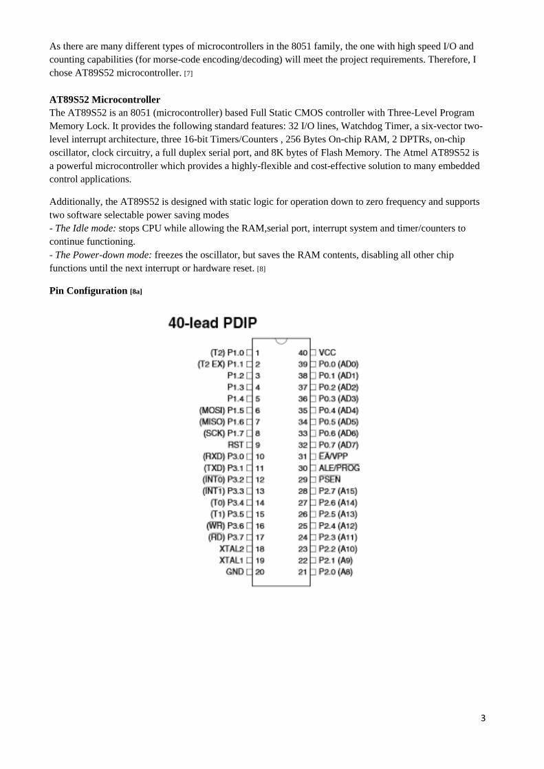
As there are many different types of microcontrollers in the 8051 family, the one with high speed I/O and
counting capabilities (for morse-code encoding/decoding) will meet the project requirements. Therefore, I
chose AT89S52 microcontroller. [7]
AT89S52 Microcontroller
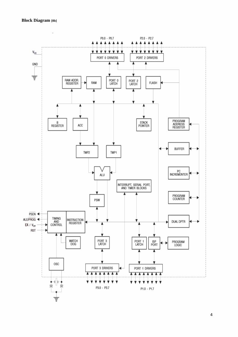
The AT89S52 is an 8051 (microcontroller) based Full Static CMOS controller with Three-Level Program
Memory Lock. It provides the following standard features: 32 I/O lines, Watchdog Timer, a six-vector two-
level interrupt architecture, three 16-bit Timers/Counters , 256 Bytes On-chip RAM, 2 DPTRs, on-chip
oscillator, clock circuitry, a full duplex serial port, and 8K bytes of Flash Memory. The Atmel AT89S52 is
a powerful microcontroller which provides a highly-flexible and cost-effective solution to many embedded
control applications.
Additionally, the AT89S52 is designed with static logic for operation down to zero frequency and supports
two software selectable power saving modes
- The Idle mode: stops CPU while allowing the RAM,serial port, interrupt system and timer/counters to
continue functioning.
- The Power-down mode: freezes the oscillator, but saves the RAM contents, disabling all other chip
functions until the next interrupt or hardware reset. [8]
Pin Configuration [8a]
4
Block Diagram [8b]
5
Programming Microcontroller
As for programming 8051 microcontroller, there are programming language compilers available, but
Assembly language seem to be more widely used. Assembly Language is a low-level programming and is
an appropriate choice as it leads to compact code. One of the microcontrollers will be programmed to
transmit data; by encoding the text entered through keypad into morse-code, using an LED. The other
microcontroller will be programmed to receive data; by decoding the morse-code received using a
photodetector and then displaying it as text.
Assembly Language of 8051
Firstly, the editor is used to write the program and produce source file extensions. The ‘asm’ source file is
then fed into the 8051 microcontroller. The microcontroller then takes that source file and converts it into
machine code. The list and object files, along with their extensions, are then created. It is necessary to
observe specific rules in order to enable the process of compiling the program into an executable ‘hex-code’
for it to run without errors. Therefore, in the third step – called Linking – which takes one or more object
files with the extension ‘abs’. The ‘abs’ file is then fed into the ‘hex converter called OH. The file extension
of this is then burned into the ROM. [9] [10]
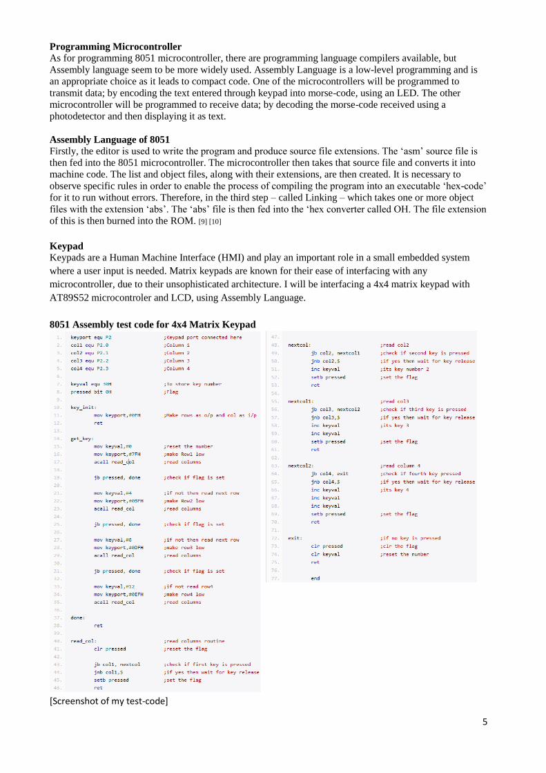
Keypad
Keypads are a Human Machine Interface (HMI) and play an important role in a small embedded system
where a user input is needed. Matrix keypads are known for their ease of interfacing with any
microcontroller, due to their unsophisticated architecture. I will be interfacing a 4x4 matrix keypad with
AT89S52 microcontroler and LCD, using Assembly Language.
8051 Assembly test code for 4x4 Matrix Keypad
[Screenshot of my test-code]
6
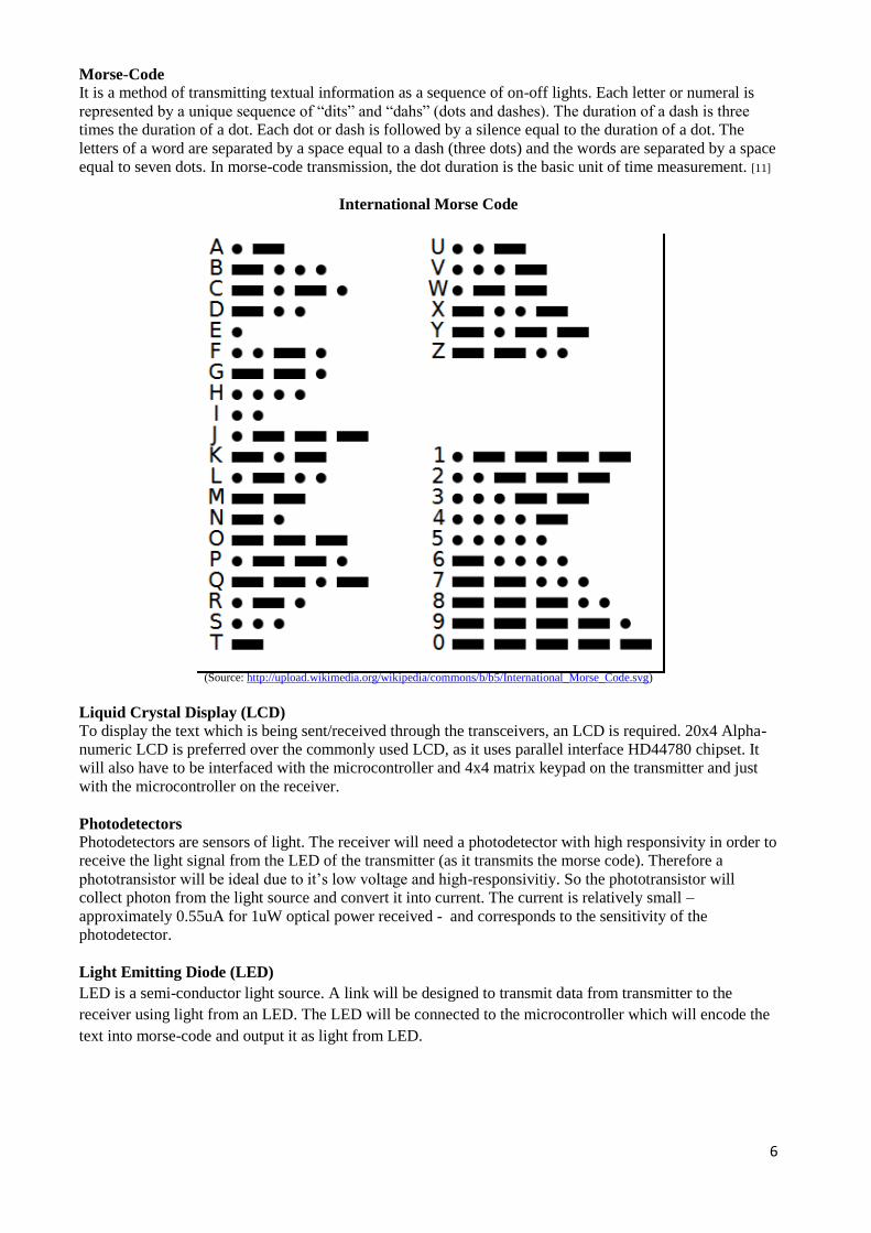
Morse-Code
It is a method of transmitting textual information as a sequence of on-off lights. Each letter or numeral is
represented by a unique sequence of “dits” and “dahs” (dots and dashes). The duration of a dash is three
times the duration of a dot. Each dot or dash is followed by a silence equal to the duration of a dot. The
letters of a word are separated by a space equal to a dash (three dots) and the words are separated by a space
equal to seven dots. In morse-code transmission, the dot duration is the basic unit of time measurement. [11]
International Morse Code
(Source: http://upload.wikimedia.org/wikipedia/commons/b/b5/International_Morse_Code.svg)
Liquid Crystal Display (LCD)
To display the text which is being sent/received through the transceivers, an LCD is required. 20x4 Alpha-
numeric LCD is preferred over the commonly used LCD, as it uses parallel interface HD44780 chipset. It
will also have to be interfaced with the microcontroller and 4x4 matrix keypad on the transmitter and just
with the microcontroller on the receiver.
Photodetectors
Photodetectors are sensors of light. The receiver will need a photodetector with high responsivity in order to
receive the light signal from the LED of the transmitter (as it transmits the morse code). Therefore a
phototransistor will be ideal due to it’s low voltage and high-responsivitiy. So the phototransistor will
collect photon from the light source and convert it into current. The current is relatively small –
approximately 0.55uA for 1uW optical power received - and corresponds to the sensitivity of the
photodetector.
Light Emitting Diode (LED)
LED is a semi-conductor light source. A link will be designed to transmit data from transmitter to the
receiver using light from an LED. The LED will be connected to the microcontroller which will encode the
text into morse-code and output it as light from LED.
7
Receiver Transmitter
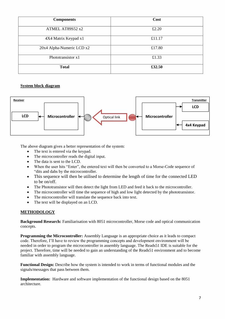
Components Cost
ATMEL AT89S52 x2 £2.20
4X4 Matrix Keypad x1 £11.17
20x4 Alpha-Numeric LCD x2 £17.80
Phototransistor x1 £1.33
Total £32.50
System block diagram
The above diagram gives a better representation of the system:
The text is entered via the keypad.
The microcontroller reads the digital input.
The data is sent to the LCD.
When the user hits “Enter”, the entered text will then be converted to a Morse-Code sequence of
“dits and dahs by the microcontroller.
This sequence will then be utilised to determine the length of time for the connected LED
to be on/off.
The Phototransistor will then detect the light from LED and feed it back to the microcontroller.
The microcontroller will time the sequence of high and low light detected by the phototransistor.
The microcontroller will translate the sequence back into text.
The text will be displayed on an LCD.
METHODOLOGY
Background Research: Familiarisation with 8051 microcontroller, Morse code and optical communication
concepts.
Programming the Microcontroller: Assembly Language is an appropriate choice as it leads to compact
code. Therefore, I’ll have to review the programming concepts and development environment will be
needed in order to program the microcontroller in assembly language. The Reads51 IDE is suitable for the
project. Therefore, time will be needed to gain an understanding of the Reads51 environment and to become
familiar with assembly language.
Functional Design: Describe how the system is intended to work in terms of functional modules and the
signals/messages that pass between them.
Implementation: Hardware and software implementation of the functional design based on the 8051
architecture.
4x4 Keypad
Microcontroller
Microcontroller
LCD
LCD Optical link
8
Validation: Testing to ensure the implementation is operational, to send and receive the data through the
freespace laser communication.
Evaluation: Evaluating the performance of the implemented system to ascertain how well it operations
under different conditions
Final Report: Preparation of the end-of-project report
Documentation: I will be documenting my work all along, which will include schematics, design diagrams,
progress, references etc.
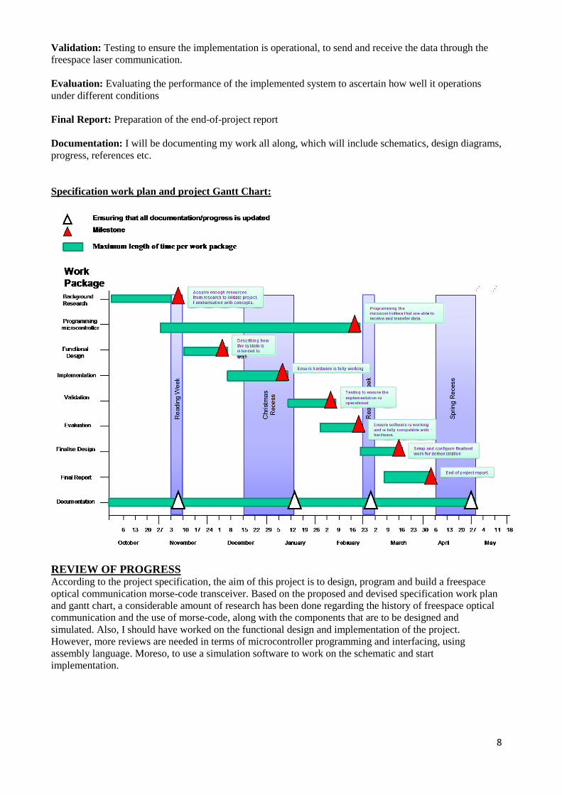
Specification work plan and project Gantt Chart:
REVIEW OF PROGRESS According to the project specification, the aim of this project is to design, program and build a freespace
optical communication morse-code transceiver. Based on the proposed and devised specification work plan
and gantt chart, a considerable amount of research has been done regarding the history of freespace optical
communication and the use of morse-code, along with the components that are to be designed and
simulated. Also, I should have worked on the functional design and implementation of the project.
However, more reviews are needed in terms of microcontroller programming and interfacing, using
assembly language. Moreso, to use a simulation software to work on the schematic and start
implementation.
9
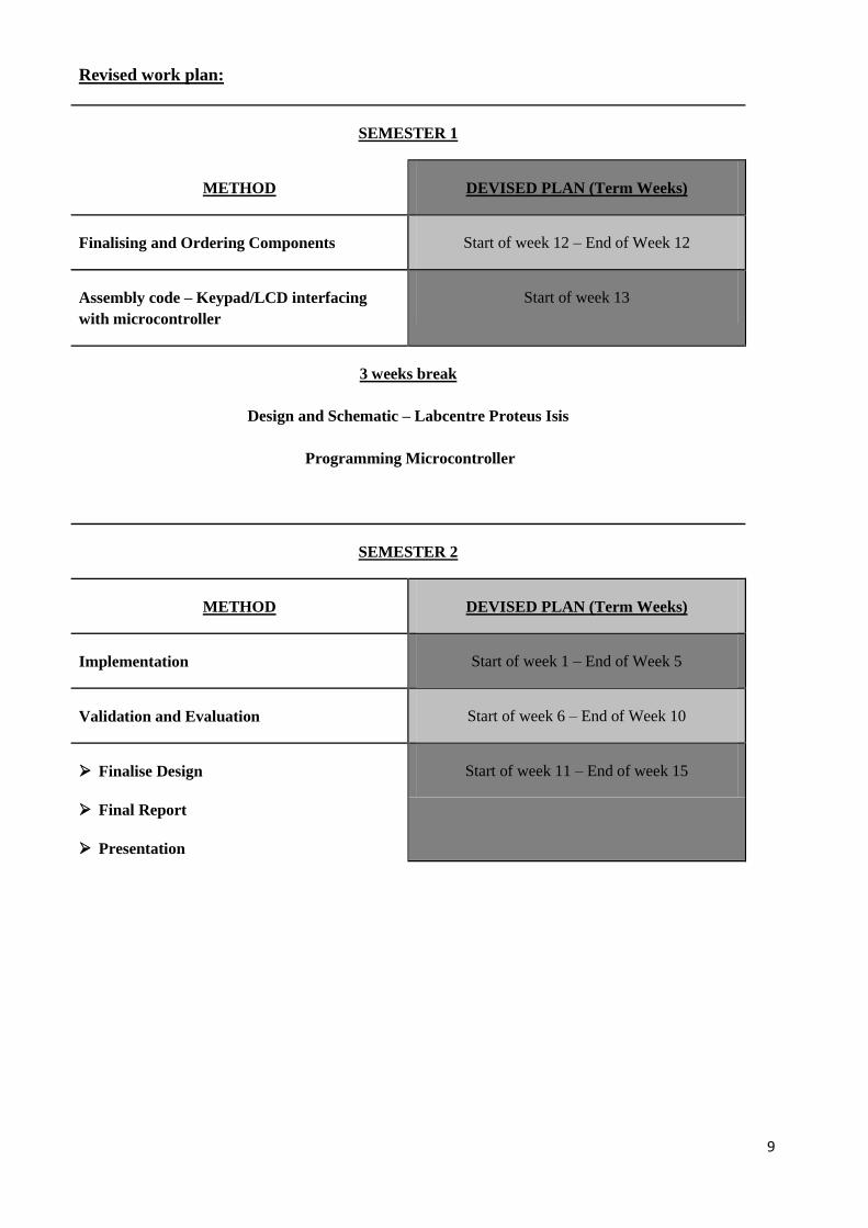
Revised work plan:
SEMESTER 1
METHOD DEVISED PLAN (Term Weeks)
Finalising and Ordering Components Start of week 12 – End of Week 12
Assembly code – Keypad/LCD interfacing
with microcontroller
Start of week 13
3 weeks break
Design and Schematic – Labcentre Proteus Isis
Programming Microcontroller
SEMESTER 2
METHOD DEVISED PLAN (Term Weeks)
Implementation Start of week 1 – End of Week 5
Validation and Evaluation Start of week 6 – End of Week 10
Finalise Design
Final Report
Presentation
Start of week 11 – End of week 15
10
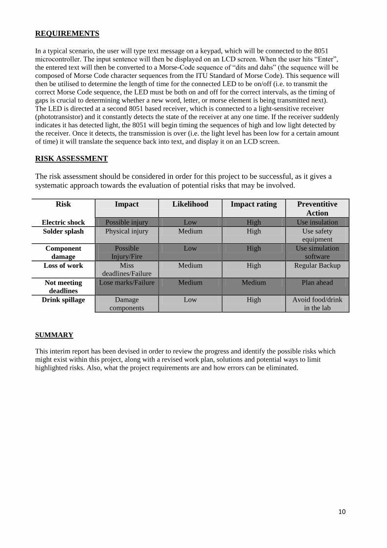
REQUIREMENTS
In a typical scenario, the user will type text message on a keypad, which will be connected to the 8051
microcontroller. The input sentence will then be displayed on an LCD screen. When the user hits “Enter”,
the entered text will then be converted to a Morse-Code sequence of “dits and dahs” (the sequence will be
composed of Morse Code character sequences from the ITU Standard of Morse Code). This sequence will
then be utilised to determine the length of time for the connected LED to be on/off (i.e. to transmit the
correct Morse Code sequence, the LED must be both on and off for the correct intervals, as the timing of
gaps is crucial to determining whether a new word, letter, or morse element is being transmitted next).
The LED is directed at a second 8051 based receiver, which is connected to a light-sensitive receiver
(phototransistor) and it constantly detects the state of the receiver at any one time. If the receiver suddenly
indicates it has detected light, the 8051 will begin timing the sequences of high and low light detected by
the receiver. Once it detects, the transmission is over (i.e. the light level has been low for a certain amount
of time) it will translate the sequence back into text, and display it on an LCD screen.
RISK ASSESSMENT
The risk assessment should be considered in order for this project to be successful, as it gives a
systematic approach towards the evaluation of potential risks that may be involved.
Risk Impact Likelihood Impact rating Preventitive
Action
Electric shock Possible injury Low High Use insulation
Solder splash Physical injury Medium High Use safety
equipment
Component
damage
Possible
Injury/Fire
Low High Use simulation
software
Loss of work Miss
deadlines/Failure
Medium High Regular Backup
Not meeting
deadlines
Lose marks/Failure Medium Medium Plan ahead
Drink spillage Damage
components
Low High Avoid food/drink
in the lab
SUMMARY
This interim report has been devised in order to review the progress and identify the possible risks which
might exist within this project, along with a revised work plan, solutions and potential ways to limit
highlighted risks. Also, what the project requirements are and how errors can be eliminated.
11
REFERENCES
[1] About Freespace Optics. LightPointer http://www.lightpointe.com/freespaceoptics.html.
Retrieved December 03, 2013.
[2] Optical Communication Systems, Pages 569-588 (2nd
Edition),by John Gowar
[3] Free-space optical communication, Wikipedia: http://en.wikipedia.org/wiki/Free-
space_optical_communication. Retrieved December 03, 2013.
[4] Dunn, Marcia (2013-09-07). "NASA launches robotic explorer to moon from Va.; trouble
develops early in much-viewed flight". Star Tribune. Retrieved 2013-09-07.
[5] "Space probe breaks laser record: A spacecraft has sent a laser signal to Earth from 24
million km (15 million miles) away in interplanetary space". BBC News. January 6, 2006.
Retrieved December 04, 2013.
[6] Dennis Killinger, “Free space optics for laser communication through the air,” Optics &
Photonics News, pp. 36-42, October 2002.
[7] The 8051 Microcontroller and Embedded systems by Muhammad Ali Mazidi and Janice
Gillispie Mazidi
[8] [a][b] ATMEL AT89S52 Datasheet. http://www.atmel.com/images/doc1919.pdf. Retrieved
December 04, 2013
[9] "Information transmission by light beams through the atmosphere", in the journal Nachrichtentechnik in June 1968 by Dr. Erhard Kube
[10] Chapter 5 Assembly Language. [Online] Available from http://www.mikroe.com/.
Retrieved December
[11] "International Morse code Recommendation ITU-R M.1677-1". itu.int. International
Telecommunication Union. October 2009. Retrieved December 3, 2013.
Related Documents


![Android Interactive Learning Morse App [Learn Morse] Morse Detailed Insrtuctions.pdfAndroid Interactive Learning Morse App [Learn Morse] Version v1.0 - April 2015 Introduction: Caution!](https://static.cupdf.com/doc/110x72/5f2e43e86c3c8526ba625367/android-interactive-learning-morse-app-learn-morse-morse-detailed-android-interactive.jpg)


