FreeBOT: A Freeform Modular Self-reconfigurable Robot with Arbitrary Connection Point - Design and Implementation Guanqi Liang 1,2 , Haobo Luo 1,2 , Ming Li 1,2 , Huihuan Qian 1,2 , and Tin Lun Lam 1,2,† Abstract— This paper proposes a novel modular self- reconfigurable robot (MSRR) “FreeBOT”, which can be con- nected freely at any point on other robots. FreeBOT is mainly composed of two parts: a spherical ferromagnetic shell and an internal magnet. The connection between the modules is genderless and instant, since the internal magnet can freely attract other FreeBOT spherical ferromagnetic shells, and not need to be precisely aligned with the specified connector. This connection method has fewer physical constraints, so the FreeBOT system can be extended to more configurations to meet more functional requirements. FreeBOT can accom- plish multiple tasks although it only has two motors: module independent movement, connector management and system reconfiguration. FreeBOT can move independently on the plane, and even climb on ferromagnetic walls; a group of FreeBOTs can traverse complex terrain. Numerous experiments have been conducted to test its function, which shows that the FreeBOT system has great potential to realize a freeform robotic system. I. I NTRODUCTION Modular self-reconfigurable robots (MSRR) have become a hot research topic in recent years [1]–[9]. MSRR system consists of many repeated modules, which can rearrange themselves into different configurations according to task requirements. The previous MSRR modules are difficult to realize a freeform robotic systems because they have lots of physical constraints such as: the module connectors are gender-opposite and discrete; the modules need to plan trajectories to align the connectors while self-assembly; the connection between modules is time-consuming and has a low success rate. Through the docking mechanism, the MSRR can realize the connection/separation and system reconfiguration be- tween modules. Therefore, the docking mechanism is one of the most basic components of the MSRR system and many creative docking mechanisms have been designed. For example, the hooks that are activated by DC motors [1], [5], [10]–[12], permanent magnets [2], electromagnets [13], or electro-permanent magnets [14]. In [15], the author proposed the concept of “the area of acceptance” for MSRR, which is defined as “the range of possible starting conditions for which mating will be successful”; a connector with a larger area of acceptance has a higher success rate when connect- ing. The hooks activated by DC motor allow the modules to be strongly connected, but has a small acceptance area *This paper is partially supported by funding 2019-INT008 from the Shenzhen Institute of Artificial Intelligence and Robotics for Society. 1 The Chinese University of Hong Kong, Shenzhen. 2 The Shenzhen Institute of Artificial Intelligence and Robotics for Society. † Corresponding author is Tin Lun Lam [email protected] Fig. 1. A freeform MSRR system - FreeBOT and needs accurate alignment, which requires the module units to plan the trajectory when connecting [10]. It is not an efficient connection mechanism for the MSRR system. Con- nections between magnets or electromagnets can increase the acceptance area [2], [14] since an accurate alignment is not required. When two MSRR modules with paired magnets (or paired electromagnets) approach, they are automatically combined together under a magnetic field. However, the previous connections between magnets or electromagnets must be gender-opposed; it will increase some path planning constraints for the connection between modules [3], [4], [16]. Since the configuration of the previous MSRR system is restricted by the location and gender of the connector, it has become a growing consensus to equip the MSRR module with multiple connectors. If one module can be connected to multiple modules at the same time, the configuration of the MSRR system will be enriched to meet more functional requirements. However, the module with multiple connectors not only increases the weight, volume and manufacturing cost of the robot, but also brings complex physical constraints for path planning at the algorithm level. Therefore, it is still challenging to design an effective and freeform MSRR module. This paper proposes a novel MSRR called FreeBOT (Freeform Robot), which can be connected together flexibly in an effective way with fewer physical constraints (as shown in Fig. 1). FreeBOT has the same basic functions as the most advanced MSRR: modules can move independently, modules can be connected/separated without manual as- sistance, and system configurations can be rearranged. In addition, The connection between modules is genderless and instant, since the internal magnet can freely attract other 2020 IEEE/RSJ International Conference on Intelligent Robots and Systems (IROS) October 25-29, 2020, Las Vegas, NV, USA (Virtual) 978-1-7281-6211-9/20/$31.00 ©2020 IEEE 988

Welcome message from author
This document is posted to help you gain knowledge. Please leave a comment to let me know what you think about it! Share it to your friends and learn new things together.
Transcript

FreeBOT: A Freeform Modular Self-reconfigurable Robot withArbitrary Connection Point - Design and Implementation
Guanqi Liang1,2, Haobo Luo1,2, Ming Li1,2, Huihuan Qian1,2, and Tin Lun Lam1,2,†
Abstract— This paper proposes a novel modular self-reconfigurable robot (MSRR) “FreeBOT”, which can be con-nected freely at any point on other robots. FreeBOT is mainlycomposed of two parts: a spherical ferromagnetic shell andan internal magnet. The connection between the modules isgenderless and instant, since the internal magnet can freelyattract other FreeBOT spherical ferromagnetic shells, and notneed to be precisely aligned with the specified connector.This connection method has fewer physical constraints, sothe FreeBOT system can be extended to more configurationsto meet more functional requirements. FreeBOT can accom-plish multiple tasks although it only has two motors: moduleindependent movement, connector management and systemreconfiguration. FreeBOT can move independently on the plane,and even climb on ferromagnetic walls; a group of FreeBOTscan traverse complex terrain. Numerous experiments have beenconducted to test its function, which shows that the FreeBOTsystem has great potential to realize a freeform robotic system.
I. INTRODUCTION
Modular self-reconfigurable robots (MSRR) have becomea hot research topic in recent years [1]–[9]. MSRR systemconsists of many repeated modules, which can rearrangethemselves into different configurations according to taskrequirements. The previous MSRR modules are difficult torealize a freeform robotic systems because they have lotsof physical constraints such as: the module connectors aregender-opposite and discrete; the modules need to plantrajectories to align the connectors while self-assembly; theconnection between modules is time-consuming and has alow success rate.
Through the docking mechanism, the MSRR can realizethe connection/separation and system reconfiguration be-tween modules. Therefore, the docking mechanism is oneof the most basic components of the MSRR system andmany creative docking mechanisms have been designed. Forexample, the hooks that are activated by DC motors [1], [5],[10]–[12], permanent magnets [2], electromagnets [13], orelectro-permanent magnets [14]. In [15], the author proposedthe concept of “the area of acceptance” for MSRR, whichis defined as “the range of possible starting conditions forwhich mating will be successful”; a connector with a largerarea of acceptance has a higher success rate when connect-ing. The hooks activated by DC motor allow the modulesto be strongly connected, but has a small acceptance area
*This paper is partially supported by funding 2019-INT008 from theShenzhen Institute of Artificial Intelligence and Robotics for Society.
1The Chinese University of Hong Kong, Shenzhen.2The Shenzhen Institute of Artificial Intelligence and Robotics for
Society.†Corresponding author is Tin Lun Lam [email protected]
Fig. 1. A freeform MSRR system - FreeBOT
and needs accurate alignment, which requires the moduleunits to plan the trajectory when connecting [10]. It is not anefficient connection mechanism for the MSRR system. Con-nections between magnets or electromagnets can increase theacceptance area [2], [14] since an accurate alignment is notrequired. When two MSRR modules with paired magnets(or paired electromagnets) approach, they are automaticallycombined together under a magnetic field. However, theprevious connections between magnets or electromagnetsmust be gender-opposed; it will increase some path planningconstraints for the connection between modules [3], [4], [16].Since the configuration of the previous MSRR system isrestricted by the location and gender of the connector, it hasbecome a growing consensus to equip the MSRR modulewith multiple connectors. If one module can be connectedto multiple modules at the same time, the configuration ofthe MSRR system will be enriched to meet more functionalrequirements. However, the module with multiple connectorsnot only increases the weight, volume and manufacturingcost of the robot, but also brings complex physical constraintsfor path planning at the algorithm level. Therefore, it isstill challenging to design an effective and freeform MSRRmodule.
This paper proposes a novel MSRR called FreeBOT(Freeform Robot), which can be connected together flexiblyin an effective way with fewer physical constraints (as shownin Fig. 1). FreeBOT has the same basic functions as themost advanced MSRR: modules can move independently,modules can be connected/separated without manual as-sistance, and system configurations can be rearranged. Inaddition, The connection between modules is genderless andinstant, since the internal magnet can freely attract other
2020 IEEE/RSJ International Conference on Intelligent Robots and Systems (IROS)October 25-29, 2020, Las Vegas, NV, USA (Virtual)
978-1-7281-6211-9/20/$31.00 ©2020 IEEE 988

Fig. 2. Assembly exploded diagram of FreeBOT
FreeBOT spherical ferromagnetic shells, and not need tobe precisely aligned with the specified connector. When itcomes to motion performance, a FreeBOT can travel alongplanar surfaces, and even climb ferromagnetic slopes orwalls; a group of FreeBOTs can be rearranged into differentconfigurations to travel through more complicated terrain.Since this connection has fewer physical constraints, theFreeBOT system can be extended to more configurations tomeet more functional requirements, which has great potentialto realize a freeform robotic system.
This paper is organized as follows. Section II describes themechanical design. The motion of FreeBOT and experimentresults are introduced in Section III and IV respectively.Section V compares FreeBOT with state-of-the-art MSRRs.Finally, conclusions and future work are given in Section VI.
II. MECHANICAL DESIGN
A. FreeBOT design
Fig. 2 is the assembly exploded diagram of the FreeBOT.FreeBOT is a spherical robot equipped with internal magnets,which is mainly composed of two parts: a ferromagneticspherical shell and an internal driving mechanism. Theinternal driving mechanism is a vehicle equipped with tworubber wheels, which are driven by two DC motors throughgearboxes. A strong permanent magnet is installed at thebottom of the internal vehicle, and the ferromagnetic spheri-cal shell is made of iron, so the internal vehicle will alwaysadhere to the spherical shell due to the great attraction causedbetween them. It is a non-touch connection between themagnet and the inner surface of the spherical shell, sincethe internal vehicle only touch the inner surface through therubber wheel, the magnet and the spherical iron shell arenot in physical contact, so the magnet is easy to move in thespherical shell. Two casters are placed in front and in rear ofthe internal vehicle through a strip-shaped aluminum alloyplate to ensure that the internal vehicle remains balancedin the spherical shell. The gravity of FreeBOT can bechanged through changing the position of the internal vehiclein the spherical shell by controlling two DC motors, sothat FreeBOT rolling on the plane can be realized. Due to
Fig. 3. Magnetic field excited by the internal magnet
Fig. 4. Magnetic attraction versus distance between two FreeBOTs
the powerful internal magnet, a single FreeBOT can moveon the slot, even on the vertical ferromagnetic surface. Inaddition, the position of the internal magnet in the sphericalshell depends on the position of the internal vehicle, thismakes a freeform connection become possible, which willbe discussed in Section III.
B. Connector
A novel connection method is adopted in FreeBOT system:FreeBOT is equipped with static permanent magnets, so thatthe magnetic field can be transmitted to the outside; theshell will be magnetized when approaching the magneticfield, since FreeBOT’s ferromagnetic spherical shell is madeof iron, therefore, when a FreeBOT approaches the internalmagnet of another FreeBOT, the magnetic attraction is gen-erated. Since the size of the internal magnet is small, butthe magnetic field strength is large (the size of the magnetis 20mm× 10mm× 10mm, but the magnetic remanence is14700 gauss), so it can excite a small but strong externalmagnetic field. Fig. 3 shows the magnetic field distributionwhen one FreeBOT attracts another FreeBOT (ANSYS isadopted to analyze the magnetic field of the FreeBOT).We can see that the internal magnet excites a magneticfield, which penetrates through the shell and transmits tothe outside, and the two spherical shells are magnetized bythis internal magnet. Fig. 4 shows the variation of magneticforce with the distance between two FreeBOTs. When d = 0,the magnetic force reaches its maximum value of 22.6N .With the increase of distance, the magnetic force decreasesexponentially.
Fig. 5 shows the attraction of the internal magnet to otherspherical shells when it moves, and the magnetic attractionis divided into two directions, parallel and perpendicular. For
989

Fig. 5. Magnetic attraction versus lifting angle
Fig. 6. Magnetic attraction versus lifting angle when two magnets areclose
the parallel direction, the magnetic attractive force decreasesas θ increases. We can see that A‖ is always positive, whichmeans that as long as θ > 0◦, there will always be a forcepointing from the internal magnet to other FreeBOT. For theperpendicular direction, as θ increases, A⊥ first decreasesand then increases, and the maximum value is only 1.4N .During changing the position of the internal magnet, A‖ ismuch larger than A⊥. Therefore, we can choose a suitableθ to realize the reconfiguration of a FreeBOT on anotherFreeBOT surface.
The above analysis shows that which small area of thespherical iron shell will attract other FreeBOT depends onthe position of the internal magnet. However, when the twointernal magnets are close together, the case is different. Fig.6 shows the forces of two internal magnets that are closed,and we decompose the magnetic attraction into parallel andperpendicular directions similarly. For the parallel direction,when 0◦ < θ < 8◦, A‖ is negative; when θ > 8◦, A‖becomes positive. A‖ will increase with the increase ofθ, and finally stabilize at 22.6N (it is also the maximumattractive force in Fig. 4). This means that the two internalmagnets repel each other when they are very close and theattraction of the internal magnet to other FreeBOT will returnto normal once the two internal magnets are far away. For theperpendicular direction, A⊥ is always negative, which meansthat they are mutually exclusive. When θ is small, there willbe a large repulsive force in the perpendicular direction, butwhen θ is large, the repulsive force will disappear. In general,since the two internal magnets are of the same gender, thetwo FreeBOTs will repel each other when their internalmagnets face each other.
In summary, FreeBOT’s internal magnet can be connectedto the entire spherical shell of other FreeBOT. The location
(a) Side view when rolling (b) Top view when turning
Fig. 7. Motion of FreeBOT
of the internal magnet is the only blind spot for connection. Itis encouraging that this is a genderless connector since thetwo FreeBOTs are essentially connected by their sphericaliron shell, and the connection of two FreeBOTs can be atalmost any point on their spherical iron shell. Therefore, aslong as two FreeBOTs touch each other, we can control theinternal vehicle to realize their connection. Based on thisdesign, FreeBOT can achieve some interesting motions.
III. MOTION OF FREEBOT
A. Module Independent Motion
FreeBOT is essentially a spherical robot, so the generalmovement method of spherical robots is also applicableto FreeBOT. Fig. 7(a) shows the side view of a FreeBOTduring rolling. When the two driving wheels rotate in thesame direction, the internal vehicle moves along the innersurface of the spherical shell, and then the gravity center ofFreeBOT is raised and torque is provided to make FreeBOTroll forward. The driving torque τ is given by
τ = rmsinθ = Iα, (1)
where r is the distance from the sphere center to the gravitycenter of the internal body, m is the mass of the internaldriving mechanism, θ is the rolling angle of the sphere, Iis the inertial moment of the spherical shell and α is theangular acceleration of the FreeBOT.
Assuming the spherical shell material is homogeneous, theinertial moment of the spherical shell is
I =2
5mball
R51 −R5
2
R31 −R3
2
+mball
4(R1 +R2)
2, (2)
where mball is the mass of the spherical shell, R1 is theexternal radius of the shell, and R2 is the internal radius ofthe shell.
The angular acceleration α is denoted as
α =rmsinθ
I= Kr
m
mballsinθ, (3)
where
K =
(2
5· R
51 −R5
2
R31 −R3
2
+(R1 +R2)
2
4
)−1.
990

Fig. 8. Connection and separation between FreeBOTs
The coefficient K depends on the geometry, so for a Free-BOT with given structure and mass, the rolling velocity onlydepends on the rolling angle of the internal vehicle.
Fig. 7(b) shows the top view of a FreeBOT during turning.When two motors rotate in different directions, the frictionfrom the iron shell will produce a torque around the centralaxis of the internal vehicle. The internal vehicle will rotatearound the axis to change the orientation.
Bicchi [17] introduces a kinematic model for generalspherical robot. It is found that this model is also suitable torepresent the properties of the FreeBOT moving on the flatground. According to [17], the kinematics in our notationsand coordinate system can be formulated as:
xy
φ
β
ψ
θ
=
cos θsin θ
sin (ψ−θ)R cos β
cos (ψ−θ)R
tan β sin (ψ−θ)R0
u1 +
000001
u2, (4)
where (x, y, φ, β, ψ, θ)T denote the configuration of therobot, parameterized by the xy location of the sphere center,the ZYX Euler angles, φ, β, ψ, and the steering angle ofthe internal driving mechanism with respect to the FreeBOTbody, θ, u1 is forward speed, and u2 is the steering speed.
B. Connection and separation
Fig. 8 from left to right shows the connection betweentwo FreeBOTs. In Fig. 8(a), FreeBOT A and FreeBOT B arenot touching each other. Next, FreeBOT A independentlyrolls to FreeBOT B, as shown in Fig. 8(b). At this time, theinternal vehicle of FreeBOT A is at the bottom, so FreeBOTA and FreeBOT B touch each other but are not connected.Following Fig. 8(c) and Fig. 8(d), FreeBOT A’s internalvehicle can move toward the contact point between thetwo FreeBOTs, and FreeBOT A’s internal magnet generatesstrong magnetic attraction to the FreeBOT B’s iron shellto achieve the connection between modules. As mentionedabove, FreeBOT A’s internal magnet will excite a magneticfield in one area, so there is still a connecting force betweenthe modules even if the internal vehicle is not preciselyadjusted to the contact point. FreeBOT’s connectors are fault-tolerant, just like some advanced MSRR systems. FreeBOTA and FreeBOT B can establish a connection from alldirections through the spherical shells, without a complex
Fig. 9. Force analysis when connecting/separating
path planning to align the connector precisely, which to someextent surpasses the existing MSRR system.
Similarly, Fig. 8 shows the separation between FreeBOT Aand FreeBOT B from right to left. In Figure 8(d), FreeBOTA’s internal magnet is attracting FreeBOT B. FollowingFig. 8(b) and Fig. 8(c), the internal vehicle of FreeBOT Agradually moves to the bottom of the spherical shell andthe magnetic attraction between FreeBOT A and FreeBOT Bgradually weakens. In Fig. 8(b), FreeBOT A and FreeBOT Btouch each other but are not connected. Finally, FreeBOT Aadjusts the internal vehicle to leave independently as shownin Fig. 8(a). Obviously, the separation between FreeBOTs isthe reverse process of the connection.
In conclusion, we only control the position of the internalmagnet to realize the connector management of FreeBOTsystem, without the need for a designated actuator or mech-anism to provide this function. However, the connectionand separation between FreeBOTs is not feasible on allgrounds. If the ground is overly smooth, there is insufficientfriction provided to keep the FreeBOT spherical shell still,so the internal vehicle cannot freely adjust its position toconnect or separate other FreeBOTs. Next, we analyze theworking conditions required of FreeBOT based on Fig. 9. IfFreeBOT’s shell can maintain the force balance and momentbalance, we have f1 +A⊥(θ) +N2 = G
A‖(θ) + f2 = N1
f1(R− r cos θ) +N1r sin θ + f2(R− r sin θ) = N2r cos θ.
(5)
When the spherical shell is about to slide, f1 and f2 canbe represented as {
f1 = µ1 ·N1
f2 = µ2 ·N2. (6)
Therefore, the required friction coefficient µ2 can be rep-
991

(a) Case on the upper hemisphere (b) Case on the lower hemisphere
Fig. 10. Force analysis of two connected FreeBOTs
resented as the Eq. (7), and the required friction coefficientis different for different lifting angles θ.
µ2(θ) =A‖(θ)(R2 + µ1R1 + µ1R4) + (A⊥(θ)−G)R4
(A⊥(θ)−G)(R2 +R3 + µ1R1) + µ1A‖(θ)R3,
(7)where
R1 = R− r cos(θ)R2 = r sin(θ)R3 = R− r sin(θ)R4 = r cos(θ)
,
G is the gravity of FreeBOT, A(θ) is the magnetic attractionwhen the angle between the internal magnet and the contactpoint is θ, R is the radius of FreeBOT spherical shell,r is the distance between the center of gravity and thespherical center, and µ1 is the friction coefficient betweentwo FreeBOTs. Comprehensively, the two FreeBOT givenabove parameters can be successfully connected and sepa-rated when the friction coefficient between the ground andthe FreeBOT is greater than µ2.
C. Reconfiguration
The combination of multiple FreeBOTs shows some excit-ing performance. For MSRR system, we are concerned abouthow to rearrange these modules to different configurations.Different from the previous MSRR system which providesreconfigurable function by specified motor and mechanicaldesign, a FreeBOT can crawl on the surface of other Free-BOT to realize the reconfigurable function. According tothe results in Fig. 5, when the internal magnet is slightlyraised, the magnetic attraction component in both directionsis always positive, which means that will generate a momentforce for rolling. Fig. 10 shows two connected FreeBOTs,one of which is connected to a ferromagnetic wall andsuspended in the midair. Fig. 10(a) shows two FreeBOTsconnected in the upper hemisphere, while Fig. 10(b) showsthe case in the lower hemisphere. Next, we analyze theconditions for two FreeBOTs to be connected from multipleangles and maintain static force balance. If the two FreeBOTsin Fig. 10(a) can keep the static force balance, we have:{
N = G sin θ +AG cos θ = f = µN
. (8)
Fig. 11. A simple reconfiguration example of FreeBOT system
So the required friction coefficient under different connec-tion angles can be expressed as
µ(θ) =G cos θ
A+G sin θ<G
A. (9)
Therefore, we can obtain the connection conditions inthe upper hemisphere, that is, the surface friction coefficientrequired between FreeBOTs are
µ >G
A. (10)
Similarly, if the two FreeBOTs in Fig. 10(b) can maintainstatic balance, then we have{
N +G sin θ = AG cos θ = f = µN
. (11)
So the required friction coefficient under different connec-tion angles can be expressed as
µ(θ) =G cos θ
A−G sin θ<AG√
A2−G2
A2
A2 −G2. (12)
Similarly, we can obtain the connection conditions in thelower hemisphere, that is, magnetic attraction A and frictioncoefficient µ fulfill{
A > G
µ >AG
√A2−G2
A2
A2−G2
. (13)
Obviously, the conditions in the lower hemisphere aremore strict than that in the upper hemisphere. Therefore, aslong as the two FreeBOTs can maintain a static connectionin the lower hemisphere, connections from all angles areavailable. (13) is a sufficient condition for two FreeBOTs tobe connected from multiple angles and maintain static forcebalance, that is, FreeBOTs should have a rough shell andstrong internal magnets.
FreeBOT can adjust the internal vehicle to connect toanother FreeBOT in multi directions. Fig. 11 shows a simplereconfiguration example of FreeBOT system. First, fourFreeBOTs are connected to form a robust base. Next, a newFreeBOT independently rolls to and connects to the base.The newly added FreeBOT can change the position of theinternal magnet so that the new FreeBOT can be moved toany point on the base surface to rearrange the system intodifferent configurations. Compared with the previous MSRRsystem, the FreeBOT system has fewer physical constraintsin the rearrangement, which means more configurationsare available. In general, FreeBOT has greater potential indeveloping applications for freeform MSRR systems in thefuture.
992
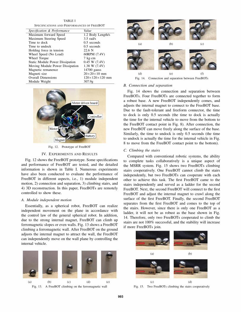
TABLE ISPECIFICATIONS AND PERFORMANCES OF FREEBOT
Specification & Performance ValueMaximum forward Speed 1.2 Body Length/sMaximum Steering Speed 3.5 rad/sTime to dock 0.5 secondsTime to undock 0.5 secondsHolding force in tension 22.6 NWheel Speed (No Load) 60RPM (7.4V)Wheel Torque 7 kg·cmStatic Module Power Dissipation 0.45 W (7.4V)Moving Module Power Dissipation 1.38 W (7.4V)Magnetic remanence 14700 gaussMagneti size 20×20×10 mmOverall Dimensions 120×120×120 mmModule Weight 307.9g
Fig. 12. Prototype of FreeBOT
IV. EXPERIMENTS AND RESULTS
Fig. 12 shows the FreeBOT prototype. Some specificationsand performance of FreeBOT are tested, and the detailedinformation is shown in Table I. Numerous experimentshave also been conducted to evaluate the performance ofFreeBOT in different aspects, i.e., 1) module independentmotion, 2) connection and separation, 3) climbing stairs, and4) 3D reconstruction. In this paper, FreeBOTs are remotelycontrolled to show these.
A. Module independent motion
Essentially, as a spherical robot, FreeBOT can realizeindependent movement on the plane in accordance withthe control law of the general spherical robot. In addition,due to the strong internal magnet, FreeBOT can climb upferromagnetic slopes or even walls. Fig. 13 shows a FreeBOTclimbing a ferromagnetic wall. After FreeBOT on the groundadjusts the internal magnet to attract the wall, the FreeBOTcan independently move on the wall plane by controlling theinternal vehicle.
(a) (b) (c) (d) (e)Fig. 13. A FreeBOT climbing on the ferromagnetic wall
(a) (b) (c)
(d) (e) (f)Fig. 14. Connection and separation between FreeBOTs
B. Connection and separation
Fig. 14 shows the connection and separation betweenFreeBOTs. Four FreeBOTs are connected together to forma robust base. A new FreeBOT independently comes, andadjusts the internal magnet to connect to the FreeBOT base.Due to the fault-tolerant and freeform connector, the timeto dock is only 0.5 seconds (the time to dock is actuallythe time for the internal vehicle to move from the bottom tothe FreeBOT contact point in Fig. 8). After connection, thenew FreeBOT can move freely along the surface of the base.Similarly, the time to undock is only 0.5 seconds (the timeto undock is actually the time for the internal vehicle in Fig.8 to move from the FreeBOT contact point to the bottom).
C. Climbing the stairs
Compared with conventional robotic systems, the abilityto complete tasks collaboratively is a unique aspect ofthe MSRR system. Fig. 15 shows two FreeBOTs climbingstairs cooperatively. One FreeBOT cannot climb the stairsindependently, but two FreeBOTs can cooperate with eachother to achieve this task. The first FreeBOT came to thestairs independently and served as a ladder for the secondFreeBOT. Next, the second FreeBOT will connect to the firstFreeBOT and adjust the internal magnet to crawl along thesurface of the first FreeBOT. Finally, the second FreeBOTseparates from the first FreeBOT and comes to the top ofthe stairs. However, since there is only one FreeBOT as aladder, it will not be as robust as the base shown in Fig.14. Therefore, only two FreeBOTs cooperated to climb thestairs are not 100% successful, and the stability will increaseif more FreeBOTs join.
(a) (b)
(c) (d)Fig. 15. Two FreeBOTs climbing the stairs cooperatively
993

(a) (b) (c) (d)Fig. 16. Two FreeBOTs show a 3D reconstruction demonstration
D. 3D Reconfiguration
In [2], a SMORES module lifts another module on aplastic structure of passive docking ports to show a demon-stration of self-reconfiguration in 3D. We conducted a similarexperiment between two FreeBOTs and a ferromagneticwall (as shown in Fig. 16). A FreeBOT is connected toa ferromagnetic wall and suspended in the air. The testedFreeBOT is connected to the suspended FreeBOT and can belifted by adjusting the internal magnet. Due to the freeformconnector, the tested FreeBOT can be lifted along many pathswithout constraints, which has great potential for 3D self-reconfiguration.
V. COMPARISON BETWEEN FREEBOT AND PREVIOUSMSRR SYSTEMS
FreeBOT has the same basic functions as the mostadvanced MSRR: module independent motion, connec-tion/separation between modules without manual assistanceand system reconfiguration. However, the previous MSRRmodule is equipped with multiple actuators for differenttasks, which increases the weight, volume and manufacturingcost of the robot. FreeBOT has only two motors for thesetasks, but it can form an MSRR system with fewer physicalconstraints. In addition, FreeBOT shows better performancethan previous MSRR systems in many aspects, the detailedcomparison between these MSRR systems is shown in TableII. But it should be noted that the holding force in tensionof FreeBOT is small, which is the weakness of FreeBOT.Although FreeBOT is not competitive in the comparison ofholding force in tension, it is sufficient for most tasks.
Multiple MSRR modules forming joints are the main self-reconfiguration method of most MSRR systems. Fig. 17shows the joint formed by FreeBOT and some previousMSRR system [1], [2], [18]–[20]. In MSRR systems withdifferent architectures, joints composed of modules havedifferent characteristics. The joint composed of the previ-ous MSRR system can only rotate around one axis, whilethe FreeBOT system can form an unlimited revolute joint.This MSRR self-reconfiguration method with less physicalconstraints makes the FreeBOT system has great potential torealize freeform robot systems and more applications.
VI. CONCLUSIONS AND FUTURE WORK
This paper proposes a novel MSRR “FreeBOT”, which canbe connected freely with less physical constraints. FreeBOTonly has two motors for multiple tasks: module independentmovement, connector management and system reconfigura-tion. Due to the fault-tolerant and freeform connector, theconnection between FreeBOTs is genderless and instant.
TABLE IIPERFORMANCES OF MSRR MODULES
Specification FreeBOT
SMORES
ATRON
M-TRAN
III
Supe
rBot
M3
No. of DoF 2 4 1 2 3 3No. of Actuators 2 5 6 5 9 6Maximum Connecting No. 12 4 8 6 6 3Ability to Move Independently Y Y N N N YNo. of Mech. Parts 24 132 145 162 - -Holding Force in Tension(N) 22.6 60 800 25 - -Dock Cycle Time (s) 0.5 2.3 4 5 50 -Weight (kg) 0.31 0.52 0.83 0.42 1.2 0.8Data Derived from [2] [2], [18] [1], [2] [2], [19] [2], [20]
(a) ATRON [18] (b) M3 [20] (c) MTRAN-III [1]
(d) SMORES [2] (e) SUPERBOT [19] (f) FreeBOTFig. 17. Joints consisting of some MSRR systems
Numerous experiments have been conducted to test its per-formance. The experimental results show that the FreeBOTsystem has great potential to realize a freeform roboticsystem.
In this paper, FreeBOT is remotely controlled to demon-strate these experiments. Our group is studying the relativelocalization [21] and motion planning algorithm [22] forthe FreeBOT system. In the future, we will equip FreeBOTwith these technologies to realize an autonomous FreeBOTsystem. In addition, we will increase the number of FreeBOTto fully demonstrate the enormous potential of FreeBOT inrealizing more MSRR applications.
REFERENCES
[1] H. Kurokawa, K. Tomita, A. Kamimura, S. Kokaji, T. Hasuo, andS. Murata, “Distributed self-reconfiguration of m-tran iii modularrobotic system,” The International Journal of Robotics Research,vol. 27, no. 3-4, pp. 373–386, 2008.
[2] J. Davey, N. Kwok, and M. Yim, “Emulating self-reconfigurablerobots-design of the smores system,” in IEEE/RSJ International Con-ference on Intelligent Robots and Systems, 2012, pp. 4464–4469.
[3] D. Saldana, B. Gabrich, G. Li, M. Yim, and V. Kumar, “Modquad:The flying modular structure that self-assembles in midair,” in IEEEInternational Conference on Robotics and Automation, 2018, pp. 691–698.
[4] J. W. Romanishin, K. Gilpin, and D. Rus, “M-blocks: Momentum-driven, magnetic modular robots,” in IEEE/RSJ International Confer-ence on Intelligent Robots and Systems, 2013, pp. 4288–4295.
[5] A. Sprowitz, S. Pouya, S. Bonardi, J. Van Den Kieboom, R. Mockel,A. Billard, P. Dillenbourg, and A. J. Ijspeert, “Roombots: reconfig-urable robots for adaptive furniture,” IEEE Computational IntelligenceMagazine, vol. 5, no. 3, pp. 20–32, 2010.
[6] J. Seo, J. Paik, and M. Yim, “Modular reconfigurable robotics,” AnnualReview of Control, Robotics, and Autonomous Systems, vol. 2, pp. 63–88, 2019.
[7] S. Chennareddy, A. Agrawal, and A. Karuppiah, “Modular self-reconfigurable robotic systems: a survey on hardware architectures,”Journal of Robotics, 2017.
[8] C. Liu and M. Yim, “Reconfiguration motion planning for variabletopology truss.” in IEEE/RSJ International Conference on IntelligentRobots and Systems, 2019, pp. 1941–1948.
994

[9] C. Liu, S. Yu, and M. Yim, “A fast configuration space algorithmfor variable topology truss modular robots,” in IEEE InternationalConference on Robotics and Automation, 2020.
[10] H. Wei, Y. Chen, J. Tan, and T. Wang, “Sambot: A self-assemblymodular robot system,” IEEE/ASME Transactions on Mechatronics,vol. 16, no. 4, pp. 745–757, 2010.
[11] A. Kamimura, H. Kurokawa, E. Yoshida, K. Tomita, S. Kokaji, andS. Murata, “Distributed adaptive locomotion by a modular robotic sys-tem, m-tran ii,” in IEEE/RSJ International Conference on IntelligentRobots and Systems, vol. 3, 2004, pp. 2370–2377.
[12] J. Liedke and H. Worn, “Cobold-a bonding mechanism for modularself-reconfigurable mobile robots,” in IEEE International Conferenceon Robotics and Biomimetics, 2011, pp. 2025–2030.
[13] K. Kotay, D. Rus, M. Vona, and C. McGray, “The self-reconfiguringrobotic molecule,” in IEEE International Conference on Robotics andAutomation, vol. 1, 1998, pp. 424–431.
[14] T. Tosun, J. Davey, C. Liu, and M. Yim, “Design and characterizationof the ep-face connector,” in IEEE/RSJ International Conference onIntelligent Robots and Systems, 2016, pp. 45–51.
[15] N. Eckenstein and M. Yim, “Area of acceptance for 3d self-aligningrobotic connectors: Concepts, metrics, and designs,” in IEEE Interna-tional Conference on Robotics and Automation, 2014, pp. 1227–1233.
[16] J. W. Romanishin, K. Gilpin, S. Claici, and D. Rus, “3d m-blocks:Self-reconfiguring robots capable of locomotion via pivoting in threedimensions,” in IEEE International Conference on Robotics andAutomation, 2015, pp. 1925–1932.
[17] A. Bicchi, A. Balluchi, D. Prattichizzo, and A. Gorelli, “Introducingthe” sphericle”: an experimental testbed for research and teaching innonholonomy,” in IEEE International Conference on Robotics andAutomation, vol. 3, 1997, pp. 2620–2625.
[18] M. W. Jorgensen, E. H. Ostergaard, and H. H. Lund, “Modular atron:Modules for a self-reconfigurable robot,” in IEEE/RSJ InternationalConference on Intelligent Robots and Systems, vol. 2, 2004, pp. 2068–2073.
[19] B. Salemi, M. Moll, and W.-M. Shen, “Superbot: A deployable,multi-functional, and modular self-reconfigurable robotic system,” inIEEE/RSJ International Conference on Intelligent Robots and Systems,2006, pp. 3636–3641.
[20] M. D. Kutzer, M. S. Moses, C. Y. Brown, M. Armand, D. H.Scheidt, and G. S. Chirikjian, “Design of a new independently-mobilereconfigurable modular robot,” in IEEE International Conference onRobotics and Automation, 2010, pp. 2758–2764.
[21] M. Li, G. Liang, H. Luo, H. Qian, and T. L. Lam, “Robot-to-robotrelative pose estimation based on semidefinite relaxation optimization,”in IEEE/RSJ International Conference on Intelligent Robots andSystems, 2020.
[22] H. Luo, M. Li, G. Liang, H. Qian, and T. L. Lam, “An obstacle-crossing strategy based on the fast self-reconfiguration for modularsphere robots,” in IEEE/RSJ International Conference on IntelligentRobots and Systems, 2020.
995
Related Documents