frame-relay lapf n201 WAN-208 Cisco IOS Wide-Area Networking Command Reference March 2011 frame-relay lapf n201 To set the Link Access Procedure for Frame Relay (LAPF) N201 value (the maximum length of the Information field of the LAPF I frame), use the frame-relay lapf n201 command in interface configuration mode. To reset the maximum length of the Information field to the default of 260 bytes (octets), use the no form of this command. frame-relay lapf n201 bytes no frame-relay lapf n201 [bytes] Syntax Description Defaults 260 bytes Command Modes Interface configuration Command History Usage Guidelines This command is used to tune Layer 2 system parameters to work well with the Frame Relay switch. Normally, you do not need to change the default setting. Manipulation of Layer 2 parameters is not recommended if you do not know well the resulting functional change. For more information, refer to the ITU-T Q.922 specification for LAPF. Examples The following example resets the N201 maximum information field length to the default value: no frame-relay lapf n201 bytes Maximum number of bytes in the Information field of the LAPF I frame. Range is from 1 to 16384. Default is 260. Release Modification 11.2 This command was introduced. 12.2(33)SRA This command was integrated into Cisco IOS Release 12.2(33)SRA. 12.2SX This command is supported in the Cisco IOS Release 12.2SX train. Support in a specific 12.2SX release of this train depends on your feature set, platform, and platform hardware.

Welcome message from author
This document is posted to help you gain knowledge. Please leave a comment to let me know what you think about it! Share it to your friends and learn new things together.
Transcript
frame-relay lapf n201
WAN-208Cisco IOS Wide-Area Networking Command Reference
March 2011
frame-relay lapf n201To set the Link Access Procedure for Frame Relay (LAPF) N201 value (the maximum length of the Information field of the LAPF I frame), use the frame-relay lapf n201 command in interface configuration mode. To reset the maximum length of the Information field to the default of 260 bytes (octets), use the no form of this command.
frame-relay lapf n201 bytes
no frame-relay lapf n201 [bytes]
Syntax Description
Defaults 260 bytes
Command Modes Interface configuration
Command History
Usage Guidelines This command is used to tune Layer 2 system parameters to work well with the Frame Relay switch. Normally, you do not need to change the default setting.
Manipulation of Layer 2 parameters is not recommended if you do not know well the resulting functional change. For more information, refer to the ITU-T Q.922 specification for LAPF.
Examples The following example resets the N201 maximum information field length to the default value:
no frame-relay lapf n201
bytes Maximum number of bytes in the Information field of the LAPF I frame. Range is from 1 to 16384. Default is 260.
Release Modification
11.2 This command was introduced.
12.2(33)SRA This command was integrated into Cisco IOS Release 12.2(33)SRA.
12.2SX This command is supported in the Cisco IOS Release 12.2SX train. Support in a specific 12.2SX release of this train depends on your feature set, platform, and platform hardware.
frame-relay lapf t200
WAN-209Cisco IOS Wide-Area Networking Command Reference
March 2011
frame-relay lapf t200To set the Link Access Procedure for Frame Relay (LAPF) retransmission timer value T200, use the frame-relay lapf t200 command in interface configuration mode. To reset the T200 timer to the default value of 15, use the no form of this command.
frame-relay lapf t200 tenths-of-a-second
no frame-relay lapf t200
Syntax Description
Defaults 15 tenths of a second (1.5 seconds)
Command Modes Interface configuration
Command History
Usage Guidelines The retransmission timer value T200 should be less than the link idle timer value T203 (using the same time unit).
This command is used to tune Layer 2 system parameters to work well with the Frame Relay switch. Normally, you do not need to change the default setting.
Manipulation of Layer 2 parameters is not recommended if you do not know well the resulting functional change. For more information, refer to the ITU-T Q.922 specification for LAPF.
Examples The following example resets the T200 timer to the default value:
no frame-relay lapf t200
Related Commands
tenths-of-a-second Time, in tenths of a second. Range is from 1 to 100. Default is 15.
Release Modification
11.2 This command was introduced.
12.2(33)SRA This command was integrated into Cisco IOS Release 12.2(33)SRA.
12.2SX This command is supported in the Cisco IOS Release 12.2SX train. Support in a specific 12.2SX release of this train depends on your feature set, platform, and platform hardware.
Command Description
frame-relay lapf t203 Sets the LAPF link idle timer value T203 of DLCI 0.
frame-relay lapf t203
WAN-210Cisco IOS Wide-Area Networking Command Reference
March 2011
frame-relay lapf t203To set the Link Access Procedure for Frame Relay (LAPF) link idle timer value T203 of data-link connection identifier (DLCI) 0, use the frame-relay lapf t203 command in interface configuration mode. To reset the link idle timer to the default value, use the no form of this command.
frame-relay lapf t203 seconds
no frame-relay lapf t203
Syntax Description
Defaults 30 seconds
Command Modes Interface configuration
Command History
Usage Guidelines The frame-relay lapf t203 command applies to the link; that is, it applies to DLCI 0. Circuits other than DLCI 0 are not affected.
The link idle timer value T203 should be greater than the retransmission timer value T200 (using the same time unit).
This command is used to tune Layer 2 system parameters to work well with the Frame Relay switch. Normally, you do not need to change the default setting.
Manipulation of Layer 2 parameters is not recommended if you do not know well the resulting functional change. For more information, refer to the ITU-T Q.922 specification for LAPF.
Examples The following example resets the T203 idle link timer to the default value:
no frame-relay lapf t203
seconds Maximum time allowed with no frames exchanged. Range is from 1 to 65535 seconds. Default is 30.
Release Modification
11.2 This command was introduced.
12.2(33)SRA This command was integrated into Cisco IOS Release 12.2(33)SRA.
12.2SX This command is supported in the Cisco IOS Release 12.2SX train. Support in a specific 12.2SX release of this train depends on your feature set, platform, and platform hardware.
frame-relay lmi-n391dte
WAN-211Cisco IOS Wide-Area Networking Command Reference
March 2011
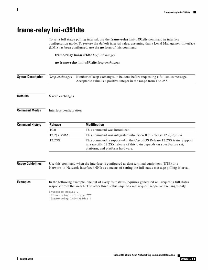
frame-relay lmi-n391dteTo set a full status polling interval, use the frame-relay lmi-n391dte command in interface configuration mode. To restore the default interval value, assuming that a Local Management Interface (LMI) has been configured, use the no form of this command.
frame-relay lmi-n391dte keep-exchanges
no frame-relay lmi-n391dte keep-exchanges
Syntax Description
Defaults 6 keep exchanges
Command Modes Interface configuration
Command History
Usage Guidelines Use this command when the interface is configured as data terminal equipment (DTE) or a Network-to-Network Interface (NNI) as a means of setting the full status message polling interval.
Examples In the following example, one out of every four status inquiries generated will request a full status response from the switch. The other three status inquiries will request keepalive exchanges only.
interface serial 0frame-relay intf-type DTEframe-relay lmi-n391dte 4
keep-exchanges Number of keep exchanges to be done before requesting a full status message. Acceptable value is a positive integer in the range from 1 to 255.
Release Modification
10.0 This command was introduced.
12.2(33)SRA This command was integrated into Cisco IOS Release 12.2(33)SRA.
12.2SX This command is supported in the Cisco IOS Release 12.2SX train. Support in a specific 12.2SX release of this train depends on your feature set, platform, and platform hardware.
frame-relay lmi-n392dce
WAN-212Cisco IOS Wide-Area Networking Command Reference
March 2011
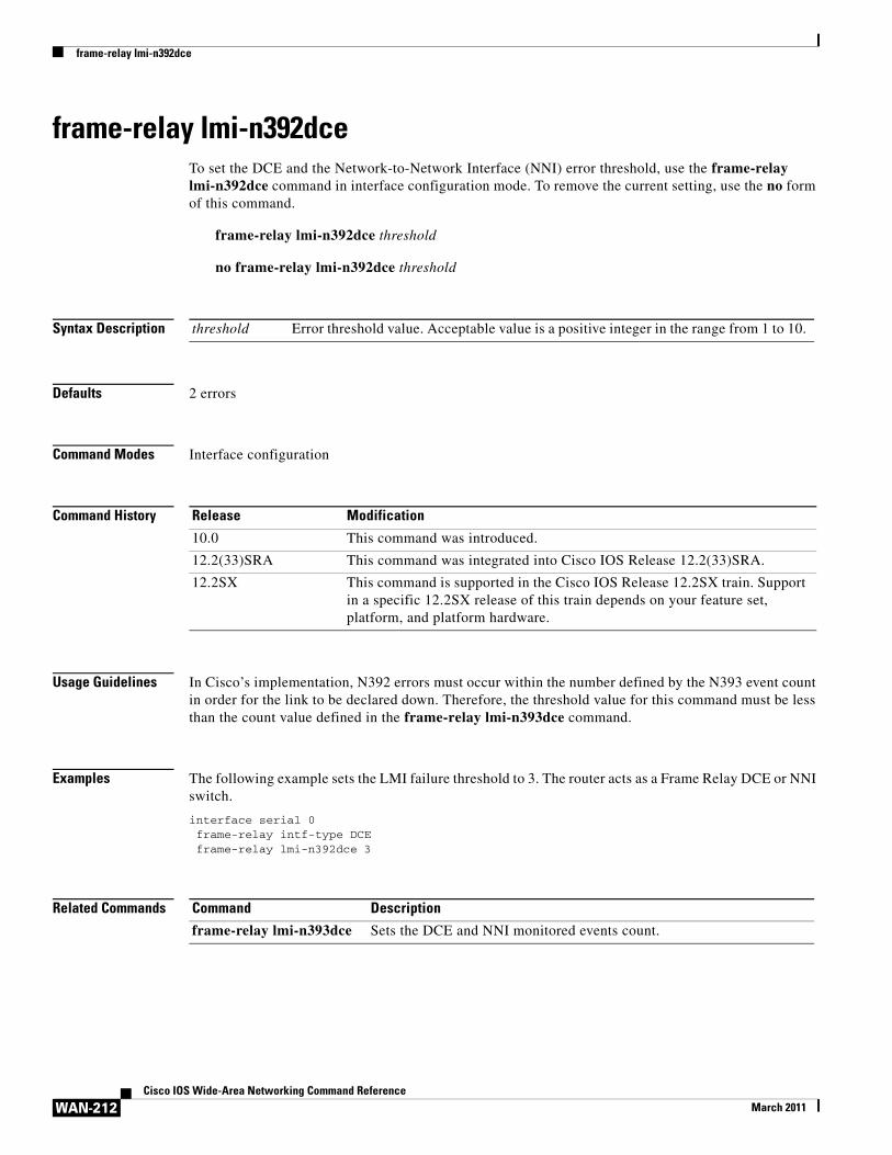
frame-relay lmi-n392dceTo set the DCE and the Network-to-Network Interface (NNI) error threshold, use the frame-relay lmi-n392dce command in interface configuration mode. To remove the current setting, use the no form of this command.
frame-relay lmi-n392dce threshold
no frame-relay lmi-n392dce threshold
Syntax Description
Defaults 2 errors
Command Modes Interface configuration
Command History
Usage Guidelines In Cisco’s implementation, N392 errors must occur within the number defined by the N393 event count in order for the link to be declared down. Therefore, the threshold value for this command must be less than the count value defined in the frame-relay lmi-n393dce command.
Examples The following example sets the LMI failure threshold to 3. The router acts as a Frame Relay DCE or NNI switch.
interface serial 0frame-relay intf-type DCEframe-relay lmi-n392dce 3
Related Commands
threshold Error threshold value. Acceptable value is a positive integer in the range from 1 to 10.
Release Modification
10.0 This command was introduced.
12.2(33)SRA This command was integrated into Cisco IOS Release 12.2(33)SRA.
12.2SX This command is supported in the Cisco IOS Release 12.2SX train. Support in a specific 12.2SX release of this train depends on your feature set, platform, and platform hardware.
Command Description
frame-relay lmi-n393dce Sets the DCE and NNI monitored events count.
frame-relay lmi-n392dte
WAN-213Cisco IOS Wide-Area Networking Command Reference
March 2011
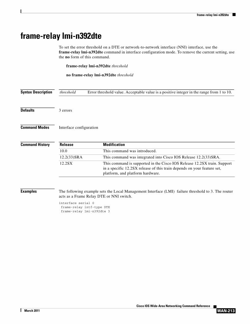
frame-relay lmi-n392dteTo set the error threshold on a DTE or network-to-network interface (NNI) interface, use the frame-relay lmi-n392dte command in interface configuration mode. To remove the current setting, use the no form of this command.
frame-relay lmi-n392dte threshold
no frame-relay lmi-n392dte threshold
Syntax Description
Defaults 3 errors
Command Modes Interface configuration
Command History
Examples The following example sets the Local Management Interface (LMI) failure threshold to 3. The router acts as a Frame Relay DTE or NNI switch.
interface serial 0frame-relay intf-type DTEframe-relay lmi-n392dte 3
threshold Error threshold value. Acceptable value is a positive integer in the range from 1 to 10.
Release Modification
10.0 This command was introduced.
12.2(33)SRA This command was integrated into Cisco IOS Release 12.2(33)SRA.
12.2SX This command is supported in the Cisco IOS Release 12.2SX train. Support in a specific 12.2SX release of this train depends on your feature set, platform, and platform hardware.
frame-relay lmi-n393dce
WAN-214Cisco IOS Wide-Area Networking Command Reference
March 2011
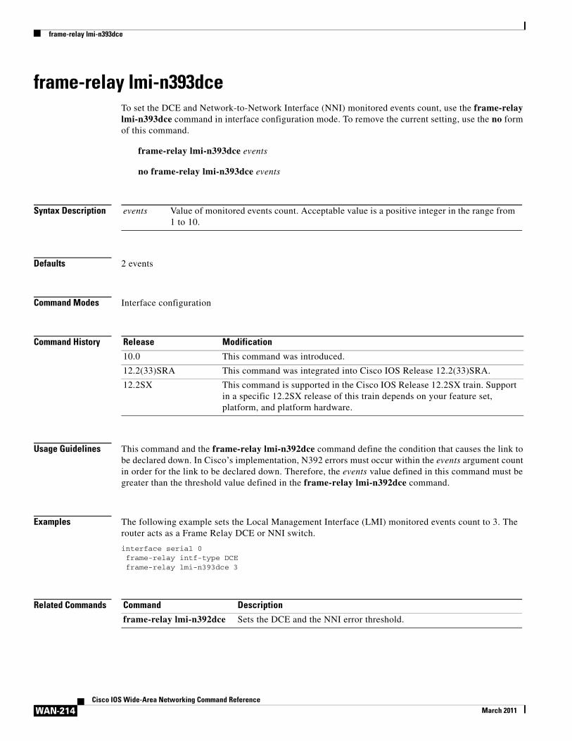
frame-relay lmi-n393dceTo set the DCE and Network-to-Network Interface (NNI) monitored events count, use the frame-relay lmi-n393dce command in interface configuration mode. To remove the current setting, use the no form of this command.
frame-relay lmi-n393dce events
no frame-relay lmi-n393dce events
Syntax Description
Defaults 2 events
Command Modes Interface configuration
Command History
Usage Guidelines This command and the frame-relay lmi-n392dce command define the condition that causes the link to be declared down. In Cisco’s implementation, N392 errors must occur within the events argument count in order for the link to be declared down. Therefore, the events value defined in this command must be greater than the threshold value defined in the frame-relay lmi-n392dce command.
Examples The following example sets the Local Management Interface (LMI) monitored events count to 3. The router acts as a Frame Relay DCE or NNI switch.
interface serial 0frame-relay intf-type DCEframe-relay lmi-n393dce 3
Related Commands
events Value of monitored events count. Acceptable value is a positive integer in the range from 1 to 10.
Release Modification
10.0 This command was introduced.
12.2(33)SRA This command was integrated into Cisco IOS Release 12.2(33)SRA.
12.2SX This command is supported in the Cisco IOS Release 12.2SX train. Support in a specific 12.2SX release of this train depends on your feature set, platform, and platform hardware.
Command Description
frame-relay lmi-n392dce Sets the DCE and the NNI error threshold.
frame-relay lmi-n393dte
WAN-215Cisco IOS Wide-Area Networking Command Reference
March 2011
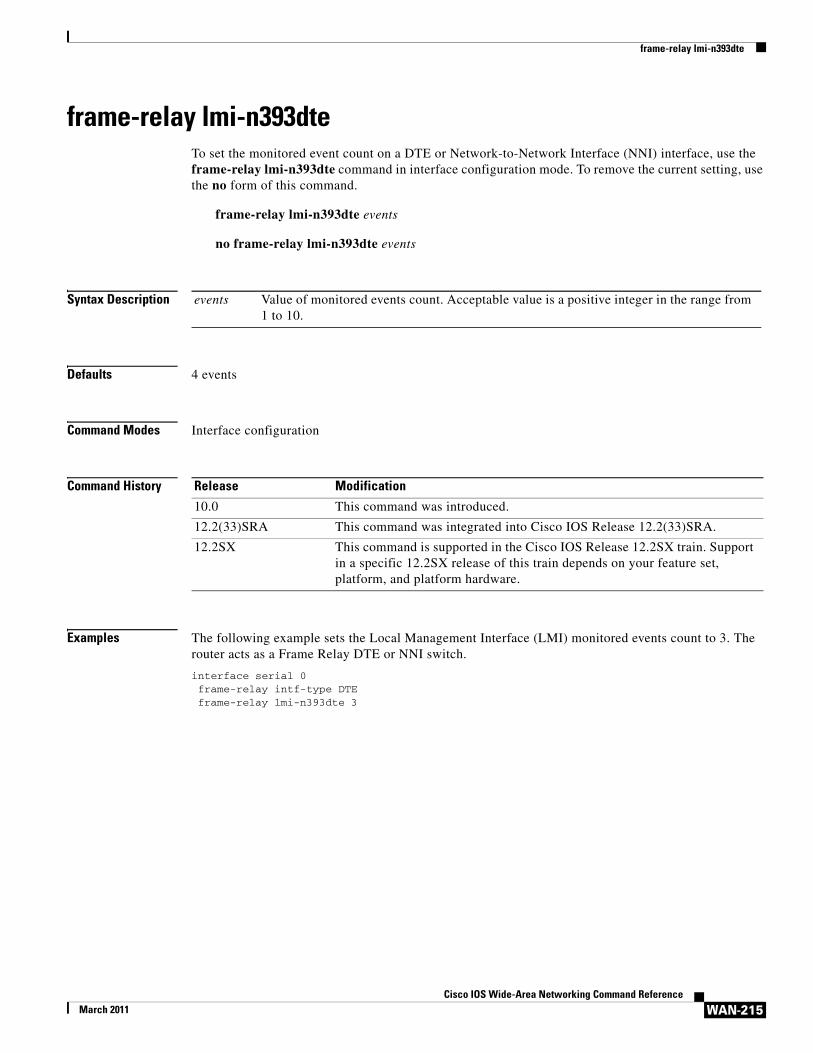
frame-relay lmi-n393dteTo set the monitored event count on a DTE or Network-to-Network Interface (NNI) interface, use the frame-relay lmi-n393dte command in interface configuration mode. To remove the current setting, use the no form of this command.
frame-relay lmi-n393dte events
no frame-relay lmi-n393dte events
Syntax Description
Defaults 4 events
Command Modes Interface configuration
Command History
Examples The following example sets the Local Management Interface (LMI) monitored events count to 3. The router acts as a Frame Relay DTE or NNI switch.
interface serial 0frame-relay intf-type DTEframe-relay lmi-n393dte 3
events Value of monitored events count. Acceptable value is a positive integer in the range from 1 to 10.
Release Modification
10.0 This command was introduced.
12.2(33)SRA This command was integrated into Cisco IOS Release 12.2(33)SRA.
12.2SX This command is supported in the Cisco IOS Release 12.2SX train. Support in a specific 12.2SX release of this train depends on your feature set, platform, and platform hardware.
frame-relay lmi-t392dce
WAN-216Cisco IOS Wide-Area Networking Command Reference
March 2011
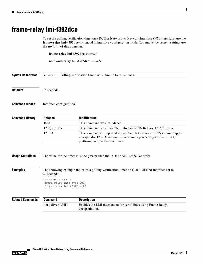
frame-relay lmi-t392dceTo set the polling verification timer on a DCE or Network-to-Network Interface (NNI) interface, use the frame-relay lmi-t392dce command in interface configuration mode. To remove the current setting, use the no form of this command.
frame-relay lmi-t392dce seconds
no frame-relay lmi-t392dce seconds
Syntax Description
Defaults 15 seconds
Command Modes Interface configuration
Command History
Usage Guidelines The value for the timer must be greater than the DTE or NNI keepalive timer.
Examples The following example indicates a polling verification timer on a DCE or NNI interface set to 20 seconds:
interface serial 3frame-relay intf-type DCEframe-relay lmi-t392dce 20
Related Commands
seconds Polling verification timer value from 5 to 30 seconds.
Release Modification
10.0 This command was introduced.
12.2(33)SRA This command was integrated into Cisco IOS Release 12.2(33)SRA.
12.2SX This command is supported in the Cisco IOS Release 12.2SX train. Support in a specific 12.2SX release of this train depends on your feature set, platform, and platform hardware.
Command Description
keepalive (LMI) Enables the LMI mechanism for serial lines using Frame Relay encapsulation.
frame-relay lmi-type
WAN-217Cisco IOS Wide-Area Networking Command Reference
March 2011
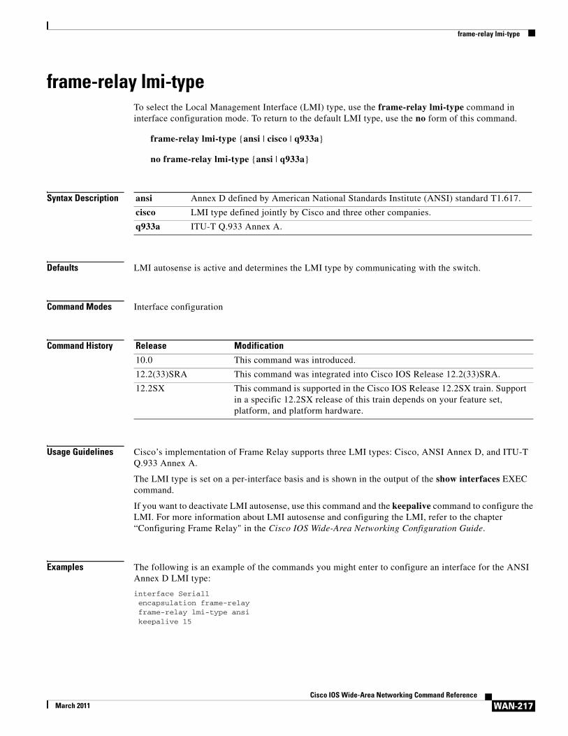
frame-relay lmi-typeTo select the Local Management Interface (LMI) type, use the frame-relay lmi-type command in interface configuration mode. To return to the default LMI type, use the no form of this command.
frame-relay lmi-type {ansi | cisco | q933a}
no frame-relay lmi-type {ansi | q933a}
Syntax Description
Defaults LMI autosense is active and determines the LMI type by communicating with the switch.
Command Modes Interface configuration
Command History
Usage Guidelines Cisco’s implementation of Frame Relay supports three LMI types: Cisco, ANSI Annex D, and ITU-T Q.933 Annex A.
The LMI type is set on a per-interface basis and is shown in the output of the show interfaces EXEC command.
If you want to deactivate LMI autosense, use this command and the keepalive command to configure the LMI. For more information about LMI autosense and configuring the LMI, refer to the chapter “Configuring Frame Relay" in the Cisco IOS Wide-Area Networking Configuration Guide.
Examples The following is an example of the commands you might enter to configure an interface for the ANSI Annex D LMI type:
interface Serial1encapsulation frame-relayframe-relay lmi-type ansikeepalive 15
ansi Annex D defined by American National Standards Institute (ANSI) standard T1.617.
cisco LMI type defined jointly by Cisco and three other companies.
q933a ITU-T Q.933 Annex A.
Release Modification
10.0 This command was introduced.
12.2(33)SRA This command was integrated into Cisco IOS Release 12.2(33)SRA.
12.2SX This command is supported in the Cisco IOS Release 12.2SX train. Support in a specific 12.2SX release of this train depends on your feature set, platform, and platform hardware.
frame-relay local-dlci
WAN-218Cisco IOS Wide-Area Networking Command Reference
March 2011
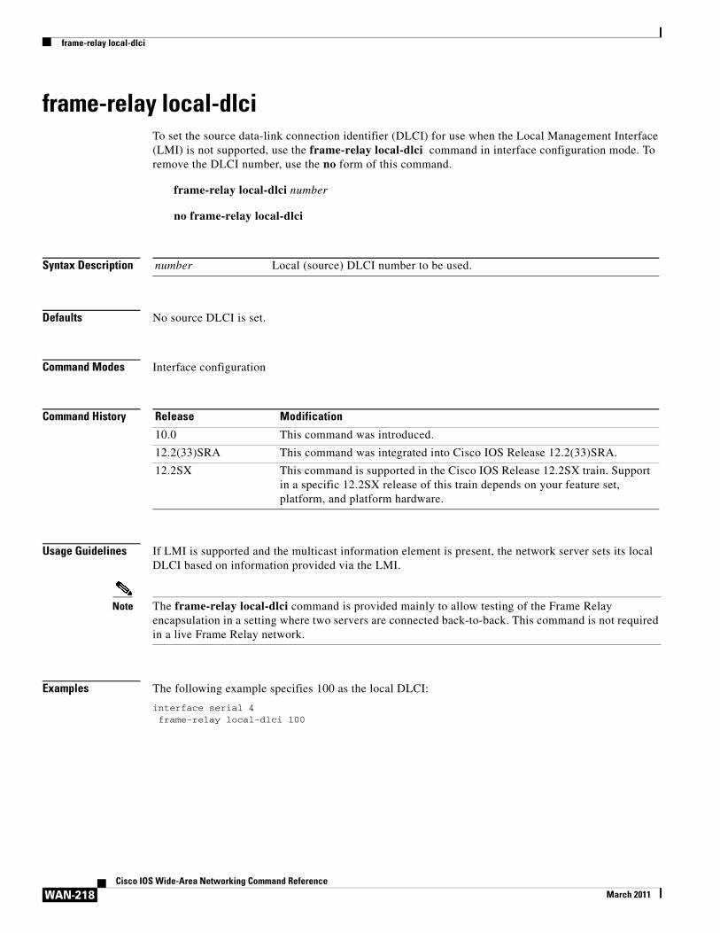
frame-relay local-dlci To set the source data-link connection identifier (DLCI) for use when the Local Management Interface (LMI) is not supported, use the frame-relay local-dlci command in interface configuration mode. To remove the DLCI number, use the no form of this command.
frame-relay local-dlci number
no frame-relay local-dlci
Syntax Description
Defaults No source DLCI is set.
Command Modes Interface configuration
Command History
Usage Guidelines If LMI is supported and the multicast information element is present, the network server sets its local DLCI based on information provided via the LMI.
Note The frame-relay local-dlci command is provided mainly to allow testing of the Frame Relay encapsulation in a setting where two servers are connected back-to-back. This command is not required in a live Frame Relay network.
Examples The following example specifies 100 as the local DLCI:
interface serial 4frame-relay local-dlci 100
number Local (source) DLCI number to be used.
Release Modification
10.0 This command was introduced.
12.2(33)SRA This command was integrated into Cisco IOS Release 12.2(33)SRA.
12.2SX This command is supported in the Cisco IOS Release 12.2SX train. Support in a specific 12.2SX release of this train depends on your feature set, platform, and platform hardware.
frame-relay map
WAN-219Cisco IOS Wide-Area Networking Command Reference
March 2011
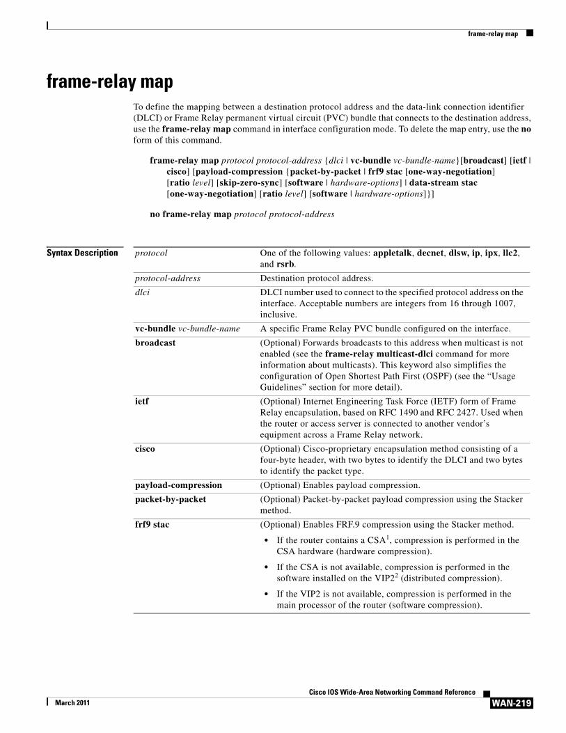
frame-relay mapTo define the mapping between a destination protocol address and the data-link connection identifier (DLCI) or Frame Relay permanent virtual circuit (PVC) bundle that connects to the destination address, use the frame-relay map command in interface configuration mode. To delete the map entry, use the no form of this command.
frame-relay map protocol protocol-address {dlci | vc-bundle vc-bundle-name}[broadcast] [ietf | cisco] [payload-compression {packet-by-packet | frf9 stac [one-way-negotiation] [ratio level] [skip-zero-sync] [software | hardware-options] | data-stream stac [one-way-negotiation] [ratio level] [software | hardware-options]}]
no frame-relay map protocol protocol-address
Syntax Description protocol One of the following values: appletalk, decnet, dlsw, ip, ipx, llc2, and rsrb.
protocol-address Destination protocol address.
dlci DLCI number used to connect to the specified protocol address on the interface. Acceptable numbers are integers from 16 through 1007, inclusive.
vc-bundle vc-bundle-name A specific Frame Relay PVC bundle configured on the interface.
broadcast (Optional) Forwards broadcasts to this address when multicast is not enabled (see the frame-relay multicast-dlci command for more information about multicasts). This keyword also simplifies the configuration of Open Shortest Path First (OSPF) (see the “Usage Guidelines” section for more detail).
ietf (Optional) Internet Engineering Task Force (IETF) form of Frame Relay encapsulation, based on RFC 1490 and RFC 2427. Used when the router or access server is connected to another vendor’s equipment across a Frame Relay network.
cisco (Optional) Cisco-proprietary encapsulation method consisting of a four-byte header, with two bytes to identify the DLCI and two bytes to identify the packet type.
payload-compression (Optional) Enables payload compression.
packet-by-packet (Optional) Packet-by-packet payload compression using the Stacker method.
frf9 stac (Optional) Enables FRF.9 compression using the Stacker method.
• If the router contains a CSA1, compression is performed in the CSA hardware (hardware compression).
• If the CSA is not available, compression is performed in the software installed on the VIP22 (distributed compression).
• If the VIP2 is not available, compression is performed in the main processor of the router (software compression).
frame-relay map
WAN-220Cisco IOS Wide-Area Networking Command Reference
March 2011
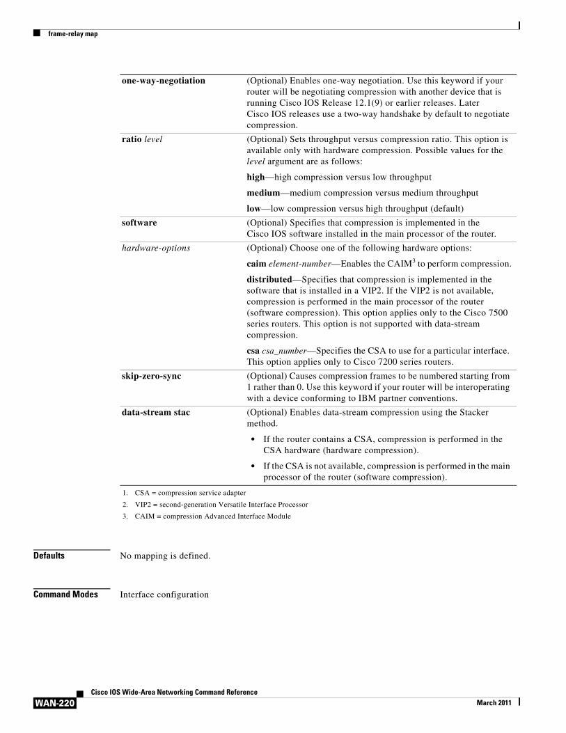
Defaults No mapping is defined.
Command Modes Interface configuration
one-way-negotiation (Optional) Enables one-way negotiation. Use this keyword if your router will be negotiating compression with another device that is running Cisco IOS Release 12.1(9) or earlier releases. Later Cisco IOS releases use a two-way handshake by default to negotiate compression.
ratio level (Optional) Sets throughput versus compression ratio. This option is available only with hardware compression. Possible values for the level argument are as follows:
high—high compression versus low throughput
medium—medium compression versus medium throughput
low—low compression versus high throughput (default)
software (Optional) Specifies that compression is implemented in the Cisco IOS software installed in the main processor of the router.
hardware-options (Optional) Choose one of the following hardware options:
caim element-number—Enables the CAIM3 to perform compression.
distributed—Specifies that compression is implemented in the software that is installed in a VIP2. If the VIP2 is not available, compression is performed in the main processor of the router (software compression). This option applies only to the Cisco 7500 series routers. This option is not supported with data-stream compression.
csa csa_number—Specifies the CSA to use for a particular interface. This option applies only to Cisco 7200 series routers.
skip-zero-sync (Optional) Causes compression frames to be numbered starting from 1 rather than 0. Use this keyword if your router will be interoperating with a device conforming to IBM partner conventions.
data-stream stac (Optional) Enables data-stream compression using the Stacker method.
• If the router contains a CSA, compression is performed in the CSA hardware (hardware compression).
• If the CSA is not available, compression is performed in the main processor of the router (software compression).
1. CSA = compression service adapter
2. VIP2 = second-generation Versatile Interface Processor
3. CAIM = compression Advanced Interface Module
frame-relay map
WAN-221Cisco IOS Wide-Area Networking Command Reference
March 2011
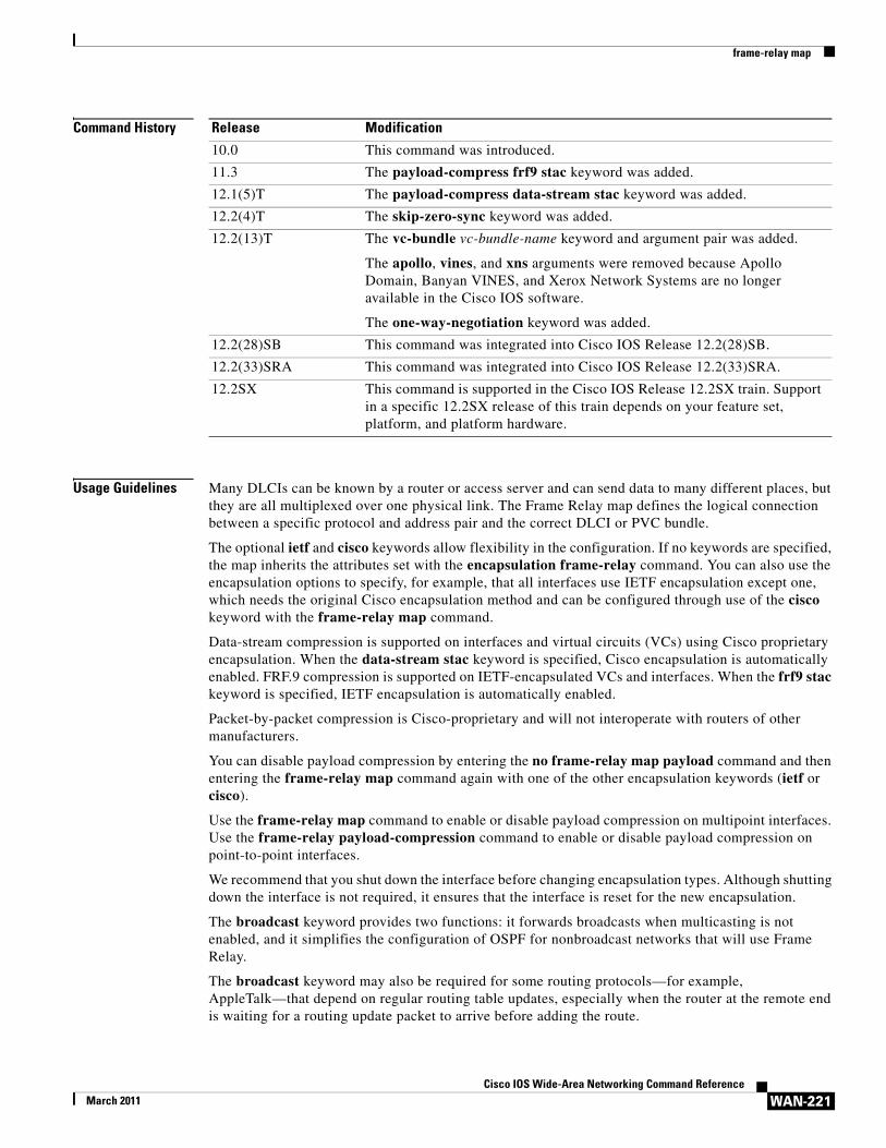
Command History
Usage Guidelines Many DLCIs can be known by a router or access server and can send data to many different places, but they are all multiplexed over one physical link. The Frame Relay map defines the logical connection between a specific protocol and address pair and the correct DLCI or PVC bundle.
The optional ietf and cisco keywords allow flexibility in the configuration. If no keywords are specified, the map inherits the attributes set with the encapsulation frame-relay command. You can also use the encapsulation options to specify, for example, that all interfaces use IETF encapsulation except one, which needs the original Cisco encapsulation method and can be configured through use of the cisco keyword with the frame-relay map command.
Data-stream compression is supported on interfaces and virtual circuits (VCs) using Cisco proprietary encapsulation. When the data-stream stac keyword is specified, Cisco encapsulation is automatically enabled. FRF.9 compression is supported on IETF-encapsulated VCs and interfaces. When the frf9 stac keyword is specified, IETF encapsulation is automatically enabled.
Packet-by-packet compression is Cisco-proprietary and will not interoperate with routers of other manufacturers.
You can disable payload compression by entering the no frame-relay map payload command and then entering the frame-relay map command again with one of the other encapsulation keywords (ietf or cisco).
Use the frame-relay map command to enable or disable payload compression on multipoint interfaces. Use the frame-relay payload-compression command to enable or disable payload compression on point-to-point interfaces.
We recommend that you shut down the interface before changing encapsulation types. Although shutting down the interface is not required, it ensures that the interface is reset for the new encapsulation.
The broadcast keyword provides two functions: it forwards broadcasts when multicasting is not enabled, and it simplifies the configuration of OSPF for nonbroadcast networks that will use Frame Relay.
The broadcast keyword may also be required for some routing protocols—for example, AppleTalk—that depend on regular routing table updates, especially when the router at the remote end is waiting for a routing update packet to arrive before adding the route.
Release Modification
10.0 This command was introduced.
11.3 The payload-compress frf9 stac keyword was added.
12.1(5)T The payload-compress data-stream stac keyword was added.
12.2(4)T The skip-zero-sync keyword was added.
12.2(13)T The vc-bundle vc-bundle-name keyword and argument pair was added.
The apollo, vines, and xns arguments were removed because Apollo Domain, Banyan VINES, and Xerox Network Systems are no longer available in the Cisco IOS software.
The one-way-negotiation keyword was added.
12.2(28)SB This command was integrated into Cisco IOS Release 12.2(28)SB.
12.2(33)SRA This command was integrated into Cisco IOS Release 12.2(33)SRA.
12.2SX This command is supported in the Cisco IOS Release 12.2SX train. Support in a specific 12.2SX release of this train depends on your feature set, platform, and platform hardware.
frame-relay map
WAN-222Cisco IOS Wide-Area Networking Command Reference
March 2011
By requiring selection of a designated router, OSPF treats a nonbroadcast, multiaccess network such as Frame Relay in much the same way as it treats a broadcast network. When the frame-relay map command (with the broadcast keyword) and the ip ospf network command (with the broadcast keyword) are configured, there is no need to configure any neighbors manually. OSPF will run automatically over the Frame Relay network as a broadcast network. (See the ip ospf network interface command for more detail.)
Note The OSPF broadcast mechanism assumes that IP class D addresses are never used for regular traffic over Frame Relay.
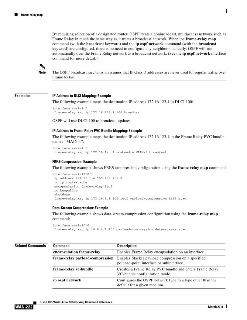
Examples IP Address to DLCI Mapping: Example
The following example maps the destination IP address 172.16.123.1 to DLCI 100:
interface serial 0frame-relay map ip 172.16.123.1 100 broadcast
OSPF will use DLCI 100 to broadcast updates.
IP Address to Frame Relay PVC Bundle Mapping: Example
The following example maps the destination IP address 172.16.123.1 to the Frame Relay PVC bundle named “MAIN-1”:
interface serial 0frame-relay map ip 172.16.123.1 vc-bundle MAIN-1 broadcast
FRF.9 Compression: Example
The following example shows FRF.9 compression configuration using the frame-relay map command:
interface serial2/0/1 ip address 172.16.1.4 255.255.255.0 no ip route-cache encapsulation frame-relay ietf no keepalive shutdown frame-relay map ip 172.16.1.1 105 ietf payload-compression frf9 stac
Data-Stream Compression: Example
The following example shows data-stream compression configuration using the frame-relay map command:
interface serial0/0frame-relay map ip 10.0.0.1 100 payload-compression data-stream stac
Related Commands Command Description
encapsulation frame-relay Enables Frame Relay encapsulation on an interface.
frame-relay payload-compression Enables Stacker payload compression on a specified point-to-point interface or subinterface.
frame-relay vc-bundle Creates a Frame Relay PVC bundle and enters Frame Relay VC-bundle configuration mode.
ip ospf network Configures the OSPF network type to a type other than the default for a given medium.
frame-relay map bridge
WAN-223Cisco IOS Wide-Area Networking Command Reference
March 2011
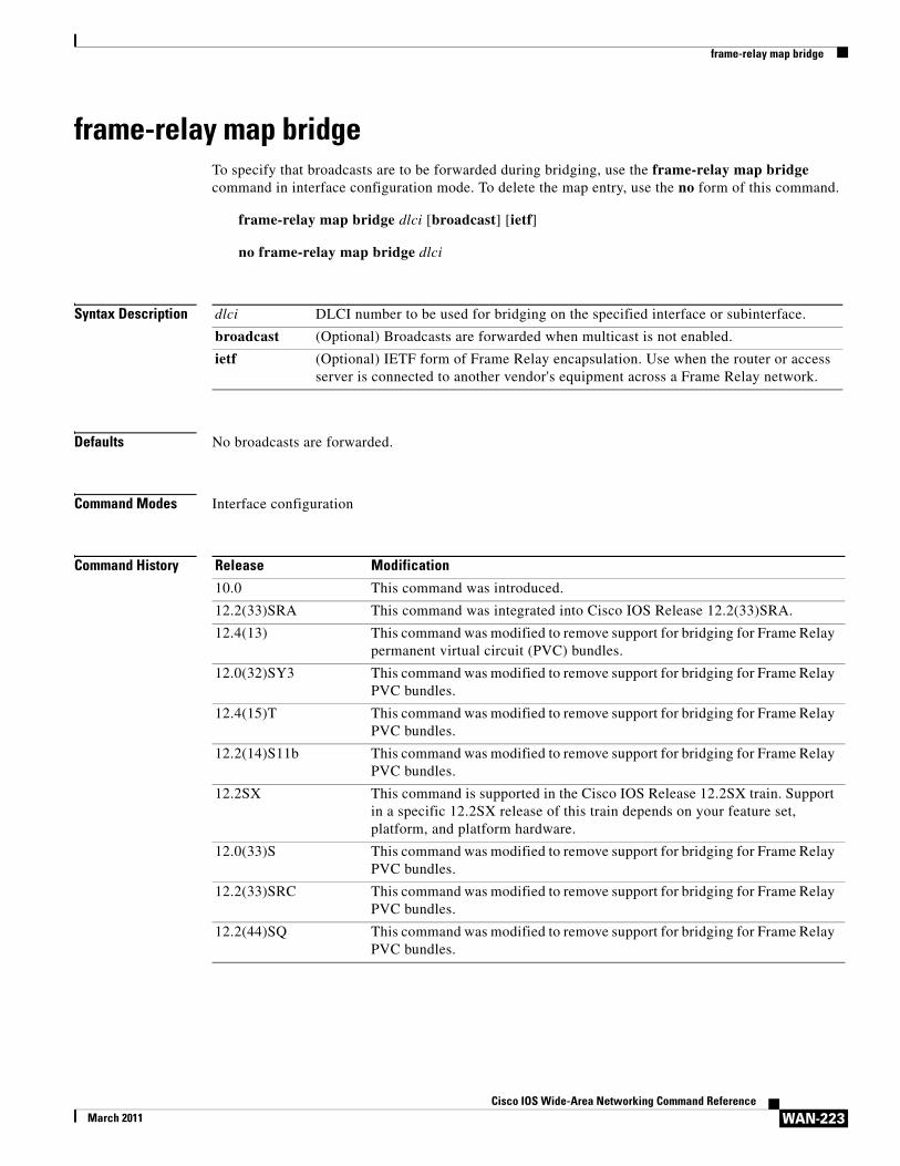
frame-relay map bridgeTo specify that broadcasts are to be forwarded during bridging, use the frame-relay map bridge command in interface configuration mode. To delete the map entry, use the no form of this command.
frame-relay map bridge dlci [broadcast] [ietf]
no frame-relay map bridge dlci
Syntax Description
Defaults No broadcasts are forwarded.
Command Modes Interface configuration
Command History
dlci DLCI number to be used for bridging on the specified interface or subinterface.
broadcast (Optional) Broadcasts are forwarded when multicast is not enabled.
ietf (Optional) IETF form of Frame Relay encapsulation. Use when the router or access server is connected to another vendor's equipment across a Frame Relay network.
Release Modification
10.0 This command was introduced.
12.2(33)SRA This command was integrated into Cisco IOS Release 12.2(33)SRA.
12.4(13) This command was modified to remove support for bridging for Frame Relay permanent virtual circuit (PVC) bundles.
12.0(32)SY3 This command was modified to remove support for bridging for Frame Relay PVC bundles.
12.4(15)T This command was modified to remove support for bridging for Frame Relay PVC bundles.
12.2(14)S11b This command was modified to remove support for bridging for Frame Relay PVC bundles.
12.2SX This command is supported in the Cisco IOS Release 12.2SX train. Support in a specific 12.2SX release of this train depends on your feature set, platform, and platform hardware.
12.0(33)S This command was modified to remove support for bridging for Frame Relay PVC bundles.
12.2(33)SRC This command was modified to remove support for bridging for Frame Relay PVC bundles.
12.2(44)SQ This command was modified to remove support for bridging for Frame Relay PVC bundles.
frame-relay map bridge
WAN-224Cisco IOS Wide-Area Networking Command Reference
March 2011
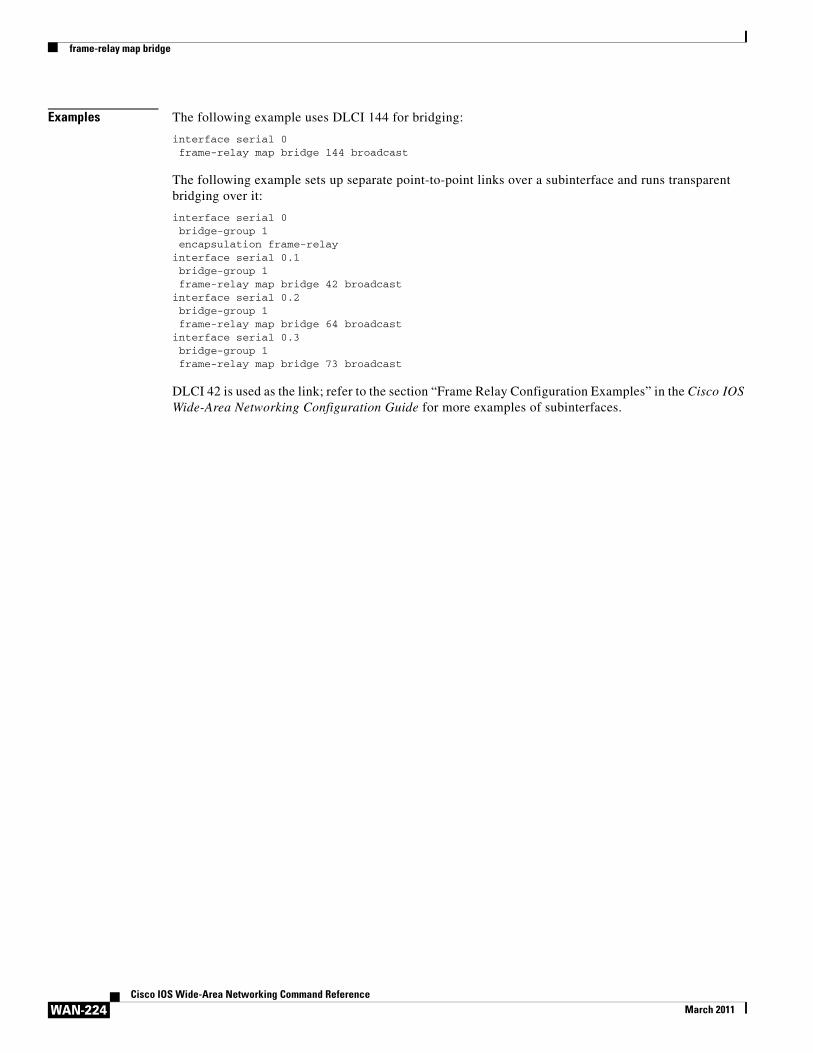
Examples The following example uses DLCI 144 for bridging:
interface serial 0frame-relay map bridge 144 broadcast
The following example sets up separate point-to-point links over a subinterface and runs transparent bridging over it:
interface serial 0bridge-group 1encapsulation frame-relay
interface serial 0.1bridge-group 1frame-relay map bridge 42 broadcast
interface serial 0.2bridge-group 1frame-relay map bridge 64 broadcast
interface serial 0.3bridge-group 1frame-relay map bridge 73 broadcast
DLCI 42 is used as the link; refer to the section “Frame Relay Configuration Examples” in the Cisco IOS Wide-Area Networking Configuration Guide for more examples of subinterfaces.
frame-relay map clns
WAN-225Cisco IOS Wide-Area Networking Command Reference
March 2011
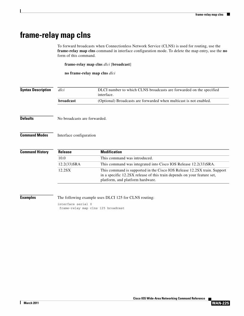
frame-relay map clns To forward broadcasts when Connectionless Network Service (CLNS) is used for routing, use the frame-relay map clns command in interface configuration mode. To delete the map entry, use the no form of this command.
frame-relay map clns dlci [broadcast]
no frame-relay map clns dlci
Syntax Description
Defaults No broadcasts are forwarded.
Command Modes Interface configuration
Command History
Examples The following example uses DLCI 125 for CLNS routing:
interface serial 0frame-relay map clns 125 broadcast
dlci DLCI number to which CLNS broadcasts are forwarded on the specified interface.
broadcast (Optional) Broadcasts are forwarded when multicast is not enabled.
Release Modification
10.0 This command was introduced.
12.2(33)SRA This command was integrated into Cisco IOS Release 12.2(33)SRA.
12.2SX This command is supported in the Cisco IOS Release 12.2SX train. Support in a specific 12.2SX release of this train depends on your feature set, platform, and platform hardware.
frame-relay map ip tcp header-compression
WAN-226Cisco IOS Wide-Area Networking Command Reference
March 2011
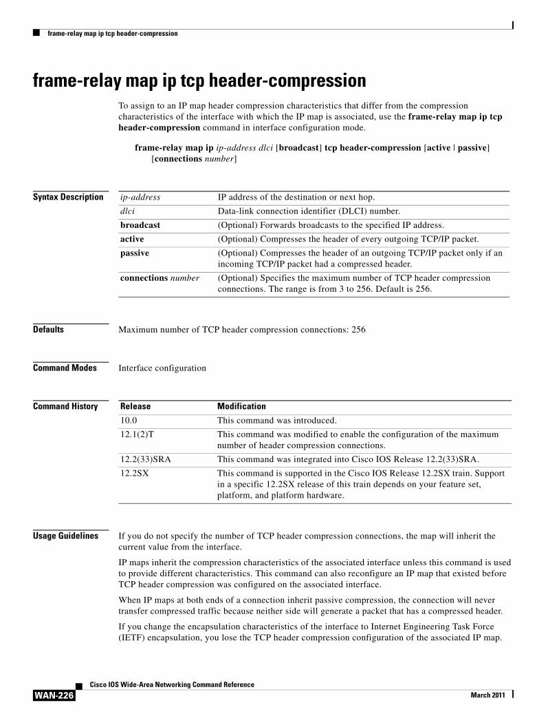
frame-relay map ip tcp header-compressionTo assign to an IP map header compression characteristics that differ from the compression characteristics of the interface with which the IP map is associated, use the frame-relay map ip tcp header-compression command in interface configuration mode.
frame-relay map ip ip-address dlci [broadcast] tcp header-compression [active | passive] [connections number]
Syntax Description
Defaults Maximum number of TCP header compression connections: 256
Command Modes Interface configuration
Command History
Usage Guidelines If you do not specify the number of TCP header compression connections, the map will inherit the current value from the interface.
IP maps inherit the compression characteristics of the associated interface unless this command is used to provide different characteristics. This command can also reconfigure an IP map that existed before TCP header compression was configured on the associated interface.
When IP maps at both ends of a connection inherit passive compression, the connection will never transfer compressed traffic because neither side will generate a packet that has a compressed header.
If you change the encapsulation characteristics of the interface to Internet Engineering Task Force (IETF) encapsulation, you lose the TCP header compression configuration of the associated IP map.
ip-address IP address of the destination or next hop.
dlci Data-link connection identifier (DLCI) number.
broadcast (Optional) Forwards broadcasts to the specified IP address.
active (Optional) Compresses the header of every outgoing TCP/IP packet.
passive (Optional) Compresses the header of an outgoing TCP/IP packet only if an incoming TCP/IP packet had a compressed header.
connections number (Optional) Specifies the maximum number of TCP header compression connections. The range is from 3 to 256. Default is 256.
Release Modification
10.0 This command was introduced.
12.1(2)T This command was modified to enable the configuration of the maximum number of header compression connections.
12.2(33)SRA This command was integrated into Cisco IOS Release 12.2(33)SRA.
12.2SX This command is supported in the Cisco IOS Release 12.2SX train. Support in a specific 12.2SX release of this train depends on your feature set, platform, and platform hardware.
frame-relay map ip tcp header-compression
WAN-227Cisco IOS Wide-Area Networking Command Reference
March 2011
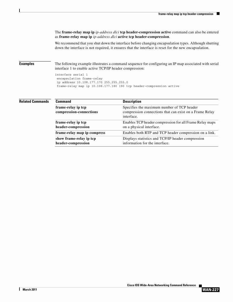
The frame-relay map ip ip-address dlci tcp header-compression active command can also be entered as frame-relay map ip ip-address dlci active tcp header-compression.
We recommend that you shut down the interface before changing encapsulation types. Although shutting down the interface is not required, it ensures that the interface is reset for the new encapsulation.
Examples The following example illustrates a command sequence for configuring an IP map associated with serial interface 1 to enable active TCP/IP header compression:
interface serial 1encapsulation frame-relayip address 10.108.177.170 255.255.255.0frame-relay map ip 10.108.177.180 190 tcp header-compression active
Related Commands Command Description
frame-relay ip tcp compression-connections
Specifies the maximum number of TCP header compression connections that can exist on a Frame Relay interface.
frame-relay ip tcp header-compression
Enables TCP header compression for all Frame Relay maps on a physical interface.
frame-relay map ip compress Enables both RTP and TCP header compression on a link.
show frame-relay ip tcp header-compression
Displays statistics and TCP/IP header compression information for the interface.
frame-relay mincir
WAN-228Cisco IOS Wide-Area Networking Command Reference
March 2011
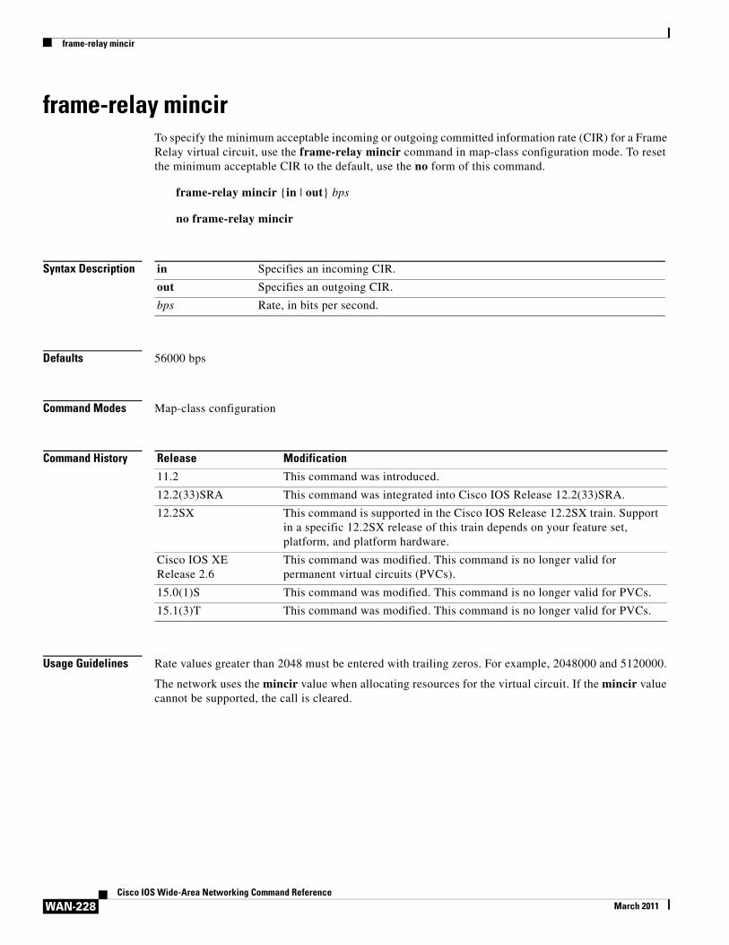
frame-relay mincirTo specify the minimum acceptable incoming or outgoing committed information rate (CIR) for a Frame Relay virtual circuit, use the frame-relay mincir command in map-class configuration mode. To reset the minimum acceptable CIR to the default, use the no form of this command.
frame-relay mincir {in | out} bps
no frame-relay mincir
Syntax Description
Defaults 56000 bps
Command Modes Map-class configuration
Command History
Usage Guidelines Rate values greater than 2048 must be entered with trailing zeros. For example, 2048000 and 5120000.
The network uses the mincir value when allocating resources for the virtual circuit. If the mincir value cannot be supported, the call is cleared.
in Specifies an incoming CIR.
out Specifies an outgoing CIR.
bps Rate, in bits per second.
Release Modification
11.2 This command was introduced.
12.2(33)SRA This command was integrated into Cisco IOS Release 12.2(33)SRA.
12.2SX This command is supported in the Cisco IOS Release 12.2SX train. Support in a specific 12.2SX release of this train depends on your feature set, platform, and platform hardware.
Cisco IOS XERelease 2.6
This command was modified. This command is no longer valid for permanent virtual circuits (PVCs).
15.0(1)S This command was modified. This command is no longer valid for PVCs.
15.1(3)T This command was modified. This command is no longer valid for PVCs.
frame-relay mincir
WAN-229Cisco IOS Wide-Area Networking Command Reference
March 2011
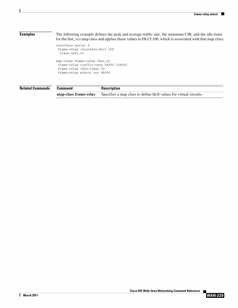
Examples The following example defines the peak and average traffic rate, the minimum CIR, and the idle timer for the fast_vcs map class and applies those values to DLCI 100, which is associated with that map class:
interface serial 0frame-relay interface-dlci 100class fast_vc
map-class frame-relay fast_vcframe-relay traffic-rate 56000 128000frame-relay idle-timer 30frame-relay mincir out 48000
Related Commands Command Description
map-class frame-relay Specifies a map class to define QoS values for virtual circuits.
frame-relay multicast-dlci
WAN-230Cisco IOS Wide-Area Networking Command Reference
March 2011
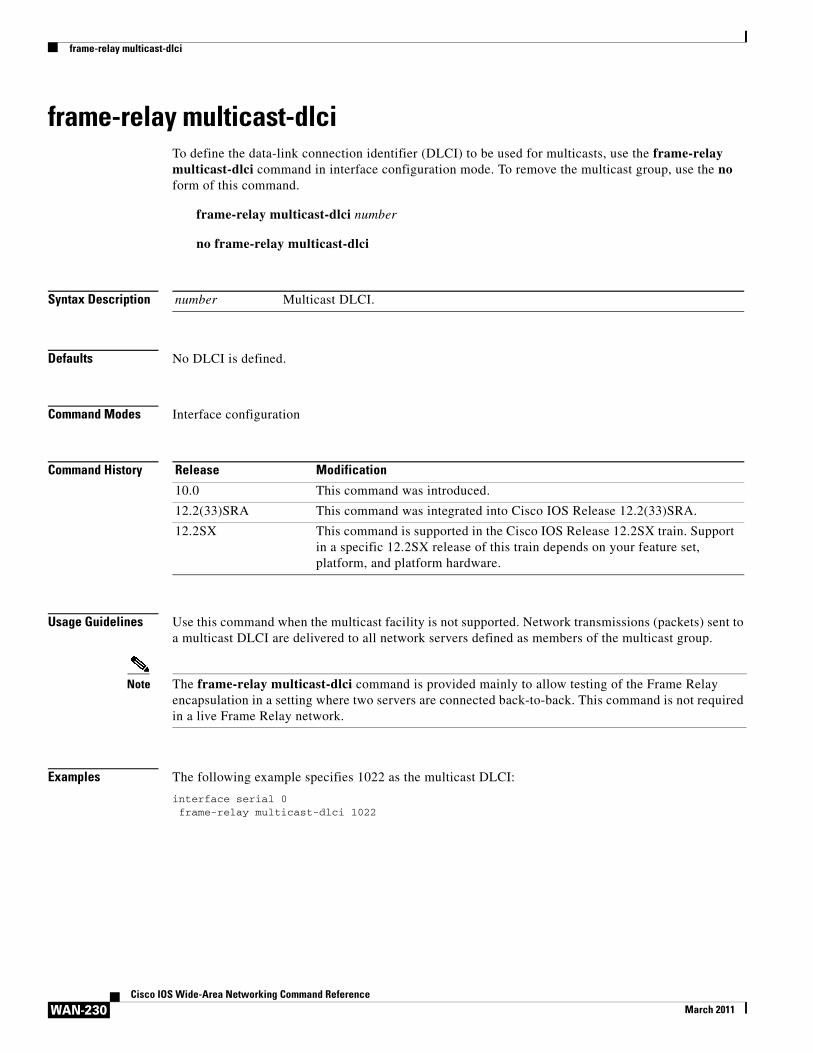
frame-relay multicast-dlciTo define the data-link connection identifier (DLCI) to be used for multicasts, use the frame-relay multicast-dlci command in interface configuration mode. To remove the multicast group, use the no form of this command.
frame-relay multicast-dlci number
no frame-relay multicast-dlci
Syntax Description
Defaults No DLCI is defined.
Command Modes Interface configuration
Command History
Usage Guidelines Use this command when the multicast facility is not supported. Network transmissions (packets) sent to a multicast DLCI are delivered to all network servers defined as members of the multicast group.
Note The frame-relay multicast-dlci command is provided mainly to allow testing of the Frame Relay encapsulation in a setting where two servers are connected back-to-back. This command is not required in a live Frame Relay network.
Examples The following example specifies 1022 as the multicast DLCI:
interface serial 0frame-relay multicast-dlci 1022
number Multicast DLCI.
Release Modification
10.0 This command was introduced.
12.2(33)SRA This command was integrated into Cisco IOS Release 12.2(33)SRA.
12.2SX This command is supported in the Cisco IOS Release 12.2SX train. Support in a specific 12.2SX release of this train depends on your feature set, platform, and platform hardware.
frame-relay multilink ack
WAN-231Cisco IOS Wide-Area Networking Command Reference
March 2011
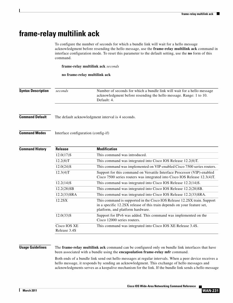
frame-relay multilink ackTo configure the number of seconds for which a bundle link will wait for a hello message acknowledgment before resending the hello message, use the frame-relay multilink ack command in interface configuration mode. To reset this parameter to the default setting, use the no form of this command.
frame-relay multilink ack seconds
no frame-relay multilink ack
Syntax Description
Command Default The default acknowledgment interval is 4 seconds.
Command Modes Interface configuration (config-if)
Command History
Usage Guidelines The frame-relay multilink ack command can be configured only on bundle link interfaces that have been associated with a bundle using the encapsulation frame-relay mfr command.
Both ends of a bundle link send out hello messages at regular intervals. When a peer device receives a hello message, it responds by sending an acknowledgment. This exchange of hello messages and acknowledgments serves as a keepalive mechanism for the link. If the bundle link sends a hello message
seconds Number of seconds for which a bundle link will wait for a hello message acknowledgment before resending the hello message. Range: 1 to 10. Default: 4.
Release Modification
12.0(17)S This command was introduced.
12.2(8)T This command was integrated into Cisco IOS Release 12.2(8)T.
12.0(24)S This command was implemented on VIP-enabled Cisco 7500 series routers.
12.3(4)T Support for this command on Versatile Interface Processor (VIP)-enabled Cisco 7500 series routers was integrated into Cisco IOS Release 12.3(4)T.
12.2(14)S This command was integrated into Cisco IOS Release 12.2(14)S.
12.2(28)SB This command was integrated into Cisco IOS Release 12.2(28)SB.
12.2(33)SRA This command was integrated into Cisco IOS Release 12.2(33)SRA.
12.2SX This command is supported in the Cisco IOS Release 12.2SX train. Support in a specific 12.2SX release of this train depends on your feature set, platform, and platform hardware.
12.0(33)S Support for IPv6 was added. This command was implemented on the Cisco 12000 series routers.
Cisco IOS XE Release 3.4S
This command was integrated into Cisco IOS XE Release 3.4S.
frame-relay multilink ack
WAN-232Cisco IOS Wide-Area Networking Command Reference
March 2011
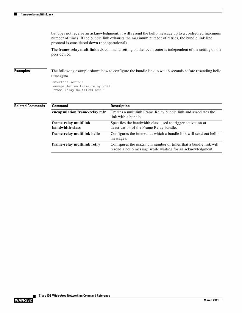
but does not receive an acknowledgment, it will resend the hello message up to a configured maximum number of times. If the bundle link exhausts the maximum number of retries, the bundle link line protocol is considered down (nonoperational).
The frame-relay multilink ack command setting on the local router is independent of the setting on the peer device.
Examples The following example shows how to configure the bundle link to wait 6 seconds before resending hello messages:
interface serial0encapsulation frame-relay MFR0frame-relay multilink ack 6
Related Commands Command Description
encapsulation frame-relay mfr Creates a multilink Frame Relay bundle link and associates the link with a bundle.
frame-relay multilink bandwidth-class
Specifies the bandwidth class used to trigger activation or deactivation of the Frame Relay bundle.
frame-relay multilink hello Configures the interval at which a bundle link will send out hello messages.
frame-relay multilink retry Configures the maximum number of times that a bundle link will resend a hello message while waiting for an acknowledgment.
frame-relay multilink bandwidth-class
WAN-233Cisco IOS Wide-Area Networking Command Reference
March 2011
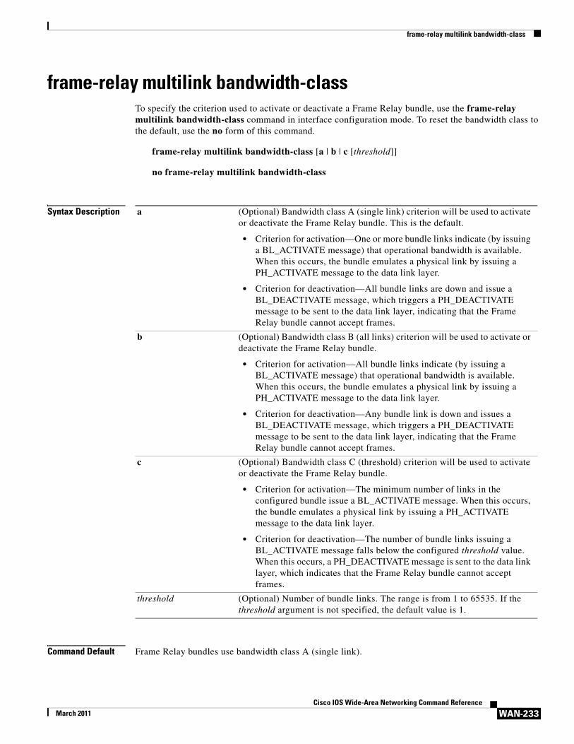
frame-relay multilink bandwidth-classTo specify the criterion used to activate or deactivate a Frame Relay bundle, use the frame-relay multilink bandwidth-class command in interface configuration mode. To reset the bandwidth class to the default, use the no form of this command.
frame-relay multilink bandwidth-class [a | b | c [threshold]]
no frame-relay multilink bandwidth-class
Syntax Description
Command Default Frame Relay bundles use bandwidth class A (single link).
a (Optional) Bandwidth class A (single link) criterion will be used to activate or deactivate the Frame Relay bundle. This is the default.
• Criterion for activation—One or more bundle links indicate (by issuing a BL_ACTIVATE message) that operational bandwidth is available. When this occurs, the bundle emulates a physical link by issuing a PH_ACTIVATE message to the data link layer.
• Criterion for deactivation—All bundle links are down and issue a BL_DEACTIVATE message, which triggers a PH_DEACTIVATE message to be sent to the data link layer, indicating that the Frame Relay bundle cannot accept frames.
b (Optional) Bandwidth class B (all links) criterion will be used to activate or deactivate the Frame Relay bundle.
• Criterion for activation—All bundle links indicate (by issuing a BL_ACTIVATE message) that operational bandwidth is available. When this occurs, the bundle emulates a physical link by issuing a PH_ACTIVATE message to the data link layer.
• Criterion for deactivation—Any bundle link is down and issues a BL_DEACTIVATE message, which triggers a PH_DEACTIVATE message to be sent to the data link layer, indicating that the Frame Relay bundle cannot accept frames.
c (Optional) Bandwidth class C (threshold) criterion will be used to activate or deactivate the Frame Relay bundle.
• Criterion for activation—The minimum number of links in the configured bundle issue a BL_ACTIVATE message. When this occurs, the bundle emulates a physical link by issuing a PH_ACTIVATE message to the data link layer.
• Criterion for deactivation—The number of bundle links issuing a BL_ACTIVATE message falls below the configured threshold value. When this occurs, a PH_DEACTIVATE message is sent to the data link layer, which indicates that the Frame Relay bundle cannot accept frames.
threshold (Optional) Number of bundle links. The range is from 1 to 65535. If the threshold argument is not specified, the default value is 1.
frame-relay multilink bandwidth-class
WAN-234Cisco IOS Wide-Area Networking Command Reference
March 2011
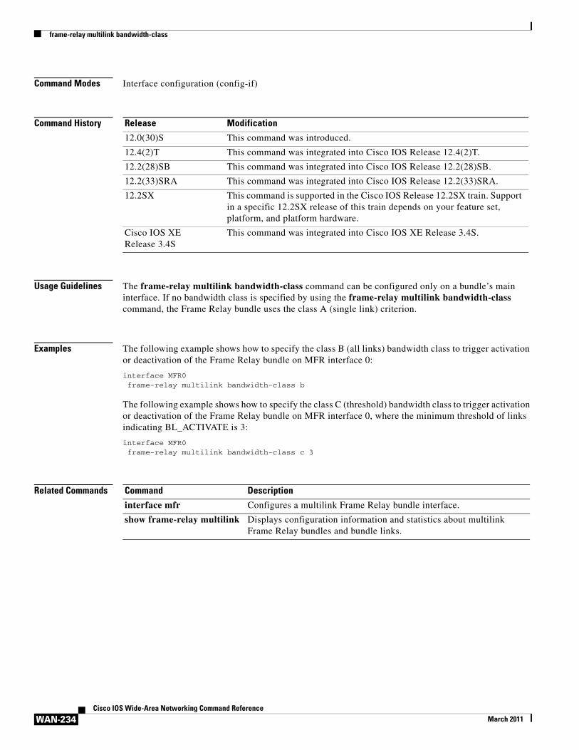
Command Modes Interface configuration (config-if)
Command History
Usage Guidelines The frame-relay multilink bandwidth-class command can be configured only on a bundle’s main interface. If no bandwidth class is specified by using the frame-relay multilink bandwidth-class command, the Frame Relay bundle uses the class A (single link) criterion.
Examples The following example shows how to specify the class B (all links) bandwidth class to trigger activation or deactivation of the Frame Relay bundle on MFR interface 0:
interface MFR0frame-relay multilink bandwidth-class b
The following example shows how to specify the class C (threshold) bandwidth class to trigger activation or deactivation of the Frame Relay bundle on MFR interface 0, where the minimum threshold of links indicating BL_ACTIVATE is 3:
interface MFR0frame-relay multilink bandwidth-class c 3
Related Commands
Release Modification
12.0(30)S This command was introduced.
12.4(2)T This command was integrated into Cisco IOS Release 12.4(2)T.
12.2(28)SB This command was integrated into Cisco IOS Release 12.2(28)SB.
12.2(33)SRA This command was integrated into Cisco IOS Release 12.2(33)SRA.
12.2SX This command is supported in the Cisco IOS Release 12.2SX train. Support in a specific 12.2SX release of this train depends on your feature set, platform, and platform hardware.
Cisco IOS XE Release 3.4S
This command was integrated into Cisco IOS XE Release 3.4S.
Command Description
interface mfr Configures a multilink Frame Relay bundle interface.
show frame-relay multilink Displays configuration information and statistics about multilink Frame Relay bundles and bundle links.
frame-relay multilink bid
WAN-235Cisco IOS Wide-Area Networking Command Reference
March 2011
frame-relay multilink bidTo assign a bundle identification (BID) name to a multilink Frame Relay bundle, use the frame-relay multilink bid command in interface configuration mode. To reset the name to the default, use the no form of this command.
frame-relay multilink bid name
no frame-relay multilink bid
Syntax Description
Command Default The BID name is assigned automatically as “mfr” followed by the number assigned to the bundle.
Command Modes Interface configuration (config-if)
Command History
Usage Guidelines This command can be entered only on the multilink Frame Relay bundle interface.
name Bundle identification (BID) name. The name can be up to 49 characters long. The default is “mfr” followed by the number assigned to the bundle using the interface mfr command; for example, “mfr0.”
Release Modification
12.0(17)S This command was introduced.
12.2(8)T This command was integrated into Cisco IOS Release 12.2(8)T.
12.0(24)S This command was implemented on Versatile Interface Processor (VIP)-enabled Cisco 7500 series routers.
12.3(4)T Support for this command on VIP-enabled Cisco 7500 series routers was integrated into Cisco IOS Release 12.3(4)T.
12.2(14)S This command was integrated into Cisco IOS Release 12.2(14)S.
12.2(28)SB This command was integrated into Cisco IOS Release 12.2(28)SB.
12.2(33)SRA This command was integrated into Cisco IOS Release 12.2(33)SRA.
12.2SX This command is supported in the Cisco IOS Release 12.2SX train. Support in a specific 12.2SX release of this train depends on your feature set, platform, and platform hardware.
12.0(33)S Support for IPv6 was added. This command was implemented on the Cisco 12000 series routers.
Cisco IOS XE Release 3.4S
This command was integrated into Cisco IOS XE Release 3.4S.
frame-relay multilink bid
WAN-236Cisco IOS Wide-Area Networking Command Reference
March 2011
Note You can enter the frame-relay multilink bid command at any time without affecting the current state of the interface; however, the BID will not go into effect until the interface has gone from the down state to the up state. One way to bring the interface down and back up again is by using the shutdown and no shutdown commands in interface configuration mode.
Only one BID is allowed per bundle. A later entry of the frame-relay multilink bid command supersedes prior entries.
The local and peer BIDs do not have to be unique.
Examples The following example shows how to assign a BID of “bundle1” to the multilink Frame Relay bundle. The previous BID for the bundle was “mfr0.”
interface MFR0frame-relay multilink bid bundle1
Related Commands Command Description
frame-relay multilink lid Assigns a LID name to a multilink Frame Relay bundle link.
interface mfr Configures a multilink Frame Relay bundle interface.
show frame-relay multilink Displays configuration information and statistics about multilink Frame Relay bundles and bundle links.
shutdown (interface) Disables an interface.

frame-relay multilink hello
WAN-237Cisco IOS Wide-Area Networking Command Reference
March 2011
frame-relay multilink helloTo configure the interval at which a bundle link will send out hello messages, use the frame-relay multilink hello command in interface configuration mode. To reset this value to the default setting, use the no form of this command.
frame-relay multilink hello seconds
no frame-relay multilink hello
Syntax Description
Command Default The interval is set at 10 seconds.
Command Modes Interface configuration (config-if)
Command History
Usage Guidelines The frame-relay multilink hello command can be configured only on bundle link interfaces that have been associated with a bundle using the encapsulation frame-relay mfr command.
Both ends of a bundle link send out hello messages at regular intervals. When a peer device receives a hello message, it responds by sending an acknowledgment. This exchange of hello messages and acknowledgments serves as a keepalive mechanism for the link. If the bundle link sends a hello message
seconds Interval, in seconds, at which a bundle link will send out hello messages. Range: 1 to 180. Default: 10.
Release Modification
12.0(17)S This command was introduced.
12.2(8)T This command was integrated into Cisco IOS Release 12.2(8)T.
12.0(24)S This command was implemented on Versatile Interface Processor (VIP)-enabled Cisco 7500 series routers.
12.3(4)T Support for this command on VIP-enabled Cisco 7500 series routers was integrated into Cisco IOS Release 12.3(4)T.
12.2(14)S This command was integrated into Cisco IOS Release 12.2(14)S.
12.2(28)SB This command was integrated into Cisco IOS Release 12.2(28)SB.
12.2(33)SRA This command was integrated into Cisco IOS Release 12.2(33)SRA.
12.2SX This command is supported in the Cisco IOS Release 12.2SX train. Support in a specific 12.2SX release of this train depends on your feature set, platform, and platform hardware.
12.0(33)S Support for IPv6 was added. This command was implemented on the Cisco 12000 series routers.
Cisco IOS XE Release 3.4S
This command was integrated into Cisco IOS XE Release 3.4S.
frame-relay multilink hello
WAN-238Cisco IOS Wide-Area Networking Command Reference
March 2011
but does not receive an acknowledgment, it will resend the hello message up to a configured maximum number of times. If the bundle link exhausts the maximum number of retries, the bundle link line protocol is considered down (nonoperational).
The setting of the hello message interval on the local router is independent of the setting on the peer device.
Examples The following example shows how to configure a bundle link to send hello messages every 15 seconds:
interface serial0encapsulation frame-relay MFR0frame-relay multilink hello 15
Related Commands Command Description
encapsulation frame-relay mfr
Creates a multilink Frame Relay bundle link and associates the link with a bundle.
frame-relay multilink ack Configures the number of seconds that a bundle link will wait for a hello message acknowledgment before resending the hello message.
frame-relay multilink retry Configures the maximum number of times that a bundle link will resend a hello message while waiting for an acknowledgment.
frame-relay multilink lid
WAN-239Cisco IOS Wide-Area Networking Command Reference
March 2011
frame-relay multilink lidTo assign a bundle link identification (LID) name to a multilink Frame Relay bundle link, use the frame-relay multilink lid command in interface configuration mode. To reset the name to the default, use the no form of this command.
frame-relay multilink lid name
no frame-relay multilink lid
Syntax Description
Command Default The name of the physical interface is used as the LID.
Command Modes Interface configuration (config-if)
Command History
Usage Guidelines The frame-relay multilink lid command can be configured only on bundle link interfaces that have been associated with a bundle using the encapsulation frame-relay mfr command.
name Bundle link identification (LID) name. The name can be up to 49 characters long. The default is the name of the physical interface.
Release Modification
12.0(17)S This command was introduced.
12.2(8)T This command was integrated into Cisco IOS Release 12.2(8)T.
12.0(24)S This command was implemented on Versatile Interface Processor (VIP)-enabled Cisco 7500 series routers.
12.3(4)T Support for this command on VIP-enabled Cisco 7500 series routers was integrated into Cisco IOS Release 12.3(4)T.
12.2(14)S This command was integrated into Cisco IOS Release 12.2(14)S.
12.2(28)SB This command was integrated into Cisco IOS Release 12.2(28)SB.
12.2(33)SRA This command was integrated into Cisco IOS Release 12.2(33)SRA.
12.2SX This command is supported in the Cisco IOS Release 12.2SX train. Support in a specific 12.2SX release of this train depends on your feature set, platform, and platform hardware.
12.0(33)S Support for IPv6 was added. This command was implemented on the Cisco 12000 series routers.
Cisco IOS XE Release 3.4S
This command was integrated into Cisco IOS XE Release 3.4S.
frame-relay multilink lid
WAN-240Cisco IOS Wide-Area Networking Command Reference
March 2011
Note You can enter the frame-relay multilink lid command at any time without affecting the current state of the interface; however, the LID will not go into effect until the interface has gone from the down state to the up state. One way to bring the interface down and back up again is by using the shutdown and no shutdown commands in interface configuration mode.
The LID will be used to identify the bundle link to peer devices and to enable the devices to identify which bundle links are associated with which bundles. The LID can also be assigned when the bundle link is created by using the encapsulation frame-relay mfr command with the name argument. If the LID is not assigned, the default LID is the name of the physical interface.
The local and peer LIDs do not have to be unique.
Examples The following example shows the LID named BL1 assigned to serial interface 0:
interface serial 0encapsulation frame-relay MFR0frame-relay multilink lid BL1
Related Commands Command Description
encapsulation frame-relay mfr Creates a multilink Frame Relay bundle link and associates the link with a bundle.
frame-relay multilink bid Assigns a BID name to a multilink Frame Relay bundle.
show frame-relay multilink Displays configuration information and statistics about multilink Frame Relay bundles and bundle links.
shutdown (interface) Disables an interface.
frame-relay multilink output-threshold
WAN-241Cisco IOS Wide-Area Networking Command Reference
March 2011
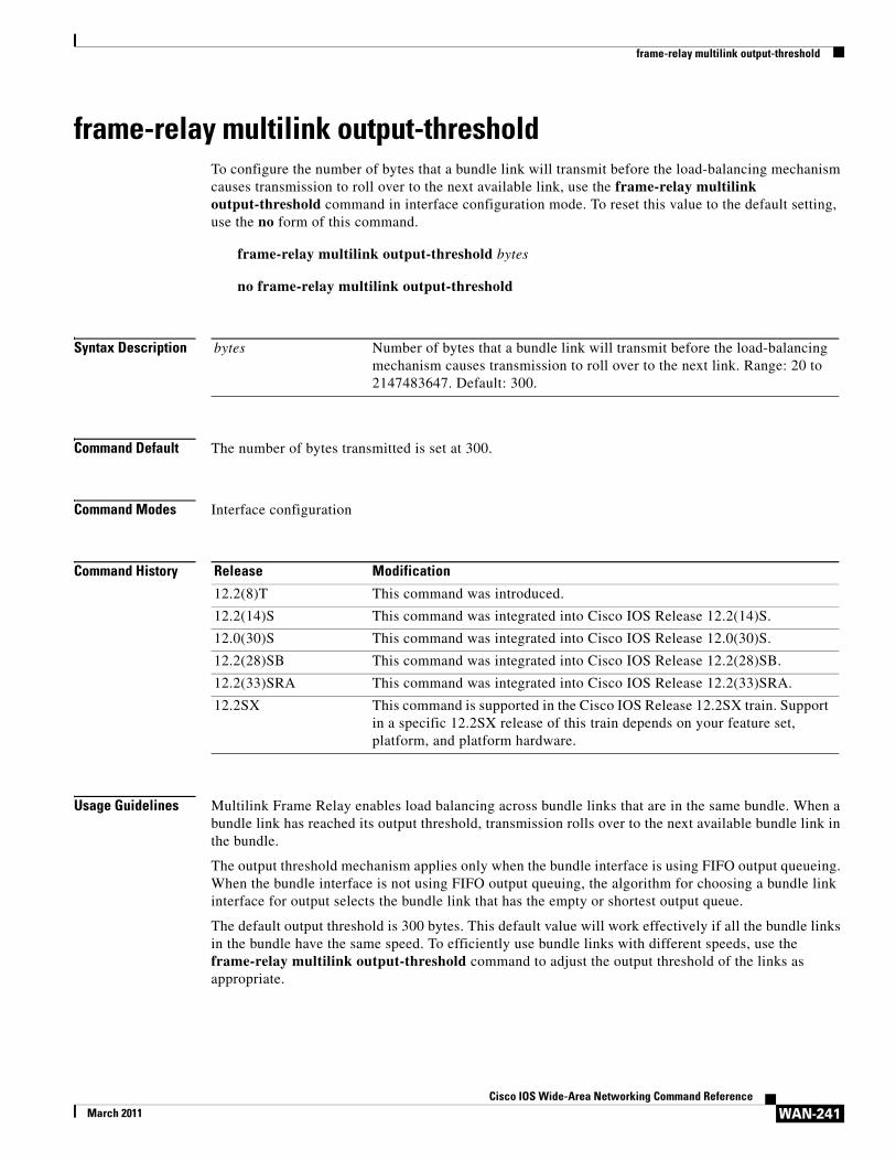
frame-relay multilink output-thresholdTo configure the number of bytes that a bundle link will transmit before the load-balancing mechanism causes transmission to roll over to the next available link, use the frame-relay multilink output-threshold command in interface configuration mode. To reset this value to the default setting, use the no form of this command.
frame-relay multilink output-threshold bytes
no frame-relay multilink output-threshold
Syntax Description
Command Default The number of bytes transmitted is set at 300.
Command Modes Interface configuration
Command History
Usage Guidelines Multilink Frame Relay enables load balancing across bundle links that are in the same bundle. When a bundle link has reached its output threshold, transmission rolls over to the next available bundle link in the bundle.
The output threshold mechanism applies only when the bundle interface is using FIFO output queueing. When the bundle interface is not using FIFO output queuing, the algorithm for choosing a bundle link interface for output selects the bundle link that has the empty or shortest output queue.
The default output threshold is 300 bytes. This default value will work effectively if all the bundle links in the bundle have the same speed. To efficiently use bundle links with different speeds, use the frame-relay multilink output-threshold command to adjust the output threshold of the links as appropriate.
bytes Number of bytes that a bundle link will transmit before the load-balancing mechanism causes transmission to roll over to the next link. Range: 20 to 2147483647. Default: 300.
Release Modification
12.2(8)T This command was introduced.
12.2(14)S This command was integrated into Cisco IOS Release 12.2(14)S.
12.0(30)S This command was integrated into Cisco IOS Release 12.0(30)S.
12.2(28)SB This command was integrated into Cisco IOS Release 12.2(28)SB.
12.2(33)SRA This command was integrated into Cisco IOS Release 12.2(33)SRA.
12.2SX This command is supported in the Cisco IOS Release 12.2SX train. Support in a specific 12.2SX release of this train depends on your feature set, platform, and platform hardware.
frame-relay multilink output-threshold
WAN-242Cisco IOS Wide-Area Networking Command Reference
March 2011
The frame-relay multilink output-threshold command can be used on the bundle interface and the bundle links. If the command is used on the bundle interface, the configured output threshold will apply to all bundle links in the bundle. If the command is used on a specific bundle link, the output threshold will overwrite the current setting for that bundle link.
Examples The following example shows how to configure the bundle link output threshold at 600 bytes. When the bundle link reaches the threshold, transmission will roll over to the next link.
interface serial0encapsulation frame-relay mfr0frame-relay multilink output-threshold 600
Related Commands Command Description
encapsulation frame-relay mfr
Creates a multilink Frame Relay bundle link and associates the link with a bundle.
frame-relay multilink bandwidth-class
Specifies the bandwidth class used to trigger activation or deactivation of the Frame Relay bundle.
frame-relay multilink retry
WAN-243Cisco IOS Wide-Area Networking Command Reference
March 2011
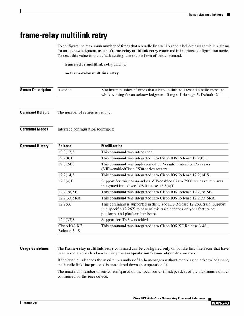
frame-relay multilink retryTo configure the maximum number of times that a bundle link will resend a hello message while waiting for an acknowledgment, use the frame-relay multilink retry command in interface configuration mode. To reset this value to the default setting, use the no form of this command.
frame-relay multilink retry number
no frame-relay multilink retry
Syntax Description
Command Default The number of retries is set at 2.
Command Modes Interface configuration (config-if)
Command History
Usage Guidelines The frame-relay multilink retry command can be configured only on bundle link interfaces that have been associated with a bundle using the encapsulation frame-relay mfr command.
If the bundle link sends the maximum number of hello messages without receiving an acknowledgment, the bundle link line protocol is considered down (nonoperational).
The maximum number of retries configured on the local router is independent of the maximum number configured on the peer device.
number Maximum number of times that a bundle link will resend a hello message while waiting for an acknowledgment. Range: 1 through 5. Default: 2.
Release Modification
12.0(17)S This command was introduced.
12.2(8)T This command was integrated into Cisco IOS Release 12.2(8)T.
12.0(24)S This command was implemented on Versatile Interface Processor (VIP)-enabledCisco 7500 series routers.
12.2(14)S This command was integrated into Cisco IOS Release 12.2(14)S.
12.3(4)T Support for this command on VIP-enabled Cisco 7500 series routers was integrated into Cisco IOS Release 12.3(4)T.
12.2(28)SB This command was integrated into Cisco IOS Release 12.2(28)SB.
12.2(33)SRA This command was integrated into Cisco IOS Release 12.2(33)SRA.
12.2SX This command is supported in the Cisco IOS Release 12.2SX train. Support in a specific 12.2SX release of this train depends on your feature set, platform, and platform hardware.
12.0(33)S Support for IPv6 was added.
Cisco IOS XE Release 3.4S
This command was integrated into Cisco IOS XE Release 3.4S.
frame-relay multilink retry
WAN-244Cisco IOS Wide-Area Networking Command Reference
March 2011
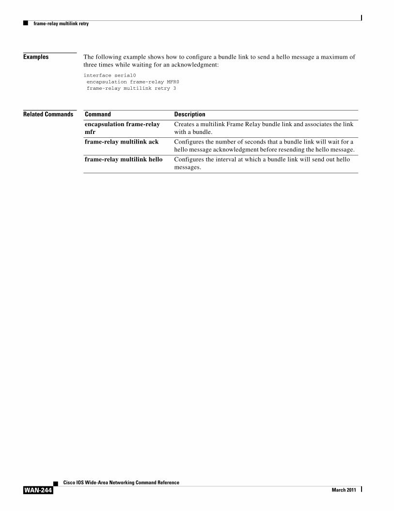
Examples The following example shows how to configure a bundle link to send a hello message a maximum of three times while waiting for an acknowledgment:
interface serial0encapsulation frame-relay MFR0frame-relay multilink retry 3
Related Commands Command Description
encapsulation frame-relay mfr
Creates a multilink Frame Relay bundle link and associates the link with a bundle.
frame-relay multilink ack Configures the number of seconds that a bundle link will wait for a hello message acknowledgment before resending the hello message.
frame-relay multilink hello Configures the interval at which a bundle link will send out hello messages.
frame-relay payload-compression
WAN-245Cisco IOS Wide-Area Networking Command Reference
March 2011
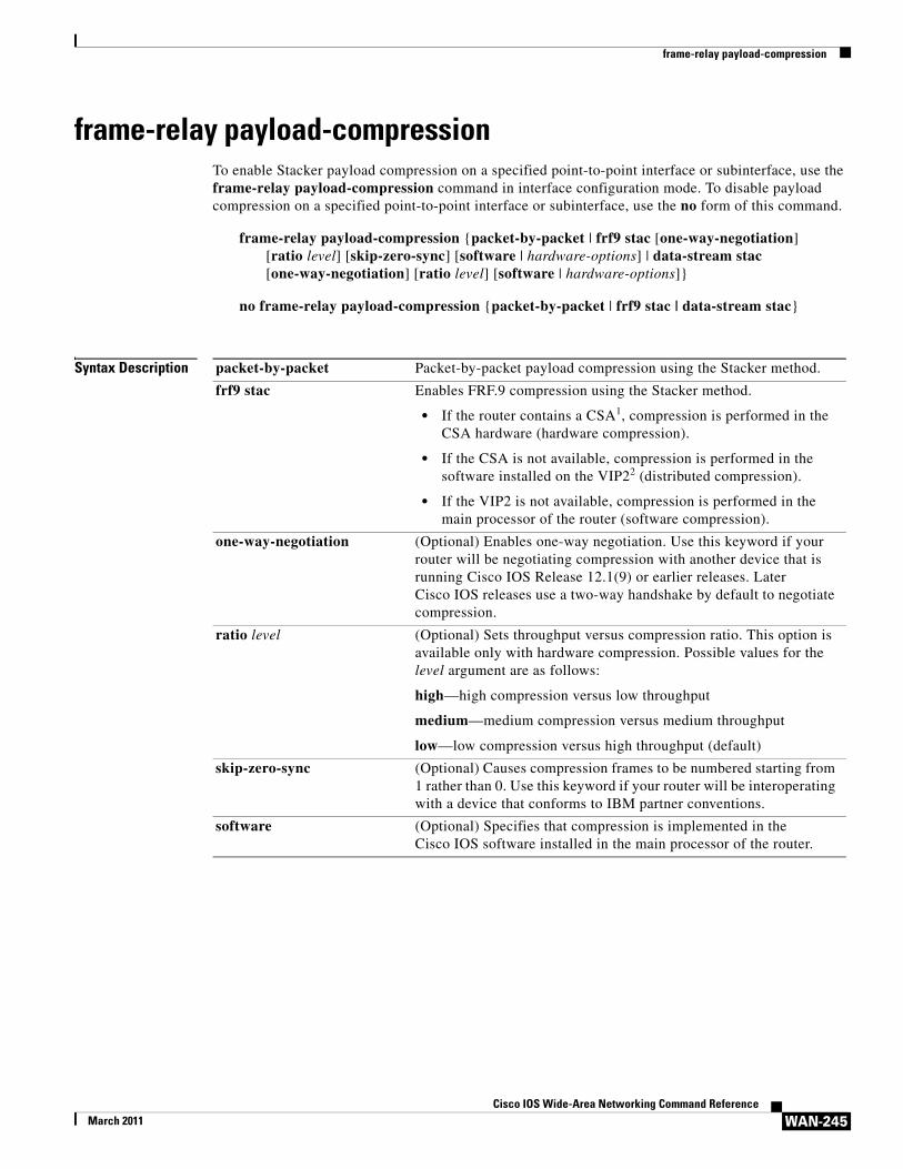
frame-relay payload-compressionTo enable Stacker payload compression on a specified point-to-point interface or subinterface, use the frame-relay payload-compression command in interface configuration mode. To disable payload compression on a specified point-to-point interface or subinterface, use the no form of this command.
frame-relay payload-compression {packet-by-packet | frf9 stac [one-way-negotiation] [ratio level] [skip-zero-sync] [software | hardware-options] | data-stream stac [one-way-negotiation] [ratio level] [software | hardware-options]}
no frame-relay payload-compression {packet-by-packet | frf9 stac | data-stream stac}
Syntax Description packet-by-packet Packet-by-packet payload compression using the Stacker method.
frf9 stac Enables FRF.9 compression using the Stacker method.
• If the router contains a CSA1, compression is performed in the CSA hardware (hardware compression).
• If the CSA is not available, compression is performed in the software installed on the VIP22 (distributed compression).
• If the VIP2 is not available, compression is performed in the main processor of the router (software compression).
one-way-negotiation (Optional) Enables one-way negotiation. Use this keyword if your router will be negotiating compression with another device that is running Cisco IOS Release 12.1(9) or earlier releases. Later Cisco IOS releases use a two-way handshake by default to negotiate compression.
ratio level (Optional) Sets throughput versus compression ratio. This option is available only with hardware compression. Possible values for the level argument are as follows:
high—high compression versus low throughput
medium—medium compression versus medium throughput
low—low compression versus high throughput (default)
skip-zero-sync (Optional) Causes compression frames to be numbered starting from 1 rather than 0. Use this keyword if your router will be interoperating with a device that conforms to IBM partner conventions.
software (Optional) Specifies that compression is implemented in the Cisco IOS software installed in the main processor of the router.
frame-relay payload-compression
WAN-246Cisco IOS Wide-Area Networking Command Reference
March 2011
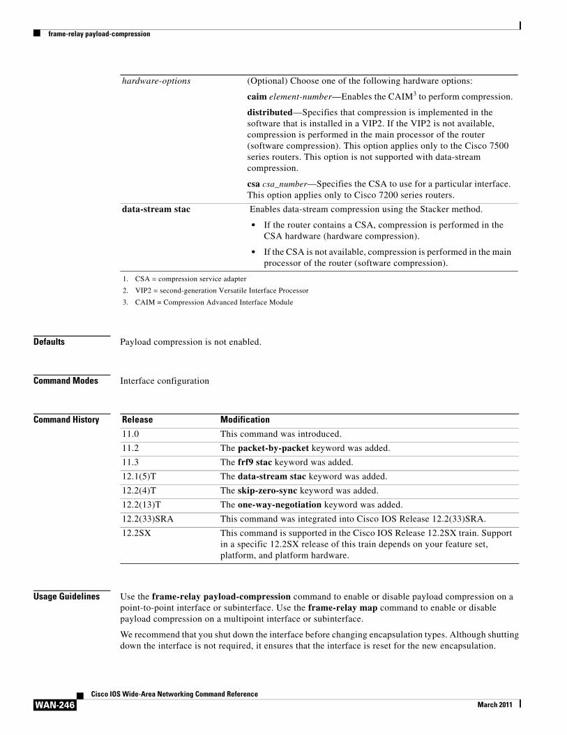
Defaults Payload compression is not enabled.
Command Modes Interface configuration
Command History
Usage Guidelines Use the frame-relay payload-compression command to enable or disable payload compression on a point-to-point interface or subinterface. Use the frame-relay map command to enable or disable payload compression on a multipoint interface or subinterface.
We recommend that you shut down the interface before changing encapsulation types. Although shutting down the interface is not required, it ensures that the interface is reset for the new encapsulation.
hardware-options (Optional) Choose one of the following hardware options:
caim element-number—Enables the CAIM3 to perform compression.
distributed—Specifies that compression is implemented in the software that is installed in a VIP2. If the VIP2 is not available, compression is performed in the main processor of the router (software compression). This option applies only to the Cisco 7500 series routers. This option is not supported with data-stream compression.
csa csa_number—Specifies the CSA to use for a particular interface. This option applies only to Cisco 7200 series routers.
data-stream stac Enables data-stream compression using the Stacker method.
• If the router contains a CSA, compression is performed in the CSA hardware (hardware compression).
• If the CSA is not available, compression is performed in the main processor of the router (software compression).
1. CSA = compression service adapter
2. VIP2 = second-generation Versatile Interface Processor
3. CAIM = Compression Advanced Interface Module
Release Modification
11.0 This command was introduced.
11.2 The packet-by-packet keyword was added.
11.3 The frf9 stac keyword was added.
12.1(5)T The data-stream stac keyword was added.
12.2(4)T The skip-zero-sync keyword was added.
12.2(13)T The one-way-negotiation keyword was added.
12.2(33)SRA This command was integrated into Cisco IOS Release 12.2(33)SRA.
12.2SX This command is supported in the Cisco IOS Release 12.2SX train. Support in a specific 12.2SX release of this train depends on your feature set, platform, and platform hardware.
frame-relay payload-compression
WAN-247Cisco IOS Wide-Area Networking Command Reference
March 2011
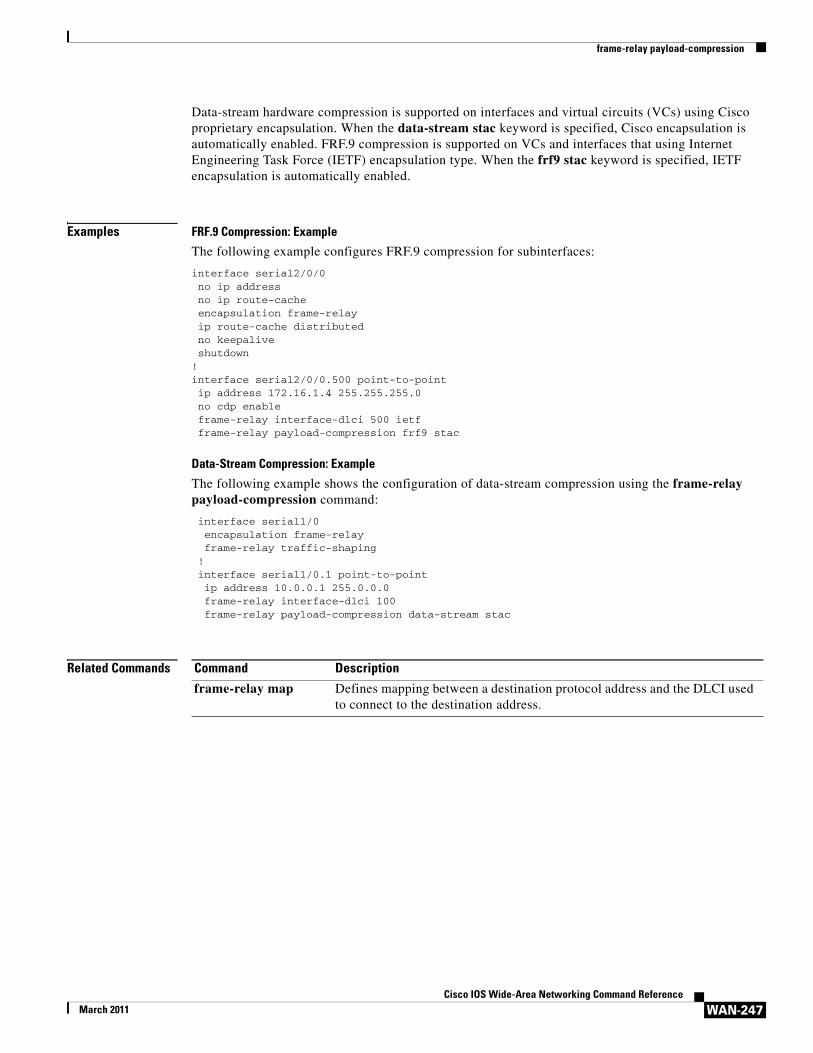
Data-stream hardware compression is supported on interfaces and virtual circuits (VCs) using Cisco proprietary encapsulation. When the data-stream stac keyword is specified, Cisco encapsulation is automatically enabled. FRF.9 compression is supported on VCs and interfaces that using Internet Engineering Task Force (IETF) encapsulation type. When the frf9 stac keyword is specified, IETF encapsulation is automatically enabled.
Examples FRF.9 Compression: Example
The following example configures FRF.9 compression for subinterfaces:
interface serial2/0/0 no ip address no ip route-cache encapsulation frame-relay ip route-cache distributed no keepalive shutdown!interface serial2/0/0.500 point-to-point ip address 172.16.1.4 255.255.255.0 no cdp enable frame-relay interface-dlci 500 ietf frame-relay payload-compression frf9 stac
Data-Stream Compression: Example
The following example shows the configuration of data-stream compression using the frame-relay payload-compression command:
interface serial1/0 encapsulation frame-relay frame-relay traffic-shaping ! interface serial1/0.1 point-to-point ip address 10.0.0.1 255.0.0.0 frame-relay interface-dlci 100
frame-relay payload-compression data-stream stac
Related Commands Command Description
frame-relay map Defines mapping between a destination protocol address and the DLCI used to connect to the destination address.
frame-relay policing
WAN-248Cisco IOS Wide-Area Networking Command Reference
March 2011
frame-relay policingTo enable Frame Relay policing on all switched PVCs on the interface, use the frame-relay policing command in interface configuration mode. To disable Frame Relay policing, use the no form of this command.
frame-relay policing
no frame-relay policing
Syntax Description This command has no arguments or keywords.
Defaults Frame Relay policing is not enabled on switched PVCs.
Command Modes Interface configuration
Command History
Usage Guidelines You must enable Frame Relay policing on the incoming interface before you can configure traffic-policing parameters.
You must enable Frame Relay switching, using the frame-relay switching global command, before the frame-relay policing command will be effective on switched PVCs.
Examples The following example shows the configuration of Frame Relay policing on serial interface 0:
interface serial0frame-relay policing
Related Commands
Release Modification
12.1(2)T This command was introduced.
12.2(33)SRA This command was integrated into Cisco IOS Release 12.2(33)SRA.
12.2SX This command is supported in the Cisco IOS Release 12.2SX train. Support in a specific 12.2SX release of this train depends on your feature set, platform, and platform hardware.
Command Description
frame-relay bc Specifies the incoming or outgoing Bc for a Frame Relay virtual circuit.
frame-relay be Specifies the incoming or outgoing Be for a Frame Relay virtual circuit.
frame-relay cir Specifies the incoming or outgoing CIR for a Frame Relay virtual circuit.
frame-relay switching Enables PVC switching on a Frame Relay DCE or NNI.
frame-relay tc Specifies the measurement interval for policing incoming traffic when the CIR is zero.
frame-relay priority-dlci-group
WAN-249Cisco IOS Wide-Area Networking Command Reference
March 2011
frame-relay priority-dlci-groupTo prioritize multiple data-link connection identifiers (DLCIs) according to the type of Frame Relay traffic, use the frame-relay priority-dlci-group interface configuration command.
frame-relay priority-dlci-group group-number high-dlci medium-dlci normal-dlci low-dlci
Syntax Description
Defaults Disabled
Command Modes Interface configuration
Command History
Usage Guidelines This command is applied at the interface or subinterface level. Levels in descending order are high, medium, normal, and low.
This command allows you to define different DLCIs for different categories of traffic based on traffic priorities. This command does not itself define priority queueing, but it can be used in conjunction with priority queueing.
A global priority list must be defined, and the associated DLCIs must already be applied to the configuration before you enable this command.
Associate the DLCIs to their prospective groups and define their priority levels. This command is used for multiple DLCIs, where the source and destination endpoints are the same (parallel paths). This command should not be used on a main interface, or point-to-point subinterface, where only a single DLCI is configured.
A DLCI can only be affiliated with a single priority-group; however, there can be multiple groups per interface or subinterface.
group-number Specific group number.
high-dlci DLCI that is to have highest priority level.
medium-dlci DLCI that is to have medium priority level.
normal-dlci DLCI that is to have normal priority level.
low-dlci DLCI that is to have lowest priority level.
Release Modification
11.0 This command was introduced.
12.2(33)SRA This command was integrated into Cisco IOS Release 12.2(33)SRA.
12.2SX This command is supported in the Cisco IOS Release 12.2SX train. Support in a specific 12.2SX release of this train depends on your feature set, platform, and platform hardware.
frame-relay priority-dlci-group
WAN-250Cisco IOS Wide-Area Networking Command Reference
March 2011
You must configure the high-priority and medium-priority DLCI values. If you do not explicitly associate a DLCI for the normal-dlci and low-dlci priority levels, the last DLCI specified in the command line is used as the value of the remaining arguments. For example, the following two commands are equivalent:
frame-relay priority-dlci-group 1 40 50frame-relay priority-dlci-group 1 40 50 50 50
When you configure static map entries using frame-relay map commands or use Inverse Address Resolution Protocol (ARP), the high-level DLCI is the only DLCI that is mapped. In the example, DLCI 40 is defined as having the highest priority. Therefore, DLCI 40 is the only DLCI that should be included in the frame-relay map command. DLCI 50 should not be included in a frame-relay map command.
Examples The following example shows the frame-relay priority-dlci-group command configured on a main interface with a static Frame Relay map entry. Note that DLCI 40 is the high-priority DLCI as defined in the frame-relay priority-dlci-group command and the only DLCI included in the frame-relay map command.
interface serial 1ip address 172.21.177.1 255.255.255.0encapsulation frame-relay frame-relay priority-dlci-group 1 40frame-relay map ip 172.21.177.2 40 broadcast
The following example shows the frame-relay priority-dlci-group command configured on subinterfaces where multiple priority groups are defined. DLCI 40 is the high-priority DLCI in group 1, and DLCI 80 is the high-priority DLCI in group 2.
interface Serial3 no ip addressencapsulation frame-relay
!interface Serial3.2 multipoint ip address 172.21.177.1 255.255.255.0 frame-relay interface-dlci 40frame-relay priority-dlci-group 1 40
!interface Serial3.3 multipoint ip address 131.108.177.180 255.255.255.0 frame-relay priority-dlci-group 2 80 90 100 100 frame-relay interface-dlci 80!interface Serial 4no ip addressencapsulation frame-relay
!interface serial4.1 multipointip address 172.16.1.1 255.255.255.0frame-relay priority-dlci-group 3 200 210 300 300frame-relay priority-dlci-group 4 400 410 410 410frame-relay interface-dlci 200frame-relay interface-dlci 400
Related Commands Command Description
frame-relay map Defines mapping between a destination protocol address and the DLCI used to connect to the destination address.
frame-relay priority-group
WAN-251Cisco IOS Wide-Area Networking Command Reference
March 2011
frame-relay priority-group
Note Effective with Cisco IOS XE Release 2.6, Cisco IOS Release 15.0(1)S, and Cisco IOS Release 15.1(3)T, the frame-relay priority-group command is hidden. Although this command is still available in Cisco IOS software, the CLI interactive Help does not display it if you attempt to view it by entering a question mark at the command line.
This command will be completely removed in a future release, which means that you will need to use the appropriate replacement command (or sequence of commands). For more information (including a list of replacement commands), see the Legacy QoS Command Deprecation feature document in the Cisco IOS XE Quality of Service Solutions Configuration Guide or the Legacy QoS Command Deprecation feature document in the Cisco IOS Quality of Service Solutions Configuration Guide.
Note Effective with Cisco IOS XE Release 3.2S, the frame-relay priority-group command is replaced by a modular QoS CLI (MQC) command (or sequence of MQC commands). For the appropriate replacement command (or sequence of commands), see the Legacy QoS Command Deprecation feature document in the Cisco IOS XE Quality of Service Solutions Configuration Guide.
To assign a priority queue to virtual circuits associated with a map class, use the frame-relay priority-group command in map-class configuration mode. To remove the specified queueing from the virtual circuit and cause it to revert to the default first-come, first-served queueing, use the no form of this command.
frame-relay priority-group list-number
no frame-relay priority-group list-number
Syntax Description
Defaults If this command is not entered, the default is first-come, first-served queueing.
Command Modes Map-class configuration
Command History
list-number Priority-list number to be associated with the specified map class.
Release Modification
11.2 This command was introduced.
12.2(33)SRA This command was integrated into Cisco IOS Release 12.2(33)SRA.
12.2SX This command is supported in the Cisco IOS Release 12.2SX train. Support in a specific 12.2SX release of this train depends on your feature set, platform, and platform hardware.
Cisco IOS XE Release 2.6
This command was modified. This command was hidden.
15.0(1)S This command was modified. This command was hidden.
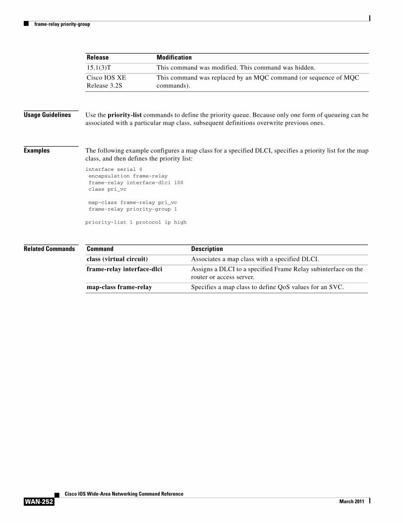
frame-relay priority-group
WAN-252Cisco IOS Wide-Area Networking Command Reference
March 2011
Usage Guidelines Use the priority-list commands to define the priority queue. Because only one form of queueing can be associated with a particular map class, subsequent definitions overwrite previous ones.
Examples The following example configures a map class for a specified DLCI, specifies a priority list for the map class, and then defines the priority list:
interface serial 0encapsulation frame-relayframe-relay interface-dlci 100class pri_vc
map-class frame-relay pri_vcframe-relay priority-group 1
priority-list 1 protocol ip high
Related Commands
15.1(3)T This command was modified. This command was hidden.
Cisco IOS XE Release 3.2S
This command was replaced by an MQC command (or sequence of MQC commands).
Release Modification
Command Description
class (virtual circuit) Associates a map class with a specified DLCI.
frame-relay interface-dlci Assigns a DLCI to a specified Frame Relay subinterface on the router or access server.
map-class frame-relay Specifies a map class to define QoS values for an SVC.
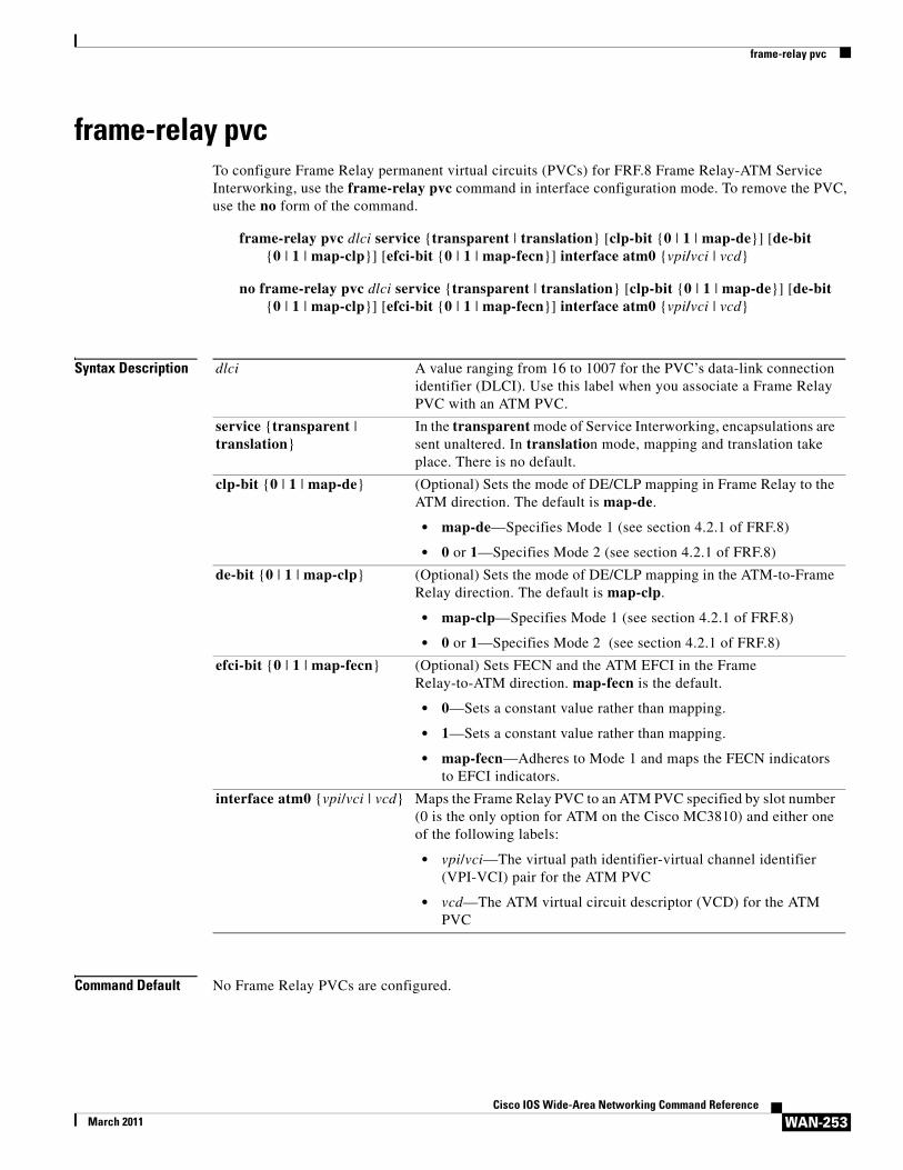
frame-relay pvc
WAN-253Cisco IOS Wide-Area Networking Command Reference
March 2011
frame-relay pvc To configure Frame Relay permanent virtual circuits (PVCs) for FRF.8 Frame Relay-ATM Service Interworking, use the frame-relay pvc command in interface configuration mode. To remove the PVC, use the no form of the command.
frame-relay pvc dlci service {transparent | translation} [clp-bit {0 | 1 | map-de}] [de-bit {0 | 1 | map-clp}] [efci-bit {0 | 1 | map-fecn}] interface atm0 {vpi/vci | vcd}
no frame-relay pvc dlci service {transparent | translation} [clp-bit {0 | 1 | map-de}] [de-bit {0 | 1 | map-clp}] [efci-bit {0 | 1 | map-fecn}] interface atm0 {vpi/vci | vcd}
Syntax Description
Command Default No Frame Relay PVCs are configured.
dlci A value ranging from 16 to 1007 for the PVC’s data-link connection identifier (DLCI). Use this label when you associate a Frame Relay PVC with an ATM PVC.
service {transparent | translation}
In the transparent mode of Service Interworking, encapsulations are sent unaltered. In translation mode, mapping and translation take place. There is no default.
clp-bit {0 | 1 | map-de} (Optional) Sets the mode of DE/CLP mapping in Frame Relay to the ATM direction. The default is map-de.
• map-de—Specifies Mode 1 (see section 4.2.1 of FRF.8)
• 0 or 1—Specifies Mode 2 (see section 4.2.1 of FRF.8)
de-bit {0 | 1 | map-clp} (Optional) Sets the mode of DE/CLP mapping in the ATM-to-Frame Relay direction. The default is map-clp.
• map-clp—Specifies Mode 1 (see section 4.2.1 of FRF.8)
• 0 or 1—Specifies Mode 2 (see section 4.2.1 of FRF.8)
efci-bit {0 | 1 | map-fecn} (Optional) Sets FECN and the ATM EFCI in the Frame Relay-to-ATM direction. map-fecn is the default.
• 0—Sets a constant value rather than mapping.
• 1—Sets a constant value rather than mapping.
• map-fecn—Adheres to Mode 1 and maps the FECN indicators to EFCI indicators.
interface atm0 {vpi/vci | vcd} Maps the Frame Relay PVC to an ATM PVC specified by slot number (0 is the only option for ATM on the Cisco MC3810) and either one of the following labels:
• vpi/vci—The virtual path identifier-virtual channel identifier (VPI-VCI) pair for the ATM PVC
• vcd—The ATM virtual circuit descriptor (VCD) for the ATM PVC
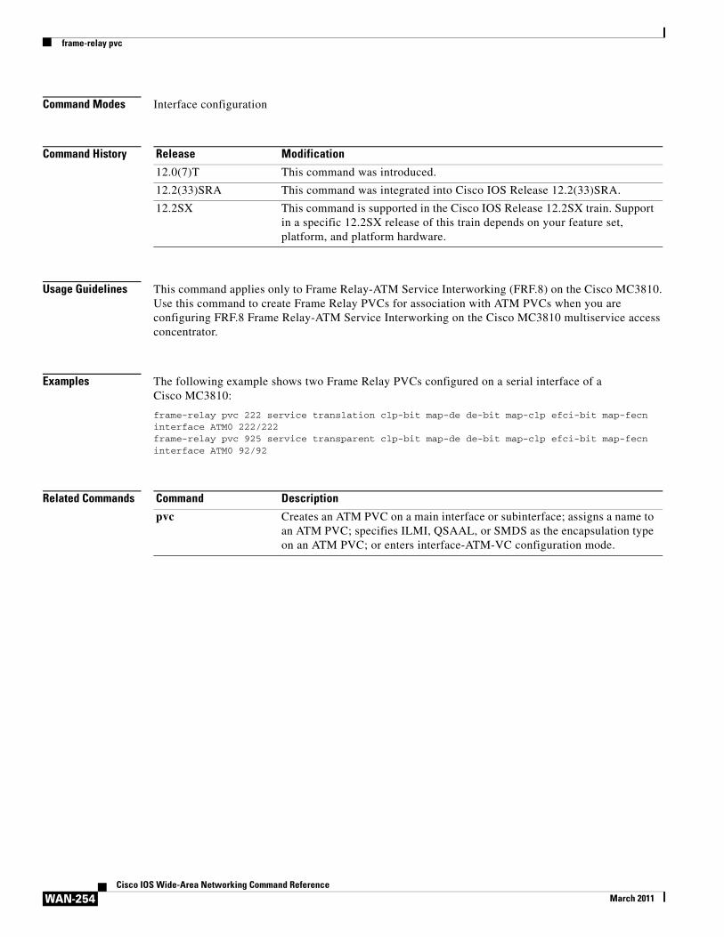
frame-relay pvc
WAN-254Cisco IOS Wide-Area Networking Command Reference
March 2011
Command Modes Interface configuration
Command History
Usage Guidelines This command applies only to Frame Relay-ATM Service Interworking (FRF.8) on the Cisco MC3810. Use this command to create Frame Relay PVCs for association with ATM PVCs when you are configuring FRF.8 Frame Relay-ATM Service Interworking on the Cisco MC3810 multiservice access concentrator.
Examples The following example shows two Frame Relay PVCs configured on a serial interface of a Cisco MC3810:
frame-relay pvc 222 service translation clp-bit map-de de-bit map-clp efci-bit map-fecn interface ATM0 222/222frame-relay pvc 925 service transparent clp-bit map-de de-bit map-clp efci-bit map-fecn interface ATM0 92/92
Related Commands
Release Modification
12.0(7)T This command was introduced.
12.2(33)SRA This command was integrated into Cisco IOS Release 12.2(33)SRA.
12.2SX This command is supported in the Cisco IOS Release 12.2SX train. Support in a specific 12.2SX release of this train depends on your feature set, platform, and platform hardware.
Command Description
pvc Creates an ATM PVC on a main interface or subinterface; assigns a name to an ATM PVC; specifies ILMI, QSAAL, or SMDS as the encapsulation type on an ATM PVC; or enters interface-ATM-VC configuration mode.
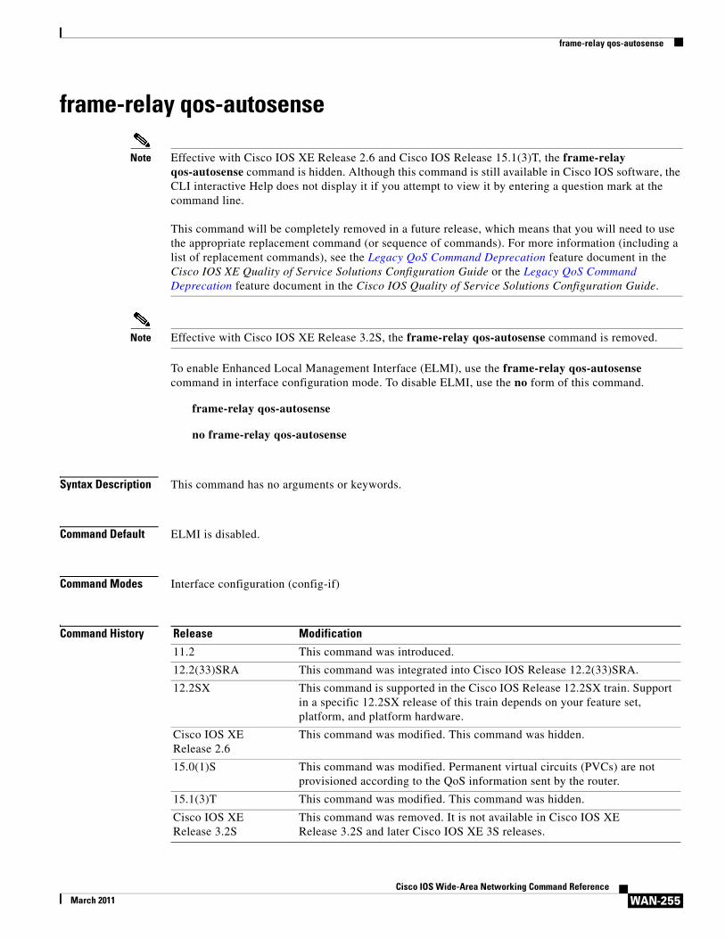
frame-relay qos-autosense
WAN-255Cisco IOS Wide-Area Networking Command Reference
March 2011
frame-relay qos-autosense
Note Effective with Cisco IOS XE Release 2.6 and Cisco IOS Release 15.1(3)T, the frame-relay qos-autosense command is hidden. Although this command is still available in Cisco IOS software, the CLI interactive Help does not display it if you attempt to view it by entering a question mark at the command line.
This command will be completely removed in a future release, which means that you will need to use the appropriate replacement command (or sequence of commands). For more information (including a list of replacement commands), see the Legacy QoS Command Deprecation feature document in the Cisco IOS XE Quality of Service Solutions Configuration Guide or the Legacy QoS Command Deprecation feature document in the Cisco IOS Quality of Service Solutions Configuration Guide.
Note Effective with Cisco IOS XE Release 3.2S, the frame-relay qos-autosense command is removed.
To enable Enhanced Local Management Interface (ELMI), use the frame-relay qos-autosense command in interface configuration mode. To disable ELMI, use the no form of this command.
frame-relay qos-autosense
no frame-relay qos-autosense
Syntax Description This command has no arguments or keywords.
Command Default ELMI is disabled.
Command Modes Interface configuration (config-if)
Command History Release Modification
11.2 This command was introduced.
12.2(33)SRA This command was integrated into Cisco IOS Release 12.2(33)SRA.
12.2SX This command is supported in the Cisco IOS Release 12.2SX train. Support in a specific 12.2SX release of this train depends on your feature set, platform, and platform hardware.
Cisco IOS XE Release 2.6
This command was modified. This command was hidden.
15.0(1)S This command was modified. Permanent virtual circuits (PVCs) are not provisioned according to the QoS information sent by the router.
15.1(3)T This command was modified. This command was hidden.
Cisco IOS XE Release 3.2S
This command was removed. It is not available in Cisco IOS XE Release 3.2S and later Cisco IOS XE 3S releases.
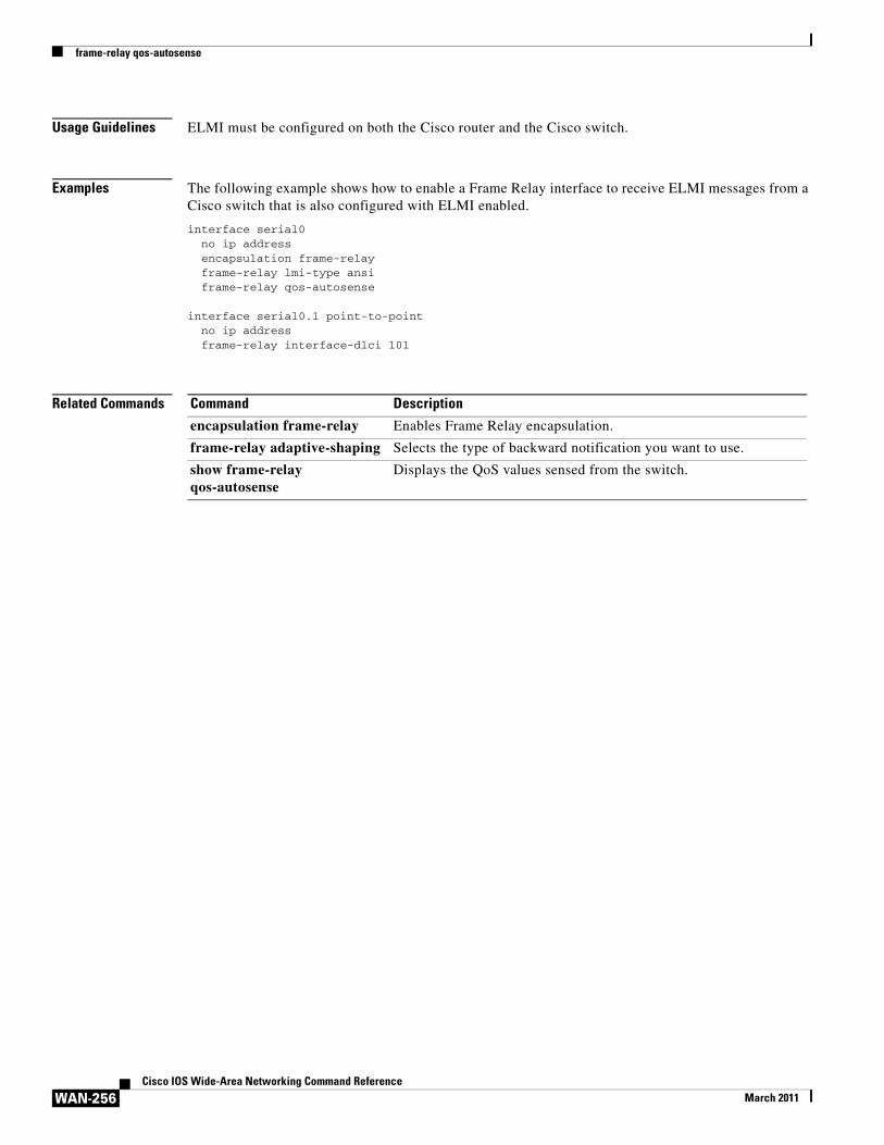
frame-relay qos-autosense
WAN-256Cisco IOS Wide-Area Networking Command Reference
March 2011
Usage Guidelines ELMI must be configured on both the Cisco router and the Cisco switch.
Examples The following example shows how to enable a Frame Relay interface to receive ELMI messages from a Cisco switch that is also configured with ELMI enabled.
interface serial0no ip addressencapsulation frame-relayframe-relay lmi-type ansiframe-relay qos-autosense
interface serial0.1 point-to-pointno ip addressframe-relay interface-dlci 101
Related Commands Command Description
encapsulation frame-relay Enables Frame Relay encapsulation.
frame-relay adaptive-shaping Selects the type of backward notification you want to use.
show frame-relay qos-autosense
Displays the QoS values sensed from the switch.
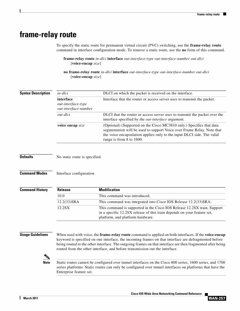
frame-relay route
WAN-257Cisco IOS Wide-Area Networking Command Reference
March 2011
frame-relay routeTo specify the static route for permanent virtual circuit (PVC) switching, use the frame-relay route command in interface configuration mode. To remove a static route, use the no form of this command.
frame-relay route in-dlci interface out-interface-type out-interface-number out-dlci [voice-encap size]
no frame-relay route in-dlci interface out-interface-type out-interface-number out-dlci [voice-encap size]
Syntax Description
Defaults No static route is specified.
Command Modes Interface configuration
Command History
Usage Guidelines When used with voice, the frame-relay route command is applied on both interfaces. If the voice-encap keyword is specified on one interface, the incoming frames on that interface are defragmented before being routed to the other interface. The outgoing frames on that interface are then fragmented after being routed from the other interface, and before transmission out the interface.
Note Static routes cannot be configured over tunnel interfaces on the Cisco 800 series, 1600 series, and 1700 series platforms. Static routes can only be configured over tunnel interfaces on platforms that have the Enterprise feature set.
in-dlci DLCI on which the packet is received on the interface.
interface out-interface-type out-interface-number
Interface that the router or access server uses to transmit the packet.
out-dlci DLCI that the router or access server uses to transmit the packet over the interface specified by the out-interface argument.
voice encap size (Optional) (Supported on the Cisco MC3810 only.) Specifies that data segmentation will be used to support Voice over Frame Relay. Note that the voice encapsulation applies only to the input DLCI side. The valid range is from 8 to 1600.
Release Modification
10.0 This command was introduced.
12.2(33)SRA This command was integrated into Cisco IOS Release 12.2(33)SRA.
12.2SX This command is supported in the Cisco IOS Release 12.2SX train. Support in a specific 12.2SX release of this train depends on your feature set, platform, and platform hardware.
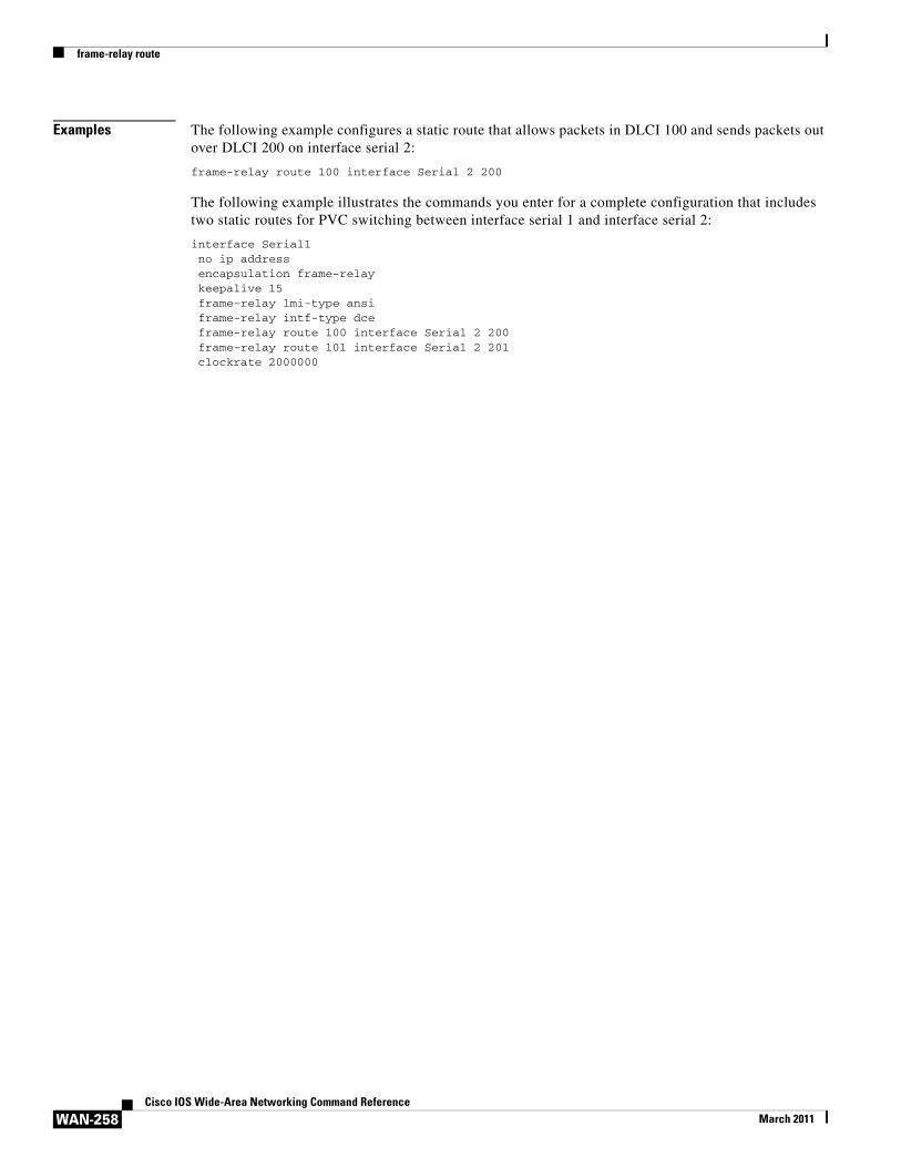
frame-relay route
WAN-258Cisco IOS Wide-Area Networking Command Reference
March 2011
Examples The following example configures a static route that allows packets in DLCI 100 and sends packets out over DLCI 200 on interface serial 2:
frame-relay route 100 interface Serial 2 200
The following example illustrates the commands you enter for a complete configuration that includes two static routes for PVC switching between interface serial 1 and interface serial 2:
interface Serial1no ip addressencapsulation frame-relaykeepalive 15frame-relay lmi-type ansiframe-relay intf-type dceframe-relay route 100 interface Serial 2 200frame-relay route 101 interface Serial 2 201clockrate 2000000
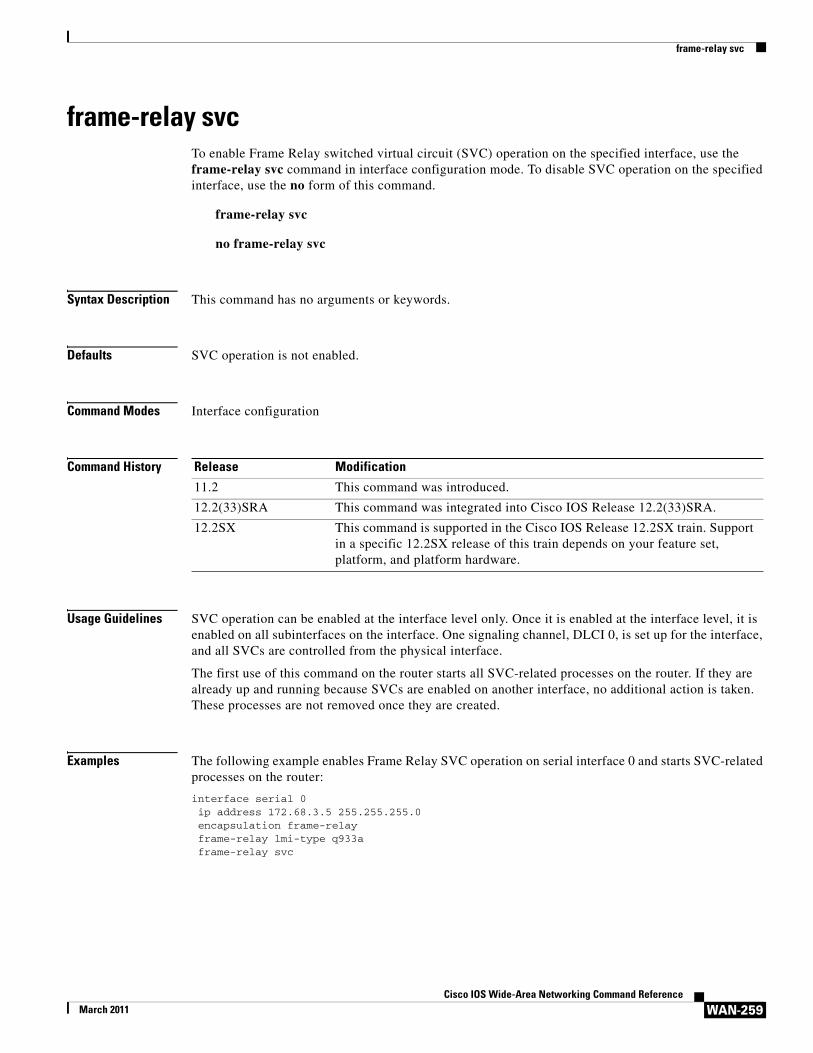
frame-relay svc
WAN-259Cisco IOS Wide-Area Networking Command Reference
March 2011
frame-relay svcTo enable Frame Relay switched virtual circuit (SVC) operation on the specified interface, use the frame-relay svc command in interface configuration mode. To disable SVC operation on the specified interface, use the no form of this command.
frame-relay svc
no frame-relay svc
Syntax Description This command has no arguments or keywords.
Defaults SVC operation is not enabled.
Command Modes Interface configuration
Command History
Usage Guidelines SVC operation can be enabled at the interface level only. Once it is enabled at the interface level, it is enabled on all subinterfaces on the interface. One signaling channel, DLCI 0, is set up for the interface, and all SVCs are controlled from the physical interface.
The first use of this command on the router starts all SVC-related processes on the router. If they are already up and running because SVCs are enabled on another interface, no additional action is taken. These processes are not removed once they are created.
Examples The following example enables Frame Relay SVC operation on serial interface 0 and starts SVC-related processes on the router:
interface serial 0ip address 172.68.3.5 255.255.255.0encapsulation frame-relayframe-relay lmi-type q933aframe-relay svc
Release Modification
11.2 This command was introduced.
12.2(33)SRA This command was integrated into Cisco IOS Release 12.2(33)SRA.
12.2SX This command is supported in the Cisco IOS Release 12.2SX train. Support in a specific 12.2SX release of this train depends on your feature set, platform, and platform hardware.
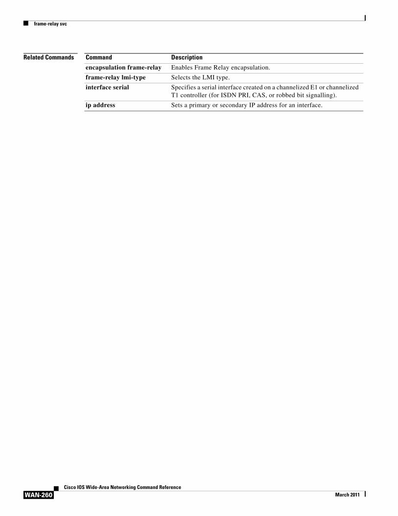
frame-relay svc
WAN-260Cisco IOS Wide-Area Networking Command Reference
March 2011
Related Commands Command Description
encapsulation frame-relay Enables Frame Relay encapsulation.
frame-relay lmi-type Selects the LMI type.
interface serial Specifies a serial interface created on a channelized E1 or channelized T1 controller (for ISDN PRI, CAS, or robbed bit signalling).
ip address Sets a primary or secondary IP address for an interface.
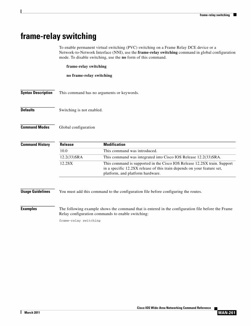
frame-relay switching
WAN-261Cisco IOS Wide-Area Networking Command Reference
March 2011
frame-relay switchingTo enable permanent virtual switching (PVC) switching on a Frame Relay DCE device or a Network-to-Network Interface (NNI), use the frame-relay switching command in global configuration mode. To disable switching, use the no form of this command.
frame-relay switching
no frame-relay switching
Syntax Description This command has no arguments or keywords.
Defaults Switching is not enabled.
Command Modes Global configuration
Command History
Usage Guidelines You must add this command to the configuration file before configuring the routes.
Examples The following example shows the command that is entered in the configuration file before the Frame Relay configuration commands to enable switching:
frame-relay switching
Release Modification
10.0 This command was introduced.
12.2(33)SRA This command was integrated into Cisco IOS Release 12.2(33)SRA.
12.2SX This command is supported in the Cisco IOS Release 12.2SX train. Support in a specific 12.2SX release of this train depends on your feature set, platform, and platform hardware.
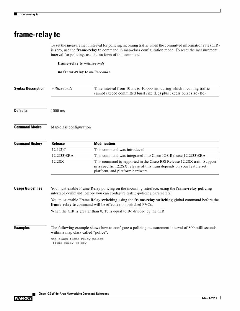
frame-relay tc
WAN-262Cisco IOS Wide-Area Networking Command Reference
March 2011
frame-relay tcTo set the measurement interval for policing incoming traffic when the committed information rate (CIR) is zero, use the frame-relay tc command in map-class configuration mode. To reset the measurement interval for policing, use the no form of this command.
frame-relay tc milliseconds
no frame-relay tc milliseconds
Syntax Description
Defaults 1000 ms
Command Modes Map-class configuration
Command History
Usage Guidelines You must enable Frame Relay policing on the incoming interface, using the frame-relay policing interface command, before you can configure traffic-policing parameters.
You must enable Frame Relay switching using the frame-relay switching global command before the frame-relay tc command will be effective on switched PVCs.
When the CIR is greater than 0, Tc is equal to Bc divided by the CIR.
Examples The following example shows how to configure a policing measurement interval of 800 milliseconds within a map class called “police”:
map-class frame-relay policeframe-relay tc 800
milliseconds Time interval from 10 ms to 10,000 ms, during which incoming traffic cannot exceed committed burst size (Bc) plus excess burst size (Be).
Release Modification
12.1(2)T This command was introduced.
12.2(33)SRA This command was integrated into Cisco IOS Release 12.2(33)SRA.
12.2SX This command is supported in the Cisco IOS Release 12.2SX train. Support in a specific 12.2SX release of this train depends on your feature set, platform, and platform hardware.
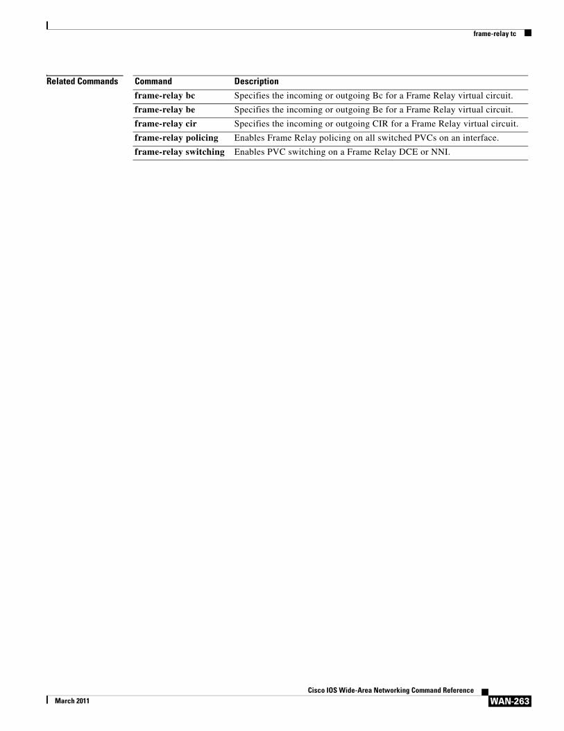
frame-relay tc
WAN-263Cisco IOS Wide-Area Networking Command Reference
March 2011
Related Commands Command Description
frame-relay bc Specifies the incoming or outgoing Bc for a Frame Relay virtual circuit.
frame-relay be Specifies the incoming or outgoing Be for a Frame Relay virtual circuit.
frame-relay cir Specifies the incoming or outgoing CIR for a Frame Relay virtual circuit.
frame-relay policing Enables Frame Relay policing on all switched PVCs on an interface.
frame-relay switching Enables PVC switching on a Frame Relay DCE or NNI.
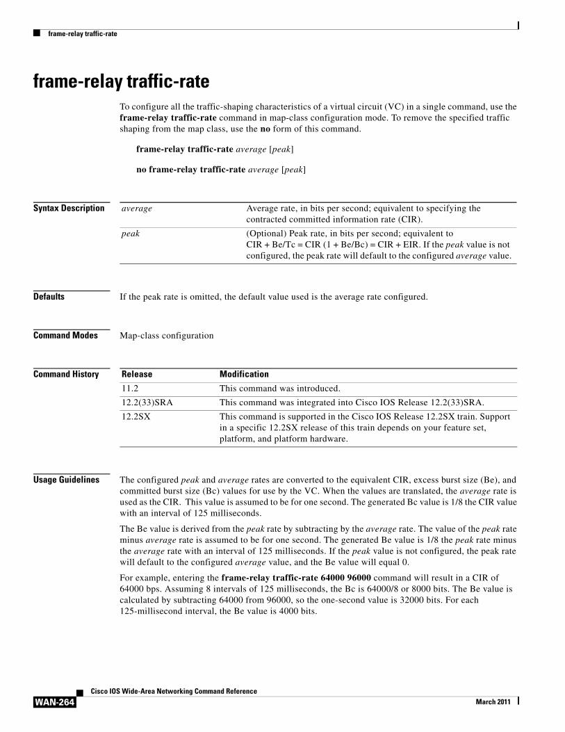
frame-relay traffic-rate
WAN-264Cisco IOS Wide-Area Networking Command Reference
March 2011
frame-relay traffic-rateTo configure all the traffic-shaping characteristics of a virtual circuit (VC) in a single command, use the frame-relay traffic-rate command in map-class configuration mode. To remove the specified traffic shaping from the map class, use the no form of this command.
frame-relay traffic-rate average [peak]
no frame-relay traffic-rate average [peak]
Syntax Description
Defaults If the peak rate is omitted, the default value used is the average rate configured.
Command Modes Map-class configuration
Command History
Usage Guidelines The configured peak and average rates are converted to the equivalent CIR, excess burst size (Be), and committed burst size (Bc) values for use by the VC. When the values are translated, the average rate is used as the CIR. This value is assumed to be for one second. The generated Bc value is 1/8 the CIR value with an interval of 125 milliseconds.
The Be value is derived from the peak rate by subtracting by the average rate. The value of the peak rate minus average rate is assumed to be for one second. The generated Be value is 1/8 the peak rate minus the average rate with an interval of 125 milliseconds. If the peak value is not configured, the peak rate will default to the configured average value, and the Be value will equal 0.
For example, entering the frame-relay traffic-rate 64000 96000 command will result in a CIR of 64000 bps. Assuming 8 intervals of 125 milliseconds, the Bc is 64000/8 or 8000 bits. The Be value is calculated by subtracting 64000 from 96000, so the one-second value is 32000 bits. For each 125-millisecond interval, the Be value is 4000 bits.
average Average rate, in bits per second; equivalent to specifying the contracted committed information rate (CIR).
peak (Optional) Peak rate, in bits per second; equivalent to CIR + Be/Tc = CIR (1 + Be/Bc) = CIR + EIR. If the peak value is not configured, the peak rate will default to the configured average value.
Release Modification
11.2 This command was introduced.
12.2(33)SRA This command was integrated into Cisco IOS Release 12.2(33)SRA.
12.2SX This command is supported in the Cisco IOS Release 12.2SX train. Support in a specific 12.2SX release of this train depends on your feature set, platform, and platform hardware.
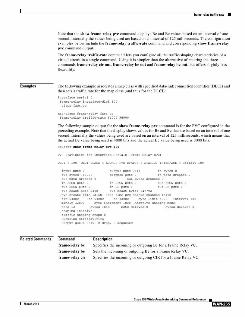
frame-relay traffic-rate
WAN-265Cisco IOS Wide-Area Networking Command Reference
March 2011
Note that the show frame-relay pvc command displays Be and Bc values based on an interval of one second. Internally the values being used are based on an interval of 125 milliseconds. The configuration examples below include the frame-relay traffic-rate command and corresponding show frame-relay pvc command output.
The frame-relay traffic-rate command lets you configure all the traffic-shaping characteristics of a virtual circuit in a single command. Using it is simpler than the alternative of entering the three commands frame-relay cir out, frame-relay be out and frame-relay bc out, but offers slightly less flexibility.
Examples The following example associates a map class with specified data-link connection identifier (DLCI) and then sets a traffic rate for the map class (and thus for the DLCI):
interface serial 0frame-relay interface-dlci 100class fast_vc
map-class frame-relay fast_vcframe-relay traffic-rate 64000 96000
The following sample output for the show frame-relay pvc command is for the PVC configured in the preceding example. Note that the display shows values for Be and Bc that are based on an interval of one second. Internally the values being used are based on an interval of 125 milliseconds, which means that the actual Be value being used is 4000 bits and the actual Bc value being used is 8000 bits.
Router# show frame-relay pvc 100
PVC Statistics for interface Serial0 (Frame Relay DTE)
DLCI = 100, DLCI USAGE = LOCAL, PVC STATUS = STATIC, INTERFACE = Serial0.100
input pkts 0 output pkts 2314 in bytes 0 out bytes 748080 dropped pkts 0 in pkts dropped 0 out pkts dropped 0 out bytes dropped 0 in FECN pkts 0 in BECN pkts 0 out FECN pkts 0 out BECN pkts 0 in DE pkts 0 out DE pkts 0 out bcast pkts 2308 out bcast bytes 747792 pvc create time 1d16h, last time pvc status changed 1d16h cir 64000 bc 64000 be 32000 byte limit 5000 interval 125 mincir 32000 byte increment 1000 Adaptive Shaping none pkts 12 bytes 3888 pkts delayed 0 bytes delayed 0 shaping inactive traffic shaping drops 0 Queueing strategy:fifo Output queue 0/40, 0 drop, 0 dequeued
Related Commands Command Description
frame-relay bc Specifies the incoming or outgoing Bc for a Frame Relay VC.
frame-relay be Sets the incoming or outgoing Be for a Frame Relay VC.
frame-relay cir Specifies the incoming or outgoing CIR for a Frame Relay VC.
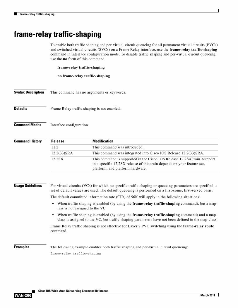
frame-relay traffic-shaping
WAN-266Cisco IOS Wide-Area Networking Command Reference
March 2011
frame-relay traffic-shapingTo enable both traffic shaping and per-virtual-circuit queueing for all permanent virtual circuits (PVCs) and switched virtual circuits (SVCs) on a Frame Relay interface, use the frame-relay traffic-shaping command in interface configuration mode. To disable traffic shaping and per-virtual-circuit queueing, use the no form of this command.
frame-relay traffic-shaping
no frame-relay traffic-shaping
Syntax Description This command has no arguments or keywords.
Defaults Frame Relay traffic shaping is not enabled.
Command Modes Interface configuration
Command History
Usage Guidelines For virtual circuits (VCs) for which no specific traffic-shaping or queueing parameters are specified, a set of default values are used. The default queueing is performed on a first-come, first-served basis.
The default committed information rate (CIR) of 56K will apply in the following situations:
• When traffic shaping is enabled (by using the frame-relay traffic-shaping command), but a map- lass is not assigned to the VC
• When traffic shaping is enabled (by using the frame-relay traffic-shaping command) and a map class is assigned to the VC, but traffic-shaping parameters have not been defined in the map-class
Frame Relay traffic shaping is not effective for Layer 2 PVC switching using the frame-relay route command.
Examples The following example enables both traffic shaping and per-virtual circuit queueing:
frame-relay traffic-shaping
Release Modification
11.2 This command was introduced.
12.2(33)SRA This command was integrated into Cisco IOS Release 12.2(33)SRA.
12.2SX This command is supported in the Cisco IOS Release 12.2SX train. Support in a specific 12.2SX release of this train depends on your feature set, platform, and platform hardware.
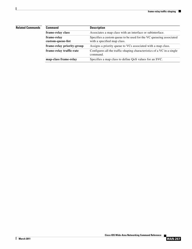
frame-relay traffic-shaping
WAN-267Cisco IOS Wide-Area Networking Command Reference
March 2011
Related Commands Command Description
frame-relay class Associates a map class with an interface or subinterface.
frame-relay custom-queue-list
Specifies a custom queue to be used for the VC queueing associated with a specified map class.
frame-relay priority-group Assigns a priority queue to VCs associated with a map class.
frame-relay traffic-rate Configures all the traffic-shaping characteristics of a VC in a single command.
map-class frame-relay Specifies a map class to define QoS values for an SVC.
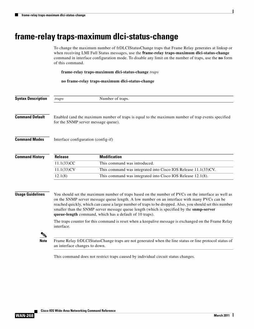
frame-relay traps-maximum dlci-status-change
WAN-268Cisco IOS Wide-Area Networking Command Reference
March 2011
frame-relay traps-maximum dlci-status-changeTo change the maximum number of frDLCIStatusChange traps that Frame Relay generates at linkup or when receiving LMI Full Status messages, use the frame-relay traps-maximum dlci-status-change command in interface configuration mode. To disable any limit on the number of traps, use the no form of this command.
frame-relay traps-maximum dlci-status-change traps
no frame-relay traps-maximum dlci-status-change
Syntax Description
Command Default Enabled (and the maximum number of traps is equal to the maximum number of trap events specified for the SNMP server message queue).
Command Modes Interface configuration (config-if)
Command History
Usage Guidelines You should set the maximum number of traps based on the number of PVCs on the interface as well as on the SNMP server message queue length. A low number on an interface with many PVCs can be reached quickly, which can cause a large number of traps to be dropped. Also, you should set this number smaller than the SNMP server message queue length (which is specified by the snmp-server queue-length command, which has a default of 10 traps).
The traps counter for this command is reset when a keepalive message is exchanged on the Frame Relay interface.
Note Frame Relay frDLCIStatusChange traps are not generated when the line status or line protocol status of an interface changes to down.
This command does not restrict traps caused by individual circuit status changes.
traps Number of traps.
Release Modification
11.1(33)CC This command was introduced.
11.1(33)CV This command was integrated into Cisco IOS Release 11.1(33)CV.
12.1(8) This command was integrated into Cisco IOS Release 12.1(8).
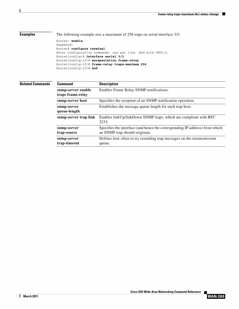
frame-relay traps-maximum dlci-status-change
WAN-269Cisco IOS Wide-Area Networking Command Reference
March 2011
Examples The following example sets a maximum of 256 traps on serial interface 3/3:
Router> enablePassword:Router# configure terminalEnter configuration commands, one per line. End with CNTL/Z.Router(config)# interface serial 3/3Router(config-if)# encapsulation frame-relayRouter(config-if)# frame-relay traps-maximum 256Router(config-if)# end
Related Commands Command Description
snmp-server enable traps frame-relay
Enables Frame Relay SNMP notifications.
snmp-server host Specifies the recipient of an SNMP notification operation.
snmp-server queue-length
Establishes the message queue length for each trap host.
snmp-server trap link Enables linkUp/linkDown SNMP traps, which are compliant with RFC 2233.
snmp-server trap-source
Specifies the interface (and hence the corresponding IP address) from which an SNMP trap should originate.
snmp-server trap-timeout
Defines how often to try resending trap messages on the retransmission queue.

frame-relay vc-bundle
WAN-270Cisco IOS Wide-Area Networking Command Reference
March 2011
frame-relay vc-bundleTo create a Frame Relay permanent virtual circuit (PVC) bundle (if the bundle does not already exist) and to enter Frame Relay VC-bundle configuration mode, use the frame-relay vc-bundle command in interface configuration mode. To remove a Frame Relay PVC bundle, use the no form of this command.
frame-relay vc-bundle vc-bundle-name
no frame-relay vc-bundle vc-bundle-name
Syntax Description
Command Default A Frame Relay PVC bundle is not created.
Command Modes Interface configuration
Command History
Usage Guidelines Use this command to create a unique Frame Relay PVC bundle (if one has not already been created using the frame-relay map command). You can also use this command to enter Frame Relay VC-bundle configuration mode, so that you can configure PVC bundle attributes and PVC bundle members.
Examples The following example creates a Frame Relay PVC bundle named MAIN-1:
interface serial 0frame-relay vc-bundle MAIN-1
Related Commands
vc-bundle-name Name of the Frame Relay PVC bundle.
Release Modification
12.2(13)T This command was introduced.
12.2(16)BX This command was integrated into Cisco IOS Release 12.2(16)BX.
12.0(26)S This command was integrated into Cisco IOS Release 12.0(26)S.
12.2(28)SB This command was integrated into Cisco IOS Release 12.2(28)SB.
12.2(33)SRA This command was integrated into Cisco IOS Release 12.2(33)SRA.
12.2SX This command is supported in the Cisco IOS Release 12.2SX train. Support in a specific 12.2SX release of this train depends on your feature set, platform, and platform hardware.
Command Description
frame-relay map Defines mapping between a destination protocol address and the DLCI or Frame Relay PVC bundle that connects to the destination address.
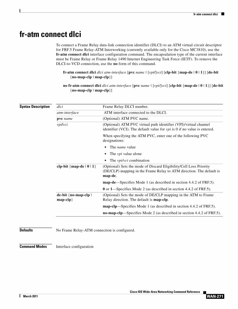
fr-atm connect dlci
WAN-271Cisco IOS Wide-Area Networking Command Reference
March 2011
fr-atm connect dlciTo connect a Frame Relay data-link connection identifier (DLCI) to an ATM virtual circuit descriptor for FRF.5 Frame Relay-ATM Interworking (currently available only for the Cisco MC3810), use the fr-atm connect dlci interface configuration command. The encapsulation type of the current interface must be Frame Relay or Frame Relay 1490 Internet Engineering Task Force (IETF). To remove the DLCI-to-VCD connection, use the no form of this command.
fr-atm connect dlci dlci atm-interface [pvc name | [vpi/]vci] [clp-bit {map-de | 0 | 1}] [de-bit {no-map-clp | map-clp}]
no fr-atm connect dlci dlci atm-interface [pvc name | [vpi/]vci] [clp-bit {map-de | 0 | 1}] [de-bit {no-map-clp | map-clp}]
Syntax Description
Defaults No Frame Relay-ATM connection is configured.
Command Modes Interface configuration
dlci Frame Relay DLCI number.
atm-interface ATM interface connected to the DLCI.
pvc name (Optional) ATM PVC name.
vpi/vci (Optional) ATM PVC virtual path identifier (VPI)/virtual channel identifier (VCI). The default value for vpi is 0 if no value is entered.
When specifying the ATM PVC, enter one of the following PVC designations:
• The name value
• The vpi value alone
• The vpi/vci combination
clp-bit {map-de | 0 | 1} (Optional) Sets the mode of Discard Eligibility/Cell Loss Priority (DE/CLP) mapping in the Frame Relay to ATM direction. The default is map-de.
map-de—Specifies Mode 1 (as described in section 4.4.2 of FRF.5).
0 or 1—Specifies Mode 2 (as described in section 4.4.2 of FRF.5).
de-bit {no-map-clp | map-clp}
(Optional) Sets the mode of DE/CLP mapping in the ATM to Frame Relay direction. The default is map-clp.
map-clp—Specifies Mode 1 (as described in section 4.4.2 of FRF.5).
no-map-clp—Specifies Mode 2 (as described in section 4.4.2 of FRF.5).
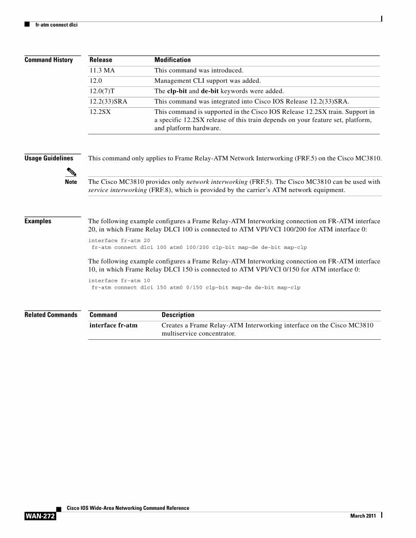
fr-atm connect dlci
WAN-272Cisco IOS Wide-Area Networking Command Reference
March 2011
Command History
Usage Guidelines This command only applies to Frame Relay-ATM Network Interworking (FRF.5) on the Cisco MC3810.
Note The Cisco MC3810 provides only network interworking (FRF.5). The Cisco MC3810 can be used with service interworking (FRF.8), which is provided by the carrier’s ATM network equipment.
Examples The following example configures a Frame Relay-ATM Interworking connection on FR-ATM interface 20, in which Frame Relay DLCI 100 is connected to ATM VPI/VCI 100/200 for ATM interface 0:
interface fr-atm 20fr-atm connect dlci 100 atm0 100/200 clp-bit map-de de-bit map-clp
The following example configures a Frame Relay-ATM Interworking connection on FR-ATM interface 10, in which Frame Relay DLCI 150 is connected to ATM VPI/VCI 0/150 for ATM interface 0:
interface fr-atm 10fr-atm connect dlci 150 atm0 0/150 clp-bit map-de de-bit map-clp
Related Commands
Release Modification
11.3 MA This command was introduced.
12.0 Management CLI support was added.
12.0(7)T The clp-bit and de-bit keywords were added.
12.2(33)SRA This command was integrated into Cisco IOS Release 12.2(33)SRA.
12.2SX This command is supported in the Cisco IOS Release 12.2SX train. Support in a specific 12.2SX release of this train depends on your feature set, platform, and platform hardware.
Command Description
interface fr-atm Creates a Frame Relay-ATM Interworking interface on the Cisco MC3810 multiservice concentrator.
Related Documents