CHAPTER Frame Relay Commands 9-1 Frame Relay Commands 9 Use the commands described in this chapter to configure Frame Relay. Frame Relay was conceived as a protocol for use over serial interfaces and was designed for those networks with large T1 installations. For Frame Relay configuration information and examples, refer to the “Configuring Frame Relay” chapter in the Access and Communication Servers Configuration Guide.

Welcome message from author
This document is posted to help you gain knowledge. Please leave a comment to let me know what you think about it! Share it to your friends and learn new things together.
Transcript

C H A P T E R
9Frame Relay Commands
Use the commands described in this chapter to configure Frame Relay. Frame Relay was conceivedas a protocol for use over serial interfaces and was designed for those networks with large T1installations.
For Frame Relay configuration information and examples, refer to the “Configuring Frame Relay”chapter in the Access and Communication Servers Configuration Guide.
Frame Relay Commands 9-1

clear frame-relay-inarp
clear frame-relay-inarpTo clear dynamically created Frame Relay maps, which are created by the use of Inverse AddressResolution Protocol (Inverse ARP), use theclear frame-relay-inarp EXEC command.
clear frame-relay-inarp
Syntax DescriptionThis command has no arguments or keywords.
Command ModeEXEC
ExampleThe following example clears dynamically created Frame Relay maps:
clear frame-relay-inarp
Related Commandsframe-relay inverse-arpshow frame-relay map
9-2 Access and Communication Servers Command Reference

encapsulation frame-relay
encapsulation frame-relayUse theencapsulation frame-relay interface configuration command to enable Frame Relayencapsulation. Theno encapsulation frame-relay command disables Frame Relay.
encapsulation frame-relay[ietf]no encapsulation frame-relay[ietf]
Syntax Description
DefaultEnabled
Command ModeInterface configuration
Usage GuidelinesIf the optional keyword is omitted, the communication server uses Cisco’s own encryption, which isa 4-byte header with 2 bytes for the DLCI and 2 bytes to identify the packet type.
ExamplesThe following example configures Cisco Frame Relay encapsulation on serial interface 1:
interface serial 1encapsulation frame-relay
Use theietf keyword if your communication server is connected to another vendor’s equipmentacross a Frame Relay network to conform with RFCs 1294 and 1490:
interface serial 1encapsulation frame-relay ietf
ietf (Optional) Sets the encapsulation method to comply with theIETF standard (RFCs 1294 and 1490). Use this keyword whenconnecting to another vendor’s equipment across a Frame Relaynetwork.
Frame Relay Commands 9-3

frame-relay broadcast-queue
frame-relay broadcast-queueTo create a special queue for a specified interface to hold broadcast traffic that has been replicatedfor transmission on multiple DLCIs, use theframe-relay broadcast-queueinterface configurationcommand.
frame-relay broadcast-queue size byte-rate packet-rate
Syntax Description
DefaultThe default values are as follows:
size—64 packetsbyte-rate—256000 bytes per secondpacket rate—36 packets per second
Command ModeInterface configuration
Usage GuidelinesFor purposes of the Frame Relay broadcast queue, broadcast traffic is defined as packets that havebeen replicated for transmission on multiple DLCIs, but not including the original routing packet orSAP packet, which passes through the normal queue. Due to timing sensitivity, bridged broadcastsand spanning tree packets are sent through the normal queue.
The Frame relay broadcast queue is managed independently of the normal interface queue. It has itsown buffers and a configurable service rate.
A broadcast queue is given a maximum transmission rate (throughput) limit measured in bytes persecond and packets per second. The queue is serviced to ensure that only this maximum is provided.The broadcast queue has priority when transmitting at a rate below the configured maximum, andhence has a guaranteed minimum bandwidth allocation. The two transmission rate limits areintended to avoid flooding the interface with broadcasts. The actual limit in any second is the firstrate limit that is reached.
Given the transmission rate restriction, additional buffering will be required to store broadcastpackets. The broadcast queue is configurable to store large numbers of broadcast packets.
The queue size should be set to avoid loss of broadcast routing update packets. The exact size willdepend upon the protocol being used and the number of packets required for each update. To be safe,set the queue size so that one complete routing update from each protocol and for each DLCI can bestored. As a general rule, start with 20 packets per DLCI.
size Number of packets to be held in the broadcast queue. Thedefault is 64 packets.
byte-rate Maximum number of bytes to be transmitted per second.The default is 256000 bytes per second.
packet-rate Maximum number of packets to be transmitted per second.The default is 36 packets per second.
9-4 Access and Communication Servers Command Reference

frame-relay broadcast-queue
As a general rule, the byte rate should be less than both of the following:
• N/4 times the minimum remote access rate (measured inbytes per second), whereN is thenumber of DLCIs to which the broadcast must be replicated
• 1/4 the local access rate (measured inbytes per second)
The packet rate is not critical if you set the byte rate conservatively. As a general rule, set the packetrate assuming 250-byte packets.
ExampleThe following example specifies a broadcast queue to hold 80 packets, to have a maximum bytetransmission rate of 240,000 bytes per second, and to have a maximum packet transmission rate of160 packets per second:
frame-relay broadcast-queue 80 240000 160
Frame Relay Commands 9-5

frame-relay de-group
frame-relay de-groupTo specify the discard eligibility (DE) group number to be used for a specified DLCI, use theframe-relay de-group interface configuration command. To disable a previously defined groupnumber assigned to a specified DLCI, use theno form of the command with the relevant keywordand arguments.
frame-relay de-groupgroup-number dlcino frame-relay de-group[group-number] [dlci]
Syntax Description
DefaultNo DE group is defined.
Command ModeInterface configuration
Usage GuidelinesTo disable all previously defined group numbers, use the no form of this command with noarguments.
This command requires that Frame Relay software be enabled.
The DE bit is not set or recognized by the Frame Relay switching code, but must be recognized andinterpreted by the Frame Relay network.
ExampleThe following example specifies that group number 3 will be used for DLCI 170:
frame-relay de-group 3 dlci 170
Related Commandframe-relay de-list
group-number DE group number to apply to the specified DLCI number,in the range from 1 through 10.
dlci DLCI number.
9-6 Access and Communication Servers Command Reference
frame-relay de-list
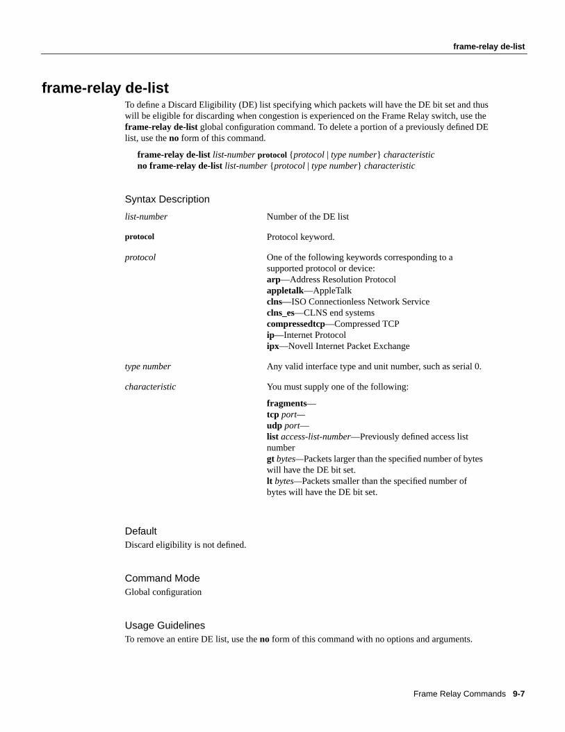
frame-relay de-listTo define a Discard Eligibility (DE) list specifying which packets will have the DE bit set and thuswill be eligible for discarding when congestion is experienced on the Frame Relay switch, use theframe-relay de-list global configuration command. To delete a portion of a previously defined DElist, use theno form of this command.
frame-relay de-list list-numberprotocol { protocol | type number} characteristicno frame-relay de-list list-number{ protocol | type number} characteristic
Syntax Description
DefaultDiscard eligibility is not defined.
Command ModeGlobal configuration
Usage GuidelinesTo remove an entire DE list, use theno form of this command with no options and arguments.
list-number Number of the DE list
protocol Protocol keyword.
protocol One of the following keywords corresponding to asupported protocol or device:arp—Address Resolution Protocolappletalk—AppleTalkclns—ISO Connectionless Network Serviceclns_es—CLNS end systemscompressedtcp—Compressed TCPip—Internet Protocolipx—Novell Internet Packet Exchange
type number Any valid interface type and unit number, such as serial 0.
characteristic You must supply one of the following:
fragments—tcp port—udp port—list access-list-number—Previously defined access listnumbergt bytes—Packets larger than the specified number of byteswill have the DE bit set.lt bytes—Packets smaller than the specified number ofbytes will have the DE bit set.
Frame Relay Commands 9-7

frame-relay de-list
This prioritization feature requires that the Frame Relay network be able to interpret the DE bit asindicating which packets can be dropped first in case of congestion or which packets are less timesensitive or both.
ExampleThe following example specifies that IP packets larger than 512 bytes will have the DE bit set:
frame-relay de-list ip gt 512
9-8 Access and Communication Servers Command Reference

frame-relay interface-dlci
frame-relay interface-dlciTo assign a DLCI to a specified Frame Relay subinterface on the access server, use theframe-relayinterface-dlci interface configuration command. To remove this assignment, use theno form of thiscommand.
frame-relay interface-dlci dlci [option]no frame-relay interface-dlcidlci [option]
frame-relay interface-dlci dlci [protocol ip ip-address]
Syntax Description
DefaultNo DLCI is assigned.
Command ModeInterface configuration
Usage GuidelinesUse the frame-relay interface–dlci command only for subinterfaces on an access server. Using thiscommand on an interface, rather than a subinterface, will prevent the access server from forwardingpackets intended for that DLCI.
Subinterfaces are logical interfaces associated with a physical interface. To use this command, youmust be in subinterface configuration mode. This requires making the logical subinterfaceassignment before assigning any DLCIs and any encapsulation of broadcast options. See thefollowing example.
Use theprotocol ip ip-addressoption only when this access server will act as the BOOTP server forautoinstallation over Frame Relay.
Table 1 lists theframe-relay interface-dlci option keywords.
Table 1 Frame Relay Interface-DLCI Option Keywords
dlci DLCI number to be used on the specified subinterface.
option (Optional) Broadcast or encapsulation keyword, as defined in the“Frame Relay Interface-DLCI Option Keywords” table.
protocol ip ip-address Indicates the IP address of the serial interface of a new access serveronto which an access server configuration file is to be autoinstalledover a Frame Relay network. See the “Usage Guidelines” section forinformation about when to use this option.
Keyword Option
broadcast Broadcasts should be forwarded out through this interface.
ietf IETF Frame Relay encapsulation.
cisco Cisco Frame Relay encapsulation.
Frame Relay Commands 9-9

frame-relay interface-dlci
ExampleThe following example assigns DLCI 100 to subinterface serial 5.17:
! Enter interface configuration and begin assignments on interface serial 5interface serial 5! Enter subinterface configuration by assigning subinterface 17interface serial 5.17! Now assign a DLCI number to subinterface 5.17frame-relay interface-dlci 100
9-10 Access and Communication Servers Command Reference

frame-relay intf-type
frame-relay intf-typeUse theframe-relay intf-type interface configuration command to configure a Frame Relay switchtype. Use theno frame-relay intf-type command to disable the switch.
frame-relay intf-type [dce | dte | nni]no frame-relay intf-type [dce | dte | nni]
Syntax Description
Defaultdte
Command ModeInterface configuration
ExampleThe following example configures a DTE switch type:
interface serial 2frame-relay intf-type dte
dce (Optional) Access server functions as a switch connected to acommunication server.
dte (Optional) Access server is connected to a Frame Relay network.
nni (Optional) Access server functions as a switch connected to a switch(supports NNI connections).
Frame Relay Commands 9-11

frame-relay inverse-arp
frame-relay inverse-arpUse theframe-relay inverse-arp interface configuration command to enable the Inverse AddressResolution Protocol (Inverse ARP) on the communication server configured for Frame Relay. Usetheno frame-relay inverse-arp command to disable this feature.
frame-relay inverse-arpprotocol dlcino frame-relay inverse-arpprotocol dlci
Syntax Description
DefaultEnabled
Command ModeInterface configuration
Usage GuidelinesThis implementation of Inverse ARP is based on RFC 1293. It allows a communication serverrunning Frame Relay to discover the protocol address of a device associated with the virtual circuit.
In Frame Relay, permanent virtual circuits are identified by a DLCI, which is the equivalent of ahardware address. By exchanging signaling messages, a network announces a new virtual circuit,and with Inverse ARP, the protocol address at the other side of the circuit can be discovered.
Theshow frame-relay mapcommand flags dynamically created virtual circuits created by InverseARP with the word dynamic.
ExampleThe following example sets Inverse ARP on an interface running AppleTalk:
interface serial 0frame-relay inverse-arp appletalk 100
Related Commandsclear frame-relay-inarpshow frame-relay map
protocol Supported protocols:appletalk, ip, ipx, andvines.
dlci DLCI number for the interface. Acceptable numbers are integers in therange 16 to 1007.
9-12 Access and Communication Servers Command Reference

frame-relay ip tcp header-compression
frame-relay ip tcp header-compressionTo configure an interface to ensure that the associated PVC will always carry outgoing TCP/IPheaders in compressed form, use theframe-relay ip tcp header-compression interfaceconfiguration command. To disable compression of TCP/IP packet headers on the interface, use theno form of this command.
frame-relay ip tcp header-compression[passive]no frame-relay ip tcp header-compression
Syntax Description
DefaultActive TCP/IP header compression; all outgoing TCP/IP packets are subjected to headercompression.
Command ModeInterface configuration.
Usage GuidelinesThis command applies to interfaces that support Frame Relay encapsulation, specifically serial ports.
Frame Relay must be configured on the interface before this command can be used.
TCP/IP header compression and IETF encapsulation are mutually exclusive. If an interface ischanged to IETF encapsulation, all encapsulation and compression characteristics are lost.
When you use this command to enable TCP/IP header compression, every IP map will inherit thecompression characteristics of the interface, unless header compression is explicitly rejected ormodified by using theframe-relay map ip header compression command.
ExampleThe following example configures interface serial 1 to use IETF encapsulation and passive TCPheader compression:
interface serial 1encapsulation frame-relayframe-relay ip tcp header-compression passive
Related Commandframe-relay map ip tcp header-compression
passive (Optional) Compress the outgoing TCP/IP packet headeronly if the incoming packet has a compressed header.
Frame Relay Commands 9-13
frame-relay keepalive
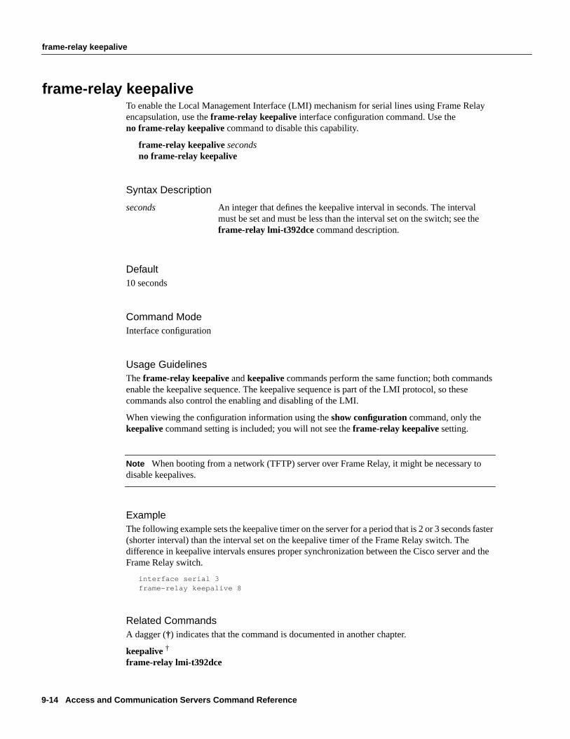
frame-relay keepaliveTo enable the Local Management Interface (LMI) mechanism for serial lines using Frame Relayencapsulation, use theframe-relay keepalive interface configuration command. Use theno frame-relay keepalive command to disable this capability.
frame-relay keepalivesecondsno frame-relay keepalive
Syntax Description
Default10 seconds
Command ModeInterface configuration
Usage GuidelinesTheframe-relay keepalive andkeepalive commands perform the same function; both commandsenable the keepalive sequence. The keepalive sequence is part of the LMI protocol, so thesecommands also control the enabling and disabling of the LMI.
When viewing the configuration information using theshow configuration command, only thekeepalive command setting is included; you will not see theframe-relay keepalive setting.
Note When booting from a network (TFTP) server over Frame Relay, it might be necessary todisable keepalives.
ExampleThe following example sets the keepalive timer on the server for a period that is 2 or 3 seconds faster(shorter interval) than the interval set on the keepalive timer of the Frame Relay switch. Thedifference in keepalive intervals ensures proper synchronization between the Cisco server and theFrame Relay switch.
interface serial 3frame-relay keepalive 8
Related CommandsA dagger (†) indicates that the command is documented in another chapter.
keepalive†
frame-relay lmi-t392dce
seconds An integer that defines the keepalive interval in seconds. The intervalmust be set and must be less than the interval set on the switch; see theframe-relay lmi-t392dce command description.
9-14 Access and Communication Servers Command Reference
frame-relay lmi-n391dte
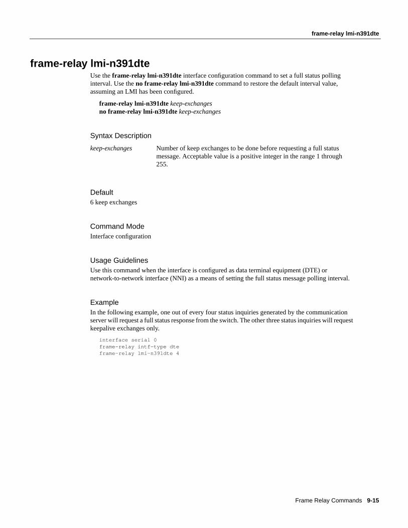
frame-relay lmi-n391dteUse theframe-relay lmi-n391dte interface configuration command to set a full status pollinginterval. Use theno frame-relay lmi-n391dte command to restore the default interval value,assuming an LMI has been configured.
frame-relay lmi-n391dtekeep-exchangesno frame-relay lmi-n391dtekeep-exchanges
Syntax Description
Default6 keep exchanges
Command ModeInterface configuration
Usage GuidelinesUse this command when the interface is configured as data terminal equipment (DTE) ornetwork-to-network interface (NNI) as a means of setting the full status message polling interval.
ExampleIn the following example, one out of every four status inquiries generated by the communicationserver will request a full status response from the switch. The other three status inquiries will requestkeepalive exchanges only.
interface serial 0frame-relay intf-type dteframe-relay lmi-n391dte 4
keep-exchanges Number of keep exchanges to be done before requesting a full statusmessage. Acceptable value is a positive integer in the range 1 through255.
Frame Relay Commands 9-15

frame-relay lmi-n392dce
frame-relay lmi-n392dceUse theframe-relay lmi-n392dceinterface configuration command to set the data communicationsequipment (DCE) and NNI error threshold. Use theno frame-relay lmi-n392dce command toremove the current setting.
frame-relay lmi-n392dcethresholdno frame-relay lmi-n392dcethreshold
Syntax Description
Default2 errors
Command ModeInterface configuration
Usage GuidelinesIn Cisco’s implementation, N392 errors must occur within the number defined by the N393 eventcount in order for the link to be declared down. Therefore, the threshold value for this commandmust be less than the count value defined in theframe-relay lmi-n393dce command.
ExampleIn the following example, the LMI failure threshold is set to 3. The communication server acts as aFrame Relay DCE or NNI switch.
interface serial 0frame-relay intf-type dceframe-relay lmi-n392dce 3
Related Commandframe-relay lmi-n393dce
threshold Error threshold value. Acceptable value is a positive integer in the range 1through 10.
9-16 Access and Communication Servers Command Reference

frame-relay lmi-n392dte
frame-relay lmi-n392dteUse theframe-relay lmi-n392dte interface configuration command to set the error threshold on aDTE or NNI interface. Use theno frame-relay lmi-n392dtecommand to remove the current setting.
frame-relay lmi-n392dte thresholdno frame-relay lmi-n392dtethreshold
Syntax Description
Default2 errors
Command ModeInterface configuration
ExampleIn the following example, the LMI failure threshold is set to 3. The communication server acts as aFrame Relay DTE or NNI switch.
interface serial 0frame-relay intf-type dteframe-relay lmi-n392dte 3
threshold Error threshold value. Acceptable value is a positive integer in the range 1through 10.
Frame Relay Commands 9-17

frame-relay lmi-n393dce
frame-relay lmi-n393dceUse theframe-relay lmi-n393dce interface configuration command to set the DCE and NNImonitored events count. Use theno frame-relay lmi-n393dce command to remove the currentsetting.
frame-relay lmi-n393dceeventsno frame-relay lmi-n393dceevents
Syntax Description
Default2 events
Command ModeInterface configuration
Usage GuidelinesThis command and theframe-relay lmi-n392dcecommand define the condition that causes the linkto be declared down. In Cisco’s implementation, N392 errors must occur within theeventscount inorder for the link to be declared down. Therefore, theeventsvalue defined in this command must begreater than the threshold value defined in theframe-relay lmi-n392dce command.
ExampleIn the following example, the LMI monitored events count is set to 3. The communication serveracts as a Frame Relay DCE or NNI switch.
interface serial 0frame-relay intf-type dceframe-relay lmi-n393dce 3
Related Commandframe-relay lmi-n392dce
events Monitored events count value. Acceptable value is a positive integer in therange 1 through 10.
9-18 Access and Communication Servers Command Reference

frame-relay lmi-n393dte
frame-relay lmi-n393dteUse theframe-relay lmi-n393dteinterface configuration command to set the monitored event counton a DTE or NNI interface. Use theno frame-relay lmi-n393dte command to remove the currentsetting.
frame-relay lmi-n393dteeventsno frame-relay lmi-n393dteevents
Syntax Description
Default2 events
Command ModeInterface configuration
ExampleIn the following example, the LMI monitored events count is set to 3. The communication serveracts as a Frame Relay DTE or NNI switch.
interface serial 0frame-relay intf-type dteframe-relay lmi-n393dte 3
events Monitored event count value. Acceptable value is a positive integer in therange 1 through 10.
Frame Relay Commands 9-19

frame-relay lmi-t392dce
frame-relay lmi-t392dceUse theframe-relay lmi-t392dce interface configuration command to set the polling verificationtimer on a DCE or NNI interface. Use theno frame-relay lmi-t392dce command to remove thecurrent setting.
frame-relay lmi-t392dcetimerno frame-relay lmi-t392dcetimer
Syntax Description
Default15 seconds
Command ModeInterface configuration
Usage GuidelinesThe value for the timer must be greater than the DTE or NNI keepalive timer.
ExampleThe following example indicates a polling verification timer on a DCE or NNI interface set to 20seconds:
interface serial 3frame-relay intf-type dceframe-relay lmi-t392dce 20
Related Commandframe-relay keepalive
timer Polling verification timer value (in seconds). Acceptable value is a positiveinteger in the range 5 through 30.
9-20 Access and Communication Servers Command Reference
frame-relay lmi-type
frame-relay lmi-typeUse theframe-relay lmi-type interface configuration command to select the Local ManagementInterface (LMI) type. Use theno frame-relay lmi-type command to return to the default LMI type.
frame-relay lmi-type { ansi | cisco| q933a}no frame-relay lmi-type { ansi | q933a}
Syntax Description
DefaultCisco LMI
Command ModeInterface configuration
Usage GuidelinesCisco’s implementation of Frame Relay supports three LMI types: Cisco, ANSI Annex D, andITU-T.
Theno form of the command is included to maintain backwards compatibility. If the LMI type ischanged from ANSI or ITU-T, the LMI type reverts to the Cisco type.
The LMI type is set on a per-interface basis and is shown in the output of theshow interfacesEXECcommand.
ExampleThe following is an example of the commands you enter to select the ANSI Annex D LMI type:
interface serial 1encapsulation frame-relayframe-relay lmi-type ansi
ansi Annex D defined by ANSI standard T1.617
cisco Group of 4 LMI
q933a ITU-T1 Q.933 Annex A
1. The International Telecommunication Union Telecommunication Standardization Sector (ITU-T) carries out the functionsof the former Consultative Committee for International Telegraph and Telephone (CCITT).
Frame Relay Commands 9-21

frame-relay local-dlci
frame-relay local-dlciUse theframe-relay local-dlci interface configuration command to set the source DLCI for usewhen the LMI is not supported. Use theno frame-relay local-dlci command to remove the DLCInumber.
frame-relay local-dlci numberno frame-relay local-dlci
Note Theframe-relay local-dlci command is provided mainly to allow testing of the Frame Relayencapsulation in a setting where two servers are connected back to back. This command is notrequired in a live Frame Relay network.
Syntax Description
DefaultNo source DLCI is set.
Command ModeInterface configuration
Usage GuidelinesIf LMI is supported and the multicast information element is present, the network server sets its localDLCI based on information provided via the LMI.
ExampleThe following example specifies 100 as the local DLCI:
interface serial 4frame-relay local-dlci 100
number Local (source) DLCI number for the interface
9-22 Access and Communication Servers Command Reference

frame-relay map
frame-relay mapUse theframe-relay map interface configuration command to define the mapping between anaddress and the DLCI used to connect to the address. Use theno frame-relay map command todelete the map entry.
frame-relay map protocol protocol-address dlci[broadcast] [ ietf | cisco]no frame-relay map protocol protocol-address
Syntax Description
DefaultNo mapping is defined.
Command ModeInterface configuration
Usage GuidelinesThere can be many DLCIs known by a communication server that can send data to many differentplaces, but they are all multiplexed over one physical link. The Frame Relay map tells thecommunication server how to get from a specific protocol and address pair to the correct DLCI.
The optionalietf andcisco keywords allow flexibility in the configuration. If no keywords arespecified in the configuration, the map inherits the attributes set with theencapsulation frame-relaycommand. You can also use the encapsulation options to specify that, for example, all interfaces useIETF encapsulation except one, which needs the original Cisco encapsulation method, and it can bedefined using thecisco keyword with theframe-relay map command.
Thebroadcast keyword provides two functions: it forwards broadcasts when multicasting is notenabled, and it simplifies the configuration of OSPF for nonbroadcast networks that will use FrameRelay.
protocol Supported protocols:appletalk, decnet, ip, xns, ipx, and vines.
protocol-address Address for the protocol.
dlci DLCI number for the interface.
broadcast (Optional) Broadcasts should be forwarded to this address whenmulticast is not enabled (see theframe-relay multicast-dlci commandfor more information about multicasts). This keyword also simplifies theconfiguration of OSPF (see “Usage Guidelines” for more detail).
ietf (Optional) IETF form of Frame Relay encapsulation. Use when thecommunication server is connected to another vendor’s equipment acrossa Frame Relay network.
cisco (Optional) Cisco encapsulation method.
Frame Relay Commands 9-23

frame-relay map
OSPF treats a nonbroadcast, multiaccess network such as Frame Relay much the same way it treatsa broadcast network in that it requires selection of a designated communication server. In previousreleases, this required manual assignment in the OSPF configuration using theneighbor interfacecommunication server command. When theframe-relay map command is included in theconfiguration with thebroadcast, andthe ip ospf networkcommand (with thebroadcastkeyword)is configured, there is no need to configure any neighbors manually. OSPF will now automaticallyrun over the Frame Relay network as a broadcast network. (Refer to theip ospf network interfaceconfiguration command for more detail.)
Note The OSPF broadcast mechanism assumes that IP class D addresses are never used for regulartraffic over Frame Relay.
ExampleThe following example maps IP address 131.108.123.1 to DLCI 100:
interface serial 0frame-relay map IP 131.108.123.1 100 broadcast
OSPF will use DLCI 100 to broadcast updates.
Related CommandA dagger (†) indicates that the command is documented in another chapter.
ip ospf network †
9-24 Access and Communication Servers Command Reference

frame-relay map ip tcp header-compression
frame-relay map ip tcp header-compressionTo assign header-compression characteristc to an IP map that differs from the compressioncharacteristics of the interface with which the IP map is associated, use theframe-relay map ip tcpheader-compression interface configuration command. To remove the IP map, use theno form ofthe command. To disable TCP/IP header compression on the IP map, use thenocompress form ofthe command.
frame-relay map ip ip-address dlci[broadcast] [cisco | ietf] [nocompress]tcp header-compression{ active | passive}
no frame-relay map ip ip-addressip-address dlci
Syntax Description
DefaultThe default encapsulation keyword iscisco.
Command ModeInterface configuration
Usage Guidelines IP maps inherit the compression characteristics of the associated interface unless this command isused to provide different characteristics. This command can also be used to configure an IP map thatexisted before TCP header compression was configured on the associated interface.
When IP maps at both ends of a connection inherit passive compression, the connection will nevertransfer compressed traffic because neither side will generate a packet with a compressed header.
If you change the encapsulation characteristics of the interface to IETF, you lose the TCP headercompression configuration of the associated IP map.
The commandframe-relay map ip ip-address dlci tcp header-compression active can alsoentered asframe-relay map ip ip-address dlci active tcp header-compression.
ip-address IP address.
dlci DLCI number.
broadcast (Optional) Forward broadcasts to the specified IP address.
cisco (Optional) Use Cisco’s proprietary encapsulation. This is thedefault.
ietf (Optional) Use RFC 1294 encapsulation. No TCP header compressionis done if IETF encapsulation is chosen for the IP map or the associatedinterface.
nocompress (Optional) Disable TCP/IP header compression for this map.
active Compress the header of every outgoing TCP/IP packet.
passive Compress the header of an outgoing TCP/IP packet only if theincoming TCP/IP packet had a compressed header.
Frame Relay Commands 9-25

frame-relay map ip tcp header-compression
ExampleThe following example illustrates a command sequence configuring an IP map associated withinterface serial 1 to enable active TCP header compression.
interface serial 1encapsulation frame-relayip address 131.108.177.170 255.255/255/0frame-relay map ip 131.108.177.170 190 cisco tcp header-compression active
Related Commandframe-relay ip tcp header-compression
9-26 Access and Communication Servers Command Reference

frame-relay multicast-dlci
frame-relay multicast-dlciUse theframe-relay multicast-dlci interface configuration command to define the DLCI to be usedfor multicasts. Use theno frame-relay multicast-dlci command to remove the multicast group.
frame-relay multicast-dlci numberno frame-relay multicast-dlci
Note Theframe-relay multicast-dlci command is provided mainly to allow testing of the FrameRelay encapsulation in a setting where two servers are connected back to back. This command is notrequired in a live Frame Relay network.
Syntax Description
DefaultNo DLCI is defined.
Command ModeInterface configuration
Usage GuidelinesUse this command when the multicast facility is not supported. Network transmissions (packets)sent to a multicast DLCI are delivered to all network servers defined as members of the multicastgroup.
ExampleThe following example specifies 1022 as the multicast DLCI:
interface serial 0frame-relay multicast-dlci 1022
number Multicast DLCI. (Note that this isnot the multicast group number,which is an entirely different value.)
Frame Relay Commands 9-27

frame-relay route
frame-relay routeUse theframe-relay route interface configuration command to specify the static route for PVCswitching. Use theno frame-relay route command to remove a static route.
frame-relay route in-dlci out-interface out-dlcino frame-relay route in-dlci out-interface out-dlci
Syntax Description
DefaultNo static route is specified.
Command ModeInterface configuration
ExamplesThe following example configures a static route that allows packets in DLCI 100 and transmitspackets out over DLCI 200 on serial interface 2:
frame-relay route 100 interface Serial2 200
The following example illustrates the commands you enter for a complete configuration thatincludes two static routes for PVC switching between serial interface 1 and serial interface 2:
interface Serial1no ip addressencapsulation frame-relaykeepalive 15frame-relay lmi-type ansiframe-relay intf-type dceframe-relay route 100 interface Serial2 200frame-relay route 101 interface Serial2 201clockrate 2000000
in-dlci DLCI on which the packet is received on the interface
out-interface Interface the communication server uses to transmit the packet
out-dlci DLCI the communication server uses to transmit the packet over the specifiedout-interface
9-28 Access and Communication Servers Command Reference

frame-relay short-status
frame-relay short-statusTo instruct the network server to request the short status message from the switch (see Version 2.3of the jointFrame Relay Interface specification), use theframe-relay short-status interfacesubcommand. Use theno frame-relay short-status command to override the default
frame-relay short-statusno frame-relay short-status
Syntax DescriptionThese commands have no keywords or arguments.
DefaultTo request the full status message
TypeInterface subcommand
ExampleThe following example returns the interface to the default state of requesting full status messages.
interface serial 0no frame-relay short-status
Frame Relay Commands 9-29

frame-relay switching
frame-relay switchingUse theframe-relay switchingglobal configuration command to enable PVC switching on a FrameRelay DCE or an NNI. Use theno frame-relay switching command to disable switching.
frame-relay switchingno frame-relay switching
Syntax DescriptionThis command has no arguments or keywords.
Command ModeGlobal configuration
DefaultDisabled
Usage GuidelinesThis command must be added to the configuration file before configuring the routes.
ExampleThe following example shows the simple command that is entered in the configuration file beforethe Frame Relay configuration commands to enable switching:
frame-relay switching
9-30 Access and Communication Servers Command Reference

show frame-relay lmi
show frame-relay lmiUse theshow frame-relay lmi EXEC command to display statistics about the Local ManagementInterface (LMI).
show frame-relay lmi [interface]
Syntax Description
Command ModeEXEC
Usage GuidelinesEnter the command without arguments to obtain statistics about all Frame Relay interfaces.
Sample DisplaysThe following is sample output from theshow frame-relay lmi command when the interface is aDTE:
cs# show frame-relay lmi
LMI Statistics for interface Serial1 (Frame Relay DTE) LMI TYPE = ANSI Invalid Unnumbered info 0 Invalid Prot Disc 0 Invalid dummy Call Ref 0 Invalid Msg Type 0 Invalid Status Message 0 Invalid Lock Shift 0 Invalid Information ID 0 Invalid Report IE Len 0 Invalid Report Request 0 Invalid Keep IE Len 0 Num Status Enq. Sent 9 Num Status msgs Rcvd 0 Num Update Status Rcvd 0 Num Status Timeouts 9
The following is sample output from theshow frame-relay lmi command when the interface is anNNI:
cs# show frame-relay lmi
LMI Statistics for interface Serial3 (Frame Relay NNI) LMI TYPE = CISCO Invalid Unnumbered info 0 Invalid Prot Disc 0 Invalid dummy Call Ref 0 Invalid Msg Type 0 Invalid Status Message 0 Invalid Lock Shift 0 Invalid Information ID 0 Invalid Report IE Len 0 Invalid Report Request 0 Invalid Keep IE Len 0 Num Status Enq. Rcvd 11 Num Status msgs Sent 11 Num Update Status Rcvd 0 Num St Enq. Timeouts 0 Num Status Enq. Sent 10 Num Status msgs Rcvd 10 Num Update Status Sent 0 Num Status Timeouts 0
Table 9-1 describes significant fields shown in the displays.
interface (Optional) LMI statistics for only the specified interface
Frame Relay Commands 9-31

show frame-relay lmi
.
CE
Table 9-1 Show Frame-Relay LMI Field Descriptions
Field Description
LMI TYPE = Signaling or LMI specification: CISCO, ANSI, or ITU-T.
Invalid Unnumbered info Number of received LMI messages with invalid unnumbered information field.
Invalid Prot Disc Number of received LMI messages with invalid protocol discriminator.
Invalid dummy Call Ref Number of received LMI messages with invalid dummy call references.
Invalid Msg Type Number of received LMI messages with invalid message type.
Invalid Status Message Number of received LMI messages with invalid status message.
Invalid Lock Shift Number of received LMI messages with invalid lock shift type.
Invalid Information ID Number of received LMI messages with invalid information identifier.
Invalid Report IE Len Number of received LMI messages with invalid Report IE Length.
Invalid Report Request Number of received LMI messages with invalid Report Request.
Invalid Keep IE Len Number of received LMI messages with invalid Keep IE Length.
Num Status Enq. Rcvd Number of LMI status inquiry messages received.
Num Status msgs Sent Number of LMI status messages sent.
Num Status Update Sent Number of LMI update status messages sent.
Num Status Enq. Sent Number of LMI status inquiry messages sent.
Num Status msgs Received Number of LMI status messages received.
Num Status Update Rcvd Number of LMI update status messages received.
Num Status Timeouts Number of times the status message was not received within the keepalive timer
Num Status Enq. Timeouts Number of times the status enquiry message was not received within the T392 Dtimer.
9-32 Access and Communication Servers Command Reference
show frame-relay ip tcp header-compression
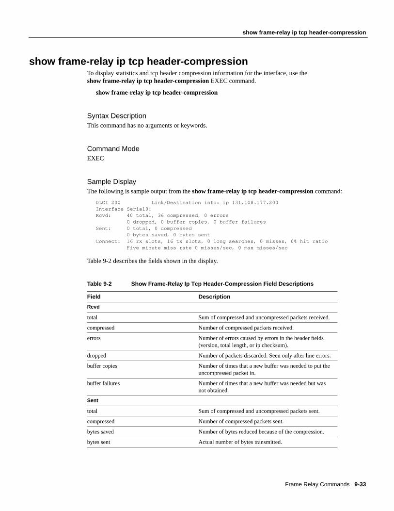
show frame-relay ip tcp header-compressionTo display statistics and tcp header compression information for the interface, use theshow frame-relay ip tcp header-compression EXEC command.
show frame-relay ip tcp header-compression
Syntax DescriptionThis command has no arguments or keywords.
Command ModeEXEC
Sample DisplayThe following is sample output from theshow frame-relay ip tcp header-compressioncommand:
DLCI 200 Link/Destination info: ip 131.108.177.200Interface Serial0:Rcvd: 40 total, 36 compressed, 0 errors 0 dropped, 0 buffer copies, 0 buffer failuresSent: 0 total, 0 compressed 0 bytes saved, 0 bytes sentConnect: 16 rx slots, 16 tx slots, 0 long searches, 0 misses, 0% hit ratio Five minute miss rate 0 misses/sec, 0 max misses/sec
Table 9-2 describes the fields shown in the display.
Table 9-2 Show Frame-Relay Ip Tcp Header-Compression Field Descriptions
Field Description
Rcvd
total Sum of compressed and uncompressed packets received.
compressed Number of compressed packets received.
errors Number of errors caused by errors in the header fields(version, total length, or ip checksum).
dropped Number of packets discarded. Seen only after line errors.
buffer copies Number of times that a new buffer was needed to put theuncompressed packet in.
buffer failures Number of times that a new buffer was needed but wasnot obtained.
Sent
total Sum of compressed and uncompressed packets sent.
compressed Number of compressed packets sent.
bytes saved Number of bytes reduced because of the compression.
bytes sent Actual number of bytes transmitted.
Frame Relay Commands 9-33

show frame-relay ip tcp header-compression
Connect
rx slots, tx slots Number of states allowed over one TCP connection. Astate is recognized by a source address, a destinationaddress, and an IP header length.
long searches Number of times that the connection ID in the incomingpacket was not the same as the previous one that wasprocessed
misses Number of times that a matching entry was not foundwithin the connection table and a new entry had to beentered
hit ratio Percentage of times that a matching entry was found inthe compression tables and the header was compressed
Five minute miss rate Miss rate computed over the most recent 5 minutes andthe maximum per-second miss rate during that period
Field Description
9-34 Access and Communication Servers Command Reference

show frame-relay map
show frame-relay mapUse theshow frame-relay map EXEC command to display the current Frame Relay map entriesand information about these connections.
show frame-relay map
Syntax DescriptionThis command has no arguments or keywords.
Command ModeEXEC
Sample DisplayThe following is sample output from theshow frame-relay map command:
cs# show frame-relay map
Serial 1 (administratively down): ip 131.108.177.177dlci 177 (oxB1,0x2C10), static,broadcast,CISCOTCP/IP Header Compression (inherited), passive (inherited)
Table 9-3 describes significant fields shown in the display.
Table 9-3 Show Frame-Relay Map Field Descriptions
Related Commandframe-relay inverse-arp
Field Description
Serial 1 (administrativelydown):
Identifies a Frame Relay interface and its status (up or down).
IP 131.108.177.177: Destination IP address.
dlci 177 (0xB1,0x2C10) DLCI that identifies the logical connection being used to reach thisinterface. This value is displayed in three ways: its decimal value (177), itshexadecimal value (0xB1), and its value as it would appear on the wire(0x2C10).
static Indicates whether or not this is a static or dynamic entry.
CISCO Indicates the encapsulation type for this map; either CISCO or IETF.
TCP/IP Header Compression(inherited), passive (inherited)
Indicates whether the TCP header compression characteristics wereinherited from the interface or were explicitly configured for the IP map.
Frame Relay Commands 9-35

show frame-relay pvc
show frame-relay pvcTo display statistics about PVCs for Frame Relay interfaces, use theshow frame-relay pvcEXECcommand.
show frame-relay pvc[type number[dlci]]
Syntax Description
Command ModeEXEC
Usage GuidelinesTo obtain statistics about PVCs on all Frame Relay interfaces, use this command with no arguments.
When the interface is configured as a pure DCE, the PVC status is determined by the status ofincoming and outgoing interfaces and line status. If the outgoing interface is a tunnel, the final PVCstatus is determined by what is learned from the tunnel.
If the remote Frame Relay interface goes down, the status is reflected in the LMI over the tunnel. Ifthe tunnel goes down, it is reflected by its line protocol when it does not have a route to the other endof the tunnel.
In the case of a hybrid DTE switch, the PVC status on the DTE side is determined by the PVC statuslearned from the external Frame Relay network.
Congestion control mechanisms are currently not supported, but the switch will pass FECN, BECN,and DE bits unchanged from ingress to egress points in the network.
Sample DisplayThe following is sample output from theshow frame-relay pvccommand:
cs# show frame-relay pvc
PVC Statistics for interface Serial1 (Frame Relay DCE)
DLCI = 100, DLCI USAGE = SWITCHED, PVC STATUS = ACTIVE
input pkts 0 output pkts 0 in bytes 0 out bytes 0 dropped pkts 0 in FECN pkts 0 in BECN pkts 0 out FECN pkts 0 out BECN pkts 0 in DE pkts 0 out DE pkts 0 pvc create time 0:03:03 last time pvc status changed 0:03:03 Num Pkts Switched 0
DLCI = 101, DLCI USAGE = SWITCHED, PVC STATUS = INACTIVE
input pkts 0 output pkts 0 in bytes 0
type (Optional) Interface type.
number (Optional) Interface number.
dlci (Optional) DLCI number for the interface. Statistics for the specifiedPVC display when a DLCI is also specified.
9-36 Access and Communication Servers Command Reference

show frame-relay pvc
out bytes 0 dropped pkts 0 in FECN pkts 0 in BECN pkts 0 out FECN pkts 0 out BECN pkts 0 in DE pkts 0 out DE pkts 0 pvc create time 0:02:58 last time pvc status changed 0:02:58 Num Pkts Switched 0
DLCI = 102, DLCI USAGE = SWITCHED, PVC STATUS = DELETED input pkts 0 output pkts 0 in bytes 0 out bytes 0 dropped pkts 0 in FECN pkts 0 in BECN pkts 0 out FECN pkts 0 out BECN pkts 0 in DE pkts 0 out DE pkts 0 pvc create time 0:02:58 last time pvc status changed 0:02:58 Num Pkts Switched 0
Table 9-4 describes the fields shown in the display.
Table 9-4 Show Frame-Relay PVC Field Descriptions
Field Description
DLCI DLCI number for the interface.
DLCI USAGE Lists SWITCHED when the communication server is used as a switch, or LOCALwhen the communication server is used as a DTE.
PVC STATUS Status of the PVC: ACTIVE, INACTIVE, or DELETED.
input pkts Number of input packets.
output pkts Number of output packets.
in bytes Number of incoming bytes.
out bytes Number of outgoing bytes.
dropped pkts Number of dropped packets.
in FECN pkts Number of incoming FECN packets.
out FECN pkts Number of outgoing FECN packets.
in BECN pkts Number of incoming BECN packets.
out BECN pkts Number of outgoing BECN packets.
in DE pkts Number of incoming DE packets.
out DE pkts Number of outgoing DE packets.
pvc create time Time the PVC was created.
last time pvc status changed Time the PVC changed status (active to inactive).
Num Pkts Switched Number of switched packets seen.
Frame Relay Commands 9-37

show frame-relay route
show frame-relay routeEnter theshow frame-relay routeEXEC command at the system prompt to display all configuredFrame Relay routes, along with their status.
show frame-relay route
Syntax DescriptionThis command has no arguments or keywords.
Command ModeEXEC
Sample DisplayThe following is sample output from theshow frame-relay route command:
cs# show frame-relay route
Input Intf Input Dlci Output Intf Output Dlci Status Serial1 100 Serial2 200 active Serial1 101 Serial2 201 active Serial1 102 Serial2 202 active Serial1 103 Serial3 203 inactive Serial2 200 Serial1 100 active Serial2 201 Serial1 101 active Serial2 202 Serial1 102 active Serial3 203 Serial1 103 inactive
Table 9-5 describes significant fields shown in the display.
Table 9-5 Show Frame-Relay Route Field Descriptions
Field Description
Input Intf Input interface and unit.
Input Dlci Input DLCI number.
Output Intf Output interface and unit.
Output Dlci Output DLCI number.
Status Status of the connection: active or inactive.
9-38 Access and Communication Servers Command Reference

show frame-relay traffic
show frame-relay trafficUse theshow frame-relay traffic EXEC command to display the communication server’s globalFrame Relay statistics since the last reload.
show frame-relay traffic
Syntax DescriptionThis command has no arguments or keywords.
Command ModeEXEC
Sample DisplayThe following is sample output from theshow frame-relay traffic command:
cs# show frame-relay traffic
Frame Relay statistics:ARP requests sent 14, ARP replies sent 0ARP request recvd 0, ARP replies recvd 10
Information shown in the display is self-explanatory.
Frame Relay Commands 9-39

show interfaces serial
show interfaces serialUse the show interfaces serial EXEC command to display information about a serial interface.When using the Frame Relay encapsulation, use theshow interfaces serial command to displayinformation on the multicast DLCI, the DLCI of the interface, and the LMI DLCI used for the LocalManagement Interface.
The multicast DLCI and the local DLCI can be set using theframe-relay multicast-dlci and theframe-relay local-dlci commands, or provided through the Local Management Interface. The statusinformation is taken from the LMI, when active.
show interfaces serialnumber
Syntax Description
Command ModeEXEC
Sample DisplaysThe following is sample output from theshow interfaces serialcommand for a serial interface withthe CISCO LMI enabled:
cs# show interfaces serial 1
Serial1 is up, line protocol is down Hardware is MCI Serial Internet address is 131.108.174.48, subnet mask is 255.255.255.0 MTU 1500 bytes, BW 1544 Kbit, DLY 20000 usec, rely 246/255, load 1/255 Encapsulation FRAME-RELAY, loopback not set, keepalive set (10 sec) LMI enq sent 2, LMI stat recvd 0, LMI upd recvd 0, DTE LMI down LMI enq recvd 266, LMI stat sent 264, LMI upd sent 0 LMI DLCI 1023 LMI type is CISCO frame relay DTE Last input 0:00:04, output 0:00:02, output hang never Last clearing of "show interface" counters 0:44:32 Output queue 0/40, 0 drops; input queue 0/75, 0 drops Five minute input rate 0 bits/sec, 0 packets/sec Five minute output rate 0 bits/sec, 0 packets/sec 307 packets input, 6615 bytes, 0 no buffer Received 0 broadcasts, 0 runts, 0 giants 0 input errors, 0 CRC, 0 frame, 0 overrun, 0 ignored, 0 abort 0 input packets with dribble condition detected 266 packets output, 3810 bytes, 0 underruns 0 output errors, 0 collisions, 2 interface resets, 0 restarts 178 carrier transitions
The display shows the statistics for the LMI as the number of status inquiry messages sent (LMIsent), the number of status messages received (LMI recvd), and the number of status updatesreceived (upd recvd). See theFrame Relay Interfacespecification for additional explanations of thisoutput.
number Interface number
9-40 Access and Communication Servers Command Reference

show interfaces serial
The following is sample output from theshow interfaces command for a serial interface with theANSI LMI enabled:
cs# show interfaces serial 1Serial1 is up, line protocol is down Hardware is MCI Serial Internet address is 131.108.174.48, subnet mask is 255.255.255.0 MTU 1500 bytes, BW 1544 Kbit, DLY 20000 usec, rely 249/255, load 1/255 Encapsulation FRAME-RELAY, loopback not set, keepalive set (10 sec) LMI enq sent 4, LMI stat recvd 0, LMI upd recvd 0, DTE LMI down LMI enq recvd 268, LMI stat sent 264, LMI upd sent 0 LMI DLCI 0 LMI type is ANSI Annex D frame relay DTE Last input 0:00:09, output 0:00:07, output hang never Last clearing of "show interface" counters 0:44:57 Output queue 0/40, 0 drops; input queue 0/75, 0 drops Five minute input rate 0 bits/sec, 0 packets/secFive minute output rate 0 bits/sec, 0 packets/sec 309 packets input, 6641 bytes, 0 no buffer Received 0 broadcasts, 0 runts, 0 giants 0 input errors, 0 CRC, 0 frame, 0 overrun, 0 ignored, 0 abort 0 input packets with dribble condition detected 268 packets output, 3836 bytes, 0 underruns 0 output errors, 0 collisions, 2 interface resets, 0 restarts 180 carrier transitions
Each display provides statistics and information about the type of LMI configured, either CISCO forthe Cisco LMI type, ANSI for the ANSI T1.617 Annex D LMI type, or ITU-T for the ITU-T Q.933Annex A LMI type. See the description for theshow interfaces command for a description of theother fields displayed by this command.
Related CommandA dagger (†) indicates that the command is documented in another chapter.
show interfaces†
Frame Relay Commands 9-41

show interfaces serial
9-42 Access and Communication Servers Command Reference
Related Documents