C. R. Mecanique 335 (2007) 455–460 http://france.elsevier.com/direct/CRAS2B/ Fracture of rigid solids: a discrete approach based on damaging interface modelling Claire Silvani a,b , Stéphane Bonelli a , Thierry Désoyer c,∗ a Cemagref, 3275, route de Cézanne, CS 40061, 13182 Aix-en-Provence cedex 5, France b LMA & université de Provence, UPR 7051-CNRS, 31, chemin Joseph-Aiguier, 13402 Marseille cedex 20, France c ECM & LMA, technopôle de Château-Gombert, 38, rue Joliot Curie, 13451 Marseille cedex 20, France Received 18 December 2006; accepted after revision 24 May 2007 Available online 2 July 2007 Presented by Pierre Suquet Abstract We describe the progressive and delayed fracture of rigid solids by a discrete modelling. Each rigid solid is considered as an assembly of particles with initial cohesive bonds, the latter decreasing progressively during the loading. A damaging interface model is proposed to describe this progressive phenomenon. The model has been implemented in a discrete element code. The first illustrative example, which is actually a parametric study, deals with the progressive damage and sudden fracture of a single interface submitted to an uniaxial tension. The second example is related to the crushing of an assembly of rigid solids—i.e. a granular medium—submitted to an oedometric compression. To cite this article: C. Silvani et al., C. R. Mecanique 335 (2007). © 2007 Académie des sciences. Published by Elsevier Masson SAS. All rights reserved. Résumé Une approche discrète de la rupture des solides rigides basée sur un modèle d’endommagement interfacial. Nous décri- vons la rupture progressive et différée de solides rigides par une approche discrète. Chaque solide rigide est représenté par une collection de particules, initialement liées par une cohésion qui peut progressivement diminuer au cours du chargement. Un mo- dèle d’endommagement interfacial est proposé pour décrire cette décroissance progressive. Implémenté dans un code de calcul par éléments discrets, ce modèle permet de simuler la rupture différée de collections de solides rigides. Le premier exemple illustratif, qui est en fait une étude paramétrique, est relatif à l’endommagement progressif puis la rupture d’une unique interface soumise à une traction simple. Le second exemple porte sur la rupture et l’attrition d’une collection de solides rigides—i.e. d’un milieu granulaire—sous compression œdométrique. Pour citer cet article : C. Silvani et al., C. R. Mecanique 335 (2007). © 2007 Académie des sciences. Published by Elsevier Masson SAS. All rights reserved. Keywords: Granular media; Rigid solids; Interfaces; Damage; Fracture Mots-clés : Milieux granulaires ; Solides rigides ; Interfaces ; Endommagement ; Rupture * Corresponding author. E-mail addresses: [email protected] (C. Silvani), [email protected] (S. Bonelli), [email protected] (T. Désoyer). 1631-0721/$ – see front matter © 2007 Académie des sciences. Published by Elsevier Masson SAS. All rights reserved. doi:10.1016/j.crme.2007.05.023

Welcome message from author
This document is posted to help you gain knowledge. Please leave a comment to let me know what you think about it! Share it to your friends and learn new things together.
Transcript
C. R. Mecanique 335 (2007) 455–460
http://france.elsevier.com/direct/CRAS2B/
Fracture of rigid solids: a discrete approach based on damaginginterface modelling
Claire Silvani a,b, Stéphane Bonelli a, Thierry Désoyer c,∗
a Cemagref, 3275, route de Cézanne, CS 40061, 13182 Aix-en-Provence cedex 5, Franceb LMA & université de Provence, UPR 7051-CNRS, 31, chemin Joseph-Aiguier, 13402 Marseille cedex 20, France
c ECM & LMA, technopôle de Château-Gombert, 38, rue Joliot Curie, 13451 Marseille cedex 20, France
Received 18 December 2006; accepted after revision 24 May 2007
Available online 2 July 2007
Presented by Pierre Suquet
Abstract
We describe the progressive and delayed fracture of rigid solids by a discrete modelling. Each rigid solid is considered as anassembly of particles with initial cohesive bonds, the latter decreasing progressively during the loading. A damaging interfacemodel is proposed to describe this progressive phenomenon. The model has been implemented in a discrete element code. Thefirst illustrative example, which is actually a parametric study, deals with the progressive damage and sudden fracture of a singleinterface submitted to an uniaxial tension. The second example is related to the crushing of an assembly of rigid solids—i.e. agranular medium—submitted to an oedometric compression. To cite this article: C. Silvani et al., C. R. Mecanique 335 (2007).© 2007 Académie des sciences. Published by Elsevier Masson SAS. All rights reserved.
Résumé
Une approche discrète de la rupture des solides rigides basée sur un modèle d’endommagement interfacial. Nous décri-vons la rupture progressive et différée de solides rigides par une approche discrète. Chaque solide rigide est représenté par unecollection de particules, initialement liées par une cohésion qui peut progressivement diminuer au cours du chargement. Un mo-dèle d’endommagement interfacial est proposé pour décrire cette décroissance progressive. Implémenté dans un code de calcul paréléments discrets, ce modèle permet de simuler la rupture différée de collections de solides rigides. Le premier exemple illustratif,qui est en fait une étude paramétrique, est relatif à l’endommagement progressif puis la rupture d’une unique interface soumiseà une traction simple. Le second exemple porte sur la rupture et l’attrition d’une collection de solides rigides—i.e. d’un milieugranulaire—sous compression œdométrique. Pour citer cet article : C. Silvani et al., C. R. Mecanique 335 (2007).© 2007 Académie des sciences. Published by Elsevier Masson SAS. All rights reserved.
Keywords: Granular media; Rigid solids; Interfaces; Damage; Fracture
Mots-clés : Milieux granulaires ; Solides rigides ; Interfaces ; Endommagement ; Rupture
* Corresponding author.E-mail addresses: [email protected] (C. Silvani), [email protected] (S. Bonelli), [email protected]
(T. Désoyer).
1631-0721/$ – see front matter © 2007 Académie des sciences. Published by Elsevier Masson SAS. All rights reserved.doi:10.1016/j.crme.2007.05.023
456 C. Silvani et al. / C. R. Mecanique 335 (2007) 455–460
1. Introduction
The general framework of this study is that of the progressive (finite cracking velocity) and delayed (with respectto the loading) fracture of rigid solids interacting by contact and friction. An illustrative example of such a structuralproblem is this of a rockfill dam, which can globally settle due to the local fracture of rock blocks in the time, see e.g.Deluzarche and Cambou [1]; Oldecop and Alonso [2].
The choice is here made to get numerically approximated solutions of the contact-friction part of the problem byusing the discrete element method proposed by Jean and Moreau (see e.g. [3,4]). However, due to the fact that therigid solids (or grains)—which will be all assumed of the same characteristic size DS—can break, each of them isconsidered as an assembly of rigid particles—which will be also all assumed of the same characteristic size Dp � DS .These particles are assumed to be initially ‘glued’. From a numerical point of view, a grain, i.e. an assembly of rigidparticles, must thus be seen as a mesh of the rigid solid, in which a crack can initiate (resp. propagate) only on (resp.through) the contact zones between rigid grains. Consequently, from a physical point of view, these contact zoneshave to be considered as rigid but breakable interfaces.
Strong cohesive forces are supposed to exist initially on the interfaces (see e.g. Delenne et al., [5]), giving to themtheir initial tensile strength. It is then assumed that, when a given interface I—characteristic area S ≈ (Dp)2—issubmitted to a sufficiently strong tensile force, microcracks and/or microcavities, i.e. damage, initiate, grow and,eventually, coalesce, that leads to the fracture of the interface (and so, to the irreversible vanishing of the cohesiveforces).
Section 2 of this Note is devoted to the presentation of a thermodynamically consistent damaging interface modelwhere, in agreement with the general frame of this study, the evolution of the damage is at the same times progressiveand delayed. Two illustrative examples are presented in Section 3. The first one is that of a single interface between twoparticles submitted to an uniaxial tensile force: the analytical solution is given, from which a parametric study of thedamaging interface model is done. The second example is related to the crushing of an assembly of two-dimensionalrigid solids—i.e. a two-dimensional granular medium—due to an oedometric compression: the results here presentedhave been obtained using a numerical code in which the damaging interface model has been implemented.
2. A damaging interface modelling
The (thermo)dynamic system considered in this section is an interface I between two grains. Like the grains, I
is assumed to be rigid: the area of the surface S occupied by I is then constant, whatever the forces acting on are.Furthermore, the displacement jump [u] through S is assumed to be zero whenever I is not destroyed (i.e. wheneverS is clearly defined); consequently, [u] cannot be considered as a state variable of I . Actually, only one ‘mechanical’state variable will be considered there, denoted by d (scalar) and characterizing the damage by microcracking and/ormicrocavitation of the constitutive material of I . It will be assumed that d ∈ [0, 1
m] where m > 0 is a material parameter
whose physical meaning will be discussed later on. It must be here emphasized that, as soon as d = 1/m, I is destroyedand the contact-friction interactions between the both grains have to be considered on the basis of the Signorini–Coulomb equations (see e.g. [4]), which will not be detailed in the present Note.
The damaging interface model is actually based on previous works on continuum damage mechanics by Marigo[6], where the necessary and sufficient condition for the intrinsic dissipation to be non-negative is simply given byd � 0. Denoting by σ the stresses acting in S, assumption is then made that σ is homogeneous. On the other hand, itis assumed that, due to the damage, the effective tough surface of I is not S but its only undamaged part (1 − md)S.Consequently, the stresses are simply linked to the global force F (defined in such a way that FN = F.N > 0 when I
is submitted to a tensile force) by:
F = (1 − md)Sσ.N (1)
A damage yield surface is introduced next. Once more, it is clearly inspired by the works by Marigo [6]. However, for asake of consistency between the present interfacial damage model and the Coulomb–Signorini one (see also Cangemiet al. [7]), which must ‘merge’ in the latter one as soon as d = 1/m, the damage yield surface is here expressed as afunction of FN and F t = F − FNN , i.e.:
gd(FN,F t , d) = FN + 1 |F t | − Fd0 (1 − md) = 0 (2)
μ
C. Silvani et al. / C. R. Mecanique 335 (2007) 455–460 457
where μ is the friction coefficient between the both grains when I is destroyed (d = 1/m), Fd0 > 0 the damage yield
when d = 0, and m > 0 a ‘softening’ parameter (the greater m, the stronger the softening). As previously indicated,Eq. (2) reduces to the classical Coulomb’s yield surface as soon as d = 1/m. As for the fracture of I , which can occursuddenly when I is sufficiently damaged, it is controlled by a fracture yield surface, which reads:
gf (FN,F t , d) = FN + 1
μ|F t | − F
f
0 (1 − md) = 0 (3)
where Ff
0 � Fd0 is the maximal tensile force I can undergo. It must be here emphasized that mechanical states
(FN,F t , d) such that gf (FN,F t , d) > 0 cannot be reached—i.e., as soon as gf (FN,F t , d) = 0, I is destroyed—and that, whatever the reachable mechanical state (FN,F t , d) is, gd(FN,F t , d) � gf (FN,F t , d)—i.e. damage takesplace before fracture, apart from the limit case of a perfectly brittle interface (Ff
0 = Fd0 ), where damage and fracture
are concomitant.Eventually, the damage evolution law is given by (η is a characteristic time):
d = 1
η
⟨gd(FN,F t , d)
F d0
⟩H−(−gf (FN,F t , d)
) +[
1
m− d
]δ(gf (FN,F t , d)
)(4)
where 〈.〉 denotes the MacCauley brackets and H− is the modified Heaviside function (H−(0) = 0). The Diracdistribution δ indicates that, as soon as gf (FN,F t , d) = 0, d is to be understood as a distribution derivative (i.e. d
‘jumps’ to its maximal value 1/m).
3. Illustrative examples
3.1. Tension
Apart from the friction coefficient μ, four material parameters have to be identified for the damaging interfacemodel (see Section 2) to be fully defined: the softening parameter m; the damage yield Fd
0 ; the fracture yield Ff
0 =(1/r)F d
0 (r � 1); the characteristic time η. The influence of each of these parameters on the damage evolution is herestudied, considering a single interface (surface S) submitted to a simple tension such that F t = 0 and σN = FN/S =cst > 0.
For convenience—and due to the fact that t = (σNσ0)/(σ0σN ), where the damage yield stress σ0 is given byσ0 = Fd
0 /S— d will be here considered as a function of σN/σ0 instead of the time t . Thus, noticing that gd(σN,d) > 0as soon as σN/σ0 > 1−md0, Eq. (4) can be rewritten (denoting by d,N0 the first derivative of d with respect to σN/σ0):
ησN
σ0d,N0 −mH
(σN
σ0− 1 + md0
)d =
(σN
σ0− 1
)H
(σN
σ0− 1 + md0
)(5)
with the initial condition d(σN/σ0 = 0) = d0. The exact solution of this equation reads (whenever gf (σN,d) =σN − σf (1 − md) < 0, where the fracture yield stress σf is given by σf = F
f
0 /S):
d
(σN
σ0
)= d0 − H
(σN
σ0− 1 + md0
)((ησN
σ0m2
)exp
(mσ0
ησN
(σN
σ0− 1 + md0
))
+ 1
m
(1 − σN
σ0
)− ησN
σ0m2− d0
)(6)
Depending on different values of the material parameters, the different shapes of this solution are presented on Fig. 1.Notice that, due to the fact that, in Eq. (6), the material parameter η and the loading parameter σN are systematicallylinked by their product, choice has been actually made to consider σN as a parameter and η as a constant.
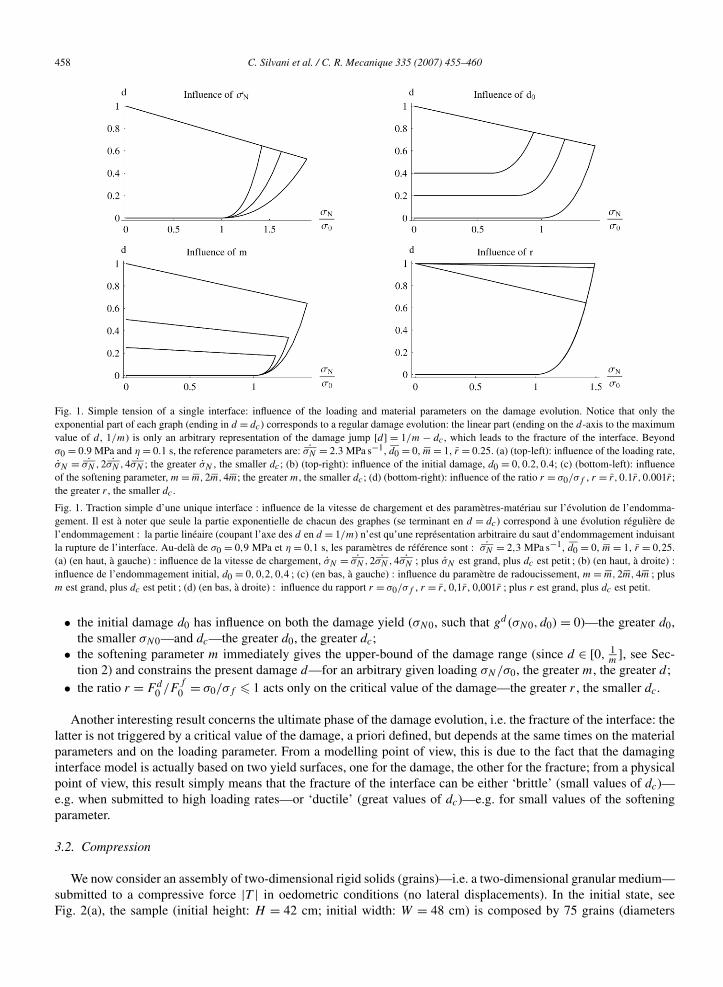
As shown on Fig. 1, the main features of the damage evolution are:
• the loading rate σN (or, in an equivalent way, the inverse of the characteristic time η) acts on both the presentdamage d—for an arbitrary given loading σN/σ0, the greater σN , the smaller d—and the critical value of thedamage (dc, such that gf (σN,dc) = 0)—the greater σN , the smaller dc;
458 C. Silvani et al. / C. R. Mecanique 335 (2007) 455–460
Fig. 1. Simple tension of a single interface: influence of the loading and material parameters on the damage evolution. Notice that only theexponential part of each graph (ending in d = dc) corresponds to a regular damage evolution: the linear part (ending on the d-axis to the maximumvalue of d , 1/m) is only an arbitrary representation of the damage jump [d] = 1/m − dc , which leads to the fracture of the interface. Beyondσ0 = 0.9 MPa and η = 0.1 s, the reference parameters are: ˙σN = 2.3 MPa s−1, d0 = 0, m = 1, r = 0.25. (a) (top-left): influence of the loading rate,σN = ˙σN ,2 ˙σN ,4 ˙σN ; the greater σN , the smaller dc ; (b) (top-right): influence of the initial damage, d0 = 0,0.2,0.4; (c) (bottom-left): influenceof the softening parameter, m = m,2m,4m; the greater m, the smaller dc ; (d) (bottom-right): influence of the ratio r = σ0/σf , r = r,0.1r,0.001r ;the greater r , the smaller dc .
Fig. 1. Traction simple d’une unique interface : influence de la vitesse de chargement et des paramètres-matériau sur l’évolution de l’endomma-gement. Il est à noter que seule la partie exponentielle de chacun des graphes (se terminant en d = dc) correspond à une évolution régulière del’endommagement : la partie linéaire (coupant l’axe des d en d = 1/m) n’est qu’une représentation arbitraire du saut d’endommagement induisantla rupture de l’interface. Au-delà de σ0 = 0,9 MPa et η = 0,1 s, les paramètres de référence sont : ˙σN = 2,3 MPa s−1, d0 = 0, m = 1, r = 0,25.(a) (en haut, à gauche) : influence de la vitesse de chargement, σN = ˙σN ,2 ˙σN ,4 ˙σN ; plus σN est grand, plus dc est petit ; (b) (en haut, à droite) :influence de l’endommagement initial, d0 = 0,0,2,0,4 ; (c) (en bas, à gauche) : influence du paramètre de radoucissement, m = m,2m,4m ; plusm est grand, plus dc est petit ; (d) (en bas, à droite) : influence du rapport r = σ0/σf , r = r , 0,1r , 0,001r ; plus r est grand, plus dc est petit.
• the initial damage d0 has influence on both the damage yield (σN0, such that gd(σN0, d0) = 0)—the greater d0,the smaller σN0—and dc—the greater d0, the greater dc;
• the softening parameter m immediately gives the upper-bound of the damage range (since d ∈ [0, 1m
], see Sec-tion 2) and constrains the present damage d—for an arbitrary given loading σN/σ0, the greater m, the greater d ;
• the ratio r = Fd0 /F
f
0 = σ0/σf � 1 acts only on the critical value of the damage—the greater r , the smaller dc.
Another interesting result concerns the ultimate phase of the damage evolution, i.e. the fracture of the interface: thelatter is not triggered by a critical value of the damage, a priori defined, but depends at the same times on the materialparameters and on the loading parameter. From a modelling point of view, this is due to the fact that the damaginginterface model is actually based on two yield surfaces, one for the damage, the other for the fracture; from a physicalpoint of view, this result simply means that the fracture of the interface can be either ‘brittle’ (small values of dc)—e.g. when submitted to high loading rates—or ‘ductile’ (great values of dc)—e.g. for small values of the softeningparameter.
3.2. Compression
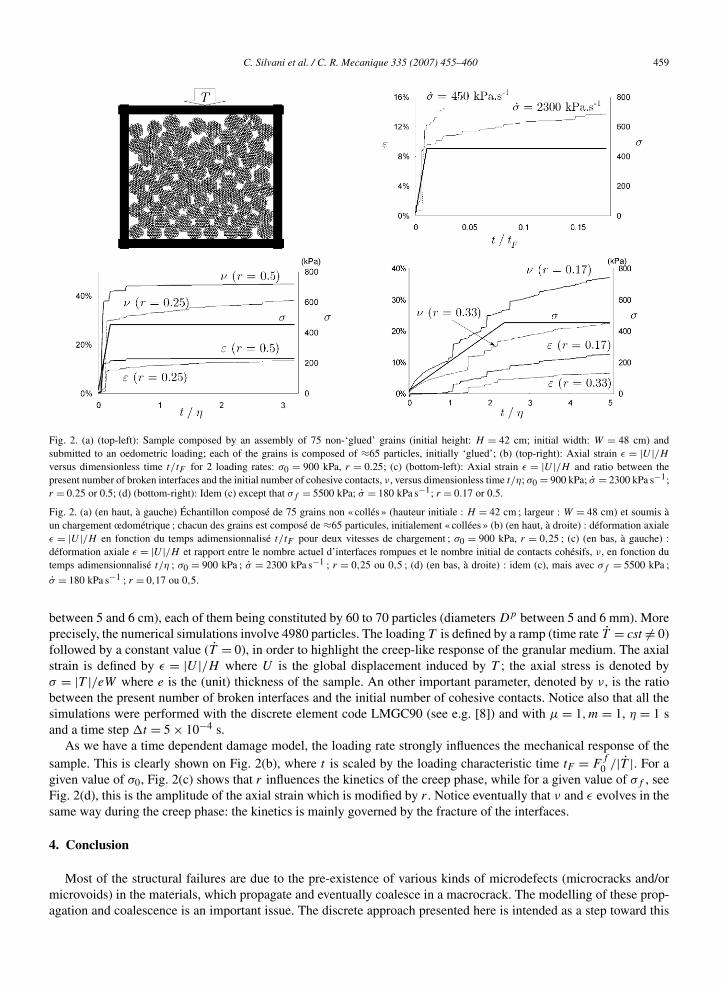
We now consider an assembly of two-dimensional rigid solids (grains)—i.e. a two-dimensional granular medium—submitted to a compressive force |T | in oedometric conditions (no lateral displacements). In the initial state, seeFig. 2(a), the sample (initial height: H = 42 cm; initial width: W = 48 cm) is composed by 75 grains (diameters
C. Silvani et al. / C. R. Mecanique 335 (2007) 455–460 459
Fig. 2. (a) (top-left): Sample composed by an assembly of 75 non-‘glued’ grains (initial height: H = 42 cm; initial width: W = 48 cm) andsubmitted to an oedometric loading; each of the grains is composed of ≈65 particles, initially ‘glued’; (b) (top-right): Axial strain ε = |U |/Hversus dimensionless time t/tF for 2 loading rates: σ0 = 900 kPa, r = 0.25; (c) (bottom-left): Axial strain ε = |U |/H and ratio between thepresent number of broken interfaces and the initial number of cohesive contacts, ν, versus dimensionless time t/η; σ0 = 900 kPa; σ = 2300 kPa s−1;r = 0.25 or 0.5; (d) (bottom-right): Idem (c) except that σf = 5500 kPa; σ = 180 kPa s−1; r = 0.17 or 0.5.
Fig. 2. (a) (en haut, à gauche) Échantillon composé de 75 grains non « collés » (hauteur initiale : H = 42 cm ; largeur : W = 48 cm) et soumis àun chargement œdométrique ; chacun des grains est composé de ≈65 particules, initialement « collées » (b) (en haut, à droite) : déformation axialeε = |U |/H en fonction du temps adimensionnalisé t/tF pour deux vitesses de chargement ; σ0 = 900 kPa, r = 0,25 ; (c) (en bas, à gauche) :déformation axiale ε = |U |/H et rapport entre le nombre actuel d’interfaces rompues et le nombre initial de contacts cohésifs, ν, en fonction dutemps adimensionnalisé t/η ; σ0 = 900 kPa ; σ = 2300 kPa s−1 ; r = 0,25 ou 0,5 ; (d) (en bas, à droite) : idem (c), mais avec σf = 5500 kPa ;
σ = 180 kPa s−1 ; r = 0,17 ou 0,5.
between 5 and 6 cm), each of them being constituted by 60 to 70 particles (diameters Dp between 5 and 6 mm). Moreprecisely, the numerical simulations involve 4980 particles. The loading T is defined by a ramp (time rate T = cst �= 0)followed by a constant value (T = 0), in order to highlight the creep-like response of the granular medium. The axialstrain is defined by ε = |U |/H where U is the global displacement induced by T ; the axial stress is denoted byσ = |T |/eW where e is the (unit) thickness of the sample. An other important parameter, denoted by ν, is the ratiobetween the present number of broken interfaces and the initial number of cohesive contacts. Notice also that all thesimulations were performed with the discrete element code LMGC90 (see e.g. [8]) and with μ = 1,m = 1, η = 1 sand a time step �t = 5 × 10⁻⁴ s.
As we have a time dependent damage model, the loading rate strongly influences the mechanical response of thesample. This is clearly shown on Fig. 2(b), where t is scaled by the loading characteristic time tF = F
f
0 /|T |. For agiven value of σ0, Fig. 2(c) shows that r influences the kinetics of the creep phase, while for a given value of σf , seeFig. 2(d), this is the amplitude of the axial strain which is modified by r . Notice eventually that ν and ε evolves in thesame way during the creep phase: the kinetics is mainly governed by the fracture of the interfaces.
4. Conclusion
Most of the structural failures are due to the pre-existence of various kinds of microdefects (microcracks and/ormicrovoids) in the materials, which propagate and eventually coalesce in a macrocrack. The modelling of these prop-agation and coalescence is an important issue. The discrete approach presented here is intended as a step toward this
460 C. Silvani et al. / C. R. Mecanique 335 (2007) 455–460
issue. The proposed damaging interface model is based on a reduced set of five parameters. The illustrative examplesseem to indicate that the numerical code in which the damaging model has been implemented is an efficient tool forsimulating the initiation and the propagation of macrocracks in rigid solids, including the time effect. Examples ofapplications clearly include dam engineering: rockfill material is characterized by delayed grain breakage under con-stant load. This is the main cause of the majority of post-constructive displacements observed in high rockfill dams,which can produce piping or cracking of the impervious element.
Acknowledgements
This project was sponsored by the Région Provence Alpes Côte d’Azur.
References
[1] R. Deluzarche, B. Cambou, Discrete numerical modelling of rockfill dams, Int. J. Numer. Anal. Geomech. 30 (2006) 1075–1096.[2] L.A. Oldecop, E.E. Alonso, Fundamentals of rockfill time-dependent behaviour, in: Juca, de Campos, Marinho (Eds.), Unsaturated Soils,
Routledge Pub., 2002, pp. 793–798.[3] M. Jean, The non-smooth contact dynamics method, Comput. Methods Appl. Mech. Engrg. 177 (1999) 235–257.[4] J.-J. Moreau, Unilateral contact and dry friction in finite freedom analysis, in: J.J. Moreau, P.D. Panagiotopoulos (Eds.), Non Smooth Mechanics
and Application, in: CISM Courses and Lectures, vol. 302, Springer-Verlag, 1988, pp. 1–82.[5] J.-Y. Delenne, M.S. El Youssoufi, F. Cherblanc, J.-C. Benet, Mechanical behaviour and failure of cohesive granular materials, Int. J. Numer.
Anal. Geomech. 28 (2004) 1577–1594.[6] J.-J. Marigo, Formulation d’une loi d’endommagement d’un matériau élastique, C. R. Acad. Sci. Paris, Ser. II 292 (1981) 1309–1312.[7] L. Cangemi, M. Cocou, M. Raous, Adhesion and friction model for the fibre/matrix interface of a composite, in: A.B. Sabir, C. Bohatier, M.G.
Fertis, G.T. Tsatsaronis, R.J. Krane, K.M. Abbott (Eds.), Proc. Third Biennal Joint Conference on Engineering Systems, Design and Analysis(ESDA 96), Montpellier, vol. 1, 1996, pp. 157–163.
[8] B. Cambou, M. Jean, Micromécanique des matériaux granulaires, Hermès Science Publications, Paris, 2001.
Related Documents