ISSN 2277-3061 Volume 15 Number 13 INTERNATIONAL JOURNAL OF COMPUTERS & TECHNOLOGY 7387 | Page November 2016 www.cirworld.com Fractal Antennas (Study and Review) Ahmed Azeez Khudhair Al-Zabee 1,2 , Saba Qasim Jabbar 1 , Desheng Wang 1 1 School of Information and Communication Engineering, Huazhong University of Sceince and Technology, Wuhan 430074, China 2 General Directorate of Electricity Distribution for Middle Euphrates, Ministry of Electricity, Iraq [email protected] ABSTRACT In recent years, great demands for an antenna with many falsities like miniaturization, multiband and wideband antenna with high gain and low profile antenna for modern wireless communication services and applications. Fractal antenna paves the way for these requirements. In this survey, we will attempt to study and review the existing fractal antennas designs and to classify them with different techniques used and additional insight into these unique structures with the most used simulation softwares for designing of fractal antenna applications. Keywords Fractal geometry, fractal antenna, antenna design and analysis. Academic Discipline And Sub-Disciplines Communication Systems, Antennas Design, . TYPE (METHOD/APPROACH) Study/Review INTRODUCTION The great divergent and huge amount of applications on wireless communication systems and an increasing demand to integrate different technologies into small user equipment has remarkably increase the fashion of introducing compact(portable) multiband( multi service) antenna and wider band width [1]. Miniaturization of antennas is one of the trends in modern communications systems. Wireless telecommunication services and related applications for voice and data transmission. Wideband and low profile antennas are in great demand for both commercial and military applications. Multi-band and wideband antennas are desirable in personal communication systems, small satellite communication terminals, and other wireless applications one of the techniques used to decrease the antenna size is application of fractal geometries are in great demand for both commercial and military application [2]. Fractals are geometrical objects featured by a highly irregularity that makes it difficult to describe with the classic Euclidean geometry. FRACTAL ANTENNA The original inspiration for the development of fractal geometry came largely from an in -depth study of the patterns of nature Figure (1) . The term “Fractal” means linguistically “broken” or “fractured” from the Latin “fractus.” This term was created by Benoît MANDELBROT 40 years ago in 1974 [3]. Fractals are geometric shapes, which cannot be defined using Euclidean geometry, are self-similar and repeating themselves on different scales like clouds, mountains, coasts, lightning, etc [4,5]. The fractal geometry has been applied to many fields such as: Medicine: structure of the lungs, intestines, and heartbeat. Meteorology: clouds, vortex, ice, rogue waves, turbulence, and lightning structure. Volcanology: prediction of volcanic eruptions, earthquakes. Astronomy: the description of the structures of the universe, craters on the Moon, and distribution galaxies [6]. Also, fractal geometry has been used in the electromagnetic, and especially in the design of antennas. Several studies have adopted fractal structures and showed that this technique can improve the performances of the antenna and it is one of the techniques to design antennas with multi-band and broad-band behavior. Fig 1: The original inspiration for the development of fractal geometry

Welcome message from author
This document is posted to help you gain knowledge. Please leave a comment to let me know what you think about it! Share it to your friends and learn new things together.
Transcript
I S S N 2 2 7 7 - 3 0 6 1 V o l u m e 1 5 N u m b e r 1 3
I N T E R N A T I O N A L J O U R N A L O F C O M P U T E R S & T E C H N O L O G Y
7 3 8 7 | P a g e
N o v e m b e r 2 0 1 6 w w w . c i r w o r l d . c o m
Fractal Antennas (Study and Review)
Ahmed Azeez Khudhair Al-Zabee1,2, Saba Qasim Jabbar1, Desheng Wang1 1School of Information and Communication Engineering, Huazhong University of Sceince and Technology,
Wuhan 430074, China 2General Directorate of Electricity Distribution for Middle Euphrates, Ministry of Electricity, Iraq
[email protected] ABSTRACT In recent years, great demands for an antenna with many falsities like miniaturization, multiband and wideband antenna with high gain and low profile antenna for modern wireless communication services and applications. Fractal antenna paves the way for these requirements. In this survey, we will attempt to study and review the existing fractal antennas designs and to classify them with different techniques used and additional insight into these unique structures with the most used simulation softwares for designing of fractal antenna applications.
Keywords
Fractal geometry, fractal antenna, antenna design and analysis.
Academic Discipline And Sub-Disciplines
Communication Systems, Antennas Design, .
TYPE (METHOD/APPROACH)
Study/Review
INTRODUCTION
The great divergent and huge amount of applications on wireless communication systems and an increasing demand to integrate different technologies into small user equipment has remarkably increase the fashion of introducing compact(portable) multiband( multi service) antenna and wider band width [1]. Miniaturization of antennas is one of the trends in modern communications systems. Wireless telecommunication services and related applications for voice and data transmission. Wideband and low profile antennas are in great demand for both commercial and military applications. Multi-band and wideband antennas are desirable in personal communication systems, small satellite communication terminals, and other wireless applications one of the techniques used to decrease the antenna size is application of fractal geometries are in great demand for both commercial and military application [2]. Fractals are geometrical objects featured by a highly irregularity that makes it difficult to describe with the classic Euclidean geometry.
FRACTAL ANTENNA
The original inspiration for the development of fractal geometry came largely from an in-depth study of the patterns of nature Figure (1) . The term “Fractal” means linguistically “broken” or “fractured” from the Latin “fractus.” This term was created by Benoît MANDELBROT 40 years ago in 1974 [3]. Fractals are geometric shapes, which cannot be defined using Euclidean geometry, are self-similar and repeating themselves on different scales like clouds, mountains, coasts, lightning, etc [4,5]. The fractal geometry has been applied to many fields such as:
Medicine: structure of the lungs, intestines, and heartbeat.
Meteorology: clouds, vortex, ice, rogue waves, turbulence, and lightning structure.
Volcanology: prediction of volcanic eruptions, earthquakes.
Astronomy: the description of the structures of the universe, craters on the Moon, and distribution galaxies [6].
Also, fractal geometry has been used in the electromagnetic, and especially in the design of antennas. Several studies have adopted fractal structures and showed that this technique can improve the performances of the antenna and it is one of the techniques to design antennas with multi-band and broad-band behavior.
Fig 1: The original inspiration for the development of fractal geometry
I S S N 2 2 7 7 - 3 0 6 1 V o l u m e 1 5 N u m b e r 1 3
I N T E R N A T I O N A L J O U R N A L O F C O M P U T E R S & T E C H N O L O G Y
7 3 8 8 | P a g e
N o v e m b e r 2 0 1 6 w w w . c i r w o r l d . c o m
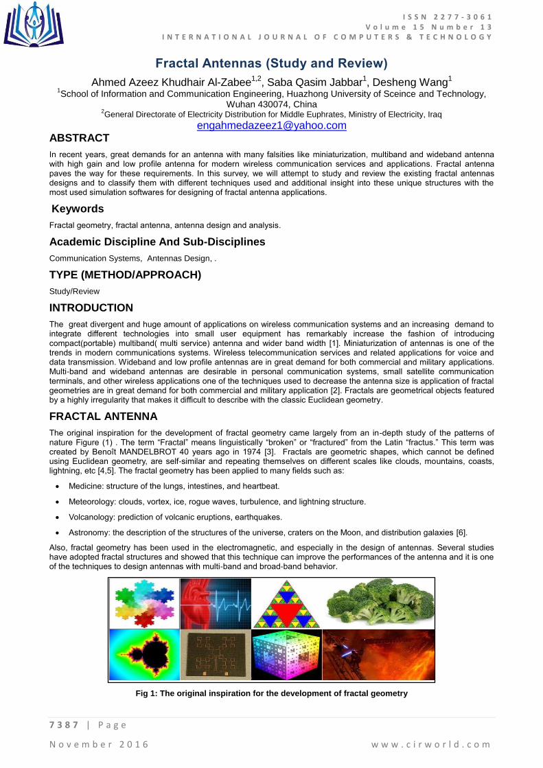
FRACTAL GEOMETRY
The concept of combining the fractal geometry (FG) with electromagnetic is analyzed. The word antenna is often prefixed with the word latest which gives the state of research in the field. In the latest antenna research the fractal geometry plays a vital role. It is a powerful means of describing any geometrical shapes Figure 2. The shapes of Coast line, leaf, clouds etc. are some complex phenomenon that are described effectively using fractals magnificent strategy has drawn the attention of many elites from mathematics, computer science, statistics, image and signal processing and electromagnetic group. Earlier the objects are classified using Euclidean geometry as one, two and three dimensional [7]. The objects in the world are not described using Euclidean geometry. Here comes the application of FG. The fractals have the properties like (a) Self Similarity, (b) Fractional Dimension and (c) Fractal boundaries.
Fig 2: The fractal geometry shapes (FG)
FRACTAL GEOMETRIES VS. FRACTAL ANTENNAS
As Euclidian geometry is weak if used for filling the space occupied by Fractal antenna so the modern (fractal) geometry that is a natural extension theory used for defining a fractal shapes .and A fractal can fill the space occupied by the antenna in a more effective manner than the traditional Euclidean antenna see Figure (2.). In the modern wireless systems the fractal antenna had been adapting the following functionalities:
It can handle large amounts of data in short period of time, which means it needs to possess broadband characteristics.
The fractal antenna represent the optimum solution for the problem that An antenna need to be designed for a particular operating frequency have a good characteristics for that frequency and may not have a fully functional operation at other frequencies.
As the miniaturization of the antenna achieved now it Owing the modern communication devices like mobile radio and handheld communication systems, the antenna has to deal with the compactness of the system and environment efficiently.
MAIN ANTENNA DESIGN PARAMETERS
This section will present a brief overview of some of the more common fractal geometries that have been found to be useful in developing new and innovative designs for antennas [8] .There are several important antenna characteristics that should be considered when choosing an antenna for your application as follows:
Frequency and Size
antennas used for HF are different from the ones used for VHF, which in turn are different from antennas for microwave. The wavelength is different at different frequencies, so the antennas must be different in size to radiate signals at the correct wavelength. As example the interesting in antennas working in the microwave range, especially in the 2.4 GHz and 5 GHz frequencies. At 2.4 GHz the wavelength is 12.5 cm, while at 5 Ghz it is 6 cm.
Directivity
antennas can be omnidirectional, sectorial or directive. Omnidirectional antennas radiate the same pattern all around the antenna in a complete 360 degrees pattern. The most popular types of omnidirectional antennas are the Dipole-Type and the Ground Plane. Sectorial antennas radiate primarily in a specific area. The beam can be as wide as 180 degrees, or as narrow as 60 degrees. Directive antennas are antennas in which the beamwidth is much narrower than in sectorial antennas. They have the highest gain and are therefore used for long distance links. Types of directive antennas are the Yagi, the biquad, the horn, the helicoidal, the patch antenna, the Parabolic Dish and many others.
I S S N 2 2 7 7 - 3 0 6 1 V o l u m e 1 5 N u m b e r 1 3
I N T E R N A T I O N A L J O U R N A L O F C O M P U T E R S & T E C H N O L O G Y
7 3 8 9 | P a g e
N o v e m b e r 2 0 1 6 w w w . c i r w o r l d . c o m
Physical construction
antennas can be constructed in many different ways, ranging from simple wires to parabolic dishes, up to coffee cans. When considering antennas suitable for 2.4 GHz WLAN use, another classification can be used.
Application
we identify two application categories which are Base Station and Point-to- Point. Each of these suggests different types of antennas for their purpose. Base Stations are used for multipoint access. Two choices are Omni antennas which radiate equally in all directions, or Sectorial antennas. which focus into a small area. In the Point-to-Point case, antennas are used to connect two single locations together. Directive antennas are the primary choice for this application.
FRACTAL ANTENNA CLASSIFICATION
As the term fractal antenna technology is used to describe those antenna engineering techniques that are based on such mathematical concepts that enable one to obtain a new generation of antennas with some features that were often thought impossible in the mid-1980s [9], this leads to a new pioneer abilities in designing and manufacturing antenna for multi-purpose so the classification of fractal antenna will have three different dominant categories of classification:
Identtation Depednd
The first group for fractal antenna classification depend on identation , Since a fractal is a self-affinity geometry that has repeating patterns, iteration methods can be used to mathematically create such geometries. Generally, there are three types of iterations that can be adopted to create fractal geometries.
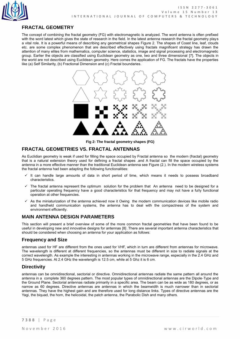
Generator Iteration
A pre-defined generator replaces creates fractals by repeatedly substituting certain part of the initial structure at each iteration. For example, some simple fractal geometries such as middle third Cantor set, can be realized by repeatedly cutting the middle line segment as shown in Figure (3).
Fig 3: Generator Itration
Iterated Function System (IFS)
Iterated function system (IFS) is a finite family of contractions S = { S1,S2,. . . , Sm}, where Sm is a contraction that transforms sets into geometrically similar sets with probability P ={P1,P2 , . . ., Pm}. Pi is the relative weight for each contraction Si and Pi needs to satisfy the following expression
∑ (1)
A unique fractal can be determined by one IFS. The transformation includes several functions such as rotation, move and reflection. Therefore, it can be seen that Generator Iteration is actually the simplest scenario of an IFS transformation with S1= S1= …. = Sm . And uniform probability distribution. With an nonuniform distribution of the probability set P, some „irregular‟ shapes can be defined such as the one shows in Figure (3) [10]. In some literature, these structures are referred as „randomized fractal‟ with statistical self-similarity.
Formula iteration: uses infinite summation of one mathematical expression to create a fractal structure. It usually leads to an nonsmooth curve due to the infinity summation. Figure (4) shows one fractal example generated using the following formula:
∑
t (2)

I S S N 2 2 7 7 - 3 0 6 1 V o l u m e 1 5 N u m b e r 1 3
I N T E R N A T I O N A L J O U R N A L O F C O M P U T E R S & T E C H N O L O G Y
7 3 9 0 | P a g e
N o v e m b e r 2 0 1 6 w w w . c i r w o r l d . c o m
Fig 4: The random version of the Koch Curve
Based on Design Method
This is another group type of classification where Fractals are classified among three major categories:
Linear: based on the iteration of linear equations (HILBERT, KOCH, SIERPINSKI, Dragon ...).
Nonlinear: based on the iteration of complex numbers (MANDELBROT, JULIA ...).
Random: based on the introduction of a random parameter in the iteration to obtain irregular shapes (such as mountains or clouds).
Based on basic design shape
The last group of classification which depend on the most useful base design on which type will start with , so here I will point out some of the most famous and useful geometries of fractal antenna engineering:
Fractal as Wire Antenna Elements: The main idea of systematically bending the wire in a fractal way, so that the overall arc length remains the same, but the size is correspondingly reduced with the addition of each successive iteration will get a standard dipole or loop antenna
Fractal Patch Antenna Elements: Fractals can be used to miniaturize patch elements as well as wire elements. The same concept of increasing the electrical length of a radiator can be applied to a patch elemen.so its can be viewed as micros trip transmission line.
TYPES OF FRACTAL ANTENNAS
The KOCH Structure
This structure was invented by the Swedish mathematician HELGE VON KOCH in 1906 before the invention of the term "fractal". There are several variations of this structure [11]:
The KOCH Curve
As shown in Figure 5, the construction of this curve is made from a segment by applying the following steps:
The segment is divided into three segments of equal length.
An equilateral triangle whose base is the middle segment of the first stage is constructed. Segment which was the base of the triangle of the second step is eliminated.
After these three steps, the resulting object has a shape similar to a cross section of a witch hat.
Fig 5: The KOCH Curve
I S S N 2 2 7 7 - 3 0 6 1 V o l u m e 1 5 N u m b e r 1 3
I N T E R N A T I O N A L J O U R N A L O F C O M P U T E R S & T E C H N O L O G Y
7 3 9 1 | P a g e
N o v e m b e r 2 0 1 6 w w w . c i r w o r l d . c o m
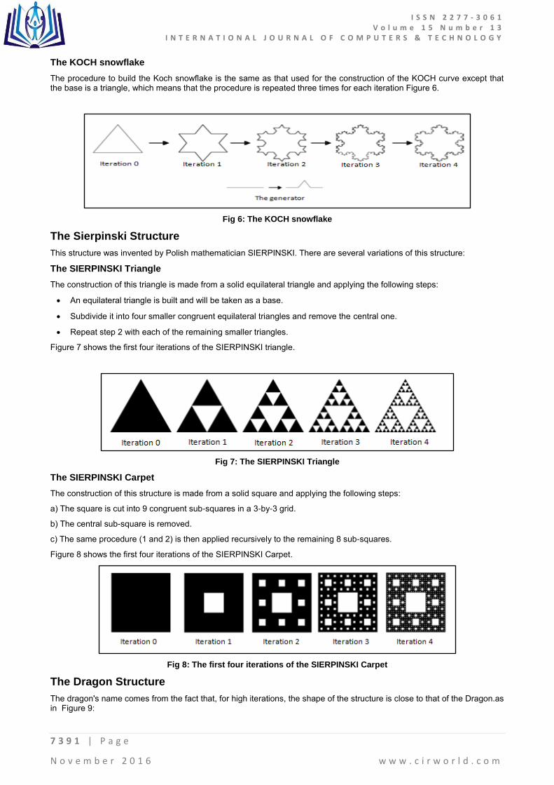
The KOCH snowflake
The procedure to build the Koch snowflake is the same as that used for the construction of the KOCH curve except that the base is a triangle, which means that the procedure is repeated three times for each iteration Figure 6.
Fig 6: The KOCH snowflake
The Sierpinski Structure
This structure was invented by Polish mathematician SIERPINSKI. There are several variations of this structure:
The SIERPINSKI Triangle
The construction of this triangle is made from a solid equilateral triangle and applying the following steps:
An equilateral triangle is built and will be taken as a base.
Subdivide it into four smaller congruent equilateral triangles and remove the central one.
Repeat step 2 with each of the remaining smaller triangles.
Figure 7 shows the first four iterations of the SIERPINSKI triangle.
Fig 7: The SIERPINSKI Triangle
The SIERPINSKI Carpet
The construction of this structure is made from a solid square and applying the following steps:
a) The square is cut into 9 congruent sub-squares in a 3-by-3 grid.
b) The central sub-square is removed.
c) The same procedure (1 and 2) is then applied recursively to the remaining 8 sub-squares.
Figure 8 shows the first four iterations of the SIERPINSKI Carpet.
Fig 8: The first four iterations of the SIERPINSKI Carpet
The Dragon Structure
The dragon's name comes from the fact that, for high iterations, the shape of the structure is close to that of the Dragon.as in Figure 9:
I S S N 2 2 7 7 - 3 0 6 1 V o l u m e 1 5 N u m b e r 1 3
I N T E R N A T I O N A L J O U R N A L O F C O M P U T E R S & T E C H N O L O G Y
7 3 9 2 | P a g e
N o v e m b e r 2 0 1 6 w w w . c i r w o r l d . c o m
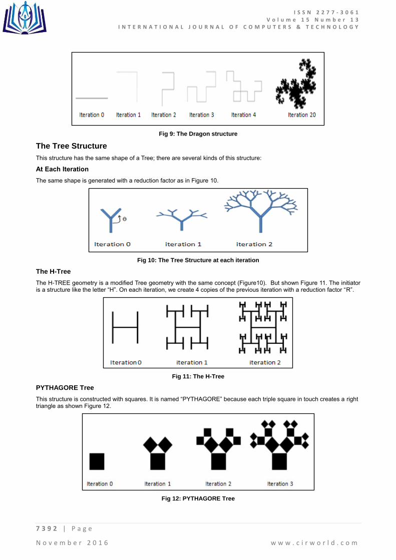
Fig 9: The Dragon structure
The Tree Structure
This structure has the same shape of a Tree; there are several kinds of this structure:
At Each Iteration
The same shape is generated with a reduction factor as in Figure 10.
Fig 10: The Tree Structure at each iteration
The H-Tree
The H-TREE geometry is a modified Tree geometry with the same concept (Figure10). But shown Figure 11. The initiator is a structure like the letter “H”. On each iteration, we create 4 copies of the previous iteration with a reduction factor “R”.
Fig 11: The H-Tree
PYTHAGORE Tree
This structure is constructed with squares. It is named “PYTHAGORE” because each triple square in touch creates a right triangle as shown Figure 12.
Fig 12: PYTHAGORE Tree
I S S N 2 2 7 7 - 3 0 6 1 V o l u m e 1 5 N u m b e r 1 3
I N T E R N A T I O N A L J O U R N A L O F C O M P U T E R S & T E C H N O L O G Y
7 3 9 3 | P a g e
N o v e m b e r 2 0 1 6 w w w . c i r w o r l d . c o m
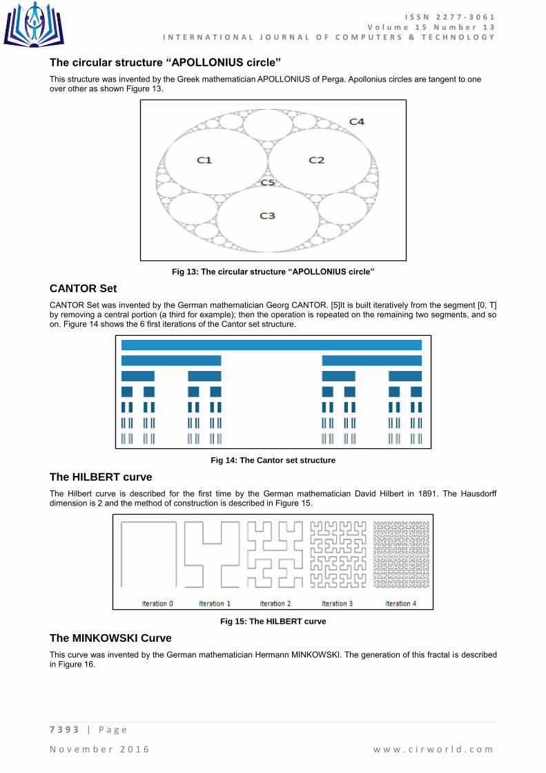
The circular structure “APOLLONIUS circle”
This structure was invented by the Greek mathematician APOLLONIUS of Perga. Apollonius circles are tangent to one over other as shown Figure 13.
Fig 13: The circular structure “APOLLONIUS circle”
CANTOR Set
CANTOR Set was invented by the German mathematician Georg CANTOR. [5]It is built iteratively from the segment [0, T] by removing a central portion (a third for example); then the operation is repeated on the remaining two segments, and so on. Figure 14 shows the 6 first iterations of the Cantor set structure.
Fig 14: The Cantor set structure
The HILBERT curve
The Hilbert curve is described for the first time by the German mathematician David Hilbert in 1891. The Hausdorff dimension is 2 and the method of construction is described in Figure 15.
Fig 15: The HILBERT curve
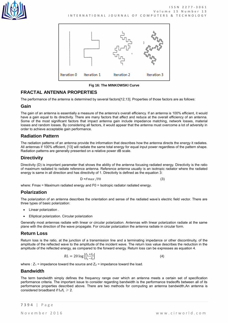
The MINKOWSKI Curve
This curve was invented by the German mathematician Hermann MINKOWSKI. The generation of this fractal is described in Figure 16.
I S S N 2 2 7 7 - 3 0 6 1 V o l u m e 1 5 N u m b e r 1 3
I N T E R N A T I O N A L J O U R N A L O F C O M P U T E R S & T E C H N O L O G Y
7 3 9 4 | P a g e
N o v e m b e r 2 0 1 6 w w w . c i r w o r l d . c o m
Fig 16: The MINKOWSKI Curve
FRACTAL ANTENNA PROPERTIES
The performance of the antenna is determined by several factors[12,13]. Properties of those factors are as follows:
Gain
The gain of an antenna is essentially a measure of the antenna‟s overall efficiency. If an antenna is 100% efficient, it would have a gain equal to its directivity. There are many factors that affect and reduce at the overall efficiency of an antenna. Some of the most significant factors that impact antenna gain include impedance matching, network losses, material losses and random losses. By considering all factors, it would appear that the antenna must overcome a lot of adversity in order to achieve acceptable gain performance.
Radiation Pattern
The radiation patterns of an antenna provide the information that describes how the antenna directs the energy it radiates. All antennas if 100% efficient, [13] will radiate the same total energy for equal input power regardless of the pattern shape. Radiation patterns are generally presented on a relative power dB scale.
Directivity
Directivity (D) is important parameter that shows the ability of the antenna focusing radiated energy. Directivity is the ratio of maximum radiated to radiate reference antenna. Reference antenna usually is an isotropic radiator where the radiated energy is same in all direction and has directivity of 1. Directivity is defined as the equation 3:
D =𝐹𝑚𝑎𝑥 F0⁄ (3)
where: Fmax = Maximum radiated energy and F0 = Isotropic radiator radiated energy.
Polarization
The polarization of an antenna describes the orientation and sense of the radiated wave‟s electric field vector. There are three types of basic polarization:
Linear polarization .
Elliptical polarization. Circular polarization
Generally most antennas radiate with linear or circular polarization. Antennas with linear polarization radiate at the same plane with the direction of the wave propagate. For circular polarization the antenna radiate in circular form.
Return Loss
Return loss is the ratio, at the junction of a transmission line and a terminating impedance or other discontinuity, of the amplitude of the reflected wave to the amplitude of the incident wave. The return loss value describes the reduction in the amplitude of the reflected energy, as compared to the forward energy. Return loss can be expresses as equation 4.
0 |
| (4)
where : Z1 = impedance toward the source and Z2 = impedance toward the load.
Bandwidth
The term bandwidth simply defines the frequency range over which an antenna meets a certain set of specification performance criteria. The important issue to consider regarding bandwidth is the performance tradeoffs between all of its performance properties described above. There are two methods for computing an antenna bandwidth,An antenna is
considered broadband if fH/fL ≥ 2.
I S S N 2 2 7 7 - 3 0 6 1 V o l u m e 1 5 N u m b e r 1 3
I N T E R N A T I O N A L J O U R N A L O F C O M P U T E R S & T E C H N O L O G Y
7 3 9 5 | P a g e
N o v e m b e r 2 0 1 6 w w w . c i r w o r l d . c o m
Narrowband by % age: 𝐵𝑊𝑃 𝑓ℎ
𝑓 ⁄
𝑓 × 00% (5)
Broadband by ratio: BWb= fh/fl
Where: f0 = Operating frequency, fh = Higher cut-off frequency and fl = Lower cut-off frequency.
FRACTAL ANTENNA ANALYSIS AND DESIGN TECHNIQUES
Fractals are objects which have a self-similar structure repeated throughout their geometry (Mandelbrot 1983; Peitgen et al. 1992).[7] This self-similar structure may be produced by the repeated application of a generator. So for the design there is amain numerical methods that used in antenna. [6]Generally speaking, there are three main numerical methods that have been widely implemented in the field of antenna simulation, namely Methods of Moments (MoM), Finite-Difference Time-Domain (FDTD) and Finite Element Method (FEM). The fundamental principles of these three popular computational electromagnetic methods, MoM, FDTD and FEM:
Methods of Moments
Methods of Moments was first proposed by Harrington in 1968 [14]. This method makes use of Maxwell‟s equation in integration form to formulate the electromagnetic problems in terms of unknown currents and calculates the coupling between the current elements.The use of MoM technique usually leads to a dense matrix and the memory usage is proportional to the N2, where N is number of nodes within the subject domain after discretization.
Finite-Difference Time-Domain Method
The FDTD method is based on the theory that the E-field and H-field are inter-related according the Maxwell‟s differential equations: the time derivative of the E-field is dependent on the curl of the H-field whilst the time derivative of the H-field is dependent on the curl of the E-field as in equations (6) and (7):
×
(6)
×
(7)
Using FDTD method, although it takes many time steps to complete the calculation, it can cover a wide frequency range with a single simulation run. The advantages of FDTD methods are that it does not need to compute all the equations simultaneously, it is robust in numerical calculations and it can efficiently solve complex 3D transient problems. However, this technique is not adequate for narrow band antenna structures as in this case, each time step will be increased and it may require long simulation time to accomplish the calculation; moreover, the calculation may not be converged in the final solution, which can cause inaccurate results.
Finite Element Method
The FEM method is a powerful tool to find the approximate solution of partial differential equations. This technique was firstly introduced into the field of civil and aeronautical engineering to solve the complex structural analysis. Later, this method gained wide application in other fields including the electromagnetic engineering. This method starts with discretizing the whole domain into a number of sub domains ,and then using an interpolating function, usually a polynomial of 1st or higher orders, to represent the unknowns inside these sub-domains.
NUMERICAL METHODS FOR ELECTRICAL SMALL ANTENNA DESIGN
Electrically small antenna refers to an antenna whose maximum dimension is much smaller than its corresponding free space wavelength at its resonant frequency[15]. To design an electrically small antenna, techniques that employ antenna of irregular shapes, substrate with non-homogeneous properties or multiple layers have been proposed. So the previous methods can not to be used unless under conditions as example, the MoM as the antenna is confined in limited space
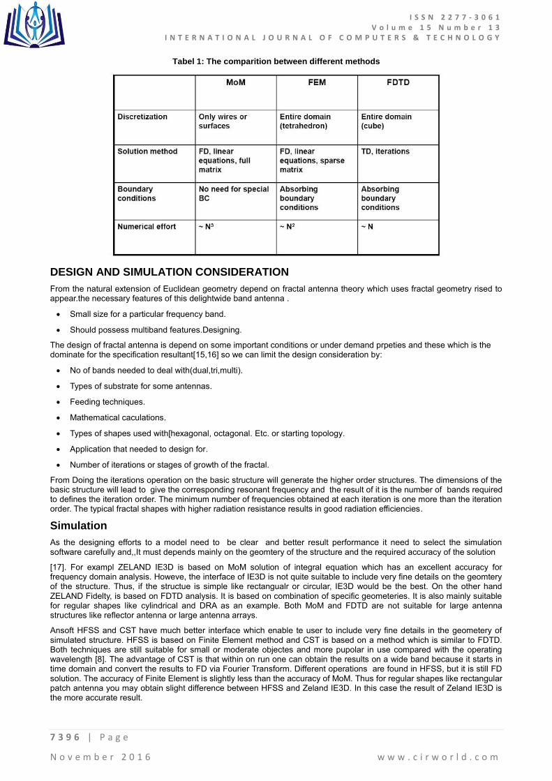
and has a non-planar structure or inhomogeneous substrate so it is not suitable to simulate such structures by using it. Because small antenna usually has a narrow bandwidth since there is always a trade-off between the antenna size and operation bandwidth/efficiency/ gain . on the other side FTDT would take a long sequence of time steps to complete because this method is based on the time domain, which is inversely proportional to the frequency domain. But in the other hand it is necessary to point out that several commercial EM simulation software packages have integrated other techniques to overcome such limits and improve the calculation efficiency as well as accuracy of the original methods. For instance, the fast multiple method (FMM) has been applied to accelerate the iterative solver of MoM and the Finite integration technique (FIT) has been developed to incorporate with the FDTD analysis. Tabel 1 shows the comparition between different methods:
I S S N 2 2 7 7 - 3 0 6 1 V o l u m e 1 5 N u m b e r 1 3
I N T E R N A T I O N A L J O U R N A L O F C O M P U T E R S & T E C H N O L O G Y
7 3 9 6 | P a g e
N o v e m b e r 2 0 1 6 w w w . c i r w o r l d . c o m
Tabel 1: The comparition between different methods
DESIGN AND SIMULATION CONSIDERATION
From the natural extension of Euclidean geometry depend on fractal antenna theory which uses fractal geometry rised to appear.the necessary features of this delightwide band antenna .
Small size for a particular frequency band.
Should possess multiband features.Designing.
The design of fractal antenna is depend on some important conditions or under demand prpeties and these which is the dominate for the specification resultant[15,16] so we can limit the design consideration by:
No of bands needed to deal with(dual,tri,multi).
Types of substrate for some antennas.
Feeding techniques.
Mathematical caculations.
Types of shapes used with[hexagonal, octagonal. Etc. or starting topology.
Application that needed to design for.
Number of iterations or stages of growth of the fractal.
From Doing the iterations operation on the basic structure will generate the higher order structures. The dimensions of the basic structure will lead to give the corresponding resonant frequency and the result of it is the number of bands required to defines the iteration order. The minimum number of frequencies obtained at each iteration is one more than the iteration order. The typical fractal shapes with higher radiation resistance results in good radiation efficiencies.
Simulation
As the designing efforts to a model need to be clear and better result performance it need to select the simulation software carefully and,,It must depends mainly on the geomtery of the structure and the required accuracy of the solution
[17]. For exampl ZELAND IE3D is based on MoM solution of integral equation which has an excellent accuracy for frequency domain analysis. Howeve, the interface of IE3D is not quite suitable to include very fine details on the geomtery of the structure. Thus, if the structue is simple like rectangualr or circular, IE3D would be the best. On the other hand ZELAND Fidelty, is based on FDTD analysis. It is based on combination of specific geometeries. It is also mainly suitable for regular shapes like cylindrical and DRA as an example. Both MoM and FDTD are not suitable for large antenna structures like reflector antenna or large antenna arrays.
Ansoft HFSS and CST have much better interface which enable te user to include very fine details in the geometery of simulated structure. HFSS is based on Finite Element method and CST is based on a method which is similar to FDTD. Both techniques are still suitable for small or moderate objectes and more pupolar in use compared with the operating wavelength [8]. The advantage of CST is that within on run one can obtain the results on a wide band because it starts in time domain and convert the results to FD via Fourier Transform. Different operations are found in HFSS, but it is still FD solution. The accuracy of Finite Element is slightly less than the accuracy of MoM. Thus for regular shapes like rectangular patch antenna you may obtain slight difference between HFSS and Zeland IE3D. In this case the result of Zeland IE3D is the more accurate result.

I S S N 2 2 7 7 - 3 0 6 1 V o l u m e 1 5 N u m b e r 1 3
I N T E R N A T I O N A L J O U R N A L O F C O M P U T E R S & T E C H N O L O G Y
7 3 9 7 | P a g e
N o v e m b e r 2 0 1 6 w w w . c i r w o r l d . c o m
However, for complicated geometery, you may find the accuracy of HFSS and CST are much better than IE3D due to the approximations which you have to do in the geometery of the structure. FEKO has two main solvers, one is based on MoM and another based on GTD (geometric theory of diffraction). The part of FEKO which is based on GTD cannot be replaced by Zeland, HFSS or CST beacuse remain essential for the solution of scattering problems involving large objects of arbitrary shapes like airplanes, helicopters, missiles, tanks and ships, at radar frequencies and it is mainly suitable for large strucutures like reflector antennas. In conclusion, a good designer should be able to use different CAD tools with deep understand of limits of their numerical techniques and modeling interface. In this report we will name some of the most popular softwares:
FEKO
This software is considerd as one of comprehensive computer aided engineering software that can be used for electromagnetic simulations using the latest techniques in the field of computational electromagnetics[18]. Its also is designed to provide solutions for a wide range of electromagnetic problems emanating from diverse industries that make use of Antenna, filters and any tool that uses time/frequency calculations. This software which is 3D EM tool can also works seamlessly with other antenna synthesis tools to design accurate antenna systems. It functions and features include:
The numerical methods it employs—MoM, FDTD—is fully equipped to handle the analysis of horns, micro strip antennas, radiation pattern analysis, and diverse EMC problems etc.
It is equipped with post-processing features that simplifies the task of editing and visualizations. Tools such as 2D/3D views, plotting 2D and 3D models and exporting designed files in different formats etc.
FEKO is equipped with certain CAD import and export features which allows for the use of external files from other CAD platforms.
Antenna Magus
The antenna magus is considerd as an antenna synthesis tool which means that it offers a huge database that serves as a collection for hot spot for different antenna models. Its also provides its users with information on how certain design specifications can be used to design the perfect antenna[17]. The magus is known for speeding up a design process by providing the following functions such as; Choosing the appropriate antenna topology, retrieving antenna information, validating the designed model and estimating its performance. These unique features makes it an accessory to be used with other design platforms such as FEKO. Its features and functions:
It can be used to rapidly design new prototypes using already existing design parameters on its database.
It supports the import of files in different format into its workspace/database and also allows for the exportation of works done its interface to other 3D CAD or CAE software applications.
Ansoft HFSS
HFSS, which is an acronym for high frequency structural simulator [19] its considerd the most advanced 3D EM software that is commonly used in antenna design and for the design of complex RF electronic circuits.its also equipped with the necessary features and tools for designing filters, transmission lines and modeling. Some of its features include:
IT bases its design and analysis method on the Finite Element Method
It integrates an automated design process that allows the user to simply specify his/her required geometry, design material properties etc.
the software generates a mesh that meets these specifications
It supports the design of linear circuits.
Microwave Studio CST
This is a CAD software built specially for the simulation of 3D Ems and antenna design. The software is unique due to its support for designing components—filters—that support high frequency propagations.And like most 3D EM platforms, it can be used to analyze multi-layer structures, and the EM behavior of high frequency designs [20]. The software comes with the following features and functions:
Mws CST integrates features such as Perfect Boundary Approximation (PBA), the Thin Sheet Technique and True Geometry Adaptation which goes a long way in improving the efficiency of its time domain and frequency calculation metrics thereby improving design accuracy.
The software also integrates filters that support the import of CAD files from other 3D EM as well as the extraction of SPICE parameters reduces the time required for designing a working prototype
It supports designs of linear or non-linear material models and its complete package comes with solver tools that can be configured to use certain solution methods—MoM, FDTD—depending on the user‟s requirements.

I S S N 2 2 7 7 - 3 0 6 1 V o l u m e 1 5 N u m b e r 1 3
I N T E R N A T I O N A L J O U R N A L O F C O M P U T E R S & T E C H N O L O G Y
7 3 9 8 | P a g e
N o v e m b e r 2 0 1 6 w w w . c i r w o r l d . c o m
ZELAND IE3D
ZELAND‟s IE3D is one of the most popular computer aided design or engineering software used by manufacturers/designers in the antenna design industry and this is due to the all-round functions a complete IE3D package provides. The software comes with the features needed for circuit 3D Geometry modelling, high capacity electromagnetic design and signal integrity modeling. The features [21], Tools and functions that make it unique includes:
Full automation for repetitive tasks which can lead to major/minor errors. Tasks such as; 3D geometry modelling, meshing and simulation falls under this group.
It incorporates MoM modelling techniques and also supports designs coming from other 3D EM design software.
More importantly, the intuitive nature of its workspaces eliminates the need for a user to have extensive knowledge of EM modeling to design a mesh thereby simplifying the entire design process.
COMSOL Multiphysics
the reason of using COMSOL for most of numerical simulations [22]. It‟s the most advanced software and recent one, it has many facilities made him pioneer and also one of The main reason is its capability of real multi-physics. , COMSOL can dominate numerical simulation world also COMSOL for numerical simulation& it's also easy to build in multiple nm size with multiple physics,which is more suitable for finite element analysis.
APPLICATIONS
Application is the exact translation of each invention and for the fractal antenna there is many application, several ideas will be showed below that improves fractal antennas can make an real impact. Thehuge and sudden growth in the wirless communication field has sprung need for compact integrated antennas, The space saving abilities of fractals to efficiently fill a limited amount of space create distinct advantage of using integrated fractal antennas over Euclidean geometry. Examples of these types of application include personal hand-held wireless devices such as cell phones and other wireless mobile devices such as laptops on wireless LANs and networkable PDAs [23]. Fractal antenna has another important feature is enrich applications that include multiband transmissions. The living used examples like the possibilities ranging from dual-mode phones to devices integrating communication and location services such as GPS,the global positioning satellites. the area of decreased a resonant antenna, which could lower the radar cross-section (RCS). Which has great influence and its benefit can be exploited in military applications where the RCS of the antenna is a very crucial parameter.
Advantages
minituratization .
better input impedance matching.
wideband/multiba instead of many) (use one antenna instead of many).
frequency independent (consistentperformance over huge frequency range) .
reduced mutual coupling in fractal array.
Didvantages of Fractal Antenna Technologie are
gain loss .
complexity.
numerical limitations.
the benefit begin to diminish after first few iterations.
DISCUSSION
Fractal antenna engineering was born or came to the world from blending attributes of fractal geometry with antenna theory by Mandelbrot in 1953 how is pioneer scientist, it was huge research area recently yielded a rich new designs of antenna elements as well as arrays .which from its marvelous Characteristics a space filling as an example which applied in wire and patch antenna. Antenna technology had to be revised to fulfill demands imposed by wireless systems, because conventional antenna technology can no longer meet future challenges.This technology used to designing high performance, small, multiband antenna.The fractal antenna to overcome of the needs of ISM band usage and this done by using different kind of simulation software like COMSOL,CSTMICROWAVE STUDIO, which will open the way for engineer to design and investigate better specification and better performance without costly and waste time time.
I S S N 2 2 7 7 - 3 0 6 1 V o l u m e 1 5 N u m b e r 1 3
I N T E R N A T I O N A L J O U R N A L O F C O M P U T E R S & T E C H N O L O G Y
7 3 9 9 | P a g e
N o v e m b e r 2 0 1 6 w w w . c i r w o r l d . c o m
REFERENCES
[1] Chowdary, P. Satish Rama, A. Mallikarjuna Prasad, P. Mallikarjuna Rao, and Jaume Anguera. "Design and performance study of sierpinski fractal based patch antennas for multiband and miniaturization characteristics." Wireless Personal Communications 83, no. 3 (2015): 1713-1730.
[2] Abdelati, R. E. H. A., E. L. Abdelkebir, Othmane BENHMAMMOUCH, and Ahmed OULAD SAID. "Fractal antennas: A novel miniaturization technique for wireless networks." Transactions on Networks and Communications 2, no. 5 (2014): 165-193.
[3]- Mandelbrot, Benoit B. The fractal geometry of nature. Vol. 173. Macmillan, 1983.
[4] Addison, Paul S. Fractals and chaos: an illustrated course. CRC Press, 1997.
[5] Falconer, Kenneth. Fractal geometry: mathematical foundations and applications. John Wiley & Sons, 2004.
[6]Romeu, Jordi, and Jordi Soler. "Generalized Sierpinski fractal multiband antenna." IEEE Transactions on Antennas and Propagation 49, no. 8 (2001): 1237-1239.
[7]Werner, Douglas H., and Suman Ganguly. "An overview of fractal antenna engineering research." IEEE Antennas and propagation Magazine 45, no. 1 (2003): 38-57.
[8] Balanis, C., Chapter 4 Linear Wire Antennas. Antenna Theory Analysis and Design, Third ed., Hoboken, New Jersey: John Wiley & Sons, Inc, 2005: p. 151-219
[9] Azari, Abolfazl. "A new fractal antenna for super wideband applications." InPIERS Proceedings, pp. 885-888. 2010.
[10] Krzysztofik, Wojciech J. "Take advantage of fractal geometry in the antenna technology of Modern Communications." In 2013 11th International Conference on Telecommunications in Modern Satellite, Cable and Broadcasting Services (TELSIKS). 2013.
[11] Lizzi, L., Azaro, R., Oliveri, G. and Massa, A., 2012. Multiband fractal antenna for wireless communication systems for emergency management. Journal of Electromagnetic Waves and Applications, 26(1), pp.1-11.
[12] Luo, Qi. "Design synthesis and miniaturization of multiband and reconfigurable microstrip antenna for future wireless applications." (2013).
[13] Dinesh, V. and Karunakar, G., 2015, January. Analysis of microstrip rectangular carpet shaped fractal antenna. In Signal Processing And Communication Engineering Systems (SPACES), 2015 International Conference on (pp. 531-535). IEEE.
[14] Cohen, Nathan. "Fractals new era in Military antenna design." Journal of RF design (2005).
[15] Sánchez-Hernández, David A. Multiband integrated antennas for 4G terminals. Artech House, 2008.
[16] Patil, Sarang, and Vandana Rohokale. "Multiband smart fractal antenna design for converged 5G wireless networks." In Pervasive Computing (ICPC), 2015 International Conference on, pp. 1-5. IEEE, 2015.
[17]Raval, Bhargavi T., Pratima R. Pimpalgaonkar, Mukesh R. Chaurasia, and Trushit Upadhyaya. "Review of Ultra-Wideband and Design Studies of Patch Antenna for Ultra-Wideband Communication."
[18] Reha, Abdelati, Abdelkebir El Amri, Othmane Benhmammouch, and Ahmed Oulad Said. "CPW-fed KOCH SNOWFLAKE fractal antenna for UWB wireless applications." Transactions on Networks and Communications 2, no. 4 (2014): 38-53.
[19]Kumar, Yadwinder, and Surinder Singh. "A Compact Multiband Hybrid Fractal Antenna for Multistandard Mobile Wireless Applications." Wireless Personal Communications 84, no. 1 (2015): 57-67.
[20] Mishra, R. K., R. Ghatak, and D. R. Poddar. "Design formula for sierpinski gasket pre-fractal planar-monopole antennas [antenna designer's notebook]." IEEE Antennas and Propagation Magazine 50, no. 3 (2008): 104-107.
[21]Srivastava, Dinesh Kumar, Anshika Khanna, and Jai Prakash Saini. "Design of a wideband gap-coupled modified square fractal antenna." Journal of Computational Electronics 15, no. 1 (2016): 239-247.
[22]Takebe, Kozaburo, Hidetoshi Miyashita, Keisuke Takano, Masanori Hangyo, and Sang-Seok Lee. "Electromagnetic wave absorption characteristics of H-shaped fractal antenna for multi-band microbolometer."

I S S N 2 2 7 7 - 3 0 6 1 V o l u m e 1 5 N u m b e r 1 3
I N T E R N A T I O N A L J O U R N A L O F C O M P U T E R S & T E C H N O L O G Y
7 4 0 0 | P a g e
N o v e m b e r 2 0 1 6 w w w . c i r w o r l d . c o m
In Nano/Micro Engineered and Molecular Systems (NEMS), 2014 9th IEEE International Conference on, pp. 135-138. IEEE, 2014.
[23] Varadhan, Chitra, Jayaram Kizhekke Pakkathillam, Malathi Kanagasabai, Ramprabhu Sivasamy, Rajesh Natarajan, and Sandeep Kumar Palaniswamy. "Triband antenna structures for RFID systems deploying fractal geometry." IEEE antennas and wireless propagation letters 12 (2013): 437-440.
Related Documents