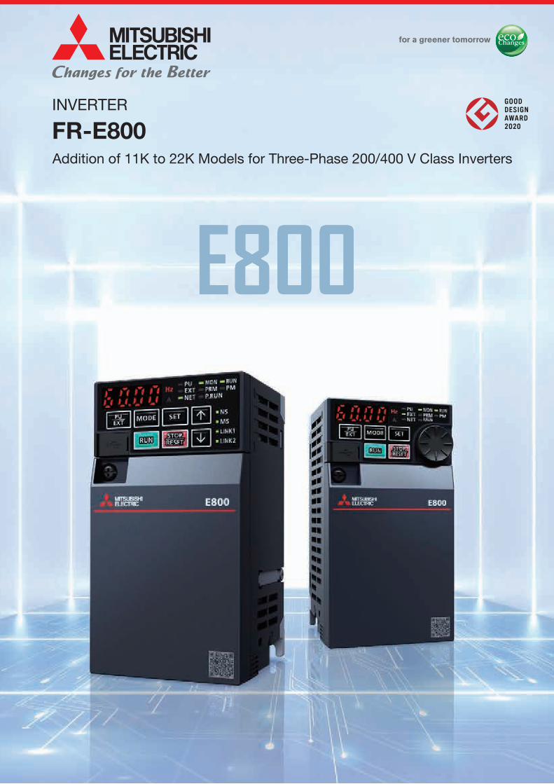
INVERTER FR-E800 Addition of 11K to 22K Models for Three-Phase 200/400 V Class Inverters

Welcome message from author
This document is posted to help you gain knowledge. Please leave a comment to let me know what you think about it! Share it to your friends and learn new things together.
Transcript
FR-E
800
INVERTER
FR-E800
L(NA)06131ENG-C (2101) MEE
HEAD OFFICE: TOKYO BLDG., 2-7-3, MARUNOUCHI, CHIYODA-KU, TOKYO 100-8310, JAPAN
Mitsubishi Electric Corporation Nagoya Works is a factory certified for ISO 14001 (standards for environmental management systems) and ISO 9001 (standards for quality assurance management systems).
Addition of 11K to 22K Models for Three-Phase 200/400 V Class Inverters

4
42
47
63
67
72
74
80
82
106
112
119
129
135
136
Contents
1
2
3
4
5
6
7
8
9
10
11
12
13
14
Global Player
Features
Operation Panel, Operation Steps
Parameter List
Protective Functions
Standard Specifications
Outline Dimensions
Terminal Connection Diagram, Terminal Specifications
Example Connections
Options
Low-Voltage Switchgear/Cables
Precaution on Selection and Operation
Compatible Motors
Compatibility
Warranty
Support
GLOBAL IMPACT OFMITSUBISHI ELECTRIC
We bring together the best minds to create the best technologies. At Mitsubishi Electric, we understand that technology is the driving force of change in our lives. By bringing great-er comfort to daily life, maximizing the efficiency of businesses and keeping things running across society, we integrate technology and innovation to bring changes for the better.
Mitsubishi Electric is involved in many areas including the following
Energy and Electric SystemsA wide range of power and electrical products from generators to large-scale displays.
Electronic DevicesA wide portfolio of cutting-edge semiconductor devices for systems and products.
Home ApplianceDependable consumer products like air conditioners and home entertain-ment systems.
Information and Communication SystemsCommercial and consumer-centric equipment, products and systems.
Industrial Automation SystemsMaximizing productivity and efficiency with cutting-edge automation technology.
Through Mitsubishi Electric’s vision, “Changes for the Better“ are possible for a brighter future.
2
4
42
47
63
67
72
74
80
82
106
112
119
129
135
136
Contents
1
2
3
4
5
6
7
8
9
10
11
12
13
14
Global Player
Features
Operation Panel, Operation Steps
Parameter List
Protective Functions
Standard Specifications
Outline Dimensions
Terminal Connection Diagram, Terminal Specifications
Example Connections
Options
Low-Voltage Switchgear/Cables
Precaution on Selection and Operation
Compatible Motors
Compatibility
Warranty
Support
GLOBAL IMPACT OFMITSUBISHI ELECTRIC
We bring together the best minds to create the best technologies. At Mitsubishi Electric, we understand that technology is the driving force of change in our lives. By bringing great-er comfort to daily life, maximizing the efficiency of businesses and keeping things running across society, we integrate technology and innovation to bring changes for the better.
Mitsubishi Electric is involved in many areas including the following
Energy and Electric SystemsA wide range of power and electrical products from generators to large-scale displays.
Electronic DevicesA wide portfolio of cutting-edge semiconductor devices for systems and products.
Home ApplianceDependable consumer products like air conditioners and home entertain-ment systems.
Information and Communication SystemsCommercial and consumer-centric equipment, products and systems.
Industrial Automation SystemsMaximizing productivity and efficiency with cutting-edge automation technology.
Through Mitsubishi Electric’s vision, “Changes for the Better“ are possible for a brighter future.
3
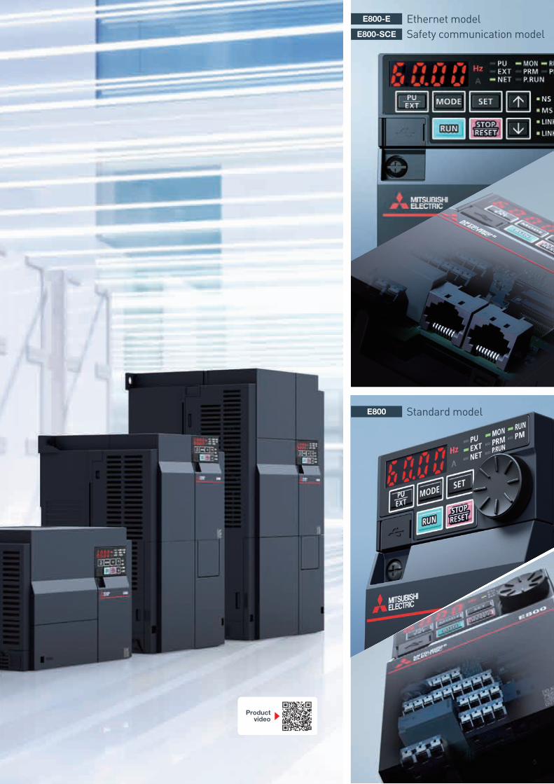
Ethernet modelSafety communication modelE800-SCE
E800-E
Standard modelE800
Productvideo
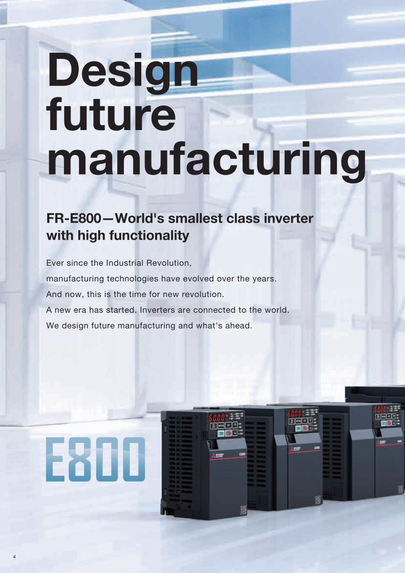
Design future manufacturingFR-E800—World's smallest class inverter with high functionality
Ever since the Industrial Revolution,
manufacturing technologies have evolved over the years.
And now, this is the time for new revolution.
A new era has started. Inverters are connected to the world.
We design future manufacturing and what's ahead.
4
Ethernet modelSafety communication modelE800-SCE
E800-E
Standard modelE800
Productvideo
Design future manufacturingFR-E800—World's smallest class inverter with high functionality
Ever since the Industrial Revolution,
manufacturing technologies have evolved over the years.
And now, this is the time for new revolution.
A new era has started. Inverters are connected to the world.
We design future manufacturing and what's ahead.
5
P13
P13EtherNet/IPPROFINET
EtherCAT, etc.
P14
1
2
3
P25
2
3
P27
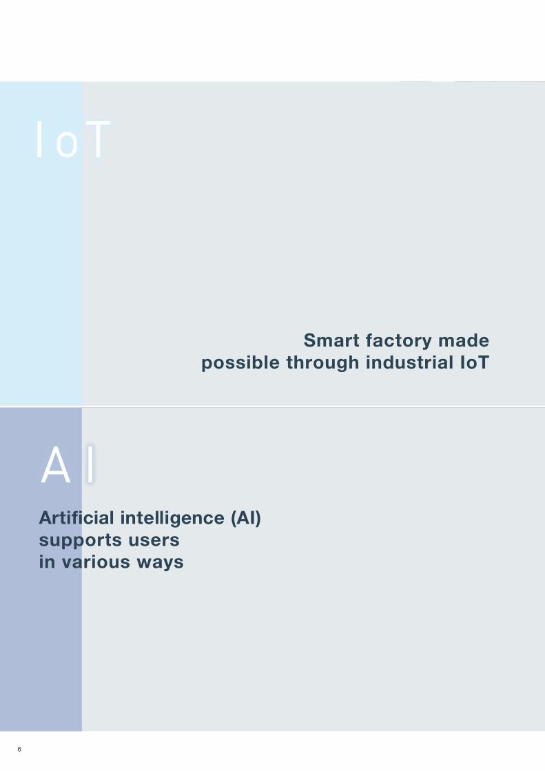
1A IA I
P28
I oTI oT
Smart factory madepossible through industrial IoT
Artificial intelligence (AI) supports users in various ways
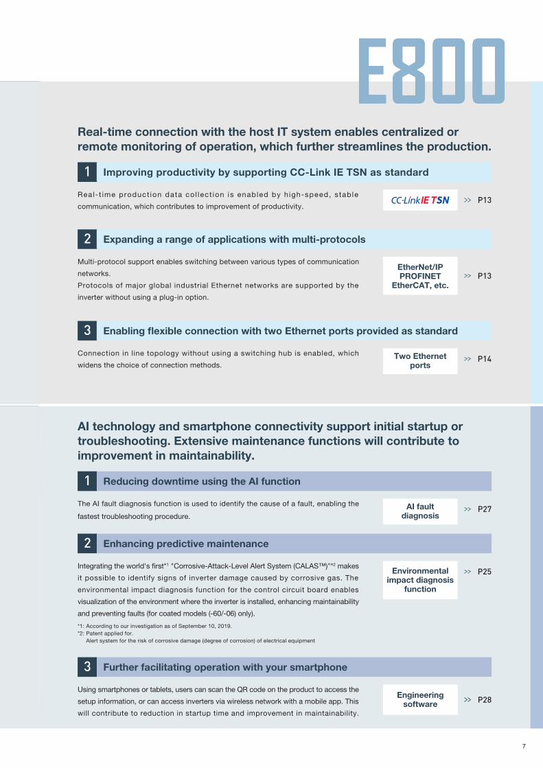
Real-time connection with the host IT system enables centralized or remote monitoring of operation, which further streamlines the production.
Real- t ime product ion data col lect ion is enabled by h igh-speed, stable
communication, which contributes to improvement of productivity.
Improving productivity by supporting CC-Link IE TSN as standard
Multi-protocol support enables switching between various types of communication
networks.
Protocols of major global industrial Ethernet networks are supported by the
inverter without using a plug-in option.
Expanding a range of applications with multi-protocols
Connection in line topology without using a switching hub is enabled, which
widens the choice of connection methods.
Enabling flexible connection with two Ethernet ports provided as standard
AI technology and smartphone connectivity support initial startup or troubleshooting. Extensive maintenance functions will contribute to improvement in maintainability.
Integrating the world's first*1 "Corrosive-Attack-Level Alert System (CALAS™)"*2 makes
it possible to identify signs of inverter damage caused by corrosive gas. The
environmental impact diagnosis function for the control circuit board enables
visualization of the environment where the inverter is installed, enhancing maintainability
and preventing faults (for coated models (-60/-06) only).
Enhancing predictive maintenance
Using smartphones or tablets, users can scan the QR code on the product to access the
setup information, or can access inverters via wireless network with a mobile app. This
will contribute to reduction in startup time and improvement in maintainability.
Further facilitating operation with your smartphone
The AI fault diagnosis function is used to identify the cause of a fault, enabling the
fastest troubleshooting procedure.
Reducing downtime using the AI function
*1: According to our investigation as of September 10, 2019. *2: Patent applied for. Alert system for the risk of corrosive damage (degree of corrosion) of electrical equipment
Two Ethernetports
Environmentalimpact diagnosis
function
AI faultdiagnosis
Engineeringsoftware
6
P13
P13EtherNet/IPPROFINET
EtherCAT, etc.
P14
1
2
3
P25
2
3
P27
1A IA I
P28
I oTI oT
Smart factory madepossible through industrial IoT
Artificial intelligence (AI) supports users in various ways
Real-time connection with the host IT system enables centralized or remote monitoring of operation, which further streamlines the production.
Real- t ime product ion data col lect ion is enabled by h igh-speed, stable
communication, which contributes to improvement of productivity.
Improving productivity by supporting CC-Link IE TSN as standard
Multi-protocol support enables switching between various types of communication
networks.
Protocols of major global industrial Ethernet networks are supported by the
inverter without using a plug-in option.
Expanding a range of applications with multi-protocols
Connection in line topology without using a switching hub is enabled, which
widens the choice of connection methods.
Enabling flexible connection with two Ethernet ports provided as standard
AI technology and smartphone connectivity support initial startup or troubleshooting. Extensive maintenance functions will contribute to improvement in maintainability.
Integrating the world's first*1 "Corrosive-Attack-Level Alert System (CALAS™)"*2 makes
it possible to identify signs of inverter damage caused by corrosive gas. The
environmental impact diagnosis function for the control circuit board enables
visualization of the environment where the inverter is installed, enhancing maintainability
and preventing faults (for coated models (-60/-06) only).
Enhancing predictive maintenance
Using smartphones or tablets, users can scan the QR code on the product to access the
setup information, or can access inverters via wireless network with a mobile app. This
will contribute to reduction in startup time and improvement in maintainability.
Further facilitating operation with your smartphone
The AI fault diagnosis function is used to identify the cause of a fault, enabling the
fastest troubleshooting procedure.
Reducing downtime using the AI function
*1: According to our investigation as of September 10, 2019. *2: Patent applied for. Alert system for the risk of corrosive damage (degree of corrosion) of electrical equipment
Two Ethernetports
Environmentalimpact diagnosis
function
AI faultdiagnosis
Engineeringsoftware
7

P16
2
1
P19
P21
Adjustments of inverter parameters and inverter monitoring can be performed
wirelessly away from the system, ensuring operators' safety.
Ensuring operators' safety by wireless interfaces
P20
1
3
P15
2
PerformancePerformance
SafetySafety
Various solutions achieved by the outstanding drive performance
Advanced harmony between humans and FA devices
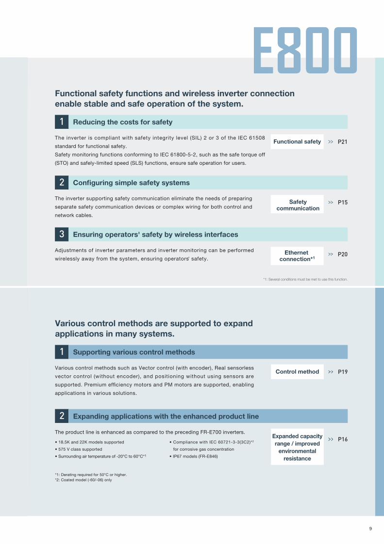
Functional safety functions and wireless inverter connection enable stable and safe operation of the system.
The inverter supporting safety communication eliminate the needs of preparing
separate safety communication devices or complex wiring for both control and
network cables.
Configuring simple safety systems
The inverter is compliant with safety integrity level (SIL) 2 or 3 of the IEC 61508
standard for functional safety.
Safety monitoring functions conforming to IEC 61800-5-2, such as the safe torque off
(STO) and safely-limited speed (SLS) functions, ensure safe operation for users.
Reducing the costs for safety
Functional safety
Safetycommunication
Ethernet connection*1
*1: Several conditions must be met to use this function.
The product line is enhanced as compared to the preceding FR-E700 inverters.
• 18.5K and 22K models supported
• 575 V class supported
• Surrounding air temperature of -20°C to 60°C*1
• Compliance with IEC 60721-3-3(3C2)*2
for corrosive gas concentration
• IP67 models (FR-E846)
Expanding applications with the enhanced product line
Expanded capacityrange / improved
environmentalresistance
Various control methods such as Vector control (with encoder), Real sensorless
vector control (without encoder), and positioning without using sensors are
supported. Premium efficiency motors and PM motors are supported, enabling
applications in various solutions.
Supporting various control methods
Control method
*1: Derating required for 50°C or higher.*2: Coated model (-60/-06) only
Various control methods are supported to expand applications in many systems.
Available when the plug-in option is connected.
8
P16
2
1
P19
P21
Adjustments of inverter parameters and inverter monitoring can be performed
wirelessly away from the system, ensuring operators' safety.
Ensuring operators' safety by wireless interfaces
P20
1
3
P15
2
PerformancePerformance
SafetySafety
Various solutions achieved by the outstanding drive performance
Advanced harmony between humans and FA devices
Functional safety functions and wireless inverter connection enable stable and safe operation of the system.
The inverter supporting safety communication eliminate the needs of preparing
separate safety communication devices or complex wiring for both control and
network cables.
Configuring simple safety systems
The inverter is compliant with safety integrity level (SIL) 2 or 3 of the IEC 61508
standard for functional safety.
Safety monitoring functions conforming to IEC 61800-5-2, such as the safe torque off
(STO) and safely-limited speed (SLS) functions, ensure safe operation for users.
Reducing the costs for safety
Functional safety
Safetycommunication
Ethernet connection*1
*1: Several conditions must be met to use this function.
The product line is enhanced as compared to the preceding FR-E700 inverters.
• 18.5K and 22K models supported
• 575 V class supported
• Surrounding air temperature of -20°C to 60°C*1
• Compliance with IEC 60721-3-3(3C2)*2
for corrosive gas concentration
• IP67 models (FR-E846)
Expanding applications with the enhanced product line
Expanded capacityrange / improved
environmentalresistance
Various control methods such as Vector control (with encoder), Real sensorless
vector control (without encoder), and positioning without using sensors are
supported. Premium efficiency motors and PM motors are supported, enabling
applications in various solutions.
Supporting various control methods
Control method
*1: Derating required for 50°C or higher.*2: Coated model (-60/-06) only
Various control methods are supported to expand applications in many systems.
Available when the plug-in option is connected.
9
Useful functions for each of the design, operation, and maintenance processes of systemsFR-E800 inverters have various functions to attract more customers by offering safe and reliable operation for a long time.This is the time to start innovation in the fields of manufacturing.
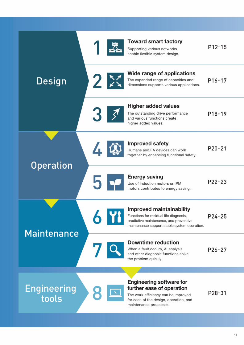
Engineering tools
Maintenance
Operation
Design
123
45
67
8 P28-31
P12-15
P16・17
P18・19
P20・21
P22・23
P24・25
P26・27
Engineering software for further ease of operationThe work efficiency can be improved for each of the design, operation, and maintenance processes.
Toward smart factorySupporting various networks enable flexible system design.
Wide range of applicationsThe expanded range of capacities and dimensions supports various applications.
Higher added valuesThe outstanding drive performance and various functions create higher added values.
Improved safetyHumans and FA devices can work together by enhancing functional safety.
Energy savingUse of induction motors or IPM motors contributes to energy saving.
Improved maintainabilityFunctions for residual life diagnosis, predictive maintenance, and preventive maintenance support stable system operation.
Downtime reductionWhen a fault occurs, AI analysis and other diagnosis functions solve the problem quickly.
10
Useful functions for each of the design, operation, and maintenance processes of systemsFR-E800 inverters have various functions to attract more customers by offering safe and reliable operation for a long time.This is the time to start innovation in the fields of manufacturing.
Engineering tools
Maintenance
Operation
Design
123
45
67
8 P28-31
P12-15
P16・17
P18・19
P20・21
P22・23
P24・25
P26・27
Engineering software for further ease of operationThe work efficiency can be improved for each of the design, operation, and maintenance processes.
Toward smart factorySupporting various networks enable flexible system design.
Wide range of applicationsThe expanded range of capacities and dimensions supports various applications.
Higher added valuesThe outstanding drive performance and various functions create higher added values.
Improved safetyHumans and FA devices can work together by enhancing functional safety.
Energy savingUse of induction motors or IPM motors contributes to energy saving.
Improved maintainabilityFunctions for residual life diagnosis, predictive maintenance, and preventive maintenance support stable system operation.
Downtime reductionWhen a fault occurs, AI analysis and other diagnosis functions solve the problem quickly.
11
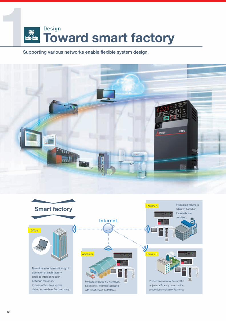
1 Toward smart factorySupporting various networks enable flexible system design.
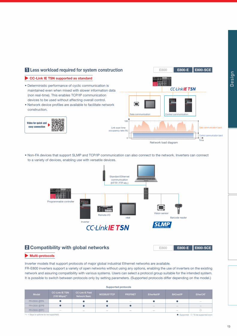
• Non-FA devices that support SLMP and TCP/IP communication can also connect to the network. Inverters can connect to a variety of devices, enabling use with versatile devices.
E800-SCEE800-EE800
Smart factory
Programmable controller
Inverter
Remote I/OHMI
Standard Ethernetcommunication(HTTP, FTP etc.)
Vision sensor
Barcode reader
MELSEC
Design
E800-SCEE800-EE800
Multi-protocols
Supported protocols
ModelCC-Link IE TSN
(100 Mbps)*1
CC-Link IE Field
Network BasicMODBUS®/TCP PROFINET EtherNet/IP BACnet/IP EtherCAT
FR-E800-[]EPA
FR-E800-[]EPB
FR-E800-[]EPC
—
—
—
—
—
—
—
—
—
—
—
: Supported : To be supported soon*1: 1 Gbps is optional (to be supported).
Less workload required for system construction
• Deterministic performance of cyclic communication is maintained even when mixed with slower information data (non real-time). This enables TCP/IP communication devices to be used without affecting overall control.
• Network device profiles are available to facilitate network construction.
Compatibility with global networks
Inverter models that support protocols of major global industrial Ethernet networks are available.FR-E800 inverters support a variety of open networks without using any options, enabling the use of inverters on the existing network and assuring compatibility with various systems. Users can select a protocol group suitable for the intended system. It is possible to switch between protocols only by setting parameters. (Supported protocols differ depending on the model.)
CC-Link IE TSN supported as standard
Control communication band
Control communicationData communication
Data communication band
Network load diagramTime
Link scan timeoccupancy rate (%)
100
0
MELSEC Des
ign
Video for quick andeasy connection
Real-time remote monitoring of
operation of each factory
enables interconnection
between factories.
In case of troubles, quick
detection enables fast recovery.
Office
Internet
Production volume is
adjusted based on
the warehouse
condition.
Factory A
Production volume of Factory B is
adjusted efficiently based on the
production condition of Factory A.
Factory BWarehouse
Products are stored in a warehouse.
Stock control information is shared
with the office and the factories.
12
1 Toward smart factorySupporting various networks enable flexible system design.
• Non-FA devices that support SLMP and TCP/IP communication can also connect to the network. Inverters can connect to a variety of devices, enabling use with versatile devices.
E800-SCEE800-EE800
Smart factory
Programmable controller
Inverter
Remote I/OHMI
Standard Ethernetcommunication(HTTP, FTP etc.)
Vision sensor
Barcode reader
MELSEC
Design
E800-SCEE800-EE800
Multi-protocols
Supported protocols
ModelCC-Link IE TSN
(100 Mbps)*1
CC-Link IE Field
Network BasicMODBUS®/TCP PROFINET EtherNet/IP BACnet/IP EtherCAT
FR-E800-[]EPA
FR-E800-[]EPB
FR-E800-[]EPC
—
—
—
—
—
—
—
—
—
—
—
: Supported : To be supported soon*1: 1 Gbps is optional (to be supported).
Less workload required for system construction
• Deterministic performance of cyclic communication is maintained even when mixed with slower information data (non real-time). This enables TCP/IP communication devices to be used without affecting overall control.
• Network device profiles are available to facilitate network construction.
Compatibility with global networks
Inverter models that support protocols of major global industrial Ethernet networks are available.FR-E800 inverters support a variety of open networks without using any options, enabling the use of inverters on the existing network and assuring compatibility with various systems. Users can select a protocol group suitable for the intended system. It is possible to switch between protocols only by setting parameters. (Supported protocols differ depending on the model.)
CC-Link IE TSN supported as standard
Control communication band
Control communicationData communication
Data communication band
Network load diagramTime
Link scan timeoccupancy rate (%)
100
0
MELSEC Des
ign
Video for quick andeasy connection
Real-time remote monitoring of
operation of each factory
enables interconnection
between factories.
In case of troubles, quick
detection enables fast recovery.
Office
Internet
Production volume is
adjusted based on
the warehouse
condition.
Factory A
Production volume of Factory B is
adjusted efficiently based on the
production condition of Factory A.
Factory BWarehouse
Products are stored in a warehouse.
Stock control information is shared
with the office and the factories.
13
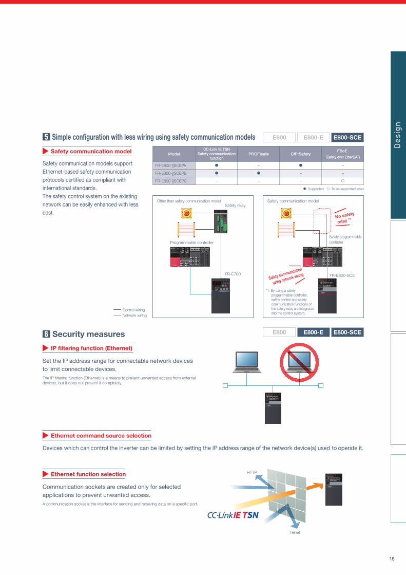
Simple configuration with less wiring using safety communication models
Safety communication models support Ethernet-based safety communication protocols certified as compliant with international standards.The safety control system on the existing network can be easily enhanced with less cost.
1 Toward smart factorySupporting various networks enable flexible system design.
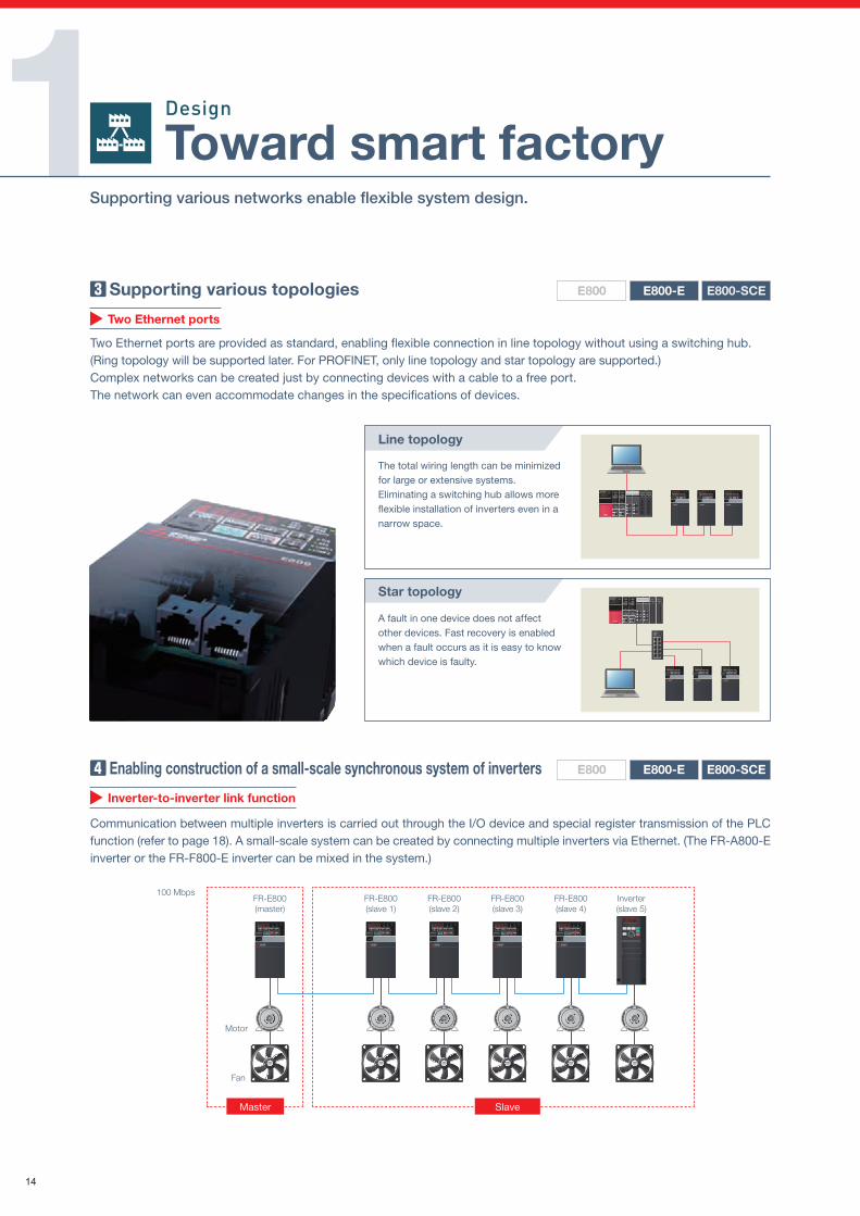
Enabling construction of a small-scale synchronous system of inverters
Communication between multiple inverters is carried out through the I/O device and special register transmission of the PLC function (refer to page 18). A small-scale system can be created by connecting multiple inverters via Ethernet. (The FR-A800-E inverter or the FR-F800-E inverter can be mixed in the system.)
E800-SCEE800-EE800
Inverter-to-inverter link function
FR-E800(slave 2)
FR-E800(slave 1)
FR-E800(slave 3)
FR-E800(master)
FR-E800(slave 4)
Inverter(slave 5)
100 Mbps
Motor
Fan
Master Slave
E800-SCEE800-EE800
Safety communication model
Safety communication modelOther than safety communication model
Programmable controller
MELSEC
FR-E700
Safety relay
Safety programmablecontroller
FR-E800-SCE
MELSEC
Security measures
Set the IP address range for connectable network devices to limit connectable devices.The IP filtering function (Ethernet) is a means to prevent unwanted access from external devices, but it does not prevent it completely.
Devices which can control the inverter can be limited by setting the IP address range of the network device(s) used to operate it.
Communication sockets are created only for selected applications to prevent unwanted access.A communication socket is the interface for sending and receiving data on a specific port.
E800-SCEE800-EE800
IP filtering function (Ethernet)
Ethernet command source selection
Ethernet function selection HTTP
Telnet
Supporting various topologies
Two Ethernet ports are provided as standard, enabling flexible connection in line topology without using a switching hub.(Ring topology will be supported later. For PROFINET, only line topology and star topology are supported.)Complex networks can be created just by connecting devices with a cable to a free port.The network can even accommodate changes in the specifications of devices.
E800-SCEE800-EE800
Two Ethernet ports
Star topology
Line topology
A fault in one device does not affect other devices. Fast recovery is enabled when a fault occurs as it is easy to know which device is faulty.
The total wiring length can be minimized for large or extensive systems.Eliminating a switching hub allows more flexible installation of inverters even in a narrow space.
Design
MELSEC
MELSEC
*1: By using a safety programmable controller, safety control and safety communication functions of the safety relay are integrated into the control system.
Des
ign
No safety
relay *1
Safety communication
using network wiring
ModelCC-Link IE TSN
Safety communicationfunction
PROFIsafe CIP SafetyFSoE
(Safety over EtherCAT)
FR-E800-[]SCEPA
FR-E800-[]SCEPB
FR-E800-[]SCEPC
–
–
–
–
–
–
–
: Supported : To be supported soon
Control wiringNetwork wiring
14
Simple configuration with less wiring using safety communication models
Safety communication models support Ethernet-based safety communication protocols certified as compliant with international standards.The safety control system on the existing network can be easily enhanced with less cost.
1 Toward smart factorySupporting various networks enable flexible system design.
Enabling construction of a small-scale synchronous system of inverters
Communication between multiple inverters is carried out through the I/O device and special register transmission of the PLC function (refer to page 18). A small-scale system can be created by connecting multiple inverters via Ethernet. (The FR-A800-E inverter or the FR-F800-E inverter can be mixed in the system.)
E800-SCEE800-EE800
Inverter-to-inverter link function
FR-E800(slave 2)
FR-E800(slave 1)
FR-E800(slave 3)
FR-E800(master)
FR-E800(slave 4)
Inverter(slave 5)
100 Mbps
Motor
Fan
Master Slave
E800-SCEE800-EE800
Safety communication model
Safety communication modelOther than safety communication model
Programmable controller
MELSEC
FR-E700
Safety relay
Safety programmablecontroller
FR-E800-SCE
MELSEC
Security measures
Set the IP address range for connectable network devices to limit connectable devices.The IP filtering function (Ethernet) is a means to prevent unwanted access from external devices, but it does not prevent it completely.
Devices which can control the inverter can be limited by setting the IP address range of the network device(s) used to operate it.
Communication sockets are created only for selected applications to prevent unwanted access.A communication socket is the interface for sending and receiving data on a specific port.
E800-SCEE800-EE800
IP filtering function (Ethernet)
Ethernet command source selection
Ethernet function selection HTTP
Telnet
Supporting various topologies
Two Ethernet ports are provided as standard, enabling flexible connection in line topology without using a switching hub.(Ring topology will be supported later. For PROFINET, only line topology and star topology are supported.)Complex networks can be created just by connecting devices with a cable to a free port.The network can even accommodate changes in the specifications of devices.
E800-SCEE800-EE800
Two Ethernet ports
Star topology
Line topology
A fault in one device does not affect other devices. Fast recovery is enabled when a fault occurs as it is easy to know which device is faulty.
The total wiring length can be minimized for large or extensive systems.Eliminating a switching hub allows more flexible installation of inverters even in a narrow space.
Design
MELSEC
MELSEC
*1: By using a safety programmable controller, safety control and safety communication functions of the safety relay are integrated into the control system.
Des
ign
No safety
relay *1
Safety communication
using network wiring
ModelCC-Link IE TSN
Safety communicationfunction
PROFIsafe CIP SafetyFSoE
(Safety over EtherCAT)
FR-E800-[]SCEPA
FR-E800-[]SCEPB
FR-E800-[]SCEPC
–
–
–
–
–
–
–
: Supported : To be supported soon
Control wiringNetwork wiring
15
SlicerSide-by-side installation
Effective solution for downsizing equipment
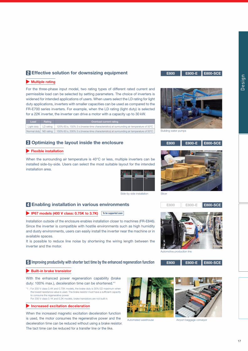
For the three-phase input model, two rating types of different rated current and permissible load can be selected by setting parameters. The choice of inverters is widened for intended applications of users. When users select the LD rating for light duty applications, inverters with smaller capacities can be used as compared to the FR-E700 series inverters. For example, when the LD rating (light duty) is selected for a 22K inverter, the inverter can drive a motor with a capacity up to 30 kW.
E800-EE800 E800-SCE
Multiple rating
Optimizing the layout inside the enclosure
When the surrounding air temperature is 40°C or less, multiple inverters can be installed side-by-side. Users can select the most suitable layout for the intended installation area.
E800-SCEE800-EE800
Flexible installation
Enabling installation in various environments
IP67 models (400 V class: 0.75K to 3.7K)
Improving productivity with shorter tact time by the enhanced regeneration function
With the enhanced power regeneration capability (brake duty: 100% max.), deceleration time can be shortened.*1
*1 : For 200 V class 0.4K and 0.75K models, the brake duty is 30% ED maximum when the lowest resistance value is used. The brake resistor must have a sufficient capacity to consume the regenerative power. For 200 V class 0.1K and 0.2K models, brake transistors are not built in.
When the increased magnetic excitation deceleration function is used, the motor consumes the regenerative power and the deceleration time can be reduced without using a brake resistor.The tact time can be reduced for a transfer line or the like.
E800-SCEE800-EE800
Built-in brake transistor
Increased excitation deceleration
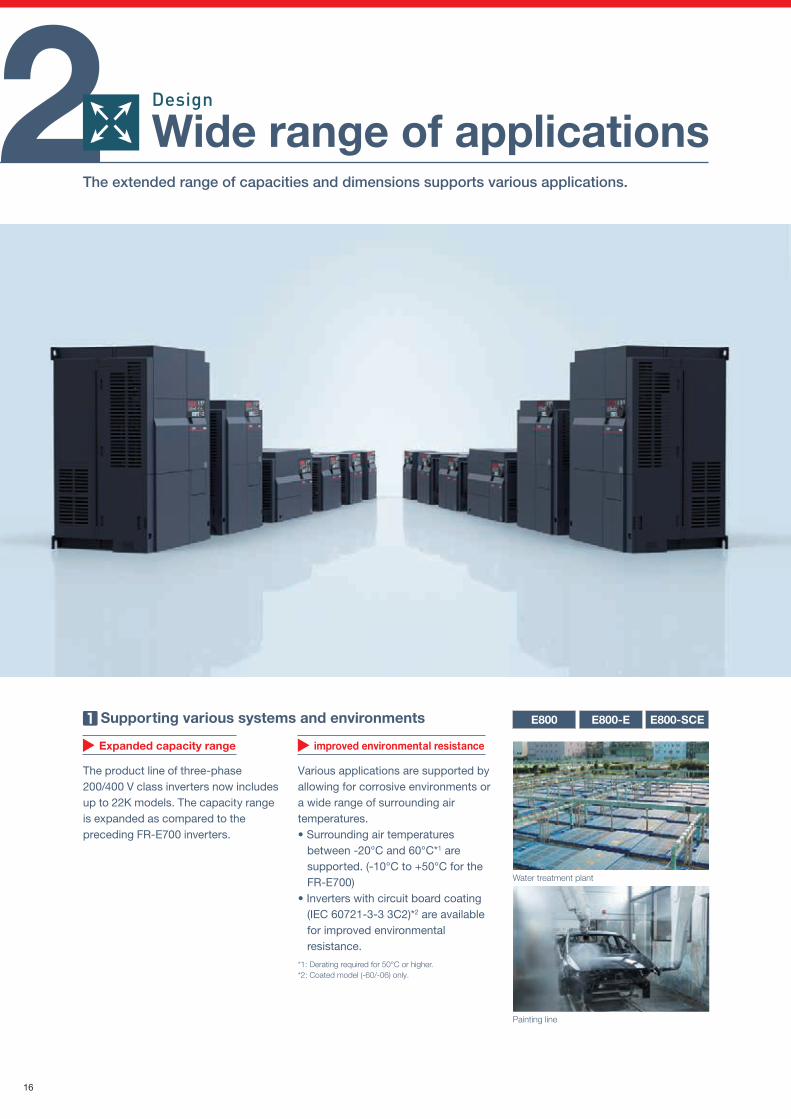
Supporting various systems and environments
Various applications are supported by allowing for corrosive environments or a wide range of surrounding air temperatures.• Surrounding air temperatures
between -20°C and 60°C*1 are supported. (-10°C to +50°C for the FR-E700)
• Inverters with circuit board coating (IEC 60721-3-3 3C2)*2 are available for improved environmental resistance.
*1: Derating required for 50°C or higher.*2: Coated model (-60/-06) only.
E800-SCEE800-EE800
Expanded capacity range improved environmental resistance
Water treatment plant
Painting line
The product line of three-phase 200/400 V class inverters now includes up to 22K models. The capacity range is expanded as compared to the preceding FR-E700 inverters.
E800-SCEE800-EE800
Automotive production line
Building water pumps
Automated warehouse Airport baggage conveyor
2 Wide range of applicationsThe extended range of capacities and dimensions supports various applications.
Load
Light duty
Normal duty
Rating Overload current rating
LD rating
ND rating
120% 60 s, 150% 3 s (inverse-time characteristics) at surrounding air temperature of 50°C
150% 60 s, 200% 3 s (inverse-time characteristics) at surrounding air temperature of 50°C
Design
Des
ign
Installation outside of the enclosure enables installation closer to machines (FR-E846).Since the inverter is compatible with hostile environments such as high humidity and dusty environments, users can easily install the inverter near the machine or in available spaces.It is possible to reduce line noise by shortening the wiring length between the inverter and the motor.
16
SlicerSide-by-side installation
Effective solution for downsizing equipment
For the three-phase input model, two rating types of different rated current and permissible load can be selected by setting parameters. The choice of inverters is widened for intended applications of users. When users select the LD rating for light duty applications, inverters with smaller capacities can be used as compared to the FR-E700 series inverters. For example, when the LD rating (light duty) is selected for a 22K inverter, the inverter can drive a motor with a capacity up to 30 kW.
E800-EE800 E800-SCE
Multiple rating
Optimizing the layout inside the enclosure
When the surrounding air temperature is 40°C or less, multiple inverters can be installed side-by-side. Users can select the most suitable layout for the intended installation area.
E800-SCEE800-EE800
Flexible installation
Enabling installation in various environments
IP67 models (400 V class: 0.75K to 3.7K)
Improving productivity with shorter tact time by the enhanced regeneration function
With the enhanced power regeneration capability (brake duty: 100% max.), deceleration time can be shortened.*1
*1 : For 200 V class 0.4K and 0.75K models, the brake duty is 30% ED maximum when the lowest resistance value is used. The brake resistor must have a sufficient capacity to consume the regenerative power. For 200 V class 0.1K and 0.2K models, brake transistors are not built in.
When the increased magnetic excitation deceleration function is used, the motor consumes the regenerative power and the deceleration time can be reduced without using a brake resistor.The tact time can be reduced for a transfer line or the like.
E800-SCEE800-EE800
Built-in brake transistor
Increased excitation deceleration
Supporting various systems and environments
Various applications are supported by allowing for corrosive environments or a wide range of surrounding air temperatures.• Surrounding air temperatures
between -20°C and 60°C*1 are supported. (-10°C to +50°C for the FR-E700)
• Inverters with circuit board coating (IEC 60721-3-3 3C2)*2 are available for improved environmental resistance.
*1: Derating required for 50°C or higher.*2: Coated model (-60/-06) only.
E800-SCEE800-EE800
Expanded capacity range improved environmental resistance
Water treatment plant
Painting line
The product line of three-phase 200/400 V class inverters now includes up to 22K models. The capacity range is expanded as compared to the preceding FR-E700 inverters.
E800-SCEE800-EE800
Automotive production line
Building water pumps
Automated warehouse Airport baggage conveyor
2 Wide range of applicationsThe extended range of capacities and dimensions supports various applications.
Load
Light duty
Normal duty
Rating Overload current rating
LD rating
ND rating
120% 60 s, 150% 3 s (inverse-time characteristics) at surrounding air temperature of 50°C
150% 60 s, 200% 3 s (inverse-time characteristics) at surrounding air temperature of 50°C
Design
Des
ign
Installation outside of the enclosure enables installation closer to machines (FR-E846).Since the inverter is compatible with hostile environments such as high humidity and dusty environments, users can easily install the inverter near the machine or in available spaces.It is possible to reduce line noise by shortening the wiring length between the inverter and the motor.
17
Constant-ratefeed
Constant-ratefeed
Same spare inverters for various applications
Switching between control methods with the FR-E800 inverter, Vector control for lift application (with the plug-in option), Advanced magnetic flux vector control for conveyors, etc., reduces the number of required spare inverters.
Time
Speed
Increasespeed
Reduced
Same
Sorting
Increasespeed
Conveyor A
Conveyor B
E800-SCEE800-EE800
Control method
Improving work efficiency by powerful high-speed operation
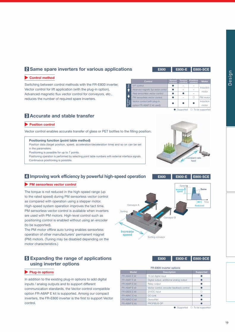
The torque is not reduced in the high-speed range (up to the rated speed) during PM sensorless vector control as compared with operation using a stepper motor.High-speed system operation improves the tact time.PM sensorless vector control is available when inverters are used with PM motors. High-level control such as positioning control is enabled without using an encoder (to be supported).The PM motor offline auto tuning enables sensorless operation of other manufacturers' permanent magnet (PM) motors. (Tuning may be disabled depending on the motor characteristics.)
Customizing inverter operation for each machine
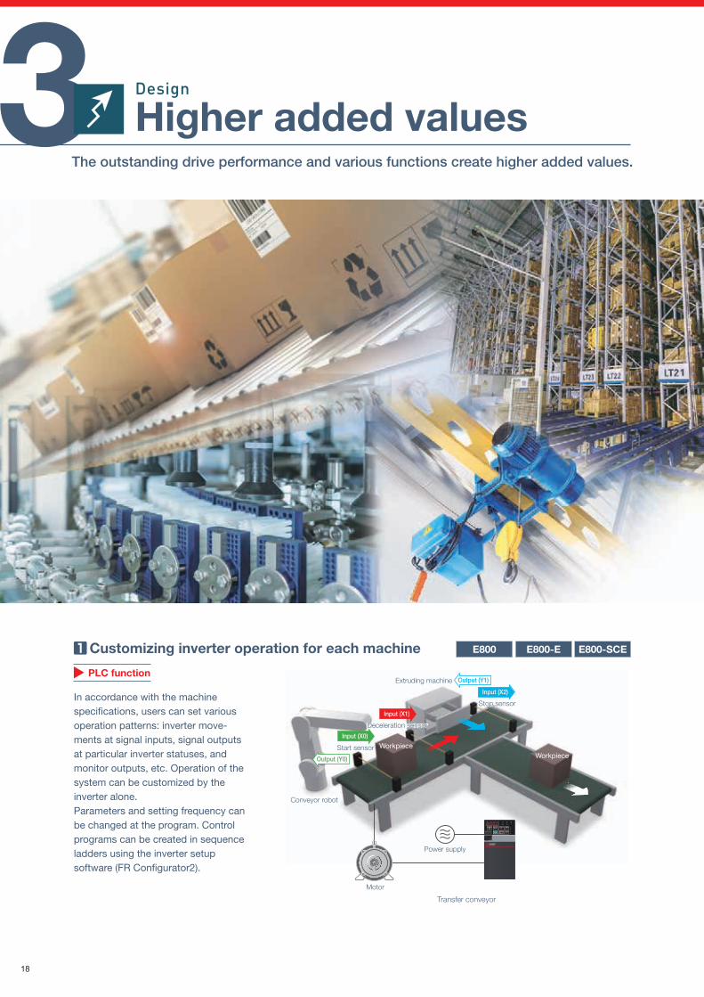
In accordance with the machine specifications, users can set various operation patterns: inverter move-ments at signal inputs, signal outputs at particular inverter statuses, and monitor outputs, etc. Operation of the system can be customized by the inverter alone.Parameters and setting frequency can be changed at the program. Control programs can be created in sequence ladders using the inverter setup software (FR Configurator2).
E800-SCEE800-EE800
PM sensorless vector control
Plug-in options
E800-SCEE800-EE800
PLC function
Transfer conveyor
FR-E800 inverter options
Sorting conveyor
E800-SCEE800-EE800Expanding the range of applications using inverter options
In addition to the existing plug-in options to add digital inputs / analog outputs and to support different communication standards, the Vector control compatible option FR-A8AP E kit is supported. Among our compact inverters, the FR-E800 inverter is the first to support Vector control.
3 Higher added valuesThe outstanding drive performance and various functions create higher added values.
Extruding machine
Stop sensorStop sensor
WorkpieceWorkpiece
Deceleration sensorDeceleration sensor
Start sensor
Conveyor robot
Motor
Power supply
Input (X0)
Input (X1)
Output (Y0)
Input (X2)
Output (Y1)
FR-A8AX E kit
FR-A8AY E kit
FR-A8AR E kit
FR-A8AP E kit
FR-E8DS E kit
FR-A8NC E kit
FR-A8ND E kit
FR-A8NP E kit
16-bit digital input
Digital output, additional analog output
Relay output
Vector control, encoder feedback control
24VDC input
CC-Link
DeviceNet
PROFIBUS-DP
Model Description Supported
: Supported : To be supported
Speedcontrol MotorTorque
controlPositioncontrol
Design
Des
ign
Control
Induction
motor
PM motor
Induction
motor
V/F control
Advanced magnetic flux vector control
Real sensorless vector control
PM sensorless vector control
Vector control (with plug-in
option FR-A8AP E kit used)
–
–
–
–
–
–
: Supported : To be supported
Accurate and stable transfer
Vector control enables accurate transfer of glass or PET bottles to the filling position.
Position control
Easy
High
-per
for-
man
ce
Positioning function (point table method)Position data (target position, speed, acceleration/deceleration time) and so on can be set in the parameters.Positioning is possible for up to 7 points.Positioning operation is performed by selecting point table numbers with external interface signals.Continuous positioning is possible.
18
Constant-ratefeed
Constant-ratefeed
Same spare inverters for various applications
Switching between control methods with the FR-E800 inverter, Vector control for lift application (with the plug-in option), Advanced magnetic flux vector control for conveyors, etc., reduces the number of required spare inverters.
Time
Speed
Increasespeed
Reduced
Same
Sorting
Increasespeed
Conveyor A
Conveyor B
E800-SCEE800-EE800
Control method
Improving work efficiency by powerful high-speed operation
The torque is not reduced in the high-speed range (up to the rated speed) during PM sensorless vector control as compared with operation using a stepper motor.High-speed system operation improves the tact time.PM sensorless vector control is available when inverters are used with PM motors. High-level control such as positioning control is enabled without using an encoder (to be supported).The PM motor offline auto tuning enables sensorless operation of other manufacturers' permanent magnet (PM) motors. (Tuning may be disabled depending on the motor characteristics.)
Customizing inverter operation for each machine
In accordance with the machine specifications, users can set various operation patterns: inverter move-ments at signal inputs, signal outputs at particular inverter statuses, and monitor outputs, etc. Operation of the system can be customized by the inverter alone.Parameters and setting frequency can be changed at the program. Control programs can be created in sequence ladders using the inverter setup software (FR Configurator2).
E800-SCEE800-EE800
PM sensorless vector control
Plug-in options
E800-SCEE800-EE800
PLC function
Transfer conveyor
FR-E800 inverter options
Sorting conveyor
E800-SCEE800-EE800Expanding the range of applications using inverter options
In addition to the existing plug-in options to add digital inputs / analog outputs and to support different communication standards, the Vector control compatible option FR-A8AP E kit is supported. Among our compact inverters, the FR-E800 inverter is the first to support Vector control.
3 Higher added valuesThe outstanding drive performance and various functions create higher added values.
Extruding machine
Stop sensorStop sensor
WorkpieceWorkpiece
Deceleration sensorDeceleration sensor
Start sensor
Conveyor robot
Motor
Power supply
Input (X0)
Input (X1)
Output (Y0)
Input (X2)
Output (Y1)
FR-A8AX E kit
FR-A8AY E kit
FR-A8AR E kit
FR-A8AP E kit
FR-E8DS E kit
FR-A8NC E kit
FR-A8ND E kit
FR-A8NP E kit
16-bit digital input
Digital output, additional analog output
Relay output
Vector control, encoder feedback control
24VDC input
CC-Link
DeviceNet
PROFIBUS-DP
Model Description Supported
: Supported : To be supported
Speedcontrol MotorTorque
controlPositioncontrol
Design
Des
ign
Control
Induction
motor
PM motor
Induction
motor
V/F control
Advanced magnetic flux vector control
Real sensorless vector control
PM sensorless vector control
Vector control (with plug-in
option FR-A8AP E kit used)
–
–
–
–
–
–
: Supported : To be supported
Accurate and stable transfer
Vector control enables accurate transfer of glass or PET bottles to the filling position.
Position controlEa
syHi
gh-p
erfo
r-m
ance
Positioning function (point table method)Position data (target position, speed, acceleration/deceleration time) and so on can be set in the parameters.Positioning is possible for up to 7 points.Positioning operation is performed by selecting point table numbers with external interface signals.Continuous positioning is possible.
19

Wireless access with hard-to-reach inverters
Even if inverters are located in a high place, narrow area, or other hard-to-reach place, wireless access enables adjustments of inverter parameters, inverter monitoring (simultaneous monitoring of multiple axes possible), and inverter maintenance such as life diagnosis checks.The FR-E800 inverter can be connected to FR Configurator2 using a commercially-available industrial wireless LAN*1 access point.*2
Inverter
Programmablecontroller
Wireless LANaccess point
Monitor
Crane
Attaining both safety and productivity
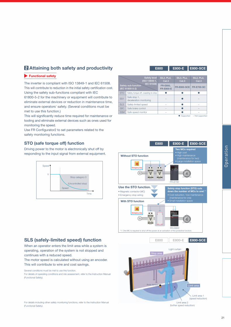
The inverter is compliant with ISO 13849-1 and IEC 61508. This will contribute to reduction in the initial safety certification cost.Using the safety sub-functions compliant with IEC 61800-5-2 for the machinery or equipment will contribute to eliminate external devices or reduction in maintenance time, and ensure operators' safety. (Several conditions must be met to use this function.)This will significantly reduce time required for maintenance or tooling and eliminate external devices such as ones used for monitoring the speed.Use FR Configurator2 to set parameters related to the safety monitoring functions.
STO (safe torque off) functionDriving power to the motor is electronically shut off by responding to the input signal from external equipment.
E800-SCEE800-EE800
E800-SCEE800-EE800
E800-SCEE800-EE800
Functional safety
Ethernet communication
Ceiling crane
*1: A wireless LAN suitable for the industrial use in severe environments or in environments requiring high reliability (redundancy).
*2: Under certain environments or installation conditions, Ethernet communication through wireless LAN is not as stable as communication through wired LAN. Before starting
operation, always check the communication status. Inverter operation (output shutoff, deceleration stop, etc.) when communication fails (due to reasons such as disconnection)
can be selected by setting parameters. For applications requiring data transmission or update periodically or within a certain time period, a wired connection is recommended.
E800-SCEE800-EE800
4 Improved safetyHumans and FA devices can work together by enhancing functional safety.
Speed
Speed
VStop category 0
(Uncontrolled stop)
Time
Operation
Light curtain
Limit area 1(speed reduction)
Limit area 2(further speed reduction)
Area sensor
Stop area
Limit area
Without STO function
With STO function
• Magnetic contactor (MC)
• Emergency stop wiring
Use the STO function.
*1: One MC is required to shut off the power at an activation of the protective function.
Oper
atio
n
MELSEC
Emergency stopMODE SET PU
EXT
RUN
RUN MONEXTPU NET
PRM
STOPRESET
FR-E700
Emergency stop
FR-E800
• High cost• High maintenance (maintenance for two)• Large installation space
Two MCs required
• Cost reduction / low maintenance (maintenance for one)• Small installation space
Safety stop function (STO) cuts down the number of MCs to one! *1
SLS (safely-limited speed) functionWhen an operator enters the limit area while a system is operating, operation of the system is not stopped and continues with a reduced speed. The motor speed is calculated without using an encoder. This will contribute to wire and cost savings.
Several conditions must be met to use this function.
For details of operating conditions and risk assessment, refer to the Instruction Manual
(Functional Safety).
For details including other safety monitoring functions, refer to the Instruction Manual
(Functional Safety).
Safety level(ISO 13849-1,
IEC 61508)Safety sub-function (IEC 61800-5-2)
SIL2, PLd, Cat.3
SIL3, PLe, Cat.3
FR-E800, FR-E800-E
FR-E800-SCE
STO
SS1
SLS
SBC
SSM
Safety torque off, coasting to stop
Safe stop 1, deceleration monitoring
Safely-limited speed
Safe brake control
Safe speed monitor: Supported –: Not supported
–
–
–
–
SIL2, PLd, Cat.3
FR-E700-SC
–
–
–
–
20
Wireless access with hard-to-reach inverters
Even if inverters are located in a high place, narrow area, or other hard-to-reach place, wireless access enables adjustments of inverter parameters, inverter monitoring (simultaneous monitoring of multiple axes possible), and inverter maintenance such as life diagnosis checks.The FR-E800 inverter can be connected to FR Configurator2 using a commercially-available industrial wireless LAN*1 access point.*2
Inverter
Programmablecontroller
Wireless LANaccess point
Monitor
Crane
Attaining both safety and productivity
The inverter is compliant with ISO 13849-1 and IEC 61508. This will contribute to reduction in the initial safety certification cost.Using the safety sub-functions compliant with IEC 61800-5-2 for the machinery or equipment will contribute to eliminate external devices or reduction in maintenance time, and ensure operators' safety. (Several conditions must be met to use this function.)This will significantly reduce time required for maintenance or tooling and eliminate external devices such as ones used for monitoring the speed.Use FR Configurator2 to set parameters related to the safety monitoring functions.
STO (safe torque off) functionDriving power to the motor is electronically shut off by responding to the input signal from external equipment.
E800-SCEE800-EE800
E800-SCEE800-EE800
E800-SCEE800-EE800
Functional safety
Ethernet communication
Ceiling crane
*1: A wireless LAN suitable for the industrial use in severe environments or in environments requiring high reliability (redundancy).
*2: Under certain environments or installation conditions, Ethernet communication through wireless LAN is not as stable as communication through wired LAN. Before starting
operation, always check the communication status. Inverter operation (output shutoff, deceleration stop, etc.) when communication fails (due to reasons such as disconnection)
can be selected by setting parameters. For applications requiring data transmission or update periodically or within a certain time period, a wired connection is recommended.
E800-SCEE800-EE800
4 Improved safetyHumans and FA devices can work together by enhancing functional safety.
Speed
Speed
VStop category 0
(Uncontrolled stop)
Time
Operation
Light curtain
Limit area 1(speed reduction)
Limit area 2(further speed reduction)
Area sensor
Stop area
Limit area
Without STO function
With STO function
• Magnetic contactor (MC)
• Emergency stop wiring
Use the STO function.
*1: One MC is required to shut off the power at an activation of the protective function.
Oper
atio
n
MELSEC
Emergency stopMODE SET PU
EXT
RUN
RUN MONEXTPU NET
PRM
STOPRESET
FR-E700
Emergency stop
FR-E800
• High cost• High maintenance (maintenance for two)• Large installation space
Two MCs required
• Cost reduction / low maintenance (maintenance for one)• Small installation space
Safety stop function (STO) cuts down the number of MCs to one! *1
SLS (safely-limited speed) functionWhen an operator enters the limit area while a system is operating, operation of the system is not stopped and continues with a reduced speed. The motor speed is calculated without using an encoder. This will contribute to wire and cost savings.
Several conditions must be met to use this function.
For details of operating conditions and risk assessment, refer to the Instruction Manual
(Functional Safety).
For details including other safety monitoring functions, refer to the Instruction Manual
(Functional Safety).
Safety level(ISO 13849-1,
IEC 61508)Safety sub-function (IEC 61800-5-2)
SIL2, PLd, Cat.3
SIL3, PLe, Cat.3
FR-E800, FR-E800-E
FR-E800-SCE
STO
SS1
SLS
SBC
SSM
Safety torque off, coasting to stop
Safe stop 1, deceleration monitoring
Safely-limited speed
Safe brake control
Safe speed monitor: Supported –: Not supported
–
–
–
–
SIL2, PLd, Cat.3
FR-E700-SC
–
–
–
–
21

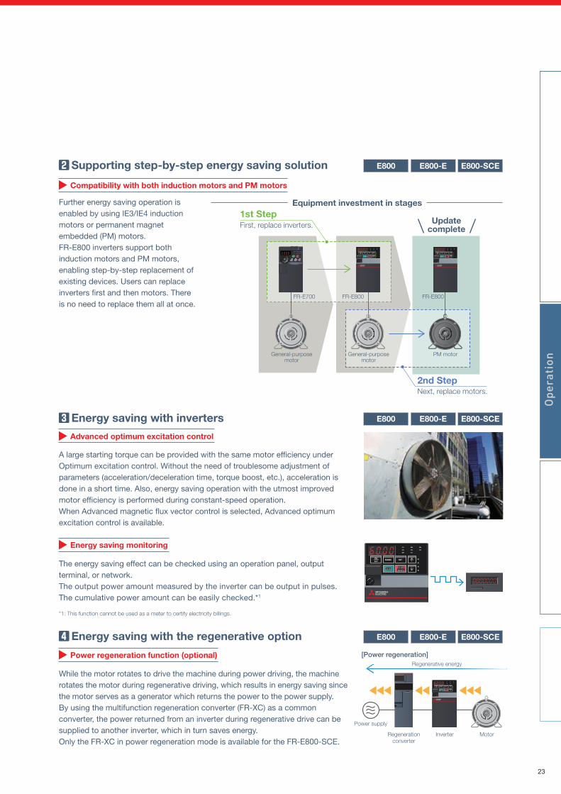
Supporting step-by-step energy saving solution
Further energy saving operation is enabled by using IE3/IE4 induction motors or permanent magnet embedded (PM) motors.FR-E800 inverters support both induction motors and PM motors, enabling step-by-step replacement of existing devices. Users can replace inverters first and then motors. There is no need to replace them all at once.
Compatibility with both induction motors and PM motors
1st Step
E800-SCEE800-EE800
E800-SCEE800-EE800
Energy saving with motors
PM motor
The PM motor achieves even higher efficiency as compared to the general-purpose motor.The setting for driving PM motors is enabled just by setting parameters.
Why is a PM motor so efficient?• No current flows to the rotor (secondary side), and no secondary
copper loss is generated.• Magnetic flux is generated with permanent magnets, and less
motor current is required.
Advanced optimum excitation control
E800-SCEE800-EE800 Energy saving with inverters
Energy saving with the regenerative option
Energy saving monitoring
The energy saving effect can be checked using an operation panel, output terminal, or network.The output power amount measured by the inverter can be output in pulses. The cumulative power amount can be easily checked.*1
*1: This function cannot be used as a meter to certify electricity billings.
5 Energy savingUse of induction motors or PM motors contributes to energy saving.
A large starting torque can be provided with the same motor efficiency under Optimum excitation control. Without the need of troublesome adjustment of parameters (acceleration/deceleration time, torque boost, etc.), acceleration is done in a short time. Also, energy saving operation with the utmost improved motor efficiency is performed during constant-speed operation.When Advanced magnetic flux vector control is selected, Advanced optimum excitation control is available.
Power regeneration function (optional)
While the motor rotates to drive the machine during power driving, the machine rotates the motor during regenerative driving, which results in energy saving since the motor serves as a generator which returns the power to the power supply.By using the multifunction regeneration converter (FR-XC) as a common converter, the power returned from an inverter during regenerative drive can be supplied to another inverter, which in turn saves energy.Only the FR-XC in power regeneration mode is available for the FR-E800-SCE.
First, replace inverters.
2nd StepNext, replace motors.
Equipment investment in stages
Updatecomplete
Regenerative energy
[Power regeneration]
Power supply
Regenerationconverter
Inverter Motor
E800-SCEE800-EE800
Operation
Oper
atio
n
FR-E700
General-purposemotor
PM motorGeneral-purposemotor
FR-E800 FR-E800
[Comparison of motor losses]* Example of 22 kW motors
General-purpose motor
Premiumhigh-efficiency
IPM motor
Premiumhigh-efficiency
IPM motor
22
Supporting step-by-step energy saving solution
Further energy saving operation is enabled by using IE3/IE4 induction motors or permanent magnet embedded (PM) motors.FR-E800 inverters support both induction motors and PM motors, enabling step-by-step replacement of existing devices. Users can replace inverters first and then motors. There is no need to replace them all at once.
Compatibility with both induction motors and PM motors
1st Step
E800-SCEE800-EE800
E800-SCEE800-EE800
Energy saving with motors
PM motor
The PM motor achieves even higher efficiency as compared to the general-purpose motor.The setting for driving PM motors is enabled just by setting parameters.
Why is a PM motor so efficient?• No current flows to the rotor (secondary side), and no secondary
copper loss is generated.• Magnetic flux is generated with permanent magnets, and less
motor current is required.
Advanced optimum excitation control
E800-SCEE800-EE800 Energy saving with inverters
Energy saving with the regenerative option
Energy saving monitoring
The energy saving effect can be checked using an operation panel, output terminal, or network.The output power amount measured by the inverter can be output in pulses. The cumulative power amount can be easily checked.*1
*1: This function cannot be used as a meter to certify electricity billings.
5 Energy savingUse of induction motors or PM motors contributes to energy saving.
A large starting torque can be provided with the same motor efficiency under Optimum excitation control. Without the need of troublesome adjustment of parameters (acceleration/deceleration time, torque boost, etc.), acceleration is done in a short time. Also, energy saving operation with the utmost improved motor efficiency is performed during constant-speed operation.When Advanced magnetic flux vector control is selected, Advanced optimum excitation control is available.
Power regeneration function (optional)
While the motor rotates to drive the machine during power driving, the machine rotates the motor during regenerative driving, which results in energy saving since the motor serves as a generator which returns the power to the power supply.By using the multifunction regeneration converter (FR-XC) as a common converter, the power returned from an inverter during regenerative drive can be supplied to another inverter, which in turn saves energy.Only the FR-XC in power regeneration mode is available for the FR-E800-SCE.
First, replace inverters.
2nd StepNext, replace motors.
Equipment investment in stages
Updatecomplete
Regenerative energy
[Power regeneration]
Power supply
Regenerationconverter
Inverter Motor
E800-SCEE800-EE800
Operation
Oper
atio
n
FR-E700
General-purposemotor
PM motorGeneral-purposemotor
FR-E800 FR-E800
[Comparison of motor losses]* Example of 22 kW motors
General-purpose motor
Premiumhigh-efficiency
IPM motor
Premiumhigh-efficiency
IPM motor
23
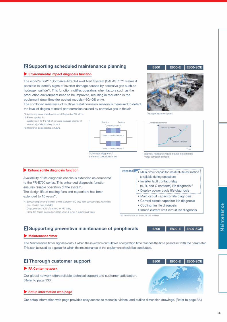
Load characteristics fault detection function
Enhanced life diagnosis function
Availability of life diagnosis checks is extended as compared to the FR-E700 series. This enhanced diagnosis function ensures reliable operation of the system.The design life of cooling fans and capacitors has been extended to 10 years*4.
*4: Surrounding air temperature: annual average 40°C (free from corrosive gas, flammable
gas, oil mist, dust and dirt)
Output current: 80% of the inverter ND rating
Since the design life is a calculated value, it is not a guaranteed value.
• Main circuit capacitor residual-life estimation (available during operation)
• Inverter fault contact relay (A, B, and C contacts) life diagnosis*5
• Display power cycle life diagnosis
• Main circuit capacitor life diagnosis• Control circuit capacitor life diagnosis• Cooling fan life diagnosis• Inrush current limit circuit life diagnosisE800-SCEE800-EE800
Setup information web page
Maintenance timer
E800-SCEE800-EE800
E800-SCEE800-EE800
6 Improved maintainabilityFunctions for residual life diagnosis, predictive maintenance, and preventive maintenance support stable system operation.
Environmental impact diagnosis function
Supporting scheduled maintenance planning
Real-time monitoring for early fault detection
Supporting preventive maintenance of peripherals
Thorough customer support
The world's first*1 “Corrosive-Attack-Level Alert System (CALAS™)”*2 makes it possible to identify signs of inverter damage caused by corrosive gas such as hydrogen sulfide*3. This function notifies operators when factors such as the production environment need to be improved, resulting in reduction in the equipment downtime (for coated models (-60/-06) only).The combined resistance of multiple metal corrosion sensors is measured to detect the level of degree of metal part corrosion caused by corrosive gas in the air.
*1: According to our investigation as of September 10, 2019.
*2: Patent applied for.
Alert system for the risk of corrosive damage (degree of
corrosion) of electrical equipment
*3: Others will be supported in future.
When a mechanical fault such as clogging of the filter occurs, the inverter outputs a warning or shuts off the output to prevent system damage.The speed–torque characteristic is stored while no fault occurs, enabling comparison between the measured data and the stored data.
The Maintenance timer signal is output when the inverter's cumulative energization time reaches the time period set with the parameter.This can be used as a guide for when the maintenance of the equipment should be conducted.
Our global network offers reliable technical support and customer satisfaction.(Refer to page 136.)
FA Center network
Maintenance
Mai
nten
ance
Extended
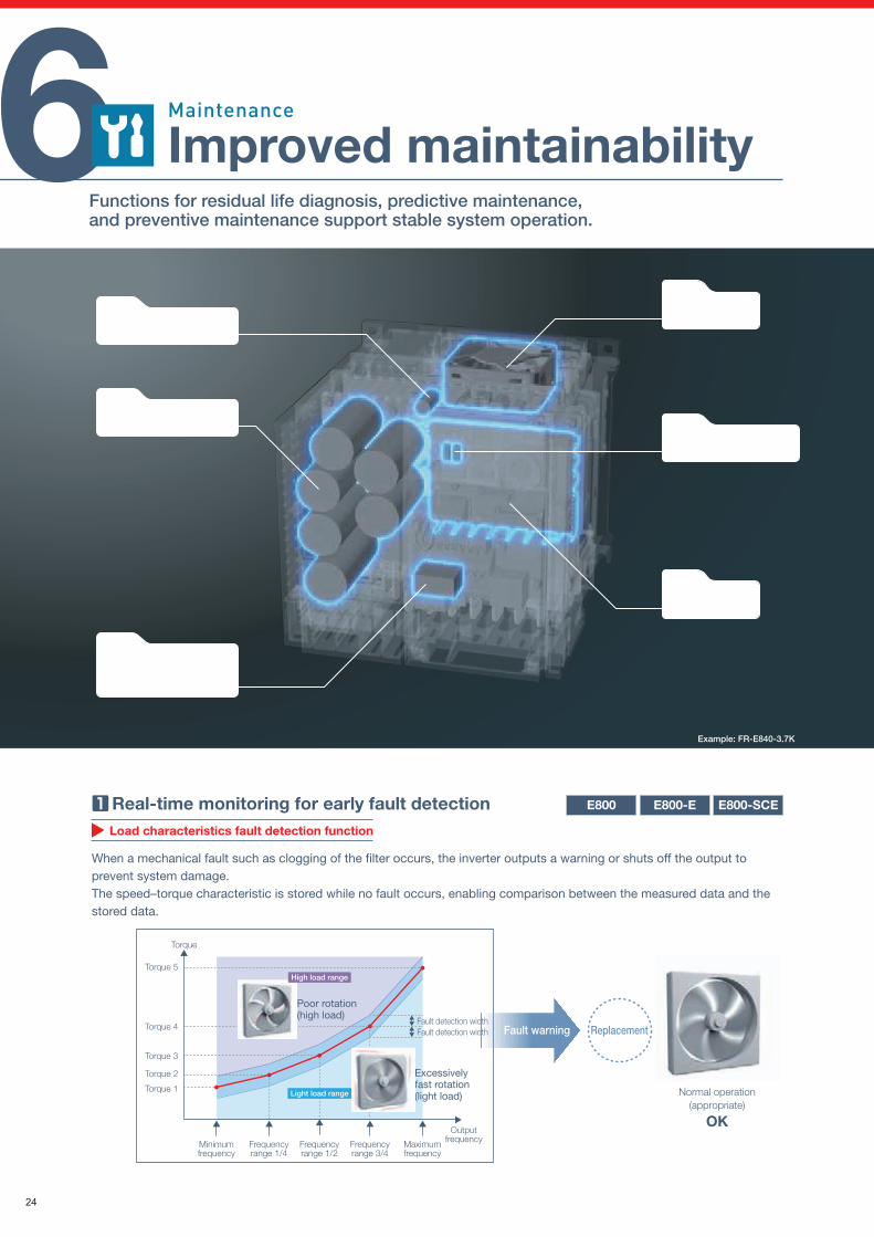
Example: FR-E840-3.7K
Control circuit capacitor
Main circuit capacitor
Fault contact relay(A, B, and C contacts)
Cooling fan
Power module
Metal corrosion sensor
*5: Terminals A, B, and C of the inverter
OutputfrequencyMaximum
frequencyFrequencyrange 3/4
Frequencyrange 1/2
Frequencyrange 1/4
Minimumfrequency
Torque 1
Torque 2
Torque 3
Torque 4
Torque 5
Torque
Fault detection widthFault detection width
Poor rotation(high load)
Normal operation(appropriate)
Replacement
OK
Excessively fast rotation(light load)
High load range
Light load range
Fault warning
E800-SCEE800-EE800
Sewage treatment plant
Example resistance value change detected by metal corrosion sensors
Schematic diagram of the metal corrosion sensor
Time
Combined resistance
Sensor 1 broken
Sensor 2 broken
Metal corrosion sensor 1
Metal corrosion sensor 2
Resistor Resistor
Thin metal film
Our setup information web page provides easy access to manuals, videos, and outline dimension drawings. (Refer to page 32.)
24
Load characteristics fault detection function
Enhanced life diagnosis function
Availability of life diagnosis checks is extended as compared to the FR-E700 series. This enhanced diagnosis function ensures reliable operation of the system.The design life of cooling fans and capacitors has been extended to 10 years*4.
*4: Surrounding air temperature: annual average 40°C (free from corrosive gas, flammable
gas, oil mist, dust and dirt)
Output current: 80% of the inverter ND rating
Since the design life is a calculated value, it is not a guaranteed value.
• Main circuit capacitor residual-life estimation (available during operation)
• Inverter fault contact relay (A, B, and C contacts) life diagnosis*5
• Display power cycle life diagnosis
• Main circuit capacitor life diagnosis• Control circuit capacitor life diagnosis• Cooling fan life diagnosis• Inrush current limit circuit life diagnosisE800-SCEE800-EE800
Setup information web page
Maintenance timer
E800-SCEE800-EE800
E800-SCEE800-EE800
6 Improved maintainabilityFunctions for residual life diagnosis, predictive maintenance, and preventive maintenance support stable system operation.
Environmental impact diagnosis function
Supporting scheduled maintenance planning
Real-time monitoring for early fault detection
Supporting preventive maintenance of peripherals
Thorough customer support
The world's first*1 “Corrosive-Attack-Level Alert System (CALAS™)”*2 makes it possible to identify signs of inverter damage caused by corrosive gas such as hydrogen sulfide*3. This function notifies operators when factors such as the production environment need to be improved, resulting in reduction in the equipment downtime (for coated models (-60/-06) only).The combined resistance of multiple metal corrosion sensors is measured to detect the level of degree of metal part corrosion caused by corrosive gas in the air.
*1: According to our investigation as of September 10, 2019.
*2: Patent applied for.
Alert system for the risk of corrosive damage (degree of
corrosion) of electrical equipment
*3: Others will be supported in future.
When a mechanical fault such as clogging of the filter occurs, the inverter outputs a warning or shuts off the output to prevent system damage.The speed–torque characteristic is stored while no fault occurs, enabling comparison between the measured data and the stored data.
The Maintenance timer signal is output when the inverter's cumulative energization time reaches the time period set with the parameter.This can be used as a guide for when the maintenance of the equipment should be conducted.
Our global network offers reliable technical support and customer satisfaction.(Refer to page 136.)
FA Center network
Maintenance
Mai
nten
ance
Extended
Example: FR-E840-3.7K
Control circuit capacitor
Main circuit capacitor
Fault contact relay(A, B, and C contacts)
Cooling fan
Power module
Metal corrosion sensor
*5: Terminals A, B, and C of the inverter
OutputfrequencyMaximum
frequencyFrequencyrange 3/4
Frequencyrange 1/2
Frequencyrange 1/4
Minimumfrequency
Torque 1
Torque 2
Torque 3
Torque 4
Torque 5
Torque
Fault detection widthFault detection width
Poor rotation(high load)
Normal operation(appropriate)
Replacement
OK
Excessively fast rotation(light load)
High load range
Light load range
Fault warning
E800-SCEE800-EE800
Sewage treatment plant
Example resistance value change detected by metal corrosion sensors
Schematic diagram of the metal corrosion sensor
Time
Combined resistance
Sensor 1 broken
Sensor 2 broken
Metal corrosion sensor 1
Metal corrosion sensor 2
Resistor Resistor
Thin metal film
Our setup information web page provides easy access to manuals, videos, and outline dimension drawings. (Refer to page 32.)
25
Easy and fast wiring
• Spring clamp terminals have been adopted for control circuit terminals for easy wiring.Furthermore, wires can be protected against loosening or contact faults due to vibrations during operation on a bogie or during transport. No additional screw tightening is required.
• The removable control circuit terminal block facilitates replacement with a new one.
AI fault diagnosis
Streamlining the installation processCompatible installation size
E800-SCEE800-EE800 E800-SCEE800-EE800
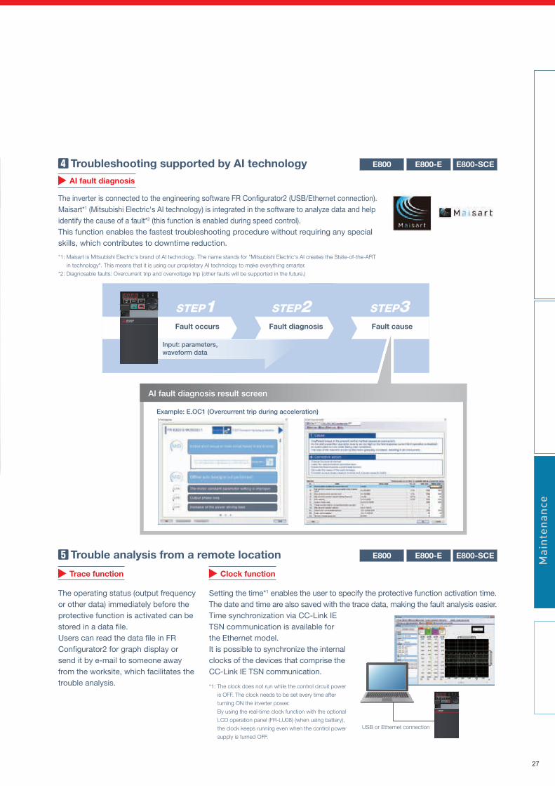
E800-SCEE800-EE800 Troubleshooting supported by AI technology
The inverter is connected to the engineering software FR Configurator2 (USB/Ethernet connection). Maisart*1 (Mitsubishi Electric's AI technology) is integrated in the software to analyze data and help identify the cause of a fault*2 (this function is enabled during speed control).This function enables the fastest troubleshooting procedure without requiring any special skills, which contributes to downtime reduction.
*1: Maisart is Mitsubishi Electric's brand of AI technology. The name stands for "Mitsubishi Electric's AI creates the State-of-the-ART
in technology". This means that it is using our proprietary AI technology to make everything smarter.
*2: Diagnosable faults: Overcurrent trip and overvoltage trip (other faults will be supported in the future.)
Control circuit terminal
Trace function
E800-SCEE800-EE800 Trouble analysis from a remote location
The operating status (output frequency or other data) immediately before the protective function is activated can be stored in a data file.Users can read the data file in FR Configurator2 for graph display or send it by e-mail to someone away from the worksite, which facilitates the trouble analysis.
Clock function
Setting the time*1 enables the user to specify the protective function activation time.The date and time are also saved with the trace data, making the fault analysis easier.Time synchronization via CC-Link IE TSN communication is available for the Ethernet model.It is possible to synchronize the internal clocks of the devices that comprise the CC-Link IE TSN communication.
*1: The clock does not run while the control circuit power
is OFF. The clock needs to be set every time after
turning ON the inverter power.
By using the real-time clock function with the optional
LCD operation panel (FR-LU08) (when using battery),
the clock keeps running even when the control power
supply is turned OFF.
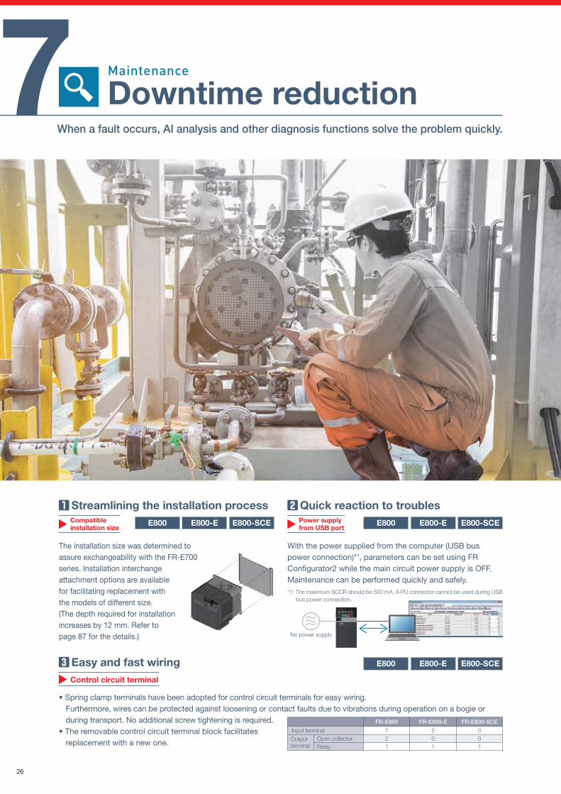
7 Downtime reductionWhen a fault occurs, AI analysis and other diagnosis functions solve the problem quickly.
USB or Ethernet connection
Quick reaction to troublesPower supply from USB port
Maintenance
The installation size was determined to assure exchangeability with the FR-E700 series. Installation interchange attachment options are available for facilitating replacement with the models of different size.(The depth required for installation increases by 12 mm. Refer to page 87 for the details.)
With the power supplied from the computer (USB bus power connection)*1, parameters can be set using FR Configurator2 while the main circuit power supply is OFF.Maintenance can be performed quickly and safely.*1: The maximum SCCR should be 500 mA. A PU connector cannot be used during USB
bus power connection.
Mai
nten
ance
E800-SCEE800-EE800
No power supply
Input terminal Open collector RelayOutput terminal
201
721
FR-E800 FR-E800-E FR-E800-SCE
001
Fault occurs Fault diagnosis Fault cause
Input: parameters, waveform data
Example: E.OC1 (Overcurrent trip during acceleration)
AI fault diagnosis result screen
STEP1 STEP2 STEP3
26
Easy and fast wiring
• Spring clamp terminals have been adopted for control circuit terminals for easy wiring.Furthermore, wires can be protected against loosening or contact faults due to vibrations during operation on a bogie or during transport. No additional screw tightening is required.
• The removable control circuit terminal block facilitates replacement with a new one.
AI fault diagnosis
Streamlining the installation processCompatible installation size
E800-SCEE800-EE800 E800-SCEE800-EE800
E800-SCEE800-EE800 Troubleshooting supported by AI technology
The inverter is connected to the engineering software FR Configurator2 (USB/Ethernet connection). Maisart*1 (Mitsubishi Electric's AI technology) is integrated in the software to analyze data and help identify the cause of a fault*2 (this function is enabled during speed control).This function enables the fastest troubleshooting procedure without requiring any special skills, which contributes to downtime reduction.
*1: Maisart is Mitsubishi Electric's brand of AI technology. The name stands for "Mitsubishi Electric's AI creates the State-of-the-ART
in technology". This means that it is using our proprietary AI technology to make everything smarter.
*2: Diagnosable faults: Overcurrent trip and overvoltage trip (other faults will be supported in the future.)
Control circuit terminal
Trace function
E800-SCEE800-EE800 Trouble analysis from a remote location
The operating status (output frequency or other data) immediately before the protective function is activated can be stored in a data file.Users can read the data file in FR Configurator2 for graph display or send it by e-mail to someone away from the worksite, which facilitates the trouble analysis.
Clock function
Setting the time*1 enables the user to specify the protective function activation time.The date and time are also saved with the trace data, making the fault analysis easier.Time synchronization via CC-Link IE TSN communication is available for the Ethernet model.It is possible to synchronize the internal clocks of the devices that comprise the CC-Link IE TSN communication.
*1: The clock does not run while the control circuit power
is OFF. The clock needs to be set every time after
turning ON the inverter power.
By using the real-time clock function with the optional
LCD operation panel (FR-LU08) (when using battery),
the clock keeps running even when the control power
supply is turned OFF.
7 Downtime reductionWhen a fault occurs, AI analysis and other diagnosis functions solve the problem quickly.
USB or Ethernet connection
Quick reaction to troublesPower supply from USB port
Maintenance
The installation size was determined to assure exchangeability with the FR-E700 series. Installation interchange attachment options are available for facilitating replacement with the models of different size.(The depth required for installation increases by 12 mm. Refer to page 87 for the details.)
With the power supplied from the computer (USB bus power connection)*1, parameters can be set using FR Configurator2 while the main circuit power supply is OFF.Maintenance can be performed quickly and safely.*1: The maximum SCCR should be 500 mA. A PU connector cannot be used during USB
bus power connection.
Mai
nten
ance
E800-SCEE800-EE800
No power supply
Input terminal Open collector RelayOutput terminal
201
721
FR-E800 FR-E800-E FR-E800-SCE
001
Fault occurs Fault diagnosis Fault cause
Input: parameters, waveform data
Example: E.OC1 (Overcurrent trip during acceleration)
AI fault diagnosis result screen
STEP1 STEP2 STEP3
27
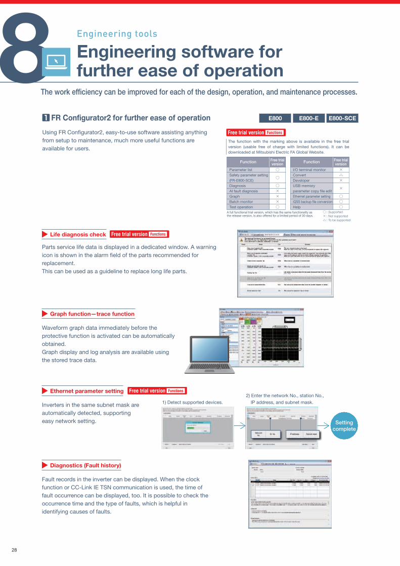
Setup information web page
Users can scan the QR code on the product to directly access the setup information.Manuals, setup videos, and outline dimension drawings are available. (Refer to page 32.)
Mobile app
Wireless access with inverters from a remote location enables setting or changing of parameters, starting and stopping, and monitoring on the screen of mobile devices.Users can easily monitor the inverter operation by checking data such as the running frequency and status of input and output terminals at a glance in one screen.Wireless communication equipment must be prepared in the system that includes the inverter.
Diagnostics (Fault history)
Fault records in the inverter can be displayed. When the clock function or CC-Link IE TSN communication is used, the time of fault occurrence can be displayed, too. It is possible to check the occurrence time and the type of faults, which is helpful in identifying causes of faults.
Ethernet parameter setting
Inverters in the same subnet mask are automatically detected, supporting easy network setting.
Graph function—trace function
Waveform graph data immediately before the protective function is activated can be automatically obtained.Graph display and log analysis are available using the stored trace data.
E800-SCEE800-EE800
Set ParametersRecognizeinverters
Check thefault history Monitor
Operating status
The function with the marking above is available in the free trial version (usable free of charge with limited functions). It can be downloaded at Mitsubishi Electric FA Global Website.
8The work efficiency can be improved for each of the design, operation, and maintenance processes.
1) Detect supported devices.2) Enter the network No., station No.,
IP address, and subnet mask.
Settingcomplete
Engi
neer
ing
tool
s
E800-SCEE800-EE800 E800-SCEE800-EE800 FR Configurator2 for further ease of operation Further facilitating operation with your smartphone
Using FR Configurator2, easy-to-use software assisting anything from setup to maintenance, much more useful functions are available for users.
Engineering software for further ease of operation
Engineering tools
Life diagnosis check
Parts service life data is displayed in a dedicated window. A warning icon is shown in the alarm field of the parts recommended for replacement.This can be used as a guideline to replace long life parts.
Free trial version Functions
Free trial version Functions
Free trial version Functions
Free trialversion
Parameter listSafety parameter setting(FR-E800-SCE)DiagnosisAI fault diagnosisGraphBatch monitorTest operation
○
○
○×××○
Function Free trialversionFunction
I/O terminal monitorConvertDeveloperUSB memory parameter copy file editEthernet parameter settingiQSS backup file conversionHelp
×△×
×
○○○
A full functional trial version, which has the same functionality as the release version, is also offered for a limited period of 30 days.
○ : Supported × : Not supported △ : To be supported
Download the free app now
28
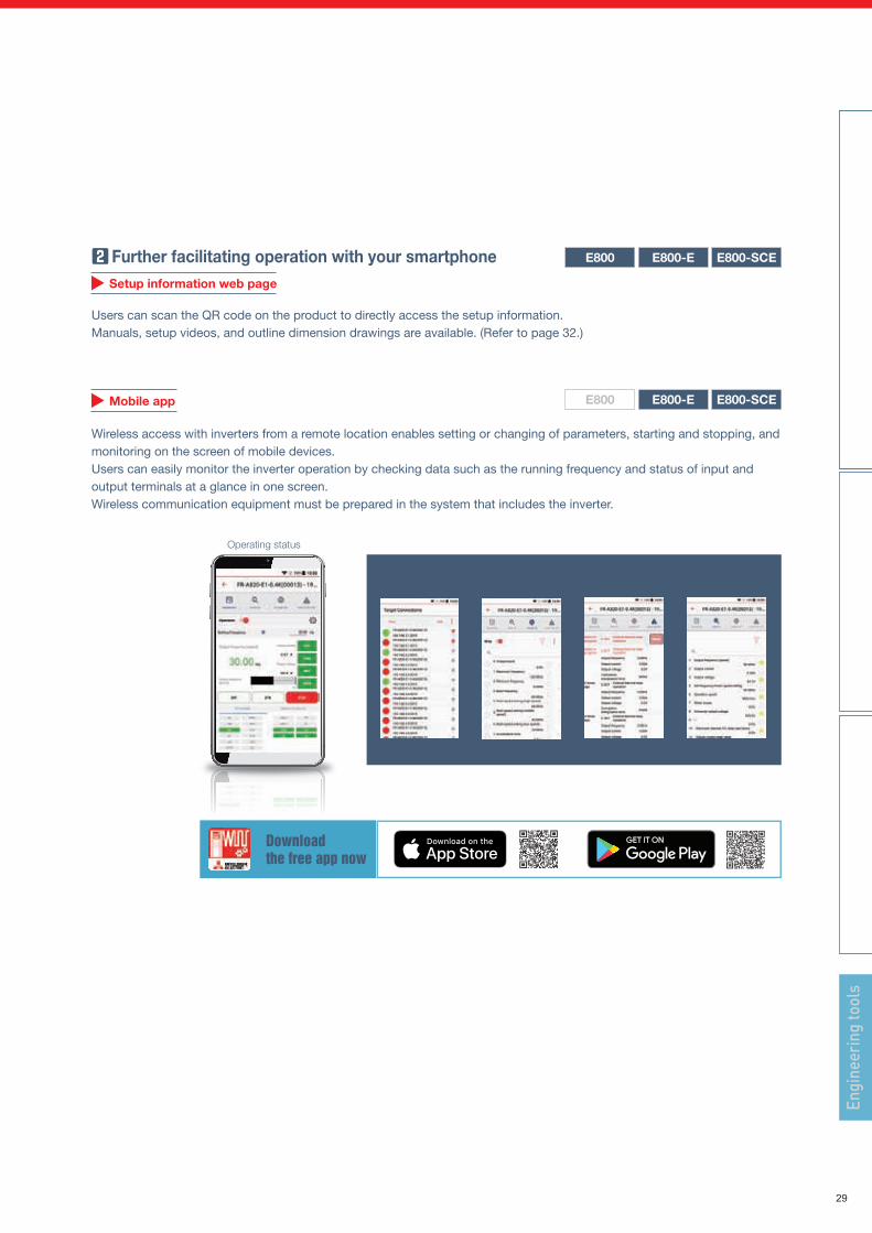
Setup information web page
Users can scan the QR code on the product to directly access the setup information.Manuals, setup videos, and outline dimension drawings are available. (Refer to page 32.)
Mobile app
Wireless access with inverters from a remote location enables setting or changing of parameters, starting and stopping, and monitoring on the screen of mobile devices.Users can easily monitor the inverter operation by checking data such as the running frequency and status of input and output terminals at a glance in one screen.Wireless communication equipment must be prepared in the system that includes the inverter.
Diagnostics (Fault history)
Fault records in the inverter can be displayed. When the clock function or CC-Link IE TSN communication is used, the time of fault occurrence can be displayed, too. It is possible to check the occurrence time and the type of faults, which is helpful in identifying causes of faults.
Ethernet parameter setting
Inverters in the same subnet mask are automatically detected, supporting easy network setting.
Graph function—trace function
Waveform graph data immediately before the protective function is activated can be automatically obtained.Graph display and log analysis are available using the stored trace data.
E800-SCEE800-EE800
Set ParametersRecognizeinverters
Check thefault history Monitor
Operating status
The function with the marking above is available in the free trial version (usable free of charge with limited functions). It can be downloaded at Mitsubishi Electric FA Global Website.
8The work efficiency can be improved for each of the design, operation, and maintenance processes.
1) Detect supported devices.2) Enter the network No., station No.,
IP address, and subnet mask.
Settingcomplete
Engi
neer
ing
tool
s
E800-SCEE800-EE800 E800-SCEE800-EE800 FR Configurator2 for further ease of operation Further facilitating operation with your smartphone
Using FR Configurator2, easy-to-use software assisting anything from setup to maintenance, much more useful functions are available for users.
Engineering software for further ease of operation
Engineering tools
Life diagnosis check
Parts service life data is displayed in a dedicated window. A warning icon is shown in the alarm field of the parts recommended for replacement.This can be used as a guideline to replace long life parts.
Free trial version Functions
Free trial version Functions
Free trial version Functions
Free trialversion
Parameter listSafety parameter setting(FR-E800-SCE)DiagnosisAI fault diagnosisGraphBatch monitorTest operation
○
○
○×××○
Function Free trialversionFunction
I/O terminal monitorConvertDeveloperUSB memory parameter copy file editEthernet parameter settingiQSS backup file conversionHelp
×△×
×
○○○
A full functional trial version, which has the same functionality as the release version, is also offered for a limited period of 30 days.
○ : Supported × : Not supported △ : To be supported
Download the free app now
29
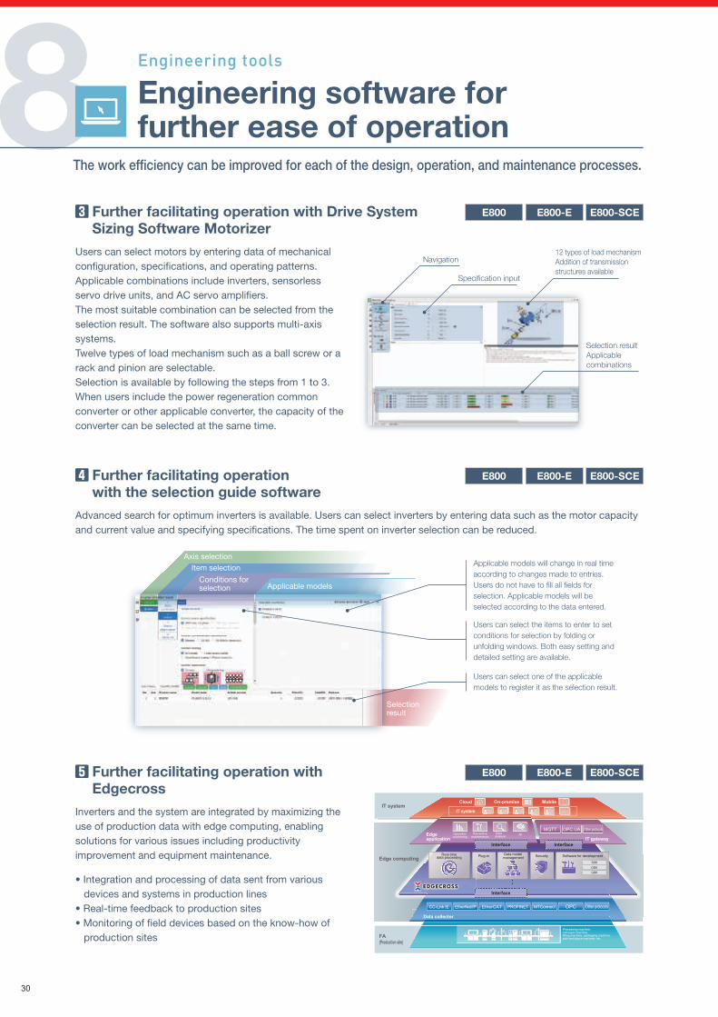
Less time spent on screen design work by importing sample screens
Various sample screens*1 are available to enable parameter setting, batch monitor, measurement of load characteristics and so on using the GOT.Using sample screens enables easy startup of the system.
*1: Sample screens are included in the GT Works3
package, or can be downloaded at Mitsubishi Electric
FA Global Website.
Sample screens are available for FR-E800 and
FR-E800-E. FR-E800-SCE is to be supported.
Immediate warning of system errors
By storing the data of relationship between the output frequency and the torque during normal inverter operation, users can judge whether the load is operating in normal condition. By outputting out-of-range warnings if applicable, users can detect mechanical faults or perform maintenance.
Users can use the GOT to set up, adjust, and perform maintenance for inverters without using a computer.
Operation monitoring
Preventive maintenance
MQTT OPC UA
OthersOthers
Other protocols
Real-time data processing Plug-in Data model
management Security Software for development
SDKDDKGDK
Interface Interface
Interface
Dataanalysis
CC-Link IE EtherNet/IP EtherCAT PROFINET OPCMTConnect Other protocols
Data collector
FA(Production site)
IT systemOn-premiseCloud
IT system
Edge application
AI
Edge computing
Mobile
IT gateway
Processing machine, conveyor machine, filling machine, packaging machine, pick-and-place machine, etc.
Applicable models will change in real time according to changes made to entries.Users do not have to fill all fields for selection. Applicable models will be selected according to the data entered.
Users can select one of the applicable models to register it as the selection result.
Users can select the items to enter to set conditions for selection by folding or unfolding windows. Both easy setting and detailed setting are available.
Selection result
Axis selectionItem selection
Conditions for selection Applicable models
The work efficiency can be improved for each of the design, operation, and maintenance processes.
STEP 3
GOT2000
Transfer Complete
FR-E800
Transfer the project data to the GOT.
STEP 2
Sample screen
Sample screens for selected connection type available to be imported to user's project data
STEP 1
GOT2000 FR-E800
Connection type selectable(Ethernet or RS-485)
Select the GOT and the inverter and connect them.
Users want to detect system errors using the inverter to facilitate maintenance.
Users want to identify causes of faults easily.
Instead on the control panel, users can check data on a GOT.
Multiple inverters can monitored using the target station switching function.
1
2
System errors such as clogged filter/pipe can be detected.
Operation of the system can be monitored constantly.
1
2
Fault records can be checked quickly (last eight faults).
Troubleshooting pages of manuals can be displayed.
1
2
Do I have to go to the control panel just to check something trivial?
Is it possible to detect a clogged filter or pipe?
What is the meaning of this fault number?
MELSEC
After
After
After
Before
Before
Before
MELSEC
Further facilitating operation with Drive System Sizing Software Motorizer
Users can select motors by entering data of mechanical configuration, specifications, and operating patterns. Applicable combinations include inverters, sensorless servo drive units, and AC servo amplifiers.The most suitable combination can be selected from the selection result. The software also supports multi-axis systems.Twelve types of load mechanism such as a ball screw or a rack and pinion are selectable.Selection is available by following the steps from 1 to 3.When users include the power regeneration common converter or other applicable converter, the capacity of the converter can be selected at the same time.
Further facilitating operation with GOT interaction functions
Enhanced compatibility between inverters and the GOT (human machine interface) brings various benefits to users.Connection with the GOT2000 series can be established just by setting the station number. Other necessary settings are automatically done.
Further facilitating operation with Edgecross
Inverters and the system are integrated by maximizing the use of production data with edge computing, enabling solutions for various issues including productivity improvement and equipment maintenance.
• Integration and processing of data sent from various devices and systems in production lines
• Real-time feedback to production sites• Monitoring of field devices based on the know-how of
production sites
Further facilitating operation with the selection guide software
Advanced search for optimum inverters is available. Users can select inverters by entering data such as the motor capacity and current value and specifying specifications. The time spent on inverter selection can be reduced.
Engi
neer
ing
tool
s
E800-SCEE800-EE800 E800-SCEE800-EE800
E800-SCEE800-EE800
E800-SCEE800-EE800
Specification input
Navigation12 types of load mechanism Addition of transmission structures available
Selection resultApplicable combinations
8 Engineering software for further ease of operation
Engineering tools
Improving work efficiency without using a computer
Reducing downtime by interacting with the GOT
Faults occurred in the inverter can be displayed on the GOT screen.When a fault occurs, it is possible to identify the cause immediately, which contributes to downtime reduction.
Users do not want to go to the control panel or use a computer to check the operation.
Trend of failure monitored by the inverter to give a warning
30
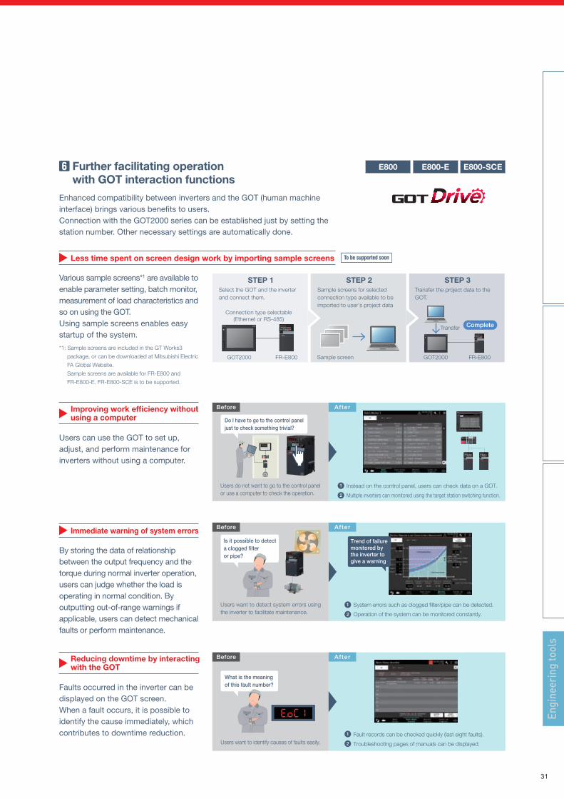
Less time spent on screen design work by importing sample screens
Various sample screens*1 are available to enable parameter setting, batch monitor, measurement of load characteristics and so on using the GOT.Using sample screens enables easy startup of the system.
*1: Sample screens are included in the GT Works3
package, or can be downloaded at Mitsubishi Electric
FA Global Website.
Sample screens are available for FR-E800 and
FR-E800-E. FR-E800-SCE is to be supported.
Immediate warning of system errors
By storing the data of relationship between the output frequency and the torque during normal inverter operation, users can judge whether the load is operating in normal condition. By outputting out-of-range warnings if applicable, users can detect mechanical faults or perform maintenance.
Users can use the GOT to set up, adjust, and perform maintenance for inverters without using a computer.
Operation monitoring
Preventive maintenance
MQTT OPC UA
OthersOthers
Other protocols
Real-time data processing Plug-in Data model
management Security Software for development
SDKDDKGDK
Interface Interface
Interface
Dataanalysis
CC-Link IE EtherNet/IP EtherCAT PROFINET OPCMTConnect Other protocols
Data collector
FA(Production site)
IT systemOn-premiseCloud
IT system
Edge application
AI
Edge computing
Mobile
IT gateway
Processing machine, conveyor machine, filling machine, packaging machine, pick-and-place machine, etc.
Applicable models will change in real time according to changes made to entries.Users do not have to fill all fields for selection. Applicable models will be selected according to the data entered.
Users can select one of the applicable models to register it as the selection result.
Users can select the items to enter to set conditions for selection by folding or unfolding windows. Both easy setting and detailed setting are available.
Selection result
Axis selectionItem selection
Conditions for selection Applicable models
The work efficiency can be improved for each of the design, operation, and maintenance processes.
STEP 3
GOT2000
Transfer Complete
FR-E800
Transfer the project data to the GOT.
STEP 2
Sample screen
Sample screens for selected connection type available to be imported to user's project data
STEP 1
GOT2000 FR-E800
Connection type selectable(Ethernet or RS-485)
Select the GOT and the inverter and connect them.
Users want to detect system errors using the inverter to facilitate maintenance.
Users want to identify causes of faults easily.
Instead on the control panel, users can check data on a GOT.
Multiple inverters can monitored using the target station switching function.
1
2
System errors such as clogged filter/pipe can be detected.
Operation of the system can be monitored constantly.
1
2
Fault records can be checked quickly (last eight faults).
Troubleshooting pages of manuals can be displayed.
1
2
Do I have to go to the control panel just to check something trivial?
Is it possible to detect a clogged filter or pipe?
What is the meaning of this fault number?
MELSEC
After
After
After
Before
Before
Before
MELSEC
Further facilitating operation with Drive System Sizing Software Motorizer
Users can select motors by entering data of mechanical configuration, specifications, and operating patterns. Applicable combinations include inverters, sensorless servo drive units, and AC servo amplifiers.The most suitable combination can be selected from the selection result. The software also supports multi-axis systems.Twelve types of load mechanism such as a ball screw or a rack and pinion are selectable.Selection is available by following the steps from 1 to 3.When users include the power regeneration common converter or other applicable converter, the capacity of the converter can be selected at the same time.
Further facilitating operation with GOT interaction functions
Enhanced compatibility between inverters and the GOT (human machine interface) brings various benefits to users.Connection with the GOT2000 series can be established just by setting the station number. Other necessary settings are automatically done.
Further facilitating operation with Edgecross
Inverters and the system are integrated by maximizing the use of production data with edge computing, enabling solutions for various issues including productivity improvement and equipment maintenance.
• Integration and processing of data sent from various devices and systems in production lines
• Real-time feedback to production sites• Monitoring of field devices based on the know-how of
production sites
Further facilitating operation with the selection guide software
Advanced search for optimum inverters is available. Users can select inverters by entering data such as the motor capacity and current value and specifying specifications. The time spent on inverter selection can be reduced.
Engi
neer
ing
tool
s
E800-SCEE800-EE800 E800-SCEE800-EE800
E800-SCEE800-EE800
E800-SCEE800-EE800
Specification input
Navigation12 types of load mechanism Addition of transmission structures available
Selection resultApplicable combinations
8 Engineering software for further ease of operation
Engineering tools
Improving work efficiency without using a computer
Reducing downtime by interacting with the GOT
Faults occurred in the inverter can be displayed on the GOT screen.When a fault occurs, it is possible to identify the cause immediately, which contributes to downtime reduction.
Users do not want to go to the control panel or use a computer to check the operation.
Trend of failure monitored by the inverter to give a warning
31
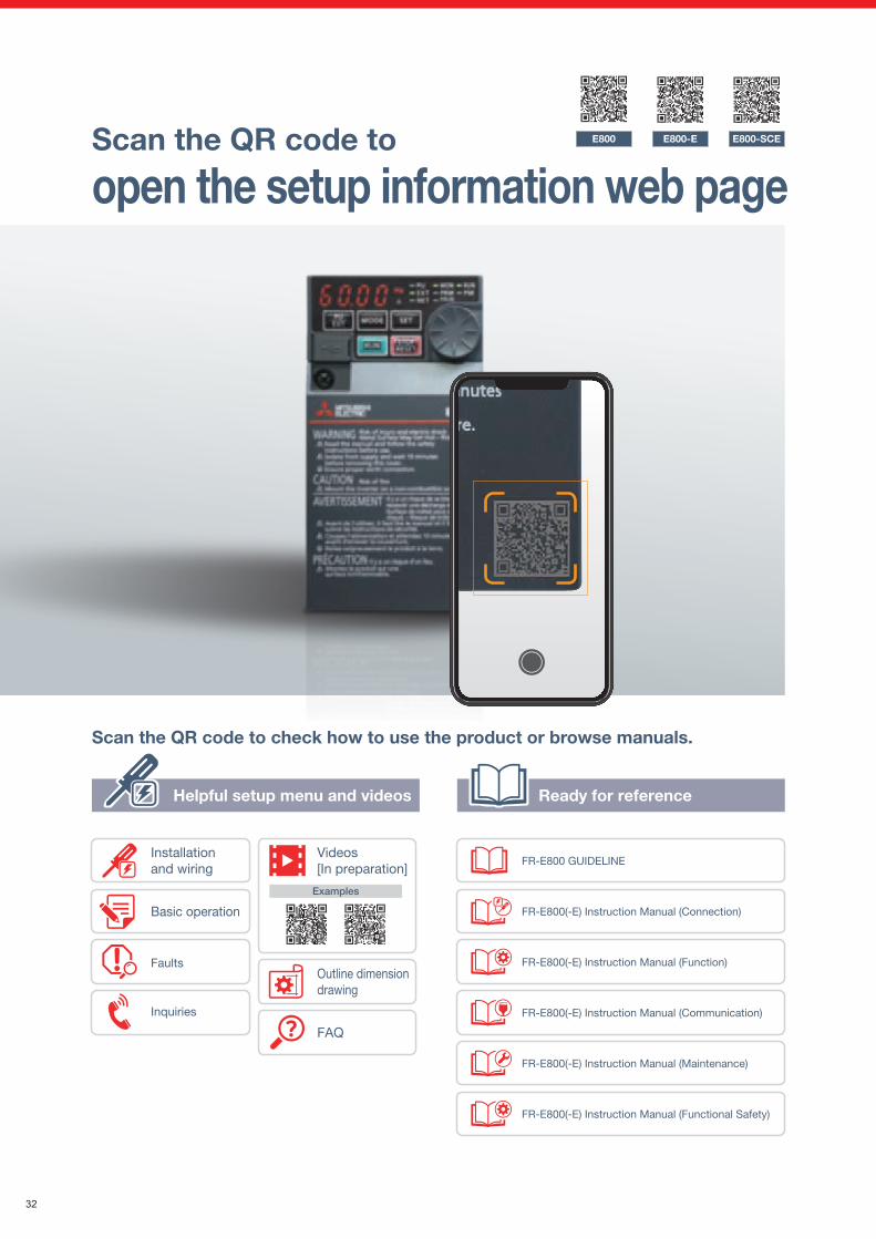
Installation and wiring
Basic operation
FaultsOutline dimension drawing
FAQ
Inquiries
Videos [In preparation]
Examples
Scan the QR code to
open the setup information web page
Prototype design / operation test
Unity of design for all models
Detailed examination of the product design (development material)
Uniformity and consistencyThe FR-E800 series product line offers more than fifty different designs.To integrate the unity of design, development of FR-E800 inverters started in accordance with common rules. They can be distinguished at a glance by their uniform characteristics of the details such as the bevel under the operation panel and the parting lines. Consistency with other Mitsubishi Electric FA products is also considered so that all the products look well-organized when they are placed together.
Scan the QR code to check how to use the product or browse manuals.
Pursuing ease of operationWith the user-friendly design, ease of use is pursued for various installation and operating conditions (such as height of the device and operation with or without gloves).Owing to the contrast of colors and flat structure, tile buttons and the LED display are clear and easy to see.
Dependable qualityE800 E800-E E800-SCE
32
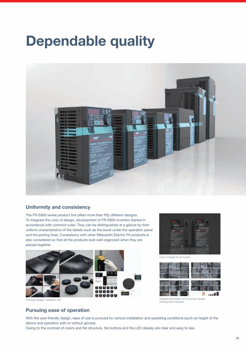
Installation and wiring
Basic operation
FaultsOutline dimension drawing
FAQ
Inquiries
Videos [In preparation]
Examples
Scan the QR code to
open the setup information web page
Prototype design / operation test
Unity of design for all models
Detailed examination of the product design (development material)
Uniformity and consistencyThe FR-E800 series product line offers more than fifty different designs.To integrate the unity of design, development of FR-E800 inverters started in accordance with common rules. They can be distinguished at a glance by their uniform characteristics of the details such as the bevel under the operation panel and the parting lines. Consistency with other Mitsubishi Electric FA products is also considered so that all the products look well-organized when they are placed together.
Scan the QR code to check how to use the product or browse manuals.
Pursuing ease of operationWith the user-friendly design, ease of use is pursued for various installation and operating conditions (such as height of the device and operation with or without gloves).Owing to the contrast of colors and flat structure, tile buttons and the LED display are clear and easy to see.
Dependable qualityE800 E800-E E800-SCE
33
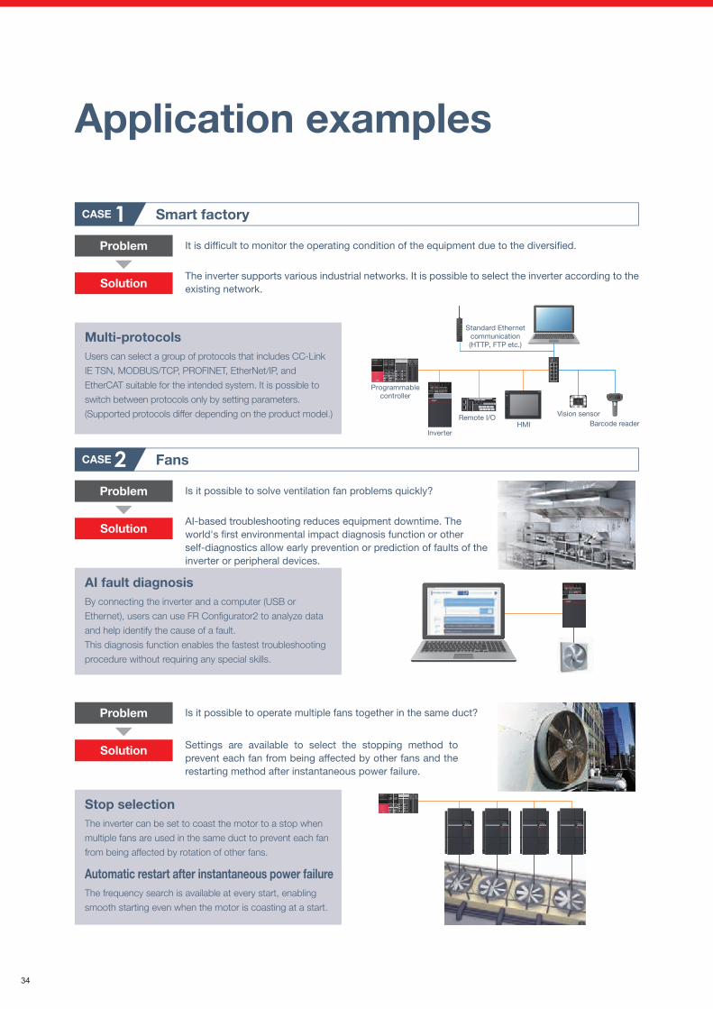
Application examples
Smart factory
Problem
Solution
CASE 1
Programmablecontroller
Inverter
Remote I/OHMI
Standard Ethernetcommunication(HTTP, FTP etc.)
Vision sensorBarcode reader
MELSEC
Multi-protocolsUsers can select a group of protocols that includes CC-Link
IE TSN, MODBUS/TCP, PROFINET, EtherNet/IP, and
EtherCAT suitable for the intended system. It is possible to
switch between protocols only by setting parameters.
(Supported protocols differ depending on the product model.)
It is difficult to monitor the operating condition of the equipment due to the diversified.
The inverter supports various industrial networks. It is possible to select the inverter according to the existing network.
Problem
Solution
Problem
Solution
PM sensorless vector controlThe speed and magnetic pole positions, the two essential bits of information to control a PM motor, are detected without a sensor (encoder). The speed detection internally-performed in an inverter enables highly accurate control of a PM motor, almost as accurate as an AC servo system, without the need of a sensor (encoder).
Speed fluctuation ratio: ±0.05% (digital input)Speed fluctuation ratio = (Speed under no load − Speed under rated load)/Rated speed × 100(%)
Transfer system
Problem
Solution
CASE 3
PLC functionIn accordance with the machine specifications, users can set
various operation patterns: inverter movements at signal
inputs, signal outputs at particular inverter statuses, and
monitor outputs, etc. Operation of the system can be
customized by the inverter alone.
Is it possible to simplify the electric control system to use a smaller enclosure?
Inverter operations can be freely customized using the PLC function in the inverter.This function enables construction of various systems without using another controller.
Food processing line
Problem
Solution
CASE 4
SLS (safely-limited speed) functionIt is possible to continue operation at a safe speed without stopping the production line. The motor speed is calculated based on the current value or other data without using an encoder. This will contribute to wire and cost savings.
Is it possible to increase productivity while ensuring the safety of operators?
Cutting machine
Problem
Solution
CASE 5Is it possible to reduce variation in the finished products?
Using PM sensorless vector control, the inverter contributes to reducing variation caused by uneven rotation.
MELSEC
Extruding machine
Stop sensorStop sensor
WorkpieceWorkpiece
Deceleration sensorDeceleration sensor
Start sensor
Conveyor robot
Motor
Power supply
Input (X0)
Input (X1)
Output (Y0)
Input (X2)
Output (Y1)
Light curtain
Limit area 1(speed reduction)
Limit area 2(further speed reduction)
Area sensor
Stop area
Limit area
The inverter supports the IEC 61508-5-2 functional safety standard. This will significantly reduce time required for maintenance or tooling and eliminate external devices such as ones used for monitoring the speed.
SensorlessPM motor
Grindingwheel Workpiece
FansCASE 2
AI fault diagnosisBy connecting the inverter and a computer (USB or
Ethernet), users can use FR Configurator2 to analyze data
and help identify the cause of a fault.
This diagnosis function enables the fastest troubleshooting
procedure without requiring any special skills.
Is it possible to solve ventilation fan problems quickly?
AI-based troubleshooting reduces equipment downtime. The world's first environmental impact diagnosis function or other self-diagnostics allow early prevention or prediction of faults of the inverter or peripheral devices.
MELSEC
Stop selectionThe inverter can be set to coast the motor to a stop when
multiple fans are used in the same duct to prevent each fan
from being affected by rotation of other fans.
Automatic restart after instantaneous power failureThe frequency search is available at every start, enabling
smooth starting even when the motor is coasting at a start.
Is it possible to operate multiple fans together in the same duct?
Settings are available to select the stopping method to prevent each fan from being affected by other fans and the restarting method after instantaneous power failure.
34
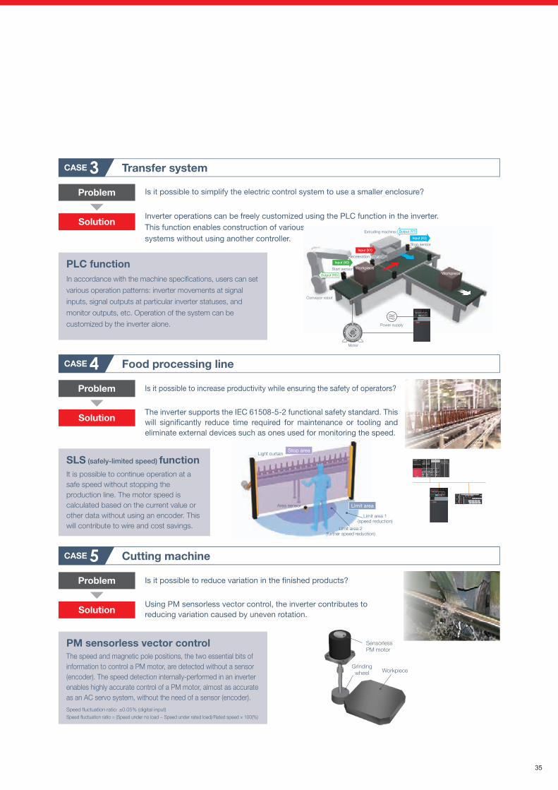
Application examples
Smart factory
Problem
Solution
CASE 1
Programmablecontroller
Inverter
Remote I/OHMI
Standard Ethernetcommunication(HTTP, FTP etc.)
Vision sensorBarcode reader
MELSEC
Multi-protocolsUsers can select a group of protocols that includes CC-Link
IE TSN, MODBUS/TCP, PROFINET, EtherNet/IP, and
EtherCAT suitable for the intended system. It is possible to
switch between protocols only by setting parameters.
(Supported protocols differ depending on the product model.)
It is difficult to monitor the operating condition of the equipment due to the diversified.
The inverter supports various industrial networks. It is possible to select the inverter according to the existing network.
Problem
Solution
Problem
Solution
PM sensorless vector controlThe speed and magnetic pole positions, the two essential bits of information to control a PM motor, are detected without a sensor (encoder). The speed detection internally-performed in an inverter enables highly accurate control of a PM motor, almost as accurate as an AC servo system, without the need of a sensor (encoder).
Speed fluctuation ratio: ±0.05% (digital input)Speed fluctuation ratio = (Speed under no load − Speed under rated load)/Rated speed × 100(%)
Transfer system
Problem
Solution
CASE 3
PLC functionIn accordance with the machine specifications, users can set
various operation patterns: inverter movements at signal
inputs, signal outputs at particular inverter statuses, and
monitor outputs, etc. Operation of the system can be
customized by the inverter alone.
Is it possible to simplify the electric control system to use a smaller enclosure?
Inverter operations can be freely customized using the PLC function in the inverter.This function enables construction of various systems without using another controller.
Food processing line
Problem
Solution
CASE 4
SLS (safely-limited speed) functionIt is possible to continue operation at a safe speed without stopping the production line. The motor speed is calculated based on the current value or other data without using an encoder. This will contribute to wire and cost savings.
Is it possible to increase productivity while ensuring the safety of operators?
Cutting machine
Problem
Solution
CASE 5Is it possible to reduce variation in the finished products?
Using PM sensorless vector control, the inverter contributes to reducing variation caused by uneven rotation.
MELSEC
Extruding machine
Stop sensorStop sensor
WorkpieceWorkpiece
Deceleration sensorDeceleration sensor
Start sensor
Conveyor robot
Motor
Power supply
Input (X0)
Input (X1)
Output (Y0)
Input (X2)
Output (Y1)
Light curtain
Limit area 1(speed reduction)
Limit area 2(further speed reduction)
Area sensor
Stop area
Limit area
The inverter supports the IEC 61508-5-2 functional safety standard. This will significantly reduce time required for maintenance or tooling and eliminate external devices such as ones used for monitoring the speed.
SensorlessPM motor
Grindingwheel Workpiece
FansCASE 2
AI fault diagnosisBy connecting the inverter and a computer (USB or
Ethernet), users can use FR Configurator2 to analyze data
and help identify the cause of a fault.
This diagnosis function enables the fastest troubleshooting
procedure without requiring any special skills.
Is it possible to solve ventilation fan problems quickly?
AI-based troubleshooting reduces equipment downtime. The world's first environmental impact diagnosis function or other self-diagnostics allow early prevention or prediction of faults of the inverter or peripheral devices.
MELSEC
Stop selectionThe inverter can be set to coast the motor to a stop when
multiple fans are used in the same duct to prevent each fan
from being affected by rotation of other fans.
Automatic restart after instantaneous power failureThe frequency search is available at every start, enabling
smooth starting even when the motor is coasting at a start.
Is it possible to operate multiple fans together in the same duct?
Settings are available to select the stopping method to prevent each fan from being affected by other fans and the restarting method after instantaneous power failure.
35
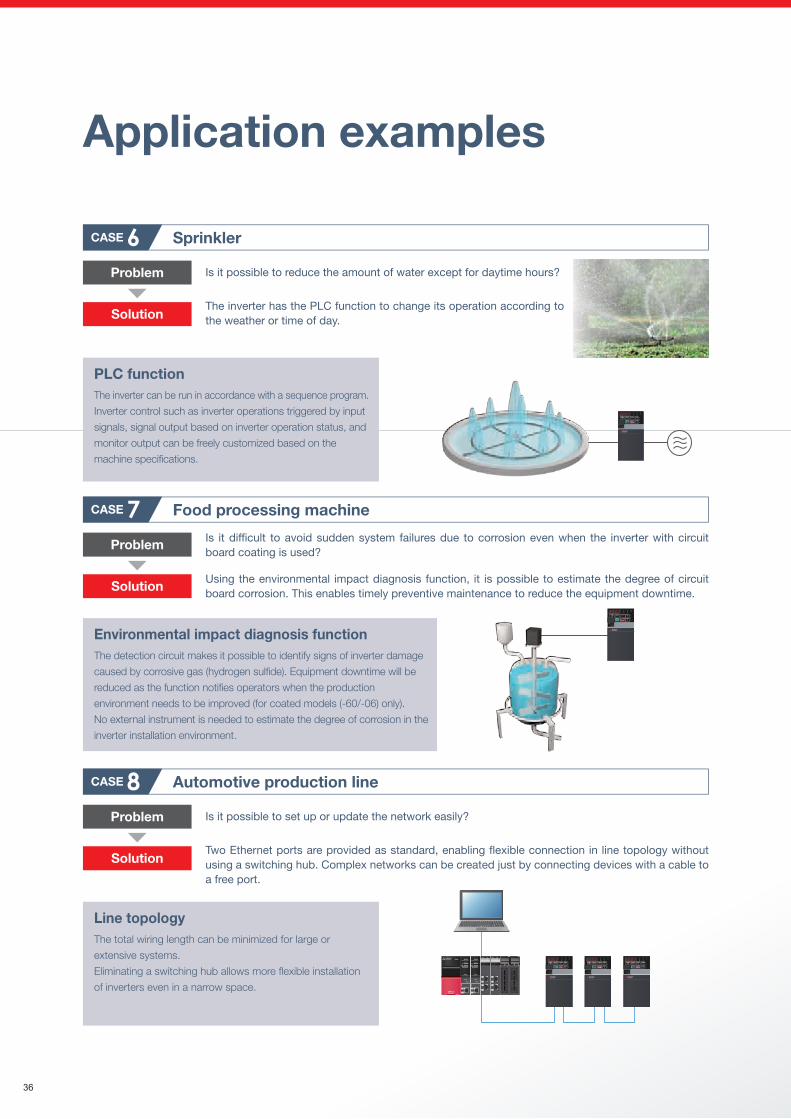
Pump
Problem
Solution
CASE 9
PLC functionIn accordance with the machine specifications, users can
set various operation patterns: inverter movements at signal
inputs, signal outputs at particular inverter statuses, and
monitor outputs, etc. Operation of the system can be
customized by the inverter alone.
Is it possible to integrate the system control functions into the invert-er without using another controller?
Inverter operations can be controlled using the PLC function in the inverter.This function enables construction of systems without using programmable controllers. This will contribute to cost reduction.
Automotive production line
Problem
Solution
CASE 8
Line topologyThe total wiring length can be minimized for large or
extensive systems.
Eliminating a switching hub allows more flexible installation
of inverters even in a narrow space.
Is it possible to set up or update the network easily?
Two Ethernet ports are provided as standard, enabling flexible connection in line topology without using a switching hub. Complex networks can be created just by connecting devices with a cable to a free port.
MELSEC
Food processing machineCASE 7
Environmental impact diagnosis functionThe detection circuit makes it possible to identify signs of inverter damage
caused by corrosive gas (hydrogen sulfide). Equipment downtime will be
reduced as the function notifies operators when the production
environment needs to be improved (for coated models (-60/-06) only).
No external instrument is needed to estimate the degree of corrosion in the
inverter installation environment.
Is it difficult to avoid sudden system failures due to corrosion even when the inverter with circuit board coating is used?
Using the environmental impact diagnosis function, it is possible to estimate the degree of circuit board corrosion. This enables timely preventive maintenance to reduce the equipment downtime.
Problem
Solution
PLC functionThe inverter can be run in accordance with a sequence program.
Inverter control such as inverter operations triggered by input
signals, signal output based on inverter operation status, and
monitor output can be freely customized based on the
machine specifications.
Sprinkler
Problem
CASE 6Is it possible to reduce the amount of water except for daytime hours?
The inverter has the PLC function to change its operation according to the weather or time of day.Solution
Application examples
36
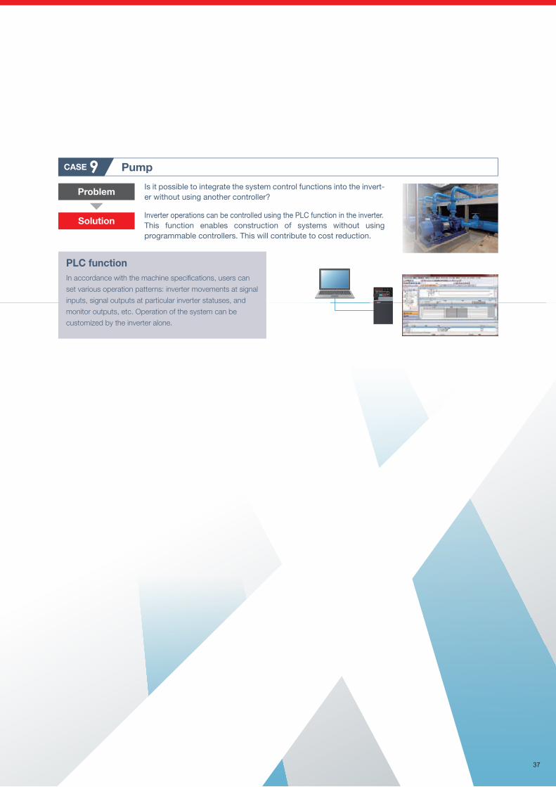
Pump
Problem
Solution
CASE 9
PLC functionIn accordance with the machine specifications, users can
set various operation patterns: inverter movements at signal
inputs, signal outputs at particular inverter statuses, and
monitor outputs, etc. Operation of the system can be
customized by the inverter alone.
Is it possible to integrate the system control functions into the invert-er without using another controller?
Inverter operations can be controlled using the PLC function in the inverter.This function enables construction of systems without using programmable controllers. This will contribute to cost reduction.
Automotive production line
Problem
Solution
CASE 8
Line topologyThe total wiring length can be minimized for large or
extensive systems.
Eliminating a switching hub allows more flexible installation
of inverters even in a narrow space.
Is it possible to set up or update the network easily?
Two Ethernet ports are provided as standard, enabling flexible connection in line topology without using a switching hub. Complex networks can be created just by connecting devices with a cable to a free port.
MELSEC
Food processing machineCASE 7
Environmental impact diagnosis functionThe detection circuit makes it possible to identify signs of inverter damage
caused by corrosive gas (hydrogen sulfide). Equipment downtime will be
reduced as the function notifies operators when the production
environment needs to be improved (for coated models (-60/-06) only).
No external instrument is needed to estimate the degree of corrosion in the
inverter installation environment.
Is it difficult to avoid sudden system failures due to corrosion even when the inverter with circuit board coating is used?
Using the environmental impact diagnosis function, it is possible to estimate the degree of circuit board corrosion. This enables timely preventive maintenance to reduce the equipment downtime.
Problem
Solution
PLC functionThe inverter can be run in accordance with a sequence program.
Inverter control such as inverter operations triggered by input
signals, signal output based on inverter operation status, and
monitor output can be freely customized based on the
machine specifications.
Sprinkler
Problem
CASE 6Is it possible to reduce the amount of water except for daytime hours?
The inverter has the PLC function to change its operation according to the weather or time of day.Solution
Application examples
37
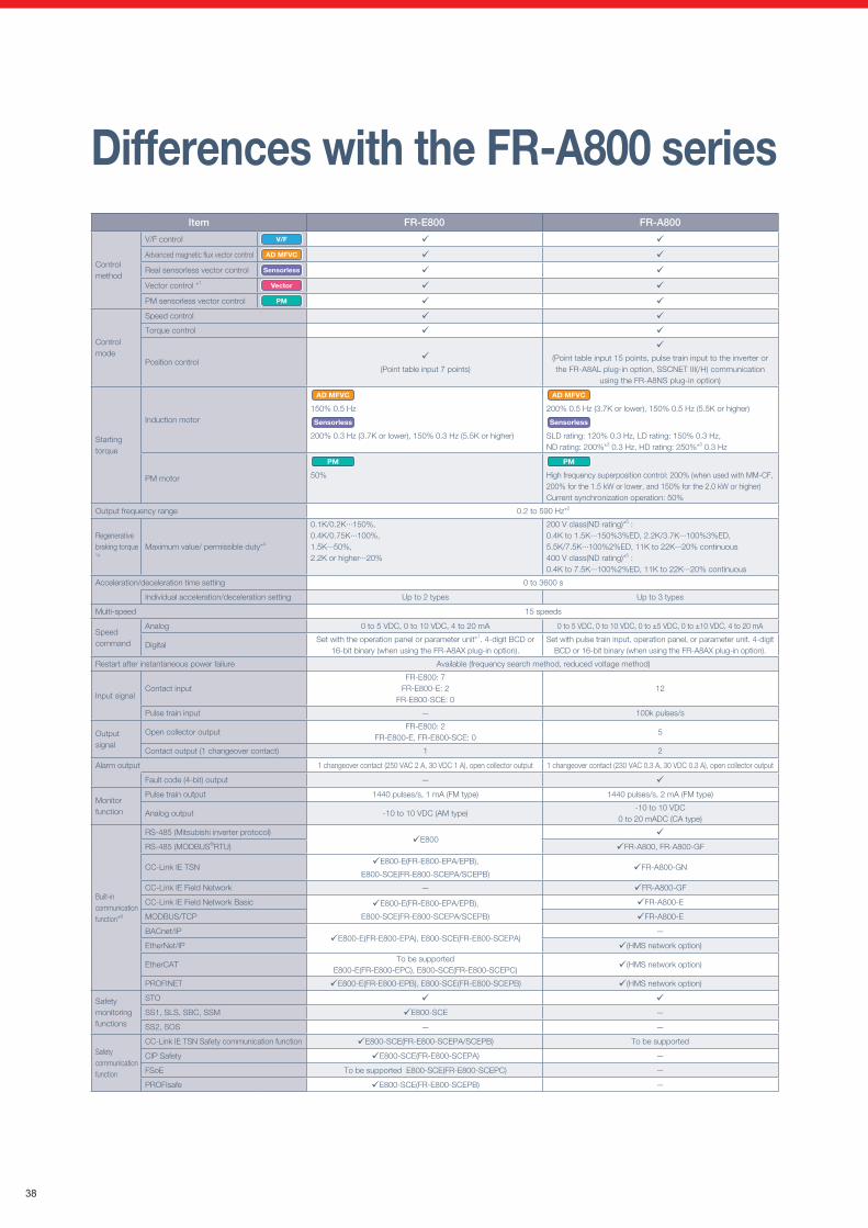
Differences with the FR-A800 seriesItem FR-E800 FR-A800
Control method
V/F control V/F
Advanced magnetic flux vector control AD MFVC
Real sensorless vector control Sensorless
Vector control *1 Vector
PM sensorless vector control PM
Control mode
Speed control Torque control
Position control
(Point table input 7 points)
(Point table input 15 points, pulse train input to the inverter or the FR-A8AL plug-in option, SSCNET III(/H) communication
using the FR-A8NS plug-in option)
Starting torque
Induction motor
AD MFVC
150% 0.5 Hz
Sensorless
200% 0.3 Hz (3.7K or lower), 150% 0.3 Hz (5.5K or higher)
AD MFVC
200% 0.5 Hz (3.7K or lower), 150% 0.5 Hz (5.5K or higher)
Sensorless
SLD rating: 120% 0.3 Hz, LD rating: 150% 0.3 Hz, ND rating: 200%*3 0.3 Hz, HD rating: 250%*3 0.3 Hz
PM motor
PM
50%
PM
High frequency superposition control: 200% (when used with MM-CF, 200% for the 1.5 kW or lower, and 150% for the 2.0 kW or higher)Current synchronization operation: 50%
Output frequency range 0.2 to 590 Hz*2
Regenerative braking torque*4
Maximum value/ permissible duty*4
0.1K/0.2K···150%,0.4K/0.75K···100%,1.5K···50%,2.2K or higher···20%
200 V class(ND rating)*5 :0.4K to 1.5K···150%3%ED, 2.2K/3.7K···100%3%ED, 5.5K/7.5K···100%2%ED, 11K to 22K···20% continuous400 V class(ND rating)*5 :0.4K to 7.5K···100%2%ED, 11K to 22K···20% continuous
Acceleration/deceleration time setting 0 to 3600 s
Individual acceleration/deceleration setting Up to 2 types Up to 3 types
Multi-speed 15 speeds
Speed command
Analog 0 to 5 VDC, 0 to 10 VDC, 4 to 20 mA 0 to 5 VDC, 0 to 10 VDC, 0 to ±5 VDC, 0 to ±10 VDC, 4 to 20 mA
DigitalSet with the operation panel or parameter unit*7. 4-digit BCD or
16-bit binary (when using the FR-A8AX plug-in option).Set with pulse train input, operation panel, or parameter unit. 4-digit
BCD or 16-bit binary (when using the FR-A8AX plug-in option).
Restart after instantaneous power failure Available (frequency search method, reduced voltage method)
Input signalContact input
FR-E800: 7FR-E800-E: 2
FR-E800-SCE: 012
Pulse train input — 100k pulses/s
Output signal
Open collector outputFR-E800: 2
FR-E800-E, FR-E800-SCE: 05
Contact output (1 changeover contact) 1 2
Alarm output 1 changeover contact (250 VAC 2 A, 30 VDC 1 A), open collector output 1 changeover contact (230 VAC 0.3 A, 30 VDC 0.3 A), open collector output
Fault code (4-bit) output —
Monitor function
Pulse train output 1440 pulses/s, 1 mA (FM type) 1440 pulses/s, 2 mA (FM type)
Analog output -10 to 10 VDC (AM type)-10 to 10 VDC
0 to 20 mADC (CA type)
Built-in communication function*6
RS-485 (Mitsubishi inverter protocol)E800
RS-485 (MODBUS®RTU) FR-A800, FR-A800-GF
CC-Link IE TSNE800-E(FR-E800-EPA/EPB),
E800-SCE(FR-E800-SCEPA/SCEPB)FR-A800-GN
CC-Link IE Field Network — FR-A800-GF
CC-Link IE Field Network Basic E800-E(FR-E800-EPA/EPB),
E800-SCE(FR-E800-SCEPA/SCEPB)
FR-A800-E
MODBUS/TCP FR-A800-E
BACnet/IPE800-E(FR-E800-EPA), E800-SCE(FR-E800-SCEPA)
—
EtherNet/IP (HMS network option)
EtherCATTo be supported
E800-E(FR-E800-EPC), E800-SCE(FR-E800-SCEPC) (HMS network option)
PROFINET E800-E(FR-E800-EPB), E800-SCE(FR-E800-SCEPB) (HMS network option)
Safety monitoring functions
STO SS1, SLS, SBC, SSM E800-SCE —
SS2, SOS — —
Safety communication function
CC-Link IE TSN Safety communication function E800-SCE(FR-E800-SCEPA/SCEPB) To be supported
CIP Safety E800-SCE(FR-E800-SCEPA) —
FSoE To be supported E800-SCE(FR-E800-SCEPC) —
PROFIsafe E800-SCE(FR-E800-SCEPB) —
38
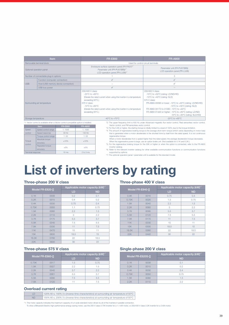
List of inverters by ratingThree-phase 200 V class
Model FR-E820-[]Applicable motor capacity (kW)*1
LD ND0.1K 0008 0.2 0.1
0.2K 0015 0.4 0.2
0.4K 0030 0.75 0.4
0.75K 0050 1.1 0.75
1.5K 0080 2.2 1.5
2.2K 0110 3 2.2
3.7K 0175 5.5 3.7
5.5K 0240 7.5 5.5
7.5K 0330 11 7.5
11K 0470 15 11
15K 0600 18.5 15
18.5K 0760 22 18.5
22K 0900 30 22
Three-phase 400 V class
Model FR-E840-[]Applicable motor capacity (kW)*1
LD ND0.4K 0016 0.75 0.4
0.75K 0026 1.5 0.75
1.5K 0040 2.2 1.5
2.2K 0060 3 2.2
3.7K 0095 5.5 3.7
5.5K 0120 7.5 5.5
7.5K 0170 11 7.5
11K 0230 15 11
15K 0300 18.5 15
18.5K 0380 22 18.5
22K 0440 30 22
Three-phase 575 V class
Model FR-E860-[]Applicable motor capacity (kW)*1
LD ND0.75K 0017 1.5 0.75
1.5K 0027 2.2 1.5
2.2K 0040 3.7 2.2
3.7K 0061 5.5 3.7
5.5K 0090 7.5 5.5
7.5K 0120 11 7.5
Overload current ratingLD 120% 60 s, 150% 3 s (inverse-time characteristics) at surrounding air temperature of 50°C
ND 150% 60 s, 200% 3 s (inverse-time characteristics) at surrounding air temperature of 50°C
Single-phase 200 V class
Model FR-E820S-[]Applicable motor capacity (kW)*1
ND0.1K 0008 0.1
0.2K 0015 0.2
0.4K 0030 0.4
0.75K 0050 0.75
1.5K 0080 1.5
2.2K 0110 2.2
*1: The motor capacity indicates the maximum capacity of a 4-pole standard motor driven by all of the inverters in parallel connection.
To drive a Mitsubishi Electric high-performance energy-saving motor, use the 200 V class 0.75K inverter for a 1.1 kW motor, or 200/400 V class 2.2K inverter for a 3 kW motor.
Item FR-E800 FR-A800
Removable terminal block Used for control circuit terminals
Optional operation panelEnclosure surface operation panel (FR-PA07)*7
Parameter unit (FR-PU07(BB))*7
LCD operation panel (FR-LU08)*7
Parameter unit (FR-PU07(BB))LCD operation panel (FR-LU08)
Number of connectable plug-in options 1 3
USB
Function (computer connection) Host (USB memory device connection) — USB bus power —
Surrounding air temperature
200/400 V class:-20°C to +60°C (Derate the rated current when using the inverter in a temperature exceeding 50°C.)
575 V class:-10°C to +60°C (Derate the rated current when using the inverter in a temperature exceeding 50°C.)
200/400 V class:-10°C to +50°C (rating: LD/ND/HD)-10°C to +40°C (rating: SLD)
575 V class:FR-A860-00090 or lower: -10°C to +40°C (rating: LD/ND/HD)
-10°C to +30°C (rating: SLD)FR-A860-00170 to 01080: -10°C to +40°CFR-A860-01440 or higher: -10°C to +50°C (rating: LD/ND)
-10°C to +30°C (rating: SLD/HD)
Storage temperature -40°C to +70°C -20°C to +65°C
*1: Vector control is available when a Vector control compatible option is installed.
Item FR-E800 FR-A800
Speed
control
Speed control range 1: 1500 1: 1500
Speed response 30 Hz 130 Hz
Torque
control
Torque control range 1: 50 1: 50
Absolute torque
accuracy±10% ±10%
Repeated torque
accuracy±5% ±5%
Terminal response 10 ms 2 to 3 ms
*2: The upper frequency limit is 400 Hz under Advanced magnetic flux vector control, Real sensorless vector control, Vector control, and PM sensorless vector control.
*3: For the 5.5K or higher, the starting torque is initially limited to a level of 150% due to the torque limitation.*4: The amount of regenerative braking torque is the average short-term torque (which varies depending on motor loss)
that is generated when a motor decelerates in the shortest time by itself from the rated speed. It is not continuous regenerative torque.When a motor decelerates from a speed higher than the rated speed, the average deceleration torque decreases.When the regenerative power is large, use an option brake unit. (Not available for 0.1K and 0.2K.)
*5: For the regenerative braking torque for the 30K or higher or when the option is connected, refer to the FR-A800 inverter catalog.
*6: Refer to the relevant inverter catalog for other available communication functions or communication functions supported by options.
*7: The optional operation panel / parameter unit is available for the standard model.
39
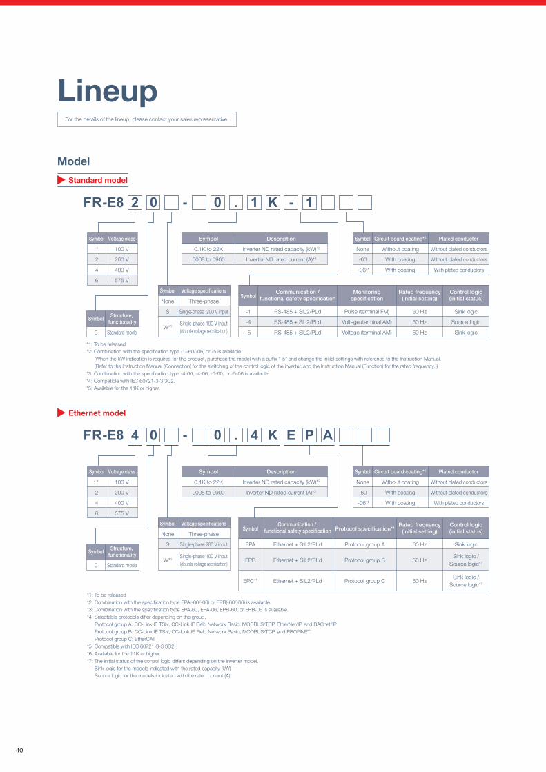
Three-phase 200 V0.1K 0.2K 0.4K 0.75K 1.5K 2.2K 3.7K 5.5K 7.5K 11K 15K 18.5K 22K
0008 0015 0030 0050 0080 0110 0175 0240 0330 0470 0600 0760 0900FR-E820-[](E/SCE)
Three-phase 400 V– – 0.4K 0.75K 1.5K 2.2K 3.7K 5.5K 7.5K 11K 15K 18.5K 22K– – 0016 0026 0040 0060 0095 0120 0170 0230 0300 0380 0440
FR-E840-[](E/SCE) – –
Three-phase 575 V– – – 0.75K 1.5K 2.2K 3.7K 5.5K 7.5K – – – –– – – 0017 0027 0040 0061 0090 0120 – – – –
FR-E860-[](E/SCE) – – – – – – –
Single-phase 200 V0.1K 0.2K 0.4K 0.75K 1.5K 2.2K – – – – – – –0008 0015 0030 0050 0080 0110 – – – – – – –
FR-E820S-[](E/SCE) – – – – – – –
Single-phase 100 V0.1K 0.2K 0.4K 0.75K – – – – – – – – –
0008 0015 0030 0050 – – – – – – – – –FR-E810W-[](E/SCE) – – – – – – – – –
: Released, : To be released, : Not applicable
0 Standard model
SymbolStructure,
functionality 0
6*1
Standard model
IP67 models
SymbolStructure,
functionality
0 Standard model
SymbolStructure,
functionality
FR-E8 4 0 0 . 4 K S C E P A -
1*1
2
4
6
None
S
W*1
100 V
200 V
400 V
575 V
Inverter ND rated capacity (kW)*2
Inverter ND rated current (A)*3
0.1K to 22K
0008 to 0900
Three-phase
Single-phase 200 V input
Single-phase 100 V input(double voltage rectification)
Symbol
SCEPA
SCEPB
SCEPC*1
Ethernet + SIL3/PLe
Ethernet + SIL3/PLe
Ethernet + SIL3/PLe
Symbol
60 Hz
50 Hz
50 Hz
Protocol group A
Protocol group B
Protocol group C
Protocol specification*4
Source logic
Source logic
Source logic
Voltage class Symbol Description
Symbol Voltage specifications
For differences between the standard model (E800), Ethernet model (E800-E), and safety communication model (E800-SCE), refer to page 133.
Lineup
*1: To be released*2: Combination with the specification type SCEPA(-60/-06) or SCEPB(-60/-06) is available. *3: Combination with the specification type SCEPA-60, SCEPA-06, SCEPB-60, or SCEPB-06 is available.*4: Selectable protocols differ depending on the group. Protocol group A: CC-Link IE TSN, CC-Link IE Field Network Basic, MODBUS/TCP, EtherNet/IP, and BACnet/IP Protocol group B: CC-Link IE TSN, CC-Link IE Field Network Basic, MODBUS/TCP, and PROFINET Protocol group C: EtherCAT*5: Compatible with IEC 60721-3-3 3C2*6: Available for the 11K or higher.*7: The control logic is fixed to the source logic.
Capacity table
For the details of the lineup, please contact your sales representative.
Model
EPA
EPB
EPC*1
Ethernet + SIL2/PLd
Ethernet + SIL2/PLd
Ethernet + SIL2/PLd
SymbolCommunication /
functional safety specification
60 Hz
50 Hz
60 Hz
Protocol group A
Protocol group B
Protocol group C
Protocol specification*4
Sink logic
Sink logic /Source logic*7
Sink logic /Source logic*7
*1: To be released*2: Combination with the specification type EPA(-60/-06) or EPB(-60/-06) is available. *3: Combination with the specification type EPA-60, EPA-06, EPB-60, or EPB-06 is available.*4: Selectable protocols differ depending on the group. Protocol group A: CC-Link IE TSN, CC-Link IE Field Network Basic, MODBUS/TCP, EtherNet/IP, and BACnet/IP Protocol group B: CC-Link IE TSN, CC-Link IE Field Network Basic, MODBUS/TCP, and PROFINET Protocol group C: EtherCAT*5: Compatible with IEC 60721-3-3 3C2.*6: Available for the 11K or higher.*7: The initial status of the control logic differs depending on the inverter model. Sink logic for the models indicated with the rated capacity (kW) Source logic for the models indicated with the rated current (A)
FR-E8 4 0 0 . 4 K E P A -
1*1
2
4
6
100 V
200 V
400 V
575 V
Symbol Voltage class
Inverter ND rated capacity (kW)*2
Inverter ND rated current (A)*3
0.1K to 22K
0008 to 0900
Symbol Description
FR-E8 2 0 0 . 1 K - 1 -
1*1
2
4
6
100 V
200 V
400 V
575 V
Symbol Voltage class
None
S
W*1
Three-phase
Single-phase 200 V input
Single-phase 100 V input(double voltage rectification)
Symbol Voltage specifications
None
S
W*1
Three-phase
Single-phase 200 V input
Single-phase 100 V input(double voltage rectification)
Symbol Voltage specifications
Inverter ND rated capacity (kW)*2
Inverter ND rated current (A)*3
0.1K to 22K
0008 to 0900
Symbol Description
-1
-4
-5
RS-485 + SIL2/PLd
RS-485 + SIL2/PLd
RS-485 + SIL2/PLd
SymbolCommunication /
functional safety specificationCommunication /
functional safety specification
60 Hz
50 Hz
60 Hz
Rated frequency(initial setting)
Pulse (terminal FM)
Voltage (terminal AM)
Voltage (terminal AM)
Monitoringspecification
Sink logic
Source logic
Sink logic
Control logic(initial status)
Rated frequency(initial setting) Control logic*7
Rated frequency(initial setting)
Control logic(initial status)
Standard model
Ethernet model
Safety communication model
None
-60
-06*5
Without coating
With coating
With coating
Symbol Circuit board coating*4
Without plated conductors
Without plated conductors
With plated conductors
Plated conductor
None
-60
-06*6
Without coating
With coating
With coating
Symbol Circuit board coating*5
Without plated conductors
Without plated conductors
With plated conductors
Plated conductor
None
-60
-06*6
Without coating
With coating
With coating
Symbol Circuit board coating*5
Without plated conductors
Without plated conductors
With plated conductors
Plated conductor
*1: To be released*2: Combination with the specification type -1(-60/-06) or -5 is available.
(When the kW indication is required for the product, purchase the model with a suffix "-5" and change the initial settings with reference to the Instruction Manual.(Refer to the Instruction Manual (Connection) for the switching of the control logic of the inverter, and the Instruction Manual (Function) for the rated frequency.))
*3: Combination with the specification type -4-60, -4-06, -5-60, or -5-06 is available. *4: Compatible with IEC 60721-3-3 3C2.*5: Available for the 11K or higher.
7.5K or lower has the KC and EAC markings (11K or higher is to be compatible with the markings).
40
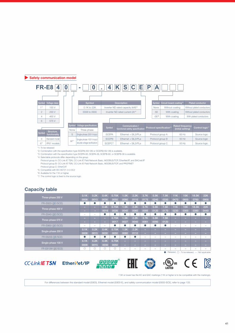
Three-phase 200 V0.1K 0.2K 0.4K 0.75K 1.5K 2.2K 3.7K 5.5K 7.5K 11K 15K 18.5K 22K
0008 0015 0030 0050 0080 0110 0175 0240 0330 0470 0600 0760 0900FR-E820-[](E/SCE)
Three-phase 400 V– – 0.4K 0.75K 1.5K 2.2K 3.7K 5.5K 7.5K 11K 15K 18.5K 22K– – 0016 0026 0040 0060 0095 0120 0170 0230 0300 0380 0440
FR-E840-[](E/SCE) – –
Three-phase 575 V– – – 0.75K 1.5K 2.2K 3.7K 5.5K 7.5K – – – –– – – 0017 0027 0040 0061 0090 0120 – – – –
FR-E860-[](E/SCE) – – – – – – –
Single-phase 200 V0.1K 0.2K 0.4K 0.75K 1.5K 2.2K – – – – – – –0008 0015 0030 0050 0080 0110 – – – – – – –
FR-E820S-[](E/SCE) – – – – – – –
Single-phase 100 V0.1K 0.2K 0.4K 0.75K – – – – – – – – –
0008 0015 0030 0050 – – – – – – – – –FR-E810W-[](E/SCE) – – – – – – – – –
: Released, : To be released, : Not applicable
0 Standard model
SymbolStructure,
functionality 0
6*1
Standard model
IP67 models
SymbolStructure,
functionality
0 Standard model
SymbolStructure,
functionality
FR-E8 4 0 0 . 4 K S C E P A -
1*1
2
4
6
None
S
W*1
100 V
200 V
400 V
575 V
Inverter ND rated capacity (kW)*2
Inverter ND rated current (A)*3
0.1K to 22K
0008 to 0900
Three-phase
Single-phase 200 V input
Single-phase 100 V input(double voltage rectification)
Symbol
SCEPA
SCEPB
SCEPC*1
Ethernet + SIL3/PLe
Ethernet + SIL3/PLe
Ethernet + SIL3/PLe
Symbol
60 Hz
50 Hz
50 Hz
Protocol group A
Protocol group B
Protocol group C
Protocol specification*4
Source logic
Source logic
Source logic
Voltage class Symbol Description
Symbol Voltage specifications
For differences between the standard model (E800), Ethernet model (E800-E), and safety communication model (E800-SCE), refer to page 133.
Lineup
*1: To be released*2: Combination with the specification type SCEPA(-60/-06) or SCEPB(-60/-06) is available. *3: Combination with the specification type SCEPA-60, SCEPA-06, SCEPB-60, or SCEPB-06 is available.*4: Selectable protocols differ depending on the group. Protocol group A: CC-Link IE TSN, CC-Link IE Field Network Basic, MODBUS/TCP, EtherNet/IP, and BACnet/IP Protocol group B: CC-Link IE TSN, CC-Link IE Field Network Basic, MODBUS/TCP, and PROFINET Protocol group C: EtherCAT*5: Compatible with IEC 60721-3-3 3C2*6: Available for the 11K or higher.*7: The control logic is fixed to the source logic.
Capacity table
For the details of the lineup, please contact your sales representative.
Model
EPA
EPB
EPC*1
Ethernet + SIL2/PLd
Ethernet + SIL2/PLd
Ethernet + SIL2/PLd
SymbolCommunication /
functional safety specification
60 Hz
50 Hz
60 Hz
Protocol group A
Protocol group B
Protocol group C
Protocol specification*4
Sink logic
Sink logic /Source logic*7
Sink logic /Source logic*7
*1: To be released*2: Combination with the specification type EPA(-60/-06) or EPB(-60/-06) is available. *3: Combination with the specification type EPA-60, EPA-06, EPB-60, or EPB-06 is available.*4: Selectable protocols differ depending on the group. Protocol group A: CC-Link IE TSN, CC-Link IE Field Network Basic, MODBUS/TCP, EtherNet/IP, and BACnet/IP Protocol group B: CC-Link IE TSN, CC-Link IE Field Network Basic, MODBUS/TCP, and PROFINET Protocol group C: EtherCAT*5: Compatible with IEC 60721-3-3 3C2.*6: Available for the 11K or higher.*7: The initial status of the control logic differs depending on the inverter model. Sink logic for the models indicated with the rated capacity (kW) Source logic for the models indicated with the rated current (A)
FR-E8 4 0 0 . 4 K E P A -
1*1
2
4
6
100 V
200 V
400 V
575 V
Symbol Voltage class
Inverter ND rated capacity (kW)*2
Inverter ND rated current (A)*3
0.1K to 22K
0008 to 0900
Symbol Description
FR-E8 2 0 0 . 1 K - 1 -
1*1
2
4
6
100 V
200 V
400 V
575 V
Symbol Voltage class
None
S
W*1
Three-phase
Single-phase 200 V input
Single-phase 100 V input(double voltage rectification)
Symbol Voltage specifications
None
S
W*1
Three-phase
Single-phase 200 V input
Single-phase 100 V input(double voltage rectification)
Symbol Voltage specifications
Inverter ND rated capacity (kW)*2
Inverter ND rated current (A)*3
0.1K to 22K
0008 to 0900
Symbol Description
-1
-4
-5
RS-485 + SIL2/PLd
RS-485 + SIL2/PLd
RS-485 + SIL2/PLd
SymbolCommunication /
functional safety specificationCommunication /
functional safety specification
60 Hz
50 Hz
60 Hz
Rated frequency(initial setting)
Pulse (terminal FM)
Voltage (terminal AM)
Voltage (terminal AM)
Monitoringspecification
Sink logic
Source logic
Sink logic
Control logic(initial status)
Rated frequency(initial setting) Control logic*7
Rated frequency(initial setting)
Control logic(initial status)
Standard model
Ethernet model
Safety communication model
None
-60
-06*5
Without coating
With coating
With coating
Symbol Circuit board coating*4
Without plated conductors
Without plated conductors
With plated conductors
Plated conductor
None
-60
-06*6
Without coating
With coating
With coating
Symbol Circuit board coating*5
Without plated conductors
Without plated conductors
With plated conductors
Plated conductor
None
-60
-06*6
Without coating
With coating
With coating
Symbol Circuit board coating*5
Without plated conductors
Without plated conductors
With plated conductors
Plated conductor
*1: To be released*2: Combination with the specification type -1(-60/-06) or -5 is available.
(When the kW indication is required for the product, purchase the model with a suffix "-5" and change the initial settings with reference to the Instruction Manual.(Refer to the Instruction Manual (Connection) for the switching of the control logic of the inverter, and the Instruction Manual (Function) for the rated frequency.))
*3: Combination with the specification type -4-60, -4-06, -5-60, or -5-06 is available. *4: Compatible with IEC 60721-3-3 3C2.*5: Available for the 11K or higher.
7.5K or lower has the KC and EAC markings (11K or higher is to be compatible with the markings).
41
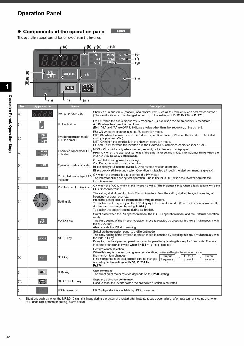
42
Operation Panel, O
peration Steps
1
Components of the operation panelThe operation panel cannot be removed from the inverter.
Situations such as when the MRS/X10 signal is input, during the automatic restart after instantaneous power failure, after auto tuning is complete, when "SE" (incorrect parameter setting) alarm occurs.
No. Appearance Name Description
(a) Monitor (4-digit LED) Shows a numeric value (readout) of a monitor item such as the frequency or a parameter number. (The monitor item can be changed according to the settings of Pr.52, Pr.774 to Pr.776.)
(b) Unit indicationHz: ON when the actual frequency is monitored. (Blinks when the set frequency is monitored.) A: ON when the current is monitored. (Both "Hz" and "A" are OFF to indicate a value other than the frequency or the current.
(c) Inverter operation mode LED indicator
PU: ON when the inverter is in the PU operation mode. EXT: ON when the inverter is in the External operation mode. (ON when the inverter in the initial setting is powered ON.) NET: ON when the inverter is in the Network operation mode. PU and EXT: ON when the inverter is in the External/PU combined operation mode 1 or 2.
(d) Operation panel mode LED indicator
MON: ON or blinks only when the first, second, or third monitor is displayed. PRM: ON when the operation panel is in the parameter setting mode. The indicator blinks when the inverter is in the easy setting mode.
(e) Operating status indicator
ON or blinks during inverter running. ON: During forward rotation operation.Blinks slowly (1.4-second cycle): During reverse rotation operation.Blinks quickly (0.2-second cycle): Operation is disabled although the start command is given.
(f) Controlled motor type LED indicator
ON when the inverter is set to control the PM motor. The indicator blinks during test operation. The indicator is OFF when the inverter controls the induction motor.
(g) PLC function LED indicator ON when the PLC function of the inverter is valid. (The indicator blinks when a fault occurs while the PLC function is valid.)
(h) Setting dial
The setting dial of the Mitsubishi Electric inverters. Turn the setting dial to change the setting of frequency or parameter, etc. Press the setting dial to perform the following operations:To display a set frequency on the LED display in the monitor mode. (The monitor item shown on the display can be changed by using Pr.992.)To display the present setting during calibration.
(i) PU/EXT key
Switches between the PU operation mode, the PUJOG operation mode, and the External operation mode.The easy setting of the inverter operation mode is enabled by pressing this key simultaneously with the MODE key.Also cancels the PU stop warning.
(j) MODE key
Switches the operation panel to a different mode.The easy setting of the inverter operation mode is enabled by pressing this key simultaneously with the PU/EXT key.Every key on the operation panel becomes inoperable by holding this key for 2 seconds. The key inoperable function is invalid when Pr.161 = "0 (initial setting)".
(k) SET key
Confirms each selection. When this key is pressed during inverter operation, the monitor item changes. (The monitor item on each screen can be changed according to the settings of Pr.52, Pr.774 to Pr.776.)
(l) RUN key Start commandThe direction of motor rotation depends on the Pr.40 setting.
(m) STOP/RESET key Stops the operation commands. Used to reset the inverter when the protective function is activated.
(n) USB connector FR Configurator2 is available by USB connection.
(c) (d)
(e)
(i)(j)
(k)
(b)(a)
(n) (l) (m)
(f)(g)
(h)
Outputfrequency
Initial setting in the monitor modeOutputcurrent
Outputvoltage
Operation Panel
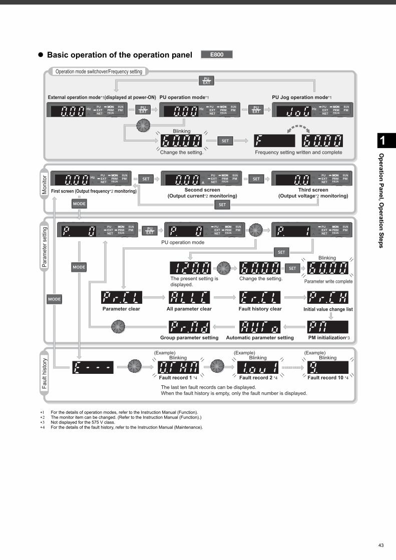
1
Operation Panel, O
peration Steps
Basic operation of the operation panel
For the details of operation modes, refer to the Instruction Manual (Function). The monitor item can be changed. (Refer to the Instruction Manual (Function).) Not displayed for the 575 V class. For the details of the fault history, refer to the Instruction Manual (Maintenance).
Para
met
er s
ettin
gFa
ult h
isto
ry
Operation mode switchover/Frequency setting
Mon
itor
External operation mode*1(displayed at power-ON)
First screen (Output frequency*2 monitoring)
PU operation mode*1 PU Jog operation mode*1
Second screen(Output current*2 monitoring)
Third screen(Output voltage*2 monitoring)
Change the setting. Frequency setting written and complete
The last ten fault records can be displayed.When the fault history is empty, only the fault number is displayed.
The present setting isdisplayed.
PU operation mode
Change the setting. Parameter write complete
(Example) (Example) (Example)
Initial value change list
PM initialization*3
Parameter clear All parameter clear Fault history clear
Automatic parameter setting
Fault record 1 *4 Fault record 2 *4 Fault record 10 *4
Group parameter setting
Blinking Blinking
Blinking
Blinking
Blinking
43
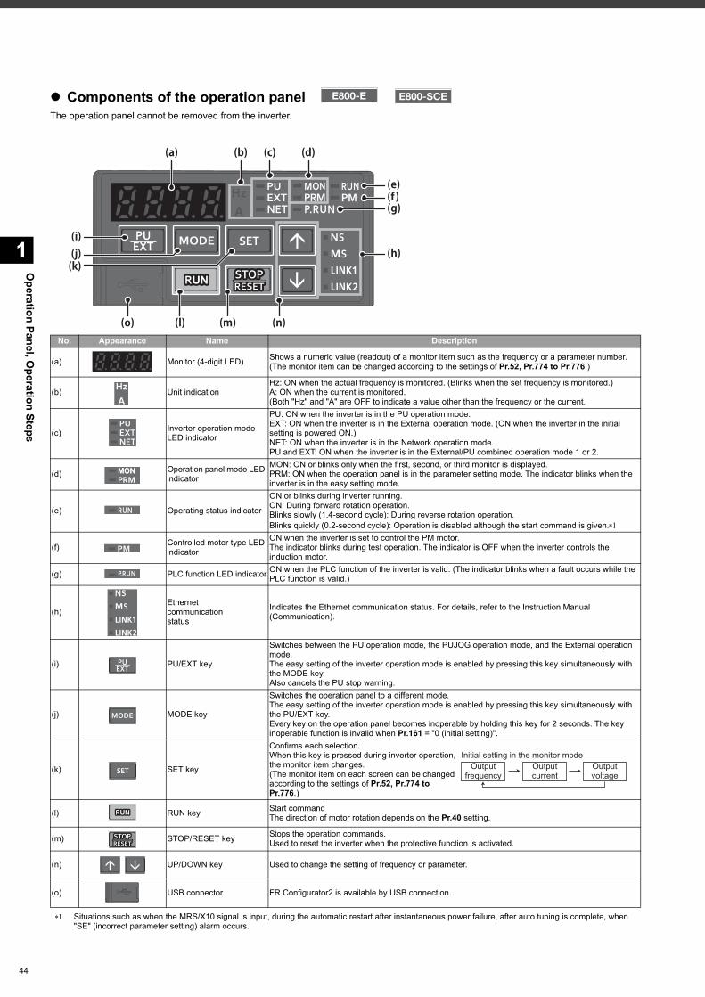
44
Operation Panel, O
peration Steps
1
Components of the operation panelThe operation panel cannot be removed from the inverter.
Situations such as when the MRS/X10 signal is input, during the automatic restart after instantaneous power failure, after auto tuning is complete, when "SE" (incorrect parameter setting) alarm occurs.
No. Appearance Name Description
(a) Monitor (4-digit LED) Shows a numeric value (readout) of a monitor item such as the frequency or a parameter number. (The monitor item can be changed according to the settings of Pr.52, Pr.774 to Pr.776.)
(b) Unit indicationHz: ON when the actual frequency is monitored. (Blinks when the set frequency is monitored.) A: ON when the current is monitored. (Both "Hz" and "A" are OFF to indicate a value other than the frequency or the current.
(c) Inverter operation mode LED indicator
PU: ON when the inverter is in the PU operation mode. EXT: ON when the inverter is in the External operation mode. (ON when the inverter in the initial setting is powered ON.) NET: ON when the inverter is in the Network operation mode. PU and EXT: ON when the inverter is in the External/PU combined operation mode 1 or 2.
(d) Operation panel mode LED indicator
MON: ON or blinks only when the first, second, or third monitor is displayed. PRM: ON when the operation panel is in the parameter setting mode. The indicator blinks when the inverter is in the easy setting mode.
(e) Operating status indicator
ON or blinks during inverter running. ON: During forward rotation operation.Blinks slowly (1.4-second cycle): During reverse rotation operation.Blinks quickly (0.2-second cycle): Operation is disabled although the start command is given.
(f) Controlled motor type LED indicator
ON when the inverter is set to control the PM motor. The indicator blinks during test operation. The indicator is OFF when the inverter controls the induction motor.
(g) PLC function LED indicator ON when the PLC function of the inverter is valid. (The indicator blinks when a fault occurs while the PLC function is valid.)
(h)Ethernetcommunicationstatus
Indicates the Ethernet communication status. For details, refer to the Instruction Manual(Communication).
(i) PU/EXT key
Switches between the PU operation mode, the PUJOG operation mode, and the External operation mode.The easy setting of the inverter operation mode is enabled by pressing this key simultaneously with the MODE key.Also cancels the PU stop warning.
(j) MODE key
Switches the operation panel to a different mode.The easy setting of the inverter operation mode is enabled by pressing this key simultaneously with the PU/EXT key.Every key on the operation panel becomes inoperable by holding this key for 2 seconds. The key inoperable function is invalid when Pr.161 = "0 (initial setting)".
(k) SET key
Confirms each selection. When this key is pressed during inverter operation, the monitor item changes. (The monitor item on each screen can be changed according to the settings of Pr.52, Pr.774 to Pr.776.)
(l) RUN key Start commandThe direction of motor rotation depends on the Pr.40 setting.
(m) STOP/RESET key Stops the operation commands. Used to reset the inverter when the protective function is activated.
(n) UP/DOWN key Used to change the setting of frequency or parameter.
(o) USB connector FR Configurator2 is available by USB connection.
(c) (d)
(e)
(i)(j)(k)
(b)(a)
(o) (l) (m) (n)
(f)(g)
(h)
Outputfrequency
Initial setting in the monitor modeOutputcurrent
Outputvoltage
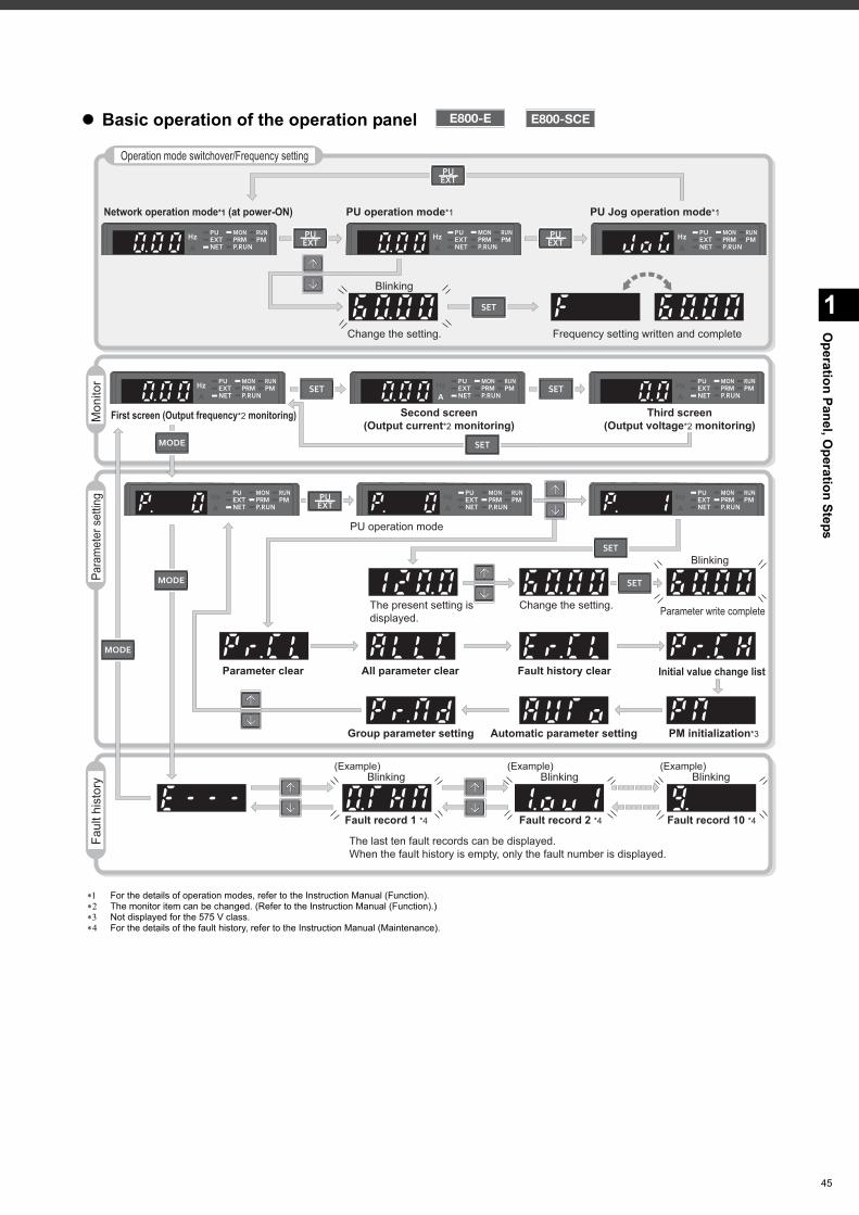
1
Operation Panel, O
peration Steps
Basic operation of the operation panel
For the details of operation modes, refer to the Instruction Manual (Function). The monitor item can be changed. (Refer to the Instruction Manual (Function).) Not displayed for the 575 V class. For the details of the fault history, refer to the Instruction Manual (Maintenance).
Operation mode switchover/Frequency setting
Network operation mode*1 (at power-ON) PU operation mode*1 PU Jog operation mode*1
Mon
itor
First screen (Output frequency*2 monitoring) Second screen(Output current*2 monitoring)
Third screen(Output voltage*2 monitoring)
Para
met
er s
ettin
g
PU operation mode
Faul
t his
tory
(Example) (Example) (Example)Blinking Blinking Blinking
The present setting isdisplayed.
Change the setting. Parameter write complete
Blinking
Initial value change list
PM initialization*3
Parameter clear All parameter clear Fault history clear
Automatic parameter settingGroup parameter setting
The last ten fault records can be displayed.When the fault history is empty, only the fault number is displayed.
Fault record 1 *4 Fault record 2 *4 Fault record 10 *4
Change the setting.
Blinking
Frequency setting written and complete
45
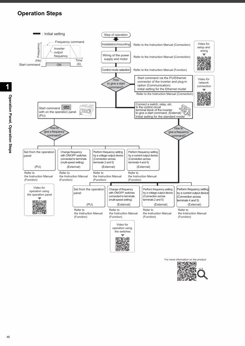
Operation Panel, O
peration Steps
1
46
ON
Freq
uenc
y
Time(S)
(Hz)Start command
Frequency command
Inverteroutputfrequency
Step of operation
Installation/mounting
Control mode selection
Wiring of the powersupply and motor
Connect a switch, relay, etc.to the control circuitterminal block of the inverterto give a start command. (External)Initial setting for the standard model
(PU)
Set from the operationpanel
Change of frequencywith ON/OFF switchesconnected to terminals(multi-speed setting)
(External) (External)
(PU) (External) (External) (External)
Howto give a startcommand?
How togive a frequency
command?
Perform frequency setting by a current output device(Connection acrossterminals 4 and 5)
Perform frequency setting by a voltage output device(Connection acrossterminals 2 and 5)
Perform frequency setting by a current output device(Connection across terminals 4 and 5)
Perform frequency setting by a voltage output device(Connection acrossterminals 2 and 5)
How togive a frequency
command?
Change frequencywith ON/OFF switchesconnected to terminals(multi-speed setting)
(External)
Start command via the PU/Ethernet connector of the inverter and plug-in option (Communication)Initial setting for the Ethernet model
Set from the operationpanel
Refer to the Instruction Manual (Connection)
Refer to the Instruction Manual (Connection)
Refer to the Instruction Manual (Function)
Refer to the Instruction Manual (Function)
Start command with on the operation panel (PU)
: Initial setting
Refer to the Instruction Manual (Function)
Refer to the Instruction Manual (Function)
Refer to the Instruction Manual (Function)
Refer to the Instruction Manual (Function)
Refer to the Instruction Manual (Function)
Refer to the Instruction Manual (Function)
Refer to the Instruction Manual (Function)
Refer to the Instruction Manual (Connection)
Video for setup and
wiring
Video for network
connection
Video for operation using
the operation panel
Video for operation using
the switches
For more information on the product
Operation Steps
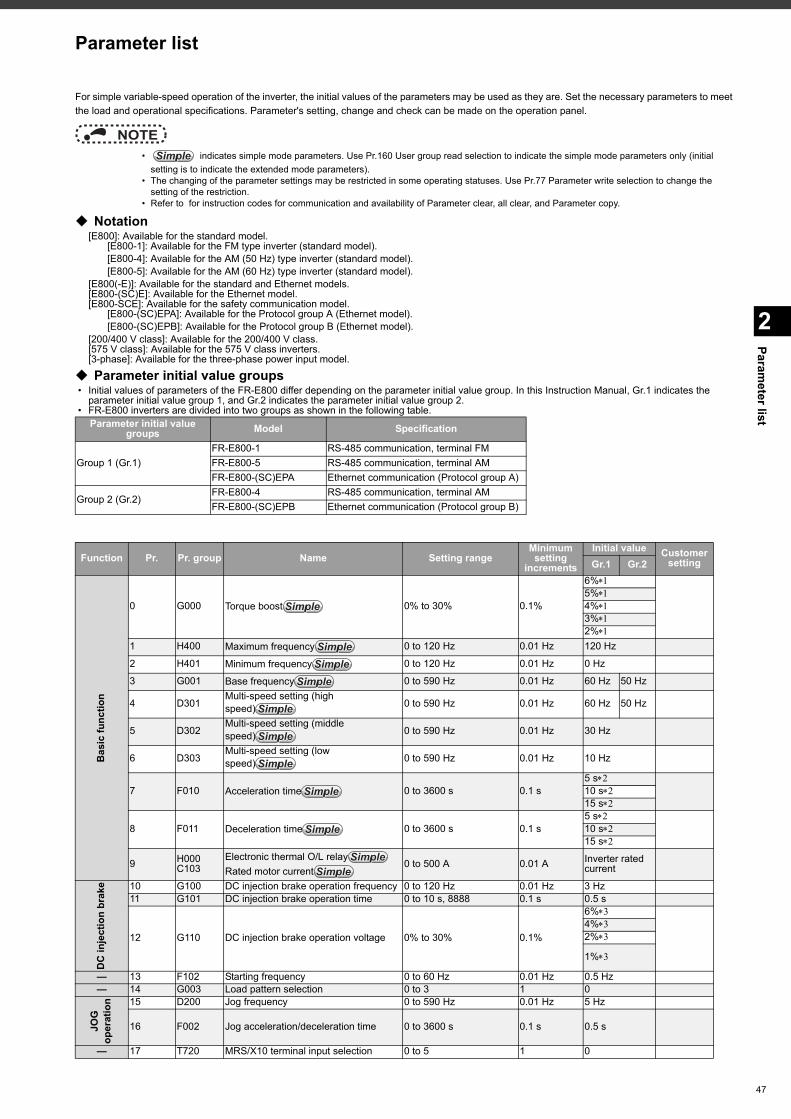
Parameter list
2
Parameter list
For simple variable-speed operation of the inverter, the initial values of the parameters may be used as they are. Set the necessary parameters to meet the load and operational specifications. Parameter's setting, change and check can be made on the operation panel.
NOTE • indicates simple mode parameters. Use Pr.160 User group read selection to indicate the simple mode parameters only (initial
setting is to indicate the extended mode parameters). • The changing of the parameter settings may be restricted in some operating statuses. Use Pr.77 Parameter write selection to change the
setting of the restriction. • Refer to for instruction codes for communication and availability of Parameter clear, all clear, and Parameter copy.
Notation[E800]: Available for the standard model.
[E800-1]: Available for the FM type inverter (standard model).[E800-4]: Available for the AM (50 Hz) type inverter (standard model).[E800-5]: Available for the AM (60 Hz) type inverter (standard model).
[E800(-E)]: Available for the standard and Ethernet models.[E800-(SC)E]: Available for the Ethernet model.[E800-SCE]: Available for the safety communication model.
[E800-(SC)EPA]: Available for the Protocol group A (Ethernet model).[E800-(SC)EPB]: Available for the Protocol group B (Ethernet model).
[200/400 V class]: Available for the 200/400 V class.[575 V class]: Available for the 575 V class inverters.[3-phase]: Available for the three-phase power input model.
Parameter initial value groups • Initial values of parameters of the FR-E800 differ depending on the parameter initial value group. In this Instruction Manual, Gr.1 indicates the
parameter initial value group 1, and Gr.2 indicates the parameter initial value group 2. • FR-E800 inverters are divided into two groups as shown in the following table.
Parameter initial value groups Model Specification
Group 1 (Gr.1)FR-E800-1 RS-485 communication, terminal FMFR-E800-5 RS-485 communication, terminal AMFR-E800-(SC)EPA Ethernet communication (Protocol group A)
Group 2 (Gr.2)FR-E800-4 RS-485 communication, terminal AMFR-E800-(SC)EPB Ethernet communication (Protocol group B)
Function Pr. Pr. group Name Setting rangeMinimum setting
increments
Initial value Customer settingGr.1 Gr.2
Bas
ic fu
nctio
n
0 G000 Torque boost 0% to 30% 0.1%
6%5%4%3%2%
1 H400 Maximum frequency 0 to 120 Hz 0.01 Hz 120 Hz
2 H401 Minimum frequency 0 to 120 Hz 0.01 Hz 0 Hz
3 G001 Base frequency 0 to 590 Hz 0.01 Hz 60 Hz 50 Hz
4 D301Multi-speed setting (high speed) 0 to 590 Hz 0.01 Hz 60 Hz 50 Hz
5 D302Multi-speed setting (middle speed) 0 to 590 Hz 0.01 Hz 30 Hz
6 D303Multi-speed setting (low speed) 0 to 590 Hz 0.01 Hz 10 Hz
7 F010 Acceleration time 0 to 3600 s 0.1 s5 s10 s15 s
8 F011 Deceleration time 0 to 3600 s 0.1 s5 s10 s15 s
9 H000C103
Electronic thermal O/L relayRated motor current
0 to 500 A 0.01 A Inverter rated current
DC
inje
ctio
n br
ake 10 G100 DC injection brake operation frequency 0 to 120 Hz 0.01 Hz 3 Hz
11 G101 DC injection brake operation time 0 to 10 s, 8888 0.1 s 0.5 s
12 G110 DC injection brake operation voltage 0% to 30% 0.1%
6%4%2%
1%
— 13 F102 Starting frequency 0 to 60 Hz 0.01 Hz 0.5 Hz— 14 G003 Load pattern selection 0 to 3 1 0
JOG
op
erat
ion 15 D200 Jog frequency 0 to 590 Hz 0.01 Hz 5 Hz
16 F002 Jog acceleration/deceleration time 0 to 3600 s 0.1 s 0.5 s
— 17 T720 MRS/X10 terminal input selection 0 to 5 1 0
SimpleSimpleSimple
SimpleSimpleSimple
SimpleSimpleSimpleSimpleSimpleSimple
SimpleSimpleSimple
SimpleSimpleSimple
SimpleSimpleSimple
SimpleSimpleSimple
SimpleSimpleSimple
SimpleSimpleSimple
SimpleSimpleSimpleSimpleSimpleSimple
47
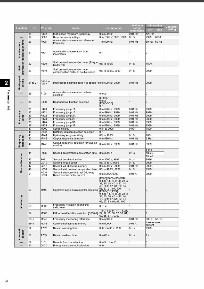
Parameter list
2
48
— 18 H402 High speed maximum frequency 0 to 590 Hz 0.01 Hz 120 Hz— 19 G002 Base frequency voltage 0 to 1000 V, 8888, 9999 0.1 V 9999 8888
Acc
eler
atio
n/de
cele
ratio
n tim
e 20 F000 Acceleration/deceleration reference frequency 1 to 590 Hz 0.01 Hz 60 Hz 50 Hz
21 F001 Acceleration/deceleration time increments 0, 1 1 0
Stal
l pr
even
tion 22 H500 Stall prevention operation level (Torque
limit level) 0% to 400% 0.1% 150%
23 H610 Stall prevention operation level compensation factor at double speed 0% to 200%, 9999 0.1% 9999
Mul
ti-sp
eed
setti
ng 24 to 27 D304 to D307 Multi-speed setting (speed 4 to speed 7) 0 to 590 Hz, 9999 0.01 Hz 9999
— 29 F100 Acceleration/deceleration pattern selection 0 to 2 1 0
— 30 E300 Regenerative function selection[E800(-E)]0 to 2[E800-SCE]0, 1
1 0
Freq
uenc
y ju
mp
31 H420 Frequency jump 1A 0 to 590 Hz, 9999 0.01 Hz 999932 H421 Frequency jump 1B 0 to 590 Hz, 9999 0.01 Hz 999933 H422 Frequency jump 2A 0 to 590 Hz, 9999 0.01 Hz 999934 H423 Frequency jump 2B 0 to 590 Hz, 9999 0.01 Hz 999935 H424 Frequency jump 3A 0 to 590 Hz, 9999 0.01 Hz 999936 H425 Frequency jump 3B 0 to 590 Hz, 9999 0.01 Hz 9999
— 37 M000 Speed display 0.01 to 9998 0.001 1800— 40 E202 RUN key rotation direction selection 0, 1 1 0
Freq
uenc
y de
tect
ion 41 M441 Up-to-frequency sensitivity 0% to 100% 0.1% 10%
42 M442 Output frequency detection 0 to 590 Hz 0.01 Hz 6 Hz
43 M443 Output frequency detection for reverse rotation 0 to 590 Hz, 9999 0.01 Hz 9999
Seco
nd fu
nctio
n 44 F020 Second acceleration/deceleration time 0 to 3600 s 0.1 s5 s10 s15 s
45 F021 Second deceleration time 0 to 3600 s, 9999 0.1 s 999946 G010 Second torque boost 0% to 30%, 9999 0.1% 999947 G011 Second V/F (base frequency) 0 to 590 Hz, 9999 0.01 Hz 999948 H600 Second stall prevention operation level 0% to 400%, 9999 0.1% 9999
51 H010C203
Second electronic thermal O/L relayRated second motor current 0 to 500 A, 9999 0.01 A 9999
Mon
itorin
g
52 M100 Operation panel main monitor selection
[E800][E800-(SC)EPB]0, 5 to 14, 17 to 20, 23 to 33, 35, 38, 40 to 42, 44, 45, 50 to 57, 61, 62, 64, 65, 67, 91, 97, 100[E800-(SC)EPA]0, 5 to 14, 17 to 20, 23 to 33, 35, 38, 40 to 42, 44, 45, 50 to 57, 61, 62, 64, 65, 67, 83, 91, 97, 100
1 0
53 M003 Frequency / rotation speed unit switchover 0, 1, 4 1 0
54 M300 FM terminal function selection [E800-1]1 to 3, 5 to 14, 17, 18, 21, 24, 32, 33, 50, 52, 53, 61, 62, 65, 67, 70, 97
1 1
55 M040 Frequency monitoring reference 0 to 590 Hz 0.01 Hz 60 Hz 50 Hz
56 M041 Current monitoring reference 0 to 500 A 0.01 A Inverter rated current
Auto
mat
ic
rest
art 57 A702 Restart coasting time 0, 0.1 to 30 s, 9999 0.1 s 9999
58 A703 Restart cushion time 0 to 60 s 0.1 s 1 s
— 59 F101 Remote function selection 0 to 3, 11 to 13 1 0— 60 G030 Energy saving control selection 0, 9 1 0
Function Pr. Pr. group Name Setting rangeMinimum setting
increments
Initial value Customer settingGr.1 Gr.2
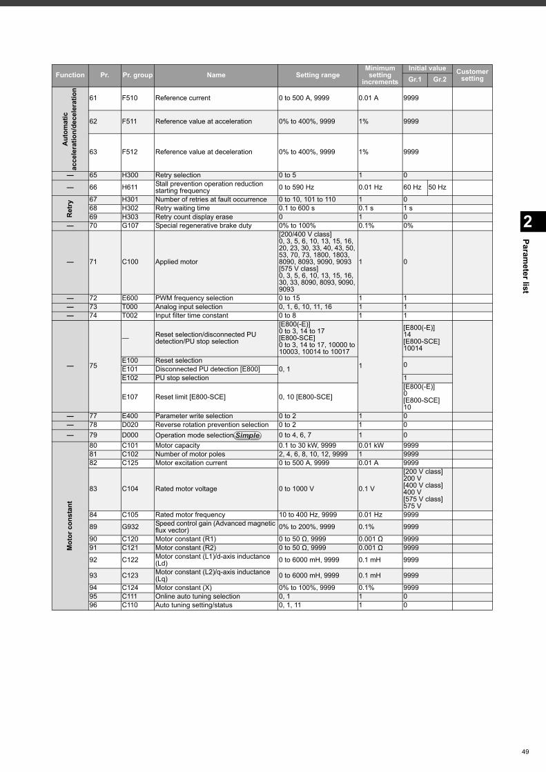
2
Parameter list
Aut
omat
ic
acce
lera
tion/
dece
lera
tion
61 F510 Reference current 0 to 500 A, 9999 0.01 A 9999
62 F511 Reference value at acceleration 0% to 400%, 9999 1% 9999
63 F512 Reference value at deceleration 0% to 400%, 9999 1% 9999
— 65 H300 Retry selection 0 to 5 1 0
— 66 H611 Stall prevention operation reduction starting frequency 0 to 590 Hz 0.01 Hz 60 Hz 50 Hz
Ret
ry 67 H301 Number of retries at fault occurrence 0 to 10, 101 to 110 1 068 H302 Retry waiting time 0.1 to 600 s 0.1 s 1 s69 H303 Retry count display erase 0 1 0
— 70 G107 Special regenerative brake duty 0% to 100% 0.1% 0%
— 71 C100 Applied motor
[200/400 V class]0, 3, 5, 6, 10, 13, 15, 16, 20, 23, 30, 33, 40, 43, 50, 53, 70, 73, 1800, 1803, 8090, 8093, 9090, 9093[575 V class]0, 3, 5, 6, 10, 13, 15, 16, 30, 33, 8090, 8093, 9090, 9093
1 0
— 72 E600 PWM frequency selection 0 to 15 1 1— 73 T000 Analog input selection 0, 1, 6, 10, 11, 16 1 1— 74 T002 Input filter time constant 0 to 8 1 1
— 75
— Reset selection/disconnected PU detection/PU stop selection
[E800(-E)]0 to 3, 14 to 17[E800-SCE]0 to 3, 14 to 17, 10000 to 10003, 10014 to 10017
1
[E800(-E)]14[E800-SCE]10014
E100 Reset selection0, 1 0E101 Disconnected PU detection [E800]
E102 PU stop selection 1
E107 Reset limit [E800-SCE] 0, 10 [E800-SCE][E800(-E)]0[E800-SCE]10
— 77 E400 Parameter write selection 0 to 2 1 0— 78 D020 Reverse rotation prevention selection 0 to 2 1 0— 79 D000 Operation mode selection 0 to 4, 6, 7 1 0
Mot
or c
onst
ant
80 C101 Motor capacity 0.1 to 30 kW, 9999 0.01 kW 999981 C102 Number of motor poles 2, 4, 6, 8, 10, 12, 9999 1 999982 C125 Motor excitation current 0 to 500 A, 9999 0.01 A 9999
83 C104 Rated motor voltage 0 to 1000 V 0.1 V
[200 V class]200 V[400 V class]400 V[575 V class]575 V
84 C105 Rated motor frequency 10 to 400 Hz, 9999 0.01 Hz 9999
89 G932 Speed control gain (Advanced magnetic flux vector) 0% to 200%, 9999 0.1% 9999
90 C120 Motor constant (R1) 0 to 50 Ω, 9999 0.001 Ω 999991 C121 Motor constant (R2) 0 to 50 Ω, 9999 0.001 Ω 9999
92 C122 Motor constant (L1)/d-axis inductance (Ld) 0 to 6000 mH, 9999 0.1 mH 9999
93 C123 Motor constant (L2)/q-axis inductance (Lq) 0 to 6000 mH, 9999 0.1 mH 9999
94 C124 Motor constant (X) 0% to 100%, 9999 0.1% 999995 C111 Online auto tuning selection 0, 1 1 096 C110 Auto tuning setting/status 0, 1, 11 1 0
Function Pr. Pr. group Name Setting rangeMinimum setting
increments
Initial value Customer settingGr.1 Gr.2
SimpleSimpleSimple
49
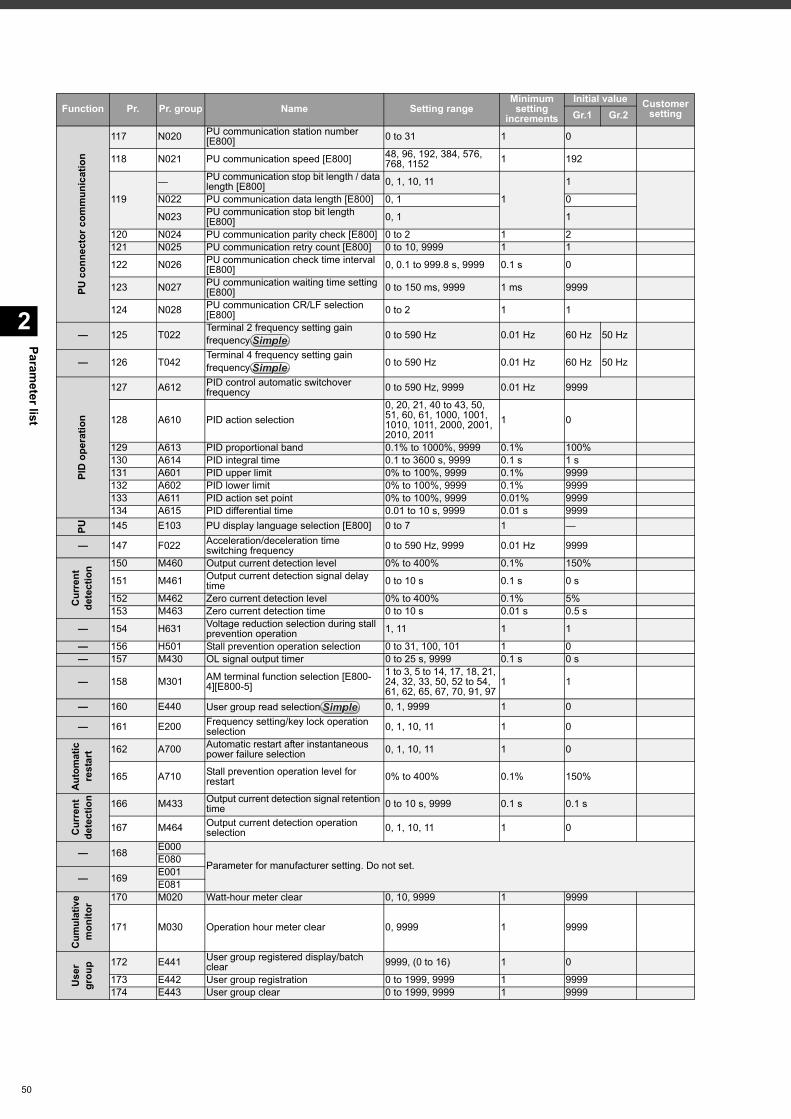
Parameter list
2
50
PU c
onne
ctor
com
mun
icat
ion
117 N020 PU communication station number [E800] 0 to 31 1 0
118 N021 PU communication speed [E800] 48, 96, 192, 384, 576, 768, 1152 1 192
119
— PU communication stop bit length / data length [E800] 0, 1, 10, 11
1
1
N022 PU communication data length [E800] 0, 1 0
N023 PU communication stop bit length [E800] 0, 1 1
120 N024 PU communication parity check [E800] 0 to 2 1 2121 N025 PU communication retry count [E800] 0 to 10, 9999 1 1
122 N026 PU communication check time interval [E800] 0, 0.1 to 999.8 s, 9999 0.1 s 0
123 N027 PU communication waiting time setting [E800] 0 to 150 ms, 9999 1 ms 9999
124 N028 PU communication CR/LF selection [E800] 0 to 2 1 1
— 125 T022Terminal 2 frequency setting gain frequency 0 to 590 Hz 0.01 Hz 60 Hz 50 Hz
— 126 T042Terminal 4 frequency setting gain frequency 0 to 590 Hz 0.01 Hz 60 Hz 50 Hz
PID
ope
ratio
n
127 A612 PID control automatic switchover frequency 0 to 590 Hz, 9999 0.01 Hz 9999
128 A610 PID action selection0, 20, 21, 40 to 43, 50, 51, 60, 61, 1000, 1001, 1010, 1011, 2000, 2001, 2010, 2011
1 0
129 A613 PID proportional band 0.1% to 1000%, 9999 0.1% 100%130 A614 PID integral time 0.1 to 3600 s, 9999 0.1 s 1 s131 A601 PID upper limit 0% to 100%, 9999 0.1% 9999132 A602 PID lower limit 0% to 100%, 9999 0.1% 9999133 A611 PID action set point 0% to 100%, 9999 0.01% 9999134 A615 PID differential time 0.01 to 10 s, 9999 0.01 s 9999
PU 145 E103 PU display language selection [E800] 0 to 7 1 —
— 147 F022 Acceleration/deceleration time switching frequency 0 to 590 Hz, 9999 0.01 Hz 9999
Cur
rent
de
tect
ion 150 M460 Output current detection level 0% to 400% 0.1% 150%
151 M461 Output current detection signal delay time 0 to 10 s 0.1 s 0 s
152 M462 Zero current detection level 0% to 400% 0.1% 5%153 M463 Zero current detection time 0 to 10 s 0.01 s 0.5 s
— 154 H631 Voltage reduction selection during stall prevention operation 1, 11 1 1
— 156 H501 Stall prevention operation selection 0 to 31, 100, 101 1 0— 157 M430 OL signal output timer 0 to 25 s, 9999 0.1 s 0 s
— 158 M301 AM terminal function selection [E800-4][E800-5]
1 to 3, 5 to 14, 17, 18, 21, 24, 32, 33, 50, 52 to 54, 61, 62, 65, 67, 70, 91, 97
1 1
— 160 E440 User group read selection 0, 1, 9999 1 0
— 161 E200 Frequency setting/key lock operation selection 0, 1, 10, 11 1 0
Auto
mat
ic
rest
art 162 A700 Automatic restart after instantaneous
power failure selection 0, 1, 10, 11 1 0
165 A710 Stall prevention operation level for restart 0% to 400% 0.1% 150%
Cur
rent
de
tect
ion 166 M433 Output current detection signal retention
time 0 to 10 s, 9999 0.1 s 0.1 s
167 M464 Output current detection operation selection 0, 1, 10, 11 1 0
— 168 E000
Parameter for manufacturer setting. Do not set.E080
— 169 E001E081
Cum
ulat
ive
mon
itor 170 M020 Watt-hour meter clear 0, 10, 9999 1 9999
171 M030 Operation hour meter clear 0, 9999 1 9999
Use
r gr
oup 172 E441 User group registered display/batch
clear 9999, (0 to 16) 1 0
173 E442 User group registration 0 to 1999, 9999 1 9999174 E443 User group clear 0 to 1999, 9999 1 9999
Function Pr. Pr. group Name Setting rangeMinimum setting
increments
Initial value Customer settingGr.1 Gr.2
SimpleSimpleSimple
SimpleSimpleSimple
SimpleSimpleSimple
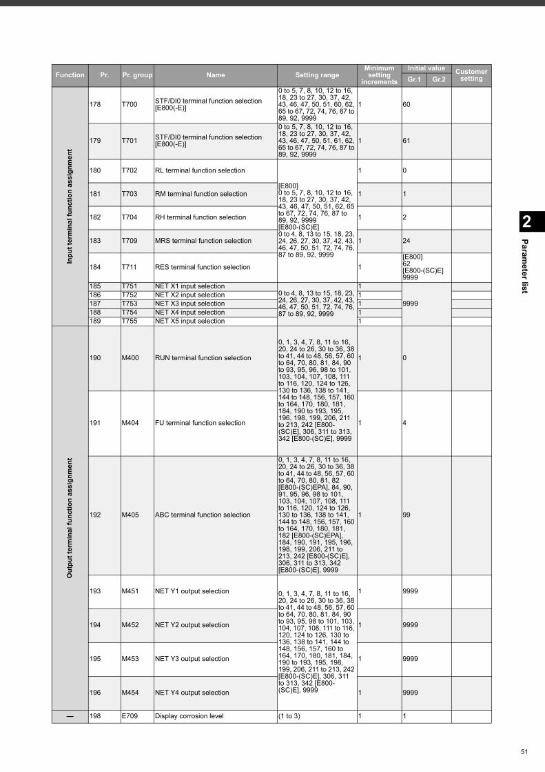
2
Parameter list
Inpu
t ter
min
al fu
nctio
n as
sign
men
t
178 T700 STF/DI0 terminal function selection [E800(-E)]
0 to 5, 7, 8, 10, 12 to 16, 18, 23 to 27, 30, 37, 42, 43, 46, 47, 50, 51, 60, 62, 65 to 67, 72, 74, 76, 87 to 89, 92, 9999
1 60
179 T701 STF/DI0 terminal function selection [E800(-E)]
0 to 5, 7, 8, 10, 12 to 16, 18, 23 to 27, 30, 37, 42, 43, 46, 47, 50, 51, 61, 62, 65 to 67, 72, 74, 76, 87 to 89, 92, 9999
1 61
180 T702 RL terminal function selection
[E800]0 to 5, 7, 8, 10, 12 to 16, 18, 23 to 27, 30, 37, 42, 43, 46, 47, 50, 51, 62, 65 to 67, 72, 74, 76, 87 to 89, 92, 9999[E800-(SC)E]0 to 4, 8, 13 to 15, 18, 23, 24, 26, 27, 30, 37, 42, 43, 46, 47, 50, 51, 72, 74, 76, 87 to 89, 92, 9999
1 0
181 T703 RM terminal function selection 1 1
182 T704 RH terminal function selection 1 2
183 T709 MRS terminal function selection 1 24
184 T711 RES terminal function selection 1[E800]62[E800-(SC)E]9999
185 T751 NET X1 input selection0 to 4, 8, 13 to 15, 18, 23, 24, 26, 27, 30, 37, 42, 43, 46, 47, 50, 51, 72, 74, 76, 87 to 89, 92, 9999
1
9999186 T752 NET X2 input selection 1187 T753 NET X3 input selection 1188 T754 NET X4 input selection 1189 T755 NET X5 input selection 1
Out
put t
erm
inal
func
tion
assi
gnm
ent
190 M400 RUN terminal function selection
0, 1, 3, 4, 7, 8, 11 to 16, 20, 24 to 26, 30 to 36, 38 to 41, 44 to 48, 56, 57, 60 to 64, 70, 80, 81, 84, 90 to 93, 95, 96, 98 to 101, 103, 104, 107, 108, 111 to 116, 120, 124 to 126, 130 to 136, 138 to 141, 144 to 148, 156, 157, 160 to 164, 170, 180, 181, 184, 190 to 193, 195, 196, 198, 199, 206, 211 to 213, 242 [E800-(SC)E], 306, 311 to 313, 342 [E800-(SC)E], 9999
1 0
191 M404 FU terminal function selection 1 4
192 M405 ABC terminal function selection
0, 1, 3, 4, 7, 8, 11 to 16, 20, 24 to 26, 30 to 36, 38 to 41, 44 to 48, 56, 57, 60 to 64, 70, 80, 81, 82 [E800-(SC)EPA], 84, 90, 91, 95, 96, 98 to 101, 103, 104, 107, 108, 111 to 116, 120, 124 to 126, 130 to 136, 138 to 141, 144 to 148, 156, 157, 160 to 164, 170, 180, 181, 182 [E800-(SC)EPA], 184, 190, 191, 195, 196, 198, 199, 206, 211 to 213, 242 [E800-(SC)E], 306, 311 to 313, 342 [E800-(SC)E], 9999
1 99
193 M451 NET Y1 output selection 0, 1, 3, 4, 7, 8, 11 to 16, 20, 24 to 26, 30 to 36, 38 to 41, 44 to 48, 56, 57, 60 to 64, 70, 80, 81, 84, 90 to 93, 95, 98 to 101, 103, 104, 107, 108, 111 to 116, 120, 124 to 126, 130 to 136, 138 to 141, 144 to 148, 156, 157, 160 to 164, 170, 180, 181, 184, 190 to 193, 195, 198, 199, 206, 211 to 213, 242 [E800-(SC)E], 306, 311 to 313, 342 [E800-(SC)E], 9999
1 9999
194 M452 NET Y2 output selection 1 9999
195 M453 NET Y3 output selection 1 9999
196 M454 NET Y4 output selection 1 9999
— 198 E709 Display corrosion level (1 to 3) 1 1
Function Pr. Pr. group Name Setting rangeMinimum setting
increments
Initial value Customer settingGr.1 Gr.2
51
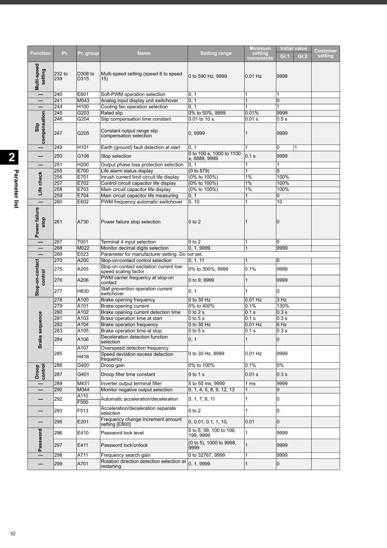
Parameter list
2
52
Mul
ti-sp
eed
setti
ng 232 to 239
D308 to D315
Multi-speed setting (speed 8 to speed 15) 0 to 590 Hz, 9999 0.01 Hz 9999
— 240 E601 Soft-PWM operation selection 0, 1 1 1— 241 M043 Analog input display unit switchover 0, 1 1 0— 244 H100 Cooling fan operation selection 0, 1 1 1
Slip
co
mpe
nsat
ion 245 G203 Rated slip 0% to 50%, 9999 0.01% 9999
246 G204 Slip compensation time constant 0.01 to 10 s 0.01 s 0.5 s
247 G205 Constant output range slip compensation selection 0, 9999 1 9999
— 249 H101 Earth (ground) fault detection at start 0, 1 1 0 1
— 250 G106 Stop selection 0 to 100 s, 1000 to 1100 s, 8888, 9999 0.1 s 9999
— 251 H200 Output phase loss protection selection 0, 1 1 1
Life
che
ck
255 E700 Life alarm status display (0 to 879) 1 0256 E701 Inrush current limit circuit life display (0% to 100%) 1% 100%257 E702 Control circuit capacitor life display (0% to 100%) 1% 100%258 E703 Main circuit capacitor life display (0% to 100%) 1% 100%259 E704 Main circuit capacitor life measuring 0, 1 1 0
— 260 E602 PWM frequency automatic switchover 0, 10 1 10
Pow
er fa
ilure
st
op 261 A730 Power failure stop selection 0 to 2 1 0
— 267 T001 Terminal 4 input selection 0 to 2 1 0— 268 M022 Monitor decimal digits selection 0, 1, 9999 1 9999— 269 E023 Parameter for manufacturer setting. Do not set.
Stop
-on-
cont
act
cont
rol
270 A200 Stop-on-contact control selection 0, 1, 11 1 0
275 A205 Stop-on contact excitation current low-speed scaling factor 0% to 300%, 9999 0.1% 9999
276 A206 PWM carrier frequency at stop-on contact 0 to 9, 9999 1 9999
277 H630 Stall prevention operation current switchover 0, 1 1 0
Bra
ke s
eque
nce
278 A100 Brake opening frequency 0 to 30 Hz 0.01 Hz 3 Hz279 A101 Brake opening current 0% to 400% 0.1% 130%280 A102 Brake opening current detection time 0 to 2 s 0.1 s 0.3 s281 A103 Brake operation time at start 0 to 5 s 0.1 s 0.3 s282 A104 Brake operation frequency 0 to 30 Hz 0.01 Hz 6 Hz283 A105 Brake operation time at stop 0 to 5 s 0.1 s 0.3 s
284 A106 Deceleration detection function selection 0, 1 1 0
285A107 Overspeed detection frequency
0 to 30 Hz, 9999 0.01 Hz 9999H416 Speed deviation excess detection frequency
Dro
op
cont
rol 286 G400 Droop gain 0% to 100% 0.1% 0%
287 G401 Droop filter time constant 0 to 1 s 0.01 s 0.3 s
— 289 M431 Inverter output terminal filter 5 to 50 ms, 9999 1 ms 9999— 290 M044 Monitor negative output selection 0, 1, 4, 5, 8, 9, 12, 13 1 0
— 292 A110 Automatic acceleration/deceleration 0, 1, 7, 8, 11 1 0F500
— 293 F513 Acceleration/deceleration separate selection 0 to 2 1 0
— 295 E201 Frequency change increment amount setting [E800] 0, 0.01, 0.1, 1, 10, 0.01 0
Pass
wor
d 296 E410 Password lock level 0 to 6, 99, 100 to 106, 199, 9999 1 9999
297 E411 Password lock/unlock (0 to 5), 1000 to 9998, 9999 1 9999
— 298 A711 Frequency search gain 0 to 32767, 9999 1 9999
— 299 A701 Rotation direction detection selection at restarting 0, 1, 9999 1 0
Function Pr. Pr. group Name Setting rangeMinimum setting
increments
Initial value Customer settingGr.1 Gr.2
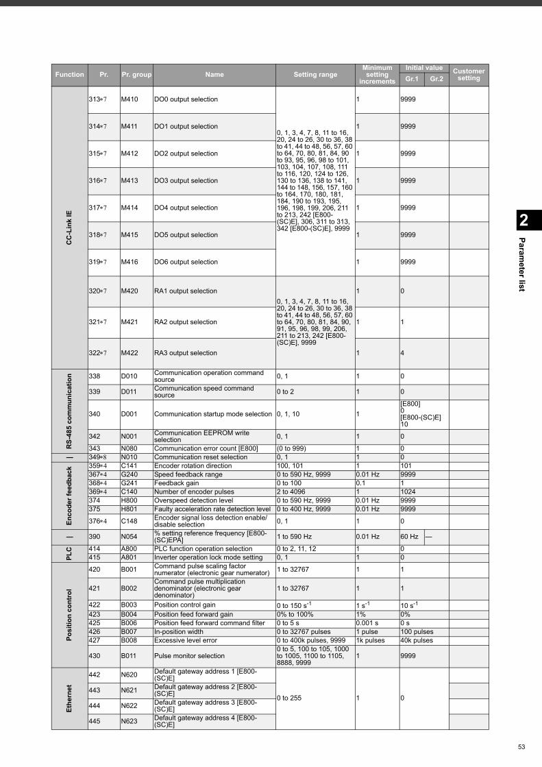
2
Parameter list
CC
-Lin
k IE
313 M410 DO0 output selection
0, 1, 3, 4, 7, 8, 11 to 16, 20, 24 to 26, 30 to 36, 38 to 41, 44 to 48, 56, 57, 60 to 64, 70, 80, 81, 84, 90 to 93, 95, 96, 98 to 101, 103, 104, 107, 108, 111 to 116, 120, 124 to 126, 130 to 136, 138 to 141, 144 to 148, 156, 157, 160 to 164, 170, 180, 181, 184, 190 to 193, 195, 196, 198, 199, 206, 211 to 213, 242 [E800-(SC)E], 306, 311 to 313, 342 [E800-(SC)E], 9999
1 9999
314 M411 DO1 output selection 1 9999
315 M412 DO2 output selection 1 9999
316 M413 DO3 output selection 1 9999
317 M414 DO4 output selection 1 9999
318 M415 DO5 output selection 1 9999
319 M416 DO6 output selection 1 9999
320 M420 RA1 output selection0, 1, 3, 4, 7, 8, 11 to 16, 20, 24 to 26, 30 to 36, 38 to 41, 44 to 48, 56, 57, 60 to 64, 70, 80, 81, 84, 90, 91, 95, 96, 98, 99, 206, 211 to 213, 242 [E800-(SC)E], 9999
1 0
321 M421 RA2 output selection 1 1
322 M422 RA3 output selection 1 4
RS-
485
com
mun
icat
ion 338 D010 Communication operation command
source 0, 1 1 0
339 D011 Communication speed command source 0 to 2 1 0
340 D001 Communication startup mode selection 0, 1, 10 1[E800]0[E800-(SC)E]10
342 N001 Communication EEPROM write selection 0, 1 1 0
343 N080 Communication error count [E800] (0 to 999) 1 0— 349 N010 Communication reset selection 0, 1 1 0
Enco
der f
eedb
ack 359 C141 Encoder rotation direction 100, 101 1 101
367 G240 Speed feedback range 0 to 590 Hz, 9999 0.01 Hz 9999368 G241 Feedback gain 0 to 100 0.1 1369 C140 Number of encoder pulses 2 to 4096 1 1024374 H800 Overspeed detection level 0 to 590 Hz, 9999 0.01 Hz 9999375 H801 Faulty acceleration rate detection level 0 to 400 Hz, 9999 0.01 Hz 9999
376 C148 Encoder signal loss detection enable/disable selection 0, 1 1 0
— 390 N054 % setting reference frequency [E800-(SC)EPA] 1 to 590 Hz 0.01 Hz 60 Hz —
PLC 414 A800 PLC function operation selection 0 to 2, 11, 12 1 0
415 A801 Inverter operation lock mode setting 0, 1 1 0
Posi
tion
cont
rol
420 B001 Command pulse scaling factor numerator (electronic gear numerator) 1 to 32767 1 1
421 B002Command pulse multiplication denominator (electronic gear denominator)
1 to 32767 1 1
422 B003 Position control gain 0 to 150 s-1 1 s-1 10 s-1
423 B004 Position feed forward gain 0% to 100% 1% 0%425 B006 Position feed forward command filter 0 to 5 s 0.001 s 0 s426 B007 In-position width 0 to 32767 pulses 1 pulse 100 pulses427 B008 Excessive level error 0 to 400k pulses, 9999 1k pulses 40k pulses
430 B011 Pulse monitor selection0 to 5, 100 to 105, 1000 to 1005, 1100 to 1105, 8888, 9999
1 9999
Ethe
rnet
442 N620 Default gateway address 1 [E800-(SC)E]
0 to 255 1 0443 N621 Default gateway address 2 [E800-
(SC)E]
444 N622 Default gateway address 3 [E800-(SC)E]
445 N623 Default gateway address 4 [E800-(SC)E]
Function Pr. Pr. group Name Setting rangeMinimum setting
increments
Initial value Customer settingGr.1 Gr.2
53
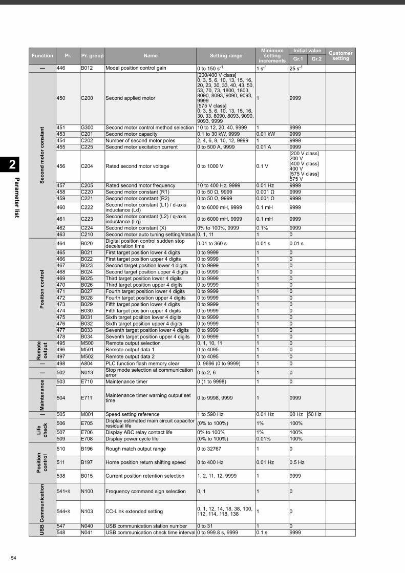
Parameter list
2
54
— 446 B012 Model position control gain 0 to 150 s-1 1 s-1 25 s-1
Seco
nd m
otor
con
stan
t
450 C200 Second applied motor
[200/400 V class]0, 3, 5, 6, 10, 13, 15, 16, 20, 23, 30, 33, 40, 43, 50, 53, 70, 73, 1800, 1803, 8090, 8093, 9090, 9093, 9999[575 V class]0, 3, 5, 6, 10, 13, 15, 16, 30, 33, 8090, 8093, 9090, 9093, 9999
1 9999
451 G300 Second motor control method selection 10 to 12, 20, 40, 9999 1 9999453 C201 Second motor capacity 0.1 to 30 kW, 9999 0.01 kW 9999454 C202 Number of second motor poles 2, 4, 6, 8, 10, 12, 9999 1 9999455 C225 Second motor excitation current 0 to 500 A, 9999 0.01 A 9999
456 C204 Rated second motor voltage 0 to 1000 V 0.1 V
[200 V class]200 V[400 V class]400 V[575 V class]575 V
457 C205 Rated second motor frequency 10 to 400 Hz, 9999 0.01 Hz 9999458 C220 Second motor constant (R1) 0 to 50 Ω, 9999 0.001 Ω 9999459 C221 Second motor constant (R2) 0 to 50 Ω, 9999 0.001 Ω 9999
460 C222 Second motor constant (L1) / d-axis inductance (Ld) 0 to 6000 mH, 9999 0.1 mH 9999
461 C223 Second motor constant (L2) / q-axis inductance (Lq) 0 to 6000 mH, 9999 0.1 mH 9999
462 C224 Second motor constant (X) 0% to 100%, 9999 0.1% 9999463 C210 Second motor auto tuning setting/status 0, 1, 11 1 0
Posi
tion
cont
rol
464 B020 Digital position control sudden stop deceleration time 0.01 to 360 s 0.01 s 0.01 s
465 B021 First target position lower 4 digits 0 to 9999 1 0466 B022 First target position upper 4 digits 0 to 9999 1 0467 B023 Second target position lower 4 digits 0 to 9999 1 0468 B024 Second target position upper 4 digits 0 to 9999 1 0469 B025 Third target position lower 4 digits 0 to 9999 1 0470 B026 Third target position upper 4 digits 0 to 9999 1 0471 B027 Fourth target position lower 4 digits 0 to 9999 1 0472 B028 Fourth target position upper 4 digits 0 to 9999 1 0473 B029 Fifth target position lower 4 digits 0 to 9999 1 0474 B030 Fifth target position upper 4 digits 0 to 9999 1 0475 B031 Sixth target position lower 4 digits 0 to 9999 1 0476 B032 Sixth target position upper 4 digits 0 to 9999 1 0477 B033 Seventh target position lower 4 digits 0 to 9999 1 0478 B034 Seventh target position upper 4 digits 0 to 9999 1 0
Rem
ote
outp
ut 495 M500 Remote output selection 0, 1, 10, 11 1 0496 M501 Remote output data 1 0 to 4095 1 0497 M502 Remote output data 2 0 to 4095 1 0
— 498 A804 PLC function flash memory clear 0, 9696 (0 to 9999) 1 0
— 502 N013 Stop mode selection at communication error 0 to 2, 6 1 0
Mai
nten
ance 503 E710 Maintenance timer 0 (1 to 9998) 1 0
504 E711 Maintenance timer warning output set time 0 to 9998, 9999 1 9999
— 505 M001 Speed setting reference 1 to 590 Hz 0.01 Hz 60 Hz 50 Hz
Life
ch
eck 506 E705 Display estimated main circuit capacitor
residual life (0% to 100%) 1% 100%
507 E706 Display ABC relay contact life 0% to 100% 1% 100%509 E708 Display power cycle life (0% to 100%) 0.01% 100%
Posi
tion
cont
rol
510 B196 Rough match output range 0 to 32767 1 0
511 B197 Home position return shifting speed 0 to 400 Hz 0.01 Hz 0.5 Hz
538 B015 Current position retention selection 1, 2, 11, 12, 9999 1 9999
Com
mun
icat
ion
541 N100 Frequency command sign selection 0, 1 1 0
544 N103 CC-Link extended setting 0, 1, 12, 14, 18, 38, 100, 112, 114, 118, 138 1 0
USB
547 N040 USB communication station number 0 to 31 1 0548 N041 USB communication check time interval 0 to 999.8 s, 9999 0.1 s 9999
Function Pr. Pr. group Name Setting rangeMinimum setting
increments
Initial value Customer settingGr.1 Gr.2
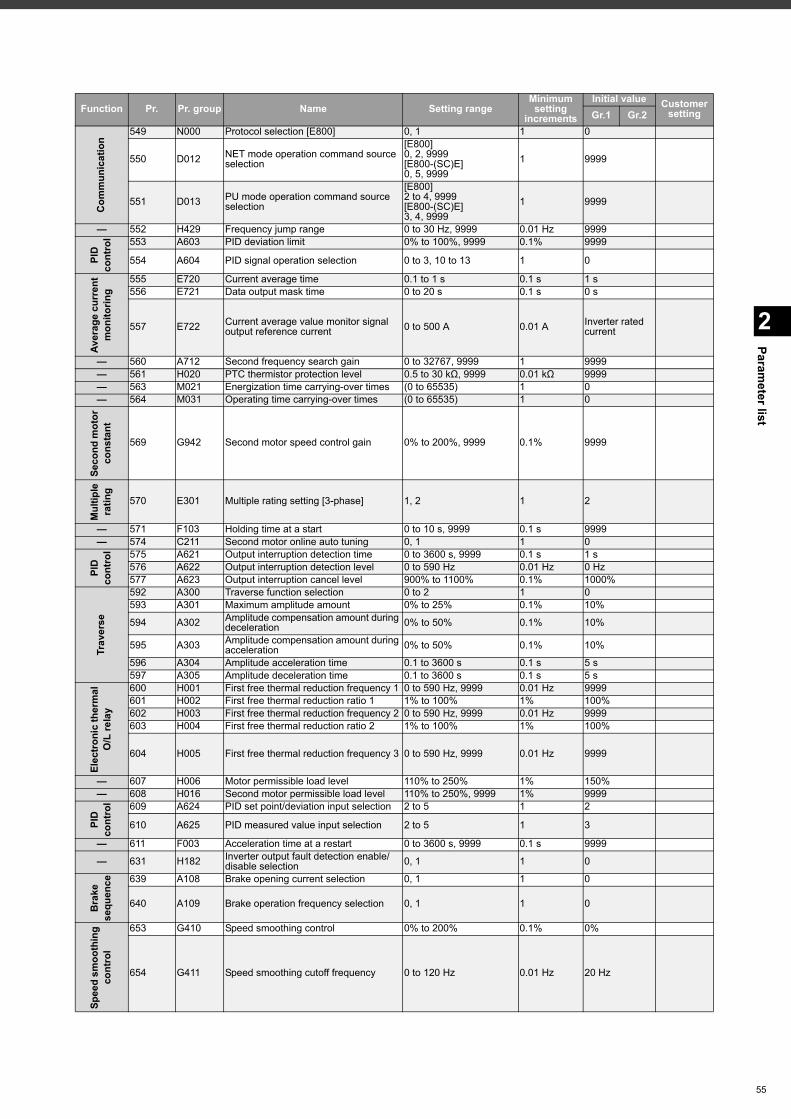
2
Parameter list
Com
mun
icat
ion
549 N000 Protocol selection [E800] 0, 1 1 0
550 D012 NET mode operation command source selection
[E800]0, 2, 9999[E800-(SC)E]0, 5, 9999
1 9999
551 D013 PU mode operation command source selection
[E800]2 to 4, 9999[E800-(SC)E]3, 4, 9999
1 9999
— 552 H429 Frequency jump range 0 to 30 Hz, 9999 0.01 Hz 9999
PID
co
ntro
l 553 A603 PID deviation limit 0% to 100%, 9999 0.1% 9999
554 A604 PID signal operation selection 0 to 3, 10 to 13 1 0
Aver
age
curr
ent
mon
itorin
g
555 E720 Current average time 0.1 to 1 s 0.1 s 1 s556 E721 Data output mask time 0 to 20 s 0.1 s 0 s
557 E722 Current average value monitor signal output reference current 0 to 500 A 0.01 A Inverter rated
current
— 560 A712 Second frequency search gain 0 to 32767, 9999 1 9999— 561 H020 PTC thermistor protection level 0.5 to 30 kΩ, 9999 0.01 kΩ 9999— 563 M021 Energization time carrying-over times (0 to 65535) 1 0— 564 M031 Operating time carrying-over times (0 to 65535) 1 0
Seco
nd m
otor
co
nsta
nt
569 G942 Second motor speed control gain 0% to 200%, 9999 0.1% 9999
Mul
tiple
ra
ting
570 E301 Multiple rating setting [3-phase] 1, 2 1 2
— 571 F103 Holding time at a start 0 to 10 s, 9999 0.1 s 9999— 574 C211 Second motor online auto tuning 0, 1 1 0
PID
co
ntro
l 575 A621 Output interruption detection time 0 to 3600 s, 9999 0.1 s 1 s576 A622 Output interruption detection level 0 to 590 Hz 0.01 Hz 0 Hz577 A623 Output interruption cancel level 900% to 1100% 0.1% 1000%
Trav
erse
592 A300 Traverse function selection 0 to 2 1 0593 A301 Maximum amplitude amount 0% to 25% 0.1% 10%
594 A302 Amplitude compensation amount during deceleration 0% to 50% 0.1% 10%
595 A303 Amplitude compensation amount during acceleration 0% to 50% 0.1% 10%
596 A304 Amplitude acceleration time 0.1 to 3600 s 0.1 s 5 s597 A305 Amplitude deceleration time 0.1 to 3600 s 0.1 s 5 s
Elec
troni
c th
erm
al
O/L
rela
y
600 H001 First free thermal reduction frequency 1 0 to 590 Hz, 9999 0.01 Hz 9999601 H002 First free thermal reduction ratio 1 1% to 100% 1% 100%602 H003 First free thermal reduction frequency 2 0 to 590 Hz, 9999 0.01 Hz 9999603 H004 First free thermal reduction ratio 2 1% to 100% 1% 100%
604 H005 First free thermal reduction frequency 3 0 to 590 Hz, 9999 0.01 Hz 9999
— 607 H006 Motor permissible load level 110% to 250% 1% 150%— 608 H016 Second motor permissible load level 110% to 250%, 9999 1% 9999
PID
co
ntro
l 609 A624 PID set point/deviation input selection 2 to 5 1 2
610 A625 PID measured value input selection 2 to 5 1 3
— 611 F003 Acceleration time at a restart 0 to 3600 s, 9999 0.1 s 9999
— 631 H182 Inverter output fault detection enable/disable selection 0, 1 1 0
Bra
ke
sequ
ence 639 A108 Brake opening current selection 0, 1 1 0
640 A109 Brake operation frequency selection 0, 1 1 0
Spee
d sm
ooth
ing
cont
rol
653 G410 Speed smoothing control 0% to 200% 0.1% 0%
654 G411 Speed smoothing cutoff frequency 0 to 120 Hz 0.01 Hz 20 Hz
Function Pr. Pr. group Name Setting rangeMinimum setting
increments
Initial value Customer settingGr.1 Gr.2
55
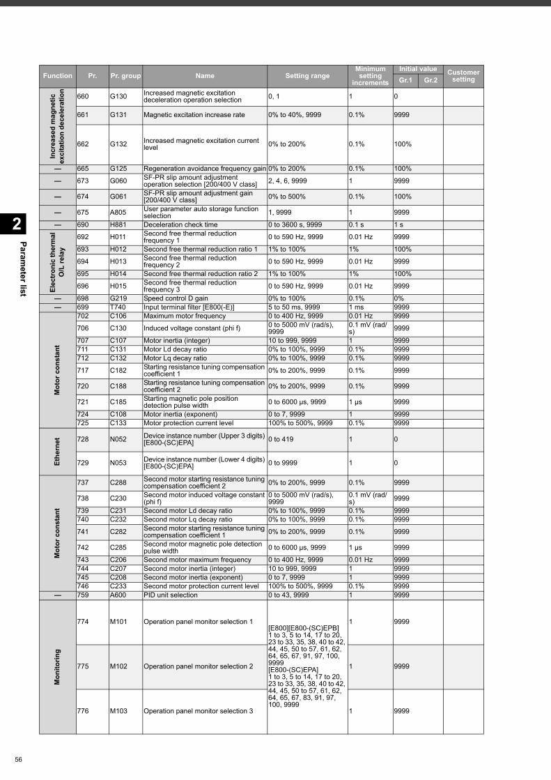
Parameter list
2
56
Incr
ease
d m
agne
ticex
cita
tion
dece
lera
tion
660 G130 Increased magnetic excitation deceleration operation selection 0, 1 1 0
661 G131 Magnetic excitation increase rate 0% to 40%, 9999 0.1% 9999
662 G132 Increased magnetic excitation current level 0% to 200% 0.1% 100%
— 665 G125 Regeneration avoidance frequency gain 0% to 200% 0.1% 100%
— 673 G060 SF-PR slip amount adjustment operation selection [200/400 V class] 2, 4, 6, 9999 1 9999
— 674 G061 SF-PR slip amount adjustment gain [200/400 V class] 0% to 500% 0.1% 100%
— 675 A805 User parameter auto storage function selection 1, 9999 1 9999
— 690 H881 Deceleration check time 0 to 3600 s, 9999 0.1 s 1 s
Elec
troni
c th
erm
al
O/L
rela
y
692 H011 Second free thermal reduction frequency 1 0 to 590 Hz, 9999 0.01 Hz 9999
693 H012 Second free thermal reduction ratio 1 1% to 100% 1% 100%
694 H013 Second free thermal reduction frequency 2 0 to 590 Hz, 9999 0.01 Hz 9999
695 H014 Second free thermal reduction ratio 2 1% to 100% 1% 100%
696 H015 Second free thermal reduction frequency 3 0 to 590 Hz, 9999 0.01 Hz 9999
— 698 G219 Speed control D gain 0% to 100% 0.1% 0%— 699 T740 Input terminal filter [E800(-E)] 5 to 50 ms, 9999 1 ms 9999
Mot
or c
onst
ant
702 C106 Maximum motor frequency 0 to 400 Hz, 9999 0.01 Hz 9999
706 C130 Induced voltage constant (phi f) 0 to 5000 mV (rad/s), 9999
0.1 mV (rad/s) 9999
707 C107 Motor inertia (integer) 10 to 999, 9999 1 9999711 C131 Motor Ld decay ratio 0% to 100%, 9999 0.1% 9999712 C132 Motor Lq decay ratio 0% to 100%, 9999 0.1% 9999
717 C182 Starting resistance tuning compensation coefficient 1 0% to 200%, 9999 0.1% 9999
720 C188 Starting resistance tuning compensation coefficient 2 0% to 200%, 9999 0.1% 9999
721 C185 Starting magnetic pole position detection pulse width 0 to 6000 μs, 9999 1 μs 9999
724 C108 Motor inertia (exponent) 0 to 7, 9999 1 9999725 C133 Motor protection current level 100% to 500%, 9999 0.1% 9999
Ethe
rnet 728 N052 Device instance number (Upper 3 digits)
[E800-(SC)EPA] 0 to 419 1 0
729 N053 Device instance number (Lower 4 digits) [E800-(SC)EPA] 0 to 9999 1 0
Mot
or c
onst
ant
737 C288 Second motor starting resistance tuning compensation coefficient 2 0% to 200%, 9999 0.1% 9999
738 C230 Second motor induced voltage constant (phi f)
0 to 5000 mV (rad/s), 9999
0.1 mV (rad/s) 9999
739 C231 Second motor Ld decay ratio 0% to 100%, 9999 0.1% 9999740 C232 Second motor Lq decay ratio 0% to 100%, 9999 0.1% 9999
741 C282 Second motor starting resistance tuning compensation coefficient 1 0% to 200%, 9999 0.1% 9999
742 C285 Second motor magnetic pole detection pulse width 0 to 6000 μs, 9999 1 μs 9999
743 C206 Second motor maximum frequency 0 to 400 Hz, 9999 0.01 Hz 9999744 C207 Second motor inertia (integer) 10 to 999, 9999 1 9999745 C208 Second motor inertia (exponent) 0 to 7, 9999 1 9999746 C233 Second motor protection current level 100% to 500%, 9999 0.1% 9999
— 759 A600 PID unit selection 0 to 43, 9999 1 9999
Mon
itorin
g
774 M101 Operation panel monitor selection 1[E800][E800-(SC)EPB]1 to 3, 5 to 14, 17 to 20, 23 to 33, 35, 38, 40 to 42, 44, 45, 50 to 57, 61, 62, 64, 65, 67, 91, 97, 100, 9999[E800-(SC)EPA]1 to 3, 5 to 14, 17 to 20, 23 to 33, 35, 38, 40 to 42, 44, 45, 50 to 57, 61, 62, 64, 65, 67, 83, 91, 97, 100, 9999
1 9999
775 M102 Operation panel monitor selection 2 1 9999
776 M103 Operation panel monitor selection 3 1 9999
Function Pr. Pr. group Name Setting rangeMinimum setting
increments
Initial value Customer settingGr.1 Gr.2
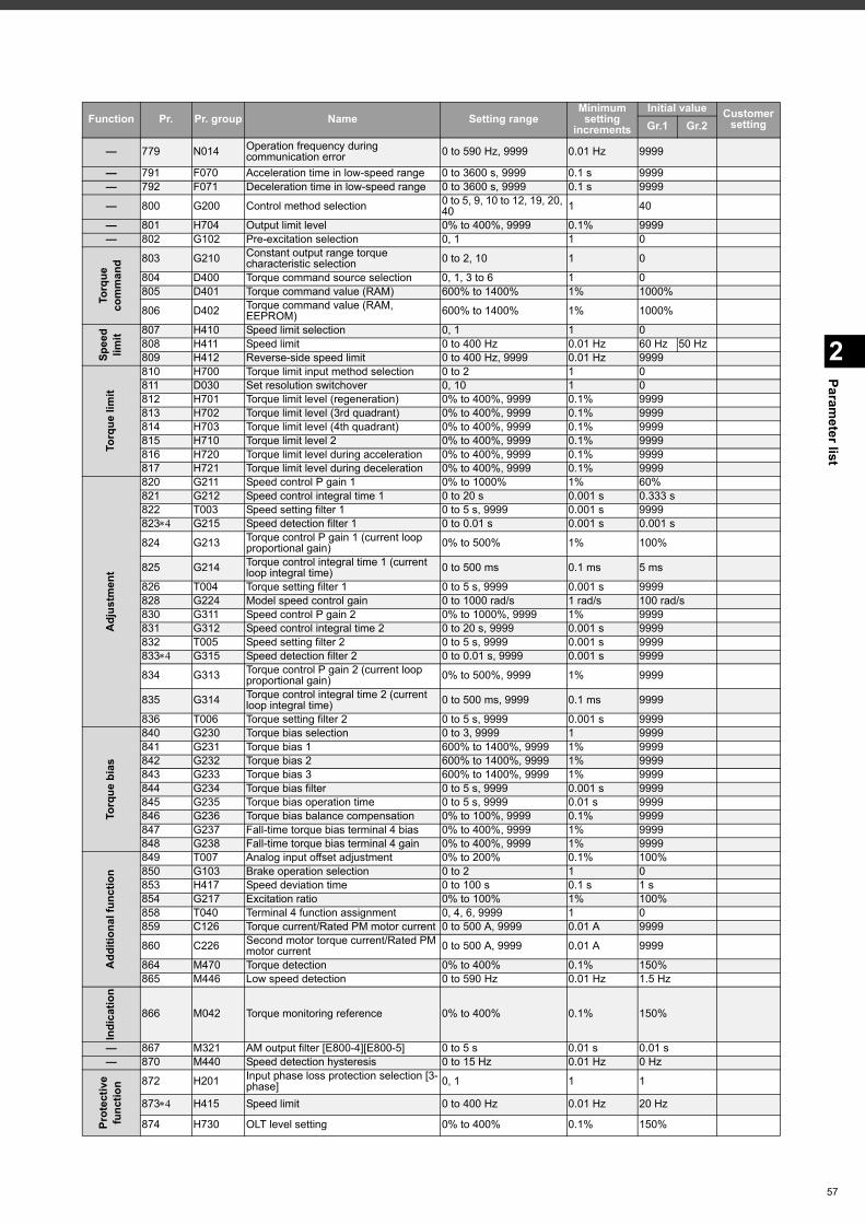
2
Parameter list
— 779 N014 Operation frequency during communication error 0 to 590 Hz, 9999 0.01 Hz 9999
— 791 F070 Acceleration time in low-speed range 0 to 3600 s, 9999 0.1 s 9999— 792 F071 Deceleration time in low-speed range 0 to 3600 s, 9999 0.1 s 9999
— 800 G200 Control method selection 0 to 5, 9, 10 to 12, 19, 20, 40 1 40
— 801 H704 Output limit level 0% to 400%, 9999 0.1% 9999— 802 G102 Pre-excitation selection 0, 1 1 0
Torq
ue
com
man
d 803 G210 Constant output range torque characteristic selection 0 to 2, 10 1 0
804 D400 Torque command source selection 0, 1, 3 to 6 1 0805 D401 Torque command value (RAM) 600% to 1400% 1% 1000%
806 D402 Torque command value (RAM, EEPROM) 600% to 1400% 1% 1000%
Spee
d lim
it 807 H410 Speed limit selection 0, 1 1 0808 H411 Speed limit 0 to 400 Hz 0.01 Hz 60 Hz 50 Hz809 H412 Reverse-side speed limit 0 to 400 Hz, 9999 0.01 Hz 9999
Torq
ue li
mit
810 H700 Torque limit input method selection 0 to 2 1 0811 D030 Set resolution switchover 0, 10 1 0812 H701 Torque limit level (regeneration) 0% to 400%, 9999 0.1% 9999813 H702 Torque limit level (3rd quadrant) 0% to 400%, 9999 0.1% 9999814 H703 Torque limit level (4th quadrant) 0% to 400%, 9999 0.1% 9999815 H710 Torque limit level 2 0% to 400%, 9999 0.1% 9999816 H720 Torque limit level during acceleration 0% to 400%, 9999 0.1% 9999817 H721 Torque limit level during deceleration 0% to 400%, 9999 0.1% 9999
Adj
ustm
ent
820 G211 Speed control P gain 1 0% to 1000% 1% 60%821 G212 Speed control integral time 1 0 to 20 s 0.001 s 0.333 s822 T003 Speed setting filter 1 0 to 5 s, 9999 0.001 s 9999823 G215 Speed detection filter 1 0 to 0.01 s 0.001 s 0.001 s
824 G213 Torque control P gain 1 (current loop proportional gain) 0% to 500% 1% 100%
825 G214 Torque control integral time 1 (current loop integral time) 0 to 500 ms 0.1 ms 5 ms
826 T004 Torque setting filter 1 0 to 5 s, 9999 0.001 s 9999828 G224 Model speed control gain 0 to 1000 rad/s 1 rad/s 100 rad/s830 G311 Speed control P gain 2 0% to 1000%, 9999 1% 9999831 G312 Speed control integral time 2 0 to 20 s, 9999 0.001 s 9999832 T005 Speed setting filter 2 0 to 5 s, 9999 0.001 s 9999833 G315 Speed detection filter 2 0 to 0.01 s, 9999 0.001 s 9999
834 G313 Torque control P gain 2 (current loop proportional gain) 0% to 500%, 9999 1% 9999
835 G314 Torque control integral time 2 (current loop integral time) 0 to 500 ms, 9999 0.1 ms 9999
836 T006 Torque setting filter 2 0 to 5 s, 9999 0.001 s 9999
Torq
ue b
ias
840 G230 Torque bias selection 0 to 3, 9999 1 9999841 G231 Torque bias 1 600% to 1400%, 9999 1% 9999842 G232 Torque bias 2 600% to 1400%, 9999 1% 9999843 G233 Torque bias 3 600% to 1400%, 9999 1% 9999844 G234 Torque bias filter 0 to 5 s, 9999 0.001 s 9999845 G235 Torque bias operation time 0 to 5 s, 9999 0.01 s 9999846 G236 Torque bias balance compensation 0% to 100%, 9999 0.1% 9999847 G237 Fall-time torque bias terminal 4 bias 0% to 400%, 9999 1% 9999848 G238 Fall-time torque bias terminal 4 gain 0% to 400%, 9999 1% 9999
Add
ition
al fu
nctio
n
849 T007 Analog input offset adjustment 0% to 200% 0.1% 100%850 G103 Brake operation selection 0 to 2 1 0853 H417 Speed deviation time 0 to 100 s 0.1 s 1 s854 G217 Excitation ratio 0% to 100% 1% 100%858 T040 Terminal 4 function assignment 0, 4, 6, 9999 1 0859 C126 Torque current/Rated PM motor current 0 to 500 A, 9999 0.01 A 9999
860 C226 Second motor torque current/Rated PM motor current 0 to 500 A, 9999 0.01 A 9999
864 M470 Torque detection 0% to 400% 0.1% 150%865 M446 Low speed detection 0 to 590 Hz 0.01 Hz 1.5 Hz
Indi
catio
n
866 M042 Torque monitoring reference 0% to 400% 0.1% 150%
— 867 M321 AM output filter [E800-4][E800-5] 0 to 5 s 0.01 s 0.01 s— 870 M440 Speed detection hysteresis 0 to 15 Hz 0.01 Hz 0 Hz
Prot
ectiv
efu
nctio
n 872 H201 Input phase loss protection selection [3-phase] 0, 1 1 1
873 H415 Speed limit 0 to 400 Hz 0.01 Hz 20 Hz
874 H730 OLT level setting 0% to 400% 0.1% 150%
Function Pr. Pr. group Name Setting rangeMinimum setting
increments
Initial value Customer settingGr.1 Gr.2
57
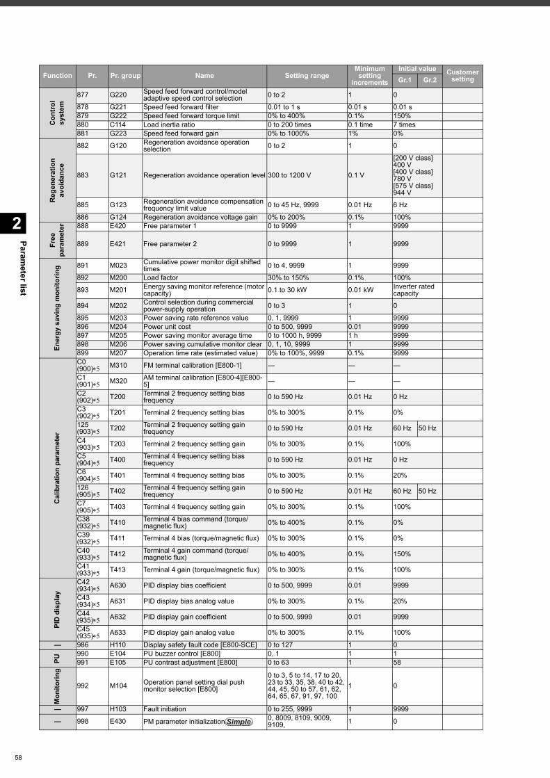
Parameter list
2
58
Con
trol
sy
stem
877 G220 Speed feed forward control/model adaptive speed control selection 0 to 2 1 0
878 G221 Speed feed forward filter 0.01 to 1 s 0.01 s 0.01 s879 G222 Speed feed forward torque limit 0% to 400% 0.1% 150%880 C114 Load inertia ratio 0 to 200 times 0.1 time 7 times881 G223 Speed feed forward gain 0% to 1000% 1% 0%
Reg
ener
atio
n av
oida
nce
882 G120 Regeneration avoidance operation selection 0 to 2 1 0
883 G121 Regeneration avoidance operation level 300 to 1200 V 0.1 V
[200 V class]400 V[400 V class]780 V[575 V class]944 V
885 G123 Regeneration avoidance compensation frequency limit value 0 to 45 Hz, 9999 0.01 Hz 6 Hz
886 G124 Regeneration avoidance voltage gain 0% to 200% 0.1% 100%
Free
pa
ram
eter 888 E420 Free parameter 1 0 to 9999 1 9999
889 E421 Free parameter 2 0 to 9999 1 9999
Ener
gy s
avin
g m
onito
ring 891 M023 Cumulative power monitor digit shifted
times 0 to 4, 9999 1 9999
892 M200 Load factor 30% to 150% 0.1% 100%
893 M201 Energy saving monitor reference (motor capacity) 0.1 to 30 kW 0.01 kW Inverter rated
capacity
894 M202 Control selection during commercial power-supply operation 0 to 3 1 0
895 M203 Power saving rate reference value 0, 1, 9999 1 9999896 M204 Power unit cost 0 to 500, 9999 0.01 9999897 M205 Power saving monitor average time 0 to 1000 h, 9999 1 h 9999898 M206 Power saving cumulative monitor clear 0, 1, 10, 9999 1 9999899 M207 Operation time rate (estimated value) 0% to 100%, 9999 0.1% 9999
Cal
ibra
tion
para
met
er
C0(900) M310 FM terminal calibration [E800-1] — — —
C1(901) M320 AM terminal calibration [E800-4][E800-
5] — — —
C2(902) T200 Terminal 2 frequency setting bias
frequency 0 to 590 Hz 0.01 Hz 0 Hz
C3(902) T201 Terminal 2 frequency setting bias 0% to 300% 0.1% 0%
125(903) T202 Terminal 2 frequency setting gain
frequency 0 to 590 Hz 0.01 Hz 60 Hz 50 Hz
C4(903) T203 Terminal 2 frequency setting gain 0% to 300% 0.1% 100%
C5(904) T400 Terminal 4 frequency setting bias
frequency 0 to 590 Hz 0.01 Hz 0 Hz
C6(904) T401 Terminal 4 frequency setting bias 0% to 300% 0.1% 20%
126(905) T402 Terminal 4 frequency setting gain
frequency 0 to 590 Hz 0.01 Hz 60 Hz 50 Hz
C7(905) T403 Terminal 4 frequency setting gain 0% to 300% 0.1% 100%
C38(932) T410 Terminal 4 bias command (torque/
magnetic flux) 0% to 400% 0.1% 0%
C39(932) T411 Terminal 4 bias (torque/magnetic flux) 0% to 300% 0.1% 0%
C40(933) T412 Terminal 4 gain command (torque/
magnetic flux) 0% to 400% 0.1% 150%
C41(933) T413 Terminal 4 gain (torque/magnetic flux) 0% to 300% 0.1% 100%
PID
dis
play
C42(934) A630 PID display bias coefficient 0 to 500, 9999 0.01 9999
C43(934) A631 PID display bias analog value 0% to 300% 0.1% 20%
C44(935) A632 PID display gain coefficient 0 to 500, 9999 0.01 9999
C45(935) A633 PID display gain analog value 0% to 300% 0.1% 100%
— 986 H110 Display safety fault code [E800-SCE] 0 to 127 1 0
PU
990 E104 PU buzzer control [E800] 0, 1 1 1991 E105 PU contrast adjustment [E800] 0 to 63 1 58
Mon
itorin
g
992 M104 Operation panel setting dial push monitor selection [E800]
0 to 3, 5 to 14, 17 to 20, 23 to 33, 35, 38, 40 to 42, 44, 45, 50 to 57, 61, 62, 64, 65, 67, 91, 97, 100
1 0
— 997 H103 Fault initiation 0 to 255, 9999 1 9999
— 998 E430 PM parameter initialization 0, 8009, 8109, 9009, 9109, 1 0
Function Pr. Pr. group Name Setting rangeMinimum setting
increments
Initial value Customer settingGr.1 Gr.2
SimpleSimpleSimple
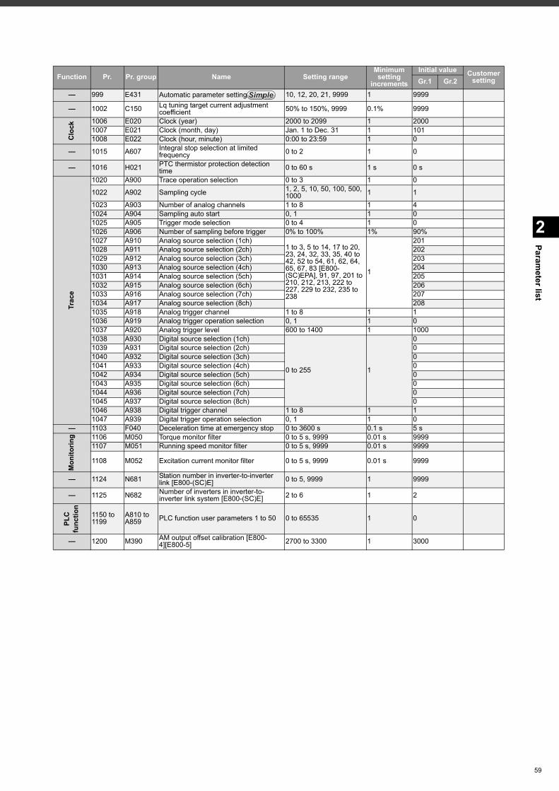
2
Parameter list
— 999 E431 Automatic parameter setting 10, 12, 20, 21, 9999 1 9999
— 1002 C150 Lq tuning target current adjustment coefficient 50% to 150%, 9999 0.1% 9999
Clo
ck
1006 E020 Clock (year) 2000 to 2099 1 20001007 E021 Clock (month, day) Jan. 1 to Dec. 31 1 1011008 E022 Clock (hour, minute) 0:00 to 23:59 1 0
— 1015 A607 Integral stop selection at limited frequency 0 to 2 1 0
— 1016 H021 PTC thermistor protection detection time 0 to 60 s 1 s 0 s
Trac
e
1020 A900 Trace operation selection 0 to 3 1 0
1022 A902 Sampling cycle 1, 2, 5, 10, 50, 100, 500, 1000 1 1
1023 A903 Number of analog channels 1 to 8 1 41024 A904 Sampling auto start 0, 1 1 01025 A905 Trigger mode selection 0 to 4 1 01026 A906 Number of sampling before trigger 0% to 100% 1% 90%1027 A910 Analog source selection (1ch)
1 to 3, 5 to 14, 17 to 20, 23, 24, 32, 33, 35, 40 to 42, 52 to 54, 61, 62, 64, 65, 67, 83 [E800-(SC)EPA], 91, 97, 201 to 210, 212, 213, 222 to 227, 229 to 232, 235 to 238
1
2011028 A911 Analog source selection (2ch) 2021029 A912 Analog source selection (3ch) 2031030 A913 Analog source selection (4ch) 2041031 A914 Analog source selection (5ch) 2051032 A915 Analog source selection (6ch) 2061033 A916 Analog source selection (7ch) 2071034 A917 Analog source selection (8ch) 2081035 A918 Analog trigger channel 1 to 8 1 11036 A919 Analog trigger operation selection 0, 1 1 01037 A920 Analog trigger level 600 to 1400 1 10001038 A930 Digital source selection (1ch)
0 to 255 1
01039 A931 Digital source selection (2ch) 01040 A932 Digital source selection (3ch) 01041 A933 Digital source selection (4ch) 01042 A934 Digital source selection (5ch) 01043 A935 Digital source selection (6ch) 01044 A936 Digital source selection (7ch) 01045 A937 Digital source selection (8ch) 01046 A938 Digital trigger channel 1 to 8 1 11047 A939 Digital trigger operation selection 0, 1 1 0
— 1103 F040 Deceleration time at emergency stop 0 to 3600 s 0.1 s 5 s
Mon
itorin
g 1106 M050 Torque monitor filter 0 to 5 s, 9999 0.01 s 99991107 M051 Running speed monitor filter 0 to 5 s, 9999 0.01 s 9999
1108 M052 Excitation current monitor filter 0 to 5 s, 9999 0.01 s 9999
— 1124 N681 Station number in inverter-to-inverter link [E800-(SC)E] 0 to 5, 9999 1 9999
— 1125 N682 Number of inverters in inverter-to-inverter link system [E800-(SC)E] 2 to 6 1 2
PLC
fu
nctio
n
1150 to 1199
A810 to A859 PLC function user parameters 1 to 50 0 to 65535 1 0
— 1200 M390 AM output offset calibration [E800-4][E800-5] 2700 to 3300 1 3000
Function Pr. Pr. group Name Setting rangeMinimum setting
increments
Initial value Customer settingGr.1 Gr.2
SimpleSimpleSimple
59
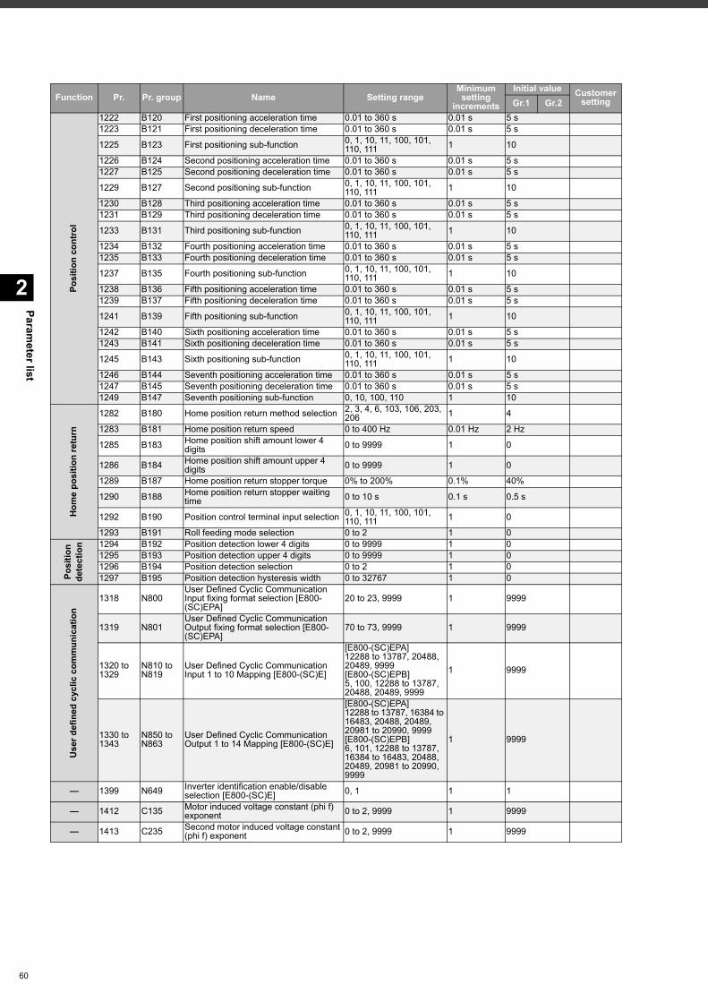
Parameter list
2
60
Posi
tion
cont
rol
1222 B120 First positioning acceleration time 0.01 to 360 s 0.01 s 5 s1223 B121 First positioning deceleration time 0.01 to 360 s 0.01 s 5 s
1225 B123 First positioning sub-function 0, 1, 10, 11, 100, 101, 110, 111 1 10
1226 B124 Second positioning acceleration time 0.01 to 360 s 0.01 s 5 s1227 B125 Second positioning deceleration time 0.01 to 360 s 0.01 s 5 s
1229 B127 Second positioning sub-function 0, 1, 10, 11, 100, 101, 110, 111 1 10
1230 B128 Third positioning acceleration time 0.01 to 360 s 0.01 s 5 s1231 B129 Third positioning deceleration time 0.01 to 360 s 0.01 s 5 s
1233 B131 Third positioning sub-function 0, 1, 10, 11, 100, 101, 110, 111 1 10
1234 B132 Fourth positioning acceleration time 0.01 to 360 s 0.01 s 5 s1235 B133 Fourth positioning deceleration time 0.01 to 360 s 0.01 s 5 s
1237 B135 Fourth positioning sub-function 0, 1, 10, 11, 100, 101, 110, 111 1 10
1238 B136 Fifth positioning acceleration time 0.01 to 360 s 0.01 s 5 s1239 B137 Fifth positioning deceleration time 0.01 to 360 s 0.01 s 5 s
1241 B139 Fifth positioning sub-function 0, 1, 10, 11, 100, 101, 110, 111 1 10
1242 B140 Sixth positioning acceleration time 0.01 to 360 s 0.01 s 5 s1243 B141 Sixth positioning deceleration time 0.01 to 360 s 0.01 s 5 s
1245 B143 Sixth positioning sub-function 0, 1, 10, 11, 100, 101, 110, 111 1 10
1246 B144 Seventh positioning acceleration time 0.01 to 360 s 0.01 s 5 s1247 B145 Seventh positioning deceleration time 0.01 to 360 s 0.01 s 5 s1249 B147 Seventh positioning sub-function 0, 10, 100, 110 1 10
Hom
e po
sitio
n re
turn
1282 B180 Home position return method selection 2, 3, 4, 6, 103, 106, 203, 206 1 4
1283 B181 Home position return speed 0 to 400 Hz 0.01 Hz 2 Hz
1285 B183 Home position shift amount lower 4 digits 0 to 9999 1 0
1286 B184 Home position shift amount upper 4 digits 0 to 9999 1 0
1289 B187 Home position return stopper torque 0% to 200% 0.1% 40%
1290 B188 Home position return stopper waiting time 0 to 10 s 0.1 s 0.5 s
1292 B190 Position control terminal input selection 0, 1, 10, 11, 100, 101, 110, 111 1 0
1293 B191 Roll feeding mode selection 0 to 2 1 0
Posi
tion
dete
ctio
n 1294 B192 Position detection lower 4 digits 0 to 9999 1 01295 B193 Position detection upper 4 digits 0 to 9999 1 01296 B194 Position detection selection 0 to 2 1 01297 B195 Position detection hysteresis width 0 to 32767 1 0
Use
r def
ined
cyc
lic c
omm
unic
atio
n
1318 N800User Defined Cyclic Communication Input fixing format selection [E800-(SC)EPA]
20 to 23, 9999 1 9999
1319 N801User Defined Cyclic Communication Output fixing format selection [E800-(SC)EPA]
70 to 73, 9999 1 9999
1320 to 1329
N810 to N819
User Defined Cyclic Communication Input 1 to 10 Mapping [E800-(SC)E]
[E800-(SC)EPA]12288 to 13787, 20488, 20489, 9999[E800-(SC)EPB]5, 100, 12288 to 13787, 20488, 20489, 9999
1 9999
1330 to 1343
N850 to N863
User Defined Cyclic Communication Output 1 to 14 Mapping [E800-(SC)E]
[E800-(SC)EPA]12288 to 13787, 16384 to 16483, 20488, 20489, 20981 to 20990, 9999[E800-(SC)EPB]6, 101, 12288 to 13787, 16384 to 16483, 20488, 20489, 20981 to 20990, 9999
1 9999
— 1399 N649 Inverter identification enable/disable selection [E800-(SC)E] 0, 1 1 1
— 1412 C135 Motor induced voltage constant (phi f) exponent 0 to 2, 9999 1 9999
— 1413 C235 Second motor induced voltage constant (phi f) exponent 0 to 2, 9999 1 9999
Function Pr. Pr. group Name Setting rangeMinimum setting
increments
Initial value Customer settingGr.1 Gr.2
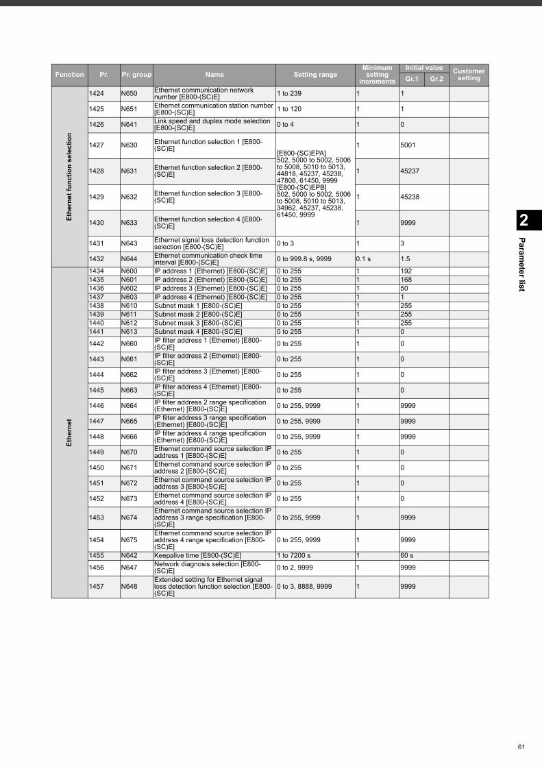
2
Parameter list
Ethe
rnet
func
tion
sele
ctio
n
1424 N650 Ethernet communication network number [E800-(SC)E] 1 to 239 1 1
1425 N651 Ethernet communication station number [E800-(SC)E] 1 to 120 1 1
1426 N641 Link speed and duplex mode selection [E800-(SC)E] 0 to 4 1 0
1427 N630 Ethernet function selection 1 [E800-(SC)E] [E800-(SC)EPA]
502, 5000 to 5002, 5006 to 5008, 5010 to 5013, 44818, 45237, 45238, 47808, 61450, 9999[E800-(SC)EPB]502, 5000 to 5002, 5006 to 5008, 5010 to 5013, 34962, 45237, 45238, 61450, 9999
1 5001
1428 N631 Ethernet function selection 2 [E800-(SC)E] 1 45237
1429 N632 Ethernet function selection 3 [E800-(SC)E] 1 45238
1430 N633 Ethernet function selection 4 [E800-(SC)E] 1 9999
1431 N643 Ethernet signal loss detection function selection [E800-(SC)E] 0 to 3 1 3
1432 N644 Ethernet communication check time interval [E800-(SC)E] 0 to 999.8 s, 9999 0.1 s 1.5
Ethe
rnet
1434 N600 IP address 1 (Ethernet) [E800-(SC)E] 0 to 255 1 1921435 N601 IP address 2 (Ethernet) [E800-(SC)E] 0 to 255 1 1681436 N602 IP address 3 (Ethernet) [E800-(SC)E] 0 to 255 1 501437 N603 IP address 4 (Ethernet) [E800-(SC)E] 0 to 255 1 11438 N610 Subnet mask 1 [E800-(SC)E] 0 to 255 1 2551439 N611 Subnet mask 2 [E800-(SC)E] 0 to 255 1 2551440 N612 Subnet mask 3 [E800-(SC)E] 0 to 255 1 2551441 N613 Subnet mask 4 [E800-(SC)E] 0 to 255 1 0
1442 N660 IP filter address 1 (Ethernet) [E800-(SC)E] 0 to 255 1 0
1443 N661 IP filter address 2 (Ethernet) [E800-(SC)E] 0 to 255 1 0
1444 N662 IP filter address 3 (Ethernet) [E800-(SC)E] 0 to 255 1 0
1445 N663 IP filter address 4 (Ethernet) [E800-(SC)E] 0 to 255 1 0
1446 N664 IP filter address 2 range specification (Ethernet) [E800-(SC)E] 0 to 255, 9999 1 9999
1447 N665 IP filter address 3 range specification (Ethernet) [E800-(SC)E] 0 to 255, 9999 1 9999
1448 N666 IP filter address 4 range specification (Ethernet) [E800-(SC)E] 0 to 255, 9999 1 9999
1449 N670 Ethernet command source selection IP address 1 [E800-(SC)E] 0 to 255 1 0
1450 N671 Ethernet command source selection IP address 2 [E800-(SC)E] 0 to 255 1 0
1451 N672 Ethernet command source selection IP address 3 [E800-(SC)E] 0 to 255 1 0
1452 N673 Ethernet command source selection IP address 4 [E800-(SC)E] 0 to 255 1 0
1453 N674Ethernet command source selection IP address 3 range specification [E800-(SC)E]
0 to 255, 9999 1 9999
1454 N675Ethernet command source selection IP address 4 range specification [E800-(SC)E]
0 to 255, 9999 1 9999
1455 N642 Keepalive time [E800-(SC)E] 1 to 7200 s 1 60 s
1456 N647 Network diagnosis selection [E800-(SC)E] 0 to 2, 9999 1 9999
1457 N648Extended setting for Ethernet signal loss detection function selection [E800-(SC)E]
0 to 3, 8888, 9999 1 9999
Function Pr. Pr. group Name Setting rangeMinimum setting
increments
Initial value Customer settingGr.1 Gr.2
61
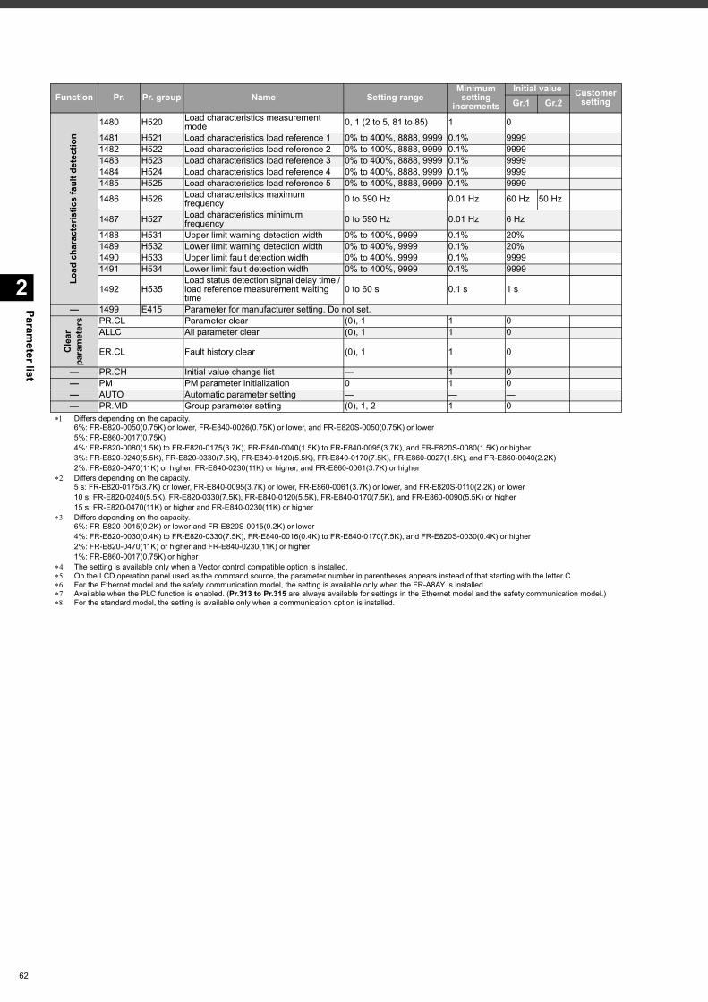
Parameter list
2
62
Differs depending on the capacity.6%: FR-E820-0050(0.75K) or lower, FR-E840-0026(0.75K) or lower, and FR-E820S-0050(0.75K) or lower5%: FR-E860-0017(0.75K)4%: FR-E820-0080(1.5K) to FR-E820-0175(3.7K), FR-E840-0040(1.5K) to FR-E840-0095(3.7K), and FR-E820S-0080(1.5K) or higher3%: FR-E820-0240(5.5K), FR-E820-0330(7.5K), FR-E840-0120(5.5K), FR-E840-0170(7.5K), FR-E860-0027(1.5K), and FR-E860-0040(2.2K)2%: FR-E820-0470(11K) or higher, FR-E840-0230(11K) or higher, and FR-E860-0061(3.7K) or higher
Differs depending on the capacity.5 s: FR-E820-0175(3.7K) or lower, FR-E840-0095(3.7K) or lower, FR-E860-0061(3.7K) or lower, and FR-E820S-0110(2.2K) or lower10 s: FR-E820-0240(5.5K), FR-E820-0330(7.5K), FR-E840-0120(5.5K), FR-E840-0170(7.5K), and FR-E860-0090(5.5K) or higher15 s: FR-E820-0470(11K) or higher and FR-E840-0230(11K) or higher
Differs depending on the capacity.6%: FR-E820-0015(0.2K) or lower and FR-E820S-0015(0.2K) or lower4%: FR-E820-0030(0.4K) to FR-E820-0330(7.5K), FR-E840-0016(0.4K) to FR-E840-0170(7.5K), and FR-E820S-0030(0.4K) or higher2%: FR-E820-0470(11K) or higher and FR-E840-0230(11K) or higher1%: FR-E860-0017(0.75K) or higher
The setting is available only when a Vector control compatible option is installed. On the LCD operation panel used as the command source, the parameter number in parentheses appears instead of that starting with the letter C. For the Ethernet model and the safety communication model, the setting is available only when the FR-A8AY is installed. Available when the PLC function is enabled. (Pr.313 to Pr.315 are always available for settings in the Ethernet model and the safety communication model.) For the standard model, the setting is available only when a communication option is installed.
Load
cha
ract
eris
tics
faul
t det
ectio
n
1480 H520 Load characteristics measurement mode 0, 1 (2 to 5, 81 to 85) 1 0
1481 H521 Load characteristics load reference 1 0% to 400%, 8888, 9999 0.1% 99991482 H522 Load characteristics load reference 2 0% to 400%, 8888, 9999 0.1% 99991483 H523 Load characteristics load reference 3 0% to 400%, 8888, 9999 0.1% 99991484 H524 Load characteristics load reference 4 0% to 400%, 8888, 9999 0.1% 99991485 H525 Load characteristics load reference 5 0% to 400%, 8888, 9999 0.1% 9999
1486 H526 Load characteristics maximum frequency 0 to 590 Hz 0.01 Hz 60 Hz 50 Hz
1487 H527 Load characteristics minimum frequency 0 to 590 Hz 0.01 Hz 6 Hz
1488 H531 Upper limit warning detection width 0% to 400%, 9999 0.1% 20%1489 H532 Lower limit warning detection width 0% to 400%, 9999 0.1% 20%1490 H533 Upper limit fault detection width 0% to 400%, 9999 0.1% 99991491 H534 Lower limit fault detection width 0% to 400%, 9999 0.1% 9999
1492 H535Load status detection signal delay time / load reference measurement waiting time
0 to 60 s 0.1 s 1 s
— 1499 E415 Parameter for manufacturer setting. Do not set.
Cle
ar
para
met
ers PR.CL Parameter clear (0), 1 1 0
ALLC All parameter clear (0), 1 1 0
ER.CL Fault history clear (0), 1 1 0
— PR.CH Initial value change list — 1 0— PM PM parameter initialization 0 1 0— AUTO Automatic parameter setting — — —— PR.MD Group parameter setting (0), 1, 2 1 0
Function Pr. Pr. group Name Setting rangeMinimum setting
increments
Initial value Customer settingGr.1 Gr.2
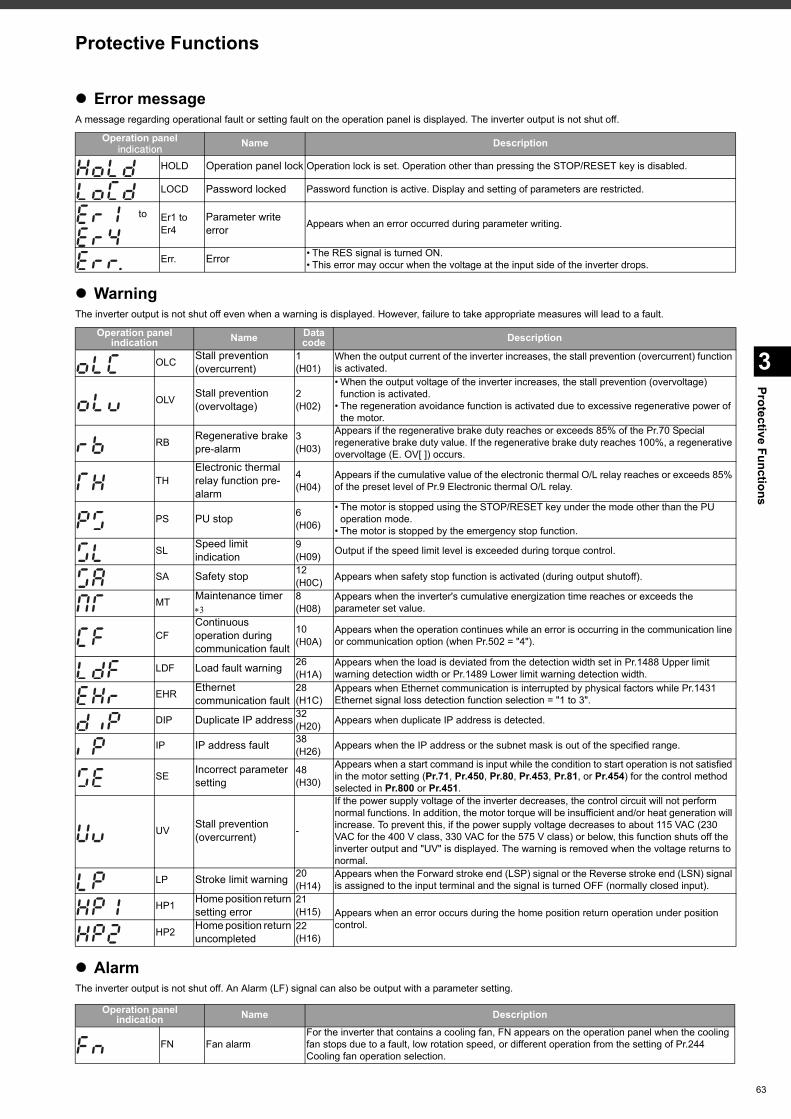
Protective Functions
3
Protective Functions
Error messageA message regarding operational fault or setting fault on the operation panel is displayed. The inverter output is not shut off.
WarningThe inverter output is not shut off even when a warning is displayed. However, failure to take appropriate measures will lead to a fault.
AlarmThe inverter output is not shut off. An Alarm (LF) signal can also be output with a parameter setting.
Operation panelindication Name Description
HOLD Operation panel lock Operation lock is set. Operation other than pressing the STOP/RESET key is disabled.
LOCD Password locked Password function is active. Display and setting of parameters are restricted.
to Er1 to Er4
Parameter write error Appears when an error occurred during parameter writing.
Err. Error • The RES signal is turned ON.• This error may occur when the voltage at the input side of the inverter drops.
Operation panelindication Name Data
code Description
OLC Stall prevention (overcurrent)
1(H01)
When the output current of the inverter increases, the stall prevention (overcurrent) function is activated.
OLV Stall prevention (overvoltage)
2(H02)
• When the output voltage of the inverter increases, the stall prevention (overvoltage) function is activated.
• The regeneration avoidance function is activated due to excessive regenerative power of the motor.
RB Regenerative brake pre-alarm
3(H03)
Appears if the regenerative brake duty reaches or exceeds 85% of the Pr.70 Special regenerative brake duty value. If the regenerative brake duty reaches 100%, a regenerative overvoltage (E. OV[ ]) occurs.
THElectronic thermal relay function pre-alarm
4(H04)
Appears if the cumulative value of the electronic thermal O/L relay reaches or exceeds 85% of the preset level of Pr.9 Electronic thermal O/L relay.
PS PU stop 6(H06)
• The motor is stopped using the STOP/RESET key under the mode other than the PU operation mode.
• The motor is stopped by the emergency stop function.
SL Speed limit indication
9(H09) Output if the speed limit level is exceeded during torque control.
SA Safety stop 12(H0C) Appears when safety stop function is activated (during output shutoff).
MT Maintenance timer
8(H08)
Appears when the inverter's cumulative energization time reaches or exceeds the parameter set value.
CFContinuous operation during communication fault
10(H0A)
Appears when the operation continues while an error is occurring in the communication line or communication option (when Pr.502 = "4").
LDF Load fault warning 26(H1A)
Appears when the load is deviated from the detection width set in Pr.1488 Upper limit warning detection width or Pr.1489 Lower limit warning detection width.
EHR Ethernet communication fault
28(H1C)
Appears when Ethernet communication is interrupted by physical factors while Pr.1431 Ethernet signal loss detection function selection = "1 to 3".
DIP Duplicate IP address 32(H20) Appears when duplicate IP address is detected.
IP IP address fault 38(H26) Appears when the IP address or the subnet mask is out of the specified range.
SE Incorrect parameter setting
48(H30)
Appears when a start command is input while the condition to start operation is not satisfied in the motor setting (Pr.71, Pr.450, Pr.80, Pr.453, Pr.81, or Pr.454) for the control method selected in Pr.800 or Pr.451.
UV Stall prevention (overcurrent) -
If the power supply voltage of the inverter decreases, the control circuit will not perform normal functions. In addition, the motor torque will be insufficient and/or heat generation will increase. To prevent this, if the power supply voltage decreases to about 115 VAC (230 VAC for the 400 V class, 330 VAC for the 575 V class) or below, this function shuts off the inverter output and "UV" is displayed. The warning is removed when the voltage returns to normal.
LP Stroke limit warning 20 (H14)
Appears when the Forward stroke end (LSP) signal or the Reverse stroke end (LSN) signal is assigned to the input terminal and the signal is turned OFF (normally closed input).
HP1 Home position return setting error
21 (H15) Appears when an error occurs during the home position return operation under position
control.HP2 Home position return
uncompleted22 (H16)
Operation panelindication Name Description
FN Fan alarmFor the inverter that contains a cooling fan, FN appears on the operation panel when the cooling fan stops due to a fault, low rotation speed, or different operation from the setting of Pr.244 Cooling fan operation selection.
63
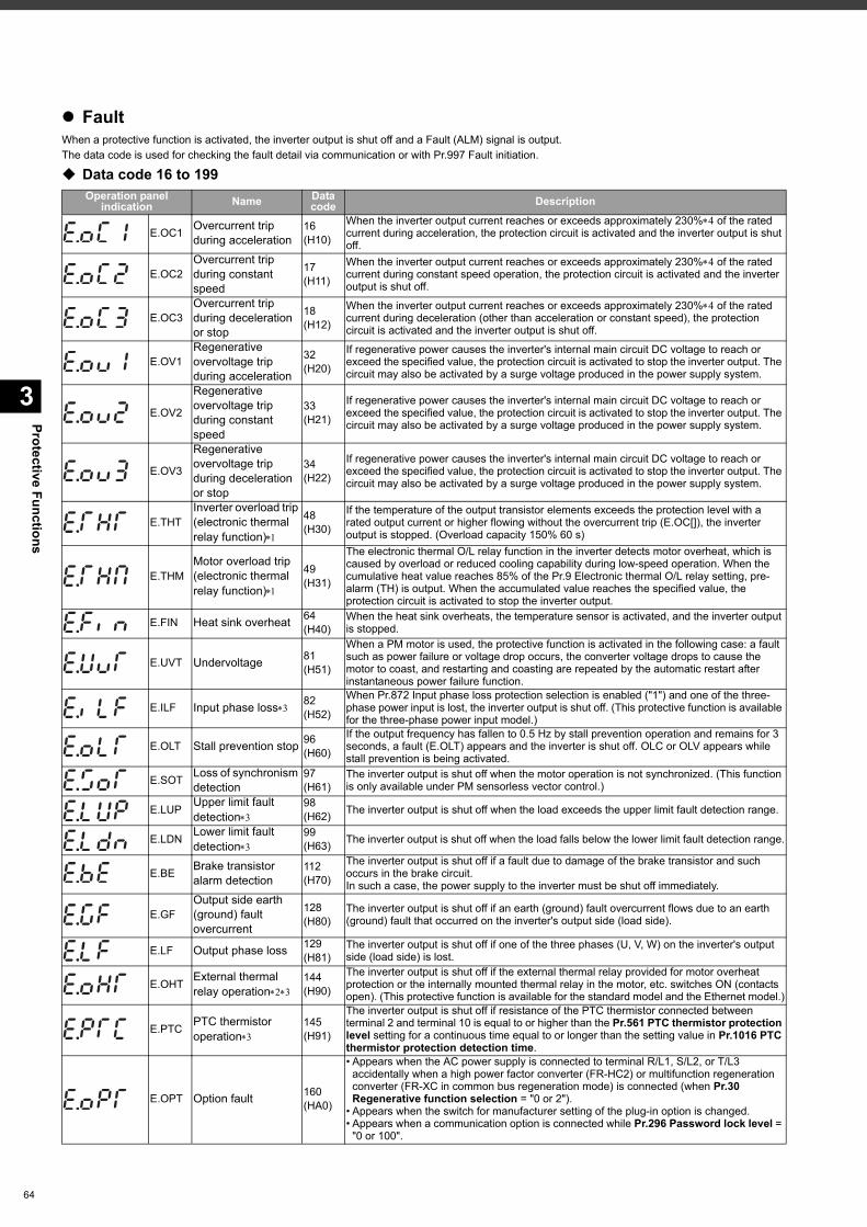
Protective Functions
3
64
FaultWhen a protective function is activated, the inverter output is shut off and a Fault (ALM) signal is output.The data code is used for checking the fault detail via communication or with Pr.997 Fault initiation.
Data code 16 to 199Operation panel
indication Name Datacode Description
E.OC1 Overcurrent trip during acceleration
16(H10)
When the inverter output current reaches or exceeds approximately 230% of the rated current during acceleration, the protection circuit is activated and the inverter output is shut off.
E.OC2Overcurrent trip during constant speed
17(H11)
When the inverter output current reaches or exceeds approximately 230% of the rated current during constant speed operation, the protection circuit is activated and the inverter output is shut off.
E.OC3Overcurrent trip during deceleration or stop
18(H12)
When the inverter output current reaches or exceeds approximately 230% of the rated current during deceleration (other than acceleration or constant speed), the protection circuit is activated and the inverter output is shut off.
E.OV1Regenerative overvoltage trip during acceleration
32(H20)
If regenerative power causes the inverter's internal main circuit DC voltage to reach or exceed the specified value, the protection circuit is activated to stop the inverter output. The circuit may also be activated by a surge voltage produced in the power supply system.
E.OV2
Regenerative overvoltage trip during constant speed
33(H21)
If regenerative power causes the inverter's internal main circuit DC voltage to reach or exceed the specified value, the protection circuit is activated to stop the inverter output. The circuit may also be activated by a surge voltage produced in the power supply system.
E.OV3
Regenerative overvoltage trip during deceleration or stop
34(H22)
If regenerative power causes the inverter's internal main circuit DC voltage to reach or exceed the specified value, the protection circuit is activated to stop the inverter output. The circuit may also be activated by a surge voltage produced in the power supply system.
E.THTInverter overload trip (electronic thermal relay function)
48(H30)
If the temperature of the output transistor elements exceeds the protection level with a rated output current or higher flowing without the overcurrent trip (E.OC[]), the inverter output is stopped. (Overload capacity 150% 60 s)
E.THMMotor overload trip (electronic thermal relay function)
49(H31)
The electronic thermal O/L relay function in the inverter detects motor overheat, which is caused by overload or reduced cooling capability during low-speed operation. When the cumulative heat value reaches 85% of the Pr.9 Electronic thermal O/L relay setting, pre-alarm (TH) is output. When the accumulated value reaches the specified value, the protection circuit is activated to stop the inverter output.
E.FIN Heat sink overheat 64(H40)
When the heat sink overheats, the temperature sensor is activated, and the inverter output is stopped.
E.UVT Undervoltage 81(H51)
When a PM motor is used, the protective function is activated in the following case: a fault such as power failure or voltage drop occurs, the converter voltage drops to cause the motor to coast, and restarting and coasting are repeated by the automatic restart after instantaneous power failure function.
E.ILF Input phase loss 82(H52)
When Pr.872 Input phase loss protection selection is enabled ("1") and one of the three-phase power input is lost, the inverter output is shut off. (This protective function is available for the three-phase power input model.)
E.OLT Stall prevention stop 96(H60)
If the output frequency has fallen to 0.5 Hz by stall prevention operation and remains for 3 seconds, a fault (E.OLT) appears and the inverter is shut off. OLC or OLV appears while stall prevention is being activated.
E.SOT Loss of synchronism detection
97(H61)
The inverter output is shut off when the motor operation is not synchronized. (This function is only available under PM sensorless vector control.)
E.LUP Upper limit fault detection
98(H62) The inverter output is shut off when the load exceeds the upper limit fault detection range.
E.LDN Lower limit fault detection
99(H63) The inverter output is shut off when the load falls below the lower limit fault detection range.
E.BE Brake transistor alarm detection
112(H70)
The inverter output is shut off if a fault due to damage of the brake transistor and such occurs in the brake circuit.In such a case, the power supply to the inverter must be shut off immediately.
E.GFOutput side earth (ground) fault overcurrent
128(H80)
The inverter output is shut off if an earth (ground) fault overcurrent flows due to an earth (ground) fault that occurred on the inverter's output side (load side).
E.LF Output phase loss 129(H81)
The inverter output is shut off if one of the three phases (U, V, W) on the inverter's output side (load side) is lost.
E.OHT External thermal relay operation
144(H90)
The inverter output is shut off if the external thermal relay provided for motor overheat protection or the internally mounted thermal relay in the motor, etc. switches ON (contacts open). (This protective function is available for the standard model and the Ethernet model.)
E.PTC PTC thermistor operation
145(H91)
The inverter output is shut off if resistance of the PTC thermistor connected between terminal 2 and terminal 10 is equal to or higher than the Pr.561 PTC thermistor protection level setting for a continuous time equal to or longer than the setting value in Pr.1016 PTC thermistor protection detection time.
E.OPT Option fault 160(HA0)
• Appears when the AC power supply is connected to terminal R/L1, S/L2, or T/L3 accidentally when a high power factor converter (FR-HC2) or multifunction regeneration converter (FR-XC in common bus regeneration mode) is connected (when Pr.30 Regenerative function selection = "0 or 2").
• Appears when the switch for manufacturer setting of the plug-in option is changed.• Appears when a communication option is connected while Pr.296 Password lock level =
"0 or 100".
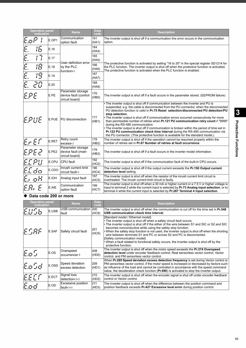
3
Protective Functions
Data code 200 or more
E.OP1 Communication option fault
161(HA1)
The inverter output is shut off if a communication line error occurs in the communication option.
E.16
User definition error by the PLC function
164(HA4)
The protective function is activated by setting "16 to 20" in the special register SD1214 for the PLC function. The inverter output is shut off when the protective function is activated.The protective function is activated when the PLC function is enabled.
E.17 165(HA5)
E.18 166(HA6)
E.19 167(HA7)
E.20 168(HA8)
E.PEParameter storage device fault (control circuit board)
176(HB0) The inverter output is shut off if a fault occurs in the parameter stored. (EEPROM failure)
E.PUE PU disconnection 177(HB1)
• The inverter output is shut off if communication between the inverter and PU is suspended, e.g. the cable is disconnected from the PU connector, when the disconnected PU detection function is valid in Pr.75 Reset selection/disconnected PU detection/PU stop selection.
• The inverter output is shut off if communication errors occurred consecutively for more than permissible number of retries when Pr.121 PU communication retry count ≠ "9999" during the RS-485 communication.
• The inverter output is shut off if communication is broken within the period of time set in Pr.122 PU communication check time interval during the RS-485 communication via the PU connector. (This protective function is available for the standard model.)
E.RET Retry count excess
178(HB2)
The inverter output is shut off if the operation cannot be resumed properly within the number of retries set in Pr.67 Number of retries at fault occurrence.
E.PE2Parameter storage device fault (main circuit board)
179(HB3) The inverter output is shut off if a fault occurs in the inverter model information.
E.CPU CPU fault 192(HC0) The inverter output is shut off if the communication fault of the built-in CPU occurs.
E.CDO Inrush current limit circuit fault
196(HC4)
The inverter output is shut off if the output current exceeds the Pr.150 Output current detection level setting.
E.IOH Analog input fault 197(HC5)
The inverter output is shut off when the resistor of the inrush current limit circuit is overheated. The inrush current limit circuit is faulty.
E.AIE Communication option fault
199(HC7)
The inverter output is shut off when a 30 mA or higher current or a 7.5 V or higher voltage is input to terminal 2 while the current input is selected by Pr.73 Analog input selection, or to terminal 4 while the current input is selected by Pr.267 Terminal 4 input selection.
Operation panelindication Name Data
code Description
E.USB USB communication fault
200(HC8)
The inverter output is shut off when the communication is cut off for the time set in Pr.548 USB communication check time interval.
E.SAF Safety circuit fault 201(HC9)
[Standard model / Ethernet model]• The inverter output is shut off when a safety circuit fault occurs.• The inverter output is shut off if the either of the wire between S1 and SIC or S2 and SIC
becomes nonconductive while using the safety stop function.• When the safety stop function is not used, the inverter output is shut off when the shorting
wire between terminals S1 and PC or across S2 and PC is disconnected.[Safety communication model]• When a fault related to functional safety occurs, the inverter output is shut off by the
protective function.
E.OS Overspeed occurrence
208(HD0)
The inverter output is shut off when the motor speed exceeds the Pr.374 Overspeed detection level under encoder feedback control, Real sensorless vector control, Vector control, and PM sensorless vector control.
E.OSD Speed deviation excess detection
209(HD1)
When Pr.285 Speed deviation excess detection frequency is set during Vector control or PM sensorless vector control, if the motor speed is increased or decreased by factors such as influence of the load and cannot be controlled in accordance with the speed command value, the deceleration check function (Pr.690) is activated to stop the inverter output.
E.ECT Signal loss detection
210(HD2)
The inverter output is shut off when the encoder signal is shut off under encoder feedback control or Vector control.
E.OD Excessive position fault
211(HD3)
The inverter output is shut off when the difference between the position command and position feedback exceeds Pr.427 Excessive level error during position control.
Operation panelindication Name Data
code Description
65
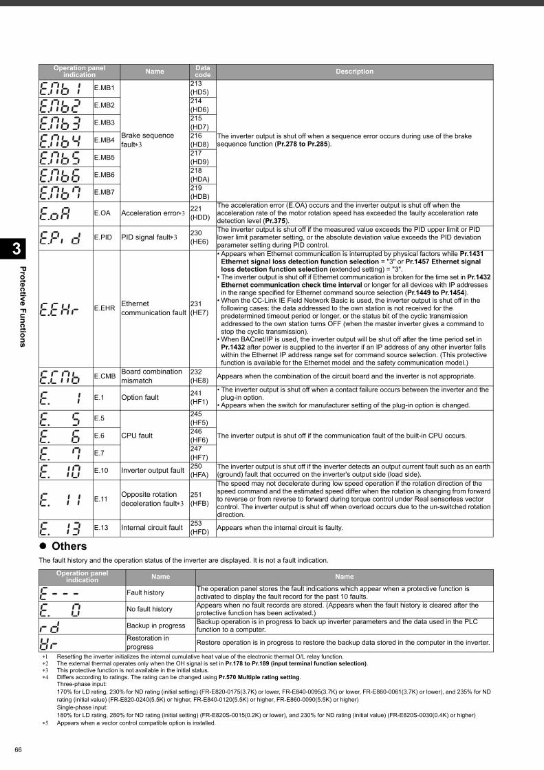
Protective Functions
3
66
OthersThe fault history and the operation status of the inverter are displayed. It is not a fault indication.
Resetting the inverter initializes the internal cumulative heat value of the electronic thermal O/L relay function. The external thermal operates only when the OH signal is set in Pr.178 to Pr.189 (input terminal function selection). This protective function is not available in the initial status. Differs according to ratings. The rating can be changed using Pr.570 Multiple rating setting.
Three-phase input:170% for LD rating, 230% for ND rating (initial setting) (FR-E820-0175(3.7K) or lower, FR-E840-0095(3.7K) or lower, FR-E860-0061(3.7K) or lower), and 235% for ND rating (initial value) (FR-E820-0240(5.5K) or higher, FR-E840-0120(5.5K) or higher, FR-E860-0090(5.5K) or higher)Single-phase input:180% for LD rating, 280% for ND rating (initial setting) (FR-E820S-0015(0.2K) or lower), and 230% for ND rating (initial value) (FR-E820S-0030(0.4K) or higher)
Appears when a vector control compatible option is installed.
E.MB1
Brake sequence fault
213(HD5)
The inverter output is shut off when a sequence error occurs during use of the brake sequence function (Pr.278 to Pr.285).
E.MB2 214(HD6)
E.MB3 215(HD7)
E.MB4 216(HD8)
E.MB5 217(HD9)
E.MB6 218(HDA)
E.MB7 219(HDB)
E.OA Acceleration error 221(HDD)
The acceleration error (E.OA) occurs and the inverter output is shut off when the acceleration rate of the motor rotation speed has exceeded the faulty acceleration rate detection level (Pr.375).
E.PID PID signal fault 230(HE6)
The inverter output is shut off if the measured value exceeds the PID upper limit or PID lower limit parameter setting, or the absolute deviation value exceeds the PID deviation parameter setting during PID control.
E.EHR Ethernet communication fault
231(HE7)
• Appears when Ethernet communication is interrupted by physical factors while Pr.1431 Ethernet signal loss detection function selection = "3" or Pr.1457 Ethernet signal loss detection function selection (extended setting) = "3".
• The inverter output is shut off if Ethernet communication is broken for the time set in Pr.1432 Ethernet communication check time interval or longer for all devices with IP addresses in the range specified for Ethernet command source selection (Pr.1449 to Pr.1454).
• When the CC-Link IE Field Network Basic is used, the inverter output is shut off in the following cases: the data addressed to the own station is not received for the predetermined timeout period or longer, or the status bit of the cyclic transmission addressed to the own station turns OFF (when the master inverter gives a command to stop the cyclic transmission).
• When BACnet/IP is used, the inverter output will be shut off after the time period set in Pr.1432 after power is supplied to the inverter if an IP address of any other inverter falls within the Ethernet IP address range set for command source selection. (This protective function is available for the Ethernet model and the safety communication model.)
E.CMB Board combination mismatch
232(HE8) Appears when the combination of the circuit board and the inverter is not appropriate.
E.1 Option fault 241(HF1)
• The inverter output is shut off when a contact failure occurs between the inverter and the plug-in option.
• Appears when the switch for manufacturer setting of the plug-in option is changed.
E.5
CPU fault
245(HF5)
The inverter output is shut off if the communication fault of the built-in CPU occurs.E.6 246(HF6)
E.7 247(HF7)
E.10 Inverter output fault 250(HFA)
The inverter output is shut off if the inverter detects an output current fault such as an earth (ground) fault that occurred on the inverter's output side (load side).
E.11 Opposite rotation deceleration fault
251(HFB)
The speed may not decelerate during low speed operation if the rotation direction of the speed command and the estimated speed differ when the rotation is changing from forward to reverse or from reverse to forward during torque control under Real sensorless vector control. The inverter output is shut off when overload occurs due to the un-switched rotation direction.
E.13 Internal circuit fault 253(HFD) Appears when the internal circuit is faulty.
Operation panelindication Name Name
Fault history The operation panel stores the fault indications which appear when a protective function is activated to display the fault record for the past 10 faults.
No fault history Appears when no fault records are stored. (Appears when the fault history is cleared after the protective function has been activated.)
Backup in progress Backup operation is in progress to back up inverter parameters and the data used in the PLC function to a computer.
Restoration in progress Restore operation is in progress to restore the backup data stored in the computer in the inverter.
Operation panelindication Name Data
code Description
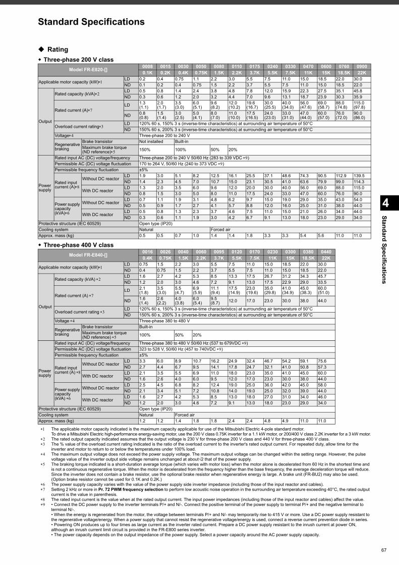
4
Standard SpecificationsStandard Specifications
Rating Three-phase 200 V class
Three-phase 400 V class
The applicable motor capacity indicated is the maximum capacity applicable for use of the Mitsubishi Electric 4-pole standard motor.To drive a Mitsubishi Electric high-performance energy-saving motor, use the 200 V class 0.75K inverter for a 1.1 kW motor, or 200/400 V class 2.2K inverter for a 3 kW motor.
The rated output capacity indicated assumes that the output voltage is 230 V for three-phase 200 V class and 440 V for three-phase 400 V class. The % value of the overload current rating indicated is the ratio of the overload current to the inverter's rated output current. For repeated duty, allow time for the
inverter and motor to return to or below the temperatures under 100% load. The maximum output voltage does not exceed the power supply voltage. The maximum output voltage can be changed within the setting range. However, the pulse
voltage value of the inverter output side voltage remains unchanged at about√2 that of the power supply. The braking torque indicated is a short-duration average torque (which varies with motor loss) when the motor alone is decelerated from 60 Hz in the shortest time and
is not a continuous regenerative torque. When the motor is decelerated from the frequency higher than the base frequency, the average deceleration torque will reduce. Since the inverter does not contain a brake resistor, use the optional brake resistor when regenerative energy is large. A brake unit (FR-BU2) may also be used. (Option brake resistor cannot be used for 0.1K and 0.2K.)
The power supply capacity varies with the value of the power supply side inverter impedance (including those of the input reactor and cables). Setting 2 kHz or more in Pr. 72 PWM frequency selection to perform low acoustic noise operation in the surrounding air temperature exceeding 40°C, the rated output
current is the value in parenthesis. The rated input current is the value when at the rated output current. The input power impedances (including those of the input reactor and cables) affect the value. • Connect the DC power supply to the inverter terminals P/+ and N/-. Connect the positive terminal of the power supply to terminal P/+ and the negative terminal to
terminal N/-.• When the energy is regenerated from the motor, the voltage between terminals P/+ and N/- may temporarily rise to 415 V or more. Use a DC power supply resistant to the regenerative voltage/energy. When a power supply that cannot resist the regenerative voltage/energy is used, connect a reverse current prevention diode in series.• Powering ON produces up to four times as large current as the inverter rated current. Prepare a DC power supply resistant to the inrush current at power ON, although an inrush current limit circuit is provided in the FR-E800 series inverter.• The power capacity depends on the output impedance of the power supply. Select a power capacity around the AC power supply capacity.
Model FR-E820-[] 0008 0015 0030 0050 0080 0110 0175 0240 0330 0470 0600 0760 09000.1K 0.2K 0.4K 0.75K 1.5K 2.2K 3.7K 5.5K 7.5K 11K 15K 18.5K 22K
Applicable motor capacity (kW)LD 0.2 0.4 0.75 1.1 2.2 3.0 5.5 7.5 11.0 15.0 18.5 22.0 30.0ND 0.1 0.2 0.4 0.75 1.5 2.2 3.7 5.5 7.5 11.0 15.0 18.5 22.0
Output
Rated capacity (kVA)LD 0.5 0.8 1.4 2.4 3.8 4.8 7.8 12.0 15.9 22.3 27.5 35.1 45.8ND 0.3 0.6 1.2 2.0 3.2 4.4 7.0 9.6 13.1 18.7 23.9 30.3 35.9
Rated current (A)LD 1.3
(1.1)2.0(1.7)
3.5(3.0)
6.0(5.1)
9.6(8.2)
12.0(10.2)
19.6(16.7)
30.0(25.5)
40.0(34.0)
56.0(47.6)
69.0(58.7)
88.0(74.8)
115.0(97.8)
ND 0.8(0.8)
1.5(1.4)
3.0(2.5)
5.0(4.1)
8.0(7.0)
11.0(10.0)
17.5(16.5)
24.0(23.0)
33.0(31.0)
47.0(44.0)
60.0(57.0)
76.0(72.0)
90.0(86.0)
Overload current ratingLD 120% 60 s, 150% 3 s (inverse-time characteristics) at surrounding air temperature of 50°CND 150% 60 s, 200% 3 s (inverse-time characteristics) at surrounding air temperature of 50°C
Voltage Three-phase 200 to 240 V
Regenerative braking
Brake transistor Not installed Built-inMaximum brake torque (ND reference) 150% 100% 50% 20%
Power supply
Rated input AC (DC) voltage/frequency Three-phase 200 to 240 V 50/60 Hz (283 to 339 VDC )Permissible AC (DC) voltage fluctuation 170 to 264 V, 50/60 Hz (240 to 373 VDC )Permissible frequency fluctuation ±5%
Rated input current (A)
Without DC reactorLD 1.9 3.0 5.1 8.2 12.5 16.1 25.5 37.1 48.6 74.3 90.5 112.9 139.5ND 1.4 2.3 4.5 7.0 10.7 15.0 23.1 30.5 41.0 63.6 79.9 99.0 114.3
With DC reactorLD 1.3 2.0 3.5 6.0 9.6 12.0 20.0 30.0 40.0 56.0 69.0 88.0 115.0ND 0.8 1.5 3.0 5.0 8.0 11.0 17.5 24.0 33.0 47.0 60.0 76.0 90.0
Power supply capacity (kVA)
Without DC reactorLD 0.7 1.1 1.9 3.1 4.8 6.2 9.7 15.0 19.0 29.0 35.0 43.0 54.0ND 0.5 0.9 1.7 2.7 4.1 5.7 8.8 12.0 16.0 25.0 31.0 38.0 44.0
With DC reactorLD 0.5 0.8 1.3 2.3 3.7 4.6 7.5 11.0 15.0 21.0 26.0 34.0 44.0ND 0.3 0.6 1.1 1.9 3.0 4.2 6.7 9.1 13.0 18.0 23.0 29.0 34.0
Protective structure (IEC 60529) Open type (IP20)Cooling system Natural Forced airApprox. mass (kg) 0.5 0.5 0.7 1.0 1.4 1.4 1.8 3.3 3.3 5.4 5.6 11.0 11.0
Model FR-E840-[] 0016 0026 0040 0060 0095 0120 0170 0230 0300 0380 04400.4K 0.75K 1.5K 2.2K 3.7K 5.5K 7.5K 11K 15K 18.5K 22K
Applicable motor capacity (kW)LD 0.75 1.5 2.2 3.0 5.5 7.5 11.0 15.0 18.5 22.0 30.0ND 0.4 0.75 1.5 2.2 3.7 5.5 7.5 11.0 15.0 18.5 22.0
Output
Rated capacity (kVA) LD 1.6 2.7 4.2 5.3 8.5 13.3 17.5 26.7 31.2 34.3 45.7ND 1.2 2.0 3.0 4.6 7.2 9.1 13.0 17.5 22.9 29.0 33.5
Rated current (A) LD 2.1
(1.8)3.5(3.0)
5.5(4.7)
6.9(5.9)
11.1(9.4)
17.5(14.9)
23.0(19.6)
35.0(29.8)
41.0(34.9)
45.0(38.3)
60.0(51.0)
ND 1.6(1.4)
2.6(2.2)
4.0(3.8)
6.0(5.4)
9.5(8.7) 12.0 17.0 23.0 30.0 38.0 44.0
Overload current rating LD 120% 60 s, 150% 3 s (inverse-time characteristics) at surrounding air temperature of 50°CND 150% 60 s, 200% 3 s (inverse-time characteristics) at surrounding air temperature of 50°C
Voltage Three-phase 380 to 480 V
Regenerative braking
Brake transistor Built-inMaximum brake torque (ND reference) 100% 50% 20%
Power supply
Rated input AC (DC) voltage/frequency Three-phase 380 to 480 V 50/60 Hz (537 to 679VDC )Permissible AC (DC) voltage fluctuation 323 to 528 V, 50/60 Hz (457 to 740VDC )Permissible frequency fluctuation ±5%
Rated input current (A)
Without DC reactorLD 3.3 6.0 8.9 10.7 16.2 24.9 32.4 46.7 54.2 59.1 75.6ND 2.7 4.4 6.7 9.5 14.1 17.8 24.7 32.1 41.0 50.8 57.3
With DC reactorLD 2.1 3.5 5.5 6.9 11.0 18.0 23.0 35.0 41.0 45.0 60.0ND 1.6 2.6 4.0 6.0 9.5 12.0 17.0 23.0 30.0 38.0 44.0
Power supply capacity (kVA)
Without DC reactorLD 2.5 4.5 6.8 8.2 12.4 19.0 25.0 36.0 42.0 45.0 58.0ND 2.1 3.4 5.1 7.2 10.8 14.0 19.0 25.0 32.0 39.0 44.0
With DC reactorLD 1.6 2.7 4.2 5.3 8.5 13.0 18.0 27.0 31.0 34.0 46.0ND 1.2 2.0 3.0 4.6 7.2 9.1 13.0 18.0 23.0 29.0 34.0
Protective structure (IEC 60529) Open type (IP20)Cooling system Natural Forced airApprox. mass (kg) 1.2 1.2 1.4 1.8 1.8 2.4 2.4 4.8 4.9 11.0 11.0
67
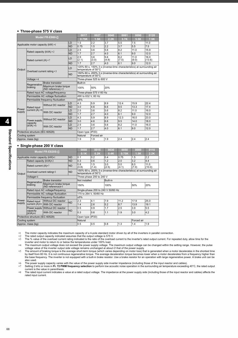
Standard Specifications
4
68
Three-phase 575 V class
Single-phase 200 V class
The motor capacity indicates the maximum capacity of a 4-pole standard motor driven by all of the inverters in parallel connection. The rated output capacity indicated assumes that the output voltage is 575 V. The % value of the overload current rating indicated is the ratio of the overload current to the inverter's rated output current. For repeated duty, allow time for the
inverter and motor to return to or below the temperatures under 100% load. The maximum output voltage does not exceed the power supply voltage. The maximum output voltage can be changed within the setting range. However, the pulse
voltage value of the inverter output side voltage remains unchanged at about√2 that of the power supply. The amount of braking torque is the average short-term torque (which varies depending on motor loss) that is generated when a motor decelerates in the shortest time
by itself from 60 Hz. It is not continuous regenerative torque. The average deceleration torque becomes lower when a motor decelerates from a frequency higher than the base frequency. The inverter is not equipped with a built-in brake resistor. Use a brake resistor for an operation with large regenerative power. A brake unit can be also used.
The power supply capacity varies with the value of the power supply side inverter impedance (including those of the input reactor and cables). Setting 2 kHz or more in Pr. 72 PWM frequency selection to perform low acoustic noise operation in the surrounding air temperature exceeding 40°C, the rated output
current is the value in parenthesis. The rated input current indicates a value at a rated output voltage. The impedance at the power supply side (including those of the input reactor and cables) affects the
rated input current.
Model FR-E860-[] 0017 0027 0040 0061 0090 01200.75K 1.5K 2.2K 3.7K 5.5K 7.5K
Applicable motor capacity (kW) LD 1.5 2.2 3.7 5.5 7.5 11.0ND 0.75 1.5 2.2 3.7 5.5 7.5
Output
Rated capacity (kVA) LD 2.5 3.6 5.6 8.2 11.0 15.9ND 1.7 2.7 4.0 6.1 9.0 12.0
Rated current (A) LD 2.5
(2.1)3.6(3.0)
5.6(4.8)
8.2(7.0)
11.0(9.0)
16.0(13.6)
ND 1.7 2.7 4.0 6.1 9.0 12.0
Overload current rating LD 120% 60 s, 150% 3 s (inverse-time characteristics) at surrounding air
temperature of 50°C
ND 150% 60 s, 200% 3 s (inverse-time characteristics) at surrounding air temperature of 50°C
Voltage Three-phase 525 to 600 V
Regenerative braking
Brake transistor Built-inMaximum brake torque (ND reference) 100% 50% 20%
Power supply
Rated input AC voltage/frequency Three-phase 575 V 60 HzPermissible AC voltage fluctuation 490 to 632 V, 60 HzPermissible frequency fluctuation ±5%
Rated input current (A)
Without DC reactorLD 4.3 5.9 8.9 12.4 15.9 22.4ND 3.0 4.6 6.6 9.5 13.3 17.4
With DC reactorLD 2.5 3.6 5.6 8.2 11.0 16.0ND 1.7 2.7 4.0 6.1 9.0 12.0
Power supply capacity (kVA)
Without DC reactorLD 4.3 5.9 8.9 12.3 16.0 23.0ND 3.0 4.6 6.6 9.5 14.0 18.0
With DC reactorLD 2.5 3.6 5.6 8.2 11.0 16.0ND 1.7 2.7 4.0 6.1 9.0 12.0
Protective structure (IEC 60529) Open type (IP20)Cooling system Natural Forced airApprox. mass (kg) 1.9 1.9 1.9 2.4 2.4 2.4
Model FR-E820S-[] 0008 0015 0030 0050 0080 01100.1K 0.2K 0.4K 0.75K 1.5K 2.2K
Applicable motor capacity (kW) ND 0.1 0.2 0.4 0.75 1.5 2.2
Output
Rated capacity (kVA) ND 0.3 0.6 1.2 2.0 3.2 4.4
Rated current (A) ND 0.8(0.8)
1.5(1.4)
3.0(2.5)
5.0(4.1)
8.0(7.0)
11.0(10.0)
Overload current rating ND 150% 60 s, 200% 3 s (inverse-time characteristics) at surrounding air temperature of 50°C
Voltage Three-phase 200 to 240 V
Regenerative braking
Brake transistor Not installed Built-inMaximum brake torque (ND reference) 150% 100% 50% 20%
Power supply
Rated input AC voltage/frequency Single-phase 200 to 240 V 50/60 HzPermissible AC voltage fluctuation 170 to 264 V, 50/60 Hz Permissible frequency fluctuation ±5%Rated input current (A)
Without DC reactorND
2.3 4.1 7.9 11.2 17.9 25.0 With DC reactor 1.4 2.6 5.2 8.7 13.9 19.1
Power supply capacity (kVA)
Without DC reactorND
0.5 0.9 1.7 2.5 3.9 5.5 With DC reactor 0.3 0.6 1.1 1.9 3.0 4.2
Protective structure (IEC 60529) Open type (IP20)Cooling system Natural Forced airApprox. mass (kg) 0.5 0.5 0.8 1.3 1.4 1.9
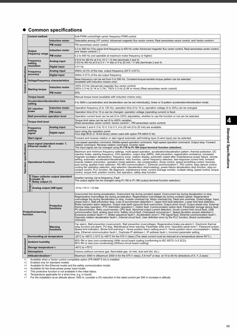
4
Standard Specifications
Common specifications
Available when a Vector control compatible option (FR-A8AP E kit) is installed. Enabled only for standard models. Available for the Ethernet model and the safety communication model. Available for the three-phase power input model. This protective function is not available in the initial status. Temperature applicable for a short time, e.g. in transit. For the installation at an altitude above 1000 m, consider a 3% reduction in the rated current per 500 m increase in altitude.
Con
trol
spe
cific
atio
ns
Control method Soft-PWM control/high carrier frequency PWM controlInduction motor Selectable among V/F control, Advanced magnetic flux vector control, Real sensorless vector control, and Vector controlPM motor PM sensorless vector control
Output frequency range
Induction motor 0.2 to 590 Hz (The upper-limit frequency is 400 Hz under Advanced magnetic flux vector control, Real sensorless vector control, and Vector control.)
PM motor 0.2 to 400 Hz (not operable at maximum motor frequency or higher)
Frequency settingresolution
Analog input 0.015 Hz /60 Hz at 0 to 10 V / 12 bits (terminals 2 and 4)0.03 Hz /60 Hz at 0 to 5 V / 11 bits or 0 to 20 mA / 11 bits (terminals 2 and 4)
Digital input 0.01 Hz
Frequencyaccuracy
Analog input Within ±0.2% of the max. output frequency (25°C ±10°C)Digital input Within 0.01% of the set output frequency
Voltage/frequency characteristics Base frequency can be set from 0 to 590 Hz. Constant-torque/variable torque pattern can be selected.(available with induction motors only)
Starting torqueInduction motor 150% 0.5 Hz (Advanced magnetic flux vector control)
200% 0.3 Hz (0.1K to 3.7K), 150% 0.3 Hz (5.5K or more) (Real sensorless vector control)PM motor 50%
Torque boost Manual torque boost (available with induction motors only)Acceleration/deceleration time setting 0 to 3600 s (acceleration and deceleration can be set individually), linear or S-pattern acceleration/deceleration mode
DC injection brake
Induction motor Operation frequency (0 to 120 Hz), operation time (0 to 10 s), operation voltage (0 to 30%) can be changed.PM motor Operation time (0 to 10 s) can be changed, operation voltage (operating current) is fixed.
Stall prevention operation level Operation current level can be set (0 to 220% adjustable), whether to use the function or not can be selected.
Torque limit level Torque limit value can be set (0 to 400% variable). (Real sensorless vector control, Vector control, PM sensorless vector control)
Ope
ratio
n sp
ecifi
catio
ns
Frequency settingsignal
Analog input Terminals 2 and 4: 0 to 10 V, 0 to 5 V, 4 to 20 mA (0 to 20 mA) are available.
Digital input Input using the operation panel.Four-digit BCD or 16-bit binary (when used with option FR-A8AX E kit)
Start signal Forward and reverse rotation or start signal automatic self-holding input (3-wire input) can be selected.
Input signal (standard model: 7, Ethernet model: 2)
Low-speed operation command, Middle-speed operation command, High-speed operation command, Output stop, Forward rotation command, Reverse rotation command, Inverter resetThe input signal can be changed using Pr.178 to Pr.189 (input terminal function selection).
Operational functions
Maximum and minimum frequency settings, multi-speed operation, acceleration/deceleration pattern, thermal protection, DC injection brake, starting frequency, JOG operation, output stop (MRS), stall prevention, regeneration avoidance, increased magnetic excitation deceleration, frequency jump, rotation display, automatic restart after instantaneous power failure, remote setting, automatic acceleration/deceleration, retry function, carrier frequency selection, fast-response current limit, forward/reverse rotation prevention, operation mode selection, slip compensation, droop control, speed smoothing control, traverse, auto tuning, applied motor selection, RS-485 communication, Ethernet communication, PID control, easy dancer control, cooling fan operation selection, stop selection (deceleration stop/coasting), power-failure deceleration stop function, stop-on-contact control, PLC function, life diagnosis, maintenance timer, current average monitor, multiple rating, speed control, torque control, torque limit, position control, test operation, safety stop function
Out
put s
igna
l Open collector output (standard model: 2)Relay output (1)
Inverter running, Up to frequency, FaultThe output signal can be changed using Pr.190 to Pr.196 (output terminal function selection).
Analog output (AM type) -10 to +10 V / 12 bits
Protective/warningfunction
Protectivefunctions
Overcurrent trip during acceleration, Overcurrent trip during constant speed, Overcurrent trip during deceleration or stop, Regenerative overvoltage trip during acceleration, Regenerative overvoltage trip during constant speed, Regenerative overvoltage trip during deceleration or stop, Inverter overload trip, Motor overload trip, Heat sink overheat, Undervoltage, Input phase loss, Stall prevention stop, Loss of synchronism detection, Upper limit fault detection, Lower limit fault detection, Brake transistor alarm detection, Output side earth (ground) fault overcurrent, Output short circuit, Output phase loss, External thermal relay operation, PTC thermistor operation, Option fault, Communication option fault, Parameter storage device fault, PU disconnection, Retry count excess, CPU fault, Abnormal output current detection, Inrush current limit circuit fault, USB communication fault, analog input error, Safety circuit fault, Overspeed occurrence, Speed deviation excess detection, Excessive position fault, Brake sequence fault, Acceleration error, PID signal fault, Ethernet communication fault, Opposite rotation deceleration fault, Internal circuit fault, User definition error by the PLC function, Board combination mismatch
Warningfunctions
Fan alarm, Stall prevention (overcurrent), Stall prevention (overvoltage), Regenerative brake pre-alarm, Electronic thermal relay function pre-alarm, PU stop, Maintenance timer warning, Parameter write error, Operation panel lock, Password locked, Speed limit indication, Stroke limit warning, Home position return setting error, Home position return uncompleted, Safety stop, Ethernet communication fault, Duplicate IP address, IP address fault, Incorrect parameter setting
Envi
ronm
ent Surrounding air temperature -20°C to +60°C (-10°C to +60°C for the 575 V class) (The rated current must be reduced at a temperature above 50°C.)
Ambient humidity 95% RH or less (non-condensing) (With circuit board coating (conforming to IEC 60721-3-3 3C2))90% RH or less (non-condensing) (Without circuit board coating)
Storage temperature -40°C to +70°C Atmosphere Indoors (without corrosive gas, flammable gas, oil mist, dust and dirt, etc.)Altitude/vibration Maximum 3000 m (Maximum 2000 m for the 575 V class), 5.9 m/s2 or less at 10 to 55 Hz (directions of X, Y, Z axes)
69
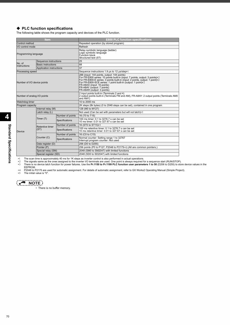
Standard Specifications
4
70
PLC function specificationsThe following table shows the program capacity and devices of the PLC function.
The scan time is approximately 40 ms for 1K steps as inverter control is also performed in actual operations. The signals same as the ones assigned to the inverter I/O terminals are used. One point is always required for a sequence start (RUN/STOP). There is no device latch function for power failures. Use the Pr.1150 to Pr.1199 PLC function user parameters 1 to 50 (D206 to D255) to store device values in the
EEPROM. P2048 to P2175 are used for automatic assignment. For details of automatic assignment, refer to GX Works2 Operating Manual (Simple Project). The initial value is "0".
NOTE • There is no buffer memory.
Item E800 PLC function specificationsControl method Repeated operation (by stored program)I/O control mode Refresh
Programming languageRelay symbolic language (ladder)Logic symbolic languageFunction blockStructured text (ST)
No. of instructions
Sequence instructions 25Basic instructions 88Application instructions 37
Processing speed Sequence instructions 1.9 μs to 12 μs/step
Number of I/O device points
288 (input: 144 points, output: 144 points)For FR-E800 series: 10 points built-in (input: 7 points, output: 3 points)For FR-E800-E series: 3 points built-in (input: 2 points, output: 1 point)For FR-E800-SCE series: 1 point built-in (output: 1 point)FR-A8AX (input: 16 points)FR-A8AY (output: 7 points)FR-A8AR (output: 3 points)
Number of analog I/O points2 input points built-in (Terminals 2 and 4)2 output points built-in (Terminals FM and AM), FR-A8AY: 2 output points (Terminals AM0 and AM1)
Watchdog timer 10 to 2000 msProgram capacity 2K steps (8k bytes) (0 to 2048 steps can be set), contained in one program
Device
Internal relay (M) 128 (M0 to M127)Latch relay (L) Not used (Can be set with parameters but will not latch)
Timer (T)Number of points 16 (T0 to T15)
Specifications 100 ms timer: 0.1 to 3276.7 s can be set10 ms timer: 0.01 to 327.67 s can be set
Retentive timer (ST)
Number of points 16 (ST0 to ST15)
Specifications 100 ms retentive timer: 0.1 to 3276.7 s can be set10 ms retentive timer: 0.01 to 327.67 s can be set
Counter (C)Number of points 16 (C0 to C15)
Specifications Normal counter: Setting range 1 to 32767Interrupt program counter: Not used
Data register (D) 256 (D0 to D255)Pointer (P) 256 points (P0 to P127, P2048 to P2175) (All are common pointers.)Special relay (SM) 2048 (SM0 to SM2047) with limited functionsSpecial register (SD) 2048 (SD0 to SD2047) with limited functions
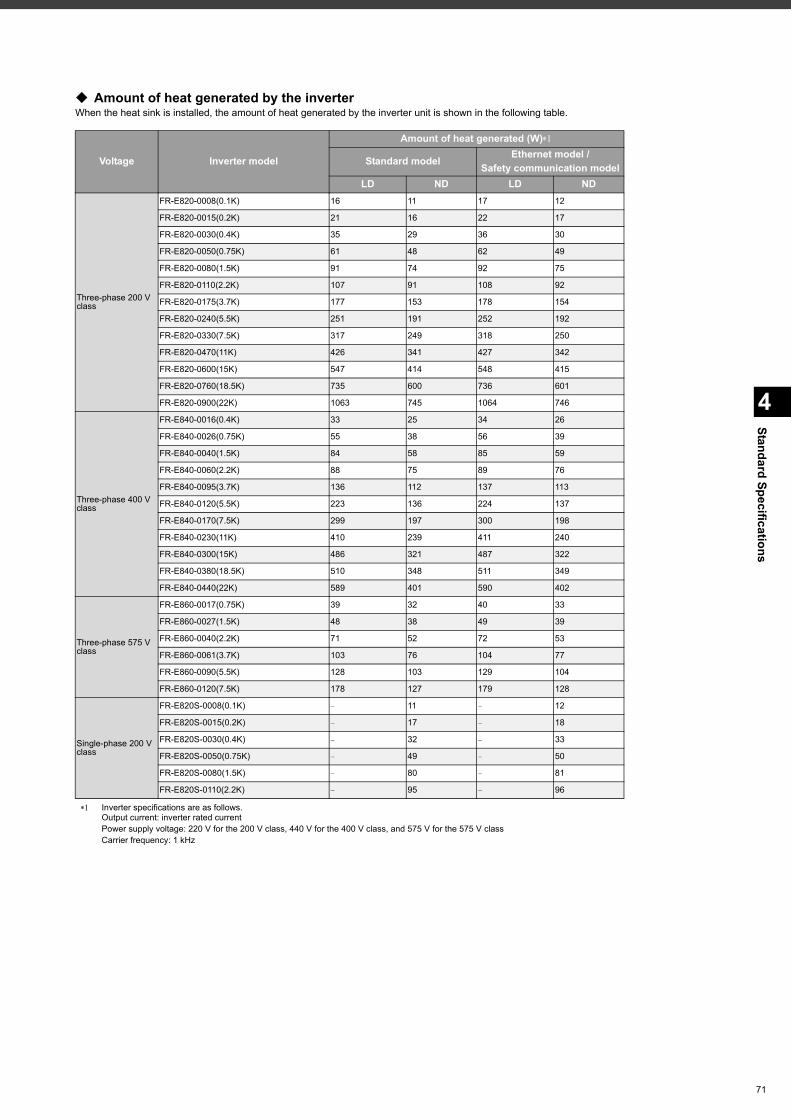
4
Standard Specifications
Amount of heat generated by the inverterWhen the heat sink is installed, the amount of heat generated by the inverter unit is shown in the following table.
Inverter specifications are as follows.Output current: inverter rated currentPower supply voltage: 220 V for the 200 V class, 440 V for the 400 V class, and 575 V for the 575 V classCarrier frequency: 1 kHz
Voltage Inverter model
Amount of heat generated (W)
Standard model Ethernet model / Safety communication model
LD ND LD ND
Three-phase 200 V class
FR-E820-0008(0.1K) 16 11 17 12
FR-E820-0015(0.2K) 21 16 22 17
FR-E820-0030(0.4K) 35 29 36 30
FR-E820-0050(0.75K) 61 48 62 49
FR-E820-0080(1.5K) 91 74 92 75
FR-E820-0110(2.2K) 107 91 108 92
FR-E820-0175(3.7K) 177 153 178 154
FR-E820-0240(5.5K) 251 191 252 192
FR-E820-0330(7.5K) 317 249 318 250
FR-E820-0470(11K) 426 341 427 342
FR-E820-0600(15K) 547 414 548 415
FR-E820-0760(18.5K) 735 600 736 601
FR-E820-0900(22K) 1063 745 1064 746
Three-phase 400 V class
FR-E840-0016(0.4K) 33 25 34 26
FR-E840-0026(0.75K) 55 38 56 39
FR-E840-0040(1.5K) 84 58 85 59
FR-E840-0060(2.2K) 88 75 89 76
FR-E840-0095(3.7K) 136 112 137 113
FR-E840-0120(5.5K) 223 136 224 137
FR-E840-0170(7.5K) 299 197 300 198
FR-E840-0230(11K) 410 239 411 240
FR-E840-0300(15K) 486 321 487 322
FR-E840-0380(18.5K) 510 348 511 349
FR-E840-0440(22K) 589 401 590 402
Three-phase 575 V class
FR-E860-0017(0.75K) 39 32 40 33
FR-E860-0027(1.5K) 48 38 49 39
FR-E860-0040(2.2K) 71 52 72 53
FR-E860-0061(3.7K) 103 76 104 77
FR-E860-0090(5.5K) 128 103 129 104
FR-E860-0120(7.5K) 178 127 179 128
Single-phase 200 V class
FR-E820S-0008(0.1K) - 11 - 12
FR-E820S-0015(0.2K) - 17 - 18
FR-E820S-0030(0.4K) - 32 - 33
FR-E820S-0050(0.75K) - 49 - 50
FR-E820S-0080(1.5K) - 80 - 81
FR-E820S-0110(2.2K) - 95 - 96
71
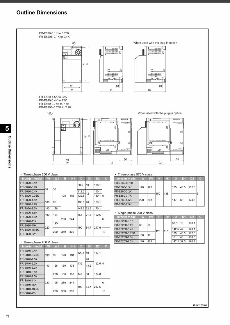
Outline D
imensions
5
72
(Unit: mm)
DD1
HH1
W1W
φC
D2D1
W1W
H1 HD1
D
φC
· FR-E820-0.1K to 0.75K· FR-E820S-0.1K to 0.4K
· FR-E820-1.5K to 22K· FR-E840-0.4K to 22K· FR-E860-0.75K to 7.5K· FR-E820S-0.75K to 2.2K
D1D2
When used with the plug-in option
When used with the plug-in option
• Three-phase 200 V class
• Three-phase 400 V class
• Three-phase 575 V class
• Single-phase 200 V class
Inverter model W W1 H H1 D D1 D2 CFR-E820-0.1K
68 56
128 118
80.5 10 108.1
5
FR-E820-0.2KFR-E820-0.4K 112.5
42140.1
FR-E820-0.75K 132.5 160.1FR-E820-1.5K
108 96 135.5 46 163.1FR-E820-2.2KFR-E820-3.7K 140 128 142.5 52.5 170.1FR-E820-5.5K
180 164260 244
165 71.5 192.66
FR-E820-7.5KFR-E820-11K
220195
190 84.7 217.6FR-E820-15KFR-E820-18.5K
200 350 330 10FR-E820-22K
Inverter model W W1 H H1 D D1 D2 CFR-E840-0.4K
108 96 128 118129.5 40 157.1
5
FR-E840-0.75KFR-E840-1.5K
13546
162.6FR-E840-2.2K140 128 150 138 43.5
FR-E840-3.7KFR-E840-5.5K
220
208 150 138 147 68 174.6FR-E840-7.5KFR-E840-11K
195 260 244190 84.7 217.6
6FR-E840-15KFR-E840-18.5K
200 350 330 10FR-E840-22K
Inverter model W W1 H H1 D D1 D2 CFR-E860-0.75K
140 128
150 138
135 43.5 162.6
5
FR-E860-1.5KFR-E860-2.2KFR-E860-3.7K
220 208 147 68 174.6FR-E860-5.5KFR-E860-7.5K
Inverter model W W1 H H1 D D1 D2 CFR-E820S-0.1K
68 56
128 118
80.5 10 108.1
5
FR-E820S-0.2KFR-E820S-0.4K 142.5 42 170.1FR-E820S-0.75K
108 96135 45.5 162.6
FR-E820S-1.5K 161 46 188.6FR-E820S-2.2K 140 128 142.5 52.5 170.1
Outline Dimensions

73
MEMO
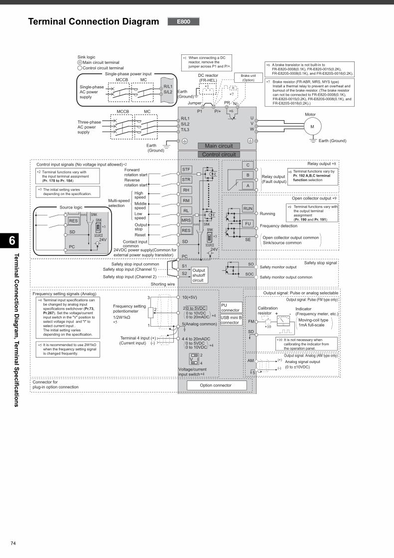
Terminal C
onnection Diagram
, Terminal Specifications
6
74
Earth (Ground)
Motor
M
Earth (Ground)
Three-phaseAC powersupply
MCCB MC
R/L1
P1 P/+
PR N/-
S/L2T/L3
UVW
Earth (Ground)
Forwardrotation startReverserotation start
Middlespeed
Highspeed
Lowspeed
OutputstopReset
Contact input common
STR
STF
RH
RM
RL
MRS
SD
Relay output ��
Relay output(Fault output)
Running
Frequency detection
Open collector output ��
Safety stop signal
Open collector output commonSink/source common
FU
RUN
SE
A
B
C
FM
SD
Indicator (Frequency meter, etc.)+ -
Moving-coil type1mA full-scale
Calibration resistor
Frequency setting signals (Analog)
2 0 to 5VDC
10(+5V)
2
3
1
4 4 to 20mADC
Frequency settingpotentiometer1/2W1kΩ
Terminal 4 input(Current input)
(+)(-)
5(Analog common)��
Connector forplug-in option connection Option connector
PUconnector
USB mini B connector
Jumper
DC reactor(FR-HEL)
��
��
��
�
�
��
Output signal: Pulse (FM type only)
Output signal: Analog (AM type only)
Multi-speed selection Terminal functions vary with
the output terminal assignment (Pr. 190 and Pr. 191)
Terminal functions vary by Pr. 192 A,B,C terminal function selection
�
0 to 5VDC0 to 10VDC
Brake unit(Option)
Voltage/current input switch
Main circuitControl circuit
R
RES
Control circuit terminalMain circuit terminal
Sink logic
It is recommended to use 2W1kΩ when the frequency setting signal is changed frequently.
��
Terminal input specifications can be changed by analog input specifications switchover (Pr.73, Pr.267). Set the voltage/current input switch in the "V" position to select voltage input and "I" to select current input .The initial setting varies depending on the specification.
�
It is not necessary when calibrating the indicator from the operation panel.
��
When connecting a DC reactor, remove the jumper across P1 and P/+. A brake transistor is not built-in to
FR-E820-0008(0.1K), FR-E820-0015(0.2K), FR-E820S-0008(0.1K), and FR-E820S-0016(0.2K).
Brake resistor (FR-ABR, MRS, MYS type)Install a thermal relay to prevent an overheat and burnout of the brake resistor. (The brake resistor can not be connected to FR-E820-0008(0.1K), FR-E820-0015(0.2K), FR-E820S-0008(0.1K), and FR-E820S-0016(0.2K).)
��
��
��
��
��
Terminal functions vary with the input terminal assignment (Pr. 178 to Pr. 184)
��
The initial setting varies depending on the specification.
��
��
Control input signals (No voltage input allowed)��
(-)
(+) Analog signal output(0 to ±10VDC)
AM
5
4
2IV
0 to 10VDC0 to 20mADC
Safety stop input common
24VDC power supply(Common for external power supply transistor) PC
SINKSOURCE
S1
S2Safety stop input (Channel 1)
Shorting wire
Safety stop input (Channel 2)
24V
Output shutoffcircuit
Safety monitor output
Safety monitor output common
SO
SOC
SINK
SOURCE
Output signal: Pulse or analog selectable
Single-phaseAC powersupply
MCCB MCR/L1S/L2
Single-phase power input
Source logicS
SD
RES��
PC
SINKSOURCE
24V
SINK
SOURCE
Terminal Connection Diagram
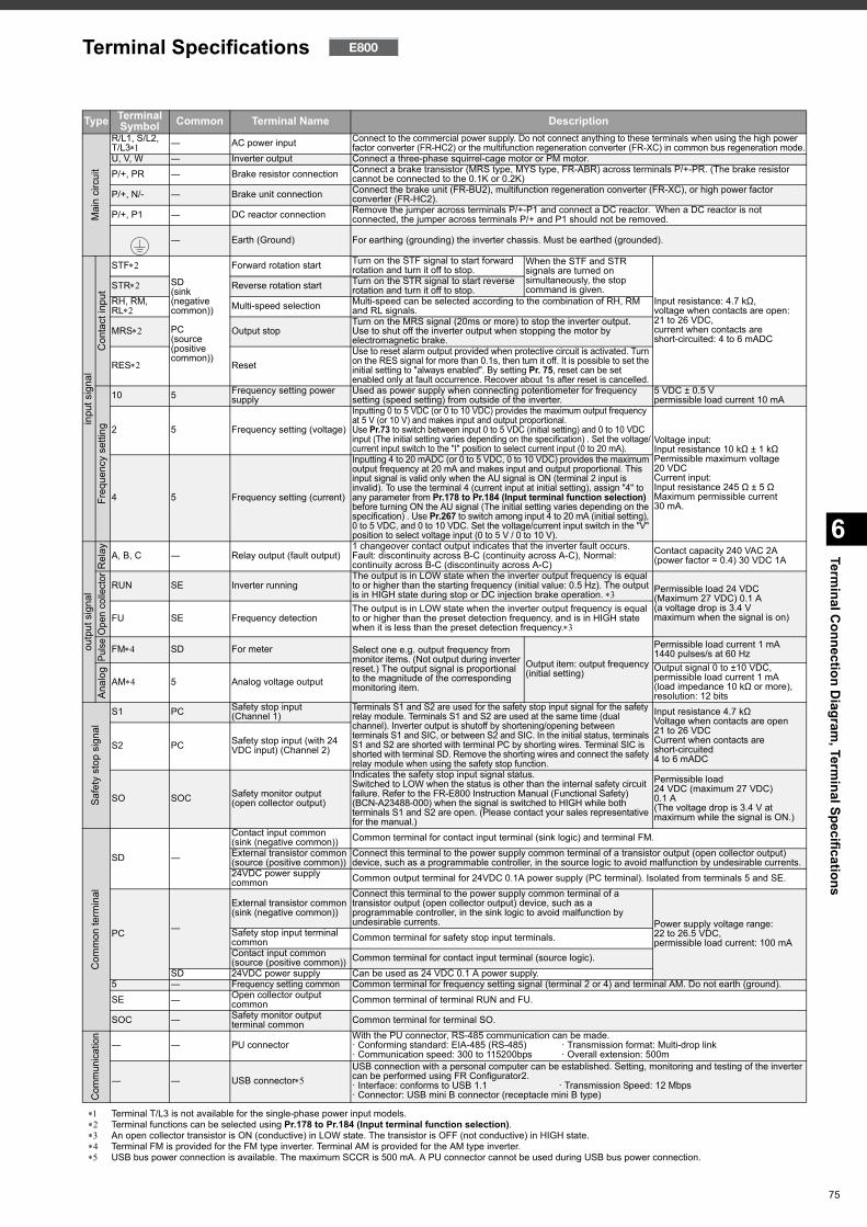
6
Terminal C
onnection Diagram
, Terminal Specifications
Terminal T/L3 is not available for the single-phase power input models. Terminal functions can be selected using Pr.178 to Pr.184 (Input terminal function selection). An open collector transistor is ON (conductive) in LOW state. The transistor is OFF (not conductive) in HIGH state. Terminal FM is provided for the FM type inverter. Terminal AM is provided for the AM type inverter. USB bus power connection is available. The maximum SCCR is 500 mA. A PU connector cannot be used during USB bus power connection.
Type Terminal Symbol Common Terminal Name Description
Mai
n ci
rcui
t
R/L1, S/L2, T/L3 ― AC power input Connect to the commercial power supply. Do not connect anything to these terminals when using the high power
factor converter (FR-HC2) or the multifunction regeneration converter (FR-XC) in common bus regeneration mode.U, V, W ― Inverter output Connect a three-phase squirrel-cage motor or PM motor.P/+, PR ― Brake resistor connection Connect a brake transistor (MRS type, MYS type, FR-ABR) across terminals P/+-PR. (The brake resistor
cannot be connected to the 0.1K or 0.2K)P/+, N/- ― Brake unit connection Connect the brake unit (FR-BU2), multifunction regeneration converter (FR-XC), or high power factor
converter (FR-HC2).P/+, P1 ― DC reactor connection Remove the jumper across terminals P/+-P1 and connect a DC reactor. When a DC reactor is not
connected, the jumper across terminals P/+ and P1 should not be removed.
― Earth (Ground) For earthing (grounding) the inverter chassis. Must be earthed (grounded).
inpu
t sig
nal
Con
tact
inpu
t
STF
SD (sink (negative common))
PC (source (positive common))
Forward rotation start Turn on the STF signal to start forward rotation and turn it off to stop.
When the STF and STR signals are turned on simultaneously, the stop command is given.
Input resistance: 4.7 kΩ,voltage when contacts are open: 21 to 26 VDC,current when contacts are short-circuited: 4 to 6 mADC
STR Reverse rotation start Turn on the STR signal to start reverse rotation and turn it off to stop.
RH, RM, RL Multi-speed selection Multi-speed can be selected according to the combination of RH, RM
and RL signals.
MRS Output stopTurn on the MRS signal (20ms or more) to stop the inverter output.Use to shut off the inverter output when stopping the motor by electromagnetic brake.
RES ResetUse to reset alarm output provided when protective circuit is activated. Turn on the RES signal for more than 0.1s, then turn it off. It is possible to set the initial setting to "always enabled". By setting Pr. 75, reset can be set enabled only at fault occurrence. Recover about 1s after reset is cancelled.
Freq
uenc
y se
tting
10 5 Frequency setting power supply
Used as power supply when connecting potentiometer for frequency setting (speed setting) from outside of the inverter.
5 VDC ± 0.5 Vpermissible load current 10 mA
2 5 Frequency setting (voltage)
Inputting 0 to 5 VDC (or 0 to 10 VDC) provides the maximum output frequency at 5 V (or 10 V) and makes input and output proportional. Use Pr.73 to switch between input 0 to 5 VDC (initial setting) and 0 to 10 VDC input (The initial setting varies depending on the specification) . Set the voltage/current input switch to the "I" position to select current input (0 to 20 mA).
Voltage input:Input resistance 10 kΩ ± 1 kΩPermissible maximum voltage20 VDCCurrent input:Input resistance 245 Ω ± 5 ΩMaximum permissible current30 mA.
4 5 Frequency setting (current)
Inputting 4 to 20 mADC (or 0 to 5 VDC, 0 to 10 VDC) provides the maximum output frequency at 20 mA and makes input and output proportional. This input signal is valid only when the AU signal is ON (terminal 2 input is invalid). To use the terminal 4 (current input at initial setting), assign "4" to any parameter from Pr.178 to Pr.184 (Input terminal function selection) before turning ON the AU signal (The initial setting varies depending on the specification) . Use Pr.267 to switch among input 4 to 20 mA (initial setting), 0 to 5 VDC, and 0 to 10 VDC. Set the voltage/current input switch in the "V" position to select voltage input (0 to 5 V / 0 to 10 V).
outp
ut s
igna
lR
elay A, B, C ― Relay output (fault output)
1 changeover contact output indicates that the inverter fault occurs.Fault: discontinuity across B-C (continuity across A-C), Normal: continuity across B-C (discontinuity across A-C)
Contact capacity 240 VAC 2A (power factor = 0.4) 30 VDC 1A
Ope
n co
llect
or
RUN SE Inverter runningThe output is in LOW state when the inverter output frequency is equal to or higher than the starting frequency (initial value: 0.5 Hz). The output is in HIGH state during stop or DC injection brake operation. Permissible load 24 VDC
(Maximum 27 VDC) 0.1 A(a voltage drop is 3.4 Vmaximum when the signal is on)FU SE Frequency detection
The output is in LOW state when the inverter output frequency is equal to or higher than the preset detection frequency, and is in HIGH state when it is less than the preset detection frequency.
Pulse FM SD For meter Select one e.g. output frequency from
monitor items. (Not output during inverter reset.) The output signal is proportional to the magnitude of the corresponding monitoring item.
Output item: output frequency (initial setting)
Permissible load current 1 mA1440 pulses/s at 60 Hz
Anal
og
AM 5 Analog voltage outputOutput signal 0 to ±10 VDC,permissible load current 1 mA(load impedance 10 kΩ or more),resolution: 12 bits
Safe
ty s
top
sign
al
S1 PC Safety stop input(Channel 1)
Terminals S1 and S2 are used for the safety stop input signal for the safety relay module. Terminals S1 and S2 are used at the same time (dual channel). Inverter output is shutoff by shortening/opening between terminals S1 and SIC, or between S2 and SIC. In the initial status, terminals S1 and S2 are shorted with terminal PC by shorting wires. Terminal SIC is shorted with terminal SD. Remove the shorting wires and connect the safety relay module when using the safety stop function.
Input resistance 4.7 kΩVoltage when contacts are open21 to 26 VDCCurrent when contacts are short-circuited4 to 6 mADC
S2 PC Safety stop input (with 24 VDC input) (Channel 2)
SO SOC Safety monitor output(open collector output)
Indicates the safety stop input signal status.Switched to LOW when the status is other than the internal safety circuit failure. Refer to the FR-E800 Instruction Manual (Functional Safety) (BCN-A23488-000) when the signal is switched to HIGH while both terminals S1 and S2 are open. (Please contact your sales representative for the manual.)
Permissible load24 VDC (maximum 27 VDC)0.1 A(The voltage drop is 3.4 V at maximum while the signal is ON.)
Com
mon
term
inal
SD ―
Contact input common (sink (negative common)) Common terminal for contact input terminal (sink logic) and terminal FM.External transistor common (source (positive common))
Connect this terminal to the power supply common terminal of a transistor output (open collector output) device, such as a programmable controller, in the source logic to avoid malfunction by undesirable currents.
24VDC power supply common Common output terminal for 24VDC 0.1A power supply (PC terminal). Isolated from terminals 5 and SE.
PC ―
External transistor common (sink (negative common))
Connect this terminal to the power supply common terminal of a transistor output (open collector output) device, such as a programmable controller, in the sink logic to avoid malfunction by undesirable currents. Power supply voltage range:
22 to 26.5 VDC,permissible load current: 100 mA
Safety stop input terminal common Common terminal for safety stop input terminals.Contact input common (source (positive common)) Common terminal for contact input terminal (source logic).
SD 24VDC power supply Can be used as 24 VDC 0.1 A power supply.5 ― Frequency setting common Common terminal for frequency setting signal (terminal 2 or 4) and terminal AM. Do not earth (ground).SE ― Open collector output
common Common terminal of terminal RUN and FU.
SOC ― Safety monitor output terminal common Common terminal for terminal SO.
Com
mun
icatio
n
― ― PU connectorWith the PU connector, RS-485 communication can be made.· Conforming standard: EIA-485 (RS-485) · Transmission format: Multi-drop link· Communication speed: 300 to 115200bps · Overall extension: 500m
― ― USB connectorUSB connection with a personal computer can be established. Setting, monitoring and testing of the inverter can be performed using FR Configurator2.· Interface: conforms to USB 1.1 · Transmission Speed: 12 Mbps· Connector: USB mini B connector (receptacle mini B type)
Terminal Specifications
75
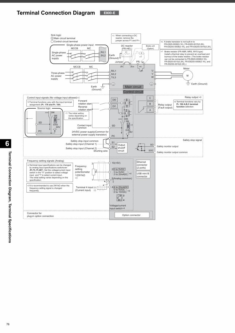
Terminal C
onnection Diagram
, Terminal Specifications
6
76
Control circuit terminalMain circuit terminal
Sink logic
Motor
Earth (Ground)
Three-phaseAC powersupply
MCCB MC
Earth (Ground)
Main circuitControl circuit
Earth (Ground)
R/L1
P1 P/+
PR N/-
S/L2T/L3
UVW
Jumper
DC reactor(FR-HEL)
��
��
��
��
R
Brake unit(Option)
When connecting a DC reactor, remove the jumper across P1 and P/+.
��
Forwardrotation startReverserotation start
Frequency setting signals (Analog)
Frequencysettingpotentiometer1/2W1kΩ
Terminal 4 input(Current input)
(+)(-)
��
Terminal input specifications can be changed by analog input specifications switchover (Pr.73, Pr.267). Set the voltage/current input switch in the "V" position to select voltage input and "I" to select current input .The initial setting varies depending on the specification.
�
Safety stop input common
24VDC power supply(Common for external power supply transistor)
Safety stop input (Channel 1)
Shorting wireSafety stop input (Channel 2)
It is recommended to use 2W1kΩ when the frequency setting signal is changed frequently.
��
2 0 to 5VDC
10(+5V)
2
3
1
4 4 to 20mADC
5(Analog common)
Connector forplug-in option connection Option connector
USB mini B connector
Ethernet connector (2 ports)
�
�
�
0 to 5VDC0 to 10VDC
Voltage/current input switch
0 to 5VDC0 to 20mADC
4
2IV
PC
S1
S2Output shutoffcircuit
SD
SOURCE
24V
SINKSINK
SOURCE
DI1
DI0
A
B
C
Safety stop signal
Safety monitor output
Safety monitor output common
SO
SOC
Relay output ��
Relay output(Fault output)
Terminal functions vary by Pr. 192 A,B,C terminal function selection
��
M
A brake transistor is not built-in to FR-E820-0008(0.1K), FR-E820-0015(0.2K), FR-E820S-0008(0.1K), and FR-E820S-0016(0.2K).
Brake resistor (FR-ABR, MRS, MYS type)Install a thermal relay to prevent an overheat and burnout of the brake resistor. (The brake resistor can not be connected to FR-E820-0008(0.1K), FR-E820-0015(0.2K), FR-E820S-0008(0.1K), and FR-E820S-0016(0.2K).)
��
��Single-phaseAC powersupply
MCCB MCR/L1S/L2
Single-phase power input
Control input signals (No voltage input allowed)��
Terminal functions vary with the input terminal assignment (Pr. 178 and Pr. 184)
��
The initial setting varies depending on the specification.
��
Contact input common
Source logic
SD��
PC
SINKSOURCE
24V
SINK
SOURCE
Terminal Connection Diagram
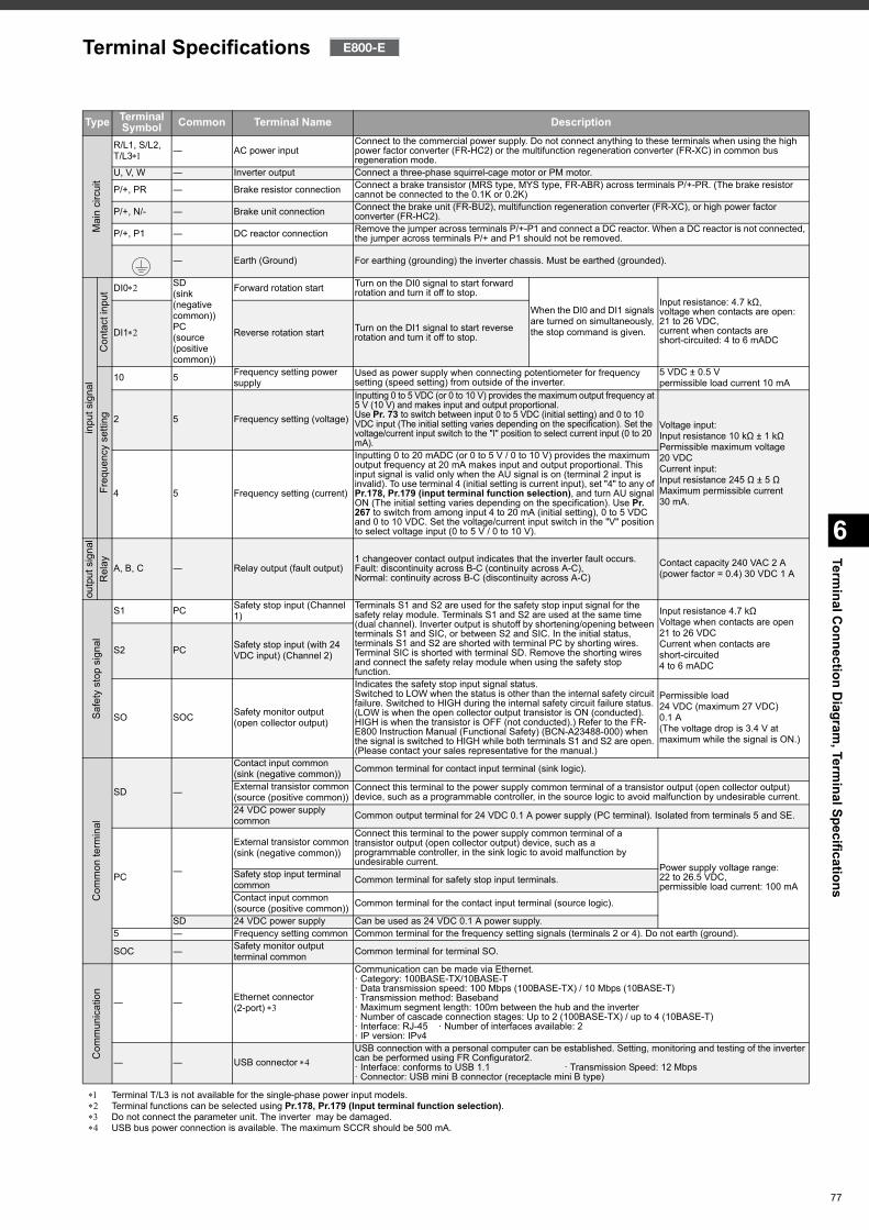
6
Terminal C
onnection Diagram
, Terminal Specifications
Terminal T/L3 is not available for the single-phase power input models. Terminal functions can be selected using Pr.178, Pr.179 (Input terminal function selection). Do not connect the parameter unit. The inverter may be damaged. USB bus power connection is available. The maximum SCCR should be 500 mA.
Type TerminalSymbol Common Terminal Name Description
Mai
n ci
rcui
t
R/L1, S/L2,T/L3 ― AC power input
Connect to the commercial power supply. Do not connect anything to these terminals when using the high power factor converter (FR-HC2) or the multifunction regeneration converter (FR-XC) in common bus regeneration mode.
U, V, W ― Inverter output Connect a three-phase squirrel-cage motor or PM motor.
P/+, PR ― Brake resistor connection Connect a brake transistor (MRS type, MYS type, FR-ABR) across terminals P/+-PR. (The brake resistor cannot be connected to the 0.1K or 0.2K)
P/+, N/- ― Brake unit connection Connect the brake unit (FR-BU2), multifunction regeneration converter (FR-XC), or high power factor converter (FR-HC2).
P/+, P1 ― DC reactor connection Remove the jumper across terminals P/+-P1 and connect a DC reactor. When a DC reactor is not connected, the jumper across terminals P/+ and P1 should not be removed.
― Earth (Ground) For earthing (grounding) the inverter chassis. Must be earthed (grounded).
inpu
t sig
nal
Con
tact
inpu
t DI0 SD (sink (negative common))PC (source (positive common))
Forward rotation start Turn on the DI0 signal to start forward rotation and turn it off to stop.
When the DI0 and DI1 signals are turned on simultaneously, the stop command is given.
Input resistance: 4.7 kΩ,voltage when contacts are open: 21 to 26 VDC,current when contacts are short-circuited: 4 to 6 mADC
DI1 Reverse rotation start Turn on the DI1 signal to start reverse rotation and turn it off to stop.
Freq
uenc
y se
tting
10 5 Frequency setting power supply
Used as power supply when connecting potentiometer for frequency setting (speed setting) from outside of the inverter.
5 VDC ± 0.5 Vpermissible load current 10 mA
2 5 Frequency setting (voltage)
Inputting 0 to 5 VDC (or 0 to 10 V) provides the maximum output frequency at 5 V (10 V) and makes input and output proportional. Use Pr. 73 to switch between input 0 to 5 VDC (initial setting) and 0 to 10 VDC input (The initial setting varies depending on the specification). Set the voltage/current input switch to the "I" position to select current input (0 to 20 mA).
Voltage input:Input resistance 10 kΩ ± 1 kΩPermissible maximum voltage20 VDCCurrent input:Input resistance 245 Ω ± 5 ΩMaximum permissible current30 mA.
4 5 Frequency setting (current)
Inputting 0 to 20 mADC (or 0 to 5 V / 0 to 10 V) provides the maximum output frequency at 20 mA makes input and output proportional. This input signal is valid only when the AU signal is on (terminal 2 input is invalid). To use terminal 4 (initial setting is current input), set "4" to any of Pr.178, Pr.179 (input terminal function selection), and turn AU signal ON (The initial setting varies depending on the specification). Use Pr. 267 to switch from among input 4 to 20 mA (initial setting), 0 to 5 VDC and 0 to 10 VDC. Set the voltage/current input switch in the "V" position to select voltage input (0 to 5 V / 0 to 10 V).
outp
ut s
igna
lR
elay A, B, C ― Relay output (fault output)
1 changeover contact output indicates that the inverter fault occurs.Fault: discontinuity across B-C (continuity across A-C), Normal: continuity across B-C (discontinuity across A-C)
Contact capacity 240 VAC 2 A (power factor = 0.4) 30 VDC 1 A
Safe
ty s
top
sign
al
S1 PC Safety stop input (Channel 1)
Terminals S1 and S2 are used for the safety stop input signal for the safety relay module. Terminals S1 and S2 are used at the same time (dual channel). Inverter output is shutoff by shortening/opening between terminals S1 and SIC, or between S2 and SIC. In the initial status, terminals S1 and S2 are shorted with terminal PC by shorting wires. Terminal SIC is shorted with terminal SD. Remove the shorting wires and connect the safety relay module when using the safety stop function.
Input resistance 4.7 kΩVoltage when contacts are open21 to 26 VDCCurrent when contacts are short-circuited4 to 6 mADC
S2 PC Safety stop input (with 24 VDC input) (Channel 2)
SO SOC Safety monitor output(open collector output)
Indicates the safety stop input signal status.Switched to LOW when the status is other than the internal safety circuit failure. Switched to HIGH during the internal safety circuit failure status.(LOW is when the open collector output transistor is ON (conducted). HIGH is when the transistor is OFF (not conducted).) Refer to the FR-E800 Instruction Manual (Functional Safety) (BCN-A23488-000) when the signal is switched to HIGH while both terminals S1 and S2 are open. (Please contact your sales representative for the manual.)
Permissible load24 VDC (maximum 27 VDC)0.1 A(The voltage drop is 3.4 V at maximum while the signal is ON.)
Com
mon
term
inal
SD ―
Contact input common (sink (negative common)) Common terminal for contact input terminal (sink logic).
External transistor common (source (positive common))
Connect this terminal to the power supply common terminal of a transistor output (open collector output) device, such as a programmable controller, in the source logic to avoid malfunction by undesirable current.
24 VDC power supply common Common output terminal for 24 VDC 0.1 A power supply (PC terminal). Isolated from terminals 5 and SE.
PC ―
External transistor common (sink (negative common))
Connect this terminal to the power supply common terminal of a transistor output (open collector output) device, such as a programmable controller, in the sink logic to avoid malfunction by undesirable current. Power supply voltage range:
22 to 26.5 VDC,permissible load current: 100 mA
Safety stop input terminal common Common terminal for safety stop input terminals.
Contact input common (source (positive common)) Common terminal for the contact input terminal (source logic).
SD 24 VDC power supply Can be used as 24 VDC 0.1 A power supply.5 ― Frequency setting common Common terminal for the frequency setting signals (terminals 2 or 4). Do not earth (ground).
SOC ― Safety monitor output terminal common Common terminal for terminal SO.
Com
mun
icat
ion
― ― Ethernet connector (2-port)
Communication can be made via Ethernet.· Category: 100BASE-TX/10BASE-T· Data transmission speed: 100 Mbps (100BASE-TX) / 10 Mbps (10BASE-T)· Transmission method: Baseband· Maximum segment length: 100m between the hub and the inverter· Number of cascade connection stages: Up to 2 (100BASE-TX) / up to 4 (10BASE-T)· Interface: RJ-45 · Number of interfaces available: 2 · IP version: IPv4
― ― USB connector USB connection with a personal computer can be established. Setting, monitoring and testing of the inverter can be performed using FR Configurator2.· Interface: conforms to USB 1.1 · Transmission Speed: 12 Mbps· Connector: USB mini B connector (receptacle mini B type)
Terminal Specifications
77
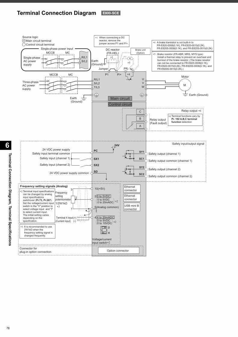
Terminal C
onnection Diagram
, Terminal Specifications
6
78
Terminal Connection Diagram
Control circuit terminalMain circuit terminal
Source logic
Motor
Earth (Ground)
Three-phaseAC powersupply
MCCB MC
Earth (Ground)
Main circuitControl circuit
Earth (Ground)
R/L1
P1 P/+
PR N/-
S/L2T/L3
UVW
Jumper
DC reactor(FR-HEL)
��
��
�
R
Brake unit(Option)
When connecting a DC reactor, remove the jumper across P1 and P/+.
��
Frequency setting signals (Analog)
Frequencysettingpotentiometer1/2W1kΩ
Terminal 4 input(Current input)
(+)(-)
��
Terminal input specifications can be changed by analog input specifications switchover (Pr.73, Pr.267). Set the voltage/current input switch in the "V" position to select voltage input and "I" to select current input.The initial setting varies depending on the specification.
��
It is recommended to use 2W1kΩ when the frequency setting signal is changed frequently.
��
2 0 to 5VDC
10(+5V)
2
3
1
4 4 to 20mADC
5(Analog common)
Connector forplug-in option connection Option connector
USB mini B connector
Ethernet connector
Ethernet connector
��
��
��
0 to 5VDC0 to 10VDC
Voltage/current input switch
0 to 5VDC0 to 20mADC
4
2IV
A
B
C Relay output ��
Relay output(Fault output)
Terminal functions vary by Pr. 192 A,B,C terminal function selection
��
M
A brake transistor is not built-in to FR-E820-0008(0.1K), FR-E820-0015(0.2K), FR-E820S-0008(0.1K), and FR-E820S-0015(0.2K).
Brake resistor (FR-ABR, MRS, MYS type)Install a thermal relay to prevent an overheat and burnout of the brake resistor. (The brake resistor can not be connected to FR-E820-0008(0.1K), FR-E820-0015(0.2K), FR-E820S-0008(0.1K), and FR-E820S-0015(0.2K).)
�
��Single-phaseAC powersupply
MCCB MCR/L1S/L2
Single-phase power input
SD
Safety input terminal common
24 VDC power supply common
24 VDC power supply PC
SX1
SX2
Safety input (channel 1)
Safety input (channel 2)
24V
Safety output (channel 2)
Safety output common (channel 2)
SY2
SC2
Safety output (channel 1)
Safety output common (channel 1)
SY1
SC1
Safety input/output signal
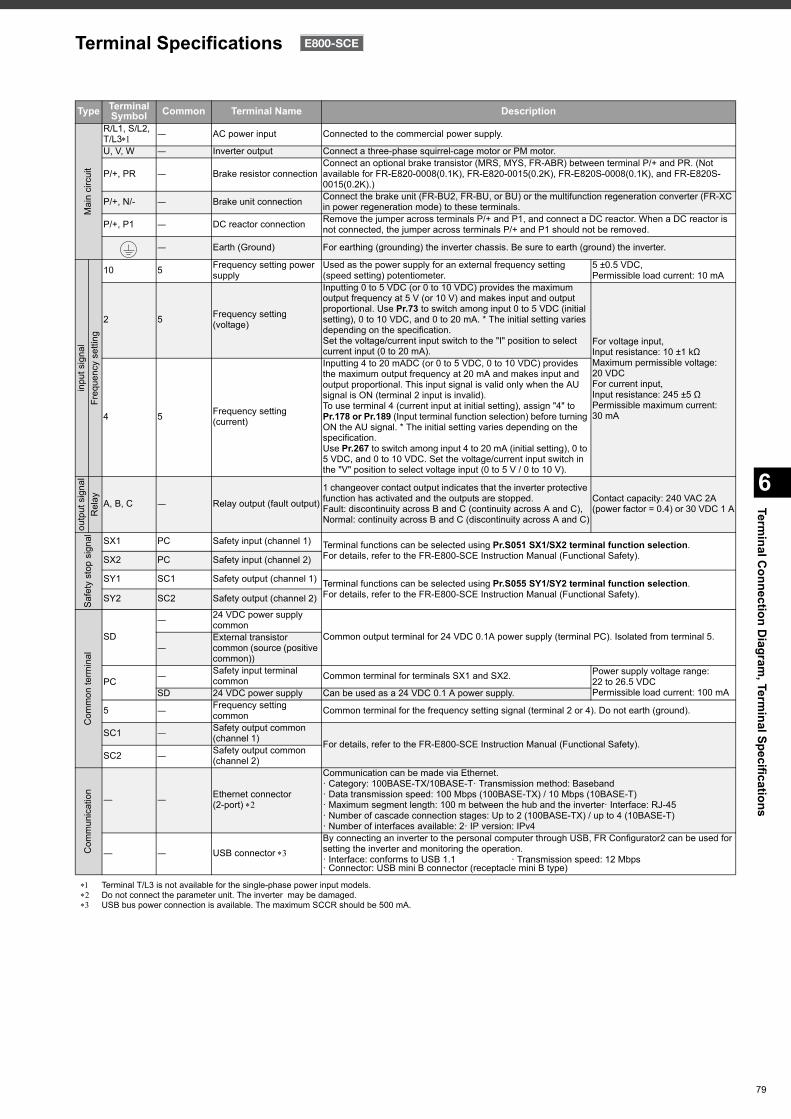
6
Terminal C
onnection Diagram
, Terminal Specifications
Terminal T/L3 is not available for the single-phase power input models. Do not connect the parameter unit. The inverter may be damaged. USB bus power connection is available. The maximum SCCR should be 500 mA.
Type TerminalSymbol Common Terminal Name Description
Mai
n ci
rcui
t
R/L1, S/L2,T/L3 ― AC power input Connected to the commercial power supply.
U, V, W ― Inverter output Connect a three-phase squirrel-cage motor or PM motor.
P/+, PR ― Brake resistor connectionConnect an optional brake transistor (MRS, MYS, FR-ABR) between terminal P/+ and PR. (Not available for FR-E820-0008(0.1K), FR-E820-0015(0.2K), FR-E820S-0008(0.1K), and FR-E820S-0015(0.2K).)
P/+, N/- ― Brake unit connection Connect the brake unit (FR-BU2, FR-BU, or BU) or the multifunction regeneration converter (FR-XC in power regeneration mode) to these terminals.
P/+, P1 ― DC reactor connection Remove the jumper across terminals P/+ and P1, and connect a DC reactor. When a DC reactor is not connected, the jumper across terminals P/+ and P1 should not be removed.
― Earth (Ground) For earthing (grounding) the inverter chassis. Be sure to earth (ground) the inverter.
inpu
t sig
nal
Freq
uenc
y se
tting
10 5 Frequency setting power supply
Used as the power supply for an external frequency setting (speed setting) potentiometer.
5 ±0.5 VDC,Permissible load current: 10 mA
2 5 Frequency setting (voltage)
Inputting 0 to 5 VDC (or 0 to 10 VDC) provides the maximum output frequency at 5 V (or 10 V) and makes input and output proportional. Use Pr.73 to switch among input 0 to 5 VDC (initial setting), 0 to 10 VDC, and 0 to 20 mA. * The initial setting varies depending on the specification.Set the voltage/current input switch to the "I" position to select current input (0 to 20 mA).
For voltage input,Input resistance: 10 ±1 kΩMaximum permissible voltage: 20 VDCFor current input,Input resistance: 245 ±5 ΩPermissible maximum current: 30 mA4 5 Frequency setting
(current)
Inputting 4 to 20 mADC (or 0 to 5 VDC, 0 to 10 VDC) provides the maximum output frequency at 20 mA and makes input and output proportional. This input signal is valid only when the AU signal is ON (terminal 2 input is invalid).To use terminal 4 (current input at initial setting), assign "4" to Pr.178 or Pr.189 (Input terminal function selection) before turning ON the AU signal. * The initial setting varies depending on the specification.Use Pr.267 to switch among input 4 to 20 mA (initial setting), 0 to 5 VDC, and 0 to 10 VDC. Set the voltage/current input switch in the "V" position to select voltage input (0 to 5 V / 0 to 10 V).
outp
ut s
igna
lR
elay A, B, C ― Relay output (fault output)
1 changeover contact output indicates that the inverter protective function has activated and the outputs are stopped.Fault: discontinuity across B and C (continuity across A and C), Normal: continuity across B and C (discontinuity across A and C)
Contact capacity: 240 VAC 2A(power factor = 0.4) or 30 VDC 1 A
Safe
ty s
top
sign
al SX1 PC Safety input (channel 1) Terminal functions can be selected using Pr.S051 SX1/SX2 terminal function selection. For details, refer to the FR-E800-SCE Instruction Manual (Functional Safety).SX2 PC Safety input (channel 2)
SY1 SC1 Safety output (channel 1) Terminal functions can be selected using Pr.S055 SY1/SY2 terminal function selection. For details, refer to the FR-E800-SCE Instruction Manual (Functional Safety).SY2 SC2 Safety output (channel 2)
Com
mon
term
inal
SD
― 24 VDC power supply common
Common output terminal for 24 VDC 0.1A power supply (terminal PC). Isolated from terminal 5.―
External transistor common (source (positive common))
PC ― Safety input terminal common Common terminal for terminals SX1 and SX2. Power supply voltage range:
22 to 26.5 VDCPermissible load current: 100 mASD 24 VDC power supply Can be used as a 24 VDC 0.1 A power supply.
5 ― Frequency setting common Common terminal for the frequency setting signal (terminal 2 or 4). Do not earth (ground).
SC1 ― Safety output common (channel 1) For details, refer to the FR-E800-SCE Instruction Manual (Functional Safety).
SC2 ― Safety output common (channel 2)
Com
mun
icat
ion
― ― Ethernet connector (2-port)
Communication can be made via Ethernet.· Category: 100BASE-TX/10BASE-T· Transmission method: Baseband· Data transmission speed: 100 Mbps (100BASE-TX) / 10 Mbps (10BASE-T)· Maximum segment length: 100 m between the hub and the inverter· Interface: RJ-45· Number of cascade connection stages: Up to 2 (100BASE-TX) / up to 4 (10BASE-T)· Number of interfaces available: 2· IP version: IPv4
― ― USB connector By connecting an inverter to the personal computer through USB, FR Configurator2 can be used for setting the inverter and monitoring the operation.· Interface: conforms to USB 1.1 · Transmission speed: 12 Mbps· Connector: USB mini B connector (receptacle mini B type)
Terminal Specifications
79
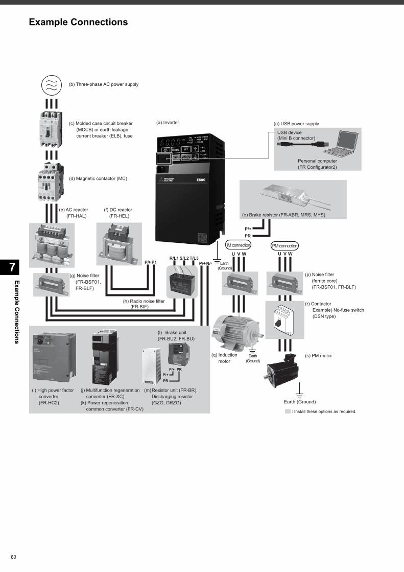
Example C
onnections
7
80
Example Connections
Earth (Ground)
R/L1 S/L2 T/L3N/-P/+
P/+PR
P/+P/+PR
PR
: Install these options as required.
U V W U V W
IM connection PM connection
(c) Molded case circuit breaker(MCCB) or earth leakagecurrent breaker (ELB), fuse
(e) AC reactor(FR-HAL)
(f) DC reactor(FR-HEL) (o) Brake resistor (FR-ABR, MRS, MYS)
(p) Noise filter(ferrite core)(FR-BSF01, FR-BLF)
(r) ContactorExample) No-fuse switch(DSN type)
(s) PM motor
(g) Noise filter(FR-BSF01,FR-BLF)
(i) High power factorconverter(FR-HC2)
(m) Resistor unit (FR-BR),Discharging resistor(GZG, GRZG)
(l) Brake unit(FR-BU2, FR-BU)
(d) Magnetic contactor (MC)
(a) Inverter
(b) Three-phase AC power supply
(n) USB power supply
Personal computer(FR Configurator2)
USB device(Mini B connector)
Earth(Ground)
(q) Inductionmotor
Earth (Ground)
(j) Multifunction regenerationconverter (FR-XC)
(k) Power regenerationcommon converter (FR-CV)
(h) Radio noise filter (FR-BIF)
P1P/+
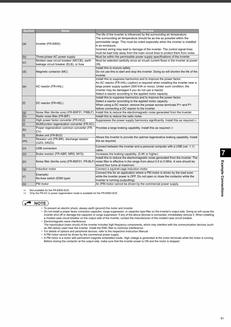
7
Example C
onnections
Not available for the FR-E800-SCE. Only the FR-XC in power regeneration mode is available for the FR-E800-SCE.
NOTE • To prevent an electric shock, always earth (ground) the motor and inverter. • Do not install a power factor correction capacitor, surge suppressor, or capacitor type filter on the inverter's output side. Doing so will cause the
inverter shut off or damage the capacitor or surge suppressor. If any of the above devices is connected, immediately remove it. When installing a molded case circuit breaker on the output side of the inverter, contact the manufacturer of the molded case circuit breaker.
• Electromagnetic wave interference:The input/output (main circuit) of the inverter includes high frequency components, which may interfere with the communication devices (such as AM radios) used near the inverter. Install the EMC filter to minimize interference.
• For details of options and peripheral devices, refer to the respective Instruction Manual. • A PM motor cannot be driven by the commercial power supply. • A PM motor is a motor with permanent magnets embedded inside. High voltage is generated at the motor terminals while the motor is running.
Before closing the contactor at the output side, make sure that the inverter power is ON and the motor is stopped.
Symbol Name Overview
(a) Inverter (FR-E800)
The life of the inverter is influenced by the surrounding air temperature. The surrounding air temperature should be as low as possible within the permissible range. This must be noted especially when the inverter is installed in an enclosure. Incorrect wiring may lead to damage of the inverter. The control signal lines must be kept fully away from the main circuit lines to protect them from noise.
(b) Three-phase AC power supply Must be within the permissible power supply specifications of the inverter.
(c) Molded case circuit breaker (MCCB), earth leakage circuit breaker (ELB), or fuse
Must be selected carefully since an inrush current flows in the inverter at power ON.
(d) Magnetic contactor (MC)Install this to ensure safety. Do not use this to start and stop the inverter. Doing so will shorten the life of the inverter.
(e) AC reactor (FR-HAL)
Install this to suppress harmonics and to improve the power factor. An AC reactor (FR-HAL) (option) is required when installing the inverter near a large power supply system (500 kVA or more). Under such condition, the inverter may be damaged if you do not use a reactor. Select a reactor according to the applied motor capacity.
(f) DC reactor (FR-HEL)
Install this to suppress harmonics and to improve the power factor. Select a reactor according to the applied motor capacity. When using a DC reactor, remove the jumper across terminals P/+ and P1 before connecting a DC reactor to the inverter.
(g) Noise filter (ferrite core) (FR-BSF01, FRBLF) Install this to reduce the electromagnetic noise generated from the inverter.(h) Radio noise filter (FR-BIF) Install this to reduce the radio noise.(i) High power factor converter (FR-HC2) Suppresses the power supply harmonics significantly. Install this as required.(j) Multifunction regeneration converter (FR-XC)
Provides a large braking capability. Install this as required.(k) Power regeneration common converter (FR-CV)
(l) Brake unit (FR-BU2) Allows the inverter to provide the optimal regenerative braking capability. Install this as required.(m) Resistor unit (FR-BR), discharge resistor
(GZG, GRZG)
(n) USB connection Connect between the inverter and a personal computer with a USB (ver. 1.1) cable.
(o) Brake resistor (FR-ABR, MRS, MYS) Increases the braking capability. (0.4K or higher)
(p) Noise filter (ferrite core) (FR-BSF01, FR-BLF)Install this to reduce the electromagnetic noise generated from the inverter. The noise filter is effective in the range from about 0.5 to 5 MHz. A wire should be wound four turns at maximum.
(q) Induction motor Connect a squirrel-cage induction motor.
(r) Example)No-fuse switch (DSN type)
Connect this for an application where a PM motor is driven by the load even while the inverter power is OFF. Do not open or close the contactor while the inverter is running (outputting).
(s) PM motor An IPM motor cannot be driven by the commercial power supply.
81
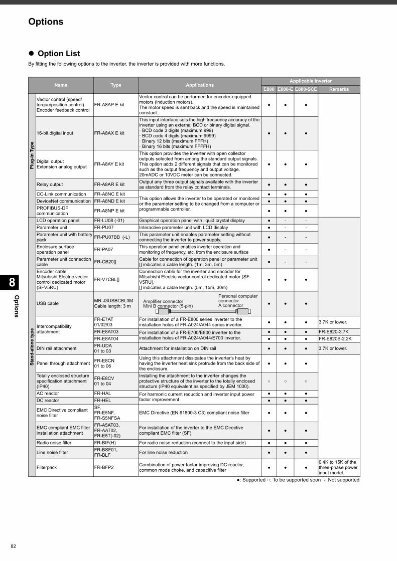
Options
8
82
Option ListBy fitting the following options to the inverter, the inverter is provided with more functions.
Name Type ApplicationsApplicable Inverter
E800 E800-E E800-SCE Remarks
Plug
-in T
ype
Vector control (speed/torque/position control)Encoder feedback control
FR-A8AP E kit
Vector control can be performed for encoder-equipped motors (induction motors).The motor speed is sent back and the speed is maintained constant.
● ● ●
16-bit digital input FR-A8AX E kit
This input interface sets the high frequency accuracy of the inverter using an external BCD or binary digital signal.· BCD code 3 digits (maximum 999)· BCD code 4 digits (maximum 9999)· Binary 12 bits (maximum FFFH)· Binary 16 bits (maximum FFFFH)
● ● ●
Digital outputExtension analog output FR-A8AY E kit
This option provides the inverter with open collector outputs selected from among the standard output signals. This option adds 2 different signals that can be monitored such as the output frequency and output voltage.20mADC or 10VDC meter can be connected.
● ● ●
Relay output FR-A8AR E kit Output any three output signals available with the inverter as standard from the relay contact terminals. ● ● ●
CC-Link communication FR-A8NC E kitThis option allows the inverter to be operated or monitored or the parameter setting to be changed from a computer or programmable controller.
● ● ●DeviceNet communication FR-A8ND E kit ● ● ●PROFIBUS-DP communication FR-A8NP E kit ● ● ●
Stan
d-al
one
type
LCD operation panel FR-LU08 (-01) Graphical operation panel with liquid crystal display ● - -Parameter unit FR-PU07 Interactive parameter unit with LCD display ● - -Parameter unit with batterypack FR-PU07BB (-L) This parameter unit enables parameter setting without
connecting the inverter to power supply. ● - -
Enclosure surface operation panel FR-PA07 This operation panel enables inverter operation and
monitoring of frequency, etc. from the enclosure surface ● - -
Parameter unit connectioncable FR-CB20[] Cable for connection of operation panel or parameter unit
[] indicates a cable length. (1m, 3m, 5m) ● - -
Encoder cableMitsubishi Electric vectorcontrol dedicated motor (SFV5RU)
FR-V7CBL[]
Connection cable for the inverter and encoder for Mitsubishi Electric vector control dedicated motor (SF-V5RU).[] indicates a cable length. (5m, 15m, 30m)
● ● ●
USB cable MR-J3USBCBL3MCable length: 3 m ● ● ●
Intercompatibility attachment
FR-E7AT01/02/03
For installation of a FR-E800 series inverter to the installation holes of FR-A024/A044 series inverter. ● ● ● 3.7K or lower.
FR-E8AT03 For installation of a FR-E700/E800 inverter to the installation holes of FR-A024/A044/E700 inverter.
● ● ● FR-E820-3.7KFR-E8AT04 ● ● ● FR-E820S-2.2K
DIN rail attachment FR-UDA01 to 03 Attachment for installation on DIN rail ● ● ● 3.7K or lower.
Panel through attachment FR-E8CN01 to 06
Using this attachment dissipates the inverter's heat by having the inverter heat sink protrude from the back side of the enclosure.
● ● ●
Totally enclosed structurespecification attachment (IP40)
FR-E8CV01 to 04
Installing the attachment to the inverter changes the protective structure of the inverter to the totally enclosed structure (IP40 equivalent as specified by JEM 1030).
○ ○ ○
AC reactor FR-HAL For harmonic current reduction and inverter input power factor improvement
● ● ●DC reactor FR-HEL ● ● ●
EMC Directive compliant noise filter
SF, FR-E5NF, FR-S5NFSA
EMC Directive (EN 61800-3 C3) compliant noise filter ● ● ●
EMC compliant EMC filterinstallation attachment
FR-A5AT03, FR-AAT02, FR-E5T(-02)
For installation of the inverter to the EMC Directive compliant EMC filter (SF). ● ● ●
Radio noise filter FR-BIF(H) For radio noise reduction (connect to the input side) ● ● ●
Line noise filter FR-BSF01, FR-BLF For line noise reduction ● ● ●
Filterpack FR-BFP2 Combination of power factor improving DC reactor, common mode choke, and capacitive filter ● ● ●
0.4K to 15K of the three-phase power input model.
●: Supported ○: To be supported soon -: Not supported
Personal computer connectorA connector
Amplifier connectorMini B connector (5-pin)
Options
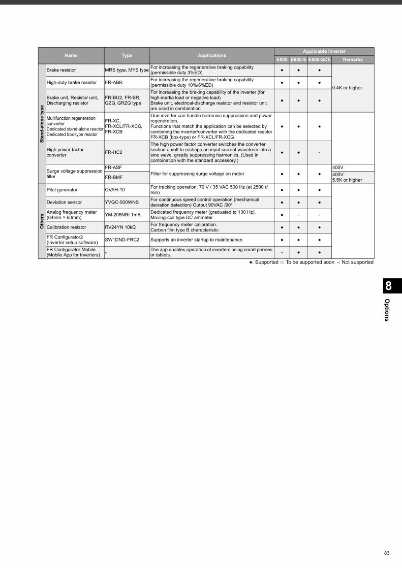
8
Options
Stan
d-al
one
type
Brake resistor MRS type, MYS type For increasing the regenerative braking capability (permissible duty 3%ED) ● ● ●
0.4K or higher.High-duty brake resistor FR-ABR For increasing the regenerative braking capability
(permissible duty 10%/6%ED) ● ● ●
Brake unit, Resistor unit,Discharging resistor
FR-BU2, FR-BR,GZG, GRZG type
For increasing the braking capability of the inverter (for high-inertia load or negative load)Brake unit, electrical-discharge resistor and resistor unit are used in combination
● ● ●
Multifunction regenerationconverterDedicated stand-alone reactorDedicated box-type reactor
FR-XC, FR-XCL/FR-XCG, FR-XCB
One inverter can handle harmonic suppression and power regeneration.Functions that match the application can be selected by combining the inverter/converter with the dedicated reactor FR-XCB (box-type) or FR-XCL/FR-XCG.
● ● ●
High power factor converter FR-HC2
The high power factor converter switches the converter section on/off to reshape an input current waveform into a sine wave, greatly suppressing harmonics. (Used in combination with the standard accessory.)
● ● -
Surge voltage suppressionfilter
FR-ASFFilter for suppressing surge voltage on motor ● ● ●
400V
FR-BMF 400V:5.5K or higher
Oth
ers
Pilot generator QVAH-10 For tracking operation. 70 V / 35 VAC 500 Hz (at 2500 r/min) ● ● ●
Deviation sensor YVGC-500WNS For continuous speed control operation (mechanical deviation detection) Output 90VAC /90° ● ● ●
Analog frequency meter(64mm × 60mm) YM-206NRI 1mA Dedicated frequency meter (graduated to 130 Hz).
Moving-coil type DC ammeter ● - -
Calibration resistor RV24YN 10kΩ For frequency meter calibration.Carbon film type B characteristic ● ● ●
FR Configurator2(Inverter setup software) SW1DND-FRC2 Supports an inverter startup to maintenance. ● ● ●
FR Configurator Mobile(Mobile App for Inverters) - The app enables operation of inverters using smart phones
or tablets. - ● ●
Name Type ApplicationsApplicable Inverter
E800 E800-E E800-SCE Remarks
●: Supported ○: To be supported soon -: Not supported
83
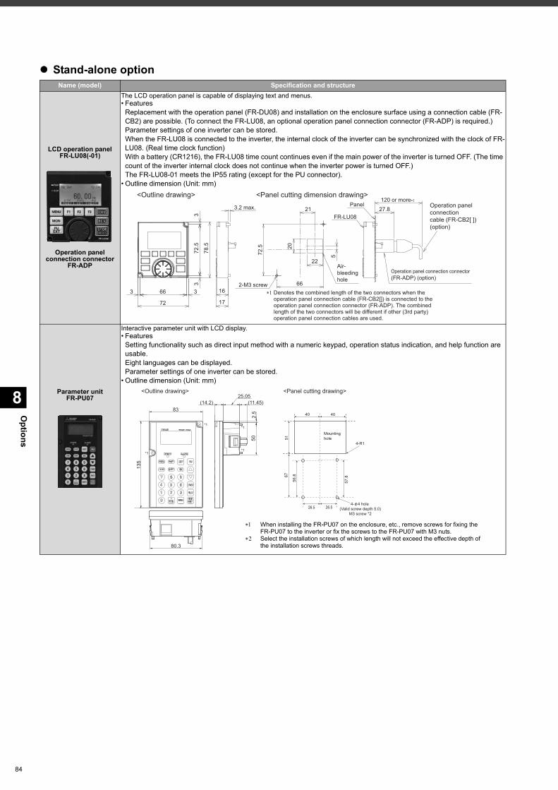
Options
8
84
Stand-alone optionName (model) Specification and structure
LCD operation panelFR-LU08(-01)
Operation panel connection connector
FR-ADP
The LCD operation panel is capable of displaying text and menus.• Features
Replacement with the operation panel (FR-DU08) and installation on the enclosure surface using a connection cable (FR-CB2) are possible. (To connect the FR-LU08, an optional operation panel connection connector (FR-ADP) is required.)Parameter settings of one inverter can be stored.When the FR-LU08 is connected to the inverter, the internal clock of the inverter can be synchronized with the clock of FR-LU08. (Real time clock function)With a battery (CR1216), the FR-LU08 time count continues even if the main power of the inverter is turned OFF. (The time count of the inverter internal clock does not continue when the inverter power is turned OFF.)The FR-LU08-01 meets the IP55 rating (except for the PU connector).
• Outline dimension (Unit: mm)
Parameter unitFR-PU07
Interactive parameter unit with LCD display.• Features
Setting functionality such as direct input method with a numeric keypad, operation status indication, and help function are usable.Eight languages can be displayed.Parameter settings of one inverter can be stored.
• Outline dimension (Unit: mm)
27.8
120 or more��
FR-LU08
Panel
Operation panel connection connector(FR-ADP) (option)
66
72.5
78.5
33
3 3
72
16
17
3.2 max.
�� Denotes the combined length of the two connectors when the operation panel connection cable (FR-CB2[]) is connected to the operation panel connection connector (FR-ADP). The combined length of the two connectors will be different if other (3rd party) operation panel connection cables are used.
<Outline drawing> <Panel cutting dimension drawing>
66
72.5
21
5
22
202-M3 screw
Air-bleedinghole
Operation panel connectioncable (FR-CB2[ ]) (option)
80.3
(14.2)
2.5
50
(11.45)25.05
135
83
6751
40
56.8
57.8
26.5
4-R1
Mountinghole
4- 4 hole (Valid screw depth 5.0)
M3 screw *226.5
40
<Outline drawing> <Panel cutting drawing>
*1
*1*1
*1
When installing the FR-PU07 on the enclosure, etc., remove screws for fixing the FR-PU07 to the inverter or fix the screws to the FR-PU07 with M3 nuts.
Select the installation screws of which length will not exceed the effective depth of the installation screws threads.
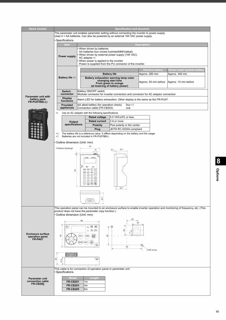
8
Options
Parameter unit with battery pack
FR-PU07BB(-L)
This parameter unit enables parameter setting without connecting the inverter to power supply.Uses 4 × AA batteries. Can also be powered by an external 100 VAC power supply.• Specifications
Use an AC adapter with the following specifications.
The battery life is a reference value. It differs depending on the battery and the usage. Batteries are not included in FR-PU07BB-L.
• Outline dimension (Unit: mm)
Enclosure surface operation panel
FR-PA07
This operation panel can be mounted to an enclosure surface to enable inverter operation and monitoring of frequency, etc. (This product does not have the parameter copy function.)• Outline dimension (Unit: mm)
Parameter unit connection cable
FR-CB20[]
This cable is for connection of operation panel or parameter unit• Specifications
Name (model) Specification and structure
Item Description
Power supply
• When driven by batteriesAA batteries four (nickel hydride(NiMH)/alkali)
• When driven by external power supply (100 VAC)AC adaptor
• When power is applied to the inverterPower is supplied from the PU connector of the inverter.
Battery life
Switch connector
Battery ON/OFF switchModular connector for inverter connection and connector for AC adaptor connection
Display functions Alarm LED for battery exhaustion, Other display is the same as the FR-PU07.
Provided appliances
AA alkali battery (for operation check) four Connection cable (FR-CB203) one
Alkaline battery Nickel metal hydride batteryBattery life Approx. 260 min Approx. 340 min
Battery exhaustion warning lamp color changing start time
From green to orange (at lowering of battery power)
Approx. 50 min before Approx. 10 min before
Output specifications
Rated voltage 5.0 VDC±5% or lessRated current 2 A or more
Polarity Plus polarity in the center.Plug JEITA RC-5320A compliant
<Outline drawing>8.2 46.7
44.7
46.7
135
83
18
6
68
59
22
22
2-M3 screw
Model LengthFR-CB201 1mFR-CB203 3mFR-CB205 5m
85
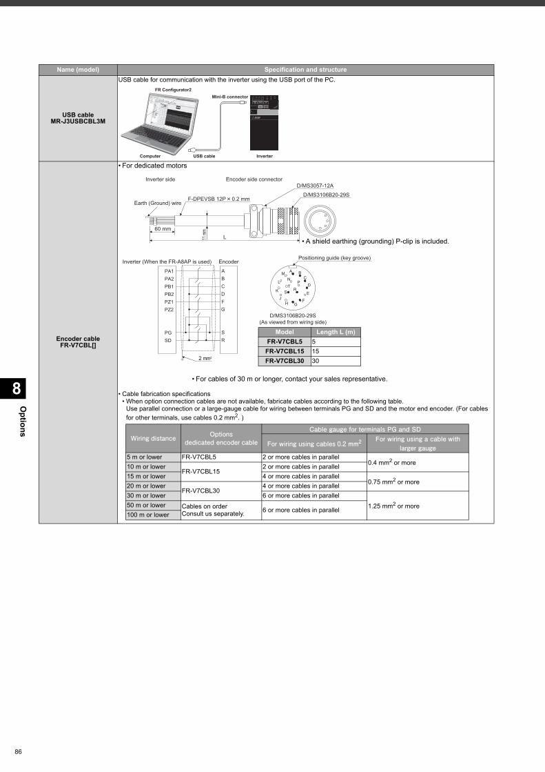
Options
8
86
USB cableMR-J3USBCBL3M
USB cable for communication with the inverter using the USB port of the PC.
Encoder cableFR-V7CBL[]
• For dedicated motors
• Cable fabrication specifications• When option connection cables are not available, fabricate cables according to the following table.
Use parallel connection or a large-gauge cable for wiring between terminals PG and SD and the motor end encoder. (For cables for other terminals, use cables 0.2 mm2. )
Name (model) Specification and structure
InverterUSB cable
Mini-B connector
Computer
FR Configurator2
Positioning guide (key groove)
D/MS3106B20-29S(As viewed from wiring side)
A BC
D
E
FGH
K
J
L
MN
PT
S R
L60 mm
Earth (Ground) wire
D/MS3057-12A
D/MS3106B20-29S
Inverter side Encoder side connector
11 m
m
Inverter (When the FR-A8AP is used)
2 mm2
Encoder
PA1PA2PB1PB2PZ1PZ2
PGSD
ABCDFG
SR
F-DPEVSB 12P 0.2 mm
Model Length L (m) FR-V7CBL5 5
FR-V7CBL15 15FR-V7CBL30 30
• A shield earthing (grounding) P-clip is included.
• For cables of 30 m or longer, contact your sales representative.
Wiring distance Optionsdedicated encoder cable
Cable gauge for terminals PG and SD
For wiring using cables 0.2 mm2For wiring using a cable with
larger gauge5 m or lower FR-V7CBL5 2 or more cables in parallel
0.4 mm2 or more10 m or lowerFR-V7CBL15
2 or more cables in parallel15 m or lower 4 or more cables in parallel
0.75 mm2 or more20 m or lowerFR-V7CBL30
4 or more cables in parallel30 m or lower 6 or more cables in parallel
1.25 mm2 or more50 m or lower Cables on orderConsult us separately. 6 or more cables in parallel
100 m or lower
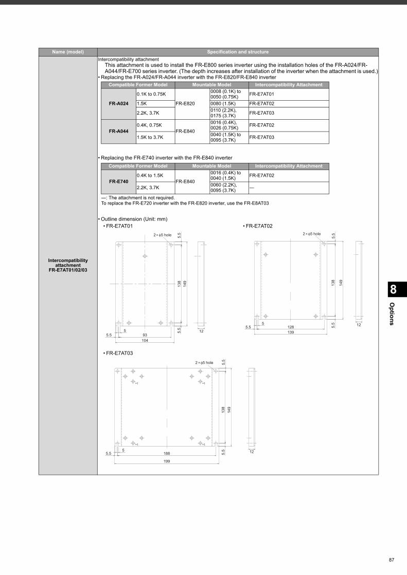
8
Options
Intercompatibility attachment
FR-E7AT01/02/03
Intercompatibility attachmentThis attachment is used to install the FR-E800 series inverter using the installation holes of the FR-A024/FR-A044/FR-E700 series inverter. (The depth increases after installation of the inverter when the attachment is used.)
• Replacing the FR-A024/FR-A044 inverter with the FR-E820/FR-E840 inverter
• Replacing the FR-E740 inverter with the FR-E840 inverter
• Outline dimension (Unit: mm)
Name (model) Specification and structure
Compatible Former Model Mountable Model Intercompatibility Attachment
FR-A024
0.1K to 0.75K
FR-E820
0008 (0.1K) to 0050 (0.75K) FR-E7AT01
1.5K 0080 (1.5K) FR-E7AT02
2.2K, 3.7K 0110 (2.2K), 0175 (3.7K) FR-E7AT03
FR-A0440.4K, 0.75K
FR-E840
0016 (0.4K), 0026 (0.75K) FR-E7AT02
1.5K to 3.7K 0040 (1.5K) to 0095 (3.7K) FR-E7AT03
―: The attachment is not required.To replace the FR-E720 inverter with the FR-E820 inverter, use the FR-E8AT03
Compatible Former Model Mountable Model Intercompatibility Attachment
FR-E7400.4K to 1.5K
FR-E840
0016 (0.4K) to 0040 (1.5K) FR-E7AT02
2.2K, 3.7K 0060 (2.2K), 0095 (3.7K) ―
• FR-E7AT01 • FR-E7AT02
• FR-E7AT03
93104
5.5
138
5.5
149
55.5
12
2 5 hole
5.5 128139
5.5
138
5.5
149
5
2 5 hole
12
5.5 188
199
5.5
138
5.5
149
5
2 5 hole
12
����
����
87
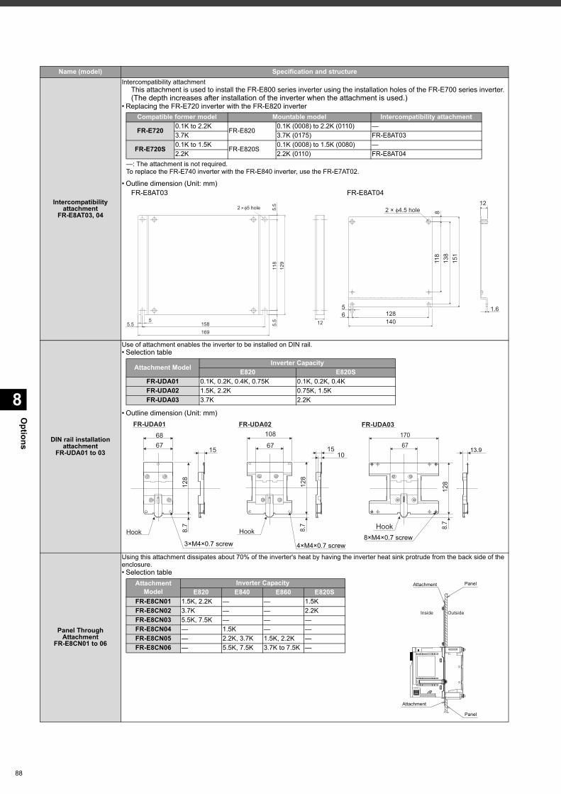
Options
8
88
Intercompatibility attachment
FR-E8AT03, 04
Intercompatibility attachmentThis attachment is used to install the FR-E800 series inverter using the installation holes of the FR-E700 series inverter. (The depth increases after installation of the inverter when the attachment is used.)
• Replacing the FR-E720 inverter with the FR-E820 inverter
• Outline dimension (Unit: mm)FR-E8AT03 FR-E8AT04
DIN rail installation attachment
FR-UDA01 to 03
Use of attachment enables the inverter to be installed on DIN rail.• Selection table
• Outline dimension (Unit: mm)
Panel Through Attachment
FR-E8CN01 to 06
Using this attachment dissipates about 70% of the inverter's heat by having the inverter heat sink protrude from the back side of the enclosure.• Selection table
Name (model) Specification and structure
—: The attachment is not required.To replace the FR-E740 inverter with the FR-E840 inverter, use the FR-E7AT02.
Compatible former model Mountable model Intercompatibility attachment
FR-E720 0.1K to 2.2KFR-E820
0.1K (0008) to 2.2K (0110) —3.7K 3.7K (0175) FR-E8AT03
FR-E720S 0.1K to 1.5KFR-E820S
0.1K (0008) to 1.5K (0080) —2.2K 2.2K (0110) FR-E8AT04
5.5
118
5.5
129
125.5 158169
5
2 5 hole
151
138
118
8
6140128
5
12
1.6
2 × 4.5 hole
Attachment Model Inverter CapacityE820 E820S
FR-UDA01 0.1K, 0.2K, 0.4K, 0.75K 0.1K, 0.2K, 0.4KFR-UDA02 1.5K, 2.2K 0.75K, 1.5KFR-UDA03 3.7K 2.2K
FR-UDA01 FR-UDA02 FR-UDA03
Hook HookHook
68 108
67
128
8.7
1567 15
10
128
8.7
128
8.7
17067
8×M4×0.7 screw4×M4×0.7 screw3×M4×0.7 screw
13.9
Attachment Model
Inverter CapacityE820 E840 E860 E820S
FR-E8CN01 1.5K, 2.2K — — 1.5KFR-E8CN02 3.7K — — 2.2KFR-E8CN03 5.5K, 7.5K — — —FR-E8CN04 — 1.5K — —FR-E8CN05 — 2.2K, 3.7K 1.5K, 2.2K —FR-E8CN06 — 5.5K, 7.5K 3.7K to 7.5K —
Attachment Panel
Panel
Attachment
Outside Inside
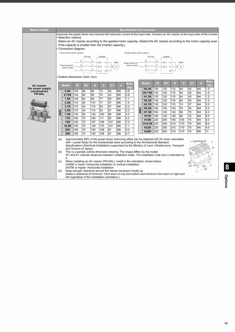
8
Options
AC reactor(for power supply
coordination)FR-HAL
Improves the power factor and reduces the harmonic current at the input side. Connect an AC reactor at the input side of the inverter.• Selection method
Select an AC reactor according to the applied motor capacity. (Select the AC reactor according to the motor capacity even if the capacity is smaller than the inverter capacity.)
• Connection diagram
• Outline dimension (Unit: mm)
(a) Approximately 88% of the power factor improving effect can be obtained (92.3% when calculated with 1 power factor for the fundamental wave according to the Architectural Standard Specifications (Electrical Installation) supervised by the Ministry of Land, Infrastructure, Transport and Tourism of Japan).
(b) This is a sample outline dimension drawing. The shape differs by the model. W1 and D1 indicate distances between installation holes. The installation hole size is indicated by d.
(c) When installing an AC reactor (FR-HAL), install in the orientation shown below.(H)55K or lower: Horizontal installation or vertical installation(H)75K or higher: Horizontal installation
(d) Keep enough clearance around the reactor because it heats up. (Keep a clearance of minimum 10cm each on top and bottom and minimum 5cm each on right and left regardless of the installation orientation.)
Name (model) Specification and structure
M
R/L1
S/L2
T/L3
U
V
W
R
S
T
X
Y
Z
Three-phase ACpower supply
InverterFR-HAL
Motor
<Single-phase power supply><Three-phase power supply>
M
R/L1
S/L2
U
V
W
R
S
T
X
Y
Z
Single-phase ACpower supply
InverterFR-HAL
Motor
Model W W1 H D D1 d Mass (kg)
200V
0.4K 104 84 99 72 40 M5 0.60.75K 104 84 99 74 44 M5 0.81.5K 104 84 99 77 50 M5 1.12.2K 115 40 115 77 57 M6 1.53.7K 115 40 115 83 67 M6 2.25.5K 115 40 115 83 67 M6 2.37.5K 130 50 135 100 86 M6 4.211K 160 75 164 111 92 M6 5.215K 160 75 167 126 107 M6 7.0
18.5K 160 75 128 175 107 M6 7.122K 185 75 150 158 87 M6 9.030K 185 75 150 168 87 M6 9.7
400V
H0.4K 135 120 115 64 45 M4 1.5H0.75K 135 120 115 64 45 M4 1.5H1.5K 135 120 115 64 45 M4 1.5H2.2K 135 120 115 64 45 M4 1.5H3.7K 135 120 115 74 57 M4 2.5H5.5K 160 145 142 76 55 M4 3.5H7.5K 160 145 142 96 75 M4 5.0H11K 160 145 146 96 75 M4 6.0H15K 220 200 195 105 70 M5 9.0
H18.5K 220 200 215 170 70 M5 9.0H22K 220 200 215 170 70 M5 9.5H30K 220 200 215 170 75 M5 11
Model W W1 H D D1 d Mass (kg)
Less than D
D1W
W1
H
89
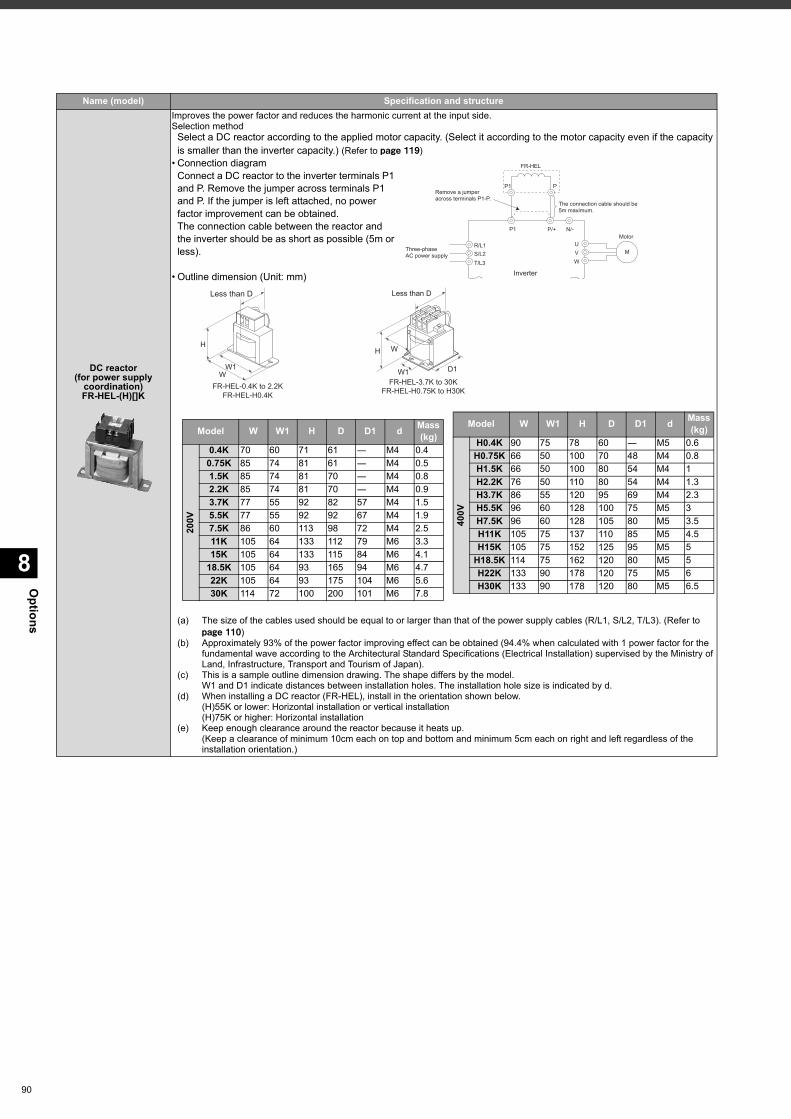
Options
8
90
DC reactor(for power supply
coordination)FR-HEL-(H)[]K
Improves the power factor and reduces the harmonic current at the input side.Selection method
Select a DC reactor according to the applied motor capacity. (Select it according to the motor capacity even if the capacity is smaller than the inverter capacity.) (Refer to page 119)
• Connection diagramConnect a DC reactor to the inverter terminals P1 and P. Remove the jumper across terminals P1 and P. If the jumper is left attached, no power factor improvement can be obtained. The connection cable between the reactor and the inverter should be as short as possible (5m or less).
• Outline dimension (Unit: mm)
(a) The size of the cables used should be equal to or larger than that of the power supply cables (R/L1, S/L2, T/L3). (Refer to page 110)
(b) Approximately 93% of the power factor improving effect can be obtained (94.4% when calculated with 1 power factor for the fundamental wave according to the Architectural Standard Specifications (Electrical Installation) supervised by the Ministry of Land, Infrastructure, Transport and Tourism of Japan).
(c) This is a sample outline dimension drawing. The shape differs by the model.W1 and D1 indicate distances between installation holes. The installation hole size is indicated by d.
(d) When installing a DC reactor (FR-HEL), install in the orientation shown below.(H)55K or lower: Horizontal installation or vertical installation(H)75K or higher: Horizontal installation
(e) Keep enough clearance around the reactor because it heats up.(Keep a clearance of minimum 10cm each on top and bottom and minimum 5cm each on right and left regardless of the installation orientation.)
Name (model) Specification and structure
Three-phase
AC power supply
R/L1
S/L2
T/L3
Motor
U
V
W
P1
P1 P
M
P/+ N/-
FR-HEL
Inverter
Remove a jumper
across terminals P1-P.
The connection cable should be
5m maximum.
W
W1
H
FR-HEL-0.4K to 2.2K
FR-HEL-H0.4K
Less than D
W
Less than D
FR-HEL-3.7K to 30KFR-HEL-H0.75K to H30K
W1 D1
H
Model W W1 H D D1 d Mass (kg)
200V
0.4K 70 60 71 61 ― M4 0.40.75K 85 74 81 61 ― M4 0.51.5K 85 74 81 70 ― M4 0.82.2K 85 74 81 70 ― M4 0.93.7K 77 55 92 82 57 M4 1.55.5K 77 55 92 92 67 M4 1.97.5K 86 60 113 98 72 M4 2.511K 105 64 133 112 79 M6 3.315K 105 64 133 115 84 M6 4.1
18.5K 105 64 93 165 94 M6 4.722K 105 64 93 175 104 M6 5.630K 114 72 100 200 101 M6 7.8
400V
H0.4K 90 75 78 60 ― M5 0.6H0.75K 66 50 100 70 48 M4 0.8H1.5K 66 50 100 80 54 M4 1H2.2K 76 50 110 80 54 M4 1.3H3.7K 86 55 120 95 69 M4 2.3H5.5K 96 60 128 100 75 M5 3H7.5K 96 60 128 105 80 M5 3.5H11K 105 75 137 110 85 M5 4.5H15K 105 75 152 125 95 M5 5
H18.5K 114 75 162 120 80 M5 5H22K 133 90 178 120 75 M5 6H30K 133 90 178 120 80 M5 6.5
Model W W1 H D D1 d Mass (kg)
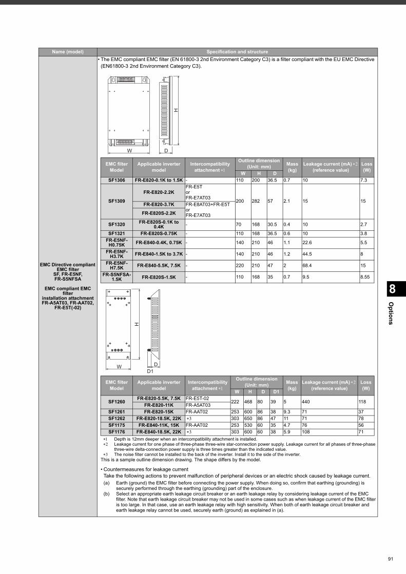
8
Options
EMC Directive compliant EMC filter
SF, FR-E5NF, FR-S5NFSA
EMC compliant EMC filter
installation attachmentFR-A5AT03, FR-AAT02,
FR-E5T(-02)
• The EMC compliant EMC filter (EN 61800-3 2nd Environment Category C3) is a filter compliant with the EU EMC Directive (EN61800-3 2nd Environment Category C3).
Name (model) Specification and structure
Depth is 12mm deeper when an intercompatibility attachment is installed. Leakage current for one phase of three-phase three-wire star-connection power supply. Leakage current for all phases of three-phase
three-wire delta-connection power supply is three times greater than the indicated value. The noise filter cannot be installed to the back of the inverter. Install it to the side of the inverter.
This is a sample outline dimension drawing. The shape differs by the model.
• Countermeasures for leakage currentTake the following actions to prevent malfunction of peripheral devices or an electric shock caused by leakage current. (a) Earth (ground) the EMC filter before connecting the power supply. When doing so, confirm that earthing (grounding) is
securely performed through the earthing (grounding) part of the enclosure. (b) Select an appropriate earth leakage circuit breaker or an earth leakage relay by considering leakage current of the EMC
filter. Note that earth leakage circuit breaker may not be used in some cases such as when leakage current of the EMC filter is too large. In that case, use an earth leakage relay with high sensitivity. When both of earth leakage circuit breaker and earth leakage relay cannot be used, securely earth (ground) as explained in (a).
EMC filter Model
Applicable inverter model
Intercompatibilityattachment
Outline dimension(Unit: mm) Mass
(kg)Leakage current (mA)
(reference value) Loss(W)W H D
SF1306 FR-E820-0.1K to 1.5K - 110 200 36.5 0.7 10 7.3
SF1309
FR-E820-2.2KFR-E5Tor FR-E7AT03
200 282 57 2.1 15 15FR-E820-3.7K FR-E8AT03+FR-E5T or FR-E7AT03FR-E820S-2.2K
SF1320 FR-E820S-0.1K to 0.4K - 70 168 30.5 0.4 10 2.7
SF1321 FR-E820S-0.75K - 110 168 36.5 0.6 10 3.8FR-E5NF-
H0.75K FR-E840-0.4K, 0.75K - 140 210 46 1.1 22.6 5.5
FR-E5NF-H3.7K FR-E840-1.5K to 3.7K - 140 210 46 1.2 44.5 8
FR-E5NF-H7.5K FR-E840-5.5K, 7.5K - 220 210 47 2 68.4 15
FR-S5NFSA-1.5K FR-E820S-1.5K - 110 168 35 0.7 9.5 8.55
EMC filter Model
Applicable inverter model
Intercompatibilityattachment
Outline dimension(Unit: mm) Mass
(kg)Leakage current (mA)
(reference value) Loss(W)W H D D1
SF1260 FR-E820-5.5K, 7.5K FR-E5T-02222 468 80 39 5 440 118FR-E820-11K FR-A5AT03
SF1261 FR-E820-15K FR-AAT02 253 600 86 38 9.3 71 37SF1262 FR-E820-18.5K, 22K 303 650 86 47 11 71 78SF1175 FR-E840-11K, 15K FR-AAT02 253 530 60 35 4.7 76 56SF1176 FR-E840-18.5K, 22K 303 600 60 38 5.9 108 71
W
H
D
W
H
DD1
91
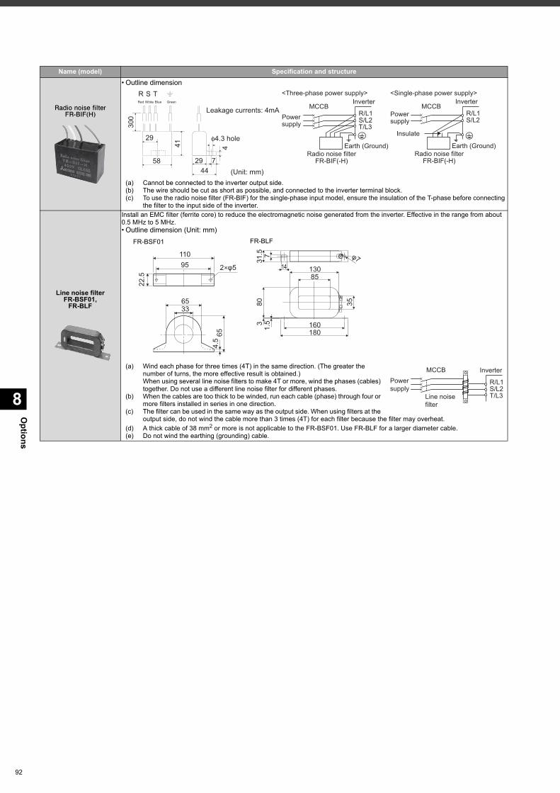
Options
8
92
Radio noise filterFR-BIF(H)
• Outline dimension
(a) Cannot be connected to the inverter output side. (b) The wire should be cut as short as possible, and connected to the inverter terminal block.(c) To use the radio noise filter (FR-BIF) for the single-phase input model, ensure the insulation of the T-phase before connecting
the filter to the input side of the inverter.
Line noise filterFR-BSF01,
FR-BLF
Install an EMC filter (ferrite core) to reduce the electromagnetic noise generated from the inverter. Effective in the range from about 0.5 MHz to 5 MHz. • Outline dimension (Unit: mm)
(a) Wind each phase for three times (4T) in the same direction. (The greater the number of turns, the more effective result is obtained.)When using several line noise filters to make 4T or more, wind the phases (cables) together. Do not use a different line noise filter for different phases.
(b) When the cables are too thick to be winded, run each cable (phase) through four or more filters installed in series in one direction.
(c) The filter can be used in the same way as the output side. When using filters at the output side, do not wind the cable more than 3 times (4T) for each filter because the filter may overheat.
(d) A thick cable of 38 mm2 or more is not applicable to the FR-BSF01. Use FR-BLF for a larger diameter cable.(e) Do not wind the earthing (grounding) cable.
Name (model) Specification and structure
30
0
29
58
41
29 7
44
4
φ4.3 hole
R S T
Leakage currents: 4mA
(Unit: mm)
Red White Blue Green
Earth (Ground)Radio noise filter
FR-BIF(-H)
T/L3S/L2R/L1
InverterMCCB
Powersupply
<Three-phase power supply>
Earth (Ground)Radio noise filter
FR-BIF(-H)
S/L2R/L1
InverterMCCB
Powersupply
<Single-phase power supply>
Insulate
FR-BSF01 FR-BLF
11095 2 φ5
22.5
6533
654.
5
31.5 7 φ7
1480
13085
1801603
35
1.5
Line noise filter
InverterMCCBPower supply
T/L3S/L2R/L1
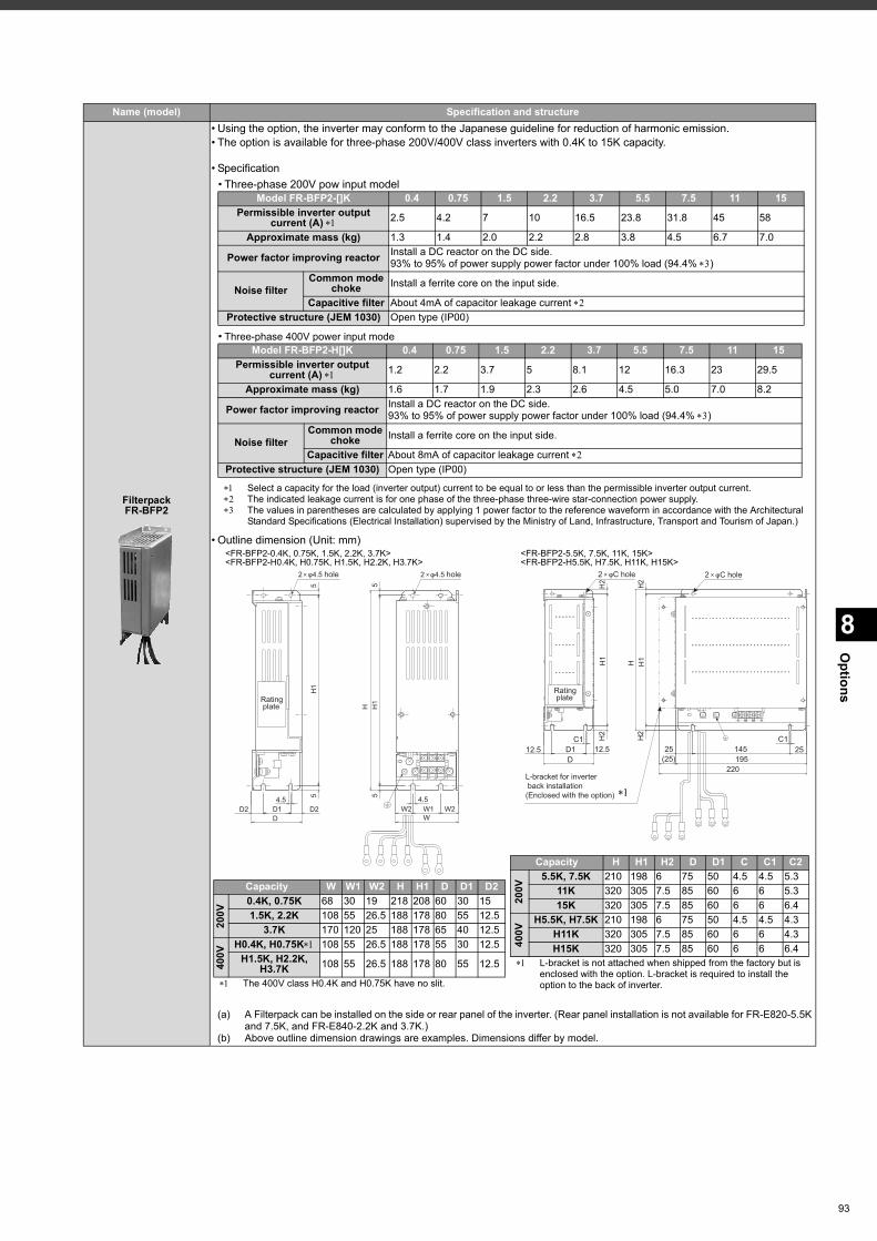
8
Options
FilterpackFR-BFP2
• Using the option, the inverter may conform to the Japanese guideline for reduction of harmonic emission.• The option is available for three-phase 200V/400V class inverters with 0.4K to 15K capacity.
• Specification
• Outline dimension (Unit: mm)<FR-BFP2-0.4K, 0.75K, 1.5K, 2.2K, 3.7K> <FR-BFP2-5.5K, 7.5K, 11K, 15K><FR-BFP2-H0.4K, H0.75K, H1.5K, H2.2K, H3.7K> <FR-BFP2-H5.5K, H7.5K, H11K, H15K>
(a) A Filterpack can be installed on the side or rear panel of the inverter. (Rear panel installation is not available for FR-E820-5.5K and 7.5K, and FR-E840-2.2K and 3.7K.)
(b) Above outline dimension drawings are examples. Dimensions differ by model.
Name (model) Specification and structure
• Three-phase 200V pow input model
• Three-phase 400V power input mode
Select a capacity for the load (inverter output) current to be equal to or less than the permissible inverter output current. The indicated leakage current is for one phase of the three-phase three-wire star-connection power supply. The values in parentheses are calculated by applying 1 power factor to the reference waveform in accordance with the Architectural
Standard Specifications (Electrical Installation) supervised by the Ministry of Land, Infrastructure, Transport and Tourism of Japan.)
Model FR-BFP2-[]K 0.4 0.75 1.5 2.2 3.7 5.5 7.5 11 15Permissible inverter output
current (A) 2.5 4.2 7 10 16.5 23.8 31.8 45 58
Approximate mass (kg) 1.3 1.4 2.0 2.2 2.8 3.8 4.5 6.7 7.0
Power factor improving reactor Install a DC reactor on the DC side.93% to 95% of power supply power factor under 100% load (94.4% )
Noise filter Common mode
choke Install a ferrite core on the input side.
Capacitive filter About 4mA of capacitor leakage current Protective structure (JEM 1030) Open type (IP00)
Model FR-BFP2-H[]K 0.4 0.75 1.5 2.2 3.7 5.5 7.5 11 15Permissible inverter output
current (A) 1.2 2.2 3.7 5 8.1 12 16.3 23 29.5
Approximate mass (kg) 1.6 1.7 1.9 2.3 2.6 4.5 5.0 7.0 8.2
Power factor improving reactor Install a DC reactor on the DC side.93% to 95% of power supply power factor under 100% load (94.4% )
Noise filterCommon mode
choke Install a ferrite core on the input side.
Capacitive filter About 8mA of capacitor leakage current Protective structure (JEM 1030) Open type (IP00)
5
D1D
4.5D2 D2
H1
55
W1W
W24.5
W2
H H1
5
2 φ4.5 hole 2 φ4.5 hole
Rating plate
D12.5
C1 C112.5 D1
H1
H
145195
220
H2
25(25)
25
H2
L-bracket for inverter back installation(Enclosed with the option)
2 φC hole 2 φC hole
Rating plate
H1
H2
H2
The 400V class H0.4K and H0.75K have no slit.
Capacity W W1 W2 H H1 D D1 D2
200V
0.4K, 0.75K 68 30 19 218 208 60 30 151.5K, 2.2K 108 55 26.5 188 178 80 55 12.5
3.7K 170 120 25 188 178 65 40 12.5
400V
H0.4K, H0.75K 108 55 26.5 188 178 55 30 12.5H1.5K, H2.2K,
H3.7K 108 55 26.5 188 178 80 55 12.5 L-bracket is not attached when shipped from the factory but is enclosed with the option. L-bracket is required to install the option to the back of inverter.
Capacity H H1 H2 D D1 C C1 C2
200V
5.5K, 7.5K 210 198 6 75 50 4.5 4.5 5.311K 320 305 7.5 85 60 6 6 5.315K 320 305 7.5 85 60 6 6 6.4
400V
H5.5K, H7.5K 210 198 6 75 50 4.5 4.5 4.3H11K 320 305 7.5 85 60 6 6 4.3H15K 320 305 7.5 85 60 6 6 6.4
93
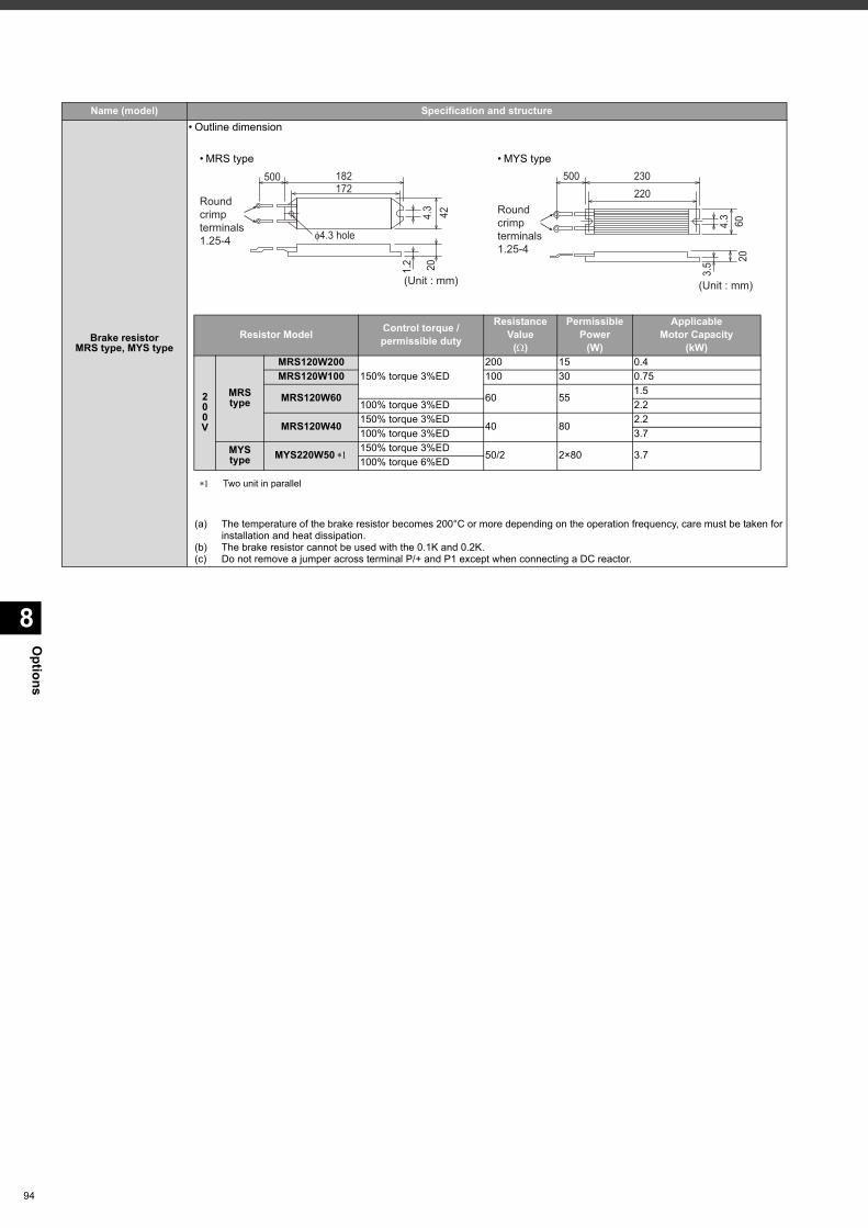
Options
8
94
Brake resistorMRS type, MYS type
• Outline dimension
(a) The temperature of the brake resistor becomes 200°C or more depending on the operation frequency, care must be taken for installation and heat dissipation.
(b) The brake resistor cannot be used with the 0.1K and 0.2K.(c) Do not remove a jumper across terminal P/+ and P1 except when connecting a DC reactor.
Name (model) Specification and structure
• MRS type • MYS type500
Round crimp terminals1.25-4
182172
φ4.3 hole
424.3
201.2
(Unit : mm)
500 230220
20
3.5
604.3
(Unit : mm)
Round crimp terminals1.25-4
Two unit in parallel
Resistor Model Control torque /permissible duty
ResistanceValue
()
PermissiblePower
(W)
ApplicableMotor Capacity
(kW)
200V
MRS type
MRS120W200150% torque 3%ED
200 15 0.4MRS120W100 100 30 0.75
MRS120W60 60 551.5
100% torque 3%ED 2.2
MRS120W40 150% torque 3%ED40 80
2.2100% torque 3%ED 3.7
MYS type MYS220W50 150% torque 3%ED
50/2 2×80 3.7100% torque 6%ED
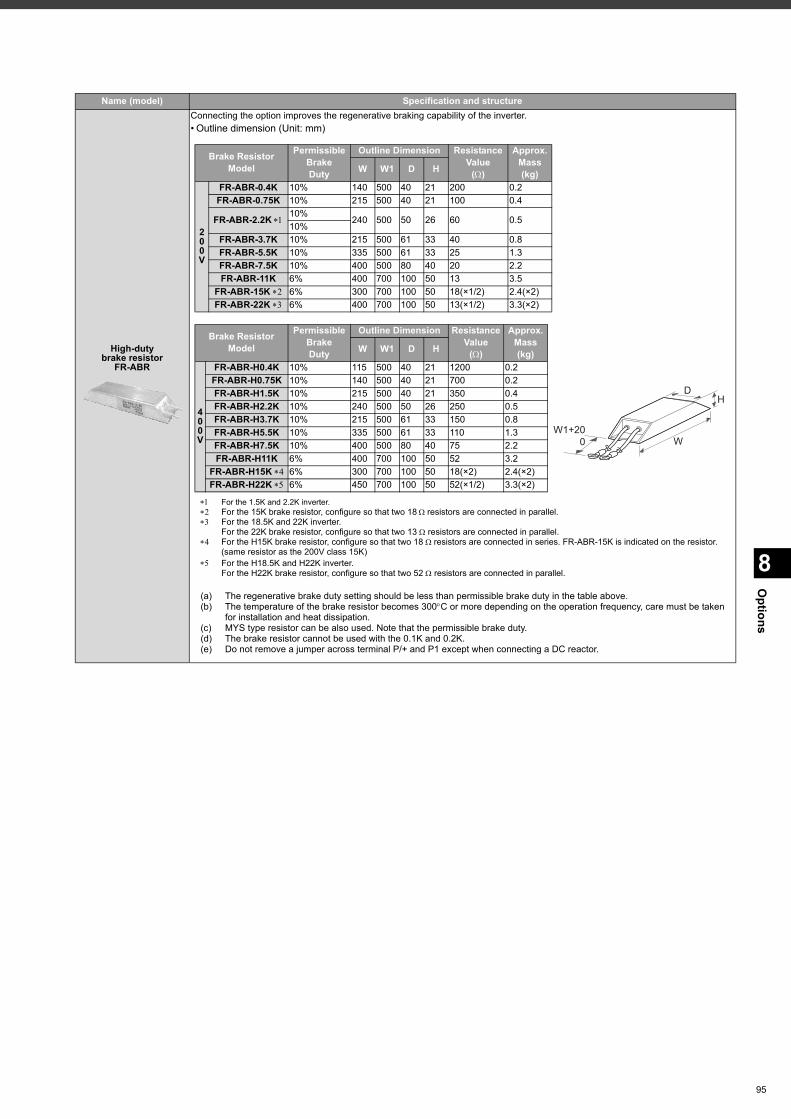
8
Options
High-dutybrake resistor
FR-ABR
Connecting the option improves the regenerative braking capability of the inverter.• Outline dimension (Unit: mm)
Name (model) Specification and structure
For the 1.5K and 2.2K inverter. For the 15K brake resistor, configure so that two 18resistors are connected in parallel. For the 18.5K and 22K inverter.
For the 22K brake resistor, configure so that two 13 resistors are connected in parallel. For the H15K brake resistor, configure so that two 18 resistors are connected in series. FR-ABR-15K is indicated on the resistor.
(same resistor as the 200V class 15K) For the H18.5K and H22K inverter.
For the H22K brake resistor, configure so that two 52 resistors are connected in parallel.
(a) The regenerative brake duty setting should be less than permissible brake duty in the table above.(b) The temperature of the brake resistor becomes 300C or more depending on the operation frequency, care must be taken
for installation and heat dissipation. (c) MYS type resistor can be also used. Note that the permissible brake duty.(d) The brake resistor cannot be used with the 0.1K and 0.2K.(e) Do not remove a jumper across terminal P/+ and P1 except when connecting a DC reactor.
Brake ResistorModel
PermissibleBrakeDuty
Outline Dimension ResistanceValue
()
Approx. Mass(kg)W W1 D H
200V
FR-ABR-0.4K 10% 140 500 40 21 200 0.2FR-ABR-0.75K 10% 215 500 40 21 100 0.4
FR-ABR-2.2K 10%240 500 50 26 60 0.5
10%FR-ABR-3.7K 10% 215 500 61 33 40 0.8FR-ABR-5.5K 10% 335 500 61 33 25 1.3FR-ABR-7.5K 10% 400 500 80 40 20 2.2FR-ABR-11K 6% 400 700 100 50 13 3.5
FR-ABR-15K 6% 300 700 100 50 18(×1/2) 2.4(×2)FR-ABR-22K 6% 400 700 100 50 13(×1/2) 3.3(×2)
Brake ResistorModel
PermissibleBrakeDuty
Outline Dimension ResistanceValue
()
Approx. Mass(kg)W W1 D H
400V
FR-ABR-H0.4K 10% 115 500 40 21 1200 0.2FR-ABR-H0.75K 10% 140 500 40 21 700 0.2FR-ABR-H1.5K 10% 215 500 40 21 350 0.4FR-ABR-H2.2K 10% 240 500 50 26 250 0.5FR-ABR-H3.7K 10% 215 500 61 33 150 0.8FR-ABR-H5.5K 10% 335 500 61 33 110 1.3FR-ABR-H7.5K 10% 400 500 80 40 75 2.2FR-ABR-H11K 6% 400 700 100 50 52 3.2
FR-ABR-H15K 6% 300 700 100 50 18(×2) 2.4(×2)FR-ABR-H22K 6% 450 700 100 50 52(×1/2) 3.3(×2)
W
W1+20
0
DH
95
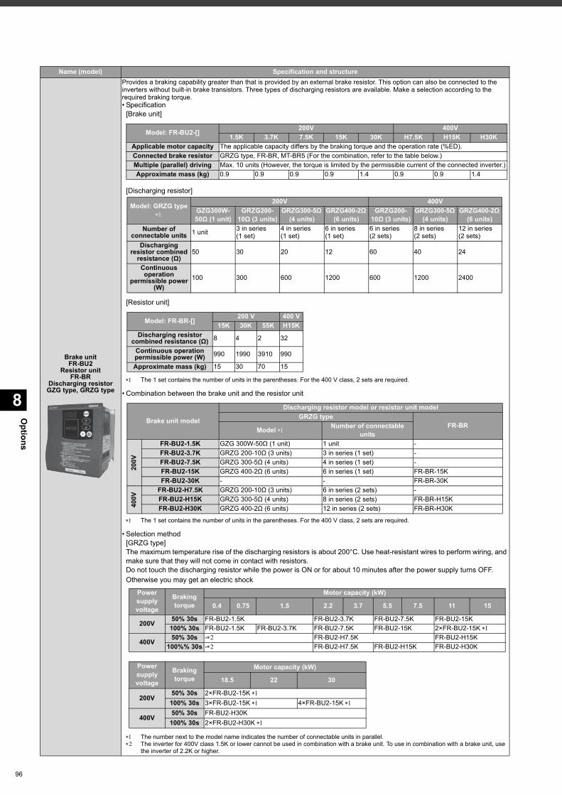
Options
8
96
Brake unitFR-BU2
Resistor unitFR-BR
Discharging resistorGZG type, GRZG type
Provides a braking capability greater than that is provided by an external brake resistor. This option can also be connected to the inverters without built-in brake transistors. Three types of discharging resistors are available. Make a selection according to the required braking torque.• Specification
[Brake unit]
[Discharging resistor]
[Resistor unit]
The 1 set contains the number of units in the parentheses. For the 400 V class, 2 sets are required.
• Combination between the brake unit and the resistor unit
The 1 set contains the number of units in the parentheses. For the 400 V class, 2 sets are required.
• Selection method[GRZG type]The maximum temperature rise of the discharging resistors is about 200°C. Use heat-resistant wires to perform wiring, and make sure that they will not come in contact with resistors.Do not touch the discharging resistor while the power is ON or for about 10 minutes after the power supply turns OFF. Otherwise you may get an electric shock
The number next to the model name indicates the number of connectable units in parallel. The inverter for 400V class 1.5K or lower cannot be used in combination with a brake unit. To use in combination with a brake unit, use
the inverter of 2.2K or higher.
Name (model) Specification and structure
Model: FR-BU2-[] 200V 400V1.5K 3.7K 7.5K 15K 30K H7.5K H15K H30K
Applicable motor capacity The applicable capacity differs by the braking torque and the operation rate (%ED).Connected brake resistor GRZG type, FR-BR, MT-BR5 (For the combination, refer to the table below.)Multiple (parallel) driving Max. 10 units (However, the torque is limited by the permissible current of the connected inverter.)Approximate mass (kg) 0.9 0.9 0.9 0.9 1.4 0.9 0.9 1.4
Model: GRZG type
200V 400VGZG300W-50Ω (1 unit)
GRZG200-10Ω (3 units)
GRZG300-5Ω (4 units)
GRZG400-2Ω (6 units)
GRZG200-10Ω (3 units)
GRZG300-5Ω (4 units)
GRZG400-2Ω (6 units)
Number of connectable units 1 unit 3 in series
(1 set)4 in series(1 set)
6 in series(1 set)
6 in series(2 sets)
8 in series(2 sets)
12 in series(2 sets)
Discharging resistor combined
resistance (Ω)50 30 20 12 60 40 24
Continuous operation
permissible power (W)
100 300 600 1200 600 1200 2400
Model: FR-BR-[] 200 V 400 V15K 30K 55K H15K
Discharging resistor combined resistance (Ω) 8 4 2 32
Continuous operation permissible power (W) 990 1990 3910 990
Approximate mass (kg) 15 30 70 15
Brake unit model
Discharging resistor model or resistor unit modelGRZG type
FR-BRModel Number of connectable units
200V
FR-BU2-1.5K GZG 300W-50Ω (1 unit) 1 unit -FR-BU2-3.7K GRZG 200-10Ω (3 units) 3 in series (1 set) -FR-BU2-7.5K GRZG 300-5Ω (4 units) 4 in series (1 set) -FR-BU2-15K GRZG 400-2Ω (6 units) 6 in series (1 set) FR-BR-15KFR-BU2-30K - - FR-BR-30K
400V
FR-BU2-H7.5K GRZG 200-10Ω (3 units) 6 in series (2 sets) -FR-BU2-H15K GRZG 300-5Ω (4 units) 8 in series (2 sets) FR-BR-H15KFR-BU2-H30K GRZG 400-2Ω (6 units) 12 in series (2 sets) FR-BR-H30K
Power supply voltage
Braking torque
Motor capacity (kW)
0.4 0.75 1.5 2.2 3.7 5.5 7.5 11 15
200V 50% 30s FR-BU2-1.5K FR-BU2-3.7K FR-BU2-7.5K FR-BU2-15K100% 30s FR-BU2-1.5K FR-BU2-3.7K FR-BU2-7.5K FR-BU2-15K 2×FR-BU2-15K
400V 50% 30s - FR-BU2-H7.5K FR-BU2-H15K100%% 30s - FR-BU2-H7.5K FR-BU2-H15K FR-BU2-H30K
Power supply voltage
Braking torque
Motor capacity (kW)
18.5 22 30
200V50% 30s 2×FR-BU2-15K 100% 30s 3×FR-BU2-15K 4×FR-BU2-15K
400V50% 30s FR-BU2-H30K100% 30s 2×FR-BU2-H30K
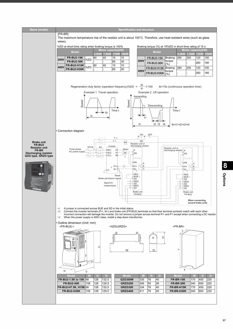
8
Options
Brake unitFR-BU2
Resistor unitFR-BR
Discharging resistorGZG type, GRZG type
[FR-BR]The maximum temperature rise of the resistor unit is about 100°C. Therefore, use heat-resistant wires (such as glass wires).
• Connection diagram
A jumper is connected across BUE and SD in the initial status. Connect the inverter terminals (P/+, N/-) and brake unit (FR-BU2) terminals so that their terminal symbols match with each other.
Incorrect connection will damage the inverter. Do not remove a jumper across terminal P/+ and P1 except when connecting a DC reactor. When the power supply is 400V class, install a step-down transformer.
• Outline dimension (Unit: mm)<FR-BU2L> <GZG,GRZG> <FR-BR>
Name (model) Specification and structure
%ED at short-time rating when braking torque is 100% Braking torque (%) at 10%ED in short-time rating of 15 s
Model Motor capacity(kW)5.5kW 7.5kW 11kW 15kW
200V FR-BU2-15K%ED
80 40 15 10FR-BU2-30K - - 65 30
400V FR-BU2-H15K%ED
80 40 15 10FR-BU2-H30K - - 65 30
Model Motor capacity(kW)5.5kW 7.5kW 11kW 15kW
200VFR-BU2-15K Braking
torque(%)
280 200 120 100
FR-BU2-30K - - 260 180
400VFR-BU2-H15K Braking
torque(%)
280 200 120 100
FR-BU2-H30K - - 260 180
Example 1 Travel operation Example 2 Lift operation
Time t
tc
tb
Sp
ee
d
Sp
ee
d
Time t
Descending
Ascending
tc
t1
t2 tb=t1+t2+t3+t4t3 t4
Regeneration duty factor (operation frequency)%ED tb<15s (continuous operation time)tb
tc100
PR
N/-
MSG
SD
MSG
SD
P/+
P
A
B
C
PR
RES
SD
U
V
W
P/+
N/-
R/L1
S/L2
T/L3
IM
PR
N/-
MSG
SD
MSG
SD
P/+
P
A
B
C
PR
MCCB MC
*1
RES
BUE
SD
*2
*2 *2
Three-phase
AC power supply
Resistor unit or
discharging resistor
Resistor unit or
discharging resistor
Brake unit
FR-BU2
When connecting
several brake units
Brake unit
FR-BU2
Motor
Signal for
master/slave
Inverter
Reset
Brake permission signal*1BUE
MC
OFFON
MC
T *3
H
W D
Model W H DFR-BU2-1.5K to 15K 68 128 132.5
FR-BU2-30K 108 128 129.5FR-BU2-H7.5K, H15K 68 128 132.5
FR-BU2-H30K 108 128 129.5
D
H
W
W
H
D
Model W H DGZG300W 335 78 40GRZG200 306 55 26GRZG300 334 79 40GRZG400 411 79 40
Model W H DFR-BR-15K 170 450 220FR-BR-30K 340 600 220
FR-BR-H15K 170 450 220FR-BR-H30K 340 600 220
97
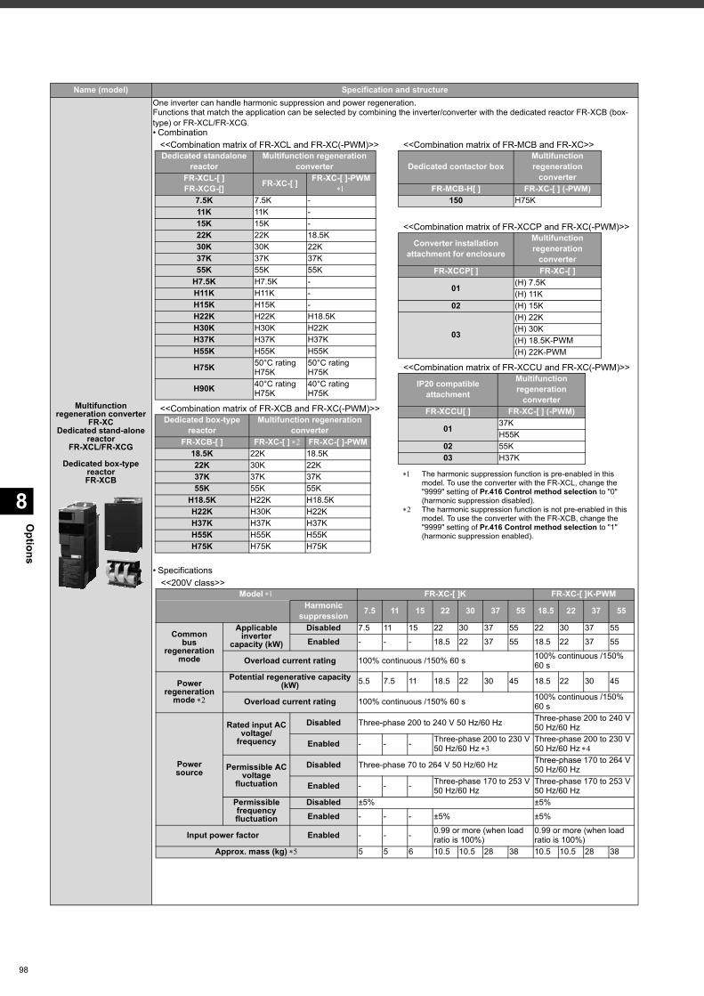
Options
8
98
Multifunction regeneration converter
FR-XCDedicated stand-alone
reactorFR-XCL/FR-XCG
Dedicated box-type reactorFR-XCB
One inverter can handle harmonic suppression and power regeneration.Functions that match the application can be selected by combining the inverter/converter with the dedicated reactor FR-XCB (box-type) or FR-XCL/FR-XCG.• Combination
• Specifications
Name (model) Specification and structure
<<Combination matrix of FR-XCL and FR-XC(-PWM)>>
<<Combination matrix of FR-XCB and FR-XC(-PWM)>>
<<Combination matrix of FR-MCB and FR-XC>>
<<Combination matrix of FR-XCCP and FR-XC(-PWM)>>
<<Combination matrix of FR-XCCU and FR-XC(-PWM)>>
The harmonic suppression function is pre-enabled in this model. To use the converter with the FR-XCL, change the "9999" setting of Pr.416 Control method selection to "0" (harmonic suppression disabled).
The harmonic suppression function is not pre-enabled in this model. To use the converter with the FR-XCB, change the "9999" setting of Pr.416 Control method selection to "1" (harmonic suppression enabled).
Dedicated standalonereactor
Multifunction regenerationconverter
FR-XCL-[ ]FR-XCG-[] FR-XC-[ ] FR-XC-[ ]-PWM
7.5K 7.5K -11K 11K -15K 15K -22K 22K 18.5K30K 30K 22K37K 37K 37K55K 55K 55K
H7.5K H7.5K -H11K H11K -H15K H15K -H22K H22K H18.5KH30K H30K H22KH37K H37K H37KH55K H55K H55K
H75K 50°C ratingH75K
50°C ratingH75K
H90K 40°C ratingH75K
40°C ratingH75K
Dedicated box-typereactor
Multifunction regenerationconverter
FR-XCB-[ ] FR-XC-[ ] FR-XC-[ ]-PWM18.5K 22K 18.5K22K 30K 22K37K 37K 37K55K 55K 55K
H18.5K H22K H18.5KH22K H30K H22KH37K H37K H37KH55K H55K H55KH75K H75K H75K
Dedicated contactor boxMultifunctionregeneration
converterFR-MCB-H[ ] FR-XC-[ ] (-PWM)
150 H75K
Converter installationattachment for enclosure
Multifunctionregeneration
converterFR-XCCP[ ] FR-XC-[ ]
01 (H) 7.5K(H) 11K
02 (H) 15K
03
(H) 22K(H) 30K(H) 18.5K-PWM(H) 22K-PWM
IP20 compatibleattachment
Multifunctionregeneration
converterFR-XCCU[ ] FR-XC-[ ] (-PWM)
01 37KH55K
02 55K03 H37K
<<200V class>>Model FR-XC-[ ]K FR-XC-[ ]K-PWM
Harmonicsuppression 7.5 11 15 22 30 37 55 18.5 22 37 55
Commonbus
regenerationmode
Applicable inverter
capacity (kW)
Disabled 7.5 11 15 22 30 37 55 22 30 37 55
Enabled - - - 18.5 22 37 55 18.5 22 37 55
Overload current rating 100% continuous /150% 60 s 100% continuous /150% 60 s
Powerregeneration
mode
Potential regenerative capacity (kW) 5.5 7.5 11 18.5 22 30 45 18.5 22 30 45
Overload current rating 100% continuous /150% 60 s 100% continuous /150% 60 s
Powersource
Rated input ACvoltage/
frequency
Disabled Three-phase 200 to 240 V 50 Hz/60 Hz Three-phase 200 to 240 V 50 Hz/60 Hz
Enabled - - - Three-phase 200 to 230 V 50 Hz/60 Hz
Three-phase 200 to 230 V 50 Hz/60 Hz
Permissible ACvoltage
fluctuation
Disabled Three-phase 70 to 264 V 50 Hz/60 Hz Three-phase 170 to 264 V 50 Hz/60 Hz
Enabled - - - Three-phase 170 to 253 V 50 Hz/60 Hz
Three-phase 170 to 253 V 50 Hz/60 Hz
Permissiblefrequency fluctuation
Disabled ±5% ±5%
Enabled - - - ±5% ±5%
Input power factor Enabled - - - 0.99 or more (when load ratio is 100%)
0.99 or more (when load ratio is 100%)
Approx. mass (kg) 5 5 6 10.5 10.5 28 38 10.5 10.5 28 38
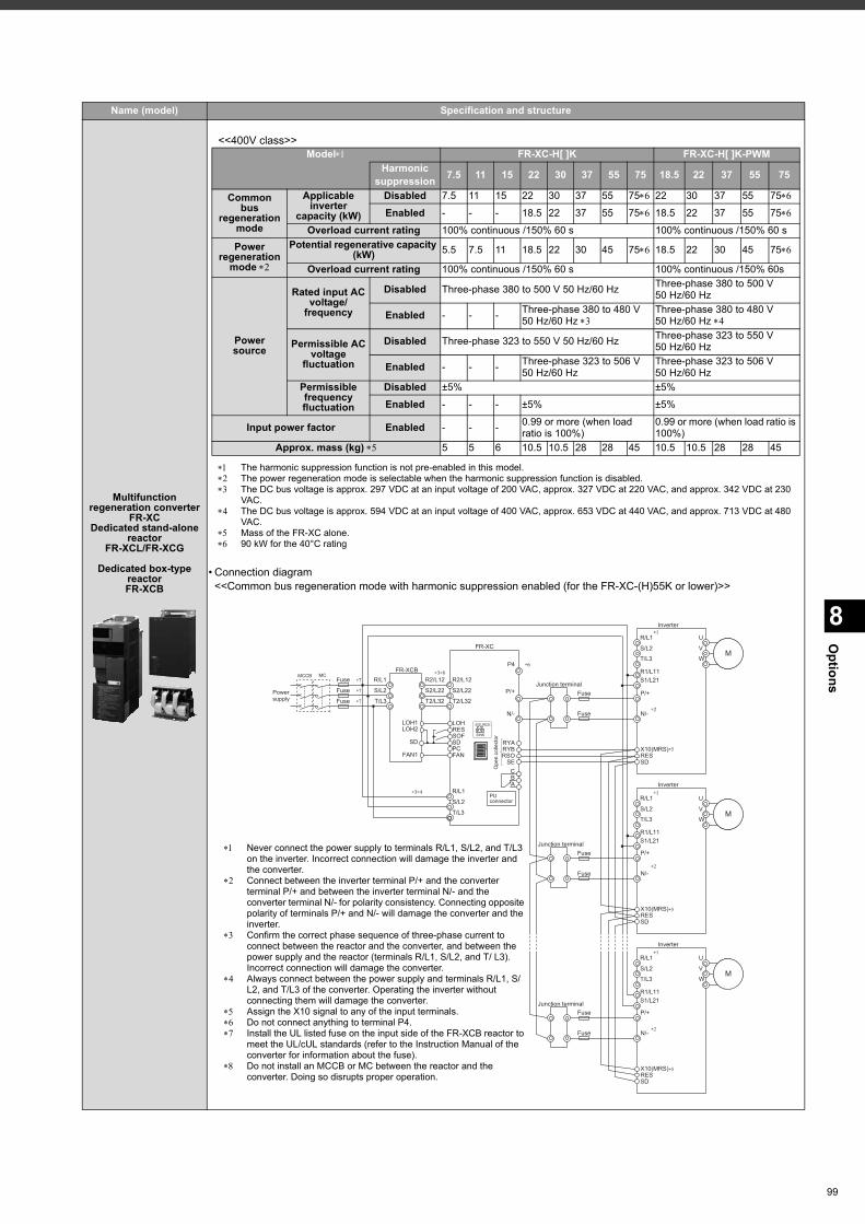
8
Options
Multifunction regeneration converter
FR-XCDedicated stand-alone
reactorFR-XCL/FR-XCG
Dedicated box-type reactorFR-XCB
• Connection diagram<<Common bus regeneration mode with harmonic suppression enabled (for the FR-XC-(H)55K or lower)>>
Name (model) Specification and structure
<<400V class>>
The harmonic suppression function is not pre-enabled in this model. The power regeneration mode is selectable when the harmonic suppression function is disabled. The DC bus voltage is approx. 297 VDC at an input voltage of 200 VAC, approx. 327 VDC at 220 VAC, and approx. 342 VDC at 230
VAC. The DC bus voltage is approx. 594 VDC at an input voltage of 400 VAC, approx. 653 VDC at 440 VAC, and approx. 713 VDC at 480
VAC. Mass of the FR-XC alone. 90 kW for the 40°C rating
Model FR-XC-H[ ]K FR-XC-H[ ]K-PWMHarmonic
suppression 7.5 11 15 22 30 37 55 75 18.5 22 37 55 75
Commonbus
regenerationmode
Applicable inverter
capacity (kW)
Disabled 7.5 11 15 22 30 37 55 75 22 30 37 55 75
Enabled - - - 18.5 22 37 55 75 18.5 22 37 55 75
Overload current rating 100% continuous /150% 60 s 100% continuous /150% 60 sPower
regenerationmode
Potential regenerative capacity (kW) 5.5 7.5 11 18.5 22 30 45 75 18.5 22 30 45 75
Overload current rating 100% continuous /150% 60 s 100% continuous /150% 60s
Powersource
Rated input ACvoltage/
frequency
Disabled Three-phase 380 to 500 V 50 Hz/60 Hz Three-phase 380 to 500 V 50 Hz/60 Hz
Enabled - - - Three-phase 380 to 480 V 50 Hz/60 Hz
Three-phase 380 to 480 V 50 Hz/60 Hz
Permissible ACvoltage
fluctuation
Disabled Three-phase 323 to 550 V 50 Hz/60 Hz Three-phase 323 to 550 V 50 Hz/60 Hz
Enabled - - - Three-phase 323 to 506 V 50 Hz/60 Hz
Three-phase 323 to 506 V 50 Hz/60 Hz
Permissiblefrequency fluctuation
Disabled ±5% ±5%
Enabled - - - ±5% ±5%
Input power factor Enabled - - - 0.99 or more (when load ratio is 100%)
0.99 or more (when load ratio is 100%)
Approx. mass (kg) 5 5 6 10.5 10.5 28 28 45 10.5 10.5 28 28 45
Powersupply
MCCB MCFR-XCB
P4
N/-
FR-XC
R/L1
S/L2
T/L3
RSOSE
CBA
RYB
IM
P/+
R2/L12
S2/L22
T2/L32
R2/L12
S2/L22
T2/L32P/+Fuse
R/L1
N/-
Inverter
MS/L2
T/L3
Fuse
RYA
RESSD
X10(MRS)
IM
P/+
R/L1
N/-
Inverter
MS/L2
T/L3
RESSD
X10(MRS)
IM
P/+
R/L1
N/-
Inverter
MS/L2
T/L3
RESSD
X10(MRS)
PUconnector
Ope
n co
llect
or
SINK
SOURCE
Junction terminal
Fuse
Fuse
Junction terminal
Fuse
Fuse
Junction terminal
∗1
∗1
∗1
∗2
∗2
∗2
∗3∗8
∗3∗4
∗5
∗5
∗5
U
V
W
U
V
W
U
V
W
R1/L11S1/L21
R1/L11S1/L21
R1/L11S1/L21
R/L1
S/L2
T/L3
∗6
FAN1
SD
LOH1LOH2
SOF
LOHRES
SDPCFAN
Fuse ∗7
Fuse ∗7
Fuse ∗7
Never connect the power supply to terminals R/L1, S/L2, and T/L3 on the inverter. Incorrect connection will damage the inverter and the converter.
Connect between the inverter terminal P/+ and the converter terminal P/+ and between the inverter terminal N/- and the converter terminal N/- for polarity consistency. Connecting opposite polarity of terminals P/+ and N/- will damage the converter and the inverter.
Confirm the correct phase sequence of three-phase current to connect between the reactor and the converter, and between the power supply and the reactor (terminals R/L1, S/L2, and T/ L3). Incorrect connection will damage the converter.
Always connect between the power supply and terminals R/L1, S/L2, and T/L3 of the converter. Operating the inverter without connecting them will damage the converter.
Assign the X10 signal to any of the input terminals. Do not connect anything to terminal P4. Install the UL listed fuse on the input side of the FR-XCB reactor to
meet the UL/cUL standards (refer to the Instruction Manual of the converter for information about the fuse).
Do not install an MCCB or MC between the reactor and the converter. Doing so disrupts proper operation.
99
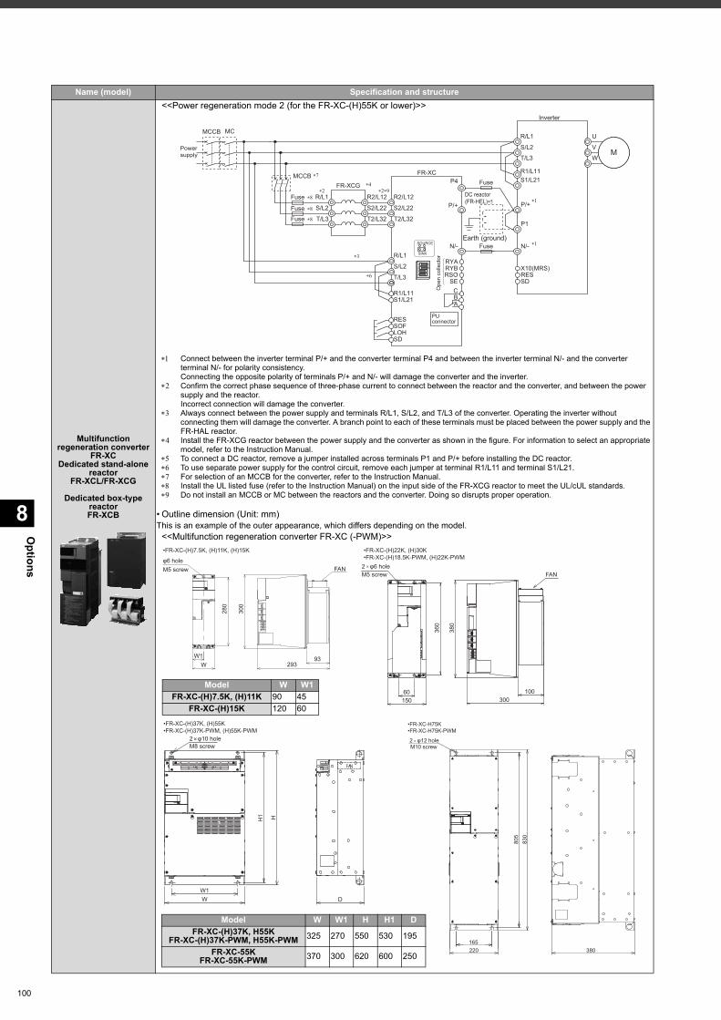
Options
8
100
Multifunction regeneration converter
FR-XCDedicated stand-alone
reactorFR-XCL/FR-XCG
Dedicated box-type reactorFR-XCB
<<Power regeneration mode 2 (for the FR-XC-(H)55K or lower)>>
Connect between the inverter terminal P/+ and the converter terminal P4 and between the inverter terminal N/- and the converter terminal N/- for polarity consistency. Connecting the opposite polarity of terminals P/+ and N/- will damage the converter and the inverter.
Confirm the correct phase sequence of three-phase current to connect between the reactor and the converter, and between the power supply and the reactor. Incorrect connection will damage the converter.
Always connect between the power supply and terminals R/L1, S/L2, and T/L3 of the converter. Operating the inverter without connecting them will damage the converter. A branch point to each of these terminals must be placed between the power supply and the FR-HAL reactor.
Install the FR-XCG reactor between the power supply and the converter as shown in the figure. For information to select an appropriate model, refer to the Instruction Manual.
To connect a DC reactor, remove a jumper installed across terminals P1 and P/+ before installing the DC reactor. To use separate power supply for the control circuit, remove each jumper at terminal R1/L11 and terminal S1/L21. For selection of an MCCB for the converter, refer to the Instruction Manual. Install the UL listed fuse (refer to the Instruction Manual) on the input side of the FR-XCG reactor to meet the UL/cUL standards. Do not install an MCCB or MC between the reactors and the converter. Doing so disrupts proper operation.
• Outline dimension (Unit: mm)This is an example of the outer appearance, which differs depending on the model.
<<Multifunction regeneration converter FR-XC (-PWM)>>
Name (model) Specification and structure
Power supply
MCCB MC
FR-XCGP4
N/-
FR-XC
R/L1
S/L2
T/L3 RSOSE
CBA
RYB
IM
P/+R2/L12
S2/L22
T2/L32
P/+
Fuse
R/L1
N/-
Inverter
MS/L2
T/L3
Fuse
RYA
RESSD
X10(MRS)
R1/L11S1/L21
LOHSD
RESSOF
PUconnector
Ope
n co
llect
or
SINK
SOURCE ��
��
��
����
��
R1/L11S1/L21
R2/L12
S2/L22
T2/L32
R/L1
S/L2
T/L3
U
V
W
P1
Earth (ground)
DC reactor(FR-HEL)��
��
Fuse ��
Fuse ��
Fuse ��
��
MCCB�
93293
300
W1W
280
φ6 hole
•FR-XC-(H)7.5K, (H)11K, (H)15K
FANM5 screw
300100
380
15060
360
2 φ6 hole FAN
•FR-XC-(H)22K, (H)30K•FR-XC-(H)18.5K-PWM, (H)22K-PWM
M5 screw
Model W W1FR-XC-(H)7.5K, (H)11K 90 45
FR-XC-(H)15K 120 60
2 φ10 hole M8 screw
W1W D
H1 H
•FR-XC-(H)37K, (H)55K•FR-XC-(H)37K-PWM, (H)55K-PWM
2 φ12 holeM10 screw
805
830
165220 380
•FR-XC-H75K•FR-XC-H75K-PWM
Model W W1 H H1 DFR-XC-(H)37K, H55K
FR-XC-(H)37K-PWM, H55K-PWM 325 270 550 530 195
FR-XC-55KFR-XC-55K-PWM 370 300 620 600 250
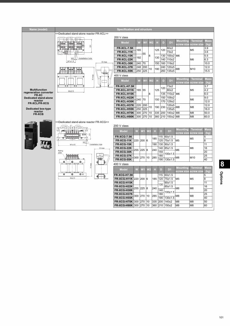
8
Options
Multifunction regeneration converter
FR-XCDedicated stand-alone
reactorFR-XCL/FR-XCG
Dedicated box-type reactorFR-XCB
<<Dedicated stand-alone reactor FR-XCL>>
<<Dedicated stand-alone reactor FR-XCG>>
Name (model) Specification and structure
W1±1.5
D1
Installation hole
D max
H m
axW±2.5
W2
200 V class
400 V class
Model W W1 W2 H D D1 Mountingscrew size
Terminalscrew size
Mass(kg)
FR-XCL-7.5K165
558
125 12080±2
M6
M53.9
FR-XCL-11K 73±2 3.6FR-XCL-15K
192 130130 100±2
M65.5
FR-XCL-22K 140 110±2 6.3FR-XCL-30K 240 70 150 160 119±2 10.0FR-XCL-37K 248 200
10 190240 120±5
M8 M1012.0
FR-XCL-55K 250 225 260 135±5 15.5
Model W W1 W2 H D D1 Mountingscrew size
Terminalscrew size
Mass(kg)
FR-XCL-H7.5K165 55
8125
12073±2
M6M5
3.7FR-XCL-H11K 80±2 4.2FR-XCL-H15K 135 110±2 6.0FR-XCL-H22K
240 70 150150 109±2
M69.0
FR-XCL-H30K 170 129±2 12.0FR-XCL-H37K 220 200
10 190 230120±5
M8 M812.0
FR-XCL-H55K 250 225 135±5 16.0FR-XCL-H75K 300 270 10 335 200 140±2 M8 M8 50.0FR-XCL-H90K 300 270 10 360 210 150±2 M8 M8 60.0
D1
Installation holeW2
W1±15
H m
ax
D maxRating plate
W±2.5
200 V class
400 V class
Model W W1 W2 H D D1 Mountingscrew size
Terminalscrew size
Mass(kg)
FR-XCG-7.5K220 200 6
185115 60±1.5
M5M5
5FR-XCG-11K 120 75±1.5 8FR-XCG-15K 190 130 90±1.5
M611
FR-XCG-22K255 225 8 240
140 85±1.5M6
16FR-XCG-30K 155
100±1.520
FR-XCG-37K300 270 10 285
180M8 M10
25FR-XCG-55K 190 130±1.5 40
Model W W1 W2 H D D1 Mountingscrew size
Terminalscrew size
Mass(kg)
FR-XCG-H7.5K220 200 6 185
115 60±1.5M5 M5
5FR-XCG-H11K 120 75±1.5 8FR-XCG-H15K
13090±1.5 11
FR-XCG-H22K255 225 8 240
85±1.5M6 M6
16FR-XCG-H30K 140
100±1.520
FR-XCG-H37K300 270 10 285
180M8 M8
25FR-XCG-H55K 190 130±1.5 40FR-XCG-H75K 300 270 10 335 200 140±2 M8 M8 50FR-XCG-H90K 300 270 10 360 210 150±2 M8 M8 60
101
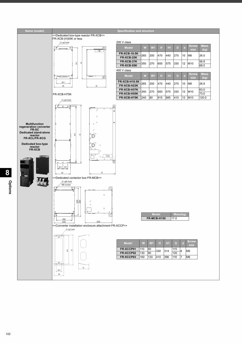
Options
8
102
Multifunction regeneration converter
FR-XCDedicated stand-alone
reactorFR-XCL/FR-XCG
Dedicated box-type reactorFR-XCB
<<Dedicated box-type reactor FR-XCB>>FR-XCB-(H)55K or less
<<Dedicated contactor box FR-MCB>>
<<Converter installation enclosure attachment FR-XCCP>>
Name (model) Specification and structure
H
D
W1
H1
W
2 φd hole 200 V class
400 V class
Model W W1 H H1 D d Screwsize
Mass(kg)
FR-XCB-18.5K265 200 470 440 275 10 M8 26.0FR-XCB-22K
FR-XCB-37K350 270 600 575 330 12 M10
56.9FR-XCB-55K 68.5
Model W W1 H H1 D d Screwsize
Mass(kg)
FR-XCB-H18.5K265 200 470 440 275 10 M8 26.9FR-XCB-H22K
FR-XCB-H37K350 270 600 575 330 12 M10
63.0FR-XCB-H55K 73.0FR-XCB-H75K 240 80 915 885 410 12 M10 120.0
FR-XCB-H75K
D
W1 W1
W
H1 H
3 φd hole
325
350
185240 320
M6 screw2 φ8 hole
Model Mass(kg)FR-MCB-H150 17.0
DW1
H1 H
W
2 φd hole
Model W W1 H H1 D d Screwsize
FR-XCCP01 110 60330 314
1156 M5FR-XCCP02 130 90 120
FR-XCCP03 160 120 410 396 116 7 M6
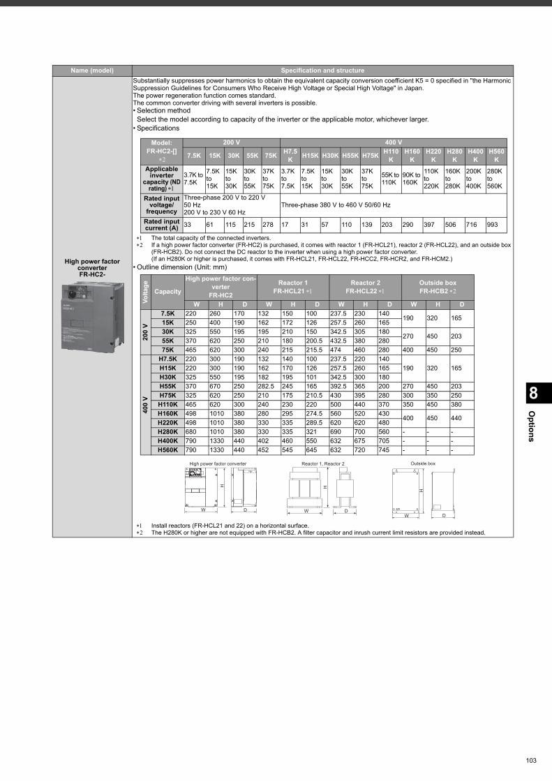
8
Options
High power factor converterFR-HC2-
Substantially suppresses power harmonics to obtain the equivalent capacity conversion coefficient K5 = 0 specified in "the Harmonic Suppression Guidelines for Consumers Who Receive High Voltage or Special High Voltage" in Japan.The power regeneration function comes standard.The common converter driving with several inverters is possible.• Selection method
Select the model according to capacity of the inverter or the applicable motor, whichever larger.• Specifications
The total capacity of the connected inverters. If a high power factor converter (FR-HC2) is purchased, it comes with reactor 1 (FR-HCL21), reactor 2 (FR-HCL22), and an outside box
(FR-HCB2). Do not connect the DC reactor to the inverter when using a high power factor converter.(If an H280K or higher is purchased, it comes with FR-HCL21, FR-HCL22, FR-HCC2, FR-HCR2, and FR-HCM2.)
• Outline dimension (Unit: mm)
Install reactors (FR-HCL21 and 22) on a horizontal surface. The H280K or higher are not equipped with FR-HCB2. A filter capacitor and inrush current limit resistors are provided instead.
Name (model) Specification and structure
Model:FR-HC2-[]
200 V 400 V
7.5K 15K 30K 55K 75K H7.5K H15K H30K H55K H75K H110
KH160
KH220
KH280
KH400
KH560
KApplicable
inverter capacity(ND
rating)
3.7K to 7.5K
7.5K to 15K
15K to 30K
30K to 55K
37K to 75K
3.7K to 7.5K
7.5K to 15K
15K to 30K
30K to 55K
37K to 75K
55K to 110K
90K to 160K
110K to 220K
160K to 280K
200K to 400K
280K to 560K
Rated input voltage/
frequency
Three-phase 200 V to 220 V 50 Hz200 V to 230 V 60 Hz
Three-phase 380 V to 460 V 50/60 Hz
Rated input current (A) 33 61 115 215 278 17 31 57 110 139 203 290 397 506 716 993
Volta
ge
Capacity
High power factor con-verter
FR-HC2
Reactor 1 FR-HCL21
Reactor 2 FR-HCL22
Outside boxFR-HCB2
W H D W H D W H D W H D
200
V
7.5K 220 260 170 132 150 100 237.5 230 140190 320 16515K 250 400 190 162 172 126 257.5 260 165
30K 325 550 195 195 210 150 342.5 305 180270 450 20355K 370 620 250 210 180 200.5 432.5 380 280
75K 465 620 300 240 215 215.5 474 460 280 400 450 250
400
V
H7.5K 220 300 190 132 140 100 237.5 220 140190 320 165H15K 220 300 190 162 170 126 257.5 260 165
H30K 325 550 195 182 195 101 342.5 300 180H55K 370 670 250 282.5 245 165 392.5 365 200 270 450 203H75K 325 620 250 210 175 210.5 430 395 280 300 350 250H110K 465 620 300 240 230 220 500 440 370 350 450 380H160K 498 1010 380 280 295 274.5 560 520 430
400 450 440H220K 498 1010 380 330 335 289.5 620 620 480H280K 680 1010 380 330 335 321 690 700 560 - - -H400K 790 1330 440 402 460 550 632 675 705 - - -H560K 790 1330 440 452 545 645 632 720 745 - - -
High power factor converter
W D
H
Reactor 1, Reactor 2
W
H
D
PSCLR
P.CPY PWRREGEN DRIVE....... FAN
H
W D
Outside box
103
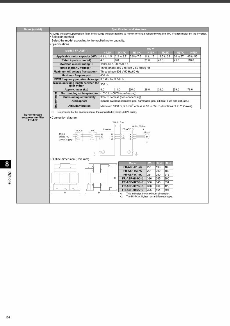
Options
8
104
Surge voltage suppression filter
FR-ASF
A surge voltage suppression filter limits surge voltage applied to motor terminals when driving the 400 V class motor by the inverter.• Selection method
Select the model according to the applied motor capacity.• Specifications
Determined by the specification of the connected inverter (400 V class).
• Connection diagram
• Outline dimension (Unit: mm)
Name (model) Specification and structure
Model: FR-ASF-[] 400 VH1.5K H3.7K H7.5K H15K H22K H37K H55K
Applicable motor capacity (kW) 0.4 to 1.5 2.2 to 3.7 5.5 to 7.5 11 to 15 18.5 to 22 30 to 37 45 to 55Rated input current (A) 4.0 9.0 17.0 31.0 43.0 71.0 110.0
Overload current rating 150% 60 s, 200% 0.5 sRated input AC voltage Three-phase 380 V to 460 V 50 Hz/60 Hz
Maximum AC voltage fluctuation Three-phase 506 V 50 Hz/60 HzMaximum frequency 400 Hz
PWM frequency permissible range 0.5 kHz to 14.5 kHzMaximum wiring length between the
filter-motor 300 m
Approx. mass (kg) 8.0 11.0 20.0 28.0 38.0 59.0 78.0
Envi
ronm
ent Surrounding air temperature -10°C to +50°C (non-freezing)
Surrounding air humidity 90% RH or less (non-condensing)Atmosphere Indoors (without corrosive gas, flammable gas, oil mist, dust and dirt, etc.)
Altitude/vibration Maximum 1000 m, 5.9 m/s2 or less at 10 to 55 Hz (directions of X, Y, Z axes)
RST
XYZ
FR-ASFMotor
Within 300 m
IMUVW
UVW
InverterMCCB MCThree-phase ACpower supply
Within 5 m
W D
H
This indicates the maximum dimension. The H15K or higher has a different shape.
Model W H D FR-ASF-H1.5K 221 193 160FR-ASF-H3.7K 221 200 180FR-ASF-H7.5K 281 250 215
FR-ASF-H15K 336 265 290FR-ASF-H22K 336 345 354FR-ASF-H37K 376 464 429FR-ASF-H55K 396 464 594
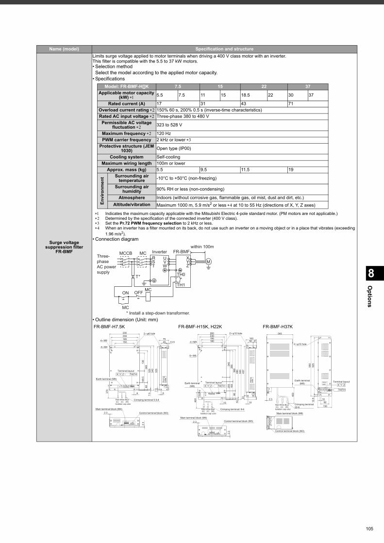
8
Options
Surge voltage suppression filter
FR-BMF
Limits surge voltage applied to motor terminals when driving a 400 V class motor with an inverter.This filter is compatible with the 5.5 to 37 kW motors.• Selection method
Select the model according to the applied motor capacity.• Specifications
Indicates the maximum capacity applicable with the Mitsubishi Electric 4-pole standard motor. (PM motors are not applicable.) Determined by the specification of the connected inverter (400 V class). Set the Pr.72 PWM frequency selection to 2 kHz or less. When an inverter has a filter mounted on its back, do not use such an inverter on a moving object or in a place that vibrates (exceeding
1.96 m/s2).• Connection diagram
• Outline dimension (Unit: mm)
Name (model) Specification and structure
Model: FR-BMF-H[]K 7.5 15 22 37Applicable motor capacity
(kW) 5.5 7.5 11 15 18.5 22 30 37
Rated current (A) 17 31 43 71Overload current rating 150% 60 s, 200% 0.5 s (inverse-time characteristics)Rated AC input voltage Three-phase 380 to 480 V
Permissible AC voltage fluctuation 323 to 528 V
Maximum frequency 120 HzPWM carrier frequency 2 kHz or lower
Protective structure (JEM 1030) Open type (IP00)
Cooling system Self-coolingMaximum wiring length 100m or lower
Approx. mass (kg) 5.5 9.5 11.5 19
Envi
ronm
ent Surrounding air
temperature -10°C to +50°C (non-freezing)
Surrounding air humidity 90% RH or less (non-condensing)
Atmosphere Indoors (without corrosive gas, flammable gas, oil mist, dust and dirt, etc.)Altitude/vibration Maximum 1000 m, 5.9 m/s2 or less at 10 to 55 Hz (directions of X, Y, Z axes)
RS
T
XYZ
TH0
TH1
FR-BMF
within 100m
MUVW
Inverter
* Install a step-down transformer.
MCCB MCThree-
phase
AC power
supply
T*
ON
MC
OFFMC
FR-BMF-H7.5K FR-BMF-H15K, H22K FR-BMF-H37K
7.5
7.5
6014
9.5
325
340
325
370
Crimping terminal 5.5-4
6
2.3
Isolation cap color
Main terminal block (M4)Control terminal block (M3)
(U)Red Blue
(W)(V)White
2.3
6
195208
150
230
4 M4
4 M5
245
138
Rat
ing
plat
e
2 φ6 hole
13.57545
XTerminal layout
Y Z TH0 TH1
Earth terminal (M5)
Rat
ing
plat
e
10
165
8028
538
0
500
480
2 φ10 hole
205
Isolation cap color
Main terminal block (M5)Control terminal block (M3)2.3
420
Red(U)
2.3
Crimping terminal: 8-6Blue(W)(V)
White
10
180
260
195230
6 M5
4 M8
245
457
33
10
3110050
XTerminal layout
Y Z TH0 TH1Earth terminal
(M6)Ratingplate
450
550
525
Crimping terminal22-6
2.3
130
108012
.5
245
XTerminal layout
Y Z
TH0 TH1
Earth terminal(M8)
Isolation cap color(U)Red Blue
(W)(V)White
Main terminal block (M6)
Control terminal block (M3)
2 φ10 hole
105
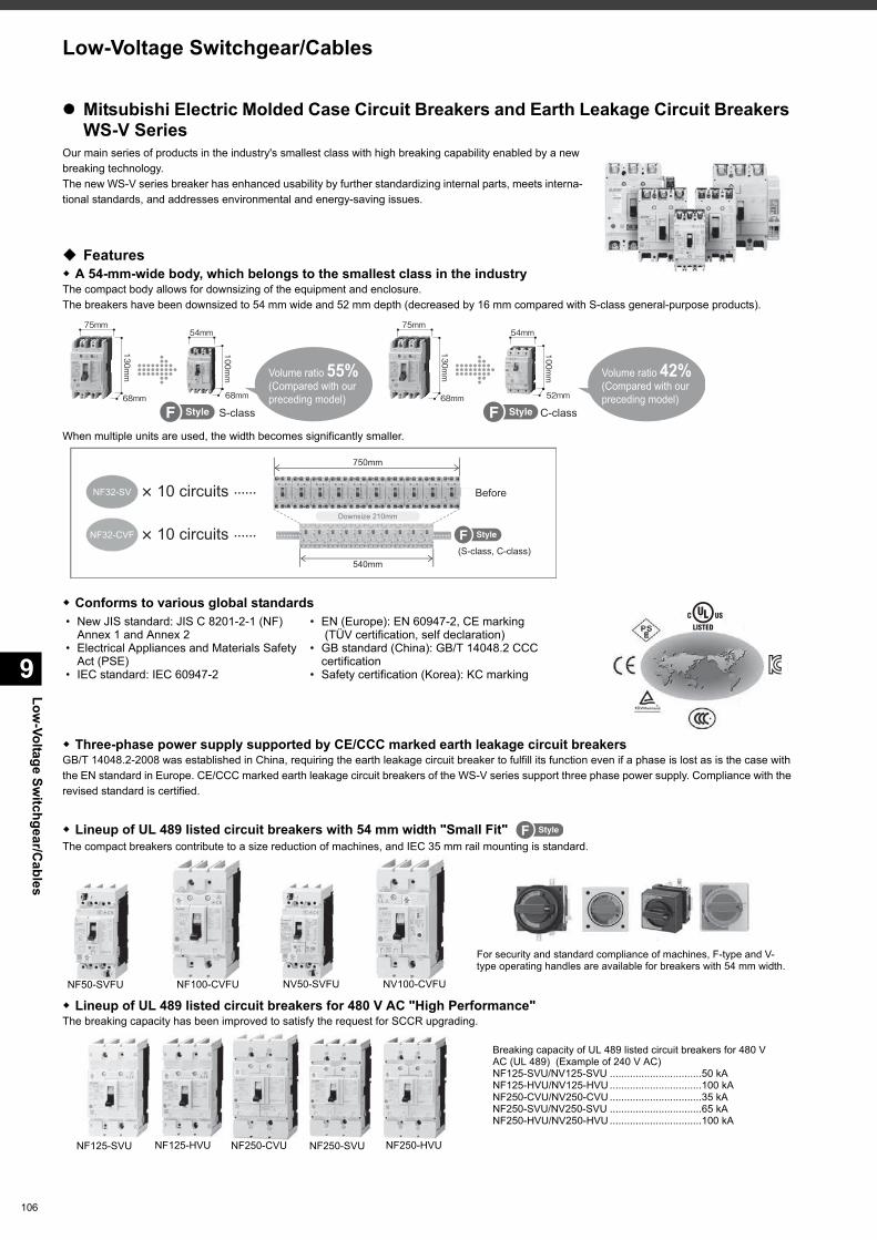
Low-Voltage Sw
itchgear/Cables
9
106
Low-Voltage Switchgear/Cables
Mitsubishi Electric Molded Case Circuit Breakers and Earth Leakage Circuit Breakers WS-V Series
Our main series of products in the industry's smallest class with high breaking capability enabled by a new breaking technology.The new WS-V series breaker has enhanced usability by further standardizing internal parts, meets interna-tional standards, and addresses environmental and energy-saving issues.
Features A 54-mm-wide body, which belongs to the smallest class in the industryThe compact body allows for downsizing of the equipment and enclosure.The breakers have been downsized to 54 mm wide and 52 mm depth (decreased by 16 mm compared with S-class general-purpose products).
When multiple units are used, the width becomes significantly smaller.
Three-phase power supply supported by CE/CCC marked earth leakage circuit breakersGB/T 14048.2-2008 was established in China, requiring the earth leakage circuit breaker to fulfill its function even if a phase is lost as is the case with the EN standard in Europe. CE/CCC marked earth leakage circuit breakers of the WS-V series support three phase power supply. Compliance with the revised standard is certified.
Lineup of UL 489 listed circuit breakers with 54 mm width "Small Fit" The compact breakers contribute to a size reduction of machines, and IEC 35 mm rail mounting is standard.
Lineup of UL 489 listed circuit breakers for 480 V AC "High Performance"The breaking capacity has been improved to satisfy the request for SCCR upgrading.
Conforms to various global standards • New JIS standard: JIS C 8201-2-1 (NF)
Annex 1 and Annex 2 • Electrical Appliances and Materials Safety
Act (PSE) • IEC standard: IEC 60947-2
• EN (Europe): EN 60947-2, CE marking (TÜV certification, self declaration)
• GB standard (China): GB/T 14048.2 CCC certification
• Safety certification (Korea): KC marking
Volume ratio 55% (Compared with our preceding model)
S-class C-class
Volume ratio 42% (Compared with our preceding model)
540mm
750mm
NF32-SV
NF32-CVF
Before
Downsize 210mm
(S-class, C-class)
10 circuits
10 circuits
NF50-SVFU NV50-SVFU NV100-CVFUNF100-CVFU
For security and standard compliance of machines, F-type and V-type operating handles are available for breakers with 54 mm width.
Breaking capacity of UL 489 listed circuit breakers for 480 V AC (UL 489) (Example of 240 V AC)NF125-SVU/NV125-SVU ................................50 kANF125-HVU/NV125-HVU ................................100 kANF250-CVU/NV250-CVU ................................35 kANF250-SVU/NV250-SVU ................................65 kANF250-HVU/NV250-HVU ................................100 kA
NF125-SVU NF250-SVU NF250-HVUNF125-HVU NF250-CVU
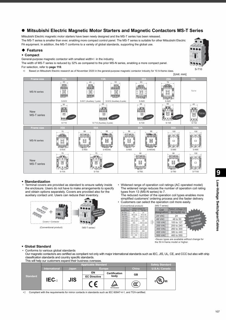
9
Low-Voltage Sw
itchgear/Cables
Mitsubishi Electric Magnetic Motor Starters and Magnetic Contactors MS-T SeriesMitsubishi Electric magnetic motor starters have been newly designed and the MS-T series has been released.The MS-T series is smaller than ever, enabling more compact control panel. The MS-T series is suitable for other Mitsubishi Electric FA equipment. In addition, the MS-T conforms to a variety of global standards, supporting the global use.
Features CompactGeneral-purpose magnetic contactor with smallest width in the industry.The width of MS-T series is reduced by 32% as compared to the prior MS-N series, enabling a more compact panel.For selection, refer to page 110. Based on Mitsubishi Electric research as of November 2020 in the general-purpose magnetic contactor industry for 10 A-frame class.
[Unit: mm]
Standardization
Global Standard • Conforms to various global standards
Our magnetic contactors are certified as compliant not only with major international standards such as IEC, JIS, UL, CE, and CCC but also with ship classification standards and country specific standards.This will help our customers expand their business overseas.
Compliant with the requirements for mirror contacts in standards such as IEC 60947-4-1, and TÜV-certified.
• Terminal covers are provided as standard to ensure safety inside the enclosure. Users do not have to make arrangements to specify and obtain options separately. Covers are provided also for the auxiliary contact unit. Users can reduce their inventory.
• Widened range of operation coil ratings (AC operated model)The widened range reduces the number of operation coil rating types from 13 (MS-N series) to 7.The reduced number of the operation coil types enables more simplified customers' ordering process and the faster delivery.
• Customers can select the operation coil more easily.
Standard
Applicable Standard Safety StandardInternational Japan Europe China U.S.A./ Canada
IEC JISEN Certification
body GBEC Directive
S-T10
44
Frame size 11A 13A 20A 32A
MS-N series
NewMS-T series
MS-N series
NewMS-T series
S-N11 (Auxiliary 1-pole) S-N12 (Auxiliary 2-pole)S-N10
S-N35
S-T35 S-T50 S-T65 S-T80 S-T100
S-N50 S-N50AE S-N65 S-N65AE S-N80 S-N95
None
S-N20 S-N25
S-T12 (Auxiliary 2-pole)S-T10 S-T20 S-T25 S-T32
135/L33/L21/L1
146/T34/T22/T1
43
135/L33/L21/L1
146/T34/T22/T1
43
2113
5/L33/L21/L1
2214
6/T34/T22/T1
63
6/T32/T1 4/T2
5/L33/L21/L1
43
44
13
32
3121
2214
75
14
13 215/L33/L21/L1
226/T34/T22/T1
53
36 44 63
-7mm! -9mm!
-13mm!
-19mm!-12mm!
25A
Frame size 50A35A 65A 80A 100A
1/L1 3/L2 5/L3
2/T1 4/T2 6/T3
43
New
75
6/T32/T1 4/T2
5/L33/L21/L1
43
44
13
32
3121
2214
88
1/L1 3/L2 5/L3
2/T1 4/T2 6/T3
13212214
43313244
88 88
1/L1 3/L2 5/L3
2/T1 4/T2 6/T3
13212214
43313244
88 100
1/L1 3/L2 5/L3
2/T1 4/T2 6/T3
100
1/L1 3/L2 5/L3
2/T1 4/T2 6/T3
75 75 88
1/L1 3/L2 5/L3
2/T1 4/T2 6/T3
88
1/L1 3/L2 5/L3
2/T1 4/T2 6/T3
100
1/L1 3/L2 5/L3
2/T1 4/T2 6/T3-12mm!
Covers are
attached as
standard.
Covers + Contactor
(Conventional product) (MS-T series)
(Conventional product) (MS-T series)
24 VAC48 VAC100 VAC120 VAC127 VAC200 VAC220 VAC230 VAC260 VAC380 VAC400 VAC440 VAC500 VAC
2448 to 50
100110 to 120125 to 127
200208 to 220220 to 240240 to 260346 to 380380 to 415415-440
500
2448 to 50
100 to 110115 to 120
127200 to 220
220230 to 240260 to 280
380400 to 440460 to 480500 to 550
Coildesignation
Rated voltage [V]50 Hz 60 Hz
24 VAC
�Seven types are available without change for the 50 A frame model or higher.
48 VAC100 VAC200 VAC300 VAC400 VAC500 VAC
2448 to 50
100 to 127200 to 240260 to 300380 to 440460 to 550
50 Hz/60 Hz
Integrated
coil ratings
facilitate
selection!
Rated voltage [V]Coildesignation
107
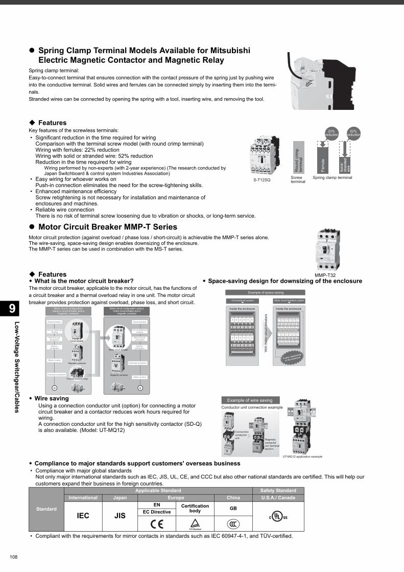
Low-Voltage Sw
itchgear/Cables
9
108
Spring Clamp Terminal Models Available for Mitsubishi Electric Magnetic Contactor and Magnetic Relay
Spring clamp terminal:Easy-to-connect terminal that ensures connection with the contact pressure of the spring just by pushing wire into the conductive terminal. Solid wires and ferrules can be connected simply by inserting them into the termi-nals.Stranded wires can be connected by opening the spring with a tool, inserting wire, and removing the tool.
FeaturesKey features of the screwless terminals: • Significant reduction in the time required for wiring
Comparison with the terminal screw model (with round crimp terminal)Wiring with ferrules: 22% reductionWiring with solid or stranded wire: 52% reductionReduction in the time required for wiring
Wiring performed by non-experts (with 2-year experience) (The research conducted by Japan Switchboard & control system Industries Association)
• Easy wiring for whoever works onPush-in connection eliminates the need for the screw-tightening skills.
• Enhanced maintenance efficiencyScrew retightening is not necessary for installation and maintenance of enclosures and machines.
• Reliable wire connectionThere is no risk of terminal screw loosening due to vibration or shocks, or long-term service.
Motor Circuit Breaker MMP-T SeriesMotor circuit protection (against overload / phase loss / short-circuit) is achievable the MMP-T series alone.The wire-saving, space-saving design enables downsizing of the enclosure.The MMP-T series can be used in combination with the MS-T series.
Features
Compliance to major standards support customers' overseas business • Compliance with major global standards
Not only major international standards such as IEC, JIS, UL, CE, and CCC but also other national standards are certified. This will help our customers expand their business in foreign countries.
• Compliant with the requirements for mirror contacts in standards such as IEC 60947-4-1, and TÜV-certified.
What is the motor circuit breaker?The motor circuit breaker, applicable to the motor circuit, has the functions of a circuit breaker and a thermal overload relay in one unit. The motor circuit breaker provides protection against overload, phase loss, and short circuit.
Space-saving design for downsizing of the enclosure
Wire savingUsing a connection conductor unit (option) for connecting a motor circuit breaker and a contactor reduces work hours required for wiring.A connection conductor unit for the high sensitivity contactor (SD-Q) is also available. (Model: UT-MQ12)
Standard
Applicable Standard Safety StandardInternational Japan Europe China U.S.A./ Canada
IEC JISEN Certification
body GBEC Directive
S-T12SQ Screw terminal
Spring clamp terminal
Rou
nd c
rimp
term
inal
Ferr
ule
Solid/
stranded
wire
22% reduction
52% reduction
MMP-T32
Circuit breaker
Magnetic contactor
Magnetic contactor
Thermal overload relay
Motor circuit breaker
Motor circuit configurationusing a circuit breaker and a
magnetic contactor
Motor circuit configuration using amotor circuit breaker and a
magnetic contactor
l l dl l dl l d
Disconnection
Circuit opening/closing
Short-circuit protection
Device protection
Motor control
Overload protection
M M
Disconnection
Circuit opening/closing
Short-circuit protection
Device protection
Overload protection
Motor control
Inside the enclosure Inside the enclosure
Example of space saving
Further downs
izing
of the enclosu
re
Conventional system Motor circuit breakers system
With
mot
or c
ircui
t bre
aker
s
Example of wire savingConductor unit connection example
UT-MQ12 application example
Magneticcontactorcoil terminalsection
Magnecontaccoil tersection
Connectionconductorunit
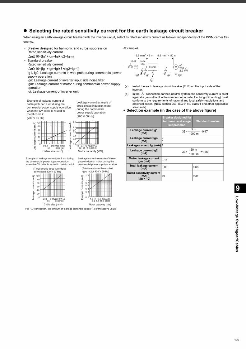
9
Low-Voltage Sw
itchgear/Cables
Selecting the rated sensitivity current for the earth leakage circuit breakerWhen using an earth leakage circuit breaker with the inverter circuit, select its rated sensitivity current as follows, independently of the PWM carrier fre-quency.
• Breaker designed for harmonic and surge suppressionRated sensitivity currentIn10×(Ig1+Ign+Igi+Ig2+Igm)
• Standard breakerRated sensitivity currentIn10×{Ig1+Ign+Igi+3×(Ig2+Igm)}Ig1, Ig2: Leakage currents in wire path during commercial power supply operationIgn: Leakage current of inverter input side noise filterIgm: Leakage current of motor during commercial power supply operationIgi: Leakage current of inverter unit
<Example>
(a) Install the earth leakage circuit breaker (ELB) on the input side of the inverter.
(b) In the connection earthed-neutral system, the sensitivity current is blunt against a ground fault in the inverter output side. Earthing (Grounding) must conform to the requirements of national and local safety regulations and electrical codes. (NEC section 250, IEC 61140 class 1 and other applicable standards)
Selection example (in the case of the above figure)
Example of leakage current ofcable path per 1 km during thecommercial power supply operationwhen the CV cable is routed inmetal conduit(200 V 60 Hz)
Leakage current example ofthree-phase induction motorduring the commercialpower supply operation(200 V 60 Hz)
Motor capacity (kW)Cable size(mm )2
1.5 3.72.2
7.5 152211
3730
55455.5 18.5
0.1
0.20.3
0.50.71.0
2.0
Leak
age
curr
ents
(mA
)
0
20
40
60
80
100
120
Leak
age
curr
ents
(mA)
2 3.55.5
8 14 223038
6080100
150
Motor capacity (kW)
For " " connection, the amount of leakage current is appox.1/3 of the above value.
(Three-phase three-wire delta connection 400 V 60 Hz)
Example of leakage current per 1 km during the commercial power supply operation when the CV cable is routed in metal conduit
Leakage current example of three-phase induction motor during the commercial power supply operation
(Totally-enclosed fan-cooled type motor 400 V 60 Hz)
0
20
40
60
80
100
120
leak
age
curr
ents
(mA
)
leak
age
curr
ents
(mA
)
2 3.55.5
8 14223038
6080100
150
Cable size (mm2)
0. 1
0. 20. 3
0. 50. 71. 0
2. 0
1. 5 3. 72. 2
7. 5 152211
3730
55455.5 18. 5
Noise filter
Inverter
ELB
Ig1 Ign
Igi
Ig2 Igm
M
5.5 mm2 5 m 5.5 mm2 50 m
200 V2.2 kW
3
Breaker designed for harmonic and surge
suppressionStandard breaker
Leakage current Ig1 (mA) 33×
5 m=0.17
1000 mLeakage current Ign
(mA) 0
Leakage current Igi (mA) 1
Leakage current Ig2 (mA) 33×
50 m=1.65
1000 mMotor leakage current
Igm (mA) 0.18
Total leakage current (mA) 3.00 6.66
Rated sensitivity current (mA)
(Ig × 10)30 100
109
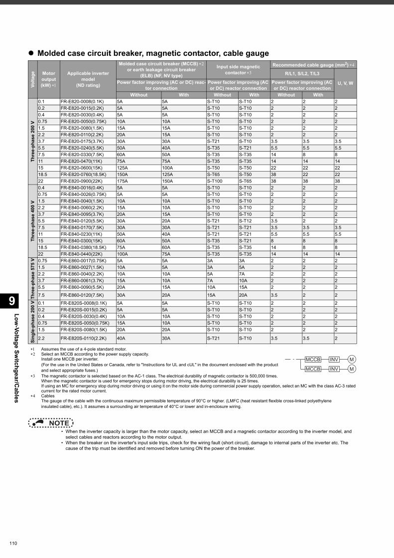
Low-Voltage Sw
itchgear/Cables
9
110
Molded case circuit breaker, magnetic contactor, cable gauge
Assumes the use of a 4-pole standard motor. Select an MCCB according to the power supply capacity.
Install one MCCB per inverter.(For the use in the United States or Canada, refer to "Instructions for UL and cUL" in the document enclosed with the product and select appropriate fuses.)
The magnetic contactor is selected based on the AC-1 class. The electrical durability of magnetic contactor is 500,000 times. When the magnetic contactor is used for emergency stops during motor driving, the electrical durability is 25 times.If using an MC for emergency stop during motor driving or using it on the motor side during commercial power supply operation, select an MC with the class AC-3 rated current for the rated motor current.
CablesThe gauge of the cable with the continuous maximum permissible temperature of 90°C or higher. (LMFC (heat resistant flexible cross-linked polyethyleneinsulated cable), etc.). It assumes a surrounding air temperature of 40°C or lower and in-enclosure wiring.
NOTE • When the inverter capacity is larger than the motor capacity, select an MCCB and a magnetic contactor according to the inverter model, and
select cables and reactors according to the motor output. • When the breaker on the inverter's input side trips, check for the wiring fault (short circuit), damage to internal parts of the inverter etc. The
cause of the trip must be identified and removed before turning ON the power of the breaker.
Volta
ge Motor output (kW)
Applicable inverter model
(ND rating)
Molded case circuit breaker (MCCB) or earth leakage circuit breaker
(ELB) (NF, NV type)
Input side magneticcontactor
Recommended cable gauge (mm2)
R/L1, S/L2, T/L3
U, V, WPower factor improving (AC or DC) reac-tor connection
Power factor improving (AC or DC) reactor connection
Power factor improving (AC or DC) reactor connection
Without With Without With Without With
Thre
e-ph
ase
200
V
0.1 FR-E820-0008(0.1K) 5A 5A S-T10 S-T10 2 2 20.2 FR-E820-0015(0.2K) 5A 5A S-T10 S-T10 2 2 20.4 FR-E820-0030(0.4K) 5A 5A S-T10 S-T10 2 2 20.75 FR-E820-0050(0.75K) 10A 10A S-T10 S-T10 2 2 21.5 FR-E820-0080(1.5K) 15A 15A S-T10 S-T10 2 2 22.2 FR-E820-0110(2.2K) 20A 15A S-T10 S-T10 2 2 23.7 FR-E820-0175(3.7K) 30A 30A S-T21 S-T10 3.5 3.5 3.55.5 FR-E820-0240(5.5K) 50A 40A S-T35 S-T21 5.5 5.5 5.57.5 FR-E820-0330(7.5K) 60A 50A S-T35 S-T35 14 8 811 FR-E820-0470(11K) 75A 75A S-T35 S-T35 14 14 1415 FR-E820-0600(15K) 125A 100A S-T50 S-T50 22 22 2218.5 FR-E820-0760(18.5K) 150A 125A S-T65 S-T50 38 22 2222 FR-E820-0900(22K) 175A 150A S-T100 S-T65 38 38 38
Thre
e-ph
ase
400
V
0.4 FR-E840-0016(0.4K) 5A 5A S-T10 S-T10 2 2 20.75 FR-E840-0026(0.75K) 5A 5A S-T10 S-T10 2 2 21.5 FR-E840-0040(1.5K) 10A 10A S-T10 S-T10 2 2 22.2 FR-E840-0060(2.2K) 15A 10A S-T10 S-T10 2 2 23.7 FR-E840-0095(3.7K) 20A 15A S-T10 S-T10 2 2 25.5 FR-E840-0120(5.5K) 30A 20A S-T21 S-T12 3.5 2 27.5 FR-E840-0170(7.5K) 30A 30A S-T21 S-T21 3.5 3.5 3.511 FR-E840-0230(11K) 50A 40A S-T21 S-T21 5.5 5.5 5.515 FR-E840-0300(15K) 60A 50A S-T35 S-T21 8 8 818.5 FR-E840-0380(18.5K) 75A 60A S-T35 S-T35 14 8 822 FR-E840-0440(22K) 100A 75A S-T35 S-T35 14 14 14
Thre
e-ph
ase
575
V 0.75 FR-E860-0017(0.75K) 5A 5A 3A 3A 2 2 21.5 FR-E860-0027(1.5K) 10A 5A 3A 5A 2 2 22.2 FR-E860-0040(2.2K) 10A 10A 5A 7A 2 2 23.7 FR-E860-0061(3.7K) 15A 10A 7A 10A 2 2 25.5 FR-E860-0090(5.5K) 20A 15A 10A 15A 2 2 2
7.5 FR-E860-0120(7.5K) 30A 20A 15A 20A 3.5 2 2
Sing
le-p
hase
200
V 0.1 FR-E820S-0008(0.1K) 5A 5A S-T10 S-T10 2 2 20.2 FR-E820S-0015(0.2K) 5A 5A S-T10 S-T10 2 2 20.4 FR-E820S-0030(0.4K) 10A 10A S-T10 S-T10 2 2 20.75 FR-E820S-0050(0.75K) 15A 10A S-T10 S-T10 2 2 21.5 FR-E820S-0080(1.5K) 20A 20A S-T10 S-T10 2 2 2
2.2 FR-E820S-0110(2.2K) 40A 30A S-T21 S-T10 3.5 3.5 2
MCCB INV
MCCB INV
M
M

111
MEMO
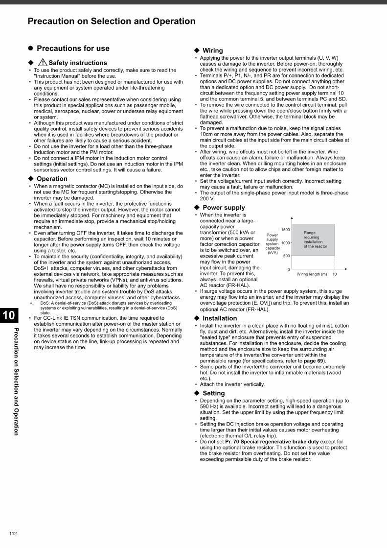
Precaution on Selection and Operation
10
112
Precautions for use
Safety instructions • To use the product safely and correctly, make sure to read the
"Instruction Manual" before the use. • This product has not been designed or manufactured for use with
any equipment or system operated under life-threatening conditions.
• Please contact our sales representative when considering using this product in special applications such as passenger mobile, medical, aerospace, nuclear, power or undersea relay equipment or system.
• Although this product was manufactured under conditions of strict quality control, install safety devices to prevent serious accidents when it is used in facilities where breakdowns of the product or other failures are likely to cause a serious accident.
• Do not use the inverter for a load other than the three-phase induction motor and the PM motor.
• Do not connect a IPM motor in the induction motor control settings (initial settings). Do not use an induction motor in the IPM sensorless vector control settings. It will cause a failure.
Operation • When a magnetic contactor (MC) is installed on the input side, do
not use the MC for frequent starting/stopping. Otherwise the inverter may be damaged.
• When a fault occurs in the inverter, the protective function is activated to stop the inverter output. However, the motor cannot be immediately stopped. For machinery and equipment that require an immediate stop, provide a mechanical stop/holding mechanism.
• Even after turning OFF the inverter, it takes time to discharge the capacitor. Before performing an inspection, wait 10 minutes or longer after the power supply turns OFF, then check the voltage using a tester, etc.
• To maintain the security (confidentiality, integrity, and availability) of the inverter and the system against unauthorized access, DoS attacks, computer viruses, and other cyberattacks from external devices via network, take appropriate measures such as firewalls, virtual private networks (VPNs), and antivirus solutions. We shall have no responsibility or liability for any problems involving inverter trouble and system trouble by DoS attacks, unauthorized access, computer viruses, and other cyberattacks.
DoS: A denial-of-service (DoS) attack disrupts services by overloading systems or exploiting vulnerabilities, resulting in a denial-of-service (DoS) state.
• For CC-Link IE TSN communication, the time required to establish communication after power-on of the master station or the inverter may vary depending on the circumstances. Normally it takes several seconds to establish communication. Depending on device status on the line, link-up processing is repeated and may increase the time.
Wiring • Applying the power to the inverter output terminals (U, V, W)
causes a damage to the inverter. Before power-on, thoroughly check the wiring and sequence to prevent incorrect wiring, etc.
• Terminals P/+, P1, N/-, and PR are for connection to dedicated options and DC power supplies. Do not connect anything other than a dedicated option and DC power supply. Do not short-circuit between the frequency setting power supply terminal 10 and the common terminal 5, and between terminals PC and SD.
• To remove the wire connected to the control circuit terminal, pull the wire while pressing down the open/close button firmly with a flathead screwdriver. Otherwise, the terminal block may be damaged.
• To prevent a malfunction due to noise, keep the signal cables 10cm or more away from the power cables. Also, separate the main circuit cables at the input side from the main circuit cables at the output side.
• After wiring, wire offcuts must not be left in the inverter. Wire offcuts can cause an alarm, failure or malfunction. Always keep the inverter clean. When drilling mounting holes in an enclosure etc., take caution not to allow chips and other foreign matter to enter the inverter.
• Set the voltage/current input switch correctly. Incorrect setting may cause a fault, failure or malfunction.
• The output of the single-phase power input model is three-phase 200 V.
Power supply • When the inverter is
connected near a large-capacity power transformer (500 kVA or more) or when a power factor correction capacitor is to be switched over, an excessive peak current may flow in the power input circuit, damaging the inverter. To prevent this, always install an optional AC reactor (FR-HAL).
• If surge voltage occurs in the power supply system, this surge energy may flow into an inverter, and the inverter may display the overvoltage protection (E. OV[]) and trip. To prevent this, install an optional AC reactor (FR-HAL).
Installation • Install the inverter in a clean place with no floating oil mist, cotton
fly, dust and dirt, etc. Alternatively, install the inverter inside the "sealed type" enclosure that prevents entry of suspended substances. For installation in the enclosure, decide the cooling method and the enclosure size to keep the surrounding air temperature of the inverter/the converter unit within the permissible range (for specifications, refer to page 69).
• Some parts of the inverter/the converter unit become extremely hot. Do not install the inverter to inflammable materials (wood etc.).
• Attach the inverter vertically.
Setting • Depending on the parameter setting, high-speed operation (up to
590 Hz) is available. Incorrect setting will lead to a dangerous situation. Set the upper limit by using the upper frequency limit setting.
• Setting the DC injection brake operation voltage and operating time larger than their initial values causes motor overheating (electronic thermal O/L relay trip).
• Do not set Pr. 70 Special regenerative brake duty except for using the optional brake resistor. This function is used to protect the brake resistor from overheating. Do not set the value exceeding permissible duty of the brake resistor.
500
0
1000
1500Range
requiring
installation
of the reactor
10Wiring length (m)
Power
supply
system
capacity
(kVA)
Precaution on Selection and Operation
10
Precaution on Selection and Operation
Real sensorless vector control • Under Real sensorless vector control, always execute offline auto
tuning before starting operations. • The speed command setting range under Real sensorless vector
control is 0 to 400 Hz. • The selectable carrier frequencies under Real sensorless vector
control are 2, 6, 10, and 14 kHz. • Torque control is not available in the low-speed (about 10 Hz or
less) regenerative range, or in the low speed with the light load (about 5 Hz or less with about 20% or less of the rated torque). Select the vector control.
• The motor may start running at a low speed even when the start signal (STF or STR) is not input. The motor may run also at a low speed when the speed limit value = 0 with a start command input. Confirm that the motor running does not cause any safety problems. Under torque control, do not switch between the forward rotation command (STF) and reverse rotation command (STR). The overcurrent trip (E. OC[]) or opposite rotation deceleration fault (E.11) occurs.
• If the inverter may restart during coasting under Real sensorless vector control, set the automatic restart after instantaneous power failure function to enable frequency search (Pr.57 "9999", Pr.162 = "10").
• Under Real sensorless vector control, sufficient torque may not be obtained in the extremely low-speed range of about 2 Hz or less.
• The approximate speed control range is as described below.Power drive: 1:200 (2, 4, 6 poles), 0.3 Hz or more for 60 Hz rating.1:30 (8, 10 poles), 2 Hz or more for 60 Hz ratingRegenerative driving: 1:12 (2 to 10 poles), 5 Hz or more for 60 Hz rating
Precautions for use of IPM motorWhen using the IPM motor, the following precautions must be observed as well.
Safety instructions • Do not use an IPM motor for an application where the motor is
driven by the load
Combination of motor and inverter • For the motor capacity, the rated motor current should be equal to
or less than the rated inverter current. (Note that the motor rated current should be 0.4 kW or higher (0.1 kW or higher for the 200 V class).) If a motor with substantially low rated current compared with the inverter rated current is used, speed and torque accuracies may deteriorate due to torque ripples, etc. Set the rated motor current to about 40% or higher of the inverter rated current.
• Only one IPM motor can be connected to an inverter. • An IPM motor cannot be driven by the commercial power supply.
Installation • While power is ON or for some time after power-OFF, do not
touch the motor since the motor may be extremely hot. Touching these devices may cause a burn.
Wiring • Applying the commercial power supply to input terminals (U, V,
W) of a motor will burn the motor. The motor must be connected with the output terminals (U, V, W) of the inverter.
• An IPM motor is a motor with permanent magnets embedded inside. High voltage is generated at the motor terminals while the motor is running. Before wiring or inspection, confirm that the motor is stopped. In an application, such a as fan or blower, where the motor is driven by the load, a low-voltage manual contactor must be connected at the inverter's output side, and wiring and inspection must be performed while the contactor is open. Otherwise an electric shock may be caused. The inverter power must be turned ON before closing the contacts of the contactor at the output side.
• Match the input terminals (U, V, W) of the motor and the output terminals (U, V, W) of the inverter when connecting.
• Use the following length of wiring or shorter when connecting an IPM motor.
Operation • About 0.1 s (magnetic pole detection time) takes to start a motor
after inputting a start signal. • An IPM motor is a motor with embedded permanent magnets.
Regression voltage is generated when the motor coasts at an instantaneous power failure or other incidents.The inverter's DC bus voltage increases if the motor coasts fast in this condition. When using the automatic restart after instantaneous power failure function, it is recommended to also use the regeneration avoidance operation to make startups stable.
• Thus, the relation between the rotation speed and the frequency setting is:Rotation speed = 120 × frequency setting value / number of motor poles
113
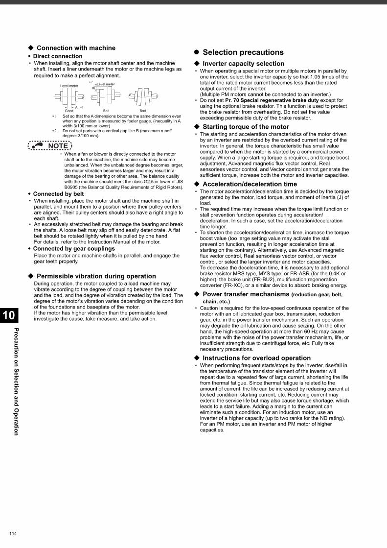
Precaution on Selection and Operation
10
114
Connection with machine Direct connection • When installing, align the motor shaft center and the machine
shaft. Insert a liner underneath the motor or the machine legs as required to make a perfect alignment.
Set so that the A dimensions become the same dimension even when any position is measured by feeler gauge. (inequality in A width 3/100 mm or lower)
Do not set parts with a vertical gap like B (maximum runoff degree: 3/100 mm).
NOTE • When a fan or blower is directly connected to the motor
shaft or to the machine, the machine side may become unbalanced. When the unbalanced degree becomes larger, the motor vibration becomes larger and may result in a damage of the bearing or other area. The balance quality with the machine should meet the class G2.5 or lower of JIS B0905 (the Balance Quality Requirements of Rigid Rotors).
Connected by belt • When installing, place the motor shaft and the machine shaft in
parallel, and mount them to a position where their pulley centers are aligned. Their pulley centers should also have a right angle to each shaft.
• An excessively stretched belt may damage the bearing and break the shafts. A loose belt may slip off and easily deteriorate. A flat belt should be rotated lightly when it is pulled by one hand.For details, refer to the Instruction Manual of the motor.
Connected by gear couplingsPlace the motor and machine shafts in parallel, and engage the gear teeth properly.
Permissible vibration during operationDuring operation, the motor coupled to a load machine may vibrate according to the degree of coupling between the motor and the load, and the degree of vibration created by the load. The degree of the motor's vibration varies depending on the condition of the foundations and baseplate of the motor.If the motor has higher vibration than the permissible level, investigate the cause, take measure, and take action.
Selection precautions Inverter capacity selection • When operating a special motor or multiple motors in parallel by
one inverter, select the inverter capacity so that 1.05 times of the total of the rated motor current becomes less than the rated output current of the inverter.(Multiple PM motors cannot be connected to an inverter.)
• Do not set Pr. 70 Special regenerative brake duty except for using the optional brake resistor. This function is used to protect the brake resistor from overheating. Do not set the value exceeding permissible duty of the brake resistor.
Starting torque of the motor • The starting and acceleration characteristics of the motor driven
by an inverter are restricted by the overload current rating of the inverter. In general, the torque characteristic has small value compared to when the motor is started by a commercial power supply. When a large starting torque is required, and torque boost adjustment, Advanced magnetic flux vector control, Real sensorless vector control, and Vector control cannot generate the sufficient torque, increase both the motor and inverter capacities.
Acceleration/deceleration time • The motor acceleration/deceleration time is decided by the torque
generated by the motor, load torque, and moment of inertia (J) of load.
• The required time may increase when the torque limit function or stall prevention function operates during acceleration/deceleration. In such a case, set the acceleration/deceleration time longer.
• To shorten the acceleration/deceleration time, increase the torque boost value (too large setting value may activate the stall prevention function, resulting in longer acceleration time at starting on the contrary). Alternatively, use Advanced magnetic flux vector control, Real sensorless vector control, or vector control, or select the larger inverter and motor capacities.To decrease the deceleration time, it is necessary to add optional brake resistor MRS type, MYS type, or FR-ABR (for the 0.4K or higher), the brake unit (FR-BU2), multifunction regeneration converter (FR-XC), or a similar device to absorb braking energy.
Power transfer mechanisms (reduction gear, belt, chain, etc.)
• Caution is required for the low-speed continuous operation of the motor with an oil lubricated gear box, transmission, reduction gear, etc. in the power transfer mechanism. Such an operation may degrade the oil lubrication and cause seizing. On the other hand, the high-speed operation at more than 60 Hz may cause problems with the noise of the power transfer mechanism, life, or insufficient strength due to centrifugal force, etc. Fully take necessary precautions.
Instructions for overload operation • When performing frequent starts/stops by the inverter, rise/fall in
the temperature of the transistor element of the inverter will repeat due to a repeated flow of large current, shortening the life from thermal fatigue. Since thermal fatigue is related to the amount of current, the life can be increased by reducing current at locked condition, starting current, etc. Reducing current may extend the service life but may also cause torque shortage, which leads to a start failure. Adding a margin to the current can eliminate such a condition. For an induction motor, use an inverter of a higher capacity (up to two ranks for the ND rating). For an PM motor, use an inverter and PM motor of higher capacities.
Level meter Level meter
A
B
Good Bad Bad∗1
∗2
10
Precaution on Selection and Operation
Precautions on peripheral device selection
Selection and installation of molded case circuit breaker
Install a molded case circuit breaker (MCCB) on the power receiving side to protect the wiring at the inverter input side. Select an MCCB according to the inverter power supply side power factor, which depends on the power supply voltage, output frequency and load. Refer to page 110. Especially for a completely electromagnetic MCCB, a slightly large capacity must be selected since its operation characteristic varies with harmonic currents. (Check the reference material of the applicable breaker.) As an earth leakage circuit breaker, use the Mitsubishi Electric earth leakage circuit breaker designed for harmonics and surge suppression. (Refer to page 109.)When installing a molded case circuit breaker on the inverter output side, contact the manufacturer of each product for selection.
Handling of the input side magnetic contactor (MC)
• For the operation using external terminals (using terminal STF or STR), install the input-side magnetic contactor to prevent accidents due to automatic restart when the power is restored after power failures such as an instantaneous power failure, or for safety during maintenance works. Do not use this magnetic contactor for frequent starting/stopping of the inverter. (The switching life of the converter part is about 1 million times.) In the operation by parameter unit, the automatic restart after power restoration is not performed and the magnetic contactor cannot be used to start the motor. The input-side magnetic contactor can stop the motor. However, the regenerative brake of the inverter does not operate, and the motor coasts to a stop.
• Installation of a magnetic contactor at the input side is recommended. A magnetic contactor avoids overheat or burnout of a brake resistor when heat capacity of the resistor is insufficient or a brake regenerative transistor is damaged with short while connecting an optional brake resistor. In this case, shut-off the magnetic contactor when fault occurs and inverter trips.
Handling of the output side magnetic contactor (MC)
• Switch the MC between the inverter and motor only when both the inverter and motor are at a stop. When the magnetic contactor is turned ON while the inverter is operating, overcurrent protection of the inverter and such will activate. When an MC is provided to switch to a commercial power supply, switch it ON/OFF after the inverter and motor have stopped.
• Do not install a magnetic contactor at the inverter's output side when using a PM motor.
Installation of thermal relayIn order to protect the motor from overheating, the inverter has an electronic thermal O/L relay. However, install an external thermal overcurrent relay (OCR) between the inverter and motors to operate several motors or a multi-pole motor with one inverter. In this case, set 0 A to the electronic thermal O/L relay setting of the inverter. For the external thermal overcurrent relay, determine the setting value in consideration of the current indicated on the motor's rating plate and the line-to-line leakage current. (Refer to page 117.)Self cooling ability of a motor reduces in the low-speed operation. Installation of a thermal protector or a use of a motor with built-in thermistor is recommended.
Output side measuring instrumentWhen the inverter-to-motor wiring length is long, especially for the 400 V class, small-capacity models, the meters and CTs may generate heat due to line-to-line leakage current. Therefore, choose the equipment which has enough allowance for the current rating.When measuring and displaying the output voltage and output current of the inverter, use of terminals AM and 5 output function of the inverter is recommended.
Disuse of power factor improving capacitor (power factor correction capacitor)The power factor improving capacitor and surge suppressor on the inverter output side may be overheated or damaged by the harmonic components of the inverter output. Also, since an excessive current flows in the inverter to activate overcurrent protection, do not provide a capacitor and surge suppressor. To improve the power factor, use an AC reactor (on page 89), a DC reactor (on page 90), or a high power factor converter (on page 103).
Electrical corrosion of the bearingWhen a motor is driven by the inverter, axial voltage is generated on the motor shaft, which may cause electrical corrosion of the bearing in rare cases depending on the wiring, load, operating conditions of the motor or specific inverter settings (high carrier frequency, use of a capacitive filter ). Contact your sales representative to take appropriate countermeasures for the motor.The following shows examples of countermeasures for the inverter. • Decrease the carrier frequency. • Remove the capacitive filter. • Provide a common mode choke on the output side of the
inverter.(This is effective regardless of the use of the capacitive filter.)
Mitsubishi Electric capacitive filter: FR-BIF, SF[], FR-E5NF-[], FR-S5NFSA[], FR-BFP2-[]
Recommended common mode choke: FT-3KM F series FINEMET® common mode choke cores manufactured by Hitachi Metals, Ltd.FINEMET is a registered trademark of Hitachi Metals, Ltd.
115
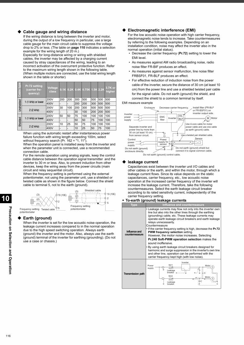
Precaution on Selection and Operation
10
116
Cable gauge and wiring distanceIf the wiring distance is long between the inverter and motor, during the output of a low frequency in particular, use a large cable gauge for the main circuit cable to suppress the voltage drop to 2% or less. (The table on page 110 indicates a selection example for the wiring length of 20 m.)Especially for long-distance wiring or wiring with shielded cables, the inverter may be affected by a charging current caused by stray capacitances of the wiring, leading to an incorrect activation of the overcurrent protective function. Refer to the maximum wiring length shown in the following table.(When multiple motors are connected, use the total wiring length shown in the table or shorter)
When using the automatic restart after instantaneous power failure function with wiring length exceeding 100m, select without frequency search (Pr. 162 = "1, 11").When the operation panel is installed away from the inverter and when the parameter unit is connected, use a recommended connection cable.For the remote operation using analog signals, keep the control cable distance between the operation signal transmitter and the inverter to 30 m or less. Also, to prevent induction from other devices, keep the wiring away from the power circuits (main circuit and relay sequential circuit).When the frequency setting is performed using the external potentiometer, not using the parameter unit, use a shielded or twisted cable as shown in the figure below. Connect the shield cable to terminal 5, not to the earth (ground).
Earth (ground)When the inverter is set for the low acoustic noise operation, the leakage current increases compared to in the normal operation due to the high speed switching operation. Always earth (ground) the inverter and the motor. Also, always use the earth (ground) terminal of the inverter for earthing (grounding). (Do not use a case or chassis.)
Electromagnetic interference (EMI)For the low acoustic noise operation with high carrier frequency, electromagnetic noise tends to increase. Take countermeasures by referring to the following examples. Depending on an installation condition, noise may affect the inverter also in the normal operation (initial status). • Decrease the carrier frequency (Pr.72) setting to lower the
EMI level. • As measures against AM radio broadcasting noise, radio
noise filter FR-BIF produces an effect. • As measures against sensor malfunction, line noise filter
FRBSF01, FR-BLF produces an effect. • For effective reduction of induction noise from the power
cable of the inverter, secure the distance of 30 cm (at least 10 cm) from the power line and use a shielded twisted pair cable for the signal cable. Do not earth (ground) the shield, and connect the shield to a common terminal by itself.
EMI measure example
leakage currentCapacitances exist between the inverter unit I/O cables and other cables or the earth, and within the motor, through which a leakage current flows. Since its value depends on the static capacitances, carrier frequency, etc., low acoustic noise operation at the increased carrier frequency of the inverter will increase the leakage current. Therefore, take the following countermeasures. Select the earth leakage circuit breaker according to its rated sensitivity current, independently of the carrier frequency setting.
To-earth (ground) leakage currents
Cab
le ty
pe Pr.72 setting(carrier fre-
quency)
Voltageclass 0.1K 0.2K 0.4K 0.75K 1.5K 2.2K 3.7K or
higher
Unshielded
1 (1 kHz) or lower200V 200 200 300 500 500 500 500400V - - 200 200 300 500 500
2 (2 kHz)200V 30 100 200 300 500 500 500400V - - 30 100 200 200 500
Shielded 1 (1 kHz) or lower
200V 50 50 75 100 100 100 100400V - - 50 50 75 100 100
2 (2 kHz)200V 10 25 50 75 100 100 100400V - - 10 25 50 75 100
Twisted cableFrequency settingpotentiometer
Shielded cable
Frequency settingpotentiometer
(3)
(2)
(1)
10 (10E)
2
5
(3)
(1)
(2)
10 (10E)
2
5Type Influence and countermeasure
Influence and countermeasure
• Leakage currents may flow not only into the inverter own line but also into the other lines through the earthing (grounding) cable, etc. These leakage currents may operate earth leakage circuit breakers and earth leakage relays unnecessarily.
Countermeasure• If the carrier frequency setting is high, decrease the Pr.72
PWM frequency selection setting.However, the motor noise increases. Selecting Pr.240 Soft-PWM operation selection makes the sound inoffensive.
• By using earth leakage circuit breakers designed for harmonic and surge suppression in the inverter's own line and other line, operation can be performed with the carrier frequency kept high (with low noise).
Transmission path
Inverter
SensorUse a twisted pair shielded cable.
Enclosure Decrease carrier frequency.
MotorMFR-BLF
Do not earth (ground) control cable.
Inverter power supply
Install filter (FR-BLF or FR-BSF01) on inverter output side.
Separate inverter and power line by more than 30 cm (at least 10 cm) from sensor circuit.
Control power supply
Do not earth (ground) enclosure directly.
Power supply for
sensor
Use 4-core cable for motor power cable and use one cable as earth (ground) cable.
Do not earth (ground) shield but connect it to signal common cable.
EMC filter
Power
supply
Leakage
breaker
Leakage
breaker
NV1
NV2
Inverter
Motor
Motor
C
C
C
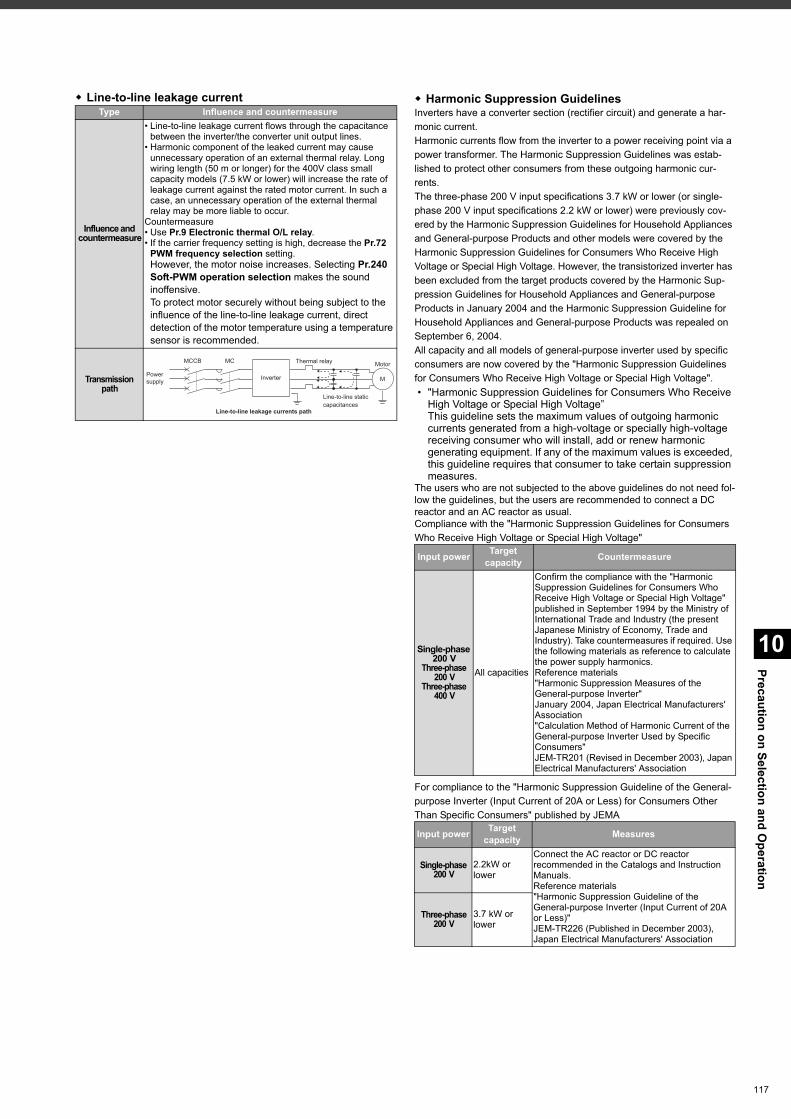
10
Precaution on Selection and Operation
Line-to-line leakage current Harmonic Suppression GuidelinesInverters have a converter section (rectifier circuit) and generate a har-monic current.Harmonic currents flow from the inverter to a power receiving point via a power transformer. The Harmonic Suppression Guidelines was estab-lished to protect other consumers from these outgoing harmonic cur-rents.The three-phase 200 V input specifications 3.7 kW or lower (or single-phase 200 V input specifications 2.2 kW or lower) were previously cov-ered by the Harmonic Suppression Guidelines for Household Appliances and General-purpose Products and other models were covered by the Harmonic Suppression Guidelines for Consumers Who Receive High Voltage or Special High Voltage. However, the transistorized inverter has been excluded from the target products covered by the Harmonic Sup-pression Guidelines for Household Appliances and General-purpose Products in January 2004 and the Harmonic Suppression Guideline for Household Appliances and General-purpose Products was repealed on September 6, 2004.All capacity and all models of general-purpose inverter used by specific consumers are now covered by the "Harmonic Suppression Guidelines for Consumers Who Receive High Voltage or Special High Voltage". • "Harmonic Suppression Guidelines for Consumers Who Receive
High Voltage or Special High Voltage”This guideline sets the maximum values of outgoing harmonic currents generated from a high-voltage or specially high-voltage receiving consumer who will install, add or renew harmonic generating equipment. If any of the maximum values is exceeded, this guideline requires that consumer to take certain suppression measures.
The users who are not subjected to the above guidelines do not need fol-low the guidelines, but the users are recommended to connect a DC reactor and an AC reactor as usual.Compliance with the "Harmonic Suppression Guidelines for Consumers Who Receive High Voltage or Special High Voltage"
For compliance to the "Harmonic Suppression Guideline of the General-purpose Inverter (Input Current of 20A or Less) for Consumers Other Than Specific Consumers" published by JEMA
Type Influence and countermeasure
Influence and countermeasure
• Line-to-line leakage current flows through the capacitance between the inverter/the converter unit output lines.
• Harmonic component of the leaked current may cause unnecessary operation of an external thermal relay. Long wiring length (50 m or longer) for the 400V class small capacity models (7.5 kW or lower) will increase the rate of leakage current against the rated motor current. In such a case, an unnecessary operation of the external thermal relay may be more liable to occur.
Countermeasure• Use Pr.9 Electronic thermal O/L relay.• If the carrier frequency setting is high, decrease the Pr.72
PWM frequency selection setting.However, the motor noise increases. Selecting Pr.240 Soft-PWM operation selection makes the sound inoffensive.To protect motor securely without being subject to the influence of the line-to-line leakage current, direct detection of the motor temperature using a temperature sensor is recommended.
Transmission path
Powersupply
Thermal relay
Line-to-line static capacitances
MCCB MC
Line-to-line leakage currents path
Motor
Inverter M
Input power Target capacity Countermeasure
Single-phase 200 V
Three-phase 200 V
Three-phase 400 V
All capacities
Confirm the compliance with the "Harmonic Suppression Guidelines for Consumers Who Receive High Voltage or Special High Voltage" published in September 1994 by the Ministry of International Trade and Industry (the present Japanese Ministry of Economy, Trade and Industry). Take countermeasures if required. Use the following materials as reference to calculate the power supply harmonics.Reference materials"Harmonic Suppression Measures of the General-purpose Inverter"January 2004, Japan Electrical Manufacturers' Association"Calculation Method of Harmonic Current of the General-purpose Inverter Used by Specific Consumers"JEM-TR201 (Revised in December 2003), Japan Electrical Manufacturers' Association
Input power Target capacity Measures
Single-phase 200 V
2.2kW or lower
Connect the AC reactor or DC reactor recommended in the Catalogs and Instruction Manuals.Reference materials"Harmonic Suppression Guideline of the General-purpose Inverter (Input Current of 20A or Less)"JEM-TR226 (Published in December 2003), Japan Electrical Manufacturers' Association
Three-phase200 V
3.7 kW or lower
117
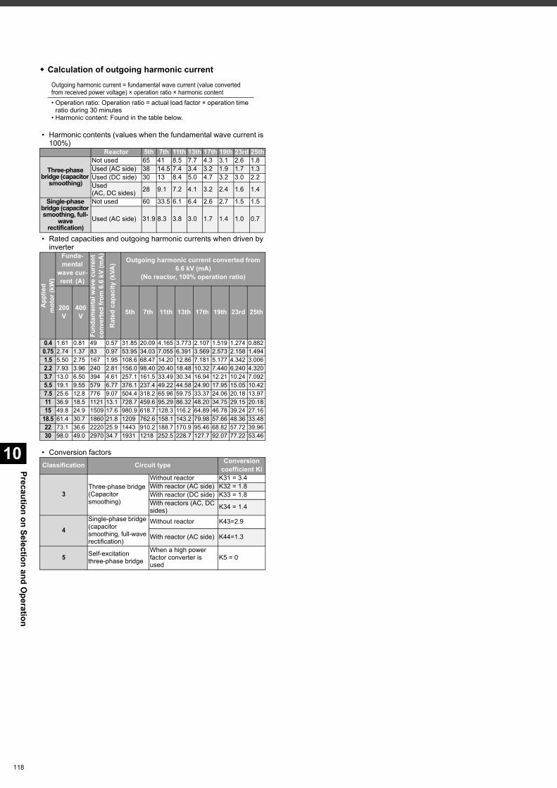
Precaution on Selection and Operation
10
118
Calculation of outgoing harmonic current
• Harmonic contents (values when the fundamental wave current is 100%)
• Rated capacities and outgoing harmonic currents when driven by inverter
• Conversion factors
Outgoing harmonic current = fundamental wave current (value converted from received power voltage) × operation ratio × harmonic content• Operation ratio: Operation ratio = actual load factor × operation time
ratio during 30 minutes• Harmonic content: Found in the table below.
Reactor 5th 7th 11th 13th 17th 19th 23rd 25th
Three-phase bridge (capacitor
smoothing)
Not used 65 41 8.5 7.7 4.3 3.1 2.6 1.8Used (AC side) 38 14.5 7.4 3.4 3.2 1.9 1.7 1.3Used (DC side) 30 13 8.4 5.0 4.7 3.2 3.0 2.2Used (AC, DC sides) 28 9.1 7.2 4.1 3.2 2.4 1.6 1.4
Single-phase bridge (capacitor smoothing, full-
wave rectification)
Not used 60 33.5 6.1 6.4 2.6 2.7 1.5 1.5
Used (AC side) 31.9 8.3 3.8 3.0 1.7 1.4 1.0 0.7
App
lied
mot
or (k
W)
Funda-mental
wave cur-rent (A)
Fund
amen
tal w
ave
curr
ent
conv
erte
d fr
om 6
.6 k
V (m
A)
Rat
ed c
apac
ity (k
VA) Outgoing harmonic current converted from
6.6 kV (mA)(No reactor, 100% operation ratio)
200 V
400 V 5th 7th 11th 13th 17th 19th 23rd 25th
0.4 1.61 0.81 49 0.57 31.85 20.09 4.165 3.773 2.107 1.519 1.274 0.8820.75 2.74 1.37 83 0.97 53.95 34.03 7.055 6.391 3.569 2.573 2.158 1.4941.5 5.50 2.75 167 1.95 108.6 68.47 14.20 12.86 7.181 5.177 4.342 3.0062.2 7.93 3.96 240 2.81 156.0 98.40 20.40 18.48 10.32 7.440 6.240 4.3203.7 13.0 6.50 394 4.61 257.1 161.5 33.49 30.34 16.94 12.21 10.24 7.0925.5 19.1 9.55 579 6.77 376.1 237.4 49.22 44.58 24.90 17.95 15.05 10.427.5 25.6 12.8 776 9.07 504.4 318.2 65.96 59.75 33.37 24.06 20.18 13.9711 36.9 18.5 1121 13.1 728.7 459.6 95.29 86.32 48.20 34.75 29.15 20.1815 49.8 24.9 1509 17.6 980.9 618.7 128.3 116.2 64.89 46.78 39.24 27.16
18.5 61.4 30.7 1860 21.8 1209 762.6 158.1 143.2 79.98 57.66 48.36 33.4822 73.1 36.6 2220 25.9 1443 910.2 188.7 170.9 95.46 68.82 57.72 39.9630 98.0 49.0 2970 34.7 1931 1218 252.5 228.7 127.7 92.07 77.22 53.46
Classification Circuit type Conversion coefficient Ki
3Three-phase bridge(Capacitor smoothing)
Without reactor K31 = 3.4With reactor (AC side) K32 = 1.8With reactor (DC side) K33 = 1.8With reactors (AC, DC sides) K34 = 1.4
4Single-phase bridge (capacitor smoothing, full-wave rectification)
Without reactor K43=2.9
With reactor (AC side) K44=1.3
5 Self-excitation three-phase bridge
When a high power factor converter is used
K5 = 0
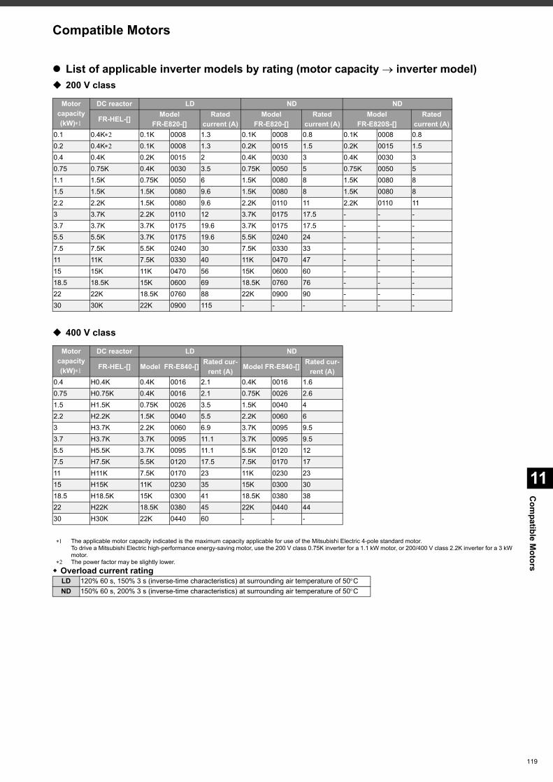
11
Com
patible Motors
119
List of applicable inverter models by rating (motor capacity inverter model) 200 V class
400 V class
The applicable motor capacity indicated is the maximum capacity applicable for use of the Mitsubishi Electric 4-pole standard motor.To drive a Mitsubishi Electric high-performance energy-saving motor, use the 200 V class 0.75K inverter for a 1.1 kW motor, or 200/400 V class 2.2K inverter for a 3 kW motor.
The power factor may be slightly lower. Overload current rating
Motor capacity(kW)
DC reactor LD ND ND
FR-HEL-[] Model FR-E820-[]
Rated current (A)
Model FR-E820-[]
Rated current (A)
Model FR-E820S-[]
Rated current (A)
0.1 0.4K 0.1K 0008 1.3 0.1K 0008 0.8 0.1K 0008 0.80.2 0.4K 0.1K 0008 1.3 0.2K 0015 1.5 0.2K 0015 1.50.4 0.4K 0.2K 0015 2 0.4K 0030 3 0.4K 0030 30.75 0.75K 0.4K 0030 3.5 0.75K 0050 5 0.75K 0050 51.1 1.5K 0.75K 0050 6 1.5K 0080 8 1.5K 0080 81.5 1.5K 1.5K 0080 9.6 1.5K 0080 8 1.5K 0080 82.2 2.2K 1.5K 0080 9.6 2.2K 0110 11 2.2K 0110 113 3.7K 2.2K 0110 12 3.7K 0175 17.5 - - -3.7 3.7K 3.7K 0175 19.6 3.7K 0175 17.5 - - -5.5 5.5K 3.7K 0175 19.6 5.5K 0240 24 - - -7.5 7.5K 5.5K 0240 30 7.5K 0330 33 - - -11 11K 7.5K 0330 40 11K 0470 47 - - -15 15K 11K 0470 56 15K 0600 60 - - -18.5 18.5K 15K 0600 69 18.5K 0760 76 - - -22 22K 18.5K 0760 88 22K 0900 90 - - -30 30K 22K 0900 115 - - - - - -
Motor capacity(kW)
DC reactor LD ND
FR-HEL-[] Model FR-E840-[] Rated cur-rent (A) Model FR-E840-[] Rated cur-
rent (A)0.4 H0.4K 0.4K 0016 2.1 0.4K 0016 1.60.75 H0.75K 0.4K 0016 2.1 0.75K 0026 2.61.5 H1.5K 0.75K 0026 3.5 1.5K 0040 42.2 H2.2K 1.5K 0040 5.5 2.2K 0060 63 H3.7K 2.2K 0060 6.9 3.7K 0095 9.53.7 H3.7K 3.7K 0095 11.1 3.7K 0095 9.55.5 H5.5K 3.7K 0095 11.1 5.5K 0120 127.5 H7.5K 5.5K 0120 17.5 7.5K 0170 1711 H11K 7.5K 0170 23 11K 0230 2315 H15K 11K 0230 35 15K 0300 3018.5 H18.5K 15K 0300 41 18.5K 0380 3822 H22K 18.5K 0380 45 22K 0440 4430 H30K 22K 0440 60 - - -
LD 120% 60 s, 150% 3 s (inverse-time characteristics) at surrounding air temperature of 50CND 150% 60 s, 200% 3 s (inverse-time characteristics) at surrounding air temperature of 50C
Compatible Motors
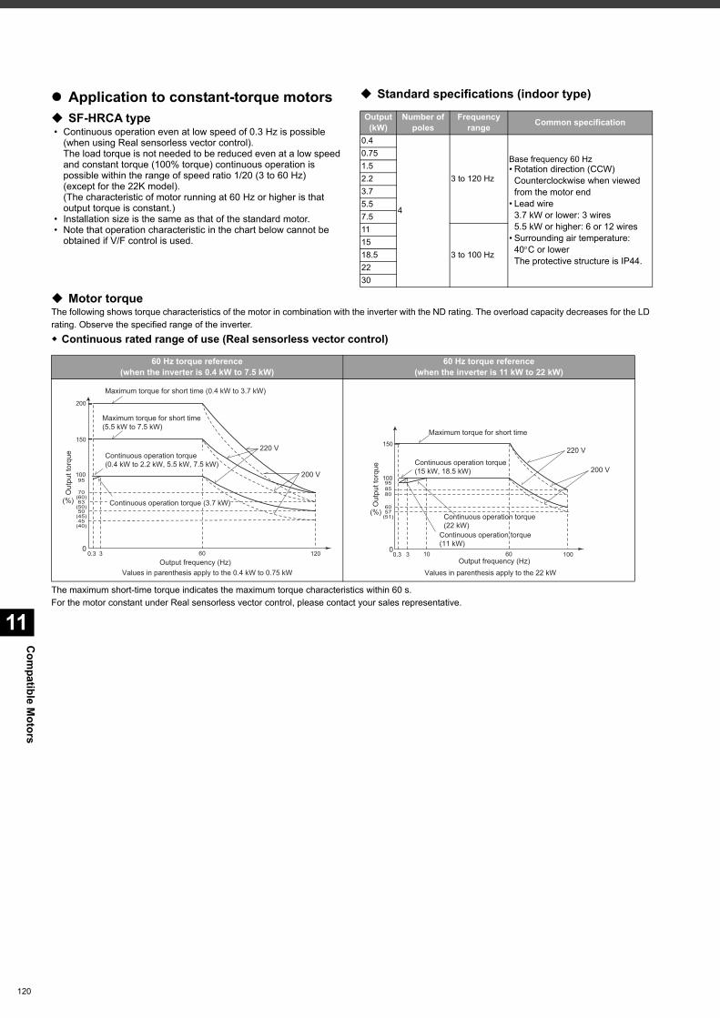
Com
patible Motors
11
120
Application to constant-torque motors SF-HRCA type • Continuous operation even at low speed of 0.3 Hz is possible
(when using Real sensorless vector control).The load torque is not needed to be reduced even at a low speed and constant torque (100% torque) continuous operation is possible within the range of speed ratio 1/20 (3 to 60 Hz)(except for the 22K model).(The characteristic of motor running at 60 Hz or higher is that output torque is constant.)
• Installation size is the same as that of the standard motor. • Note that operation characteristic in the chart below cannot be
obtained if V/F control is used.
Standard specifications (indoor type)
Motor torqueThe following shows torque characteristics of the motor in combination with the inverter with the ND rating. The overload capacity decreases for the LD rating. Observe the specified range of the inverter. Continuous rated range of use (Real sensorless vector control)
The maximum short-time torque indicates the maximum torque characteristics within 60 s.For the motor constant under Real sensorless vector control, please contact your sales representative.
Output (kW)
Number of poles
Frequency range Common specification
0.4
4
3 to 120 Hz
Base frequency 60 Hz• Rotation direction (CCW)
Counterclockwise when viewed from the motor end
• Lead wire3.7 kW or lower: 3 wires5.5 kW or higher: 6 or 12 wires
• Surrounding air temperature: 40C or lowerThe protective structure is IP44.
0.751.52.23.75.57.511
3 to 100 Hz1518.52230
60 Hz torque reference(when the inverter is 0.4 kW to 7.5 kW)
60 Hz torque reference(when the inverter is 11 kW to 22 kW)
Values in parenthesis apply to the 0.4 kW to 0.75 kW
Maximum torque for short time(5.5 kW to 7.5 kW)
Maximum torque for short time (0.4 kW to 3.7 kW)
Out
put t
orqu
e
(%)
Output frequency (Hz)
150
100
200
70(60)63
(50)50
(45)45
(40)
030.3 60 120
220 V
200 V95
Continuous operation torque (3.7 kW)
Continuous operation torque(0.4 kW to 2.2 kW, 5.5 kW, 7.5 kW)
Maximum torque for short time
Continuous operation torque (15 kW, 18.5 kW)
Continuous operation torque (22 kW)
Continuous operation torque (11 kW)
Out
put t
orqu
e
(%)
Output frequency (Hz)Values in parenthesis apply to the 22 kW
57(51)
150
100
8580
60
03 60 100
220 V
200 V
0.3 10
95
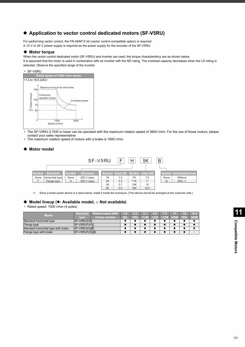
11
Com
patible Motors
Application to vector control dedicated motors (SF-V5RU)For performing vector control, the FR-A8AP E kit (vector control compatible option) is required.A 12 V or 24 V power supply is required as the power supply for the encoder of the SF-V5RU.
Motor torqueWhen the vector control dedicated motor (SF-V5RU) and inverter are used, the torque characteristics are as shown below.It is assumed that the motor is used in combination with an inverter with the ND rating. The overload capacity decreases when the LD rating is selected. Observe the specified range of the inverter.
• SF-V5RU
• The SF-V5RU-3.7kW or lower can be operated with the maximum rotation speed of 3600 r/min. For the use of those motors, please contact your sales representative.
• The maximum rotation speed of motors with a brake is 1800 r/min.
Motor model
Model lineup (: Available model, -: Not available) • Rated speed: 1500 r/min (4 poles)
Rated speed of 1500 r/min series<1.5 to 18.5 (kW)>
Constant power
Maximum torque for short time
Speed (r/min)
Continuous operation torque
50
0
75
100
1500 3000
150
Out
put t
orqu
e
(%)
SF-V5RU
Symbol StructureNone
FHorizontal type
Flange type
Symbol StructureNone
H200 V class400 V class
Symbol Output (kW)1K2K3K5K
1.52.23.75.5
Symbol Output (kW)7K
11K15K18K
7.51115
18.5
Symbol Electromagnetic brakeNone
BWithoutWith ��
H 5K BF
Since a brake power device is a stand-alone, install it inside the enclosure. (This device should be arranged at the customer side.)
Model Standard type
Rated output (kW) 1.5 2.2 3.7 5.5 7.5 11 15 18.5Frame number 90L 100L 112M 132S 132M 160M 160L 180M
Standard horizontal type SF-V5RU(H)[] Flange type SF-V5RUF(H)[] Standard horizontal type with brake SF-V5RU(H)[]B Flange type with brake SF-V5RUF(H)[]B -
121
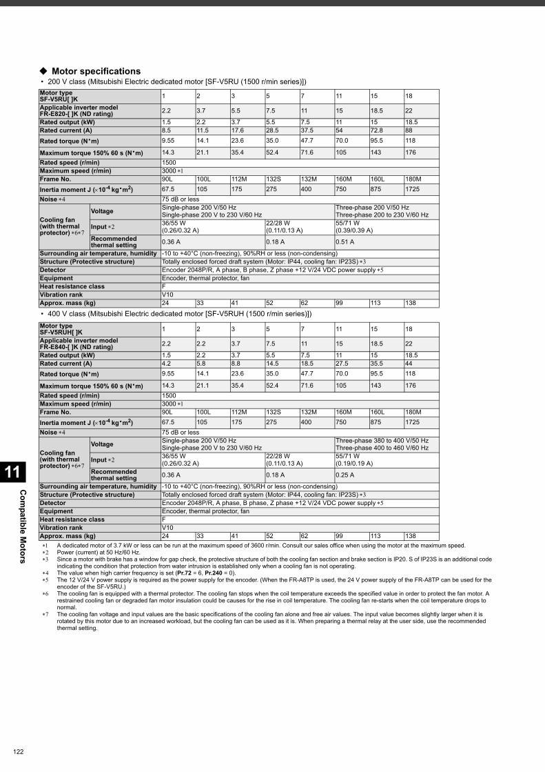
Com
patible Motors
11
122
Motor specifications • 200 V class (Mitsubishi Electric dedicated motor [SF-V5RU (1500 r/min series)])
• 400 V class (Mitsubishi Electric dedicated motor [SF-V5RUH (1500 r/min series)])
A dedicated motor of 3.7 kW or less can be run at the maximum speed of 3600 r/min. Consult our sales office when using the motor at the maximum speed. Power (current) at 50 Hz/60 Hz. Since a motor with brake has a window for gap check, the protective structure of both the cooling fan section and brake section is IP20. S of IP23S is an additional code
indicating the condition that protection from water intrusion is established only when a cooling fan is not operating. The value when high carrier frequency is set (Pr.72 = 6, Pr.240 = 0). The 12 V/24 V power supply is required as the power supply for the encoder. (When the FR-A8TP is used, the 24 V power supply of the FR-A8TP can be used for the
encoder of the SF-V5RU.) The cooling fan is equipped with a thermal protector. The cooling fan stops when the coil temperature exceeds the specified value in order to protect the fan motor. A
restrained cooling fan or degraded fan motor insulation could be causes for the rise in coil temperature. The cooling fan re-starts when the coil temperature drops to normal.
The cooling fan voltage and input values are the basic specifications of the cooling fan alone and free air values. The input value becomes slightly larger when it is rotated by this motor due to an increased workload, but the cooling fan can be used as it is. When preparing a thermal relay at the user side, use the recommended thermal setting.
Motor typeSF-V5RU[ ]K 1 2 3 5 7 11 15 18
Applicable inverter modelFR-E820-[ ]K (ND rating) 2.2 3.7 5.5 7.5 11 15 18.5 22
Rated output (kW) 1.5 2.2 3.7 5.5 7.5 11 15 18.5Rated current (A) 8.5 11.5 17.6 28.5 37.5 54 72.8 88Rated torque (N·m) 9.55 14.1 23.6 35.0 47.7 70.0 95.5 118
Maximum torque 150% 60 s (N·m) 14.3 21.1 35.4 52.4 71.6 105 143 176Rated speed (r/min) 1500Maximum speed (r/min) 3000 Frame No. 90L 100L 112M 132S 132M 160M 160L 180MInertia moment J (10-4 kg·m2) 67.5 105 175 275 400 750 875 1725Noise 75 dB or less
Cooling fan(with thermal protector)
Voltage Single-phase 200 V/50 HzSingle-phase 200 V to 230 V/60 Hz
Three-phase 200 V/50 HzThree-phase 200 to 230 V/60 Hz
Input 36/55 W(0.26/0.32 A)
22/28 W(0.11/0.13 A)
55/71 W(0.39/0.39 A)
Recommendedthermal setting 0.36 A 0.18 A 0.51 A
Surrounding air temperature, humidity -10 to +40°C (non-freezing), 90%RH or less (non-condensing)Structure (Protective structure) Totally enclosed forced draft system (Motor: IP44, cooling fan: IP23S) Detector Encoder 2048P/R, A phase, B phase, Z phase +12 V/24 VDC power supply Equipment Encoder, thermal protector, fanHeat resistance class FVibration rank V10Approx. mass (kg) 24 33 41 52 62 99 113 138
Motor typeSF-V5RUH[ ]K 1 2 3 5 7 11 15 18
Applicable inverter modelFR-E840-[ ]K (ND rating) 2.2 2.2 3.7 7.5 11 15 18.5 22
Rated output (kW) 1.5 2.2 3.7 5.5 7.5 11 15 18.5Rated current (A) 4.2 5.8 8.8 14.5 18.5 27.5 35.5 44Rated torque (N·m) 9.55 14.1 23.6 35.0 47.7 70.0 95.5 118
Maximum torque 150% 60 s (N·m) 14.3 21.1 35.4 52.4 71.6 105 143 176Rated speed (r/min) 1500Maximum speed (r/min) 3000 Frame No. 90L 100L 112M 132S 132M 160M 160L 180MInertia moment J (10-4 kg·m2) 67.5 105 175 275 400 750 875 1725Noise 75 dB or less
Cooling fan(with thermal protector)
Voltage Single-phase 200 V/50 HzSingle-phase 200 V to 230 V/60 Hz
Three-phase 380 to 400 V/50 HzThree-phase 400 to 460 V/60 Hz
Input 36/55 W(0.26/0.32 A)
22/28 W(0.11/0.13 A)
55/71 W(0.19/0.19 A)
Recommendedthermal setting 0.36 A 0.18 A 0.25 A
Surrounding air temperature, humidity -10 to +40°C (non-freezing), 90%RH or less (non-condensing)Structure (Protective structure) Totally enclosed forced draft system (Motor: IP44, cooling fan: IP23S) Detector Encoder 2048P/R, A phase, B phase, Z phase +12 V/24 VDC power supply Equipment Encoder, thermal protector, fanHeat resistance class FVibration rank V10Approx. mass (kg) 24 33 41 52 62 99 113 138
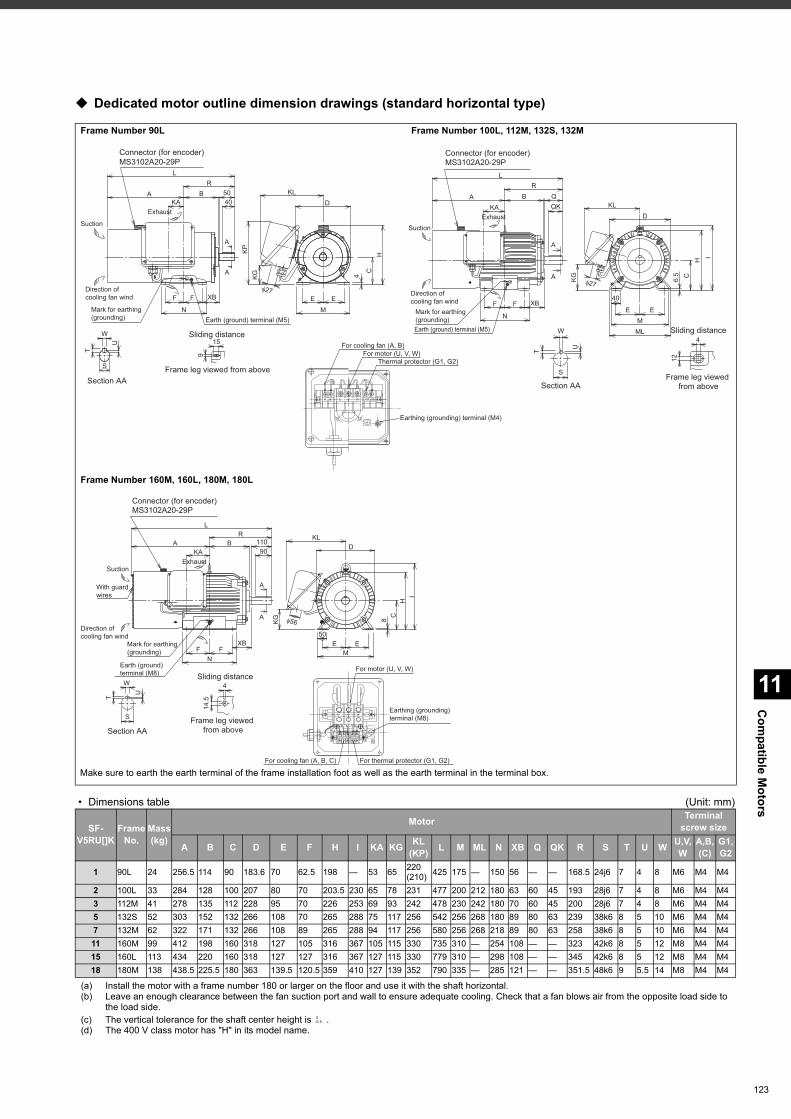
11
Com
patible Motors
Dedicated motor outline dimension drawings (standard horizontal type)
• Dimensions table (Unit: mm)
(a) Install the motor with a frame number 180 or larger on the floor and use it with the shaft horizontal.(b) Leave an enough clearance between the fan suction port and wall to ensure adequate cooling. Check that a fan blows air from the opposite load side to
the load side.(c) The vertical tolerance for the shaft center height is .(d) The 400 V class motor has "H" in its model name.
Frame Number 90L Frame Number 100L, 112M, 132S, 132M
Frame Number 160M, 160L, 180M, 180L
SF-V5RU[]K
FrameNo.
Mass(kg)
Motor Terminal screw size
A B C D E F H I KA KG KL(KP) L M ML N XB Q QK R S T U W U,V,
WA,B,(C)
G1,G2
1 90L 24 256.5 114 90 183.6 70 62.5 198 — 53 65 220(210) 425 175 — 150 56 — — 168.5 24j6 7 4 8 M6 M4 M4
2 100L 33 284 128 100 207 80 70 203.5 230 65 78 231 477 200 212 180 63 60 45 193 28j6 7 4 8 M6 M4 M43 112M 41 278 135 112 228 95 70 226 253 69 93 242 478 230 242 180 70 60 45 200 28j6 7 4 8 M6 M4 M45 132S 52 303 152 132 266 108 70 265 288 75 117 256 542 256 268 180 89 80 63 239 38k6 8 5 10 M6 M4 M47 132M 62 322 171 132 266 108 89 265 288 94 117 256 580 256 268 218 89 80 63 258 38k6 8 5 10 M6 M4 M411 160M 99 412 198 160 318 127 105 316 367 105 115 330 735 310 — 254 108 — — 323 42k6 8 5 12 M8 M4 M415 160L 113 434 220 160 318 127 127 316 367 127 115 330 779 310 — 298 108 — — 345 42k6 8 5 12 M8 M4 M418 180M 138 438.5 225.5 180 363 139.5 120.5 359 410 127 139 352 790 335 — 285 121 — — 351.5 48k6 9 5.5 14 M8 M4 M4
S
T
W
U
Section AA
15
9
Frame leg viewed from above
Sliding distance
Earth (ground) terminal (M5)Mark for earthing (grounding)
Direction of cooling fan wind
Exhaust
Suction
4050
L
A
Connector (for encoder)MS3102A20-29P
XBFF
N
KAB
R
A
A
D
φ27
4
CH
KG
KL
EE
M
KP
4
12
Sliding distance
Frame leg viewed
from above
S
U
T
W
Section AA
Mark for earthing
(grounding)
Earth (ground) terminal (M5)
φ27
40
EE
M
ML
6.5 C
H
I
KG
D
KL
Connector (for encoder)
MS3102A20-29P
Direction of
cooling fan wind
Exhaust
Suction
XBFF
N
QKKA
QBA
R
L
A
A
For motor (U, V, W)
For cooling fan (A, B)
Thermal protector (G1, G2)
A B G2G1U V W
Earthing (grounding) terminal (M4)
Direction of
cooling fan wind
Mark for earthing
(grounding)
Earth (ground)
terminal (M8)
With guard
wires
Exhaust
Suction
Connector (for encoder)
MS3102A20-29P
φ56KG
XB
FF
N
90KA
110BA
R
L
50
EE
M
D
KL
8
C
H
I
A
A
Section AA
T
U
S
W
14
.5
4
Sliding distance
Frame leg viewed
from above
For motor (U, V, W)
For cooling fan (A, B, C) For thermal protector (G1, G2)
Earthing (grounding)
terminal (M8)
Make sure to earth the earth terminal of the frame installation foot as well as the earth terminal in the terminal box.
0-0.5
123
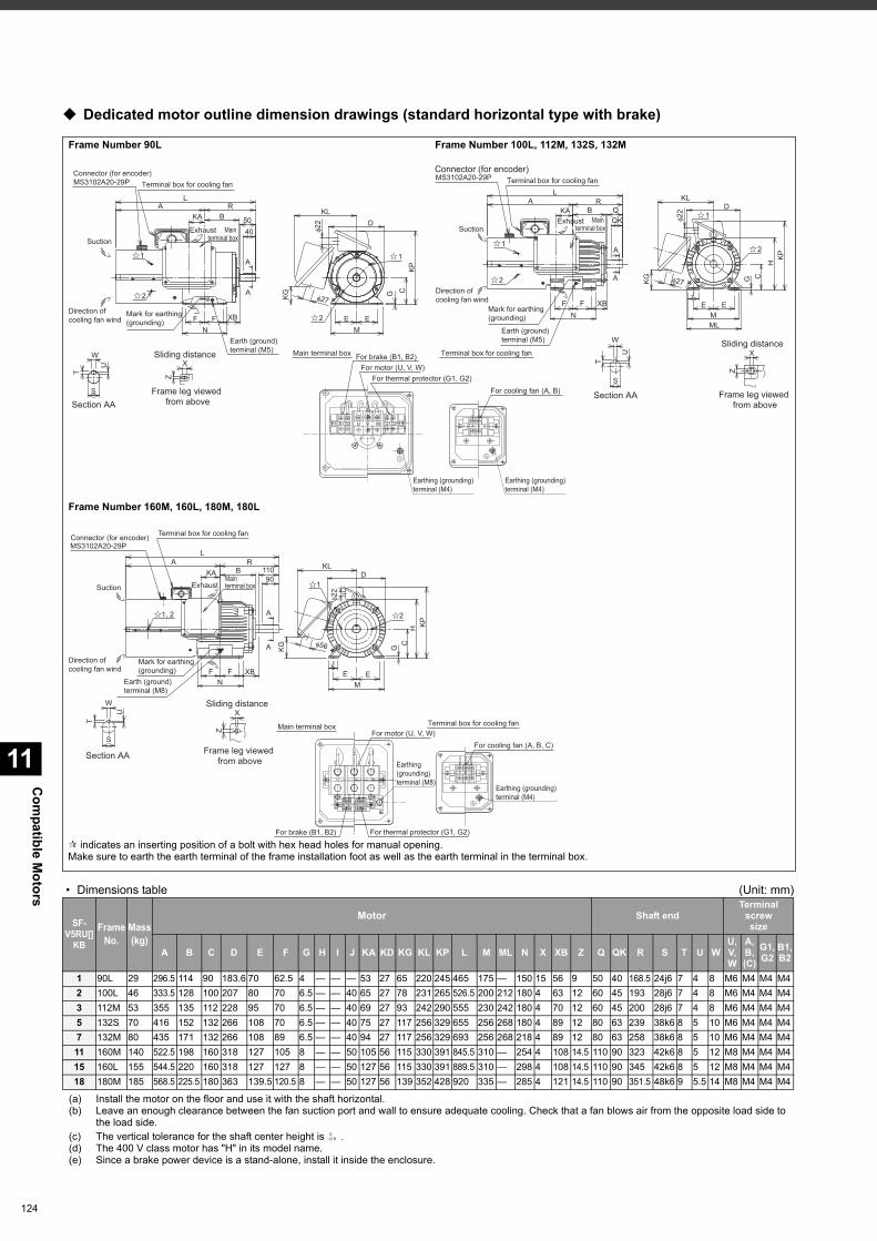
Com
patible Motors
11
124
Dedicated motor outline dimension drawings (standard horizontal type with brake)
• Dimensions table (Unit: mm)
(a) Install the motor on the floor and use it with the shaft horizontal.(b) Leave an enough clearance between the fan suction port and wall to ensure adequate cooling. Check that a fan blows air from the opposite load side to
the load side.(c) The vertical tolerance for the shaft center height is .(d) The 400 V class motor has "H" in its model name.(e) Since a brake power device is a stand-alone, install it inside the enclosure.
Frame Number 90L Frame Number 100L, 112M, 132S, 132M
Frame Number 160M, 160L, 180M, 180L
SF-V5RU[]
KB
FrameNo.
Mass(kg)
Motor Shaft endTerminal
screwsize
A B C D E F G H I J KA KD KG KL KP L M ML N X XB Z Q QK R S T U WU,V,W
A,B,(C)
G1,G2
B1,B2
1 90L 29 296.5 114 90 183.6 70 62.5 4 — — — 53 27 65 220 245 465 175 — 150 15 56 9 50 40 168.5 24j6 7 4 8 M6 M4 M4 M42 100L 46 333.5 128 100 207 80 70 6.5 — — 40 65 27 78 231 265 526.5 200 212 180 4 63 12 60 45 193 28j6 7 4 8 M6 M4 M4 M43 112M 53 355 135 112 228 95 70 6.5 — — 40 69 27 93 242 290 555 230 242 180 4 70 12 60 45 200 28j6 7 4 8 M6 M4 M4 M45 132S 70 416 152 132 266 108 70 6.5 — — 40 75 27 117 256 329 655 256 268 180 4 89 12 80 63 239 38k6 8 5 10 M6 M4 M4 M47 132M 80 435 171 132 266 108 89 6.5 — — 40 94 27 117 256 329 693 256 268 218 4 89 12 80 63 258 38k6 8 5 10 M6 M4 M4 M411 160M 140 522.5 198 160 318 127 105 8 — — 50 105 56 115 330 391 845.5 310 — 254 4 108 14.5 110 90 323 42k6 8 5 12 M8 M4 M4 M415 160L 155 544.5 220 160 318 127 127 8 — — 50 127 56 115 330 391 889.5 310 — 298 4 108 14.5 110 90 345 42k6 8 5 12 M8 M4 M4 M418 180M 185 568.5 225.5 180 363 139.5 120.5 8 — — 50 127 56 139 352 428 920 335 — 285 4 121 14.5 110 90 351.5 48k6 9 5.5 14 M8 M4 M4 M4
Sliding distance
Frame leg viewed
from above
Z
X
Section AA
U
W
T
S
Connector (for encoder)
MS3102A20-29P
Mark for earthing
(grounding)
Earth (ground)
terminal (M5)
A
A
R
B
N
F F XB
50
40
Suction
Exhaust
Direction of
cooling fan wind
Terminal box for cooling fan
L
A
KA
M
E E
C
G
D
φ2
22
2
11
KL
KP
KG
φ27
Main
terminal box
Connector (for encoder)MS3102A20-29P
Earth (ground)
terminal (M5)
Mark for earthing
(grounding)
Suction
Exhaust
Direction of
cooling fan wind
A
A
R
N
F F XB
CG
D
ML
M
E E
J
B Q
QKMain
terminal box
A
L
Terminal box for cooling fan
φ2
2
φ27
KA
KL
KP
H
KG
Section AA
W
S
U
T
Sliding distance
Frame leg viewed
from above
Z
X
1
2
1
2
VUB2B1 W G1 G2CBA
For motor (U, V, W)
For cooling fan (A, B)
For brake (B1, B2)
For thermal protector (G1, G2)
Earthing (grounding)
terminal (M4)
Main terminal box
Earthing (grounding)
terminal (M4)
Terminal box for cooling fan
Sliding distance
Frame leg viewed
from above
X
Z
W
S
U
T
Section AA
Connector (for encoder)
MS3102A20-29P
Earth (ground)
terminal (M8)
Mark for earthing
(grounding)
Suction
Direction of
cooling fan wind
Terminal box for cooling fan
1, 2
1
2A
A
R
B 110KA
Exhaust90
N
F F XB
L
A
H
C
G
D
M
E E
J
KG φ56
φ2
2
KL
KP
Main
terminal box
B2B1
U
G2G1
WV
CBA
For cooling fan (A, B, C)
For motor (U, V, W)
Earthing
(grounding)
terminal (M8)Earthing (grounding)
terminal (M4)
For brake (B1, B2) For thermal protector (G1, G2)
Main terminal boxTerminal box for cooling fan
indicates an inserting position of a bolt with hex head holes for manual opening.Make sure to earth the earth terminal of the frame installation foot as well as the earth terminal in the terminal box.
0-0.5
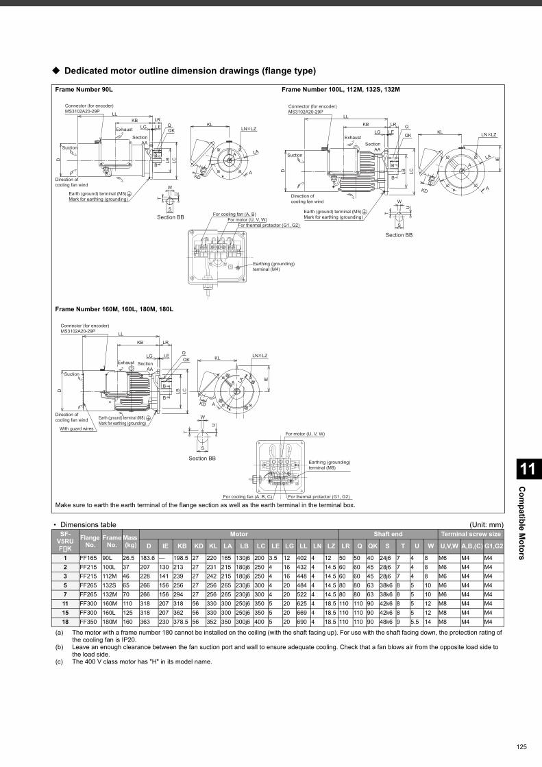
11
Com
patible Motors
Dedicated motor outline dimension drawings (flange type)
• Dimensions table (Unit: mm)
(a) The motor with a frame number 180 cannot be installed on the ceiling (with the shaft facing up). For use with the shaft facing down, the protection rating of the cooling fan is IP20.
(b) Leave an enough clearance between the fan suction port and wall to ensure adequate cooling. Check that a fan blows air from the opposite load side to the load side.
(c) The 400 V class motor has "H" in its model name.
Frame Number 90L Frame Number 100L, 112M, 132S, 132M
Frame Number 160M, 160L, 180M, 180L
SF-V5RUF[]K
Flange No.
FrameNo.
Mass (kg)
Motor Shaft end Terminal screw size
D IE KB KD KL LA LB LC LE LG LL LN LZ LR Q QK S T U W U,V,W A,B,(C) G1,G2
1 FF165 90L 26.5 183.6 — 198.5 27 220 165 130j6 200 3.5 12 402 4 12 50 50 40 24j6 7 4 8 M6 M4 M42 FF215 100L 37 207 130 213 27 231 215 180j6 250 4 16 432 4 14.5 60 60 45 28j6 7 4 8 M6 M4 M43 FF215 112M 46 228 141 239 27 242 215 180j6 250 4 16 448 4 14.5 60 60 45 28j6 7 4 8 M6 M4 M45 FF265 132S 65 266 156 256 27 256 265 230j6 300 4 20 484 4 14.5 80 80 63 38k6 8 5 10 M6 M4 M47 FF265 132M 70 266 156 294 27 256 265 230j6 300 4 20 522 4 14.5 80 80 63 38k6 8 5 10 M6 M4 M411 FF300 160M 110 318 207 318 56 330 300 250j6 350 5 20 625 4 18.5 110 110 90 42k6 8 5 12 M8 M4 M415 FF300 160L 125 318 207 362 56 330 300 250j6 350 5 20 669 4 18.5 110 110 90 42k6 8 5 12 M8 M4 M418 FF350 180M 160 363 230 378.5 56 352 350 300j6 400 5 20 690 4 18.5 110 110 90 48k6 9 5.5 14 M8 M4 M4
LN LZ
KL
KD
LA
A
A
Section BB
U
W
T
S
Earth (ground) terminal (M5)
Mark for earthing (grounding)
Connector (for encoder)
MS3102A20-29PLL
KB LR
LG LEQK
Q
LC
LB
B
B
Section
AA
D
Suction
Direction of
cooling fan wind
Exhaust
Section BB
W
U
T
S
LN LZ
KD
KL
IE
A
A
LA
Connector (for encoder)
MS3102A20-29P
Earth (ground) terminal (M5)
Mark for earthing (grounding)
LL
KB LR
LG LEQK
Q
LC
LB
Section
AA
B
B
D
Suction
Direction of
cooling fan wind
Exhaust
For motor (U, V, W)
For cooling fan (A, B)
For thermal protector (G1, G2)
A B G2G1U V W
Earthing (grounding)
terminal (M4)
Section BB
W
S
T
U
A
A
LN LZ
LA IE
KL
KD
QK
Q
Connector (for encoder)
MS3102A20-29P
Earth (ground) terminal (M8)
Mark for earthing (grounding)
With guard wires
Section
AA
LC
LB
B
B
LRKB
LG LE
LL
D
Suction
Direction of
cooling fan wind
Exhaust
For motor (U, V, W)
For cooling fan (A, B, C) For thermal protector (G1, G2)
Earthing (grounding)
terminal (M8)
Make sure to earth the earth terminal of the flange section as well as the earth terminal in the terminal box.
125
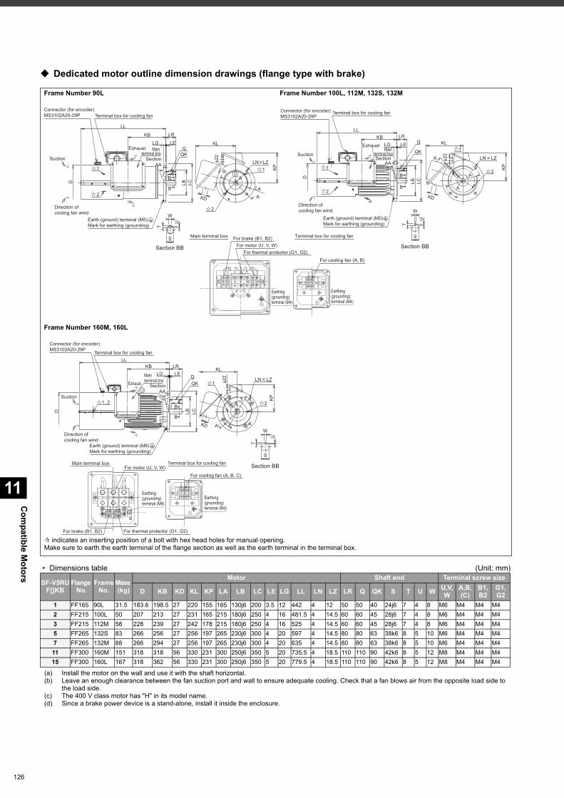
Com
patible Motors
11
126
Dedicated motor outline dimension drawings (flange type with brake)
• Dimensions table (Unit: mm)
(a) Install the motor on the wall and use it with the shaft horizontal.(b) Leave an enough clearance between the fan suction port and wall to ensure adequate cooling. Check that a fan blows air from the opposite load side to
the load side.(c) The 400 V class motor has "H" in its model name.(d) Since a brake power device is a stand-alone, install it inside the enclosure.
Frame Number 90L Frame Number 100L, 112M, 132S, 132M
Frame Number 160M, 160L
SF-V5RUF[]KB
Flange No.
FrameNo.
Mass (kg)
Motor Shaft end Terminal screw size
D KB KD KL KP LA LB LC LE LG LL LN LZ LR Q QK S T U W U,V,W
A,B,(C)
B1,B2
G1,G2
1 FF165 90L 31.5 183.6 198.5 27 220 155 165 130j6 200 3.5 12 442 4 12 50 50 40 24j6 7 4 8 M6 M4 M4 M42 FF215 100L 50 207 213 27 231 165 215 180j6 250 4 16 481.5 4 14.5 60 60 45 28j6 7 4 8 M6 M4 M4 M43 FF215 112M 58 228 239 27 242 178 215 180j6 250 4 16 525 4 14.5 60 60 45 28j6 7 4 8 M6 M4 M4 M45 FF265 132S 83 266 256 27 256 197 265 230j6 300 4 20 597 4 14.5 80 80 63 38k6 8 5 10 M6 M4 M4 M47 FF265 132M 88 266 294 27 256 197 265 230j6 300 4 20 635 4 14.5 80 80 63 38k6 8 5 10 M6 M4 M4 M411 FF300 160M 151 318 318 56 330 231 300 250j6 350 5 20 735.5 4 18.5 110 110 90 42k6 8 5 12 M8 M4 M4 M415 FF300 160L 167 318 362 56 330 231 300 250j6 350 5 20 779.5 4 18.5 110 110 90 42k6 8 5 12 M8 M4 M4 M4
Connector (for encoder)
MS3102A20-29P
Earth (ground) terminal (M5)
Mark for earthing (grounding)
Suction
Exhaust
Direction of
cooling fan wind
Terminal box for cooling fan
1
2
B
B
Section
AA
LC
LB
LG LE
LL
LR
Q
QK
D
KB
LN LZ
1
2
KD
A
A
LA
KL
φ2
2
KP
Section BB
U
W
T
S
Main terminal box
Section BB
W
S
U
T
Connector (for encoder)
MS3102A20-29P
QK
Q
Earth (ground) terminal (M5)
Mark for earthing (grounding)
Suction
Exhaust
Direction of
cooling fan wind
Terminal box for cooling fan
1
2
Section
AA
LC
LB
B
B
LR
LG LE
LL
D
KB
A LN LZ
A
1
2
LA
KD
KL
φ2
2
KP
Main terminal box
VUB2B1 W G1 G2CBA
For motor (U, V, W)
For cooling fan (A, B)
For brake (B1, B2)
For thermal protector (G1, G2)
Earthing
(grounding)
terminal (M4)
Earthing
(grounding)
terminal (M4)
Main terminal box Terminal box for cooling fan
Section BB
W
S
U
T
A
A
LN LZ
2
1
LA
KD
KL
φ2
2
KP
Connector (for encoder)
MS3102A20-29P
QK
Q
D
Earth (ground) terminal (M8)
Mark for earthing (grounding)
Suction
Direction of
cooling fan wind
Terminal box for cooling fan
1, 2
Section
AA
LC
LB
B
B
LL
KB LR
LG LE
Exhaust
Main
terminal box
B2B1
U
G2G1
WV
CBA
For cooling fan (A, B, C)
For motor (U, V, W)
Earthing
(grounding)
terminal (M8)
Earthing
(grounding)
terminal (M4)
For brake (B1, B2) For thermal protector (G1, G2)
Terminal box for cooling fanMain terminal box
indicates an inserting position of a bolt with hex head holes for manual opening.Make sure to earth the earth terminal of the flange section as well as the earth terminal in the terminal box.
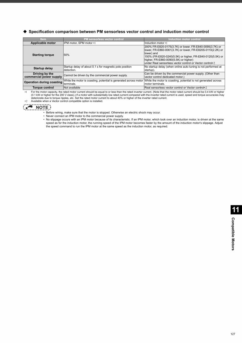
11
Com
patible Motors
Specification comparison between PM sensorless vector control and induction motor control
For the motor capacity, the rated motor current should be equal to or less than the rated inverter current. (Note that the motor rated current should be 0.4 kW or higher (0.1 kW or higher for the 200 V class).) If a motor with substantially low rated current compared with the inverter rated current is used, speed and torque accuracies may deteriorate due to torque ripples, etc. Set the rated motor current to about 40% or higher of the inverter rated current.
Available when a Vector control compatible option is installed.
NOTE • Before wiring, make sure that the motor is stopped. Otherwise an electric shock may occur. • Never connect an IPM motor to the commercial power supply. • No slippage occurs with an IPM motor because of its characteristic. If an IPM motor, which took over an induction motor, is driven at the same
speed as for the induction motor, the running speed of the IPM motor becomes faster by the amount of the induction motor's slippage. Adjust the speed command to run the IPM motor at the same speed as the induction motor, as required.
Item PM sensorless vector control Induction motor controlApplicable motor IPM motor,SPM motor Induction motor
Starting torque 50%
200% FR-E820-0175(3.7K) or lower, FR-E840-0095(3.7K) or lower, FR-E860-0061(3.7K) or lower, FR-E820S-0110(2.2K) or lower) and150% (FR-E820-0240(5.5K) or higher, FR-E840-0120(5.5K) or higher, FR-E860-0090(5.5K) or higher)under Real sensorless vector control or Vector control
Startup delay Startup delay of about 0.1 s for magnetic pole position detection.
No startup delay (when online auto tuning is not performed at startup).
Driving by thecommercial power supply Cannot be driven by the commercial power supply. Can be driven by the commercial power supply. (Other than
vector control dedicated motor.)
Operation during coasting While the motor is coasting, potential is generated across motor terminals.
While the motor is coasting, potential is not generated across motor terminals.
Torque control Not available Real sensorless vector control or Vector control
127
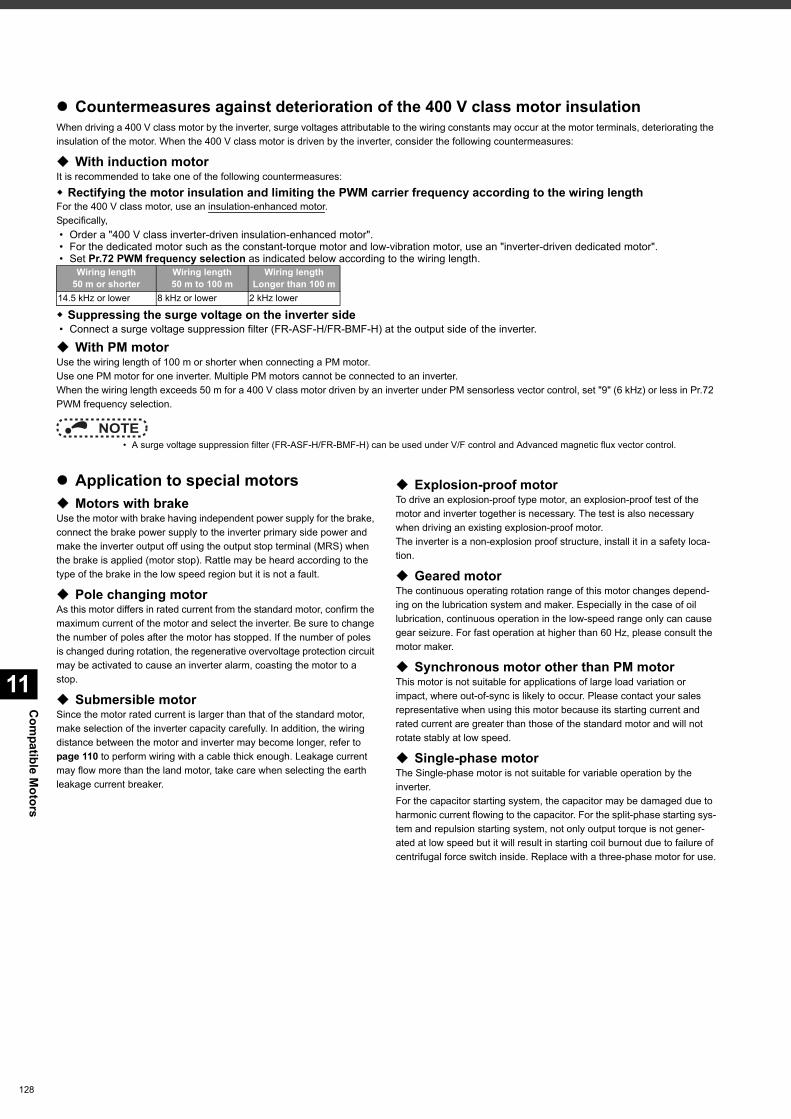
Com
patible Motors
11
128
Countermeasures against deterioration of the 400 V class motor insulationWhen driving a 400 V class motor by the inverter, surge voltages attributable to the wiring constants may occur at the motor terminals, deteriorating the insulation of the motor. When the 400 V class motor is driven by the inverter, consider the following countermeasures:
With induction motorIt is recommended to take one of the following countermeasures: Rectifying the motor insulation and limiting the PWM carrier frequency according to the wiring lengthFor the 400 V class motor, use an insulation-enhanced motor.Specifically, • Order a "400 V class inverter-driven insulation-enhanced motor". • For the dedicated motor such as the constant-torque motor and low-vibration motor, use an "inverter-driven dedicated motor". • Set Pr.72 PWM frequency selection as indicated below according to the wiring length.
Suppressing the surge voltage on the inverter side • Connect a surge voltage suppression filter (FR-ASF-H/FR-BMF-H) at the output side of the inverter.
With PM motorUse the wiring length of 100 m or shorter when connecting a PM motor.Use one PM motor for one inverter. Multiple PM motors cannot be connected to an inverter.When the wiring length exceeds 50 m for a 400 V class motor driven by an inverter under PM sensorless vector control, set "9" (6 kHz) or less in Pr.72 PWM frequency selection.
NOTE • A surge voltage suppression filter (FR-ASF-H/FR-BMF-H) can be used under V/F control and Advanced magnetic flux vector control.
Application to special motors Motors with brakeUse the motor with brake having independent power supply for the brake, connect the brake power supply to the inverter primary side power and make the inverter output off using the output stop terminal (MRS) when the brake is applied (motor stop). Rattle may be heard according to the type of the brake in the low speed region but it is not a fault.
Pole changing motorAs this motor differs in rated current from the standard motor, confirm the maximum current of the motor and select the inverter. Be sure to change the number of poles after the motor has stopped. If the number of poles is changed during rotation, the regenerative overvoltage protection circuit may be activated to cause an inverter alarm, coasting the motor to a stop.
Submersible motorSince the motor rated current is larger than that of the standard motor, make selection of the inverter capacity carefully. In addition, the wiring distance between the motor and inverter may become longer, refer to page 110 to perform wiring with a cable thick enough. Leakage current may flow more than the land motor, take care when selecting the earth leakage current breaker.
Explosion-proof motorTo drive an explosion-proof type motor, an explosion-proof test of the motor and inverter together is necessary. The test is also necessary when driving an existing explosion-proof motor.The inverter is a non-explosion proof structure, install it in a safety loca-tion.
Geared motorThe continuous operating rotation range of this motor changes depend-ing on the lubrication system and maker. Especially in the case of oil lubrication, continuous operation in the low-speed range only can cause gear seizure. For fast operation at higher than 60 Hz, please consult the motor maker.
Synchronous motor other than PM motorThis motor is not suitable for applications of large load variation or impact, where out-of-sync is likely to occur. Please contact your sales representative when using this motor because its starting current and rated current are greater than those of the standard motor and will not rotate stably at low speed.
Single-phase motorThe Single-phase motor is not suitable for variable operation by the inverter.For the capacitor starting system, the capacitor may be damaged due to harmonic current flowing to the capacitor. For the split-phase starting sys-tem and repulsion starting system, not only output torque is not gener-ated at low speed but it will result in starting coil burnout due to failure of centrifugal force switch inside. Replace with a three-phase motor for use.
Wiring length50 m or shorter
Wiring length50 m to 100 m
Wiring lengthLonger than 100 m
14.5 kHz or lower 8 kHz or lower 2 kHz lower
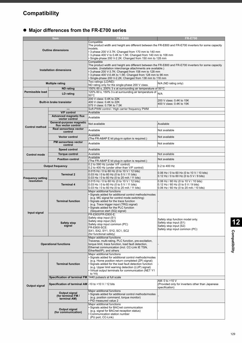
12
Com
patibility
Major differences from the FR-E700 seriesItem FR-E800 FR-E700
Outline dimensions
CompatibleThe product width and height are different between the FR-E800 and FR-E700 inverters for some capacity models.• 3-phase 200 V-3.7K: Changed from 170 mm to 140 mm• 3-phase 400 V to 0.4K to 1.5K: Changed from 140 mm to 108 mm• Single-phase 200 V-2.2K: Changed from 150 mm to 128 mm
Installation dimensions
CompatibleThe product width and height are different between the FR-E800 and FR-E700 inverters for some capacity models. (Installation interchange attachments are available.)• 3-phase 200 V-3.7K: Changed from 158 mm to 128 mm• 3-phase 400 V-0.4K to 1.5K: Changed from 128 mm to 96 mm• Single-phase 200 V-2.2K: Changed from 138 mm to 118 mm
Multiple rating Two ratings (LD/ND)ND rating only for the single-phase 200 V class. N/A (ND rating only)
Permissible loadND rating 150% 60 s, 200% 3 s at surrounding air temperature of 50°C
LD rating 120% 60 s, 150% 3 s at surrounding air temperature of 50°C N/A
Built-in brake transistor200 V class: 0.4K to 22K400 V class: 0.4K to 22K575 V class: 0.75K to 7.5K
200 V class: 0.4K to 15K400 V class: 0.4K to 15K
Control method
— Soft-PWM control / High carrier frequency PWMV/F control Available
Advanced magnetic flux vector control Available
General-purpose magnetic flux vector control Not available Available
Real sensorless vector control Available Not available
Vector control Available (The FR-A8AP E kit plug-in option is required.) Not available
PM sensorless vector control Available Not available
Control mode
Speed control AvailableTorque control Available Not available
Position control Available (The FR-A8AP E kit plug-in option is required.) Not available
Output frequency 0.2 to 590 Hz (under V/F control)0.2 to 400 Hz (under other than V/F control) 0.2 to 400 Hz
Frequency setting resolution
Terminal 20.015 Hz / 0 to 60 Hz (0 to 10 V / 12 bits)0.03 Hz / 0 to 60 Hz (0 to 5 V / 11 bits)0.03 Hz / 0 to 60 Hz (0 to 20 mA / 11 bits)
0.06 Hz / 0 to 60 Hz (0 to 10 V / 10 bits)0.12 Hz / 0 to 60 Hz (0 to 5 V / 9 bits)
Terminal 40.015 Hz / 0 to 60 Hz (0 to 10 V / 12 bits)0.03 Hz / 0 to 60 Hz (0 to 5 V / 11 bits)0.03 Hz / 0 to 60 Hz (0 to 20 mA / 11 bits)
0.06 Hz / 60 Hz (0 to 10 V / 10 bits)0.12 Hz / 60 Hz (0 to 5 V / 9 bits)0.06 Hz / 60 Hz (0 to 20 mA / 10 bits)
Input signal
Terminal function
Major additional functions• Signals added for additional control methods/modes
(e.g. MC signal for control mode switching)• Signals added for the trace function
(e.g. Trace trigger input (TRG) signal)• Signals added for the PLC function
(Sequence start (SQ) signal)
-
Safety stopsignal
FR-E800/FR-E800-E:Safety stop input (S1)Safety stop input (S2)Safety stop input common (PC)FR-E800-SCE: SX1, SX2, SY1, SY2, SC1, SC2(for functional safety)
Safety stop function model only.Safety stop input (S1)Safety stop input (S2)Safety stop input common (PC)
Operational functions
Major additional functionsTraverse, multi-rating, PLC function, pre-excitation, torque limit, trace function, load fault detection, Ethernet communication (incl. CC-Link IE TSN, EtherNet/IP), and others
-
Output signal
Terminal function
Major additional functions• Signals added for additional control methods/modes
(e.g. Home position return completed (ZP) signal)• Signals added for the load fault detection function
(e.g. Upper limit warning detection (LUP) signal)• Virtual output terminals for communication (NET Y1
to Y4)
-
Specification of terminal FM 1440 pulses/s at full scale
Specification of terminal AM -10 to +10 V / 12 bitsAM: 0 to +10 V(Provided only for inverters other than Japanese specification)
Output signal(for terminal FM /
terminal AM)
Major additional functions• Signals added for additional control methods/modes
(e.g. position command, torque monitor)• PID measured value 2
-
Output signal(for communication)
Major additional functions• Signals added for BACnet communication
(e.g. signal for BACnet reception status)• Communication station number
(PU port, CC-Link)
-
Compatibility
129
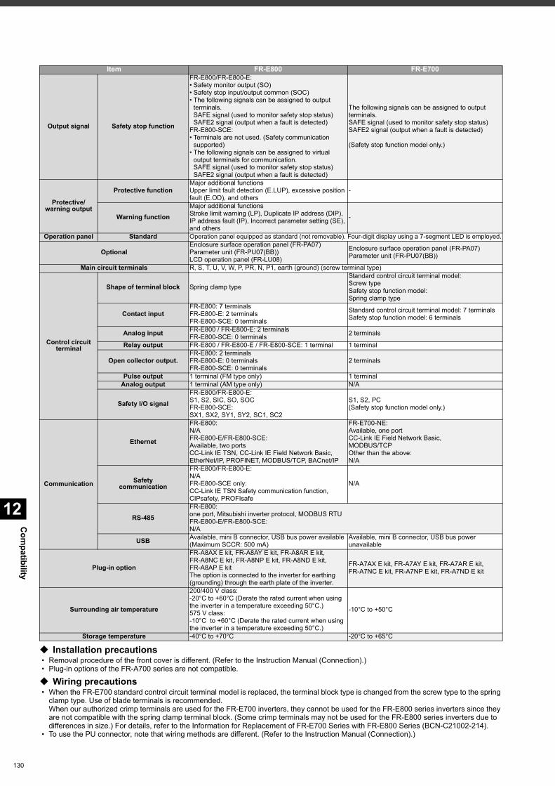
Com
patibility
12
130
Installation precautions • Removal procedure of the front cover is different. (Refer to the Instruction Manual (Connection).) • Plug-in options of the FR-A700 series are not compatible.
Wiring precautions • When the FR-E700 standard control circuit terminal model is replaced, the terminal block type is changed from the screw type to the spring
clamp type. Use of blade terminals is recommended.When our authorized crimp terminals are used for the FR-E700 inverters, they cannot be used for the FR-E800 series inverters since they are not compatible with the spring clamp terminal block. (Some crimp terminals may not be used for the FR-E800 series inverters due to differences in size.) For details, refer to the Information for Replacement of FR-E700 Series with FR-E800 Series (BCN-C21002-214).
• To use the PU connector, note that wiring methods are different. (Refer to the Instruction Manual (Connection).)
Output signal Safety stop function
FR-E800/FR-E800-E:• Safety monitor output (SO)• Safety stop input/output common (SOC)• The following signals can be assigned to output
terminals.SAFE signal (used to monitor safety stop status)SAFE2 signal (output when a fault is detected)
FR-E800-SCE:• Terminals are not used. (Safety communication
supported)• The following signals can be assigned to virtual
output terminals for communication.SAFE signal (used to monitor safety stop status)SAFE2 signal (output when a fault is detected)
The following signals can be assigned to output terminals.SAFE signal (used to monitor safety stop status)SAFE2 signal (output when a fault is detected)
(Safety stop function model only.)
Protective/warning output
Protective functionMajor additional functionsUpper limit fault detection (E.LUP), excessive position fault (E.OD), and others
-
Warning functionMajor additional functionsStroke limit warning (LP), Duplicate IP address (DIP), IP address fault (IP), Incorrect parameter setting (SE), and others
-
Operation panel Standard Operation panel equipped as standard (not removable). Four-digit display using a 7-segment LED is employed.
OptionalEnclosure surface operation panel (FR-PA07)Parameter unit (FR-PU07(BB))LCD operation panel (FR-LU08)
Enclosure surface operation panel (FR-PA07)Parameter unit (FR-PU07(BB))
Main circuit terminals R, S, T, U, V, W, P, PR, N, P1, earth (ground) (screw terminal type)
Control circuit terminal
Shape of terminal block Spring clamp type
Standard control circuit terminal model:Screw typeSafety stop function model:Spring clamp type
Contact inputFR-E800: 7 terminalsFR-E800-E: 2 terminalsFR-E800-SCE: 0 terminals
Standard control circuit terminal model: 7 terminalsSafety stop function model: 6 terminals
Analog input FR-E800 / FR-E800-E: 2 terminalsFR-E800-SCE: 0 terminals 2 terminals
Relay output FR-E800 / FR-E800-E / FR-E800-SCE: 1 terminal 1 terminal
Open collector output.FR-E800: 2 terminalsFR-E800-E: 0 terminalsFR-E800-SCE: 0 terminals
2 terminals
Pulse output 1 terminal (FM type only) 1 terminalAnalog output 1 terminal (AM type only) N/A
Safety I/O signalFR-E800/FR-E800-E:S1, S2, SIC, SO, SOCFR-E800-SCE:SX1, SX2, SY1, SY2, SC1, SC2
S1, S2, PC(Safety stop function model only.)
Communication
Ethernet
FR-E800:N/AFR-E800-E/FR-E800-SCE:Available, two portsCC-Link IE TSN, CC-Link IE Field Network Basic,EtherNet/IP, PROFINET, MODBUS/TCP, BACnet/IP
FR-E700-NE:Available, one portCC-Link IE Field Network Basic, MODBUS/TCPOther than the above:N/A
Safetycommunication
FR-E800/FR-E800-E:N/AFR-E800-SCE only:CC-Link IE TSN Safety communication function, CIPsafety, PROFIsafe
N/A
RS-485FR-E800:one port, Mitsubishi inverter protocol, MODBUS RTUFR-E800-E/FR-E800-SCE:N/A
USB Available, mini B connector, USB bus power available(Maximum SCCR: 500 mA)
Available, mini B connector, USB bus power unavailable
Plug-in option
FR-A8AX E kit, FR-A8AY E kit, FR-A8AR E kit, FR-A8NC E kit, FR-A8NP E kit, FR-A8ND E kit, FR-A8AP E kitThe option is connected to the inverter for earthing (grounding) through the earth plate of the inverter.
FR-A7AX E kit, FR-A7AY E kit, FR-A7AR E kit, FR-A7NC E kit, FR-A7NP E kit, FR-A7ND E kit
Surrounding air temperature
200/400 V class:-20°C to +60°C (Derate the rated current when using the inverter in a temperature exceeding 50°C.)575 V class:-10°C to +60°C (Derate the rated current when using the inverter in a temperature exceeding 50°C.)
-10°C to +50°C
Storage temperature -40°C to +70°C -20°C to +65°C
Item FR-E800 FR-E700
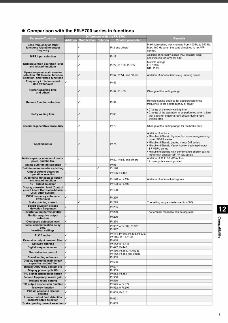
12
Com
patibility
Comparison with the FR-E700 series in functionsParameter/function Differences with the FR-E700 RemarksAddition Modification Deletion Related parameter
Base frequency or other functions related to output
frequency Pr.3 and others
Maximum setting was changed from 400 Hz to 590 Hz. Max. 400 Hz when the control method is not V/F control.
MRS input selection Pr.17 Addition of normally closed (NC contact) input specification for terminal X10
Stall prevention operation level and related functions Pr.22, Pr.150, Pr.165
Multiple ratingsLD: 120%ND: 150%
Operation panel main monitor selection, TM terminal function selection, and related functions
Pr.52, Pr.54, and others Addition of monitor items (e.g. running speed)
Frequency / rotation speedUnit switchover Pr.53
Restart coasting timeand others Pr.57, Pr.165 Change of the setting range
Remote function selection Pr.59 Remote setting enabled for deceleration to the frequency to the set frequency or lower
Retry waiting time Pr.68
• Change of the retry waiting time• Change of the operation to be performed when a fault
that does not trigger a retry occurs during retry waiting time
Special regenerative brake duty Pr.70 Change of the setting range for the brake duty
Applied motor Pr.71
Addition of motors:• Mitsubishi Electric high-performance energy-saving
motor SF-PR series• Mitsubishi Electric geared motor GM series• Mitsubishi Electric Vector control dedicated motor
SF-V5RU series• Mitsubishi Electric high-performance energy-saving
motor with encoder SF-PR-SC seriesMotor capacity, number of motor
poles, and the like Pr.80, Pr.81, and others Addition of 11 to 30 kW motors.12 motor poles are supported.
Online auto tuning selection Pr.95Built-in potentiometer switching Pr.146
Output current detection operation selection Pr.166, Pr.167
I/O terminal function selection and related functions Pr.178 to Pr.192 Addition of input/output signals
NET output selection Pr.193 to Pr.196Display corrosion level (Control circuit board Corrosion-Attack-
Level Alert System) Pr.198
PWM frequency automatic switchover Pr.260
Brake opening current Pr.279 The setting range is extended to 400%.Speed deviation excess
detection frequency Pr.285
Inverter output terminal filter Pr.289 The terminal response can be adjusted.Monitor negative output
selection Pr.290
Overspeed detection level Pr.374Initial communication delay
time,heartbeat settings
Pr.387 to Pr.389, Pr.391, Pr.392
PLC function Pr.414, Pr.415, Pr.498, Pr.675, Pr.1150 to Pr.1199
Extension output terminal filter Pr.418Gateway address Pr.442 to Pr.445
Digital torque command Pr.447, Pr.448
Second motor control Pr.450, Pr.451, Pr.453 to Pr.462, Pr.463 and others
Speed setting reference Pr.505Display estimated main circuit
capacitor residual life Pr.506
Display ABC relay contact life Pr.507Display power cycle life Pr.509
PID signal operation selection Pr.553, Pr.554Second frequency search gain Pr.560
Multiple rating setting Pr.570PID output suspension function Pr.575 to Pr.577
Traverse function Pr.592 to Pr.597PID set point and related
settings Pr.609, Pr.610
Inverter output fault detection enable/disable selection Pr.631
Brake opening current selection Pr.639
131
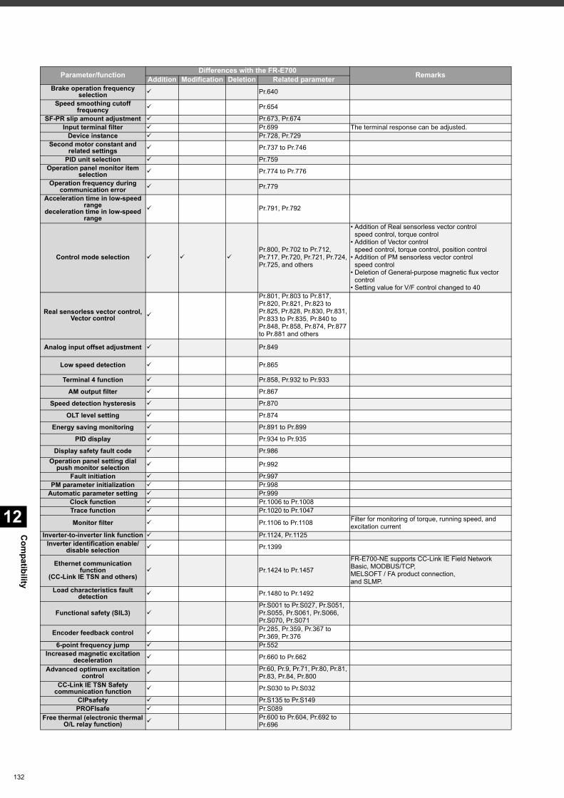
Com
patibility
12
132
Brake operation frequency selection Pr.640
Speed smoothing cutoff frequency Pr.654
SF-PR slip amount adjustment Pr.673, Pr.674Input terminal filter Pr.699 The terminal response can be adjusted.
Device instance Pr.728, Pr.729Second motor constant and
related settings Pr.737 to Pr.746
PID unit selection Pr.759Operation panel monitor item
selection Pr.774 to Pr.776
Operation frequency during communication error Pr.779
Acceleration time in low-speed range
deceleration time in low-speed range
Pr.791, Pr.792
Control mode selection Pr.800, Pr.702 to Pr.712, Pr.717, Pr.720, Pr.721, Pr.724, Pr.725, and others
• Addition of Real sensorless vector controlspeed control, torque control
• Addition of Vector controlspeed control, torque control, position control
• Addition of PM sensorless vector controlspeed control
• Deletion of General-purpose magnetic flux vector control
• Setting value for V/F control changed to 40
Real sensorless vector control, Vector control
Pr.801, Pr.803 to Pr.817, Pr.820, Pr.821, Pr.823 to Pr.825, Pr.828, Pr.830, Pr.831, Pr.833 to Pr.835, Pr.840 to Pr.848, Pr.858, Pr.874, Pr.877 to Pr.881 and others
Analog input offset adjustment Pr.849
Low speed detection Pr.865
Terminal 4 function Pr.858, Pr.932 to Pr.933
AM output filter Pr.867
Speed detection hysteresis Pr.870
OLT level setting Pr.874
Energy saving monitoring Pr.891 to Pr.899
PID display Pr.934 to Pr.935
Display safety fault code Pr.986Operation panel setting dial
push monitor selection Pr.992
Fault initiation Pr.997PM parameter initialization Pr.998
Automatic parameter setting Pr.999Clock function Pr.1006 to Pr.1008Trace function Pr.1020 to Pr.1047
Monitor filter Pr.1106 to Pr.1108 Filter for monitoring of torque, running speed, and excitation current
Inverter-to-inverter link function Pr.1124, Pr.1125Inverter identification enable/
disable selection Pr.1399
Ethernet communication function
(CC-Link IE TSN and others) Pr.1424 to Pr.1457
FR-E700-NE supports CC-Link IE Field Network Basic, MODBUS/TCP,MELSOFT / FA product connection,and SLMP.
Load characteristics fault detection Pr.1480 to Pr.1492
Functional safety (SIL3) Pr.S001 to Pr.S027, Pr.S051, Pr.S055, Pr.S061, Pr.S066, Pr.S070, Pr.S071
Encoder feedback control Pr.285, Pr.359, Pr.367 to Pr.369, Pr.376
6-point frequency jump Pr.552Increased magnetic excitation
deceleration Pr.660 to Pr.662
Advanced optimum excitation control
Pr.60, Pr.9, Pr.71, Pr.80, Pr.81, Pr.83, Pr.84, Pr.800
CC-Link IE TSN Safety communication function Pr.S030 to Pr.S032
CIPsafety Pr.S135 to Pr.S149PROFIsafe Pr.S089
Free thermal (electronic thermal O/L relay function)
Pr.600 to Pr.604, Pr.692 to Pr.696
Parameter/function Differences with the FR-E700 RemarksAddition Modification Deletion Related parameter
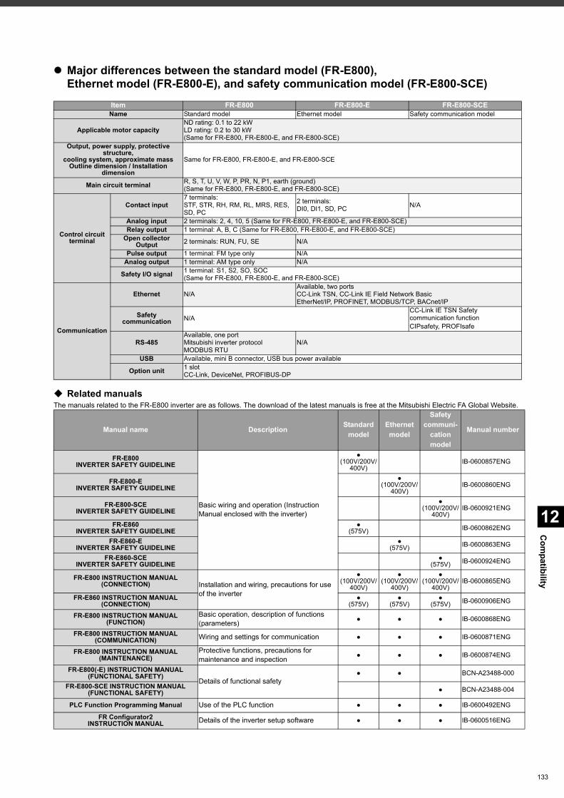
12
Com
patibility
Major differences between the standard model (FR-E800), Ethernet model (FR-E800-E), and safety communication model (FR-E800-SCE)
Related manualsThe manuals related to the FR-E800 inverter are as follows. The download of the latest manuals is free at the Mitsubishi Electric FA Global Website.
Item FR-E800 FR-E800-E FR-E800-SCEName Standard model Ethernet model Safety communication model
Applicable motor capacityND rating: 0.1 to 22 kWLD rating: 0.2 to 30 kW(Same for FR-E800, FR-E800-E, and FR-E800-SCE)
Output, power supply, protective structure,
cooling system, approximate massOutline dimension / Installation
dimension
Same for FR-E800, FR-E800-E, and FR-E800-SCE
Main circuit terminal R, S, T, U, V, W, P, PR, N, P1, earth (ground)(Same for FR-E800, FR-E800-E, and FR-E800-SCE)
Control circuit terminal
Contact input7 terminals:STF, STR, RH, RM, RL, MRS, RES, SD, PC
2 terminals:DI0, DI1, SD, PC N/A
Analog input 2 terminals: 2, 4, 10, 5 (Same for FR-E800, FR-E800-E, and FR-E800-SCE)Relay output 1 terminal: A, B, C (Same for FR-E800, FR-E800-E, and FR-E800-SCE)
Open collectorOutput 2 terminals: RUN, FU, SE N/A
Pulse output 1 terminal: FM type only N/AAnalog output 1 terminal: AM type only N/A
Safety I/O signal 1 terminal: S1, S2, SO, SOC(Same for FR-E800, FR-E800-E, and FR-E800-SCE)
Communication
Ethernet N/AAvailable, two portsCC-Link TSN, CC-Link IE Field Network BasicEtherNet/IP, PROFINET, MODBUS/TCP, BACnet/IP
Safety communication N/A
CC-Link IE TSN Safety communication functionCIPsafety, PROFIsafe
RS-485Available, one portMitsubishi inverter protocolMODBUS RTU
N/A
USB Available, mini B connector, USB bus power available
Option unit 1 slotCC-Link, DeviceNet, PROFIBUS-DP
Manual name Description Standard model
Ethernet model
Safety communi-
cation model
Manual number
FR-E800 INVERTER SAFETY GUIDELINE
Basic wiring and operation (Instruction Manual enclosed with the inverter)
●(100V/200V/
400V)IB-0600857ENG
FR-E800-E INVERTER SAFETY GUIDELINE
●(100V/200V/
400V)IB-0600860ENG
FR-E800-SCE INVERTER SAFETY GUIDELINE
●(100V/200V/
400V)IB-0600921ENG
FR-E860 INVERTER SAFETY GUIDELINE
●(575V) IB-0600862ENG
FR-E860-EINVERTER SAFETY GUIDELINE
●(575V) IB-0600863ENG
FR-E860-SCE INVERTER SAFETY GUIDELINE
●(575V) IB-0600924ENG
FR-E800 INSTRUCTION MANUAL (CONNECTION) Installation and wiring, precautions for use
of the inverter
●(100V/200V/
400V)
●(100V/200V/
400V)
●(100V/200V/
400V)IB-0600865ENG
FR-E860 INSTRUCTION MANUAL (CONNECTION)
●(575V)
●(575V)
●(575V) IB-0600906ENG
FR-E800 INSTRUCTION MANUAL (FUNCTION)
Basic operation, description of functions (parameters) ● ● ● IB-0600868ENG
FR-E800 INSTRUCTION MANUAL (COMMUNICATION) Wiring and settings for communication ● ● ● IB-0600871ENG
FR-E800 INSTRUCTION MANUAL (MAINTENANCE)
Protective functions, precautions for maintenance and inspection ● ● ● IB-0600874ENG
FR-E800(-E) INSTRUCTION MANUAL(FUNCTIONAL SAFETY)
Details of functional safety● ● BCN-A23488-000
FR-E800-SCE INSTRUCTION MANUAL(FUNCTIONAL SAFETY) ● BCN-A23488-004
PLC Function Programming Manual Use of the PLC function ● ● ● IB-0600492ENG
FR Configurator2INSTRUCTION MANUAL Details of the inverter setup software ● ● ● IB-0600516ENG
133

134
MEMO
13
Warranty
135
When using this product, make sure to understand the warranty described below.
1. Warranty period and coverage
We will repair any failure or defect (hereinafter referred to as "failure") in our FA equipment (hereinafter referred to as the "Product") arisen during warranty period at no charge due to causes for which we are responsible through the distributor from which you purchased the Product or our service provider. However, we will charge the actual cost of dispatching our engineer for an on-site repair work on request by customer in Japan or overseas countries. We are not responsible for any on-site readjustment and/or trial run that may be required after a defective unit are repaired or replaced.
[Term]The term of warranty for Product is twelve months after your purchase or delivery of the Product to a place designated by you or eighteen months from the date of manufacture whichever comes first ("Warranty Period"). Warranty period for repaired Product cannot exceed beyond the original warranty period before any repair work.
[Limitations](1) You are requested to conduct an initial failure diagnosis by yourself, as a general rule. It can also be carried out by us or our
service company upon your request and the actual cost will be charged.However, it will not be charged if we are responsible for the cause of the failure.
(2) This limited warranty applies only when the condition, method, environment, etc. of use are in compliance with the terms and conditions and instructions that are set forth in the instruction manual and user manual for the Product and the caution label affixed to the Product.
(3) Even during the term of warranty, the repair cost will be charged on you in the following cases;1) a failure caused by your improper storing or handling, carelessness or negligence, etc., and a failure caused by your hardware
or software problem2) a failure caused by any alteration, etc. to the Product made on your side without our approval3) a failure which may be regarded as avoidable, if your equipment in which the Product is incorporated is equipped with a safety
device required by applicable laws and has any function or structure considered to be indispensable according to a common sense in the industry
4) a failure which may be regarded as avoidable if consumable parts designated in the instruction manual, etc. are duly maintained and replaced
5) any replacement of consumable parts (condenser, cooling fan, etc.)6) a failure caused by external factors such as inevitable accidents, including without limitation fire and abnormal fluctuation of
voltage, and acts of God, including without limitation earthquake, lightning and natural disasters7) a failure generated by an unforeseeable cause with a scientific technology that was not available at the time of the shipment of
the Product from our company8) any other failures which we are not responsible for or which you acknowledge we are not responsible for
2. Term of warranty after the stop of production(1) We may accept the repair at charge for another seven (7) years after the production of the product is discontinued. The
announcement of the stop of production for each model can be seen in our Sales and Service, etc.(2) Please note that the Product (including its spare parts) cannot be ordered after its stop of production.
3. Service in overseasOur regional FA Center in overseas countries will accept the repair work of the Product; however, the terms and conditions of the repair work may differ depending on each FA Center. Please ask your local FA center for details.
4. Exclusion of loss in opportunity and secondary loss from warranty liabilityRegardless of the gratis warranty term, Mitsubishi shall not be liable for compensation to:(1) Damages caused by any cause found not to be the responsibility of Mitsubishi.(2) Loss in opportunity, lost profits incurred to the user by Failures of Mitsubishi products.(3) Special damages and secondary damages whether foreseeable or not, compensation for accidents, and compensation for
damages to products other than Mitsubishi products.(4) Replacement by the user, maintenance of on-site equipment, start-up test run and other tasks.
5. Change of Product specificationsSpecifications listed in our catalogs, manuals or technical documents may be changed without notice.
6. Application and use of the Product(1) For the use of our product, its applications should be those that may not result in a serious damage even if any failure or
malfunction occurs in product, and a backup or fail-safe function should operate on an external system to product when any failure or malfunction occurs.
(2) Our product is designed and manufactured as a general purpose product for use at general industries.Therefore, applications substantially influential on the public interest for such as atomic power plants and other power plants of electric power companies, and also which require a special quality assurance system, including applications for railway companies and government or public offices are not recommended, and we assume no responsibility for any failure caused by these applications when used.In addition, applications which may be substantially influential to human lives or properties for such as airlines, medical treatments, railway service, incineration and fuel systems, man-operated material handling equipment, entertainment machines, safety machines, etc. are not recommended, and we assume no responsibility for any failure caused by these applications when used.We will review the acceptability of the abovementioned applications, if you agree not to require a specific quality for a specific application. Please contact us for consultation.
Warranty
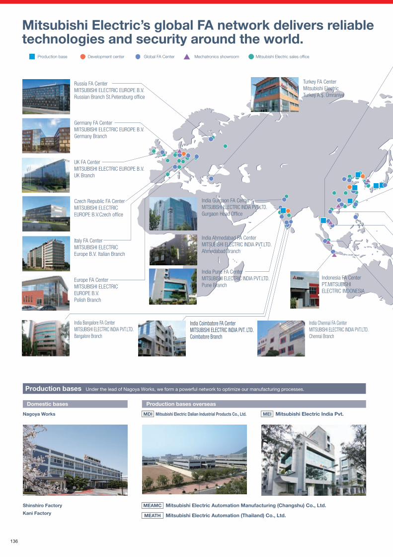
India Coimbatore FA CenterMITSUBISHI ELECTRIC INDIA PVT. LTD.Coimbatore Branch
Production bases Under the lead of Nagoya Works, we form a powerful network to optimize our manufacturing processes.
Domestic bases
Nagoya Works
Production bases overseas
MDI Mitsubishi Electric Dalian Industrial Products Co., Ltd. Mitsubishi Electric India Pvt.MEI
MEAMC Mitsubishi Electric Automation Manufacturing (Changshu) Co., Ltd.
MEATH Mitsubishi Electric Automation (Thailand) Co., Ltd.
Shinshiro Factory
Kani Factory
Philippines FA CenterMELCO FACTORY AUTOMATION PHILIPPINES INC.
136
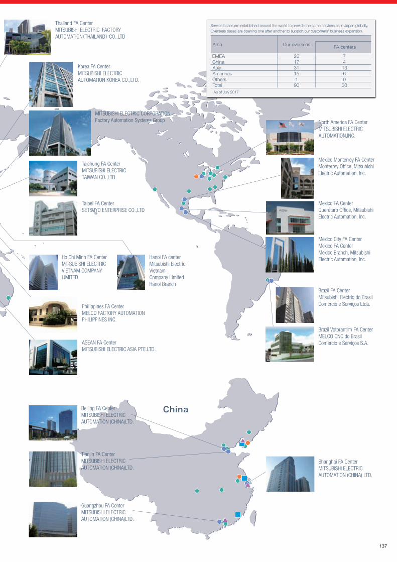
India Coimbatore FA CenterMITSUBISHI ELECTRIC INDIA PVT. LTD.Coimbatore Branch
Production bases Under the lead of Nagoya Works, we form a powerful network to optimize our manufacturing processes.
Domestic bases
Nagoya Works
Production bases overseas
MDI Mitsubishi Electric Dalian Industrial Products Co., Ltd. Mitsubishi Electric India Pvt.MEI
MEAMC Mitsubishi Electric Automation Manufacturing (Changshu) Co., Ltd.
MEATH Mitsubishi Electric Automation (Thailand) Co., Ltd.
Shinshiro Factory
Kani Factory
Philippines FA CenterMELCO FACTORY AUTOMATION PHILIPPINES INC.
137
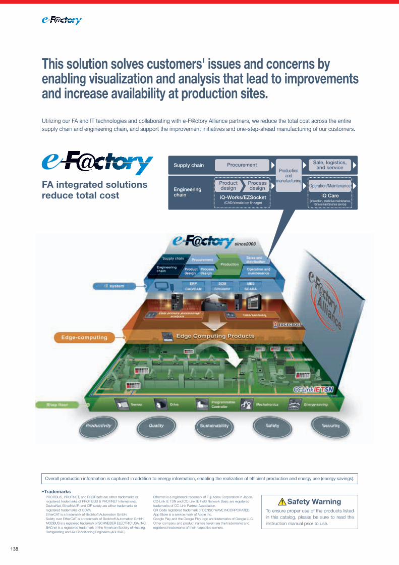
Overall production information is captured in addition to energy information, enabling the realization of efficient production and energy use (energy savings).
This solution solves customers' issues and concerns by enabling visualization and analysis that lead to improvements and increase availability at production sites.
FA integrated solutionsreduce total cost
Utilizing our FA and IT technologies and collaborating with e-F@ctory Alliance partners, we reduce the total cost across the entire supply chain and engineering chain, and support the improvement initiatives and one-step-ahead manufacturing of our customers.
Supply chain Sale, logistics,and service
Productionand
manufacturing
iQ-Works/EZSocket(CAD/simulation linkage)
iQ Care(prevention, predictive maintenance,
remote maintenance service)
Productdesign
Processdesign Operation/Maintenance
Engineering chain
Procurement
YOUR SOLUTION PARTNER
Automation solutions
Mitsubishi Electric offers a wide range of automation equipment from PLCs and HMIs to
CNC and EDM machines.
A NAME TO TRUSTSince its beginnings in 1870, some 45 companies use the Mitsubishi name, covering a spectrum of finance, commerce and industry.
The Mitsubishi brand name is recognized around the world as a symbol of premium quality.
Mitsubishi Electric Corporation is active in space development, transportation, semi-conductors, energy systems, communications and information processing, audio visual equipment and home electronics, building and energy management and automation systems, and has 237 factories and laboratories worldwide in over 121 countries.
This is why you can rely on Mitsubishi Electric automation solution - because we know first hand about the need for reliable, efficient, easy-to-use automation and control in our own factories.
As one of the world’s leading companies with a global turnover of over 4 trillion Yen (over $40 billion), employing over 100,000 people, Mitsubishi Electric has the resource and the commitment to deliver the ultimate in service and support as well as the best products.
Medium voltage: VCB, VCC
Power monitoring, energy management
Compact and Modular Controllers
Inverters, Servos and Motors
Visualisation: HMIs
Numerical Control (NC)
Robots: SCARA, Articulated arm
Processing machines: EDM, Lasers, IDS
Transformers, Air conditioning, Photovoltaic systems
Low voltage: MCCB, MCB, ACB
* Not all products are available in all countries.
To ensure proper use of the products listed in this catalog, please be sure to read the instruction manual prior to use.
Safety WarningPROFIBUS, PROFINET, and PROFIsafe are either trademarks or registered trademarks of PROFIBUS & PROFINET International.DeviceNet, EtherNet/IP, and CIP safety are either trademarks or registered trademarks of ODVA.EtherCAT is a trademark of Beckhoff Automation GmbH.Safety over EtherCAT is a trademark of Beckhoff Automation GmbH.MODBUS is a registered trademark of SCHNEIDER ELECTRIC USA, INC.BACnet is a registered trademark of the American Society of Heating, Refrigerating and Air-Conditioning Engineers (ASHRAE).
Ethernet is a registered trademark of Fuji Xerox Corporation in Japan.CC-Link IE TSN and CC-Link IE Field Network Basic are registered trademarks of CC-Link Partner Association.QR Code registered trademark of DENSO WAVE INCORPORATED.App Store is a service mark of Apple Inc.Google Play and the Google Play logo are trademarks of Google LLC.Other company and product names herein are the trademarks and registered trademarks of their respective owners.
•Trademarks
138

Overall production information is captured in addition to energy information, enabling the realization of efficient production and energy use (energy savings).
This solution solves customers' issues and concerns by enabling visualization and analysis that lead to improvements and increase availability at production sites.
FA integrated solutionsreduce total cost
Utilizing our FA and IT technologies and collaborating with e-F@ctory Alliance partners, we reduce the total cost across the entire supply chain and engineering chain, and support the improvement initiatives and one-step-ahead manufacturing of our customers.
Supply chain Sale, logistics,and service
Productionand
manufacturing
iQ-Works/EZSocket(CAD/simulation linkage)
iQ Care(prevention, predictive maintenance,
remote maintenance service)
Productdesign
Processdesign Operation/Maintenance
Engineering chain
Procurement
YOUR SOLUTION PARTNER
Automation solutions
Mitsubishi Electric offers a wide range of automation equipment from PLCs and HMIs to
CNC and EDM machines.
A NAME TO TRUSTSince its beginnings in 1870, some 45 companies use the Mitsubishi name, covering a spectrum of finance, commerce and industry.
The Mitsubishi brand name is recognized around the world as a symbol of premium quality.
Mitsubishi Electric Corporation is active in space development, transportation, semi-conductors, energy systems, communications and information processing, audio visual equipment and home electronics, building and energy management and automation systems, and has 237 factories and laboratories worldwide in over 121 countries.
This is why you can rely on Mitsubishi Electric automation solution - because we know first hand about the need for reliable, efficient, easy-to-use automation and control in our own factories.
As one of the world’s leading companies with a global turnover of over 4 trillion Yen (over $40 billion), employing over 100,000 people, Mitsubishi Electric has the resource and the commitment to deliver the ultimate in service and support as well as the best products.
Medium voltage: VCB, VCC
Power monitoring, energy management
Compact and Modular Controllers
Inverters, Servos and Motors
Visualisation: HMIs
Numerical Control (NC)
Robots: SCARA, Articulated arm
Processing machines: EDM, Lasers, IDS
Transformers, Air conditioning, Photovoltaic systems
Low voltage: MCCB, MCB, ACB
* Not all products are available in all countries.
To ensure proper use of the products listed in this catalog, please be sure to read the instruction manual prior to use.
Safety WarningPROFIBUS, PROFINET, and PROFIsafe are either trademarks or registered trademarks of PROFIBUS & PROFINET International.DeviceNet, EtherNet/IP, and CIP safety are either trademarks or registered trademarks of ODVA.EtherCAT is a trademark of Beckhoff Automation GmbH.Safety over EtherCAT is a trademark of Beckhoff Automation GmbH.MODBUS is a registered trademark of SCHNEIDER ELECTRIC USA, INC.BACnet is a registered trademark of the American Society of Heating, Refrigerating and Air-Conditioning Engineers (ASHRAE).
Ethernet is a registered trademark of Fuji Xerox Corporation in Japan.CC-Link IE TSN and CC-Link IE Field Network Basic are registered trademarks of CC-Link Partner Association.QR Code registered trademark of DENSO WAVE INCORPORATED.App Store is a service mark of Apple Inc.Google Play and the Google Play logo are trademarks of Google LLC.Other company and product names herein are the trademarks and registered trademarks of their respective owners.
•Trademarks
139

L(NA)06131ENG-C (2101) MEE
HEAD OFFICE: TOKYO BLDG., 2-7-3, MARUNOUCHI, CHIYODA-KU, TOKYO 100-8310, JAPAN
Mitsubishi Electric Corporation Nagoya Works is a factory certified for ISO 14001 (standards for environmental management systems) and ISO 9001 (standards for quality assurance management systems).
Related Documents