Revision 1.3 Page i FPM100 Fluid Pressure Monitor User’s Manual Revision 1.3 Copyright © 2015 Maretron, LLP All Rights Reserved Maretron, LLP 9014 N. 23 rd Ave #10 Phoenix, AZ 85021 http://www.maretron.com Maretron Manual Part #: M002801

Welcome message from author
This document is posted to help you gain knowledge. Please leave a comment to let me know what you think about it! Share it to your friends and learn new things together.
Transcript

Revision 1.3 Page i
FPM100 Fluid Pressure Monitor
User’s Manual
Revision 1.3
Copyright © 2015 Maretron, LLP All Rights Reserved
Maretron, LLP 9014 N. 23rd Ave #10 Phoenix, AZ 85021
http://www.maretron.com
Maretron Manual Part #: M002801

FPM100 User’s Manual
Page ii Revision 1.3
Revision History
Revision Description
1.0 Original document
1.2 Corrected accessory table and added new sensors
1.3 Added warning to not use pressure transducer accessories with gasoline
Revision 1.3 Page iii
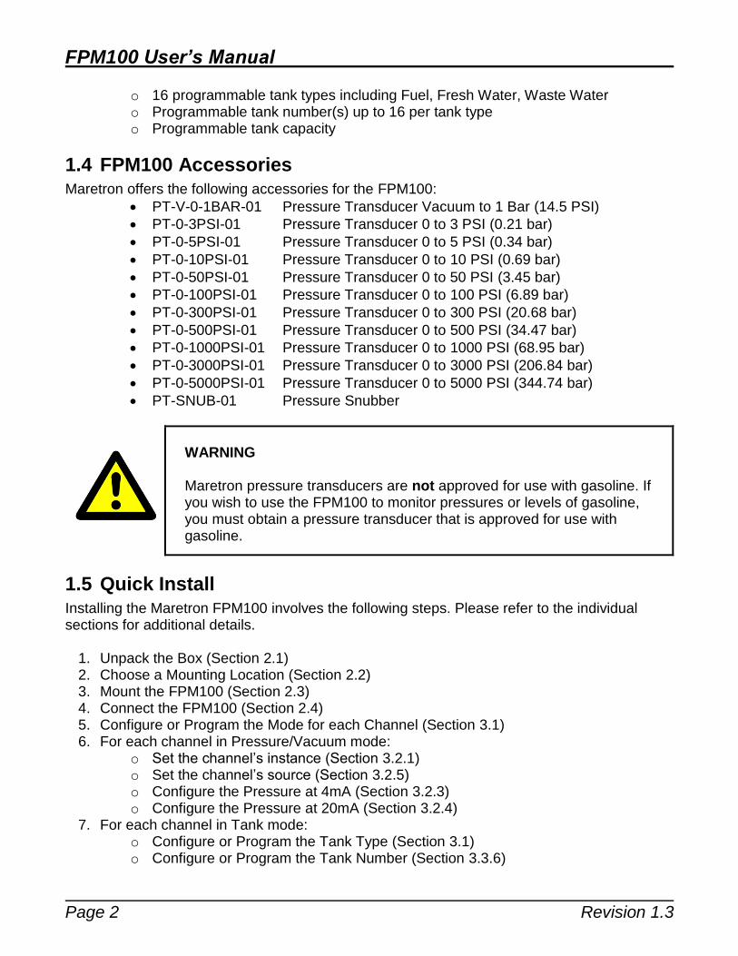
Table of Contents 1 General ................................................................................................................................ 1
1.1 Introduction .................................................................................................................... 1 1.2 Firmware Revision ......................................................................................................... 1
1.3 Features ........................................................................................................................ 1 1.4 FPM100 Accessories ..................................................................................................... 2 1.5 Quick Install ................................................................................................................... 2 1.6 Theory of Operation ....................................................................................................... 3
1.6.1 Choosing a Pressure Transducer Mounting Location for Tank Level Measurement ................................................................................................................. 3 1.6.2 Accuracy of Tank Level Measurement ................................................................ 3
2 Installation ............................................................................................................................ 4
2.1 Unpacking the Box ......................................................................................................... 4 2.2 Choosing a Mounting Location ...................................................................................... 5 2.3 Mounting the FPM100 ................................................................................................... 5
2.4 Mounting the Pressure Transducer ................................................................................ 5 2.4.1 Pressure Measurement Applications .................................................................. 5 2.4.2 Tank Level Measurement Applications ............................................................... 6
2.5 Connecting the FPM100 ................................................................................................ 7 2.5.1 NMEA 2000® Connection .................................................................................... 7
2.5.2 Pressure Transducer Connections ...................................................................... 8 3 Configuring the FPM100 ...................................................................................................... 9
3.1 Configuring Channel Mode ............................................................................................ 9
3.2 Configuring a Channel in Pressure/Vacuum Mode ...................................................... 10
3.2.1 Configuring Instance ......................................................................................... 10 3.2.2 Configuring Label .............................................................................................. 10 3.2.3 Configuring Pressure at 4mA ............................................................................ 10
3.2.4 Configuring Pressure at 20mA .......................................................................... 10 3.2.5 Configuring Source ........................................................................................... 10
3.2.6 Configuring Data Damping Period .................................................................... 11 3.3 Configuring a Channel in Tank Mode .......................................................................... 11
3.3.1 Configuring Label .............................................................................................. 11 3.3.2 Configuring Pressure at 4mA ............................................................................ 11
3.3.3 Configuring Pressure at 20mA .......................................................................... 11 3.3.4 Configuring Tank Capacity ................................................................................ 11 3.3.5 Tank Levels Calibration ..................................................................................... 11 3.3.6 Configuring Tank Number ................................................................................. 12
3.3.7 Configuring Tank Type ...................................................................................... 13 3.3.8 Configuring Data Damping Period .................................................................... 13
4 Maintenance ....................................................................................................................... 13
5 Troubleshooting ................................................................................................................. 14 6 Technical Specifications ..................................................................................................... 15 7 Technical Support .............................................................................................................. 16 8 Installation Template .......................................................................................................... 17 9 Maretron (2 Year) Limited Warranty ................................................................................... 18

FPM100 User’s Manual
Page iv Revision 1.3
Table of Figures Figure 1 - Graph of Transducer Accuracy vs. Tank Depth......................................................... 4 Figure 2 - Pressure Transducer Selection Chart for Tank Level Applications ............................ 4 Figure 3 – Mounting the FPM100 .............................................................................................. 5
Figure 4 – Fluid Level Measurement with Pressure Transducer ................................................ 6 Figure 5 - Tank Mounting of the Pressure Transducer with Recommended Ball Value ............. 7 Figure 6 – NMEA 2000® Connector Face Views ....................................................................... 8 Figure 7 – Pressure Transducer Connection Diagram .............................................................. 9 Figure 8 – Empty Tank Depth and Full Tank Depth Parameters ............................................. 12
Figure 9 – Troubleshooting Guide ........................................................................................... 14 Figure 10 – Mounting Surface Template.................................................................................. 17
Table of Appendices
Appendix A – NMEA 2000® Interfacing.................................................................................... A1

Revision 1.3 Page 1
1 General
1.1 Introduction Congratulations on your purchase of the Maretron Fluid Pressure Monitor (FPM100). Maretron has designed and built your monitor to the highest standards for years of reliable, dependable, and accurate service. Maretron’s Fluid Pressure Monitor (FPM100) is used to adapt up to six pressure transducers to the NMEA 2000® network (pressure transducers sold separately). This allows you to observe fluid pressures and tank levels anywhere on the vessel where there are NMEA 2000® compatible displays. With the appropriate transducer, the FPM100 reports either pressure or vacuum for a variety of applications including water pressures, oil pressures, hydraulic pressures, or system vacuum for detecting clogged filters. The FPM100 also has a tank level mode, so that fluid levels in a tank can be monitored via a pressure transducer mounted at the bottom of the tank and transmitted over the NMEA 2000® network. This allows you to monitor the fluid levels in tanks that are extremely deep, have internal structures, or are otherwise not suited for other tank level sensing technologies. In this mode, the FPM100 can be calibrated for irregular tank shapes so that you know the true level of the tanks. The Maretron FPM100 is designed to operate within the harsh demands of the marine environment. However, no piece of marine electronic equipment can function properly unless installed, calibrated, and maintained in the correct manner. Please read carefully and follow these instructions for installation, calibration, and usage of the Maretron FPM100 in order to ensure optimal performance.
1.2 Firmware Revision
This manual corresponds to FPM100 firmware revision 1.0.1.
1.3 Features
The Maretron FPM100 has the following features:
NMEA 2000® interface
Adapts up to six pressure transducers to the NMEA 2000 network
Each channel independently programmable to match pressure transducer characteristics
Each channel independently programmable to pressure/vacuum mode or tank level mode
In Pressure Mode: o Can report programmable pressure sources including Water Pressure,
Atmospheric Pressure, Compressed Air Pressure, Hydraulic Pressure, Steam Pressure, or User Defined pressure sources.
In Tank Level Mode: o Pressure transducer allows use in extremely deep or irregularly shaped tanks
that can’t be sensed using other technologies
FPM100 User’s Manual
Page 2 Revision 1.3
o 16 programmable tank types including Fuel, Fresh Water, Waste Water o Programmable tank number(s) up to 16 per tank type o Programmable tank capacity
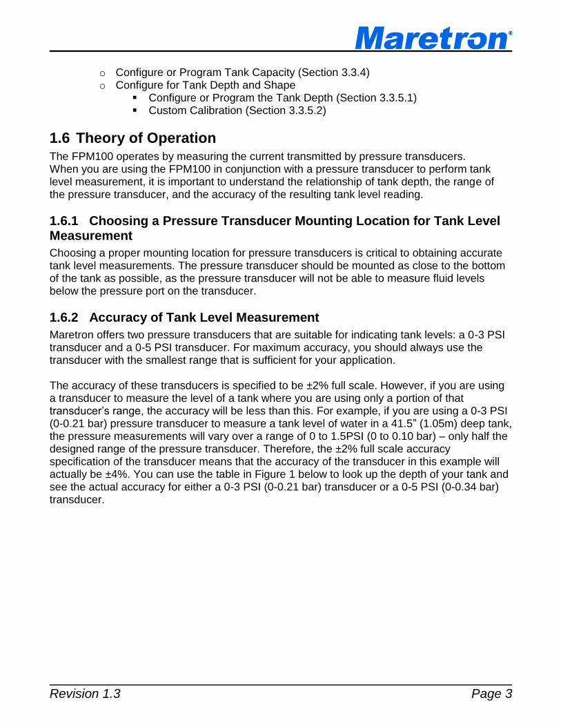
1.4 FPM100 Accessories
Maretron offers the following accessories for the FPM100:
PT-V-0-1BAR-01 Pressure Transducer Vacuum to 1 Bar (14.5 PSI)
PT-0-3PSI-01 Pressure Transducer 0 to 3 PSI (0.21 bar)
PT-0-5PSI-01 Pressure Transducer 0 to 5 PSI (0.34 bar)
PT-0-10PSI-01 Pressure Transducer 0 to 10 PSI (0.69 bar)
PT-0-50PSI-01 Pressure Transducer 0 to 50 PSI (3.45 bar)
PT-0-100PSI-01 Pressure Transducer 0 to 100 PSI (6.89 bar)
PT-0-300PSI-01 Pressure Transducer 0 to 300 PSI (20.68 bar)
PT-0-500PSI-01 Pressure Transducer 0 to 500 PSI (34.47 bar)
PT-0-1000PSI-01 Pressure Transducer 0 to 1000 PSI (68.95 bar)
PT-0-3000PSI-01 Pressure Transducer 0 to 3000 PSI (206.84 bar)
PT-0-5000PSI-01 Pressure Transducer 0 to 5000 PSI (344.74 bar)
PT-SNUB-01 Pressure Snubber
WARNING
Maretron pressure transducers are not approved for use with gasoline. If you wish to use the FPM100 to monitor pressures or levels of gasoline, you must obtain a pressure transducer that is approved for use with gasoline.
1.5 Quick Install
Installing the Maretron FPM100 involves the following steps. Please refer to the individual sections for additional details.
1. Unpack the Box (Section 2.1) 2. Choose a Mounting Location (Section 2.2) 3. Mount the FPM100 (Section 2.3) 4. Connect the FPM100 (Section 2.4) 5. Configure or Program the Mode for each Channel (Section 3.1) 6. For each channel in Pressure/Vacuum mode:
o Set the channel’s instance (Section 3.2.1) o Set the channel’s source (Section 3.2.5) o Configure the Pressure at 4mA (Section 3.2.3) o Configure the Pressure at 20mA (Section 3.2.4)
7. For each channel in Tank mode: o Configure or Program the Tank Type (Section 3.1) o Configure or Program the Tank Number (Section 3.3.6)
Revision 1.3 Page 3
o Configure or Program Tank Capacity (Section 3.3.4) o Configure for Tank Depth and Shape
Configure or Program the Tank Depth (Section 3.3.5.1) Custom Calibration (Section 3.3.5.2)
1.6 Theory of Operation
The FPM100 operates by measuring the current transmitted by pressure transducers. When you are using the FPM100 in conjunction with a pressure transducer to perform tank level measurement, it is important to understand the relationship of tank depth, the range of the pressure transducer, and the accuracy of the resulting tank level reading.
1.6.1 Choosing a Pressure Transducer Mounting Location for Tank Level Measurement
Choosing a proper mounting location for pressure transducers is critical to obtaining accurate tank level measurements. The pressure transducer should be mounted as close to the bottom of the tank as possible, as the pressure transducer will not be able to measure fluid levels below the pressure port on the transducer.
1.6.2 Accuracy of Tank Level Measurement
Maretron offers two pressure transducers that are suitable for indicating tank levels: a 0-3 PSI transducer and a 0-5 PSI transducer. For maximum accuracy, you should always use the transducer with the smallest range that is sufficient for your application. The accuracy of these transducers is specified to be ±2% full scale. However, if you are using a transducer to measure the level of a tank where you are using only a portion of that transducer’s range, the accuracy will be less than this. For example, if you are using a 0-3 PSI (0-0.21 bar) pressure transducer to measure a tank level of water in a 41.5” (1.05m) deep tank, the pressure measurements will vary over a range of 0 to 1.5PSI (0 to 0.10 bar) – only half the designed range of the pressure transducer. Therefore, the ±2% full scale accuracy specification of the transducer means that the accuracy of the transducer in this example will actually be ±4%. You can use the table in Figure 1 below to look up the depth of your tank and see the actual accuracy for either a 0-3 PSI (0-0.21 bar) transducer or a 0-5 PSI (0-0.34 bar) transducer.

FPM100 User’s Manual
Page 4 Revision 1.3
Figure 1 - Graph of Transducer Accuracy vs. Tank Depth
The pressure transducer you select must have sufficient range to measure the full height of the liquid column of a full tank. The table in Figure 2 below shows the maximum depth that can be sensed by each pressure transducer type. This table assumes that water level is being measured. The maximum depth of diesel fuel can that can be measured varies from these figures slightly depending on the density of the diesel fuel.
Transducer Maximum tank depth
PT-0-3PSI-01 (0-3 PSI) 83.04” (2.11m)
PT-0-5PSI-01 (0-5 PSI) 138.4” (3.52m)
Figure 2 - Pressure Transducer Selection Chart for Tank Level Applications
2 Installation
2.1 Unpacking the Box
When unpacking the box containing the Maretron FPM100, you should find the following items:
1 – FPM100 Fluid Pressure Monitor
1 – Parts Bag containing 4 Stainless Steel Mounting Screws
1 – FPM100 User’s Manual
1 – Warranty Registration Card If any of these items are missing or damaged, please contact Maretron.
Revision 1.3 Page 5
2.2 Choosing a Mounting Location
Please consider the following when choosing a mounting location.
1. The FPM100 is waterproof, so it can be mounted in a damp or dry location. 2. The orientation is not important, so the FPM100 can be mounted on a horizontal deck,
vertical bulkhead, or upside down if desired. 3. The FPM100 is temperature-rated to 55°C (130°F), so it should be mounted away from
engines or engine rooms where the operating temperature exceeds the specified limit.
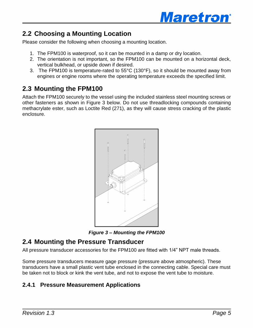
2.3 Mounting the FPM100 Attach the FPM100 securely to the vessel using the included stainless steel mounting screws or other fasteners as shown in Figure 3 below. Do not use threadlocking compounds containing methacrylate ester, such as Loctite Red (271), as they will cause stress cracking of the plastic enclosure.
Figure 3 – Mounting the FPM100
2.4 Mounting the Pressure Transducer All pressure transducer accessories for the FPM100 are fitted with 1/4” NPT male threads. Some pressure transducers measure gage pressure (pressure above atmospheric). These transducers have a small plastic vent tube enclosed in the connecting cable. Special care must be taken not to block or kink the vent tube, and not to expose the vent tube to moisture.
2.4.1 Pressure Measurement Applications
FPM100 User’s Manual
Page 6 Revision 1.3
Keep in mind that the rated burst pressure of the pressure transducer is 2.4 to 3 times the maximum measurement pressure of the transducer. If the pressure transducer will experience pressure spikes in excess of the transducer’s maximum measurement pressure, use of a Pressure Snubber (PT-SNUB-01) accessory is highly recommended. The snubber will dampen pressure spikes that will be seen by the pressure transducer. Please refer to the installation instructions packaged with the pressure transducer accessory for detailed installation instructions for the transducer itself.
2.4.2 Tank Level Measurement Applications
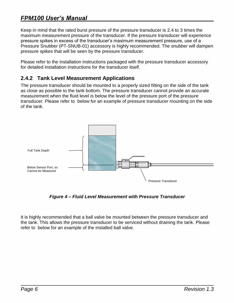
The pressure transducer should be mounted to a properly sized fitting on the side of the tank as close as possible to the tank bottom. The pressure transducer cannot provide an accurate measurement when the fluid level is below the level of the pressure port of the pressure transducer. Please refer to below for an example of pressure transducer mounting on the side of the tank.
Figure 4 – Fluid Level Measurement with Pressure Transducer
It is highly recommended that a ball valve be mounted between the pressure transducer and the tank. This allows the pressure transducer to be serviced without draining the tank. Please refer to below for an example of the installed ball valve.
Pressure Transducer
Full Tank Depth
Below Sensor Port, so Cannot be Measured
Revision 1.3 Page 7
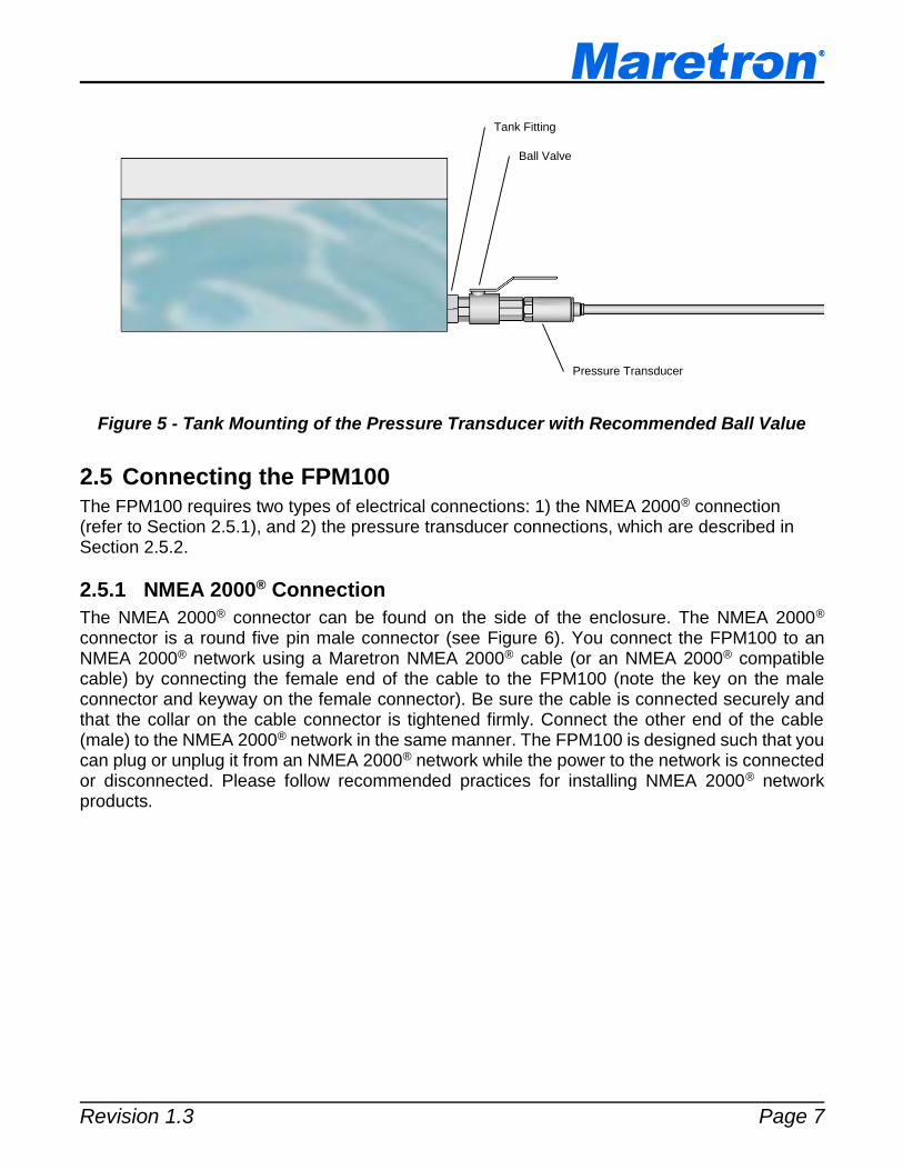
Figure 5 - Tank Mounting of the Pressure Transducer with Recommended Ball Value
2.5 Connecting the FPM100
The FPM100 requires two types of electrical connections: 1) the NMEA 2000® connection (refer to Section 2.5.1), and 2) the pressure transducer connections, which are described in Section 2.5.2.
2.5.1 NMEA 2000® Connection
The NMEA 2000® connector can be found on the side of the enclosure. The NMEA 2000® connector is a round five pin male connector (see Figure 6). You connect the FPM100 to an NMEA 2000® network using a Maretron NMEA 2000® cable (or an NMEA 2000® compatible cable) by connecting the female end of the cable to the FPM100 (note the key on the male connector and keyway on the female connector). Be sure the cable is connected securely and that the collar on the cable connector is tightened firmly. Connect the other end of the cable (male) to the NMEA 2000® network in the same manner. The FPM100 is designed such that you can plug or unplug it from an NMEA 2000® network while the power to the network is connected or disconnected. Please follow recommended practices for installing NMEA 2000® network products.
Tank Fitting
Ball Valve
Pressure Transducer

FPM100 User’s Manual
Page 8 Revision 1.3
Figure 6 – NMEA 2000® Connector Face Views
2.5.2 Pressure Transducer Connections
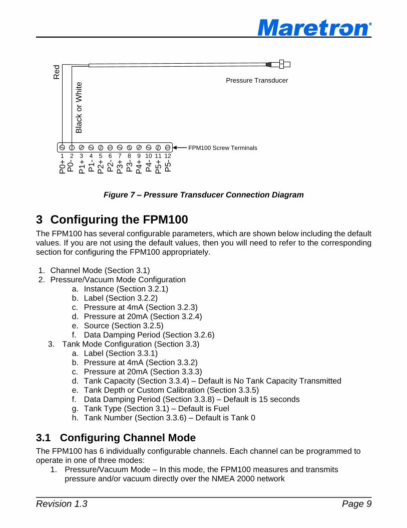
The FPM100 pressure transducer connections are made by connecting to the 12-pin terminal strip on the top of the unit. First, remove the four screws at the corners of the unit detaching the splash guard from the unit. On the bottom of the splash guard, you will find a label detailing the wire connection to pin number assignments, which are repeated in the table below.
Pin # Signal Name Connection
1 P0+ Pressure Transducer 0 (positive terminal)
2 P0- Pressure Transducer 0 (negative terminal)
3 P1+ Pressure Transducer 1 (positive terminal)
4 P1- Pressure Transducer 1 (negative terminal)
5 P2+ Pressure Transducer 2 (positive terminal)
6 P2- Pressure Transducer 2 (negative terminal)
7 P3+ Pressure Transducer 3 (positive terminal)
8 P3- Pressure Transducer 3 (negative terminal)
9 P4+ Pressure Transducer 4 (positive terminal)
10 P4- Pressure Transducer 4 (negative terminal)
11 P5+ Pressure Transducer 5 (positive terminal)
12 P5- Pressure Transducer 5 (negative terminal)
Please refer to Figure 7 for connecting the FPM100 to a pressure transducer. This figure shows the connection of the pressure transducer to channel 0 via the terminals named P0+ and P0-. Connections to other channels are similar.
Revision 1.3 Page 9
Figure 7 – Pressure Transducer Connection Diagram
3 Configuring the FPM100 The FPM100 has several configurable parameters, which are shown below including the default values. If you are not using the default values, then you will need to refer to the corresponding section for configuring the FPM100 appropriately. 1. Channel Mode (Section 3.1) 2. Pressure/Vacuum Mode Configuration
a. Instance (Section 3.2.1) b. Label (Section 3.2.2) c. Pressure at 4mA (Section 3.2.3) d. Pressure at 20mA (Section 3.2.4) e. Source (Section 3.2.5) f. Data Damping Period (Section 3.2.6)
3. Tank Mode Configuration (Section 3.3) a. Label (Section 3.3.1) b. Pressure at 4mA (Section 3.3.2) c. Pressure at 20mA (Section 3.3.3) d. Tank Capacity (Section 3.3.4) – Default is No Tank Capacity Transmitted e. Tank Depth or Custom Calibration (Section 3.3.5) f. Data Damping Period (Section 3.3.8) – Default is 15 seconds g. Tank Type (Section 3.1) – Default is Fuel h. Tank Number (Section 3.3.6) – Default is Tank 0
3.1 Configuring Channel Mode
The FPM100 has 6 individually configurable channels. Each channel can be programmed to operate in one of three modes:
1. Pressure/Vacuum Mode – In this mode, the FPM100 measures and transmits pressure and/or vacuum directly over the NMEA 2000 network
Pressure Transducer
1 2 5 4 3 6 7 8 9 10 11 12
P0
+
P1
-
FPM100 Screw Terminals
Red
P1
+
P2
+
P2
- P
3+
P3
- P
4+
P4
- P
5+
P5
-
P0
- B
lack o
r W
hite

FPM100 User’s Manual
Page 10 Revision 1.3
2. Tank Mode – In this mode, the FPM100 measures pressure and uses information about the tank dimensions and the type of fluid in the tank to calculate a tank level, which is transmitted over the NMEA 2000 network
3. Disable – The channel is disabled and transmits no data over the NMEA 2000 network The Disable mode requires no configuration. The following sections describe in detail the configuration of an FPM100 channel for Pressure/Vacuum Mode and in Tank Mode.
3.2 Configuring a Channel in Pressure/Vacuum Mode
The following sections describe the parameters that are available for configuration for a channel which has been set to Pressure/Vacuum mode.
3.2.1 Configuring Instance
Program this parameter to match the desired instance number of the pressure reading for this channel. You can program this parameter to any value between 0 and 252.
3.2.2 Configuring Label
Program this parameter with a text string which identifies the particular parameter being monitored by this channel. Maretron display products will display this label text when you are selecting data to display.
3.2.3 Configuring Pressure at 4mA
Program this parameter to match the pressure reading of the pressure transducer when it is sourcing a current of 4mA. You can determine this value by examining the specification of the pressure transducer being used.
3.2.4 Configuring Pressure at 20mA
Program this parameter to match the pressure reading of the pressure transducer when it is sourcing a current of 20mA. You can determine this value by examining the specification of the pressure transducer being used.
3.2.5 Configuring Source
You can configure a “Source” descriptor to be transmitted with the pressure reading which is used to provide an indication of the source of the pressure data for this channel. Choices are as follows:
1. Water Pressure 2. Atmospheric Pressure 3. Compressed Air Pressure 4. Hydraulic Pressure 5. Steam Pressure 6. 16 User Defined pressure sources (User Defined 129 – User
Defined 144)
Revision 1.3 Page 11
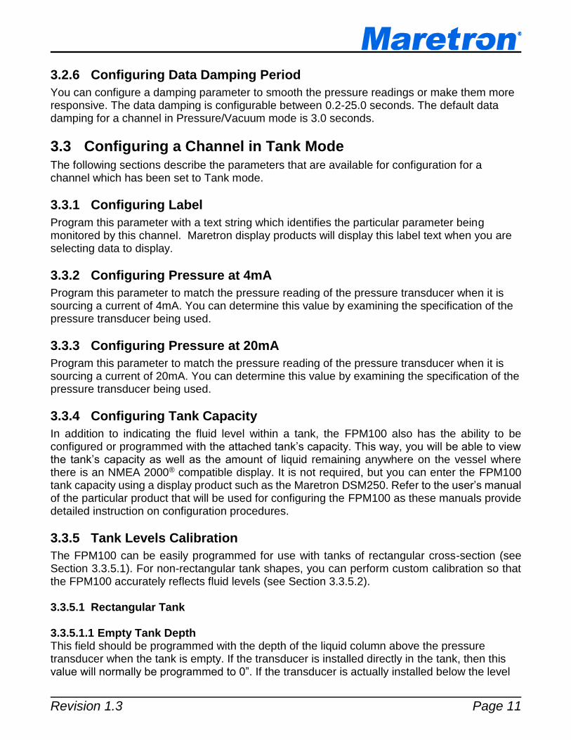
3.2.6 Configuring Data Damping Period
You can configure a damping parameter to smooth the pressure readings or make them more responsive. The data damping is configurable between 0.2-25.0 seconds. The default data damping for a channel in Pressure/Vacuum mode is 3.0 seconds.
3.3 Configuring a Channel in Tank Mode
The following sections describe the parameters that are available for configuration for a channel which has been set to Tank mode.
3.3.1 Configuring Label
Program this parameter with a text string which identifies the particular parameter being monitored by this channel. Maretron display products will display this label text when you are selecting data to display.
3.3.2 Configuring Pressure at 4mA
Program this parameter to match the pressure reading of the pressure transducer when it is sourcing a current of 4mA. You can determine this value by examining the specification of the pressure transducer being used.
3.3.3 Configuring Pressure at 20mA
Program this parameter to match the pressure reading of the pressure transducer when it is sourcing a current of 20mA. You can determine this value by examining the specification of the pressure transducer being used.
3.3.4 Configuring Tank Capacity
In addition to indicating the fluid level within a tank, the FPM100 also has the ability to be configured or programmed with the attached tank’s capacity. This way, you will be able to view the tank’s capacity as well as the amount of liquid remaining anywhere on the vessel where there is an NMEA 2000® compatible display. It is not required, but you can enter the FPM100 tank capacity using a display product such as the Maretron DSM250. Refer to the user’s manual of the particular product that will be used for configuring the FPM100 as these manuals provide detailed instruction on configuration procedures.
3.3.5 Tank Levels Calibration
The FPM100 can be easily programmed for use with tanks of rectangular cross-section (see Section 3.3.5.1). For non-rectangular tank shapes, you can perform custom calibration so that the FPM100 accurately reflects fluid levels (see Section 3.3.5.2). 3.3.5.1 Rectangular Tank 3.3.5.1.1 Empty Tank Depth This field should be programmed with the depth of the liquid column above the pressure transducer when the tank is empty. If the transducer is installed directly in the tank, then this value will normally be programmed to 0”. If the transducer is actually installed below the level

FPM100 User’s Manual
Page 12 Revision 1.3
of the tank bottom, then this value should be programmed to the vertical distance between the tank bottom and the pressure port on the pressure transducer. 3.3.5.1.2 Full Tank Depth This field should be programmed with the depth of the liquid column above the pressure transducer when the tank is full. Please refer to below for an illustration of Full Tank Depth and Empty Tank Depth parameters.
Figure 8 – Empty Tank Depth and Full Tank Depth Parameters
3.3.5.1.3 Fluid Density
In order for the FPM100 to properly convert pressure readings to tank levels using a rectangular tank calibration, it must be configured with the density of the fluid being monitored. The default value for this parameter is the density of fresh water (1000 kg/m3). If you are monitoring the level of fluids other than water, you must program this parameter with the density of the fluid being monitored.
The density of Marine Diesel Fuel is approximately 991 kg/m3. This value may vary depending on the exact fuel formulation. 3.3.5.2 Custom Calibration For accurate tank level readings, the FPM100 must be custom calibrated if the tank shape is irregular or non-rectangular. You can calibrate the FPM100 using a display product such as the Maretron DSM250. Refer to the user’s manual of the particular product that will be used for configuring the FPM100 as these manuals provide detailed instruction on configuration procedures.
3.3.6 Configuring Tank Number
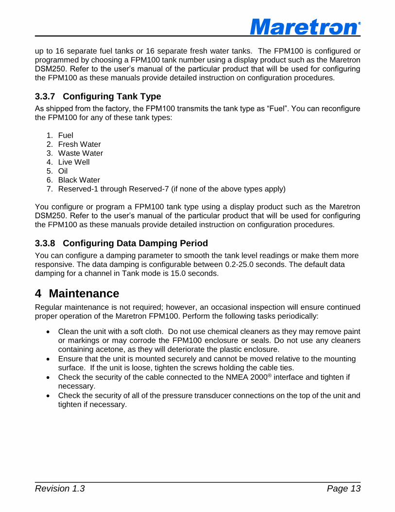
As shipped from the factory, the FPM100 transmits the Tank Number as “0”. The FPM100 supports up to sixteen tanks (0 through 15) for a given type of tank, which means you can monitor
Full Tank Depth
Empty Tank Depth
Revision 1.3 Page 13
up to 16 separate fuel tanks or 16 separate fresh water tanks. The FPM100 is configured or programmed by choosing a FPM100 tank number using a display product such as the Maretron DSM250. Refer to the user’s manual of the particular product that will be used for configuring the FPM100 as these manuals provide detailed instruction on configuration procedures.
3.3.7 Configuring Tank Type
As shipped from the factory, the FPM100 transmits the tank type as “Fuel”. You can reconfigure the FPM100 for any of these tank types:
1. Fuel 2. Fresh Water 3. Waste Water 4. Live Well 5. Oil 6. Black Water 7. Reserved-1 through Reserved-7 (if none of the above types apply)
You configure or program a FPM100 tank type using a display product such as the Maretron DSM250. Refer to the user’s manual of the particular product that will be used for configuring the FPM100 as these manuals provide detailed instruction on configuration procedures.
3.3.8 Configuring Data Damping Period
You can configure a damping parameter to smooth the tank level readings or make them more responsive. The data damping is configurable between 0.2-25.0 seconds. The default data damping for a channel in Tank mode is 15.0 seconds.
4 Maintenance Regular maintenance is not required; however, an occasional inspection will ensure continued proper operation of the Maretron FPM100. Perform the following tasks periodically:
Clean the unit with a soft cloth. Do not use chemical cleaners as they may remove paint or markings or may corrode the FPM100 enclosure or seals. Do not use any cleaners containing acetone, as they will deteriorate the plastic enclosure.
Ensure that the unit is mounted securely and cannot be moved relative to the mounting surface. If the unit is loose, tighten the screws holding the cable ties.
Check the security of the cable connected to the NMEA 2000® interface and tighten if necessary.
Check the security of all of the pressure transducer connections on the top of the unit and tighten if necessary.
FPM100 User’s Manual
Page 14 Revision 1.3
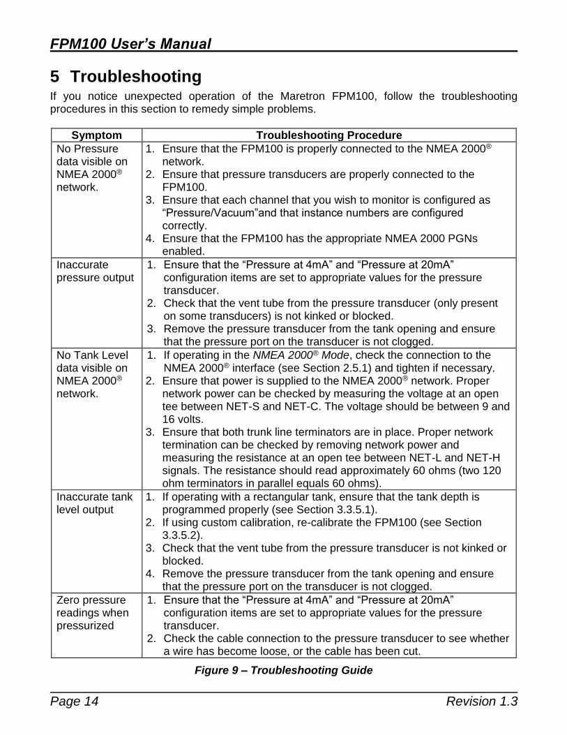
5 Troubleshooting If you notice unexpected operation of the Maretron FPM100, follow the troubleshooting procedures in this section to remedy simple problems.
Symptom Troubleshooting Procedure
No Pressure data visible on NMEA 2000® network.
1. Ensure that the FPM100 is properly connected to the NMEA 2000® network.
2. Ensure that pressure transducers are properly connected to the FPM100.
3. Ensure that each channel that you wish to monitor is configured as “Pressure/Vacuum”and that instance numbers are configured correctly.
4. Ensure that the FPM100 has the appropriate NMEA 2000 PGNs enabled.
Inaccurate pressure output
1. Ensure that the “Pressure at 4mA” and “Pressure at 20mA” configuration items are set to appropriate values for the pressure transducer.
2. Check that the vent tube from the pressure transducer (only present on some transducers) is not kinked or blocked.
3. Remove the pressure transducer from the tank opening and ensure that the pressure port on the transducer is not clogged.
No Tank Level data visible on NMEA 2000® network.
1. If operating in the NMEA 2000® Mode, check the connection to the NMEA 2000® interface (see Section 2.5.1) and tighten if necessary.
2. Ensure that power is supplied to the NMEA 2000® network. Proper network power can be checked by measuring the voltage at an open tee between NET-S and NET-C. The voltage should be between 9 and 16 volts.
3. Ensure that both trunk line terminators are in place. Proper network termination can be checked by removing network power and measuring the resistance at an open tee between NET-L and NET-H signals. The resistance should read approximately 60 ohms (two 120 ohm terminators in parallel equals 60 ohms).
Inaccurate tank level output
1. If operating with a rectangular tank, ensure that the tank depth is programmed properly (see Section 3.3.5.1).
2. If using custom calibration, re-calibrate the FPM100 (see Section 3.3.5.2).
3. Check that the vent tube from the pressure transducer is not kinked or blocked.
4. Remove the pressure transducer from the tank opening and ensure that the pressure port on the transducer is not clogged.
Zero pressure readings when pressurized
1. Ensure that the “Pressure at 4mA” and “Pressure at 20mA” configuration items are set to appropriate values for the pressure transducer.
2. Check the cable connection to the pressure transducer to see whether a wire has become loose, or the cable has been cut.
Figure 9 – Troubleshooting Guide

Revision 1.3 Page 15
If these steps do not solve your problem, please contact Maretron Technical Support (refer to Section 7 for contact information).
6 Technical Specifications Specifications (Tank Level Mode)
Parameter Value Comment
Accuracy +/-1% FS Exclusive of Pressure Transducer
Resolution +/-0.33% FS Over Full Pressure Transducer Range
Number of Tank Types 16 Fuel, Fresh Water, Waste water, Live well, Oil, etc.
Number of Tanks per Tank Type 16 16 Tanks per Tank Type Numbered 0-15
Support for Irregularly Shaped Tanks
Yes Can be Calibrated for any Shape Tank
Programmable Tank Capacity Yes Allows Displays to Calculate Amount Remaining
Specifications (Pressure/Vacuum Mode) Parameter Value Comment
Accuracy +/-1% FS Exclusive of Pressure Transducer
Resolution +/-0.33% FS Over Full Pressure Transducer Range
Number of Pressure Source Types 21 Water Pressure, Atmospheric Pressure, Compressed Air Pressure, Hydraulic Pressure, Steam Pressure, 16 User Defined Sources
Certifications
Parameter Comment
NMEA 2000 Level A
Maritime Navigation and Radiocommunication Equipment & Systems IEC 61162-3
Maritime Navigation and Radiocommunication Equipment & Systems Tested to IEC 60945
FCC and CE Mark Electromagnetic Compatibility
NMEA 2000® Parameter Group Numbers (PGNs) - See Appendix A for Details
Description PGN # PGN Name Default Rate
Periodic Data PGNs 127505 Fluid Level 0.4 Times/Second
130314 Actual Pressure 0.5 Times/Second
Response to Requested PGNs 126464 PGN List (Transmit and Receive) N/A
126996 Product Information N/A
126998 Configuration Information N/A
Protocol PGNs 059392 ISO Acknowledge N/A
059904 ISO Request N/A
060928 ISO Address Claim N/A
065240 ISO Address Command N/A
126208 NMEA N/A
Maretron Proprietary PGNs 128720 Configuration N/A
Electrical
Parameter Value Comment
Operating Voltage 9 to 32 Volts DC Voltage
Power Consumption 400mA Maximum Current Drain
Load Equivalence Number (LEN) 8 NMEA 2000® Spec. (1LEN = 50mA)
Reverse Battery Protection Yes Indefinitely
Load Dump Protection Yes Energy Rated per SAE J1113
FPM100 User’s Manual
Page 16 Revision 1.3
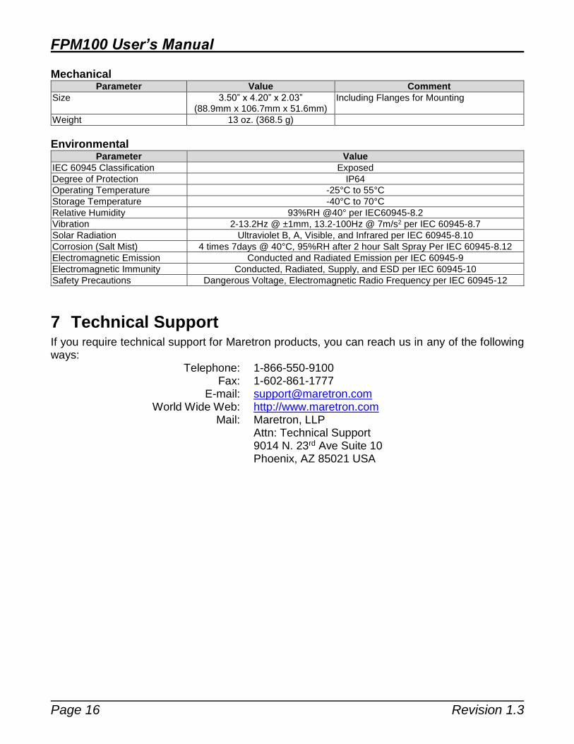
Mechanical Parameter Value Comment
Size 3.50” x 4.20” x 2.03” (88.9mm x 106.7mm x 51.6mm)
Including Flanges for Mounting
Weight 13 oz. (368.5 g)
Environmental Parameter Value
IEC 60945 Classification Exposed
Degree of Protection IP64
Operating Temperature -25°C to 55°C
Storage Temperature -40°C to 70°C
Relative Humidity 93%RH @40° per IEC60945-8.2
Vibration 2-13.2Hz @ ±1mm, 13.2-100Hz @ 7m/s2 per IEC 60945-8.7
Solar Radiation Ultraviolet B, A, Visible, and Infrared per IEC 60945-8.10
Corrosion (Salt Mist) 4 times 7days @ 40°C, 95%RH after 2 hour Salt Spray Per IEC 60945-8.12
Electromagnetic Emission Conducted and Radiated Emission per IEC 60945-9
Electromagnetic Immunity Conducted, Radiated, Supply, and ESD per IEC 60945-10
Safety Precautions Dangerous Voltage, Electromagnetic Radio Frequency per IEC 60945-12
7 Technical Support If you require technical support for Maretron products, you can reach us in any of the following ways: Telephone: 1-866-550-9100 Fax: 1-602-861-1777 E-mail: [email protected] World Wide Web: http://www.maretron.com Mail: Maretron, LLP Attn: Technical Support 9014 N. 23rd Ave Suite 10 Phoenix, AZ 85021 USA

Revision 1.3 Page 17
8 Installation Template Please check the dimensions before using the following diagram as a template for drilling the mounting holes because the printing process may have distorted the dimensions.
Figure 10 – Mounting Surface Template

FPM100 User’s Manual
Page 18 Revision 1.3
9 Maretron (2 Year) Limited Warranty Maretron warrants the FPM100 to be free from defects in materials and workmanship for two (2) years from the date of original purchase. If within the applicable period any such products shall be proved to Maretron’s satisfaction to fail to meet the above limited warranty, such products shall be repaired or replaced at Maretron’s option. Purchaser's exclusive remedy and Maretron’s sole obligation hereunder, provided product is returned pursuant to the return requirements below, shall be limited to the repair or replacement, at Maretron’s option, of any product not meeting the above limited warranty and which is returned to Maretron; or if Maretron is unable to deliver a replacement that is free from defects in materials or workmanship, Purchaser’s payment for such product will be refunded. Maretron assumes no liability whatsoever for expenses of removing any defective product or part or for installing the repaired product or part or a replacement therefore or for any loss or damage to equipment in connection with which Maretron’s products or parts shall be used. With respect to products not manufactured by Maretron, Maretron’s warranty obligation shall in all respects conform to and be limited to the warranty actually extended to Maretron by its supplier. The foregoing warranties shall not apply with respect to products subjected to negligence, misuse, misapplication, accident, damages by circumstances beyond Maretron’s control, to improper installation, operation, maintenance, or storage, or to other than normal use or service. THE FOREGOING WARRANTIES ARE EXPRESSLY IN LIEU OF AND EXCLUDES ALL OTHER EXPRESS OR IMPLIED WARRANTIES, INCLUDING BUT NOT LIMITED TO THE IMPLIED WARRANTIES OF MERCHANTABILITY AND OF FITNESS FOR A PARTICULAR PURPOSE. Statements made by any person, including representatives of Maretron, which are inconsistent or in conflict with the terms of this Limited Warranty, shall not be binding upon Maretron unless reduced to writing and approved by an officer of Maretron. IN NO CASE WILL MARETRON BE LIABLE FOR INCIDENTAL OR CONSEQUENTIAL DAMAGES, DAMAGES FOR LOSS OF USE, LOSS OF ANTICIPATED PROFITS OR SAVINGS, OR ANY OTHER LOSS INCURRED BECAUSE OF INTERRUPTION OF SERVICE. IN NO EVENT SHALL MARETRON’S AGGREGATE LIABILITY EXCEED THE PURCHASE PRICE OF THE PRODUCT(S) INVOLVED. MARETRON SHALL NOT BE SUBJECT TO ANY OTHER OBLIGATIONS OR LIABILITIES, WHETHER ARISING OUT OF BREACH OF CONTRACT OR WARRANTY, TORT (INCLUDING NEGLIGENCE), OR OTHER THEORIES OF LAW WITH RESPECT TO PRODUCTS SOLD OR SERVICES RENDERED BY MARETRON, OR ANY UNDERTAKINGS, ACTS OR OMISSIONS RELATING THERETO. Maretron does not warrant that the functions contained in any software programs or products will meet purchaser’s requirements or that the operation of the software programs or products will be uninterrupted or error free. Purchaser assumes responsibility for the selection of the software programs or products to achieve the intended results, and for the installation, use and results obtained from said programs or products. No specifications, samples, descriptions, or illustrations provided Maretron to Purchaser, whether directly, in trade literature, brochures or other documentation shall be construed as warranties of any kind, and any failure to conform with such specifications, samples, descriptions, or illustrations shall not constitute any breach of Maretron’s limited warranty. Warranty Return Procedure: To apply for warranty claims, contact Maretron or one of its dealers to describe the problem and determine the appropriate course of action. If a return is necessary, place the product in its original packaging together with proof of purchase and send to an Authorized Maretron Service Location. You are responsible for all shipping and insurance charges. Maretron will return the replaced or repaired product with all shipping and handling prepaid except for requests requiring expedited shipping (i.e. overnight shipments). Failure to follow this warranty return procedure could result in the product’s warranty becoming null and void. Maretron reserves the right to modify or replace, at its sole discretion, without prior notification, the warranty listed above. To obtain a copy of the then current warranty policy, please go to the following web page:
http://www.maretron.com/company/warranty.php

Revision 1.3 Appendix A – NMEA 2000® Interfacing Page A1
Appendix A – NMEA 2000® Interfacing
FPM100 NMEA 2000® Periodic Data Transmitted PGNs PGN 130314 – Actual Pressure The FPM100 uses this PGN to provide a regular transmission of various pressures. The factory default for periodic transmission rate is once every two seconds. The transmission of this PGN can be disabled (see PGN 126208 – NMEA Request Group Function – Transmission Periodic Rate).
Field 1:SID – The sequence identifier field is used to tie related PGNs together. For example, the FPM100 will transmit identical SIDs for 130312 (Temperature) and 130311 (Environmental Parameters) to indicate that the readings are linked together (i.e., the data from each PGN was taken at the same time although they are reported at slightly different times).
2: Pressure Instance – The FPM100 sets this field to identify a particular pressure measurement from the source specified in Field 3. Every pressure measurement from a given source type on the network should have a distinct instance value, so that monitoring devices and displays can identify which measurement is which.
3: Pressure Source – This field is used to indicate the type of pressure measurement being taken. Possible values for this field include Atmospheric Pressure, Water Pressure, Steam Pressure, Compressed Air Pressure, Hydraulic Pressure, and 16 User Defined pressure sources.
4: Pressure – This field is used to indicate the pressure, whose source is specified in field 2, in units of 0.1 Pa.
6: Reserved bits – The FPM100 sets all bits in this field to a value of “1”. PGN 127505 – Fluid Level The FPM100 uses this PGN to indicate the attached tank’s fluid instance, fluid type, fluid level, and tank capacity.
Field 1: Fluid Instance – This field is used to identify the tank number and ranges between 0 and 15. There can be up to 16 tanks of a given type as defined by the Fluid Type field. This field is programmable through the NMEA command PGN. The FPM100 ships from the factory with a default value of zero.
2: Fluid Type – This field identifies the type of fluid contained within the tank. Currently the defined fluid types are fuel, fresh water, wastewater, live well, oil, and black water. This field is programmable through the NMEA command PGN. The FPM100 ships from the factory with a default value of 0x0 indicating “Fuel”.
3: Fluid Level – This field is used to indicate the current fluid level in percentage. The value transmitted in this field depends on the distance from the sender to the top of the fluid or tank bottom.
4: Tank Capacity – This field is used to indicate the tank capacity. This field is programmable through the NMEA command PGN. The FPM100 ships from the factory with a default value of 0xFFFFFFFF indicating “Data Not Available”.
5: Reserved – This field is reserved by NMEA; therefore, the FPM100 sets all bits to a logic 1.
Related Documents