FPGA Placement using Space Filling Curves: Theory Meets Practice 1 PRITHA BANERJEE, SUSMITA SUR-KOLAY, ARIJIT BISHNU, SANDIP DAS, and SUBHAS C. NANDY Indian Statistical Institute, Kolkata, India SUBHASIS BHATTACHARJEE Synopsis (India) Pvt. Ltd., Bangalore, India Research in VLSI placement, an NP-hard problem, has branched in two different directions. The first one employs iterative heuristics with many tunable parameters to produce near-optimal so- lution but without theoretical guarantee on its quality. The other one considers placement as graph embedding and designs approximation algorithms with provable bounds on the quality of the solution. In this paper, we aim at unifying the above two directions. First, we extend the existing approximation algorithms for graph embedding in 1D and 2D mesh to those for hyper- graphs, which typically model circuits to be placed on a FPGA. We prove an O(d √ log n log log n) approximation bound for 1D and O(d log n log log n) approximation bound for the 2D mesh, where d is the maximum degree of hyperedges and n the number of vertices in the hypergraph. Next, we propose an efficient method based on linear arrangement of the CLBs, and the notion of space filling curves, for placing the configurable logic blocks (CLBs) of a netlist on island-style FPGAs with an approximation guarantee of O(d 4 √ log n √ k log log n). For the set of FPGA placement benchmarks, the running time is near-linear in the number of CLBs, thus allowing for scalability towards large circuits. We obtained on an average a 33× speedup with only 1.31× degradation in the quality of solution with respect to that produced by the popular FPGA tool VPR, thereby demonstrating the suitability of this very fast method for FPGA placement, with a provable performance guarantee. Categories and Subject Descriptors: B.7.2 [Integrated Circuits]: Design Aids—Placement and routing; J.6 [Computer-Aided Engineering]: Computer-Aided Design (CAD); F.2.2 [Anal- ysis of Algorithms and Problem Complexity]: Nonnumerical Algorithms and Problems— Routing and layout; C.3 [Special-Purpose and Application-Based Systems]: Real-time and Embedded systems; B.7.1 [Integrated Circuits]: Types and Design Styles—VLSI(Very Large Scale Integration), Gate Arrays Additional Key Words and Phrases: FPGA placement, approximation algorithm, hypergraph, linear arrangement, space filling curve 1. INTRODUCTION Field Programmable Gate Arrays (FPGAs) are programmable platforms for a wide range of applications. In recent times, FPGAs are increasingly competing with ASICs in medium to low volume market. FPGAs have also become the most suitable component for applications in the embedded computing environment. The most general island-style FPGAs consist of a large number of programmable or 1 Submitted to Special Issue CAPA ACM Transactions on Embedded Computing Systems, Vol. V, No. N, Month 20YY, Pages 1–0??.

Welcome message from author
This document is posted to help you gain knowledge. Please leave a comment to let me know what you think about it! Share it to your friends and learn new things together.
Transcript

FPGA Placement using Space Filling Curves:
Theory Meets Practice 1
PRITHA BANERJEE, SUSMITA SUR-KOLAY, ARIJIT BISHNU, SANDIP DAS, and
SUBHAS C. NANDY
Indian Statistical Institute, Kolkata, India
SUBHASIS BHATTACHARJEE
Synopsis (India) Pvt. Ltd., Bangalore, India
Research in VLSI placement, an NP-hard problem, has branched in two different directions. Thefirst one employs iterative heuristics with many tunable parameters to produce near-optimal so-lution but without theoretical guarantee on its quality. The other one considers placement asgraph embedding and designs approximation algorithms with provable bounds on the quality ofthe solution. In this paper, we aim at unifying the above two directions. First, we extend theexisting approximation algorithms for graph embedding in 1D and 2D mesh to those for hyper-graphs, which typically model circuits to be placed on a FPGA. We prove an O(d
√log n log log n)
approximation bound for 1D and O(d log n log log n) approximation bound for the 2D mesh, whered is the maximum degree of hyperedges and n the number of vertices in the hypergraph. Next,we propose an efficient method based on linear arrangement of the CLBs, and the notion of spacefilling curves, for placing the configurable logic blocks (CLBs) of a netlist on island-style FPGAswith an approximation guarantee of O(d 4
√log n
√k log log n). For the set of FPGA placement
benchmarks, the running time is near-linear in the number of CLBs, thus allowing for scalabilitytowards large circuits. We obtained on an average a 33× speedup with only 1.31× degradationin the quality of solution with respect to that produced by the popular FPGA tool VPR, therebydemonstrating the suitability of this very fast method for FPGA placement, with a provableperformance guarantee.
Categories and Subject Descriptors: B.7.2 [Integrated Circuits]: Design Aids—Placement androuting; J.6 [Computer-Aided Engineering]: Computer-Aided Design (CAD); F.2.2 [Anal-
ysis of Algorithms and Problem Complexity]: Nonnumerical Algorithms and Problems—Routing and layout; C.3 [Special-Purpose and Application-Based Systems]: Real-time andEmbedded systems; B.7.1 [Integrated Circuits]: Types and Design Styles—VLSI(Very LargeScale Integration), Gate Arrays
Additional Key Words and Phrases: FPGA placement, approximation algorithm, hypergraph,linear arrangement, space filling curve
1. INTRODUCTION
Field Programmable Gate Arrays (FPGAs) are programmable platforms for a widerange of applications. In recent times, FPGAs are increasingly competing withASICs in medium to low volume market. FPGAs have also become the mostsuitable component for applications in the embedded computing environment. Themost general island-style FPGAs consist of a large number of programmable or
1Submitted to Special Issue CAPA
ACM Transactions on Embedded Computing Systems, Vol. V, No. N, Month 20YY, Pages 1–0??.

2 · Pritha Banerjee et al.
configurable logic blocks and a programmable routing architecture as shown inFigure 1(a). Placement in an FPGA is the design phase where a netlist of circuitblocks is mapped onto physical locations arranged in a two-dimensional (2D) array,such that certain placement and routing metrics like semi-perimeter wirelength,critical path delay [Betz and Rose 1997] are minimized. The circuit blocks may beinput/output blocks (IOBs) or configurable logic blocks (CLBs). Henceforth, CLBsand logic blocks are used interchangeably in this paper. Most of the recent CADalgorithms usually take long time to map, place and route circuits with millionsof gates on a state-of-the-art FPGA chip. For example, circuits with 3000-15000logic elements take about 4-24 hours by Xilinx ISE tool [Verma 2008]. This maynullify its time-to-market, and in particular the advantages of reconfigurability.With increasing emphasis on reconfigurable computing, there is a pressing need forvery fast CAD tools that quickly provide acceptable solutions in terms of quality,especially in real-time applications which may not even require optimality at thecost of much longer time. Moreover, modern FPGA architecture comprises notonly the CLBs, but also RAM blocks, multiplier blocks and even processor corespreplaced on the FPGA chip [Wang et al. 2003; XILINX ]. These preplaced blocksand cores segregate the sea of CLBs into more than one array of CLBs, as shownin Figure 1(b). Thus a given netlist of CLBs can be placed on the FPGA chip bypartitioning the problem into subproblems of sizes matching that of the arrays ofCLB available. In this context also, a very fast placement method is mandated.
(a) (b)
CLB
RAM
MUL
I/O
Core
Island of CLBs
Fig. 1. Target FPGA architecture: (a) island-style and (b) Virtex like architecture of Xilinx, withisland of CLBs within preplaced RAM, Multiplier blocks and processor cores
1.1 FPGA Placement: Theory and Practice
VLSI placement, be it for ASIC or FPGA, is a computationally difficult problemthat challenges both theoreticians and practitioners alike. On the theoretical front,the placement problem, formally defined in Section 2.2, is modeled as a graph em-bedding problem on a two dimensional mesh that minimizes a cost resembling thewirelength [Even et al. 2000; Vempala 1998]. The best known approximation ratiosfor the graph embedding problem are poly-logarithmic [Even et al. 2000; Feige andLee 2007; Rao and Richa 1998]. This implies worsening theoretical guarantees withincrease in the problem size. On the other hand, inapproximability results havealso eluded researchers. The best theoretical result for this problem is due to Even
ACM Transactions on Embedded Computing Systems, Vol. V, No. N, Month 20YY.

FPGA Placement using Space Filling Curves · 3
et al. [Even et al. 2000] where the authors propose an O(log n log log n) approxi-mation result. As it turns out, the one dimensional version of this problem is alsoNP-hard [Garey and Johnson 1979]. Rao and Richa [Rao and Richa 1998] showedthat the approximation ratio of the one dimensional version is O(log n). The cur-rent approximation result stands at O(
√log n log log n) [Feige and Lee 2007]. The
algorithms are of polynomial time complexity, use advanced concepts and are the-oretically very elegant. But the running time of these algorithms are prohibitivelyhigh for VLSI practitioners since they involve solving linear programs with ex-ponential number of constraints by the ellipsoid method or semidefinite program.Moreover, the theory developed thus far is tuned for VLSI placement modeled asgraph embedding. But in FPGA placement problem, the model of a hypergraph ismore accurate for representing a given circuit netlist. To the best of our knowledge,there have been no efforts on the part of VLSI practitioners to bring this theoryinto practice. Practical algorithms should be fast, give reasonably acceptable solu-tions and should scale up well for huge circuits [Sarrafzadeh et al. 2001]. In effect,as Vygen [Vygen 2007] points out, one has to accept that no approximation guar-antee can be given for practical algorithms. This has led practitioners to look forheuristics for global placement that can be broadly classified into three categories:(i) stochastic iterative search, most notably, using simulated annealing (SA), (ii)recursive partitioning, and (iii) analytical placement. These methods, which wereview in the next Section, suffer from all or some of the following drawbacks - notheoretical guarantee, immense running time for good quality solution, not scalablefor all practical purposes.
Thus, we observe that there is a wide gap between theory and practice regardingVLSI placement. Our effort, in this paper, is to bridge this gap.
1.2 Our Contribution
We first extend the existing graph embedding approximation algorithms [Feige andLee 2007; Even et al. 2000] to hypergraphs and prove an O(d
√log n log log n) bound
for 1D, and an O(d log n log log n) bound for the 2D case. Next, we propose a verysimple algorithm for FPGA placement. We obtain a linear arrangement of thevertices of the hypergraph modeling the circuit netlist using an approximation al-gorithm, and then use a recursive space filling curve for deterministically mappingthis linear arrangement to a two dimensional mesh. We establish an approxima-tion bound of O(d 4
√log n
√k log log n) for this method. However, the theoretical
approximation bound is not tight and the time complexity is still high. How aboutbringing this into practice?
We answer this by replacing the complex approximation algorithm for determiningoptimal linear arrangement with the left to right order of the leaves of the recursivebi-partition tree produced by a top-down min-cut hypergraph partitioning heuris-tic (e.g. hMetis [HMETIS ; Karypis et al. 1999]). This method runs in just afew seconds for standard benchmark circuits to yield reasonably good solutions. Apreliminary version of this strategy appeared in [Banerjee et al. 2005]. Further, wereport that the solution obtained is routable even without any iterative improve-ment or legalization heuristic. In existing literature, we have not found reports on
ACM Transactions on Embedded Computing Systems, Vol. V, No. N, Month 20YY.

4 · Pritha Banerjee et al.
routability for the deterministic heuristics. To sum up, our technique (i) transformsthe netlist hypergraph to a linear arrangement of nodes of the hypergraph usingtop-down hypergraph bi-partitioning techniques, (ii) maps this linear arrangementdirectly onto the two dimensional mesh using a recursive space filling curve. Theintuition behind using space filling curves is that on one hand the target locationfor each node in the linear arrangement is computable in constant time and onthe other, it retains the locality properties of the one dimensional arrangement.Although it is not the main focus of our work, we also show that our placementcan be improved by ultra-low temperature simulated annealing schedule with fastconvergence, just as placements obtained by other methods [Maidee et al. 2003;Xu and Khalid 2005; Gopalakrishnan et al. 2006] have been improved using localsearch or simulated annealing.
The rest of the paper is organized as follows. In Section 2, we briefly describethe previous approaches for FPGA placement. Section 3 forms the theoreticalbackbone of our work wherein we discuss approximation algorithms for FPGAplacement. We also discuss in this Section the ways of implementing the theoreticalalgorithmic results for real FPGAs. Section 4 reports experimental results. Finally,the concluding remarks appear in Section 5.
2. EXISTING APPROACHES FOR FPGA PLACEMENT
The existing approaches to solve the placement problem have branched into twodifferent directions. One that uses stochastic iterative heuristics with many tunableparameters that try to get the optimal solution, but nothing theoretical can be saidabout the quality of the solution. The problem under study being NP-hard [Sha-hookar and Mazumdar 1991], the other line of study mainly concerns researchersdealing with approximation algorithms where the concern is to give theoreticalbounds on the deviation of the obtained solution from the optimal one. But, asliterature on placement shows, there have been almost no effort at bridging the gapbetween theory and practice.
2.1 Methods in practice
For actual FPGA placement, researchers have followed the traditional methods ofsimulated annealing based iterative heuristics, recursive partitioning and analyticalmethods to obtain near-optimal solutions.
Simulated annealing is a stochastic heuristic that randomizes the iterative improve-ment procedure, even allowing moves that worsen the current solution in order toprevent the search from getting stuck at a locally optimal solution. The movesare controlled probabilistically by an annealing temperature. Theoretical analysisshows that this class of algorithms converge to a global optimum asymptoticallywith a probability 1, provided certain conditions are met [Wong et al. 1988; Sechen1988]. In reality though, it is almost equivalent to searching the entire feasible so-lution space [Vygen 2007]. So, the research of VLSI placement using this method,has boiled down to empirically finding suitably well tuned parameters in the objec-tive function and an appropriate annealing schedule by performing several trials,
ACM Transactions on Embedded Computing Systems, Vol. V, No. N, Month 20YY.

FPGA Placement using Space Filling Curves · 5
such that near-optimal solutions are obtained. Among these methods, the placeand route tool called VPR by Betz and Rose [Betz and Rose 1997] has become themost popular one. They employed a congestion aware semi-perimeter boundingbox metric, which is minimized by an adaptive simulated annealing schedule forisland-style FPGAs. Although simulated annealing based methods, such as VPR,produce “good” quality of solution with suitably tuned parameters in terms of totalsemi-perimeter wirelength and critical path delay during routing, it takes long hours[Mulpuri and Hauck 2001; Chen et al. 2006] to execute. This drawback affects theruntime reconfigurability advantages of FPGAs, and hence is not scalable. Vari-ous other stochastic approaches such as thermodynamic combinatorial optimization[Vicente et al. 2004], tabu search based placement [Emmert and Bhatia 1999] havebeen devised to produce routable placement with improved critical path delay inless time than VPR. Although there has been some improvement in run-time, noguarantee on the quality of the solution has been given.
In recursive partitioning, on one hand the rectangular FPGA chip is divided intosub-rectangles by horizontal or vertical cuts, and on the other the circuit is si-multaneously partitioned such that each partition fits into the corresponding sub-rectangles and the number of nets going across partitions is minimized. This isthe minimum bisection problem where the objective is to partition the set of ver-tices into equal sized subsets such that the number of edges having its two end-points in the two different partitions is minimized. The problem being NP-Hard,mostly heuristics [Fiduccia and Mattheyses 1982; Kernighan and Lin 1970; Alpertand Kahng 1995] are employed. For recursive partitioning based method such as[Maidee et al. 2003], although the objective function is global, a “good” cut at a leveldoes not guarantee “good” cuts at subsequent levels. Their method employ a localnet terminal alignment heuristic during each level of partitioning. It is based ona reverse engineering technique where the routing profile statistics of some alreadyrouted circuits are used. The quality of the placement obtained before applyinglow-temperature simulated annealing, is not presented or analyzed in their paper.
In analytical placement, the objective is to minimize the netlength, but here blockoverlap is allowed by relaxing certain constraints. This leads to an easier placementproblem which is formulated as certain variant of a mathematical program such asquadratic placement [Vygen 2007]. But, this entails a major bottleneck. Becauseof the constraint relaxation, block overlap remains. Removing such overlaps, whilemaintaining the objective criteria of netlength minimization, remains a dauntingtask and again does not scale up to large circuits. In QPF [Xu and Khalid 2005],the authors have proposed a placement algorithm based on quadratic placement. Itbuilds and solves linear equations repeatedly to produce the placement. The place-ments generated in each iteration might not be legal and thus requires additionalheuristic to obtain a legal placement. Gopalakrishnan et. al. in their work CAPRI[Gopalakrishnan et al. 2006], have proposed an architecture aware analytical place-ment using graph embedding and metric geometry. This also requires a legalizationstep to map the logic blocks from a higher dimension to a 2D array of logic blockson FPGA. As in partitioning based approaches, they have also performed a lowtemperature simulated annealing to obtain final placement. This indicates that thesolution produced by a partitioning based approach or an analytical approach alone
ACM Transactions on Embedded Computing Systems, Vol. V, No. N, Month 20YY.

6 · Pritha Banerjee et al.
are not close to that by the simulated annealing based methods. Thus, one needs tofurther refine such a solution by low-temperature simulated annealing to producethe final placement. Nevertheless, the solution by these methods are better than arandom initial placement, and so the simulated annealing converges much faster inboth types of heuristics; the pertinent question of how much better has not beenaddressed.
All of the above works aim at faster method for routable placement with better orcomparable critical path delay as in VPR. However, no work addresses the qualityof the initial placement as obtained by their deterministic method in terms of semiperimeter bounding box, the routability of the placement or the critical path delayof this placement after routing. Also, there is no theoretical guarantee on how closetheir placement solution is to the optimal solution. In this paper, we propose a verysimple placement method with theoretical bound on the quality of the placement.Further, to emphasize the suitability of this fast yet effective method in the contextof reconfigurability, we route the placement and show that all the placements areroutable with reasonable critical path delay when compared to VPR.
2.2 Graph embedding and approximation algorithms
In contrast to the line of research mentioned above, there has been a different line ofstudy where researchers look at designing approximation algorithms for producingsolutions that lie within some bounds of the optimal solution [Even et al. 2000;Vempala 1998]. These works mainly formulate the VLSI layout problem as embed-ding a graph in a d-dimensional mesh. For d = 1, the graph embedding problemis basically the graph optimal linear arrangement(GOLA) problem, which is knownto be NP-hard [Garey and Johnson 1979]. Most of these works deal with laying outa graph on a grid optimizing a cost which in a way resembles an estimate of thetotal wirelength. But, a more accurate model of a circuit represented as netlists ofCLBs, is a hypergraph. Before presenting a brief review of existing results, a seriesof problem definitions [Bhasker and Sahni 1987; Even et al. 2000; Rao and Richa1998; Feige and Lee 2007] related to embedding of graphs or hypergraphs, are inorder.
Problem 1 (Graph Optimal Linear Arrangement (GOLA)). Given an undi-rected graph G = (V, E), the problem is to find a linear arrangement of the verticesh : V → {1, . . . , |V |}, that minimizes the sum of edge lengths, i.e.
∑
(i,j)∈E |h(i) −h(j)|.
Problem 2 (Graph Placement on Grid (GPG)). Given an undirected graphG = (V, E), the problem is to find an embedding of G in a two dimensional grid,or equivalently, a one-to-one mapping, h of G to a subgraph containing |V | verticesof the two dimensional grid, such that the cost function
∑
(i,j)∈E d(h(i), h(j)) is
minimized. Here d(x, y) is the number of mesh edges in the shortest path betweenx and y in the mesh.
For FPGAs, the circuit represented by the CLB netlist is more realistically modeledas a hypergraph H = (V, S) where V = {1, 2, . . . , n} are the n CLBs and S =
ACM Transactions on Embedded Computing Systems, Vol. V, No. N, Month 20YY.

FPGA Placement using Space Filling Curves · 7
{S1, S2, . . . , Sk} are the k hyperedges or nets where each hyperedge Si is a subsetof V . Let a net i (1 ≤ i ≤ k) have ni number of CLBs, i.e. |Si| = ni. Letd = maxk
i=1{ni}. Surely, d ≤ n. Hence, we progress to the following problems.
Problem 3 (Hypergraph Optimal Linear Arrangement (HOLA)). Givena hypergraph H = (V, S), the problem is to find a linear arrangement of the vertices
h : V → {1, . . . , |V |}, that minimizes the following cost:∑k
i=1 maxq,l∈Si{|h(q) −
h(l)|}.
Problem 4 (Hypergraph Placement on Grid (HPG)). Given a hypergraphH = (V, S), the problem is to find an embedding of H in a two dimensional grid,or equivalently, a one-to-one mapping, h of H to a subgraph containing |V | verticesof the two dimensional grid, such that the cost function
BB =
k∑
i=1
(bbx(i) + bby(i))
is minimized. Here, bbx(i) is the x span of net i, bby(i) is the y span of net i. So,bbx(i) + bby(i) can be termed as the semi-perimeter of net i.
Note that the shortest path between i and j in the mesh, as defined in GPG, issimilar to the BB-cost as defined in HPG. Both measure the semi-perimeter of theenclosing rectilinear bounding box.
Bhasker and Sahni [Bhasker and Sahni 1987] show that the problem of computingthe ǫ-approximation solution for GOLA and HOLA are NP-hard. They providebranch-and-bound and dynamic programming algorithms for optimal solutions forHOLA, but obviously the algorithms are not of polynomial time complexity. Ap-proximation algorithms for GOLA and GPG were designed by Even et al. [Evenet al. 2000]. Their approximation algorithms are applicable in cases where divide-and-conquer is applicable and a fractional spreading metric can be computed inpolynomial time. A spreading metric on a graph is an assignment of rationallengths to edges such that subgraphs for which the optimization problem is non-trivial, are spread apart in the associated metric space. The sum of the lengthsof these edges multiplied by the corresponding weights gives a lower bound on thecost of solving the optimization problem. The crux of the strategy by Even et al.is a novel divide-and-conquer that divides not according to the sizes of the sub-problems, but on the cost of solving the optimization problem which is boundedfrom below by the volume of the spreading metric. Their approximation bounds forboth GOLA and GPG are O(log n log log n). Following on the work of Even et al.[Even et al. 2000] by using better graph separators, Rao and Richa [Rao and Richa1998] improved the bound to O(log n) for GOLA. This has been further tightenedto O(
√log n log log n) [Feige and Lee 2007]. So, the current approximation bound
for GOLA stands at O(√
log n log log n) [Feige and Lee 2007] and GPG stands atO(log n log log n) [Even et al. 2000]. Apart from minimizing the sum of distancesas done in the above reviewed works, there has been effort in minimizing the maxi-mum edge length. Vempala [Vempala 1998] obtained an O(log3.5 n) approximationalgorithm for this problem. The above algorithms though polynomial in nature,
ACM Transactions on Embedded Computing Systems, Vol. V, No. N, Month 20YY.

8 · Pritha Banerjee et al.
has high time complexity as they need to solve a linear program by the ellipsoidmethod or semidefinite program as a subpart. This is understandable from a the-oretic standpoint since the challenge is to reduce the approximation bound withinpolynomial time. Our goal, on the contrary, is designing approximation algorithms
Placement
Theory: Graph embedding problem Practice
(1D placement)Graph Optimal
Linear Order(GOLA)
[Feige et al. 2007]O((log n)0.5 log log n)
(2D placement)Graph Placement on Grid (GPG)[Even et al. 2000]
O(log n log log n)
Stochastic search (SA)Space Filling
curve
Partitioning based Analytical
(1D placement)Hypergraph Optimal Linear Order (HOLA)
O(d (log n)0.5 log log n)
(2D placement)Hypergraph Placement
on Grid (HPG)O(d(k (log n)0.5 log log n)0.5)
extended to
extended to
applied to
applied to
Theory meets Practice
linear order
Fig. 2. Theory meets practice: a schematic showing where our work is positioned.
with theoretical bounds for HOLA and HPG, that run in reasonable time and areeasy to implement. The application under consideration is the FPGA placement.We present two types of results. One that extends the work of [Rao and Richa1998; Feige and Lee 2007] on GOLA to HOLA, and the work of [Even et al. 2000]on GPG to HPG. These are mainly of theoretical interest. Next, we present anotherapproximation algorithm using HOLA and space filling curves [Sagan 1994]. Weshow that this algorithm can be adapted for practical FPGA placement running innear-linear time if the algorithm for HOLA is replaced with a linear arrangementobtained from a recursive min-cut partitioning of the CLB netlist. We provideexperimental results on standard benchmarks that support our claim.
A schematic representation of our line of research is presented in Figure 2. Thearrows show the steps/directions of the development of different approaches in boththeory and practice. The dotted lines show the theoretical derivation of approx-imation ratio of our method from existing results. The dashed lines show thetheoretically or practically available concepts or methods used in our method. Thesteps of our method is shown in oval containers. The rectangular container in the
ACM Transactions on Embedded Computing Systems, Vol. V, No. N, Month 20YY.
FPGA Placement using Space Filling Curves · 9
middle shows how our approach is bridging the gap between theory and practiceby providing a solution with an effective theoretical bound.
3. APPROXIMATION ALGORITHMS FOR FPGA PLACEMENT
3.1 Extending approximation algorithms for graphs to hypergraphs
First, note that GOLA is a special case of HOLA and similarly, GPG is a specialcase of HPG. We now deduce relations between costs of GOLA and HOLA.
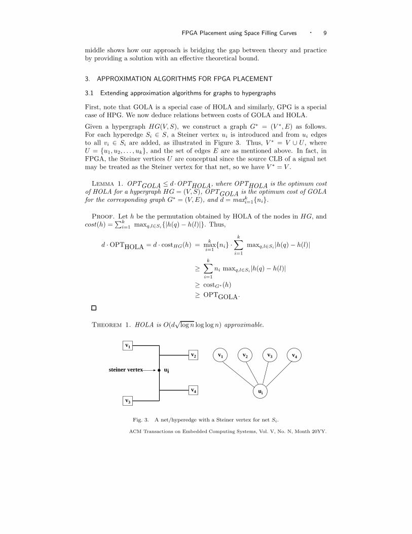
Given a hypergraph HG(V, S), we construct a graph G∗ = (V ∗, E) as follows.For each hyperedge Si ∈ S, a Steiner vertex ui is introduced and from ui edgesto all vi ∈ Si are added, as illustrated in Figure 3. Thus, V ∗ = V ∪ U , whereU = {u1, u2, . . . , uk}, and the set of edges E are as mentioned above. In fact, inFPGA, the Steiner vertices U are conceptual since the source CLB of a signal netmay be treated as the Steiner vertex for that net, so we have V ∗ = V .
Lemma 1. OPTGOLA ≤ d ·OPTHOLA, where OPTHOLA is the optimum costof HOLA for a hypergraph HG = (V, S), OPTGOLA is the optimum cost of GOLAfor the corresponding graph G∗ = (V, E), and d = maxk
i=1{ni}.
Proof. Let h be the permutation obtained by HOLA of the nodes in HG, andcost(h) =
∑ki=1 maxq,l∈Si
{|h(q) − h(l)|}. Thus,
d · OPTHOLA = d · costHG(h) =k
maxi=1
{ni} ·k
∑
i=1
maxq,l∈Si|h(q) − h(l)|
≥k
∑
i=1
ni maxq,l∈Si|h(q) − h(l)|
≥ costG∗(h)
≥ OPTGOLA.
Theorem 1. HOLA is O(d√
log n log log n) approximable.
steiner vertex ui
v1
v2
v3
v4 ui
v1 v2 v3 v4
Fig. 3. A net/hyperedge with a Steiner vertex for net Si.
ACM Transactions on Embedded Computing Systems, Vol. V, No. N, Month 20YY.

10 · Pritha Banerjee et al.
Proof. Using the O(√
log n log log n) approximation algorithm A(G) for GOLA[Feige and Lee 2007], we have
A(G)
OPTGOLA
≤ c√
log n log log n, where c is a constant. (1)
By Lemma 1 and Equation 1, we have
d OPTHOLA ≥ OPTGOLA ≥ A(G)
c√
log n log log n(2)
Thus, we have A(G)
OPTHOLA
≤ c d√
log n log log n.
In order to get an O(d√
log n log log n) approximation algorithm for HOLA, trans-form the hypergraph netlist to the corresponding graph G∗ as stated above, andthen run the O(
√log n log log n) approximation algorithm for GOLA [Feige and Lee
2007] on G∗.
Note that, a result similar to Lemma 1, holds for the costs of GPG and HPG byreplacing the cost functions of GOLA and HOLA by the rectilinear semi-perimeterbounding box cost. Using this observation, we can proceed on similar lines like The-orem 1 by using approximation algorithm for GPG by Even at al. [Even et al. 2000]to have an approximation algorithm for HPG as stated in the following theorem.
Theorem 2. HPG is O(d log n log log n) approximable.
These results are only of theoretical interest since these are not implementablein reasonable time as mandated by VLSI practitioners. In the next subsection,we begin a line of study that would finally lead to an algorithm with reasonablerunning time.
3.2 Approximation algorithm for HPG using space filling curve
Our algorithm for placement is very simple. We obtain a linear arrangement fromthe hypergraph and then use a space filling curve [Peano 1890; Sagan 1994] toembed the linear arrangement on the grid.
Algorithm 1: SFCTheoreticalPlace: Placement using HOLA and SFC.
Input : CLB netlist hypergraphOutput: Placement of CLBs
Step 1: use the O(d√
log n log log n) approximation algorithm for HOLA asper Theorem 1;Step 2: map this linear arrangement directly onto the two dimensional meshusing a recursive space filling curve, e.g., Hilbert curve;
ACM Transactions on Embedded Computing Systems, Vol. V, No. N, Month 20YY.

FPGA Placement using Space Filling Curves · 11
l = 0 l = 1 l = 2
l = 3
Fig. 4. Generation of Hilbert space filling curve for l = 0, 1, 2, 3
3.2.1 Recursive Space Filling Curves. Peano [Peano 1890] first defined and provedthe existence of space filling curves. A space filling curve is defined to be a contin-uous map from the unit interval in 1D into the d-dimensional Euclidean space thatpasses through every point of a d-dimensional region [Peano 1890; Hilbert 1891;Sagan 1994]. A discrete space filling curve provides a linear traversal or indexing ofa multi-dimensional grid space. Space filling curves are commonly used to reducea multidimensional problem to a 1-dimensional one [Asano et al. 1997]. But ourobjective is the reverse. A given linear arrangement is to be mapped onto a twodimensional mesh. This is possible because the mapping is bijective as given in thefollowing definition.
Definition 1. For positive integers a and l, where a = 2l, let us denote [a] ={1, 2, . . . , a}. A 2-dimensional discrete space filling curve of length a2 is a bijective
mapping C : [a2] → [a]2, that provides a linear indexing/traversal or total ordering
of all grid points in [a]2. This 2D grid is said to be of order l, and has sides oflength a = 2l.
The generation of a 2D space filling curve of successive orders usually follows arecursive framework. Several space filling curves are available in the literature. Wediscuss Hilbert space filling curve that is relevant to our FPGA placement problem.The Hilbert space filling curve can be constructed from a basic unit shape as shownfor l = 1 in Figure 4. The relative position and rotation of each unit shape is definedby its sequential position in the curve generation (see Figure 4). As the resolutionof the curve increases, more unit shapes are required for its description, but theprinciple remains same as the original proposition of dividing each part into smallerparts. These curves can be generated using an EOL-type (extended zero-sidedLindenmayer) grammar [Wood 1987] that basically forces simultaneous rewritingat every cell of the grid partition. A more practical and easily implementable wayto generate such curves using recursive procedures appear in [Breinholt and Schierz1998].
ACM Transactions on Embedded Computing Systems, Vol. V, No. N, Month 20YY.

12 · Pritha Banerjee et al.
3.2.2 Approximation ratio. The approximation algorithm we discuss next needs alower bound on OPT , the optimal solution for HPG.
Assume that the nets are disjoint. Then, the semi-perimeter of each net i has tobe greater than 2
√ni. This follows from the fact that for a fixed area, say ni, the
perimeter is minimized when both sides are equal (i.e. =√
ni). So,
OPT ≥ 2
k∑
i=1
√ni. (3)
First consider the approximation algorithm for HOLA. As per Theorem 1, we haveA(HG)
OPTHOLA≤ c d
√log n log log n, where A(HG) is the output of HOLA.
1 2 3 nix
Fig. 5. Span of a net (hyperedge) with ni CLBs.
Lemma 2. In the optimal solution for HOLA, the sum of the maximum spanof the nets is bounded by d
∑k
i=1 ni, i.e., OPTHOLA ≤ d∑k
i=1 ni, where k is thenumber of nets.
Proof. Refer Figure 5. Consider a vertex x /∈ Si but lying in the span of thenet Si. It is easy to observe that x has to share a net Sj 6= Si with any vertexvi ∈ Si, otherwise OPTHOLA can be reduced further. Observe that, if none of
the nets shared vertices, then OPTHOLA =∑k
i=1 ni. Now, each vertex of the netSi in the worst case can belong to different nets Sj (6= Si) apart from belongingto Si. Each Sj can be at most of size d. Thus, if we expand each net Si to aspan of dni and take the sum, then the sum exceeds OPTHOLA. making the total
OPTHOLA ≤ d∑k
i=1 ni, where k is the number of nets.
As a consequence of Lemma 2 and Theorem 1 we have the following.
A(HG) ≤ cd2√
log n log log nk
∑
i=1
ni (4)
Let us now consider a hyperedge (net) Si that spans a length ri in the lineararrangement A(HG). Therefore,
r1 + . . . + rk ≤ cd2√
log n log log n
k∑
i=1
ni (5)
Lemma 3. [Sagan 1994; Even et al. 2000] In a 2D embedding using space fillingcurve, each net spanning a length ri in the linear arrangement will have a perimeterbounded by C
√ri where C is a positive constant.
ACM Transactions on Embedded Computing Systems, Vol. V, No. N, Month 20YY.

FPGA Placement using Space Filling Curves · 13
Proof. See [Sagan 1994; Even et al. 2000; Gotsman and Lindenbaum 1996]. Aproof outline is as follows. Consider a Hilbert curve of order l. It is easy to observethat the Hilbert curve of the next order is obtained using a 4-fold reduction. As anexample, the lower left 16 cells of l = 3 in Figure 4 are mapped to the lower left 4cells of l = 2. Now, consider a net spanning a length of ri and consider its Hilbertfilling. As we go down the order of Hilbert curves using the 4-fold reduction, thenet spanning a length ri becomes successively smaller till it reaches a size of 4. Ifx is the number of such 4-fold reduction for a net of length ri, then ri
4x = 4. So,x = O(log2
√r).
Now, if we expand again 4-fold, the sides increase exponentially as a power of 2.See Figure 4. So, the perimeter is bounded by 2O(log
2
√r) = O(
√r).
We now derive the approximation ratio of our algorithm for the grid embedding ofhypergraph.
Theorem 3. HPG is O(d 4√
log n√
k log log n) approximable.
Proof. As a consequence of Lemma 3, the upper bound of the semi-perimeternetlength or the bounding box cost is BB ≤ C(
√r1 + . . . +
√rk).
Using Cauchy-Schwarz inequality [Abramowitz and Stegun 1972] and Equation 5,we have
BB ≤ C(√
r1 + · · · + √rk) ≤ C
′
d√
k
√
√
√
√
√
log n log log nk
∑
i=1
ni (6)
where C′
is a constant. Finally, using Equations 2, 3 and 6, and the fact that ni’sare all non-zero positive integers, the approximation ratio becomes
BB
OPT≤
C′
d√
k√
log n log log n√
∑ki=1 ni
2∑k
i=1
√ni
≤ C′
d√
k√
log n log log n
2
√
∑ki=1 ni
∑k
i=1
√ni
.
Thus, BBOPT
≤ O(d 4√
log n√
k log log n) because
(√P
k
i=1ni
P
k
i=1
√ni
)
≤ 1 as ni’s are all
non-zero positive integers.
The approximation ratio obtained here is dependent on the number of hyper-
edges/nets. If k = o(log3
2 n log log n), then the approximation ratio of Theorem3 is better than the approximation ratio of Theorem 2.
This theorem is not straightaway implementable as per fast FPGA placement stan-dards because of the time consuming O(d
√log n log log n) approximation algorithm
of HOLA. Next, we focus on how we can modify this algorithm so as to make itrun very fast.
3.3 The Algorithm in practice
In general, our placement technique consists of the three steps as shown in Algo-rithm 2. We replace the time consuming Step 1 of Algorithm 1 as follows. Apply
ACM Transactions on Embedded Computing Systems, Vol. V, No. N, Month 20YY.

14 · Pritha Banerjee et al.
Algorithm 2: SfcPlace: Our efficient placement method.
Input : CLB netlist hypergraph with IOBOutput: Placement of CLBs and IOBs
Step 1: transform the netlist hypergraph to a linear arrangement of CLBs ofthe hypergraph using top-down min-cut graph bi-partitioning technique;Step 2: map this linear arrangement directly onto the
√n × √
n 2D gridusing a recursive space filling curve;Step 3: IOBs are placed on the periphery by minimum weighted bipartitematching formulation
a min-cut recursive bipartitioner to partition the netlist of CLBs such that finallyeach partition has one element. The left to right order of the leaves of the partitiontree is treated as the linear arrangement of CLBs. We give reasons in Section 3.3.1as to why it works. Step 2 is described in Section 3.3.2. In the third step, the IOBsare placed on the periphery using a minimum weight bipartite matching as statedin Section 3.3.3.
3.3.1 Computation of linear arrangement. In this step, our goal is to obtain alinear arrangement of nodes in a circuit hypergraph such that the total wirelengthof nets is minimum. The problem of placing the nodes of a graph on a straight linewith equal spacing such that the sum of edge lengths of the graph is minimum, isNP-complete [Garey and Johnson 1979]. But, for some special classes of graphs,i.e., rooted directed trees, undirected trees, and series parallel graphs, this problemcan be solved in polynomial time [Adolphson and Hu 1973; Shiloach 1979; Nandyet al. 1997]. As a circuit hypergraph does not belong to these special classes, weadopt a heuristic procedure based on balanced min-cut bipartition to generate a lin-ear arrangement of the nodes. In this recursive process, at each level we obtain twopartitions having almost the same number of nodes, which are heavily connectedintra-partition. The recursive partitioning process is represented as a bipartitiontree, where the root corresponds to all the nodes in the hypergraph. The left andright child correspond to the two partitions. Without loss of generality, the ar-rangement of the two partitions in the bipartition tree can be swapped. We adoptthe convention that the partition assigned to the left child is the first partition inthe linear arrangement and that to the right child is the second one. Even et al.[Even et al. 2000] designed a divide-and-conquer based approximation algorithmfor optimal linear arrangement using the decomposition tree of a graph. Here rootnode corresponds to all the vertices of graph and each internal node of the treecorresponds to a partition of the vertices. The tree is fully decomposed when eachleaf contains a single node. The decomposition may be based on any “criteria”that partitions the set of vertices such that “related” vertices belong to the samepartition. The authors established that the partitions induced by a decompositiontree gives a qualitatively good linear arrangement of the vertices according to theirorder of appearance as the leaves of the decomposition tree. We use this idea to ob-tain a linear arrangement of blocks using a very fast hypergraph partitioner hMetis[HMETIS ; Karypis et al. 1999]. The hMetis reduces the size of the hypergraph
ACM Transactions on Embedded Computing Systems, Vol. V, No. N, Month 20YY.

FPGA Placement using Space Filling Curves · 15
by collapsing vertices and edges in the coarsening phase, then partitions the re-duced graph in the initial partitioning phase, and finally uncoarsens it to constructa bi-partition for the original graph in the uncoarsening and refinement phase.
The authors of hMetis have not reported about the quality of the linear arrangementobtained by their method. But, we observed that, as established in [Even et al.2000], the linear arrangement produced by hMetis is very good and this can verywell help in reducing the final wirelength and hence, delay.
3.3.2 Placement by space filling curves. We generate Hilbert space filling curves asdescribed in Section 3.2.1, to place the logic blocks on the FPGA array. Essentially,this allocates a specific co-ordinate position for each of the logic blocks in the lineararrangement, using the sequence generated by Hilbert curve. In our case, the matrixsize may not necessarily be of the form a = 2l. We draw the Hilbert curve for anarbitrary R × C matrix as follows. Let N = max{R, C}, and a = 2l, wherel = ⌈log2 N⌉. Next, we find the space filling curve corresponding to a and crop thecurve within the array of size R × C. This completes the placement of CLBs byour method.
3.3.3 Placement of IO blocks. After the CLBs are placed onto a 2D FPGA array,the IOBs (input/output blocks) are to be placed on the periphery of the array.We have formulated this problem as an instance of a minimum weighted bi-partitematching problem (MWBM) as follows. Let B = {B1 ∪ B2, Q} be a completeweighted bipartite graph, where B1 ∩ B2 = φ; the nodes in B1 correspond to theprimary inputs and primary outputs, and those in B2 correspond to the locationsavailable on the periphery of the FPGA array of CLBs. Each pair of vertices (bi, bj),bi ∈ B1 and bj ∈ B2 contributes an edge q = (bi, bj), and its weight is the Manhattandistance between the center of the bounding box of the net corresponding to theIOB bi ∈ B1 and the specific location corresponding to bj ∈ B2. For each matchededge (bi, bj) in the solution, we assign the IOB bi to the location bj .
3.3.4 Complexity analysis. The recursive min-cut partitioning of CLB netlist byhMetis is an iterative process and the authors of hMetis [Karypis et al. 1999] claimthat the time taken is almost linear in the number of hyperedges. Since n locationscorresponding to n CLBs are visited only once during the construction of spacefilling curve, the time complexity of CLB placement is O(n). As to the placementof IOBs, note that there can be O(
√n) IOBs that are to be placed on the periphery
of the√
n×√n FPGA board. Thus, the number of vertices in the bipartite graph
will be O(√
n) and the number of edges will be O(n). So, the MWBM methodfor placement of IOBs takes O(n1.25). Thus, the overall time complexity of ouralgorithm is near-linear, and scalable for large circuits.
4. EXPERIMENTAL RESULTS
In this section, we present the experimental results of our placement methodologyand compare these with the placement and routing results produced by the popularFPGA placement tool VPR [Betz and Rose 1997]. The platform used is 1.2GHz
ACM Transactions on Embedded Computing Systems, Vol. V, No. N, Month 20YY.

16 · Pritha Banerjee et al.
SunBlade 2000 workstation. The LEDA [LEDA ] library is employed to solve theMWBM problem described in Section 3.3.3.
Table I shows the characteristics of twenty MCNC benchmark circuits. The columns2 to 5 show the number of CLBs, primary inputs, primary outputs and the max-imum degree (d) of a net respectively in the given circuit. Column 6 shows theminimum square array required to place all CLBs and IOBs.
Table I. Characteristics of MCNC FPGA Placement Benchmark circuitsCkt # CLBs # Inputs # Outputs Max. # Size of
(n) terminals (d) 2D gridtseng 1047 52 122 246 33 × 33ex5p 1064 8 63 75 33 × 33apex4 1262 9 19 84 36 × 36dsip 1370 229 197 450 54 × 54misex3 1397 14 14 49 38 × 38diffeq 1497 64 39 196 39 × 39alu4 1522 14 8 24 40 × 40des 1591 256 245 227 63 × 63bigkey 1707 229 197 449 54 × 54seq 1750 41 35 90 42 × 42apex2 1878 38 3 86 44 × 44s298 1931 4 6 244 44 × 44frisc 3556 20 116 124 60 × 60elliptic 3604 131 114 292 61 × 61spla 3690 16 46 155 61 × 61pdc 4575 16 40 238 68 × 68ex1010 4598 10 10 260 68 × 68s38417 6406 29 106 236 81 × 81s38584.1 6447 38 304 188 81 × 81clma 8383 62 82 457 92 × 92
Table II shows the quality of placement and the speedup achieved by our methodover the simulated annealing based method of VPR. We report the sum of semi-perimeter of the bounding box of all nets by our method in column 2 and thesame obtained by VPR in column 3. Assuming the result obtained by VPR tobe the optimum, the approximation ratio of our method, computed empirically
as BB(SFC)BB(V PR) , is reported in column 6. The time taken by our method and VPR
are shown in columns 4 and 5. Column 7 shows the speedup achieved by ourmethod. We observed that the approximation ratio is 1.31 on an average in practice,which is much lower than the theoretical bound derived by us. This shows thatthough theoretically our bound is not very tight, our method performs very wellin practice. The gain in speed is very significant. The speedup over the existingiterative method is about 33× on an average. This shows the suitability of our
ACM Transactions on Embedded Computing Systems, Vol. V, No. N, Month 20YY.

FPGA Placement using Space Filling Curves · 17
Table II. Comparison of semi perimeter bounding box (BB) of our placement vs.VPR
BB CPU time (s) SFC/VPR DelayCkt SFC VPR SFC VPR BB Speedup SFC VPR SFC/VPRtseng 9653 7302 5 152 1.32 30.4 12.6 5.71 2.21ex5p 17089 13395 5 169 1.27 33.8 14.0 6.55 2.13apex4 18241 14217 6 222 1.28 37.0 15.6 7.85 1.99dsip 18037 11666 15 248 1.54 16.5 7.6 6.55 1.16misex3 17550 13430 7 218 1.30 31.1 12.4 7.53 1.65diffeq 13714 10913 8 247 1.25 30.8 14.1 6.27 2.25alu4 16669 12197 8 242 1.30 30.2 14.4 8.02 1.80des 28288 18441 22 312 1.53 14.2 13.2 9.02 1.46bigkey 18100 13167 16 331 1.37 20.7 8.4 6.79 1.24seq 22905 17747 9 312 1.29 34.7 13.2 7.87 1.67apex2 25527 18816 10 339 1.29 33.9 16.8 10.00 1.68s298 11207 11635 10 321 0.96 32.1 27.2 13.10 2.07frisc 40942 40655 23 969 1.00 42.1 35.1 12.70 2.77elliptic 34492 29760 24 846 1.15 35.2 31.3 10.80 2.90spla 49545 37006 23 961 1.33 41.8 22.3 12.90 1.74pdc 74087 55269 31 1280 1.34 41.3 34.7 14.10 2.46ex1010 71669 43327 32 1161 1.65 36.3 45.8 18.30 2.51s38417 62404 47179 51 1700 1.32 33.3 20.0 9.40 2.13s38584.1 64510 44597 52 1930 1.44 37.1 19.2 10.10 1.90clma 114271 81412 69 3200 1.40 46.4 37.2 22.40 1.66Avg: 1.31 32.9 1.97
method for placement where fast placement is required for large circuits with alittle compromise on quality.
One may recall that simulated annealing based methods (say VPR) do not scaleup well for large circuits. In order to verify this fact, we carried out another setof experiments on the same set of benchmark circuits. First, we noted the CPUtime t taken by our method (as shown in Algorithm 2). Then, we allowed VPRto run for the same amount of time t and observed the BB-cost at that stage of
SA. Let this said BB-cost be denoted as BB(V PRt). The ratios BB(SFC)BB(V PR) and
BB(V PRt)BB(V PR) are plotted, as shown in Figure 6. It can be observed that our method
always outperforms the quality of solution as given by VPR when allowed to runfor the same duration of time t.
We have also observed the routability of placement by routing our placement usingVPR router. The columns 8 and 9 show the critical path delay (in 10−8 secs.)obtained for our placement method and that for VPR. Our placement is routablewith a fixed channel width, and on the average the critical path delay is about1.97× of that obtained by VPR. To the best of our knowledge, no one has reportedroutability in benchmark circuits with deterministic heuristics prior to us. Although
ACM Transactions on Embedded Computing Systems, Vol. V, No. N, Month 20YY.

18 · Pritha Banerjee et al.
0.5
1
1.5
2
2.5
3
3.5
4
1000 2000 3000 4000 5000 6000 7000 8000 9000
Rat
io -
-->
No. of blocks (n) --->
BB(SFC):BB(VPR)BB(VPR(t)):BB(VPR)
Fig. 6. Effectiveness of our proposed Algorithm 2: comparison of the ratios BB(SF C)BB(V PR)
and
BB(V PRt)BB(V PR)
, where t is the time taken by Algorithm 2, and BB(V PRt) is the BB-cost of the
solution produced by VPR run only for time t.
it is not the main focus of our work, for completeness sake, a ultra-low temperaturesimulated annealing was applied to the solutions obtained by our Algorithm 2 toattain the same quality as VPR yet with a speedup of 2×, as reported in theAppendix.
Finally, we observe that in practice the BB-cost of the placement produced by ourmethod stays within 0.96× to 1.65× of the solution of VPR. The theoretical boundderived by us (O(d 4
√log n
√k log log n)) is a monotonically increasing function of
n, the number of CLBs. But, as can be observed from Column 6 of Table II, thequality of our practical method is almost independent of n. This shows that qualitywise our method-in-practice is also scalable like it is time-wise.
5. CONCLUSION
We presented a very simple and effective yet fast placement approach for island-style FPGAs with theoretical bounds on the quality of the solution. We firstextended theoretical results for graph linear arrangement and graph embeddingto linear arrangement and embedding for hypergraphs. Next, we designed anO(d 4
√log n
√k log log n) approximation algorithm. It is needless to say that this
bound automatically improves along with tighter approximation bound on GOLA,as it is derived from that for GOLA. Our algorithm is easy to implement; it usesonly an approximate linear arrangement and a recursive space filling curve. Thetheoretical algorithm proposed by us works for real-life benchmark circuits withminor modifications. The running time is near-linear in the number of CLBs andhence is scalable for large circuits. As per our knowledge, this is the first attempt
ACM Transactions on Embedded Computing Systems, Vol. V, No. N, Month 20YY.

FPGA Placement using Space Filling Curves · 19
in bringing into practice a method for placement that has theoretical bounds ofapproximation. Applying our method to a set of benchmark circuits, we observedthat on the average, the quality of our solution is 1.31× of the popular simulatedannealing based tool VPR while the speedup is 33×. The quality of solutions, asobserved from experiments on benchmark circuits, stays within a constant rangeand do not depend on the number of CLBs. Also the placements obtained areroutable with fixed channel width. This justifies the applicability of our methodfor fast FPGA placement.
REFERENCES
Abramowitz, M. and Stegun, I. A., Eds. 1972. Handbook of Mathematical Functions withFormulas, Graphs, and Mathematical Tables. Dover, New York.
Adolphson, D. and Hu, T. C. 1973. Optimal linear ordering. SIAM J. Appl. Math 25, 3,403–423.
Alpert, C. J. and Kahng, A. B. 1995. Recent directions in netlist partitioning: A survey.Integration, the VLSI Journal 19, 1–81.
Asano, T., Ranjan, D., Roos, T., Welzl, E., and Widmayer, P. 1997. Space-filling curvesand their use in the design of geometric data structures. Theoretical Computer Science 181, 1,3–15.
Banerjee, P., Bhattacharjee, S., Sur-Kolay, S., Das, S., and Nandy, S. C. 2005. FastFPGA placement using space-filling curve. In Proc. IEEE International Conference on FieldProgrammable Logic and Applications. 415–420.
Betz, V. and Rose, J. 1997. VPR: A new packing, placement and routing tool for FPGAresearch. In Proc. of International Conference on Field Programmable Logic and Applications,W. Luk, P. Y. Cheung, and M. Glesner, Eds. Springer-Verlag, Berlin, 213–222.
Bhasker, J. and Sahni, S. 1987. Optimal linear arrangement of circuit components. Journal ofVLSI & Computer Systems 2, 87–109.
Breinholt, G. and Schierz, C. 1998. Generating Hilbert’s space-filling curve by recursion. ACMTrans. on Mathematical Software 24, 2, 184–189.
Chen, D., Cong, J., and Pan, P. 2006. FPGA design automation: A survey. Found. TrendsElectron. Des. Autom. 1, 3, 139–169.
Emmert, J. M. and Bhatia, D. K. 1999. Tabu search: Ultra-fast placement for FPGAs. In Proc.IEEE International Conference on Field Programmable Logic and Applications. 81–90.
Even, G., Naor, J. S., Rao, S., and Schieber, B. 2000. Divide-and-conquer approximationalgorithms via spreading metrics. Journal of the ACM 47, 4, 585–616.
Feige, U. and Lee, J. R. 2007. An improved approximation ratio for the minimum lineararrangement problem. Information Processing Letters 101, 1, 26–29.
Fiduccia, C. M. and Mattheyses, R. M. 1982. A linear-time heuristic for improving networkpartitions. In Proc. of IEEE/ACM Design Automation Conference. 175–181.
Garey, M. R. and Johnson, D. S. 1979. Computers and Intractability: A Guide to Theory ofNP-completeness. W. H. Freeman & Co., San Francisco, CA.
Gopalakrishnan, P., Li, X., and Pileggi, L. T. 2006. Architecture-aware FPGA placementusing metric embedding. In Proc. of Design Automation Conference. 460–465.
Gotsman, C. and Lindenbaum, M. 1996. On the metric properties of discrete space-filling curves.IEEE Transactions on Image Processing 5, 5, 794–797.
Hilbert, D. 1891. Uber stetige abbildung einer linie auf ein flachenstuck. Mathematische An-nalen 38, 459–460.
HMETIS. http://www-users.cs.umn.edu/ karypis/metis/hmetis.
Karypis, G., Aggarwal, R., Kumar, V., and Shekhar, S. 1999. Multilevel hypergraph partition-ing: applications in VLSI domain. IEEE Trans. on Very Large Scale Integration Systems 7, 1,69–79.
ACM Transactions on Embedded Computing Systems, Vol. V, No. N, Month 20YY.

20 · Pritha Banerjee et al.
Kernighan, B. W. and Lin, S. 1970. An efficient heuristic procedure for partitioning graphs.
Bell System Technical Journal 49, 291–307.
LEDA. http://www.algorithmic-solutions.com/.
Maidee, P., Ababei, C., and Bazargan, K. 2003. Fast timing-driven partitioning-based place-ment for island style FPGAs. In Proc. of ACM /IEEE Design Automation Conference. 598–603.
Mulpuri, C. and Hauck, S. 2001. Runtime and quality tradeoffs in fpga placement and routing.In Proc. of the 2001 ACM/SIGDA ninth international symposium on Field programmable gatearrays. 29–36.
Nandy, S. C., Nandakumar, G. N., and Bhattacharya, B. B. 1997. Efficient algorithms forsingle and two-layer linear placement of parallel graphs. Computers and Mathematics withApplication 34, 12, 121–135.
Peano, G. 1890. Sur une courbe qui remplit toute une aire plaine. Mathematische Annalen 36,157–160.
Rao, S. and Richa, A. W. 1998. New approximation techniques for some ordering problems. InACM-SIAM Symposium on Discrete Algorithms. 211–218.
Sagan, H. 1994. Space-Filling Curves. Springer Verlag, ISBN 0-387-94265-3.
Sarrafzadeh, M., Bozorgzadeh, E., Kastner, R., and Srivastava, A. 2001. Design and anal-ysis of physical design algorithms. In Proc. of the 2001 ACM/SIGDA International Symposiumon Physical Design. 82–89.
Sechen, C. 1988. VLSI Placement and Global Routing using Simulated Annealing. KluwerAcademic Publishers, Boston, USA.
Shahookar, K. and Mazumdar, P. 1991. VLSI cell placement techniques. ACM ComputingSurveys 23, 2, 143–220.
Shiloach, Y. 1979. Minimum linear arrangement algorithm for undirected trees. SIAM Journalon Computing 8, 1, 15–32.
Vempala, S. 1998. Random projection: a new approach to VLSI layout. In Proc. of IEEESymposium on Foundations of Computer Science.
Verma, S. 2008. How to perform meaningful benchmarks on fpgas from different vendors.http://www.embedded.com/design/embeddedfpga/208400710?pgno=1.
Vicente, J. D., Lanchares, J., and Hermida, R. 2004. Annealing placement by thermodynamiccombinatorial optimization. ACM Trans. on Design Automation of Electronic Systems 9, 3,310–332.
Vygen, J. 2007. New theoretical results on quadratic placement. Integration, the VLSI Jour-nal 40, 3, 305–314.
Wang, M., Ranjan, A., and Raje, S. 2003. Multi-million gate fpga physical design challenges.In Proc. of International Conference on Computer Aided Design. 891–898.
Wong, D. F., Leong, H. W., and Liu, C. L. 1988. Simulated Annealing for VLSI Design. KluwerAcademic Publishers, Boston, USA.
Wood, D. 1987. Theory of Computation. Harper & Row.
XILINX. http://www.xilinx.com.
Xu, Y. and Khalid, M. 2005. QPF: Efficient quadratic placement for FPGAs. In Proc. IEEEInternational Conference on Field Programmable Logic and Applications. 555–558.
ACM Transactions on Embedded Computing Systems, Vol. V, No. N, Month 20YY.

FPGA Placement using Space Filling Curves · 21
APPENDIX
We employed a ultra-low temperature simulated annealing to overcome the local op-tima and compared the performance of the benchmarks with respect to the longestpath, i.e., the critical path delay. The results are shown in Table III. In columns 2and 3 we report the critical path delay (CP (SFC)) and (CP (SFC+SA)) achievedby Algorithm 2 given in Section 3.3 (Method I), and the same method followed bylow temperature simulated annealing (Method II) respectively. The critical pathdelay obtained by VPR (CP (V PR)) is reported in column 4. The comparison ofthe critical path delay achieved by our Methods I and II with that of VPR are
reported in columns 5 and 6 as ratios CP (SFC)CP (V PR) and CP (SFC+SA)
CP (V PR) respectively. We
observed that, on an average, the critical path delay obtained by our Methods Iand II is 1.97× and 1.03× respectively. We also noted that for Method II, due toexecution of SA we achieve a much lower speedup of 2×, as opposed to 33× for ourproposed Method I (Algorithm 2) based on linear arrangement followed by spacefilling curve.
Table III. Comparison of critical path delay with VPR.Critical Path(CP)(10−8 secs.) Comparison of CP
Ckt CP (SFC) CP (SFC + SA) CP (V PR) CP (SF C)CP (V PR)
CP (SF C+SA)CP (V PR)
tseng 12.6 5.83 5.71 2.21 1.02ex5p 14.0 7.00 6.55 2.13 1.07apex4 15.6 8.22 7.85 1.99 1.05dsip 7.6 6.79 6.55 1.16 1.04misex3 12.4 7.99 7.53 1.65 1.06diffeq 14.1 6.84 6.27 2.25 1.09alu4 14.4 7.96 8.02 1.80 0.99des 13.2 9.32 9.02 1.46 1.03bigkey 8.4 6.56 6.79 1.24 0.97seq 13.2 8.95 7.87 1.67 1.14apex2 16.8 10.10 10.00 1.68 1.00s298 27.2 13.60 13.10 2.07 1.04frisc 35.1 13.30 12.70 2.77 1.05elliptic 31.3 11.70 10.80 2.90 1.08
spla 22.3 13.50 12.90 1.74 1.05pdc 34.7 15.00 14.10 2.46 1.06ex1010 45.8 16.50 18.30 2.51 0.90s38417 20.0 11.10 9.40 2.13 1.18s38584.1 19.2 9.41 10.10 1.90 0.93clma 37.2 20.00 22.40 1.66 0.89
Avg: 1.97 1.03
ACM Transactions on Embedded Computing Systems, Vol. V, No. N, Month 20YY.
Related Documents