Modes of Heat Transfer S K Mondal’s Chapter 1 1. Modes of Heat Transfer Theory at a Glance (For IES, GATE, PSU) Heat Transfer by Conduction Kinetic Energy of a molecule is the sum of A. Translational Energy B. Rotational Energy And C. Vibrational Energy Increase in Internal Energy means A. Increase in Kinetic Energy or B. Increase in Potential Energy or C. Increase in both Kinetic Energy and Potential Energy. Fourier's Law of Heat Conduction k dt Q=- A dx The temperature gradient dt dx ⎛ ⎞ ⎜ ⎟ ⎝ ⎠ is always negative along positive x direction and, therefore, the value as Q becomes + ve. Essential Features of Fourier’s law: 1. It is applicable to all matter (may be solid, liquid or gas). 2. It is a vector expression indicating that heat flow rate is in the direction of decreasing temperature and is normal to an isotherm. 3. It is based on experimental evidence and cannot be derived from first principle. Thermal Conductivity of Materials Sl. NO. Materials Thermal conductivity, (k) 1 Silver 10 W/mk 2 Copper 85 W/mk 3 Aluminium 25 W/mk 4 Steel 40 W/mk 5 Saw dust 0.07 W/mk 2013 Page 1 of 216

Welcome message from author
This document is posted to help you gain knowledge. Please leave a comment to let me know what you think about it! Share it to your friends and learn new things together.
Transcript

Modes of Heat Transfer S K Mondal’s Chapter 1
1. Modes of Heat Transfer
Theory at a Glance (For IES, GATE, PSU)
Heat Transfer by Conduction Kinetic Energy of a molecule is the sum of A. Translational Energy B. Rotational Energy
And C. Vibrational Energy Increase in Internal Energy means A. Increase in Kinetic Energy or B. Increase in Potential Energy
or C. Increase in both Kinetic Energy and Potential Energy.
Fourier's Law of Heat Conduction
k dtQ =- Adx
The temperature gradient dtdx
⎛ ⎞⎜ ⎟⎝ ⎠
is always negative along positive x direction and,
therefore, the value as Q becomes + ve. Essential Features of Fourier’s law:
1. It is applicable to all matter (may be solid, liquid or gas). 2. It is a vector expression indicating that heat flow rate is in the direction of
decreasing temperature and is normal to an isotherm. 3. It is based on experimental evidence and cannot be derived from first principle.
Thermal Conductivity of Materials Sl. NO. Materials Thermal conductivity, (k)
1 Silver 10 W/mk
2 Copper 85 W/mk
3 Aluminium 25 W/mk
4 Steel 40 W/mk
5 Saw dust 0.07 W/mk
2013 Page 1 of 216
Modes of Heat Transfer S K Mondal’s Chapter 1
6 Glass wool 0.03 W/mk
7 Freon 0.0083 W/mk
Solid: A. Pure metals, (k) = 10 to 400 W/mk B. Alloys, (k) = 10 to 120 W/mk C. Insulator, (k) = 0.023 to 2.9 W/mk
Liquid: k = 0.2 to 0.5 W/mk
Gas: k = 0.006 to 0.5 W/mk
Thermal conductivity and temperature:
( )β= +0 1k k t
2
( )Metals, if except. ,. . ,
( )Liquid if except.i k t Al U
i e veii k t H O
β⎡ ⎤↓ ↑
−⎢ ⎥↓ ↑⎢ ⎥⎣ ⎦
( )Gas if( ) Non-metal and . . ,
insulating material
iii k tiv i e ve
k if tβ
⎡ ⎤↑ ↑⎢ ⎥ +⎢ ⎥⎢ ⎥↑ ↑⎣ ⎦
Questions: Discuss the effects of various parameters on the thermal conductivity
of solids. Answer: The following are the effects of various parameters on the thermal
conductivity of solids.
1. Chemical composition: Pure metals have very high thermal conductivity. Impurities or alloying elements reduce the thermal conductivity considerably [Thermal conductivity of pure copper is 385 W/mºC, and that for pure nickel is 93 W/mºC. But monel metal (an alloy of 30% Ni and 70% Cu) has k of 24 W/mºC. Again for copper containing traces of Arsenic the value of k is reduced to 142 W/mºC].
2. Mechanical forming: Forging, drawing and bending or heat treatment of metals causes considerable variation in thermal conductivity. For example, the thermal conductivity of hardened steel is lower than that of annealed state.
3. Temperature rise: The value of k for most metals decreases with temperature rise since at elevated temperatures the thermal vibrations of the lattice become higher that retard the motion of free electrons.
4. Non-metallic solids: Non-metallic solids have k much lower than that for metals. For many of the building materials (concrete, stone, brick, glass
2013 Page 2 of 216

Modes of Heat Transfer S K Mondal’s Chapter 1
wool, cork etc.) the thermal conductivity may vary from sample to sample due Fire brick to variations in structure, composition, density and porosity.
5. Presence of air: The thermal conductivity is reduced due to the presence of air filled pores or cavities.
6. Dampness: Thermal conductivity of a damp material is considerably higher than that of dry material.
7. Density: Thermal conductivity of insulating powder, asbestos etc. increases with density Growth. Thermal conductivity of snow is also proportional to its density.
Thermal Conductivity of Liquids
k = σλ
s2
V3
Where σ = Boltzmann constant per molecule ⎛ ⎞⎜ ⎟⎝ ⎠v
RA
(Don’t confused with Stefen Boltzmann Constant) sV = Sonic velocity of molecule λ = Distance between two adjacent molecule. R = Universal gas constant Av = Avogadro’s number Thermal conductivity of gas
k = 16 snv fσλ
Where n = Number of molecule/unit volume sv = Arithmetic mean velocity f = Number of DOF λ = Molecular mean free path For liquid thermal conductivity lies in the range of 0.08 to 0.6 W/m-k For gases thermal conductivity lies in the range of 0.005 to 0.05 W/m-k The conductivity of the fluid related to dynamic viscosity (μ)
4.51 ;2
where, number of atoms in a molecule
vk Cnn
⎡ ⎤= + μ⎢ ⎥⎣ ⎦=
Sequence of thermal conductivity
Pure metals > alloy > non-metallic crystal and amorphous > liquid > gases
Wiedemann and Franz Law (based on experimental results)
2013 Page 3 of 216

Modes of Heat Transfer S K Mondal’s Chapter 1
“The ratio of the thermal and electrical conductivities is the same for all metals at the same temperature; and that the ratio is directly proportional to the absolute temperature of the metal.’’
ork kT CT
αυ υ
∴ = Where k = Thermal conductivity at T(K) υ = Electrical conductivity at T(K) C = Lorenz number 8 22.45 10 /w k−= × Ω
This law conveys that: the metals which are good conductors of electricity are also good conductors of heat. Except mica.
Thermal Resistance: (Rth) Ohm’s Law: Flow of Electricity
Voltage Drop = Current flow × Resistance Thermal Analogy to Ohm’s Law:
thT qRΔ = Temperature Drop = Heat Flow × Resistance
A. Conduction Thermal Resistance:
(i) Slab ( ) =thLR
kA
(ii) Hollow cylinder ( )π
= 2 1( / )2th
n r rRkL
2013 Page 4 of 216

Modes of Heat Transfer S K Mondal’s Chapter 1
(iii) Hollow sphere ( )π−
= 2 1
1 24thr rR
kr r
B. Convective Thermal Resistance: ( ) = 1thR
hA
C. Radiation Thermal Resistance: ( )( ) ( )σ
=+ +2 2
1 2 1 2
1thR
F A T T T T
1D Heat Conduction through a Plane Wall
ktLR
h A A h A= + +∑
1 2
1 1 (Thermal resistance)
2013 Page 5 of 216

Modes of Heat Transfer S K Mondal’s Chapter 1
1D Conduction (Radial conduction in a composite cylinder)
1D Conduction in Sphere Inside Solid:
kd dTrdr drr
⎛ ⎞ =⎜ ⎟⎝ ⎠
22
1 0
{ } ( )( ), , ,
/( )
/s s sr r
T r T T Tr r
⎡ ⎤−→ = − − ⎢ ⎥
−⎢ ⎥⎣ ⎦
11 1 2
1 2
11
( )( )
, ,kk
/ /s sT TdTqr A
dr r r−
→ = − =−
1 2
1 2
41 1π
,/ /
k1 21 14t cond
r rRπ−
→ =
Isotropic & Anisotropic material If the directional characteristics of a material are equal /same, it is called an ‘Isotropic material’ and if unequal/different ‘Anisotropic material’.
Example: Which of the following is anisotropic, i.e. exhibits change in thermal conductivity due to directional preferences?
2013 Page 6 of 216

Modes of Heat Transfer S K Mondal’s Chapter 1
(a) Wood (b) Glass wool (c) Concrete (d) Masonry brick
Answer. (a)
( ) ( )( )
αρ
Thermalconductivity kThermal diffusivity =
Thermalcapacity c
αρ
=ki.e . unitc
2ms
The larger the value of ,α the faster will be the heat diffuse through the material and its temperature will change with time. – Thermal diffusivity is an important characteristic quantity for unsteady condition
situation.
2013 Page 7 of 216

Modes of Heat Transfer S K Mondal’s Chapter 1
OBJECTIVE QUESTIONS (GATE, IES, IAS)
Previous 20-Years GATE Questions
Fourier's Law of Heat Conduction GATE-1. For a given heat flow and for the same thickness, the temperature drop
across the material will be maximum for [GATE-1996] (a) Copper (b) Steel (c) Glass-wool (d) Refractory brick GATE-2. Steady two-dimensional heat conduction takes place in the body shown
in the figure below. The normal temperature gradients over surfaces P
and Q can be considered to be uniform. The temperature gradient Tx
∂∂
at surface Q is equal to 10 k/m. Surfaces P and Q are maintained at constant temperatures as shown in the figure, while the remaining part of the boundary is insulated. The body has a constant thermal
conductivity of 0.1 W/m.K. The values of andT Tx y
∂ ∂∂ ∂
at surface P are:
(a) ,/20 mKxT=
∂∂ mK
yT /0=∂∂
(b) ,/0 mKxT=
∂∂ mK
yT /10=∂∂
(c) ,/10 mKxT=
∂∂ mK
yT /10=∂∂
(d) ,/0 mKxT=
∂∂ mK
yT /20=∂∂
[GATE-2008] GATE-3. A steel ball of mass 1kg and specific heat 0.4 kJ/kg is at a temperature
of 60°C. It is dropped into 1kg water at 20°C. The final steady state temperature of water is: [GATE-1998]
(a) 23.5°C (b) 300°C (c) 35°C (d) 40°C
Thermal Conductivity of Materials GATE-4. In descending order of magnitude, the thermal conductivity of a. Pure iron, [GATE-2001] b. Liquid water, c. Saturated water vapour, and d. Pure aluminium can be arranged as (a) a b c d (b) b c a d (c) d a b c (d) d c b a
2013 Page 8 of 216

Modes of Heat Transfer S K Mondal’s Chapter 1
Previous 20-Years IES Questions
Heat Transfer by Conduction IES-1. A copper block and an air mass block having similar dimensions are
subjected to symmetrical heat transfer from one face of each block. The other face of the block will be reaching to the same temperature at a rate: [IES-2006]
(a) Faster in air block (b) Faster in copper block (c) Equal in air as well as copper block (d) Cannot be predicted with the given information
Fourier's Law of Heat Conduction IES-2. Consider the following statements: [IES-1998]
The Fourier heat conduction equation dTQ kAdx
= − presumes
1. Steady-state conditions 2. Constant value of thermal conductivity. 3. Uniform temperatures at the wall surfaces 4. One-dimensional heat flow. Of these statements: (a) 1, 2 and 3 are correct (b) 1, 2 and 4 are correct (c) 2, 3 and 4 are correct (d) 1, 3 and 4 are correct IES-3. A plane wall is 25 cm thick with an area of 1 m2, and has a thermal
conductivity of 0.5 W/mK. If a temperature difference of 60°C is imposed across it, what is the heat flow? [IES-2005]
(a) 120W (b) 140W (c) 160W (d) 180W IES-4. A large concrete slab 1 m thick has one dimensional temperature
distribution: [IES-2009]
T = 4 – 10x + 20x2 + 10x3
Where T is temperature and x is distance from one face towards other face of wall. If the slab material has thermal diffusivity of 2 × 10⁻³ m2/hr, what is the rate of change of temperature at the other face of the wall?
(a) 0.1°C/h (b) 0.2°C/h (c) 0.3°C/h (d) 0.4°C/h IES-5. Thermal diffusivity of a substance is: [IES-2006] (a) Inversely proportional to thermal conductivity (b) Directly proportional to thermal conductivity (c) Directly proportional to the square of thermal conductivity (d) Inversely proportional to the square of thermal conductivity IES-6. Which one of the following expresses the thermal diffusivity of a
substance in terms of thermal conductivity (k), mass density (ρ) and specific heat (c)? [IES-2006]
(a) k2 ρc (b) 1/ρkc (c) k/ρc (d) ρc/k2
IES-7. Match List-I and List-II and select the correct answer using the codes given below the lists: [IES-2001]
2013 Page 9 of 216

Modes of Heat Transfer S K Mondal’s Chapter 1
hm - mass transfer coefficient, D - molecular diffusion coefficient, L - characteristic length dimension, k - thermal conductivity, ρ - density, Cp - specific heat at constant pressure, µ- dynamic viscosity)
List-I List-II
A. Schmidt number 1. ( )p
kC Dρ
B. Thermal diffusivity 2. mh LD
C. Lewis number 3. Dμρ
D. Sherwood number 4. p
kCρ
Codes: A B C D A B C D (a) 4 3 2 1 (b) 4 3 1 2 (c) 3 4 2 1 (d) 3 4 1 2 IES-8. Match List-I with List-II and select the correct answer using the codes
given below the lists: [IES-1996] List-I List-II A. Momentum transfer 1. Thermal diffusivity B. Mass transfer 2. Kinematic viscosity C. Heat transfer 3. Diffusion coefficient Codes: A B C A B C (a) 2 3 1 (b) 1 3 2 (c) 3 2 1 (d) 1 2 3 IES-9. Assertion (A): Thermal diffusivity is a dimensionless quantity. Reason (R): In M-L-T-Q system the dimensions of thermal diffusivity
are [L2T-1] [IES-1992] (a) Both A and R are individually true and R is the correct explanation of A (b) Both A and R are individually true but R is not the correct explanation of A (c) A is true but R is false (d) A is false but R is true IES-10. A furnace is made of a red brick wall of thickness 0.5 m and
conductivity 0.7 W/mK. For the same heat loss and temperature drop, this can be replaced by a layer of diatomite earth of conductivity 0.14 W/mK and thickness [IES-1993]
(a) 0.05 m (b) 0.1 m (c) 0.2 m (d) 0.5 m IES-11. Temperature profiles for four cases are shown in the following
figures and are labelled A, B, C and D.
2013 Page 10 of 216

Modes of Heat Transfer S K Mondal’s Chapter 1
Match the above figures with [IES-1998] 1. High conductivity fluid 2. Low conductivity fluid 3. Insulating body 4. Guard heater Select the correct answer using the codes given below: Codes: A B C D A B C D (a) 1 2 3 4 (b) 2 1 3 4 (c) 1 2 4 3 (d) 2 1 4 3
Thermal Conductivity of Materials IES-12. Match the following: [IES-1992] List-I List-II A. Normal boiling point of oxygen 1. 1063°C B. Normal boiling point of sulphur 2. 630.5°C C. Normal melting point of Antimony 3. 444°C D. Normal melting point of Gold 4. –182.97°C Codes: A B C D A B C D (a) 4 2 3 1 (b) 4 3 1 2 (c) 4 2 3 1 (d) 4 3 2 1 IES-13. Assertion (A): The leakage heat transfer from the outside surface of a
steel pipe carrying hot gases is reduced to a greater extent on providing refractory brick lining on the inside of the pipe as compared to that with brick lining on the outside. [IES-2000]
Reason (R): The refractory brick lining on the inside of the pipe offers a higher thermal resistance.
(a) Both A and R are individually true and R is the correct explanation of A (b) Both A and R are individually true but R is not the correct explanation of A (c) A is true but R is false (d) A is false but R is true IES-14. Assertion (A): Hydrogen cooling is used for high capacity electrical
generators. [IES-1992] Reason (R): Hydrogen is light and has high thermal conductivity as
compared to air. (a) Both A and R are individually true and R is the correct explanation of A (b) Both A and R are individually true but R is not the correct explanation of A (c) A is true but R is false (d) A is false but R is true
2013 Page 11 of 216
Modes of Heat Transfer S K Mondal’s Chapter 1
IES-15. In MLT θ system (T being time and θ temperature), what is the
dimension of thermal conductivity? [IES-2009] (a) 1 1 3ML T θ− − − (b) 1 1MLT θ− − (c) 1 3ML Tθ − − (d) 1 2ML Tθ − − IES-16. Assertion (A): Cork is a good insulator. [IES-2009] Reason (R): Good insulators are highly porous. (a) Both A and R are individually true and R is the correct explanation of A (b) Both A and R individually true but R in not the correct explanation of A (c) A is true but R is false (d) A is false but R is true IES-17. In which one of the following materials, is the heat energy propagation
minimum due to conduction heat transfer? [IES-2008] (a) Lead (b) Copper (c) Water (d) Air IES-18. Assertion (A): Non-metals are having higher thermal conductivity than
metals. [IES-2008] Reason (R): Free electrons In the metals are higher than those of non
metals. (a) Both A and R are true and R is the correct explanation of A (b) Both A and R are true but R is NOT the correct explanation of A (c) A is true but R is false (d) A is false but R is true
2013 Page 12 of 216

Modes of Heat Transfer S K Mondal’s Chapter 1
Answers with Explanation (Objective)
Previous 20-Years GATE Answers
GATE-1. Ans. (c) dTQ kAdx
= −
Qdx 1kdT kdT cons tant or dTA k
= − ∴ = ∞
Which one has minimum thermal conductivity that will give maximum temperature drop.
GATE-2. Ans. (d) Heat entry = Heat exit
( ) ( )2 1dT dTB Bdx dy
× = ×
GATE-3. Ans. (a) Heat loss by hot body = Heat gain by cold body
( ) ( )( ) ( )or 1 0.4 60 1 4.2 20 or 13.5 C
h ph h f c pc f c
f f f
m c t t m c t t
t t t
− = −
× × − = × × − = °
GATE-4. Ans. (c)
Previous 20-Years IES Answers
IES-1. Ans. (b) IES-2. Ans. (d) Thermal conductivity may constant or variable.
IES-3. Ans. (a) Q = kA dT 600.5 1 W 120 Wdx 0.25
= × × =
IES-4. Ans. (b) 2
2210 40 30 40 60T Tx x x
x x∂ ∂
= − + + ⇒ = +∂ ∂
( )
( ) ( )
2
2 31
3
1 140 60 12 10
2 10 100 0.2 C/hour
x
T T Tx
T
α τ τ
τ
−=
−
∂ ∂ ∂⎛ ⎞= ⇒ + = ⎜ ⎟∂ ∂∂ ×⎝ ⎠
∂⇒ = × = °
∂
IES-5. Ans. (b) Thermal diffusivity (α) = ;p
k kc
αρ
∴ ∞
IES-6. Ans. (c) α =p
kcρ
IES-7. Ans. (d) IES-8. Ans. (a) IES-9. Ans. (d)
IES-10. Ans. (b) For thick place homogeneous wall, heat loss = dtkAdx
2013 Page 13 of 216

Modes of Heat Transfer S K Mondal’s Chapter 1
0.7 0.14 0.1 [ constant]0.5
⎛ ⎞ ⎛ ⎞× × = × Δ = =⎜ ⎟ ⎜ ⎟⎝ ⎠ ⎝ ⎠
∵red brick diatomic
dt dtor A A or x m dtdx
IES-11. Ans. (a) Temperature slope is higher for low conducting and lower for high conducting fluid. Thus A is for 1, B for 2. Temperature profile in C is for insulator. Temperature rise is possible only for heater and as such D is for guard heater.
IES-12. Ans. (d) IES-13. Ans. (a) IES-14. Ans. (a) It reduces the cooling systems size.
IES-15. Ans. (c) ( ) ( ) ( )( )
2 3 2;dTQ KA ML T K Ldx L
θ−= − =
( ) ( )2 3
2 3 3 1ML TML T K L K MLTL
θ θθ
−− − −⎡ ⎤⇒ = ⇒ = = ⎣ ⎦
IES-16. Ans. (a) IES-17. Ans. (d) Heat energy propagation minimum due to conduction heat transfer in case of Air as its thermal conductivity is high. IES-18. Ans. (d) Non-metals have lower thermal conductivity and free electrons in metal
higher then non metal therefore (d) is the answer.
2013 Page 14 of 216

One Dimensional Steady State Conduction S K Mondal’s Chapter 2
2. One Dimensional Steady State
Conduction
Theory at a Glance (For IES, GATE, PSU)
General Heat Conduction Equation in Cartesian Coordinates
Recognize that heat transfer involves an energy transfer across a system boundary. A logical place to begin studying such process is from Conservation of Energy (1st Law of – Thermodynamics) for a closed system:
outinsystem
dE Q Wdt
= −i i
The sign convention on work is such that negative work out is positive work in:
outinsystem
dE Q Wdt
= +i i
The work in term could describe an electric current flow across the system boundary and through a resistance inside the system. Alternatively it could describe a shaft turning across the system boundary and overcoming friction within the system. The net effect in either case would cause the internal energy of the system to rise. In heat transfer we generalize all such terms as “heat sources”.
in gensystem
dE Q Qdt
= +i i
The energy of the system will in general include internal energy, (U), potential energy, ( mgz1
2 ), or kinetic energy, (½ m 2v ). In case of heat transfer problems, the latter two terms could often be neglected. In this case,
( ) ( )ρ= = ⋅ = ⋅ ⋅ − = ⋅ ⋅ ⋅ −p ref p refE U m u m c T T V c T T
Where Tref is the reference temperature at which the energy of the system is defined as zero. When we differentiate the above expression with respect to time, the reference temperature, being constant disappears:
i i
in genpsystem
dTc V Q Qdt
ρ ⋅ ⋅ ⋅ = +
Consider the differential control element shown below. Heat is assumed to flow through the element in the positive directions as shown by the 6-heat vectors.
2013 Page 15 of 216

One Dimensional Steady State Conduction S K Mondal’s Chapter 2
In the equation above we substitute the 6-heat inflows/outflows using the appropriate sign:
( )i
genp x x x y y y z z zsystem
dTc x y z q q q q q q Qdt
ρ +Δ +Δ +Δ⋅ ⋅ Δ ⋅ Δ ⋅ Δ ⋅ = − + − + − +
Substitute for each of the conduction terms using the Fourier Law:
( ) ( ) ( ) ( )psystem
T T T Tc x y z y z y z y z xt x x x x
ρ⎧ ⎫⎡ ⎤∂ ∂ ∂ ∂ ∂⎛ ⎞⋅ ⋅ Δ ⋅ Δ ⋅ Δ ⋅ = ⋅ Δ ⋅ Δ ⋅ ⋅ Δ ⋅ Δ ⋅ + ⋅ Δ ⋅ Δ ⋅ ⋅ Δ⎨ ⎬⎜ ⎟⎢ ⎥∂ ∂ ∂ ∂ ∂⎝ ⎠⎣ ⎦⎩ ⎭-k - -k -k
( ) ( ) ( )⎧ ⎫⎡ ⎤∂ ∂ ∂ ∂⎛ ⎞⎪ ⎪+ − ⋅ Δ ⋅ Δ ⋅ − − ⋅ Δ ⋅ Δ ⋅ + − ⋅ Δ ⋅ Δ ⋅ ⋅ Δ⎨ ⎬⎢ ⎥⎜ ⎟∂ ∂ ∂ ∂⎝ ⎠⎪ ⎪⎣ ⎦⎩ ⎭
k k kT T Tx z x z x z yy y y y
( ) ( ) ( )⎧ ⎫⎡ ⎤∂ ∂ ∂ ∂⎛ ⎞+ − ⋅ Δ ⋅ Δ ⋅ + − ⋅ Δ ⋅ Δ ⋅ + − ⋅ Δ ⋅ Δ ⋅ ⋅ Δ⎨ ⎬⎜ ⎟⎢ ⎥∂ ∂ ∂ ∂⎝ ⎠⎣ ⎦⎩ ⎭k k kT T Tx y x y x y z
z z z z
( )+ Δ ⋅ Δ ⋅ Δi
gq x y z
Where i
gq is defined as the internal heat generation per unit volume.
The above equation reduces to:
( ) ( )ρ⎧ ⎫⎡ ⎤∂ ∂⎛ ⎞⋅ ⋅ Δ ⋅ Δ ⋅ Δ ⋅ = − − ⋅ Δ ⋅ Δ ⋅ ⋅ Δ⎨ ⎬⎜ ⎟⎢ ⎥∂ ∂⎝ ⎠⎣ ⎦⎩ ⎭
kpsystem
dT Tc x y z y z xdt x x
( )⎧ ⎫⎡ ⎤∂ ∂⎛ ⎞⎪ ⎪+ − − ⋅ Δ ⋅ Δ ⋅ ⋅ Δ⎨ ⎬⎢ ⎥⎜ ⎟∂ ∂⎝ ⎠⎪ ⎪⎣ ⎦⎩ ⎭
k Tx z yy y
( ) ( )⎧ ⎫⎡ ⎤∂ ∂⎛ ⎞+ − ⋅ Δ ⋅ Δ ⋅ ⋅ Δ + ⋅ Δ ⋅ Δ ⋅ Δ⎨ ⎬⎜ ⎟⎢ ⎥∂ ∂⎝ ⎠⎣ ⎦⎩ ⎭
ik g
Tx y z q x y zz z
Dividing by the volume ( ) ,x y zΔ ⋅ Δ ⋅ Δ
p gsystem
dT T T Tc qdt x x y y z z
ρ ∂ ∂ ∂ ∂ ∂ ∂⎛ ⎞⎛ ⎞ ⎛ ⎞⋅ ⋅ = ⋅ ⋅ ⋅ +⎜ ⎟ ⎜ ⎟⎜ ⎟∂ ∂ ∂ ∂ ∂ ∂⎝ ⎠ ⎝ ⎠⎝ ⎠- -k - -k - -k
i
2013 Page 16 of 216

One Dimensional Steady State Conduction S K Mondal’s Chapter 2
Which is the general conduction equation in three dimensions. In the case where k is independent of x, y and z then
ρ ⋅ ∂ ∂ ∂⋅ = + + +
∂ ∂ ∂
i
k kp g
system
c qdT T T Tdt x y z
2 2 2
2 2 2
Define the thermodynamic property, α, the thermal diffusivity:
αρ
=⋅k
pc
Then
α
∂ ∂ ∂⋅ = + + +
∂ ∂ ∂
i
kg
system
qdT T T Tdt x y z
2 2 2
2 2 21
or,
α⋅ = ∇ +
i
kg
system
qdT Tdt
21
The vector form of this equation is quite compact and is the most general form. However, we often find it convenient to expand the del-squared term in specific coordinate systems: General Heat Conduction equation:
x y z gT T T Tk k k q c
x x x y z zρ
τ∂ ∂ ∂ ∂ ∂ ∂ ∂⎛ ⎞⎛ ⎞ ⎛ ⎞+ + + =⎜ ⎟⎜ ⎟ ⎜ ⎟∂ ∂ ∂ ∂ ∂ ∂ ∂⎝ ⎠ ⎝ ⎠⎝ ⎠
i ( ). . . g
Ti e k T q cρτ
∂∇ ∇ + =
∂
i
For: – Non-homogeneous material. Self-heat generating.
Unsteady three- dimensional heat flow.
Fourier’s equation:
2 2 2
2 2 2
2
1
1or, .
T T T Tx y z
TT
α τ
α τ
∂ ∂ ∂ ∂+ + =
∂∂ ∂ ∂∂
∇ =∂
Material: Homogeneous, isotropic State: Unsteady state Generation: Without internal heat generation.
Poisson’s equation:
∂ ∂ ∂+ + + =
∂ ∂ ∂
i2 2 2
2 2 2 0gqT T Tkx y z
Material: Homo, isotopic.
or State: Steady.
∇ + =
i
2 0gqT
k Generation: With heat generation.
2013 Page 17 of 216

One Dimensional Steady State Conduction S K Mondal’s Chapter 2
Lap lace equation:
2 2 2
2 2 2 0T T Tx y z
∂ ∂ ∂+ + =
∂ ∂ ∂ Material: Homogeneous, isotopic.
or State: Steady.
2 0T∇ = Generation: Without heat generation.
General Heat Conduction Equation in Cylindrical Coordinates
φ α τ
⎡ ⎤∂ ∂ ∂ ∂ ∂+ + + + =⎢ ⎥∂ ∂ ∂ ∂ ∂⎣ ⎦
i2 2 2
2 2 2 21 1 1gqT T T T T
r r r r z k
For steady, one – D, without heat generation.
∂ ∂ ⎛ ⎞+ = =⎜ ⎟∂∂ ⎝ ⎠
2
21 0 . . 0T T d dTi e rr r dr drr
General Heat Conduction Equation in Spherical Coordinates
θθ θ α τθ θ φ
∂ ∂ ∂ ∂ ∂ ∂⎛ ⎞ ⎛ ⎞+ + + =⎜ ⎟ ⎜ ⎟∂ ∂ ∂ ∂ ∂∂⎝ ⎠ ⎝ ⎠
i2
22 2 2 2 2
1 1 1 1. . sin . .sin sin
gqT T T Trr r kr r r
For one – D, steady, without heat generation
⎛ ⎞ =⎜ ⎟⎝ ⎠
2 0d dTrdr dr
• Steady State: steady state solution implies that the system condition is not
changing with time. Thus / .T τ∂ ∂ = 0 • One dimensional: If heat is flowing in only one coordinate direction, then it
follows That there is no temperature gradient in the other two directions. Thus the two partials associated with these directions are equal to zero.
• Two dimensional: If heat is flowing in only two coordinate directions, then it follows That there is no temperature gradient in the third direction. Thus the partial derivative associated with this third direction is equal to zero.
2013 Page 18 of 216

One Dimensional Steady State Conduction S K Mondal’s Chapter 2
• No Sources: If there are no heat sources within the system then the term, =i
.gq 0
Note: For temperature distribution only, use conduction equation
Otherwise: = −dtUse Q kAdx
Every time = −dtQ kAdx
will give least
complication to the calculation. Heat Diffusion Equation for a One Dimensional System Consider the system shown above. The top, bottom, front and back of the cube are insulated. So that heat can be conducted through the cube only in the x-direction. The internal heat generation per unit
volume is ( )i
W/m .gq 3
Consider the heat flow through an arbitrary differential element of the cube.
From the 1st Law we write for the element: ( )in out gen stE E E E− + =
+Δ
∂− + Δ =
∂
i( )x x x x g
Eq q A x qt
∂
= −∂
kx xTq Ax
xx x x
qq q xx+Δ
∂= + Δ
∂
ρ∂ ∂ ∂ ∂ ∂⎛ ⎞− + + Δ + Δ = Δ⎜ ⎟∂ ∂ ∂ ∂ ∂⎝ ⎠
ik k kx x x x g x
T T T TA A A x A x q A c xx x x x t
2013 Page 19 of 216

One Dimensional Steady State Conduction S K Mondal’s Chapter 2
ρα
∂ ∂ ∂+ = =
∂ ∂ ∂
i
k kgqT c T T
x t t
2
21
(When k is constant)
• For T to rise, LHS must be positive (heat input is positive) • For a fixed heat input, T rises faster for higher α • In this special case, heat flow is 1D. If sides were not insulated, heat flow could be
2D, 3D.
Heat Conduction through a Plane Wall
The differential equation governing heat diffusion is: ⎛ ⎞ =⎜ ⎟⎝ ⎠kd dT
dx dx0
With constant k, the above equation may be integrated twice to obtain the general solution: ( )T x C x C= +1 2
Where C1 and C2 are constants of integration. To obtain the constants of integration, we apply the boundary conditions at x = 0 and x = L, in which case ( ) ,sT T= 10 And ( ) ,sT L T= 2
Once the constants of integration are substituted into the general equation, the temperature distribution is obtained:
( ) ( ), , ,s s sXT x T T TL
= − +2 1 1
The heat flow rate across the wall is given by:
( ) −= − = − = , ,
, ,kk
/ ks s
x s sT TdT Aq A T T
dx L L A1 2
1 2
Thermal resistance (electrical analogy): Physical systems are said to be analogous if that obey the same mathematical equation. The above relations can be put into the form of Ohm’s law:
2013 Page 20 of 216

One Dimensional Steady State Conduction S K Mondal’s Chapter 2
Using this terminology it is common to speak of a thermal resistance:
Δ = thT qR
A thermal resistance may also be associated with heat transfer by convection at a surface. From Newton’s law of cooling,
( )∞= −2q hA T T
The thermal resistance for convection is then
, .1s
t convT TR
q hA∞−
= =
Applying thermal resistance concept to the plane wall, the equivalent thermal circuit for the plane wall with convection boundary conditions is shown in the figure below:
The heat transfer rate may be determined from separate consideration of each element in the network. Since xq is constant throughout the network, it follows that
2013 Page 21 of 216

One Dimensional Steady State Conduction S K Mondal’s Chapter 2
, , , , , ,
/ / k /1 1 1 2 2 2
1 21 1s s s s
xT T T T T T
qh A L A h A
∞ ∞− − −= = =
In terms of the overall temperature difference , , ,∞ ∞−1 2T T and the total thermal resistance
,totR The heat transfer rate may also be expressed as
, ,∞ ∞−= 1 2
xtot
T Tq
R
Since the resistances are in series, it follows that
k1 2
1 1tot t
LR Rh A A h A
= = + +∑
Uniform thermal conductivity
( ) ( )
− −= − × ⇒ =
−
− −= =
1 2 11
2 1
1 2 1 2
./ th cond
T T T T xT T xL T T L
T T T TQL kA R
Variable thermal conductivity, ( )1ok k Tβ= +
Use = −dTQ kAdx
and integrate for t and Q both
−∴ = 1 2
mT TQ k A
L
β β β
⎡ ⎤⎛ ⎞= − + + −⎢ ⎥⎜ ⎟
⎢ ⎥⎝ ⎠⎣ ⎦
122
11 1 2
o
Qxand T Tk A
( ) ( )β β⎡ ⎤+
= + = +⎢ ⎥⎣ ⎦
1 20 1 1
2m o m
T TWhere k k k T
If k = k0 f(t) Then, km = ( ) ( )+
− ∫2
1
0
2 1
T
T
k f T dtT T
Heat Conduction through a Composite Wall Consider three blocks, A, B and C, as shown. They are insulated on top, bottom, front and Back. Since the energy will flow first through block A and then through blocks B and C, we Say that these blocks are thermally in a series arrangement.
2013 Page 22 of 216

One Dimensional Steady State Conduction S K Mondal’s Chapter 2
The steady state heat flow rate through the walls is given by:
, , , ,
k k
1 2 1 2
1 2
1 1xA Bt
A B
T T T Tq UA TL LR
h A A A h A
∞ ∞ ∞ ∞− −= = Δ
+ + +∑
Where =1tot
UR A
is the overall heat transfer coefficient . In the above case, U is expressed
as
k k kCA B
A B C
U LL Lh h
=+ + + +
1 2
11 1
Series-parallel arrangement:
2013 Page 23 of 216

One Dimensional Steady State Conduction S K Mondal’s Chapter 2
The following assumptions are made with regard to the above thermal resistance model: 1) Face between B and C is insulated. 2) Uniform temperature at any face normal to X.
Equivalent Thermal Resistance The common mistake student do is they take length of equivalent conductor as L but it must be 2L. Then equate the thermal resistance of them.
The Overall Heat Transfer Coefficient Composite Walls:
1 2 1 2
1 2
1 1, , , ,
k k k
xCA Bt
A B C
T T T Tq UA TLL LR
h A A A A h A
∞ ∞ ∞ ∞− −= = = Δ
+ + + +∑
2013 Page 24 of 216

One Dimensional Steady State Conduction S K Mondal’s Chapter 2
Overall Heat Transfer Coefficient
1 2
1 11 1total
U = LR Ah k h
=+ +∑
U =
h k k kCA B
A B C
LL Lh
+ + + +1 2
11 1
Heat Conduction through a Hollow Cylinder
2013 Page 25 of 216

One Dimensional Steady State Conduction S K Mondal’s Chapter 2
Uniform conductivity For temperature distribution,
⎛ ⎞ =⎜ ⎟⎝ ⎠
. 0d dtrdr dr
( )( )
( )
( )
π
π
−∴ =
−
=−
−∴ =
11
2 1 2 1
1 2
2 1
//
, 2
/2
In r rt tt t In r r
dtFor Q use Q k rLdr
t tQIn r r
kL
Variable thermal conductivity, k = ko (1+βt)
( )β π
= −
= − +
Use
1 2o
dtQ k Adr
dtk t rLdr
( ) ( )
βπ
π
⎡ ⎤+ + −⎢ ⎥ −⎣ ⎦= =0 1 2 1 2
1 2
2 12 1
2 1 ( ) ( )2then
/ln /2 m
k L t t t tt tQ
In r rr rk L
and
( ) ( )( ) ( ) ( ){ }β β β
β β⎡ ⎤
=− ± + − + − +⎢ ⎥⎢ ⎥⎣ ⎦
12
2 2 211 1 2
2 1
/1 1 1 1 1/
In r rt t t t
In r r
( )
β β β π
⎡ ⎤⎛ ⎞= − + + −⎢ ⎥⎜ ⎟
⎢ ⎥⎝ ⎠⎣ ⎦
122
11
0
/1 1 .In r rQt
k L
Logarithmic Mean Area for the Hollow Cylinder
Invariably it is considered conferment to have an expression for the heat flow through a hollow cylinder of the same form as that for a plane wall. Then thickness will be equal to ( )2 1r r− and the area A will be an equivalent area mA shown in the Now, expressions for
heat flow through the hollow cylinder and plane wall will be as follows.
( )( )ln /
k
t tQ
r rL
−= 1 2
2 1
2π
Heat flows through cylinder
2013 Page 26 of 216

One Dimensional Steady State Conduction S K Mondal’s Chapter 2
( )( )k
1 2
2 1
m
t tQ
r rA
−=
− Heat flow through plane wall
mA is so chosen that heat flow through cylinder and plane wall be equal for the same
thermal potential.
( )( )
( )( )ln /
k k
1 2 1 2
2 1 2 1
2 m
t t t tr r r r
L Aπ
− −=
−
or. ( ) ( )ln /k k2 1 2 1
2 m
r r r rL Aπ
−=
or ( )( ) ( )ln / ln /
2 1 2 1
2 1 2 1
2 2 22 2m
L r r Lr LrAr r Lr Lr
π π ππ π
− −= =
or 2 1
2
1ln
mA AA
AA
−=
⎛ ⎞⎜ ⎟⎝ ⎠
Where 1A and 2A are inside and outside surface areas of the cylinder.
Heat Conduction through a Composite Cylinder
Heat Conduction through a Composite Cylinder
2013 Page 27 of 216
One Dimensional Steady State Conduction S K Mondal’s Chapter 2
( )( )
π
+
+
−=
+ +∑hf cf
nn n
hf n cf n
L t tQ
ln r rh r h r
1
11 1
2/1 1
k
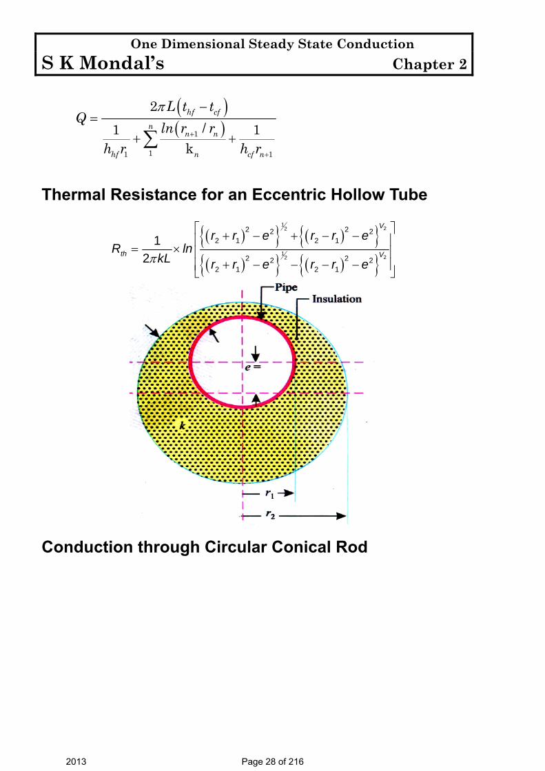
Thermal Resistance for an Eccentric Hollow Tube
( ){ } ( ){ }( ){ } ( ){ }π
⎡ ⎤+ − + − −⎢ ⎥= × ⎢ ⎥+ − − − −⎢ ⎥⎣ ⎦
122
122
2 22 22 1 2 1
2 22 22 1 2 1
12
V
th V
r r e r r eR ln
kL r r e r r e
Conduction through Circular Conical Rod
2013 Page 28 of 216

One Dimensional Steady State Conduction S K Mondal’s Chapter 2
2 2
1 1
2 2
22
Use4
4x t
x t
dt dtQ kA k c xdx dx
dxQ kc dtx
π
π
= − = −
∴ = −∫ ∫
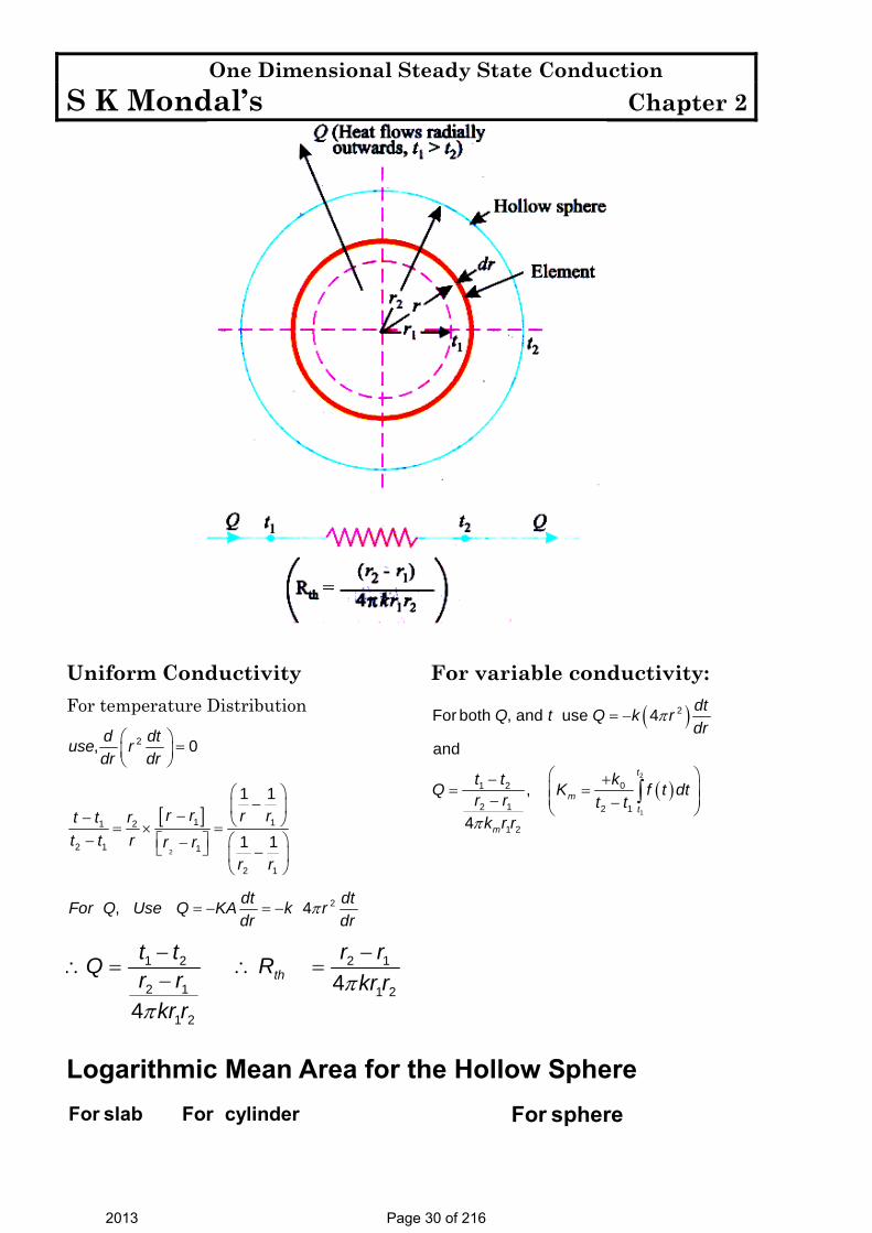
Heat Conduction through a Hollow Sphere
2013 Page 29 of 216
One Dimensional Steady State Conduction S K Mondal’s Chapter 2
Uniform Conductivity For temperature Distribution
⎛ ⎞ =⎜ ⎟⎝ ⎠
2, 0d dtuse rdr dr
[ ]⎛ ⎞
−⎜ ⎟−− ⎝ ⎠= × =− ⎡ ⎤ ⎛ ⎞−⎣ ⎦ −⎜ ⎟
⎝ ⎠2
1 11 2
2 1 1
2 1
1 1
1 1r r r rt t r
t t r r rr r
π= − = − 2, 4dt dtFor Q Use Q KA k rdr dr
ππ
− −∴ = ∴ =
−1 2 2 1
2 1 1 2
1 2
44
tht t r rQ Rr r kr r
kr r
For variable conductivity:
( )
( )
π
π
= −
⎛ ⎞+−= =⎜ ⎟⎜ ⎟− −⎝ ⎠
∫2
1
2
01 2
2 1 2 1
1 2
For both , and use 4
and
,
4
t
mt
m
dtQ t Q k rdr
kt tQ K f t dtr r t t
k r r
Logarithmic Mean Area for the Hollow Sphere
For slab For cylinder For sphere
2013 Page 30 of 216
One Dimensional Steady State Conduction S K Mondal’s Chapter 2
Heat
Conditi
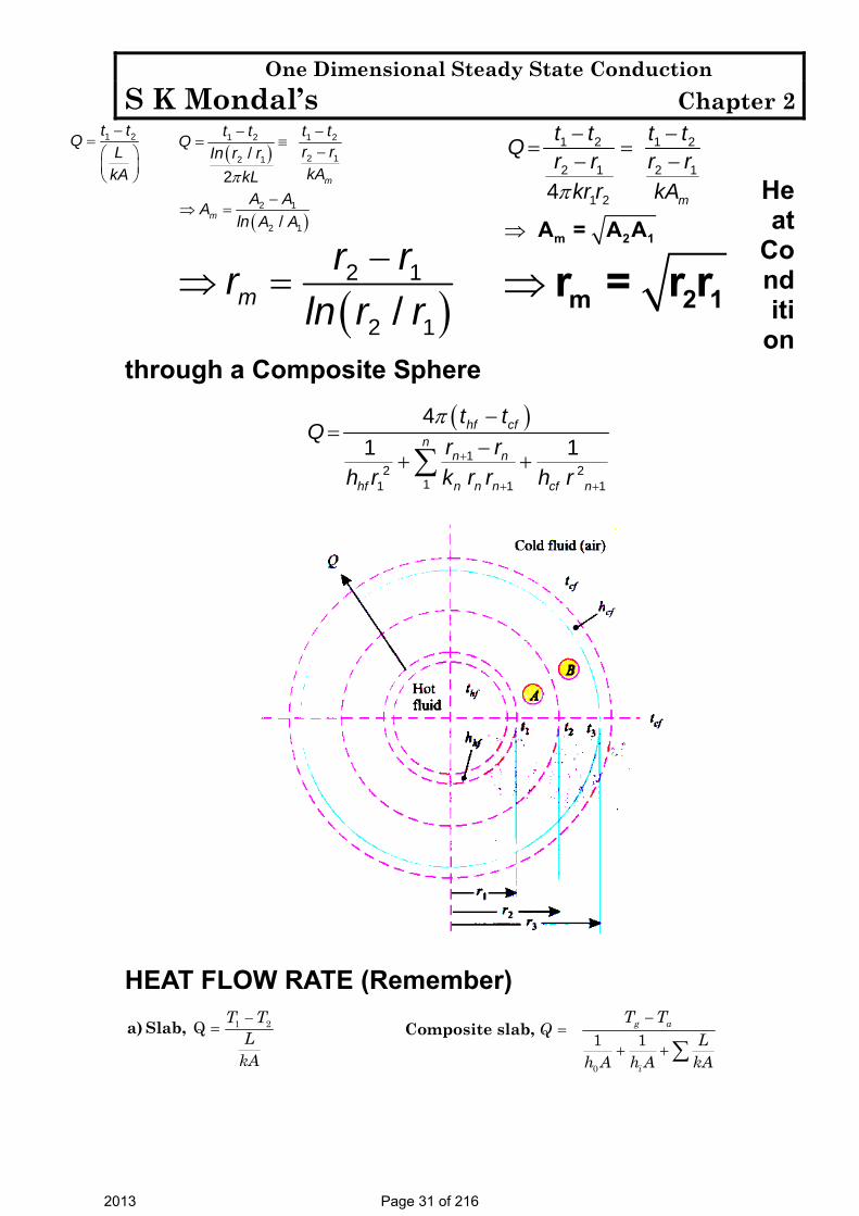
on through a Composite Sphere
( )π
+
+ +
−=
−+ +∑ 1
2 21 11 1
41 1
hf cfn
n n
n n nhf cf n
t tQ
r rk r rh r h r
HEAT FLOW RATE (Remember)
1 2 Q T TL
kA
−=a) Slab,
0
1 1g a
i
T TQ L
h A h A kA
−=
+ +∑Composite slab,
−=⎛ ⎞⎜ ⎟⎝ ⎠
1 2t tQL
kA
( )
( )
π
− −= ≡
−
−⇒ =
1 2 1 2
2 12 1
2 1
2 1
/2
/
m
m
t t t tQr rIn r rkAkL
A AAln A A
( )−
⇒ = 2 1
2 1/mr rr
ln r r
π
− −= =
− −
⇒
1 2 1 2
2 1 2 1
1 24 m
t t t tQ r r r rkr r kA
m 2 1A = A A
⇒ m 2 1r = r r
2013 Page 31 of 216

One Dimensional Steady State Conduction S K Mondal’s Chapter 2
( )1 2
2
1
2,
ln
L T TQ
rr
k
π −=
⎧ ⎫⎛ ⎞⎪ ⎪⎜ ⎟⎪ ⎪⎝ ⎠⎨ ⎬⎪ ⎪⎪ ⎪⎩ ⎭
b) Cylinder ( )1
1 0 1
2;
ln1 1
g a
n
n
i n n
L T TQ
rr
h r h r k
π
+
+
−=
⎛ ⎞⎜ ⎟⎝ ⎠+ +∑
Composite cylinder,
2 1
2
1
lnm
A AAAA
−=
⎛ ⎞⎜ ⎟⎝ ⎠
( )1 2
2 1
2 1
4 T TQ
r rkr r
π −=
⎧ ⎫−⎨ ⎬⎩ ⎭
c) Sphere, ( )1
2 211 0 1
4;1 1
g a
n n
n n ni n
T TQ r r
k r rh r h r
π
+
++
−=
−+ +∑
Composite sphere,
1 2mA A A=
2013 Page 32 of 216

One Dimensional Steady State Conduction S K Mondal’s Chapter 2
OBJECTIVE QUESTIONS (GATE, IES, IAS)
Previous 20-Years GATE Questions
General Heat Conduction Equation in Cartesian Coordinates GATE-1. In a case of one dimensional heat conduction in a medium with
constant properties, T is the temperature at position x, at time t. Then Tt
∂∂
is proportional to: [GATE-2005]
2 2
2(a) (b) (c) (d)∂ ∂ ∂∂ ∂ ∂ ∂
T T T Tx x x t x
General Heat Conduction Equation in Spherical Coordinates GATE-2. One dimensional unsteady state heat transfer equation for a sphere
with heat generation at the rate of 'q' can be written as [GATE-2004]
(a) 1 1T q Trr r r k tα∂ ∂ ∂⎛ ⎞ + =⎜ ⎟∂ ∂ ∂⎝ ⎠
(b) 22
1 1T qrr r k tr α∂ ∂ ∂⎛ ⎞ + =⎜ ⎟∂ ∂ ∂⎝ ⎠
(c) 2
21T q T
k tr α∂ ∂
+ =∂∂
(d) ( )2
21q TrT
k tr α∂ ∂
+ + =∂∂
Heat Conduction through a Plane Wall GATE-3. A building has to be maintained at 21°C (dry bulb) and 14.5°C. The
outside temperature is –23°C (dry bulb) and the internal and external surface heat transfer coefficients are 8 W/m2K and 23 W/m2K respectively. If the building wall has a thermal conductivity of 1.2 W/mK, the minimum thickness (in m) of the wall required to prevent condensation is: [GATE-2007]
(a) 0.471 (b) 0.407 (c) 0.321 (d) 0.125 GATE-4. For the three-dimensional object shown in the
figure below, five faces are insulated. The sixth face (PQRS), which is not insulated, interacts thermally with the ambient, with a convective heat transfer coefficient of 10 W /m2.K. The ambient temperature is 30°C. Heat is uniformly generated inside the object at the rate of 100 W/m3. Assuming the face PQRS to be at uniform temperature, its steady state temperature is:
[GATE-2008] (a) 10°C (b) 20°C (c) 30°C (d) 40°C
2013 Page 33 of 216

One Dimensional Steady State Conduction S K Mondal’s Chapter 2
Heat Conduction through a Composite Wall GATE-5. Consider steady-state heat
conduction across the thickness in a plane composite wall (as shown in the figure) exposed to convection conditions on both sides.
Given: hi = 20 W/m2K; ho = 50 W/m2K; . 20iT C∞ = ° ; . 2oT C∞ = − ° ; k1 = 20 W/mK; k2 = 50 W/mK; L1 = 0.30 m and L2 = 0.15 m. Assuming negligible contact resistance between the wall surfaces, the interface temperature, T (in °C), of the two walls will be:
[GATE-2009]
(a) – 0.50 (b) 2.75 (c) 3.75 (d) 4.50 GATE-6. In a composite slab, the temperature
at the interface (Tinter) between two materials is equal to the average of the temperatures at the two ends. Assuming steady one-dimensional heat conduction, which of the following statements is true about the respective thermal conductivities?
[GATE-2006]
(a) 2k1 = k2 (b) k1 = k2 (c) 2k1 = 3k2 (d) k1 = 2k2
GATE-7. Heat flows through a
composite slab, as shown below. The depth of the slab is 1 m. The k values are in W/mK. the overall thermal resistance in K/W is:
(a) 17. (b) 21.9 (c) 28.6 (d) 39.2
[GATE-2005]
2013 Page 34 of 216

One Dimensional Steady State Conduction S K Mondal’s Chapter 2
GATE-8. The temperature variation under steady heat conduction across a composite slab of two materials with thermal conductivities K1 and K2 is shown in figure. Then, which one of the following statements holds?
1 2 1 2
1 1 2
(a) (b)(c) 0 (d)
> == <
K K K KK K K
[GATE-1998]
Heat Conduction through a Composite Cylinder GATE-9. A stainless steel tube (ks = 19 W/mK) of 2 cm ID and 5 cm OD is
insulated with 3 cm thick asbestos (ka = 0.2 W/mK). If the temperature difference between the innermost and outermost surfaces is 600°C, the heat transfer rate per unit length is: [GATE-2004]
(a) 0.94 W/m (b) 9.44 W/m (c) 944.72 W/m (d) 9447.21 W/m GATE-10. Two insulating materials of thermal conductivity K and 2K are
available for lagging a pipe carrying a hot fluid. If the radial thickness of each material is the same. [GATE-1994]
(a) Material with higher thermal conductivity should be used for the inner layer and one with lower thermal conductivity for the outer.
(b) Material with lower thermal conductivity should be used for the inner layer and one with higher thermal conductivity for the outer.
(c) It is immaterial in which sequence the insulating materials are used. (d) It is not possible to judge unless numerical values of dimensions are given.
Previous 20-Years IES Questions
Heat Conduction through a Plane Wall IES-1. A wall of thickness 0.6 m has width has a normal area 1.5 m2 and is
made up of material of thermal conductivity 0.4 W/mK. The temperatures on the two sides are 800°C. What is the thermal resistance of the wall? [IES-2006; 2007]
(a) 1 W/K (b) 1.8 W/K (c) 1 K/W (d) 1.8 K/W IES-2. Two walls of same thickness and cross sectional area have thermal
conductivities in the ratio 1 : 2. If same temperature difference is maintained across the two faces of both the walls, what is the ratio of heat flow Q1/Q2? [IES-2008]
(a) ½ (b) 1 (c) 2 (d) 4
2013 Page 35 of 216

One Dimensional Steady State Conduction S K Mondal’s Chapter 2
IES-3. A composite wall of a furnace has 2 layers of equal thickness having thermal conductivities in the ratio of 3 : 2. What is the ratio of the temperature drop across the two layers? [IES-2008]
(a) 2:3 (b) 3: 2 (c) 1: 2 (d) loge2: loge3 IES-4.
A wall as shown above is made up of two layers (A) and (B). The
temperatures are also shown in the sketch. The ratio of thermal
conductivity of two layers is 2.A
B
kk
= [IES-2008]
What is the ratio of thickness of two layers? (a) 0·105 (b) 0·213 (c) 0·555 (d) 0·840 IES-5. Heat is conducted through a 10 cm thick wall at the rate of 30 W/m2
when the temperature difference across the wall is 10oC. What is the thermal conductivity of the wall? [IES-2005]
(a) 0.03 W/mK (b) 0.3 W/mK (c) 3.0 W/mK (d) 30.0 W/mK IES-6. A 0.5 m thick plane wall has its two surfaces kept at 300°C and 200°C.
Thermal conductivity of the wall varies linearly with temperature and its values at 300°C and 200°C are 25 W/mK and 15W/mK respectively. Then the steady heat flux through the wall is: [IES-2002]
(a) 8 kW/m2 (b) 5 kW/m2 (c) 4kW/m2 (d) 3 kW/m2 IES-7. 6.0 kJ of conduction heat transfer has to take place in 10 minutes from
one end to other end of a metallic cylinder of 10 cm2 cross-sectional area, length 1 meter and thermal conductivity as 100 W/mK. What is the temperature difference between the two ends of the cylindrical bar?
[IES-2005] (a) 80°C (b) 100°C (c) 120°C (d) 160°C IES-8. A steel plate of thermal conductivity 50 W/m-K and thickness 10 cm
passes a heat flux by conduction of 25 kW/m2. If the temperature of the hot surface of the plate is 100°C, then what is the temperature of the cooler side of the plate? [IES-2009]
(a) 30°C (b) 40°C (c) 50°C (d) 60°C
2013 Page 36 of 216
One Dimensional Steady State Conduction S K Mondal’s Chapter 2
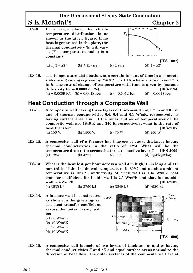
IES-9. In a large plate, the steady temperature distribution is as shown in the given figure. If no heat is generated in the plate, the thermal conductivity 'k' will vary as (T is temperature and α is a constant)
[IES-1997] (a) (1 )ok Tα+ (b) (1 )ok Tα− (c) 1 Tα+ (d) 1 Tα− IES-10. The temperature distribution, at a certain instant of time in a concrete
slab during curing is given by T = 3x2 + 3x + 16, where x is in cm and T is in K. The rate of change of temperature with time is given by (assume diffusivity to be 0.0003 cm2/s). [IES-1994]
(a) + 0.0009 K/s (b) + 0.0048 K/s (c) – 0.0012 K/s (d) – 0.0018 K/s
Heat Conduction through a Composite Wall IES-11. A composite wall having three layers of thickness 0.3 m, 0.2 m and 0.1 m
and of thermal conductivities 0.6, 0.4 and 0.1 W/mK, respectively, is having surface area 1 m2. If the inner and outer temperatures of the composite wall are 1840 K and 340 K, respectively, what is the rate of heat transfer? [IES-2007]
(a) 150 W (b) 1500 W (c) 75 W (d) 750 W IES-12. A composite wall of a furnace has 3 layers of equal thickness having
thermal conductivities in the ratio of 1:2:4. What will be the temperature drop ratio across the three respective layers? [IES-2009]
(a) 1:2:4 (b) 4:2:1 (c) 1:1:1 (d) log4:log2:log1 IES-13. What is the heat lost per hour across a wall 4 m high, 10 m long and 115
mm thick, if the inside wall temperature is 30°C and outside ambient temperature is 10°C? Conductivity of brick wall is 1.15 W/mK, heat transfer coefficient for inside wall is 2.5 W/m2K and that for outside wall is 4 W/m2K. [IES-2009]
(a) 3635 kJ (b) 3750 kJ (e) 3840 kJ (d) 3920 kJ IES-14. A furnace wall is constructed
as shown in the given figure. The heat transfer coefficient across the outer casing will be:
(a) 80 W/m2K (b) 40 W/m2K (c) 20 W/m2K (d) 10 W/m2K
[IES-1999] IES-15. A composite wall is made of two layers of thickness σ1 and σ2 having
thermal conductivities K and 2K and equal surface areas normal to the direction of heat flow. The outer surfaces of the composite wall are at
2013 Page 37 of 216
One Dimensional Steady State Conduction S K Mondal’s Chapter 2
100°C and 200°C respectively. The heat transfer takes place only by conduction and the required surface temperature at the junction is 150°C [IES-2004]
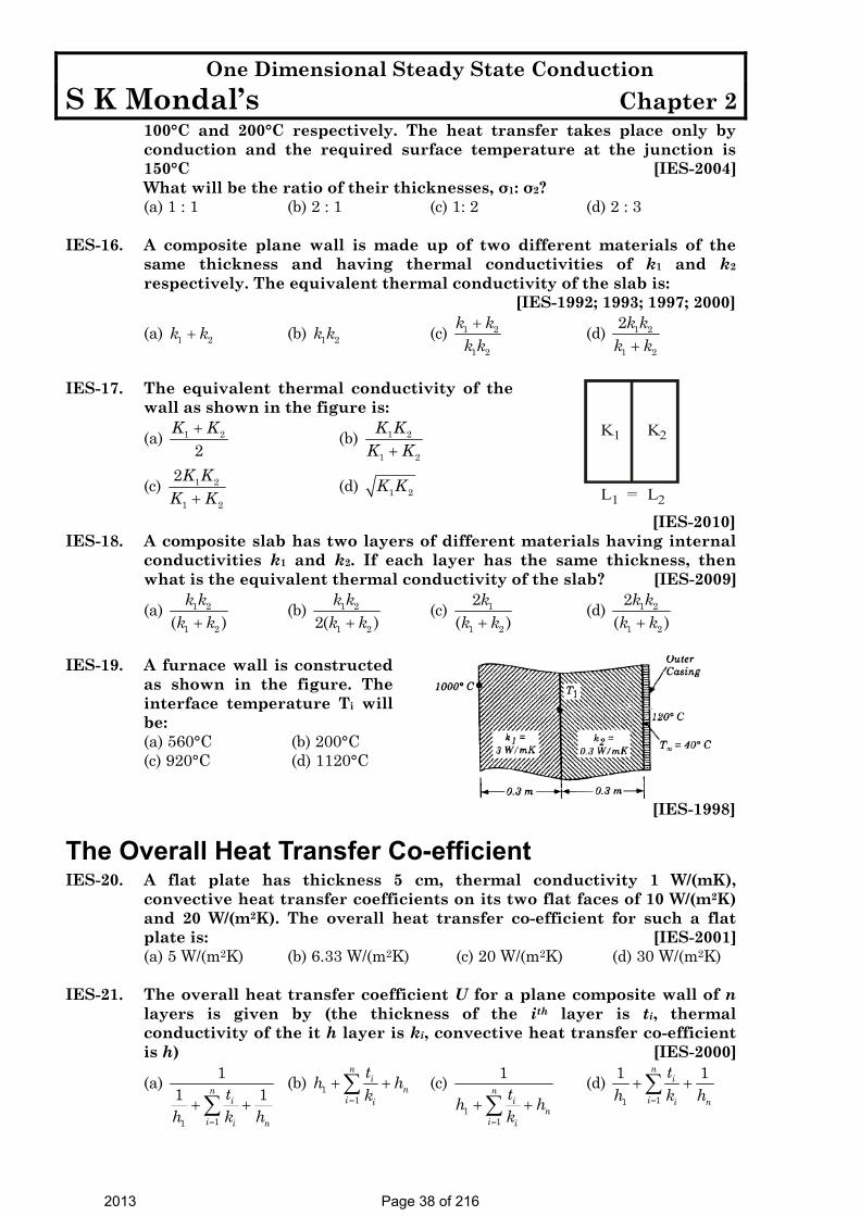
What will be the ratio of their thicknesses, σ1: σ2? (a) 1 : 1 (b) 2 : 1 (c) 1: 2 (d) 2 : 3 IES-16. A composite plane wall is made up of two different materials of the
same thickness and having thermal conductivities of k1 and k2 respectively. The equivalent thermal conductivity of the slab is:
[IES-1992; 1993; 1997; 2000]
(a) 1 2k k+ (b) 1 2k k (c) 1 2
1 2
k kk k+ (d) 1 2
1 2
2k kk k+
IES-17. The equivalent thermal conductivity of the
wall as shown in the figure is:
(a) 1 2
2K K+ (b) 1 2
1 2
K KK K+
(c) 1 2
1 2
2K KK K+
(d) 1 2K K
K1
L1
K2
L2= [IES-2010]
IES-18. A composite slab has two layers of different materials having internal conductivities k1 and k2. If each layer has the same thickness, then what is the equivalent thermal conductivity of the slab? [IES-2009]
(a) 1 2
1 2( )k k
k k+ (b) 1 2
1 22( )k kk k+
(c) 1
1 2
2( )
kk k+
(d) 1 2
1 2
2( )
k kk k+
IES-19. A furnace wall is constructed
as shown in the figure. The interface temperature Ti will be:
(a) 560°C (b) 200°C (c) 920°C (d) 1120°C
[IES-1998]
The Overall Heat Transfer Co-efficient IES-20. A flat plate has thickness 5 cm, thermal conductivity 1 W/(mK),
convective heat transfer coefficients on its two flat faces of 10 W/(m2K) and 20 W/(m2K). The overall heat transfer co-efficient for such a flat plate is: [IES-2001]
(a) 5 W/(m2K) (b) 6.33 W/(m2K) (c) 20 W/(m2K) (d) 30 W/(m2K) IES-21. The overall heat transfer coefficient U for a plane composite wall of n
layers is given by (the thickness of the ith layer is ti, thermal conductivity of the it h layer is ki, convective heat transfer co-efficient is h) [IES-2000]
(a)
11
11 1n
i
i i n
th k h=
+ +∑ (b) 1
1
ni
ni i
th hk=
+ +∑ (c) 1
1
1n
in
i i
th hk=
+ +∑ (d)
11
1 1ni
i i n
th k h=
+ +∑
2013 Page 38 of 216

One Dimensional Steady State Conduction S K Mondal’s Chapter 2
IES-22. A steel plate of thickness 5 cm
and thermal conductivity 20 W/mK is subjected to a uniform heat flux of 800 W/m2 on one surface 'A' and transfers heat by convection with a heat transfer co-efficient of 80 W/m2K from the other surface 'B' into ambient air Tα of 25°C. The temperature of the surface 'B' transferring heat by convection is:
[IES-1999] (a) 25°C (b) 35°C (c) 45°C (d) 55°C
Logarithmic Mean Area for the Hollow Cylinder IES-23. The heat flow equation through a cylinder of inner radius “r1” and
outer radius “r2” is desired in the same form as that for heat flow through a plane wall. The equivalent area Am is given by: [IES-1999]
(a) 1 2
2
1
loge
A AAA
+⎛ ⎞⎜ ⎟⎝ ⎠
(b) 1 2
2
1
2 loge
A AAA
+⎛ ⎞⎜ ⎟⎝ ⎠
(c) 2 1
2
1
2 loge
A AAA
−⎛ ⎞⎜ ⎟⎝ ⎠
(d) 2 1
2
1
loge
A AAA
−⎛ ⎞⎜ ⎟⎝ ⎠
IES-24. The outer surface of a long cylinder is maintained at constant
temperature. The cylinder does not have any heat source. [IES-2000] The temperature in the cylinder will: (a) Increase linearly with radius (b) Decrease linearly with radius (c) Be independent of radius (d) Vary logarithmically with radius
Heat Conduction through a Composite Cylinder IES-25. The heat flow through a composite cylinder is given by the equation:
(symbols have the usual meaning) [IES-1995]
(a) 1 1
1
1
( )21 log
nn n
ne
n n n
T T LQr
K r
π+
=+
=
−=
⎛ ⎞⎜ ⎟⎝ ⎠
∑ (b) 1 1
1
1 1
4 ( )nn n
n n
n n n n
T TQr rK r r
π +
=+
= +
−=
⎡ ⎤−⎢ ⎥⎣ ⎦
∑
(c) 1 1
1
1n
n nn
n n
T TQL
A K
+
=
=
−=
⎛ ⎞⎜ ⎟⎝ ⎠
∑ (d) 1 2
2
1
log
2
e
T TQrr
KLπ
−=
⎛ ⎞⎜ ⎟⎝ ⎠
Heat Conduction through a Hollow Sphere IES-26. For conduction through a spherical wall with constant thermal
conductivity and with inner side temperature greater than outer wall temperature, (one dimensional heat transfer), what is the type of temperature distribution? [IES-2007]
(a) Linear (b) Parabolic (c) Hyperbolic (d) None of the above
2013 Page 39 of 216

One Dimensional Steady State Conduction S K Mondal’s Chapter 2
IES-27. What is the expression for the thermal conduction resistance to heat transfer through a hollow sphere of inner radius r1 and outer radius r2, and thermal conductivity k? [IES-2007]
(a) (k
rrrrπ4
) 2112 − (b) (21
12 )4rr
rrk −π (c) 21
12
4 rkrrr
π− (d) None of the above
IES-28. A solid sphere and a hollow sphere of the same material and size are
heated to the same temperature and allowed to cool in the same surroundings. If the temperature difference between the body and that of the surroundings is T, then [IES-1992]
(a) Both spheres will cool at the same rate for small values of T (b) Both spheres will cool at the same reactor small values of T (c) The hollow sphere will cool at a faster rate for all the values of T (d) The solid sphere will cool a faster rate for all the values of T
Logarithmic Mean Area for the Hollow Sphere IES-29. What will be the geometric radius of heat transfer for a hollow sphere
of inner and outer radii r1 and r2? [IES-2004] (a) 1 2r r (b) 2 1r r (c) 2 1/r r (d) ( )2 1r r−
Heat Condition through a Composite Sphere IES-30. A composite hollow sphere with steady internal heating is made of 2
layers of materials of equal thickness with thermal conductivities in the ratio of 1 : 2 for inner to outer layers. Ratio of inside to outside diameter is 0.8. What is ratio of temperature drop across the inner and outer layers? [IES-2005]
(a) 0.4 (b) 1.6 (c) 2 ln (0.8) (d) 2.5 IES-31. Match List-I (Governing Equations of Heat Transfer) with List-II
(Specific Cases of Heat Transfer) and select the correct answer using the code given below: [IES-2005]
List-I List-II
A. 2
2
2 0d T dTdr r dr
+ = 1. Pin fin 1–D case
B. 2
2
1T Tx tα
∂ ∂=
∂ ∂ 2. 1–D conduction in cylinder
C. 2
2
1 0d T dTdr r dr
+ = 3. 1–D conduction in sphere
D. 2
22 0d m
dxθ θ− = 4. Plane slab
(Symbols have their usual meaning) Codes: A B C D A B C D (a) 2 4 3 1 (b) 3 1 2 4 (c) 2 1 3 4 (d) 3 4 2 1
2013 Page 40 of 216
One Dimensional Steady State Conduction S K Mondal’s Chapter 2
Previous 20-Years IAS Questions
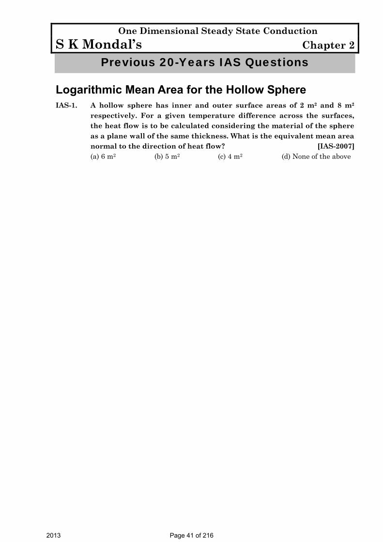
Logarithmic Mean Area for the Hollow Sphere IAS-1. A hollow sphere has inner and outer surface areas of 2 m2 and 8 m2
respectively. For a given temperature difference across the surfaces, the heat flow is to be calculated considering the material of the sphere as a plane wall of the same thickness. What is the equivalent mean area normal to the direction of heat flow? [IAS-2007]
(a) 6 m2 (b) 5 m2 (c) 4 m2 (d) None of the above
2013 Page 41 of 216

One Dimensional Steady State Conduction S K Mondal’s Chapter 2
Answers with Explanation (Objective)
Previous 20-Years GATE Answers
GATE-1. Ans. (d) One dimensional, Unsteady state, without internal heat generation
2
21T T
tx α∂ ∂
=∂∂
GATE-2. Ans. (b) GATE-3. Ans. (b) GATE-4. Ans. (d)
GATE-5. Ans. (c) 20 2 2501 0.30 0.15 120 20 50 50
Q += =
+ + +
20or 250 or 3.75 C1 0.3020 20
T T−= = °
+
GATE-6. Ans. (d) 1 2int 2er
T TT +=
1 2 1 2
1 2
1 2
1 2
2 2Heat flow must be same( )2
or 2
T T T TT TQ k A k
b bk k
+ +⎛ ⎞ ⎛ ⎞− −⎜ ⎟ ⎜ ⎟⎝ ⎠ ⎝ ⎠= − = −
=
GATE-7. Ans. (c) Electrical circuit
Use this formula
1
1 1
2 3
2 2 3 3
11 1eq
LRK A
L LK A K A
= ++
GATE-8. Ans. (d) Lower the thermal conductivity greater will be the slope of the temperature distribution curve (The curve shown here is temperature distribution curve).
GATE-9. Ans. (c) ( ) ( )
32
1 2
2 2 1 600944.72W/m
0.025 0.055ln lnln ln 0.01 0.02519 0.2
i f
A B
L t tQ
rrr r
K K
π π− × ×= = =
⎛ ⎞ ⎛ ⎞ ⎛ ⎞ ⎛ ⎞⎜ ⎟ ⎜ ⎟⎜ ⎟ ⎜ ⎟ ⎝ ⎠ ⎝ ⎠⎝ ⎠ ⎝ ⎠ ++
GATE-10. Ans. (b)
2013 Page 42 of 216

One Dimensional Steady State Conduction S K Mondal’s Chapter 2
Previous 20-Years IES Answers
IES-1. Ans. (c) R = KAL =
5.14.06.0×
= 1 WK
IES-2. Ans. (a) 1
1
22
dTK AQ dxdTQ K Adx
=
IES-3. Ans. (a) ( ) ( )1 1 2 2T TK A K Adx dxΔ Δ
=
( ) ( ) 1 21 1 2 2
2 1
T 2T TT 3
KK KK
Δ⇒ Δ = Δ ⇒ = =
Δ
IES-4. Ans. (b) ( ) ( )1325 1200 1200 25A B
A B
k kx x− −
=
2 125 0.2127 0.2131175
A
B
xx
×⇒ = =
IES-5. Ans. (b) 30or 0.3 W/mK
100.1
dT qq K kdTdxdx
= = = =⎛ ⎞ ⎛ ⎞⎜ ⎟ ⎜ ⎟⎝ ⎠ ⎝ ⎠
IES-6. Ans. (c) 25 15 202averageK +
= = [As it is varying linearly]
IES-7. Ans. (b) dTQ kAdx
∴ =
6000 10or 100
10 60 10000 1or 100 C
dT
dT
⎛ ⎞= × ×⎜ ⎟× ⎝ ⎠= °
IES-8. Ans. (b) dT Q dTQ KA Kdx A dx
= − ⇒ = −
( )( )
232
10025 10 50 50 C
0.1T
T−
⇒ × = × ⇒ = °
IES-9. Ans. (a) For the shape of temperature profile.
K = (1 )ok Tα+
IES-10. Ans. (d) Use
2
21d T dT
ddx α τ= relation.
Temperature distribution is T = 3x2 + 3x + 16, dTdx
= 6x + 3°K/cm2
IES-11. Ans. (d) 1840 340 750 W0.3 0.2 0.10.6 1 0.4 1 0.1 1
f it tQ L
KA
− −= = =
+ +× × ×∑
IES-12. Ans. (b) 1 1 2 2 3 3K T K T K T QΔ = Δ = Δ =
2013 Page 43 of 216

One Dimensional Steady State Conduction S K Mondal’s Chapter 2
1 2 31 2 3
1 1 1: : : : : : 4 : 2 :11 2 4
Q Q QT T TK K K
⇒ Δ Δ Δ = = =
IES-13. Ans. (c) ( ) ( )1 2
1 1 2
30 10Heat Loss / sec 1 1 1 0.115 1 1
40 1.15 2.5 4
T Tx
h A K A h A
− −= =
⎛ ⎞+ + + +⎜ ⎟⎝ ⎠
( )
40 20 3840.0001066.66 kJ/sec kJ/hour 3840 kJ/hour0.1 0.4 0.25 1000
×= = = =
+ +
IES-14. Ans. (d) For two insulating layers,
1 2
1 2
1 2
1000 120 880 8000.3 0.3 1.13 0.3
t tQx xA
k k
− −= = = =Δ Δ
++
2120 40 1 800For outer casing, , or 800 , and 10 W/m K1 / 80
Q hA h h
−= × = =
IES-15. Ans. (c) AB BCQ Q=
1 2
1
2
200 150 150 100or . . 2
50 1or2 50 2
k A kAδ δ
δδ
⎛ ⎞ ⎛ ⎞− −− = −⎜ ⎟ ⎜ ⎟
⎝ ⎠ ⎝ ⎠
= =×
IES-16. Ans. (d) The common mistake student do is they take length of equivalent
conductor as L but it must be 2L. Then equate the thermal resistance of them.
IES-17. Ans. (c) 1 2
1 1 1 12eqK K K⎛ ⎞
= +⎜ ⎟⎝ ⎠
1 2
1 2
2eq
K KKK K
=+
K1
L1
K2
L2= IES-18. Ans. (d) Same questions [IES-1997] and [IES-2000]
IES-19. Ans. (c) 1 2
1 2
1 2
1000 120For two insulating layers, 8000.3 0.33 0.3
t tQx xA
k k
− −= = =Δ Δ
++
1000Considering first layer, 800, or 1000 80 920°C0.33
ii
TQ TA
−= = = − =
2013 Page 44 of 216

One Dimensional Steady State Conduction S K Mondal’s Chapter 2
IES-20. Ans. (a) IES-21. Ans. (a)
IES-22. Ans. (b) 258001 / 1 / 80B o Bt t t
h− −
= =
IES-23. Ans. (d) IES-24. Ans. (d) IES-25. Ans. (a)
IES-26. Ans. (c) Temp distribution would be 12
1
tttt−− =
12
1
11
11
rr
rr
−
−
IES-27. Ans. (c) Resistance (R) = )(4 21
12
rrkrr
π− ∵ Q =
RtΔ =
⎟⎟⎠
⎞⎜⎜⎝
⎛ −−
21
12
21 )(4
rrrr
ttkπ
IES-28. Ans. (c) IES-29. Ans. (a) IES-30. Ans. (d) 20.8 andi o ir r r r t r t= = + = −
( )
0
22
1.25 1.1252
0.8 10.92 0.9
4 4 2
i oi o
i ii
o oo
i o
i o
i o
r rr r r r
r rr r
r r rr rr
t t t tQ r r r rkrr k rrπ π
+⇒ = + ⇒ =
+⇒ = =
+⇒ = = ⇒ =
− −∴ = =
− −
IES-31. Ans. (d)
Previous 20-Years IAS Answers
IAS-1. Ans. (c) 21 2 2 8 4 mmA A A= = × =
2013 Page 45 of 216

Critical Thickness of Insulation S K Mondal’s Chapter 3
3. Critical Thickness of Insulation
Theory at a Glance (For IES, GATE, PSU)
Critical Thickness of Insulation [IES-05] • Note: When the total thermal resistance is made of conductive thermal
resistance (Rcond.) and convective thermal resistance (Rconv.), the addition
of insulation in some cases, May reduces the convective thermal
resistance due to increase in surface area, as in the case of cylinder and
sphere, and the total thermal resistance may actually decreases resulting
in increased heat flow.
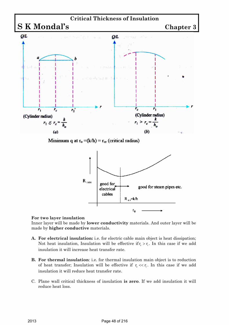
Critical thickness: the thickness up to which heat flow increases and after which heat
flow decreases is termed as critical thickness.
Critical thickness = (rc – r1)
For Cylinder: c
kr =h
For Sphere: c
2kr =h
Common Error: In the examination hall student’s often get confused about hk
or kh
A little consideration can remove this problem, Unit of kh
is =2
//
W mK mW m K
2013 Page 46 of 216

Critical Thickness of Insulation S K Mondal’s Chapter 3
( )( )
( )
π• −
−=
+
⇒ +
1
2 1
2
2 1max
2
2/ 1
/ 1For
is minimum
airL t tQ
In r rk hr
In r rQ
k hr
For cylinder
( )2 1
2 2
22 2
/ 1 0
1 1 1 1 0
⎡ ⎤∴ + =⎢ ⎥
⎣ ⎦⎛ ⎞
∴ × + × − = ∴⎜ ⎟⎝ ⎠
2kr =h
In r rddr k hr
k r h r
Critical Thickness of Insulation for Cylinder
( )π −• =
−+
⎛ ⎞−∴ + =⎜ ⎟
⎝ ⎠
1
2 12
1 2 2
2 12
2 1 2 2
4,
1
1 0
airt tQ
r rkr r hr
r rd givesdr kr r hr
2
For Sphere
2kr =h
(i) For cylindrical bodied with 1 ,cr r< the heat transfer increase by adding
insulation till 2 1r r= as shown in Figure below (a). If insulation thickness is further increased, the rate of heat loss will decrease from this peak value, but until a certain amount of insulation denoted by 2 'r at b is added, the heat loss rate is still greater for the solid cylinder. This happens when 1r is small and cr is large, viz., the thermal conductivity of the insulation k is high (poor insulation material) and hο is low. A practical application would be the insulation of electric cables which should be a good insulator for current but poor for heat.
(ii) For cylindrical bodies with 1 ,cr r> the heat transfer decrease by adding insulation (Figure below) this happens when 1r is large and 2r is small, viz., a good insulation material is used with low k and hο is high. In stream and refrigeration pipes heat insulation is the main objective. For insulation to be properly effective in restricting heat transmission, the outer radius must be greater than or equal to the critical radius.
2013 Page 47 of 216
Critical Thickness of Insulation S K Mondal’s Chapter 3
For two layer insulation Inner layer will be made by lower conductivity materials. And outer layer will be made by higher conductive materials. A. For electrical insulation: i.e. for electric cable main object is heat dissipation;
Not heat insulation, Insulation will be effective if 1rc r> . In this case if we add insulation it will increase heat transfer rate.
B. For thermal insulation: i.e. for thermal insulation main object is to reduction
of heat transfer; Insulation will be effective if 1rc r<< . In this case if we add insulation it will reduce heat transfer rate.
C. Plane wall critical thickness of insulation is zero. If we add insulation it will
reduce heat loss.
2013 Page 48 of 216

Critical Thickness of Insulation S K Mondal’s Chapter 3
Heat Conduction with Internal Heat Generation Volumetric heat generation, ( gq
•
) =W/m3
Unit of gq•
is W/m3 but in some problem we will find that unit is W/m2 . In this case they assume that the thickness of the material is one metre. If the thickness is L
meter then volumetric heat generation is ( gq•
) W/m3 but total heat generation is •
gq L W/m2 surface area.
Plane Wall with Uniform Heat Generation Equation: For a small strip of dx (shown in figure below)
( )
( )
( )
( )
( )2
2
That given
0
x g x dx
x g x x
g x
g x
g
Q Q Q
dQ Q Q Q dxdx
dQ Q dxdx
dq Adx Q dxdx
qd t ikdx
+
•
•
+ =
∴ + = +
∴ =
∴ =
+ = −
For any problem integrate this Equation and use boundary condition
( )
( )
1
2
1 2or2
g
g
qdt x c iidx k
q xt c x c iii
k
•
•
+ = −
+ = + −
Use boundary condition and find 1 2& C C than proceed.
00,
For xat x
x
Lx L
dtQ kAdx
dtQ kAdxdtQ kAdx
=
=
⎛ ⎞= − ⎜ ⎟⎝ ⎠
⎛ ⎞∴ = − ⎜ ⎟⎝ ⎠
⎛ ⎞= − ⎜ ⎟⎝ ⎠
Heat Conduction with Internal Heat Generation
2013 Page 49 of 216

Critical Thickness of Insulation S K Mondal’s Chapter 3
( )•
wallMaximum temperature, If both wall temperature,tgq 2
max wall
For objective :
Lt = + t
8k
Current Carrying Electrical Conductor ρ
ρ ρ
•
•
= = =
∴ = × = ⋅
2 2
22
2
gg
g
LQ q AL I R IA
Iq JA
( )= = 2current density amp./mIJA
Where, I = Current flowing in the conductor, R = Electrical resistance, ρ = Specific resistance of resistivity, L = Length of the conductor, and A = Area of cross-section of the conductor.
If One Surface Insulated Then will be 0
i.e. use end conditionsx o
dtdx =
⎛ ⎞ =⎜ ⎟⎝ ⎠
( )
( )0
2
2
0
At ,Maxmimum temperature will occuredat 0,But start from that first Equation ,
0
x
L
g
dtidx
ii x L t t
x
qd tkdx
=
•
⎛ ⎞ =⎜ ⎟⎝ ⎠
= =
=
+ =
If one surface insulated
2013 Page 50 of 216

Critical Thickness of Insulation S K Mondal’s Chapter 3
Maximum Temperature (Remember)
( )2
max w
2
max
2
max
For plate both wall temperature t ; at centreof plate,8 2
For cylinder,at centre, ( 0)4
For sphere,at centre,( 0)6
gw
gw
gw
q L Lt t xk
q Rt t r
k
q Rt t r
k
•
•
•
= + =
= + =
= + =
Starting Formula (Remember) 2
2
2 2
0 For Plate
. 0 For cylinder
. 0 For Sphere
g
g
g
qd tkdx
qd dtr rdr dr k
qd dtr rdr dr k
•
•
•
+ =
⎛ ⎞ + =⎜ ⎟⎝ ⎠
⎛ ⎞ + =⎜ ⎟⎝ ⎠
Temperature Distribution – with Heat Generation (a) For both sphere and cylinder
2
max
1w
w
t t rt t R
⎡ ⎤− ⎛ ⎞= −⎢ ⎥⎜ ⎟− ⎝ ⎠⎢ ⎥⎣ ⎦
(b) Without heat generation
( )( )
1
2 1
11
2 1 2 1
1 1
2 1
2 1
( ) For
/( ) For
/1 1
( ) For 1 1
−=
−
−=
−
−−
=− −
plane,
cylinder ,
sphere,
t t xit t L
ln r rt tiit t ln r r
t t r riiit t
r r
2013 Page 51 of 216

Critical Thickness of Insulation S K Mondal’s Chapter 3
Dielectric Heating Dielectric heating is a method of
quickly heating insulating
materials packed between the
plates (of an electric condenser)
to which a high frequency, high
voltage alternating current is
applied.
Dielectric heating
Where ( )1 1θ = −w at t temperature of electrode (1) above surroundings. ( )2 2θ = −w at t temperature of electrode (2) above surroundings.
If we use θ form then it will be easy to find out solution. That so why we are using the following equation in θ form
( )
( )
2
2
2
1 2
1 1 10
21 1
1
21 1
2 1 2
0
.2
Using boundary condition 0, ;
.2
. ... ,2
g
g
w ax
g
g
qdkdx
q x c x ck
dx kA h A t tdx
qh xk k
qh L i at x Lk k
θ
θ
θθ θ
θθ θ
θθ θ θ θ
•
•
=
•
•
+ =
∴ + = +
⎛ ⎞= = − = −⎜ ⎟⎝ ⎠
= + −
∴ = + − = =⎡ ⎤⎣ ⎦∵
(but don’t use it as a boundary condition)
And Heat generated within insulating material = Surface heat loss from both electrode:
2013 Page 52 of 216

Critical Thickness of Insulation S K Mondal’s Chapter 3
Cylinder with Uniform Heat Generation For Solid cylinder one boundary condition
( )0
0
as maximum temperaturer
dtdr =
⎛ ⎞ =⎜ ⎟⎝ ⎠
Solid Cylinder with Heat generation
For Hollow Cylinder with Insulation
1
0r r
dtdr =
⎛ ⎞ =⎜ ⎟⎝ ⎠
2013 Page 53 of 216

Critical Thickness of Insulation S K Mondal’s Chapter 3
Heat Transfer through Piston Crown
( )
2Here heat generating, W/m
2 , 2
that gives, . 0
g
gr g
g r
g
q
dtQ k rb Q q rdrdr
dQ Q drdr
qd dtr rdr dr kb
π π
•
•
•
⎛ ⎞ =⎜ ⎟⎝ ⎠
= − = ×
∴ =
⎛ ⎞ + =⎜ ⎟⎝ ⎠
(Note unit)
Heat transfer through piston crown
Heat conduction with Heat Generation in the Nuclear Cylindrical Fuel Rod Here heat generation rate
•
gq (r)
0
2
1
then use, . 0
gfr
g
rq qR
qd dtr rdr dr k
• •
•
⎡ ⎤⎛ ⎞⎢ ⎥= − ⎜ ⎟⎜ ⎟⎢ ⎥⎝ ⎠⎣ ⎦
⎛ ⎞ + =⎜ ⎟⎝ ⎠
Where, gq = Heat generation rate at radius r. oq = Heat generation rate at the centre
of the rod (r = 0). And frR = Outer radius of the fuel rod.
Nuclear Cylinder Fuel Rod
Nuclear Cylinder Fuel Rod with ‘Cladding’ i.e. Rod covered with protective materials known as ‘Cladding’.
2013 Page 54 of 216

Critical Thickness of Insulation S K Mondal’s Chapter 3
OBJECTIVE QUESTIONS (GATE, IES, IAS)
Previous 20-Years GATE Questions
Critical Thickness of Insulation GATE-1. A steel steam pipe 10 cm inner diameter and 11 cm outer diameter is
covered with insulation having the thermal conductivity of 1 W/mK. If the convective heat transfer coefficient between the surface of insulation and the surrounding air is 8 W / m2K, then critical radius of insulation is: [GATE-2000]
(a) 10 cm (b) 11 cm (c) 12.5 cm (d) 15 cm GATE-2. It is proposed to coat a 1 mm diameter wire with enamel paint (k = 0.1
W/mK) to increase heat transfer with air. If the air side heat transfer coefficient is 100 W/m2K, then optimum thickness of enamel paint should be: [GATE-1999]
(a) 0.25 mm (b) 0.5 mm (c) 1 mm (d) 2 mm GATE-3. For a current wire of 20 mm diameter exposed to air (h = 20 W/m2K),
maximum heat dissipation occurs when thickness of insulation (k = 0.5 W/mK) is: [GATE-1993; 1996]
(a) 20 mm (b) 25 mm (c) 20 mm (d) 10 mm
Heat Conduction with Heat Generation in the Nuclear Cylindrical Fuel Rod GATE-4. Two rods, one of length L and the other of length 2L are made of the
same material and have the same diameter. The two ends of the longer rod are maintained at 100°C. One end of the shorter rod Is maintained at 100°C while the other end is insulated. Both the rods are exposed to the same environment at 40°C. The temperature at the insulated end of the shorter rod is measured to be 55°C. The temperature at the mid-point of the longer rod would be: [GATE-1992]
(a) 40°C (b) 50°C (c) 55°C (d) 100°C
Previous 20-Years IES Questions
Critical Thickness of Insulation IES-1. Upto the critical radius of insulation: [IES-1993; 2005] (a) Added insulation increases heat loss (b) Added insulation decreases heat loss (c) Convection heat loss is less than conduction heat loss (d) Heat flux decreases
IES-2. Upto the critical radius of insulation [IES-2010] (a) Convection heat loss will be less than conduction heat loss (b) Heat flux will decrease
2013 Page 55 of 216

Critical Thickness of Insulation S K Mondal’s Chapter 3
(c) Added insulation will increase heat loss (d) Added insulation will decrease heat loss IES-3. The value of thermal conductivity of thermal insulation applied to a
hollow spherical vessel containing very hot material is 0·5 W/mK. The convective heat transfer coefficient at the outer surface of insulation is 10 W/m2K.
What is the critical radius of the sphere? [IES-2008] (a) 0·1 m (b) 0·2 m (c) 1·0 m (d) 2·0 m IES-4. A hollow pipe of 1 cm outer diameter is to be insulated by thick
cylindrical insulation having thermal conductivity 1 W/mK. The surface heat transfer coefficient on the insulation surface is 5 W/m2K. What is the minimum effective thickness of insulation for causing the reduction in heat leakage from the insulated pipe? [IES-2004]
(a) 10 cm (b) 15 cm (c) 19.5 cm (d) 20 cm IES-5. A metal rod of 2 cm diameter has a conductivity of 40W/mK, which is to
be insulated with an insulating material of conductivity of 0.1 W/m K. If the convective heat transfer coefficient with the ambient atmosphere is 5 W/m2K, the critical thickness of insulation will be: [IES-2001; 2003]
(a) 1 cm (b) 2 cm (c) 7 cm (d) 8 cm IES-6. A copper wire of radius 0.5 mm is insulated with a sheathing of
thickness 1 mm having a thermal conductivity of 0.5 W/m – K. The outside surface convective heat transfer coefficient is 10 W/m2 – K. If the thickness of insulation sheathing is raised by 10 mm, then the electrical current-carrying capacity of the wire will: [IES-2000]
(a) Increase (b) Decrease (c) Remain the same (d) Vary depending upon the
electrical conductivity of the wire IES-7. In current carrying conductors, if the radius of the conductor is less
than the critical radius, then addition of electrical insulation is desirable, as [IES-1995]
(a) It reduces the heat loss from the conductor and thereby enables the conductor to carry a higher current.
(b) It increases the heat loss from the conductor and thereby enables the conductor to carry a higher current.
(c) It increases the thermal resistance of the insulation and thereby enables the conductor to carry a higher current.
(d) It reduces the thermal resistance of the insulation and thereby enables the conductor to carry a higher current.
IES-8. It is desired to increase the heat dissipation rate over the surface of an
electronic device of spherical shape of 5 mm radius exposed to convection with h = 10 W/m2K by encasing it in a spherical sheath of conductivity 0.04 W/mK, For maximum heat flow, the diameter of the sheath should be: [IES-1996]
(a) 18 mm (b) 16 mm (c) 12 mm (d) 8 mm IES-9. What is the critical radius of insulation for a sphere equal to? k = thermal conductivity in W/m-K [IES-2008]
2013 Page 56 of 216

Critical Thickness of Insulation S K Mondal’s Chapter 3
h = heat transfer coefficient in W/m2K (a) 2kh (b) 2k/h (c) k/h (d) 2kh IES-10. Assertion (A): Addition of insulation to the inside surface of a pipe
always reduces heat transfer rate and critical radius concept has no significance. [IES-1995]
Reason (R): If insulation is added to the inside surface, both surface resistance and internal resistance increase.
(a) Both A and R are individually true and R is the correct explanation of A (b) Both A and R are individually true but R is not the correct explanation of A (c) A is true but R is false (d) A is false but R is true IES-11. Match List-I (Parameter) with List-II (Definition) and select the correct
answer using the codes given below the lists: [IES-1995] List-I List-II A. Time constant of a thermometer of radius ro 1. hro/kfluid B. Biot number for a sphere of radius ro 2. k/h C. Critical thickness of insulation for a wire of radius ro 3. hro/ksolid
D. Nusselt number for a sphere of radius ro 4. 2 oh r l cVπ ρ Nomenclature: h: Film heat transfer coefficient, ksolid: Thermal
conductivity of solid, kfluid: Thermal conductivity of fluid, ρ: Density, c: Specific heat, V: Volume, l: Length.
Codes: A B C D A B C D (a) 4 3 2 1 (b) 1 2 3 4 (c) 2 3 4 1 (d) 4 1 2 3 IES-12. An electric cable of aluminium conductor (k = 240 W/mK) is to be
insulated with rubber (k = 0.15 W/mK). The cable is to be located in air (h = 6W/m2). The critical thickness of insulation will be: [IES-1992]
(a) 25mm (b) 40 mm (c) 160 mm (d) 800 mm IES-13. Consider the following statements: [IES-1996]
1. Under certain conditions, an increase in thickness of insulation may increase the heat loss from a heated pipe.
2. The heat loss from an insulated pipe reaches a maximum when the outside radius of insulation is equal to the ratio of thermal conductivity to the surface coefficient.
3. Small diameter tubes are invariably insulated. 4. Economic insulation is based on minimum heat loss from pipe.
Of these statements (a) 1 and 3 are correct (b) 2 and 4 are correct (c) 1 and 2 are correct (d) 3 and 4 are correct.
IES-14. A steam pipe is to be lined with two layers of insulating materials of different thermal conductivities. For minimum heat transfer
(a) The better insulation must be put inside [IES-1992; 1994; 1997] (b) The better insulation must be put outside (c) One could place either insulation on either side (d) One should take into account the steam temperature before deciding as to
which insulation is put where.
2013 Page 57 of 216

Critical Thickness of Insulation S K Mondal’s Chapter 3
Heat Conduction with Internal Heat Generation IES-15. Water jacketed copper rod “D” m in diameter is used to carry the
current. The water, which flows continuously maintains the rod temperature at o
iT C during normal operation at “I” amps. The electrical resistance of the rod is known to be “R” Ω /m. If the coolant water ceased to be available and the heat removal diminished greatly, the rod would eventually melt. What is the time required for melting to occur if the melting point of the rod material is Tmp? [IES-1995]
[Cp = specific heat, ρ = density of the rod material and L is the length of the rod]
2
2 2 2 2
( / 4) ( ) ( ) ( ) ( )( ) ( ) ( ) ( )p mp i mp i mp i p mp iD C T T T T T T C T Ta b c d
I R I R I I Rρ π ρ
ρ− − − −
Plane Wall with Uniform Heat Generation IES-16. A plane wall of thickness 2L has a uniform volumetric heat source q*
(W/m3). It is exposed to local ambient temperature T∞ at both the ends (x = ± L). The surface temperature Ts of the wall under steady-state condition (where h and k have their usual meanings) is given by:
[IES-2001]
(a) *
sq LT Th∞= + (b)
* 2
2sq LT T
k∞= + (c) * 2
sq LT T
h∞= + (d) * 3
2sq LT T
k∞= +
IES-17. The temperature variation in a large
plate, as shown in the given figure, would correspond to which of the following condition (s)?
1. Unsteady heat 2. Steady-state with variation of k 3. Steady-state with heat generation
Select the correct answer using the codes given below: [IES-1998] Codes: (a) 2 alone (b) 1 and 2 (c) 1 and 3 (d) 1, 2 and 3 IES-18. In a long cylindrical rod of radius R and a surface heat flux of qo the
uniform internal heat generation rate is: [IES-1998]
(a) 02qR
(b) 02q (c) 0qR
(d) 02
qR
Previous 20-Years IAS Questions
Critical Thickness of Insulation IAS-1. In order to substantially reduce leakage of heat from atmosphere into
cold refrigerant flowing in small diameter copper tubes in a refrigerant system, the radial thickness of insulation, cylindrically wrapped around the tubes, must be: [IAS-2007]
(a) Higher than critical radius of insulation
2013 Page 58 of 216

Critical Thickness of Insulation S K Mondal’s Chapter 3
(b) Slightly lower than critical radius of insulation (c) Equal to the critical radius of insulation (d) Considerably higher than critical radius of insulation IAS-2. A copper pipe carrying refrigerant at – 200 C is covered by cylindrical
insulation of thermal conductivity 0.5 W/m K. The surface heat transfer coefficient over the insulation is 50 W/m2 K. The critical thickness of the insulation would be: [IAS-2001]
(a) 0.01 m (b) 0.02 m (c) 0.1 m (d) 0.15 m
2013 Page 59 of 216
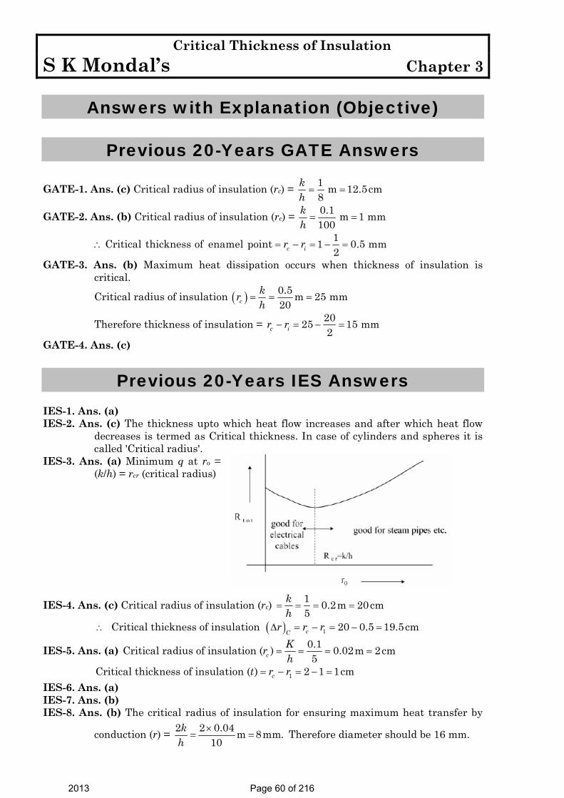
Critical Thickness of Insulation S K Mondal’s Chapter 3
Answers with Explanation (Objective)
Previous 20-Years GATE Answers
GATE-1. Ans. (c) Critical radius of insulation (rc) = 1 m 12.5cm8
kh= =
GATE-2. Ans. (b) Critical radius of insulation (rc) = 0.1 m 1 mm100
kh= =
1Critical thickness of enamel point 1 0.5 mm2c ir r∴ = − = − =
GATE-3. Ans. (b) Maximum heat dissipation occurs when thickness of insulation is critical.
Critical radius of insulation ( ) 0.5 m 25 mm20c
krh
= = =
Therefore thickness of insulation = 2025 15 mm2c ir r− = − =
GATE-4. Ans. (c)
Previous 20-Years IES Answers IES-1. Ans. (a) IES-2. Ans. (c) The thickness upto which heat flow increases and after which heat flow
decreases is termed as Critical thickness. In case of cylinders and spheres it is called 'Critical radius'.
IES-3. Ans. (a) Minimum q at ro = (k/h) = rcr (critical radius)
IES-4. Ans. (c) Critical radius of insulation (rc) 1 0.2m 20cm
5kh
= = = =
∴ Critical thickness of insulation ( ) 1 20 0.5 19.5cmcCr r rΔ = − = − =
IES-5. Ans. (a) 0.1Critical radius of insulation ( ) 0.02m 2cm5c
Krh
= = = =
1Critical thickness of insulation ( ) 2 1 1cmct r r= − = − = IES-6. Ans. (a) IES-7. Ans. (b) IES-8. Ans. (b) The critical radius of insulation for ensuring maximum heat transfer by
conduction (r) = 2 2 0.04 m 8mm.10
kh
×= = Therefore diameter should be 16 mm.
2013 Page 60 of 216

Critical Thickness of Insulation S K Mondal’s Chapter 3
IES-9. Ans. (b) Critical radius of insulation for sphere in 2kh
and for cylinder is k/h
IES-10. Ans. (a) A and R are correct. R is right reason for A. IES-11. Ans. (a) IES-12. Ans. (a) IES-13. Ans. (c) IES-14. Ans. (a) For minimum heat transfer, the better insulation must be put inside. IES-15. Ans. (a) IES-16. Ans. (a) IES-17. Ans. (a) IES-18. Ans. (a)
Previous 20-Years IAS Answers
IAS-1. Ans. (d) At critical radius of insulation heat leakage is maximum if we add more insulation then heat leakage will reduce.
IAS-2. Ans. (a) Critical radius of insulation ( ) 0.5 m 0.01m50c
krh
= = =
2013 Page 61 of 216

Heat Transfer from Extended Surfaces (Fins) S K Mondal’s Chapter 4
4. Heat Transfer from Extended
Surfaces (Fins)
Theory at a Glance (For IES, GATE, PSU) Convection: Heat transfer between a solid surface and a moving fluid is governed by the Newton’s cooling law: q = hA ( )sT T∞− Therefore, to increase the convective heat transfer, One can. • Increase the temperature difference ( )sT T∞− between the surface and the fluid. • Increase the convection coefficient h. This can be accomplished by increasing the fluid
flow over the surface since h is a function of the flow velocity and the higher the velocity,
• The higher the h. Example: a cooling fan. • Increase the contact surface area A. Example: a heat sink with fins.
( ) ( ) ,∞= −conv sdq h dA T T Where dAs is the surface area of the element
( ) ,k C
d T hP T TAdx ∞− − =
2
2 0 A second - order, ordinary differential equation
Define a new variable ( ) ( ) ,∞= −x T x Tθ so that
,− =2
22 0d m
dxθ θ Where ( )2 2 2 0m
k C
hP or D mA
θ= − =
Characteristics equation with two real roots: + m & – m The general solution is of the form
1 2( ) mx mxx C e C eθ −= +
2013 Page 62 of 216

Heat Transfer from Extended Surfaces (Fins) S K Mondal’s Chapter 4
To evaluate the two constants C1 and C2, we need to specify two boundary conditions: The first one is obvious: the base temperature is known as T (0) = Tb The second condition will depend on the end condition of the tip.
Common type of configuration of FINS
Heat Flow through “Rectangular Fin”
Heat Flow through a Rectangular Fin
Let, l = Length of the fin (perpendicular to surface from which heat is to be removed. b = Width of the fin (parallel to the surface from which heat is to be removed. y = Thickness of the fin. p = Perimeter of the fin =2(b + y)|. cA = Area of cross-section (b.y)
2013 Page 63 of 216

Heat Transfer from Extended Surfaces (Fins) S K Mondal’s Chapter 4
ot = Temperature at the base of the fin. And at = Temperature of the ambient/surrounding fluid. k = Thermal conductivity (constant). And h = Heat transfer coefficient (convective).
( )
+
⎛ ⎞=− ⎜ ⎟⎝ ⎠
∂= − + ⎡ ⎤⎣ ⎦∂
= −
⎡ ⎤− − =⎢ ⎥
⎣ ⎦
− − =
x c
x dx x x
a
c a
ac
dTQ Adx
Q Q Q dxx
Q h P dx t td TA dx h Pdx t tdx
d T hP t tdx A
cov2
2
2
2
k
( . )( )
k ( )( ) 0
0k
Temperature excess, at tθ = −
d dtdx dxθ=
2
22 0 or
c
d hPm mkAdx
θ θ− = =
Heat Dissipation from an Infinitely Long Fin (ℓ→∞ ):
22
2
0 0
0
0, . ., . 0a
d mdxat x t t i eat x t t i e
− =
= = =
= ∞ = =
θ θ
θ θθ
1 2
0 1 2( )
1 2 10 0
mx mx
m m
C e C eC C
C e C e C
−
∞ −∞
= +
= +
= ⋅ + ⋅ ∴ =
θθ
2013 Page 64 of 216

Heat Transfer from Extended Surfaces (Fins) S K Mondal’s Chapter 4
Temperature Distribution -mx
0θ = θ e
0
or mxeθθ
−=
Temperature Distribution
(a) By considering the heat flow across the root or base by conduction. (b) By considering the heat which is transmitted by convection from the surface. (a) By considering the heat flow across the root or base by conduction
0
00
00
0 0
0
( )
( )
( )k
fin cat x
mx mxaa a
a
mxa
x
fin c a cc
fin c
dtQ kAdx
t t e t t t t et t
dt m t t edx
hPQ k A m t t k AA
Q hP kA
θ
θ
=
− −
−
=
⎛ ⎞= − ⎜ ⎟⎝ ⎠
−= ⇒ − = −
−
⎛ ⎞ = − −⎜ ⎟⎝ ⎠
= − = ⋅
⇒ = ×
(b) By considering the heat which is transmitted by convection from the
surface
0
0 0
0
( ) ( )
1( ) k
mxfin a a
fin a c o
Q h P dx t t h P t t e dx
Q h P t t hP Am
θ
∞ ∞−= − = −
⇒ = − = ⋅
∫ ∫
2013 Page 65 of 216
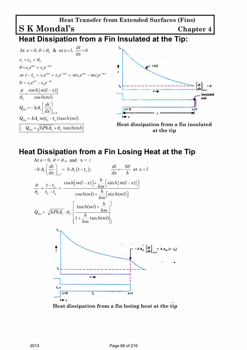
Heat Transfer from Extended Surfaces (Fins) S K Mondal’s Chapter 4
Heat Dissipation from a Fin Insulated at the Tip: 0At 0, & at , 0dtx x l
dxθ θ= = = =
{ }
1 2 0
1 2
1 2 1 2
1 2
0
0
0
0
or0
( )( )
k
( ) tan ( )
tan ( )
mx mx
mx mx mx mxaml ml
fin cx
fin c a
fin c
c cc e c et t c e c e mc e mc ec e c ecosh m l x
cosh mldtQ Adx
Q kA m t t h ml
Q hPkA h ml
θ
θ
θθ
θ
−
− −
−
=
+ =
= +
− = + = −
= −
−=
⎡ ⎤=− ⎢ ⎥⎣ ⎦= −
∴ = ×
Heat dissipation from a fin insulated at the tip
Heat Dissipation from a Fin Losing Heat at the Tip At x = 0, θ = θ 0 and x =
( )
{ }
0 0
0
; at
cos ( ) sin ( )
cos ( ) sin ( )
tan ( )
1 tan ( )
c c ax l
a
a
fin c
dt dt hk A h A t t x ldx dx k
hh m l x h m l xt t kmht t h ml h ml
kmhh ml
kmQ hPkA h h mlkm
θ
θθ
θ
=
⎛ ⎞− = − =− =⎜ ⎟⎝ ⎠
⎡ ⎤− + −⎡ ⎤⎣ ⎦ ⎣ ⎦−= =
− + ⎡ ⎤⎣ ⎦
⎡ ⎤+⎢ ⎥= ⋅ ⋅ ⎢ ⎥
⎢ ⎥+⎢ ⎥⎣ ⎦
Heat dissipation from a fin losing heat at the tip
2013 Page 66 of 216

Heat Transfer from Extended Surfaces (Fins) S K Mondal’s Chapter 4
Temperature Distribution for Fins Different Configurations Case Tip Condition Temp. Distribution Fin heart transfer
A Convection heat transfer:
x=Lhθ(L)=-k(dθ/dx)
( )hcoshm(L-x)+ sinhm L-xmk
hcoshmL+ sinhmLmk
⎛ ⎞⎜ ⎟⎝ ⎠⎛ ⎞⎜ ⎟⎝ ⎠
ο
hsinhmL+ coshmLmkMθhcoshmL+ sinhmL
mk
⎛ ⎞⎜ ⎟⎝ ⎠⎛ ⎞⎜ ⎟⎝ ⎠
B Adiabatic
( / ) 0x Ld dxθ = = cosh ( )
coshm L x
mL− tanhM mLοθ
C Given
temperature: ( ) LLθ θ=
( ) ( )sinh - sinh -
sinh
L
b
m L x m L x
mL
θθ
+
cosh
sinh
L
b
mLM
mLο
θθ
θ
⎛ ⎞−⎜ ⎟
⎝ ⎠
D Infinitely long fin
( ) 0Lθ = mxe− M οθ
2,θ ∞= − =c
hPT T mkA
(0) ,θ θ θ∞= = − =b b c bT T M hPkA
Correction Length
The correction length can be determined by using the formula: cL = L+ ( cA /P), where Ac is the cross-sectional area and P is the
Perimeter of the fin at the tip.
Thin rectangular fin: cA = Wt, P=2(Wet)≈2W, since t << W cL = L+ ( cA /P) = L+ (Wt/2W) = L+ (t/2)
Cylindrical fin: cA = ( π /4) 2D , P= π D, cL = L+( cA /P) = L+(D/4)
Square fin: Ac =W2, P=4W,
cL = L+ ( cA /P) = L+ ( 2W /4W) = L+ (W/4).
Fin with Internal Heat Generation — Straight Fin
( ) ( )
•2
22
•
1 2 2
0
cos sin
g
g
qd mkdx
qC h mx C h mx
km
θ θ
θ
− + =
∴ = + +
Then use boundary condition.
2013 Page 67 of 216

Heat Transfer from Extended Surfaces (Fins) S K Mondal’s Chapter 4
Composite Fin; No Temperature Gradient Along the Radial Direction
As no temperature Gradient along the radial direction
( )
2
2
.
( )
. 0
X i i o o
o
x c
i i o o
i i o o
dQ A k A kdx
Q hPdx
dx Qx
d hPk A k Adx
h Pmk A k A
θ
θ
θ
θ θ
∴ = − +
=
∂∴ − =
∂⎛ ⎞
∴ − =⎜ ⎟+⎝ ⎠
∴ =+
Efficiency and Effectiveness of Fin ( )
( )max
Actual heat transferred by the finEfficiency of fin( )
Maximumheat that would be transferred if whole surface of the fin maintained at the base temperature
finfin
Q
Q
η =
( ) Heat loss with finEffectivenessof finHeat loss without finfinε =
)i ( )ηFor infinitely long fin, fin =1
m
2013 Page 68 of 216

Heat Transfer from Extended Surfaces (Fins) S K Mondal’s Chapter 4
)ii ( )ηFor insulated tip fin, fin ( )=
tanh mm
)iii ( )∈For infinitely long fin, fin =c
k Ph A
)iv ( )∈For insulated tip fin, fin ( )= × tanc
k P h mh A
Thermal resistance concepts for fin
Effectiveness, (εfin)
( )( )
−= = =
−finε with fin c a
without fin c c a
Q hP A t tPQ h A h A t t
0
0
kk
If the ratio ε↑ ↑finc
P isA
(1) Due to this reason, thin and closely spaced fins are preferred, but boundary layer is the limitation.
2013 Page 69 of 216
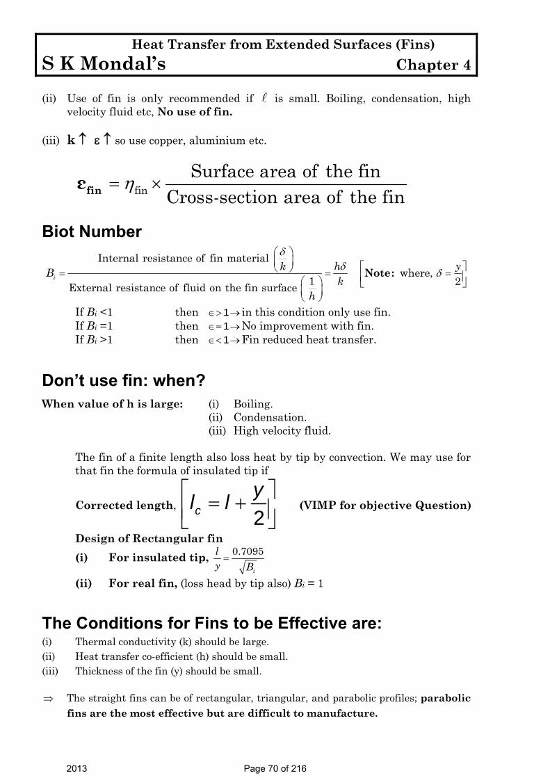
Heat Transfer from Extended Surfaces (Fins) S K Mondal’s Chapter 4
(ii) Use of fin is only recommended if is small. Boiling, condensation, high
velocity fluid etc, No use of fin. (iii) k ↑ ε ↑ so use copper, aluminium etc.
finε finSurface area of the fin
Cross-section area of the finη= ×
Biot Number
Note:Internal resistance of fin material
where, 1 2External resistance of fluid on the fin surface
ih ykBk
h
δδ δ
⎛ ⎞⎜ ⎟ ⎡ ⎤⎝ ⎠= = =⎢ ⎥⎛ ⎞ ⎣ ⎦
⎜ ⎟⎝ ⎠
If Bi <1 then 1∈> → in this condition only use fin. If Bi =1 then 1∈= →No improvement with fin. If Bi >1 then 1∈< →Fin reduced heat transfer.
Don’t use fin: when?
When value of h is large: (i) Boiling. (ii) Condensation. (iii) High velocity fluid. The fin of a finite length also loss heat by tip by convection. We may use for that fin the formula of insulated tip if
Corrected length, ⎡ ⎤= +⎢ ⎥⎣ ⎦2c
yl l (VIMP for objective Question)
Design of Rectangular fin (i) For insulated tip, 0.7095
i
ly B=
(ii) For real fin, (loss head by tip also) Bi = 1
The Conditions for Fins to be Effective are: (i) Thermal conductivity (k) should be large. (ii) Heat transfer co-efficient (h) should be small. (iii) Thickness of the fin (y) should be small.
⇒ The straight fins can be of rectangular, triangular, and parabolic profiles; parabolic
fins are the most effective but are difficult to manufacture.
2013 Page 70 of 216
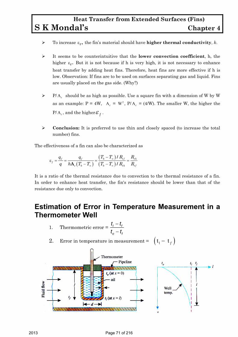
Heat Transfer from Extended Surfaces (Fins) S K Mondal’s Chapter 4
To increase f ,ε the fin’s material should have higher thermal conductivity, k.
It seems to be counterintuitive that the lower convection coefficient, h, the
higher f .ε But it is not because if h is very high, it is not necessary to enhance heat transfer by adding heat fins. Therefore, heat fins are more effective if h is low. Observation: If fins are to be used on surfaces separating gas and liquid. Fins are usually placed on the gas side. (Why?)
P/ Ac should be as high as possible. Use a square fin with a dimension of W by W
as an example: P = 4W, Ac = 2W , P/ Ac = (4/W). The smaller W, the higher the
P/ Ac , and the higher fε .
Conclusion: It is preferred to use thin and closely spaced (to increase the total
number) fins. The effectiveness of a fin can also be characterized as
( )
( )( )
∞
∞ ∞
−ε = = = =
− −
/A /
b t f thf ff
c b b th t f
T T R Rq qq h T T T T R R
It is a ratio of the thermal resistance due to convection to the thermal resistance of a fin. In order to enhance heat transfer, the fin's resistance should be lower than that of the resistance due only to convection.
Estimation of Error in Temperature Measurement in a Thermometer Well
1. Thermometric error = −−
l f
o f
t tt t
2. Error in temperature in measurement = ( )1 t t f−
2013 Page 71 of 216

Heat Transfer from Extended Surfaces (Fins) S K Mondal’s Chapter 4
Estimate of error in Temperature Measurement in a thermometer well
Assume No heat flow in tip i.e. Insulated tip formula.
Thermometric error1
{ ( )}( )
1At( )
x
o
f
o o f
cosh m xcosh m
t tx
t t cosh m
θθ
θθ
−∴ =
−= = = =
−
Note (I): If only wall thickness δ is given then
( )2
A
i i
cs i
i
c i
P d dA d
h dhP hmk k d k
π δ π
π δ
ππ δ δ
= + ≈
=
×∴ = = =
×
( ) ( ) ( )
( )
ii2 2
If a & given or b & given then( )or c & given where Actual d ;
4
i o
o ii o
d dd dd P A
δ δ
πδ π
−= = =
Heat Transfer from a Bar Connected to the Two Heat Sources at Different, Temperatures
Heat Transfer from a Bar connected between two sources of different
temperature
(i) Same fin 2
22equation 0d m
dxθ θ− =
(ii) Boundary condition (1) at x = 0 θ θ= 1
at x = θ θ= 2
(iii) Note:1 2sin { ( )} sin ( ) [ All sin ]sin ( )
h m x h mx hh m
θ θθ
− +=
(iv) ( )1 2
cos ( ) 1Heat loss by convection
sin ( )co
h mh P dx hPkA
h mθ θ θ θ
−⎡ ⎤⎣ ⎦= ⋅ = × + ⎡ ⎤⎣ ⎦∫
2013 Page 72 of 216

Heat Transfer from Extended Surfaces (Fins) S K Mondal’s Chapter 4
(v) Maximum temperature occure at, 0ddxθ=
1 2i.e. cos { ( )} cos ( )h m x h mxθ θ− =
(vi) 1 0 2 and x x ld dQ kA Q kAdx dxθ θ
= == − = −
1 2Q Q Q∴ = −
2013 Page 73 of 216

Heat Transfer from Extended Surfaces (Fins) S K Mondal’s Chapter 4
OBJECTIVE QUESTIONS (GATE, IES, IAS)
Previous 20-Years GATE Questions
Heat Dissipation from a Fin Insulated at the Tip GATE-1. A fin has 5mm diameter and 100 mm length. The thermal conductivity
of fin material is 400 Wm−1K−1. One end of the fin is maintained at 130ºC and its remaining surface is exposed to ambient air at 30ºC. If the convective heat transfer coefficient is 40 Wm-2K-1, the heat loss (in W) from the fin is: [GATE-2010]
(a) 0.08 (b) 5.0 (c) 7.0 (d) 7.8
Estimation of Error in Temperature Measurement in a Thermometer Well GATE-2. When the fluid velocity is doubled, the thermal time constant of a
thermometer used for measuring the fluid temperature reduces by a factor of 2. [GATE-1994]
Previous 20-Years IES Questions
IES-1. From a metallic wall at 100°C, a metallic rod protrudes to the ambient air. The temperatures at the tip will be minimum when the rod is made of: [IES-1992]
(a) Aluminium (b) Steel (d) Copper (d) Silver IES-2. On heat transfer surface, fins are provided [IES-2010] (a) To increase temperature gradient so as to enhance heat transfer (b) To increase turbulence in flow for enhancing heat transfer (c) To increase surface are to promote the rate of heat transfer (d) To decrease the pressure drop of the fluid
Heat Dissipation from an Infinitely Long Fin IES-3. The temperature distribution in a stainless fin (thermal conductivity
0.17 W/cm°C) of constant cross -sectional area of 2 cm2 and length of 1-cm, exposed to ambient of 40°C (with a surface heat transfer coefficient of 0.0025 W/cm20C) is given by (T – T∞ ) = 3x2 – 5x + 6, where T is in °C and x is in cm. If the base temperature is 100°C, then the heat dissipated by the fin surface will be: [IES-1994]
(a) 6.8 W (b) 3.4 W (c) 1.7 W (d) 0.17 W
2013 Page 74 of 216

Heat Transfer from Extended Surfaces (Fins) S K Mondal’s Chapter 4
Heat Dissipation from a Fin Insulated at the Tip IES-4. The insulated tip temperature of a rectangular longitudinal fin having
an excess (over ambient) root temperature of θo is: [IES-2002]
(a) tan ( )o h mlθ (b) sin ( )
o
h mlθ (c)
( )tan ( )o h ml
mlθ (d)
cos ( )o
h mlθ
IES-5. The efficiency of a pin fin with insulated tip is: [IES-2001]
(a) ( )0.5
tan/hmL
hA kP (b) tan hmL
mL (c)
tanmL
hmL (d) ( )0.5/
tanhA kP
hmL
IES-6. A fin of length 'l' protrudes from a surface held at temperature to
greater than the ambient temperature ta. The heat dissipation from the free end' of the fin is assumed to be negligible. The temperature
gradient at the fin tip x l
dtdx =
⎛ ⎞⎜ ⎟⎝ ⎠
is: [IES-1999]
(a) Zero (b) 1 a
o a
t tt t−−
(c) ( )o lh t t− (d) o lt tl−
IES-7. A fin of length l protrudes from a surface held at temperature To; it
being higher than the ambient temperature Ta. The heat dissipation from the free end of the fin is stated to be negligibly small, What is the
temperature gradient x l
dTdx =
⎛ ⎞⎜ ⎟⎝ ⎠
at the tip of the fin? [IES-2008]
(a) Zero (b) o lT Tl− (c) ( )o ah T T− (d) l a
o a
T TT T
−−
Efficiency and Effectiveness of Fin IES-8. Which one of the following is correct? [IES-2008] The effectiveness of a fin will be maximum in an environment with (a) Free convection (b) Forced convection (c) Radiation (d) Convection and radiation IES-9. Usually fins are provided to increase the rate of heat transfer. But fins
also act as insulation. Which one of the following non-dimensional numbers decides this factor? [IES-2007]
(a) Eckert number (b) Biot number (c) Fourier number (d) Peclet number IES-10. Provision of fins on a given heat transfer surface will be more it there
are: [IES-1992] (a) Fewer number of thick fins (b) Fewer number of thin fins (c) Large number of thin fins (d) Large number of thick fins
IES-11. Which one of the following is correct? [IES-2008] Fins are used to increase the heat transfer from a surface by
2013 Page 75 of 216

Heat Transfer from Extended Surfaces (Fins) S K Mondal’s Chapter 4
(a) Increasing the temperature difference (b) Increasing the effective surface area (c) Increasing the convective heat transfer coefficient (d) None of the above IES-12. Fins are made as thin as possible to: [IES-2010] (a) Reduce the total weight (b) Accommodate more number of fins (c) Increase the width for the same profile area (d) Improve flow of coolant around the fin IES-13. In order to achieve maximum heat dissipation, the fin should be
designed in such a way that: [IES-2005] (a) It should have maximum lateral surface at the root side of the fin (b) It should have maximum lateral surface towards the tip side of the fin (c) It should have maximum lateral surface near the centre of the fin (d) It should have minimum lateral surface near the centre of the fin IES-14. A finned surface consists of root or base area of 1 m2 and fin surface
area of 2 m2. The average heat transfer coefficient for finned surface is 20 W/m2K. Effectiveness of fins provided is 0.75. If finned surface with root or base temperature of 50°C is transferring heat to a fluid at 30°C, then rate of heat transfer is: [IES-2003]
(a) 400 W (b) 800 W (c) 1000 W (d) 1200 W IES-15. Consider the following statements pertaining to large heat transfer
rate using fins: [IES-2002] 1. Fins should be used on the side where heat transfer coefficient is
small 2. Long and thick fins should be used 3. Short and thin fins should be used 4. Thermal conductivity of fin material should be large
Which of the above statements are correct? (a) 1, 2 and 3 (b) 1, 2 and 4 (c) 2, 3 and 4 (d) 1, 3 and 4 IES-16. Assertion (A): In a liquid-to-gas heat exchanger fins are provided in the
gas side. [IES-2002] Reason (R): The gas offers less thermal resistance than liquid (a) Both A and R are individually true and R is the correct explanation of A (b) Both A and R are individually true but R is not the correct explanation of A (c) A is true but R is false (d) A is false but R is true IES-17. Assertion (A): Nusselt number is always greater than unity. Reason (R): Nusselt number is the ratio of two thermal resistances, one
the thermal resistance which would be offered by the fluid, if it was stationary and the other, the thermal resistance associated with convective heat transfer coefficient at the surface. [IES-2001]
(a) Both A and R are individually true and R is the correct explanation of A (b) Both A and R are individually true but R is not the correct explanation of A (c) A is true but R is false (d) A is false but R is true
2013 Page 76 of 216

Heat Transfer from Extended Surfaces (Fins) S K Mondal’s Chapter 4
IES-18. Extended surfaces are used to increase the rate of heat transfer. When the convective heat transfer coefficient h = mk, the addition of extended surface will: [IES-2010] (a) Increase the rate of heat transfer (b) Decrease the rate of heat transfer (c) Not increase the rate of heat transfer (d) Increase the rate of heat transfer when the length of the fin is very large
IES-19. Addition of fin to the surface increases the heat transfer if /hA KP is: (a) Equal to one (b) Greater than one [IES-1996] (c) Less than one (d) Greater than one but less than two IES-20. Consider the following statements pertaining to heat transfer through
fins: [IES-1996] 1. Fins are equally effective irrespective of whether they are on the
hot side or cold side of the fluid. 2. The temperature along the fin is variable and hence the rate of heat
transfer varies along the elements of the fin. 3. The fins may be made of materials that have a higher thermal
conductivity than the material of the wall. 4. Fins must be arranged at right angles to the direction of flow of the
working fluid. Of these statements: (a) 1 and 2 are correct (b) 2 and 4 are correct (c) 1 and 3 are correct (d) 2 and 3 are correct.
Previous 20-Years IAS Questions
Heat Transfer from a Bar Connected to the Two Heat Sources at Different, Temperatures IAS-1. A metallic rod of uniform diameter and length L connects two heat
sources each at 500°C. The atmospheric temperature is 30°C. The
temperature gradient dTdL
at the centre of the bar will be: [IAS-2001]
(a) 500/ 2L
(b) 500/ 2L
−
(c) 470/ 2L
− (d) Zero
2013 Page 77 of 216

Heat Transfer from Extended Surfaces (Fins) S K Mondal’s Chapter 4
Answers with Explanation (Objective)
Previous 20-Years GATE Answers
GATE-1. Ans. (b) tan ( )Q h p K A h mlθ=
2; 2 ,4
Substituting we are gettingQ=5 watt
hpm P rl A dKA
ππ= = =
∴
GATE-2. Ans. False
Previous 20-Years IES Answers
IES-1. Ans. (b) IES-2. Ans. (c) By the use of a fin, surface area is increased due to which heat flow rate
increases. Increase in surface area decreases the surface convection resistance, whereas the conduction resistance increases. The decrease in convection resistance must be greater than the increase in conduction resistance in order to increase the rate of heat transfer from the surface. In practical applications of fins the surface resistance must be the controlling factor (the addition of fins might decrease the heat transfer rate under some situations).
IES-3. Ans. (b) Heat dissipated by fin surface
= 1 2 0.0025 2 100 40 3.4 W/ 0.17 1 1 / 0.17 2
t thPkA x kA
− × −= × =
× ×
or Heat dissipated by fin surface = ( )0
l
h Pdx t tα× −∫
IES-4. Ans. (d) IES-5. Ans. (b) IES-6. Ans. (a)
IES-7. Ans. (a) hA(Tat tip – Ta) = – KA x l
dTdx =
⎛ ⎞⎜ ⎟⎝ ⎠
= Negligibly small.
2013 Page 78 of 216

Heat Transfer from Extended Surfaces (Fins) S K Mondal’s Chapter 4
Therefore, the temperature gradient x l
dTdx =
⎛ ⎞⎜ ⎟⎝ ⎠
at the tip will be negligibly small
i.e. zero. IES-8. Ans. (a) The effectiveness of a fin can also be characterized as
( )
( )( )
, ,
, ,
//
f f b t f t hf
C b b t h t f
q q T T R Rq hA T T T T R R
ε ∞
∞ ∞
−= = = =
− −
It is a ratio of the thermal resistance due to convection to the thermal resistance of a fin. In order to enhance heat transfer, the fin's resistance should be lower than that of the resistance due only to convection.
IES-9. Ans. (b) IES-10. Ans. (c) IES-11. Ans. (b) IES-12. Ans. (b) Effectiveness (εfin)
( )( )
0
0
with fin cs a
without fin cs cs a
Q hPkA t tkPQ h A h A t t
−= = =
−finε
If the ratio fincs
P isA
ε↑ ↑
IES-13. Ans. (a)
IES-14. Ans. (a) 0.75 20 1C
KP KPhA
∈= ⇒ = × ×
( )fin 0
fin
without fin
20 1 20 1 0.75 2020 0.75 20 300
300 40075
If 1; fins behave like insulator.
Cq hPKA
WQ W
Q
θ=
= × ⋅ × × ×× × =
∈ = = =
∈<
IES-15. Ans. (d) IES-16. Ans. (c) IES-17. Ans. (a) IES-18. Ans. (c) IES-19. Ans. (c) Addition of fin to the surface increases the heat transfer if /hA KP <<1. IES-20. Ans. (d)
Previous 20-Years IAS Answers
IAS-1. Ans. (d)
2013 Page 79 of 216

One Dimensional Unsteady Conduction S K Mondal’s Chapter 5
5. One Dimensional Unsteady
Conduction
Theory at a Glance (For IES, GATE, PSU)
Heat Conduction in Solids having Infinite Thermal Conductivity (Negligible internal Resistance-Lumped Parameter Analysis)
Biot Number (Bi) • Defined to describe the relative resistance in a thermal circuit of the convection
compared
= = =/ k Internal conduction resistance within solid
k 1 / External convection resistance at body surfaceC ChL L ABi
hA
CL Is a characteristic length of the body. Bi → 0: No conduction resistance at all. The body is isothermal. Small Bi: Conduction resistance is less important. The body may still be approximated as isothermal (purple temperature plot in figure) Lumped capacitance analysis can be performed. Large Bi: Conduction resistance is significant. The body cannot be treated as isothermal (blue temperature plot in figure). Many heat transfer problems require the understanding of the complete time history of the temperature variation. For example, in metallurgy, the heat treating process can be controlled to directly affect the characteristics of the processed materials. Annealing (slow cool) can soften metals and improve ductility. On the other hand, quenching (rapid cool) can harden the strain boundary and increase strength. In order to characterize this transient behavior, the full unsteady equation is needed:
ρα
∂ ∂= ∇ = ∇
∂ ∂2 21k orT Tc T T
t t,
Where αρ
=c
k is the thermal diffusivity.
2013 Page 80 of 216

One Dimensional Unsteady Conduction S K Mondal’s Chapter 5
“A heated/cooled body at Ti is suddenly exposed to fluid at ∞T with a known heat transfer coefficient. Either evaluate the temperature at a given time, or find time for a given temperature.”
Question: “How good an approximation would it be to say the bar is more or less isothermal?”
Answer: “Depends on the relative importance of the thermal conductivity in the thermal circuit compared to the convective heat transfer coefficient”.
The process in which the internal resistance is assumed negligible in comparison with its surface resistance is called the Newtonian heating or cooling process. The temperature, in this process, is considered to be uniform at a given time. Such an analysis is called Lumped parameter analysis because the whole solid, whose energy at any time is a function of its temperature and total heat capacity is treated as one lump.
internal resistance of body.
1Now,
LkA
LkA hA
=
If k is very high the process in which the internal resistance or is assumed negligible in comparison with its surface resistance is called the Newtonian heating or cooling process.
2013 Page 81 of 216

One Dimensional Unsteady Conduction S K Mondal’s Chapter 5
( )
( )
1
1
12
02 2
0
At 0,
where, Biot number & Fourier number
s
s a
s
a
i
i a
h AVc
s s ci
s c
i
dtQ Vc h A t td
hAdt ct t Vc
t tc n t t
e
hA A k hLhV B FVc kA kV c L
B F
τρ
ρτ
τρ
τ
θθ
αττ τρ ρ
= − = −
= − +−
= =
= −
∴ =
⎛ ⎞⎛ ⎞= ⋅ = ⋅ = ×⎜ ⎟⎜ ⎟
⎝ ⎠ ⎝ ⎠= =
Where, ρ = Density of solid, kg/m3, V = Volume of the body, m3, c = Specific heat of body, J/kgºC, h = Unit surface conductance, W/m2°C, t = Temperature of the body at any time, °C, As = Surface area of the body, m2, αt = Ambient temperature, °C, and τ = Time, s. Now,
( ) ( )
( )0
A A
1
i o
i o i o
i o
B F
i
B F B Fsi i a s i a
B Ftotal i i a
e
hdtQ Vc Vc t t e h t t ed Vc
Q Q d Vc t t eτ
θθ
ρ ρτ ρ
τ ρ
− ×
− × − ×
− ×
=
−⎧ ⎫⎡ ⎤= = − = − −⎨ ⎬⎣ ⎦
⎩ ⎭
⎡ ⎤= = − −⎣ ⎦∫
Algorithm Step-I: Characteristic Length, =c
s
VLA
Step-II: Biot Number =k
chL
Check Bi ≤ 0.1 or not if yes then Step-III: Thermal Diffusivity
αρ
=k
pC
Step-IV: Four numbers ατ
= 2( )oc
FL
2013 Page 82 of 216

One Dimensional Unsteady Conduction S K Mondal’s Chapter 5
Step-V: i oB Fa
i a
t t et t
− ×−=
−
Step-VI: ( )totalQ 1i oB Fi aVc t t eρ − ×⎡ ⎤= − −⎣ ⎦
Spatial Effects and the Role of Analytical Solutions If the lumped capacitance approximation can not be made, consideration must be given to spatial, as well as temporal, variations in temperature during the transient process. The Plane Wall: Solution to the Heat Equation for a Plane Wall it Symmetrical Convection Conditions.
• For a plane wall with symmetrical convection conditions and constant properties, the heat equation and initial boundary conditions are:
Note: Once spatial variability of temperature is included, there is existence of seven different independent variables.
( , , , , ,k, )iT T x t T T h∞= α
How may the functional dependence be simplified?
• The answer is Non-dimensionalisation. We first need to understand the physics behind the phenomenon, identify parameters governing the process, and group them into meaningful non-dimensional numbers.
Non-dimensionalisation of Heat Equation and Initial/Boundary Conditions:
The following dimensionless quantities are defined.
Dimensionless temperature difference: i i
T TT T
θθθ
∗∞
∞
−= =
−
Dimensionless coordinate: xxL
∗
=
Dimensionless time: 02tt F
Lα∗
=
The Biot Number: ksolid
hLBi =
2013 Page 83 of 216
One Dimensional Unsteady Conduction S K Mondal’s Chapter 5
The solution for temperature will now be a function of the other non-dimensional
quantities
( , , )f x Fo Biθ∗ ∗
=
Exact Solution:
exp(- )cos( )20
1n n n
nC F xθ ζ ζ
∞∗ ∗
−
= ∑
sinsin(2 )
=+4
2n
nn n
C ζζ ζ
tann n iBζ ζ =
The roots (eigen values) of the equation can be obtained.
The One-Term Approximation F o > 0.2
Variation of mid-plane ( )0x∗
= temperature with time ( 0F )
exp(- )20 1 1
i
T T C FoT T
θ ζ∗
∞
∞
−= ≈
−
One can obtain 1C and 1ζ as a function of Bi.
Variation of temperature with location ( 0)x • = and time ( 0F ):
icos( )0 1xθ θ ζ∗ ∗
= =
Change in thermal energy storage with time:
Δ = −stE Q
sin 100
11Q Q ζ
θζ
∗⎛ ⎞= −⎜ ⎟
⎝ ⎠
( )∞= −0 iQ cV T Tρ
Can the foregoing results be used for a plane wall that is well insulated on one side and
convectively heated or cooled on the other? Can the foregoing results be used if an
isothermal condition ( )s iT T≠ is instantaneously imposed on both surfaces of a plane wall
or on one surface of a wall whose other surface is well insulated?
Graphical Representation of the One-Term Approximation: The Heisler Charts Midplane Temperature:
2013 Page 84 of 216

One Dimensional Unsteady Conduction S K Mondal’s Chapter 5
Temperature Distribution
2013 Page 85 of 216

One Dimensional Unsteady Conduction S K Mondal’s Chapter 5
Change in Thermal Energy Storage
• Assumptions in using Heisler charts:
l. Constant Ti and thermal properties over the body
2. Constant boundary fluid T∞ by step change
3. Simple geometry: slab, cylinder or sphere
• Limitations:
l. Far from edges
2. No heat generation (Q = 0)
3. Relatively long after initial times (Fo > 0.2)
Radial Systems Long Rods or Spheres Heated or Cooled by Convection
/
/iB hr k
F t rα=
=0
20 0
Important tips: Pay attention to the length scale used in those charts, and calculate your
Biot number accordingly.
2013 Page 86 of 216

One Dimensional Unsteady Conduction S K Mondal’s Chapter 5
OBJECTIVE QUESTIONS (GATE, IES, IAS)
Previous 20-Years GATE Questions
Heat Conduction in Solids having Infinite Thermal Conductivity (Negligible internal Resistance-Lumped Parameter Analysis) GATE-1. The value of Biot number is very small (less than 0.01) when (a) The convective resistance of the fluid is negligible [GATE-2002] (b) The conductive resistance of the fluid is negligible (c) The conductive resistance of the solid is negligible (d) None of these GATE-2. A small copper ball of 5 mm diameter at 500 K is dropped into an oil
bath whose temperature is 300 K. The thermal conductivity of copper is 400 W/mK, its density 9000 kg/m3 and its specific heat 385 J/kg.K.1f the heat transfer coefficient is 250 W/m2K and lumped analysis is assumed to be valid, the rate of fall of the temperature of the ball at the beginning of cooling will be, in K/s. [GATE-2005]
(a) 8.7 (b) 13.9 (c) 17.3 (d) 27.7 GATE-3. A spherical thermocouple junction of diameter 0.706 mm is to be used
for the measurement of temperature of a gas stream. The convective heat transfer co-efficient on the bead surface is 400 W/m2K. Thermophysical properties of thermocouple material are k = 20 W/mK, C =400 J/kg, K and ρ = 8500 kg/m3. If the thermocouple initially at 30°C is placed in a hot stream of 300°C, then time taken by the bead to reach 298°C, is: [GATE-2004]
(a) 2.35 s (b) 4.9 s (c) 14.7 s (d) 29.4 s
Previous 20-Years IES Questions
Heat Conduction in Solids having Infinite Thermal Conductivity (Negligible internal Resistance-Lumped Parameter Analysis) IES-1. Assertion (A): Lumped capacity analysis of unsteady heat conduction
assumes a constant uniform temperature throughout a solid body. Reason (R): The surface convection resistance is very large compared
with the internal conduction resistance. [IES-2010]
IES-2. The ratio Internal conduction resistance Surface convection resistance
is known as [IES-1992]
(a) Grashoff number (b) Biot number
2013 Page 87 of 216

One Dimensional Unsteady Conduction S K Mondal’s Chapter 5
(c) Stanton number (b) Prandtl number IES-3. Which one of the following statements is correct? [IES-2004] The curve for unsteady state cooling or heating of bodies (a) Parabolic curve asymptotic to time axis (b) Exponential curve asymptotic to time axis (c) Exponential curve asymptotic both to time and temperature axis (d) Hyperbolic curve asymptotic both to time and temperature axis IES-4. Assertion (A): In lumped heat capacity systems the temperature
gradient within the system is negligible [IES-2004] Reason (R): In analysis of lumped capacity systems the thermal
conductivity of the system material is considered very high irrespective of the size of the system
(a) Both A and R are individually true and R is the correct explanation of A (b) Both A and R are individually true but R is not the correct explanation of A (c) A is true but R is false (d) A is false but R is true IES-5. A solid copper ball of mass 500 grams, when quenched in a water bath
at 30°C, cools from 530°C to 430°C in 10 seconds. What will be the temperature of the ball after the next 10 seconds? [IES-1997]
(a) 300°C (b) 320°C (c) 350°C (d) Not determinable for want of sufficient data
Time Constant and Response of — Temperature Measuring Instruments IES-6. A thermocouple in a thermo-well measures the temperature of hot gas
flowing through the pipe. For the most accurate measurement of temperature, the thermo-well should be made of: [IES-1997]
(a) Steel (b) Brass (c) Copper (d) Aluminium
Transient Heat Conduction in Semi-infinite Solids (h or Hj 4.5. 30~5 00) IES-7. Heisler charts are used to determine transient heat flow rate and
temperature distribution when: [IES-2005] (a) Solids possess infinitely large thermal conductivity (b) Internal conduction resistance is small and convective resistance is large (c) Internal conduction resistance is large and the convective resistance is small (d) Both conduction and convention resistance are almost of equal significance
2013 Page 88 of 216

One Dimensional Unsteady Conduction S K Mondal’s Chapter 5
Previous 20-Years IAS Questions
Time Constant and Response of — Temperature Measuring Instruments IAS-1. Assertion (A): During the temperature measurement of hot gas in a
duct that has relatively cool walls, the temperature indicated by the thermometer will be lower than the true hot gas temperature.
Reason(R): The sensing tip of thermometer receives energy from the hot gas and loses heat to the duct walls. [IAS-2000]
(a) Both A and R are individually true and R is the correct explanation of A (b) Both A and R are individually true but R is not the correct explanation of A (c) A is true but R is false (d) A is false but R is true
2013 Page 89 of 216

One Dimensional Unsteady Conduction S K Mondal’s Chapter 5
Answers with Explanation (Objective)
Previous 20-Years GATE Answers
GATE-1. Ans. (c) GATE-2. Ans. (c)
3
42
40.005 / 23Charactaristic length( ) 8.3333 10 m
3 34cs
rV rLA r
π
π−= = = = = ×
Thermal diffusivity, 4400 1.1544 109000 385p
kc
αρ
−= = = ××
Fourier number (Fo) = 2 166cL
ατ τ=
Biot number (Bi) = 4
4250 8.3333 10 5.208 10400
chLk
−−× ×
= = ×
Then,
( ) ( )
4166 5.208 10
500
300500 300
or ln( 300) ln 200 0.086461or 0.08646 or 0.08646 500 300 17.3K/s300
i oB Fa
i i a
T K
T T Te or eT TT
dT dTT d d
τθθ
τ
τ τ
−− × − × ×
≈
− −= = =
− −
− − = −
⎛ ⎞= − = − × − = −⎜ ⎟− ⎝ ⎠
GATE-3. Ans. (b) Characteristic length (Lc) = 3
32
43 0.11767 10 m
34
rV rA r
π
π−= = = ×
Biot number (Bi) = ( )3
3400 0.11767 10
2.3533 1020
chLk
−−
× ×= = ×
As Bi < 0.1 the lumped heat capacity approach can be used
6 220 5.882 10 m /s8500 400p
kc
αρ
−= = = ××
Fourier number (Fo) = 2 425cL
ατ τ=
.
3
or . ln
300 30or 425 2.3533 10 ln or 4.9300 298
o iF Bo i
i i
e F B
s
θ θθ θ
τ τ
−
−
⎛ ⎞= = ⎜ ⎟
⎝ ⎠−⎛ ⎞× × = =⎜ ⎟−⎝ ⎠
2013 Page 90 of 216
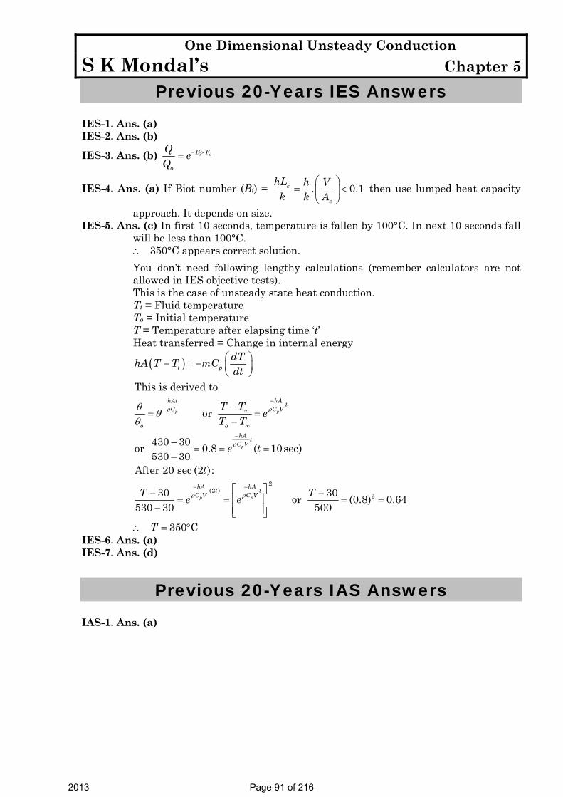
One Dimensional Unsteady Conduction S K Mondal’s Chapter 5
Previous 20-Years IES Answers
IES-1. Ans. (a) IES-2. Ans. (b)
IES-3. Ans. (b) i oB F
o
Q eQ
− ×=
IES-4. Ans. (a) If Biot number (Bi) = . 0.1c
s
hL h Vk k A
⎛ ⎞= <⎜ ⎟
⎝ ⎠ then use lumped heat capacity
approach. It depends on size. IES-5. Ans. (c) In first 10 seconds, temperature is fallen by 100°C. In next 10 seconds fall
will be less than 100°C. ∴ 350°C appears correct solution.
You don’t need following lengthy calculations (remember calculators are not allowed in IES objective tests).
This is the case of unsteady state heat conduction. Tt = Fluid temperature To = Initial temperature T = Temperature after elapsing time ‘t’ Heat transferred = Change in internal energy
( )
2
(2 )2
This is derived to
or
430 30or 0.8 ( 10sec)530 30
After 20 sec (2 ):
30 30or (0.8) 0.64530 30 500
350 C
p p
p
p p
t p
hAt hA tC C V
o ohA t
C V
hA hAt tC V C V
dThA T T mCdt
T T eT T
e t
t
T Te e
T
ρ ρ
ρ
ρ ρ
θ θθ
−−
∞
∞
−
− −
⎛ ⎞− = − ⎜ ⎟⎝ ⎠
−= =
−
−= = =
−
⎡ ⎤− −⎢ ⎥= = = =− ⎢ ⎥⎣ ⎦
∴ = °
IES-6. Ans. (a) IES-7. Ans. (d)
Previous 20-Years IAS Answers
IAS-1. Ans. (a)
2013 Page 91 of 216

Free & Forced Convection S KMondal’s Chapter 6
6. Free & Forced Convection
Theory at a Glance (For IES, GATE, PSU)
Objectives of Convection Analysis Main purpose of convective heat transfer analysis is to determine:
• Flow field
• Temperature field in fluid
• Heat transfer coefficient, (h)
How do we determine h? Consider the process of convective cooling, as we pass a cool fluid past a heated wall. This process is described by Newton’s law of Cooling;
( )sq h A T T∞= ⋅ ⋅ −
Near any wall a fluid is subject to the no slip condition; that is, there is a stagnant sub layer. Since there is no fluid motion in this layer, heat transfer is by conduction in this region. Above the sub layer is a region where viscous forces retard fluid motion; in this region some convection may occur, but conduction may well predominate. A careful analysis of this region allows us to use our conductive analysis in analyzing heat transfer. This is the basis of our convective theory.
At the wall, the convective heat transfer rate can be expressed as the heat flux.
( )0
conv f sy
Tq k h T Ty
•∞
=
∂⎛ ⎞= − = −⎜ ⎟∂⎝ ⎠
( )0Hence,
fy
s
Tky
hT T
=
∞
∂ ⎞− ⎟∂ ⎠
=−
2013 Page 92 of 216

Free & Forced Convection S KMondal’s Chapter 6
0
Buty
Ty =
∂⎛ ⎞⎜ ⎟∂⎝ ⎠
depends on the whole fluid motion, and both fluid flow and heat transfer
equations are needed.
The expression shows that in order to determine h, we must first determine the temperature distribution in the thin fluid layer that coats the wall.
Classes of Convective Flows:
• Extremely diverse. • Several parameters involved (fluid properties, geometry, nature of flow, phases
etc). • Systematic approach required. • Classify flows into certain types, based on certain parameters. • Identify parameters governing the flow, and group them into meaningful non-
dimensional numbers. • Need to understand the physics behind each phenomenon.
Common Classifications A. Based on geometry: External flow / Internal flow
B. Based on driving mechanism:- Natural convection / forced convection / mixed convection
C. Based on nature of flow: Laminar / turbulent.
Typical values of h (W/m2k)
Free convection Gases : 2 – 25 Liquid : 50 –100
Forced convection Gases : 25 – 250 Liquid : 50 – 20,000
Boiling/ Condensation 2500 – 100,000
2013 Page 93 of 216

Free & Forced Convection S KMondal’s Chapter 6
How to Solve a Convection Problem? • Solve governing equations along with boundary conditions • Governing equations include
1. Conservation of mass: 0u v
x y∂ ∂
+ =∂ ∂
2. Conservation of momentum: ∂ ∂ ∂ ∂⎛ ⎞+ = + ⎜ ⎟∂ ∂ ∂ ∂⎝ ⎠
u u dU uu v U vx y dx y y
3. Conservation of energy: ∂ ∂ ∂ ∂⎛ ⎞+ = ⎜ ⎟∂ ∂ ∂ ∂⎝ ⎠αT T Tu v
x y y y
For flat plate constant; 0dUUdx
= ∴ =
Exact solution: Blasius
=δ 4.99
Rexx
Local friction co-efficient, 0
2
0.664( ) 1 Re2
xx
CU
τ
ρ= =
00
Re ,xx
y
U uV y
τ μ=
∂= =
∂
Average drag co-efficient, ( )0
1 1.328Re
L
D xL
C C dxL
= =∫
Local Nusselt number, ( )11320.339Re Prx xNu =
Average Nusselt number, ( )11320.678Re Prx LNu =
∴ Local heat transfer co-efficient, ( )1132k k0.339 Re Prx
x xNuh
x x⋅
= =
Average heat transfer co-efficient, ( )1132k k0.678 Re Prx
LNuh
L L= = ⋅
Recall ( )wq h A T Tα= − heat flow rate from wall.
• In Conduction problems, only some equation is needed to be solved. Hence, only few
parameters are involved. • In Convection, all the governing equations need to be solved. ⇒ Large number of parameters can be involved.
2013 Page 94 of 216

Free & Forced Convection S KMondal’s Chapter 6
Forced Convection: External Flow (over flat plate) An internal flow is surrounded by solid boundaries that can restrict the development of its boundary layer, for example, a pipe flow. External flows, on the other hand, are flows over bodies immersed in an unbounded fluid so that the flow boundary layer can grow freely in one direction. Examples include the flows over airfoils, ship hulls, turbine blades, etc.
• Fluid particle adjacent to the solid surface is at rest. • These particles act to retard the motion of adjoining layers. • Boundary layer effect. Inside the boundary layer, we can apply the following conservation principles: Momentum balance: inertia forces, pressure gradient, viscous forces, body forces. Energy balance: convective flux, diffusive flux, heat generation, energy storage.
Forced Convection Correlations Since the heat transfer coefficient is a direct function of the temperature gradient next to the wall, the physical variables on which it depends can be expressed as follows: h = f (fluid properties, velocity field, geometry, temperature etc.). As the function is dependent on several parameters, the heat transfer coefficient is usually expressed in terms of correlations involving pertinent non-dimensional numbers. Forced convection: Non-dimensional groupings: —
• Nusselt Number (Nu) hx / k (Convection heat transfer strength) / (conduction heat transfer strength)
• Prandtl Number (Pr) v /α (Momentum diffusivity) / (thermal diffusivity)
• Reynolds Number (Re) U x / ν (Inertia force) / (viscous force)
Viscous force provides the dam pending effect for disturbances in the fluid. If dampening is strong enough ⇒ laminar flow.
Otherwise, instability ⇒ turbulent flow ⇒ critical Reynolds number.
For forced convection, the heat transfer correlation can be expressed as Nu=f (Re, Pr)
The convective correlation for laminar flow across a flat plate heated to a constant wall Temperature is:
2013 Page 95 of 216

Free & Forced Convection S KMondal’s Chapter 6
/x xNu . .Re .Pr
1 1 320 323= Where
xNu h.x/k≡ xRe (U .x. )/∞≡ ρ μ Pr c . / kp≡ μ
Physical Interpretation of Convective Correlation The Reynolds number is a familiar term to all of us, but we may benefit by considering what the ratio tells us. Recall that the thickness of the dynamic boundary layer, δ, is proportional to the distance along the plate, x.
xRe (U .x. )/ (U . . )/ ( .U )/( .U / )∞ ∞ ∞ ∞≡ ρ μ∞ δ ρ μ = ρ μ δ2 The numerator is a mass flow per unit area times a velocity; i.e. a momentum flow per unit area. The denominator is a viscous stress, i.e. a viscous force per unit area. The ratio represents the ratio of momentum to viscous forces. If viscous forces dominate, the flow will be laminar; if momentum dominates, the flow will be turbulent.
Physical Meaning of Prandtl Number The Prandtl number was introduced earlier. If we multiply and divide the equation by the fluid density, ρ, we obtain:
Pr ( ) ( )p/ k/ .c /≡ μ ρ ρ = v a
The Prandtl number may be seen to be a ratio reflecting the ratio of the rate that viscous forces penetrate the material to the rate that thermal energy penetrates the material. As a consequence the Prandtl number is proportional to the rate of growth of the two boundary layers:
// Prδ δ = 1 3t
Physical Meaning of Nusselt Number The Nusselt number may be physically described as well.
xNu h.x/k≡
If we recall that the thickness of the boundary layer at any point along the surface, δ, is also a function of x then
( )xNu h. /k /k .A / ( / h.A)1∝ δ ∝ δ We see that the Nusselt may be viewed as the ratio of the conduction resistance of a material to the convection resistance of the same material.
2013 Page 96 of 216

Free & Forced Convection S KMondal’s Chapter 6
Students, recalling the Biot number, may wish to compare the two so that they may distinguish the two.
x fluidNu h.x/k≡ x solidBi h.x/k≡ The denominator of the Nusselt number involves the thermal conductivity of the fluid at the solid-fluid convective interface; the denominator of the Biot number involves the thermal conductivity of the solid at the solid-fluid convective interface.
Local Nature of Convective Correlation Consider again the correlation that we have developed for laminar flow over a flat plate at constant wall temperature
/x xNu . .Re .Pr=
1 1 320 323
To put this back into dimensional form, we replace the Nusselt number by its equivalent, hx/k and take the x/k to the other side:
/xh . .(k/x).Re .Pr=
1 1 320 323 Now expand the Reynolds number
/h . .(k/x). (U .x. ) / .Pr∞= ρ μ⎡ ⎤⎣ ⎦1 1 320 323
We proceed to combine the x terms:
/h . .k. (U . ) / .Prx∞= ρ μ⎡ ⎤⎣ ⎦1 1 320 323
And see that the convective coefficient decreases with
12x
We see that as the boundary layer thickness, the convection coefficient decreases. Some designers will introduce a series of “trip wires”, i.e. devices to disrupt the boundary layer, so that the build up of the insulating layer must begin a new. This will result in regular “thinning” of the boundary layer so that the convection coefficient will remain high.
Use of the “Local Correlation” A local correlation may be used whenever it is necessary to find the convection coefficient at a particular location along a surface. For example, consider the effect of chip placement upon a printed circuit board:
2013 Page 97 of 216

Free & Forced Convection S KMondal’s Chapter 6
Here are the design conditions. We know that as the higher the operating temperature of a chip, the lower the life expectancy.
With this in mind, we might choose to operate all chips at the same design temperature.
Where the chip generating the largest power per unit surface area should be placed? The lowest power?
Averaged Correlations If one were interested in the total heat loss from a surface, rather than the temperature at a point, then they may well want to know something about average convective coefficients. For example, if we were trying to select a heater to go inside an aquarium, we would not be interested in the heat loss at 5 cm, 7 cm and 10 cm from the edge of the aquarium; instead we want some sort of an average heat loss.
The desire is to find a correlation that provides an overall heat transfer rate:
L wall wall wallQ=h .A. T T . T T . . T T .∞ ∞ ∞− = − = −⎡ ⎤ ⎡ ⎤ ⎡ ⎤⎣ ⎦ ⎣ ⎦ ⎣ ⎦∫ ∫0L
x xh dA h dx Where xh and Lh , refer to local and average convective coefficients, respectively. Compare the equations where the area is assumed to be equal to A = (1·L):
2013 Page 98 of 216

Free & Forced Convection S KMondal’s Chapter 6
L wall wallh .L. T T . T T .∞ ∞− = −⎡ ⎤ ⎡ ⎤⎣ ⎦ ⎣ ⎦∫0L
xh dx Since the temperature difference is constant, it may be taken outside of the integral and cancelled:
Lh .L .= ∫0
Lxh dx
This is a general definition of an integrated average. Proceed to substitute the correlation for the local coefficient.
./
LU . .kh .L . . .Pr .
L x dxx
∞⎡ ⎤= ⎢ ⎥
⎣ ⎦∫
0 51 3
00 323 ρ
μ
Take the constant terms from outside the integral, and divide both sides by k.
. ./
LU .h .L/k . . .Pr . .
Ldx
x∞⎡ ⎤ ⎡ ⎤= ⎢ ⎥ ⎢ ⎥⎣ ⎦⎣ ⎦
∫0 5 0 5
1 30
10 323 ρμ
Integrate the right side.
. ./
LU .h .L/k . . .Pr .
.
Lx∞⎡ ⎤
= ⎢ ⎥⎣ ⎦
0 5 0 51 3
0
0 3230 5
ρμ
The left side is defined as the average Nusselt number, ( LNu ). Algebraically rearrange the right side.
. ./ . /
LU . U . ..Nu . .Pr . . . .Pr
.LLρ ρ
μ μ∞ ∞⎡ ⎤ ⎡ ⎤
= =⎢ ⎥ ⎢ ⎥⎣ ⎦ ⎣ ⎦
0 5 0 51 3 0 5 1 30 323 0 646
0 5
The term in the brackets may be recognized as the Reynolds number, evaluated at the end of the convective section. Finally,
.LNu . .Re .PrL=
10 5 30 646 This is our average correlation for laminar flow over a flat plate with constant wall temperature.
Reynolds Analogy In the development of the boundary layer theory, one may notice the strong relationship between the dynamic boundary layer and the thermal boundary layer. Reynolds’s noted the strong correlation and found that fluid friction and convection coefficient could be related. This refers to the Reynolds Analogy.
Pr 1, tatonnumber2
= = fCS
Conclusion from Reynolds’s analogy: Knowing the frictional drag, we know the Nusselt Number. If the drag coefficient is increased, say through increased wall roughness,
2013 Page 99 of 216

Free & Forced Convection S KMondal’s Chapter 6
then the convective coefficient will increase. If the wall friction is decreased, the convective coefficient is decreased. ⇒ Laminar, fully developed circular pipe flow:
↓= −" ( )s nNs hA T T
"4.36 when, constantD sf
hDNu qk
= = =
4811
khD
= [VIMP]
⇒ Fully developed turbulent pipe flow
= nDNu 0.80.023 Re Pr
n = 0.4 for heating
n = 0.3 for cooling
Turbulent Flow We could develop a turbulent heat transfer correlation in a manner similar to the von Karman analysis. It is probably easier, having developed the Reynolds analogy, to follow that course. The local fluid friction factor, Cf, associated with turbulent flow over a flat plate is given as:
.f xC . / Re= 0 20 0592
Substitute into the Reynolds analogy:
( ).x x x. / Re / Nu / Re Pr=
10 2 30 0592 2
Rearrange to find
. /x xNu . .Re .Pr= 0 8 1 30 0296
Local Correlation Turbulent Flow Flat Plate
In order to develop an average correlation, one would evaluate an integral along the plate similar to that used in a laminar flow:
Note: The critical Reynolds number for flow over a flat plate is 5 × 10⁵; the critical Reynolds number for flow through a round tube is 2000.
2013 Page 100 of 216

Free & Forced Convection S KMondal’s Chapter 6
The result of the above integration is:
Note: Fluid properties should be evaluated at the average temperature in the boundary layer, i.e. at an average between the wall and free stream temperature.
Free Convection Free convection is sometimes defined as a convective process in which fluid motion is caused by buoyancy effects.
T∞ < Tboundary. layer < Tw ρ∞ < ρ Boundary layer
Velocity Profiles Compare the velocity profiles for forced and natural convection shown figure:
Coefficient of Volumetric Expansion The thermodynamic property which describes the change in density leading to buoyancy in The Coefficient of Volumetric Expansion, (β).
ρβρ =
∂≡− ⋅
∂ .
1P ConstT
Evaluation of β • Liquids and Solids: β is a thermodynamic property and should be found from
Property Tables. Values of β are found for a number of engineering fluids.
2013 Page 101 of 216

Free & Forced Convection S KMondal’s Chapter 6
• Ideal Gases: We may develop a general expression for β for an ideal gas from the Ideal gas law:
Then, P = ρ.R.T ρ = P/R.T Differentiating while holding P constant:
2 2.
. .. .p Const
d P R TdT R T R T Tρ ρ ρ
−
=− =− =−
Substitute into the definition of β
β =1absT Ideal Gas
Grashof Number Because U∞ is always zero, the Reynolds number, [ρ·U∞ ·D]/μ, is also zero and is no longer
suitable to describe the flow in the system. Instead, we introduce a new parameter for natural convection, the Grashof Number. Here we will be most concerned with flow across a vertical surface, so that we use the vertical distance, z or L, as the characteristic length.
3
2. . .βυΔ
≡g T LGr
Just as we have looked at the Reynolds number for a physical meaning, we may consider the Grashof number:
( )3
2max22 3
2 22 max
2
2
. . . . . .. . . .
.
Buoyant Force Momentum.Area Area
Viscous ForceArea
g T L ULg T LGr
UL
ρ β ρρ β
μ μ
⎛ ⎞Δ⎜ ⎟Δ ⎝ ⎠≡ =
⎛ ⎞ ⎛ ⎞⎜ ⎟ ⎜ ⎟⎝ ⎠ ⎝ ⎠=
⎛ ⎞⎜ ⎟⎝ ⎠
Free Convection Heat Transfer Correlations The standard form for free, or natural, convection correlations will appear much like those for forced convection except that (1) the Reynolds number is replaced with a Grashof
2013 Page 102 of 216

Free & Forced Convection S KMondal’s Chapter 6
number and (2) the exponent on Prandtl number is not generally 1/3 (The von Karman boundary layer analysis from which we developed the 1/3 exponent was for forced convection flows):
. .Prm nx xNu C Gr= Local Correlation.
. .Prm nL LNu C Gr= Average Correlation.
Quite often experimentalists find that the exponent on the Grashof and Prandtl numbers are equal so that the general correlations may be written in the form:
.Prm
x xNu C Gr⎡ ⎤= ⋅ ⎣ ⎦ Local Correlation
.Prm
L LNu C Gr⎡ ⎤= ⋅ ⎣ ⎦ Average Correlation This leads to the introduction of the new, dimensionless parameter, the Rayleigh number, Ra: Rax = Grx . Pr
RaL = GrL . Pr So, that the general correlation for free convection becomes:
Laminar to Turbulent Transition Just as for forced convection, a boundary layer will form for free convection. The insulating film will be relatively thin toward the leading edge of the surface resulting in a relatively high convection coefficient. At a Rayleigh number of about 109 the flow over a flat plate will transition to a turbulent pattern. The increased turbulence inside the boundary layer will enhance heat transfer leading to relative high convection coefficients, much like forced convection.
Ra < 109 Laminar flow [Vertical Flat Plate] Ra > 109 Turbulent flow [Vertical Flat Plate]
Generally the characteristic length used in the correlation relates to the distance over which the boundary layer is allowed to grow. In the case of a vertical flat plate this will be x or L, in the case of a vertical cylinder this will also be x or L; in the case of a
m
x xNu C Ra= ⋅ Local Correlation m
L LNu C Ra= ⋅ Average Correlation
2013 Page 103 of 216
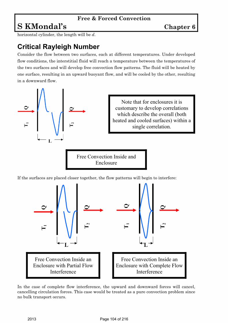
Free & Forced Convection S KMondal’s Chapter 6
horizontal cylinder, the length will be d.
Critical Rayleigh Number Consider the flow between two surfaces, each at different temperatures. Under developed flow conditions, the interstitial fluid will reach a temperature between the temperatures of the two surfaces and will develop free convection flow patterns. The fluid will be heated by one surface, resulting in an upward buoyant flow, and will be cooled by the other, resulting in a downward flow.
Note that for enclosures it is customary to develop correlations which describe the overall (both
heated and cooled surfaces) within a single correlation.
If the surfaces are placed closer together, the flow patterns will begin to interfere:
Free Convection Inside an Enclosure with Partial Flow
Interference
Free Convection Inside an Enclosure with Complete Flow
Interference
In the case of complete flow interference, the upward and downward forces will cancel, cancelling circulation forces. This case would be treated as a pure convection problem since no bulk transport occurs.
Free Convection Inside and Enclosure
2013 Page 104 of 216
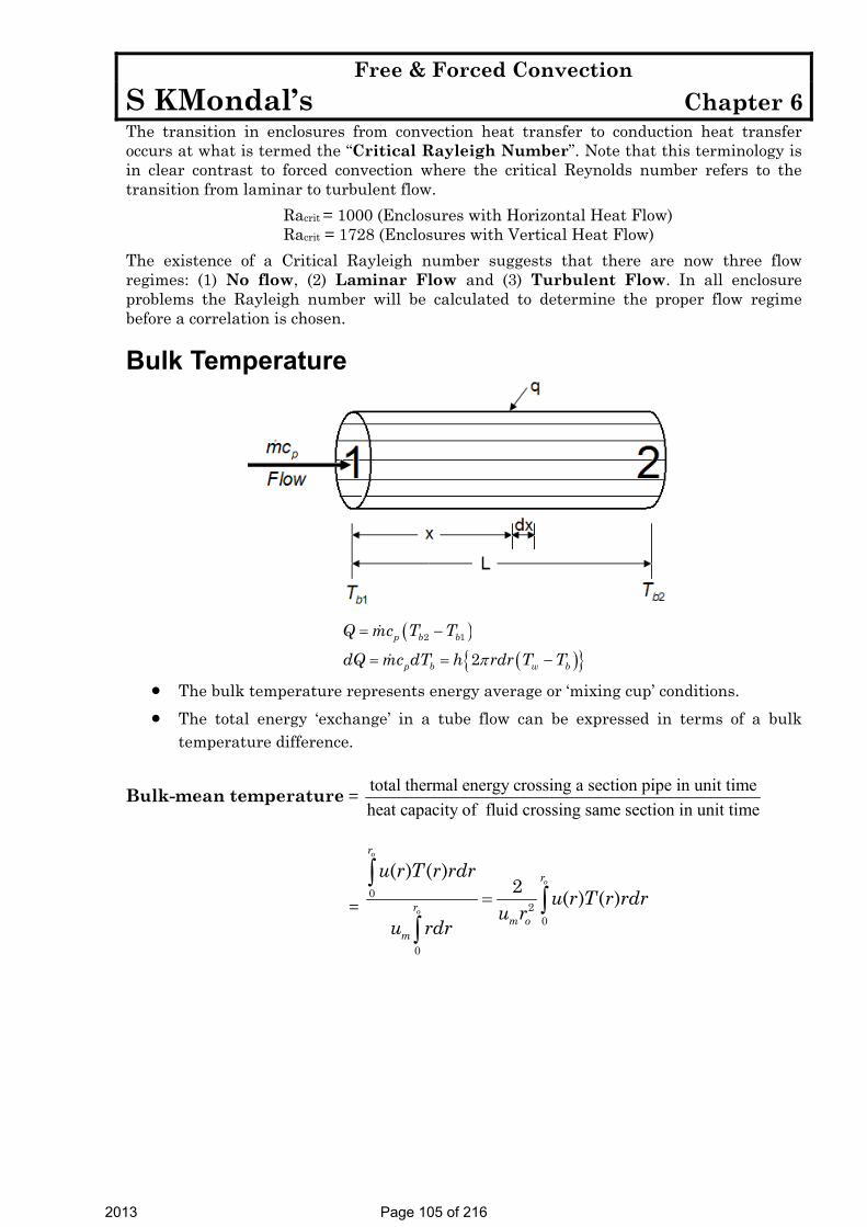
Free & Forced Convection S KMondal’s Chapter 6
The transition in enclosures from convection heat transfer to conduction heat transfer occurs at what is termed the “Critical Rayleigh Number”. Note that this terminology is in clear contrast to forced convection where the critical Reynolds number refers to the transition from laminar to turbulent flow.
Racrit = 1000 (Enclosures with Horizontal Heat Flow) Racrit = 1728 (Enclosures with Vertical Heat Flow)
The existence of a Critical Rayleigh number suggests that there are now three flow regimes: (1) No flow, (2) Laminar Flow and (3) Turbulent Flow. In all enclosure problems the Rayleigh number will be calculated to determine the proper flow regime before a correlation is chosen.
Bulk Temperature
( )( ){ }
2 1
2p b b
p b w b
Q mc T T
dQ mc dT h rdr T Tπ
= −
= = −
• The bulk temperature represents energy average or ‘mixing cup’ conditions. • The total energy ‘exchange’ in a tube flow can be expressed in terms of a bulk
temperature difference.
Bulk-mean temperature = total thermal energy crossing a section pipe in unit timeheat capacity of fluid crossing same section in unit time
= 0
20
0
( ) ( )2 ( ) ( )
o
o
o
r
r
rm o
m
u r T r rdru r T r rdr
u ru rdr
=∫
∫∫
2013 Page 105 of 216

Free & Forced Convection S KMondal’s Chapter 6
OBJECTIVE QUESTIONS (GATE, IES, IAS)
Previous 20-Years GATE Questions GATE-1. A coolant fluid at 30°C flows over a heated flat plate maintained at a
constant temperature of 100°C. The boundary layer temperature distribution at a given location on the plate may be approximated as T = 30 + 70exp(–y) where y (in m) is the distance normal to the plate and T is in °C. If thermal conductivity of the fluid is 1.0 W/mK, the local convective heat transfer coefficient (in W/m2K) at that location will be:
[GATE-2009] (a) 0.2 (b) 1 (c) 5 (d) 10 GATE-2. The properties of mercury at 300 K are: density = 13529 kg/m3, specific
heat at constant pressure = 0.1393 kJ/kg-K, dynamic viscosity = 0.1523 × 10⁻² N.s/m2 and thermal conductivity = 8.540 W/mK. The Prandtl number of the mercury at 300 K is: [GATE-2002]
(a) 0.0248 (b) 2.48 (c) 24.8 (d) 248 GATE-3. The average heat transfer coefficient on a thin hot vertical plate
suspended in still air can be determined from observations of the change in plate temperature with time as it cools. Assume the plate temperature to be uniform at any instant of time and radiation heat exchange with the surroundings negligible. The ambient temperature is 25°C, the plate has a total surface area of 0.1 m2 and a mass of 4 kg. The specific heat of the plate material is 2.5 kJ/kgK. The convective heat transfer coefficient in W/m2K, at the instant when the plate temperature is 225°C and the change in plate temperature with time dT/dt = – 0.02 K/s, is: [GATE-2007]
(a) 200 (b) 20 (c) 15 (d) 10 Data for Q4–Q5 are given below. Solve the problems and choose correct answers.
Heat is being transferred by convection from water at 48°C to a glass plate whose surface that is exposed to the water is at 40°C. The thermal conductivity of water is 0.6 W/mK and the thermal conductivity of glass is 1.2 W/mK. The spatial Water gradient of temperature in the water at the water-glass interface is dT/dy =1 × 10⁴ K/m.
[GATE-2003]
GATE-4. The value of the temperature gradient in the glass at the water-glass interface in k/m is:
(a) – 2 × 10⁴ (b) 0.0 (c) 0.5 × 10⁴ (d) 2 × 10⁴
GATE-5. The heat transfer coefficient h in W/m2K is: (a) 0.0 (b) 4.8 (c) 6 (d) 750
2013 Page 106 of 216

Free & Forced Convection S KMondal’s Chapter 6
GATE-6. If velocity of water inside a smooth tube is doubled, then turbulent
flow heat transfer coefficient between the water and the tube will: (a) Remain unchanged [GATE-1999] (b) Increase to double its value (c) Increase but will not reach double its value (d) Increase to more than double its value
Previous 20-Years IES Questions
IES-1. A sphere, a cube and a thin circular plate, all made of same material and having same mass are initially heated to a temperature of 250oC and then left in air at room temperature for cooling. Then, which one of the following is correct? [IES-2008]
(a) All will be cooled at the same rate (b) Circular plate will be cooled at lowest rate (c) Sphere will be cooled faster (d) Cube will be cooled faster than sphere but slower than circular plate IES-2. A thin flat plate 2 m by 2 m is hanging freely in air. The temperature of
the surroundings is 25°C. Solar radiation is falling on one side of the rate at the rate of 500 W/m2. The temperature of the plate will remain constant at 30°C, if the convective heat transfer coefficient (in W/m2 °C) is: [IES-1993]
(a) 25 (b) 50 (c) 100 (d) 200 IES-3. Air at 20°C blows over a hot plate of 50 × 60 cm made of carbon steel
maintained at 220°C. The convective heat transfer coefficient is 25 W/m2K. What will be the heat loss from the plate? [IES-2009]
(a) 1500W (b) 2500 W (c) 3000 W (d) 4000 W IES-4. For calculation of heat transfer by natural convection from a
horizontal cylinder, what is the characteristic length in Grashof Number? [IES-2007]
(a) Diameter of the cylinder (b) Length of the cylinder (c) Circumference of the base of the cylinder (d) Half the circumference of the base of the cylinder IES-5. Assertion (A): For the similar conditions the values of convection heat
transfer coefficients are more in forced convection than in free convection. [IES-2009]
Reason (R): In case of forced convection system the movement of fluid is by means of external agency.
(a) Both A and R are individually true and R is the correct explanation of A (b) Both A and R individually true but R in not the correct explanation of A (c) A is true but R is false
2013 Page 107 of 216

Free & Forced Convection S KMondal’s Chapter 6
(d) A is false but R is true IES-6. Assertion (A): A slab of finite thickness heated on one side and held
horizontal will lose more heat per unit time to the cooler air if the hot surface faces upwards when compared with the case where the hot surface faces downwards. [IES-1996]
Reason (R): When the hot surface faces upwards, convection takes place easily whereas when the hot surface faces downwards, heat transfer is mainly by conduction through air.
(a) Both A and R are individually true and R is the correct explanation of A (b) Both A and R are individually true but R is not the correct explanation of A (c) A is true but R is false (d) A is false but R is true IES-7. For the fully developed laminar flow and heat transfer in a uniformly
heated long circular tube, if the flow velocity is doubled and the tube diameter is halved, the heat transfer coefficient will be: [IES-2000]
(a) Double of the original value (b) Half of the original value (c) Same as before (d) Four times of the original value IES-8. Assertion (A): According to Reynolds analogy for Prandtl number equal
to unity, Stanton number is equal to one half of the friction factor. Reason (R): If thermal diffusivity is equal to kinematic viscosity, the
velocity and the temperature distribution in the flow will be the same. (a) Both A and R are individually true and R is the correct explanation of A (b) Both A and R are individually true but R is not the correct explanation of A (c) A is true but R is false [IES-2001] (d) A is false but R is true IES-9. The Nusselt number is related to Reynolds number in laminar and
turbulent flows respectively as [IES-2000] (a) Re-1/2 and Re0.8 (b) Re1/2 and Re0.8 (c) Re-1/2 and Re-0.8 (d) Re1/2 and Re-0.8 IES-10. In respect of free convection over a vertical flat plate the Nusselt
number varies with Grashof number 'Gr' as [IES-2000] (a) Gr and Gr1/4 for laminar and turbulent flows respectively (b) Gr1/2 and Gr1/3 for laminar and turbulent flows respectively (c) Gr1/4 and Gr1/3 for laminar and turbulent flows respectively (d) Gr1/3 and Gr1/4 for laminar and turbulent flows respectively IES-11. Heat is lost from a 100 mm diameter steam pipe placed horizontally in
ambient at 30°C. If the Nusselt number is 25 and thermal conductivity of air is 0.03 W/mK, then the heat transfer co-efficient will be: [IES-1999]
(a) 7.5 W/m2K (b) 16.2 W/m2K (c) 25.2 W/m2 K (d) 30 W/m2K
IES-12. Match List-I (Non-dimensional number) with List-II (Application) and select the correct answer using the code given below the lists:
List-I List-II [IES 2007] A. Grashof number 1. Mass transfer B. Stanton number 2. Unsteady state heat conduction C. Sherwood number 3. Free convection D. Fourier number 4. Forced convection Codes: A B C D A B C D
2013 Page 108 of 216

Free & Forced Convection S KMondal’s Chapter 6
(a) 4 3 1 2 (b) 3 4 1 2 (c) 4 3 2 1 (d) 3 4 2 1 IES-13. Match List-I (Type of heat transfer) with List-II (Governing
dimensionless parameter) and select the correct answer: [IES-2002] List-I List-II A. Forced convection 1. Reynolds, Grashof and Prandtl
number B. Natural convection 2. Reynolds and Prandtl number C. Combined free and forced convection 3. Fourier modulus and Biot number D. Unsteady conduction with 4. Prandtl number and Grashof
convection at surface number Codes: A B C D A B C D (a) 2 1 4 3 (b) 3 4 1 2 (c) 2 4 1 3 (d) 3 1 4 2 IES-14. Match List-I (Phenomenon) with List-II (Associated dimensionless
parameter) and select the correct answer using the code given below the lists: [IES-2006]
List-I List-II A. Transient conduction 1. Reynolds number B. Forced convection 2. Grashoff number C. Mass transfer 3. Biot number D. Natural convection 4. Mach number 5. Sherwood number Codes: A B C D A B C D (a) 3 2 5 1 (b) 5 1 4 2 (c) 3 1 5 2 (d) 5 2 4 1 IES-15. Match List-I (Process) with List-II (Predominant parameter associated
with the flow) and select the correct answer: [IES-2004] List-I List-II A. Transient conduction 1. Sherwood Number B. Mass transfer 2. Mach Number C. Forced convection 3. Biot Number D. Free convection 4. Grashof Number 5. Reynolds number Codes: A B C D A B C D (a) 1 3 5 4 (b) 3 1 2 5 (c) 3 1 5 4 (d) 1 3 2 5
IES-16. Which one of the following non-dimensional numbers is used for transition from laminar to turbulent flow in free convection? [IES-2007]
(a) Reynolds number (b) Grashof number (c) Peclet number (d) Rayleigh number IES-17. Match List-I (Process) with List-II (Predominant parameter associated
with the process) and select the correct answer using the codes given below the lists: [IES-2003]
List-I List-II A. Mass transfer 1. Reynolds Number B. Forced convection 2. Sherwood Number
2013 Page 109 of 216

Free & Forced Convection S KMondal’s Chapter 6
C. Free convection 3. Mach Number D. Transient conduction 4. Biot Number 5. Grashoff Number Codes: A B C D A B C D (a) 5 1 2 3 (b) 2 1 5 4 (c) 4 2 1 3 (d) 2 3 5 4 IES-18. In free convection heat transfer transition from laminar to turbulent
flow is governed by the critical value of the [IES-1992] (a) Reynolds number (b) Grashoff's number (c) Reynolds number, Grashoff number (d) Prandtl number, Grashoff number IES-19. Nusselt number for fully developed turbulent flow in a pipe is given by
.a bu e rN CR P= The values of a and b are: [IES-2001]
(a) a = 0.5 and b = 0.33 for heating and cooling both (b) a = 0.5 and b = 0.4 for heating and b = 0.3 for cooling (c) a = 0.8 and b = 0.4 for heating and b = 0.3 for cooling (d) a = 0.8 and b = 0.3 for heating and b = 0.4 for cooling IES-20. For natural convective flow over a
vertical flat plate as shown in the given figure, the governing differential equation for momentum is:
2
2( )u u uu v g T T yx y y
β ∞
∂ ∂ ∂⎛ ⎞+ = − +⎜ ⎟∂ ∂ ∂⎝ ⎠
If equation is non-dimensionalized by uU
U∞
= , xXL
= , yYL
= and s
T TT T
θ ∞
∞
−=
−
then the term ( )g T Tβ ∞− , is equal to:
[IES-2001] (a) Grashof number (b) Prandtl number
(c) Rayleigh number (d) ( )2
Grashof number Reynolds number
IES-21. Which one of the following numbers represents the ratio of kinematic
viscosity to the thermal diffusivity? [IES-2005] (a) Grashoff number (b) Prandtl number (c) Mach number (d) Nusselt number
IES-22. Nusselt number for a pipe flow heat transfer coefficient is given by the equation NuD = 4.36. Which one of the following combinations of conditions does exactly apply for use of this equation? [IES-2004]
(a) Laminar flow and constant wall temperature (b) Turbulent flow and constant wall heat flux (c) Turbulent flow and constant wall temperature (d) Laminar flow and constant wall heat flux IES-23. For steady, uniform flow through pipes with constant heat flux
supplied to the wall, what is the value of Nusselt number? [IES-2007] (a) 48/11 (b) 11/48 (c) 24/11 (d) 11/24 IES-24. A fluid of thermal conductivity 1.0 W/m-K flows in fully developed flow
with Reynolds number of 1500 through a pipe of diameter 10 cm. The
2013 Page 110 of 216
Related Documents