Computers and Graphics 33 (2009) 299-311 ISSN: 0097-8493 Elsevier DOI: 10.1016/j.cag.2009.03.002 The final publication is available at www.elsevier.com/locate/cag Fourier method for large-scale surface modeling and registration Li Shen * , Sungeun Kim, Andrew J. Saykin IU Center for Neuroimaging, Div. of Imaging Sciences, Dept. of Radiology, Indiana University School of Medicine, 950 W Walnut St., R2 E124, Indianapolis, IN 46202 Center for Computational Biology and Bioinformatics, Indiana University School of Medicine, 410 West 10th St., Suite 5000, Indianapolis, IN 46202 * Email: [email protected], phone: 317 278 0498, fax: 317 274 1067

Welcome message from author
This document is posted to help you gain knowledge. Please leave a comment to let me know what you think about it! Share it to your friends and learn new things together.
Transcript

Computers and Graphics 33 (2009) 299-311 ISSN: 0097-8493 Elsevier DOI: 10.1016/j.cag.2009.03.002 The final publication is available at www.elsevier.com/locate/cag
Fourier method for large-scale surface modeling and registration Li Shen*, Sungeun Kim, Andrew J. Saykin
IU Center for Neuroimaging, Div. of Imaging Sciences, Dept. of Radiology, Indiana University School of Medicine, 950 W Walnut St., R2 E124, Indianapolis, IN 46202
Center for Computational Biology and Bioinformatics, Indiana University School of Medicine, 410 West 10th St., Suite 5000, Indianapolis, IN 46202
* Email: [email protected], phone: 317 278 0498, fax: 317 274 1067
Fourier method for large scale surface modeling and registration
Li Shen∗, Sungeun Kim, Andrew J. Saykin
Center for Neuroimaging, Division of Imaging Sciences, Department of RadiologyCenter for Computational Biology and Bioinformatics
Indiana University School of Medicine950 W Walnut St, R2 E124, Indianapolis, IN 46074
Abstract
Spherical harmonic (SPHARM) description is a powerful Fourier shape modeling method for processing arbitrarily shaped butsimply connected 3D objects. As a highly promising method, SPHARM has been widely used in several domains including medicalimaging. However, its primary use has been focused on modeling small or moderately-sized surfaces that are relatively smooth,due to challenges related to its applicability, robustnessand scalability. This paper presents an enhanced SPHARM frameworkthat addresses these issues and show that the use of SPHARM can expand into broader areas. In particular, we present a simpleand efficient Fourier expansion method on the sphere that enables large scale modeling, and propose a new SPHARM registrationmethod that aims to preserve the important homological properties between 3D models. Although SPHARM is a global descriptor,our experimental results show that the proposed SPHARM framework can accurately describe complicated graphics modelsandhighly convoluted 3D surfaces and the proposed registration method allows for effective alignment and registration ofthese 3Dmodels for further processing or analysis. These methods greatly enable the potential of applying SPHARM to broader areas suchas computer graphics, medical imaging, CAD/CAM, bioinformatics, and other related geometric modeling and processingfields.
Key words: Spherical harmonics, spherical parameterization, SPHARMexpansion, surface registration, spherical thin plate spline
1. Introduction
Spherical harmonics were first used as a type of parametricsurface representation for radial or stellar surfacesr(θ, φ) byBallard et al. [1, 2]. An extended method, called SPHARM,was proposed by Brechbuhler et al. [3] to model more generalshapes, where three functions ofθ andφ were used to repre-sent a surface. These spherical harmonic methods have recentlyreceived a lot attention, and have been studied and applied toapplications in various fields including computer vision [1, 3],graphics [4, 5, 6, 7, 8], medical image analysis [9, 10, 11, 12],bioinformatics [13, 14, 15], and biology [16, 17, 18].
SPHARM is a highly promising Fourier method for model-ing arbitrarily shaped but simply connected 3D objects, whereprotrusions and intrusions can be effectively handled. Thanksto its underlying spherical parameterization, SPHARM is suit-able for many surface manipulation and analysis applications,including texture mapping, morphing, remeshing, compression,statistical modeling, and surface-based morphometry, becauseof the following reasons: (1) processing is much easier on thespherical domain than on an irregular mesh; (2) the sphericaldomain is continuous, allowing for more flexible processingonit than on a regular mesh; and (3) processing can be done notonly in the spatial domain but also in the frequency domain.
∗Corresponding author. Tel: +1 317 278 0498. Fax: +1 317 274 1067Email addresses: [email protected] (Li Shen),[email protected]
(Sungeun Kim),[email protected] (Andrew J. Saykin)
A typical SPHARM processing pipeline includes three keysteps: (1) spherical parameterization [3, 6, 7, 8, 19], (2)SPHARM expansion [3, 20], and (3) SPHARM registration[3, 21]. Spherical parameterization has been extensively stud-ied and we will briefly review a few existing methods that areappropriate for different SPHARM modeling conditions in Sec-tion 2. However, the existing methods still have limitationsin the SPHARM expansion and registration steps that preventSPHARM from being applied to its full potential for large scaleand flexible 3D modeling and analysis.
In this paper, we introduce a new SPHARM framework toovercome these limitations. In particular, we emphasize thata recently proposed, simple and efficient Fourier expansionmethod on the sphere is an essential component of our frame-work for modeling large scale 3D surfaces. In addition, wepropose a new SPHARM registration method that aims to keepthe important homological relationships between 3D models.Although SPHARM is a global descriptor, our experimental re-sults show that the proposed SPHARM framework can accu-rately describe complicated graphics models and highly convo-luted surfaces and the proposed registration method allowsforeffective alignment of these 3D models for further processingor analysis.
The rest of the paper is organized as follows. Section 2briefly describes the SPHARM framework. Section 3 describesour SPHARM expansion method that can deal with large scale3D models. Section 4 proposes a new SPHARM registrationmethod that aims to align surface landmarks as well as mini-
Preprint submitted to Elsevier February 26, 2009
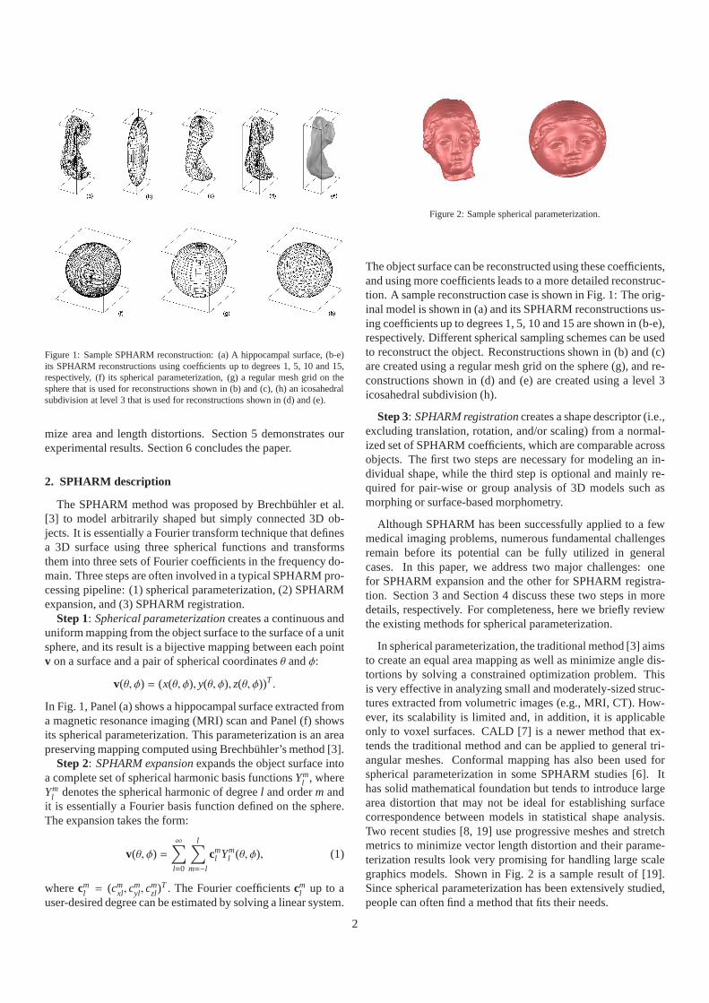
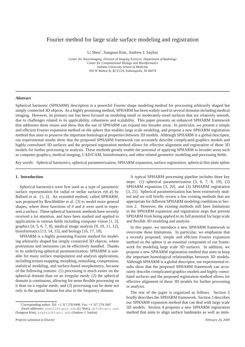
Figure 1: Sample SPHARM reconstruction: (a) A hippocampal surface, (b-e)its SPHARM reconstructions using coefficients up to degrees1, 5, 10 and 15,respectively, (f) its spherical parameterization, (g) a regular mesh grid on thesphere that is used for reconstructions shown in (b) and (c),(h) an icosahedralsubdivision at level 3 that is used for reconstructions shown in (d) and (e).
mize area and length distortions. Section 5 demonstrates ourexperimental results. Section 6 concludes the paper.
2. SPHARM description
The SPHARM method was proposed by Brechbuhler et al.[3] to model arbitrarily shaped but simply connected 3D ob-jects. It is essentially a Fourier transform technique thatdefinesa 3D surface using three spherical functions and transformsthem into three sets of Fourier coefficients in the frequencydo-main. Three steps are often involved in a typical SPHARM pro-cessing pipeline: (1) spherical parameterization, (2) SPHARMexpansion, and (3) SPHARM registration.
Step 1: Spherical parameterization creates a continuous anduniform mapping from the object surface to the surface of a unitsphere, and its result is a bijective mapping between each pointv on a surface and a pair of spherical coordinatesθ andφ:
v(θ, φ) = (x(θ, φ), y(θ, φ), z(θ, φ))T .
In Fig. 1, Panel (a) shows a hippocampal surface extracted froma magnetic resonance imaging (MRI) scan and Panel (f) showsits spherical parameterization. This parameterization isan areapreserving mapping computed using Brechbuhler’s method [3].
Step 2: SPHARM expansion expands the object surface intoa complete set of spherical harmonic basis functionsYm
l , whereYm
l denotes the spherical harmonic of degreel and orderm andit is essentially a Fourier basis function defined on the sphere.The expansion takes the form:
v(θ, φ) =∞∑
l=0
l∑
m=−l
cml Ym
l (θ, φ), (1)
wherecml = (cm
xl, cmyl, c
mzl)
T . The Fourier coefficientscml up to a
user-desired degree can be estimated by solving a linear system.
Figure 2: Sample spherical parameterization.
The object surface can be reconstructed using these coefficients,and using more coefficients leads to a more detailed reconstruc-tion. A sample reconstruction case is shown in Fig. 1: The orig-inal model is shown in (a) and its SPHARM reconstructions us-ing coefficients up to degrees 1, 5, 10 and 15 are shown in (b-e),respectively. Different spherical sampling schemes can beusedto reconstruct the object. Reconstructions shown in (b) and(c)are created using a regular mesh grid on the sphere (g), and re-constructions shown in (d) and (e) are created using a level 3icosahedral subdivision (h).
Step 3: SPHARM registration creates a shape descriptor (i.e.,excluding translation, rotation, and/or scaling) from a normal-ized set of SPHARM coefficients, which are comparable acrossobjects. The first two steps are necessary for modeling an in-dividual shape, while the third step is optional and mainly re-quired for pair-wise or group analysis of 3D models such asmorphing or surface-based morphometry.
Although SPHARM has been successfully applied to a fewmedical imaging problems, numerous fundamental challengesremain before its potential can be fully utilized in generalcases. In this paper, we address two major challenges: onefor SPHARM expansion and the other for SPHARM registra-tion. Section 3 and Section 4 discuss these two steps in moredetails, respectively. For completeness, here we briefly reviewthe existing methods for spherical parameterization.
In spherical parameterization, the traditional method [3]aimsto create an equal area mapping as well as minimize angle dis-tortions by solving a constrained optimization problem. Thisis very effective in analyzing small and moderately-sized struc-tures extracted from volumetric images (e.g., MRI, CT). How-ever, its scalability is limited and, in addition, it is applicableonly to voxel surfaces. CALD [7] is a newer method that ex-tends the traditional method and can be applied to general tri-angular meshes. Conformal mapping has also been used forspherical parameterization in some SPHARM studies [6]. Ithas solid mathematical foundation but tends to introduce largearea distortion that may not be ideal for establishing surfacecorrespondence between models in statistical shape analysis.Two recent studies [8, 19] use progressive meshes and stretchmetrics to minimize vector length distortion and their parame-terization results look very promising for handling large scalegraphics models. Shown in Fig. 2 is a sample result of [19].Since spherical parameterization has been extensively studied,people can often find a method that fits their needs.
2

3. Large scale SPHARM expansion
Given a 3D modelv(θ, φ) and a user-specified maximum de-greeLmax, the task of SPHARM expansion is to extract coef-ficientscm
l in Eq. (1) for l ≤ Lmax and |m| ≤ l. There are twotypes of approaches for computingcm
l : one uses numerical inte-gration [14, 20]; the other formulates a linear system and solvesit using least square fitting (LSF) [3].
The naive numerical integration method is inefficient and sonot applicable to large models. Healy et al. [20] proposed a fastalgorithm to accelerate the integration procedure using a divide-and-conquer strategy; and several studies [4, 6, 8] employedthis method. However, to use Healy’s method, a preprocessingstep is required to remesh the model using a regular sphericalmesh grid (e.g., Fig. 1(g)). This step is inconvenient and also ittends to introduce additional remeshing errors.
In contrast, the LSF method [3] is very easy to implementand works directly on original object meshes even if they areir-regular. The LSF method seems to be a more popular method inSPHARM studies, especially in brain imaging. The bottleneckof this method is its limited scalability, because most methodsfor solving large linear systems [22, 23] are either designed forsparse or symmetric matrices or not easy to implement. Thismight be the reason that SPHARM has been mostly used formodeling small or moderately sized 3D surfaces.
We describe an iterative residual fitting (IRF) method thatovercomes this limitation and facilitates the opportunityof cre-ating large scale SPHARM models. The basic idea behind theIRF method is simple and follows the properties of sphericalharmonic transform.First, these harmonics form a coarse-to-fine hierarchy. If we just use a few low degree harmonics to ex-pand a spherical functionf (θ, φ), we get a low-pass filtered re-construction. If we use more degrees, more details are includedin the reconstruction. The IRF method takes advantage of thiscoarse-to-fine hierarchy. It starts from a low degree reconstruc-tion and then iteratively adds more details into our model byin-volving higher degree harmonics.Second, spherical harmonicsform an orthonormal basis and geometric information is storedin different frequency channels. Thus, if we first extract infor-mation from low frequency channels, the residual (i.e., f (θ, φ)−its reconstruction) will exactly contain information in high fre-quency channels. To add in more details to our model, we cansimply use a few higher degree harmonics to fit the residual.
The IRF method breaks a large linear system into severalsmall linear systems and thus SPHARM modeling can be eas-ily done at a large scale on standard workstations with aver-age configuration using a standard linear solver. We also be-lieve that much larger SPHARM models can be created if onecombines the IRF method with an enhanced large-scale lin-ear solver. IRF was originally presented in [24, 9], where thismethod was tested on a few models with around 40, 000 verticesand it worked well. In this paper, we aim to demonstrate that theIRF method can be used to accurately model larger scale graph-ics models and to enable a broader range of surface processingapplications. We also want to emphasize that IRF is an essentialcomponent in the proposed enhanced SPHARM framework formodeling large scale 3D surfaces.
Note that a degreel SPHARM model involves (l + 1)2 × 3complex coefficients. Our experiments show that a degree 85SPHARM model described by 22,188 complex coefficients canreasonably capture surface details of an original model with100,002 vertices and 200,000 faces that is described by 900,006variables in total. Additional quantifiable information about thereconstruction errors and the compression ratios is available inTable 1 of Section 5.1. For more details about IRF (e.g., pro-jection errors, optimal frequency band selection), pleasereferto [9, 24].
4. Landmark guided SPHARM registration
SPHARM registration is an important operation allowingfor pairwise processing or group analysis across differentSPHARM models and is a critical step in many applications(e.g., surface-based morphometry in medical imaging [9, 10,11, 12, 15], evolutionary morphology in biology [16, 17, 18]).The traditional method [3] uses the first order ellipsoid foralignment, and works only if this ellipsoid is a real ellipsoid andmay not work well in many other cases. SHREC [21] is a newerSPHARM registration method that minimizes the mean squaredistance between corresponding surface parts and works forgeneral cases. Both methods are designed for relatively smoothsurfaces without landmarks. However, landmarks often containimportant prior knowledge about the objects. For example, theytend to have critical anatomical or biological meanings in medi-cal and biological applications and should not be ignored intheregistration procedure.
In this paper, we present a new SPHARM registrationmethod that is guided by a set of pre-existing landmarks. SinceSPHARM is a parametric model, registration should be done inboth object and parameter spaces. In the object space, we firstscale all the objects with landmarks to have a normalized size,and then apply the iterative closest points (ICP) method [25] toalign landmarks together in a least square fashion. Now the keyproblem is how to align landmarks in the parameter space.
Given two SPHARM models, a template and an individual,we can distort the parameterization of the individual to matchits landmarks with the corresponding landmarks on the parame-terization of the template. This can be done by applying spher-ical thin plate spline (STPS) [26]. We observe that there aremany different ways to apply STPS and the results are very dif-ferent from one another. Note that the correspondence betweenSPHARM models is implied by the underlying parameteriza-tion: two points with the same parameter pair (θ, φ) on two sur-faces are defined to be a corresponding pair. Thus, in order tocreate an ideal correspondence, our goal is to identify an un-derlying parameterization that is the least distorted. To achievethis goal, we present a few strategies that aim to find the “best”parameterization from these STPS results.
Zou et al. [27, 28] did a similar study, where they directlyapplied STPS to spherical conformal parameterizations butdidnot consider to reduce area and length distortions. In the field ofthe SPHARM surface modeling, we feel that an equal area map-ping is more attractive than other mappings because we want totreat each area unit on object surface equally by assigning the
3
same amount of parameter space to it (i.e., similar to arc-lengthparameterization for comparing 2D contours). Our method isdesigned to achieve this goal. Asirvatham et al. [29] did an-other similar study, where landmark constraints were used toguide the spherical parameterization procedure in a progressivemesh framework. In our case, we don’t want to re-parameterizethe entire object, since the existing parameterization hasalreadybeen optimized based on certain criteria. Our goal is simplytodistort as little as possible the existing parameterization in orderto match landmarks.
In the rest of this section, we describe our landmark-guidedSPHARM registration method. We assume that objects arealready aligned to one another in the object space and theirSPHARM descriptions are known (pre-calculated). We firstbriefly describe STPS, then define the area and length distor-tions we try to minimize, and finally presents our methods.
4.1. Spherical thin plate spline
Spherical thin plate spline (STPS), defined in [26], is an ex-tension of 2D thin plate spline to a spherical domain and hasbeen used to deform spherical parametric domains [27, 28].STPS on a spherical domainS 2 minimizes a bending energyJ(u), subject tou(Pi) = zi, i = 1, 2, · · · , n, wherePi ∈ S 2 andzi
is the fixed displacement atPi. This bending energy is formu-lated as
J(u) =∫ 2π
0
∫ π
0(∆u(θ, φ))2 sinφdθdφ, (2)
whereθ ∈ [0, π] is latitude,φ ∈ [0, 2π] is longitude, and∆ is theLaplace-Beltrami operator.
The solution on the sphere is given by
un(P) =n
∑
i=1
ciK(P, Pi) + d (3)
wherec andd are determined by
Knc + dT = z,TTc = 0,
Kn is the n × n matrix with i, jth entry K(Pi, P j), T =
(1, ..., 1)T , andz = (z1, ..., zn)T . K(X, Y) between two arbitrarypointsX, Y ∈ S 2 is defined as follows:
K(X, Y) =14π
∫ 1
0(logh)(1−
1h
)(1
√1− 2ha + h2
− 1)dh
wherea = cos(γ(X, Y)) andγ(X, Y) is the angle betweenX andY. However, this is not in a computable closed form expres-sion. Therefore, thin plate pseudo-spline on the sphereR(X, Y),defined in [26], is used in this study, which is formulated as
R(X, Y) =12π
[
1(2m − 2)!
q2m−2(a) − 1(2m − 1)!
]
(4)
and
qm(a) =∫ 1
0(1− h)m(1− 2ha + h2)−1/2dh,m = 0, 1, · · · .
In our case, we havem = 2 giving
q2(a) =12
ln
1+
√
1W
[
12W2 − 4W]
− 12W3/2+ 6W + 1
,
(5)whereW = (1− a)/2. Therefore, the Eq. 3 becomes
un(P) =n
∑
i=1
ciR(P, Pi) + d, (6)
andc andd are determined by
Rnc + dT = z,TTc = 0,
whereRn is then × n matrix with i, jth entryR(Pi, P j), T =(1, ..., 1)T , andz = (z1, ..., zn)T .
Given n pairs of two corresponding points{Pi, Pnewi }, i =
1, · · · , n on the sphere, the displacements (∆θi,∆φi) at a set ofpoints {Pi, i = 1, · · · , n} are calculated. With this displace-ments, Eqs. 4, 5, and 6 are used to compute displacement(∆θk,∆φk) of any pointPk ∈ S 2 and the pointPk, located atp(θ, φ), is moved to a new pointPnew
k at p(θ+∆θk, φ+∆φk). Forconvenience, we call this theSTPS-based displacement scheme.
4.2. Mesh distortion measures
In this study, STPS is employed to match the landmark posi-tions of an individual object in the spherical parametric domainto the corresponding landmark positions of the template objectand subsequently transform the underlying parametric meshofthe individual object. This algorithm distorts the parametricmesh of the individual object and can introduce additional er-rors to some extent to the reconstructed shape of the individualobject. Therefore, mesh distortion cost functions are employedand these distortion costs are used as selection criteria for find-ing best rotation angles in the proposed algorithm.
Distortion of the parametric mesh by STPS is measured bycalculating the area distortion cost (ADC) and the length dis-tortion cost (LDC). The overall and worst costs for the wholeparametric mesh are measured to evaluate the performance ofthe proposed algorithms in Section 4.3.
4.2.1. Area distortion measuresThe concept of area distortion cost introduced by [7] is em-
ployed as one of the performance measures in this study. LetM = {ti} be a triangle mesh in the parametric space and letΨ bea continuous STPS-based displacement scheme, which mapsMto a distorted parametric meshΨ(M) = {Ψ(ti)}. A(·) is used todenote the area of a triangle or a mesh. The area distortion cost(ADC) Ca with respect toΨ is defined as follows:
For each triangleti ∈ M,
Ca(ti,Ψ) =A(Ψ(ti))
A(ti).
This measures the local ADC of a single triangle.For each mesh vertexv in M,
Ca(v,Ψ) =
∑
ti∈MvA(Ψ(ti))
∑
ti∈MvA(ti)
,
4

whereMv is the set of triangle incident uponv. This measuresthe local ADC around a single vertex.
For the whole parametric meshM,
Ca(M,Ψ) =
∑
ti∈M max(Ca(ti,Ψ), 1Ca(ti ,Ψ) )A(Ψ(ti))
A(Ψ(M)). (7)
This measures the overall ADC for the whole mesh. By taking
max
(
Ca(ti,Ψ),1
Ca(ti,Ψ)
)
as the ADC contribution from each triangle, we treat contrac-tion and expansion equally, and so always haveCa(M,Ψ) ≥ 1.
The worst ADC is defined as follows
CWa (M,Ψ) = max
{
max
(
Ca(ti,Ψ),1
Ca(ti,Ψ)
)
|ti ∈ M
}
. (8)
4.2.2. Length distortion measuresTo measure length distortion introduced by STPS, the stretch
concept by Sander et al. [30] is adopted in this study. Theyconsidered the case of mapping from a planar domain to 3Dsurface and at any point in the planar domain, two singular val-ues of the 3×2 Jacobian matrix were computed to represent thelargest and smallest length distortions when a vector in the2Ddomain was mapped to the 3D surface. In our case, the lengthdistortion cost (LDC)Cs with respect to a given mesh mappingΨ from M toΨ(M), is defined as follows:
Given a mesh mappingΨ from M toΨ(M),
Cs(M,Ψ) =
√
∑
ti∈M(Γ(ti)2 +1γ(ti)2 )A(Ψ(ti))
2A(Ψ(M)), and (9)
CWs (M,Ψ) = max
{
max
(
Γ(ti),1γ(ti)
)
|ti ∈ M
}
, (10)
whereΓ(ti) andγ(ti) are the largest and smallest length distor-tions for a triangleti and A(·) is used to denote the area of atriangle or a mesh.
In the above definitions,Cs(M,Ψ) measures the averagelength distortion cost (LDC) for the whole meshM and theworst LDC is defined byCW
s (M,Ψ). The largest and small-est length distortions are directly computed from the length ofthree corresponding sides betweenti andΨ(ti). Again, contrac-tion and expansion are equally treated in both definitions.
4.2.3. Calculation of minimum distortion costAt each step of the proposed approach, after STPS algorithm
is applied, we calculate the average and worst ADCs as well asthe average and worst LDCs, defined by Eqs. 7, 8, 9, and 10, re-spectively. In current experiments, we try to minimize the worstADC. If several STPS results have the same worst ADCs, thentheir average ADCs, the worst LDCs, and the average LDCsare compared in order. This rule is used to avoid the extremecontraction or expansion while maintaining the reasonableareadistorting and length distortion. We plan to explore other crite-ria using these measures in future studies.
Algorithm 1 Basis STPS method for SPHARM registration1: Map landmarks of the template and an individual onto a
common parametric mesh, e.g. an icosahedral subdivision2: Distort the individual parametric mesh using STPS to move
its landmarks to the location of the template’s landmarks3: Calculate new SPHARM expansion of the individual using
the STPS-distorted parameterization
Figure 3: Application of basic STPS method. When one or more landmarks areclosely located to the north or south pole, the parametric mesh of the individualcan be severely distorted. The average costa and the worst costw are shown as(a,w) for ADC and LDC.
4.3. Alignment of parametric mesh using STPS
4.3.1. Basic STPS algorithmThe basic method is to directly apply the STPS algorithm to
two sets of landmarks with known correspondence between thesets, defined in a parametric mesh. Alg. 1 describes this ap-proach to the landmark-guided alignment. Zou et al. [27, 28]used this approach in their studies. However, this naive ap-proach can severely distort the parametric mesh of an individ-ual object and result in a distorted reconstruction withoutre-sampling the parametric mesh, especially when one or morelandmarks are located near the north or south pole (see Fig. 3).
4.3.2. Hierarchical STPS algorithm
Algorithm 2 Hierarchical STPS method1: i:=1; assume that an parameter net is given2: repeat3: Create icosahedral samples at leveli for α’s andβ’s4: if i=1 then5: Rotate the parameter net using each (αβ0), apply
STPS, and keep the top K candidates that minimizethe distortion costs, defined in Section 4.2.3
6: else7: Keep only local icosahedral samples forα’s & β’s8: Rotate the parameter net of each top K candidate using
each (αβ0), apply STPS, and select top K candidates9: i:=i+1
10: until The best distortion costs do not improve11: Return the best result in top K list
To avoid large distortion introduced by STPS, we employ asampling-based strategy that rotates the individual’s landmarkson the sphere using Euler angles (αβγ) in order to find thebest oriented landmarks for applying STPS. The rotation space
5
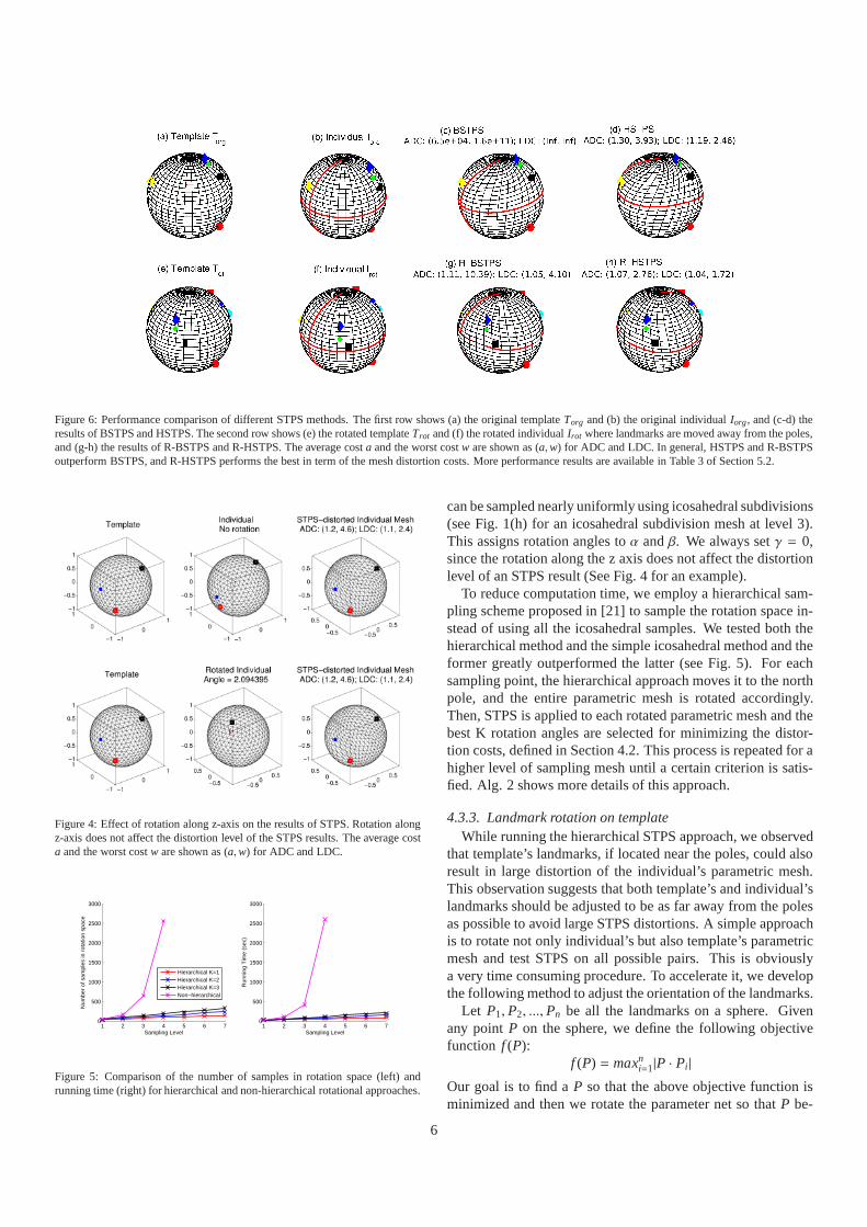
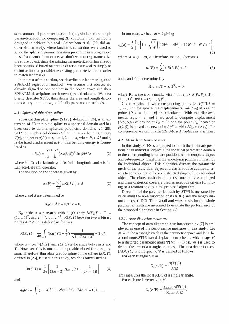
Figure 6: Performance comparison of different STPS methods. The first row shows (a) the original templateTorg and (b) the original individualIorg, and (c-d) theresults of BSTPS and HSTPS. The second row shows (e) the rotated templateTrot and (f) the rotated individualIrot where landmarks are moved away from the poles,and (g-h) the results of R-BSTPS and R-HSTPS. The average cost a and the worst costw are shown as (a,w) for ADC and LDC. In general, HSTPS and R-BSTPSoutperform BSTPS, and R-HSTPS performs the best in term of the mesh distortion costs. More performance results are available in Table 3 of Section 5.2.
Figure 4: Effect of rotation along z-axis on the results of STPS. Rotation alongz-axis does not affect the distortion level of the STPS results. The average costa and the worst costw are shown as (a,w) for ADC and LDC.
1 2 3 4 5 6 70
500
1000
1500
2000
2500
3000
Sampling Level
Num
ber
of s
ampl
es in
rot
atio
n sp
ace
Hierarchical K=1Hierarchical K=2Hierarchical K=3Non−hierarchical
1 2 3 4 5 6 70
500
1000
1500
2000
2500
3000
Sampling Level
Run
ning
Tim
e (s
ec)
Figure 5: Comparison of the number of samples in rotation space (left) andrunning time (right) for hierarchical and non-hierarchical rotational approaches.
can be sampled nearly uniformly using icosahedral subdivisions(see Fig. 1(h) for an icosahedral subdivision mesh at level 3).This assigns rotation angles toα andβ. We always setγ = 0,since the rotation along the z axis does not affect the distortionlevel of an STPS result (See Fig. 4 for an example).
To reduce computation time, we employ a hierarchical sam-pling scheme proposed in [21] to sample the rotation space in-stead of using all the icosahedral samples. We tested both thehierarchical method and the simple icosahedral method and theformer greatly outperformed the latter (see Fig. 5). For eachsampling point, the hierarchical approach moves it to the northpole, and the entire parametric mesh is rotated accordingly.Then, STPS is applied to each rotated parametric mesh and thebest K rotation angles are selected for minimizing the distor-tion costs, defined in Section 4.2. This process is repeated for ahigher level of sampling mesh until a certain criterion is satis-fied. Alg. 2 shows more details of this approach.
4.3.3. Landmark rotation on templateWhile running the hierarchical STPS approach, we observed
that template’s landmarks, if located near the poles, couldalsoresult in large distortion of the individual’s parametric mesh.This observation suggests that both template’s and individual’slandmarks should be adjusted to be as far away from the polesas possible to avoid large STPS distortions. A simple approachis to rotate not only individual’s but also template’s parametricmesh and test STPS on all possible pairs. This is obviouslya very time consuming procedure. To accelerate it, we developthe following method to adjust the orientation of the landmarks.
Let P1, P2, ..., Pn be all the landmarks on a sphere. Givenany pointP on the sphere, we define the following objectivefunction f (P):
f (P) = maxni=1|P · Pi|
Our goal is to find aP so that the above objective function isminimized and then we rotate the parameter net so thatP be-
6
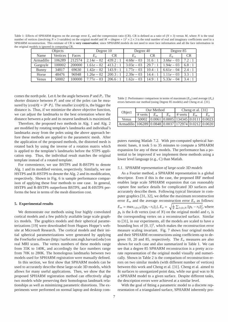
Table 1: Effects of SPHARM degrees on the average errorEa and the compression ratio (CR). CR is defined as a ratio of (N × 3) versusM, whereN is the totalnumber of vertices (involvingN × 3 variables) on the original model andM = (degree+ 1)2 × 2× 3 is the total number of real and imaginary coefficients used in aSPHARM reconstruction. This estimate of CR isvery conservative, since SPHARM models do not need to store face information and all the face information inthe original models is ignored in computing CR.
Objects Degree 10 Degree 40 Degree 85Name Vertices Faces Ea CR Ea CR Ea CR
Armadillo 106289 212574 2.14e − 02 439.2 : 1 4.68e − 03 31.6 : 1 3.66e − 03 7.2 : 1Gargoyle 100002 200000 1.61e − 02 413.2 : 1 3.03e − 03 29.7 : 1 1.94e − 03 6.8 : 1Bunny 34817 69630 1.42e − 02 143.9 : 1 1.77e − 03 10.4 : 1 6.61e − 04 2.4 : 1Horse 48476 96948 1.26e − 02 200.3 : 1 2.39e − 03 14.4 : 1 1.11e − 03 3.3 : 1Venus 50002 100000 7.77e − 03 206.6 : 1 1.62e − 03 14.9 : 1 5.33e − 04 3.4 : 1
comes the north pole. Letθi be the angle betweenP andPi. Theshorter distance betweenPi and one of the poles can be mea-sured by|cos(θ)| = |P ·Pi|. The smaller|cos(θ)| is, the bigger thedistance is. Thus, if we minimize the above objective function,we can adjust the landmarks to the best orientation where thedistance between a pole and its nearest landmark is maximized.
Therefore, the proposed two methods in Alg. 1 and Alg. 2are modified by rotating template’s landmarks and individual’slandmarks away from the poles using the above approach be-fore these methods are applied to the parametric mesh. Afterthe application of the proposed methods, the distorted meshisrotated back by using the inverse of a rotation matrix whichis applied to the template’s landmarks before the STPS appli-cation step. Thus, the individual result matches the originaltemplate instead of a rotated template.
For convenience, we use BSTPS and R-BSTPS to denoteAlg. 1 and its modified version, respectively. Similarly, weuseHSTPS and R-HSTPS to denote the Alg. 2 and its modification,respectively. Shown in Fig. 6 is sample performance compar-ison of applying these four methods to one case. In general,HSTPS and R-BSTPS outperform BSTPS, and R-HSTPS per-forms the best in terms of the mesh distortion cost.
5. Experimental results
We demonstrate our methods using four highly convolutedcortical models and a few publicly available large scale graph-ics models. The graphics models and their spherical parame-terizations [19] were downloaded from Hugues Hoppe’s web-site at Microsoft Research. The cortical models and their ini-tial spherical parameterizations were generated by applyingthe FreeSurfer software (http://surfer.nmr.mgh.harvard.edu/) onreal MRI scans. The vertex numbers of these models rangefrom 35K to 140K, and accordingly the face numbers rangefrom 70K to 280K. The homologous landmarks between twomodels used for SPHARM registration were manually defined.
In this section, we first show that SPHARM models can beused to accurately describe these large-scale 3D models, whichallows for many useful applications. Then, we show that theproposed SPHARM registration method can effectively aligntwo models while preserving their homologous landmark rela-tionships as well as minimizing parametric distortions. The ex-periments were performed on normal laptop and desktop com-
Table 2: Performance comparison in terms of maximum (Em) and average (Ea)errors between our method (using Degree 85 models) and Chenget al. [31].
ObjectOur Method Cheng et al. [31]
# verts Em Ea # verts Em Ea
Venus 50002 0.0061 0.0005 134345 0.0111 0.0023Armadillo 106289 0.0848 0.0037 172974 0.0212 0.0020
puters running Matlab 7.2. With pre-computed spherical har-monic bases, it took 5 to 35 minutes to compute a SPHARMexpansion for any of these models. The performance has a po-tential to be improved if we implement these methods using alower level language (e.g., C) than Matlab.
5.1. SPHARM representation of large-scale 3D models
As a Fourier method, a SPHARM representation is a globaldescriptor. Even if this is the case, the proposed IRF methodenables large scale SPHARM expansion that can reasonablycapture fine surface details for complicated 3D surfaces andaccurately describe them. Following typical literature incom-puter graphics [31, 32], we define the maximum reconstructionerror Em and the average reconstruction errorEa as follows:
Em = max1≤k≤N {||pk−rk ||2}, Ea =
√
1N
∑
1≤k≤N ||pk − rk ||22,wherepk is thek-th vertex (out ofN) on the original model andrk isthe corresponding vertex on a reconstructed surface. Similarto [31], in our experiments, all the models are scaled to haveabounding box of [0, 1]3, which makes the reconstruction errormeasure scaling invariant. Fig. 7 shows four original modelsand their SPHARM reconstructions using coefficients up to de-grees 10, 20 and 85, respectively. TheEa measures are alsoshown for each case and also summarized in Table 1. We cansee that a degree 85 SPHARM reconstruction is a pretty accu-rate representation of the original model visually and numeri-cally. Shown in Table 2 is the comparison of reconstruction er-rors on two similar models (with different number of vertices)between this work and Cheng et al. [31]. Cheng et al. aimed tofit surfaces to unorganized point data, while our goal was to fita SPHARM model to a given surface. Despite different tasks,the description errors were achieved at a similar level.
With the goal of fitting a parametric model to a discrete rep-resentation of a triangulated surface, SPHARM inherently pro-
7

Figure 7: Shown from left to right are original models and their SPHARM reconstructions (with reconstruction errorEa) of degrees 10, 20 and 85. SPHARM canaccurately model large scale 3D surfaces as well as be used for interesting applications such as geometric compression,surface filtering, etc.; see text for details.
Figure 8: SPHARM reconstructions using different spherical sampling schemes: The top two rows use icosahedral subdivisions and the bottom two rows use regularspherical meshes. Potential applications include remeshing, multi-resolution modeling, and level of details.
8

Figure 9: Two alignment results between cortical models. The first two rowsshow the result of aligning an individual left hemisphere toits template, whilethe last two rows show the results for a right hemisphere case. The first columnshows a template model. The second and the third columns exhibit an individ-ual model before and after SPHARM registration respectively. A quadrilateralmesh and a bump map on sphere show the correspondence betweeneach objectand its parameterization. Landmarks are shown as blue dots on the surface.
vides a mechanism for surface interpolation. While some sur-face interpolation methods (e.g., [33]) can deal with surfacesof arbitrary topology, SPHARM is only applicable to genuszero surfaces. Since SPHARM is a mathematical model de-fined on a continuous spherical domain, it enables easier pro-cessing for many applications involving arbitrarily-shaped butsimply-connected 3D objects.
First, it is a more compact representation than a triangu-lated surface in many cases. For example, the original gargoylemodel has 100,002 vertices and 200,000 faces, and so it is de-scribed by 900,006 variables in total. However, a degree 85SPHARM model of gargoyle is described only by 22,188 com-plex coefficients and can reasonably capture the overall shapetogether with many surface details of the original model. Thiscompactness property can be used for geometric compression.Table 1 shows effects of SPHARM degrees on the descriptionerror Ea and the compression ratio (CR). Even though the CRestimation is very conservative (i.e., ignoring all the face infor-mation in the original model), decent CRs andEa’s can still beachieved for degree 85 reconstructions of the tested models.
Second, one can operate not only in the spatial domain butalso in the frequency domain. Taking a lower order SPHARMreconstruction can naturally achieve the goal of surface smooth-ing and filtering. See Fig. 7 for a few samples. This property
has been used in a couple of prior studies [4, 8] for surfacesmoothing and filtering. It can also be used for level of detailsrepresentation and transferring.
Third, the level of details applications can be done not onlyvia the frequency domain but also via the spatial domain.A SPHARM reconstruction is essentially a remeshed origi-nal model. We can use different spherical sampling schemeswith different sampling resolutions for SPHARM reconstruc-tion. Fig. 8 shows several reconstruction cases using regu-lar spherical mesh grids (Fig. 1(g)) and icosahedral subdivi-sions (Fig. 1(h)) at different sampling resolutions. Although nottested in our experiments, the adaptive sampling mesh schemedescribed in [8] seems like a promising method that can derivemore accurate reconstructions with fewer vertices.
5.2. SPHARM registration
Table 3 presents the performance comparison among fourproposed approaches to apply STPS to five cases. In general, R-BSTPS and R-HSTPS outperform BSTPS and HSTPS respec-tively in terms of the mesh distortion costs, and R-HSTPS ex-hibits the best performance. It is noticed that, however, HSTPSshows the better performance than R-HSTPS in the first case.However, even in this case, the distorted mesh using R-HSTPSdoes not introduce any noticeable distortion to its reconstructedobject. This observation suggests that the criteria for selectingthe best orientation of the landmarks on the sphere require fur-ther investigation for both the template’s parameterization andthe individual’s parameterization.
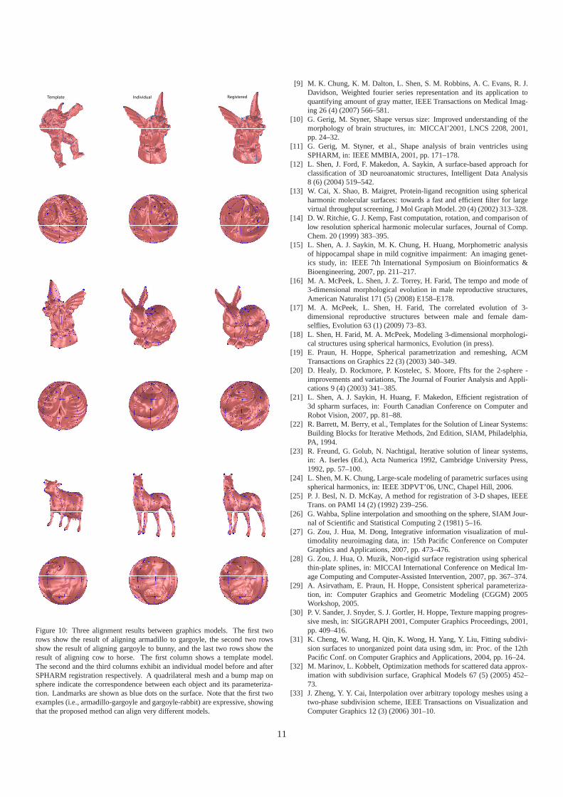
Fig. 9 and Fig. 10 show the R-HSTPS alignment results oftwo pairs of cortical models and three pairs of graphics mod-els respectively and their distortion costs can be found in Ta-ble 3. Each two rows correspond to one alignment case, wherethe top row shows the objects and the bottom row shows theirspherical parameterization. We use bump maps to visualizethe correspondence between the object and its parameteriza-tion. Landmarks and a coarse mesh grid are also shown on eachsurface. The first column shows template models. The secondand the third columns exhibit individual models before and af-ter SPHARM registration respectively. Comparing an originalindividual with the corresponding template, you will notice thattheir landmarks are aligned only in the object space but not inthe spherical parameter space. However, comparing a regis-tered individual with the corresponding template, you can seethat their landmarks are aligned not only in the object spacebutalso in the parameter space.
This improvement of alignment can subsequently contributeto the feasibility of performing pair-wise processing or groupanalysis of these 3D models. For example, such a SPHARMregistered result can help improve a morphing sequence be-tween two 3D models. Results shown in Fig. 11 exhibit severalmorphing sequences between a template and an original indi-vidual (Rows 1, 3, and 5) or between a template and a registeredindividual (Rows 2, 4, and 6). All the templates and the originaland registered individuals are reconstructed using their degree85 SPHARM models. We can see that morphing the templateto the registered individual achieves a much better effect than
9

Table 3: Comparison of mesh distortion costs among the proposed methods: each entry (a,w) contains the average costa and the worst costb.
Template Individual Distortion Cost BSTPS HSTPS R-BSTPS R-HSTPSADC (8.2e+4, 8.8e+4) (1.2, 26.7) (4.2e+4, 8.4e+4) (4.4, 268.7)
Armadillo GargoyleLDC (4.4, 567.7) (1.1, 6.1) (8.0, 26.4) (2.1, 19.0)ADC (8.1e+4, 1.6e+11) (8.1e+4, 8.8e+4) (8.4e+4, 8.8e+4) (6.0, 386.6)
Gargoyle BunnyLDC (Inf, Inf) (4.2, 129.2) (3.7, 131.8) (2.5, 25.5)ADC (6.4e+4, 1.1e+11) (2.2, 168.3) (1.3, 3.7) (1.3, 3.7)
Cow HorseLDC (Inf, Inf) (1.5, 17.0) (1.2, 3.0) (1.2, 3.0)ADC (6.5e+4, 1.6e+11) (1.3, 3.9) (1.1, 10.4) (1.1, 2.8)
Left Cortex 1 Left Cortex 2LDC (Inf, Inf) (1.2, 2.5) (1.0, 4.1) (1.0, 1.7)ADC (4.5e+4, 2.5e+10) (1.3, 4.9) (4.9e+4, 5.6e+10) (1.1, 5.3)
Right Cortex 1 Right Cortex 2LDC (Inf, Inf) (1.2, 2.5) (Inf, Inf) (1.1, 2.4)
to the original individual, since the intermediate shape ofmor-phing to the registered individual looks more natural than thoseof morphing to the original individual. Besides morphing, thereare many other SPHARM applications requiring models beingregistered with landmark guidance, such as surface-based mor-phometry in biomedical imaging [9, 10, 11, 12, 15] and mor-phological analysis in evolutionary biology [16, 17, 18].
6. Conclusions
We have presented an enhanced spherical harmonic(SPHARM) surface modeling and processing framework, anddemonstrated that it could be used to accurately model largescale 3D surfaces and it could effectively register these modelswith or without landmark constraints. The main contribution istwofold: (1) incorporation of our recently proposed large scaleSPHARM expansion method into the framework for facilitat-ing the possibility of using SPHARM to accurately model largescale 3D surfaces, (2) design of a new STPS-based SPHARMalignment method that can register SPHARM models togetherunder pre-existing landmark constraints as well as minimizeparametric distortions. Our experimental results show theef-fectiveness of the proposed methods. These methods greatlyenable the potential of applying the highly promising SPHARMmethod to broader areas such as computer graphics, medicalimaging, CAD/CAM, bioinformatics, and other related geomet-ric modeling and processing fields. The proposed methods willbe incorporated into SPHARM-MAT, a 3D shape modeling andanalysis toolkit, and will be released at the Neuroimaging Infor-matics Tools and Resources Clearinghouse (NITRC) websitehttp://www.nitrc.org/ in the near future.
While image registration is considered as one of the mostimportant topic in image processing and analysis, surface reg-istration plays a similarly important role in computer graphicsand shape analysis. The reasonable choice for criterion usedfor quantifying registration quality is critical. Different appli-cations may require different criteria for obtaining optimal re-sults. For smooth surfaces without landmarks (e.g., hippocam-pus, ventricle), we can use traditional SPHARM registrationmethods [3, 21] to align them. In these cases, their underlying
parameterizations are not distorted. However, for surfaces asso-ciated with homologous landmarks (e.g., many biological struc-tures), the underlying parameterizations have to be distortedso that the corresponding landmarks can be registered togetheracross different objects. While the proposed registrationmeth-ods are designed for this purpose and aim to control the area andlength distortions, it remains an interesting future topicto ex-amine the effects of using alternative criteria (i.e., considering adifferent combination of the area, length and angle distortions)for developing other effective registration schemes.
Acknowledgements
This work was supported in part by NIBIB/NEI R03EB008674-01, NIA R01 AG19771, NCI R01 CA101318 andU54 EB005149 from the NIH, Foundation for the NIH, andgrant #87884 from the Indiana Economic Development Cor-poration (IEDC). Graphics models were downloaded fromHugues Hoppe’s website for [19] at Microsoft Research. Thecortical models were generated by the FreeSurfer softwarehttp://surfer.nmr.mgh.harvard.edu/. We thank the anonymousreviewers for their insightful comments and suggestions thathelp improve the paper.
References
[1] D. H. Ballard, C. M. Brown, Computer Vision, Prentice-Hall, EnglewoodCliffs, N.J., 1982.
[2] R. Schudy, D. Ballard, Towards an anatomical model of heart motion asseen in 4-D cardiac ultrasound data, in: 6th Conf. on Comp. App. in Rad.& Anal. of Rad. Im., 1979.
[3] C. Brechbuhler, G. Gerig, O. Kubler, Parametrization of closed surfacesfor 3D shape description, Computer Vision and Image Understanding61(2) (1995) 154–170.
[4] T. Bulow, Spherical diffusion for 3D surface smoothing,IEEE Trans. onPattern Analysis and Machine Intelligence 26 (12) (2004) 1650–1654.
[5] T. Funkhouser, P. Min, et al., A search engine for 3d models, ACM Trans-actions on Graphics 22 (1) (2003) 83–105.
[6] X. Gu, Y. Wang, T. F. Chan, P. M. Thompson, S.-T. Yau, Genuszerosurface conformal mapping and its application to brain surface mapping,IEEE Transaction on Medical Imaging 23 (8) (2004) 949–958.
[7] L. Shen, F. Makedon, Spherical mapping for processing of3d closed sur-faces, Image and Vision Computing 24 (2006) 743–61.
[8] K. Zhou, H. Bao, J. Shi, 3D surface filtering using spherical harmonics,CAD 36 (4) (2004) 363–375.
10
Template RegisteredIndividual
Figure 10: Three alignment results between graphics models. The first tworows show the result of aligning armadillo to gargoyle, the second two rowsshow the result of aligning gargoyle to bunny, and the last two rows show theresult of aligning cow to horse. The first column shows a template model.The second and the third columns exhibit an individual modelbefore and afterSPHARM registration respectively. A quadrilateral mesh and a bump map onsphere indicate the correspondence between each object andits parameteriza-tion. Landmarks are shown as blue dots on the surface. Note that the first twoexamples (i.e., armadillo-gargoyle and gargoyle-rabbit)are expressive, showingthat the proposed method can align very different models.
[9] M. K. Chung, K. M. Dalton, L. Shen, S. M. Robbins, A. C. Evans, R. J.Davidson, Weighted fourier series representation and its application toquantifying amount of gray matter, IEEE Transactions on Medical Imag-ing 26 (4) (2007) 566–581.
[10] G. Gerig, M. Styner, Shape versus size: Improved understanding of themorphology of brain structures, in: MICCAI’2001, LNCS 2208, 2001,pp. 24–32.
[11] G. Gerig, M. Styner, et al., Shape analysis of brain ventricles usingSPHARM, in: IEEE MMBIA, 2001, pp. 171–178.
[12] L. Shen, J. Ford, F. Makedon, A. Saykin, A surface-basedapproach forclassification of 3D neuroanatomic structures, Intelligent Data Analysis8 (6) (2004) 519–542.
[13] W. Cai, X. Shao, B. Maigret, Protein-ligand recognition using sphericalharmonic molecular surfaces: towards a fast and efficient filter for largevirtual throughput screening, J Mol Graph Model. 20 (4) (2002) 313–328.
[14] D. W. Ritchie, G. J. Kemp, Fast computation, rotation, and comparison oflow resolution spherical harmonic molecular surfaces, Journal of Comp.Chem. 20 (1999) 383–395.
[15] L. Shen, A. J. Saykin, M. K. Chung, H. Huang, Morphometric analysisof hippocampal shape in mild cognitive impairment: An imaging genet-ics study, in: IEEE 7th International Symposium on Bioinformatics &Bioengineering, 2007, pp. 211–217.
[16] M. A. McPeek, L. Shen, J. Z. Torrey, H. Farid, The tempo and mode of3-dimensional morphological evolution in male reproductive structures,American Naturalist 171 (5) (2008) E158–E178.
[17] M. A. McPeek, L. Shen, H. Farid, The correlated evolution of 3-dimensional reproductive structures between male and female dam-selflies, Evolution 63 (1) (2009) 73–83.
[18] L. Shen, H. Farid, M. A. McPeek, Modeling 3-dimensionalmorphologi-cal structures using spherical harmonics, Evolution (in press).
[19] E. Praun, H. Hoppe, Spherical parametrization and remeshing, ACMTransactions on Graphics 22 (3) (2003) 340–349.
[20] D. Healy, D. Rockmore, P. Kostelec, S. Moore, Ffts for the 2-sphere -improvements and variations, The Journal of Fourier Analysis and Appli-cations 9 (4) (2003) 341–385.
[21] L. Shen, A. J. Saykin, H. Huang, F. Makedon, Efficient registration of3d spharm surfaces, in: Fourth Canadian Conference on Computer andRobot Vision, 2007, pp. 81–88.
[22] R. Barrett, M. Berry, et al., Templates for the Solutionof Linear Systems:Building Blocks for Iterative Methods, 2nd Edition, SIAM, Philadelphia,PA, 1994.
[23] R. Freund, G. Golub, N. Nachtigal, Iterative solution of linear systems,in: A. Iserles (Ed.), Acta Numerica 1992, Cambridge University Press,1992, pp. 57–100.
[24] L. Shen, M. K. Chung, Large-scale modeling of parametric surfaces usingspherical harmonics, in: IEEE 3DPVT’06, UNC, Chapel Hill, 2006.
[25] P. J. Besl, N. D. McKay, A method for registration of 3-D shapes, IEEETrans. on PAMI 14 (2) (1992) 239–256.
[26] G. Wahba, Spline interpolation and smoothing on the sphere, SIAM Jour-nal of Scientific and Statistical Computing 2 (1981) 5–16.
[27] G. Zou, J. Hua, M. Dong, Integrative information visualization of mul-timodality neuroimaging data, in: 15th Pacific Conference on ComputerGraphics and Applications, 2007, pp. 473–476.
[28] G. Zou, J. Hua, O. Muzik, Non-rigid surface registration using sphericalthin-plate splines, in: MICCAI International Conference on Medical Im-age Computing and Computer-Assisted Intervention, 2007, pp. 367–374.
[29] A. Asirvatham, E. Praun, H. Hoppe, Consistent spherical parameteriza-tion, in: Computer Graphics and Geometric Modeling (CGGM) 2005Workshop, 2005.
[30] P. V. Sander, J. Snyder, S. J. Gortler, H. Hoppe, Texturemapping progres-sive mesh, in: SIGGRAPH 2001, Computer Graphics Proceedings, 2001,pp. 409–416.
[31] K. Cheng, W. Wang, H. Qin, K. Wong, H. Yang, Y. Liu, Fitting subdivi-sion surfaces to unorganized point data using sdm, in: Proc.of the 12thPacific Conf. on Computer Graphics and Applications, 2004, pp. 16–24.
[32] M. Marinov, L. Kobbelt, Optimization methods for scattered data approx-imation with subdivision surface, Graphical Models 67 (5) (2005) 452–73.
[33] J. Zheng, Y. Y. Cai, Interpolation over arbitrary topology meshes using atwo-phase subdivision scheme, IEEE Transactions on Visualization andComputer Graphics 12 (3) (2006) 301–10.
11
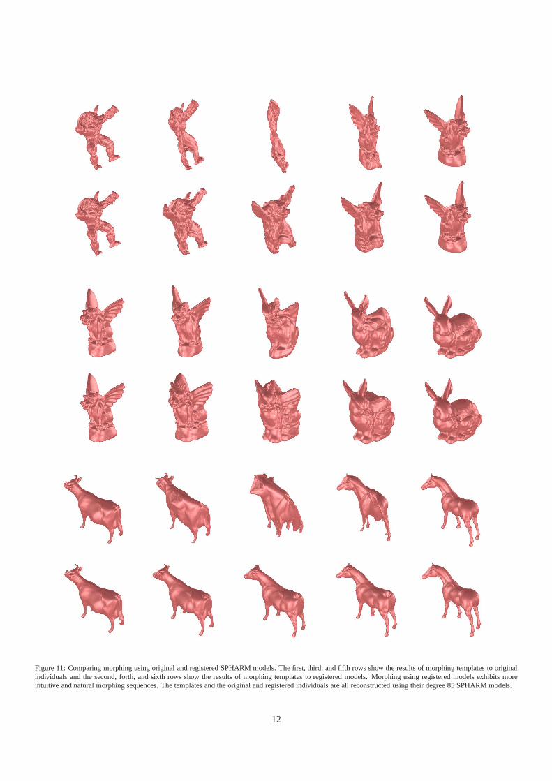
Figure 11: Comparing morphing using original and registered SPHARM models. The first, third, and fifth rows show the results of morphing templates to originalindividuals and the second, forth, and sixth rows show the results of morphing templates to registered models. Morphingusing registered models exhibits moreintuitive and natural morphing sequences. The templates and the original and registered individuals are all reconstructed using their degree 85 SPHARM models.
12
Related Documents