Cracks in Cosine Residual Stress Fields 1 Fourier Basis for the Engineering Assessment of Cracks in Residual Stress Fields P. J. Bouchard 1* , P. J. Budden 2 , P. J. Withers 3 1. Materials Engineering, The Open University, Milton Keynes, MK7 6AA, UK 2. EdF Energy, Barnwood, Gloucester, GL4 3RS, UK 3. School of Materials, University of Manchester, Grosvenor St., Manchester, M1 7HS, UK Abstract A theoretical basis is presented for determining the significance of a residual stress distribution of arbitrary shape on the crack tip stress intensity factor for a centre-cracked plate as a function of crack length. The Fourier series based approach enables one to increasingly add more spatial definition to the stress field and thereby determine the level of detailed knowledge of the residual stress required to make a reliable assessment of structural integrity. The approach is applied to examples of measured symmetric distributions of residual stresses in welded plates and used to determine the significance of residual stress length-scales in fracture mechanics analysis. Keywords: membrane; bending; self-equilibrated stress; stress intensity factor; structural assessment * Corresponding author: [email protected], Tel: +44 (0)1908 332950

Welcome message from author
This document is posted to help you gain knowledge. Please leave a comment to let me know what you think about it! Share it to your friends and learn new things together.
Transcript

Cracks in Cosine Residual Stress Fields
1
Fourier Basis for the Engineering Assessment of Cracks in Residual Stress Fields
P. J. Bouchard1*, P. J. Budden2, P. J. Withers3
1. Materials Engineering, The Open University, Milton Keynes, MK7 6AA, UK
2. EdF Energy, Barnwood, Gloucester, GL4 3RS, UK
3. School of Materials, University of Manchester, Grosvenor St., Manchester, M1 7HS, UK
Abstract
A theoretical basis is presented for determining the significance of a residual stress
distribution of arbitrary shape on the crack tip stress intensity factor for a centre-cracked plate
as a function of crack length. The Fourier series based approach enables one to increasingly
add more spatial definition to the stress field and thereby determine the level of detailed
knowledge of the residual stress required to make a reliable assessment of structural integrity.
The approach is applied to examples of measured symmetric distributions of residual stresses
in welded plates and used to determine the significance of residual stress length-scales in
fracture mechanics analysis.
Keywords: membrane; bending; self-equilibrated stress; stress intensity factor; structural assessment
* Corresponding author: [email protected], Tel: +44 (0)1908 332950

Cracks in Cosine Residual Stress Fields
2
Nomenclature
a half-length of an embedded through-thickness crack in a wide plate, m
b half-length across which a symmetric periodic distribution of residual stress
applies, m
c x co-ordinate where a self-equilibrated residual stress profile changes sign, m
f equivalent force acting at the centroid of a planar intersection sub-domain, N
m equivalent moment acting around an axis passing through the centroid of a planar
sub-domain, Nm
n order of term in a Fourier series expansion
p maximum order of cosine or sine terms included in a Fourier series expansion
r index term
x, y, z Cartesian axes with the z-axis directed out of the domain plane, m
An Fourier series cosine term coefficient for order n
Bn Fourier series sine term coefficient for order n
Ep bounding error given by truncating a Fourier series expansion for KI at n = p
F equivalent force acting at the centroid of a planar intersection domain, N
G approximate KI solution function for a cosine residual stress field
J0 Bessel function of the first kind and order zero
KI stress intensity factor under mode I loading, MPa √m
M equivalent moment acting around an axis passing through the centroid of a planar
domain, N m
SIF stress intensity factor, MPa √m
λ wavelength of a self-equilibrated residual stress distribution, m
σij stress in direction i acting on the plane with the normal in the direction j, MPa
σ0 reference value of a residual stress field, MPa
Cracks in Cosine Residual Stress Fields
3
σ∞ remote uniform stress in an infinitely wide plate, MPa
σ b bending component of stress that spans a defined sub-domain, MPa
σ m membrane component of stress that spans a defined sub-domain, MPa
σ se self-equilibrated component of stress that spans a defined sub-domain, MPa
1 Introduction
A structure can be defined as any assembly of materials intended to withstand loads.
Engineering structural integrity assessment is concerned with design against premature
failure, but structures must also be fit for purpose and economic to make. Residual stresses
can exist inside a body or structure in the absence of any externally applied loads at various
length-scales [1]. As such they add to (or subtract from) applied stresses and are often the
cause of unexpected failure. The science of fracture mechanics [2] has developed rapidly
since the mid-1950s and provides methods [3], [4] for engineers to assess whether flaws or
crack-like defects in structures will progress through various mechanisms, including
corrosion, creep and fatigue, and ultimately become unstable. Fracture mechanics studies
involve both stress analysis aspects and the resistance behaviour of the material to the stresses
imposed. The present study is based on the linear elastic analysis of stress surrounding a
crack in an ideal material having isotropic elastic properties, which is an essential ingredient
in most current fracture assessment methods. Here we lay out a new approach based on
Fourier series analysis, that formalises the consideration of length-scale initiated by Bouchard
and Withers [5] and first quantified in a specific case in [6]. It has certain advantages over
established approaches. First it provides a general stress intensity factor solution that can be
applied to arbitrary residual stress profiles. Secondly, it enables one to increasingly add more
spatial detail to the stress field and thereby determine the level of detailed knowledge of the
residual stress required to make a reliable fracture assessment for a crack of a given length.

Cracks in Cosine Residual Stress Fields
4
This has consequences both for the measurement strategy and the complexity of
computational methods used to characterise residual stresses, for example in welded
structures.
“Fitness-for-service” life and integrity assessment procedures for engineering structures [7],
[8], [9], explicitly concede the presence of actual, or potential, cracks in welded joints or
other critical locations and consider the effect of residual stress at various levels of detail:
i. The simplest residual stress characterisation approach, widely adopted, is to assume
the presence of a uniform residual stress equal in magnitude to the material yield
strength, [7], [9]. This always produces an overestimate of the local stress field at the
crack tip, characterised by the stress intensity factor (SIF).
ii. An upper-bound linear residual stress profile has been advocated for determining SIFs
of cracks at T-butt welds [10]. This gives an overestimate of the SIF for cracks in the
tensile stress region but ignores the self-equilibrating nature of the stress field.
iii. Non-linear residual stress profiles that provide an upper-bound to measured data for a
generic type of weldment can be found in published compendia [7-9] and are often
used. This approach also secures an overestimate of the SIF, especially for longer
cracks.
iv. A more realistic residual stress profile is assumed for a generic type of weldment
based on analytical modelling and/or numerical analysis and/or measurements [11].
v. A best estimate residual stress distribution is considered for a specific weldment based
on numerical analysis validated by diverse measurements [7].
Clearly the level of information required about the stress field increases moving down this
list, as does the effort needed to calculate the resulting SIF as a function of crack length.

Cracks in Cosine Residual Stress Fields
5
Case (iv) relies on analytical modelling and measurements, for example [11], [12]. Case (v)
requires application of non-linear computational mechanics methods to predict residual
stresses introduced by manufacturing processes [13] and, for safety-critical applications,
validation of the results through application of diverse measurements [7]. Modern
measurement techniques [1], [14] have the potential to give a reliable characterisation of the
true state of stress in a real structure, but the information is invariably incomplete; that is only
some components of the stress tensor are measured to a finite length-scale resolution over a
limited spatial sub-domain. For example strain gauges provide surface measurements at a
few key locations; neutron diffraction measurements tend to be made on line-scans and
synchrotron x-ray measurements can feasibly be made over areas, for example [15]. Further,
the measured data have associated scatter and uncertainties [16]. A key issue for both
computational modelling and measurement is what level of residual stress detail is required;
this question can be conveniently studied in terms of self-equilibrated stress wavelength
analysis. Here we develop a Fourier approach to examine how much detail of the residual
stress field is required to get a sufficient estimate of the stress intensity factor for a given
crack length. Further, the approach is completely general providing a simple means of
determining the stress intensity factor for an arbitrary stress field along the proposed crack
path.
In a previous paper [17], the authors have discussed the residual stress length-scales to be
considered in engineering fracture assessments and suggested that a self-equilibrated
component of stress can be ignored when the crack length is at least twice the size of the
tensile zone of the profile. In this paper, a rigorous theoretical basis for studying the
significance of residual stress length-scale is presented. The new approach is applied to
simple and complex examples of measured residual stresses in welded plates. The insights

Cracks in Cosine Residual Stress Fields
6
provided by the new approach are discussed and the implications for characterisation of
residual stresses in weldments by computational mechanics and measurements identified.
2 Residual stress decomposition
2.1 Membrane, bending and self-equilibrating stresses
In modern stress analysis of structures the three dimensional spatial distribution of the stress
tensor under prescribed loads is generally obtained by using numerical (finite element based)
methods. But for engineering integrity and life assessments of structures the 3-D stress field
is often simplified by considering single components of the tensor that act at a few key points
in the body, or vary along a line (stress profile), or across an area (stress map). Moreover
stress profiles are commonly rationalised by considering equivalent “membrane” and
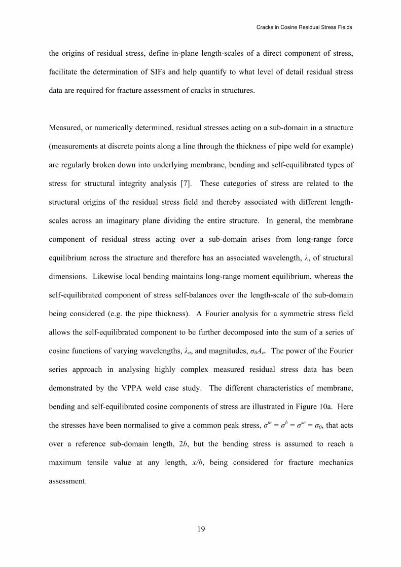
“bending” stresses, see Figure 1. Such linearised stresses are generally calculated using
simple beam bending theory. However, it is necessary to define membrane and bending
stress terms with more rigour in order to determine the “self-equilibrated” residual stress
profiles treated in this paper.
First consider an arbitrary plane that divides a body into two parts creating a planar
intersection domain, Figure 2a. Define a Cartesian axis system (x, y, z) with its origin at the
centroid of the plane and the z-axis normal to it, see Figure 2b. Equivalent forces acting at
the centroid of the domain, and moments acting about the x and y axes, can be determined by
simple integration of the stress distribution σzz(x, y):
Fz = σ zz∫ dA (1)
Mx = yσ zz dA∫ My = xσ zz dA∫ (2)

Cracks in Cosine Residual Stress Fields
7
By definition the equivalent forces and moments acting on an arbitrary cross-section through
a complete body containing residual stress must equal zero to satisfy equilibrium (that is in
the absence of external tractions or self-load). However, if a sub-domain is considered, as in
Figure 2c, the equivalent forces and moments (fx, fy, fz, mx, my, mz) associated with the
residual stress field need not equal zero. Instead equilibrium is maintained by
counterbalancing forces and moments arising from stresses acting over the (unconsidered)
remainder of the domain. The sub-domain concept is critical for interpretation of residual
stress measurements because, for practical reasons, they tend to focus on key locations, lines
or zones, and so invariably provide an incomplete picture of the spatial distribution of
residual stress in a body as a whole. For example, three direct components of the stress
tensor might be measured by neutron diffraction at discrete locations along a straight line
passing through the thickness of a pipe. In this instance the sub-domain is the intersection
between the straight line and the pipe wall thickness.
An equivalent average (membrane, σm) component of σzz stress on a sub-domain is calculated
from fz and the equivalent linearly varying (bending, σb(x) and σb(y)) components of stress
about the x and y axes are calculated from mx and my. Self-equilibrated distributions of
residual stress along the x and y axes, σ se(x) or σ se(y), of a sub-domain can be readily
calculated by subtracting the membrane stress, σm, and appropriate bending stress
component, σb(x) or σb(y), from the total stress distribution acting on a sub-domain. Thus the
distribution of the direct component of residual stress, σzz, acting along an x-axis line passing
through a body (i.e. a line sub-domain) comprises the sum of membrane, bending and self-
equilibrating distributions of stress, for example see Figure 1:
(3)
σ zz (x) = σ zzm (x) + σ zz
b (x) + σ zzse(x)

Cracks in Cosine Residual Stress Fields
8
By definition, the membrane and bending components of residual stress acting on the sub-
domain must self-equilibrate over the cross-section of the whole domain and therefore have
long effective ‘wavelengths’ related to the dimensions of the structural system being
considered. In this paper a self-equilibrated stress profile, σ zzse , is considered to comprise a
(Fourier) series of superposed self-equilibrated residual stress distributions having different
characteristic in-plane wavelengths, λ. For example, the largest value of λ is likely to
approach the length of the intersection line (the extent of the sub-domain), whereas there will
be much shorter wavelength fluctuations associated with geometric stress concentrations and
microstructural features at various length scales (grains, precipitates, dislocations, etc). In
choosing a spacing and gauge volume for stress measurement one is inherently disregarding
shorter wavelength fluctuations. Such arguments have led to the membrane component of
stress being classified as a long length-scale stress, bending as a medium length-scale stress,
and the self-equilibrated component as a short length-scale stress [5]. Typically, structural
integrity assessments focus solely on the membrane and bending components and the self-
equilibrated stress is neglected completely, for example [10]. Our Fourier analysis allows a
more rigorous consideration of the effects of the self-equilibrated stress
2.2 Fourier-based residual stress decomposition
An arbitrary spatial distribution of residual stress along a line in a body can be broken down
into the sum of a series of basis functions. A number of different families of basis functions
have been used by other researchers. For example Korsunsky et al. [18] have used
Chebyshev polynomials and Kartal et al. [19] employed Legendre polynomials in eigenstrain
analyses. Here we adopt a classical Fourier approach because the basis functions have a well
defined wavelength that is inversely proportional to the order of the term and because the

Cracks in Cosine Residual Stress Fields
9
terms are separated into even and odd functions which is convenient for determining stress
intensity factor contributions.
Consider the distribution of a single tensor component of residual stress, (x), which may
be measured or predicted, along a line of finite length, 2b. Then, assuming that the residual
stress can be represented by a piece-wise continuous function on that line, the distribution can
be transformed onto a periodic interval [-π, π] and expressed as the sum of multiple
wavelength components using a Fourier series analysis :
for a reference value, !!, of the residual stress distribution. The coefficients An and
Bn are given by integrating the residual stress distribution according to:
(4)
(5)
for n = 1 to ∞ (6)
for n = 1 to ∞ (7)
The membrane residual stress, σ zzm (x) , discussed previously is simply represented by the A0
term in Eq. (4) and the bending and self-equilibrated components of stress are represented by
the An and Bn terms. Symmetric residual stress problems involve only the cosine terms
(Bn = 0 for all n). This type of stress distribution is the particular focus of interest of the
present paper. This class of problems includes centre cracks growing laterally through
σ zz
σ zz (x) =σ 012A0 + An cos(nx)+ Bn sin(nx)
n=1
n=∞
∑n=1
n=∞
∑#
$%
&
'(
A0 =1πσ 0
σ zz (x)dx−π
π
∫
An =1πσ 0
σ zz (x)cos(nx)dx−π
π
∫
Bn =1πσ 0
σ zz (x)sin(nx)dx−π
π
∫
Cracks in Cosine Residual Stress Fields
10
symmetric residual stress fields, and edge cracks where the sample is constrained to inhibit
bending, however the approach described is completely general.
For example, the symmetric analytical stress profile:
σ zz (x)σ 0
= e−12xc"
#$%
&'2
1− xc"
#$%
&'2(
)*
+*
,-*
.*
(8)
has been used by Terada [20] to describe the distribution of longitudinal (welding direction)
residual stress with distance from the weld centre-line, where σo is the peak stress at the plane
of symmetry, x is the distance from the symmetry plane and c is the location where the stress
profile changes sign. This function can be represented to high accuracy (see Figure 3) over a
periodic interval [-4c, 4c] by a Fourier series having 5 terms (p = 4) with coefficients An =
0.000, 0.283, 0.451, 0.216, 0.045.
3 SIFs for even stress functions: the cosine Fourier terms
The re-distribution of stress in a body caused by the introduction of a crack can be solved by
methods of linear elastic stress analysis. The stress field surrounding a crack of length 2a in
an infinitely wide plate under uniform applied far-field stress, σ∞ , has been expressed by
Irwin [21] using the method of Westergaard [22].
(9)
where KI is the mode I stress intensity factor that represents the strength of the crack-tip stress
field.
Now consider the same crack loaded by a periodic cosine residual stress function defined by:
KI =σ∞ πa

Cracks in Cosine Residual Stress Fields
11
(10)
where σo is the peak stress located at mid-length of the crack, 2a is the length of crack and 2b
is the interval over which the cosine function of order n is acting, where b > a, see Figure 4a.
Various approaches can be adopted to determine the stress intensity factor, for example
integrating the stress profile with a weight function or Green’s function along the crack
flanks. A more convenient approach is to define the mode I stress intensity factor in terms of
the Bessel function, J0, of the first kind and order zero:
KI =σ 0 πa J0πnab
!
"#
$
%& (11)
Where J0(0) = 1. This expression follows from the solution for a point load on page 138 of
Tada, Paris and Irwin [23] integrating over the crack length, and then using Gradshteyn and
Ryzhik [24] to evaluate the resulting integral after some simplification. By rearrangement the
equation can be expressed in the following non-dimensional form:
G ab,n
!
"#
$
%&=
KI
σ 0 πb n=
nab J0
πnab
!
"#
$
%& (12)
If n increases without bound then KI is asymptotically:
KI
σ 0 πb / n=
2πcos πna
b−π4
"
#$%
&' (13)
When the Bessel function J0 in Eq. (12) cannot be readily evaluated, the following
approximation for the mode I stress intensity factor for a centre-crack in a periodic cosine
residual stress field may be used:
G ab,n
!
"#
$
%&=
KI
σ 0 πb / n≈ H 2
πcos πna
b−π4
!
"#
$
%&
)
*+
,
-.+ J
2nπtan πa
2bcos2 πa
2b3cos2 πa
2b− 2
!
"#
$
%&
)
*+
,
-.
(14)
σ zz (x) =σ 0 cosnπ xb

Cracks in Cosine Residual Stress Fields
12
where [H, J] = [0, 1] for 0 < a/b ≤ 0.36/n or [1, 0] for 0.36/n < a/b < 1.
The first term comes from Eq. (13) and the second term is based on the KI solution for an
infinite periodic array of cracks, spaced 2b apart, in an infinitely wide plate loaded by an even
cosine residual stress function of order n = 2 (see Figure 4b). The stress intensity factor
handbook of [23] provides KI solutions for the periodic case n = 1 and 2 based on integration
of Westergaard’s stress function [25] and the present authors have generalised this approach
to consider any positive integer value of n:
KI =σ 0 πa 2bπatan πa
2b . 1+ (−1)r+1(4n2 )(4n2 − 22 )....(4n2 − 4r2 )
22r (r!)2 (2r + 2)2sin πa
2b"
#$
%
&'
(
)*
+
,-
2r+2
r=0
r=n−1
∑/01
21
341
51
(15)
The limits for [H, J] in Eq. (14) have been assigned by inspecting Figure 5 that compares the
SIF approximation, Eq. (14), with the exact solution, Eq. (12).
The SIF can now be determined for an arbitrary even residual stress function through an
appropriate summation of Fourier-based cosine SIF terms based either on the exact solution,
Eq. (12), or approximate solution, Eq. (14), for a centre-cracked infinite body:
KI ≈σ 012A0 πa + An
πbnG a
b,n
"
#$
%
&'
n=1
n=∞
∑*
+,
-
./ (16)
where A0 and An are the Fourier coefficients defined in Eq. (5) and Eq. (6). The first term
defines the contribution to KI from the membrane stress and the second term the contribution
from the self-equilibrated component of residual stress.
4 Validation and applications of the Fourier approach
Before we deploy the new Fourier-based SIF solution for a centre-cracked plate it is
worthwhile to compare its predictive capability with other approaches in the literature. Tan

Cracks in Cosine Residual Stress Fields
13
[26] presented a flexible method derived from exact closed-form solutions for determining
SIFs for a centre-crack in an infinite plate under arbitrary residual stress fields. This method
was applied to solve the case of a crack subjected to a symmetric n = 4 cosine residual stress
distribution. Figure 6 shows how the approximate SIF solution, Eq. (14), for cosine loading
with n = 4 agrees closely with that of Tan et al.
Of course in general a Fourier series rather than a single component will be needed to
represent a given residual stress distribution. For example Terada [20] published exact SIF
results (in tabular form) for a centre-crack loaded by his symmetric analytical residual stress
function, which has been considered earlier in this paper, see Eq. (8) and Figure 3.
Using Eq. (16), the first 4 Fourier series components (n = 1 to 4) have been combined with
the ½ A0 !" membrane stress term (in this case zero) to produce the SIF results shown in
Figure 7. These results are presented in the more usual normalised form, often referred to as
the SIF configuration factor defined by:
KI
σ 0 πa (17)
where σo is the peak stress. It is seen that the Fourier-based SIF solution correlates closely
with Terada’s published data. Also shown in Figure 7 is the SIF solution of Tada et al. [23]
for Terada’s residual stress function which is claimed to be accurate to within 0.5%.
Interestingly the small error in Tada’s solution, evident at values of "x/c"> 2.0, is not present
in the Fourier series result. While it is reassuring that the series approach shows excellent
agreement with existing solutions, it is more important to examine the extra insights that a

Cracks in Cosine Residual Stress Fields
14
Fourier approach can deliver. This is best achieved through a consideration of practical
examples.
4.1 Application case 1: simple weld in a flat plate
Consider residual stress measurements in the longitudinal direction (i.e. the direction of
welding) made by Kanazawa et al. [27] at various distances from the weld-line of a long
single weld bead in a flat plate shown in Figure 8a. As longitudinal stresses are expected to
be symmetric about the weld centre-line [x/c = 0 ], the measured profile has been to assumed
to act symmetrically on both sides of the weld (so that it corresponds to the interval required
in Eq. (4)). The measured profile has stimulated a number of approaches to predict the
resulting stress intensity variation for a centre-crack in a wide plate spanning the weld, as
summarised in (Figure 8a). Terada [20] concluded that his analytic stress function presented
earlier in Eq. (8) simulated the “test result fairly except for minor differences on the
compression side” and derived exact SIF results for this stress function, see Figure 8b. Tada
and Paris [28] analysed the same data and proposed a different analytical stress function
meeting the same boundary conditions (an even function having a maximum value at x/c=0
and crossing the axis at x=c with the residual stress vanishing far from the weld as x/c → ∞).
(18)
A similar analytic stress function representing the same problem is given by [29]:
(19)
The three analytic stress functions, Eq. (8), Eq. (18) and Eq. (19) are all given in Tada, Paris
and Irwin [23] and are compared with the original experimental residual stress data in Figure
σ zz (x)σ 0
= 1− xc"
#$%
&'2(
)*
+*
,-*
.*1+ x
c"
#$%
&'4(
)*
+*
,-*
.*
σ zz (x)σ 0
= 1− xc"
#$%
&'2(
)*
+*
,-*
.*1+ x
c"
#$%
&'2(
)*
+*
,-*
.*
2

Cracks in Cosine Residual Stress Fields
15
8a. None of the functions provide an exact fit to the stress measurements, although Eq. (8)
and Eq. (18) perform well within the tensile region ("x/c"< 1), but are they sufficiently good
and which is the most appropriate given the data and any likely associated measurement
errors?
The use of a Fourier series approach allows one to choose the number of terms and hence the
degree to which the curve fits the data. As is evident from Figure 8a, a Fourier series analysis
produces a reasonable fit with 6 cosine terms (p = 5; A0=0.072; A1=0.347; A2=0.359;
A3=0.208; A4=0.087; A5=-0.014). The fact that the zero’th term is non-zero (A0 = 0.072)
immediately reveals that the measured stress profile is not fully self-equilibrated over the
measured sub-domain "x/c"< 4 giving a small membrane component of stress (0.036σo).
This is an indication that either measurements have not been made over a sufficiently wide
sub-domain to define fully the expected self-equilibrated stress field or perhaps, more
plausibly, that there are significant uncertainties in Kanazawa’s measured data.
The SIF results for a centre-crack spanning the weld are summarised in Figure 8b. The slight
deviation from unity apparent at a/c = 0 for the Fourier series result (based on Eq. (16)) arises
because the y-axis has been normalised by the stress measured at x/c = 0 rather than by the
stress given by the fitted function (see Figure 8a). One could argue, given the potential for
experimental scatter at each point, that the stress at x = 0 would be better estimated from the
fitted curve rather than the measured data point. Also shown are Terada’s “exact” SIF results
for stress function Eq. (8) and results from the following SIF solutions given in Tada, Paris
and Irwin [23] for stress functions Eq. (18) and Eq. (19) respectively:

Cracks in Cosine Residual Stress Fields
16
KI
σ 0 πa=
1+ a c( )2 − a c( )2
1+ a c( )4"#$
%$
&'$
($
12
(20)
KI
σ 0 πa=
1
1+ a c( )2( )32
(21)
For short crack lengths [a/c < 1.0] Terada’s exact results, Eq. (20) and the Fourier approach
(Eq. (16)) give similar results, but the performance of Eq. (21) is poor. For longer crack
lengths [a/c > 1.0] marked variations in magnitude (up to 14%) are evident for the analytical
solutions compared with the Fourier-based p = 5 solution. This is owing to the approximate
nature of the fitted idealised stress profiles to the experimental data (Figure 8a). The Fourier-
based SIF solution, Eq. (16), models a finite positive value of membrane stress in the
measured data over the sub-domain considered; this makes the SIF more positive than
Terada’s results based on Eq. (8) which is a completely self-equilibrated stress function in the
range [-4 < x/c < 4]. If the membrane stress component is subtracted from the stress profile
then the normalised SIF, for the Fourier-based p = 5 case, changes sign at a/c = 2.1. Overall
the Fourier-based analysis approach gives a good fit to the measured stress data and therefore
should give reliable SIF results over the entire crack length range.
4.2 Application case 2: complex butt weld in a plate
The previous example was for a relatively simple residual stress profile, but in real cases it is
common to record more complex variations and an important question is how critical is it to
capture all the detail when calculating SIFs? A good example is provided by residual stress
measurements made on an aluminium alloy butt-welded plate joined by a variable polarity
plasma-arc (VPPA) welding technique [30]. Plates approximately 140 mm wide and 240 mm
long and 12 mm thick were butt welded together. The bulk longitudinal residual stress field
Cracks in Cosine Residual Stress Fields
17
across the mid-width cross-sectional plane of the welded plate was measured using neutron
diffraction, synchrotron x-ray diffraction [30], laboratory x-ray diffraction [31] and the
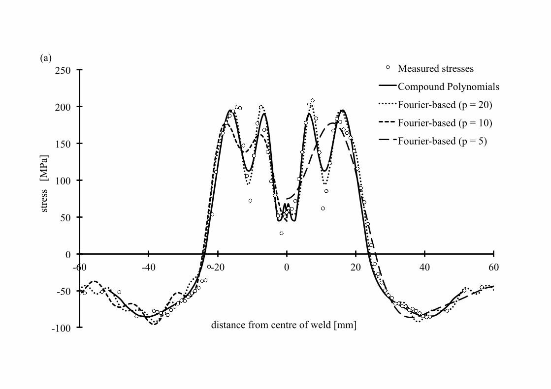
contour method [32]. Figure 9a shows the variation in longitudinal stress (that is the
component of stress parallel to the weld) based on sets of neutron diffraction data combined
with synchrotron X-ray results and averaged across several locations through the thickness.
The typical uncertainty of these combined stress measurements is ± 10 MPa [30]. Note that
the measured data cover a sub-domain [-60, 60] mm of the 278 mm wide cross-section. The
stress distribution is complex but, as one might expect, is essentially symmetric about the
weld centre-line.
Residual stress profiles of this kind are commonly idealised using a polynomial stress
function for subsequent use in weight function numerical calculations to determine the stress
intensity factor solution, for example [33]. But this particular measured stress distribution is
too complex to fit using a single polynomial function. Instead, the general closed-form SIF
solution of Tan et al. [26] for a centre-cracked plate under an arbitrary shape stress field
acting along the crack faces has been successfully applied. Recognising the symmetry of the
stress field, the problem was simplified by averaging stress data at mirror locations relative to
the weld centre-line and fitting two piecewise polynomial stress functions; that is a 10th order
polynomial was fitted over the range 0 < x < 24 mm and a 5th order polynomial for 24 mm < x
< 50 mm ensuring slope continuity between the two functions. The fitted polynomials are
shown in Figure 9a and the resultant SIF solution for a through-thickness crack
symmetrically emanating from the centre of the weld is depicted in Figure 9b.
As the measured residual stress profile (comprising 90 points) is essentially symmetric about
the weld centre-line, the Fourier stress and SIF analysis approach can be applied without

Cracks in Cosine Residual Stress Fields
18
mirroring and averaging. Figure 9a shows how a cosine Fourier series analysis (p =20)
matches the measured data closely and provides a better quality of fit than the compound
polynomial approach of Tan et al.; that is it captures more effectively the measured peaks and
covers data over the entire sub-domain [-60, 60] mm. Also shown on this plot are Fourier
analysis fits using fewer terms (p = 5 and 10). The membrane stress, given by the first term
of the series (½ A0), is 12.3 MPa. It is non-zero because the measured stress data analysed
cover a sub-domain (less than 50%) of the total plate cross-section. The remaining terms An
(n = 1 – 20) of the Fourier analysis define the self-equilibrated component of residual stress.
The Fourier-based SIF solution for p = 20 correlates very closely with that of Tan et al., see
Figure 9b. The p = 10 case gives an accurate value of the peak KI at a crack half-length of 20
mm. The analysis based on just 6-terms also performs well in approximating the peak KI to
within 5%, but does not capture the “knee” evident in the more detailed solutions at a crack
half-length of 10 mm. But for cracks longer than about 25 mm the SIF solution is fairly
insensitive to the number of terms p ≥ 5 included in the analysis.
This example illustrates the power of the Fourier-based residual stress decomposition
approach for dealing with highly complex measured residual stress data. It suggests that from
a structural integrity viewpoint, it is not necessary to determine in great detail the fluctuations
in stress around 10 mm, thereby reducing the number of measurements saving both time and
money. Moreover the SIFs can be readily determined by simple summation of Fourier terms.
The Fourier-based solution has the added advantage that the measured data can be examined
at various levels of detail at the discretion of the analyst.
5 Discussion
Stress decomposition coupled with Fourier-based SIF analysis is a highly effective approach
for the engineering assessment of cracks in residual stress fields. It can help one to identify
Cracks in Cosine Residual Stress Fields
19
the origins of residual stress, define in-plane length-scales of a direct component of stress,
facilitate the determination of SIFs and help quantify to what level of detail residual stress
data are required for fracture assessment of cracks in structures.
Measured, or numerically determined, residual stresses acting on a sub-domain in a structure
(measurements at discrete points along a line through the thickness of pipe weld for example)
are regularly broken down into underlying membrane, bending and self-equilibrated types of
stress for structural integrity analysis [7]. These categories of stress are related to the
structural origins of the residual stress field and thereby associated with different length-
scales across an imaginary plane dividing the entire structure. In general, the membrane
component of residual stress acting over a sub-domain arises from long-range force
equilibrium across the structure and therefore has an associated wavelength, λ, of structural
dimensions. Likewise local bending maintains long-range moment equilibrium, whereas the
self-equilibrated component of stress self-balances over the length-scale of the sub-domain
being considered (e.g. the pipe thickness). A Fourier analysis for a symmetric stress field
allows the self-equilibrated component to be further decomposed into the sum of a series of
cosine functions of varying wavelengths, λn, and magnitudes, σ0An. The power of the Fourier
series approach in analysing highly complex measured residual stress data has been
demonstrated by the VPPA weld case study. The different characteristics of membrane,
bending and self-equilibrated cosine components of stress are illustrated in Figure 10a. Here
the stresses have been normalised to give a common peak stress, σm = σb = σse = σ0, that acts
over a reference sub-domain length, 2b, but the bending stress is assumed to reach a
maximum tensile value at any length, x/b, being considered for fracture mechanics
assessment.

Cracks in Cosine Residual Stress Fields
20
It is instructive to examine the relative contributions of membrane, bending and cosine self-
equilibrated stresses to the SIF used in fracture mechanics analysis following the approach of
Withers [6]. The SIF for a through-thickness crack in a wide plate under membrane stress is
given by Eq. (9) with σ∞ = σm. The equivalent SIF for a pure bending stress of tensile
magnitude σb at one crack tip and compression –σb at the other tip can be derived from page
138 of Tada, Paris and Irwin [23] giving KI = ±½σb(πa)½. For a self-equilibrated cosine
function of peak magnitude, σn, the SIF is given by G(a/b, n), from Eq. (12) or Eq. (14). The
SIFs for these kinds of loading can be compared with each other directly using the
normalisation shown in Eq. (22) assuming a common peak stress, σm = σb = σn = σ0.
KIm
σ m πb=
ab
; KIb
σ b πb=12
ab
; KIn
σ n πb≈
1nG a
b,n
"
#$
%
&' (22)
The results of this SIF comparison are presented in Figure 10b and relate to the unit
membrane, bending and cosine components of stress shown in Figure 10a. It is observed that
the membrane stress makes the greatest relative contribution to the SIF followed by the
cosine functions for short cracks. But for longer cracks, the bending component increases in
importance and the magnitude of the cosine contribution depends on the order, n, and exact
crack length. In general the SIF for combined membrane, bending and self-equilibrated
(symmetric) residual stress can be evaluated from:
KI ≈σ 012A0 πa ± 1
2σ b
σ 0
πa + AnπbnG a
b,n
"
#$
%
&'
n=1
n=∞
∑*
+,
-
./ (23)
where the first term of the Fourier series analysis A0 = 2σm/σ0 and G(a/b,n) is the cosine SIF
solution defined either by Eq. (12) or Eq. (14).

Cracks in Cosine Residual Stress Fields
21
The cosine SIF solution has periodic properties of high engineering relevance. The
maximum magnitude of KI for any value of n can be approximated using Eq. (13), (see Figure
5) even although this expression is strictly an asymptotic limit:
KI max≈
2πσ 0
πbn= 0.8σ 0
bn
(24)
First, it should be noted the maximum SIF magnitude defined by this approximate limit is
independent of crack length. Secondly, as the order, n, of the cosine function increases, the
magnitude of KI decreases with the inverse of the square root of n, for example see Figure
10b. Thus, the higher the order of the Fourier term, the less it will contribute to the SIF in a
Fourier-based analysis. But even more significant is the fact that the peak magnitude of KI
depends on the square root of the wavelength of the cosine function, λn = 2b/n. This property
demonstrates that the longer the residual stress length-scale, the greater its contribution to the
SIF of embedded cracks in structures, and therefore its importance in fracture mechanics
analysis and structural integrity assessment. For example, periodic residual stress variations
at the grain-scale of stainless steel components for σ0 = 50 MPa and 2b = λ = 0.0005 m
(assuming λ is approximately 5 times an average grain size of 0.1 mm) will have a negligible
influence on fracture (KI ≈ 0 . 6 MPa√m). Thus the power of the Fourier approach is that it
enables one to investigate the dependency of the SIF on the degree of detail to which the
residual stress profile needs be known or estimated.
The error, Ep, from truncating the series expansion for KI at the p’th term is bounded by
Ep ≤ An KIn=p+1
∞
∑ max≤ 0.8σ 0 bAnnn=p+1
∞
∑ (25)

Cracks in Cosine Residual Stress Fields
22
using Eq. (4) and Eq. (24). The Fourier-based approach then intrinsically converges as n
increases, noting that standard Fourier series theory implies that, for a piecewise continuous
function, with discontinuities only at a finite number of points, the coefficients An are O(1/n)
for large n. Hence, from Eq. (25), the Fourier series expansion for KI is absolutely
convergent. Smoother residual stress distributions lead to more rapid decay of An with
increasing n, and often the sign of An alternates, which both increase the rate of series
convergence.
The convergence properties can be illustrated by comparing SIF results from the p = 5 and p
= 10 cases with the p = 20 solution, see Figure 9b. The maximum differences in SIF are 4.6
MPa√m and 2.4 MPa√m for the p = 5 and p = 10 cases respectively for a ½-crack length of 8
mm. The peak KI values for the truncated p = 5 and 10 analyses are accurate to within 5%
and 1% respectively of the p = 20 solution for a ½-crack 19 - 20 mm long. Even the p = 5
case is within the expected range of accuracy for SIF solutions in engineering applications.
Note also how good estimates of KI were obtained in the other studies using 6 terms (p = 5) or
fewer.
The cosine KI solution, Eq. (12), initially increases with crack length and reaches a maximum
at na/b ≈ 0.3, see Figure 5. The magnitude of this first peak is marginally lower (a few per
cent) than the asymptotic limit for later cycles defined by Eq. (13). The latter is therefore
taken as a good engineering approximation to the maxima for all the cycles. The appropriate
KI solution then falls with increasing crack length until it first changes sign at na/b = 0.75 and
remains negative up to a crack length na/b = 1.75. It is important to note that KI first becomes
negative at a crack length equal to about 1.5 times the tensile length-scale, b/n, of the cosine

Cracks in Cosine Residual Stress Fields
23
function and does not return to a positive value until 3.5 times the tensile length-scale.
Similar behaviour is observed in more realistic self-equilibrated weld residual stress profiles
that comprise several Fourier term contributions; for example in Figure 7, KI first changes
sign at 1.75 times the tensile length-scale, see Figure 3) and in Figure 8b KI changes sign at a
crack length about 2.1 times the tensile length-scale when the membrane component is
removed (see earlier description of application case 1). These results support an engineering
“rule of thumb” stating that KI for self-equilibrated residual stress profiles becomes
insignificant when the crack is longer than twice the length of the tensile zone in agreement
with the less rigorous arguments of Bouchard and Withers [17].
The tensile length-scale “rule of thumb” combined with the knowledge that the maximum
magnitude of KI becomes small at short stress wavelengths can be used to assess the
significance of local perturbations in residual stress. This assessment is essential in the
planning stage for residual stress measurements of complex structures and in the determining
the level of sophistication required in computational mechanics predictions of residual stress
in welds. For example, measurement scientists or engineering analysts [7] may need to
decide whether to measure/model phase transformation effects in welded joints made from
ferritic steel. Consider a localised cosine form of residual stress distribution representing the
expected, or bounding, magnitude of stress fluctuation and wavelength. Two significance
tests can be applied. First what is the magnitude of the peak SIF from Eq. (24) and is this
significant to the fracture or other assessment being made? Secondly, if the crack length of
concern is greater than twice the tensile length-scale of the stress perturbation then it will
have a negligible effect on fracture and therefore can be ignored. For example, a localised
100 MPa magnitude cosine perturbation over a wavelength of 5 mm would give a maximum
KI = 2 MPa√m for cracks < 5 mm long but would be benign for longer cracks. In this instance

Cracks in Cosine Residual Stress Fields
24
it may well be judged irrelevant to undertake the more detailed measurements and analysis
required to capture the short length-scale residual stress field.
The properties of the approximate cosine SIF solution can be used to help design and inform
residual stress measurement studies of engineering components. Consider a set of point
residual stress measurements that are equally spaced along a straight line and have an
identical measurement uncertainty, Δσ0. If the uncertainty is truly random then the worst-
case maximum error in stress profile could be represented by a cosine function of amplitude
Δσ0 and wavelength equal to twice the measurement spacing. The maximum SIF error for
this worst case is given by Eq. (24). This analysis neatly demonstrates how increasing the
density of measurement points can reduce the uncertainty in a stress distribution and the
calculated SIFs for a centre-cracked structure. Indeed if a tolerable error/uncertainty in the
SIF can be defined, and the measurement method uncertainty is known, then the
measurement spacing required can be estimated. Thus for a 2 MPa√m error in SIF with
random uncertainty in stress of 25 MPa (typical of neutron diffraction measurements in
stainless steel), a 10 mm spacing is adequate, whereas for one-half the error in SIF
(1 MPa√m) a minimum measurement spacing of 2.5 mm would be required.
The Fourier-based approach presented here could be extended to cover isolated cracks in
asymmetric residual stress profiles through developing a generic SIF solution for sine
functions of arbitrary order. In addition, a similar Fourier-based SIF approach could be
developed for edge-cracked (unrestrained) plates that would have wider applicability and
relevance to cracked engineering structures. The Fourier-based methodology also opens up
the possibility of estimating the out-of-plane length-scale of a residual stress field. This is
important for the purpose of assessing the level and significance of elastic follow-up in non-

Cracks in Cosine Residual Stress Fields
25
linear fracture mechanics analysis and high temperature deformation and damage processes.
In addition, the out-of-plane length-scale has a key influence in determining what stress
remains in test specimens extracted from weldments and in application of the Contour
Method of residual stress measurement.
6 Conclusions
1. Direct components of the residual stress tensor acting normal to a planar sub-domain of a
structure have often been decomposed into membrane, bending and self-equilibrated
distributions of stress for engineering structural integrity analysis. Here we have used a
classical Fourier series approach to analyse both the long and the short wavelength
fluctuations in residual stress within a single framework.
2. A closed-form SIF solution for a through-thickness crack in a wide plate under a periodic
cosine residual stress field of order n has been developed. When combined with a Fourier
analysis, SIFs for a through-thickness crack in a wide plate within a symmetric residual
stress field of arbitrary shape can be determined by superposition. The new approach has
been successfully applied both to simple and complex examples of measured residual
stresses in welded plates.
3. The Fourier-based SIF analysis approach intrinsically converges as n increases and
therefore complex residual stress fields can be represented using a truncated Fourier
series involving relatively few terms without introducing large errors.
4. The magnitude of the peak SIF for any order cosine stress function depends solely on the
peak stress and square root of the wavelength, |KI|max = 0.8σ0√(0.5λn), thus the longer the
residual stress length-scale the greater its significance in fracture mechanics assessment.
Conversely, short length-scale residual stress fluctuations can often be ignored.

Cracks in Cosine Residual Stress Fields
26
5. The Fourier-based SIF results support an engineering “rule of thumb” stating that KI for
self-equilibrated residual stress profiles becomes insignificant when the crack length
exceeds about twice the length of the tensile zone proposed by [17].
6. The insights provided by the new approach enable one to determine the degree of detail,
and the accuracy, to which a residual stress field need be known for the engineering
assessment of cracks in structures. Examples discussed include the significance of
intergranular stresses and when local stress perturbations, such as introduced by phase
transformations, need to be characterised by more detailed measurements or refined
computational analysis. It is also shown how measurement spacing requirements can be
estimated if a tolerable uncertainty in SIF is defined, or if a set of stress measurements
has been already obtained, how the Fourier SIF approach can be used to bound potential
random error in the residual stress distribution in a fracture mechanics analysis.
Acknowledgements
P J Bouchard is grateful for support from a Royal Society Industry Fellowship and for
collaboration with staff at EdF Energy and Rolls-Royce plc. P J Withers acknowledges
support from a Royal Society Wolfson Merit Award and numerous EPSRC grants on this
topic. This paper is published with permission from EdF Energy.
References
[1] Withers PJ, Bhadeshia HKDH. Residual stress part 1 - measurement techniques. Materials Science and Technology. 2001;17:335-65.
[2] Karihaloo B, Xiao QZ. Linear and nonlinear fracture mechanics. In: Milne I, Ritchie RO, Karihaloo B, editors. Comprehensive Structural Integrity: Elsevier; 2003. p. 81-212.
[3] Milne I, Karihaloo B, Ritchie RO. Structural integrity assurance. In: Milne I, Ritchie RO, Karihaloo B, editors. Comprehensive Structural Integrity. Oxford: Elsevier; 2003. p. 1-24.
[4] Zerbst U, Schwalbe K-H, Ainsworth R, A. An overview of failure assessment methods in codes and standards. In: Milne I, Ritchie RO, Karihaloo B, editors. Comprehensive Structural Integrity. Oxford: Elsevier; 2003. p. 1-48.
[5] Bouchard PJ, Withers PJ. The appropriateness of residual stress length scales in structural integrity. Journal of Neutron Research. 2004;12:81-91.
[6] Withers PJ. Residual Stress and its Role in Failure. Progress in Physics. 2007;70:2211-64.

Cracks in Cosine Residual Stress Fields
27
[7] R6 Revision 4, Assessment of the Integrity of Structures Containing Defects. Gloucester, UK: British Energy Generation Ltd; 2010.
[8] API 579-1/ASME FFS-1, Fitness-for-Service, Second edition. Washington DC: American Society of Mechanical Engineers; 2007.
[9] BS7910:2005, Guide to Methods for Assessing the Acceptability of Flaws in Metallic Structures, Incorporating Amendment No.1. London: BSI; 2007.
[10] Lee HY, Nikbin KM, O'Dowd NP. A generic approach for a linear elastic fracture mechanics analysis of components containing residual stress. Int Journal Pressure Vessels and Piping. 2005;82:797-806.
[11] Bouchard PJ. Validated residual stress profiles for fracture assessments of stainless steel pipe girth welds. International Journal of Pressure Vessels and Piping. 2007;84:195-222.
[12] Nadri B, Bouchard PJ, Smith MC, Truman CE, Smith DJ. Modelling and Statistical Treatment of Residual Stress Distributions in an Edge Welded Stainless Steel Beam. Strain. 2010;no. doi: 10.1111/j.1475-1305.2009.00718.x.
[13] Lingren LE. Computational Welding Mechanics, Thermomechanical and Microstructural Simulations. Cambridge: Woodhead Publishing Limited; 2007.
[14] Withers PJ, Turski M, Edwards L, Bouchard PJ, Buttle DJ. Recent advances in residual stress measurement. International Journal of Pressure Vessels and Piping. 2008;85:118-27.
[15] Owen RA, Preston RV, Withers PJ, Shercliff HR, Webster PJ. Neutron and Synchrotron Measurements of Residual Strain in an Aluminium Alloy TIG Weld. Mat Sci Eng. A346: 159-167. Materials Science and Engineering A. 2003;A346:159-67.
[16] Nadri B, Bouchard PJ, Truman CE, Smith DJ. A statistical framework for analysing weld residual stresses for structural integrity assessment. ASME PVP2008-61339. Chicago: American Society of Mechanical Engineers, New York; 2008.
[17] Bouchard PJ, Withers PJ. Identification of residual stress length scales in welds for fracture assessment. In: Youtsos AG, editor. Residual stress and its effects on fatigue and fracture, Proceedings of a Special Symposium held within the 16th European Conference on Fracture - ECF16, Alexandroupolis, Greece, Part 4, 163-176: Springer Netherlands; 2006. p. 163-76.
[18] Korsunsky AM, Regino GM, Nowell D. Variational eigenstrain analysis of residual stresses in a welded plate. International Journal of Solids and Structures. 2007;44:4574-691.
[19] Kartal ME, Liljedahl CDM, Gungor S, Edwards L, Fitzpatrick ME. Determination of the profile of the complete residual stress tensor in a VPPA weld using the multi-axial contour method. Acta Materialia. 2008;56:4417-28.
[20] Terada H. An analysis of the stress intensity factor of a crack perpendicular to the welding bead. Engineering Fracture Mechanics. 1976;8:441-4.
[21] Irwin GR. Anaysis of stresses and strains near the end of a crack traversing a plate. Journal of Applied Mechanics. 1957;24:361-4.
[22] Westergaard HM. Bearing pressures and cracks. Transactions of the ASME. 1939;61:A49-A53.
[23] Tada H, Paris PC, Irwin GR. The Stress Analysis of Cracks Handbook, Third Edition. Third edition ed. New York: American Society of Mechanical Engineers; 2000.
[24] Gradshteyn IS, Ryzhik IM. Tables of integrals, seies and products. New York and London: Academic Press; 1965.
[25] Tada H. Westergaard stress functions for several periodic crack problems. Engineering Fracture Mechanics. 1970;2:177-80.
[26] Tan JM-L, Fitzpatrick ME, Edwards L. Stress intensity factors for through-thickness cracks in a wide plate: derivation and application to arbitrary residual stress fields. Engineering Fracture Mechanics. 2007;74:2030-54.
[27] Kanazawa T, Oba H, Susei S. The effect of welding residual stress upon brittle fracture propagation (Report II). Soc Nav Arch Japan. 1962;110:359-68.
[28] Tada H, Paris PC. The stress intensity factor of a crack perpendicular to the welding bead. International Journal of Fracture. 1983;21:279-84.
[29] Tada H, Paris PC, Irwin GR. The Stress Analysis of Cracks Handbook, Second Edition: Paris Productions and Del Research Corp; 1985.
[30] Ganguly S, Fitzpatrick ME, Edwards L. Use of neutron and synchrotron X-ray diffraction for evaluation of residual stresses in a 2024-T351 aluminium alloy variable-polarity plasma-arc weld. Metall Mater Trans A-Phys Metall Mater Sci. 2006;37A:411-20.
[31] Ganguly S. Non-destructive measurement of residual stresses in welded aluminium 2024 airframe alloy. Internal report. Milton Keynes: Department of Materials Engineering, The Open University; 2004.

Cracks in Cosine Residual Stress Fields
28
[32] Zhang Y, Ganguly S, Edwards L, Fitzpatrick ME. Cross-sectional mapping of residual stresses in a VPPA weld using the contour method. Acta Materialia. 2004;52:5225-32.
[33] R-Code, Software for Asssessing the Integrity of Structures Containing Defects, Version 4.4. Gloucester, UK: British Energy Generation Limited; 2010.

Cracks in Cosine Residual Stress Fields
29
Figure 1. Decomposition of the residual stress distribution σzz along a line of length L into membrane, σm, bending, σb, and self-equilibrating, σse, stress profiles.
Figure 2. (a) Arbitrary plane intersecting a general body. (b) Equivalent forces and moments acting on the intersection domain. (c) Equivalent forces and moments acting on a sub-domain of the intersection.Figure 3. Terada’s analytical function [20] simulating the distribution of longitudinal residual stress with distance from a butt weld in a wide plate; x/c is the distance from the weld, c is the distance at which the stress function changes sign and the stress function is normalised by the peak value, σ0, at x/c = 0. The Fourier series stress analysis (p = 4) gives a highly accurate fit to the function.
Figure 4. Single crack in a cosine residual stress field spanning length 2b of order n = 1 (top), and periodic array of cracks spaced at 2b in a cosine residual stress field of order n = 2 (bottom).
Figure 5. Normalised SIFs from Eq. (12) for a single crack in an infinite plate under arbitrary cosine loading (n = 1 – 12) compared with results of the approximate SIF solution Eq. (14).
Figure 6. Comparison of the approximate cosine SIF solution for a single crack in an infinite plate with the solution of Tan et al. [26] for a cosine function (n = 4).
Figure 7. Normalised SIF results, for the analytical residual stress function shown in Figure 3.
Figure 8. (a) Longitudinal residual stress data measured by Kanazawa et al. [27] at various distances from a long single weld bead in a flat plate compared with various analytical approximations, see also Figure 3, (b) Corresponding SIF results.
Figure 9. (a) Measured longitudinal residual stress data (thickness averaged) for a variable polarity plasma-arc (VPPA) butt weld joining two aluminium alloy plates (240mm x 140 mm x12mm) [30]. Four analytical representations of the measured stress profile are shown: a compound polynomial fit and Fourier series analysis fits for p = 5, 10 and 20. (b) Associated SIF results based on the approach of Tan et al. [26] and the Fourier-based SIF analysis for p = 5, 10 and 20.
Figure 10. (a) Normalised membrane and self-equilibrated cosine stress distributions (n = 1, 2, 4, and 8) acting across ½-range b, and normalised bending stress acting across x/b. (b) Associated normalised SIFs.


-0.6
-0.4
-0.2
0.0
0.2
0.4
0.6
0.8
1.0
-4 -3 -2 -1 0 1 2 3 4
nor
mal
ised
stre
ss
normalised distance from weld centre-line, x/c
Terada analytical profile
Fourier (p = 4)

Draft 1 Cracks in Periodic Residual Stress Fields
1
!0
a -a
b b
! zz (x) =! 0 cos2" xb
!0
a -a
b b
! zz (x) =! 0 cos" xb

-0.5
-0.4
-0.3
-0.2
-0.1
0.0
0.1
0.2
0.3
0.4
0.5
0 1 2 3 4 5 6 7 8 9 10 11 12
norm
alis
ed S
IF
normalised crack half-length, na/b
Exact Solution, Eq 12 Approximate solution, Eq 14 KI
! 0 " b n

-0.5
-0.4
-0.3
-0.2
-0.1
0.0
0.1
0.2
0.3
0.4
0.5
0 1 2 3 4
norm
alis
ed S
IF
normalised crack half-length, na/b
Exact solution, Eq 12
approximate solution, Eq 14
Tan et al. solution (n = 4)
KI
! 0 " b n

-0.6
-0.4
-0.2
0.0
0.2
0.4
0.6
0.8
1.0
0.0 0.5 1.0 1.5 2.0 2.5 3.0 3.5 4.0
nor
mal
ised
stre
ss
normalised distance from centre, x/c
Kanazawa measured data
Fourier (p =5)
Terada function, Eq 8
Tada function, Eq 18
Tada function, Eq 19
(a)

-0.2
0.0
0.2
0.4
0.6
0.8
1.0
-4.0 -3.0 -2.0 -1.0 0.0 1.0 2.0 3.0 4.0
SIF
conf
igur
atio
n fa
ctor
normalised crack half-length, a/c
Terada solution
Tada et al. solution
Fourier (p = 4)
KI
! 0 "a

-0.2
0.0
0.2
0.4
0.6
0.8
1.0
0.0 0.5 1.0 1.5 2.0 2.5 3.0 3.5 4.0
SIF
conf
igur
atio
n fa
ctor
normalised crack half-length, a/c
Fourier (p = 5), Eq 16
Terada exact for Eq 8
Tada, Eq 20
Tada Eq 21
(b)
KI
! 0 "a
-100
-50
0
50
100
150
200
250
-60 -40 -20 0 20 40 60
stre
ss
[MPa
]
distance from centre of weld [mm]
Measured stresses
Compound Polynomials
Fourier-based (p = 20)
Fourier-based (p = 10)
Fourier-based (p = 5)
(a)

-10
-5
0
5
10
15
20
25
30
35
40
0.000 0.010 0.020 0.030 0.040 0.050 0.060
SIF
[MPa
m0.
5 ]
crack half-length [m]
Tan et al. Solution
Fourier-based (p = 20)
Fourier-based (p = 10)
Fourier-based (p = 5)
(b)

-1.0
-0.8
-0.6
-0.4
-0.2
0.0
0.2
0.4
0.6
0.8
1.0
0.0 0.1 0.2 0.3 0.4 0.5 0.6 0.7 0.8 0.9 1.0
nor
mal
ised
stre
ss
x/b
Membrane Stress Bending Stress Cosine (n = 1) Cosine (n = 2) Cosine (n = 4) Cosine (n = 8)
! x b( )! 0
(a) Bending over x/b

-0.4
-0.2
0.0
0.2
0.4
0.6
0.8
1.0
0.0 0.1 0.2 0.3 0.4 0.5 0.6 0.7 0.8 0.9 1.0
norm
alis
ed S
IF
a/b
Membrane Bending Fourier-based (n = 1) Fourier-based (n = 2) Fourier-based (n = 4) Fourier-based (n = 8)
(b)
KI
! 0 "b
Related Documents