Network Protocols

Welcome message from author
This document is posted to help you gain knowledge. Please leave a comment to let me know what you think about it! Share it to your friends and learn new things together.
Transcript

Network Protocols
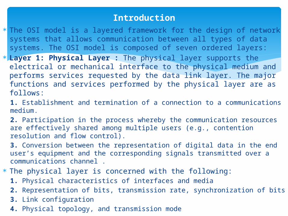
The OSI model is a layered framework for the design of network systems that allows communication between all types of data systems. The OSI model is composed of seven ordered layers:
Layer 1: Physical Layer : The physical layer supports the electrical or mechanical interface to the physical medium and performs services requested by the data link layer. The major functions and services performed by the physical layer are as follows:1. Establishment and termination of a connection to a communications medium. 2. Participation in the process whereby the communication resources are effectively shared among multiple users (e.g., contention resolution and flow control).3. Conversion between the representation of digital data in the end user’s equipment and the corresponding signals transmitted over a communications channel .
The physical layer is concerned with the following:1. Physical characteristics of interfaces and media2. Representation of bits, transmission rate, synchronization of bits3. Link configuration4. Physical topology, and transmission mode
Introduction
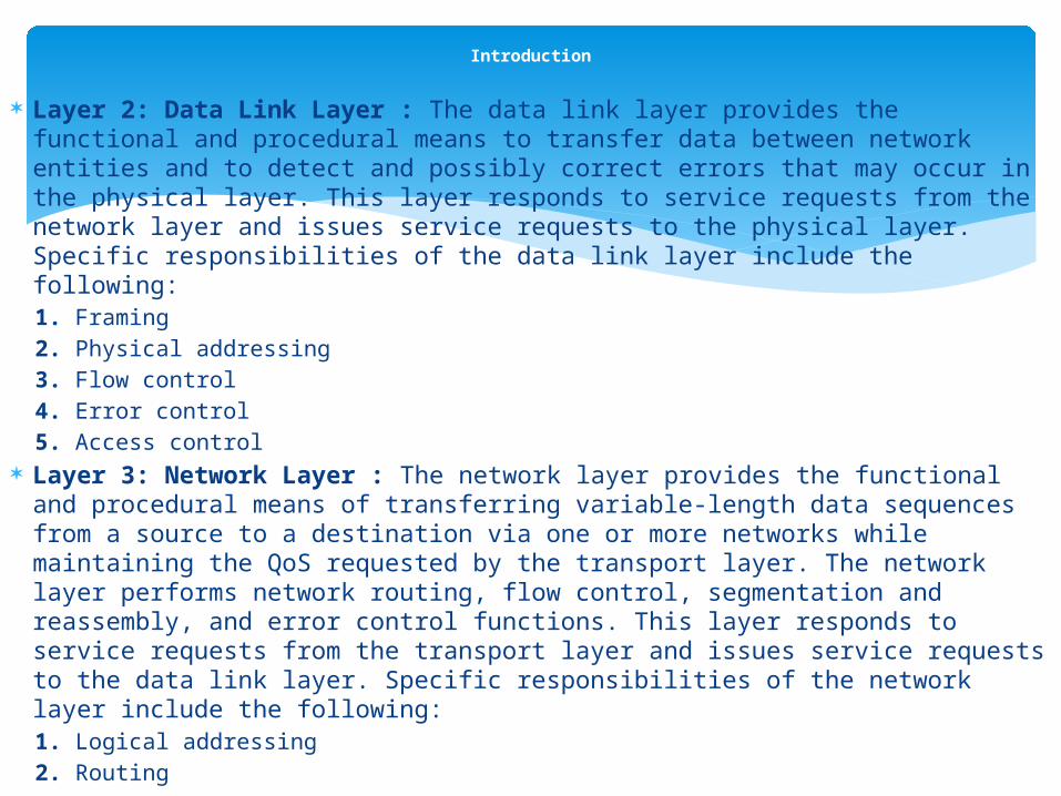
Layer 2: Data Link Layer : The data link layer provides the functional and procedural means to transfer data between network entities and to detect and possibly correct errors that may occur in the physical layer. This layer responds to service requests from the network layer and issues service requests to the physical layer. Specific responsibilities of the data link layer include the following:1. Framing2. Physical addressing3. Flow control4. Error control5. Access control
Layer 3: Network Layer : The network layer provides the functional and procedural means of transferring variable-length data sequences from a source to a destination via one or more networks while maintaining the QoS requested by the transport layer. The network layer performs network routing, flow control, segmentation and reassembly, and error control functions. This layer responds to service requests from the transport layer and issues service requests to the data link layer. Specific responsibilities of the network layer include the following:1. Logical addressing2. Routing
Introduction

Layer 4: Transport Layer : The purpose of the transport layer is to provide transparent transfer of data between end users, thus relieving the upper layers from any concern with providing reliable and cost-effective data transfer.
This layer responds to service requests from the session layer and issues service requests to the network layer. Specific responsibilities of the transport layer include the following:1. Service-point addressing2. Segmentation and reassembly3. Connection control and flow control4. Error control
Layer 5: Session Layer : The session layer provides the mechanism for managing a dialog between end user application processes. It supports either duplex or half-duplex operations and establishes check pointing, adjournment, termination, and restart procedures. This layer responds to service requests from the presentation layer and issues service requests to the transport layer. Specific responsibilities of the session layer include the following:1. Dialog control2. Synchronization
Introduction
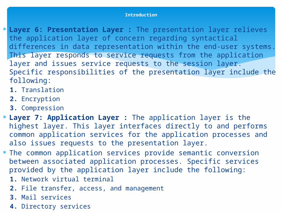
Layer 6: Presentation Layer : The presentation layer relieves the application layer of concern regarding syntactical differences in data representation within the end-user systems. This layer responds to service requests from the application layer and issues service requests to the session layer. Specific responsibilities of the presentation layer include the following:1. Translation2. Encryption3. Compression
Layer 7: Application Layer : The application layer is the highest layer. This layer interfaces directly to and performs common application services for the application processes and also issues requests to the presentation layer.
The common application services provide semantic conversion between associated application processes. Specific services provided by the application layer include the following:1. Network virtual terminal2. File transfer, access, and management3. Mail services4. Directory services
Introduction

The TCP/IP protocol suite provides service to transfer data from one network device to another using the Internet. The TCP/IP protocol suite is composed of five layers:
Physical and Data Link Layers : The physical and data link layers are responsible for communicating with the actual network hardware (e.g., the Ethernet card). Data received from the physical medium are handed over to the network layer, and data received from the network layer are sent to the physical medium. The TCP/IP does not specify any specific protocol at this layer and supports all standard and proprietary protocols.
Network Layer : The network layer is responsible for delivering data to the destination. It does not guarantee the delivery of data and assumes that the upper layer will handle this issue. This layer consists of several supporting protocols :
Internet Protocol (IP) : is a network layer protocol that provides a connectionless, “best effort” delivery of packets through an internetwork. The term best effort means that there is no error checking or tracking done for the sequence of packets being transmitted. It assumes that the higher-layer protocol takes care of the reliability of packet delivery. The packets being transmitted are called datagrams. Each of these datagrams is transmitted independently and may take different routes to reach the same destination. IP supports a mechanism of fragmentation and reassembly of datagrams to handle data links with different maximum-transmission unit (MTU) sizes.
TCP/IP Protocol

Internet Control Message Protocol (ICMP) : is a companion protocol to IP that provides a mechanism for error reporting and query to a host or a router. The query message is used to probe the status of host or a router by the network manager whereas the error-reporting message is used by the host and routers to report errors.
Internet Group Management Protocol (IGMP) : is used to maintain multicast group membership within a domain. Similar to ICMP, it uses query and reply messages to maintain multicast group membership in its domain. A multicast router sends a periodic IGMP query message to find out the multicast session members in its domain. If a new host wants to join a multicast group, it sends an IGMP join message to its neighboring multicast router, which takes care of adding the host to the multicast delivery tree.
Dynamic Host Configuration Protocol (DHCP) : is designed to handle dynamic assignments of IP addresses in a domain. This protocol is an extension of the bootstrap protocol (BOOTP) and provides a way for the mobile nodes to request an IP address from a DHCP server in case nodes move to a different network.
This dynamic assignment of IP address is also applicable to the hosts that attach to the network occasionally. It saves precious IP address space by utilizing the same IP address for needed hosts. DHCP is fully compatible with BOOTP, which supports only static binding of physical address to IP address.
TCP/IP Protocol
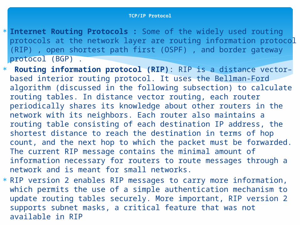
Internet Routing Protocols : Some of the widely used routing protocols at the network layer are routing information protocol (RIP) , open shortest path first (OSPF) , and border gateway protocol (BGP) .
Routing information protocol (RIP): RIP is a distance vector–based interior routing protocol. It uses the Bellman-Ford algorithm (discussed in the following subsection) to calculate routing tables. In distance vector routing, each router periodically shares its knowledge about other routers in the network with its neighbors. Each router also maintains a routing table consisting of each destination IP address, the shortest distance to reach the destination in terms of hop count, and the next hop to which the packet must be forwarded. The current RIP message contains the minimal amount of information necessary for routers to route messages through a network and is meant for small networks.
RIP version 2 enables RIP messages to carry more information, which permits the use of a simple authentication mechanism to update routing tables securely. More important, RIP version 2 supports subnet masks, a critical feature that was not available in RIP
TCP/IP Protocol
Open shortest path first (OSPF): OSPF is an interior routing protocol developedfor IP networks. This protocol is based on the shortest path first (SPF)algorithm, which sometimes is referred to as the Dijkstra algorithm. OSPF supports hierarchical routing, in which hosts are partitioned into autonomous systems (AS). Based on the address range, an AS is further split into OSPF areas that help border routers to identify every single node in the area. Theconcept of OSPF area is similar to subnetting in IP networks. Routing can belimited to a single OSPF or can cover multiple OSPFs. OSPF is a link-staterouting protocol that requires sending link-state advertisements (LSAs) to allother routers within the same hierarchical area. As OSPF routers accumulatelink-state information, they use the SPF algorithm to calculate the shortest pathto each node. As a link-state routing protocol, OSPF contrasts with RIP, whichis a distance vector routing protocol. Routers running the distance vector algorithm send all or a portion of their routing tables in routing-update messages to their neighbors.
TCP/IP Protocol

Border gateway protocol (BGP): BGP is an interdomain or interautonomous system routing protocol. Using BGP, interautonomous systems communicate with each other to exchange reachability information.
BGP is based on the Path Vector Routing Protocol, wherein each entry in the routing table contains the destination network, the next router, and the path to reach the destination. The path is an ordered list of autonomous systems that a packet should travel to reach the destination.
TCP : is a connection-oriented reliable transport protocol that sends data as a stream of bytes. At the sending end, TCP divides the stream of data into smaller units called segments. TCP marks each segment with a sequence number.
The sequence number helps the receiver to reorder the packets and detect any lost packets. If a segment has been lost in transit from source to destination, TCP retransmits the data until it receives a positive acknowledgment from the receiver.
TCP can also recognize duplicate messages and can provide flow control mechanisms in case the sender is transmitting at a faster speed than the receiver can handle.
TCP/IP Protocol

Application Layer : In TCP/IP the top three layers of OSI—session, presentation, and application layers—are merged into a single layer called the application layer. Some of the applications running at this layer are domain name server (DNS), simple mail transfer protocol (SMTP), Telnet, file transfer protocol (FTP), remote login (Rlogin), and network file system (NFS).
Routing Using Bellman-Ford Algorithm : One step that can take a substantial amount of time is the selection of a route between the source and destination. This is important as appropriate path selection is critical for minimizing communication delays.
The Bellman-Ford algorithm is one of the routing algorithms designed to find shortest paths between two nodes of a given graph (Figure 9.3).
TCP/IP Protocol

Figure 9.4 Steps in the Bellman-Ford algorithm for the sample network.

TCP/IP Protocol

Need for TCP over Wireless : The existing Internet employs TCP/IP as its protocol stack. Many of the existing applications require TCP as the transport layer for reliable transfer of data packets.
Accessing the Internet is essential for commercial applications, while voice and other data communications utilize the underlying Internet backbone. For wireless networks to become popular, support for the existing applications and compatibility with the wired Internet must be provided. Therefore, it is imperative that wireless networks also adopt and support TCP for reliable transfer of data.
Limitations of Wired Version of TCP : The primary concern in the use of conventional TCP over wireline networks is packet loss, because congestion can be present at various nodes in the network.
In such systems where congestion is the only source for errors, TCP congestion avoidance mechanisms are extremely useful. However, the same cannot be said about wireless networks, as errors can be introduced due to inherent use of air as a medium of packet transport. Errors can also be attributed to the mobility of users in the network. In such cases, TCP’s congestion-avoidance and error-recovery mechanisms lead to unnecessary retransmissions, thereby leading to inefficient use of available wireless bandwidth. In the following subsection, a summary of the various approaches used to improve the efficiency of TCP over wireless networks is given. These strategies range from modifying link layer modules to using split TCP.
TCP over Wireless

Solutions for Wireless Environment : The scarce spectrum imposes a fundamental limit on the performance of the wireless channel, and MSs have limited computing resources and severe energy constraints. Due to these characteristics, a lot of work has been done to optimize the performance of the protocol stack.
Some of the approaches to improving the performance of TCP over wireless links are as follows:
End-to-end protocols attempt to make the TCP sender handle losses through the use of two techniques :
First, they use some form of selective acknowledgments to allow the sender to recover from multiple packet losses in a window, without resorting to a coarse timeout.
Second, they attempt to have the sender distinguish between congestion and other forms of losses using an explicit loss notification (ELN) mechanism.
TCP over Wireless

TCP–SACK : Standard TCP uses a cumulative acknowledgment scheme, which does not provide the sender with sufficient information to recover quickly from multiple packet losses within a single transmission window.
A selective acknowledgment (SACK) mechanism, combined with a selective repeat retransmission policy, can help to overcome these limitations. The receiving TCP sends back SACK packets to the sender, informing the sender of the data that have been received. The sender can then retransmit only the missing data segments. If the duplicate segment is received and is part of a larger block of noncontiguous data in the receiver’s data queue, then the next SACK block should be used to specify this larger block.
Wireless wide-area transmission control protocol (WTCP) : WTCP protocol is a reliable transport layer protocol for a network with wireless links. WTCP runs on the BS that is involved in the TCP connection. In this protocol, the BS buffers data from the fixed host and uses separate flow and congestion control mechanisms for the link between itself and the MS. It temporarily hides the fact that a mobile link breakage has occurred by using local retransmissions of the data for which the MS has not sent an ACK. Once it has received an ACK from the MS, it sends this ACK to the fixed host, but only after changing the timestamp value in the ACK, so that the TCP’s round-trip estimation at the fixed sender is not affected. This mechanism effectively hides the wireless link errors from the fixed sender.
TCP over Wireless

Freeze-TCP protocol [9.14]: The main idea behind freeze-TCP is to move the onus of signaling an impending disconnection to the client. A mobile node can certainly monitor signal strengths in wireless antennas and detect an impending handoff and, in certain cases, might even be able to predict a temporary disconnection. In such a case, it can advertise a zero window size, to force the sender into zero window probe mode and prevent it from dropping its congestion window.
Explicit bad state notification (EBSN) : Explicit bad state notification uses local retransmission from the BS to shield the wireless link errors and improve performance of TCP over the wireless link. However, while the BS is performing local recovery, the source could still timeout, causing unnecessary source retransmission. The EBSN approach avoids source timeout by using the EBSN message to the source during local recovery. The EBSN message causes the source to reset its timeout value. In this way, timeouts at the source during local recovery are eliminated.
Fast retransmission approach : The fast retransmission approach tries to reduce the effect of MS handoff. Regular TCP at the sender interprets the delay caused by a handoff process to be due to congestion. Therefore, whenever a timeout occurs, its TCP window size is reduced and these packets are retransmitted.
The fast retransmission approach alleviates the retransmission problem by having the MS send a certain number of duplicate acknowledgments to the sender immediately after completing the handoff. This step causes TCP at the sender to reduce its window size immediately and retransmit packets starting from the first missing packet for which the duplicate acknowledgment has been sent, without waiting for the timeout period to expire.
TCP over Wireless

Link Layer Protocols : There are two main classes of techniques employed for reliable link layer protocols:1. Error correction using techniques such as FEC2. Retransmission of lost packets in response to ARQ messages
Transport unaware link improvement protocol (TULIP) : TULIP provides a link layer that is transparent to the TCP, has no knowledge of the TCP’s state, takes advantage of the TCP’s generous timeouts, and makes efficient use of the bandwidth over the wireless link. TULIP provides reliability only for packets (frames) that require such service (service awareness), but it does not know any details of the particular protocol to which it provides reliable service for packets carrying TCP data traffic and unreliable service for other packet types, such as user datagram protocol (UDP) traffic. TULIP maintains local recovery of all lost packets at the wireless link in order to prevent unnecessary and delayed retransmission of packets over the entire path and a subsequent
reduction in TCP’s congestion window.
TCP over Wireless

AIRMAIL protocol : AIRMAIL is the abbreviation of Asymmetric Reliable Mobile Access in Link Layer. This protocol employs a combination of FEC and ARQ techniques for loss recovery. The BS sends an entire window of data before the mobile receiver returns an acknowledgment. The rationale for this approach is not to waste bandwidth on ACKs and to limit the amount of work done by the mobile unit in order to conserve power.
Snoop protocol : In the snoop protocol, a transport layer aware agent, called a snoop agent, is introduced at the BS. The agent monitors the link interface for any TCP segment destined for the MS and caches it if buffer space is available. The BS also monitors the acknowledgments from the MS. A segment loss is detected by the arrival of duplicate acknowledgments from the MS or by a local timeout.
The snoop agent retransmits the lost segment if it has been cached and suppresses the duplicate acknowledgments. The snoop agent essentially hides the link failures in the wireless link by using local retransmissions rather than allowing the TCP sender to invoke congestion avoidance mechanisms and the fast retransmission scheme.
Split TCP Approach : Split connection protocols split each TCP connection between a sender and receiver into two separate connections at the BS—one TCP connection between the sender and the BS, and the other between the BS and the MS. Over the wireless hop, a specialized protocol may be used that can tune into the wireless environment.
TCP over Wireless

Indirect-TCP (I-TCP) : I-TCP is a split connection solution that uses standard TCP for its connection over the wireline link. The indirect protocol model for MSs suggests that any interaction from a MS to a fixed host should be split into two separate interactions—one between the MS and its mobile support router (MSR) over the wireless medium and another between the MSR and the fixed host over the fixed network. All the specialized support that is needed for the mobile applications and low-speed and unreliable wireless medium can be built into the wireless side of the interaction while the fixed side is left unchanged at the transport layer. Handoff between two different MSRs is supported on the wireless side without having to reestablish the connection at the new MSR.
M-TCP protocol : In this approach, the BS relays ACKs back to the sender only when the receiver (MS) has acknowledged data; therefore, the end-to-end semantics is maintained, though it also splits up the connection between a sender (fixed host) and a mobile receiver (MS) into two parts: one between fixed host and BS and another between BS and MS, which uses a customized wireless protocol. The receiver can make the sender enter the persist mode by advertising a zero window size in the presence of frequent disconnections. In this case, the sender freezes all packet retransmit timers and does not drop the congestion window so that the idle time during the slow start phase can be avoided. Whenever the BS detects a disconnection or packet loss, it sends back an ACK with a zero window size to force the sender into persist mode and to force it not to drop the congestion window.
TCP over Wireless

IPv6 also known as IPng (Internet Protocol next generation) has been proposed to address the unforeseen growth of the Internet and the limited address space provided by IPv4.
Transition from IPv4 to IPv6 : IPv4 has extensively been used for data communication in wired networks.
We introduce this Internet protocol to understand its format. This is important, because a large number of IPv4-hosts and IPv4-routers have been installed and we need to maintain their compatibility.
The IPv4 uses a 32-bit address to provide unreliable and connectionless best effort delivery service. Datagrams (packets in the IP layer) may need to be fragmented into smaller datagrams due to the maximum packet size in some physical networks. It also depends on checksum to protect corruption during the transmission. However, the following are some disadvantages of IPv4:1. Since the 32-bit address is not sufficient according to the rapidly increased sizeof the Internet, more address space is needed.2. Real-time audio and video transmissions are being used increasingly, and theyrequire strategies to minimize transmission delay and resource reservation.Unfortunately, those features are neither provided nor supported by IPv4.3. IPv4 does not have encryption or authentication.
Internet Protocol Version 6 (IPv6)

The transition from IPv4 to IPv6 is supposed to be simple and without any considerable (temporal) dependencies upon other measures. The IETF plans the following transition mechanisms:
The basic principle should be Dual-IP-Stack (i.e., IPv4 hosts and IPv4 routers get an IPv6 stack in addition to their IPv4 stack). This coexistence ensures full compatibility between not yet updated systems, and already upgraded systems make it possible to employ IPv6 for communication right away.
IPv6-in-IPv4 encapsulation: IPv6 datagrams can get encapsulated in IPv4 datagrams enabling IPv6 communication via pure IPv4 topologies. This so-called tunneling of IPv6 packets allows early worldwide employment of IPv6, although not all networks that are part of the communication path support IPv6. The tunnels between two routers must be manually configured, whereas tunnels between hosts and routers may be built up automatically. Tunneling of IPv6 datagrams can be removed as soon as all routers along the respective path have been upgraded with IPv6.
Internet Protocol Version 6 (IPv6)

Internet Protocol Version 6 (IPv6)
Figure 9.5IPv4 header format.
Figure 9.6Format of IPv6.
Features of IPv6 : IPv6 uses a 128-bit (16-byte) address to identify a host in the Internet. Some of the salient features of IPv6 are as follows:
Address space: An IPv6 address is 128 bits long, which can effectively handle the problems created by a limited IPv4 address space.
Resource allocation: IPv6 supports resource allocation by adding the mechanism of flow label. By using flow label, a sender can request special handling of the packet in the Internet.
Modified header format: IPv6 separates options from the base header. This helps speed up the routing process since most of the options need not be checked by routers.
Support for security: IPv6 supports encryption and decryption options, which provide authentication and integrity.
Differences between IPv6 and IPv4 : The main differences between IPv6 and IPv4 are as follows:
Expanded addressing capabilities: In IPv6 the address space is increased from 32 to 128 bits. This way, more hierarchical address levels are possible and address prefix routing may be used more efficiently. Furthermore, the longer IPv6 addresses allow more devices and simplify address auto-configuration. The multicast capabilities are improved, and a new address type “anycast” is introduced for addressing the nearest interface out of a group of interfaces.
Internet Protocol Version 6 (IPv6)

Simplified header format: To optimize the speed of processing an IPv6 packet and to minimize its bandwidth requirements, some fields of the IPv4 header have been eliminated for IPv6 or made optional.
Improved support for options and extensions: A new design concept for IPv6 is the extension header, which means that options and extensions can be more efficiently added, transmitted, and processed. The size of options is not so strictly limited as in IPv4, which facilitates flexibility for installing future options.
Flow labeling capabilities: In IPv6, it is possible to label data flows, which enables the sender to require a special treatment of packets (QoS) by routers on the way to the destination. This may be a non-default QoS or a real-time service for multimedia applications such as audio or video. In particular, the capabilities of ATM can be used effectively.
Support for authentication and encryption: IPv6 supports authentication of the sender (i.e., a form of digital signature) and data encryption.
IPv6 supports mobility and auto configuration. MSs such as laptops are supposed to be reachable everywhere in the Internet with their home IP address, and a computer that is connected to a network is supposed to configure its correct address automatically.
Internet Protocol Version 6 (IPv6)

Internet Protocol Version 6 (IPv6)
Format of IPv6.

The End Of
Network Protocols
Related Documents