Foundation Fieldbus Integration Product Specification The Experion PKS Series C Redundant Fieldbus Interface EP03-470-300 Release 300 April, 2007

Welcome message from author
This document is posted to help you gain knowledge. Please leave a comment to let me know what you think about it! Share it to your friends and learn new things together.
Transcript

Foundation Fieldbus IntegrationProduct Specification
The Experion PKS Series C Redundant Fieldbus Interface
EP03-470-300 Release 300 April, 2007

Foundation Fieldbus Integration, Release 300 2
Table of Contents
Product Introduction ................................................................................................................................................ 3 Product Description & Features .............................................................................................................................. 3 Architecture Overview ............................................................................................................................................. 6 Specifications and Capacity .................................................................................................................................... 9
CC-PFB401 Specifications ................................................................................................................................. 9 CC-PFB401 Specifications (cont’d) .................................................................................................................. 10 Series C FIM, IOTA and Conditioner Models ................................................................................................... 10 TC-FFIF01, TK-FFIF01 Specifications.............................................................................................................. 11 TC-FFIF01, TK-FFIF01 Specifications.............................................................................................................. 12 Chassis I/O - CIOM-A FOUNDATION™ Fieldbus Interface Module (FIM) ...................................................... 12 TC-FFIF01, TK-FFIF01 Specifications (cont’d)................................................................................................. 13 CIOM-A FIM, Cable and RTP Models .............................................................................................................. 13 CIOM-A FIM Unpowered RTPs ........................................................................................................................ 13 CIOM-A RTP Specifications.............................................................................................................................. 14 CIOM-A FIM Redundant Powered RTPs.......................................................................................................... 14 CIOM-A Maximum Combinations of Redundant and Non-Redundant FIMs per C200................................... 15 Fieldbus Usage License Models (Both Series)................................................................................................. 15 Fieldbus Device Interoperability Testing........................................................................................................... 16
Revision History
Revision Date Description
0.7 March 16, 2007 Added R301 items; some revisions
0.9 April 12, 2007 Reformatted

Foundation Fieldbus Integration, Release 300 3
Product Introduction
FOUNDATION™ Fieldbus (FF) is an enabling technology for completely integrating field devices with digitally-based process control systems. It defines how "smart" field
devices communicate and operate with other devices in a control network.
The Fieldbus Foundation is the leading organization dedicated to a single international, interoperable fieldbus standard and responsible for FOUNDATION Fieldbus. Established in September 1994, the Foundation is a not-for-profit corporation consisting of over 200 of the world's leading suppliers and end users of process control and manufacturing automation products.
The Experion® PKS Series C and Chassis I/O-Series A (CIOM-A) Fieldbus Interface Modules (FIMs) are high-performance components that completely and transparently integrate FOUNDATION Fieldbus devices into the Experion PKS system and help provide the benefits you expect from this powerful technology.
Product Description & Features
Robust Fieldbus design. The Series C FIM represents the latest advances in capacity, cost-effectiveness and performance from Honeywell. It supports four (4) H1 links, installs into a redundant or non-redundant Series C I/O Termination Assembly (IOTA), and integrates transparently with the Experion PKS C300 Controller and ACE node. The Series C FIM features a high-capacity design that delivers
system-wide integration of data access, control, connections, diagnostics, and alarms with the Experion PKS system.
The field-proven CIOM-A FIM, which supports two (2) H1 Fieldbus links, installs in the Experion PKS C200 Controller rack or in a remote I/O chassis rack to suit the needs of the process. Like the Series C FIM, this field-proven double-width chassis-based module features a high-capacity design that delivers all of the benefits of a world-class Fieldbus integration.
Fieldbus is completely and transparently integrated into a single, unified database using a common engineering tool. Connections between FF and Controller function blocks are made in the same manner as connecting control blocks within the Controller. Either FIM may be used with or without their respective Controllers.
The CIOM-A and Series C FIM's can both be located locally with a controller, or remotely, up to 10 kilometers away. The Series C FIM contains built-in Fault-Tolerant Ethernet (FTE) connectivity, so the FIM can be placed virtually any place that FTE can be installed. H1 link connections are made directly to the FIM’s I/O Termination Assembly (IOTA). Qualified third-party Fieldbus power systems are available to provide bus power directly to the IOTA. Alternately, external power conditioning may be used. For the CIOM-A FIM, qualified third-party DIN-rail mounted Remote Termination Panels (RTPs) allow link power to be maintained in the unlikely event the FIM is shut down or disconnected.
Figure 1. The Experion PKS Series C and CIOM-A
Fieldbus Interface Modules (FIMs)

Foundation Fieldbus Integration, Release 300 4
Easy engineering with Control Builder. Control Builder is the Experion PKS engineering tool for creating and configuring process control strategies, including those utilizing Fieldbus. Time-saving Fieldbus-specific features include device replacement (to replace failed devices), block assign and un-assign (for configuration flexibility), and device upload (to save valuable information in devices). An especially useful feature is recognition of uncommissioned (new) fieldbus devices on the link. When a new device is added, its presence is shown both on the FIM display and in Control Builder. Important information about the device, including tag name, address, model, and revision, are immediately available.
Direct use of DD/CFF files. Control Builder directly reads Device Description (DD) and Capability files from manufacturers and adds these devices to the library for off-line and on-line configuration. There is no need to wait for special files to use the latest available FOUNDATION Fieldbus devices. The Experion control system is able to use all block information as defined by the device DD/CFF files directly in control strategies, custom graphic displays, trends, etc., without the requirement for a separate, external asset management software package. Control Builder also adds parameter help information from Device Description files to Knowledge Builder (KB), the Experion PKS on-line system documentation.
Time-saving Firmware Download feature. Downloading new software to devices is a time-saving feature of Experion. This Honeywell-pioneered capability handles
new product enhancements and is a FOUNDATION Fieldbus specification. Using the Firmware Download feature, there is no need to physically change firmware, and no need to disconnect or remove devices for updating to the latest available revision. The entire download process is handled directly from Control Builder.
Firmware download times vary by device, but typically require at least ten minutes per device to download new firmware. Experion PKS supports the ability to simultaneously download the latest firmware to multiple field devices, saving considerable time and expense.
Chart Visualization to get the correct information to the operator. Chart Visualization is a powerful feature that presents device blocks (Resource and Transducer) and function blocks (AI, AO, PID, etc.) with all manufacturer-defined information directly to the operator. With Chart Visualization, there is no need for custom forms or displays for every type of device.
There is also no need to worry about the security of parameters. Access follows the Station security level and is the same as for parameters all other displays. No special engineering effort is required, and implementation time is minimal. Experion PKS provides flexibility to create your own custom detail displays. Experion PKS also features device replacement directly from the operator station. A failed or troublesome device can be securely replaced with a new or repaired one without need for engineering support.
Uncommisioned Devices
Figure 2. Experion PKS Control Builder provides on-line
recognition of fieldbus devices added to the link
Figure 3. Experion PKS can simultaneously download firmware to multiple devices!

Foundation Fieldbus Integration, Release 300 5
Figure 6. Control Builder provides consistent
configuration of devices and control strategies along as well as transparent redundancy implementation
Full Support for Link Active Schedule and Backup Link Schedule. Graphical support of the Link Active Schedule (LAS) is an important Experion tool for building schemes around Fieldbus. Experion PKS supports the Back-up Link Active Schedule in multiple LAS-capable devices, for highest possible robustness. Link Schedule Optimization maximizes available communications bandwidth, allowing for more devices and better performance, resulting in significant cost savings over competitive systems.
Fieldbus Interface Module Redundancy for No Single Point of Failure. With Experion PKS, fieldbus redundancy is robust as well as easy to use. The Series C FIM supports direct module-to-module redundancy. The CIOM-A FIM uses the Redundancy Module (RM) to synchronize the primary and secondary FIMs. Fieldbus devices, function blocks and control strategies are all built in the same way, whether redundant or not and regardless of FIM used. This makes redundancy transparent to the operator as well as the engineer. The user sees a single set of tags, and there is no need to re-think control strategies to accommodate redundancy. Fieldbus function blocks continue to execute and communicate during switchover or failover.
With Honeywell’s advanced diagnostics, the primary and secondary fieldbus modules are in constant communication. The absence of a redundant partner, for example, is detected and announced to the user in the form of a system notification, not a process alarm. Diagnostics are also provided for a potential failure or problem with Fieldbus power. In the event of a power problem on the RTP, IOTA or link, the FIM alerts the operator with a system alarm.
Fieldbus Host Interoperability Test. The Experion PKS Fieldbus solution has successfully completed the FOUNDATION Fieldbus Host Interoperability Support Testing (HIST), performed at Honeywell’s Fieldbus Interoperability Test Lab and witnessed by a Fieldbus Foundation representative. HIST procedures provide a common methodology for assessing host interoperability with registered devices. Documentation of the Experion PKS solution test results is available upon request.
Figure 4. Chart Visualization gets the right information to the operator
Figure 5. Experion PKS’s graphical Link
Schedule display with Optimization

Foundation Fieldbus Integration, Release 300 6
Architecture Overview
Figures 7 and 8 illustrate Series C and CIOM-A FIM non-redundant configurations. Figures 9 and 10 illustrate redundant configurations. These are for example only and do not reflect specific configuration rules.
The Series C FIM IOTA supports four (4) H1 Fieldbus links via on-board direct H1 connectors. Power conditioners for the four links are available on separate qualified IOTAs supplied by Pepperl+Fuchs (P+F) or MTL. A special IOTA cable connects with the separate power conditioning system. Customers may instead use external fieldbus segment power conditioners or bulk power supplies of their own choice. In either case, the on-board direct connections provide the H1 trunk. The FIM IOTAs also include FTE
connections.
The CIOM-A Fieldbus Interface Module (FIM) connects to a DIN-rail mounted Remote Termination Panel (RTP) via a FIM Cable (available in several lengths). Unpowered RTPs are available as standard Honeywell products, and powered RTPs are available from P+F and MTL as described later in this document. An RTP supports two (2) H1 Fieldbus link connections. CIOM-A FIMs can be placed in all rack locations that support Series A Chassis I/O. Like the Series C FIM, the CIOM-A FIM does not require presence of the C200 controller. The FIM may be used in either non-redundant or redundant configurations. A non-redundant FIM can be located in a C200 or remote I/O chassis and connects to a single Non-Redundant RTP. Redundant FIM
FOUNDATION Fieldbus Devices (up to 16 per network)
FOUNDATION™ FieldbusFOUNDATION™ Fieldbus CC-PFB401, Fieldbus Interface Module (4 Links)
CC-TFB401, Fieldbus IOTA, Non-redundant
Figure 7. Series C Fieldbus Interface Module (Non-Redundant) with Four H1 Networks
Fieldbus RTPTC-FFRU01, Unpowered
TC-FFCxxx, Fieldbus RTP Cable, 1 to 10 meters (several lengths available)
TC-FFIF01, Fieldbus Interface Module (FIM) (2 Channels)
FOUNDATION Fieldbus Devices
24 VDC Conditioned
Power
H1 (1) H1 (2)
DIN Rail
Figure 8. CIOM-A Fieldbus Interface Module (Non-Redundant) Shown Configured with Two H1 Networks

Foundation Fieldbus Integration, Release 300 7
pairs reside in redundant racks following the same rules as C200 Controller and IO Link Module redundancy (racks must be identical in every way). The Redundant RTP has two FIM cable connections, and each FIM in the redundant pair connects via a separate FIM cable.
Rules and Guidelines – Series C Fieldbus Interface Modules. The following are some important rules and guidelines regarding the implementation of Series C FIMs.
• The Series C FIM mounts to an IOTA, which is mounted in a cabinet. Power is provide within the cabinet. All Series C models are conformally coated.
• FIM redundancy requires the Redundant IOTA; it cannot be done with two non-redundant IOTAs. A single Series C FIM may be placed into a redundant IOTA for non-redundant operation,
and a user may add an additional FIM at a later time to upgrade to redundant operation.
• C300 and Series C FIMs must be connected to the Series C 9-port Control Firewall. Special performance and security filters are used to protect Controllers & FIMs from excessive or unwanted network traffic.
• Each C300 will support up to 15 FIMs (60 links) regardless of redundancy. The per-Server limit is 125 FIMs (500 links) regardless of number of C300s.
• Typically the 9-port Control Firewall will be in the same cabinet as the C300s or FIMs, but connecting a C300 or FIM to a 9-port Control Firewall in a close proximity (100 meters) cabinet will be supported.
• The C300 will not communicate with CIOM-A FIMs, and the C200 cannot communicate with Series C FIMs.
FOUNDATION Fieldbus Devices (up to 16 per network)
CC-PFB401, Fieldbus Interface Module (4 Links)
CC-TFB411, Fieldbus IOTA Redundant
Figure 9. Redundant Series C Fieldbus Interface Module with Four H1 Networks
Foundation Fieldbus Integration, Release 300 8
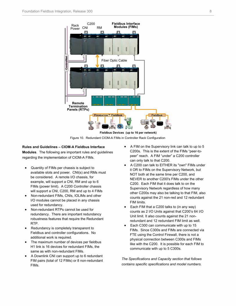
Rules and Guidelines – CIOM-A Fieldbus Interface Modules. The following are important rules and guidelines regarding the implementation of CIOM-A FIMs.
• Quantity of FIMs per chassis is subject to available slots and power. CNI(s) and RMs must be considered. A remote I/O chassis, for example, will support a CNI, RM and up to 6 FIMs (power limit). A C200 Controller chassis will support a CNI, C200, RM and up to 4 FIMs
• Non-redundant FIMs, CNIs, IOLIMs and other I/O modules cannot be placed in any chassis used for redundancy.
• Non-redundant RTPs cannot be used for redundancy. There are important redundancy robustness features that require the Redundant RTP.
• Redundancy is completely transparent to Fieldbus and controller configurations. No additional work is required.
• The maximum number of devices per fieldbus H1 link is 16 devices for redundant FIMs, the same as with non-redundant FIMs.
• A Downlink CNI can support up to 6 redundant FIM pairs (total of 12 FIMs) or 8 non-redundant FIMs.
• A FIM on the Supervisory link can talk to up to 5 C200s. This is the extent of the FIMs “peer-to-peer” reach. A FIM “under” a C200 controller can only talk to that C200.
• A C200 can talk to EITHER its "own" FIMs under it OR to FIMs on the Supervisory Network, but NOT both at the same time per C200, and NEVER to another C200's FIMs under the other C200. Each FIM that it does talk to on the Supervisory Network regardless of how many other C200s may also be talking to that FIM, also counts against the 21 non-red and 12 redundant FIM limits.
• Each FIM that a C200 talks to (in any way) counts as 2 I/O Units against that C200’s 64 I/O Unit limit. It also counts against the 21 non-redundant and 12 redundant FIM limit as well.
• Each C300 can communicate with up to 15 FIMs. Since C300s and FIMs are connected via FTE using the Control Firewall, there is not a physical connection between C300s and FIMs like with the C200. It is possible for each FIM to communicate with up to 5 C300s.
The Specifications and Capacity section that follows contains specific specifications and model numbers.
Con
trol
Net
CNI RMFieldbus Interface
Modules (FIMs)Rack Power
Remote Termination
Panels (RTPs)
Fiber Optic Cable
C200
Fieldbus Devices (up to 16 per network)
FOUNDATION™ FieldbusFOUNDATION™ Fieldbus FieldbusFieldbus
Figure 10. Redundant CIOM-A FIMs in Controller Rack Configuration
Foundation Fieldbus Integration, Release 300 9
Specifications and Capacity
Information in this section is intended to provide a set of specifications for the Experion PKS Foundation Fieldbus solution.
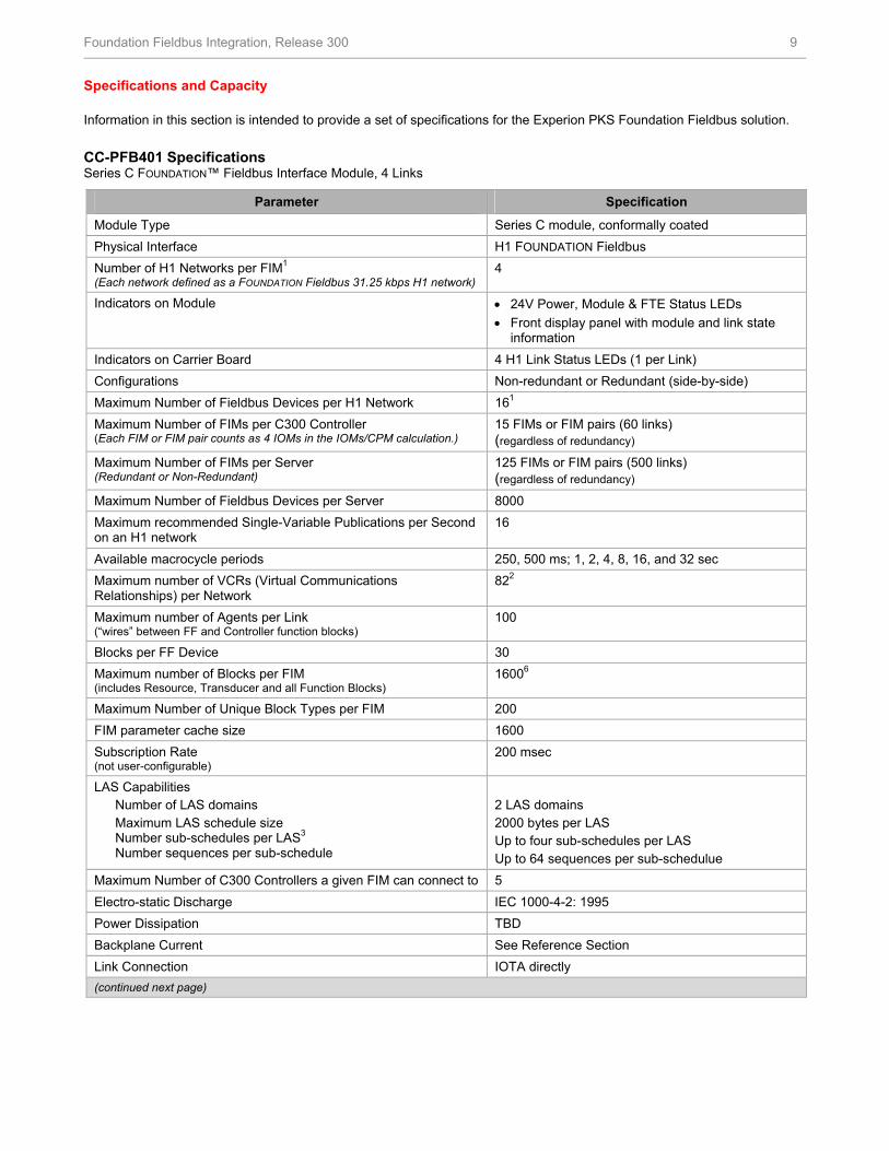
CC-PFB401 Specifications Series C FOUNDATION™ Fieldbus Interface Module, 4 Links
Parameter Specification
Module Type Series C module, conformally coated Physical Interface H1 FOUNDATION Fieldbus Number of H1 Networks per FIM1 (Each network defined as a FOUNDATION Fieldbus 31.25 kbps H1 network)
4
Indicators on Module • 24V Power, Module & FTE Status LEDs • Front display panel with module and link state
information Indicators on Carrier Board 4 H1 Link Status LEDs (1 per Link) Configurations Non-redundant or Redundant (side-by-side) Maximum Number of Fieldbus Devices per H1 Network 161 Maximum Number of FIMs per C300 Controller (Each FIM or FIM pair counts as 4 IOMs in the IOMs/CPM calculation.)
15 FIMs or FIM pairs (60 links) (regardless of redundancy)
Maximum Number of FIMs per Server (Redundant or Non-Redundant)
125 FIMs or FIM pairs (500 links) (regardless of redundancy)
Maximum Number of Fieldbus Devices per Server 8000 Maximum recommended Single-Variable Publications per Second on an H1 network
16
Available macrocycle periods 250, 500 ms; 1, 2, 4, 8, 16, and 32 sec Maximum number of VCRs (Virtual Communications Relationships) per Network
822
Maximum number of Agents per Link (“wires” between FF and Controller function blocks)
100
Blocks per FF Device 30 Maximum number of Blocks per FIM (includes Resource, Transducer and all Function Blocks)
16006
Maximum Number of Unique Block Types per FIM 200 FIM parameter cache size 1600 Subscription Rate (not user-configurable)
200 msec
LAS Capabilities Number of LAS domains Maximum LAS schedule size Number sub-schedules per LAS3 Number sequences per sub-schedule
2 LAS domains 2000 bytes per LAS Up to four sub-schedules per LAS Up to 64 sequences per sub-schedulue
Maximum Number of C300 Controllers a given FIM can connect to 5 Electro-static Discharge IEC 1000-4-2: 1995 Power Dissipation TBD Backplane Current See Reference Section Link Connection IOTA directly (continued next page)

Foundation Fieldbus Integration, Release 300 10
CC-PFB401 Specifications (cont’d)
Notes
1 The maximum number of supportable devices per network is highly dependent on application, bandwidth, devices, available current, bus length and topology. An understanding of Fieldbus is crucial to system sizing.
2 Each FIM H1 network uses 2 VCRs, each device uses 2 VCRs, and each “published” connection to/from a Controller FB uses 1 VCR. Connections between devices do not use FIM VCRs.
3 A 1 sec macrocycle could, for example, have subschedule periods of 1 sec, 500ms, and 250ms.
4 The FIM should not be used use with any control module executing more frequently than the FF device.
5 Qualified for use only with the C300 Controller.
6 The total block count includes all blocks that exist in all connected devices. Blocks may or may not be loaded to monitor. For
example, a device with 1 resource block, 5 transducer blocks and 5 function blocks will consume 11 blocks from the total block count. It does not matter if the function blocks are in use or not.
7 Each relationship between a C300 and a Series C FIM consumes 1 Peer Connection Unit (PCU). Each C300 supports up to 30
PCUs. Each "published" connection to/from a C300 FB and an FF device FB uses a peer parameter connection. Up to 500 peer parameter connections in and 500 peer parameter connections out of a C300 can be processed each second.
Model Numbers. Model numbers for CC, IOTAs, and Power Conditioner Panels are shown in the table below.
Series C FIM, IOTA and Conditioner Models
Model Number Model Description Fieldbus Interface Module CC-PFB401 Fieldbus Interface Module, 4 Links, coated Fieldbus Interface I/O Termination Panels (IOTAs) CC-TFB401 Fieldbus IOTA, Non-redundant, 4 Links, coated CC-TFB411 Fieldbus IOTA Redundant, 4 Links, coated
Redundant Powered IOTAs. The F660A Redundant Fieldbus Power IOTA, from MTL/Relcom, provides redundant power for four H1 fieldbus links to a single Series C FIM IOTA, using two plug-in power modules per link. Each link includes a switchable fieldbus segment terminator. Galvanic isolation is provided between the fieldbus segment and the input power supplies. Output voltage and current are maintained even if one power module is available on a segment. A separate module provides a FIM alarm in the event of a problem with any conditioning module or input. The F660A connects directly to the Series C FIM IOTA via a multi-conductor cable. For more information and specifications, contact MTL Incorporated, Houston, TX, at 713-341-7580.
Figure 11. Relcom F660A Redundant Fieldbus Power IOTA

Foundation Fieldbus Integration, Release 300 11
The F860 Redundant Fieldbus Power IOTA from MTL/Relcom provides redundant, isolated conditioned power for eight (8) H1 fieldbus links, servicing two (2) redundant or non-redundant Series C FIM IOTAs. It requires the same footprint as the F660A, and so offers greatly improved space usage. Connection to the IOTAs uses the same multi-conductor cable as the F660A. An on-board, link connected diagnostic module provides detailed H1 performance information about all 8 links. The F660 can be powered either from the Series C cabinet power supply or from an external power source.
The Pepperl+Fuchs Fieldbus Power Hub IOTA provides redundant, isolated power for four H1 fieldbus links to a single Series C FIM IOTA, using two plug-in power modules per link. An on-board, diagnostic module provides detailed H1 performance information about all 4 links. Both basic and advanced versions of the diagnostic module are available. For details and pricing, contact Pepperl+Fuchs Inc., 1600 Enterprise Parkway, Twinsburg, OH 44087-2245, at 330 486-0171.
Figure 12. Relcom F860 Redundant Fieldbus Power IOTA
(diagnostic module not shown)
Figure 13. Pepperl+Fuchs Fieldbus Power Hub IOTA with Diagnostic Module

Foundation Fieldbus Integration, Release 300 12
TC-FFIF01, TK-FFIF01 Specifications Chassis I/O - CIOM-A FOUNDATION™ Fieldbus Interface Module (FIM)
Parameter Specification Module Type Double slot-width chassis module (coated or
uncoated) Physical Interface H1 FOUNDATION Fieldbus Number of H1 Networks per FIM1 (Each network defined as a FOUNDATION Fieldbus 31.25 kbps H1 network)
2
Configurations Non-redundant or redundant Maximum Number of Fieldbus Devices per H1 Network 162 Maximum Number of FIMs per Controller (Each double-wide FIM counts as 2 IOMs in the IOMs/CPM calculation.)
• 21 non-redundant FIMs or • 12 redundant FIM pairs or • Any redundant/non-redundant combination
of no more than 21 total active FIMs For possible combinations, see table below entitled CIOM-A Maximum Combinations of Redundant and Non-Redundant FIMs per C200.
Maximum Number of FIMs per “Downlink” CNI (A Downlink CNI can support the equivalent of 24 IOMs. For the case of 5 redundant FIMs, the total of 25 IO Units [instead of 24] per CNI is acceptable.)
• 6 redundant FIM pairs (4 IOMs per redundant FIM pair)
• 8 non-redundant FIMs (3 IOMs per non-redundant FIM)
Maximum Number of FIMs per Server (Redundant or Non-Redundant)
100 total FIMs (50 redundant pairs)
Maximum Number of Fieldbus Devices per Server 3000 Maximum recommended Single-Variable Publications per Second on an H1 network
16
Available macrocycle period 250, 500 ms; 1, 2, 4, 8, 16, and 32 sec Maximum number of VCRs (Virtual Communications Relationships) per Network
643
Maximum number of Subschedules per Link 4 4 Maximum number of Agents per Link (“wires” between FF and Controller function blocks)
50
Maximum number of Blocks per FIM (includes Resource, Transducer and all Function Blocks)
5007
Maximum Number of Unique Block Types per FIM 100 Maximum Number of Controllers a given FIM can connect to 5 Electro-static Discharge IEC 1000-4-2: 1995 Power Dissipation 7.34 watt max. Backplane Current See Reference Section Module Connection to RTP TC-FFCxxx, Fieldbus RTP Cable
(see next two pages) See next page for notes
Foundation Fieldbus Integration, Release 300 13
TC-FFIF01, TK-FFIF01 Specifications (cont’d)
Notes 1 Qualified for use with 50 ms C200 CEE and ControlNet Supervisory Process Control Network or Fault Tolerant Ethernet only. The
Fieldbus Interface Module is not supported with the Ethernet Supervisory Process Control Network.
2 The maximum number of supportable devices per network is highly dependent on application, bandwidth, devices, available current, bus length and topology. An understanding of Fieldbus is crucial to system sizing.
3 Each FIM network uses 2 VCRs, each device uses 2 VCRs, and each “published” connection to/from a Controller FB uses 1 VCR. Connections between devices do not use FIM VCRs.
4 A 1 sec macrocycle could, for example, have subschedule periods of 1 sec, 500ms, and 250ms.
5 The FIM should not be used use with any control module executing more frequently than the FF device.
6 Only Revision D CNI modules must be used with the FIM.
7 The total block count includes all blocks that exist in all connected devices. Blocks may or may not be loaded to monitor. For
example, a device with 1 resource block, 5 transducer blocks and 5 function blocks will consume 11 blocks from the total block count. It does not matter if the function blocks are in use or not.
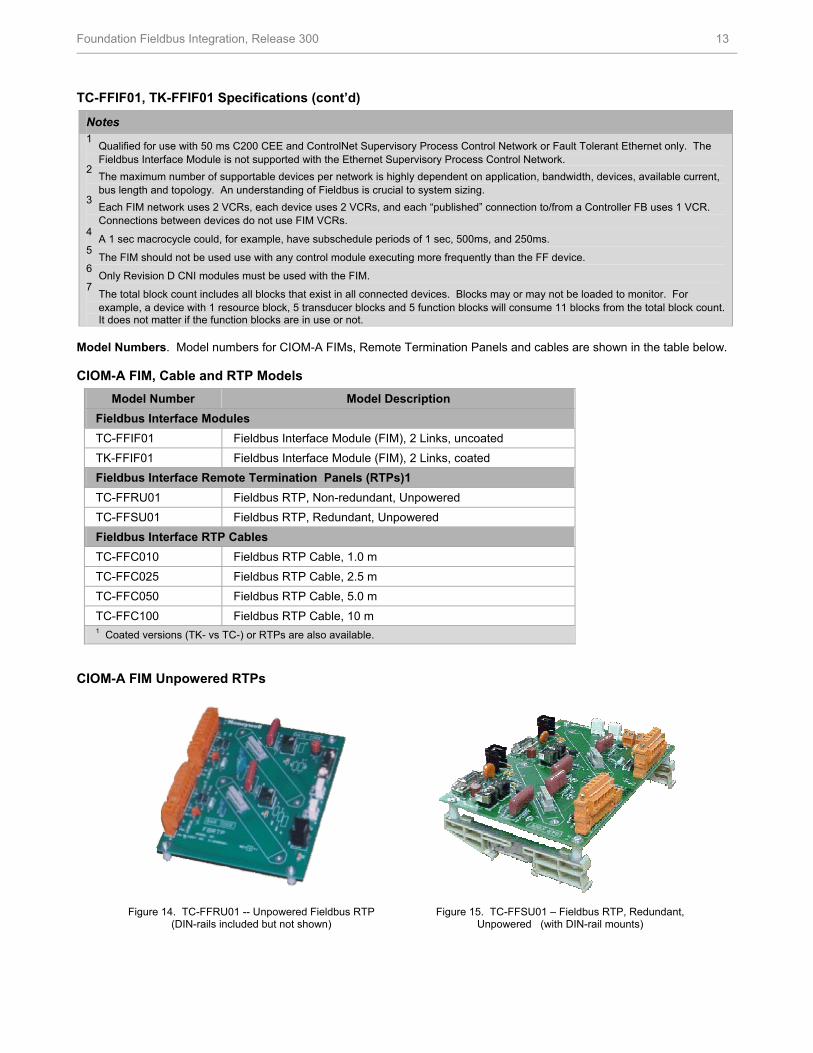
Model Numbers. Model numbers for CIOM-A FIMs, Remote Termination Panels and cables are shown in the table below. CIOM-A FIM, Cable and RTP Models
Model Number Model Description Fieldbus Interface Modules TC-FFIF01 Fieldbus Interface Module (FIM), 2 Links, uncoated TK-FFIF01 Fieldbus Interface Module (FIM), 2 Links, coated Fieldbus Interface Remote Termination Panels (RTPs)1 TC-FFRU01 Fieldbus RTP, Non-redundant, Unpowered TC-FFSU01 Fieldbus RTP, Redundant, Unpowered Fieldbus Interface RTP Cables TC-FFC010 Fieldbus RTP Cable, 1.0 m TC-FFC025 Fieldbus RTP Cable, 2.5 m TC-FFC050 Fieldbus RTP Cable, 5.0 m TC-FFC100 Fieldbus RTP Cable, 10 m 1 Coated versions (TK- vs TC-) or RTPs are also available.
CIOM-A FIM Unpowered RTPs
Figure 14. TC-FFRU01 -- Unpowered Fieldbus RTP
(DIN-rails included but not shown) Figure 15. TC-FFSU01 – Fieldbus RTP, Redundant,
Unpowered (with DIN-rail mounts)

Foundation Fieldbus Integration, Release 300 14
CIOM-A RTP Specifications
Parameter Specification
Remote Termination Panel (RTP) TC-FFRU01 TC-FFSU01 Description Unpowered, Non-Redundant Unpowered, Redundant RTP Maximum Power Requirements None None Fieldbus Current Available per Link Limited by user-supplied power Limited by user-supplied power Terminators per Link None None H1 Terminal Connection Type Compression Compression RTP Dimensions (all models) 4.9" W x 6.1" L 4.9" W x 7.5" L H1 Distance to Field Devices • Per Clause 22 of IEC 1158-22 specification
• Intrinsically safe distance limited by cable impedance (refer to MTL Application Brief AB003 for more details)
Each RTP has two connectors to allow quick connection to each of the H1 links. Mating connector is Honeywell P/N 51190691-102, Wiedmuller part number 150186.
Redundant Powered RTPs. For even greater robustness, Redundant Powered RTPs for use with FIM redundancy are available from MTL and Pepperl+Fuchs. The MTL-Relcom F650A Redundant Fieldbus Power System provides redundant Honeywell FIM connections as well as fully redundant, isolated power conditioners for each of two fieldbus networks. For more information and specifications, contact MTL Incorporated, Houston, TX, 713-341-7580.
The Pepperl+Fuchs RTP for Honeywell Redundant FIM provides redundant FIM connections combined with non-redundant power conditioners using high-reliability, passive components for each of two fieldbus networks. Up to 1 A of conditioned power is available from each link. For details and pricing, contact Pepperl+Fuchs Inc., 1600 Enterprise Parkway, Twinsburg, OH 44087-2245, (330) 486-0171.
CIOM-A FIM Redundant Powered RTPs
Figure 16. MTL-Relcom F650A Redundant
Fieldbus Power System (DIN-rails included but not shown)
Figure 17. Pepperl+Fuchs RTP FieldConnex MB-FB-PC2-HON Power Conditioner System
(DIN-rails included but not shown)

Foundation Fieldbus Integration, Release 300 15
CIOM-A Maximum Combinations of Redundant and Non-Redundant FIMs per C200
Redun Non-Red
Active Total
0 21 21 21 1 20 21 22 2 19 21 23 3 18 21 24 4 16 20 24 5 14 19 24 6 12 18 24 7 10 17 24 8 8 16 24 9 6 15 24 10 4 14 24 11 2 13 24 12 0 12 24
Fieldbus Usage Licenses, TC-FFLXxx, are required based on the total number of FIMs per Server actually in use. This applies equally to CIOM-A and Series C FIMs. License model numbers are purchased in combinations that support the total number of FIMs required. Licenses must be purchased starting with the first FIM used.
Fieldbus Usage License Models (Both Series)
Fieldbus Usage Licenses TC-FFLX01 Fieldbus Usage License, 1 FIM TC-FFLX05 Fieldbus Usage License, 5 FIMs TC-FFLX10 Fieldbus Usage License, 10 FIMs TC-FFLX50 Fieldbus Usage License, 50 FIMs

Foundation Fieldbus Integration, Release 300 16
For More Information To learn more about how Honeywell’s Fieldbus Solution can protect your system investment, visit our website www.honeywell.com/ps or contact your Honeywell account manager. Automation & Control Solutions Process Solutions Honeywell 2500 W. Union Hills Dr. Phoenix, AZ 85027 Tel: 877.466.3993 or 602.313.6665 www.honeywell.com/ps
Fieldbus Device Interoperability Testing
Device Testing. Experion uses the Control Builder tool to create a library of Fieldbus devices and their function blocks. Experion also uses Control Builder’s off-line capabilities to implement strategies involving fieldbus devices and to support live device commissioning. For the system and the FIM to work properly, devices must be registered with the Fieldbus Foundation.
Honeywell maintains a Fieldbus Interoperability Test Laboratory for testing FOUNDATION Fieldbus devices with Experion. Although most devices integrate easily, in some cases device manufacturers’ interpretations of the Fieldbus specifications may vary. When device
interoperability problems arise, Honeywell and the device manufacturer work together to create a successful integration. Device Descriptor files for devices tested are made available on our public website at http://www.honeywell.com/ps (select Products, then Foundation Fieldbus from the Quick Links, then look for Fieldbus Interoperability Support link). It is not necessary to test devices to insure they will work correctly with the system, but we are happy to test any device at no charge if requested to do so and testing is highly encouraged.
To get a device scheduled for testing, contact the Fieldbus Device Interoperability Test Program through [email protected]. There is no charge for devices that meet the above criteria. For earlier version or non-qualified devices, additional resources will be required and a service fee will be assessed for the additional effort. Note that most very early devices have been found to be incompatible with ITK 4.0.
EP03-470-300 April 2007 Printed in USA © 2007 Honeywell International Inc.
Related Documents


