Foundation Deployment Guide Revision: H2CY10

Welcome message from author
This document is posted to help you gain knowledge. Please leave a comment to let me know what you think about it! Share it to your friends and learn new things together.
Transcript

Foundation Deployment Guide
Revision: H2CY10

2Using this Borderless Networks Guide
The Purpose of this Document
The Cisco Smart Business Architecture (SBA) for Government was designed, built, and validated as an end-to-end system. This guide provides step-by-step instructions to deploy the Borderless Network Foundation solutions. To reflect our ease-of-use principle, this guide is organized into modules. You can start at the beginning or jump to any module. Each part of the guide is designed to stand alone, so you can deploy the Cisco technol-ogy for that section without having to follow the previous module.
Who Should Read This Guide
This guide is intended for the reader with any or all of the following:
• An agency with up to 1000 connected employees
• Up to 20 remote sites with approximately 25 employees each
• External-facing applications, which are hosted offsite
• A server room containing agency applications
• IT workers with a CCNA® certification or equivalent experience
The reader may be looking for any or all of the following:
• A solution for teleworker and mobile worker
• Security for agency resources
• Wired and wireless network access for employees
• Solutions for wired and wireless voice access
• Wireless guest access
• A migration path for growth
• Ways to reduce cost by optimizing WAN bandwidth
• The assurance of a tested solution
Related Documents:
Before reading this guide, you may want to see these documents:
Borderless Networks Foundation Design Overview
Optional Documents
Borderless Networks Configuration Files Guide
Foundation Configuration Guide
Design Guides Deployment Guides
FoundationDeployment Guide
Deployment Guides
Data CenterDeployment Guide
Design Guides
Design Overview
Design Overview You are Here

Table of Contents
ALL DESIGNS, SPECIFICATIONS, STATEMENTS, INFORMATION, AND RECOMMENDATIONS (COLLECTIVELY, "DESIGNS") IN THIS MANUAL ARE PRESENTED "AS IS," WITH ALL FAULTS. CISCO AND ITS SUPPLIERS DISCLAIM ALL WARRANTIES, INCLUDING, WITHOUT LIMITATION, THE WARRANTY OF MERCHANTABILITY, FITNESS FOR A PARTICULAR PURPOSE AND NONINFRINGEMENT OR ARISING FROM A COURSE OF DEALING, USAGE, OR TRADE PRACTICE. IN NO EVENT SHALL CISCO OR ITS SUPPLIERS BE LIABLE FOR ANY INDIRECT, SPECIAL, CONSEQUENTIAL, OR INCIDENTAL DAMAGES, INCLUDING, WITHOUT LIMITA-TION, LOST PROFITS OR LOSS OR DAMAGE TO DATA ARISING OUT OF THE USE OR INABILITY TO USE THE DESIGNS, EVEN IF CISCO OR ITS SUPPLIERS HAVE BEEN ADVISED OF THE POSSIBILITY OF SUCH DAMAGES. THE DESIGNS ARE SUBJECT TO CHANGE WITHOUT NOTICE. USERS ARE SOLELY RESPONSIBLE FOR THEIR APPLICATION OF THE DESIGNS. THE DESIGNS DO NOT CONSTITUTE THE TECHNICAL OR OTHER PROFESSIONAL ADVICE OF CISCO, ITS SUPPLIERS OR PARTNERS. USERS SHOULD CONSULT THEIR OWN TECHNICAL ADVISORS BEFORE IMPLEMENTING THE DESIGNS. RESULTS MAY VARY DEPENDING ON FACTORS NOT TESTED BY CISCO.
Any Internet Protocol (IP) addresses used in this document are not intended to be actual addresses. Any examples, command display output, and figures included in the document are shown for illustrative purposes only. Any use of actual IP addresses in illustrative content is unintentional and coincidental. Cisco Unified Communications SRND (Based on Cisco Unified Communications Manager 7.x)
© 2010 Cisco Systems, Inc. All rights reserved.
Table of Contents
Introduction . . . . . . . . . . . . . . . . . . . . . . . . . . . . . . . . . . . . . . . . . . . . . . . . . . . . . . . . . . . . . . . .1Design Goals . . . . . . . . . . . . . . . . . . . . . . . . . . . . . . . . . . . . . . . . . . . . . . . . . . . . . . . . . . . 3
Agency Overview . . . . . . . . . . . . . . . . . . . . . . . . . . . . . . . . . . . . . . . . . . . . . . . . . . . . . . . 3
Architecture Overview . . . . . . . . . . . . . . . . . . . . . . . . . . . . . . . . . . . . . . . . . . . . . . . . . . 4
Global Configuration Module . . . . . . . . . . . . . . . . . . . . . . . . . . . . . . . . . . . . . . . . . . . . . .8
LAN Module . . . . . . . . . . . . . . . . . . . . . . . . . . . . . . . . . . . . . . . . . . . . . . . . . . . . . . . . . . . . . .13Core LAN . . . . . . . . . . . . . . . . . . . . . . . . . . . . . . . . . . . . . . . . . . . . . . . . . . . . . . . . . . . . . . 14
Client LAN Access . . . . . . . . . . . . . . . . . . . . . . . . . . . . . . . . . . . . . . . . . . . . . . . . . . . . . 20
Server Room . . . . . . . . . . . . . . . . . . . . . . . . . . . . . . . . . . . . . . . . . . . . . . . . . . . . . . . . . . . 23
Wide-Area Network Module . . . . . . . . . . . . . . . . . . . . . . . . . . . . . . . . . . . . . . . . . . . . . 26
Quality of Service Module . . . . . . . . . . . . . . . . . . . . . . . . . . . . . . . . . . . . . . . . . . . . . . . 30
Wireless Module . . . . . . . . . . . . . . . . . . . . . . . . . . . . . . . . . . . . . . . . . . . . . . . . . . . . . . . . . 35
Remote Site Wireless . . . . . . . . . . . . . . . . . . . . . . . . . . . . . . . . . . . . . . . . . . . . . . . . . . . . .51
Internet Edge Module . . . . . . . . . . . . . . . . . . . . . . . . . . . . . . . . . . . . . . . . . . . . . . . . . . . . 54Cisco Adaptive Security Appliance Configuration . . . . . . . . . . . . . . . . . . . . . 55
Intrusion Prevention System Configuration . . . . . . . . . . . . . . . . . . . . . . . . . . . . 59
Remote Access VPN . . . . . . . . . . . . . . . . . . . . . . . . . . . . . . . . . . . . . . . . . . . . . . . . . . . 66
Unified Communication Module . . . . . . . . . . . . . . . . . . . . . . . . . . . . . . . . . . . . . . . . . .70
Application Optimization Module . . . . . . . . . . . . . . . . . . . . . . . . . . . . . . . . . . . . . . . . 75
Appendix A: Midsize Agencies Deployment Product List . . . . . . . . . . . . . . . . 83
Appendix B: SBA for Midsize Agencies Document System . . . . . . . . . . . . . . .87

1Introduction
Introduction
For our Partners servicing customers with up to 1000 connected users, Cisco has designed an out-of–the-box deployment that is simple, fast, affordable, scalable, and flexible. We designed it to be easy—easy to configure, deploy, and manage.
The simplicity of this deployment, though, masks the depth and breadth of the architecture. Based on feedback from many customers and Partners, Cisco has developed a solid network foundation with a flexible platform that does not require re-engineering to support additional Network or User services.
This deployment guide has been architected to make your life a little bit-maybe even a lot—smoother. This architecture:
• Provides a solid foundation
• Makes deployment fast and easy
• Accelerates your ability to easily deploy additional services
• Avoids the need to re-engineer the core network
Here’s an overview of the modules included in this guide:
• The first module covers Global Configuration of the elements that are universal among many, if not all, of the devices in the solution. As an example Secure Shell (SSH) setup can be used throughout the design for secure remote management of devices.
• The LAN Module includes guidance for all segments of the agency LAN from the headquarters to remote sites. The Core LAN section focuses on that portion of the LAN which serves as the central aggregation for all user access switching at the headquarters and the interconnect point for the WAN and Server Room. The Client LAN Access Module explains how to configure the LAN switches at headquarters and remote sites for desktop computer, phone, and other device connectivity. The Server Room Module explains how to configure server ports on the switches, VLAN usage and trunking, resiliency and connectivity to the LAN core.
• The Quality of Service (QoS) Module provides you with guidance on protecting your traffic as it crosses the network and then walks you through the steps to deploy this critical service for the LAN and WAN. Some pieces of QoS are also embedded in other modules for clarity.
• The Wide-Area Network (WAN) Module includes the WAN aggregation at the headquarters as well as the connectivity to remote locations. The WAN also covers connectivity to the LAN infrastructure at those remote locations.
• The Wireless Module covers the wireless infrastructure for the head-quarters and remote sites and its use for employees to access the intranet and Internet and secure guest user access to the Internet.
• The Internet Edge Module focuses on the deployment of firewalls and advanced security services to protect the information assets of your agency. The Intrusion Protection System (IPS) Module explains how to install IPS to monitor your network for intrusions or attacks. The Remote Access VPN section of the internet edge module explains how to pro-vide secure remote access to your network for teleworkers and remote mobile users.
• The Unified Communications (UCs) Module provides guidance on how to plan your Cisco® UC/IP telephony deployment and how the integrated services in your routers show you how the embedded resources in the network foundation can be utilized to support a UC deployment without re-engineering the core network.
• The Application Optimization Module shows you how to optimize the bandwidth between the headquarters and remote offices. Ensuring economical use of your IT resources can delay WAN upgrades or make room for new applications.
• The Appendix provides the complete list of products used in the lab testing of this design as well as the software revisions used on the products in the system.
To enhance the architecture, there are a number of supplemental guides that address specific functions, technologies, or features that may be important to solving your operational problems.
Figure 1 illustrates the complete SBA foundation design with all of the modules deployed.

2Introduction
Figure 1 . Network Architecture Baseline

3Introduction
Design Goals
From the beginning, one of the primary concepts of this design has been the “modular concept.” The deployment process was divided into modules according to the following principles:
• Ease of use: A top requirement was to develop a design that could be deployed with the minimal amount of configuration and day-two management.
• Cost-effective: Another critical requirement in the selection of products was to meet the budget guidelines for an agency of this size.
• Flexibility and scalability: As the agency grows, so too must its infra-structure. Products selected needed to have the ability to grow or be repurposed within the architecture.
• Reuse: The goal, when possible, was to reuse the same products throughout the various modules to minimize the number of products required for spares.
Agency Overview
The Cisco SBA for Midsize Agencies—Borderless Networks Foundation Deployment Guide is designed to address five primary needs that midsize agencies must meet:
• To provide reliable access to agency resources
• To minimize time required to select and absorb technology investments
• To enable workforce mobility
• To provide guest and partner access
• To reduce operational costs
Provide Reliable Access to Agency Resources
Data networks are critical to an agencies’ ability to operate. Online workforce-enablement tools only offer benefit if the data network provides reliable access to information resources. Collaboration tools and content distribution rely on high-speed, low-latency network infrastructure to provide an effective user experience. However, as networks become more complex, the level of risk increases for network availability loss or poor per-formance due to inadequate design, configuration errors, maintenance and upgrade outages, or hardware and software faults. The design and methods used in this deployment guide were created to minimize these risks.
Minimize Time Required to Select and Absorb Technology Investments
New technology can impose significant costs, from the perspectives of the time required to select the proper equipment, the investment in the equipment, as well as the time and workforce investment that is required to deploy the new technology and establish operational readiness. Matching the correct equipment to solve operational problems with the right mix of scalability, growth, and cost can be difficult with the number of choices in the market. When new technology is introduced it takes time to understand how the technology operates, and to ascertain how to effectively integrate the new technology into the existing infrastructure. Over time the methods and procedures used to deploy a new technology are refined to be more efficient and accurate.
This deployment guide eases the agency’s cost of technology selection and implementation by providing recommended equipment appropriate for the midsize agency along with methods and procedures that have been developed and tested by Cisco. Applying the guidance within this docu-ment reduces the time required for assimilation of the technology into the agency’s network, and allows the technology to be deployed quickly and accurately, so the agency can achieve a head start realizing the return on its investment.
Enable Workforce Mobility
The ability for a user to maintain productivity without being tethered to their desk for computer and telephone connectivity is driving increased efficiency into the operation of most agencies. Providing network access in a conference room without the need to run wires to every meeting attendee reduces infrastructure costs and enables a more productive environment. Agencies looking to control overhead costs by improving office space efficiently can utilize wireless mobility features. For example, by sharing workspace between multiple users, reaching hard to wire locations for office space, or enabling ad hoc meetings in lunch rooms, agencies can maximize their workspace efficiency. Common network access at headquarters and remote locations means users can be productive regardless of their work location for the day.
This design provides mobility services that increase employee productivity by allowing users to move throughout the physical plant while maintaining access to their applications, and control costs by maximizing the use of office space.

4Introduction
Provide Guest and Partner Access
Agencies’ facilities are frequently used by a wide range of guests, including customers, partner agencies, and vendors. Many of these guests desire net-work connectivity to gain access to permitted organizational resources, as well as VPN connectivity to their employer’s network and the Internet, while they are on-site so they can be as productive as possible. However, offering guests the same level of network access as the agency’s users exposes the agency to a significant risk. Additionally, variations in frequency and number of guests can cause difficulty predicting when and where the connectivity will be required.
The design provides wireless service that offers authenticated guest access to the Internet without allowing access to the agencies’ internal resources.
Reduce Operational Costs
Agencies constantly pursue opportunities to reduce network operational costs, while maintaining the network ’s effectiveness for the end users. Operational costs include not only the cost of the physical operation (power, cooling, etc), but also the labor cost required to staff an IT department that monitors and maintains the network. Additionally, network outages and performance issues impose costs that are more difficult to quantify, in the form of loss of productivity and interruption of operational continuity.
The network provided by this deployment guide offers network resilience in its ability to tolerate failure or outage of portions of the network, along with a sufficiently robust-yet-simple design that staff should be able to operate, troubleshoot and return to service in the event of a network outage.
Architecture Overview
The Cisco SBA for Midsize Agencies—Borderless Networks Foundation Deployment Guide provides a design that enables communications across the agency. The deployment guide is broken up into modules that provide design guidance for that place in the network or the network service you need to deploy.
LAN Module
The Core LAN, as the hub of communications between all modules in the network, is one of the most important modules in the design. Although there are multiple Cisco products that can provide the functionality needed in the core—primarily fault tolerance and high-speed switching—this architecture provides flexibility so that the infrastructure can grow with the agency.
In the design, two options are provided: the first option is for up to 600 users supported by a resilient core stack design using the Cisco Catalyst® 3750 switch. The second option is for 500-1000 users supported by a resilient Cisco Catalyst 4507R chassis equipped with dual supervisor modules.
Both provide the required fault tolerance and capacity. Another critical factor is port densitythe number of physical ports needed to connect other devices from the other modules. The actual product you select should be driven by your specific agency needs.
Up to 600 Users
The Cisco Catalyst 3750 product line is a fixed-port, stackable, Gigabit Ethernet switch that provides redundancy via the StackWise® technology. Further discussion is provided later in the Core module.
The Cisco Catalyst 3750 switch provides both Layer 3 and Layer 2 switch-ing capabilities and is configured to route traffic between other modules in the LAN. In the future, should an agency require more ports in the core, additional 3750s can easily be added to the core stack, or if a move to a split core/distribution is required, the current Cisco Catalyst 3750 core stack can be repurposed. The dual function means it can also be reused in the server room or as a client LAN access switch. In the design validation, Cisco used a pair of stacked Cisco Catalyst 3750G-12S-E switches that use Small Form-Factor Pluggable transceivers, allowing for a port-by-port option of either twisted pair or fiber optic cables. In addition, the Cisco Catalyst 3750 stack provides in-service additions of stack members to add more port capacity. This ensures maximum availability and minimal downtime.
500-1000 Users
A design to support more users requires additional switching capacity and more ports to connect to the additional client LAN access switches. For this design we have selected a resilient Cisco Catalyst 4507R switch equipped with dual supervisor modules that provide the fault tolerance needed in the core. Its flexible chassis design allows for different line cards to match the number of uplink ports required.
Server Room and Client LAN Access
Both the Server Room and the Client LAN Access have the primary respon-sibility of connecting devices to the network. The main difference is the requirement in the client LAN access for Power over Ethernet (PoE). We have selected three product lines from which to choose: the Cisco Catalyst 3750-X, the Cisco Catalyst 3560-X, and the Cisco Catalyst 2960-S switches.

5Introduction
The Cisco Catalyst 3750-X switch is a stackable 10/100/1000 Ethernet fixed-port product line with PoE+ support, modular 1-Gigabit and 10-Gigabit uplink options, and higher overall capacity because of its 64-Gbps back-plane and StackWise Plus technology. The Cisco Catalyst 3560-X switch is a fixed-configuration, non-stackable, 10/100/1000 Ethernet switch family with PoE+ support and modular 1-Gigabit and 10-Gigabit uplinks that provides flexibility and features for many access-level switching environments. The Cisco Catalyst 2960-S is an economical fixed-configuration 10/100/1000 Ethernet switch family with FlexStack expansion capability, 10-Gbps uplink options, and it supports PoE+.
All three switch families, the Cisco Catalyst 3750-X, Catalyst 3560-X, and Catalyst 2960-S include 10/100/1000 ports with 10Gigabit uplinks and PoE+. While a PoE-capable device is not required in the server room, the marginal cost difference ensures a single product line can be used across multiple modules and repurposed as the infrastructure grows.
PoE/PoE+ supports IP telephony, wireless access points, security cameras, and other low-power devices. PoE/PoE+ enables devices to be powered in a location using the twisted-pair cable without the expense of installing or modifying the building power in locations (such as in ceilings for installing cameras and wireless access points [AP]). Including PoE in the design future proofs the network, removing the added cost of re-engineering the network in the future as PoE devices are deployed. While the configurations are different, the management and ability to use a single product line between multiple modules lowers operational expenses.
WAN Module
The headquarters WAN is the point of connection between the main office and remote site. In this design, the WAN assumes that private and secure connections are provided by a service provider. While the design includes Internet access, the Internet is not used for connectivity between locations. The WAN interconnects all locations and aggregates traffic for the Internet at the headquarters.
When selecting a device, Cisco also considered the ability to support additional functions and services. Beyond the primary function of routing traffic between locations, the device may need to support voice media and gateway services, in addition to optimization and security functions through the expansion capabilities provided by plug-in modules.
Given all these requirements, the Cisco 3845 Integrated Services Router (ISR) or the Cisco 3925 Integrated Services Router Generation 2 (ISR G2) are the recommended options for the headquarters WAN router. The Cisco 3845 and 3925 ISR are flexible, modular platforms enabling high-speed routing and other services—such as voice—for connectivity needs between the headquarters and remote sites.
The remote site design supports up to 25 users with computers, IP phones, and wireless. The computers will be using desktop applications as well as email and other agency applications that are accessed over the WAN to the server room at the headquarters. The IP phone system also needs to be supported through the WAN. The local LAN switch needs to support PoE for the IP phones and wireless APs, so they do not require external power.
In addition, QoS and Application Optimization offer cost savings by efficient use of the LAN and WAN. Additionally, threat mitigation security measures are provided as remote workers often have laptop computers that are placed on public networks.
The Cisco 2811 ISR or 2911 ISR G2 are the platforms that meet the require-ments for connecting the remote site via the WAN back to the headquarters. Both platforms provide integrated services with voice gateway capability for local connectivity to the Public Switched Telephone Network, and Wide-Area Application Services Network Module (NM) for optimization of data, voice, and video over the WAN.
For computer, IP phone, wireless AP, and other office access connectivity, the Cisco Catalyst 2960-S or Cisco Catalyst 3560-X (either 24 or 48 ports) are the products selected at the remote site for this design. Each enables simple network access plus the required PoE. In keeping with the principle of ease of use, each product has the same command set as the Cisco Catalyst 3750-X, 3560-X, and 2960-S switches used in the headquarters LAN, keeping deployment and operational cost to a minimum.
The final device is the wireless AP. In this design, the Cisco AIR-LAP1140 Series was chosen as it is a PoE-capable product that can be centrally man-aged from the headquarters using a wireless LAN controller.
QoS Module
In a network where multiple applications share a single transport, it is necessary to provide varying levels of service to guarantee satisfactory application performance. Real-time traffic like voice is very delay and drop sensitive therefore it must be handled with priority so that the stream of data is not interrupted. QoS provides the agency the ability to define different traffic types for both data and multimedia applications and to create more deterministic handling for real-time traffic and levels of priority for cirtical agency applications.
In the LAN, the need for QoS is less evident due to the high bandwidth available like Gigabit Ethernet, but even high-speed LANs have congestion points where packets can be delayed or dropped in buffers to manage traffic flow. In the WAN, the need for QoS is much more evident as the difference in available bandwidth as you leave the LAN to cross the WAN can be very large and creates congestion points as you cross from high to low

6Introduction
bandwidth. It is important to note that QoS cannot create bandwidth; rather, it takes bandwidth from one class to give to another class with higher priority.
QoS is an important part of the foundation design as it allows agencies to combine once separate voice and data networks onto a single IP based transport. To stay consistent with our ease of use goal with our design, we keep our QoS as simple as possible to maintain correct operation of the real-time traffic on the network and to allow the agency to customize if desired to classify specific critical application handling.
The QoS module provides the guidance necessary to:
• Establish a limited number of classes to map applications into
• Handle different classes of service with bandwidth and priority policies
• Map the policies to LAN and WAN interfaces to achieve intended results
This approach establishes a solid baseline that is scalable to handle expanding needs of the agency.
Wireless Module
The foundation design includes both wired and wireless access to improve the effectiveness of the user by allowing them to stay connected regardless of location. The design utilizes 802.11 Wi-Fi technology for transporting voice, data, and even video rather than using cellular technology. The 802.11a/b/g/n support in the wireless design provides easy migration from legacy Wi-Fi networks to the highest speed and performance infrastructure available.
Traditional wireless network designs used the autonomous or standalone Access Point (AP) model where each AP is individually configured and managed. This methodology made it difficult to monitor and expand the network size and functionality. At the heart of the SBA design for wireless is a centralized Wireless LAN Controller (WLC) appliance that can be scaled to support the number of APs and locations necessary to support the agency.
In the wireless design Cisco recommends using the 5500 Series Wireless LAN Controller that provides support for up to 250 APs each. To keep the design simple yet resilient, secure, and scalable we use one WLC for guest traffic, and four WLCs to handle data and voice traffic for the agency users. Of the four WLCs, two are designated to provide a resilient WLAN at the headquarters location while the other two WLCs will provide the same ability for wireless voice and data at each remote office. The same APs that offer employee access to internal network access via authentication also offer guest and partner access. The guest access data is tunneled from each AP back to the anchor guest WLC and via a secured VLAN is handed to the
firewall, which prevents those users from accessing internal assets. More WLCs can be added to provide additional scalability and resiliency if needed.
The access points used in the WLAN are the Cisco 1140 Series Lightweight APs with 802.11a/b/g/n support. Power is provided for AP operation using PoE from the LAN switches which allows installation without installing electrical outlets for every location. Both the headquarters and remote site locations use the same Cisco 1140 AP models for a standard and efficient design. If a remote site loses connection to the headquarters WLC the APs at that site will continue to operate in standalone mode switching traffic locally.
Every location provides the same wireless service set identifier (SSID) for data, voice, and guest access making mobility that much easier. Though the SSIDs are universal across the network, the design switches WLAN traffic for remote site voice and data local to that site for efficient transport. Remote Authentication Dial In User Service (RADIUS) authentication is utilized to provide access to internal networks. The guest WLAN uses an OPEN web authentication which allows expiring account access controls.
Internet Edge Module
Within the design, there are many requirements and opportunities for security features. The deployment guide will cover IDS in the WAN, VPN software and hardware for the mobile teleworker, and small office or home office (SOHO) worker. There is additional security at the switch port level where devices connect to the switch; this type of security will be covered in detail in the LAN and WAN modules.
At the headquarters, there is another layer of security to protect the agency information assets. These devices provide direct and indirect protection against potential threats.
The first product in the headquarters security perim-eter is the Cisco ASA 5510. The ASA 5510 is a hardened multifunction device providing firewall capability, VPN, and SSL VPN access for remote/mobile users. It also has a slot for an additional services module; and in this design, the additional services module added is the IPS module.
IPS SSM Functionality
The IPS module adds the ability to inspect application layer data for attacks and block malicious traffic.
The indirect security is established by the use of intrusion detection. This is a passive method for monitoring threats. Once a threat is detected, mitiga-tion steps can be taken. The Cisco IPS 4200 Series allows the agency to

7Introduction
continuously monitor the network traffic for potential threats. When a threat is detected, an alert can be sent to the appropriate resource, and an action can be taken to resolve the issue.
Teleworker and Remote Access VPN
The foundation for both teleworkers and remote workers is the use of virtual private network (VPN) technologies.
Remote mobile workers use hotspots in coffee shops, hotels, airports, and other locations to access the Internet. Once the mobile worker is connected to the Internet, they can use a software VPN client to gain secure access to agency resources. Cisco provides a software VPN client for this purpose.
Teleworkers are users that work from a primary location such as a home office that is neither the headquarters nor a remote site. Most teleworkers’ activities don’t warrant the cost of a dedicated WAN connection to the headquarters, but still have many of the connectivity requirements of the remote site or headquarters user. Therefore, connecting back to the head-quarters via the Internet is more economical, but the Internet is inherently insecure. They need to connect a computer, IP phone, and perhaps a printer and wireless AP at their location. The teleworker needs a secure connection and ports for their networked office equipment, which includes PoE for their IP phone and AP.
The Cisco ASA 5505 is a perfect match for this situation. It is an economical, full-functioning firewall with eight 10/100 ports (two of which are PoE) to sup-port an IP phone and/or AP. The Cisco ASA 5505 also provides a hardware-based VPN for secure connections from the teleworker location back to the headquarters. The device can be preconfigured before being shipped to the teleworker location. It is both simple to use and deploy while providing the required security.
UC/IP Telephony Module
Agencies are looking to maximize the return on investment in their data network infrastructure. One of the more widespread technologies being deployed is IP telephony. IP telephony is basically the migration of the old standalone phone switch to a software-based switch—and the use of the data network as the physical transport for voice communications, rather than separate cabling plans for data and voice communications. The market category that defines IP telephony and other forms of communications, including video, is known as Unified Communications (UC). This design ensures all modules support Cisco UC solutions from the onset. Therefore, no additional work or re-engineering of the network foundation is required to add Cisco UC, specifically IP telephony, to this design.
Cisco’s Unified Communications has two software components. The first is the Cisco Unified Communi-cations Manager. The Communications Manager is the hub for interconnecting and managing IP telephony and other communication applications. The second is the Cisco Unity® Connections. Unity Connections provide services such as voicemail for 1000 users, voicemail integration with your email inbox, and many other productivity features.
Because UC applications, such as IP telephony and voicemail, have differ-ent processing and storage requirements based on the number of users and the features applied, it is important to select the appropriate platform based on expected usage. This design recommends the Cisco Unified Communications MCS 7835 and the Cisco Unity Connections MCS 7825.
Application Optimization Module
Remote sites must connect back to the main office to access applications. This connectivity affects the productivity of an agency; therefore, it is critical to maximize its usage for cost-effectiveness. In the last three to four years, a new class of product—called Application Optimization—has allowed greater amounts of voice and data to traverse these links without incurring the additional cost of buying more bandwidth. Similar to the UC module, the ability to add Application Optimization with minimal cost and effort is an essential requirement.
The recommendation is Cisco Wide-Area Application Services (WAAS) software. WAAS runs on a variety of devices that are selected based on specific performance requirements of applications, WAN links, and number of users.
The WAAS solution has three components: an application optimization device at each remote site, an application optimization endpoint at the headquarters that acts as a collection point for the remote sites, and a Central Manager that is the control point for the entire WAAS solution. In the lab, we used a Cisco Wide-Area Engine (WAE) 502 NM within the router at the remote site, a Cisco WAVE 574 appliance for the application acceleration endpoint at the headquarters, and a Cisco WAVE 274 as the central manager at the headquarters.
Refer to the WAAS Sizing Guide on Cisco.com or contact a Cisco applica-tion optimization specialist when designing your WAAS solution to ensure optimal performance.

8Global Configuration Module
Global Configuration Module
Agency Overview
The ability to standardize a setting or variable across a large number of instances reduces complexity and aids in comprehension. As networks become more complex agencies are striving to simplify operations to reduce risk and lower cost. IT team members are required to wear many hats in smaller agencies; they may deal with the LAN infrastructure in the morn-ing, the Internet Edge in the afternoon, and a WAN issue in the evening. The ability to use a common network admin access, or gather statistics from a large number of devices with timestamps to aid with correlation of events is crucial to reducing the challenge of deploying and monitoring a network.
The Foundation Deployment Guide Global Configuration module benefits your agency by providing a standardized approach to secure network device access, network protocol settings, and the baseline for network management application access. The end result is a network foundation that is easier to deploy and manage which will help lower your operational costs.
Technical Overview
The challenge with managing a network of switches and routers for LAN and WAN, network appliances and modules that provide security and other network services, and network based user services like IP Telephony can be daunting for a small IT staff. The ability to standardize on common settings, features, and services reduces time to repair and makes it easier to train new staff on network operations. Because the variety of devices can require different interfaces like CLI or GUI the ability to standardize settings and methods will reduce confusion.
This module provides recommendations for the settings within the SBA for an up to 1000 user design that are common across multiple systems and simplify and secure the management for the solution.
To provide consistent and secure network device access, Secure Shell (SSH) is recommended for use across the network. When browser based access is desired, HTTP settings are provided and Secure HTTP (HTTPS) is recommended. The use of fully qualified IP domain names is useful for
accessing devices versus memorizing the IP address of every device which can change over time as well. Some network devices also require IP domain name services for operation. Finally, to reduce the ability for someone viewing a configuration printout to see confidential passwords, we will use password encryption services.
When troubleshooting an event or anomaly in a network it is important to be able to correlate events across a large number of devices. Network Time Protocol (NTP) is recommended for the foundation of the network as it provides a consistent and synchronized timestamp for network event and debug logs. The ability to view the same point in time across network device logs is critical to reducing your time to repair a problem.
In the LAN design Unidirectional Link Detection (UDLD) is used to monitor the switch-to-switch fiber-optic or copper interconnects for unidirectional links that can lead to spanning-tree loops, black holes, and other non-deterministic forwarding. Virtual Trunking Protocol (VTP) will operate in the transparent mode as the network size makes it less beneficial versus some tradeoffs in using VTP. Spanning Tree loops are eliminated in the design but STP is enabled for Rapid Spanning Tree operation to protect against unexpected loops.
This module explains how to complete each of the procedures that make up the global configuration.
Tech Tip
The actual setting and values depend on your current network configu-ration. Please review all settings and configuration changes for a given module before submitting them so you are familiar with the intent and potential impact on your network.

9Global Configuration Module
Process
Completing Global Configuration
1. • Set Enable Password and Enable Password Encryption
2. • Enable NTP and Set the Local Time Zone
3. • Set VLAN Trunking Protocol (VTP)
4. • Enable Unidirectional Link Detection (UDLD)
5. • Enable SSH for remote management
6. • Add Domain Name Services
7. • Enable HTTP or HTTPS Access
8. • Enable Spanning Tree Protocol (STP)
9. • Enable SNMP Management
The following global system administration procedures will simplify and secure the management of your network.
Procedure 1 Set Enable Password and Encryption
The enable password secures access to the device configuration mode. Enabling password encryption makes it impossible to read the plain text passwords from the configuration files.
When enabling password encryption, be sure to adhere to your agency standards for compliance requirements with both internal and external guidelines and regulations.
Step 1: Set an enable password and enable password encryption to secure access to the device configuration mode:
enable secret [password] service password-encryption
Procedure 2 Enable NTP and Set Local Time Zone
The Network Time Protocol (NTP) is designed to synchronize a network of devices. An NTP network usually gets its time from an authoritative time
source, such as a radio clock or an atomic clock attached to a time server. NTP then distributes this time across the agencies’ network.
Network devices should be programmed to synchronize to a local NTP server in the network.
Step 1: Enable Network Time Protocol (NTP) ntp server 192.168.31.2
Step 2: Set the local time zone for the device locationclock timezone UTC -8 clock summer-time UTC recurring
Procedure 3 Set VLAN Trunking Protocol
Setting VLAN Trunking Protocol (VTP)to transparent on a switch forwards VTP information from other switches, but does not incorporate VTP updates in the local database. Switches in transparent mode are not active members of a VTP domain. Instead, they store their own VLAN configuration in NVRAM.
Step 1: Set VLAN Trunking Protocol to transparent. vtp mode transparent
Procedure 4 Enable Unidirectional Link Detection
Unidirectional links can cause a variety of problems, including:
• Spanning-tree loops
• Black holes
• Nondeterministic forwarding
Unidirectional llink detection (UDLD) is a Layer 2 protocol that enables devices connected through fiber-optic or twisted-pair Ethernet cables to monitor the physical configuration of interswitch link cables and detect when a unidirectional link exists.
When UDLD detects a unidirectional link:
• It disables the affected port
• The network device sends an alert
UDLD also enables faster link failure detection and quick reconvergence of port trunks, especially with fiber, which is more susceptible to unidirectional failures.

10Global Configuration Module
All connected devices must support UDLD for the protocol to successfully identify and disable unidirectional links.
UDLD does not function any differently when in normal or aggressive mode. The same messages are sent and the same messages are expected to be received. The modes only differ in the way that UDLD reacts to a unidirectional link failure. If the link state of the port is determined to be unidirectional:
• In normal mode, the port continues to forward traffic normally but the traffic is marked as undetermined. The port cycles through the regular Spanning Tree Protocol (STP) states and continues to forward traffic.
• In aggressive mode, the port enters “errdisable” state and is effectively shut down. To recover from errdisable, you have to shut down and restart the port by issuing the shut and no shut commands.
Cisco recommends using the aggressive mode.
Step 1: Set UDLD to “aggressive” mode
udld aggressive
Procedure 5 Enable SSH
Cisco recommends that you enable Secure Shell (SSH) for remote management.
Step 1: Configure an IP domain prior to configuring SSH:ip domain-name [domain name]
Step 2: Set SSH to version 2 as it is more secure than version 1 and is sup-ported by most SSH clients. When enabling SSH, you will need to generate RSA Keys.
Ip ssh version 2 crypto key generate rsa general-keys modulus 2048
Step 3: Secure authentication can be enabled either locally or using an authentication server. Again, it is best to adhere to your agency policies. The following is an example of the commands to enable SSH login and secure the access request via an access list:
line vty 0 15 login local transport input ssh access-class 55 in access-list 55 permit 192.168.28.0 0.0.0.255
Tech Tip
All IP addresses, VLAN numbers, and other specific values used in the Configuration Guide are for example purposes only.
Procedure 6 Add Domain Name Services
Using a fully qualified domain name rather than the IP address ensures access to the network, services, and specific devices even if the IP addresses change. It is also required for the IP telephony gateway.
In our configuration, we added Dynamic Host Control Protocol (DHCP) services in the core.
Below are two examples of pools of IP addresses for access clients and “voice” clients, including the domain name and DNS server IP to enable DNS service.
Step 1: Enter the pool of IP addresses for access clients:ip dhcp pool access network 192.168.8.0 255.255.255.0 default-router 192.168.8.1 domain-name [cisco.local] dns-server 192.168.28.10
Step 2: Enter the pool of IP addresses for “voice” clients:ip dhcp pool voice network 192.168.12.0 255.255.255.0 default-router 192.168.12.1 domain-name [cisco.local] dns-server 192.168.28.10
Step 3: Add Option 150 in the voice pool. This specific configuration com-mand defines the default gateway and the TFTP Server IP Address for voice services.
option 150 ip 192.168.28.20 192.168.28.21

11Global Configuration Module
Procedure 7 X Enable HTTP or HTTPS Access
Enabling HTTP access allows the use of the web-based GUI for both stan-dard HTTP (TCP 80) and HTTPS (TCP 443).
Step 1: Enable HTTP(S) access: ip http server ip http secure-server
Tech Tip
Secure versions of terminal and web access methods exist and should be used when possible (for example, SSH to replace Telnet, and HTTPS to replace HTTP). If you only want to allow secured access to the switch web interface, remove the command “ip http server”.
Procedure 8 Enable Spanning Tree Protocol
The SBA design ensures there are no loops. However, if any physical or logical loops are accidentally configured, the Spanning Tree Protocol (STP) commands will ensure no actual bridging loops occur.
Step 1: Enter the following text at the command line to enable Rapid Spanning Tree:
spanning-tree mode rapid-pvst spanning-tree extend system-id
Step 2: Configure all switches other than the core switch to a higher STP priority
spanning-tree vlan 1-1005 priority 24576
Procedure 9 Enable SNMP Management
Step 1: Define a read only and a read write SNMP community for network management. In our example shown here, the read only community is “cisco” and the read write community is “cisco123”. SNMP version (2c) is used:
snmp-server enable snmp-server community cisco RO snmp-server community cisco123 RW
Tech Tip
Network management: Within this design there are a variety of devices from switches and routers to various appliances and modules. Most of the products rely on a command-line interface (CLI) for initial boot and startup configuration. Once the product is up and running from the initial boot configuration, many products also provide a GUI. The extent to which each device can be configured after the initial boot setup from a GUI varies product by product.
There are also a number of third-party tools available for day-two management. Once you have completed the deployment, these tools provide critical information in monitoring the network and applications and troubleshooting any problems that may arise.

12Global Configuration Module
VLAN Assignment
Matching the VLAN number to the IP subnet simplifies VLAN configuration. In this deployment guide we have matched the 3rd octet of the IP address to the VLAN number for easier reference.
Headquarters VLANs
Vlan1 Management 192.168.1.0
Vlan8 HQ Data 192.168.8.0/24
Vlan10 HQ Wireless Data 192.168.10.0/24
Vlan12 HQ Voice 192.168.12.0/24
Vlan14 HQ Wireless Voice 192.168.14.0/24
Vlan16 Wireless Guest 192.168.16.0/24
Vlan28 Server Farm A 192.168.28.0/24
Vlan29 Server Farm B 192.168.29.0/24
Vlan31 Core Routing 192.168.31.0/24
Remote site VLANs
Vlan64 Wired Data 192.168.64.0/24
Vlan65 Wired Voice 192.168.65.0/24
Vlan69 Wireless Data 192.168.69.0/24
Vlan70 Wireless Voice 192.168.70.0/24

13LAN Module
LAN Module
Agency Overview
The Local Area Network (LAN) is the networking infrastructure that pro-vides wired and wireless access to network communication services and resources for end users and devices spread over a single floor or build-ing. In the age of the connected user who is connected to applications and information that help them perform their job, develop new ideas, and connect with their customers, the LAN is their access point to all of this information.
The LAN module of this deployment guide is intended to simplify selecting products to build the network, to provide a guide for enabling the user con-nectivity, and to create a network that supports the connected user. When user productivity relies on being connected to the applications and informa-tion users need to do their job, and those applications and that information is stored somewhere on the other side of the network, then network resilience, and ease of access are critical to the success of the agency.
The sections of the LAN module provide prescriptive guidance based on best practices in building out the core of the network which ties everything together, the client access which provides easy yet secure access, and the server farm where the applications and data reside. This prescriptive guid-ance will reduce the time required to implement new networks and solutions by building a solid network foundation, yet can be customized further to meet your agency’s unique needs.
Technical Overview
The LAN Module of the Cisco SBA for Midsize Agencies—Borderless Networks Foundation Deployment Guide provides a design that enables communications between devices in a building or group of buildings as well as interconnection to the Wide Area Network (WAN) and Internet Modules.
Specifically, this module shows you how to deploy the network foundation and services to enable
• LAN connectivity for up to 1000 connected users
• Core LAN design for backbone interconnect
• Wired network access for employees
• Server Farm connectivity for application services
• Wired infrastructure ready for voice services
This design uses a two-tier design model to break the design up into modu-lar groups or layers. Breaking the design up into layers allows each layer to focus on specific functions, which simplifies the design and provides simpli-fied deployment and management. In flat or meshed network architectures, changes tend to impact a large number of systems. Hierarchical design helps constrain operational changes to a subset of the network, which makes it easy to manage as well as improves resiliency.
Figure 2 . LAN Hierarchical Design
As shown in Figure 2, the design includes the following three layers:
• Core Layer: central aggregation for the headquarters LAN
• Client Access Layer: provides user/endpoint access
• Server Farm Layer: provides connectivity for local application servers

14LAN Module
The three layers—core, access, and server farm—each provide different functionality and capability to the network. Larger agencies may scale to an additional network tier for scale by adding a distribution or aggregation layer. Based on the target for the Midsize design of up to 1000 connected users and the spread of connectivity in the typical LAN, we will use two tiers plus the server farm layer.
The remote-site LANs will use the sames access layer features as the head-quarters, which makes the design and the features available in all locations a standard offering.
Core LAN
Agency Overview
When an agency invests in IT assets to drive their operations, the local and wide area networks become the foundation for connecting users to the applications and data they need to perform their job.
In the SBA Borderless Network for Midsize design, the core of the headquar-ters or central site LAN forms the hub for all communications from users to their applications or to the Internet, whether located at the headquarters or a remote site. Due to the importance to the overall IT operations for the agency, the core LAN design must be resilient to protect the operations, and scalable to grow with the success of the agency.
The design and components used in the core LAN design are selected to provide a robust foundation for the flow of information in your agency. Based on years of experience in designing LANs, the design is simplified to reduce unnecessary complexity without sacrificing resiliency or scalbility.
Technical Overview
The network core is the hub of communications between all modules in the network, which makes it one of the most important modules in the design. In the SBA design, two options are provided:
• Deployments with up to 600 users are supported by a resilient core stack design using the Cisco Catalyst® 3750 switch.
• Deployments with 500-1000 users are supported by a resilient Cisco Catalyst 4507R chassis equipped with dual supervisor modules.
The hierarchical design allows the network to scale. The distribution layer provides aggregation and other services to the client access layer like Layer 3 IP routing and IP default gateway services. The core layer provides the Layer 3 connection backbone for a larger LAN where larger scale is required. As seen in Figure 3, the two-tier model can scale to three tiers by separating the core layer from the distribution layer to allow the design to grow with the agency’s needs.
Figure 3 . Scalable LAN Design
The SBA design diverges from traditional three-tier Core/Distribution/Access local-area network (LAN) models to provide several benefits. As shown in Figure 4, the major change is in the core of the network:
• Instead of a pair of standalone core boxes, there is a resilient core providing combined distribution layer and core layer services.
• Physically, the core can be a stack of Cisco Catalyst 3750 switches or a highly available Cisco Catalyst 4507R switch.
• Even though the core appears as a single device for configuration and to other devices in the network, it is a fully resilient design.
• The Cisco Catalyst 3750 stack has independent power and processors for each switch in the StackWise stack.
• The Cisco Catalyst 4507R switch has redundant supervisors, line cards, and power.

15LAN Module
Figure 4 . Core LAN
With this design, growth of the core can be accomplished easily without an outage by adding line cards to the Cisco Catalyst 4507R switch or by adding switches to the Cisco Catalyst 3750 stack.
Traditional LAN Design vs . Resilient Core Design
The traditional dual core design shown in Figure 5 has an uplink from each access switch to each core switch.
Figure 5 . Traditional LAN Design
Figure 6 . Resilient Core Design
To avoid the longer Spanning Tree Protocol (STP) recovery times, it is pos-sible to carry the VLAN from the access to the core and not trunk the VLAN between the two core switches, which creates a “V” design so there is no looped topology.
This design, shown in Figure 6, allows for faster failure recovery, however, it requires a separate VLAN configuration for each access switch. In the past, this was an acceptable solution. Today, with voice and data VLANs for wired and wireless traffic, the number of VLANs and subnets that need to be configured can become large and unwieldy quickly. Also, IPv4 hosts only support a single default gateway.
If a LAN design uses the same VLAN across multiple access switches, STP must be used to prevent Layer 2 loops in the network. STP and has two main drawbacks:
• It has a slow recovery time when compared to other technologies.
• To prevent loops, it has to block one of the Gigabit Ethernet links from the access layer, which cuts the available bandwidth in half as shown in Figure 7.

16LAN Module
Figure 7 . Traditional Looped Design with HSRP and VLANs spanning access switches
To make this single IP gateway address highly available, a first-hop redun-dancy protocol (FHRP) is used to make sure that the gateway IP is on a healthy switch.
Hot Standby Router Protocol (HSRP), Gateway Load Balancing Protocol (GLBP), and Virtual Router Redundancy Protocol (VRRP) are FHRPs that are used to gain gateway redundancy.
• HSRP and VRRP are the most common FHRPs, but they only allow hosts on a VLAN to talk to one switch at a time, so the redundant link to the core does not carry any traffic.
• GLBP is a newer protocol that allows for some load balancing by splitting the outbound traffic between the two core routers. Return traffic, which is typically the majority of the volume, may not be load balanced, so the benefit does not adequately address the needs of most systems.
The Benefits of Resilient Core
Figure 8 . SBA LAN Design
With the resilient core model, it appears to the core and access switch that there is a single link. This is because both uplinks from the access go to the core as a Gigabit EtherChannel link split across multiple blades if the core is a Cisco Catalyst 4507R switch, or across switches if the core is a stack of Cisco Catalyst 3750 switches.
There is no longer a looped topology, because the core only has a single logical link to each access switch, making a logical hub-and-spoke topology. With a loop-free topology:
• No failures require STP to reconverge so recovery times are faster.
• No uplinks are blocked.
• Both links from the access switch to the core are load balanced via EtherChannel, so inbound and outbound data is split across the links for a more effective use of the links.
• It is possible to increase the bandwidth to the access layer or server room by increasing the number of links in the EtherChannel to four or eight.
• The core only has a single logical interface for each VLAN from the access layer. This eliminates the need to run a first-hop redundancy protocol, which reduces the complexity of the configuration.
• If the access layer closet is large and requires multiple switches, they can be stacked and an EtherChannel uplink can be split across switches in the core stack to minimize the impact of a switch or link failure.

17LAN Module
• The larger Cisco Catalyst 4507R switch can be used in place of the Cisco 3750 core stack to provide network scalability while maintaining the resilient core design.
• The server room switches can be stacked or separate and are connected to the core via EtherChannel uplinks just like the access layer switches.
• Servers can be dual homed into two standalone switches or connected to separate member switches in a stack for high availability and load balancing with “NIC teaming” (802.3ad port channeling).
Reader Tip
Since the global configuration has been covered in the Global Configuration Module, we will now cover core-specific configuration only.
Process
Completing Layer 2 Configuration
1. • Configure Core Spanning Tree Protocol (STP)
2. • Configure EtherChannel Links
3. • Configure Ports in the EtherChannel
4. • Configure Dual-Homed Devices
The following is the core configuration for Cisco Catalyst 3750 Series switches and should work on any model in that product line. Two Catalyst 3750G-12S stacked switches were used in this design. We have included any required changes to make the configuration work with a Cisco Catalyst 4507R Core switch.
The Layer 2 configuration process guides us through setting up the VLANs and trunks that make up the bridged portion of the headquarters LAN backbone.
Procedure 1 Configure Spanning Tree Protocol
With a resilient core design, there is a hub-and-spoke or star design. Even though there are no spanning-tree blocking links in this design, the core should be configured to be the root for all STP instances.
Step 1: Enter the following commands to configure rapid spanning tree and setthe STP root on the core switch:
spanning-tree mode rapid-pvst spanning-tree vlan 1-1005 root primary
Tech Tip
STP should never be turned off. If a switch is cabled or configured incorrectly, it could result in a loop that could cause a network outage.
Procedure 2 Configure EtherChannel Links
EtherChannel links are provisioned from the core to the access layer and server farm switches, WAN router, and Wireless LAN Controller (WLC). When physically attaching devices to the core with an EtherChannel, it is important that the links be on separate switches in the core stack.
Tech Tip
For design simplicity, each port is channeled on the first Cisco Catalyst 3750 switch with the same port on the second Cisco Catalyst 3750 switch. So 3750-1 interface Gigabit Ethernet 1/0/1 is put in the same port channel as 3750-2 interface Gigabit Ethernet 2/0/1.
In the command line interface (CLI), EtherChannels are configured on interface port channels.
Step 1: Cisco recommends that the devices are cabled together first before initiating the EtherChannel commands.
Step 2: Enter the following text to configure the EtherChannel port channel and enable 802.1Q trunking:
interface Port-channel1 switchport trunk encapsulation dot1q

18LAN Module
Enter the following text at the command line to configure the port channel for the Cisco Catalyst 4507R switch:
interface Port-channel1 switchport
The Cisco Catalyst 4500 Series does not need the command “switchport trunk encapsulation dot1q” and needs the command “switchport” because the ports are routed ports by default.
Step 3: Enter the following text to ensure that only necessary VLANs are allowed on links (for example, for access 1,8,12):
switchport trunk allowed vlan [VLAN] switchport mode trunk
Reader Tip
The VLAN numbers in this guide are for example purposes only and based on the Cisco test lab environment. The values you use may differ.
Procedure 3 Configure Ports in the EtherChanel
The port configuration is identical on the physical ports that make up an EtherChannel.
Port channels are associated with physical interfaces using the channel-group command.
The following example is from the Cisco Catalyst 3750-12s switches used in the lab; in this configuration, the interfaces Gigabit Ethernet 1/0/1 and 2/0/1 were used.
Step 1: In most cases, the links from the core need to carry multiple VLANs. Use 802.1Q VLAN tagging to accomplish this. Configure the switch port as a trunk so it can carry several VLANs on one physical link and set the encap-sulation type to dot1q.
interface GigabitEthernet [port number] switchport trunk encapsulation dot1q
Step 2: Use the switchport trunk allowed vlan command to limit, or prune, the VLANs that can exist on the link to the one that needs to exist on the switch on the other end. Configure the ports for QoS trust of DSCP for inter-switch links.
These ports connect to an access layer switch so only access VLANs are allowed over the trunk.
switchport trunk allowed vlan 1,8,12 switchport mode trunk auto qos voip trust mls qos trust dscp
The Cisco Catalyst 4507R switch does not support auto QoS on trunk ports.
Step 3: Set the Channel groups that span multiple switches in a stack to “on”:
channel-group 1 mode on spanning-tree link-type point-to-point
Step 4: Configure the EtherChannel to the WAN router :interface Port-channel12 switchport trunk encapsulation dot1q switchport trunk allowed vlan 31 switchport mode trunk
Step 5: Configure the ports in the EtherChannel to the WAN router.
Only the VLAN that is used for LAN WAN interconnectivity is allowed on this trunk. Configure it for a trunk to make it easy to add additional VLANs for future services later:
interface GigabitEthernet [port number] switchport trunk encapsulation dot1q switchport trunk allowed vlan 31 switchport mode trunk auto qos voip trust mls qos trust dscp
Step 6: Set the Channel group that connects to the WAN router to “on”: channel-group 12 mode on spanning-tree link-type point-to-point
Procedure 4 Configure Dual-Homed Devices
For devices that are dual homed to the core for high availability but do not connect via EtherChannel, like the firewalls, employ the following configura-tion. No port channel is configured here because the firewalls each have a separate inside interface.
Step 1: Enter the following text at the CLI:interface GigabitEthernet [port number] switchport trunk encapsulation dot1q

19LAN Module
Step 2: Allow core routing and guest VLANs to the firewall:switchport trunk allowed vlan 16,31 switchport mode trunk spanning-tree link-type point-to-point
Process
Completing Layer 3 Configuration
1. • Configure EIGRP Routing
2. • Enable EIGRP peering to backbone devices
3. • Enable IP Multicast Routing
4. • Configure the IOS DHCP Server
In this section we will enable Layer 3 routing in the LAN core for InterVLAN communications and for routing connectivity to the WAN router.
Procedure 1 Configure EIGRP Routing
Enhanced Interior Gateway Routing Protocol (EIGRP) was chosen as the routing protocol because it is easy to configure, does not require a large amount of planning, and can scale to large networks.
Step 1: Enter the following text at the command line to configure EIGRP:ip routing router eigrp 1
Step 2: Configure the address space you are routing for and make all interfaces passive by default. Add additional network statements if there is other address space besides what is listed:
network 192.168.0.0 0.0.255.255 no auto-summary
passive-interface default
Procedure 2 Enable EIGRP peering to backbone devices
Step 1: A passive routing interface does not send routing updates or accept them. In order for the core switch to communicate via EIGRP to the WAN
router on VLAN 31 we must disable passive mode on that interface. In our design all routing devices are connected to VLAN 31 in the core.
The following command will enable communication with other routing devices on VLAN 31:
no passive-interface Vlan31
Procedure 3 Enable IP Multicast Routing
IP multicast allows a single IP data stream to be replicated by the infra-structure (routers and switches) and sent from a single source to multiple receivers. Using IP multicast is much more efficient than multiple individual unicast streams or a Broadcast stream that would propagate everywhere. IP Telephony Music on Hold and IP Video Broadcast Streaming are two examples of IP Multicast applications.
Step 1: Enter the following global command to enable multicast routing: ip multicast-routing distributed
On the Cisco Catalyst 4500 Series, use the global command: ip multicast-routing
Step 2: IP Multicast running PIM Sparse mode requires a Rendezvous Point (RP) to be defined in the network. Enter the text below to specify the interface that connects to the WAN as the PIM Rendezvous Point (RP). In this network, it is VLAN 31:
ip pim rp-address 192.168.31.1
Step 3: Add this command to all routed interfaces in the LAN and WAN to enable IP multicast packets to flow on the interfaces :
ip pim sparse-mode
Procedure 4 Configure the IOS DHCP Server
If there is no external server for address assignment, an IOS DHCP server can be run on the core switch. The example configuration prevents the IOS DHCP server from assigning addresses 1-10 for network 192.168.8.9/24.
Step 1: Apply the following example of a single scope: ip dhcp excluded-address 192.168.8.1 192.168.8.10 ip dhcp pool access network 192.168.8.0 255.255.255.0 default-router 192.168.8.1 domain-name [cisco.local] dns-server [DNS server IP]

20LAN Module
Step 2: If you are running an external DHCP server, add the following command on the VLAN interfaces, which forwards DHCP requests to the external DHCP server. The address used should be the IP address of your external DHCP server:
ip helper-address xxx.xxx.xxx.xxx
Tech Tip
At the end of each module, check the running configuration file against the configuration file in the Configuration Files Guide to ensure accu-racy of your configuration.
Client LAN Access
Agency Overview
Agencies rely on the flow of information to operate. The ability to access applications to make informed decisions, check email correspondence from internal and external associates, or relay directives to a dispersed workforce all rely on the ability to move information around the agency.
User productivity relies on easy access to applications, resources, and information. Whether a user is located in the headquarters or working at a remote site, consistent methods of connecting to the network and consistent services, once connected, increase user productivity.
Communication is transforming from flat written text or voice conversations to a multimedia experience where audio, video, and text combine to improve the receivers understanding and retention. As agencies evolve to deliver these richer modes of communications, they face the challenge of combin-ing these various modes onto a single infrastructure to provide a scalable, cost effective and secure foundation for delivery.
Technical Overview
The access layer provides high-speed user–controlled and user-accessible device connectivity. As the access layer is the connection point between the network and client devices, it plays a role in ensuring the network is protected from human error and from malicious attacks. This protection includes making sure the devices connecting to the network do not attempt to provide services to the rest of the end users that they are not authorized for, do not attempt to take over the role of any other device on the network, and, when possible, verifying the device is allowed on the network.
The access layer also provides a set of network services that support advanced technologies. Voice and Video are commonplace in today’s agencies and the network must provide services that enable these technolo-gies. The access layer provides Power over Ethernet(PoE) for IP Phones and Wireless Access Points, QoS for congestion control, and automated provisioning of VLANs to the connected IP phones.
In the SBA design, the access layer configuration is very simple. The same port configuration can be used for a standalone computer, an IP phone, an IP phone with an attached computer, or wireless access point. To add security for end hosts and the network at the access layer, several port-level features have been enabled, including:
• Port security limits the number of MAC addresses that can be active on a single port to protect against MAC flooding attacks.
• DHCP snooping prevents rogue DHCP servers from operating on the network and helps protect against DHCP starvation attacks.
• ARP inspection ties an IP address to a MAC address and protects against ARP spoofing attacks.
• IP source guard prevents attacks that use spoofed source IP addresses.
This section explains how to implement each of the procedures necessary to complete the access layer configuration of your network.

21LAN Module
Figure 9 . Client LAN Access
Process
Completing Access Configuration
1. Configure the Stack Master
2. Enable DHCP Snooping and ARP Inspection
3. Configure the EtherChannel Uplinks
4. Configure Client Access Ports
Procedure 1 Configure the Stack Master
The access layer switch can be a standalone switch or a switch stack. The connection from the access to the core is an EtherChannel. If there are multiple switches in a stack, the channel should be split across switches to improve high availability. If there are three or more switches in the stack, the uplinks should be on switches that are not the stack master.
Step 1: Enter the following command to configure a switch in the middle of the stack to be the stack master:
switch [switch number] priority 15
Procedure 2 Enable DHCP Snooping & ARP Inspection
To configure DHCP snooping and ARP inspection on the switch, there are a few global switch commands that are needed.
Step 1: Add the following text to configure DHCP snooping and ARP inspection:
ip dhcp snooping vlan [VLAN range] ip dhcp snooping ip arp inspection vlan [VLAN range]
Later in the process we will enable DHCP Snooping and ARP Inspection to operate on port interfaces.

22LAN Module
Procedure 3 Configure EtherChannel Uplinks
EtherChannel Uplinks are used to connect to the core switch.
Figure 10 . Client Access
Step 1: Enter the EtherChannel(Port Channel) interface that you want to configure. Set the PortChannel to trunking mode, and prune the VLANs allowed on the trunk to only the VLANs that are active on the access switch. This configuration should match the settings on the core switch ports it is connecting to:
interface Port-channel1 switchport trunk encapsulation dot1q switchport trunk allowed vlan 1,8,12 switchport mode trunk
Step 2: Set ARP inspection and DHCP snooping to trust the uplink ports. Since hosts do not plug directly into them, no inspection is needed.
ip arp inspection trust ip dhcp snooping trust
Tech Tip
To make access port configuration easier, the switches support the range command which allows you to issue acommand once and have it apply to several ports at the same time. Since most of the ports in the access layer are configured identically, this can save a lot of time.
For example: The following command would allow you to enter com-mands on all 24 ports (Gig 0/1 to Gig 0/24) simultaneously: interface range gigabitethernet 0/1-24
There are variants of this command based on the type of ports and specific switch being configured.
Step 3: Configure the physical interfaces for the EtherChannel as trunks with only the necessary VLANs allowed. This configuration should match the settings on the core switch ports it is connecting to:
interface GigabitEthernet [port range] switchport trunk encapsulation dot1q switchport trunk allowed vlan 1,8,12 switchport mode trunk
Step 4: Set ARP inspection and DHCP snooping as trusted because it is a network infrastructure connection:
ip arp inspection trust ip dhcp snooping trust
Step 5: Quality of Service (QoS) is trusted here since it is on a network link and not connected directly to a host. Enable QoS on the interfaces.:
auto qos voip trust
mls qos trust dscp
Step 6: Tie the interfaces to the port channel group using the channel-group command, set EtherChannel mode to on, and set the spanning tree link type:
channel-group 1 mode on spanning-tree link-type point-to-point

23LAN Module
Procedure 4 Configure Client Access Ports
We will configure the access port configurations so that they will support connectivity to PCs, phones, or wireless access points. Inline power is avail-able on switches that support 802.3AF for capable devices:
Step 1: Configure the access port for the data VLAN that provides connec-tivity to the PC, and the voice VLAN for the IP Phone:
interface GigabitEthernet [port number] switchport access vlan [data VLAN] switchport mode access switchport voice vlan [voice VLAN]
Step 2: Configure the port to allow up to 11 MAC addresses to be active on the port. With this in place, additional MAC addresses are in violation and their traffic will be dropped:
switchport port-security maximum 11 switchport port-security
Step 3: Set the MAC address aging time to 2 minutes:switchport port-security aging time 2
Step 4: Add the Restrict function which will drop traffic from MAC addresses that are in violation of the maximum 11 allowed, but will not shut down the port so an IP phone will still function:
switchport port-security violation restrict switchport port-security aging type inactivity
Step 5: Enable the switch port to trust the QoS markings from the phone: auto qos voip cisco-phone
Note: The auto qos command macro automatically creates the following port commands:
mls qos trust device cisco-phone mls qos trust cos
Step 6: Set the port to spanning tree portfast mode to shorten the time it takes for the port connected to a host to go into a forwarding state:
spanning-tree portfast
Step 7: Enable BPDU guard to watch for spanning tree BPDU packets which would indicate that a switch has been plugged into the port. This will disable the port if another switch is plugged into the port and is sending BPDUs:
spanning-tree bpduguard enable
Step 8: Enable IP source guard on the port. Then enable rate limiting for IP ARP inspection and DHCP snooping to protect the control plane of the switch:
ip verify source ip arp inspection limit rate 100 ip dhcp snooping limit rate 100
Reader Tip
Reader Note: Quality of Service(QoS) is covered in depth in the QoS section of this guide.
Tech Tip
Ports that become error disabled do not automatically recover and have to be manually enabled. To enable automatic recovery, use the global command below:
errdisable recovery cause all
Server Room
Agency Overview
Young agencies often begin their IT practices with application servers sitting under desks or in closets with switches, and perhaps some storage tapes for ad hoc backups stacked on top. As the agency grows and their reliance on data grows with it, the need to provide a more stable environ-ment for their critical applications forces change. Whether it is the fear of an outage delaying productivity, data loss that could harm an agency’s percep-tion, or regulatory compliance, the IT person or group is forced to build a more suitable environment.

24LAN Module
In the young agency, the server room represents the first move into a serious IT environment onsite with the agency. This environment will have controlled cooling and power, perhaps two to three equipment racks for application servers and the supporting network connectivity and perhaps a small backup system. The SBA recognizes the importance of the server room facility and its importance in the over-all agency operations. The design provides a small yet resilient and scalable Ethernet LAN foundation to connect the application servers to the users located throughout the rest of the agency’s network. As agencies scale beyond the server room to data centers with many application servers and larger storage environments, the Cisco SBA for Midsize Agencies—Data Center Deployment Guide provides a methodology for a smooth transition.
Technical Overview
In the SBA, the server room provides basic compute and storage capability for operations and is designed to accommodate up to 24 physical servers. The design utilizes the Cisco Catalyst 3750-X Series stackable Ethernet LAN switches, with 10/100/1000 support to accommodate a wide range of server Ethernet interface speeds.
The Stackwise+ feature of the Catalyst 3750-X series provides a resilient, high-speed backplane for the server room environment and the ability to dual home servers to the server room LAN for increased resiliency. With two or more switches in the stack, and dual homing to servers and the core LAN switches, your server room is protected from single points of failure. The Catalyst 3750-X switches in a stack provide automated control plane failover in the event that the master switch experiences an issue. The option of dual power supplies and Stackpower with the Catalyst 3750-X series switches provides more resiliency to the server room design.
In the SBA design, the server farm switches are connected to the core with an EtherChannel so that two Gigabit Ethernet ports combine to make a single 2-Gigabit channel. It is possible to increase the number of links to the core from the server farm to four or eight for more bandwidth if needed.
Figure 11 . Server Room
This section includes the explanation of each procedure necessary to configure your server room.
Process
Configuring the Server Room LAN
1. Configure the Stack Master
2. Configure EtherChannel Uplinks
3. Configure Server Ports
Procedure 1 Configure the Stack Master
Depending on the size of the server farm, the LAN switch can be a stand-alone switch or a switch stack. The connection from the Server Farm to the core is an EtherChannel. If there are multiple switches in a stack, the channel should be split across switches to improve high availability. If there are three

25LAN Module
or more switches in the stack, the uplinks should be on switches that are not the stack master.
Step 1: Enter the following command to configure a switch in the middle of the stack to be the stack master:
switch [switch number] priority 15
Procedure 2 Configure EtherChannel Uplinks
Configure the EtherChannel to the LAN core switch.
Step 1: Enter the EtherChannel(port channel) interface that you want to configure. Set the port channel to trunking mode, and prune the VLANs allowed on the trunk to only the VLANs that are active in the server farm which should match the settings on the core switch ports it is connecting to:
interface Port-channel1 switchport trunk encapsulation dot1q switchport trunk allowed vlan 1,28-29 switchport mode trunk
Step 2: Configure the physical interfaces for the EtherChannel as trunks with only the necessary VLANs allowed. This configuration should match the settings on the port channel and the core switch ports it is connecting to:
interface GigabitEthernet [port range] switchport trunk encapsulation dot1q switchport trunk allowed vlan 1,28-29 switchport mode trunk
Step 3: Quality of Service (QoS) is trusted since it is on a network link and not connected directly to a host. Enable QoS on the interfaces and tie them to the port channel using the channel-group command:
auto qos voip trust mls qos trust dscp
Step 4: Tie the interfaces to the port channel group using the channel-group command, set EtherChannel mode to forced on and set spanning tree link type:
channel-group 1 mode on spanning-tree link-type point-to-point
Procedure 3 Configure Server Ports
The server ports trust the Quality of Service (QoS) marked by the server. This configuration is required for UC servers in the solution and may be needed depending on the applications running on other servers. Apply the following example port configuration for server connectivity.
Step 1: Set the port to the VLAN that you wish the server to be a member of:interface GigabitEthernet1/0/1 switchport access vlan [vlan] switchport mode access
Step 2: Enable QoS on the port and set it to trust DSCP: auto qos voip trust mls qos trust dscp
Step 3: Set the spanning-tree state on the port to portfast to shorten the time it takes for the port connected to a host to go into a forwarding state:
spanning-tree portfast
Step 4: Enable BPDU guard to watch for spanning tree BPDU packets which would indicate that a switch has been plugged into the port. This will disable the port if another switch is plugged into the port and is sending BPDUs:
spanning-tree bpduguard enable
Reader Tip
Since the global configuration has been covered in the Global Configuration Module, we will now cover core-specific configuration only.
When you need it, the SBA Data Center for Midsize Agencies design and deployment guides can guide you through the migration from the server room in the SBA foundation architecture to a more advanced operations and applications environment.

26Wide-Area Network Module
Wide-Area Network Module
Agency Overview
Depending on their needs, many agencies require dispersed sites outside of the headquarters or central site to be effective. Whether it is a restaurant chain needing to be close to the people it serves, a freight service requiring regional delivery depots, or an education agency with schools distributed about a geography, these and many other types of agencies have the need for a dispersed work force.
One challenge of a dispersed workforce is providing the users at the remote sites access to information and applications often housed at the headquarters location. Even if the application servers or some of the data is dispersed, they are typically backed up to central locations for efficiency and the data merged for all to use. This means that the agencies will require a network to connect together these sites spread over a wide area. Depending on the ability of the remote site to function without connectivity to the central site, the remote site may require varying levels of redundancy of network equipment and transport.
Another challenge of managing the IT needs of a dispersed agency is provid-ing connectivity that satisfies the application performance when running over a WAN. Whether a user is visiting a remote site or permanently assigned there, the application performance must be sufficient for it to function correctly and also good enough for the user to be productive. Lengthy waits or timeouts can cause customer dissatisfaction.
The nature of a WAN is that the farther it must reach and the more complex it is, the more succeptable it is to failure. The challenge to the agency is to bal-ance the cost of spending on the WAN for bandwidth, equipment, and resilency versus the cost of the loss of productivity if an outage occurs.
Technical Overview
The headquarters WAN is the point of connection between the main office and the remote sites. The WAN design utilized is based on secure private line connectivity provided by a service provider. Due to the breadth of WAN service offerings and multitude of possible hardware and software configurations, this deployment guide covers a generic example for a T1/E1 leased line. Typical
examples that can be used on the headquarters or remote site WAN interface are provided. While the reference design includes Internet access, the Internet is not used for connectivity between locations. The WAN interconnects all loca-tions and aggregates traffic for the Internet at the headquarters.
The selection criteria for the WAN routers went beyond the primary function of routing packets between locations. To be flexible enough to provide a long time in service, the router may need to support voice media and gateway services, application optimization, or security functions through the expansion capabili-ties provided by integrated service modules.
Based on the requirements to support WAN interfaces with varying needs, voice interfaces for IP Telephony, as well as additional capacities for security, Wide-Area Application Services, and Cisco Unified Communications services, the Cisco Integrated Services router was the chosen product line:
• The Cisco 3845 Integrated Services Router (ISR) or the Cisco 3925 Integrated Service Router Generation 2 (ISR G2) are the recommended options for the headquarters WAN router to provide the routing capacity to support twenty remote sites, each with T1/E1 connectivity speeds or below.
• The Cisco 3845 and 3925 ISR are flexible, modular platforms that enable high-speed routing and other services—such as voice—for connectivity needs between the headquarters and remote sites.
• The Cisco 3925 ISR was chosen for future proofing and investment protec-tion. This router supports an upgradable motherboard in the future if higher performance is required; it also supports the T3/E3 Network Module for high-speed WAN connectivity.
• The router at the main site can also provide Unified Communications media resources and gateway functions. Therefore, it is configured with sufficient DSPs and a dual T1/E1 HWIC, which supports WAN and PSTN PRI configu-rations using a single HWIC slot.
The remote site design supports up to 25 users with computers, IP phones, and wireless. The computers will be using desktop applications as well as email and other agency applications, which are accessed over the WAN to the server room at the headquarters. The IP phone system also needs to be supported through the WAN.
The Cisco 2811 ISR or 2911 ISR G2 are the platform that meets the require-ments for connecting the remote site via the WAN back to the headquarters:
• The selected platforms provide the processing power necessary to support a T1/E1 of bandwidth and have the ability to grow.
• Both platforms provide integrated services with voice gateway capability for local connectivity to the Public Switched Telephone Network, Wide-Area

27Wide-Area Network Module
Application Services Network Module (NM) for optimization of data, voice, and video over the WAN, and security services like IPS.
• The Cisco 2911 ISR supports service modules but does not support AIM modules. A Cisco 2811 ISR should be chosen if an AIM module is specifically required.
This module presents a detailed explanation of each of the procedures required to configure your WAN.
Tech Tip
Any specific interfaces and IP addresses are examples based on the Cisco lab used to validate the Deployment Guide. Your interfaces and IP addresses may differ.
Process
Configuring the WAN Routers
1. Specify the T1/E1 Interface Mode
2. Configure Clocking on the Router
3. Enable Dynamic Routing
4. Configure Headquarters Router Ethernet
5. Configure Remote-site Router Ethernet
Complete each of the following procedures to configure the WAN.
Reader Tip
Refer to the SBA Borderless Networks Foundation Configuration Files Guide for configuration details.
Procedure 1 Specify the T1/E1 Interface Mode
Step 1: With the HWIC, either a T1 or E1 can be used, so it is necessary to specify the mode. Enter the following command:
card type t1 0 0
This is a global configuration command, where 0 0 specifies that the HWIC is in card slot 0 and WIC slot 0.
Procedure 2 Configure Clocking on the Router
Clocking for the router is configured to use Port 0 on the T1/E1 HWIC. Following the clocking configuration we will configure the WAN interface addressing.
Step 1: First, enable the card to provide clocking:network-clock-participate wic 0
Step 2: Next, select the clock with a priority of 1 (highest) using the following global configuration command:
network-clock-select 1 T1 0/0/0
Step 3: Apply the following commands to select port 0 on the HWIC as the source of the clock, which is set to be recovered from the line, and therefore be synchronized to the service provider network.
The second command may vary based on the service speed. In this deploy-ment, however, the channel group command allocates all 24 timeslots to a serial interface 0/0/0:0, which is created after issuing this command:
controller T1 0/0/0 clock source line primary channel-group 0 timeslots 1-24
Step 4: The resulting serial interface from the channel group command allows us to configure the address required for the WAN. In this case, the network subnet is 10.0.1.0/30.
interface Serial0/0/0:0 ip address 10.0.1.1 255.255.255.252

28Wide-Area Network Module
Step 5: Enable IP multicast routing on the WAN interface and set the interface statistics monitor to 30 seconds:
ip pim sparse-mode load-interval 30
Step 6: Tie the WAN QoS service policy from the QoS section to the interface:
max-reserved-bandwidth 100 service-policy output WAN
Procedure 3 Enable Dynamic Routing
EIGRP is used to enable dynamic routing.
Step 1: To enable dynamic routing, use EIGRP with the same autonomous system number as the other router and switches defined in the LAN:
router eigrp 1
Step 2: Using the network command, enable EIGRP on all interfaces within the network range specified in this router:
network 192.168.0.0 0.0.255.255
no auto-summary
Procedure 4 Configure Headquarters Router Ethernet
The headquarters router is connected to the core switches, and both Gigabit Ethernet interfaces use EtherChannel for high availability. Each interface is connected to a different switch or blade in the core stack or modular switch.
Figure 12 . Headquarter Router to Core LAN Switch
Step 1: Create the EtherChanel to the headquarters Core switch:
interface Port-channel1 no ip address hold-queue 150 in
Step 2: Configure the EtherChannel to use 802.1Q encapsulation and trunk VLAN 31 on the link.
In addition to the EtherChannel configuration, the LAN interface is defined as a trunk interface (802.1q). Now, and possibly in the future, there may be a need for another VLAN for additional purposes, such as wired guest access. By defining the configuration this way at the start, further subinterfaces can be easily added with minimum disruption.
interface Port-channel1.31 encapsulation dot1Q 31 ip address 192.168.31.2 255.255.255.0
Step 3: Assign physical interfaces to the EtherChannelinterface GigabitEthernet0/0 no ip address duplex auto speed auto media-type rj45 channel-group 1 ! interface GigabitEthernet0/0.31 channel-group 1 !interface GigabitEthernet0/1 no ip address duplex auto speed auto media-type rj45 channel-group 1 ! interface GigabitEthernet0/1.31 channel-group 1

29Wide-Area Network Module
Procedure 5 Configure Remote-site Router Ethernet
The remote-site router Ethernet configuration is similar to the headquarters, except:
• There is no EtherChannel
• There are more subinterfaces since the router is providing Layer 3 switching at the remote site for multiple VLANs over a single physical interface
Figure 13 . Remote-site Router to LAN Switch
Step 1: Configure the remote-site Ethernet physical port connection to the remote-site Ethernet switch.
interface FastEthernet0/0 no ip address duplex auto speed auto
Step 2: Configure the subinterfaces that will provide routing for the subnets at the remote site, match them to the 802.1q tag for the subinterface, and configure them for IP routing:
interface FastEthernet0/0.64 description Access Subnet encapsulation dot1Q 64 ip address 192.168.64.1 255.255.255.0 ! interface FastEthernet0/0.65 description Voice Subnet encapsulation dot1Q 65 ip address 192.168.65.1 255.255.255.0interface FastEthernet0/0.69 description Wireless Access encapsulation dot1Q 69 ip address 192.168.69.1 255.255.255.0 interface FastEthernet0/0.70 description Wireless Voice encapsulation dot1Q 70 ip address 192.168.70.1 255.255.255.0
This configuration enables data, voice, wireless, and guest wireless access services at the remote site.

30Quality of Service Module
Quality of Service Module
Agency Overview
An agency’s network has to transport multiple applications, from email and web browsing to Enterprise Resource Planning (ERP) applications that drive the entire agency. As more applications are placed on the LAN and WAN, they have to share the available bandwidth and tolerate the temporary and sometimes sustained congestion that busy networks experience.
As the agency moves to a single network transport for voice, video, and data, the ability to support more stringent performance requirements of rich-media applications alongside the traditional agency applications must be accom-modated. The cost savings of deploying and operating a single network transport versus multiple discrete networks is eliminated if the applications do not operate effectively in the environment. Quality of Service (QoS) allows the agency to define different traffic types to create more deterministic handling for the real-time traffic, and prioritization of critical applications over other data application information flowing on the network.
It is important to realize that QoS cannot create more bandwidth; rather it allows the ability to assign more bandwidth or priority to some applications over others in handling of the data flow on the network. The classification of priority and bandwidth must be based on the needs of the application performance rather than the political importance of one groups’s data over anothers on the network. The ability to categorize applications and data correctly is critical to the success of a QoS policy deployment.
Technical Overview
In order for the network to provide predictable, measurable, and sometimes guaranteed services, it must manage bandwidth, delay, jitter, and loss parameters.
QoS makes it possible for a multitude of user services and applications to coexist on the same network, including:
• Real-time voice
• High-quality video
• Critical or delay-sensitive data
Even if you do not require QoS for your current applications, using QoS for management and network protocols protects the network functionality and manageability under normal and abnormal traffic conditions.
The goal of this design is to provide sufficient classes of service to allow voice, interactive video, critical data applications, and management traffic to be added to the network either from the initial deployment or later with minimum system impact and engineering effort. QoS is an essential function of the network infrastructure devices used throughout this design.
The network infrastructure QoS configuration for this design is split into two processes:
• Local-area network (LAN)
• Wide-area network (WAN)
This module includes the processes you should follow to first deploy QoS for the LAN and then for the WAN. QoS-specific configurations for other technologies that utilize the network infrastructure are covered in those respective sections.
Reader Tip
The configuration details for Client Access ports is covered in the Client Access section of this deployment guide.
The QoS classifications presented on Table QoS-1 are applied through-out this design. This table is for reference only.

31Quality of Service Module
Table 1 . QoS Classifications
Application
Layer 3 Classification Layer
2 CoSIPP PHB DSCP
IP Routing 6 CS6 48 6
Voice 5 EF 46 5
Interactive Video 4 AF41
AF42
34
36
4
TelePresence 4 CS4 32 4
Locally Defined Mission-Critical Data
3 AF31 26 3
Call Signaling 3 CS3 24 3
Transactional Data 2 AF21 18 2
Network Management 2 CS2 16 2
Bulk Data 1 AF11 10 1
Scavenger 1 CS1 8 1
Best Effort 0 0 0 0
Process
Configuring QoS for the LAN
1. Enable QoS Globally
2. Configure Platform-Specific QoS
3. Configure QoS for Server Farm Switches
4. Configure QoS on Inter-switch and Router LAN links
5. Modify the AP Access Port Configuration
To begin deploying QoS, complete each of the following procedures to configure QoS for the LAN.
Procedure 1 Enable QoS Globally
The mls qos command enables QoS globally, within the switch, and must be enabled prior to any other QoS commands.
Step 1: Enter the following command to enable QoS globally:mls qos
Procedure 2 Configure Platform-Specific QoS
After mls qos has been enabled, the most effective way to configure QoS for platform-specific best practices is to use one of the auto qos interface commands.
For all wired access ports outside of the server farm, the cisco-phone ver-sion is recommended. This allows for an untrusted personal computer and/or a trusted Cisco® IP phone to be connected and automatically sets global and port QoS parameters.
Step 1: Enter the following text at the command line:auto qos voip cisco-phone
When this command is first applied, it will auto generate the mls global configuration, which includes the QoS mapping and queuing configuration that is specific to the switch.
Procedure 3 Configure QoS for Server Farm Switches
Server farm switches will not normally have IP phones attached. Also, the default “trust” using the auto qos voip cisco-phone command is for class of service (CoS), which is not the typical method used by servers that classify their traffic.
Step 1: For the server farm switches, configure auto qos voip trust on the ports connected to servers to auto generate the QoS global and port level commands:
auto qos voip trust

32Quality of Service Module
Step 2: Change the default of trust CoS to trust Differentiated Services Code Point (DSCP) as required on the server ports configured in step-1 using the mls qos trust DSCP interface command:
mls qos trust dscp
Procedure 4 Configure QoS on LAN links
Step 1: Because all inter-switch interfaces trust DSCP, configure qos trust DSCP on all access, server farm, and core interfaces that provide interswitch connections:
interface GigabitEthernet1/0/1 auto qos voip trust mls qos trust dscp
Step 2: In the same manner we will apply the configuration provided in Step 1 to the switch to router links, the wireless LAN controller, the Cisco Unified Communications Manager, and the Cisco Unity Connections appliances.
interface GigabitEthernet1/0/2 auto qos voip trust mls qos trust dscp
Procedure 5 Modify the AP Access Port Configuration
The wireless access points (APs) for this design allow for their placement on any client access LAN port with autoconfiguration of IP address and the wireless LAN controller (WLC). However, the default QoS for access ports is to distrust IP phone devices from vendors other than Cisco.
Step 1: Use the text below to modify the AP access port QoS configuration. The specific port configured is based on where the AP is plugged in:
interface GigabitEthernet1/0/24 auto qos voip trust mls qos trust dscp
Process
Configuring QoS for the WAN
1. Map traffic types to a QoS Class
2. Define QoS Policy
3. Attach QoS Policy to the Interface
The procedures below presents a sample configuration that provides for Unified Communications (UCs) of voice and video, as well as prioritizing interactive data traffic.
In addition to the default Best Effort class, the QoS configuration for the WAN provides five classes of service. You can configure these additional classes even if there are no plans to use them in the immediate future, as the bandwidth assigned is still available for other traffic.
To further simplify the configuration in the design, bandwidth is allocated based on a percentage of the available interface or link speed.
Tech Tip
Due to the variety of WAN interfaces and service provider offerings, consult with the service provider for specific configuration details for connecting to their WAN service.
Procedure 1 Map traffic types to a QoS Class
Step 1: Define a class for Interactive Video (video conferencing):class-map match-all Interactive-Video match ip dscp af41 af42

33Quality of Service Module
Step 2: Define a class for Network Control (network protocols and manage-ment traffic):
class-map match-any Network-Control match ip dscp cs6 match ip dscp cs2
Step 3: Define a class for critical data (highly interactive, such as telnet, Citrix, and Oracle thin clients):
class-map match-all Critical-Data match ip dscp af21 af22 class-map match-all Call-Signalling match ip dscp cs3
Step 4: Define a class for voice:class-map match-all Voice match ip dscp ef
Procedure 2 Define QoS Policy
The second part of the configuration uses the class names and defines the maximum guaranteed bandwidth allocated to each. Bandwidth provisioning is a key feature that defines QoS policy based on typical traffic patterns.
One additional default class is also added that defines the minimum allowed bandwidth available for Best Effort traffic.
Step 1: Enter the following text at the command line:policy-map WAN class Voice priority percent 10 class Interactive-Video priority percent 35 class Network-Control bandwidth percent 10 class Critical-Data bandwidth percent 15 random-detect dscp-based class Call-Signalling bandwidth percent 5 class class-default bandwidth percent 25 random-detect
Video has been defined as a placeholder for a later phase, and as there is no video traffic, the bandwidth is available to other traffic classes.
Step 2: Normally, the sum of all the bandwidth allocations cannot exceed 75 percent, still allowing for 25 percent availability for network traffic. However, you can change that using the interface command:
max-reserved-bandwidth
Tech Tip
Tech Tip If you adjust max-reserved-bandwidth you mustensure sufficient bandwidth is defined in the Network Control class for correct operation.
Step 3: On lower-speed circuits, below a T1 or E1, additional bandwidth can be saved for voice traffic by enabling header compression if the router CPU is sufficient.
By enabling this, you reduce a low bandwidth voice call using the G.729 code from 24 kbps to approximately 11 kbps. Header compression must be enabled at both ends of the WAN circuit to function.
The additional command is added to the Voice class within the policy: class Voice priority percent 10 compression header ip rtp
Procedure 3 Attach QoS Policy to the Interface
Step 1: Attach the service policy created in Step 1 to the WAN interface: Interface Serial0/0/0:0 Service-policy output WAN

34Quality of Service Module
Step 2: Create a new service policy for connecting the remote-site router to the LAN switch and attach it to the router to switch interface.
When transitioning from the WAN to the LAN, keep the QoS classifications used at Layer 3 (DSCP) consistent with Layer 2 (CoS) within the LAN. As the router at the headquarters is attached directly to the Core via Layer 3, there is no requirement there. However, at the remote site where the router is connected to the LAN using Layer 2, add the following commands to the remote-site router and apply them to the interface attached to the switch:
policy-map Lan-Edge class class-default set cos dscp interface FastEthernet0/0.64 description Access Subnet encapsulation dot1Q 64 ip address 192.168.64.1 255.255.255.0 service-policy output Lan-Edge

35Wireless Module
Wireless Module
Agency Overview
The effectiveness and efficiency of today’s employee can be improved with the ability to stay connected regardless of location. As an integrated part of the wired networking port design that provides connectivity when a user is at their desk or another prewired location, wireless allows connectivity in transit to meetings and turns cafeterias or other meeting places into ad-hoc conference rooms. Wireless networks enable the users to stay connected and the flow of information moving regardless of any physical building limitations.
In the SBA design, wireless uses Wi-Fi technology to transport data, voice and even video traffic rather than using cellular technology.
Remote site and headquarters users can connect to voice and data services via the same methods, creating a seamless operational environment for the agency.
Figure 14 . Simplified Network Diagram
Benefits:
• Location independent network access improves employee productivity
• Additional Network Flexibility: hard-to-wire locations can be reached without costly construction
• Easy to manage and operate: there us centralized control of distributed wireless environment
• Plug and play deployment: network core preconfigured to recognize new access points connected to any access port
Technology Overview
With ease of deployment one of the core goals, this wireless network design is secure and expandable and covers the headquarters and remote sites connected via a WAN. It does not cover the radio frequency (RF) design that is unique in every environment.
In the past, the simplest approach was to use standalone access points (APs), but each needed to be managed individually, and they lacked the ability to expand the network functionality across the entire network.

36Wireless Module
At the center of this new design is a Wireless LAN Controller (WLC) appliance that can be scaled to support the required number of APs to match the required coverage. For this design, Cisco recommends using a Cisco 5500 Series WLC that provides support for up to 50 APs each. For simplicity, the design uses a single unit, although multiple units can be grouped to provide additional capacity and high availability. In our design, we specifically used the Cisco 5508 WLC, which has eight Small Form-Factor Pluggable (SFP)-based distribution ports that can be used to provide EtherChannel connectivity to the core switches or Cisco 4500 Series blades and can be either copper or fiber, depending on distance and choice.
The APs used at the headquarters are Cisco 1140 Series Lightweight Access Points with 802.11a/b/g/n support. Power is provided by standard PoE from the switches, which allows the APs to be deployed without installing or modifying existing building electrical outlets, which is often the case as access points are typically mounted on the ceiling.
In normal conditions, APs operate in Lightweight mode; if connectivity between the remote site and headquarters is lost, they operate in Standalone mode, which allows clients to remain connected to the Local Area Network (LAN).
The deployment of wireless mobility requires a RADIUS server for authentication and DNS entry for the APs to locate the WLC.
At the headquarters, there will be a campus wide data wireless LAN (WLAN) and a separate voice WLAN that will be terminated at the WLC where they will be put on their separate broadcast domains.
Each remote site will also carry the same data and voice WLANs that will be locally switched within the remote site to avoid traversing the WAN when access-ing local resources. A single guest WLAN is deployed for the headquarters and all the remote sites, which is then tunneled back to the WLC and onto a specific VLAN that connects to the Adaptive Security Appliance (ASA) providing secure access to the Internet. The guest WLAN has no wireless security and uses open authentication. Access to the Internet is controlled using web authentication that uses an expiring guest account created locally on the WLC.
Process
Configuring Wireless for the LAN
1. Enable Port Channel and Trunking
2. Verify Necessary Layer 3 Interfaces
3. Run WLC Setup Script
Procedure 1 Enable Port Channel and Trunking
After the WLC is physically installed and powered up, connect distribution port 1 and 2 into core switch 1 and 2, respectively (or separate blades), and configure an EtherChannel between them.
The VLANs used in the following configuration are for HQ wireless data (10), HQ wireless voice (14), and wireless guest (16), with VLAN 31 being used for the management and access point manager interfaces:
Step 1: Create Port Channel for the Wireless LAN Controller for Global Configuration Mode.
interface Port-channel11description WLAN Controller
Step 2: Make Port-Channel a Layer 2 Interface to Trunk.switchport trunk encapsulation dot1qswitchport trunk allowed vlan 10,14,16,31switchport mode trunk
Step 3: Add physical ports to port channel as a group.interface range GigabitEthernet1/0/11, 2/0/11description WLAN Controller HQ
Step 4: Make interface trunk limit VLANs to only wireless subnets.switchport trunk encapsulation dot1qswitchport trunk allowed vlan 10,14,16,31switchport mode trunksrr-queue bandwidth share 10 10 60 20
Step 5: Create QoS parameters to ensure DSCP is observed.queue-set 2priority-queue out auto qos voip trust mls qos trust dscp
Step 6: Assign both ports to the port channel.channel-group 11 mode on
Step 7: Set spanningtree to allow for fast failover and exit configuration mode.
spanning-tree link-type point-to-point

37Wireless Module
Procedure 2 Verify Necessary Layer 3 Interfaces
This configuration was completed in the core switching section; verify that your Layer 3 interfaces are configured properly on your core layer 3 switch before continuing.
Core3750G1#show running-config interface vlan 14Building configuration...
Current configuration : 87 bytes!interface Vlan14 description Voice WLAN ip address 192.168.14.1 255.255.255.0end
Core3750G1#show running-config interface vlan 16Building configuration...Current configuration : 67 bytes!interface Vlan16 description Wireless Guest no ip addressend
Procedure 3 Run WLC Setup Script
Next, using the WLC console port after powering up the WLC, you will be prompted by a setup script.
Reader Tip
The answers to the onscreen prompts throughout this module are in bold.
After the initial hardware boot process is complete, you will see the following on the screen:
Welcome to the Cisco Wizard Configuration ToolUse the ‘-‘ character to backupWould you like to terminate autoinstall? [yes]:no
Step1: Enter a system name.System Name [Cisco_7e:8e:43] (31 characters max): HQWLC
Step 2:Enter an administrator username and password.
NOTE: Do not use the username below. When entering the passwords, the characters echo back as “*” symbols.
Enter Administrative User Name (24 characters max): adminEnter Administrative Password (24 characters max): *****Re-enter Administrative Password : *****
Step 3: Use DHCP for the service port Interface address.Service Interface IP address Configuration [none] [DHCP]: DHCP
Step 4: Enable Link Aggregation.Enable Link Aggregation (LAG) [yes][NO]: yes
Step 5: Enter the IP address and subnet mask for the management interface. Management Interface IP Address: 192.168.31.64Management Interface Netmask: 255.255.255.0Management interface Default Router: 192.168.31.1Management Interface VLAN Identifier (0 = untagged): 31
Step6: Enter the default DHCP server for clients.Management Interface DHCP Server IP Address: 192.168.1.1
Step 7: Enter the virtual interface. It is used by the WLC for Mobility DHCP relay and inter-controller communication.
Virtual Gateway IP Address: 1.1.1.1
Step 8: Enter a name that will be used as the default mobility and RF group.Mobility/RF Group Name: SBA
Step 9: Enter an initial SSID of Guest.Network Name (SSID): Guest
Step 10: Enter no to make clients use DHCP IP Addresses.Allow Static IP Addresses {YES][no]: no
Step 11: Enter no to configure RADIUS as we will configure this later using the Graphical User Interface (GUI).
Configure a RADIUS Server now? [YES][no]: noThe default WLAN security policy requires a RADIUS server.

38Wireless Module
Step 12: Enter the correct country code for the country you are deploying in. Enter help to get a list of valid country codes.
Enter Country Code list (enter ‘help’ for a list of countries) [US]: US
Step 13: Enter yes to enable all wireless networks, 802.11a will typically be used for wireless IP Phones while 802.11b/g/n will typically be used for data.
Enable 802.11b network [YES][no]: yesEnable 802.11a network [YES][no]: yesEnable 802.11g network [YES][no]: yes
Step 14: Enable the WLC’s radio resource management (RRM) auto RF feature by entering yes.
Enable Auto-RF [YES][no]: yes
Step 15: Enter no for NTP server and enter the current date and time.Configure a NTP server now? [YES][no]: noEnter the date in MM/DD/YY format: 01/01/2010Enter the time in HH:MM:SS format: 01/01/2010
Step 16: If no mistakes were made, enter yes and continue.Configuration correct? If yes, system will save it and reset [yes][NO]: yesConfiguration saved!Resetting system with new configuration…
Reader Tip
If a mistake is made you can use the ‘-‘ key followed by a return to move back one screen. By entering ‘NO’ above, all information will be dis-carded and you will return to step 1.
At this point, the WLC will save the configuration and reboot. When the onscreen prompt appears, enter the username and password used in Step 2 above.
To verify the basic installation, use the show port summary command to confirm that both ports are up and enabled. Use the show port summary command to confirm that the IP addresses and VLAN for the AP Manager and Management interfaces are correct. Notably, the port used by both is Link Aggregation Group (LAG), which groups the two distribution ports together so that they can provide load balancing and high availability to the two core switches configured for EtherChannel.
Once the configuration is confirmed, it will be possible to access the WLC GUI by using a web browser from the wired network:
https://192.168.31.64
Figure 15 . Login Page for Wireless LAN Controller
You may also use a DNS name if you have added a Host entry for the management IP address.
Tech Tip
Before further configuration on the WLC, confirm that there is a Host entry for cisco-lwapp-controller with the Wireless LAN Controller’s Management IP address in the DNS server specified in the DHCP pools or DHCP server scopes. In this case, the DNS server is 192.168.28.10.

39Wireless Module
Using DHCP for the IP address, netmask, gateway, and DNS server informa-tion, the AP will use DNS to resolve cisco-lwapp-controller and establish a connection with the WLC to allow the enabling of the radios (they are disabled by default) and additional configuration. We recommend that you also define a DNS Host entry for the management IP address, although it is not required.
At the headquarters, the access ports, which are connected to the APs, should use a standard access switchport configuration, with one exception: the default trust must be changed from CoS to DSCP using the interface command.
mls qos trust dscp
After logging into the web interface, we are able to verify the basic health of the WLC on the Monitor > Summary page.
Please confirm that you saved the configuration (top right of the GUI) after any configuration steps.
This page shows the distribution ports that are up (in green) and any APs that have established communications.
Wireless Guest Access
In this section we present how to deploy a guest wireless network that allows visitors, with a guest username and password, to access the Internet at both headquarters and remote sites.
On the core switches, VLAN 16 was previously defined to trunk guest traffic specifically to the ASA. The VLAN interface on the core switch does not have an IP address as the default gateway because this subnet will be the ASA and does not allow access to the rest of the network. DHCP services and guest authentication will be provided by the WLC. The guest account on the WLC expires after a predetermined length of time (the default is 24 hours), after which a new authentication is needed using a newly created username and password.
Process
1. Create Guest Interface
2. Create Guest DHCP Scope and Authentication Page
3. Create Guest WLAN
4. Create Guest User Accounts
Procedure 1 Create Guest Interface
For reference, the following information is used to configure wireless guest access:
VLAN 16IP address 192.168.16.5Netmask 255.255.255.0Gateway 192.168.16.254Primary DHCP server 192.168.31.64SSID guest
Step 1: Confirm that the private VLAN (VLAN 16) is allowed on the core switch interfaces connected to the ASA and WLC interfaces .
Step 2: Configure an interface on the WLC’s Controller page.
Step 3: Browse to CONTROLLER > Interfaces and click New.
Figure 16 . New Controller Interface
Step 4: Create the Interface Name of guest and VLAN tag of 16 and click Apply.

40Wireless Module
Figure 17 . Interface name and VLAN tag
Step 5: Insert the IP address of 192 .168 .16 .5, with a network mask of 255 .255 .255 .0, the default gateway 192 .168 .16 .254 and DHCP server address of the controller at 192 .168 .31 .64 and click Apply.
Figure 18 . Interface Details
Upon completion, you should have a new interface summary page as illustrated in Figure 19.
Figure 19 . Interface Controller Summary
Procedure 2 Create Guest DHCP Scope
Configure a DHCP scope on the WLC’s internal DHCP server.
Step 1: Browse to Controller > Internal DHCP Server and click New.
Figure 20 . Internal DHCP Server
Step 2: Create the new DHCP Scope name of Guest_Scope and click Apply.
Figure 21 . DHCP Scope Name

41Wireless Module
Step 3: Select the New Scope Guest_Scope and configure the following scope parameters and click Apply.
Pool Start Address: 192.168.16.50Pool End Address: 192.168.16.250Network: 192.168.16.0Netmask: 255.255.255.0Lease Time (seconds): 86400 (This is the default 1 Day)Default Routers: 192.168.16.254 (leave last two at 0.0.0.0)DNS Domain Name: cisco.com (Our external Service Provider)DNS Servers: 171.70.168.183 (Our Service Providers DNS Server)Status Enabled (Select from Drop down)
Figure 22 . DHCP Scope
Figure 23 . Configure New Scope Details
You should find new Guest_Scope in the scope summary to be enabled and showing a lease time of one day as shown in Figure 24.
Figure 24 . DHCP Scope Summary
Step 4: Browse to Security > Web Auth > Web Login Page to create a page that you would want your guest users to see and understand before entering their credentials to authenticate and click Apply.
Figure 25 . Guest Authentication Login Page Configuration

42Wireless Module
Step 5: Confirm the page you have created by clicking Preview.
Step 6: Close the Preview window and click Apply to accept your newly created page.
Figure 26 . Web Authentication Login Page
Procedure 3 Create Guest WLAN
Tech Tip
A temporary SSID of Guest was created initially during the installation script. We will modify this SSID for our guest authentication.
Step 1: Select the guest SSID.
Figure 27 . Guest WLAN
Step 2: Change the Interface from Management to the newly created guest interface.
Figure 28 . Select Interface for SSID
Step 3: Under the Security tab change Layer 2 Security to None.
Figure 29 . Layer 2 Security Configuration

43Wireless Module
Step 4: Change Layer 3 Security to None with the Web Policy checkbox checked.
Check the Web Policy checkbox and confirm that the Authentication option is selected.
Figure 30 . Layer 3 Web Policy
Step 5: Under the QoS tab, select Bronze (background).
Figure 31 . QoS for Guest SSID
Click Apply to finish.
Procedure 4 Create Guest User Accounts
The Guest User accounts can be created with a separate lobby administrator account on the WLC. This will allow Guest User accounts to be created without contacting the network administration team.
Step 1: From MANAGEMENT > Local Management Users, click New.
Figure 32 . Local Management Users Summary
Step 2: Create the username Albert, enter the Password LobbyAdmin in both password fields and change the User Access Mode to LobbyAdmin.
Figure 33 . Create Lobby Administrator Account
Upon completion you should see your new user in the Local Management Users summary.
Figure 34 . Local Management Users Summary

44Wireless Module
The newly created lobby administrator account can now be used to create usernames and passwords for partners, customers and anyone else not normally granted access to your network.
Step 3: Log in using your LobbyAdmin account with the username Albert and password LobbyAdmin.
Figure 35 . Lobby Administrator Account Login
Step 4: From the Lobby Ambassador Guest Management page, click New.
Figure 36 . Create a new Guest Access User
Step 5: Create a new username and password or allow the system to create a password automatically by checking the Generate Password checkbox.
Figure 37 . Guest Access User Details
With a wireless client, you can now test connectivity to the Guest WLAN. Without any security enabled, you should receive an IP address, and after opening a web browser, be redirected to a web page to enter a username and password for Internet access, which will be available for a user for 24 hours.
By default, all APs in the deployment will have the guest WLAN. If you wish to restrict the Guest WLAN to specific APs, refer to the “Restricting WLANs” section for configuration details.
Process
Configure Voice and Data Access
1. Configure IAS on a Windows Server
2. Add Radius Server to WLC
3. Create Data and Voice Interfaces
4. Create Voice and Data WLAN’s
The data and voice WLANs at the headquarters and the remote site will authenticate clients against Active Doman (AD) accounts. To achieve this, we will use Microsoft’s Internet Authentication Server (IAS) to provide a RADIUS server.

45Wireless Module
Procedure 1 Configure Windows IAS
A RADIUS server must be used as your authentication server and to central-ize user management. This centralized server can manage your employee access and at the same time allow you one central location to remove users who no longer require access to your network
Step 1: Install IAS on a Windows Server.
Step 2: Open the Internet Authentication Service Management Console.
Step 3: Using the Policy Wizard, add a Wireless policy with the group or users who will be allowed to connect to the wireless network (that is, Domain Users).
Step 4: Using the RADIUS Client’s wizard, add a new client that will use the IP address (or DNS name) of the WLC management interface. You will need a shared secret in this step that will also be used when you configure the WLC RADIUS client.
Procedure 2 Add Radius Server to WLC
Each Wireless LAN can be authenticated to a different RADIUS server or to a single server, based on your security policy. Adding multiple RADIUS servers on the Wireless LAN Controller is as simple as repeating the follow-ing steps for each RADIUS Server.
Step 1: Log in to the Wireless LAN Controller.
Step 2: Navigate to SECURITY > RADIUS > Authentication.
Figure 38 . RADIUS Authentication Servers
Step 3: Click New.
Figure 39 . Create new RADIUS Server

46Wireless Module
Step 4: Enter the Server IP Address of 192.168.28.10 and the Shared Secret of cisco123 and then click Apply.
Figure 40 . RADIUS Authentication Servers
Create Voice and Data Connectivity
No network is complete without providing a secure wireless access for voice and data. The challenges with Wi-Fi include the idea of the shared media aspect. Each client can transmit and receive only when it has a time slot to do so. As the number of clients grows, congestion can create a less than ideal condition for voice and video clients and the requirement for Quality of Service becomes a must have.
Hybrid Remote Edge Access Point (H-REAP) is used to locally switch wireless packets at the remote site. The remote site configuration will be discussed later, however during the initial creation of the WLANs, both the Voice and Data Wireless LANs will be enabled to locally switch packets for this purpose alone.
Voice and Data Wired Connections
The policy of keeping Voice and Data traffic separate has been applied to maintain consistency with the wired policy. Applying Quality of Service to traffic based on Layer 3 characteristics can be easier to enforce.
Procedure 3 Create Data and Voice Interfaces
Step 1: Log in to the Wireless LAN Controller.
Step 2: Navigate to CONTROLLER > Interfaces and click New.
Figure 41 . Interface Summary
Step 3: Add the data interface name of sba-data (without spaces) and data VLAN ID of 10 and click Apply.
Figure 42 . New Interface

47Wireless Module
Step 4: Add the IP Address of 192.168.10.5, Network Mask of 255.255.255.0, Default-Gateway of 192.168.10.1 and DHCP server of 192.168.1.1 and click Apply.
Figure 43 . Data Interface Details
Step 5: Navigate to CONTROLLER > Interfaces and click New.
Step 6: Add the Voice interface name of sba-voice (without spaces) and Voice VLAN ID of 14 and click Apply.
Figure 44 . New Voice Interface
Step 7: Add the IP Address of 192.168.14.5, Network Mask, Default-Gateway 192.168.14.1 and DHCP server address of 192.168.1.1 and click Apply.
Figure 45 . Voice Interface Details
Figure 46 . Interface Summary

48Wireless Module
Procedure 4 Create Voice and Data WLANs
The following section provides a Voice WLAN for agency employees. This Wireless LAN will have identical security as our data wireless LAN and be authenticated against the previously configured RADIUS server. Quality of Service is the real difference, as Voice must have greater access to transmit and receive packets than our Wireless Data traffic.
Step 1: Log in to the Wireless LAN Controller.
Step 2: Navigate to WLANs.
Step 3: Select Create New from the drop-down list and click Go.
Figure 47 . Create New WLAN
Step 4: Add a profile name of Voice and the Voice SSID of SBAvoice, keep the ID provided in the drop-down list, and click Apply.
Figure 48 . Create Voice WLAN
Step 5: From the General tab, check the Status Enabled checkbox and in the Interface drop-down list, select the sba-voice interface you created previously.
Figure 49 . Voice General Tab
Step 6: From the QoS tab, select Platinum (voice) in the drop-down list.
Figure 50 . Voice QoS Tab

49Wireless Module
Step 7: From the Advanced tab, check the H-REAP Local Switching Enabled checkbox, and click Apply.
Figure 51 . Voice Advanced Tab
The data wireless LAN must be secure and is considered to be more toler-ant of packet delay than the voice wireless LAN.
Tech Tip
The SSID of SBAdata that is tied to the preceding SBA-Data interface and the profile name of Data will be used to illustrate the creation of the data wireless LAN.
Step 8: Navigate to WLANs.
Step 9: Select Create New from the drop-down list and click Go.
Figure 52 . Create New WLAN
Step 10: Add the profile name of Data and the Data SSID of SBAdata, keep the ID selected in the drop-down list, and click Apply.
Figure 53 . Create New Data WLAN
Step 11: From the General tab, check the Status Enabled checkbox, and in the Interface drop-down list, select the VLAN sba-data you created previously.
Figure 54 . Data WLAN General Tab

50Internet Edge Module
Step 12: From the Advanced tab, check the H-REAP Local Switching Enabled checkbox and click Apply.
Figure 55 . Data WLAN Advanced TAB
Figure 56 . Wireless LAN Summary

51Remote Site Module
Remote Site Wireless
Each remote site will have a site-specific Data and Voice WLAN, which will be the same WLANs that we just configured for the LAN, but with one fundamental difference: they will be locally switched at the remote site.
At the headquarters, the wireless user traffic is transported over CAPWAP using the wired data VLAN to the WLC. From there it is switched out over the LAG ports, which form an 802.1Q trunk, into the resilient core as illustrated at the beginning of this module. If wireless traffic at the remote sites also behaved this way, the traffic between two devices within the remote site would then be transported via CAPWAP over the WAN to the agency’s WLC where it would be trunked into the core, to be routed back across the WAN to its destination. The routing of traffic in this way can be problematic for Unified Communications because a wireless IP phone making a call out of the remote site gateway would traverse the WAN twice, when in reality, it did not need to leave the remote site at all. To resolve this, the Voice and Data WLAN will be locally switched via a trunking interface on the Access Point while the guest WLAN will still be centrally switched. This switching pattern allows only the management, control, and guest traffic to be transported via CAPWAP to the WLC at the headquarters.
Process
Configure Remote Site Wireless Access
1. Configure Hybrid Remote Edge AP
2. Configure Remote Site Switch
Reader Tip
Another benefit of H-REAP is that the AP can operate in standalone operating mode should it lose contact with the WLC due to a WAN outage, for example. This functionality requires additional configuration because the wireless authentication is carried out using services located across the WAN at the HQ and is outside the scope of this Deployment Guide.
Procedure 1 Configure Hybrid Remote Edge AP
We have configured three Wireless Local Area Networks, two of which we have enabled for local switching via H-REAP. Cisco wireless access points have different mode of operation, two of which can associate clients and relay traffic. In the headquarters we will leave the default mode of operation as Local Mode, and have all wireless LAN traffic be forwarded via CAPWAP to the controller and switched to the wired network. At the remote site we will change this default behavior to Hybrid Remote Edge Access Point mode. Configuring each remote site access point is best completed at a staging facility to ensure connectivity and, if the need should arise, the ability to troubleshoot any issues.
Tech Tip
The Wired Data VLAN tag is 64, the Voice VLAN tag is 65, and the native VLAN tag is 64.
Step 1: Log in to the Wireless LAN Controller.
Step 2: Navigate to WIRELESS.
Step 3: Select a Remote-site Access Point.
Figure 57 . Select Remote-site Access Point

52Remote Site Module
Step 4: Change the Access Point Mode to H-REAP.
Figure 58 . Select H-REAP Mode
Step 5: Click Apply and then click Back .
Figure 59 . Select Same Remote-site Access Point After Reboot
The access point will reboot and should come back and connect to the controller after three minutes.
Step 6: Select the same Remote-site Access Point and observe that there is now an H-REAP tab.
Figure 60 . Access Point in HREAP Mode
Step 7: Select the H-REAP tab.
Figure 61 . Step 8: Check the VLAN Support checkbox and apply the Native VLAN ID of 64 and click Apply.
Figure 62 . Check VLAN Support

53Remote Site Module
Figure 63 . VLAN support Tab and Native VLAN Tag
Step 9: Click VLAN Mappings as this button is now active..
Figure 64 . VLAN Mapping button activated
Step 10: Notice that the guest WLAN is gray and unable to map, but the Voice and Data WLANS can be assigned to the two Wired Voice and Data VLANs at the remote site you have.
Apply the VLAN ID of 70 for the SBAvoice SSID and the VLAN ID of 69 for the SBAdata SSID, and click Apply.
Figure 65 . VLAN tagging for AP Local Switching
Procedure 2 Configure Remote Site Switch
By moving your access point to your remote site, it should now be connected to a trunking interface so local switching of traffic can occur.
Step 1: Telnet into the remote site one switch.telnet 192.168.64.8username: adminPassword:
Step 2: Enter enable, which you can do with the username Admin, and change to global configuration mode.
enablePassword > configure terminal
Step 3: Change to interface configuration mode.interface GigabitEthernet 0/23
Step 4: Enter the following description for the interface: description HREAP Access Point Connection
Step 5: Configure the switchport trunking parameters.switchport trunk encapsulation dot1qswitchport trunk native vlan 64switchport trunk allowed vlan 64-70switchport mode trunk
Step 6: Configure Dynamic ARP inspection (DAI).ip arp inspection trust
Step 7: Configure spanning tree Portfast to allow the access point to come up quickly despite trunking mode operation.
spanning-tree portfast trunk
Step 8: Configure DHCP snooping to trust for multiple clients.ip dhcp snooping trust

54Remote Site Module
Internet Edge Module
Agency Overview
The Internet Edge addresses the following problems:
• Agencies need to provide users access to Internet services
• (email and web)
• Users need access to services inside the agency from remote locations
• Agencies need to provide controlled access to data and/or services for the public, partners, and customers
• Agencies need to improve employee productivity by controlling Internet web access to work-related locations
• Agencies need to manage security risk associated with Internet connectivity
The Internet Edge provides connectivity for traffic traversing between the agency and the Internet. This includes traffic to and from the agency, the Internet, and DMZs. An agency’s Internet Edge deployment needs to enforce the agency’s security policy and function as a real-world representation of that policy. As part of this policy, employees’ appropriate use of Internet ser-vices is an important consideration in order to maintain productivity, avoid legal issues, and reduce costs associated with nonwork-related bandwidth consumption.
Another service provided by the Internet Edge is access for a user from anywhere and allowing them access to the services and data they require to perform their role.
In the Borderless Networks being deployed today, a user could be an employee, a contractor, a partner, or a customer. Each user has different needs for access, data, and the services that should be available.
As users’ Internet access requirements broaden, the risk associated with such access must be managed. This risk can be broken down to two fun-damental types; direct attacks, where specific information or resources are sought for misappropriation, and indirect attacks, where malicious software agents are planted to gather information or consume resources over a longer term. The result of not protecting the agency against this activity includes loss of intellectual property, data theft, resource mis-use, or even potential legal liability.
Technical Overview
The Internet edge is the point in the network where the agency network connects to the Internet; this is the perimeter of the agency network.
With most networks connected to the Internet and vulnerable to a constant barrage of worms, viruses, and targeted attacks, agencies must vigilantly protect their:
• Network,
• User data, and
• Customer information
At this point in the network, it is common to have a Firewall, a VPN appliance, and an Intrusion Prevention System (IPS) appliance. In this design, the Cisco Adaptive Security Appliance (ASA) is deployed at the Internet edge and performs the function in a single, low-cost device (as shown in Figure 66).

55Internet Edge Module
Figure 66 . Internet Edge
InternetEdge
Teleworker
ASA 5510Standby
ASA 5510Active
Mobile Worker
Core/ Distribution
Internet
Internet Edge
Reader Tip
In the Internet Edge Module, basic Cisco ASA Firewall setup and VPN configuration is addressed.
IPS is covered in its own section, since dedicated IPS appliances and router-integrated IPS are also deployed at other places throughout the network. As regulatory requirements vary by country and industry, this document will not be an exhaustive coverage of specific regulatory requirements.
Cisco Adaptive Security Appliance Configuration
Cisco Adaptive Security Appliance (ASA) is available in several form factors and performance levels. The ASA integrates several different capabilities:
• NAT and stateful inspection firewall
• Remote-access and site-to-site IPsec VPN
• Remote-access SSL VPN
• A hardware bay that accommodates Security Service Modules (SSMs), such as the Intrusion Prevention System SSM (IPS-SSM)
Process
Configuring the Internet Edge
1. Configure Cisco ASA
2. Complete Global Firewall Configuration
3. Configure Firewall High Availability
4. Configure Firewall Routing
5. Configure Address Translation
6. Configure Remote Management
Complete each of the following procedures to configure the Internet Edge.
Procedure 1 Configure Cisco ASA
The Cisco ASAs are set up as a highly available active/standby pair. Active/standby:
• Is much simpler than an active/active configuration
• Allows the use of the same appliance for Firewall and VPN (VPN function-ality is disabled on the ASA in active/active)
The Internet link speeds in this design do not surpass the performance of a single ASA appliance.
In the event that the active ASA appliance fails or needs to be taken out of service for maintenance, the secondary ASA appliance will take over all Firewall, IPS, and VPN functions.
The ASA is running EIGRP on the inside to simplify the routing configuration; therefore changes to the campus and WAN do not require routing configura-tion changes on the ASA. There is a DMZ configured in case there is a need for Internet-accessible servers to be hosted on site, but are not configured in this example. The inside interface is trunked to the core switch with a VLAN interface for agency Internet traffic and another VLAN configured for guest Internet access.

56Internet Edge Module
Step 1: Configure the Cisco ASA from the command line or from the graphi-cal user interface Cisco Adaptive Security Device Manager (ASDM). The Cisco ASA’s default configuration provides IP connectivity via the ‘manage-ment’ port for a user at a PC to gain access to ASDM.
The default configuration is used in this example for the Cisco ASA 5510 and other Cisco ASA 5500 Series appliances:
interface management 0/0 ip address 192.168.1.1 255.255.255.0 nameif management security-level 100 no shutdown asdm logging informational 100 asdm history enable http server enable http 192.168.1.0 255.255.255.0 management dhcpd address 192.168.1.2-192.168.1.254 management dhcpd lease 3600 dhcpd ping_timeout 750 dhcpd enable management
To configure the ASA via CLI, connect to the console port and use a terminal client.
The Internet Edge
This design applies the following topology and IP addresses for the Cisco ASA firewall connectivity (Figure 67)
Tech Tip
IP addresses and specific interfaces in this example are for demonstra-tion purposes only and will likely differ in your network.
Figure 67 . Cisco ASA Connectivity
InternetEdge
ASA 5510Standby
E-Net 0/1192.168.30.65
E-Net 0/2Failover
E-Net 0/310.194.40.56
ASA 5510Active
Core/ Distribution
Internet
E-Net 0/0.31192.168.31.254
E-Net 0/0
E-Net 0/0.16192.168.16.254
Procedure 2 Complete Global Firewall Configuration
Step 1: Configure the host and domain name for your ASA using the follow-ing command line text:
hostname [ASA5510] domain-name cisco.com
Step 2: Use the following text to configure and enable password and console/telnet password:
enable password [password] passwd [password]
Step 3: Configure the Firewall interfaces to enable connectivity to the inside and outside networks.
All interfaces on the ASA have a security-level setting. The higher the number, the more secure the interface.
Inside interfaces are typically assigned 100, the highest security level.
Outside interfaces are generally assigned 0.
By default, traffic can pass from a high-security interface to a lower-security interface. In other words, traffic from an inside network is permitted to an outside network, but not conversely.

57Internet Edge Module
Tech Tip
The interfaces have a standby IP address in addition to the main address. This is part of the failover Firewall configuration and is covered more in Procedure 3: Configure Firewall High Availability.
Step 4: In this configuration, multiple VLAN interfaces are trunked to Ethernet 0/0, the inside interface.
The 31 VLAN carries the internal agency traffic. The 16 VLAN is for wireless guest access.
interface Ethernet0/0 no nameif no security-level no ip address interface Ethernet0/0.16 vlan 16 nameif guest security-level 0 ip address 192.168.16.254 255.255.255.0 standby 192.168.16.253 interface Ethernet0/0.31 vlan 31 nameif inside security-level 100 ip address 192.168.31.254 255.255.255.0 standby 192.168.31.253
Ethernet 0/1 is a DMZ network for hosts that need to be reached directly from the Internet.
interface Ethernet0/1 nameif DMZ security-level 50 ip address 192.168.30.65 255.255.255.192 standby 192.168.30.66 interface Ethernet0/2 description LAN/STATE Failover Interface
Ethernet 0/3 is the outside interface and is connected to the ISP. interface Ethernet0/3 nameif outside security-level 0 ip address 10.194.40.56 255.255.255.0 standby 10.194.40.55
Procedure 3 Configure Firewall High Availability
For failover to work, both units must be identical, meaning they need to be the same model, with identical licenses and Security Services Modules (SSMs) (if SSMs are installed). The secondary ASA unit needs to be powered up and cabled to the same networks as the primary.
In this example:
• Ethernet 0/2 is the failover interface and a crossover cable connects the primary and secondary units on this interface.
• The failover interface is also the state failover interface, meaning that the session state is replicated from the primary to the standby unit on this interface. This can be a substantial amount of data, so Cisco recom-mends that this be a dedicated interface.
Step 1: Enter the following text at the command line to configure failover between two ASAs:
failover failover lan unit primary failover lan interface failover Ethernet0/2 failover replication http failover link failover Ethernet0/2 failover interface ip failover 192.168.30.1255.255.255.252 standby 192.168.30.2
Step 2: A standby address must be configured for each shared interface between the active and standby ASAs. The standby will always be config-ured with the standby address. If the standby ASA becomes active, it will take over the primary address, and the other ASA in the pair will get the standby address if it is still online.
Enter the following text to configure the standby address:ip address 192.168.31.254 255.255.255.0 standby192.168.31.253
Step 3: As an option, you can tune the failover timers to speed up failover in the event of a device or link failure. With the default, depending on the failure, the ASA can take from 2 to 25 seconds to failover to the standby unit. Tuning the failover poll times can reduce that to 0.5 to 5 seconds, depending on the failure.

58Internet Edge Module
On an ASA with low to average load, the poll times can be tuned down without performance impact.
Enter the following text at the command line to tune the failover timers:failover polltime unit 1 holdtime 3 failover polltime interface 1 holdtime 5
Procedure 4 Configure Firewall Routing
There are no other routers with which we want to communicate routing information on these interfaces, and we do not want to leak out any internal information to a less secure network . Therefore, all the interfaces except the inside interface are set to “passive .”
We are redistributing static routes, because the ASA is the gateway of last resort as the dedicated and only connection to the Internet from the agency network.
Redistributing static routes causes the ASA to advertise a default to the rest of the network. If a specific network cannot be accessed, the traffic will fol-low the default route to the ASA and it will send the traffic out to the Internet.
Step 1: Enter the following text at the command line to configure Firewall routing:
router eigrp 1 network 192.168.0.0 255.255.0.0 passive-interface guest passive-interface DMZ passive-interface outside redistribute static route outside 0.0.0.0 0.0.0.0 10.194.40.1 1
Procedure 5 Configure Address Translation
Because the inside network is numbered using RFC 1918 addressing that is not Internet routable, configure network address translation (NAT) to trans-late the inside private addresses to an outside public address.
Step 1: For this configuration, use the following text to translate all inside addresses to the public address of the outside interface:
global (outside) 1 interface nat (inside) 1 192.168.0.0 255.255.0.0
Procedure 6 Configure Remote Management
After the initial setup of the ASA, you can connect to the device remotely for convenient configuration, management, and troubleshooting.
Step 1: Use this configuration to allow remote connectivity from any internal network via HTTPS or SSH. The ASA can have limited access to a single address or can be accessed through a management network by changing the network statements:
http server enable http 192.168.0.0 255.255.0.0 inside ssh 192.168.0.0 255.255.0.0 inside ssh version 2
Step 2: Configure a username and password. Do this locally on the ASA, or the ASA can point at a server for Authentication, Authorization, and Accounting (AAA). As a safeguard, configure an account locally in case the ASA loses connectivity to the AAA server.
username cisco password [password]
Tech Tip
All passwords in this document are examples and should not be used in production configurations. Follow your agency’s policy: or if no policy exists, a minimum of 8 characters with a combination of uppercase, lowercase, and numerals.

59Internet Edge Module
Intrusion Prevention System Configuration
Cisco offers Intrusion Prevention System (IPS) in several form factors and performance levels. IPS can be deployed:
• On its own as a standalone service with the Cisco 4200 series appliances
• Integrated into the ASA with the SSM modules
• Integrated into the Cisco ISR routers as an AIM module
The Cisco 2911 ISR does not support the AIM-IPS module so a Cisco 2811 ISR should be used if IPS integration in the remote site is required.
All of the IPS devices deployed in this design are in promiscuous mode. This mode allows all the traffic in the network to be inspected without any possi-bility of network disruption. Once the normal traffic on the network is under-stood and a policy is created that satisfies the needs of the agency, the IPS sensors can be switched from “promiscuous” mode to “inline” mode and begin actively blocking attack or out-of-policy traffic. If the agency does not require inline functionality and is deploying IPS for compliance reasons, the sensors can be left in “promiscuous” mode where blocking is not required. Visibility into what is going on inside an agency network is a great advantage when following up on possible attack, auditing policy, or troubleshooting network and application problems; the value of IPS in “promiscuous” mode should not be overlooked.
This design has IPS deployed at three key locations in the network (Figure 68):
• The first IPS, the SSM-20 in the Cisco ASA 5510, is deployed in the Internet Edge. This sensor gives the agency the ability to look at traffic coming in and out of the network from the Internet, and is a good inspec-tion point for VPN traffic after it is decrypted.
• The second is a Cisco IPS 4200 series sensor connected to the core of the network that can look at traffic from selected VLANs. This sensor can inspect traffic to and from the server, between wireless and the wired network, and traffic going between the LAN and WAN.
• The third sensor in this network is in the Cisco ISR at the remote site
Figure 68 . IPS Design
WANBranch
IPS SSM-20 inthe ASA 5510
Core/ Distribution
X
VVV
WANV
IPS Integratedin ISR
In the past, it was possible to centralize IPS at the headend of the WAN, since all traffic had to flow through headquarters before it could get any-where else in the network. Today, though, it is common for remote sites to be able to communicate with other remote sites or even have Internet access directly with WAN technologies like Multi-Protocol Label Switching (MPLS).
This module explains how to configure IPS and how to send network traffic to the sensor for inspection.
Process
Configuring IPS
1. Complete Initial IPS Configuration
2. Add Sensors
To configure IPS, you will first complete the initial configuration and then add sensors.
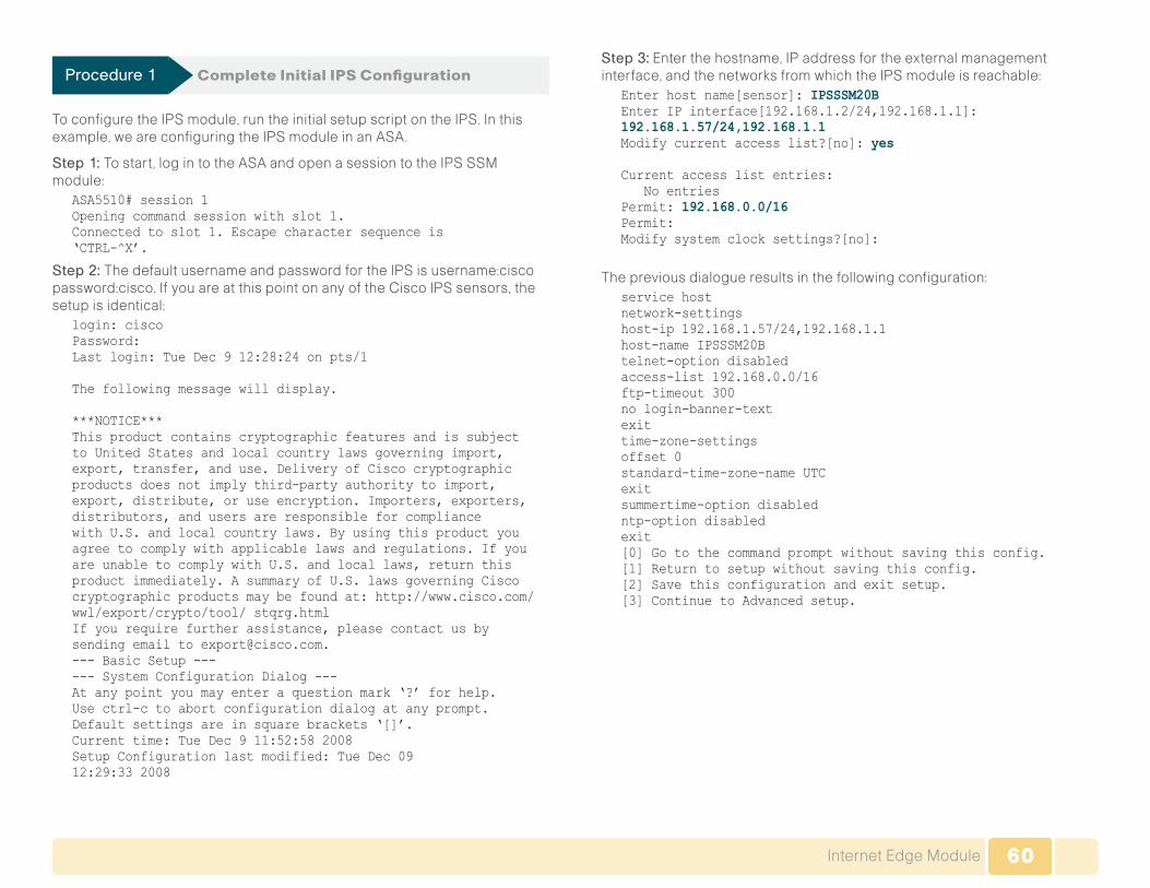
60Internet Edge Module
Procedure 1 Complete Initial IPS Configuration
To configure the IPS module, run the initial setup script on the IPS. In this example, we are configuring the IPS module in an ASA.
Step 1: To start, log in to the ASA and open a session to the IPS SSM module:
ASA5510# session 1 Opening command session with slot 1. Connected to slot 1. Escape character sequence is‘CTRL-^X’.
Step 2: The default username and password for the IPS is username:cisco password:cisco. If you are at this point on any of the Cisco IPS sensors, the setup is identical:
login: cisco Password: Last login: Tue Dec 9 12:28:24 on pts/1
The following message will display.
***NOTICE*** This product contains cryptographic features and is subject to United States and local country laws governing import, export, transfer, and use. Delivery of Cisco cryptographic products does not imply third-party authority to import, export, distribute, or use encryption. Importers, exporters, distributors, and users are responsible for compliance with U.S. and local country laws. By using this product you agree to comply with applicable laws and regulations. If you are unable to comply with U.S. and local laws, return this product immediately. A summary of U.S. laws governing Cisco cryptographic products may be found at: http://www.cisco.com/wwl/export/crypto/tool/ stqrg.html If you require further assistance, please contact us by sending email to [email protected]. --- Basic Setup --- --- System Configuration Dialog --- At any point you may enter a question mark ‘?’ for help. Use ctrl-c to abort configuration dialog at any prompt. Default settings are in square brackets ‘[]’. Current time: Tue Dec 9 11:52:58 2008 Setup Configuration last modified: Tue Dec 0912:29:33 2008
Step 3: Enter the hostname, IP address for the external management interface, and the networks from which the IPS module is reachable:
Enter host name[sensor]: IPSSSM20B Enter IP interface[192.168.1.2/24,192.168.1.1]: 192.168.1.57/24,192.168.1.1 Modify current access list?[no]: yes
Current access list entries: No entries Permit: 192.168.0.0/16 Permit: Modify system clock settings?[no]:
The previous dialogue results in the following configuration:service host network-settings host-ip 192.168.1.57/24,192.168.1.1 host-name IPSSSM20B telnet-option disabled access-list 192.168.0.0/16 ftp-timeout 300 no login-banner-text exit time-zone-settings offset 0 standard-time-zone-name UTC exit summertime-option disabled ntp-option disabled exit [0] Go to the command prompt without saving this config. [1] Return to setup without saving this config. [2] Save this configuration and exit setup. [3] Continue to Advanced setup.

61Internet Edge Module
Step 4: Finally, save the configuration. There is no need to go on to the advanced setup at this point:
Enter your selection[3]: 2 --- Configuration Saved --- Complete the advanced setup using CLI or IDM. To use IDM, point your web browser at https://<sensor-ip-address>. sensor# exit
Remote card closed command session. Press any key to continue.
Command session with slot 1 terminated. ASA5510#
Procedure 2 Add Sensors
Now that the IPS is reachable via the management interface, use the GUI for the remainder of the configuration.
Step 1: To access the sensor, connect to HTTPS://192.168.1.57.
Figure 69 shows the screen that you should see upon initial access.
Figure 69 . Initial Access Screen

62Internet Edge Module
Because several sensors are being configured in this network, use Cisco IME (IPS Manager Express). It allows management and monitoring of up to 5 IPS sensors from a single application.
Step 2: To download IME, click the link on the initial IPS Web page and install IME on your local machine.
Step 3: Next, launch IME and you should see the starting IME home screen. To add a sensor, click the Add button under Devices (Figure 70).
Figure 70 . IME Home Screen
Step 4: At this point, to add a sensor, enter the sensor name, IP address, and the username and password. For IME to add the sensor, it must be running on a machine whose IP address is part of the permitted addresses in the network configured on the sensor during the initial setup (Figure 71).
Figure 71 . Add Device Window

63Internet Edge Module
Step 5: Review the certificate information after you receive a message ask-ing if you want to accept the client certificate from the sensor. Confirm that the information matches the data you entered during setup. If everything is correct, click Yes (Figure 72).
Figure 72 . Certificate Information
Time synchronization is critical with IPS, as this allows you to pinpoint the time an event occurred and compare it with other sensors in the network for optimal troubleshooting and system management.
Step 6: Click on Configure and Time and enter the IP address of your NTP server (Figure 73).
Figure 73 . IME Time Screen

64Internet Edge Module
Step 7: To get the default policy associated with an interface, click Policies and edit the existing virtual sensor (Figure 74).
Figure 74 . IME IPS Policies Screen
Step 8: Select the IPS module in the ASA, click OK, and then click Apply. In this case, the IPS module in the ASA only has one interface (Figure 75).
Figure 75 . Edit Virtual Sensor
The basic sensor setup is now complete. Notably, all Cisco IPS sensors run the same software; therefore, the setup is always identical except for the number and type of interfaces that are associated with the virtual sensor.

65Internet Edge Module
Process
Sending Traffic to the Sensor
1. Configure IPS SSM
2. Configure Remote-site IPS AIM
3. Configure IPS 4200 LAN
With the IPS configuration complete, you will now send network traffic to the sensor for inspection.
Procedure 1 Configure IPS SSM
This configuration is for a very basic policy that will match and inspect any-thing coming in or out of the ASA that is permitted by the access rules. The current mode is “promiscuous,” which means that the IPS will only inspect traffic and will not take any drop action.
Step 1: Enter the following text at the command line:access-list inside_mpc extended permit ip 192.168.0.0 255.255.0.0 any access-list outside_mpc extended permit ip any 192.168.0.0 255.255.0.0
class-map inside-class match access-list inside_mpc class-map outside-class match access-list outside_mpc
policy-map IDS-Inside class inside-class ips promiscuous fail-open sensor vs0 policy-map IDS-Outside class outside-class ips promiscuous fail-open sensor vs0
service-policy IDS-Inside interface inside service-policy IDS-Outside interface outside
Procedure 2 Configure Remote-site IPS AIM
The AIM-IPS is supported with a straightforward configuration in the Cisco 2811 ISR. AIM modules are not supported on the Cisco 2911 ISR or any Cisco ISR G2 series routers.
The recommended way to configure the module is to set the IDS-Sensor interface as an unnumbered interface associated with a physical or loop-back interface on the ISR. Then configure the IPS module so that it uses an IP address from the same subnet as the interface that it is assigned to. In this example, the module is set to run in a fail-open mode, which allows the module to be taken offline without causing a network outage.
Step 1: Enter the following text at the command line:interface IDS-Sensor0/0 ip unnumbered Loopback0 service-module fail-open hold-queue 60 out
Step 2: To connect to the IPS AIM module in the router, enter the following command:
service-module ids-Sensor 0/0 session
Step 3: Create a route to the IDS interface. For management access, the router needs a route to the IDS interface so it knows where to send the traffic. Here is the route statement:
ip route 192.168.1.66 255.255.255.255 IDS Sensor0/0
Step 4: Apply this command to any interface where traffic inspection is required. Most commonly, traffic inspection is applied where the Ethernet interface connects to the local LAN. This is also where “promiscuous” or “inline” mode is specified. For initial deployment, “promiscuous” mode is preferred:
ids-service-module monitoring promiscuous access-list199
Step 5: Create the access list. The access list below rejects all traffic. Traffic that is permitted by the IPS ACL bypasses the IPS, and traffic that would be denied by the IPS ACL is sent to the IPS module for inspection; the example ACL below directs all traffic to be inspected:
access-list 199 deny ip any any
Step 6: If you want to forego inspecting HTTPS traffic, change the ACL to look like this:
access-list 199 permit tcp any any eq 443 access-list 199 deny ip any any

66Internet Edge Module
Procedure 3 Configure IPS 4200 LAN
The IPS 4200 is connected to port Gigabit Ethernet 1/0/9, and the monitor session sends all traffic from VLANs 1-31 to the interface for inspection.
Step 1: Enter the following text at the command line:monitor session 1 source vlan 1 - 31 monitor session 1 destination interface Gi1/0/9
Remote Access VPN
The Cisco ASA supports IPsec, Web portal, and full tunnel SSL VPNs for client-based remote access and IPsec for hardware client or site-to-site VPN. This section describes the basic configuration of remote access IPsec, Web portal, and SSL VPNs for basic remote access, plus the configuration of Cisco EZVPN for hardware client (ASA 5505) access (Figure 76).
Figure 76 . Remote Access VPN
Core/ Distribution
ASA 5510 withSSL VPN
Internet
InternetEdge
For mobile workers or users that occasionally need remote connectivity, we recommend software clients such as the Cisco VPN Client and Cisco AnyConnect Client. IPsec VPN requires the user to have client software already loaded and configured on their machine to connect. IPsec VPN works best with agency-owned machines such as laptops.
SSL VPN access uses a Web browser for portal access or the Cisco AnyConnect as a client. SSL access is:
• More flexible than IPsec VPN
• Likely to be accessible from more locations than IPsec as few agencies block HTTPS access out of their networks
• More secure than IPsec for the agency network because a restricted level of service can be offered when the user connects from unknown machines
The ASA will support a wide variety of routers as VPN hardware remote cli-ents, as well as the ASA 5505. In this example, the ASA 5505 for the remote hardware client is being used.
A hardware client is a physical device, like a small appliance or router that provides an always-onconnection back to the agency network. They are typi-cally used in situations where the user connects regularly, for long periods of time, and from a static location, such as a home office.

67Internet Edge Module
Process
Configuring Remote Access VPN
1. Configure ASA
2. Configure VPN Software Client
3. Configure VPN Headend
4. Configure Remote VPN
Complete the following procedures to configure remote access VPN.
Reader Tip
Any underlined command should be entered on one line.
Procedure 1 Configure ASA
You configure the ASA for remote VPN access by adding a baseline configu-ration to the default configuration on the appliance. Users authenticate to the local Windows Domain Controller.
Step 1: Enter the following at the command line:group-policy DfltGrpPolicy attributes dns-server value 192.168.28.10 vpn-tunnel-protocol IPSec svc webvpn split-tunnel-policy tunnelspecified split-tunnel-network-list value RA_SplitTunnelACL address-pools value VPN-Pool
Step 2: Create an access list for split tunneling. This split tunneling access list tunnels all traffic with a destination address of 192.168.0.0/16 to the internal network. Enter the following at the command line:
access-list RA_SplitTunnelACL standard permit192.168.0.0 255.255.0.0
Step 3: Assign addresses. Remote access clients are assigned an address from the pool “VPN-Pool”. Enter the following at the command line:
ip local pool VPN-Pool 192.168.30.129-192.168.30.254 mask 255.255.255.128 tunnel-group DefaultRAGroup general-attributes address-pool VPN-Pool
Step 4: Specify the authentication server. Web and IPsec VPN clients authenticate to an AAA server called “AD.” If the server is unreachable, the ASA falls back to local authentication. Enter the following at the command line:
authentication-server-group AD LOCAL tunnel-group DefaultRAGroup ipsec-attributes pre-shared-key [password] tunnel-group DefaultWEBVPNGroup general-attributes address-pool VPN-Pool authentication-server-group AD LOCAL
Step 5: Configure the authentication server. Here is the configuration for the AAA server “AD.” The ASA supports several native authentication protocols and does not require an intermediate RADIUS server to authenticate users via protocols such as LDAP, NT domain, Kerberos, etc.:
aaa-server AD protocol nt aaa-server AD (inside) host 192.168.28.10 nt-auth-domain-controller 192.168.28.10
Step 6: Create an access list to control NAT. The last part of the configura-tion is critical if the internal addresses are being NATed to the outside, which is common. The following configuration prevents the VPN clients’ return traf-fic from being NATed and lost when it is sent back from the agency network. This creates a NAT 0 or NAT exempt rule going out of the Firewall that keeps traffic sourced from the inside from being translated if the destination is the VPN-Pool of addresses.
Step 6 addresses one of the most common configuration errors; if left out, the consequence is that a VPN client is connected, but cannot pass traffic.
access-list inside_nat0_outbound extended permit ip192.168.0.0 255.255.0.0 192.168.30.128 255.255.255.128
Step 7: If the Web portal is being used, include the following important command:
http redirect outside 80
This will redirect any access to the outside interface on port 80 (HTTP) to port 443 (HTTPS). It also keeps users from having to type HTTPS://ssl.company.com to gain access to the portal.

68Internet Edge Module
Procedure 2 Configure VPN Software Client
Step 1: On the client side for IPsec, enter the following information that the user needs: the IP address or DNS name of the headend, the group name and password, and a username and password (Figure 77).
Figure 77 . VPN Client
Step 2: For SSL VPN access, enter the following information that the user needs: the IP address or DNS name of the headend and a username and password (Figure 78).
Figure 78 . Cisco AnyConnect VPN Client
Procedure 3 Configure VPN Headend
Now apply the following ASA 5510 headend configuration.
IPsec encryption will be set to AES-128 and SHA-1. The ASA supports a wide range of transform sets including DES, 3DES, AES 128-256, and MD5 and SHA algorithms. Here AES-128 is used because it provides a good balance of security and performance.
Step 1: Enter the following text at the command line:crypto ipsec transform-set 5505SET esp-aes esp-sha-hmac
Step 2: Associate the 5505 dynamic crypto map to the 5505SET encryption algorithm:
crypto dynamic-map 5505DYN-MAP 5 set transform-set5505SET

69Internet Edge Module
Step 3: Set the lifetime in seconds and bytes so that the connection will rekey the IPsec tunnels after the specified period:
crypto dynamic-map 5505DYN-MAP 5 set security-association lifetime seconds 28800
crypto dynamic-map 5505DYN-MAP 5 set securityassociation lifetime kilobytes 4608000
Step 4: Configure the headend to advertise a route into the agency network so that the remote network is reachable:
crypto dynamic-map 5505DYN-MAP 5 set reverse-route
Step 5: Associate the crypto map with the outside interface where the remote ASA 5505s will connect:
crypto map 5505MAP 60 ipsec-isakmp dynamic 5505DYN-MAP crypto map 5505MAP interface outside
group-policy 5505Group internal
group-policy 5505Group attributes vpn-tunnel-protocol IPSec ip-comp enable split-tunnel-policy tunnelspecified
Step 6: Reuse the split tunnel policy from the client remote access configuration:
split-tunnel-network-list value RA_SplitTunnelACL user-authentication-idle-timeout 480 nem enable
username 5505site1 password [password] username 5505site1 attributes vpn-group-policy 5505Group
tunnel-group RA5505 type remote-access tunnel-group RA5505 general-attributes default-group-policy 5505Group tunnel-group RA5505 ipsec-attributes pre-shared-key [password]
Step 7: Apply the NAT 0 or NAT exempt rule to prevent the return traffic to the VPN remote from being translated:
nat (inside) 0 access-list inside_nat0_outbound access-list inside_nat0_outbound extended permit ip192.168.0.0 255.255.0.0 192.168.192.0 255.255.255.0
Procedure 4 Configure Remote VPN
Step 1: Apply this configuration for the remote ASA 5505: The pre-shared-key password and vpn client vpn group password need to match.
vpnclient server 10.194.40.56 vpnclient mode network-extension-mode vpnclient nem-st-autoconnect vpnclient vpngroup RA5505 password [password] vpnclient username 5505site1 password [password] vpnclient enable

70Internet Edge Module
Unified Communication Module
Agency Overview
“ You can’t truly collaborate when you are constantly reminded of the technology. Collaboration must happen very naturally, with the technology disappearing into the background.”
—Laurie Heltsley, Director of Strategic Initiatives, Procter & Gamble
• Empower your workforce: Users are empowered when they have better communications tools at their disposal that allow them to access and use information when they need it most. Younger employees—especially those of the “Generation Y” demographic who are now in their twen-ties—are bringing these networking tools into the workplace. Agencies will need to develop a concerted strategy to proactively manage these technologies and, ideally, develop organizational capabilities to take best advantage of them.
• Provide real-time information: Collaborative applications make real-time information available to empowered users and provide for information sharing and privacy. Because information can be shared across the entire user community, its accuracy can be more easily verified and corrected.
• Accelerate through innovation: Agencies that successfully adopt new collaborative processes will be able to move faster, make better deci-sions, draw from a deeper base of information, and more effectively operate across time and distance barriers.
These challenges can be addressed with Web 2.0 networking technolo-gies, such as virtual workspaces, social networking tools, web conferencing applications, text messaging, Unified Communications, and as-if-you-are-there video meetings. However, providing these types of capabilities to an entire agency requires a robust and scalable network infrastructure. The SBA network foundation is designed to support new user and collaboration services like Unified Communications without forklift upgrades.
Technical Overview
Unified Communication (UC) deployment is greatly simplified by the product selections and configurations in other modules. For example:
• Access switches provide PoE for phone deployments without the need for a local power outlet.
• The entire network is preconfigured with QoS to support high-quality voice and video traffic.
• The choice of the HQ router in the WAN module supports the PSTN gateway function, as well as the conference bridge resources with the addition of packet voice digital signal processing (DSP) modules (PVDM) and the required interface card specific to the PSTN connectivity requirements, although at the HQ site, this is very likely to be a T1 or E1 PRI interface.
• The wireless network is preconfigured for wireless UC devices, providing IP telephony over 802.11 Wi-Fi (referred to as mobility), not only at the HQ, but also at the remotes sites.
• The security and mobility module is ready to provide “soft” phones and regular “hard” phones via VPN. These can be plugged directly into the Cisco ASA 5505, which provides PoE on two ports and connectivity back to the Cisco ASA 5510 at the HQ site.
Reader Tip
In addition to the other hardware modules added to the router, the IOS code needs to include the “Voice” feature set.
Although not part of the foundation configuration, the HQ Cisco ASA 5510 can also support a phone proxy. This allows for the deployment of phones across the Internet in home offices without the Cisco ASA 5505 hardware VPN.
Building upon this platform, we add three appliances to provide a highly available and scalable communications manager and a voicemail system capable of email client integration.
• The Cisco Unified Communications Manager (Unified CM) was chosen to provide the PBX functionality for all users within the HQ, as well as the remote sites.
• Using two Cisco MCS 7835s for the platform and connecting each to a different switch within the server farm provides for high availability should a switch or MCS platform fail.

71Unified Communication Module
The selection of the Cisco MCS 7835 provides a balance between flexibility for future services and cost. With this platform:
• There is sufficient capacity for multiple devices for each user. For example, you can enable a desk phone and a soft phone with enough computer telephony integration (CTI) to allow a high percentage of users to have click-to-call or other applications that can remote control their phones.
• There is additional capacity available for phones not assigned to a specific user, such as public areas, meeting room phones, storage and break rooms.
• It is possible to expand to support other services including presence and instant messaging, advanced conferencing and collaboration, and contact center and video conferencing.
• High availability is provided by a redundant array of independent disks (RAID) and dual power supplies.
For the remote sites, the ISR-based router includes the capability for providing phone service during a WAN outage or loss of connectivity to the HQ site. Survivable Remote Site Telephony (SRST) is configured within the router and automatically takes over during a failure.
Voicemail is considered part of the UC foundation and is provided by a Cisco Unity Connection deployed on a Cisco MCS 7835 platform, allowing up to 1000 users to have a voice mailbox accessible through the phone or integrated into their email client.
Unity Connection is deployed as a simple voicemail system. However, with additional configuration, it will provide calendar-based call handling integration with Microsoft Exchange, Cisco Unified MeetingPlace, and other networkable voicemail systems.
Unity Connection is deployed in the architecture as nonredundant, although the option can be added as required.
Reader Tip
The following section contains the additional procedures that are required to deploy Cisco Unified Communications within the SBA in addition to the main deployment procedures covered by the Rapid Deployment Method which is documented in a separate, companion guide.
This module presents the detailed procedures to deploy Cisco Unified IP Phones and then deploy Cisco Unified Communications Manager.
Process
Deploying Cisco Unified IP Phones
1. Select the Phone Model
2. Configure initial Phone Load options
First, select Cisco Unified IP Phones.
Procedure 1 Select the Phone Model
The choice of phone model depends on the user needs, the environment, and cost.
• Support for phone services and video requires at least Cisco 7942G or Cisco 7962G phones, with Cisco 7945G and Cisco 7965G providing high-resolution color backlit screens and Gigabit Ethernet capabilities.
• The Cisco 7931G and Cisco 7911G phones provide less functionality and, hence, are a lower-cost option.
• The Cisco 7921 and 7925 wireless phones provide mobility, with the Cisco 7937 conference station for conference room and IP Communicator software client providing a desktop computer solution.
Although these options are highly recommended, they are only a selection of the possible phones that can be deployed.
Procedure 2 Configure initial Phone Load options
Whichever phone is required, the Skinny Client Control Protocol (SCCP) is chosen as the signaling protocol, as this also provides video and expansion module capabilities.

72Unified Communication Module
The wired phones use Cisco Discovery Protocol to acquire the voice VLAN configured in the access switch and then DHCP to obtain an IP address, subnet mask, default gateway, domain name, domain name server address(es), and Configuration Server (Option 150 or TFTP Server) informa-tion. This provides the two IP addresses of the Unified CMs, which allows the phones to download their configuration files and firmware. Option 150 is added to the voice DHCP scopes and uses the “Publisher” Unified CM as the primary and “Subscriber” as the secondary option.
Step 1: Enter the following configuration on you DHCP server to provide DHCP for one of the voice subnets, where 192.168.28.20 is the IP address of the Publisher and 192.168.28.21 is the IP address of the Subscriber Unified CM:
ip dhcp pool voice network 192.168.12.0 255.255.255.0 default-router 192.168.12.1 dns-server 192.168.28.1 option 150 ip 192.168.28.20 192.168.28.21 domain-name cisco.local
The access layer will automatically negotiate PoE for the phone and also trust the QoS classification used by the phone for the various sessions, including signaling, media, and other services.
Process
Deploying Cisco Unified Communications
1. Configure UC Headquarters Router
2. Configure PSTN Gateways
The first Unified CM appliance installed is known as the Publisher” because this contains the master database that all other Unified CMs within the same cluster will subscribe and are hence known as Subscribers. After the Unified CMs are installed and required service enabled, the configuration can begin.
Procedure 1 Configure UC Headquarters Router
Step 1: Apply the following configuration in the HQ router to register 10 conference bridge resources with the subscriber as the highest priority and the publisher as the second priority:
voice-card 0 dsp services dspfarm voice-port 0/0/1:23 ccm-manager sccp local Port-channel1 sccp local Port-channel1.31 sccp ccm 192.168.28.21 identifier 2 priority 1 version 7.0 sccp ccm 192.168.28.20 identifier 1 priority 2 version 7.0 sccp sccp ccm group 1 bind interface Port-channel1.31 associate ccm 2 priority 1 associate ccm 1 priority 2 associate profile 1 register hq_conf switchback method graceful switchback interval 60 dspfarm profile 1 conference description HQ Conference Bridges codec g711ulaw codec g711alaw codec g729ar8 codec g729abr8 codec g729r8 codec g729br8 codec g722-64 codec ilbc maximum sessions 10 associate application SCCP
Procedure 2 Configure PSTN Gateways
The gateways used for connectivity to the PSTN use the ISR router platforms already deployed for the WAN in this architecture. The specific interface and protocol used for connectivity to the PSTN service provider depend on the country, provider, and cost.
Whichever option is used, the recommended protocol to connect the gateway to Unified CM at the HQ and remote sites is Session Initiation Protocol (SIP), as it provides a common configuration between both types of sites.

73Unified Communication Module
The gateways could use Media Gateway Control Protocol (MGCP); however, this protocol cannot be used when there is no connectivity to the Unified CM servers or in the event of a WAN failure. Under these conditions, there would normally be a fallback protocol configured, such as SIP or H.323 for SRST to use for routing inbound and outbound calls via the PSTN. To further simplify the configuration, SIP is configured for use by Unified CM and is also available for Survivable Remote Site Telephony (SRST) during a WAN failure. This avoids configuring the remote-site gateway twice, once for MGCP and again for SIP.
The following is an example for a North American SIP gateway configuration for the HQ site. The remote site gateways will be similar with the exception of at least the destination patterns of some dial peers and the interface that the gateway control and media is bound to.
isdn switch-type primary-ni ! voice service voip fax protocol cisco sip bind control source-interface Port-channel1.31 bind media source-interface Port-channel1.31 ! ! voice class codec 1 codec preference 1 g711ulaw codec preference 2 g711alaw codec preference 3 g729r8 codec preference 4 ilbc ! controller T1 0/0/1 Description PSTN PRIcablelength short 110 pri-group timeslots 1-24
dial-peer voice 100 voip description SIP TRUNK to CUCM1 preference 2 destination-pattern 1408555.... voice-class codec 1 session protocol sipv2 session target ipv4:192.168.28.20 incoming called-number . !
dial-peer voice 101 voip description SIP TRUNK to CUCM2 preference 1 destination-pattern 1408555.... voice-class codec 1 session protocol sipv2 session target ipv4:192.168.29.20 incoming called-number . !dial-peer voice 911 pots destination-pattern 911 port 0/0/1:23 forward-digits 3 ! dial-peer voice 9911 pots destination-pattern 9911 port 0/0/1:23 forward-digits 3 ! dial-peer voice 7 pots destination-pattern 9[2-9]...... port 0/0/1:23 forward-digits 7 ! dial-peer voice 11 pots destination-pattern 91[2-9]..[2-9]...... port 0/0/1:23 forward-digits 11 ! dial-peer voice 9011 pots destination-pattern 9011T incoming called-number . direct-inward-dial port 0/0/1:23 prefix 011 !
The Unified Communications deployment of DHCP, Media Resources and the Gateways should occur prior to the main deployment procedures contained within the UC Rapid Deployment Method Guide to ensure the IP Phones all register at the correct time to ensure successful completion.

74Unified Communication Module
Additional details for the Cisco Unified Communication deployment within SBA can be found in the UC Rapid Deployment Method Guide and include:
• Auto-Registration
• Active Directory Integration
• Dial Plan
• Class of Service
• Local Route Groups
• Survivable Remote Site Telephony
• Device Mobility
• Extention Mobility
• Extension Mobility
• Media Resources
• High Availability
• Call Admission Control
When completed, this Unified Communications deployment provides a flexible and scalable foundation for deploying many other services such as video, IM and presence, help desk, conferencing and social networking.
Reader Tip
All of the techniques discussed above are more fully documented in the Unified Communications Solution Reference Network Design (SRND) along with additional guidelines for deploying Unified Communications.
The UC Rapid Deployment Guide, a step-by-step process for deploying Cisco Unified Communications Manager and Cisco UnityConnections, can be found at Cisco.com/go/sba.

75Unified Communication Module
Application Optimization Module
Agency Overview
As an agency expands its presence to include new remote sites, additional network investment is required to allow remote-site users access to the same applications and services available at the headquarters.
WAN connections are normally provisioned by a Service Provider, who charges a recurring cost for the bandwidth provided. Regardless of the WAN technology in use, Service Provider charges increase as the provisioned bandwidth increases, so it is in the best interest of the agency to use this resource efficiently.
Maintaining consistent application response time for remote-site users can be a challenge with the delay introduced by WAN connections when applications are hosted at headquarters. Duplicating services locally at each remote site can be cost-prohibitive, requiring hardware, software, and additional staff to manage.
Cisco Application Optimization technologies provide a way for agencies to improve user productivity, without buying additional bandwidth or hardware for remote sites.
Cisco Application Optimization also helps to protect your data by allowing centralization of application resources at the headquarters location. Proper data protection procedures can then be applied consistently across all of the agency’s data by removing the need for separate backup and archival functions at the remote sitess. The design allows remote-site users to experience similar performance levels for centralized application access as that of users working from the headquarters location.
By using the existing bandwidth more effectively, the agency can often add staff or new applications at a remote site without requiring additional band-width. The performance improvements delivered through Cisco Application Optimization improve remote-site user productivity, while allowing critical equipment and processes to remain centralized at the headquarters loca-tion, further reducing operating costs.
Technical Overview
The Cisco Wide Area Application Services (WAAS) is a comprehensive system designed to accelerate and optimize data over a WAN network.
Cisco WAAS Wide-Area Virtualization Engine (WAVE) appliances and router-integrated network modules (NME-WAE) provide right-sized options for deployment with the SBA.
WAAS uses multiple technologies to minimize the transmission of traffic between headquarters and remote sites, which reduces the consumption of WAN bandwidth.
• Cisco WAAS Transport Flow Optimization (TFO) terminates a TCP session locally; optimizing flows that traverse the WAN and shielding end-user applications from WAN characteristics.
• Persistent Lempel-Ziv (LZ) compression saves 10 to 20 percent of the WAN bandwidth required for typical traffic profiles.
• Cisco WAAS provides additional bandwidth savings using Data Redundancy Elimination (DRE), which identifies redundant patterns in network data and eliminates the need to resend this data over the WAN. Depending on the application, DRE can reduce the traffic between the remote site and headquarters by 40–80 percent.
• Additional application-specific acceleration capabilities are also included in WAAS that have been approved by vendors of commonly used applications such as Microsoft Outlook and Windows file and printing services.

76Application Optimization Module
Figure 79 . Application Optimization: WAAS Components and Traffic Flow
The combination of the technologies included in Cisco WAAS may provide enough savings to allow additional applications such as voice and video to be deployed over an existing WAN without incurring the cost of additional carrier bandwidth.
For this deployment, the headquarters location uses the WAVE-574 appli-ance to provide application optimization services as a central connection point for the remote sites. A separate Central Manager WAVE-274 appliance is used as a management, monitoring, and reporting point for the WAAS solution. The remote sites utilize the NME-WAE modules, which integrate directly into the Cisco ISR routers. The following process will walk you through the procedure required to configure and deploy a basic WAAS environment
Process
Deploying a Basic WAAS environment
1. Configure WAAS Central Manager
2. Configure WAAS Headquarters WAVE
3. Configure WAAS Remote-site NME-WAE
4. Configure WAAS WCCP Version 2
5. Check Visibility from Central Manager
Complete each of the following procedures to deploy a basic WAAS environment.
Procedure 1 Configure WAAS Central Manager
A Cisco WAVE-274 device is utilized for the Central Manager function at the headend location to provide graphical management, configuration, and reporting for the WAAS network. This device resides in the server farm since it is not directly in the forwarding path of the application optimization, but is providing management and monitoring services. Initial configuration of the Central Manager requires terminal access to the console port for basic configuration options and IP address assignment.
Step 1: The initial setup utility is started from the command line by entering the setup command.
The setup will run. Respond to each prompt. The first three steps required are to reject the default-generated configuration, choose Central Manager for the device mode, and choose the interface to be used for communica-tion on the network. The Centralized Management System (CMS) is enabled after the device is reloaded. Configure the following defaults:
Device mode: Application-accelerator Interception Method: Inline Management Interface: InlineGroup 1/1 Autosense: yes Timezone: UTC 0 0 To keep above defaults and continue configuration, press ‘y’ To change above defaults and continue configuration, press ‘n’ [y]: n

77Application Optimization Module
Step 2: Configure WAAS appliance mode of operation: Select device mode : 1.application-accelerator 2.central-manager Enter your choice [1]: 2 This configuration will take effect after a reload.Enable CMS automatically after reload(y/n) [y]: y
Step 3: Configure network interface to be used to communicate with the rest of the network. Select interface to configure as management interface:
NO INTERFACE NAME STATUS IP ADDRESS NETMASK 1: InlineGroup 1/1 UP unassigned unassigned 2:GigabitEthernet 1/0 UP unassigned unassigned Enter choice [1]: 2
Step 4: The configuration options in this step are primarily for network con-figuration, Network Time Protocol (NTP) and product licensing. An example of these configuration items is shown below:
Configure autosense for duplex and speed on this interface(y/n) [y]: y Enable DHCP on this interface (y/n) [n]: n IP address of interface: 192.168.28.100 Netmask of this interface: 255.255.255.0 Default gateway: 192.168.28.1 Domain name server IP: 192.168.28.10 Domain name: cisco.local Enter hostname[none]: WAAS-CM Configure NTP [none]: 192.168.31.2 Enter timezone [UTC 0 0]: PST -8 0
Step 5: Select the appropriate mode of operation based on the licenses purchased.
The product supports the following licenses: 1. Enterprise Enter the license(s) you purchased [1]: 1
Step 6: Review the setup configuration:Based on the input, the following configurations will be done: device mode central-manager no central-manager address no wccp version 2 interface GigabitEthernet 1/0 ip address 192.168.28.100 255.255.255.0 autosense exit ip default-gateway 192.168.28.1 ip name-server 192.168.28.10 ip domain-name cisco.local primary-interface GigabitEthernet 1/0 hostname WAAS-CM ntp server 192.168.31.2 clock timezone PST -8 0
Step 7: Respond to the prompts to confirm and implement the configuration:Do you accept these configurations (y/n) [y]: y Would you like to apply the configurations (y/n) [y]: yThis may take a few moments. Please wait. All CLI configurations were applied successfully.
To implement this configuration, it is necessary to save the running configu-ration of the device and execute a system reload according to the following commands:
WAAS-CM# copy running-config startup-config WAAS-CM# reload Proceed with reload?[confirm] y Shutting down all services, will timeout in 15 minutes. reload in progress ..Reload requested by CLI@ttyS0. Reload requested by CLI@ttyS0. Restarting system.
Step 8: The Central Manager device should now be up and running after the reload completes and is accessed via a web browser at the IP address assigned during Step 4 of the setup utility (192.168.28.100), or the associ-ated hostname if it has been configured in DNS.
Specify secure HTTP and the port number 8443 to access the Central Manager, for example: https://192.168.28.100:8443.
Log in using the default username of admin and password of default.
Step 9: Choose My WAN -> Manage Devices from the panel on the left to display a screen now showing the Central Manager initially as the only man-aged device as shown in Figure 80.

78Application Optimization Module
Figure 80 . Central Manager
Procedure 2 Configure WAAS Headquarters WAVE
The Cisco WAVE-574 appliance is deployed at the headquarters location to provide the headend termination for WAAS traffic to and from the remote sites across the WAN. This device is connected directly to the network core switch, since its role in optimization requires it to be part of the forwarding path for WAN traffic.
The same setup utility leveraged in the initial configuration of the WAAS Central Manager is utilized for the setup of the WAVE and NME-WAE devices. These devices only require basic setup through their console port to assign initial settings; once this is completed, all management of the WAAS network is performed through the graphical interface of the Central Manager system.
Step 1: The Setup Utility configuration steps for the headend WAVE are similar to the setup of the Central Manager, but the step numbering begins to differ after choosing “application-accelerator” as the device mode in Step 2. After this mode is chosen, the setup script changes to allow for registering the WAVE with the existing Central Manager, and define the traffic intercep-tion method as WCCP.
Configure the following defaults can be configured: Device mode: Application-accelerator Interception Method: Inline Management Interface: InlineGroup 1/1 Autosense: yes Timezone: UTC 0 0 To keep above defaults and continue configuration, press ‘y’ To change above defaults and continue configuration, press ‘n’ [y]: n
Step 2: Configure WAAS appliance mode of operation. Select device mode : 1.application-accelerator 2.central-manager Enter your choice [1]: 1
Step 3: Enter the Central Manager address. [none] 192.168.28.100
Step 4: Select the interception method.(inline|wccp|other)wccp
Step 5: Configure the network interface to be used to communicate with the rest of the network.
Once the WAVE has been directed to register with a Central Manager, the Setup Utility allows configuration of basic network parameters .
Select the interface to configure as management interface:NO INTERFACE NAME STATUS IP ADDRESS NETMASK 1: InlineGroup 1/1 U unassigned unassigned 2:GigabitEthernet 1/ UP unassigned unassigned 3:GigabitEthernet 2/0 DOWN unassigned unassigned Enter choice [1]: 2

79Application Optimization Module
Step 6: The configuration options in this step are primarily for network configuration, and Network Time Protocol (NTP). An example of these configuration items is shown below.
Configure autosense for duplex and speed on this interface(y/n) [y]: y Enable DHCP on this interface (y/n) [n]: n IP address of interface: 192.168.31.10 Netmask of this interface: 255.255.255.0 Default gateway: 192.168.31.1 Domain name server IP: 192.168.28.10 Domain name: cisco.local Enter hostname:[none]: WAAS-HE Configure NTP: [none]: 192.168.31.2 Enter timezone: [UTC 0 0]: PST -8 0
Step 7: When the script proceeds to this step, the WAVE needs to be specifically configured to establish WCCP association with the local router. Since this process is configuring the headend WAAS device, the IP address entered should correspond to the IP address of the headquarters Cisco ISR.
In the example network, a VLAN trunk has been configured between the headquarters router and the core switch stack for flexibility. The primary VLAN used for routing data on this link is shown as VLAN 31; the specific VLAN and router IP address used in the network being configured should be used here.
WCCPv2 allows the WAVE to perform optimization for multiple routers; in our example, configuration of a single address representing the headquarters router is all that is required:
Enter the space separated list of routers(maximum 4) for WCCPv2 [192.168.31.1]:192.168.31.1
Step 8: This step allows specification of the licensing level:
The product supports the following licenses: 1. Enterprise 2. Enterprise & Video 3. Enterprise & Virtual-Blade 4. Enterprise, Video & Virtual-Blade Enter the license(s) you purchased [1]: 1
Step 9: At this point in the script, the WAVE has sufficient information to provide sample command-line configuration for use in the proper configura-tion of WCCP on the headquarters router.
Copy this output into a text file and save it to assist in configuration of the router in the Configuring WCCP Version 2 section(Procedure 4). Although the output says to copy and paste the commands, interface names that match the router need to be replaced in the sample configuration before it is applied to the router:
Please copy, paste the following in the router config mode: ip wccp version 2 ip wccp 61 ip wccp 62 interface <Router LAN sub-interface 1> ip wccp 61 redirect in interface <Router WAN interface> ip wccp 62 redirect in interface <Router LAN sub-interface 2> ip wccp redirect exclude in
Step 10: Acknowledge the remaining prompts after confirming the informa-tion entered through the Setup Utility. After completion of the Setup Utility, save the running configuration of the device. You can confirm that the WAVE is successfully registered with the WAAS Central Manager system by executing the show cms info command:
WAAS-HE# copy running-config startup-config WAAS-HE# show cms info Device registration information : Device Id = 326 Device registered as = WAAS Application Engine Current WAAS Central Manager = 192.168.28.100 Registered with WAAS Central Manager = 192.168.28.100 Status = Online Time of last config-sync = Thu Oct 29 11:33:59 2009 CMS services information : Service cms_ce is running
Reader Tip
In the configuration examples, private IP address space is used so a full IP subnet with a /24 mask is assigned for simplicity. In the interest of conserving address space the addresses could also be assigned from a /30 network since only two host addresses are required.

80Application Optimization Module
Procedure 3 Configure WAAS Remote-site NME-WAE
The remote-site WAAS equipment in this design is specified as NME-WAE modules inserted directly into a network module slot in the remote-site router. This allows the Cisco ISR router to provide WAAS functionality without requiring additional space, network cables, or power connections. A separate standalone appliance could also be deployed at a remote site that has a higher number of users, or requires the virtualization capabilities available in the Cisco WAVE appliances.
The remote-site router communicates with the NME-WAE directly on the router backplane, and requires a small IP subnet to be assigned for this communication.
Step 1: Apply the following configuration on a remote-site router which assigns the required configuration to the Integrated-Service-Engine inter-face that represents the NME-WAE.
An additional no shutdown command also needs to be applied to the interface when initially configured:
interface Integrated-Service-Engine1/0 ip address 192.168.75.1 255.255.255.0 service-module ip address 192.168.75.2 255.255.255.0 service-module ip default-gateway 192.168.75.1 no keepalive no shut
Step 2: Once the initial router configuration has been entered and saved, open a session into the NME-WAE from the router command line.
Authenticate using the default username of admin and password of default. Enter the setup command to begin the setup utility:
Router# service-module integrated-Service-Engine 1/0 session Trying 192.168.75.1, 2066 ... Open
Cisco Wide Area Application Engine Console Username: admin Password: defaultSystem Initialization Finished. NO-HOSTNAME# setup
Step 3: From this point, the remote-site NME-WAE is configured in a similar manner to the headend WAVE appliance through the setup script.
The IP address of the NME-WAE itself is inherited from the service-module ip address statement applied to the router configuration.
When prompted for the WCCP router address, use the address assigned to the Integrated-Service-Engine in the router configuration (in the example configuration shown as 192.168.75.1).
Step 4: When this configuration is complete, save the configuration on the NME-WAE. Return the session to the command line of the router by entering the escape sequence Ctrl-Shift-6 x. Use the show cms info command to verify that the NME-WAE has properly registered with the Central Manager.
Step 5: After both the headend WAVE appliance and the remote-site NME-WAE modules are configured, confirm that they are listed in the graphical interface of the Central Manager by choosing My WAN -> Manage Devices as shown in Figure 81.
Figure 81 . Central Manager

81Application Optimization Module
Procedure 4 Configure WAAS WCCP Version 2
WCCP is utilized in this design to divert network traffic destined for the WAN to the WAAS system for optimization. This provides for a clean deployment with minimal additional cabling, and requires both the headend and remote-site routers to be configured for WCCP.
Step 1: First, WCCP Version 2 should be enabled on the headend router in global command mode, even though it is normally enabled by default.
ip wccp version 2 ip wccp 61 ip wccp 62
Step 2: Now you must identify specific interfaces where traffic to and from the WAN is intercepted. Use the sample router configurations provided by the WAAS Setup Utility and simply substitute the actual interface definitions of your network into the text provided during that configuration.
From the example network configuration, the headend router requires the following configuration:
interface Port-channel1.31 description Interface to HQ Core Switch encapsulation dot1Q 31 ip address 192.168.31.2 255.255.255.0 ip wccp 62 redirect in interface GigabitEthernet0/2 description Interface to WAN ip address 10.0.1.254 255.255.255.252 ip wccp 61 redirect in
Reader Tip
The numbers 61 and 62 illustrated in the IP WCCP commands are ser-vice identifiers that correspond to interception of TCP traffic. Identifier 61 is specified as facing the remote sites where client machines are more likely to be located, and 62 is specified as facing the headquar-ters core or server farm. Additional service identifiers are available for more advanced configuration. The setup as shown provides optimiza-tion services for common TCP traffic types.
Step 3: Configure the corresponding remote-site routers to intercept their traffic bound for the WAN. First we enable WCCP Version 2 in the global command mode:
ip wccp version 2 ip wccp 61 ip wccp 62
Step 4: Now you must identify specific interfaces on the remote-site router where traffic to and from the WAN is intercepted. Use the sample router configurations below which are intercepting data coming from the remote-site LAN on an 802.1q trunk into the remote-site router:
interface FastEthernet0/0.72 description Wired Data Access encapsulation dot1Q 72 ip address 192.168.72.1 255.255.255.0 ip wccp 61 redirect in
interface FastEthernet0/1 description Interface to WAN ip address 10.0.1.246 255.255.255.252 ip wccp 62 redirect in
interface FastEthernet0/0.76 description Wireless Data Access encapsulation dot1Q 76 ip address 192.168.76.1 255.255.255.0 ip wccp 61 redirect in
With WCCP now configured on both the headend and remote site WAN routers, traffic is intercepted for WAAS optimization.

82Application Optimization Module
Procedure 5 Check Visibility from Central Manager
Step 1: Access the Central Manager using a secure web browser connec-tion. You should now be able to monitor, configure features, and report on the WAAS network from this interface.
To view statistics after traffic has been flowing across the WAAS system, choose My WAN > Dashboard from the Central Manager’s graphical inter-face as shown in Figure 82.
Figure 82 . Central Manager
Application Optimization Summary
Cisco WAAS provides multiple traffic optimization technologies to acceler-ate applications over the WAN. In this Deployment Guide section we covered the basic configuration needed to add WAAS capabilities to a network built using the SBA. WAAS also has specific templates and customizable settings for many applications not covered in this guide. For more information please consult your Cisco representative, authorized Channel Partner, or http://www.cisco.com.
WAAS Configuration Checklist
Table 9-1 specifies the different parameters and data needed to set up and configure the WAAS network. For your convenience, you can enter your values in the table and refer back to it when configuring the WAAS network. The values you enter will differ from those in this example; these are only for demonstration purposes.
Table 2 . WAAS Network System Parameters Checklist
Parameter
WAAS Central Manager Values
Main Office WAE Values
Branch Office WAE Values – You will need one Branch column for each branch
Interface Speed Default Default Default
Duplex Mode
IP Address 192.168.28.100 192.168.31.10 192.168.68.2
Subnet Mask 255.255.255.0 255.255.255.0 255.255.255.0
Default Gateway 192.168.28.1 192.168.31.1 192.168.68.1
DNS Server 1 192.168.28.10 192.168.28.10 192.168.28.10
DNS Server 2
DNS Domain cisco.com cisco.com cisco.com
WAAS Device (Hostname)
WAAS-CM WAAS-HE Branch-1
Windows Domain
IP Addresses of Routers Intercepting Traffic with WCCP
NTP Server (Optional)
Time Zone (Optional)

83Application Optimization Module
Appendix A: Midsize Agencies Deployment Product List
Functional Area Product Part Numbers Software Version
100-600 Network Core Catalyst 3750G Stackable 12 Port SFP and IP Services Image
WS-C3750G-12S-S 12.2-50.SE2
500-1000 Network Core Catalyst 4507RE
Dual Supervisors
Dual Power Supplies
WS-C4507R-E Catalyst 4500 E-Series 7-Slot Chassis, fan, no ps, Red Sup Capable
WS-X4624-SFP-E Catalyst 4500 E-Series 24-Port GE (SFP)
WS-X45-SUP6-E Catalyst 4500 E-Series Sup 6-E, 2x10GE(X2) with Twin Gig
12.2-50.SG2
Headquarter access for PC, phones, APs, other devices
Catalyst 3750G Stackable 24 & 48 Ethernet 10/100/1000 ports with PoE, 4 SFP ports, and IP Base Image
Cisco Catalyst 3560G 24 & 48 Ethernet 10/100/1000 ports with PoE, 4 SFP ports, and IP Base Image
WS-C3750G-24PS-S
WS-C3750G-48PS-S
WS-C3560G-24PS-S
WS-C3560G-48PS-S
12.2-50.SE2
Server room switch Catalyst 3750G 24 & 48 Ethernet 10/100/1000 ports, 4 SFP ports, and IP Base Image
Catalyst 3560G24 & 48 Ethernet 10/100/1000 ports, 4 SFP ports, and IP Bae Image
WS-C3750G-24TS-S1U
WS-C3750G-48TS-S
WS-C3560G-24TS-S
WS-C3560G-48TS-S
12.2-50.SE2
Headquarters WAN router
Cisco 3925 or 3845 Integrated Services Router C3925-VSEC/K9
C3845-VSEC/K9
HWIC-2CE1T1-PRI
15.0.1M
Branch WAN router Cisco 2911 or 2811 Integrated Services Router C2911-VSEC/K9
C2811-VSEC-SRST/K9
HWIC-2CE1T1-PRI
15.0.1M

84Appendix A: Midsize Agencies Deployment Product List
Functional Area Product Part Numbers Software Version
Branch router modules Wide Area Acceleration Module
Intrusion Prevention Module
NME-WAE-502-K9
AIM-IPS-K9
4.1.5b
7.0(1)E3
Branch Switch Catalyst 3750G Stackable 24 & 48 Ethernet 10/100/1000 ports with PoE, 4 SFP ports, and IP Base Image
Cisco Catalyst 3560G 24 & 48 Ethernet 10/100/1000 ports with PoE, 4 SFP ports, and IP Base Image
WS-C3750G-24PS-S
WS-C3750G-48PS-S
WS-C3560G-24PS-S
WS-C3560G-48PS-S
12.2-50.SE2
Internet Edge Firewall Adaptive Security Appliance
ASA 5510 with the SSM-10 IPS Module
ASA5510-AIP10-K9 8.0.4.ED
7.0(1)E3
Headquarters— Intrusion Prevention System
Cisco Intrusion Prevention System 4200 Series IPS-4240-K9 (300 Mbps)
IPS-4255-K9 (600 Mbps)
IPS-4260-K9 (2 Gbps)
7.0(1)E3
Application Acceleration
Headquarters CM
Headquarters endpoint
WAVE 574
WAVE 274
WAVE-574-K9
WAVE-274-K9
4.1.5b
Wireless Access Points 1140 Fixed with Internal Antennas
1250 Ruggedized, External Ant.
AIR-LAP1142N (Country-specific)
AIR-AP1252AG (Country-specific)
Wireless LAN Controller WLC 5508 AIR-CT5508-12-K9 7.0.98.0
Unified Communications Cisco Unified Communications Manager—MCS 7835 CMC
Cisco Unity Connections
MCS 7825 UCB
MCS7835I3-K9-CMC2 (2 required)
MCS7825I4-K9-UCB1
8.0(2c)
8.0(2c)

85Appendix A: Midsize Agencies Deployment Product List
Functional Area Product Part Numbers Software Version
Phones CP-7921G Wireless Phone
CP-7925G Wireless Phone
CP-7931G Multibutton Phone
CP-7937G Conference Phone
CP-7942G B&W Display Phone
CP-7962G B&W Display Phone
CP-7945G Color Display Phone
CP-7965G Color Display Phone
CP-7965G Color Executive Phone
IPCOMM7-SW Soft Phone
A wide variety of phone models are available that meet specific needs of the user and the country where they are deployed.
Teleworker Adaptive Security Appliance 5505 ASA5505-BUN-K9
ASA 5505 Appliance with SW, 10 Users, 8 ports, 3DES/AES
8.0.4
Headquarters access for PC, phones, Aps, and other devices
Calatyst 3750-X Stackable 24 & 48 Ethernet 10/100/1000 ports with PoE+, IP Base. Uplink Module is optional.*
Catalyst 3560-X Non-stackable 24 & 48 Ethernet 10/100/1000 ports with PoE+, IP Base. Uplink Module is optional.*
Catalyst 2960-S Stackable** 24 & 48 Ethernet 10/100/1000 ports with PoE+, LAN Base, 4 SFP ports. Stacking Module is optional.**
*Optional 3560-X or 3750-X 4xSFP Uplink Module
**Optional 2960-S FlexStack Stack Module
WS-C3750X-24P-S
WS-C3750X-48PF-S
WS-C3560X-24P-S
WS-C3560X-48PF-S
WS-C2960S-24PS-L
WS-C2960S-48FPS-L
C3KX-NM-1G
C2960S-STACK
12.2(53)SE2
12.2(53)SE2
12.2(53)SE2
Server Room Switch Calatyst 3750-X Stackable 24 & 48 Ethernet 10/100/1000 ports with IP Base. Uplink module is optional.*
Catalyst 3560-X Non-stackable 24 & 48 Ethernet 10/100/1000 ports with IP Base, Uplink module is optional.*
*Optional 3560-X or 3750-X 4xSFP Uplink Module
WS-C3750X-24T-S
WS-C3750X-48T-S
WS-C3560X-24T-S
WS-C3560X-48T-S
C3KX-NM-1G
12.2(53)SE2
12.2(53)SE2

86Appendix A: Midsize Agencies Deployment Product List
Functional Area Product Part Numbers Software Version
Branch Switch Calatyst 3750-X Stackable 24 & 48 Ethernet 10/100/1000 ports with PoE+, IP Base. Uplink Module is optional.*
Catalyst 3560-X Non-stackable 24 & 48 Ethernet 10/100/1000 ports with PoE+, IP Base. Uplink Module is optional.*
Catalyst 2960-S Stackable** 24 & 48 Ethernet 10/100/1000 ports with PoE+, LAN Base, 4 SFP ports. Stacking module is optional.**
*Optional 3560-X or 3750-X 4xSFP Uplink Module
**Optional 2960-S FlexStack Stack Module
WS-C3750X-24P-S
WS-C3750X-48PF-S
WS-C3560X-24P-S
WS-C3560X-48PF-S
WS-C2960S-24PS-L
WS-C2960S-48FPS-L
C3KX-NM-1G
12.2(53)SE2
12.2(53)SE2
12.2(53)SE2
** Uplink modules on the 3750-X and 3560-X Series switches are now modular. Uplink modules will be needed on 3560-X switches that require uplinks. Uplink modules in a 3750-X multi-switch stack are only needed on 2 switches, the top and bottom switches in the stack. A modular uplink module for the 3560-X and 3750-X Series, which provides 2xSFP for 1Gbps uplinks and 2xSFP+ for future migration to 10Gbps uplinks, is available (P/N= C3kX-NM-10G)
** The optional FlexStack Stack Module for the 2960-S series is not necessary if you require 48 ports or less and will not be stacking the switches.

87
Appendix B: SBA for Midsize Agencies Document System
Appendix B: SBA for Midsize Agencies Document System
Wireless CleanAir Deployment Guide
3G Wireless Remote Site Deployment Guide
Web Security Deployment Guide
Email Security Deployment Guide
Modular Access LayerDeployment Guide
Ipswitch Network Management Guide
ScienceLogic Network Management Guide
SolarWinds Network Management Guide
Design Overview
IPv4 AddressingGuide
IPv6 AddressingGuide
Foundation Configuration Guide
Network ManagementGuides
Design Guides Deployment Guides Supplemental Guides
FoundationDeployment Guide
You are Here

88
Cisco has more than 200 offices worldwide. Addresses, phone numbers, and fax numbers are listed on the Cisco Website at www.cisco.com/go/offices.
Cisco and the Cisco Logo are trademarks of Cisco Systems, Inc. and/or its affiliates in the U.S. and other countries. A listing of Cisco's trademarks can be found at www.cisco.com/go/trademarks. Third party trademarks mentioned are the property of their respective owners. The use of the word partner does not imply a partnership relationship between Cisco and any other company. (1005R)
Americas HeadquartersCisco Systems, Inc.San Jose, CA
Asia Pacific HeadquartersCisco Systems (USA) Pte. Ltd.Singapore
Europe HeadquartersCisco Systems International BVAmsterdam, The Netherlands
C07-641118-00 12/10
Related Documents