REGULATOR INFORMATION DISTRIBUTION S <M (BIDS) AGCESSION NBR:8501170165 DOC+DATE: 84/12/20 NOTARIZED: NO FACIL:50"400 Shearon Harr is Nuclear Power Plant~ Unit 1, Carolina AUTH BYNAME AUTHOR AFFILIATION CUTTER,A,B, Carolina Power 8 Light Co. REC I P ~ NAME RECIPIENT AFFILIATION DENTONgH ~ Ri Office of Nuclear Reactor Regulationp Director SUBJECT: Forwards "Emergency Diesel Generator Equipment" L Vols 1-4 of "TDI Diesel Generator Design Review L Quality Revalidation Rept' " DOCKET ¹ 05000400 DISTRIBUTION CODE: B031D COPIES RECEIVED:LTR 5 ENCL J SIZE: ,a+ lit'. TITLE: Tr ansamer i ca Del aval i Inc, (TDI) Diesel Gener ator Owners Group NOTES: RECIPIENT ID CODE/NAME NRR LB3 LA INTERNAL: ACRS AEOO CHIRAMAL,M ASLBP GC NRR BERL INGER g C NRR MURPHEYgE NRR SELLERS D NRR SPANOgA NRR TREHANgN OP ONED G FI 04 EXTERNAL; LPDR 03 NSIC 05 COPIES LTTR ENCL 1 1 1 1 1 1 1 1 1 1 1 l~ 1 1~ NRC PDR 02 REC IPIENT ID CODE/NAME BUCKLEYiB 01 ADM/LFMB ASLAP ELD/HDS1 IE KRIESSEL NRR MICHAELSqT NRR PERS INKO NRR SHAl'] g H NRR TOMLINSONg E NRR NRIGHTg R PA RGN2 COPIES LTTR ENCL 1 li TOTAL NUMBER OF COPIES REQUIRED: LTTR 34 ENCL

Welcome message from author
This document is posted to help you gain knowledge. Please leave a comment to let me know what you think about it! Share it to your friends and learn new things together.
Transcript
REGULATOR INFORMATION DISTRIBUTION S <M (BIDS)
AGCESSION NBR:8501170165 DOC+DATE: 84/12/20 NOTARIZED: NO
FACIL:50"400 Shearon Harr is Nuclear Power Plant~ Unit 1, CarolinaAUTH
BYNAME
AUTHOR AFFILIATIONCUTTER,A,B, Carolina Power 8 Light Co.
REC I P ~ NAME RECIPIENT AFFILIATIONDENTONgH ~ Ri Office of Nuclear Reactor Regulationp Director
SUBJECT: Forwards "Emergency Diesel Generator Equipment" L Vols 1-4of "TDI Diesel Generator Design Review L QualityRevalidation
Rept'�
"
DOCKET ¹05000400
DISTRIBUTION CODE: B031D COPIES RECEIVED:LTR 5 ENCL J SIZE:,a+ lit'.TITLE: Tr ansamer i ca Del aval i Inc, (TDI) Diesel Gener ator Owners Group
NOTES:
RECIPIENTID CODE/NAME
NRR LB3 LA
INTERNAL: ACRSAEOO CHIRAMAL,MASLBPGCNRR BERL INGER g C
NRR MURPHEYgENRR SELLERS D
NRR SPANOgANRR TREHANgNOP ONED
G FI 04
EXTERNAL; LPDR 03NSIC 05
COPIESLTTR ENCL
1
1
1
1
1
1
1
1
1 1
1 l~1 1~
NRC PDR 02
REC IPIENTID CODE/NAME
BUCKLEYiB 01
ADM/LFMBASLAPELD/HDS1IE KRIESSELNRR MICHAELSqTNRR PERS INKONRR SHAl'] g H
NRR TOMLINSONg ENRR NRIGHTg R
PARGN2
COPIESLTTR ENCL
1 li
TOTAL NUMBER OF COPIES REQUIRED: LTTR 34 ENCL

!q
I
~ 1(
bl,
Jl;
l f~(, i
s
1
t
'I
H
tl
l'
Carolina+ower & Light CompanySIC g:p ]gg~
SERIAL- NLS-84-490
Mr. Harold R. Denton, DirectorOffice of Nuclear Reactor RegulationUnited States Nuclear Regulatory CommissionWashington, DC 20555
SHEARON HARRIS NUCLEAR POWER PLANTUNIT NO+ 1 — DOCKET NO. 50-400EMERGENCY DIESEL GENERATORS
Dear Mr. Denton:
The Transamerica DeLaval Inc. (TDI) Owners'roup was formed in late 1983 toaddress and resolve technical concerns related to the TDI diesel generators.Carolina Power & Light Company (CP6L) is a participant in thi.s Owners'roupprogram as a result of procuring and installing TDI diesels for the ShearonHarris Nuclear Power Plant (SHNPP) ~
The Owners'roup program has addressed the generic engine components inreports submitted directly to the NRC. Plant specific components arediscussed in reports provided to the individual utilities. The plant-specificreports are referred to as Phase II DR/QR Reports. These Phase II reportsalso address the generic items applicable to each specific plant.
Attachment A is a brief report which summarizes the status of the SHNPP dieselgenerators and the Company's plan for placing the equipment into operation.The report also discusses the SHNPP resolution of the Owners'roup's Phase Igeneric equipment issues and discusses the results of the inspectionsconducted to date. The analysis and evaluation performed during the
Owners'roup
Phase I program has shown that, with some modifications, the TDI dieselgenerator units are capable of performing their safety function at theirfull-load rating.
Attachment B is the SHNPP Phase II DR/QR report as prepared by theOwners'roup.The Company endorses the maintenance and surveillance program
recommended by the Owners'roup. Several preliminary clarifications to thePhase II recommendations are presented in Attachment A. If additionalclarifications are required to address updated information for SHNPP, we willsubmit them in subsequent correspondence.
8501170185 841220PDR ADOCK 050004008 PDR
pqg I
411 Fayettevilte Street ~ P, O. Bex 1551 ~ Raleigh. N. C. 27602

t
1
I
c I
~ ll
A a
1
v
kA
E
Mr. Harold R. Dentoid
The implementation of the Owners'roup's confirmatory Phase IIrecommendations, as described in Attachment A, will provide further assurancethat the diesel generators are capable of reliably performing their intendedsafety function. Should you have any questions concerning this letter, pleasecontact Mr. Sherwood R. Zimmerman at (919) 836-6242.
Yours very trul
A. B. Cutter — Vice esidentNuclear Engineering & Licensing
ABC/DLD/crs (889SRZ)
Attachments
CC ~ Mr. C. A. Barth (NRC)*Mr. C. H. Berlinger (NRC)(8)*Mr ~ B. C. Buckley (NRC)*Mr. G. F. Maxwell (NRC-SHNPP)*Mr. J. P. O'Reilly (NRC-RII)*Mr. Travis Payne (KUDZU)Mr. Daniel F. Read (CHANGE/ELP)Chapel Hill Public Library*
Wake County Public Library*Mr. Wells Eddleman*Mr. John D. RunkleDr. Richard D. WilsonMr. G. 0. Bright (ASLB)Dr. J. H. Carpenter (ASLB)Mr. J. L. Kelley (ASLB)*Mr. W. W. Laity (PNL)(2)*
* Denotes Recipients of Attachment B
~ " ~
t
4
7
C
4
1
TDI DIESEL GENERATOR
DESIGN REVIEWAND
QUALITYREVALIDATIONREPORT
Prepared For
CAROLINAPOWER S. LIGHTCOMPANY
SHEARON HARRIS NUCLEAR POWER PLANT
By
TDI DIESEL GENERATOR OWNERS GROUP
g gooSec~ 4 ~go l(7o (8>
,. Cpa~HPVOLUME3

~
How To Use This Re ort
Tabs in this report identify the following categories:
Turbo, Intake, Intercooler 8 ExhaustLube OilEngine Base & Bearing CapsCrankshaft 8 BearingsCylinder Block, Liners 8 Water ManifoldAir Start 8 Barring DeviceConnecting rodsPistonsCamshaft 8 Valve TrainIdler Gear Assembly & Front Gear CaseFlywheelEngine Instrumentation & WiringOverspeed Trip 8 GovernorEngine Shutdown 8 EquipmentJacket WaterCylinder Heads & ValvesFuel Oi 1 InjectionGeneratorControl Panel AssemblyEngine 8 Auxiliary Sub-Base & Foundation Bolts
These categories have been defined to allow the reader to review a completediesel generator subsystem in a convenient manner.
Within each category tabs identify Shearon Harris specific component numbers.
A given component report can be found by:
a) If the component number is known - use the alpha — numberic indexwhich identifies the volume number and category in which the compon-ent report is located.
b) If only the component name is known - Section 3.2 may be used as across-reference to find the volume number where the component reportmay be found.
Some reports address more than one component. a tab is provided for eachcomponent. However, some components are combined under one report. Slipsheets are provided where required to reference back to the appropriate tab.Some components required more than one report. These are identified by theabbreviation LB-Large Bore and SB-Small Bore on the component number tabs.
SH2651
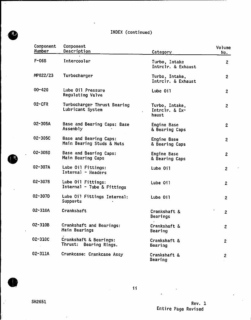
INDEX (continued)
Component ComponentNumber Descri tion
F-068 Intercooler
MP022/23 Turbocharger
Cate or
Turbo, IntakeIntrclr. 8 Exhaust
Turbo, Intake,Intrclr. 8 Exhaust
VolumeNo.
00-420
02-CFR
02-305A
02-305C
02-3050
02-307A
02-307B
02-307D
02-310A
02-310B
02-310C
02-311A
Lube Oil PressureRegulating Valve
Turbocharger Thrust BearingLubricant System
Base and Bearing Caps: BaseAssembly
Base and Bearing Caps:Main Bearing Studs 8 Nuts
Base and Bearing Caps:Main Bearing Caps
Lube Oil Fittings:Internal - Headers
Lube Oil Fittings:Internal - Tube 8 Fittings
Lube Oil Fittings Internal:Supports
Cr ankshaf t
Crankshaft and Bearings:Main Bearings
Crankshaft 8 Bearings:Thrust: Bearing Rings.
Crankcase: Crankcase Assy
Lube Oil
Turbo, Intake,Intrclr. 8 Ex-haust
Engine Base8 Bearing Caps
Engine Base8 Bearing Caps
Engine Base& Bearing Caps
Lube Oil
Lube Oil
Lube Oil
Crankshaft &Bearings
Crankshaft 8
Bearing
Crankshaft &Bearing
Crankshaft &Bearing
SH2651 Rev. 1Entire Page Revised
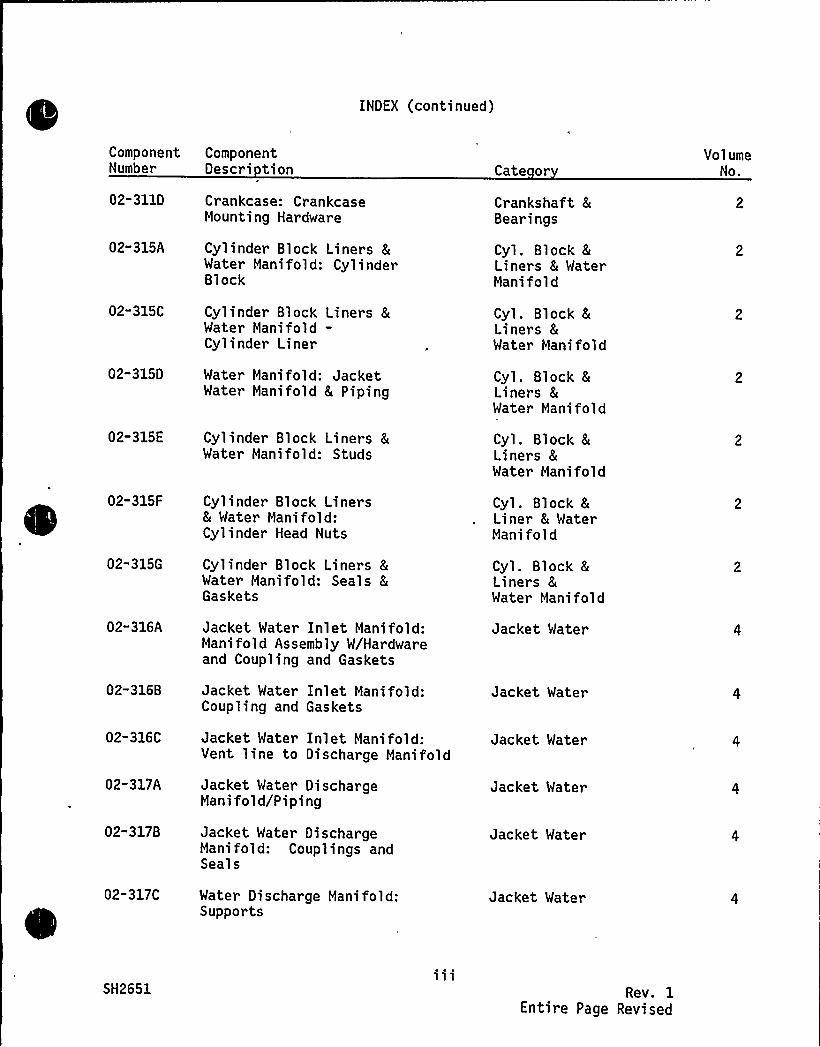
INDEX (continued)
ComponentNumber
02-311D
02" 315A
02"315C
02-315D
02-315E
02-315F
02-315G
02" 316A
02-316B
02-316C
02" 317A
02-317B
02-317C
ComponentOescri tion
Crankcase: CrankcaseMounting Hardware
Cylinder Block Liners 8Water Manifold: CylinderBlock
Cylinder Block Liners &Water Manifold-Cylinder Liner
Water Mani fold: JacketWater Manifold 8 Piping
Cylinder Block Liners 8Water Manifold: Studs
Cylinder Block Liners& Water Manifold:Cylinder Head Nuts
Cylinder Block Liners 8Water Manifold: Seals 8
Gaskets
Jacket Water Inlet Manifold:Manifold Assembly W/Hardwareand Coupling and Gaskets
Jacket Water Inlet Manifold:Coupling and Gaskets
Jacket Water Inlet Manifold:Vent line to Discharge Manifold
Jacket Water DischargeManifold/Piping
Jacket Water DischargeManifold: Couplings andSeals
Water Discharge Manifold:Supports
Cate or
Crankshaft 8
Bearings
Cyl. Block &Liners 8 WaterMani fold
Cyl. Block 8
Liners 8
Water Mani fold
Cyl. Block 8
Liners &Water Manifold
Cyl. Block 8
Liners 8
Water Manifold
Cyl. Block 8
Liner 8 WaterManifold
Cyl. Block 8
Liners 8Water Manifold
Jacket Water
Jacket Water
Jacket Water
Jacket Water
Jacket Water
Jacket Water
VolumeNo.
SH2651 Rev. 1Entire Page Revised

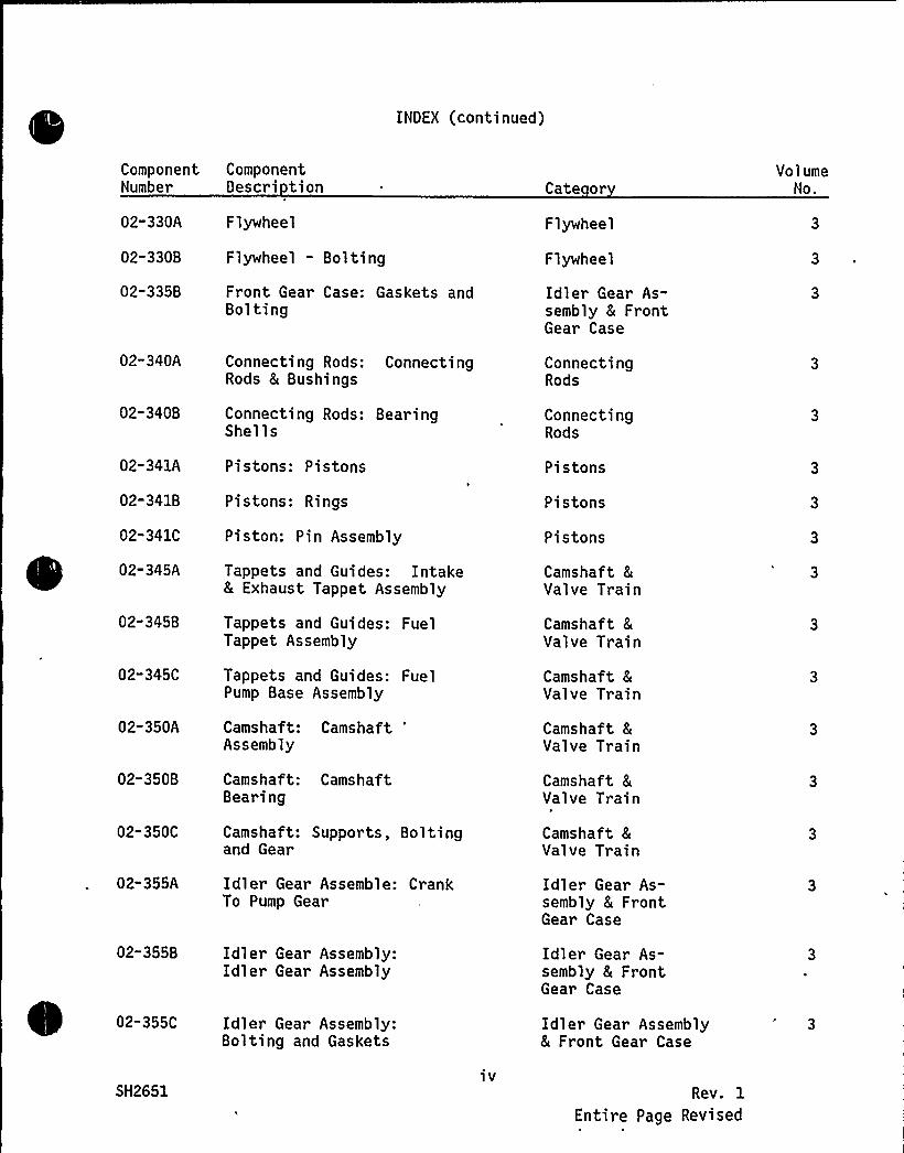
INOEX (continued)
ComponentNumber
02-330A
02-330B
02-335B
02-340A
02-340B
ComponentDescri tion
Flywheel
Flywheel - Bolting
Front Gear Case: Gaskets andBolting
Connecting Rods: ConnectingRods 8 Bushings
Connecting Rods: BearingShells
Cate or
Flywheel
Flywheel
Idler Gear As-sembly 8 FrontGear Case
ConnectingRods
ConnectingRods
VolumeNo.
02-341A
02-341B
02-341C
02-345A
02-345B
02-345C
02-350A
02-350B
02-350C
02" 355A
02-355B
02-355C
Pistons: Pistons
Pistons: Rings
Piston: Pin Assembly
Tappets and Guides: Intake8 Exhaust Tappet Assembly
Tappets and Guides: FuelTappet Assembly
Tappets and Guides: FuelPump Base Assembly
Camshaft: CamshaftAssembly
Camshaft: CamshaftBearing
Camshaft: Supports, Boltingand Gear
Idler Gear Assemble: CrankTo Pump Gear
Idler Gear Assembly:Idler Gear Assembly
Idler Gear Assembly:Bolting and Gaskets
Pistons
Pistons
Pistons
Camshaft 8
Valve Train
Camshaft 8
Valve Train
Camshaft 8
Valve Train
Camshaft &Val ve Train
Camshaft 8
Valve Train
Camshaft 8
Valve Train
Idler Gear As-sembly 8 FrontGear Case
Idler Gear As-sembly 8 FrontGear Case
Idler Gear Assembly& Front Gear Case
3
SH2651iv
Rev. 1
Entire Page Revised
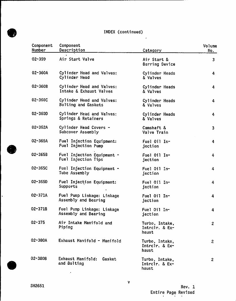
INOEX (continued)
ComponentNumber
02-359
02-360A
02"360B
02-360C
02-360O
02-362A
02-365A
02-365B
02"365C
02" 3650
02-371A
02-371B
02-375
02"380A
02-3808
ComponentOescri tion
Air Start Valve
Cylinder Head and Valves:Cylinder Head
Cylinder Head and Valves:Intake 8 Exhaust Valves
Cylinder Head and Valves:Bolting and Gaskets
Cylinder Head and Valves:Springs 8 Retainers
Cylinder Head Covers-Subcover Assembly
Fuel Injection Equipment:Fuel Injection Pump
Fuel Injection Equipment-Fuel Injection Tips
Fuel Injection Equipment-Tube Assembly
Fuel Injection Equipment:Supports
Fuel Pump Linkage: LinkageAssembly and Bearing
Fuel Pump Linkage: LinkageAssembly and Bearing
Air Intake Manifold andPiping
Exhaust Manifold - Manifold
Exhaust Manifold: Gasketand Bolting
Cate or
Air Start &Barring Oevice
Cylinder Heads8 Valves
Cylinder Heads8 Valves
Cylinder Heads& Valves
Cylinder Heads& Valves
Camshaft 8
Valve Tr ain
Fuel Oil In-jection
Fuel Oil In-jection
Fuel Oil In-jection
Fuel Oil In-jection
Fuel Oi 1 In-jection
Fuel Oil In-jection
Turbo, Intake,Intrclr. 8 Ex-haust
Turbo, Intake,Intrclr. 8 Ex-haust
Turbo, Intake,Intrclr. 8 Ex-haust
VolumeNo.
SH2651 Rev. 1
Entire Page Revised

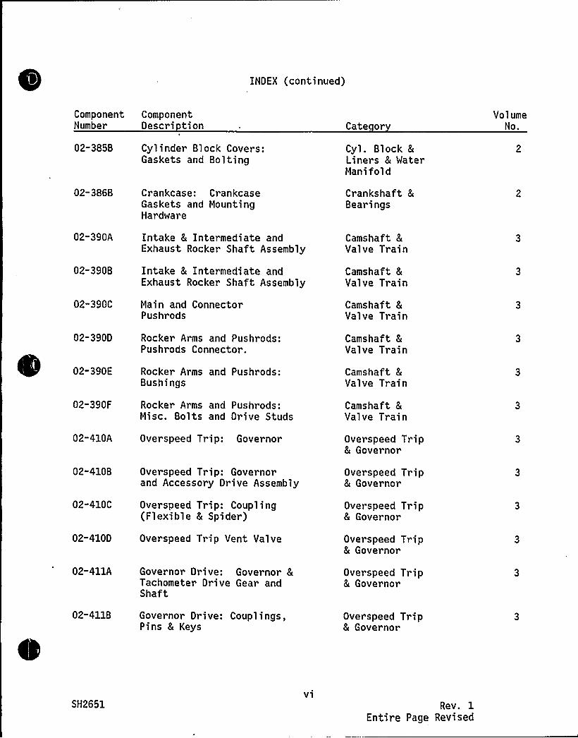
INDEX (continued)
ComponentNumber
ComponentOescri tion Cate or
VolumeNo.
02-385B Cylinder Block Covers:Gaskets and Bolting
Cyl. Block 8
Liner s 8 WaterManifold
02-386B Crankcase: CrankcaseGaskets and MountingHardware
Crankshaft 8
Bearings
02-390A Intake 8 Intermedi ate andExhaust Rocker Shaft Assembly
Camshaft 8
Valve Train
02-390B Intake 8 Intermediate andExhaust Rocker Shaft Assembly
Camshaft 8
Valve Train
02-390C
02-390D
02-390E
02-390F
Main and ConnectorPushrods
Rocker Arms and Pushrods:Pushrods Connector.
Rocker Arms and Pushrods:Bushings
Rocker Arms and Pushrods:Misc. Bolts and Drive Studs
Camshaft 8
Valve Train
Camshaft &Valve Train
Camshaft 8
Valve Train
Camshaft 8
Valve Train
02-410A Overspeed Trip: Governor Overspeed Trip8 Governor
02-4108 Overspeed Trip: Governorand Accessory Drive Assembly
Overspeed Trip8 Governor
02-410C
02-4100
Overspeed Trip: Coupling(Flexible 8 Spider)
Overspeed Trip Vent Valve
Overspeed Trip8 Governor
Overspeed Trip8 Governor
02-411A Governor Drive: Governor 8Tachometer Drive Gear andShaft
Overspeed Trip& Governor
02-4118 Governor Drive: Couplings,Pins & Keys
Overspeed Trip8 Governor
SH2651v1
Rev. 1Entire Page Revised
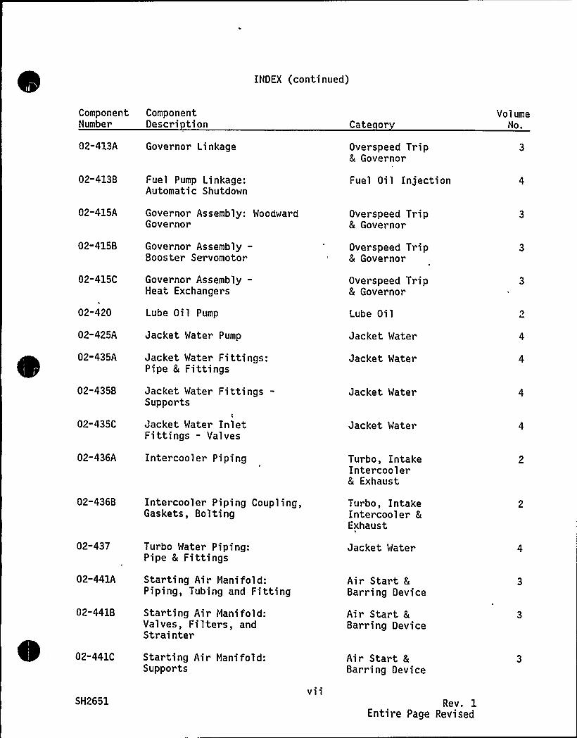
INDEX (continued)
ComponentNumber
ComponentDescri tion Cate or
Vol umeNo.
02-413A Governor Linkage Overspeed Trip8 Governor
02-413B
02-415A
02-415B
02-415C
02"420
02-425A
02-435A
02"435B
02-435C
02-436A
Fuel Pump Linkage:Automatic Shutdown
Governor Assembly: WoodwardGovernor
Governor Assembly-Booster Servomotor
Governor Assembly-Heat Exchangers
Lube Oil Pump
Jacket Water Pump
Jacket Water Fittings:Pipe & Fittings
Jacket Water Fittings-Supports
Jacket Water InletFittings - Valves
Inter cooler Piping
Fuel Oil Injection
Overspeed Trip& Governor
Overspeed Trip8 Governor
Overspeed Trip8 Governor
Lube Oi 1
Jacket Water
Jacket Water
Jacket Water
Jacket Water
Turbo, IntakeIntercooler& Exhaust
02-436B Intercooler Piping Coupling,Gaskets, Bolting
Turbo, IntakeIntercooler &Exhaust
02-437
02-441A
02-441B
02-441C
SH2651
Turbo Water Piping:Pipe 8 Fittings
Starting Air Manifold:Piping, Tubing and Fitting
Starting Air Manifold:Valves, Filters, andStrainter
Starting Air Manifold:Supports
vii
Jacket Water
Air Start 8
Barring Device
Air Start 8
Barring Device
Air Start &Bar ring Device
Rev. 1Entire Page Revised
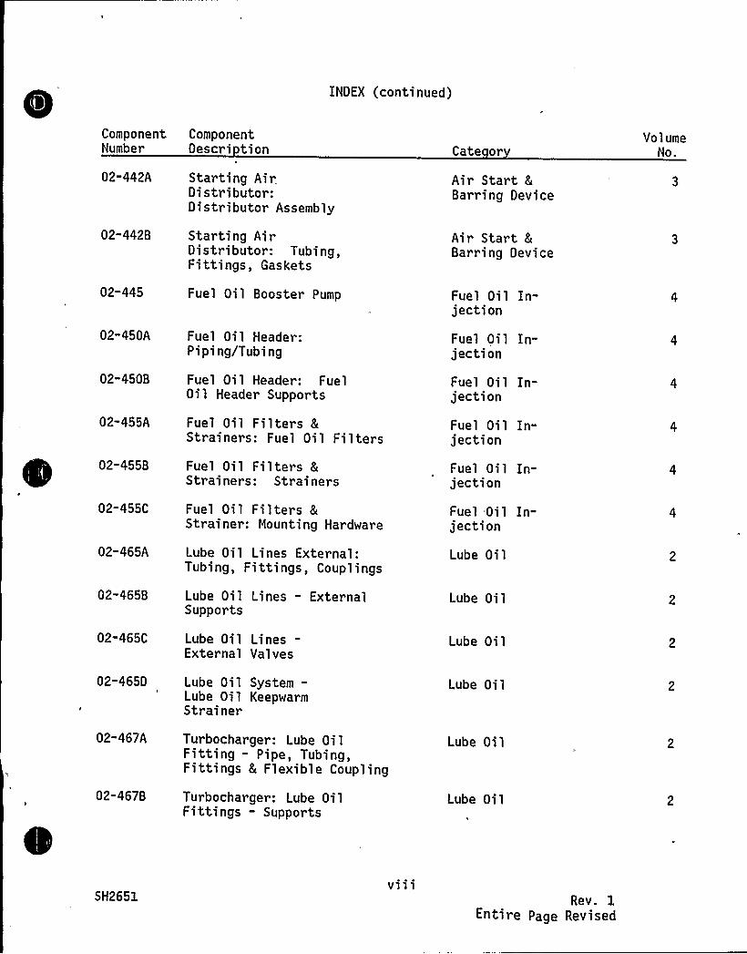
INDEX (continued)
ComponentNumber
02-442A
02"442B
02-445
02"450A
02"450B
02-455A
02-455B
02-455C
02-465A
02-465B
02-465C
02-465D
02-467A
02-467B
ComponentDescri tion
Starting AirDistributor:Distributor Assembly
Starting AirDistributor: Tubing,Fittings, Gaskets
Fuel Oil Booster Pump
Fuel Oil Header:Piping/Tubing
Fuel Oil Header: FuelOil Header Supports
Fuel Oil Filters 8Strainers: Fuel Oil Filters
Fuel Oil Filters 8Strainers: Strainers
Fuel Oil Filters 8Strainer: Mounting Hardware
Lube Oil Lines External:Tubing, Fittings, Couplings
Lube Oil Lines - ExternalSupports
Lube Oil Lines-Exter nal Val ves
Lube Oil System-Lube Oil KeepwarmStrainer
Turbocharger: Lube OilFitting - Pipe, Tubing,Fittings 8 Flexible Coupling
Turbocharger: Lube OilFittings - Supports
Cate or
Air Start 8
Barring Device
Air Star t 8
Barring Device
Fuel Oil In-jection
Fuel Oi 1 In-jection
Fuel Oil In-jection
Fuel Oil In-jection
Fuel Oil In-jection
Fuel Oil In-jection
Lube Oi 1
Lube Oil
Lube Oil
Lube Oil
Lube Oil
Lube Oil
VolumeNo.
SH2651v111
Rev. 1Entire Page Revised
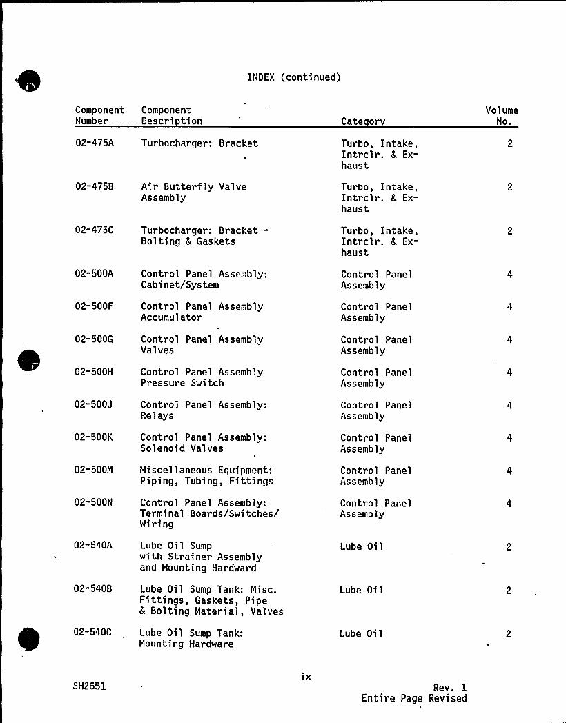
INDEX (continued)
ComponentNumber
02-475A
02-475B
02-475C
02-500A
02-500F
02-500G
02-500H
02-500J
02-500K
02-500M
02-500N
02"540A
02-540B
02-540C
ComponentDescri tion
Turbocharger: Bracket
Air Butterfly ValveAssembly
Turbocharger: Bracket-Bolting & Gaskets
Control Panel Assembly:Cabinet/System
Control Panel AssemblyAccumulator
Control Panel AssemblyValves
Control Panel AssemblyPressure Switch
Control Panel Assembly:Relays
Control Panel Assembly:Solenoid Valves
Miscellaneous Equipment:Piping, Tubing, Fittings
Control Panel Assembly:Terminal Boards/Switches/Wiring
Lube Oil Sumpwith Strainer Assemblyand Mounting Hardward
Lube Oil Sump Tank: Misc.Fittings, Gaskets, Pipe& Bolting Material, Valves
Lube Oil Sump Tank:Mount,ing Hardware
Cate or
Turbo, Intake,Intrclr. & Ex-haust
Turbo, Intake,Intrclr. 8 Ex-haust
Turbo, Intake,Intrclr. & Ex-haust
Control PanelAssembly
Control PanelAssembly
Control PanelAssembly
Control PanelAssembly
Control PanelAssembly
Control PanelAssembly
Control PanelAssembly
Control PanelAssembly
Lube Oi 1
Lube Oi 1
Lube Oil
VolumeNo.
SH2651ix
Rev. 1Entire Page Revised
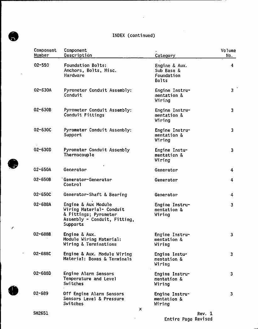
INOEN (continued)
ComponentNumber
ComponentOescri tion Cate or
VolumeNo.
02-550 Foundation Bolts:Anchors, Bolts, Misc.Hardware
Engine 8 Aux.Sub Base 8
FoundationBolts
02-630A
02-630B
Pyrometer Conduit Assembly:Conduit
Pyrometer Conduit Assembly:Conduit Fittings
Engine Instru-mentation 8
Wiring
Engine Instru-mentation 8
Wiring
02-630C
02"6300
Pyrometer Conduit Assembly:Support
Pyrometer Conduit AssemblyThermocouple
Engine Instru-mentation 8
Wiring
Engine Instu-mentation 8
Wiring
02-650A Generator Generator
02-650B "Generator-GeneratorControl
Generator
02-650C Generator-Shaft 8 Bearing Generator
02-688A " Engine 8 Aux ModuleWiring Material- Conduit8 Fittings; PyrometerAssembly - Conduit, Fitting,Supports
Engine Instru-mentation &Wiring
02-688B
02"688C
02-6880
Engine & Aux.Module Wiring Material:Wiring 8 Terminations
Engine 8 Aux. Module WiringMaterial: Boxes 8 Terminals
Engine Alarm SensorsTemperature and LevelSwitches
Engine Instru-mentation &Wiring
Engine Instu-mentation 8
Wiring
Engine Instru-mentation &Wiring
02-689
SH2651
Off Engine Alarm SensorsSensors Level 8 PressureSwitches
Engine Instru-mentation &Wiring
Rev. 1Entire Page Revised
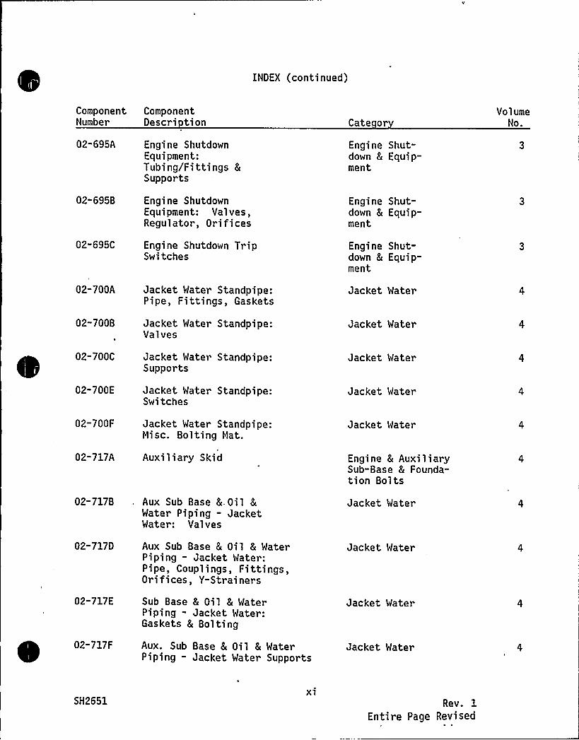
INDEX (continued)
ComponentNumber
02-695A
02-695B
02-695C
02-700A
02-700B
02-700C
02-700E
02-700F
02-717A
02-717B
02-717D
02-717E
02-717F
ComponentDescri tion
Engine ShutdownEquipment:Tubing/Fittings 8
Supports
Engine ShutdownEquipment: Valves,Regulator, Orifices
Engine Shutdown TripSwitches
Jacket Water Standpipe:Pipe, Fittings, Gaskets
Jacket Water Standpipe:Valves
Jacket Water Standpipe:Supports
Jacket Water Standpipe:Switches
Jacket Water Standpipe:Misc. Bolting Mat.
Auxi 1 iary Ski d
. Aux Sub Base & Oil 8
Water Piping - JacketWater: Valves
Aux Sub Base & Oil 8 WaterPiping - Jacket Water:Pipe, Couplings, Fittings,Orifices, Y-Strainers
Sub Base 8 Oil 8 WaterPiping - Jacket Water:Gaskets 8 Bolting
Aux. Sub Base 8 Oil & WaterPiping - Jacket Mater Supports
Cate or
Engine Shut-down 8 Equip-ment
Engine Shut-down & Equip-ment
Engine Shut-down 8 Equip-ment
Jacket Water
Jacket Water
Jacket Water
Jacket Water
Jacket Water
Engine 8 AuxiliarySub-Base 8 Founda-tion Bolts
Jacket Water
Jacket Water
Jacket Mater
Jacket Water
VolumeNo.
SH2651xi
Rev. 1Entire Page Revised
INDEX (continued)
Component ComponentNumber Descri tion Cate or
VolumeNo.
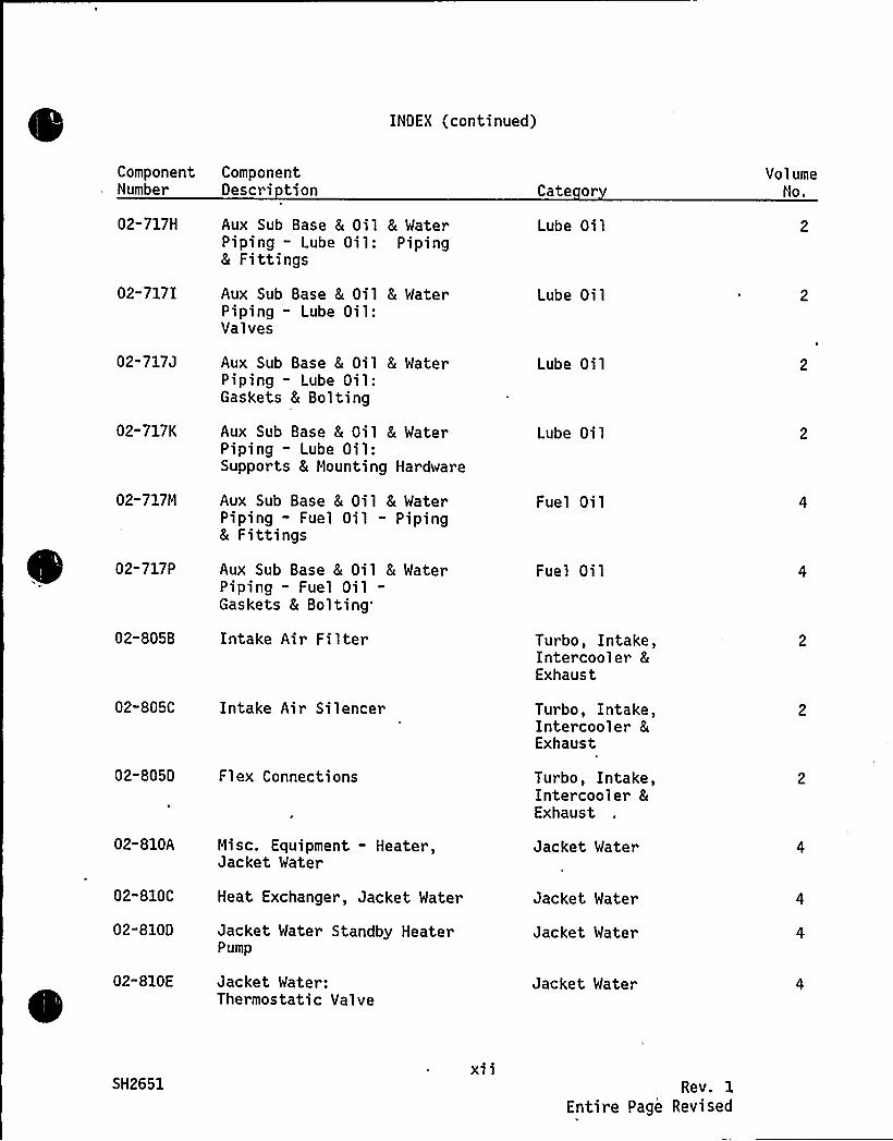
02-717H
02-717I
02"717J
02-717K
02-717M
02-717P
02-805B
Aux Sub Base 8 Oil 8 WaterPiping - Lube Oil: Piping8 Fittings
Aux Sub Base 8 Oil 8 WaterPiping - Lube Oil:Valves
Aux Sub Base 8 Oil 8 WaterPiping - Lube Oil:Gaskets & Bolting
Aux Sub Base & Oil 8 MaterPiping - Lube Oil:Supports 8 Mounting Hardware
Aux Sub Base & Oil & WaterPiping - Fuel Oil — Piping& Fittings
Aux Sub Base 8 Oil 8 WaterPiping - Fuel Oil-Gaskets 8
Bolting'ntake
Air Filter
Lube Oi 1
Lube Oi 1
Lube Oil
Lube Oi 1
Fuel Oil
Fuel Oil
Turbo, Intake,Intercooler 8
Exhaust
02-805C Intake Air Silencer
02-805D Flex Connections
Turbo, Intake,Intercooler &Exhaust
Turbo, Intake,Intercooler &Exhaust
02-810A
02" 810C
02-810D
02-810E
Misc. Equipment - Heater,Jacket Water
Heat Exchanger, Jacket Mater
Jacket Water Standby HeaterPump
Jacket Water:Thermostatic Valve
Jacket Water
Jacket Water
Jacket Water
Jacket Water
SH2651X11
Rev. 1
Entire Page Revised
INDEX (continued)
ComponentNumber
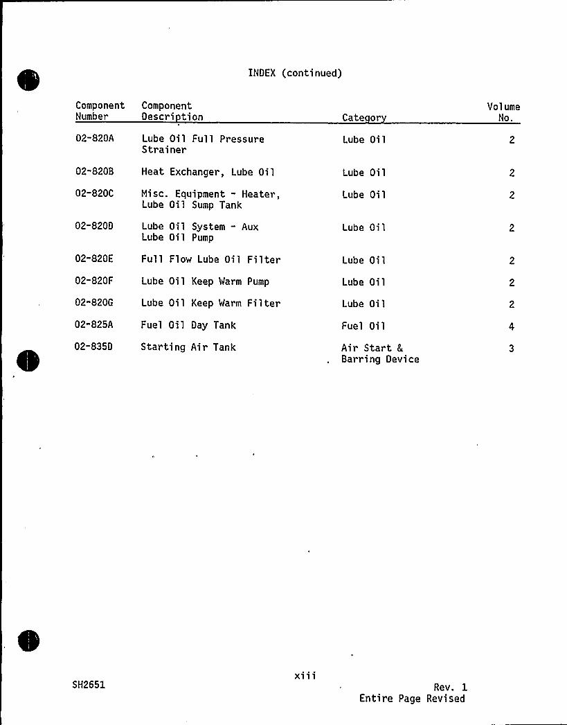
02-820A
02-820B
02-820C
02-820D
02-820E
02-820F
02-820G
02-825A
02-8350
ComponentOescri tion
Lube Oil Full PressureStrainer
Heat Exchanger, Lube Oil
Misc. Equipment - Heater,Lube Oil Sump Tank
Lube Oil System - AuxLube Oil Pump
Full Flow Lube Oil Filter
Lube Oil Keep Warm Pump
Lube Oil Keep Warm Filter
Fuel Oil Day Tank
Starting Air Tank
Cate or
Lube Oil
Lube Oi 1
Lube Oil
Lube Oi 1
Lube Oi 1
Lube Oil
Lube Oil
Fuel Oil
Air Start &Barring Device
Vol umeNo.
SH2651X111
Rev. 1Entire Page Revised
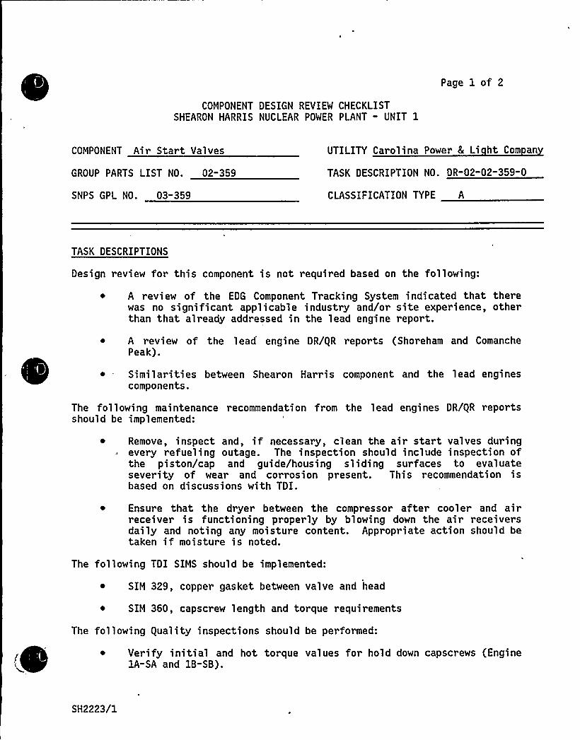
Page 1 of 2
COMPONENT DESIGN REVIEW CHECKLISTSHEARON HARRIS NUCLEAR POWER PLANT - UNIT 1
COMPONENT Air Start Valves UTILITY Carolina Power 8 Li ht Com an
GROUP PARTS LIST NO. 02-359 TASK DESCRIPTION NO. DR-02"02-359-0
SNPS GPL NO. 03-359 CLASSIFICATION TYPE A
TASK DESCRIPTIONS
Design review for this component is not required based on the following:
A review of the EDG Component Tracking System indicated that therewas no significant applicable industry and/or site experience, otherthan that already addressed in the lead engine report.
~ A review of the lead engine DR/gR reports (Shoreham and ComanchePeak).
~ Similarities between Shearon Harris component and the lead enginescomponents.
The following maintenance recommendation from the lead engines DR/gR reportsshould be implemented:
Remove, inspect and, if necessary, clean the air start valves duringevery refueling outage. The inspection should include inspection ofthe piston/cap and guide/housing sliding surfaces to evaluateseverity of wear and corrosion present. This recommendation isbased on discussions with TDI.
~ Ensure that the dryer between the compressor after cooler and airreceiver is functioning properly by blowing down the air receiversdaily and noting any moisture content. Appropriate action should betaken if moisture is noted.
The following TDI SIMS should be implemented:
~ SIM 329, copper gasket between valve and head
~ SIM 360, capscrew length and torque requirements
'The following guality inspections should be performed:
~ Verify initial and hot torque values for hold down capscrews (EnginelA-SA and 1B-SB).
SH2223/1

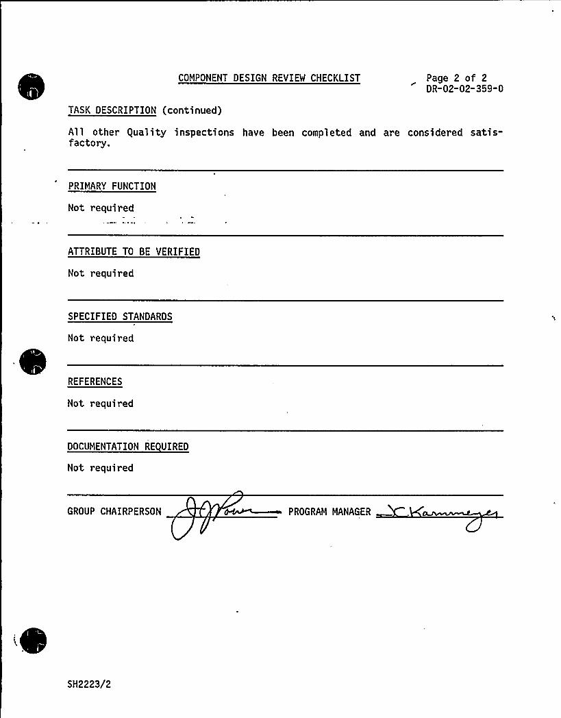
COMPONENT DESIGN REVIEM CHECKLIST
TASK DESCRIPTION (continued)
Page 2 of 2DR-02-02-359-0
All other equality inspections have been completed and are considered satis-factory.
PRIMARY FUNCTION
Not required
ATTRIBUTE TO BE VERIFIED
Not required
SPECIFIED STANDARDS
Not required
REFERENCES
Not required
DOCUMENTATION RE VIREO
Not required
GROUP CHAIRPERSON PROGRAM MANAGER
SH2223/2
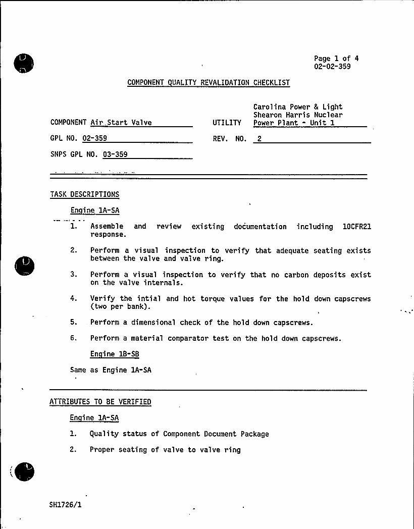
COMPONENT UALITY REVALIDATION CHECKLIST
Page 1 of 402-02-359
COMPONENT Air.Start Valve
GPL NO. 02-359
SNPS GPL NO. 03-359
Carolina Power 8 LightShearon Harris Nuclear
UTILITY Power Plant - Unit 1
REV. NO. 2
TASK DESCRIPTIONS
2.
3.
Assemble and review existing documentation including 10CFR21response.
Perform a visual inspection to verify that adequate seating existsbetween the valve and valve ring.
Perform a visual inspection to verify that no carbon deposits existon the valve internals.
4. Verify the intial and hot torque values for the hold down capscrews(two per bank).
,5., Perform a dimensional check of the hold down capscrews.
6. Perform a material comparator test on the hold down capscrews.
Same as Engine 1A-SA
ATTRIBUTES TO BE VERIFIED
En ine 1A-SA
l. guality status of Component Document Package
2. Proper seating of valve to valve ring
SH1726/1
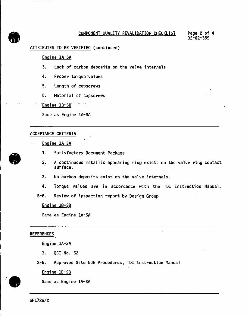
COMPONENT UALITY REVALIDATION CHECKLIST Page 2 of 402"02-359
ATTRIBUTES TO BE VERIFIED (continued)
En ine lA-SA
3. Lack of carbon deposits on the valve internals
4. Proper torqu'e values
5. Length of capscrews
6. Material of capscrews
Same as Engine 1A-SA
ACCEPTANCE CRITERIA
1. Satisfactory Document Package
2. A continuous metallic appearing ring exists on the valve ring contactsurface.
3. No carbon deposits exist on the valve internals.
4. Torque values are in accordance with the TDI Instruction Manual.
5-6. Review of inspection report by Design Group
Same as Engine lA-SA
REFERENCES
l. (CI No. 52
2-6. Approved Site NDE Procedures, TDI Instruction Manual
' Same as Engine 1A-SA
SH1726/2

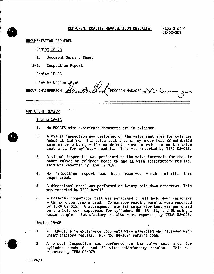
COMPONENT UALITY REVALIDATION CHECKLIST Page 3 of 402-02"359
DOCUMENTATION RE UIRED
1. Document Summary Sheet
2-6. Inspection Report
En ine 1B-SB
Same as Engine -SA
GROUP CHAIRPERSON PROGRAM MANAGER
COMPONENT REVIEW
1. No EDGCTS site experience documents are in evidence.
2. A visual inspection was performed on the valve seat area for cylinderheads 1L and 8R. The valve seat area on cylinder head R8 exhibitedsome minor pitting while no defects were in evidence on the valveseat area for cylinder head 1L. This was reported by TER¹ 02-016.
3. A visual inspection was performed on the valve internals for the airstart valves on cylinder heads 8R and 1L with satisfactory results.This was reported by TER¹ 02-016.
4. No inspection report has been received which fulfills thisrequirement.
5. A dimensional check was performed on twenty hold down capscrews. Thiswas reported by TER¹ 02-016.
6. A material comparator test was performed on all hold down capscrewswith no known sample used. Comparator reading results were reportedby TER¹ 02-016. A subsequent material comparator test was performedon the hold down capscrews for cylinders 3R, 6R, 3L, and 6L using aknown sample. Satisfactory results were reported by TER¹ 02-093.
En ine 1B-SB
1. All EDGCTS site experience documents were assembled and reviewed withunsatisfactory results. NCR No. 84-1634 remains open.
2. A visual inspection was performed on the val ve seat area forcyl inder heads 8L and 5R with sati s factory resul ts. Thi s wasreported by TER¹ 02-079.
SH1726/3

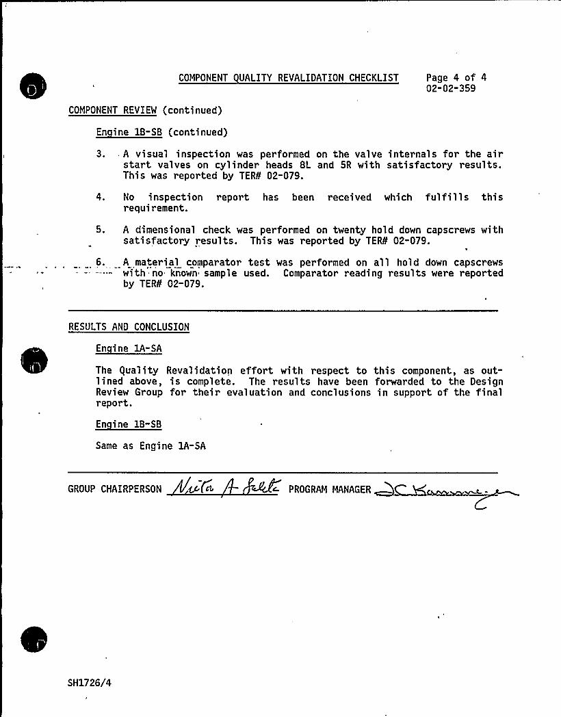
COMPONENT UALITY REVALIDATION CHECKLIST Page 4 of 402-02-359
COMPONENT REVIEW (continued)
3.. A visual inspection was performed on the valve internals for the airstart valves on cylinder heads 8L and 5R with satisfactory results.This was reported by TER¹ 02-079.
4. No inspection report has been received which fulfills thisrequirement.
5. A dimensional check was performed on twenty hold down capscrews withsatisfactory results. This was reported by TERS 02-079.
6. A material comparator test was performed on all hold down capscrewswith no known sample used. Comparator reading results were reportedby TER¹ 02-079.
RESULTS AND CONCLUSION
En ine 1A-SA
The guality Revalidation effort with respect to this component, as out-lined above, is complete. The results have been forwarded to the DesignReview Group for their evaluation and conclusions in support of the finalreport.
Same as Engine 1A-SA
GROUP CHAIRPERSON <c (c> PROGRAM MANAGER
SH1726/4

COMPONENT DESIGN REVIEW CHECKLISTSHEARON HARRIS NUCLEAR POWER STATION - UNIT 1
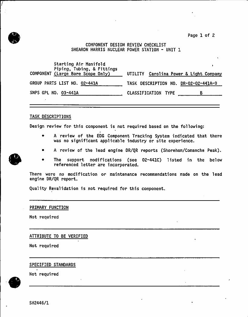
Page 1 of 2
Starting Air ManifoldPiping, Tubing, 8 Fittings
COMPONENT Lar e Bore Sco e Onl
GROUP PARTS LIST NO. 02-441A
SNPS GPL NO. 03-441A
UTILITY Carolina Power 8 Li ht Com an
TASK DESCRIPTION NO. DR-02-02-441A-0
CLASSIFICATION TYPE
TASK DESCRIPTIONS
Design review for this component is not required based on the following:
~ A review of the EDG Component Tracking System indicated that therewas no significant applicable industry or site experience.
~ A review of the lead engine DR/gR reports (Shoreham/Comanche Peak).
The support modifications (see 02-441C) listed in the belowreferenced letter are incorporated.
There were no modification or maintenance recommendations made on the leadengine DR/gR report.
guality Revalidation is not required for this component.
PRIMARY FUNCTION
Not required
ATTRIBUTE TO BE VERIFIED
Not required
SPECIFIED STANDARDS
Not required
SH2446/1
REFERENCES
COMPONENT DESIGN REVIEW CHECKLIST Page 2 of 2DR-02-02"441A"0
Letter from R. Markovich/G. Shears (Impell) to J. Kammeyer (SMEC),"Recommended Design of Piping Components 02-441A and 02-441C for ShearonHarris", dated 10/24/84.
DOCUMENTATION RE UIRED
Not reqUired
GROUP CHAIRPERSON PROGRAM MANAGER ~C X(~-
SH2446/2

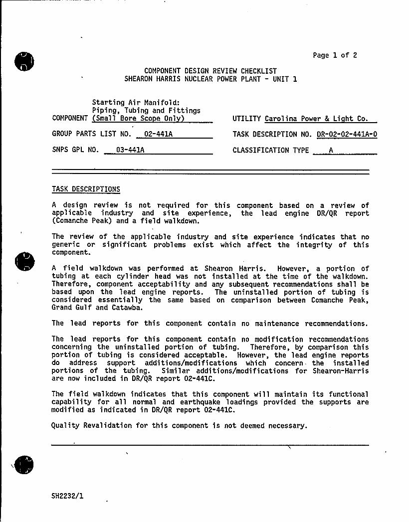
COMPONENT DESIGN REVIEW CHECKLISTSHEARON HARRIS NUCLEAR POWER PLANT - UNIT 1
Page 1 of 2
Starting Air Manifold:Piping, Tubing and Fittings
COMPONENT Small Bore Sco e Onl UTILITY Carolina Power 8 Li ht Co.
GROUP PARTS LIST NO. 02-441A
SNPS GPL NO. 03-441A
TASK DESCRIPTION NO. DR-02-02-441A-0
CLASSIFICATION TYPE A
TASK DESCRIPTIONS
A design review is not required for this component based on a review ofapplicable industry and site experience, the lead engine DR/gR report(Comanche Peak) and a field walkdown.
The review of the applicable industry and site experience indicates that nogeneric or significant problems exist which affect the integrity of thiscomponent.
A field walkdown was performed at Shearon Harris. However, a portion oftubing at each cylinder head was not installed at the time of the walkdown.Therefore, component acceptability and any subsequent recommendations shall bebased upon the lead engine reports. The uninstalled portion of tubing isconsidered essentially the same based on comparison between Comanche Peak,Grand Gulf and Catawba.
The lead reports for this component contain no maintenance recommendations.
The lead reports for this component contain no modification recommendationsconcerning the uninstalled portion of tubing. Therefore, by comparison thisportion of tubing is considered acceptable. However, the lead engine reportsdo address support additions/modifications which concern- the installedportions of the tubing. Similar additions/modifications for Shearon-Harrisare now included in DR/gR report 02-441C.
The field walkdown indicates that this component will maintain its functionalcapability for all normal and earthquake loadings provided the supports aremodified as indicated in DR/gR report 02-441C.
guality Revalidation for this component is not deemed necessary.
SH2232/1

PRIMARY FUNCTION
Not required
COMPONENT DESIGN REVIEW CHECKLIST Page 2 of 2DR-02-02-441A" 0
ATTRIBUTE TO BE VERIFIED
Not required
SPECIFIED'STANDARDS
Not required
REFERENCES
Not required
DOCUMENTATION RE UIRED
Not required
GROUP CHAIRPERSON PROGRAM MANAGER C-
SH2232/2
COMPONENT DESIGN REVIEW CHECKLISTSHEARON HARRIS NUCLEAR POWER PLANT - UNIT 1
Page 1 of 2
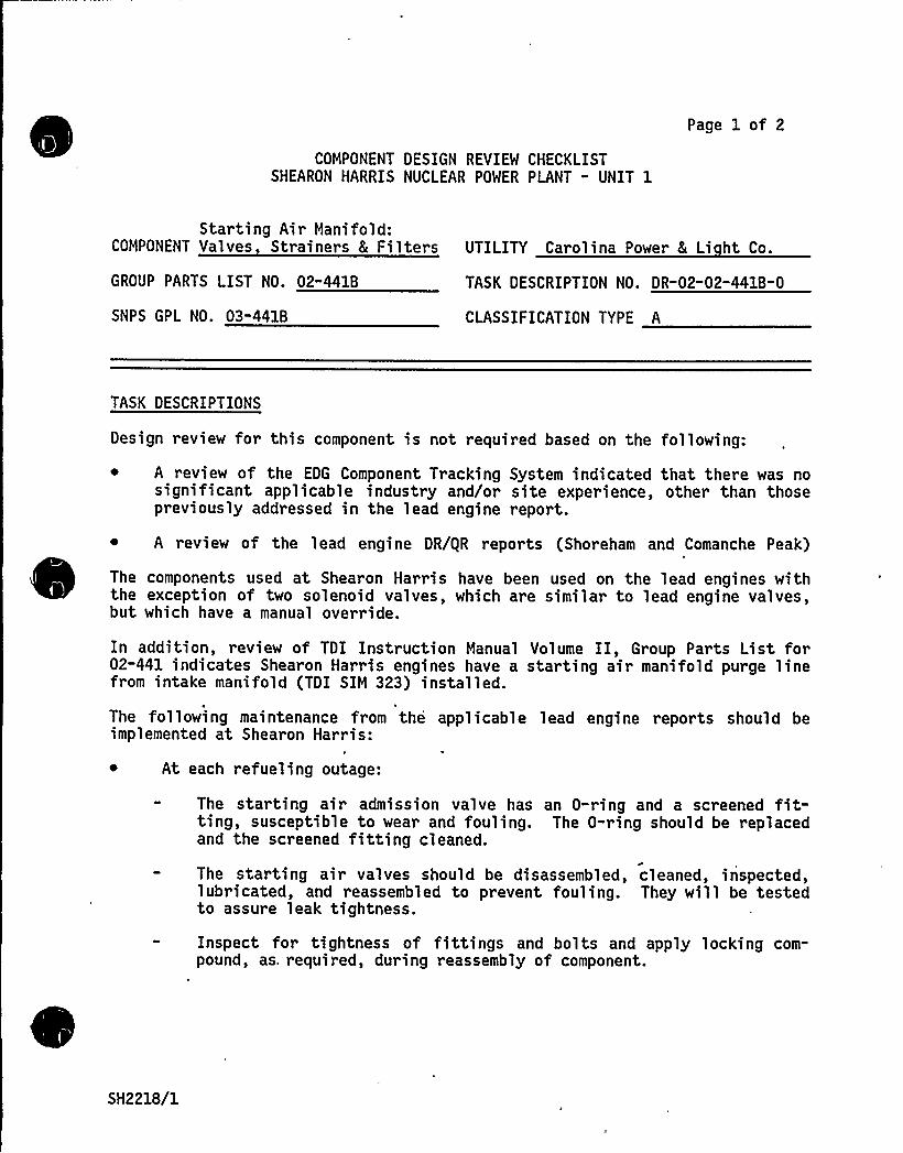
Starting Air Manifold:COMPONENT Valves Strainers 8 Filters UTILITY Carolina Power 8 Li ht Co.
GROUP PARTS LIST NO. 02"441B TASK DESCRIPTION NO. DR-02"02-441B" 0
SNPS GPL NO. 03-441B CLASSIFICATION TYPE A
TASK DESCRIPTIONS
Design review for this component is not required based on the following:
~ A review of the EDG Component Tracking System indicated that there was nosignificant applicable industry and/or site experience, other than thosepreviously addressed in the lead engine report.
A review of the lead engine DR/gR reports (Shoreham and Comanche Peak)
The components used at Shearon Harris have been used on the lead engines withthe exception of two solenoid valves, which are similar to lead engine valves,but which have a manual override.
In addition, review of TDI Instruction Manual Volume II, Group Parts List for02-441 indicates Shearon Harris engines have a starting air manifold purge linefrom intake manifold (TDI SIM 323) installed.
The following maintenance from the applicable lead engine reports should beimplemented at Shearon Harris:
~ At each refueling outage:
The starting air admission valve has an 0-ring and a screened fit-ting, susceptible to wear and fouling. The 0-ring should be replacedand the screened fitting cleaned.
The starting air valves should be disassembled, cleaned, inspected,lubricated, and reassembled to prevent fouling. They will be testedto assure leak tightness.
Inspect for tightness of fittings and bolts and apply locking com-pound, as. required, during reassembly of component.
SH2218/1
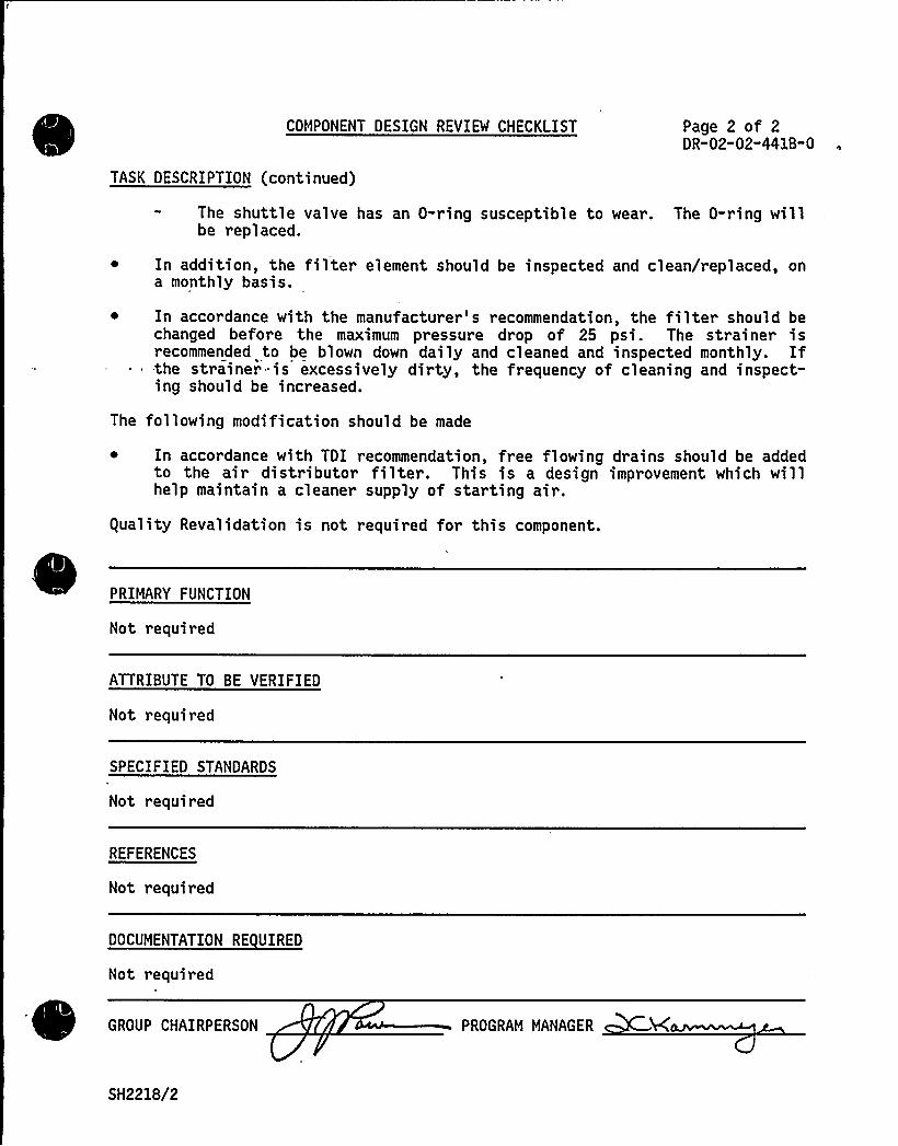
COMPONENT DESIGN REVIEM CHECKLIST
TASK DESCRIPTION (continued)
Page 2 of 2DR-02-02-441B-0
The shuttle valve has an 0-ring susceptible to wear. The 0-ring willbe replaced.
~ In addition, the filter element should be inspected and clean/replaced, ona monthly basis.
~ In accordance with the manufacturer's recommendation, the filter should bechanged before the maximum pressure drop of 25 psi. The strainer isrecommended to be blown down daily and cleaned and inspected monthly. If-the strainer -is excessively dirty, the frequency of cleaning and inspect-ing should be increased.
The following modification should be made
~ In accordance with TDI recommendation, free flowing drains should be addedto the air distributor filter. This is a design improvement which willhelp maintain a cleaner supply of starting air.
guality Revalidation is not required for this component.
PRIMARY FUNCTION
Not required
ATTRIBUTE TO BE VERIFIED
Not required
SPECIFIED STANDARDS
Not required
REFERENCES
Not required
DOCUMENTATION RE UIRED
Not required
GROUP CHAIRPERSON PROGRAM MANAGER
SH2218/2

*.<
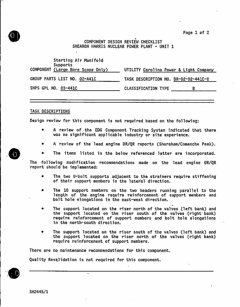
COMPONENT DESIGN REVIEW CHECKLISTSHEARON HARRIS NUCLEAR POWER PLANT - UNIT 1
Page 1 of 2
Starting Air Mani foldSupports
COMPONENT Lar e Bore Sco e Onl
GROUP PARTS LIST NO. 02-441C
SNPS GPL NO. 03-441C
UTILITY Carolina Power & Li ht Com an
TASK DESCRIPTION NO. DR-02-02-441C" 0
CLASSIFICATION TYPE
TASK DESCRIPTIONS
Design review for this component is not required based on the following:
~ A review of the EDG Component Tracking System indicated that therewas no significant applicable industry or site experience.
~ A review of the lead engine DR/gR reports (Shoreham/Comanche Peak).
~ The items listed in the below referenced letter are incorporated.
The following modification recommendations made on the lead engine DR/gRreport should be implemented:
The two U-bolt supports adjacent to the strainers require stiffeningof their support members in the later'al direction.
The 10 support members on the two headers running parallel to thelength of the engine require reinforcement of support members andbolt hole elongations in the east-west direction.
The support located on the riser north of the valves (left bank) andthe support located on the riser south of the valves (right'ank)require reinforcement of support members and bolt hole elongationsin the north-south direction.
~ The support located on the riser south of the valves (left bank) andthe support located on the riser north of the valves (right bank)require reinforcement of support members.
There are no maintenance recommendations for this'component.
guality Revalidation is not required for this component.
SH2445/1
PRIMARY FUNCTION
Not required
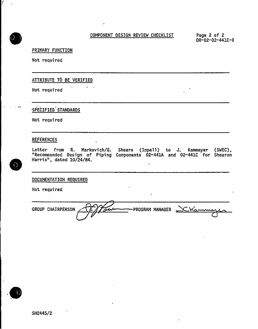
COMPONENT DESIGN REVIEW CHECKLIST Page 2 of 2DR-02-02-441C-0
ATTRIBUTE TO BE VERIFIED
Not required
SPECIFIED STANDARDS
Not required
REFERENCES
Letter from R. Markovich/G. Shears (Impell) to J. Kammeyer (SWEC),"Recommended Design of Piping Components 02-441A and 02-441C for ShearonHarris", dated 10/24/84.
DOCUMENTATION RE UIRED
Not required
GROUP CHAIRPERSON PROGRAM MANAGER
SH2445/2
TDI OWNERS GROUP
for
SHEARON HARRIS NUCLEAR POWER PLANT - UNIT 1
STARTING AIR MANIFOLD " SUPPORTSSMALL BORE SCOPE ONLY
COMPONENT PART NO. 02"441C
I INTRODUCTION
The TDI Emergency Diesel Generator Owners Group Program for the ShearonHarris Nuclear Power Plant requires Design and equality Revalidationreviews of the structural adequacy of the star ting air manifold tubingsupports to withstand the effects of normal operating and earthquakeloadings. The primary function of these supports is to provide adequaterestraint of the starting air manifold tubing components.
II OBJECTIVE
The objective of this review was to perform an engineering evaluation ofthe tubing supports to assure that the component will perform its intendeddesign function during normal operating and earthquake loadings.
III METHODOLOGY
In order to meet the stated objective, the following methods were used:
~ The TDI Emergency Diesel Generator Component Tracking System wasreviewed for the Shearon Harris site, nuclear, and non-nuclearindustry experience. See Appendix C for results.
~ The equality Revalidation Checklist results were reviewed foracceptability.
~ Comparison with the lead engine reports (Comanche Peak, Grand Gulf,Catawba).
Refer to the review procedures as described in Reference 1 for a detailedmethodology of this evaluation.
IV RESULTS AND CONCLUSIONS
The tubing supports, as defined by this Component Design Review, have beenevaluated in accordance with Reference 1 and have been found acceptablewith modifications. The conclusions of this report are based on the com-
SH2369/1

Page 2 of 2
bination of a field walkdown and a review of the lead engine reports sinceportions of this component were not installed at the time of the walkdown.
There are no TERs associated with this component.
The guality Revalidation Inspection results identified in Appendix B havebeen reviewed and considered in the performance of this design review, andthe results are consistent with the final conclusions of this report.
Based on the above review, it is concluded from References 1 and 2 thatthe tubing supports will perform their intended design function at ShearonHarris under all normal operating and earthquake loadings if the followingrecommended modifications are implemented as detailed in Reference 3:
Existin Su ort Chan es - En ine lA
The existing two-direction lateral support on the air supply to distribu-tor tubing located adjacent to the r ight bank filter requires replacementsince it does not provide sufficient structural capacity to withstand theloadings.
Su ort Additions - En ine 1B
In order to support the piping/tubing of Component 02-441A, it is recom-mended that a two-direction lateral restraint should be added on thedistributor air supply tubing on the right bank lines between the header,filter and distributor to reduce the unsupported span length and filternozzle loadings and also to maintain consistency with Engine lA.
V REFERENCES
l. "Engineering Review Criteria Document for the Design Review of TDIDiesel Small Bore Piping, Tubing, and Supports for the TDI
Owners'roup,"
Report No. 11600.60-DC-02, Revision 0.
2. Stone & Webster Calculation number 11600.60-NP(B)-0201-XH.
3. Memo No. 6451 from C. Malovrh/SWEC to J. Kammeyer/SWEC dated10/29/84.
SH2369/2
APPENDIX A
COMPONENT DESIGN REVIEW CHECKLISTSHEARON HARRIS NUCLEAR POWER PLANT - UNIT 1
Page Al of 2
Starting Air ManifoldTubing Supports
COMPONENT Small Bore Sco e Onl
GROUP PARTS LIST NO. 02"441C
SNPS GPL NO. 03-441C
UTILITY Carolina Power 8 Li ht
TASK DESCRIPTION NO. DR-02"02-441C-0
CLASSIFICATION TYPE A
TASK DESCRIPTIONS
Pe~form an engineering review of the tubing supports to provide additionalassurances that the component will perform its intended design function duringnormal operating and earthquake loading.
PRIMARY FUNCTION
Provide adequate restraint to the starting air manifold tubing components.
ATTRIBUTES TO BE VERIFIED
Structural adequacy of the tubing supports due to the effects of normaloperating and earthquake loadings.
SPECIFIED STANDARDS
IEEE 387
REFERENCES
"Engineering Review Criteria Document for the Design Review of TDI Diesel SmallBore Piping, Tubing, and Supports for the TDI Owners'roup" Report No.11600.60-DC-02, Revision 0.
SH2253/1
COMPONENT DESIGN REVIEW CHECKLIST
DOCUMENTATION RE UIRED
Page A2 of 2DR-02-02"441C-0
Delaval design documentation (specifications, calculations, drawings, etc.).In lieu of information from Delaval, the following information is required:verified support sketches and piping isometrics, material specifications, pipesize and schedule, and operating parameters (pressure, temperature, loadcombinations).
GROUP CHAIRPERSON PROGRAM MANAGER
SH2253/2
A endix B
COMPONENT UALITY REVALIDATION CHECKLIST
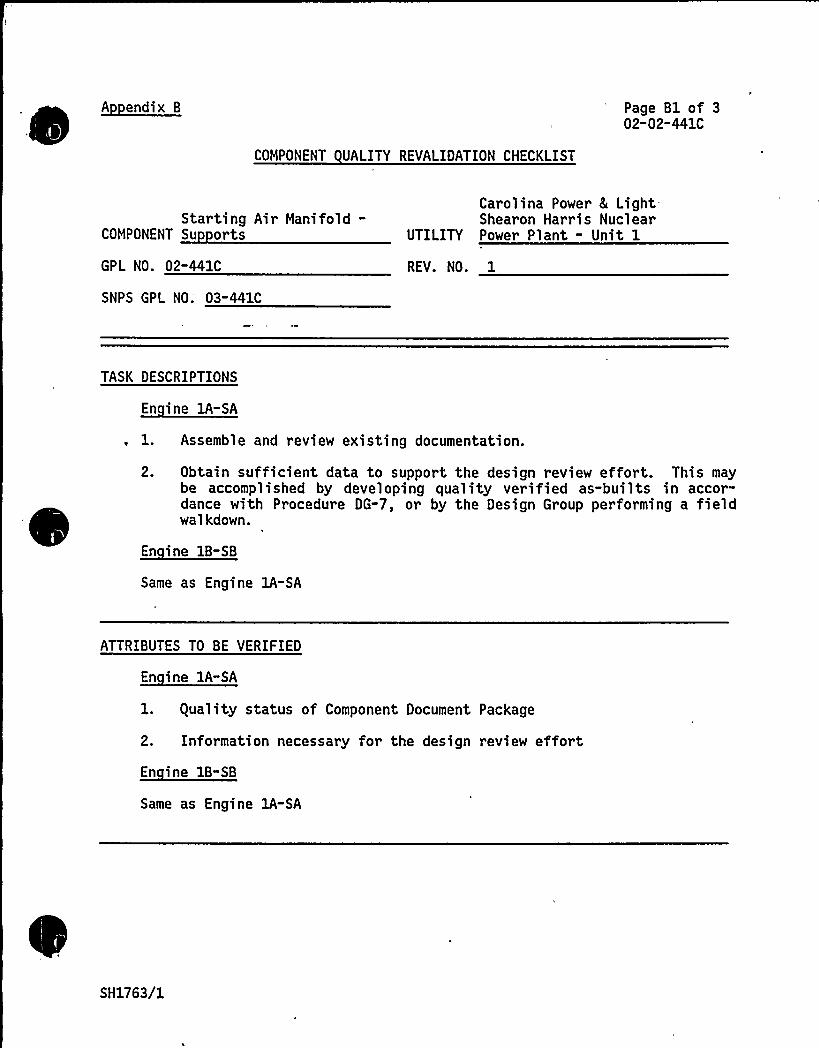
Page Bl of 302-02-441C
Starting Air Manifold-COMPONENT Su orts
GPL NO. 02-441C
SNPS GPL NO ~ 03-441C
Carolina Power 8 LightShearon Harris Nuclear
UTILITY Power Plant - Unit 1
REV. NO. 1
TASK DESCRIPTIONS
1. Assemble and review existing documentation.
2. Obtain sufficient data to support the design review effort. This maybe accomplished by developing quality verified as-builts in accor-dance with Procedure DG-7, or by the Design Group performing a fieldwalkdown.
En ine 1B-SB
Same as Engine lA-SA
ATTRIBUTES TO BE VERIFIED
En ine lA-SA
1. guality status of Component Document Package
2. Information necessary for the design review effort
Same as Engine lA-SA
SH1763/1
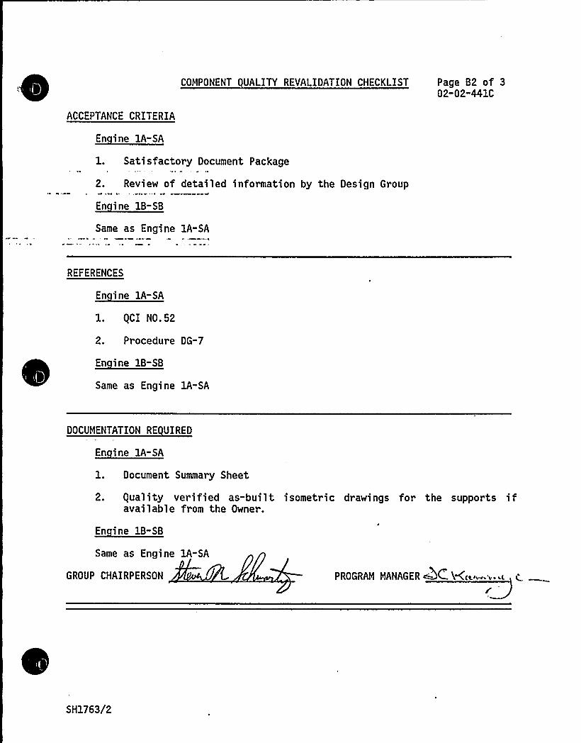
ACCEPTANCE CRITERIA
En ine 1A-SA
COMPONENT UALITY REVALIDATION CHECKLIST Page B2 of 302-02"441C
1. Satisfactory Document Package
2. Review of detailed information by the Design Group
En ine 1B-SB
Same as Engine 1A-SA4
REFERENCES
1. gCI N0.52
2. Procedure DG-7
Same as Engine 1A-SA
DOCUMENTATION RE UIRED
1. Document Summary Sheet
2. equality verified as-built isometric drawings for the supports ifavailable from the Owner.
En ine 1B-SB
Same as Engine 1A-SA
GROUP CHAIRPERSON PROGRAM MANAGER QC. Hc~"" i'-~
SH1763/2

COMPONENT REVIEW
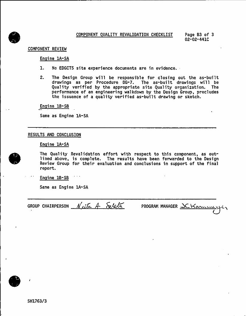
COMPONENT UALITY REVALIDATION CHECKLIST Page 83 of 302-02-441C
1. No EDGCTS site experience documents are in evidence.
2. The Design Group will be responsible for closing out the as-builtdrawings as per Procedure DG-7. The as-built drawings will beguality verified by the appropriate site guality organization. Theperformance of an engineering walkdown by the Design Group, precludesthe issuance of a quality verified as-built drawing or sketch.
En ine 18-SB
Same as Engine 1A-SA
RESULTS AND CONCLUSION
The guality Revalidation effort with respect to this component, as out-lined above, is complete. The results have been forwarded to the DesignReview Group for their evaluation and conclusions in support of the finalreport.
En ine 18-SB
Same as Engine lA-SA
GROUP CHAIRPERSON PROGRAM MANAGER DC l(c~~ '~~c. i
SH1763/3

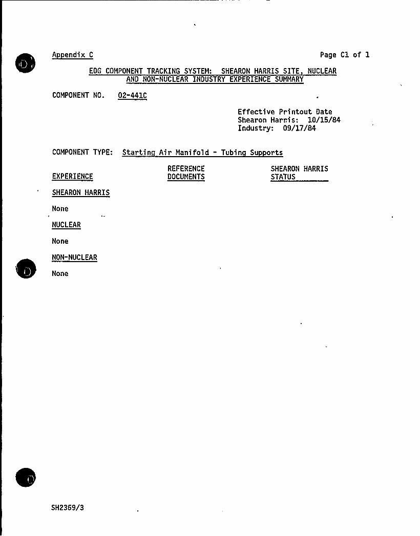
~Aendix C Page Cl of 1
EDG COMPONENT TRACKING SYSTEM: SHEARON HARRIS SITE NUCLEARAND NON"NUCLEAR INDUSTRY EXPERIENCE SUMMARY
COMPONENT NO. 02-441C
Effective Printout DateShearon Harn s: 10/15/84Industry: 09/17/84
COMPONENT TYPE: Startin Air Manifold - Tubin Su orts
EXPERIENCE
SHEARON HARRIS
None
NUCLEAR
None
NON-NUCLEAR
None
REFERENCEDOCUMENTS
SHEARON HARRISSTATUS
SH2369/3
COMPONENT DESIGN REVIEW CHECKLISTSHEARON HARRIS NUCLEAR POWER, PLANT " UNIT 1
Page 1 of 2
Starting Air Distributor:COMPONENT Distributor Assembl
GROUP PARTS LIST NO. 02"442A
SNPS GPL NO. 03"442A
UTILITY Carolina Power 8 Li ht Com an
TASK DESCRIPTION NO. DR-02-02-442A-0
CLASSIFICATION TYPE A
TASK DESCRIPTIONS
Design review is not required for this component, based on the Comanche Peaklead engine DR/gR report which establishes the acceptability of the distributorassembly. The parts under review are the same as those of the lead engine,with the exception of the timing shaft. The timing shaft assembly at ShearonHarris utilizes an adjustable cam arrangement, per TDI Service Information Memo(SIM) No. 311.
A review of the Component Tracking System indicates no significant applicable~
~
~
~
~
~
~
~ ~ ~
~ ~
~ ~ ~
~
~
~
industry or site experience.
In addition to the normal maintenance tasks of water removal and filter re-placement for the starting air system, the following maintenance recommendationfrom the lead engine DR/gR report should be implemented:
~ Maintain surveillance inspections to assure that the starting airmanifold vent remains open and effective.
~ Perform an inspection of the poppet valves and cams on all enginesduring refueling outages, to assess the degree of wear.
There are no modifications recommendations for this component.
The following guality inspections are recommended to be performed on engines lAand 1B.
~ Verify the proper timing of the air start distributor as described inthe TDI Manual.
~ After verifying the correct timing of each starting air distributor,as described in the TDI Manual, the evaluation of wear on the cam andvalve contacts should be performed as follows:
1. Remove the distributor from the engine
2. Visually inspect the wear marks on the cam lobes.
SH2092/1
Note the position and orientation of the lube oil jet. Oil flow fromthe jet should cover the wear mark region on the cam lobe.

5 ~
COMPONENT DESIGN REVIEW CHECKLIST
TASK DESCRIPTIONS (continued)
Page 2 of 2DR"02-02-442A-0
3. Visually inspect the wear marks on the end of each valve spool whereit slides on the cam. Measure the average diameter of the "flat"worn area on the end of each spool to the nearest 1/64-inch. If thelargest of these measurements is more than 1.5 times the smallest, anengineering evaluation of the observed wear should be performed and asuperficial hardness measurement should be made on the end "wearflat" of each valve spool. If the hardness of any spool end issignificantly below 30 Rc, it should replaced.
- Verify- the installation of the follower lobe on the camshaft (oneengine only)
PRIMARY FUNCTION
Not required
ATTRIBUTE TO BE VERIFIED
Not required
SPECIFIED STANDARDS
Not required
REFERENCES
Not required
DOCUMENTATION RE UIRED
Not required
GROUP CHAIRPERSON PROGRAM MANAGER C.
SH2092/2
COMPONENT UALITY REVALIDATION CHECKLIST
Page 1 of 302-02"442A
Starting Air Distributor-COMPONENT Distributor Assembl
Carolina Power 8 LightShearon Harris Nuclear
UTILITY Power Plant - Unit 1
GPL NO. 02-442A REV. NO. 1
SNPS GPL NO. 03"442A
TASK DESCRIPTIONS
1. Assemble and review existing documentation
2. Verify the proper timing of the air start distributor as describedin the TDI Manual.
3 ~ After verifying the correct timing of each starting air distributor,as described in the TDI Manual, the evaluation of wear on the camand valve contacts should be performed as follows:
a. Remove the distributor from the engine
b. Visually inspect the wear marks on the cam lobes.
Note the position and orientation of the lube oil jet. Oilflow from the jet should cover the wear mark region on the camlobe.
C. Visually inspect the wear marks on the end of each valve spoolwhere it slides on the cam. Measure the average diameter ofthe "flat" worn area on the end of each spool to the nearest1/64-inch. If the largest of these measurements is more than1.5 times the smallest, an engineering evaluation of theobserved wear should be performed and a superficial hardnessmeasurement should be made on the end "wear flat" of each valvespool. If the hardness of any spool end is significantly below30 Rc, it should be replaced.
4. Verify the installation of the follower lobe on the camshaft (oneengine only)
Same as Engine lA-SA
SH1918/1

A1
ATTRIBUTES TO BE VERIFIED
En ine 1A-SA
l. guality status of Component Document Package
2, Timing of the air start distributor.
Page 2 of 302-02-442A
3. Proper lubrication of poppets by lack of scoring or wear on poppetsurface.
4..-- Proper installation of the follower lobe on the camshaft.
En ine 1B-SB
Same as Engine 1A-SA
ACCEPTANCE CRITERIA
En ine 1A-SA
1. Satisfactory Document Package
2. Timing in accordance with TDI Manual.
3-4. Review of inspection report by Design Group.
Same as Engine 1A-SA
REFERENCES
1. gCI No. 52
2. Approved Site NDE Procedures, TDI Instruction Manual, TER¹ 99-020
3. Approved Site NDE Procedures, TDI Instruction Manual, TER¹ 99-020
4. Approved Site NDE Procedure, TDI Instruction Manual
Same as Engine 1A-SA
SH1918/2
DOCUMENTATION RE UIRED
Page 3 of 302-02-442A
1. Document Summary Sheet
2-4. Inspection Report
Same as Engine 1A-SA
GROUP CHAIRPERSON rW'l. 'ROGRAM MANAGER . C.X4.
COMPONENT REVIEW
En ine 1A-SA
En ine 18-SB
RESULTS AND CONCLUSION
En ine 18-SB
GROUP CHAIRPERSON PROGRAM MANAGER
SH1918/3
COMPONENT DESIGN REVIEW CHECKLISTSHEARON HARRIS NUCLEAR POWER PLANT - UNIT 1
Page 1 of 1
Starting Air Distributor:COMPONENT Tubin Fittin s . Gaskets
GROUP PARTS LIST NO. 02-442B
SNPS GPL NO. 03-442B
UTILITY Carolina Power 8 Li ht Com an
TASK DESCRIPTION NO. DR-02-02" 442B" 0
CLASSIFICATION TYPE A
TASK DESCRIPTIONS
The tubing, fittings, and gaskets for this component are considered underComponent Nos. 02-441A/C and 02-307B.
PRIMARY FUNCTION
Not required
ATTRIBUTE TO BE VERIFIED
Not required
SPECIFIED STANDARDS
Not required
REFERENCES
Not required
DOCUMENTATION RE UIRED
Not required
GROUP CHAIRPERSON ROGRAM MANAGER ~SH2212/1

COMPONENT DESIGN REVIEW CHECKLISTSHEARON HARRIS NUCLEAR POWER PLANT - UNIT 1
Page 1 of 2
COMPONENT Startin Air Tank
GROUP PARTS LIST NO. 02-835D
SNPS GPL NO. 02-835D
UTILITY Carolina Power & Li ht Com an
TASK DESCRIPTION NO. DR-02-02-8350" 0
CLASSIFICATION TYPE A
TASK DESCRIPTIONS
Design review of this component for Shearon Harris is not required based onthe following:
~ A review of the lead engine DR/gR reports (Shoreham/Comanche Peak).
~ A review of the EDG Component Tracking System indicated no significantapplicable industry and/or site experience.
A detailed dynamic analysis was performed to seismically qualify the skid(Ref. 2).
The tank is similar in configuration to the Grand Gulf tank but isqualified to ASME III (instead of ASME VIII).
Special maintenance requirements identified in the lead engine design reviews(Comanche Peak and Shoreham), do not have to be implemented at ShearonHarris. The Shearon Harris air start tank is an ASME III tank for which acorrosion allowance was required. Air drying equipment is used, thus nospecial checks for moisture content need to be made for the starting airtank. Note, however, that the requirement for daily checks for moisture at thedrain valve or float trap is required to ensure proper operation of othercomponents such as the float trap or air start distributor.
guality Revalidation is not required for this component.
PRIMARY FUNCTION
Not required
ATTRIBUTE TO BE VERIFIED
SH2555/1

SPECIFIED STANDARDS
Not required
COMPONENT DESIGN REVIEW CHECKLIST Page 2 of 2DR"02-02-835D"0
REFERENCES
l. Ebasco Specification 8 216-73-Tb, Rev. 3, 4-25-78, "Diesel EngineGenerator Unit and Control Panel for Carolina Power 8 Light Company,
.-Shearon Harris Nuclear Power Plant Units 1, 2, 3, and 4, Wake County,North Carolina.
2. Final Report Volume II, Analytic Modeling of Engine Auxiliaries Seismicgualification of TDI Diesel Generator Sets, Serial Numbers 74046/53 forCarolina Power 8 Light Company, Shearon Harris Nuclear Power Plant Units1, 2, 3, and 4, Section I, Starting Air Receiver.
DOCUMENTATION RE UIRED
Not required
GROUP CHAIRPERSON PROGRAM MANAGER ~C XC
SH2555/2
COMPONENT DESIGN REVIEW CHECKLISTSHEARON HARRIS NUCLEAR POWER PLANT - UNIT 1
Page 1 of 2
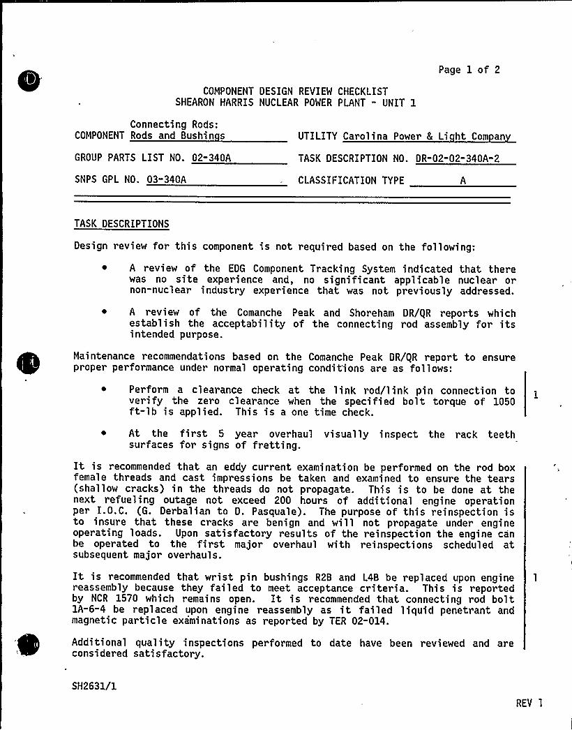
Connecting Rods:COMPONENT Rods and Bushin s UTILITY Carolina Power & Li ht Com an
GROUP PARTS LIST NO. 02-340A TASK DESCRIPTION NO. DR-02-02-340A-2
SNPS GPL NO. 03-340A CLASSIFICATION TYPE
TASK DESCRIPTIONS
Design review for this component is not required based on the following;
~ A review of the EDG Component Tracking System indicated that therewas no site experience and, no significant applicable nuclear ornon-nuclear industry experience that was not previously addressed.
A review of the Comanche Peak and Shoreham DR/gR reports whichestablish the acceptability of the connecting rod assembly for itsintended purpose.
Maintenance recommendations based on the Comanche Peak DR/gR report to ensureproper performance under normal operating condit'ions are as follows:
~ Perform a clearance check at the link rod/link pin connection toverify the zero clearance when the specified bolt torque of 1050ft-lb is applied. This is a one time check.
~ At the first 5 year overhaul visually inspect the rack teethsurfaces for signs of fretting.
It is recommended that an eddy current examination be performed on the rod boxfemale threads and cast impressions be taken and examined to ensure the tears(shallow cracks) in the threads do not propagate. This is to be done at thenext refueling outage not exceed 200 hours of additional engine operationper I.O.C. (G. Derbalian to D. Pasquale). The purpose of this reinspection isto insure that these cracks are benign and will not propagate under engineoperating loads. Upon satisfactory results of the reinspection the engine canbe operated to the first major overhaul with reinspections scheduled atsubsequent major overhauls.
It is recommended that wrist pin bushings R28 and L48 be replaced upon enginereassembly because they failed to meet acceptance criteria. This is reportedby NCR 1570 which remains open. It is recommended that connecting rod boltlA-6-4 be replaced upon engine reassembly as it failed liquid penetrant andmagnetic particle examinations as reported by TER 02-014.
Additional quality inspections performed to date have been reviewed and areconsidered sati s factory.
SH2631/1
REV 1
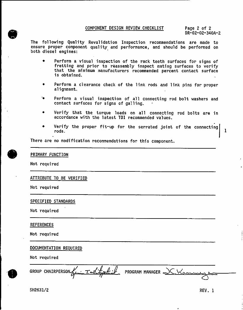
COMPONENT DESIGN REVIEW. CHECKLIST Page 2 of 2DR-02-02-340A"2
The fol lowing equality Reval idati on Inspection recommendations are made toensure proper component quality and performance, and should be performed onboth diesel engines:
Per form a visual inspection of the rack teeth surfaces for signs offretting and prior to reassembly inspect mating surfaces to verifythat the minimum manufacturers recommended percent contact surfaceis obtained.
~ Perform a clearance check of the link rods and link pins for properalignment.
Perform a visual inspection of all connecting rod bolt washers andcontact surfaces for signs of galling.
Verify that the torque loads on all connecting rod bolts are inaccordance with the latest TDI recommended values.
Verify the proper fit-up for the serrated joint of the connectingrods. I
There are no modification recommendations for this component.
PRIMARY FUNCTION
Not required
ATTRIBUTE TO BE VERIFIED
Not required
SPECIFIED STANDARDS
Not required
REFERENCES
Not required
DOCUMENTATION RE UIRED
Not required
GROUP CHAIRPERSO
SH2631/2
PROGRAM MANAGER QC 4(
REV. 1
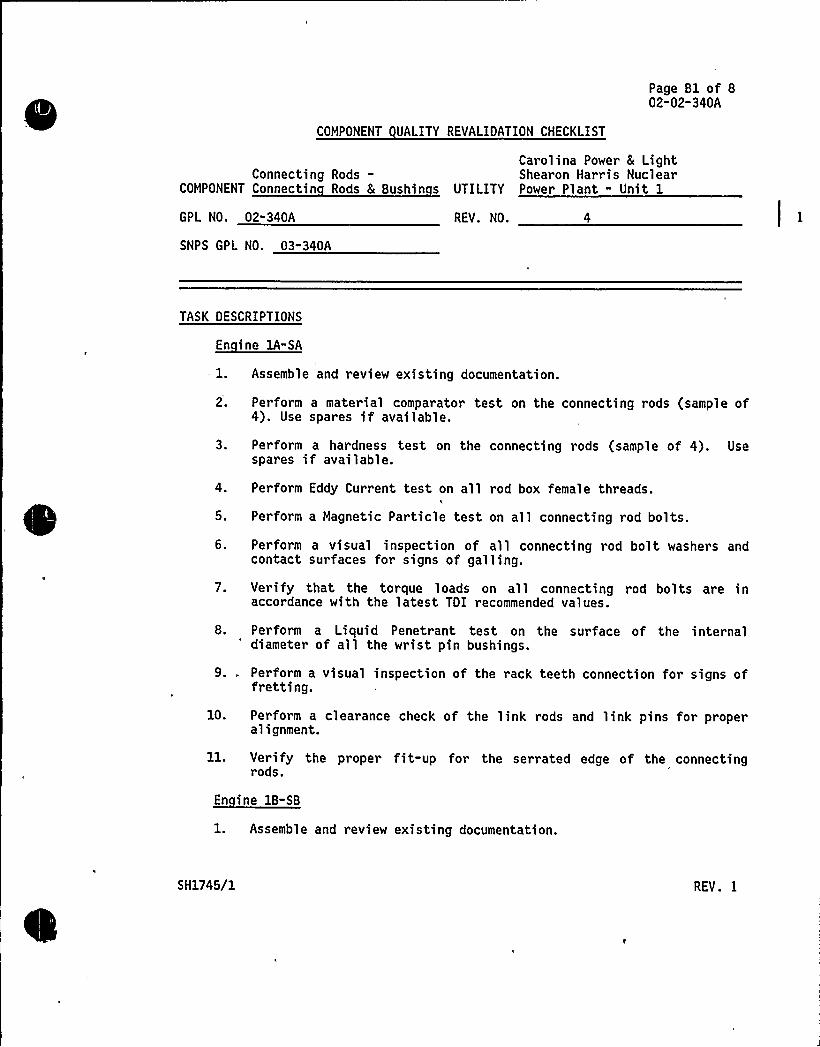
Page Bl of 802-02-340A
COMPONENT UALITY REVALIDATION CHECKLIST
Carolina Power 8 LightConnecting Rods- Shearon Harris Nuclear
COMPONENT Connectin Rods 8 Bushin s UTILITY Power Plant - Unit 1
GPL NO. 02-340A
SNPS GPL NO. 03-340A
REV. NO. 4
TASK DESCRIPTIONS
En ine 1A"SA
1. Assemble and review existing documentation.
2. Perform a material comparator test on the connecting rods (sample of4). Use spares if available.
3. Perform a hardness test on the connecting rods (sample of 4). Usespares if available.
4. Perform Eddy Current test on all rod box female threads.I
5. Perform a Magnetic Particle test on all connecting rod bolts.
6. Perform a visual inspection of all connecting rod bolt washers andcontact surfaces for signs of galling.
7. Verify that the torque loads on all connecting rod bolts are inaccordance with the latest TDI recommended values.
8. Perform a Liquid Penetrant test on the surface of the internal'iameter of all the wrist pin bushings.
9. . Perform a visual inspection of the rack teeth connection for signs offretting.
10. Perform a clearance check of the link rods and link pins for properalignment.
ll. Verify the proper fit-up for the serrated edge of the connectingrods.
En ine 18-SB
1. Assemble and review existing documentation.
SH1745/1 REV. I
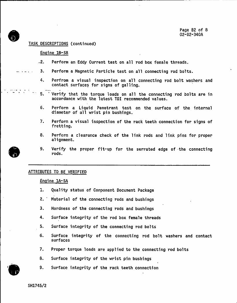
Page B2 of 802-02-340A
TASK DESCRIPTIONS (continued)
En ine 1B-SB
-2.
3.
4.
5.
Perform an Eddy Current test on all rod box female threads.
.Perform a Magnetic Particle test on all connecting rod bolts.
Perfrom a visual inspection on all connecting rod bolt washers andcontact surfaces for signs of galling.
Verify that the torque loads on all the connecting rod bolts are inaccordance with the latest TDI recommended values.
6.
7.
8.
Perform a Liquid Penetrant test on the surface of the internaldiameter of all wrist pin bushings.
Perform a visual inspection of the rack teeth connection for signs offretting.
Perform a clearance check of the link rods and link pins for properalignment.
9. Verify the proper fit-up for the serrated edge of the connectingrods.
ATTRIBUTES TO BE VERIFIED
En ine 1A-SA
1. equality status of Component Document Package
2. 'aterial of the connecting rods and bushings
3. Hardness of the connecting rods and bushings
4. Surface integrity of the rod box female threads
5. Surface integrity of the connecting rod bolts
6. Surface integrity of the connecting rod bolt washers and contactsurfaces
7. Proper torque loads are applied to the connecting rod bolts
8. Surface integrity of the wrist pin bushings
9. Surface integrity of the rack teeth connection
SH1745/2
Page B3 of 802-02-340A
ATTRIBUTES TO BE VERIFIED (continued)~( '
10. Proper clearance of the link rods and link pins
ll. Proper fit-up for the serrated edge.
2.
3.
guality status of Component Document Package
Surface integrity of the rod box female threads
Surface integrity of the connecting rod bolts
4. Surface integrity of the connecting rod bolt washers and contactsurfaces
5.
6.
7.
8.
9.
Proper torque loads are applied to the connecting rod bolts
Surface integrity of the wrist pin bushings
Surface integrity of the rack teeth connection
Proper clearance of the link rods and link pins
Proper fit-up for the serrated edge.
ACCEPTANCE CRITERIA
En ine 1A-SA
2"3.
4"5.
Satisfactory Document Package
Material to be AISI-4140
Review of inspection report by the Design Group
6. No signs fo galling on the connecting rod bolt washers and contactsurfaces
7 ~ Torque loads on the connecting rod bolts are in accordance with theTDI Instruction Manual
8. Absence of linear indications on the internal diameter (bottom deadcenter a15 only) of the wrist pin bushings (see Attachment A)
9. No signs of fretting on the rack teeth connection
SH1745/3
Page 84 of 802-02-340A
ACCEPTANCE CRITERIA (continued)
10. Proper clearance of the link rods and link pins
11. 75K minimum rack teeth surface contact
1. Satisfactory Document Package
2-3. Material to be AISI-4140
4. No signs of galling on the connecting rod bolts washers and contactsurfaces
5. Torque loads on the connecting rod bolts are in accordance with theTDI Instruction Manual.
6. Absence of linear indications on internal diameter (bottom deadcenter a15'nly) of the wrist pin bushings (see Attachment A).
7. No signs of fretting on the rack teeth connection
8. Clearance dimension must be zero when the specified torque of 1050ft. - lb. is applied.
9. 75K minimum rack teeth surface contact
REFERENCES
1. gCI No. 52
2-6. Approved Site NDE Procedures
7. TDI Instruction Manual
8-9. Approved Site NOE Procedures
10. TDI Instruction Manual
ll. Approval Site NDE Procedures, TER¹ 99-034
SH1745/4 REV 1

REFERENCES
En ine 1B-SB
1. gCI No. 52
2-4. Approved Site NDE Procedures
5. TDI Instruction Manual
6-7. Approved Site NDE Procedures
8. TDI Instruction Manual
9. Approved Site NDE Procedures, TER¹ 99-034
DOCUMENTATION RE UIRED
Page B5 of 802-02-340A
1. Document Summary Sheet
2-11. Inspection Report
1. Document Summary Sheet
2-9. Inspection port
GROUP CHAIRPERSONrf:
PROGRAM MANAGE
COMPONENT REVIEW
En ine lA-SA
1. No EDGCTS site experience documents are in evidence.
2. A material comparator test was performed on connecting rods 3,5,7 and8. The results were reported by TER¹ 02-014.
3. A hardness test was performed on connecting rods 3, 5, 7 and 8. Theresults were reported by TER¹ 02-014.
4. An Eddy Current test was performed on all left bank connecting rodbox female threads. The results were reported by TER¹ 02-014.
SH1745/5
COMPONENT REVIEW (continued)
Page B6 of 802-02-340A
5.
6"7.
A Magnetic Particle test was performed on all upper connecting rodbolts. The results were reported by TER¹ 02-014.
No inspection reports have been received which fulfill theserequirements.
8.
9-11.
Note:
A Liquid Penetrant test was performed on all wrist pin bushings forconnecting rods 5, 6, 7, and 8. Some indications were noted outsidethe critical area. The results were reported by TER¹ 02-014.
No inspection repor ts have been recei ved which fulfi 1 1 theserequirements.
a) A dimensional check of the master and link rods wasperformed to determine the amount of centerline bow. Resultswere reported by TER¹ 02-031.
En ine 1B-SA
An Eddy Current test was performed on all left bank connecting rodbox female threads. In addition, an Eddy Current test was performedon the connecting rod oil holes for cylinders 3 and 7. Results werereported by TER¹ 02-059.
1. All EDGCTS site experience documents were assembled and reviewed with~
~
~
~
~
~
~
~unsatisfactory results. NCR No. 84-1570 remains open.
2.
3. A Magnetic Particle test was performed on all connecting rod bolts.Indications were noted on cylinder 7. Results were reported by TER¹02"059.
4-5. No inspection reports have been received which fulfill theserequirements.
6.
7"9.
Note:
A Liquid Penetrant test was performed on the rod eye bushings.Results were reported by TER¹ 02-059.
No inspection report has been received which fulfills thisrequirement.
a) A dimensional check of the master and link rods wasperformed to determine the amount of centerline bow.Results were reported by TER¹ 02-038.
SH1745/6
COMPONENT REVIEW (continued)
Page B7 of 802"02"340A
b) A hardness test was performed on four connecting rods.Results were reported by TERS,02-059.
c) Material Comparator tests were ~ performed on fourconnecting rods. This was reported by TERS 02-059.
RESULTS AND CONCLUSION
- A
The guality Revalidation effort with respect to this component, as out-lined above, is complete. The results have been forwarded to the OesignReview Group for their evaluation and conclusions in support of the finalreport.
En ine 1B-SB
Same as Engine 1A-SA.
GROUP CHAIRPERSON 0 Ac f~'.(Qkc Pc. PROGRAM MANAGER~A
SH1745/7

0
ATTACHMENT A COMPONENT UALITY REVALIDATION CHECKLIST Page BS of 802-02-340A
LI UIO PENETRANT ACCEPTANCE CRITERIA
Acceptance criteria are gener ally included in the code or specificationwhich establishes the required examination. Such specified criteriashall be used to determine the specific type, size and location ofobserved discontinuities.
When acceptance criteria is not specified in the documentation estab-lishing the requirement for the examination, the following relevantindications are unacceptable. Only indications with major dimensionsgreater that 1/16 inch shall be considered relevant.
a.) Wrou ht For ed or Welded Items:
l. Any crack or linear indication
Rounded indications with dimensions greater than 1/8 inch forthickness less than 5/8 inch and greater than 3/16 inch forthickness of 5/8 inch and greater.
e
Four or more indications in line separated by 1/16 inch orless edge to edge.
4. Ten or more indications in any 6 square inches of area whosemajor dimension is no more than 6 inches with the dimensionstaken in the most unfavorable location relative to theindications being evaluated.
b.) Bolts and Boltin Material Greater than 1 inch Normal Size
1. Any linear nonaxial indications.
2. Linear axial indications greater than 1 inch.
SH1745/8 REV. I
COMPONENT DESIGN REVIEW CHECKLISTSHEARON HARRIS NUCLEAR POWER PLANT " UNIT 1
Page 1 of 2
COMPONENT Connectin Rod Bearin Shells UTILITY Carolina Power 8 Li ht Co.
GROUP PARTS LIST NO. 02-340B TASK DESCRIPTION NO. DR"02-02" 340B-0
SNPS GPL NO. 03-340B CLASSIFICATION TYPE A
TASK DESCRIPTIONS
Design review for this component is not required based on the following:
A review of the Comanche Peak and Shoreham DR/gR reports whichestablishes the acceptability of the bearing shells for theirintended purpose.
The applicable engine dimensions and operating parameters at ShearonHarris are identical or very similar to those for the same componentat Comanche Peak (lead engine).
A review of the Component Tracking System nuclear and non-nuclearexperience, and site experience listed below which does not appearin the CTS.
Maintenance recommendations based on the Comanche Peak DR/gR report to ensureproper performance under normal operating conditions are as follows:
~ Inspect and measure the connecting rod bearing shells to verify lubeoil maintenance which affects wear rate. The visual and
dimensional'nspectionof the bearing shells should be conducted at the fueloutage which precedes 500 hours of operation by at least the sum ofhours of oper ation in a LOOP/LOCA event plus the expected hours ofoperation between outages.
~ Perform an X-ray examination on all bearing shells using a procedurewith sufficient resolution to implement recommendations foracceptance criteria as documented in the TDI Owners Group connectingrod bearing shells Phase I Report.
No modifications are recommended for this component.
The guality Revalidation requirements for this component have been completed.
Engine 1A has two outstanding NCR nos. 84-1271 and 84-1639. Engine 1B has twooutstanding NCR nos. 84-1271 and 84-1640. It is recommended that all threeoutstanding NCRs be closed during reassembly of the engines.
SH2293/1


PRIMARY FUNCTION
Not required
COMPONENT DESIGN REVIEW CHECKLIST Page 2 of 2DR-02" 02-340B-0
ATTRIBUTE TO BE VERIFIED
Not required
SPECIFIED STANDARDS
Not required
REFERENCES
Not required
DOCUMENTATION RE VIREO
Not required
GROUP CHAIRPERSON PROGRAM MANAGERDC
SH2293/2
COMPONENT UALITY REVALIDATION CHECKLIST
Page 1 of 702-02-340B
Connecting Rod BearingCOMPONENT Shells
GPL NO. 02"340B
SNPS GPL NO. 03"340B
Carolina Power 8 LightShearon Harris Nuclear
UTILITY Power Pl ant - Uni t 1
REV. NO. 2
TASK DESCRIPTIONS
En ine 1A-SA
l. Assemble and review existing documentation.
2. Perform a visual inspection of'he connecting rod bearing shells.
3. Perform a Liquid Penetrant test on the connecting rod bearing shells.
4. Perform a dimensional check of the connecting rod bearing shells.
5. Peform a Radiographic inspection of the connecting rod bearingshells.
6. Perform an Eddy Current test as required to identifydiscontinuities.
surface
Same as Engine 1A-SA
ATTRIBUTES TO BE VERIFIED
En ine 1A-SA
2 3 ~
5"6.
guality status of Component Document Package
Surface integrity of bearing shells
Proper bearing shell dimensions
Integrity of the bearing shells
SH1904/1
COMPONENT UALITY REVALIDATION CHECKLIST
ATTRIBUTES TO BE VERIFIED (continued)
En ine 1B-SB
Same as Engine 1A-SA
Page 2 of 702"02"340B
ACCEPTANCE CRITERIA
2"3.
5.
6.
Satisfactory Document Package
Review of inspection report by the Design Group
Dimensions are in accordance with the TDI Instruction Manual
See Attachments A & B.
Review of inspection report by the Design Group
En ine 1B-SB
Same as Engine lA-SA
REFERENCES
En ine 1A-SA
1. (CI No. 52
2-3. Approved Site NDE Procedure
4. TDI Instruction Manual or applicable drawing
5. FaAA NDE Procedure 9.3, TERS 99-011
6. Approved site NDE Procedures
Same as Engine 1A-SA
SH1904/2
COMPONENT UALITY REVALIDATION CHECKLIST
DOCUMENTATION RE UIRED
Page 3 of 702-02-340B
En ine lA-SA
1. Document Summary Sheet
2-6. Inspection Report
En ine 1B-SB
Same as Engine lA-SA
GROUP CHAIRPERSON PROGRAM MANAGER ~'-
COMPONENT REVIEW
En ine lA-SA
l. All EDGCTS site experience documents were assembled and reviewedwith unsatisfactory results. NCR Nos. 84-1271 and 84-1639 remainopen.
2. A visual inspection was performed on various connecting rod bearingshells. The results were reported by TER¹ 02-032.
3. A Liquid Penetrant test was performed on all connecting rod bearingshells with satisfactory results. This was reported by TER¹02-094.
4. A dimensional check of all connecting rod bearing shells wasperformed with the exception of the top shell of bearing no. 7 whichwas rejected because of cracking. The results were reported byTER¹ 02-032.
5. A Radiographic test was performed on the connecting rod bearingshells with indications reported on the No. 7 lower shell. Thiswas reported by TER¹ 02-094.
6. An Eddy Current test was performed on various bearing shells withsatisfactory results. This was reported by TER¹ 02-094.
En ine 1B-SB
l. All EDGCTS site experience documents were assembled and reviewedwith unsatisfactory results. NCR Nos. 84-1271 and 84-1640 remainopen.
2. A visual inspection was performed on various connecting rod bearingshells. The results were reported by TER¹ 02-039.
SH1904/3

COMPONENT UALITY REVALIDATION CHECKLIST
COMPONENT REVIEW (continued)
Page 4 of 702"02-3408
3. A Liquid Penetrant test was performed on the bearing shells withsatisfactory results. This was reported by TER¹s 02-087 and 02-094.
4. A dimensional check was performed on bearing shells Nos. 1, 4, 6, and8, top bearing No. 2 and the bottom shells of bearing Nos. 3 and 7.'he remaining bearing shells were rejected due to either cracking orforeign material indications. The results were reported on TER¹02-039.
5. A Radiographic inspection was performed on the bearing shells withunsatisfactory results. This was reported by TER¹ 02-087.
6. An Eddy Current test was performed on most bearing shells withsatisfactory results. This was reported by TER¹s 02-087 and 094.
RESULTS AND CONCLUSION
En ine lA-SA
The guality Revalidation effort with respect to this component, asoutlined above, is complete. The results have been forwarded to theDesign Review Group for their evaluation and conclusions in support ofthe final report.
Same as Engine lA-SA
GROUP CHAIRPERSON c. PROGRAM MANAGER
SH1904/4

Attachment A COMPONENT UALITY REVALIDATION CHECKLIST Page 5 of 702-02-340B
Component:
Examination:
Examination:Area
Acceptance:~ ~Criteria
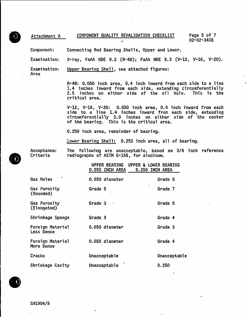
Connecting Rod Bearing Shells, Upper and Lower.
X-ray, FaAA NDE 9.2 (R-48); FaAA NDE 9.3 (V-12, V-16, V-20).
U er Bearin Shell, see attached figures:
R-48: 0.050 inch area, 0.4 inch inward from each side to a line1.4 inches inward from each side, extending circumferentially2.5 inches on either side of the oil hole. This is thecritical area.
V-12, V-16, V-20: 0.050 inch area, 0.4 inch inward from eachside to a line 1.4 inches inward from each side, extendingcircumferentially 5.0 inches on either side of the centerof the bearing. This is the critical area.
0.250 inch area, remainder of bearing.
.Lower Bearin Shell: 0.250 inch area, all of bearing.
The following are unacceptable, based on 3/4 inch referenceradiographs of ASTM E-155, for aluminum.
UPPER BEARING UPPER 8( LOWER BEARING0. 050 INCH AREA 0. 250 INCH AREA
Gas Holes
Gas Porosity(Rounded)
Gas Porosity(Elongated)
Shrinkage Sponge
Foreign MaterialLess Dense
Foreign MaterialMore Dense
Cracks
Shrinkage Cavity
0.050 diameter
Grade 5
Grade 3
Grade 3
0.050 diameter
0.050 diameter
Unacceptable
Unacceptable
Grade 5
Grade 7
Grade 5
Grade 4
Grade 3
Grade 4
Unacceptable
0.250
SH1904/5
Attachment A COMPONENT UALITY REVALIDATION CHECKLIST Page 6 of 702-02-340B
Note: Mottling/segregation and micro sht inkage shall not be evaluated forrejection.
4 Radiographic features that are associated with the babbitt (leadalloy) layer on the bearing I.D. shall not be evaluated forrejection.
For further clarification of these criteria, please contact the Owner s Group.
SH1904/6
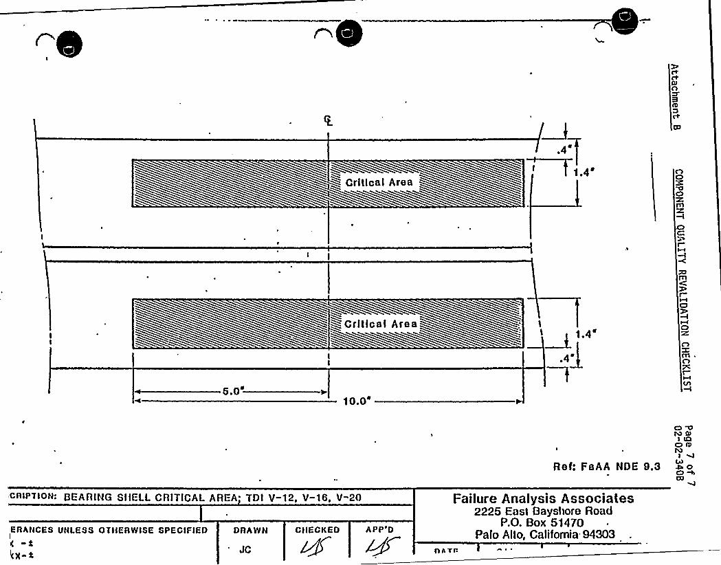
~ Grltlcal Area
4N
t.4'.0'~~
~Critical Area
0 0.0'
1.4'lfTl
D'wC7
wCl
nn
-I
lEAANCES UNLESS OTIIEANISE SPECIFIED
x-iDRANN CIIECKED
DEARlNG SIIELL CRlTICAL AREA TDl Y-12, Y-t6, Y-20
Ref: FaAA NDE 9.3
Fat|ore Analysts Assoctates2225 East t3ayslIore Road
P.o. Box 5)470Palo Alto, California 94303
navr-
O Q~ COI LQ
O IbJW OC) MU7
Page 1 of 2
COMPONENT DESIGN REVIEW CHECKLISTSHEARON HARRIS NUCLEAR POWER PLANT - UNIT 1
COMPONENT Pistons
GROUP PARTS LIST NO. 02-341A
SNPS GPL NO ~ 03-341A
UTILITY Carolina Power 8 Li ht Com an
TASK DESCRIPTION NO. DR-02-02-341A" 2
CLASSIFICATION TYPE A
TASK DESCRIPTIONS
Design review for this component is not required based on a review of theShoreham and Comanche Peak DR/gR reports, the Phase I report and the reportedindustry experience. There is no site experience in the EDG Component TrackingSystem.
CP&L is in the process of changing from AN to AE pistons at Shearon Harris..The AE piston incorporates design changes and has not been observed to crackin service. The stud boss region of the AE is considerably thicker than theAN. The rib has also been thickened and blended more smoothly into the wristpin bosses, thereby considerably strengthening the rib area in this design.
There are no maintenance or modification recommendations for this component.
guality inspections have been completed and the results were found to besatisfactory.
PRIMARY FUNCTION
Not required
ATTRIBUTE TO BE VERIFIED
Not required
SPECIFIED STANDARDS
Not required
SH2134/1
REFERENCES
Not required
COMPONENT DESIGN REVIEW CHECKLIST Page 2 of 2DR-02-02-341A- 2
DOCUMENTATION RE VIREO
Not required
GROUP CHAIRPERSON PROGRAM MANAGER C.KK
SH2134/2

COMPONENT UALITY REVALIDATION CHECKLIST
Page 1 of 502-02-341A
COMPONENT Piston
GPL NO. 02-341A
SNPS GPL NO. 03-341A
Carolina Power 8 Light,Shearon Harris Nuclear
UTILITY Power Plant - Unit 1
REV. NO. 3
TASK DESCRIPTIONS
En ine lA-SA
1. Assemble and review existing documentation,
2. Prior to installation, perform a Liquid Penetant test on the pistonskirts. Map all linear indications in the stud boss area anddocument with photographs. In addition, "AN" pistons should beinspected adjacent to the wrist pin boss.
3. If Liquid Penetrant test results from task ¹2 reveal indicationsgreater than 1/32 inch length, one of the following tasks should beperformed:
a) Remove the indications by surface conditioning; or
b) Perform an Eddy Current test to determine if the indicationsmust be removed.
4. Perform Liquid Penetrant test on the rib areaon the rib at the intersection of the wristindications in the casting ("AE" pistonssketch.
near the wrist pin andpin boss to check foronly). See attached
Same as Engine 1A-SA
NOTE:'f no rejectable indications are found,performed on one station engine only.
inspections should be
SH1040/1

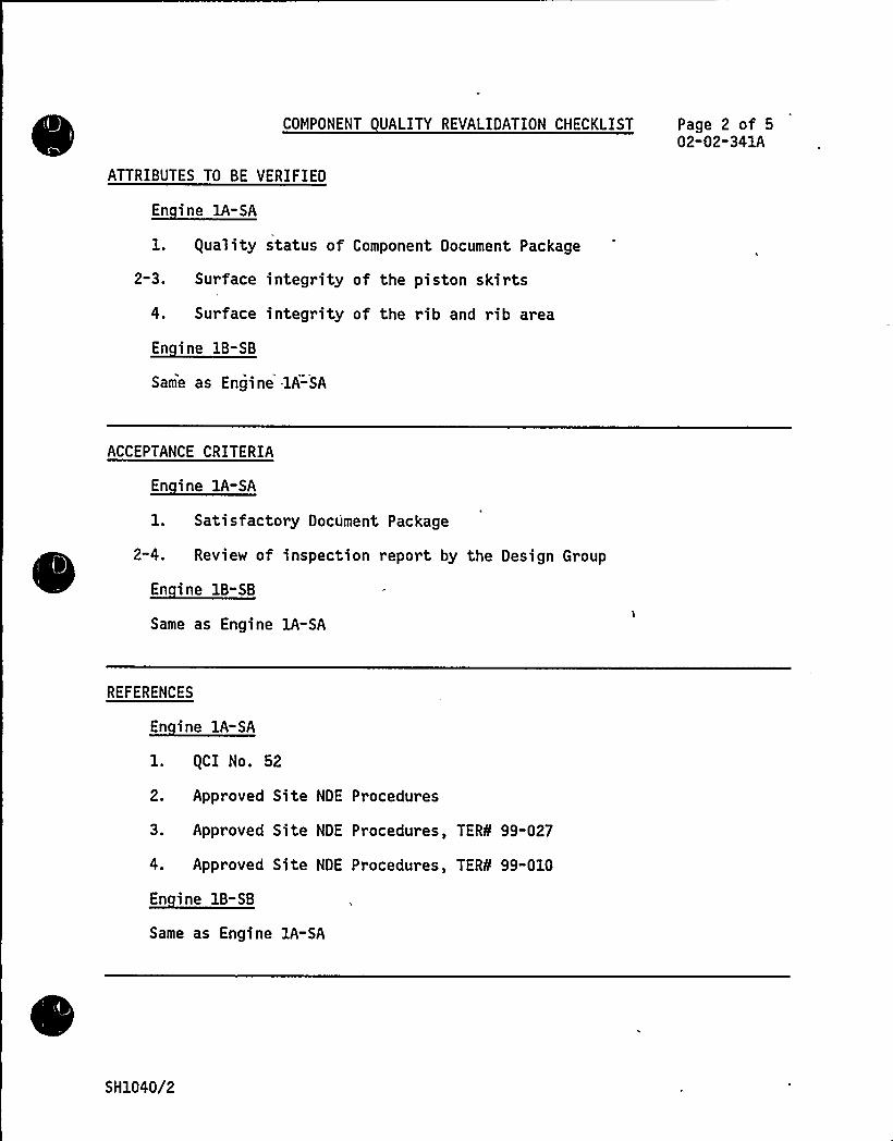
COMPONENT UALITY REVALIDATION CHECKLIST Page 2 of 502"02-341A
ATTRIBUTES TO BE VERIFIED
En ine lA-SA
l. guality status of Component Document Package
2-3. Surface integrity of the piston skirts
4. Surface integrity of the rib and rib area
En ine 18-SB
Same as Engine -lA-SA
ACCEPTANCE CRITERIA
En ine 1A-SA
1. Satisfactory Document Package
2-4. Review of inspection report by the Design Group
Same as Engine lA"SA
REFERENCES
En ine lA-SA
l. gCI No. 52
2. Approved Site NDE Procedures
3. Approved Site NDE Procedures, TER¹ 99-027
4. Approved Site NDE Procedures, TER¹ 99-010
Same as Engine 1A-SA
SH1040/2
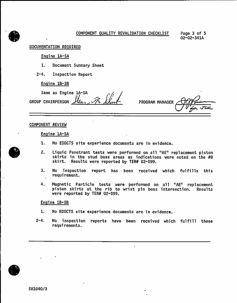
COMPONENT UALITY REVALIDATION CHECKLIST Page 3 of 502-02-341A
DOCUMENTATION RE UIRED
En ine 1A-SA
1. Document Summary Sheet
2-4. Inspection Report
En ine 1B-SB
Same as Engine 1A-SA
GROUP CHAIRPERSON PROGRAM MANAGER
COMPONENT REVIEW
En ine lA-SA
No EDGCTS site experience documents are in evidence.
2.
3.
Liquid Penetrant tests were performed on all "AE" replacement pistonskirts in the stud boss areas as indications were noted on the ¹8skirt. Results were reported by TER¹ 02-099.
No inspection report has been received which fulfills thisrequirement.
Magnetic Particle tests were performed on all "AE" replacementpiston skirts at the rib to wrist pin boss intersection. Resultswere reported by TER¹ 02-099.
En ine 1B-SB
2-4.
No EDGCTS site experience documents are in evidence.
No inspection reports have been received which fulfill theserequirements.
SH1040/3

COMPONENT UALITY REVALIDATION CHECKLIST Page 4 of 502"02-341A
RESULTS AND CONCLUSION
The gual ity Reval idati on effort with respect to thi s component, asoutlined above, is complete. The results have been forwarded to theDesign Review Group for their evaluation and conclusions in support ofthe final report.
Same as Engine 1A-SA
PROGRAM MANAGER
SH1040/4
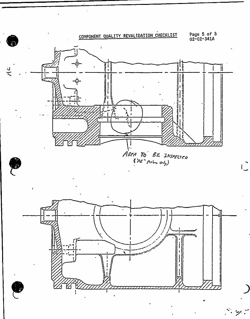
COMPONENT UALITY REVALIOATION CHECKLIST Page 5 of 502-02-341A
COMPONENT DESIGN REVIEW CHECKLISTSHEARON HARRIS NUCLEAR POWER PLANT - UNIT 1
Page 1 of 2
COMPONENT Piston: Rin s
GROUP PARTS LIST NO. 02-341B
UTILITY Carolina Power & Li ht Com an
TASK DESCRIPTION NO. DR"02"02"341B-0
SNPS GPL NO. 03"341B CLASSIFICATION TYPE A
TASK DESCRIPTIONS
Design review for this component is not required based on the following:
~ A review of the Comanche Peak and Shoreham DR/gR reports whichestablishes the acceptability of the piston rings for their intendedpurpose.
~ The applicable engine dimensions and operating parameters at ShearonHarris are identical or very similar to those for the same componentat Comanche Peak (lead engine).
~ A review of the Component Tracking System indicated that there wasno significant applicable industry or site experience.
Maintenance recommendations based on the Comanche Peak DR/gR report to ensureproper performance under normal operating conditions are as follows:
Inspect and measure replacement piston rings in accordance with TDIinspection and maintenance records.
To assure freedom from harmful scuffing, the cylinder liners shouldbe inspected at each fuel outage to evaluate liner wear and cokedeposits. Ring replacements and cylinder liner honing should beperformed in accordance with TDI maintenance procedures.
When replacing engine oil use H.D. oil that exceeds series 3standards. The base stock should be more resistant to thermaldegradation and coke formation. The additive package should providehigh detergent dispersant properties with high alkalinity and a highlevel of antiwear additive such as zinc dithiophosphate. Total BaseNumber (TBN) should be 12 to 15 for use with 02 fuel oil and asulfated ash content of 1.5X to 2.0X is preferred. An engine oilwith such properties, Mobil-Guard 412 or equivalent product may beused to ensure improved lubrication.
135 fuel oil spr ay tips may be used if inspections results indicatea need for additional action to improve lubrication and reduce cokebuildup.
SH2107/1
COMPONENT DESIGN REVIEW CHECKLIST Page 2 of 2DR-02-02" 3418-0
The following guality Revalidation inspection is recommended to ensurecomponent quality:
~ Verify piston ring installation is in compliance with TDI assemblyrequirements for all station engines.
There are no modification recommendations for this component.
PRIMARY FUNCTION
Not required
ATTRIBUTE TO BE VERIFIED
Not required
S PECIFIED STANDARDS
Not required
REFERENCES
Not required
DOCUMENTATION RE UIRED
Not required
GROUP CHAIRPERSON PROGRAM MANAGER e K(~
SH2107/2
COMPONENT DESIGN REVIEW CHECKLISTSHEARON HARRIS NUCLEAR POWER PLANT - UNIT 1
Page 1 of 3
COMPONENT Piston Pin Assembl UTILITY Carolina Power 8 Li ht Com an
GPL NO. 02-341C TASK DESCRIPTION NO. DR"02-02-341C-0
SNPS GPL NO. 03" 341C CLASSIFICATION TYPE A
TASK DESCRIPTIONS
Design review for this component is not required based on review of the leadengine DR/gR reports (Shoreham/Comanche Peak) and the reported applicableindustry experience. There is no reported site experience in the EDG ComponentTracking System.
Presently Shearon Harris uses spiral ring retainers (P/N F-108-030) to preventlateral movement of the wrist pin. For increased engine reliability as statedin the Shoreham DR/gR report it is recommended that:
~ The present spiral ring retainers be replaced with Waldes snap ringretainers (P/N GE-003-067) at the first fuel outage.
guality inspections conducted to date have been reviewed. Three wrist pins, R-2and R-5 from engine 1A-SA, and R-2 from engine 1B-SB displayed either linearindications, chrome blistering or chrome chipping. These three pins have allbeen rejected (Refs. 1, 2 and 3) and wrist pin R-2 from engine 1B-SB was sentback to TDI to be re-chromed. Hardness tests were performed on two separateoccasions, the second time extra caution was taken to ensure the tested surfacewas thoroughly clean. Results indicated that two wrist pins had values slight-ly higher than specification. This is not of concern since a certain loss ofaccuracy can be expected when performing one type of hardness test and convert-ing the values to another measuring system. Also, the wrist pins are inductionhardened and since the test was performed on the ends of the pins, the resultsmay not be representative of the load bearing surface. Material comparatortests were performed on all thir ty-two wrist pins. All of the wrist pins weresatisfactory, with the exception of wrist pin L-4 from engine lA-SA, whichvaried from the known sample by 70 units.
Based on the results of the quality inspections, the following recommendationsare made:
~ Either return wrist pins R-2 and R-5 from engine lA-SA to TDI forreworking, or replace with acceptable wrist pins.
SH2405/1
COMPONENT DESIGN REVIEW CHECKLIST Page 2 of 3DR-02-02-341C" 0
TASK DESCRIPTIONS (continued)
Re-test by material comparator method wrist pin L-4 from engine1A-SA, making sure the surface being tested is clean and dry, and theprobe tip is clean. Make certain the test is performed on the samelocation of the pin that the other tests were taken. If the resultof the material comparator test are satisfactory, the wrist pin isacceptable for use. If the results of the re-test are unsatisfactorythe wrist pin should be replaced with an acceptable one.
The .following maintenance inspections are recommended for this component:'I
~ Visually inspect all pins for chrome plate damage.
~ Inspect end plugs and reroll or replace any that are loose.
NOTE: The above inspections should be performed during majorengine overhauls and also whenever the pistons are removedand disassembled to an extent that such inspections arepossible.
Perform a liquid penetrant test or a magnetic particle test on allnew or replacement pins before installation in engines.
The following guality inspection is recommended for engines lA-SA and 18-SB:
~ Visually inspect the rolled-in oil plugs for proper installation.
PRIMARY FUNCTION
Not required
ATTRIBUTE TO BE VERIFIED
Not required
SPECIFIED STANDARDS
Not required
SH2405/2

REFERENCES
. COMPONENT DESIGN REVIEW CHECKLIST Page 3 of 3DR-02-02-341C-0
1. NCR 84-1672 8( TER 02-033
2. NCR 84-1776 8( TER 02-033
3. NCR 84-1570 8 TERs 02-040 8 02-084
DOCUMENTATION RE VIREO
Not reqvired
GROUP CHAIRPERSON PROGRAM MANAGER QC
SH2405/3

0
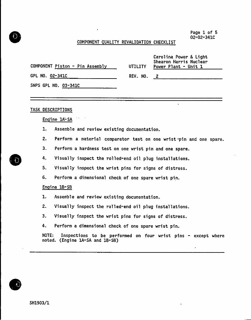
COMPONENT UALITY REVALIDATION CHECKLIST
Page 1 of 502"02"341C
COMPONENT Piston - Pin Assembl
GPL NO. 02"341C
Carolina Power 8 LightShearon Harris Nuclear
UTILITY Power Plant - Unit 1
REV. NO. 2
SNPS GPL NO. 03-341C
TASK DESCRIPTIONS
1. Assemble and review existing documentation.
2. Perform a material comparator test on one wrist .pin and one spare.
3. Perform a hardness test on one wrist pin and one spare.
4. Visually inspect the rolled-end oil plug installations.
5. Visually inspect the wrist pins for signs of distress.
6. Perform a dimensional check of one spare wrist pin.
1. Assemble and review existing documentation.
2. Visually inspect the rolled-end oil plug installations.
3. Visually inspect the wrist pins for signs of distress.
4. Perform a dimensional check of one spare wrist pin.
NOTE: Inspections to be performed on four wrist pins - except wherenoted. (Engine lA-SA and 1B-SB)
SH1903/1
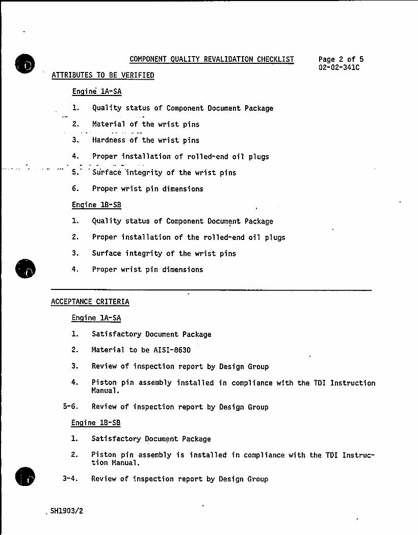
COMPONENT UALITY REVALIDATION CHECKLIST
ATTRIBUTES TO BE VERIFIED
En ine 1A-SA
1. guality status of Component Document Package
2. Material of the wrist pins
3. Hardness of the wrist pins
4. Proper installation of rolled-end oil plugs
5. Su'rface 'integrity of the wrist pins
6. Proper wrist pin dimensions
Page 2 of 502-02-341C
1. guality status of Component Document Package
2. Proper installation of the rolled-end oil plugs
3. Surface integrity of the wrist pins
4. Proper wrist pin dimensions
ACCEPTANCE CRITERIA
1. Satisfactory Document Package
2. Material to be AISI-8630
3. Review of inspection report by Design Group
4. Piston pin assembly installed in compliance with the TDI InstructionManual.
5-6. Review of inspection report by Design Group
En ine 1B-SB
Satisfactory Document Package
2.
3-4.
Piston pin assembly is installed in compliance with the TDI Instruc-tion Manual.
Review of inspection report by Design Group
,, SH1903/2

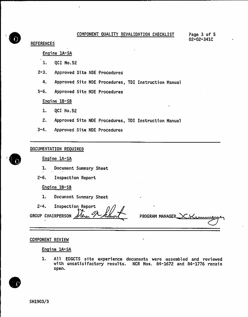
REFERENCES
En ine lA-SA
COMPONENT UALITY REVALIDATION CHECKLIST Page 3 of 502-02-341C
l. gCI No.52
2 3 ~
5-6.
Approved Site NDE Procedures
Approved Site NDE Procedures, TDI Instruction Manual
Approved Site NDE Procedures
En ine 1B-SB
gCI No.52
2. Approved Site NDE Procedures, TDI Instruction Manual
3-4. Approved Site NDE Procedures
DOCUMENTATION RE UIRED
1. Document Summary Sheet
2-6. Inspection Report
En ine 1B-SB
1. Document Summary Sheet
2-4. Inspection Report
GROUP CHAIRPERSON PROGRAM MANAGER
COMPONENT REVIEW
En ine lA-SA
1. All EDGCTS site experience documents were assembled and reviewedwith unsatisifactory results. NCR Nos. 84-1672 and 84-1776 remainopen.
SH1903/3

Fg
fl,
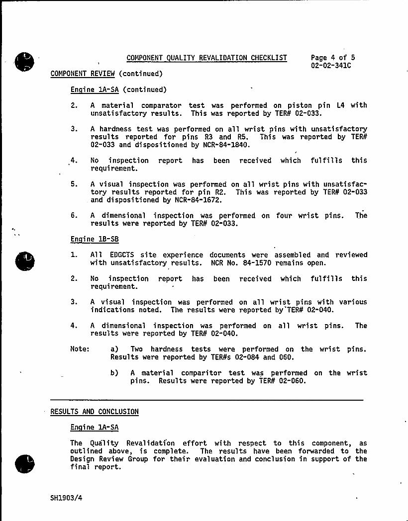
COMPONENT UALITY REVALIDATION CHECKLIST Page 4 of 502-02-341C
COMPONENT REVIEW (continued)
2. A mater ial comparator test was performed on piston pin L4 withunsatisfactory results. This was reported by TER¹ 02-033.
3. A hardness test was performed on all wrist pins with unsatisfactoryresults reported for pins R3 and RS. This was reported by TER¹02-033 and dispositioned by NCR-84-1840.
4. No inspection report has been received which fulfills thisrequirement.
5. A visual inspection was performed on all wrist pins with unsatisfac-tory results reported for pin R2. This was reported by TER¹ 02-033and dispositioned by NCR-84-1672.
6. A dimensional inspection was performed on four wrist pins. Theresults were reported by TER¹ 02-033.
En ine 1B-SB
1. All EDGCTS site experience documents were assembled and reviewedwith unsatisfactory results. NCR No. 84-1570 remains open.
2. No inspection report has been received which fulfills thisrequirement.
3. A visual inspection was performed on all wrist pins with variousindications noted. The results were reported by TER¹ 02-040.
4. A dimensional inspection was performed on all wrist pins. Theresults were reported by TER¹ 02-040.
Note: a) Two hardness tests were performed on the wrist pins.Results were reported by TER¹s 02-084 and 060.
b) A material comparitor test was performed on the wristpins. Results were reported by TER¹ 02-060.
RESULTS AND CONCLUSION
En ine 1A-SA
The guality Revalidation effort with respect to this component, asoutlined above, is complete. The results have been forwarded to theDesign Review Group for their evaluation and conclusion in support of thefinal report.
SH1903/4
COMPONENT UALITY REVALIOATION CHECKLIST
RESULTS AND CONCLUSION (continued)
Page 5 of 502-02"341C
Same as Engine 1A-SA
GROUP CHAIRPERSON PROGRAM MANAGER
SH1903/5
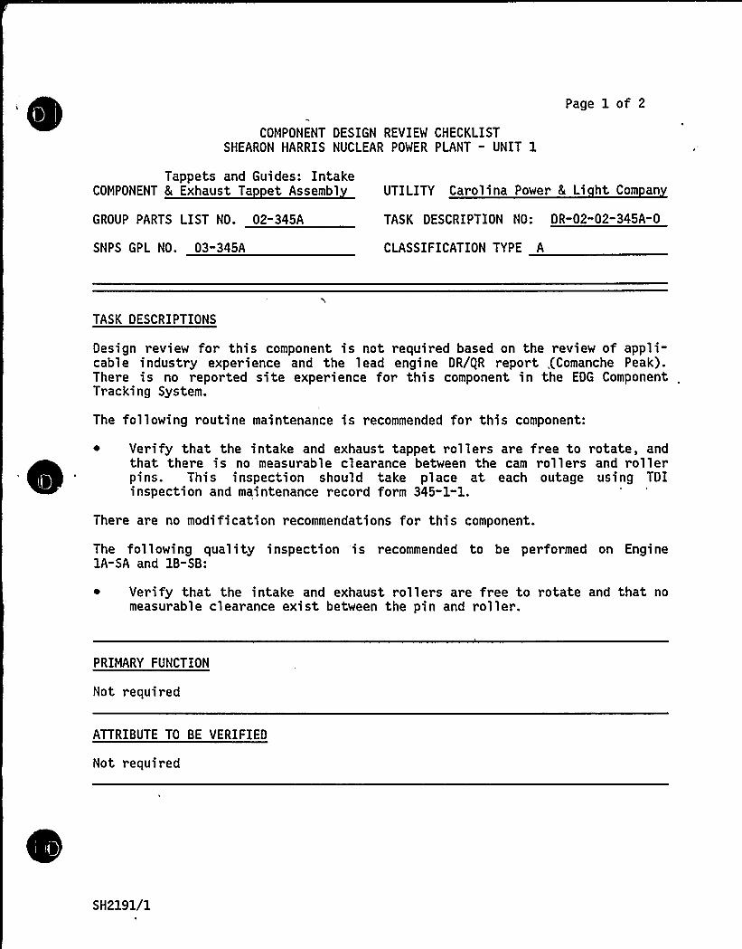
COMPONENT DESIGN REVIEW CHECKLISTSHEARON HARRIS NUCLEAR POWER PLANT - UNIT 1
Page 1 of 2
Tappets and Guides: IntakeCOMPONENT 8 Exhaust Ta et Assembl
GROUP PARTS LIST NO. 02"345A
SNPS GPL NO. 03-345A
UTILITY Carolina Power 8 Li ht Com an
TASK DESCRIPTION NO: DR-02"02-345A-0
CLASSIFICATION TYPE A
TASK DESCRIPTIONS
Design review for this component is not required based on the review of appli-cable industry experience and the lead engine DR/gR report ,(Comanche Peak).There is no reported site experience for this component in the EDG Component ,
Tracking System.
The following routine maintenance is recommended for this component:
~ Verify that the intake and exhaust tappet rollers are free to rotate, andthat there is no measurable clearance between the cam rollers and rollerpins. This inspection should take place at each outage using TDIinspection and maintenance record form 345-1-1.
There are no modification recommendations for this component.
The following quality inspection is recommended to be performed on Engine1A-SA and 1B-SB:
Verify that the intake and exhaust rollers are free to rotate and that nomeasurable clearance exist between the pin and roller.
PRIMARY FUNCTION
Not required
ATTRIBUTE TO BE VERIFIED
Not required
SH2191/1
SPECIFIED STANDARDS
Not requred
COMPONENT DESIGN REVIEM CHECKLIST Page 2 of 2DR-02-02-345A-0
REFERENCES
Not required
~ DOCUMENTATION RE UIRED
Not required
GROUP CHAIRPERSON PROGRAM MANAGER
SH2191/2
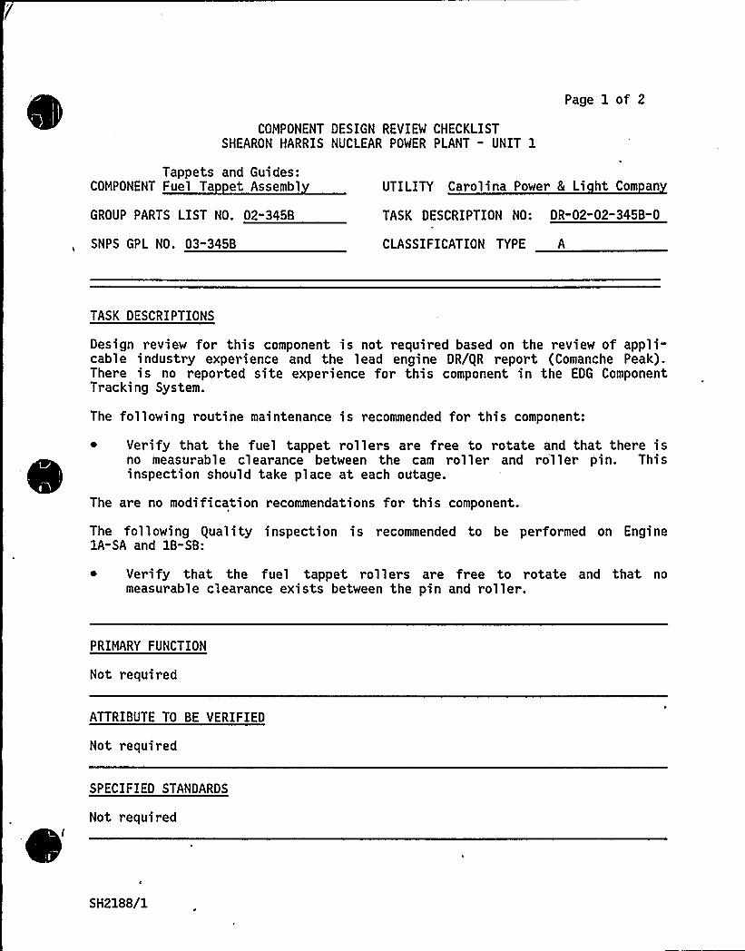
COMPONENT DESIGN REVIEW CHECKLISTSHEARON HARRIS NUCLEAR POWER PLANT - UNIT 1
Page 1 of 2
Tappets and Guides:COMPONENT Fuel Ta et Assembl
GROUP PARTS LIST NO. 02-345B
SNPS GPL NO. 03"345B
UTILITY Carolina Power & Li ht Com an
TASK DESCRIPTION NO: DR-02-02-345B-0
CLASSIFICATION TYPE A
TASK DESCRIPTIONS
Design review for this component is not required based on the review of appli-cable industry experience and the lead engine DR/gR report (Comanche Peak).There is no reported site experience for this component in the EDG ComponentTracking System.
The following routine maintenance is recommended for this component:
~ Verify that the fuel tappet rollers are free to rotate and that there isno measurable clearance between the cam roller and roller pin. Thisinspection should take place at each outage.
The are no modification recommendations for this component.
The following equality inspection is recommended to be performed on EnginelA-SA and 1B-SB:
~ Verify that the fuel tappet rollers are free to rotate and that nomeasurable clearance exists between the pin and roller.
PRIMARY FUNCTION
Not required
ATTRIBUTE TO BE VERIFIED
Not required
SPECIFIED STANDARDS
Not required
SH2188/1
'REFERENCES
Not required
COMPONENT DESIGN REVIEW CHECKLIST Page 2 of 2DR-02-02-3458-0
DOCUMENTATION RE UIRED
Not required
GROUP CHAIRPERSON PROGRAM MANAGER
i
SH2188/2

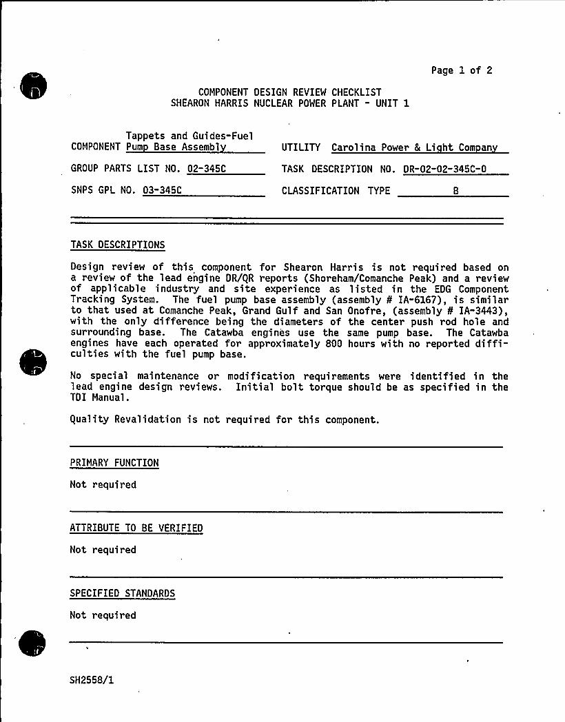
COMPONENT DESIGN REVIEW CHECKLISTSHEARON HARRIS NUCLEAR POWER PLANT - UNIT 1
Page 1 of 2
Tappets and Guides-FuelCOMPONENT Pum Base Assembl
GROUP PARTS LIST NO. 02-345C
SNPS GPL NO. 03-345C
UTILITY Carolina Power L Li ht Com an
TASK DESCRIPTION NO. DR-02-02-345C-0
CLASSIFICATION TYPE
TASK DESCRIPTIONS
Design review of this component for Shearon Harris is not required based ona review of the lead engine DR/QR reports (Shoreham/Comanche Peak) and a reviewof applicable industry and site experience as listed in the EDG ComponentTracking System. The fuel pump base assembly (assembly O'A-6167), is similarto that used at Comanche Peak, Grand Gulf and San Onofre, (assembly 8 IA-3443),with the only difference being the diameters of the center push rod hole andsurrounding base. The Catawba engines use the same pump base. The Catawbaengines have each operated for approximately 800 hours with no reported diffi-culties with the fuel pump base.
No special maintenance or modification requirements were identified in thelead engine design reviews. Initial bolt torque should be as specified in theTDI Manual.
Quality Revalidation is not required for this component.
PRIMARY FUNCTION
Not r equired
ATTRIBUTE TO BE VERIFIED
Not required
SPECIFIED STANDARDS
Not required
SH2558/1
REFERENCES
COMPONENT DESIGN REVIEW CHECKLIST Page 2 of 2- DR"02-02-345C" 0
1. TDI Drawing No. 02-345-05-AF, "Base, Fuel Pump" (listed in the ShearonHarris Parts list as the base for the fuel pump base assembly ¹IA-6167)
DOCUMENTATION RE UIRED
Not required
GROUP CHAIRPERSON PROGRAM MANAGER—3C ~
SH2558/2

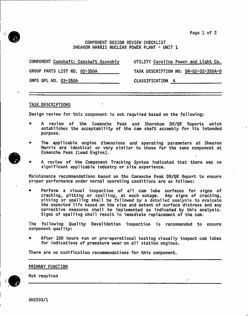
COMPONENT DESIGN REVIEW CHECKLISTSHEARON HARRIS NUCLEAR POWER PLANT " UNIT 1
Page 1 of 2
COMPONENT Camshaft: Camshaft Assembl UTILITY Carolina Power and Li ht Co.
GROUP PARTS LIST NO. 02-350A TASK DESCRIPTION NO: DR-02-02-350A-0
SNPS GPL NO. 03-350A CLASSIFICATION A
TASK DESCRIPTIONS
Design review for this component is not required based on the following:
~ A review of the Comanche Peak and Shoreham DR/gR Reports whichestablishes the acceptability of the cam shaft assembly for its intendedpurpose.
~ The applicable engine dimensions and operating parameters at ShearonHarris are identical or very similar to those for the same component atComanche Peak (Lead Engine).
~ A review of the Component Tracking System indicated that there was nosignificant applicable industry or site experience.
Maintenance recommendations based on the Comanche Peak DR/gR Report to ensureproper performance under normal operating conditions are as follows:
~ Perform a visual inspection of all cam lobe surfaces for signs ofcracking, pitting or spalling, at each outage. Any signs of cracking,pitting or spalling shall be followed by a detailed analysis to evaluatethe expected life based on the size and extent of surface distress and anycorrective measures shall be implemented as indicated by this analysis.Signs of spalling shall result in immediate replacement of the cam.
The following guality Revalidation inspection is recommended to ensurecomponent quality:
~ After 100 hour s run or pre-operational testing visually inspect cam lobesfor indications of premature wear on all station engines.
There are no modification recommendations for this component.
PRIMARY FUNCTION
Not requiredI
SH2093/1
COMPONENT DESIGN REVIEW CHECKLIST
ATTRIBUTE TO BE VERIFIED
Not required
Page 2 of 2DR-02-02-350A-0
SPECIFIED STANDARDS
Not required
REFERENCES
Not required
DOCUMENTATION RE UIRED
Not required
GROUP CHAIRPERSON PROGRAM MANAGER.—
SH2093/2

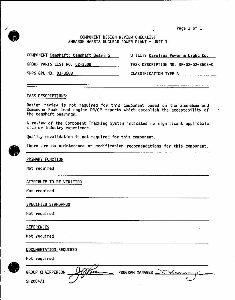
COMPONENT DESIGN REVIEW CHECKLISTSHEARON HARRIS NUCLEAR POWER PLANT - UNIT 1
Page 1 of 1
COMPONENT Camshaft: Camshaft Bearin
GROUP PARTS LIST NO. 02"350B
SNPS GPL NO. 03-350B
UTILITY Carolina Power 8 Li ht Co.
TASK DESCRIPTION NO. DR-02-02-350B-0
CLASSIFICATION TYPE A
TASK DESCRIPTIONS:
Design review is not required for this component based on the Shoreham andComanche Peak lead engine DR/gR reports which establish the acceptability ofthe camshaft bearings.
A review of the Component Tracking System indicates no significant applicablesite or industry experience.
equality revalidation is not required for this component.
There are no maintenance or modification recommendations for this component.
PRIMARY FUNCTION
Not required
ATTRIBUTE TO BE VERIFIED
Not required
SPECIFIED STANDARDS
Not required
REFERENCES
Not required
DOCUMENTATION RE UIRED
Not required
GROUP CHAIRPERSON
SH2004/1
PROGRAM MANAGER

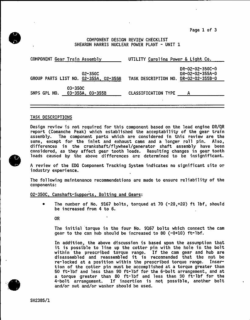
COMPONENT DESIGN REVIEW CHECKLISTSHEARON HARRIS NUCLEAR POWER PLANT " UNIT 1
Page 1 of 3
COMPONENT Gear Train Assembl UTILITY Carolina Power 8 Li ht Co.
DR-02-02"350C-002-350C DR-02"02-355A-0
GROUP PARTS LIST NO. 02"355A 02-355B TASK DESCRIPTION NO. DR"02-02-355B-0
03"350CSNPS GPL NO. 03-355A 03-355B CLASSIFICATION TYPE A
TASK DESCRIPTIONS
Design review is not required for this component based on the lead engine DR/gRreport (Comanche Peak) which established the acceptability of the gear trainassembly. The component parts which are considered in this review are thesame, except for the inlet and exhaust cams and a longer roll pin. Also,differences in the crankshaft/flywheel/generator shaft assembly have beenconsidered, as they affect gear tooth loads. Resulting changes in gear toothloads caused by the above differences are determined to be insignificant.
A review of the EDG Component Tracking System indicates no significant site orindustry experience.
The following maintenance recommendations are made to ensure reliability of thecomponents:
02-350C Camshaft-Su orts Boltin and Gears:
~ The number of No. 9167 bolts, torqued at 70 (-20,+20) ft lbf, shouldbe increased from 4 to 6.
OR
The initial torque in the four No. 9167 bolts which connect the camgear to the cam hub should be increased to 80 (-0+10) ft-lbf.In addition, the above discussion is based upon the assumption thatit is possible to line up the cotter pin with the hole in the boltwithin the prescribed torque range. If the cam gear and hub aredisassembled and reassembled it is recommended that the nut bere-locked at a position within the prescribed torque range. Inser-tion of the cotter pin must be accomplished at a torque greater than50 ft-lbf and less than 90 ft-lbf for the 6-bolt arrangement, and ata torque greater than 80 ft-lbf and less than 90 ft-lbf for the4-bolt arrangement. If insertion is not possible, another boltand/or nut and/or washer should be used.
SH2385/1
COMPONENT DESIGN REVIEW CHECKLIST Page 2 of 3OR"02-02" 350C-0DR"02"02-355A-0OR"02-02-355B-0
TASK DESCRIPTIONS (continued)
~ The surveillance maintenance/inspection procedures should be modifiedto inspect the cam gear at every refueling outage.
02-355A Idler Gear Assembl - Crank to Pum Gear:
~ The crank to pump gear should be inspected during each refuelingoutage. The inspection should be directed at potential pitting. Anyabnormal indications or progressive pitting should be reported for anengineering evaluation.
02-355B Idler Gear Assembl
~ The idler gear and especially the jacket water pump gear should beinspected at all scheduled fuel outages, with any progressive pittingbeing reported for an engineering evaluation. A photographic recordof these inspections should be maintained at the site to assist inthis evaluation.
Note: If the idler gear and hub are disassembled and reassembled, itis recommended that the nut be relocked at a position within theprescribed torque range of 70 (-20,+20) ft-lbf. Insertion of thecotter pin must be accomplished at a torque greater than 50 ft-lbfand less that 90 ft-lbf. If this is not possible, another bolt and/ornut and/or washer should be used.
There are no modification recommendations for this component.
guality inspections that have been conducted to date have been reviewed andare considered satisfactory.
It is recommended that the guality inspections listed below be performed:
02-350C Camshaft-Su orts Boltin and Gears:
~ Verify that the proper torque values are applied to the bolts (cam tocam gear) on Engines lA-SA and 1B-SB.
~ Perform a visual inspection of the cam gear for signs of wear,pitting or any other discontinuities on Engine 1A-SA.
02-355A 8 B Idler Gear Assembl - Crank to Pum 8 Idler Gears:
~ Perform a visual inspection on the crank to pump gear set teeth andidler gear teeth for signs of wear, pitting, or any other discontinu-ities, on engine 1A-SA.
SH2385/2
PRIMARY FUNCTION
Not required
COMPONENT DESIGN REVIEW CHECKLIST Page 3 of 3OR-02" 02-350C-0DR"02-02-355A-0DR-02-02" 355B-0
ATTRIBUTE TO BE VERIFIED
Not required
SPECIFIED STANDARDS
Not required
REFERENCES
Not required
DOCUMENTATION RE UIRED
Not required
GROUP CHAIRPERSON PROGRAM MANAGER
SH2385/3
COMPONENT UALITY REVALIDATION CHECKLIST
Page 1 of 402-02-350C
Camshaft - Supports,COMPONENT Boltin and Gears
GPL NO. 02"350C
Carolina Power & LightShearon Harris Nuclear
UTILITY Power Plant - Unit 1
REV. NO. 2
SNPS GPL NO. 03"350C
TASK DESCRIPTIONS
~E
1. Assemble and review existing documentation.
2. Verify that the proper torque values are applied to the bolts (cam tocam gear).
3. Perform a visual inspection of the cam gears for sign of wear, pittingor any other discontinuities.
4. Determine the hardness of the cam gears.
5. Determine the material of the cam gears.
l. Assemble and review existing documentation.
2. Verify that the proper torque values are applied to the bolts.
3 ~ Perform a visual inspection of the cam gear for sign of wear, pittingor any other discontinuities.
ATTRIBUTES TO BE VERIFIED
En ine 1A-SA
l. guality status of Component Document Package
2. Proper torque loads are applied to the bolts.
SH1722/1
COMPONENT UALITY REVALIDATION CHECKLIST
ATTRIBUTES'TO BE VERIFIED (continued)
Page 2 of 402-02-350C
3. Surface integrity of the cam gears
4. Hardness of the cam gears
5.'at'erial of the cam gears
'. -'-1.::- guality"status at Component Document Package
2. Proper torque loads are applied to the bolts
3. Surface integrity of the cam gears
ACCEPTANCE CRITERIA
En ine 1A-SA
Satisfactory Document Package
2. Tor que values are in accordance with the TDI Instr uction Manual.
3-4.
5.
Review of inspection report by Design Group
Material. of the cam gear is AISI-4340
En ine 1B-SB
Satisfactory Document Package
2.
3.
Torque values are in accordance with the TDI Instruction Manual.
Review of inspection report by Design Group
REFERENCES
~E
l. gCI No. 52
2. Approved Site NDE Procedures, TDI Instruction Manual
SH1722/2

'Ltt"
& T
,I
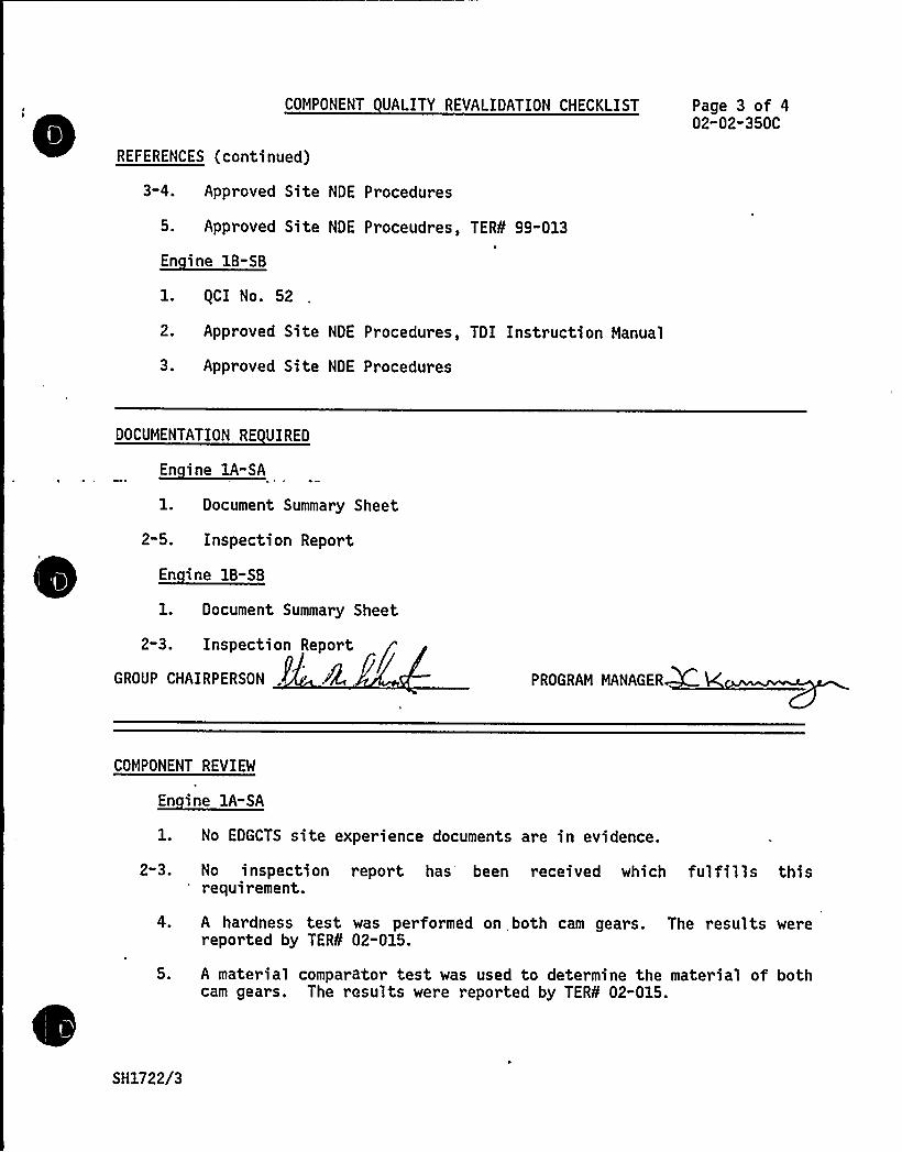
COMPONENT UALITY REVALIDATION CHECKLIST
REFERENCES (continued)
Page 3 of 402"02-350C
3-4.
5.
Approved Site NDE Procedures
Approved Site NDE Proceudres, TER¹ 99-013
En ine 1B-SB
1. gCI No. 52
2.
3.
Approved Site NDE Procedures, TDI Instruction Manual
Approved Site NDE Procedures
DOCUMENTATION RE VIREO
1. Document Summary Sheet
2-5. Inspection Report
En ine 18-SB
1. Document Summary Sheet
2-3. Inspection Report
GROUP CHAIRPERSON PROGRAM MANAGER
COMPONENT REVIEW
En ine lA-SA
No EDGCTS site experience documents are in evidence.
2"3.
4.
5.
No inspecti on report has 'een recei ved which ful fi 1 l s thi srequirement.
A hardness test was performed on both cam gears. The results werereported by TER¹ 02-015.
A material comparator test was used to determine the material of bothcam gears. The results were reported by TER¹ 02-015.
SH1722/3

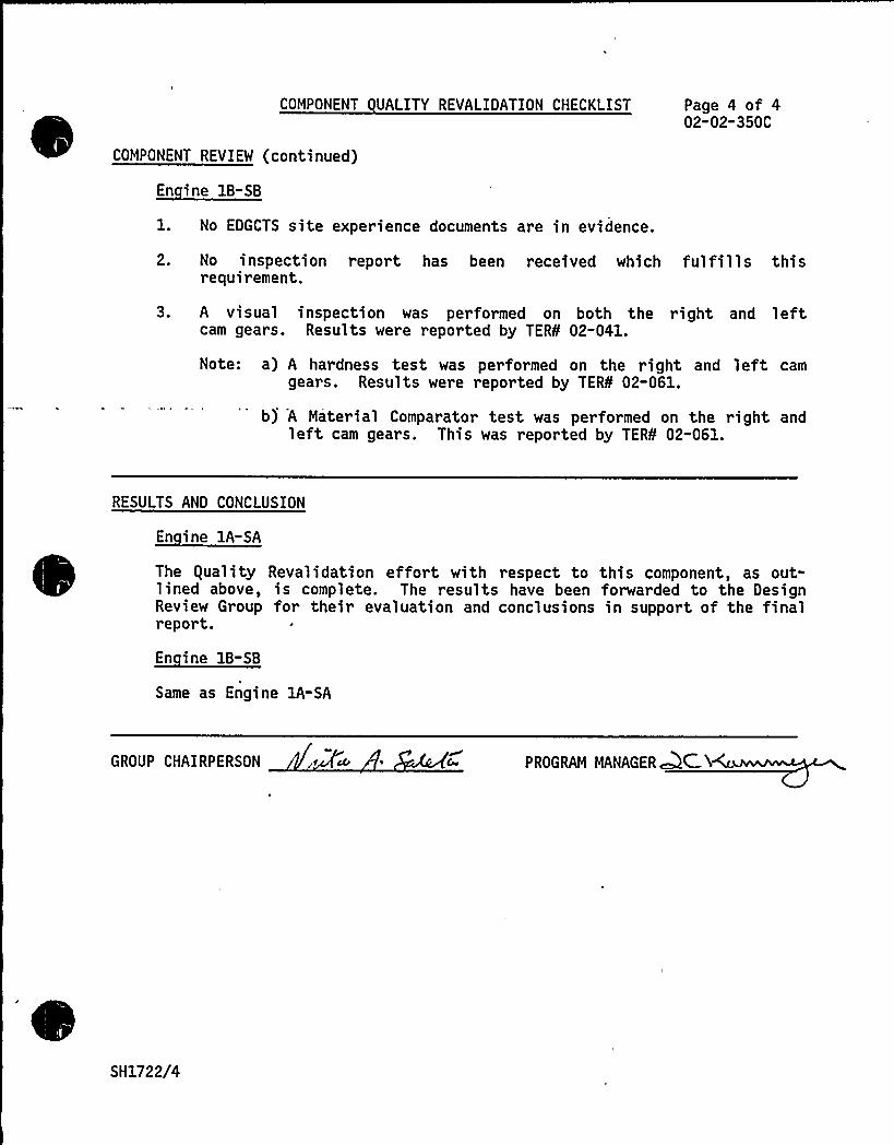
COMPONENT UALITY REVALIDATION CHECKLIST
COMPONENT REVIEW (continued)
En ine 1B-SB
1. No EDGCTS site experience documents are in evidence.
Page 4 of 402-02-350C
2. No inspection report has been received which fulfills thisrequirement.
3. A visual inspection was performed on both the right and leftcam gears. Results were reported by TER¹ 02-041.
Note: a) A hardness test was performed on the right and left camgears. Results were reported by TER¹ 02-061.
b) A Material Comparator test was performed on the right andleft cam gears. This was reported by TER¹ 02-061.
RESULTS AND CONCLUSION
En ine 1A-SA
The equality Revalidation effort with respect to this component, as out-lined above, is complete. The results have been forwarded to the DesignReview Group for their evaluation and conclusions in support of the finalreport.
Same as Engine 1A-SA
GROUP CHAIRPERSON PROGRAM MANAGER~C.I
SH1722/4
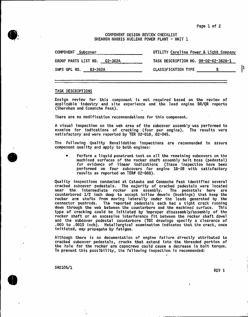
COMPONENT DESIGN REVIEW CHECKLISTSHEARON HARRIS NUCLEAR POWER PLANT - UNIT 1
Page 1 of 2
COMPONENT Subcover UTILITY Carolina Power 8 Li ht Com an
GROUP PARTS LIST NO. 02-362A TASK DESCRIPTION NO. DR-02-02-362A-1
SNPS GPL NO. 03-362A CLASSIFICATION TYPE 8
TASK DESCRIPTIONS
Design review for this component is not required based on the review ofapplicable industry and site experience and the lead engine DR/gR reports(Shoreham and Comanche Peak).
There are no modification recommendations for this component.
A visual inspection on the web area of the subcover assembly was performed toexamine for indications of cracking (four per engine). The results weresatisfactory and were reported by TER 02-018, 02"045.
The following equality Revalidation inspections are recommended to assurecomponent quality and apply to both engines:
~ Perform a liquid penetrant test on all the remaining subcovers on themachined surfaces of the rocker shaft assembly bolt boss (pedestal)for evidence of linear indications (These inspection have beenperformed on four subcovers for engine 18-SB with satisfactoryresults as reported on TER¹ 02-088).
guality inspections conducted at Catawba and Comanche Peak identified severalcracked subcover pedestals. The majority of cracked pedestals were locatednear the intermediate rocker arm assembly. The pedestals here arecounterbored 1/2 inch deep to accept hollow dowels (bushings) that keep therocker arm shafts from moving laterally under the loads generated by theconnector pushrods. The reported pedestals each had a tight crack runningdown through the web between the counterbore and the machined surface. Thistype of cracking could be initiated by improper disassembly/assembly of therocker shaft or an excessive interference fit between the rocker shaft doweland the subcover pedestal counterbore (TDI drawings specify a clearance of.000 to .0015 inch). Metallurgical examination indicates that the crack, onceinitiated, may propagate by fatigue.
Although there is no documentation of engine failure directly attributed tocracked subcover pedestals, cracks that extend into the threaded portion ofthe hole for the rocker arm capscrews could cause a decrease in bolt torque.To prevent this possibility, the following inspection is recommended:
SH2105/1REV 1

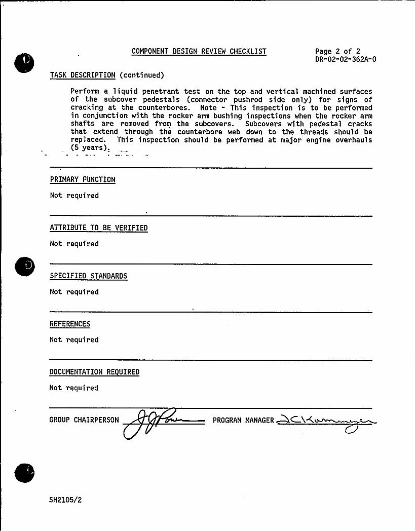
COMPONENT DESIGN REVIEW CHECKLIST
TASK DESCRIPTION (continued)
Page 2 of 2DR-02-02"362A-0
Perform a liquid penetrant test on the top and vertical machined surfacesof the subcover pedestals (connector pushrod side only) for signs ofcracking at the counterbores. Note - This inspection is to be performedin conjunction with the rocker arm bushing inspections when the rocker armshafts are removed from the subcovers. Subcovers with pedestal cracksthat extend through the counterbore web down to the threads should bereplaced. This inspection should be performed at major engine overhauls(5 years).
PRIMARY FUNCTION
Not required
ATTRIBUTE TO BE VERIFIED
Not required
SPECIFIED STANDARDS
Not required
REFERENCES
Not required
DOCUMENTATION RE UIRED
Not required
GROUP CHAIRPERSON PROGRAM MANAGER C %A~
SH2105/2
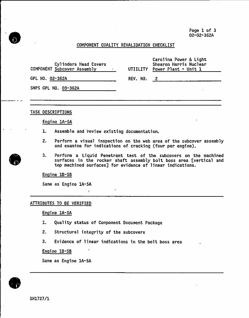
COMPONENT UALITY REVALIDATION CHECKLIST
Page 1 of 302-02-362A
Cylinders Head CoversCOMPONENT Subcover Assembl
GPL NO. 02-362A
SNPS GPL NO. 03"362A
Carolina Power & LightShearon Harris Nuclear
UTIILITY Power Plant - Unit 1
REV. NO. 2
TASK DESCRIPTIONS
A- A
l. Assemble and 'review existing documentation.
2. Perform a visual inspection on the web area of the subcover assemblyand examine for indications of cracking (four per engine).
3. Perform a Liquid Penetrant test of the subcovers on the machinedsurfaces in the rocker shaft assembly bolt boss area [vertical andtop machined surfaces] for evidence of linear indications.
En ine 1B-SB
Same as Engine 1A-SA
ATTRIBUTES TO BE VERIFIED
1. guality status of Component Document Package
2. Structural integrity of the subcovers
3. Evidence of linear indications in the bolt boss area
Same as Engine 1A-SA
SH1727/1
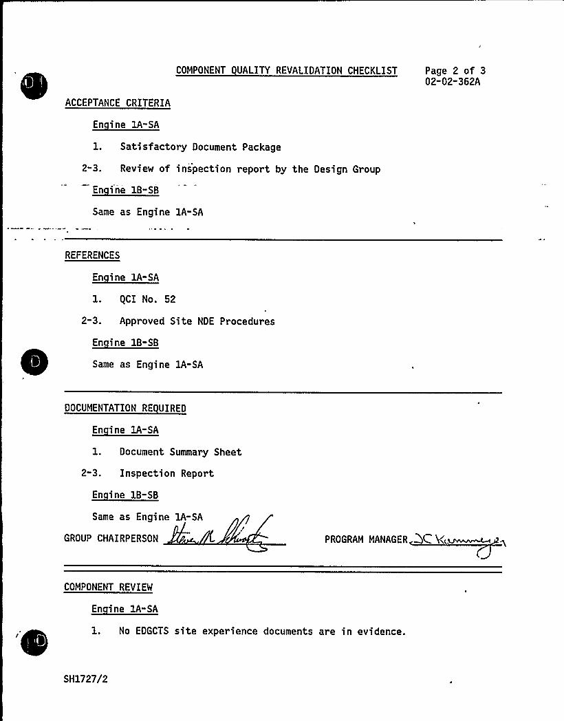
COMPONENT UALITY REVALIDATION CHECKLIST Page 2 of 302-02-362A
ACCEPTANCE CRITERIA
En ine 1A-SA
1. Satisfactory Document Package
2-3. Review of inspection report by the Design Group
Same as Engine lA-SA
REFERENCES
En ine 1A-SA
1. (CI No. 52
2-3. Approved Site NDE Procedures
En ine 1B-SB
Same as Engine lA-SA
DOCUMENTATION RE VIREO~*1. Document Summary Sheet
2-3. Inspection Report
En ine 1B-SB
Same as Engine 1A-SA
GROUP CHAIRPERSON PROGRAM MANAGER C V(~COMPONENT REVIEW
1. No EDGCTS site experience documents are in evidence.
SH1727/2

i
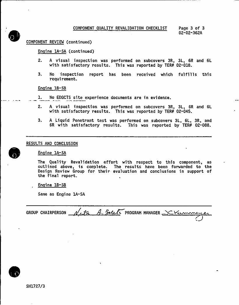
COMPONENT UALITY REVALIDATION CHECKLIST Page 3 of 302-02-362A
COMPONENT REVIEW (continued)
2. A visual inspection was per formed on subcovers 3R, 3L, 6R and 6Lwith satisfactory results. This was reported by TER¹ 02-018.
3. No inspection report has been received which fulfills thisrequirement.
En ine 1B-SB
1. No EDGCTS site experience documents are in evidence.
2. A visual inspection was performed on subcovers 3R, 3L, 6R and 6Lwith satisfactory results. This was reported by TER¹ 02-045.
3. A Liquid Penetrant test was performed on subcovers 3L, 6L, 3R, and6R with satisfactory results. This was reported by TER¹ 02-088.
RESULTS AND CONCLUSION
En ine 1A-SA
The guality Revalidation effort with respect to this component, asoutlined above, is complete. The results have been forwarded to theDesign Review Group for their evaluation and conclusions in support ofthe final report.
Same as Engine 1A-SA
GROUP CHAIRPERSON c PROGRAM MANAGER . C.
SH1727/3

8
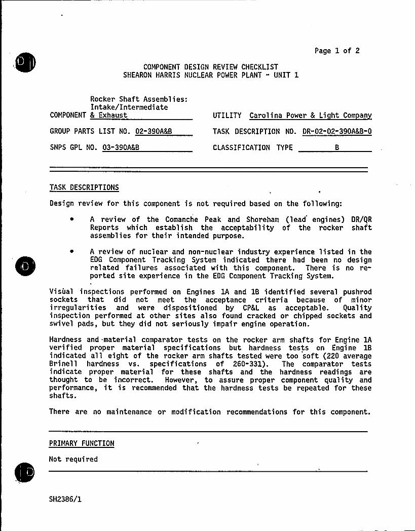
Page 1 of 2
COMPONENT DESIGN REVIEW CHECKLISTSHEARON HARRIS NUCLEAR POWER PLANT " UNIT 1
Rocker Shaft Assemblies:Intake/Intermediate
COMPONENT 8 Exhaust UTILITY Carolina Power 8 Li ht Com an
GROUP PARTS LIST NO. 02-390A&B TASK DESCRIPTION NO. DR"02-02-390A8(B-0
SNPS GPL NO. 03"390A8B CLASSIFICATION TYPE
TASK DESCRIPTIONS
Design review for this component is not required based on the following:
A review of the Comanche Peak and Shoreham (lead engines) DR/gRReports which establish the acceptability of the rocker shaftassemblies for their intended purpose.
~ A review of nuclear and non-nuclear industry experience listed in theEDG Component Tracking System indicated there had been no designrelated failures associated with this component. There is no re-ported site experience in the EDG Component Tracking System.
Visual inspections performed on Engines lA and 1B identified several pushrodsockets that did not meet the acceptance criteria because of minorirregularities and were dispositioned by CP8L as acceptable. gualityinspection performed at other sites also found cracked or chipped sockets andswivel pads, but they did not seriously impair engine operation.
Hardness and material comparator tests on the rocker arm shafts for Engine lAverified proper material specifications but hardness tests on Engine 1Bindicated all eight of the rocker arm shafts tested were too soft (220 averageBrinell hardness vs. specifications of 260-331). The comparator testsindicate proper material for these shafts and the hardness readings arethought to be incorrect. However, to assure proper component quality andperformance, it is recommended that the hardness tests be repeated for theseshafts.
There are no maintenance or modification recommendations for this component.
PRIMARY FUNCTION
Not required
SH2386/1

8 kW
i
0
COMPONENT DESIGN REVIEW CHECKLIST
ATTRIBUTE TO BE VERIFIED
Not required
Page 2 of 2DR"02-02-390A&B-0
SPECIFIED STANDARDS
Not required
REFERENCES
Not required
DOCUMENTATION RE UIRED
Not required
GROUP CHAIRPERSON PROGRAM MANAGER
SH2386/2

4
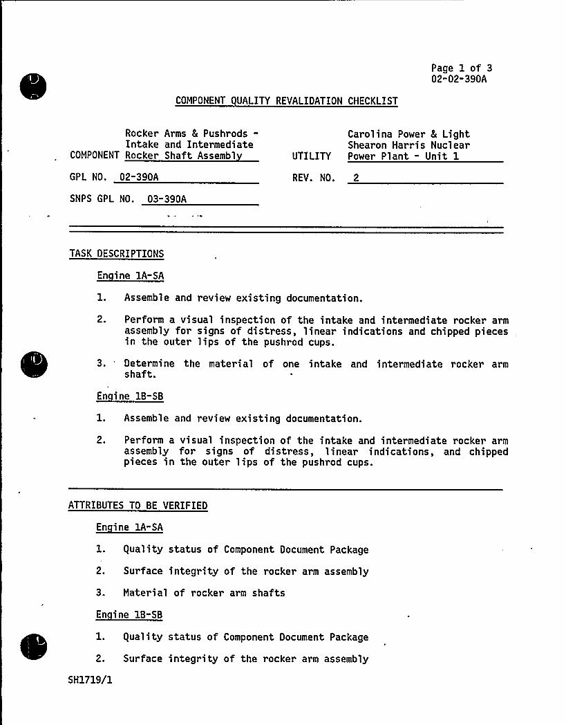
Page 1 of 302"02-390A
COMPONENT UALITY REVALIDATION CHECKLIST
Rocker Arms 8 Pushrods-Intake and Intermediate
COMPONENT Rocker Shaft Assembl
Carolina Power 8 LightShearon Harris Nuclear
UTILITY Power Plant - Unit 1
GPL NO. 02-390A REV. NO. 2
SNPS GPL NO ~ 03-390A
TASK DESCRIPTIONS
1. Assemble and review existing documentation.
2. Perform a visual inspection of the intake and intermediate rocker armassembly for signs of distress, linear indications and chipped pieces
,
in the outer lips of the pushrod cups.
3. 'etermine the material of one intake and intermediate rocker armshaft.
1. Assemble and review existing documentation.
2. Perform a visual inspection of the intake and intermediate rocker armassembly for signs of distress, linear indications, and chippedpieces in the outer lips of the pushrod cups.
ATTRIBUTES TO BE VERIFIED
En ine lA-SA
l. guality status of Component Document Package
2. Surface integrity of the rocker arm assembly
3. Material of rocker arm shafts
l. guality status of Component Document Package
2. Surface integrity of the rocker arm assembly
SH1719/1
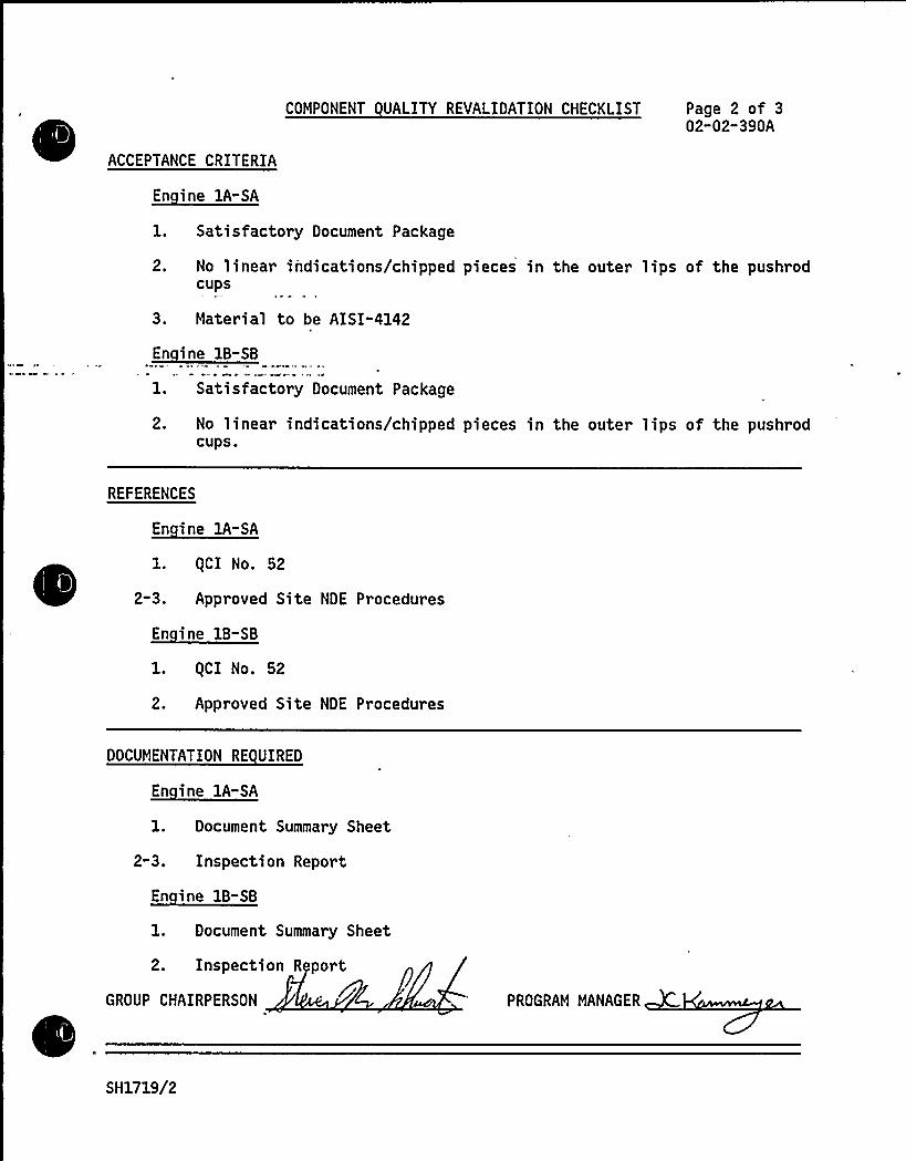
C OMPONENT UALITY REVALIDATION CHECKLIST Page 2 of 302"02-390A
ACCEPTANCE CRITERIA
1. Satisfactory Document Package
2. No linear indications/chipped pieces in the outer lips of the pushrodCUPS
3. Mater ial to be AISI-4142
1. Satisfactory Document Package
2. No linear indications/chipped pieces in the outer lips of the pushrodCUPS.
REFERENCES
En ine lA-SA
1. (CI No. 52
2-3. Approved Site NDE Procedures
En ine 1B-SB
1. gCI No. 52
2. Approved Site NDE Procedures
DOCUMENTATION RE UIRED
1. Document Summary Sheet
2-3. Inspection Report
En ine 1B-SB
l. Document Summary Sheet
2. Inspection R port
GROUP CHAIRPERSON PROGRAM MANAGER
SH1719/2

%4
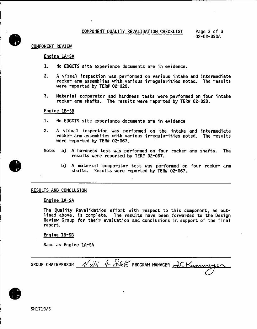
COMPONENT UALITY REVALIDATION CHECKLIST Page 3 of 302"02-390A
COMPONENT REVIEW
1. No EDGCTS site experience documents are in evidence.
2. A visual inspection was performed on various intake and intermediaterocker arm assemblies with various irregularities noted. The resultswere reported by TER¹ 02-020.
3. Material comparator and hardness tests were performed on four intakerocker arm shafts. The results were reported by TER¹ 02-020.
1. No EDGCTS site experience documents are in evidence
2. A visual inspection was performed on the intake and intermediaterocker arm assemblies with various irregularities noted. The resultswere reported by TER¹ 02-067.
Note: a) A hardness test was performed on four rocker arm shafts. Theresults were reported by TER¹ 02-067.
b) A material comparator test was performed on four rocker armshafts. Results were reported by TER¹ 02-067.
RESULTS AND CONCLUSION
En ine 1A-SA
The guality Revalidation effort with respect to this component, as out-lined above, is complete. The results have been forwarded to the DesignReview Group for their evaluation and conclusions in support of the finalreport.
Same as Engine 1A-SA
GROUP CHAIRPERSON /~c ' c4:fiz PROGRAM MANAGER C i
SH1719/3
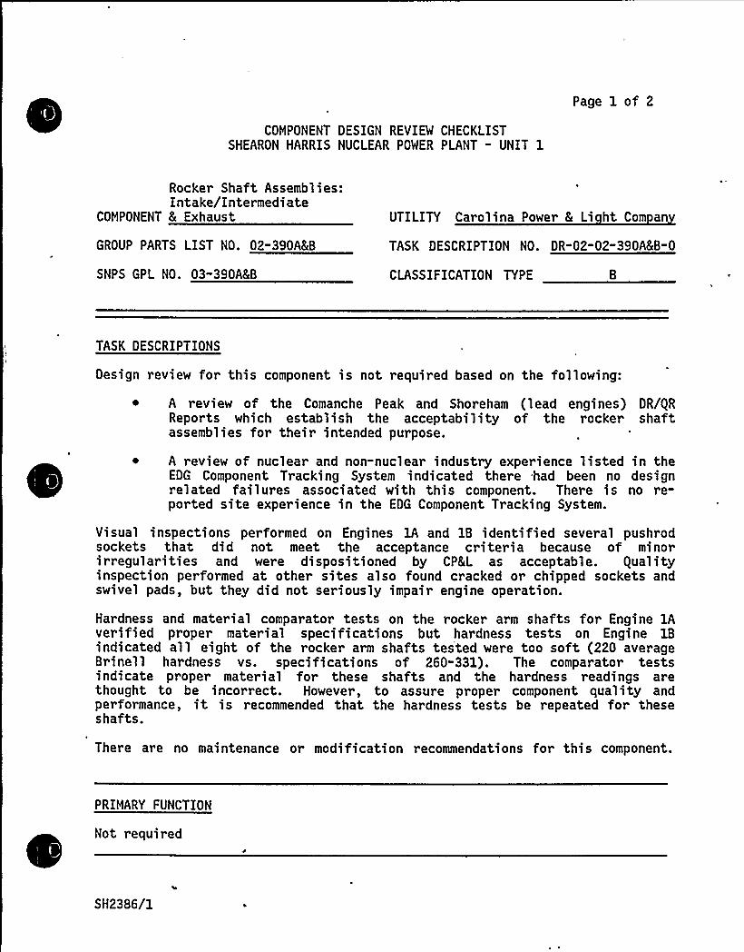
Page 1 of 2
COMPONENT DESIGN REVIEW CHECKLISTSHEARON HARRIS NUCLEAR POWER PLANT - UNIT 1
Rocker Shaft Assemblies:Intake/Intermediate
COMPONENT 8 Exhaust UTILITY Carolina Power 8 Li ht Com an
GROUP PARTS LIST NO. 02-390ALB TASK DESCRIPTION NO. DR"02-02-390'(B-0
SNPS GPL NO. 03-390A8B CLASSIFICATION TYPE
TASK DESCRIPTIONS
Design review for this component is not required based on the following:
A review of the Comanche Peak and Shoreham (lead engines) DR/gRReports which establish the acceptability of the rocker shaftassemblies for their intended purpose.
~ A review of nuclear and non-nuclear industry experience listed in theEDG Component Tracking System indicated there had been no designrelated failures associated with this component. There is no re-ported site experience in the EDG Component Tracking System.
Visual inspections performed on Engines lA and 1B identified several pushrodsockets that did not meet the acceptance criteria because of minorirregularities and were dispositioned by CP&L as acceptable. gualityinspection performed at other sites also found cracked or chipped sockets andswivel pads, but they did not seriously impair engine operation.
Hardness and material comparator tests on the rocker arm shafts for Engine 1Averified proper material specifications but hardness tests on Engine 1Bindicated all eight of the rocker arm shafts tested were too soft (220 averageBrinell hardness vs. specifications of 260-331). The comparator testsindicate proper material for these shafts and the hardness readings arethought to be incorrect. However, to assure proper component quality andperformance, it is recommended that the hardness tests be repeated for theseshafts.
There are no maintenance or modification recommendations for this component.
PRIMARY FUNCTION
Not required
SH2386/1

COMPONENT DESIGN REVIEW CHECKLIST
ATTRIBUTE TO BE VERIFIED
Not required
Page 2 of 2DR-02-02-390A&B"0
SPECIFIED STANDARDS
Not required
--REFERENCES
Not required
DOCUMENTATION RE UIRED
Not required
GROUP CHAIRPERSON PROGRAM MANAGER
SH2386/2

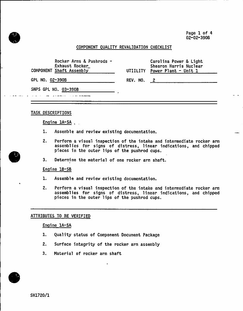
Page 1 of 402-02-390B
COMPONENT UALITY REVALIDATION CHECKLIST
Rocker Arms & Pushrods-Exhaust Rocker
COMPONENT Shaft Assembl
Carolina Power 8 LightShearon Harris Nuclear
UTIILITY Power Plant - Unit 1
GPL NO. 02-390B
SNPS GPL NO. 03-390B
REV. NO. 2
TASK DESCRIPTIONS
1. Assemble and review existing documentation.
2. Perform a visual inspection of the intake and intermediate rocker armassemblies for signs of distress, linear indications, and chippedpieces in the outer lips of the pushrod cups.
3. Determine the material of one rocker arm shaft.
En ine 1B-SB
1. Assemble and review existing documentation.
2. Perform a visual inspection of the intake and intermediate rocker armassemblies for signs of distress, linear indications, and chippedpieces in the outer lips of the pushrod cups.
ATTRIBUTES TO BE VERIFIED
l. guality status of Component Document Package
2. Surface integrity of the rocker arm assembly
3. Material of rocker arm shaft
SH1720/1

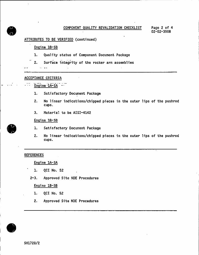
COMPONENT UALITY REVALIDATION CHECKLIST Page 2 of 402-02-390B
ATTRIBUTES TO BE VERIFIED (continued)
En ine 1B-SB
1. guality status of Component Document Package
2. Surface integrity of the rocker arm assemblies
ACCEPTANCE CRITERIA
1. Sati s factory Document Package
2. No linear indications/chipped pieces in the outer lips of the pushrodCUPS.
3. Material to be AISI-4142
1. Satisfactory Document Package
2. No linear indications/chipped pieces in the outer lips of the pushrodCUPS.
REFERENCES
1. (CI No. 52
2-3. Approved Site NDE Procedures
En ine 1B-SB
1. (CI No. 52
2. Approved Site NDE Procedures
SH1720/2
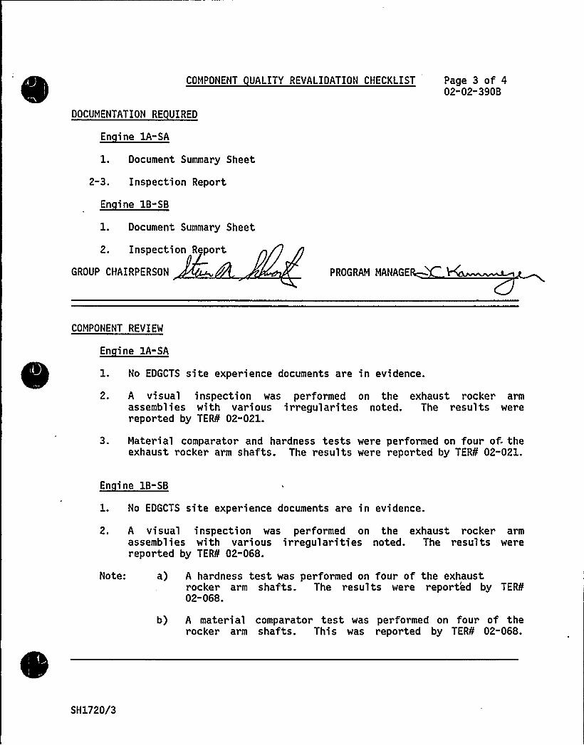
COMPONENT UALITY REVALIDATION CHECKLIST Page 3 of 402"02-390B
DOCUMENTATION RE UIRED
En ine 1A-SA
1. Document Summary Sheet
2-3. Inspection Report
1. Document Summary Sheet
2. Inspection Report
GROUP CHAIRPERSON PROGRAM MANAGE
COMPONENT REVIEW
1. No EDGCTS site experience documents are in evidence.
2. A visual inspection was performed on the exhaust rocker armassemblies with various irregularites noted. The results werereported by TER¹ 02-021.
3. Material comparator and hardness tests were performed on four of- theexhaust rocker arm shafts. The results were reported by TER¹ 02-021.
1. No EDGCTS site experience documents are in evidence.
2. A visual inspection was performed on the exhaust rocker armassemblies with various irregularities noted. The results werereported by TER¹ 02-068.
Note: a) A hardness test was performed on four of the exhaustrocker arm shafts. The results were reported by TER¹02-068.
b) A material comparator test was performed on four of therocker arm shafts. This was reported by TER¹ 02-068.
SH1720/3
COMPONENT UALITY REVALIDATION CHECKLIST Page 4 of 402"02-390B
RESULTS AND CONCLUSION
En ine 1A-SA
The equality Revalidation effort with respect to this component, as out-lined above, is complete. The results have been forwarded to the DesignReview Group for their evaluation and conclusions in support of the finalreport.
En ine 1B-SB
Same as Engine 1A-SA
GROUP CHAIRPERSON 44 f'< PROGRAM MANAGER ~~K~
SH1720/4

e
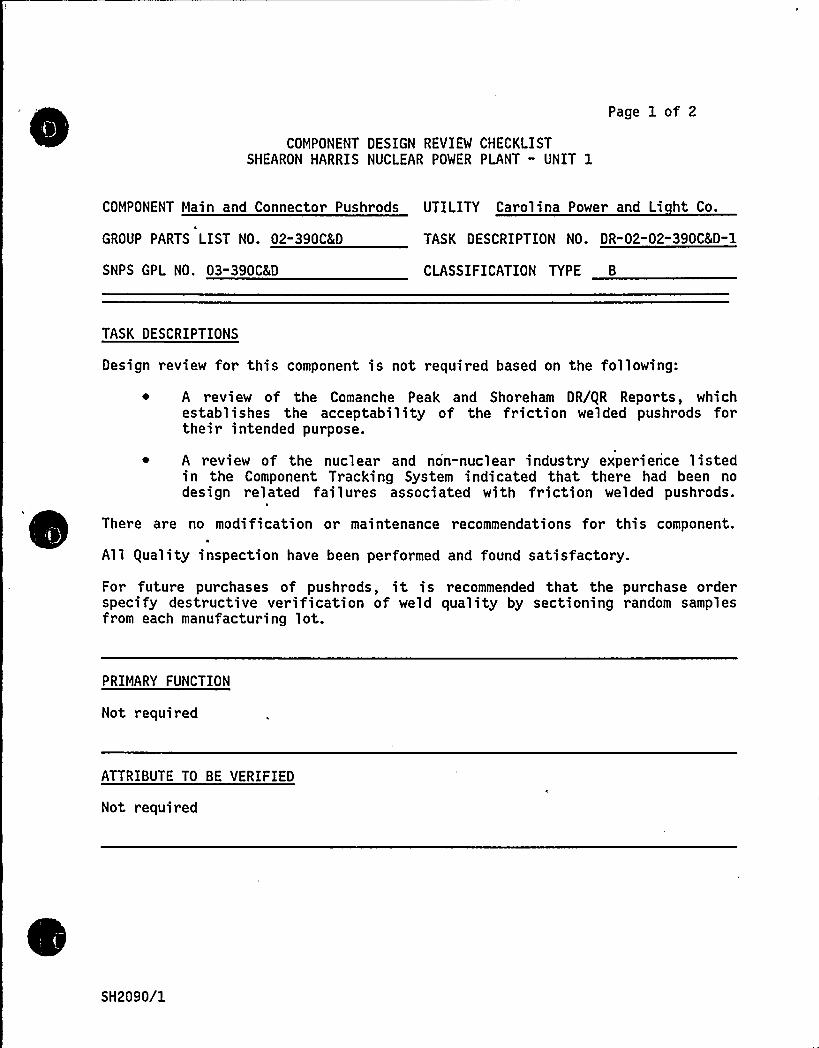
COMPONENT DESIGN REVIEW CHECKLISTSHEARON HARRIS NUCLEAR POWER PLANT " UNIT 1
Page 1 of 2
COMPONENT Main and Connector Pushrods UTILITY Carolina Power and Li ht Co.
GROUP PARTS LIST NO. 02-390C8(D
SNPS GPL NO. 03-390CKD
TASK DESCRIPTION NO. DR-02-02-390C&D-1
CLASSIFICATION TYPE B
TASK DESCRIPTIONS
Design review for this component is not required based on the following:
A review of the Comanche Peak and Shoreham DR/gR Reports, whichestablishes the acceptability of the friction welded pushrods fortheir intended purpose.
A review of the nuclear and non-nuclear industry experience listedin the Component Tracking System indicated that there had been nodesign related failures associated with friction welded pushrods.
There are no modification or maintenance recommendations for this component.4
All guality inspection have been performed and found satisfactory.
For future purchases of pushrods, it is recommended that the purchase orderspecify destructive verification of weld quality by sectioning random samplesfrom each manufacturing lot.
PRIMARY FUNCTION
Not required
ATTRIBUTE TO BE VERIFIED
Not required
SH2090/1

COMPONENT DESIGN REVIEW CHECKLIST
SPECIFIED STANDARDS
Not required
Page 2 of 2DR-02-02-390C&D-1
REFERENCES
Not required
DOCUMENTATION RE UIRED
Not required
GROUP CHAIRPERSON PROGRAM MANAGER ~H
SH2090/2
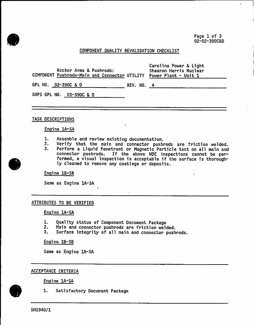
COMPONENT UALITY REVALIDATION CHECKLIST
Page 1 of 302-02-390C&D
Carolina Power & LightRocker Arms & Pushrods: Shearon Harris Nuclear
COMPONENT Pushrods-Main and Connector UTILITY Power Plant - Unit 1
GPL NO. 02-390C & D
SNPS GPL NO. 03"390C & D
REV. NO. 4
TASK DESCRIPTIONS
1.2.3.
Assemble and review existing documentation.Verify that the main and connector pushrods are friction welded.Perform a Liquid Penetrant or Magnetic Particle test on all main andconnector pushrods. If the above NDE inspections cannot be per-formed, a visual inspection is acceptable if the surface is thorough-ly cleaned to remove any coatings or deposits.
En ine 1B-SB
Same as Engine 1A-SA
ATTRIBUTES TO BE VERIFIED
En ine 1A-SA
l. equality status of Component Document Package2. Main and connector pushrods are friction welded.3. Surface integrity of all main and connector pushrods.
En ine 1B-SB
Same as Engine lA-SA
ACCEPTANCE CRITERIA
En ine 1A-SA
1. Satisfactory Document Package
SH1940/1
COMPONENT UALITY REVALIDATION CHECKLIST Page 2 of 302-02-390C8(D
ACCEPTANCE CRITERIA (continued)
~Ei -A (
2. Main and connector pushrods are friction welded.3. No surface cracks allowed along the bond line between the rod end and
thetube.'ame
as Engine lA-SA
REFERENCES
En ine 1A-SA
1. gCI No. 522. Approved Site NDE Procedures3. Approved site NDE Procedures, TERS 99-017, TERS 99-035
Same as Engine lA-SA
DOCUMENTATION RE UIRED
En ine lA-SA
1. Document Summary Sheet2-3. Inspection Report
En ine 1B-SB
Same as Engine lA- A'7 /
GROUP CHAIRPERSON / PROGRAM MANAGER~h4
COMPONENT REVIEW
En ine 1A-SA
1. No EDGCTS site experience documents are in evidence.
SH1940/2
COMPONENT UALITY REVALIDATION CHECKLIST
COMPONENT REVIEM (continued)
En ine lA-SA
Page 3 of 302-02"390CLD
2. Friction welded pushrods, were installed as verified through avisual inspection. This was reported by TERS 02"101.
3. A Magnetic Particle test was performed on all main and connectorpushrods with no indications found. This was reported by TERS02-101.
1. No EDGCTS site experience documents are in evidence.
2. Friction welded pushrods were installed as verified during a visualinspection. This was reported by TERS 02-078.
3. A Magnetic Particle test was performed on all main and connectorpushrods with no indications found. This was reported by TERS02"101.
RESULTS AND CONCLUSION
The guality Revalidation effort with respect to this component, asoutlined above, is complete. The results have been forwarded to theDesign Review Group for their evaluation and conclusions in support ofthe final report.
En ine 1B-SB
GROUP'CHAIRPERSON PROGRAM MANAGER DC &
SH1940/3
TDI OWNERS GROUP
fol
SHEARON HARRIS NUCLEAR POWER PLANT
Rocker Arms and Pushrods: Pushrods Connector
COMPONENT PART NO.: 02-39OD
See Component Part No. 02-390C
Page 1 of 2
COMPONENT DESIGN REVIEW CHECKLISTSHEARON HARRIS NUCLEAR PLANT " UNIT 1
Rocker Arms &COMPONENT Pushrods:Bushin s
GROUP PARTS LIST NO. 02-390E
SNPS GPL NO. 03-390E
UTILITY Carolina Power & Li ht Com an
TASK DESCRIPTION NO. DR-05-02-390E-1
CLASSIFICATION TYPE B
TASK DESCRIPTIONS
Design review for this component is not required based on the following:
~ A review of the Comanche Peak and Shoreham DR/gR Reports whichestablishes the acceptability of the bushings for their intendedpurpose.
The applicable engine dimensions and operating parameters at ShearonHarris are identical or very similar to those for the same componentat Comanche Peak (Lead Engine).
~ A review of the Component Tracking System indicated that there was nosite experience and no significant applicable nuclear or non-nuclearindustry experience.
Maintenance recommendations based on the Comanche Peak DR/gR Report to ensureproper performance under normal conditions are as follows:
~ Visually inspect and measure the intake, intermediate, and exhaust rockerarm bushings. The periods of engine operation to wear the bushings froman initial clearance of 0.0045 inch (diametral) to 0.010 inch (value atwhich bushings should be replaced) were calculated to be: 2300 hours-Intake, 730 hours - Intermediate, and 1300 hours - Exhaust. It is recom-mended that an inspection be conducted at the fuel outage which precedesthe applicable number of engine hours of operation by at least the sum ofthe expected hours of operation in a LOOP/LOCA event plus the expectedhours of operation between outages. The inspection schedule may berevised after the first or subsequent inspections if the inspectionresults justify a longer period of engine operation between inspections.
No guality revalidation is required for this component.
No modifications are recommended for this component.
PRIMARY FUNCTION
Not required
SH2085/1 REV. I
COMPONENT DESIGN REVIEW CHECKLIST
ATTRIBUTE TO BE VERIFIED
Not required
Page 2 of 2DR"02-02-390E"0
SPECIFIED STANDARDS
Not required
REFERENCES
Not required
„DOCUMENTATION RE UIRED
Not required
GROUP CHAIRPERSON PROGRAM MANAGER
SH2085/2
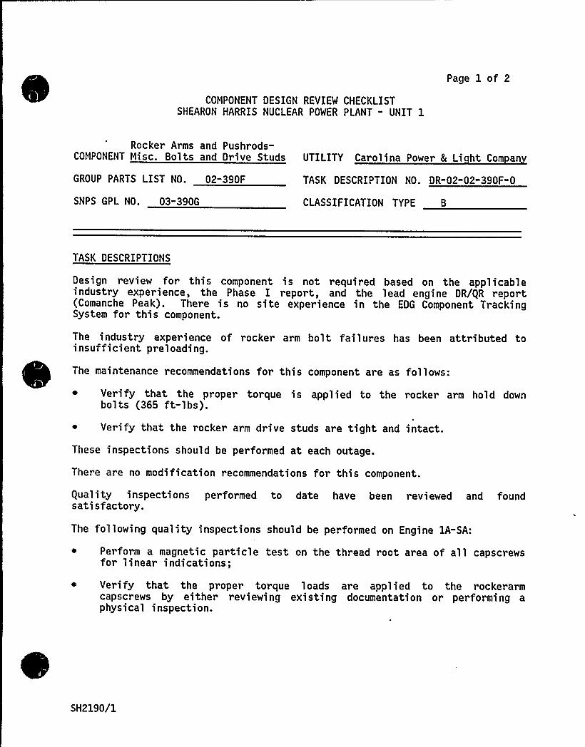
COMPONENT DESIGN REVIEW CHECKLISTSHEARON HARRIS NUCLEAR POWER PLANT - UNIT 1
Page 1 of 2
Rocker Arms and Pushrods-COMPONENT Misc. Bolts and Drive Studs UTILITY Carolina Power 8 Li ht Com an
GROUP PARTS LIST NO. 02-390F
SNPS GPL NO. 03-390G
TASK- DESCRIPTION NO. DR-02-02-390F-0
CLASSIFICATION TYPE B
TASK DESCRIPTIONS
Design review for this component is not required based on the applicableindustry experience, the Phase I report, and the lead engine DR/gR report(Comanche Peak). There is no site experience in the EDG Component TrackingSystem for this component.
The industry experience of rocker arm bolt failures has been attributed toinsufficient preloading.
The maintenance recommendations for this component are as follows:
~ Verify that the proper torque is applied to the rocker arm hold downbolts (365 ft-lbs).
~ Verify that the rocker arm drive studs are tight and intact.
These inspections should be performed at each outage.
There are no modification recommendations for this component.
equality inspections performed to date have been reviewed and foundsatisfactory.
The following quality inspections should be performed on Engine 1A-SA:
Perform a magnetic particle test on the thread root area of all capscrewsfor linear indications;
Verify that the proper torque loads are applied to the rockerarmcapscrews by either reviewing existing documentation or performing aphysical inspection.
SH2190/1
COMPONENT DESIGN REVIEW CHECKLIST Page 2 of 2DR-02-02-390F" 0
The following quality inspections should be performed on Engine 1B-SB:
~ Verify that the proper torque loads are applied to the rockerarmcapscrews by either reviewing existing documentation or performing aphysical inspection.
PRIMARY FUNCTION
Not required
ATTRIBUTE TO BE VERIFIED
Not required
SPECIFIED STANDARDS
Not required
REFERENCES
Not required
DOCUMENTATION RE UIRED
Not required
GROUP CHAIRPERSON ROGRAM MANAGER CH
SH2190/2
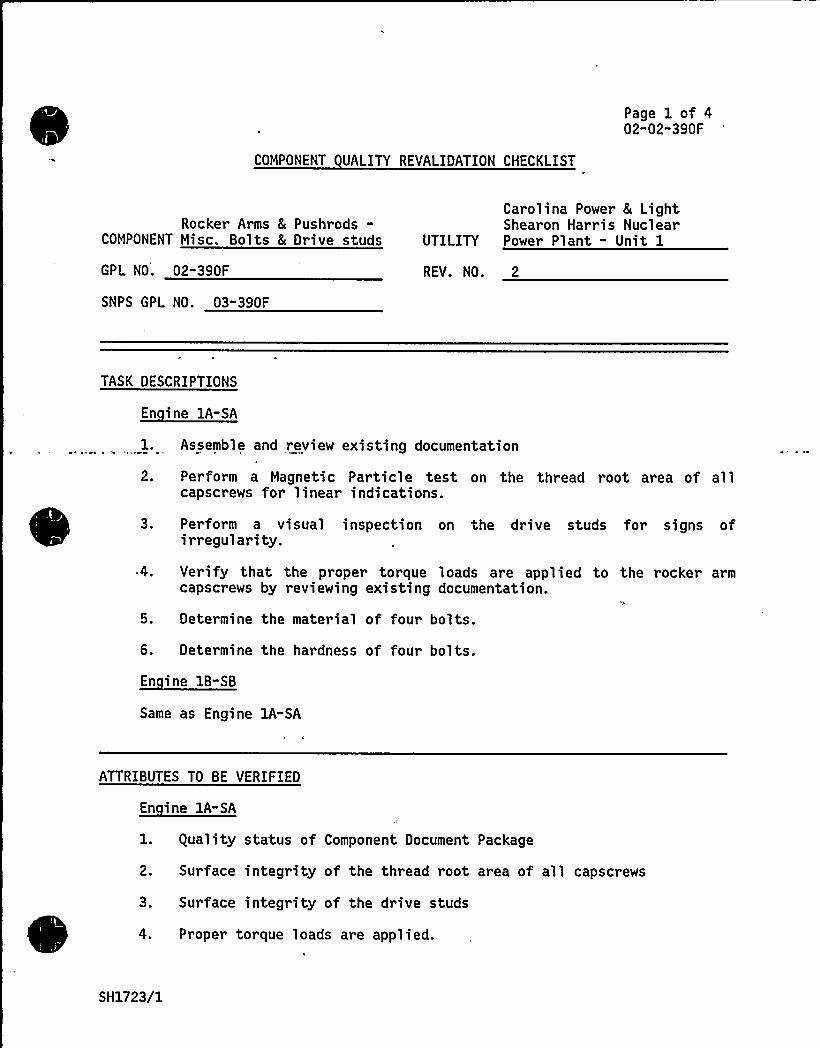
COMPONENT UALITY REVALIDATION CHECKLIST
Page 1 of 402"02"390F
Rocker Arms 8 Pushrods-COMPONENT Misc. Bolts & Drive studs
GPL NO. 02-390F
SNPS GPL NO. 03-390F
Carolina Power 8 LightShearon Harris Nuclear
UTILITY Power Plant - Unit 1
REV. NO. 2
TASK DESCRIPTIONS
2.
Assemble and review existing documentation
Perform a Magnetic Particle test on the thread root area of allcapscrews for linear indications.
3. Perform a visual inspection on the drive studs for signs ofi rregul ari ty.
.4. Verify that the proper torque loads are applied to the rocker armcapscrews by reviewing existing documentation.
5. Determine the material of four bolts.
6. Determine the hardness of four bolts.
~E
Same as Engine 1A-SA
ATTRIBUTES TO BE VERIFIED
1. guality status of Component Document Package
2. Surface integrity of the thread root area of all capscrews
3. Surface integrity of the drive studs
4. Proper torque loads are applied.
SH1723/1
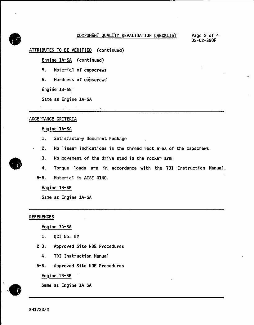
COMPONENT UALITY REVALIDATION CHECKLIST
ATTRIBUTES TO BE VERIFIED (continued)
Page 2 of 402-02-390F
5. Material of capscrews
6. Hardness of capscrews
~E
Same as Engine lA-SA
ACCEPTANCE CRITERIA
1. Satisfactory Document Package
~ 2. No linear indications in the thread root area of the capscrews
3. No movement of the drive stud in the rocker arm
4. Torque loads are in accordance with the TDI Instruction Manual.
5-6. Material is AISI 4140.
Same as Engine lA-SA
REFERENCES
1. (CI No. 52
2-3. Approved Site NDE Procedures
4. TDI Instruction Manual
5-6. Approved Site NDE Procedures
En ine 1B-SB
Same as Engine 1A-SA
SH1723/2

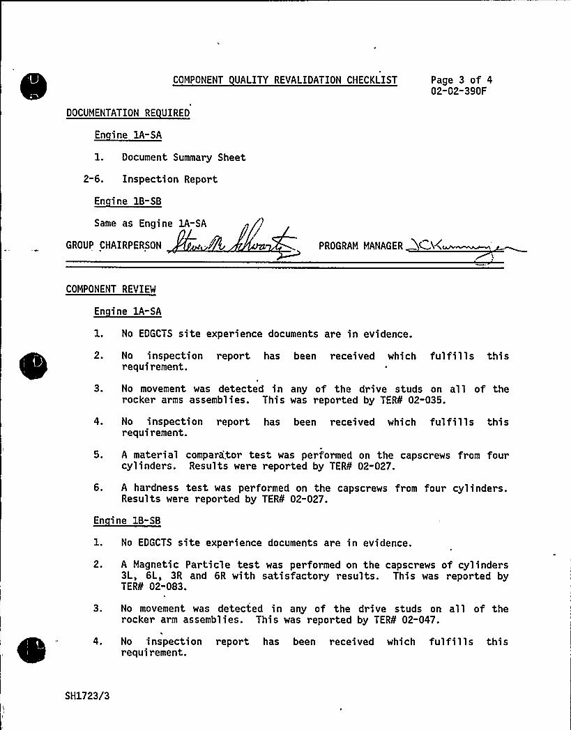
COMPONENT UALITY REVALIDATION CHECKLIST
DOCUMENTATION RE UIRED
Page 3 of 402-02"390F
En ine 1A-SA
1. Document Summary Sheet
2-6. Inspection Report
En ine 1B-SB
Same as Engine 1A-SA
GROUP CHAIRPERSON PROGRAM MANAGER
CN+~~'OMPONENT
REVIEW
En ine lA-SA
1. No EDGCTS site experience documents are in evidence.
2. No inspection report has been received which fulfills thisrequirement.
'I
3. No movement was detected in any of the drive studs on all of therocker arms assemblies. This was reported by TER¹ 02-035.
4. No inspection report has been received which fulfills thisrequirement.
5. A material compara'tor test was performed on the capscrews from fourcylinders. Results were reported by TER¹ 02-027.
6. A hardness test was performed on the capscrews from four cylinders.Results were reported by TER¹ 02-027.
En ine 1B-SB
1. No EDGCTS site experience documents are in evidence.
2. A Magnetic Particle test was performed on the capscrews of cylinders3L, 6L, 3R and 6R with satisfactory results. This was reported byTER¹ 02-083.
3. No movement was detected in any of the drive studs on all of therocker arm assemblies. This was reported by TER¹ 02-047.
4. No inspection report has been received which fulfills thisrequirement.
SH1723/3
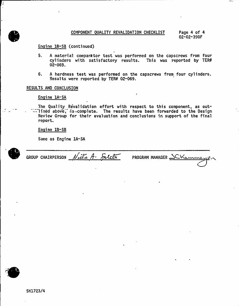
COMPONENT UALITY REVALIDATION CHECKLIST Page 4 of 402-02-390F
5. A material comparator test was performed on the capscrews from fourcylinders with satisfactory results. This was reported by TER¹02-069.
6. A hardness test was performed on the capscrews from four cylinders.Results were reported by TER¹ 02-069.
RESULTS AND CONCLUSION
En ine 1A-SA
The equality Revalidation effort with respect to this component, as out-'-'ined above, is=-complete. The results have been forwarded to the Design
Review Group for their evaluation and conclusions in support of the finalreport.
En ine 1B-SB
Same as Engine 1A-SA
GROUP CHAIRPERSON PROGRAM MANAGER 5C-Kcxsi~~- p.~
SH1723/4

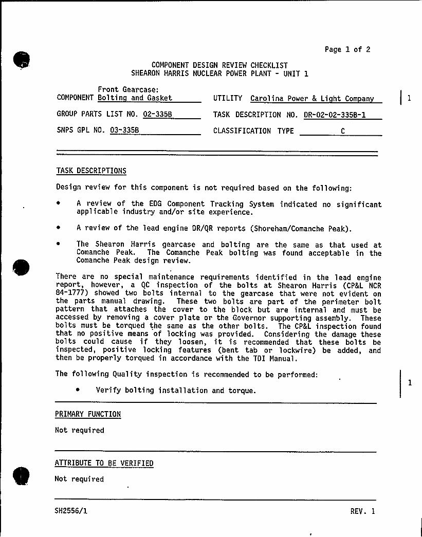
COMPONENT DESIGN REVIEW CHECKLISTSHEARON HARRIS NUCLEAR POWER PLANT - UNIT 1
Page 1 of 2
Front Gearcase:COMPONENT Boltin and Gasket
GROUP PARTS LIST NO. 02-335B
SNPS GPL NO. 03"335B
UTILITY Carolina Power 8 Li ht Com an
TASK DESCRIPTION NO. DR-02" 02-335B-1
CLASSIFICATION TYPE
TASK DESCRIPTIONS
Design review for this component is not required based on the following:
A review of the EDG Component Tracking System indicated no significantapplicable industry and/or site experience.
~ A review of the lead engine DR/gR reports (Shoreham/Comanche Peak).
~ The Shearon Harris gearcase and bolting are the same as that used atComanche Peak. The Comanche Peak bolting was found acceptable in theComanche Peak design review.
There are no special maintenance requirements identified in the lead enginereport, however, a gC inspection of the bolts at Shearon Harris (CP8 L NCR84-1777) showed two bolts internal to the gearcase that were not evident onthe parts manual drawing. These two bolts are part of the perimeter boltpattern that attaches the cover to the block but are internal and must beaccessed by removing a cover plate or the Governor supporting assembly. Thesebolts must be torqued the same as the other bolts. The CP8L inspection foundthat no positive means of locking was provided. Considering the damage thesebolts could cause if they loosen, it is recommended that these bolts beinspected, positive locking features (bent tab or lockwire) be added, andthen be properly torqued in accordance with the TDI Manual.
The following guality inspection is recommended to be performed:
Verify bolting installation and torque.
PRIMARY FUNCTION
Not required
ATTRIBUTE TO BE VERIFIED
Not required
SH2556/1 REV. I
SPECIFIED STANDARDS
Not required
COMPONENT DESIGN REVIEW CHECKLIST Page 2 of 2DR"02-02-335B" 0
REFERENCES
Not required
DOCUMENTATION RE UIRED
Not required
GROUP CHAIRPERSON PROGRAM MANAGER
SH2556/2

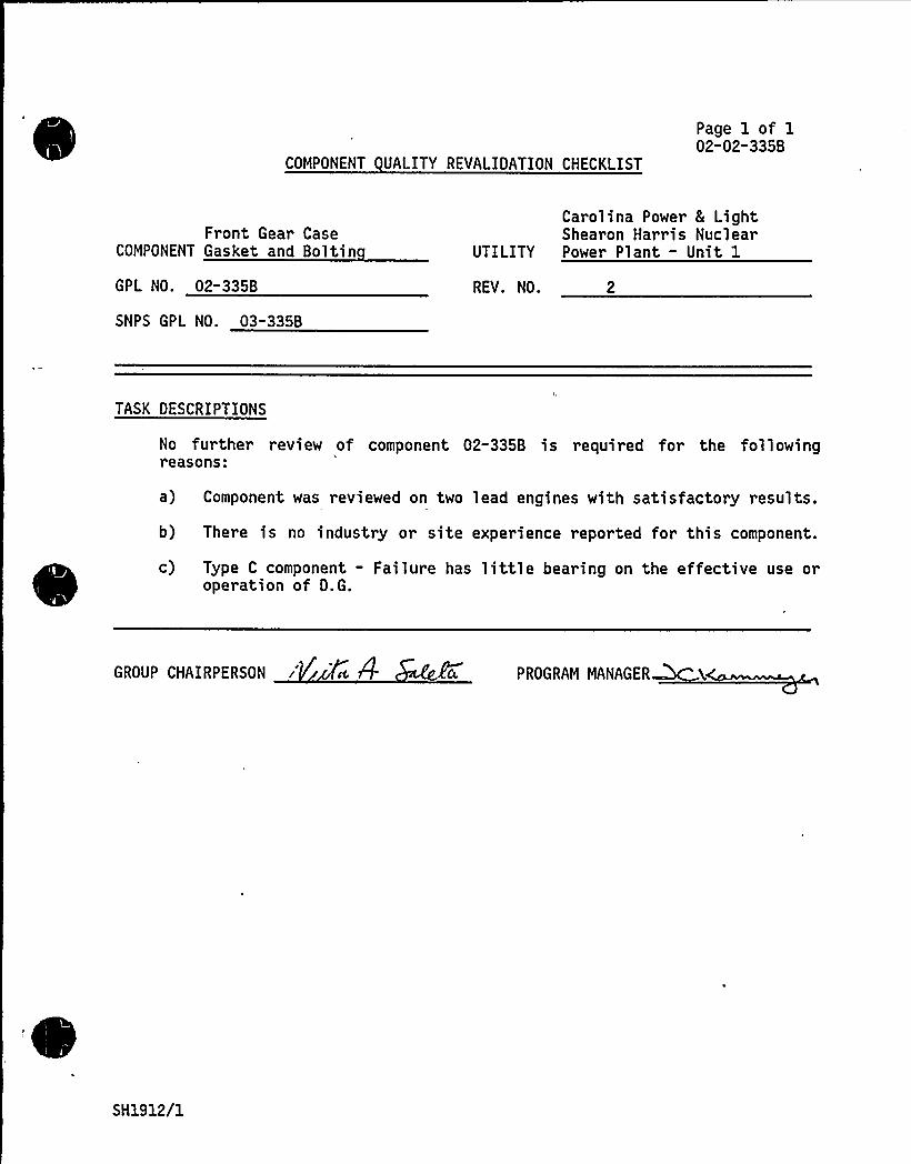
COMPONENT UALITY REVALIDATION CHECKLIST
Page 1 of 102"02"335B
Front Gear CaseCOMPONENT Gasket and Boltin
GPL NO. 02-335B
SNPS GPL NO. 03-335B
Carolina Power 8 LightShearon Harris Nuclear
UTILITY Power Plant - Unit 1
REV. NO. 2
TASK DESCRIPTIONS
No further review of component 02-335B i s required for the fol lowingreasons:
a) Component was reviewed on two lead engines with satisfactory results.
b) There is no industry or site experience reported for this component.
c) Type C component - Failure has little bearing on the effective use oroperation of D.G.
GROUP CHAIRPERSON PROGRAM MANAGER
SH1912/1
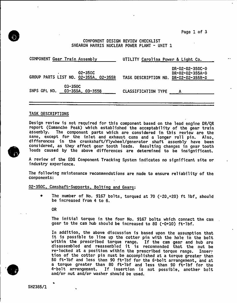
COMPONENT DESIGN REVIEW CHECKLISTSHEARON HARRIS NUCLEAR POWER PLANT - UNIT 1
Page 1 of 3
COMPONENT Gear Train Assembl UTILITY Carolina Power 8 Li ht Co.
DR"02-02"350C-002-350C DR-02-02-355A-0
GROUP PARTS LIST NO. 02-355A 02" 355B TASK DESCRIPTION NO. DR-02-02-355B-0
03"350CSNPS GPL NO. 03-355A 03-355B CLASSIFICATION TYPE A
TASK DESCRIPTIONS
Design review is not required for this component based on the lead engine DR/gRreport (Comanche Peak) which established the acceptability of the gear trainassembly. The component parts which are considered in this review are thesame, except for the inlet and exhaust cams and a longer roll pin. Also,differences in the crankshaft/flywheel/generator shaft assembly have beenconsidered, as they affect gear tooth loads. Resulting changes sn gear toothloads caused by the above differences are determined to be insignificant.
A review of the EDG Component Tracking System indicates no significant site orindustry experience.
The following maintenance recommendations are made to ensure reliability of thecomponents:
02-350C Camshaft-Su orts Boltin and Gears:
~ The number of No. 9167 bolts, torqued at 70 (-20,+20) ft lbf, shouldbe increased from 4 to 6.
OR
The initial torque in the four No. 9167 bolts which connect the camgear to the cam hub should be increased to 80 (-0+10) ft-lbf.In addition, the above discussion is based upon the assumption thatit is possible to line up the cotter pin with the hole in the boltwithin the prescribed torque range. If the cam gear and hub aredisassembled and reassembled it is recommended that the nut bere-locked at a position within the prescribed torque range. Inser-.tion of the cotter pin must be accomplished at a torque greater than50 ft-lbf and less than 90 ft-lbf for the 6-bolt arrangement, and ata torque greater than 80 ft-lbf and less than 90 ft-lbf for the4-bolt arrangement. If insertion is not possible, another boltand/or nut and/or washer should be used.
SH2385/1
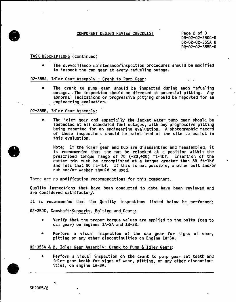
COMPONENT DESIGN REVIEW CHECKLIST Page 2 of 3DR-02-02-350C-0DR-02"02-355A-0
.DR-02"02"355B"0
TASK DESCRIPTIONS (continued)
~ The surveillance maintenance/inspection procedures should be modifiedto inspect the cam gear at every refueling outage.
02-355A Idler Gear Assembl - Crank to Pum Gear:
~ The crank to pump gear should be inspected during each refueling-outage... The inspection should be directed at potential pitting. Anyabnormal indications or progressive pitting should be reported for anengineering evaluation.
02-355B Idler Gear Assembl
~ The idler gear and especially the jacket water pump gear should beinspected at all scheduled fuel outages, with any progressive pittingbeing reported for an engineering evaluation. A photographic recordof these inspections should be maintained at the site to assist inthis evaluation.
F
Note: If the idler gear and hub are disassembled and reassembled, itis recommended that the nut be relocked at a position within theprescribed torque range of 70 (-20,+20) ft-lbf. Insertion of thecotter pin must be accomplished at a torque greater than 50 ft"lbfand less that 90 ft-lbf. If this is not possible, another bolt and/ornut and/or washer should be used.
There are no modification recommendations for this component.
guality inspections that have been conducted to date have been reviewed andare considered satisfactory.
It is recommended that the guality inspections listed below be performed:
02-350C Camshaft-Su orts Boltin and Gears:
~ Verify that the proper torque values are applied to the bolts (cam tocam gear) on Engines 1A-SA and 1B-SB.
~ Perform a visual inspection of the cam gear for Signs of wear,pitting or any other discontinuities on Engine 1A-SA.
02-355A & B Idler Gear Assembl - Crank to Pum 8 Idler Gears:
~ Perform a visual inspection on the crank to pump gear set teeth andidler gear teeth for signs of wear, pitting, or any other discontinu-ities, on engine lA-SA.
SH2385/2
PRIMARY FUNCTION
Not required
COMPONENT DESIGN REVIEW CHECKLIST Page 3 of 3DR-02"02-350C"0DR-02-02-355A-0DR-02-02-355B-0
ATTRIBUTE TO BE VERIFIED
Not required
SPECIFIED STANDARDS
Not required
REFERENCES
Not required
DOCUMENTATION RE UIRED
Not required
GROUP CHAIRPERSON PROGRAM MANAGER
SH2385/3
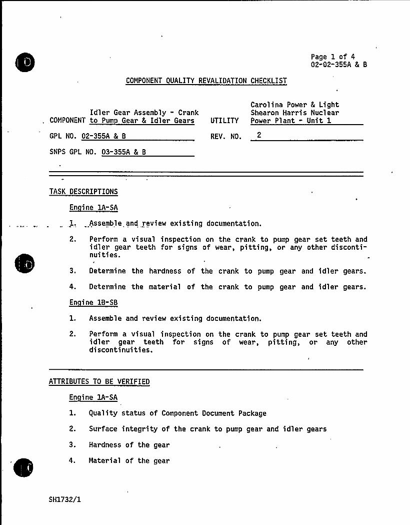
COMPONENT UALITY REVALIDATION CHECKLIST
Page 1 of 402-02-355A 8L B
Idler Gear Assembly - CrankCOMPONENT to Pum Gear 5 Idler Gears
GPL NO. 02"355A 4 B
SNPS GPL NO. 03-35SA 8( B
Carolina Power 8 LightShearon Harris Nuclear
UTILITY Power Plant - Unit 1
REV. NO. 2
TASK DESCRIPTIONS
En ine lA-SA
l. Assemble and review existing documentation.
2. Perform a visual inspection on the crank to pump gear set teeth andidler gear teeth for signs of wear, pitting, or any other disconti-nuities.
3 ~ Determine the hardness of the crank to pump gear and idler gears.
4. Determine the material of the crank to pump gear and idler gears.
1. Assemble and review existing documentation.
2. Perform a visual inspection on the crank to pump gear set teeth andidler gear teeth for signs of wear, pitting, or any otherdiscontinuities.
ATTRIBUTES TO BE VERIFIED
En ine lA-SA
1. guality status of Component Document Package
2. Surface integrity of the crank to pump gear and idler gears
3. Hardness of the gear
4. Material of the gear
SH1732/1
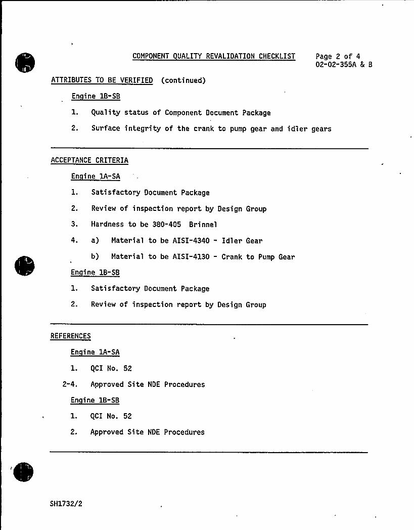
COMPONENT UALITY REVALIDATION CHECKLIST Page 2 of 402-02"355A 5 B
ATTRIBUTES TO BE VERIFIED (continued)
En ine 1B-SB
1. guality status of Component Document Package
2. Surface integrity of the crank to pump gear and idler gears
ACCEPTANCE CRITERIA
1. Satisfactory Document Package
2. Review of inspection report by Design Group
3. Hardness to be 380-405 Brinnel
4. a) Material to be AISI-4340 - Idler Gear
b) Material to be AISI-4130 - Crank to Pump Gear
1. Satisfactory Document Package
2. Review of inspection report by Design Group
REFERENCES
En ine 1A-SA
1. gCI No. 52
2-4. Approved Site NDE Procedures
En ine 1B-SB
l. gCI No. 52
2. Approved Site NDE Procedures
SH1732/2
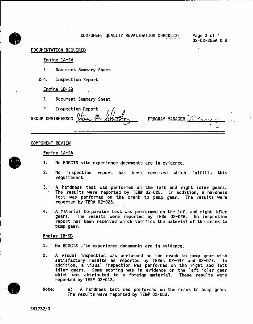
COMPONENT UALITY REVALIDATION CHECKLIST Page 3 of 402"02"355A 8[ B
DOCUMENTATION RE UIRED
1. Document Summary Sheet
2-4. Inspection Report
1. Document Summary Sheet
2. Inspection Report
GROUP CHAIRPERSON PROGRAM MANAGER
COMPONENT REVIEM
En ine 1A-SA
1. No EDGCTS site experience documents are in evidence.
2. No inspection report has been received which fulfills thisrequirement.
3. A hardness test was performed on the left and right idler gears.The results were reported by TER¹ 02-026. In addition, a hardnesstest was performed on the crank to pump gear. The results werereported by TER¹ 02-025.
A Material Comparator test was performed on the left and right idlergears. The results were reported by TER¹ 02-026. No inspectionreport has been received which verifies the material of the crank topump gear.
En ine 1B-SB
1. No EDGCTS site experience documents are in evidence.
2. A visual inspection was performed on the crank to pump gear withsatisfactory results as reported by TER¹s 02-042 and 02-077. Inaddition, a visual inspection was performed on the right and leftidler gears. Some scoring was in evidence on the left idler gearwhich was attributed to a foreign material. These results werereported by TER¹ 02-043.
Note: a) A hardness test was performed on the crank to pump gear.The results were reported by TER¹ 02-063.
SH1732/3
COMPONENT UALITY REVALIDATION CHECKLIST Page 4 of 402-02-355A 8I 8
COMPONENT REVIEW (continued)
b) A Material Comparator test was performed on the left and rightidler gears. The results were reported by TER¹ 02-062.
c) A hardness test was performed on the left and right idlergears. The results were reported by TER¹ 02-062.
RESULTS AND CONCLUSION
The equality Revalidation effort with respect to this component, asoutlined above, is complete. The results have been forwarded to theDesign Review Group for their evaluation and conclusions in support of thefinal report.
En ine 1B-SB
Same as Engine lA-SA
GROUP CHAIRPERSON,' ~IA PROGRAM MANAGER,
SH1732/4
TDI OWNERS GROUP
for
SHEARON HARRIS NUCLEAR POWER PLANT
Idler Gear Assembly: Idler Gear Assemb1y
COMPONENT PART NO : 02-355B
See Component Part No. 02-350C 8 02-355A
COMPONENT UALITY REVALIDATION CHECKLIST
Page 1 of 302"02"355C
Idler Gear Assembly-COMPONENT Bol tin and Gaskets
GPL NO. 02"355C
SNPS GPL NO. 03-355C
Carolina Power 8 LightShearon Harris Nuclear
UTILITY Power Plant - Unit 1
REV. NO. 2
TASK DESCRIPTIONS
1. Assemble and review existing documentation.
2. Visually inspect the bolting and gaskets for signs of distress.
Same as Engine 1A-SA
ATTRIBUTES TO BE VERIFIED
1. guality status of Component Document Package
2. Conditions of bolting and gaskets
Same as Engine 1A-SA
ACCEPTANCE CRITERIA
1. Satisfactory Document Package
2. Review of inspection report by the Design Group
SH1914/1
COMPONENT UALITY REVALIDATION CHECKLIST Page 2 of 3-02-02-355C
ACCEPTANCE CRITERIA (continued)
En ine 1B-SB
Same as Engine 1A-SA
REFERENCES
En ine 1A-SA
1. gCI No. 52
2. Approved Site NDE Procedures
Same as Engine 1A-SA
DOCUMENTATION RE UIRED
1. Document Summary Sheet
2. Inspection Report
Same as Engine -SAI
GROUP CHAIRPERSON PROGRAM MANAGER—C Yi~~
'
COMPONENT REVIEW
En ine 1A-SA
1. No EDGCTS site experience documents are in evidence.
2. No inspection report has been received which fulfills thisrequirement.
SH1914/2

COMPONENT UALITY REVALIDATION CHECKLIST Page 3 of 302-02-355C
COMPONENT REVIEW (continued)
En ine 1B-SB
1. No EDGCTS site experience documents are in evidence.
2. The bolt heads were free from deformation and the bolt markings wereidentified. The gaskets were inaccessible, however, there was noapparent leakage. This was reported by TER¹s 02-044 and 089.
Note: a) The bolt markings were reported by TER¹ 02-044.
RESULTS AND CONCLUSION
En ine 1A-SA
The equality Revalidation effort with respect to this component, asoutlined above, is complete. The results have been forwarded to theDesign Review Group for their evaluation and conclusions in support ofthe final report.
Same as Engine lA-SA
GROUP CHAIRPERSON iclA k W~ PROGRAM MANAGER . I 'cpu~~ "~
SH1914/3
COMPONENT DESIGN REVIEW CHECKLISTSHEARON HARRIS NUCLEAR POWER PLANT - UNIT 1
Page 1 of 2I
COMPONENT Fl heel
GROUP PARTS LIST NO. 02-330A
SNPS GPL NO. 03-330A
UTILITY Carolina Power 8 Li ht Com an
TASK DESCRIPTION NO: DR-02-02-330A-0
CLASSIFICATION TYPE A
TASK DESCRIPTIONS
Design review for this component is not required based on the following:
There is no relevant nuclear or non-nuclear experience listed in theComponent Tracking System.
The DR/gR report for Comanche Peak indicated a sufficiently largefactor of safety for the flywheel to cover the larger diameterflywheel used at Shearon Harris (90 inch versus 68 inch).
~ ~
~
~
There are no maintenance or modification recommendations for this component.
guality Revalidation for this component is not required.
PRIMARY FUNCTION
Not required
ATTRIBUTE TO BE VERIFIED
Not required
SPECIFIED STANDARDS
Not required
REFERENCESI
Not required
SH2088/1
DOCUMENTATION RE UIRED
Not required
COMPONENT DESIGN REVIEW CHECKLIST Page 2 of 2DR"02"02-330A"0
GROUP CHAIRPERSON ROGRAM MANAGER C N~
'SH2088/2

.COMPONENT DESIGN REVIEW CHECKLIST
SHEARON HARRIS NUCLEAR POWER PLANT - UNIT 1
Page 1 of 2
COMPONENT Fl heel-Boltin
GROUP PARTS LIST NO. 02-330B
SNPS GPL NO. 03-330B
UTILITY Carolina Power 8 Li ht Com an
TASK DESCRIPTION NO. DR"05"02-330B-0
CLASSIFICATION TYPE
TASK DESCRIPTIONS
Design review for this component is not required based on the review of theComanche Peak lead engine DR/gR report, design information furnished in TDIParts Manual Vol. II (Ref. 2), and the EDG Component Tracking System for appli-cable industry and site exper ience (Refs. 3 and 4). The Component TrackingSystem cited TDI Service Information Memo No. 64H for an increase in torqueload for the in-line engine flywheel bolts; the memo, however, does not applyto the V-16 engines and therefore has no impact on the Shearon Harris site.
The flywheel assembly for Shearon Harris has the identical quantity (12) andpart numbers (97253 and F-090-038 for bolt and nut, respectively), as well asbolt torque requirement (4,500 ft-lb) for the flywheel bolting components asthose for the Comanche Peak Station (Ref. 5). However, the design of theflywheels is different with the engine flywheels for the Shearon Harris sitebeing considerably larger.
At both Comanche Peak and Shearon Harris, the flywheel is assembled to theengine crankshaft flange and the generator flange with the mating surfaceslubricated with "anti-seize lubricant; the flywheel bolts are lubricated andfitted to the bolt-holes. Assuming that the peak torque transient for all TDIV-16 engines does not vary significantly, the flywheel assembly procedureindicated results in a favorable ratio of the torque transmission capabilityover the peak torque transient. Review of Comanche Peak DR/gR Report (Ref. 1)further indicates that a large design margin exists, and that two, bolts wouldbe adequate to carry the applied shear load from the peak transient torque.The flywheel bolting at Shearon Harris should therefore be adequate for itsintended application.
There are no modification or maintenance recommendations for this component.
guality Revalidation is not required for the flywheel bolting.
SH2457/1

PRIMARY FUNCTION
Not required
COMPONENT DESIGN REVIEW CHECKLIST Page 2 of 2DR-02-02-330B"0
ATTRIBUTE TO BE VERIFIED
Not required
SPECIFIED STANDARDS
Not required
REFERENCES
1. Comanche Peak Steam Electric Station - Unit 1, DR/gR Report for GroupParts List No. 02-330B
2. TDI Parts Manual, Volume II, for Model DSRV-16-4 Diesel Engine/Generator,Shearon Harris Nuclear Power Plant, Units 1, 2, 3, and 4, Parts List No.02-33-0-01-14 and Drawing No. 02-330-01
3. Emergency Diesel Generator Component Tracking System - Nuclear andNon-Nuclear Industry Experience dated October 15, 1984
4. Emergency Diesel Generator Component Tracking System - Shearon HarrisNuclear Power Plant dated October 15, 1984
5. TDI Parts Manual, Volume II, for Model DSRV-16-4 Diesel Engine/Generator, Comanche Peak Power Station, Parts List 02-330-02-05 andDrawing No. 101505
DOCUMENTATION RE UIRED
Not required
GROUP CHAIRPERSON ROGRAM MANAGER~C cC
'SH2457/2
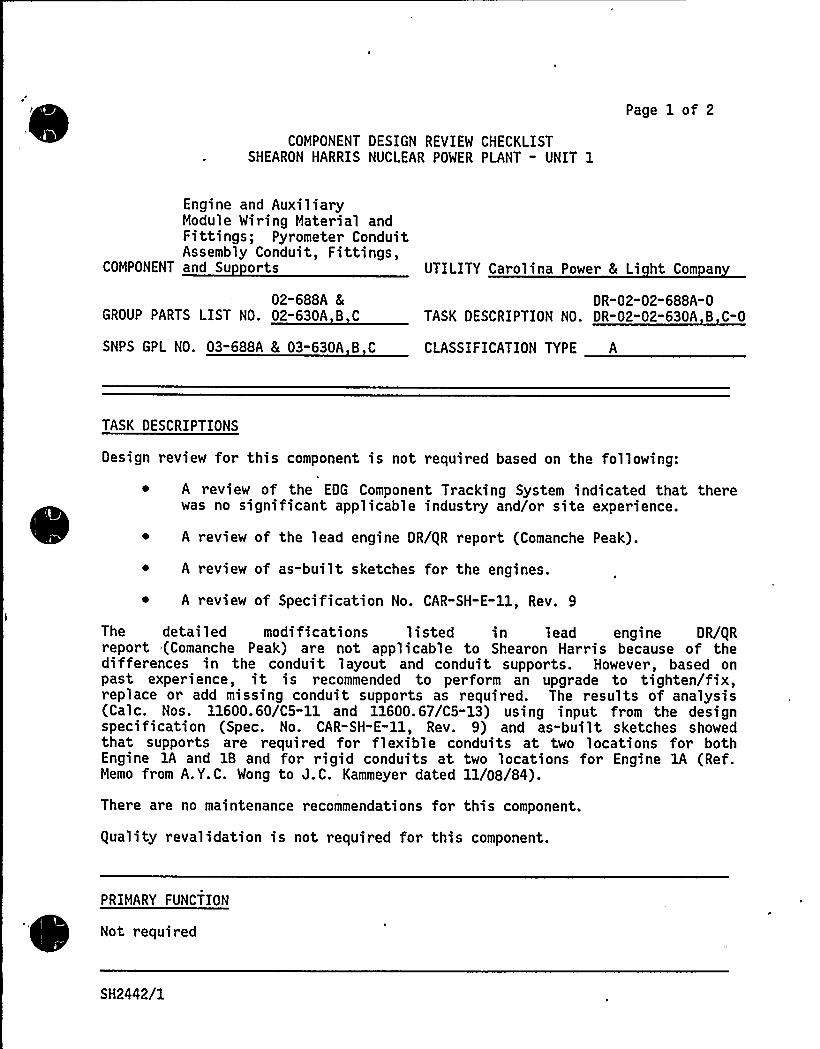
COMPONENT DESIGN REVIEW CHECKLISTSHEARON HARRIS NUCLEAR POWER PLANT - UNIT 1
Page 1 of 2
Engine and AuxiliaryModule Wiring Material andFittings; Pyrometer ConduitAssembly Conduit, Fittings,
COMPONENT and Su orts
02-688A 8GROUP PARTS LIST NO. 02"630A B C
SNPS GPL NO. 03-688A & 03-630A B C
UTILITY Carolina Power 5 Li ht Com an
DR-02-02" 688A-0TASK DESCRIPTION NO. DR-02"02"630A B C-0
CLASSIFICATION TYPE A
TASK DESCRIPTIONS
Design review for this component is not required based on the following:
~ A review of the EDG Component Tracking System indicated that therewas no significant applicable industry and/or site experience.
A review of the lead engine DR/gR report (Comanche Peak).
A review of as-built sketches for the engines.
~ A review of Specification No. CAR-SH-E-ll, Rev. 9
The detailed modifications listed in lead engine DR/gRreport (Comanche Peak) are not applicable to Shearon Harris because of thedifferences in the conduit layout and conduit supports. However, based onpast experience, it is recommended to perform an upgrade to tighten/fix,replace or add missing conduit supports as required. The results of analysis(Gale. Nos. 11600.60/C5-11 and 11600.67/C5-13) using input from the designspecification (Spec. No. CAR-SH-E-ll, Rev. 9) and as-built sketches showedthat supports are required for flexible conduits at two locations for bothEngine lA and 1B and for rigid conduits at two locations for Engine 1A (Ref.Memo from A.Y.C. Wong to J.C. Kammeyer dated ll/08/84).
Ther e are no maintenance recommendations for this component.
guality revalidation is not required for this component.
PRIMARY FUNCTION
Not required
SH2442/1

COMPONENT DESIGN REVIEW CHECKLIST
ATTRIBUTE TO BE VERIFIED
Not required
Page 2 of 2DR"02"02-688A 8c
DR"02 02-630A,B,C-O
SPECIFIED STANDARDS
Not required
REFERENCES
Not required
DOCUMENTATION RE UIRED
Not required
GROUP CHAIRPERSON PROGRAM MANAGER ~C Ma.~~~
SH2442/2

TDI OWNERS GROUP
for
SHEARON HARRIS NUCLEAR POWER PLANT
Pyrometer Conduit Assembly: Conduit Fittings
COMPONENT PART NO.: OP 63OB
See Component Part No. O2-63OA
TDI OWNERS GROUP
for
SHEARON HARRIS NUCLEAR POWER PLANT
Pyrometer Conduit Assembly: Support
COMPONENT PART NO : 02-630C
See Component Part No.02-630A
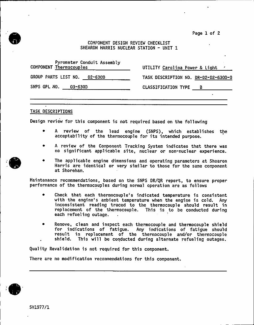
COMPONENT DESIGN REVIEW CHECKLISTSHEARON HARRIS NUCLEAR STATION - UNIT 1
Page 1 of 2
Pyrometer Conduit AssemblyCOMPONENT Thermocou les
GROUP PARTS LIST NO. 02"630D
UTILITY Carolina Power 8 Li ht
TASK DESCRIPTION NO. DR-02-02" 630D-O
SNPS GPL NO. 03"630D CLASSIFICATION TYPE B
TASK DESCRIPTIONS
Design review for this component is not required based on the following
A review of the lead engine (SNPS), which establishes theacceptability of the thermocouple for its intended purpose.
A review of the Component Tracking System indicates that there wasno significant applicable site, nuclear or non-nuclear experience.
The applicable engine dimensions and operating parameters at ShearonHarris are identical or very similar to those for the same componentat Shoreham.
Maintenance recommendations, based on the SNPS DR/gR report, to ensure properperformance of the thermocouples during normal operation are as follows
~ Check that each thermocouple's indicated temperature is consistentwith the engine s ambient temperature when the engine is cold. Anyinconsistent reading traced to the thermocouple should result inreplacement of the thermocouple. This is to be conducted duringeach refueling outage.
Remove, clean and inspect each thermocouple and thermocouple shieldfor indications of fatigue. Any indications of fatigue shouldresult in replacement of the thermocouple and/or thermocoupleshield. This will be conducted during alternate refueling outages.
guality Revalidation is not required for this component.
There are no modification recommendations for this component.
SH1977/1

lE
~ rw n
'RIMARY FUNCTION
Not required
COMPONENT DESIGN REVIEW CHECKLIST Page 2 of 2DR"02-02-630D-O
ATTRIBUTE TO BE VERIFIED
Not required
SPECIFIED STANDARDS
Not required
REFERENCES
Not required
DOCUMENTATION RE UIRED
Not required
GROUP CHAIRPERSON PROGRAM MANAGER 4k'I is v ~
SH1977/2
TDI OWNERS GROUP
fol
SHEARON HARRIS NUCLEAR POWER PLANT
Engine 5 Aux Module Wiring Material- Conduit 5 Fittings;Pyrometer Assembly - Conduit, Fitting, Supports
COMPONENT PART NO.: 02-688A
See Component Part No. 02-630C
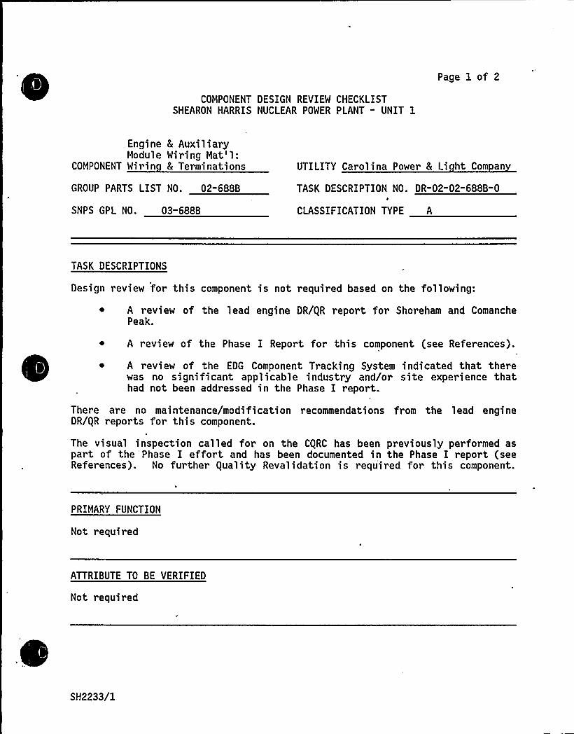
COMPONENT DESIGN REVIEW CHECKLISTSHEARON HARRIS NUCLEAR POWER PLANT " UNIT 1
Page 1 of 2
Engine 8 AuxiliaryModule Wiring Mat'1:
COMPONENT Wirin 8 Terminations
GROUP PARTS LIST NO ~ 02-688B
SNPS GPL NO. 03-688B
UTILITY Carolina Power 8 Li ht Com an
TASK DESCRIPTION NO. DR-02"02-688B-0
CLASSIFICATION TYPE A
TASK DESCRIPTIONS
Design review for this component is not required based on the following:
~ A review of the lead engine DR/gR report for Shoreham and ComanchePeak.
~ A review of the Phase I Report for this component (see References).
~ A review of the EDG Component Tracking System indicated that therewas no significant applicable industry and/or site experience thathad not been addressed in the Phase I report.
There are no maintenance/modification recommendations from the lead engineDR/gR reports for this component.
The visual inspection called for on the CgRC has been previously performed aspart of the Phase I effort and has been documented in the Phase I report (seeReferences). No further guality Revalidation is required for this component.
PRIMARY FUNCTION
Not required
ATTRIBUTE TO BE VERIFIED
Not required
.SH2233/1
SPECIFIED STANDARDS
None
COMPONENT DESIGN REVIEW CHECKLIST Page 2 of 2DR-02" 02-688B-O
REFERENCES
"Emergency Diesel Generator Auxiliary Module Control Miring and Terminationgualification Review," prepared by Stoner & Mebster Engineering Corporation,July, 1984.
DOCUMENTATION RE UIRED
None
GROUP CHAIRPERSON PROGRAM MANAGER
SH2233/2
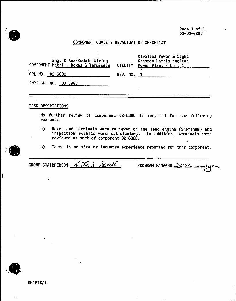
COMPONENT UALITY REVALIDATION CHECKLIST
Page 1 of 102"02"688C
Eng. & Aux-Module WiringCOMPONENT Mat'1 - Boxes 8 Terminals
GPL NO. 02-688C
SNPS GPL NO. 03-688C
Carolina Power & LightShearon Harris Nuclear
UTILITY Power Plant - Unit 1
REV. NO. 1
TASK DESCRIPTIONS
No further revi ew of component 02-688C is required for the fol 1 owingreasons:
a) Boxes and terminals were reviewed on the lead engine (Shoreham) andinspection results were satisfactory. In addition, terminals werereviewed as part of component 02-688B.
b) There is no site or industry experience reported for this component.
GROUP CHAIRPERSON Mvt, PROGRAM MANAGER
SH1816/1
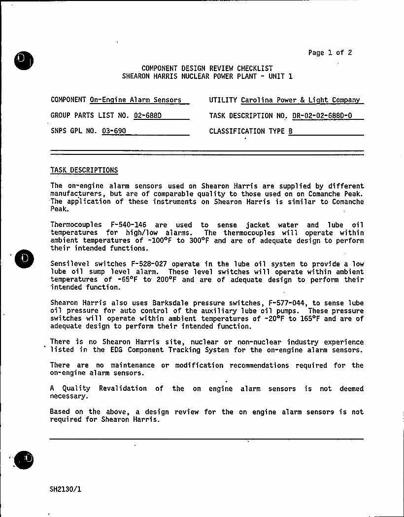
COMPONENT DESIGN REVIEW CHECKLISTSHEARON HARRIS NUCLEAR POWER PLANT " UNIT 1
Page 1 of 2
COMPONENT On-En ine Alarm Sensors UTILITY Carolina Power L Li ht Com an
GROUP PARTS LIST NO. 02"688D TASK DESCRIPTION NO. DR"02-02-688D-0
SNPS GPL NO. 03-690 CLASSIFICATION TYPE B
TASK DESCRIPTIONS
The on-engine alarm sensors used on Shearon Harris are supplied by differentmanufacturers, but are of comparable quality to those used on on Comanche Peak.-The application of these instruments on Shearon Harris is similar to ComanchePeak.
Thermocouples F-540-146 are used to sense jacket water and lube oiltemperatures for high/low alarms. The thermocouples will operate withinambient temperatures of -100 F to 300'F and are of adequate design to performtheir intended functions.
Sensilevel switches F-528-027 operate in the lube oil system to provide a lowlube oil sump level alarm. These level switches will operate within ambienttemperatures of -65 F to 200 F and are of adequate design to perform theirintended function.
Shearon Harris also uses Barksdale pressure switches, F-577-044, to sense lubeoil pressure for auto control of the auxiliary lube oil pumps. These pressureswitches -will operate within ambient temperatures of -204F to 1654F and are ofadequate design to perform their intended function.
There is no Shearon Harris site, nuclear or non-nuclear industry experiencelisted in the EDG Component Tracking System for the on-engine alarm sensors.
There are no maintenance or modification recommendations required for theon-engine alarm sensors.
A equality Revalidation of the on engine alarm sensors is not deemednecessary.
Based on the above, a design review for the on engine alarm sensors is notrequired for Shearon Harris.
SH2130/1
PRIMARY FUNCTION
Not required
COMPONENT DESIGN REVIEW CHECKLIST Page 2 of 2DR"02-02-688D-O
ATTRIBUTE TO BE VERIFIED
Not required
SPECIFIED STANDARDS
Not required
REFERENCES
Not required
DOCUMENTATION RE UIRED
Not required
GROUP CHAIRPERSON PROGRAM MANAGER
SH2130/2

Cl
COMPONENT DESIGN REVIEW CHECKLISTSHEARON HARRIS NUCLEAR POWER PLANT " UNIT 1
Page 1 of 2
COMPONENT Off-En ine Alarm Sensors
GROUP PARTS LIST NO. 02-689
SNPS GPL NO. 99-691A
UTILITY Carolina Power L Li ht Com an
TASK DESCRIPTION NO. DR-02-02-689-0
CLASSIFICATION TYPE B
TASK DESCRIPTIONS
The application of the off engine alarm sensors used on Shearon Harris issimilar to that used on Comanche Peak, with the exception of the Magnetrollevel switch (TDI Part No. F-528-042). This level switch is used to provide ahigh or high/high output condition to control the fuel oil day tank inlet valveand to start/stop the fuel oil transfer pumps. Also, Shearon Harris uses aliquid level transmitter (TDI Part No. 74046-206) to provide a high/low outputsignal to activate alarms on the annunciator. A review of vendor informationshows that these components are of adequate design to perform their intended
~
~
~funct> on.
There is no Shearon Harris site, nuclear or non-nuclear industry experiencelisted in the EDG Component Tracking System for the off-engine alarm sensors.
There are no maintenance or modification recommendations required for theoff-'ngine alarm sensors.
guality Revalidation of the off engine alarm sensors is not deemed necessary.
Based on the above, a design review for the off engine alarm sensors is notrequired for Shearon Harris.
PRIMARY FUNCTION
Not required
ATTRIBUTE TO BE VERIFIED
Not required
SH2131/1
SPECIFIED STANDARDS
Not required
COMPONENT DESIGN REVIEW CHECKLIST Page 2 of 2DR-02-02-689-0
REFERENCES
Not required
DOCUMENTATION RE UIRED
Not required
GROUP CHAIRPERSON PROGRAM MANAGER DC
.
SH2131/2
Page 1 of 2
COMPONENT DESIGN REVIEW CHECKLISTSHEARON HARRIS NUCLEAR POWER PLANT - UNIT 1
COMPONENT Overs eed Tri : Governor UTILITY Carolina Power & Li ht Co.
GROUP PARTS LIST NO. 02-410A TASK DESCRIPTION NO. DR-02-02-410A-0
SNPS GPL NO. 03"410A CLASSIFICATION TYPE A
TASK DESCRIPTIONS
Design Review is not required for this component, based on the Shoreham leadengine DR/gR report, which establishes the acceptability of the overspeed tripgovernor.
A review of the Component Tracking System indicates no significant applicablenuclear, non-nuclear or site experience.
The following quality inspections are recommended to ensure component qualityand performance:
~ Verify p~oper installation and calibration of the governor over speedtrip'n accordance with the Installation and Oil Supply Topicof Woodward Documentation, TDI Manual.
~ Verify that proper operational procedures are used on the over-speed trip governor, in accordance with Woodward Documentation,TDI Manual.
The- following:maintenance items, from the lead engine DR/gR report (Shoreham),are recommended for Shearon Harris to ensure reliability of the overspeed tripgovernor:
~ Modify the surveillance testing procedures to include verificationthat the overspeed trip is correctly set to an over speed tripsetting of 518 +/- 5 rpm at every refueling outage, ensuring thatboth the electric governor and the mechanical backup governor areproperly returned to their normal settings following the overspeedtest. The test is to be performed with no load on the engine byincreasing the normal governor's speed setting(s) until a tripoccurs. After several inspection periods, the history of therequired adjustments should be reviewed to evaluate and possiblymodify the testing interval.
~ After setting the overspeed governor, the adjustment screw positionsshould be mar ked with Torque-Seal to reveal any unintended changesin the set positions.
There are no modification recommendations for this component.
SH2005/1
PRIMARY FUNCTION
Not required
COMPONENT UALITY REVALIDATION CHECKLIST Page 2 of 2DR-02-02-410A-0
ATTRIBUTE TO BE VERIFIED
Not re'quired
SPECIFIED STANDARDS
Not required
REFERENCES
Not required
DOCUMENTATION RE UIRED
Not required
GROUP CHAIRPERSON PROGRAM MANAGER. ~
SH2005/2
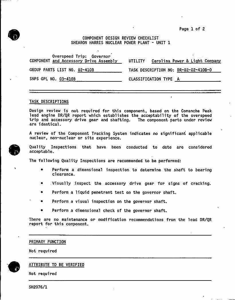
Page 1 of 2
COMPONENT DESIGN REVIEW CHECKLISTSHEARON HARRIS NUCLEAR POWER PLANT - UNIT 1
Overspeed Trip: GovernorCOMPONENT and Accessor Drive Assembl UTILITY Carolina Power 8 Li ht Com an
GROUP PARTS LIST NO. 02"4108
SNPS GPL NO. 03-410B
TASK DESCRIPTION NO: DR"02"02-410B-0
CLASSIFICATION TYPE A
TASK DESCRIPTIONS
Design review is not required for this component, based on the Comanche Peaklead engine DR/gR .report which establishes the acceptability of the overspeedtrip and accessory drive gear and shafting. The component parts under revieware identical.
A review of the Component Tracking System indicates no significant applicablenuclear, non-nuclear or site experience.
guality Inspections that have been conducted to date are considered~
~
~
acceptable.
The following guality Inspections are recommended to be performed:
Perform a dimensional inspection to determine the shaft 'to bearingclearance.
.Visually ,inspect the accessory drive gear for signs of cracking.
Perform a liquid penetrant test on the governor shaft.
Perform a visual inspection on the governor shaft.
Perform a dimensional check of the governor shaft.
There are no maintenance or modification recommendations from the lead DR/gRreport for this component.
PRIMARY FUNCTION
Not required
ATTRIBUTE TO BE VERIFIED
Not required
SH2076/1

a"
SPECIFIED STANDARDS
Not required
COMPONENT DESIGN REVIEW CHECKLIST Page 2 of 2DR-02"02-410B-0
REFERENCES
Not required
DOCUMENTATION RE UIRED
Not required
GROUP CHAIRPERSON PROGRAM MANAGER)
,SH2076/2
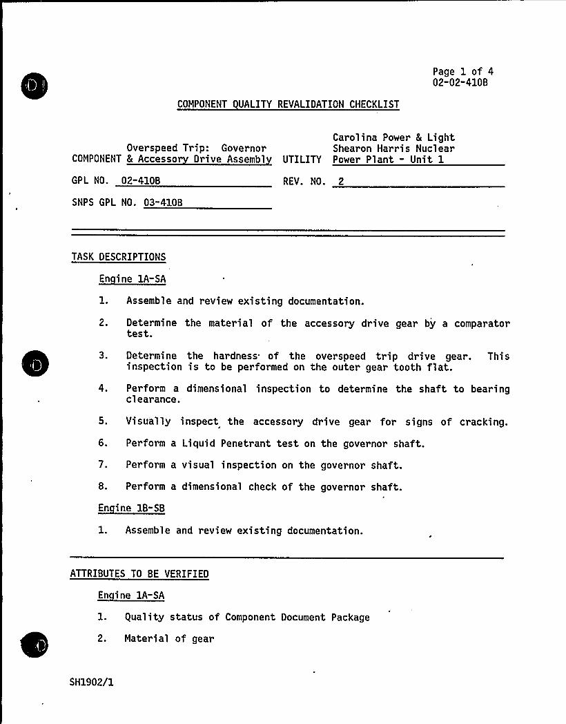
»COMPONENT UALITY REVALIDATION CHECKLIST
Page 1 of 402-02-410B
Overspeed Trip: GovernorCOMPONENT & Accessor Drive Assembl
Carolina Power 8 LightShearon Harris Nuclear
UTILITY Power Plant - Unit 1
GPL NO. 02-410B
SNPS GPL NO. 03"410B
REV. NO. 2
TASK DESCRIPTIONS
~E
l. Assemble and review existing documentation.
2. Determine the material of the accessory drive gear by a comparatortest.
3. Determine the hardness of the overspeed trip drive gear. Thisinspection is to be performed on the outer gear tooth flat.
4. Perform a dimensional inspection to determine the shaft to bearingclearance.
5. Visually inspect the accessory drive gear for signs of cracking.
6. Perform a Liquid Penetrant test on the governor shaft.
7. Perform a visual inspection on the governor shaft.
8. Perform a dimensional check of the governor shaft.
1. Assemble and review existing documentation.
ATTRIBUTES TO BE VERIFIED
En ine lA-SA
1. guality status of Component Document Package
,
2. Material of gear
SH1902/1
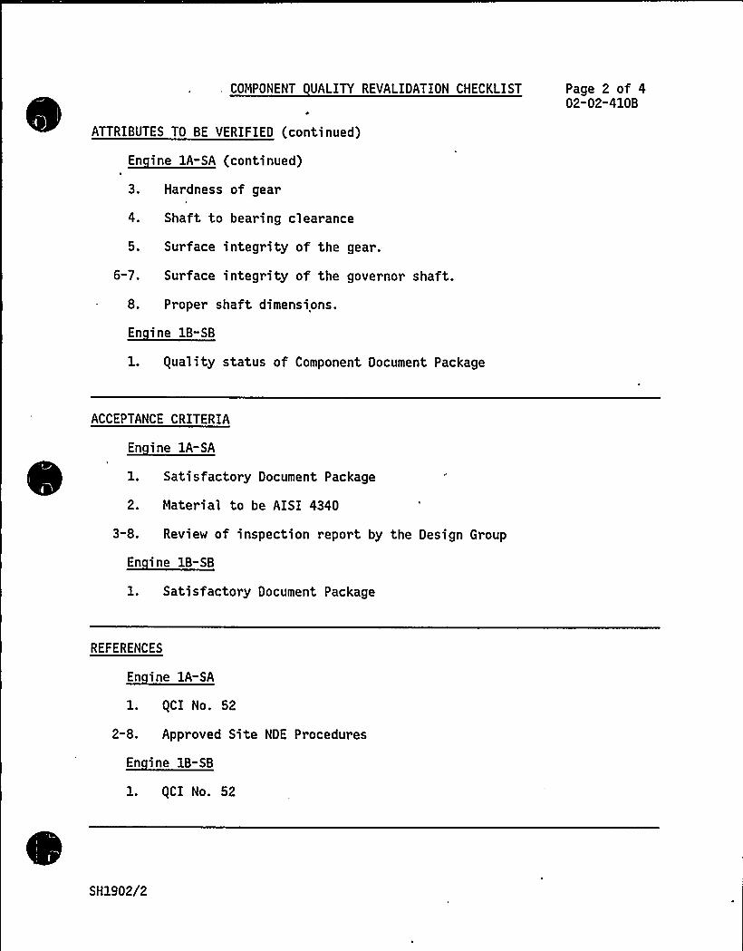
, COMPONENT UALITY REVALIDATION CHECKLIST
ATTRIBUTES TO BE VERIFIED (continued)~( '
Page 2 of 402-02-410B
3.
4.
5.
6-7.
8.
Hardness of gear
Shaft to bearing clearance
Surface integrity of the gear.
Surface integrity of the governor shaft.
Proper shaft dimensions.
~E
1. guality status of Component Document Package
ACCEPTANCE CRITERIA
1. Satisfactory Document Package
2. Material to be AISI 4340
3-8. Review of inspection report by the Design Group
1. Satisfactory Document Package
REFERENCES
1. gCI No. 52
2-8. Approved Site NDE Procedures
l. gCI No. 52
SH1902/2

I
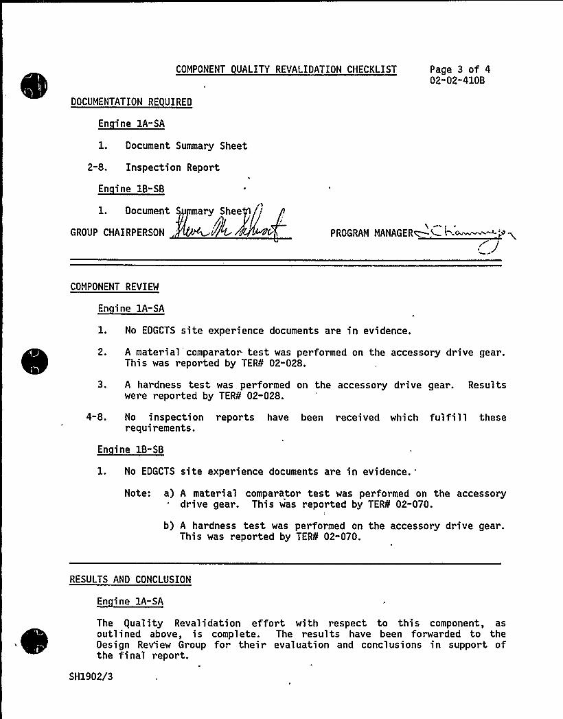
COMPONENT UALITY REVALIDATION CHECKLIST Page 3 of 402"02-410B
DOCUMENTATION RE UIRED
l. Document Summary Sheet
2-8. Inspection Report
En ine 1B-SB
1. Document S mary Sheets
GROUP CHAIRPERSON 'l/~L. PROGRAM MANAGER~Ktwo8j
COMPONENT REVIEW
En ine 1A-SA
2.
No EDGCTS site experience documents are in evidence.
A material comparator test was performed on the accessory drive gear.This was reported by TER¹ 02-028.
3.
4"8.
A hardness test was performed on the accessory drive gear. Resultswere reported by TER¹ 02-028.
No inspection reports have been received which fulfill theserequirements.
En ine 1B-SB
No EDGCTS site experience documents are in evidence.
Note: a) A material comparator test was performed on the accessorydrive gear. This was reported by TER¹ 02-070.
b) A hardness test was performed on the accessory drive gear.This was reported by TER¹ 02-070.
RESULTS AND CONCLUSION
En ine 1A-SA
The guality Revalidation effort with respect to this component, asoutlined above, is complete. The results have been forwarded to theDesign Review Group for their evaluation and conclusions in support ofthe final report.
SH1902/3
COMPONENT UALITY REVALIDATION CHECKLIST
RESULTS AND CONCLUSION (continued)
En ine 1B-SB
Same as Engine 1A-SA
Page 4 of 402"02"410B
GROUP CHAIRPERSON PROGRAM MANAGER —.MKerr
SH1902/4
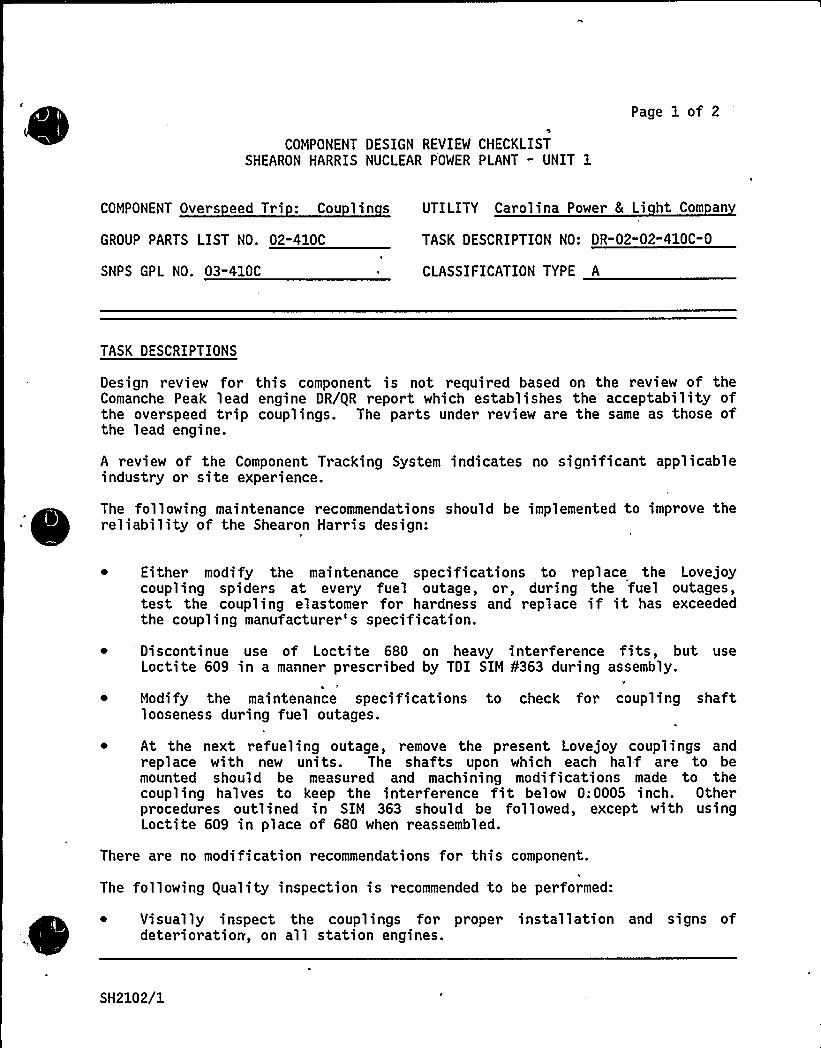
COMPONENT DESIGN REVIEW CHECKLISTSHEARON HARRIS NUCLEAR POWER PLANT - UNIT 1
Page 1 of 2
COMPONENT Over s eed Tri: Cou 1 in s UTILITY Carolina Power 8 Li ht Com an
GROUP PARTS LIST NO. 02-410C
SNPS GPL NO. 03-410C
TASK DESCRIPTION NO: DR-02"02-410C-0
CLASSIFICATION TYPE A
TASK DESCRIPTIONS
Design review for this component is not required based on the review of theComanche Peak lead engine DR/gR report which establishes the acceptability ofthe overspeed trip couplings. The parts under review are the same as those ofthe lead engine.
A review of the Component Tracking System indicates no significant applicableindustry or site experience.
The following maintenance recommendations should be implemented to improve the~ ~
~
~ ~
~
re 1 iabi 1 ity of the Shear on Harri s des ign:
~ Either modify the maintenance specifications to replace the Lovejoycoupling spiders at every fuel outage, or, during the fuel outages,test the coupling elastomer for hardness and replace if it has exceededthe coupling manufacturer's specification.
Discontinue use of Loctite 680 on heavy interference fits, but useLoctite 609 in a manner prescribed by TDI SIM ¹363 during assembly.
Modify the maintenance specifications to check for coupling shaftlooseness during fuel outages.
~ At the next refueling outage, remove the present Lovejoy couplings andreplace with new units. The shafts upon which each half are to bemounted should be measured and machining modifications made to thecoupling halves to keep the interference fit below 0;0005 inch. Otherprocedures outlined in SIM 363 should be followed, except with usingLoctite 609 in place of 680 when reassembled.
There are no modification recommendations for this component.
The following guality inspection is recommended to be performed:
~ Visually inspect the couplings for proper installation and signs ofdeterioration, on all station engines.
SH2102/1
PRIMARY FUNCTION
Not required
COMPONENT DESIGN REVIEW CHECKLIST Page 2 of 2DR"02-02-410C-0
ATTRIBUTE TO BE VERIFIED
Not required
SPECIFIED STANDARDS
Not required
REFERENCES
Not required
DOCUMENTATION RE UIRED
Not required
GROUP CHAIRPERSON PROGRAM MANAGER
SH2102/2
COMPONENT DESIGN REVIEW CHECKLISTSHEARON HARRIS NUCLEAR POWER PLANT - UNIT 1
Page 1 of 2
COMPONENT Overs eed Tri Vent Valve UTILITY Carolina Power & Li ht Com an
GROUP PARTS LIST NO. 02-410D
SNPS GPL NO. 03-410D
TASK DESCRIPTION NO. DR-02-02" 410D-O
~ CLASSIFICATION TYPE A
TASK DESCRIPTIONS
Design review for this component is not required based on the following:
A review of the EDG Component Tracking System indicated that there was nosignificant applicable industry or site experience.
~ A review of the lead engine DR/gR reports (Shoreham and Comanche Peak)
~ Similarity between Shearon Harris and lead engine components
The following maintenance from the Lead Engine DR/gR Report should beimplemented.
~ Replace valve 0-rings every 5 years
There are no modifications required for this component.
No equality revalidation is required for this component.
PRIMARY FUNCTION
Not r equired
ATTRIBUTE TO BE VERIFIED
Not required
'SH2230/1
'SPECIFIED STANDARDS
Not required
COMPONENT DESIGN REVIEW CHECKLIST Page 2 of 2DR-02-02-410B-0
REFERENCES
Not required
DOCUMENTATION RE UIRED
Not required
GROUP CHAIRPERSON PROGRAM MANAGER
SH2230/2
COMPONENT DESIGN REVIEW CHECKLISTSHEARON HARRIS NUCLEAR POWER PLANT " UNIT 1
Page 1 of 2
Governor Drive: Governor & Tach-COMPONENT ometer Drive Gear and Shaft
GROUP PARTS LIST NO. 02-411A
SNPS GPL NO. 03-402A
UTILITY Carolina Power 8 Li ht Com an
TASK DESCRIPTION NO. DR-02-02-411A-0
CLASSIFICATION TYPE A
TASK DESCRIPTIONS
Design review for this component is not required based on the Comanche Peaklead -engine DR/gR report which establishes the acceptability of the governordrive gears and shafts.
A review of the Component Tracking System indicates no significant applicableindustry or site experience.
'E
There are no modifications or maintenance recommendations for this component.
~
~
~ ~ ~
~
~
guality inspections conducted to date have been reviewed and are considere
The ,following quality inspection is recommended to be performed on Engine1A-SA:
dsatisfactory, with the except>on of a hardness test of the governor drsvegears which gave inconclusive results. This hardness inspection is notrequired in the Component guality Revalidation Checklist; the visualinspection recommendation outlined in the Preventive Maintenance Matrix willaccommodate the need for wear inspection on these gears.
~ Perform a liquid penetrant test of the governor drive gear'and shaftfor fatigue cracks in the following areas:
'a 0
b.C.d.
Gear and 'haft contact surfaces and surfaces immediatelyadjacentGear pins and boresVertical shaft to gear keywayReduced shaft diameter of coupling
PRIMARY FUNCTION
Not required
ATTRIBUTE TO BE VERIFIED
Not required
SH2168/1
COMPONENT DESIGN REVIEW CHECKLIST
SPECIFIED STANDARDS
Not requir ed
Page 2 of 2DR-02-02-411A" 0
REFERENCES
Not required
DOCUMENTATION RE UIRED
Not required
GROUP CHAIRPERSON PROGRAM MANAGER X~ ~~-.~a
SH2168/2
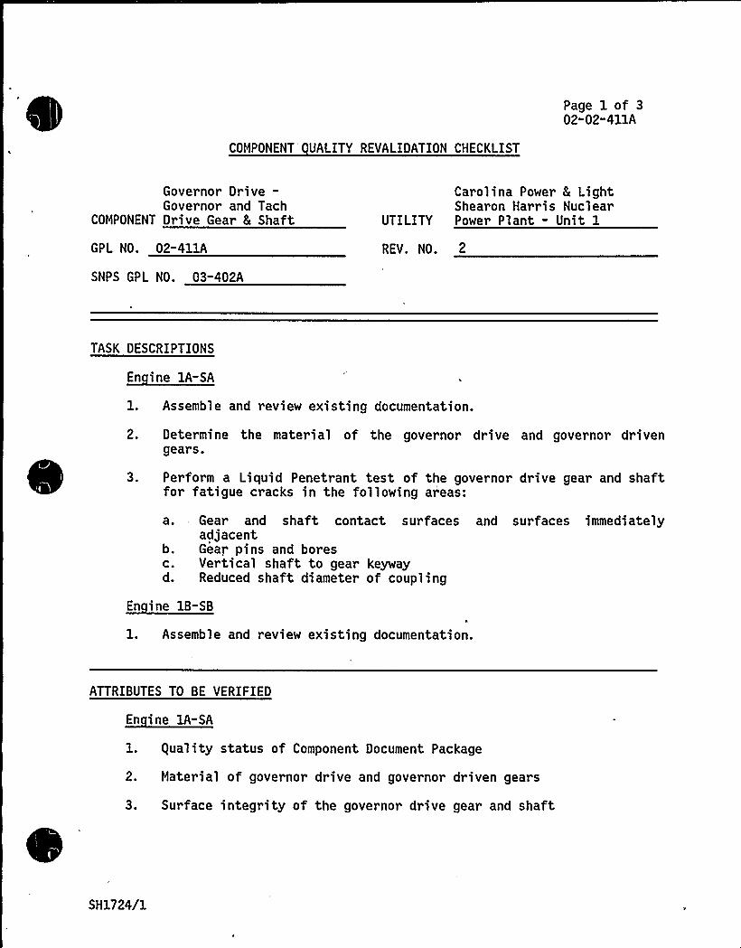
COMPONENT UALITY REVALIDATION CHECKLIST
Page 1 of 302-02"411A
Governor Drive-Governor and Tach
COMPONENT Drive Gear 8 Shaft
Carolina Power 8 LightShearon Harris Nuclear
UTILITY Power Plant - Unit 1
GPL NO. 02-411A REV. NO, 2
SNPS GPL NO. 03-402A
TASK DESCRIPTIONS
~Ei *- A
l. Assemble and review existing documentation.
2. Determine the material of the governor drive and governor drivengears.
3. Perform a Liquid Penetrant test of the governor drive gear and shaftfor fatigue cracks in the following areas:
b.C.d.
a. Gear and shaft contact surfaces and surfaces immediatelyadjacentGear pins and boresVertical shaft to gear keywayReduced shaft diameter of coupling
l. Assemble and review existing documentation.
ATTRIBUTES TO BE VERIFIED
En ine lA-SA
1. guality status of Component Document Package
2. Material of governor drive and governor driven gears
3. Surface integrity of the governor drive gear and shaft
SH1724/1
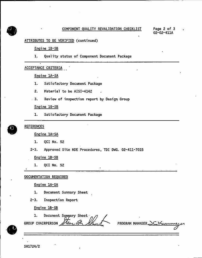
COMPONENT UALITY REVALIDATION CHECKLIST
ATTRIBUTES TO BE VERIFIED (continued)
Page 2 of 302"02-411A
1. guality status of Component Document Package
ACCEPTANCE CRITERIA
1. Satisfactory Document Package
2. Material to be AISI-4142
3. Review of inspection report by Design Group
1. Satisfactory Document Package
REFERENCESnd:l. gCI No. 52
2-3. Approved Site NDE Procedures, TDI DWG. 02-411-7015
l. gCI No. 52
DOCUMENTATION RE UIRED
En ine lA-SA
l. Document Summary Sheet
2-3. Inspection Report
1. Document Sum ary Sheet-
GROUP CHAIRPERSON PROGRAM MANAGER C.K
SH1724/2

f ~
W A t I
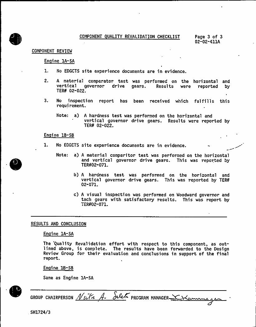
COMPONENT REVIEW
COMPONENT UALITY REVALIDATION CHECKLIST Page 3 of 302-02-411A
1. No EDGCTS site experience documents are in evidence.
2. A material comparator test was performed on the horizontal andvertical governor drive gears. Results were reported byTER¹ 02-022.
3. No inspection report has been received which fulfills thisrequirement.
Note: a) A hardness test was performed on the horizontal andvertical governor drive gears. Results were reported byTER¹ 02"022.
1. No EDGCTS
Note: a)
site experience documents are in evidence.
A material comparitor test was performed on the horizontaland vertical governor drive gears. This was reported byTER¹02-071.
b) A har dness test was performed on the horizontal andvertical governor drive gears. This was reported by TER¹02-071.
c) A visual inspection was performed on Woodward governor andtach gears with satisfactory results. This was report byTER¹02" 071.
RESULTS AND CONCLUSION
En ine 1A-SA
The 'equality Revalidation effort with respect to this component, as out-lined above, is complete. The results have been forwarded to the DesignReview Group for their evaluation and conclusions in support of the finalreport.
Same as Engine lA-SA
GROUP CHAIRPERSON .kite 4 S~~~ PROGRAM MANAGER
, SH1724/3
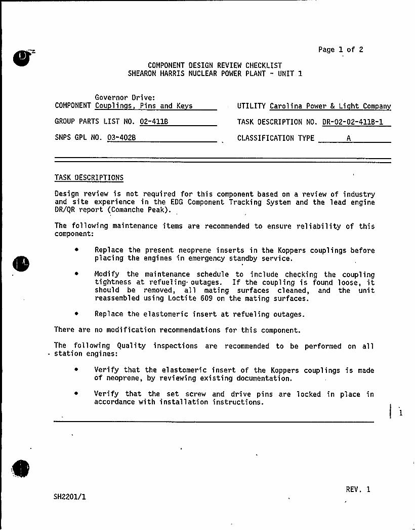
COMPONENT DESIGN REVIEW CHECKLISTSHEARON HARRIS NUCLEAR POWER PLANT - UNIT 1
Page 1 of 2N
Governor Drive:COMPONENT Cou lin s Pins and Ke s UTILITY Carolina Power & Li ht Com an
GROUP PARTS LIST NO. 02-411B TASK DESCRIPTION NO. DR-02-02-411B-1
SNPS GPL NO. 03"402B CLASSIFICATION TYPE A
TASK DESCRIPTIONS
Design review is not required for this component based on a review of industryand site experience in the EDG Component Tracking System and the lead engineDR/gR report (Comanche Peak).
The following maintenance items are recommended to ensure reliability of thiscomponent:
Replace the present neoprene inserts in the Koppers couplings beforeplacing the engines in emergency standby service.
~ Modify the maintenance schedule to include checking the couplingtightness at refueling outages. If the coupling is found loose, itshould be removed, all mating surfaces cleaned, and the unitreassembled using Loctite 609 on the mating surfaces.
Replace the elastomeric insert at refueling outages.
There are no modification recommendations for this component.
The following equality inspections are recommended to be performed on allstation engines:
Verify that the elastomeric insert of the Koppers couplings is madeof neoprene, by reviewing existing documentation.
Verify that the set screw and drive pins are locked in place inaccordance with installation instructions.
SH2201/1REV. I
PRIMARY FUNCTION
Not required
COMPONENT DESIGN REVIEW CHECKLIST Page 2 of 2DR-'02-02-411B-0
ATTRIBUTE TO BE VERIFIED
Not required
SPECIFIED STANDARDS
Not required
REFERENCES
Not required
DOCUMENTATION RE UIRED
Not required
GROUP CHAIRPERSON PROGRAM MANAGER CAW
SH2201/2

COMPONENT DESIGN REVIEW CHECKLISTSHEARON HARRIS NUCLEAR POWER PLANT - UNIT 1
Page 1 of 3
COMPONENT Governor Linka e
GROUP PARTS LIST NO. 02-413A
SNPS GPL NO. 03-413
UTILITY Carolina Power 8 Li ht Com an
TASK DESCRIPTION NO. DR"02-02-413A-0
CLASSIFICATION TYPE A
TASK DESCRIPTIONS
Design review for this component is not required based on the review of theComanche Peak lead engine DR/gR report and the EDG Component Tracking System,which indicates no significant applicable site experience. The ComponentTracking System industry experience, however, reported one incident ofloosening governor linkage components, a valid concern in the absence ofpositive locking devices at the lever clamp screws. The -required preventivemeasure is addressed under maintenance/modification recommendations below.
Component No. 02-413A includes the following items (Ref. 2):
Item Part No.
Lever, GovernorExtensive Link AssemblyCross-shaft Assembly
02-413-10-AL1A-57791A-6133
The cross-shaft assembly includes the fuel control shaft, bearings, and theactuating levers which consist of the cross-shaft lever 02-413-11-AG,connecting to the extensible link assembly, the fuel control levers02-413-11AB, and the shutdown lever 02-413-09-AF.
The governor linkage and cross-shaft assemblies are identical for both ShearonHarris and Comanche Peak and, based on the review for ComanchePeak, are satisfactory for the seismic and operational loads.
The cross-shaft bearings are oil lubricated, sleeve-type, bronze bearings,similar to Comanche Peak design. However, there are some differences in thedesign details for maintaining oil supply to the wicking felt. The arrangementat Shearon Harris (Ref. 3) is a later design apparently having a largelubricant holding volume but without the washer immediately above the felt.The following maintenance and modification recommendations stated in theComanche Peak lead engine DR/gR report should be implemented:
~ The cross-shaft bearings should be lubricated monthly, and allrod-end fittings should be greased at each outage to maintain properservice.
SH2377/1
COMPONENT DESIGN REVIEW CHECKLIST
TASK DESCRIPTION (continued)
Page 2 of3'R-02"02-413A-0
~ To prevent loosening of governor linkage components, a periodicinspection for loose 'parts should be performed and suitable lockinghardware be added to the lever bolts and roll pins experiencing suchproblems.
The following guality inspections as described in the Component equalityRevalidation Checklist and Task Evaluation Report TER No. 99-021, should be
'erformed on all the station engines:
Visual inspection on the governor linkage to detect signs ofcorrosion, wear, pitting, and discoloration.
Verification of the installation of roll pins to hold the fuelcontrol levers to the cross-shaft.
PRIMARY FUNCTION
Not required
ATTRIBUTE TO BE VERIFIED
Not required
SPECIFIED STANDARDS
Not required
SH2377/2
REFERENCES
COMPONENT DESIGN REVIEW CHECKLIST Page 3 of 3DR"02-02" 413A"0
1. Comanche Peak Steam Electric Station - Unit 1, DR/gR Report for ComponentPart No. 02-413A.
2. TDI Parts Manual Volume II, Model DSRV-16-4 Diesel Engine/Generator.Shearon Harris Power Station - Units 1, 2, 3, and 4.
3. TDI Parts Drawings 02-413-12, 02-41312, 02-413-3693, 02-413-3841, and02"413-4933.
4. Emergency Diesel Generator Component Tracking System - Nuclear andNon-Nuclear Industry experience dated October 15, 1984.
5. Emergency Diesel Generator Component Tracking System - Shearon HarrisNuclear Power Station dated October 15. 1984.
DOCUMENTATION RE UIRED
Not required
GROUP CHAIRPERSON ROGRAM MANAGER C.EC
SH2377/3
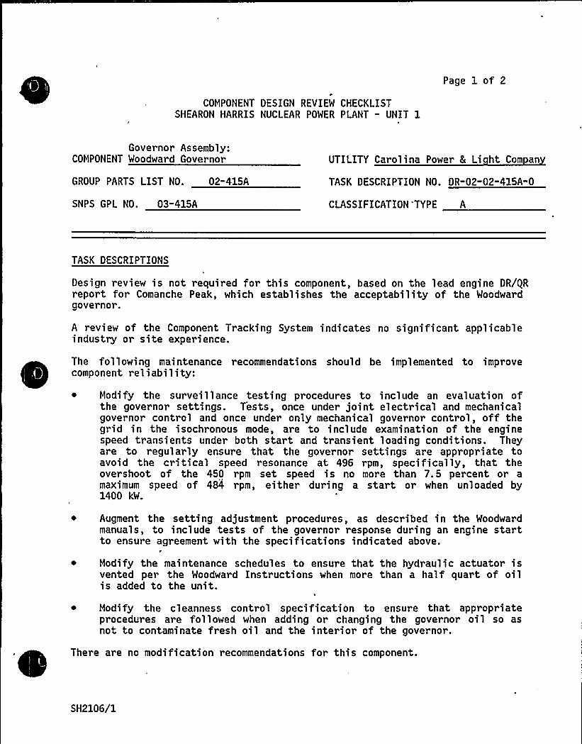
Page 1 of 2
COMPONENT DESIGN REVIEW CHECKLISTSHEARON HARRIS NUCLEAR POWER PLANT — UNIT 1
Governor Assembly:COMPONENT Woodward Governor
GROUP PARTS LIST NO. 02-415A
UTILITY Carolina Power 8 Li ht Com an
TASK DESCRIPTION NO. DR-02-02-415A-0
SNPS GPL NO. 03"415A CLASSIFICATION 'TYPE A
TASK DESCRIPTIONS
Design review is not required for this component, based on the lead engine DR/gRreport for Comanche Peak, which establishes the acceptability of the Woodwardgovernor.
A review of the Component Tracking System indicates no significant applicableindustry or site experience.
The following maintenance recommendations should be implemented to improvecomponent reliability:
Modify the surveillance testing procedures to include an evaluation ofthe governor settings. Tests, once under joint electrical and mechanicalgovernor control and once under only mechanical governor control, off thegrid in the isochronous mode, are to include examination of the enginespeed transients under both start and transient loading conditions. Theyare to regularly ensure that the governor settings are appropriate toavoid the critical speed resonance at 496 rpm, specifically, that theovershoot of the 450 rpm set speed is no more than 7.5 percent or amaximum speed of 484 rpm, either during a start or when unloaded by1400 kW.
Augment the setting adjustment procedures, as described in the Woodwardmanuals, to include tests of the governor response during an engine startto ensure agreement with the specifications indicated above.
Modify the maintenance schedules to ensure that the hydraulic actuator isvented per the Woodward Instructions when more than a half quart of oilis added to the unit.
Modify the cleanness control specification to ensure that appropriateprocedures are followed when adding or changing the governor oil so asnot to contaminate fresh oil and the interior of the governor.
There are no modification recommendations for this component.
SH2106/1
COMPONENT DESIGN REVIEW CHECKLIST
TASK DESCRIPTION (continued)
equality Revalidation is not required for this component.
Page 2 of 2DR-02-02-415A-0
PRIMARY FUNCTION
Not required
ATTRIBUTE TO BE VERIFIED
Not required
SPECIFIED STANDARDS
Not required
REFERENCES
Not required
DOCUMENTATION RE UIRED
Not required
GROUP CHAIRPERSON PROGRAM MANAGER
SH2106/2
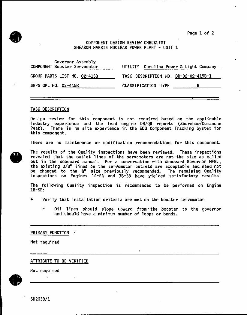
Page 1 of 2
COMPONENT DESIGN REVIEW CHECKLISTSHEARON HARRIS NUCLEAR POWER PLANT - UNIT 1
Governor AssemblyCOMPONENT Booster Servomotor
GROUP PARTS LIST NO. 02"415B
UTILITY Carolina Power L Li ht Com an
TASK DESCRIPTION NO. DR"02-02-415B" 1
SNPS GPL NO. 03"415B CLASSIFICATION TYPE
TASK DESCRIPTION
Design review for this component is not required based on the applicableindustry experience and the lead engine DR/gR reports (Shoreham/ComanchePeak). There is no site experience in the EDG Component Tracking System forthis component.
There are no maintenance or modification recommendations for this component.
The results of the guality inspections have been reviewed. These inspectionsrevealed that the outlet lines of the servomotors are not the size as calledout in the Woodward manual. Per a conversation with Woodward Governor MFG.,the existing 3/8" lines on the servomotor outlets are acceptable and need notbe changed to the >4" size previously recommended. The remaining gualityinspections on Engines lA-SA and 1B-SB have yielded satisfactory results.
The following guality inspection is recommended to be performed on Engine1B"SB:
~ Verify that installation criteria are met on the booster servomotor
Oil lines should slope upward from 'he booster to the governorand should have a minimum number of loops or bends.
PRIMARY FUNCTION
Not required
ATTRIBUTE TO BE VERIFIED
Not required
SH2638/1

SPECIFIED STANDARDS
Not required
COMPONENT DESIGN REVIEW CHECKLIST Page 2 of 2OR-02-02" 415B-1
REFERENCES
Telecon: J. Carbonaro (SWEC) to D. Brown (Woodward) "Adequacy of 3/8 InchOutlet on Booster Servomotor".
DOCUMENTATION RE UIRED
Not required
GROUP CHAIRPERSON PROGRAM MANAGER
SH2638/2
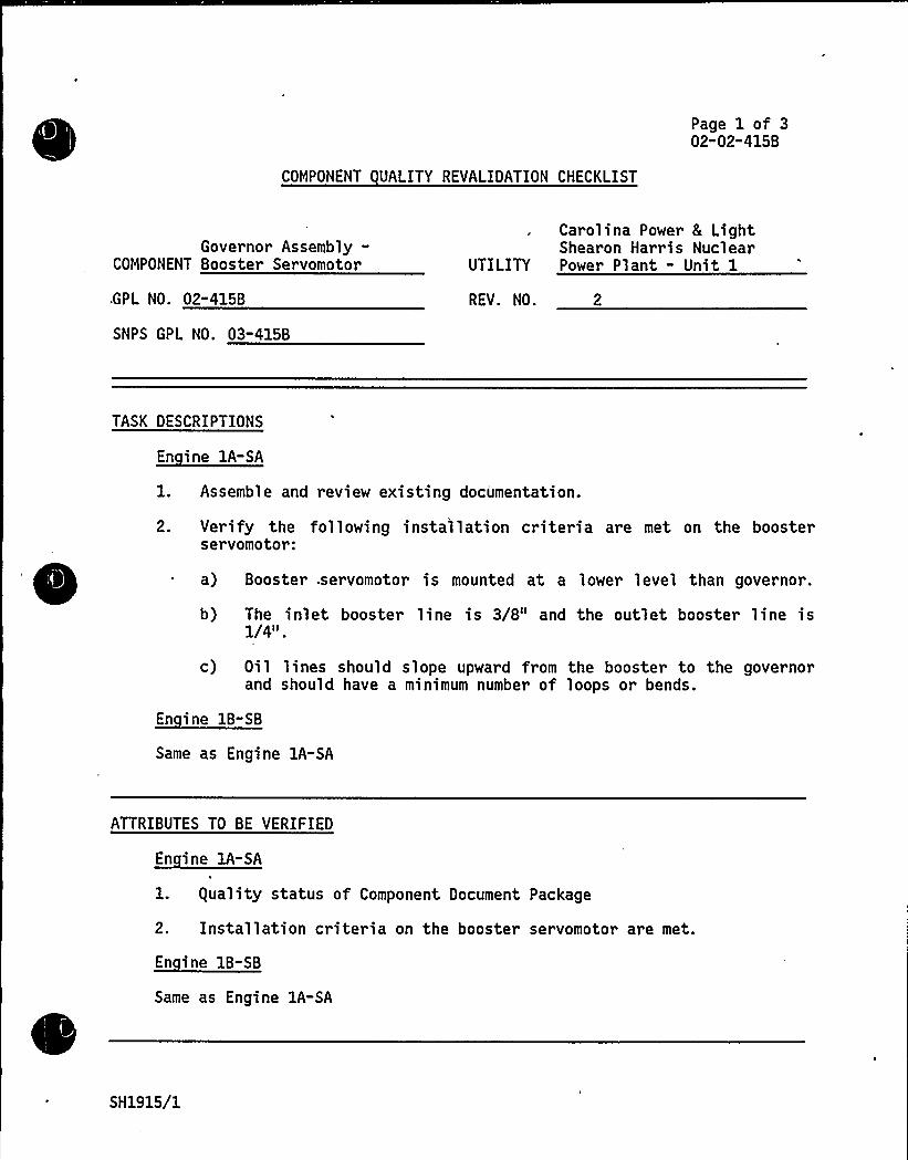
COMPONENT UALITY REVALIDATION CHECKLIST
Page 1 of 302"02-415B
Governor Assembly-COMPONENT Booster Servomotor
.GPL NO. 02-415B
SNPS GPL NO. 03-415B
Carolina Power & LightShearon Harris Nuclear
UTILITY Power Plant - Unit 1
REV. NO. 2
TASK DESCRIPTIONS
En ine 1A-SA
1. Assemble and review existing documentation.
2. Verify the following installation criteria are met on the boosterservomotor:
a) Booster .servomotor is mounted at a lower level than governor.
b) The inlet booster line is 3/8" and the outlet booster line is1/41 I
c) Oil lines should slope upward from the booster to the governorand should have a minimum number of loops or bends.
En ine 1B-SB
Same as Engine 1A-SA
ATTRIBUTES TO BE VERIFIED
En ine 1A-SA
l. guality status of Component Document Package
2. Installation criteria on the booster servomotor are met.
Same as Engine 1A-SA
SH1915/1
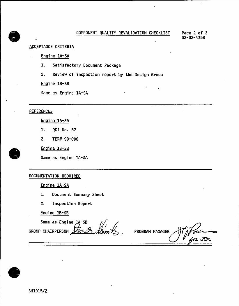
ACCEPTANCE CRITERIA
En ine 1A-SA
COMPONENT UALITY REVALIDATION CHECKLIST Page 2 of 302"02"415B
1. Satisfactory Document Package
2. Review of inspection report by the Design Group
Same as Engine 1A-SA
REFERENCES
En ine lA-SA
1. gCI No. 52
2. TER¹ 99"008
Same as Engine 1A-SA
DOCUMENTATION RE UIRED
1. Document Summary Sheet
2. Inspection Report
Same as Engine -SBn
GROUP CHAIRPERSON PROGRAM MANAGER
SH1915/2
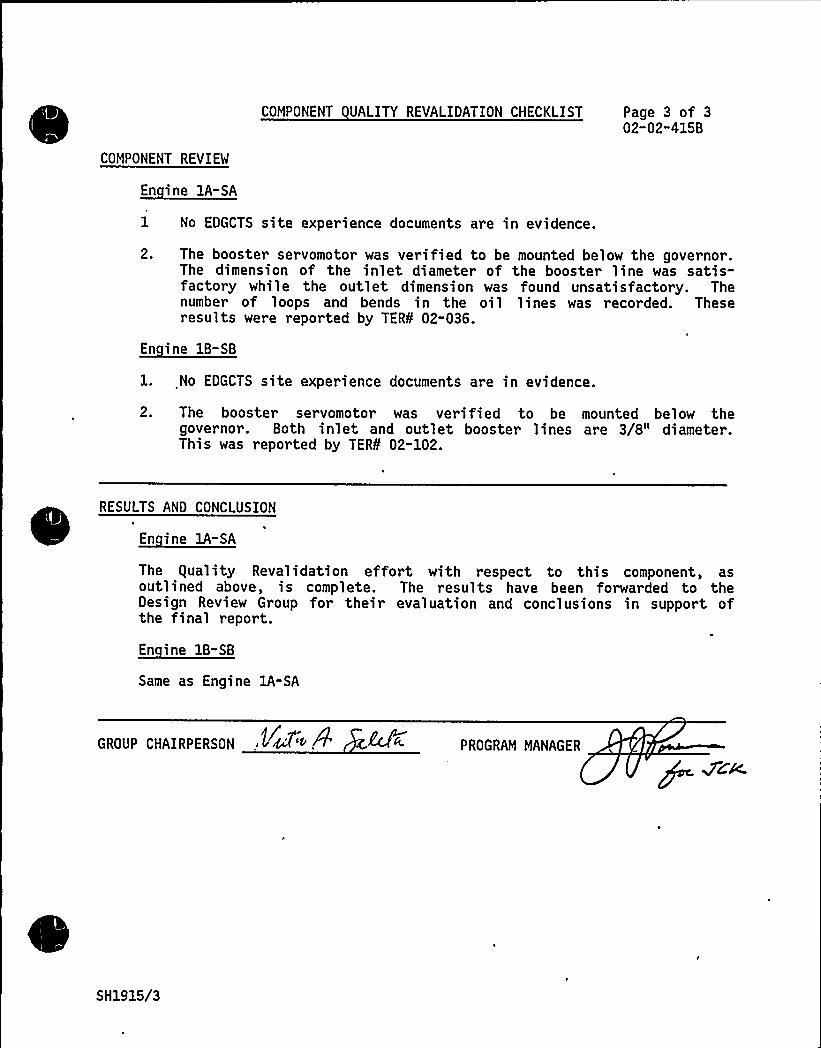
COMPONENT UALITY REVALIDATION CHECKLIST Page 3 of 302"02"415B
COMPONENT REVIEW
En ine 1A-SA
1 No EDGCTS site experience documents are in evidence.
2. The booster servomotor was verified to be mounted below the governor.The dimension of the inlet diameter of the booster line was satis-factory while the outlet dimension was found unsatisfactory. Thenumber of loops and bends in the oil lines was recorded. Theseresults were reported by TER¹ 02-036.
En ine 1B-SB
1. No EDGCTS site experience documents are in evidence.
2. The booster servomotor was verified to be mounted below thegovernor. Both inlet and outlet booster lines are 3/8" diameter.This was reported by TER¹ 02-102.
RESULTS AND CONCLUSION
The guality Revalidation effort with respect to this component, asoutlined above, is complete. The results have been forwarded to theDesign Review Group for their evaluation and conclusions in support ofthe final report.
En ine 1B-SB
Same as Engine 1A-SA
GROUP CHAIRPERSON K~'"+ PROGRAM MANAGER
SH1915/3
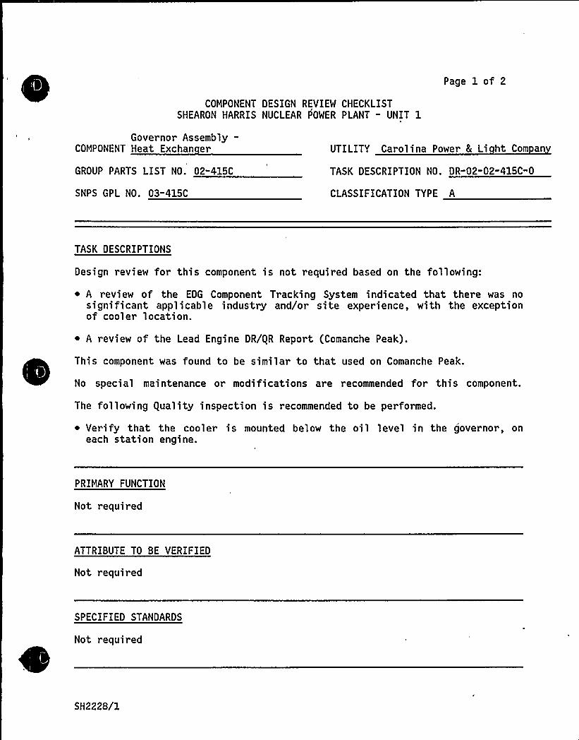
COMPONENT DESIGN REVIEW CHECKLISTSHEARON HARRIS NUCLEAR f OWER PLANT - UNIT 1
Page 1 of 2
Governor Assembly-COMPONENT Heat Exchan er
GROUP PARTS LIST NO. 02-415C
SNPS GPL NO. 03-415C
UTILITY Carolina Power & Li ht Com an
TASK DESCRIPTION NO. DR-02-02-415C-0
CLASSIFICATION TYPE A
TASK DESCRIPTIONS
Design review for this component is not required based on the following:
A review of the EDG Component Tracking System indicated that there was nosignificant applicable industry and/or site experience, with the exceptionof cooler location.
~ A review of the Lead Engine DR/gR Report (Comanche Peak).
~
~
This component was found to be similar to that used on Comanche Peak.
No special maintenance or modifications are recommended for this component.
The following guality inspection is recommended to be performed.
~ Verify that the cooler is mounted below the oil level in the governor, oneach station engine.
PRIMARY FUNCTION
Not required
ATTRIBUTE TO BE VERIFIED
Not required
SPECIFIED STANDARDS
Not required
SH2228/1
REFERENCES
Not required
COMPONENT DESIGN REVIEW CHECKLIST Page 2 of 2DR-02-02-415C" 0
DOCUMENTATION RE UIRED
Not required
GROUP CHAIRPERSON PROGRAM MANAGER ~~K
SH2228/2

TDI OWNERS GROUP
for
SHEARON HARRIS POWER PLANT — UNIT 1
ENGINE SHUTDOWN E UIPMENT - TUBING/FITTINGS 5 SUPPORTSSMALL BORE SCOPE ONLY
COMPONENT PART NO. 02-695A
I INTRODUCTION
The TDI Emergency Diesel Generator Owners Group Program for the ShearonHarri s Nuclear Power Plant requires Design and gual ity Reval idati onreviews of the structural adequacy of the engine shutdown equipment—tubing/fittings and supports to withstand the effects of normal operatingand earthquake loadings. The primary function is to maintain the capabil-ity to effect engine shutdown.
II OBJECTIVE
The objective of this review was to perform an engineering evaluation ofthe tubing and supports to assure that the component will perform itsintended design function during normal operating and earthquake loadings.
III METHODOLOGY
In order to meet the stated objective, the following methods were used:
The TDI Emergency Diesel Generator Component Tracking System wasreviewed for the Shearon Harris site, nuclear, and non-nuclearindustry experience. See Appendix C for results.
~ The equality Revalidation Checklist results were reviewed foracceptability.
~ Comparison with the lead engine reports (Comanche Peak, Grand Gulfand Catawba).
Refer to the review procedures described in Reference 1 for a detailedmethodology of this evaluation.
IV RESULTS AND CONCLUSIONS
The tubing and supports, as defined by this Component Design Review, havebeen evaluated in accordance with Reference 1 and have been found accept-able with the modifications. The conclusions of this report are based ona combination of the field walkdown and the review of the lead engine re-
SH2370/1
Page 2 of 2
ports as portions of this component were not installed at the time of thewalkdown.
Based on the above review, it is concluded from References 1 and 2 thatthe tubing and supports will perform their intended design function atShearon Harris under all normal operating and'earthquake loadings with theprovision that the following recommended modifications be implemented asdetailed in Reference 3.
It is recommended that two-way supports be added to the following lines,such that the between-support spans are limited to a maximum of 4 feet 6inches:
~ Line E33, left bank turbo oil pressure, between the cross connectionat the sight glass assembly and the first support downstream.
~ Line E16, high temperature jacket water, between the water dischargemanifold (governor end) and the gearcase area below.
It is recommended that two-way supports be added to the following lines asindicated:
~ Lines E31R and E31L, starting air pressure indication, midway betweenthe air start header connection and cylinder No. 8 (right and leftbanks).
Locations of supports should accommodate thermal expansion by provid-ing a minimum of 6-inch tubing offset around elbows.
All additions/modifications apply to Engines 1A & 1B unless otherwisespecified.
It is recommended that supports be modified to the following lines asindicated:
The tubing lines which run along the right bank just above thecrankcase access doors (gearcase to flywheel) are insufficientlyrestrained in the horizontal direction because of excessive clearancein the brackets. Therefore it is recommended that these sevensupports be modified to provide two-direction lateral restraint(Engine 1B only).
V REFERENCES
l. "Engineering Review Criteria Document for the Design Review of TDIDiesel Small Bore Piping, Tubing, and Supports for the TDI
Owners'roup,"Report No. 11600.60-DC-02, Revision 0.
2. Stone 8 Webster Calculation No. 11600.60-NP(B)-0201-XH.
3. Memo No. 6451 from C. Malovrh/SWEC to J. Kammeyer/SWEC dated10/29/84.
SH2370/2

APPENDIX A
COMPONENT DESIGN REVIEW CHECKLISTSHEARON HARRIS NUCLEAR POWER PLANT - UNIT 1
Page A1 of 2
Engine Shutdown -EquipmentTubing/Fittings
COMPONENT Small Bore Sco e Onl
GROUP PARTS LIST NO. 02-695A
SNPS GPL NO. 03-695A
UTILITY Carolina Power 8 Li ht
TASK DESCRIPTION NO. DR-02"02-695A-0
CLASSIFICATION TYPE
TASK DESCRIPTIONS
Perform an engineering review of the tubing and supports to provide additionalassurances that the components will perform their intended design functionduring normal operating and earthquake loading.
~ ~ ~ ~
PRIMARY FUNCTION
Maintain capability to affect engine shutdown.
ATTRIBUTES TO BE VERIFIED
Structural adequacy of the tubing and supports due to the effects of normaloperating and earthquake loadings.
SPECIFIED STANDARDS
IEEE 387
REFERENCES
"Engineering Review Criteria Document for the Design Review of TDI Diesel SmallBore Piping, Tubing, and Supports for the TDI Owners'roup" Report No.11600.60-DC-02, Revision 0.
SH2257/1
COMPONENT DESIGN REVIEW CHECKLIST
DOCUMENTATION RE UIRED
Page A2 of 2DR-02-02-695A-0
Delaval design documentation (specifications, calculations, drawings, etc.).In lieu of information from Delaval, the following information is required:verified support sketches and piping isometrics, material specifications, pipesize and schedule, and operating parameters (pressure, temperature, loadcombinations).
GROUP CHAIRPERSON PROGRAM MANAGER C l
SH2257/2

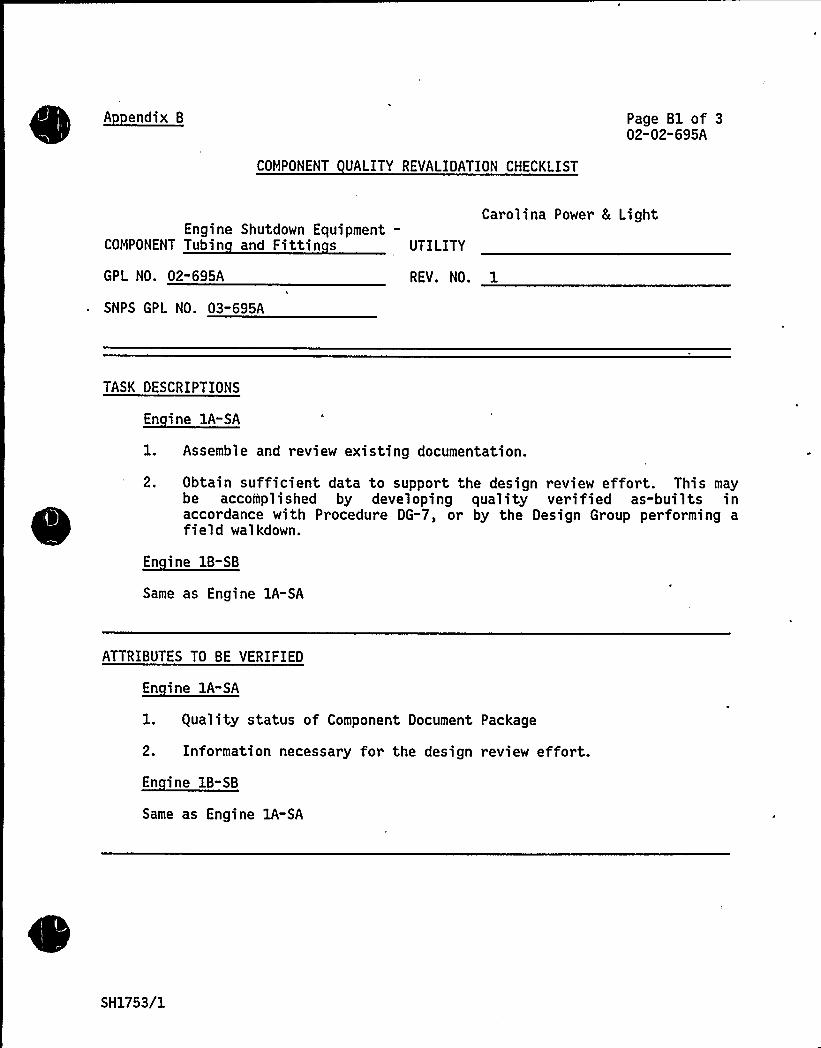
AppendixB
COMPONENT UALITY REVALIDATION CHECKLIST
Page Bl of 302-02-695A
Engine Shutdown Equipment-COMPONENT Tubin and Fittin s UTILITY
Carolina Power 8 Light
GPL NO. 02-695A
SNPS GPL NO. 03-695A
REV. NO. 1
TASK DESCRIPTIONS
~E
1. Assemble and review existing documentation.
2. Obtain sufficient data to support the design review effort. This maybe accomplished by developing quality verified as-builts inaccordance with Procedure DG-7, or by the Design Group performing afield walkdown.
~E
Same as Engine 1A-SA
ATTRIBUTES TO BE VERIFIED
1. guality status of Component Document Package
2. Information necessary for the design review effort.
Same as Engine 1A-SA
SH1753/1
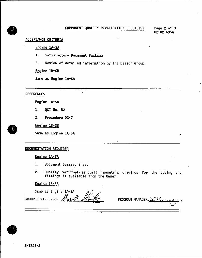
ACCEPTANCE CRITERIA
En ine lA-SA
COMPONENT UALITY REVALIDATION CHECKLIST Page 2 of 302"02-695A
1. Satisfactory Document Package
2. Review of detailed information by the Design Group
~E
Same as Engine 1A-SA
REFERENCES
En ine lA-SA
1. gCI No. 52
2. Procedure DG-7
Same as Engine 1A-SA
DOCUMENTATION RE UIRED
l. Document Summary Sheet
2. equality verified as-built isometric drawings for the tubing andfittings if available from the Owner.
En ine 1B-SB
Same as Engine 1A-SA
GROUP CHAIRPERSON PROGRAM MANAGER KiA-' "~.e i
SH1753/2
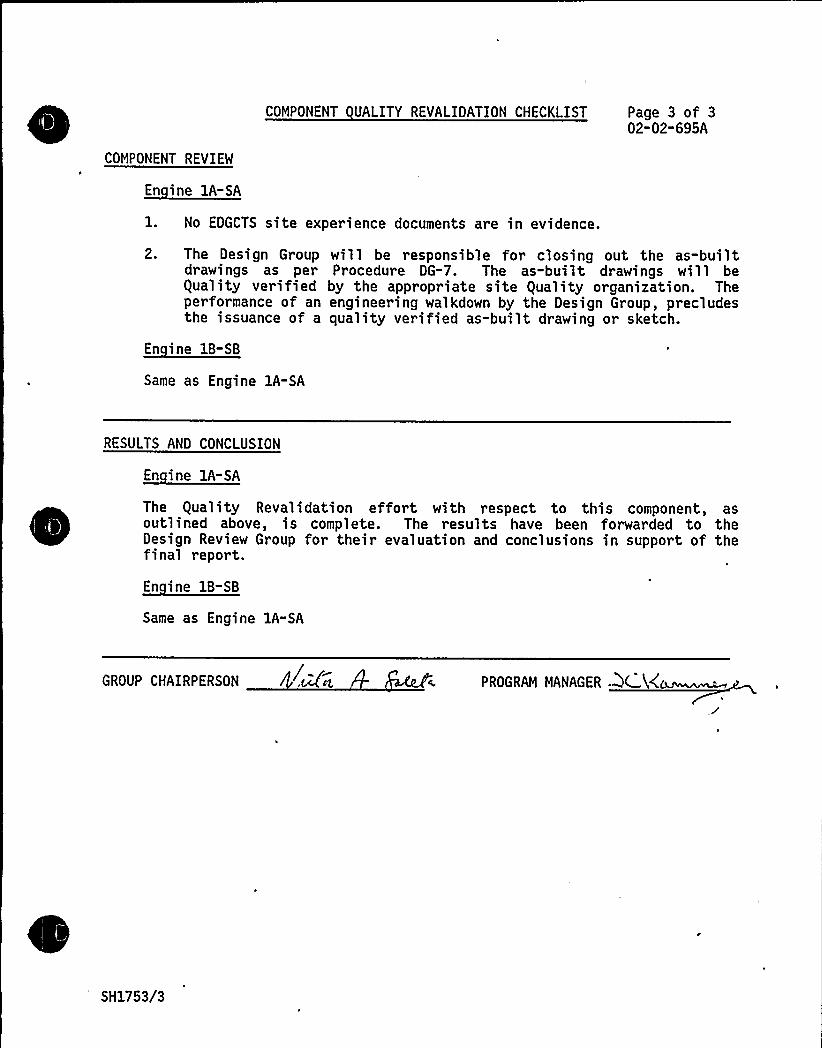
COMPONENT REVIEM
COMPONENT UALITY REVALIDATION CHECKLIST Page 3 of 302-02-695A
1. No EDGCTS site experience documents are in evidence.
2. The Design Groupdrawings as perequality verifiedperformance of anthe issuance of a
will be responsible for closing out the as-builtProcedure DG-7. The as-built drawings will be
by the appropriate site guality organization. Theengineering walkdown by the Design Group, precludesquality verified as-built drawing or sketch.
Same as Engine 1A-SA
RESULTS AND CONCLUSION
En ine lA-SA
The guality Revalidation effort with respect to this component, asoutlined above, is complete. The results have been forwarded to theDesign Review Group for their evaluation and conclusions in support of thefinal report.
En ine 1B-SB
Same as Engine 1A-SA
GROUP CHAIRPERSON PROGRAM MANAGER ~~K~~
SH1753/3
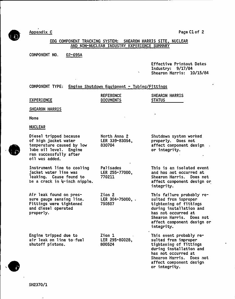
A endix C Page Cl of 2
EDG COMPONENT TRACKING SYSTEM: SHEARON HARRIS SITE NUCLEARAND NON-NUCLEAR INDUSTRY EXPERIENCE SUMMARY
COMPONENT NO. 02"695A
Effective Printout DatesIndustry: 9/17/84Shearon Harris: 10/15/84
COMPONENT TYPE: En ine Shutdown E ui ment - Tubin /Fittin s
EXPERIENCE
SHEARON HARRIS
None
NUCLEAR
Diesel tripped becauseof high jacket watertemperature caused by lowlube oil level. Engineran successfully afteroil was added.
Instrument line to coolingjacket water line wasleaking. Cause found tobe a crack in >4-inch nipple.
Air leak found on pres-sure gauge sensing line.Fittings were tightenedand diesel operatedproperly.
Engine tripped due toair leak on line to fuelshutoff pistons.
REFERENCEDOCUMENTS
North Anna 2LER 339-83054,830704
PalisadesLER 255-77000,770211
Zion 2LER 304-75000, .
750507
Zion 1LER 295-80028,800524
SHEARON HARRISSTATUS
Shutdown system workedproperly. Does notaffect component designor integrity.
This is an isolated eventand has not occurred atShearon Harris. Does notaffect component design orintegrity.
This failure probably re-sulted from impropertightening of fittingsduring installation andhas not occurred atShearon Harris. Does notaffect component design orintegrity.
Thi s event probably re-sulted from impropertightening of fittingsduring installation andhas not occurred atShearon Harris. Does notaffect component designor integrity.
SH2370/1
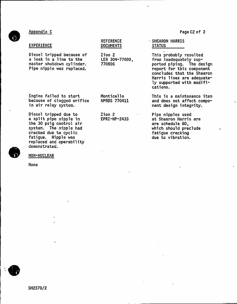
~Aendix C
Engine failed to startbecause of clogged orificein air relay system.
Diesel tripped due toa split pipe nipple inthe 30 psig control airsystem. The nipple hadcracked due to cyclicfatigue. Nipple wasreplaced and operability
d.demonstrate
NON-NUCLEAR
None
EXPERIENCE
Diesel tripped because ofa leak in a line to themaster shutdown cylinder.Pipe nipple was replaced.
REFERENCEDOCUMENTS
Zion 2LER 304"77000,770S06
MonticelloNPRDS 770411
Zion 2EP RI"NP"2433
Page C2 of 2
SHEARON HARRISSTATUS
This probably resultedfrom inadequately sup-ported piping. The designreport for this componentconcludes that the ShearonHarris lines are adequate-ly supported with modifi-cations.
This is a maintenance itemand does not affect compo-nent design integrity.
Pipe nipples usedat Shearon Harris areare schedule 80,which should precludefatigue crackingdue to vibration.
SH2370/2

COMPONENT DESIGN REVIEW CHECKLISTSHEARON HARRIS NUCLEAR POWER PLANT - UNIT 1
Page 1 of 2
Engine Shutdown Equipment-Valves, Regulators,
COMPONENT Orifices UTILITY Carolina Power 8 Li ht Com an
GROUP PARTS LIST NO. 02"695B
SNPS GPL NO. 03-695B
TASK DESCRIPTION NO. DR-02"02-695B-0
CLASSIFICATION TYPE A
TASK DESCRIPTIONS
The engine shutdown equipment valves, regulators, and orifices used on ShearonHarris are identical to Comanche Peak, with regard to manufacturer andapplication. In addition, the configuration of this equipment on ShearonHarris in the pneumatic shutdown system to trip on engine overspeed and topropagate the shutdown signal is also identical to Comanche Peak.
There is no Shearon Harris site or non-nuclear industry experience listed inEDG Component Tracking System for this component. The nuclear industry experi-ence listed does not show any significant problems applicable to Shearon Harrisdesign.
To minimize fouling of the engine shutdown equipment valves, regulators andorifices, it is recommended that the equipment be inspected and cleaned and theelastomeric parts be replaced during each refueling outage. This recommendedmaintenance interval should be reassessed depending on the degree of systemfouling.
There are no ,recommended modifications for the engine shutdown equipmentvalves, regulators and orifices.
A guality Revalidation for the engine shutdown equipment valves, regulatorsand orifices is not deemed necessary.
Based on the above, a design review for the engine shutdown equipmentvalves, regulators, and orifices is not required for Shearon Harris.
PRIMARY FUNCTION
Not required
ATTRIBUTE TO BE VERIFIED
Not required
SH2132/1

\~ I
e
I'PECIFIED STANDARDS
Not required
COMPONENT DESIGN REVIEW CHECKLIST Page 2 of 2DR-02"02"695B"0
REFERENCES
Not required
DOCUMENTATION RE UIRED
Not required
GROUP CHAIRPERSON PROGRAM MANAGER
SH2132/2

COMPONENT DESIGN REVIEW CHECKLISTSHEARON HARRIS NUCLEAR POMER PLANT - UNIT 1
Page 1 of 2
COMPONENT En ine Shutdown Tri Switches
GROUP PARTS LIST NO. 02"695C
SNPS GPL NO. 03-695C
UTILITY Carolina Power 8 Li ht Com an
TASK DESCRIPTION NO. DR-02"02"695C-0
CLASSIFICATION TYPE A
TASK DESCRIPTIONS
The application and manufacturer of the engine shutdown trip switches used onShearon Harris are identical to those on Comanche Peak with the exception of alow pressure trip switch, F-573-378. This California Controls pressure switchis installed in the jacket water system and actuates to trip the diesel on lowpressure. The switch has a narrow trip range and, therefore, is sensitive tothe lower pressur es in the jacket water system.
There is no Shearon Harris site experience listed in the EDG Component
~
~
~
~
~~
~
~
~
Tracking System for the engine shutdown trip switches. The applicable nuclearand non-nuclear industry experiences listed do not indicate any generic orsignificant problems with the trip switches.
There are no maintenance or modification recommendations required for theengine shutdown trip switches.
A guality Revalidation of the engine shutdown trip switches is not deemednecessary.
Based on the above, a design review for the engine shutdown trip switches isnot required for Shearon Harris.
PRIMARY FUNCTION
Not required
ATTRIBUTE TO BE VERIFIED
Not required.
SH2133/1
SPECIFIED STANDARDS
Not required
COMPONENT DESIGN REVIEW CHECKLIST Page 2 of 2DR-02-02-695C-0
REFERENCES
Not required
DOCUMENTATION RE UIRED
Not required
GROUP CHAIRPERSON PROGRAM MANAGER MCk
SH2133/2
TDI DIESEL GENERATOR
DESIGN REVIEWAND
QUALITYREVALIDATIONREPORT
Prepared For
CAROLINAPOWER S. LIGHTCOMPANY
SHEARON HARRIS NUCLEAR POWER PLANT
By
TDI DIESEL GENERATOR OWNERS GROUP
VOLUME4
i
How To Use This Re or t
Tabs in this report identify the following categories:
Turbo, Intake, Intercooler & ExhaustLube OilEngine Base 8 Bearing CapsCrankshaft & BearingsCylinder Block, Liners 8 Water ManifoldAir Start 8 Barring DeviceConnecting rodsPistonsCamshaft 8 Valve TrainIdler Gear Assembly 8 Front Gear CaseFlywheelEngine Instrumentation 8 WiringOverspeed Trip 8 GovernorEngine Shutdown 8 EquipmentJacket WaterCylinder Heads 8 ValvesFuel Oil InjectionGeneratorControl Panel AssemblyEngine 8 Auxiliary Sub-Base & Foundation Bolts
These categories have been defined to allow the reader to review a completediesel generator subsystem in a convenient manner.
Within each category tabs identify Shearon Harris specific component numbers.
A given component report can be found by:
a) If the component number is known - use the alpha - numberic indexwhich identifies the volume number and category in which the compon-ent report is located.
b) If only the component name is known — Section 3.2 may be used as across-reference to find the volume number where the component reportmay be found.
Some reports address more than one component. a tab is provided for eachcomponent. However, some components are combined under one report. Slipsheets are provided where required to reference back to the appropriate tab.Some components required more than one report, These are identified by the
, abbreviation LB-Large Bore and SB-Small Bore on the component number tabs.
SH2651
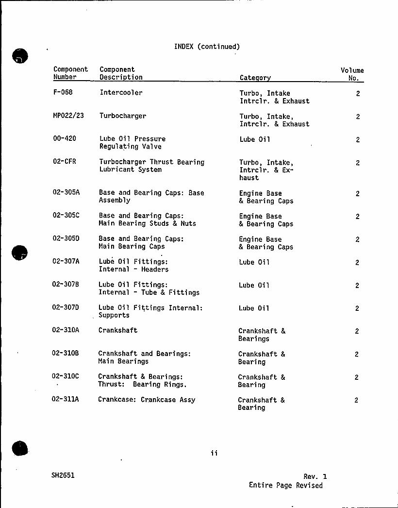
INDEX (continued)
Component ComponentNumber Descri tion
F-068 Intercooler
MP022/23 Turbocharger
Cate or
Turbo, IntakeIntrclr. 8 Exhaust
Turbo, Intake,Intrclr. & Exhaust
VolumeNo.
00-420
02-CFR
02-305A
02-305C
02-305D
02-307A
02"3078
02-307D
02-310A
02-310B
02-310C
02-311A
Lube Oil PressureRegulating Valve
Turbocharger Thrust BearingLubricant System
Base and Bearing Caps: BaseAssembly
Base and Bearing Caps:Main Bearing Studs 8 Nuts
Base and Bearing Caps:Main Bearing Caps
Lube Oil Fittings:Internal — Headers
Lube Oil Fittings:Internal - Tube 8 Fittings
Lube Oil Fittings Internal:Supports
Crankshaft
Crankshaft and Bearings:Main Bearings
Crankshaft & Bearings:Thrust: Bearing Rings.
Crankcase: Crankcase Assy
Lube Oil
Turbo, Intake,Intrclr. & Ex-haust
Engine Base8 Bearing Caps
Engine Base& Bearing Caps
Engine Base8 Bearing Caps
Lube Oil
Lube Oil
Lube Oil
Crankshaft &Bearings
Crankshaft 8
Bearing
Crankshaft &Bea~ing
Crankshaft &Bearing
SH2651 Rev. 1Entire Page Revised

INDEX (continued)
ComponentNumber
02-311D
02-315A
02-315C
02-315D
02-315E
02-315F
02-315G
02-316A
02-316B
02" 316C
02-317A
02-317B
02-317C
ComponentOescri tion
Crankcase: CrankcaseMounting Hardware
Cylinder Block Liners 8Water Manifold: CylinderBlock
Cylinder Block Liners 8Water Manifold-Cylinder Liner
Water Manifold: JacketWater Manifold 8 Piping
Cylinder Block Liners 8
Water Manifold: Studs
Cylinder Block Liners8 Water Manifold:Cylinder Head Nuts
Cylinder Block Liners &Water Manifold: Seals &Gaskets
Jacket Water Inlet Manifold:Manifold Assembly W/Hardwareand Coupling and Gaskets
Jacket Water Inlet Manifold:Coupling and Gaskets
Jacket Water Inlet Manifold:Vent line to Discharge Manifold
Jacket Water DischargeManifold/Piping
Jacket Water DischargeManifold: Couplings andSeals
Water Discharge Manifold:Supports
Cate or
Crankshaft 8
Bearings
Cyl. Block &Liners 8 WaterManifold
Cyl. Block &Liners 8
Water Manifold
Cyl. Block 8
Liners 8
Water Manifold
Cyl. Block 8
Liners 8
Water Manifold
Cyl. Block &Liner 8 WaterMani fold
Cyl. Block &Liners 8
Water Manifold
Jacket Water
Jacket Water
Jacket Water
Jacket Water
Jacket Water
Jacket Water
VolumeNo.
SH2651 Rev. 1Entire Page Revised
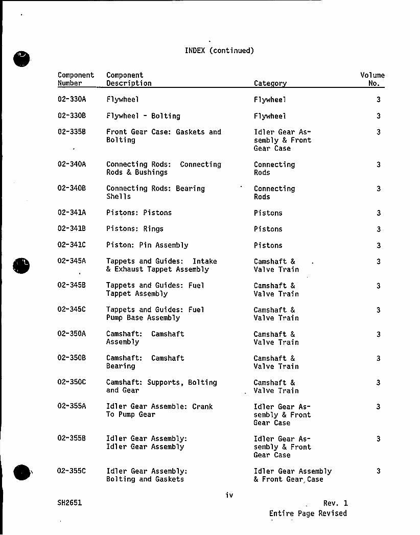
INDEX (continued)
Component ComponentNumber Descri tion Cate or
VolumeNo.
02-330A
02-330B
02-335B
02-340A
02-340B
02-341A
02-341B
02-341C
02-345A
02-345B
02-345C
02-350A
02-350B
02"350C
Flywheel
Flywheel - Bolting
Front Gear Case: Gaskets andBolting
Connecting Rods: ConnectingRods 8 Bushings
Connecting Rods: BearingShel ls
Pistons: Pistons
Pistons: Rings
Piston: Pin Assembly
Tappets and Guides: Intake8 Exhaust Tappet Assembly
Tappets and Guides: FuelTappet Assembly
Tappets and Guides: FuelPump Base Assembly
Camshaft: CamshaftAssembly
Camshaft: CamshaftBearing
Camshaft: Supports, Boltingand Gear
Flywheel
Flywheel
Idler Gear As-sembly 8 FrontGear Case
ConnectingRods
ConnectingRods
Pistons
Pistons
Pistons
Camshaft 8
Valve Train
Camshaft 8
Val ve Train
Camshaft &Valve Train
Camshaft 8
Valve Train
Camshaft 8
Val ve Tr ain
Camshaft 8
Valve Train
02"355A Idler Gear Assemble: CrankTo Pump Gear
Idler Gear As-sembly 8 FrontGear Case
02-355B Idler Gear Assembly:Idler Gear Assembly
Idler Gear As-sembly 8 FrontGear Case
02-355C
SH2651
Idler Gear Assembly:Bolting and Gaskets
iv
Idler Gear Assembly& Front Gear Case
Rev. 1
Entire Page Revised
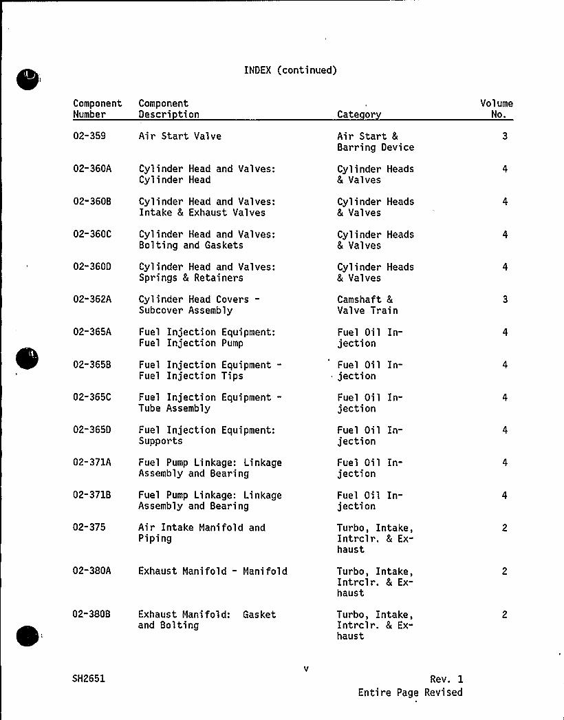
INDEX (continued)
Component ComponentNumber Descri tion
02-359 Air Start Valve
t
Cate or
Air Start &Barring Device
VolumeNo.
02-360A
02-360B
02-360C
02-360D
02-362A
02-365A
02-365B
02-365C
02-3650
02-371A
02-371B
02-375
Cylinder Head and Valves:Cylinder Head
Cylinder Head and Valves:Intake & Exhaust Valves
Cylinder Head and Valves:Bol ting and Gaskets
Cyl inder Head and Valves:Springs & Retainers
Cylinder Head Covers-Subcover Assembly
Fuel Injection Equipment:Fuel Injection Pump
Fuel Injection Equipment-Fuel Injection Tips
Fuel Injection Equipment-Tube Assembly
Fuel Injection Equipment:Supports
Fuel Pump Linkage: LinkageAssembly and Bearing
Fuel Pump Linkage: LinkageAssembly and Bearing
Air Intake Manifold andPiping
Cylinder Heads& Valves
Cylinder Heads& Valves
Cylinder Heads& Valves
Cylinder Heads& Valves
Camshaft &Valve Train
Fuel Oil In-jection
Fuel Oi 1 In-jection
Fuel Oil In-jection
Fuel Oil In-jection
Fuel Oil In-jection
Fuel Oil In-jection
Turbo, Intake,Intrclr. & Ex-haust
02-380A Exhaust Manifold - Manifold
02-380B Exhaust Manifold: Gasketand Bolting
Turbo, Intake,Intrclr. & Ex-haust
Turbo, Intake,Intrclr. & Ex-haust
SH2651 Rev. 1
Entire Page Revised

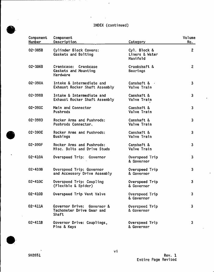
INDEX (continued)
Component ComponentNumber Descri tion Cate or
VolumeNo.
02-385B Cyl inder Bl ock Covers:Gaskets and Bolting
Cyl. Block 8
Liners 8 WaterManifold
02-386B Crankcase: CrankcaseGaskets and MountingHardware
Crankshaft 8
Bearings
02-390A
02" 390B
Intake 8 Intermediate andExhaust Rocker Shaft Assembly
Intake 8 Intermediate andExhaust Rocker Shaft Assembly
Camshaft 8
Valve Train
Camshaft &Valve Train
02-390C Main and ConnectorPushrods
Camshaft 8
Valve Train
02-390D Rocker Arms and Pushrods:Pushrods Connector.
Camshaft 8
Valve Train
02-390E Rocker Arms and Pushrods:Bushings
Camshaft 8
Valve Tr ain
02-390F Rocker Arms and Pushrods:Misc. Bolts and Drive Studs
Camshaft 8
Valve Train
02-410A Overspeed Trip: Governor Overspeed Trip& Governor
02-410B Overspeed Trip: Governorand Accessory Drive Assembly
Overspeed Trip8 Governor
02-410C Overspeed Trip: Coupling(Flexible & Spider)
Overspeed Trip8 Governor
02-410D Overspeed Trip Vent Valve Overspeed Trip8 Governor
02-411A Governor Drive: Governor 8
Tachometer Drive Gear andShaft
Overspeed Trip8 Governor
02-411B Governor Drive: Couplings,Pins 8 Keys
Over speed Trip8 Governor
SH2651vi
Rev. 1Entire Page Revised
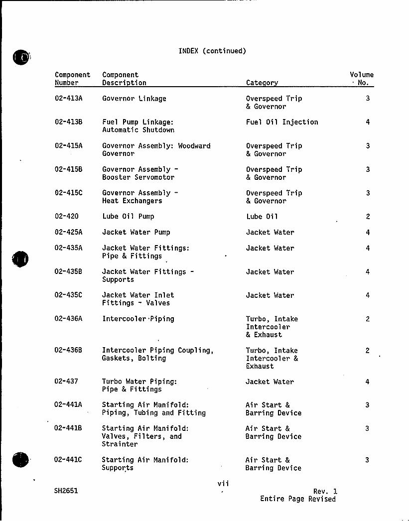
INDEX (continued)
Component ComponentNumber Descri tion
02-413A Governor Linkage
Cate or
Overspeed Trip& Governor
VolumeNo.
02-413 B Fuel Pump Linkage:Automatic Shutdown
Fuel Oil Injection
02-415A
02-415B
02"415C
02-420
02-425A
02-435A
02-435B
02-435C
02-436A
Governor Assembly: WoodwardGovernor
Governor Assembly-Booster Servomotor
Governor Assembly—Heat Exchangers
Lube Oil Pump
Jacket Water Pump
Jacket Water Fittings:Pipe & Fittings
Jacket Water Fittings-Supports
Jacket Water InletFittings - Valves
Intercooler Piping
Overspeed Trip8 Governor
Overspeed Trip8 Governor
Overspeed Trip& Governor
Lube Oil
Jacket Water
Jacket Water
Jacket Water
Jacket Water
Turbo, IntakeIntercooler& Exhaust
02-436B Intercooler Piping Coupling,Gaskets, Bolting
Turbo, IntakeIntercooler 8
Exhaust
02-437
02-441A
02-441B
Turbo Water Piping:Pipe 8 Fittings
Starting Air Manifold:Piping, Tubing and Fitting
Starting Air Manifold:Valves, Filters, andStrainter
Jacket Water
Air Start 8
Barring Device
Air Start &Barring Device
02-441C
SH2651
Starting Air Manifold:Supports
vii
Air Start 8
Barring Device
Rev. 1Entire Page Revised

INDEX (continued)
ComponentNumber
02-442A
02"442B
02-445
02-450A
02-450B
02-455A
02-455B
02-455C
02"465A
02-465B
02-465C
02-465D
ComponentDescri tion
Starting AirDistributor:Distributor Assembly
Starting AirDistributor: Tubing,Fittings, Gaskets
Fuel Oil Booster Pump
Fuel Oil Header:Piping/Tubing
Fuel Oil Header: FuelOil Header Supports
Fuel Oil Filters 8
Strainers: Fuel Oil Filters
Fuel Oil Fi 1 ters 8
Strainers: Strainers
Fuel Oil Filters 8Strainer: Mounting Hardware
Lube Oil Lines External:Tubing, Fittings, Couplings
Lube Oil Lines - ExternalSupports
Lube Oil Lines-External Valves
Lube Oil System—Lube Oil KeepwarmStrainer
Cate or
Air Start &Barring Device
Air Start 8
Barring Device
Fuel Oil In-jection
Fuel Oi 1 In-jection
Fuel Oil In-jection
Fuel Oil In-jection
Fuel Oil In-jection
Fuel Oil In-jection
Lube Oi 1
Lube Oil
Lube Oil
Lube Oi 1
VolumeNo.
02"467A
02"467B
Turbocharger: Lube OilFitting - Pipe, Tubing,Fittings & Flexible Coupling
Turbocharger: Lube OilFittings - Supports
Lube Oil
Lube Oil
SH2651vi 1 1
Rev. 1Entire Page Revised

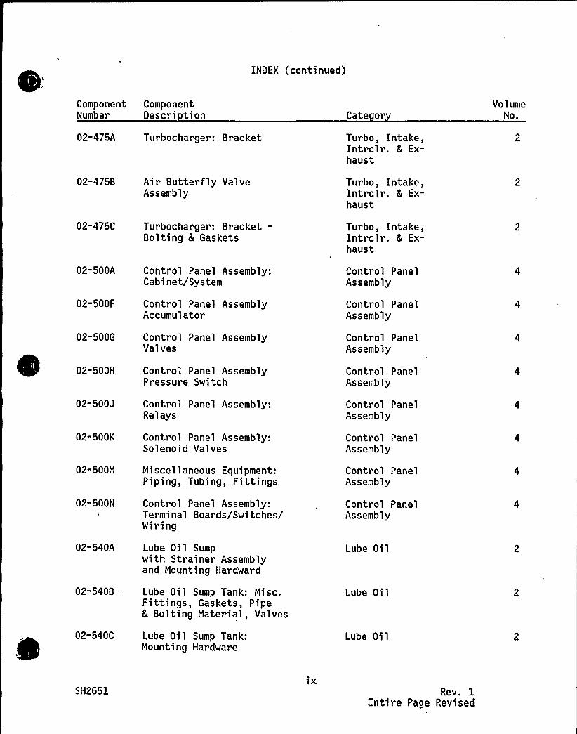
INDEX (continued)
ComponentNumber
02-475A
02-475B
02-475C
02-500A
02-500F
02-500G
02-500H
02"500J
02-500K
02-500M
02-500N
02-540A
02"540B .
02-540C
ComponentDescri tion
Turbocharger: Bracket
Air Butterfly ValveAssembly
Turbocharger: Bracket-Bolting 8 Gaskets
Control Panel Assembly:Cabinet/System
Control Panel AssemblyAccumulator
Control Panel AssemblyValves
Control Panel AssemblyPressure Switch
Control Panel Assembly:Re 1 ays
Control Panel Assembly:Solenoid Valves
Miscellaneous Equipment:Piping, Tubing, Fittings
Control Panel Assembly:Terminal Boards/Switches/Miring
Lube Oil Sumpwith Strainer Assemblyand Mounting Hardward
Lube Oil Sump Tank: Misc.Fittings, Gaskets, Pipe& Bolting Material, Valves
Lube Oil Sump Tank:Mounting Hardware
Cate or
Turbo, Intake,Intrclr. 8 Ex-haust
Turbo, Intake,Intrclr. & Ex-haust
Turbo, Intake,Intrclr. & Ex-haust
Control PanelAssembly
Control PanelAssembly
Control PanelAssembly
Control PanelAssembly
Control PanelAssembly
Control PanelAssembly
Control PanelAssembly
Control PanelAssembly
Lube Oil
Lube Oil
Lube Oi 1
VolumeNo.
SH2651ix
Rev. 1Entire Page Revised
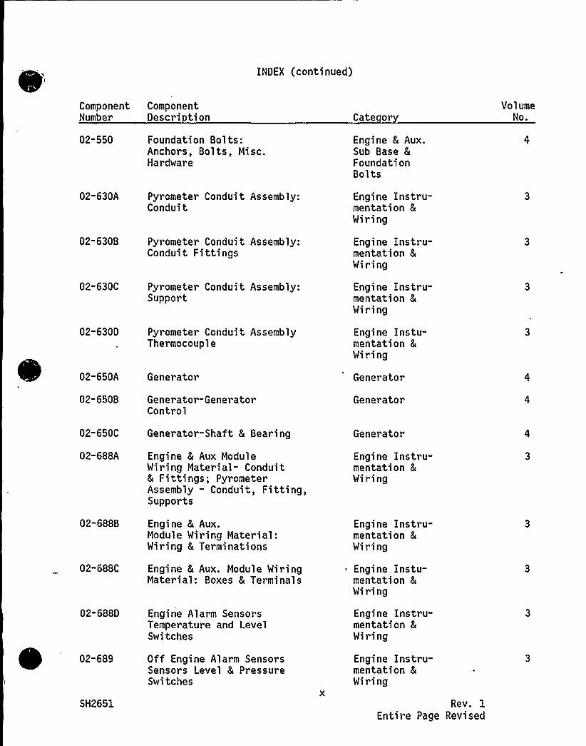
INDEX (continued)
ComponentNumber
ComponentDescri tion Cate or
VolumeNo.
02-550 Foundation Bolts:Anchors, Bolts, Misc.Hardware
Engine 8 Aux.Sub Base 8
FoundationBolts
02-630A
02-630B
Pyrometer Conduit Assembly:Conduit
Pyrometer Conduit Assembly:Conduit Fittings
Engine Instru-mentation &Wiring
Engine Instru-mentation 8
Wiring
02-630C
02" 630D
02-650A
02-650B
Pyrometer Conduit Assembly:Support
Pyrometer Conduit AssemblyThermocouple
Generator
Generator-GeneratorControl
Engine Instru-mentation 8
Wiring
Engine Instu-mentation &Wiring
Generator
Generator
02-650C Generator-Shaft 8 Bearing Generator
02-688A Engine 8 Aux ModuleWiring Material- Conduit& Fittings; PyrometerAssembly - Conduit, Fitting,Supports
Engine Instru-mentation 8
Wiring
02-688B
02"688C
Engine 8 Aux.Module Wiring Material:Wiring 8 Terminations
Engine 8 Aux. Module WiringMaterial: Boxes 8 Terminals
Engine Instru-mentation 8
Wiring
Engine Instu-mentation 8
Wiring
02-688D Engine Alarm SensorsTemperature and LevelSwitches
Engine Instru-mentation &Wiring
02-689 Off Engine Alarm SensorsSensors Level 8 PressureSwitches
Engine Instru-mentation 8
Wiring
SH2651 Rev. 1Entire Page Revised
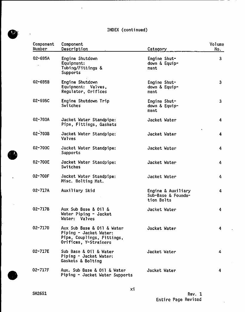
INDEX (continued)
ComponentNumber
02-695A
02-695B
02-695C
02-700A
02-700B
02-700C
02-700E
02-700F
02-717A
02-717B
02-717D
02-717E
02-717F
ComponentDescri tion
Engine ShutdownEquipment:Tubing/Fittings 8
Supports
Engine ShutdownEquipment: Valves,Regulator, Orifices
Engine Shutdown TripSwitches
Jacket Water Standpipe:Pipe, Fittings, Gaskets
Jacket Water Standpipe:Valves
Jacket Water Standpipe:Supports
Jacket Water Standpipe:Switches
Jacket Water Standpipe:Misc. Bolting Mat.
Auxiliary Skid
Aux Sub Base 8 Oil 8Water Piping - JacketWater: Valves
Aux Sub Base 8 Oil 8 WaterPiping - Jacket Mater:Pipe, Couplings, Fittings,Orifices, Y-Strainers
Sub Base 8 Oil & WaterPiping - Jacket Water:Gaskets 8 Bolting
Aux. Sub Base 8 Oil & WaterPiping - Jacket Mater Supports
Cate or
Engine Shut-down & Equip-ment
Engine Shut-down 8 Equip-ment
Engine Shut-down 8 Equip-ment
Jacket Water
Jacket Water
Jacket Water
Jacket Water
Jacket Water
Engine 8 AuxiliarySub-Base 8 Founda-tion Bolts
Jacket Water
Jacket Water
Jacket Mater
Jacket Water
VolumeNo.
SH2651xi
Rev. 1Entire Page Revised
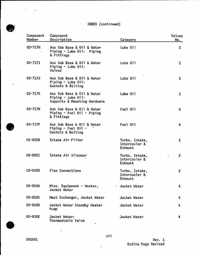
INDEX (continued)
Component ComponentNumber Descri tion Cate or
VolumeNo.
02" 717H
02-717I
02-717 J
02-717K
02-717M
02-717P
02-805B
02-805C
02-8050
02-810A
02"810C
02-810D
02-810 E
Aux Sub Base 8 Oil 8 WaterPiping — Lube Oil: Piping8 Fittings
Aux Sub Base 8 Oil 8 WaterPiping - Lube Oil:Valves
Aux Sub Base 8 Oil 8 MaterPiping — Lube Oil:Gaskets 8 Bolting
Aux Sub Base 8 Oil & WaterPiping — Lube Oil:Supports 8 Mounting Hardware
Aux Sub Base 8 Oil 8 WaterPiping - Fuel Oil - Piping8 Fittings
Aux Sub Base & Oil 8 MaterPiping - Fuel Oil-Gaskets 8 Bolting
Intake Air Filter
Intake Air Silencer
Flex Connections
Misc. Equipment - Heater,Jacket Water
Heat Exchanger, Jacket Water
Jacket Water Standby HeaterPump
Jacket Water:Thermostatic Valve
Lube Oil
Lube Oil
Lube Oil
Lube Oil
Fuel Oil
Fuel Oi 1
Turbo, Intake,Intercooler 8
Exhaust
Turbo, Intake,Intercooler 8
Exhaust
Turbo, Intake,Intercooler 8
Exhaust
Jacket Water
Jacket Water
Jacket Water
Jacket Water
SH2651xi 1
Rev. 1
Entire Page Revised
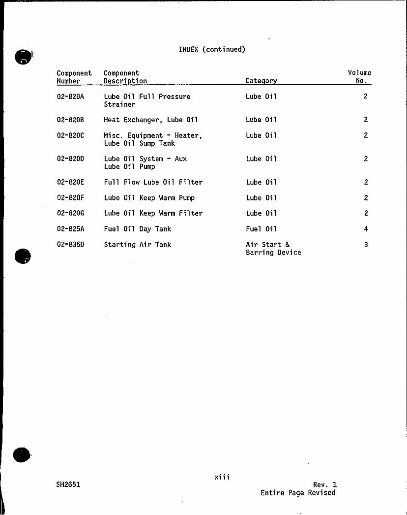
INDEX (continued)
Component ComponentNumber Descri tion Cate or
VolumeNo.
02-820A
02-820B
02-820C
02-8200
02"820E
02-820F
02-820G
02-825A
02-835D
Lube Oil Full PressureStrainer
Heat Exchanger, Lube Oil
Misc. Equipment - Heater,Lube Oil Sump Tank
Lube Oil System - AuxLube Oil Pump
Full Flow Lube Oil Filter
Lube Oil Keep Warm Pump
Lube Oil Keep Warm Filter
Fuel Oil Day Tank
Starting Air Tank
Lube Oil
Lube Oil
Lube Oil
Lube Oil
Lube Oil
Lube Oil
Lube Oil
Fuel Oil
Air Start 8
Barring Device
SH2651xi 1 1
Rev. 1Entire Page Revised

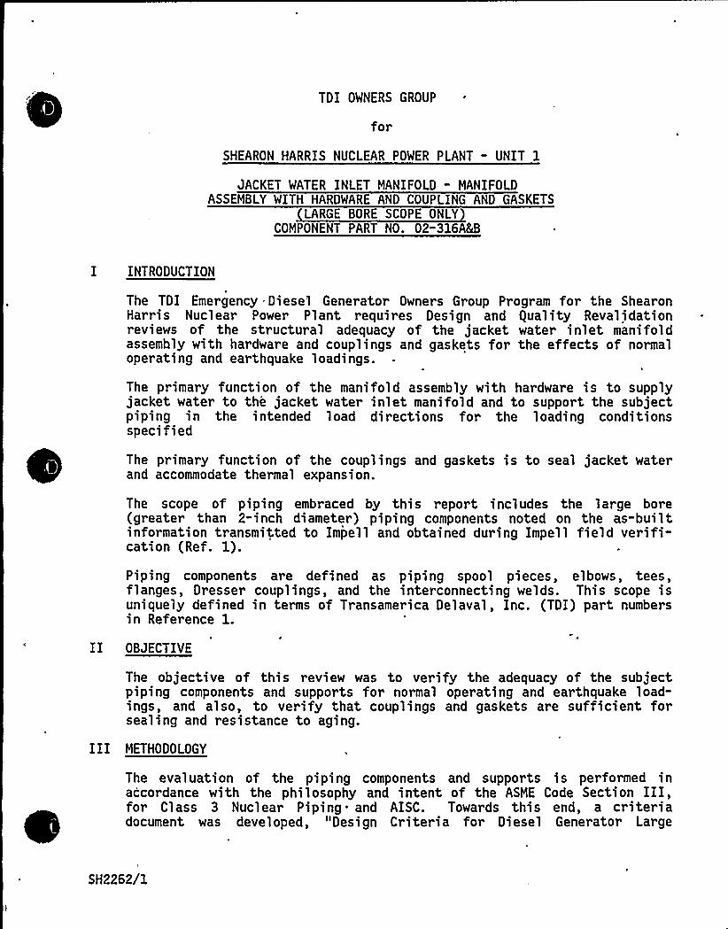
TDI OWNERS GROUP
for
SHEARON HARRIS NUCLEAR POWER PLANT - UNIT 1
JACKET WATER INLET MANIFOLD - MANIFOLDASSEMBLY WITH HARDWARE AND COUPLING AND GASKETS
LARGE BORE SCOPE ONLYCOMPONENT PART NO. 02-316A&B
I INTRODUCTION
The TDI Emergency Diesel Generator Owner s Group Program for the ShearonHarris Nuclear Power Plant requires Design and equality Revalidationreviews of the structural adequacy of the jacket water inlet manifoldassembly with hardware and couplings and gaskets for the effects of normaloperating and earthquake loadings.
The primary function of the manifold assembly with hardware is to supplyjacket water to the jacket water inlet manifold and to support the subjectpiping in the intended load directions for the loading conditionsspecified
The primary function of the couplings and gaskets is to seal jacket waterand accommodate thermal expansion.
The scope of piping embraced by this report includes the large bore(greater than 2"inch diameter ) piping components noted on the as-builtinformation transmitted to Impell and obtained during Impell field verifi-cation (Ref. 1).
Piping components are defined as piping spool pieces, elbows, tees,flanges, Dresser couplings, and the interconnecting welds. This scope isuniquely defined in terms of Transamerica Delaval, Inc. (TDI) part numbersin Reference 1.
II OBJECTIVE
The objective of this review was to verify the adequacy of the subjectpiping components and supports for normal operating and earthquake load-ings, and also, to verify that couplings and gaskets are sufficient forsealing and resistance to aging.
III METHODOLOGY
The evaluation of the piping components and supports is performed inaccordance with the philosophy and intent of the ASME Code Section III,for Class 3 Nuclear Piping and AISC. Towards this end, a criteriadocument was developed, "Design Criteria for Diesel Generator Large
SH2262/1
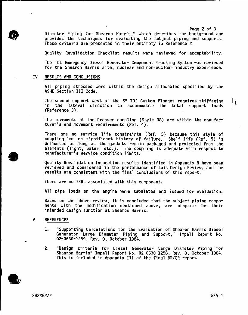
Page 2 of 3Diameter Piping for Shearon Harris," which describes the background andprovides the techniques for evaluating the subject piping and supports.These criteria are presented in their entirety in Reference 2.
guality Revalidation Checklist results were reviewed for acceptability.
The TDI Emergency Diesel Generator Component Tracking System was reviewedfor the Shearon Harris site, nuclear and non-nuclear industry experience.
IV RESULTS AND CONCLUSIONS
All piping stresses were within the design allowables specified by theASME Section III Code.
The second support west of the 6" TDI Custom Flanges requires stiffeningin the lateral direction to accommodate the total support loads(Reference 3).
The movements at the Dresser coupling (Style 38) are within the manufac-turer's end movement requirements (Ref. 4).
There are no service life constraints (Ref. 5) because this style ofcoupling has no significant history of failure. Shelf life (Ref. 5) isunlimited as long as the gaskets remain packaged and protected from theelements (light, water, etc.). The coupling is adequate with respect tomanufacturer's service condition limits.
guality Revalidation Inspection results identified in Appendix B have beenreviewed and considered in the performance of this Design Review, and theresults are consistent with the final conclusions of this report.
There are no TERs associated with this component.
All pipe loads on the engine were tabulated and issued for evaluation.
Based on the above review, it is concluded that the subject piping compo-nents with the modification mentioned above, are adequate for theirintended design function at Shearon Harris.
V REFERENCES
1. "Supporting Calculations for the Evaluation of Shearon Harris DieselGenerator Large Diameter Piping and Support," Impell Report No.02-0630-1259, Rev. 0, October 1984.
2. "Design Criteria for Diesel Generator Large Diameter Piping forShearon Harris" Impell Report No. 02-0630-1258, Rev. 0, October 1984.This is included in Appendix III of the final DR/gR report.
SH2262/2 REV I

Page 3 of 33. Letter from R. Markovich/G. Shears (Impell) to J. Kammeyer (SWEC),
"Required Modifications for Validation of Impell's Design Revi'ew forComponent No. 02-316AM - Shearon Harris," dated October 10, 1984.
4. Dresser Pipe Couplings, Pipe Fittings, and Pipe Repair ProductsCatalog, No. 63.
5. Telephone conversation between A. Palumbo and M. Riley of DresserManufacturing Company, June 5, 1984.
SH2262/3
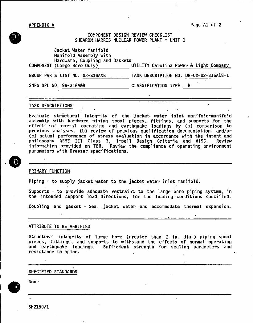
APPENDIX A
COMPONENT DESIGN REVIEW CHECKLISTSHEARON HARRIS NUCLEAR POWER PLANT - UNIT 1
Page Al of 2
Jacket Water ManifoldManifold Assembly withHardware, Coupling and
COMPONENT Lar e Bore Onl
GROUP PARTS LIST NO. 02-316'(B
SNPS GPL NO. 99-316'(B
GasketsUTILITY Carolina Power 8 Li ht Com an
TASK DESCRIPTION NO. DR-02-02-316'(B-1
CLASSIFICATION TYPE B
TASK DESCRIPTIONS
Evaluate structural integrity of the jacket water inlet mani fold"mani foldassembly with hardware piping spool pieces, fittings, and supports for theeffects of normal operating and earthquake loadings by (a) comparison toprevious analyses, (b) review of previous qualification documentation, and/or(c) actual performance of stress evaluation in accordance with the intent andphilosophy ASME III Class 3, Impell Design Criteria and AISC. Reviewinformation provided on TER. Review the compliance of operating environmentparameters with Dresser specifications.
PRIMARY FUNCTION
Piping - to supply jacket water to the jacket water inlet manifold.
Supports - to provide adequate restraint to the large bore. piping system, inthe intended support load directions, for the loading conditions specified.
Coupling and gasket - Seal jacket water and accommodate thermal expansion.
ATTRIBUTE TO BE VERIFIED
Structural integrity of large bore (greater than 2 in. dia.) piping spoolpieces, fittings, and supports to withstand the effects of normal operatingand earthquake loadings. Sufficient strength for sealing parameters andresistance to aging.
SPECIFIED STANDARDS
None
SH2150/1
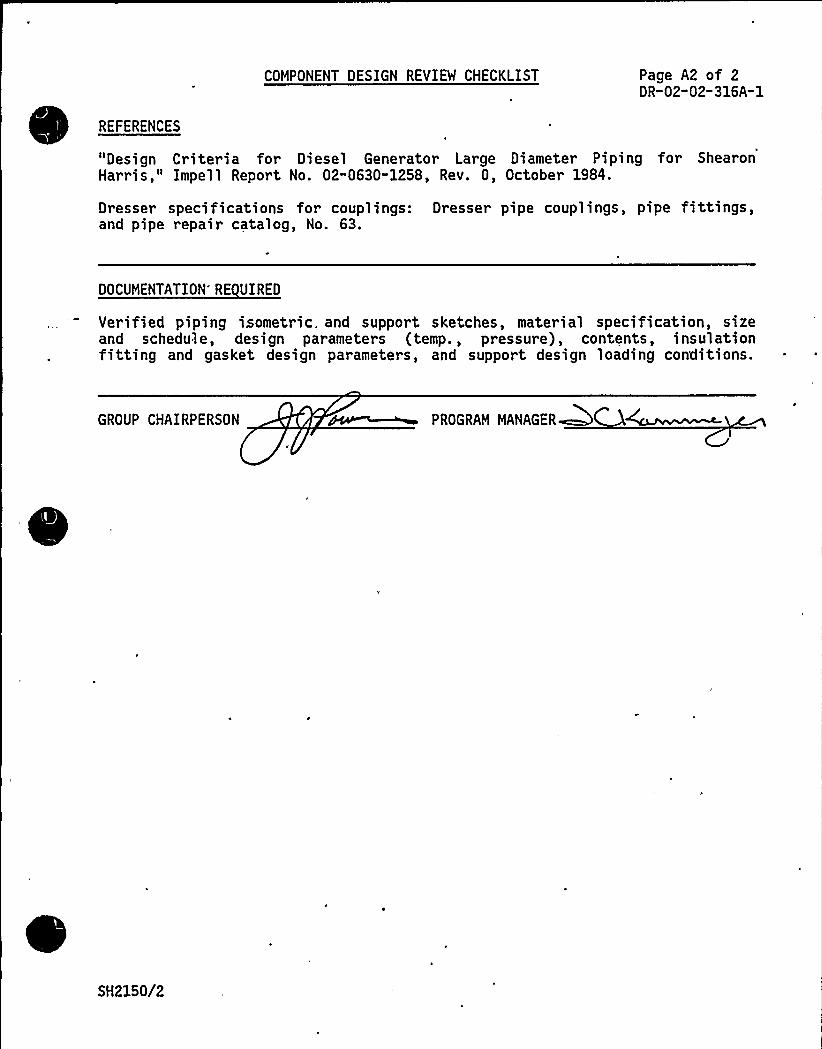
COMPONENT DESIGN REVIEW CHECKLIST Page A2 of 2DR-02-02-316A-1
REFERENCES
"Design Criteria for Diesel Generator Large Diameter Piping for ShearonHarris," Impell Report No. 02-0630-1258, Rev. 0, October 1984.
Dresser specifications for couplings: Dresser pipe couplings, pipe fittings,and pipe repair catalog, No. 63.
DOCUMENTATION'E UIRED
Verified piping isometric. and support sketches, material specification, sizeand schedule, design parameters (temp., pressure), contents, insulationfitting and gasket design parameters, and support design loading conditions.
GROUP CHAIRPERSON PROGRAM MAMAGERM
SH2150/2

Cl
I, QJb%
qyV s
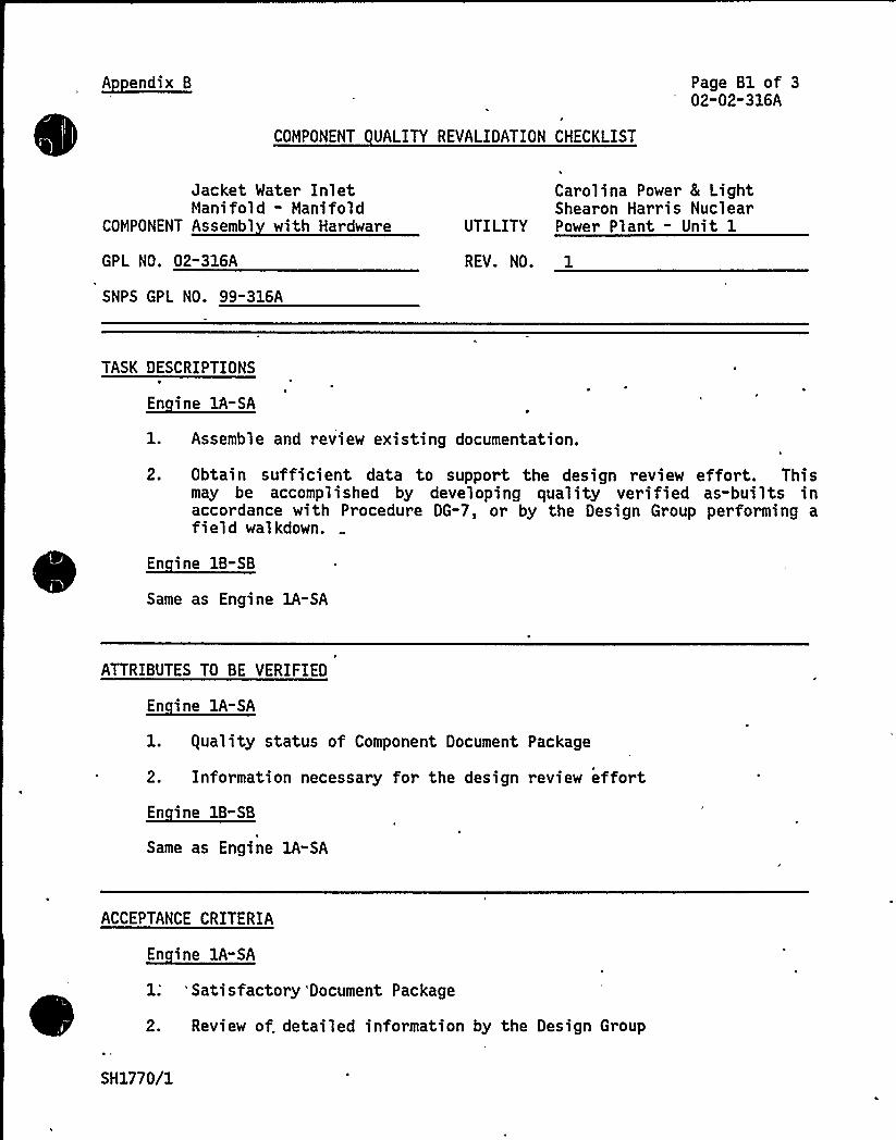
A endix 8
COMPONENT UALITY REVALIDATION CHECKLIST
Page B1 of 302-02" 316A
Jacket Water InletMani fold - Mani fold
COMPONENT Assembl with Hardware
GPL NO. 02-316A
SNPS GPL NO. 99-316A
Carolina Power 8 LightShearon Harris Nuclear
UTILITY Power Plant - Unit 1
REV. NO. 1
TASK DESCRIPTIONS
En ine 1A-SA
l. Assemble and review existing documentation.
2. Obtain sufficient data to support the design review effort. Thismay be accomplished by developing quality verified as-builts inaccordance with Procedure DG-7, or by the Design Group performing afield walkdown.
En ine 1B-SB
Same as Engine lA-SA
ATTRIBUTES TO BE VERIFIED
En ine 1A-SA
l. guality status of Component Document Package
2. Information necessary for the design review effort
~Ei -B
Same as Engine 1A-SA
ACCEPTANCE CRITERIA
En ine lA-SA
1; 'Satisfactory 'Document Package
2. Review of. detailed information by the Design Group
SH1770/1
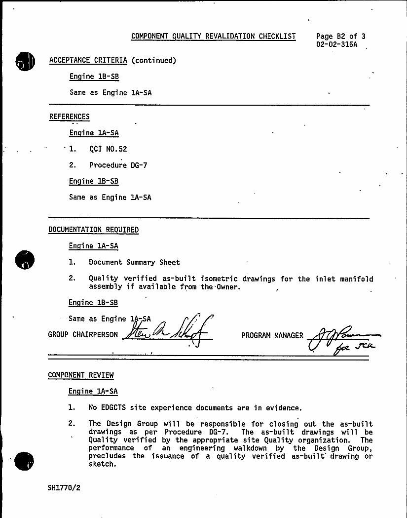
COMPONENT UALITY REVALIDATION CHECKLIST Page B2 of 302" 02-316A
ACCEPTANCE CRITERIA (continued)
~Ei 1B- B
Same as Engine lA-SA
REFERENCES
~Ei 1-l. QCI N0.52
2. Procedure DG-7
~E
Same as Engine 1A-SA
DOCUMENTATION RE UIRED
~Ei A-E
1. Document Summary Sheet,
2. Quality verified as-built isometric drawings for the inlet manifoldassembly if available from the Owner.
En ine 1B-SB
Same as Engine 1 -SA
GROUP CHAIRPERSON PROGRAM MANAGER
COMPONENT REVIEW
En ine 1A-SA
1. No EDGCTS site experience documents are in evidence.
2. The Design Group will be responsible for closing out the as-builtdrawings as per Procedure DG-7. The as-built drawings will beQuality verified by the appropriate site Quality organization. Theperformance of an engineering walkdown by the Design Group,precludes the issuance of a quality verified as-built'rawing orsketch.
SH1770/2
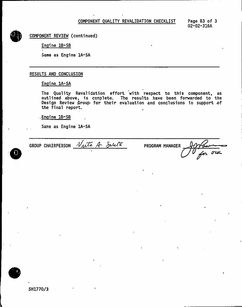
COMPONENT UALITY REVALIDATION CHECKLIST
COMPONENT REVIEW (continued)
~Ei IB-EB
Same as Engine 1A-SA
Page B3 of 302-02-316A
RESULTS AND CONCLUSION
En ine. 1A-SA
The equality Revalidation effort with respect to this component, asoutlined above, is complete. The results have been forwarded to theD'esign Review Group for their evaluation and conclusions in support Bofthe final report.
.I~Bi EB-EB
Same as Engine 1A-SA
GROUP CHAIRPERSON PROGRAM MANAGER
SH1770/3
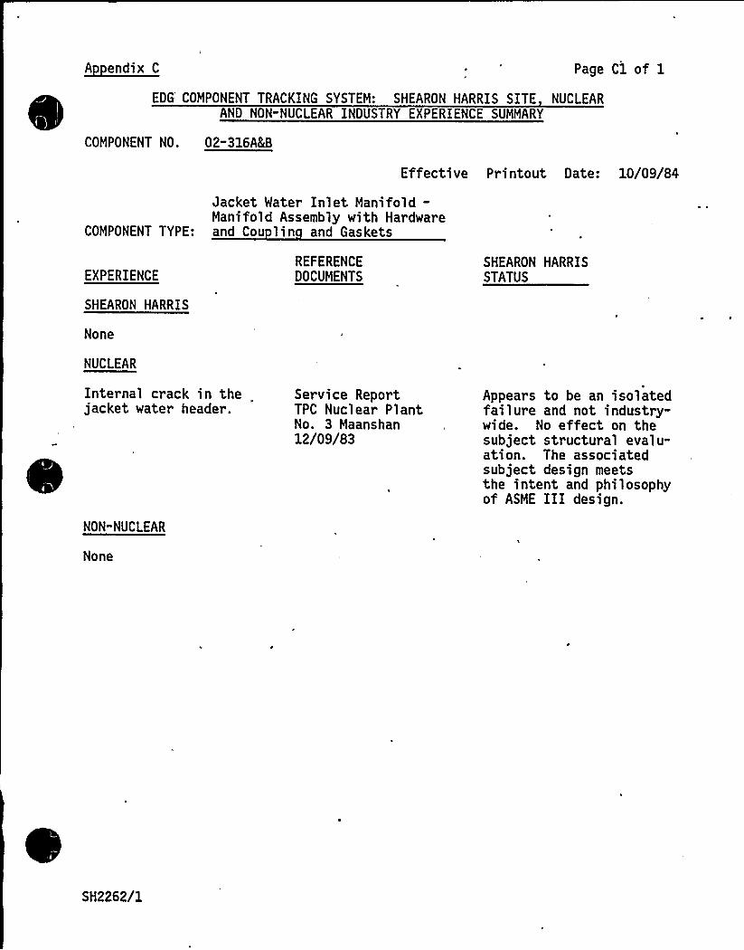
A endix C Page Cl of 1
EDG'OMPONENT TRACKING SYSTEM: SHEARON HARRIS SITE NUCLEARAND NON-NUCLEAR INDUSTRY EXPERIENCE SUMMARY
COMPONENT NO. 02-316A&B
Effective Printout Date: 10/09/84
Jacket Water Inlet Manifold-Manifold Assembly with Hardware
COMPONENT TYPE: and Cou lin and Gaskets
EXPERIENCE
SHEARON HARRIS
None
NUCLEAR
Internal crack in thejacket water header.
NON-NUCLEAR
None
REFERENCEDOCUMENTS
Service ReportTPC Nuclear PlantNo. 3 Maanshan12/09/83
SHEARON HARRISSTATUS
Appears to be an isolatedfailure and not industry-wide. No effect on thesubject structural evalu-ation. The associatedsubject design meetsthe intent and philosophyof ASME III design.
SH2262/1

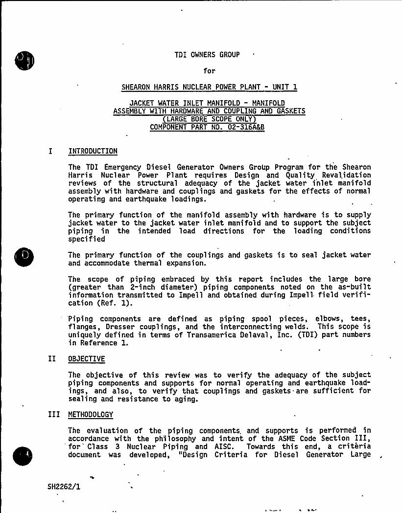
TDI OWNERS GROUP
for
SHEARON HARRIS NUCLEAR POWER PLANT " UNIT 1
JACKET WATER INLET MANIFOLD " MANIFOLDASSEMBLY WITH HARDWARE AND COUPLING AND GASKETS
LARGE BORE SCOPE ONLYCOMPONENT PART NO. 02-316'(B
I INTRODUCTION
The TDI Emergency Diesel Generator Owners GroUp Program for the ShearonHarri s Nucl ear Power Pl ant requires Design and gual ity Reval idati onreviews of the structural adequacy of the jacket water inlet manifoldassembly with hardware and couplings and gaskets for the effects of normaloperating and ear thquake 1 oadings.
The primary function of the manifold assembly with hardware is to supplyjacket water to the jacket water inlet manifold and to support the subjectpiping in the intended load directions for the loading conditionsspeci fied
The primary function of the couplings and gaskets is to seal jacket waterand accommodate thermal expansion.
The scope of piping embraced by this report includes the large bore(greater than 2-inch diameter) piping components noted on the as-builtinformation transmitted to Impell and obtained during Impell field verifi-cation (Ref. 1).
'Piping components are defined as piping spool pieces, elbows, tees,flanges, Dresser couplings, and the interconnecting welds. This scope isuniquely defined in terms of Transamerica Delaval, Inc. (TDI) part numbersin Reference 1.
II OBJECTIVE
The objective of this review was to verify the adequacy of the subjectpiping components and supports for normal operating and earthquake load-ings, and also, to verify that couplings and gaskets narc sufficient forsealing and resistance to aging.
III METHODOLOGY
The evaluation of the piping components. and supports is performed inaccordance with the ph'ilosophy and intent of the ASME Code Section III,
'for 'lass 3 Nuclear Piping and AISC. Towards this end, a criteriadocument was developed, "Design Criteria for Diesel Generator Large
SH2262/1

I
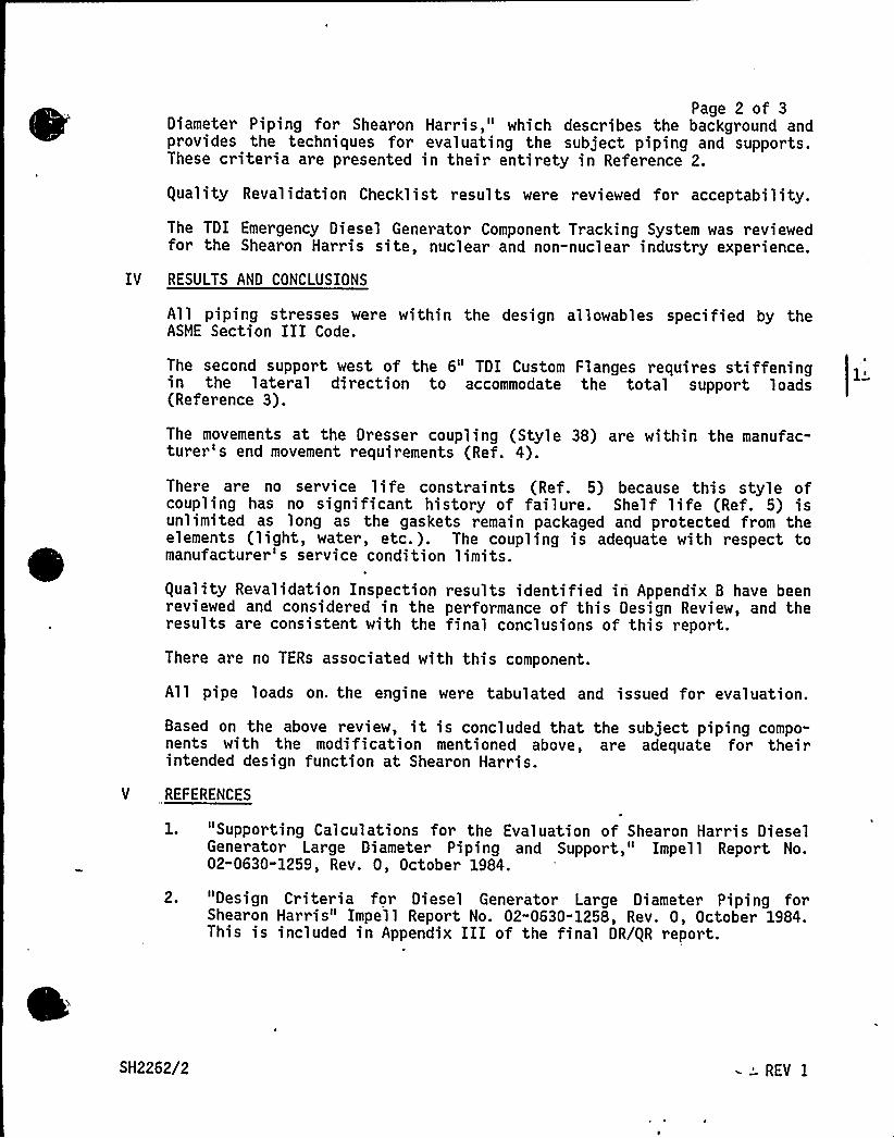
Page 2 of 3Diameter Piping for Shearon Harris," which describes the background andprovides the techniques for evaluating the subject piping and supports.These criteria are presented in their entirety in Reference 2.
guality Revalidation Checklist results were reviewed for acceptability.
The TDI Emergency Diesel Generator Component Tracking System was reviewedfor the Shearon Harris site, nuclear and non-nuclear industry experience.
IV RESULTS AND CONCLUSIONS
All piping stresses were within the design allowables specified by theASIDE Section III Code.
The second support west of the 6" TDI Custom Flanges requires stiffeningin the lateral direction to accommodate the total support loads(Reference 3).
The movements at the Dresser coupling (Style 38) are within the manufac-turer's end movement requirements (Ref. 4).
There are no service life constraints (Ref. 5) because this style ofcoupling has no significant history of failure. Shelf life (Ref. 5) isunlimited as long as the gaskets remain packaged and protected from theelements (light, water, etc.). The coupling is adequate with respect tomanufacturer's service condition limits.
guality Revalidation Inspection results identified iri Appendix B have beenreviewed and considered in the performance of this Design Review, and theresults are consistent with the final conclusions of this report.
There are no TERs associated with this component.
All pipe loads on. the engine were tabulated and issued for evaluation.
Based on the above review, it is concluded that the subject piping compo-nents with the modification mentioned above, are adequate for theirintended design function at Shearon Harris.
V REFERENCES
1. "Supporting Calculations for the Evaluation of Shearon Harris DieselGenerator Large Diameter Piping and Support," Impell Report No.02-0630-1259, Rev. 0, October 1984.
2. "Design Criteria for Diesel Generator Large Diameter Piping forShearon Harris" Impell Report No. 02-0630-1258, Rev. 0, October 1984.This is included in Appendix III of the final DR/gR report.
SH2262/2 - 'EV I
Page 3 of 33. Letter from R. Markovich/G. Shears (Impell) to J. Kammeyer (SMEC),
"Required Modifications for Validation of Impell's Design Review forComponent No. 02-316AEB - Shearon Harris," dated October 10, 1984.
4. Dresser Pipe Couplings, Pipe Fittings, and Pipe Repair ProductsCatalog, No. 63.
5. Telephone conversation between A. Palumbo and M. Riley of DresserManufacturing Company, June 5, 1984.
SH2262/3
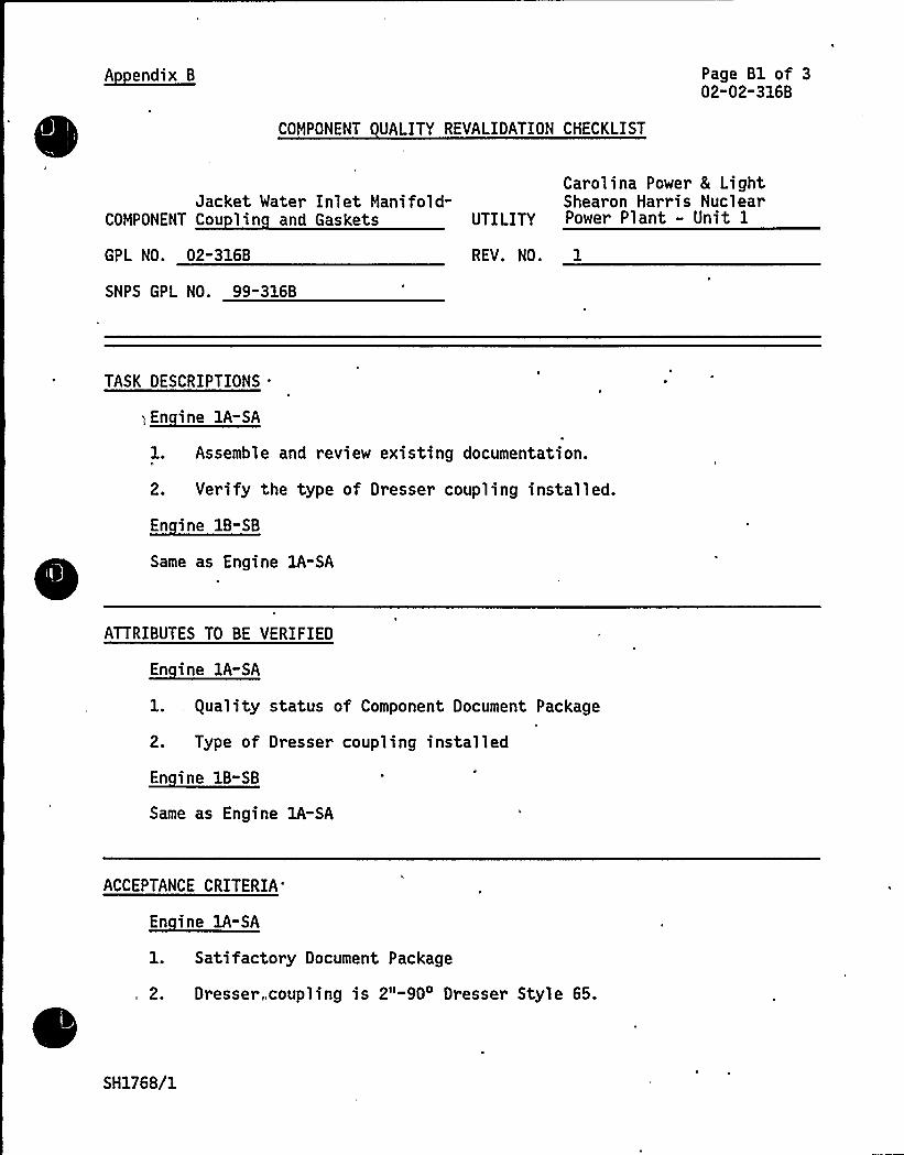
A endix B Page Bl of 302-02-316B
COMPONENT UALITY REVALIDATION CHECKLIST
Jacket Water Inlet Manifold-COMPONENT Cou lin and Gaskets
GPL NO. 02-316B
SNPS GPL NO. 99-316B
Carolina Power 8 LightShearon Harris Nuclear
UTILITY Power Plant - Unit 1
REV. NO. 1
TASK DESCRIPTIONS .
.~Ei A-EA
1. Assemble and review existing documentation.
2. Verify the type of Dresser coupling installed.
~Ei B- B
Same as Engine lA-SA
ATTRIBUTES TO BE VERIFIED
~Ei IA-EA
1. guality status of Component Document Package
2. Type of Dresser coupling installed
~E
Same as Engine lA-SA
ACCEPTANCE CRITERIA
~Ei IA- A
1. Satifactory Document Package
,„ 2. Dresser„coupling is 2"-90 Dresser Style 65.
SH1768/1

Cl
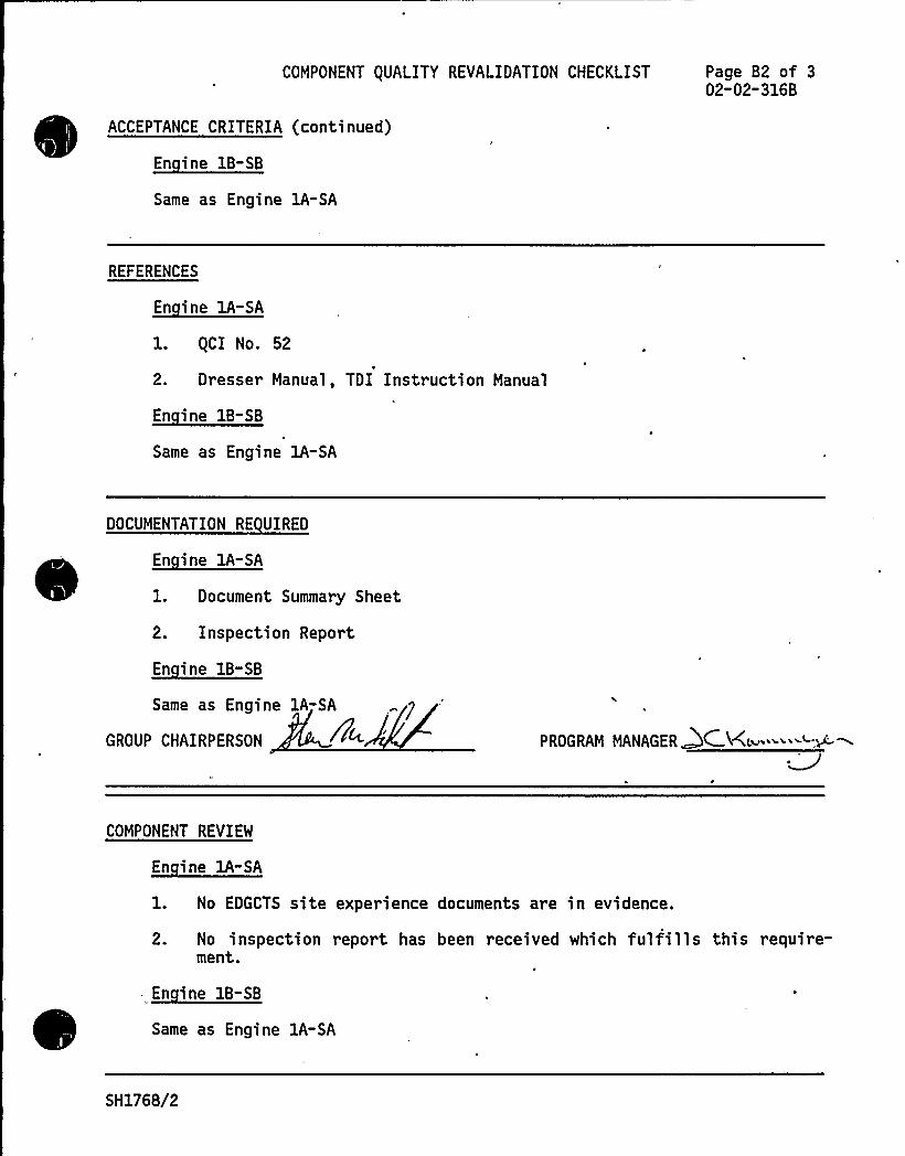
COMPONENT OUALITY REVALIDATION CHECKLIST
ACCEPTANCE CRITERIA (continued)
~Ei B- B
Same as Engine lA-SA
Page B2 of 302-02-316B
REFERENCES
En ine lA-SA
l. gCI No. 52
2. Dresser Manual, TDI Instruction Manual
~Ei B-EB
Same as Engine 1A-SA
DOCUMENTATION RE UIRED
~Ei -E1. Document Summary Sheet
2. Inspection Report
~Ei E- B
Same as Engine lA-SA
GROUP CHAIRPERSON PROGRAM MANAGERQCK~'j-COMPONENT REVIEW
En ine 1A-SA
1. No EDGCTS site experience documents are in evidence.
2. No inspection report has been received which fulfills this require-ment.
~Ei B-EB
Same as Engine lA-SA
SH1768/2
COMPONENT EQUALITY REVALIDATION CHECKLIST Page B3 of 302-02-316B
RESULTS AND CONCLUSION
~Ei -SA
The guality Revalidation effort with respect to this component, asoutlined above, is complete. The results have been forwarded to theDesign Review Group for their evaluation and conclusions in support ofthe final report.
En ine 1B-SB
Same as Engine lA-SA
GROUP CHAIRPERSON !4 wWW PR0GRAM MANAGER DC 5(
SH1768/3

Cl
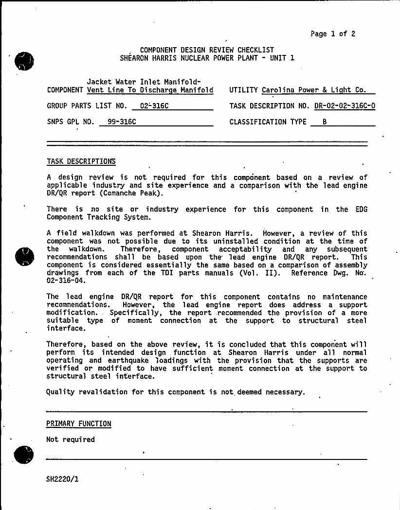
COMPONENT DESIGN REVIEW CHECKLISTSHEARON HARRIS NUCLEAR POWER PLANT - UNIT 1
Page 1 of 2
Jacket Water Inlet Manifold-COMPONENT Vent Line To Dischar e Manifold
GROUP PARTS LIST NO. 02-'316C
SNPS GPL NO. 99-316C
UTILITY Carolina Power 8 Li ht Co.
TASK DESCRIPTION NO. DR-02" 02"316C-0
CLASSIFICATION TYPE B
TASK DESCRIPTIOMS
A design review is not required for this component based on a review ofapplicable industry and site experience and a comparison with the lead engineDR/gR report (Comanche Peak).
There is no site or industry experience for this component in the EDG
Component Tracking System.
A field walkdown was performed at Shearon Harris. However, a review of thiscomponent was not possible due to its uninstalled condition at the time ofthe walkdown. Therefore, component acceptability and any subsequentrecommendations shall be based upon the lead engine DR/gR report. Thiscomponent is considered essentially the same based on a comparison of assemblydrawings from each of the TDI parts manuals (Vol. II). Reference Dwg. No'.02"316-04.
The lead engine DR/gR report for this component contains no maintenancerecommendations. However, the lead engine report does address a supportmodification.. Specifically, the report recommended the provision of a moresuitable type of moment connection at the support to structural steelinterface.
Therefore, based on the above review, it is concluded that t'his component willperform its intended design function at Shearon Harris under all normaloperating and earthquake loadings with the provision that the supports areverified or modified to have sufficient moment connection at the support tostructural steel interface.
guality revalidation for this component is not deemed necessary.
PRIMARY FUNCTION
Not required
SH2220/1

COMPONENT DESIGN REVIEW CHECKLIST
'TTRIBUTE TO BE VERIFIEDH
Not requiredl
Page 2 of 2DR"02-02-316C"0
SPECIFIED STANDARDS
Not required
REFERENCES
Not required
DOCUMENTATION RE UIRED
Not required
GROUP CHAIRPERSON ROGRAM MANAGER CK
eSH2220/2

8

COMPONENT DESIGN REVIEW CHECKLISTSHEARON HARRIS NUCLEAR POWER PLANT - UNIT 1
Page 1 of 2
Jacket Water DischargeManifold/Piping
COMPONENT Lar e Bore Onl
GROUP PARTS LIST NO. 02-317A&B
SNPS GPL NO. 03-317A&B
UTILITY Carol ina Power & Li ht Com an
TASK DESCRIPTION NO. DR-02-02-317A&B-0
CLASSIFICATION TYPE B
TASK DESCRIPTIONS
Design Review for this component is not. required based on the foll'owing:
~ A review of the component tracking system indicated that there wasno significant applicable industry or site experience.
~ A review of the. lead engine DR/gR Reports (Shoreham/Comanche Peak)
~ A comparison of the jacket water discharge manifold and piping spoolpieces and fittings for Shearon Harris with Comanche Peak.
~
~ ~
The fol 1 owing maintenance modi ficati ons r ecommendations made on the LeadEngine DR/gR Report should be implemented:
~ The Style 65 Dresser couplings are to be replaced with Style 90 orStyle 165 Dresser couplings should leaks develop.
There are no modification recommendations for this component, however duringthe Impell field verification several pipe supports were disassembled. Alljacket water manifold supports should be verified for proper installation.
guality Revalidation is not required for this component.
PRIMARY FUNCTION
Not required
ATTRIBUTE TO BE VERIFIED
Not required
SH2138/1

0
SPECIFIED STANDARDS
Not required
COMPONENT DESIGN REVIEW CHECKLIST Page 2 of 2DR-02-02-317'(B-0
REFERENCES
Not required
DOCUMENTATION RE UIRED
Not required
, GROUP CHAIRPERSON
~+
ROGRAM MANAGER '
SH2138/2

,
TDI OWNERS GROUP
for
SHEARON HARRIS NUCLEAR POWER PLANT
Water Discharge Manifold: Coupling 8 Seals
COMPONENT PART NO.: O2-317B
'ee Component Part No. 02-317A

Page 1 of 2
COMPONENT DESIGN REVIEW CHECKLISTSHEARON HARRIS NUCLEAR POWER PLANT - UNIT 1
Water Discharge Manifold:COMPONENT Su orts (Lar e Bore Onl
GROUP PARTS LIST NO. 02-317C
SNPS GPL NO. 03-317C
UTILITY Carolina Power 8 Li ht Com an
TASK DESCRIPTION NO. DR-02-02-317C-1
CLASSIFICATION TYPE B
TASK DESCRIPTIONS
Design Review for this component is not required based on the following:
~ A review of the EDG Component Tracking System indicated that therewas no significant applicable site or industry experience.
~ A review of the lead engine DR/gR Reports (Shoreham/Comanche Peak)
~ A comparison of the water discharge manifold supports for ShearonHarris with Comanche Peak.
There are no maintenance recommendations for this component.
The following modification recommendations made on the lead engine DR/gRreport should be implemented:
~ Ensure that the supports pads (item No. 6 on TDI drawing 02-317-18,Rev. 8), for the supports on each of the 5-inch jacket waterdischarge headers, have a minimum weld of 1/4-inch (3 inches long)between the engine block and the longer sides of the support pad.Also, ensure that the welds between the engine block and the shortersides of the support pad are 1/4-inch (min.) .
guality revalidation is not required for this component.
PRIMARY FUNCTION
Not required
ATTRIBUTE TO BE VERIFIED
Not required
SH2139/1
REV 1
SPECIFIED STANDARDS
Not required
COMPONENT DESIGN REVIEW CHECKLIST Page 2 of 2DR-02-02-317C-0
REFERENCES
Not required
DOCUMENTATION RE UIRED
Not required
GROUP CHAIRPERSON PROGRAM MANAGER C K
SH2139/2
Page 1 of 3
COMPONENT DESIGN REVIEW CHECKLISTSHEARON HARRIS NUCLEAR POWER PLANT - UNIT 1
Engine DrivenCOMPONENT Jacket Water Pum UTILITY Carolina Power 8 Li ht Com an
GROUP PARTS LIST NO. 02-425A TASK DESCRIPTION NO. DR-02-02-425A-0
SNPS GPL NO. 03-425A CLASSIFICATION TYPE A
TASK DESCRIPTIONS ~ ~
Design review for this component is not required based on the. following:
A review of the EDG Component Tracking System indicated that ther ewas no site experience. Significant applicable industry experiencewas previously addressed in the lead engine report.
~ A review of the lead engine DR/QR report (Comanche Peak).
The engine driven jacket water pumps at Shearon Harris and Comanche Peak areof the same design, but the impellers on the Shearon Harris pump are cut tosmaller diameters for lower design flows so that the torques, and consequentlythe stress levels, are lower.
The following maintenance recommendations from the lead engine DR/QR should beimplemented.
It is recommended that the key to keyway interface be checked for a tight fiton both the pump shaft and the impeller during pump reassembly. This, alongwith the drive fit of the impeller onto the shaft, will preclude past problemswhere relative motion between shaft and impeller caused fretting and upset ofthe keyway sides.
It is also recommended that the key to keyway interface be checked for a tightfit on both the spline and the pump shaft during pump reassembly. This, alongwith the drive fit of the impeller onto the shaft, will preclude past problemswhere relative motion between spline and pump shaft caused fretting and upsetof the keyway sides.
The castle nut that drives the external spline on its taper does not have amaximum specified torque "not to be exceeded." It is recommended that theminimum and maximum torque values of 120 ft-lb and 660 ft-lb respectively beincluded in the Shearon Harris maintenance procedures.
There are no modifications required for the pump, based on the lead engineDR/QR report.
'\
All Quality Revalidation inspections which have been performed to date havebeen reviewed and were found to be satisfactory.
SH2603/1

~ = l J '
COMPONENT DESIGN REVIEW CHECKLIST Page 2 of 3OR-02" 02-425A" 0
TASK DESCRIPTION (continued)
The following quality inspections have not been performed to date and arerecommended:
~ Perform a visual inspection of the pump shaft for signs of excessivegalling wear or scoring. Document any questionable items withphotographs (Engine 1A-SA).
~ Perform a visual inspection of the pump driven gears for signs ofpitting or galling. Document any questionable items withphotographs (Engine 1A-SA).
~'erfrom a Liquid Penetrant test on'he gear teeth and transitionarea (gear to shaft) (Engine 1A-SA).
Perform a visual inspection on the wear ring for evidence of gallingor excessive wear (Engine 1A-SA).
PRIMARY FUNCTION
Not required
ATTRIBUTE TO BE VERIFIED
Not required
SPECIFIED-'STANDARDS
Not required
SH2603/2
REFERENCES
Not required
COMPONENT DESIGN REVIEW CHECKLIST Page 3 of3'R-02-02-425A-0
DOCUMENTATION RE VIREO
Not required
GROUP CHAIRPERSON OGRAM MANAGER
SH2603/3

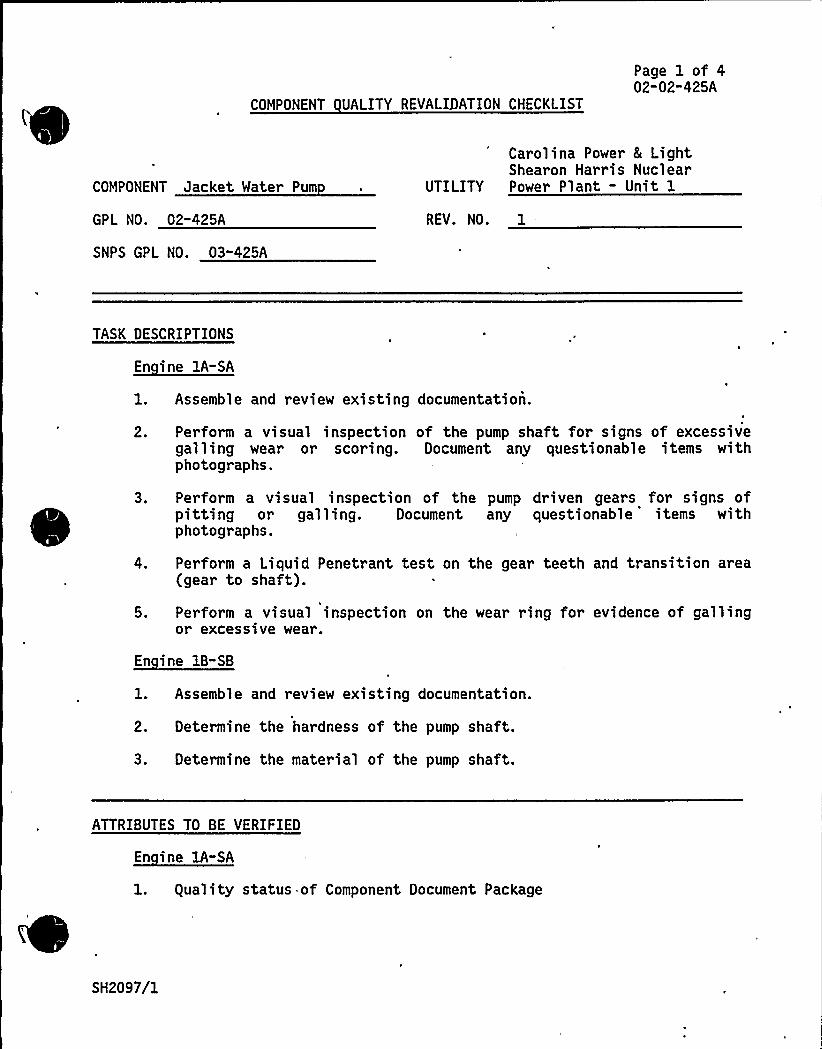
COMPONENT UALITY REVALIDATION CHECKLIST
Page 1 of 402-02"425A
COMPONENT Jacket Water Pum
GPL NO. 02-425A
SNPS GPL NO. 03-425A
Carolina Power 8 LightShearon Harris Nuclear
UTILITY Power Plant - Unit 1
REV. NO. 1
TASK DESCRIPTIONS
~Ei A- A
1. Assemble and review existing documentation.
2. Perform a visual inspection of the pump shaft for signs of excessivegalling wear or scoring. Document any questionable items withphotographs.
3. Perform a visual inspection of the pump driven gears for signs ofpitting or galling. Document any questionable items withphotographs.
4. Perform a Liquid Penetrant test on the gear teeth and transition area(gear to shaft).
5. Perform a visual inspection on the wear ring fot evidence of gallingor excessive wear.
En ine 18-SB
1. Assemble and review existing documentation.
2. Determine the hardness of the pump shaft.
3. Determine the material of the pump shaft.
ATTRIBUTES TO BE VERIFIED
En ine 1A-SA
l. guality status of Component Document Package
SH2097/1

O I
4l'
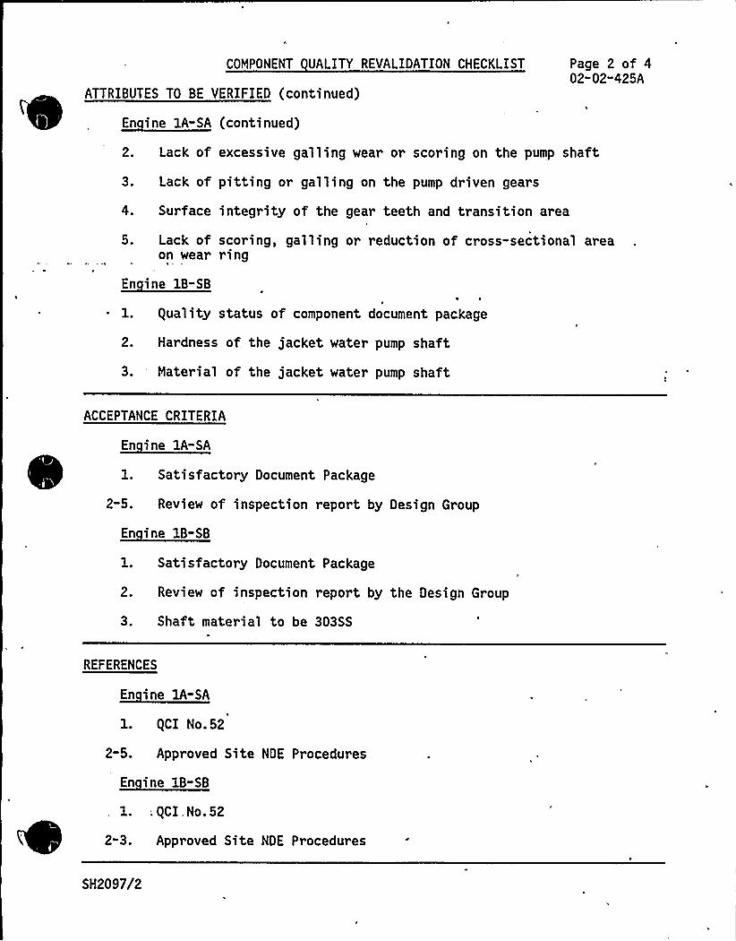
COMPONENT UALITY REVALIDATION CHECKLIST
ATTRIBUTES TO BE VERIFIED (continued)
~di -EA E 1 d)
Page 2 of 402-02-425A
2. Lack of excessive galling wear or scoring on the pump shaft
3. Lack of pitting or galling on the pump driven gears
4.
5.
Surface integrity of the gear teeth and transition area\
Lack of scoring, galling or reduction of cross-sectional areaon wear ring
~di B- 1
~ 1. Quality status of component document package
2. Hardness of the jacket water pump shaft
3. Material of the jacket water pump shaft
ACCEPTANCE CRITERIA
En ine 1A-SA
1. Satisfactory Document Package
2-5. Review of inspection report by Design Group
~di EB- B
1. Satisfactory Document Package
2. Review of inspection report by the Design Group
3. Shaft material to be 303SS
REFERENCES
En ine 1A-SA
2-5.
QCI No.52
Approved Site NDE Procedures
En ine 1B-SB
, . QCI . No. 52
2-3. Approved Site NDE Procedures
SH2097/2
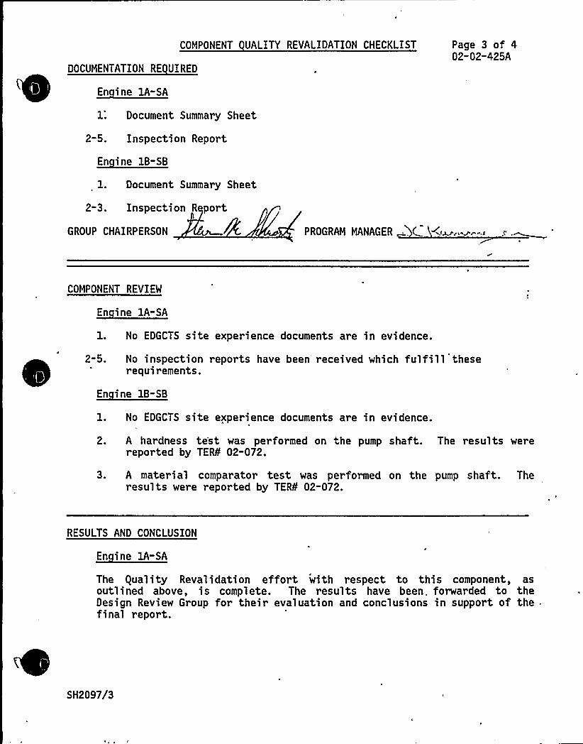
COMPONENT UALITY REVALIDATION CHECKLIST
DOCUMENTATION RE UIRED
~E" i EA-EA
1: Document Summary Sheet
2-5. Inspection Report
En ine 1B-SB
1. Document Summary Sheet
2-3. Inspection R port
Page 3 of 402-02-425A
GROUP CHAIRPERSON PROGRAM MANAGER .. C
COMPONENT REVIEW
~Ei A-
1. No EDGCTS site experience documents are in evidence.
2-5. No inspection reports have been'eceived which fulfill theserequirements.
En ine 1B-SB
1. No EDGCTS site experience documents are in evidence.
2. A hardness te'st was performed on the pump shaft. The results werereported by TER¹ 02-072.
3. A material comparator test was performed on the pump shaft. Theresults were reported by TER¹ 02-072.
RESULTS AND CONCLUSION
~Ei !A-EA
The equality Revalidation effort with respect to this component, asoutlined above, is complete. The results have been. forwarded to theDesign Review Group for their evaluation and conclusions in support of thefinal report.
SH2097/3

COMPONENT UALITY REVALIDATION CHECKLIST
RESULTS AND CONCLUSION (continued)
~Ei BB- B
Same as Engine lA-SA
Page 4 of'02"02-425A
GROUP CHAIRPERSON "./„,/: L 0< PROGRAM MANAGER .
SH2097/4

0"
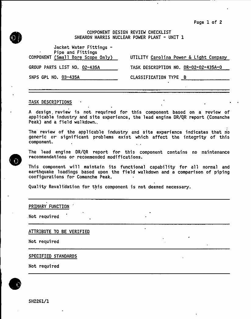
COMPONENT DESIGN REVIEW CHECKLISTSHEARON HARRIS NUCLEAR POWER PLANT - UNIT 1
Page 1 of 2
Jacket Water Fittings-Pipe and Fittings
COMPONENT Small Bore Sco e Onl
GROUP PARTS LIST NO. 02-435A
SNPS GPL NO. 03"435A
UTILITY Carolina Power 8 Li ht Com an
TASK DESCRIPTION NO. DR-02-02-435A-0
CLASSIFICATION TYPE 8
TASK DESCRIPTIONS
A design. review is not required for this component based on a review ofapplicable industry and site experience, the lead engine DR/gR report (ComanchePeak) and a field walkdown..
The review of the applicable industry and site experience indicates that nogeneric or significant problems exist which affect the integrity of thiscomponent.
The lead engine DR/gR report for this component contains no maintenance
~
~
~
~
~ ~ ~ ~
~ ~
~
~
~
~ ~
~ ~
~ ~
recommendations or recommended modifications.
This component will maintain its functional capability for all normal andearthquake loadings based upon the field walkdown and a comparison of pipingconfigurations for Comanche Peak.
guality Revali'dation for this component is not deemed necessary.
PRIMARY FUNCTION
,Not required
ATTRIBUTE TO BE VERIFIED
Not required
SPECIFIED STANDARDS
Not r equired
SH2261/1
COMPONENT DESIGN REVIEM CHECKLIST Page 2 of 2DR-02-02-435A"0
REFERENCES
Not required
DOCUMENTATION RE UIRED
Not requi,red
GROUP CHAIRPERSON *PROGRAM MANAGER
-
(SH2261/2
TDI OWNERS GROUP
for
SHEARON HARRIS NUCLEAR POWER PLANT - UNIT 1
JACKET WATER FITTINGS.- PIPE AND FITTINGSLARGE BORE SCOPE ONLY
COMPONENT PART NO. 02-435A
I INTRODUCTION
(
The TDI Emergency Diesel Generator Owners Group Program for the ShearonHar ris Nucl eat Power Pl ant r equires Desi gn and equal ity Reval idati onreviews of. the structural 'adequacy of the jacket water pipe and fittingsfor. the effects of normal operating and earthquake loadings.
The primary function of the jacket water pipe and fittings is to carryjacket water from the engine pump discharge to the auxiliary skid jacketwater piping.
The scope of piping embraced by this report includes the large bore.(greater than 2-.inch diameter) piping components noted on the as-builtinformation transmitted to Impell and obtained during Impell field verifi-cation (Ref. 1).
Piping components are defined as piping spool pieces, elbows, tees,flanges, and the interconnecting welds. This scope is uniquely defined interms of Transamerica Delaval, Inc. (TDI) part numbers in Reference l.
II OBJECTIVE
The objective of this review was to verify the adequacy of the subjectpiping components for normal operating and earthquake loadings.
III METHODOLOGY
The evaluation of the piping components is performed in accordance withthe philosophy and intent of the ASME Code Section III, for Class 3Nuclear Piping. Towards this end, a criteria document, "Design Criteriafor Diesel Generator Large Diameter Piping for Shearon Harris," wasdeveloped, which describes the background and provides the techniquesfor evaluating the subject piping and supports: These criteria arepresented in their entirety in Reference 2.
guality Revalidation Checklist results were reviewed for acceptability.
(SH2028/2
Page 2 of 2
The TDI Emergency Diesel Generator Component Tracking System was reviewedfor the Shearon Harris site, nuclear, and non-nuclear industry experience.
RESULTS AND CONCLUSIONS
All piping stresses were within the design allowables specified by theASME Section III Code.
All„pipe loads on the engine were tabulated and issued for evaluation.
All supports require reinforcement of their support members. Details onthese modifications are-summarized in Reference 3.
guality Revalidation Inspection results identified in Appendix B have beenreviewed and considered in the performance of this Design Review arrd theresults are consistent with the final conclusion of this report.
There are no TERs associated with this component.
Based on the above review, it is concluded that the subject piping compo-nents, with the modifications mentioned above, are adequate for theirintended design function at Shearon Harris.
V REFERENCES
- "Supporting Calculations for the Evaluation of Shearon Harris DieselGenerator Large Diametet Piping and Support," Impell Report No.02-0630-1259, Rev. 0, October
1984.'.
"Design Criteria for Diesel Generator Large Diameter Piping forShearon Harri s," Impell Repor t No. 02-0630-1258, Rev. 0, October1984. This is included in Appendix III of the final DR/gR report.
3. Letter from R. Markovich/G. Shears (Impell) to J. Kammeyer (SWEC),"Required Modifications for Validation of Impell's Design Reviewfor Component No. 02-435A - Shearon Harris," dated October 10,1984.
SH2028/3
APPENDIX A
COMPONENT DESIGN REVIEW CHECKLISTSHEARON HARRIS NUCLEAR POWER PLANT " UNIT 1
Page Al of 2
Jacket Water Fittings-Pipe and Fittings
COMPONENT Lar e Bore Onl
GROUP PARTS LIST NO. 02-435A
SNPS GPL NO. 03-717D
UTILITY Carolina Power 8 Li ht Com an
TASK DESCRIPTION NO. DR"02"02-435A" 0
CLASSIFICATION TYPE B
TASK DESCRIPTIONS "
Evaluate structural integrity of the jacket water fittings piping spool piecesand fittings for effects of normal operating and earthquake loadings by (a)comparison to previous analyses, (b) review of previous qualificationdocumentation, and/or (c) actual performance of stress evaluation'aaccordance with intent and philosophy of 'ASME III Class 3 and Impell Design
Criteria.'eview
information provided on TERs.
PRIMARY FUNCTION
Carry jacket water from the engine pump discharge to the auxiliary skid jacketwater piping.
ATTRIBUTE TO BE VERIFIED
Structural integrity of large bore (greater than 2 inches in diameter) pipingspool pieces and fittings due to the effects of normal operating andearthquake loadings.
SPECIFIED STANDARDS
None
REFERENCES
'"Design Criteria for Diesel Generator Large Diameter Piping for Shearon
(
Harris," Impell Report No. 02-0630-1258, Rev. 0, October 1984.
SH2151/1

S
COMPONENT DESIGN REVIEM CHECKLIST Page A2 of 2
DOCUMENTATION RE UIRED
Verified piping isometric, material specification, size and schedule, designparameters (temperature, pressure), contents, additives, insulation, fittingand gasket design parameters.
GROUP CHAIRPERSON PROGRAM MANAGER
SH2151/2
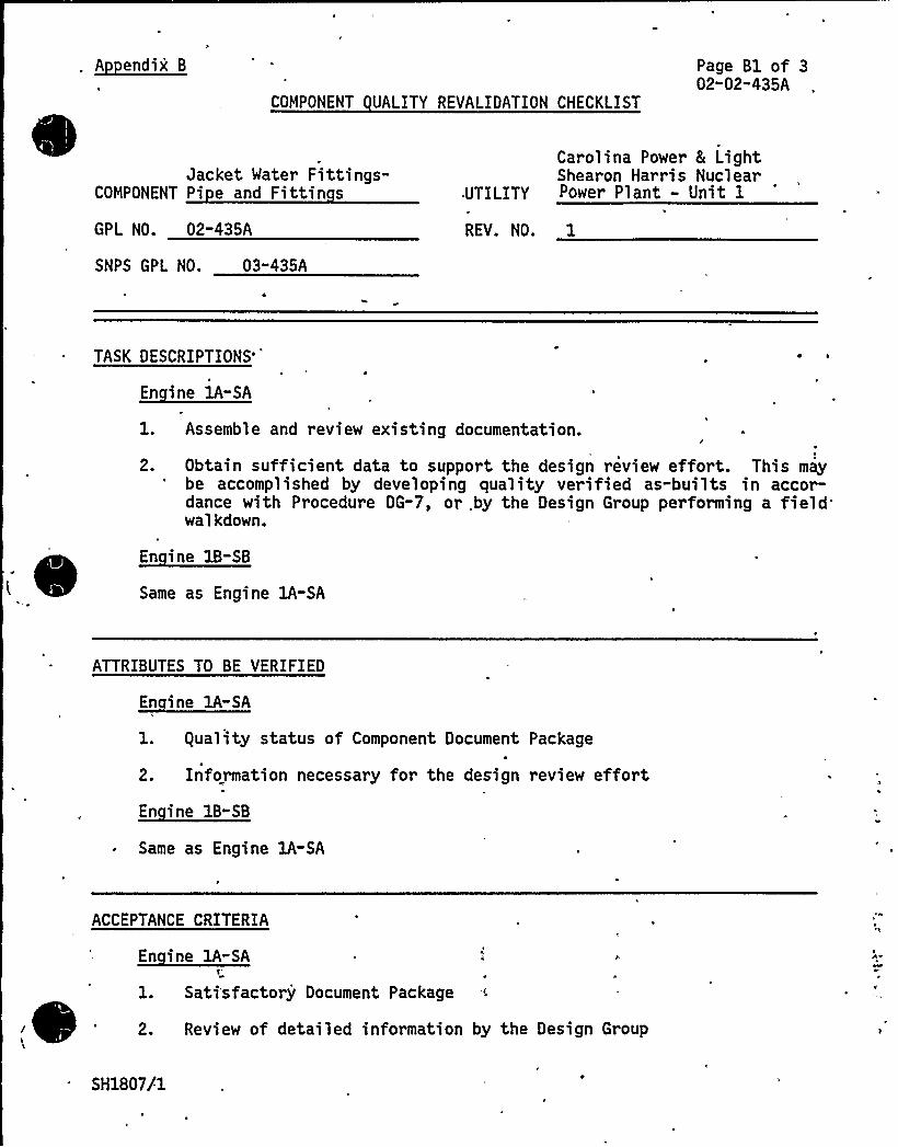
A endix B
COMPONENT UALITY REVALIDATION CHECKLIST
Page Bl of 302-02-435A
Jacket Mater Fittings-COMPONENT Pi e and Fittin s
GPL NO. 02-435A
SNPS GPL NO. 03-435A
I
Carolina Power 8 LightShearon Harris Nuclear
UTILITY Power Plant - Unit 1
REV. NO. 1
TASK DESCRIPTIONS'
En ine 1A-SA
1. Assemble and review existing documentation.
2.
I
Obtain sufficient data to support the design review effort. This maybe accomplished by developing quality verified as-builts in accor-dance with Procedure DG-7, or. by the Design Group performing a fieldwalkdown.
~Ei IB-EB
Same as Engine lA-SA
ATTRIBUTES TO BE VERIFIED
En ine 1A-SA
1. equality status of Component Document Package
2. Information necessary for the design review effort
~Ei BB-BB
Same as Engine 1A-SA
ACCEPTANCE CRITERIA
~Ei IA-EAT"
1. Sati'sfactory Document Package
2. Review of detailed information by the Design Group
EA
SH1807/1
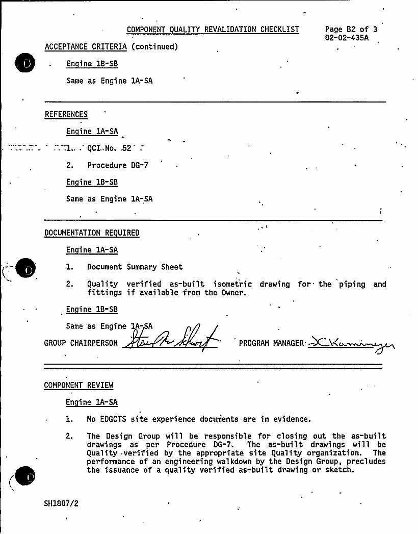
COMPONENT UALITY REVALIDATION CHECKLIST
ACCEPTANCE CRITERIA (continued)
~Ei AB-EB
Same as Engine lA-SA
Page B2 of 302"02"435A
REFERENCES
~Ei IA-EAA
...l..." gCI„.No. 52
2. Procedure DG-7
~Ei 11-EB
Same as Engine 1A-SA
(--
DOCUMENTATION RE UIRED
~Ei AA-EA
1. Document Summary Sheet
S
2. gual ity veri fied as-bui 1 t isometri c drawing for the piping andfittings if available from the Owner.
En ine 1B-SB
Same as Engine 1A- A
GROUP CHAIRPERSON PROGRAM MANAGER'.~NAY
(
COMPONENT REVIEW
En ine 1A-SA
1. No EDGCTS site experience documents are in evidence.
2. The Design Group will be responsible for closing out the as-builtdrawings as per Procedure DG-7. The as-built drawings will beguality verified by the appropriate site guality organization. Theperformance of an engineering walkdown by the Design Group, precludesthe issuance of a quality verified as-built drawing or sketch.
SH1807/2
COMPONENT UALITY REVALIDATION CHECKLIST
COMPONENT REVIEW (continued)
~Ei 1B-EB
Same as Engine lA-SA
Page B3 of 302"02-435A
RESULTS AND CONCLUSION
En ine lA-SA
The guality Revalidation effort with respect to this component, as out-lined above, is complete. The results have been forwarded to the DesignReview Group for their evaluation and conclusions in support of the finalrepor t.
~Ei 1B-EB
Same as Engine lA-SA
(GROUP CHA?RPERSON 4 BE. PROGRAM MANAGER
SH1807/3
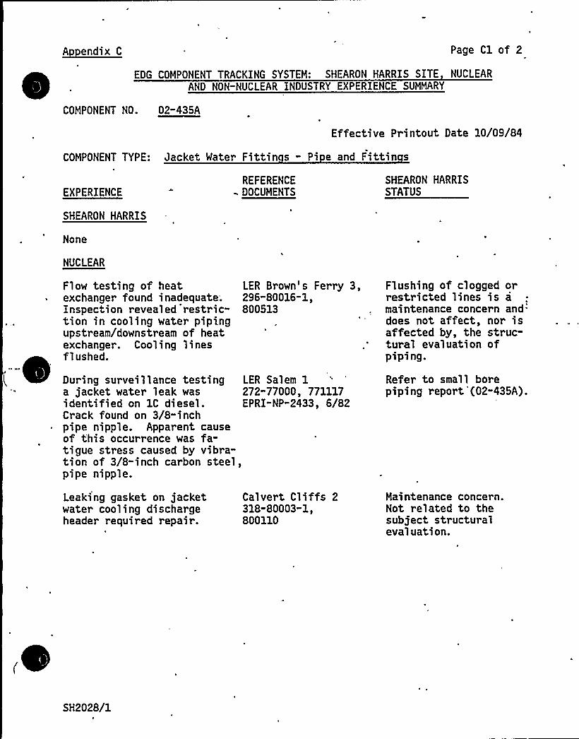
A endix C Page Cl of 2
EDG COMPONENT TRACKING SYSTEM: SHEARON HARRIS SITE NUCLEAR
AND NON-NUCLEAR INDUSTRY EXPERIENCE SUMMARY
COMPONENT NO. 02-435A
Effective Printout Date 10/09/84
COMPONENT. TYPE: Jacket Water Fittin s - Pi e and Fittin s
EXPERIENCE
SHEARON HARRIS
None
NUCLEAR
Flow testing of heatexchanger found inadequate.Inspection revealed 'restric-tion in cooling water pipi.ngupstream/downstream of heatexchanger. Cooling linesflushed.
REFERENCE- DOCUMENTS
LER Brown's Ferry 3,296"80016-1,800513
SHEARON HARRISSTATUS
Flushing of clogged orrestricted lines is amaintenance concern and:does not affect, nor isaffected by, the struc-tural evaluation ofpiping.
During surveillance testinga jacket water leak wasidentified on 1C diesel.Crack found on 3/8-inch
~ pipe nipple. Apparent causeof this occurrence was fa-tigue stress caused by vibra-tion of 3/8-inch carbon steel,pipe nipple.
Leaking gasket on jacketwater cooling dischargeheader required repair.
LER Sal em 1272"77000, 771117EPRI" NP-2433, 6/82
Calvert Cliffs 2318-80003-1i800110
Refer to small borepiping report '(02-435A).
Maintenance concern.Not related to thesubject structuralevaluation.
SH2028/1

'
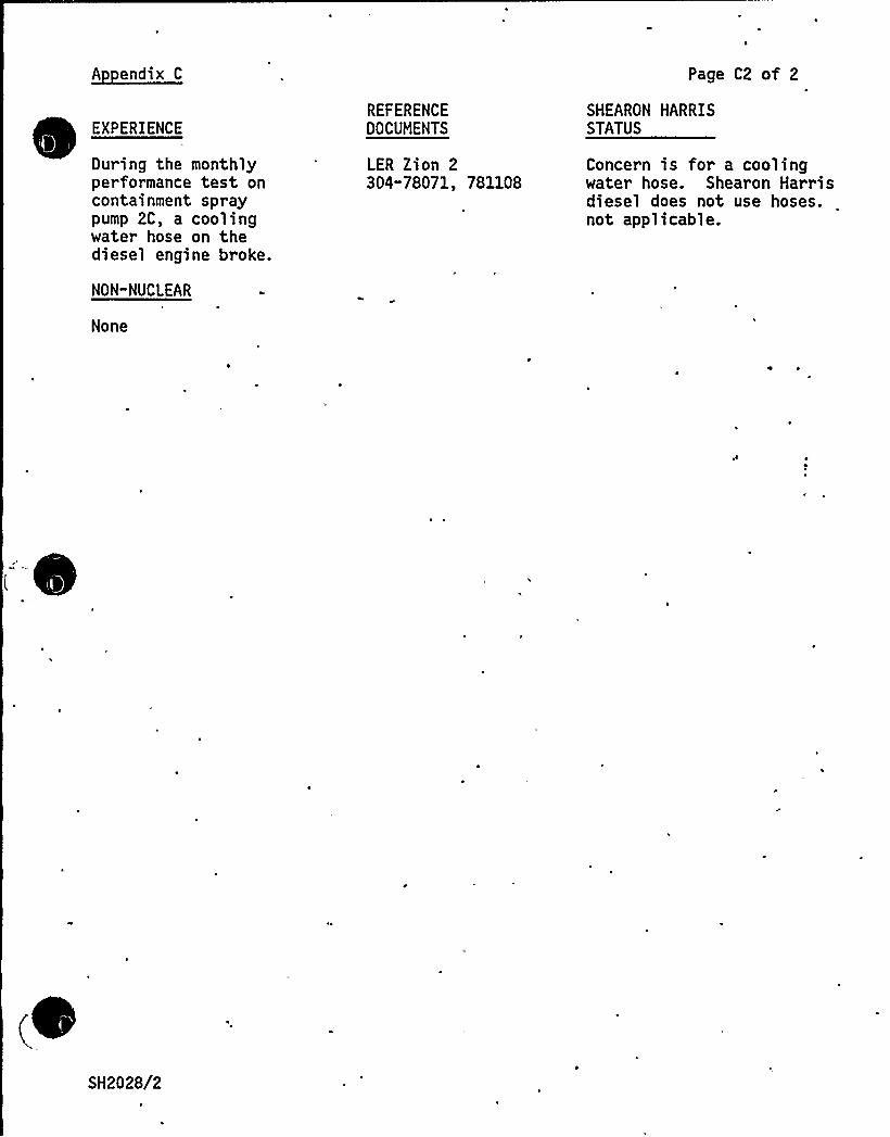
A endix C
EXPERIENCE
During the monthlyperformance test oncontainment spraypump 2C, a coolingwater hose on thediesel engine broke.
NON"NUCLEAR
None
REFERENCEDOCUMENTS
LER Zion 2304-78071, 781108
Page C2 of 2
SHEARON HARRISSTATUS
Concern is for a coolingwater hose. Shearon Harrisdiesel does not use hoses.not applicable.
SH2028/2
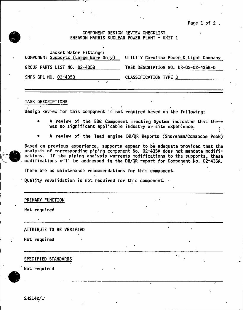
COMPONENT DESIGN REVIEM CHECKLISTSHEARON HARRIS NUCLEAR POWER PLANT " UNIT 1
Page 1 of 2
'
Jacket Mater Fittings:COMPONENT Su orts Lar e Bore Onl
GROUP PARTS LIST NO. 02"435B
SNPS'PL NO. 03-4358
UTILITY Carolina Power 8 Li ht Com an
TASK DESCRIPTION NO. DR-02-02" 435B-0
CLASSIFICATION TYPE B
TASK DESCRIPTIONS
Design Review for this component is not required based on the following:
A review of the EDG Component Tracking System indicated that therewas no significant applicable industry or site experience.
A review of the lead engine DR/gR Reports (Shoreham/Comanche Peak)
Based on previous experience, supports appear to be adequate provided that theanalysis of corresponding piping component No. 02-435A does not mandate modifi-cations. If the piping analysis warrents modifications to the supports, these
. modifications will be addressed in the DR/gR,report for Component No. 02-435A.~
~
~~
~
~
~ ~
~
~
~
~
~
There are no maintenance recommendations for this component.
'quality revalidation is not required for this component.
PRIMARY FUNCTION
Not required
ATTRIBUTE TO BE VERIFIED
Not required
SPECIFIED STANDARDS
Not required
SH2142/1'
REFERENCES
Not required
COMPONENT DESIGN REVIEW CHECKLIST Page 2 of 2DR"02"02-435B"0
DOCUMENTATION RE UIRED
'ot
required
GROUP CHAIRPERSON PROGRAM MANAGER
(
SH2142/2
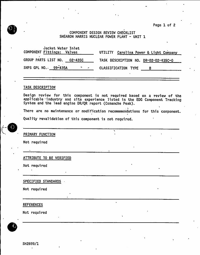
COMPONENT DESIGN REVIEW CHECKLISTSHEARON HARRIS NUCLEAR POWER PLANT - UNIT 1
Page 1 of 2
Jacket Water InletCOMPONENT Fittin s: Valves
GROUP PARTS LIST NO. 02"435C
SNPS GPL NO.. 99"435A
UTILITY Carolina Power 8 Li ht Com an
TASK DESCRIPTION NO. DR"02-02-435C-0
CLASSIFICATION TYPE B
TASK DESCRIPTION
Design review for this component is not required based on a review of theapplicable industry and site experience listed in the EDG Component TrackingSystem and the lead engine DR/gR report (Comanche Peak).
There are no maintenance or modification recommme'ndations for this component.
equality revalidation of this component is not required.
(-PRIMARY FUNCTION
Not required
ATTRIBUTE TO BE VERIFIED
Not required
SPECIFIED STANDARDS
Not required
REFERENCES
Not required
SH2699/1
COMPONENT DESIGN REVIEW CHECKLIST
DOCUMENTATION RE UIRED
Not required
Page 2 of 2DR-02"02-435C-0
GROUP CHAIRPERSON ~ PROGRAM MANAGER
(
(SH2699/2

(-
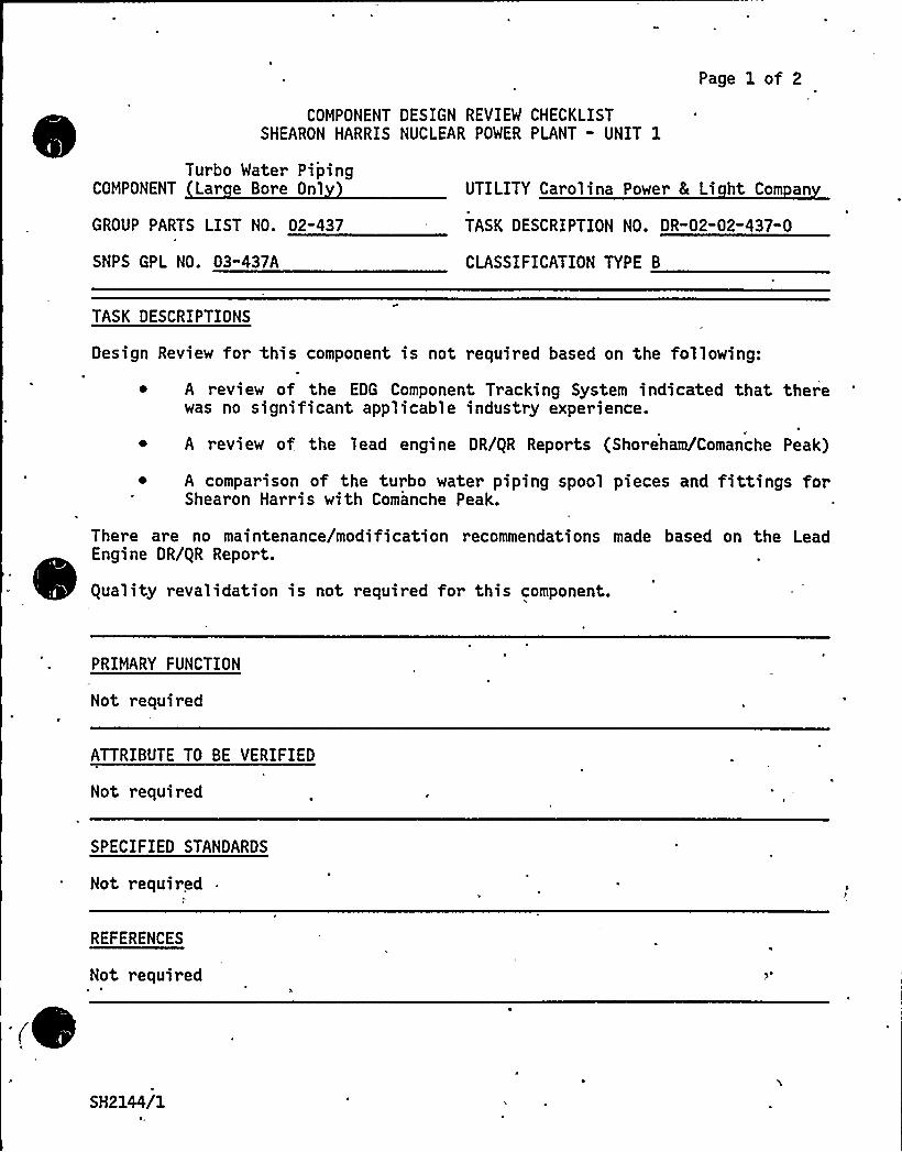
COMPONENT DESIGN REVIEW CHECKLISTSHEARON HARRIS NUCLEAR POWER PLANT - UNIT 1
Page 1 of 2
Turbo Water PipingCOMPONENT Lar e Bore Onl
GROUP PARTS LIST NO. 02-437
SNPS GPL NO. 03-437A
UTILITY Carolina Power 8 Li ht Com an
TASK DESCRIPTION NO. DR"02-02"437-0
CLASSIFICATION TYPE B
TASK DESCRIPTIONS
Design Review for this compooent is not required based on the following:
~ A review of the EDG Component Tracking System indicated that therewas no significant applicable industry experience.
0
A review of the lead engine DR/gR Reports (Shoreham/Comanche Peak)
~ A comparison of the turbo water piping spool pieces and fittings forShearon Harris with Comanche Peak.
There are no maintenance/modification recommendations made based on the LeadEngine DR/gR Report.
guality revalidation is not required for this component.
PRIMARY FUNCTION
Not required
ATTRIBUTE TO BE VERIFIED
Not required
SPECIFIED STANDARDS
Not requir ed
REFERENCES
Not required
SH2144/1~,,

COMPONENT DESIGN REVIEW CHECKLIST
DOCUMENTATION RE UIRED
Not required
Page 2 of 2DR-02-02"437-0
GROUP CHAIRPERSON PROGRAM MANAGER
(
(SH2144/2

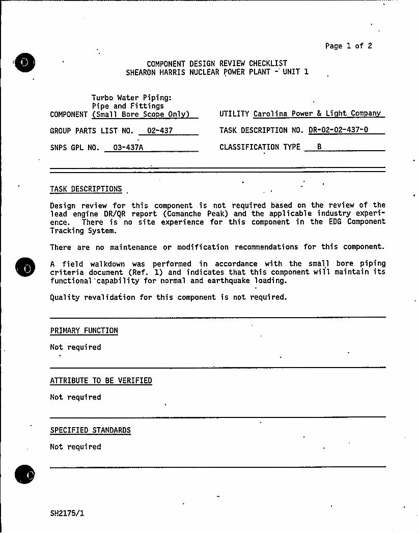
COMPONENT DESIGN REVIEW CHECKLISTSHEARON HARRIS NUCLEAR POWER PLANT -'NIT 1
Page 1 of 2
Turbo Water Piping:Pipe and Fittings
COMPONENT Small Bore Sco e Onl
GROUP PARTS LIST NO. 02-437
SNPS GPL NO. 03-437A
UTILITY Carolina Power 8 Li ht Com an
TASK DESCRIPTION NO. OR-02-02-437" 0
CLASSIFICATION TYPE B
TASK DESCRIPTIONS
Design review for this component is not required based on the review of thelead engine DR/gR report (Comanche Peak) and the applicable industry experi-ence. There is no site experience for this component in the EDG ComponentTracking System.
There are no maintenance or modification recommendations for this component.
A field walkdown was performed in accordance with the small bore pipingcriteria document (Ref. 1) and indicates that this component will maintain itsfunctional'capability for normal and earthquake loading.
guality revalidation for this component is not required.
PRIMARY FUNCTION
Not required
ATTRIBUTE TO BE VERIFIED
Not required
SPECIFIED STANDARDS
Not required
SH2175/1

REFERENCES
COMPONENT DESIGN REVIEW CHECKLIST Page 2. of 2DR"02-02-437-0
"Engineering Review Criteria Document for the Design Review of TDI Diesel SmallBore Piping, Tubing, and Supports for the TDI Owners'roup," report No.11600.60-DC-02, Revision 0.
DOCUMENTATION RE UIRED
Not required
GROUP CHAIRPERSON PROGRAM MANAGER C
SH2175/2

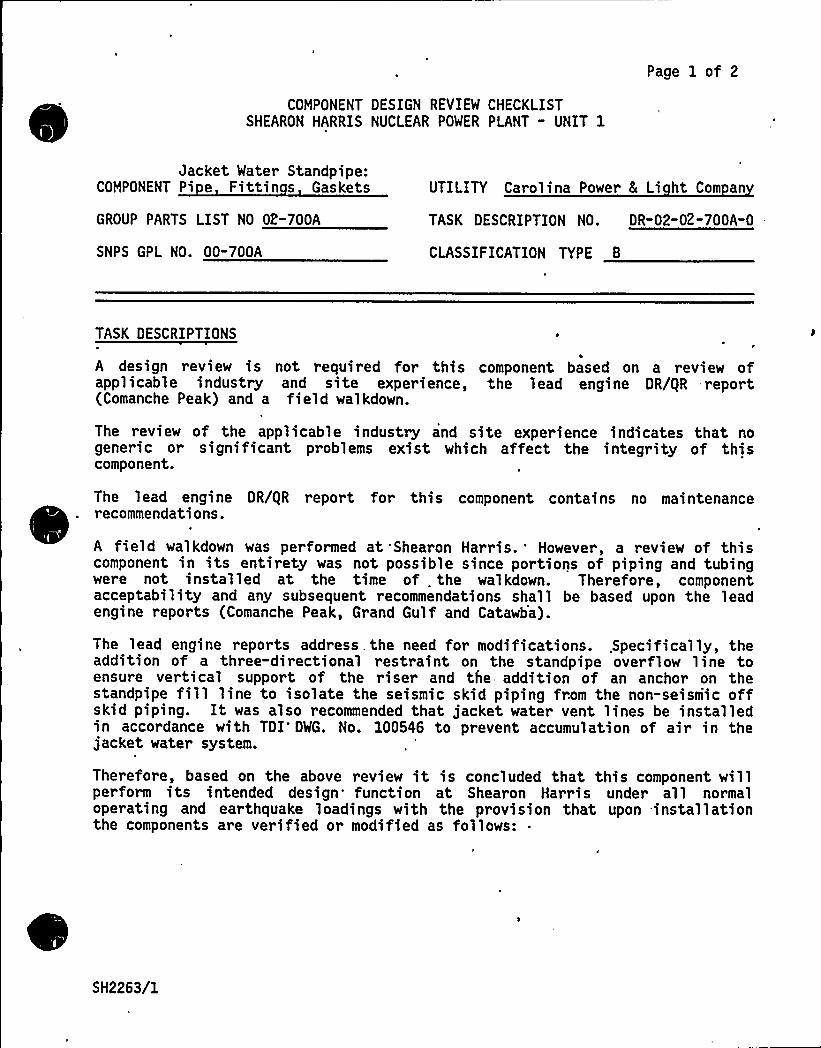
Page 1 of 2
COMPONENT DESIGN REVIEW CHECKLISTSHEARON HARRIS NUCLEAR POWER PLANT - UNIT 1
Jacket Water Standpipe:COMPONENT Pi e Fittin s Gaskets
GROUP PARTS LIST NO 02-700A
SNPS GPL NO. 00-700A
UTILITY Carolina Power & Li ht Com an
TASK DESCRIPTION NO. DR-02-02-700A-0
CLASSIFICATION TYPE B
TASK DESCRIPTIONS
A design review is not required for this component based on a review ofapplicable industry and site experience, the lead engine DR/gR report(Comanche Peak) and a field walkdown.
The review of the applicable industry and site experience indicates that nogeneric or significant problems exist which affect the integrity of thiscomponent.
The lead engine DR/gR report for this component contains no maintenancerecommendations.
A field walkdown was performed at 'Shearon Harris. 'owever, a review of thiscomponent in its entirety was not possible since portions of piping and tubingwere not installed at the time of . the walkdown. Therefore, componentacceptability and any subsequent recommendations shall be based upon the leadengine reports (Comanche Peak, Grand Gulf and Catawba).
The lead engine reports address . the need for modifications. .Specifically, theaddition of a three-directional restraint on the standpipe overflow line toensure vertical support of the riser and the addition of an anchor on thestandpipe fill line to isolate the seismic skid piping from the non-seismic offskid piping. It was also recommended that jacket water vent lines be installedin accordance with TDI DWG. No. 100546 to prevent accumulation of air in thejacket water system.
Therefore, based on the above review it is concluded that this component willperform its intended design function at Shearon Harris under all normaloperating and earthquake loadings with the provision that upon -installationthe components are verified or modified as follows:
SH2263/1
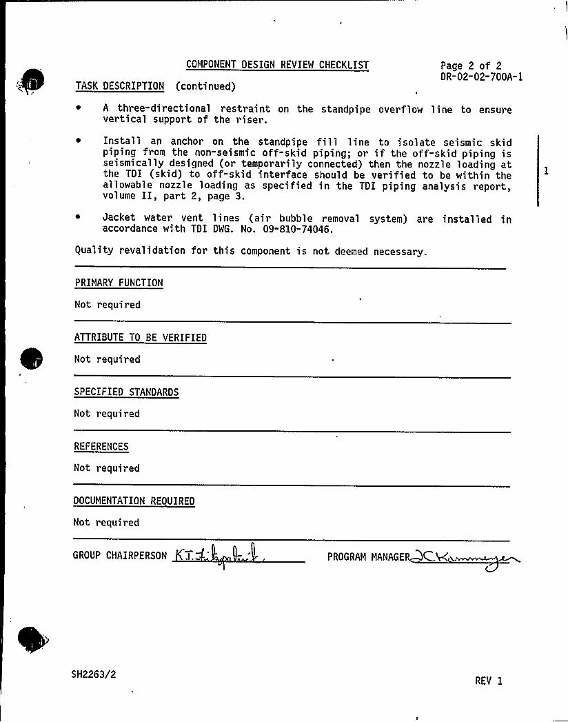
COMPONENT DESIGN REVIEW CHECKLIST
TASK DESCRIPTION (continued)
Page 2 of 2DR-02-02-700A-I
~ A three-directional restraint on the standpipe overflow line to ensurevertical support of the riser.
~ Install an anchor on the standpipe fi11 line to isolate seismic skidpiping from the non-seismic off-skid piping; or if the off-skid piping isseismically designed (or temporarily connected) then the nozzle loading atthe TDI (skid) to off-skid interface should be verified to be within theallowable nozzle loading as specified in the TDI piping analysis report,volume II, part 2, page 3.
~ Jacket water vent lines (air bubble removal system) are installed inaccordance with TDI DWG. No. 09-810-74046.
guality revalidation for this component is not deemed necessary.
PRIMARY FUNCTION
Not required
ATTRIBUTE TO BE VERIFIED
Not required
SPECIFIED STANDARDS
Not r equired
REFERENCES
Not required
DOCUMENTATION RE UIRED
Not required
GROUP CHAIRPERSON PROGRAM MANAGE C,
SH2263/2REV I
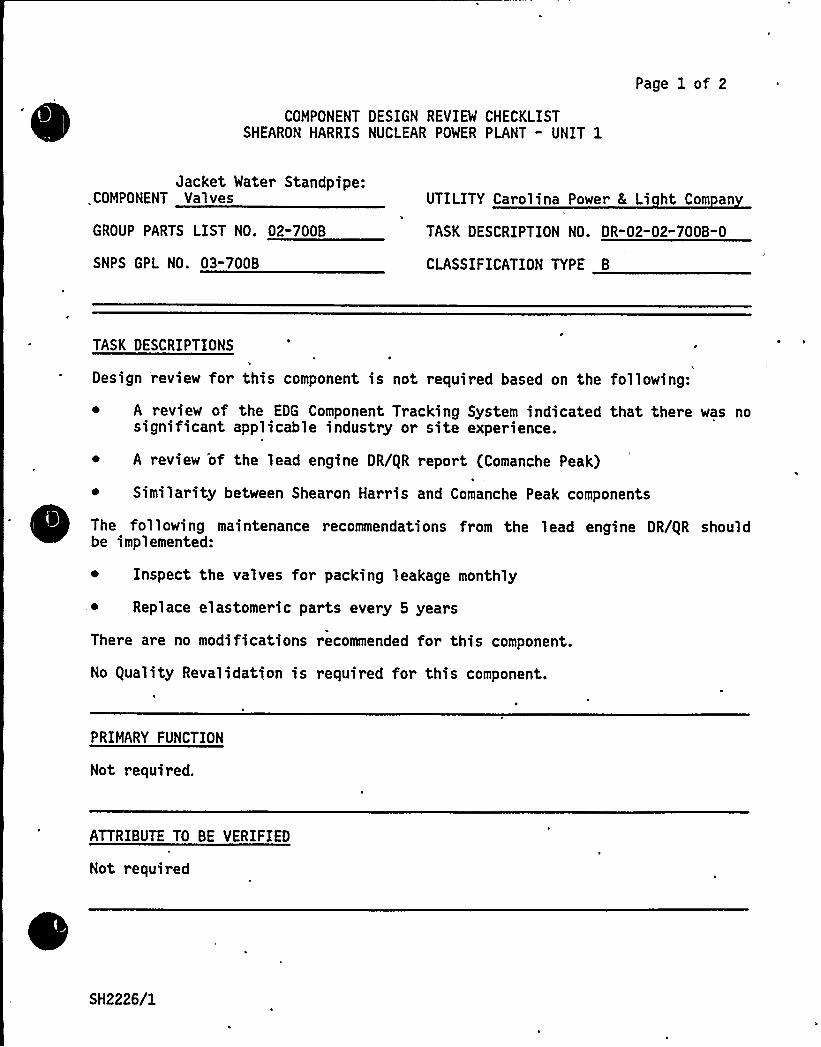
COMPONENT DESIGN REVIEW CHECKLISTSHEARON HARRIS NUCLEAR POWER PLANT - UNIT 1
Page 1 of 2
Jacket Water Standpipe:COMPONENT Valves
GROUP PARTS LIST NO. 02-700B
SNPS GPL NO. 03-700B
UTILITY Carolina Power 8 Li ht Com an4
TASK DESCRIPTION NO. DR"02-02"7008-0
CLASSIFICATION TYPE B
TASK DESCRIPTIONS
Design review for this component is not required based on the following:
~ A review of the EDG Component Tracking System indicated that there was nosignificant applicable industry or site experience.
~ A review 'of the lead engine DR/gR report (Comanche Peak)
~ Similarity between Shearon Harris and Comanche Peak components
~
~ ~
~
~
~
The following maintenance recommendations from the lead engine DR/gR shouldbe implemented:
~ Inspect the valves for packing leakage monthly
~ Replace elastomeric parts every 5 years
There are no modifications recommended for this component.
No guality Revalidation is required for this component.
PRIMARY FUNCTION
Not required.
ATTRIBUTE TO BE VERIFIED
Not required
SH2226/1
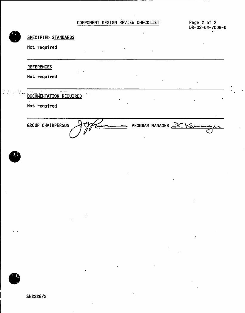
SPECIFIEO STANDARDS
Not required
COMPONENT DESIGN REVIEW CHECKLIST 'age 2 of 2DR-02-02-700B-0
REFERENCES
Not required
DOCUMENTATION RE UIRED
Not required
GROUP CHAIRPERSON PROGRAM MANAGER C
SH2226/2

Page 1 of 2
COMPONENT DESIGN REVIEW CHECKLISTSHEARON HARRIS NUCLEAR POWER PLANT - UNIT 1
Jacket Water Standpipe:COMPONENT Pi e Su orts UTILITY Carolina Power L Li ht Co.
GROUP PARTS LIST NO. 02-700C
SNPS GPL NO. 00-700C
TASK DESCRIPTION NO. DR-02-02-700C-0
CLASSIFICATION TYPE B
TASK DESCRIPTIONS
A design review is not required for this component based on a review ofapplicable industry and site experience, the lead engine DR/gR report(Comanche Peak) and a field walkdown.
The review of the applicable industry and site experience indicates that nogeneric or significant problems exist which affect the integrity of thiscomponent.
The Lead Engine DR/gR Report for this component contains no maintenancerecommendations.
A field walkdown was performed at Shearon Harris. However, a review of thiscomponent in its entirety was not possible since portions of piping and tubingwere not installed at the time of the walkdown. Therefore, componentacceptability and any subsequent recommendations shall be based upon the LeadEngine Reports (Comanche Peak, Grand Gulf and Catawba).
The Lead Engine Reports address the need for modification. Specifically,five tubing supports on the jacket water vent lines did not provide either aminimum of two-directions of restraint or sufficient moment connection betweenthe support members and the supporting structure. It was also recommendedthat the 1/4 inch dia. U-bolts used in the support of the standpipe overflowline be increased to 3/8 in. dia. with suitable locking devices installed.
Therefore, based on the above review it is concluded that this component willperform its intended design function at Shearon Harris under all normaloperating and earthquake loadings with the, provision that upon installationthe tubing supports are 'erified or modified to have as a minimumtwo-directions of restraint and sufficient moment connection. Also, theU-bolts used in the support of the standpipe overflow line should be a minimumof 3/8 in. in diameter and that suitable locking devices should be installed.
guality Revalidation for this component is not deemed necessary.
SH2264/1
COMPONENT DESIGN REVIEW CHECKLIST
PRIMARY FUNCTION
Not required
ATTRIBUTE TO BE VERIFIED
Not required
Page 2 of 2DR"02-02"700C-0
SPECIFIED STANDARDS
Not required
REFERENCES
Not required
DOCUMENTATION RE UIRED
Not required
GROUP CHAIRPERSON PROGRAM MANAGER
SH2264/2

Page 1 of 2
COMPONENT DESIGN REVIEW CHECKLISTSHEARON HARRIS NUCLEAR POWER PLANT - UNIT 1
Jacket WaterCOMPONENT Stand i e: Switches UTILITY Carolina Power 8 Li ht Com an
GROUP PARTS LIST NO. 02-700E
SNPS GPL NO. 00-700E
TASK DESCRIPTION NO: DR"02"00" 700E" I
CLASSIFICATION TYPE B
TASK DESCRIPTIONS
The jacket water standpipe switch used at Shearon Harris is similar to thatused at Comanche Peak with regard to manufacturer and application, and bothare identified as TDI Part No. F-577-066.
The Shearon Harris site differs from Comanche Peak in the model number andoperating range of the Dwyer Instruments low differential pressure switchused for low level alarming on the jacket water standpipe. Shearon Harris usesa Dwyer 0/P switch, Model 1823-80, with operating range of 9 to 85 inches W.C.(set point established at level of 36 inches W.C. - falling). Comanche Peakhas a Dwyer D/P switch, Model 1823-40, with operating range of 5 to 44 in.W.C. (set point is at 37 in. W.G. - falling).
The sensor tap, located 43 in. below the centerline of the inlet flange on thejacket water standpipe, is piped to the differential pressure switch identi-cally for both Shearon Harris and Comanche Peak sites,
The exact additives to be used in the jacket water system at Shearon Harrishave not yet been identified, however, information received from site repre-sentatives indicates that the TDI recommendation of sodium dichromate anddisodium phosphate treatment shall be'sed. Based on the above, the designfunction of the jacket water standpipe switch is adequate for its intendedservice at Shearon Harris. If Shearon Harris chooses different additives inthe cooling water, the effects on the jacket water standpipe switch must beevaluated at that time.
There is no Shearon Harris site experience, or nuclear or non-nuclearindustry experience listed in the EDG Component Tracking System for thiscomponent.
There are no maintenance or modification recommendations for this component.
guality Revalidation for this component is not deemed necessary.
Based on the above information, a design review is not required for the jacketwater standpipe switches at Shearon Harris.
SH2135/1
REV I
PRIMARY FUNCTION
Not required.
COMPONENT DESIGN REVIEW CHECKLIST Page 2 of 2DR-02-00-700E-0
ATTRIBUTE TO BE VERIFIED
Not required
SPECIFIED STANDARDS
Not required
REFERENCES-
Not required
DOCUMENTATION RE UIRED
Not required
GROUP CHAIRPERSON PROGRAM MANAGER CA
SH2135/2.
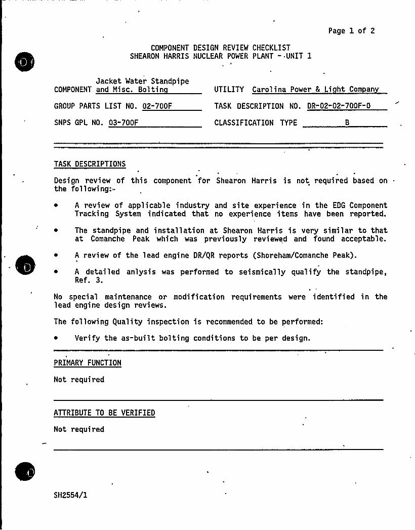
COMPONENT DESIGN REVIEW CHECKLISTSHEARON HARRIS NUCLEAR POWER PLANT - UNIT 1
Page 1 of 2
Jacket Water StandpipeCOMPONENT and Misc. Boltin
GROUP PARTS LIST NO. 02-700F
SNPS GPL NO. 03-700F
UTILITY Carolina Power & Li ht Com an
TASK DESCRIPTION NO. DR"02-02"700F-0
CLASSIFICATION TYPE
TASK DESCRIPTIONS
Design review of this component for Shearon Harris is not required based onthe following:-
~ A review of applicable industry and site experience in the EDG ComponentTracking System indicated that no experience items have been reported.
~ The standpipe and installation at Shearon Harris is very similar to thatat Comanche Peak which was previously reviewed and found acceptable.
A review of the lead engine DR/gR reports (Shoreham/Comanche Peak).
~ A detailed anlysis was performed to seismically qualify the standpipe,Ref. 3.
No special maintenance or modification requirements were identified in thelead engine design reviews.
The following guality inspection is recommended to be performed:
~ Verify the as-built bolting conditions to be per design.
PRIMARY FUNCTION
Not required
ATTRIBUTE TO BE VERIFIED
Not required
SH2554/1
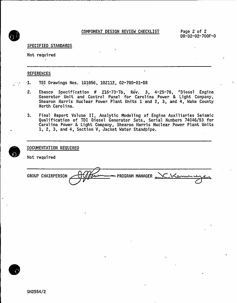
SPECIFIED STANDARDS
Not required
COMPONENT DESIGN REVIEW CHECKLIST Page 2 of 2DR-02-02-700F-0
REFERENCES
TDI Drawings Nos. 101856, 102112, 02-700-Ol-DR
2.
3.
Ebasco Specification 8 216-73-Tb, Rev. 3, 4-25-78, "Diesel EngineGenerator Unit and Control Panel for Carolina Power 8 Light Company,Shearon Harris Nuclear Power Plant Units 1 and 2, 3, and 4, Wake CountyNorth Carolina.
Final Report Volume II, Analytic Modeling of Engine Auxiliaries Seismicgualification of TDI Diesel Generator Sets, Serial Numbers 74046/53 forCarolina Power 8 Light Company, Shearon Harris Nuclear Power Plant Units1, 2, 3, and 4, Section V, Jacket Water Standpipe.
DOCUMENTATION RE VIREO
Not required
GROUP CHAIRPERSON PROGRAM MANAGER C X(c~~
SH2554/2

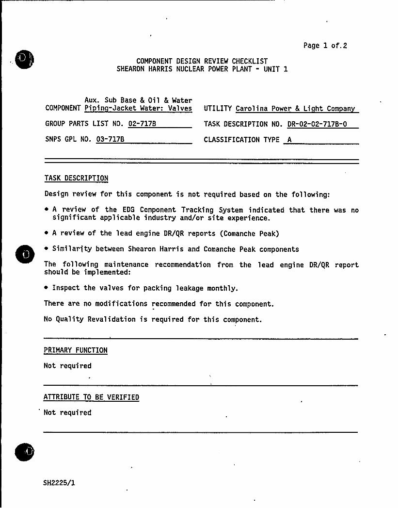
COMPONENT DESIGN REVIEW CHECKLISTSHEARON HARRIS NUCLEAR POWER PLANT " UNIT 1
Page 1 of.2
Aux. Sub Base 8 Oil 8 WaterCOMPONENT Pi in -Jacket Water: Valves UTILITY Carolina Power 8 Li ht Com an
GROUP PARTS LIST NO. 02-717B
SNPS GPL NO. 03-717B
TASK DESCRIPTION NO. DR-02"02-717B-0
CLASSIFICATION TYPE A
TASK DESCRIPTION
Design review for this component is not required based on the following:
~ A review of the EDG Component Tracking System indicated that there was nosignificant applicable industry and/or site experience.
~ A review of the lead engine DR/gR reports (Comanche Peak)
~ Similarjty between Shearon Harris and Comanche Peak components
The following maintenance recommendation from the lead engine DR/gR reportshould be implemented:
~ Inspect the valves for packing leakage monthly.
There are no modifications recommended for this component.
No guality Revalidation is required for this component.
PRIMARY FUNCTION
Not required
ATTRIBUTE TO BE VERIFIED
Not required
SH2225/1
SPECIFIED STANDARDS
Not required
COMPONENT DESIGN REVIEW CHECKLIST Page 2 of 2DR-02-02" 717B" 0
REFERENCES
Not required
DOCUMENTATION RE UIRED
Not required
GROUP CHAIRPERSON PROGRAM MANAGER CK
SH2225/2
COMPONENT DESIGN REVIEW CHECKLISTSHEARON HARRIS NUCLEAR POWER PLANT - UNIT 1
Page 1 of 2
Aux. Sub Base 8 Oil 8 WaterPiping-Jacket Water: Pipe,Couplings, Fittings,Orifices, Y-Strainers
COMPONENT Lar e Bore Sco e .Onl
GROUP PARTS LIST NO. 02-717D
SNPS GPL NO. 03-717D
UTILITY Carolina Power 8 Li ht Com an
TASK DESCRIPTION NO. DR-02-02-717D-1
CLASSIFICATION TYPE
TASK DESCRIPTIONS
Design review for this component is not required based on a review of theapplicable industry and site experience in the EDG Component Tracking Systemand the lead engine DR/gR report (Comanche Peak).
There are no maintenance recommendations for this component. However, thelead engine report does address site specific modifications to the skid pipingand/or supports. Generic application of these modifications is not requiredfor Shearon Harris since the Comanche Peak modifications were not required forpiping operability. The lead engine modifications were recommended in order tomeet the intent and philosophy of the ASME Code for the boundary conditionsand assumptions used in the Owners Group analysis. These boundary conditionsand assumptions may be somewhat different from those used in the originalmanufacturer's analysis. Lead engine skid mounted large bore pipe modifica-tions, as they apply to equipment nozzle loads, are addressed, if necessary, inthe individual equipment design reviews.
guality Revalidation for this component is not required.
PRIMARY FUNCTION
Not required
ATTRIBUTE TO BE VERIFIED
Not requir ed
SH2640/1
8
~ W
SPECIFIED STANDARDS
Not required
COMPONENT DESIGN REVIEW CHECKLIST Page 2 of 2OR-02-02-7170-1
REFERENCES
Not required
DOCUMENTATION RE UIRED
Not required
GROUP CHAIRPERSON ROGRAM MANAGER
SH2640/2

~"
t
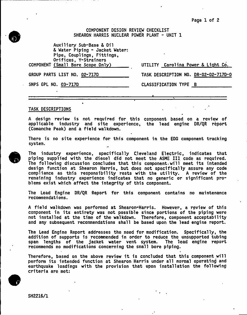
Page 1 of 2
COMPONENT DESIGN REVIEW CHECKLISTSHEARON HARRIS NUCLEAR POWER PLANT - UNIT 1
Auxiliary Sub-Base 8 Oil8 Water Piping - Jacket Water:Pipe, Couplings, Fittings,Orifices, Y-Strainer s
COMPONENT Small Bore Sco e Onl UTILITY Carolina Power 8 Li ht Co.
GROUP PARTS LIST NO. 02"717D
SNPS GPL NO. 03"717D
TASK DESCRIPTION NO. DR"02-02"717D"0
CLASSIFICATION TYPE B
TASK DESCRIPTIONS
A design review is not required for this component based on a review ofapplicable industry and site experience, the lead engine DR/gR report(Comanche Peak) and a field walkdown.
There is no site experience for this component in the EDG component trackingsystem.
The industry experience, specifically Cleveland Electric, indicates thatpiping supplied with the diesel did not meet the ASME III code as required.The following discussion concludes that this component. will meet its intendeddesign function at Shearon Harris, but does not specifically assure any codecompliance as this responsibility rests with the utility. A review of theremaining industry experience indicates that no generic or significant pro"blems exist which affect the integrity of this component.
The Lead Engine DR/gR Report for this component contains no maintenancerecommendations.
A field walkdown was performed at Shearon-Harris. However, a review of thiscomponent in its entirety was not possible since portions of the piping werenot installed at the time of the walkdown. Therefore, component acceptabilityand any subsequent recommendations shall be based upon the lead engine report.
The Lead Engine Report addresses the need for modification. Specifically, theaddition of supports is recommended in order to reduce the unsupported tubingspan lengths of the jacket water vent system. The lead engine reportrecommends no modifications concerning the small bore piping.
Therefore, based on the above review it is concluded that this component willperform its intended function at Shearon Harris under all normal operating andearthquake loadings with the provision that upon installation the followingcriteria are met:
SH2216/1

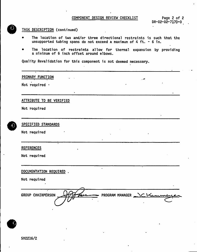
COMPONENT DESIGN REVIEW CHECKLIST
TASK DESCRIPTION (continued)
Page 2 of 2DR-02-02-717D-0
The location of two and/or three directional restraints is such that theunsupported tubing spans do not exceed a maximum of 4 ft. - 6 in.
~ The location of restraints allow for thermal expansion by providinga minimum of 6 inch offset around elbows.
guality Revalidation for this component is not deemed necessary.
PRIMARY FUNCTION
Hot required
ATTRIBUTE TO BE VERIFIED
Not required
SPECIFIED STANDARDS
Not required
REFERENCES
Not required
DOCUMENTATION RE UERED .
Not required
GROUP CHAIRPERSON PROGRAM MANAGER
SH2216/2

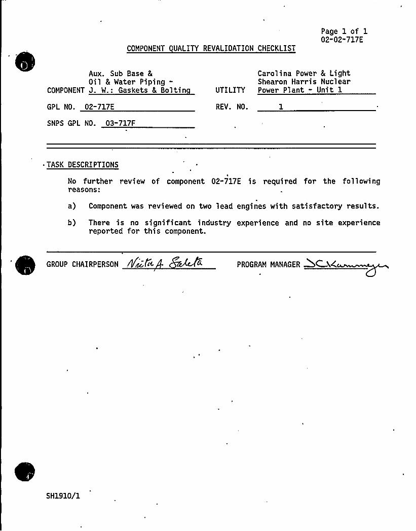
COMPONENT UALITY REVALIDATION CHECKLIST
Page 1 of 102-02" 717 E
Aux. Sub Base &Oil 8 Water Piping-
COMPONENT J. W.: Gaskets 8 Boltin
GPL NO. 02-717E
SNPS GPL NO. 03-717F
Carolina Power 8 LightShearon Harris Nuclear
UTILITY Power Plant - Unit 1
REV. NO. 1
~ TASK OESCRIPTIONS
No further revi ew of component 02-717E i s required for the fo1 1 owingreasons:
a) Component was reviewed on two lead engines with satisfactory results.
b) There is no significant industry experience and no site experiencereported for this component.
PROGRAM MANAGER AC X4
SH1910/1

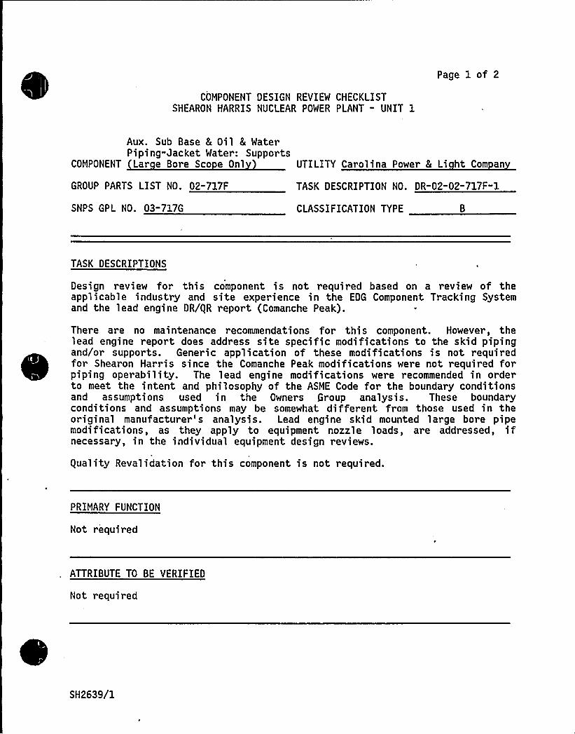
COMPONENT DESIGN REVIEW CHECKLISTSHEARON HARRIS NUCLEAR POWER PLANT " UNIT 1
Page 1 of 2
Aux. Sub Base 8 Oil 8 WaterPiping-Jacket Water: Supports
COMPONENT Lar e Bore Sco e Onl UTILITY Carolina Power & Li ht Com an
GROUP PARTS LIST NO. 02-717F
SNPS GPL NO. 03-717G
TASK DESCRIPTION NO. DR-02-02-717F-1
CLASSIFICATION TYPE
TASK DESCRIPTIONS
Design review for this component is not required based on a review of theapplicable industry and site experience in the EDG Component Tracking Systemand the lead engine DR/gR report (Comanche Peak).
There are no maintenance recommendations for this component. However, thelead engine report does address site specific modifications to the skid pipingand/or supports. Generic application of these modifications is not requiredfor Shearon Harris since the Comanche Peak modifications were not required forpiping operability. The lead engine modifications were recommended in orde~to meet the intent and philosophy of the ASME Code for the boundary conditionsand assumptions used in the Owners Group analysis. These boundaryconditions and assumptions may be somewhat different from those used in theoriginal manufacturer's analysis. Lead engine skid mounted large bore pipemodifications, as they apply to equipment nozzle loads, are addressed, ifnecessary, in the individual equipment design reviews.
guality Revalidation for this component is not required.
PRIMARY FUNCTION
Not required
ATTRIBUTE TO BE VERIFIED
Not required
SH2639/1


SPECIFIED STANDARDS
Not required
COMPONENT DESIGN REVIEW CHECKLIST Page 2 of 2DR"02-02-717F-1
REFERENCES
Not required
DOCUMENTATION RE UIRED
Not required
GROUP CHAIRPERSON PROGRAM MANAGER
SH2639/2

8
V.
V
Page 1 of 2
COMPONENT DESIGN REVIEW CHECKLISTSHEARON HARRIS NUCLEAR POWER PLANT -'NIT 1
Auxiliary Sub-Base 8 Oil8 Water Piping-Jacket Water Supports
COMPONENT Small Bore Sco e Onl
COMPONENT PART NUMBER 02-717F
UTILITY Carolina Power 8 Li ht Com an
TASK DESCRIPTION NO. DR-02-02"717F-0
SNPS GPL NO. 03-717F CLASSIFICATION TYPE B
TASK DESCRIPTIONS
A design review is not requir ed for thi s component based on a r evi ew ofappl icabl e industry and s i te experience, the lead engine DR/gR repor t(Comanche Peak) and a field walkdown.
There's no site experience for this component in the EDG 'Component TrackingSystem.
The industry experience, specifically Cleveland Electric, indicates thatsupports supplied with the diesel did not meet the ASME III code as required.The following discussion concludes that this component will meet its intendeddesign function at Shearon Harris, but does not specifically assure any codecompliance as that responsibility rests with the utility. There is no otherindustry experience for this component.
The lead engine DR/gR report for this component contains no maintenancerecommendations.
A field walkdown was performed at Shearon Harris however, a review of thiscomponent in its entirety was not possible since portions of piping/tubing andsupports were not installed at the time of the walkdown. Therefore, componentacceptability and any subsequent recommendations shall be based upon the leadengine report.
The lead engine report addresses the need for modification. Specifically, itinvolves a jacket water cooler drain line anchor which required additionalweld and an increase in member/plate stiffness. All other piping and tubingsupports required no modification.
Therefore, based upon the above review,, it is concluded that this componentwill perform its intended design function at Shearon Harr is under all normaloperating and earthquake loadings with the provision that upon installationthe jacket water cooler drain line supports are verified or modified to havesufficient stiffness and weld.
SH2213/1
C~p
+I
'pEW II
. COMPONENT DESIGN REVIEW CHECKLIST
~ ~ ~guality Revalidation for this component is not deemed necessary.
Page 2 of 2DR"02-02-717F-0
PRIMARY FUNCTION
Not required
ATTRIBUTE TO BE VERIFIED
Not required
SPECIFIED STANDARDS
Not required
REFERENCES
Not required
DOCUMENTATION RE UIRED
Not required
GROUP CHAIRPERSON PROGRAM MANAGER
SH2213/2
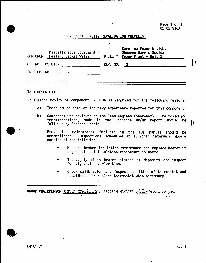
Page 1 of 102-02-810A
COMPONENT UALITY REVALIOATION CHECKLIST
Carolina Power 8 LightMiscellaneous Equipment- Shearon Harris Nuclear
COMPONENT Heater Jacket Water UTILITY Power Plant - Unit 1
GPL NO. 02-810A
SNPS GPL NO. 03-800A
REV. NO. 2
TASK OESCRIPTIONS
No further review of component 02-810A is required for the following reasons:
a) There is no site or industry experience reported for this component.
b) Component was reviewed on the lead engines (Shoreham). The followingrecommendations, made in the Shoreham DR/gR report should befollowed by Shearon Harris. )I
Preventive maintenance included in the TDI manual should beaccomplished. Inspections scheduled at 18-month intervals shouldconsist of the following.
Measure heater insulation resistance and replace heate~ ifdegradation of insulation resistance is noted.
Thoroughly clean heater element of deposits and inspectfor signs of deterioration.
Check calibration and inspect condition of thermostat andrecalibrate or replace thermostat when necessary.
GROUP CHAIRPERSON PROGRAM MANAGER C.%ca
SH1814/1 REV I

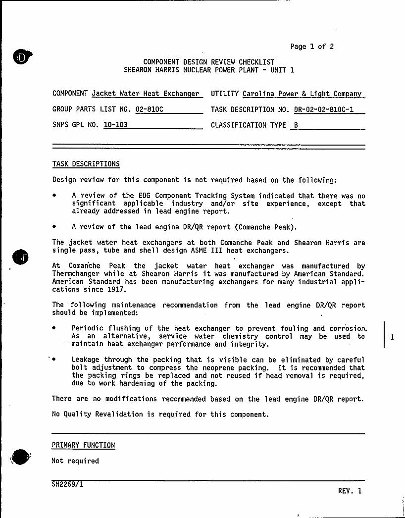
Page 1 of 2
COMPONENT DESIGN REVIEW CHECKLISTSHEARON HARRIS NUCLEAR POWER PLANT - UNIT 1
COMPONENT Jacket Water Heat Exchan er UTILITY Carolina Power 8 Li ht Com an
GROUP PARTS LIST NO. 02"810C TASK DESCRIPTION NO. DR-02-02-810C-1
SNPS GPL NO. 10-103 CLASSIFICATION TYPE B
TASK DESCRIPTIONS
Design review for this component is not required based on the following:
~ A review of the EDG Component Tracking System indicated that there was nosignificant applicable industry and/or site experience, except thatalready addressed in lead engine report.
~ A review of the lead engine DR/gR report (Comanche Peak).
The jacket water heat exchangers at both Comanche Peak and Shearon Harris aresingle pass, tube and shell design ASME III heat exchangers.
At Comanche Peak the jacket water heat exchanger was manufactured byThermchanger while at Shearon Harris it was manufactured by American Standard.American Standard has been manufacturing exchangers for many industrial appli-cations since 1917.
The following maintenance recommendation from the lead engine DR/gR reportshould be implemented:
~ Periodic flushing of the heat exchanger to prevent fouling and corrosion.As an alternative, service water chemistry control may be used tomaintain heat exchanger performance and integrity.
~ Leakage through the packing that is visible can be eliminated by carefulbolt adjustment to compress the neoprene packing. It is recommended thatthe packing rings be replaced and not reused if head removal is required,due to work hardening of the packing.
There are no modifications recommended based on the lead engine DR/gR report.
No guality Revalidation is required for this component.
PRIMARY FUNCTION
Not required
SH2269/1REV. I
COMPONENT DESIGN REVIEW CHECKLIST
ATTRIBUTE TO BE VERIFIED
Not required
Page 2 of 2DR-02" 02-810C" 0
SPECIFIED STANDARDS
. '..... " .:Not,required
REFERENCES
Not required
DOCUMENTATION RE UIRED
Not required
GROUP CHAIRPERSON PROGRAM MANAGER CA
SH2269/2

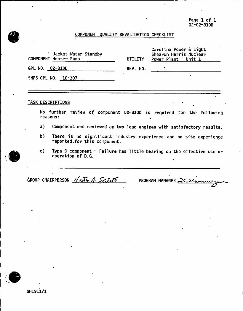
COMPONENT UALITY REVALIDATION CHECKLIST
Page 1 of 102-02-810D
Jacket Water StandbyCOMPONENT Heater Pum
GPL NO. 02-810D
SNPS GPL NO. 10-107
Carolina Power & LightShearon Harris Nuclear
UTILITY Power Plant - Unit 1
REV. NO. 1
TASK DESCRIPTIONS
No further review of component 02-810D is required for the followingreasons:
a) Component was reviewed on two lead engines with satisfactory results.
b) There is no significant industry experience and no site experiencereported .for this component.
c) Type C component - Failure has little bearing on the effective use oroperation of D.G.
GROUP CHAIRPERSON PROGRAM MANAGER
SH1911/1

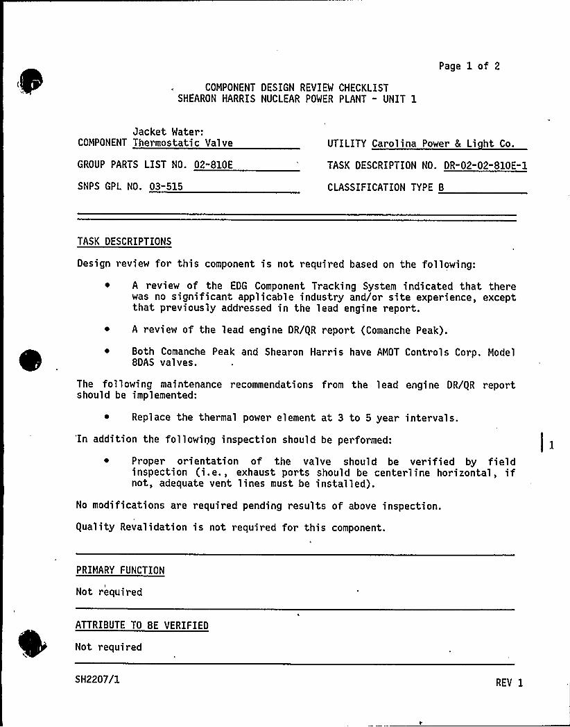
COMPONENT DESIGN REVIEW CHECKLISTSHEARON HARRIS NUCLEAR POWER PLANT " UNIT 1
Page 1 of 2
Jacket Water:COMPONENT Thermostatic Valve
GROUP PARTS LIST NO. 02-810E
SNPS GPL NO. 03-515
UTILITY Carolina Power 8 Li ht Co.
TASK DESCRIPTION NO. DR-02-02-810E" 1
CLASSIFICATION TYPE B
TASK DESCRIPTIONS
Design review for this component is not required based on the following:
~ A review of the EDG Component Tracking System indicated that therewas no significant applicable industry and/or site experience, exceptthat previously addressed in the lead engine report.
~ A review of the lead engine DR/gR report (Comanche Peak).
Both Comanche Peak and Shearon Harris have AMDT Controls Corp. ModelBOAS valves.
The following maintenance recommendations from the lead engine DR/gR reportshould be implemented:
~ Replace the thermal power element at 3 to 5 year intervals.'In addition the following inspection should be performed:
~ Proper orientation of the valve should be verified by fieldinspection (i.e., exhaust ports should be centerline horizontal, ifnot, adequate vent lines must be installed).
No modifications are required pending results of above inspection.
equality Revalidation is not required for this component.
PRIMARY FUNCTION
Not required
ATTRIBUTE TO BE VERIFIED
Not required
SH2207/1 REV I
SPECIFIED STANDARDS
Not required
COMPONENT DESIGN REVIEW CHECKLIST Page 2 of 2DR-02-02-810E-0
REFERENCES
Not required
DOCUMENTATION RE UIRED
Not required
GROUP CHAIRPERSON PROGRAM MANAGER
SH2207/2

Cl
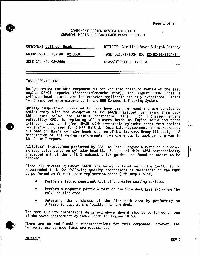
COMPONENT DESIGN REVIEW CHECKLISTSHEARON HARRIS NUCLEAR POWER PLANT - UNIT 1
Page 1 of 2
COMPONENT C linder Heads UTILITY Carolina Power 8 Li ht Com an
GROUP PARTS LIST NO. 02"360A TASK DESCRIPTION NO. DR-02-02-360A-1
SNPS GPL NO. 03-360A CLASSIFICATION TYPE A
TASK DESCRIPTIONS
Design review for this component is not required based on review of the leadengine DR/QR reports (Shoreham/Comanche Peak), the August 1984 Phase Icylinder head report, and the reported applicable industry experience. Thereis no reported site experience in the EDG Component Tracking System.
Quality inspections conducted to date have been reviewed and are consideredsatisfactory with the exception of six heads rejected for having fire deckthicknesses below the minimum acceptable value. For increased enginereliability CP8 L is replacing all sixteen heads on Engine 1A-SA and threecylinder heads on Engine 1B-SB with acceptable cylinder heads from enginesoriginally purchased for SHNPP Unit 2. Once this replacement is incorporated,all Shearon Harris cylinder heads will be of the improved Group III design. Adescription of the design improvements from one Group to another is given inthe Phase I report.
Additional inspections performed by CPCL on Unit 2 engine A revealed a crackedexhaust valve guide on cylinder head L3. Because of this, CP&L borescopicallyinspected all of the Unit 1 exhaust valve guides and found no others to becracked.
Since all sixteen cylinder heads are being replaced on Engine 1A-SA, it isrecommended that the following Quality inspections as delineated in the CQRCbe performed on four of these replacement heads (25K sample plan).
Perform a liquid penetrant test of the valve seating surfaces.
~ Perform a magnetic particle test on the fire deck area excluding thevalve seating area.
~ Determine the thickness of the fire deck area by performing anUltrasonic test at six locations on the deck.
The same Quality inspections described above should also be performed on oneof the three replacement cylinder heads for Engine 1B-SB.
There are no modification recommendations for this component, however, thefollowing maintenance items are recommended:
SH2382/1 REV 1

"~
COMPONENT DESIGN REVIEW CHECKLIST Page 2 of 2DR-02" 02-360A-0
Blow-over the engine after each operation of the engine to ensureagainst harmful effects of water leaks. In the event that water isdetected as a result of a cylinder head leak, the cylinder headshould be replaced.
Visually inspect the fuel injection port on each cylinder head forwater 1eaks during the normal monthly engine run. If water leakageis detected, the cylinder head should be replaced.
PRIMARY FUNCTION
Not required
ATTRIBUTE TO BE VERIFIED
Not required
SPECIFIED STANDARDS
Not required
REFERENCES
"Not required
DOCUMENTATION RE UIRED
Not required
GROUP CHAIRPERSON PROGRAM MANAGER C &
SH2382/2
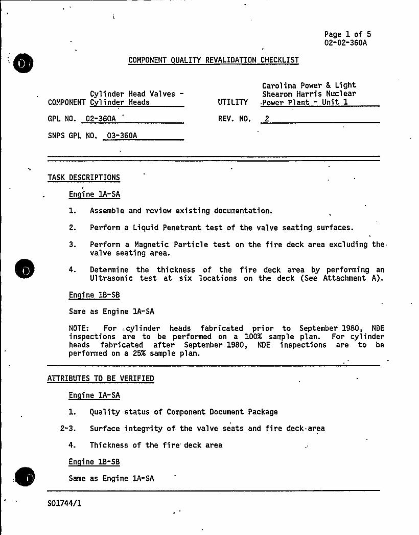
: COMPONENT UALITY REVALIDATION CHECKLIST
Page 1 of 502-02-360A
Cylinder Head Valves-COMPONENT C linder Heads
GPL NO. 02-360A
SNPS GPL NO. 03-360A
Carolina Power 8 LightShearon Harris Nuclear
UTILITY Power Plant - Unit 1
REV. NO. 2
TASK DESCRIPTIONS
En ine lA-SA
1. Assemble and review existing documentation.
2. Perform a Liquid Penetrant test of the valve seating surfaces.
3. Perform a Magnetic Particle test on the fire deck area excluding thevalve seating area.
4. Determine the thickness of the fire deck area by performing anUltrasonic test at six locations on the deck (See Attachment A).
~Ei ll- 1
Same as Engine 1A-SA
NOTE: For . cylinder heads fabricated prior to September 1980, NDEinspections are to be performed on a 100K sample plan. For cylinderheads fabricated after September 1980, NDE inspections are to beperformed on a 25K sample plan.
ATTRIBUTES TO BE VERIFIED
~Ei EA-EA
l. guality status of Component Document Package
2 3A Surface integrity of the valve seats and fire deck area
4. Thickness of the fire deck ar ea
~E
Same as Engine 1A-SA
S01744/1
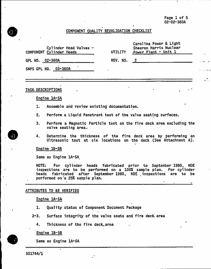
Page 1 of 502-02-360A
COMPONENT UALITY REVALIDATION CHECKLIST
Cylinder Head Valves-COMPONENT C linder Heads
GPL NO. 02-360A
SNPS GPL NO. 03"360A
Carolina Power 8 LightShearon Harris Nuclear
UTILITY .Power Plant - Unit 1
REV. NO. 2
TASK DESCRIPTIONS
~Ei lA-SA
1. Assemble and review existing documentation.
2. Perform a Liquid Penetrant test of the valve seating surfaces.
3. Perform a Magnetic Particle test on the fire deck area excluding thevalve seating area.
4. Determine the thickness of the fire deck area by performing anUltrasonic test at six locations on the deck (See Attachment A).
~Ei 1B- B
Same as Engine 1A-SA
NOTE: For cylinder heads fabricated prior to September 1980, NDEinspections are to be performed on a 100K sample plan. For cylinderheads, fabricated after September 1980, NDE inspections are to beperformed on 'a 25K sample plan.
ATTRIBUTES TO BE VERIFIED
En ine 1A-SA
1. guality status of Component Document Package
2-3. Surface integrity of the valve seats and fire deck area
4. Thickness of the fire deck. area
~Ei -8Same as Engine 1A-SA
S 01744/1

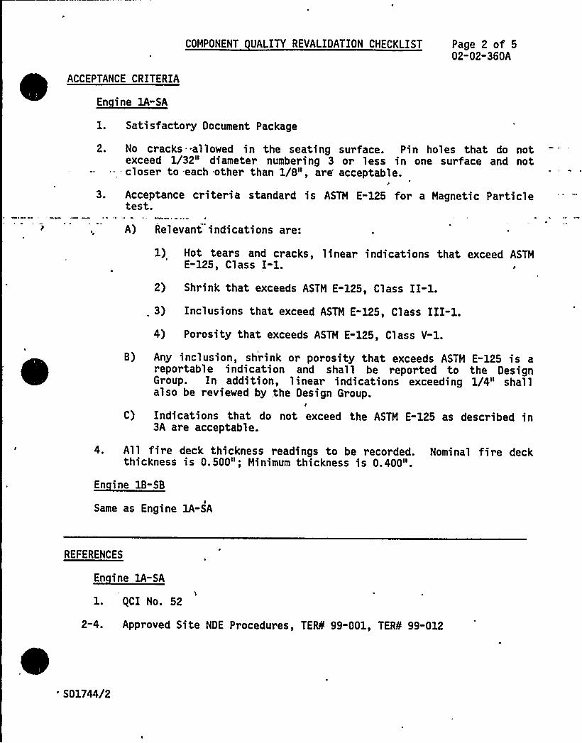
ACCEPTANCE CRITERIA
~Ei 1A-EA
COMPONENT UALITY REVALIDATION CHECKLIST Page 2 of 502-02-360A
1. Satisfactory Document Package
2.
3.
No cracks -allowed in the seating surface. Pin holes that do notexceed 1/32" diameter numbering 3 or less in one surface and notcloser to -each other than 1/8", are'cceptable.
Acceptance criteria standard is ASTM E-125 for a Magnetic Particletest.
A) Relevant indications are:
1) Hot tears and cracks, linear indications that exceed ASTME-125, Class I-l.
2) Shrink that exceeds ASTM E-125, Class II-1.
3) Inclusions that exceed ASTM E-125, Class III-1.4) Porosity that exceeds ASTM E-125, Class V-1.
B)
C)
Any inclusion, shrink or porosity that exceeds ASTM E-125 is areportable indication and shall be reported to the DesignGroup. In addition, linear indications exceeding 1/4" shallalso be reviewed by the Design Group.
I
Indications that do not exceed the ASTM E-125 as described in3A are acceptable.
4. All fire deck thickness readings to be recorded. Nominal fire deckthickness is 0.500"; Minimum thickness is 0.400".
~Ei -EB
Same as Engine 1A-SA
REFERENCES
~Ei BA-EA
l. gCI No. 52
2-4. Approved Site NDE Procedures, TERS 99-001, TERS 99-012
'01744/2

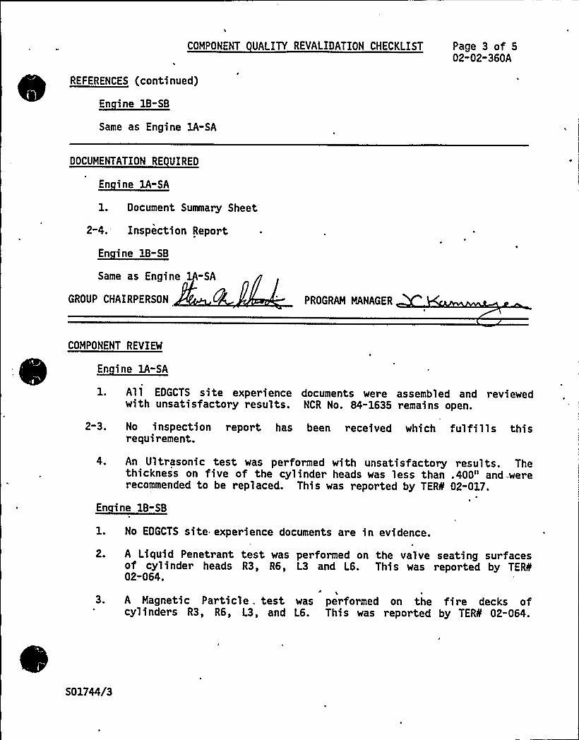
COMPONENT UALITY REVALIDATION CHECKLIST Page 3 of 502"02-360A
REFERENCES (continued)
~Ei EB-EB
Same as Engine 1A-SA
DOCUMENTATION RE UIRED
~Ei IA-EA
1. Document Summary Sheet
2-4. Inspection Report
En ine 1B-SB
Same as Engine 1 -SA
GROUP CHAIRPERSON PROGRAM MANAGER
COMPONENT REVIEW
En ine 1A-SA
All EDGCTS site experience documents were assembled and reviewedwith unsatisfactory results. NCR No. 84-1635 remains open.
2 3.
4.
No inspection report has been received which fulfills thisrequirement.
An Ultrasonic test was performed with unsatisfactory results. Thethickness on five of the cylinder heads was less than .400" and.wererecommended to be replaced. This was reported by TERS 02-017.
En ine IB«SB
1. No EDGCTS site experience documents are in evidence.
2.
3.
A Liquid Penetrant test was performed on the valve seating surfacesof cylinder heads R3, R6, L3 and L6. This was reported by TEfS02-064.
1
A Magnetic Particle . test was performed on the fire decks ofcylinders R3, R6, L3, and L6. This was reported by TERS 02-064.
S01744/3

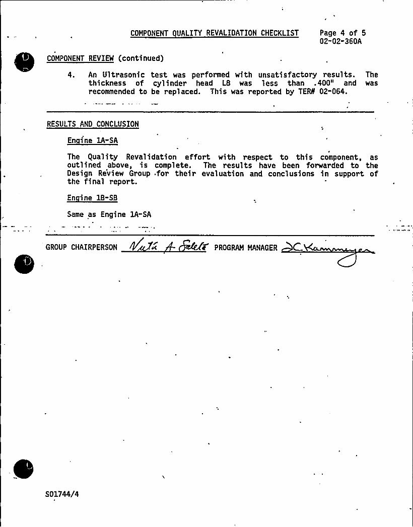
COMPONENT UALITY REVALIDATION CHECKLIST Page 4 of 502-02-360A
COMPONENT REVIEW (continued)
4. An Ultrasonic test was performed with unsatisfactory results. Thethickness of cylinder head L8 was less than .400" and wasrecommended to be replaced. This was reported by TEIL 02-064.
RESULTS AND CONCLUSION
En ine lA-SA
The guality Revalidation effort with respect to this component, asoutlined above, is complete. The results have been forwarded to theDesign Review Group for their evaluation and conclusions in support ofthe final report.
~Ei 8-SB
Same as Engine 1A-SA
GROUP CHAIRPERSON PROGRAM MANAGER C
S 01744/4
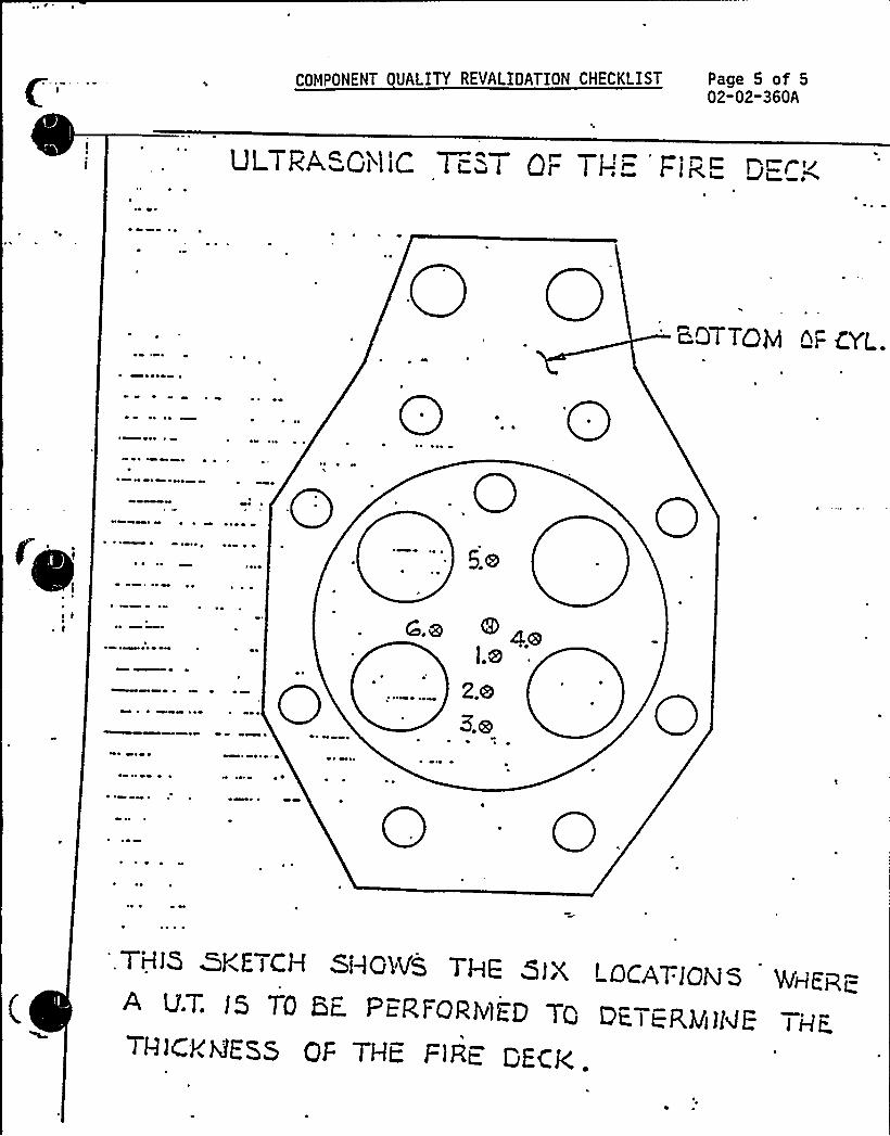
COMPONENT UAI ITY REVALIDATION CHECKLIST Page 5 of 502-02-360A
Ul TRA~Qi~l!C Ti:.i QF ) I-l
B.QT| QQ AP gyL
0 % ~ ~ ~
~ ~
0.0
0
~ 0
~ 0 0
-0~ ~
0 0
COMPONENT DESIGN REVIEW CHECKLISTSHEARON HARRIS NUCLEAR POWER PLANT - UNIT 1
Page 1 of 2
Cylinder Head Valves:COMPONENT Intake and Exhaust Valves UTILITY Carolina Power 8 Li ht Com an
GROUP PARTS LIST NO. 02-360B TASK DESCRIPTION NO. DR-02-02" 360B-0
SNPS GPL NO. 03-3608 CLASSIFICATION TYPE B
TASK DESCRIPT ONS
Design review for this component is not required based on the following:
A review of the Comanche Peak and Shoreham DR/gR reports, whichestablish the acceptability of the cylinder head valves for theirintended purpose.
~ ~ A review of site, nuclear, and non-nuclear industry experienceindicated that there had been no design related failures associatedwith this component. The cylinder head valves are identical on allthe Owners Group TDI diesel engines (TDI Part No. 03-360-02"OD).
The primary nuclear and non-nuclear industry experiences associated with thiscomponent have been chrome plate flaking, scuffing, and scoring, and exhaustgas blowby due to lack of concentricity of the valve and seat. Because of thesmall, number of hours nuclear service diesels are expected to operate betweeninspections,'uch problems will not noticeably affect engine performance.
The valve inspections outlined in the DR/gR reports also applies to the enginesat Shearon Harris. This inspection should be performed for all new orreworked cylinder heads after an initial 500-600 hours of operation:
~ Remove the subcover bonnet and inspect the interior for soot whichindicates valve blowby. Corrective action should be taken if thissituation is found to exist.
There are no modifications recommended for this component.
All quality inspections that have been performed to date have been reviewed.Unsatisfactory conditions have been dispositioned by the utility.The following equality Revalidation inspection recommendations are made toensure proper component performance and quality and should be performed onboth engines:
~ Perform a visual inspection to verify adequate valve seating. Thereshould be a unifo'rm linear metallic ring on each valve ring.
SH2089/1

I~
COMPONENT DESIGN REVIEW CHECKLIST
TASK DESCRIPTIONS (conti nued)
Page 2 of 2DR"02"02-360B-0
~ Perfor m a visual examinati on of the valve and valve ring forscuffing and erosion on valve ring or valve seat area.
~ Perform a dimensional check of the valve to valve guide clearance.
~ Perform a visual examination of the top of the val ve stems forscuffing and pitting.
—'--=. '-.--'= -In 'addi.tion. the ..fo1:lowing -quality inspection is required to be -performed on .." ..-
engine lA-SA.
~ Perform a liquid penetrant test on the blended radius of the stemhead for cracking.
PRIMARY FUNCTION
Not required
ATTRIBUTES TO BE VERIFIED
Not required
SPECIFIED STANDARDS
Not required
REFERENCES
Not required
DOCUMENTATION RE UIRED
Not required
GROUP CHAIRPERSON ROGRAM MANAGER
SH2089/2
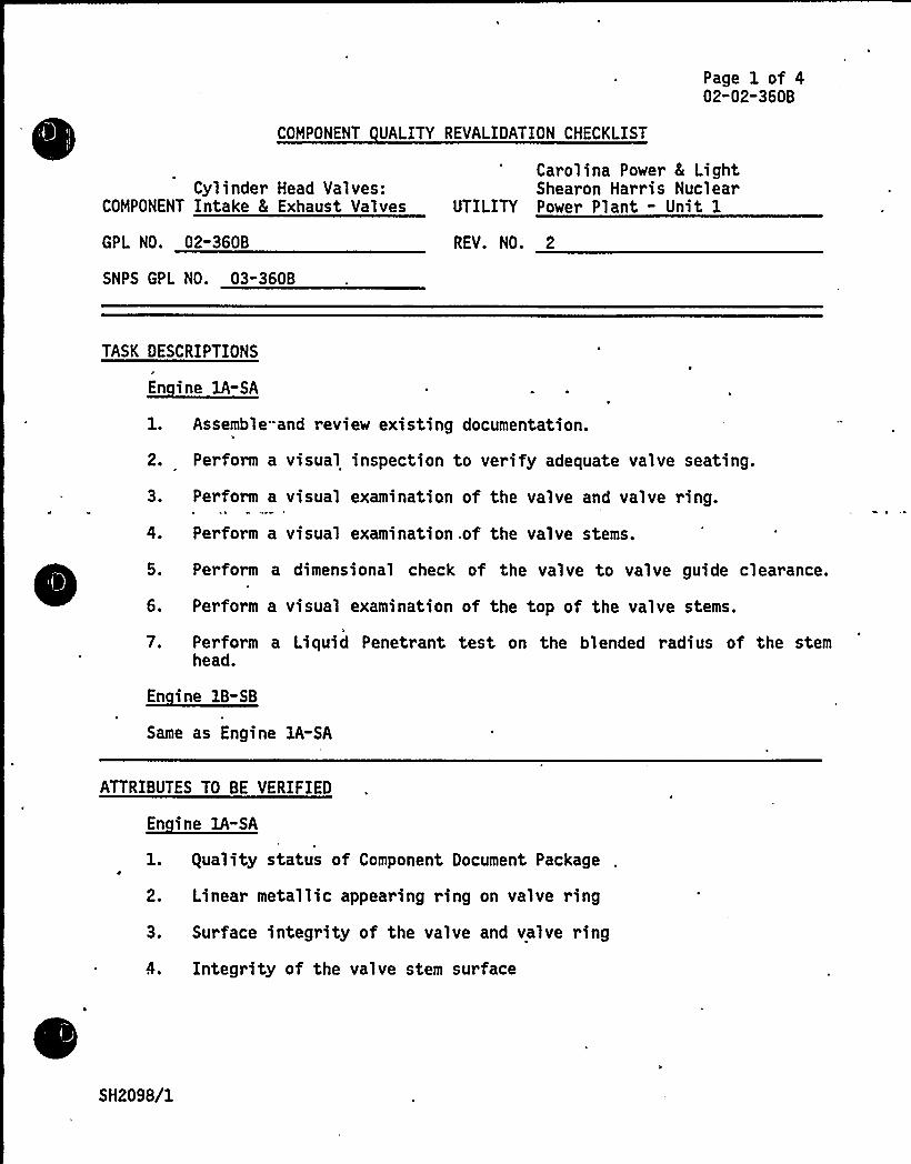
COMPONENT UALITY REVALIDATION CHECKLIST
Page 1 of 402-02-360B
Cylinder Head Valves:COMPONENT Intake 8 Exhaust Valves
Carolina Power 8 LightShearon Harris Nuclear
UTILITY Power Plant - Unit 1
GPL NO. 02-360B REV. NO. 2
SNPS GPL NO. 03-360B
TASK DESCRIPTIONS
En ine 1A-SA
1. Assemble. and review existing documentation.
2. Perform a visual inspection to verify adequate valve seating.
3. Perform a
4. Perform a
visual examination of the valve and valve ring.
visual examination .of the valve stems.
5. Perform a dimensional check of the valve to valve guide clearance.
6. Perform a visual examination of the top of the valve stems.
7. Perform a Liquid Penetrant test on the blended radius of the stemhead.
En ine 1B-SB
Same as Engine lA-SA
ATTRIBUTES TO BE VERIFIED
En ine 1A-SA
1. guality status of Component Document Package
2. Linear metallic appearing ring on valve ring
3. Surface integrity of the valve and valve ring
4. Integrity of the valve stem surface
SH2098/1

c. ~
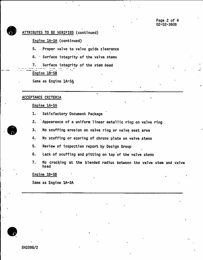
Page 2 of 402-02-360B
ATTRIBUTES TO BE VERIFIED (continued)
~di 1A-EA E 1 d)
5. Proper valve to valve guide clearance
6. Surface integrity of the valve stems
7. Surface integrity of the stem head
~di B-EB
Same as Engine 1A-S$
ACCEPTANCE CRITERIA
~di EA-EA
1. Satisfactory Document Package
2. Appearance of a uniform linear metallic ring on valve ring
3. No scuffing erosion on valve ring or valve seat area
4. No scuffing or scoring of chrome plate on valve. stems
5. Review of inspection report by Design Group
6. Lack of scuffing and -pitting on top of the valve stems
7. No cracking at the blended radius between the valve stem and valvehead
En ine 1B-SB
Same as Engine lA-SA
SH2098/2
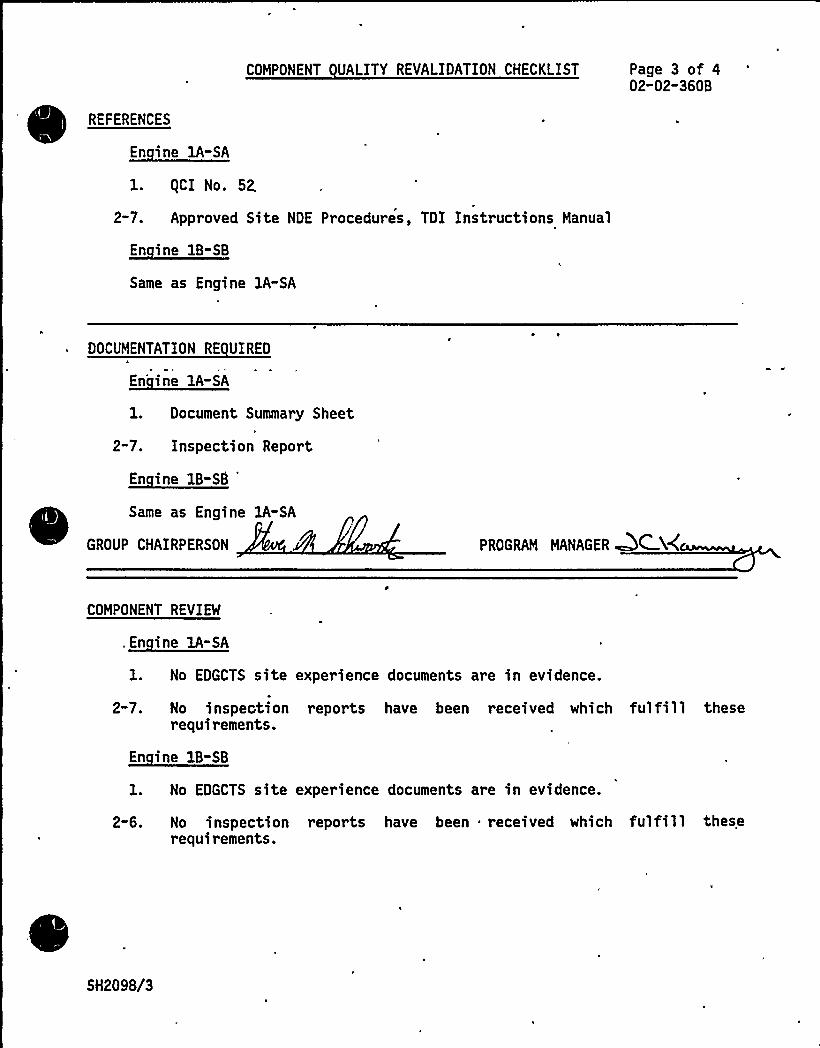
REFERENCES
En ine 1A-SA
COMPONENT UALITY REVALIDATION CHECKLIST Page 3 of 402-02-3608
1. gCI No. 52,
2-7. Approved Site NDE Procedures, TDI Instructions Manual
~Ei B-EB
Same as Engine 1A-SA
DOCUMENTATION RE UIRED
~Ei EA-EA
1. Document Summary Sheet
2-7. Inspection Report
En ine 18-SB
Same as Engine 1A-SA
GROUP CHAIRPERSON .V'ROGRAM MANAGER ~C Xg
COMPONENT REVIEW
.~Ei BA- A
1. No EDGCTS site experience documents are in evidence.
2 70 No inspeGti onrequirements.
reports have been recei ved whi ch ful fill these
En ine 18-SB
1. No EDGCTS site experience documents are in evidence.
2-6. No inspectionrequirements.
reports have been received which fulfill these
SH2098/3
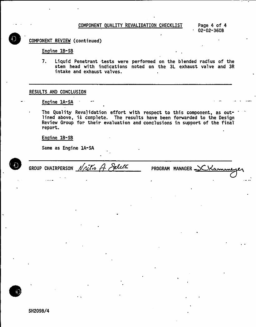
COMPONENT UALITY REVALIDATION CHECKLIST
COMPONENT REVIEW (continued)
En ine 1B-SB
Page 4 of 402"02-360B
7. Liquid Penetrant tests were performed on the blended radius of thestem head with indications noted on the 3L exhaust valve and 3Rintake and exhaust valves.
RESULTS AND CONCLUSION
~Ei 1A-SA
~ The guality Revalidation effort with respect to this component, as out-lined above, is complete. The results have been forwarded to the DesignReview Group for their evaluation and conclusions in support of the finalreport.
En ine 1B-SB
Same as Engine lA-SA
GROUP CHAIRPERSON f c+ PROGRAM MANAGER C g
SH2098/4

COMPONENT DESIGN REVIEW CHECKLISTSHEARON HARRIS NUCLEAR POWER PLANT - UNIT 1
Page 1 of 2
Cylinder Head AndCOMPONENT Valves: Boltin And Gaskets UTILITY Carolina Power 8 Li ht Com an
GROUP PARTS LIST NO. 02-360C
SNPS GPL NO. 03-360C
TASK DESCRIPTION NO. DR-02-02-360C-0
CLASSIFICATION TYPE B
TASK DESCRIPTIONS
Design review for this. component is not required based on the review of thelead engine DR/gR report (Comanche Peak) 'nd the applicable industryexperience. There is no site experience in the EDG Component Tracking Systemfor this component.
There are no modification or maintenance recommendations for this component.
The following guality Revalidation inspections should be performed on allstation engines:
~ 'Verify that the proper gaskets are installed in accordance withspecification requirements;
~ Perform a visual inspection of the gasket for signs of distress.
PRIMARY FUNCTION
Not required
ATTRIBUTE TO BE VERIFIED
Not required
SPECIFIED STANDARDS
Not requir ed
REFERENCES
Not required
SH2192/1
COMPONENT DESIGN REVIEW CHECKLIST
DOCUMENTATION RE UIRED
Not required
Page 2 of 2DR-02-02-360C-0
GROUP CHAIRPERSON PROGRAM MANAGER
SH2192/2
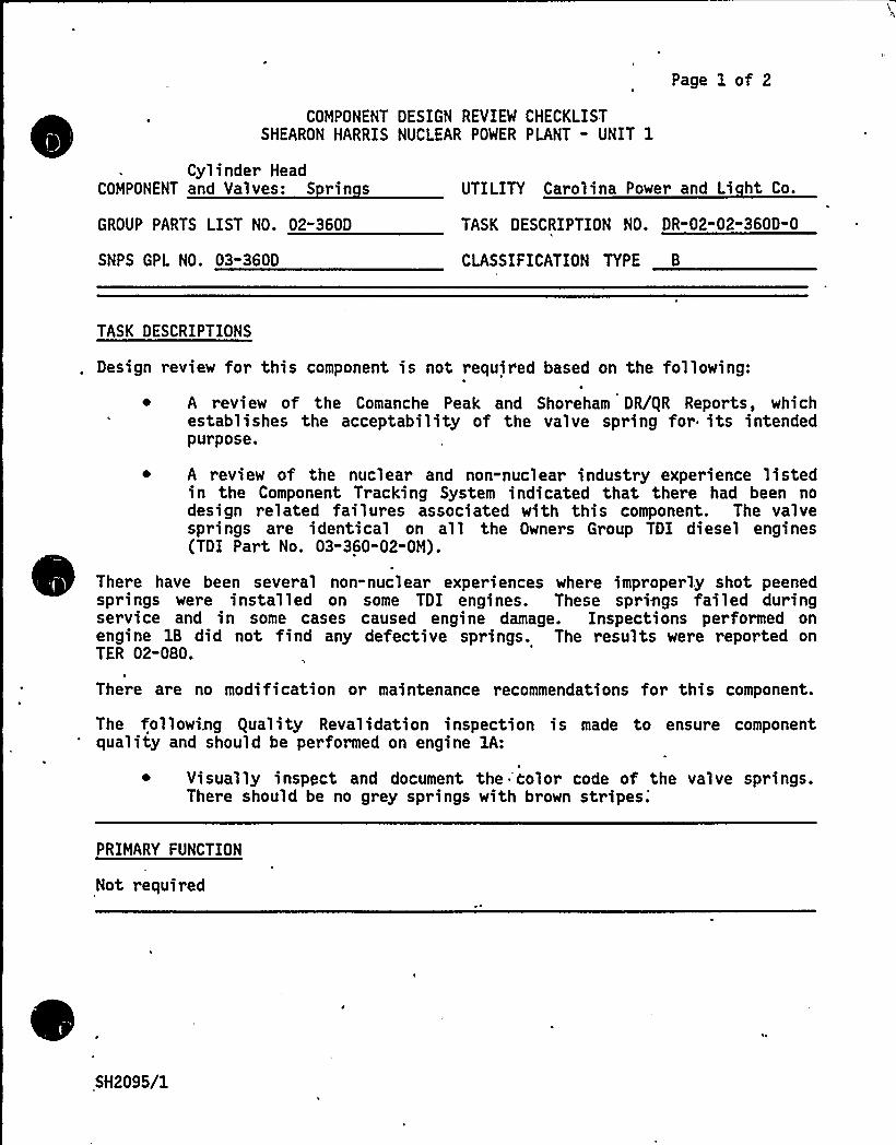
COMPONENT DESIGN REVIEW CHECKLISTSHEARON HARRIS NUCLEAR POWER PLANT - UNIT 1
Page 1 of 2
Cylinder HeadCOMPONENT and Valves: S rin s
GROUP PARTS LIST NO. 02"360D
SNPS GPL NO. 03-360D
UTILITY Carolina Power and Li ht Co.
TASK DESCRIPTION NO. DR-02-02" 360D-0
CLASSIFICATION TYPE B
TASK DESCRIPTIONS
Design review for this component is not required based on the following:
~ A review of the Comanche Peak and Shoreham DR/gR Reports, whichestablishes the acceptability of the valve spring for its intendedpurpose.
A review of the nuclear and non-nuclear industry experience listedin the Component Tracking System indicated that there had been nodesign related failures associated with this component. The valvesprings are identical on all the Owners Group TDI diesel engines(TDI Part No. 03-360-02-0M).
Ther e have been several non-nuclear experiences where improperly shot peenedsprings were installed on some TDI engines. These springs failed duringservice and in some cases caused engine damage. Inspections performed onengine 1B did not find any defective springs. The results were reported onTER 02-080.
There are no modification or maintenance recommendations for this component.
The followi.ng equality Revalidation inspection is made to ensure componentquality and should be performed on engine 1A:
~ Visually inspect and document the 'Color code of the valve springs.There should be no grey springs with brown
stripes.'RIMARY
FUNCTION
Not required
,SH2095/1

COMPONENT DESIGN REVIEW CHECKLIST Page 2 of 2DR"02" 02-360D" 0
ATTRIBUTE TO BE VERIFIED
Not required
SPECIFIED STANDARDS
Not required
REFERENCES
Not required
DOCUMENTATION RE UIRED
Not required
GROUP CHAIRPERSON PROGRAM MANAGER
SH2095/2
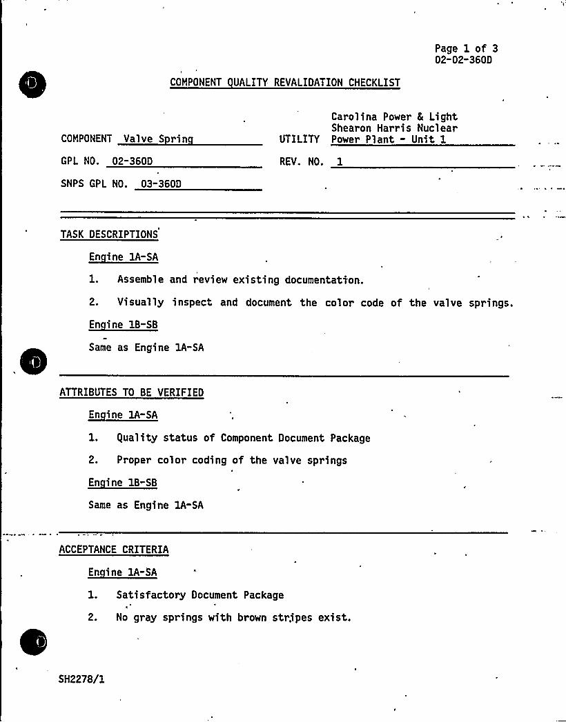
COMPONENT UALITY REVALIDATION CHECKLIST
Page 1 of 302-02-360D
COMPONENT Valve S rin
GPL NO. 02-360D
SNPS GPL NO. 03-360D
Carolina Power 8 LightShearon Harris Nuclear
UTILITY Power Plant - Unit 1
REV. NO. 1
TASK DESCRIPTIONS
En ine 1A-SA
1. Assemble and review existing documentation.
2. Visually inspect and document the color code of the valve springs.
~Ei 1B-EB
Same as Engine 1A-SA
ATTRIBUTES TO BE VERIFIED
En ine lA-SA
1. guality status of Component Document Package
2. Proper color coding of the valve springs
~Ei 1B- 1
Same as Engine 1A-SA
ACCEPTANCE CRITERIA
En ine IA-SA
1. Satisfactory Document Package
2. No gray springs with brown stripes exist.
SH2278/1
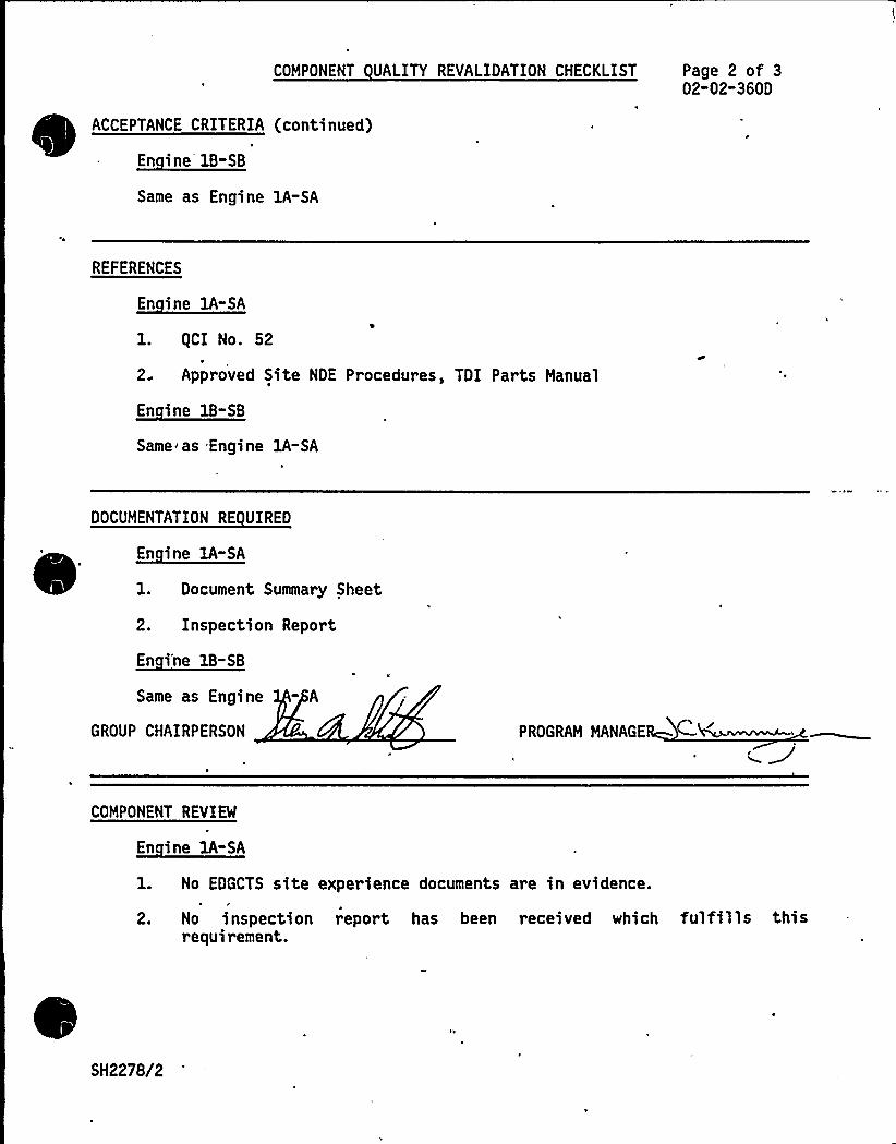
COMPONENT UALITY REVALIDATION CHECKLIST Page 2 of 302"02"360D
ACCEPTANCE CRITERIA (continued)~
~
EB-BB
Same as Engine lA-SA
REFERENCES
En ine lA-SA
1. (CI No. 52
2. Approved Site NDE Procedures, TDI Parts Manua1
En ine 1B-SB
Same as Engine 1A-SA
DOCUMENTATION RE UIRED
En ine 1A-SA
1. Document Summary Sheet
2. Inspection Report
~Ei'-BBSame as Engine - A
GROUP CHAIRPERSON PEB AN NAN E E
N'OMPONENT
REVIEW
En ine 1A-SA
1. No EDGCTS site experience documents are in evidence.
2. No inspection report has been received which fulfills thisrequirement.
SH2278/2

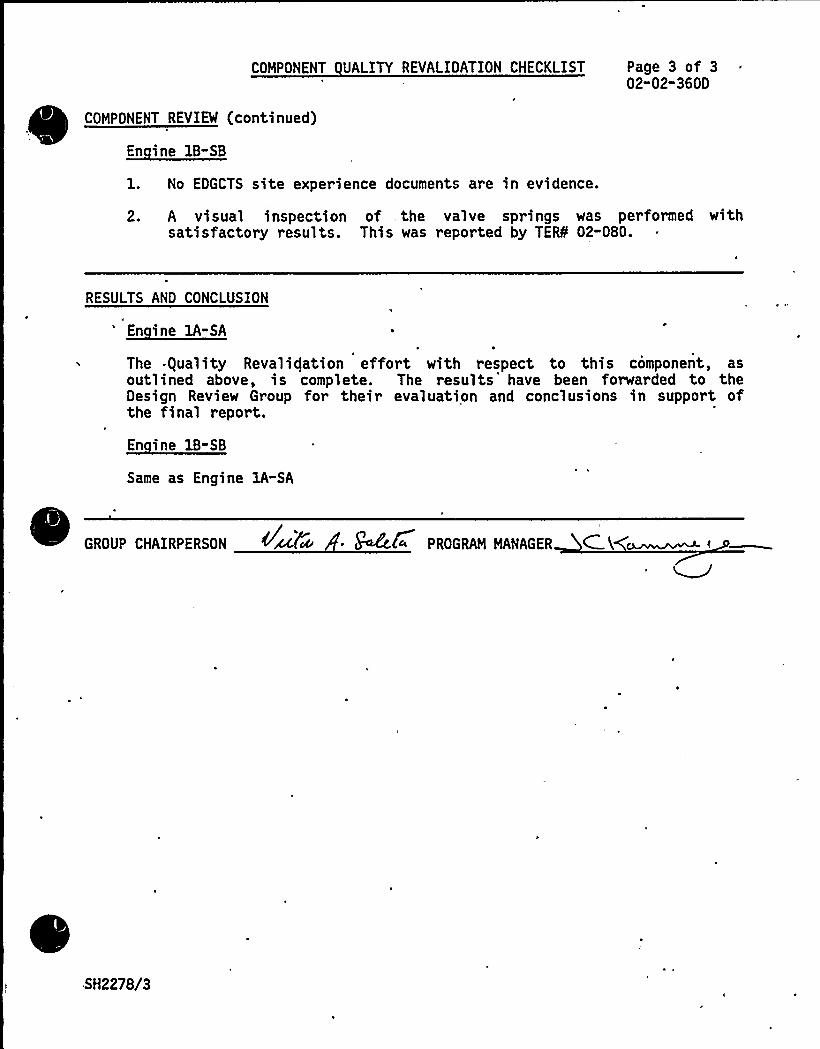
COMPONENT UALITY REVALIDATION CHECKLIST Page 3 of 302-02-360D
COMPONENT REVIEW (continued)
~Ei ll-EA
1. No EDGCTS site experience documents are in evidence.
2. A visual inspection of . the valve springs was performed withsatisfactory results. This was reported by TEfS 02-080.
RESULTS AND CONCLUSION
'Ei lA-EA
The -guality Revalidation effort with respect to this component, asoutlined above, is complete. The results have been forwarded to theDesign Review Group for their evaluation and conclusions in support ofthe final report.
En ine 1B-SB
Same as Engine lA"SA
E
GROUP CHAIRPERSON ~%tee ~ g+Ec f» PR,OGRAM MANAGER C.'\
.SH2278/3
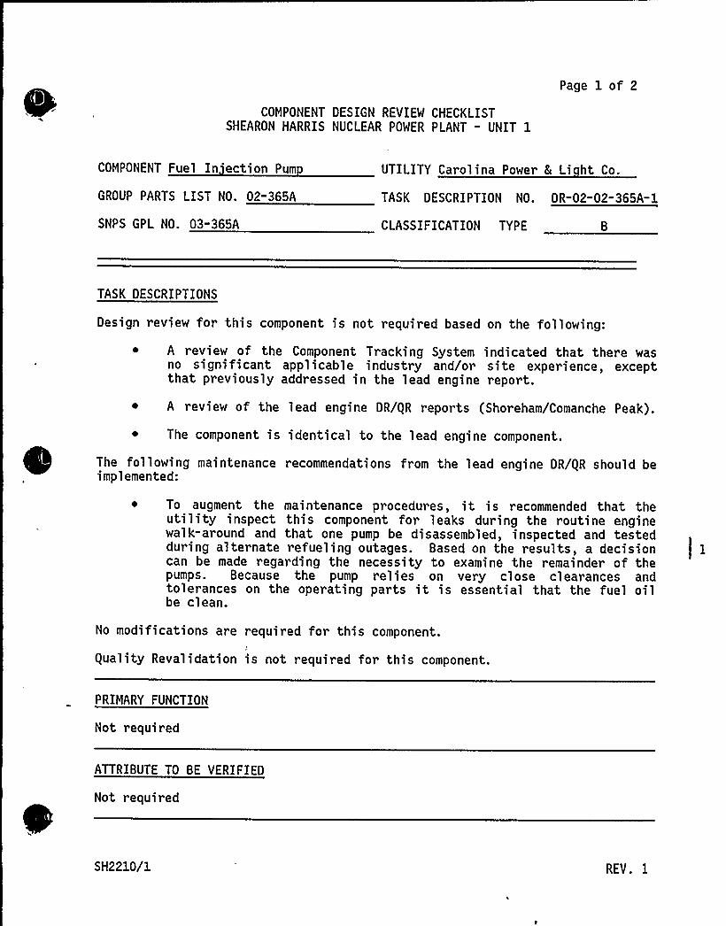
COMPONENT DESIGN REVIEW CHECKLISTSHEARON HARRIS NUCLEAR POWER PLANT - UNIT 1
Page 1 of 2
COMPONENT Fuel In ection Pum
GROUP PARTS LIST NO. 02-365A
SNPS GPL NO. 03-365A
UTILITY Carolina Power 8 Li ht Co.
TASK DESCRIPTION NO. DR"02"02" 365A-1
CLASSIFICATION TYPE B
TASK DESCRIPTIONS
Design review for this component is not required based on the following:
~ A review of the Component Tracking System indicated that there wasno significant applicable industry and/or site experience, exceptthat previously addressed in the lead engine report.
~ A review of the lead engine DR/gR reports (Shoreham/Comanche Peak).
~ The component is identical to the lead engine component.
The following maintenance recommendations from the lead engine DR/gR should beimplemented:
To augment the maintenance procedures, it is recommended that theutility inspect this component for leaks during the routine enginewalk-around and that one pump be disassembled, inspected and testedduring alternate refueling outages. Based on the results, a decisioncan be made regarding the necessity to examine the remainder of thepumps. Because the pump relies on very close clearances andtolerances on the operating parts it is essential that the fuel oilbe clean.
No modifications are required for this component.
guality Revalidation is not required for this component.
PRIMARY FUNCTION
Not required
ATTRIBUTE TO BE VERIFIED
Not required
SH2210/1 REV. I
SPECIFIED STANDARDS
Not required
COMPONENT DESIGN REVIEW CHECKLIST Page 2 of 2DR"02"02"365A"0
REFERENCES
Not required
DOCUMENTATION RE UIRED
Not required
GROUP CHAIRPERSON PROGRAM MANAGER
SH2210/2
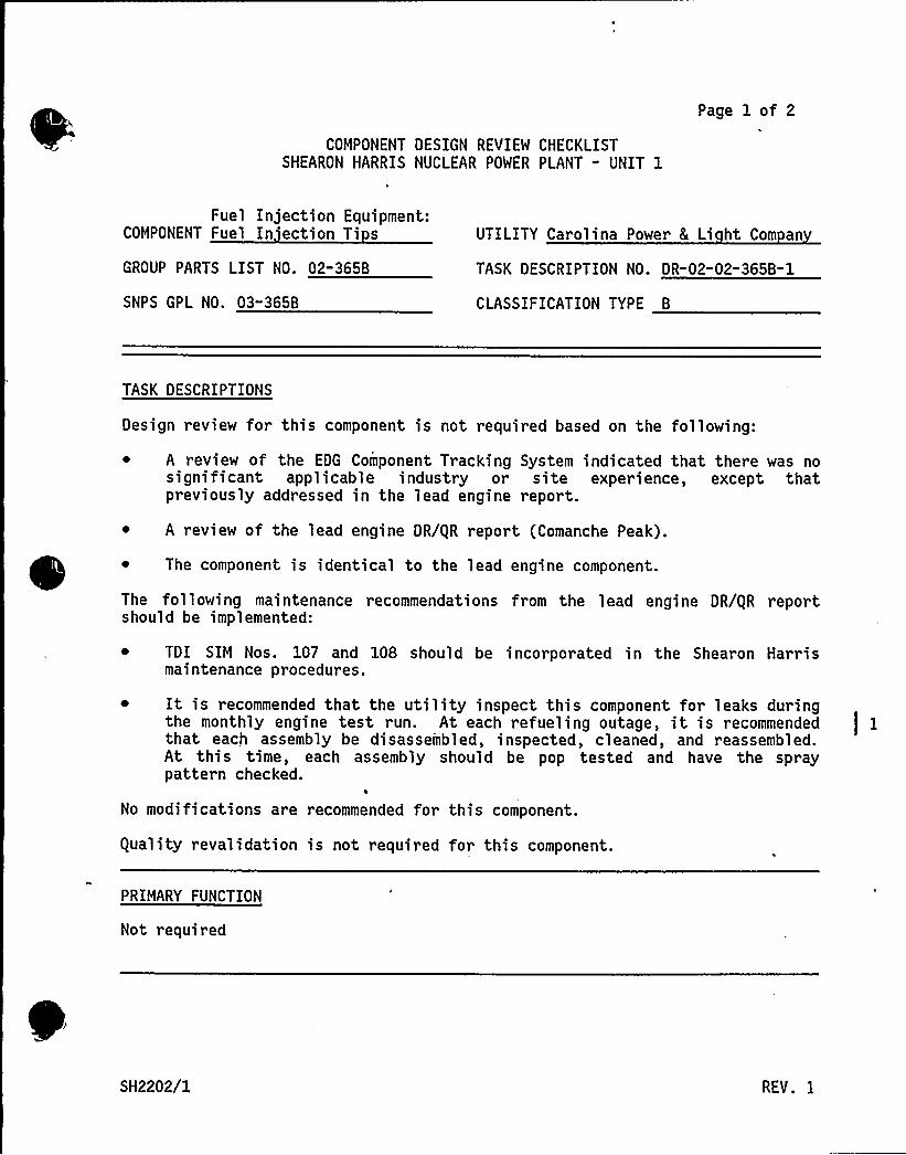
COMPONENT DESIGN REVIEW CHECKLISTSHEARON HARRIS NUCLEAR POWER PLANT " UNIT 1
Page 1 of 2
Fuel Injection Equipment:COMPONENT Fuel In ection Ti s
GROUP PARTS LIST NO. 02-365B
SNPS GPL NO. 03-365B
UTILITY Carolina Power L Li ht Com an
TASK DESCRIPTION NO. DR-02-02-365B-1
CLASSIFICATION TYPE B
TASK DESCRIPTIONS
Design review for this component is not required based on the following:
~ A review of the EDG Component Tracking System indicated that there was nosignificant applicable industry or site experience, except thatpreviously addressed in the lead engine report.
~ A review of the lead engine DR/QR report (Comanche Peak).
~ The component is identical to the lead engine component.
The following maintenance recommendations from the lead engine DR/QR reportshould be implemented:
~ TDI SIM Nos. 107 and 108 should be incorporated in the Shearon Harrismaintenance procedures.
It is recommended that the utility inspect this component for leaks duringthe monthly engine test run. At each refueling outage, it is recommendedthat each assembly be disassembled, inspected, cleaned, and reassembled.At this time, each assembly should be pop tested and have the spraypattern checked.
No modifications are recommended for this component.
Quality revalidation is not required for this component.
PRIMARY FUNCTION
Not required
SH2202/1 REV. 1
COMPONENT DESIGN REVIEW CHECKLIST
ATTRIBUTE TO BE VERIFIED
Not required
Page 2 of 2DR-02"02-365B-0
SPECIFIED STANDARDS
Not required
REFERENCES
Not required
DOCUMENTATION RE UIRED
Not required
GROUP CHAIRPERSON ~PROGRAN NANAGER M
SH2202/2
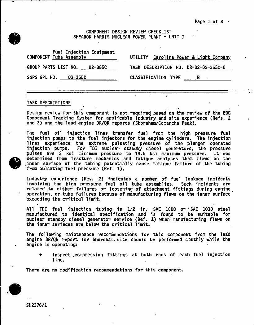
Page 1 of 3
COMPONENT DESIGN REVIEW CHECKLISTSHEARON HARRIS NUCLEAR POWER PLANT " UNIT 1
Fuel Injection EquipmentCOMPONENT Tube Assembl
,GROUP PARTS LIST NO. 02-365C
UTILITY Carolina Power 8 Li ht Com an
TASK DESCRIPTION NO. DR-02-02"365C"0
SNPS GPL NO. 03"365C CLASSIFICATION TYPE B
TASK DESCRIPTIONS
Design review for this component is not required based on the review of the EDG
Component Tracking System for applicable industry and site experience (Refs. 2and 3) and the lead engine DR/gR reports (Shoreham/Comanche Peak).
The fuel oil injection lines transfer fuel from the high pressure fuelinjection pumps to the fuel inject'ors for the engine cylinders. The injectionlines experience the extreme pulsating pressure of the plunger operatedinjection pumps. For TDI nuclear standby diesel generators, the pressurepulses are 3 ksi minimum pressure to 14.5 ksi maximum pressure. It was
~
~
~
~ ~ ~
~ ~
~~
~
~
~
~
~
~determined from fracture mechanics and fatigue analyses that flaws on theinner surface of the tubing potentially cause fatigue failure of the tubingfrom pulsating fuel pressure (Ref. 1).
Industry experience (Rev. 2) indicates a number of fuel leakage incidentsinvolving the high pressure fuel oil tube assemblies. Such incidents arerelated to either failures or loosening of attachment fittings during engineoperation, or tube failures because of manufacturing flaws on the inner surfaceexceeding the critical limit.
All TDI fuel injection tubing is 1/2 in. SAE 1008 or "SAE 1010 steel
manufactured to identical specification and is found to be suitable fornuclear standby diesel generator service (Ref. 1) when manufacturing flaws onthe inner surfaces are below the critical limit.
The following maintenance recommendations for this component from the leadengine DR/gR report for Shoreham. site should be performed monthly while theengine is operating:
Inspect .compression fittings at both ends of each fuel injection. line.
.There are no modification recommendations for this component.
SH2376/1

0
d/ +l
COMPONENT DESIGN REVIEW CHECKLIST Page 2 of 3DR-02-02" 365C-0
TASK DESCRIPTION (continued)
The following guality inspections as described on the Component guality ReviewChecklist should be performed on all station engines:
~ All high pressure fuel lines are to be completely examined by an eddy.current test (Ref. 4).
PRIMARY FUNCTION
Not required
ATTRIBUTE TO BE VERIFIED
Not required
SPECIFIED STANDARDS
Not required
REFERENCES
1. Emergency Diesel Generator Fuel Oil Injection Tubing qualificationAnalysis prepared for TDI Emergency Diesel Generator Owners GroupApril 1, -1984.
2. Emergency Diesel Generator Computer Tracking System - Industry Experienpedated October 15, 1984.
3.. Emergency Diesel Generator Computer Tracking System - Shearon HarrisNuclear Power Plant dated October 15, 1984.
4. Failure Analysis Assoc. NDE Procedure 11.10 "Eddy Current InspectionProcedure - High Pressure Fuel Lines - Carbon Steel."
SH2376/2
COMPONENT DESIGN REVIEW CHECKLIST
DOCUMENTATION RE UIRED
Not required
Page 3- of 3DR"02-02-365C-0
GROUP CHAIRPERSON PROGRAM MANAGER
5H2376/3
1
COMPONENT UALITY REVALIDATION CHECKLIST
Page 1 of 302-02-365C
Fuel Injection EquipmentCOMPONENT Tube Assembl
GPL NO. 02-365C
SNPS GPL NO. 03-365C
Carolina Power & LightShearon Harris Nuclear
UTILITY Power Plant - Unit 1
REV. NO. 2
TASK DESCRIPTIONS
~Ei EA- A
l. Assemble and review existing documentation.
2. Perform an Eddy Current test on the inside diameter of all the fuelinjection tubing.
En ine 1B-SB
Same as Engine 1A-SA
ATTRIBUTES TO BE VERIFIED
~E" i BA-EA
1. . guality.status of Component Document Package
2. Integrity of the fuel injection tubing
~E" i 1B-EB
Same as Engine 1A-SA
ACCEPTANCE CRITERIA
~Ei lA-EA
1. Satisfactory Document Package
2. The minimum detectable flaw size is rejectable (0.003" t 0.0005").
SH1002/1

COMPONENT UALITY REVALIDATION CHECKLIST
ACCEPTANCE 'CRITERIA (continued)
~E' 11-EB
Same as Engine 1A-SA
Page 2 of 302"02-365C
REFERENCES
En ine lA-SA
1. gCI No.52
2. Approved Site NDE Procedures, TElS 99-006, FaAA NDE procedure 11.10
En ine 1B-SB
Same as Engine 1A-SA
DOCUMENTATION RE UIRED
~Ei EA-EA
1. Document Summary Sheet
2. Inspection Report
~Ei 1B-EB
-Same as Engine 1 -SA
GROUP CHAIRPERSON PROGRAM MANAGER
COMPONENT REVIEW
En ine 1A-SA
1. No EDGCTS site experience documents are in evidence.
2. An Eddy Current test was performed on all fuel injection tubingexcept where the tubing's inner diameter was too small to beexamined. All tubing that was tested showed no relevantindications. This was reported by TERS 02-082.
SH1002/2
COMPONENT UALITY REVALIDATION CHECKLIST
COMPONENT REVIEW (continued)
~Ei lA-SA
Page 3 of 302-02-365C
NOTE: a) A visual inspection of the tubing was performed withsatisfactory results. This was reported by TERS 02-082.
En ine 1B-SB
No EDGCTS site experience documents are in evidence.
2.
NOTE:
An Eddy Current test was per for med on al 1 fuel injecti on tubingexcept where the tubing's inner diameter was too small to beexamined. Results for tubing on cylinder $ L was found to be unsatis-factory. This was reported by 'TERS 02-082.
a) A visual inspecti on of the tubing was. performed withsatisfactory results. This was reported by TEfbF 02-046.
RESULTS AND CONCLUSION
En ine 1A-SA
The guality Revalidation effort with respect to this component,'soutlined above, is complete. The results have been forwarded to theDesign Review Group for their evaluation and conclusions in support ofthe final report.
En ine 1B-SB
,Same as Engine 1A-SA
GROUP CHAIRPERSON .V PROGRAM MANAGER
SH1002/3
' COMPONENT DESIGN REVIEW CHECKLISTSHEARON HARRIS NUCLEAR POWER PLANT - 'NIT 1
Page 1 of 2
Fuel Injection Equipment:Supports
COMPONENT Small Bore Sco e Onl
GROUP PARTS LIST NO. 02-365D
SNPS GPL NO. 03-365D
UTILITY Carolina Powe~ 8 Li ht Com an
TASK DESCRIPTION NO. DR-02-02" 365D-1
CLASSIFICATION TYPE B
TASK'ESCRIPTIONS
Design review for this component is not required based on the review of thelead engine DR/gR report (Comanche Peak) and the applicable industry experi-ence. There is no site experience for this component in the EDG ComponentTracking System.
There are no modification recommendations for this component.
A visual inspection of the support elastomer for signs of deterioration ordegradation should be performed at each refueling outage. Any inserts found
~
~
~
~ ~
unsat'isfactory should be replaced.
A fiel d wal kdown was per formed in accordance with the smal 1 bore pipingcriteria document (Ref. 1) and indicates that this component will maintain itsfunctional capability for normal and earthquake loading.
guality revalidation for this component is not required.
PRIMARY FUNCTION
Not required
ATTRIBUTE TO BE VERIFIED
Not required
SPECIFIED STANDARDS
SH2176/1
COMPONENT DESIGN REVIEW CHECKLIST Page 2 of 2DR-02"02"365D-1
R EFERENCES
"Engineering Review Criteria Document for the Design Review of TDI Diesel SmallBore Piping, Tubing, and Supports for the TDI Owners'roup," report No.11600.60-DC-02, Revision 0.
DOCUMENTATION RE UIRED
Not required
GROUP CHAIRPERSON PROGRAM MANAGER
SH2176/2
' COMPONENT DESIGN REVIEW CHECKLISTSHEARON HARRIS NUCLEAR POWER PLANT - UNIT 1
Page 1 of 2
Fuel Control RodCOMPONENT Linka e & Bearin s
GROUP PARTS LIST NO. 02-371A&B
SNPS GPL NO. 03"371A&B
UTILITY Carolina Power & Li ht Com an
TASK DESCRIPTION NO. DR"02-02-371A&B-1
CLASSIFICATION TYPE A
~ TASK DESCRIPTIONS
Design review for this component is not required based on the following:
A review of the EDG Component Tracking System indicated that therewas no significant applicable industry and/or site experience, exceptthat already addressed in the lead engine report.
~ A review of the lead engine DR/gR report (Comanche Peak).
~ Component is identical to lead engine report.
~
~ ~
~ ~ ~
.The following maintenance recommendations from the lead engine DR/gR reportshould be implemented:
~ To maintain proper control shaft alignment, it is recommended thatthe oil cups be inspected and filled on a monthly basis.
No modifications are required for this component.
All inspections that have been completed were found to be satisfactory.
The following guality inspections should be performed:
~ Inspect linkage and bearings for freedom of movement.
~ Determine the'ardness of the shaft.
PRIMARY FUNCTION
Not required
SH2206/1

i.
I
COMPONENT DESIGN REVIEW CHECKLIST
ATTRIBUTE TO BE VERIFIED
Not required
Page 2 of 2DR-02-02-37108-1
SPECIFIED STANDARDS
Not required
REFERENCES
Not required
DOCUMENTATION RE VIREO.
Not required
GROUP CHAIRPERSON PROGRAM MANAGER&C
SH2206/2
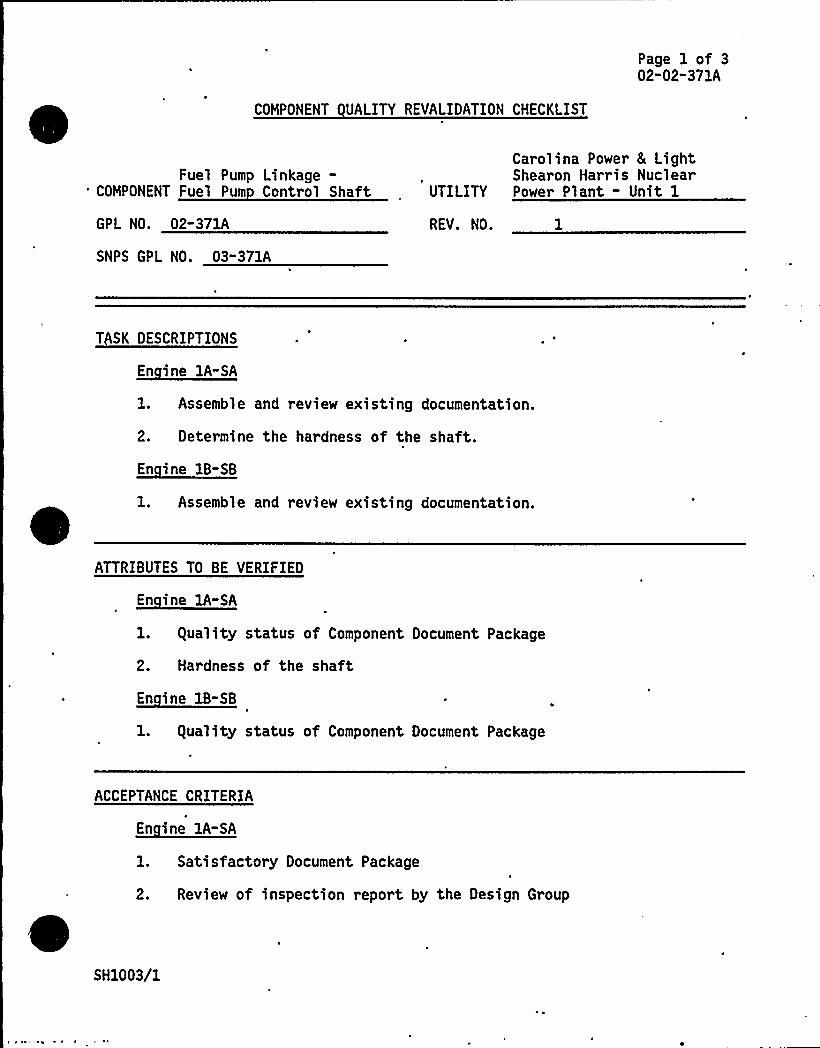
Page 1 of 302-02" 371A
COMPONENT UALITY REVALIDATION CHECKLIST
Fuel Pump Linkage-COMPONENT Fuel Pum Control Shaft
GPL NO. 02"371A
SNPS GPL NO. 03"371A
Carolina Power 8 LightShearon Harris Nuclear
UTILITY Power Plant - Unit 1
REV. NO.
T SK DESCRIPTIONS
En ine 1A-SA
l. Assemble and review existing documentation.
2. Determine the hardness of the shaft.
~Ei 1B-EB
1. Assemble and review existing documentation.
ATTRIBUTES TO BE VERIFIED
En ine 1A-SA
1. guality status of Component Document Package
2. Hardness of the shaft
~E" i 11-EB
1. guality status of Component Document Package
ACCEPTANCE CRITERIA
En ine 1A-SA
1. Satisfactory Document Package
2. Review of inspection report by the Design Group
SH1003/1
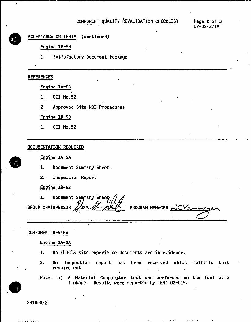
COMPONENT UALITY REVALIDATION CHECKLIST
ACCEPTANCE CRITERIA (continued)
B-BB
1. Satisfactory Document Package
Page 2 of 302-02"371A
REFERENCES
En ine lA-SA
l. (CI No.52
2. Approved Site NDE Procedures
~Ei 1-BB
1. gCI No.52
.DOCUMENTATION RE UIRED
~Ei EA-BA
1. Document Summary Sheet.
2. Inspection Report
~Ei B- B
1. Document Su ary Shee
- GROUP CHAIRPERSON PROGRAM MANAGER
COMPONENT REVIEW
En ine 1A-SA
1. No EDGCTS site experience documents are in evidence.
2. No inspection report has been received which fulfills thisrequirement.
.Note: a) A Material Comparatot test was performed on the fuel pumplinkage. Results were reported by TEfS 02-019.
SH1003/2

~ ~
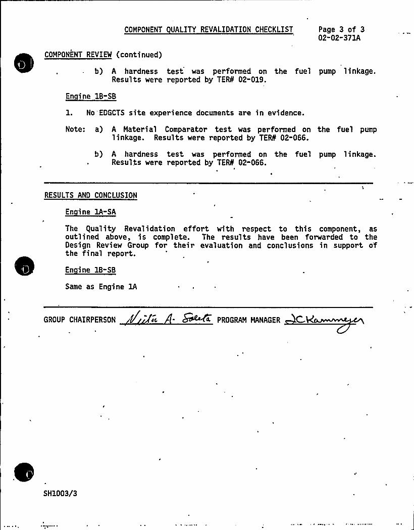
COMPONENT UALITY REVALIDATION CHECKLIST Page 3 of 302-02-371A
COMPONENT REVIEW (continued)
b) A hardness test was performed on the fuel pump linkage.Results were reported by TEIL 02-019.
En ine 1B-SB
1. No EDGCTS site experience documents are in evidence.
Note: a) A Material Comparator test was performed on the fuel pumplinkage. Results were reported by TEiS 02-066.
b) A hardness test was performed on the fuel pump linkage.Results were reported by TEIL 02-066.
RESULTS AND CONCLUSION
~Ei 1A-SA
The guality Revalidation effort with respect to this component, asoutlined above, is complete. The results have been forwarded to theDesign Review Group for their evaluation and conclusions in support o'
the final report.
En ine 1B-SB
Same as Engine 1A
GROUP CHAIRPERSON ~c - &~4 PROGRAM MANAGER C-
SH1003/3
TDI OWNERS GROUP
for
SHEARON HARRIS NUCLEAR POWER PLANT
Fuel Pump Linkage: Linkage Assembly and Bearing
COMPONENT PART NO.: O2-371B
See Component Part No. 02-371A
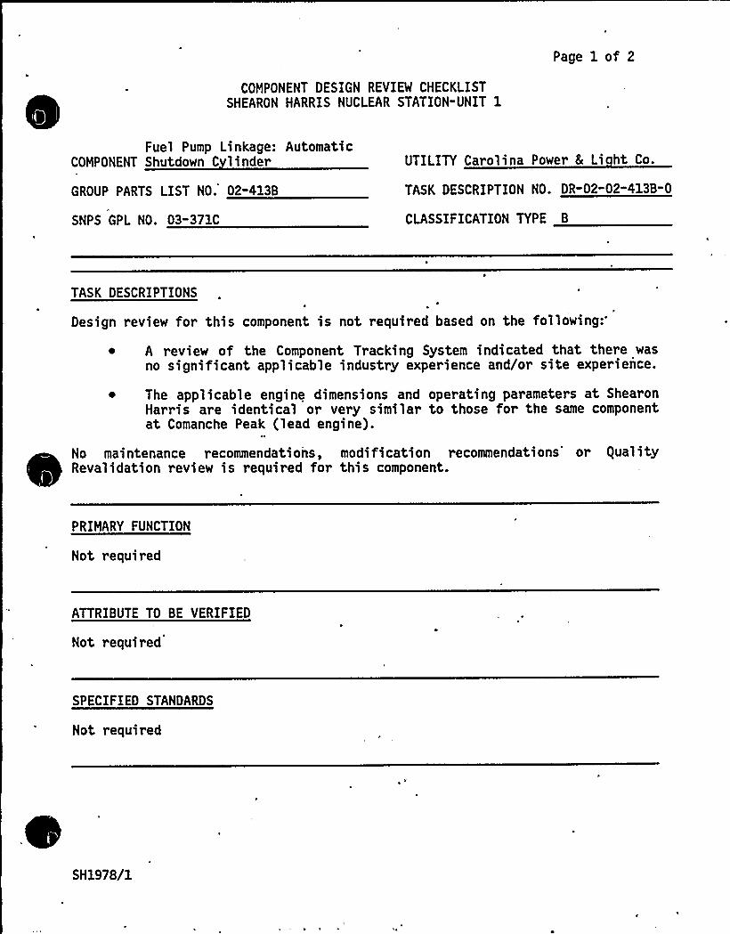
COMPONENT DESIGN REVIEW CHECKLISTSHEARON HARRIS NUCLEAR STATION"UNIT 1
Page 1 of 2
Fuel Pump Linkage: AutomaticCOMPONENT Shutdown C linder
GROUP PARTS LIST NO. 02-413B
SNPS GPL NO. 03-371C
UTILITY Carolina Power 8 Li ht Co.
TASK DESCRIPTION NO. DR-02-02-413B" 0
CLASSIFICATION TYPE B
TASK DESCRIPTIONSI
Design review for this component is not required based on the following
~ A review of the Component Tracking System indicated that there wasno significant applicable industry experience and/or site experience.
~ The applicable engine dimensions and operating parameters at ShearonHarris are identical or very similar to those for the same componentat Comanche Peak (lead engine).
No maintenance recommendations, modification recommendations'r guality~
~
~ ~ ~ ~
~
~
~ ~ ~
~Revalidation review is required for this component.
PRIMARY FUNCTION
Not required
ATTRIBUTE TO BE VERIFIED
Not required
SPECIFIED STANDARDS
Not required
SH1978/1

8
REFERENCES
Not required
COMPONENT DESIGN REVIEW CHECKLIST Page 2 of 2DR-02-02-413B-0
DOCUMENTATION RE UIRED
Not required
GROUP CHAIRPERSON PROGRAM MANAGER C
SH1978/2
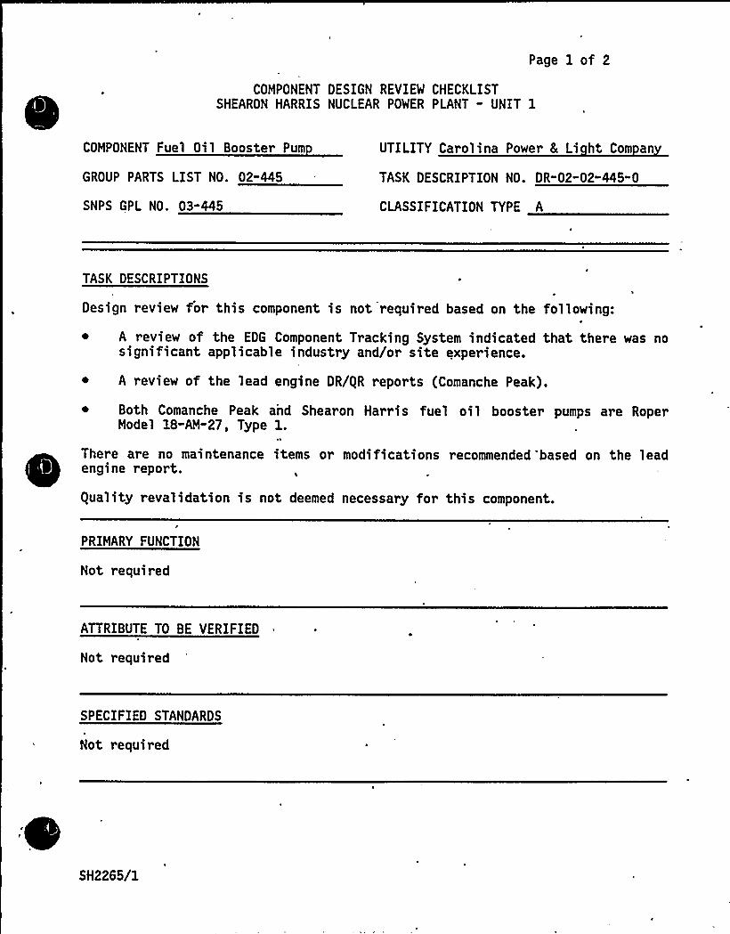
Page 1 of 2
COMPONENT DESIGN REVIEW CHECKLISTSHEARON HARRIS NUCLEAR POWER PLANT - UNIT 1
COMPONENT Fuel Oil Booster Pum
GROUP PARTS LIST NO. 02-445
SNPS GPL NO. 03-445
UTILITY Carolina Power 8 Li ht Com an
TASK DESCRIPTION NO. DR-02"02-445-0
CLASSIFICATION TYPE A
TASK DESCRIPTIONS
Design review for this component is not required based on the following:
A review of the EDG Component Tracking System indicated that there was nosignificant applicable industry and/or site experience.
~ A review of the lead engine DR/gR reports (Comanche Peak).
~ Both Comanche Peak and Shearon Harris fuel oil booster pumps are RoperModel 18-AM-27, Type 1.
There are no maintenance items or modifications recommended 'based on the lead~
~
~
~
engine report.
guality revalidation is not deemed necessary for this component.
/
PRIMARY FUNCTION
Not required
ATTRIBUTE TO BE VERIFIED
Not required
SPECIFIED STANDARDS
Not required
SH2265/1

REFERENCES
Not required
COMPONENT DESIGN REVIBf CHECKLIST Page 2 of 2DR-02-02"445-0
DOCUMENTATION RE UIRED
Not required
GROUP CHAIRPERSON PROGRAM MANAGER
SH2265/2

Page 1 of 2
COMPONENT DESIGN REVIEW CHECKLISTSHEARON HARRIS NUCLEAR POWER PLANT - UNIT 1
Fuel Oil Header:COMPONENT Pi in /Tubin
GROUP PARTS LIST NO. 02-450A
UTILITY Carolina Power 8 Li ht Co.
TASK DESCRIPTION NO. DR-02"02-450A-0
SNPS GPL NO. 03-450B CLASSIFICATION TYPE A
TASK DESCRIPTIONS
A design review is not required for this component based on a review ofapplicable industry and site experience, the lead engine DR/gR report(Comanche Peak) and a field walkdown.
The review of the applicable industry and site experience indicates that fueloil line failures have occur red at Grand Gulf and Catawba. These failures werelocated at a tee connection on the fuel oil header. Cause of failure has beenattributed to vibration. The field walkdown indicates that a 3/4 inchthreadolet was used as the -method of connecting the 1-inch fuel oil supplytubing (branch side) to the 3/4 inch front crossover header. This could resultin stress concentration at the fitting to run pipe juncture, because of theabrupt change in wall thickness. (Fitting O.D. exceeds run pipe O.D.)Therefore, it . is recommended that the 3/4 inch threadolet be changed to asocket welded tee to preclude the possibility of fatigue failure from longterm vibration stresses.
The lead engine DR/gR report for this component contains no maintenancerecommendations.
A field walkdown was performed at Shearon Harris. However, a review of thiscomponent in its entirety was not possible since portions of the piping andtubing were not installed .at the time of the walk5own. Therefore, componentacceptability and any subsequent recommendations shall be based upon the leadengine reports (Comanche Peak, Grand Gulf and Catawba).
The lead engine reports address the need for modification, specifically,suppor t additions and modifications. Similar additions/modifications forShearon Harris are now included in DR/gR report 02-450B.
Therefore, based on the above review it is 'concluded that this component willperform its intended design function at Shearon-Harris under all normaloperating and earthquake loading provided that supports are added/modified as
indicated in DR/gR report 02-450B, and provided the threadolet mentioned aboveis replaced with a socket welded tee.
guality Revalidation is not deemed necessary.
SH2222 1
PRIMARY FUNCTION
Not required
COMPONENT DESIGN REVIEW CHECKLIST Page 2 of 2DR-02-02"450A"0
ATTRIBUTE TO BE VERIFIED
Not required
SPECIFIED STANDARDS
Not required
REFERENCES
Not required
DOCUMENTATION RE UIRED
Not required
GROUP CHAIRPERSON PROGRAM MANAGER C EC
SH2222/2

TDI OWNERS GROUP
for
SHEARON HARRIS NUCLEAR POWER PLANT - UNIT 1
FUEL OIL HEADER - FUEL OIL SUPPORTSSMALL BORE SCOPE ONLY
COMPONENT PART NO. 02-450B
I INTRODUCTION
The TDI Emergency 'iesel Gener ator Owners Group Program for the ShearonHarris Nuclear Power Plant requir es Design and gual ity Reval i dationreviews of the structural adequacy of the fuel oil header small borepiping/tubing supports to withstand the effects of normal operating 'andearthquake loadings. The primary function of these supports is to provideadequate restraint of the small bore piping/tubing system in the intendedsupport load direction.
II OBJECTIVE
The objective of this review was to perform an engineering evaluation ofthe small bore piping/tubing supports to assure that the component willperform its intended design function during normal operating andearthquake loadings.
III METHODOLOGY
In order to meet the stated objective, the following methods wer e used:
~ The TDI Emergency Diesel Generator Component Tracking System wasreviewed for the Shearon Harris site, nuclear, and non-nuclearindustry experience. See Appendix C for results.
The equality Revalidation Checklist results were reviewed foracceptab'ility.'
Comparison with the lead engine reports (Comanche Peak, Grand Gulf,Catawba).
Refer to the review procedures as described in Reference 1 for a detailedmethodology of this evaluation.
IV RESULTS AND CONCLUSIONS
The small bore piping/tubing supports, as defined by this ComponentDesign Review, have been evaluated in accordance with Reference 1 and havebeen found acceptable with modifications. The conclusions of this reportare based on the combination of a field walkdown and a review of the leadengine reports as portions of this component were not installed at thetime of the walkdown.
SH2368/1

8
J„'
Page 2 of 3
There are no TERs associated with this component.
The guality Revalidation Inspection results identified in Appendix B havebeen reviewed and considered in the performance of this design review,and the results are consistent with the final c'onclusions of thisreport.
Based on the above review, it is concluded from References 1 and 2 thatthe small bore piping/tubing supports will perform their intended designfunction at Shearon Harris under all normal operating and earthquakeloadings if the following recommended modifications as detailed inReference 3 are implemented:
~ The support located above -the ejector assembly on Engine 1Ashould be modified to restrain a two-directional, lateral loading inorder to reduce the unsupported span length. Also, this supportappears to have been damaged by welding at the time of installation.
In order to support the piping/tubing of Component 02-450A it isrecommended that:
For each fuel oil drip header (2 per engine), one of the existingtwo-directional r estraints per header be modified to athree-directional restraint in order to provide axial restraint ofthe header and to minimize the effects on all associated tubing.
The ejector assembly and adjacent 1-inch diameter tubing beresupported/anchored in order to minimize the imposed loading andstress concentration on the ejector assembly nozzles.
Upon installation, an anchor (six-way restraint) be added on thefuel-oil-to-day-tank return piping (two lines per engine) in order toreduce the unsupported span length and to minimize the effects fromthe off-engine piping. This recommendation is based on the leadengine reports.
A three-directional restraint be added on the 4-inch diameter dripheader to ejector tube (Engine 1A left bank only) in order to reducethe unsupported span length.
A two-direction lateral restraint be added on Engine 1A only on the1-inch ejector tubing (2 lines) approximately 2 feet - 6 inches belowthe supply and circulation rear crossover headers in order to reducethe unsupported span lengths and to maintain consistency with Engine18.
The recommendations above apply to both the Engines 1A and 1B unlessotherwise. specified.
SH2368/2

8
Page 3 of 3
~~
~ ~ ~
~ ~
~ ~
~
~ ~
V REFERENCES
1. "Engineering Review Criteria Document for the Design Review of TDI~ Diesel Small Bore Piping, Tubing, and Supports for the TDI Owners
Group," Report No. 11600.60-DC-02, Revision 0.
2. Stone 8 Webster Calculation number 11600.60-NP(B)-0201-XH.
3. Memo no. 6451 from C. Malovrh/SWEC to J. Kammeyer/SWEC dated10/29/84 .
SH2368/3

~ A
l
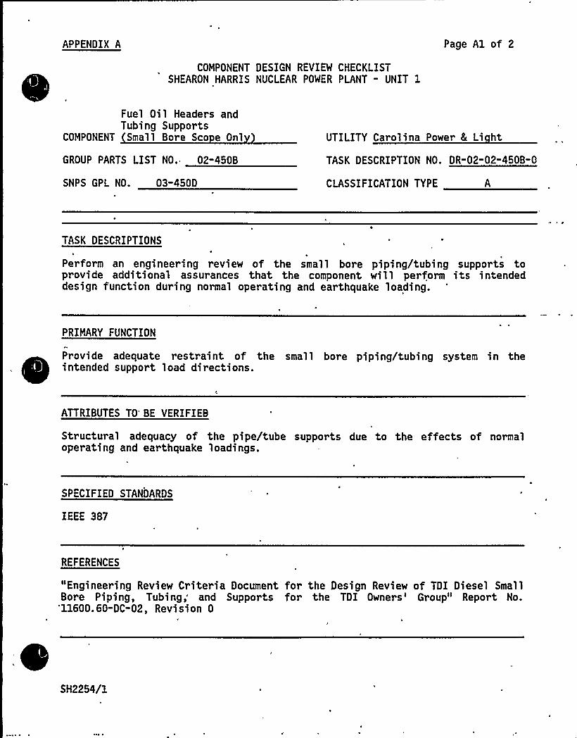
APPENDIX A
COMPONENT DESIGN REVIEW CHECKLISTSHEARON HARRIS NUCLEAR POWER PLANT - UNIT 1
Page A1 of 2
Fuel Oil Headers andTubing Supports
COMPONENT Small Bore Sco e Onl
GROUP PARTS LIST NO. 02-450B
SNPS GPL NO. 03-450D
UTILITY Carolina Power 8 Li ht
TASK DESCRIPTION NO. DR-02-02" 450B" 0
CLASSIFICATION TYPE
TASK DESCRIPTIONS ~ ~
Perform an engineering review of the small bore piping/tubing supports toprovide additional assurances that the component will perform its intendeddesign function during normal operating and earthquake loading.
PRIMARY FUNCTION
~
~Provide adequate restraint of the small bore piping/tubing system in theintended support load directions.
ATTRIBUTES TO'E VERIFIEB
Structural adequacy of the pipe/tube supports due to the effects of normaloperating and earthquake loadings.
SPECIFIED STANDARDS
IEEE 387
REFERENCES
"Engineering Review Criteria Document for the Design Review of TDI Diesel SmallBore Piping, Tubing; and Supports for the TDI Owners'roup" Report No.
'11600.60-DC-02, Revision 0
SH2254/1
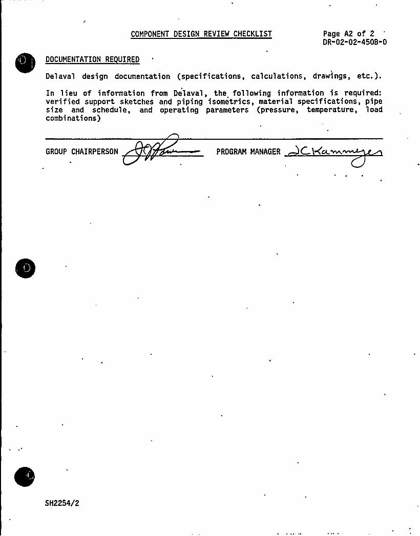
COMPONENT DESIGN REVIEW CHECKLIST Page A2 of 2DR-02-02"450B-0
DOCUMENTATION RE UIRED
Delaval design documentation (specifications, calculations, drawings, etc.).
In lieu of information from Delaval, the following information is required:verified support sketches and piping isometrics, material specifications, pipesize and schedule, and operating parameters (pressure, temperature, loadcombinations)
GROUP CHAIRPERSON PROGRAM MANAGER C 4a.~
SH2254/2
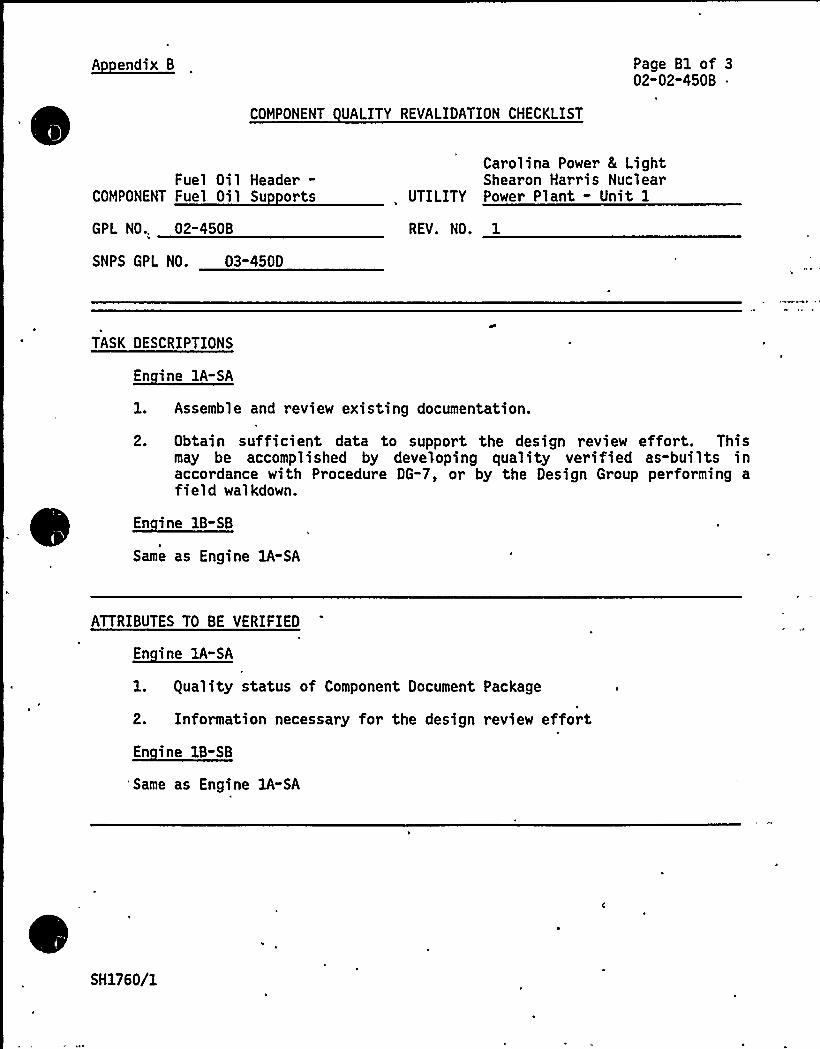
A endix B
COMPONENT UALITY REVALIDATION CHECKLIST
Page Bl of 302-02-450B ~
Fuel Oil Header-COMPONENT Fuel Oil Su orts
GPL NO.. 02-450B
SNPS GPL NO. 03-450D
Carolina Power & LightShearon Harris Nuclear
UTILITY Power Plant - Unit 1
REV. NO. 1
TASK DESCRIPTIONS
En ine lA-SA
1. Assemble and review existing documentation.
2. Obtain sufficient data to support the design review effort. Thismay be accomplished by developing quality verified as-builts inaccordance with Procedure DG-7, or by the Design Group performing afield walkdown.
~Ei 1B-EB
Same as Engine 1A-SA
ATTRIBUTES TO BE VERIFIED
~Ei A-EA
1. guality status of Component Document Package
2. Information necessary for the design review effort
~Ei 1B-EB
'Same as Engine lA-SA
SH1760/1

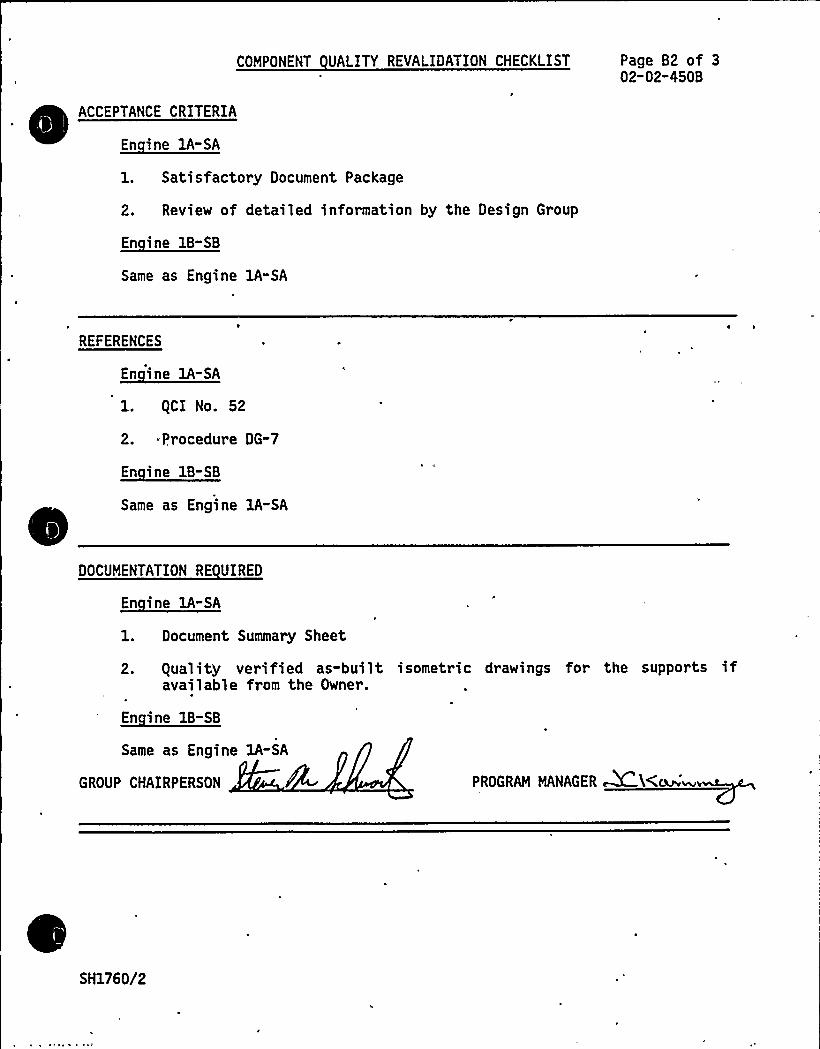
COMPONENT UALITY REVALIDATION CHECKLIST
ACCEPTANCE CRITERIA
~Ei EA-SA
1. Satisfactory Document Package
2. Review of detailed information by the Design Group
~Ei B-S
Same as Engine lA-SA
Page B2 of 302-02-450B
REFERENCES
~Ei 1A-E
l. gCI No. 52
2. Procedure DG-7
~Ei 1-SB
Same as Engine 1A-SA
DOCUMENTATION RE UIRED
~Ei 1A-SA
1. Document Summary Sheet
2. equality verified as-built isometric drawings for the supports ifavailable from the Owner.
En ine 18-SB
Same as Engine 1A-SA
GROUP CHAIRPERSON PROGRAM MANAGER~ L(~~v
SH1760/2
l r r

E
~
COMPONENT REVIEWI
~Ei A-EA
COMPONENT UALITY REVALIDATION CHECKLIST Page 83 of 302-02"4508
1. No EDGCTS site experience documents are in evidence.
2. The Design Group will be responsible for closing out the as-builtdrawings as per Procedure DG-7. The as-built drawings will beguality verified by the appropriate site guality organization. Theperformance of an engineering walkdown by the Design Group,precludes the issuance of a quality verified as-built drawing orsketch.
~Ei IB-EB
Same as Engine 1A-SA
RESULTS AND CONCLUSION
En ine 1A-SA
The equality Revalidation effort with respect to this component, asoutlined above, is complete. The results have been forwarded to theDesign Review Group for their evaluation and conclusions in support ofthe final report.
En ine 18-SB
Same as Engine 1A"SA
GROUP CHAIRPERSON PROGRAM MANAGER C KC(i~ vi
SH1760/3

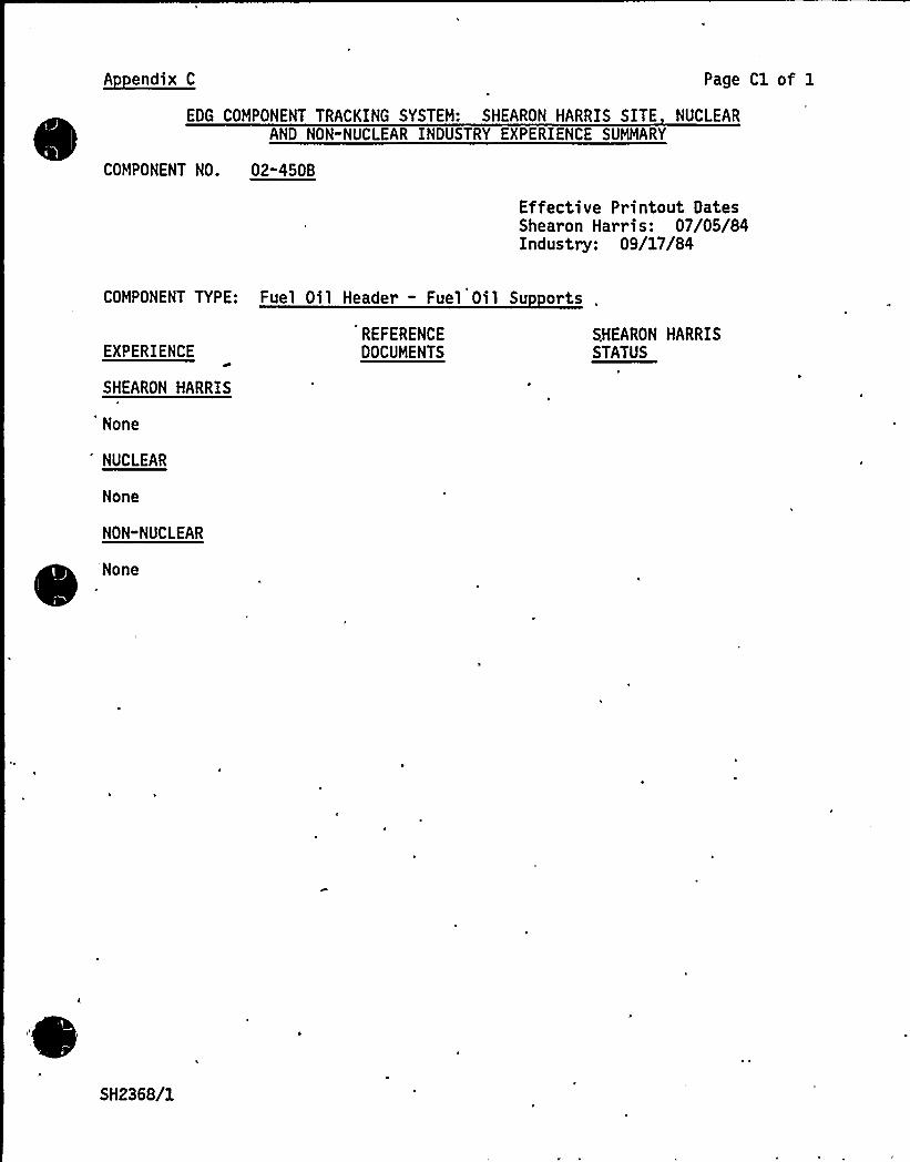
A endix C Page Cl of 1
EDG COMPONENT TRACKING SYSTEM: SHEARON HARRIS SITE NUCLEARAND NON-NUCLEAR INDUSTRY EXPERIENCE SUMMARY
COMPONENT NO. 02"450B
Effective Printout DatesShearon Harris: 07/05/84Industry: 09/17/84
COMPONENT TYPE: Fuel Oil Header - Fuel Oil Su orts
EXPERIENCE
SHEARON HARRIS
None
'UCLEAR
None
NON-NUCLEAR
None
REFERENCEDOCUMENTS
SHEARON HARRISSTATUS
SH2368/1
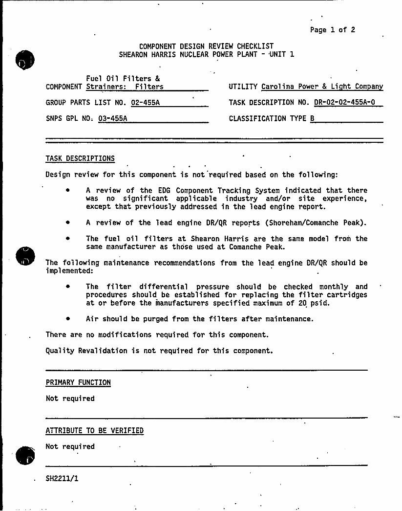
COMPONENT DESIGN REVIEW CHECKLISTSHEARON HARRIS NUCLEAR POWER PLANT - UNIT 1
Page 1 of 2
Fuel Oi 1 Filters 8
COMPONENT Strainers: Filters
GROUP PARTS LIST NO. 02-455A
SNPS GPL NO; 03-455A
UTILITY Carolina Power 8 Li ht Com an
TASK DESCRIPTION NO. DR-02-02-455A" 0
CLASSIFICATION TYPE B
TASK DESCRIPTIONS
Design review for this component is not required based on the following:
~ A review of the EDG Component Tracking System indicated that therewas no significant applicable industry and/or site experience,except that previously addressed in the lead engine report.
~ A review of the lead engine DR/gR reports (Shoreham/Comanche Peak).
The fuel oil filters at Shearon Harris are the same model from thesame manufacturer as those used at Comanche Peak.
The following maintenance recommendations from the lead engine DR/gR should beimplemented:
~ The filter differential pressure should be checked monthly andprocedures should be established for replacing the filter cartridgesat or before the manufacturers specified maximum of 20 psid.
~ Air should be purged from the filters after maintenance.
There are no modifications required for this component.
guality Revalidation is not required for this component.
PRIMARY FUNCTION
Not required
ATTRIBUTE TO BE VERIFIED
Not required
SH2211/1
SPECIFIED STANDARDS
Not required
COMPONENT DESIGN REVIBI CHECKLIST Page 2 of 2DR"02-02" 455A"0
REFERENCES
Not required
DOCUMENTATION RE UIRED
Not required
GROUP CHAIRPERSON PROGRAM MANAGER
SH2211/2

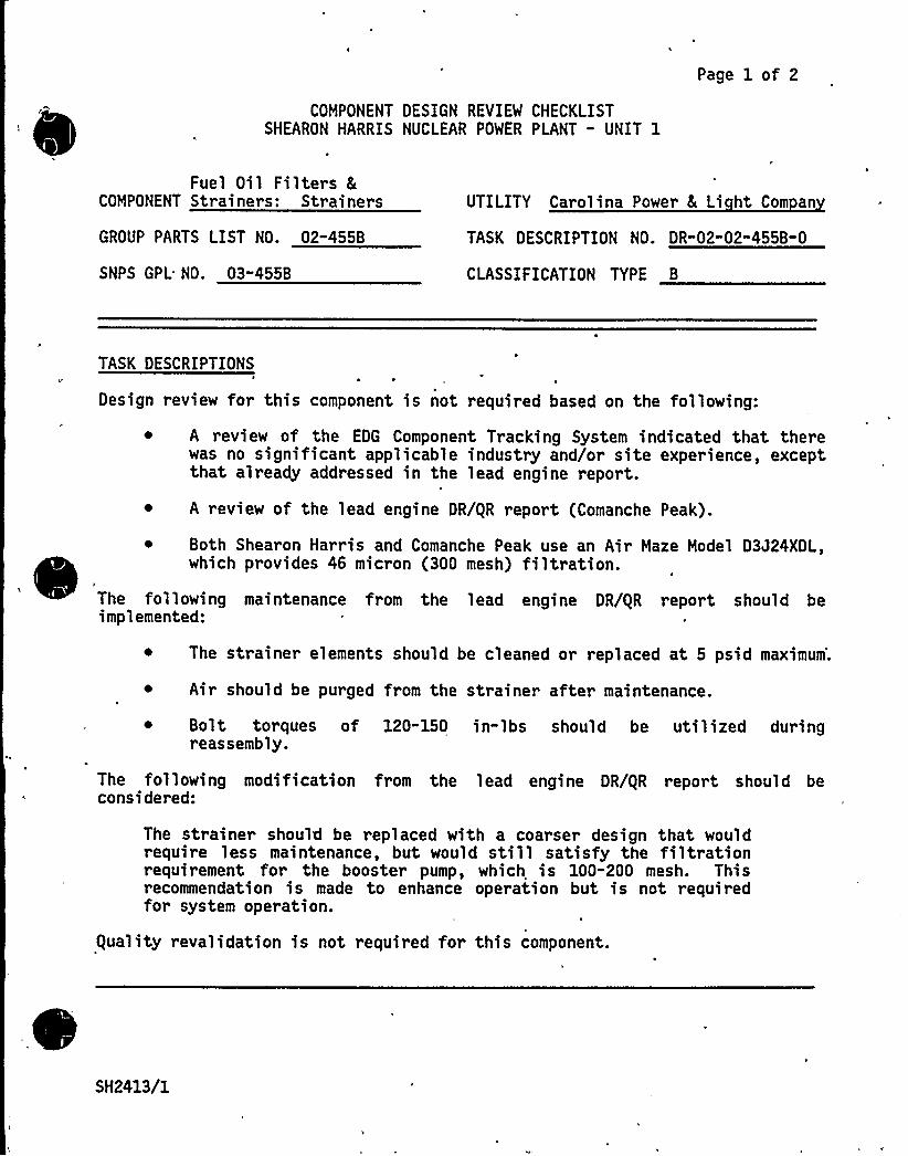
COMPONENT DESIGN REVIEW CHECKLISTSHEARON HARRIS NUCLEAR POWER PLANT - UNIT 1
Page 1 of 2
Fuel Oil Filters 8COMPONENT Strainers: Strainers
GROUP PARTS LIST NO. 02-455B
SNPS GPL NO. 03"455B
UTILITY Carolina Power 8 Li ht Com an
TASK DESCRIPTION NO. DR"02-02"455B-0
CLASSIFICATION TYPE B
TASK DESCRIPTIONS
Design review for this component is not required based on the following:
~ A review of the EDG Component Tracking System indicated that therewas no significant applicable industry and/or site experience, exceptthat already addressed in the lead engine report.
~ A review of the lead engine DR/gR report (Comanche Peak).
~ Both Shearon Harris and Comanche Peak use an Air Maze Model D3J24XDL,which provides 46 micron (300 mesh) filtration.
The following maintenance from the lead engine DR/gR report should beimplemented:
The strainer elements should be cleaned or replaced at 5 psid maximum'.
~ Air should be purged from the strainer after maintenance.
~ Bolt torques of 120-150 in-lbs should be utilized duringreassembly.
The following modification from the lead engine DR/gR report should beconsidered:
The strainer should be replaced with a coarser design that wouldrequire less maintenance, but would still satisfy the filtrationrequirement for the booster pump, which is 100-200 mesh. Thisrecommendation is made to enhance operation but is not requiredfor system operation.
guality revalidation is not required for this component.
SH2413/1
PRIMARY FUNCTION
Not required
COMPONENT DESIGN REVIEW CHECKLIST Page 2 of 2DR-02-02-455B-0
ATTRIBUTE TO BE VERIFIED
Not required
SPECIFIED STANDARDS
Not required
REFERENCES
Not required
DOCUMENTATION RE UIRED
Not required
GROUP CHAIRPERSON PROGRAM MANAGER DC
SH2413/2

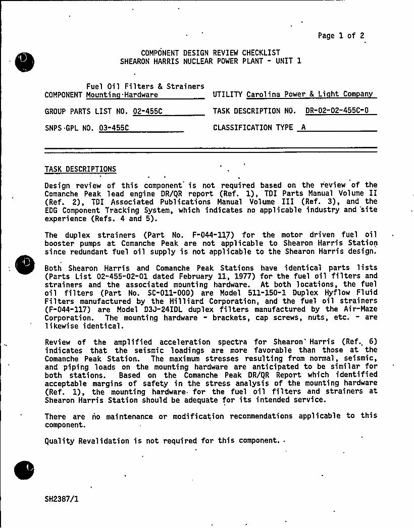
Page 1 of 2
COMPONENT DESIGN REVIEW CHECKLISTSHEARON HARRIS NUCLEAR POWER PLANT - UNIT 1
Fuel Oil Filters 8 StrainersCOMPONENT Mountin Hardware UTILITY Carolina Power 8 Li ht Com an
GROUP PARTS LIST NO. 02"455C TASK DESCRIPTION NO. DR"02-02-455C-0
SNPS GPL NO. 03"455C CLASSIFICATION TYPE A
TASK DESCRIPTIONS
Design review of this component is not required based on the r'eview of theComanche Peak lead engine DR/gR report (Ref. 1), TDI Parts Manual Volume II(Ref. 2), TDI Associated Publications Manual Volume III (Ref. 3), and theEDG Component Tracking System, which indicates no applicable industry and 'siteexper ience (Refs. 4 and 5).
The duplex strainers (Part No. F-044-117) for the motor driven fuel oilbooster pumps at Comanche Peak are not applicable to Shearon Harris Stationsince redundant fuel oil supply is not applicable to the Shearon Harris design.
Both Shearon Harris and Comanche Peak Stations have identical parts lists(Parts List 02-455-02-01 dated February 11, 1977) for the fuel oil filters andstrainers and the associated mounting hardware. At both locations, the fueloi 1 filters (Part No. SC-011-000) are Model 511-150-1 Dupl ex Hyf1 ow Flui dFilters manufactured by the Hilliard Corporation, and the fuel oil strainers(F-044-117) are Model D3J-24IDL duplex filters manufactured by the Air-MazeCorporation. The mounting hardware - brackets, cap screws, nuts, etc. - arelikewise identical.
Review of the amplified acceleration spectra for Shearon'arris (Ref. 6)indicates that the seismic loadings are more favorable than those at theComanche Peak Station. The maximum stresses resulting from normal, seismic,and piping loads on the mounting hardware are anticipated to be similar forboth stations. Based on the Comanche Peak DR/gR Report which identifiedacceptable margins of safety in the stress analysis of the mounting hardware(Ref. 1), the mounting hardware for the fuel oil filters and strainers atShearon Harris Station should be adequate for its intended service.
There are no maintenance or modification recommendations applicable to thiscomponent.
guality Revalidation is not required for this component.
SH2387/1
fW," w ~%/)C
, 1
PRIMARY FUNCTION
Not required
COMPONENT DESIGN REVIEW CHECKLIST Page 2 of 2DR-02-02-455C-0
ATTRIBUTE TO BE VERIFIED
Not required
SPECIFIED STANDARDS~+
Not required >
REFERENCES
1. Comanche Peak Steam Electric - Unit 1, DR/gR Report for Group Parts ListNo. 02"455C.
2. TDI Manual Volume II, for Model DSRV-16-4 Diesel Engine/Generator,Shearon Harris Nuclear Power Plant, Units 1, 2, 3, and 4, Parts List02-455-02-01.
3. 'TDI Manual Volume III for Model DSRV-16-4 Diesel/Generator, Shearon HarrisNuclear Power Plants, Units 1, 2; 3, and 4, Part Nos. F-044-117 andSC"011-000.
4. Emergency Diesel Generator Component Tracking System - Nuclear andNon-Nuclear Industry Experience dated October 15, 1984.
5.
6.
Emergency Diesel Generator Component Tracking System - Shearon HarrisNuclear Power Station dated October 15, 1984.
Ebasco Services, Inc. Project CAR-SH-E-11, Specification 216-73-Tb forDiesel Engine Generator Unit and Control Panel for Nuclear Power Plants,Rev. 7 dated September 14, 1981, Addendum A, "Seismic Considerations forMechanical Equipment," - Response Acceleration Spectra Curves (12 sheets)Revised December 26, 1978.
DOCUMENTATION RE VIREO
Not required
GROUP CHAIRPERSON
SH2387/2
PROGRAM MANAGER C
COMPONENT DESIGN REVIEW CHECKLISTSHEARON HARRIS NUCLEAR POWER PLANT - UNIT 1
Page 1 of 2
Auxiliary Sub-Base 8 Oil8 Water Piping - Fuel Oil:Piping and Fittings
COMPONENT Small Bore Sco e Onl
GROUP PARTS LIST NO. 02-717M
SNPS GPL NO. 03-717M
UTILITY Carolina Power 8 Li ht Co.
TASK DESCRIPTION NO. DR"02-02-717M"0
CLASSIFICATION TYPE B
TASK DESCRIPTIONS
A design review is not required for this component based on a review ofapplicable industry and site exper ience, thy lead engine DR/gR report(Comanche Peak) and a field walkdown.
There is no site experience for this component in the EDG Component TrackingSystem.
The industry experience, specifically Cleveland Electric, indicates thatpiping supplied with the diesel did not meet the ASME III code as required.The following discussion concludes that this component will meet its intendeddesign function at Shearon Harris, but does not specifically assure any codecompliance as this responsibility rests with the utility. A review of theremaining industry experience indicates that no generic or significant pro-blems exist which affect the integrity of this component.
The lead engine DR/gR Report for this component contains no maintenancerecommendations.
A field walkdown was performed at Shearon Harris. However, a review of thiscomponent in its entirety was not possible since portions of the piping werenot installed at the time of the walkdown. Therefore, component acceptabilityand any subsequent recommendations shall be based upon the lead engine report.
The lead engine reports (02-717', M) indicate that there were no modificationsrelated to the small bore piping/tubing and supports.
Therefore, based on the above review it is concluded that this component willperform its intended function under all normal operating and earthquakeloadings.
guality Revalidation for this component is not deemed necessary.
SH2217/1

PRIMARY FUNCTION
Not requir ed
COMPONENT DESIGN REVIEW CHECKLIST Page 2 of 2DR-02-02" 717M-0
ATTRIBUTE TO BE VERIFIED
Not required
SPECIFIED STANDARDS~+
Not required
REFERENCES
Not required
DOCUMENTATION RE UIRED
Not required
GROUP CHAIRPERSON PROGRAM MANAGER DC K
SH2217/2

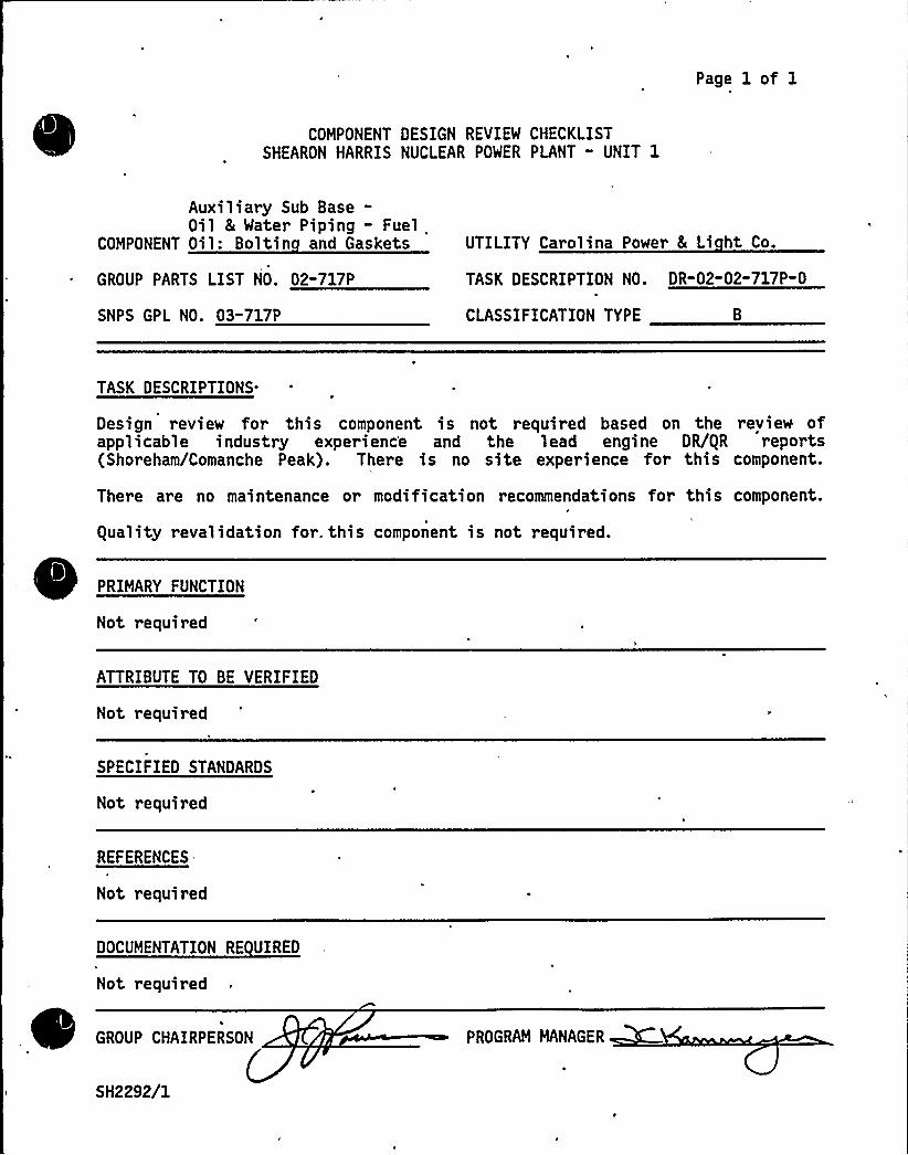
Page 1 of 1
COMPONENT DESIGN REVIEW CHECKLISTSHEARON HARRIS NUCLEAR POWER PLANT " UNIT 1
Auxiliary Sub Base-Oil 8 Water Piping - Fuel
COMPONENT Oil: Boltin and Gaskets
GROUP PARTS LIST NO. 02-717P
SNPS GPL NO. 03-717P
UTILITY Carolina Power 8 Li ht Co.
TASK DESCRIPTION NO. DR-02-02-717P-0
CLASSIFICATION TYPE B
TASK DESCRIPTIONS.
Design review for this component is not required based on the review ofapplicable industry experienc'e and the lead engine DR/gR reports(Shoreham/Comanche Peak). There is no site experience for this component.
There are no maintenance or modification recommendations for this component.
guality revalidation for. this component is not required.
PRIMARY FUNCTION
Not required
ATTRIBUTE TO BE VERIFIED
Not required
SPECIFIED STANDARDS
Not required
REFERENCES
Not required
DOCUMENTATION RE UIRED
Not required
GROUP CHAIRPERSON PROGRAM MANAGER
SH2292/1

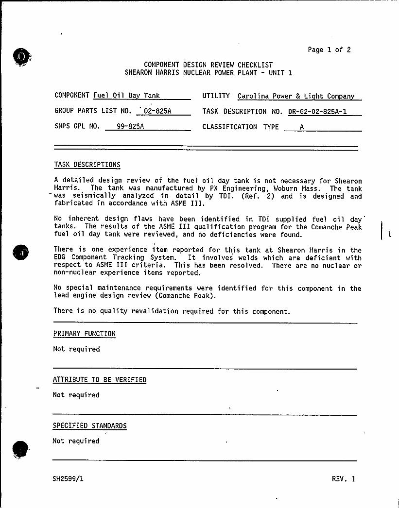
COMPONENT DESIGN REVIEW CHECKLISTSHEARON HARRIS NUCLEAR POWER PLANT - UNIT 1
Page 1 of 2
COMPONENT Fuel Oil Da Tank
GROUP PARTS LIST NO. 02-825A
UTILITY Carolina Power 8 Li ht Com an
TASK DESCRIPTION NO. DR-02-02-825A-1
SNPS GPL NO. 99-825A CLASSIFICATION TYPE A
TASK DESCRIPTIONS
A detailed design review of the fuel oil day tank is not necessary for ShearonHarris. The tank was manufactured by PX Engineering, Woburn Mass. The tank
= was seismically analyzed in detail by TDI. (Ref. 2) and is designed andfabricated in accordance with ASME III.No inherent design flaws have been identified in TDI supplied fuel oil daytanks. The results of the ASME III qualification program for the Comanche Peakfuel oil day tank were reviewed, and no deficiencies were found.
k
There is one experience item reported for this tank at Shearon Harris in theEDG Component Tracking System. It involves welds which are deficient withrespect to ASME III criteria. This has been resolved. There are no nuclear ornon-nuclear experience items reported.
No special maintenance requirements were identified for this component in thelead engine design review (Comanche Peak).
There is no quality revalidation required for this component.
PRIMARY FUNCTION
Not required
ATTRIBUTE TO BE VERIFIED
Not required
SPECIFIED STANDARDS
Not required
SH2599/1 REV. 1
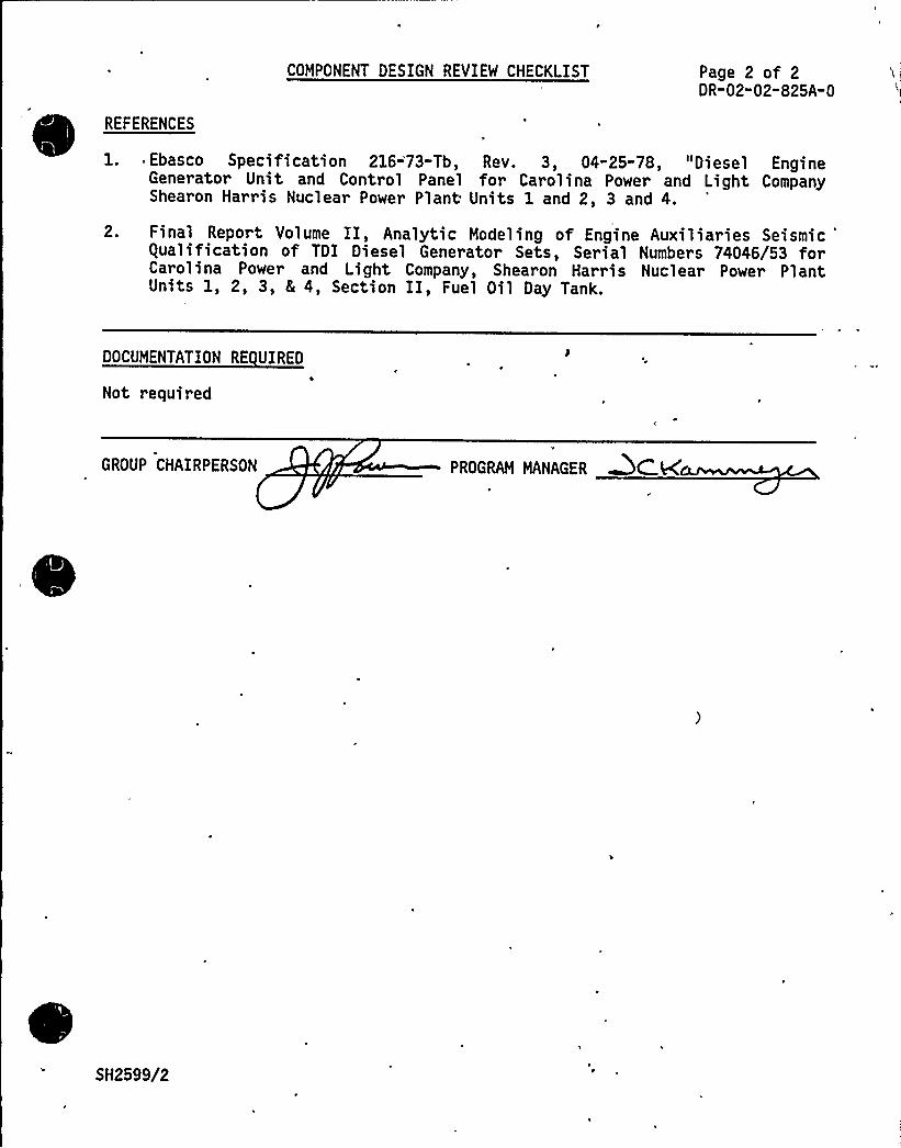
REFERENCES
COMPONENT DESIGN REVIEW CHECKLIST Page 2 of 2DR-02-02-825A-0
1. Ebasco Specification 216-'73-Tb, Rev. 3, 04-25-78, "Diesel EngineGenerator Unit and Control Panel for Carolina Power and Light CompanyShearon Harris Nuclear Power Plant Units 1 and 2, 3 and 4.
2. Final Report Volume II, Analytic Modeling of Engine Auxiliaries Seismic'ualificationof TDI Diesel Generator Sets, Serial Numbers 74046/53 for
Carolina Power and Light Company, Shearon Harris Nuclear Power PlantUnits 1, 2, 3, 8 4, Section II, Fuel Oil Day Tank.
DOCUMENTATION RE UIRED
Not required
GROUP CHAIRPERSON PROGRAM MANAGER &Chal
SH2599/2
Page 1 of 302-02"825B
COMPONENT UALITY REVALIDATION CHECKLIST
Fuel Oil System - FuelCOMPONENT Oil Du lex Strainer
GPL NO. 02-825B
SNPS GPL NO. 99-825E
Carolina Power 8 LightShearon Harris Nuclear
UTILITY Power Plant - Unit 1
REV. NO. 1
TASK DESCRIPTIONS
~En inc IA
No further review of component 02-825B is required for the followingreasons
a) There is no site or industry experience reported for this component.b) Component was reviewed on the lead engi.nes (Shoreham) with
satisfactory results.
GROUP CHAIRPERSON +Mur PROGRAM MANAGER
SH1906/1
TDI OWNERS GROUP
for
SHEARON HARRIS NUCLEAR POWER PLANT " UNIT 1
EMERGENCY DIESEL GENERATORCOMPONENT PART NO. 02-650A
I INTRODUCTION
The TDI Emergency Diesel Generator Owners Group Program for the ShearonHarri s Nucl ear Power Pl ant (SHNPP) r equir es Desi gn and equal ityRevalidation reviews of .the generator to determine its adequacy for itsintended use at Shearon Hart-is. The primary function o$ the'enerator(AC Synchronous Generators, serial nos. 17408432/33, manufactured byElectric Products Division, Portec, Inc.) is to supply all safety relatedloads in the event of loss of offsite power., which will provide for thesafe shutdown of the plant and subsequent continuation of safe shutdownconditions.
SHNPP Unit 1 has two diesel generators to supply the ESF loads ofDivisions A and B. These diesel generators are each rated at 6500 kW andare supplied by TDI. The units have been installed but have not beensite tested to date.
II OBJECTIVE
The objective was to verify the generator's ability to maintain emergencybus voltage under emergency loading conditions.
III METHODOLOGY
'he maximum coincident demand on the diesel generators was compared withthe continuous and short-term ratings of the generator. NRC Safety Guide9.0 (Ref. 1), Regulatory Guide 1.9 (Ref. 2); and IEEE Standard 387-1977(Ref. 3) were reviewed regarding the ratings.
The sequential loading of the generators as specified in the procurementspecifications (Ref. 4) was examined. Using the generator parametersdetermined by the vendor's shop tests (Ref. 5), minimum generator voltagewas computed for each step of the sequential load. Calculations (Ref. 6)were performed to verify that the minimum generator terminal voltage isin excess of 75 percent of the rated voltage, as required in Reference 2.The qualification tests were reviewed to verify that the voltage recoversto 90 percent of the rated voltage in less than two seconds because of theaction of the voltage regulator, as required in Reference 2.
SH2471/1
Page 2 of 3
Shearon Harris site experience, as reported in Component Tracking Systemprintouts, was reviewed. In addition, nuclear and non-nuclear industryexperience was reviewed.
The design of the brush arrangement was reviewed for adequacy (Ref. 6).Comparison was made with the brush arrangement at Shoreham.
The generator maintenance program was reviewed with regard to brushes andslip rings (Ref. 5).
The procurement specification, CAR-SH-E-11 (Ref. 4), was reviewed in thelight of IEEE Std. 387-1977, NRC Regulatory Guide 1.9, and Safety, Guide9. 0.
IV
guality Revalidation Checklist results were reviewed for acceptability.
RESULTS AND CONCLUSIONS
The maximum coincident demand on the diesel generators will be duringloss of offsite power. The estimated maximum continuous ESF loads are6265 kW for Division A and 6261 kW for Division B (SHNPP FSAR, Amendment3, Tables 8.3. 1-2 [aj and fb]). Each generator has a continuous ratingof 6500 kW and a 2-hour rating of 7150 kW. It is concluded, therefore,that the rating of each diesel generator is adequate. Recent reductionsin continuous ESF loads have lowered the total load to 5677 kW for eachdiesel generator, thereby making this analysis conservative.
Cal cul ati ons (Ref. 6) show that the maximum vol tage of the generatorduring automatic sequencing in the event of loss of offsite power willnot drop below 79.5 percent of the rated voltage. gualification tests(Ref. 7) show that the generator terminal voltage recovers to 90 percentof the rated voltage within 0.3 seconds. Based upon the calculations andqualification tests results, the performance of the generator isacceptable with regard to the specified minimum voltage (75 percent ofthe rated voltage as per Reference 2) and recovery time.
Shearon Harris, nuclear and non-nuclear industry experience listed in theComponent Tracking System (dated September 17, 1984) was reviewed. Theresults of the review are given in Appendix C of this report. It wasfound that the incidents were not of a generic nature and do not impactthe conclusions of this report.
Evaluation of the design of the brushes and brush holders at ShearonHarris and comparison with those at Shoreham show that the brushes andbrush holders are selected and designed adequately for both generators(Ref. 5).
No cases of failure of the brushes or slip rings have been reported atShearon Harris. Maintenance procedures recommended by the manufacturer(Ref. 5) are adequate.
SH2471/2

I'(,
Page 3 of 3e
The procurement specifications (Ref. 4) reflect the relevant standards(Refs. 1, 2, and 3).
The information provided on TER 02-074 dated 10/15/84 has been reviewedand is consistent with the final conclusions of this report.
gual ity Reval idati on Inspecti on resul ts identified in Appendi x B havebeen reviewed and considered in the performance of this design review andthe results are consistent with the final conclusions of this report.
Based on the above review, it is concluded that the emergency dieselgenerator is acceptable for its intended use at Shearon Harris.
V REFERENCES
1. NRC Safety Guide 9.0, "Selection of Diesel Generator Set Capabilityfor Standby Power Supplies," dated 03/10/71.
2. NRC Regulatory Guide 1.9, "Selection, Design and gualification ofDiesel-Generator Uni ts used as Standby (Onsi te) El ectri cal PowerSystems of Nuclear Power Plants," Rev. 2, December 1979.
3. IEEE Std. 387-1977, "Criteria for Diesel Generator Units Applied asStandby Power Supplies for Nuclear Power Generating Stations."
4. EBASCO Technical Specification for Standby Diesel Generators forCPEL Co., Shearon Harris Nuclear Power Plant Unit 1, No.CAR"SH- E-11.
5. Portec Instruction Manual Operation, Maintenance and Parts List forAC Synchoronous Generator S. N. 17408432/33 and Portec Test Report,April, 1981.
6. Support Package FaAA-SP-84-6-45 (f).7. gual ificati on Test for TDI Generator Set CP8 L, Shearon Harri s
Nuclear Power Plant Units 1-4, April 10, 1981.
SH2471/3'

a >
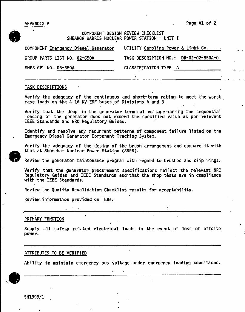
APPENDIX A Page A1 of 2
COMPONENT DESIGN REVIEW CHECKLISTSHEARON HARRIS NUCLEAR POWER STATION - UNIT I
COMPONENT Emer enc Diesel Generator UTILITY Carolina Power 8 Li ht Co.
GROUP PARTS LIST NO. 02-650A
SNPS GPL NO. 03"650A
TASK DESCRIPTION NO.: DR-02-02-650A" 0
CLASSIFICATION TYPE A
TASK DESCRIPTIONS
Verify the adequacy of the continuous and short-term rating to meet the worstcase loads on thy 4. 16 KV ESF buses of Divisions A and B.
Verify that the drop in the generator terminal voltage .during the sequentialloading of the generator does not exceed the specified value as per relevantIEEE Standards and NRC Regulatory Guides.
Identify and resolve any recurrent patterns. of component failure listed on theEmergency Diesel Generator Component Tracking System.
Verify the adequacy of the design of the brush arrangement and compare it withthat at Shoreham Nuclear Power Station (SNPS).
Review the generator maintenance program with regard to brushes and slip rings.
Verify that the generator procurement specifications reflect the relevant NRC
Regulatory Guides and IEEE Standards and that the shop tests are in compliancewith the IEEE Standards.
Review the guality Revalidation Checklist results for acceptability.
Review. information provided on TERs.
PRIMARY FUNCTION
Supply all safety related electrical loads in the event of loss of offsitepower.
ATTRIBUTES TO BE VERIFIED
Ability to maintain emergency bus voltage under emergency loading condit'ions.
SH1999/1
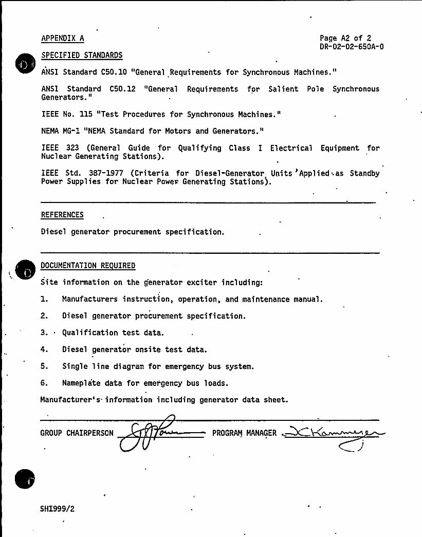
APPENDIX A
SPECIFIED STANDARDS
Page A2 of 2DR-02-02-650A-0
ANSI Standard C50.10 "General Requirements for Synchronous Machines."
ANSI Standard C50. 12 "General Requirements for Sal ient Pole Synchr onousGenerator s."
IEEE No. 115 "Test Procedures for Synchronous Machines."
NEMA MG-1 "NEMA Standard for Motors and Generators."
IEEE 323 (General Guide for qualifying Class I Electrical Equipment forNuclear Generating Stations).
IEEE Std. 387-1977 (Criteria for Diesel-Generator Units 'Applied 'as StandbyPower Supplies for Nuclear Powe~ Generating Stations).
REFERENCES
Diesel generator procurement specification.
DOCUMENTATION RE UIRED
~ ~ ~Site information on the generator exciter including:
1. Manufacturers instruction, operation, and maintenance manual.
2. Diesel generator procurement specification.
3. gualification'est data.
4. Diesel generator onsite test data.
5. Single line diagram for emergency bus system.
6. Nameplate data for emergency bus loads.
Manufacturer's information including generator data sheet.
GROUP CHAIRPERSON PROGRAM MANAGER .~
SH1999/2
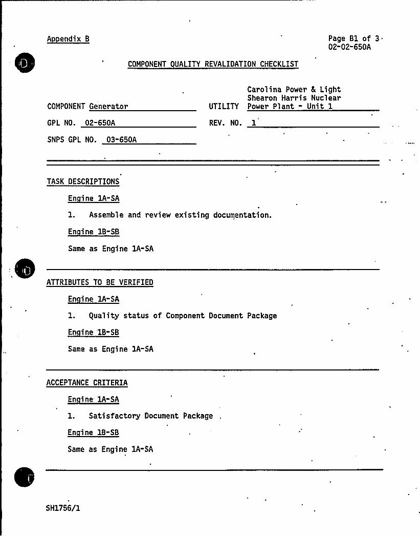
A endix B Page B1 of 302-02-650A
COMPONENT UALITY REVALIDATION CHECKLIST
COMPONENT Generator
GPL NO. 02-650A
SNPS GPL NO. 03"650A
Car ol ina Power & LightShearon Harris Nuclear
UTILITY Power Plant - Unit 1
REV. NO. 1
TASK DESCRIPTIONS
En ine 1A-SA
1. Assemble and review existing documentation.
~Ei 18-88
Same as Engine lA-SA
ATTRIBUTES TO BE VERIFIED
AA-EA
1. guality status of Component Document Package
~Ei '-88Same as Engine 1A-SA
ACCEPTANCE CRITERIA
~Ei AA-EA
1. Satisfactory Document Package
~8" i 18-88
Same as Engine lA-SA
SH1756/1
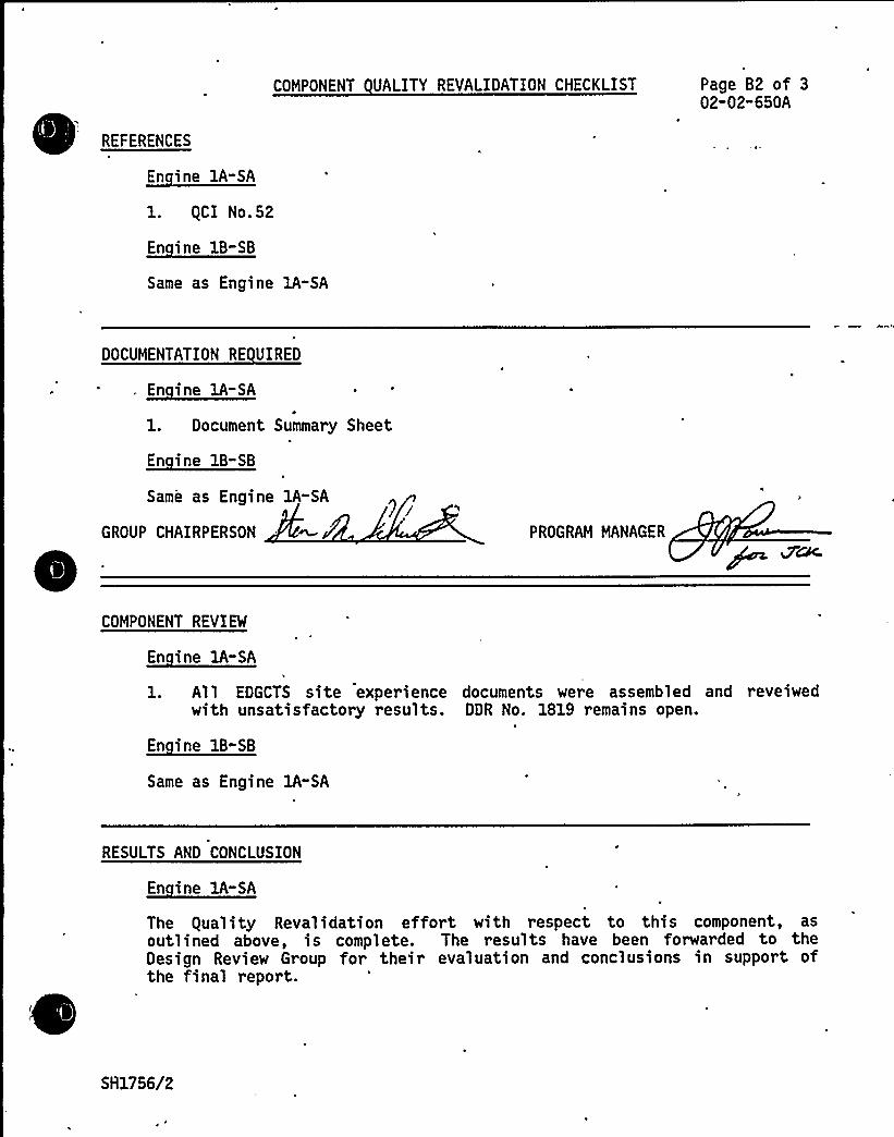
COMPONENT UALITY REVALIDATION CHECKLIST
REFERENCES
En ine lA-SA
1. gCI No.52
~Ei B-EB
Page B2 of 302-02"650A
Same as Engine 1A-SA
DOCUMENTATION RE UIRED
. ~Ei 1 -EA
1. Document Summary Sheet
~Ei 1B-EB
Same as Engine 1A-SA
GROUP CHAIRPERSON PROGRAM MANAGER
COMPONENT REVIEW
~Ei AA- A
l. All EDGCTS site experience documents were assembled and reveiwedwith unsatisfactory results. DDR No. 1819 remains open.
~E" i 11-EB
Same as Engine 1A-SA
RESULTS AND CONCLUSION
En ine lA-SA
The guality Revalidation effort with respect to this component, asoutlined above, is complete. The results have been forwarded to theDesign Review Group for their evaluation and conclusions in support ofthe final report.
S 81756/2
COMPONENT UALITY REVALIDATION CHECKLIST
RESULTS AND CONCLUSION (continued)
~Ei BB-BB
Same as Engine lA-SA
Page B3 of 302-02-650A
GROUP CHAIRPERSON PROGRAM MANAGER
SH1756/3
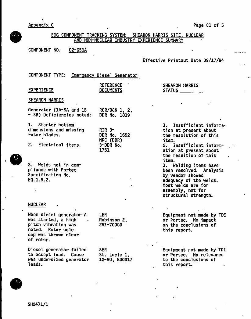
A endix C Page Cl of 5
EDG COMPONENT TRACKING SYSTEM: SHEARON HARRIS SITE NUCLEARAND NON-NUCLEAR INDUSTRY EXPERIENCE SUMMARY
COMPONENT NO. 02-650A
Effective Printout Date 09/17/84
COMPONENT TYPE: Emer enc Diesel Generator
EXPERIENCE
SHEARON HARRIS
Generator (1A-SA and 1B- SB) Deficiencies noted:
1. Starter bottomdimensions and missingrotor blades.
2. Electrical items.
L
~3. Wel ds not in com-pliance with PortecSpecification No.EQ.l. 5.2.
NUCLEAR
When diesel generator Awas started, a highpitch vibration wasnoted. Rotor polecap was thrown clearof rotor.
Diesel generator failedto accept load. Causewas undersized generatorleads.
REFERENCEDOCUMENTS
RCR/DCN 1, 2,DDR No. 1819
RIR 3-DDR No. 1692NRC (DDR).3"DDR No.1751
LERRobinson 2,261-70000
SERSt. Lucie 1,12"80, 800317
SHEARON HARRISSTATUS
1. Insufficient informa-tion at present aboutthe resolution of thisitem.2. Insufficient inform-ation at present aboutthe resultion of thisitem.3. Welding items havebeen resolved. Analysisby vendor showedadequacy of the welds.Most welds are forassembly, not forstructural strength.
Equipment not made by TDIor Portec. No impacton the conclusions ofthis report.
Equipment not made by TDIor Portec. No relevanceto the conclusions ofthis report.
SH2471/1

A endix C
EXPERIENCEREFERENCEDOCUMENTS
Page C2 of 5
SHEARON HARRISSTATUS
Brushes looked whitehot while running.
EOG-1 slip ring repair.
During test, generatorstator high temperaturealarm was received.
During electrical switch-ing operations, the Eldiesel breaker to theUnit 3 emergency busfailed to close becauselinkage in the breakercubicle elevatormechanism cell switch,was bent.
NPRDSDavis-Besse 1,810318, Hit 24
NPRDSDavis-Besse 1,81-4-2, Hit 91
LERPrairie Island1, 282-7400740809
EPRIPeach Bottom 3062775 DG-El
Equipment not made byTDI or Portec. No impacton the conclusions ofthe report.
Equipment not made by TDIor Portec. No impact onthe conclusions of thisrepor t.
Equipment not made by TDIor Portec. No impact onthe conclusions of'hisreport.
Equipment not made byTOI or Portec. No impacton the conclusions ofthis report.
OG-El tripped on "A"phase differential re-lay after generator hadbeen paral 1 cled.
EPRIPeach Bottom 2121977DG-E1
False trip of protectiverelays. Does not concernthe issues addressed inthe report.
Short between one coilto stator caused byloose laminations.
EPRI Pilgrim 1,101178, DG-1B
Diesel generator brush NPROS Brunswick 2,rigging damaged by arcing. 830203 Hit 212
Equipment not made by TOIor Portec. No impact onthe conclusions of thisreport.
Equipment not made by TDIor Portec. No impact onthe conclusions of thisreport.
480 V ground due togrounded stator lead.
NPRDS~ 10CFR50.55E.San Onofre 1,760609, Hit 196
Equipment not made by TDI.or Portec. No impact onthe conclusions of thisreport.
SH2471/2
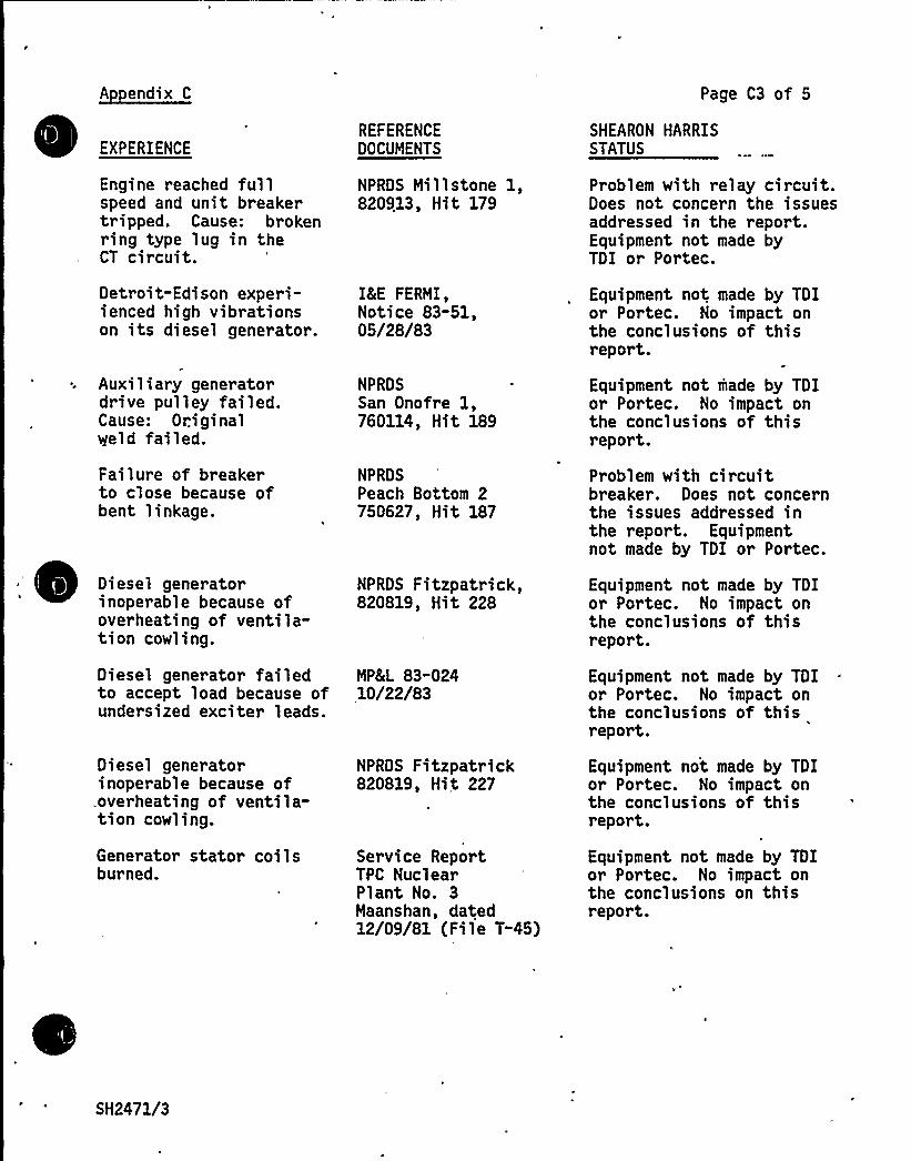
A endix C Page C3 of 5
EXPERIENCE
Engine reached fullspeed and unit breakertripped. Cause: brokenring type lug in theCT circuit.
Detroit"Edison experi-ienced high vibrationson its diesel generator.
Auxi1 iary generatordrive pulley failed.Cause: Originalvleld failed.
Failure of breakerto close because ofbent linkage.
Diesel generatorinoperable because ofoverheating of ventila-tion cowling.
Diesel generator failedto accept load because ofundersized exciter leads.
Diesel generatorinoperable because of.overheating of ventila-tion cowling.
Generator stator coilsburned.
REFERENCEDOCUMENTS
NPRDS Millstone 1,820913, Hit 179
ISE FERMI,Notice 83-51,05/28/83
NPRDSSan Onofre 1,760114, Hit 189
NPRDSPeach Bottom 2750627, Hit 187
NPRDS Fitzpatrick,820819, Hit 228
MP8(L 83"02410/22/83
NPRDS Fitzpatrick820819, Hit 227
Service ReportTPC NuclearPlant No. 3Maanshan, dated12/09/81 (File T-45)
SHEARON HARRISSTATUS
Problem with relay circuit.Does not concern the issuesaddressed in the report.Equipment not made byTDI or Portec.
Equipment not made by TDIor Portec. No impact onthe conclusions of thisreport.
Equipment not made by TDIor Portec. No impact onthe conclusions of thisreport.
Problem with circuitbreaker. Does not concernthe issues addressed inthe report. Equipmentnot made by TDI or Portec.
Equipment not made by TDIor Portec. No impact onthe conclusions of thisreport.
Equipment not made by TDIor Portec. No impact onthe conclusions of thisreport.
Equipment not made by TDIor Portec. No impact onthe conclusions of thisreport.
Equipment not made by TDIor Portec. No impact onthe conclusions on thisreport.
SH2471/3

af
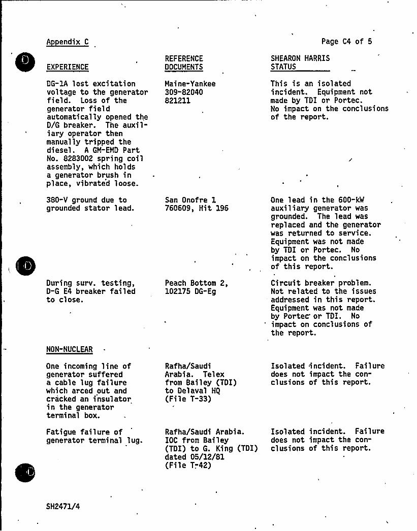
A endix C Page C4 of 5
EXPERIENCEREFERENCEDOCUMENTS
SHEARON HARRISSTATUS
DG-lA lost excitationvoltage to the gener atorfield. Loss of thegenerator fieldautomatically opened theD/G breaker. The auxil-iary operator thenmanually tripped thediesel. A GM-EMD PartNo. 8283002 spring coilassembly, which holdsa generator brush inplace, vibrated loose.
380-V ground due togrounded stator lead.
During surv. testing,D-G E4 breaker failedto close.
NON-NUCLEAR
Maine-Yankee309"82040821211
San Onofre 1760609, Hit 196
Peach Bottom 2,102175 DG-Eg
Thi s i s an isol atedincident. Equipment notmade by TDI or Portec.No impact on the conclusionsof the report.
One lead in the 600-kWauxiliary generator wasgrounded. The lead wasreplaced and the generatorwas returned to service.Equipment was not madeby TDI or Portec. Noimpact on the conclusionsof this report.
Circuit breaker problem.Not related to the issuesaddressed in this report.Equipment was not madeby Portec'r TDI. No
'mpact on conclusions ofthe report.
One incoming line ofgenerator suffereda cable lug failurewhich arced out andcracked an insulatorin the generatorterminal box.
Rafha/SaudiArabia. Telexfrom Bailey (TDI)to Delaval HQ
(File T-33)
Isolated incident. Failuredoes not impact the con-clusions of this report.
Fatigue failure ofgenerator terminal lug.
Rafha/Saudi Arabia.IOC from Bailey(TDI) to G. King (TDI)dated 05/12/81(File T.-42)
Isolated incident. Failuredoes not impact the con-clusions of this report.
SH2471/4
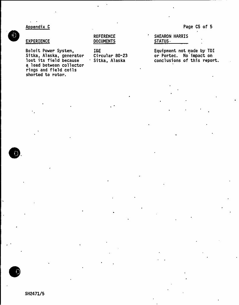
A endix C
EXPERIENCEREFERENCEDOCUMENTS
Page C5 of 5
SHEARON HARRIS
STATUS'oloit
Power System, IKESitka, Alaska, generator Circular 80-23lost i ts fiel d because 'itka, Alas kaa lead between collectorrings and field coilsshorted to rotor.
Equipment not made by TDIor Portec. No impact onconclusions of this report.
SH2471/5
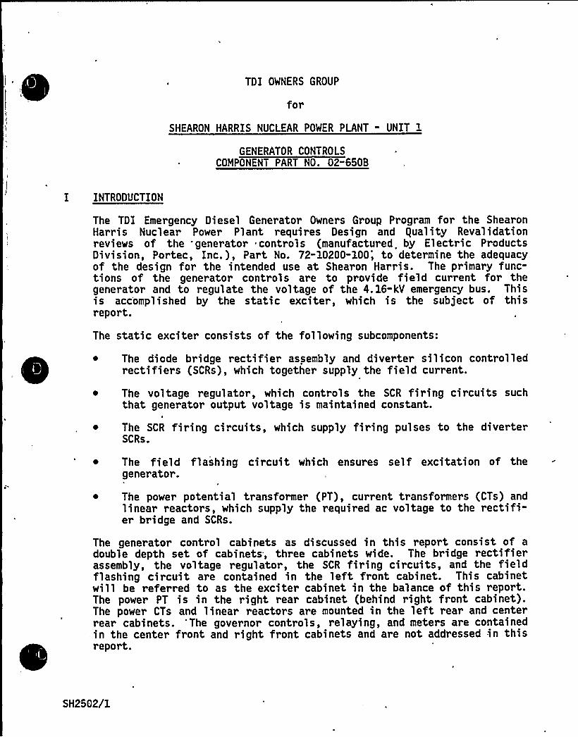
TDI OWNERS GROUP
for
SHEARON HARRIS NUCLEAR POWER PLANT - UNIT 1
GENERATOR CONTROLSCOMPONENT PART NO. 02"650B
I INTRODUCTION
The TDI Emergency Diesel Generator Owners Group Program for the ShearonHar ris Nuc 1 ear Power Pl ant r equires Desi gn and equal ity Reval idati onreviews of the generator controls (manufactured. by Electric Pr oductsDivision, Portec, Inc.), Part No. 72-10200-100; to determine the adequacyof the design for the intended use at Shearon Harris. The primary func-tions of the generator controls are to provide field current for thegenerator and to regulate the voltage of the 4.16-kV emergency bus. Thisis accomplished by the static exciter, which is the subject of thisreport.
The static exciter consists of the following subcomponents:
~ The diode bridge rectifier assembly and diverter silicon controlledrectifiers (SCRs), which together supply the field current.
The voltage regulator, which controls the SCR firing circuits suchthat generator output voltage is maintained constant.
The SCR firing circuits, which supply fi~ing pulses to the diverterSCRs.
The field flashing circuit which ensures self excitation of thegenerator.
~ The power potential transformer (PT), current transformers (CTs) andlinear reactors, which supply the required ac voltage to the rectifi-er bridge and SCRs.
The generator control cabinets as discussed in this report consist of adouble depth set of cabinets, three cabinets wide. The bridge rectifierassembly, the voltage regulator, the SCR firing circuits, and the fieldflashing circuit are contained in the left front cabinet. This cabinetwill be referred to as the exciter cabinet in the balance of this report.The power PT is in the right rear cabinet (behind right front cabinet).The power CTs and linear reactors are mounted in the left rear and centerrear cabinets. 'The governor controls, relaying, and meters are containedin the center front and right front cabinets and are not addressed in thisreport.
SH2562/1

IJ
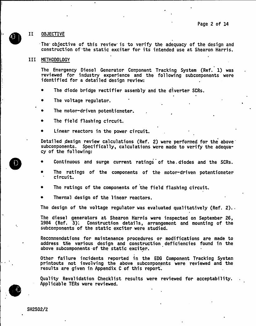
Page 2 of 14
I ~
~
~
~ ~
~
~
~
II OBJECTIVE
The objective of this review'is to verify the adequacy of the design andconstruction of 'the static exciter for its intended use at Shearon Harris.
III METHODOLOGY
The Emergency Diesel Generator Component Tracking System (Ref. 1) wasreviewed for industry experience and the following subcomponents wereidentified for a detailed design review:
~ The diode bridge rectifier assembly and the diverter SCRs.
~ The voltage regulator.
~ The motor-driven potentiometer.
~ The field flashing circuit.~ Linear reactors in the power circuit.Detailed design review calculations (Ref. 2) were performed for the above
'ubcomponents.Specifically, calculations were made to verify the adequa-cy of the following:
~ Continuous and surge current ratings of the. diodes and the SCRs.
~ The ratings of the components of the motor-driven potentiometercircuit.
The ratings of the components of the field flashing circuit.~ Thermal design of the linear reactors.
The design of the voltage regulator was evaluated qualitatively (Ref. 2)..
The diesel generators at Shearon Harris were inspected on September 26,1984 (Ref. 3): Construction details, arrangement and mounting of thesubcomponents of the static exciter were studied.
Recommendations for maintenance procedures or modifications are made toaddress the various design and construction deficiencies found in theabove subcomponents-of the static exciter.
Other failure incidents reported in the EDG Component Tracking Systemprintouts not involving the above subcomponents were reviewed and theresults are given in Appendix C of this report.
guality Revalidation Checklist results were reviewed for acceptability.Applicable TERs were'reviewed.
SH2502/2
Page 3 of 14
The Emergency Diesel Generator Component Tracking System does not list anyincidents related to operation of the generator controls at ShearonHarris. However, Shearon Harris DDR No. 2028 is listed in the ComponentTracking System and indicates that various construction deficiencies werefound during the initial inspection of the generator control panels. ThisDDR has been reviewed as part of the design review process. All of thedeficiencies reported in the DDR are construction deficiencies rather thanelectrical design deficiencies. One of the deficiencies is the result
of'oor
wiring practices and is addressed in this design review.
In the nuclear and non-nuclear industry experience, there are 70 incidentsrelating to the generator controls. Seventeen of the 70 incidents involvefailures of the following subcomponents: diodes of the bridge rectifierassembly and the diverter SCRs; the voltage regulator; the field flash"ing circuit; the motor-driven potentiometer. The remaining 53 incidentsare random failures and do not present any pattern indicating designproblems.
Design review 'alculations (Ref.. 2) made for the above subcomponentsreveal the following:
The diodes and the SCRs are adequately rated to conduct the maximumcontinuous and surge currents if there is free air convection in theexciter (left front) cabinet. ,Recommendations for temperaturemonitoring are included in Attachment 1;
The field flashing relay is inadequately rated. This is a relayoperated from the 125-V (nominal) battery source and closes itscontacts to supply, the field flashing current. Failure of the relayto close would make the diesel generator unavailable to supply thesafety related loads. Procurement specifications (Ref. 4) state thatthe voltage of the dc source may vary between 90 V and 140 V. The FF
relay would fail to close its contacts when the source voltage is 90V. Discussions with the relay manufacturer and with Portec confirmthis fact. Results of analysis and copies of correspondence withPortec on this subject are enclosed in Reference 2. It is recom-mended that this relay be replaced by an appropriately rated relay.Detailed recommendations are given in Attachment 1 of this report.
SH2502/3
Tl.
Page 4 of 14
~ Thermal calculations for the linear reactors that supply current to. the exciter show that the temperature rating of the coil insulation
will be exceeded if additional cabinet ventilation is not provided.The reactor coils are built with Class F insulation, which is ratedfor 155 degrees C (311 degrees F). Procurement specifications (Ref.4) require that the generator controls operate with a maximum ambientair temperature in the diesel room of 120 degrees F or about 50degrees C. Calculations (Ref. 2) show that at rated current and asurrounding air temperature of 50 degrees C the internal t'emperatureof the coils is 157 degrees C. However, the reactors are mountedinside the left rear and center rear generator control cabinets,which are vented but not force ventilated. The heat generated bythe reactors themselves will cause a temperature rise of at least10 degrees C. The coils will, therefore, operate very closely to thetemperature rating of the insulation if ventilation is not provided.Detailed recommendations for ventilation of the cabinets are dis-cussed in Attachment 1.
gualitative evaluation of the design of the voltage regulator indicatesthat although this subcomponent can perform its intended functions,several desirable features that ensure high reliability and performancehave not been incorporated in the design. These features are power supplybypassing, coating of all adjustable potentiometer spindles with Glyptollacquer, using MIL style multiturn sealed potentiometers, solderingi.ntegrated circuits to the printed circuit board (PC) directly instead ofmounting in sockets, using double-sided PCs, conformal coating of the PC
boards, and shielding signal leads. Detailed recommendations to incorpo-rate these features are made in'ttachment 3 of this report. When therecommendations are implemented the long-term reliability and performanceof the voltage regulator will be enhanced. As the voltage regulator inits present state is adequate to meet its intended functions, implementa-tion of the recommendations of Attachment 3 is left to the discretion of
. -CPKL.
At Shearon Harris there is a spare voltage regulator board which can beswitched in if the original voltage regulator fails. Therefore, redesignof the voltage regulator, although desirable, is not mandatory.
Inspection of the subcomponents reviewed in this report (Ref. 3) revealedthe following construction and mounting inadequacies:.
~ The diodes of the bridge rectifier assembly are mounted on the heatsinks by tapped holes, contrary to the manufacturer's recommenda-tions. The SCRs of the bridge rectifier assembly are mounted withnuts. However, the Portec assembly drawings call for a tapped holein the heat sink. During the inspection, it was not possible todetermine whether the hole is tapped or has been drilled out. Twoleading manufacturers specifically advise against mounting by tappedholes.
~ The generato~ control cabinets are inadequately ventilated.
SH2502/4
g h~ ill'~
Page 5 of 14
Power cables are terminated with up to three lugs on one stud,contrary to good wiring practice.
These deficiencies do not presently endanger the diodes and SCRs. But forcontinued safe operation, these deficiencies should be remedied to ensureproper thermal and electrical contact with the heat sinks, to preventloosening of the diodes by vibration, and to ensure proper contact at allcable terminations. Remedial measures are recommended in the form ofmaintenance and modification procedures as detailed in Attachment 1 ofthis report, and design and construction modifications as detailed inAttachment 2 of this report. The recommendations of .Attachment 1 may beimplemented without significant modification of the existing equipment.These recommendations will allow monitoring on the temperature of the.diodes and the SCRs. The recommendations of Attachment 2 involve remount-ing of the. diodes, installing cooling fans in the exciter cabinet andredesign of the cable terminations. These recommendations may be imple-mented at the first refueling outage of the plant or earlier at the dis-cretion of CP&L.
Recommendations to remedy the design and construction deficiencies areorganized as follows:
~ Attachment 1 - the recommendations are to be implemented prior toplacing the engine in emergency standby service to enable monitoringof the diodes. Recommendations are also made concerning the fieldflashing relay, linear reactors, heat sink wiring, and voltageregulator.
~ Attachment 2 - the recommendations are to be implemented at the firstrefueling outage of the plant. or earlier at the discretion of CPCLto alleviate the need for the maintenance procedures in Sections IA,IB, and IC of Attachment 1.
~ Attachment 3 - the recommendations are to be implemented at thediscretion of CP8L to enhance the long-term reliability and perfor-mance of the voltage regulator.
Other incidents of failures reported in the EDG Component Tracking Systemnot involving the subcomponents considered in this report were reviewed.The results are given in Appendix C of this report. It was found that thefailures were not of generic nature and do not impact the conclusions ofthis report.
I
The information provided on TER 02-074, dated 10/15/84, has been reviewedand is consistent with the final conclusions of this report.
guality Revalidation Inspection results identified in Appendix B of thisreport have been reviewed and considered in the performance of this designreview and the results are consistent with the final conclusions of thisr epor t.
SH2502/5

Page 6 of 14
Based upon the above review, it is concluded that the generator controlsare adequate for their intended use at Shearon Harris if all the recommen-dations of Attachment 1 of this report are adopted. The recommendationsof Attachment 2 of this report should be implemented at the firstrefueling outage or earlier at the discretion of CPEL so that the re-commendations in Sections IA, IB, and IC of Attachment 1 are no longernecessary. Recommendations of Attachment 3 of this report may be imple-mented at the discretion of CPEL to improve the long-term reliability.
V REFERENCES
1. Component Tracking System printout for Shearon Harris Nuclear PowerPlant, Component Part No. 02-650B, dated 09/17/84.
2. FaAA design review support package SP-84-6-46 (F).
3. Alexander Kusko, Inc. Trip Report, Shearon Harris Nuclear PowerPlant, dated 09/26/84.
4. EBASCO Procurement Specification 216-73Tb dated April 25, 1978, Rev.3.
SH2502/6'

Page 7 of 14
Attachment 1
Shearon Harris Nuclear Power Plant - Unit 1Maintenance and Modification Procedures - Generator Controls
I BRIDGE RECTIFIER ASSEMBLY
A. ~0i M
Monitor the maximum temperature attained by the diodes byplacing a temperature-sensitive label on the most visible faceof the hexagonal body of the diode.
.2 ~ The temperature-sensitive Abel should be of the type thatpermanently blackens when its temperature has been reached. orexceeded.
3.
4.
The temperature rating of the labels shall be 275 degrees F.Omega brand model BE-275 or equivalent (Ref. 1) is recommended.
The label shall be inspected before and after each running ofthe emergency generator.
5.
6.
If the temperature label indicates that the speci fied temper a-ture has been exceeded, perform an electrical test of the diode(Ref. 2), remove the diode from the heatsink and inspect themounting threads of the heatsink and the diode.
Replace the diode and the heatsink as required to assure thatproper mounting tightness, 360 in-lbs (Ref. 3) and threadcondition is maintained.
B. ~KR-M
1. Monitor the SCR maximum temperature as in I.A above.
2. Use Omega brand model BE 220 or equivalent (Ref. 1) for 220degrees F.
3. Tighten to 360 in-lbs (Ref. 4).
C. Heatsink
1. Coat the side of the lugs and mounting bolt for the lugs thatattach to the bottom of the diode and SCR Heatsinks with Glyptollacquer (Ref. 5).
2... Apply the Glyptol on a readily visible side so that relativemotion of the lugs with respect to one another or with respectto the mounting bolt can be detected.
SH2502/7

Page 8 of 14
3. Inspect the connections after each monthly test of the emergencygenerator.
4. Retighten connections that appear to have loosened. Remove oldGlyptol and reapply if connections are retightened.
II VOLTAGE REGULATOR BOARDS
A. Ad ustment Potentiometers
1. Coat one. side of the adjustment screw for each of the fiveadjustment potentiometers on the printed circuit board of thevoltage regulator with Glyptol lacquer.
2. 'f adjustments are needed, remove the Glyptol. and reapply whenthe adjustment procedure is complete.
B. Printed Circuit Board
1. At each refueling outage, remove the covers of the voltageregulator enclosures and inspect the components mounted on theprinted circuit boards. Check for cleanliness and propermounting of components. Report any abnormal conditions toengineering for evaluation.
C. ~5Pl. It is recommended that an adequate supply of spare parts be
maintained.
III FIELD FLASHING RELAY
A. Replace the FF relay (a dc contactor, class P10 Cat. No. P102D12 madeby Gould Distribution and Control Division (Ref. 6) by an equivalent
'c
contactor rated as follows: Coil voltage, 90-140 V; contactvoltage, 140 V dc; contact current, 70A dc. The relay should be onthe enclosed type to prevent particles of dirt from .being depositedon the contacts. It may be necessary to install a voltage regulationcircuit to permit the use of a contactor with a conventional coilvoltage range.
IV POWER CIRCUIT LINEAR REACTORS
A. The left rear and center rear cabinets must be ventilated or cooledso that the air temperature in the cabinet does not exceed 50degrees C (120 degrees F).
SH2502/8

0'
Page 9 of 14
~
~ ~
V REFERENCES
1. 1983 Omega Temperature Measurement Handbook, Omega Engineering, Inc.,p. 005.
2. Portec Static Exciter Voltage Regulator Model 72-10200-100 Instruc-tion Manual.
3. Westinghouse Power Semiconductor Manual pp R35-R38.
4. Westinghouse Power Semiconductor Manual pp 541-544.
5. Gerber Electronics Catalog, p. 585 - General Cement ProductionBulletin.
6. Ported Dwg. D72-10200-710.
SH2502/9

+I,
JSj +
Page 10 of 14
Attachment 2
Shearon Harris Nuclear Power Plant - Unit 1Recommendations for Desi n and Construction
Modifications - Generator Controls
I Brid e Rectifier Assembl
A. Exciter Cabinet Ventilation
1. The bridge rectifi'er assembly in the exciter cabinet (left frontcabinet) must be ventilated so that the air temperature insidethe cabinet does not exceed a temperature of 60 degrees C (140degas ees F).
2. Ventilation may be accomplished by supplying chilled air intothe cabinets, by installing exhaust fans or by other means. Ifchilled air is used, care must be taken to avoid condensationwithin the cabinet.
B. ~BMM M
1. The diodes should be mounted on the heatsinks with drilledholes, nuts, and lockwashers, and tightened to the proper torque(Ref. 1).
M ~ddd M
1. The SCR's should be mounted on the heatsinks with drilled holes,nuts, and lockwashers, and tightened to the. proper torque (Ref.2).
D. Heatsink Connections
1. The bolted on lug arrangement must be redesigned so that thereare no more than two lugs on each bolt.
2. Heatsink anodizing must be removed in the co'ntact areas of allbolts and bus bar studs.
3. Current-carrying surfaces of lugs must not be separated bywashers or nuts.
II VOLTAGE REGULATOR BOARDS
Any integrated circuit which is in the TO-5 (metal can) package shall bereplaced with those of the DIP (Dual-in-Line) or Mini-DIP package. BothRCA (Refs. 3 and 4) and National Semiconductor Corporation (Ref. 5)manufacture IC's in TO-5 and Mini-DIP (or DIP) packages, which are pincompatible with each other.
SH2502/10
Page 11 of 14
III POWER CIRCUIT REACTORS
,One, terminal of the reactors has 3 lugged wires attached to it. The lugarrangement should be modified so that there are no more than two lugs onany one bolt.
IV REFERENCES
1. Westinghouse Power Semiconductor Manual pp R33-R38.
2. Westinghouse Power Semiconductor Manual pp 541-544.
3. Spec Sheet-RCA Linear Integrated Circuits, Type CA3094.
4. Spec Sheet-RCA Linear Integrated Circuits, Type CA723T.
5. Spec Sheet-National Semiconductor Corporation Operational Amplifier,Type LM741.
SH2502/11

l4 J
J"
% II
Page 12 of 14
Attachment 3
Shearon Harris Nuclear Power Plant - Unit 1Modifications Recommended to Im rove
Lon -Term Reliabilit - Generator Controls
I VOLTAGE REGULATOR
A. ~Ci i 0
1. Power Su l B assin
The purpose of power supply bypassing is to prevent ac noisevoltage generated outside the voltage regulator circuit frominterfering with its operation and to prevent voltages generatedby the circuit itself from propagating in the circuit. Inspec-tion of the PC board and the voltage regulator schematic showsthat power supply bypassing has been almost completely neglectedin the circuit design. The following modifications arerecommended:
. a. The power supply terminals of each individual integratedcircuit (IC) should be bypassed with a 0 01 - 0 1 pFceramic capacitor from its supply terminals to ground (Ref.1). The high current buffers (U3, U5, U7, Portec DrawingNo. D72-13000-710 Rev. B, Schemati c-SVS Regulator withparalleling) require bypassing capacitors of 0.1 pF so thattransients will not get back to the ICs (Ref. 2).
2.
b. In addition to the high frequency bypass capacitor, a large.value capacitor (approximately 10 pF) is required forvoltage regulator op amp U1, Portec Drawing No.D72-13000-710, Schematic-SVS Regulator with paralleling.This is because of the presence of CR31 and R73.
Shieldin and Routin of External Si nal Leads
Shielding and proper routing of signal leads external to the PC
board is intended to prevent electromagnetically induced noisevoltages from entering the signal leads. This is done by usingshielded signal leads and by routing the leads so as to maximizethe distance between the signal and high current leads. Thesetechniques have been neglected in the wiring of the voltageregulator. The following modifications are recommended:
a. Shielded signal leads should be used for the connectionsbetween the motor-driven potentiometer and the voltageregulator.
SH2502/12
Page 13 of 14
b. A high frequency bypass capacitor providing an in-circuitlow frequency cutoff of no less than 1.kHz be installed toreduce high frequency noise on the feedback signal withoutinterfering with the feedback loop operation.
c. The leads for the SCR gate signals should be run in sepa-rate bundles away from the current carrying leads.
3. 'urrent Feedback Si nal
The purpose of the current feedback signal is to improve theclosed loop response of . the voltage regulator. The currentfeedback signal is derived from a sensing transformer whichmeasures one of the diode currents in the bridge rectifier. Thefollowing modification should be made to improve the stabilityof the voltage regulator while providing the same performance.
Replace the single-phase current sensing circuit with athree-phase current sensing circuit. This requires the use of athree-phase sensing transformer and a three-phase bridge recti-fier circuit on the PC board. Additional stability is providedby reducing the filtering requirements of the feedback signal,which are presently provided by a resistance-capacitance filteron the PC board.
B. Construction
1. Vibrati on Protecti on
Reliable mounting of components on the PC board and the properselection of components is necessary to ensure that the voltageregulator can withstand the vibration encountered during seismicevents, construction or maintenance. However, the design of theboard does not appear to be adequate for .these conditions. At aminimum, the following modifications should be made:
ao
b.
The nine integrated circuits on the PC board which arepresently mounted in sockets should be soldered directly tothe PC board (Ref. 3).
The voltage range and stability adjustment potentiometer(R4 and R5) are unsealed, one turn commercial grade devic-es. General recommendations in Reference 4 suggest thatNIL style components should be used in such Class 1Eapplications. These potentiometers should be replaced withMIL style, sealed, multitur n potentiometers to improve thereliability and stability of these components.
SH2502/13
Page 14 of 14
2. Printed Circuit Board Construction
It is essential that the PC board construction be suitable forthe reliability, mechanical, environmental and electromagneticrequirements of the Class lE application. The following modifi-cations should be made to ensure adequacy of the design:
a 0
b.
C.
d.
The board material has not been identified at this time. ANEMA grade G-10 glass epoxy board material should be used.
The present PC board is a single-sided board (i.e., coppercircuit on one side and components on the other).Double-sided PC boards are commonly used in noise sensitiveapplications and where high reliability is necessary. Theextra copper layer provides additional bypassing of highfrequency AC noise.
The PC board should be conformally coated as a final stepin manufacturing. Conformal coating prevents humidity andairborne particles from affecting the operation of'hecircuitry.
Components should be soldered directly to the PC board. Ifsockets are used, retaining mechanisms must be provided tohold the components in the sockets.
II REFERENCES
1. Roberge, J. K., "Operational Amplifiers - Theory and Practice," p.444, John Wiley 8 Sons, Inc., New York 1975.
2. Stout D., and M. Kaufman, "Handbook of Operational Amplifier CircuitDesign," p. 3-27, McGraw-Hill Book Co., New York 1976.
3. "IEEE Trial-Use Guide for Class 1E Control Switchboards for NuclearPower Generating Stations," IEEE Std. 420-1973, p. 8, Sec. 4.1.2.
4. "IEEE Standard: Criteria for Protecting Systems for Nuclear PowerGenerating Stations," IEEE Std. 279-1971, p. 8, Sec. 7.3.
SH2502/14

Jp
eE
APPENDIX A Page Al of 2
COMPONENT DESIGN REVIEW CHECKLISTSHEARON HARRIS NUCLEAR POWER STATION - UNIT 1
COMPONENT Emer enc Generator Controls UTILITY Carolina Power 8 Li ht Co.
GROUP PARTS LIST NO. 02-650B
SNPS GPL NO. 03-650B
TASK DESCRIPTION NO. DR-02-02-650B-0
CLASSIFICATION TYPE A
TASK DESCRIPTIONS
The design review of the generator controls focuses on the generator exciter.Specific steps to the design review are:
Review the site experience reported in the Component Tracking System.
Contact site personnel to obtain additional background information onthe exciter.
Identify Component Tracking System events that're related to the designof the equipment.
Perform a site inspection to gather additional information on theconstruction, installation, operation, and enviro'nment of theequipment. These inspections constitute the quality revalidationeffort for this component.
The exciter is typically organized as three assemblies: 1) the bridgerectifier assembly, consisting of diodes and thyristors; 2) thevoltage regulator consisting of one or more printed circuit boards; and3) a motor driven potentiometer. Design review calculations areperformed to verify the adequacy of these assemblies.
Recommend maintenance procedures or modifications as needed to assure theadequacy of the exciter.
Verify that all 'design related events listed in the Component TrackingSystem are addressed by the design review.
Review information provided on TERs.
PRIMARY FUNCTION
Provides field current for the generator and regulates the generator AC outputvoltage.
SH2002/1

+tl
"l
Yi
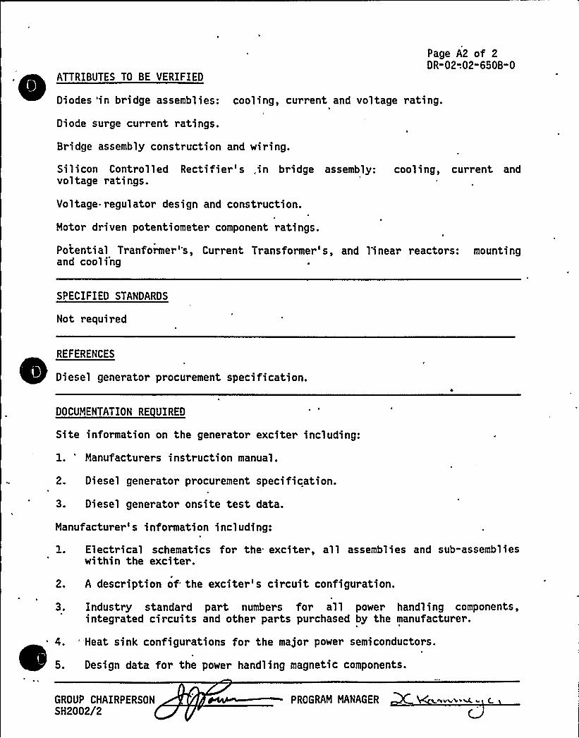
Page A2 of 2DR-02-.02-650B-O
ATTRIBUTES TO BE VERIFIED
Diodes 'in bridge assemblies: cooling, current and voltage rating.
Diode surge current ratings.
Bridge assembly construction and wiring.
Silicon Controlled Rectifier s ,in bridge assembly: cooling, current andvoltage ratings.
Voltage.t egulator design and construction.
Motor driven potentiometer component ratings.
Potential Tranformer's, Current Transformer's, and 1'inear reactors: mountingand cooling
SPECIFIED STANDARDS
Not required
REFERENCES
Diesel generator procurement specification.
DOCUMENTATION RE UIRED
Site information on the generator exciter including:
1. 'anufacturer s instruction manual.
2. Diesel generator procurement specification.
3. Diesel generator onsite test data.
Manufacturer' information including:
1. Electrical schematics for the exciter, all assemblies and sub-assemblieswithin the exciter.
2. A description of the exciter's circuit configuration.
3. Industry standard part numbers for all power handling components,integrated circuits and other parts purchased by the manufacturer.
"Heat sink configurations for the major power semiconductors.
Design data for the power handling magnetic components.
GROUP CHAIRPERSONSH2002/2
PROGRAM MANAGER <hvVW>% (
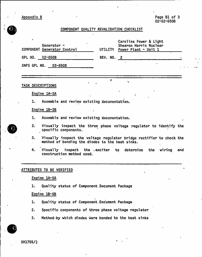
A endix B Page Bl of 302-02-650B
COMPONENT UALITY REVALIDATION CHECKLIST
Generator-COMPONENT Generator Control
GPL NO. 02-650B
SNPS GPL NO. 03"650B
Carolina Power 8 LightShearon Harris Nuclear
UTILITY Power Plant - Unit 1
REV. NO. 2
TASK DESCRIPTIONS
En ine 1A"SA
l. Assemble and review existing documentation.
~Ei 8-88
1. Assemble and review existing documentation.
2. Visually inspect the three phase voltage regulator to identify thespecific components.
3. Visually inspect the voltage regulator bridge rectifier to check themethod of bonding the diodes to the heat sinks.
4. Visually inspect the , exciter to determine the wiring andconstruction method used.
ATTRIBUTES TO BE VERIFIED
~Ei 1A-EA
1. guality status of Component Document Package
~Ei 18- 8
1. guality status of Component Document Package
2. Specific components of three phase voltage regulator
3. Method by which diodes were bonded to the heat sinks
SH1755/1

VPp'l"
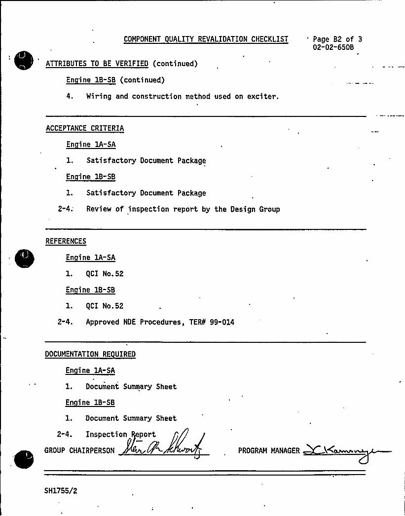
COMPONENT UALITY REVALIDATION CHECKLIST Page B2 of 302"02-650B
,ATTRIBUTES TO BE VERIFIED (continued)
~di 8-88 ( I 8)
4. Wiring and construction method used on exciter.
ACCEPTANCE CRITERIA
En ine 1A-SA
1. Satisfactory Document Package
~di IB-EB
1. Satisfactory Document Package
2-4; Review of inspection report by the Design Group
REFERENCES
En ine lA-SA
1. QCI No.52
~di IA-EB
1. QCI No.52
2-4. Appr oved NDE Procedures, TERS'9-014
DOCUMENTATION RE UIRED
~di IA-EA
1. Document Summary Sheet
~di -81. Document Summary Sheet
2-4. Inspection port
GROUP CHAIRPERSON PROGRAM MANAGER
SH1755/2
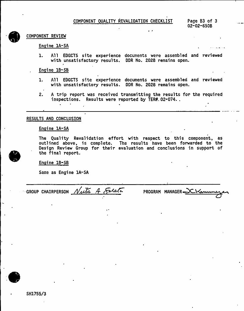
COMPONENT UALITY REVALIDATION CHECKLIST Page B3 of 302-02-650B
COMPONENT REVIEM
En ine 1A-SA
1. All EDGCTS site experience documents were assembled and reviewedwith unsatisfactory results. DDR No. 2028 remains open.
En ine 1B-SB
l. All EDGCTS site experience documents were assembled and reviewedwith unsatisfactory results. DDR No. 2028 remains open.
2. A trip report was received transmitting the results for the requiredinspections. Results were reported by TERO. 02-074..
RESULTS AND CONCLUSION
En ine 1A-SA
The guality Revalidation effort with respect to this component, asoutlined above, is complete. The results have been forwarded to theDesign Review Group for their evaluation and conclusions in support ofthe final report.
~Bi BB-BB
Same as Engine 1A-SA
'- GROUP CHAIRPERSON PROGRAM MANAGER~MY
SH1755/3
4 JV
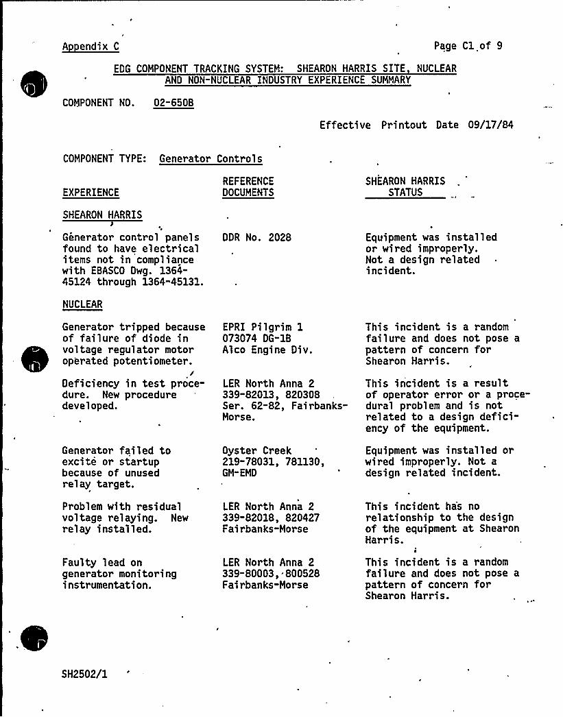
A endix C Page Cl of 9
EDG COMPONENT TRACKING SYSTEM: SHEARON HARRIS SITE NUCLEARAND NON-NUCLEAR INDUSTRY EXPERIENCE SUMMARY
COMPONENT NO. 02-650B
Effecti ve Printout Date 09/17/84
COMPONENT TYPE: Generator Controls
EXPERIENCE
SHEARON HARRIS
Generator control panelsfound to have electricalitems not in compliancewith EBASCO Dwg. 1364-45124 through 1364-45131.
NUCLEAR
Generator tripped becauseof failur e of diode involtage regulator motoroperated potentiometer.
Deficiency in test proce-dure. New proceduredeveloped.
Generator failed toexcite or startupbecause of unusedrelay target.
Problem with residualvoltage relaying. Newrelay installed.
Faulty lead ongenerator monitoringinstrumentation.
REFERENCEDOCUMENTS
DDR No. 2028
EPRI Pilgrim 1073074 DG"1BAlco Engine Div.
LER North Anna 2339-82013$ 820308Ser. 62-82, Fairbanks-Morse.
Oyster Creek219-78031, 781130,GM-EMD
LER North Anna 2339-82018, 820427Fairbanks-Norse
LER North Anna 2339-80003,.800528Fairbanks-Morse
SHEARON HARRISSTATUS
Equipment was installedor wired improperly.Not a design relatedincident.
This incident is a randomfailure and does not pose apattern of concern forShearon Harris.
This incident is a resultof operator error or a proce-dural problem and is notrelated to a design defici-ency of the equipment.
Equipment was installed orwired improperly. Not adesign related incident.
This incident ha's norelationship to the designof the equipment at ShearonHarris.
This incident is a randomfailure and does not pose a
pattern of concern forShearon Harris.
SH2502/1
8
h
]!
1
,l
l
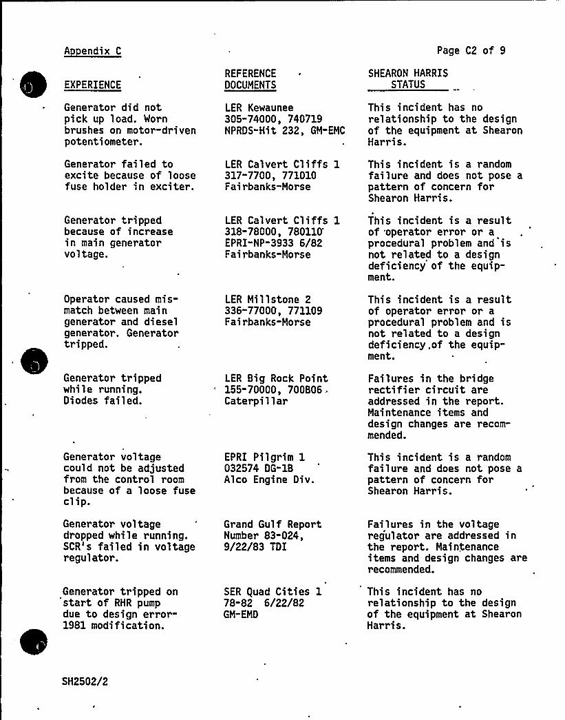
A endix C
EXPERIENCE
~ Generator did notpick up load. Wornbrushes on motor-drivenpotentiometer.
REFERENCE ~
DOCUMENTS
LER Kewaunee305"74000, 740719NPRDS"Hit 232, GM-EMC
Page C2 of 9
SHEARON HARRISSTATUS
This sncsdent has norelationship to the designof the equipment at ShearonHarr is.
Generator failed toexcite because of loosefuse holder in exciter.
Generator trippedbecause of increasein main generatorvoltage.
Operator caused mis-match between maingenerator and dieselgenerator. Generatortripped.
Generator trippedwhile running.Diodes failed.
LER Calvert Cliffs 1317"7700, 771010Fairbanks-Morse
LER Calvert Cliffs 1318-78000,
780110'PRI"
NP-3933 6/82Fairbanks-Morse
LER Millstone 2336-77000, 771109Fairbanks-Morse
LER Big Rock Point155-700000 700B06 .
Caterpillar
This incident is a randomfailure and does not pose apattern of concern forShearon Harris.
This incident is a resultof operator error or aprocedural problem and isnot related to a designdeficiency of the equip-ment.
Thi s incident is a res ul tof operator error or aprocedural problem and isnot related to a designdeficiency, of the equip-ment.
Failures in the bridgerectifier circuit areaddressed in the report.Maintenance items anddesign changes are recom-mended.
Generator voltagecould not be adjustedfrom the control roombecause of a loose fuseclip.
Generator voltagedropped while running.SCR's failed in voltageregulator.
Generator tripped onstart of RHR pumpdue to design error-1981 modification.
EPRI Pilgrim 1032574 DG-1BAlco Engine Div.
Grand Gulf ReportNumber 83-024,9/22/83 TDI
SER squad Cities 178"82 6/22/82GM-EMD
This incident is a randomfailure and does not pose apattern of concern forShearon Harris.
Failures in the voltageregulator are addressed inthe report. Maintenanceitems and design changes arerecommended.
This incident has norelationship to the designof the equipment at ShearonHarris.
SH2502/2
f"
k
, ~ V
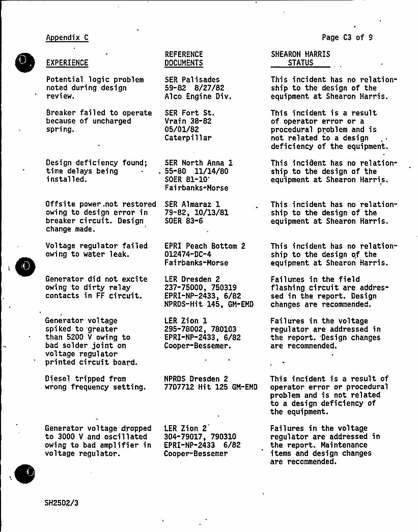
A endix C Page C3 of 9
EXPERIENCEREFERENCEDOCUMENTS
SHEARON HARRISSTATUS
Potential logic problemnoted during designreview.
Breaker failed to operatebecause of unchargedspring.
Design deficiency found;time delays beinginstalled.
SER Palisades59"82 8/27/82Alco Engine Div.
SER Fort St.Vrain 38-8205/01/82Cater pi 1 1 ar
SER North Anna 1. 55-80 11/14/80
SOER81-10'airbanks-Morse
This incident has no relation-ship to the design of theequipment at Shearon Harris.
This incident is a resultof operator error or aprocedural problem and isnot related to a designdeficiency of the equipment.
This incident has no relation-ship to the design of theequipment at Shearon Harris.
Offsite power,not restoredowing to design error inbreaker circuit. Designchange made.
Voltage regulator failedowing to water leak.
~
~
~
~Generator did not exciteowing to dirty relaycontacts in FF circuit.
Generator voltagespiked to 'greaterthan 5200 V owing tobad solder joint onvoltage regulatorprinted circuit board.
Diesel tripped fromwrong frequency setting.
Generator voltage droppedto 3000 V and oscillatedowing to bad amplifier involtage regulator.
SER Almaraz 179"82, 10/13/81SOER 83-6
EPRI Peach Bottom 2012474-DC-4Fairbanks-Morse
LER Dresden 2237-75000, 750319EPRI-NP-2433, 6/82NPRDS-Hit 145, GM-EMD
LER Zion 1295-78002, 780103EPRI-NP-2433, 6/82Cooper-Bessemer.
NPRDS Dresden 27707712 Hit 125 GM-EMD
LER Zion 2304-79017, 790310EPRI"NP-2433 6/82Cooper-Bessemer
This incident has no relation-ship to the design of theequipment at Shearon Harris.
Thi s incident has no re 1 ati on-ship to the design of theequipment at Shearon Harris.
Failures in the fieldflashing circuit are addres-sed in the report. Designchanges are recommended.
Failures in the voltageregulator are addressed inthe report. Design changesare recommended.
This incident is a result ofoperator error or proceduralproblem and is not relatedto a design deficiency ofthe equipment.
Failures in the voltageregulator are addressed inthe report. Maintenanceitems and design changesare recommended.
SH2502/3

1
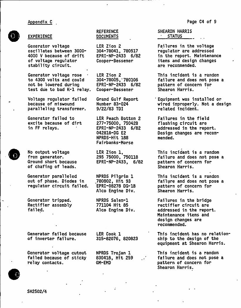
A endix C Page C4 of 9
EXPERIENCE
Gener ator vol tageoscillates between 3000-4000 V because of driftof voltage regulatorstability circuit.
Generator voltage roseto 4300 volts and couldnot be lowered duringtest due to bad K-1 relay.
Voltage regulator failedbecause of miswoundparalleling transformer.
Generator failed toexcite because of dirtin FF relays.
No output voltagefrom generator.Ground short becauseof chafing of leads.
Generator paralleledout of phase. Diodes inregulator circuit failed.
REFERENCEDOCUMENTS
LER Zion 2304"78041, 780517EPRI-NP-2433 6/82Cooper-Bessemer
LER Zion 2304-78005,'780106EPRI"NP-2433 6/82Cooper-Bessemer
Grand Gulf ReportNumber 83-0249/22/83 TDI
LER Peach Bottom 2277-75000, 75042BEPRI-NP-2433 6/82042818-DG E2NPRDS-Hit 188Fairbanks-Morse
LER Zion 1,295 75000, 750118EPRI" NP-2433, 6/82
NPRDS Pilgrim 1780802, Hit 93EPRI-08278 DG-1BAlco Engine Div.
SHEARON HARRISSTATUS
Failures in the voltageregulator are addressedin the report. Maintenanceitems and design changesare recommended.
This incident is a randomfailure and does not pose apattern of concern forShearon Harris.
'quipment was installed orwired improperly. Not a designrelated incident.
Failures in the fieldflashing circuit areaddressed in the report.Design changes are recom-mended.
This incident is a randomfailure and does not pose apattern of concern forShearon Harris.
This incident is a,randomfailure and does not pose apattern of concern forShearon Harris.
Generator tripped.Rectifier assemblyfailed.
NPRDS Salem-1771104 Hit 85Alco Engine Div.
Failures in the bridgerectifier circuit areaddressed in %he report.Maintenance items anddesign changes arerecommended.
Generator failed becauseof inverter failure.
Generator voltage cutoutfailed because of stickyrelay contacts.
LER Cook 1315-82076$ 820823
NPRDS Trojan 1830418, Hit 259GM-EMD
This incident has no relation-ship to the design of theequipment at Shearon Harris.
This incident is a randomfailure and does not pose apattern of concern forShearon Harris.
SH2502/4
'1
t
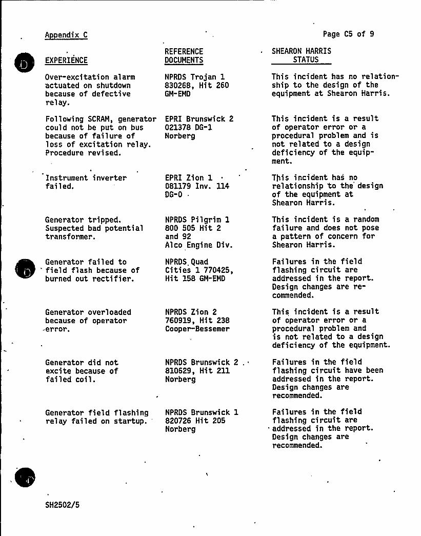
A endix C Page C5 of 9
EXPERIENCEREFERENCEDOCUMENTS
SHEARON HARRISSTATUS
Over-excitation alarmactuated on shutdownbecause of defectiverelay.
NPRDS Trojan 1830268, Hit 260GM-EMD
This incident has no relation-ship to the design of theequipment at Shearon Harris.
Following SCRAM, generator EPRI Brunswick 2could not be put on bus 021378 DG-1because of failure of Norbergloss of excitation relay.Procedure revised.
This incident is a resultof operator error or aprocedural problem and isnot related to a designdeficiency of the equip-ment.
Instrument inverterfailed.
EPRI Zion 1081179 Inv. 114DG-0
This incident has norelationship to the designof the equipment atShearon Harris.
Generator tripped.Suspected bad potentialtransformer.
NPRDS Pilgrim 1800 505 Hit 2and 92Alco Engine Div.
This incident is a randomfailure and does not posea pattern of concern forShearon Harris.
Generator failed to'ield flash because ofburned out rectifier.
Generator overloadedbecause of operator
"er ror.
Generator did notexcite because offailed coil.
NPRDS guadCities 1 770425,Hit 158 GM"EMD
NPRDS Zion 2760919$ Hit 238Cooper-Bessemer
'V
NPRDS Brunswick 2810629, Hit 211Norber g
Failures in the fieldflashing circuit areaddressed in the report.Design changes are re-commended.
This incident is a resultof operator error or aprocedural problem andis not related to a designdeficiency of the equipment.
Failures in the fieldflashing circuit have beenaddressed in the report.Design changes arerecommended.
Generator field flashing NPRDS Brunswick 1relay failed on startup. * 820726 Hit 205
Norberg
Failures in the fieldflashing circuit areaddressed in the report.Design changes arerecommended.
SH2502/5

I p
J
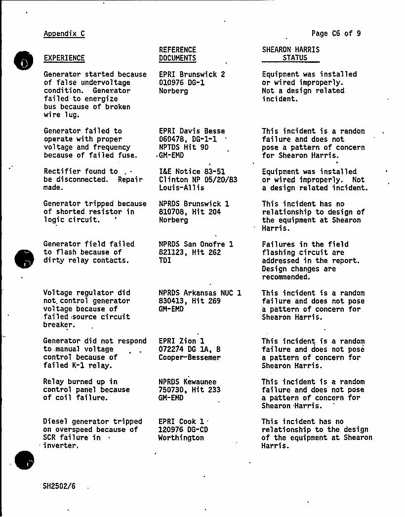
A endix C Page C6 of 9
EXPERIENCEREFERENCEDOCUMENTS
SHEARON HARRISSTATUS
Generator started becauseof false undet voltagecondition. Generatorfailed to energizebus because of brokenwire lug.
Generator failed tooperate with propervoltage and frequencybecause of failed fuse.
Rectifier found tobe disconnected. Repairmade.
Generator tripped becauseof shorted resistor inlogic circuit.
EPRI Brunswick 2010976 DG-1Norberg
EPRI Davis Besse060478, OG-1-1NPTOS Hit 90
~ GM-EMO
ICE Notice 83-51Clinton NP 05/20/83Louis-Allis
NPRDS Brunswick 1810708, Hit 204Norberg
Equipment was installedor wired improperly.Not a design relatedincident.
This incident is a randomfailure and does notpose a pattern of concernfor Shearon Harris.
Equipment was installedor wired improperly. Nota design related incident.
This incident has norelationship to design ofthe equipment at ShearonHarris.
Generator field failedto flash because ofdirty relay contacts.
NPRDS San Onofre 1821123, Hit 262TDI
Failures in the fieldflashing circuit areaddressed in the report.Design changes arerecommended.
Voltage regulator didnot. control generatorvoltage because offailed .source cir cui.tbreaker.
NPRDS Arkansas NUC 1830413, Hit 269GM-EMD
This incident is a randomfailure and does not posea pattern of concern forShearon Harris.
Generator did not respondto .manual voltagecontrol because offailed K-1 relay.
EPRI Zion 1072204 DG lA, BCooper-Bessemer
This incident is a randomfailure and does not posea pattern of concern forShearon Harris.
Relay burned up incontrol panel becauseof coil failure.
NPROS Kewaunee750730, Hit 233GM-EMD
This incident is a randomfailure and does not posea pattern of concern forShearon Harris.
Diesel generator trippedon overspeed because ofSCR failure ininverter.
EPRI Cook 1.120976 OG-CDWorthington
This incident has norelationship to the designof the equipment at ShearonHarris.
SH2502/6
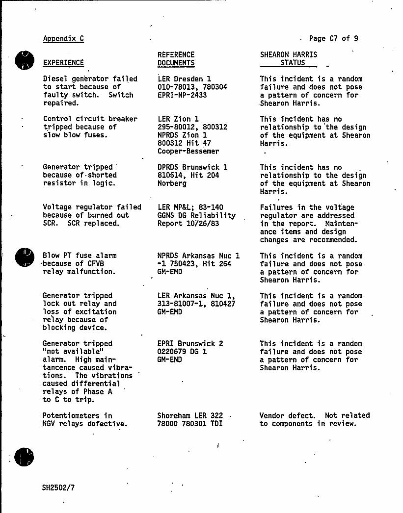
A endix C
EXPERIENCE
Diesel generator failedto star t because offaulty switch. Switchrepaired.
Control circuit breakertripped because ofslow blow fuses.
Generator tripped'ecauseof shorted
resistor in logic.
REFERENCEDOCUMENTS
LER Dresden 1010-78013, 780304EPRI-NP-2433
LER Zion 1295-80012, 800312NPRDS Zion 1800312 Hit 47Cooper-Bessemer
DPRDS Brunswick 1810614, Hit 204Norber g
Page C7 of 9
SHEARON HARRISSTATUS
This incident is a randomfailure and does not posea pattern of concern forShearon Harris.
This incident has norelationship to the designof the equipment at ShearonHar ris.
This incident has norelationship to the designof the equipment at ShearonHarris.
Voltage regulator failed LER MPHIL; 83-140because of burned out GGNS DG ReliabilitySCR. SCR repl aced. Report 10/26/83
Fai,lures in the voltageregulator are addressedin the report. Mainten-ance items and designchanges are recommended.
Blow PT fuse alarmbecause of CFVBrelay malfunction.
NPRDS Arkansas Nuc 1-1 750423, Hit 264GM-EMD
This incident is a randomfailure and does not posea pattern of concern forShearon Harris.
Generator trippedlock out relay andloss of excitationrelay because ofblocking device.
Generator tripped"not available"alarm. High main-tancence caused vibra-tions. The vibrationscaused differentialrelays of Phase Ato C to trip.Potentiometers inNGV relays defective.
LER Arkansas Nuc 1,313-81007"1, 810427GM-EMD
EPRI Brunswick 20220679 DG 1GM"END
Shoreham LER 32278000 780301 TDI
This incident is a randomfailure and does not posea pattern of concern forShearon Harris.
This incident is a randomfailure and does n'ot posea pattern of concern forShearon Harris.
Vendor defect. Not relatedto components in review.
SH2502/7
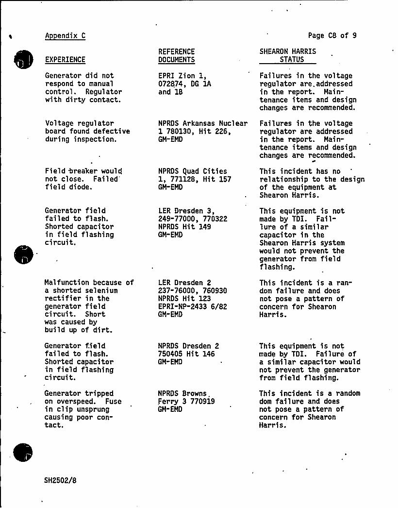
A endix C Page C8 of 9
EXPERIENCEREFERENCEDOCUMENTS
SHEARON HARRISSTATUS
Generator did notrespond to manualcontrol. Regulatorwith dirty contact.
Voltage regulatorboard found defectiveduring inspection.
Field Crea'ker wouldnot cl ose. Failedfield diode.
EPRI Zion 1,072874, DG 1Aand 1B
NPRDS Arkansas Nuclear1 780130, Hit 226,GM-EMD
NPRDS guad Cities1, 771128, Hit 157GM"EMD
Failures in the voltageregulator are. addressedin the report. Main-tenance items and designchanges are recommended.
Failures in the voltageregulator are addressedin the report. Main-tenance items and designchanges are recommended.
~+
This incident has norelationship to the designof the equipment atShearon Harris.
Generator fieldfailed to flash.Shorted capacitorin field flashingcircuit.
Malfunction because ofa shorted seleniumrectifier in thegenerator fieldcircuit. Shortwas caused bybuild up of dirt.Generator fieldfailed to flash.Shorted capacitorin field flashingcircuit.
Generator trippedon overspeed. Fusein clip unsprungcausing poor con-tact.
LER Dresden 3,249-77000, 770322NPRDS Hit 149GM"EMD
LER Dresden 2237-76000, 760930NPRDS Hit 123EPRI-NP-2433 6/82GM-EMD
NPRDS Dresden 2750405 Hit 146GM-EMD
NPRDS Browns.Ferry 3 770919GM-EMD
This equipment is notmade by TDI. Fail-lure of a similarcapacitor in theShearon Harris systemwould not prevent thegenerator from fieldflashing.
This incident is a ran-dom failure and doesnot pose a pattern ofconcern for ShearonHarris.
This equipment is notmade by TDI. Failure ofa similar capacitor wouldnot prevent the generatorfrom field flashing.
This incident is a randomdom failure and doesnot pose a pattern ofconcern for ShearonHarris.
SH2502/8
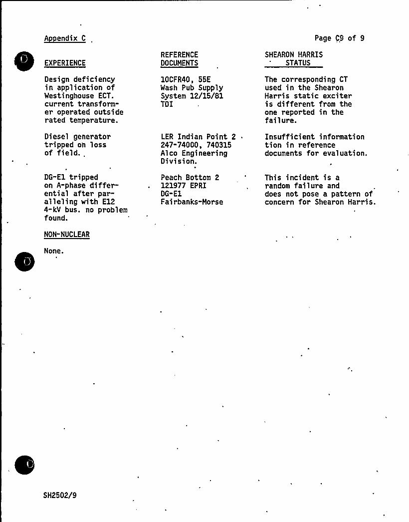
A endix C
EXPERIENCE
Design deficiencyin application ofWestinghouse ECT.current transform-er operated outsiderated temperature.
Diesel generatortripped oh lossof field..
DG-El trippedon A-phase differ-ential after par-alleling with E124-kV bus. no problemfound.
NON-NUCLEAR
None.
REFERENCEDOCUMENTS
10CFR40, 55EWash Pub SupplySystem 12/15/81TDI
LER Indian Point 2247-74000, 740315Alco EngineeringDivision.
Peach Bottom 2121977 EPRIDG-E1Fairbanks-Morse
Page C9 of 9
SHEARON HARRISSTATUS
The corresponding CTused in the ShearonHar ris static exciteris different from theone reported in thefailure.
Insufficient informationtion in referencedocuments for evaluation.
This incident is arandom failure anddoes not pose a pattern ofconcern for Shearon Harris.
SH2502/9
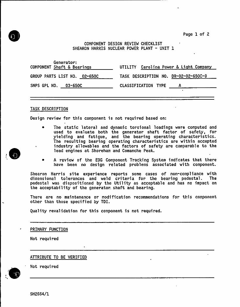
COMPONENT DESIGN REVIEW CHECKLISTSHEARON HARRIS NUCLEAR POWER PLANT - UNIT 1
Page 1 of 2
Generator:COMPONENT Shaft 8 Bearin s
GROUP PARTS LIST NO. 02-650C
SNPS GPL NO. 03-650C
UTILITY Carolina Power 5 Li ht Com an
TASK DESCRIPTION NO. DR-02-02-650C-0
CLASSIFICATION TYPE A
TASK DESCRIPTION
Design review for this component is not required based on:
~ The static lateral and dynamic torsional loadings were computed andused to evaluate both the generator shaft factor of safety, foryielding and fatigue, and the bearing operating characteristics.The resulting bearing operating characteristics are within acceptedindustry allowables and the factors of safety are comparable to thelead engines at Shoreham and Comanche Peak.
~ A rpview of the EDG Component Tracking System indicates that therehave been no design related problems associated with component.
Shearon Harris site experience reports some cases of non-compliance withdimensional tolerances and weld criteria for the bearing pedestal. Thepedestal was dispositioned by the Utility as acceptable and has no impact onthe acceptability of the generator. shaft and bearing.
There are no maintenance or modification recommendations for this componentother than those specified by TDI.
guality revalidation for this component is not required.
PRIMARY FUNCTION
Not required
ATTRIBUTE TO BE VERIFIED
Not required
SH2664/1
SPECIFIED STANDARDS
Not required
COMPONENT DESIGN REVIEW'HECKLIST Page 2 of 2DR-02-02-650C-0
REFERENCES
Not required
DOCUMENTATION RE UIRED
Not required
GROUP CHAIRPERSON PROGRAM MANAGER
SH2664/2
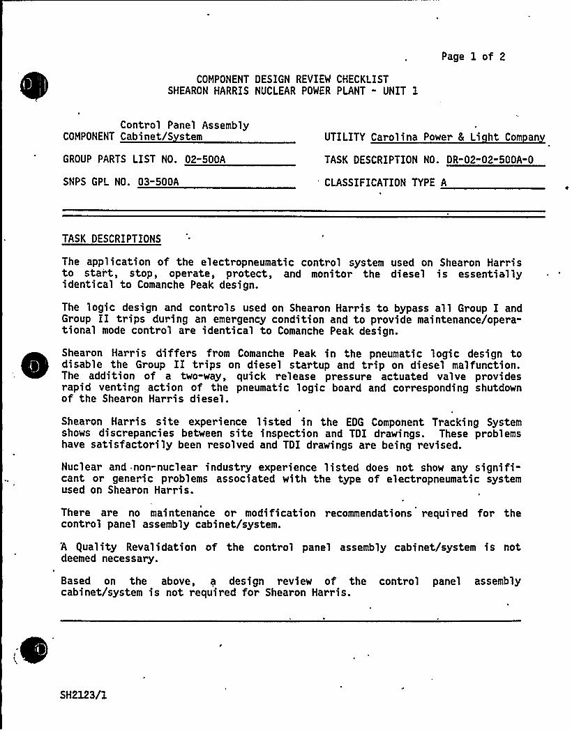
Page 1 of 2
COMPONENT DESIGN REVIEW CHECKLISTSHEARON HARRIS NUCLEAR POWER PLANT " UNIT 1
Control Panel AssemblyCOMPONENT Cabinet/S stem
GROUP PARTS LIST NO. 02"500A
SNPS GPL NQ. 03-500A
UTILITY Carolina Power 8 Li ht Com an
TASK DESCRIPTION NO. DR-02-02-500A-0
'LASSIFICATION TYPE A
TASK DESCRIPTIONS
The application of the electropneumatic control system used on Shearon Harristo stai t, stop, operate, protect, and monitor the diesel is essentiallyidentical to Comanche Peak design.
The logic design and controls used on Shearon Harris ta bypass all Group I andGroup II trips during an emergency condition and to provide maintenance/opera-tional mode control are identical to Comanche Peak design.
Shearon Harris differs from Comanche Peak in the pneumatic logic design todisable the Group II trips on diesel startup and trip on diesel malfunction.The addition of a two-way, quick release pressure actuated valve providesrapid venting action of the pneumatic logic board and corresponding shutdownof the Shearon Harris diesel.
Shearon Harris site experience listed in the EDG Component Tracking Systemshows discrepancies between site inspection and TDI drawings. These problemshave satisfactorily been resolved and TDI drawings are being revised.
Nuclear and non-nuclear industry experience listed does not show any signifi-cant or generic problems associated with the type of electropneumatic systemused on Shearon Harris.
There are no maintenance or modification recommendations required for thecontt ol panel assembly cabinet/system.
A guality Revalidation of the control panel assembly cabinet/system is notdeemed necessary.
Based on the above, a design review of the control panel assemblycabinet/system is not required for Shearon Harris.
SH2123/1

. PRIMARY FUNCTION~
~Not required
COMPONENT DESIGN REVIEW CHECKLIST Page 2 of 2DR-02-02-500A-0
ATTRIBUTE TO BE VERIFIED
Not r equired
SPECIFIED STANDARDS
Not required
REFERENCES
Not required
DOCUMENTATION RE UIRED
Not required
GROUP CHAIRPERSON PROGRAM MANAGER
SH2123/2

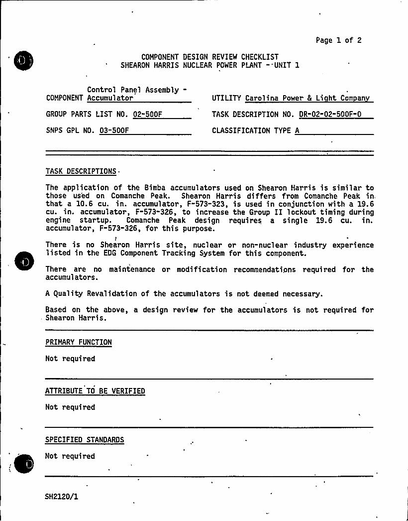
COMPONENT DESIGN REVIEW CHECKLISTSHEARON HARRIS NUCLEAR POWER PLANT -'UNIT 1
Page 1 of 2
Control Panel Assembly-COMPONENT Accumulator
GROUP PARTS LIST NO. 02"500F
SNPS GPL NO. 03-500F
UTILITY Carolina Power 8 Li ht Com an
TASK DESCRIPTION NO. DR-02-02-500F-0
CLASSIFICATION TYPE A
TASK DESCRIPTIONS
The application of the Bimba accumulators used on Shearon Harris is similar tothose used on Comanche Peak. Shearon Harris differs from Comanche Peak in.that a 10.6 cu. in. accumulator, F-573-323, is used in conjunction with a 19.6cu. in. accumulator, F-573-326, to increase the Group II lockout timing duringengine startup. Comanche Peak design requires a single 19.6 cu. in.accumulator, F-573-326, for this purpose.
IThere is no Shearon Harris site, nuclear .or non-nuclear industry experience
~
~
~
~
~
~ ~
~ ~ ~
~
~
~
~
listed in the EDG Component Tracking System for this component.
There are no maintenance or modification recommendations required for theaccumulators.
A guality Revalidation of the accumulators is not deemed necessary.
Based on the above, a design review for the accumulators is not required forShearon Harris.
PRIMARY FUNCTION
Not required
ATTRIBUTE TO BE VERIFIED
Not required
SPECIFIED STANDARDS
Not requiredI
SH2120/1

REFERENCES
Not required
COMPONENT DESIGN REVIEW CHECKLIST Page 2 of 2DR-02-02-500F-0
DOCUMENTATION RE UIRED
Not required
GROUP CHAIRPERSON PROGRAM MANAGER
SH2120/2
Page 1 of 2
COMPONENT DESIGN REVIEW CHECKLISTSHEARON HARRIS NUCLEAR POWER PLANT -'UNIT 1
COMPONENT Control Panel Valves UTILITY Carol ina Power & Li ht Com an
GROUP PARTS LIST NO. 02-500G TASK DESCRIPTION NO. DR"02"02-500G-0
SNPS GPL NO. 03-500G CLASSIFICATION TYPE A
TASK DESCRIPTIONS
The control panel val ves used on Shearon Harri s are identi cal in val veapplication and manufacturer to .those on Comanche Peak, with the exception of3-way valve F-573-090 and 2-way valve F-573-156. Shearon Harris uses manuallyactuated ARO 3-way valves F-573-090 to direct the flow of control airproviding fuel oil tank level indication, lube oil tank level indication andannunciation on a manual start. Shearon Harris also uses a pressure actuatedCalifornia Controls 2-way, quick release valve, F-573-156, to disable theGroup II trips during diesel startup and provide rapid venting action of thelogic board to shut down the diesel on a malfunction. The above valves
~
~
~
~
~
operate in the compressed air system at 60 psi and are adequate for theirintended service.
There is no Shearon Harris site experience listed in the EDG ComponentTracking System for the control panel valves. The industry experience listeddoes not show any significant experience relating to the control panel valves.
To minimize fouling of the control panel valves, it is recommended that thevalves be inspected and cleaned during each refueling outage. Thisrecommended maintenance interval should be reassessed depending on the degreeof system fouling.
A guality Revalidation of the control panel valves is not deemed necessary.
Based on the above, a design review for the control panel valves is notrequired for Shearon Harris.
r
PRIMARY FUNCTION
Not required
'ATTRIBUTE TO BE VERIFIED
Not required
SH2126/1

, 'F ~,
SPECIFIED STANDARDS
Not required
COMPONENT DESIGN REVIEW CHECKLIST Page 2 of 2DR-02"02"500G" 0
REFERENCES
Not required
DOCUMENTATION RE UIRED
Not required
GROUP CHAIRPERSON PROGRAM MANAGER C. h4
SH2126/2
COMPONENT DESIGN REVIEM CHECKLISTSHEARON HARRIS NUCLEAR POWER PLANT " UNIT 1
Page 1 of 2
Control Panel AssemblyCOMPONENT Pressure Switches
GROUP PARTS LIST NO. 02-500H
SNPS GPL NO. 03-500H
UTILITY Carolina Power 8 Li ht Com an
TASK DESCRIPTION NO. DR-02-02-500H-0
CLASSIFICATION TYPE B
TASK DESCRIPTIONS
The pressure switches used on Shearon Harris are identical to those used onComanche Peak in regard to manufacturer and application.
There is no Shearon Harris site or non-nuclear industry experience listed inthe EDG Component Tracking System for this component. The nuclear, industryexperience listed does not show any generic or significant problems with thepressure switches.
There are no maintenance or modification recommendations required for the
~
~
~ ~
pressure switches.
A guality Revalidation of the pressure switches is not deemed necessary.
Based on the above, a design review for pressure switches is not required forShearon Harris.
PRIMARY FUNCTION
Not required
ATTRIBUTE TO BE VERIFIED
Not required
SPECIFIED STANDARDS
Not required
5H2127/1

REFERENCES
Not required
COMPONENT DESIGN REVIEW CHECKLIST Page 2 of 2DR-02-02-500H-0
DOCUMENTATION RE UIREO
Not required
GROUP CHAIRPERSON PROGRAM MANAGER
SH2127/2
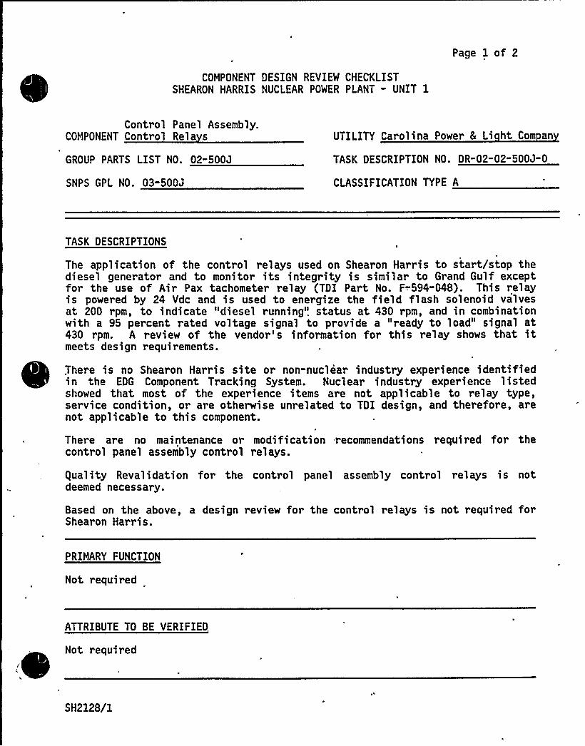
COMPONENT DESIGN REVIEW CHECKLISTSHEARON HARRIS NUCLEAR POWER PLANT - UNIT 1
Page 1 of 2
Control Panel Assembly.COMPONENT Control Rela s
GROUP PARTS LIST NO. 02"500J
SNPS GPL NO. 03-500J
UTILITY Carolina Power 8 Li ht Com an
TASK DESCRIPTION NO. DR-02"02-500J-0
CLASSIFICATION TYPE A
TASK DESCRIPTIONS
The application of the. control relays used on Shearon Harris to start/stop thediesel generator and to monitor its integrity is similar to Grand Gulf exceptfor the use of Air Pax tachometer relay (TDI Part No. F-594"048). This relayis powered by 24 Vdc and is used to energize the field flash solenoid valvesat 200 rpm, to indicate "diesel running". status at 430 rpm, and in combinationwith a 95 percent rated voltage signal to provide a "ready to load" signal at430 rpm. A review of the vendor's information for this relay shows that itmeets design requirements.
There is no Shearon Harris site or non-nuclear industry experience identifiedin the EDG Component Tracking System. Nuclear industry experience listedshowed that most of the experience items are not applicable to relay type,service condition, or are otherwise unrelated to TDI design, and therefore, arenot applicable to this component.
There are no maintenance or modification recommendations required for thecontrol panel assembly control relays.
equality Revalidation for the control panel assembly control relays is notdeemed necessary.
Based on the above, a design review for the control relays is not required forShearon Harris.
PRIMARY FUNCTION
Not required
ATTRIBUTE TO BE VERIFIED
Not required/
SH2128/1

SPECIFIED STANDARDS
Not required
COMPONENT DESIGN REVIEW CHECKLIST Page 2 of 2DR-02-02-500J-0
REFERENCES
Not required
DOCUMENTATION RE UIRED
Not required
GROUP CHAIRPERSON PROGRAM MANAGER
SH2128/2
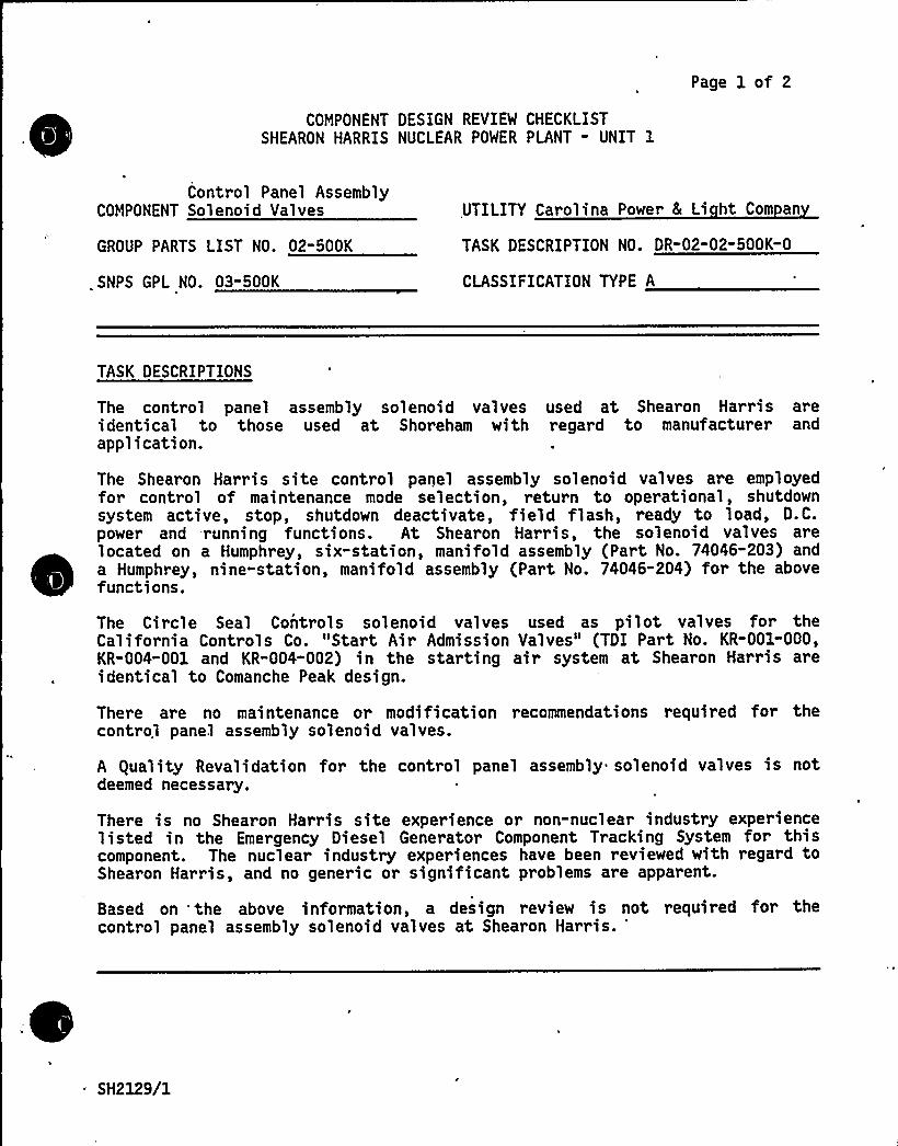
Page 1 of 2
COMPONENT DESIGN REVIEW CHECKLISTSHEARON HARRIS NUCLEAR POWER PLANT - UNIT 1
Control Panel AssemblyCOMPONENT Solenoid Valves UTILITY Carolina Power 8 Li ht Com an
GROUP PARTS LIST NO. 02-500K TASK DESCRIPTION NO. DR-02"02-500K-0
.SNPS GPL NO. 03"500K CLASSIFICATION TYPE A
TASK DESCRIPTIONS
The control panel assembly solenoid valves used at Shearon Harris areidentical to those used at Shoreham with regard to manufacturer andapplication.
The Shearon Harris site control panel assembly solenoid valves are employedfor control of maintenance mode selection, return to operational, shutdownsystem active, stop, shutdown deactivate, field flash, ready to load, D.C.power and running functions. At Shearon Harris, the solenoid valves arelocated on a Humphrey, six-station, manifold assembly (Part No. 74046-203) anda Humphrey, nine-station, manifold assembly (Part No. 74046-204) for the abovefunctions.
The Circle Seal Controls solenoid valves used as pilot valves for theCalifornia Controls Co. "Start Air Admission Valves" (TDI Part No. KR-001-000,KR-004-001 and KR-004-002) in the starting air system at Shearon Harris areidentical to Comanche Peak design.
There are no maintenance or modification recommendations required for thecontrol panel assembly solenoid valves.
A guality Revalidation for the control panel assembly solenoid valves is notdeemed necessary.
There is no Shearon Harris site experience or non-nuclear industry experiencelisted in the Emergency Diesel Generator Component Tracking System for thiscomponent. The nuclear industry experiences have been reviewed with regard toShearon Harris, and no generic or significant problems are apparent.
Based on 'the above information, a design review is not required for thecontrol panel assembly solenoid valves at Shearon Harris.
'H2129/1
PRIMARY FUNCTION
Not required
COMPONENT DESIGN REVIEM CHECKLIST Page 2 of 2DR"02"02-500K-0
ATTRIBUTE TO BE VERIFIED
Not required
SPECIFIED STANDARDS
Not required
REFERENCES
Not required
DOCUMENTATION RE UIRED
,Not required
GROUP CHAIRPERSON PROGRAM MANAGER
SH2129/2


COMPONENT UALITY REVALIDATION CHECKLIST
Page 1 of 102-02-500M
Control Panel Assembly-COMPONENT Pi in Tubin Fittin s
GPL NO. 02"500M
SNPS GPL NO. 03-500M
Carolina Power & LightShearon Harris Nuclear
. UTILITY Power Plant - Unit 1
REV. NO. 1
TASK DESCRIPTIONS
~En inc 1A
No further revi ew of component 02-500M i s required for the fol 1 owingreasons:
a) Component was reviewed on two lead engines with satisfactory results.b) There is no significant industry ..or site experience for this
component.
GROUP CHAIRPERSON + PROGRAM MANAGER C
SH1813/1
COMPONENT UALITY REVALIDATION CHECKLIST
Page 1 of 102-02-500N
Control Panel AssemblyTerminal Boards/
COMPONENT Switches Wirin
GPL NO. 02"500N
SNPS GPL NO. 03-500N
Carolina Power L LightShearon Harris Nuclear
UTILITY Power Plant - Unit 1
REV. NO. 1
TASK DESCRIPTIONS
No further review of component 02-500N is required for the followingreasons:
a) There is no site experience. or signi ficant industry experiencereported for this component.
b) Component was reviewed on- the lead engines (Shoreham) withsatisfactory results.
GROUP CHAIRPERSON P PROGRAM, MANAGER
SH1812/1
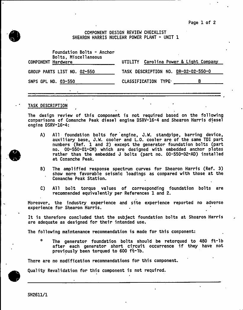
Page 1 of 2
COMPONENT DESIGN REVIEW CHECKLISTSHEARON HARRIS NUCLEAR POWER PLANT - UNIT 1
Foundation Bolts - AnchorBolts, Miscellaneous
COMPONENT Hardware UTILITY Carolina Power & Li ht Com an
GROUP PARTS LIST NO. 02"550 TASK DESCRIPTION NO. DR"02-02-550" 0
SNPS GPL NO. 03-550 CLASSIFICATION TYPE'
TASK DESCRIPTION
The design review of this component is not required based on the followingcomparisons of Comanche Peak diesel engine DSRV-16-4 and Shearon Harris dieselengine DSRV-16-4:
A) All foundation bolts for engine, J.W. standpipe, barring device,auxiliary base, J.W. cooler and L.O. cooler are of the same TDI partnumbers (Ref. 1 and 2) except the generator foundation bolts (partno. 00-550-01-CM) which are designed with embedded anchor platesrather than the embedded J bolts (part no. 00-550-02-AD) installedat Comanche Peak.
B) The amplified response spectrum curves for Shearon Harris (Ref. 3)show more favorable seismic loadings as compared with those at theComanche Peak Station.
C) All bolt torque values of corresponding foundation bolts arerecommended equivalently per References 1 and 2.
Moreover, the industry experience and site experience reported no adverseexperience for Shearon Harris.
It is therefore concluded that the subject foundation bolts at Shearon Harrisare adequate as designed for their intended use.
The following maintenance recommendation is made for this component:
The generator foundation bolts should be retorqued to 480 ft-lbafter each generator short circuit occurrence if they have notpreviously been torqued to 600 ft-lb.
There are no modification recommendations for this component.
guality Revalidation for this component is not required.~ ~
J
SH2611/1
'a/I+
PRIMARY FUNCTION
Not required
COMPONENT DESIGN REVIEW CHECKLIST Page 2 of 2OR-02-02-550 -0
ATTRIBUTE TO BE VERIFIED
Not required
SPECIFIED STANDARDS
Not required
REFERENCES
1. 'DI Manual Volume II, for Model DSRV-16-4 Diesel Engine/Generator,Shearon Harris Nuclear Power Plant, Units 1, 2, 3, and 4, Parts List Nos.02-550 (for 74046) and 02-550-03-04, and Drawing No. R-4051.
2. TDI Manual Volume II for Model DRSV-16-4 Diesel Engine/Generator,Comanche Peak Steam Electric Station - Unit 1, Parts List Nos. 02-550(for 76001), and 02-550-03-04, and Drawing No. R-3943.
3. Ebasco Services, Inc., Project CAR-SH-E-11, Specification 216-73-TB forDiesel Engine Generator Unit and Control Panel for Nuclear Power Plants,Rev. 7, dated September 14, 1981, Addendum A, "Seismic Considerations forMechanical Equipment," - Response Acceleration Spectra Curves (12 sheets)Revised December 26, 1978.
DOCUMENTATION RE UIRED .
Not required
GROUP CHAIRPERSON PROGRAM MANAGER MCA
SH2611/2

Cl
COMPONENT DESIGN REVIEW CHECKLISTSHEARON HARRIS NUCLEAR POWER PLANT - UNIT 1
Page 1 of 2
COMPONENT Auxiliar Skid
GROUP PARTS LIST NO. 02-717A
SNPS GPL NO. 03-717A
UTILITY Carolina Power 8 Li ht Com an
TASK DESCRIPTION NO. DR-02-02-717A" 0
CLASSIFICATION TYPE
TASK DESCRIPTIONS~+
Design review far this component is not. required based on the following:
A review of the lead engine DR/gR reports (Shoreham/Comanche Peak).
~ A review of the EDG Component Tracking System indicated no significantapplicable industry and/or site experience.
~ A 'detailed dynamic analysis was performed to seismically qualify the skid(Ref. 2).
The Parts Manual for Shearon Harris lists the auxiliary sub-base as an ASMEIII component. It is evidently intended that the skid should be an NF Supportfor the skid mounted ASME III components. However, the seismic qualificationreport (Ref. 2) says that the auxiliary base is non ASME III. A similarsituation existed at Comanche Peak where Gibbs and Hill attempted to backfitan NF qualification for the skid. The skid was found acceptable, but it didnot fully satisfy NF. The seismic models and drawings are different betweenComanche Peak and Shearon Harris and thus the Gibbs and Hill analyses wouldnot be directly applicable to Shearon Harris. The CTS for Shearon Harris doeslist one problem with ASME III weld deficiencies on auxiliary skid pipesupports, but does not list any deficiencies with ASME III auxiliary skidqualifications. Given the experience at Comanche Peak, it is recommended thatCP8L snvestigate the adequacy of the ASME III qual.ifications as they apply tothe auxiliary skid.
There are no maintenance recommendations from the lead engine beyond thoserecommended in the TDI Instruction Manual.
-There are no modifications recommended for this component.
guality Revalidation is not required for this component.
,SH2557/1

,~
'RIMARY FUNCTION
Not required
COMPONENT DESIGN REVIEW CHECKLIST Page 2 of 2DR-02-02-717A-0
ATTRIBUTE TO BE VERIFIED
Not required
SPECIFIED STANDARDS
Not required
REFERENCES
l. Ebasco Specification ¹ 216-73-Tb, Rev. 3, 4-25-78, "Diesel EngineGenerator Unit and Control Panel for Carolina Power 8 Light Company,Shearon Harris Nuclear Power Plant Units 1, 2, 3, and 4, Wake County,North Carolina.
'inal Report Volume II,'nalytic Modeling of Engine Auxiliaries Seismicgualification of TDI Diesel Generator Sets, Serial Numbers 74046/53 forCarolina Power 8 Light Company, Shearon Harris Nuclear Power Plant Units1, 2, 3, and 4, Section X, Auxiliary Sub-Base.
DOCUMENTATION RE UIRED
Not required
GROUP CHAIRPERSON PROGRAM MANAGER
SH2557/2
TDI OWNERS GROUP
for
SHEARON HARRIS NUCLEAR POWER PLANT
MAINTENANCE REVIEWAPPENDIX - II
I INTRODUCTION
The purpose of this Appendix is to provide Shearon Harris with a set ofmaintenance and surveillance recommendations for diesel generator compo-nents which have been developed by TDI and/or the Owners Group as a resultof the overall Owners Group Program. This Appendix is intended tosupplement the existing TDI Instruction Manual, Volume I and Volume III,which will maintain the qualification of the diesel generators for thelife of the plant.
II METHODOLOGY
During the implementation of the Owners Group Program Plan, the OwnersGroup Technical Staff reviewed many sources of information regarding themaintenance, and surveillance for the diesel generator components identi-fied in this Appendix. These sources included TDI Instruction Manuals,Service Information Memos (SIMS), and TDI correspondence on specificcomponents. This review along with Technical Staff input regarding theadequacy of the recommendations found in the sources mentioned above, andadditional maintenance recommendations identified during the DR/gR review,forms the basis for the content of this matrix.
III RESULTS AND CONCLUSIONS
Proper maintenance is important in ensuring long, reliable and satisfacto-ry service of the emergency diesel generators. Maintenance work, in orderto be effective, must be carried out thoroughly and regularly. It is forthese reasons that a detailed schedule of maintenance service has beenlaid out by the Owners Group for the TDI Diesel Generators at ShearonHarris Nuclear Power Plant. The schedule details specific componentsrequiring maintenance on a regular basis. This schedule separates themaintenance activities into a daily, monthly, outage, alternate outage(every other), 5-year and 10-year frequencies. It should be noted herethat the duration time between outages at Shearon Harris is assumed to be18 months.
SH2401/1

Page 2 of 3
Those less significant diesel generator system components with whichstandard engineering pr actice and maintenance will ensure continuedoperation, are not specifically addressed in the matrix. Standard mainte-nance practices are briefly discussed below.
The engine and generator should be kept clean and dry at all times. Oiland water leakage should be wiped off the unit as quickly as possible inorder to assist in locating the source of leakage, prevent potentialequipment damage and maintain a safe working environment. Leaking pipes,gaskets and packing glands should be attended to promptly so as not toimpair the reliability and/or operation of the system. Flanged gasketedconnections may be retightened to stop leaks and any abnormal enginenoises or vibrations. Actions required to correct any abnormal conditionsshould be carried out in a timely manner. Loose bolts and electricalterminals should be attended to in a safe, practical manner.
Specific items to be maintained on a DAILY basis consist of the following:
l. Observe and record lubricating oil and jacket water temperatures(keep warm pump running).
2. Drain all low point water collectors, and air receiver tank floattraps in the air start system.
3. Check engine and auxiliary equipment and piping connections for oil,water, and fuel oil leaks.
4. Check level of lubricating oil in the governor, sump tank and ped-estal bearing. Add oil as needed.
5. Check fuel oil pump rack for freedom of movement through full limitof travel. Do not disconnect from governor.
6. Check turbocharger bearing lubricating oil system sight glass for oilf1 ow.
7. Drain water from crankcase vent piping drip legs.
8. Verify all controls in proper position for standby mode.
9. Check all governor knob settings.
Load Maximum Droop ZeroSpeed To provide mechanical governor control at
460 rpm.
SH2401/2Revision 1
Page 3 of 3
10. Visually inspect lube oil heat exchanger and jacket water heatexchanger for signs of leakage from the lantern ring leakoff ports,indicating leaking packing r ings.
The following Preventive Maintenance Recommendation Matrix was designed toassist the Maintenance Department in determining the scope of work re-quired to maintain the intended design function of the diesel generatorsat Shearon Harris on a planned schedule basis. It should be followedclosely and referred to often.
SH2401/3
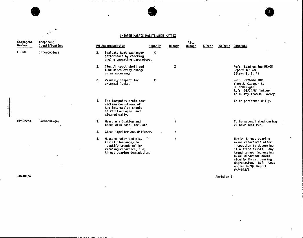
SHEARON HARRIS HAINTENANCE MATRIX
Component ComponentNumber Identification PH Recommendation l~lo nthl
Alt.~Outa e ~Outa e 5 Year 10 Year Comments
F-068 Intercoolers
HP-022/3 Turbocharger
l. Evaluate heat exchanger Xperformance by checkingengine operating parameters.
2. Clean/inspect shell andtube sides every outageor as necessary.
3. Visually inspect forexternal leaks.
4. The low-point drain con-nection downstream ofthe intercooler shouldbe verified open, andcleaned daily.
1. Measure vibration andcheck with base line data.
2. Clean impeller and diffuser.
Ref: Lead engine OR/0RReport 8F-068(Items 2, 3, 4)
Ref: 7/26/84 IOCfrom J. Cadogan toH. HcGerigle,Ref: 08/14/84 letterto C. Ray from H. Lowrey
To be performed daily.
To be accomplished during24 hour test run.
SH2401/4
3. Measure rotor end play(axial clearance) toidentify trends of in-creasing clearance, i.e;thrust bearing degradation.
Revision 1
Review thrust bearingaxial clearances afterinspection to determineif a trend exists. Anytrend toward increasingaxial clearance couldsignify thrust bearingdegradation. Ref: Leadengine OR/0R Report8HP-022/3
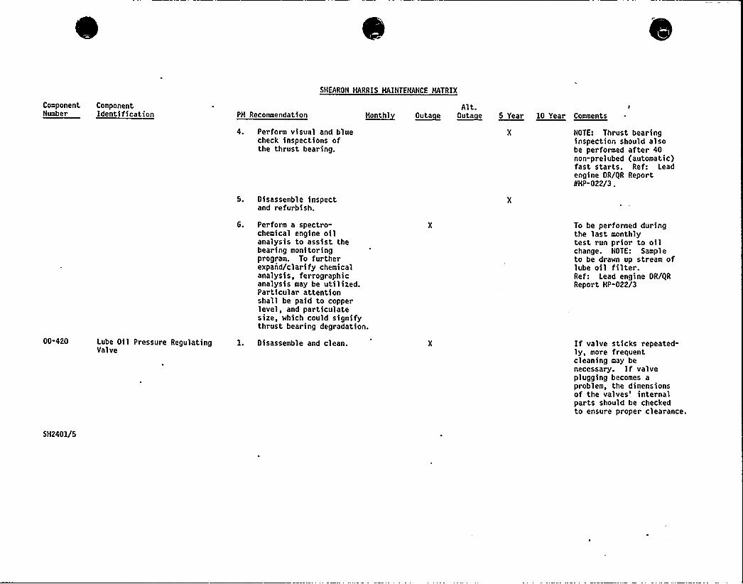
ComponentNumber
ComponentIdentification PH Recommendation
SHEARON HARRIS HAINTENANCE MATRIX
Alt.a~hathi ~Outa e ~outa e 5 Year 10 Year Cameuta
00-420 Lube Oil Pressure RegulatingValve
4. Perform visual and bluecheck inspections ofthe thrust bearing.
5. Disassemble inspectand refurbish.
6. Perform a spectro-chemical engine oilanalysis to assist thebearing monitoringprogram. To furtherexpand/clarify chemicalanalysis, ferrographicanalysis may be utilized.Particular attentionshall be paid to copperlevel, and particulatesize, which could signifythrust bearing degradation.
l. Oi sassemble and clean.
NOTE: Thrust bearinginspection should alsobe performed after 40non-prelubed (automatic)fast starts. Ref: Leadengine OR/0R ReportSHP-022/3 .
To be performed duringthe last monthlytest run prior to oilchange. NOTE: Sampleto be drawn up stream oflube oil filter.Ref: Lead engine OR/I|RReport HP-022/3
If valve st>cks repeatedly, more frequentcleaning may benecessary. If valveplugging becomes aproblem, the dimensionsof the valves'nternalparts should be checkedto ensure proper clearance.
5H2401/5
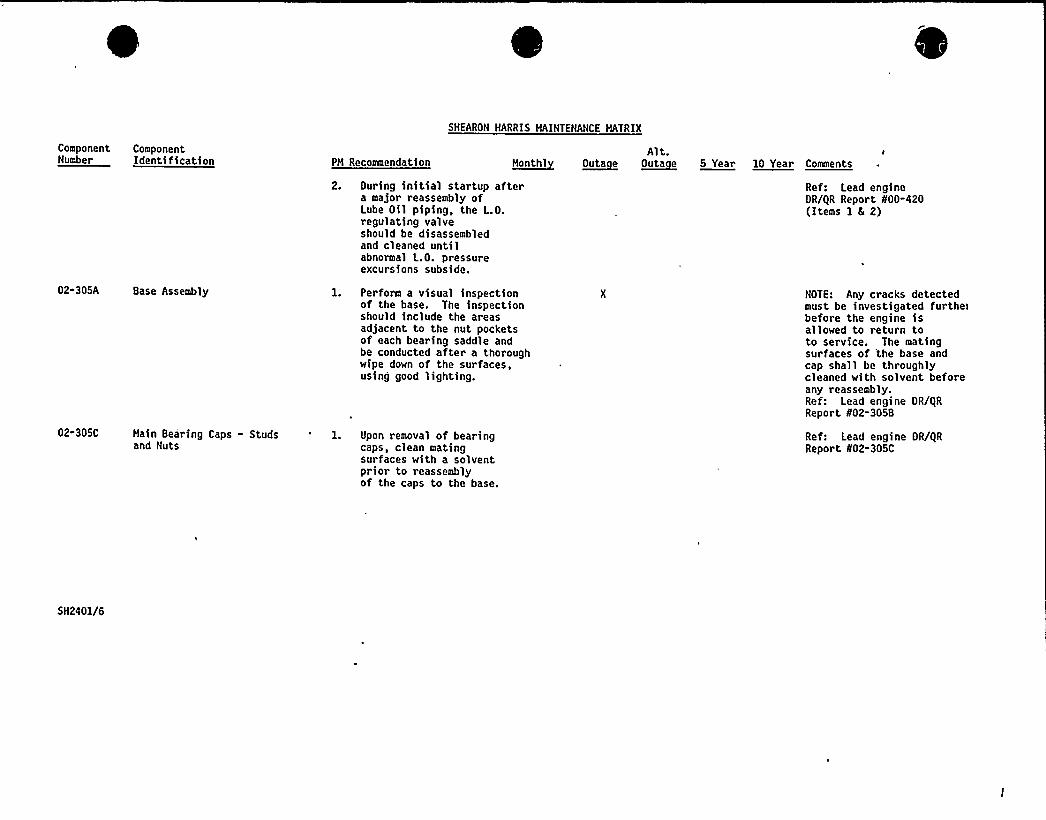
SHEARON MARRIS MAINTENANCE MATRIX
ComponentNumber
ComponentIdentification PM Recosmendation ~Month1
Alt. I
~Outa e ~Outa e 5 Year 10 Year Comments
2. During initial startup aftera major reassembly ofLube Oil piping, the L.O.regulating valveshould be disassembledand cleaned untilabnormal L.O. pressureexcursions subside.
Ref: Lead engineDR/gR Report 800-420(Items 1 8 2)
02-305A Base Assembly
02-305C Main Bearing Caps - Studsand Nuts
1. Perform a visual inspectionof the base. The inspectionshould include the areasadjacent to the nut pocketsof each bearing saddle andbe conducted after a thoroughwipe down of the surfaces,using good lighting.
1. Upon removal of bearingcaps, clean matingsurfaces with a solventprior to reassemblyof the caps to the base.
NOTE: Any cracks detectedmust be investigated furthe>before the engine isallowed to return toto service. The matingsurfaces of 'the base andcap shall be throughlycleaned with solvent beforeany reassembly.Ref: Lead engine DR/IiRReport 802-305B
Ref: Lead engine DR/gRReport N02-305C
5H2401/6
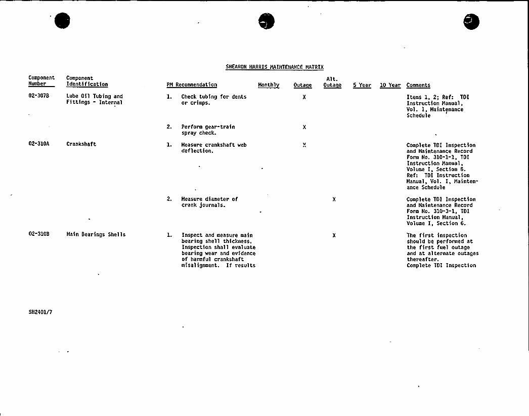
ComponentNumber
ComponentIdentification PH Recommendation
SHEARON HARRIS HAINTENANCE MATRIX
Alt.~Honth1 ~Outa e O~uta e 5 Year 10 Year Comaea<j
02-307B Lube Oil Tubing andFittings - Internal
1. Check tubing for dentsor crimps.
Items 1, 2; Ref: TOIInstruction Manual,Vol. I, HaintenanceSchedule
02-310A Crankshaft
02-310B Hain Bearings Shells
2. Perform gear-trainspray check.
1. Heasure crankshaft webdeflection.
2. Measure diameter ofcrank journals.
1. Inspect and measure mainbearing shell thickness.Inspection shall evaluatebearing wear and evidenceof harmful crankshaftmisalignment. If results
Complete TOI Inspectionand Maintenance RecordForm No. 310-1-1, TOIInstruction Hanual,Volume I, Section 6.Ref: TOI InstructionManual, Vol. I, Hainten-ance Schedule
Complete TOI Inspectionand Haintenance RecordForm No. 310-3-1, TOIInstruction Manual,Volume I, Section 6.
The first inspectionshould be performed atthe first fuel outageand at alternate outagesthereafter.Complete TOI Inspection
SH2401/7
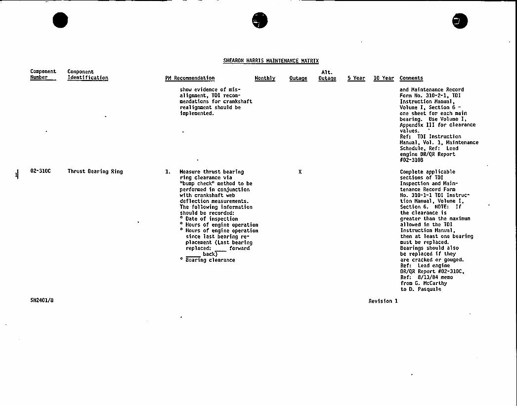
Component ComponentNumber Identification PH Recommendation
SHEARON HARRIS MAINTENANCE MATRIX
Alt.~uaathl ~etta e ~Outa e 5 Year 10 Year Comments
02-310C Thrust Bearing Ring
SH2401/8
show evidence of mis-alignment, TOI recom-mendations for crankshaftrealignment should beimplemented.
1. Measure thrust bearingring clearance via"bump check" method to beperformed in conjunctionwith crankshaft webdeflection measurements.The following informationshould be recorded:
Bate of inspectionHours of engine operation
4 Hours of engine operationsince last bearing re-placement (Last bearingreplaced: forward
backT4 Bearing clearance
Revision 1
and Maintenance RecordForm No. 310-2-1, TOIInstruction Manual,Volume I, Section 6-one sheet for each mainbearing. Use Volume I,Appendix III for clearancevalues.Ref: TOI InstructionHanual, Vol. 1, MaintenanceSchedule, Ref: Leadengine OR/QR Report802-310B
Complete applicablesections of TOIInspection and Main-tenance Record FormNo. 310-1-1 TOI Instruc-tion Manual, Volume I,Section 6. NOTE: Ifthe clearance isgreater than the maximumallowed in the TOIInstruction Hanual,then at least one bearingmust be replaced.Bearings should alsobe replaced if theyare cracked or gouged.Ref: Lead engineOR/QR Report f02-310C,Ref: 8/13/84 memofrom G. HcCarthyto O. Pasquale
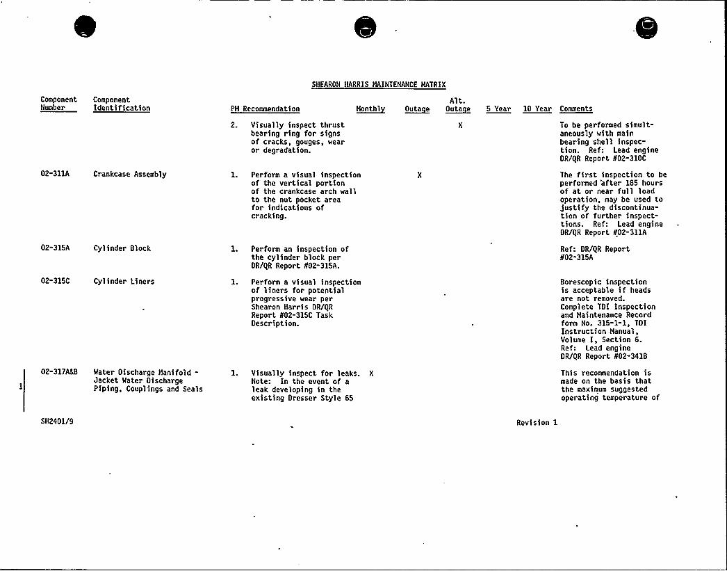
Component ComponentNumber Identification PM Recommendation
SHEARON HARRIS MAINTENANCE MATRIX
Alt.u~eutht ~Outa e ~Outa e 5 Year 10 Year Comments
02-311A Crankcase Assembly
02-315A Cyl inder Block
02-315C Cylinder Liners
02-317'ater Discharge Manifold-Jacket Water DischargePiping, Couplings and Seals
5H2401/9
2. Visually inspect thrustbearing ring for signsof cracks, gouges, wearor degradation.
1. Perform a visual inspectionof the vertical portionof the crankcase arch wallto the nut pocket areafor indications ofcracking.
1. Perform an inspection ofthe cylinder block perOR/IiR Report N02-315A.
1. Perform a visual inspectionof liners for potentialprogressive wear perShearon Harris OR/gRReport N02-315C TaskDescription.
1. Visually inspect for leaks. XNote: In the event of aleak developing in theexisting Dresser Style 65
To be performed simult-aneously with mainbearing shell inspec-tion. Ref: Lead engineDR/gR Report N02-310C
The first inspection to beperformed 'after 185 hoursof at or near full loadoperation, may be used tojustify the discontinua-tion of further inspect-tions. Ref: Lead engineDR/gR Report N02-311A
Ref: DR/gR ReportN02-315A
Borescopic inspectionis acceptable if headsare not removed.Complete TOI Inspectionand Maintenance Recordform No. 315-1-1, TOIInstruction Manual,Volume I, Section 6.Ref: Lead engineOR/gR Report N02-341B
This recommendation ismade on the basis thatthe maximum suggestedoperating temperature of
Revision 1
8
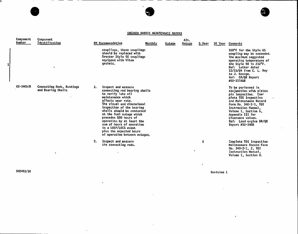
ComponentNumber
ComponentIdentification PH Recommendation
SNEARON HARRIS HAINTENANCE HATRIX
Alt.H~onthl ~OUta e ~outa e 5 Year 10 Year Comments
02-340A/8 Connecting Rods, Bushingsand Bearing Shells
couplings, these couplingsshould be replaced withDresser Style 90 couplingsequipped with Vitongaskets.
1. Inspect and measureconnecting rod bearing shellsto verify lube oilmaintenance whichaffects wear rate.The visual and dimensionalinspection of the bearingshells should be conductedat the fuel outage whichprecedes 500 hours ofoperation by at least thesum of hours of operationin a LOOP/LOCA eventplus the expected hoursof operation between outages,
2. Inspect and measurethe connecting rods.
150'F for the Style 65coupling may be exceeded.The maximum suggestedoperating temperature ofthe Style 90 is 212~F.Ref: Letter dated12/13/84 from C. L. Rayto J. George.Ref: DR/QR ReportI/02-317ALB
To be performed inconjunction with pistonpin inspection. Com-plete TDI Inspectionand Haintenance RecordForm No. 340-1-1, TOIInstruction Hanual,Volume I, Section 6,Appendix III forclearance values.Ref: Lead engine OR/QRReport 802-340B
Complete TDI InspectionHaintenance Record FormNo. 340-2-1, 2, TDIInstruction Hanual,Volume I, Section 6.
5H2401/10 Revision 1
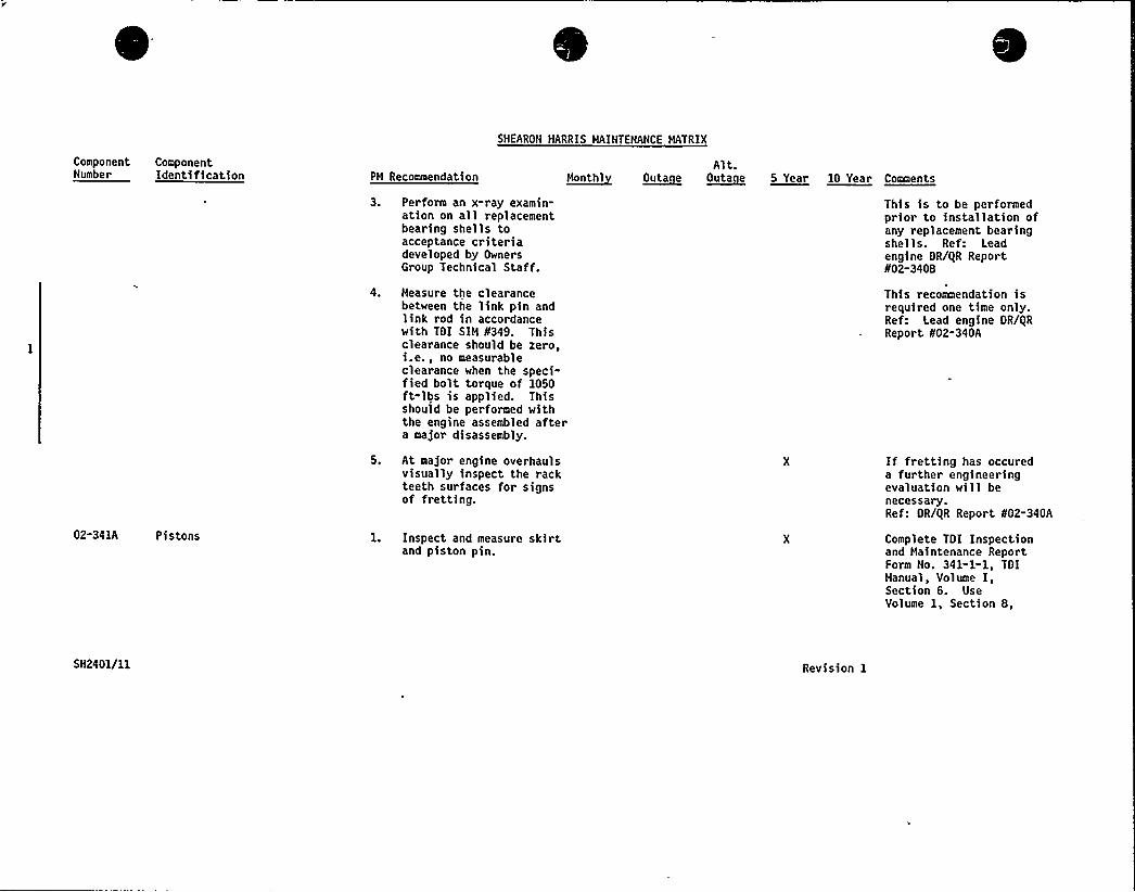
Component ComponentNumber Identification PH Recommendation
SHEARON HARRIS MAINTENANCE HATRIX
Alt.M~onth) O~uta e O~uta e 5 Year 10 Year Comments
02-341A Pistons
3. Perform an x-ray examin-ation on all replacementbearing shells toacceptance criteriadeveloped by OwnersGroup Technical Staff.
4. Measure the clearancebetween the link pin andlink rod in accordancewith TDI SIH fI349. Thisclearance should be zero,i.en 5 nO meaSurableclearance when the speci-fied bolt torque of 1050ft-lbs is applied. Thisshould be performed withthe engine assembled aftera major disassembly.
5. At major engine overhaulsvisually inspect the rackteeth surfaces for signsof fret ting.
1. Inspect and measure skirtand piston pin.
This is to be performedprior to snstallatson ofany replacement bearingshells. Ref: Leadengine OR/iiR Reportif02-3408
This recommendation isrequired one time only.Ref: Lead engine OR/gRReport 802-340A
If frett>ng has occureda further eng>neer>ngevaluation will benecessary.Ref: OR/gR Report 802-340A
Complete TOI Inspectionand Haintenance ReportForm No. 341-1-1, TOIManual, Volume I,Section 6. UseVolume 1, Section 8,
5H2401/11 Revision 1
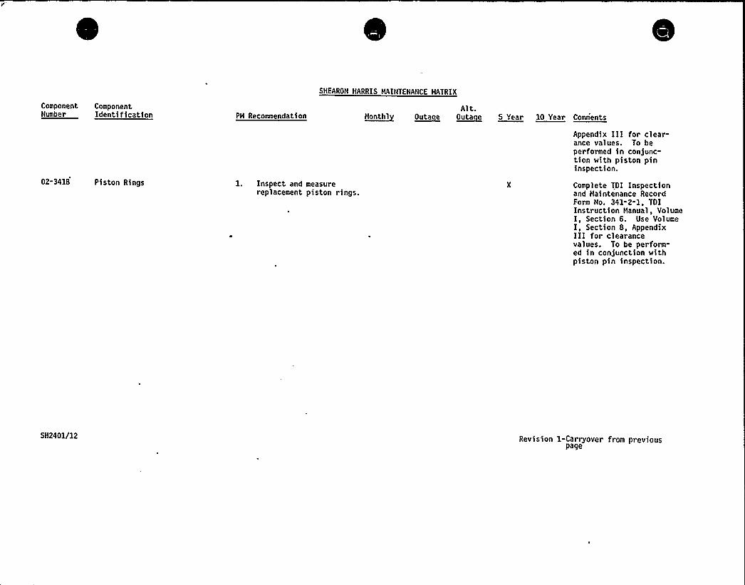
SHEARON HARRIS HAINTENANCE HATRIX
ComponentNumber
ComponentIdentification PH Recommendation
Alt.~ttuatht O~uta e ~Outa e 5 Year 10 Year Comments
02-3418 Piston Rings l. Inspect and measurereplacement piston rings.
Appendix III for clear-ance values. To beperformed >n conjunc-tion with piston pininspection.
Complete TOI Inspectionand Haintenance RecordForm No. 341-2-1, TOIInstruction Hanual, VolumeI, Section 6. Use VolumeI, Section 8, AppendixIII for clearancevalues. To be perform-ed in conjunction withpiston pin inspection.
SH2401/12 Revision 1-Carryover from previouspage
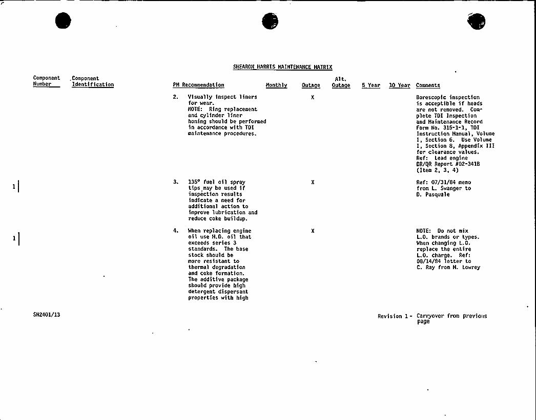
Component .ComponentNumber ldentlffaatlon PH Recommendation
SHEARON HARRIS MAINTENANCE MATRIX
Alt.N~onthl ~Outa e Outafle 5 Year 10 Year Comments
2. Visually inspect linersfor wear.NOTE: Ring replacementand cylinder linerhoning should be performedin accordance with TDImaintenance procedures.
3. 135 fuel oil spraytips may be used ifinspection resultsindicate a need foradditional action toimprove lubrication andreduce coke buildup.
4. When replacing engineoil use H.O. oil thatexceeds series 3standards. The basestock should bemore resistant tothermal degradationand coke formation.The additive packageshould provide highdetergent disper santproperties with high
Borescopic inspectionis acceptible if headsare not removed. Com-
plete TDI Inspectionand Maintenance RecordForm No. 315-1-1, TOIinstruction Manual, VolumeI, Section 6. Use VolumeI, Section 8, Appendix IIIfor clearance values.Ref: Lead engineDR/gR Report N02-3418(Item 2, 3, 4)
Ref: 07/31/84 memofrom L. Swanger to0. Pasquale
NOTE: Oo not mixL.O. brands or types.When changing L.O.replace the entireL.O. charge. Ref:08/14/84 letter toC. Ray from H. Lowrey
SH2401/13 Revision 1- Carryover from previouspage
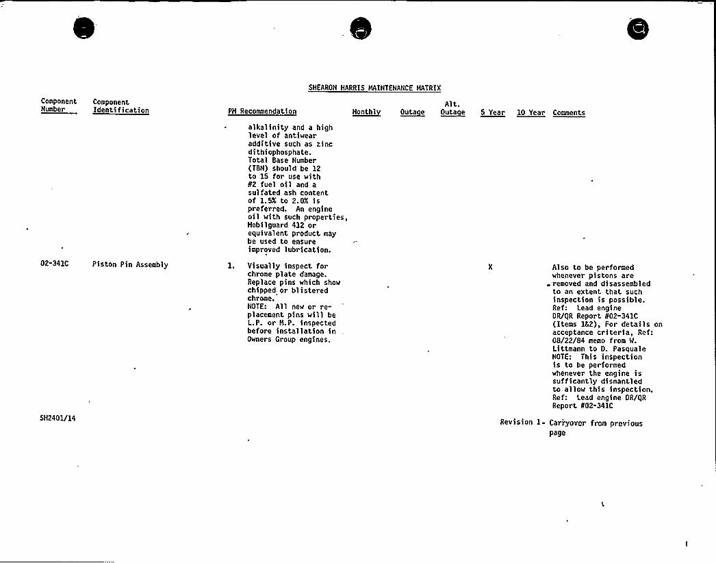
Component ComponentNumber Ident'Ifiaatinn PM Recommendation
SHEARON HARRIS MAINTENANCE MATRIX
Alt.~Nantbl ~outa e ~outa e 5 Year 10 Year cnmenta
02-341C Piston Pin Assembly
SH2401/14
alkalinity and a highlevel of antiwearadditive such as tinedithiophosphate.Total Base Number(TBN) should be 12to 15 for use with¹2 fuel oil and asulfated ash contentof 1. 5X to 2. OX i spreferred. An engineoil with such properties,Mobilguard 412 orequivalent product maybe used to ensureimproved lubrication.
1. Visually inspect forchrome plate damage.Replace pins which showchipped or blisteredchrome.NOTE: All new or re-placement pins will beL.P. or M.P. inspectedbefore installation inOwners Group engines.
Also to be performedwhenever pistons are-removed and disassembledto an extent that suchinspection is possible.Ref: Lead engineOR/QR Report ¹02-341C(Items 152), For details onacceptance criteria, Ref:08/22/84 memo from W.Littmann to O. PasqualeHOTE: This inspectionis to be performedwhenever the engine issufficantly dismantledto allow this inspection.Ref: Lead engine OR/QRReport ¹02-341C
Revision 1- Carryover from previouspage

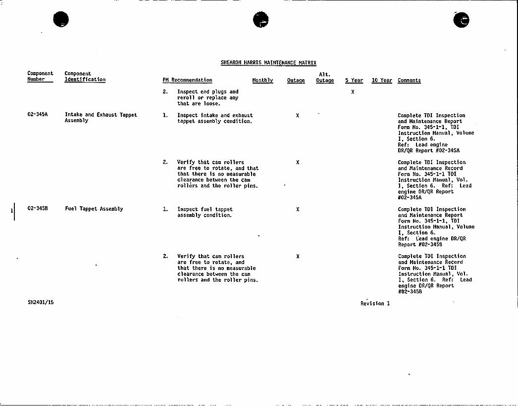
SHEARON HARRIS MAINTENANCE HATRIX
Component ComponentNumber Identification PH Recommendation
Alt.~unntnt ~Outa e O~uta e 5 Year 10 Year Cnaaente
2. Inspect end plugs andreroll or replace anythat are loose.
02-345A Intake and Exhaust TappetAssembly
02-345B Fuel Tappet Assembly
SH2401/15
l. Inspect intake and exhausttappet assembly condition.
2. Verify that cam rollersare free to rotate, and thatthat there is no measurableclearance between the camrollers and the roller pins.
1. Inspect fuel tappetassembly condition.
2. Verify that cam rollersare free to rotate, andthat there is no measurableclearance between the camrollers and the roller pins.
Revision 1
Complete TDI Inspectionand Maintenance ReportForm No. 345-1-1, TDIInstruction Manual, VolumeI, Section 6.Ref: Lead engineOR/QR Report 802-345A
Complete TOI Inspectionand Maintenance RecordForm No. 345-1-1 TDIInstruction Manual, Vol.I, Section 6. Ref: Leadengine OR/QR Report802-345A
Complete TDI Inspectionand Haintenance ReportForm No. 345-1-1, TDIInstruction Manual, VolumeI, Section 6.Ref: Lead engine OR/QRReport 802-345B
Complete TOI Inspectionand Maintenance RecordForm No. 345-1-1 TOIInstruction Manual, Vol.I, Section 6. Ref: Leadengine OR/QR Report002-345B
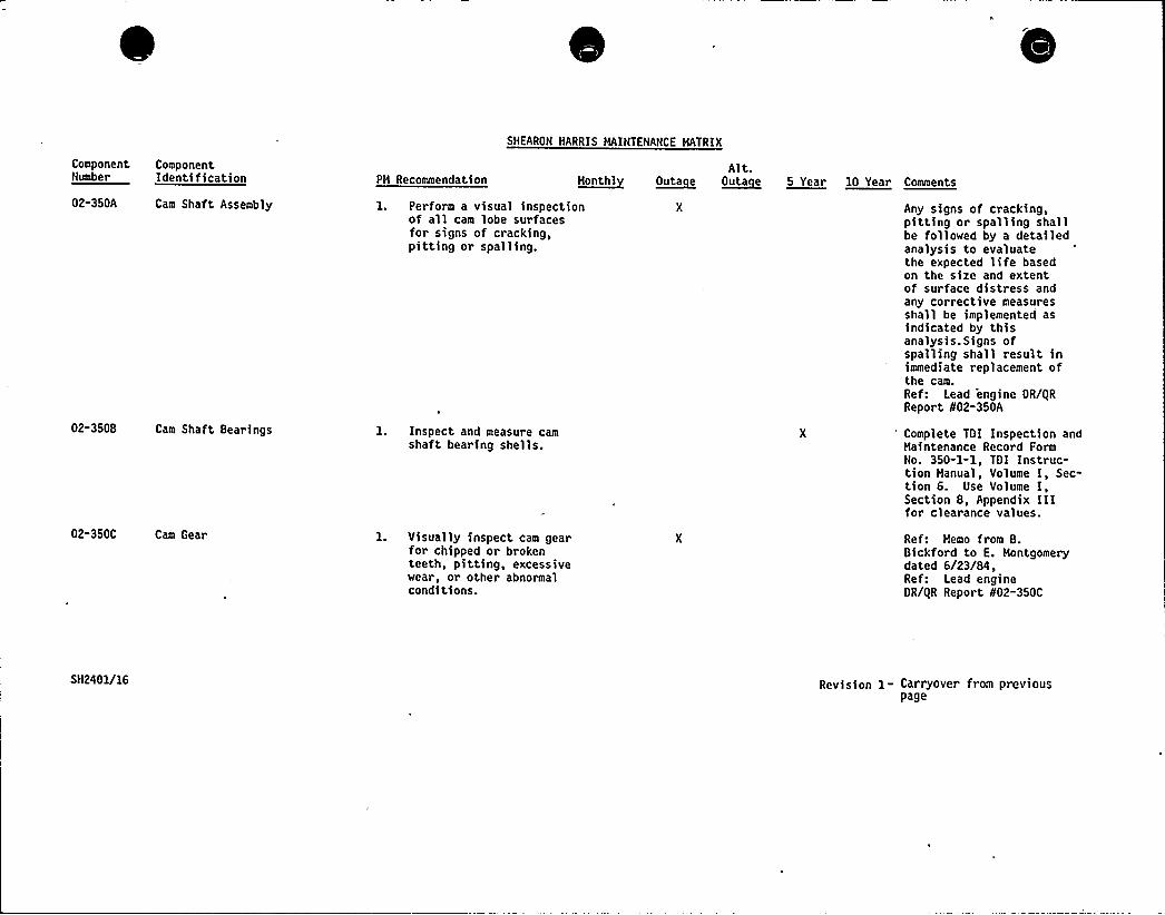
SNEARON HARRIS HAINTENANCE MATRIX
ComponentNumber
ComponentIdentification PH Recommendation Month 1 ~Outa e
Alt.~Outa e 5 Year 10 Year Comments
02-350A Cam Shaft Assembly 1. Perform a visual inspectionof all cam lobe surfacesfor signs of cracking,pitting or spalling.
Any signs of cracking,p>tting or spalling shallbe followed by a detailedanalysis to evaluatethe expected life basedon the size and extentof surface distress andany corrective measuresshall be implemented asindicated by thisanalysis. Signs ofspalling shall result inimmediate replacement ofthe cam.Ref: Lead engine OR/gRReport N02-350A
02-350B Cam Shaft Bearings
02-350C Cam Gear
l. Inspect and measure camshaft bearing shells.
l. Visually inspect cam gearfor chipped or brokenteeth, pitting, excessivewear, or other abnormalconditions.
Complete TOI Inspection andHaintenance Record FormNo. 350-1-1, TOI Instruc-tion Manual, Volume I, Sec-tion 6. Use Volume I,Section 8, Appendix III .
for clearance values.
Ref: Memo from B.Bickford to E. Montgomerydated 6/23/84,Ref: Lead engineOR/gR Report 802-350C
SH2401/16 Revision 1- Carryover from previouspage
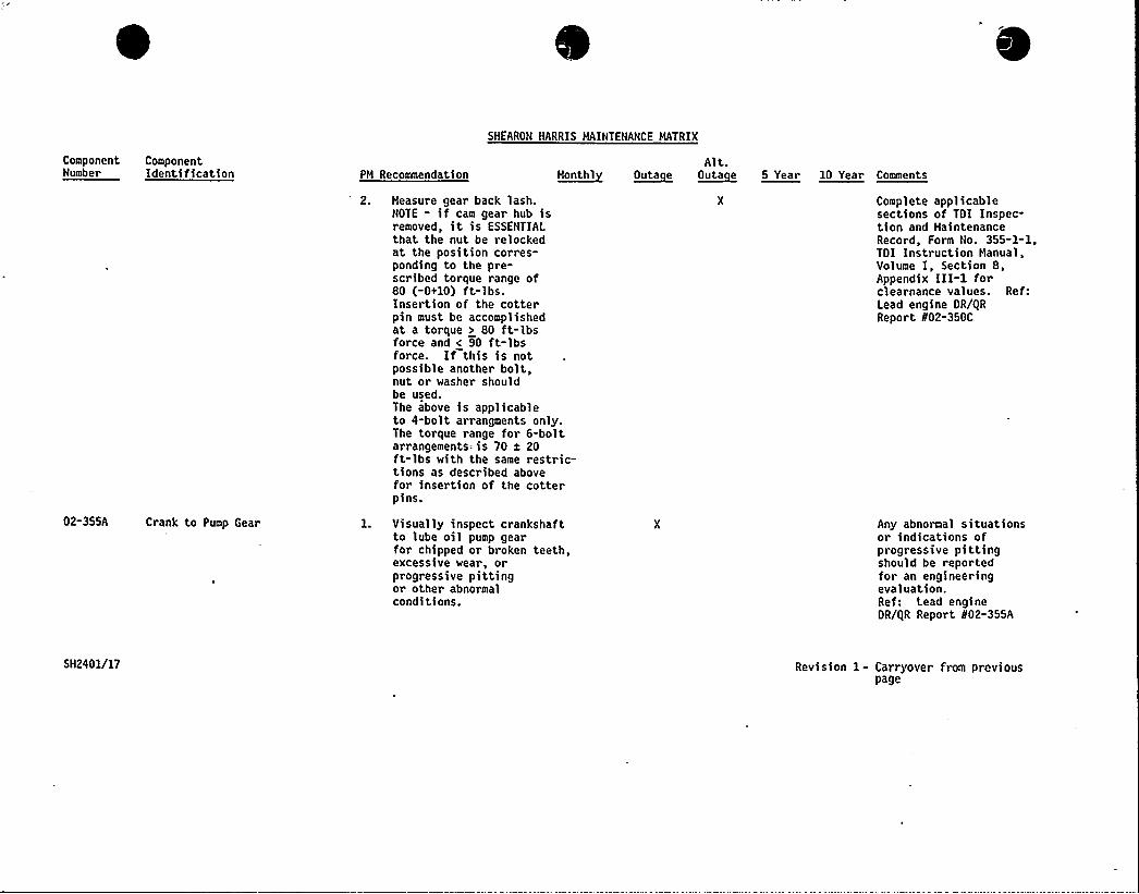
SHEARON HARRIS MAINTENANCE MATRIX
ComponentNumber
ComponentIdentification PM Recommendation
Alt.~Mehtht ~Outa e ~Outa e 5 Year 10 Year Comments
02-355A Crank to Pump Gear
2. Measure gear back lash.NOTE - if cam gear hub isremoved, it is ESSENTIALthat the nut be relockedat the position corres-ponding to the pre-scribed torque range of80 (-0+10) ft-lbs.Insertion of the cotterpin must be accomplishedat a torque > 80 ft-lbsforce and < 90 ft-lbsforce. If this is notpossible another bolt,nut or washer shouldbe used.The above is applicableto 4-bolt arrangments only.The torque range for 6-boltarrangements= is 70 x 20ft-lbs with the same restric-tions as described abovefor insertion of the cotterpins.
l. Visually inspect crankshaftto lube oil pump gearfor chipped or broken teeth,excessive wear, orprogressive pittingor other abnormalconditions.
Complete applicablesections of TOI Inspec-tion and MaintenanceRecord, Form No. 355-1-1,TOI Instruction Manual,Volume I, Section 8,Appendix III-1 forclearnance values. Ref:Lead engine OR/gRReport 802-350C
Any abnormal situationsor indications ofprogressive pittingshould be reportedfor an engineeringevaluation.Ref: Lead engineOR/gR Report 802-355A
SH2401/17 Revision 1 - Carryover from previouspage
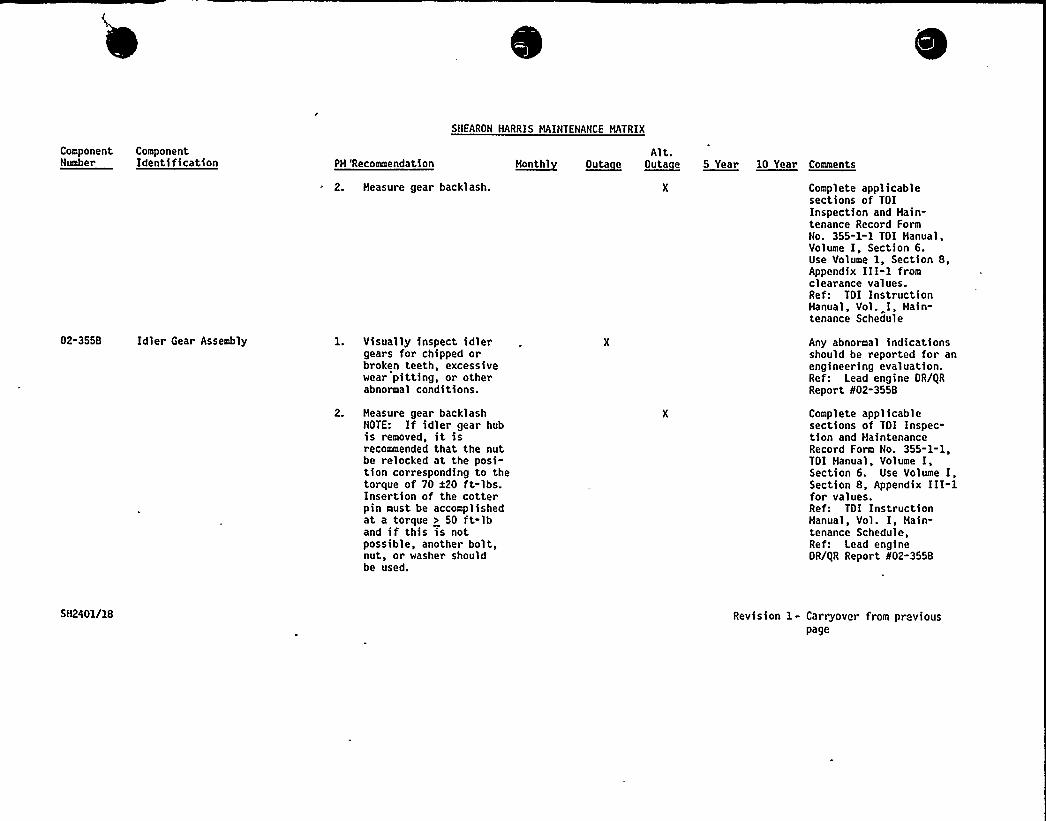
SNEARON HARRIS MAINTENANCE HATRIX
Component ComponentNumber Identification
02-355B Idler Gear Assembly
PH 'Recommendation
2. Heasure gear backlash.
1. Visually inspect idlergears for chipped orbroken teeth, excessivewear pitting, or otherabnormal conditions.
2. Heasure gear backlashNOTE: If idler gear hubis removed, it isrecommended that the nutbe relocked at the posi-tion corresponding to thetorque of 70 a20 ft-lbs.Insertion of the cotterpin must be accomplishedat a torque > 50 ft-lband if this is notpossible, another bolt,nut, or washer shouldbe used.
Alt.~haathl Outargue ~Outa e 0 Year 10 Year Caaaeata
Complete applicablesections of TDIInspection and Hain-tenance Record FormNo. 355-1-1 TDI Hanual,Volume I, Section 6.Use Volume 1, Section 8,Appendix III-1 fromclearance values.Ref: TDI InstructionHanual, Vol. I, Hain-tenance Schedule
Any abnormal indicationsshould be reported for anengineering evaluation.Ref: Lead engine OR/QRReport 802-3558
Complete applicablesections of TOI Inspec-tion and HaintenanceRecord Form No. 355-1-1,TOI Manual, Volume I,Section 6. Use Volume I,Section 8, Appendix III-lfor values.Ref: TOI InstructionManual, Vol. I, Main-tenance Schedule,Ref: Lead engineDR/QR Report 802-355B
SH2401/18 Revision 1- Carryover from pr viouspage

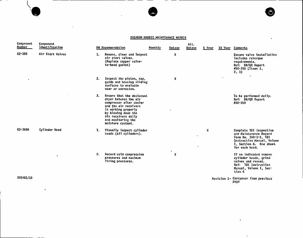
Component ComponentNumber Identification PM Recommendation
SHEARON HARRIS MAINTENANCE MATRIX
Alt.M~teethl ~Outa e O~ta e 5 Year 10 Year Comments
02-359 Air Start Valves 1. Remove, clean and inspectair start valves.(Replace copper valve-to-head gasket)
2. Inspect the piston, cap,guide and housing slidingsurfaces to evaluatewear or corrosion.
Ensure valve installationincludes retorquerequirements.Ref: DR/QR Report802-359 (Items 1,2, 3)
3. Ensure that the desiccantdryer between the aircompressor after coolerand the air receiversis working properlyby blowing down theair receivers dailyand monitoring themoisture content.
To be performed daily.Ref: DR/QR Report802-359
02-360A Cylinder Head
5H2401/19
1. Visually inspect cylinderheads (all cylinders).
2. Record cold compressionpressures and maximumfiring pressures.
Complete TOI Inspectionand Maintenance RecordForm No. 360-1-1, TOIInstruction Manual, VolumeI, Section 6. One sheetfor each head.
If so indicated removecylinder heads, grindvalves and reseat.Ref: TOI InstructionManual, Volume I, Sec-tion 6
Revision 1- Carryover from previouspage

SHEARON HARRIS MAINTENANCE MATRIX
ComponentNumber
ComponentIdentification PM Recommendation
3. Blow-over the engine perTOI maintenance require-ments, Volume I or atappropriate intervalsafter shutdown ofthe engine to ensureagainst harmful effectsof water leaks.
M~hhthlAlt.
~Outa e ~Outa e 5 Year 10 Year Comments
In the event water isdetected, the cylinderhead should be replacedor returned to thevendor for repair.Ref: Lead engine OR/gRReport 802-360A
4. Visually inspect thefuel in)ection port oneach cylinder head"during" the normalmonthly engine runfor water leaks.
If water leakage isdetected, the head(s)should be replaced.Ref: Lead engineOR/I|R Report 802-360A
02-360B Cylinder Head - Intake andExhaust Valves
l. Visually inspect intakeand exhaust valve, discs,stems and seats for wiredrawing, pitting, distortion,concentricity, or anyabnormal condition.
2. Visually inspect subcoversfor evidence of valveguide blowby (Soot).
This is a one time onlyinspection to be per-formed after 500-600hrs. of engine operationafter rebuild of thecylinder head. Ref:Lead engine OR/gRReport 802-360B
5H2401/20 Revision 1- Carryover from previouspage
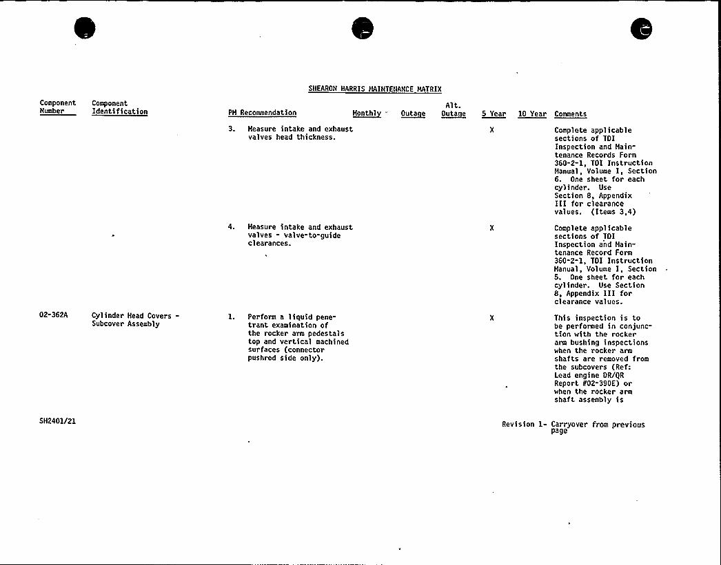
SNEARON HARRIS HAINTENANCE MATRIX
ComponentNumber
ComponentIdentification PH Recommendation H~onth1
Alt.O~uta e O~uta e 5 Year 10 Year Comaents
02-362A Cylinder Head Covers-Subcover Assembly
3. Measure intake and exhaustvalves head thickness.
4. Measure intake and exhaustvalves - valve-to-guideclearances.
1. Perform a liquid pene-trant examination ofthe rocker arm pedestalstop and vertical machinedsurfaces (connectorpushrod side only).
Complete applicablesections of TOIInspection and Main-tenance Records Form360-2-1, TDI InstructionManual,- Volume I, Section6. One sheet for eachcylinder. UseSection 8, AppendixIII for clearancevalues. (Items 3,4)
Complete applicablesections of TOIInspection and Main-tenance Record Form360-2-1, TOI InstructionManual, Volume I, Section5. One sheet for eachcylinder. Use Section8, Appendix III forclearance values.
This inspection is tobe performed in conjunc-tion with the rockerarm bushing inspectionswhen the rocker armshafts are removed fromthe subcovers (Ref:Lead engine OR/gRReport 802-390E) orwhen the rocker armshaft assembly is
SM2401/21 Revision 1- Carryover from previouspage

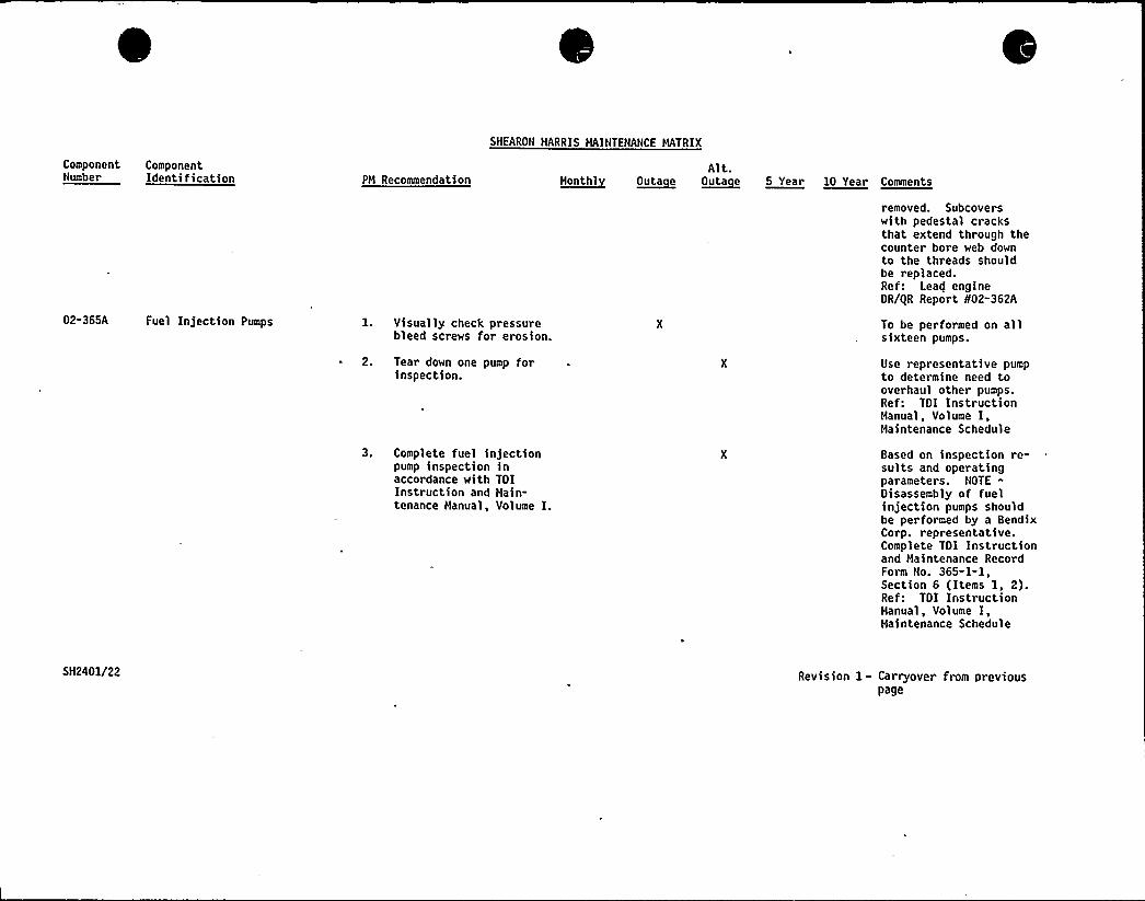
ComponentNumber
ComponentIdentification PH Recommendation
SHEARON HARRIS HAINTENANCE HATRIX
Alt.~ueutul O~uta e ~Outa a 5 Year 10 Year Comments
02-365A Fuel Injection Pumps l. Visually check pressurebleed screws for erosion.
2. Tear down one pump forinspection.
3. Complete fuel injectionpump inspection inaccordance with TOIInstruction and Main-tenance Hanual, Volume I.
removed. Subcoverswith pedestal cracksthat extend through thecounter bore web downto the threads shouldbe replaced.Ref: Lead engineDR/gR Report 802-362A
To be performed on allsixteen pumps.
Use representative pumpto determine need tooverhaul other pumps.Ref: TOI InstructionHanual, Volume I,Maintenance Schedule
Based on inspection re-sults and operatingparameters. NOTE-Oisassembly of fuelinjection pumps shouldbe performed by a BendixCorp. representative.Complete TOI Instructionand Maintenance RecordForm No. 365-1-1,Section 6 (Items 1, 2).Ref: TOI InstructionHanual, Volume I,Haintenance Schedule
5H2401/22 Revision 1- Carryover from previouspage
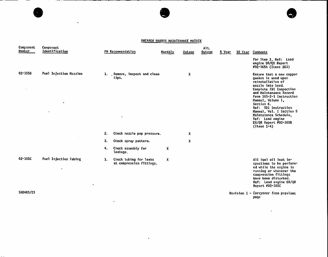
Component ComponentNumber Identification PM Recommendation
SNEARON HARRIS HAINTENANCE MATRIX
Alt.~ueatul O~uta e ~Outa e 5 Year 10 Year Comments
02-365B Fuel Infection Nozzles 1. . Remove, inspect and cleantips.
2. Check nozzle pop pressure.
3. Check spray pattern.
for Item 3, Ref: Leadengine OR/QR Report802-365A (Items 243)
Ensure that a new coppergasket is used uponreinstallation ofnozzle into head.Complete TOI Inspectionand Haintenance RecordForm 365-2-1 InstructionManual, Volume I,Section 6.Ref: TOI InstructionHanual, Vol. I Section 5Maintenance Schedule,Ref: Lead engineOR/QR Report N02-365B(Items 1-4)
02-365C Fuel In)ection Tubing
SH2401/23
4. Check assembly forleakage.
1. Check tubing for leaksat compression fittings.
All fuel oil leak in-spections to be perform-ed while the engine isrunning or whenever thecompression fittingshave been disturbed.Ref: Lead engine OR/QRReport 802-365C
Revision 1 - Carryover from nreviouspage
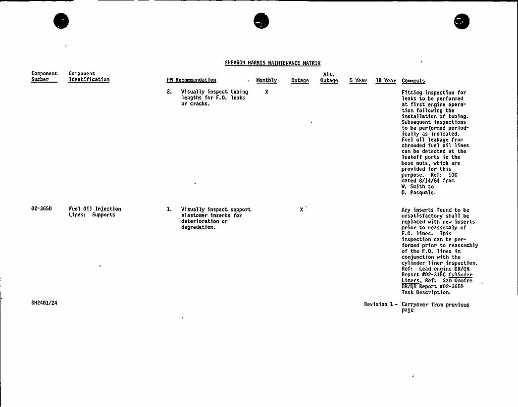
SHEARON HARRIS MAINTENANCE MATRIX
Component ComponentNumber Identification PM RecoRmsendation
Alt.R~outhl ~Outa e ~Outa e 5 Year 10 Year Comments
2. Visually inspect tubing Xlengths for F.O. leaksor cracks.
Fitting inspection forleaks to be performedat first engine opera-tion following theinstallation of tubing.Subsequent inspectionsto be performed period-ically as indicated.Fuel oil leakage fromshrouded fuel oil linescan be detected at theleakoff ports in thebase nuts, which areprovided for thispurpose. Ref: IOCdated 8/14/84 fromW. Smith toO. Pasquale.
02-3650
5H2401/24
Fuel Oil InjectionLines: Supports
l. Visually inspect supportelastomer inserts fordeterioration ordegredation.
Revision 1-
Any inserts found to beunsatisfactory shall bereplaced with new insertsprior to reassembly ofF.O. lines. Thisinspection can be per-formed prior to reassemblyof the F.O. lines inconjunction with thecylinder liner inspection.Ref: Lead engine OR/gRReport 002 3100 ~t-louderLiners, Ref: San OnofreOR/gR Report 802-3650Task Oescription.
Carryover from previouspage
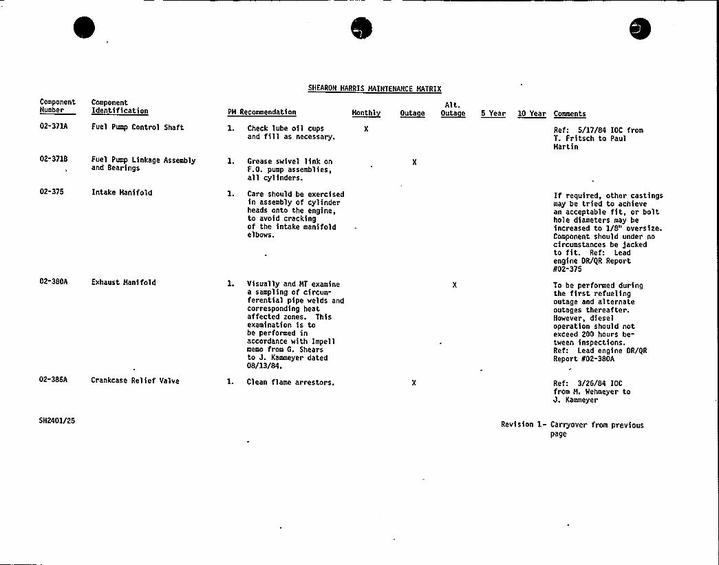
SHEARON HARRIS MAINTENANCE MATRIX
ComponentNumber
02-371A
02-3718
02-375
ComponentIdentification
Fuel Pump Control Shaft
Fuel Pump Linkage Assemblyand Bearings
Intake Hani fold
PH Recoamendation
1. Check lube oil cupsand fill as necessary.
1. Grease swivel link onF.O. pump assemblies,all cylinders.
1. Care should be exercisedin assembly of cylinderheads onto the engine,to avoid crackingof the intake manifoldelbows.
~Hant hlAlt.
~Outa e ~Outa e 5 Year 10 Year Comments
Ref: 5/17/84 IOC fromT. Fritsch to PaulHartin
If required, other castingsmay be tried to achievean acceptable fit, or bolthole diameters may beincreased to 1/8" oversize.Component should under nocircumstances be 5ackedto fit. Ref: Leadengine OR/gR Report802-375
02"380A Exhaust Hanifold l. Visually and HT examinea sampling of circum-ferential pipe welds andcorresponding heataffected zones. Thisexamination is tobe performed inaccordance with Impellmemo from G. Shearsto J. Kammeyer dated08/13/84.
To be performed duringthe first refuelingoutage and alternateoutages thereafter.However, dieseloperation should notexceed 200 hours be-tween inspections.Ref: Lead engine OR/iiRReport 802-380A
02-386A Crankcase Relief Valve 1. Clean flame arrestors. Ref: 3/26/84 IOCfrom H. Wehmeyer toJ. Kammeyer
SH2401/25 Revision 1- Carryover from previouspage
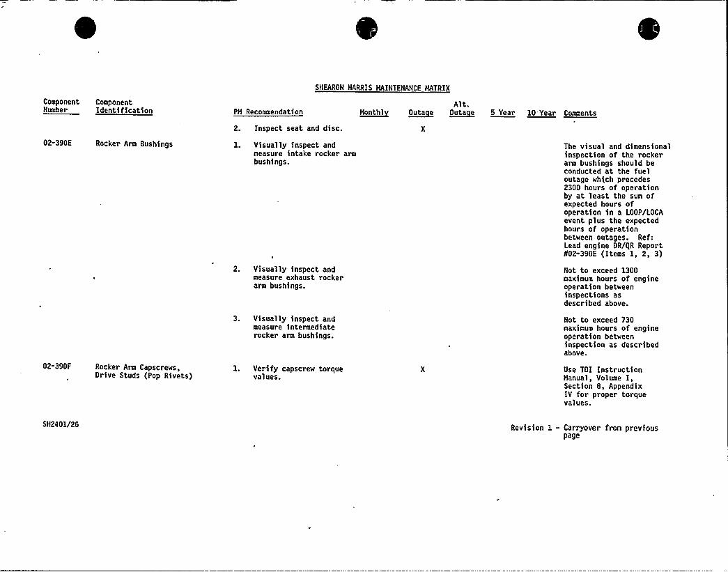
SHEARON HARRIS MAINTENANCE NATRIX
ComponentNumber
ComponentIdentification PH Recommendation
2. Inspect seat and disc.
Alt.~uonthl ~Outa e ~nota e 5 Year 10 Year Coaaaenta
02-390E Rocker Arm Bushings
02"390F Rocker Arm Capscrews,Drive Studs (Pop Rivets)
l. Visually inspect andmeasure intake rocker armbushings.
2. Visually inspect andmeasure exhaust rockerarm bushings.
3. Visually inspect andmeasure intermediaterocker arm bushings.
l. Verify capscrew torquevalues.
The visual and dimensionalinspection of the rockerarm bushings should beconducted at the fueloutage which precedes2300 hours of operationby at least the sum ofexpected hours ofoperation in a LOOP/LOCAevent plus the expectedhours of operationbetween outages. Ref:Lead engine OR/gR Report802-390E (Items 1, 2, 3)
Not to exceed 1300maximum hours of engineoperation betweeninspections asdescribed above.
Not to exceed 730maximum hour s of engineoperation betweeninspection as describedabove.
Use TOI InstructionHanual, Volume I,Section 8, AppendixIV for proper torquevalues.
SH2401/26 Revision 1 - Carryover from previouspage
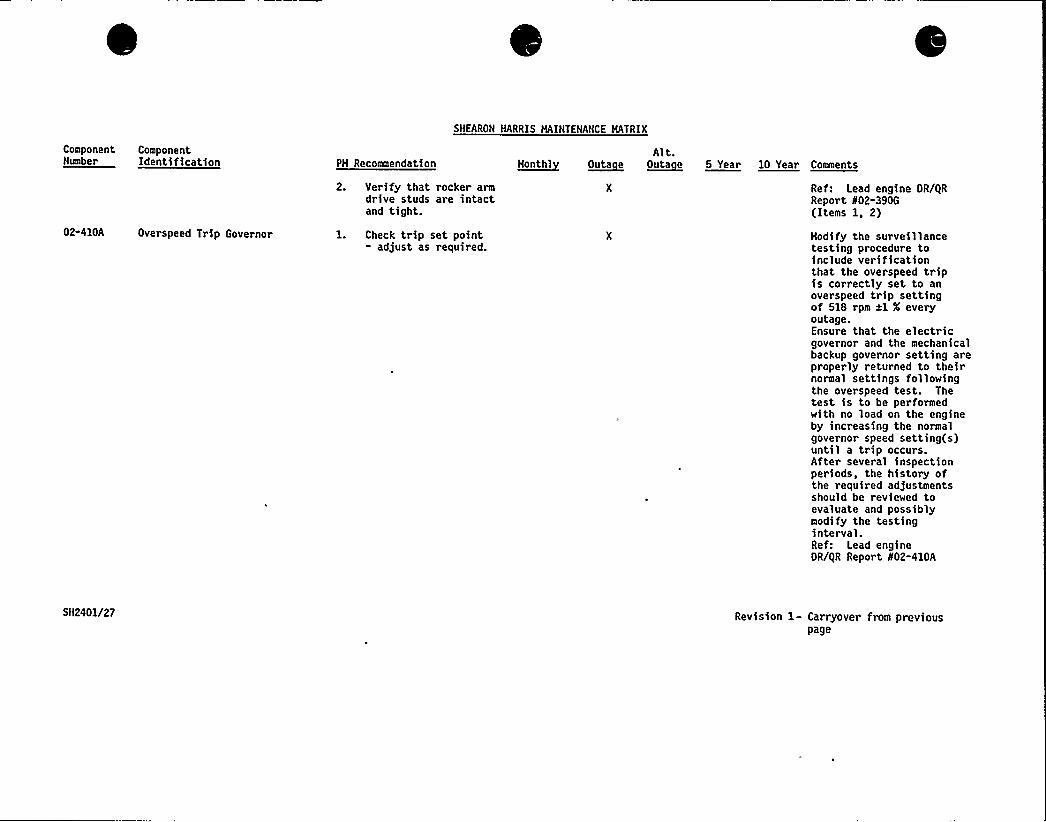
Component ComponentNumber Identification PM Recommendation
SHEARON HARRIS MAINTENANCE MATRIX
Alt.~taeetht ~Outa e o~uta e 5 Year 10 Year Comments
02-410A Overspeed Trip Governor
2. Verify that rocker armdrive studs are intactand tight.
1. Check trip set point- adjust as required.
Ref: Lead engine DR/QRReport 802-390G(Items 1, 2)
Mod> fy the surve>1 lancetesting procedure toinclude verificationthat the overspeed tripis correctly set to anoverspeed trip settingof 518 rpm xl X everyoutage.Ensure that the electricgovernor and the mechanicalbackup governo~ setting areproperly returned to theirnormal settings followingthe overspeed test. Thetest is to be performedwith no load on the engineby increasing the normalgovernor speed setting(s)until a trip occurs.After several inspectionperiods, the history ofthe required adjustmentsshould be reviewed toevaluate and possiblymodify the testinginterval.Ref: Lead engineOR/QR Report 802-410A
SH2401/27 Revision 1- Carryover from previouspage
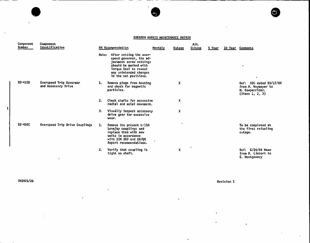
Component ComponentNumber Identification PH Recommendation
SNEARON HARRIS HAINTENANCE HATRIX
Alt.~Honthl n~uta e ~outa e 5 Year 10 Year comente
02-4108 Overspeed Trip Governorand Accessory Drive
Note: After setting the over-speed governor, the ad-justment screw settingsshould be marked withTorque Seal to revealany unintended changesin the set positions.
1. Remove plugs from housingand check for magneticparticles.
2. Check shafts for excessiveradial and axial movement.
Ref: IOC dated 03/17/84from H. Weymeyer toN. Cooperrider.(Items 1, 2, 3)
3. Visually inspect accessorydrive gear for excessivewear.
02-410C Overspeed Trip Drive Couplings 1. Remove the present L-110Lovejoy couplings andreplace them with newunits in accordancewith SIH 363 and OR/0RReport recommendations.
To be completed atthe first refuelingoutage.
2. Verify that coupling istight on shaft.
Ref: 6/24/84 Nemofrom O. Limbert toE. Hontgomery
SN2401/28 Revision 1
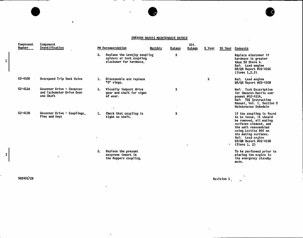
SHEARON HARRIS MAINTENANCE MATRIX
Component ComponentNumber Identification PM Recommendation H~onthl ~Outa e
Alt.Outacue 5 Year 10 Year Comments
02-410D Overspeed Trip Vent Valve
02-411A Governor Drive - Governorand Tachometer Drive Gearand Shaft
3. Replace the Lovejoy couplingspiders or test couplingelastomer for hardness.
1. Disassemble and replace"0" rings.
l. Visually inspect drivegear and shaft for signsof wear.
Replace elastomer ifhardness is greaterthan 90 Shore A.Ref: Lead engineOR/ilR Report 802-410C(Items 1,2,3)
Ref: Lead engineDR/IlR Report 802-4100
Ref: Task Descriptionfor Shearon Harris com-ponent fif02-411A,Ref: TOI InstructionManual, Vol. I, Section 5Maintenance Schedule
02-411B Governor Drive - Couplings, 1. Check that coupling isPins and Keys tight on shaft.
2. Replace the presentneoprene insert inthe Koppers coupling.
If the coupling is foundto be loose, it shouldbe removed, all matingsurfaces cleaned, andthe unit reassembledusing Loctite 609 onthe mating surfaces.Ref: Lead engineDR/iiR Report 802-411B(Items 1, 2)
To be performed prior toplacing the engine inthe emergency standbymode.
SH2401/29 Revision 1
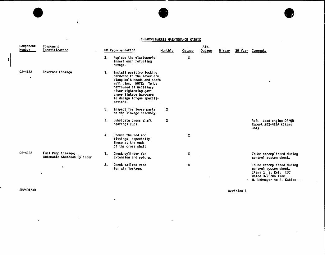
ComponentNumber
ComponentIdenti fication PH Recommendation
SHEARON HARRIS HAINTEHANCE HATRIX
Alt.a~hathi ~Outa e ~Outa e 5 Year 10 Year Cnaeenta
02-413A Governor Linkage
3. Replace the elastomericinsert each refuelingoutage.
l. Install positive lockinghardware to the lever armclamp bolt heads and shaftroll pins. NOTE: To beperformed as necessaryafter tightening gov-ernor linkage hardwareto design torque specifi-cations.
2. Inspect for loose parts Xon the linkage assembly.
3. Lubricate cross shaftbearings cups.
Ref: Lead engine OR/iiRReport 802-413A (Items384)
4. Grease the rod endfittings, especiallythose at the endsof the cross shaft.
02-413B Fuel Pump Linkage:Automatic Shutdown Cylinder
1. Check cylinder forextension and return.
2. Check tailrod ventfor air leakage.
To be accomplished duringcontrol system check.
To be accomplished duringcontrol system check.Items 1, 2; Ref: IOCdated 3/26/84 fromH. Wehmeyer to R. Kaklec
SH2401/30 Revision 1
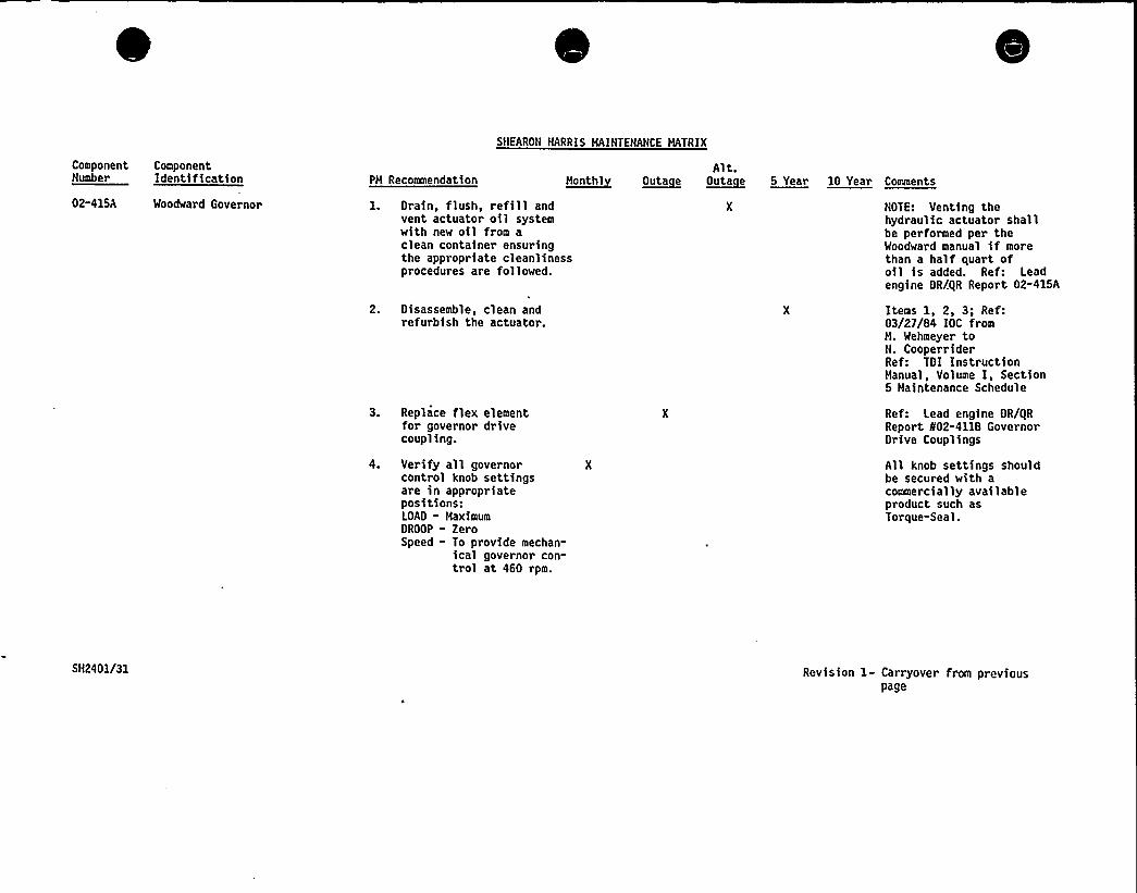
Component ComponentNumber Identification PH Recommendation
SNEARON HARRIS HAINTENANCE MATRIX
Alt.M~euthl ~Outa e Outeeue 5 Year 10 Year Comments
02-415A Woodward Governor 1. Drain, flush, refill andvent actuator oil systemwith new oil from aclean container ensuringthe appropriate cleanlinessprocedures are followed.
2. Disassemble, clean andrefurbish the actuator.
3. Replace flex elementfor governor drivecoupling.
4. Verify all governorcontrol knob settingsare in appropriatepositions:LOAD - MaximumDROOP - ZeroSpeed " To provide mechan-
ical governor con-trol at 460 rpm.
NOTE: Venting thehydraulic actuator shallbe performed per theWoodward manual if morethan a half quart ofoil is added. Ref: Leadengine DR/gR Report 02-415A
Items 1, 2, 3; Ref:03/27/84 IOC fromH. Wehmeyer toN. CooperriderRef: TDI InstructionHanual, Volume I, Section5 Maintenance Schedule
Ref: Lead engine DR/gRReport 802-4118 GovernorDrive Couplings
All knob settings shouldbe secured with acommercially availableproduct such asTorque-Seal.
5H2401/31 Revision 1- Carryover from previouspage

ComponentNutter
ComponentIdentification PM Recommendation
SHEARON HARRIS MAINTENANCE MATRIX
Alt.h~uatht haute e hutatuee5 Year 10 Year Comments
5. Modify the surveillancetesting procedures toinclude an evaluationof the governor settingsbe means of the twotest below:
(a) Perfrom a test ofthe governor settingswhile under mechanical/electrical governorcontrol, with thediesel generator offthe grid in theisochronous mode.
(b) Perform a test ofthe governor settingswhile under mechanical(only) governorcontrol, with thediesel generator offthe grid in theisochronous mode.
NOTE: These tests shallinclude examinations ofthe engine speed transi-ents during start andtransient loading condi-tions. Included aspart of the above testsis the verification thatthe engine set speed of450 rpm is not exceededby more than 7.5 percent(484 rpm max.) eitherduring an engine start orduring the largest singleload reduction.Ref: Lead engine OR/gRReport 802-415A
6. Augment the settingadjustment proceduresas 'described in theWoodward manuals, toinclude a test of thegovernor response,during an engine startto ensure agreement withthe specification asdetailed in Item N5 above.
Ref: Lead engineOR/gR Report 802-415A
SH2401/32 Revision 1- Carryover from previouspage
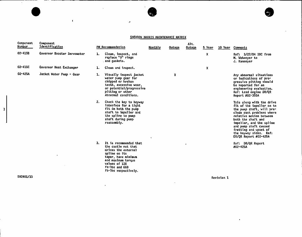
ComponentNumber
ComponentIdentification PH Recommendation
SHEARON HARRIS HAINTENANCE HATRIX
Alt.t~tuntat ~outa e OuteeLe 5 Year 10 Year cuuuente
02-415B
02-415C
02-425A
5H2401/33
Governor Booster Servomotor
Governor Heat Exchanger
Jacket Water Pump - Gear
1. Clean, inspect, andreplace "0" rings
, and gaskets.
1. Clean and inspect.
1. Visually inspect )acketwater pump gear forchipped or brokenteeth, excessive wear,or potential/progressivepitting or otherabnormal conditions.
2. Check the key to keywayinterface for a tightfit on both the pumpshaft to impeller andthe spline to pumpshaft during pumpreassembly.
3. It is recommended thatthe castle nut thatdrives the externalspline on itstaper, have minimumand maximum torquevalues of 120ft-lbs and 660ft-lbs respectively.
Revision 1
Ref: 3/27/84 IOC fromH. Wehmeyer toJ. Kammeyer
Any abnormal situationsor indications of pro-gressive pitting shouldbe reported for anengineering evaluation.Ref: Lead engine OR/gRReport 802-355A
This along with the drivefit of the impeller on tothe pump shaft, will pre-clude past problems whererelative motion betweenboth the shaft andimpeller, and the splineand pump shaft causedfretting and upset ofthe keyway sides. Ref:OR/gR Report N02-425A
Ref: OR/gR Report802-425A

SHEARON HARRIS MAINTENANCE HATRIX
ComponentNumber
ComponentIdentification PH Recommendation monthly
Alt.~Outa e ~Outa e 5 Year 10 Year Comments
02-435A
02"437
Jacket Water Fittings-Pipe and Fittings(Small Bore Scope Only)
Turbo Water Piping-Pipe and Fittings
l. Visually inspect for leaks. X
Note: In the event of aleak developing in theexisting Dresser Style 65couplings, these couplingsshould be replaced withDresser Style 90 couplingsequipped with Viton gaskets
l. Visually inspect for leaks. XNote: In the event of aleak developing in theexisting Dresser Style 65couplings, these couplingsshould be replaced withDresser Style 90 couplingsequipped with Viton gaskets
This recommendation ismade on the basis thatthe maximum suggestedoperating temperature of150 F for the Style 65coupling may be exceeded.The maximum suggestedoperating temperature ofthe Style 90 is 2124F.Ref: Letter dated12/13/84 from C. L. Rayto J. George.
This recommendation ismade on the'asis thatthe maximum suggestedoperating temperature of150 F for the Style 65coupling may be exceeded.The maximum suggestedoperating temperature ofthe Style 90 is 212 F.Ref: Letter dated12/13/84 from C. L. Rayto J. George.
02-441A Starting Air Hanifold:Air Vent
1. Ensure that the starting Xair manifold vent isopen and effective.
Ref: 08/27/84 Hemo fromW. Littmann to J. Cadogan,Ref: Lead engine OR/gRReport 802-442A (STAD)
02-4418 Air Filter to Starting AirDistributor
1. Inspect filter elements. X Ref: TDI InstructionHanual, Vol. I, Hain-tenance Schedule
SN2401/34 Revision 1

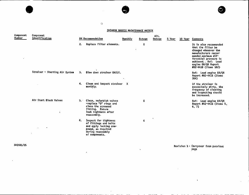
ComponentNumber
ComponentIdentification PM Recommendation
SHEARON HARRIS MAINTENANCE MATRIX
Alt.~Honthl ~OUta e ~OUta e 5 Year 10 Year Comments
2. Replace filter elements.
Strainer - Starting Air System 3. Blow down strainer DAILY.
4. Clean and inspect strainer X
monthly.
It is also recommendedthat the filter bechanged whenever themanufacturers recom-mended maximum dif-ferential pressure isachieved.. Ref: Leadengine OR/(iR Report802-4418 (Items 1&2)
Ref: Lead engine OR/iiRReport N02-4418 (Items3&4)
If the strainer isexcessively dirty, thefrequency of cleaningand inspecting shouldbe increased.
Air Start Block Valves 5. Clean, refurbish valves-replace "0" rings andclean the screenedfitting. Ensureleak tightness afterreassembly.
6. Inspect for tightnessof fittings and boltsand apply locking com-pound, as requiredduring reassemblyof components.
Ref: Lead engine OR/gRReport 802-4418 (Items 5,6, 7)
5H2401/35 Revision 1- Carryover from previouspage
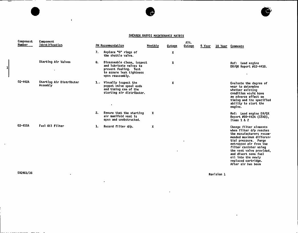
SHEARON HARRIS MAINTENANCE MATRIX
ComponentNumber
ComponentIdentification PM Recoaeendation
7. Replace "0" rings ofthe shuttle valve.
Alt.0~natal ~Outa e ~Outa e 0 Year 10 Year Cnmaenta
02-442A
Starting Air Valves
Starting Air DistributorAssembly
8. Disassemble clean, inspectand lubricate valves toprevent fouling. Testto assure leak tightnessupon reassembly.
l.. Visually inspect thepoppet valve spool endsand timing cam of thestarting air distributor.
2. Ensure that the starting Xair manifold vent isopen and unobstructed.
Ref: Lead engineDR/iiR Report 802-441B.
Evaluate the degree ofwear to determinewhether existingcondition would havean adverse effect ontiming and the specifiedability to start theengine.
Ref: Lead engine DR/gRReport 100-442A (STAO),Items 1 4 2
02-455A Fuel Oil Filter 1. Record filter d/p. Change filter elementswhen filter d/p reachesthe manufacturers recom-mended maximum differen-tial pressure. Purgeentrapped air from thefilter canister usingthe vent valve provided,and divert some fueloil into the newlyreplaced cartridge.After air has been
5H2401/36 Revision 1
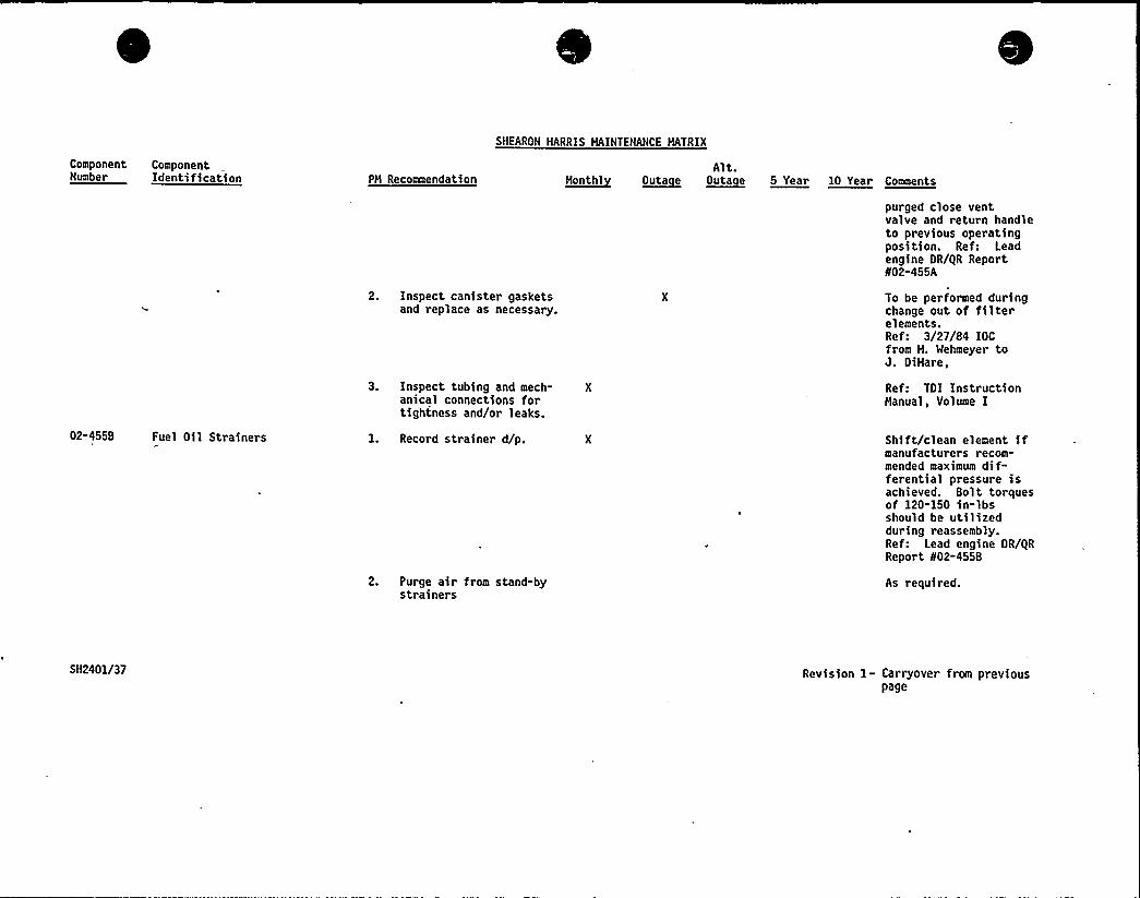
Componentuuaher
ComponentIdentification PM Recommendation
SHEARON HARRIS MAINTENANCE MATRIX
Alt.M~eutht O~uta e ~Outa e 5 Year 10 Year Comnents
02-455B Fuel Oil Strainers
2. Inspect canister gasketsand replace as necessary.
3. Inspect tubing and mech- Xanical connections fortightness and/or leaks.
1. Record strainer d/p.
2. Purge air from stand-bystrainers
purged close ventvalve and return handleto previous operatingposition. Ref: Leadengine OR/QR Report¹02-455A
To be performed duringchange out of filterelements.Ref: 3/27/84 IOCfrom M. Wehmeyer toJ. OiMare,
Ref: TOI InstructionManual, Volume I
Shift/clean element ifmanufacturers recom-mended maximum dif-ferential pressure isachieved. Bolt torquesof 120-150 in-lbsshould be utilizedduring reassembly.Ref: Lead engine OR/QRReport ¹02-455B
As required.
5H2401/37 Revision 1- Carryover from previouspage
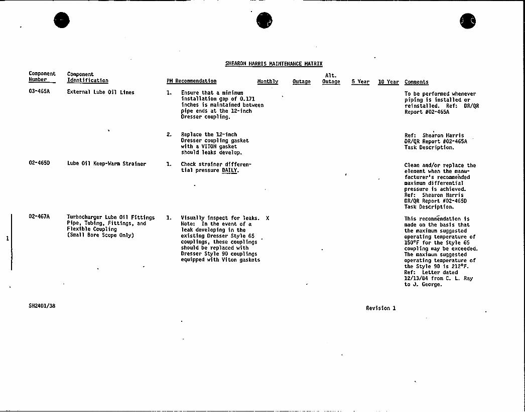
SHEARON HARRIS MAINTENANCE MATRIX
ComponentNumber
ComponentIdentification PM Recommendation ~Mont hl
Alt.~Outa e Outacue 5 Year 10 Year Comments
03-465A External Lube Oil Lines 1. Ensure that a minimuminstallation gap of 0. 171inches is maintained betweenpipe ends at the 12-inchDresser coupling.
To be performed wheneverpiping is installed orreinstalled. Ref: DR/QRReport 802-465A
02-465D Lube Oil Keep-Warm Strainer
2. Replace the 12-inchDresser coupling gasketwith a VITON gasketshould leaks develop.
1. Check strainer differen-tial pressure DAILY.
Ref: Shearon HarrisDR/QR Report 802-465ATask Description.
Clean and/or replace theelement when the manu-facturer's recommendedmaximum differentialpressure is achieved.Ref: Shearon HarrisDR/QR Report 402-4650Task Description.
02-467A Turbocharger Lube Oil FittingsPipe, Tubing, Fittings, andFlexible Coupling(Small Bore Scope Only)
l. Visually inspect for leaks. XNote: In the event of aleak developing in theexisting Dresser Style 65couplings, these couplingsshould be replaced withDresser Style 90 couplingsequipped with Viton gaskets
This recommendation ismade on the basis thatthe maximum suggestedoperating temperature of150~F for the Style 65coupling may be exceeded.The maximum suggestedoperating temperature ofthe Style 90 is 212'F.Ref: Letter dated12/13/84 from C. L. Rayto J. George.
5H2401/38 Revision 1
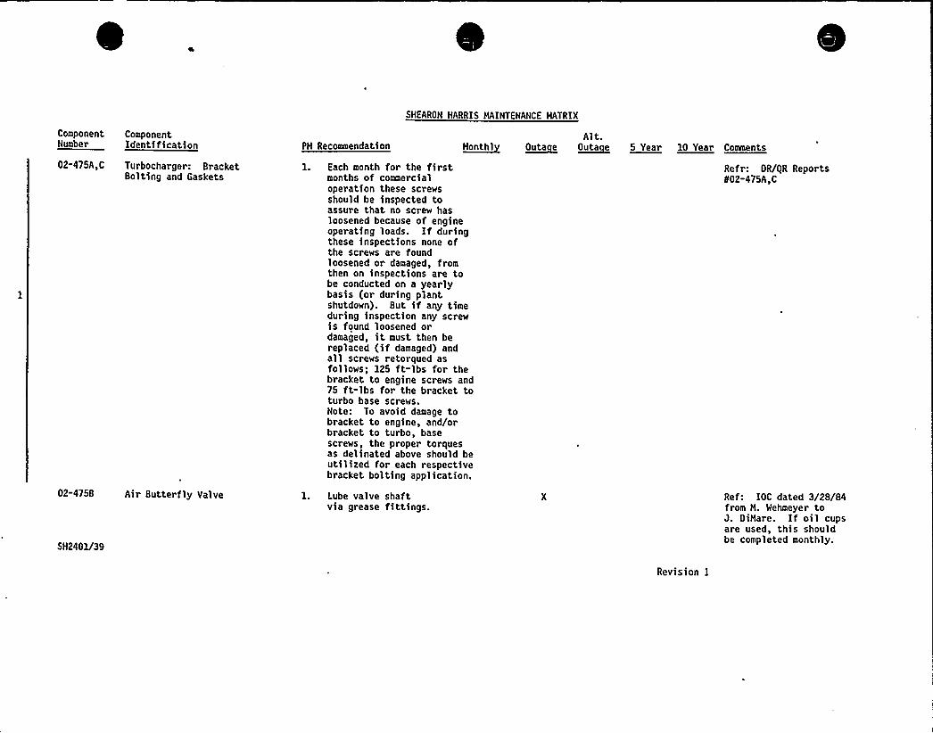
ComponentNumber
ComponentIdentification PH Recommendation
SHEARON HARRIS HAINTENANCE HATRIX
Alt.a~hathi ~Outa e ~outa e 5 Year 10 Year tomeute
02-475A,C Turbocharger: BracketBolting and Gaskets
1. Each month for the firstmonths of commercialoperation these screwsshould be inspected toassure that no screw hasloosened because of engineoperating loads. If duringthese inspections none ofthe screws are foundloosened or damaged, fromthen on inspections are tobe conducted on a yearlybasis (or during plantshutdown). But if any timeduring inspection any screwis found loosened ordamaged, it must then bereplaced (if damaged) andall screws retorqued asfollows; 125 ft-lbs for thebracket to engine screws and75 ft-lbs for the bracket toturbo base screws.Note: To avoid damage tobracket to engine, and/orbracket to turbo, basescrews, the proper torquesas delinated above should beutilized for each respectivebracket bolting application.
Re fr: OR/gR Reports802-475A,C
02-4758 Air Butterfly Valve
5H2401/39
1. Lube valve shaftvia grease fittings.
Revision I
Ref: IOC dated 3/28/84from H. Wehmeyer toJ. OiHare. If oil cupsare used, this shouldbe completed monthly.
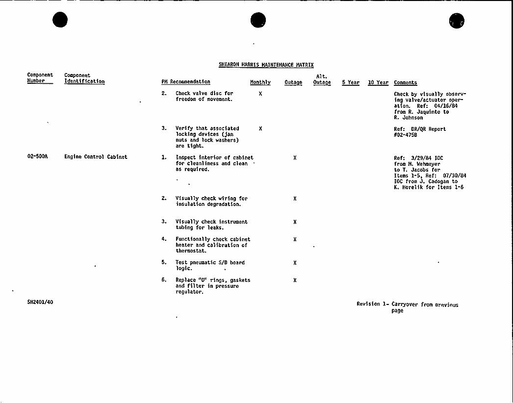
SHEARON HARRIS HAINTENANCE HATRIX
ComponentNumber
ComponentIdentification PH Recommendation
2. Check valve disc forfreedom of movement.
M~anthlAlt.
~outa e ~Outa e 5 Year 10 Year Comments
Check by visually observ-ing valve/actuator oper-ation. Re f: 04/16/84from R. Jaquinto toR. Johnson
02-500A Engine Control Cabinet
3. Verify that associated Xlocking devices (jamnuts and lock washers)are tight.
1. Inspect interior of cabinetfor cleanliness and cleanas required.
2. Visually check wiring forinsulation degradation.
Ref: DR/iiR ReportI/02-4758
Ref: 3/29/84 IOCfrom H. Wehmeyerto T. Jacobs forItems 1-5, Ref: 07/30/84IOC from J. Cadogan toK. Horelik for Items 1-6
3. Visually check instrumenttubing for leaks.
4. Functionally check cabinetheater and calibration ofthermostat.
SH2401/40
5. Test pneumatic S/0 boardlogic.
6. Replace "0" rings, gasketsand filter in pressureregulator.
Revision 1 Carryover from orevinuspage
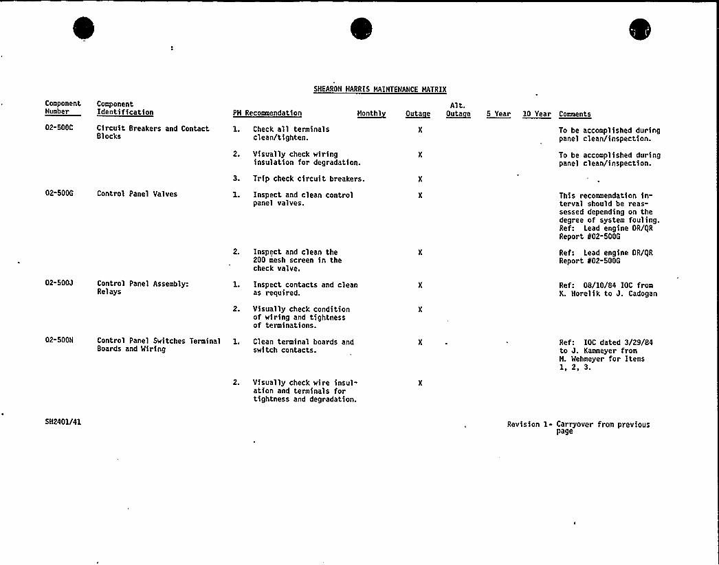
ComponentNumber
ComponentIdentification PN Recommendation
SHEARON HARRIS MAINTENANCE NATRIX
Alt.~uontht ~outa e ~Outa e 5 Year la Year conaento
02-500C Circuit Breakers and ContactBlocks
1. Check all terminalsclean/tighten.
2. Visually check wiringinsulation for degradation.
3. Trip check circuit breakers.
To be accomplished duringpanel clean/inspection.
To be accomplished duringpanel clean/inspection.
02-500G Control Panel Valves
02-500J Control Panel Assembly:Relays
1. Inspect and clean controlpanel valves.
2. Inspect and clean the200 mesh screen in thecheck valve.
1. Inspect contacts and cleanas required.
2. Visually check conditionof wiring and tightnessof terminations.
This recommendation in-terval should be reas-sessed depending on thedegree of system fouling.Ref: Lead engine DR/i|RReport 802-500G
Ref: Lead engine DR/gRReport 802-500G
Ref: 08/10/84 IOC fromK. Horelik to J. Cadogan
02-500N Control Panel Switches TerminalBoards and Wiring
1. Clean terminal boards andswitch contacts.
Ref: IOC dated 3/29/84to J. Kammeyer fromH. Wehmeyer for Items1, 2, 3.
2. Visually check wire insul-ation and terminals fortightness and degradation.
SH2401/41 Revision 1- Carryover from previouspage

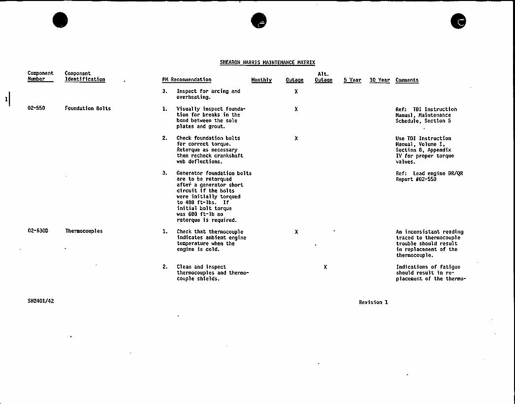
ComponentNumber
ComponentIdentification PH Recommendation
SNEARON HARRIS HAINTENANCE HATRIX
Alt.M~eatat ~Outa e ~Outa e 5 Year 10 Year Caaaeata
3. Inspect for arcing andoverheating.
02-550 Foundation Bolts l. Visually inspect founda-tion for breaks in thebond between the soleplates and grout.
Ref: TDI InstructionHanual, MaintenanceSchedule, Section 5
02-630D Thermocouples
2. Check foundation boltsfor correct torque.Retorque as necessarythen recheck crankshaftweb deflections.
3. Generator foundation boltsare to be retorquedafter a generator shortcircuit if the boltswere initially torquedto 480 ft-lbs. Ifinitial bolt torquewas 600 ft-lb noretorque is required.
1. Check that thermocoupleindicates ambient enginetemperature when theengine is cold.
2. Clean and inspectthermocouples and thermo-couple shields.
Use TDI InstructionHanual, Volume I,Section 8, AppendixIV for proper torquevalues.
Ref: Lead engine DR/QRReport 802-550
An inconsistant readingtraced to thermocoupletrouble should resultin replacement of thethermocouple.
Indications of fatigueshould result in re-placement of the thermo-
SN2401/42 Revision 1
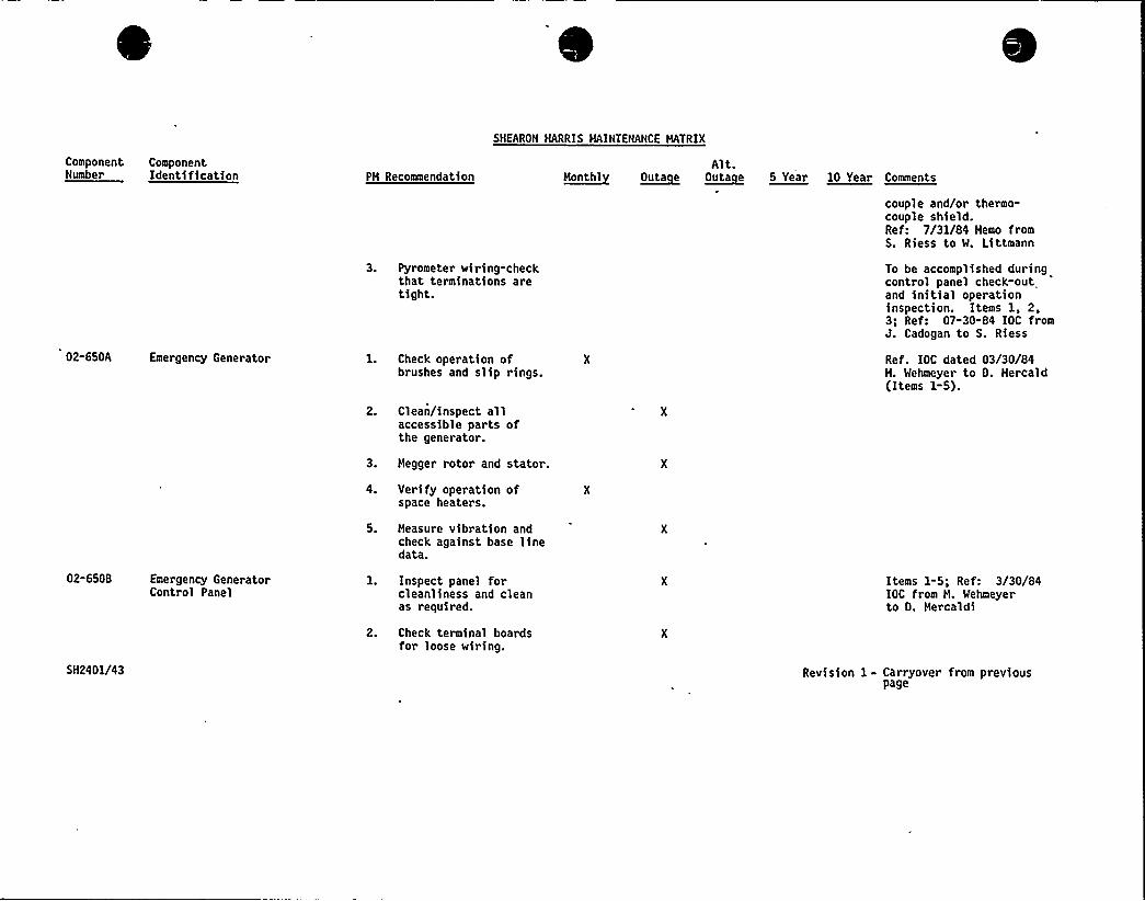
Component ComponentNumber Identification PH Recomaendation
SHEARON HARRIS HAINTENANCE HATRIX
Alt.e~eaathl ~Outa e ~Outa e 55ueee 10 Year Comments
couple and/or thermo-couple shield.Ref: 7/31/84 Hemo fromS. Riess to W. Littmann
02-650A Emergency Generator
3. Pyrometer wiring-checkthat terminations aretight.
1. Check operation ofbrushes and slip rings.
2. Clean/inspect allaccessible parts ofthe generator.
3. Hegger rotor and stator.
To be accomplished duringcontrol panel check-outand initial operationinspection. Items 1, 2,3; Ref: 07-30-84 IOC fromJ. Cadogan to S. Riess
Ref. IOC dated 03/30/84M. Wehmeyer to O. Hercald(Items 1-5).
02-6508 Emergency GeneratorControl Panel
5H2401/43
4. Verify operation ofspace heaters.
5. Measure vibration andcheck against base linedata.
1. Inspect panel forcleanliness and cleanas required.
2. Check terminal boardsfor loose wiring.
Items 1-5; Ref: 3/30/84IOC from H. Wehmeyerto D. Hercaldi
Revision 1- Carryover from previouspage
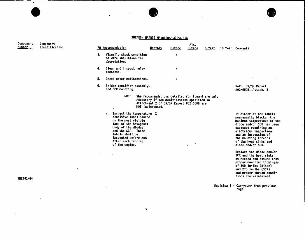
ComponentNumber
ComponentIdentification PH Recosmendation
SHEARON HARRIS NAINTENANCE NATRIX
Alt.h~entht ~Outa e ~Outa e 0 Year 10 Year Cuauenta
3. Visually check conditionof wire insulation fordegradation.
4. Clean and inspect relaycontacts.
5. Check meter calibrations.
6. Bridge rectifier assembly.and SCR mounting.
Ref: DR/gR Report802-650B, Attach. 1
NOTE: The recommendations detailed for Item 6 are onlynecessary if the modifications specified inAttachment 2 of DR/gR Report 802-650B areNOT implemented.
a. Inspect the temperature Xsensitive label placedon the most visibleface of the hexagonalbody of the diodesand the SCR. Theselabels shall beinspected before andafter each runningof the engine.
If either of the labelspermanently blacken themaximum temperature of thediode and/or SCR has beenexceeded requiring anelectrical inspectionand an inspection ofthe mounting threadsof the heat sinks anddiode and/or SCR.
5H2401/44
Replace the diode and/orSCR and the heat sinksas needed and assure thatproper mounting tightnessof 300 in-lbs (diode)and 275 in-lbs (SCR)and proper thread condi-tions are maintained.
Revision I - Carryover from previouspage
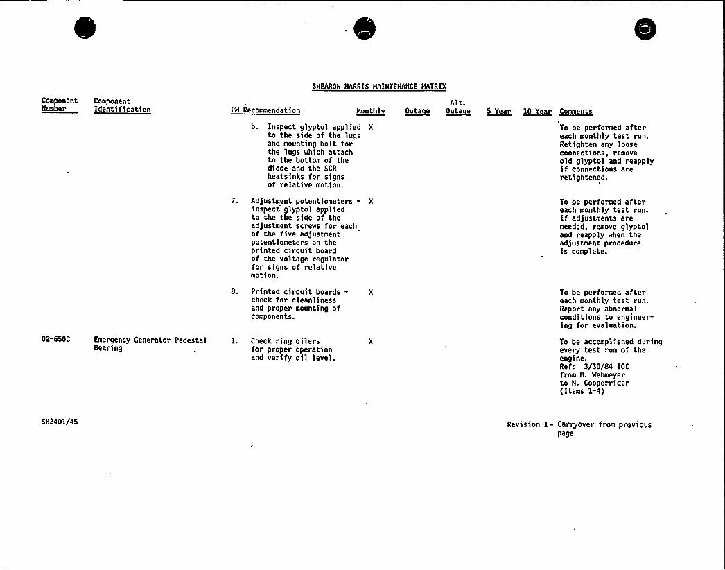
SHEARON HARRIS MAINTENANCE MATRIX
Component ComponentNumber Identification PM Recommendation ~Nanthl
Alt.~Outa e ~Outa e 5 Year 10 Year Comments
b. Inspect glyptol applied Xto the side of the lugsand mounting bolt forthe lugs which attachto the bottom of thediode and the SCRheatsinks for signsof relative motion.
To be performed aftereach monthly test run.Retighten any looseconnections, removeold glyptol and reapplyif connections areretightened.
7. Adjustment potentiometers - Xinspect glyptol appliedto the the side of theadjustment screws for eachof the five adjustmentpotentiometers on theprinted circuit boardof the voltage regulatorfor signs of relativemotion.
To be performed aftereach monthly test run.If adjustments areneeded, remove glyptoland reapply when theadjustment procedureis complete.
8. Printed circuit boards - Xcheck for cleanlinessand proper mounting ofcomponents.
02-650C Emergency Generator Pedestal 1. Check ring oilersBearing for proper operation
and verify oil level.
To be performed aftereach monthly test run.Report any abnormalconditions to engineer-ing for evaluation.
To be accomplished duringevery test run of theengine.Ref: 3/30/84 IOCfrom M. Wehmeyerto N. Cooperrider(Items 1-4)
SH2401/45 Revision 1- Carryover from previouspage
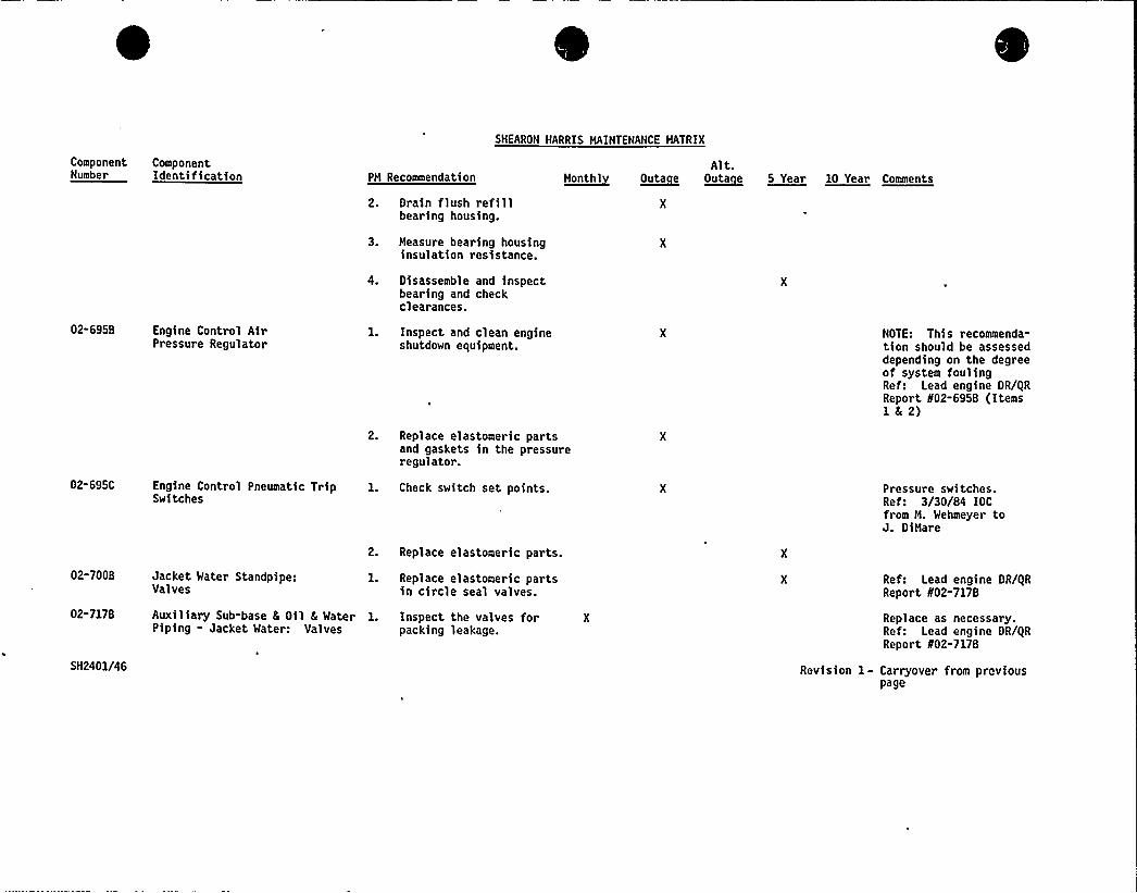
SNEARON HARRIS HAINTENANCE HATRIX
ComponentNumber
ComponentIdentification PH Recommendation
2. Drain flush refillbearing housing.
3. Measure bearing housinginsulation resistance.
Alt.~eeonthl ~Outa e ~0llta e 5 Year la Year Comaenta
02-695B Engine Control AirPressure Regulator
4. Disassemble and inspectbearing and checkclearances.
1. Inspect and clean engineshutdown equipment.
2. Replace elastomeric partsand gaskets in the pressureregulator.
NOTE: This recommenda-tion should be assesseddepending on the degreeof system foulingRef: Lead engine OR/i|RReport N02-695B (Items1')
02-695C
02-7008
Engine Control Pneumatic TripSwitches
Jacket Water Standpipe:Valves
1. Check switch set points.
2. Replace elastomeric parts.
1. Replace elastomeric partsin circle seal valves.
Pressure switches.Ref: 3/30/84 IOCfrom H. Wehmeyer toJ. OiHare
Ref: Lead engine OR/gRReport N02-7178
02-7178
5N2401/46
Auxiliary Sub-base 6 Oil 6 Water 1. Inspect the valves for XPiping - Jacket Water: Valves packing leakage.
Replace as necessary.Ref: Lead engine DR/gRReport N02-7178
Revision 1- Carryover from previouspage
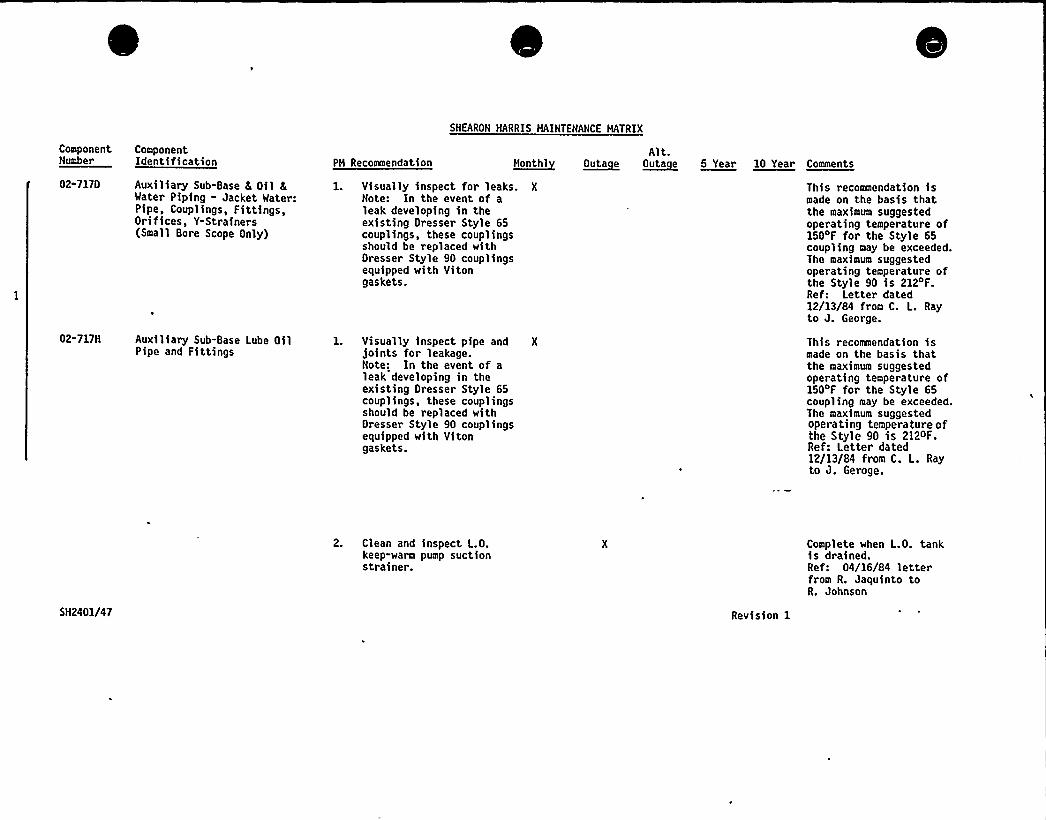
SHEARON HARRIS HAINTENANCE HATRIX
ComponentNumber
ComponentIdentification PH Recoamendation M~onthl
Alt.Outacue ~Outa e 5 Year 10 Year Comments
02-7170
02-717H
Auxiliary Sub-Base 6 Oil 8Water Piping - Jacket Water:Pipe, Couplings, Fittings,Orifices, Y-Strainers(Small Bore Scope Only)
Auxiliary Sub-Base Lube OilPipe and Fittings
1. Visually inspect for leaks. X
Note: In the event of aleak developing in theexisting Dresser Style 65couplings, these couplingsshould be replaced withDresser Style 90 couplingsequipped with Vitongaskets.
Visually inspect pipe andjoints for leakage.Note: In the event of aleak developing in theexisting Dresser Style 65couplings, these couplingsshould be replaced withDresser Style 90 couplingsequipped with Vitongaskets.
This recommendation ismade on the basis thatthe maximum suggestedoperating temperature of150'F for the Style 65coupling may be exceeded.The maximum suggestedoperating temperature ofthe Style 90 is 212'F.Ref: Letter dated12/13/84 from C. L. Rayto J. George.
This recommendation ismade on the basis thatthe maximum suggestedoperating temperature of150OF for the Style 65coupling may be exceeded.The maximum suggestedoperating temperature ofthe Style 90 is 212oF.Ref: Letter dated12/13/84 from C. L. Rayto J. Geroge.
SH2401/47
2. Clean and inspect L.O.keep-warm pump suctionstrainer.
Revision 1
Complete when L.O. tankis drained.Ref: 04/16/84 letterfrom R. Jaquinto toR. Johnson
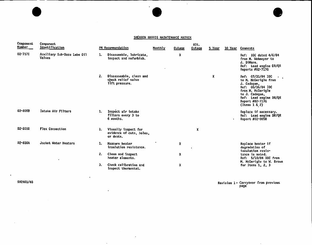
ComponentNumber
ComponentIdent(fication PH Recommendation
SHEARON HARRIS HAINTENANCE MATRIX
Alt.H~onthl ~Outa e ~OUta e 5 Year 10 Year Comments
02-717I Auxiliary Sub-Base Lube OilValves
1. Disassemble, lubricate,inspect and refurbish.
2. Dissassemble, clean andcheck relief valveliftpressure.
Ref: IOC dated 4/6/84from H. Wehmeyer toJ. DiHare.Ref: Lead engine OR/QRReports f02-717G
Ref: 07/31/84 IOCto H. McGerigle fromJ. Cadogan,Ref: 08/16/84 IOCfrom H. HcGeri g1 eto J. Cadogan,Ref: Lead engine OR/QRReport 802-717G(Items 1 8 2)
02-805B Intake Air Filters l. Inspect air intakefilters every 3 to6 months.
Replace if necessary.Ref: Lead engine OR/QRReport 802-805B
02-805D Flex Connection
02-810A Jacket Water Heaters
l. Visually inspect forevidence nf cuts, holes,or dents.
1. Heasure heaterinsulation resistance.
2. Clean and inspectheater elements.
3. Check calibration andinspect thermostat.
Replace heater ifdegradation ofinsulation resis-tance is noted.Ref: 5/10/84 IOC fromM. HcGerigle to W. Brownfor Items 1, 2, 3
5H2401/48 Revision 1- Carryover from previouspage
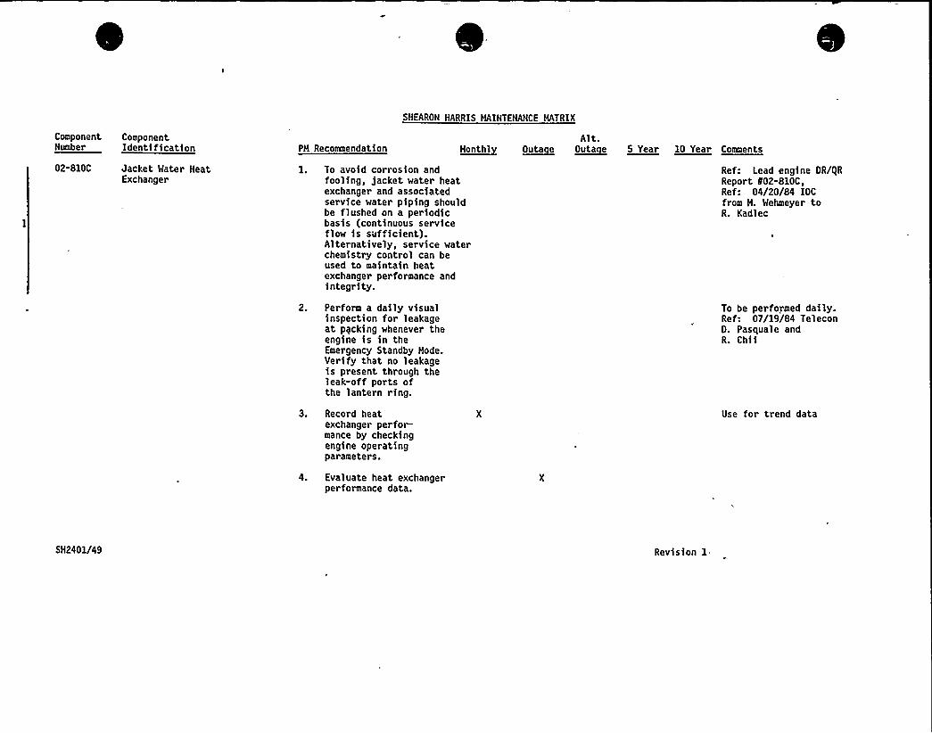
ComponentNumber
ComponentIdentification PH Recoaeendation
SNEARON HARRIS HAINTENANCE MATRIX
Alt.t~tontnl ~outa e ~outa e 5 Year 10 Year Comenta
02-810C Jacket Water NeatExchanger
1. To avoid corrosion andfooling, jacket water heatexchanger and associatedservice water piping shouldbe flushed on a periodicbasis (continuous serviceflow is sufficient).Alternatively, ser vice waterchemistry control can beused to maintain heatexchanger performance andintegrity.
2. Perform a daily visualinspection for leakageat pycking whenever theengine is in theEmergency Standby Mode.Verify that no leakageis present through theleak-off ports ofthe lantern ring.
3. Record heatexchanger perfor-mance by checkingengine operatingparameters.
4. Evaluate heat exchangerperformance data.
Ref: Lead engine OR/gRReport 102-810C,Ref: 04/20/84 IOCfrom H. Wehmeyer toR. Kadlec
To be performed daily.Ref: 07/19/84 Tel econO. Pasquale andR. Chii
Use for trend data
SH2401/49 Revision 1.
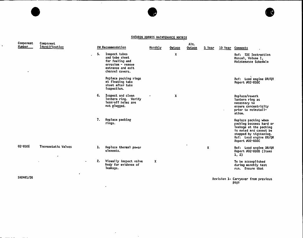
ComponentNumber
ComponentIdentification PM Recommendation
SHEARON HARRIS MAINTENANCE MATRIX
Alt.~montnt ~puta e o~uta e 5 Year le Year Comments
5. Inspect tubesand tube sheetfor fouling anderrosion - removeentrance and exitchannel covers.
Ref: TOI InstructionManual, Volume I,Maintenance Schedule
02-810E Thermostatic Valves
Replace packing ringsat floating tubesheet after tubeinspection.
6. Inspect and cleanlantern ring. Verifyleak-off holes arenot plugged.
7. Replace packingrings.
1. Replace thermal powerelements.
2. Visually inspect valve Xbody for evidence ofleakage.
Ref: Lead engine OR/QRReport ¹02-810C
Replace/reworklantern ring asnecessary toensure concentricityprior to reinstall-ation.
Replace packing whenpacking becomes hard orleakage at the packingis noted and cannot bestopped by tightening.Ref: Lead engine OR/QRReport ¹02-810C
Ref: Lead engine OR/QRReport ¹02-810D (Items1, 2)
To be accomplishedduring monthly testrun. Ensure that
SH2401/50 Revision 1- Carryover from previouspage
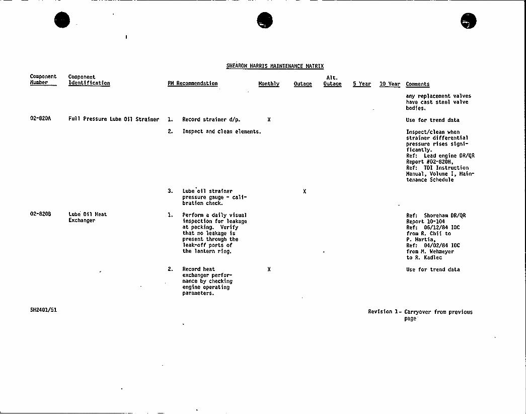
Component ComponentNumber Identification PM Recommendation
SHEARON HARRIS MAINTENANCE MATRIX
Alt.~tteatht ~Outa e 0~tata e 5 Year 10 Year Comments
any replacement valveshave cast steel valvebodies.
02-820A Full Pressure Lube Oil Strainer 1. Record strainer d/p.
2. Inspect and clean elements.
3. Lube oil strainerpressure gauge - cali-bration check.
Use for trend data
Inspect/clean whenstrainer differentialpressure rises signi-ficantly.Ref: Lead engine OR/QRReport f02-820M,Ref: TOI InstructionManual, Volume I, Main-tenance Schedule
02-8208 Lube Oil HeatExchanger
1. Perform a daily visualinspection for leakageat packing. Verifythat no leakage ispresent through theleak-off ports ofthe lantern ring.
Ref: Shoreham OR/QRReport 10-104Re f: 06/12/84 IOCfrom R. Chii toP. Martia,Ref: 04/02/84 IOCfrom M. Wehmeyerto R. Kadlec
2. Record heatexchanger perfor-mance by checkingengine operatingparameters.
Use for trend data
5H240U51 Revision 1- Carryover from previouspage
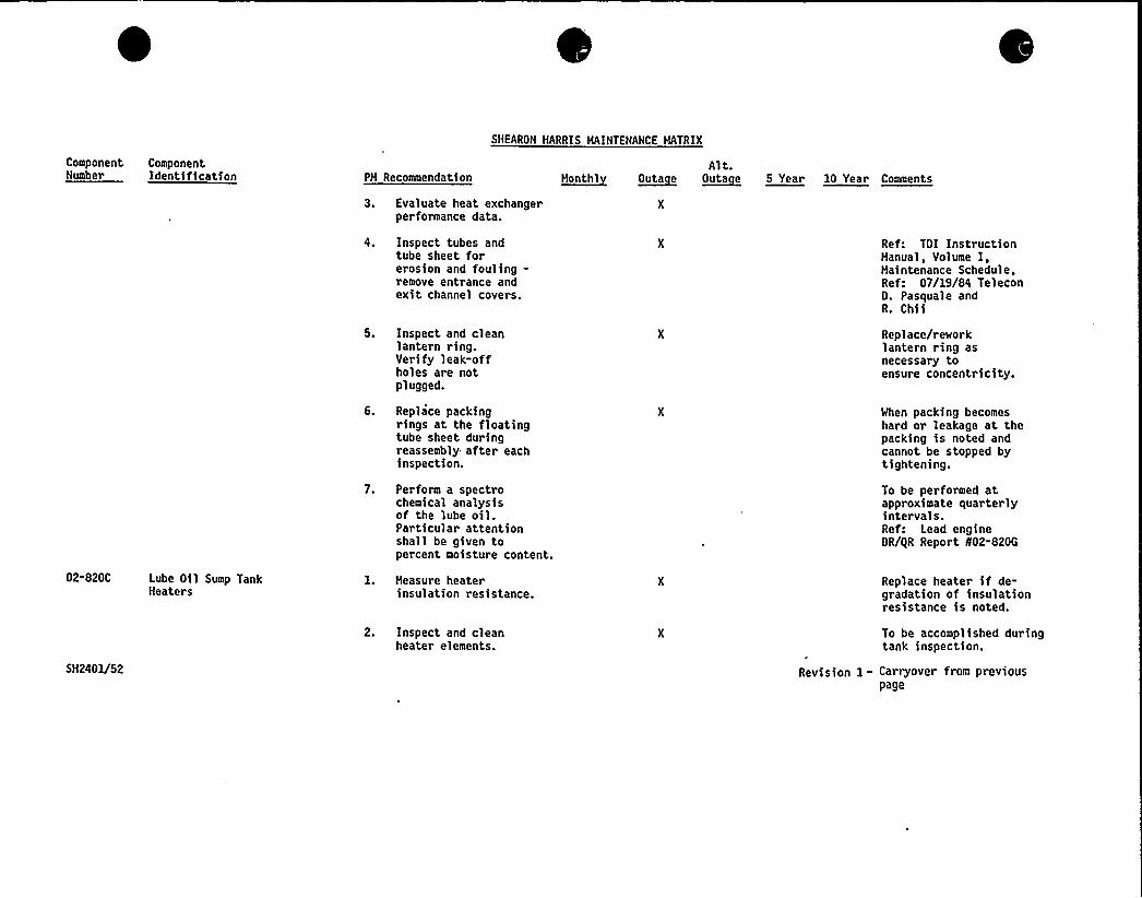
Component ComponentNumber Identification PH Recommendation
SHEARON HARRIS MAINTENANCE HATRIX
Alt.~uoutat ~putt e O~uta e 5 Year 10 Year Couoeote
02-820C
SH2401/52
Lube Oil Sump TankHeaters
3. Evaluate heat exchangerperformance data.
4. Inspect tubes andtube sheet forerosion and fouling-remove entrance andexit channel covers.
5. Inspect and cleanlantern ring.Verify leak-offholes are notplugged.
6. Replace packingrings at the floatingtube sheet duringreassembly after eachinspection.
7. Perform a spectrochemical analysisof the lube oil.Particular attentionshall be given topercent moisture content.
1. Heasure heaterinsulation resistance.
2. Inspect and cleanheater elements.
Ref: TOI InstructionManual, Volume I,Maintenance ScheduleRe f: 07/19/84 Tel econD. Pasquale andR. Chii
Replace/reworklantern ring asnecessary toensure concentricity.
When packing becomeshard or leakage at thepacking is noted andcannot be stopped bytightening.
To be performed atapproximate quarterlyintervals.Ref: Lead engineOR/gR Report 802-820G
Replace heater if de-gradation of insulationresistance is noted.
To be accomplished duringtank inspection.
Revision 1 - Carryover from previouspage
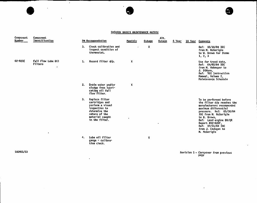
SHEARON HARRIS MAINTENANCE MATRIX
ComponentNumber
ComponentIdentification PH Recomnendation H~onthl ~Outa e
Alt.~Outa e 5 Year 10 Year Comments
02-820E Full Flow Lube OilFilters
3. Check calibration andinspect condition ofthermostat.
1. Record filter d/p.
2. Drain water and/orsludge from lubri-cating oil fullflow filter.
Ref: 05/10/84 IOCfrom H. HcGerigleto W. Brown for Items1, 2, 3
Use for trend data,Ref: 04/02/84 IOCfrom M. Wehmeyer toJ. OiHare,Ref: TOI InstructionManual, Volume I,Maintenance Schedule
3. Replace filtercartridges andperform a visualinspection todetermine thenature of thematerial caughtin the filter.
4. Lube oil filtergauge - calibra-tion check.
To be performed beforethe filter d/p reaches themanufacturers recommendedmaximum differentialpressure. Ref: 05/30/84IOC from M. HcGerigleto B. Brown,Ref: Lead engine OR/ORReport 802-820F,Ref: 07/31/84 IOCfrom J. Cadogan toH. McGerigle
SH2401/53 Revision 1 - Carryover from previouspage
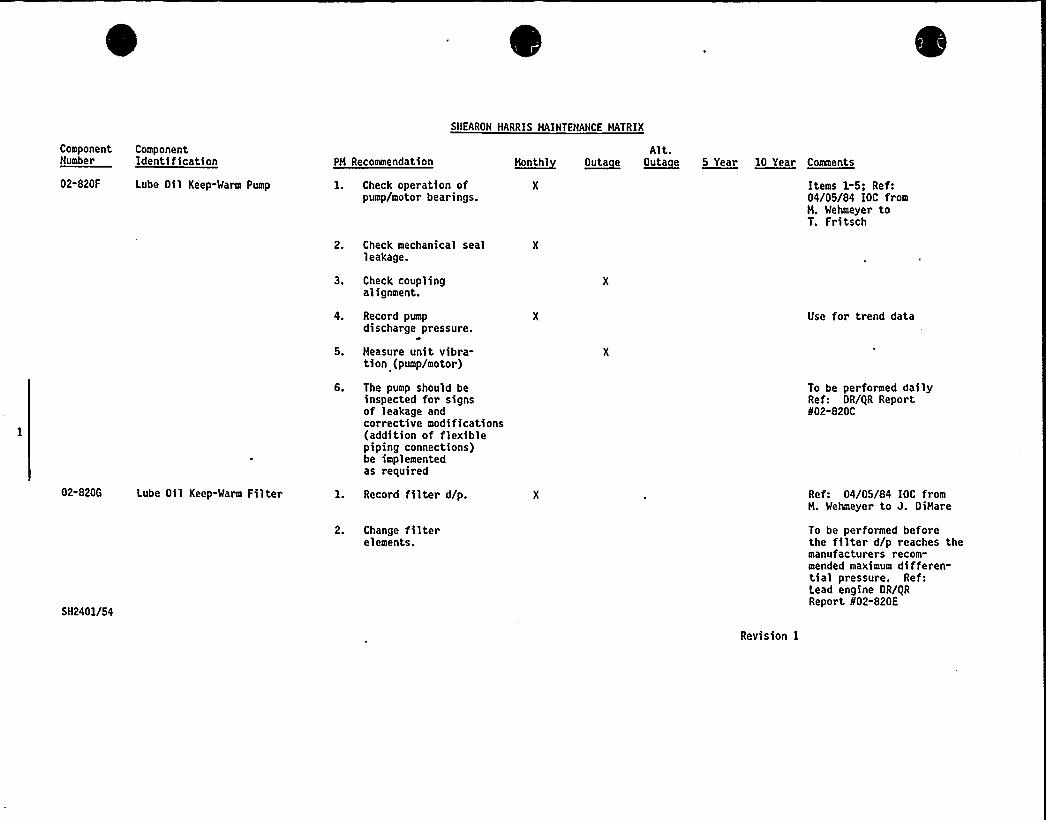
SHEARON HARRIS MAINTENANCE MATRIX
ComponentNumber
02-820F
ComponentIdentification
Lube Oil Keep-Warm Pump
PH Recommendation
1. Check operation ofpump/motor bearings.
2. Check mechanical sealleakage.
3. Check couplingalignment.
4. Record pumpdischarge pressure.
5. Measure unit vibra-tion (pump/motor)
6. The pump should beinspected for signsof leakage andcorrective modifications(addition of flexiblepiping connections)be implementedas required
honthlyAlt.
~Outa e ~Outa e 5 Year 10 Year Coaments
Items 1-5; Ref:04/05/84 IOC fromH. Wehmeyer toT. Fritsch
Use for trend data
To be performed dailyRef: DR/gR Report802-820C
02-820G Lube Oil Keep-Warm Filter
SN2401/54
1. Record filter d/p.
2. Change filterelements.
Revision I
Ref: 04/05/84 IOC fromH. Wehmeyer to J. DiHare
To be performed beforethe filter d/p reaches themanufacturers recom-mended maximum differen-tial pressure. Ref:Lead engine OR/gRReport 802-820E
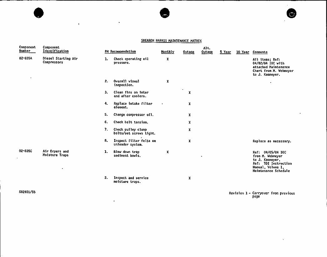
SMEARON HARRIS HAINTENANCE MATRIX
ComponentNumber
02-835A
ComponentIdentification
Oiesel Starting AirCompressors
PH Recommendation
1. Check operating oilpressure.
2. Overall visualinspection.
3. Clean fins on interand after coolers.
4. Replace intake filterelement.
5. Change compressor oil.6. Check belt tension.
~Honth1Alt.
~Outa e ~Outa e 5 Year 10 Year Comments
All items; Ref:04/02/84 IOC withattached MaintenanceChar t from H. Wehmeyerto J. Kammeyer.
02-835C Air Dryers andMoisture Traps
7. Check pulley clampbolts/set screws tight.
8. Inspect filter felts onunloader system.
1. Blow down trapsediment bowls.
2. Inspect and servicemoisture traps.
Replace as necessary.
Ref: 04/05/84 IOCfrom H. Wehmeyerto J. Kammeyer,Ref: TOI InstructionManual, Volume I,Haintenance Schedule
5H2401/55 Revision 1 - Carryover from previouspage
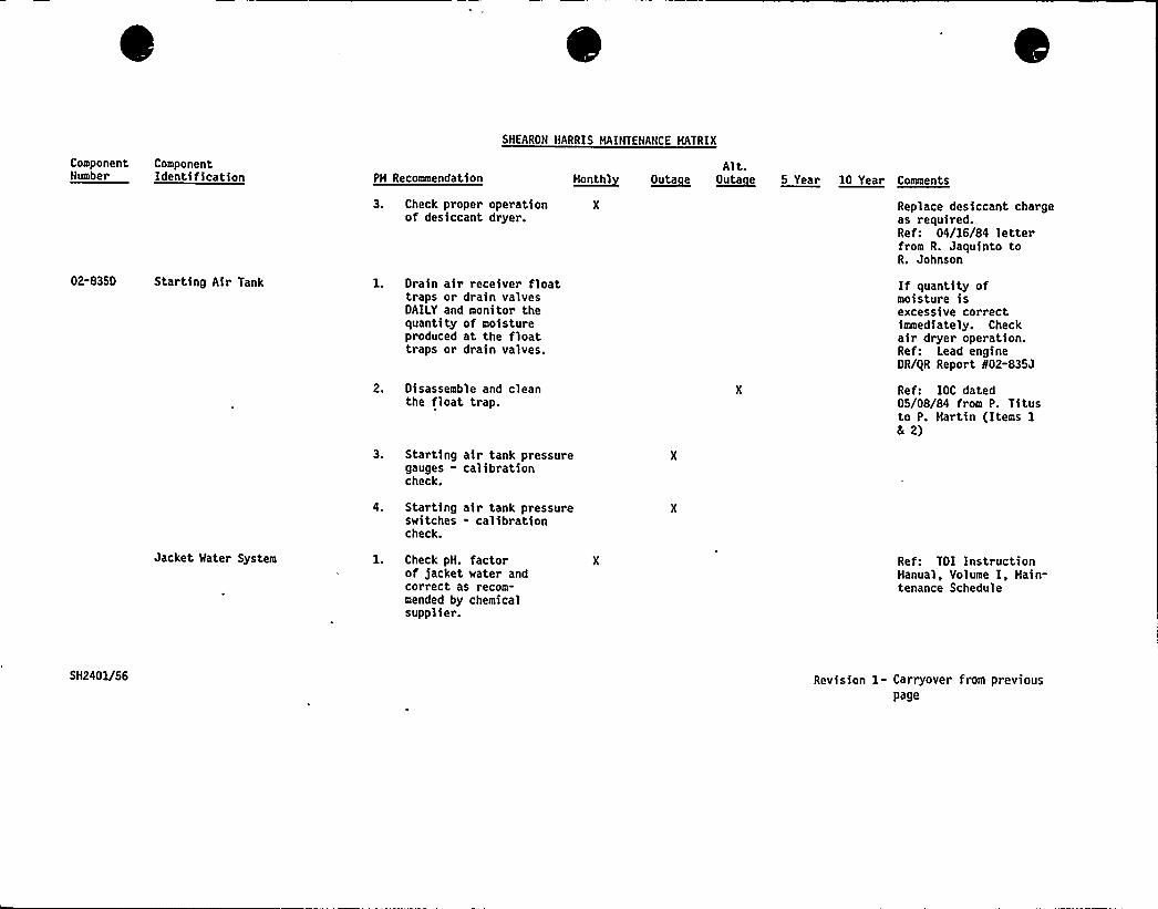
SHEARON HARRIS MAINTENANCE MATRIX
ComponentNumber
ComponentIdentification PH Recommendation
3. Check proper operationof desiccant dryer.
M~anthlAlt.
~Outa e Outacue 5 Year 10 Year Comments
Replace desiccant chargeas required.Ref: 04/16/84 letterfrom R. Jaquinto toR. Johnson
02-835D Starting Air Tank l. Drain air receiver floattraps or drain valvesDAILY and monitor thequantity of moistureproduced at the floattraps or drain valves.
2. Disassemble and cleanthe float trap.
3. Starting air tank pressuregauges - calibrationcheck.
If quantity ofmoisture isexcessive correctimmediately. Checkair dryer operation.Ref: Lead engineDR/gR Report N02-835J
Ref: IOC dated05/08/84 from P. Titusto P. Hartin (Items 18 2)
4. Starting air tank pressureswitches - calibrationcheck.
Jacket Mater System 1. Check pN. factorof jacket water andcorrect as recom-mended by chemicalsupplier.
Ref: TDI Instruct>onManual, Volume I, Hain-tenance Schedule
5H2401/56 Revision 1- Carryover from previouspage
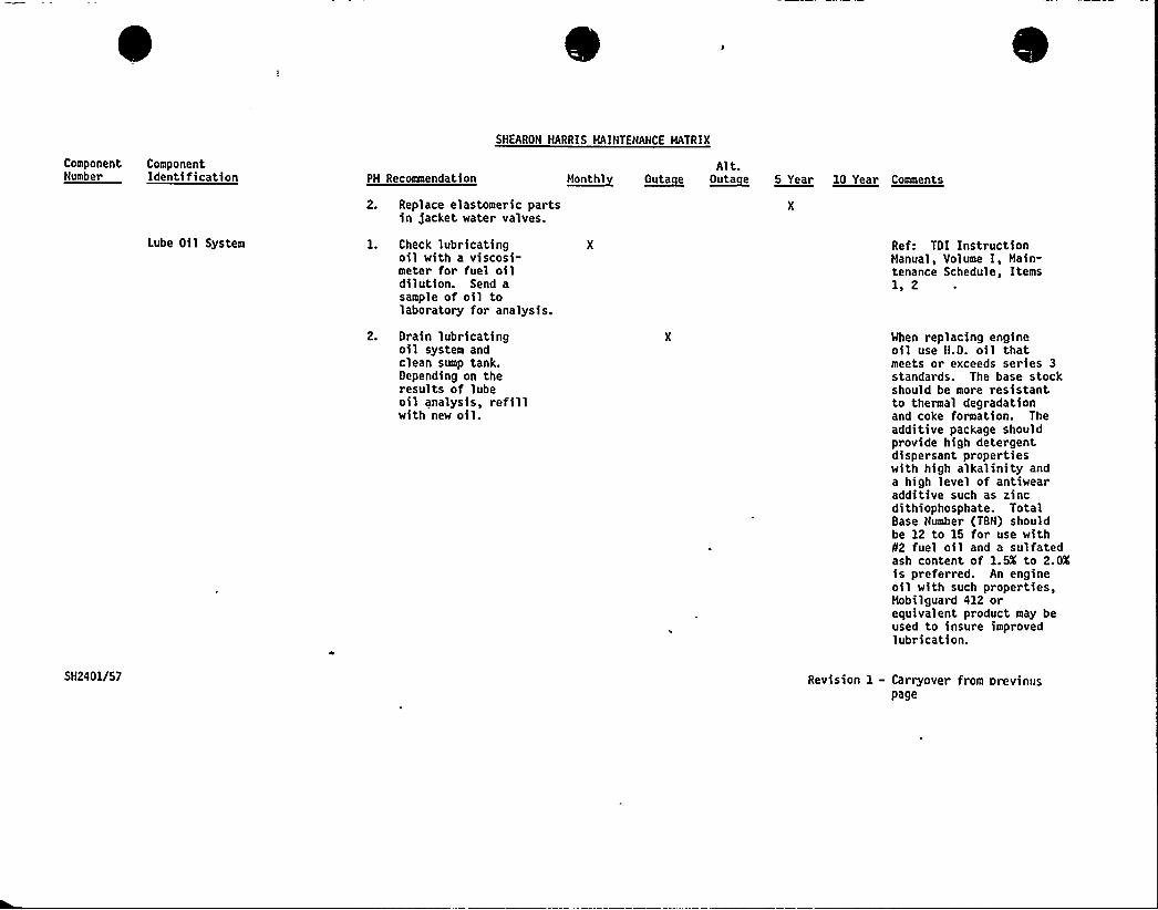
Component ComponentNumber Identification PH Recommendation
SHEARON HARRIS HAINTENANCE HATRIX
Alt.M~onthl O~uta e O~uta e 5 Year 10 Year Comments
Lube Oil System
2. Replace elastomeric partsin jacket water valves.
1. Check lubricatingoil with a viscosi-meter for fuel oildilution. Send asample of oil tolaboratory for analysis.
Ref: TOI InstructionHanual, Volume I, Hain-tenance Schedule, Items1, 2
2. Drain lubricatingoil system andclean sump tank.Depending on theresults of lubeoil analysis, refillwith new oil.
When replacing engineoil use H.D. oil thatmeets or exceeds series 3standards. The base stockshould be more resistantto thermal degradationand coke formation. Theadditive package shouldprovide high detergentdispersant propertieswith high alkal>nity anda high level of antiwearadditive such as zincdithiophosphate. TotalBase Number (TBN) shouldbe 12 to 15 for use with82 fuel oil and a sulfatedash content of 1.5X to 2.0Xis preferred. An engineoil with such properties,Hobilguard 412 orequivalent product may beused to insure improvedlubrication.
SH2401/57 Revision 1 - Carryover from previouspage
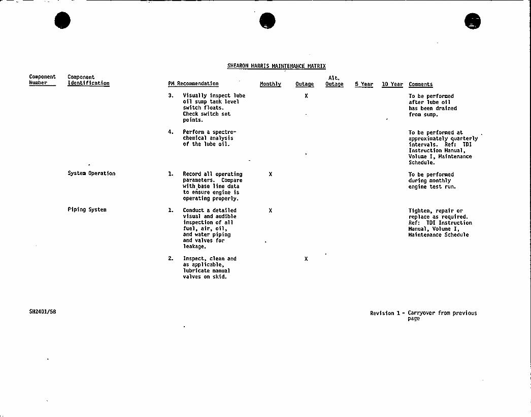
ComponentNumber
ComponentIdentification PM Recommendation
SHEARON HARRIS MAINTENANCE MATRIX
Alt.t~tanthl 0~tata e ~Outa e 5 Year 10 Year Cneeaentt
System Operation
Piping System
3. Visually inspect lubeoil sump tank levelswitch floats.Check switch setpoints.
4. Perform a spectro-chemical analysisof the lube oil.
1. Record all operatingparameters. Comparewith base line datato ensure engine isoperating properly.
1. Conduct a detailedvisual and audibleinspection of allfuel, air, oil,and water pipingand valves forleakage.
To be performedafter lube oilhas been drainedfrom sump.
To be per formed atapproximately quar terlyintervals. Ref: TDIInstruction Manual,Volume I, MaintenanceSchedule.
To be performedduring monthlyengine test run.
Tighten, repair orreplace as required.Ref: TDI InstructionManual, Volume I,Maintenance Schedule
2. Inspect, clean andas applicable,lubricate manualvalves on skid.
5H2401/58 Revision 1- Carryover from previouspage
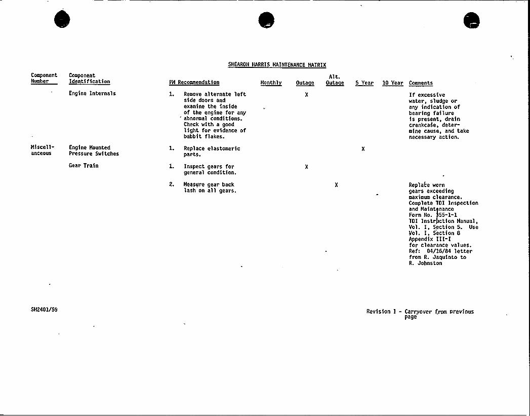
SHEARON HARRIS HAINTENANCE HATRIX
Component ComponentNumber Identification PH Recommendation
Alt.~mentht ~Outa e ~Outa e 5 Year 10 Year Comments
Hiscell-anceous
Engine Internals
Engine HountedPressure Switches
Gear Train
1. Remove alternate leftside doors andexamine the insideof the engine for any
" abnormal conditions.Check with a goodlight for evidence ofbabbit flakes.
1. Replace elastomericparts.
l. Inspect gears forgeneral condition.
2. Measure gear backlash on all gears.
If excessivewater, sludge orany indication ofbearing failureis present, draincrankcase, deter-mine cause, and takenecessary action.
Replace worngears exceedingmaximum clearance.Complete TOI Inspectionand Haint nanceForm No. 55-1-1TOI Instr ction Manual,Vol. I, Section 5. UseVol. I, Section 8Appendix III-Ifor clearance values.Ref: 04/16/84 letterfrom R. Jaquinto toR. Johnston
5H2401/59 Revision I - Carryover from previouspage
ENGINEERING REVIEW CRITERIA DOCUMENT
FOR
THE DESIGN REVIEW OF THE TDI DIESEL
SMALL BORE PIPING, TUBING AND SUPPORTS
FOR THE TDI OWNERS GROUP
Re ort No. 11600.60-DC-02Revision 0
Preparedby
Stone L Webster En ineerin Co orationBoston, Massachusetts
August 1984
,TDI1154
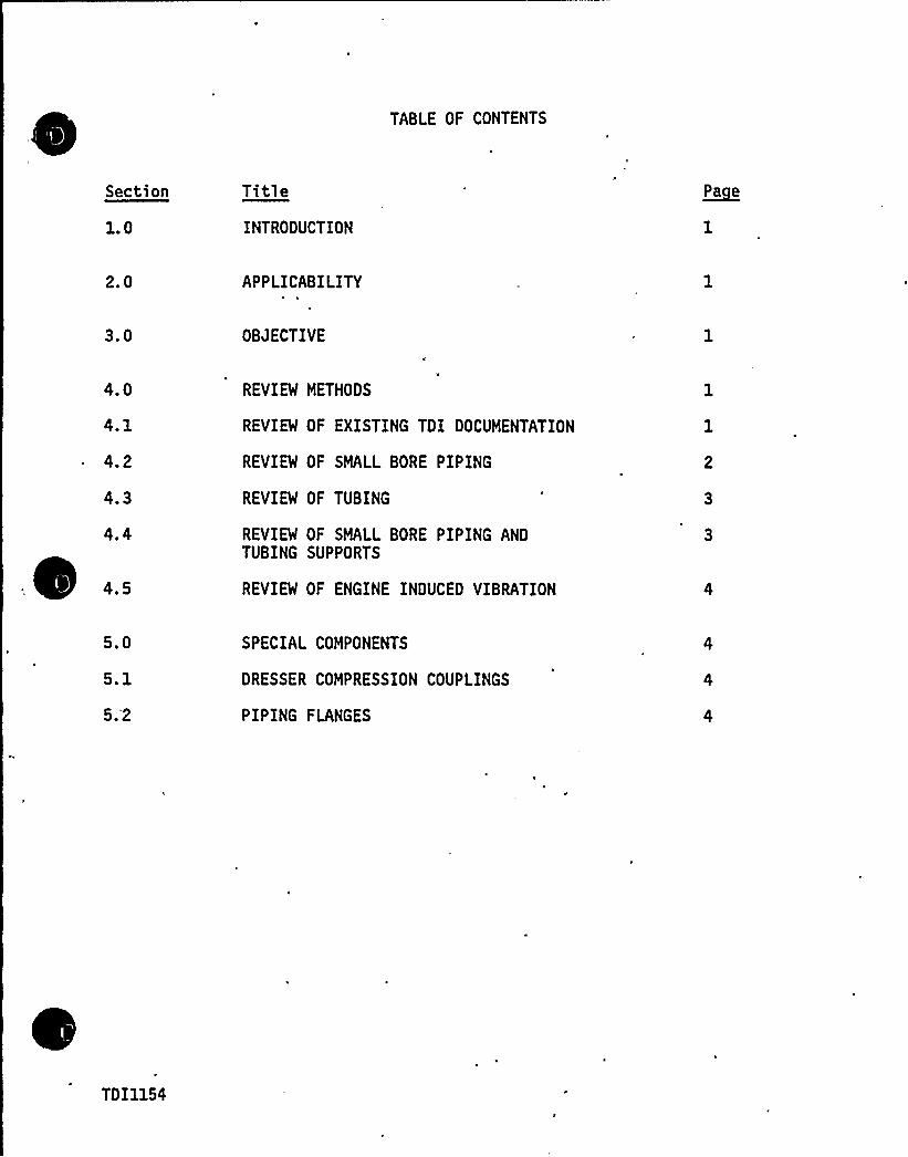
TABLE OF CONTENTS
Section
1.0
Title
INTRODUCTION
~Pa e
2.0 APPLICABILITY
3.0 OBJECTIVE
4.0
4.1
4.2
4.3
REVIEW METHODS
REVIEW OF EXISTING TDI DOCUMENTATION
REVIEW OF SMALL BORE PIPING
REVIEW OF TUBING
REVIEW OF SMALL BORE PIPING ANDTUBING SUPPORTS
REVIEW OF ENGINE INDUCED VIBRATION
5.0
5.1
5.'2
SPECIAL COMPONENTS
DRESSER COMPRESSION COUPLINGS
PIPING FLANGES
TDI1154

V
"~
~ IO
TDI OWNERS GROUP
ENGINEERING REVIEW CRITERIADOCUMENT FOR
THE DESIGN REVIEW OF THE TDI DIESELSMALL BORE PIPING, TUBING AND SUPPORTS
FOR THE TDI OWNERS GROUP
1. 0 INTRODUCTION
The TDI Emergency Diesel Generator Owners Group Program requires Design andguality Revalidation reviews. 'to independently verify the structural adequacyof the small bore piping, tubing and associated supports to withstand theeffects of normal operating and earthquake loadings. This report provides thecriteria to be used to perform the review.
2.0 APPLICABILITY
The requirements of the review contained in this report are applicable to allTDI supplied small bore piping and tubing systems including associatedsupports contained in - the diesel engine and its skid, unless specificallyexcluded by . an approved Task Description in. accordance with TDI DieselGenerator Owners Group Procedure DG-3.
3. 0 OBJECTIVE
The objective of this report is to provide the criteria to be utilized toverify that the small bore piping, tubing and supports will perform theirintended function under all normal and earthquake loadings.
4.0 REVIEW METHODS
4. 1 Review of Existin TDI Documentation
The initial method to be utiTized in determining a component's acceptabilityis to perform a review of all existing small bore pipe stress and supportdocumentation provided by TDI.
The documentation will be reviewed to determine if it provides an adequatedesign basis in accordance with the appropriate codes as delineated by theindividual utilities design specification for the diesel engine, The reviewshall also compare the as built piping and support condition to the existingdesign basis to determine compatability.
TDI1154/1

T
gl
C
Page 2
If, after completing the review, the engineer determines that the component isacceptable, based on the existing documentation, the Component Design Reportwill be issued stating the conclusion of acceptability.
If TDI documentation is not available, or if it is determined that theavailable documentation does not readily lead to a conclusion of accpetabilitythe engineer will alternatively continue the review as outlined in thefollowing paragraphs.
4.2 Review of Small Bore Pi in for Acce tabilitIn cases where the review of TDI documentation does not lead to componentacceptability, the engineer will judge if the component will perform itsintended function under all normal and earthquake loadings. This judgmentwill be based on a review of the following information:
guality approved as built piping isometrics
System operating parameters
Physical piping data
Site specific amplified response spectra
System function
In addition to reviewing the above information, a physical walkdown of theengine and skid piping may be required. The walkdown would include a reviewof the piping to determine pipe support type and function, as well as a reviewfor the following:
lThermal flexibi 1 it: The engineer will determine if sufficientflexibility exists for each between support section of small bore piping.The thermal movement imparted by the supports onto the piping will alsobe considered.
Deadwei ht s ans: The deadweight spans between supports will be reviewedby the engineer and acceptability will be based on judgment.
Tthe engineer and acceptability will be based on judgment. Theengineer's judgment will consider the site specific amplified responsespectra and all components, fittings and branch connections. Engineinduced vibration will also be considered in determining acceptabilityof seismic spans and is further discussed in paragraph 4.5.
The engineer will document the reviews of the individual components by awritten trip report. The trip report will serve as a summarization ofthe engineering walkdown.
TDI1154/2 REV I
Page 3
In cases where the engineer judges that the component will perform itsintended design function the Component Design Report will be issued stat-ing the conclusion of acceptability.
In cases where the engineer judges that a modification may be required toassure functional capability, a recommendation for the modification willbe stated in the conclusions of the Component Design Review. The analystmay perform calculations to support the judgment in cases where it isnot apparent that a modification is required. The object of thesecalculations is not to provide code compliance, but specific codes may bereferenced for guidance.
4.3 Review of Tubin .for Acce tabilitA field walkdown of all critical tubing components will be required. The samemethods as outline in paragraph 4.2 for small bore piping review will .beemployed for tubing.
4.4 Review of Small Bore Pi in and Tubin Su ort
In cases whe~e the review of TDI documentation, as outlined in paragraph 4.1,does not lead to component acceptability the engineer must continue the reviewbased on the following:
1) guality approved as built support sketches, if available.r
2) Physical support data
3) Anticipated support loads
In addition to, or in 'conjunction with, reviewing the above information, aphysical walkdown of the engine and skid supports may be required. The walk-down would consist of a review of the following support components so that theengineer may judge if the support will perform its intended function:
1) Structural members
2) Structural bolts and base plates
3) Welds
The engineer will document the review and recommend modifications as outlinedin paragraph 4.2.
4.5 En ine Induced Vibration
The effects of engine induced vibration will be considered in determing theadequacy of the piping spans for dynamic loading. Specifically, the engi'neer
TDI1154/3
Page 4
will determine if the existing piping spans may cause the piping to respondat the resonant frequency of the engine. This determination may be based oncalculation or review of the vibration test results obtained at Shoreham andComanche Peak. Another acceptable method of considering engine induced vibra-tion is to compare the specific engine small bore piping or tubing with provenacceptable design experience.
The documentation of acceptability or recommendation of modifications will bein accordance with paragraph 4.2.
5. 0 SPECIAL COMPONENTS
5. 1 Dresser Com ression Cou linBased on review of the small bore Dresser couplings at Shoreham, it is notrequired to perform qualifying calculations for the coupling on the remainingengines. The couplings are inherently qualified based on acceptability of theattached piping.
5.2 'Pi Fi
Based on review of the small bore pipe flanges at Shoreham, it is not requiredto perform qualifying calculations for the flanges on the remaining engines.The flanges are inherently qualified based on acceptability of the attachedpiping.
TDI1154/4
DESIGN CRITERIA FORDIESEL GENERATOR
LARGE DIAMETER PIPING FOR SHEARON HARRIS
Submitted toTDI Owners Group
Charlotte, North Carolina
Prepared byImpell Corporation
225 Broad Hollow RoadMelville, New York 11747
Report No. 02-0630-1258Rev. A
Job No. 0630-037-1641
October, 1984 .
SH2666
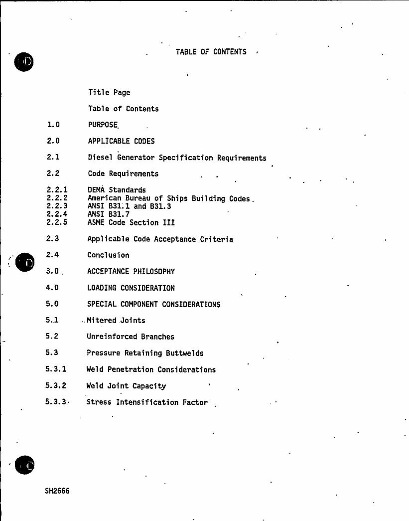
TABLE OF CONTENTS
1.0
2.0
2.1
2.2
2.2.12.2.22.2.32.2.42.2.5
2.3
2.4
3.0 „
4.0
5.0
5..1
5.2
5.3
5.3.1
5.3.2
5.3.3
Title Page
Table of Contents
PURPOSE
APPLICABLE CODES
Diesel Generator Specification Requirements
Code Requirements
DEMA StandardsAmerican Bureau of Ships Building Codes .ANSI B31;1 and 831.3ANSI B31.7ASME Code Section IIIApplicable Code Acceptance Criteria
Conclusion
ACCEPTANCE PHILOSOPHY
LOADING CONSIDERATION
SPECIAL COMPONENT CONSIDERATIONS
.,Mitered Joints
Unreinforced Branches
Pressure Retaining Buttwelds
Weld Penetration Considerations
Weld Joint Capacity
Stress Intensification Factor
SH2666

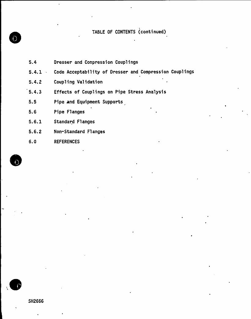
TABLE OF CONTENTS (continued)
5.4 Dresser and Compression Couplings
5.4.1 Code Acceptability of Dresser and Compression Couplings
5.4.2
5.4.3
5.5
5.6
5.6.1
5. 6.2
6.0
Coupling Validation
Effects of Couplings on Pipe Stress Analysis
Pipe and Equipment Supports
Pipe Flanges
Standard Flanges
Non-Standard Flanges
REFERENCES
SH2666
"Ql
ij'.
1.0 PURPOSE
'he
purpose of this document is to provide structural acceptance criteria forevaluation of the Transameri ca Del aval, Inc. (TDI), 1 ar ge di ameter, di eselgenerator skid. mounted piping at the Shearon Harris Nuclear Power PlantUnit .No. 1, (SHNPP). This criteria was based primarily upon the philosophyembodied in industry accepted Codes and Standards for design of nuclear powerstation piping.
2. 0 APPLICABLE CODES
2.1 Diesel Generator S ecification Re uirements
According to Reference 1, ASME III-Class 3 (Ref. 2) is invoked for the subjectpiping at SHNPP.
2.2 Code Re uirements
2.2.1 Diesel En ine Manufacturers Association DEMA Standards
The DEMA Standard (Ref. 3) extensively covers the detailed performancerequirements of systems and subsystems for diesel engine driven electric powergenerating units, but does not cover analytical requirements or allowablestresses for piping systems. It relies on other codes for these requirementsbut does not specifically reference any.
2.2.2 American Bureau of Shi s Buildin Code
Section 36 of the American Bureau of Ships Building Code (Ref.4) discussesrequirements for pumps and piping systems. This code presents very few designrequirements, providing specific analytical formulas only for pipe wall thick-ness versus piping design pressure. The code makes no specific provisions foranalysis for deadweight, thermal expansion, or dynamic effects. Piping materi-als and allowable membrane stresses are addressed in,this code. For example,ASTM A53 Grade B and A106 Grade B are approved materials. It is noted that.this code provides tab'ulated membrane stress allowables which are the same asfor B31.1 (Rpf. 5) and ASME III Class 3 and 2 (Refs. 2 and 6).
2.2.3 ANSI B31.1 and 831.3
The general philosophy of ANSI B31.1 (Ref. 5) and B31.3 (Ref. 7) is to parallelthose provisions of Section I "Power Boilers" of the ASME Boiler and PressureVessel Code, as they can be applied to piping systems functioning at elevatedpressures and temperatures. These codes are conservative, reflecting thegeneral need for long service life and maximum reliability in power, chemical,and petroleum refinery installations.
SH2666/1
~4iV
I'
4
tV
Xp
V
Page 2
B31.1 and B31.3 are quite similar, except that 831.3 allowable stresses aresomewhat more permissive than B31.1 values. Both are all inclusive codes whichset forth engineering requirements for design and construction of pipingsystems. These codes contain basic reference data and formulas deemed neces-sary for design, including the following:
(1) Material specifications and component standards which have been acceptedfor code usage;
(2) The designation of proper dimensional standards for the elements compris-ing piping systems;
(3)
(4)
Requirements for the design of component parts and assembled units,including necessary pipe supporting elements;
Requirements for the evaluation and limitation of stresses, reactions, andmovements associated with pressure, temperature, and external forces;
(5) Requirements for the fabrication, assembly, and erection of pipingsystems.
(6) Requirements for testing and inspection of elements before assembly orerection and of the completed systems after erection.
2.2.4 ANSI B31.7~ ~
~
~
~
~
~ ~ANSI B31.7 "Nuclear Power Piping" (Ref. 8) was the precursor of ASME III-Class1 Subarticle NB-3600, which covers ASME Code Class 1 piping design, and embrac-es the same design philosophy as ASME III-Class 1 (Ref. 9).
2.2.5 ASME Code Section IIIThe ASME Boiler and Pressure Vessel Code provides rules for the construction ofboilers, pressure vessels, and nuclear components. Section III of this Codeaddresses nuclear power plant components, and consists of two (2) divisions.Division 2 covers concrete reactor vessels and containments and is not perti-nent here. Division 1 cohsists of the following subsections:
NCANBNC
ND
NENFNG
Appendices
General RequirementsClass 1 ComponentsClass 2 ComponentsClass 3 ComponentsClass MC ComponentsComponents SupportsCore Support Structures
SH2666/2

lab
4
Page 3
Each subsection is divided into articles as follows:
Article 1000Article 2000Article 3000Article 4000Article 5000Article 6000Article 7000Article 8000
Introduction and Scope.MaterialDesignFabrication and InstallationExaminationTestingOverpressure ProtectionNameplates, Stamping and Reports
The code recognizes that various components have different levels of importanceassociated with the components'unction, as related to the safe operation ofthe nuclear power plant. The code classes thus permit a choice of rules thatprovide assurance of structural integrity and quality commensurate with therelative importance assigned 'to the individual items. Class 1 components areassigned the highest level of importance. Reactor coolant pressure boundarycomponents are examples of what is normally assigned as ASME III-Class l.Class 2 components are assigned the next lower level of importance. Nuclearsafety related components other than reactor coolant pressure boundary compo-nents are examples of what is normally assigned to ASME III-Class 2. Class 3components are usually of the same level of importance as Class 2 components,but are assigned to ASME III-Class 3 by virtue of their moderate normal operat-ing temperatures and pressures.
ASME Code Section III does not provide guidance in the selection of componentclassification and places the responsibility of such component classificationon the owner of the nuclear power plant.
2.3 A licable Code Acce tance Criteria
Those portions of the applicable building codes and standards which refer tostructural integrity of the subject piping are addressed herein. The portionsof these codes which provide requirements for documentation and other qualityassurance related requirements, as well as adequacy of system designrequirements such as overpressure protection adequacy, are not. part of thisscope.
Reference 1 invokes ASME-Class 3, (1974 edition, including addendums throughwinter 1976) for the SHNPP diesel generator piping. This classification isconsistent with the moderate service temperatures and pressures associated withthe subject piping. ASME III Class 3 applies specifically to nuclear safetyrelated piping, having rigorous dnalytical requirements that are acceptable tothe nuclear industry and the U.S. Nuclear Regulatory Commission. ANSI B31.1(Ref. 5) and ANSI B31.3 (Ref. 7) by virtue of its similarity, is also applica-bl e.
SH2666/3
p%lp%,1 A L4 ~
kr«r
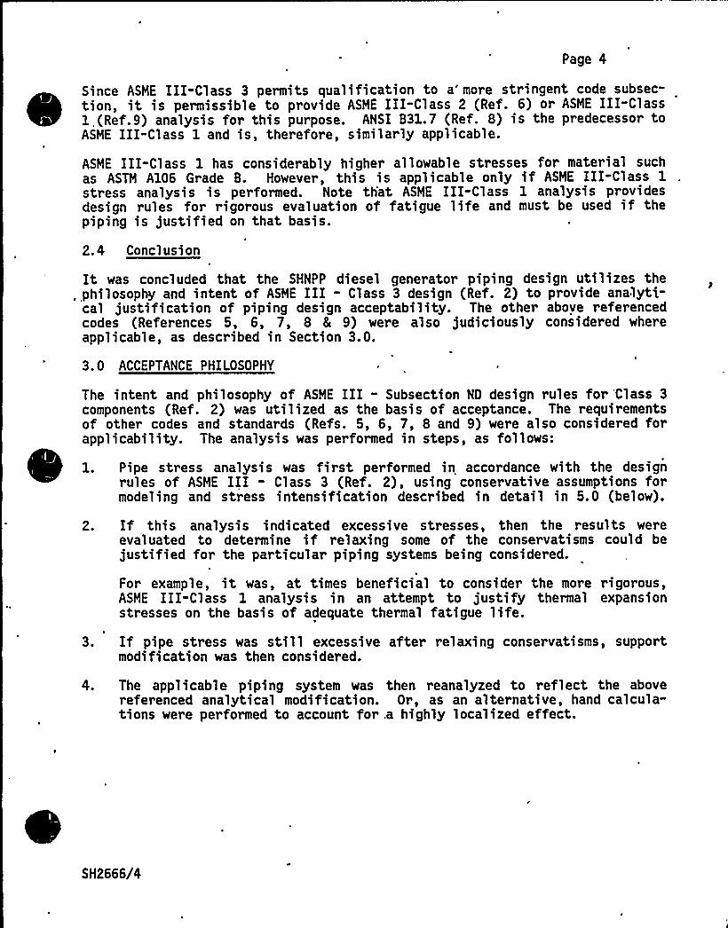
Page 4
Since ASME III-Class 3 permits qualification to a'ore stringent code subsec-tion, it is permissible to provide ASME III-Class 2 (Ref. 6) or ASME III-Class1,(Ref. 9) analysis for this purpose. ANSI B31. 7 (Ref. 8) is the predecessor toASME III-Class 1 and is, therefore, similarly applicable.
ASME III-Class 1 has considerably higher allowable stresses for material suchas ASTM A106 Grade B. However, this is applicable only if ASME III-Class 1stress analysis is performed. Note th'at ASME III-Class 1 analysis providesdesign rules for rigorous evaluation of fatigue life and must be used if thepiping is justified on that basis.
2.4 Conclusion
It was concluded that the SHNPP diesel generator piping design utilizes the. philosophy and intent of ASME III - Class 3 design (Ref. 2) to provide analyti-
cal justification of piping design acceptability. The other above referencedcodes (References 5, 6, 7, 8 & 9) were also judiciously considered whereapplicable, as described in Section 3.0.
3.0 ACCEPTANCE PHILOSOPHY
The intent and philosophy of ASME III - Subsection ND design rules for Class 3components (Ref. 2) was utilized as the basis of acceptance. The requirementsof other codes and standards (Refs. 5, 6, 7, 8 and 9) were also considered forapplicability. The analysis was performed in steps, as follows:
1. Pipe stress analysis was first performed in accordance with the designrules of ASME III - Class 3 (Ref. 2), using conservative assumptions formodeling and stress intensification described in detail in 5.0 (below).
2. If this analysis indicated excessive stresses, then the results wereevaluated to determine if relaxing some of the conservatisms could bejustified for the particular piping systems being considered.
For example, it was, at times beneficial to consider the more rigorous,ASME III-Class 1 analysis in an attempt to justify thermal expansionstresses on the basis of adequate thermal fatigue life.
3. If pipe stress was still excessive after relaxing conservatisms, supportmodification was then considered.
4. The applicable piping system was then reanalyzed to reflect the abovereferenced analytical modification. Or, as an alternative, hand calcula-tions were performed to account for .a highly localized effect.
SH2666/4
v +"4k
F'
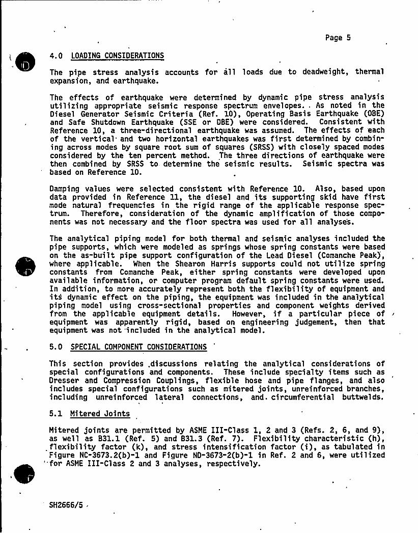
Page 5
'i 4. 0 LOADING CONSIDERATIONS
The pipe stress analysis accounts for all loads due to deadweight, thermalexpansion, and earthquake.
The effects of earthquake were determined by dynamic pipe stress analysisutilizing appropriate seismic response spectrum envelopes.. As noted in theDiesel Generator Seismic Criteria (Ref. 10), Operating Basis Earthquake (OBE)and Safe Shutdown Earthquake (SSE or DBE) were considered. Consistent withReference 10, a three-directional earthquake was assumed. The effects of 'eachof the vertical and two horizontal earthquakes was first determined by combin-ing across modes by square root sum of squares (SRSS) with closely spaced modesconsidered by the ten percent method. The three directions of earthquake werethen combined by SRSS to determine the seismic results. Seismic spectra wasbased on Reference 10.
Damping values were selected consistent with Reference 10. Also, based upondata provided in Reference 11, the diesel and its supporting skid have firstmode natural frequencies in the rigid range of the applicable response spec-trum. Therefore, consideration of the dynamic amplification of those compo-nents was not necessary and the floor spectra was used for all analyses.
The analytical piping model for both thermal and seismic analyses included thepipe supports, which were modeled as springs whose spring constants were basedon the as-built pipe support configuration of the Lead Diesel (Comanche Peak),where applicable. When the Shearon Harris supports could not utilize springconstants from Comanche Peak, either spring constants were developed uponavailable information, or computer program default spring constants were used.In addition, to more accurately represent both the flexibilityof equipment andits dynamic effect on the piping, the equipment was included in the analyticalpiping model using cross"sectional properties and component weights derivedfrom the applicable equipment details. However, if a particular piece ofequipment was apparently rigid, based on engineer ing judgement, then thatequipment was not included in the analytical model.
5. 0 SPECIAL COMPONENT CONSIDERATIONS
This section provides .discussions relating the analytical considerations ofspecial configurations and components. These include specialty items such asDresser and Compression Couplings, flexible hose and pipe flanges, and alsoincludes special configurations such as mitered joints, unreinforced branches,including unreinforced lateral connections, and. circumferential buttwelds.
5.1 Mitered Joints
Mitered joints are permitted by ASME III-Class 1, 2 and 3 (Refs. 2, 6, and 9),as well as B31.1 (Ref. 5) and B31.3 (Ref. 7). Flexibility characteristic (h),flexibility factor (k), and stress intensification factor (i), as tabulated inFigure NC-3673.2(b)-1 and Figure ND-3673-2(b)-1 in Ref. 2 and 6, were utilized'for ASME III-Class 2 and 3 analyses, respectively.
SH2666/5
vW IP Al
~ ~ ~~"4(
Page 6
Furthermore, to assure that the miter joint induced discontinuity stresses wereacceptably low, equation 4(c), paragraph 304.2.3 of B31.3 (Ref 7) was evaluatedto 'determine the pressure capacity of the joint as compared with the normaloperating pressure of the pipe in question. ~
5.2 Unreinforced Branches
The use of unreipforced branch connections, including unreinforced lateralconnections as used in the SHNPP diesel generator skid mounted piping, ispermitted by ASME III-Class 1, 2 and 3, as well as by B31.1 and B31.3..
Flexibility characteristic (h), flexibility factor (k) and stress intensifica-tion factor (i), as tabulated in Figure NC-3673.2(b)-1 arid FigureND-3673.2(b)-l were utilized for ASME III-Class 2 and 3 respectively.
P
Additiohal analysis .'was performed to confirm that the pipe is . "sel f-,reinforcing" and that the rules for metal reinforcement requirements set forthin the codes (e.g., ASME III-NC-3643.3, et. al.) were satisfied. It is notedthat since the design pressure was small in relation to the actually furnishedpipe wall thickness, there was considerable excess wall thickness available forself-reinforcing of the branch penetrations.
5.3 Pressure Retainin Buttwelds
5.3.1 Weld Penetration Considerations
For the seamless on-engine piping, weld only in the bevel region was assumed.No weld penetration in the land region (assumed as 1/16 inch) was assumed.
5.3.2 Weld Joint Ca acit
Minimum wall thickness requirements dictated by design pressure (e.g. ASME
III-NC-3641.1, Equation (3), et. al. ) must be maintained at the circumferen-tial buttwelds, which join adjacent spool pieces.
For the SHNPP diesel generator piping, it was conservatively assumed that thematerial available for design pressure requirements was equal to the pipe wallthickness minus 3/32 inch, to account for the worst possible minimum weldthickness. Minimum weld thickness to minimum required pipe wall thicknessratios were determined for all of the subject pipe sections. The smallestratio of (tw/tmin) was found to be 2.0 (or 200 percent of minimum required wallthickness). Thus, these welds always met minimum Code requirements for pres-sure dependent pipe wall thickness. This excess wall provides adequate genericmargin against corrosion. More specific data regarding corrosion is providedin the specific component reports where applicable.
SH2666/6
Page 7
All pipe stress calculations, other than design pressure vs. wall thicknesscalculations, utilized the nominal pipe wall'hickness, since a local thinningof the pipe affects its pressure capacity but has a negligible effect on grossbending stresses. This is consistent with the philosophy of ASME III and ANSIcodes.
Applying this philosophy to the circumferential welds, it was thus assumed thatfor deadweight, thermal expansion and sei smi c loading stress analysi s, theavailable wall thickness was the nominal wall thickness minus the nominal flatlanding of 1/16 inch. The evaluation of stresses at the circumferentialbuttwelds considered this reduction in section.
If the stresses thus derived were adequately low, then strength capacity of thecircumferential weld joints furnished for the subject piping was considered tobe adequate.
5.3.3 Stress Intensification Factor
The initial analysis utilized a stress intensification factor (SIF) of 1.8,which was the upper limit specified in ASME III-ND (1974 version includingaddenda through Winter 1976) Figure ND-3673.2(b)-1 for a mismatch of an aswelded buttweld (which is in excess of 0.]., i.e, having a ratio of mismatch topipe wall thickness [delta/t„]).This approach was a conservative necessity. If it could easily be determinedthat the ratio (delta/t ) is 0. 1 or less, then the code permits an SIF of 1.0for as welded or flush buttweld. However, since the pipe had independentI.D.,O.D., and 'ut of round tolerances, it was not possible to determine theactual pipe wall mismatch (delta) between two adjacent spools by visual inspec-tion of the outside of the piping. Thus the conservative value of 1.8 wasutilized.
5.4 Dresser and Com ression Cou lin s
Dresser Couplings (see Figure 1) and Compression Couplings (see Figure 1) wereutilized throughout the SHNPP diesel generator skid mounted piping. Thesecouplings provide a flexible, leak proof seal at the pipe spool piece inter-face, without pipe threading, or welding, and do not require precise spoolpiece end preparation or precise piping alignment.
These couplings have an 80 year record of successful service on all kinds ofpiping such as water mains, sewage treatment, and water filtration piping, andin all branches of the oil industry, and have been used extensively by TDI forother diesel generator installations.
SH2666/7

g]
Page 8
5.4.1 Code Acce tabilit of Dresser and Com ression C'ou lin s
. ASME III-NC-3649 (for Class 2 components) and ASHE III-ND-3649 (for Class 3components) permit the use of pressure retaining products not specificallycovered in the code, which are shaped, proportioned, and sized similar tocomponents that have been proven satisfactory by successful performance undercomparable service conditions.
By virtue of their long record of satisfactory service for moderate pressure/temperature systems of this type of application, the Dresser Couplings meet theintent of ASIDE-III Class 2 and Class 3 (Refs. 2 and 6) and were thereforeacceptable components.
5.4.2 Cou lin Validation
1. Selection
The Dresser catalog specifies limiting pressures and temperatures for thevarious couplings. The subject service conditions were evaluated against theserequirements and some couplings, because of the gaskets supplied, were slightlymarginal with respect to the temperature requirements. For these couplings,replacement with an upgraded model was specified if leaks developed.
2. Ois lacement Verification
When acceptable piping/pipe support results are obtained, the relative transla-tions and rotations of the joined pipes were compared to the vendor allowablesfor the coupling to validate the analysis.
5.4.3 Effects of Cou lin s on Pi e Stress Anal sis
1. Pressure Effects
Pressure integrity of the piping is achieved by wedging the coupling gasketagainst the outside of the pipe and into the mating fitting (Reference Figures1 and 2). However, this configuration permits axial pipe movements of theadjacent pipe spool pieces. Thus, when the pipe is pressurized, it would tendto slip out of the coupling and separate, if some external axial anchorage werenot also furnished. Pipe supports and terminal end connections were reliedupon to prevent slipping. The pipe stress analysis included the effects ofthese resulting unbalanced pressure forces.
2. Constraint of Thermal Ex ansion
As shown in Figures 1 and 2, a gap is intended to be maintained between the twopipe spool pieces during installation. This .would accommodate a modest amountof thermal pipe expansion. However, if this gap is not maintained during theinstallation of the piping, then the thermal expansion relief is partiallynegated.
SH2666/8
~l'
Cou lin s Without Tie Rods
Page 9
Pipes joined by couplings without ,tie rods have only the gasket and itsfrictional capacity to provide any mutual stiffening across the joint. Sincethis is very low, couplings without tie rods were analyzed as completely freeto rotate and translate relatively.
Cou lin s With Tie Rods
Couplings with tie rods were addressed according to the tendency of the joinedpipes to separate or close the original installation gap under various loads.
For the case where the joined pipes move to decrease the installation gapunder thermal and internal pressure loadings, i.e., the tie rods becomingineffective, the analyses were performed allowing all relative translations androtations.
3. .Seismic Interaction at the Cou lin s
i
Examination of Figures 1 and 2 indicates that modest translations and rotationsbetween the two adjacent piping spool pieces are possible, by. virtue of thesoft gaskets, and the gaps within the couplings. For seismic analysis, it isnot conservative to neglect this flexibility.In order to account for this, seismic pipe stress analysis first conservativelyassumed the piping systems to be completely separated at the coupling, thustaking no credit for any mutual stiffening across the coupling. If the seismicstresses were acceptable, then no further evaluation was performed.
5.5 Pi e and' ui ment Su orts
Pipe and equipment supports were qualified on the basis of plant specificoperating history as well as Impell's experience with the Shoreham andComanche Peak Diesel Generators. Engineering judgement was used in thequalification of supports. Since as-built details for supports were notprovided, it was assumed that supports were installed as originally designedby TDI. Where previous support problems existed, either on the Grand Gulfengine or on similar engines, generic-type recommendations for modificationswere made. Where piping analysis deemed support modifications (e.g., additionor removal of supports) necessary, recommendations to incorporate such changeswere included in the final reports. Where there was no history of problemswith a support nor any analytical basis for modification, that support wasjudged adequate for its intended purpose.
SH2666/9

I,
Page 10
5. 6 ~PI F1
5.6.1 Standard Flan es
Flanges fabricated to standards listed in ASME III-NC-3132-1 (for Class 2) andND-3132-1 (for Class 3) are acceptable for ASME III Class 2 and 3. For theseflanges the established pressure/temperature rating was first compared withoperating pressure/temperature to evaluate the flange selection..
Since the operating pressures for the subject piping systems were modest, theflange had excess capacity to carry mechanical loads imposed on the flange.This was confirmed by conservative hand calculations using techniques outlinedin ASME III - Subsection ND 3658.
5.6.2 Non-Standard Flan es
At a number of locations within the SHNPP Diesel Generator skid mounted piping,square or rectangular, flat plate flanges were utilized. These flanges wereanalyzed as flat plates, using conservative assumptions.
6.0 REFERENCES
1. TDI Letter to Mr. F. Thompson from Mr.. L. Duck, dated June 11, 1984.
2. American Society of Mechanical Engineers (ASME) Boiler and Pressure VesselCode, Section III, "Rules for Construction of Nuclear Power Plant Compo-nents" (ASME III) Subsection ND Class 3 Components (ASME III-Class 3).
3. Diesel Engine Manufacturers Association (DEMA), "Standards and Practicesfor Low and Medium Speed Stationary Diesel and Gas Engines," 1972.
4. American Bureau of Ships, "Rules for Buiding and Classing Steel Vessels,"1976.
5. American National Standards Institute (ANSI) Document ANSI/ASME B31.1,"Power Piping" (B31.1).
6. ASME III, Subsection NC, Class 2 Components (ASME III-Class 2).
7. ANSI document ANSI/ASME B31.3, "Chemical Plant and Petroleum RefineryPiping" (B31. 3).
8. ANSI B31.7, "Nuclear Power Piping" (B31.7).
9. ASME III, Subsection NB, Class 1 Components (ASME III-Class 1).
10. Ebasco Speci ficati on 216-73Tb (Pro ject Identi ficati on No CAR-SH-E-11)"Diesel Engine-Generator Unit 8 Control Panel for Nuclear Power Plants",Addendum A, Revision 9, November 2, 1977.
SH2666/10
Page 11
11. TDI Final Report Volume I - Seismic gualification of Transamerica DelavalDSRV-16-4 Diesel Generator Unit. Prepared for CP&L Shearon HarrisNuclear Power Plant. Section II: Modal Testing and Seismicgualification of the Engine.
12. TDI Final Report Volume II - Seismic gualification of TransamericaDelaval Diesel Generator Sets - Serial Numbers 74046/53 for CarolinaPower & Light Co., Shearon Harris Nuclear Power Plant, Units 1, 2, 3, and4. Section X: Auxiliary Sub-base, dated April 16, 1984.
SH2666/11

~ \4 I ~
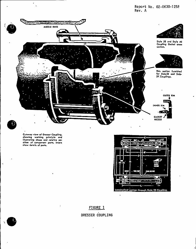
Report No. 02-0630-125P.Rev. A
MIODLR RIHO
Style 38 and Style RQCoupling Gasket ctosssection.
This section furnishedfor Stab-38 and Stab-39:Covplings.
OUTRR RIM
IHHKR RIM
tl
OisrRT gRRCKSS
Cutaway view of Oresser Ccwpling,showing working principle andiilvstrating shape and relative positlon of component pans. Insetsshow details of parts.
faa~~gBk I'+l
FIGURE I
DRESSER COUPLING

I
tlat
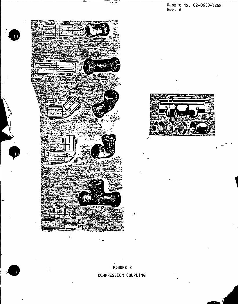
Report No. 02-0630-1258Rev. A
1
.Q
)»
0$
~0
~b~rl)
'CoeeakA~
w J
'IGURE 2
COMPRESSION COUPLING

ATTACHMENTB TO NLS-85-l00
REVISION TO ATTACHMENTA TO NLS-N-190 DATED DECEMBER l7, l980
(1337PPC/mf)
Page 13
SECTION E
MAINTENANCER SURVEILLANCEPROGRAM
As part of the TDI Diesel, Generator Owners'roup effort, a maintenance andsurveillance matrix has been developed for the SHNPP equipment. This matrix isprovided in Appendix II of the DR/QR Report (see Volume 0).
The maintenance matrix was developed utilizing TDI instruction manuals, TDI serviceinformation memos (SIMs), TDI correspondence on specific components, and
Owners'roup
technical staff input resulting from the development of the diesel generatorreliability program.
The DR/QR Maintenance Matrix will be used in lieu of the manufacturer's manuals.CPRL will implement the Owners'roup maintenance recommendations by incorporatingthem into the overall SHNPP maintenance program subject to the followingclarifications:
1. Where five-year inspections are indicated, these will be performed at the firstrefueling outage following the completion of the fifth year of plant commercialoperation.
2. Where ten-year inspections are indicated, these will be performed at the firstrefueling outage following the completion of the tenth year of plant commercialoperation.
Regardless of the accumulation of engine operating hours, the first inspectionrequiring disabling of the diesel generator will be performed at the first refuelingoutage following plant commercial operation.
0. Subsequent to licensing of SHNPP, periodic testing of the diesel generators duringnormal plant operation will cause the equipment to run for about 00 to 50 hoursduring a fuel cycle. During the 1985 testing phase on this equipment, CPRL intendsto operate one diesel generator for at least 50 hours more than the other dieselgenerator. This unit will then be the "lead" diesel generator and will bedisassembled and inspected as required by the maintenance matrix. The "follow"diesel generator inspection will be performed at the next refueling outage. Theintent is to only perform major maintenance on one diesel during a particularoutage. This is reasonable utilizing the "lead" engine concept.
5. (Deleted)
6. Page 55 of the matrix (component 02-835A, starting air compressors),recommendation number 8, discusses the inspection of filter felts on the unloadersystem. The filter felts were not included in the design or installation of theSHNPP equipment and the recommendation is not applicable.
(1337PPC/ccc )
Page 15
SECTION F
DISCUSSION OF OWNERS'ROUPSHNPP PHASE II DR/QR REPORT
The TDI Diesel Generator Owners'roup SHNPP DR/QR Report represents acomprehensive review of the equipment procured for installation at the SHNPP site. Itencompasses about 160 items as identified with an "X"in either the DR or QR column ofTable 2-2 (see Volume I). On the basis of implementation of the recommendationscontained within the DR/QR Report, it is concluded that the SHNPP diesel generatorsare fullycapable of performing their intended safety function as described in the FSAR.
As discussed elsewhere in this report, the engines have been disassembled, inspected,upgraded as deemed appropriate, and are presently being reassembled. At this time, notall actions have been completed. However, CPRL will satisfy the recommendationscontained within the DR/QR Report, as discussed within this section, or willspecificallyperform engineering evaluations to justify deviation from the OG recommendations.
The purpose of this section is to identify clarifications needed in the SHNPP DR/QRReport based upon CPRL's review. This does not include editorial, or labeling,corrections that could be incorporated. Further, as one item may appear in more thanone place in the four-volume report, the following comments are identified by componentnumber and apply in all applicable locations.
~
~
1. (Deleted)
2. Component 02-385A: Relief valves are not included at SHNPP. Refer toComponent 02-386A.
3. (Deleted)
0. (Deleted)
5. (Deleted)
(1337PPC/ccc)

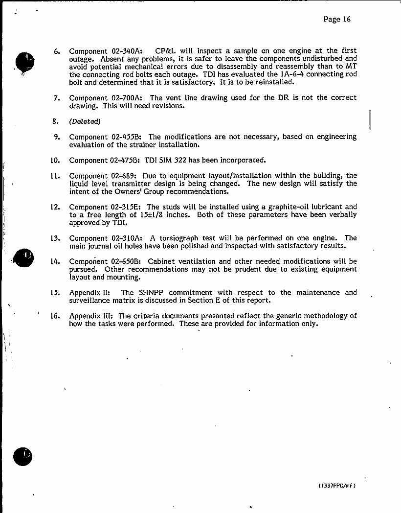
Page 16
6. Component 02-300A: CPRL will inspect a sample on one engine at the firstoutage. Absent any problems, it is safer to leave the components undisturbed andavoid potential mechanical errors due to disassembly and reassembly than to MTthe connecting rod bolts each outage. TDI has evaluated the IA-6-0 connecting rodbolt and determined that it is satisfactory. It is to be reinstalled.
7. Component 02-700A: The vent line drawing used for the DR is not the correctdrawing. This willneed revisions.
3. (Deleted)
9. Component 02-055B: The modifications are not necessary, based on engineeringevaluation of the strainer installation.
10. Component 02-075B: TDI SIM 322 has been incorporated.
11. Component 02-689: Due to equipment layout/installation within the building, theliquid level transmitter design is being changed. The new design will satisfy theintent of the Owners'roup recommendations.
12. Component 02-315E: The studs will be installed using a graphite-oil lubricant andto a free length of 15+1/3 inches. Both of these parameters have been verballyapproved by TDI.
413. Component 02-310A: A torsiograph test will be performed on one engine. The
main journal oil holes have been polished and inspected with satisfactory results.
IO. Component 02-650B: Cabinet ventilation and other needed modifications will bepursued. Other recommendations may not be prudent due to existing equipmentlayout and mounting.
15. Appendix II: The SHNPP commitment with respect to the maintenance andsurveillance matrix is discussed in Section E of this report.
16. Appendix III: The criteria documents presented reflect the generic methodology ofhow the tasks were performed. These are provided for information only.
(1337PPC/mf)

I,

ATTACHMENTA TO NLS-85-I00
REVISION I TODR/QR REPORT FOR THE SHEARON HARRIS DIESEL GENERATORS

J$
TDIOWNERS GROUP
APPENDIX - IIGENERIC MAINTENANCE MATRIX
TDIOWNERS GROUP
GENERIC MAINTENANCE MATRIX
APPENDIX - II
OVERVIEW AND DEFINITIONS
OPERATING AND STANDBY SURVEILLANCEPARAMETERS
PART A
TDI OWNERS GROUP
GENERIC MAINTENANCE AND SURVEILLANCE PROGRAM
APPENDIX - II
I INTRODUCTION
The purpose of this appendix is to provide the TDI Owners with a set ofmaintenance and surveillance recommendations for diesel generator com-ponents which have been developed by TDI and/or the Owners Group as aresult of the overall Owners Group Program and including subsequenttesting and inspections performed following the review conducted by theoriginal program. This appendix is intended to enhance the existingTDI Instruction Manual, Volume I and Volume III, which will maintain thequalification of the diesel generators for the life of the plant.
!I METHODOLOGY
During the implementation of the Owners Group Program Plan, the OwnersGroup Technical Staff reviewed many sources of information regardi ng themaintenance and surveillance for the diesel generator components iden-tified in this appendix. These sources included TDI Instruction Manuals,Service Information Memos (SIMS), and TDI correspondence on specificcomponents. The basis of this matrix is formed by the following:
~ Owners Group Technical Staff review of TDI Instruction Manuals, SIMs,and TDI correspondence on specific components.
Technical Staff input regarding the adequacy of recommendations foundin sources mentioned above.
Additional maintenance recommendations identified during the DR/gRreview.
~ Results of subsequent testing and surveillance (i. e., Shoreham EDG103750-hour endurance run and subsequent engine teardown) performedfollowing the review conducted during the original program.
~ Additional review by the Owners Group representatives.
It should be noted that this revision in some cases modifies the originalprogram results based on this additional information and review.
III RESULTS AND CONCLUSIONS
Proper maintenance is important in ensuring long, reliable and satis-factory service of the emergency diesel generators. Maintenance work, inorder to be effective, must be carried out thoroughly and regularly. It
II-A"1 Revision 2
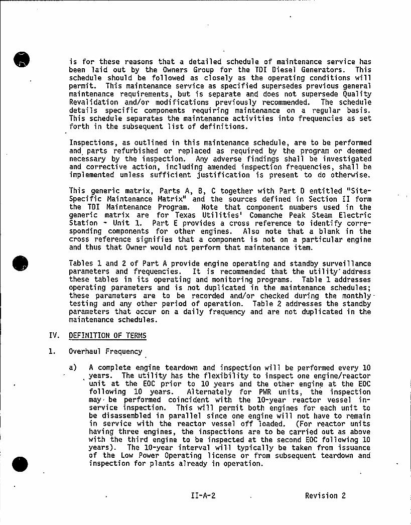
is for these reasons that a detailed schedule of maintenance service hasbeen laid out by the Owners Group for the TDI Diesel Generators. Thisschedule should be followed as closely as the operating conditions willpermit. This maintenance service as specified supersedes previous generalmaintenance requirements, but is separate and does not supersede gualityRevalidation and/or modifications previously recommended. The scheduledetails specific components requiring maintenance on a regular basis.This schedule separates the maintenance activities into frequencies as setforth in the subsequent list of definitions.
Inspections, as outlined in this maintenance schedule, are to be performedand parts refurbished or replaced as required by the program or deemednecessary by the inspection. Any adverse findings shall be investigatedand corrective action, including amended inspection frequencies, shall beimplemented unless sufficient justification is present to do otherwise.
This generic matrix, Parts A, B, C together with Part 0 entitled "Site-Specific Maintenance Matrix" and the sources defined in Section II formthe TOI Maintenance Program. Note that component numbers used in thegeneric matrix are for Texas Utilities'omanche Peak Steam ElectricStation - Unit 1. Part E provides a cross reference to identify corre-sponding components for other engines. Also note that a blank in thecross reference signifies that a component is not on a particular engineand thus that Owner would not perform that maintenance item.
Tables 1 and 2 of Part A provide engine operating and standby surveillanceparameters and frequencies. It is recommended that the utility'ddressthese tables in its operating and monitoring programs. Table 1 addressesoperating parameters and is not duplicated in the maintenance schedules;these parameters are to be recorded and/or checked during the monthly—testing and any other period of operation. Table 2 addresses the standbyparameters that occur on a daily frequency and are not duplicated in themaintenance schedules.
OEFINITION OF TERMS
Overhaul Frequency
a) A complete engine teardown and inspection will be performed every 10years. The utility has the flexibility to inspect one engine/reactorunit at the EOC prior to 10 years and the other engine at the EOC
following 10 years. Alternately for PMR units, the inspectionmay be performed coincident with the 10-year reactor vessel in-service inspection. This will permit both engines for each unit tobe disassembled in parallel since one engine will not have to remainin service with the reactor vessel off loaded. (For reactor unitshaving three engines, the inspections are to be carried out as abovewith the third engine to be inspected at the second EOC following 10years). The 10-year interval will typically be taken from issuanceof the Low Power Operating license or from subsequent teardown andinspection for plants already in operation.
I I "A-2 Revision 2
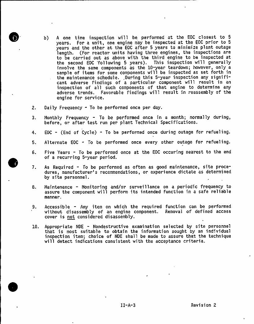
b) A one time inspection will be performed at the EOC closest to 5
years. For a unit, one engine may be inspected at the EOC prior to 5
years and the other at the EOC after 5 years to minimize plant outagelength. (For reactor units having three engines, the inspections areto be car ried out as above with the third engine to be inspected atthe second EOC 'following 5 years). This inspection will generallyinvolve the same components as the 10-year teardown; however, only a
sample of items for some components will be inspected as set forth inthe maintenance schedule. „During this 5-year inspection any signifi-cant adverse findings of a particular component will result in aninspection of all such components of that engine to determine anyadverse trends. Favorable findings will result in reassembly of theengine for service.
2. Daily Frequency - To be performed once per day.
3. Monthly Frequency - To be performed once in a month; normally during,before, or after test run per plant Technical Specifications.
4. EOC - (End of Cycle) - To be performed once during outage for refueling.
5. Alternate EOC - To be performed once every other outage for refueling.
6. Five Years - To be performed once at the EOC occuring nearest to the endof a recurring 5-year period.
7. As Required - To be performed as often as good maintenance, site proce-dures, manufacturer's recommendations, or experience dictate as determinedby site personnel.
8. Maintenance - Monitoring and/or surveillance on a periodic frequency toassure the component will perform its intended function in a safe reliablemanner.
9. Accessible - Any item on which the required function can be performedwithout disassembly of an engine component. Removal of defined accesscover is not considered disassembly.
10. Appropriate NDE - Nondestructive examination selected by site personnelthat is most suitable to obtain the information sought by an individualinspection item; choice of NDE shall be made to assure that the techniquewill detect indications consistent with the acceptance criteria.
Revision 2
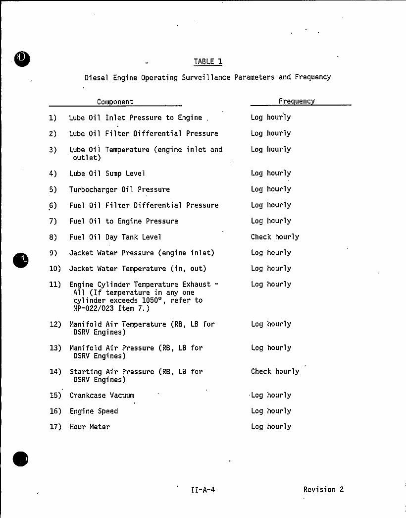
TABLE 1
Diesel Engine Operating Surveillance Parameters and Frequency
Com onent
1) Lube Oil Inlet Pressure to Engine „
2) Lube Oil Filter Differential Pressure
3) Lube Oil Temperature (engine inlet andoutlet)
4) Lube Oil Sump Level
5) Turbocharger Oil Pressure
6) Fuel Oil Filter Differential Pressure
7) Fuel Oil to Engine Pressure
8) Fuel Oil Day Tank Level
9) Jacket Mater Pressure (engine inlet)
10) Jacket Mater Temperature (in, out)
11) Engine Cylinder Temperature Exhaust-All (If temperature in any onecylinder exceeds 1050', refer toMP-022/023 Item 7'.)
12) Manifold Air Temperature (RB, LB forDSRV Engines)
13) Manifold Air Pressure (RB, LB forDSRV Engines)
14) Starting Air Pressure (RB, LB forDSRV Engines)
15) Crankcase Vacuum
16) Engine Speed
17) Hour Meter
Fre uenc
Log hourly
Log hourly
Log hourly
Log hourly
Log hour ly
Log hour ly
Log hourly
Check hourly
Log hourly
Log hourly
Log hourly
Log hourly
Log hour ly
Check hourly
Log hourly
Log hourly
Log hourly
I I-A-4 Revision 2
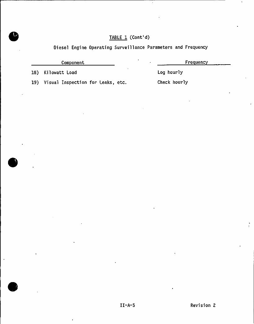
TABLE 1 (Cont')
Diesel Engine Operating Surveillance Parameters and Frequency
Com onent Fre uenc
18) Kilowatt Load
19) Visual Inspection for Leaks, etc.
Log hourly
Check hourly
Revision 2
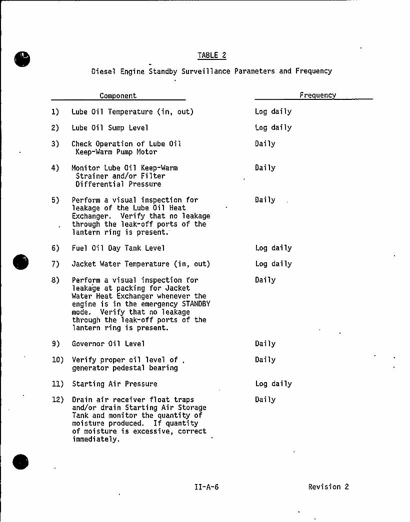
TABLE 2
Diesel Engine Standby Surveillance Parameters and Frequency
Com onent
1) Lube Oil Temperature (in, out)
2) Lube Oil Sump Level
3) Check Operation of Lube OilKeep-Warm Pump Motor
4) Monitor Lube Oil Keep-WarmStrainer and/or FilterDifferential Pressure
Log daily
Log daily
Daily
Daily
Fre uenc
5) Perform a visual inspection forleakage of the Lube Oil HeatExchanger. Verify that no leakagethrough the leak-off ports of thelantern ring is present.
6) Fuel Oil Day Tank Level
7) Jacket Water Temperature (in, out)
8) Perform a visual inspection forleakage at packing for JacketWater Heat Exchanger whenever theengine is in the emergency STANDBYmode. Verify that no leakagethrough the leak-off ports of thelantern ring is present.
9) Governor Oil Level
10) Verify proper oil level of ,
generator pedestal bearing
11) Starting Air Pressure
12) Drain air receiver float trapsand/or drain Starting Air StorageTank and monitor the quantity ofmoisture produced. If quantityof moisture is excessive, correctimmediately.
Daily
Log daily
Log daily
Daily
Daily
Daily
Log daily
Daily
II-A-6 Revision 2
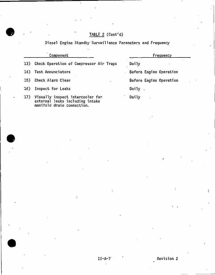
TABLE 2 (Cont')
Diesel Engine Standby Surveillance Parameters and Frequency
Com onent Fre uenc
13) Check Operation of Compressor Air Traps
14) Test Annunciators
15) Check Alarm Clear
16) Inspect for Leaks
17) Visually inspect intercooler forexternal leaks including intakemanifold drain connection.
Daily
Before Engine Operation
Before Engine Operation
Dai ly
Dai ly
Revision 2
TDIOWNERS GROUP
APPENDIX - IIGENERIC MAINTENANCE MATRIX
PART B
PHASE I COMPONENTS

0
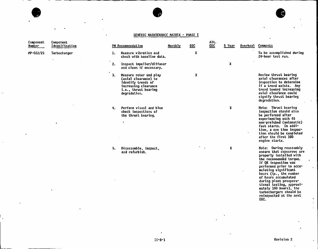
GENERIC MAINTENANCE MATRIX - PHASE I
Component ComponentNumber = Identification
HP-022/23 Turbocharger
PH Recommendation
1. Heasure vibration andcheck with baseline data.
2. Inspect impeller/diffuserand clean if necessary.
3. Heasure rotor end play(axial clearance) toidentify trends ofincreasing clearancei.e., thrust bearingdegradation.
4. Perform visual and bluecheck inspections ofthe thrust bearing.
5. Disassemble, inspect,and refurbish.
~Honth1 EOC
Alt.EOC 5 Year Overhaul Comments
To be accomplished during24-hour test run.
Review thrust bearingaxial clearances afterinspection to determineif a trend exists. Anytrend toward increasingaxial clearance couldsignify thrust bearingdegradation.
Note: Thrust bearinginspection should alsobe performed afterexperiencing each 40non-prelubed (automatic)fast starts. In addi-tion, a one time inspec-tion should be completedafter the first 100engine starts.
Note: During reassemblyensure that capscrews areproperly installed withthe recommended torque.If IiR inspection wasperformed prior to accu-mulating significanthours (ip., the numberof hours accumulatedduring plant preopera-tional testing, approxi-mately 100 hours), theturbochargers should bereinspected at the nextEOC.
II-B-l Revision 2
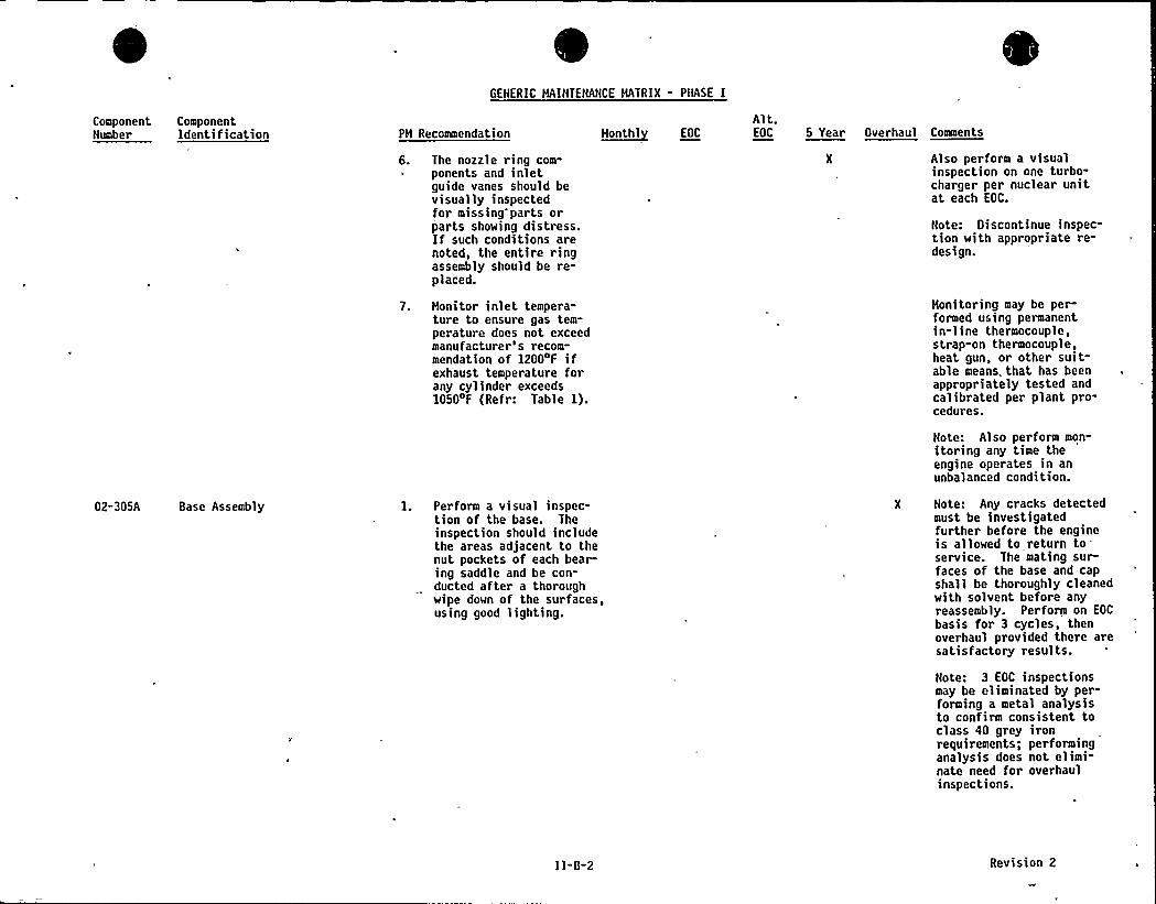
GENERIC MAINTENANCE MATRIX - PHASE I
ComponentNumber
ComponentIdentification PH Recoamendation
6. The nozzle ring com-ponents and inletguide vanes should bevisually inspectedfor missing parts orparts showing distress.If such conditions arenoted, the entire ringassembly should be re-placed.
7. Honitor inlet tempera-ture to ensure gas tem-perature does not exceedmanufacturer's recom-mendation of 12004F ifexhaust temperature forany cylinder exceeds1050 F (Refr: Table 1).
~Month1 EOC
Alt.EOC 5 Year Overhaul Comaents
Also perform a visualinspection on one turbo-charger per nuclear unitat each EOC.
Note: Discontinue inspec-tion with appropriate re-design.
Honitoring may be per-formed using permanentin-line thermocouple,strap-on thermocouple,heat gun, or other suit-able means, that has beenappropriately tested andcalibrated per plant pro-cedures.
Note: Also perform mon-itoring any time theengine operates in anunbalanced condition.
02-305A Base Assembly 1. Perform a visual inspec-tion of the base. Theinspection should includethe areas adjacent to thenut pockets of each bearing saddle and be con-ducted after a thoroughwipe down of the surfaces,using good lighting.
X Note: Any cracks detectedmust be investigatedfurther before the engineis allowed to return toservice. The mating surfaces of the base and capshall be thoroughly cleanedwith solvent before anyreassembly. Perform on EOC
basis for 3 cycles, thenoverhaul provided there aresatisfactory results.
Note: 3 EOC inspectionsmay be eliminated by per-forming a metal analysisto confirm consistent toclass 40 grey ironrequirements; performinganalysis does not elimi-nate need for overhaulinspections.
I1-0-2 Revision 2
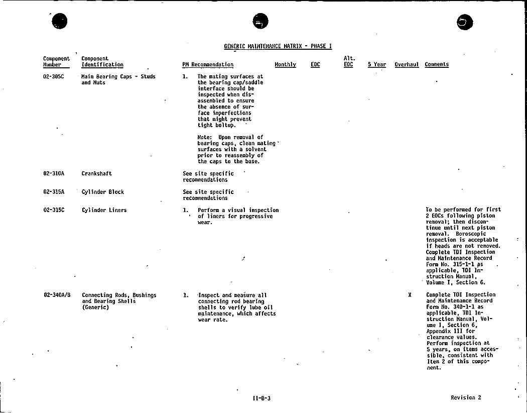
GENERIC MAINTENANCE HATRIX - PliASE I
ComponentNumber
ComponentIdentification PH Recommendation H~onthl EOC
Alt.EOC 5 Year Overhaul Comments
02-305C Hain Bearing Caps - Studsand Nuts
02-310A Crankshaft
1. The mating surfaces atthe bearing cap/saddleinterface should beinspected when dis-assembled to ensurethe absence of sur-face imperfectionsthat might preventtight boltup.
Note: Upon removal ofbearing caps, clean mating
'urfaceswith a solventprior to reassembly ofthe caps to the base.
See site specificrecommendations
02-315A Cylinder Block See site specificrecommendations
02-315C Cylinder Liners
02-340A/B Connecting Rods, Bushingsand Bearing Shells(Generic)
1. Perform a visual inspectionof liners for progressivewear.
1..Inspect and measure allconnecting rod bearingshells to verify lube oilmaintenance, which affectswear rate.
To be performed for first2 EOCs following pistonremoval; then discon-tinue until next pistonremoval. Boroscopicinspection is acceptableif heads are not removed.Complete TDI Inspectionand Haintenance RecordForm No. 315-1-1 asapplicable, TDI In-struction Hanual,Volume I, Section 6.
X Complete TOI Inspectionand Maintenance RecordForm No. 340-1-1 asapplicable, TOI In-struction Hanual, Vol-ume I, Section 6,Appendix III for-clearance values.Perform inspection at5 years, on items acces-sible, consistent withItem 2 of this compo-nent.
II-B-3 Revision 2
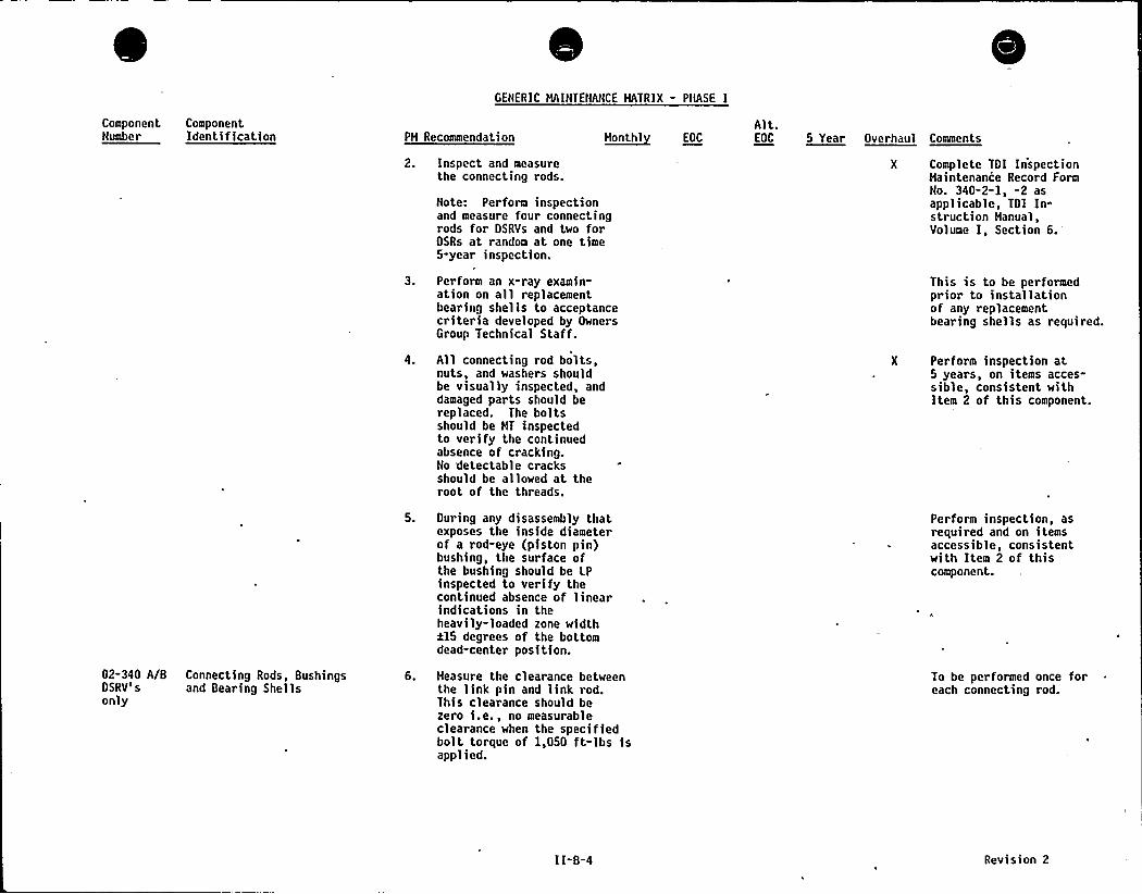
GENERIC MAINTENANCE MATRIX - PHASE I
ComponentNumber
ComponentIdentification PM Recommendation ~Monthl fOC
Alt.EOC 5 Year Overhaul Comments
Inspect and measurethe connecting rods.
Note: Perform inspectionand measure four connectingrods for OSRVs and two forOSRs at random at one time5-year inspection.
Perform an x-ray examin"ation on all replacementbearing shells to acceptancecriteria developed by OwnersGroup Technical Staff.
All connecting rod bolts,nuts, and washers shouldbe visually inspected, anddamaged parts should bereplaced. The boltsshould be HT inspectedto verify the continuedabsence of cracking.No detectable cracksshould be allowed at theroot of the threads.
X Complete TOI InspectionHaintenance Record FormNo. 340-2-1, -2 asapplicable, TOI In-struction Hanual,Volume I, Section
6.'his
is to be performedprior to installationof any replacementbearing shells as required.
X Perform inspection at5 years, on items acces"sible, consistent withItem 2 of this component.
02-340 A/B Connecting Rods, BushingsOSRV's and Bearing Shellsonly
Ouring any disassembly thatexposes the inside diameterof a rod-eye (piston pin)bushing, the surface ofthe bushing should be LPinspected to verify thecontinued absence of linearindications in theheavily-loaded zone widthil5 degrees of the bottomdead-center position.
Heasure the clearance betweenthe link pin and link rod.This clearance should bezero i.e., no measurableclearance when the specifiedbolt torque of 1,050 ft-lbs isapplied.
Perform inspect>on, asrequired and on itemsaccessible, consistentwith Item 2 of thiscomponent.
To be performed once foreach connecting rod.
II-B-4 Revision 2
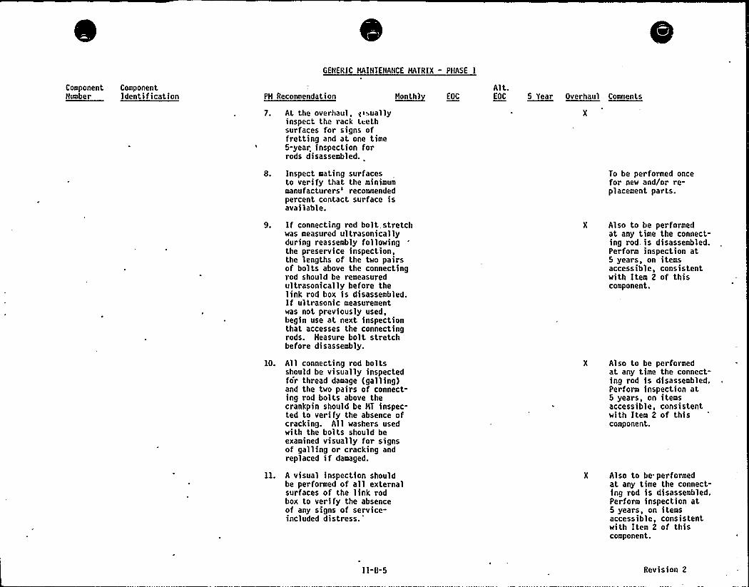
GENERIC MAINTENANCE MATRIX - PNASE I
ComponentNumber
ComponentIdentification PM Recommendation ~Hoolh1 EOC
Alt.EOC 5 Year Overhaul Comments
7. At the overhaul, gisuailyinspect the rack teethsurfaces for signs offretting and at one time5-year inspection forrods disassembled.
Inspect mating surfacesto verify that the minimummanufacturers'ecommendedpercent contact surface isavailable.
To be performed oncefor new and/or re-placement parts.
10.
If connecting rod bolt. stretchwas measured ultrasonicallyduring reassembly followingthe preservice inspection,the lengths of the two pairsof bolts above the connectingrod should be remeasuredultrasonically before thelink rod box is disassembled.If ultrasonic measurementwas not previously used,begin use at next inspectionthat accesses the connectingrods. Measure bolt stretchbefore disassembly.
All connecting rod boltsshould be visually inspectedfor thread damage (galling)and the two pairs of connect-ing rod bolts above thecrankpin should be MT inspec-ted to verify the absence ofcracking. All washers usedwith the bolts should beexamined visually for signsof galling or cracking andreplaced if damaged.
A visual inspection shouldbe performed of all externalsurfaces of the link rodbox to verify the absenceof any signs of service-included distress.'
Also to be performedat any time the connect-ing rod, is disassembled.Perform inspection at5 years, on itemsaccessible, consistentwith Item 2 of thiscomponent.
X Also to be performedat any time the connect-ing rod is disassembled.Perform inspection at5 years, on itemsaccessible, consistentwith Item 2 of thiscomponent.
X Also to be performedat any time the connect-ing rod is disassembled.Perform inspection at5 years, on itemsaccessible, consistentwith Item 2 of thiscomponent.
11-8-5 Rev>s>on 2
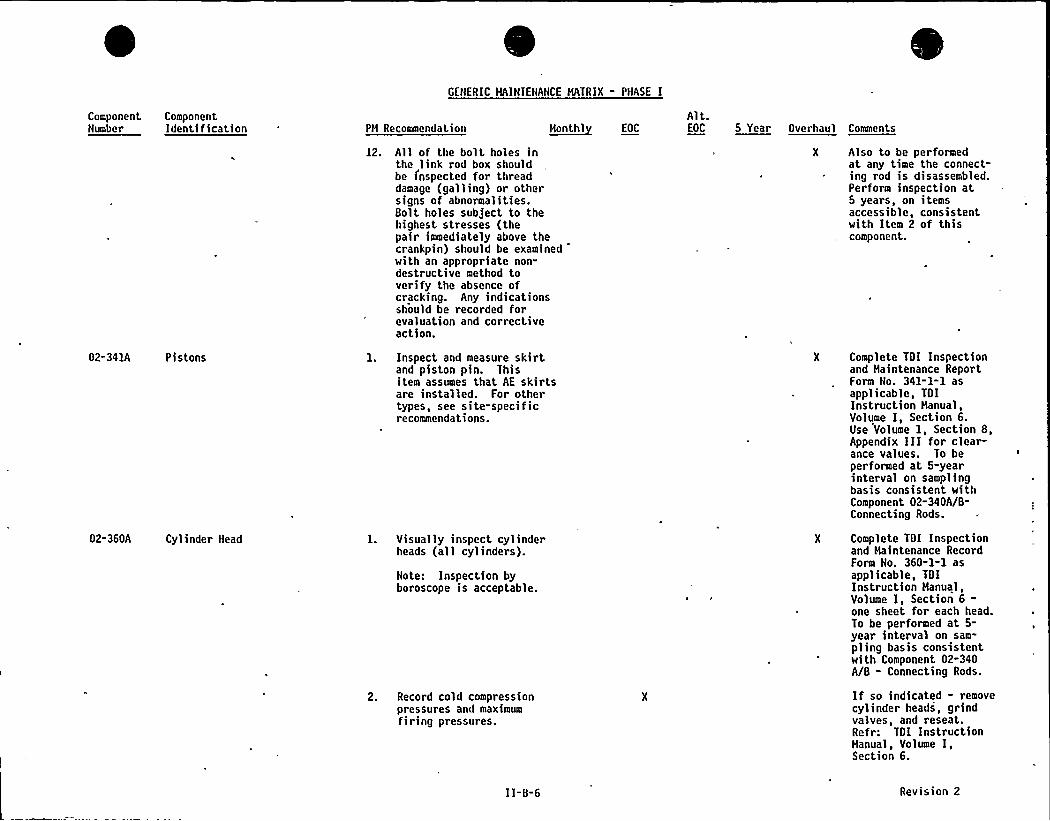
GENERIC MAINIENANCE MATRIX - PHASE I
ComponentNumber
ComponentIdentification PM Recommendation ~Monthl EOC
Alt.EOC 5 Year Overhaul Comments
12. All of the bolt holes inthe link rod box shouldbe inspected for threaddamage (galling) or othersigns of abnormalities.Bolt holes subject to thehighest stresses (thepair immediately above thecrankpin) should be examinedwith an appropriate non-destructive method toverify the absence ofcracking. Any indicationsshould be recorded forevaluation and correctiveaction.
Also to be performedat any time the connect-ing rod is disassembled.Perform inspection at5 years, on itemsaccessible, consistentwith Item 2 of thiscomponent.
02-341A Pistons
02-360A Cylinder Head
l. Inspect and measure skirtand piston pin. Thisitem assumes that AE skirtsare installed. For othertypes, see site-specificrecommendations.
l. Visually inspect cylinderheads (all cylinders).
Note: Inspection byboroscope is acceptable.
2. Record cold compressionpressures and maximumfiring pressures.
Complete TDI Inspectionand Haintenance ReportForm No. 341-l-l asapplicable, TDIInstruction Hanual,Volume I, Section 6.Use Volume I, Section 8,Appendix III for clear-ance values. To beperformed at 5-yearinterval on samplingbasis consistent withComponent 02-340A/8-Connecting Rods.
Complete TDI Inspectionand Maintenance RecordForm No. 360-1-1 asapplicable, TDIInstruction Hanual,Volume I, Section 6-one sheet for each head.To be performed at 5-year interval on sam-pling basis consistentwith Component 02-340A/B - Connecting Rods.
If so indicated - removecylinder heads, grindvalves, and reseat.Refr: TDI InstructionHanual, Volume I,Section 6.
I 1-8-6 Revision 2
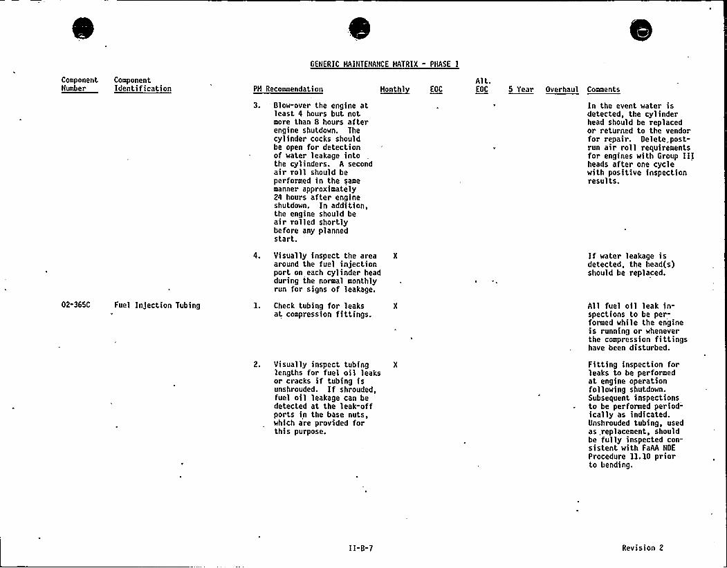
GENERIC MAINTENANCE NATRIX - PHASE I
ComponentNumber
ComponentIdentification PH Recommendation
3. 'low-over the engine atleast 4 hours but notmore than 8 hours afterengine shutdown. Thecylinder cocks shouldbe open for detectionof water leakage intothe cylinders. A secondair roll should beperformed in the samemanner approximately24 hours after engineshutdown. In addition,the engine should beair rolled shortlybefore any plannedstart.
H~onthl EOC
Alt.EOC 5 Year Overhaul Comments
In the event water isdetected, the cylinderhead should be replacedor returned to the vendorfor repair. Delete, post-run air roll requirementsfor engines with Group IIIheads after one cyclewith positive inspectionresults.
02-365C Fuel Injection Tubing
4. Visually inspect the area Xaround the fuel injectionport on each cylinder headduring the normal monthlyrun for signs of leakage.
1. Check tubing for leaks Xat compression fittings.
2. Visually inspect tubing Xlengths for fuel oil leaksor cracks if tubing isunshrouded. If shrouded,fuel oil leakage can bedetected at the leak-offports in the base nuts,which are provided forthis purpose.
If water leakage isdetected, the head(s)should be replaced.
All fuel oil leak in-spections to be per-formed while the engineis running or wheneverthe compression fittingshave been disturbed.
Fitting inspection forleaks to be performedat engine operationfollowing shutdown.Subsequent inspectionsto be performed period-ically as indicated.Unshrouded tubing, usedas, replacement, shouldbe fully inspected con-sistent with FaAA NDE
Procedure 11. 10 priorto bending.
II-B-7 Revision 2
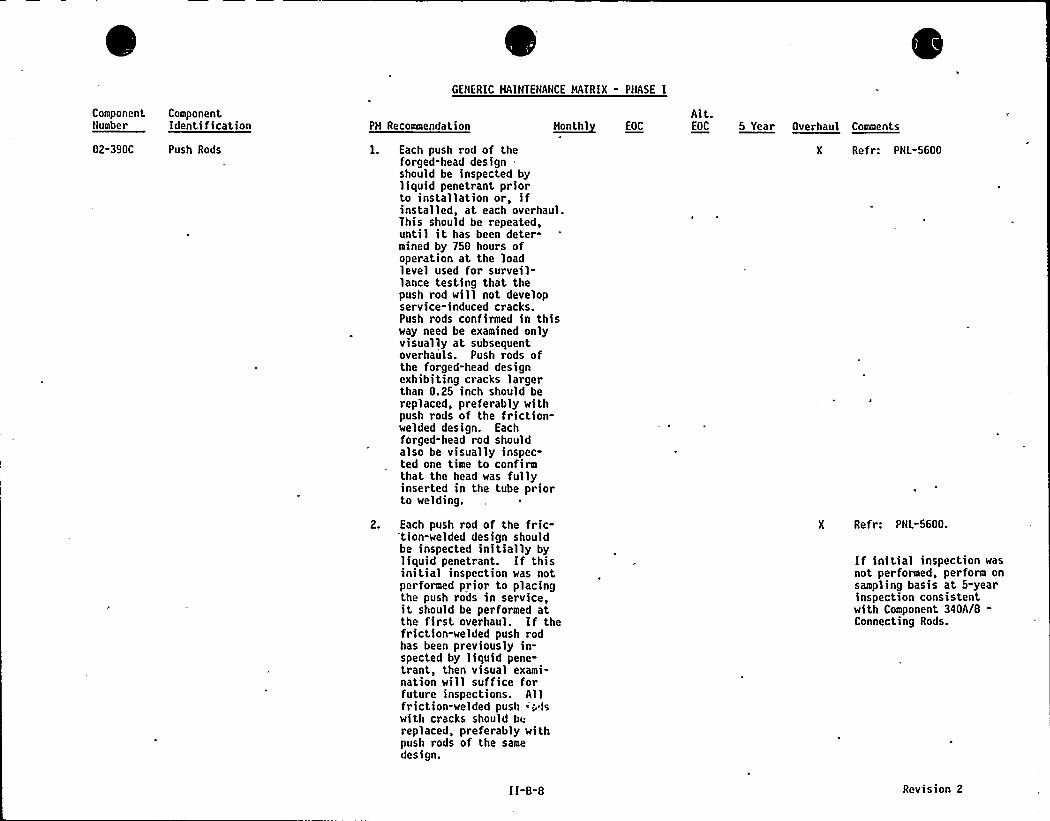
GENERIC HAINTENANCE HATRIX - PHASE I
ComponentNumber
ComponentIdentification PH Recommendation ~Honth1 EOC
Alt.EOC 5 Year Overhaul Comments
02-390C Push Rods Each push rod of theforged-head designshould be inspected byliquid penetrant priorto installation or, ifinstalled, at each overhaul.This should be repeated,until it has been deter-mined by 750 hours ofoperation at the loadlevel used for surveil-lance testing that thepush rod will not developservice-induced cracks.Push rods confirmed in thisway need be examined onlyvisually at subsequentoverhauls. Push rods ofthe forged-head designexhibiting cracks largerthan 0.25 inch should bereplaced, preferably withpush rods of the friction-welded design. Eachforged-head rod shouldalso be visually inspec-ted one time to confirmthat the head was fullyinserted in the tube priorto welding.
Each push rod of the fric-'tion-welded design shouldbe inspected initially byliquid penetrant. If thisinitial inspection was notperformed prior to placingthe push rods in service,it should be performed atthe first overhaul. If thefriction-welded push rodhas been previously in-spected by liquid pene-trant, then visual exami-nation will suffice forfuture inspections. Allfriction-welded push ':"iswith cracks should bureplaced, preferably withpush rods of the samedesign.
X Ref r: PNL-5600
X Ref r: PNL-5600.
If initial inspection wasnot performed, perform onsampling basis at 5-yearinspection consistentwith Component 340A/8-Connecting Rods
II-8-8 Revision 2
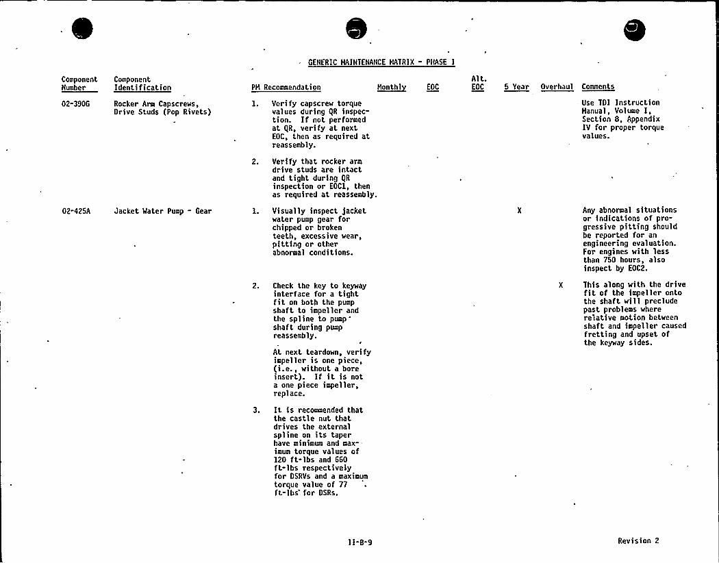
GENFRIC MAINTENANCE MATRIX - PNASE I
ComponentNumber
02-390G
ComponentIdentification
Rocker Arm Capscrews,Drive Studs (Pop Rivets)
PM Recommendation
Verify capscrew torquevalues during IlR inspec-tion. If not performedat IiR, verify at nextEOC, then as required atreassembly.
Verify that rocker armdrive studs are intactand tight during IlRinspection or EOCl, thenas required at reassembly.
H~onthl EOC
Alt.EOC 5 Year Overhaul Comments
— Use TDI InstructionManual, Volume I,Section 8, AppendixIV for proper torquevalues.
02-425A Jacket Mater Pump - Gear Visually inspect jacketwater pump gear forchipped or brokenteeth, excessive wear,pitting or otherabnormal conditions.
Check the key to keywayinterface for a tightfit on both the pumpshaft to impeller andthe spline to pumpshaft. during pumpreassembly.
At next teardown, verifyimpeller is one piece,(i.e., without a boreinsert). If it is nota one piece impeller,replace.
It is recommended thatthe castle nut thatdrives the externalspline on its taperhave minimum and max--imum torque values of120 ft-lbs and 660ft-lbs respectivelyfor DSRVs and a maximumtorque value of 77ft-lbs for DSRs.
Any abnormal situationsor indications of pro-gressive pitting shouldbe reported for anengineering evaluation.For engines with lessthan 750 hours, alsoinspect by EOC2.
X This along with the drivefit of the impeller ontothe shaft will precludepast problems whererelative motion betweenshaft and impeller causedfretting and upset ofthe keyway sides.
II-B-9 Revision 2
TDIOWNERS GROUP
APPENDIX " IIGENERIC MAINTENANCE MATRIX
PART C
PHASE II COMPONENTS


GENERIC HAINTENANCE MATRIX - PHASE II
Component ComponentNumber Identification PH Recommendation N~onthl EOC
Alt.EOC 5 Year Overhaul Comments
F-068 Intercool ers Record the followingtemperatures during themonthly surveillance testof the engine: exhaustfrom cylinders and jacketcooling water supply.Compare these results withsimilar data from previousmonth to establish whetherthe trend is sufficient towarrant further action.
CP-101A Emergency Generator
Inspect shell andtube sides, and cleanas required.
Verify intake manifold X
drain connection isopen and clean.
Perform leakage test ofwater side boundary forgross degradation.
Check operation ofbrushes and slip ringsby visual examinationduring operation.
Inspect at EOC1 and EOC3
to verify Item 1 resultsare valid.
Note: Refer to TOI SIHto be issued subsequentto Harch 1986.
Inspect all accessibleparts of the generator,and clean as required.
3. Hegger.rotor and stator.
Verify that space heaters X
are on with engine shutdown.
Heasure vibration andcheck against baselinedata.
CP-101B Emergency Generator PedestalBearing
Orain, flush, refillbearing housing.
Heasure bearing hou;i>uinsulation resistance.
II-C-1 Revision 2
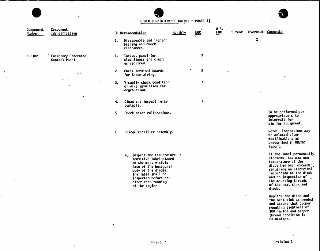
GENERIC HAINIENANCE HAIRIX " PHASE II
Component ComponentNumber Identification PH Recommendation ~Mon lhl E0C
Alt.EOC 5 Year Overhaul Comments
CP-102 Emergency GeneratorControl Panel
3. Disassemble and inspectbearing and checkc 1earances.
l. Inspect panel forcleanliness and cleanas required.
2. Check terminal boardsfor loose wiring.
3. Visually check conditionof wire insulation fordegradation.
4. Clean and inspect relaycontacts.
5. Check meter calibrations.
6. Bridge recti fier assembly.
a. Inspect the temperature X
sensitive label placedon the most visibleface of the hexagonalbody of the diodes.The label shall beinspected before andafter each runningof the engine.
To be performed perappropriate siteintervals forsimilar equipment.
Note: Inspections maybe deleted aftermodif>cat>ons asprescribed in DR/gRReport.
If the label permanentlyblackens, the maximumtemperature of thediode has been exceeded,requiring an electricalinspection of the diodeand an inspection ofthe mounting threadsof the heat sink anddiode.
Replace the diode andthe heat sink as neededand assure that propermounting tightness of300 in-lbs and properthread condition ismaintained.
11-C-2 Revision 2

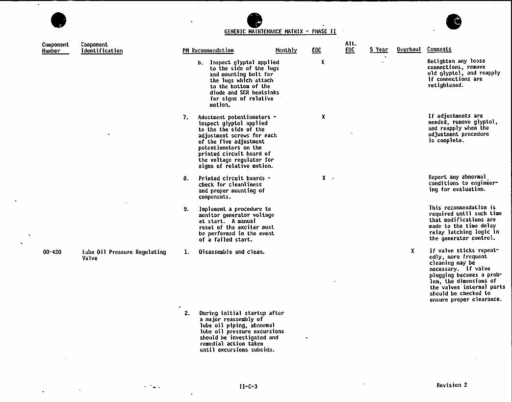
GENERIC HAINTENANCE HATRIX - PHASE II
ComponentNumber
ComponentIdentification PH Recommendation ~ttonthl EOC
Alt.EOC 5 Year Overhaul Comments
b. Inspect glyptol appliedto the side of the lugsand mounting bolt forthe lugs which attachto the bottom of thediode and SCR heatsinksfor signs of relativemotion.
Retighten any looseconnections, removeold glyptol, and reapplyif connections areretightened.
00-420 Lube Oil Pressure RegulatingValve
7. Adustment potentiometers-inspect glyptol appliedto the the side of theadjustment screws for eachof the five adjustmentpotentiometers on theprinted circuit board ofthe voltage regulator forsigns of relative motion.
8. Printed circuit boards-check for cleanlinessand proper mounting ofcomponents.
9. Implement a procedure tomonitor generator voltageat start. A manualreset of the exciter mustbe performed in the eventof a failed start.
l. Disassemble and clean.
2. Ouring initial startup aftera major reassembly oflube oil piping, abnormallube oil pressure excursions-should be investigated andremedial action takenuntil excursions subside.
If adjustments areneeded, remove glyptol,and reapply when theadjustment procedureis complete.
Report any abnormalconditions to engineer-ing for evaluation.
This recommendation isrequired until such timethat modifications aremade to the time delayrelay latching logic inthe generator control.
X If valve sticks repeat-edly, more frequentcleaning may benecessary. If valveplugging becomes a prob-lem, the dimensions ofthe valves internal partsshould be checked toensure proper clearance.
II-C-3 Revision 2
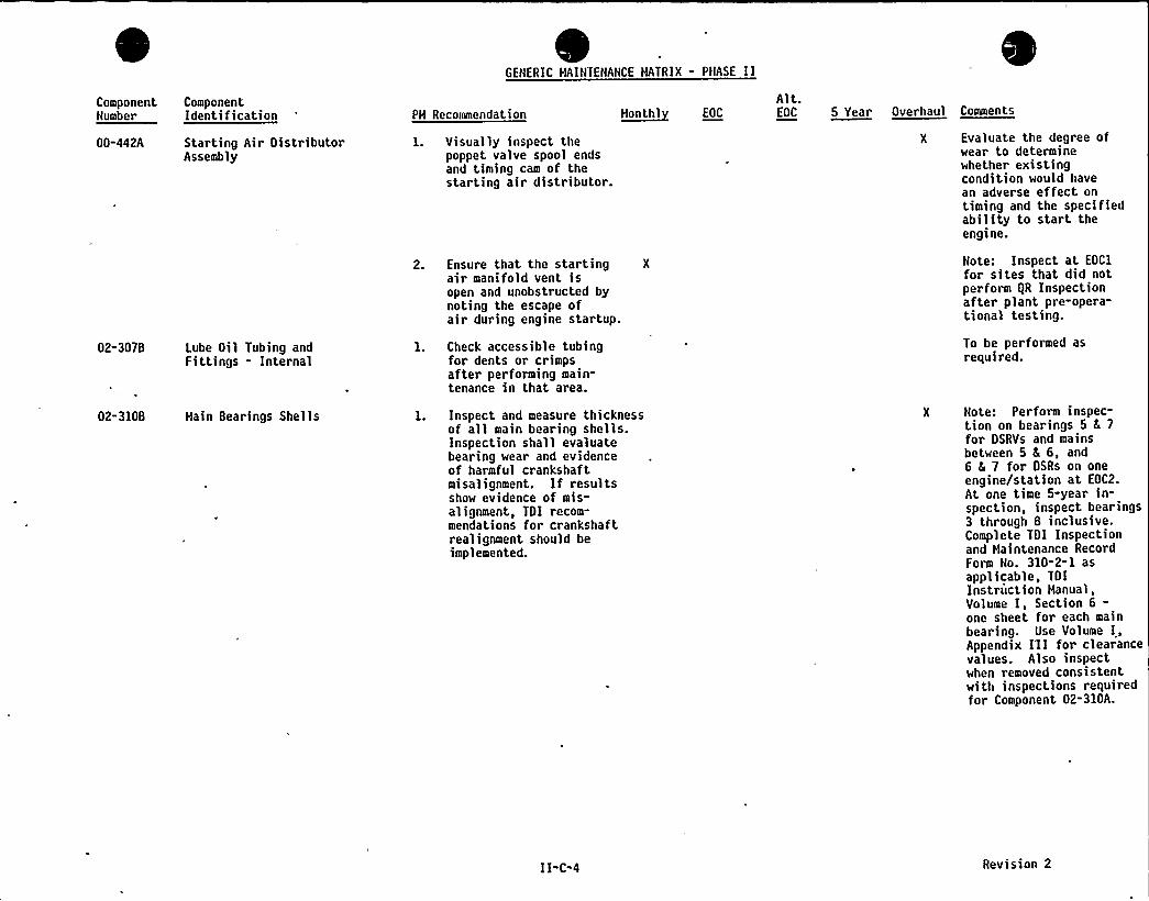
GENERIC HAINTENANCE MATRIX - PHASE II
ComponentNumber
00-442A
ComponentIdentification
Starting Air DistributorAssembly
PH Recommendation
l. Visually inspect thepoppet valve spool endsand timing cam of thestarting air distributor.
Ensure that the startingair manifold vent isopen and unobstructed bynoting the escape ofair during engine startup.
N~onlhl EOC
Alt.EOC 5 Year Overhaul Comments
Evaluate the degree ofwear to determinewhether existingcondition would havean adverse effect ontiming and the specifiedability to start theengine.
Note: Inspect at EOC1
for sites that did notperform IiR Inspectionafter plant pre-opera-tional testing.
02-3078 Lube Oil Tubing andFittings - Internal
1. Check accessible tubingfor dents or crimpsafter performing main-tenance in that area.
To be performed asrequired.
02-310B Main Bearings Shells 1. Inspect and measure thicknessof all main bearing shells.Inspection shall evaluatebearing wear and evidenceof harmful crankshaftmisalignment. If resultsshow evidence of mis-alignment, TOI recom-mendations for crankshaftrealignment should beimplemented.
Note: Perform inspec-tion on bearings 5 8 7
for DSRVs and mainsbetween 5 8 6, and6 6 7 for OSRs on oneengine/station at EOC2.
At one time 5-year in-spection, inspect bearings3 through 8 inclusive.Complete TOI Inspectionand Haintenance RecordForm No. 310-2"1 asapplicable, TOIInstruction Hanual,Volume I, Section 6-one sheet for each mainbearing. Use Volume I,Appendix I'Il for clearancevalues. Also inspectwhen removed consistentwith inspections requiredfor Component 02-310A.
II-C-4 Revision 2
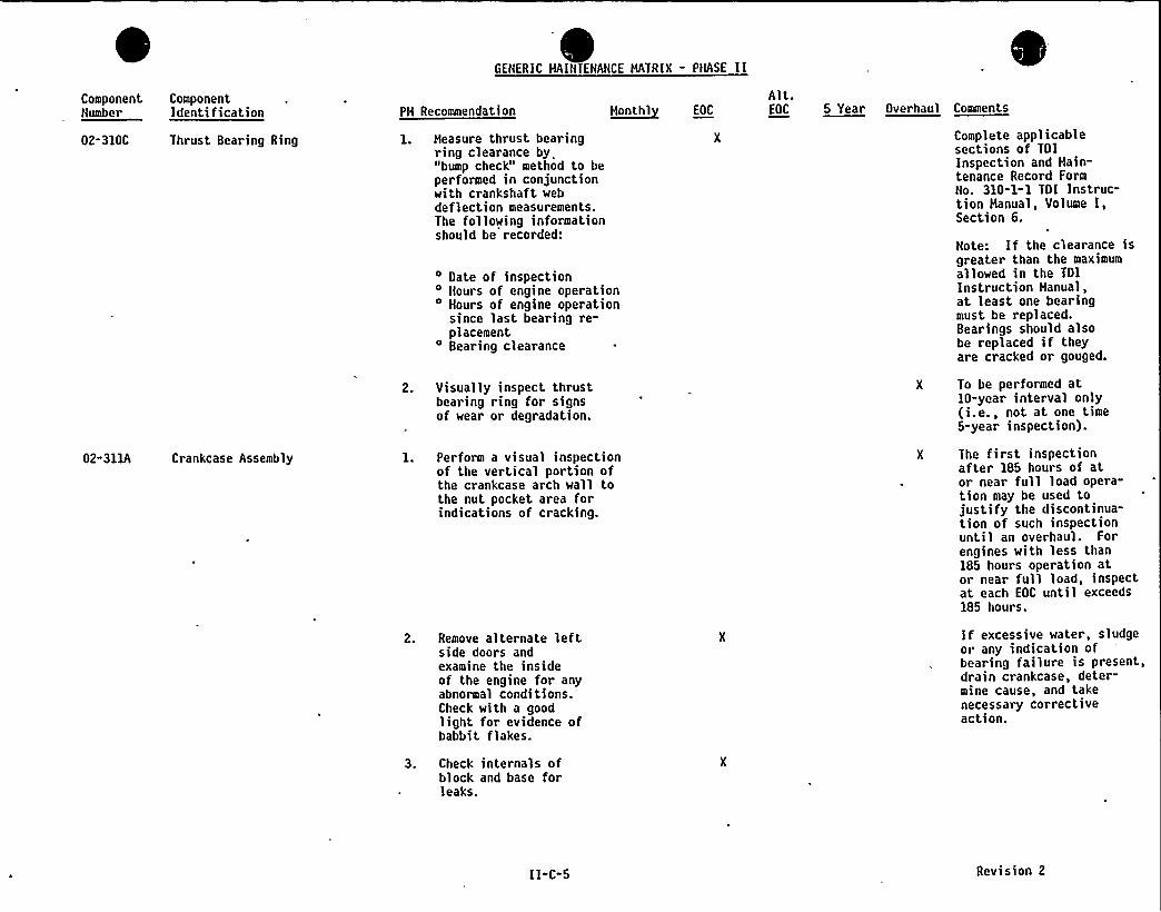
GENERIC HAINIENANCE HATRIX - PHASE II
Component ComponentNumber Identification
02-310C Thr ust Bearing Ring
PH Recommendation
1. Heasure thrust bearingring clearance by"bump check" method to beperformed in conjunctionwith crankshaft webdeflection measurements.The following informationshould be recorded:
~Nonthl EOC
Alt,.EOC 5 Year Overhaul Comments
Complete applicablesections of TOIInspection and Hain-tenance Record FormNo. 310-1-1 TDI Instruc"tion Hanual, Volume I,Section 6.
02" 311A Crankcase Assembly
Date of inspectionHours of engine operation
'ours of engine operationsince last bearing re-placementBearing clearance
2. Visually inspect thrustbearing ring for signsof wear or degradation.
1. Perform a visual inspectionof the vertical portion ofthe crankcase arch wall tothe nut pocket area forindications of cracking.
2. Remove alternate leftside doors andexamine the insideof the engine for anyabnormal conditions.Check with a goodlight for evidence ofbabbit flakes.
Note. If the clearance >s
greater than the maximumallowed in the TDIInstruction Hanual,at least one bearingmust be replaced.Bearings should a)sobe replaced if theyare cracked or gouged.
To be performed at10-year interval only(i.e., not at one time5-year inspection).
The first inspectionafter 185 hours of at.or near full load opera-tion may be used tojustify the discontinua-tion of such inspectionuntil an overhaul. Forengines with less than185 hours operation ator near full load, inspectat each EOC until exceeds185 hours.
If excessive water, sludgeor any indication ofbearing failure is present,drain crankcase, deter-mine cause, and takenecessary correctiveaction.
3. Check internals ofblock and base forleaks.
II-C-5 Revision 2
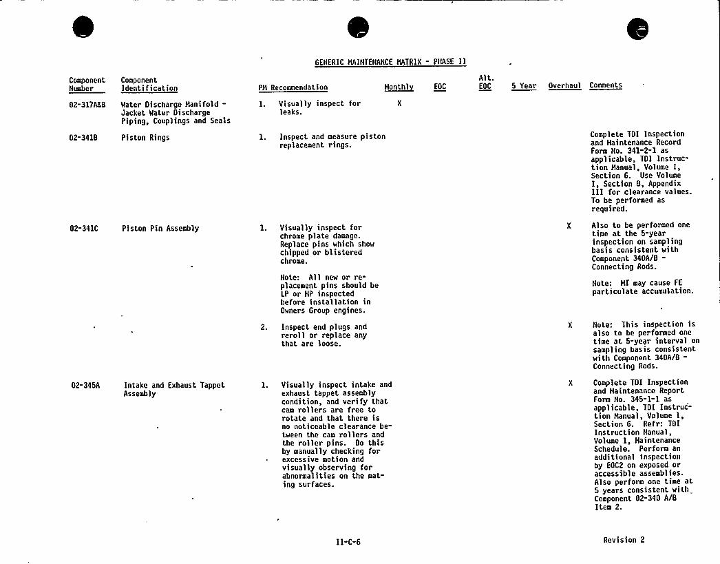
GENERIC HAINIENANCE MATRIX - PHASE II
ComponentNumber
02-317ALB
ComponentIdentification
Water Discharge Hanifold-Jacket Water DischargePiping, Couplings and Seals
PH Recommendation
l. Visually inspect forleaks.
H~onthl EOC
Alt.EOC 5 Year Overhaul Comments
02-3418 Piston Rings l. Inspect and measure pistonreplacement rings.
Complete TDI Inspectionand Haintenance RecordForm No. 341-2-1 asapplicable, TDI Instruc-tion Hanual, Volume I,Section 6. Use VolumeI, Section 8, AppendixIII for clearance values.To be performed asrequired.
02-341C Piston Pin Assembly l. Visually inspect forchrome plate damage.Replace pins which showchipped or blisteredchrome.
Note: All new or re-placement pins should beLP or HP inspectedbefore installation inOwners Group engines.
Also to be performed onetime at the 5-yearinspection on samplingbasis consistent withComponent 340A/8-Connecting Rods.
Note: HT may cause FE
particulate accumulation.
02-345A Intake and Exhaust TappetAssembly
2. Inspect end plugs andreroll or replace anythat are loose.
l. Visually inspect intake andexhaust tappet assemblycondition, and verify thatcam rollers are free torotate and that there isno noticeable clearance be-tween the cam rollers andthe roller pins. Do thisby manually checking forexcessive motion andvisually observing forabnormalities on the mat-ing surfaces.
Note: This inspection isalso to be performed onetime at 5-year interval onsampling basis consistentwith Component 340A/8-Connecting Rods.
Complete TDI Inspectionand Haintenance ReportForm No. 345-1-1 asapplicable, TDI Instruc-tion Manual, Volume I,Section 6. Refr: TDIInstruction Hanual,Volume I, HaintenanceSchedule. Perform anadditional inspectionby EOC2 on exposed oraccessible assemblies.Also perform one time at5 years consistent withComponent 02-340 A/8Item 2.
II-C-6 Revision 2
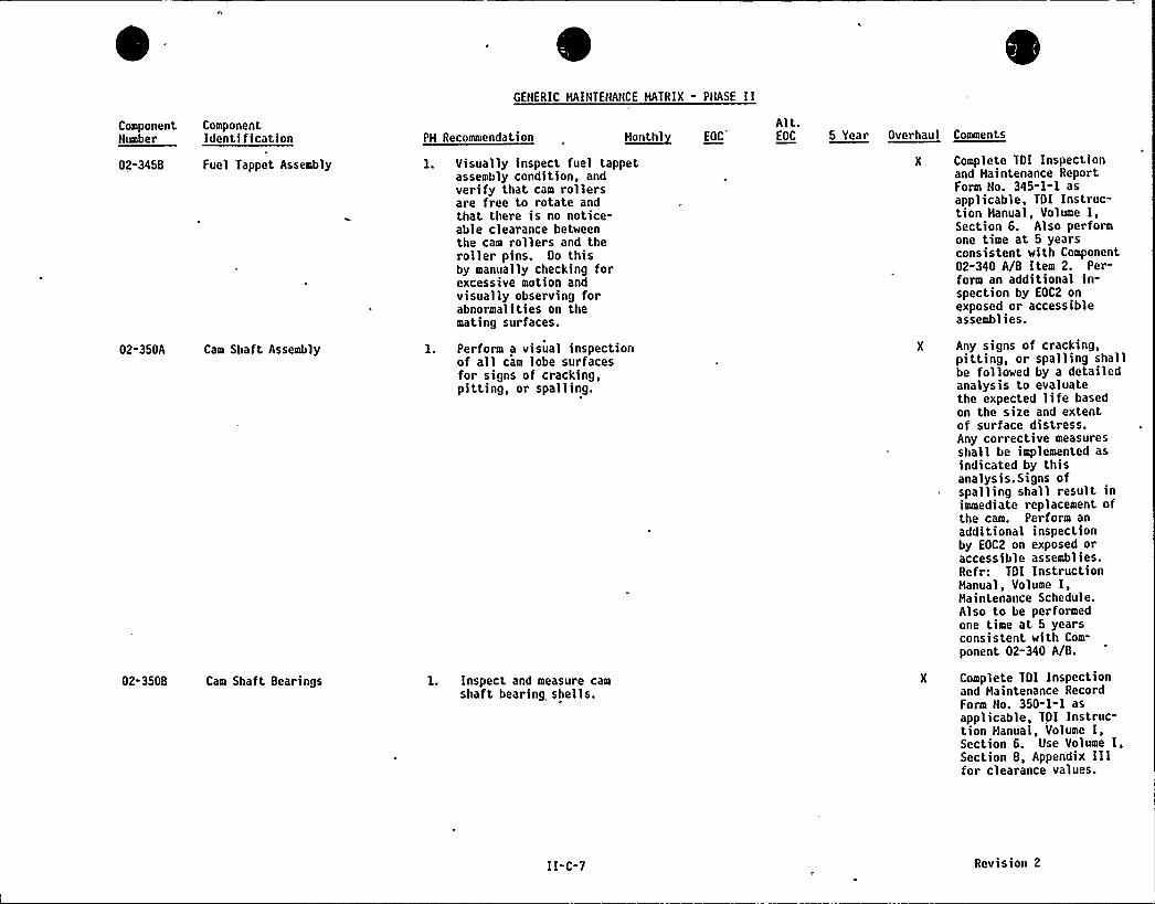
GENERIC MAINTENANCE MATRIX " PNASE 11
Component ComponentHnahar Idantificatinn PM Recommendation ~Hantht EOC
Alt.EOC 5 Year Overhaul Comments
02-3458 Fuel Tappet Assembly
02-350A Cam Shaft Assembly
02-350B Cam Shaft Bearings
l. Visually inspect fuel tappetassembly condition, andverify that cern rollersare free to rotate andthat there is no notice-able clearance betweenthe cam rollers and theroller pins. Oo thisby manually checking forexcessive motion andvisually observing forabnormalities on themating surfaces.
1. Perform a visual inspectionof all cam lobe surfacesfor signs of cracking,pitting, or spalling.
l. Inspect and measure camshaft bearing shells.
Complete TOI Inspectionand Maintenance ReportForm No. 345-1-1 asapplicable, TOI Instruc-tion Manual, Volume I,Section 6. Also performone time at 5 yearsconsistent with Component02-340 A/B Item 2. Per-form an additional in-spection by EOC2 onexposed or accessibleassemblies.
Any signs of cracking,pitting, or spalling shallbe followed by a detailedanalysis to evaluatethe expected life basedon the size and extentof surface distress.Any corrective measuresshall be implemented asindicated by thisanalysis. Signs ofspalling shall result inimmediate replacement ofthe cam. Perform anadditional inspectionby EOC2 on exposed oraccessible assemblies.Refr: TOI InstructionManual, Volume I,Maintenance Schedule.Also to be performedone time at 5 yearsconsistent with Com-
ponent 02-340 A/B.
Complete TOI Inspectionand Maintenance RecordForm No. 350-l-l asapplicable, TOI Instruc-tion Manual, Volume I,Section 6. Use Volume I,Section 8, Appendix Illfor clearance values.
II-C-7 Revision 2
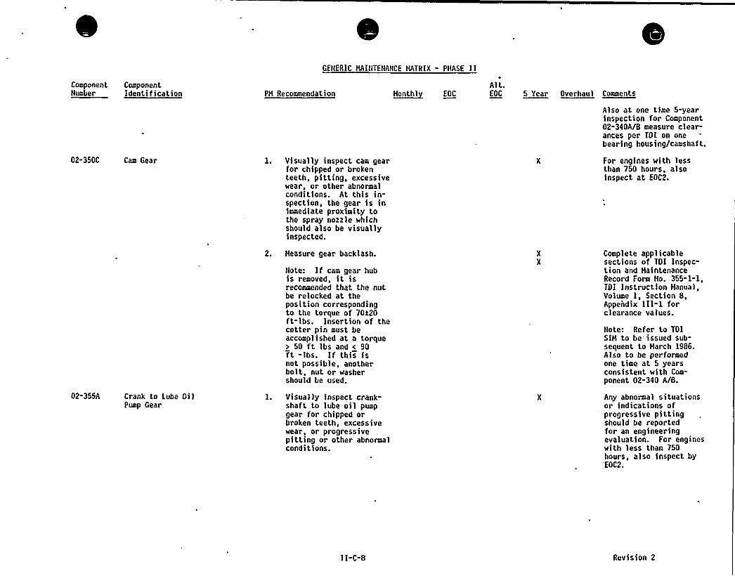
GENERIC HAINTENANCE HATRIX - PIIASE IIComponent ComponentNumber Identification PH Recommendation ~ttontbl EOC
Alt.EOC 5 Year Overhaul Comments
02-350C Cam Gear
02-355A Crank to Lube OilPump Gear
1. Visually inspect cam gearfor chipped or brokenteeth, pitting, excessivewear, or other abnormalconditions. At this in-spection, the gear is inimmediate proximity tothe spray nozzle whichshould also be visuallyinspected.
2. Heasure gear backlash.
Note: If cam gear hubis removed, it isrecommended that the nutbe relocked at theposition correspondingto the torque of 70120ft-lbs. Insertion of thecotter pin must beaccomplished at a torque> 50 ft lbs and < 90ft -lbs. If this isnot possible, anotherbolt, nut or washershould be used.
l. Visually inspect crank-shaft to lube oil pumpgear for chipped orbroken teeth, excessivewear, or progressivepitting or other abnormalconditions.
Also at one time 5-yearinspection for Component02-340A/8 measure clear-ances per TOI on onebearing housing/camshaft.
For engines with lessthan 750 hours, alsoinspect at EOC2.
Complete applicablesect>ons of TOI Inspection and HaintenanceRecord Form No. 355-1-1,TOI Instruction HanualVolume I, Section 8,Appendix 111-1 forclearance values
Note: Refer to TOISIH to be issued sub-sequent to Harch 1986.A)so to be performedone time at 5 yearsconsistent with Com-
ponent 02-340 A/8.
Any abnormal situationsor indications ofprogressive pittingshould be reportedfor an engineeringevaluation. For engineswith less than 750hours, also inspect by
'EOC2.
11-C-8 Revision 2
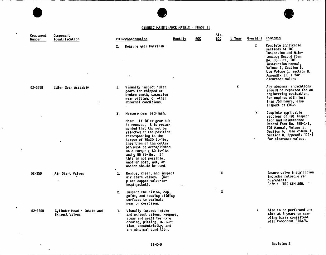
GENERIC MAINTENANCE MATRIX - PHASE II
ComponentNumber
ComponentIdentification PH Recommendation
2. Heasure gear backlash.
5~anti>l EOC
Alt.EOC 5 Year Overhaul Ceeeeeta
X Complete applicablesections of TDIInspection and Hain-tenance Record FormNo. 355-1-1, TOIInstruction Hanual,Volume I Section 6Use Volume 1, Section 8,Appendix III-lforclearance values.
02-355B Idler Gear Assembly
02-359 Air Start Valves
02-360B Cylinder Head - Intake andExhaust Valves
l. Visually inspect idlergears for chipped orbroken teeth, excessivewear pitting, or otherabnormal conditions.
2. Heasure gear backlash.
Note: If idler gear hubis removed, it is recom-mended that the nut berelocked at the positioncorresponding to thetorque of 70120 ft-lbs.Insertion of the cotterpin must be accomplishedat a torque > 50 ft-lbsand < 90 ft-Tbs. Ifthis is not possible,another bolt, nut, orwasher should be used.
Remove, clean, and inspectair start valves. (Re-place copper valve-to-head gasket).
2. Inspect the piston, cap,guide, and housing slidingsurfaces to evaluate.wear or corrosion.
l. Visually inspect .intakeand exhaust valves, keepers,stems and seats for 5 iredrawing, pitting, d»tE r-tion, concentricity, andany abnormal condition.
Any abnormal indicationsshould be reported for anengineering evaluation.For engines with lessthan 750 hours, alsoinspect at EOC2.
X Complete applicablesections of TOI Inspec-tion and HaintenanceRecord Form No. 355-1-1,TDI Manual, Volume I,Section 6. Use Volume I,Section 8, Appendix III-lfor clearance values.
Ensure valve >nstallat>onincludes retorque re-quirements.Refr.: TOI SIH 360.
Also to be performed onetime at 5 years on sam-
pling basis consistentwith Component 340A/B.
II-C-9 Revision 2

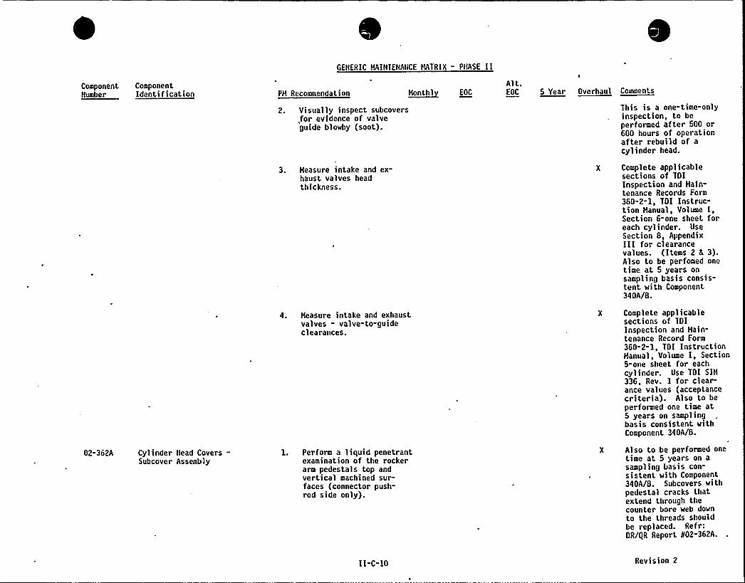
GENERIC MAINTENANCE MATRIX - PHASE II
ComponentNumber
02-362A
ComponentIdentification
Cylinder tiead Covers-Subcover Assembly
h~onthlPH Recommendation
2. Visually inspect subcovers,for evidence of valveguide blowby (soot).
3. Measure intake and ex-haust valves headthickness.
4. Heasure intake and exhaustvalves - valve-to-guideclearances.
II-C-10
1. Perform a liquid penetrantexamination of the rockerarm pedestals top andvertical machined sur-faces (connector push-rod side only).
EOC
Alt.OOC 5 Year Overhaul Ceeeente
This is a one-time-onlyinspection, to beperformed after 500 or600 hours of operationafter rebuild of acylinder head.
Complete applicablesections of TOIInspection and Hain-tenance Records Form360-2-1, TOI Instruc-tion Hanual, Volume I,Section 6-one sheet foreach cylinder. UseSection 8, AppendixIII for clearancevalues. (Items 2 f 3).Also to be perfomed onetime at 5 years onsampling basis consis-tent with Component340A/B.
Complete applicablesections of TOIInspection and Hain-tenance Record Form360-2-1, TOI InstructionManual, Volume I, Section5-one sheet for eachcylinder. Use TOI SIH336, Rev. 1 for clear-ance values (acceptancecriteria). Also to beperformed one time at5 years on samplingbasis consistent withComponent 340A/B.
Also to be performed onetime at 5 years on a
sampling basis con-sistent with Component340A/B. Subcovers withpedestal cracks thatextend through thecounter bore web downto the threads shouldbe replaced. Refr:OR/QR Report 802-362A.
Revision 2
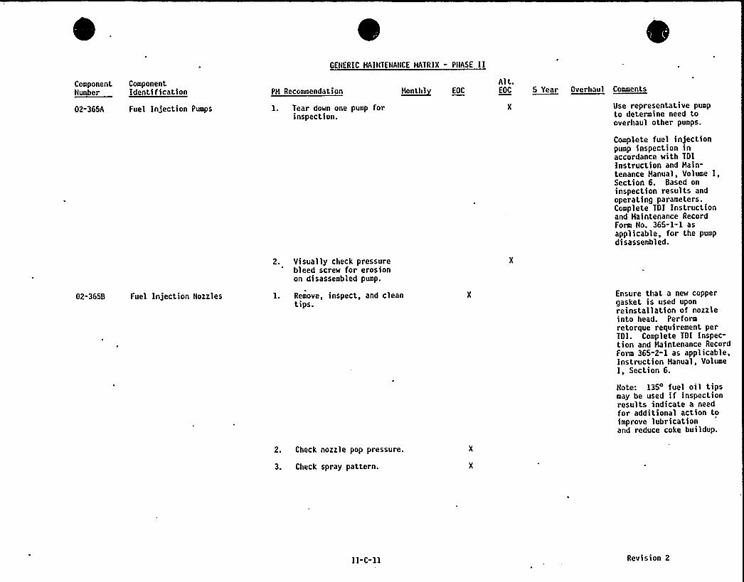
GENERIC HAINTENANCE MATRIX " PIIASE II
ComponentNumber
02-365A
ComponentIdentification
Fuel Injection Pumps
PH Recommendation
1. Tear down one pump forinspection.
2. Visually check pressurebleed screw for erosionon disassembled pump.
H~onlhl fOCAlt.EOC 5 Year Overhaul Comments
Use repr esentative pumpto determine need tooverhaul other pumps.
Complete fuel injectionpump inspection inaccordance with TDIInstruction and Main-tenance Manual, Volume I,Section 6. Based oninspection results andoperating parameters.Complete TDI Instructionand Haintenance RecordForm No. 365-1-1 asapplicable, for the pumpdisassembled.
02-365B Fuel Injection Nozzles 1. Remove, inspect, and cleantips.
2. Check nozzle pop pressure.
3. Check spray pattern.
Ensure that a new coppergasket is used uponreinstallation of nozzleinto head. Performretorque requirement perTDI. Complete TDI Inspec-tion and Haintenance RecordForm 365-2-1 as applicable,Instruction Hanual, VolumeI, Section 6.
Note: 135 fuel oil tipsmay be used if inspectionresults indicate a needfor additional action toimprove lubricationand reduce coke buildup.
II-C-11 Revision 2

GENERIC HAINTENANCE HATRIX - PHASE Il
ComponentNumber
ComponentIdentification PH Recoaeendation n~ontnl EOC
Alt.EOC 5 Year Ooernaol Connenta
02-3650 Fuel Oil Injection Lines:Supports
02-371A Fuel Pump Control Shaft
02-3718 Fuel Pump Linkage Assemblyand Bearings
02-380A Exhaust Hanifold
l. Visually inspect supportelastomer inserts fordeterioration or degrada-tion.
1. Check and lubricateas required.
1. Grease swivel link orotherwise lubricateall fuel oil pumpassemblies.
1. Perform a visual examinationof accessible pipe weldsand corresponding heat-affected zones.
Any inserts found to beunsatisfactory shall bereplaced with new insertsprior to reassembly offuel oil lines. Thisinspection can be per-formed prior to reassemblyof the fuel oil lines inconjunction with thecylinder liner inspection.
To be performed at EOCland alternate EOCs
thereafter.
02-385A Crankcase Relief Valve
02-387A Crankcase Vacuum Fan
02-390E Rocker Arm Bushings
1. Clean flame arrestors.
2. Inspect seat and disc.
l. Inspect fan and cleanas necessary.
2. Check bearing forroughness.
l. Visually inspect andmeasure intake rocker armbushings.
2. Visually inspect andmeasure exhaust rockerarm bushings.
3. Visually inspect andmeasure intermediaterocker arm bushings.
X Also to be performed onetime at 5 years onsampling basis con-sistent with Component340A/B.
X Also to be performed onetime at 5 years onsampling basis con-sistent with Component340A/B.
X Also to be performed onetime at 5 years onsampling basis consist-ent with Component 340A/8.
II-C-12 Revision 2
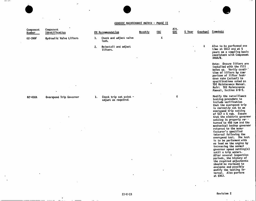
GENERIC HAINTENANCE HATRIX - PHASE II
Component ComponentNumber Identification
02-390F Hydraulic Valve Lifters
02-410A Overspeed Trip Governor
PH Recommendation
1. Check and adjust valvelash.
2. Reinstall and adjustlifters.
1. Check trip set point-ad3ust as required.
~Hant hl E0CAlt.EOC 5 Year Overhaul Comments
Also to be performed onetime at EOC2 and at 5
years on a sampling basisconsistent with Component340A/B.
Note: Ensure lifters areinstalled with the fillholes up. Verify condi-tion of lifters by com-
parisonn
of lifter leak"down rate (actual) tospecifications noted onTDI Haintenance Hanual.Refr: TOI HaintenanceManual, Section 6-8-5.
Hodify the surveillancetesting procedure toinclude ver>fscat>onthat the overspeed tripis correctly set to anoverspeed trip settingof 517 a 5 rpm. Ensurethat the electric governorsetting is properly re- .
turned to 450 rpm and themechanical backup governorreturned to the manu-facturer's specifiedinterval following theoverspeed test. The testis to be performed withno load on the engine byincreasing the normalgovernor speed setting(s)until a trip occurs.After several inspectionperiods, the history ofthe required adjustmentsshould be reviewed toevaluate and possiblymodify the testing in-terval. Also performat EOC2.
II-C-13 Revision 2
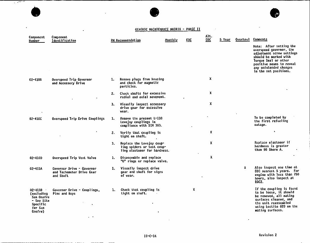
GENERIC MAINTENANCE MATRIX - PNASE II
ComponentNumber
ComponentIdentification PM Recommendation ~Mon th) E0C
Alt.EOC 5 Year Overhaul Comments
Note: After setting theoverspeed governor, theadjustment screw settingsshould be marked withTorque Seal or otherpositive means to revealany unintended changesin the set positions.
02-4100 Overspeed Trip Governorand Accessory Drive
1. Remove plugs from housingand check for magneticparticles.
2. Check shafts for excessiveradial and axial movement.
3. Visually inspect accessorydrive gear for excessivewear.
02-410C Overspeed Trip Drive Couplings 1. Remove the present L-110Lovejoy couplings incompliance with SIM 363.
2. Verify that coupling istight on shaft.
3. Replace the Lovejoy coup-ling spiders or test coup-ling elastomer for hardness.
To be completed bythe first refuelingoutage.
Replace elastomer ifhardness is greaterthan 90 Shore A.
02-4100 Overspeed Trip Vent Valve
02-411A Governor Drive - Governorand Tachometer Drive Gearand Shaft
02-411B Governor Drive - Couplings,(excluding Pins and Keys
San Onofre- See SiteSpecificfor SanOnofre)
l. Disassemble and replace"0" rings or replace valve.
1. Visually inspect drivegear and shaft for signsof wear.
1. Check that coupling istight on shaft.
X Also inspect one time atEOC nearest 5 years. Forengine with less than 750hours, also inspect atEOC2.
If the coupling is foundto be loose, it shouldbe removed, all matingsurfaces cleaned, andthe unit reassembledusing Loctite 609 on themating surfaces.
II-C-14 Revision 2
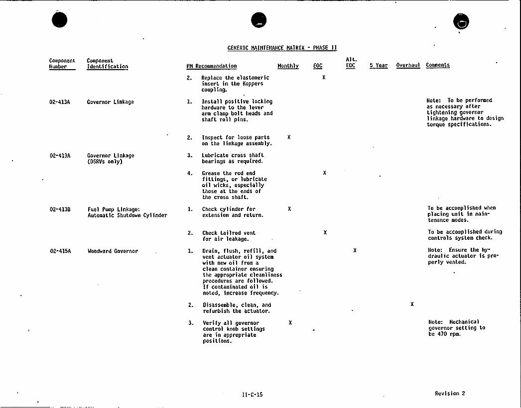
GENERIC HAINTENANCE HATRIX - PHASE II
ComponentNumber
ComponentIdentification PH Recommendation
2. Replace the elastomericinsert in the Kopperscoupling.
~Honthl EOC
Alt.EOC 5 Year Overhaul Comments
02-413A Governor Linkage
02-413A Governor Linkage(OSRVs only)
l. Install positive lockinghardware to the leverarm clamp bolt heads andshaft roll pins.
2. Inspect for loose partson the linkage assembly.
3. Lubricate cross shaftbearings as required.
4. Grease the rod endfittings, or lubricateoil wicks, especiallythose at the ends ofthe cross shaft.
Note: To be performedas necessary aftertightening governorlinkage hardware to designtorque specifications.
02-413B Fuel Pump Linkage:Automatic Shutdown Cy)inder
02-415A Woodward Governor
1. Check cylinder forextension and return.
2. Check tai lrod ventfor air leakage.
l. Orain, flush, refill, andvent actuator oil systemwith new oil from aclean container ensuringthe appropriate cleanlinessprocedures are followed.If contaminated oil isnoted, increase frequency.
2. Disassemble, clean, andrefurbish the actuator.
To be accomplished whenplacing unit in main-tenance modes.
To be accomplished duringcontrols system check.
Note: Ensure the hy-draulic actuator is pro-perly vented.
3. Veri fy all governorcontrol knob settingsare in appropriatepositions.
Note: Hechanicalgovernor setting tobe 470 rpm.
II-C-15 Revision 2
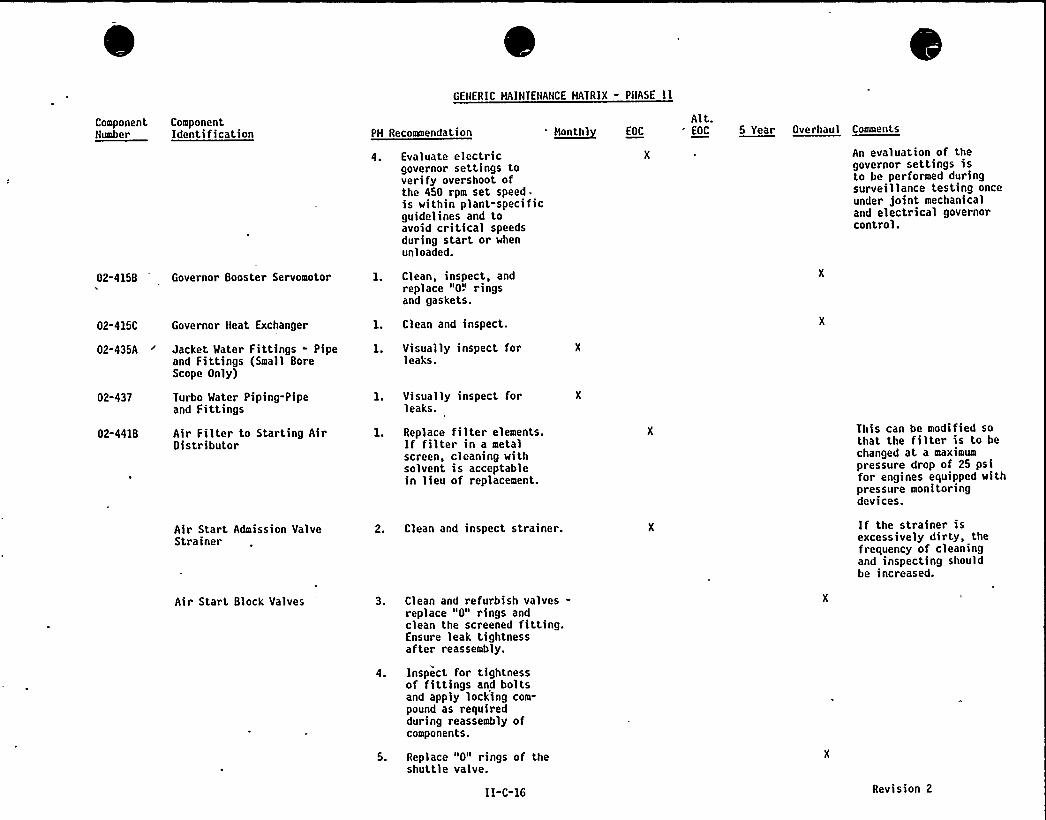
GENERIC MAINTENANCE MATRIX - PHASE II
ComponentNumber
ComponentIdentification PM RecoEENEendation O~onthl EOC
Alt.EOC 5 Year Oreraael Coeeeele
02-4158 Governor Booster Servomotor
02-415C Governor Heat Exchanger
02-435A 'acket Water Fittings - Pipeand Fittings (Smail BoreScope Only)
Evaluate electricgovernor settings toverify overshoot ofthe 450 rpm set speed .
is within plant-specificguidelines and toavoid critical speedsduring start or whenunl oa ded.
Clean, inspect, andreplace "0!'ingsand gaskets.
Clean and inspect.
Visually inspect forleaks.
An evaluation of thegovernor settings isto be performed duringsurveillance testing onceunder joint mechanicaland electrical governorcontrol.
02-437
02-4418
Turbo Water Piping-Pipeand Fittings
Air Filter to Starting AirDistributor
Air Start Admission ValveStrainer
Air Start Block Valves
Visually inspect forleaks.
Replace filter elements.If filter in a metalscreen, cleaning withsolvent is acceptablein lieu of replacement.
Clean and inspect strainer.
Clean and refurbish valves-replace "0" rings andclean the screened fitting.Ensure leak tightnessafter reassembly.
Inspect for tightnessof fittings and boltsand apply locking com-pound as requiredduring reassembly ofcomponents.
Replace "0" rings of theshuttle valve.
II-C-16
This can be modified sothat the filter is to bechanged at a maximumpressure drop of 25 psifor engines equipped withpressure monitoringdevices.
If the strainer isexcessively dirty, thefrequency of cleaningand inspecting shouldbe increased.
Revision 2
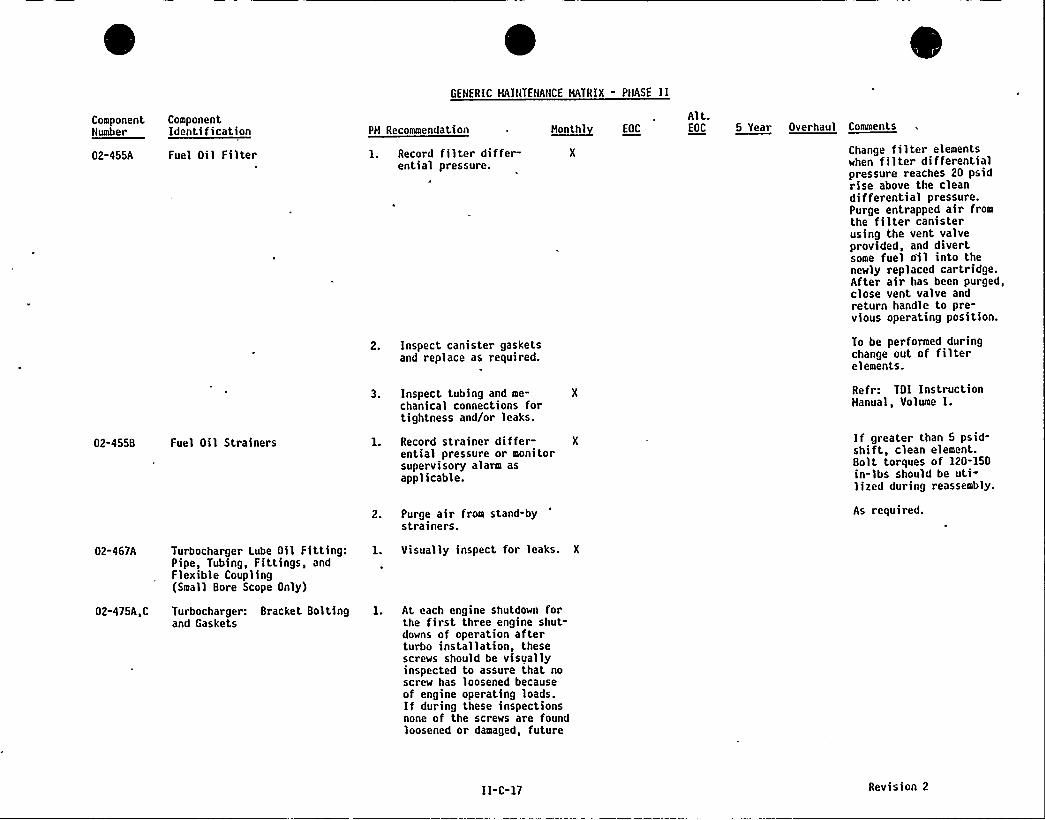
GENERIC HAINTENANCE HATRIX - PHASE II
ComponentNumber
02-455A
ComponentIdentification
Fuel Oil Filter
PH Recommendation
1. Record filter differ-ential pressure.
2. Inspect canister gasketsand replace as required.
3. Inspect tubing and me-chanical connections fortightness and/or leaks.
h~eathl EOC
Alt.EOC 5 Year Overhaul Caeveeate
Change filter elementswhen filter differeritiaipressure reaches 20 psidrise above the cleandifferential pressure.Purge entrapped air fromthe filter canisterusing the vent valveprovided, and divertsome fuel o'il into thenewly replaced cartridge.After air has been purged,close vent valve andreturn handle to pre-vious operating position.
To be performed duringchange out of filterelements.
Refr TDI InstructionHanual, Volume I.
02-455B Fuel Oil Strainers 1. Record strainer differ- X
ential pressure or monitorsupervisory alarm asapplicable.
2. Purge air from stand-bystrainers.
If greater than 5 psid-shift, clean element.Bolt torques of 120-150in-lbs should be uti-lized during reassembly.
As required.
02-467A
02-475A,C
Turbocharger Lube Oil Fitting:Pipe, Tubing, Fittings, andFlexible Coupling(Small Bore Scope Only)
Turbocharger: Bracket Bol tingand Gaskets
l. Visually inspect for leaks. X
l. At each engine shutdown forthe first three engine shut-downs of operation afterturbo installation, thesescrews should be visuallyinspected to assure that noscrew has loosened becauseof engine operating loads.If during these inspectionsnone of the screws are foundloosened or damaged, future
II-C-I7 Revision 2
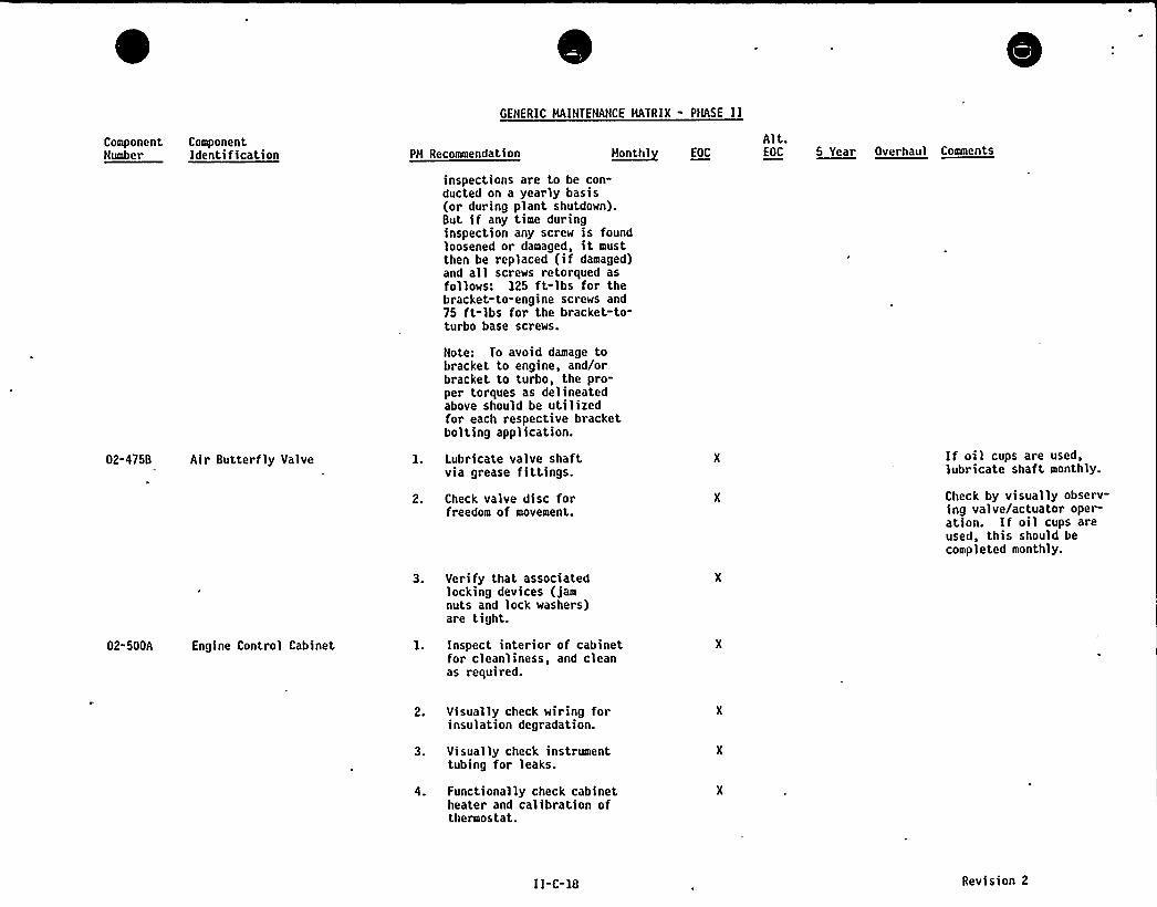
GENERIC MAINTENANCE MATRIX - PNASE IlComponentNumber
ComponentIdentification PM Recommendation M~onthl EOC
Alt.EOC 55Yaa Overhaul Comments
inspections are to be con"ducted on a yearly basis(or during plant shutdown).But if any time duringinspection any screw is foundloosened or damaged, it mustthen be replaced (if damaged)and all screws retorqued asfollows: 125 ft-lbs for thebracket-to-engine screws and75 ft-lbs for the bracket-to-turbo base screws.
02-4758 Air Butterfly Valve
02-500A Engine Control Cabinet
Note: To avoid damage tobracket to engine, and/orbracket to turbo, the pro-per torques as delineatedabove should be utilizedfor each respective bracketbolting application.
Lubricate valve shaftvia grease fittings.
Check valve disc forfreedom of movement.
Verify that associatedlocking devices (jamnuts and lock washers)are tight.
Inspect interior of cabinetfor cleanliness, and cleanas required.
If oil cups are used,lubricate shaft monthly.
Check by visually observ-ing valve/actuator oper-ation. If oil cups areused, this should becompleted monthly.
Visually check wiring forinsulation degradation.
Visually check instrumenttubing for leaks.
Functionally check cabinetheater and calibration ofthermostat.
II-C-18 Revision 2
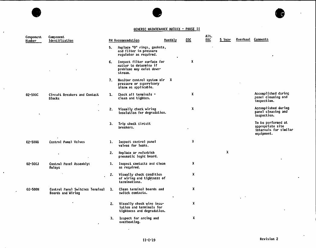
GENERIC MAINTENANCE MATRIX - PNASE II
ComponentNumber
ComponentIdentification PM Recommendation H~onthl EOC
Alt.EOC a Year Overhaul Coavaento
5. Replace "0" rings, gaskets,and filter in pressureregulator as required.
6. Inspect filter surface formatter to determine ifproblems may exist down-stream.
02-500C Circuit Breakers and ContactBlocks
7. Monitor control system air X
pressure or supervisoryalarm as applicable.
1. Check all terminals-clean and tighten.
2. Visually check wiringinsulation for degradation.
Accomplished duringpanel cleaning andinspection.
Accomplished duringpanel cleaning andinspection.
02-SOOG Control Panel Valves
3. Trip check circuitbreakers.
l. Inspect control panelvalves for leaks.
To be performed atappropriate siteintervals for similarequipment.
02-500J Control Panel Assembly:Relays
2. Replace or refurbishpneumatic logic board.
1. Inspect contacts and cleanas required.
02-SOON Control Panel Switches TerminalBoards and Miring
2. Visually check conditionof wiring and tightness ofterminations.
1. Clean terminal boards andswitch contacts.
2. Visually check wire insu-lation and terminals fortightness and degradation.
3. Inspect for arcing andoverheating.
II-C-19 Revision 2
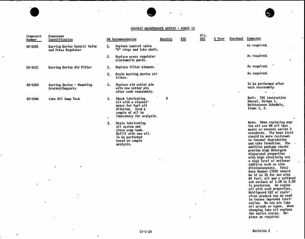
GENERIC MAINTENANCE MATRIX - PHASE I I
ComponentNumber
02-5258
ComponentIdentification
Barring Device Control Valveand Press Regulator
PH Recommendation
1. Replace control valve"0" rings and lube shaft.
2. Replace press regulatorelastomeric parts.
~Mont.hl EOC
Alt.EOC 5 Year Overhaul Comments
As required.
As required.
02-525C Barring Device Air Filter
02-5250 Barring Device - MountingBracket/Supports
02-540A Lube Oil Sump Tank
1. Replace filter element.
2. Drain barring device airfilter.
1. Replace old cotter pinwith new cotter pinafter each reassembly.
1. Check lubricatingoil with a viscosi-meter for fuel oildilution. Send asample of oil tolaboratory for analysis.
As required.
As required.
To be performed aftereach reassembly.
Ref r: TDI InstructionManual, Volume I,Haintenance Schedule,Items 1, 2.
2. Drain lubricatingoil system andclean sump tank.Refill with new oil.To be performedbased on sampleanalysis.
Note: When replacing eng-ine oil use ND oil thatmeets or exceeds series 3standards. The base stockshould be more resistantto thermal degradationand coke formation. Theadditive package shouldprovide high Qetergentdispersant propertieswith high alkalinity anda high level of antiwearadditive such as zincdithiophosphate. TotalBase Number (TBN) shouldbe 12 to 15 for use withN2 fuel, oil and a sulfatedash content of 1. 5X to 2.0Xis preferred. An engineoil with such properties,Hobi lguard 412 or equiv-alent product may be usedto insure improved lubri-cation. Do not mix lubeoil brands or types. When
changing lube oil replacethe entire charge. Re-
place as required.
II-C-20 Revision 2

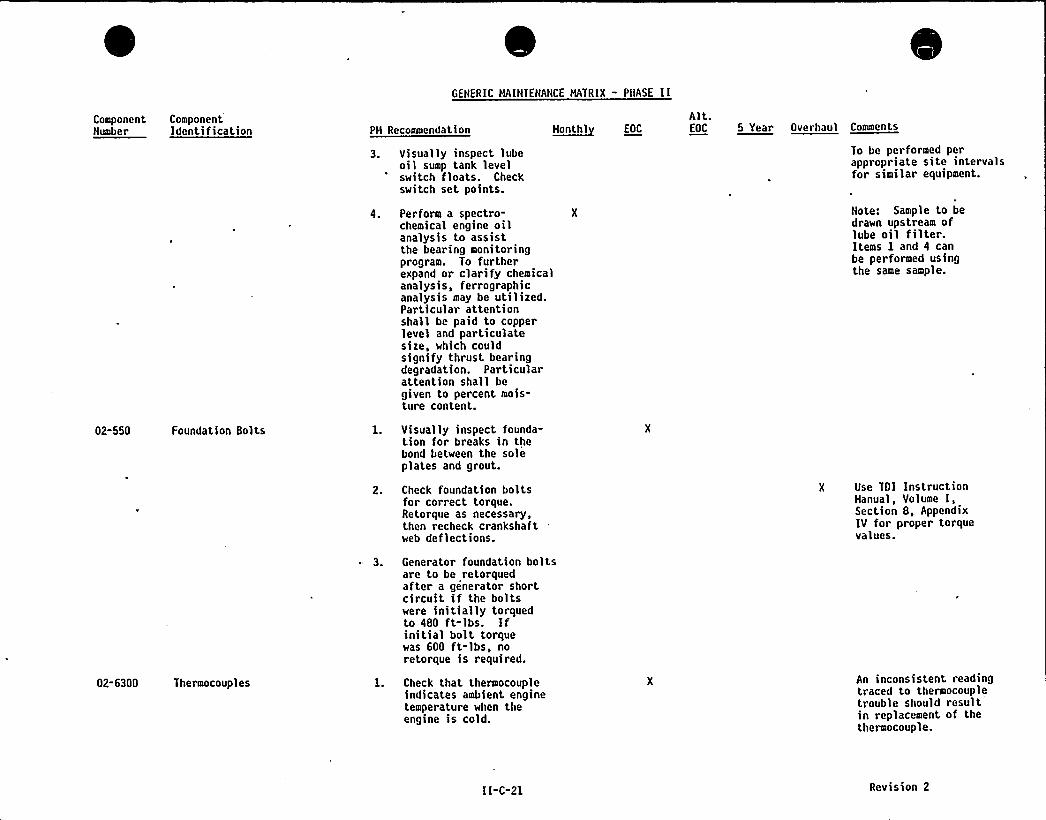
GENERIC MAINTENANCE MATRIX - PMASE II
ComponentNumber
ComponentIdentification PM Recommendation
Visually inspect lubeoil sump tank levelswitch floats. Checkswitch set points.
~hentht EOC
Alt.EOC 5 Year Overhaul Ceeeeente
To be performed perappropriate site intervalsfor similar equipment.
Perform a spectro-chemical engine oilanalysis to assistthe bearing monitoringprogram. To furtherexpand or clarify chemicalanalysis, ferrographicanalysis may be utilized.Particular attentionshall be paid to copperlevel and particulatesize, which couldsignify thrust bearingdegradation. Particularattention shall begiven to percent mois-ture content.
Note: Sample to bedrawn upstream oflube oil filter.Items 1 and 4 canbe performed usingthe same sample.
02-550 Foundation Bolts Visually inspect founda-tion for breaks in thebond between the soleplates and grout.
02-6300 Thermocoupl es
Check foundation boltsfor correct torque.Retorque as necessary,then recheck crankshaftweb deflections.
Generator foundation boltsare to be retorquedafter a generator shortcircuit if the boltswere initially torquedto 480 ft-lbs. Ifinitial bolt torquewas 600 ft-lbs, noretorque is required.
Check that thermocoupleindicates ambient enginetemperature when theengine is cold.
X Use TDI InstructionManual, Volume I,Section 8 AppendixIV for proper torquevalues.
An inconsistent readingtraced to thermocoupletrouble should resultin replacement of thethermocouple.
II-C-21 Revision 2

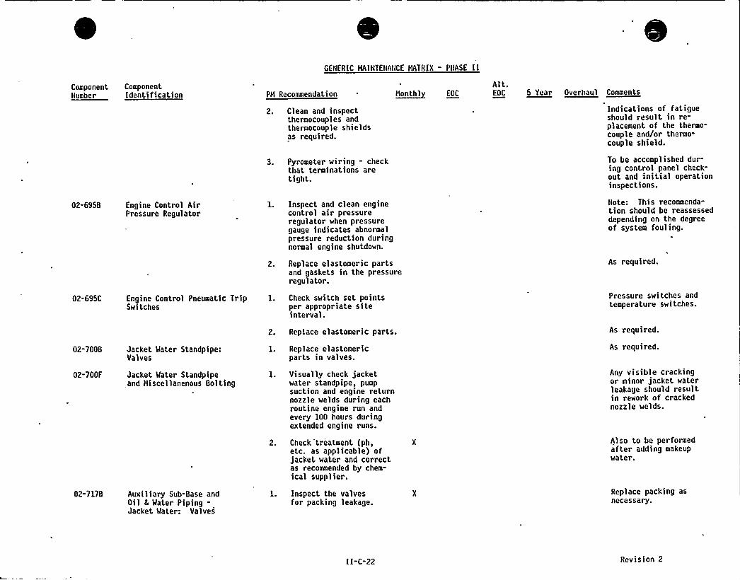
GENERIC MAINTENANCE MATRIX - PNASE II
Component ComponentNumber Identification
02-6958 Engine Control AirPressure Regulator
PM Recommendation
Clean and inspectthermocouples andthermocouple shieldsas required.
Pyrometer wiring - checkthat terminations aretight.
Inspect and clean enginecontrol air pressureregulator when pressuregauge indicates abnormalpressure reduction duringnormal engine shutdown.
H~onthl EOC
Alt.OOC 5 Year Oeerhael Ceeeaente
Indications of fatigueshould result in re-placement of the thermo-couple and/or thermo-couple shield.
To be accomplished dur-ing control panel check-out and initial operationinspections.
Note: This recommenda-tion should be reassesseddepending on the degreeof system fouling.
02-695C
02-7008
02-700F
Engine Control Pneumatic TripSwitches
Jacket Water Standpipe:Valves
Jacket Water Standpipeand Hiscellanenous Bolting
Replace elastomeric partsand gaskets in the pressureregulator.
Check switch set pointsper appropriate siteinterval.
Replace elastomeric parts.
Replace elastomericparts in valves.
Visually check jacketwater standpipe, pumpsuction and engine returnnozzle welds during eachroutine engine run andevery 100 hours duringextended engine runs.
Check treatment (ph,etc. as applicable) ofjacket water and correctas recommended by chem-ical supplier.
As required.
Pressure switches andtemperature switches.
As required.
As required.
Any visible crackingor minor jacket waterleakage should resultin rework of crackednozzle welds.
Also to be performedafter adding makeupwater.
02-717B Auxiliary Sub-Base andOil 8 Water Piping-Jacket Water: Valves
Inspect the valvesfor packing leakage.
Replace packing asnecessary.
II-C-22 Revision 2
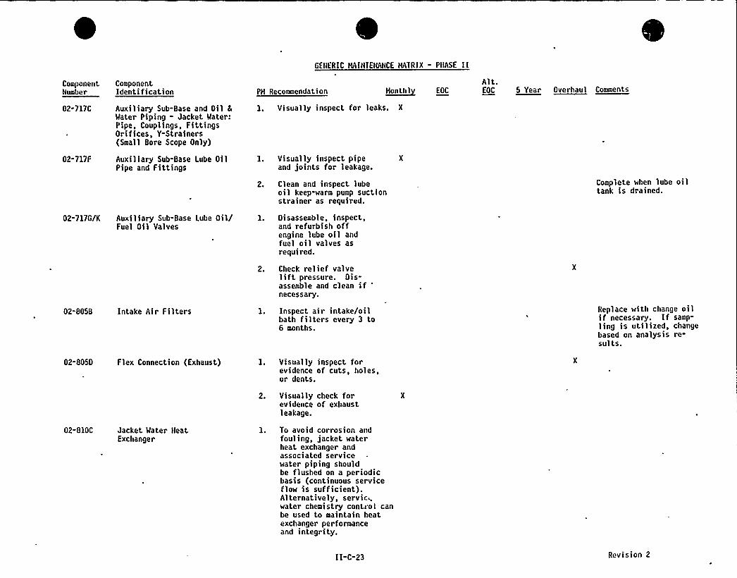
GENERIC HAINIENANCE HA'IRIX - PHASE II
ComponentNumber
ComponentIdentification PH Recomnendation ~Honthl EOC
Alt.EOC 5 Year Overhaul Comments
02-717C
02-717F
02-717G/K
Auxiliary Sub-Base and Oil 8
Water Piping - Jacket Water:Pipe, Couplings, FittingsOrifices, Y-Strainers(Small Bore Scope Only)
Auxiliary Sub-Base Lube OilPipe and Fittings
Auxiliary Sub-Base Lube Oil/Fuel Oil Valves
Visually inspect for leaks. X
Visually inspect pipeand joints for leakage.
Clean and inspect lubeoil keep-warm pump suctionstrainer as required.
Disassemble, inspect,and refurbish offengine lube oil andfuel oil valves asrequired.
Check relief valveliftpressure. Dis-assemble and clean ifnecessary.
Complete when lube oiltank is drained.
02-805B Intake Air Filters
02-8050 Flex Connection (Exhaust)
Inspect air intake/oilbath filters every 3 to6 months.
Visually inspect forevidence of cuts, holes,or dents.
Replace with change oilif necessary. If samp-ling is utilized, changebased on analysis re-sults.
02-810C Jacket Water HeatExchanger
Visually check forevidence of exhaustleakage.
To avoid corrosion andfouling, jacket waterheat exchanger andassociated servicewater piping shouldbe flushed on a periodicbasis (continuous serviceflow is sufficient).Alternatively, servic.,water chemistry contiol canbe used to maintain heatexchanger performanceand integrity.
II-C-23 Revision 2

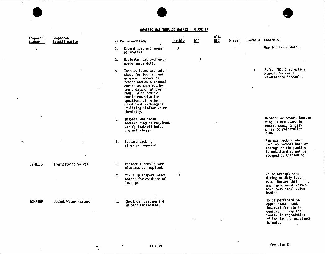
GENERIC HAINTENANCE MATRIX - PHASE II
ComponentNumber
ComponentIdentification PH Recommendation
2. Record heat exchangerparameters.
3. Evaluate heat exchangerperformance data.
4. Inspect tubes and tubesheet for fouling anderosion - remove en-trance and exit channelcovers as required bytrend data or at over-haul. Also reviewconsistent with in-spections of otherplant heat exchangersutilizing similar waterchemistry.
5. Inspect and cleanlantern ring as required.Verify leak-off holesare not plugged.
6. Replace packingrings as required.
~Honthl EOC
Alt.EOC 5 Year Overhaul Ceenente
Use for trend data.
X Refr: TOI InstructionHanual, Volume I,Haintenance Schedule.
Replace or rework lanternring as necessary toensure concentricityprior to reinstalla-t,ion.
Replace packing whenpacking becomes hard orleakage at the packingis noted and cannot bestopped by tightening.
02-8100 Thermostatic Valves
02-810E Jacket Mater Heaters
1. Replace thermal powerelements as required.
2. Visually inspect valve X
bonnet for evidence ofleakage.
1. Check calibration andinspect thermostat.
To be accomplishedduring monthly testrun. Ensure thatany replacement valveshave cast steel valvebodies.
To be performed atappropriate plantinterval for similarequipment. Replaceheater if degradationof insulation resistanceis noted.
II-C-24 Revision 2
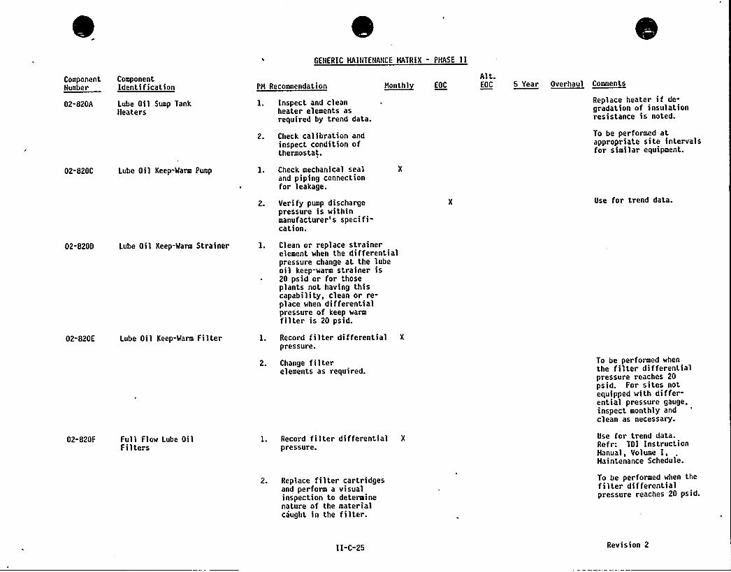
GENERIC HAINTENANCE MATRIX - PHASE II
ComponentNumber
02-820A
ComponentIdentification
Lube Oil Sump TankHeaters
PH Recommendation
l. Inspect and cleanheater elements asrequired by trend data.
2. Check calibration andinspect condition ofthermostat.
N~onl,hl EOC
Alt.EOC 5 Year Overhaul Commenta
Replace heater if degradation of insulationresistance is noted.
To be performed atappropriate site intervalsfor similar equipment.
02-820C Lube Oil Keep-Warm Pump 1. Check mechanical sealand piping connectionfor leakage.
2. Verify pump dischargepressure is withinmanufacturer's specifi-cation.
Use for trend data.
02-8200 Lube Oil Keep-Warm Strainer 1. Clean or replace strainerelement when the differentialpressure change at the lubeoil keep-warm strainer is20 psid or for thoseplants not having thiscapability, clean or re-place when differentialpressure of keep warmfilter is 20 psid.
02-820E Lube Oil Keep-Warm Filter 1. Record filter differential X
pressure.
02-820F Full Flow Lube OilFilters
2. Change filterelements as required.
1. Record filter di fferential X
pressure.
2. Replace filter cartridgesand perform a visualinspection to determinenature of the materialcaught in the filter.
To be performed whenthe filter differentialpressure reaches 20psid. For sites notequipped with differ-ential pressure gauge,inspect monthly andclean as necessary.
Use for trend data.Refr: TOI InstructionHanual, Volume I,Haintenance Schedule.
To be performed when thefilter differentialpressure reaches 20 psid.
11-C-25 Revision 2
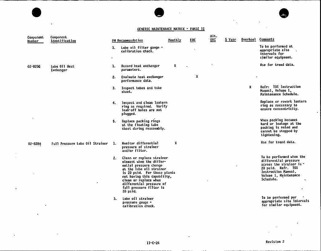
GENERIC HAINTENANCE HATRIX - PHASE II
ComponentNumber
ComponentIdentification PH Recommendation
3. Lube oil filter gauge-calibration check.
H~anthl EOC
Alt."EOC 5 Year Overhaul Comments
To be performed atappropriate siteintervals forsimilar equipment.
02-820G Lube Oil MeatExchanger
1. Record heat exchangerparameters.
2. Evaluate heat exchangerperformance data.
3. Inspect tubes and tubesheet.
X Use for trend data.
X Refr: TOI InstructionHanual, Volume I,Maintenance Schedule.
02-820M
4. Inspect and clean lanternring as required. Verifyleak-off holes are notplugged.
5. Replace packing ringsat the floating tubesheet during reassembly.
Full Pressure Lube Oil Strainer 1. Monitor differentialpressure of strainerand/or filter.
2. Clean or replace strainerelement when the differ-ential pressure changeat the lube oil straineris 20 psid. For those plantsnot having this capability,clean or replace whendifferential pressure offull pressure filter is20 psid.
3. Lube oil strainerpressure gauge-calibration check.
Replace or rework lanternring as necessary toensure concentricity.
When packing becomeshard or leakage at thepacking is noted andcannot be stopped bytightening.
Use for trend data.
To be performed when thedifferential pressureacross the strainer is-20 psid. Refr. TOIInstruction Hanual,Volume I,
Haintenance'chedule.
To be performed perappropriate site intervalsfor s>m>1ar equ>pment
II-C-26 Revision 2
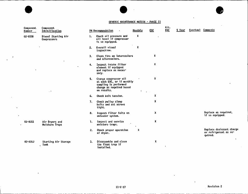
GENERIC MAINTENANCE MATRIX - PHASE 11
ComponentNumber
ComponentIdentification PM Recommendation ~hootht EOC
Alt.EOC 5 Year Overhaul Coeeeota
02-8358 Diesel Starting AirCompressors
1. Check oil pressure and X
oil level if compressoris so equipped.
2. Overall visualinspection.
3. Clean fins on intercoolersand aftercoolers.
4. Inspect intake filterelement if equippedand replace as neces-sary.
5. Change compressor oilat each EOC, or if monthlysampling is performedchange as required basedon results.
6. Check belt tension.
02-8351 Air Dryers andMoisture Traps
02-835J Starting Air Storage, Tank
7. Check pulley clampbolts and set screwstight.
8. Inspect filter felts onunloader system.
l. Inspect and servicemoisture traps.
2. Check proper operationof dryer.
1. Disassemble and cleanthe float trap ifinstalled.
Replace as required,if so equipped.
Replace desiccant chargeor refrigerant as re-quired.
11-C-27 Revision 2
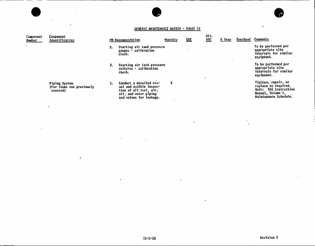
GENERIC HAINTENANCE MATRIX - PHASE II
ComponentNumber
ComponentIdentification PH Recommendation H~onthl EOC
Alt.EOC 5 Year Overhaul Comments
Piping System(For items not previouslycovered)
2. Starting air tank pressuregauges - calibrationcheck.
3. Starting air tank pressureswitches - calibrationcheck.
1. Conduct a detailed vis- X
ual and audible inspec-tion of all fuel, air,oil, and water pipingand valves for leakage.
To be performed perappropriate siteintervals for similarequipment.
To be performed perappropriate siteintervals for similarequipment.
Tighten, repair, orreplace as required.Refr: TOI InstructionHanual, Volume I,Haintenance Schedule.
II-C-28 Revision 2
TDI
OWNERS GROUP
APPENDIX"II
SITE SPECIFIC MAINTENANCE MATRIX
PART 0
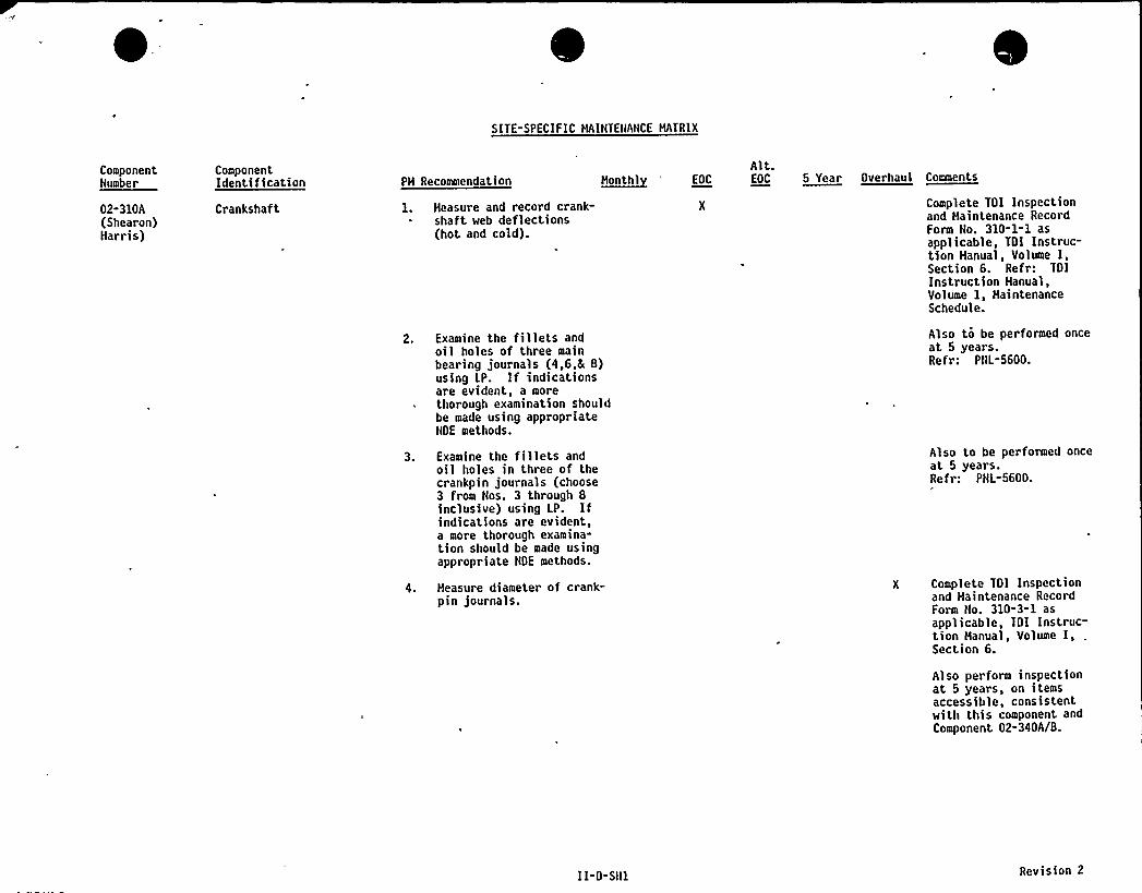
SITE-SPECIFIC HAINTENANCE HATRIX
ComponentNumber
02-310A(Shearon)Harris)
ComponentIdentification
Crankshaf tPH Recommendation
1. Heasure and record crank-shaft web deflections(hot and cold).
Alt.H~anthl 'OC EOC 5 Year Overhaul Caanenta
Complete TOI Inspectionand Haintenance RecordForm No. 310-1-1 asapplicable, TOI Instruc-tion Hanual, Volume I,Section 6. Refr: TOIInstruction Manual,Volume 1, HaintenanceSchedule.
2. Examine the fillets andoil holes of three mainbearing journals (4,6,h 8)using LP. If indicationsare evident, a more
~ thorough examination shouldbe made using appropriateNOE methods.
Also to be performed onceat 5 years.Refr: PNL-5600.
3. Examine the fillets andoil holes in three of thecrankpin journals (choose3 from Nos. 3 through 8inclusive) using LP. Ifindications are evident,a more thorough examina-tion should be made usingappropriate NDE methods.
4. Heasure diameter of crank-pin journals.
Also to be performed onceat 5 years.Refr: PNL-5600.
X Complete TOI Inspectionand Maintenance RecordForm No. 310-3-1 asapplicable, TDI Instruc-tion Hanual, Volume I, .
Sect ion 6.
Also perform inspectionat 5 years, on itemsaccessible, consistentwith this component andComponent 02-340A/B.
I I-D-SH1 Revision 2
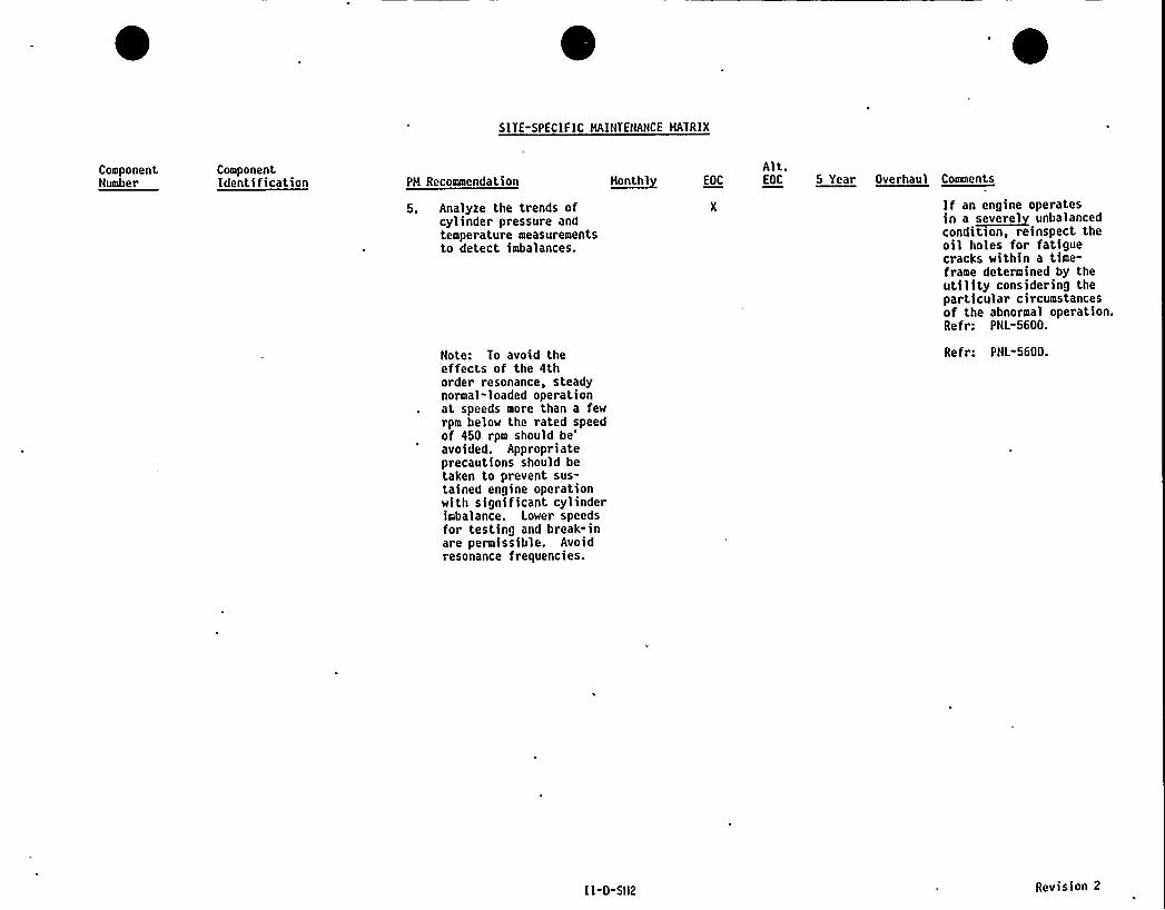
SITE-SPECIFIC HAINTENANCE HATRIX
ComponentNumber
ComponentIdentification PH Recommendation
5. Analyze the trends ofcylinder pressure andtemperature measurementsto detect imbalances.
Note: To avoid theeffects of the 4thorder resonance, steadynormal-loaded operationat speeds more than a fewrpm below the rated speed
~of 450 rpm should
be'voided.Appropriateprecautions should betaken to prevent sus-tained engine operationwith significant cylinderimbalance. Lower speedsfor testing and break-inare permissible. Avoidresonance frequencies.
n~onthl EOC
Alt.EOC 5 Year Overhaul Comments
If an engine operatesin a ~eeuerel unbalancedconditzon, reinspect theoil holes for fatiguecracks within a time-frame determined by theutility considering theparticular circumstancesof the abnormal operation.Refr: PNL"5600.
Refr: PNL-5600.
I I-D-SN2 Revision 2
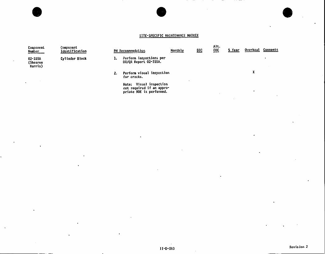
SITE-SPECIFIC HAINTENANCE HATRIX
ComponentNumber
02-315A(ShearonHarris)
ComponentIdentification
Cylinder Block
PM Recommendation
1. Perform inspections perDR/gR Report 02-315A.
2. Perform visual inspectionfor cracks.
Note: Visual inspectionnot required if an appro-priate NDE is performed.
Alt.~Ho otal EOC EOC 55ataer Overhaul Cuneate
I I-D-SII3 Revision 2
TDI
OWNERS GROUP
APPENDIX-II
CROSS REFERENCE INDEX
BYCOMPONENT'ART
E
~Le end
1. Index sorted by component name.
2. Component number listed or "nonum" indicates that the utility engineshould perform the maintenance as described.
3. Blank indicates that utility is not required to perform maintenanceindicated.
4. Maintenance or surveillance requirements for a'subcomponent should bedisregarded for those engines not equipped with the subcomponent.
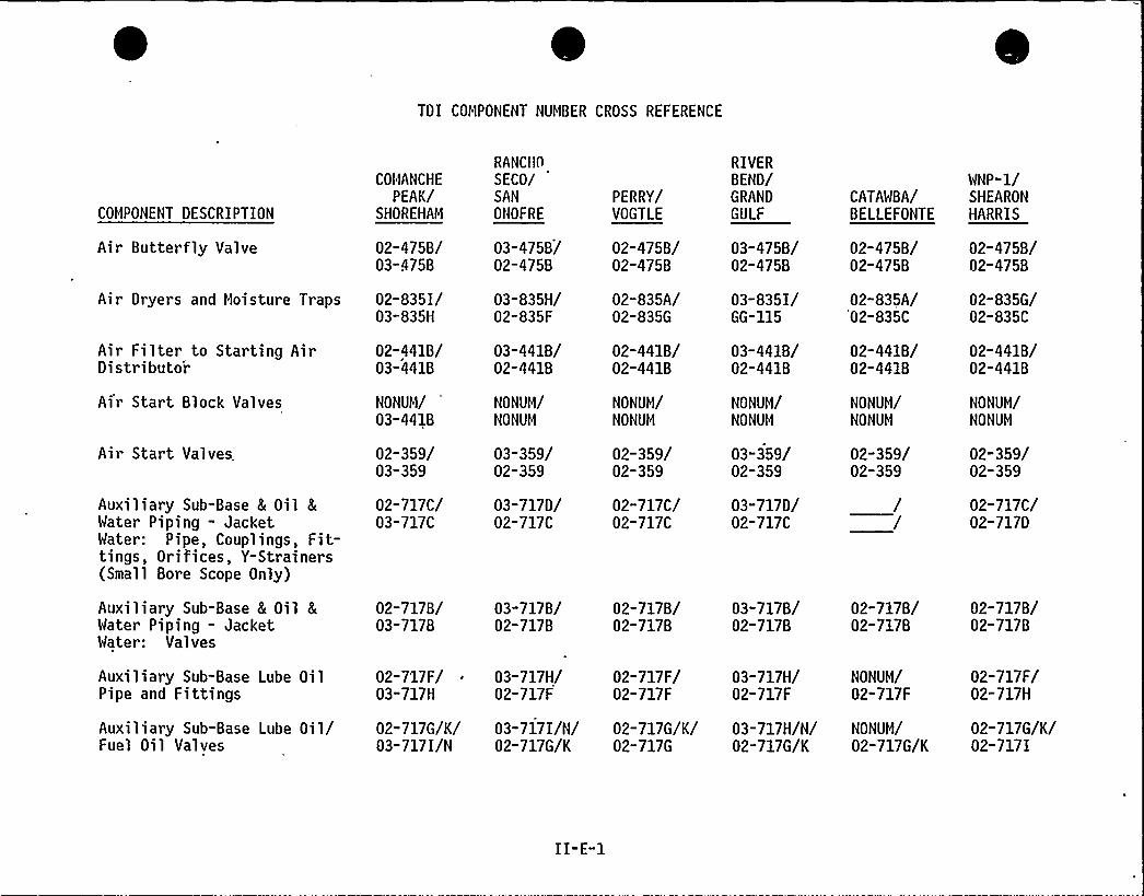
TDI COMPONENT NUMBER CROSS REFERENCE
COMPONENT DESCRIPTION
Air Butterfly Valve
COMANCHE
PEAK/SHOREHAM
02-475B/03-475B
Air Filter to Starting AirDistributor
Air Start Block Valves
Air Start Valves,
Auxiliary Sub-Base L Oil 8
Water Piping - JacketWater: Pipe, Couplings, Fit-tings, Orifices, Y-Strainers(Small Bore Scope Only)
02-441B/03-4418
NONUM/03-4418
02-359/03-359
02-717C/03-717C
Air Dryers and Moisture Traps 02-835I/03-835H
RANCflnSECO/SAN
ONOFRE
03-475B/02-475B
03-835H/02-835F
03-441B/02-441B
NONUM/NONUM
03-359/02-359
03-717D/02-717C
PERRY/VOGTLE
02-475B/02-475B
02-835A/02-835G
02-441B/02-441B
NONUM/NONUM
02-359/02-359
02-717C/02-717C
RIVERBEND/GRAND
GULF
03-475B/02-475B
03-835I/GG-115
03-441B/02-441B
NONUM/NONUM
03-359/02-359
03-717D/02-717C
CATAWBA/BELLEFONTE
02-475B/02-475B
02-835A/02-835C
02-441B/02-441B
NONUM/NONUM
02-359/02-359
WNP-1/SHEARONHARRIS
02-475B/02-475B
02-835G/02-835C
02-441B/02-441B
NONUM/NONUM
02-359/02-359
02-717C/02-717D
Auxiliary Sub-Base 8 Oil LWater Piping - JacketWater: Valves
02-717B/03-717B
03-717 B/02-717B
02-717B/02-717B
03-717B/02-717B
02-717B/02-717B
02-717B/02-717B
Auxiliary Sub-Base Lube OilPipe and Fittings
Auxiliary Sub-Base Lube Oil/Fuel Oil Valves
02-717F/03-717H
02-717G/K/03-717I/N
03-717H/02-717F
03-717I/N/02-717G/K
02-717F/02-717F
02-717G/K/02-717G
03-717H/02-717F
03-717H/N/02-717G/K
NONUM/02-717F
02-717F/02-717H
NONUM/ 02-717G/K/02-717G/K 02-717 I
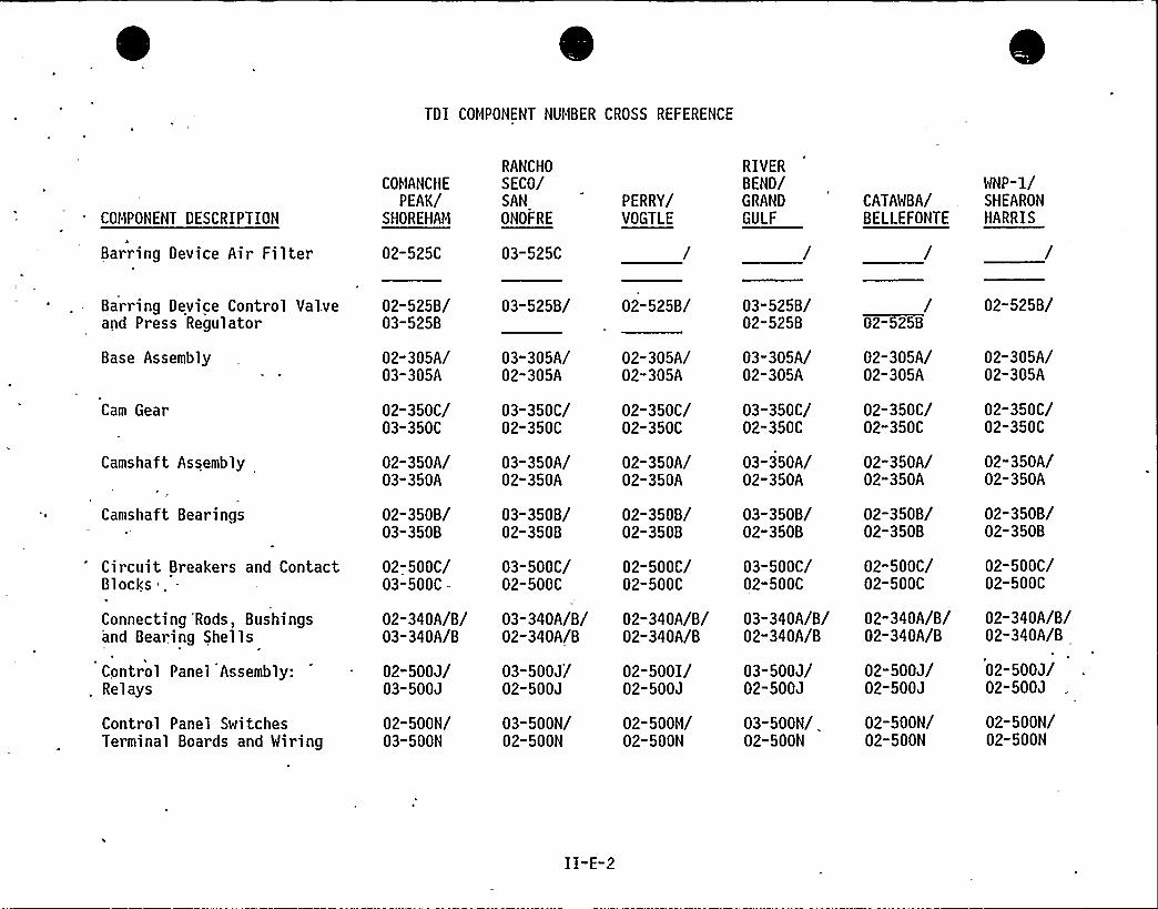
TDI COMPONENT NUMBER CROSS REFERENCE
COMPONENT DESCRIPTION
Barring Device Air Filter
COMANCHE
PEAK/SHOREHAM
02-525C
RANCHO
SECO/SAN
ONOFRE
03-525C
PERRY/VOGTLE
RIVERBEND/GRAND
GULF
WNP-1/CATAWBA/ . SHEARON
BELLEFONTE HARRIS
Barring Device Control Val.veand Press Regulator
Base Assembly
Cam Gear
Camshaft Assembly
Camshaft Bearings
Circuit Breakers and ContactBlocks
Connecting 'Rods, Bushingsand Bearing Shells
Control Panel Assembly:Relays
Control Panel SwitchesTerminal Boards and Wiring
02-5258/03-5258
02-305A/03-305A
02-350C/03-350C
02-350A/03-350A
02-3508/03-3508
02-500C/03-500C—
02-340A/8/03-340A/8
02-500J/03-500J
02-500N/03-500N
03-5258/
03-305A/02-305A
03-350C/02-350C
03-350A/02-350A
03-3508/02-3508
03-500C/02-500C
03-340A/8/02-340A/8
03-500J/02-500J
03-500N/02-500N
02-5258/
02-305A/02-305A
02-350C/02-350C
02-350A/02-350A
02-3508/02-3508
02-500C/02-500C
02-340A/8/02-340A/8
02-500I/02-500J
02-500M/02-500N
03-5258/02-5258
03-305A/02-305A
03-350C/02-350C
03-350A/02-350A
03-3508/02-3508
03-500C/02-500C
03-340A/8/02-340A/8
03-500J/02-500J
03-500N/02-500N
/02-5258
02-305A/02-305A
02-350C/02-350C
02-350A/02-350A
02-3508/02-3508
02-500C/02-500C
02-340A/8/02-340A/8
02-500J/02-500J
02-500N/02-500N
02-5258/
02-305A/02-305A
02-350C/02-350C
02-350A/02-350A
02-3508/02-3508
02-500C/02-500C
02-340A/8/02-340A/8
02-500J/02-500J
02-500N/02-500N
II-E-2

TDI COMPONENT NUMBER CROSS REFERENCE
COMPONENT DESCRIPTION
Control Panel Valves
Crank to Lube Oil Pump Gear
Crankcase Assembly
Crankcase Relief Valve(and covers)
Crankcase Vacuum Fan
Crankshaft
Cylinder Block
Cylinder Head
Cylinder Head — Intakeand Exhaust Valves
Cylinder Head Covers-Subcover Assembly
COMANCHE
PEAK/SHOREHAM
02-500G/03-500G
02-355A/03-355A
02-311A/
02-385A/03-385A
02-387A/
02-310A/03-310A
02-315A/03-315A
02-360A/03-360A
02-360B/03-3608
02-362A/03-362A
RANCHO
SECO/SANONOFRE
03-500G/02-500G
03-355A/02-355A
/02-311A
03-385A/02-385A
/NONUM
03-310A/02-310A
03-315A/02-315A
03-360A/02-360A
03-360B/02-360B
03-362A/02-362A
PERRY/VOGTLE
02-500G/02-500G
02-355A/02-355A
02-311A/02-311A
02-385A/02-385A
02-310A/02-310A
02-315A/02-315A
02-360A/02-360A
02-360B/02-360B
02-362A/02-362A
RIVERBEND/GRAND
GULF
03-500G/02-500G
03-355A/02-355A
/02-311A
03-385A/02-385A
/02-387A
03-310A/02-310A
03-315A/02-315A
03-360A/02-360A
03-360B/02-360B
03-362A/02-362A
CATAWBA/BELLEFONTE
02-500G/02-500G
02-355A/02-355A
02-311A/02-311A
02-385A/02-385A
02-310A02-310A
02-315A/02-315A
02-360A/02-360A
02-360B/02-360B
02-362A/-02-362A
WNP-1/SHEA RON
HARRIS
02-500G/02-500G
'02-355A/02-355A
02-311A/02-311A
02-385A/02-386A
02-310A/02-310A
02-315A/02-315A
02"360A/02-360A
02-360B/02-360B
02-362A/02-362A
II-E-3
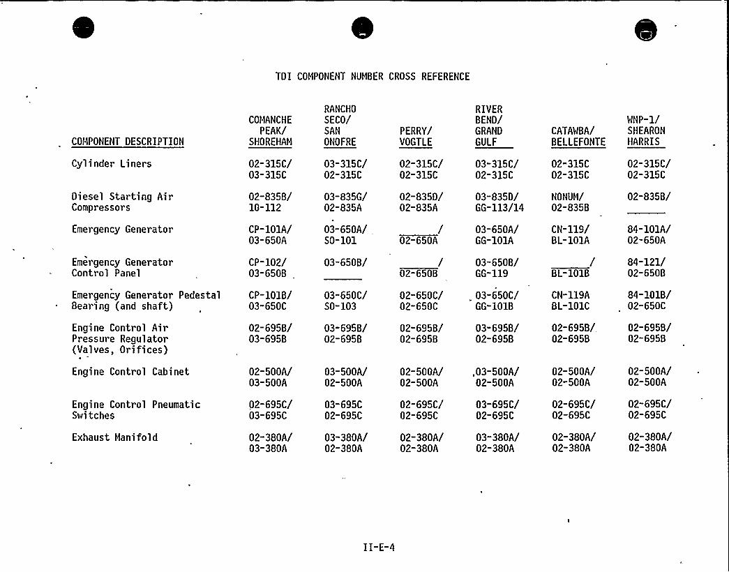
TDI COMPONENT NUMBER CROSS REFERENCE
COMPONENT DESCRIPTION
Cylinder Liners
Diesel Starting AirCompressors
Emergency Generator
Emergency GeneratorControl Panel
Emergency Generator PedestalBearing (and shaft)
Engine Control AirPressure Regulator(Valves, Orifices)
Engine Control Cabinet
Engine Control PneumaticSwitches
Exhaust Manifold
COMANCHE
PEAK/SHOREHAM
02-315C/03-315C
02-835B/10-112
CP-101A/03-650A
CP-102/03-6508
CP-101B/03-650C
02-695B/03-695B
02-500A/03-500A
02-695C/03-695C
02-380A/03-380A
RANCHO
SECO/SAN
ONOFRE
03-315C/02-315C
03-835G/02-835A
03-650A/S0-101
03-650B/
03-650C/S0-103
03-695B/02-695B
03-500A/02-500A
03-695C02-695C
03-380A/02-380A
PERRY/VOGTLE
02-315C/02-315C
02-835D/02-835A
/02-650A
/02-650B
02-650C/02-650C
02-695B/02-695B
02-500A/02-500A
02-695C/02-695C
02-380A/02-380A
RIVERBEND/GRAND
GULF
03-315C/02-315C
03-835D/GG-113/14
03-650A/GG-101A
03-6508/GG-119
03-650C/GG-1018
03-695B/02-695B
,03-500A/02-500A
03-695C/02-695C
03-380A/02-380A
CATAWBA/BELLEFONTE
02-315C02-315C
NONUM/02-835B
CN-119/BL-101A
/BL-101B
CN-119ABL-101C
02-695B/02-695B
02-500A/02-500A
02-695C/02-695C
02-380A/02-380A
WNP-1/SHEARONHARRIS
02-315C/02-315C
02-8358/
84-101A/02-650A
84-121/02-6508
84-1018/02-650C
02-695B/02-695B
02-500A/02-500A
02-695C/02-695C
02-380A/02-380A
II-E-4
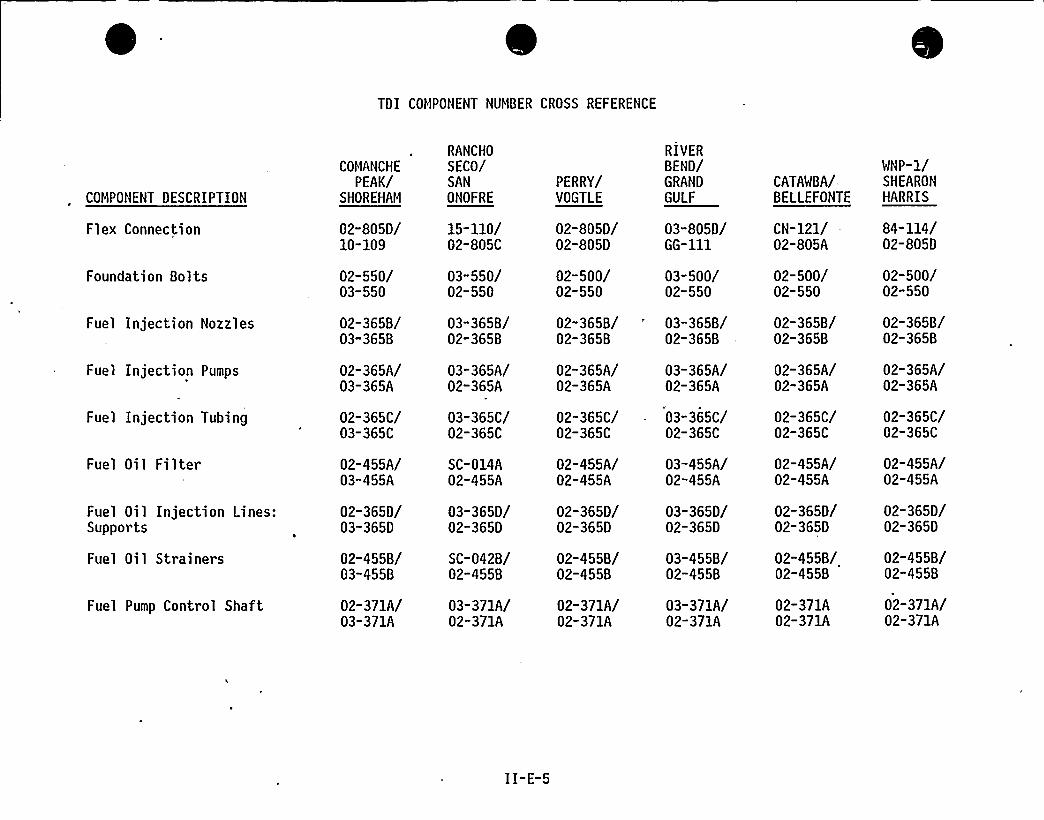
TDI COMPONENT NUMBER CROSS REFERENCE
COMPONENT DESCRIPTION
Flex Connection
Foundation Bolts
Fuel Injection Nozzles
Fuel Injection Pumps
Fuel Injection Tubing
Fuel Oil Filter
Fuel Oil Injection Lines:Supports
Fuel Oil Strainers
Fuel Pump Control Shaft
02-805D/10-109
02-550/03-550
02-365B/03-365B
02-365A/03-365A
02-365C/03-365C
02-455A/03-455A
02-365D/03-365D
02-455B/03-455B
02-371A/03-371A
15-110/02-805C
03-550/02-550
03-365B/02-365B
03-365A/02-365A
03-365C/02-365C
SC-014A02-455A
03-365D/02-365D
SC-042B/02-455B
03-371A/02-371A
RANCHO
COMANCHE SECO/PEAK/ SAN
SHOREHAM ONOFRE
PERRY/VOGTLE
02-805D/02-805D
02-500/02-550
02-365B/02-365B
02-365A/02-365A
02-365C/02-365C
02-455A/02-455A
02-365D/02-365D
02-455B/02-455B
02-371A/02-371A
RIVERBEND/GRAND
GULF
03-805D/GG-ill
03-500/02-550
03-365B/02-365B
03-365A/02-365A
03-365C/02-365C
03-455A/02-455A
03-365D/02-365D
03-455B/02-455B
03-371A/02-371A
CATAWBA/-BELLEFONTE
CN-121/02-805A
02-500/02-550
02-365B/02-365B
02-365A/02-365A
02-365C/02-365C
02-455A/02-455A
02-365D/02-365D
02-455B/02-455B
02-371A02-371A
WNP-1/SHEARONHARRIS
84-114/02-805D
02-500/02-550
02-365B/02-365B
02-365A/02-365A
02-365C/02-365C
02-455A/02-455A
02-365D/02-365D
02-455B/02-455B
02-371A/02-371A
II-E-5
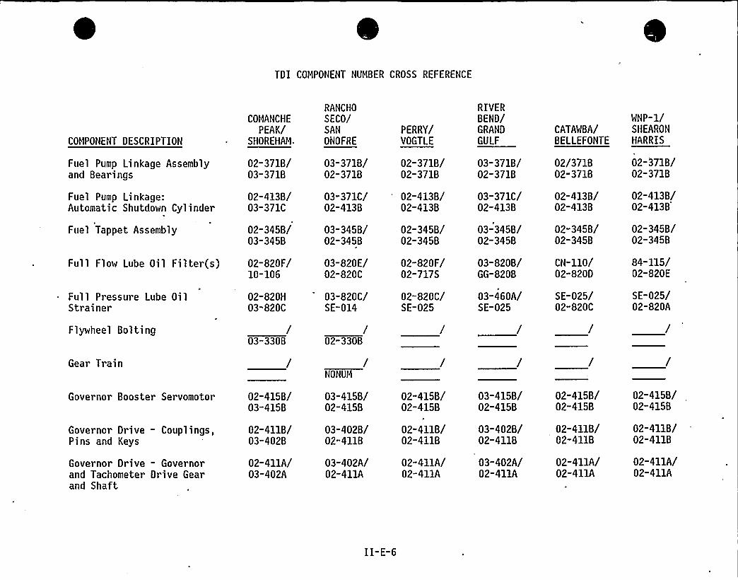
TDI COMPONENT NUMBER CROSS REFERENCE
COMPONENT DESCRIPTION
Fuel Pump Linkage Assemblyand Bearings
Fuel Pump Linkage:Automatic Shutdown Cylinder
Fuel Tappet Assembly
COMANCHE
PEAK/SHOREHAM
02-371B/03-371B
02-413B/03-371C
02-345B/03-345B
Full Pressure Lube OilStrainer
Flywheel Bol ting
Gear Train
02-820H03-820C
/03-330B
Full Flow Lube Oil Filter(s) 02-820F/10-106
RANCHO
SECO/SAN
ONOFRE
03-371B/02-371B
03-371C/02-4138
03-345B/02-345B
03-820E/02-820C
03-820C/SE-014
/02-330B
NONUM
PERRY/VOGTLE
02-371B/02-371B
02-413B/02-413B
02-345B/02-345B
02-820F/02-717S
02-820C/SE-025
RIVERBEND/GRAND
GULF
03-371B/02-371B
03-371C/02-413B
03-345B/02-345B
03-820B/GG-820B
03-460A/SE-025
CATAWBA/BELLEFONTE
02/371B02-371B
02-413B/02-413 B
02-3458/02-345B
CN-110/02-820D
SE-025/02-820C
WNP-1/SHEARONHARRIS
02-371B/02-371B
02-413B/02-413B
02-345B/02-345B
84-115/02-820E
SE-025/02-820A
Governor Booster Servomotor
Governor Drive - Couplings,Pins and Keys
Governor Drive — Governorand Tachometer Drive Gearand Shaft
02-415B/03-415B
02-411B/03-402B
02-411A/03-402A
03-415B/02-415B
03-402B/02-411B
03-402A/02-411A
02-415B/02-415B
02-411B/02-411B
02-411A/02-411A
03-415B/02-415B
03-402B/02-411B
03"402A/02-411A
02-415B/02-415B
02-411B/02-411B
02-411A/02-411A
02-415B/02-415B
02-411B/02-411B
02-411A/02-411A
II-E-6
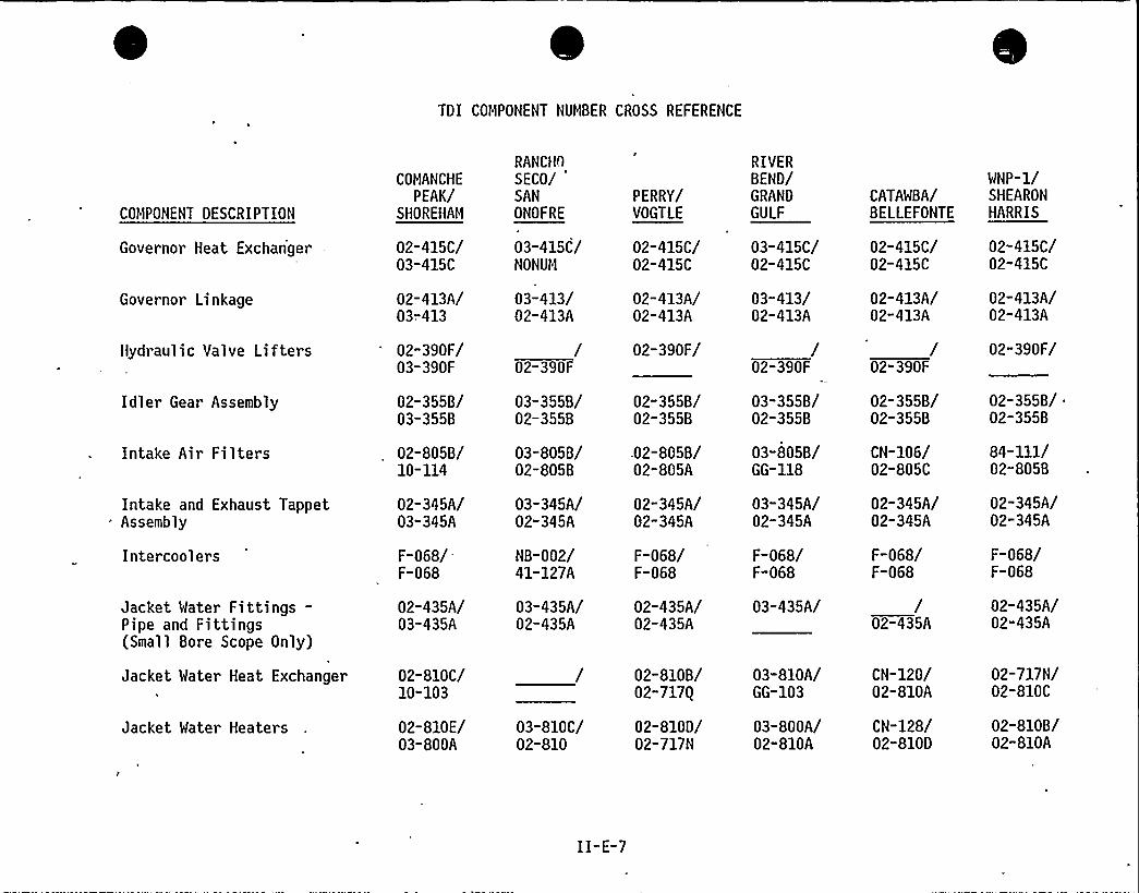
TDI COMPONENT NUMBER CROSS REFERENCE
COMPONENT DESCRIPTION
Governor Heat Exchanger
Governor Linkage
Hydraulic Valve Lifters
Idler Gear Assembly
Intake Air Filters
Intake and Exhaust TappetAssembly
Intercoolers
Jacket Water Fittings—Pipe and Fittings(Small Bore Scope Only)
Jacket Water Heat Exchanger
Jacket Water Heaters
COMANCHE
PEAK/SHOREHAM
02-415C/03-415C
02-413A/03-413
02-390F/03-390F
02-355B/03-355B
02-805B/10-114
02-345A/03-345A
F-068/F-068
02-435A/03-435A
02-810C/10-103
02-810E/03-800A
RANCHO
SECO/'AN
ONOFRE
03-415C/NONUM
03-413/02-413A
/02-390F
03-355B/02-355B
03-805B/02-805B
03-345A/02-345A
NB-002/41-127A
03-435A/02-435A
03-810C/02-810
PERRY/VOGTLE
02-415C/02-415C
02-413A/02-413A
02-390F/
02-355B/02-355B
02-805B/02-805A
02-345A/02-345A
F-068/F-068
02-435A/02-435A
02-810B/02-717Q
02-810D/02-717N
RIVERBEND/GRAND
GULF
03-415C/02-415C
03-413/02-413A
/02-390F
03-355B/02-355B
03-805B/GG-118
03-345A/02-345A
F-068/F-068
03-435A/
03-810A/GG-103
03-800A/02-810A
CATAWBA/BELLEFONTE
02-415C/02-415C
02-413A/02-413A
CN-120/02-810A
CN-128/02-810D
/02-390F
02-355B/02-355B
CN-106/02-805C
02-345A/02-345A
F-068/F-068
/02-435A
WNP-1/SHEARONHARRIS
02-415C/02-415C
02-413A/02-413A
02-390F/
02-717N/02-810C
02-810B/02-810A
02-355B/02-355B
84-111/02-805B
02-345A/02-345A
F-068/F-068
02-435A/02-435A
II-E-7
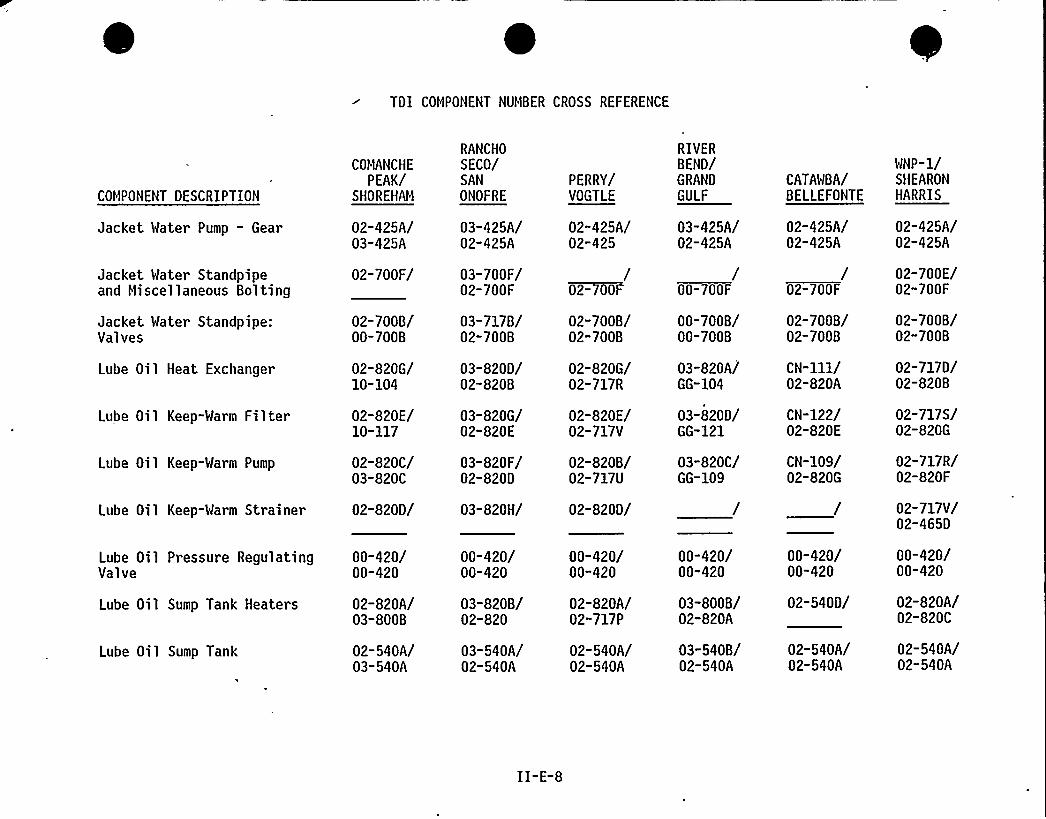
TDI COMPONENT NUMBER CROSS REFERENCE
COMPONENT DESCRIPTION
Jacket Water Pump - Gear
Jacket Water Standpipeand Miscellaneous Bolting
Jacket Water Standpipe:Valves
Lube Oil Heat Exchanger
Lube Oil Keep-Warm Filter
Lube Oil Keep-Warm Pump
Lube Oil Keep-Warm Strainer
Lube Oil Pressure RegulatingValve
Lube Oil Sump Tank Heaters
Lube Oil Sump Tank
COMANCHE
PEAK/SHOREHAM
02-425A/03-425A
02-700F/
02-700B/00-700B
02-820G/10-104
02-820E/10-117
02-820C/03-820C
02-820D/
00-420/00-420
02-820A/03-800B
02-540A/03-540A
RANCHO
SECO/SANONOFRE
03-425A/02-425A
03-700F/02-700F
03-717B/02-700B
03-820D/02-8208
03-820G/02-820E
03-820F/02-820D
03-820H/
00-420/00-420
03-820B/02-820
03-540A/02-540A
PERRY/VOGTLE
02-425A/02-425
/~02- 00F
02-700B/02-700B
02-820G/02-717R
02-820E/02-717V
02-8208/02-717U
02-820D/
00-420/00-420
02-820A/02-717 P
02-540A/02-540A
RIVERBEND/GRAND
GULF
03-425A/02-425A
/00-700F
00-700B/00-700B
03-820A/GG-104
03-820D/GG-121
03-820C/GG-109
00-420/00-420
03-800B/02-820A
03-540B/02-540A
CATAWBA/BELLEFONTE
02-425A/02-425A
/02-700F
02-700B/02-700B
CN-111/02-820A
CN-122/02-820E
CN-109/02-820G
00-420/00-420
02-540D/
02-540A/02-540A
WNP-1/SHEARON
HARRIS
02-425A/02-425A
02-700E/02-700F
02-700B/02-700B
02-717D/02-820B
02-717S/02-820G
02-717R/02-820F
02-717V/02-465D
00-420/00-420
02-820A/02-820C
02-540A/02-540A
II-E-8
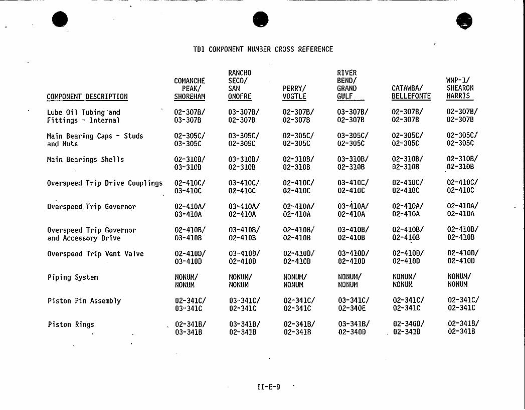
TDI COMPONENT NUMBER CROSS REFERENCE
COMPONENT DESCRIPTION
COMANCHE
PEAK/SHOREHAM
RANCHO
SECO/SANONOFRE
PERRY/VOGTLE
RIVERBEND/GRAND
GULFCATAWBA/BELLEFONTE
WNP-1/SHEARON
HARRIS
Lube Oil Tubing andFittings - Internal
Main Bearing Caps - Studsand Nuts
Main Bearings Shells
02-3078/03-3078
02-305C/03-305C
02-3108/03-3108
Overspeed Trip Governor
Overspeed Trip Governorand Accessory Drive
Overspeed Trip Vent Valve
Piping System
Piston Pin Assembly
Piston Rings
02-410A/03-410A
02-4108/03-4108
02-410D/03-410D
NONUM/NONUM
02-341C/03-341C
02-3418/03-3418
Overspeed Trip Drive Couplings 02-410C/03-410C
03-3078/02-3078
03-305C/02-305C
03-3108/02-3108
03-410C/02-410C
03-410A/02-410A
03-4108/02-4108
03-410D/02-410D
NONUM/NONUM
03-341C/02-341C
03-3418/02-3418
02-3078/02-3078
02-305C/02-305C
02-3108/02-3108
02-410C/02-410C
02-410A/02-410A
02-4108/02-4108
02-410D/02-410D
NONUM/NONUM
02-341C/02-341C
02-3418/02-3418
03-3078/02-3078
03-305C/02-305C
03-3108/02-3108
03-410C/02-410C
03-410A/02-410A
03-4108/02-4108
03-410D/02-410D
NONUM/NONUM
03-341C/02-340E
03-3418/02-340D
02-3078/02-3078
02-305C/02-305C
02-3108/02-3108
02-410C/02-410C
02-410A/02-410A
02-4108/02-4108
02-410D/02-410D
NONUM/NONUM
02-341C/02-341C
02-340D/02-3418
02-3078/02-3078
02-305C/02-305C
02-3108/02-3108
02-410C/02-410C
02-410A/02-410A
02-4108/02-4108
02-410D/02-410D
NONUM/NONUM
02-341C/02-341C
02-3418/02-3418
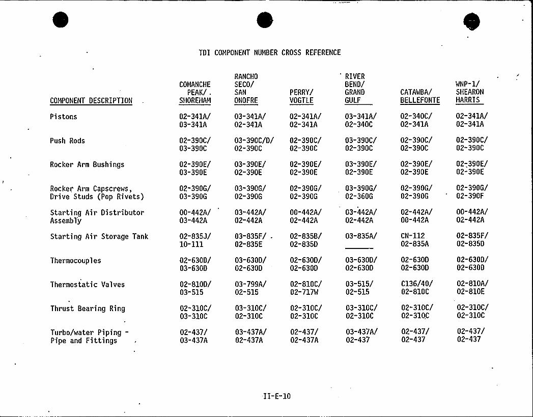
TDI COMPONENT NUMBER CROSS REFERENCE
COMPONENT DESCRIPTION
Pistons
Push Rods
Rocker Arm Bushings
Rocker Arm Capscrews,Drive Studs (Pop Rivets)
Starting Air DistributorAssembly
Star ting Air Storage Tank
Thermocouples
Thermostatic Valves
Thrust Bearing Ring
Turbo/water Piping-Pipe and Fittings
COMANCHE
PEAK/ .
SHOREHAM
02-341A/03-341A
02-390C/03-390C
02-390E/03-390E
02-390G/03-390G
00-442A/03-442A
02-835J/10-111
02-630D/03-630D
02-810D/03-515
02-310C/03-310C
02-437/03-437A
RANCHO
SECO/SAN
ONOFRE
03-341A/02-341A
03-390C/D/02-390C
03-390E/02-390E
03-390G/02-390G
03-442A/02-442A
03-835F/ .
02-835E
03-630D/02-630D
03-799A/02-515
03-310C/02-310C
03-437A/02-437A
PERRY/VOGTLE
02-341A/02-341A
02-390C/02-390C
02-390E/02-390E
02-390G/02-390G
00-442A/02-442A
02-835B/02-835D
02-630D/02-630D
02-810C/02-717W
02-310C/02-310C
02-437/02-437A
RIVERBEND/GRAND
GULF
03-341A/02-340C
03-390C/02-390C
03-390E/02-390E
03-390G/02-360G
03-442A/02-442A
03-835A/
03-630D/02-630D
03-515/02-515
03-310C/02-310C
03-437A/02-437
CATAWBA/BELLEFONTE
02-340C/02-341A
02-390C/02-390C
02-390E/02-390E
02-390G/02-390G
02-442A/00-442A
CN-11202-835A
02-630D02-630D
C136/40/02-810C
02-310C/02-310C
02-437/02-437
WNP-1/SHEARONHARRIS
02-341A/02-341A
02-390C/02-390C
02-,390E/02-390E
02-390G/02-390F
00-442A/02-442A
02-835F/02-835D
02-630D/02-630D
02-810A/02-810 E
02-310C/02-310C
02-437/02-437
II-E-10
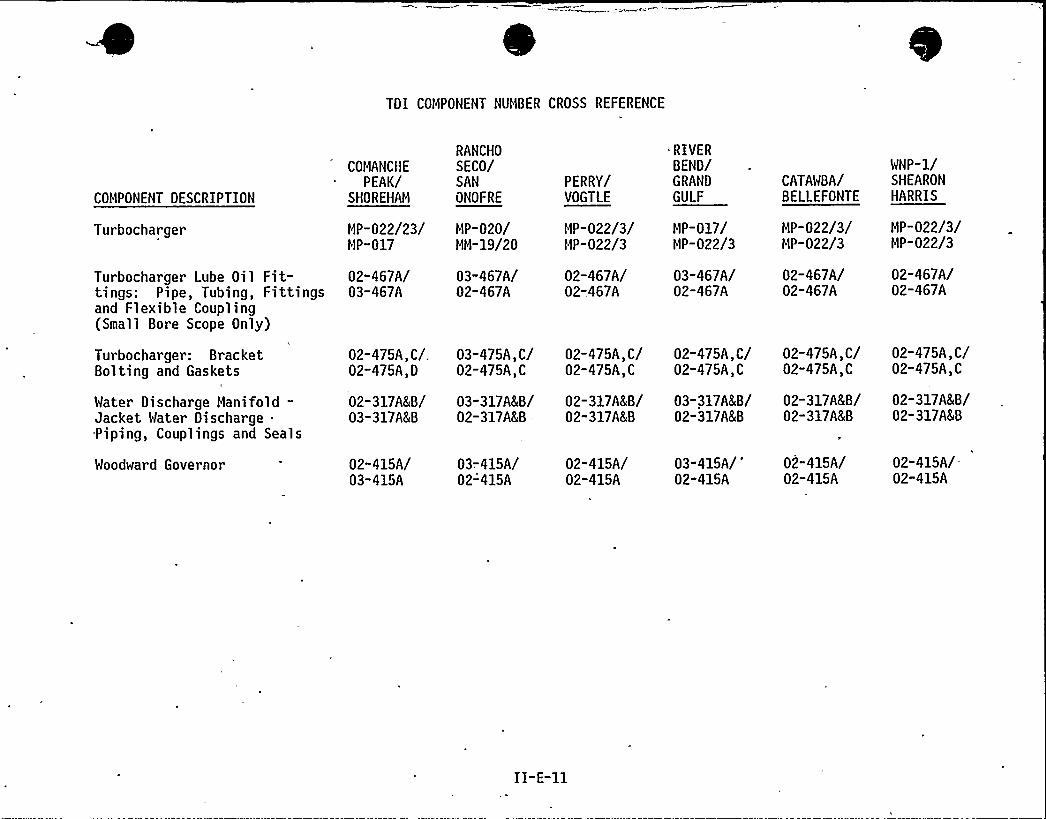
TDI COMPONENT NUMBER CROSS REFERENCE
COMPONENT DESCRIPTION
Turbocharger
Turbocharger Lube Oil Fit-tings: Pipe, Tubing, Fittingsand Flexible Coupling(Small Bore Scope Only)
Turbocharger: BracketBolting and Gaskets
Water Discharge Manifold-Jacket Water Discharge .
Piping, Couplings and Seals
Woodward Governor
COMANCHE
PEAK/SHOREHAM
HP-022/23/MP-017
02-467A/03-467A
02-475A,C/,02-475A,D
02-317A8 B/03-317A&B
02-415A/03-415A
RANCHO
SECO/SANONOFRE
HP-020/HH-19/20
03-467A/02-467A
03-475A,C/02-475A,C
03-317A8B/02-317A8 B =-
03-415A/02-415A
PERRY/VOGTLE
MP-022/3/HP-022/3
02-467A/02-467A
02-475A,C/02-475A,C
02-317A8 B/02-317A8 B
02-415A/02-415A
'RIVERBEND/GRAND
GULF
HP-017/HP-022/3
03-467A/02-467A
02-475A,C/02-475A,C
03-317A8 B/02-317A8 B
03-415A/'2-415A
CATAWBA/BELLEFONTE
HP-022/3/MP-022/3
02-467A/02-467A
02-475A,C/02-475A,C
02-317A8 B/02-317A8 B
02-415A/02-415 A
WNP-1/SHEARON
HARRIS
HP-022/3/MP-022/3
02-467A/02-467A
02-475A,C/02-475A,C
02-317A8B/02-317A8 B
02-415A/02-415A
ATTACHMENT 1
SERIAL: NLS-84-522
(978PPC/ccc)
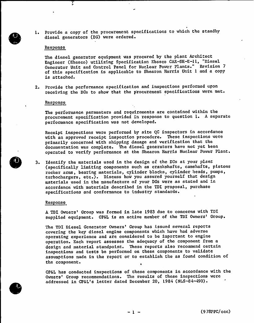
Provide a copy of the procurement specifications to which the standbydiesel generators (DG) were ordered.
~Res onse
The diesel generator equipment was procured by the plant ArchitectEngineer (Ebasco) utilizing Specification Ebasco CAR-SH-E-11, "DieselGenerator Unit and Control Panel for Nuclear Power Plants." Revision 7
of this specification is applicable to Shearon Harris Unit 1 and a copyis attached.
2 ~ Provide the performance specification and inspections performed uponreceiving the DGs to show that the p'rocurement specifications were met.
~Res onse
The performance parameters and requirements are contained within theprocurement specification provided in response to question 1. A separateperformance specification was not developed.
Receipt inspections were performed by site QC inspectors in accordancewith an approved receipt inspection procedure. These inspections wereprimarily concerned with shipping damage and verification that thedocumentation was complete. The diesel generators have not yet beenoperated to verify performance at the Shearon Harris Nuclear Power Plant.
3 ~ Identify the materials used in the design of the DGs at your plant(specifically limiting components such as crankshafts, camshafts, pistonsrocker arms, bearing materials, cylinder blocks, cylinder heads, pumps,turbochargers, etc.). Discuss how you assured yourself that designmaterials used in the manufacture of your DGs were as stated and inaccordance with materials described in the TDI proposal, purchasespecifications and conformance to industry standards.
~Res onse
A TDI Owners'roup was formed in late 1983 due to concerns with TDIsupplied equipment. CPSL is an active member of the TDI Owners'roup.
The TDI Diesel Generator Owners'roup has issued several reportscovering the key diesel engine components which have had adverseoperating experience and are considered to be important to engineoperation. Each report assesses the adequacy of the component from a
design and material standpoint. These reports also recommend certaininspections and tests be performed on these components to validateassumptions made in the report or to establish the as found condition ofthe component.
CP6L has conducted inspections of these components in accordance with theOwners'roup recommendations. The results of these inspections wereaddressed in CPSL's letter dated December 20, 1984 (NLS-84-490).
(9 78PPC/ccc)
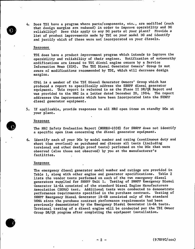
Does TDI have a program where parts/components, etc.', are modified (suchthat design margins are reduced) in order to improve operability and DG
reliability? Does this apply to any DG parts at your plant? Provide alist of product improvements made by TDI on your model DG and identifyand justify which of these were not incorporated on your diesels.
~Res onse
TDI does have a product improvement program which intends to improve theoperability and reliability of their engines. Notification of noteworthymodifications are issued to TDI dies'el engine owners by a ServiceInformation Memo (SIM). The TDI Diesel Generator Owners'roup is notaware of modifications recommended by TDI, which will decrease designmargins.
CP6L is a member of the TDI Diesel Generator Owners'roup which hasproduced a report to specifically address the SHNPP diesel generatorequipment. This report is referred to as the Phase II DR/QR Report andwas provided to the NRC in a letter dated December 20, 1984. The reportaddresses the improvements which have been incorporated into the SHNPP
diesel generator equipment.
If applicable, provide responses to all NRC open items on standby DGs atyour plant.
~Res onse
The NRC Safety Evaluation Report (NUREG-1038) for SHNPP does not identifya specific open item concerning the diesel generator equipment.
Identify each of your DGs by model number and rating (continuous duty andshort time overload) as purchased and discuss all tests (includingtorsional and other design proof tests) performed on the DGs that wereobserved (also those not observed) by you at the manufacturer'sfacilities.
~Res onse
The emergency diesel generator model number and ratings are provided inTable 1, along with other engine and generator specifications. Table 2
lists the vendor tests performed on each of the two emergency dieselgenerators supplied for SHNPP Unit 1. Testing of SHNPP Emergency DieselGenerator 1A-SA consisted of the standard Diesel Engine ManufacturersAssociation (DEMA) test. Additional tests were conducted to demonstrateperformance requirements specified in the purchase contract. Testing ofSHNPP Emergency Diesel Generator 1B-SB consisted only of the standardDEMA since the purchase contract p'erformance requirements had beenpreviously demonstrated by the Emergency Diesel Generator 1AHA tests.Torsional testing of a diesel engine will be conducted per the TDI OwnerGroup DR/QR program after completing the equipment installation.
(9 78P PC/ccc)
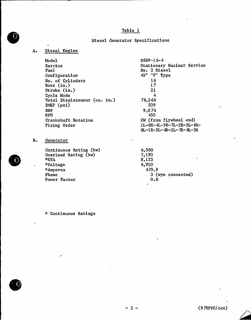
Table 1
Diesel Generator Specifications
ModelServiceFuelConfigurationNo. of CylindersBore (in.)Stroke (in.)Cycle ModeTotal Displacement (cu. in.)BMEP (psi)BHPRPM
Crankshaft RotationFiring Order
DSRV-1 6-4Stationary Nuclear ServiceNo. 2 Diesel45'V" Type
161721
476,266
2099,074
450CW (from flywheel end)1L-8R-4L-5R-7L-2R-3L-6R-8L«1R-5L- 4R-2L- 7R- 6L-3R
Generator
Continuous Rating (kw)Overload Rating (kw)*KVA*Voltage*AmperesPhasePower Factor
6,500711508,1256,900
679. 93 (wye connected)0.8
* Continuous Ratings
(9 78P PC/ccc)
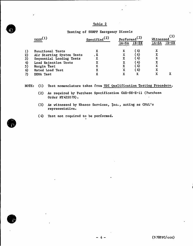
Table 2
Testing of SHNPP Emergency Diesels
TEST(') S ecified( Performed (3)IA-SA IB-SB
(3)Witnessed1A-SA 1B-SB
1) Functional Tests2) Air Starting System Tests3) Sequential Loading Tests4) Load Rejection Tests5) Margin Test6) Rated Load Test7) DEMA Test
X,X
XXXXX
XXXXXXX
(4)(4)(4)(4)(4)(4)
X
XXXXXXX
NOTE: (1) Test nomenclature taken from TDI uglification Testin Procedure.
(2) As required by Purchase Specification CAR-SH-E-11 (PurchaseOrder NY435079) .
(3) As witnessed by Ebasco Services, Inc., acting as CPSL'srepresentative.
( 4) Test not required to be performed.O
(9 78PPC/ccc)
7. In addition to qualification tests that were performed in accordance withRegulatory Guides 1.9 and 1.108, and IEEE Standard 387, describe allother onsite tests performed on your DGs.
~Res onse
The emergency diesel generator (EDG) installation at SHNPP isapproximately 95 percent complete. Turnover of emergency dieselgenerator and associated, auxiliary systems from the construction phase tothe startup testing phase will commence in early 1985. Testing to beperformed is described in the SHNPP FSAR Sections 1.8, 8.3.1, and 14.2.
The start-up test phase will be modified as necessary to incorporaterecommendations made as a result of the TDI Diesel Owners'roup DesignReview and Quality Revalidation program for SHNPP Unit 1 EDG
installation.
Test reports will be written and retained in accordance with siteprocedures.
8. In addition to any deficiency reports already provided to the NRC,summarize and describe problems encountered and resolved duringinstallation and preliminary operation of the DGs. During this period,were any unusual or abnormal operations observed such as excessivevibration noise, etc., and how were these conditions corrected. Providea detailed summary of the complete operating histories of your DGs.
~Res onse
During the installation of the emergency diesel generators the followingproblems were encountered:
A. The below listed conditions were found prior to installation:
a. Six pole washers on the rotors were found to be cracked orbroken.
b. One wire hold-down stud on the rotor was damaged.
c. Pour stator cover plate studs were broken off.
d. One rotor would not register on a megger due to condensationfound when crate was opened.
The above noted conditions were processed in accordance with siteprocedures and all repairs have been made.
(9 78P PC/ccc)
B. During the preparation and installation process, some clarificationsand additional information had to be obtained to supplement theinstruction manual. This was not considered a major problem but ismentioned here to ensure completeness of response. Examples are:
a. The manual does not state any tolerances on specified torquingvalues.
Tolerances were provided by the vendor and issued per a FieldChange Request.
b. The vendor manual states that the connecting bolts for the rotor/flywheel/engine flange are to be a press fit. However, themanual also states that mechanical devices are not to be used toinstall the bolts.
The vendor representative stated that a porta~ower jack may beused to push bolts through the flanges.
c. Roll pins are installed between the nut crown and through the,connecting bolt for the rotor/engine/flywheel flangeconnection. Several instances occurred where once the connectingbolts were torqued to their specified value the holes in thebolts and nut crown did not line up to allow installation of rollpins. The manual states the nuts are then to be tightened untilopening comes up. However, no maximum torque or alternate methodof alignment are given to install the roll pins.
Vendor representative supplied the required maximum torque valueand alternate method for installation (i.e., shaving nuts).
CPGL's letter dated December 20, 1984 (NLS-84-490) discusses theinspections performed and changes implemented on the dieselgenerators as a result of the TDI Diesel Generator Owners'roupprogram. This work will be performed prior to operating theequipment at the site. The SHNPP diesel generators are presentlyscheduled for initial operation in May 1985.
9. Tabulate, compare and discuss differences in present actual DG loading toestimated loads included in the procurement specifications. Identify themagnitude of the increased load (if any) on the DGs and describe how theincreased loading affects the DG capability with regard to reservemargin.
~Res ense
The procurement specification (provided in response to question 1)contains electrical loading information and tabulates the data in SketchNo. CAR-2166&29, Rev. 6 for load blocks 1 through 8. Per this sketchthe maximum tabulated load for blocks 1 through 8 is 5322.55 kw.
(9 78PPC/ccc)
A recent review of the estimated loading on the diesel generatorsindicates that the anticipated blocks 1 through 8 loading is about 70 kw
less than identified in the procurement specification. The followingtabulates the summation of the 1E loads from the recent review:
Blocks 1-8 Block 9 Total~En ine Condition Load, kw Load, kw Load, kw
A Safe Shutdown 4821.05 703 552 4.05LOCA 52 47. 55 3 44. 5 5592.05
B Safe Shutdown 4823. 05 748. 5 55 71. 55LOCA 5249.55 348.5 5598.05
The present maximum load of 5598.05 kw is substantially less than the6500 kw design rating for the diesel generators. However, these numbersare subject to revision particularly in light of the cancellation ofSHNPP Unit 2.
If DG loading has increased from that specified in the procurementspecifications, has it been necessary to upgrade the standby DGs to meetthe new load requirements? If DG upgrading has been performed, provide adetailed description of the upgrading accomplished on your DGs? What isthe revised manufacturer's rating for each upgraded unit for normalcontinuous duty and short time overload conditions? Is the DG built-indesign margin (after upgrading) still within the recommendations of IEEEStandard 387. What is the reserve load carrying capability (margin) ofyour upgraded DGs?
~Res onse
The diesel generator rating has not been increased from that specified inthe procurement specification.
In light of the problems that have been identified to date with Delavaldiesels, discuss your plans to perform an internal visual inspection ofeach standby DG with regard to potential crankshaft and/or web cracks asidentified at the Shoreham Station and provide a detailed discussion ofyour plans to perform any nondestructive testing (NDT) such as dyepenetrant testing, etc., as deemed appropriate to assure absence ofcracks at these locations or at any other locations where cracks may havebeen observed. Discuss schedules for such testing.
~Res onse
As a result of the failure of the Shoreham crankshaft, the TDI DieselGenerator Owners'roup identified the crankshaft as a generic componentfor analysis in Phase I of the program.
Failure Analysis Associates (FaAA) completed its analysis of crankshaftsfor the DSR-48, DSRV-1 6-4, DSRV-12, and DSRV-20 diesel engines. Thesereports were forwarded to the NRC for review in letters dated April 20,1984 (Serial No. TDI-17), May 24, 1984 (Serial.No. OGTP-39), and June 15,1984 (Serial No. OGTP-76) ~
(9 78PPC/ccc)
The FaAA reports recommend torsiograph testing of one crankshaft at eachplant and NDE inspection of the oil holes in the main journals number 4,
6, and 8 for the DSRV-16-4 crankshafts. The torsiograph of onecrankshaft will be performed at SHNPP during the initial diesel generatortesting. The NDE inspection of the SHNPP oil holes in the main journals(journals 2 through 9) has been successfully completed by FaAA NDE
personnel on both diesel generators installed at SHNPP. Results of thisinspection have been forwarded to the TDI Owners'roup technicalstaff. This information was also discussed in 'CP&L's December 20, 1984NRC submittal.
Justify that the standby DGs at your plant are sufficiently reliable thatthere will be reasonable assurance that the facility can operate withoutundue risk to the health and safety of the public.
Your, justification should include, but not be limited to the following:(1) quality assurance program conducted by you during procurement,manufacturing and receipt of your DGs, (2) your assessment of the TDImanufacturing process, inspection, and quality assurance programconducted during manufacture of your DGs, (3) your assessment of TDIresponsiveness to problems that have occurred with your engines duringinstallation and preliminary operation including assessment of TDIperformance, (4) comparison of your DGs with all other TDI emergency DG
models now in use or to be used in other nuclear generating stations (andother non-nuclear facilities) to show that the conditions and/or failuremodes present at Shoreham will not occur at your plant and at othernuclear plants; provide any supporting information that may be obtainedfrom nonnuclear installations, (5) independent revie~ of verification ofany TDI design calculations for critical components of your DGs, and/orother means used to assure that your DGs are designed to DEMA standardsand applicable industry codes and standards, and ( 6) your overallassessment of the DGs at your plant with regard to TDI system design,operating experience to date, and system dependability, availability, andreliability to warrant operation of your plant.
Response
Ebasco Services, Inc. was employed by CP&L as the plant's ArchitectEngineer (A/E) during the design and construction of the SHNPP. As theplant's A/E, Ebasco procured the SHNPP diesel generator equipment. Thespecification provided in response to Question 1 shows that the dieselgenerators were purchased as nuclear safety-related Class 1E and wererequired to be covered by a vendor quality assurance program.
The Quality Assurance Program for procurement, manufacturing and releasefor shipment was formulated and implemented by Ebasco Services Inc. afterreview and concurrence by CP&L.
(9 78PPC/ccc)
The installation and assembly process up to the present time has beencompleted with the supervision of Transamerica Delaval representative.The representative has been helpful and informative in resolvinginstallation problems. The vendor representative was also responsive inproviding the needed information to solve problems and answer questionspertaining to QA, electrical systems and piping.
The SHNPP diesel generators are TDI Model DSRV-1 6-4. Similar engines arepresently in use at other nuclear power plants. CP&L is a member of theTDI Diesel Generator Owners'roup (OG) and provided specific informationto the OG on the SHNPP equipment. The OG program has used theinformation, provided by CP&L and other utilities, to develop a data baseand perform a component by component comparison of the CP&L dieselengine. The comparison used failure history data developed by theOwners'roup for nuclear and non-nuclear diesel engines. The aboveprocess is described in the Owners'roup Program Plan as the ComponentSelection process. The Owners'roup has performed an independent DesignReview and/or Quality Revalidation of each component as applicable. Theresults of the SHNPP review were forwarded to the NRC in a letter datedDecember 20, 1984. This letter provided the Owners'roup Phase II DR/QR
Report on the SHNPP equipment.
CP&L believes that the overall Owners'roup program has been beneficial.The Owners'roup program used a two phase approach. The first phaseaddresses generic problems with the TDI diesel engines and is essentiallycomplete. A detailed review was performed to identify the cause of these1 6 problems and to recommend corrective action. The results of thereview identified the need for increased component inspection, betterinstallation procedures, some component design changes and periodiccomponent maintenance and inspection. CP&L and the TDI Diesel GeneratorOwners'roup maintain that the resolution of these 1 6 generic problemshas assured that the diesel generator equipment will perform reliably.As a confirmatory effort, Phase II of the program (the DR/QR report) hasreviewed a substantially larger number of engine components andidentified many improvements for operation and maintenance that willfurther enhance the equipment's reliability.Provide a tabulation of the number of times (including each date ofoccurrence) voltage was lost at the emergency bus(es) requiring operationof the DG(s) including a brief description of each incident. In theabove tabulation, also identify the loss of emergency bus voltage due toloss of offsite power.
~Res ense
The Shearon Harris Nuclear Power Plant is presently under constructionand the installation of the SHNPP emergency diesel generators is not yetcomplete.
Shoreham has identified connecting rod bearing materials are not inaccordance with design specifications on their engines. This conditionmay also exist on all other TDI diesels. Provide assurance the correct
(9 78PPC/ccc)
bearing design and materials have been used in your engines. Should youfind that improper bearings have been used in your diesels, state how andwhen you propose to correct this problem.
~Res onse
The Failure Analysis Associates report on Connecting Rod Bearing Shells(FaAA-84-3-1) discusses the failure mode of the original 11-inch diameterbearings on the Shoreham engines. The report concludes that thereplacement Shoreham 12" diameter bearing shells will not exhibit thesame failure mode. The report also analyzed the DSRV-1 6-4 bearing shelldesign used at SHNPP and .concluded that the design is acceptable. FaAA
was unable to establish that the original bearing shells met designspecifications in the area of tensile strength and elongation. Thereason for the discrepancy was attributed to the inability to obtain alarge enough test specimen on the finished bearing shell; However,tensile and ductile properties of the material were not identified as theroot cause of the failure.
The FaAA report recommends radiography of the bearing shells to ensure nocasting voids greater than .050 inch are present in the critical areas ofthe bearing shells. The FaAA report states that this inspection shouldbe done on a sampling basis.
All connecting rod bearing shells installed on both SHNPP TDI diesels andspare bearing shells have been radiographically examined to the criteriastated in the SHNPP Phase II Design Review/Quality Revalidation Report.A total of six bearing shells (one on diesel 1A-SA and five on diesel1B-SB) were rejected for material porosity or material density belowspecification and will be replaced during engine reassembly. Examinationof spare bearing shells is still in progress.
Most of the piston skirts in the Shoreham diesels were cracked. Becauseof a common cylinder design for all TDI diesels, it is presumed that thiscondition potentially exists on all other TDI diesels. Discuss yourplans, including internal inspection or other means to determine thepotential or actual existence of such cracking. In your response,indicate whether the design and materials are identical to those in theShoreham units; if not identify differences. Identify any correctiveactions you have taken to date or plan to take.
The staff understands that the TDI has a piston design modification tocorrect the above problems. Are you aware of this and has TDItransmitted this service information to you?
~Res onse
The TDI Diesel Generator Owners'roup has completed an extensive reviewof the modified type AF piston skirt originally installed in the Shorehamengines. Failure Analysis Associates reports FaAA-84-2-14, May 23, 1984and FaAA-84-5-8, June 1984 documents this review.
-10- (9 78PPC/ccc)
There are several types of pistons in use in nuclear services. The abovereports deal with the AF and AE piston type. The TDI Diesel GeneratorOwners'roup reported on the AH and AN piston type designs in FailureAnalysis Associates report FaAA-84-10-30, November 1984. CP&L is awareof the various piston types as a result of the Owners'roup review ofthis component.
The piston skirts installed in the SHNPP diesels were originally of theAN design. Due to the timeframe of the SHNPP Diesel Quality RevalidationInspection and that the design review of the AN piston type was notcomplet'e, SHNPP decided to replace all AN piston skirts originallyinstalled with the latest design AE piston skirts. These new componentshave been successfully liquid penetrant and magnetic particle inspected.The Owners'roup has also determined that the AE piston skirts areacceptable.
What maintenance and/or operating practices have you developed to assureoptimum reliability of your diesel generators at your plant7
~Res ones
A review of maintenance practices and recommendations has also beenperformed by the TDI Diesel Generator Owners'roup. This resulted in amaintenance matrix being provided in the SHNPP DR/QR report which wastransmitted to NRC by CP&L's letter of December 20, 1984 (NLS-84-490).With a few exceptions as discussed in that transmittal, CP&L commits tofollowing the Owners'roup recommended maintenance recommendations aspart of the overall SHNPP maintenance program.
What surveillance practices in addition to those required by planttechnical specifications have you instituted to assure optimumreliability of your diesel generators at your plantf
~Res onse
The TDI Diesel Generator Owners'roup program has developed amaintenance matrix for this equipment based upon documentation review.The maintenance matrix is provided in the SHNPP DR/QR Report(Appendix II) and includes surveillance items which should be checked ona daily basis.
CP&L's letter of December 20, 1984 (NLS-84-490) transmitted the DR/QRreport to NRC and, except as noted in the transmittal, committed toincorporating the Owners'roup recommendations into the overall SHNPP
program.
— 11 (9 78PPC/ccc)

0
Related Documents