Forward and Inverse Source Modeling Zeynep AKALIN ACAR 12th EEGLAB Workshop, San Diego November 19, 2010

Welcome message from author
This document is posted to help you gain knowledge. Please leave a comment to let me know what you think about it! Share it to your friends and learn new things together.
Transcript

Forward and Inverse Source Modeling
Zeynep AKALIN ACAR 12th EEGLAB Workshop, San Diego November 19, 2010

Outline
! Basic definitions ! Forward model errors ! Example: epilepsy source localization

Source of Brain Electrical Activity
Dipole ‘d’ is defined by is position and
direction
Dipole representation of current sources

Potentials on the scalp

Forward and inverse problem Forward Problem
Inverse Problem
EEG/ MEG

Infinite homogeneous medium
Field lines of a point dipole
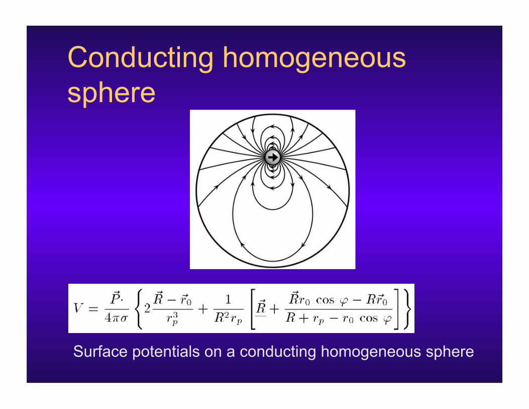
Conducting homogeneous sphere
Surface potentials on a conducting homogeneous sphere

Multi-layer sphere
Concentric conducting spheres [Rush and Driscoll, 1969]

Analytical Head Models ! Spheroid ! Homogeneous Sphere ! Multi-Layer Sphere
– 3-Layer: Scalp, Skull, Brain – 4-Layer: Scalp, Skull, CSF, Brain

Human head

Numerical methods ! Boundary Element Method (BEM) ! Finite Element Method (FEM) ! Finite Difference Method (FDM)
Meijs et al, 1989
Yan et al, 1991

Formulation Integral equation for Potential Field:
kth surface
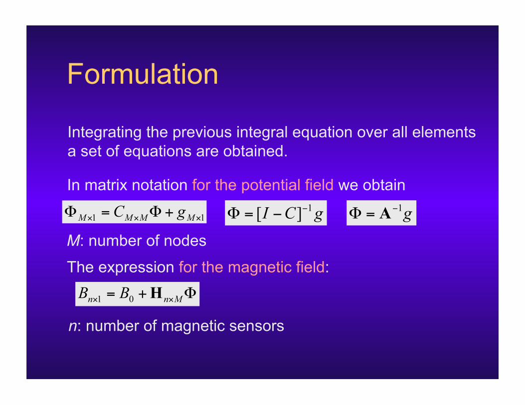
Formulation
In matrix notation for the potential field we obtain
M: number of nodes
Integrating the previous integral equation over all elements a set of equations are obtained.
The expression for the magnetic field:
n: number of magnetic sensors

Numerical Head Models
NFT BEM mesh
BEM FEM
Generated using Tetgen from NFT BEM mesh

FEM/BEM comparison
BEM FEM Position of computational points
surface volume
Free choice of computational points
yes yes
System matrix full sparse
Solvers direct iterative
Number of compartments small large
Requires tesselation yes yes
Handles anisotropy no yes

Source models
Equivalent current dipole
Overdetermined Nonlinear optimization
Source space: Brain volume

Source models Distributed source models
Overlapping patches
Source space: Cortical surface

Inverse Problem
Parametric Methods ! Overdetermined ! Searches for parameters
of a number of dipoles ! Nonlinear optimization
techniques ! May converge to local
minima
Imaging Methods ! Underdetermined ! Searches for activation in
given locations. ! Linear optimization
techniques ! Needs additional
constraints

MODELING ERRORS Effects of Forward Model Errors on EEG Source Localization

Head Model Generation ! Reference Head Model
– From whole head T1 weighted MR of subject – 4-layer realistic BEM model
! MNI Head model – From the MNI head – 3-layer and 4-layer template BEM model
! Warped MNI Head Model – Warp MNI template to EEG sensors
! Spherical Head model – 4-layer concentric spheres – Fitted to EEG sensor locations
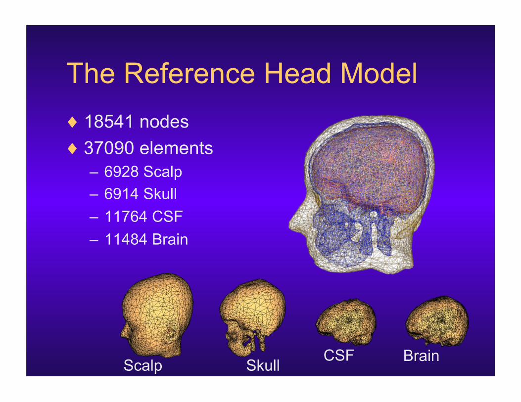
The Reference Head Model ! 18541 nodes ! 37090 elements
– 6928 Scalp – 6914 Skull – 11764 CSF – 11484 Brain
Scalp Brain CSF Skull

The MNI Head Model ! 4-layer
– 16856 nodes – 33696 elements
! 3-layer – 12730 nodes – 25448 elements
Scalp Skull CSF Brain

The Warped MNI Head Model
Registered MNI template
Warped MNI mesh
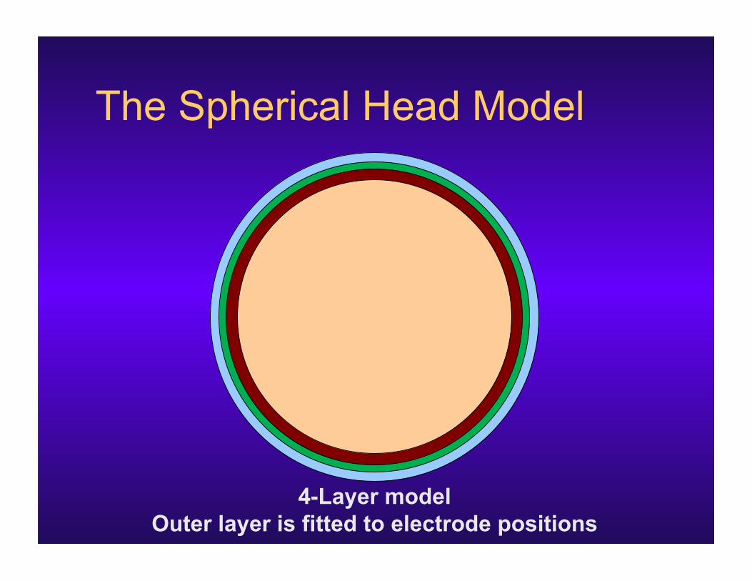
The Spherical Head Model
4-Layer model Outer layer is fitted to electrode positions

Forward Problem Solution
BEM mesh BEM Matrices
BEM Matrices Transfer Matrices
BEM Matrix Generator
Dipole Field Lead Field Matrix
Sensor locations [# of sensors x # of nodes]
[# of sensors x # of dipoles]
Invert Sensor Columns
Generate RHS, Multiply
Model param.
Transfer Matrices

Head Modeling Errors ! Solve FP with reference model
– 3D grid inside the brain. – 3 Orthogonal dipoles at each point – 6,717 dipoles total
! Localize using other head models – Single dipole search.
! Plot location and orientation errors

Spherical Model Location Errors

Spherical Model Direction Errors

3-Layer MNI Location Errors

3-Layer MNI Direction Errors

Source localization errors of patch activity
Forward Problem Source : patches of cortex
Inverse Problem Equivalent current dipole
Reference head model: 4-layer MR-based BEM

Source localization errors of patch activity
cm Patch size = 10 mm Patch size = 6 mm Patch size = 3 mm
Head model: 4-layer MR-based BEM model

Source localization errors of patch activity
cm Patch size = 10 mm Patch size = 6 mm Patch size = 3 mm
Head model: 3-layer spheres

Observations ! Spherical Model
– Location errors more than 4 cm.
! 3-Layer MNI – Large errors where models do not agree. – Higher around chin and the neck regions.
! 4-Layer MNI – Similar to 3-Layer MNI. – Smaller in magnitude.

Electrode co-registration errors ! Solve FP with reference model
! Shift all electrodes and re-register – 5° backwards – 5° left
! Localize using shifted electrodes
! Plot location and orientation errors

5° Backwards Location Errors
mm

5° Left Location Errors
mm

Observations ! Errors increase close to the surface near
electrode locations.
! Changing or incorrectly registering electrodes may cause 5-10 mm localization error.

Effect of skull conductivity Measurement of skull conductivity
In vivo In vitro
Hoekama et al, 2003
MREIT Magnetic stimulation
Current injection
He et al, 2005

Effect of skull conductivity Brain to skull ratio
Rush and Driscoll 1968 80
Cohen and Cuffin 1983 80
Oostendorp et al 2000 15
Lai et al 2005 25
Skull conductivity by age
Measurement Age ! (mS/m) Sd (mS/m)!
Agar-agar phantom – 43.6 3.1
Patient 1 11 80.1 5.5
Patient 2 25 71.2 8.3
Patient 3 36 53.7 4.3
Patient 4 46 34.4 2.3
Patient 5 50 32.0 4.5
Post mortem skull 68 21.4 1.3
Hoekama et al, 2003
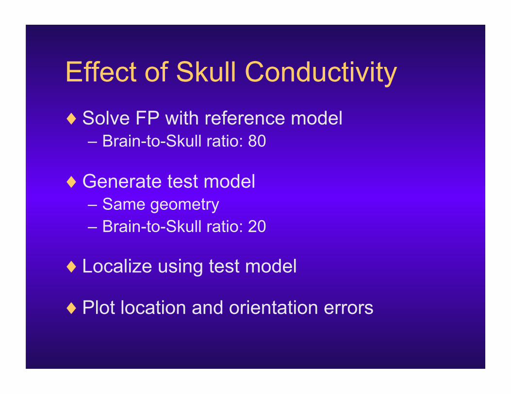
Effect of Skull Conductivity ! Solve FP with reference model
– Brain-to-Skull ratio: 80
! Generate test model – Same geometry – Brain-to-Skull ratio: 20
! Localize using test model
! Plot location and orientation errors

FP ratio: 80 IP ratio: 20
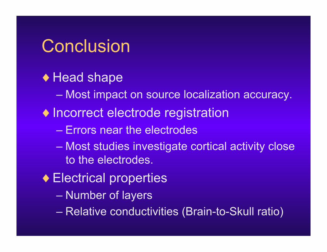
Conclusion ! Head shape
– Most impact on source localization accuracy. ! Incorrect electrode registration
– Errors near the electrodes – Most studies investigate cortical activity close
to the electrodes. ! Electrical properties
– Number of layers – Relative conductivities (Brain-to-Skull ratio)

CASE STUDY Epilepsy Head Modeling

Epilepsy Head Modeling ! Large hole in skull ! Plastic sheet ! A pre-surgery MR and post-
surgery CT ! Differences in brain shape after
surgery ! Co-registration of electrodes
– Subdural – from CT segmentation – Scalp – no digitizer data
MR
CT

Pre-surgery MR 0.86 x 1.6 x 0.86 mm
Post-surgery CT 0.49 x 0.49 x 2.65 mm
Z. Akalin Acar - Head Modeling and Cortical Source Localization in Epilepsy
Head modeling in epilepsy

Scalp, skull and sheet models
Number of elements: Scalp: 10000 Skull: 30000
Plastic sheet : 7000
Z. Akalin Acar - Head Modeling and Cortical Source Localization in Epilepsy

BEM model

Analyzing Epilepsy Recordings
Grid 1 Grid 2
Strip
CT image of the implanted grid electrodes
! Pre-Surgical Evaluation ! Rest Data ! Simultaneous recordings
– 78 iEEG electrodes – 29 scalp electrodes
! Provided by Dr. Greg Worrell, Mayo Clinic
Z. Akalin Acar - Head Modeling and Cortical Source Localization in Epilepsy

iEEG data

Independent Component Analysis
scalp sheet
Z. Akalin Acar - Head Modeling and Cortical Source Localization in Epilepsy

Independent Components
Potentials on scalp Potentials on plastic sheet
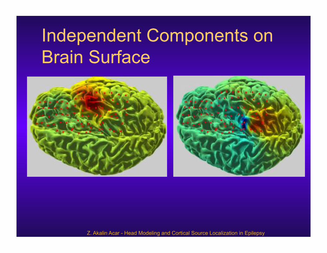
Independent Components on Brain Surface
Z. Akalin Acar - Head Modeling and Cortical Source Localization in Epilepsy

Source Localization Results
Radial source Tangential source
Z. Akalin Acar - Head Modeling and Cortical Source Localization in Epilepsy

Distributed source localization Patch - based source localization
Three Gaussian patches in different scales with radius 10mm, 6mm, and 3mm.

Cortical activity
Cortical activity of the two IC maps
The SBL algorithm managed to identify sparse mixtures of overlapping patches that describe both components.

Cortical activity of seizure components

Final Words ! Accurate source localization
– Realistic head models. – Correct electrode locations. – Signal Processing
! NFT can work with EEGLAB – Create realistic models

References 1. Z. Akalin Acar, S. Makeig, “Neuroelectromagnetic Forward Head
modeling Toolbox”, J. of Neuroscience Methods, vol. 190 (2), 258-270, 2010.
2. Z. Akalin Acar, N. Gencer, “An advanced boundary element method (BEM) implementation for the forward problem of electromagnetic source imaging”, vol. 49, 5011-5028, 2004.
3. Z. Akalin Acar, G. Worrell, S. Makeig, “Patch-based cortical source localization in epilepsy”, Proc. of IEEE EMBC 2009, Minneapolis.
4. Z. Akalin Acar, S. Makeig, “Effect of head models in EEG source localization”, Sfn 2010, San Diego.
Related Documents