Fort Benning, Georgia Solicitation Number W912HN-11-X-CV01 Replace White Elementary School Volume 4 of 4: Technical Divisions 25 - 33 September 2014 U.S. ARMY ENGINEER DISTRICT, SAVANNAH CORPS OF ENGINEERS 100 WEST OGLETHORPE AVENUE SAVANNAH, GEORGIA 31401-3640 US Army Corps of Engineers Savannah District

Welcome message from author
This document is posted to help you gain knowledge. Please leave a comment to let me know what you think about it! Share it to your friends and learn new things together.
Transcript
Fort Benning, Georgia
Solicitation Number W912HN-11-X-CV01 Replace White Elementary School Volume 4 of 4: Technical Divisions 25 - 33 September 2014
U.S. ARMY ENGINEER DISTRICT, SAVANNAH CORPS OF ENGINEERS
100 WEST OGLETHORPE AVENUE SAVANNAH, GEORGIA 31401-3640
US Army Corps of Engineers Savannah District

White Elementary School 11XCV01Ft. Benning, GA
PROJECT TABLE OF CONTENTS
DIVISION 01 - GENERAL REQUIREMENTS
01 11 00 SUMMARY OF WORK01 14 00 WORK RESTRICTIONS01 23 00 BID OPTIONS01 30 00 ADMINISTRATIVE REQUIREMENTS01 32 01.00 10 PROJECT SCHEDULE01 33 00 SUBMITTAL PROCEDURES01 33 29 LEED(TM) DOCUMENTATION01 35 26 GOVERNMENTAL SAFETY REQUIREMENTS01 42 00 SOURCES FOR REFERENCE PUBLICATIONS01 45 00.00 10 QUALITY CONTROL01 45 00.10 10 QUALITY CONTROL SYSTEM (QCS)01 50 00 TEMPORARY CONSTRUCTION FACILITIES AND CONTROLS01 57 16 TEMPORARY PEST CONTROL01 57 19.11 INDOOR AIR QUALITY (IAQ) MANAGEMENT01 57 20.00 10 ENVIRONMENTAL PROTECTION01 57 23 TEMPORARY STORM WATER POLLUTION CONTROL01 58 00 PROJECT IDENTIFICATION01 62 35.10 RECYCLED / RECOVERED/ BIOBASED MATERIALS01 74 19.10 CONSTRUCTION AND DEMOLITION WASTE MANAGEMENT01 78 00 CLOSEOUT SUBMITTALS01 78 23 OPERATION AND MAINTENANCE DATA01 91 00.00 COMMISSIONING
DIVISION 02 - EXISTING CONDITIONS
02 52 61 SOIL NAIL DESIGN/BUILD SPECIFICATION
DIVISION 03 - CONCRETE
03 11 13.00 10 STRUCTURAL CAST-IN-PLACE CONCRETE FORMING03 15 00.00 10 CONCRETE ACCESSORIES03 20 00.00 10 CONCRETE REINFORCING03 30 00.00 10 CAST-IN-PLACE CONCRETE03 35 00.00 10 CONCRETE FINISHING03 39 00.00 10 CONCRETE CURING03 45 00 PRECAST ARCHITECTURAL CONCRETE03 52 00 LIGHTWEIGHT CONCRETE ROOF INSULATION
DIVISION 04 - MASONRY
04 20 00 MASONRY04 21 13.13 NONBEARING MASONRY VENEER/STEEL STUD WALLS
DIVISION 05 - METALS
05 05 23.13 10 ULTRASONIC INSPECTION OF WELDMENTS05 05 23 WELDING, STRUCTURAL05 12 00 STRUCTURAL STEEL05 21 16 LONGSPAN STEEL JOIST FRAMING05 21 19 OPEN WEB STEEL JOIST FRAMING05 30 00 STEEL DECKS05 40 00 COLD-FORMED METAL FRAMING05 50 13 MISCELLANEOUS METAL FABRICATIONS05 51 00 METAL STAIRS05 51 33 METAL LADDERS
PROJECT TABLE OF CONTENTS Page 1

White Elementary School 11XCV01Ft. Benning, GA
05 52 00 METAL RAILINGS
DIVISION 06 - WOOD, PLASTICS, AND COMPOSITES
06 10 00 ROUGH CARPENTRY06 20 00 FINISH CARPENTRY06 41 16.00 10 LAMINATE CLAD ARCHITECTURAL CASEWORK06 61 16 SOLID POLYMER (SOLID SURFACING) FABRICATIONS
DIVISION 07 - THERMAL AND MOISTURE PROTECTION
07 08 27.00 10 BUILDING AIR BARRIER SYSTEM TESTING FOR COMMISSIONING07 11 13 BITUMINOUS DAMPPROOFING07 13 53 ELASTOMERIC SHEET WATERPROOFING07 21 13 BOARD AND BLOCK INSULATION07 21 16 MINERAL FIBER BLANKET INSULATION07 21 29 SPRAYED-ON INSULATION07 22 00 ROOF AND DECK INSULATION07 27 00.45 10 BUILDING AIR BARRIER SYSTEM07 42 13 METAL WALL PANELS07 42 63 FABRICATED WALL AND SOFFIT PANEL ASSEMBLIES07 54 19 POLYVINYL-CHLORIDE ROOFING07 54 23 THERMOPLASTIC POLYOLEFIN (TPO) ROOFING07 60 00 FLASHING AND SHEET METAL07 61 14.00 20 STEEL STANDING SEAM ROOFING07 84 00 FIRESTOPPING07 92 00 JOINT SEALANTS
DIVISION 08 - OPENINGS
08 11 13 STEEL DOORS AND FRAMES 08 11 16 ALUMINUM DOORS AND FRAMES08 14 00 WOOD DOORS08 33 13 METAL ROLLING COUNTER DOORS08 33 23 OVERHEAD COILING DOORS08 34 73 SOUND CONTROL DOOR ASSEMBLIES08 39 54 BLAST RESISTANT DOORS08 41 13 ALUMINUM-FRAMED ENTRANCES AND STOREFRONTS08 44 00 CURTAIN WALL AND GLAZED ASSEMBLIES08 60 45 TRANSLUCENT PANELS08 71 00 DOOR HARDWARE08 81 00 GLAZING
DIVISION 09 - FINISHES
09 06 90 COLOR SCHEDULE09 22 00 SUPPORTS FOR GYPSUM BOARD09 29 00 GYPSUM BOARD09 30 13 CERAMIC TILING09 51 00 ACOUSTICAL CEILINGS09 65 00 RESILIENT FLOORING09 65 66 RESILIENT ATHLETIC FLOORING09 66 23 RESINOUS TERRAZZO FLOORING09 68 00 CARPETING09 77 00 MODULAR WALL SYSTEM09 83 13 ACOUSTICAL WALL TREATMENT09 90 00 PAINTS AND COATINGS
DIVISION 10 - SPECIALTIES
PROJECT TABLE OF CONTENTS Page 2

White Elementary School 11XCV01Ft. Benning, GA
10 10 00 VISUAL COMMUNICATIONS SPECIALTIES10 14 00.20 INTERIOR SIGNAGE10 14 01 EXTERIOR SIGNAGE10 21 13 TOILET COMPARTMENTS10 21 23.16 CUBICLE TRACK, HARDWARE AND CURTAINS10 22 39.10 OPERABLE PANEL PARTITIONS10 26 13 WALL AND CORNER GUARDS10 28 13 TOILET ACCESSORIES10 35 00 FLAGPOLES10 44 16 FIRE EXTINGUISHER CABINETS10 51 13 METAL LOCKERS10 56 26.13 MOBILE STORAGE SHELVING UNITS
DIVISION 11 - EQUIPMENT
11 05 40 COMMON WORK RESULTS FOR FOODSERVICE EQUIPMENT11 06 40.13 FOODSERVICE EQUIPMENT SCHEDULE11 13 10 DOCK LEVELERS11 30 00 RESIDENTIAL EQUIPMENT11 65 00 GYMNASIUM EQUIPMENT11 66 23.13 BASKETBALL EQUIPMENT11 68 13 PLAYGROUND EQUIPMENT11 95 05 KILN
DIVISION 12 - FURNISHINGS
12 21 00 WINDOW BLINDS12 22 00 STAGE CURTAINS12 24 13 ROLLER WINDOW SHADES12 36 00 COUNTERTOPS12 48 13 ENTRANCE FLOOR GRATES AND FRAMES12 93 00 SITE FURNISHINGS
DIVISION 13 - SPECIAL CONSTRUCTION
13 31 23 TENSIONED FABRIC STRUCTURES13 34 20 EXTRUDED ALUMINUM WALKWAY COVERS AND CANOPIES
DIVISION 14 - CONVEYING EQUIPMENT
14 24 00 HYDRAULIC ELEVATORS
DIVISION 21 - FIRE SUPPRESSION
21 13 13.00 10 WET PIPE SPRINKLER SYSTEM, FIRE PROTECTION
DIVISION 22 - PLUMBING
22 00 00 PLUMBING, GENERAL PURPOSE22 05 48.00 20 MECHANICAL SOUND, VIBRATION, AND SEISMIC CONTROL
DIVISION 23 - HEATING, VENTILATING, AND AIR CONDITIONING
23 00 00 AIR SUPPLY, DISTRIBUTION, VENTILATION, AND EXHAUST SYSTEMS23 05 15 COMMON PIPING FOR HVAC23 05 93 TESTING, ADJUSTING, AND BALANCING FOR HVAC23 07 00 THERMAL INSULATION FOR MECHANICAL SYSTEMS23 09 23 LONWORKS DIRECT DIGITAL CONTROL FOR HVAC AND OTHER
PROJECT TABLE OF CONTENTS Page 3

White Elementary School 11XCV01Ft. Benning, GA
BUILDING CONTROL SYSTEMS23 11 25 FACILITY GAS PIPING23 23 00 REFRIGERANT PIPING23 25 00 CHEMICAL TREATMENT OF WATER FOR MECHANICAL SYSTEMS23 52 00 HEATING BOILERS23 64 10 WATER CHILLERS, VAPOR COMPRESSION TYPE23 64 26 CHILLED, CHILLED-HOT, AND CONDENSER WATER PIPING SYSTEMS
DIVISION 25 - INTEGRATED AUTOMATION
25 08 10 UTILITY MONITORING AND CONTROL SYSTEM TESTING25 10 10 UTILITY MONITORING AND CONTROL SYSTEM (UMCS) FRONT END
AND INTEGRATION
DIVISION 26 - ELECTRICAL
26 20 00 INTERIOR DISTRIBUTION SYSTEM26 23 00 SWITCHBOARDS AND SWITCHGEAR26 28 01.00 10 COORDINATED POWER SYSTEM PROTECTION26 41 00 LIGHTNING PROTECTION SYSTEM26 51 00 INTERIOR LIGHTING
DIVISION 27 - COMMUNICATIONS
27 10 00 BUILDING TELECOMMUNICATIONS CABLING SYSTEM27 51 23.10 INTERCOMMUNICATION SYSTEM
DIVISION 28 - ELECTRONIC SAFETY AND SECURITY
28 31 76 INTERIOR FIRE ALARM AND MASS NOTIFICATION SYSTEM
DIVISION 31 - EARTHWORK
31 00 00 EARTHWORK31 11 00 CLEARING AND GRUBBING31 31 16 SOIL TREATMENT FOR SUBTERRANEAN TERMITE CONTROL31 32 11 SOIL SURFACE EROSION CONTROL
DIVISION 32 - EXTERIOR IMPROVEMENTS
32 01 19 FIELD MOLDED SEALANTS FOR SEALING JOINTS IN RIGID PAVEMENTS
32 05 33 LANDSCAPE ESTABLISHMENT32 11 24 GRADED CRUSHED AGGREGATE BASE COURSE FOR PAVEMENT32 11 26.16 BITUMINOUS CONCRETE BASE COURSE32 12 16 HOT-MIX ASPHALT (HMA) FOR ROADS32 13 13.06 PORTLAND CEMENT CONCRETE PAVEMENT FOR ROADS AND SITE
FACILITIES32 16 13 CONCRETE SIDEWALKS AND CURBS AND GUTTERS32 17 23.00 20 PAVEMENT MARKINGS32 18 16.13 PLAYGROUND PROTECTIVE SURFACING32 18 17 POURED-IN-PLACE RUBBER SURFACING32 31 13 WIRE MESH FENCES AND GATES32 31 19 STEEL ORNAMENTAL FENCE SYSTEM32 92 19 SEEDING32 92 23 SODDING32 93 00 EXTERIOR PLANTS
DIVISION 33 - UTILITIES
PROJECT TABLE OF CONTENTS Page 4

White Elementary School 11XCV01Ft. Benning, GA
33 11 00 WATER DISTRIBUTION33 30 00 SANITARY SEWERS33 40 00 STORM DRAINAGE UTILITIES33 82 00 TELECOMMUNICATIONS OUTSIDE PLANT (OSP)
-- End of Project Table of Contents --
PROJECT TABLE OF CONTENTS Page 5

White Elementary School 11XCV01Ft. Benning, GA
SECTION TABLE OF CONTENTS
DIVISION 25 - INTEGRATED AUTOMATION
SECTION 25 08 10
UTILITY MONITORING AND CONTROL SYSTEM TESTING
04/06
PART 1 GENERAL
1.1 REFERENCES 1.2 DEFINITIONS 1.2.1 Algorithm 1.2.2 Analog 1.2.3 Analog to Digital (A/D) Converter 1.2.4 CEA-709.1-C 1.2.5 Application Specific Controller 1.2.6 Architecture 1.2.7 Binary 1.2.8 Building Point of Connection (BPOC) 1.2.9 Control Wiring 1.2.10 Demand 1.2.11 Diagnostic Program 1.2.12 Distributed Control 1.2.13 Graphical User Interface (GUI) 1.2.14 Integration 1.2.15 Interoperable 1.2.16 LonTalk(r) 1.2.17 LONWORKS(r) 1.2.18 LONMARK(r) International (LONMARK(r) Interoperability Assoc.) 1.2.19 LonMarked(r) 1.2.20 LONWORKS(r) Application Specific Controller (ASC) 1.2.21 LONWORKS(r) General Purpose Programmable Controller 1.2.22 LONWORKS(r) Network Services (LNS) 1.2.23 Network 1.2.24 Network Configuration Tool 1.2.25 Node ID 1.2.26 Node 1.2.27 Operating System (OS) 1.2.28 Operator Workstation (OWS) 1.2.29 Peripheral 1.2.30 Router 1.2.31 Standard Network Variable Type (SNVT) 1.2.32 UMCS Network Media 1.2.33 XIF 1.2.34 Gateway 1.3 SYSTEM DESCRIPTION 1.3.1 Factory Test 1.3.2 Performance Verification and Endurance Test 1.3.3 Test Equipment and Setup 1.4 SUBMITTALS
PART 2 PRODUCTS
SECTION 25 08 10 Page 1
White Elementary School 11XCV01Ft. Benning, GA
PART 3 EXECUTION
3.1 UMCS AND BUILDING LEVEL DDC TESTING SEQUENCE 3.2 COORDINATION 3.3 PROTECTION 3.4 FACTORY TEST 3.4.1 Factory Test Plan 3.4.2 Test Procedures 3.4.3 Test Report 3.5 FIELD TEST REQUIREMENTS 3.5.1 Start-up Testing 3.5.2 Point-to-Point Testing 3.5.3 Field Calibration 3.5.4 Detailed Functional Testing 3.5.5 Alarms and Interlocks 3.5.6 System Schedules and Setpoints 3.6 PERFORMANCE VERIFICATION TEST 3.6.1 Test Plan 3.6.2 Test Procedures 3.6.3 Test Report 3.7 ENDURANCE TESTING 3.7.1 General 3.7.2 Phase I 3.7.3 Phase II 3.7.4 Phase III 3.7.5 Phase IV 3.7.6 Failure Reports 3.8 ATTACHMENT A
ATTACHMENTS:
ATTACHMENT A
-- End of Section Table of Contents --
SECTION 25 08 10 Page 2
White Elementary School 11XCV01Ft. Benning, GA
SECTION 25 08 10
UTILITY MONITORING AND CONTROL SYSTEM TESTING04/06
PART 1 GENERAL
1.1 REFERENCES
The publications listed below form a part of this specification to the extent referenced. The publications are referred to within the text by the basic designation only.
CONSUMER ELECTRONICS ASSOCIATION (CEA)
CEA-709.1-C (2010) Control Network Protocol Specification
CEA-709.3 (1999; R 2004) Free-Topology Twisted-Pair Channel Specification
CEA-852-B (2010) Tunneling Component Network Protocols Over Internet Protocol Channels
1.2 DEFINITIONS
1.2.1 Algorithm
A set of well-defined rules or procedures for solving a problem or providing an output from a specific set of inputs.
1.2.2 Analog
A continuously varying signal value (temperature current, velocity, etc.).
1.2.3 Analog to Digital (A/D) Converter
An A/D converter is a circuit or device whose input is information in analog form and whose output is the same information in digital form.
1.2.4 CEA-709.1-C
"Control Network Protocol Specification", Standard communication protocol for networked control systems that provides peer-to-peer communications.
1.2.5 Application Specific Controller
A device that is furnished with a pre-established built in application that is configurable but not re-programmable.
1.2.6 Architecture
Architecture is the general organization and structure of hardware and software.
SECTION 25 08 10 Page 3
White Elementary School 11XCV01Ft. Benning, GA
1.2.7 Binary
A two-state system where an "ON" condition is represented by a high signal level and an "OFF" condition is represented by a low signal level.
1.2.8 Building Point of Connection (BPOC)
The point of connection between the UMCS network backbone and the building network backbone. The hardware at this location, which performs/provides the connection is referred to as the BPOC Hardware.
1.2.9 Control Wiring
This includes conduit, wire, and wiring devices to install complete HVAC control systems, including motor control circuits, interlocks, sensors, PE and EP switches, and like devices. This also includes all wiring from node to node, and nodes to all sensors and points defined in the I/O summary shown on drawings or specified herein, and required to execute the sequence of operation. Does not include line voltage power wiring.
1.2.10 Demand
The maximum rate of use of electrical energy averaged over a specific interval of time, usually expressed in kW.
1.2.11 Diagnostic Program
Machine-executable instructions used to detect and isolate system and component malfunctions.
1.2.12 Distributed Control
A system whereby all control processing is decentralized and independent of a central computer. In regards to a LonWorks based system, it also means where the control logic for a single piece of building level control resides in more than one controller (node).
1.2.13 Graphical User Interface (GUI)
Human-machine interfacing allows the operator to manage, command, monitor, and program the system.
1.2.14 Integration
Establishing communication between two or more systems to create a single system.
1.2.15 Interoperable
Two devices are interoperable if installed into the same system and they communicate with each other without the use of another device (such as a gateway).
1.2.16 LonTalk(r)
Open communication protocol developed by the Echelon(r) Corporation.
SECTION 25 08 10 Page 4

White Elementary School 11XCV01Ft. Benning, GA
1.2.17 LONWORKS(r)
The communication technology developed by Echelon(r) Corporation for control systems developed. The technology is based on the CEA-709.1-C protocol and employs interoperable devices along with the capability to openly manage these devices using a network configuration tool.
1.2.18 LONMARK(r) International (LONMARK(r) Interoperability Assoc.)
Standards committee consisting of numerous independent product developers and systems integrators dedicated to determining and maintaining the interoperability guidelines for the LONWORKS(r) industry.
1.2.19 LonMarked(r)
A device that has been certified for compliance with LonMark(r) standards by the LonMark(r) International.
1.2.20 LONWORKS(r) Application Specific Controller (ASC)
A networked device or node that contains a complete, configurable application that is specific to a particular task.
1.2.21 LONWORKS(r) General Purpose Programmable Controller
A programmable control product, that unlike an ASC, is not installed with a fixed factory-installed application program. The application in the controller is custom software produced by the integrator specifically for the project.
1.2.22 LONWORKS(r) Network Services (LNS)
The database format for addressing nodes and variable bindings node-to-node.
1.2.23 Network
A system of distributed control units that are linked together on a communication bus. A network allows sharing of point information between all control units. Additionally, a network provides central monitoring and control of the entire system from any distributed control unit location.
1.2.24 Network Configuration Tool
Software used to create and modify the control network database and configure controllers.
1.2.25 Node ID
A unique 48-bit node identification (ID) tag given to each node by Echelon Corporation.
1.2.26 Node
An intelligent LONWORKS(r) device with a node ID and communicates via CEA-709.1-C and is connected to an CEA-709.1-C network.
1.2.27 Operating System (OS)
Software which controls the execution of computer programs and which
SECTION 25 08 10 Page 5
White Elementary School 11XCV01Ft. Benning, GA
provides scheduling, debugging, input/output controls, accounting, compilation, storage assignment, data management, and related services.
1.2.28 Operator Workstation (OWS)
The OWS consists of a high-level processing desktop or laptop computer that provides a graphic user interface to network.
1.2.29 Peripheral
Input/Output (I/O) equipment used to communicate to and from the computer and make hard copies of system outputs and magnetic files.
1.2.30 Router
A device which routes messages destined for a node on another segment subnet or domain of the control network. The device controls message traffic based on node address and priority. Routers may also serve as communication links between powerline, twisted pair, fiber, coax, and RF media.
1.2.31 Standard Network Variable Type (SNVT)
A network variable of a standard format type used to define data information transmitted and receive by the individual nodes.
1.2.32 UMCS Network Media
Transmission equipment including cables and interface modules (excluding MODEMs) permitting transmission of digital information.
1.2.33 XIF
"External Interface File" contains the contents of the manufacturer's product documentation.
1.2.34 Gateway
A device that translates from one protocol to another. Gateways are also called Communications Bridges or Protocol Translators.
1.3 SYSTEM DESCRIPTION
a. The purpose of this Specification is to define generic Factory, Performance Verification, and Endurance Test procedures for Utility Monitoring and Control Systems (UMCS) and building level DDC. These tests are to be used to assure that the physical and performance requirements of UMCS and building level DDC are tested, and that the test results are adequately documented. The Government will base certain contractual decisions on the results of these tests.
b. This document covers the factory, performance verification, and endurance test procedures for the Utility Monitoring and Control System (UMCS) and Direct Digital Control for HVAC. It has been written for a host based system where the LONWORKS(r) LNS database resides on the main computer (server) and communicates over the Ethernet (TCP/IP) connection to the field level controller nodes. The system shall be comprised of the server hardware and software, IP network hardware and software, and building point of connection (BPOC) hardware and software.
SECTION 25 08 10 Page 6
White Elementary School 11XCV01Ft. Benning, GA
c. The contractor who provided building level DDC under Section 23 09 23 LONWORKS DIRECT DIGITAL CONTROL FOR HVAC AND OTHER LOCAL BUILDING SYSTEMS is responsible for testing the building level DDC. All control testing and controller tuning required under Section 23 09 23 shall be completed and approved before performing Performance Verification and Endurance Tests under this section.
d. The following UFGS: Section 25 10 10LONWORKS UTILITY MONITORING AND CONTROL SYSTEM (UMCS) and Section 23 09 23 LONWORKS DIRECT DIGITAL CONTROL FOR HVAC AND OTHER LOCAL BUILDING SYSTEMS shall be part of the contract documents.
1.3.1 Factory Test
Conduct a factory test at a company site. Perform some of the basic functions of the UMCS and building level DDC, to assure that the performance requirements of the specifications are met.
1.3.2 Performance Verification and Endurance Test
a. Shall be conducted on hardware and software installed at the jobsite to assure that the physical and performance requirements of specifications are met. Tests on network media shall include all contractor furnished media and shall include at least one type of each device installed.
b. Shall be conducted under normal mode operation, unless otherwise indicated in the initial conditions description for each test. System normal mode describes a condition in which the system is performing its assigned tasks in accordance with the contract requirements.
c. Shall utilize the operator workstation (OWS) to issue commands or verify status data.
1.3.3 Test Equipment and Setup
All test equipment calibrations shall be traceable to NIST. The accuracy of the test equipment and overall test method shall be at least twice the maximum accuracy required for the test. For example, if a temperature sensor has an accuracy of +1 degree F over the executed range, the test instrument used shall have an accuracy of at least +0.5 degree F or better. Provide all test equipment unless otherwise noted in the contract documents.
1.4 SUBMITTALS
Government approval is required for submittals with a "G" designation; submittals not having a "G" designation are for information only. When used, a designation following the "G" designation identifies the office that will review the submittal for the Government. Submit the following in accordance with Section 01 33 00 SUBMITTAL PROCEDURES:
SD-01 Preconstruction Submittals
Factory Test; G
SD-06 Test Reports
UMCS and Building Level DDC Testing Sequence
SECTION 25 08 10 Page 7

White Elementary School 11XCV01Ft. Benning, GA
Performance Verification Test; GEndurance Testing
PART 2 PRODUCTS
Not Used
PART 3 EXECUTION
3.1 UMCS AND BUILDING LEVEL DDC TESTING SEQUENCE
Perform a successful factory test prior to start of installation work, as described in this section. During the installation phase, perform all required field testing requirements on the UMCS and building level DDC as specified in Sections 25 10 10 LONWORKS UTILITY MONITORING AND CONTROL SYSTEM (UMCS) and 23 09 23 LONWORKS DIRECT DIGITAL CONTROL FOR HVAC AND OTHER LOCAL BUILDING SYSTEMS, to verify that systems are functioning and installed in accordance with specifications. Submit field test report prior to start of PVT and endurance testing. After completing all required field testing, perform a successful PVT and endurance test. All tests shall be successfully completed, and test reports received, prior to final acceptance of the UMCS and building level DDC. Perform and document Contractor field test on UMCS and building level DDC.
3.2 COORDINATION
Coordinate the testing schedule with the Government. Coordination shall include controls specified in other sections or divisions which include controls and control devices that are to be part of or interfaced to the UMCS specified in this section.
3.3 PROTECTION
Protect all work and material from damage by the work or workers. The Contractor is liable for any damage caused and responsible for the work and equipment until finally inspected, tested, and accepted. Protect the work against theft, and carefully store material and equipment received onsite that is not immediately installed.
3.4 FACTORY TEST
3.4.1 Factory Test Plan
Prior to the scheduling of the factory tests, provide the Government with a Factory Test Plan for approval, and wait to receive notification of approval of the Test Plan and Procedures before performing the tests. The plan shall include the following, as a minimum:
a. System one-line block diagram of equipment used in the factory test model, indicating servers, workstations, peripherals, network equipment, controllers, and instrumentation.
b. System hardware description used in the factory test.
c. System software description used in the factory test.
d. Listing of control and status points in the factory test model; plus a table with the following information:
SECTION 25 08 10 Page 8
White Elementary School 11XCV01Ft. Benning, GA
(1) Input and output variables.(2) SNVTs for each variable.(3) Expected engineering units for each variable.(4) Node ID.(5) Domain & subnet addressing.
e. Required passwords for each operator access level.
f. List of other test equipment.
3.4.2 Test Procedures
Develop the factory test procedures from the generic test procedures in ATTACHMENT A. The test procedures shall consist of detailed instructions for test setup, execution, and evaluation of test results. Edit the generic test procedure for the provided UMCS and building level DDC. Perform a factory test on a model of the UMCS and building level DDC for the Government to verify the system will function to the requirements of the contract documents. The test architecture shall mimic a two building arrangement. There shall be a TCP/IP layer with two Internet Protocol (IP) to Lon routers. Below each of the routers shall be both programmable (GPPC) and application-specific controllers (ASC). One server and one workstation with printers shall be connected to the IP layer. There shall be simulated input devices connected to controllers to enable the creation of changing variables. If, during testing, the system fails a portion of a test, the Government will inform the Contractor if the entire test or only the portion that failed shall be re-performed. Give the Government a written report of those items which failed, what the problem was, and what was done to correct it. Provide onsite technical support to perform the PVT. ATTACHMENT A presents the generic Test Procedures with the following information:
a. Test identification number.
b. Test title.
c. Objective.
d. Initial conditions (if applicable).
e. Test equipment (if required).
f. Sequence of events.
g. Expected results.
3.4.3 Test Report
Submit a factory final, complete test report after completing the test, consisting of the following, as a minimum:
a. Section one of the submittal shall be a short summary of the factory test.
b. Section two of the submittal shall be a copy of the test plans.
c. Section three shall be the executed test procedure and shall be divided using tabs. Each tab section shall include all pertinent information pertaining to the executed and approved test, showing date and
SECTION 25 08 10 Page 9
White Elementary School 11XCV01Ft. Benning, GA
Government representative who witnessed/approved the test.
3.5 FIELD TEST REQUIREMENTS
The UMCS contractor shall perform and document contractor start-up and field tests as required by Sections 25 10 10 LONWORKS UTILITY MONITORING AND CONTROL SYSTEM (UMCS) and 23 09 23 LONWORKS DIRECT DIGITAL CONTROL FOR HVAC AND OTHER LOCAL BUILDING SYSTEMS. The field test validates that the UMCS and building level DDC are in operation without any problems or system errors prior to starting a PVT. Validate that all software along with all hardware is installed to meet or exceed the contract document requirements. This includes all LONWORKS(r) networking and monitoring hardware and all peripherals associated with the network and hardware. Start-up and field testing shall include:
3.5.1 Start-up Testing
All testing listed in Sections 25 10 10 and 23 09 23 shall be completed.
3.5.2 Point-to-Point Testing
All point-to-point testing of end field devices through proper input/output to graphic and operator interface shall be completed and approved.
3.5.3 Field Calibration
All field calibration shall be completed and approved.
3.5.4 Detailed Functional Testing
Detailed functional tests, verified by the Government that the system operation adheres to the Sequences of Operation.
3.5.5 Alarms and InterlocksAll alarm limits and testing shall be completed.
3.5.6 System Schedules and Setpoints
All schedule start/stops and system setpoints shall be entered, operating, and approved.
3.6 PERFORMANCE VERIFICATION TEST
3.6.1 Test Plan
Prior to the scheduling of the performance verification tests, provide the Government with a Performance Verification and Endurance Test Plan and Procedures for approval, and receive notification of approval of the Test Plan and Procedures. The plan shall include the following, as a minimum:
a. Installed system one-line block diagram, indicating servers, workstations, peripherals, network equipment, controllers, and instrumentation.
b. Installed system hardware description.
c. Installed system software description, including any software revisions made since the factory test.
d. Listing of control and status points installed in the system; plus a
SECTION 25 08 10 Page 10
White Elementary School 11XCV01Ft. Benning, GA
table with the following information:
(1) Input and output variables.(2) SNVTs for each variable.(3) Expected engineering units for each variable.(4) Node ID.(5) Domain & subnet addressing.
e. Required passwords for each operator access level.
f. List of other test equipment.
3.6.2 Test Procedures
Develop the performance verification test procedures from the generic test procedures in ATTACHMENT A. The test procedures shall consist of detailed instructions for test setup, execution, and evaluation of test results. Edit the generic test procedure for the provided UMCS and building level DDC. Perform a performance verification test (PVT) on the completed UMCS and building level DDC for the Government to verify the system is completely functional. If, during testing, the system fails a portion of a test, the Government will inform the Contractor if the entire test or only the portion that failed shall be re-performed. Give the Government a written report of those items which failed, what the problem was, and what was done to correct it. Provide on-site technical support to perform the PVT. ATTACHMENT A presents the generic UMCS Performance Verification Test Procedures with the following information:
a. Test identification number.
b. Test title.
c. Objective.
d. Initial conditions (if applicable).
e. Test equipment (if required).
f. Sequence of events.
g. Expected results.
3.6.3 Test Report
Submit a final, complete PVT test report, after completing the test, consisting of the following, as a minimum:
a. Section one of the submittal shall be a short summary of the performance verification test.
b. Section two of the submittal shall be a copy of the test plans.
c. Section three shall be the executed test procedure and shall be divided using tabs. Each tab section shall include all pertinent information pertaining to the executed and approved test, showing date and Government representative who witnessed/approved the test.
SECTION 25 08 10 Page 11
White Elementary School 11XCV01Ft. Benning, GA
3.7 ENDURANCE TESTING
3.7.1 General
Endurance Test shall be designed to demonstrate the specified overall system reliability requirement of the completed system. Conduct the Endurance Test in four phases as described below. The Endurance Test shall not be started until the Government notifies the Contractor, in writing, that the Performance Verification Tests have been satisfactorily completed, training as specified has been completed, correction of all outstanding deficiencies has been satisfactorily completed, and that the Contractor has permission to start the Endurance Test. Provide an operator to man the system eight hours per day during first shift operations, including weekends and holidays, during Phase I and Phase III Endurance testing, in addition to any Government personnel that may be made available. The Government may terminate testing at any time if the system fails to perform as specified. Upon termination of testing by the Government or by the Contractor, commence an assessment period as described for Phase II and Phase IV. Upon successful completion of the Endurance Test, submit test reports to the Government explaining in detail the nature of any failures, corrective action taken, and results of tests performed, prior to acceptance of the system. Keep a record of the time and cause of each outage that takes place during the test period.
3.7.2 Phase I
During the Phase I testing, operate the system as specified for 24 hours per day, 7 days per week, for 15 consecutive calendar days, including holidays. Do not make repairs during this phase of testing unless authorized by the Government, in writing. If the system experiences no failures during the Phase I test, proceed directly to Phase III testing, after receiving written permission from the Government.
3.7.3 Phase II
In Phase II, which occurs after the conclusion of Phase I, identify all failures, determine the causes of all failures, repair all failures, and submit a test failure report to the Government. After submitting the written report, convene a test review meeting at the job site to present the results and recommendations to the Government. The meeting shall be scheduled no earlier than five business days after receipt of the report by the Government. As a part of this test review meeting, demonstrate that all failures have been corrected by performing appropriate Performance Verification Tests. Based on the Contractor's report, the test review meeting, and the Contractor's recommendation, the Government will independently determine the restart point and may require that the Phase I test be totally or partially rerun. Do not commence any required retesting until after receipt of written notification by the Government.
3.7.4 Phase III
After the conclusion of any retesting which the Government may require, repeat the Phase II assessment as if Phase I had just been completed. If the retest is completed without any failures, proceed directly to Phase III testing, after receiving written permission from the Government. During Phase III testing, operate the system as specified for 24 hours per day, 7 days per week, for 15 consecutive calendar days, including holidays. Do not make repairs during this phase of testing unless authorized by the Government, in writing.
SECTION 25 08 10 Page 12
White Elementary School 11XCV01Ft. Benning, GA
3.7.5 Phase IV
In Phase IV, which occurs after the conclusion of Phase III, identify all failures, determine the causes of all failures, repair all failures, and submit a test failure report to the Government. After submitting the written report, convene a test review meeting at the job site to present the results and recommendations to the Government. The meeting shall not be scheduled earlier than five business days after receipt of the report by the Government. As a part of this test review meeting, demonstrate that all failures have been corrected by performing appropriate Performance Verification Tests. Based on the Contractor's report, the test review meeting, and the Contractor's recommendation, the Government will independently determine the restart point and may require that the Phase III test be totally or partially rerun. Do not commence any required retesting until after receipt of written notification by the Government. After the conclusion of any retesting which the Government may require, the Phase IV assessment shall be repeated as if Phase III had just been completed. The Contractor will not be held responsible for failures resulting from the following:
a. An outage of the main power supply in excess of the capability of any backup power source, provided that the automatic initiation of all backup sources was accomplished and that automatic shutdown and restart of the UMCS performed as specified.
b. Failure of a Government-furnished communications link, provided that the LON nodes and LON routers automatically and correctly operate in the stand-alone mode as specified, and that the failure was not due to contractor furnished equipment, installation, or software.
c. Failure of existing Government-owned equipment, provided that the failure was not due to contractor-furnished equipment, installation, or software.
3.7.6 Failure Reports
Provide UMCS Endurance Test Failure Reports. UMCS Test Failure Reports shall explain in detail the nature of each failure, corrective action taken, results of tests performed. If any failures occur during Phase I or Phase III testing, recommend the point at which the Phase I or Phase III testing, as applicable, should be resumed.
3.8 ATTACHMENT A
SECTION 25 08 10 Page 13

White Elementary School 11XCV01Ft. Benning, GA
TEST PROCEDURES
TITLE: Test IndexOBJECTIVE: The following is an index of tests.
NOTES: Tests one through twenty contain specific "item(s)" that apply to Sections 25 10 10 UTILITY MONITORING AND CONTROL SYSTEMS (UMCS) and 23 09 23 DIRECT DIGITAL CONTROL FOR HVAC AND OTHER BUILDING SYSTEMS. The following index of tests provides a summary of which "items numbers" apply to which specification.
Test No. Test Title Section 23 09 23, Section 25 10 10
DDC for HVAC
One Initial System Equipment Verification
Items 1 through 15 Items 16 through 32
Two System Start-up Items 1 through 4 Items 5 and 6
Three Monitor and Control Software
Items 1 through 5 Not Applicable
Four Graphic Display of Data
Items 1 through 18 Not Applicable
Five Graphic Navigation Scheme
Items 1 and 2 Not Applicable
Six Command Functions Items 1 through 6 Not Applicable
Seven Command Input Errors Items 1 through 6 Items 1 through 6
Eight Special Functions Item 1 Not Applicable
Nine Software Editing Tools
Items 1 through 42 Items 1 through 42
Ten Scheduling Items 1 through 7 Items 8 through 10
Eleven Alarm function Items 1 through 15 item 16
Twelve Trending Items 1 through 8 Not Applicable
Thirteen Demand Limiting Items 1 through 8 Not Applicable
Fourteen Report Generation Items 1 through 6 Not Applicable
Fifteen UPS Test Items 1 through 5 Not Applicable
Sixteen CEA-709.1-C to IP Router Test
Items 1 through 3 Not Applicable
Seventeen CEA-709.1-C Router and Repeater
Not Applicable Items 1 through 4
Eighteen CEA-709.1-C Gateway Test
Items 1 through 5 Items 1 through 5
Nineteen Local Display Panel Not Applicable Items 1 through 5
SECTION 25 08 10 Page 14

White Elementary School 11XCV01Ft. Benning, GA
Test No. Test Title Section 23 09 23, Section 25 10 10
DDC for HVAC
Twenty Network Configuration Tool
Items 1 through 8 Items 1 through 8
Twenty-OneCustom Tests Item 1 and 2 Item 1 and 2
SECTION 25 08 10 Page 15
White Elementary School 11XCV01Ft. Benning, GA
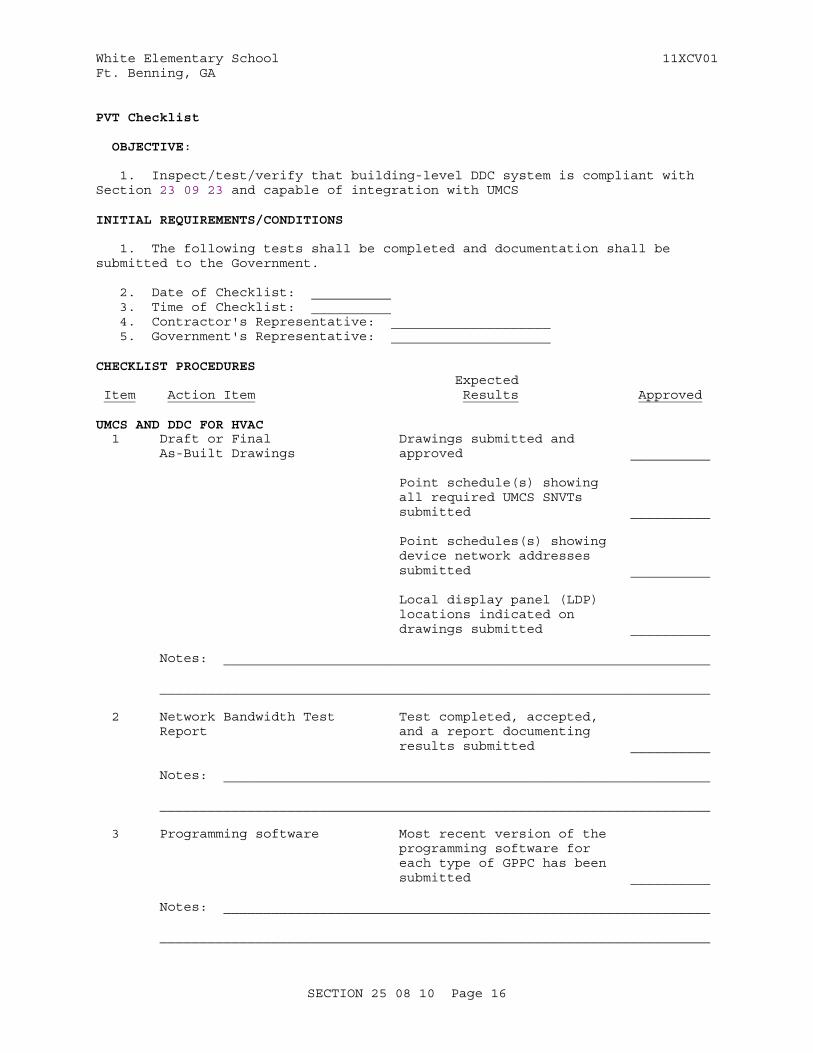
PVT Checklist
OBJECTIVE:
1. Inspect/test/verify that building-level DDC system is compliant with Section 23 09 23 and capable of integration with UMCS
INITIAL REQUIREMENTS/CONDITIONS
1. The following tests shall be completed and documentation shall be submitted to the Government.
2. Date of Checklist: __________ 3. Time of Checklist: __________ 4. Contractor's Representative: ____________________ 5. Government's Representative: ____________________
CHECKLIST PROCEDURES Expected Item Action Item Results Approved
UMCS AND DDC FOR HVAC 1 Draft or Final Drawings submitted and As-Built Drawings approved __________
Point schedule(s) showing all required UMCS SNVTs submitted __________
Point schedules(s) showing device network addresses submitted __________
Local display panel (LDP) locations indicated on drawings submitted __________
Notes: _____________________________________________________________
_____________________________________________________________________
2 Network Bandwidth Test Test completed, accepted, Report and a report documenting results submitted __________ Notes: _____________________________________________________________
_____________________________________________________________________
3 Programming software Most recent version of the programming software for each type of GPPC has been submitted __________
Notes: _____________________________________________________________
_____________________________________________________________________
SECTION 25 08 10 Page 16
White Elementary School 11XCV01Ft. Benning, GA
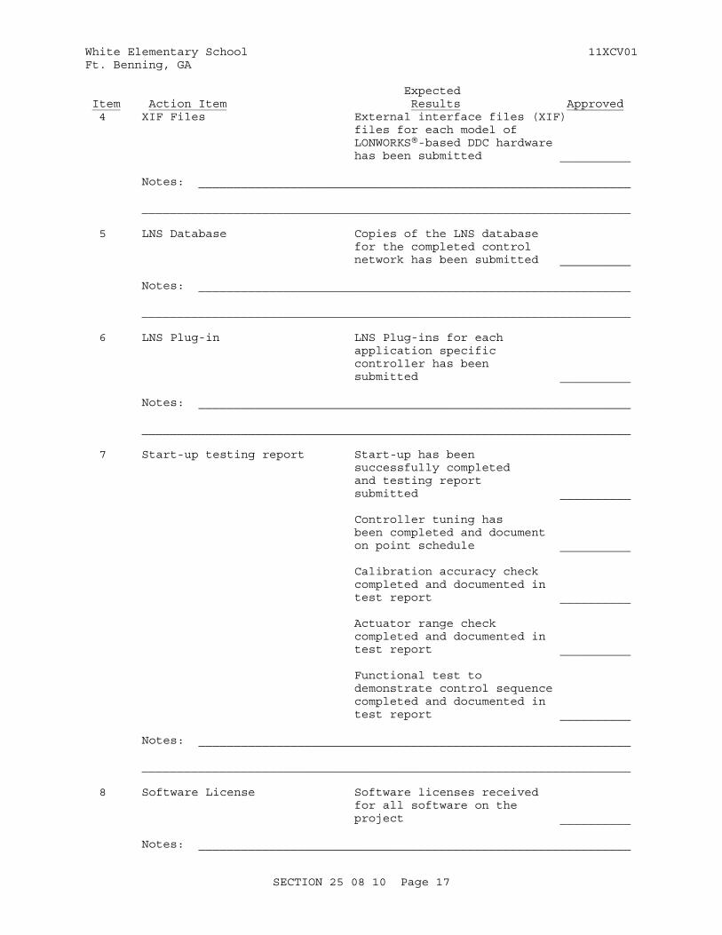
Expected Item Action Item Results Approved 4 XIF Files External interface files (XIF) files for each model of LONWORKS®-based DDC hardware has been submitted __________
Notes: _____________________________________________________________
_____________________________________________________________________
5 LNS Database Copies of the LNS database for the completed control network has been submitted __________
Notes: _____________________________________________________________
_____________________________________________________________________
6 LNS Plug-in LNS Plug-ins for each application specific controller has been submitted __________
Notes: _____________________________________________________________
_____________________________________________________________________
7 Start-up testing report Start-up has been successfully completed and testing report submitted __________ Controller tuning has been completed and document on point schedule __________
Calibration accuracy check completed and documented in test report __________
Actuator range check completed and documented in test report __________
Functional test to demonstrate control sequence completed and documented in test report __________
Notes: _____________________________________________________________
_____________________________________________________________________
8 Software License Software licenses received for all software on the project __________
Notes: _____________________________________________________________
SECTION 25 08 10 Page 17

White Elementary School 11XCV01Ft. Benning, GA
Expected Item Action Item Results Approved
_____________________________________________________________________
End of Test
Specific Abbreviations: Y = Yes N = No NA = Not Applicable
SECTION 25 08 10 Page 18

White Elementary School 11XCV01Ft. Benning, GA
TEST NUMBER: One TITLE: Initial System Equipment Verification
OBJECTIVE:
1. To verify that the hardware and software components of the system provided by the Contractor are in accordance with the contract plans and specifications and all approved submittals.
INITIAL REQUIREMENTS/CONDITIONS
1. Submittals
a. Submit a detailed list of all approved hardware with Manufacturer, model number and location. This list is based on the contract plans, specifications, change orders (if any) and approved submittals which shall be available for reference purposes during the test.
b. Submit a detailed list of all approved software with revision number and purpose of software. This list is based on the contract plans, specifications, change orders (if any) and approved submittals which shall be available for reference purposes during the test.
2. Equipment
a. Verify all equipment is functional.
3. Reference Documentation
a. List user manual documentation and sections pertaining to the testing.
4. Date of Test: __________ 5. Time of Test: __________ 6. Contractor's Representative: ____________________ 7. Government's Representative: ____________________
TEST PROCEDURES Expected Item Action Item Results Approved
UMCS 1 The workstation hardware is installed and complies with specification paragraph titled "Workstation Hardware". ________________ __________ Notes: _____________________________________________________________
_____________________________________________________________________
2 The Server hardware is installed and complies with specification paragraph titled "Server Hardware". ________________ __________
Notes: _____________________________________________________________
SECTION 25 08 10 Page 19
White Elementary School 11XCV01Ft. Benning, GA
Expected Item Action Item Results Approved _____________________________________________________________________
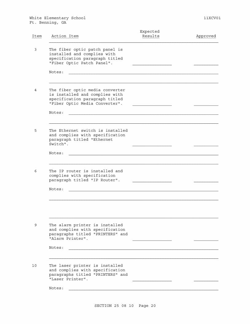
3 The fiber optic patch panel is installed and complies with specification paragraph titled "Fiber Optic Patch Panel". ________________ __________
Notes: _____________________________________________________________
_____________________________________________________________________
4 The fiber optic media converter is installed and complies with specification paragraph titled "Fiber Optic Media Converter". ________________ __________
Notes: _____________________________________________________________
_____________________________________________________________________
5 The Ethernet switch is installed and complies with specification paragraph titled "Ethernet Switch". ________________ __________
Notes: _____________________________________________________________
_____________________________________________________________________
6 The IP router is installed and complies with specification paragraph titled "IP Router". ________________ __________
Notes: _____________________________________________________________
_____________________________________________________________________
_____________________________________________________________________
9 The alarm printer is installed and complies with specification paragraphs titled "PRINTERS" and "Alarm Printer". ________________ __________
Notes: _____________________________________________________________
_____________________________________________________________________
10 The laser printer is installed and complies with specification paragraphs titled "PRINTERS" and "Laser Printer". ________________ __________
Notes: _____________________________________________________________
SECTION 25 08 10 Page 20
White Elementary School 11XCV01Ft. Benning, GA
Expected Item Action Item Results Approved _____________________________________________________________________
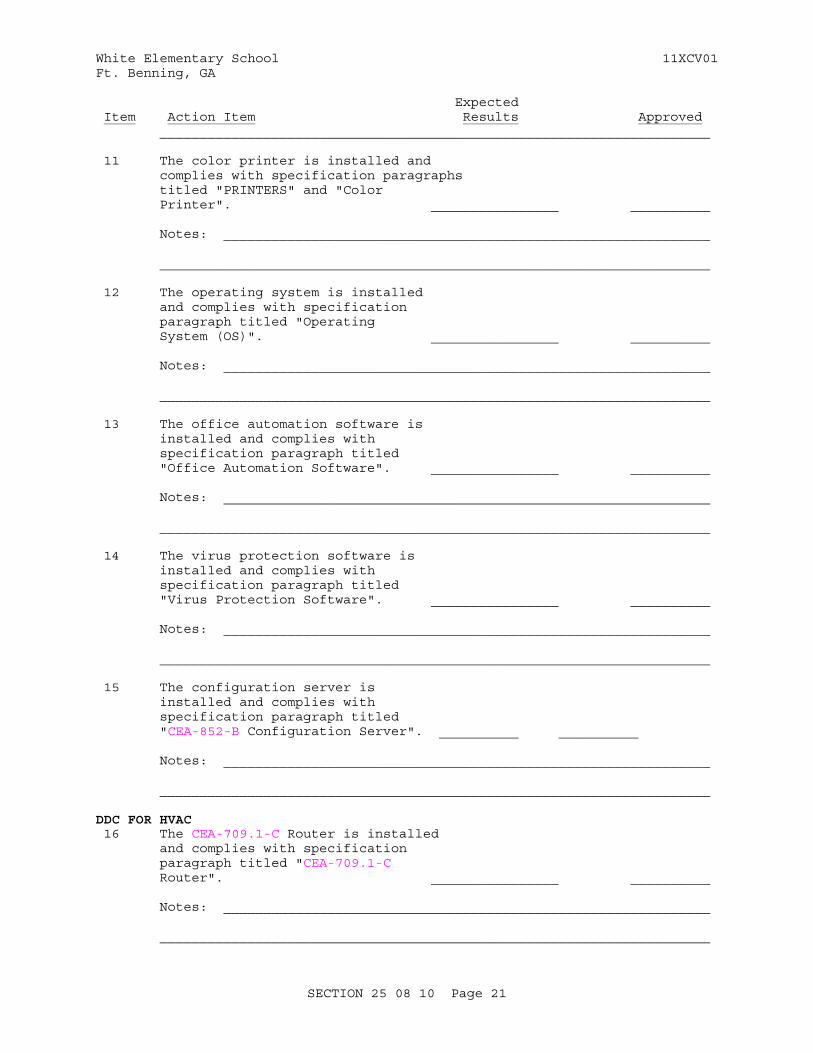
11 The color printer is installed and complies with specification paragraphs titled "PRINTERS" and "Color Printer". ________________ __________
Notes: _____________________________________________________________
_____________________________________________________________________
12 The operating system is installed and complies with specification paragraph titled "Operating System (OS)". ________________ __________
Notes: _____________________________________________________________
_____________________________________________________________________
13 The office automation software is installed and complies with specification paragraph titled "Office Automation Software". ________________ __________
Notes: _____________________________________________________________
_____________________________________________________________________
14 The virus protection software is installed and complies with specification paragraph titled "Virus Protection Software". ________________ __________
Notes: _____________________________________________________________
_____________________________________________________________________
15 The configuration server is installed and complies with specification paragraph titled "CEA-852-B Configuration Server". __________ __________
Notes: _____________________________________________________________
_____________________________________________________________________
DDC FOR HVAC 16 The CEA-709.1-C Router is installed and complies with specification paragraph titled "CEA-709.1-C Router". ________________ __________
Notes: _____________________________________________________________
_____________________________________________________________________
SECTION 25 08 10 Page 21
White Elementary School 11XCV01Ft. Benning, GA
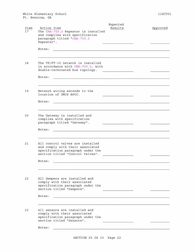
Expected Item Action Item Results Approved 17 The CEA-709.3 Repeater is installed and complies with specification paragraph titled "CEA-709.3 Repeater". ________________ __________
Notes: _____________________________________________________________
_____________________________________________________________________
18 The TP/FT-10 network is installed in accordance with CEA-709.3, with double-terminated bus topology. ________________ __________
Notes: _____________________________________________________________
_____________________________________________________________________
19 Network wiring extends to the location of UMCS BPOC. ________________ __________
Notes: _____________________________________________________________
_____________________________________________________________________
20 The Gateway is installed and complies with specification paragraph titled "Gateway". ________________ __________
Notes: _____________________________________________________________
_____________________________________________________________________
21 All control valves are installed and comply with their associated specification paragraph under the section titled "Control Valves". ________________ __________
Notes: _____________________________________________________________
_____________________________________________________________________
22 All dampers are installed and comply with their associated specification paragraph under the section titled "Dampers". ________________ __________
Notes: _____________________________________________________________
_____________________________________________________________________
23 All sensors are installed and comply with their associated specification paragraph under the section titled "Sensors". ________________ __________
Notes: _____________________________________________________________
SECTION 25 08 10 Page 22
White Elementary School 11XCV01Ft. Benning, GA
Expected Item Action Item Results Approved
_____________________________________________________________________
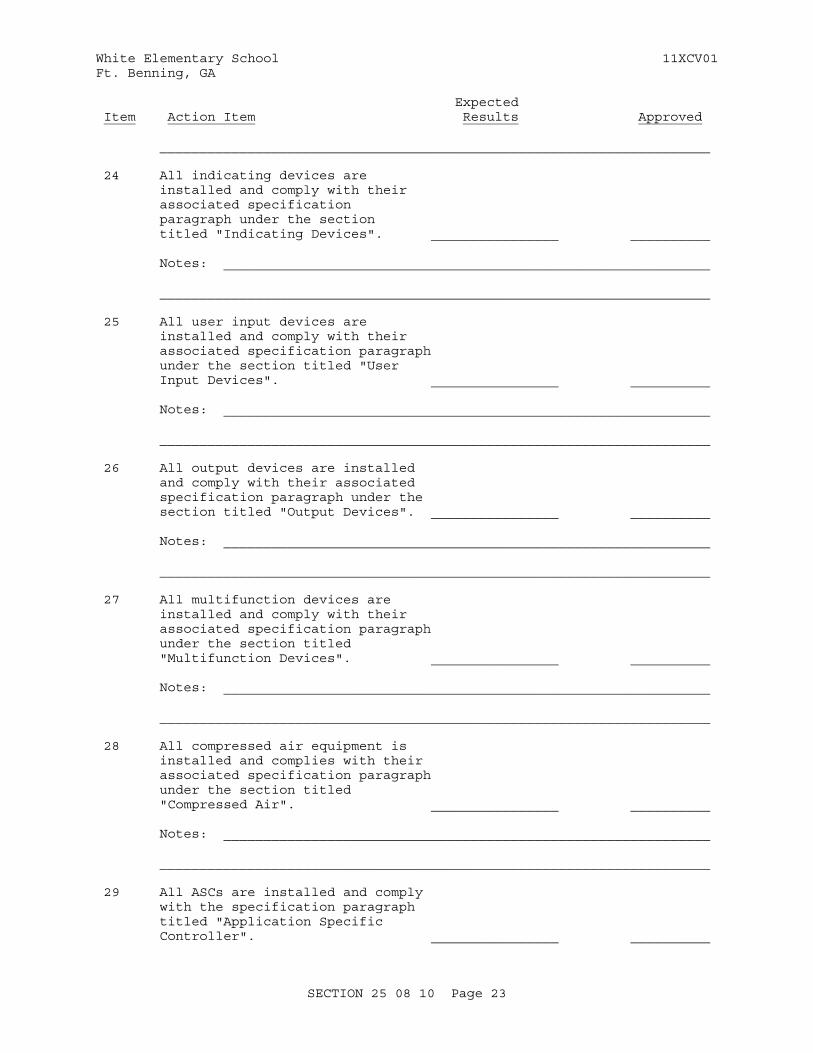
24 All indicating devices are installed and comply with their associated specification paragraph under the section titled "Indicating Devices". ________________ __________
Notes: _____________________________________________________________
_____________________________________________________________________
25 All user input devices are installed and comply with their associated specification paragraph under the section titled "User Input Devices". ________________ __________
Notes: _____________________________________________________________
_____________________________________________________________________
26 All output devices are installed and comply with their associated specification paragraph under the section titled "Output Devices". ________________ __________
Notes: _____________________________________________________________
_____________________________________________________________________
27 All multifunction devices are installed and comply with their associated specification paragraph under the section titled "Multifunction Devices". ________________ __________
Notes: _____________________________________________________________
_____________________________________________________________________
28 All compressed air equipment is installed and complies with their associated specification paragraph under the section titled "Compressed Air". ________________ __________
Notes: _____________________________________________________________
_____________________________________________________________________
29 All ASCs are installed and comply with the specification paragraph titled "Application Specific Controller". ________________ __________
SECTION 25 08 10 Page 23
White Elementary School 11XCV01Ft. Benning, GA
Expected Item Action Item Results Approved Notes: _____________________________________________________________
_____________________________________________________________________
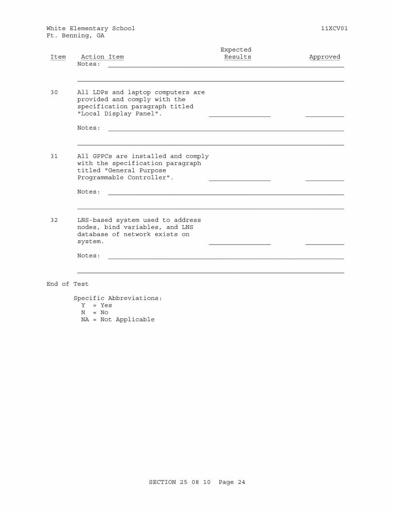
30 All LDPs and laptop computers are provided and comply with the specification paragraph titled "Local Display Panel". ________________ __________
Notes: _____________________________________________________________
_____________________________________________________________________
31 All GPPCs are installed and comply with the specification paragraph titled "General Purpose Programmable Controller". ________________ __________
Notes: _____________________________________________________________
_____________________________________________________________________
32 LNS-based system used to address nodes, bind variables, and LNS database of network exists on system. ________________ __________
Notes: _____________________________________________________________
_____________________________________________________________________
End of Test
Specific Abbreviations: Y = Yes N = No NA = Not Applicable
SECTION 25 08 10 Page 24
White Elementary School 11XCV01Ft. Benning, GA
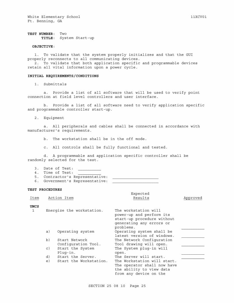
TEST NUMBER: Two TITLE: System Start-up
OBJECTIVE:
1. To validate that the system properly initializes and that the GUI properly reconnects to all communicating devices. 2. To validate that both application specific and programmable devices retain all vital information upon a power cycle.
INITIAL REQUIREMENTS/CONDITIONS
1. Submittals
a. Provide a list of all software that will be used to verify point connection at field level controllers and user interface.
b. Provide a list of all software need to verify application specific and programmable controller start-up.
2. Equipment
a. All peripherals and cables shall be connected in accordance with manufacturer's requirements.
b. The workstation shall be in the off mode.
c. All controls shall be fully functional and tested.
d. A programmable and application specific controller shall be randomly selected for the test.
3. Date of Test: __________ 4. Time of Test: __________ 5. Contractor's Representative: ____________________ 6. Government's Representative: ____________________
TEST PROCEDURES Expected Item Action Item Results Approved
UMCS 1 Energize the workstation. The workstation will power-up and perform its start-up procedure without generating any errors or problems. __________ a) Operating system Operating system shall be latest version of windows. __________ b) Start Network The Network Configuration Configuration Tool. Tool drawing will open. __________ c) Start the System The System plug-in will Plug-in. open. __________ d) Start the Server. The Server will start. __________ e) Start the Workstation. The Workstation will start. The operator shall now have the ability to view data from any device on the
SECTION 25 08 10 Page 25
White Elementary School 11XCV01Ft. Benning, GA
Expected Item Action Item Results Approved network. __________ Notes: _____________________________________________________________
_____________________________________________________________________
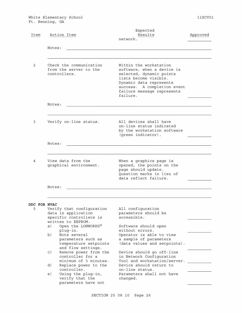
2 Check the communication Within the workstation from the server to the software, when a device is controllers. selected, dynamic points lists become visible. Dynamic data represents success. A completion event failure message represents failure. __________
Notes: _____________________________________________________________
_____________________________________________________________________
3 Verify on-line status. All devices shall have on-line status indicated by the workstation software (green indicator). __________
Notes: _____________________________________________________________
_____________________________________________________________________
4 View data from the When a graphics page is graphical environment. opened, the points on the page should update. Question marks in lieu of data reflect failure. __________
Notes: _____________________________________________________________
_____________________________________________________________________
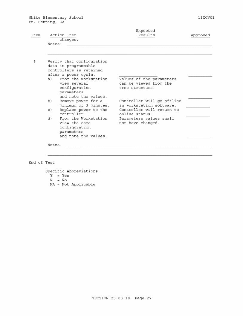
DDC FOR HVAC 5 Verify that configuration All configuration data in application parameters should be specific controllers is accessible. __________ written to EEPROM. a) Open the LONWORKS® Software should open plug-in. without errors. __________ b) Note several Operator is able to view parameters such as a sample of parameters temperature setpoints (data values and setpoints). and flow settings. __________ c) Remove power from the Device should go off-line controller for a in Network Configuration minimum of 3 minutes. Tool and workstation/server. __________ d) Replace power to the Device should return to controller. on-line status. __________ e) Using the plug-in, Parameters shall not have verify that the changed. parameters have not __________
SECTION 25 08 10 Page 26
White Elementary School 11XCV01Ft. Benning, GA
Expected Item Action Item Results Approved changes. Notes: _____________________________________________________________
_____________________________________________________________________ 6 Verify that configuration data in programmable controllers is retained after a power cycle. ________________ __________ a) From the Workstation Values of the parameters view several can be viewed from the configuration tree structure. parameters and note the values. __________ b) Remove power for a Controller will go offline minimum of 3 minutes. in workstation software. __________ c) Replace power to the Controller will return to controller. online status. __________ d) From the Workstation Parameters values shall view the same not have changed. configuration parameters and note the values. __________
Notes: _____________________________________________________________
_____________________________________________________________________
End of Test
Specific Abbreviations: Y = Yes N = No NA = Not Applicable
SECTION 25 08 10 Page 27
White Elementary School 11XCV01Ft. Benning, GA
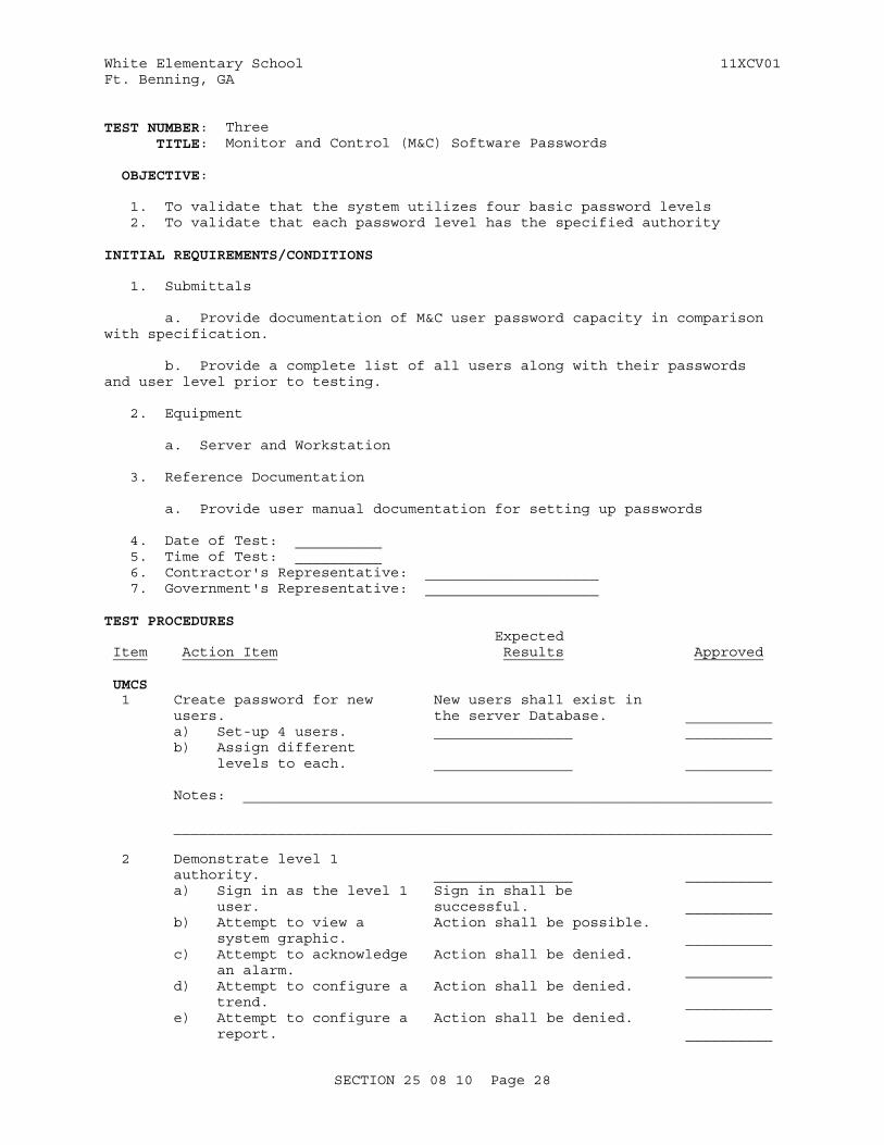
TEST NUMBER: Three TITLE: Monitor and Control (M&C) Software Passwords
OBJECTIVE: 1. To validate that the system utilizes four basic password levels 2. To validate that each password level has the specified authority
INITIAL REQUIREMENTS/CONDITIONS
1. Submittals
a. Provide documentation of M&C user password capacity in comparison with specification.
b. Provide a complete list of all users along with their passwords and user level prior to testing.
2. Equipment
a. Server and Workstation
3. Reference Documentation
a. Provide user manual documentation for setting up passwords
4. Date of Test: __________ 5. Time of Test: __________ 6. Contractor's Representative: ____________________ 7. Government's Representative: ____________________
TEST PROCEDURES Expected Item Action Item Results Approved UMCS 1 Create password for new New users shall exist in users. the server Database. __________ a) Set-up 4 users. ________________ __________ b) Assign different levels to each. ________________ __________ Notes: _____________________________________________________________
_____________________________________________________________________
2 Demonstrate level 1 authority. ________________ __________ a) Sign in as the level 1 Sign in shall be user. successful. __________ b) Attempt to view a Action shall be possible. system graphic. __________ c) Attempt to acknowledge Action shall be denied. an alarm. __________ d) Attempt to configure a Action shall be denied. trend. __________ e) Attempt to configure a Action shall be denied. report. __________
SECTION 25 08 10 Page 28
White Elementary School 11XCV01Ft. Benning, GA
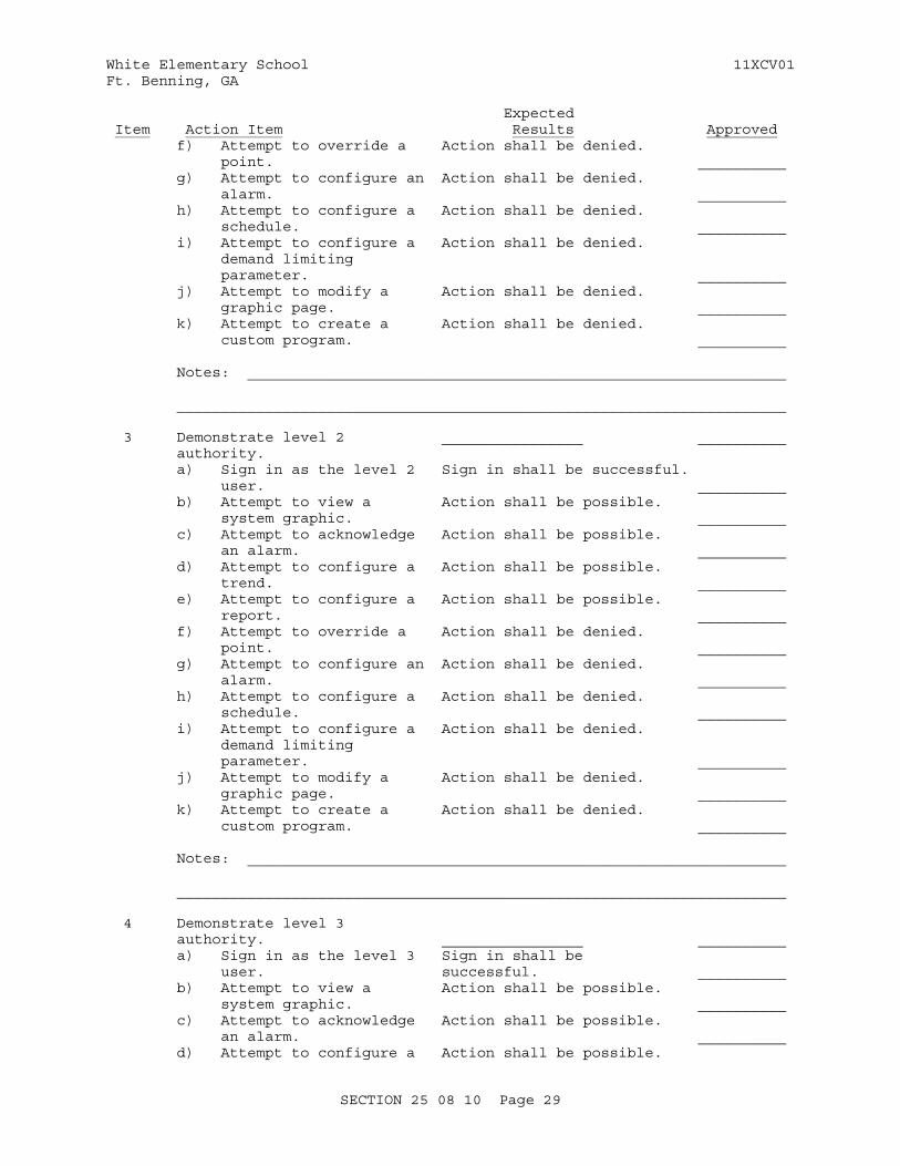
Expected Item Action Item Results Approved f) Attempt to override a Action shall be denied. point. __________ g) Attempt to configure an Action shall be denied. alarm. __________ h) Attempt to configure a Action shall be denied. schedule. __________ i) Attempt to configure a Action shall be denied. demand limiting parameter. __________ j) Attempt to modify a Action shall be denied. graphic page. __________ k) Attempt to create a Action shall be denied. custom program. __________
Notes: _____________________________________________________________
_____________________________________________________________________
3 Demonstrate level 2 ________________ __________ authority. a) Sign in as the level 2 Sign in shall be successful. user. __________ b) Attempt to view a Action shall be possible. system graphic. __________ c) Attempt to acknowledge Action shall be possible. an alarm. __________ d) Attempt to configure a Action shall be possible. trend. __________ e) Attempt to configure a Action shall be possible. report. __________ f) Attempt to override a Action shall be denied. point. __________ g) Attempt to configure an Action shall be denied. alarm. __________ h) Attempt to configure a Action shall be denied. schedule. __________ i) Attempt to configure a Action shall be denied. demand limiting parameter. __________ j) Attempt to modify a Action shall be denied. graphic page. __________ k) Attempt to create a Action shall be denied. custom program. __________
Notes: _____________________________________________________________
_____________________________________________________________________
4 Demonstrate level 3 authority. ________________ __________ a) Sign in as the level 3 Sign in shall be user. successful. __________ b) Attempt to view a Action shall be possible. system graphic. __________ c) Attempt to acknowledge Action shall be possible. an alarm. __________ d) Attempt to configure a Action shall be possible.
SECTION 25 08 10 Page 29
White Elementary School 11XCV01Ft. Benning, GA
Expected Item Action Item Results Approved trend. __________ e) Attempt to configure a Action shall be possible. report. __________ f) Attempt to override a Action shall be possible. point. __________ g) Attempt to configure an Action shall be possible. alarm. __________ h) Attempt to configure a Action shall be possible. schedule. __________ i) Attempt to configure a Action shall be possible. demand limiting parameter. __________ j) Attempt to modify a Action shall be denied. graphic page. __________ k) Attempt to create a Action shall be denied. custom program. __________
Notes: _____________________________________________________________
_____________________________________________________________________
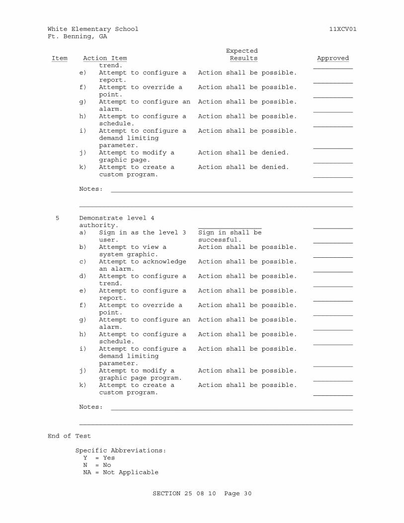
5 Demonstrate level 4 authority. ________________ __________ a) Sign in as the level 3 Sign in shall be user. successful. __________ b) Attempt to view a Action shall be possible. system graphic. __________ c) Attempt to acknowledge Action shall be possible. an alarm. __________ d) Attempt to configure a Action shall be possible. trend. __________ e) Attempt to configure a Action shall be possible. report. __________ f) Attempt to override a Action shall be possible. point. __________ g) Attempt to configure an Action shall be possible. alarm. __________ h) Attempt to configure a Action shall be possible. schedule. __________ i) Attempt to configure a Action shall be possible. demand limiting parameter. __________ j) Attempt to modify a Action shall be possible. graphic page program. __________ k) Attempt to create a Action shall be possible. custom program. __________
Notes: _____________________________________________________________
_____________________________________________________________________
End of Test
Specific Abbreviations: Y = Yes N = No NA = Not Applicable
SECTION 25 08 10 Page 30

White Elementary School 11XCV01Ft. Benning, GA
SECTION 25 08 10 Page 31
White Elementary School 11XCV01Ft. Benning, GA
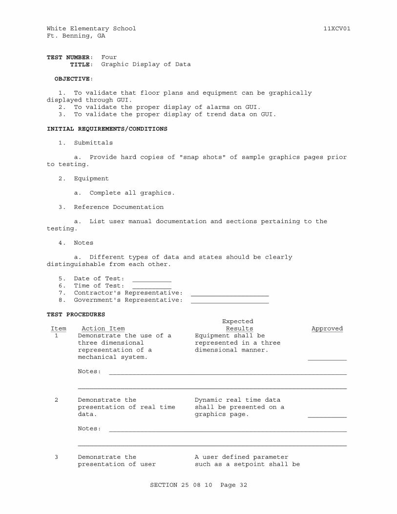
TEST NUMBER: Four TITLE: Graphic Display of Data
OBJECTIVE:
1. To validate that floor plans and equipment can be graphically displayed through GUI. 2. To validate the proper display of alarms on GUI. 3. To validate the proper display of trend data on GUI.
INITIAL REQUIREMENTS/CONDITIONS
1. Submittals
a. Provide hard copies of "snap shots" of sample graphics pages prior to testing.
2. Equipment
a. Complete all graphics.
3. Reference Documentation
a. List user manual documentation and sections pertaining to the testing.
4. Notes
a. Different types of data and states should be clearly distinguishable from each other.
5. Date of Test: __________ 6. Time of Test: __________ 7. Contractor's Representative: ____________________ 8. Government's Representative: ____________________
TEST PROCEDURES Expected Item Action Item Results Approved 1 Demonstrate the use of a Equipment shall be three dimensional represented in a three representation of a dimensional manner. mechanical system. __________ Notes: _____________________________________________________________
_____________________________________________________________________
2 Demonstrate the Dynamic real time data presentation of real time shall be presented on a data. graphics page. __________ Notes: _____________________________________________________________
_____________________________________________________________________
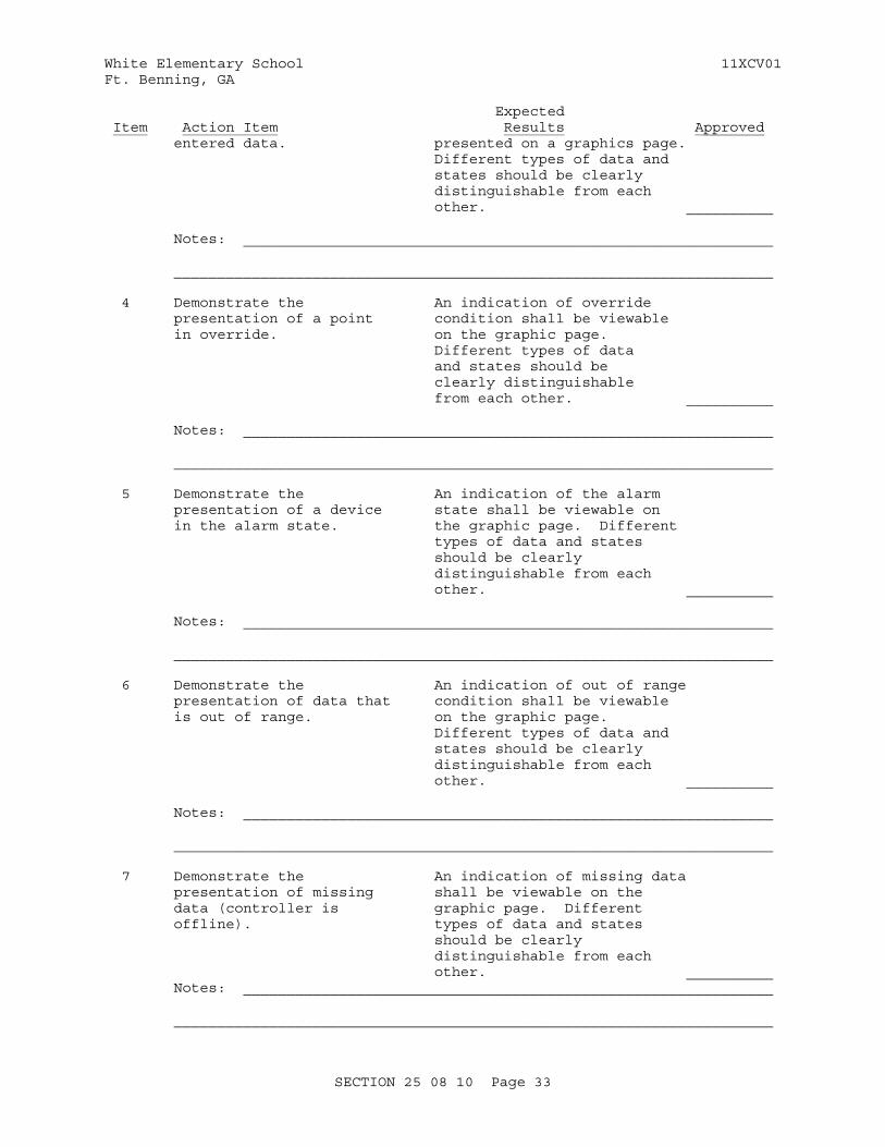
3 Demonstrate the A user defined parameter presentation of user such as a setpoint shall be
SECTION 25 08 10 Page 32
White Elementary School 11XCV01Ft. Benning, GA
Expected Item Action Item Results Approved entered data. presented on a graphics page. Different types of data and states should be clearly distinguishable from each other. __________
Notes: _____________________________________________________________
_____________________________________________________________________
4 Demonstrate the An indication of override presentation of a point condition shall be viewable in override. on the graphic page. Different types of data and states should be clearly distinguishable from each other. __________ Notes: _____________________________________________________________
_____________________________________________________________________
5 Demonstrate the An indication of the alarm presentation of a device state shall be viewable on in the alarm state. the graphic page. Different types of data and states should be clearly distinguishable from each other. __________
Notes: _____________________________________________________________
_____________________________________________________________________
6 Demonstrate the An indication of out of range presentation of data that condition shall be viewable is out of range. on the graphic page. Different types of data and states should be clearly distinguishable from each other. __________
Notes: _____________________________________________________________
_____________________________________________________________________
7 Demonstrate the An indication of missing data presentation of missing shall be viewable on the data (controller is graphic page. Different offline). types of data and states should be clearly distinguishable from each other. __________ Notes: _____________________________________________________________
_____________________________________________________________________
SECTION 25 08 10 Page 33
White Elementary School 11XCV01Ft. Benning, GA
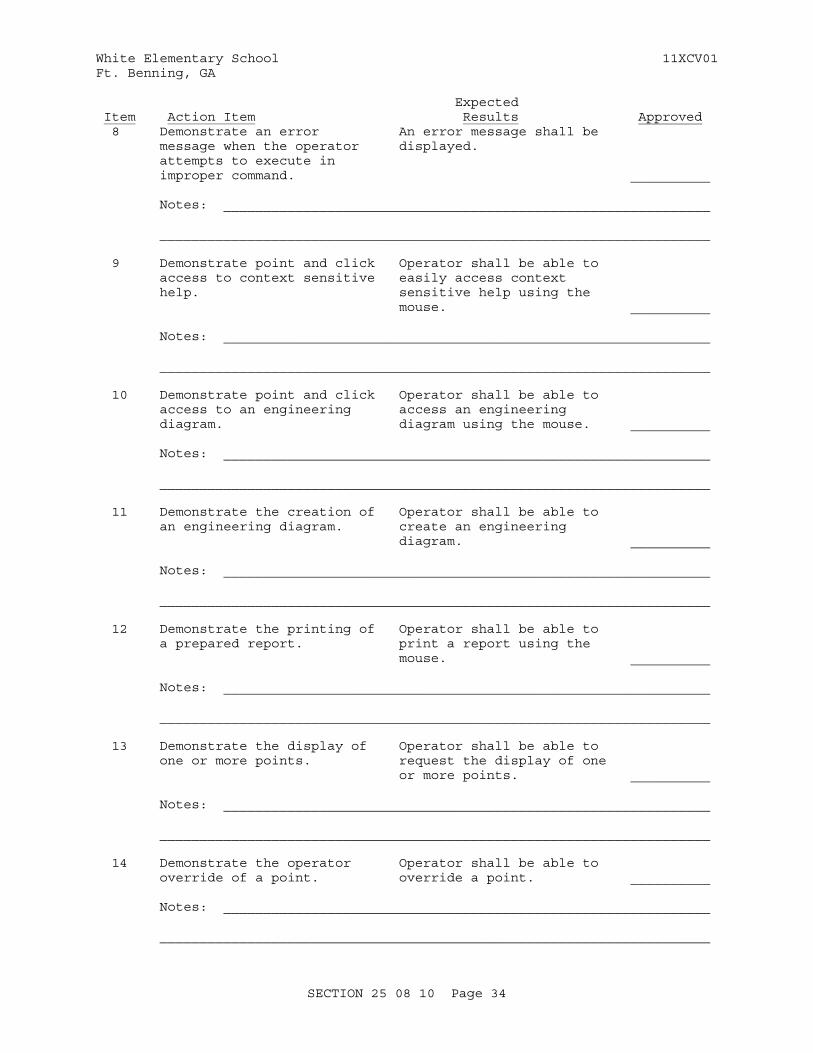
Expected Item Action Item Results Approved 8 Demonstrate an error An error message shall be message when the operator displayed. attempts to execute in improper command. __________
Notes: _____________________________________________________________
_____________________________________________________________________
9 Demonstrate point and click Operator shall be able to access to context sensitive easily access context help. sensitive help using the mouse. __________
Notes: _____________________________________________________________
_____________________________________________________________________
10 Demonstrate point and click Operator shall be able to access to an engineering access an engineering diagram. diagram using the mouse. __________
Notes: _____________________________________________________________
_____________________________________________________________________
11 Demonstrate the creation of Operator shall be able to an engineering diagram. create an engineering diagram. __________ Notes: _____________________________________________________________
_____________________________________________________________________
12 Demonstrate the printing of Operator shall be able to a prepared report. print a report using the mouse. __________
Notes: _____________________________________________________________
_____________________________________________________________________
13 Demonstrate the display of Operator shall be able to one or more points. request the display of one or more points. __________ Notes: _____________________________________________________________
_____________________________________________________________________
14 Demonstrate the operator Operator shall be able to override of a point. override a point. __________ Notes: _____________________________________________________________
_____________________________________________________________________
SECTION 25 08 10 Page 34
White Elementary School 11XCV01Ft. Benning, GA
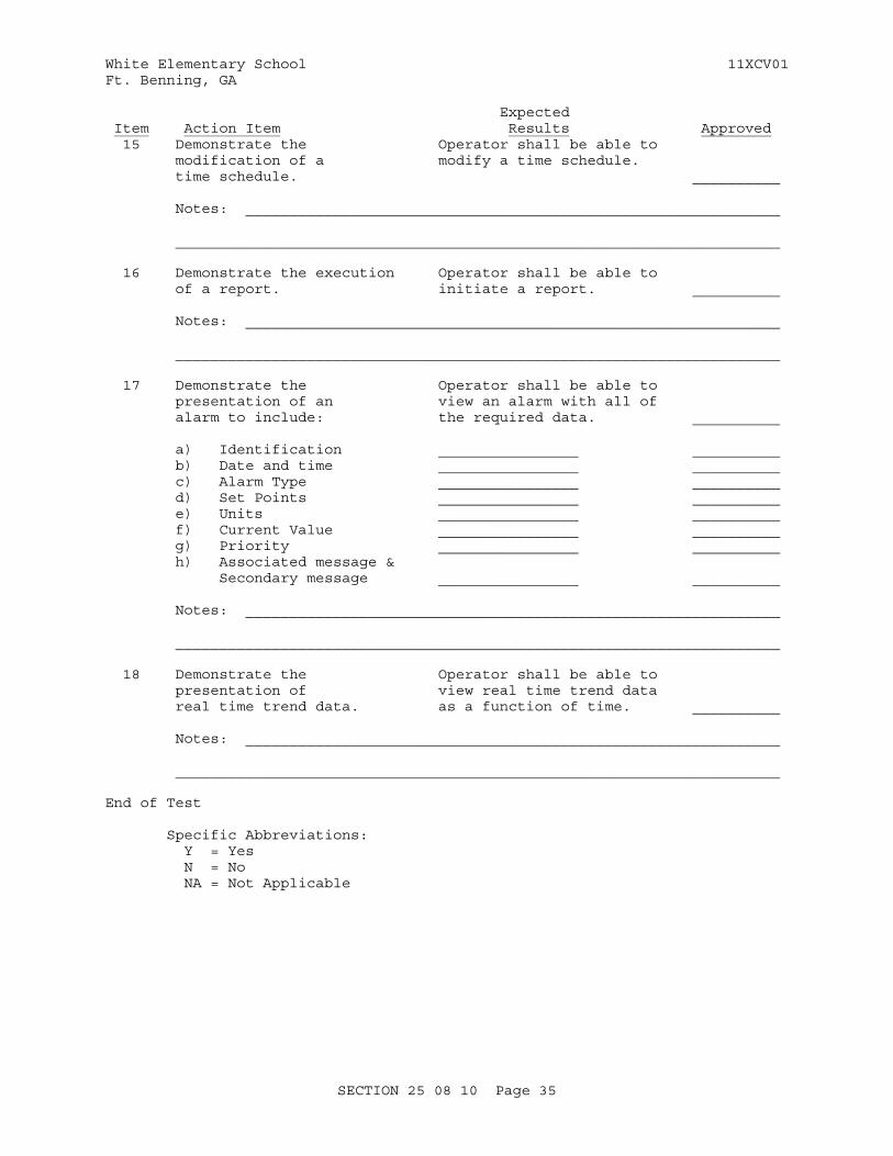
Expected Item Action Item Results Approved 15 Demonstrate the Operator shall be able to modification of a modify a time schedule. time schedule. __________
Notes: _____________________________________________________________
_____________________________________________________________________
16 Demonstrate the execution Operator shall be able to of a report. initiate a report. __________
Notes: _____________________________________________________________
_____________________________________________________________________
17 Demonstrate the Operator shall be able to presentation of an view an alarm with all of alarm to include: the required data. __________ a) Identification ________________ __________ b) Date and time ________________ __________ c) Alarm Type ________________ __________ d) Set Points ________________ __________ e) Units ________________ __________ f) Current Value ________________ __________ g) Priority ________________ __________ h) Associated message & Secondary message ________________ __________
Notes: _____________________________________________________________
_____________________________________________________________________
18 Demonstrate the Operator shall be able to presentation of view real time trend data real time trend data. as a function of time. __________
Notes: _____________________________________________________________ _____________________________________________________________________
End of Test
Specific Abbreviations: Y = Yes N = No NA = Not Applicable
SECTION 25 08 10 Page 35
White Elementary School 11XCV01Ft. Benning, GA
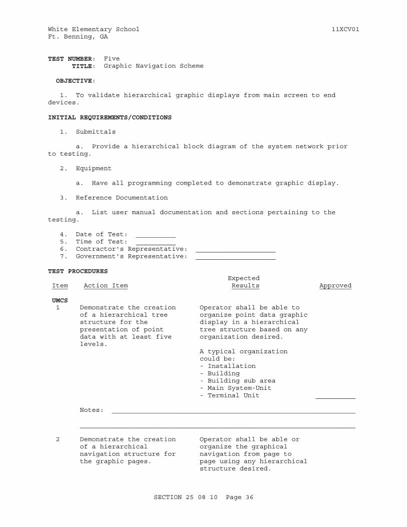
TEST NUMBER: Five TITLE: Graphic Navigation Scheme
OBJECTIVE:
1. To validate hierarchical graphic displays from main screen to end devices.
INITIAL REQUIREMENTS/CONDITIONS
1. Submittals
a. Provide a hierarchical block diagram of the system network prior to testing.
2. Equipment
a. Have all programming completed to demonstrate graphic display.
3. Reference Documentation
a. List user manual documentation and sections pertaining to the testing.
4. Date of Test: __________ 5. Time of Test: __________ 6. Contractor's Representative: ____________________ 7. Government's Representative: ____________________
TEST PROCEDURES Expected Item Action Item Results Approved UMCS 1 Demonstrate the creation Operator shall be able to of a hierarchical tree organize point data graphic structure for the display in a hierarchical presentation of point tree structure based on any data with at least five organization desired. levels. A typical organization could be: - Installation - Building - Building sub area - Main System-Unit - Terminal Unit __________
Notes: _____________________________________________________________
_____________________________________________________________________
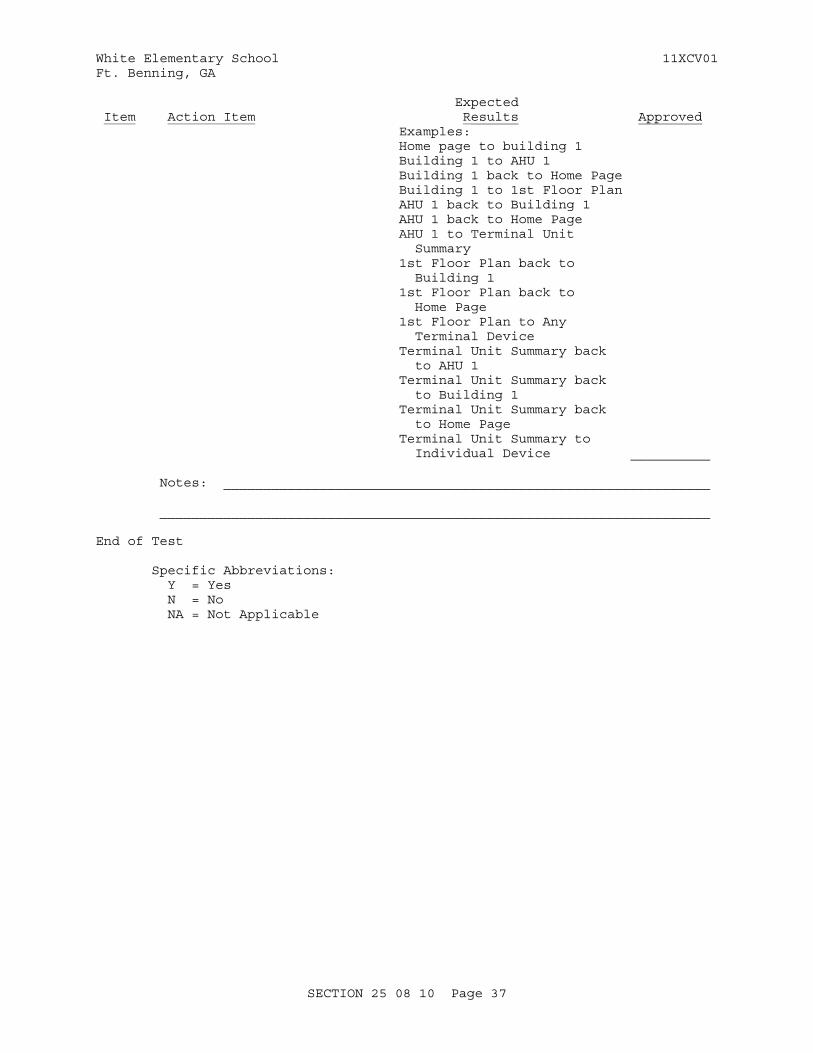
2 Demonstrate the creation Operator shall be able or of a hierarchical organize the graphical navigation structure for navigation from page to the graphic pages. page using any hierarchical structure desired.
SECTION 25 08 10 Page 36
White Elementary School 11XCV01Ft. Benning, GA
Expected Item Action Item Results Approved Examples: Home page to building 1 Building 1 to AHU 1 Building 1 back to Home Page Building 1 to 1st Floor Plan AHU 1 back to Building 1 AHU 1 back to Home Page AHU 1 to Terminal Unit Summary 1st Floor Plan back to Building 1 1st Floor Plan back to Home Page 1st Floor Plan to Any Terminal Device Terminal Unit Summary back to AHU 1 Terminal Unit Summary back to Building 1 Terminal Unit Summary back to Home Page Terminal Unit Summary to Individual Device __________ Notes: _____________________________________________________________
_____________________________________________________________________
End of Test
Specific Abbreviations: Y = Yes N = No NA = Not Applicable
SECTION 25 08 10 Page 37
White Elementary School 11XCV01Ft. Benning, GA
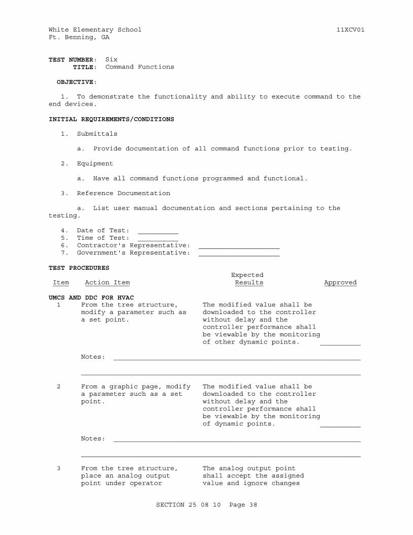
TEST NUMBER: Six TITLE: Command Functions
OBJECTIVE:
1. To demonstrate the functionality and ability to execute command to the end devices.
INITIAL REQUIREMENTS/CONDITIONS
1. Submittals
a. Provide documentation of all command functions prior to testing.
2. Equipment
a. Have all command functions programmed and functional.
3. Reference Documentation
a. List user manual documentation and sections pertaining to the testing.
4. Date of Test: __________ 5. Time of Test: __________ 6. Contractor's Representative: ____________________ 7. Government's Representative: ____________________
TEST PROCEDURES Expected Item Action Item Results Approved
UMCS AND DDC FOR HVAC 1 From the tree structure, The modified value shall be modify a parameter such as downloaded to the controller a set point. without delay and the controller performance shall be viewable by the monitoring of other dynamic points. __________
Notes: _____________________________________________________________
_____________________________________________________________________
2 From a graphic page, modify The modified value shall be a parameter such as a set downloaded to the controller point. without delay and the controller performance shall be viewable by the monitoring of dynamic points. __________
Notes: _____________________________________________________________
_____________________________________________________________________
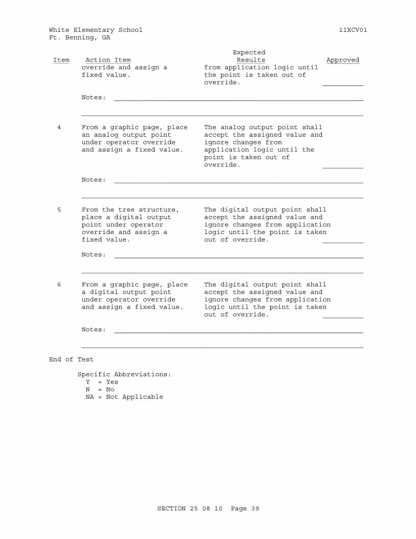
3 From the tree structure, The analog output point place an analog output shall accept the assigned point under operator value and ignore changes
SECTION 25 08 10 Page 38
White Elementary School 11XCV01Ft. Benning, GA
Expected Item Action Item Results Approved override and assign a from application logic until fixed value. the point is taken out of override. __________
Notes: _____________________________________________________________
_____________________________________________________________________
4 From a graphic page, place The analog output point shall an analog output point accept the assigned value and under operator override ignore changes from and assign a fixed value. application logic until the point is taken out of override. __________
Notes: _____________________________________________________________
_____________________________________________________________________
5 From the tree structure, The digital output point shall place a digital output accept the assigned value and point under operator ignore changes from application override and assign a logic until the point is taken fixed value. out of override. __________ Notes: _____________________________________________________________
_____________________________________________________________________
6 From a graphic page, place The digital output point shall a digital output point accept the assigned value and under operator override ignore changes from application and assign a fixed value. logic until the point is taken out of override. __________
Notes: _____________________________________________________________
_____________________________________________________________________
End of Test
Specific Abbreviations: Y = Yes N = No NA = Not Applicable
SECTION 25 08 10 Page 39
White Elementary School 11XCV01Ft. Benning, GA
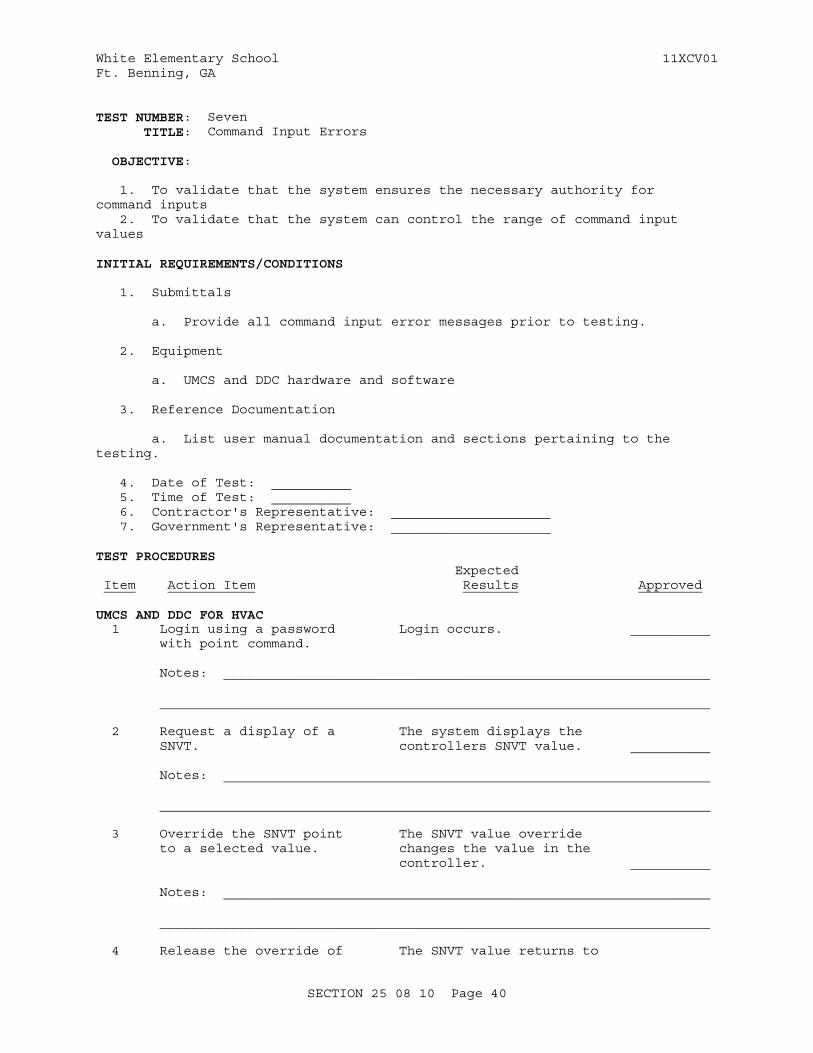
TEST NUMBER: Seven TITLE: Command Input Errors
OBJECTIVE:
1. To validate that the system ensures the necessary authority for command inputs 2. To validate that the system can control the range of command input values
INITIAL REQUIREMENTS/CONDITIONS
1. Submittals
a. Provide all command input error messages prior to testing.
2. Equipment
a. UMCS and DDC hardware and software
3. Reference Documentation
a. List user manual documentation and sections pertaining to the testing.
4. Date of Test: __________ 5. Time of Test: __________ 6. Contractor's Representative: ____________________ 7. Government's Representative: ____________________
TEST PROCEDURES Expected Item Action Item Results Approved
UMCS AND DDC FOR HVAC 1 Login using a password Login occurs. __________ with point command.
Notes: _____________________________________________________________
_____________________________________________________________________
2 Request a display of a The system displays the SNVT. controllers SNVT value. __________
Notes: _____________________________________________________________
_____________________________________________________________________
3 Override the SNVT point The SNVT value override to a selected value. changes the value in the controller. __________
Notes: _____________________________________________________________
_____________________________________________________________________
4 Release the override of The SNVT value returns to
SECTION 25 08 10 Page 40
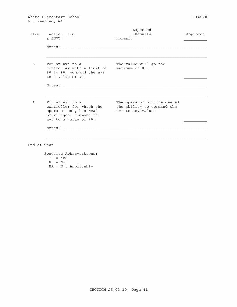
White Elementary School 11XCV01Ft. Benning, GA
Expected Item Action Item Results Approved a SNVT. normal. __________
Notes: _____________________________________________________________
_____________________________________________________________________
5 For an nvi to a The value will go the controller with a limit of maximum of 80. 50 to 80, command the nvi to a value of 90. __________
Notes: _____________________________________________________________
_____________________________________________________________________
6 For an nvi to a The operator will be denied controller for which the the ability to command the operator only has read nvi to any value. privileges, command the nvi to a value of 90. __________
Notes: _____________________________________________________________
_____________________________________________________________________
End of Test
Specific Abbreviations: Y = Yes N = No NA = Not Applicable
SECTION 25 08 10 Page 41
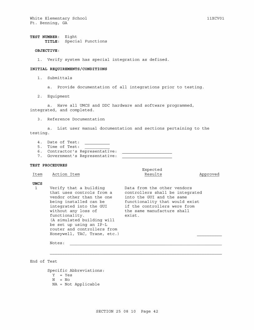
White Elementary School 11XCV01Ft. Benning, GA
TEST NUMBER: Eight TITLE: Special Functions
OBJECTIVE:
1. Verify system has special integration as defined.
INITIAL REQUIREMENTS/CONDITIONS
1. Submittals
a. Provide documentation of all integrations prior to testing.
2. Equipment
a. Have all UMCS and DDC hardware and software programmed, integrated, and completed.
3. Reference Documentation
a. List user manual documentation and sections pertaining to the testing.
4. Date of Test: __________ 5. Time of Test: __________ 6. Contractor's Representative: ____________________ 7. Government's Representative: ____________________
TEST PROCEDURES Expected Item Action Item Results Approved UMCS 1 Verify that a building Data from the other vendors that uses controls from a controllers shall be integrated vendor other than the one into the GUI and the same being installed can be functionality that would exist integrated into the GUI if the controllers were from without any loss of the same manufacture shall functionality. exist. (A simulated building will be set up using an IP-L router and controllers from Honeywell, TAC, Trane, etc.) __________
Notes: _____________________________________________________________
_____________________________________________________________________
End of Test
Specific Abbreviations: Y = Yes N = No NA = Not Applicable
SECTION 25 08 10 Page 42
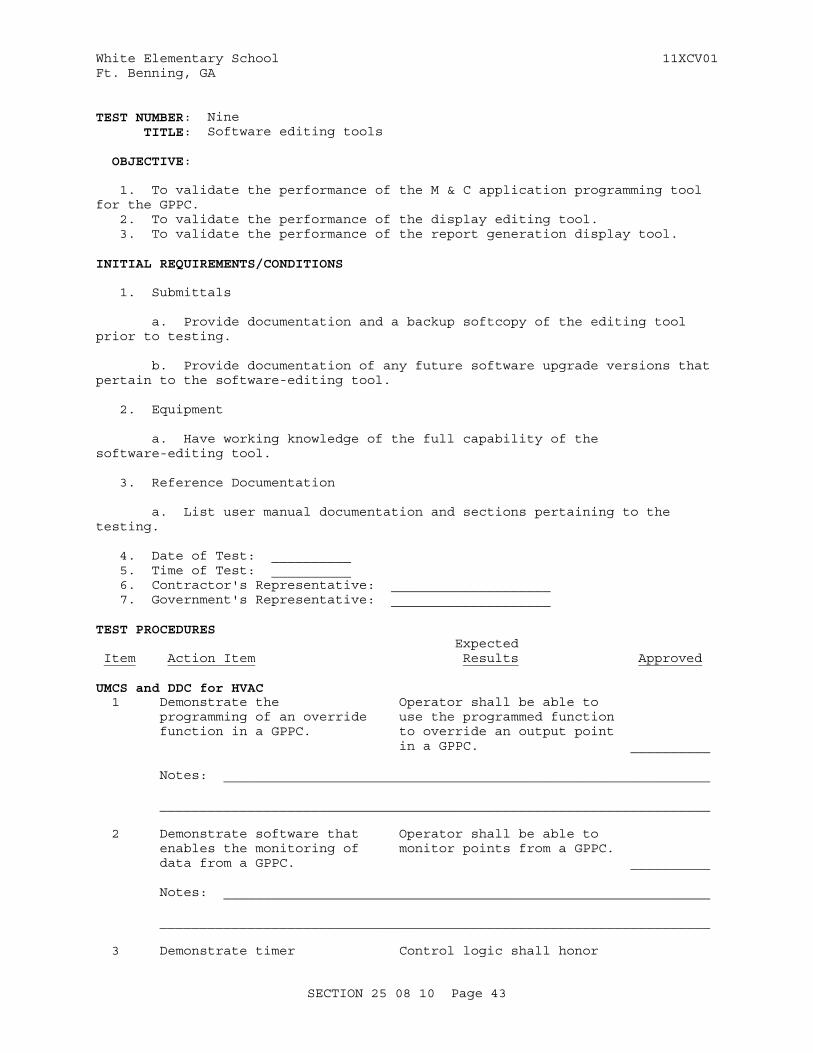
White Elementary School 11XCV01Ft. Benning, GA
TEST NUMBER: Nine TITLE: Software editing tools
OBJECTIVE:
1. To validate the performance of the M & C application programming tool for the GPPC. 2. To validate the performance of the display editing tool. 3. To validate the performance of the report generation display tool.
INITIAL REQUIREMENTS/CONDITIONS
1. Submittals
a. Provide documentation and a backup softcopy of the editing tool prior to testing.
b. Provide documentation of any future software upgrade versions that pertain to the software-editing tool.
2. Equipment
a. Have working knowledge of the full capability of the software-editing tool.
3. Reference Documentation
a. List user manual documentation and sections pertaining to the testing.
4. Date of Test: __________ 5. Time of Test: __________ 6. Contractor's Representative: ____________________ 7. Government's Representative: ____________________
TEST PROCEDURES Expected Item Action Item Results Approved
UMCS and DDC for HVAC 1 Demonstrate the Operator shall be able to programming of an override use the programmed function function in a GPPC. to override an output point in a GPPC. __________
Notes: _____________________________________________________________
_____________________________________________________________________
2 Demonstrate software that Operator shall be able to enables the monitoring of monitor points from a GPPC. data from a GPPC. __________ Notes: _____________________________________________________________
_____________________________________________________________________
3 Demonstrate timer Control logic shall honor
SECTION 25 08 10 Page 43
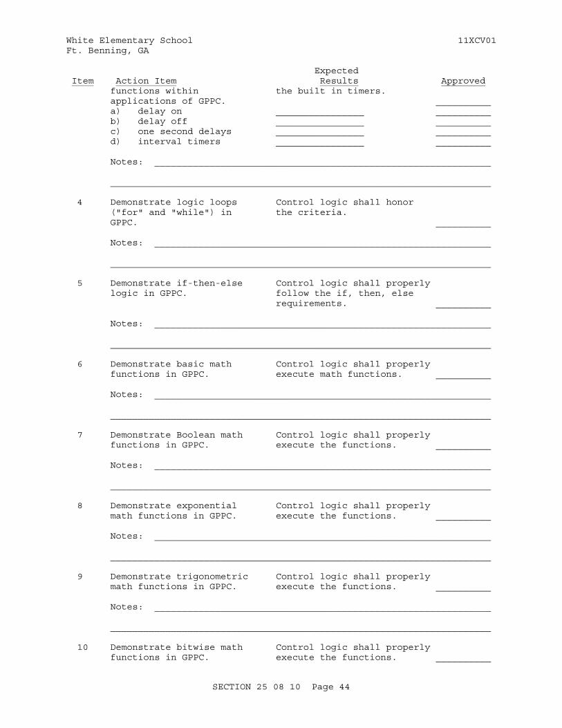
White Elementary School 11XCV01Ft. Benning, GA
Expected Item Action Item Results Approved functions within the built in timers. applications of GPPC. __________ a) delay on ________________ __________ b) delay off ________________ __________ c) one second delays ________________ __________ d) interval timers ________________ __________
Notes: _____________________________________________________________
_____________________________________________________________________
4 Demonstrate logic loops Control logic shall honor ("for" and "while") in the criteria. GPPC. __________
Notes: _____________________________________________________________
_____________________________________________________________________
5 Demonstrate if-then-else Control logic shall properly logic in GPPC. follow the if, then, else requirements. __________
Notes: _____________________________________________________________
_____________________________________________________________________
6 Demonstrate basic math Control logic shall properly functions in GPPC. execute math functions. __________
Notes: _____________________________________________________________
_____________________________________________________________________
7 Demonstrate Boolean math Control logic shall properly functions in GPPC. execute the functions. __________
Notes: _____________________________________________________________
_____________________________________________________________________
8 Demonstrate exponential Control logic shall properly math functions in GPPC. execute the functions. __________
Notes: _____________________________________________________________
_____________________________________________________________________
9 Demonstrate trigonometric Control logic shall properly math functions in GPPC. execute the functions. __________
Notes: _____________________________________________________________
_____________________________________________________________________
10 Demonstrate bitwise math Control logic shall properly functions in GPPC. execute the functions. __________
SECTION 25 08 10 Page 44
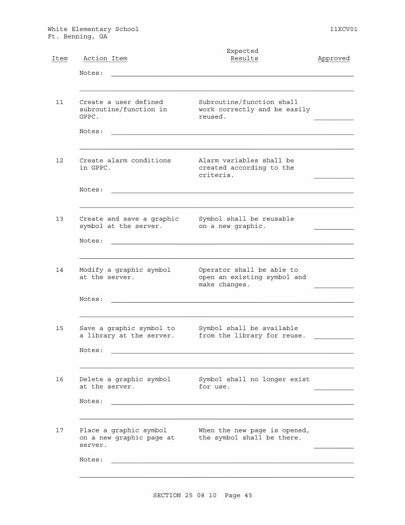
White Elementary School 11XCV01Ft. Benning, GA
Expected Item Action Item Results Approved
Notes: _____________________________________________________________
_____________________________________________________________________
11 Create a user defined Subroutine/function shall subroutine/function in work correctly and be easily GPPC. reused. __________
Notes: _____________________________________________________________
_____________________________________________________________________
12 Create alarm conditions Alarm variables shall be in GPPC. created according to the criteria. __________
Notes: _____________________________________________________________
_____________________________________________________________________
13 Create and save a graphic Symbol shall be reusable symbol at the server. on a new graphic. __________
Notes: _____________________________________________________________
_____________________________________________________________________
14 Modify a graphic symbol Operator shall be able to at the server. open an existing symbol and make changes. __________
Notes: _____________________________________________________________ _____________________________________________________________________
15 Save a graphic symbol to Symbol shall be available a library at the server. from the library for reuse. __________
Notes: _____________________________________________________________ _____________________________________________________________________
16 Delete a graphic symbol Symbol shall no longer exist at the server. for use. __________
Notes: _____________________________________________________________ _____________________________________________________________________
17 Place a graphic symbol When the new page is opened, on a new graphic page at the symbol shall be there. server. __________
Notes: _____________________________________________________________
_____________________________________________________________________
SECTION 25 08 10 Page 45
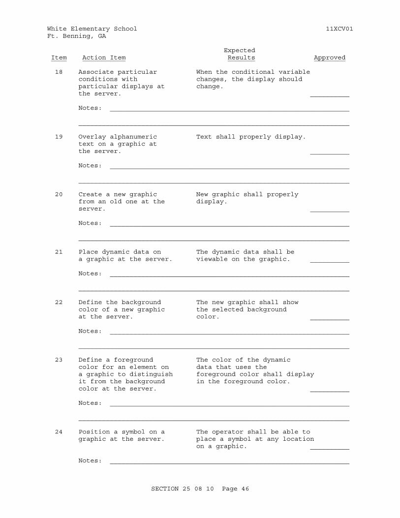
White Elementary School 11XCV01Ft. Benning, GA
Expected Item Action Item Results Approved
18 Associate particular When the conditional variable conditions with changes, the display should particular displays at change. the server. __________
Notes: _____________________________________________________________
_____________________________________________________________________
19 Overlay alphanumeric Text shall properly display. text on a graphic at the server. __________
Notes: _____________________________________________________________
_____________________________________________________________________
20 Create a new graphic New graphic shall properly from an old one at the display. server. __________
Notes: _____________________________________________________________
_____________________________________________________________________
21 Place dynamic data on The dynamic data shall be a graphic at the server. viewable on the graphic. __________
Notes: _____________________________________________________________
_____________________________________________________________________
22 Define the background The new graphic shall show color of a new graphic the selected background at the server. color. __________
Notes: _____________________________________________________________
_____________________________________________________________________
23 Define a foreground The color of the dynamic color for an element on data that uses the a graphic to distinguish foreground color shall display it from the background in the foreground color. color at the server. __________
Notes: _____________________________________________________________
_____________________________________________________________________
24 Position a symbol on a The operator shall be able to graphic at the server. place a symbol at any location on a graphic. __________
Notes: _____________________________________________________________
SECTION 25 08 10 Page 46
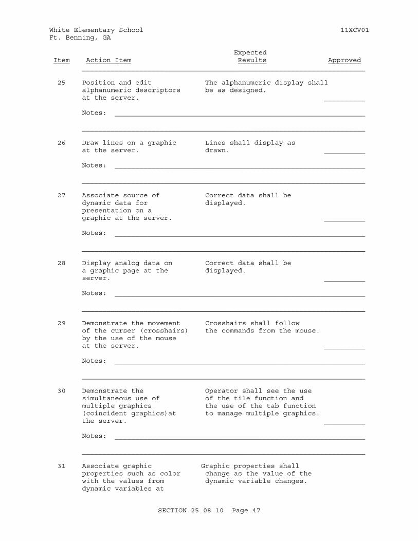
White Elementary School 11XCV01Ft. Benning, GA
Expected Item Action Item Results Approved _____________________________________________________________________
25 Position and edit The alphanumeric display shall alphanumeric descriptors be as designed. at the server. __________
Notes: _____________________________________________________________
_____________________________________________________________________
26 Draw lines on a graphic Lines shall display as at the server. drawn. __________
Notes: _____________________________________________________________
_____________________________________________________________________
27 Associate source of Correct data shall be dynamic data for displayed. presentation on a graphic at the server. __________ Notes: _____________________________________________________________
_____________________________________________________________________
28 Display analog data on Correct data shall be a graphic page at the displayed. server. __________
Notes: _____________________________________________________________
_____________________________________________________________________
29 Demonstrate the movement Crosshairs shall follow of the curser (crosshairs) the commands from the mouse. by the use of the mouse at the server. __________
Notes: _____________________________________________________________
_____________________________________________________________________
30 Demonstrate the Operator shall see the use simultaneous use of of the tile function and multiple graphics the use of the tab function (coincident graphics)at to manage multiple graphics. the server. __________
Notes: _____________________________________________________________
_____________________________________________________________________
31 Associate graphic Graphic properties shall properties such as color change as the value of the with the values from dynamic variable changes. dynamic variables at
SECTION 25 08 10 Page 47
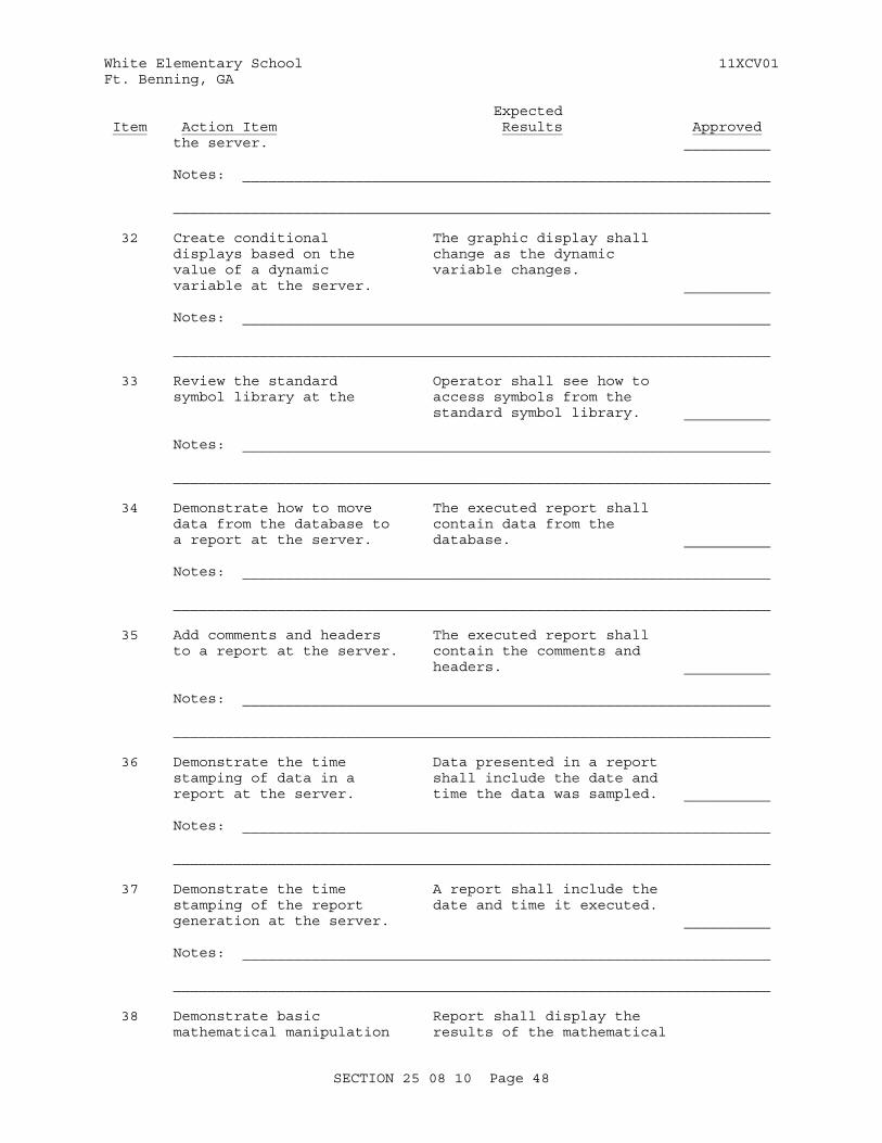
White Elementary School 11XCV01Ft. Benning, GA
Expected Item Action Item Results Approved the server. __________
Notes: _____________________________________________________________
_____________________________________________________________________
32 Create conditional The graphic display shall displays based on the change as the dynamic value of a dynamic variable changes. variable at the server. __________
Notes: _____________________________________________________________
_____________________________________________________________________
33 Review the standard Operator shall see how to symbol library at the access symbols from the standard symbol library. __________
Notes: _____________________________________________________________
_____________________________________________________________________
34 Demonstrate how to move The executed report shall data from the database to contain data from the a report at the server. database. __________
Notes: _____________________________________________________________
_____________________________________________________________________
35 Add comments and headers The executed report shall to a report at the server. contain the comments and headers. __________
Notes: _____________________________________________________________
_____________________________________________________________________
36 Demonstrate the time Data presented in a report stamping of data in a shall include the date and report at the server. time the data was sampled. __________
Notes: _____________________________________________________________
_____________________________________________________________________
37 Demonstrate the time A report shall include the stamping of the report date and time it executed. generation at the server. __________
Notes: _____________________________________________________________
_____________________________________________________________________
38 Demonstrate basic Report shall display the mathematical manipulation results of the mathematical
SECTION 25 08 10 Page 48
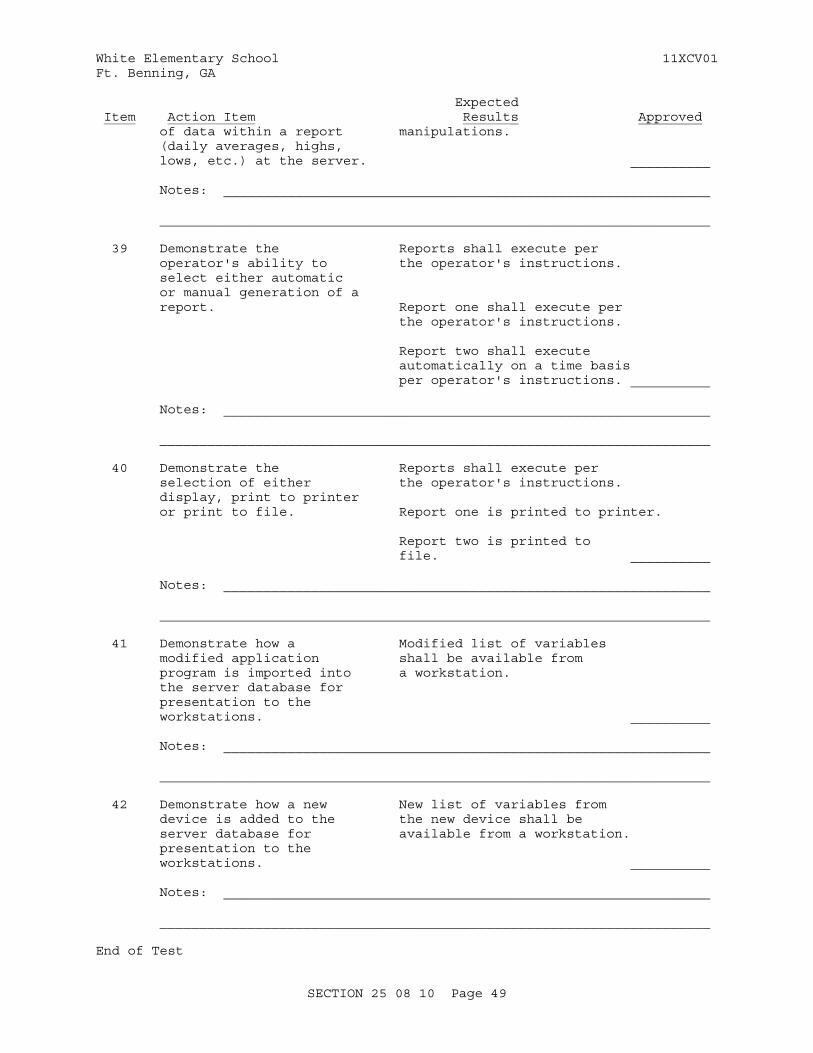
White Elementary School 11XCV01Ft. Benning, GA
Expected Item Action Item Results Approved of data within a report manipulations. (daily averages, highs, lows, etc.) at the server. __________
Notes: _____________________________________________________________
_____________________________________________________________________
39 Demonstrate the Reports shall execute per operator's ability to the operator's instructions. select either automatic or manual generation of a report. Report one shall execute per the operator's instructions.
Report two shall execute automatically on a time basis per operator's instructions. __________
Notes: _____________________________________________________________ _____________________________________________________________________
40 Demonstrate the Reports shall execute per selection of either the operator's instructions. display, print to printer or print to file. Report one is printed to printer.
Report two is printed to file. __________ Notes: _____________________________________________________________
_____________________________________________________________________
41 Demonstrate how a Modified list of variables modified application shall be available from program is imported into a workstation. the server database for presentation to the workstations. __________
Notes: _____________________________________________________________
_____________________________________________________________________
42 Demonstrate how a new New list of variables from device is added to the the new device shall be server database for available from a workstation. presentation to the workstations. __________
Notes: _____________________________________________________________
_____________________________________________________________________
End of Test
SECTION 25 08 10 Page 49

White Elementary School 11XCV01Ft. Benning, GA
Expected Item Action Item Results Approved
Specific Abbreviations: Y = Yes N = No NA = Not Applicable
SECTION 25 08 10 Page 50
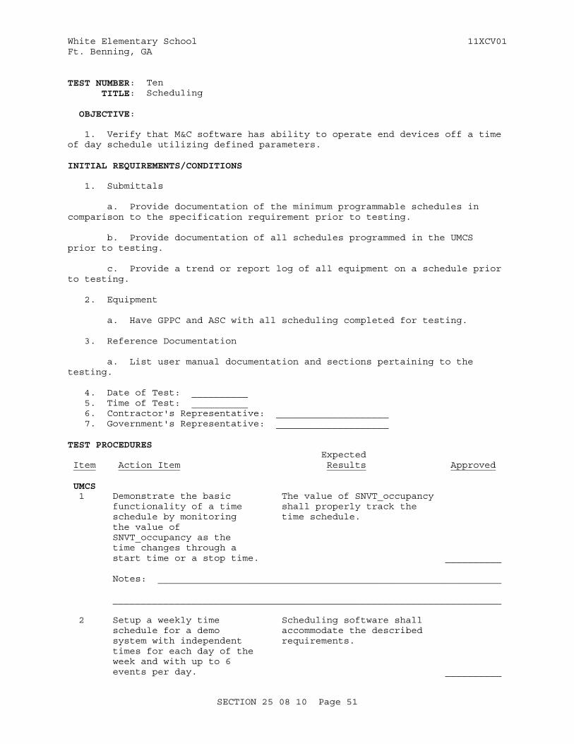
White Elementary School 11XCV01Ft. Benning, GA
TEST NUMBER: Ten TITLE: Scheduling
OBJECTIVE:
1. Verify that M&C software has ability to operate end devices off a time of day schedule utilizing defined parameters.
INITIAL REQUIREMENTS/CONDITIONS
1. Submittals
a. Provide documentation of the minimum programmable schedules in comparison to the specification requirement prior to testing.
b. Provide documentation of all schedules programmed in the UMCS prior to testing. c. Provide a trend or report log of all equipment on a schedule prior to testing.
2. Equipment
a. Have GPPC and ASC with all scheduling completed for testing.
3. Reference Documentation
a. List user manual documentation and sections pertaining to the testing.
4. Date of Test: __________ 5. Time of Test: __________ 6. Contractor's Representative: ____________________ 7. Government's Representative: ____________________
TEST PROCEDURES Expected Item Action Item Results Approved
UMCS 1 Demonstrate the basic The value of SNVT_occupancy functionality of a time shall properly track the schedule by monitoring time schedule. the value of SNVT_occupancy as the time changes through a start time or a stop time. __________
Notes: _____________________________________________________________
_____________________________________________________________________
2 Setup a weekly time Scheduling software shall schedule for a demo accommodate the described system with independent requirements. times for each day of the week and with up to 6 events per day. __________
SECTION 25 08 10 Page 51
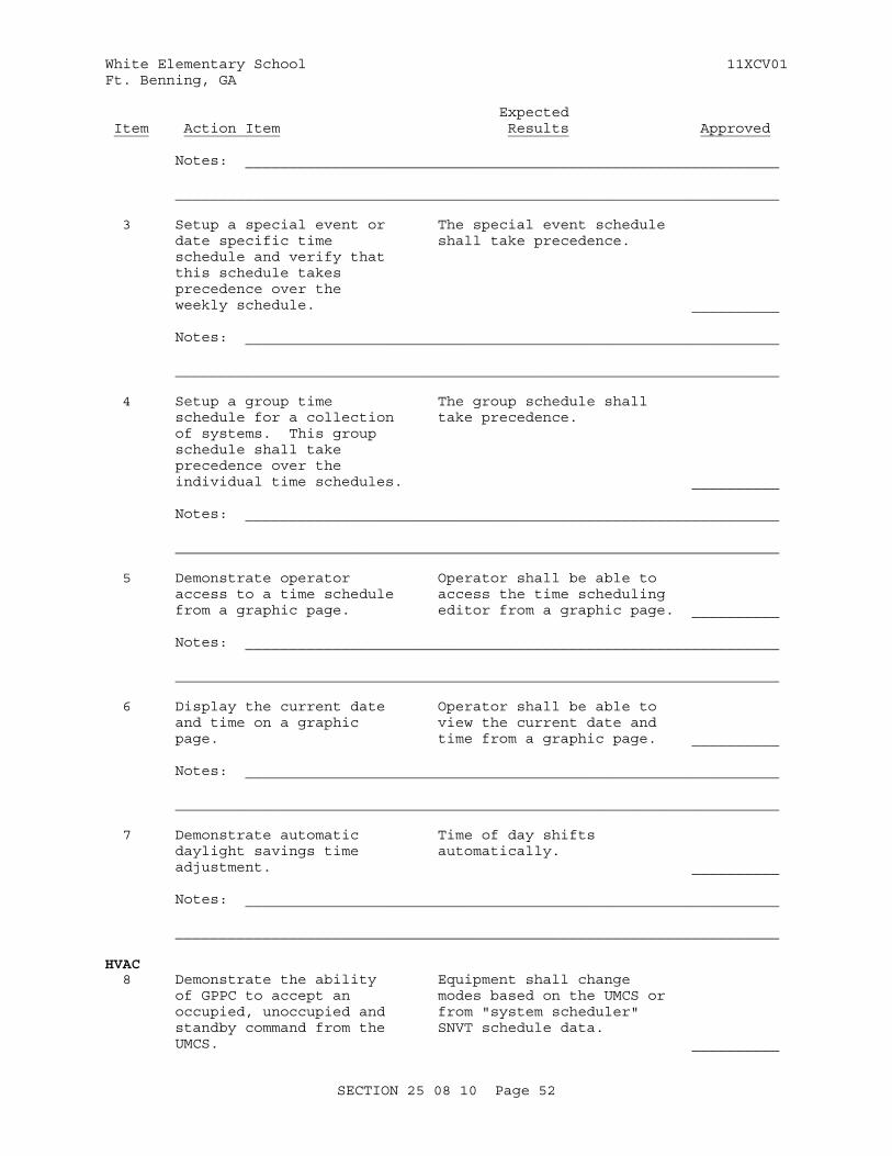
White Elementary School 11XCV01Ft. Benning, GA
Expected Item Action Item Results Approved
Notes: _____________________________________________________________
_____________________________________________________________________
3 Setup a special event or The special event schedule date specific time shall take precedence. schedule and verify that this schedule takes precedence over the weekly schedule. __________
Notes: _____________________________________________________________
_____________________________________________________________________
4 Setup a group time The group schedule shall schedule for a collection take precedence. of systems. This group schedule shall take precedence over the individual time schedules. __________
Notes: _____________________________________________________________
_____________________________________________________________________
5 Demonstrate operator Operator shall be able to access to a time schedule access the time scheduling from a graphic page. editor from a graphic page. __________ Notes: _____________________________________________________________
_____________________________________________________________________
6 Display the current date Operator shall be able to and time on a graphic view the current date and page. time from a graphic page. __________
Notes: _____________________________________________________________
_____________________________________________________________________
7 Demonstrate automatic Time of day shifts daylight savings time automatically. adjustment. __________ Notes: _____________________________________________________________
_____________________________________________________________________
HVAC 8 Demonstrate the ability Equipment shall change of GPPC to accept an modes based on the UMCS or occupied, unoccupied and from "system scheduler" standby command from the SNVT schedule data. UMCS. __________
SECTION 25 08 10 Page 52
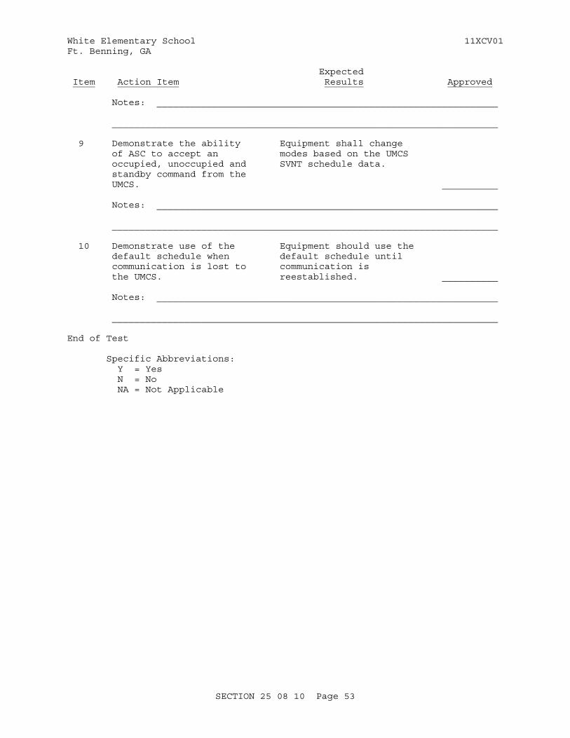
White Elementary School 11XCV01Ft. Benning, GA
Expected Item Action Item Results Approved
Notes: _____________________________________________________________
_____________________________________________________________________
9 Demonstrate the ability Equipment shall change of ASC to accept an modes based on the UMCS occupied, unoccupied and SVNT schedule data. standby command from the UMCS. __________
Notes: _____________________________________________________________
_____________________________________________________________________
10 Demonstrate use of the Equipment should use the default schedule when default schedule until communication is lost to communication is the UMCS. reestablished. __________
Notes: _____________________________________________________________
_____________________________________________________________________
End of Test
Specific Abbreviations: Y = Yes N = No NA = Not Applicable
SECTION 25 08 10 Page 53
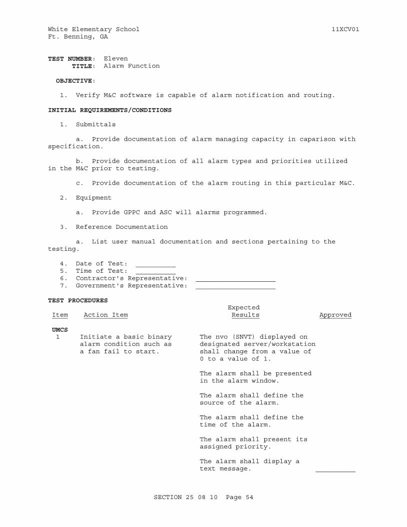
White Elementary School 11XCV01Ft. Benning, GA
TEST NUMBER: Eleven TITLE: Alarm Function
OBJECTIVE:
1. Verify M&C software is capable of alarm notification and routing.
INITIAL REQUIREMENTS/CONDITIONS
1. Submittals
a. Provide documentation of alarm managing capacity in caparison with specification.
b. Provide documentation of all alarm types and priorities utilized in the M&C prior to testing.
c. Provide documentation of the alarm routing in this particular M&C.
2. Equipment
a. Provide GPPC and ASC will alarms programmed.
3. Reference Documentation
a. List user manual documentation and sections pertaining to the testing.
4. Date of Test: __________ 5. Time of Test: __________ 6. Contractor's Representative: ____________________ 7. Government's Representative: ____________________
TEST PROCEDURES Expected Item Action Item Results Approved
UMCS 1 Initiate a basic binary The nvo (SNVT) displayed on alarm condition such as designated server/workstation a fan fail to start. shall change from a value of 0 to a value of 1.
The alarm shall be presented in the alarm window.
The alarm shall define the source of the alarm.
The alarm shall define the time of the alarm.
The alarm shall present its assigned priority.
The alarm shall display a text message. __________
SECTION 25 08 10 Page 54
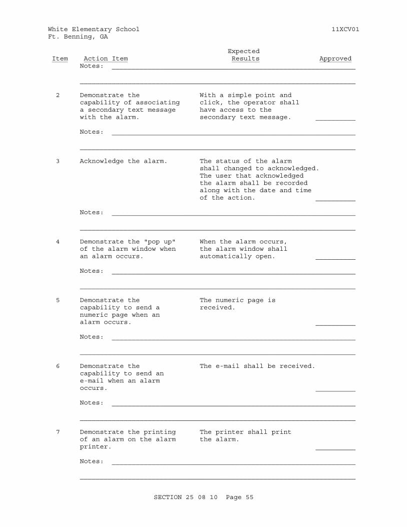
White Elementary School 11XCV01Ft. Benning, GA
Expected Item Action Item Results Approved Notes: _____________________________________________________________
_____________________________________________________________________
2 Demonstrate the With a simple point and capability of associating click, the operator shall a secondary text message have access to the with the alarm. secondary text message. __________
Notes: _____________________________________________________________
_____________________________________________________________________
3 Acknowledge the alarm. The status of the alarm shall changed to acknowledged. The user that acknowledged the alarm shall be recorded along with the date and time of the action. __________
Notes: _____________________________________________________________
_____________________________________________________________________
4 Demonstrate the "pop up" When the alarm occurs, of the alarm window when the alarm window shall an alarm occurs. automatically open. __________
Notes: _____________________________________________________________
_____________________________________________________________________
5 Demonstrate the The numeric page is capability to send a received. numeric page when an alarm occurs. __________
Notes: _____________________________________________________________
_____________________________________________________________________
6 Demonstrate the The e-mail shall be received. capability to send an e-mail when an alarm occurs. __________
Notes: _____________________________________________________________
_____________________________________________________________________
7 Demonstrate the printing The printer shall print of an alarm on the alarm the alarm. printer. __________
Notes: _____________________________________________________________
_____________________________________________________________________
SECTION 25 08 10 Page 55
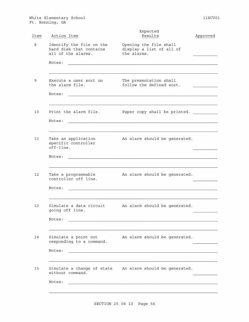
White Elementary School 11XCV01Ft. Benning, GA
Expected Item Action Item Results Approved
8 Identify the file on the Opening the file shall hard disk that contains display a list of all of all of the alarms. the alarms. __________
Notes: _____________________________________________________________
_____________________________________________________________________
9 Execute a user sort on The presentation shall the alarm file. follow the defined sort. __________
Notes: _____________________________________________________________
_____________________________________________________________________
10 Print the alarm file. Paper copy shall be printed. __________
Notes: _____________________________________________________________
_____________________________________________________________________
11 Take an application An alarm should be generated. specific controller off-line. __________
Notes: _____________________________________________________________
_____________________________________________________________________
12 Take a programmable An alarm should be generated. controller off line. __________
Notes: _____________________________________________________________
_____________________________________________________________________
13 Simulate a data circuit An alarm should be generated. going off line. __________
Notes: _____________________________________________________________
_____________________________________________________________________
14 Simulate a point not An alarm should be generated. responding to a command. __________
Notes: _____________________________________________________________
_____________________________________________________________________
15 Simulate a change of state An alarm should be generated. without command. __________
Notes: _____________________________________________________________
_____________________________________________________________________
SECTION 25 08 10 Page 56
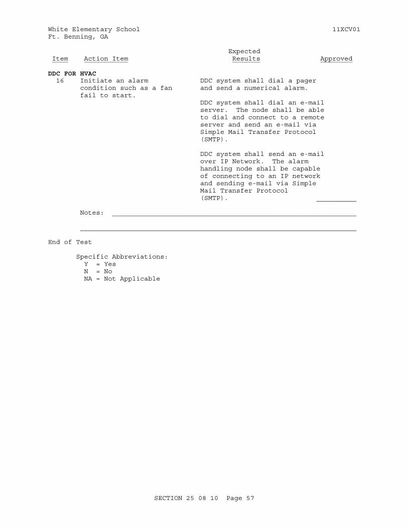
White Elementary School 11XCV01Ft. Benning, GA
Expected Item Action Item Results Approved
DDC FOR HVAC 16 Initiate an alarm DDC system shall dial a pager condition such as a fan and send a numerical alarm. fail to start. DDC system shall dial an e-mail server. The node shall be able to dial and connect to a remote server and send an e-mail via Simple Mail Transfer Protocol (SMTP).
DDC system shall send an e-mail over IP Network. The alarm handling node shall be capable of connecting to an IP network and sending e-mail via Simple Mail Transfer Protocol (SMTP). __________
Notes: _____________________________________________________________
_____________________________________________________________________
End of Test
Specific Abbreviations: Y = Yes N = No NA = Not Applicable
SECTION 25 08 10 Page 57
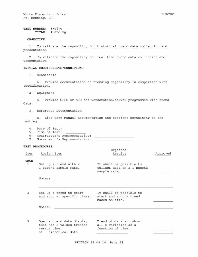
White Elementary School 11XCV01Ft. Benning, GA
TEST NUMBER: Twelve TITLE: Trending
OBJECTIVE:
1. To validate the capability for historical trend data collection and presentation
2. To validate the capability for real time trend data collection and presentation
INITIAL REQUIREMENTS/CONDITIONS
1. Submittals
a. Provide documentation of trending capability in comparison with specification.
2. Equipment
a. Provide GPPC or ASC and workstation/server programmed with trend data.
3. Reference Documentation
a. List user manual documentation and sections pertaining to the testing.
4. Date of Test: __________ 5. Time of Test: __________ 6. Contractor's Representative: ____________________ 7. Government's Representative: ____________________
TEST PROCEDURES Expected Item Action Item Results Approved
UMCS 1 Set up a trend with a It shall be possible to 1 second sample rate. collect data on a 1 second sample rate. __________ Notes: _____________________________________________________________
_____________________________________________________________________
2 Set up a trend to start It shall be possible to and stop at specific times. start and stop a trend based on time. __________
Notes: _____________________________________________________________
_____________________________________________________________________
3 Open a trend data display Trend plots shall show that has 8 values trended all 8 variables as a versus time. function of time. __________ a) historical data ________________ __________
SECTION 25 08 10 Page 58
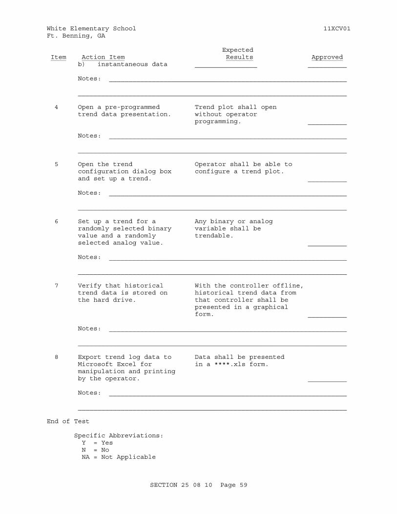
White Elementary School 11XCV01Ft. Benning, GA
Expected Item Action Item Results Approved b) instantaneous data ________________ __________
Notes: _____________________________________________________________
_____________________________________________________________________
4 Open a pre-programmed Trend plot shall open trend data presentation. without operator programming. __________
Notes: _____________________________________________________________
_____________________________________________________________________
5 Open the trend Operator shall be able to configuration dialog box configure a trend plot. and set up a trend. __________
Notes: _____________________________________________________________
_____________________________________________________________________
6 Set up a trend for a Any binary or analog randomly selected binary variable shall be value and a randomly trendable. selected analog value. __________
Notes: _____________________________________________________________
_____________________________________________________________________
7 Verify that historical With the controller offline, trend data is stored on historical trend data from the hard drive. that controller shall be presented in a graphical form. __________
Notes: _____________________________________________________________
_____________________________________________________________________
8 Export trend log data to Data shall be presented Microsoft Excel for in a ****.xls form. manipulation and printing by the operator. __________ Notes: _____________________________________________________________
_____________________________________________________________________
End of Test
Specific Abbreviations: Y = Yes N = No NA = Not Applicable
SECTION 25 08 10 Page 59

White Elementary School 11XCV01Ft. Benning, GA
SECTION 25 08 10 Page 60
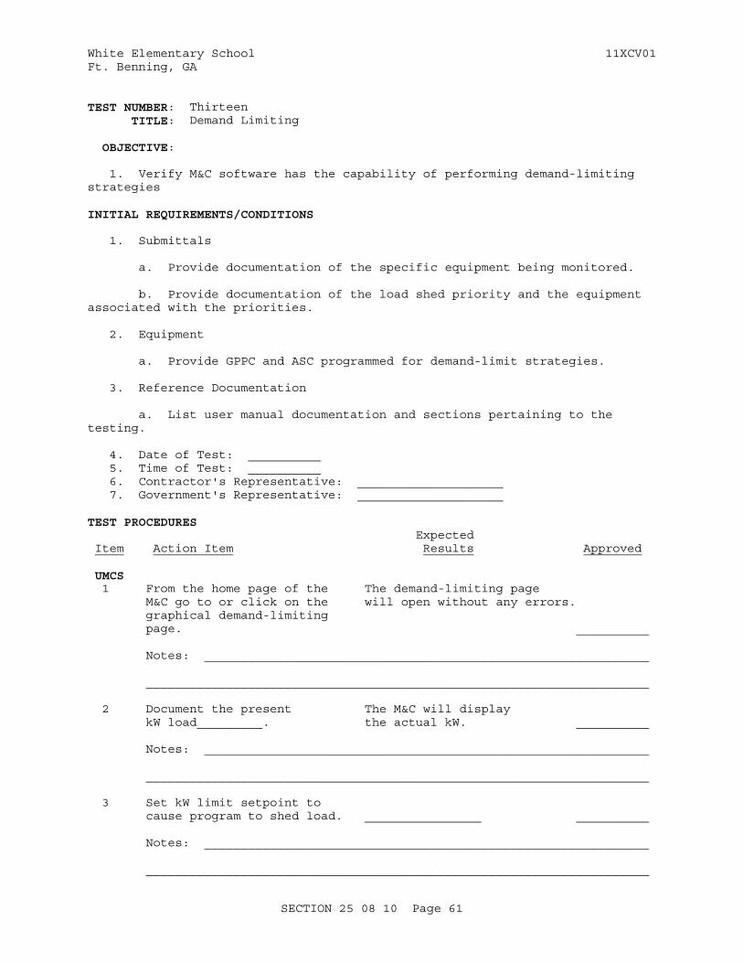
White Elementary School 11XCV01Ft. Benning, GA
TEST NUMBER: Thirteen TITLE: Demand Limiting
OBJECTIVE:
1. Verify M&C software has the capability of performing demand-limiting strategies
INITIAL REQUIREMENTS/CONDITIONS
1. Submittals
a. Provide documentation of the specific equipment being monitored.
b. Provide documentation of the load shed priority and the equipment associated with the priorities.
2. Equipment
a. Provide GPPC and ASC programmed for demand-limit strategies.
3. Reference Documentation
a. List user manual documentation and sections pertaining to the testing.
4. Date of Test: __________ 5. Time of Test: __________ 6. Contractor's Representative: ____________________ 7. Government's Representative: ____________________
TEST PROCEDURES Expected Item Action Item Results Approved
UMCS 1 From the home page of the The demand-limiting page M&C go to or click on the will open without any errors. graphical demand-limiting page. __________
Notes: _____________________________________________________________
_____________________________________________________________________
2 Document the present The M&C will display kW load_________. the actual kW. __________
Notes: _____________________________________________________________
_____________________________________________________________________
3 Set kW limit setpoint to cause program to shed load. ________________ __________
Notes: _____________________________________________________________
_____________________________________________________________________
SECTION 25 08 10 Page 61
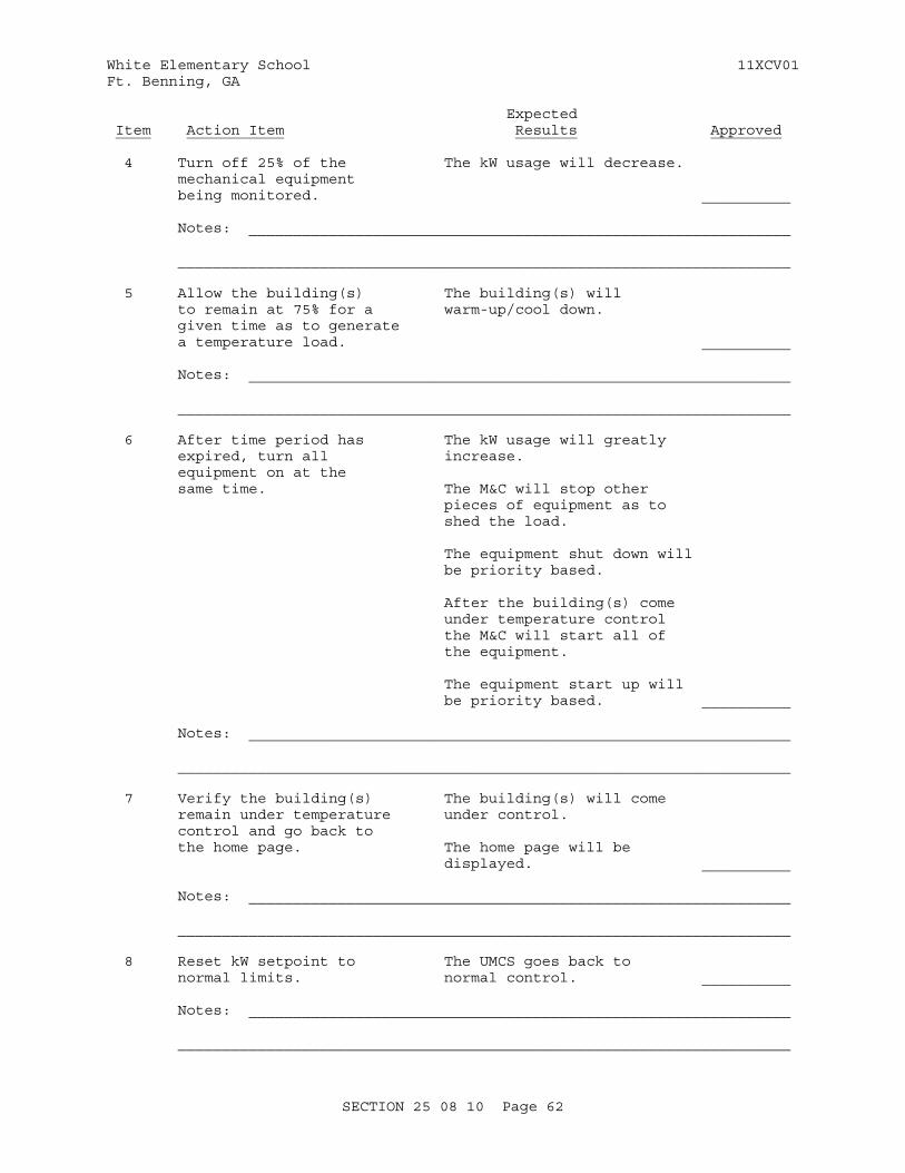
White Elementary School 11XCV01Ft. Benning, GA
Expected Item Action Item Results Approved
4 Turn off 25% of the The kW usage will decrease. mechanical equipment being monitored. __________
Notes: _____________________________________________________________
_____________________________________________________________________
5 Allow the building(s) The building(s) will to remain at 75% for a warm-up/cool down. given time as to generate a temperature load. __________
Notes: _____________________________________________________________
_____________________________________________________________________
6 After time period has The kW usage will greatly expired, turn all increase. equipment on at the same time. The M&C will stop other pieces of equipment as to shed the load. The equipment shut down will be priority based.
After the building(s) come under temperature control the M&C will start all of the equipment.
The equipment start up will be priority based. __________
Notes: _____________________________________________________________
_____________________________________________________________________
7 Verify the building(s) The building(s) will come remain under temperature under control. control and go back to the home page. The home page will be displayed. __________
Notes: _____________________________________________________________
_____________________________________________________________________
8 Reset kW setpoint to The UMCS goes back to normal limits. normal control. __________
Notes: _____________________________________________________________
_____________________________________________________________________
SECTION 25 08 10 Page 62

White Elementary School 11XCV01Ft. Benning, GA
Expected Item Action Item Results ApprovedEnd of Test
Specific Abbreviations: Y = Yes N = No NA = Not Applicable
SECTION 25 08 10 Page 63
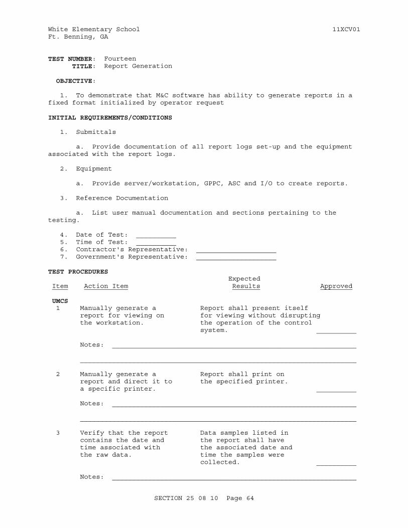
White Elementary School 11XCV01Ft. Benning, GA
TEST NUMBER: Fourteen TITLE: Report Generation
OBJECTIVE:
1. To demonstrate that M&C software has ability to generate reports in a fixed format initialized by operator request
INITIAL REQUIREMENTS/CONDITIONS
1. Submittals
a. Provide documentation of all report logs set-up and the equipment associated with the report logs.
2. Equipment
a. Provide server/workstation, GPPC, ASC and I/O to create reports.
3. Reference Documentation
a. List user manual documentation and sections pertaining to the testing.
4. Date of Test: __________ 5. Time of Test: __________ 6. Contractor's Representative: ____________________ 7. Government's Representative: ____________________
TEST PROCEDURES Expected Item Action Item Results Approved
UMCS 1 Manually generate a Report shall present itself report for viewing on for viewing without disrupting the workstation. the operation of the control system. __________
Notes: _____________________________________________________________
_____________________________________________________________________
2 Manually generate a Report shall print on report and direct it to the specified printer. a specific printer. __________
Notes: _____________________________________________________________
_____________________________________________________________________
3 Verify that the report Data samples listed in contains the date and the report shall have time associated with the associated date and the raw data. time the samples were collected. __________
Notes: _____________________________________________________________
SECTION 25 08 10 Page 64
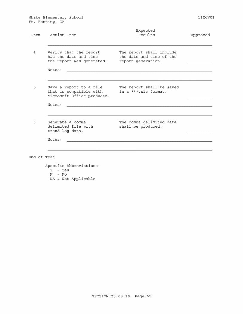
White Elementary School 11XCV01Ft. Benning, GA
Expected Item Action Item Results Approved
_____________________________________________________________________
4 Verify that the report The report shall include has the date and time the date and time of the the report was generated. report generation. __________ Notes: _____________________________________________________________
_____________________________________________________________________
5 Save a report to a file The report shall be saved that is compatible with in a ***.xls format. Microsoft Office products. __________
Notes: _____________________________________________________________
_____________________________________________________________________
6 Generate a comma The comma delimited data delimited file with shall be produced. trend log data. __________
Notes: _____________________________________________________________
_____________________________________________________________________
End of Test
Specific Abbreviations: Y = Yes N = No NA = Not Applicable
SECTION 25 08 10 Page 65
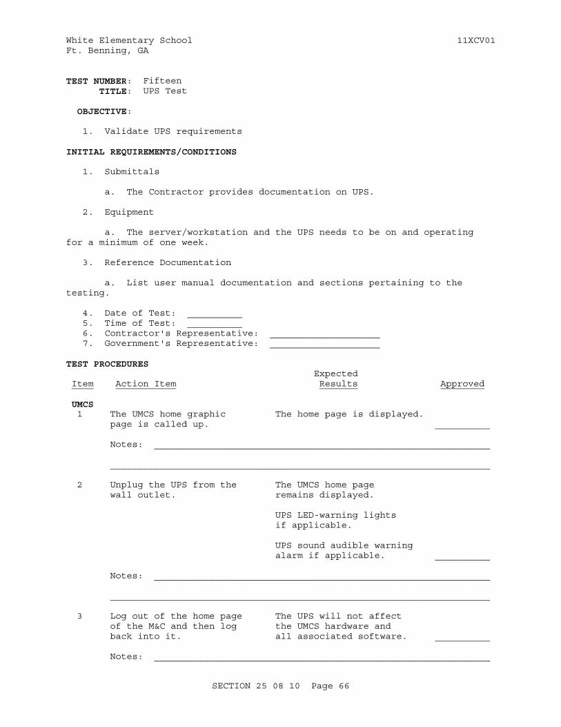
White Elementary School 11XCV01Ft. Benning, GA
TEST NUMBER: Fifteen TITLE: UPS Test
OBJECTIVE:
1. Validate UPS requirements
INITIAL REQUIREMENTS/CONDITIONS
1. Submittals
a. The Contractor provides documentation on UPS.
2. Equipment
a. The server/workstation and the UPS needs to be on and operating for a minimum of one week.
3. Reference Documentation
a. List user manual documentation and sections pertaining to the testing.
4. Date of Test: __________ 5. Time of Test: __________ 6. Contractor's Representative: ____________________ 7. Government's Representative: ____________________
TEST PROCEDURES Expected Item Action Item Results Approved
UMCS 1 The UMCS home graphic The home page is displayed. page is called up. __________
Notes: _____________________________________________________________
_____________________________________________________________________
2 Unplug the UPS from the The UMCS home page wall outlet. remains displayed.
UPS LED-warning lights if applicable.
UPS sound audible warning alarm if applicable. __________
Notes: _____________________________________________________________
_____________________________________________________________________
3 Log out of the home page The UPS will not affect of the M&C and then log the UMCS hardware and back into it. all associated software. __________
Notes: _____________________________________________________________
SECTION 25 08 10 Page 66
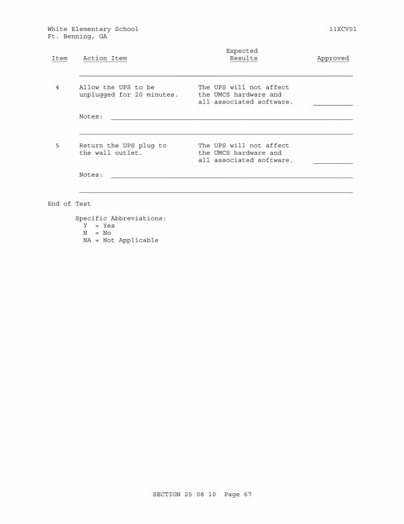
White Elementary School 11XCV01Ft. Benning, GA
Expected Item Action Item Results Approved
_____________________________________________________________________
4 Allow the UPS to be The UPS will not affect unplugged for 20 minutes. the UMCS hardware and all associated software. __________
Notes: _____________________________________________________________
_____________________________________________________________________
5 Return the UPS plug to The UPS will not affect the wall outlet. the UMCS hardware and all associated software. __________
Notes: _____________________________________________________________
_____________________________________________________________________
End of Test
Specific Abbreviations: Y = Yes N = No NA = Not Applicable
SECTION 25 08 10 Page 67
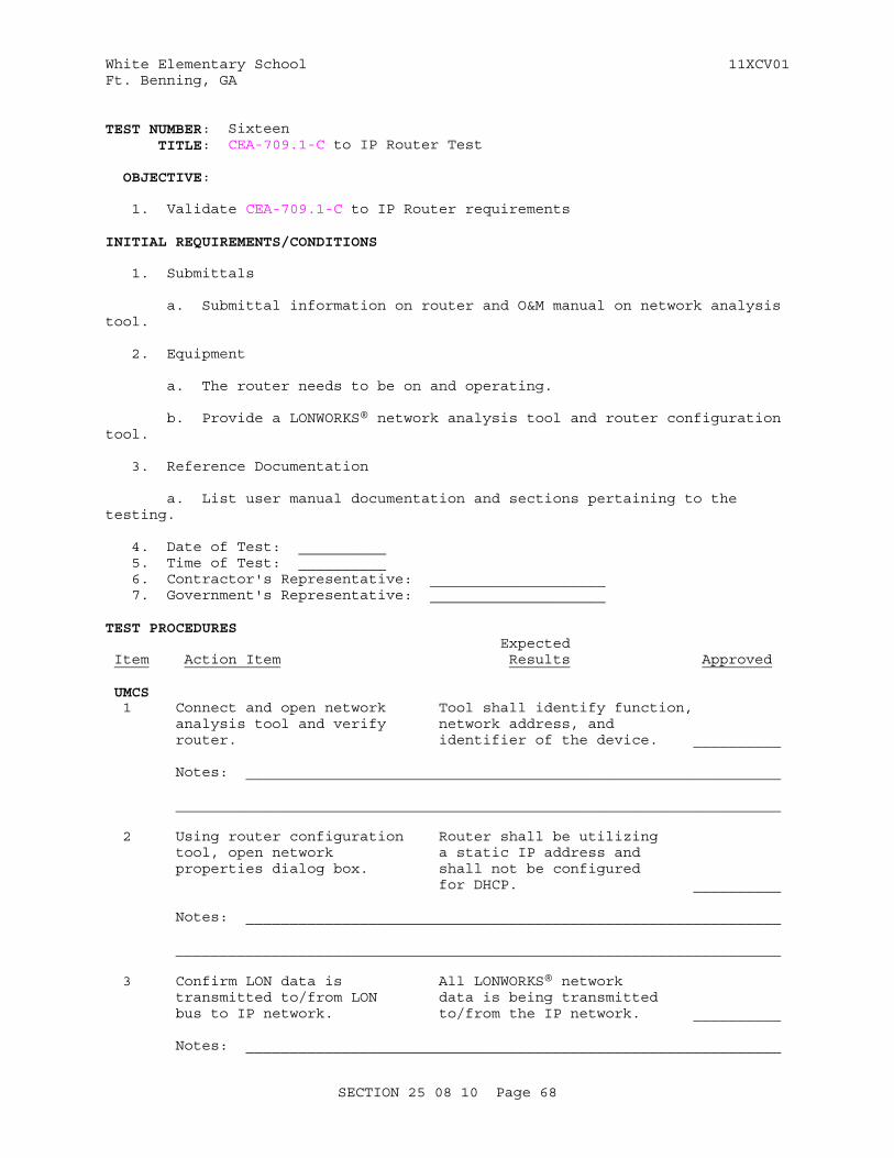
White Elementary School 11XCV01Ft. Benning, GA
TEST NUMBER: Sixteen TITLE: CEA-709.1-C to IP Router Test
OBJECTIVE:
1. Validate CEA-709.1-C to IP Router requirements
INITIAL REQUIREMENTS/CONDITIONS
1. Submittals
a. Submittal information on router and O&M manual on network analysis tool.
2. Equipment
a. The router needs to be on and operating.
b. Provide a LONWORKS® network analysis tool and router configuration tool.
3. Reference Documentation
a. List user manual documentation and sections pertaining to the testing.
4. Date of Test: __________ 5. Time of Test: __________ 6. Contractor's Representative: ____________________ 7. Government's Representative: ____________________
TEST PROCEDURES Expected Item Action Item Results Approved
UMCS 1 Connect and open network Tool shall identify function, analysis tool and verify network address, and router. identifier of the device. __________
Notes: _____________________________________________________________
_____________________________________________________________________
2 Using router configuration Router shall be utilizing tool, open network a static IP address and properties dialog box. shall not be configured for DHCP. __________
Notes: _____________________________________________________________
_____________________________________________________________________
3 Confirm LON data is All LONWORKS® network transmitted to/from LON data is being transmitted bus to IP network. to/from the IP network. __________
Notes: _____________________________________________________________
SECTION 25 08 10 Page 68

White Elementary School 11XCV01Ft. Benning, GA
Expected Item Action Item Results Approved
_____________________________________________________________________
End of Test
Specific Abbreviations: Y = Yes N = No NA = Not Applicable
SECTION 25 08 10 Page 69
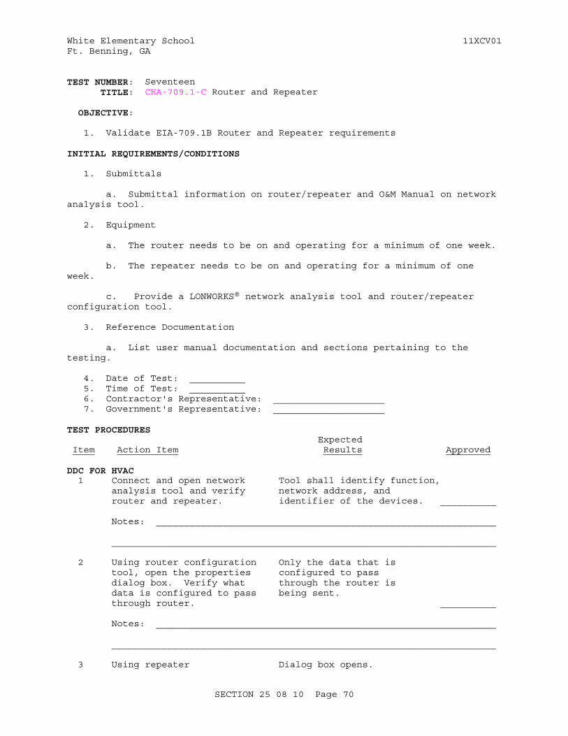
White Elementary School 11XCV01Ft. Benning, GA
TEST NUMBER: Seventeen TITLE: CEA-709.1-C Router and Repeater
OBJECTIVE:
1. Validate EIA-709.1B Router and Repeater requirements
INITIAL REQUIREMENTS/CONDITIONS
1. Submittals
a. Submittal information on router/repeater and O&M Manual on network analysis tool.
2. Equipment
a. The router needs to be on and operating for a minimum of one week.
b. The repeater needs to be on and operating for a minimum of one week.
c. Provide a LONWORKS® network analysis tool and router/repeater configuration tool.
3. Reference Documentation
a. List user manual documentation and sections pertaining to the testing.
4. Date of Test: __________ 5. Time of Test: __________ 6. Contractor's Representative: ____________________ 7. Government's Representative: ____________________
TEST PROCEDURES Expected Item Action Item Results Approved
DDC FOR HVAC 1 Connect and open network Tool shall identify function, analysis tool and verify network address, and router and repeater. identifier of the devices. __________
Notes: _____________________________________________________________
_____________________________________________________________________
2 Using router configuration Only the data that is tool, open the properties configured to pass dialog box. Verify what through the router is data is configured to pass being sent. through router. __________
Notes: _____________________________________________________________
_____________________________________________________________________
3 Using repeater Dialog box opens.
SECTION 25 08 10 Page 70
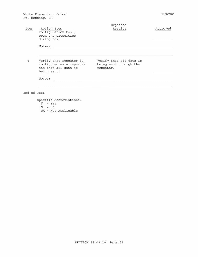
White Elementary School 11XCV01Ft. Benning, GA
Expected Item Action Item Results Approved configuration tool, open the properties dialog box. __________
Notes: _____________________________________________________________
_____________________________________________________________________
4 Verify that repeater is Verify that all data is configured as a repeater being sent through the and that all data is repeater. being sent. __________
Notes: _____________________________________________________________
_____________________________________________________________________
End of Test
Specific Abbreviations: Y = Yes N = No NA = Not Applicable
SECTION 25 08 10 Page 71
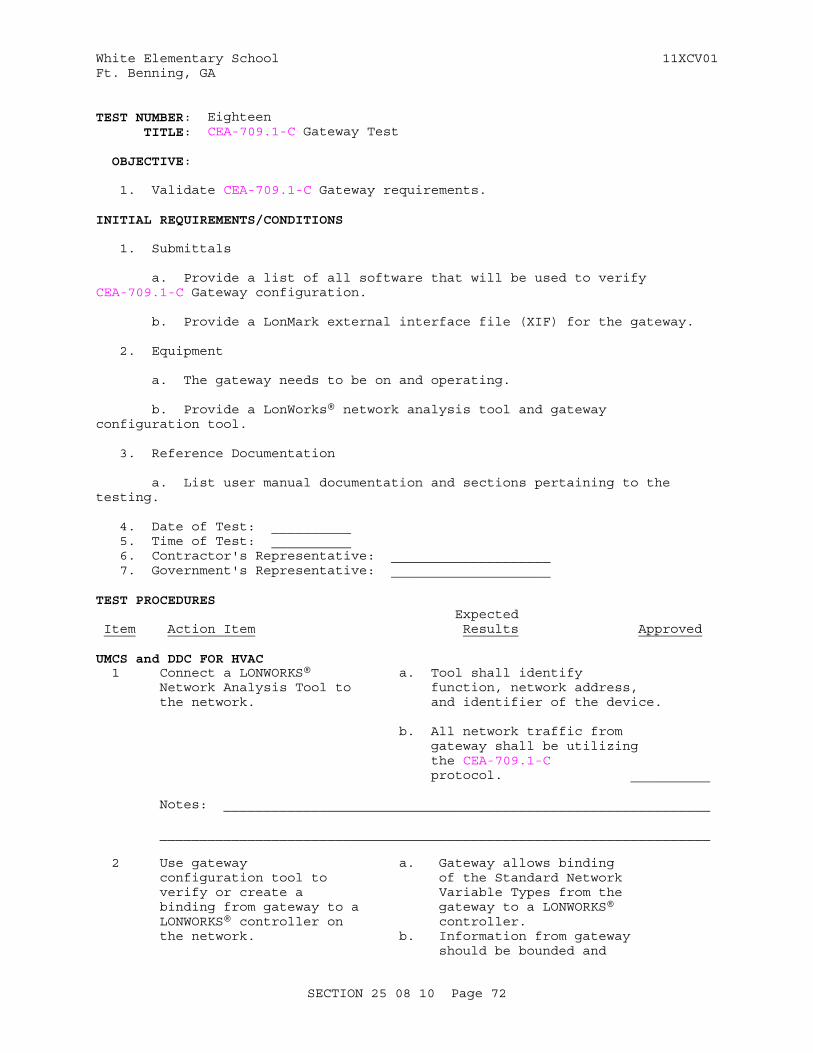
White Elementary School 11XCV01Ft. Benning, GA
TEST NUMBER: Eighteen TITLE: CEA-709.1-C Gateway Test
OBJECTIVE:
1. Validate CEA-709.1-C Gateway requirements.
INITIAL REQUIREMENTS/CONDITIONS
1. Submittals
a. Provide a list of all software that will be used to verify CEA-709.1-C Gateway configuration.
b. Provide a LonMark external interface file (XIF) for the gateway.
2. Equipment
a. The gateway needs to be on and operating.
b. Provide a LonWorks® network analysis tool and gateway configuration tool.
3. Reference Documentation
a. List user manual documentation and sections pertaining to the testing.
4. Date of Test: __________ 5. Time of Test: __________ 6. Contractor's Representative: ____________________ 7. Government's Representative: ____________________
TEST PROCEDURES Expected Item Action Item Results Approved
UMCS and DDC FOR HVAC 1 Connect a LONWORKS® a. Tool shall identify Network Analysis Tool to function, network address, the network. and identifier of the device.
b. All network traffic from gateway shall be utilizing the CEA-709.1-C protocol. __________
Notes: _____________________________________________________________
_____________________________________________________________________
2 Use gateway a. Gateway allows binding configuration tool to of the Standard Network verify or create a Variable Types from the binding from gateway to a gateway to a LONWORKS® LONWORKS® controller on controller. the network. b. Information from gateway should be bounded and
SECTION 25 08 10 Page 72
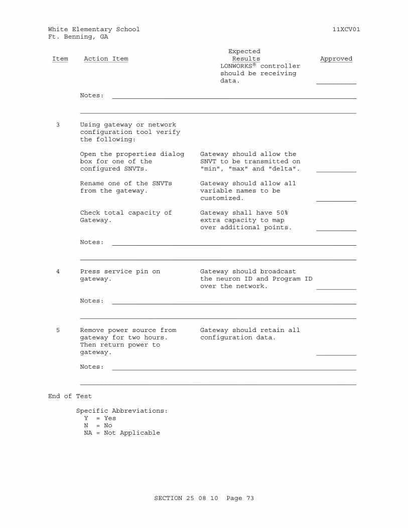
White Elementary School 11XCV01Ft. Benning, GA
Expected Item Action Item Results Approved LONWORKS® controller should be receiving data. __________
Notes: _____________________________________________________________
_____________________________________________________________________
3 Using gateway or network configuration tool verify the following:
Open the properties dialog Gateway should allow the box for one of the SNVT to be transmitted on configured SNVTs. "min", "max" and "delta". __________
Rename one of the SNVTs Gateway should allow all from the gateway. variable names to be customized. __________
Check total capacity of Gateway shall have 50% Gateway. extra capacity to map over additional points. __________ Notes: _____________________________________________________________
_____________________________________________________________________
4 Press service pin on Gateway should broadcast gateway. the neuron ID and Program ID over the network. __________
Notes: _____________________________________________________________
_____________________________________________________________________
5 Remove power source from Gateway should retain all gateway for two hours. configuration data. Then return power to gateway. __________
Notes: _____________________________________________________________
_____________________________________________________________________
End of Test
Specific Abbreviations: Y = Yes N = No NA = Not Applicable
SECTION 25 08 10 Page 73
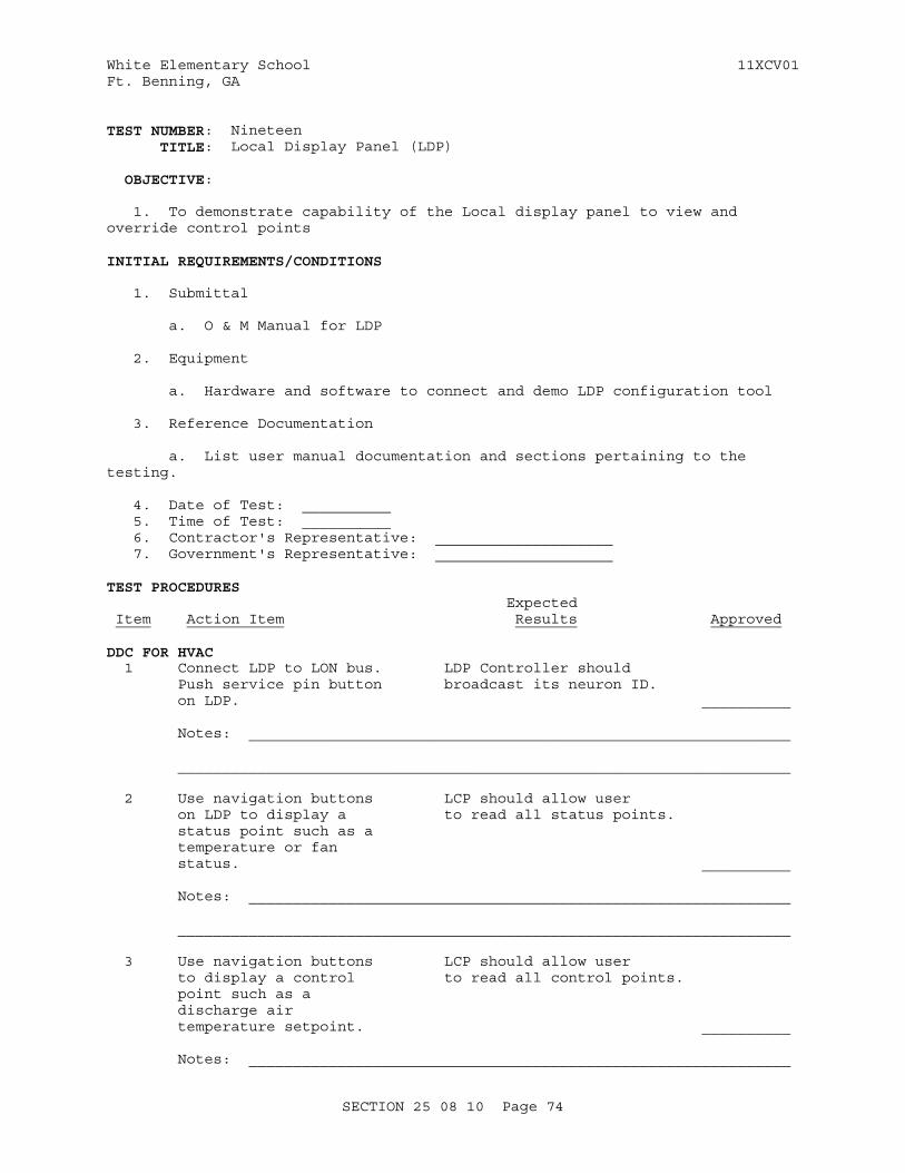
White Elementary School 11XCV01Ft. Benning, GA
TEST NUMBER: Nineteen TITLE: Local Display Panel (LDP)
OBJECTIVE:
1. To demonstrate capability of the Local display panel to view and override control points
INITIAL REQUIREMENTS/CONDITIONS
1. Submittal
a. O & M Manual for LDP
2. Equipment
a. Hardware and software to connect and demo LDP configuration tool
3. Reference Documentation
a. List user manual documentation and sections pertaining to the testing.
4. Date of Test: __________ 5. Time of Test: __________ 6. Contractor's Representative: ____________________ 7. Government's Representative: ____________________
TEST PROCEDURES Expected Item Action Item Results Approved
DDC FOR HVAC 1 Connect LDP to LON bus. LDP Controller should Push service pin button broadcast its neuron ID. on LDP. __________
Notes: _____________________________________________________________
_____________________________________________________________________
2 Use navigation buttons LCP should allow user on LDP to display a to read all status points. status point such as a temperature or fan status. __________
Notes: _____________________________________________________________
_____________________________________________________________________
3 Use navigation buttons LCP should allow user to display a control to read all control points. point such as a discharge air temperature setpoint. __________
Notes: _____________________________________________________________
SECTION 25 08 10 Page 74

White Elementary School 11XCV01Ft. Benning, GA
Expected Item Action Item Results Approved
_____________________________________________________________________
4 Use LDP to override System accepts new setpoint. setpoint. Verify system reacts to new setpoint. __________
Notes: _____________________________________________________________
_____________________________________________________________________
5 Use LDP to release local Verify system returns control override. to normal control. __________
Notes: _____________________________________________________________
_____________________________________________________________________
End of Test
Specific Abbreviations: Y = Yes N = No NA = Not Applicable
SECTION 25 08 10 Page 75
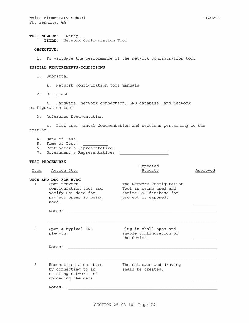
White Elementary School 11XCV01Ft. Benning, GA
TEST NUMBER: Twenty TITLE: Network Configuration Tool
OBJECTIVE:
1. To validate the performance of the network configuration tool
INITIAL REQUIREMENTS/CONDITIONS
1. Submittal
a. Network configuration tool manuals
2. Equipment
a. Hardware, network connection, LNS database, and network configuration tool
3. Reference Documentation
a. List user manual documentation and sections pertaining to the testing.
4. Date of Test: __________ 5. Time of Test: __________ 6. Contractor's Representative: ____________________ 7. Government's Representative: ____________________
TEST PROCEDURES Expected Item Action Item Results Approved
UMCS AND DDC FOR HVAC 1 Open network The Network Configuration configuration tool and Tool is being used and verify LNS data for entire LNS database for project opens is being project is exposed. used. __________
Notes: _____________________________________________________________
_____________________________________________________________________
2 Open a typical LNS Plug-in shall open and plug-in. enable configuration of the device. __________
Notes: _____________________________________________________________
_____________________________________________________________________
3 Reconstruct a database The database and drawing by connecting to an shall be created. existing network and uploading the data. __________
Notes: _____________________________________________________________
SECTION 25 08 10 Page 76
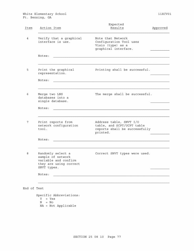
White Elementary School 11XCV01Ft. Benning, GA
Expected Item Action Item Results Approved _____________________________________________________________________
4 Verify that a graphical Note that Network interface is use. Configuration Tool uses Visio (type) as a graphical interface. __________
Notes: _____________________________________________________________
_____________________________________________________________________
5 Print the graphical Printing shall be successful. representation. __________
Notes: _____________________________________________________________
_____________________________________________________________________
6 Merge two LNS The merge shall be successful. databases into a single database. __________
Notes: _____________________________________________________________
_____________________________________________________________________
7 Print reports from Address table, SNVT I/O network configuration table, and SCPT/UCPT table tool. reports shall be successfully printed. __________
Notes: _____________________________________________________________
_____________________________________________________________________
8 Randomly select a Correct SNVT types were used. sample of network variable and confirm they are using correct SNVT types. __________
Notes: _____________________________________________________________
_____________________________________________________________________
End of Test
Specific Abbreviations: Y = Yes N = No NA = Not Applicable
SECTION 25 08 10 Page 77
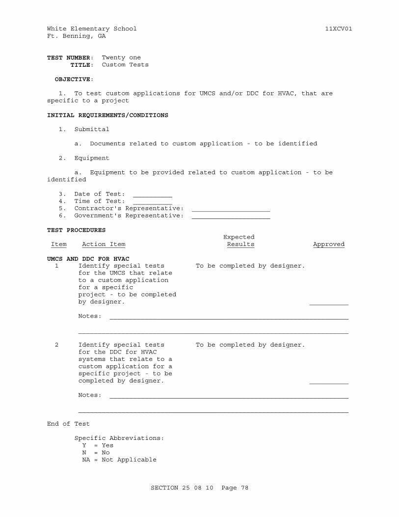
White Elementary School 11XCV01Ft. Benning, GA
TEST NUMBER: Twenty one TITLE: Custom Tests
OBJECTIVE:
1. To test custom applications for UMCS and/or DDC for HVAC, that are specific to a project
INITIAL REQUIREMENTS/CONDITIONS
1. Submittal
a. Documents related to custom application - to be identified
2. Equipment
a. Equipment to be provided related to custom application - to be identified
3. Date of Test: __________ 4. Time of Test: __________ 5. Contractor's Representative: ____________________ 6. Government's Representative: ____________________
TEST PROCEDURES Expected Item Action Item Results Approved
UMCS AND DDC FOR HVAC 1 Identify special tests To be completed by designer. for the UMCS that relate to a custom application for a specific project - to be completed by designer. __________
Notes: _____________________________________________________________
_____________________________________________________________________
2 Identify special tests To be completed by designer. for the DDC for HVAC systems that relate to a custom application for a specific project - to be completed by designer. __________
Notes: _____________________________________________________________
_____________________________________________________________________
End of Test
Specific Abbreviations: Y = Yes N = No NA = Not Applicable
SECTION 25 08 10 Page 78

White Elementary School 11XCV01Ft. Benning, GA
-- End of Section --
SECTION 25 08 10 Page 79

White Elementary School 11XCV01Ft. Benning, GA
SECTION TABLE OF CONTENTS
DIVISION 25 - INTEGRATED AUTOMATION
SECTION 25 10 10
UTILITY MONITORING AND CONTROL SYSTEM (UMCS) FRONT END AND INTEGRATION
11/12
PART 1 GENERAL
1.1 SUMMARY 1.1.1 System Requirements 1.1.1.1 General System Requirements 1.1.1.2 LonWorks Requirements 1.1.1.3 Niagara Framework Requirements 1.1.2 General Information Assurance Requirements 1.1.3 Symbols, Definition and Abbreviations 1.1.4 System Units and Accuracy 1.1.5 Data Packages/Submitals Requirements 1.2 REFERENCES 1.3 DEFINITIONS 1.3.1 Alarm Generation 1.3.2 Alarm Handling 1.3.3 Alarm Routing 1.3.4 Application Generic Controller (AGC)(LonWorks) 1.3.5 Application Specific Controller (ASC)(LonWorks) 1.3.6 BACnet (BACnet) 1.3.7 BACnet Advanced Application Controller (B-AAC)(BACnet) 1.3.8 BACnet Advanced Operator Workstation (B-AWS)(BACnet) 1.3.9 BACnet Application Specific Controller (B-ASC)(BACnet) 1.3.10 BACnet Building Controller (B-BC)(BACnet) 1.3.11 BACnet Internetwork (BACnet) 1.3.12 BACnet Interoperability Building Blocks (BIBBs) (BACnet) 1.3.13 BACnet Operator Display (B-OD)(BACnet) 1.3.14 BACnet Operator Workstation (B-OWS)(BACnet) 1.3.15 BACnet Smart Actuator (B-SA)(BACnet) 1.3.16 BACnet Smart Sensor (B-SS)(BACnet) 1.3.17 BACnet Testing Laboratories (BTL)(BACnet) 1.3.18 BACnet Testing Laboratories (BTL) Listed (BACnet) 1.3.19 Binary 1.3.20 Binding (LonWorks) 1.3.21 Broadcast 1.3.22 Building Control Network (BCN) 1.3.23 Building Control System (BCS) 1.3.24 Building Point of Connection (BPOC) 1.3.25 Channel (LonWorks) 1.3.26 Commandable (BACnet) 1.3.27 Configuration Property (LonWorks) 1.3.28 Control Logic Diagram 1.3.29 Device Object (BACnet) 1.3.30 Explicit Messaging (LonWorks) 1.3.31 External Interface File (XIF) (LonWorks) 1.3.32 Facility Point Of Connection (FPOC) 1.3.33 Field Control Network
SECTION 25 10 10 Page 1

White Elementary School 11XCV01Ft. Benning, GA
1.3.34 Field Control System (FCS) 1.3.35 Fox Protocol (Niagara Framework) 1.3.36 Functional Profile (LonWorks) 1.3.37 Gateway 1.3.38 General Purpose Programmable Controller (GPPC) (LonWorks) 1.3.39 Internetwork (BACnet) 1.3.40 JACE (Niagara Framework) 1.3.41 LonMark Object (LonWorks) 1.3.42 LNS Plug-in (LonWorks) 1.3.43 LonMark (LonWorks) 1.3.44 LonMark International (LonWorks) 1.3.45 LonWorks (LonWorks) 1.3.46 LonWorks Network Services (LNS) (LonWorks) 1.3.47 LonWorks Network Services (LNS) Database (LonWorks) 1.3.48 Modbus 1.3.49 Master-Slave/Token Passing (MS/TP)(BACnet) 1.3.50 Monitoring and Control (M&C) Software 1.3.51 Network (BACnet) 1.3.52 Network Variable (LonWorks) 1.3.53 Network Configuration Tool (LonWorks) 1.3.54 Niagara AX (Niagara Framework) 1.3.55 Niagara Framework (Niagara Framework) 1.3.56 Niagara Framework Supervisory Gateway (Niagara Framework) 1.3.57 Node (LonWorks) 1.3.58 Node Address (LonWorks) 1.3.59 Node ID (LonWorks) 1.3.60 Object (BACnet) 1.3.61 Override 1.3.62 Point, Calculated 1.3.63 Point, Network 1.3.64 Polling 1.3.65 Program ID (LonWorks) 1.3.66 Property (BACnet) 1.3.67 Protocol Implementation Conformance Statement (PICS)(BACnet) 1.3.68 Repeater 1.3.69 Router(LonWorks) 1.3.70 Router (BACnet) 1.3.71 Segment 1.3.72 Service (BACnet) 1.3.73 Service Pin (LonWorks) 1.3.74 Standard BACnet Object/Property/Service (BACnet) 1.3.75 Standard Configuration Property Type (SCPT) (LonWorks) 1.3.76 Standard Network Variable Type (SNVT) (LonWorks) 1.3.77 Subnet (LonWorks) 1.3.78 Supervisory Controller 1.3.79 Supervisory Gateway 1.3.80 TP/FT-10 (LonWorks) 1.3.81 TP/XF-1250 (LonWorks) 1.3.82 UMCS Network 1.3.83 User-defined Configuration Property Type (UCPT) (LonWorks) 1.3.84 User-defined Network Variable Type (UNVT) (LonWorks) 1.3.85 Utility Control System (UCS) 1.4 SUBMITTALS 1.5 PROJECT SEQUENCING 1.6 QUALITY CONTROL (QC) CHECKLISTS 1.7 OPERATION AND MAINTENANCE (O&M) INSTRUCTIONS
PART 2 PRODUCTS
SECTION 25 10 10 Page 2

White Elementary School 11XCV01Ft. Benning, GA
2.1 EQUIPMENT REQUIREMENTS 2.1.1 Product Certifications 2.1.2 Product Sourcing 2.1.3 General Requirements 2.1.4 Nameplates 2.1.5 Product Data Sheets 2.2 CONTROL HARDWARE 2.2.1 Control Protocol Routers 2.2.1.1 LonWorks/IP Router 2.2.2 Monitoring and Control (M&C) Controller Hardware 2.2.3 Control Protocol Gateways 2.2.3.1 Niagara Framework Supervisory Gateway 2.3 COMPUTER HARDWARE 2.3.1 Server Hardware 2.4 COMPUTER SOFTWARE 2.4.1 Operating System (OS) 2.4.2 Niagara Framework Engineering Tool 2.4.3 Monitoring and Control (M&C) Software 2.4.3.1 M&C Software License 2.4.3.2 Supported Field Control Protocols 2.4.3.3 Supported Enterprise Protocols 2.4.3.4 Point Information 2.4.3.4.1 Name 2.4.3.4.2 Description 2.4.3.4.3 Value 2.4.3.4.4 Units 2.4.3.4.5 Source 2.4.3.5 Point Calculations 2.4.3.6 Browser-Based Graphical User Interface (GUI) 2.4.3.7 Passwords 2.4.3.8 Graphical System Displays 2.4.3.9 Graphic Editor 2.4.3.10 System Display Editor 2.4.3.11 Scheduling 2.4.3.12 Alarms 2.4.3.13 Trending 2.4.3.14 Report Generation 2.5 UNINTERRUPTIBLE POWER SUPPLY (UPS) 2.6 RACKS AND ENCLOSURES 2.6.1 Enclosures 2.6.2 Equipment Racks
PART 3 EXECUTION
3.1 FACTORY TEST 3.2 DRAWINGS AND CALCULATIONS 3.2.1 UMCS IP Network Bandwidth Usage Estimate 3.2.2 Certificate of Networthiness Documentation 3.2.3 UMCS Contractor Design Drawings 3.2.4 As-Built Drawings 3.3 INSTALLATION REQUIREMENTS 3.3.1 General 3.3.2 Isolation, Building Penetrations and Equipment Clearance 3.3.3 Nameplates 3.4 INSTALLATION OF EQUIPMENT 3.4.1 Wire and Cable Installation 3.4.2 Grounding 3.4.3 Power-Line Surge Protection 3.4.4 IP Addresses
SECTION 25 10 10 Page 3
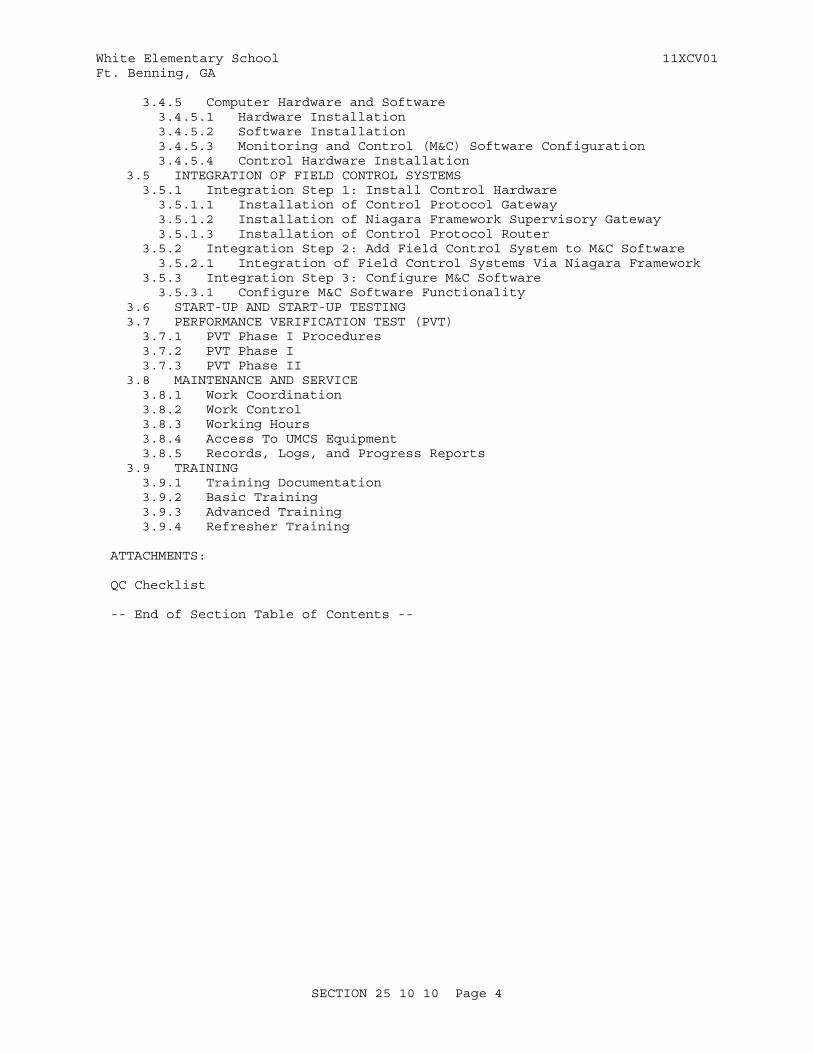
White Elementary School 11XCV01Ft. Benning, GA
3.4.5 Computer Hardware and Software 3.4.5.1 Hardware Installation 3.4.5.2 Software Installation 3.4.5.3 Monitoring and Control (M&C) Software Configuration 3.4.5.4 Control Hardware Installation 3.5 INTEGRATION OF FIELD CONTROL SYSTEMS 3.5.1 Integration Step 1: Install Control Hardware 3.5.1.1 Installation of Control Protocol Gateway 3.5.1.2 Installation of Niagara Framework Supervisory Gateway 3.5.1.3 Installation of Control Protocol Router 3.5.2 Integration Step 2: Add Field Control System to M&C Software 3.5.2.1 Integration of Field Control Systems Via Niagara Framework 3.5.3 Integration Step 3: Configure M&C Software 3.5.3.1 Configure M&C Software Functionality 3.6 START-UP AND START-UP TESTING 3.7 PERFORMANCE VERIFICATION TEST (PVT) 3.7.1 PVT Phase I Procedures 3.7.2 PVT Phase I 3.7.3 PVT Phase II 3.8 MAINTENANCE AND SERVICE 3.8.1 Work Coordination 3.8.2 Work Control 3.8.3 Working Hours 3.8.4 Access To UMCS Equipment 3.8.5 Records, Logs, and Progress Reports 3.9 TRAINING 3.9.1 Training Documentation 3.9.2 Basic Training 3.9.3 Advanced Training 3.9.4 Refresher Training
ATTACHMENTS:
QC Checklist
-- End of Section Table of Contents --
SECTION 25 10 10 Page 4
White Elementary School 11XCV01Ft. Benning, GA
SECTION 25 10 10
UTILITY MONITORING AND CONTROL SYSTEM (UMCS) FRONT END AND INTEGRATION11/12
PART 1 GENERAL
1.1 SUMMARY
The Utility Monitoring and Control System (UMCS) shall perform supervisory monitoring and supervisory control of base-wide building control systems and utility control systems using one or more of: CEA-709.1-C (LonWorks) with LonWorks Network Services (LNS), ASHRAE 135 (BACnet), Modbus, OPC DA, or the Niagara Framework with Fox protocol as specified and shown. The UMCS shall interface to local CEA-709.1-C building control systems installed per Section 23 09 23 LONWORKS DIRECT DIGITAL CONTROL FOR HVAC AND OTHER BUILDING CONTROL SYSTEMS, and maintain the LNS database(s) for the entire network.
1.1.1 System Requirements
Provide a UMCS as specified and shown, and in accordance with the following characteristics:
1.1.1.1 General System Requirements
a. The system shall perform supervisory monitoring and control functions including but not limited to Scheduling, Alarm Handling, Trending, Overrides, Report Generation, and Electrical Demand Limiting as specified.
b. The system shall include a Graphical User Interface which shall allow for graphical navigation between systems, graphical representations of systems, access to real-time data for systems, ability to override points in a system, and access to all supervisory monitoring and control functions.
c. All software used by the UMCS and all software used to install and configure the UMCS shall be licensed to and delivered to the installation.
d. All necessary documentation, configuration information, configuration tools, programs, drivers, and other software shall be licensed to and otherwise remain with the Government such that the Government or their agents are able to repair, replace, upgrade, and expand the system without subsequent or future dependence on the Contractor. Software licenses shall not require periodic fees and shall be valid in perpetuity.
e. Provide sufficient documentation and data, including rights to documentation and data, such that the Government or their agents can execute work to repair, replace, upgrade, and expand the system without subsequent or future dependence on the Contractor.
SECTION 25 10 10 Page 5

White Elementary School 11XCV01Ft. Benning, GA
f. The UMCS shall interface directly to CEA-709.1-C, and Niagara Framework field control systems as specified and may interface to field control systems using other protocols via an M&C Software protocol driver or a Gateway.
g. For UMCS systems with Monitoring and Control Software functionality implemented in Monitoring and Control (M&C) Controller Hardware, provide sufficient additional controller hardware to support the full capacity requirements as specified.
h. All Niagara Framework components shall have an unrestricted interoperability license with a Niagara Compatability Statement (NiCS) following the Tridium Open NiCS Specification and shall have a value of "ALL" for "Station Compatibility In", "Station Compatability Out", "Tool Compatability In" and "Tool Compatability Out". Note that this will result in the following entries in the license.dat file: "accept.station.in=*" "accept.station.out=*" "accept.wb.in=*" "accept.wb.out=*"
1.1.1.2 LonWorks Requirements
a. The UMCS shall communicate using CEA-709.1-C over the Government furnished IP network in accordance with CEA-852-B as shown and specified and shall interface to CEA-709.1-C building control networks using LonWorks/IP Routers as specified.
b. All communication between the UMCS and LonWorks field control networks shall be via the CEA-709.1-C protocol over the IP network in accordance with CEA-852-B.
c. Except for communication for device commissioning, configuration, and programming, all communication between the M&C Software and the field control system devices shall be via SNVT.
1.1.1.3 Niagara Framework Requirements
The UMCS shall use the Niagara Framework and shall communicate with Niagara Framework field control systems using the Fox protocol over an IP network as specified in documents and as indicated and specified.
1.1.2 General Information Assurance Requirements
Information Assurance for the system shall be addressed in accordance with DA AR 25-2.
1.1.3 Symbols, Definition and Abbreviations
Symbols, definitions, and engineering unit abbreviations used in displays, submittals and reports shall be as shown in the contract drawings. Symbols, definitions and abbreviations not in the contract drawings shall conform at a minimum to IEEE Stds Dictionary and the ASHRAE FUN IP, as applicable.
1.1.4 System Units and Accuracy
Displays, print-outs and calculations shall be performed in English
SECTION 25 10 10 Page 6
White Elementary School 11XCV01Ft. Benning, GA
(inch-pound) units. Calculations shall have accuracy equal to or exceeding sensor accuracy as specified in Section 23 09 23 LONWORKS DIRECT DIGITAL CONTROL FOR HVAC AND OTHER BUILDING CONTROL SYSTEMS. Displays and printouts shall present values to at least three significant figures.
1.1.5 Data Packages/Submitals Requirements
Technical data packages consisting of computer software and technical data (meaning technical data which relates to computer software) which are specifically identified in this project and which may be defined/required in other specifications shall be delivered strictly in accordance with the CONTRACT CLAUSES and in accordance with the Contract Data Requirements List, DD Form 1423. Data delivered shall be identified by reference to the particular specification paragraph against which it is furnished. All submittals not specified as technical data packages are considered shop drawings under the Federal Acquisition Regulation Supplement (FARS) and shall contain no proprietary information and shall be delivered with unrestricted rights.
1.2 REFERENCES
The publications listed below form a part of this specification to the extent referenced. The publications are referred to within the text by the basic designation only.
AMERICAN SOCIETY OF HEATING, REFRIGERATING AND AIR-CONDITIONING ENGINEERS (ASHRAE)
ASHRAE 135 (2012; Errata 2013; INT 1-5 2013; Errata 2013) BACnet—A Data Communication Protocol for Building Automation and Control Networks
ASHRAE FUN IP (2013) Fundamentals Handbook, I-P Edition
CONSUMER ELECTRONICS ASSOCIATION (CEA)
CEA-709.1-C (2010) Control Network Protocol Specification
CEA-709.3 (1999; R 2004) Free-Topology Twisted-Pair Channel Specification
CEA-852-B (2010) Tunneling Component Network Protocols Over Internet Protocol Channels
INSTITUTE OF ELECTRICAL AND ELECTRONICS ENGINEERS (IEEE)
IEEE C62.41 (1991; R 1995) Recommended Practice on Surge Voltages in Low-Voltage AC Power Circuits
IEEE Stds Dictionary (2009) IEEE Standards Dictionary: Glossary of Terms & Definitions
LONMARK INTERNATIONAL (LonMark)
LonMark Interoperability Guide (2005) LonMark Application-Layer Interoperability Guide and LonMark Layer
SECTION 25 10 10 Page 7
White Elementary School 11XCV01Ft. Benning, GA
1-6 Interoperability Guide; Version 3.4
MODBUS ORGANIZATION, INC (MODBUS)
Modbus (2006) Modbus Application Protocol Specification; Version 1.1b and Modbus Messaging on TCP/IP Implementation Guide; Version V1.0b
NATIONAL ELECTRICAL MANUFACTURERS ASSOCIATION (NEMA)
NEMA 250 (2008) Enclosures for Electrical Equipment (1000 Volts Maximum)
NATIONAL FIRE PROTECTION ASSOCIATION (NFPA)
NFPA 262 (2011) Standard method of Test for Flame Travel and Smoke of Wires and Cables for Use in Air-Handling Spaces
NFPA 70 (2014) National Electrical Code
OPC FOUNDATION (OPC)
OPC DA (2002) OPC Data Access (DA) Specification; Version 2.05a
TELECOMMUNICATIONS INDUSTRY ASSOCIATION (TIA)
TIA-568-C.1 (2009; Add 2 2011; Add 1 2012) Commercial Building Telecommunications Cabling Standard
TIA-606 (2012b) Administration Standard for the Telecommunications Infrastructure
TIA-607 (2011b) Generic Telecommunications Bonding and Grounding (Earthing) for Customer Premises
THE INTERNET ENGINEERING TASK FORCE (IETF)
IETF RFC 4361 (2006) Node-specific Client Identifiers for Dynamic Host Configuration Protocol Version Four (DHCPv4)
IETF RFC 5246 (2008) The Transport Layer Security (TLS) Protocol Version 1.2
RFC 821 (2001) Simple Mail Transfer Protocol (SMTP)
TRIDIUM, INC (TRIDIUM)
Niagara Framework (2012) NiagaraAX User's Guide
Tridium Open NiCS (2005) Understanding the NiagaraAX Compatibility Statement (NiCS)
SECTION 25 10 10 Page 8
White Elementary School 11XCV01Ft. Benning, GA
U.S. ARMY (DA)
DA AR 25-2 (2007; RAR 2009) Information Assurance
U.S. FEDERAL COMMUNICATIONS COMMISSION (FCC)
FCC EMC (2002) FCC Electromagnetic Compliance Requirements
FCC Part 15 Radio Frequency Devices (47 CFR 15)
UNDERWRITERS LABORATORIES (UL)
UL 1778 (2005; Reprint Oct 2011) Uninterruptible Power Systems
UL 60950 (2000; Reprint Oct 2007) Safety of Information Technology Equipment
1.3 DEFINITIONS
The following list of definitions may contain terms not found elsewhere in this Section but are included here for completeness. Some terms are followed with a protocol reference in parenthesis (for example: (BACnet)) indicating to which protocol the term and definition applies.
1.3.1 Alarm Generation
The process of comparing a point value (thepoint being alarmed) with a pre-defined alarm condition (e.g. a High Limit) and performing some action based on the result ofthe comparison.
1.3.2 Alarm Handling
see Alarm Routing
1.3.3 Alarm Routing
Alarm routing is M&C software functionality that starts with a notification that an alarm exists (typically as the output of an Alarm Generation process) and sends a specific message to a specific alarm recipient or device.
1.3.4 Application Generic Controller (AGC)(LonWorks)
A device that is furnished with a (limited) pre-established application that also has the capability of being programmed. Further, the ProgramID and XIF file of the device are fixed. The programming capability of an AGC may be less flexible than that of a General Purpose Programmable Controller (GPPC).
1.3.5 Application Specific Controller (ASC)(LonWorks)
A device that is furnished with a pre-established built in application that is configurable but not re-programmable. An ASC has a fixed factory-installed application program (i.e Program ID) with configurable settings.
SECTION 25 10 10 Page 9
White Elementary School 11XCV01Ft. Benning, GA
1.3.6 BACnet (BACnet)
The term BACnet is used in two ways. First meaning the BACnet Protocol Standard - the communication requirements as defined by ASHRAE 135 including all annexes and addenda. The second to refer to the overall technology related to the ASHRAE 135 protocol.
1.3.7 BACnet Advanced Application Controller (B-AAC)(BACnet)
A hardware device BTL Listed as a B-AAC. A control device which contains BIBBs in support of scheduling and alarming but otherwise has limited resources relative to a B-BC. It may be intended for specific applications and supports some degree of programmability.
1.3.8 BACnet Advanced Operator Workstation (B-AWS)(BACnet)
Monitoring and Control (M&C) Software BTL Listed as an Advanced Operator Workstation and includes the ability to manage scheduling, alarming and trending in an open manner. The B-AWS is the advanced operator's window into a BACnet system. It is primarily used to monitor the performance of a system and to modify parameters that affect the operation of a system.
1.3.9 BACnet Application Specific Controller (B-ASC)(BACnet)
A hardware device BTL Listed as a B-ASC. A controller with limited resources relative to a B-AAC. It is intended for use in a specific application and supports limited programmability.
1.3.10 BACnet Building Controller (B-BC)(BACnet)
A hardware device BTL Listed as a B-BC. A general-purpose, field-programmable device capable of carrying out a variety of building automation and control tasks including control and monitoring via direct digital control (DDC) of specific systems and data storage for trend information, time schedules, and alarm data. Like the other BTL Listed controller types (B-AAC, B-ASC etc.) a B-BC device is required to support the server ("B") side of the ReadProperty and WriteProperty services, but unlike the other controller types it is also required to support the client ("A") side of these services. Communication between controllers requires that one of them support the client side and the other support the server side, so a B-BC is often used when communication between controllers is needed.
1.3.11 BACnet Internetwork (BACnet)
Two or more BACnet networks connected with BACnet routers. In a BACnet Internetwork, there exists only one message path between devices.
1.3.12 BACnet Interoperability Building Blocks (BIBBs) (BACnet)
A BIBB is a collection of one or more BACnet services intended to define a higher level of interoperability. BIBBs are combined to build the BACnet functional requirements for a device in a specification. Some BIBBs define additional requirements (beyond requiring support for specific services) in order to achieve a level of interoperability. For example, the BIBB DS-V-A (Data Sharing-View-A), which would typically be used by an M&C client, not only requires the client to support the ReadProperty Service, but also provides a list of data types (Object / Properties) which the client must be able to interpret and display for the user.
SECTION 25 10 10 Page 10
White Elementary School 11XCV01Ft. Benning, GA
1.3.13 BACnet Operator Display (B-OD)(BACnet)
A hardware device BTL Listed as a B-OD. A basic operator interface with limited capabilities relative to a B-OWS. It is not intended to perform direct digital control. The B-OD profile could be used for wall-mounted LCD devices, displays affixed to BACnet devices; hand-held terminals or other very simple user interfaces.
1.3.14 BACnet Operator Workstation (B-OWS)(BACnet)
Monitoring and Control (M&C) Software BTL Listed as a B-OWS. An operator interface with limited capabilities relative to a B-AWS. The B-OWS is used for monitoring and basic control of a system, but differs from a B-AWS in that it does not support configuration activities, nor does it provide advanced troubleshooting capabilities.
1.3.15 BACnet Smart Actuator (B-SA)(BACnet)
A hardware device BTL Listed as a B-SA. A simple control output device with limited resources; it is intended for specific applications.
1.3.16 BACnet Smart Sensor (B-SS)(BACnet)
A hardware device BTL Listed as a B-SS. A simple sensing device with very limited resources.
1.3.17 BACnet Testing Laboratories (BTL)(BACnet)
Established by BACnet International to support compliance testing and interoperability testing activities and consists of BTL Manager and the BTL Working Group (BTL-WG). BTL also publishes Implementation Guidelines.
1.3.18 BACnet Testing Laboratories (BTL) Listed (BACnet)
A device that has been certified by BACnet® Testing Laboratory. Devices may be certified to a specific device profile, in which case the certification indicates that the device supports the required capabilities for that profile, or may be certified as "other".
1.3.19 Binary
A two-state system or signal; for example one where an "ON" condition is represented by a high signal level and an "OFF" condition is represented by a low signal level. 'Digital' is sometimes used interchangeably with 'binary'.
1.3.20 Binding (LonWorks)
The act of establishing communications between CEA-709.1-C devices by associating the output of a device to the input of another so that information is automatically (and regularly) sent without being requested by the recipient.
1.3.21 Broadcast
Unlike most messages, which are intended for a specific recipient device, a broadcast message is intended for all devices on the network.
SECTION 25 10 10 Page 11
White Elementary School 11XCV01Ft. Benning, GA
1.3.22 Building Control Network (BCN)
The network used by the Building Control System. Typically the BCN is a BACnet ASHRAE 135 or LonWorks CEA-709.1-C network installed by the building control system contractor.
1.3.23 Building Control System (BCS)
One type of Field Control System. A control system for building electrical and mechanical systems, typically HVAC (including central plants) and lighting. A BCS generally uses Direct Digital Control (DDC) Hardware and generally does NOT include its own local front end.
1.3.24 Building Point of Connection (BPOC)
A FPOC for a Building Control System. (This term is being phased out of use in preference for FPOC but is still used in some specifications and criteria.)
1.3.25 Channel (LonWorks)
A portion of the control network consisting of one or more segments connected by repeaters. Channels are separated by routers. The device quantity limitation is dependent on the topology/media and device type. For example, a TP/FT-10 network with locally powered devices is limited to 128 devices per channel.
1.3.26 Commandable (BACnet)
A point (Object) is commandable if its Present_Value Property is writable and it supports the optional Priority_Array Property. This functionality is useful for Overrides.
1.3.27 Configuration Property (LonWorks)
Controller parameter used by the application which is usually set during installation/testing and seldom changed. For example, the P and I settings of a P-I control loop. Also see 'Standard Configuration Property Type (SCPT)'
1.3.28 Control Logic Diagram
A graphical representation of control logic for multiple processes that make up a system.
1.3.29 Device Object (BACnet)
Every BACnet device requires one Device Object, whose properties represent the network visible properties of that device. Every Device Object requires a unique Object_Identifier number on the BACnet internetwork. This number is often referred to as the device instance or device ID.
1.3.30 Explicit Messaging (LonWorks)
A non-standard and often vendor (application) specific method of communication between devices.
SECTION 25 10 10 Page 12
White Elementary School 11XCV01Ft. Benning, GA
1.3.31 External Interface File (XIF) (LonWorks)
A file which documents a device's external interface, specifically the number and types of LonMark objects, the number, types, directions, and connection attributes of network variables, and the number of message tags.
1.3.32 Facility Point Of Connection (FPOC)
The FPOC is the point of connection between the UMCS IP Network and the field control network (either an IP network, a non-IP network, or both). The hardware at this location which provides the connection is generally one of a control protocol router, a control protocol gateway, or an IT device such as a switch, IP router, or firewall.
In general, the term "FPOC Location" means the place where this connection occurs, and "FPOC Hardware" means the device that provides the connection. Sometimes the term "FPOC" is used to mean either and its actual meaning (i.e. location or hardware) is determined by the context in which it is used.
1.3.33 Field Control Network
The network used by a field control system.
1.3.34 Field Control System (FCS)
A building control system or utility control system.
1.3.35 Fox Protocol (Niagara Framework)
The protocol used for communication between components in the Niagara Framework. By default, Fox uses TCP port 1911
1.3.36 Functional Profile (LonWorks)
A standard description, defined by LonMark International, of a LonMark Object used to classify and certify devices.
1.3.37 Gateway
A device that translates from one protocol to another. Devices that change only the transport mechanism of the protocol - "translating" from LonWorks over TP/FT-10 to LonWorks over IP for example - are not gateways as the underlying protocol (data format) does not change. Gateways are also called Communications Bridges or Protocol Translators.
1.3.38 General Purpose Programmable Controller (GPPC) (LonWorks)
Unlike an ASC or AGC, a GPPC is not furnished with a fixed application program and does not have a fixed ProgramID or XIF file. A GPPC can be (re-)programmed, usually using vendor-supplied software. When a change to the program affects the external interface (and the XIF file) the ProgramID will change.
1.3.39 Internetwork (BACnet)
See BACnet Internetwork.
SECTION 25 10 10 Page 13

White Elementary School 11XCV01Ft. Benning, GA
1.3.40 JACE (Niagara Framework)
Java Application Control Engine. See Niagara Framework Supervisory Gateway
1.3.41 LonMark Object (LonWorks)
A collection of network variables, configuration properties, and associated behavior defined by LonMark International and described by a Functional Profile. It defines how information is exchanged between devices on a network (inputs from and outputs to the network).
1.3.42 LNS Plug-in (LonWorks)
Software which runs in an LNS compatible software tool, typically a network configuration tool. Device configuration plug-ins provide a 'user friendly' method to edit a device's configuration properties.
1.3.43 LonMark (LonWorks)
See LonMark International. Also, a certification issued by LonMark International to CEA-709.1-C devices.
1.3.44 LonMark International (LonWorks)
Standards committee consisting of independent product developers, system integrators and end users dedicated to determining and maintaining the interoperability guidelines for LonWorks. Maintains guidelines for the interoperability of CEA-709.1-C devices and issues the LonMark Certification for CEA-709.1-C devices.
1.3.45 LonWorks (LonWorks)
The term used to refer to the overall technology related to the CEA-709.1-C protocol (sometimes called "LonTalk"), including the protocol itself, network management, interoperability guidelines and products.
1.3.46 LonWorks Network Services (LNS) (LonWorks)
A network management and database standard for CEA-709.1-C devices.
1.3.47 LonWorks Network Services (LNS) Database (LonWorks)
The standard database created and used by LonWorks Network Services (LNS) compatible tools, such as LNS Network Configuration tools.
1.3.48 Modbus
A basic protocol for control network communications generally used in utility control systems. The Modbus protocol standard is maintained by The Modbus Organization.
1.3.49 Master-Slave/Token Passing (MS/TP)(BACnet)
Data link protocol as defined by the BACnet standard. Multiple speeds (data rates) are permitted by the BACnet MS/TP standard.
1.3.50 Monitoring and Control (M&C) Software
The UMCS 'front end' software which performs supervisory functions such as
SECTION 25 10 10 Page 14

White Elementary School 11XCV01Ft. Benning, GA
alarm handling, scheduling and data logging and provides a user interface for monitoring the system and configuring these functions.
1.3.51 Network (BACnet)
In BACnet, a portion of the control internetwork consisting of one or more segments of the same media connected by repeaters. Networks are separated by routers.
1.3.52 Network Variable (LonWorks)
See 'Standard Network Variable Type (SNVT)'.
1.3.53 Network Configuration Tool (LonWorks)
The software used to configure the control network and set device configuration properties. This software creates and modifies the control network database (LNS Database).
1.3.54 Niagara AX (Niagara Framework)
The current version (release) of the Niagara Framework. While it is often used to refer to just the front end, it includes all components of the Niagara Framework. (Note: The previous version of the Niagara Framework is "R2".)
1.3.55 Niagara Framework (Niagara Framework)
A set of hardware and software specifications for building and utility control owned by Tridium Inc. and licensed to multiple vendors. The Framework consists of front end (M&C) software, web based clients, field level control hardware, and engineering tools. While the Niagara Framework is not adopted by a recognized standards body and does not use an open licensing model, it is sufficiently well-supported by multiple HVAC vendors to be considered a de-facto Open Standard.
1.3.56 Niagara Framework Supervisory Gateway (Niagara Framework)
DDC Hardware component of the Niagara Framework. A typical Niagara architecture has Niagara specific supervisory gateways at the IP level and other (non-Niagara specific) controllers on field networks (TP/FT-10, MS/TP, etc.) beneath the Niagara supervisory gateways. The Niagara specific controllers function as a gateway between the Niagara framework protocol (Fox) and the field network beneath. These supervisory gateways may also be used as general purpose controllers and also have the capability to provide a web-based user interface.
Note that different vendors refer to this component by different names. The most common name is "JACE"; other names include "EC-BOS", "FX-40", and "UNC".
1.3.57 Node (LonWorks)
A device that communicates using the CEA-709.1-C protocol and is connected to a CEA-709.1-C network.
1.3.58 Node Address (LonWorks)
The logical address of a node on the network, consisting of a Domain
SECTION 25 10 10 Page 15
White Elementary School 11XCV01Ft. Benning, GA
number, Subnet number and Node number. Note that the "Node number" portion of the address is the number assigned to the device during installation and is unique within a subnet. This is not the factory-set unique Node ID (see Node ID).
1.3.59 Node ID (LonWorks)
A unique 48-bit identifier assigned (at the factory) to each CEA-709.1-C device. Sometimes called the Neuron ID.
1.3.60 Object (BACnet)
A BACnet Object. The concept of organizing BACnet information into standard components with various associated Properties. Examples include Analog Input objects and Binary Output objects.
1.3.61 Override
To change the value of a point outside of the normal sequence of operation where this change has priority over the sequence. An override can be accomplished in one of two ways: the point itself may be Commandable and written to with a priority or there may be a separate point on the controller for the express purpose of implementing the override.
Typically this override is from the Utility Monitoring and Control System (UMCS) Monitoring and Control (M&C) Software. Note that this definition is not standard throughout industry.
1.3.62 Point, Calculated
A value within the M&C Software that is not a network point but has been calculated by logic within the software based on the value of network points or other calculated points. Calculated points are sometimes called virtual points or internal points.
1.3.63 Point, Network
A value that the M&C Software reads from or writes to a field control network.
1.3.64 Polling
A requested transmission of data between devices, rather than an unrequested transmission such as Change-Of-Value (COV) or Binding where data is automatically transmitted under certain conditions.
1.3.65 Program ID (LonWorks)
An identifier (number) stored in the device (usually EEPROM) that identifies the node manufacturer, functionality of device (application & sequence), transceiver used, and intended device usage.
1.3.66 Property (BACnet)
A BACnet Property - a data element associated with an Object. Different Objects have different Properties, for example an Analog Input Object has a Present_Value Property (which provides the value of the underlying hardware analog input), a High_Limit Property (which contains a high limit for alarming), as well as other properties.
SECTION 25 10 10 Page 16
White Elementary School 11XCV01Ft. Benning, GA
1.3.67 Protocol Implementation Conformance Statement (PICS)(BACnet)
A document, created by the manufacturer of a device, which describes which potions of the BACnet standard are implemented by a given device.
1.3.68 Repeater
A device that connects two control network segments and retransmits all information received on one side onto the other.
1.3.69 Router(LonWorks)
A device that connects two channels and controls traffic between the channels by retransmitting signals received from one subnet onto the other based on the signal destination. Routers are used to subdivide a control network and to control bandwidth usage.
1.3.70 Router (BACnet)
A device that connects two or more BACnet networks and controls traffic between the networks by retransmitting signals received from one network onto another based on the signal destination. Routers are used to subdivide an internetwork and to control bandwidth usage.
1.3.71 Segment
A 'single' section of a control network that contains no repeaters or routers. There is generally a limit on the number of devices on a segment, and this limit is dependent on the topology/media and device type. For example, a TP/FT-10 segment with locally powered devices is limited to 64 devices, and a BACnet MS/TP segment is limited to 32 devices.
1.3.72 Service (BACnet)
A BACnet Service. A defined method for sending a specific type of data between devices. Services are always defined in a Client-Server manner, with a Client initiating a Service request and a Server Executing the Service. Some examples are ReadProperty (a client requests a data value from a server), WriteProperty (a client writes a data value to a server), and CreateObject (a client requests that a server create a new object within the server device).
1.3.73 Service Pin (LonWorks)
A hardware push-button on a device which causes the device to broadcast a message containing its Node ID and Program ID. This broadcast can also be initiated via software.
1.3.74 Standard BACnet Object/Property/Service (BACnet)
BACnet Objects, Properties, or Services that are standard Objects, Properties, or Services enumerated and defined in ASHRAE 135. Clause 23 of ASHRAE 135 defines methods to extend ASHRAE 135 to non-standard or proprietary information. Standard BACnet Objects/Properties/Services specifically exclude any vendor specific extensions.
SECTION 25 10 10 Page 17
White Elementary School 11XCV01Ft. Benning, GA
1.3.75 Standard Configuration Property Type (SCPT) (LonWorks)
Pronounced 'skip-it'. A standard format type (maintained by LonMark International) for Configuration Properties.
1.3.76 Standard Network Variable Type (SNVT) (LonWorks)
Pronounced 'snivet'. A standard format type (maintained by LonMark International) used to define data information transmitted and received by the individual nodes. The term SNVT is used in two ways. Technically it is the acronym for Standard Network Variable Type, and is sometimes used in this manner. However, it is often used to indicate the network variable itself (i.e. it can mean "a network variable of a standard network variable type"). In general, the intended meaning should be clear from the context.
1.3.77 Subnet (LonWorks)
Consists of a logical grouping of up to 127 nodes, where the logical grouping is defined by node addressing. Each subnet is assigned a number which is unique within the Domain. See also Node Address.
1.3.78 Supervisory Controller
A controller implementing a combination of supervisory logic (global control strategies or optimization strategies), scheduling, alarming, event management, trending, web services or network management. Note this is defined by use; many supervisory controllers have the capability to also directly control equipment.
1.3.79 Supervisory Gateway
A device that is both a supervisory controller and a gateway, such as a Niagara Framework Supervisory Gateway.
1.3.80 TP/FT-10 (LonWorks)
A Free Topology Twisted Pair network (at 78 kbps) defined by CEA-709.3. This is the most common media type for a CEA-709.1-C control network.
1.3.81 TP/XF-1250 (LonWorks)
A high speed (1.25 Mbps) twisted pair, doubly-terminated bus network defined by the LonMark Interoperability Guidelines. This media is typically used only as a backbone media to connect multiple TP/FT-10 networks.
1.3.82 UMCS Network
An IP network connecting multiple field control systems to the Monitoring and Control Software using one or more of: LonWorks (CEA-709.1-C and CEA-852-B), BACnet (ASHRAE 135 Annex J), Modbus or OPC DA.
1.3.83 User-defined Configuration Property Type (UCPT) (LonWorks)
Pronounced 'u-keep-it'. A Configuration Property format type that is defined by the device manufacturer.
SECTION 25 10 10 Page 18
White Elementary School 11XCV01Ft. Benning, GA
1.3.84 User-defined Network Variable Type (UNVT) (LonWorks)
A network variable format defined by the device manufacturer. Note that UNVTs create non-standard communications (other vendor's devices may not correctly interpret it) and may close the system and therefore are not permitted by this specification.
1.3.85 Utility Control System (UCS)
One type of field control system. Used for control of utility systems such as an electrical substation, sanitary sewer lift station, water pump station, etc. Building controls are excluded from a UCS, however it is possible to have a Utility Control System and a Building Control System in the same facility, and for those systems to share components such as the FPOC. A UCS may include its own local front-end.
1.4 SUBMITTALS
Government approval is required for submittals with a "G" designation; submittals not having a "G" designation are for information only. When used, a designation following the "G" designation identifies the office that will review the submittal for the Government. Submit the following in accordance with Section 01 33 00 SUBMITTAL PROCEDURES and TABLE 1: PROJECT SEQUENCING
SD-02 Shop Drawings
UMCS Contractor Design Drawings; G
UMCS Contractor Design Drawings in hard copy and on optical disk in PDF and AutoCAD format.
Draft As-Built Drawings; G
Draft As-Built Drawings in hard copy and on optical disk in PDF and AutoCAD format.
Final As-Built Drawings; G
Final As-Built Drawings in hard copy and on optical disk in PDF and AutoCAD format.
SD-03 Product Data
Product Data Sheets; G
Copies of all manufacturer catalog cuts and specification sheets for all products (equipment) specified in PART 2 and supplied under this contract.
Computer Software; G
The most recent versions of all computer software provided under this specification delivered as a Technical Data Package. The user manuals for all software delivered for this project shall be submitted with the software.
Certificate of Networthiness Documentation; G
SECTION 25 10 10 Page 19
White Elementary School 11XCV01Ft. Benning, GA
Documentation of existing Certificates of Networthiness or completed via email and on optical disk.
SD-05 Design Data
UMCS IP Network Bandwidth Usage Estimate; G
Four copies of the UMCS IP Network Bandwidth Usage Estimate.
SD-06 Test Reports
Factory Test Procedures; G
Four copies of the Factory Test Procedures. The Factory Test Procedures may be submitted as a Technical Data Package.
Factory Test Report; G
Four copies of the Factory Test Report. The Factory Test Report may be submitted as a Technical Data Package.
Start-Up and Start-Up Testing Report; G
Four copies of the Start-Up and Start-Up Testing Report. The Start-Up and Testing report may be submitted as a Technical Data Package.
PVT Phase I Procedures; G
Four copies of the PVT Phase I Procedures. The PVT Procedures may be submitted as a Technical Data Package.
PVT Phase I Report; G
Four copies of the PVT Phase I Report. The PVT Phase I Report may be submitted as a Technical Data Package.
PVT Phase II Report; G
Four copies of the PVT Phase II Report. The PVT Phase II Report may be submitted as a Technical Data Package.
Pre-Construction QC Checklist; G
Four copies of the Pre-Construction QC Checklist.
Post-Construction QC Checklist; G
Four copies of the Post-Construction QC Checklist.
SD-10 Operation and Maintenance Data
Basic Training Documentation; G
Training manuals for Basic Training delivered for each trainee on the Course Attendance List with two additional copies delivered for archival at the project site. Two copies of the Course
SECTION 25 10 10 Page 20
White Elementary School 11XCV01Ft. Benning, GA
Attendance List shall be delivered with the archival copies. The Basic Training Documentation may be submitted as a Technical Data Package.
Advanced Training Documentation; G
One set of training manuals delivered for each trainee on the Course Attendance List with two additional copies delivered for archival at the project site. Two copies of the Course Attendance List shall be delivered with the archival copies. The Advanced Training Documentation may be submitted as a Technical Data Package.
Refresher Training Documentation; G
One set of training manuals delivered for each trainee on the Course Attendance List with two additional copies delivered for archival at the project site. Two copies of the Course Attendance List shall be delivered with the archival copies. The Refresher Training Documentation may be submitted as a Technical Data Package.
Operation and Maintenance (O&M) Instructions; G, CxA
Four bound O&M Instructions1. Bound Instructions shall be indexed and tabbed. Instructions in PDF form shall be a single PDF file, or multiple PDF files with a PDF file table of contents containing links to the other files. O&M Instructions may be submitted as a Technical Data Package.
SD-11 Closeout Submittals
Closeout QC Checklist; G
Four copies of the Closeout QC Checklist.
1.5 PROJECT SEQUENCING
TABLE I: PROJECT SEQUENCING specifies the sequencing of submittals as specified in paragraph SUBMITTALS (denoted by an 'S' in the 'TYPE' column) and activities as specified in PART 3: EXECUTION (denoted by an 'E' in the 'TYPE' column).
a. Sequencing for submittals: The sequencing specified for submittals is the deadline by which the submittal must be initially submitted to the Government. Following submission there will be a Government review period as specified in Section 01 33 00 SUBMITTAL PROCEDURES. If the submittal is not accepted by the Government, revise the submittal and resubmit it to the Government within 14 days of notification that the submittal has been rejected. Upon re-submittal there will be an additional Government review period. If the submittal is not accepted the process repeats until the submittal is accepted by the Government.
b. Sequencing for Activities: The sequencing specified for activities indicates the earliest the activity may begin.
c. Abbreviations: In TABLE I the abbreviation AAO is used for 'after approval of' and 'ACO' is used for 'after completion of'.
SECTION 25 10 10 Page 21
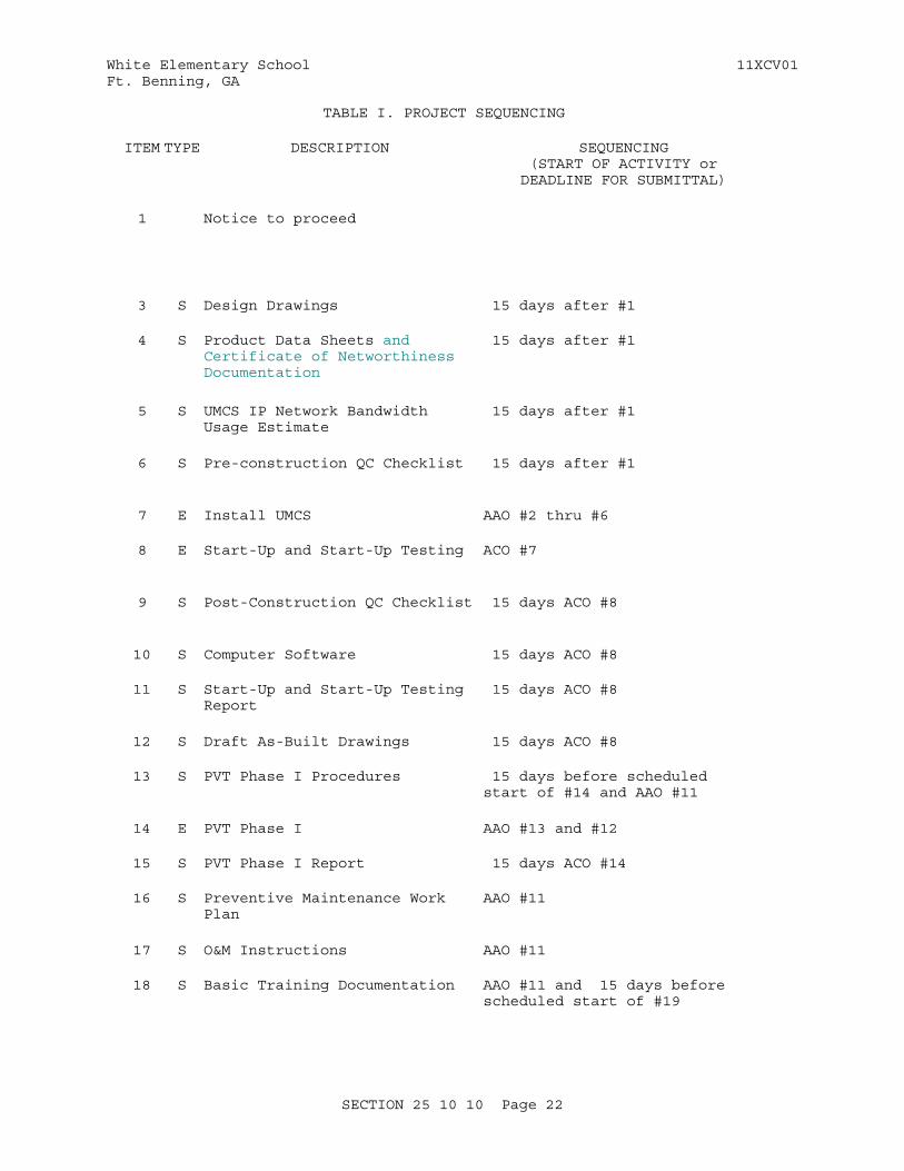
White Elementary School 11XCV01Ft. Benning, GA
TABLE I. PROJECT SEQUENCING
ITEM TYPE DESCRIPTION SEQUENCING(START OF ACTIVITY orDEADLINE FOR SUBMITTAL)
1 Notice to proceed
3 S Design Drawings 15 days after #1
4 S Product Data Sheets and Certificate of Networthiness Documentation
15 days after #1
5 S UMCS IP Network Bandwidth Usage Estimate
15 days after #1
6 S Pre-construction QC Checklist 15 days after #1
7 E Install UMCS AAO #2 thru #6
8 E Start-Up and Start-Up Testing ACO #7
9 S Post-Construction QC Checklist 15 days ACO #8
10 S Computer Software 15 days ACO #8
11 S Start-Up and Start-Up Testing Report
15 days ACO #8
12 S Draft As-Built Drawings 15 days ACO #8
13 S PVT Phase I Procedures 15 days before scheduled start of #14 and AAO #11
14 E PVT Phase I AAO #13 and #12
15 S PVT Phase I Report 15 days ACO #14
16 S Preventive Maintenance Work Plan
AAO #11
17 S O&M Instructions AAO #11
18 S Basic Training Documentation AAO #11 and 15 days before scheduled start of #19
SECTION 25 10 10 Page 22
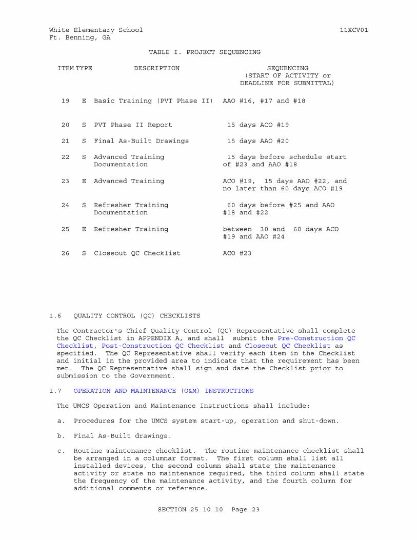
White Elementary School 11XCV01Ft. Benning, GA
TABLE I. PROJECT SEQUENCING
ITEM TYPE DESCRIPTION SEQUENCING(START OF ACTIVITY orDEADLINE FOR SUBMITTAL)
19 E Basic Training (PVT Phase II) AAO #16, #17 and #18
20 S PVT Phase II Report 15 days ACO #19
21 S Final As-Built Drawings 15 days AAO #20
22 S Advanced Training Documentation
15 days before schedule start of #23 and AAO #18
23 E Advanced Training ACO #19, 15 days AAO #22, and no later than 60 days ACO #19
24 S Refresher Training Documentation
60 days before #25 and AAO #18 and #22
25 E Refresher Training between 30 and 60 days ACO #19 and AAO #24
26 S Closeout QC Checklist ACO #23
1.6 QUALITY CONTROL (QC) CHECKLISTS
The Contractor's Chief Quality Control (QC) Representative shall complete the QC Checklist in APPENDIX A, and shall submit the Pre-Construction QC Checklist, Post-Construction QC Checklist and Closeout QC Checklist as specified. The QC Representative shall verify each item in the Checklist and initial in the provided area to indicate that the requirement has been met. The QC Representative shall sign and date the Checklist prior to submission to the Government.
1.7 OPERATION AND MAINTENANCE (O&M) INSTRUCTIONS
The UMCS Operation and Maintenance Instructions shall include:
a. Procedures for the UMCS system start-up, operation and shut-down.
b. Final As-Built drawings.
c. Routine maintenance checklist. The routine maintenance checklist shall be arranged in a columnar format. The first column shall list all installed devices, the second column shall state the maintenance activity or state no maintenance required, the third column shall state the frequency of the maintenance activity, and the fourth column for additional comments or reference.
SECTION 25 10 10 Page 23
White Elementary School 11XCV01Ft. Benning, GA
d. Qualified service organization list including points of contact with phone numbers.
e. Start-Up and Start-Up Testing Report.
f. Performance Verification Test (PVT) Procedures and Reports.
PART 2 PRODUCTS
2.1 EQUIPMENT REQUIREMENTS
2.1.1 Product Certifications
Computing devices, as defined in FCC Part 15, supplied as part of the UMCS shall be certified to comply with the requirements of Class B computing devices.
2.1.2 Product Sourcing
Contractor supplied units of the same type of equipment shall be products of a single manufacturer. Each major component of equipment shall have the manufacturer's name and the model and serial number in a conspicuous place. Materials and equipment shall be new standard unmodified products of a manufacturer regularly engaged in the manufacturing of such products.
2.1.3 General Requirements
Provide components that meet the following requirements:
a. Portions of the data communications equipment system installed in unconditioned spaces shall operate properly in an environment with ambient temperatures between +32 and 120 degrees F and ambient relative humidity between 10 percent and 90 percent noncondensing.
b. Components shall accept 100 to 125 volts AC (Vac), 60 Hz, single phase, three wire with a three-pronged, dedicated circuit outlet or be provided with a transformer to meet the component's power requirements.
c. The equipment shall meet the requirements of NFPA 70, UL 60950, NFPA 262, FCC EMC, and FCC Part 15.
2.1.4 Nameplates
Nameplates shall be laminated plastic and shall identify the function, network address, if applicable, and identifier of the device. Laminated plastic shall be at least 0.125 inch thick, white with black center core. Nameplates shall be a minimum of 1 by 3 inch with minimum 0.25 inch high engraved block lettering.
2.1.5 Product Data Sheets
For all products (equipment) specified in PART 2 and supplied under this contract, submit copies of all manufacturer catalog cuts and specification sheets to indicate conformance to product requirements. For M&C Software also include the PICS verifying BTL Listing as a B-AWS.
SECTION 25 10 10 Page 24

White Elementary School 11XCV01Ft. Benning, GA
2.2 CONTROL HARDWARE
2.2.1 Control Protocol Routers
2.2.1.1 LonWorks/IP Router
LonWorks/IP Routers shall perform layer 3 routing of CEA-709.1-C packets over an IP network in accordance with CEA-852-B. The router shall provide the appropriate connection to the IP network and connections to the CEA-709.3 TP/FT-10 or TP/XF-1250 network. LonWorks/IP Routers shall support the Dynamic Host Configuration Protocol (DHCP; IETF RFC 4361) for IP configuration and the use of an CEA-852-B Configuration Server (for CEA-852-B configuration), but shall not rely on these services for configuration. LonWorks/IP Routers shall be capable of manual configuration via a console RS-232 port.
2.2.2 Monitoring and Control (M&C) Controller Hardware
Monitoring and Control (M&C) Controller Hardware shall be microprocessor-based direct digital control hardware and shall communicate over the UMCS IP network using one of:
a. CEA-709.1-C in accordance with CEA-852-B and using only Standard Network Variable Types (SNVTs) as defined by the LonMark SNVT List.
b. ASHRAE 135 in accordance with ASHRAE 135 Annex J and using only Standard ASHRAE 135 services.
Monitoring and Control (M&C) Controller Hardware shall either meet the requirements of the LonMark Interoperability Guide or be BTL Listed.
2.2.3 Control Protocol Gateways
The Control Protocol Gateway shall perform bi-directional protocol translation between two of the following protocols, or between one of the following protocols and another protocol: CEA-709.1-C, ASHRAE 135, Modbus, Fox protocol, and OPC DA.
a. Gateways shall have two separate network connections, each appropriate for the protocol and media used. A single network connection shall not be used for both protocols.
b. Gateways shall be capable of being installed, configured and programmed through the use of instructions in the manual supplied by the Contractor.
c. All software required for gateway configuration shall be provided and licensed to the Government.
d. Gateways shall retain their configuration after a power loss of an indefinite time, and shall automatically return to their pre-power loss state once power is restored.
e. Gateways shall provide capacity for mapping all required points as shown plus an additional 10 percent between the two protocols it uses.
f. Gateways shall, in addition, meet all requirements specified (in the following subparagraphs) for each of the two protocols it translates.
SECTION 25 10 10 Page 25
White Elementary School 11XCV01Ft. Benning, GA
2.2.3.1 Niagara Framework Supervisory Gateway
Niagara Framework Supervisory Gateway Hardware shall:
a. be direct digital control hardware.
b. have an unrestricted interoperability license and its Niagara Compatability Statement (NiCS) shall follow the Tridium Open NiCS Specification.
c. manage communications between a field control network and the Niagara Framework Monitoring and Control Software and between itself and other Niagara Framework Supervisory Gateways. Niagara Framework Supervisory Gateway Hardware shall use Fox protocol for communication with other Niagara Framework Components.
d. be fully programmable using the Niagara Framework Engineering Tool and shall support the following:
(1) Time synchronization, Calendar, and Scheduling using Niagara Scheduling Objects
(2) Alarm generation and routing using the Niagara Alarm Service
(3) Trending using the Niagara History Service and Niagara Trend Log Objects
(4) Integration of field control networks using the Niagara Framework Engineering Tool
(5) Configuration of integrated field control system using the Niagara Framework Engineering Tool when supported by the field control system
e. meet the following minimum hardware requirements:
(1) Two 10/100/1000 Mbps Ethernet Ports
(2) One port compatible with the field control system to be integrated using this product.
(3) Central Processing Unit of 600 Mhz or higher.
(4) Embedded operating system.
f. provide access to field control network data and supervisory functions via web interface and support a minimum of 16 simultaneous users
2.3 COMPUTER HARDWAREAll computer hardware furnished under this specification shall be standard products of a single manufacturer which advertises service in all 48 contiguous states, and shall be a model currently in production. Except for PCI-E cards installed into expansion slots provided in a desktop or server computer in order to meet the requirements of this specification, computer hardware shall not be modified from the manufacturer configuration.
2.3.1 Server Hardware
Computer Server Hardware (server) will be furnished by the Government and
SECTION 25 10 10 Page 26

White Elementary School 11XCV01Ft. Benning, GA
existing.
2.4 COMPUTER SOFTWARE
2.4.1 Operating System (OS)
The operating system (OS) shall be the latest version of the Army Gold Master Windows Operating System. The Operating System media will be furnished by the Government. The Government will provide the Operating System license.
2.4.2 Niagara Framework Engineering Tool
The Niagara Framework Engineering Tool shall be Niagara Workbench or an equivalent Niagara Framework engineering tool software and shall:
a. have an unrestricted interoperability license and its Niagara Compatability Statement (NiCS) shall follow the Tridium Open NiCS Specification.
b. be capable of performing network configuration for Niagara Framework Supervisory Gateways and Niagara Framework Monitoring and Control Software.
c. be capable of programming and configuring for Niagara Framework Supervisory Gateways and Niagara Framework Monitoring and Control Software.
d. be capable of discovery of Niagara Framework Supervisory Gateways and all points mapped into each Niagara Framework Supervisory Gateway and making these points accessible to Niagara Framework Monitoring and Control Software.
2.4.3 Monitoring and Control (M&C) Software
The monitoring and control (M&C) software shall be a client-server software package with a graphical user interface (GUI) using web-browser based clients. The Software shall be Niagara Framework AX Web Supervisor or equivalent Niagara Framework monitoring and control software and shall communicate with Niagara Framework field control systems using the Fox protocol. The software shall communicate via CEA-709.1-C, and ASHRAE 135, and Modbus, and OPC DA. The M&C Software may support other field control protocols.
The M&C Software shall be BACnet Testing Laboratories Certified ("Listed") as a B-AWS.
The Scheduling, Alarming, Trending, Graphical System Display, and System Display Editor functionality shall be implemented in a single software package. Other specified M&C functionality may be implemented in the same software package or in additional software packages. As specified in PART 3 EXECUTION, the M&C Software shall operate on Server hardware, except that software for Point Calculations and Demand Limiting may operate on M&C Controller Hardware.
2.4.3.1 M&C Software License
The M&C Software shall be licensed in accordance with the other schools on base. Use of multiple copies of M&C Server software working in
SECTION 25 10 10 Page 27
White Elementary School 11XCV01Ft. Benning, GA
coordination and sharing data between them such that they function as, and appear to an operator as, a single M&C Server is permitted to meet these requirements.
2.4.3.2 Supported Field Control Protocols
The M&C Software shall support field control protocols as follows:
a. The Software shall use the Niagara Framework and shall communicate with Niagara Framework Supervisory Gateways using the Fox protocol.
f. The M&C Software may, in addition, include drivers to other protocols.
The M&C Software shall be capable of reading values from and writing values to points via any supported field protocol and shall be capable of reading values from one field protocol and writing them to another. All points obtained from any field protocol shall be available to all M&C Software functionality.
2.4.3.3 Supported Enterprise Protocols
If this project specification has an issue date after 1 January 2014 the M&C Software shall support oBIX or BACnet Web Services as an enterprise protocol and shall meet the following requirements:
a. It shall be capable of reading values from any point or collection of points (network point, internal point, trend log or schedule) and transmitting these values via the enterprise protocol.
b. It shall be capable of receiving data via the enterprise protocol and using this data to change the value of any point.
2.4.3.4 Point Information
Every point, both network and internal, in the M&C Software shall contain the following fields:
2.4.3.4.1 Name
A configurable name used for identification of the point within the M&C Software.
2.4.3.4.2 Description
A configurable description of no less than 80 alpha-numeric characters.
2.4.3.4.3 Value
A field containing the current point value.
2.4.3.4.4 Units
A field containing the engineering units.
SECTION 25 10 10 Page 28
White Elementary School 11XCV01Ft. Benning, GA
2.4.3.4.5 Source
A field identifying the source of the point. For network points, this is generally the address or identification of the field device (for example, the Domain-Subnet-Node address for LonWorks field control devices or the DeviceID for BACnet devices).
2.4.3.5 Point Calculations
M&C software shall have capability of performing calculationsand computing the value of a calculated point based on the valuesof two or more network points and calculated points. Mathematical operators shall include: addition, subtraction, multiplication, division, exponentiation (y^x, power), square root, reciprocal, natural logarithm, sin, cos, tan, arcsin, arccos, arctan, and parenthesis. Pi and e shall be available as constants for use in calculations.
2.4.3.6 Browser-Based Graphical User Interface (GUI)The M&C Software shall include a web-browser based (client-server) graphical user interface. All M&C Software functionality, except for the Graphics Editor, System Display Editor, report configuration, point calculation configuration, and enterprise protocol configuration, shall be accessible through this graphical user interface.
Graphical user interface web server and web clients shall meet the following requirements:
a. The web server shall use HTTPS based on the Transport Layer Security (TLS) Protocol in accordance with IETF RFC 5246 using a Government-furnished certificate.
b. If this project specification has an issue date after 1 January 2014, the graphical user interface shall be Common Access Card (CAC) enabled: It shall support web client authentication using certificates obtained from a Department of Defense Common Access Card (CAC) Smart Card.
c. The web client shall operate on the Windows operating system version XP SP2 and on later Windows operating system versions.
d. The web client shall function in the most recent three version of Internet Explorer and the most recent three versions of Firefox.
e. The web client shall not require a connection to any server other than the M&C Server.
f. The web client shall function in a browser with Java, Shockwave, Silverlight, and Flash installed. The client may require a download of mobile code from the M&C Server, but shall not require the download of additional browser plug-ins or add-ins and there shall be no limit on the number of downloads. The client shall not require ActiveX.
2.4.3.7 PasswordsThe M&C software shall provide user-based access control to M&C functionality. The M&C Software shall recognize at least 100 separate users and have at least 4 levels of user permissions. User permission levels (from most restrictive to most permissive) shall include:
a. Permission Level 1: View-only access to the graphical user interface.
SECTION 25 10 10 Page 29
White Elementary School 11XCV01Ft. Benning, GA
b. Permission Level 2: Permission Level 1 plus acknowledge alarms and set up (configure) trends and reports.
c. Permission Level 3: Permission Level 2 plus override points and set up (configure) alarms, schedules and demand limiting.
d. Permission Level 4: Permission Level 3 plus create and modify Graphical System Displays using the System Display Editor.
Passwords shall not be displayed and shall not be logged. The system shall maintain a disk file on the server hardware logging all activity of the system. This file shall maintain, as a minimum, a record of all operators logged onto the system, alarm acknowledgments, commands issued and all database modifications. If the file format is not plain ASCII text, provide a means to export or convert the file to plain ASCII text. The system shall provide a mechanism for archiving the log files for long term record storage.
2.4.3.8 Graphical System Displays
The graphical displays shall consist of building system (air handler units, VAV boxes, chillers, cooling towers, boilers, etc.) graphic displays. Data associated with an active display shall be updated at least once every 5 seconds.
a. Navigation Scheme: System graphic displays of building systems and points shall be hierarchical displays using a building-to-equipment point-and-click navigation scheme which allows navigation from a garrison-wide display, through a building-wide display to the individual units. Each display shall show the building name and number. Each display shall show system wide data such as outside air temperature and humidity in the case of an HVAC system application.
(1) Each Building or Building Sub-Area display shall show the building foot print and basic floor plan, and shall clearly show and distinguish between the individual zones and the equipment serving each zone and space. The building display shall also show all space sensor and status readings, as applicable, for the individual zones such as space temperature, humidity, occupancy status, etc. The building display shall show the locations of individual pieces of monitored and controlled equipment.
(2) Each equipment display shall show a 3-dimensional representation of the individual pieces of equipment using the symbols and M&C point data types as specified. Different colors and textures shall be used to indicate various components and real time data. Color and texture meanings shall be consistent across all displays.
(3) Each display shall clearly distinguish between the following point data types and information:
(a) Real-time data.
(b) Other user-entered data.
(c) Devices in alarm (unacknowledged).
(d) Out-of-range, bad, or missing data.
SECTION 25 10 10 Page 30

White Elementary School 11XCV01Ft. Benning, GA
b. Navigation Commands: The system displays shall support English language operator commands via point-and-click mouse or keyboard entry for defining and selecting points, parameters, graphics, report generation, and all other functions associated with operation. The operator commands shall be usable from any operator workstation with individual operator passwords as specified.
2.4.3.9 Graphic Editor
The graphic editor shall be a fully featured graphics editor and shall be capable of creating custom graphics and graphic symbols for use by the System Display Editor.
2.4.3.10 System Display Editor
The system display editor shall enable the user to create, modify, and delete graphic displays. The display editor may have a separate user interface and is not required to be accessible via the web browser interface. The display editor shall include the following functions:
a. Create and save displays. Save an existing or modified display as a new display (i.e. "save as")
b. Group and ungroup graphics, where graphics include both alphanumerics and graphic symbols. The grouped graphic shall be manipulated as a single graphic.
c. Place, locate, resize, move, remove, reposition, rotate and mirror a graphic on a display.
d. Overlay graphics over other graphics and assign depths such that when there are coincident graphics the one on top is visible.
e. Modify graphic properties based on the value of network points and create conditions governing the display of a graphics such that different graphics are visible based on the value of network points or calculated points
f. Integrate real-time data with the display.
g. Establish connecting lines.
h. Establish sources of latest data and location of readouts.
i. Display analog values as specified.
j. Assign conditions which automatically initiate a system display.
k. Include a Symbols Library: The M&C Software shall include a library of display symbols which shall include: Pump, Motor, Two- and Three-way Valves, Flow Sensing Element, Point and Averaging Temperature Sensors, Pressure Sensor, Humidity Sensor, Single and Double Deck Air Handling Unit, Fan, Chiller, Boiler, Air Compressor, Chilled Water Piping, Steam Piping, Hot Water Piping, Ductwork, Unit Heater, Pressure Reducing Valve, Damper, Electric Meter, Limit Switch, Flow Switch, High- and Low- Point and Averaging Temperature Switches, High- and Low- Pressure Switches, Coil, Solenoid Valve, Filter, Condensing Unit, Cooling Tower, Variable Frequency Drive (VFD), Heat Exchanger, Current Sensing Relays, Generator, Circuit Breaker, Transformer, Tank. Symbols shall at a
SECTION 25 10 10 Page 31
White Elementary School 11XCV01Ft. Benning, GA
minimum conform to ASHRAE FUN IP where applicable.
2.4.3.11 Scheduling
a. The M&C software shall be capable of changing the value of any network point according to a schedule. The M&C Software shall be capable of scheduling points to any value, including a "null" or invalid value if one is defined for the data type of the point.
b. The specified scheduling functions shall be operator accessible and adjustable via the graphical user interface. Each schedule shall be able to change the value of multiple points. The M&C software shall reinforce all schedules by transmitting the scheduled value no less than once every 30 minutes.
c. The M&C software shall be capable of performing time synchronization and configuring Niagara Framework Schedule Objects in Niagara Framework Supervisory Gateways.
e. The M&C Software shall include a scheduling graphic display, accessible via the graphical user interface, with the following fields and functions:
(1) Current date and time.
(2). System identifier(s) and name(s), including location information such as Building name(s) and number(s).
(3) System group. Systems shall be capable of being grouped by the user to perform according to a common schedule.
(4) Weekly schedules. Each system shall have a weekly schedule based on a seven day per week schedule with independent schedules for each day of the week including no less than 6 value changes per day.
(5) Holiday and special event schedules. System scheduling shall support holiday and special event calendar schedules independent of the daily schedule. Special event schedules shall include one-time events and recurring events. Scheduling of one-time events shall include the beginning and ending dates and times of the event. Holiday and special event schedules shall have precedence over device weekly schedules.
2.4.3.12 Alarms
a. The M&C software shall be capable of generating alarms by comparing the value of any point from any connected system to user-configurable limits, and configuring alarms in ASHRAE 135 field devices in accordance with the B-AWS BIBBs, and configuring alarms in Niagara Framework Supervisory Gateways using the Niagara Alarm Service.
b. The M&C software shall be capable of handling (routing) alarms generated by the M&C Software, and alarms received as an ASHRAE 135 Alarm Event Notifications, and alarms received from a Niagara Framework Supervisory Gateway.
c. The M&C software shall support Niagara Framework Alarm Classes.
SECTION 25 10 10 Page 32
White Elementary School 11XCV01Ft. Benning, GA
d. The M&C software shall support at least two alarm priority levels: critical and informational. Critical alarms shall remain in alarm until acknowledged by an operator and the alarm condition no longer exists; informational alarms shall remain in alarm until the alarm condition no longer exists or until the alarm is acknowledged.
e. The creation, modification, and handling (routing) of alarms shall be fully accessible and fully adjustable from the graphical user interface.
f. Alarm Data. Alarm data to be displayed and stored shall include:
(1) Identification of alarm including building, system (or sub-system), and device name.
(2) Date and time to the nearest second of occurrence.
(3) Alarm type:
(a) Unreliable: Indicates that the source device has failed due to the sensing device or alarm parameter being out-of-range or bad data.
(b) High Alarm.
(c) Low Alarm.
(4) Current value or status of the alarm point, including engineering units
(5) Alarm limits, including engineering units.
(6) Alarm priority.
(7) Alarm Message: A unique message with a field of at least 60 characters. Assignment of messages to an alarm shall be an operator editable function.
(8)Acknowledgement status of the alarm including the time, date and user of acknowledgement.
g. Alarm Notification and Routing: The M&C software shall be capable of performing alarm notification and routing functions. Upon receipt of ASHRAE 135 event notification, network variable of type SNVT_alarm or SNVT_alarm_2, OPC alarm, or upon generation of an alarm the M&C software shall immediately perform alarm notification and routing according to an assigned routing for that alarm. The M&C software shall support at least 100 alarm routes; an alarm route shall be a unique combination of any of the following activities:
(1) Generate a pop-up up active clients. The pop-up display shall include the Alarm Data. Alarms shall be capable of being acknowledged from the pop-up display by operators with sufficient permissions. Pop-up displays shall be displayed until acknowledged.
(2) Send an e-mail message via simple mail transfer protocol (SMTP; RFC 821). The e-mail shall contain a configurable message and all alarm data. The e-mail recipient and scripted message shall be
SECTION 25 10 10 Page 33
White Elementary School 11XCV01Ft. Benning, GA
user configurable for each alarm route.
(3) Print alarms to designated alarm printers. The printed message shall be the same as the pop-up message.
h. Alarm Display and Acknowledgement. The M&C software shall include an alarm display. Alarms shall be available for display at each workstation as shown, along with all associated alarm data. Alarms shall be capable of being acknowledged from this display. Multiple alarms shall be capable of being acknowledged using a single command. Operator acknowledgment of one alarm shall not automatically be considered as acknowledgment of any other alarm nor shall it inhibit reporting of subsequent alarms.
i. Alarm Storage and Reports: The M&C software shall store each alarm and its associated alarm data to hard disk and shall retain this information after the alarm no longer exists. The stored data shall be sortable, searchable, and printable.
2.4.3.13 Trending
The M&C software shall be capable of creating, modifying, uploading and archiving ASHRAE 135 Trend Objects in field devices in accordance with the B-AWS BIBBs and of performing real-time trending with a minimum trending rate of 100 points per second and of using the Niagara history service to create, modify, upload and archive trend log objects in Niagara Framework Supervisory Gateways.
The M&C Software shall include a graphical display for trend configuration, creation and deletion accessible through the graphical user interface. Each trend shall be user-configurable for:
a. Point to trend.
b. Sampling interval shall be adjustable between 1 second and 1 hour.
c. Start and Stop Time of Trend: Start and stop times shall be determined by one or more of the following methods:
(1) Start time and stop time
(2) Start time and duration
(3) Start time and number of samples
The M&C software shall be capable of displaying and printing a graphical representation of each trend, and of multiple trended points on the same graph. The software shall be capable of saving trend logs to a file. If the file format is not plain ASCII text in a Comma-Separated-Value (CSV) format, provide a means to export or convert the file to plain ASCII text in a CSV format.
2.4.3.14 Report Generation
M&C Software shall be capable of generating, saving and printing reports. Dynamic operation of the system shall not be interrupted to generate a report. The report shall contain the time and date when the samples were taken, and the time and date when the report was generated. The software shall be capable of saving reports to a PDF file and to a file compatible
SECTION 25 10 10 Page 34
White Elementary School 11XCV01Ft. Benning, GA
with the provided Office Automation Software.
The software shall allow for automatic and manual generation of reports. For automatic reports an operator shall be able to specify the time the initial report is to be generated, the time interval between reports, end of period, and the output format for the report. Manual report generation shall allow for the operator to request at any time the output of any report.
The M&C software shall be capable of generating custom reports, including but not limited to the the following standard reports:
a. Electrical Power Usage Report: An electrical power Usage summary, operator selectable for substations, meters, or transducers, individual meters and transducers, any group of meters and transducers, and all meters for an operator selected time period. The report shall include the voltage, current, power factor, electrical demand, electrical power consumption, reactive power (Kvar) for each substation, facility, system or equipment as selected by the operator. The report shall be automatically printed at the end of each summary period and shall include:
(1) Total period consumption.
(2) Demand interval peak for the period, with time of occurrence.
(3) Energy consumption (kWh) over each demand interval.
(4) Time-of-use peak, semi-peak, off-peak, or baseline total kWh consumption.
(5) Reactive power during each demand interval.
(6) Power factor during each demand interval.
(7) Outside air (OA) temperature and relative humidity (RH) taken at the maximum and minimum of OA temperature of the report period with the time and dates of occurrence. At the installation's peak demand interval, the OA temperature and RH shall also be recorded.
(8) Calculated heating and cooling degree days based on a 65 degrees F balance point.
b. Energy usage Report: An energy usage summary, operator selectable, for a unit, building, area, installation, and the entire UMCS. The report shall be divided by utility, and shall be capable of reporting on at least four separate utilities. The report shall include the following information:
(1) Beginning and ending dates and times.
(2) Total energy usage for each utility for the current and previous day.
(3) Total energy usage for each utility for the current and previous month.
SECTION 25 10 10 Page 35
White Elementary School 11XCV01Ft. Benning, GA
(4) Maximum 15-minute interval average rate of consumption for each utility for the current and previous day and current and previous month.
(5) Outside air (OA) temperature and OA humidity for current and previous month and current and previous day:
(a) Average temperature and humidity.
(b) Temperature and humidity at maximum and minimum OA temperature with time and date of occurrence.
(c) Temperature and humidity at maximum and minimum humidity with time and date of occurrence.
(d) Temperature and humidity at the installation's peak demand interval with the time and date of occurrence
(6) Calculated degree days. Reports which include humidity shall be configurable to report either dewpoint or relative humidity.
c. Water Usage Report: A water usage summary, operator selectable, for a unit, building, area, installation, and the entire UMCS. The report shall include the following information:
(1) Beginning and ending dates and times.
(2) Total energy water usage for the current and previous day.
(3) Total water usage for the current and previous month.
d. Alarm Report: Outstanding alarms by building or unit, including time of occurrence.
e. M&C Software Override Report: Points overridden by the M&C Software, including time overridden, and identification of operator overriding the point.
f. Run Time Reports: A report totalizing the accumulated run time of individual pieces of equipment. The operator shall be able define equipment groupings and shall be able to generate reports based on these groupings.
g. Chiller usage Report: A report of the operation of each chiller as shown on a daily and monthly basis, for each of at least 10 discrete loading levels. The report shall include:
(1) Average power for the month at each level in kW
(2) Total monthly energy use in kWh at each level
(3) Total monthly energy use in kWh for the chiller (all levels)
(4) Total daily run hours at each level
(5) Total Monthly run hours at each level
SECTION 25 10 10 Page 36
White Elementary School 11XCV01Ft. Benning, GA
h. Device Offline Report: A report listing all offline devices in all CEA-709.1-C or ASHRAE 135 building control systems integrated to the M&C Software and all offline Niagara Framework Supervisory Gateways.
2.5 UNINTERRUPTIBLE POWER SUPPLY (UPS)
The uninterruptible power supply (UPS) shall be a self contained device suitable for installation and operation at the location of Server and Workstation hardware and shall be sized to provide a minimum of 20 minutes of operation of the connected hardware. Equipment connected to the UPS shall not be affected in any manner by a power outage of a duration less than the rated capacity of the UPS. UPS shall be complete with all necessary power supplies, transformers, batteries, and accessories and shall include visual indication of normal power operation, UPS operation, abnormal operation and visual and audible indication of AC input loss and low battery power. The UPS shall be UL 1778 approved. UPS powering Server Hardware shall notify the server via USB interface of impending battery failure.
2.6 RACKS AND ENCLOSURES
2.6.1 Enclosures
Enclosures shall meet the following minimum requirements:
a. Outdoors: Enclosures located outdoors shall meet NEMA 250 Type 4 requirements.
b. Mechanical and Electrical Rooms: Enclosures located in mechanical or electrical rooms shall meet NEMA 250 Type 2 requirements.
c. Other Locations: Enclosures in other locations including but not limited to occupied spaces, above ceilings, and plenum returns shall meet NEMA 250 Type 1 requirements.
Enclosures supplied as an integral (pre-packaged) part of another product are acceptable. Keys for lockable enclosures shall be furnished.
2.6.2 Equipment Racks
Equipment racks shall be standard 19 inch racks compatible with the electronic equipment provided. Racks shall be either aluminum or steel with bolted or welded construction. Steel equipment racks shall be painted with a flame-retardant paint. Guard rails shall be included with each equipment rack and have a copper grounding bar installed and grounded to the earth.
PART 3 EXECUTION
3.1 FACTORY TEST
Perform factory testing of the UMCS as specified. The Contractor is responsible for providing personnel, equipment, instrumentation, and supplies necessary to perform required testing. Written notification of planned testing shall be given to the Government at least 21 days prior to testing, and in no case shall notice be given until after the Contractor has received written Government approval of the specific Factory Test Procedures. The Factory Test Procedures shall define the tests required to ensure that the system meets technical, operational, and performance
SECTION 25 10 10 Page 37
White Elementary School 11XCV01Ft. Benning, GA
specifications. The Procedures shall define location of tests, milestones for the tests, and identify simulation programs, equipment, personnel, facilities, and supplies required. The test procedures shall provide for testing all capabilities and functions specified and shown. . The Factory Test shall be performed using equipment and software of the same manufacturer, model and revision as will be used by the Contractor for the specified project. Procedures shall consist of detailed instructions for test setup, execution, and evaluation of test results. Upon completion of the test, prepare a Factory Test Report, documenting the results of the Test, and submit it as specified.
The Factory Test shall be performed and Factory Test Submittals shall be submitted as shown in TABLE II. FACTORY TEST SEQUENCING.
TABLE II. FACTORY TEST SEQUENCING
ITEM # DESCRIPTION
SEQUENCING(START OF ACTIVITY orDEADLINE FOR SUBMITTAL)
1 Submit Factory Test Procedures 15 days after notice to proceed
2 Perform Factory Test After Approval Of #1
3 Submit Factory Test Report 15 days After Completion Of #2
3.2 DRAWINGS AND CALCULATIONS
3.2.1 UMCS IP Network Bandwidth Usage Estimate
Provide a UMCS IP Network Bandwidth Usage Estimate for a small, medium or large systems. In this estimate account for field control systems using all M&C required protocols and the integration of field control system via gateways. Define all assumptions used to create the estimate, including but not limited to: trending, fast trends for commissioning, schedules, alarms, display of system graphics and load shedding.
3.2.2 Certificate of Networthiness Documentation
For all software provided, provide documentation that an Enterprise Certificate of Networthiness exists, that a Limited Certificate of Networthiness applicable to the project site exists, or provide a completed Certificate of Networthiness "Application Checklist".
3.2.3 UMCS Contractor Design Drawings
Revise and update the Contract Drawings to include details of the system design and all hardware components, including contractor provided and Government furnished components. Drawings shall be on ANSI B (11 by 17 inches) sheets. Details to be shown on the Design Drawing include:
a. The logical structure of the network, including but not limited to the location of all Control Hardware (including but not limited to each BACnet Supervisory Controller, Control Protocol Gateway, Control Protocol Router, Niagara Framework Supervisory Gateway and Monitoring
SECTION 25 10 10 Page 38

White Elementary School 11XCV01Ft. Benning, GA
and Control (M&C) Controller).
b. Manufacturer and model number for each piece of Computer Hardware and Control Hardware.
c. Physical location for each piece of Computer Hardware and Control Hardware.
d. Version and service pack number for all software and for all Control Hardware firmware.
3.2.4 As-Built Drawings
Prepare draft as-built drawings consisting of Points Schedule drawings for the entire UMCS, including Points Schedules for each Gateway, and an updated Design Drawing including details of the actual installed system as it is at the conclusion of Start-Up and Start-Up Testing. As-Built Drawings shall include details of all hardware components, including contractor provided and Government furnished components. In addition to the details shown in the design drawings, the as-built drawing shall include:
a. IP address(es) and Ethernet MAC address(es) as applicable for each piece of Control Hardware (including but not limited to each BACnet Supervisory Controller, Niagara Framework Supervisory Gateway, Control Protocol Gateway, Control Protocol Router, and Monitoring and Control (M&C) Controller).
b. IP address and Ethernet MAC address for each computer server, workstation, and networked printer.
c. Network identifier (name) for each printer, computer server and computer workstation.
d. List of ports, protocols and network services for each device connected to an IP network.
e. CEA-709.1-C address (domain, subnet, node address) for all Control Hardware using CEA-709.1-C.
f. ASHRAE 135 address and Object_ID of the Device Object for all Control Hardware using ASHRAE 135.
g. Modbus address for all Control Hardware using Modbus.
h. Niagara Framework Station ID for all Niagara Framework components including but not limited to Niagara Framework Supervisory Gateways and the AX Web Supervisor.
Prepare Draft As-Built Drawings upon the completion of Start-Up and Start-Up Testing and Final As-Built Drawings upon completion of PVT Phase II.
3.3 INSTALLATION REQUIREMENTS
3.3.1 General
Install system components as shown and specified and in accordance with the
SECTION 25 10 10 Page 39
White Elementary School 11XCV01Ft. Benning, GA
manufacturer's instructions and provide necessary interconnections, services, and adjustments required for a complete and operable system. Communication equipment and cable grounding shall be installed as necessary to preclude ground loops, noise, and surges from adversely affecting system operation. Fiber Optic cables and wiring in exposed areas, including low voltage wiring but not including network cable in telecommunication closets, shall be installed in metallic raceways or EMT conduit as specified in Section 26 20 00 INTERIOR DISTRIBUTION SYSTEM. Do not install equipment in any space which experiences temperatures or humidity outside of the rated operating range of the equipment.
3.3.2 Isolation, Building Penetrations and Equipment Clearance
The UMCS shall be completely installed and ready for operation, as specified and shown. Dielectric isolation shall be provided where dissimilar metals are used for connection and support. Penetrations through and mounting holes in the building exteriors shall be made watertight. Holes in concrete, brick, steel and wood walls shall be drilled or core drilled with proper equipment; conduits installed through openings shall be sealed with materials which are compatible with existing materials. Openings shall be sealed with materials which meet the requirements of NFPA 70 and SECTION 07 84 00 FIRESTOPPING.
3.3.3 Nameplates
Provide Nameplates for all Control Hardware and all Computer Hardware. Attach Nameplates to the device in a conspicuous location.
3.4 INSTALLATION OF EQUIPMENT
3.4.1 Wire and Cable Installation
System components and appurtenances shall be installed in accordance with NFPA 70, manufacturer's instructions and as shown. Necessary interconnections, services, and adjustments required for a complete and operable signal distribution system shall be provided. Components shall be labeled in accordance with TIA-606. Penetrations in fire-rated construction shall be firestopped in accordance with Section 07 84 00 FIRESTOPPING. Conduits, outlets and raceways shall be installed in accordance with Section 26 20 00 INTERIOR DISTRIBUTION SYSTEM. Wiring shall be installed in accordance with TIA-568-C.1 and as specified in Section 26 20 00 INTERIOR DISTRIBUTION SYSTEM. Wiring, and terminal blocks and outlets shall be marked in accordance with TIA-606. Non fiber-optic cables shall not be installed in the same cable tray, utility pole compartment, or floor trench compartment with power cables. Cables not installed in conduit or raceways shall be properly secured and neat in appearance.
3.4.2 Grounding
Signal distribution system ground shall be installed in accordance with TIA-607 and Section 26 20 00 INTERIOR DISTRIBUTION SYSTEM. Equipment racks shall be connected to the electrical safety ground.
3.4.3 Power-Line Surge Protection
Equipment connected to ac circuits shall be protected against or withstand power-line surges. Equipment protection shall meet the requirements of IEEE C62.41. Fuses shall not be used for surge protection.
SECTION 25 10 10 Page 40
White Elementary School 11XCV01Ft. Benning, GA
3.4.4 IP Addresses
For all Control Hardware requiring an IP address on the UMCS IP Network, coordinate with the NEC to obtain IP addresses .
3.4.5 Computer Hardware and Software
3.4.5.1 Hardware Installation
Computer Hardware shall be installed as shown. Computer Servers shall be powered through a UPS, and shall be installed and configured such that the server will automatically undergo a clean shutdown upon low battery signal from the UPS.
3.4.5.2 Software Installation
Install software as follows:
a. CEA-852-B Configuration Server: Install and configure one CEA-852-B Configuration Server. The CEA-852-B Configuration Server shall be installed on Server Hardware or on an CEA-709.1-C TP/FT-10 to IP Router.
b. CEA-709.1-C Network Configuration Tool: Install the CEA-709.1-C Network Configuration Tool software as shown. The CEA-709.1-C Network Configuration Tool shall be installed on workstation or server hardware.
d. Niagara Framework Engineering Tool: Install the Niagara Framework Engineering Tool on the AX Web Supervisor Server.
e. Monitoring and Control Software: Install the monitoring and control (M&C)software as shown. Except for M&C Software performing Point Calculations or Electrical Peak Demand Limiting, install M&C Software on server hardware. Install M&C Software performing Point Calculations or Electrical Peak Demand Limiting on either server hardware or Monitoring and Control (M&C) Controller Hardware. M&C Software shall be installed in a manner consistent with its B-AWS listing such that it provides all functionality of a B-AWS.
Provide sufficient computer hardware and M&C Controller Hardware and install M&C Software to support the number of points required in PART 2 (PRODUCTS), regardless of the number of points integrated under this project specification. Note that meeting this requirement may entail the installation of unused hardware or spare point licenses to accommodate the full number of required points in order to allow for integration of future field control systems.
f. M&C Controller Hardware Configuration Software: Install the M&C Controller Hardware Configuration Software software on server hardware.
g. Operating system: Install the OS on each Server and Workstation and configure user names and passwords. Coordinate with DDES for user names and passwords.
h. Office Automation Software: Install the office automation software on each server and workstation.
i. Virus Protection software: Install the virus protection software on
SECTION 25 10 10 Page 41
White Elementary School 11XCV01Ft. Benning, GA
each server and workstation and configure weekly virus scans. Configure the virus protection software to update virus definitions automatically . Coordinate with the NEC to obtain update server information.
Where software requires connection to an IP device outside of the UMCS, coordinate with the project site NEC to obtain access to a Government-furnished server to provide the needed functionality. No connection with a device outside of the UMCS shall be established without explicit permission from the project site NEC.
3.4.5.3 Monitoring and Control (M&C) Software Configuration
Configure the Monitoring and Control (M&C) Software as specified, as shown and as follows:
a. Set up M&C Software user accounts and passwords. Coordinate user accounts, passwords and permissions with the Controls shop supervisor.
b. Change the default password on all accounts. Remove or disable any accounts which do not require authentication (such as guest accounts).
c. Disable all ports, protocols, and network services other than those required or specifically permitted by this Section. Services to be disabled include but are not limited to: FTP, Telnet and SSH.
d. Install web server certificate. Obtain certificate from the project site NEC.
3.4.5.4 Control Hardware Installation
Control Hardware shall be installed in an enclosure and as specified. Configure Control Hardware as specified, as required to meet the functions for which the hardware used and as follows:
a. Disable all ports, protocols, and network services other than those required or specifically permitted by this Section. Services to be disabled include but are not limited to: FTP, Telnet, SSH, and HTTP. HTTP may be enabled for Niagara Framework Supervisory Gateways. When disabling of ports, protocols and services is not supported by a product, obtain an exception from this requirement prior to using the product and document non-compliance on the Product Data Sheets and As-Built drawings.
b. Change the default passwords in all Control Hardware which have passwords. Coordinate new passwords with the Controls shop supervisor.
3.5 INTEGRATION OF FIELD CONTROL SYSTEMS
Fully integrate the field control systems in accordance with the following three step sequence and as specified and shown.
STEP 1: Install and configure Control Hardware as necessary to provide a Field Point of Connection to connect the field control system to the UMCS IP network and, when necessary, to provide control protocol
SECTION 25 10 10 Page 42

White Elementary School 11XCV01Ft. Benning, GA
translation and supervisory functionality.
STEP 2: Add Field Control System to M&C Software: Perform system discovery, system database merges, or any other actions necessary to allow M&C Software access to the field control system.
STEP 3: Configure M&C Software to provide monitoring and control of the field control system, including but not limited to the creation of system displays and the configuration of scheduling, alarming, and trending.
3.5.1 Integration Step 1: Install Control Hardware
Install Control Hardware as specified at the FPOC location as directed by installation to connect the field control system to the UMCS IP network and, if necessary, to provide control protocol translation and supervisory functionality. Depending on the field control system media and protocol this shall be accomplished through one of the following:
a. Connect the existing field control network FPOC to the UMCS IP network. (Note: The existing FPOC will generally be a control protocol router or control protocol gateway for non-Niagara Framework field control systems, or a Niagara Framework Supervisory Gateway)
b. Install either a Control Protocol Gateway or Niagara Framework Supervisory Gateway connected to both the field control network and the UMCS IP network.
c. Install a Control Protocol Router connected to both the field control network and the UMCS IP network.
d. Install a Control Protocol Gateway connected to the field control network. Then install a Control Protocol Router connected to both the Control Protocol Gateway and the UMCS IP network.
In addition, for integration of field control systems via ASHRAE 135, also install a BACnet Supervisory Controller as needed to implement scheduling, alarming and trending in the field control system. The BACnet supervisory controller may be the same device as the control protocol gateway or router.
3.5.1.1 Installation of Control Protocol Gateway
If the field control system uses a protocol which is not supported by the M&C Software, install a gateway to convert the field control system protocol to ASHRAE 135, or to CEA-709.1-C, or to Modbus, or to OPC DA. Install additional field control system network media and hardware as needed to connect the Gateway to the field control system. Connect the Gateway according to one of the two following methods:
a. Connect the Gateway to the field control network and to the UMCS IP network. The gateway is the FPOC unless a BACnet Supervisory Controller is also installed, in which case the FPOC will be an upstream device such as an Ethernet Switch.
b. Connect the Gateway to the field control network and to a BACnet/IP Router, or to a LonWorks/IP Router, or to a Modbus/IP Router installed as specified.
Create and configure points and establish network communication between the
SECTION 25 10 10 Page 43
White Elementary School 11XCV01Ft. Benning, GA
Control Protocol Gateway and the field control system to provide points from the field control system to the M&C software.
3.5.1.2 Installation of Niagara Framework Supervisory Gateway
Install Niagara Framework Supervisory Gateway hardware to connect the field control network to the UMCS IP network. Install additional field control system network media and hardware as needed to connect the Niagara Framework Supervisory Gateway to the field control system. The Niagara Framework Supervisory Gateway is the FPOC.
3.5.1.3 Installation of Control Protocol Router
If there is not an existing connection between the UMCS IP Network and the field control network, install a BACnet/IP Router, or a LonWorks/IP Router, or a Modbus/IP Router to connect the field control network to the UMCS IP network. Install additional field control system network media as needed to connect the Router to the field control system. This Router is the FPOC.
3.5.2 Integration Step 2: Add Field Control System to M&C Software
Perform system discovery, system database merges, or any other actions necessary to allow M&C Software access to points and data in the field control system.
3.5.2.1 Integration of Field Control Systems Via Niagara Framework
For each Niagara Framework Supervisory Gateway installed in integration step 1 for this project do both of the following:
a. Use the Niagara Framework Engineering Tool to fully discover the field control system and make all field control system information available to the Niagara Framework Supervisory Gateway.
b. Create and configure points and establish network communication between the Niagara Framework Supervisory Gateway and the field control system to provide points from the field control system to the M&C software and to provide support for supervisory functions, including but not limited to schedule objects, trend logs and alarming.
For each Niagara Framework Supervisory Gateway to be integrated as part of this project, make all information in the Niagara Framework Supervisory Gateway available to the M&C Software.
3.5.3 Integration Step 3: Configure M&C Software
Configure M&C Software to provide monitoring and control of the field control system, including but not limited to the creation of system displays and the configuration of scheduling, alarming, and trending.
3.5.3.1 Configure M&C Software Functionality
Configure M&C Software functionality as specified:
a. Create System Displays using the project site sample displays, including overrides, as shown on the Points Schedule and as specified. Label all points on displays with the point description as shown on the
SECTION 25 10 10 Page 44
White Elementary School 11XCV01Ft. Benning, GA
Points Schedule. Configure user permissions for access to and executions of action using graphic pages. Coordinate user permissions with the Controls shop supervisor
b. Configure alarm generation and alarm handling as shown on the Points Schedule, as shown on the Alarm Routing Schedule, and as specified. Create and configure Alarm Objects in BACnet Supervisory Controllers and in the field control systems as shown on the Points Schedule and as specified. For alarms requiring notification via text message or email, configure the alarm notification to use the specified Government furnished SMTP server to send the alarm notification.
c. Configure M&C Software scheduling functionality to schedule systems as shown on the Points Schedule and as specified. Create and configure Schedule Objects in BACnet Supervisory Controllers and in the field control system as shown on the Points Schedule and as specified.
Create and configure displays for configuration of M&C Software schedules and Schedule Objects. Label schedules and scheduled points with full English-language descriptors.
d. Create M&C Software trends for required points as shown on the Points Schedule and as specified. Create and configure Trend Objects in BACnet Supervisory Controllers and in the field control system as shown on the Points Schedule and as specified. Trend points at 15 minute intervals.
Create and configure displays for creation and configuration of trends and for display of all trended points.
e. Configure Demand Limiting as shown on the Demand Limit Schedule and Points Schedule and as specified.
f. Configure M&C Software standard reports.
3.6 START-UP AND START-UP TESTING
Test all equipment and perform all other tests necessary to ensure the system is installed and functioning as specified. Prepare a Start-Up and Start-Up Testing Report documenting all tests performed and their results and certifying that the system meets the requirements specified in the contract documents.
3.7 PERFORMANCE VERIFICATION TEST (PVT)
3.7.1 PVT Phase I Procedures
PVT Procedures shall include:.
a. Network bandwidth usage and available bandwidth (throughput) measurements. Network bandwidth usage shall reference the normal usage network Bandwidth Calculations.
b. Test System Reaction during PVT: The total system response time from initiation of a control action command from the workstation, to display of the resulting status change on the workstation shall not exceed 20 seconds under system normal heavy load conditions assuming a zero response time for operation of the node's control device.
c. Verification of IP Connectivity.
SECTION 25 10 10 Page 45
White Elementary School 11XCV01Ft. Benning, GA
d. Verification of configuration of M&C Software functionality.
3.7.2 PVT Phase I
Demonstrate compliance of the control system with the contract documents. Using test plans and procedures previously approved by the Government, demonstrate all physical and functional requirements of the project. Upon completion of PVT Phase I and as specified, prepare and submit the PVT Phase I Report documenting all tests performed during the PVT and their results. The PVT report shall include all tests in the PVT Procedures and any other testing performed during the PVT. Failures and repairs shall be documented with test results.
3.7.3 PVT Phase II
PVT Phase II shall include Basic Training. Failures or deficiencies of the UMCS during Basic Training shall be considered PVT failures. Upon completion of PVT Phase II, and as specified, prepare and submit the PVT Phase II Report documenting any failures which occurred and repairs performed during PVT Phase II.
3.8 MAINTENANCE AND SERVICE
Perform inspection, testing, cleaning, and part or component replacement as specified and as required to maintain the warranty. Work includes providing necessary preventive and unscheduled maintenance and repairs to keep the UMCS operating as specified, and accepted by the Government, and other services as specified. Work shall comply with manufacturer's recommendations and industry standards. Provide technical support via telephone during regular working hours.
3.8.1 Work Coordination
Schedule and arrange work to cause the least interference with the normal Government business and mission. In those cases where some interference may be essentially unavoidable, coordinate with the Government to minimize the impact of the interference, inconvenience, equipment downtime, interrupted service and personnel discomfort.
3.8.2 Work Control
When the Contractor completes work on a system or piece of equipment, that system or piece of equipment shall be free of missing components or defects which would prevent it from functioning as originally intended and designed. Replacements shall conform to the same specifications as the original equipment. During and at completion of work, debris shall not be allowed to spread unnecessarily into adjacent areas nor accumulate in the work area itself.
3.8.3 Working Hours
Working hours are from 7:30 A.M. to 4:00 P.M. local time Mondays through Fridays except Federal holidays.
3.8.4 Access To UMCS Equipment
Access shall be in accordance with the following:
SECTION 25 10 10 Page 46
White Elementary School 11XCV01Ft. Benning, GA
a. Coordinate access to facilities and arrange that they be opened and closed during and after the accomplishment of the work effort. For access to a controlled facility contact the Government for assistance.
b. The Government may provide keys for access to UMCS equipment where the Government determines such key issuance is appropriate. Establish and implement methods of ensuring that keys issued by the Government are not lost or misplaced, are not used by unauthorized persons, and are not duplicated.
c. The Government may provide passwords or issue Common Access Cards (CAC) for access to UMCS computer equipment where the Government determines such issuance is appropriate. Establish and implement methods of ensuring that passwords and Common Access Cards issued by the Government are not used by unauthorized persons.
3.8.5 Records, Logs, and Progress Reports
Keep records and logs of each task, and organize cumulative chronological records for each major component, and for the complete system. Maintain a continuous log for the UMCS. Keep complete logs and be available for inspection on site, demonstrating that planned and systematic adjustments and repairs have been accomplished for the UMCS.
3.9 TRAINING
Conduct training courses for designated personnel in the maintenance, service, and operation of the system as specified, including specified hardware and software. The training shall be oriented to the specific system provided under this contract. The Contractor is responsible for providing audiovisual equipment and other training material and supplies. When training is conducted at Government facilities, the Government reserves the right to record the training sessions for later use. A training day is defined as 8 hours of classroom instruction, excluding lunchtime, Monday through Friday, during the daytime shift in effect at the training facility. For guidance in planning the required instruction, the Contractor should assume that attendees will be tradesmen such as electricians or boiler operators. Approval of the Contractor's training schedule shall be obtained from the Government at least 30 days prior to the first day of training.
3.9.1 Training Documentation
Prepare and submit one set of Training manuals for each of Basic Training Documentation, Advanced Training Documentation, and Refresher Training Documentation. Documentation shall each consist of:
a. Course attendance list: A list of course attendees shall be developed in coordination with and signed by the Controls shop supervisor.
b. Training Manuals: Training manuals shall include an agenda, defined objectives for each lesson, and a detailed description of the subject matter for each lesson. Where the Contractor presents portions of the course material by audiovisuals, copies of those audiovisuals shall be delivered to the Government as a part of the printed training manuals.
3.9.2 Basic Training
The Basic Training course shall be taught at the project site on the
SECTION 25 10 10 Page 47
White Elementary School 11XCV01Ft. Benning, GA
installed system for a period of no less than 5 training days during Phase 2 of the PVT. A maximum of ten personnel will attend this course. This training shall be targeted towards training personnel in the day-to-day operation and basic maintenance of the system. Upon completion of this course, each student, using appropriate documentation, should be able to start the system, operate the system, recover the system after a failure, perform routine maintenance and describe the specific hardware architecture and operation of the system. This course shall at a minimum include:
a. General system architecture.
b. Functional operation of the system, including workstations and system navigation.
c. System start-up procedures.
d. Failure recovery procedures.
e. Schedule configuration.
f. Trend configuration.
g. Perform point overrides and override release.
h. Reports generation.
i. Alarm reporting and acknowledgements.
j. Diagnostics.
k. Historical files.
l. Maintenance procedures:
(1) Physical layout of each piece of hardware.
(2) Troubleshooting and diagnostic procedures.
(3) Preventive maintenance procedures and schedules.
3.9.3 Advanced Training
The advanced operator course shall be taught at the project site for a period of not less then five days. A maximum of ten personnel will attend this course. The course shall consist of "hands-on" training under the constant monitoring of the instructor. Advanced Training shall include training on the M&C Software, and the CEA-709.1-C Network Configuration Tool , and the BACnet Network Browser, and the Niagara Framework Engineering Tool. Upon completion of this course, the students should be fully proficient in the operation and management of all system operations and shall be able to perform all tasks required to integrate a field control system into the UMCS. Report the skill level of each student at the end of this course. This course shall at minimum include:
a. A review of all topics in Basic Training
b. Using the CEA-709.1-C Network Configuration Tool for Network Managementand using the BACnet Network Browser for network discovery
SECTION 25 10 10 Page 48
White Elementary School 11XCV01Ft. Benning, GA
c. M&C Software configuration, including but not limited to: creating and editing system displays, alarms, schedules, trends, demand limiting and calculations.
3.9.4 Refresher TrainingThe refresher course shall be taught at the project site for a period of two training days when approved by the Government and as specified in paragraph PROJECT SEQUENCING. A maximum of ten personnel will attend the course. The course shall be structured to address specific topics that the students need to discuss and to answer questions concerning the operation of the system. Upon completion of the course, the students should be fully proficient in system operation and have no unanswered questions regarding operation of the installed UMCS. Any system failures discovered during the Refresher Training shall be corrected by the Contractor at no cost to the Government.
SECTION 25 10 10 Page 49
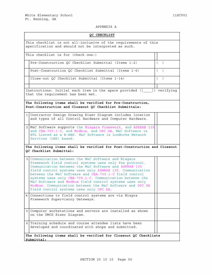
White Elementary School 11XCV01Ft. Benning, GA
APPENDIX A
QC CHECKLIST
This checklist is not all-inclusive of the requirements of this specification and should not be interpreted as such.
This checklist is for (check one:)
Pre-Construction QC Checklist Submittal (Items 1-2) ( )
Post-Construction QC Checklist Submittal (Items 1-6) ( )
Close-out QC Checklist Submittal (Items 1-14) ( )
Instructions: Initial each item in the space provided (|____|) verifying that the requirement has been met.
The following items shall be verified for Pre-Construction, Post-Construction and Closeout QC Checklist Submittals:
1 Contractor Design Drawing Riser Diagram includes location and types of all Control Hardware and Computer Hardware.
2 M&C Software supports the Niagara Framework, and ASHRAE 135and CEA-709.1-C, and Modbus, and OPC DA. M&C Software is BTL Listed as a B-AWS. M&C Software is LonWorks Network Services (LNS) based.
The following items shall be verified for Post-Construction and Closeout QC Checklist Submittal:
3 Communication between the M&C Software and Niagara Framework field control systems uses only Fox protocol.Communication between the M&C Software and ASHRAE 135 field control systems uses only ASHRAE 135. Communication between the M&C Software and CEA-709.1-C field control systems uses only CEA-709.1-C. Communication between the M&C Software and Modbus field control systems uses only Modbus. Communication between the M&C Software and OPC DA field control systems uses only OPC DA.
4 Connections to field control systems are via Niagra Framework Supervisory Gateways.
5 Computer workstations and servers are installed as shown on the UMCS Riser Diagram.
6 Training schedule and course attendee lists have been developed and coordinated with shops and submitted.
The following items shall be verified for Closeout QC Checklists Submittal:
SECTION 25 10 10 Page 50
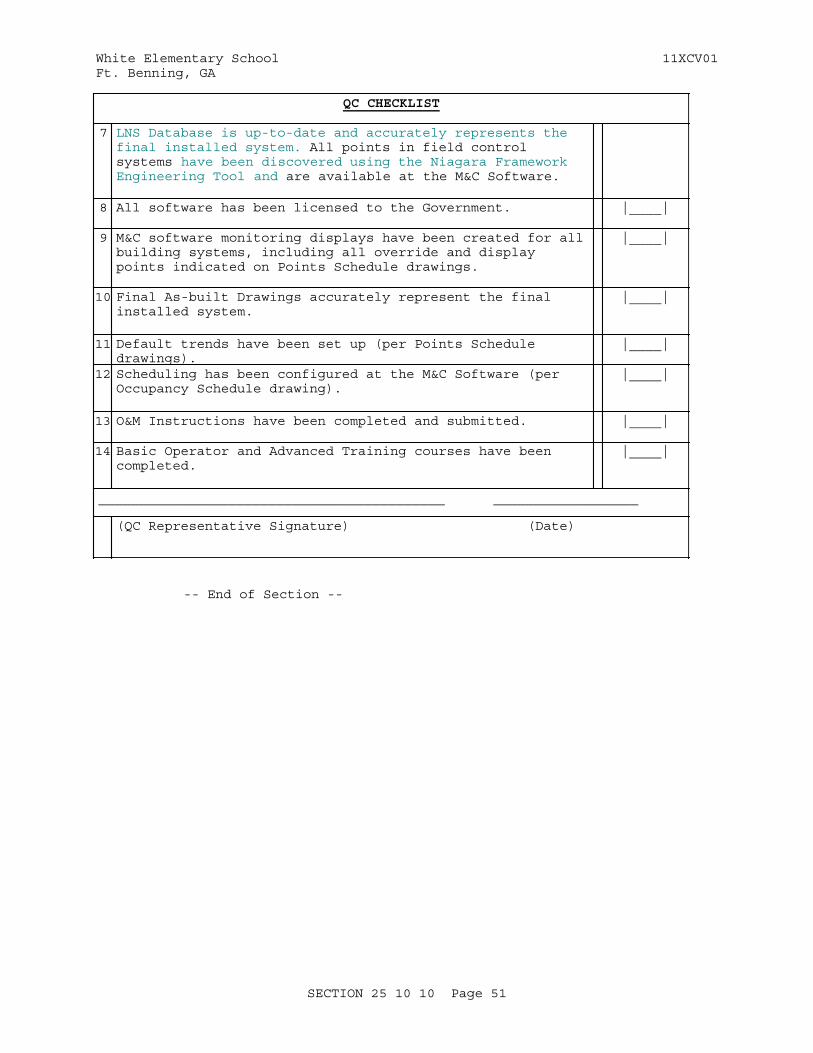
White Elementary School 11XCV01Ft. Benning, GA
QC CHECKLIST
7 LNS Database is up-to-date and accurately represents the final installed system. All points in field control systems have been discovered using the Niagara Framework Engineering Tool and are available at the M&C Software.
8 All software has been licensed to the Government. |____|
9 M&C software monitoring displays have been created for all building systems, including all override and display points indicated on Points Schedule drawings.
|____|
10 Final As-built Drawings accurately represent the final installed system.
|____|
11 Default trends have been set up (per Points Schedule drawings).
|____|
12 Scheduling has been configured at the M&C Software (per Occupancy Schedule drawing).
|____|
13 O&M Instructions have been completed and submitted. |____|
14 Basic Operator and Advanced Training courses have been completed.
|____|
___________________________________________ __________________
(QC Representative Signature) (Date)
-- End of Section --
SECTION 25 10 10 Page 51
White Elementary School 11XCV01Ft. Benning, GA
SECTION TABLE OF CONTENTS
DIVISION 26 - ELECTRICAL
SECTION 26 20 00
INTERIOR DISTRIBUTION SYSTEM
08/08
PART 1 GENERAL
1.1 REFERENCES 1.2 DEFINITIONS 1.3 SUBMITTALS 1.4 QUALITY ASSURANCE 1.4.1 Fuses 1.4.2 Regulatory Requirements 1.4.3 Standard Products 1.4.3.1 Alternative Qualifications 1.4.3.2 Material and Equipment Manufacturing Date 1.5 MAINTENANCE 1.5.1 Electrical Systems 1.6 WARRANTY
PART 2 PRODUCTS
2.1 MATERIALS AND EQUIPMENT 2.2 CONDUIT AND FITTINGS 2.2.1 Rigid Metallic Conduit 2.2.1.1 Rigid, Threaded Zinc-Coated Steel Conduit 2.2.2 Rigid Nonmetallic Conduit 2.2.3 Intermediate Metal Conduit (IMC) 2.2.4 Electrical, Zinc-Coated Steel Metallic Tubing (EMT) 2.2.5 Plastic-Coated Rigid Steel and IMC Conduit 2.2.6 Flexible Metal Conduit 2.2.6.1 Liquid-Tight Flexible Metal Conduit, Steel 2.2.7 Fittings for Metal Conduit, EMT, and Flexible Metal Conduit 2.2.7.1 Fittings for Rigid Metal Conduit and IMC 2.2.7.2 Fittings for EMT 2.2.8 Fittings for Rigid Nonmetallic Conduit 2.3 CABLE TRAYS 2.3.1 Basket-Type Cable Trays 2.3.2 Ladder-Type Cable Trays 2.4 OPEN TELECOMMUNICATIONS CABLE SUPPORT 2.4.1 Open Top Cable Supports 2.5 OUTLET BOXES AND COVERS 2.5.1 Floor Outlet Boxes 2.5.2 Outlet Boxes for Telecommunications System 2.5.3 Clock Outlet for Use in Other Than Wired Clock System 2.6 CABINETS, JUNCTION BOXES, AND PULL BOXES 2.7 WIRES AND CABLES 2.7.1 Conductors 2.7.1.1 Equipment Manufacturer Requirements 2.7.1.2 Aluminum Conductors 2.7.1.3 Minimum Conductor Sizes
SECTION 26 20 00 Page 1

White Elementary School 11XCV01Ft. Benning, GA
2.7.2 Color Coding 2.7.3 Insulation 2.7.4 Bonding Conductors 2.7.4.1 Telecommunications Bonding Backbone (TBB) 2.7.4.2 Bonding Conductor for Telecommunications 2.7.5 Mineral-Insulated, Metal-Sheathed Cable 2.8 SPLICES AND TERMINATION COMPONENTS 2.9 DEVICE PLATES 2.10 SWITCHES 2.10.1 Toggle Switches 2.10.2 Switch with Red Pilot Handle 2.10.3 Breakers Used as Switches 2.10.4 Disconnect Switches 2.11 FUSES 2.11.1 Fuseholders 2.11.2 Cartridge Fuses, Current Limiting Type (Class R) 2.11.3 Cartridge Fuses, High-Interrupting Capacity, Current Limiting
Type (Classes J, L, and CC) 2.12 RECEPTACLES 2.12.1 Weatherproof Receptacles 2.12.2 Ground-Fault Circuit Interrupter Receptacles 2.12.3 Special Purpose Receptacles 2.12.4 Range Receptacles 2.12.5 Dryer Receptacles 2.12.6 Tamper-Resistant Receptacles 2.13 PANELBOARDS 2.13.1 Enclosure 2.13.2 Panelboard Buses 2.13.3 Circuit Breakers 2.13.3.1 Multipole Breakers 2.13.3.2 Circuit Breaker With GFCI 2.13.3.3 Circuit Breakers for HVAC Equipment 2.14 ENCLOSED CIRCUIT BREAKERS 2.15 MOTOR SHORT-CIRCUIT PROTECTOR (MSCP) 2.16 TRANSFORMERS 2.16.1 Specified Transformer Efficiency 2.16.2 Vibration/Isolation 2.17 MOTORS 2.17.1 High Efficiency Single-Phase Motors 2.17.2 Premium Efficiency Polyphase Motors 2.17.3 Motor Sizes 2.17.4 Wiring and Conduit 2.18 MOTOR CONTROLLERS 2.18.1 Control Wiring 2.18.2 Control Circuit Terminal Blocks 2.18.2.1 Types of Terminal Blocks 2.18.3 Control Circuits 2.18.4 Enclosures for Motor Controllers 2.18.5 Multiple-Speed Motor Controllers and Reversible Motor
Controllers 2.18.6 Pushbutton Stations 2.18.7 Pilot and Indicating Lights 2.18.8 Reduced-Voltage Controllers 2.19 MANUAL MOTOR STARTERS (MOTOR RATED SWITCHES) 2.19.1 Pilot Lights 2.20 LOCKOUT REQUIREMENTS 2.21 TELECOMMUNICATIONS SYSTEM 2.22 GROUNDING AND BONDING EQUIPMENT 2.22.1 Ground Rods
SECTION 26 20 00 Page 2

White Elementary School 11XCV01Ft. Benning, GA
2.22.2 Ground Bus 2.22.3 Telecommunications and CATVGrounding Busbar 2.23 MANUFACTURER'S NAMEPLATE 2.24 FIELD FABRICATED NAMEPLATES 2.25 WARNING SIGNS 2.26 FIRESTOPPING MATERIALS 2.27 WIREWAYS 2.28 METERING 2.29 METER BASE ONLY 2.30 SURGE PROTECTIVE DEVICES 2.31 FACTORY APPLIED FINISH 2.32 SOURCE QUALITY CONTROL 2.32.1 Transformer Factory Tests 2.33 COORDINATED POWER SYSTEM PROTECTION 2.34 Demonstration Photovoltaic System 2.35 Demonstration Wind Turbine 2.36 Main Photovoltaic System
PART 3 EXECUTION
3.1 INSTALLATION 3.1.1 Underground Service 3.1.2 Service Entrance Identification 3.1.2.1 Labels 3.1.3 Wiring Methods 3.1.3.1 Pull Wire 3.1.4 Conduit Installation 3.1.4.1 Restrictions Applicable to EMT 3.1.4.2 Restrictions Applicable to Nonmetallic Conduit 3.1.4.3 Restrictions Applicable to Flexible Conduit 3.1.4.4 Service Entrance Conduit, Underground 3.1.4.5 Underground Conduit Other Than Service Entrance 3.1.4.6 Conduit Installed Under Floor Slabs 3.1.4.7 Conduit Through Floor Slabs 3.1.4.8 Stub-Ups 3.1.4.9 Conduit Support 3.1.4.10 Directional Changes in Conduit Runs 3.1.4.11 Locknuts and Bushings 3.1.4.12 Flexible Connections 3.1.4.13 Telecommunications and Signal System Pathway 3.1.4.14 Community Antenna Television (CATV) System Conduits 3.1.5 Busway Installation 3.1.6 Cable Tray Installation 3.1.7 Telecommunications Cable Support Installation 3.1.8 Boxes, Outlets, and Supports 3.1.8.1 Boxes 3.1.8.2 Pull Boxes 3.1.8.3 Extension Rings 3.1.9 Mounting Heights 3.1.10 Mineral Insulated, Metal Sheathed (Type MI) Cable Installation 3.1.11 Conductor Identification 3.1.11.1 Marking Strips 3.1.12 Splices 3.1.12.1 Splices of Aluminum Conductors 3.1.13 Terminating Aluminum Conductors 3.1.13.1 Termination to Copper Bus 3.1.13.2 Termination to Aluminum Bus 3.1.14 Covers and Device Plates 3.1.15 Electrical Penetrations
SECTION 26 20 00 Page 3
White Elementary School 11XCV01Ft. Benning, GA
3.1.16 Grounding and Bonding 3.1.16.1 Ground Rods 3.1.16.2 Grounding Connections 3.1.16.3 Ground Bus 3.1.16.4 Resistance 3.1.16.5 Telecommunications System 3.1.17 Equipment Connections 3.1.18 Elevator 3.1.19 Government-Furnished Equipment 3.1.20 Repair of Existing Work - Separate package (Refer to Division
02) 3.1.20.1 Workmanship 3.1.20.2 Existing Concealed Wiring to be Removed 3.1.20.3 Removal of Existing Electrical Distribution System 3.1.21 Meters 3.1.22 Surge Protective Devices 3.2 FIELD FABRICATED NAMEPLATE MOUNTING 3.3 WARNING SIGN MOUNTING 3.4 FIELD APPLIED PAINTING 3.5 FIELD QUALITY CONTROL 3.5.1 Devices Subject to Manual Operation 3.5.2 600-Volt Wiring Test 3.5.3 Transformer Tests 3.5.4 Ground-Fault Receptacle Test 3.5.5 Grounding System Test 3.5.6 Meter
-- End of Section Table of Contents --
SECTION 26 20 00 Page 4
White Elementary School 11XCV01Ft. Benning, GA
SECTION 26 20 00
INTERIOR DISTRIBUTION SYSTEM08/08
PART 1 GENERAL
1.1 REFERENCES
The publications listed below form a part of this specification to the extent referenced. The publications are referred to in the text by the basic designation only.
ASTM INTERNATIONAL (ASTM)
ASTM B1 (2012) Standard Specification for Hard-Drawn Copper Wire
ASTM B8 (2011) Standard Specification for Concentric-Lay-Stranded Copper Conductors, Hard, Medium-Hard, or Soft
ASTM D709 (2001; R 2007) Laminated Thermosetting Materials
INSTITUTE OF ELECTRICAL AND ELECTRONICS ENGINEERS (IEEE)
IEEE 100 (2000; Archived) The Authoritative Dictionary of IEEE Standards Terms
IEEE 81 (2012) Guide for Measuring Earth Resistivity, Ground Impedance, and Earth Surface Potentials of a Ground System
IEEE C2 (2012; Errata 2012; INT 1-4 2012; INT 5 2013) National Electrical Safety Code
INTERNATIONAL ELECTRICAL TESTING ASSOCIATION (NETA)
NETA ATS (2013) Standard for Acceptance Testing Specifications for Electrical Power Equipment and Systems
NATIONAL ELECTRICAL MANUFACTURERS ASSOCIATION (NEMA)
ANSI C12.1 (2008) Electric Meters Code for Electricity Metering
ANSI C12.7 (2005) Requirements for Watthour Meter Sockets
ANSI C80.1 (2005) American National Standard for Electrical Rigid Steel Conduit (ERSC)
ANSI C80.3 (2005) American National Standard for Electrical Metallic Tubing (EMT)
SECTION 26 20 00 Page 5

White Elementary School 11XCV01Ft. Benning, GA
NEMA 250 (2008) Enclosures for Electrical Equipment (1000 Volts Maximum)
NEMA FU 1 (2002; R 2007) Low Voltage Cartridge Fuses
NEMA ICS 1 (2000; R 2008; E 2010) Standard for Industrial Control and Systems: General Requirements
NEMA ICS 2 (2000; R 2005; Errata 2008) Standard for Controllers, Contactors, and Overload Relays Rated 600 V
NEMA ICS 4 (2010) Terminal Blocks
NEMA ICS 6 (1993; R 2011) Enclosures
NEMA KS 1 (2001; R 2006) Enclosed and Miscellaneous Distribution Equipment Switches (600 V Maximum)
NEMA MG 1 (2011; Errata 2012) Motors and Generators
NEMA MG 10 (2001; R 2007) Energy Management Guide for Selection and Use of Fixed Frequency Medium AC Squirrel-Cage Polyphase Induction Motors
NEMA MG 11 (1977; R 2012) Energy Management Guide for Selection and Use of Single Phase Motors
NEMA RN 1 (2005) Polyvinyl-Chloride (PVC) Externally Coated Galvanized Rigid Steel Conduit and Intermediate Metal Conduit
NEMA ST 20 (1992; R 1997) Standard for Dry-Type Transformers for General Applications
NEMA TC 2 (2003) Standard for Electrical Polyvinyl Chloride (PVC) Conduit
NEMA TC 3 (2004) Standard for Polyvinyl Chloride (PVC) Fittings for Use With Rigid PVC Conduit and Tubing
NEMA TP 1 (2002) Guide for Determining Energy Efficiency for Distribution Transformers
NEMA VE 1 (2009) Standard for Metal Cable Tray Systems
NEMA WD 1 (1999; R 2005; R 2010) Standard for General Color Requirements for Wiring Devices
NEMA WD 6 (2002; R 2008) Wiring Devices Dimensions Specifications
NEMA Z535.4 (2011) American National Standard for
SECTION 26 20 00 Page 6
White Elementary School 11XCV01Ft. Benning, GA
Product Safety Signs and Labels
NATIONAL FIRE PROTECTION ASSOCIATION (NFPA)
NFPA 70 (2014) National Electrical Code
NFPA 70E (2012; Errata 2012) Standard for Electrical Safety in the Workplace
NFPA 780 (2014) Standard for the Installation of Lightning Protection Systems
TELECOMMUNICATIONS INDUSTRY ASSOCIATION (TIA)
TIA-568-C.1 (2009; Add 2 2011; Add 1 2012) Commercial Building Telecommunications Cabling Standard
TIA-569 (2012c; Addendum 1 2013; Errata 2013) Commercial Building Standard for Telecommunications Pathways and Spaces
TIA-607 (2011b) Generic Telecommunications Bonding and Grounding (Earthing) for Customer Premises
U.S. NATIONAL ARCHIVES AND RECORDS ADMINISTRATION (NARA)
29 CFR 1910.147 Control of Hazardous Energy (Lock Out/Tag Out)
UNDERWRITERS LABORATORIES (UL)
UL 1 (2005; Reprint Jul 2012) Standard for Flexible Metal Conduit
UL 1063 (2006; Reprint Jul 2012) Machine-Tool Wires and Cables
UL 1242 (2006; Reprint Jul 2012) Standard for Electrical Intermediate Metal Conduit -- Steel
UL 1449 (2006; Reprint Jul 2012) Surge Protective Devices
UL 198M (2003; Reprint Feb 2013) Standard for Mine-Duty Fuses
UL 20 (2010; Reprint Feb 2012) General-Use Snap Switches
UL 2043 (2008) Fire Test for Heat and Visible Smoke Release for Discrete Products and Their Accessories Installed in Air-Handling Spaces
UL 360 (2013; Reprint May 2013) Liquid-Tight Flexible Steel Conduit
SECTION 26 20 00 Page 7
White Elementary School 11XCV01Ft. Benning, GA
UL 4248 (2007) UL Standard for Safety Fuseholders
UL 44 (2010) Thermoset-Insulated Wires and Cables
UL 467 (2007) Grounding and Bonding Equipment
UL 486A-486B (2013) Wire Connectors
UL 486C (2013) Splicing Wire Connectors
UL 489 (2013) Molded-Case Circuit Breakers, Molded-Case Switches, and Circuit-Breaker Enclosures
UL 498 (2012; Reprint Nov 2012) Attachment Plugs and Receptacles
UL 50 (2007; Reprint Apr 2012) Enclosures for Electrical Equipment, Non-environmental Considerations
UL 508 (1999; Reprint May 2013) Industrial Control Equipment
UL 510 (2005; Reprint Apr 2008) Polyvinyl Chloride, Polyethylene and Rubber Insulating Tape
UL 514A (2013) Metallic Outlet Boxes
UL 514B (2012) Conduit, Tubing and Cable Fittings
UL 514C (1996; Reprint Nov 2011) Nonmetallic Outlet Boxes, Flush-Device Boxes, and Covers
UL 6 (2007; reprint Nov 2010) Electrical Rigid Metal Conduit-Steel
UL 651 (2011; Reprint Mar 2012) Standard for Schedule 40 and 80 Rigid PVC Conduit and Fittings
UL 67 (2009; Reprint Jan 2013) Standard for Panelboards
UL 797 (2007; Reprint Dec 2012) Electrical Metallic Tubing -- Steel
UL 83 (2008) Thermoplastic-Insulated Wires and Cables
UL 869A (2006) Reference Standard for Service Equipment
UL 870 (2008; Reprint Feb 2013) Standard for Wireways, Auxiliary Gutters, and Associated Fittings
SECTION 26 20 00 Page 8

White Elementary School 11XCV01Ft. Benning, GA
UL 943 (2006; Reprint Jun 2012) Ground-Fault Circuit-Interrupters
UL 984 (1996; Reprint Sep 2005) Hermetic Refrigerant Motor-Compressors
1.2 DEFINITIONS
Unless otherwise specified or indicated, electrical and electronics terms used in these specifications, and on the drawings, shall be as defined in IEEE 100.
1.3 SUBMITTALS
Government approval is required for submittals with a "G" designation; submittals not having a "G" designation are for information only. When used, a designation following the "G" designation identifies the office that will review the submittal for the Government. The following shall be submitted in accordance with Section 01 33 00 SUBMITTAL PROCEDURES:
SD-02 Shop Drawings
Panelboards; G
Transformers; G
Cable trays; G
Include wiring diagrams and installation details of equipment indicating proposed location, layout and arrangement, control panels, accessories, piping, ductwork, and other items that must be shown to ensure a coordinated installation. Wiring diagrams shall identify circuit terminals and indicate the internal wiring for each item of equipment and the interconnection between each item of equipment. Drawings shall indicate adequate clearance for operation, maintenance, and replacement of operating equipment devices.
Marking strips drawings; G
SD-03 Product Data
Receptacles; G
Circuit breakers; G
Switches; G
Transformers; G
Enclosed circuit breakers; G
Motor controllers; G
Wireways; G
SECTION 26 20 00 Page 9
White Elementary School 11XCV01Ft. Benning, GA
Manual motor starters; G
Metering; ; G,
Meter base only; G
Telecommunications Grounding Busbar; G
Surge protective devices; G
Demonstration Photovoltaic System;G
Demonstration Wind Turbine;G
Main Photovoltaic System;G
Submittals shall include performance and characteristic curves.
SD-06 Test Reports
600-volt wiring test
Grounding system test; G
Transformer tests; G
Ground-fault receptacle test; G
Transformer Tests;G
SD-07 Certificates
Fuses; G
SD-09 Manufacturer's Field Reports
Transformer factory tests
SD-10 Operation and Maintenance Data
Electrical Systems, Data Package 5; G
Metering, Data Package 5; G
Submit operation and maintenance data in accordance with Section 01 78 23, OPERATION AND MAINTENANCE DATA and as specified herein.
1.4 QUALITY ASSURANCE
1.4.1 Fuses
Submit coordination data as specified in paragraph, FUSES of this section.
1.4.2 Regulatory Requirements
In each of the publications referred to herein, consider the advisory provisions to be mandatory, as though the word, "shall" had been substituted for "should" wherever it appears. Interpret references in
SECTION 26 20 00 Page 10
White Elementary School 11XCV01Ft. Benning, GA
these publications to the "authority having jurisdiction," or words of similar meaning, to mean the Contracting Officer. Equipment, materials, installation, and workmanship shall be in accordance with the mandatory and advisory provisions of NFPA 70 unless more stringent requirements are specified or indicated.
1.4.3 Standard Products
Provide materials and equipment that are products of manufacturers regularly engaged in the production of such products which are of equal material, design and workmanship. Products shall have been in satisfactory commercial or industrial use for 2 years prior to bid opening. The 2-year period shall include applications of equipment and materials under similar circumstances and of similar size. The product shall have been on sale on the commercial market through advertisements, manufacturers' catalogs, or brochures during the 2-year period. Where two or more items of the same class of equipment are required, these items shall be products of a single manufacturer; however, the component parts of the item need not be the products of the same manufacturer unless stated in this section.
1.4.3.1 Alternative Qualifications
Products having less than a 2-year field service record will be acceptable if a certified record of satisfactory field operation for not less than 6000 hours, exclusive of the manufacturers' factory or laboratory tests, is furnished.
1.4.3.2 Material and Equipment Manufacturing Date
Products manufactured more than 3 years prior to date of delivery to site shall not be used, unless specified otherwise.
1.5 MAINTENANCE
1.5.1 Electrical Systems
Submit operation and maintenance manuals for electrical systems that provide basic data relating to the design, operation, and maintenance of the electrical distribution system for the building. This shall include:
a. Single line diagram of the "as-built" building electrical system.
b. Schematic diagram of electrical control system (other than HVAC, covered elsewhere).
c. Manufacturers' operating and maintenance manuals on active electrical equipment.
1.6 WARRANTY
The equipment items shall be supported by service organizations which are reasonably convenient to the equipment installation in order to render satisfactory service to the equipment on a regular and emergency basis during the warranty period of the contract.
SECTION 26 20 00 Page 11

White Elementary School 11XCV01Ft. Benning, GA
PART 2 PRODUCTS
2.1 MATERIALS AND EQUIPMENT
Materials, equipment, and devices shall, as a minimum, meet requirements of UL, where UL standards are established for those items, and requirements of NFPA 70.
2.2 CONDUIT AND FITTINGS
Shall conform to the following:
2.2.1 Rigid Metallic Conduit
2.2.1.1 Rigid, Threaded Zinc-Coated Steel Conduit
ANSI C80.1, UL 6.
2.2.2 Rigid Nonmetallic Conduit
PVC Type EPC-40, and EPC-80accordance with NEMA TC 2,UL 651.
2.2.3 Intermediate Metal Conduit (IMC)
UL 1242, zinc-coated steel only.
2.2.4 Electrical, Zinc-Coated Steel Metallic Tubing (EMT)
UL 797, ANSI C80.3.
2.2.5 Plastic-Coated Rigid Steel and IMC Conduit
NEMA RN 1, Type 40( 40 mils thick).
2.2.6 Flexible Metal Conduit
UL 1.
2.2.6.1 Liquid-Tight Flexible Metal Conduit, Steel
UL 360.
2.2.7 Fittings for Metal Conduit, EMT, and Flexible Metal Conduit
UL 514B. Ferrous fittings shall be cadmium- or zinc-coated in accordance with UL 514B.
2.2.7.1 Fittings for Rigid Metal Conduit and IMC
Threaded-type. Split couplings unacceptable.
2.2.7.2 Fittings for EMT
Steel compression type.
2.2.8 Fittings for Rigid Nonmetallic Conduit
NEMA TC 3 for PVC, and UL 514B.
SECTION 26 20 00 Page 12
White Elementary School 11XCV01Ft. Benning, GA
2.3 CABLE TRAYS
NEMA VE 1. Cable trays shall form a wireway system, and shall be of nominal depth as indicated. Cable trays shall be constructed ofhot dipped galvanized aluminum. Trays shall include splice and end plates, dropouts, and miscellaneous hardware. Edges, fittings, and hardware shall be finished free from burrs and sharp edges. Fittings shall have not less than load-carrying ability of straight tray sections and shall have manufacturer's minimum standard radius. Radius of bends shall be as indicated.
2.3.1 Basket-Type Cable Trays
Provide size as indicated with maximum wire mesh spacing of 2 by 4 inch.
2.3.2 Ladder-Type Cable Trays
Provide size as indicated with maximum rung spacing of6 inches.
2.4 OPEN TELECOMMUNICATIONS CABLE SUPPORT
2.4.1 Open Top Cable Supports
Provide open top cable supports in accordance with UL 2043. Open top cable supports shall be galvanized.
2.5 OUTLET BOXES AND COVERS
UL 514A, cadmium- or zinc-coated, if ferrous metal. UL 514C, if nonmetallic.
2.5.1 Floor Outlet Boxes
Boxes shall be nonadjustable and concrete tight. Refer to Drawings for Basis of Design indication.
2.5.2 Outlet Boxes for Telecommunications System
Provide standard type 4 inches square by 2 1/8 inches deep. Depth of boxes shall be large enough to allow manufacturers' recommended conductor bend radii. Outlet boxes for fiber optic telecommunication outlets shall include a minimum 3/8 inch deep single or two gang plaster ring as shown and installed using a minimum 1 inch conduit system. Outlet boxes for handicapped telecommunications station shall be 4 by 2 1/8 by 2 1/8 inches deep.
2.5.3 Clock Outlet for Use in Other Than Wired Clock System
Provide outlet box with plastic cover, where required, and single receptacle with clock outlet plate. Receptacle shall be recessed sufficiently within box to allow complete insertion of standard cap, flush with plate. Suitable clip or support for hanging clock shall be secured to top plate. Material and finish of plate shall be as specified in paragraph DEVICE PLATES of this section.
2.6 CABINETS, JUNCTION BOXES, AND PULL BOXES
Volume greater than 100 cubic inches, UL 50, hot-dip, zinc-coated, if sheet steel.
SECTION 26 20 00 Page 13
White Elementary School 11XCV01Ft. Benning, GA
2.7 WIRES AND CABLES
Wires and cables shall meet applicable requirements of NFPA 70 and UL for type of insulation, jacket, and conductor specified or indicated. Wires and cables manufactured more than 12 months prior to date of delivery to site shall not be used.
2.7.1 Conductors
Conductors No. 8 AWG and larger diameter shall be stranded. Conductors No. 10 AWG and smaller diameter shall be solid, except that conductors for remote control, alarm, and signal circuits, classes 1, 2, and 3, shall be stranded unless specifically indicated otherwise. Conductor sizes and capacities shown are based on copper, unless indicated otherwise. Conductors indicated to be No. 6 AWG or smaller diameter shall be copper. Conductors indicated to be No. 4 AWG and larger diameter shall be either copper or aluminum, unless type of conductor material is specifically indicated, or specified, or required by equipment manufacturer.
2.7.1.1 Equipment Manufacturer Requirements When manufacturer's equipment requires copper conductors at the terminations or requires copper conductors to be provided between components of equipment, provide copper conductors or splices, splice boxes, and other work required to satisfy manufacturer's requirements.
2.7.1.2 Aluminum Conductors
Aluminum conductors shall be AA-8000 series electrical grade aluminum alloy conductors. Type EC/1350 aluminum is not acceptable. Should Contractor choose to provide aluminum for conductors No. 4 AWG and larger diameter, Contractor shall be responsible for increasing conductor size to have same ampacity as copper size indicated; increasing conduit and pull box sizes to accommodate larger size aluminum conductors in accordance with NFPA 70; ensuring that pulling tension rating of aluminum conductor is sufficient; providing panelboards that are UL listed for use with aluminum, and so labeled; relocating equipment, modifying equipment terminations, resizing equipment; and resolving problems that are direct results of providing aluminum conductors in lieu of copper.
2.7.1.3 Minimum Conductor Sizes
Minimum size for branch circuits shall be No. 12 AWG; for Class 1 remote-control and signal circuits, No. 14 AWG; for Class 2 low-energy, remote-control and signal circuits, No. 16 AWG; and for Class 3 low-energy, remote-control, alarm and signal circuits, No. 22 AWG.
2.7.2 Color Coding
Provide for service, feeder, branch, control, and signaling circuit conductors. Color shall be green for grounding conductors and white for neutrals; except where neutrals of more than one system are installed in same raceway or box, other neutrals shall be white with a different colored (not green) stripe for each. Color of ungrounded conductors in different voltage systems shall be as follows:
a. 208/120 volt, three-phase
SECTION 26 20 00 Page 14
White Elementary School 11XCV01Ft. Benning, GA
(1) Phase A - black
(2) Phase B - red
(3) Phase C - blue
b. 480/277 volt, three-phase
(1) Phase A - brown
(2) Phase B - orange
(3) Phase C - yellow
2.7.3 Insulation
Unless specified or indicated otherwise or required by NFPA 70, power and lighting wires shall be 600-volt, Type THWN/THHN conforming to UL 83, except that grounding wire may be type TW conforming to UL 83; remote-control and signal circuits shall be Type TW or TF, conforming to UL 83. Where lighting fixtures require 90-degree Centigrade (C) conductors, provide only conductors with 90-degree C insulation or better.
2.7.4 Bonding Conductors
ASTM B1, solid bare copper wire for sizes No. 8 AWG and smaller diameter; ASTM B8, Class B, stranded bare copper wire for sizes No. 6 AWG and larger diameter.
2.7.4.1 Telecommunications Bonding Backbone (TBB)
Provide a copper conductor TBB in accordance with TIA-607. The TBB shall be a minimum No. 6 AWG and be sized at 2 kcmil per linear foot of conductor length up to a maximum size of 3/0 AWG.
2.7.4.2 Bonding Conductor for Telecommunications
Provide a copper conductor Bonding Conductor for Telecommunications between the telecommunications main grounding busbar (TMGB) and the electrical service ground in accordance with TIA-607. The bonding conductor for telecommunications shall be sized #3/o AWG.
2.7.5 Mineral-Insulated, Metal-Sheathed Cable
UL listed; NFPA 70, Type MI cable. Sheathing containing asbestos fibers shall not be used.
2.8 SPLICES AND TERMINATION COMPONENTS
UL 486A-486B for wire connectors and UL 510 for insulating tapes. Connectors for No. 10 AWG and smaller diameter wires shall be insulated, pressure-type in accordance with UL 486A-486B or UL 486C (twist-on splicing connector). Provide solderless terminal lugs on stranded conductors.
2.9 DEVICE PLATES
Provide UL listed, one-piece device plates for outlets to suit the devices installed. For metal outlet boxes, plates on unfinished walls shall be of zinc-coated sheet steel or cast metal having round or beveled edges. For
SECTION 26 20 00 Page 15
White Elementary School 11XCV01Ft. Benning, GA
nonmetallic boxes and fittings, other suitable plates may be provided. Plates on finished walls shall be satin finish stainless steel or brushed-finish aluminum, minimum 0.03 inch thick. Screws shall be machine-type with countersunk heads in color to match finish of plate. Sectional type device plates will not be permitted. Plates installed in wet locations shall be gasketed and UL listed for "wet locations."
2.10 SWITCHES
2.10.1 Toggle Switches
NEMA WD 1, UL 20, single pole, totally enclosed with bodies of thermoplastic or thermoset plastic and mounting strap with grounding screw. Handles shall becolor by Architect thermoplastic. Wiring terminals shall be screw-type, side-wired. Contacts shall be silver-cadmium and contact arm shall be one-piece copper alloy. Switches shall be rated quiet-type ac only, 120/277 volts, with current rating and number of poles indicated.
2.10.2 Switch with Red Pilot Handle
NEMA WD 1. Provide pilot lights that are integrally constructed as a part of the switch's handle. The pilot light shall be red and shall illuminate whenever the switch is closed or "on". The pilot lighted switch shall be rated 20 amps and 120 volts or 277 volts as indicated. Provide the circuit's neutral conductor to each switch with a pilot light.
2.10.3 Breakers Used as Switches
For 120- and 277-Volt fluorescent fixtures, mark breakers "SWD" in accordance with UL 489.
2.10.4 Disconnect Switches
NEMA KS 1. Provide heavy duty-type switches where indicated, where switches are rated higher than 240 volts, and for double-throw switches. Fused switches shall utilize Class R fuseholders and fuses, unless indicated otherwise. Switches serving as motor-disconnect means shall be horsepower rated. Provide switches in NEMA enclosure as indicated per NEMA ICS 6.
2.11 FUSES
NEMA FU 1. Provide complete set of fuses for each fusible switch . Time-current characteristics curves of fuses serving motors or connected in series with circuit breakers or other circuit protective devices shall be coordinated for proper operation. Submit coordination data for approval. Fuses shall have voltage rating not less than circuit voltage.
2.11.1 Fuseholders
Provide in accordance with UL 4248.
2.11.2 Cartridge Fuses, Current Limiting Type (Class R)
UL 198M, Class RK-5 time-delay type. Associated fuseholders shall be Class R only.
SECTION 26 20 00 Page 16
White Elementary School 11XCV01Ft. Benning, GA
2.11.3 Cartridge Fuses, High-Interrupting Capacity, Current Limiting Type (Classes J, L, and CC)
UL 198M, Class J for zero to 600 amperes, Class L for 601 to 6,000 amperes, and Class CC for zero to 30 amperes.
2.12 RECEPTACLES
UL 498, hard use, heavy-duty, grounding-type. Ratings and configurations shall be as indicated. Bodies shall be of color by Architect as per NEMA WD 1. Face and body shall be thermoplastic supported on a metal mounting strap. Dimensional requirements shall be per NEMA WD 6. Provide screw-type, side-wired wiring terminals. Connect grounding pole to mounting strap. The receptacle shall contain triple-wipe power contacts and double or triple-wipe ground contacts.
2.12.1 Weatherproof Receptacles
Provide in cast metal box with gasketed, weatherproof, cast-metal cover plate and gasketed cap over each receptacle opening. Provide caps with a spring-hinged flap. Receptacle shall be UL listed for use in "wet locations with plug in use."
2.12.2 Ground-Fault Circuit Interrupter Receptacles
UL 943, duplex type for mounting in standard outlet box. Device shall be capable of detecting current leak of 6 milliamperes or greater and tripping per requirements of UL 943 for Class A GFCI devices. Provide screw-type, side-wired wiring terminals or pre-wired (pigtail) leads.
2.12.3 Special Purpose Receptacles
Receptacles serving special equipment as indicated are special purpose. Provide in ratings indicated.
2.12.4 Range Receptacles
NEMA 14-50 configuration, rated 50 amperes, 125/250 volts, or as indicated.
2.12.5 Dryer Receptacles
NEMA 14-30 configuration, rated 30 amperes, 125/250 volts, or as indicated.
2.12.6 Tamper-Resistant Receptacles
Provide duplex receptacle with mechanical sliding shutters that prevent the insertion of small objects into its contact slots.
2.13 PANELBOARDS
UL 67 and UL 50 having a short-circuit current rating as indicated. Panelboards for use as service disconnecting means shall additionally conform to UL 869A. Panelboards shall be circuit breaker-equipped . Design shall be such that individual breakers can be removed without disturbing adjacent units or without loosening or removing supplemental insulation supplied as means of obtaining clearances as required by UL. "Specific breaker placement" is required in panelboards to match the breaker placement indicated in the panelboard schedule on the drawings. Use of "Subfeed Breakers" is not acceptable unless specifically indicated
SECTION 26 20 00 Page 17
White Elementary School 11XCV01Ft. Benning, GA
otherwise. Main breaker shall be "separately" mounted "above" or "below" branch breakers. Where "space only" is indicated, make provisions for future installation of breakers. Directories shall indicate load served by each circuit in panelboard. Directories shall also indicate source of service to panelboard (e.g., Panel PA served from Panel MDP). Type directories and mount in holder behind transparent protective covering. Panelboards shall be listed and labeled for their intended use. Panelboard shall have nameplates in accordance with paragraph FIELD FABRICATED NAMEPLATES.
2.13.1 Enclosure
Enclosures shall meet the requirements of UL 50. All cabinets shall be fabricated from sheet steel of not less than No. 10 gauge if flush-mounted or mounted outdoors, and not less than No. 12 gauge if surface-mounted indoors, with full seam-welded box ends. Cabinets mounted outdoors or flush-mounted shall be hot-dipped galvanized after fabrication. Cabinets shall be painted in accordance with paragraph PAINTING. Outdoor cabinets shall be of NEMA 3R raintight with conduit hubs welded to the cabinet. Front edges of cabinets shall be form-flanged or fitted with structural shapes welded or riveted to the sheet steel, for supporting the panelboard front. All cabinets shall be so fabricated that no part of any surface on the finished cabinet shall deviate from a true plane by more than 1/8 inch. Holes shall be provided in the back of indoor surface-mounted cabinets, with outside spacers and inside stiffeners, for mounting the cabinets with a 1/2 inch clear space between the back of the cabinet and the wall surface. Flush doors shall be mounted on hinges that expose only the hinge roll to view when the door is closed. Each door shall be fitted with a combined catch and lock, except that doors over 24 inches long shall be provided with a three-point latch having a knob with a T-handle, and a cylinder lock. Two keys shall be provided with each lock, and all locks shall be keyed alike. Finished-head cap screws shall be provided for mounting the panelboard fronts on the cabinets.
2.13.2 Panelboard Buses
Support bus bars on bases independent of circuit breakers. Main buses and back pans shall be designed so that breakers may be changed without machining, drilling, or tapping. Provide isolated neutral bus in each panel for connection of circuit neutral conductors. Provide separate ground bus identified as equipment grounding bus per UL 67 for connecting grounding conductors; bond to steel cabinet. In addition
2.13.3 Circuit Breakers
UL 489, thermal magnetic-typeor solid state-type having a minimum short-circuit current rating equal to the short-circuit current rating of the panelboard in which the circuit breaker shall be mounted. Breaker terminals shall be UL listed as suitable for type of conductor provided. Where indicated on the drawings, provide circuit breakers with shunt trip devices. Series rated circuit breakers and plug-in circuit breakers are unacceptable.
2.13.3.1 Multipole Breakers
Provide common trip-type with single operating handle. Breaker design shall be such that overload in one pole automatically causes all poles to open. Maintain phase sequence throughout each panel so that any three
SECTION 26 20 00 Page 18
White Elementary School 11XCV01Ft. Benning, GA
adjacent breaker poles are connected to Phases A, B, and C, respectively.
2.13.3.2 Circuit Breaker With GFCI
UL 943 and NFPA 70. Provide with "push-to-test" button, visible indication of tripped condition, and ability to detect and trip on current imbalance of 6 milliamperes or greater per requirements of UL 943 for Class A GFCI devices, for personnel protection.
2.13.3.3 Circuit Breakers for HVAC Equipment
Circuit breakers for HVAC equipment having motors (group or individual) shall be marked for use with HACR type and UL listed as HACR type.
2.14 ENCLOSED CIRCUIT BREAKERS
UL 489. Individual molded case circuit breakers with voltage and continuous current ratings, number of poles, overload trip setting, and short circuit current interrupting rating as indicated. Enclosure type as indicated. Provide solid neutral.
2.15 MOTOR SHORT-CIRCUIT PROTECTOR (MSCP)
Motor short-circuit protectors, also called motor circuit protectors (MCPs); shall conform to UL 508 and UL 489 and shall be provided as shown. MSCPs shall consist of an adjustable instantaneous trip circuit breaker used only in conjunction with a combination motor controller which provides coordinated motor branch-circuit overload and short-circuit protection. MSCPs shall be rated in accordance with the requirements of NFPA 70.
2.16 TRANSFORMERS
NEMA ST 20, general purpose, dry-type, self-cooled, ventilated. Provide transformers in NEMA 1enclosure. Transformer shall have 220 degrees C insulation system for transformers 15 kVA and greater, and shall have 180 degrees C insulation for transformers rated 10 kVA and less, with temperature rise not exceeding 115 degrees C under full-rated load in maximum ambient of 40 degrees C. Transformer of 115 degrees C temperature rise shall be capable of carrying continuously 115 percent of nameplate kVA without exceeding insulation rating. Transformers shall be quiet type with maximum sound level at least 3 decibels less than NEMA standard level for transformer ratings indicated.
2.16.1 Specified Transformer Efficiency
Transformers, indicated and specified with: 480V primary, 80 degrees C or 115 degrees C temperature rise, kVA ratings of 37.5 to 100 for single phase or 30 to 500 for three phase, shall be energy efficient type. Minimum efficiency, based on factory test results, shall not be less than NEMA Class 1 efficiency as defined by NEMA TP 1.
2.16.2 Vibration/Isolation
Provide vibration / isolation mounting for all transformers. Basis of Design: Mason Industried, inc. BR Series: All directional captive mounting for seismic, mobile, marine, wall hung and overseas applications.
SECTION 26 20 00 Page 19
White Elementary School 11XCV01Ft. Benning, GA
2.17 MOTORS
NEMA MG 1 FIRE PUMPS; hermetic-type sealed motor compressors shall also comply with UL 984. Provide the size in terms of HP, or kVA, or full-load current, or a combination of these characteristics, and other characteristics, of each motor as indicated or specified. Determine specific motor characteristics to ensure provision of correctly sized starters and overload heaters. Motors for operation on 208-volt, 3-phase circuits shall have terminal voltage rating of 200 volts, and those for operation on 480-volt, 3-phase circuits shall have terminal voltage rating of 460 volts. Motors shall be designed to operate at full capacity with voltage variation of plus or minus 10 percent of motor voltage rating. Unless otherwise indicated, motors rated 1 HP and above shall be continuous duty type.
Where fuse protection is specifically recommended by the equipment manufacturer, provide fused switches in lieu of non-fused switches indicated.
2.17.1 High Efficiency Single-Phase Motors
Single-phase fractional-horsepower alternating-current motors shall be high efficiency types corresponding to the applications listed in NEMA MG 11. In exception, for motor-driven equipment with a minimum seasonal or overall efficiency rating, such as a SEER rating, provide equipment with motor to meet the overall system rating indicated.
2.17.2 Premium Efficiency Polyphase Motors
Polyphase motors shall be selected based on high efficiency characteristics relative to typical characteristics and applications as listed in NEMA MG 10. In addition, continuous rated, polyphase squirrel-cage medium induction motors shall meet the requirements for premium efficiency electric motors in accordance with NEMA MG 1, including the NEMA full load efficiency ratings. In exception, for motor-driven equipment with a minimum seasonal or overall efficiency rating, such as a SEER rating, provide equipment with motor to meet the overall system rating indicated.
2.17.3 Motor Sizes
Provide size for duty to be performed, not exceeding the full-load nameplate current rating when driven equipment is operated at specified capacity under most severe conditions likely to be encountered. When motor size provided differs from size indicated or specified, make adjustments to wiring, disconnect devices, and branch circuit protection to accommodate equipment actually provided. Provide controllers for motors rated 1-hp and above with electronic phase-voltage monitors designed to protect motors from phase-loss, undervoltage, and overvoltage. Provide protection for motors from immediate restart by a time adjustable restart relay.
2.17.4 Wiring and Conduit
Provide internal wiring for components of packaged equipment as an integral part of the equipment. Provide power wiring and conduit for field-installed equipment as specified herein. Power wiring and conduit shall conform to the requirements specified herein. Control wiring shall be provided under, and conform to the requirements of the section specifying the associated equipment.
SECTION 26 20 00 Page 20
White Elementary School 11XCV01Ft. Benning, GA
2.18 MOTOR CONTROLLERS
UL 508, NEMA ICS 1, and NEMA ICS 2. Controllers shall have thermal overload protection in each phase and shall have one spare normally open and one spare normally closed auxiliary contact. Provide controllers for motors rated 1-hp and above with electronic phase-voltage monitors designed to protect motors from phase-loss, undervoltage, and overvoltage. Provide protection for motors from immediate restart by a time adjustable restart relay. Magnetic-type motor controllers shall have undervoltage protection when used with momentary-contact pushbutton stations or switches and shall have undervoltage release when used with maintained-contact pushbutton stations or switches. When used with pressure, float, or similar automatic-type or maintained-contact switch, controller shall have hand/off/automatic selector switch. Connections to selector switch shall be such that only normal automatic regulatory control devices are bypassed when switch is in "hand" position. Safety control devices, such as low and high pressure cutouts, high temperature cutouts, and motor overload protective devices, shall be connected in motor control circuit in "hand" and "automatic" positions. Control circuit connections to hand/off/automatic selector switch or to more than one automatic regulatory control device shall be made in accordance with indicated or manufacturer's approved wiring diagram. For each motor not in sight of controller or where controller disconnecting means is not in sight of motor location and driven machinery location, controller disconnecting means shall be capable of being locked in open position. As an alternative, provide a manually operated, lockable, nonfused switch which disconnects motor from supply source within sight of motor. Overload protective devices shall provide adequate protection to motor windings; be thermal inverse-time-limit type; and include manual reset-type pushbutton on outside of motor controller case. Cover of combination motor controller and manual switch or circuit breaker shall be interlocked with operating handle of switch or circuit breaker so that cover cannot be opened unless handle of switch or circuit breaker is in "off" position..
2.18.1 Control Wiring
All control wire shall be stranded tinned copper switchboard wire with 600-volt flame-retardant insulation Type SIS meeting UL 44, or Type MTW meeting UL 1063, and shall pass the VW-1 flame tests included in those standards. Hinge wire shall have Class K stranding. Current transformer secondary leads shall be not smaller than No. 10 AWG. The minimum size of control wire shall be No. 14 AWG. Power wiring for 480-volt circuits and below shall be of the same type as control wiring and the minimum size shall be No. 12 AWG. Special attention shall be given to wiring and terminal arrangement on the terminal blocks to permit the individual conductors of each external cable to be terminated on adjacent terminal points.
2.18.2 Control Circuit Terminal Blocks
NEMA ICS 4. Control circuit terminal blocks for control wiring shall be molded or fabricated type with barriers, rated not less than 600 volts. The terminals shall be removable binding, fillister or washer head screw type, or of the stud type with contact and locking nuts. The terminals shall be not less than No. 10 in size and shall have sufficient length and space for connecting at least two indented terminals for 10 AWG conductors to each terminal. The terminal arrangement shall be subject to the approval of the Contracting Officer and not less than four (4) spare terminals or 10 percent, whichever is greater, shall be provided on each
SECTION 26 20 00 Page 21
White Elementary School 11XCV01Ft. Benning, GA
block or group of blocks. Modular, pull apart, terminal blocks will be acceptable provided they are of the channel or rail-mounted type. The Contractor shall submit data showing that the proposed alternate will accommodate the specified number of wires, are of adequate current-carrying capacity, and are constructed to assure positive contact between current-carrying parts.
2.18.2.1 Types of Terminal Blocks
a. Short-Circuiting Type: Short-circuiting type terminal blocks shall be furnished for all current transformer secondary leads and shall have provision for shorting together all leads from each current transformer without first opening any circuit. Terminal blocks shall meet the requirements of paragraph CONTROL CIRCUIT TERMINAL BLOCKS above.
b. Load Type: Load terminal blocks rated not less than 600 volts and of adequate capacity shall be provided for the conductors for NEMA Size 3 and smaller motor controllers and for other power circuits, except those for feeder tap units. The terminals shall be of either the stud type with contact nuts and locking nuts or of the removable screw type, having length and space for at least two indented terminals of the size required on the conductors to be terminated. For conductors rated more than 50 amperes, screws shall have hexagonal heads. Conducting parts between connected terminals shall have adequate contact surface and cross-section to operate without overheating. Each connected terminal shall have the circuit designation or wire number placed on or near the terminal in permanent contrasting color.
2.18.3 Control Circuits
Control circuits shall have maximum voltage of 120 volts derived from a separate control source. Provide terminals and terminal boards. Provide separate control disconnect switch within controller. One secondary lead shall be fused; other shall be grounded.
2.18.4 Enclosures for Motor Controllers
NEMA ICS 6.
2.18.5 Multiple-Speed Motor Controllers and Reversible Motor Controllers
Across-the-line-type, electrically and mechanically interlocked. Multiple-speed controllers shall have compelling relays and shall be multiple-button, station-type with pilot lights for each speed.
2.18.6 Pushbutton Stations
Provide with "start/stop" momentary contacts having one normally open and one normally closed set of contacts, and red lights to indicate when motor is running. Stations shall be heavy duty, oil-tight design.
2.18.7 Pilot and Indicating Lights
Provide LED cluster lamps.
2.18.8 Reduced-Voltage Controllers
Provide for polyphase motors 25 horsepower and larger. Reduced-voltage
SECTION 26 20 00 Page 22
White Elementary School 11XCV01Ft. Benning, GA
starters shall be single-step, closed transition autotransformer, reactor, primary resistor-type, solid state-type, or as indicated, and shall have adjustable time interval between application of reduced and full voltages to motors. Wye-delta reduced voltage starter or part winding increment starter having adjustable time delay between application of voltage to first and second winding of motor may be used in lieu of the reduced-voltage starters for starting ofreciprocating compressors provided with automatic unloaders.
2.19 MANUAL MOTOR STARTERS (MOTOR RATED SWITCHES)
Single pole designed for flush mounting with overload protection and pilot lights.
2.19.1 Pilot Lights
Provide yoke-mounted, seven element LED cluster light module. Color shall be in accordance with NEMA ICS 2.
2.20 LOCKOUT REQUIREMENTS
Provide disconnecting means capable of being locked out for machines and other equipment to prevent unexpected startup or release of stored energy in accordance with 29 CFR 1910.147. Mechanical isolation of machines and other equipment shall be in accordance with requirements of Division 23, "Mechanical."
2.21 TELECOMMUNICATIONS SYSTEM
Provide system of telecommunications wire-supporting structures (pathway), including: outlet boxes, conduits with pull wires, cable trays, and other accessories for telecommunications outlets and pathway in accordance with TIA-569 and as specified herein. Additional telecommunications requirements are specified in Section 27 10 00, BUILDING TELECOMMUNICATIONS CABLING SYSTEM.
2.22 GROUNDING AND BONDING EQUIPMENT
2.22.1 Ground Rods
UL 467. Ground rods shall be copper-clad steel, with minimum diameter of 3/4 inch and minimum length of 10 feet.
2.22.2 Ground Bus
A copper ground bus shall be provided in the electrical equipment rooms as indicated.
2.22.3 Telecommunications and CATVGrounding Busbar
Provide corrosion-resistant grounding busbar suitable for indoor installation in accordance with TIA-607. Busbars shall be plated for reduced contact resistance. If not plated, the busbar shall be cleaned prior to fastening the conductors to the busbar, and an anti-oxidant shall be applied to the contact area to control corrosion and reduce contact resistance. Provide a telecommunications main grounding busbar (TMGB) in the telecommunications entrance facility and a (TGB) in all other telecommunications rooms and equipment rooms. The telecommunications main grounding busbar (TMGB) and the telecommunications grounding busbar (TGB)
SECTION 26 20 00 Page 23
White Elementary School 11XCV01Ft. Benning, GA
shall be sized in accordance with the immediate application requirements and with consideration of future growth. Provide telecommunications grounding busbars with the following:
a. Predrilled copper busbar provided with holes for use with standard sized lugs,
b. Minimum dimensions of 0.25 in thick by 4 in wide for the TMGB and TGBs with length as indicated;
c. Listed by a nationally recognized testing laboratory.
2.23 MANUFACTURER'S NAMEPLATE
Each item of equipment shall have a nameplate bearing the manufacturer's name, address, model number, and serial number securely affixed in a conspicuous place; the nameplate of the distributing agent will not be acceptable.
2.24 FIELD FABRICATED NAMEPLATES
ASTM D709. Provide laminated plastic nameplates for each equipment enclosure, relay, switch, and device; as specified or as indicated on the drawings. Each nameplate inscription shall identify the function and, when applicable, the position. Nameplates shall be melamine plastic, 0.125 inch thick, white with black center core. Surface shall be matte finish. Corners shall be square. Accurately align lettering and engrave into the core. Minimum size of nameplates shall be one by 2.5 inches. Lettering shall be a minimum of 0.25 inch high normal block style.
2.25 WARNING SIGNS
Provide warning signs for flash protection in accordance with NFPA 70E and NEMA Z535.4 for switchboards, panelboards, industrial control panels, and motor control centers that are in other than dwelling occupancies and are likely to require examination, adjustment, servicing, or maintenance while energized. Provide field installed signs to warn qualified persons of potential electric arc flash hazards when warning signs are not provided by the manufacturer. The marking shall be clearly visible to qualified persons before examination, adjustment, servicing, or maintenance of the equipment.
2.26 FIRESTOPPING MATERIALS
Provide firestopping around electrical penetrations in accordance with Section 07 84 00, FIRESTOPPING .
2.27 WIREWAYS
UL 870. Material shall be steel galvanized 16 gauge for heights and depths up to 6 by 6 inches, and 14 gauge for heights and depths up to 12 by 12 inches. Provide in length required for the application with screw- cover NEMA 1 enclosure per NEMA ICS 6.
2.28 METERING
ANSI C12.1.
a. Design: Provide meter indicated as Basis of Design on Drawings or
SECTION 26 20 00 Page 24
White Elementary School 11XCV01Ft. Benning, GA
equal.
2.29 METER BASE ONLY
ANSI C12.7. Provide NEMA Type 3R, box-mounted socket, ringless, having jaws compatible with requirements of a class: per Flint EMC requirements. Provide gray plastic closing cover and bypass links. Provide manufacturers standard enclosure color unless otherwise indicated.
2.30 SURGE PROTECTIVE DEVICES
Provide parallel type surge protective devices which comply with UL 1449 3rd Edition and UL96Aat the service entrance, panelboardsandas indicated. Provide surge protectors in a NEMA 1 enclosure per NEMA ICS 6. Provide the following modes of protection:
FOR SINGLE PHASE AND THREE PHASE WYE CONNECTED SYSTEMS- Each phase to neutral ( L-N ) Neutral to ground ( N-G ) Phase to ground ( L-G )
Surge protective devices at the service entrance shall have a minimum surge current rating of 50,000 amperes per mode minimumand Distribution Panels SPD shall be rated 100kA per mode and Branch pales SRD shall be rated 50kA per mode. The maximum line to neutral (L-N) Clamping Voltage (VPR) shall be: 700V for 208Y/120V, three phase system 1200V for 480Y/277V, three phase system
The minimum MCOV (Maximum Continuous Operating Voltage) rating shall be:
not less than 115 percent of nominal system operating voltage per UL 1449 3rd Edition.150V for 120V, single phase system
EMI/RFI filtering shall be provided for each mode with the capability to attenuate high frequency noise. Minimum attenuation shall be 20db.
2.31 FACTORY APPLIED FINISH
Electrical equipment shall have factory-applied painting systems which shall, as a minimum, meet the requirements of NEMA 250 corrosion-resistance test and the additional requirements as specified herein. Interior and exterior steel surfaces of equipment enclosures shall be thoroughly cleaned and then receive a rust-inhibitive phosphatizing or equivalent treatment prior to painting. Exterior surfaces shall be free from holes, seams, dents, weld marks, loose scale or other imperfections. Interior surfaces shall receive not less than one coat of corrosion-resisting paint in accordance with the manufacturer's standard practice. Exterior surfaces shall be primed, filled where necessary, and given not less than two coats baked enamel with semigloss finish. Equipment located indoors shall be ANSI Light Gray, and equipment located outdoors shall be ANSI Light Gray. Provide manufacturer's coatings for touch-up work and as specified in paragraph FIELD APPLIED PAINTING.
SECTION 26 20 00 Page 25
White Elementary School 11XCV01Ft. Benning, GA
2.32 SOURCE QUALITY CONTROL
2.32.1 Transformer Factory Tests
Submittal shall include routine NEMA ST 20 transformer test results on each transformer and also contain the results of NEMA "design" and "prototype" tests that were made on transformers electrically and mechanically equal to those specified.
2.33 COORDINATED POWER SYSTEM PROTECTION
Analyses shall be prepared as specified in Section 26 28 01.00 10 COORDINATED POWER SYSTEM PROTECTION.
2.34 Demonstration Photovoltaic System
A photovoltaic system for education purposes shall be provided as indicated in the Drawings. The system shall meet all requirements of NFPA 70. All major materials shall be Buy American Act compliant and UL certified. The system shall be turn-key; all system design, engineering, procurement and construction shall be provided. Submit shop drawings of system for review and coordination. Provide 25 year manufacturer production warranty on solar modules, 10 year standard manufacturer warranty on solar moules, 5 year standard warranty on inverters and one year workmanship warranty on installation. Include all required grounding / lightning protection, which may require tie-in to building ground electrode system. Provide signed and sealed structural drawings for foundation and structure.
2.35 Demonstration Wind Turbine
A wind turbine for educational purposes shall be provided as indicated in the Drawings. The system shall meet all requirements of NFPA 70. All major components shall be Buy American Act compliant and UL certified. The system shall be turn-key; all system design, engineering, procurement and construction shall be provided. Submit shop drawings for review and coordination. Provide a five year standard warranty on the wind turbine and inverter and a one year workmanship warranty on installation. Include all grounding / lightning protection, which may include tie-in to building ground electrode system. Provide signed and sealed structural drawings for foundation and structure.
2.36 Main Photovoltaic System
A photovoltaic System for energy production shall be provided as indicated on the Drawings. System shall be capable of producing 125,000 KWH AC annually (average). The System shall meet all requirements of NFPA 70. All major materials shall be Buy American Act compliant and UL certified. The system shall be turn-key; all system design, engineering, procurement and construction shall be provided. Submit shop drawings of system for review and coordination. Provide 25 year manufacturer production warranty on solar modules, 10 year standard manufacturer warranty on solar moules, 5 year standard warranty on inverters and one year workmanship warranty on installation. Include all required grounding / lightning protection, which may require tie-in to building ground electrode system. Provide signed and sealed structural drawings for foundation and structure.
SECTION 26 20 00 Page 26

White Elementary School 11XCV01Ft. Benning, GA
PART 3 EXECUTION
3.1 INSTALLATION
Electrical installations, including weatherproof and hazardous locations and ducts, plenums and other air-handling spaces, shall conform to requirements of NFPA 70 and IEEE C2 and to requirements specified herein.
3.1.1 Underground Service
Underground service conductors and associated conduit shall be continuous from service entrance equipment to outdoor power system connection.
3.1.2 Service Entrance Identification
Service entrance disconnect devices, switches, and enclosures shall be labeled and identified as such.
3.1.2.1 Labels
Wherever work results in service entrance disconnect devices in more than one enclosure, as permitted by NFPA 70, each enclosure, new and existing, shall be labeled as one of several enclosures containing service entrance disconnect devices. Label, at minimum, shall indicate number of service disconnect devices housed by enclosure and shall indicate total number of enclosures that contain service disconnect devices. Provide laminated plastic labels conforming to paragraph FIELD FABRICATED NAMEPLATES. Use lettering of at least 0.25 inch in height, and engrave on black-on-white matte finish. Service entrance disconnect devices in more than one enclosure, shall be provided only as permitted by NFPA 70.
3.1.3 Wiring Methods
Provide insulated conductors installed in rigid steel conduit, IMC, rigid nonmetallic conduit, or EMT, except where specifically indicated or specified otherwise or required by NFPA 70 to be installed otherwise. Grounding conductor shall be separate from electrical system neutral conductor. Provide insulated green equipment grounding conductor for circuit(s) installed in conduit and raceways. Shared neutral, or multi-wire branch circuits, are not permitted . Minimum conduit size shall be 1/2 inch in diameter for low voltage lighting and power circuits. Vertical distribution in multiple story buildings shall be made with metal conduit in fire-rated shafts. Metal conduit shall extend through shafts for minimum distance of 6 inches. Conduit which penetrates fire-rated walls, fire-rated partitions, or fire-rated floors shall be firestopped in accordance with Section 07 84 00, FIRESTOPPING.
3.1.3.1 Pull Wire
Install pull wires in empty conduits. Pull wire shall be plastic having minimum 200-pound force tensile strength. Leave minimum 36 inches of slack at each end of pull wire.
3.1.4 Conduit Installation
Unless indicated otherwise, conceal conduit under floor slabs and within finished walls, ceilings, and floors. Keep conduit minimum 6 inches away from parallel runs of flues and steam or hot water pipes. Install conduit parallel with or at right angles to ceilings, walls, and structural members
SECTION 26 20 00 Page 27
White Elementary School 11XCV01Ft. Benning, GA
where located above accessible ceilings and where conduit will be visible after completion of project.
3.1.4.1 Restrictions Applicable to EMT
a. Do not install underground.
b. Do not encase in concrete, mortar, grout, or other cementitious materials.
c. Do not use in areas subject to severe physical damage including but not limited to equipment rooms where moving or replacing equipment could physically damage the EMT.
d. Do not use in fire pump rooms.
3.1.4.2 Restrictions Applicable to Nonmetallic Conduit
a. PVC Schedule 40 and PVC Schedule 80
(1) Do not use in areas where subject to severe physical damage, including but not limited to, mechanical equipment rooms, electrical equipment rooms, hospitals, power plants, missile magazines, and other such areas.
(2) Do not use in penetrating fire-rated walls or partitions, or fire-rated floors.
(3) Do not use above grade, except where allowed in this section for rising through floor slab or indicated otherwise.
3.1.4.3 Restrictions Applicable to Flexible Conduit
Use only as specified in paragraph FLEXIBLE CONNECTIONS.
3.1.4.4 Service Entrance Conduit, Underground
PVC, Type-EPC 40, galvanized rigid steel or steel IMC. Underground portion shall be encased in minimum of 3 inches of concrete and shall be installed minimum 18 inches below slab or grade.
3.1.4.5 Underground Conduit Other Than Service Entrance
Plastic-coated rigid steel; plastic-coated steel IMC; PVC, Type EPC-40. Convert nonmetallic conduit, other than PVC Schedule 40 or 80, to plastic-coated rigid, or IMC, steel conduit before rising through floor slab. Plastic coating shall extend minimum 6 inches above floor.
3.1.4.6 Conduit Installed Under Floor Slabs
Conduit run under floor slab shall be located a minimum of 12 inches below the vapor barrier. Seal around conduits at penetrations thru vapor barrier.
SECTION 26 20 00 Page 28

White Elementary School 11XCV01Ft. Benning, GA
3.1.4.7 Conduit Through Floor Slabs
Where conduits rise through floor slabs, curved portion of bends shall not be visible above finished slab.
3.1.4.8 Stub-Ups
Provide conduits stubbed up through concrete floor for connection to free-standing equipment with adjustable top or coupling threaded inside for plugs, set flush with finished floor. Extend conductors to equipment in rigid steel conduit, except that flexible metal conduit may be used 6 inches above floor. Where no equipment connections are made, install screwdriver-operated threaded flush plugs in conduit end.
3.1.4.9 Conduit Support
Support conduit by pipe straps, wall brackets, hangers, or ceiling trapeze. Fasten by wood screws to wood; by toggle bolts on hollow masonry units; by concrete inserts or expansion bolts on concrete or brick; and by machine screws, welded threaded studs, or spring-tension clamps on steel work. Threaded C-clamps may be used on rigid steel conduit only. Do not weld conduits or pipe straps to steel structures. Load applied to fasteners shall not exceed one-fourth proof test load. Fasteners attached to concrete ceiling shall be vibration resistant and shock-resistant. Holes cut to depth of more than 1 1/2 inches in reinforced concrete beams or to depth of more than 3/4 inch in concrete joints shall not cut main reinforcing bars. Fill unused holes. In partitions of light steel construction, use sheet metal screws. In suspended-ceiling construction, run conduit above ceiling. Do not support conduit by ceiling support system. Conduit and box systems shall be supported independently of both (a) tie wires supporting ceiling grid system, and (b) ceiling grid system into which ceiling panels are placed. Supporting means shall not be shared between electrical raceways and mechanical piping or ducts. Installation shall be coordinated with above-ceiling mechanical systems to assure maximum accessibility to all systems. Spring-steel fasteners may be used for lighting branch circuit conduit supports in suspended ceilings in dry locations. Support exposed risers in wire shafts of multistory buildings by U-clamp hangers at each floor level and at 10 foot maximum intervals. Where conduit crosses building expansion joints, provide suitablewatertight expansion fitting that maintains conduit electrical continuity by bonding jumpers or other means. For conduits greater than 2 1/2 inches inside diameter, provide supports to resist forces of 0.5 times the equipment weight in any direction and 1.5 times the equipment weight in the downward direction.
3.1.4.10 Directional Changes in Conduit Runs
Make changes in direction of runs with symmetrical bends or cast-metal fittings. Make field-made bends and offsets with hickey or conduit-bending machine. Do not install crushed or deformed conduits. Avoid trapped conduits. Prevent plaster, dirt, or trash from lodging in conduits, boxes, fittings, and equipment during construction. Free clogged conduits of obstructions.
3.1.4.11 Locknuts and Bushings
Fasten conduits to sheet metal boxes and cabinets with two locknuts where required by NFPA 70, where insulated bushings are used, and where bushings cannot be brought into firm contact with the box; otherwise, use at least
SECTION 26 20 00 Page 29

White Elementary School 11XCV01Ft. Benning, GA
minimum single locknut and bushing. Locknuts shall have sharp edges for digging into wall of metal enclosures. Install bushings on ends of conduits, and provide insulating type where required by NFPA 70.
3.1.4.12 Flexible Connections
Provide flexible steel conduit between 3 and 6 feet in length for recessed and semirecessed lighting fixtures; for equipment subject to vibration, noise transmission, or movement; and for motors. Install flexible conduit to allow 20 percent slack. Minimum flexible steel conduit size shall be 1/2 inch diameter. Provide liquidtight flexible nonmetallic conduit in wet and damp locations for equipment subject to vibration, noise transmission, movement or motors. Provide separate ground conductor across flexible connections.
3.1.4.13 Telecommunications and Signal System Pathway
Install telecommunications pathway in accordance with TIA-569.
a. Horizontal Pathway: Telecommunications pathways from the work area to the telecommunications room shall be installed and cabling length requirements in accordance with TIA-568-C.1. Size conduits, wireways, and cable trays in accordance with TIA-569 and as indicated.
b. Backbone Pathway: Telecommunication pathways from the telecommunications entrance facility to telecommunications rooms, and, telecommunications equipment rooms (backbone cabling) shall be installed in accordance with TIA-569. Size conduits, wireways, and cable trays for telecommunications risers in accordance with TIA-569 and as indicated.
3.1.4.14 Community Antenna Television (CATV) System Conduits
Install a system of CATV wire-supporting structures (pathway), including: outlet boxes, conduits with pull wires wireways,cable trays, and other accessories for CATV outlets and pathway in accordance with TIA-569. Distribution system shall be star topology with empty conduit and pullwire from each outlet box to the telecommunications room and empty conduit and pullwire from each telecommunications room to the headend equipment location.
3.1.5 Busway Installation
Installation shall comply at minimum with NFPA 70. Install busways parallel with or at right angles to ceilings, walls, and structural members. Support busways at 5 foot maximum intervals, and brace to prevent lateral movement. Hinges provided on risers shall be fixed type; spring-type are unacceptable. Provide flanges where busway makes penetrations through walls and floors, and seal to maintain smoke and fire ratings. Provide waterproof curb where busway riser passes through floor. Seal gaps with fire-rated foam and caulk. Provide expansion joints, but only where bus duct crosses building expansion joints. Provide supports to resist forces of 0.5 times the equipment weight in any direction and 1.5 times the equipment weight in the downward direction.
3.1.6 Cable Tray Installation
Install and ground in accordance with NFPA 70. In addition, install and ground telecommunications cable tray in accordance with TIA-569, and TIA-607. Install cable trays parallel with or at right angles to ceilings, walls,
SECTION 26 20 00 Page 30

White Elementary School 11XCV01Ft. Benning, GA
and structural members. Support in accordance with manufacturer recommendations but at not more than 6 foot intervals. Contact surfaces of aluminum connections shall be coated with an antioxidant compound prior to assembly. Adjacent cable tray sections shall be bonded together by connector plates of an identical type as the cable tray sections. For grounding of cable tray system provide No. 2 AWG bare copper wire throughout cable tray system, and bond to each section, except use No. 1/0 aluminum wire if cable tray is aluminum. Terminate cable trays 10 inches from both sides of smoke and fire partitions. Conductors run through smoke and fire partitions shall be installed in 4 inch rigid steel conduits with grounding bushings, extending 12 inches beyond each side of partitions. Seal conduit on both ends to maintain smoke and fire ratings of partitions. Penetrations shall be firestopped in accordance with Section 07 84 00, FIRESTOPPING. Provide supports to resist forces of 0.5 times the equipment weight in any direction and 1.5 times the equipment weight in the downward direction.
3.1.7 Telecommunications Cable Support Installation
Install open top and closed ring cable supports on 4 ft to 5 ft centers to adequately support and distribute the cable’s weight. These types of supports shall be used to support a maximum of 50 0.25 in diameter cables. Install suspended cables with at least 3 in of clear vertical space above the ceiling tiles and support channels (T-bars). Open top and closed ring cable supports shall be suspended from or attached to the structural ceiling or walls with hardware or other installation aids specifically designed to support their weight.
3.1.8 Boxes, Outlets, and Supports
Provide boxes in wiring and raceway systems wherever required for pulling of wires, making connections, and mounting of devices or fixtures. Boxes for metallic raceways shall be cast-metal, hub-type when located in wet locations, when surface mounted on outside of exterior surfaces,and when specifically indicated. Boxes in other locations shall be sheet steel, except that aluminum boxes may be used with aluminum conduit, and nonmetallic boxes may be used with nonmetallic conduit system. Each box shall have volume required by NFPA 70 for number of conductors enclosed in box. Boxes for mounting lighting fixtures shall be minimum 4 inches square, or octagonal, except that smaller boxes may be installed as required by fixture configurations, as approved. Boxes for use in masonry-block or tile walls shall be square-cornered, tile-type, or standard boxes having square-cornered, tile-type covers. Provide gaskets for cast-metal boxes installed in wet locations and boxes installed flush with outside of exterior surfaces. Provide separate boxes for flush or recessed fixtures when required by fixture terminal operating temperature; fixtures shall be readily removable for access to boxes unless ceiling access panels are provided. Support boxes and pendants for surface-mounted fixtures on suspended ceilings independently of ceiling supports. Fasten boxes and supports with wood screws on wood, with bolts and expansion shields on concrete or brick, with toggle bolts on hollow masonry units, and with machine screws or welded studs on steel. Threaded studs driven in by powder charge and provided with lockwashers and nuts or nail-type nylon anchors may be used in lieu of wood screws, expansion shields, or machine screws. In open overhead spaces, cast boxes threaded to raceways need not be separately supported except where used for fixture support; support sheet metal boxes directly from building structure or by bar hangers. Where bar hangers are used, attach bar to raceways on opposite sides of box, and support raceway with approved-type fastener maximum 24 inches from
SECTION 26 20 00 Page 31
White Elementary School 11XCV01Ft. Benning, GA
box. When penetrating reinforced concrete members, avoid cutting reinforcing steel.
3.1.8.1 Boxes
Boxes for use with raceway systems shall be minimum 1 1/2 inches deep, except where shallower boxes required by structural conditions are approved. Boxes for other than lighting fixture outlets shall be minimum 4 inches square, except that 4 by 2 inch boxes may be used where only one raceway enters outlet. Telecommunications outlets shall be a minimum of 4 inches square by 2 1/8 inches deep. Mount outlet boxes flush in finished walls.
3.1.8.2 Pull Boxes
Construct of at least minimum size required by NFPA 70 of code-gauge aluminum or galvanized sheet steel, and compatible with nonmetallic raceway systems, except where cast-metal boxes are required in locations specified herein. Provide boxes with screw-fastened covers. Where several feeders pass through common pull box, tag feeders to indicate clearly electrical characteristics, circuit number, and panel designation.
3.1.8.3 Extension Rings
Extension rings are not permitted for new construction. Use only on existing boxes in concealed conduit systems where wall is furred out for new finish.
3.1.9 Mounting Heights
Mount panelboards, enclosed circuit breakers, and disconnecting switches so height of operating handle at its highest position is maximum 78 inches above floor. Mount lighting switches and handicapped telecommunications stations 48 inches above finished floor. Mount receptacles and telecommunications outlets 18 inches above finished floor, unless otherwise indicated. Wall-mounted telecommunications outlets shall be mounted at height indicated. Mount other devices as indicated. Measure mounting heights of wiring devices and outletsto center of device or outlet.
3.1.10 Mineral Insulated, Metal Sheathed (Type MI) Cable Installation
Mineral-insulated, metal-sheathed cable system, Type MI, may be used in lieu of exposed conduit and wiring. Conductor sizes shall be not less than those indicated for the conduit installation. Cables shall be fastened within 12 inches of each turn or offset and at 33 inches maximum intervals. Make cable terminations in accordance with NFPA 70 and cable manufacturer's recommendations. Single-conductor cables of a circuit, having capacities of more than 50 amperes, shall terminate in a single box or cabinet opening. Individual conductors in all outlets and cabinets shall be color-coded.
3.1.11 Conductor Identification
Provide conductor identification within each enclosure where tap, splice, or termination is made. For conductors No. 6 AWG and smaller diameter, color coding shall be by factory-applied, color-impregnated insulation. For conductors No. 4 AWG and larger diameter, color coding shall be by plastic-coated, self-sticking markers; colored nylon cable ties and plates; or heat shrink-type sleeves. Identify control circuit terminations in
SECTION 26 20 00 Page 32
White Elementary School 11XCV01Ft. Benning, GA
accordance with Section 23 09 23 LONWORKS DIRECT DIGITAL CONTROL FOR HVAC AND OTHER BUILDING CONTROL SYSTEMS. Provide telecommunications system conductor identification as specified in Section 27 10 00 BUILDING TELECOMMUNICATIONS CABLING SYSTEMS.
3.1.11.1 Marking Strips
White or other light-colored plastic marking strips, fastened by screws to each terminal block, shall be provided for wire designations. The wire numbers shall be made with permanent ink. The marking strips shall be reversible to permit marking both sides, or two marking strips shall be furnished with each block. Marking strips shall accommodate the two sets of wire numbers. Each device to which a connection is made shall be assigned a device designation in accordance with NEMA ICS 1 and each device terminal to which a connection is made shall be marked with a distinct terminal marking corresponding to the wire designation used on the Contractor's schematic and connection diagrams. The wire (terminal point) designations used on the Contractor's wiring diagrams and printed on terminal block marking strips may be according to the Contractor's standard practice; however, additional wire and cable designations for identification of remote (external) circuits shall be provided for the Government's wire designations. Prints of the marking strips drawings submitted for approval will be so marked and returned to the Contractor for addition of the designations to the terminal strips and tracings, along with any rearrangement of points required.
3.1.12 Splices
Make splices in accessible locations. Make splices in conductors No. 10 AWG and smaller diameter with insulated, pressure-type connector. Make splices in conductors No. 8 AWG and larger diameter with solderless connector, and cover with insulation material equivalent to conductor insulation.
3.1.12.1 Splices of Aluminum Conductors
Make with solderless circumferential compression-type, aluminum-bodied connectors UL listed for AL/CU. Remove surface oxides from aluminum conductors by wire brushing and immediately apply oxide-inhibiting joint compound and insert in connector. After joint is made, wipe away excess joint compound, and insulate splice.
3.1.13 Terminating Aluminum Conductors
3.1.13.1 Termination to Copper Bus
Terminate aluminum conductors to copper bus either by: (a) inline splicing a copper pigtail, of ampacity at least that of aluminum conductor, or (b) utilizing circumferential, compression-type, aluminum-bodied terminal lug UL listed for AL/CU, and steel Belleville cadmium-plated hardened steel spring washers, flat washers, bolts, and nuts. Carefully install Belleville spring washers with crown up toward nut or bolt head, with concave side of Belleville bearing on heavy-duty, wide series flat washer of larger diameter than Belleville. Tighten nuts sufficiently to flatten Belleville, and leave in position. Lubricate hardware with joint compound prior to making connection. Wire brush and apply joint compound to conductor prior to inserting in lug.
SECTION 26 20 00 Page 33
White Elementary School 11XCV01Ft. Benning, GA
3.1.13.2 Termination to Aluminum Bus
Terminate aluminum conductors to aluminum bus by using aluminum nuts, bolts, washers, and compression lugs. Wire brush and apply joint compound to conductor prior to inserting in lug. Lubricate hardware with joint compound prior to making connection. When bus contact surface is unplated, scratch-brush and coat with joint compound, without grit.
3.1.14 Covers and Device Plates
Install with edges in continuous contact with finished wall surfaces without use of mats or similar devices. Plaster fillings are not permitted. Install plates with alignment tolerance of 1/16 inch. Use of sectional-type device plates are not permitted. Provide gasket for plates installed in wet locations.
3.1.15 Electrical Penetrations
Seal openings around electrical penetrations through fire resistance-rated walls, partitions, floors, or ceilings in accordance with Section 07 84 00 FIRESTOPPING.
3.1.16 Grounding and Bonding
Provide In accordance with NFPA 70 and NFPA 780. Ground exposed, non-current-carrying metallic parts of electrical equipment, metallic raceway systems, grounding conductor in metallic and nonmetallic raceways, telecommunications system grounds, and neutral conductor of wiring systems. Make ground connection at main service equipment, and extend grounding conductor to point of entrance of metallic water service. Make connection to water pipe by suitable ground clamp or lug connection to plugged tee. If flanged pipes are encountered, make connection with lug bolted to street side of flanged connection. Supplement metallic water service grounding system with additional made electrode in compliance with NFPA 70. Make ground connection to driven ground rods on exterior of building. Interconnect all grounding media in or on the structure to provide a common ground potential. This shall include lightning protection, electrical service, telecommunications system grounds, as well as underground metallic piping systems. Interconnection to the gas line shall be made on the customer's side of the meter. Use main size lightning conductors for interconnecting these grounding systems to the lightning protection system. In addition to the requirements specified herein, provide telecommunications grounding in accordance with TIA-607. Where ground fault protection is employed, ensure that connection of ground and neutral does not interfere with correct operation of fault protection.
3.1.16.1 Ground Rods
Provide cone pointed ground rods. The resistance to ground shall be measured using the fall-of-potential method described in IEEE 81. The maximum resistance of a driven ground shall not exceed 25 ohms under normally dry conditions. If this resistance cannot be obtained with a single rod,2 additional rods not less than 6 feet on centers,. If the resultant resistance exceeds 25 ohms measured not less than 48 hours after rainfall, notify the Contracting Officer who will decide on the number of ground rods to add.
SECTION 26 20 00 Page 34
White Elementary School 11XCV01Ft. Benning, GA
3.1.16.2 Grounding Connections
Make grounding connections which are buried or otherwise normally inaccessible, by exothermic weld or compression connector.
a. Make exothermic welds strictly in accordance with the weld manufacturer's written recommendations. Welds which are "puffed up" or which show convex surfaces indicating improper cleaning are not acceptable. Mechanical connectors are not required at exothermic welds.
b. Make compression connections using a hydraulic compression tool to provide the correct circumferential pressure. Tools and dies shall be as recommended by the manufacturer. An embossing die code or other standard method shall provide visible indication that a connector has been adequately compressed on the ground wire.
3.1.16.3 Ground Bus
A copper ground bus shall be provided in the electrical equipment rooms as indicated. Noncurrent-carrying metal parts of transformer neutrals and other electrical equipment shall be effectively grounded by bonding to the ground bus. The ground bus shall be bonded to both the entrance ground, and to a ground rod or rods as specified above having the upper ends terminating approximately 4 inches above the floor. Connections and splices shall be of the brazed, welded, bolted, or pressure-connector type, except that pressure connectors or bolted connections shall be used for connections to removable equipment.
3.1.16.4 Resistance
Maximum resistance-to-ground of grounding system shall not exceed 5 ohms under dry conditions. Where resistance obtained exceeds 5 ohms, contact Contracting Officer for further instructions.
3.1.16.5 Telecommunications System
Provide telecommunications grounding in accordance with the following:
a. Telecommunications Grounding Busbars: Provide a telecommunications main grounding busbar (TMGB) in the telecommunications entrance facility. The TMGB shall be as close to the electrical service entrance grounding connection as practicable. Provide a telecommunications grounding busbar (TGB) in all other telecommunications rooms and telecommunications equipment rooms. The TGB shall be as close to the telecommunications room panelboard as practicable, when equipped. Where a panelboard for telecommunications equipment is not installed in the telecommunications room, the TGB shall be located near the backbone cabling and associated terminations. In addition, the TGB shall be placed to provide for the shortest and straightest routing of the grounding conductors. Where a panelboard for telecommunications equipment is located within the same room or space as a TGB, that panelboard’s alternating current equipment ground (ACEG) bus (when equipped) or the panelboard enclosure shall be bonded to the TGB. Telecommunications grounding busbars shall be installed to maintain clearances as required by NFPA 70 and shall be insulated from its support. A minimum of 2 inches separation from the wall is recommended to allow access to the rear of the busbar and the mounting height shall be adjusted to accommodate overhead or underfloor cable routing.
SECTION 26 20 00 Page 35
White Elementary School 11XCV01Ft. Benning, GA
b. Telecommunications Bonding Conductors: Provide main telecommunications service equipment ground consisting of separate bonding conductor for telecommunications, between the TMGB and readily accessible grounding connection of the electrical service. Grounding and bonding conductors should not be placed in ferrous metallic conduit. If it is necessary to place grounding and bonding conductors in ferrous metallic conduit that exceeds 3 feet in length, the conductors shall be bonded to each end of the conduit using a grounding bushing or a No. 6 AWG conductor, minimum. Provide a telecommunications bonding backbone (TBB) that originates at the TMGB extends throughout the building using the telecommunications backbone pathways, and connects to the TGBs in all telecommunications rooms and equipment rooms. The TBB conductors shall be installed and protected from physical and mechanical damage. The TBB conductors should be installed without splices and routed in the shortest possible straight-line path. The bonding conductor between a TBB and a TGB shall be continuous. Where splices are necessary, the number of splices should be a minimum and they shall be accessible and located in telecommunications spaces. Joined segments of a TBB shall be connected using exothermic welding, irreversible compression-type connectors, or equivalent. All joints shall be adequately supported and protected from damage. Whenever two or more TBBs are used within a multistory building, the TBBs shall be bonded together with a grounding equalizer (GE) at the top floor and at a minimum of every third floor in between. The TBB and GE shall not be connected to the pathway ground, except at the TMGB or the TGB.
c. Telecommunications Grounding Connections: Telecommunications grounding connections to the TMGB or TGB shall utilize listed compression two-hole lugs, exothermic welding, suitable and equivalent one hole non-twisting lugs, or other irreversible compression type connections. All metallic pathways, cabinets, and racks for telecommunications cabling and interconnecting hardware located within the same room or space as the TMGB or TGB shall be bonded to the TMGB or TGB respectively. In a metal frame (structural steel) building, where the steel framework is readily accessible within the room; each TMGB and TGB shall be bonded to the vertical steel metal frame using a minimum No. 6 AWG conductor. Where the metal frame is external to the room and readily accessible, the metal frame shall be bonded to the TGB or TMGB with a minimum No. 6 AWG conductor. When practicable because of shorter distances and, where horizontal steel members are permanently electrically bonded to vertical column members, the TGB may be bonded to these horizontal members in lieu of the vertical column members. All connectors used for bonding to the metal frame of a building shall be listed for the intended purpose.
3.1.17 Equipment Connections
Provide power wiring for the connection of motors and control equipment under this section of the specification. Except as otherwise specifically noted or specified, automatic control wiring, control devices, and protective devices within the control circuitry are not included in this section of the specifications but shall be provided under the section specifying the associated equipment.
3.1.18 Elevator
Provide circuit to line terminals of elevator controller, and disconnect switch on line side of controller, outlet for control power, outlet
SECTION 26 20 00 Page 36
White Elementary School 11XCV01Ft. Benning, GA
receptacle and work light at midheight of elevator shaft, and work light and outlet receptacle in elevator pit.
3.1.19 Government-Furnished Equipment
Contractor shall make connections to Government-furnished equipment to make equipment operate as intended, including providing miscellaneous items such as plugs, receptacles, wire, cable, conduit, flexible conduit, and outlet boxes or fittings.
3.1.20 Repair of Existing Work - Separate package (Refer to Division 02)
Repair of existing work, demolition, and modification of existing electrical distribution systems shall be performed as follows:
3.1.20.1 Workmanship
Lay out work in advance. Exercise care where cutting, channeling, chasing, or drilling of floors, walls, partitions, ceilings, or other surfaces is necessary for proper installation, support, or anchorage of conduit, raceways, or other electrical work. Repair damage to buildings, piping, and equipment using skilled craftsmen of trades involved.
3.1.20.2 Existing Concealed Wiring to be Removed
Existing concealed wiring to be removed shall be disconnected from its source. Remove conductors; cut conduit flush with floor, underside of floor, and through walls; and seal openings.
3.1.20.3 Removal of Existing Electrical Distribution System
Removal of existing electrical distribution system equipment shall include equipment's associated wiring, including conductors, cables, exposed conduit, surface metal raceways, boxes, and fittings, back to equipment's power source as indicated.
3.1.21 Meters
ANSI C12.1.Refer to Drawings.
3.1.22 Surge Protective Devices
Connect the surge protective devices in parallel to the power source, keeping the conductors as short and straight as practically possible.
3.2 FIELD FABRICATED NAMEPLATE MOUNTING
Provide number, location, and letter designation of nameplates as indicated. Fasten nameplates to the device with a minimum of two sheet-metal screws or two rivets.
3.3 WARNING SIGN MOUNTING
Provide the number of signs required to be readable from each accessible side. Space the signs in accordance with NFPA 70E.
3.4 FIELD APPLIED PAINTING
Paint electrical equipment as required to match finish of adjacent surfaces
SECTION 26 20 00 Page 37
White Elementary School 11XCV01Ft. Benning, GA
or to meet the indicated or specified safety criteria. Painting shall be as specified in Section 09 90 00 PAINTS AND COATINGS.
3.5 FIELD QUALITY CONTROL
Furnish test equipment and personnel and submit written copies of test results. Give Contracting Officer 5 working days notice prior to each test.
3.5.1 Devices Subject to Manual Operation
Each device subject to manual operation shall be operated at least five times, demonstrating satisfactory operation each time.
3.5.2 600-Volt Wiring Test
Test wiring rated 600 volt and less to verify that no short circuits or accidental grounds exist. Perform insulation resistance tests on wiring No. 6 AWG and larger diameter using instrument which applies voltage of approximately 500 volts to provide direct reading of resistance. Minimum resistance shall be 250,000 ohms.
3.5.3 Transformer Tests
Perform the standard, not optional, tests in accordance with the Inspection and Test Procedures for transformers, dry type, air-cooled, 600 volt and below; as specified in NETA ATS. Measure primary and secondary voltages for proper tap settings. Tests need not be performed by a recognized independent testing firm or independent electrical consulting firm.
3.5.4 Ground-Fault Receptacle Test
Test ground-fault receptacles with a "load" (such as a plug in light) to verify that the "line" and "load" leads are not reversed.
3.5.5 Grounding System Test
Test grounding system to ensure continuity, and that resistance to ground is not excessive. Test each ground rod for resistance to ground before making connections to rod; tie grounding system together and test for resistance to ground. Make resistance measurements in dry weather, not earlier than 48 hours after rainfall. Submit written results of each test to Contracting Officer, and indicate location of rods as well as resistance and soil conditions at time measurements were made.
3.5.6 Meter
a. Visual and mechanical inspection
(1) Examine for broken parts, shipping damage, and tightness of connections.
(2) Verify that meter type, scales, and connections are in accordance
SECTION 26 20 00 Page 38
White Elementary School 11XCV01Ft. Benning, GA
with approved shop drawings.
b. Electrical tests
(1) Determine accuracy of meter.
(2) Calibrate watthour meters to one-half percent.
(3) Verify that correct multiplier has been placed on face of meter, where applicable.
-- End of Section --
SECTION 26 20 00 Page 39

White Elementary School 11XCV01Ft. Benning, GA
SECTION TABLE OF CONTENTS
DIVISION 26 - ELECTRICAL
SECTION 26 23 00
SWITCHBOARDS AND SWITCHGEAR
07/06
PART 1 GENERAL
1.1 REFERENCES 1.2 DEFINITIONS 1.3 SUBMITTALS 1.4 QUALITY ASSURANCE 1.4.1 Switchboard Product Data 1.4.2 Switchboard Drawings 1.4.3 Regulatory Requirements 1.4.4 Standard Products 1.4.4.1 Alternative Qualifications 1.4.4.2 Material and Equipment Manufacturing Date 1.5 MAINTENANCE 1.5.1 Switchboard Operation and Maintenance Data 1.5.2 Assembled Operation and Maintenance Manuals 1.6 WARRANTY
PART 2 PRODUCTS
2.1 PRODUCT COORDINATION 2.2 SWITCHBOARD 2.2.1 Ratings 2.2.2 Construction 2.2.2.1 Enclosure 2.2.2.2 Bus Bars 2.2.2.3 Main Section 2.2.2.4 Distribution Sections 2.2.2.5 Auxiliary Sections 2.2.2.6 Handles 2.2.3 Protective Device 2.2.3.1 Molded-Case Circuit Breaker 2.2.4 Drawout Breakers 2.2.5 Electronic Trip Units 2.2.6 Watthour and Digital Meters 2.2.6.1 Digital Meters 2.2.7 Current Transformers 2.2.8 Heaters 2.2.9 Terminal Boards 2.2.10 Wire Marking 2.3 MANUFACTURER'S NAMEPLATE 2.4 FIELD FABRICATED NAMEPLATES 2.5 SOURCE QUALITY CONTROL 2.5.1 Equipment Test Schedule 2.5.2 Switchboard Design Tests 2.5.2.1 Design Tests 2.5.3 Switchboard Production Tests
SECTION 26 23 00 Page 1
White Elementary School 11XCV01Ft. Benning, GA
2.6 COORDINATED POWER SYSTEM PROTECTION
PART 3 EXECUTION
3.1 INSTALLATION 3.2 GROUNDING 3.2.1 Grounding Electrodes 3.2.2 Equipment Grounding 3.2.3 Connections 3.2.4 Grounding and Bonding Equipment 3.3 INSTALLATION OF EQUIPMENT AND ASSEMBLIES 3.3.1 Switchboard 3.3.2 Meters and Instrument Transformers 3.3.3 Field Applied Painting 3.3.4 Galvanizing Repair 3.3.5 Field Fabricated Nameplate Mounting 3.4 FOUNDATION FOR EQUIPMENT AND ASSEMBLIES 3.4.1 Interior Location 3.5 FIELD QUALITY CONTROL 3.5.1 Performance of Acceptance Checks and Tests 3.5.1.1 Switchboard Assemblies 3.5.1.2 Circuit Breakers - Low Voltage - Power 3.5.1.3 Circuit Breakers 3.5.1.4 Current Transformers 3.5.1.5 Metering and Instrumentation 3.5.1.6 Grounding System 3.5.2 Follow-Up Verification
-- End of Section Table of Contents --
SECTION 26 23 00 Page 2

White Elementary School 11XCV01Ft. Benning, GA
SECTION 26 23 00
SWITCHBOARDS AND SWITCHGEAR07/06
PART 1 GENERAL
1.1 REFERENCES
The publications listed below form a part of this specification to the extent referenced. The publications are referred to in the text by the basic designation only.
ASTM INTERNATIONAL (ASTM)
ASTM A123/A123M (2012) Standard Specification for Zinc (Hot-Dip Galvanized) Coatings on Iron and Steel Products
ASTM A153/A153M (2009) Standard Specification for Zinc Coating (Hot-Dip) on Iron and Steel Hardware
ASTM A653/A653M (2011) Standard Specification for Steel Sheet, Zinc-Coated (Galvanized) or Zinc-Iron Alloy-Coated (Galvannealed) by the Hot-Dip Process
ASTM A780/A780M (2009) Standard Practice for Repair of Damaged and Uncoated Areas of Hot-Dip Galvanized Coatings
ASTM D1535 (2013) Specifying Color by the Munsell System
ASTM D709 (2001; R 2007) Laminated Thermosetting Materials
INSTITUTE OF ELECTRICAL AND ELECTRONICS ENGINEERS (IEEE)
IEEE 100 (2000; Archived) The Authoritative Dictionary of IEEE Standards Terms
IEEE 81 (2012) Guide for Measuring Earth Resistivity, Ground Impedance, and Earth Surface Potentials of a Ground System
IEEE C2 (2012; Errata 2012; INT 1-4 2012; INT 5 2013) National Electrical Safety Code
IEEE C37.90.1 (2012) Standard for Surge Withstand Capability (SWC) Tests for Relays and Relay Systems Associated with Electric Power Apparatus
IEEE C57.12.28 (2005; INT 3 2011) Standard for Pad-Mounted Equipment - Enclosure Integrity
SECTION 26 23 00 Page 3
White Elementary School 11XCV01Ft. Benning, GA
IEEE C57.13 (2008; INT 2009) Standard Requirements for Instrument Transformers
INTERNATIONAL ELECTRICAL TESTING ASSOCIATION (NETA)
NETA ATS (2013) Standard for Acceptance Testing Specifications for Electrical Power Equipment and Systems
NATIONAL ELECTRICAL MANUFACTURERS ASSOCIATION (NEMA)
ANSI C12.1 (2008) Electric Meters Code for Electricity Metering
ANSI/NEMA PB 2.1 (2007) General Instructions for Proper Handling, Installation, Operation and Maintenance of Deadfront Distribution Switchboards Rated 600 V or Less
NEMA ICS 6 (1993; R 2011) Enclosures
NEMA LI 1 (1998; R 2011) Industrial Laminating Thermosetting Products
NEMA PB 2 (2011) Deadfront Distribution Switchboards
NEMA ST 20 (1992; R 1997) Standard for Dry-Type Transformers for General Applications
NATIONAL FIRE PROTECTION ASSOCIATION (NFPA)
NFPA 70 (2014) National Electrical Code
UNDERWRITERS LABORATORIES (UL)
UL 467 (2007) Grounding and Bonding Equipment
UL 489 (2013) Molded-Case Circuit Breakers, Molded-Case Switches, and Circuit-Breaker Enclosures
UL 891 (2005; Reprint Oct 2012) Switchboards
1.2 DEFINITIONS
a. Unless otherwise specified or indicated, electrical and electronics terms used in these specifications, and on the drawings, shall be as defined in IEEE 100.
1.3 SUBMITTALS
Government approval is required for submittals with a "G" designation; submittals not having a "G" designation are for information only. When used, a designation following the "G" designation identifies the office that will review the submittal for the Government. Submit the following in accordance with Section 01 33 00 SUBMITTAL PROCEDURES:
SD-02 Shop Drawings
SECTION 26 23 00 Page 4
White Elementary School 11XCV01Ft. Benning, GA
Switchboard Drawings; G
Include wiring diagrams and installation details of equipment indicating proposed location, layout and arrangement, control panels, accessories, piping, ductwork, and other items that must be shown to ensure a coordinated installation. Wiring diagrams shall identify circuit terminals and indicate the internal wiring for each item of equipment and the interconnection between each item of equipment. Drawings shall indicate adequate clearance for operation, maintenance, and replacement of operating equipment devices. Submittals shall include the nameplate data, size, and capacity. Submittals shall also include applicable federal, military, industry, and technical society publication references.
SD-03 Product Data
Switchboard; G
SD-06 Test Reports
Switchboard design tests; G
Switchboard production tests; G
Acceptance checks and tests; G
SD-10 Operation and Maintenance Data
Switchboard Operation and Maintenance, Data Package 5; G, AE
SD-11 Closeout Submittals
Assembled Operation and Maintenance Manuals; G
Equipment Test Schedule; G
Request for Settings; G
1.4 QUALITY ASSURANCE
1.4.1 Switchboard Product Data
Each submittal shall include manufacturer's information for each component, device and accessory provided with the switchboard including:
a. Circuit breaker type, interrupting rating, and trip devices, including available settings
b. Manufacturer's instruction manuals and published time-current curves (on full size logarithmic paper) of the main secondary breaker and largest secondary feeder device.
1.4.2 Switchboard Drawings
Drawings shall include, but are not limited to the following:
a. One-line diagram including breakers, current transformers, and meters
SECTION 26 23 00 Page 5
White Elementary School 11XCV01Ft. Benning, GA
b. Outline drawings including front elevation, section views, footprint, and overall dimensions
c. Bus configuration including dimensions and ampere ratings of bus bars
d. Markings and NEMA nameplate data
e. Circuit breaker type, interrupting rating, and trip devices, including available settings
f. Three-line diagrams and elementary diagrams and wiring diagrams with terminals identified, and indicating prewired interconnections between items of equipment and the interconnection between the items.
g. Manufacturer's instruction manuals and published time-current curves (on full size logarithmic paper) of the main secondary breaker and largest secondary feeder device. These shall be used by the designer of record to provide breaker settings that will ensure protection and coordination are achieved.
1.4.3 Regulatory Requirements
In each of the publications referred to herein, consider the advisory provisions to be mandatory, as though the word, "shall" had been substituted for "should" wherever it appears. Interpret references in these publications to the "authority having jurisdiction," or words of similar meaning, to mean the Contracting Officer. Equipment, materials, installation, and workmanship shall be in accordance with the mandatory and advisory provisions of NFPA 70 unless more stringent requirements are specified or indicated.
1.4.4 Standard Products
Provide materials and equipment that are products of manufacturers regularly engaged in the production of such products which are of equal material, design and workmanship. Products shall have been in satisfactory commercial or industrial use for 2 years prior to bid opening. The 2-year period shall include applications of equipment and materials under similar circumstances and of similar size. The product shall have been on sale on the commercial market through advertisements, manufacturers' catalogs, or brochures during the 2-year period. Where two or more items of the same class of equipment are required, these items shall be products of a single manufacturer; however, the component parts of the item need not be the products of the same manufacturer unless stated in this section.
1.4.4.1 Alternative Qualifications
Products having less than a 2-year field service record will be acceptable if a certified record of satisfactory field operation for not less than 6000 hours, exclusive of the manufacturers' factory or laboratory tests, is furnished.
1.4.4.2 Material and Equipment Manufacturing Date
Products manufactured more than 3 years prior to date of delivery to site shall not be used, unless specified otherwise.
SECTION 26 23 00 Page 6
White Elementary School 11XCV01Ft. Benning, GA
1.5 MAINTENANCE
1.5.1 Switchboard Operation and Maintenance Data
Submit Operation and Maintenance Manuals in accordance with Section 01 78 23 OPERATION AND MAINTENANCE DATA.
1.5.2 Assembled Operation and Maintenance Manuals
Manuals shall be assembled and bound securely in durable, hard covered, water resistant binders. The manuals shall be assembled and indexed in the following order with a table of contents. The contents of the assembled operation and maintenance manuals shall be as follows:
a. Manufacturer's O&M information required by the paragraph entitled "SD-10, Operation and Maintenance Data".
b. Catalog data required by the paragraph entitled, "SD-03, Product Data".
c. Drawings required by the paragraph entitled, "SD-02, Shop Drawings".
d. Prices for spare parts and supply list.
meter O and M information, including connection information to Energy Dashboards and technical support contact information.
f. Design test reports
g. Production test reports
1.6 WARRANTY
The equipment items shall be supported by service organizations which are reasonably convenient to the equipment installation in order to render satisfactory service to the equipment on a regular and emergency basis during the warranty period of the contract.
PART 2 PRODUCTS
2.1 PRODUCT COORDINATION
Products and materials not considered to be switchboards and related accessories are specified in and Section 26 20 00 INTERIOR DISTRIBUTION SYSTEM.
2.2 SWITCHBOARD
NEMA PB 2 and UL 891.
2.2.1 Ratings
The voltage rating of the switchboard shall be 480Y/277 volts AC, 4-wire as indicated. The continuous current rating of the main bus shall be as indicated. The short-circuit current rating shall be as indicated. The switchboard shall be UL listed and labeled for its intended use.
2.2.2 Construction
Switchboard shall consist of vertical sections bolted together to form a
SECTION 26 23 00 Page 7

White Elementary School 11XCV01Ft. Benning, GA
rigid assembly and shall be rear aligned. All circuit breakers shall be front accessible. Rear aligned switchboards shall have front accessible load connections. Compartmentalized switchboards shall have vertical insulating barriers between the front device section, the main bus section, and the cable compartment with full front to rear vertical insulating barriers between adjacent sections. Where indicated, "space for future" or "space" shall mean to include bus, device supports, and connections. Provide insulating barriers in accordance with NEMA LI 1, Type GPO-3, 0.25 inch minimum thickness. Apply moisture resistant coating to all rough-cut edges of barriers. Switchboard shall be completely factory engineered and assembled, including protective devices and equipment indicated with necessary interconnections, instrumentation, and control wiring.
2.2.2.1 Enclosure
The switchboard enclosure shall be a NEMA ICS 6 Type . Enclosure shall be bolted together with removable bolt-on side and rear covers. Front doors shall be provided with padlockable vault handles with a three point catch. Bases, frames and channels of enclosure shall be corrosion resistant and shall be fabricated of galvanized steel. Base shall include any part of enclosure that is within 3 inches of concrete pad. Galvanized steel shall be ASTM A123/A123M, ASTM A653/A653M G90 coating, and ASTM A153/A153M, as applicable. Galvanize after fabrication where practicable. Paint enclosure, including bases, ASTM D1535 light gray No. 61 or No. 49. Paint coating system shall comply with IEEE C57.12.28 for galvanized steel.
2.2.2.2 Bus Bars
Bus bars shall be copper with silver-plated contact surfaces. Plating shall be a minimum of 0.0002 inch thick. Make bus connections and joints with hardened steel bolts. The through-bus shall be rated at the full ampacity of the main throughout the switchboard. Provide minimum one-quarter by 2 inch copper ground bus secured to each vertical section along the entire length of the switchboard. The neutral bus shall be rated 100 percent of the main bus continuous current rating.
2.2.2.3 Main Section
The main section shall consist of an individually mounted drawout molded-case circuit breaker.
2.2.2.4 Distribution Sections
The distribution sections shall consist of individually mounted, molded-case circuit breakers as indicated.
2.2.2.5 Auxiliary Sections
Auxiliary sections shall consist of indicated metering equipment, as indicated.
2.2.2.6 Handles
Handles for individually mounted devices shall be of the same design and method of external operation. Label handles prominently to indicate device ampere rating, color coded for device type. Identify ON-OFF indication by handle position and by prominent marking.
SECTION 26 23 00 Page 8
White Elementary School 11XCV01Ft. Benning, GA
2.2.3 Protective Device
Provide main and branch protective devices as indicated.
2.2.3.1 Molded-Case Circuit Breaker
UL 489. UL listed and labeled, 100 percent rated, stationary,, manually operated, low voltage molded-case circuit breaker, with a short-circuit current rating of as indicated at indicated volts. Breaker frame size shall be as indicated. Series rated circuit breakers are unacceptable.
2.2.4 Drawout Breakers
Equip drawout breakers with disconnecting contacts, wheels, and interlocks for drawout application. The main, auxiliary, and control disconnecting contacts shall be silver-plated, multifinger, positive pressure, self-aligning type. Each drawout breaker shall be provided with four-position operation. Each position shall be clearly identified by an indicator on the circuit breaker front panel.
a. Connected Position: Primary and secondary contacts are fully engaged. Breaker must be tripped before racking into or out of position.
b. Test Position: Primary contacts are disconnected but secondary contacts remain fully engaged. Position shall allow complete test and operation of the breaker without energizing the primary circuit.
c. Disconnected Position: Primary and secondary contacts are disconnected.
d. Withdrawn (Removed) Position: Places breaker completely out of compartment, ready for removal. Removal of the breaker shall actuate assembly that isolates the primary stabs.
2.2.5 Electronic Trip Units
Equip main and distribution breakers as indicated with a solid-state tripping system consisting of three current sensors and a microprocessor-based trip unit that will provide true rms sensing adjustable time-current circuit protection. The ampere rating of the current sensors shall be as indicated. The trip unit ampere rating shall be as indicated. Ground fault protection shall be as indicated residual type sensing. The electronic trip units shall have the following features.
a. Indicated Breakers shall have long delay pick-up and time settings, and LED indication of cause of circuit breaker trip.
b. Main breakers shall have short delay pick-up and time settings and, instantaneous settings and ground fault settings as indicated.
c. Distribution breakers shall have short delay pick-up and time settings, instantaneous settings as indicated.
SECTION 26 23 00 Page 9
White Elementary School 11XCV01Ft. Benning, GA
2.2.6 Watthour and Digital Meters
2.2.6.1 Digital Meters
IEEE C37.90.1 for surge withstand. Provide true rms, plus/minus one percent accuracy, programmable, microprocessor-based meter enclosed in sealed cases with a simultaneous three line, twelve value LED display. Meters shall have 0.56 inch, minimum, LEDs. Watthour meter shall have 0.56 inch, minimum, LEDs. The meters shall accept input from standard 5A secondary instrument transformers and direct voltage monitoring range to 600 volts, phase to phase. Programming shall be via a front panel display and a communication interface with a computer. Password secured programming shall be stored in non-volatile EEPROM memory. Digital communications shall be Modbus protocol via a RS485 serial port and an independently addressable RS485 serial port. The meter shall calculate and store average max/min demand values for all readings based on a user selectable sliding window averaging period. The meter shall have programmable hi/low set limits with two Form C dry contact relays when exceeding alarm conditions. Meter shall provide Total Harmonic Distortion (THD) measurement to the thirty-first order. Historical trend logging capability shall include ability to store up to 100,000 data points with intervals of 1 second to 180 minutes. The unit shall also store and time stamp up to 100 programmable triggered conditions. Event waveform recording shall be triggered by the rms of 2 cycles of voltage or current exceeding programmable set points. Waveforms shall be stored for all 6 channels of voltage and current for a minimum of 10 cycles prior to the event and 50 cycles past the event.
a. Multi-Function Meter: Meter shall simultaneously display a selected phase to neutral voltage, phase to phase voltage, percent phase to neutral voltage THD, percent phase to phase voltage THD; a selected phase current, neutral current, percent phase current THD, percent neutral current; selected total PF, kW, KVA, kVAR, FREQ, kVAh, kWh. Detected alarm conditions include over/under current, over/under voltage, over/under KVA, over/under frequency, over/under selected PF/kVAR, voltage phase reversal, voltage imbalance, reverse power, over percent THD. The meter shall have a Form C KYZ pulse output relay.
2.2.7 Current Transformers
IEEE C57.13. Transformers shall be single ratio, 60 hertz, 2000 to 5-ampere ratio, 1.5 rating factor, with a metering accuracy class of 0.3 through B-1.8.
2.2.8 Heaters
Provide 120-volt heaters in each switchboard section. Heaters shall be of sufficient capacity to control moisture condensation in the section, shall be 250 watts minimum, and shall be controlled by a thermostat and humidistat located in the section. Thermostat shall be industrial type, high limit, to maintain sections within the range of 60 to 90 degrees F. Humidistat shall have a range of 30 to 60 percent relative humidity. Supply voltage for the heaters shall be obtained from a control power transformer within the switchboard. If heater voltage is different than switchboard voltage, provide transformer rated to carry 125 percent of heater full load rating. Transformer shall have 220 degrees C insulation
SECTION 26 23 00 Page 10
White Elementary School 11XCV01Ft. Benning, GA
system with a temperature rise not exceeding 115 degrees C and shall conform to NEMA ST 20. Energize electric heaters in switchboard assemblies while the equipment is in storage or in place prior to being placed in service. Provide method for easy connection of heater to external power source. Provide temporary, reliable external power source if commercial power at rated voltage is not available on site.
2.2.9 Terminal Boards
Provide with engraved plastic terminal strips and screw type terminals for external wiring between components and for internal wiring between removable assemblies. Terminal boards associated with current transformers shall be short-circuiting type. Terminate conductors for current transformers with ring-tongue lugs. Terminal board identification shall be identical in similar units. External wiring shall be color coded consistently for similar terminal boards.
2.2.10 Wire Marking
Mark control and metering conductors at each end. Provide factory-installed, white, plastic tubing, heat stamped with black block type letters on factory-installed wiring. On field-installed wiring, provide white, preprinted, polyvinyl chloride (PVC) sleeves, heat stamped with black block type letters. Each sleeve shall contain a single letter or number, shall be elliptically shaped to securely grip the wire, and shall be keyed in such a manner to ensure alignment with adjacent sleeves. Provide specific wire markings using the appropriate combination of individual sleeves. Each wire marker shall indicate the device or equipment, including specific terminal number to which the remote end of the wire is attached.
2.3 MANUFACTURER'S NAMEPLATE
Each item of equipment shall have a nameplate bearing the manufacturer's name, address, model number, and serial number securely affixed in a conspicuous place; the nameplate of the distributing agent will not be acceptable. This nameplate and method of attachment may be the manufacturer's standard if it contains the required information.
2.4 FIELD FABRICATED NAMEPLATES
ASTM D709. Provide laminated plastic nameplates for each switchboard, equipment enclosure, relay, switch, and device; as specified in this section or as indicated on the drawings. Each nameplate inscription shall identify the function and, when applicable, the position. Nameplates shall be melamine plastic, 0.125 inch thick, white with black center core. Surface shall be matte finish. Corners shall be square. Accurately align lettering and engrave into the core. Minimum size of nameplates shall be one by 2.5 inches. Lettering shall be a minimum of 0.25 inch high normal block style.
2.5 SOURCE QUALITY CONTROL
2.5.1 Equipment Test Schedule
The Government reserves the right to witness tests. Provide equipment test schedules for tests to be performed at the manufacturer's test facility. Submit required test schedule and location, and notify the Contracting Officer 30 calendar days before scheduled test date. Notify Contracting
SECTION 26 23 00 Page 11
White Elementary School 11XCV01Ft. Benning, GA
Officer 15 calendar days in advance of changes to scheduled date.
a. Test Instrument Calibration
1. The manufacturer shall have a calibration program which assures that all applicable test instruments are maintained within rated accuracy.
2. The accuracy shall be directly traceable to the National Institute of Standards and Technology.
3. Instrument calibration frequency schedule shall not exceed 12 months for both test floor instruments and leased specialty equipment.
4. Dated calibration labels shall be visible on all test equipment.
5. Calibrating standard shall be of higher accuracy than that of the instrument tested.
6. Keep up-to-date records that indicate dates and test results of instruments calibrated or tested. For instruments calibrated by the manufacturer on a routine basis, in lieu of third party calibration, include the following:
(a) Maintain up-to-date instrument calibration instructions and procedures for each test instrument.
(b) Identify the third party/laboratory calibrated instrument to verify that calibrating standard is met.
2.5.2 Switchboard Design Tests
NEMA PB 2 and UL 891.
2.5.2.1 Design Tests
Furnish documentation showing the results of design tests on a product of the same series and rating as that provided by this specification.
a. Short-circuit current test
b. Enclosure tests
c. Dielectric test
2.5.3 Switchboard Production Tests
NEMA PB 2 and UL 891. Furnish reports which include results of production tests performed on the actual equipment for this project. These tests include:
a. 60-hertz dielectric tests
b. Mechanical operation tests
c. Electrical operation and control wiring tests
d. Ground fault sensing equipment test
SECTION 26 23 00 Page 12
White Elementary School 11XCV01Ft. Benning, GA
2.6 COORDINATED POWER SYSTEM PROTECTION
Provide a power system study as specified in Section 26 28 01.00 10 COORDINATED POWER SYSTEM PROTECTION.
PART 3 EXECUTION
3.1 INSTALLATION
Electrical installations shall conform to IEEE C2, NFPA 70, and to the requirements specified herein.
3.2 GROUNDING
NFPA 70 and IEEE C2, except that grounds and grounding systems shall have a resistance to solid earth ground not exceeding 5 ohms.
3.2.1 Grounding Electrodes
Provide driven ground rods as specified inSection 26 20 00 INTERIOR DISTRIBUTION SYSTEM. Connect ground conductors to the upper end of the ground rods by exothermic weld or compression connector. Provide compression connectors at equipment end of ground conductors.
3.2.2 Equipment Grounding
Provide bare copper cable not smaller than No. 4/0 AWG not less than 24 inches below grade connecting to the indicated ground rods. When work in addition to that indicated or specified is directed to obtain the specified ground resistance, the provision of the contract covering "Changes" shall apply.
3.2.3 Connections
Make joints in grounding conductors and loops by exothermic weld or compression connector. Exothermic welds and compression connectors shall be installed as specified inSection 26 20 00 INTERIOR DISTRIBUTION SYSTEM
3.2.4 Grounding and Bonding Equipment
UL 467, except as indicated or specified otherwise.
3.3 INSTALLATION OF EQUIPMENT AND ASSEMBLIES
Install and connect equipment furnished under this section as indicated on project drawings, the approved shop drawings, and as specified herein.
3.3.1 Switchboard
ANSI/NEMA PB 2.1.
3.3.2 Meters and Instrument Transformers
ANSI C12.1.
3.3.3 Field Applied Painting
Where field painting of enclosures is required to correct damage to the
SECTION 26 23 00 Page 13

White Elementary School 11XCV01Ft. Benning, GA
manufacturer's factory applied coatings, provide manufacturer's recommended coatings and apply in accordance with manufacturer's instructions.
3.3.4 Galvanizing Repair
Repair damage to galvanized coatings using ASTM A780/A780M, zinc rich paint, for galvanizing damaged by handling, transporting, cutting, welding, or bolting. Do not heat surfaces that repair paint has been applied to.
3.3.5 Field Fabricated Nameplate Mounting
Provide number, location, and letter designation of nameplates as indicated. Fasten nameplates to the device with a minimum of two sheet-metal screws or two rivets.
3.4 FOUNDATION FOR EQUIPMENT AND ASSEMBLIES
3.4.1 Interior Location
Mount switchboard on concrete slab. Unless otherwise indicated, the slab shall be at least 4 inches thick. The top of the concrete slab shall be approximately 4 inches above finished floor. Edges above floor shall have 1/2 inch chamfer. The slab shall be of adequate size to project at least 8 inches beyond the equipment. Provide conduit turnups and cable entrance space required by the equipment to be mounted. Seal voids around conduit openings in slab with water- and oil-resistant caulking or sealant. Cut off and bush conduits 3 inches above slab surface. Concrete work shall be as specified in Section 03 30 00.00 10 CAST-IN-PLACE CONCRETE.
3.5 FIELD QUALITY CONTROL
Contractor shall submit request for settings of breakers to the Contracting Officer after approval of switchboard and at least 30 days in advance of their requirement.
3.5.1 Performance of Acceptance Checks and Tests
Perform in accordance with the manufacturer's recommendations and include the following visual and mechanical inspections and electrical tests, performed in accordance with NETA ATS.
3.5.1.1 Switchboard Assemblies
a. Visual and Mechanical Inspection
1. Compare equipment nameplate data with specifications and approved shop drawings.
2. Inspect physical, electrical, and mechanical condition.
3. Confirm correct application of manufacturer's recommended lubricants.
4. Verify appropriate anchorage, required area clearances, and correct alignment.
5. Inspect all doors, panels, and sections for paint, dents, scratches, fit, and missing hardware.
SECTION 26 23 00 Page 14
White Elementary School 11XCV01Ft. Benning, GA
6. Verify that circuit breaker sizes and types correspond to approved shop drawings.
7. Verify that current transformer ratios correspond to approved shop drawings.
8. Inspect all bolted electrical connections for high resistance using low-resistance ohmmeter, verifying tightness of accessible bolted electrical connections by calibrated torque-wrench method, or performing thermographic survey.
9. Confirm correct operation and sequencing of electrical and mechanical interlock systems.
10. Clean switchboard.
11. Inspect insulators for evidence of physical damage or contaminated surfaces.
12. Verify correct barrier installation.
13. Exercise all active components.
14. Inspect all mechanical indicating devices for correct operation.
15. Verify that vents are clear.
16. Test operation, alignment, and penetration of instrument transformer withdrawal disconnects.
17. Inspect control power transformers.
b. Electrical Tests
1. Perform insulation-resistance tests on each bus section.
2. Perform overpotential tests.
3. Perform insulation-resistance test on control wiring; Do not perform this test on wiring connected to solid-state components.
4. Perform control wiring performance test.
5. Perform primary current injection tests on the entire current circuit in each section of assembly.
7. Verify operation of switchboard heaters.
3.5.1.2 Circuit Breakers - Low Voltage - Power
a. Visual and Mechanical Inspection
1. Compare nameplate data with specifications and approved shop drawings.
2. Inspect physical and mechanical condition.
3. Confirm correct application of manufacturer's recommended lubricants.
SECTION 26 23 00 Page 15
White Elementary School 11XCV01Ft. Benning, GA
4. Inspect anchorage, alignment, and grounding. Inspect arc chutes. Inspect moving and stationary contacts for condition, wear, and alignment.
5. Verify that all maintenance devices are available for servicing and operating the breaker.
6. Verify that primary and secondary contact wipe and other dimensions vital to satisfactory operation of the breaker are correct.
7. Perform all mechanical operator and contact alignment tests on both the breaker and its operating mechanism.
8. Inspect all bolted electrical connections for high resistance using low-resistance ohmmeter, verifying tightness of accessible bolted electrical connections by calibrated torque-wrench method, or performing thermographic survey.
9. Verify cell fit and element alignment.
10. Verify racking mechanism.
b. Electrical Tests
1. Perform contact-resistance tests on each breaker.
2. Perform insulation-resistance tests.
3. Adjust Breaker(s) for final settings in accordance with Government provided settings.
4. Determine long-time minimum pickup current by primary current injection.
5. Determine long-time delay by primary current injection.
6. Determine short-time pickup and delay by primary current injection.
7. Determine ground-fault pickup and delay by primary current injection.
8. Determine instantaneous pickup value by primary current injection.
9. Activate auxiliary protective devices, such as ground-fault or undervoltage relays, to ensure operation of shunt trip devices; Check the operation of electrically-operated breakers in their cubicle.
10. Verify correct operation of any auxiliary features such as trip and pickup indicators, zone interlocking, electrical close and trip operation, trip-free, and antipump function.
11. Verify operation of charging mechanism.
3.5.1.3 Circuit Breakers
Low Voltage Molded Case with Solid State Trips
SECTION 26 23 00 Page 16
White Elementary School 11XCV01Ft. Benning, GA
a. Visual and Mechanical Inspection
1. Compare nameplate data with specifications and approved shop drawings.
2. Inspect circuit breaker for correct mounting.
3. Operate circuit breaker to ensure smooth operation.
4. Inspect case for cracks or other defects.
5. Inspect all bolted electrical connections for high resistance using low resistance ohmmeter, verifying tightness of accessible bolted connections and/or cable connections by calibrated torque-wrench method, or performing thermographic survey.
6. Inspect mechanism contacts and arc chutes in unsealed units.
b. Electrical Tests
1. Perform contact-resistance tests.
2. Perform insulation-resistance tests.
3. Perform Breaker adjustments for final settings in accordance with Government provided settings.
4. Perform long-time delay time-current characteristic tests
5. Determine short-time pickup and delay by primary current injection.
6. Determine ground-fault pickup and time delay by primary current injection.
7. Determine instantaneous pickup current by primary injection.
8. Verify correct operation of any auxiliary features such as trip and pickup indicators, zone interlocking, electrical close and trip operation, trip-free, and anti-pump function.
3.5.1.4 Current Transformers
a. Visual and Mechanical Inspection
1. Compare equipment nameplate data with specifications and approved shop drawings.
2. Inspect physical and mechanical condition.
3. Verify correct connection.
4. Verify that adequate clearances exist between primary and secondary circuit.
5. Inspect all bolted electrical connections for high resistance using low-resistance ohmmeter, verifying tightness of accessible bolted electrical connections by calibrated torque-wrench method, or performing thermographic survey.
SECTION 26 23 00 Page 17

White Elementary School 11XCV01Ft. Benning, GA
6. Verify that all required grounding and shorting connections provide good contact.
b. Electrical Tests
1. Perform resistance measurements through all bolted connections with low-resistance ohmmeter, if applicable.
2. Perform insulation-resistance tests.
3. Perform polarity tests.
4. Perform ratio-verification tests.
3.5.1.5 Metering and Instrumentation
a. Visual and Mechanical Inspection
1. Compare equipment nameplate data with specifications and approved shop drawings.
2. Inspect physical and mechanical condition.
3. Verify tightness of electrical connections.
b. Electrical Tests
1. Determine accuracy of meters at 25, 50, 75, and 100 percent of full scale.
2. Calibrate watthour meters according to manufacturer's published data.
3. Verify all instrument multipliers.
4. Electrically confirm that current transformer and voltage transformer secondary circuits are intact.
3.5.1.6 Grounding System
a. Visual and Mechanical Inspection
1. Inspect ground system for compliance with contract plans and specifications.
b. Electrical Tests
1. IEEE 81. Perform ground-impedance measurements utilizing the fall-of-potential method. On systems consisting of interconnected ground rods, perform tests after interconnections are complete. On systems consisting of a single ground rod perform tests before any wire is connected. Take measurements in normally dry weather, not less than 48 hours after rainfall. Use a portable ground testing megger in accordance with manufacturer's instructions to test each ground or group of grounds. The instrument shall be equipped with a meter reading directly in ohms or fractions thereof to indicate the ground value of the ground rod or grounding systems under test.
SECTION 26 23 00 Page 18
White Elementary School 11XCV01Ft. Benning, GA
2. Submit the measured ground resistance of each ground rod and grounding system, indicating the location of the rod and grounding system. Include the test method and test setup (i.e., pin location) used to determine ground resistance and soil conditions at the time the measurements were made.
3.5.2 Follow-Up Verification
Upon completion of acceptance checks, settings, and tests, the Contractor shall show by demonstration in service that circuits and devices are in good operating condition and properly performing the intended function. Circuit breakers shall be tripped by operation of each protective device. Test shall require each item to perform its function not less than three times. As an exception to requirements stated elsewhere in the contract, the Contracting Officer shall be given 5 working days advance notice of the dates and times for checks, settings, and tests.
-- End of Section --
SECTION 26 23 00 Page 19

White Elementary School 11XCV01Ft. Benning, GA
SECTION TABLE OF CONTENTS
DIVISION 26 - ELECTRICAL
SECTION 26 28 01.00 10
COORDINATED POWER SYSTEM PROTECTION
10/07
PART 1 GENERAL
1.1 REFERENCES 1.2 SYSTEM DESCRIPTION 1.3 SUBMITTALS 1.4 QUALITY ASSURANCE 1.4.1 System Coordinator 1.4.2 System Installer 1.5 DELIVERY, STORAGE, AND HANDLING 1.6 PROJECT/SITE CONDITIONS
PART 2 PRODUCTS
2.1 STANDARD PRODUCT 2.2 NAMEPLATES 2.3 CORROSION PROTECTION 2.4 MOTOR CONTROLS AND MOTOR CONTROL CENTERS 2.4.1 Motor Starters 2.4.2 Reduced-Voltage Starters 2.4.3 Thermal-Overload Protection 2.4.4 Low-Voltage Motor Overload Relays 2.4.4.1 General 2.4.4.2 Construction 2.4.4.3 Ratings 2.4.5 Automatic Control Devices 2.4.5.1 Direct Control 2.4.5.2 Pilot-Relay Control 2.4.5.3 Manual/Automatic Selection 2.5 LOW-VOLTAGE FUSES 2.5.1 General 2.5.2 Cartridge Fuses; Current-Limiting Type 2.5.2.1 Continuous Current Ratings (600 amperes and smaller) 2.5.2.2 Continuous Current Ratings (greater than 600 amperes) 2.5.2.3 Motor and Transformer Circuit Fuses 2.6 MOTOR SHORT-CIRCUIT PROTECTOR (MSCP) 2.6.1 General 2.6.2 Construction 2.6.3 Ratings 2.7 MOLDED-CASE CIRCUIT BREAKERS 2.7.1 General 2.7.2 Construction 2.7.3 Ratings 2.7.4 Cascade System Ratings 2.7.5 Thermal-Magnetic Trip Elements 2.7.6 Solid-State Trip Elements 2.7.7 SWD Circuit Breakers
SECTION 26 28 01.00 10 Page 1
White Elementary School 11XCV01Ft. Benning, GA
2.7.8 HACR Circuit Breakers 2.7.9 Motor Circuit Protectors (MCP) 2.8 INSTRUMENT TRANSFORMERS 2.8.1 General 2.8.2 Current Transformers 2.8.2.1 For Power Transformers 2.8.2.2 For kW Hour and Demand Metering (Low Voltage) 2.9 COORDINATED POWER SYSTEM PROTECTION 2.9.1 Scope of Analyses 2.9.2 Determination of Facts 2.9.3 Single Line Diagram 2.9.4 Fault Current Analysis 2.9.4.1 Method 2.9.4.2 Data 2.9.4.3 Fault Current Availability 2.9.5 Coordination Study 2.9.6 Study report
PART 3 EXECUTION
3.1 EXAMINATION 3.2 INSTALLATION 3.3 FIELD TESTING 3.3.1 General 3.3.2 Safety 3.3.3 Molded-Case Circuit Breakers 3.3.4 Protective Relays
-- End of Section Table of Contents --
SECTION 26 28 01.00 10 Page 2

White Elementary School 11XCV01Ft. Benning, GA
SECTION 26 28 01.00 10
COORDINATED POWER SYSTEM PROTECTION10/07
PART 1 GENERAL
1.1 REFERENCES
The publications listed below form a part of this specification to the extent referenced. The publications are referred to within the text by the basic designation only.
INSTITUTE OF ELECTRICAL AND ELECTRONICS ENGINEERS (IEEE)
IEEE 242 (2001; Errata 2003) Recommended Practice for Protection and Coordination of Industrial and Commercial Power Systems - Buff Book
IEEE 399 (1997) Brown Book IEEE Recommended Practice for Power Systems Analysis
IEEE C2 (2012; Errata 2012; INT 1-4 2012; INT 5 2013) National Electrical Safety Code
IEEE C57.13 (2008; INT 2009) Standard Requirements for Instrument Transformers
NATIONAL ELECTRICAL MANUFACTURERS ASSOCIATION (NEMA)
NEMA FU 1 (2002; R 2007) Low Voltage Cartridge Fuses
NEMA ICS 1 (2000; R 2008; E 2010) Standard for Industrial Control and Systems: General Requirements
NEMA ICS 2 (2000; R 2005; Errata 2008) Standard for Controllers, Contactors, and Overload Relays Rated 600 V
NEMA ICS 3 (2005; R 2010) Medium-Voltage Controllers Rated 2001 to 7200 V AC
NEMA ICS 6 (1993; R 2011) Enclosures
NEMA/ANSI C12.11 (2007) Instrument Transformers for Revenue Metering, 10 kV BIL through 350 kV BIL (0.6 kV NSV through 69 kV NSV)
NATIONAL FIRE PROTECTION ASSOCIATION (NFPA)
NFPA 70 (2014) National Electrical Code
SECTION 26 28 01.00 10 Page 3
White Elementary School 11XCV01Ft. Benning, GA
UNDERWRITERS LABORATORIES (UL)
UL 1203 (2006; Reprint Oct 2009) UL Standard for Safety Explosion-Proof and Dust-Ignition-Proof Electrical Equipment for Use in Hazardous (Classified) Locations
UL 198M (2003; Reprint Feb 2013) Standard for Mine-Duty Fuses
UL 486E (2009; Reprint May 2013) Equipment Wiring Terminals for Use with Aluminum and/or Copper Conductors
UL 489 (2013) Molded-Case Circuit Breakers, Molded-Case Switches, and Circuit-Breaker Enclosures
UL 508 (1999; Reprint May 2013) Industrial Control Equipment
UL 845 (2005; Reprint Jul 2011) Motor Control Centers
1.2 SYSTEM DESCRIPTION
The power system covered by this specification consists of: 277/480 volt, wye, 4-wire distribution system with a 2000A service size.
1.3 SUBMITTALS
Government approval is required for submittals with a "G" designation; submittals not having a "G" designation are for information only. When used, a designation following the "G" designation identifies the office that will review the submittal for the Government. Submit the following in accordance with Section 01 33 00 SUBMITTAL PROCEDURES:
SD-03 Product Data
Fault Current AnalysisProtective Device Coordination StudyEquipmentSystem CoordinatorProtective RelaysInstallation
SD-06 Test Reports
Field Testing
SD-07 Certificates
Devices and Equipment
1.4 QUALITY ASSURANCE
1.4.1 System Coordinator
System coordination, recommended ratings and settings of protective
SECTION 26 28 01.00 10 Page 4
White Elementary School 11XCV01Ft. Benning, GA
devices, and design analysis shall be accomplished by a registered professional electrical power engineer with a minimum of 3 years of current experience in the coordination of electrical power systems. Submit verification of experience and license number, of a registered Professional Engineer as specified above. Experience data shall include at least five references for work of a magnitude comparable to this contract, including points of contact, addresses and telephone numbers.
1.4.2 System Installer
Calibration, testing, adjustment, and placing into service of the protective devices shall be accomplished by a manufacturer's product field service engineer or independent testing company with a minimum of two years of current product experience in protective devices.
1.5 DELIVERY, STORAGE, AND HANDLING
Devices and equipment shall be visually inspected when received and prior to acceptance from conveyance. Protect stored items from the environment in accordance with the manufacturer's published instructions. Damaged items shall be replaced.
1.6 PROJECT/SITE CONDITIONS
Submit certificates attesting that all devices or equipment meet the requirements of the contract documents. Devices and equipment furnished under this section shall be suitable for the following site conditions. .
a. Altitude: 400 feet
b. Ambient Temperature: conditioned, indoors
c. Frequency: 60 Hz
f. Humidity Control: controlled, indoors
PART 2 PRODUCTS
2.1 STANDARD PRODUCT
Provide protective devices and equipment which are the standard product of a manufacturer regularly engaged in the manufacture of the product and that essentially duplicate items that have been in satisfactory utility type use for at least two years prior to bid opening. Submit data consisting of manufacturer's time-current characteristic curves for individual protective devices, recommended settings of adjustable protective devices, and recommended ratings of non-adjustable protective devices.
2.2 NAMEPLATES
Provide nameplates to identify all protective devices and equipment. Nameplate information shall be in accordance with UL 489.
2.3 CORROSION PROTECTION
Metallic materials shall be protected against corrosion. Ferrous metal hardware shall be zinc or chrome-plated.
SECTION 26 28 01.00 10 Page 5
White Elementary School 11XCV01Ft. Benning, GA
2.4 MOTOR CONTROLS AND MOTOR CONTROL CENTERS
Motor controls and motor control centers shall be in accordance with NEMA ICS 1, NEMA ICS 2, NEMA ICS 3 and NEMA ICS 6, and UL 508and UL 845.
2.4.1 Motor Starters
Provide combination starters with fusible switches as indicated.
2.4.2 Reduced-Voltage Starters
Provide reduced-voltage starters for polyphase motors 25 hp or larger, of the single-step autotransformer, reactor, or resistor type having an adjustable time interval between application of reduced and full voltages to the motors. Wye-delta reduced voltage starter or part winding increment starters having an adjustable time delay between application of voltage to first and second winding of motor, may be used in lieu of the reduced voltage starters specified above for starting of motor-generator sets, centrifugally operated equipment or reciprocating compressors provided with automatic unloaders.
2.4.3 Thermal-Overload Protection
Each motor of 1/8 hp or larger shall be provided with thermal-overload protection. Polyphase motors shall have overload protection in each ungrounded conductor. The overload-protection device shall be provided either integral with the motor or controller, or shall be mounted in a separate enclosure. Unless otherwise specified, the protective device shall be of the manually reset type. Single or double pole tumbler switches specifically designed for alternating-current operation only may be used as manual controllers for single-phase motors having a current rating not in excess of 80 percent of the switch rating.
2.4.4 Low-Voltage Motor Overload Relays
2.4.4.1 General
Thermal overload relays shall conform to NEMA ICS 2 and UL 508. Overload protection shall be provided either integral with the motor or controller, and shall be rated in accordance with the requirements of NFPA 70. Standard units shall be used for motor starting times up to 7 second. Quick trip units shall be used on hermetically sealed, submersible pumps, and similar motors.
2.4.4.2 Construction
Manual reset type thermal relays shall be bimetallic construction. Automatic reset type relays shall be bimetallic construction. Magnetic current relays shall consist of a contact mechanism and a dash pot mounted on a common frame.
2.4.4.3 Ratings
Voltage ratings shall be not less than the applicable circuit voltage. Trip current ratings shall be established by selection of the replaceable overload device and shall not be adjustable. Where the controller is remotely-located or difficult to reach, an automatic reset, non-compensated overload relay shall be provided. Manual reset overload relays shall be
SECTION 26 28 01.00 10 Page 6
White Elementary School 11XCV01Ft. Benning, GA
provided otherwise, and at all locations where automatic starting is provided. Where the motor is located in a constant ambient temperature, and the thermal device is located in an ambient temperature that regularly varies by more than 14 degrees F, an ambient temperature-compensated overload relay shall be provided.
2.4.5 Automatic Control Devices
2.4.5.1 Direct Control
Automatic control devices (such as thermostats, float or pressure switches) which control the starting and stopping of motors directly shall be designed for that purpose and have an adequate horsepower rating.
2.4.5.2 Pilot-Relay Control
Where the automatic-control device does not have such a rating, a magnetic starter shall be used, with the automatic-control device actuating the pilot-control circuit.
2.4.5.3 Manual/Automatic Selection
a. Where combination manual and automatic control is specified and the automatic-control device actuates the pilot control circuit of a magnetic starter, the magnetic starter shall be provided with a three-position selector switch marked MANUAL-OFF-AUTOMATIC.
b. Connections to the selector switch shall only allow the normal automatic regulatory control devices to be bypassed when the switch is in the Manual position; all safety control devices, such as low-or high-pressure cutouts, high-temperature cutouts, and motor-overload protective devices, shall be connected in the motor-control circuit in both the Manual and the Automatic positions of the selector switch. Control circuit connections to any MANUAL-OFF-AUTOMATIC switch or to more than one automatic regulatory control device shall be made in accordance with wiring diagram approved by the contracting Officer unless such diagram is included on the drawings. All controls shall be 120 volts or less unless otherwise indicated.
2.5 LOW-VOLTAGE FUSES
2.5.1 General
Low-voltage fuses shall conform to NEMA FU 1. Time delay and nontime delay options shall be as specified. Equipment provided under this contract shall be provided with a complete set of properly rated fuses when the equipment manufacturer utilizes fuses in the manufacture of the equipment, or if current-limiting fuses are required to be installed to limit the ampere-interrupting capacity of circuit breakers or equipment to less than the maximum available fault current at the location of the equipment to be installed. Fuses shall have a voltage rating of not less than the phase-to-phase circuit voltage, and shall have the time-current characteristics requires for effective power system coordination.
2.5.2 Cartridge Fuses; Current-Limiting Type
Cartridge fuses, current-limiting type, Class J L RK5 CC shall have tested interrupting capacity not less than 200,000 amperes. Fuse holders shall be the type that will reject Class H fuses.
SECTION 26 28 01.00 10 Page 7
White Elementary School 11XCV01Ft. Benning, GA
a. Class J L CC fuses shall conform to UL 198M.
c. Class R fuses shall conform to UL 198M.
2.5.2.1 Continuous Current Ratings (600 amperes and smaller)
Service entrance and feeder circuit fuses (600 amperes and smaller) shall be Class RK5 , current-limiting, time-delay with 200,000 amperes interrupting capacity.
2.5.2.2 Continuous Current Ratings (greater than 600 amperes)
Service entrance and feeder circuit fuses (greater than 600 amperes) shall be Class L, current-limiting, time-delay with 200,000 amperes interrupting capacity.
2.5.2.3 Motor and Transformer Circuit Fuses
Motor, motor controller, transformer, and inductive circuit fuses shall be Class RK1 or RK5, current-limiting, time-delay with 200,000 amperes interrupting capacity.
2.6 MOTOR SHORT-CIRCUIT PROTECTOR (MSCP)
2.6.1 General
Motor short-circuit protectors shall conform to UL 508 and shall be provided as shown. Protectors shall be used only as part of a combination motor controller which provides coordinated motor branch-circuit overload and short-circuit protection, and shall be rated in accordance with the requirements of NFPA 70.
2.6.2 Construction
Motor short-circuit protector bodies shall be constructed of high temperature, dimensionally stable, long life, nonhygroscopic materials. Protectors shall fit special MSCP mounting clips and shall not be interchangeable with any commercially available fuses. Protectors shall have 100 percent one-way interchangeability within the A-Y letter designations. All ratings shall be clearly visible.
2.6.3 Ratings
Voltage ratings shall be not less than the applicable circuit voltage. Letter designations shall be A through Y for motor controller Sizes 0, 1, 2, 3, 4, and 5, with 100,000 amperes interrupting capacity rating. Letter designations shall correspond to controller sizes as follows:
CONTROLLER SIZE MSCP DESIGNATION
NEMA 0 A-N
NEMA 1 A-P
NEMA 2 A-S
SECTION 26 28 01.00 10 Page 8
White Elementary School 11XCV01Ft. Benning, GA
CONTROLLER SIZE MSCP DESIGNATION NEMA 3 A-U
NEMA 4 A-W
NEMA 5 A-Y
2.7 MOLDED-CASE CIRCUIT BREAKERS
2.7.1 General
Molded-case circuit breakers shall conform to UL 489 and UL 489. Circuit breakers may be installed in panelboards, switchboards, enclosures, motor control centers, or combination motor controllers. Circuit breakers and circuit breaker enclosures located in hazardous (classified) areas shall conform to UL 1203.
2.7.2 Construction
Molded-case circuit breakers shall be assembled as an integral unit in a supporting and enclosing housing of glass reinforced insulating material providing high dielectric strength. Circuit breakers shall be suitable for mounting and operating in any position. Lugs shall be listed for copper and aluminum conductors in accordance with UL 486E. Single-pole circuit breakers shall be full module size with not more than one pole per module. Multi-pole circuit breakers shall be of the common-trip type having a single operating handle such that an overload or short circuit on any one pole will result in all poles opening simultaneously. Sizes of 100 amperes or less may consist of single-pole breakers permanently factory assembled into a multi-pole unit having an internal, mechanical, nontamperable common-trip mechanism and external handle ties. All circuit breakers shall have a quick-make, quick-break overcenter toggle-type mechanism, and the handle mechanism shall be trip-free to prevent holding the contacts closed against a short-circuit or sustained overload. All circuit breaker handles shall assume a position between "ON" and "OFF" when tripped automatically. All ratings shall be clearly visible.
2.7.3 Ratings
Voltage ratings shall be not less than the applicable circuit voltage. The interrupting rating of the circuit breakers shall be at least equal to the available short-circuit current at the line terminals of the circuit breaker and correspond to the UL listed integrated short-circuit current rating specified for the panelboards and switchboards. Molded-case circuit breakers shall have nominal voltage ratings, maximum continuous-current ratings, and maximum short-circuit interrupting ratings in accordance with UL 489. Ratings shall be coordinated with system X/R ratio.
2.7.4 Cascade System Ratings
Circuit breakers used in series combinations shall be in accordance with UL 489. Equipment, such as switchboards and panelboards, which house series-connected circuit breakers shall be clearly marked accordingly. Series combinations shall be listed in the UL Recognized Component Directory under "Circuit Breakers-Series Connected."
SECTION 26 28 01.00 10 Page 9
White Elementary School 11XCV01Ft. Benning, GA
2.7.5 Thermal-Magnetic Trip Elements
Thermal magnetic circuit breakers shall be provided as shown. Automatic operation shall be obtained by means of thermal-magnetic tripping devices located in each pole providing inverse time delay and instantaneous circuit protection. The instantaneous magnetic trip shall be adjustable and accessible from the front of all circuit breakers on frame sizes above 150 amperes.
2.7.6 Solid-State Trip Elements
Solid-state circuit breakers shall be provided as shown. All electronics shall be self-contained and require no external relaying, power supply, or accessories. Printed circuit cards shall be treated to resist moisture absorption, fungus growth, and signal leakage. All electronics shall be housed in an enclosure which provides protection against arcs, magnetic interference, dust, and other contaminants. Solid-state sensing shall measure true RMS current with error less than one percent on systems with distortions through the 13th harmonic. Peak or average actuating devices are not acceptable. Current sensors shall be toroidal construction, encased in a plastic housing filled with epoxy to protect against damage and moisture and shall be integrally mounted on the breaker. Where indicated on the drawings, circuit breaker frames shall be rated for 100 percent continuous duty. Circuit breakers shall have tripping features as shown on the drawings and as described below:
a. Long-time current pick-up, adjustable from 50 percent to 100 percent of continuous current rating.
b. Adjustable long-time delay.
c. Short-time current pick-up, adjustable from 1.5 to 9 times long-time current setting.
d. Adjustable short-time delay.
e. Short-time I square times t switch.
f. Instantaneous current pick-up, adjustable from 1.5 to 9 times long-time current setting.
g. Ground-fault pick-up, adjustable from 20 percent to 60 percent of sensor rating, but in no case greater than 1200 amperes. Sensing of ground-fault current at the main bonding jumper or ground strap shall not be permitted.
h. Adjustable ground-fault delay.
i. Ground-fault I square times t switch.
j. Overload and Short-circuit and Ground-fault trip indicators shall be provided.
2.7.7 SWD Circuit Breakers
Circuit breakers rated 15 amperes or 20 amperes and intended to switch 277 volts or less fluorescent lighting loads shall be marked "SWD."
SECTION 26 28 01.00 10 Page 10
White Elementary School 11XCV01Ft. Benning, GA
2.7.8 HACR Circuit Breakers
Circuit breakers 60 amperes or below, 240 volts, 1-pole or 2-pole, intended to protect multi-motor and combination-load installations involved in heating, air conditioning, and refrigerating equipment shall be marked "Listed HACR Type."
2.7.9 Motor Circuit Protectors (MCP)
Motor circuit protectors shall conform to UL 489 and UL 489 and shall be provided as shown. MCPs shall consist of an adjustable instantaneous trip circuit breaker in conjunction with a combination motor controller which provides coordinated motor circuit overload and short-circuit protection. Motor Circuit Protectors shall be rated in accordance with NFPA 70.
2.8 INSTRUMENT TRANSFORMERS
2.8.1 General
Instrument transformers shall comply with NEMA/ANSI C12.11 and IEEE C57.13. Instrument transformers shall be configured for mounting in/on the device to which they are applied. Polarity marks on instrument transformers shall be visually evident and shown on the drawings.
2.8.2 Current Transformers
Unless otherwise indicated, bar, wound, or window-type transformers are acceptable; and except for window-type units installed over insulated buses, transformers shall have a BIL rating consistent with the rated BIL of the associated switchgear or electric power apparatus bushings, buses or conductors. Current transformers shall have the indicated ratios. The continuous thermal-current rating factor shall be not less than 1.5 . Other thermal and mechanical ratings of current transformers and their primary leads shall be coordinated with the design of the circuit breaker and shall be not less than the momentary rating of the associated circuit breaker. Circuit protectors shall be provided across secondary leads of the current transformers to prevent the accidental open-circuiting of the transformers while energized. Each terminal of each current transformer shall be connected to a short-circuiting terminal block in the circuit interrupting mechanism cabinet, power transformer terminal cabinet, and in the associated instrument and relay cabinets.
2.8.2.1 For Power Transformers
Single-ratio bushing type current transformers shall be provided internally around power transformer bushings as shown. Single-ratio units shall have a minimum metering accuracy class of 0.6B-0.5 .
2.8.2.2 For kW Hour and Demand Metering (Low Voltage)
Current transformers shall conform to IEEE C57.13. Current transformers with a metering accuracy Class of 0.3 through 1.8, with a minimum RF of 1.5 at 86 degrees F, with 600-volt insulation, and 10 kV BIL shall be provided. Butyl-molded, window-type current transformers mounted on the transformer low-voltage bushings shall be provided. Route current transformer leads in a location as remote as possible from the power transformer secondary cables to permit current measurements to be taken with hook-on-ammeters.
SECTION 26 28 01.00 10 Page 11
White Elementary School 11XCV01Ft. Benning, GA
2.9 COORDINATED POWER SYSTEM PROTECTION
Analyses shall be prepared to demonstrate that the equipment selected and system constructed meet the contract requirements for ratings, coordination, and protection. They shall include a load flow analysis, a Fault Current Analysis, and a Protective Device Coordination study. Submit the study along with protective device equipment submittals. No time extensions or similar contact modifications will be granted for work arising out of the requirements for this study. Approval of protective devices proposed will be based on recommendations of this study. The Government shall not be held responsible for any changes to equipment, device ratings, settings, or additional labor for installation of equipment or devices ordered and/or procured prior to approval of the study. The studies shall be performed by a registered professional engineer with demonstrated experience in power system coordination in the last 3 years. Provide a list of references complete with points of contact, addresses and telephone numbers. The selection of the engineer is subject to the approval of the Contracting Officer.
2.9.1 Scope of Analyses
The fault current analysis, and protective device coordination study shall begin at: the source bus and extend down to system buses where fault availability is 10,000 amperes (symmetrical) for building/facility 600 volt level distribution buses.
2.9.2 Determination of Facts
The time-current characteristics, features, and nameplate data for each existing protective device shall be determined and documented. Coordinate with the commercial power company, Flint EMC for fault current availability at the site.
2.9.3 Single Line Diagram
A single line diagram shall be prepared to show the electrical system buses, devices, transformation points, and all sources of fault current (including generator and motor contributions). A fault-impedance diagram or a computer analysis diagram may be provided. Each bus, device or transformation point shall have a unique identifier. If a fault-impedance diagram is provided, impedance data shall be shown. Location of switches, breakers, and circuit interrupting devices shall be shown on the diagram together with available fault data, and the device interrupting rating.
2.9.4 Fault Current Analysis
2.9.4.1 Method
The fault current analysis shall be performed in accordance with methods described in IEEE 242, and IEEE 399.
2.9.4.2 Data
Actual data shall be utilized in fault calculations. Bus characteristics and transformer impedance shall be those proposed. Data shall be documented in the report.
SECTION 26 28 01.00 10 Page 12
White Elementary School 11XCV01Ft. Benning, GA
2.9.4.3 Fault Current Availability
Balanced three-phase fault, bolted line-to-line fault, and line-to-ground fault current values shall be provided at each voltage transformation point and at each power distribution bus. The maximum and minimum values of fault available at each location shall be shown in tabular form on the diagram or in the report.
2.9.5 Coordination Study
The study shall demonstrate that the maximum possible degree of selectivity has been obtained between devices specified, consistent with protection of equipment and conductors from damage from overloads and fault conditions. The study shall include a description of the coordination of the protective devices in this project. A written narrative shall be provided describing: which devices may operate in the event of a fault at each bus; the logic used to arrive at device ratings and settings; situations where system coordination is not achievable due to device limitations (an analysis of any device curves which overlap); coordination between upstream and downstream devices; and relay settings. Recommendations to improve or enhance system reliability, and detail where such changes would involve additions or modifications to the contract and cost damages (addition or reduction) shall be provided. Composite coordination plots shall be provided on log-log graph paper.
2.9.6 Study report
a. The report shall include a narrative describing: the analyses performed; the bases and methods used; and the desired method of coordinated protection of the power system.
b. The study shall include descriptive and technical data for existing devices and new protective devices proposed. The data shall include manufacturers published data, nameplate data, and definition of the fixed or adjustable features of the existing or new protective devices.
c. The report shall document utility company data including system voltages, fault MVA, system X/R ratio, time-current characteristic curves, current transformer ratios, and relay device numbers and settings; .
d. The report shall contain fully coordinated composite time-current characteristics curves for each bus in the system, as required to ensure coordinated power system protection between protective devices or equipment. The report shall include recommended ratings and settings of all protective devices in tabulated form.
e. The report shall provide the calculation performed for the analyses, including computer analysis programs utilized. The name of the software package, developer, and version number shall be provided.
PART 3 EXECUTION
3.1 EXAMINATION
After becoming familiar with details of the work, verify dimensions in the field, and advise the Contracting Officer of any discrepancy before performing any work.
SECTION 26 28 01.00 10 Page 13
White Elementary School 11XCV01Ft. Benning, GA
3.2 INSTALLATION
Submit procedures including diagrams, instructions, and precautions required to properly install, adjust, calibrate, and test the devices and equipment. Install protective devices in accordance with the manufacturer's published instructions and in accordance with the requirements of NFPA 70 and IEEE C2.
3.3 FIELD TESTING
Prior to field tests, submit the proposed test plan consisting of complete field test procedure, tests to be performed, test equipment required, and tolerance limits, and complete testing and verification of the ground fault protection equipment, where used. Submit performance test reports in booklet form showing all field tests performed to adjust each component and all field tests performed to prove compliance with the specified performance criteria, upon completion and testing of the installed system. Each test report shall indicate the final position of controls.
3.3.1 General
Perform field testing in the presence of the Contracting Officer. Notify the Contracting Officer 14 days prior to conducting tests. Furnish all materials, labor, and equipment necessary to conduct field tests. Perform all tests and inspections recommended by the manufacturer unless specifically waived by the Contracting Officer. Maintain a written record of all tests which includes date, test performed, personnel involved, devices tested, serial number and name of test equipment, and test results.
3.3.2 Safety
Provide and use safety devices such as rubber gloves, protective barriers, and danger signs to protect and warn personnel in the test vicinity. Replace any devices or equipment which are damaged due to improper test procedures or handling.
3.3.3 Molded-Case Circuit Breakers
Circuit breakers shall be visually inspected, operated manually, and connections checked for tightness. Current ratings shall be verified and adjustable settings incorporated in accordance with the coordination study.
3.3.4 Protective Relays
Protective relays shall be visually and mechanically inspected, adjusted, tested, and calibrated in accordance with the manufacturer's published instructions. Submit data including calibration and testing procedures and instructions pertaining to the frequency of calibration, inspection, adjustment, cleaning, and lubrication. Tests shall include pick-up, timing, contact action, restraint, and other aspects necessary to ensure proper calibration and operation. Relay settings shall be implemented in accordance with the coordination study. Relay contacts shall be manually or electrically operated to verify that the proper breakers and alarms initiate. Relaying current transformers shall be field tested in accordance with IEEE C57.13.
-- End of Section --
SECTION 26 28 01.00 10 Page 14
White Elementary School 11XCV01Ft. Benning, GA
SECTION TABLE OF CONTENTS
DIVISION 26 - ELECTRICAL
SECTION 26 41 00
LIGHTNING PROTECTION SYSTEM
11/13
PART 1 GENERAL
1.1 REFERENCES 1.2 RELATED REQUIREMENTS 1.2.1 Verification of Dimensions 1.2.2 System Requirements 1.2.3 Lightning Protection System Installers Documentation 1.3 SUBMITTALS 1.4 QUALITY ASSURANCE 1.4.1 Installation Drawings 1.4.1.1 Overall System Drawing 1.4.1.2 Major Components 1.4.2 Component UL Listed and Labeled 1.4.3 Lightning Protection and Grounding System Test Plan 1.4.4 Lightning Protection System Inspection Certificate 1.5 SITE CONDITIONS
PART 2 PRODUCTS
2.1 MATERIALS 2.1.1 Main and Bonding Conductors 2.2 COMPONENTS 2.2.1 Air Terminals 2.2.2 Ground Rods 2.2.3 Connections and Terminations 2.2.4 Connector Fittings
PART 3 EXECUTION
3.1 INTEGRAL SYSTEM 3.1.1 Roof-Mounted Components 3.1.1.1 Air Terminals 3.1.1.2 Roof Conductors 3.1.2 Down Conductors 3.1.3 Ground Connections 3.1.4 Grounding Electrodes 3.2 APPLICATIONS 3.2.1 Nonmetallic Exterior Walls with Metallic Roof 3.2.2 Personnel Ramps and Covered Passageways 3.3 INTERFACE WITH OTHER STRUCTURES 3.3.1 Fences 3.4 RESTORATION 3.5 FIELD QUALITY CONTROL 3.5.1 Lightning Protection and Grounding System Test
-- End of Section Table of Contents --
SECTION 26 41 00 Page 1

White Elementary School 11XCV01Ft. Benning, GA
SECTION 26 41 00 Page 2
White Elementary School 11XCV01Ft. Benning, GA
SECTION 26 41 00
LIGHTNING PROTECTION SYSTEM11/13
PART 1 GENERAL
1.1 REFERENCES
The publications listed below form a part of this specification to the extent referenced. The publications are referred to within the text by the basic designation only.
INSTITUTE OF ELECTRICAL AND ELECTRONICS ENGINEERS (IEEE)
IEEE 81 (2012) Guide for Measuring Earth Resistivity, Ground Impedance, and Earth Surface Potentials of a Ground System
NATIONAL FIRE PROTECTION ASSOCIATION (NFPA)
NFPA 70 (2014) National Electrical Code
NFPA 780 (2014) Standard for the Installation of Lightning Protection Systems
UNDERWRITERS LABORATORIES (UL)
UL 467 (2007) Grounding and Bonding Equipment
UL 96 (2005; Reprint Oct 2010) Standard for Lightning Protection Components
UL Electrical Constructn (2012) Electrical Construction Equipment Directory
1.2 RELATED REQUIREMENTS
1.2.1 Verification of Dimensions
Confirm all details of work, verify all dimensions in field, and advise Contracting Officer of any discrepancy before performing work. Obtain prior approval of Contracting Officer before making any departures from the design.
1.2.2 System Requirements
Provide a system furnished under this specification consisting of the latest UL Listed products of a manufacturer regularly engaged in production of lightning protection system components. Comply with NFPA 70, NFPA 780, and UL 96.
1.2.3 Lightning Protection System Installers Documentation
Provide documentation showing that the installer is certified with a commercial third-party inspection company whose sole work is lightning protection, or is a UL Listed Lightning Protection Installer. In either
SECTION 26 41 00 Page 3
White Elementary School 11XCV01Ft. Benning, GA
case, the documentation must show that they have completed and passed the requirements for certification or listing, and have a minimum of 2 years documented experience installing lightning protection systems for DoD projects of similar scope and complexity.
1.3 SUBMITTALS
Government approval is required for submittals with a "G" designation; submittals not having a "G" designation are for information only. When used, a designation following the "G" designation identifies the office that will review the submittal for the Government. Submit the following in accordance with UFGS 01 33 00 SUBMITTAL PROCEDURES:
SD-02 Shop Drawings
Overall lightning protection system; G
Each major component; G
SD-06 Test Reports
Lightning Protection and Grounding System Test Plan; G
Lightning Protection and Grounding System Test; G
SD-07 Certificates
Lightning Protection System Installers Documentation; G,
Component UL Listed and Labeled; G
Lightning protection system inspection certificate; G
Roof manufacturer's warranty; G
1.4 QUALITY ASSURANCE
In each standard referred to herein, consider the advisory provisions to be mandatory, as though the word "shall" or "must" has been substituted for "should" wherever it appears. Interpret references in these standards to "authority having jurisdiction," or words of similar meaning, to mean Contracting Officer.
1.4.1 Installation Drawings
1.4.1.1 Overall System Drawing
Submit installation shop drawing for the overall lightning protection system. Include on the drawings the physical layout of the equipment (plan view and elevations), mounting details, relationship to other parts of the work, and wiring diagrams.
1.4.1.2 Major Components
Submit detail drawings for each major component including manufacturer's descriptive and technical literature, catalog cuts, and installation instructions.
SECTION 26 41 00 Page 4
White Elementary School 11XCV01Ft. Benning, GA
1.4.2 Component UL Listed and Labeled
Submit proof of compliance that components are UL Listed and Labeled. Listing alone in UL Electrical Constructn, which is the UL Electrical Construction Directory, is not acceptable evidence. In lieu of Listed and Labeled, submit written certificate from an approved, nationally recognized testing organization equipped to perform such services, stating that items have been tested and conform to requirements and testing methods of Underwriters Laboratories.
1.4.3 Lightning Protection and Grounding System Test Plan
Provide a lightning protection and grounding system test plan. Detail both the visual inspection and electrical testing of the system and components in the test plan. Identify (number) the system test points/locations along with a listing or description of the item to be tested and the type of test to be conducted. As a minimum, include a sketch of the facility and surrounding lightning protection system as part of the specific test plan for each structure. Include the requirements specified in paragraph, "Testing of Integral Lightning Protection System" in the test plan.
1.4.4 Lightning Protection System Inspection Certificate
Provide certification from a commercial third-party inspection company whose sole work is lightning protection, stating that the lightning protection system complies with NFPA 780. Third party inspection company cannot be the system installer or the system designer. Alternatively, provide a UL Lightning Protection Inspection Master Label Certificate for each facility indicating compliance to NFPA 780.
Inspection must cover every connection, air terminal, conductor, fastener, accessible grounding point and other components of the lightning protection system to ensure 100% system compliance. This includes witnessing the tests for the resistance measurements for ground rods with test wells, and for continuity measurements for bonds. It also includes verification of proper surge protective devices for power, data and telecommunication systems. Random sampling or partial inspection of a facility is not acceptable.
1.5 SITE CONDITIONS
Confirm all details of work, verify all dimensions in field, and advise Contracting Officer of any discrepancy before performing work. Obtain prior approval of Contracting Officer before changing the design.
PART 2 PRODUCTS
2.1 MATERIALS
Do not use a combination of materials that forms an electrolytic couple of such nature that corrosion is accelerated in the presence of moisture unless moisture is permanently excluded from the junction of such metals. Where unusual conditions exist which would cause corrosion of conductors, provide conductors with protective coatings, such as tin or lead, or oversize conductors. Where a mechanical hazard is involved, increase conductor size to compensate for the hazard or protect conductors. When metallic conduit or tubing is provided, electrically bond conductor to
SECTION 26 41 00 Page 5
White Elementary School 11XCV01Ft. Benning, GA
conduit or tubing at the upper and lower ends by clamp type connectors or welds (including exothermic). All lightning protection components, such as bonding plates, air terminals, air terminal supports and braces, chimney bands, clips, connector fittings, and fasteners are to comply with the requirements of UL 96 classes as applicable.
2.1.1 Main and Bonding Conductors
NFPA 780 and UL 96 Class I modified materials as applicable.
2.2 COMPONENTS
2.2.1 Air Terminals
Provide solid air terminals with a blunt tip. Tubular air terminals are not permitted. Support air terminals more than 24 inches in length by suitable brace, supported at not less than one-half the height of the terminal.
2.2.2 Ground Rods
Provide ground rods made of copper-clad steel conforming to conform to UL 467. Provide ground rods that are not less than 3/4 inch in diameter and 10 feet in length. Do not mix ground rods of copper-clad steel or solid copper on the job.
2.2.3 Connections and Terminations
Provide connectors for splicing conductors that conform to UL 96, class as applicable. Conductor connections can be made by clamps or welds (including exothermic). Provide style and size connectors required for the installation.
2.2.4 Connector Fittings
Provide connector fittings for "end-to-end", "Tee", or "Y" splices that conform to NFPA 780 and UL 96.
PART 3 EXECUTION
3.1 INTEGRAL SYSTEM
Provide a lightning protection system that meets the requirements of NFPA 780. Lightning protection system consists of air terminals, roof conductors, down conductors, ground connections, and grounding electrodes. Bond secondary conductors with grounded metallic parts within the building. Make interconnections within side-flash distances at or below the level of the grounded metallic parts.
3.1.1 Roof-Mounted Components
Coordinate with the roofing manufacturer and provide certification that the roof manufacturer's warranty is not violated by the installation methods for air terminals and roof conductors.
3.1.1.1 Air Terminals
Use adhesive shoes with adhesive approved by the roof manufacturer when installing air terminals on "rubber" (EPDM) type roofs. In areas of snow or constant wind, ensure that a section of roofing material (minimum
SECTION 26 41 00 Page 6
White Elementary School 11XCV01Ft. Benning, GA
dimensional area of 1 square foot) is first glued to the roof and then the air terminal is glued to it unless the roof manufacturer recommends another solution. Use a standing seam base for installation of air terminals on a standing seam metal roof that does not produce any roof penetrations.
3.1.1.2 Roof Conductors
Use adhesive shoes with adhesive approved by the roof manufacturer when installing roof conductors on "rubber" (EPDM) type roofs. Use a standing seam base for installation of roof conductors on a standing seam metal roof that does not produce any roof penetrations. Roof conductors are to be concealed within the ceiling cavities as much as practicable.
3.1.2 Down Conductors
Protect exposed down conductors from physical damage as required by NFPA 780. Use Schedule 80 PVC to protect down conductors. Paint the Schedule 80 PVC to match the surrounding surface with paint that is approved for use on PVC. Down conductors are to be concealed within the wall cavities.
3.1.3 Ground Connections
Attach each down conductor to ground rods by welding (including exothermic), brazing, or compression. All connections to ground rods below ground level must be by exothermic weld connection or with a high compression connection using a hydraulic or electric compression tool to provide the correct circumferential pressure. Accessible connections above ground level and in test wells can be accomplished by mechanical clamping.
3.1.4 Grounding Electrodes
Extend driven ground rods vertically into the existing undisturbed earth for a distance of not less 10 feet. Set ground rods not less than 3 feet nor more than 8 feet, from the structure foundation, and at least beyond the drip line for the facility. After the completed installation, measure the total resistance to ground using the fall-of-potential method described in IEEE 81. Maximum allowed resistance of a driven ground rod is 25 ohms, under normally dry conditions . Contact the Contracting Officer for direction on how to proceed when two of any three ground rods, driven not less than 10 feet into the ground, a minimum of 10 feet apart, and equally spaced around the perimeter, give a combined value exceeding 50 ohms immediately after having driven.
3.2 APPLICATIONS
3.2.1 Nonmetallic Exterior Walls with Metallic Roof
Bond metal roof sections together which are insulated from each other so that they are electrically continuous, having a surface contact of at least 3 square inches.
3.2.2 Personnel Ramps and Covered Passageways
Place a down conductor and a driven ground at one of the corners where the ramp connects to each building or structure. Connect down conductor and driven ground to the ground ring electrode or nearest ground connection of the building or structure. Where buildings or structures and connecting ramps are clad with metal, separately bond the metal of the buildings and ramps to a down conductor as close to grade as possible.
SECTION 26 41 00 Page 7
White Elementary School 11XCV01Ft. Benning, GA
3.3 INTERFACE WITH OTHER STRUCTURES
3.3.1 Fences
Bond metal fence and gate systems to the lightning protection system whenever the fence or gate is within 6 feet of any part of the lightning protection system in accordance with ANSI C2.
3.4 RESTORATION
Where sod has been removed, place sod as soon as possible after completing the backfilling. Restore, to original condition, the areas disturbed by trenching, storing of dirt, cable laying, and other work. Overfill to accommodate for settling. Include necessary topsoil, fertilizing, liming, seeding, sodding, sprigging or mulching in any restoration. Maintain disturbed surfaces and replacements until final acceptance.
3.5 FIELD QUALITY CONTROL
3.5.1 Lightning Protection and Grounding System Test
Test the lightning protection and grounding system to ensure continuity is not in excess of 1 ohm and that resistance to ground is not in excess of 25 ohms. Provide documentation for the measured values at each test point. Test the ground rod for resistance to ground before making connections to the rod. Tie the grounding system together and test for resistance to ground. Make resistance measurements in dry weather, not earlier than 48 hours after rainfall. Include in the written report: locations of test points, measured values for continuity and ground resistances, and soil conditions at the time that measurements were made. Submit results of each test to the Contracting Officer.
-- End of Section --
SECTION 26 41 00 Page 8

White Elementary School 11XCV01Ft. Benning, GA
SECTION TABLE OF CONTENTS
DIVISION 26 - ELECTRICAL
SECTION 26 51 00
INTERIOR LIGHTING
07/07
PART 1 GENERAL
1.1 REFERENCES 1.2 RELATED REQUIREMENTS 1.3 DEFINITIONS 1.4 SYSTEM DESCRIPTION 1.4.1 Lighting Control System 1.5 SUBMITTALS 1.6 QUALITY ASSURANCE 1.6.1 Regulatory Requirements 1.6.2 Standard Products 1.6.2.1 Alternative Qualifications 1.6.2.2 Material and Equipment Manufacturing Date 1.6.2.3 Energy Efficiency 1.7 WARRANTY 1.8 OPERATIONAL SERVICE 1.9 SUSTAINABLE DESIGN REQUIREMENTS 1.9.1 Local/Regional Materials
PART 2 PRODUCTS
2.1 LED FIXTURES 2.1.1 Light Level Sensor 2.2 RECESS- AND FLUSH-MOUNTED FIXTURES 2.3 SUSPENDED FIXTURES 2.4 SWITCHES 2.4.1 Toggle Switches 2.5 LIGHTING CONTROL PANEL 2.6 PHOTOCELL SWITCH 2.7 POWER HOOK FIXTURE HANGERS 2.8 EXIT SIGNS 2.8.1 Remote-Powered Exit Signs 2.9 EMERGENCY LIGHTING EQUIPMENT 2.10 CENTRAL EMERGENCY SYSTEM 2.10.1 Operation 2.10.2 Battery Charger 2.10.3 Batteries 2.10.4 Accessories 2.10.5 Enclosure 2.11 OCCUPANCY/VACANCY SENSOR LAYOUT 2.12 SUPPORT HANGERS FOR LIGHTING FIXTURES IN SUSPENDED CEILINGS 2.12.1 Wires 2.12.2 Rods 2.13 EQUIPMENT IDENTIFICATION 2.13.1 Manufacturer's Nameplate 2.13.2 Labels
SECTION 26 51 00 Page 1
White Elementary School 11XCV01Ft. Benning, GA
2.14 FACTORY APPLIED FINISH
PART 3 EXECUTION
3.1 INSTALLATION 3.1.1 Lighting Fixtures 3.1.2 Suspended Fixtures 3.1.3 LED Drivers 3.1.4 Exit Signs and Emergency Lighting Units 3.1.4.1 Exit Signs 3.1.4.2 Emergency Lighting from Central Emergency System 3.1.5 Photocell Switch Aiming 3.1.6 Occupancy Sensor 3.1.7 Light Level Sensor 3.2 FIELD APPLIED PAINTING 3.3 FIELD QUALITY CONTROL 3.3.1 LED Dimming 3.3.2 Occupancy Sensor
-- End of Section Table of Contents --
SECTION 26 51 00 Page 2
White Elementary School 11XCV01Ft. Benning, GA
SECTION 26 51 00
INTERIOR LIGHTING07/07
PART 1 GENERAL
1.1 REFERENCES
The publications listed below form a part of this specification to the extent referenced. The publications are referred to in the text by the basic designation only.
ASTM INTERNATIONAL (ASTM)
ASTM A641/A641M (2009a) Standard Specification for Zinc-Coated (Galvanized) Carbon Steel Wire
GREEN SEAL (GS)
GS-12 (1997) Occupancy Sensors
ILLUMINATING ENGINEERING SOCIETY OF NORTH AMERICA (IES)
IES HB-10 (2011) IES Lighting Handbook
INSTITUTE OF ELECTRICAL AND ELECTRONICS ENGINEERS (IEEE)
IEEE 100 (2000; Archived) The Authoritative Dictionary of IEEE Standards Terms
IEEE C2 (2012; Errata 2012; INT 1-4 2012; INT 5 2013) National Electrical Safety Code
NATIONAL ELECTRICAL MANUFACTURERS ASSOCIATION (NEMA)
NEMA 250 (2008) Enclosures for Electrical Equipment (1000 Volts Maximum)
NATIONAL FIRE PROTECTION ASSOCIATION (NFPA)
NFPA 101 (2012; Amendment 1 2012) Life Safety Code
NFPA 70 (2014) National Electrical Code
U.S. ENVIRONMENTAL PROTECTION AGENCY (EPA)
Energy Star (1992; R 2006) Energy Star Energy Efficiency Labeling System
UNDERWRITERS LABORATORIES (UL)
UL 1598 (2008; Reprint Oct 2012) Luminaires
UL 773 (1995; Reprint Mar 2002) Standard for Plug-In, Locking Type Photocontrols for Use with Area Lighting
SECTION 26 51 00 Page 3
White Elementary School 11XCV01Ft. Benning, GA
UL 773A (2006; Reprint Mar 2011) Standard for Nonindustrial Photoelectric Switches for Lighting Control
UL 924 (2006; Reprint Feb 2011) Standard for Emergency Lighting and Power Equipment
1.2 RELATED REQUIREMENTS
Materials not considered to be lighting equipment or lighting fixture accessories are specified in Section 26 20 00 INTERIOR DISTRIBUTION SYSTEM. Lighting fixtures and accessories mounted on exterior surfaces of buildings are specified in this section.
1.3 DEFINITIONS
a. Unless otherwise specified or indicated, electrical and electronics terms used in these specifications, and on the drawings, shall be as defined in IEEE 100.
b. Average life is the time after which 50 percent will have failed and 50 percent will have survived under normal conditions.
c. Total harmonic distortion (THD) is the root mean square (RMS) of all the harmonic components divided by the total fundamental current.
1.4 SYSTEM DESCRIPTION
1.4.1 Lighting Control System
Provide lighting control system as indicated. Lighting control equipment shall include, if indicated: control modules, power packs, dimming drivers, occupancy sensors, and light level sensors.
1.5 SUBMITTALS
Government approval is required for submittals with a "G" designation; submittals not having a "G" designation are for information only or as otherwise designated. When used, a designation following the "G" designation identifies the office that will review the submittal for the Government. The following shall be submitted in accordance with Section 01 33 00 SUBMITTAL PROCEDURES:
Data, drawings, and reports shall employ the terminology, classifications, and methods prescribed by the IES HB-10, as applicable, for the lighting system specified.
SD-02 Shop Drawings
Occupancy/Vacancy Sensor layout;G
SD-03 Product Data
LED fixtures; G
Lighting control panel; G
SECTION 26 51 00 Page 4
White Elementary School 11XCV01Ft. Benning, GA
Photocell switch; G
Power hook fixture hangers; G
Exit signs; G
Emergency lighting equipment; G
Central emergency systemG
Occupancy/Vacancy Sensor layout; G
Light Level Sensor ; G
Local/Regional Materials
Documentation indicating distance between manufacturing facility and the project site. Indicate distance of raw material origin from the project site. Indicate relative dollar value of local/regional materials to total dollar value of products included in project.
Energy Efficiency Delivered Lumens per watt, CRI, Color TemperatureSD-06 Test Reports
Operating test
Submit test results as stated in paragraph entitled "Field Quality Control."
SD-10 Operation and Maintenance Data
Lighting Control System, Data Package 5; G
Submit operation and maintenance data in accordance with Section 01 78 23 OPERATION AND MAINTENANCE DATA and as specified herein, showing all light fixtures, control modules, control zones, occupancy sensors, light level sensors, power packs, schematic diagrams and all interconnecting control wire, conduit, and associated hardware.
Operational Service
Submit documentation that includes contact information, summary of procedures, and the limitations and conditions applicable to the project. Indicate manufacturer's commitment to reclaim materials for recycling and/or reuse.
1.6 QUALITY ASSURANCE
1.6.1 Regulatory Requirements
In each of the publications referred to herein, consider the advisory provisions to be mandatory, as though the word, "shall" had been substituted for "should" wherever it appears. Interpret references in these publications to the "authority having jurisdiction," or words of similar meaning, to mean the Contracting Officer. Equipment, materials, installation, and workmanship shall be in accordance with the mandatory and
SECTION 26 51 00 Page 5

White Elementary School 11XCV01Ft. Benning, GA
advisory provisions of NFPA 70 unless more stringent requirements are specified or indicated.
1.6.2 Standard Products
Provide materials and equipment that are products of manufacturers regularly engaged in the production of such products which are of equal material, design and workmanship. Products shall have been in satisfactory commercial or industrial use for 2 years prior to bid opening. The 2-year period shall include applications of equipment and materials under similar circumstances and of similar size. The product shall have been on sale on the commercial market through advertisements, manufacturers' catalogs, or brochures during the 2-year period. Where two or more items of the same class of equipment are required, these items shall be products of a single manufacturer; however, the component parts of the item need not be the products of the same manufacturer unless stated in this section.
1.6.2.1 Alternative Qualifications
Products having less than a 2-year field service record will be acceptable if a certified record of satisfactory field operation for not less than 6000 hours, exclusive of the manufacturers' factory or laboratory tests, is furnished.
1.6.2.2 Material and Equipment Manufacturing Date
Products manufactured more than 3 years prior to date of delivery to site shall not be used, unless specified otherwise.
1.6.2.3 Energy Efficiency
Comply with National Energy Policy Act and Energy Star requirements for lighting products. Submit documentation for Energy Star qualifications for equipment provided under this section. Submit data indicating lumens per watt efficiency and color rendition index of light source.
1.7 WARRANTY
The equipment items shall be supported by service organizations which are reasonably convenient to the equipment installation in order to render satisfactory service to the equipment on a regular and emergency basis during the warranty period of the contract.
1.8 OPERATIONAL SERVICE
Coordinate with manufacturer for take-back program. Collect information from the manufacturer about green lease options, and submit to Contracting Officer. Services shall reclaim materials for recycling and/or reuse. Services shall not landfill or burn reclaimed materials. Indicate procedures for compliance with regulations governing disposal of mercury. When such a service is not available, local recyclers shall be sought after to reclaim the materials.
1.9 SUSTAINABLE DESIGN REQUIREMENTS
1.9.1 Local/Regional Materials
Use materials or products extracted, harvested, or recovered, as well as manufactured, within a 800mile radius from the project site, if available
SECTION 26 51 00 Page 6
White Elementary School 11XCV01Ft. Benning, GA
from a minimum of three sources.
PART 2 PRODUCTS
2.1 LED FIXTURES
Provide LED light fixtures as indicated on the Drawings. Refer to Drawings for color temperature, dimming capability and sequence of control operations.
2.1.1 Light Level Sensor
UL listed. Light level sensor shall be capable of detecting changes in ambient lighting levels, shall provide a dimming range of 20 percent to 100 percent, minimum, and shall be designed for use with dimming ballast and voltage system to which they are connected. Sensor shall be capable of controlling 40 electronic dimming ballast, minimum. Sensor light level shall be adjustable and have a set level range from 10 to 100 footcandles, minimum. Sensor shall have a bypass function to electrically override sensor control.
2.2 RECESS- AND FLUSH-MOUNTED FIXTURES
Provide type that can be relamped from the bottom. Access to ballast shall be from the bottom. Trim for the exposed surface of flush-mounted fixtures shall be as indicated.
2.3 SUSPENDED FIXTURES
Provide hangers capable of supporting twice the combined weight of fixtures supported by hangers. Provide with swivel hangers to ensure a plumb installation. Hangers shall be cadmium-plated steel with a swivel-ball tapped for the conduit size indicated. Hangers shall allow fixtures to swing within an angle of 45 degrees. Brace pendants 4 feet or longer provided in shops or hangers to limit swinging. Single-unit suspended fixtures shall have twin-stem hangers. Multiple-unit or continuous row fluorescent fixtures shall have a tubing or stem for wiring at one point and a tubing or rod suspension provided for each unit length of chassis, including one at each end. Rods shall be a minimum 0.18 inch diameter.
2.4 SWITCHES
2.4.1 Toggle Switches
Provide toggle switches as specified in Section 26 20 00 INTERIOR DISTRIBUTION SYSTEM.
2.5 LIGHTING CONTROL PANEL
Provide master/slave lighting control panel system to meet sequence of operations indicated on Drawings. Provide network connection to HVAC Control Systems.
2.6 PHOTOCELL SWITCH
UL 773 or UL 773A, hermetically sealed cadmium-sulfide or silicon diode type cell rated as indicated , 60 Hz with single-throw contacts. Switch shall turn on at or below 3 footcandles and off at 2 to 10 footcandles. A time delay shall prevent accidental switching from transient light
SECTION 26 51 00 Page 7
White Elementary School 11XCV01Ft. Benning, GA
sources. Provide switch:
a. In a U.V. stabilized polycarbonate housing with swivel arm and adjustable window slide, rated 1800 VA, minimum.
2.7 POWER HOOK FIXTURE HANGERS
Provide UL listed assembly including through-wired power hook housing, interlocking plug and receptacle, power cord, and fixture support loop. Power hook housing shall be cast aluminum having two 3/4 inch threaded hubs. Support hook shall have safety screw. Fixture support loop shall be cast aluminum with provisions for accepting 3/4 inch threaded fixture stems. Power cord shall include 16 inches of 3 conductor No. 16 Type SO cord. Assembly shall be rated as indicated.
2.8 EXIT SIGNS
UL 924, NFPA 70, and NFPA 101. Exit signs shall be remote-powered type. Exit signs shall use no more than 5 watts.
2.8.1 Remote-Powered Exit Signs
Provide remote ac/dc exit signs with provisions for wiring to external ac and dc power sources. Provide signs with a minimum of two ac lamps for normal illumination and a minimum of two dc lamps for emergency lighting.
2.9 EMERGENCY LIGHTING EQUIPMENT
UL 924, NFPA 70, and NFPA 101. Provide lamps in wattage indicated. Provide accessories required for remote-mounted lamps where indicated. Remote-mounted lamps shall be as indicated.
2.10 CENTRAL EMERGENCY SYSTEM
Each system shall supply emergency power as indicated for a minimum period of 90 minutes. Sine wave ac system shall have an inverter output distortion of not more than 10 percent at unity power factor. The system shall be designed to handle surges during loss and recovery of power.
2.10.1 Operation
With normal power applied, batteries shall be automatically charged. Upon loss of normal power, system shall automatically disengage from the normal input line and switch to a self-contained inverter . Inverter shall have built-in protection when output is shorted or overloaded. When normal power resumes, the emergency system shall automatically switch back to normal operation before the power loss. Size transfer switch for this function to handle 125 percent of full load.
2.10.2 Battery Charger
The charger shall be solid-state, completely automatic, maintaining the batteries in a fully charged condition, and recharging the batteries to full capacity as specified in UL 924.
2.10.3 Batteries
Batteries shall be sealed lead-calcium type, shall operate unattended, and shall require no maintenance, including no additional water, for a period of not less than 5 years.
SECTION 26 51 00 Page 8
White Elementary School 11XCV01Ft. Benning, GA
2.10.4 Accessories
Provide visual indicators to indicate normal power, inverter power, and battery charger operation. Provide test switch to simulate power failure by interrupting the input line, automatic brown-out circuitry to switch to emergency power when input line voltage drops below 75 percent of normal value.
2.10.5 Enclosure
Provide a free-standing cabinet with floor stand. Cabinet construction shall be of 14 gage sheet steel with baked-on enamel finish and locking type latch.
2.11 OCCUPANCY/VACANCY SENSOR LAYOUT
UL listed. Comply with GS-12. Occupancy sensors and power packs shall be designed to operate on the voltage indicated. Sensors and power packs shall have circuitry that only allows load switching at or near zero current crossing of supply voltage. Occupancy sensor mounting as indicated. Sensor shall have an LED occupant detection indicator. Sensor shall have adjustable sensitivity and adjustable delayed-off time range of 5 minutes to 15 minutes. Wall mounted sensors shall match the color of adjacent wall plates as specified in Section 26 20 00 INTERIOR DISTRIBUTION SYSTEM, ceiling mounted sensors shall be white. Ceiling mounted sensors shall have 360 degree coverage unless otherwise indicated.a. Ultrasonic/Infrared Combination Sensor
Refer to Sequence of Operations indicated on drawings. Provide Shop Drawing with recommended sensor layout with Product Submittal.
2.12 SUPPORT HANGERS FOR LIGHTING FIXTURES IN SUSPENDED CEILINGS
2.12.1 Wires
ASTM A641/A641M, galvanized regular coating, soft temper, 0.1055 inches in diameter (12 gage).
2.12.2 Rods
Threaded steel rods, 3/16 inch diameter, zinc or cadmium coated.
2.13 EQUIPMENT IDENTIFICATION
2.13.1 Manufacturer's Nameplate
Each item of equipment shall have a nameplate bearing the manufacturer's name, address, model number, and serial number securely affixed in a conspicuous place; the nameplate of the distributing agent will not be acceptable.
2.13.2 Labels
Provide labeled luminaires in accordance with UL 1598 requirements. All luminaires shall be clearly marked for operation of specific LED modules and drivers. The following lamp characteristics shall be noted in the format "Use Only _____":
SECTION 26 51 00 Page 9
White Elementary School 11XCV01Ft. Benning, GA
a. LED module and driver, manufacturer, model number, website address and technical support phone number.
b. Correlated color temperature (CCT) and color rendering index (CRI) for all luminaires.
All markings related to light fixture component type shall be clear and located to be readily visible to service personnel, but unseen from normal viewing angles when components are in place.
2.14 FACTORY APPLIED FINISH
Electrical equipment shall have factory-applied painting systems which shall, as a minimum, meet the requirements of NEMA 250 corrosion-resistance test.
PART 3 EXECUTION
3.1 INSTALLATION
Electrical installations shall conform to IEEE C2, NFPA 70, and to the requirements specified herein.
3.1.1 Lighting Fixtures
Set lighting fixtures plumb, square, and level with ceiling and walls, in alignment with adjacent lighting fixtures, and secure in accordance with manufacturers' directions and approved drawings. Installation shall meet requirements of NFPA 70. Mounting heights specified or indicated shall be to the bottom of fixture for ceiling-mounted fixtures and to center of fixture for wall-mounted fixtures. Obtain approval of the exact mounting for lighting fixtures on the job before commencing installation and, where applicable, after coordinating with the type, style, and pattern of the ceiling being installed. Recessed and semi-recessed fixtures shall be independently supported from the building structure by a minimum of four wires or rods per fixture and located near each corner of each fixture. Ceiling grid clips are not allowed as an alternative to independently supported light fixtures. Round fixtures or fixtures smaller in size than the ceiling grid shall be independently supported from the building structure by a minimum of four wires or rods per fixture spaced approximately equidistant around the fixture. Do not support fixtures by ceiling acoustical panels. Where fixtures of sizes less than the ceiling grid are indicated to be centered in the acoustical panel, support such fixtures independently and provide at least two 3/4 inch metal channels spanning, and secured to, the ceiling tees for centering and aligning the fixture. Provide wires or rods for lighting fixture support in this section. Lighting fixtures installed in suspended ceilings shall also comply with the requirements of Section 09 51 00 ACOUSTICAL CEILINGS. Support wires, or rods shall not be visible from the floor in public areas.
3.1.2 Suspended Fixtures
Suspended fixtures shall be provided with 45 degree swivel hangers so that they hang plumb and shall be located with no obstructions within the 45 degree range in all directions. The stem, canopy and fixture shall be
SECTION 26 51 00 Page 10
White Elementary School 11XCV01Ft. Benning, GA
capable of 45 degree swing. Pendants, rods, or chains 4 feet or longer excluding fixture shall be braced to prevent swaying using three cables at 120 degree separation. Suspended fixtures in continuous rows shall have internal wireway systems for end to end wiring and shall be properly aligned to provide a straight and continuous row without bends, gaps, light leaks or filler pieces. Aligning splines shall be used on extruded aluminum fixtures to assure hairline joints. Steel fixtures shall be supported to prevent "oil-canning" effects. Fixture finishes shall be free of scratches, nicks, dents, and warps, and shall match the color and gloss specified. Pendants shall be finished to match fixtures. Aircraft cable shall be stainless steel. Canopies shall be finished to match the ceiling and shall be low profile unless otherwise shown. Maximum distance between suspension points shall be 10 feet or as recommended by the manufacturer, whichever is less.
3.1.3 LED Drivers
LED drivers shall be provided by light fixture manufacturer and shall be assembled with light fixture at factory (not field-installed).3.1.4 Exit Signs and Emergency Lighting Units
Wire exit signs and emergency lighting units ahead of the switch to the normal lighting circuit located in the same room or area.
3.1.4.1 Exit Signs
Wire exit signs on separate circuits and serve from an emergency panel. Signs shall have only one control, which shall be the circuit breaker in the emergency panel. Paint control device red and provide lockout.
3.1.4.2 Emergency Lighting from Central Emergency System
Wire emergency lighting powered from a central emergency system as indicated on the drawings.
3.1.5 Photocell Switch Aiming
Aim switch according to manufacturer's recommendations.
3.1.6 Occupancy Sensor
Provide quantity of sensor units indicated as a minimum. Provide additional units to give full coverage over controlled area. Full coverage shall provide hand and arm motion detection for office and administration type areas and walking motion for industrial areas, warehouses, storage rooms and hallways. Locate the sensor(s) as indicated and in accordance with the manufacturer's recommendations to maximize energy savings and to avoid nuisance activation and deactivation due to sudden temperature or airflow changes and usage. Set sensor "on" duration to 15 minutes.
3.1.7 Light Level Sensor
Locate light level sensor as indicated and in accordance with the manufacturer's recommendations. Adjust sensor for 50 footcandles or for the indicated light level at the typical work plane for that area.
SECTION 26 51 00 Page 11
White Elementary School 11XCV01Ft. Benning, GA
3.2 FIELD APPLIED PAINTING
Paint electrical equipment as required to match finish of adjacent surfaces or to meet the indicated or specified safety criteria. Painting shall be as specified in Section 09 90 00 PAINTS AND COATINGS.
3.3 FIELD QUALITY CONTROL
Upon completion of installation, verify that equipment is properly installed, connected, and adjusted. Conduct an operating test to show that equipment operates in accordance with requirements of this section.
3.3.1 LED Dimming
Test for full range of dimming capability. Observe for visually detectable flicker over full dimming range.
3.3.2 Occupancy Sensor
Test sensors for proper operation. Observe for light control over entire area being covered.
-- End of Section --
SECTION 26 51 00 Page 12
White Elementary School 11XCV01Ft. Benning, GA
SECTION TABLE OF CONTENTS
DIVISION 27 - COMMUNICATIONS
SECTION 27 10 00
BUILDING TELECOMMUNICATIONS CABLING SYSTEM
08/11
PART 1 GENERAL
1.1 REFERENCES 1.2 DEFINITIONS 1.2.1 Campus Distributor (CD) 1.2.2 Building Distributor (BD) 1.2.3 Floor Distributor (FD) 1.2.4 Telecommunications Room (TR) 1.2.5 Entrance Facility (EF) (Telecommunications) 1.2.6 Equipment Room (ER) (Telecommunications) 1.2.7 Open Cable 1.2.8 Open Office 1.2.9 Pathway 1.3 SYSTEM DESCRIPTION 1.4 SUBMITTALS 1.5 QUALITY ASSURANCE 1.5.1 Shop Drawings 1.5.1.1 Telecommunications Drawings 1.5.1.2 Telecommunications Space Drawings 1.5.2 Telecommunications Qualifications 1.5.2.1 Telecommunications Contractor 1.5.2.2 Key Personnel 1.5.2.3 Minimum Manufacturer Qualifications 1.5.3 Test Plan 1.5.4 Regulatory Requirements 1.5.5 Standard Products 1.5.5.1 Alternative Qualifications 1.5.5.2 Material and Equipment Manufacturing Date 1.6 DELIVERY AND STORAGE 1.7 ENVIRONMENTAL REQUIREMENTS 1.8 WARRANTY 1.9 MAINTENANCE 1.9.1 Operation and Maintenance Manuals 1.9.2 Record Documentation 1.9.3 Spare Parts
PART 2 PRODUCTS
2.1 COMPONENTS 2.2 TELECOMMUNICATIONS PATHWAY 2.3 TELECOMMUNICATIONS CABLING 2.3.1 Backbone Cabling 2.3.1.1 Backbone Copper 2.3.1.2 Backbone Optical Fiber 2.3.2 Horizontal Cabling 2.3.2.1 Horizontal Copper
SECTION 27 10 00 Page 1

White Elementary School 11XCV01Ft. Benning, GA
2.3.2.2 Horizontal Optical Fiber 2.3.3 Work Area Cabling 2.3.3.1 Work Area Copper 2.3.3.2 Work Area Optical Fiber 2.4 TELECOMMUNICATIONS SPACES 2.4.1 Backboards 2.4.2 Equipment Support Frame 2.4.3 Connector Blocks 2.4.4 Cable Guides 2.4.5 Patch Panels 2.4.5.1 Modular to 110 Block Patch Panel 2.4.5.2 Fiber Optic Patch Panel 2.4.6 Optical Fiber Distribution Panel 2.5 TELECOMMUNICATIONS OUTLET/CONNECTOR ASSEMBLIES 2.5.1 Outlet/Connector Copper 2.5.2 Optical Fiber Adapters(Couplers) 2.5.3 Optical Fiber Connectors 2.5.4 Cover Plates 2.6 GROUNDING AND BONDING PRODUCTS 2.7 FIRESTOPPING MATERIAL 2.8 MANUFACTURER'S NAMEPLATE 2.9 FIELD FABRICATED NAMEPLATES 2.10 TESTS, INSPECTIONS, AND VERIFICATIONS 2.10.1 Factory Reel Tests 2.11 RG6 Cable and CATV Outlets 2.11.1 Distribution Amplifiers 2.11.2 Passive Devices 2.11.3 Outlets 2.11.4 Video Distribution Cable 2.11.5 Connectors and Adapters 2.11.6 Surge Suppression
PART 3 EXECUTION
3.1 INSTALLATION 3.1.1 Cabling 3.1.1.1 Open Cable 3.1.1.2 Backbone Cable 3.1.1.3 Horizontal Cabling 3.1.2 Pathway Installations 3.1.3 Service Entrance Conduit, Overhead 3.1.4 Service Entrance Conduit, Underground 3.1.5 Cable Tray Installation 3.1.6 Work Area Outlets 3.1.6.1 Terminations 3.1.6.2 Cover Plates 3.1.6.3 Cables 3.1.6.4 Pull Cords 3.1.7 Telecommunications Space Termination 3.1.7.1 Connector Blocks 3.1.7.2 Patch Panels 3.1.7.3 Equipment Support Frames 3.1.8 Electrical Penetrations 3.1.9 Grounding and Bonding 3.2 LABELING 3.2.1 Labels 3.2.2 Cable 3.2.3 Termination Hardware 3.3 FIELD APPLIED PAINTING
SECTION 27 10 00 Page 2

White Elementary School 11XCV01Ft. Benning, GA
3.3.1 Painting Backboards 3.4 FIELD FABRICATED NAMEPLATE MOUNTING 3.5 TESTING 3.5.1 Telecommunications Cabling Testing 3.5.1.1 Inspection 3.5.1.2 Verification Tests 3.5.1.3 Performance Tests 3.5.1.4 Final Verification Tests
-- End of Section Table of Contents --
SECTION 27 10 00 Page 3
White Elementary School 11XCV01Ft. Benning, GA
SECTION 27 10 00
BUILDING TELECOMMUNICATIONS CABLING SYSTEM08/11
PART 1 GENERAL
1.1 REFERENCES
The publications listed below form a part of this specification to the extent referenced. The publications are referred to within the text by the basic designation only.
ASTM INTERNATIONAL (ASTM)
ASTM D709 (2013) Laminated Thermosetting Materials
ELECTRONIC COMPONENTS ASSOCIATION (ECA)
ECA EIA/ECA 310 (2005) Cabinets, Racks, Panels, and Associated Equipment
INSTITUTE OF ELECTRICAL AND ELECTRONICS ENGINEERS (IEEE)
IEEE 100 (2000; Archived) The Authoritative Dictionary of IEEE Standards Terms
INSULATED CABLE ENGINEERS ASSOCIATION (ICEA)
ICEA S-83-596 (2011) Indoor Optical Fiber Cables
ICEA S-90-661 (2012) Category 3, 5, & 5e Individually Unshielded Twisted Pair Indoor Cables for Use in General Purpose and LAN Communications Wiring Systems Technical Requirements
NATIONAL ELECTRICAL CONTRACTORS ASSOCIATION (NECA)
NECA/BICSI 568 (2006) Standard for Installing Building Telecommunications Cabling
NATIONAL ELECTRICAL MANUFACTURERS ASSOCIATION (NEMA)
ANSI/NEMA WC 66 (2001; Errata 2003) Performance Standard for Category 6 and Category 7 100 Ohm Shielded and Unshielded Twisted Pairs
NATIONAL FIRE PROTECTION ASSOCIATION (NFPA)
NFPA 70 (2014) National Electrical Code
TELECOMMUNICATIONS INDUSTRY ASSOCIATION (TIA)
TIA-1152 (2009) Requirements for Field Test Instruments and Measurements for Balanced Twisted-Pair Cabling
SECTION 27 10 00 Page 4
White Elementary School 11XCV01Ft. Benning, GA
TIA-455-21 (1988a; R 2012) FOTP-21 - Mating Durability of Fiber Optic Interconnecting Devices
TIA-526-14 (2010b) OFSTP-14A Optical Power Loss Measurements of Installed Multimode Fiber Cable Plant
TIA-526-7 (2002; R 2008) OFSTP-7 Measurement of Optical Power Loss of Installed Single-Mode Fiber Cable Plant
TIA-568-C.0 (2009; Add 1 2010; Add 2 2012) Generic Telecommunications Cabling for Customer Premises
TIA-568-C.1 (2009; Add 2 2011; Add 1 2012) Commercial Building Telecommunications Cabling Standard
TIA-568-C.2 (2009; Errata 2010) Balanced Twisted-Pair Telecommunications Cabling and Components Standards
TIA-568-C.3 (2008; Add 1 2011) Optical Fiber Cabling Components Standard
TIA-569 (2012c; Addendum 1 2013; Errata 2013) Commercial Building Standard for Telecommunications Pathways and Spaces
TIA-570 (2012c) Residential Telecommunications Infrastructure Standard
TIA-607 (2011b) Generic Telecommunications Bonding and Grounding (Earthing) for Customer Premises
TIA/EIA-598 (2005c) Optical Fiber Cable Color Coding
TIA/EIA-604-10 (2002a) FOCIS 10 Fiber Optic Connector Intermateability Standard - Type LC
TIA/EIA-606 (2002a; Errata 2007; R 2007; Adm 1 2008) Administration Standard for the Telecommunications Infrastructure
U.S. FEDERAL COMMUNICATIONS COMMISSION (FCC)
FCC Part 68 Connection of Terminal Equipment to the Telephone Network (47 CFR 68)
UNDERWRITERS LABORATORIES (UL)
UL 1286 (2008; Reprint Sep 2011) Office Furnishings
UL 1666 (2007; Reprint Jun 2012) Test for Flame Propagation Height of Electrical and
SECTION 27 10 00 Page 5
White Elementary School 11XCV01Ft. Benning, GA
Optical-Fiber Cables Installed Vertically in Shafts
UL 1863 (2004; Reprint Nov 2012) Communication Circuit Accessories
UL 444 (2008; Reprint Apr 2010) Communications Cables
UL 467 (2007) Grounding and Bonding Equipment
UL 50 (2007; Reprint Apr 2012) Enclosures for Electrical Equipment, Non-environmental Considerations
UL 514C (1996; Reprint Nov 2011) Nonmetallic Outlet Boxes, Flush-Device Boxes, and Covers
UL 723 (2008; Reprint Aug 2013) Test for Surface Burning Characteristics of Building Materials
UL 969 (1995; Reprint Nov 2008) Standard for Marking and Labeling Systems
1.2 DEFINITIONS
Unless otherwise specified or indicated, electrical and electronics terms used in this specification shall be as defined in TIA-568-C.1, TIA-568-C.2, TIA-568-C.3, TIA-569, TIA/EIA-606 and IEEE 100 and herein.
1.2.1 Campus Distributor (CD)
A distributor from which the campus backbone cabling emanates. (International expression for main cross-connect (MC).)
1.2.2 Building Distributor (BD)
A distributor in which the building backbone cables terminate and at which connections to the campus backbone cables may be made. (International expression for intermediate cross-connect (IC).)
1.2.3 Floor Distributor (FD)
A distributor used to connect horizontal cable and cabling subsystems or equipment. (International expression for horizontal cross-connect (HC).)
1.2.4 Telecommunications Room (TR)
An enclosed space for housing telecommunications equipment, cable, terminations, and cross-connects. The room is the recognized cross-connect between the backbone cable and the horizontal cabling.
1.2.5 Entrance Facility (EF) (Telecommunications)
An entrance to the building for both private and public network service cables (including wireless) including the entrance point at the building wall and continuing to the equipment room.
SECTION 27 10 00 Page 6
White Elementary School 11XCV01Ft. Benning, GA
1.2.6 Equipment Room (ER) (Telecommunications)
An environmentally controlled centralized space for telecommunications equipment that serves the occupants of a building. Equipment housed therein is considered distinct from a telecommunications room because of the nature of its complexity.
1.2.7 Open Cable
Cabling that is not run in a raceway as defined by NFPA 70. This refers to cabling that is "open" to the space in which the cable has been installed and is therefore exposed to the environmental conditions associated with that space.
1.2.8 Open Office
A floor space division provided by furniture, moveable partitions, or other means instead of by building walls.
1.2.9 Pathway
A physical infrastructure utilized for the placement and routing of telecommunications cable.
1.3 SYSTEM DESCRIPTION
The building telecommunications cabling and pathway system shall include permanently installed backbone and horizontal cabling, horizontal and backbone pathways, service entrance facilities, work area pathways, telecommunications outlet assemblies, conduit, raceway, and hardware for splicing, terminating, and interconnecting cabling necessary to transport telephone and data (including LAN) between equipment items in a building. The horizontal system shall be wired in a star topology from the telecommunications work area to the floor distributor or campus distributor at the center or hub of the star. The backbone cabling and pathway system includes intrabuilding and interbuilding interconnecting cabling, pathway, and terminal hardware. The intrabuilding backbone provides connectivity from the floor distributors to the building distributors or to the campus distributor and from the building distributors to the campus distributor as required. The backbone system shall be wired in a star topology with the campus distributor at the center or hub of the star. Provide telecommunications pathway systems referenced herein as specified in Section 26 20 00 INTERIOR DISTRIBUTION SYSTEM. The telecommunications contractor must coordinate with the NMCI/COSC/NGEN contractor concerning access to and configuration of telecommunications spaces. The telecommunications contractor may be required to coordinate work effort within the telecommunications spaces with the NMCI/COSC/NGEN contractor.
1.4 SUBMITTALS
Government approval is required for submittals with a "G" designation; submittals not having a "G" designation are for information only. When used, a designation following the "G" designation identifies the office that will review the submittal for the Government. The following shall be submitted in accordance with Section 01 33 00 SUBMITTAL PROCEDURES:
SD-02 Shop Drawings
SECTION 27 10 00 Page 7
White Elementary School 11XCV01Ft. Benning, GA
Telecommunications drawings; G
Telecommunications Space Drawings; G
Pull cable schedule as described in DDESS Design Guide; G
In addition to Section 01 33 00 SUBMITTAL PROCEDURES, provide shop drawings in accordance with paragraph SHOP DRAWINGS.
SD-03 Product Data
Telecommunications cabling (backbone and horizontal); G
RG6 Cable and CATV Outlets; G
Patch panels; G
Telecommunications outlet/connector assemblies; G
Equipment support frame; G
Connector blocks; G
Spare Parts; G
Submittals shall include the manufacturer's name, trade name, place of manufacture, and catalog model or number. Include performance and characteristic curves. Submittals shall also include applicable federal, military, industry, and technical society publication references. Should manufacturer's data require supplemental information for clarification, the supplemental information shall be submitted as specified in paragraph REGULATORY REQUIREMENTS and as required in Section 01 33 00 SUBMITTAL PROCEDURES.
SD-06 Test Reports
Telecommunications cabling testing; G
RG6 Cabling and Testing; G
911 test for each phone to determine the building location of the 911 caller; G
SD-07 Certificates
Telecommunications Contractor Qualifications; G
Key Personnel Qualifications; G
Manufacturer Qualifications; G
Test plan; G
SD-09 Manufacturer's Field Reports
Factory reel tests; G
SD-10 Operation and Maintenance Data
SECTION 27 10 00 Page 8
White Elementary School 11XCV01Ft. Benning, GA
Telecommunications cabling and pathway system Data Package 5; G
SD-11 Closeout Submittals
Record Documentation; G
1.5 QUALITY ASSURANCE
1.5.1 Shop Drawings
In exception to Section 01 33 00 SUBMITTAL PROCEDURES, submitted plan drawings shall be a minimum of 11 by 17 inches in size using a minimum scale of 1/8 inch per foot, except as specified otherwise. Include wiring diagrams and installation details of equipment indicating proposed location, layout and arrangement, control panels, accessories, piping, ductwork, and other items that must be shown to ensure a coordinated installation. Wiring diagrams shall identify circuit terminals and indicate the internal wiring for each item of equipment and the interconnection between each item of equipment. Drawings shall indicate adequate clearance for operation, maintenance, and replacement of operating equipment devices. Submittals shall include the nameplate data, size, and capacity. Submittals shall also include applicable federal, military, industry, and technical society publication references.
1.5.1.1 Telecommunications Drawings
Provide registered communications distribution designer (RCDD) approved, drawings in accordance with TIA/EIA-606. The identifier for each termination and cable shall appear on the drawings. Drawings shall depict final telecommunications installed wiring system infrastructure in accordance with TIA/EIA-606. The drawings should provide details required to prove that the distribution system shall properly support connectivity from the EF telecommunications and ER telecommunications, CD's, BD's, and FD's to the telecommunications work area outlets. Provide a plastic laminated schematic of the as-installed telecommunications cable system showing cabling, CD's, BD's, FD's, and the EF and ER for telecommunications keyed to floor plans by room number. Mount the laminated schematic in the EF telecommunications space as directed by the Contracting Officer. The following drawings shall be provided as a minimum:
a. T1 - Layout of complete building per floor - Building Area/Serving Zone Boundaries, Backbone Systems, and Horizontal Pathways. Layout of complete building per floor. The drawing indicates location of building areas, serving zones, vertical backbone diagrams, telecommunications rooms, access points, pathways, grounding system, and other systems that need to be viewed from the complete building perspective.
b. T2 - Serving Zones/Building Area Drawings - Drop Locations and Cable Identification (ID’S). Shows a building area or serving zone. These drawings show drop locations, telecommunications rooms, access points and detail call outs for common equipment rooms and other congested areas.
c. T4 - Typical Detail Drawings - Faceplate Labeling, Firestopping, Americans with Disabilities Act (ADA), Safety, Department of Transportation (DOT). Detailed drawings of symbols and typicals such as faceplate labeling, faceplate types, faceplate population installation procedures, detail racking, and raceways.
SECTION 27 10 00 Page 9
White Elementary School 11XCV01Ft. Benning, GA
1.5.1.2 Telecommunications Space Drawings
Provide T3 drawings in accordance with TIA/EIA-606 that include telecommunications rooms plan views, pathway layout (cable tray, racks, ladder-racks, etc.), mechanical/electrical layout, and cabinet, rack, backboard and wall elevations. Drawings shall show layout of applicable equipment including incoming cable stub or connector blocks, building protector assembly, outgoing cable connector blocks, patch panels and equipment spaces and cabinet/racks. Drawings shall include a complete list of equipment and material, equipment rack details, proposed layout and anchorage of equipment and appurtenances, and equipment relationship to other parts of the work including clearance for maintenance and operation. Drawings may also be an enlargement of a congested area of T1 or T2 drawings.
1.5.2 Telecommunications Qualifications
Work under this section shall be performed by and the equipment shall be provided by the approved telecommunications contractor and key personnel. Qualifications shall be provided for: the telecommunications system contractor, the telecommunications system installer, and the supervisor (if different from the installer). A minimum of 30 days prior to installation, submit documentation of the experience of the telecommunications contractor and of the key personnel.
1.5.2.1 Telecommunications Contractor
The telecommunications contractor shall be a firm which is regularly and professionally engaged in the business of the applications, installation, and testing of the specified telecommunications systems and equipment. The telecommunications contractor shall demonstrate experience in providing successful telecommunications systems within the past 3 years of similar scope and size. Submit documentation for a minimum of three and a maximum of five successful telecommunication system installations for the telecommunications contractor.
1.5.2.2 Key Personnel
Provide key personnel who are regularly and professionally engaged in the business of the application, installation and testing of the specified telecommunications systems and equipment. There may be one key person or more key persons proposed for this solicitation depending upon how many of the key roles each has successfully provided. Each of the key personnel shall demonstrate experience in providing successful telecommunications systems within the past 3 years.
Supervisors and installers assigned to the installation of this system or any of its components shall be Building Industry Consulting Services International (BICSI) Registered Cabling Installers, Technician Level. Submit documentation of current BICSI certification for each of the key personnel.
In lieu of BICSI certification, supervisors and installers assigned to the installation of this system or any of its components shall have a minimum of 3 years experience in the installation of the specified copper and fiber optic cable and components. They shall have factory or factory approved certification from each equipment manufacturer indicating that they are qualified to install and test the provided products. Submit documentation
SECTION 27 10 00 Page 10
White Elementary School 11XCV01Ft. Benning, GA
for a minimum of three and a maximum of five successful telecommunication system installations for each of the key personnel. Documentation for each key person shall include at least two successful system installations provided that are equivalent in system size and in construction complexity to the telecommunications system proposed for this solicitation. Include specific experience in installing and testing telecommunications systems and provide the names and locations of at least two project installations successfully completed using optical fiber and copper telecommunications cabling systems. All of the existing telecommunications system installations offered by the key persons as successful experience shall have been in successful full-time service for at least 18 months prior to the issuance date for this solicitation. Provide the name and role of the key person, the title, location, and completed installation date of the referenced project, the referenced project owner point of contact information including name, organization, title, and telephone number, and generally, the referenced project description including system size and construction complexity.
Indicate that all key persons are currently employed by the telecommunications contractor, or have a commitment to the telecommunications contractor to work on this project. All key persons shall be employed by the telecommunications contractor at the date of issuance of this solicitation, or if not, have a commitment to the telecommunications contractor to work on this project by the date that the bid was due to the Contracting Officer.
Note that only the key personnel approved by the Contracting Officer in the successful proposal shall do work on this solicitation's telecommunications system. Key personnel shall function in the same roles in this contract, as they functioned in the offered successful experience. Any substitutions for the telecommunications contractor's key personnel requires approval from The Contracting Officer.
1.5.2.3 Minimum Manufacturer Qualifications
Cabling, equipment and hardware manufacturers shall have a minimum of 3 years experience in the manufacturing, assembly, and factory testing of components which comply with TIA-568-C.1, TIA-568-C.2 and TIA-568-C.3.
1.5.3 Test Plan
Provide a complete and detailed test plan for the telecommunications cabling system including a complete list of test equipment for the components and accessories for each cable type specified, 60 days prior to the proposed test date. Include procedures for certification, validation, and testing.
1.5.4 Regulatory Requirements
In each of the publications referred to herein, consider the advisory provisions to be mandatory, as though the word, "shall" had been substituted for "should" wherever it appears. Interpret references in these publications to the "authority having jurisdiction," or words of similar meaning, to mean the Contracting Officer. Equipment, materials, installation, and workmanship shall be in accordance with the mandatory and advisory provisions of NFPA 70 unless more stringent requirements are specified or indicated.
SECTION 27 10 00 Page 11

White Elementary School 11XCV01Ft. Benning, GA
1.5.5 Standard Products
Provide materials and equipment that are products of manufacturers regularly engaged in the production of such products which are of equal material, design and workmanship. Products shall have been in satisfactory commercial or industrial use for 2 years prior to bid opening. The 2-year period shall include applications of equipment and materials under similar circumstances and of similar size. The product shall have been on sale on the commercial market through advertisements, manufacturers' catalogs, or brochures during the 2-year period. Where two or more items of the same class of equipment are required, these items shall be products of a single manufacturer; however, the component parts of the item need not be the products of the same manufacturer unless stated in this section.
1.5.5.1 Alternative Qualifications
Products having less than a 2-year field service record will be acceptable if a certified record of satisfactory field operation for not less than 6000 hours, exclusive of the manufacturers' factory or laboratory tests, is furnished.
1.5.5.2 Material and Equipment Manufacturing Date
Products manufactured more than 1 year prior to date of delivery to site shall not be used, unless specified otherwise.
1.6 DELIVERY AND STORAGE
Provide protection from weather, moisture, extreme heat and cold, dirt, dust, and other contaminants for telecommunications cabling and equipment placed in storage.
1.7 ENVIRONMENTAL REQUIREMENTS
Connecting hardware shall be rated for operation under ambient conditions of 32 to 140 degrees F and in the range of 0 to 95 percent relative humidity, noncondensing.
1.8 WARRANTY
The equipment items shall be supported by service organizations which are reasonably convenient to the equipment installation in order to render satisfactory service to the equipment on a regular and emergency basis during the warranty period of the contract.
1.9 MAINTENANCE
1.9.1 Operation and Maintenance Manuals
Commercial off the shelf manuals shall be furnished for operation, installation, configuration, and maintenance of products provided as a part of the telecommunications cabling and pathway system, Data Package 5. Submit operations and maintenance data in accordance with Section 01 78 23 OPERATION AND MAINTENANCE DATA and as specified herein not later than 2 months prior to the date of beneficial occupancy. In addition to requirements of Data Package 5, include the requirements of paragraphs TELECOMMUNICATIONS DRAWINGS, TELECOMMUNICATIONS SPACE DRAWINGS, and RECORD DOCUMENTATION. Ensure that these drawings and documents depict the as-built configuration.
SECTION 27 10 00 Page 12
White Elementary School 11XCV01Ft. Benning, GA
1.9.2 Record Documentation
Provide T5 drawings including documentation on cables and termination hardware in accordance with TIA/EIA-606. T5 drawings shall include schedules to show information for cut-overs and cable plant management, patch panel layouts and cover plate assignments, cross-connect information and connecting terminal layout as a minimum. T5 drawings shall be provided on electronic media using Windows based computer cable management software. A licensed copy of the cable management software including documentation, shall be provided. Provide the following T5 drawing documentation as a minimum:
a. Cables - A record of installed cable shall be provided in accordance with TIA/EIA-606. The cable records shall include only the required data fieldsinclude the required data fields for each cable and complete end-to-end circuit report for each complete circuit from the assigned outlet to the entry facility in accordance with TIA/EIA-606. Include manufacture date of cable with submittal.
b. Termination Hardware - A record of installed patch panels, cross-connect points, distribution frames, terminating block arrangements and type, and outlets shall be provided in accordance with TIA/EIA-606. Documentation shall include the required data fields as a minimum only in accordance with TIA/EIA-606.
1.9.3 Spare Parts
In addition to the requirements of Section 01 78 23 OPERATION AND MAINTENANCE DATA, provide a complete list of parts and supplies, with current unit prices and source of supply, and a list of spare parts recommended for stocking.
PART 2 PRODUCTS
2.1 COMPONENTS
Components shall be UL or third party certified. Where equipment or materials are specified to conform to industry and technical society reference standards of the organizations, submit proof of such compliance. The label or listing by the specified organization will be acceptable evidence of compliance. In lieu of the label or listing, submit a certificate from an independent testing organization, competent to perform testing, and approved by the Contracting Officer. The certificate shall state that the item has been tested in accordance with the specified organization's test methods and that the item complies with the specified organization's reference standard. Provide a complete system of telecommunications cabling and pathway components using star topology. Provide support structures and pathways, complete with outlets, cables, connecting hardware and telecommunications cabinets/racks. Cabling and interconnecting hardware and components for telecommunications systems shall be UL listed or third party independent testing laboratory certified, and shall comply with NFPA 70 and conform to the requirements specified herein.
2.2 TELECOMMUNICATIONS PATHWAY
Provide telecommunications pathways in accordance with TIA-569 and as specified in Section 26 20 00 INTERIOR DISTRIBUTION SYSTEM. Provide system
SECTION 27 10 00 Page 13
White Elementary School 11XCV01Ft. Benning, GA
furniture pathways in accordance with UL 1286.
2.3 TELECOMMUNICATIONS CABLING
Cabling shall be UL listed for the application and shall comply with TIA-568-C.0, TIA-568-C.1, TIA-568-C.2, TIA-568-C.3 and NFPA 70. Provide a labeling system for cabling as required by TIA/EIA-606 and UL 969. Ship cable on reels or in boxes bearing manufacture date for for unshielded twisted pair (UTP) in accordance with ICEA S-90-661 and optical fiber cables in accordance with ICEA S-83-596 for all cable used on this project. Cabling manufactured more than 12 months prior to date of installation shall not be used.
2.3.1 Backbone Cabling
2.3.1.1 Backbone Copper
Copper backbone cable shall be solid conductor, 24 AWG, 100 ohm, number of pairs as shown on drawings, Category 3, UTP, in accordance with ICEA S-90-661, TIA-568-C.1, TIA-568-C.2 and UL 444, formed into 25 pair binder groups covered with a gray thermoplastic jacket and overall metallic shield. Cable shall be imprinted with manufacturers name or identifier, flammability rating, gauge of conductor, transmission performance rating (category designation) at regular length marking intervals in accordance with ICEA S-90-661 . Provide plenum (CMP), communications rated cabling in accordance with NFPA 70. Substitution of a higher rated cable shall be permitted in accordance with NFPA 70.
2.3.1.2 Backbone Optical Fiber
Provide in accordance with ICEA S-83-596, TIA-568-C.3, UL 1666 and NFPA 70. Cable shall be imprinted with fiber count, fiber type and aggregate length at regular intervals not to exceed 40 inches.
Provide the number of strands indicated, (but not less than 12 strands between the main telecommunication room and each of the other telecommunication rooms), of single-mode(OS1), tight buffered fiber optic cable.
Provide tight buffered fiber optic multimode, 50/125-um diameter laser optimized(OM3) cable as indicated.
Provide plenum (OFNP), rated non-conductive, fiber optic cable in accordance with NFPA 70. Substitution of a higher rated cable shall be permitted in accordance with NFPA 70. The cable cordage jacket, fiber, unit, and group color shall be in accordance with TIA/EIA-598.
Provide plenum (OFNP) riser (OFNR), rated non-conductive, fiber optic cable in accordance with NFPA 70. Substitution of a higher rated cable shall be permitted in accordance with NFPA 70. The cable cordage jacket, fiber, unit, and group color shall be in accordance with TIA/EIA-598.
2.3.2 Horizontal Cabling
Provide horizontal cable in compliance with NFPA 70 and performance characteristics in accordance with TIA-568-C.1.
SECTION 27 10 00 Page 14
White Elementary School 11XCV01Ft. Benning, GA
2.3.2.1 Horizontal Copper Provide horizontal copper cable, UTP, 100 ohm in accordance with TIA-568-C.2, UL 444, ANSI/NEMA WC 66, ICEA S-90-661 . Provide four each individually twisted pair, minimum size 24 AWG conductors, Category 6, with a blue thermoplastic jacket. Cable shall be imprinted with manufacturers name or identifier, flammability rating, gauge of conductor, transmission performance rating (category designation) and length marking at regular intervals in accordance with ICEA S-90-661. Provide plenum (CMP), communications rated cabling in accordance with NFPA 70. Substitution of a higher rated cable shall be permitted in accordance with NFPA 70. Cables installed in conduit within and under slabs shall be UL listed and labeled for wet locations in accordance with NFPA 70.
2.3.2.2 Horizontal Optical Fiber
Provide optical fiber horizontal cable in accordance with ICEA S-83-596and TIA-568-C.3. Cable shall be tight buffered, multimode, 50/125-um diameter laser optimized, OM3. Cable shall be imprinted with manufacturer, flammability rating and fiber count at regular intervals not to exceed 40 inches.
Provide plenum (OFNP), riser (OFNR), rated non-conductive, fiber optic cable in accordance with NFPA 70. Substitution of a higher rated cable shall be permitted in accordance with NFPA 70.Cables installed in conduit within and under slabs be UL listed and labeled for wet locations in accordance with NFPA 70. The cable jacket shall be of single jacket construction with color coding of cordage jacket, fiber, unit, and group in accordance with TIA/EIA-598.
2.3.3 Work Area Cabling
2.3.3.1 Work Area Copper
Provide work area copper cable in accordance with TIA-568-C.2, with a blue, thermoplastic jacket.
2.3.3.2 Work Area Optical Fiber
Provide optical work area cable in accordance with TIA-568-C.3.
2.4 TELECOMMUNICATIONS SPACES Provide connecting hardware and termination equipment in the telecommunications entrance facility and telecommunication equipment rooms to facilitate installation as shown on design drawings for terminating and cross-connecting permanent cabling. Provide telecommunications interconnecting hardware color coding in accordance with TIA/EIA-606.
2.4.1 Backboards
Provide void-free, interior gradeA-C plywood 3/4 inch thickas indicated. Backboards shall be fire rated by manufacturing process. Fire stamp shall be clearly visible. Paint applied over fire retardant backboard shall be UL 723 fire retardant paint. Provide label including paint manufacturer, date painted, UL listing and name of Installer. When painted, paint label and fire stamp shall be clearly visible. . Backboards shall be provided on a minimum of two adjacentwalls in the telecommunication spaces.
SECTION 27 10 00 Page 15
White Elementary School 11XCV01Ft. Benning, GA
2.4.2 Equipment Support Frame
Provide in accordance with ECA EIA/ECA 310 and UL 50.
a. Bracket, wall mounted, 8 gauge aluminum. Provide hinged bracket compatible with 19 inches 23 inches panel mounting.
b. Racks, floor mounted modular type, 11 gauge aluminum construction, minimum, treated to resist corrosion. Provide rack with vertical and horizontal cable management channels, top and bottom cable troughs, grounding lug and a surge protected power strip with 6 duplex 20 amp receptacles. Rack shall be compatible with 19 inches 23 inches panel mounting.
c. Cabinets, freestanding modular type, 11 gauge aluminum construction, minimum, treated to resist corrosion. Cabinet shall have removable and lockable side panels, front and rear doors, and have adjustable feet for leveling. Cabinet shall be vented in the roof and rear door. Cabinet shall have cable access in the roof and base and be compatible with 19 inches 23 inches panel mounting. Provide cabinet with grounding bar rack mounted 550 CFM fan with filter and a surge protected power strip with 6 duplex 20 amp receptacles. All cabinets shall be keyed alike.
2.4.3 Connector Blocks
Provide insulation displacement connector (IDC) Type 110 for Category 6 systems. Provide blocks for the number of horizontal and backbone cables terminated on the block plus 25 percent spare.
2.4.4 Cable Guides
Provide cable guides specifically manufactured for the purpose of routing cables, wires and patch cords horizontally and vertically on 19 inches equipment racks and telecommunications backboards. Cable guides of ring or bracket type devices mounted on rack panels for horizontal cable management and individually mounted for vertical cable management. Mount cable guides with screws, and or nuts and lockwashers.
2.4.5 Patch Panels
Provide ports for the number of horizontal and backbone cables terminated on the panel plus 25 percent spare. Provide pre-connectorized optical fiber and copper patch cords for patch panels. Provide patch cords, as complete assemblies, with matching connectors as specified. Provide fiber optic patch cables with crossover orientation in accordance with TIA-568-C.3. Patch cords shall meet minimum performance requirements specified in TIA-568-C.1, TIA-568-C.2 and TIA-568-C.3 for cables, cable length and hardware specified.
2.4.5.1 Modular to 110 Block Patch Panel
Provide in accordance with TIA-568-C.1 and TIA-568-C.2. Panels shall be third party verified and shall comply with EIA/TIACategory 6 requirements. Panel shall be constructed of 0.09 inches minimum aluminum and shall be rack mounted and compatible with an ECA EIA/ECA 310 19 inches equipment rack. Panel shall provide 48 non-keyed, 8-pin modular ports, wired to T568B. Patch panels shall terminate the building cabling on Type
SECTION 27 10 00 Page 16
White Elementary School 11XCV01Ft. Benning, GA
110 IDCs and shall utilize a printed circuit board interface. The rear of each panel shall have incoming cable strain-relief and routing guides. Panels shall have each port factory numbered and be equipped with laminated plastic nameplates above each port.
2.4.5.2 Fiber Optic Patch Panel
Provide panel for maintenance and cross-connecting of optical fiber cables. Panel shall be constructed of 11 gauge aluminum minimum and shall be rack mounted and compatible with a ECA EIA/ECA 310 19 inches equipment rack. Each panel shall provide multimode adapters as duplex LC in accordance with TIA/EIA-604-10 with zirconia ceramic alignment sleeves, alignment sleeves. Provide dust cover for unused adapters. The rear of each panel shall have a cable management tray a minimum of 8 inches deep with removable cover, incoming cable strain-relief and routing guides. Panels shall have each adapter factory numbered and be equipped with laminated plastic nameplates above each adapter.
2.4.6 Optical Fiber Distribution Panel
Rack mounted optical fiber distribution panel (OFDP) shall be constructed in accordance with ECA EIA/ECA 310 utilizing 11 gauge aluminum minimum. Panel shall be divided into two sections, distribution and user. Distribution section shall have strain relief, routing guides, splice tray and shall be lockable, user section shall have a cover for patch cord protection. Each panel shall provide 12 multimode 12 single-mode pigtails and adapters. Provide adapters as duplex LC with zirconia ceramic alignment sleeves. Provide dust covers for adapters. Provide patch cords as specified in the paragraph PATCH PANELS.
2.5 TELECOMMUNICATIONS OUTLET/CONNECTOR ASSEMBLIES
2.5.1 Outlet/Connector Copper
Outlet/connectors shall comply with FCC Part 68, TIA-568-C.1, and TIA-568-C.2. UTP outlet/connectors shall be UL 1863 listed, non-keyed, 8-pin modular, constructed of high impact rated thermoplastic housing and shall be third party verified and shall comply with TIA-568-C.2 Category 6 requirements. Outlet/connectors provided for UTP cabling shall meet or exceed the requirements for the cable provided. Outlet/connectors shall be terminated using a Type 110 IDC PC board connector, color-coded for both T568A and T568B wiring. Each outlet/connector shall be wired T568B. UTP outlet/connectors shall comply with TIA-568-C.2 for 200 mating cycles.
2.5.2 Optical Fiber Adapters(Couplers)
Provide optical fiber adapters suitable for duplex LC in accordance with TIA/EIA-604-10 with zirconia ceramic alignment sleeves, as indicated. Provide dust cover for adapters. Optical fiber adapters shall comply with TIA-455-21 for 500 mating cycles.
2.5.3 Optical Fiber Connectors
Provide in accordance with TIA-455-21. Optical fiber connectors shall be duplex LC in accordance with TIA/EIA-604-10 with zirconia ceramic alignment sleeves, ferrule, epoxyless compatible with 50/125 multimode fiber. The connectors shall provide a maximum attenuation of 0.3 dB at 850 nm with less than a 0.2 dB change after 500 mating cycles.
SECTION 27 10 00 Page 17
White Elementary School 11XCV01Ft. Benning, GA
2.5.4 Cover Plates
Telecommunications cover plates shall comply with UL 514C, and TIA-568-C.1, TIA-568-C.2, TIA-568-C.3; flush or oversized design constructed of high impact thermoplastic material ivory in colorto match color of receptacle/switch cover plates specified in Section 26 20 00 INTERIOR DISTRIBUTION SYSTEM. Provide labeling in accordance with the paragraph LABELING in this section.
2.6 GROUNDING AND BONDING PRODUCTS Provide in accordance with UL 467, TIA-607, and NFPA 70. Components shall be identified as required by TIA/EIA-606. Provide ground rods, bonding conductors, and grounding busbars as specified in Section 26 20 00 INTERIOR DISTRIBUTION SYSTEM.
2.7 FIRESTOPPING MATERIAL
Provide as specified in Section 07 84 00 FIRESTOPPING.
2.8 MANUFACTURER'S NAMEPLATE
Each item of equipment shall have a nameplate bearing the manufacturer's name, address, model number, and serial number securely affixed in a conspicuous place; the nameplate of the distributing agent will not be acceptable.
2.9 FIELD FABRICATED NAMEPLATES
ASTM D709. Provide laminated plastic nameplates for each equipment enclosure, relay, switch, and device; as specified or as indicated on the drawings. Each nameplate inscription shall identify the function and, when applicable, the position. Nameplates shall be melamine plastic, 0.125 inches thick, white with black center core. Surface shall be matte finish. Corners shall be square. Accurately align lettering and engrave into the core. Minimum size of nameplates shall be one by 2.5 inches. Lettering shall be a minimum of 0.25 inches high normal block style.
2.10 TESTS, INSPECTIONS, AND VERIFICATIONS
2.10.1 Factory Reel Tests
Provide documentation of the testing and verification actions taken by manufacturer to confirm compliance with TIA-568-C.1, TIA-568-C.2, TIA-568-C.3, TIA-526-7 for single mode optical fiber , and TIA-526-14 for multimode optical fiber cables.
2.11 RG6 Cable and CATV Outlets
Provide RG6 cables, television outlets, "F" type barrel connectors, amplifier, passive devices, connectors and adapters and surge suppression.
2.11.1 Distribution Amplifiers
This amplifier shall be used only in the distribution system and shall have the following specifications:
1. Frequency Range: As stated in paragraph 1.4. B of this section2. Forward gain: 43dB
SECTION 27 10 00 Page 18
White Elementary School 11XCV01Ft. Benning, GA
3. Gain Control Range: Greater or equal to10dB4. Slope Control Range: Greater or equal to 8dB5. Input Return Loss: Greater or equal to 16dB6. Noise Figure: Greater or equal to 7dB7. Required output Level: 36/44 dBmV8. Hybrid technology: Power doubling9. Input/Output Test Point Level: -30dB
Design Selection: Blonder Tongue BIDA 5900 series, or approved equal with required pads and equalizers.
2.11.2 Passive Devices
All passive devices shall have a minimum bandwidth of 5 to 1000 MHz.
Splitters for drops or backbones designed with RG-6 lines: Splitters shall be Blonder Tongue SXRS-2, 3, 4 & 8 as required by the system configuration.
2.11.3 Outlets
The television outlet shall provide (1) "F" type barrel connector mounted alone or with other structured wiring connectors on a common face plate. Outlets shall be mounted as indicated on the documents, or as otherwise indicated and directly inline with the proposed television location. Coordinate final location based upon provided drawings and coordination with the Owner. A three wire grounded, 120 VAC power outlet shall be located adjacent to the television outlet and be provided by owner selected Division 26 Installer. Coaxial cable shall be provided by the CATV installer to each outlet location indicated on the drawings. Conduit and boxes shall also be provided according to specifications Division 26.
2.11.4 Video Distribution Cable
Structural Return Loss Testing: All cable shall be 100% swept tested. Return loss shall not be less than 23dB at any given frequency between 5MhZ and 1000MhZ.
Attenuation: Attenuation characteristics in decibels per 100 feet at 20oC shall not deviate more than 10% from the following values:
Frequency (MHz) RG-6
5 0.57
55 1.5
211 2.87
300 3.43
400 4.0
450 4.28
550 4.76
SECTION 27 10 00 Page 19
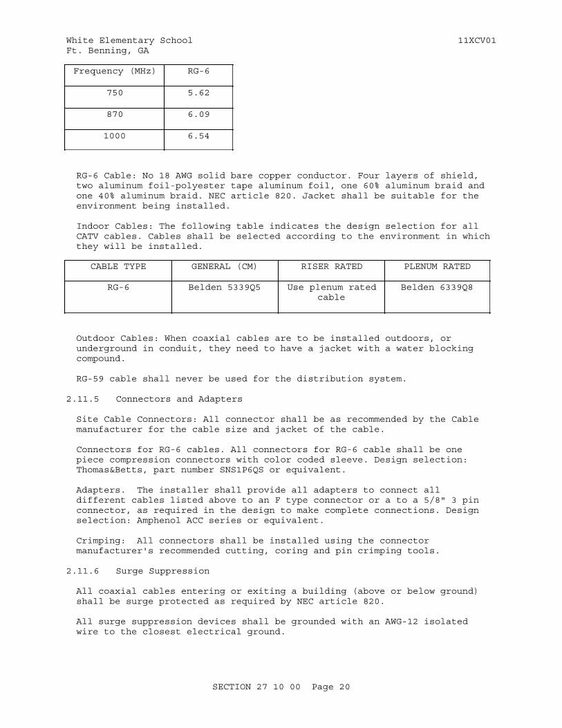
White Elementary School 11XCV01Ft. Benning, GA
Frequency (MHz) RG-6
750 5.62
870 6.09
1000 6.54
RG-6 Cable: No 18 AWG solid bare copper conductor. Four layers of shield, two aluminum foil-polyester tape aluminum foil, one 60% aluminum braid and one 40% aluminum braid. NEC article 820. Jacket shall be suitable for the environment being installed.
Indoor Cables: The following table indicates the design selection for all CATV cables. Cables shall be selected according to the environment in which they will be installed.
CABLE TYPE GENERAL (CM) RISER RATED PLENUM RATED
RG-6 Belden 5339Q5 Use plenum ratedcable
Belden 6339Q8
Outdoor Cables: When coaxial cables are to be installed outdoors, or underground in conduit, they need to have a jacket with a water blocking compound.
RG-59 cable shall never be used for the distribution system.
2.11.5 Connectors and Adapters
Site Cable Connectors: All connector shall be as recommended by the Cable manufacturer for the cable size and jacket of the cable.
Connectors for RG-6 cables. All connectors for RG-6 cable shall be one piece compression connectors with color coded sleeve. Design selection: Thomas&Betts, part number SNS1P6QS or equivalent.
Adapters. The installer shall provide all adapters to connect all different cables listed above to an F type connector or a to a 5/8" 3 pin connector, as required in the design to make complete connections. Design selection: Amphenol ACC series or equivalent.
Crimping: All connectors shall be installed using the connector manufacturer's recommended cutting, coring and pin crimping tools.
2.11.6 Surge Suppression
All coaxial cables entering or exiting a building (above or below ground) shall be surge protected as required by NEC article 820.
All surge suppression devices shall be grounded with an AWG-12 isolated wire to the closest electrical ground.
SECTION 27 10 00 Page 20
White Elementary School 11XCV01Ft. Benning, GA
PART 3 EXECUTION
3.1 INSTALLATION
Install telecommunications cabling and pathway systems, including the horizontal and backbone cable, pathway systems, telecommunications outlet/connector assemblies, and associated hardware in accordance with NECA/BICSI 568, TIA-568-C.1, TIA-568-C.2, TIA-568-C.3, TIA-569, NFPA 70, and UL standards as applicable. Provide cabling in a star topology network. Pathways and outlet boxes shall be installed as specified in Section 26 20 00 INTERIOR DISTRIBUTION SYSTEM. Install telecommunications cabling with copper media in accordance with the following criteria to avoid potential electromagnetic interference between power and telecommunications equipment. The interference ceiling shall not exceed 3.0 volts per meter measured over the usable bandwidth of the telecommunications cabling. Cabling shall be run with horizontal and vertical cable guides in telecommunications spaces with terminating hardware and interconnection equipment.
3.1.1 Cabling
Install UTP, and optical fiber telecommunications cabling system as detailed in TIA-568-C.1, TIA-568-C.2, TIA-568-C.3 and TIA-570 for residential cabling. Screw terminals shall not be used except where specifically indicated on plans. Use an approved insulation displacement connection (IDC) tool kit for copper cable terminations. Do not exceed manufacturers' cable pull tensions for copper and optical fiber cables. Provide a device to monitor cable pull tensions. Do not exceed 25 pounds pull tension for four pair copper cables. Do not chafe or damage outer jacket materials. Use only lubricants approved by cable manufacturer. Do not over cinch cables, or crush cables with staples. For UTP cable, bend radii shall not be less than four times the cable diameter. Cables shall be terminated; no cable shall contain unterminated elements. Cables shall not be spliced. Label cabling in accordance with paragraph LABELING in this section.
3.1.1.1 Open Cable
Use only where specifically indicated on plans for use in cable trays, or below raised floors. Install in accordance with TIA-568-C.1, TIA-568-C.2 and TIA-568-C.3. Do not exceed cable pull tensions recommended by the manufacturer. Copper cable not in a wireway or pathway shall be suspended a minimum of 12 inches above ceilings by cable supports no greater than 60 inches apart. Cable shall not be run through structural members or in contact with pipes, ducts, or other potentially damaging items. Placement of cable parallel to power conductors shall be avoided, if possible; a minimum separation of 12 inches shall be maintained when such placement cannot be avoided.
Plenum cable shall be used where open cables are routed through plenum areas. Cable routed exposed under raised floors shall be plenum rated. Plenum cables shall comply with flammability plenum requirements of NFPA 70. Install cabling after the flooring system has been installed in raised floor areas. Cable 6 feet long shall be neatly coiled not less than 12 inches in diameter below each feed point in raised floor areas.
3.1.1.2 Backbone Cable
a. Copper Backbone Cable. Install intrabuilding backbone copper cable, in
SECTION 27 10 00 Page 21

White Elementary School 11XCV01Ft. Benning, GA
indicated pathways, between the campus distributor, located in the telecommunications entrance facility or room, the building distributors and the floor distributors located in telecommunications rooms and telecommunications equipment rooms as indicated on drawings.
b. Optical fiber Backbone Cable. Install intrabuilding backbone optical fiber in indicated pathways. Do not exceed manufacturer's recommended bending radii and pull tension. Prepare cable for pulling by cutting outer jacket 10 inches leaving strength members exposed for approximately 10 inches. Twist strength members together and attach to pulling eye. Vertical cable support intervals shall be in accordance with manufacturer's recommendations.
3.1.1.3 Horizontal Cabling
Install horizontal cabling as indicated on drawings Do not untwist Category 6 UTP cables more than one half inch from the point of termination to maintain cable geometry. Provide slack cable in the form of a figure eight (not a service loop) on each end of the cable, 10 feet in the telecommunications room, and 12 inches in the work area outlet..
3.1.2 Pathway Installations
Provide in accordance with TIA-569 and NFPA 70. Provide building pathway as specified in Section 26 20 00 INTERIOR DISTRIBUTION SYSTEM.
3.1.3 Service Entrance Conduit, Overhead
Provide service entrance overhead as specified in Section 26 20 00 INTERIOR DISTRIBUTION SYSTEMS.
3.1.4 Service Entrance Conduit, Underground
Provide service entrance underground as specified in Section 26 20 00 INTERIOR DISTRIBUTION SYSTEM.
3.1.5 Cable Tray Installation
Install cable tray as specified in Section 26 20 00 INTERIOR DISTRIBUTION SYSTEM. Only CMP and OFNP type cable shall be installed in a plenum.
3.1.6 Work Area Outlets
3.1.6.1 Terminations
Terminate UTP cable in accordance with TIA-568-C.1, TIA-568-C.2 and wiring configuration as specified. Terminate fiber optic cables in accordance with TIA-568-C.3
3.1.6.2 Cover Plates
As a minimum, each outlet/connector shall be labeled as to its function and a unique number to identify cable link in accordance with the paragraph LABELING in this section.
3.1.6.3 Cables
Unshielded twisted pair and fiber optic cables shall have a minimum of 12 inches of slack cable loosely coiled into the telecommunications outlet
SECTION 27 10 00 Page 22
White Elementary School 11XCV01Ft. Benning, GA
boxes. Minimum manufacturer's bend radius for each type of cable shall not be exceeded.
3.1.6.4 Pull Cords
Pull cords shall be installed in conduit serving telecommunications outlets that do not have cable installed.
3.1.7 Telecommunications Space Termination
Install termination hardware required for Category 6 and optical fiber system. An insulation displacement tool shall be used for terminating copper cable to insulation displacement connectors.
3.1.7.1 Connector Blocks
Connector blocks shall be rack mounted in orderly rows and columns. Adequate vertical and horizontal wire routing areas shall be provided between groups of blocks. Install in accordance with industry standard wire routing guides in accordance with TIA-569.
3.1.7.2 Patch Panels
Patch panels shall be mounted racks with sufficient ports to accommodate the installed cable plant plus 25 percent spares.
a. Copper Patch Panel. Copper cable entering a patch panel shall be secured to the panel as recommended by the manufacturer to prevent movement of the cable.
b. Fiber Optic Patch Panel. Fiber optic cable loop shall be 3 feet in length. The outer jacket of each cable entering a patch panel shall be secured to the panel to prevent movement of the fibers within the panel, using clamps or brackets specifically manufactured for that purpose.
3.1.7.3 Equipment Support Frames
Install in accordance with TIA-569:
a. Bracket, wall mounted. Mount bracket to plywood backboard in accordance with manufacturer's recommendations. Mount rack so height of highest panel does not exceed 78 inches above floor.
b. Racks, floor mounted modular type. Permanently anchor rack to the floor in accordance with manufacturer's recommendations.
3.1.8 Electrical Penetrations
Seal openings around electrical penetrations through fire resistance-rated wall, partitions, floors, or ceilings as specified in Section 07 84 00 FIRESTOPPING.
3.1.9 Grounding and Bonding
Provide in accordance with TIA-607, NFPA 70 and as specified in Section 26 20 00 INTERIOR DISTRIBUTION SYSTEM.
SECTION 27 10 00 Page 23
White Elementary School 11XCV01Ft. Benning, GA
3.2 LABELING
3.2.1 Labels
Provide labeling in accordance with TIA/EIA-606. Handwritten labeling is unacceptable. Stenciled lettering for voice and data circuits shall be provided using thermal ink transfer process .
3.2.2 Cable
Cables shall be labeled using color labels on both ends with identifiers in accordance with TIA/EIA-606.
3.2.3 Termination Hardware
Workstation outlets and patch panel connections shall be labeled using color coded labels with identifiers in accordance with TIA/EIA-606.
3.3 FIELD APPLIED PAINTING
Paint electrical equipment as required to match finish of adjacent surfaces or to meet the indicated or specified safety criteria. Painting shall be as specified in Section 09 90 00 PAINTS AND COATINGS.
3.3.1 Painting Backboards
If backboards are required to be painted, then the manufactured fire retardant backboard must be painted with fire retardant paint, so as not to increase flame spread and smoke density and must be appropriately labeled. Label and fire rating stamp must be unpainted.
3.4 FIELD FABRICATED NAMEPLATE MOUNTING
Provide number, location, and letter designation of nameplates as indicated. Fasten nameplates to the device with a minimum of two sheet-metal screws or two rivets.
3.5 TESTING
3.5.1 Telecommunications Cabling Testing
Perform telecommunications cabling inspection, verification, and performance tests in accordance with TIA-568-C.1, TIA-568-C.2, TIA-568-C.3. Test equipment shall conform to TIA-1152. Perform optical fiber field inspection tests via attenuation measurements on factory reels and provide results along with manufacturer certification for factory reel tests. Remove failed cable reels from project site upon attenuation test failure.
3.5.1.1 Inspection
Visually inspect UTP and optical fiber jacket materials for UL or third party certification markings. Inspect cabling terminations in telecommunications rooms and at workstations to confirm color code for T568A or T568B pin assignments, and inspect cabling connections to confirm compliance with TIA-568-C.1, TIA-568-C.2, TIA-568-C.3, and TIA-570 for residential cabling. Visually confirm Category 6, marking of outlets, cover plates, outlet/connectors, and patch panels.
SECTION 27 10 00 Page 24
White Elementary School 11XCV01Ft. Benning, GA
3.5.1.2 Verification Tests
UTP backbone copper cabling shall be tested for DC loop resistance, shorts, opens, intermittent faults, and polarity between conductors, and between conductors and shield, if cable has overall shield. Test operation of shorting bars in connection blocks. Test cables after termination but prior to being cross-connected.
For multimode optical fiber, perform optical fiber end-to-end attenuation tests in accordance with TIA-568-C.3 and TIA-526-14 using Method A, Optical Power Meter and Light Source. For single-mode optical fiber, perform optical fiber end-to-end attenuation tests in accordance with TIA-568-C.3 and TIA-526-7 using Method A, Optical Power Meter and Light Source for single-mode optical fiber. Perform verification acceptance tests.
3.5.1.3 Performance Tests
Perform testing for each outlet and MUTOA as follows:
3.5.1.4 Final Verification Tests
Perform verification tests for UTP and optical fiber systems after the complete telecommunications cabling and workstation outlet/connectors are installed.
a. Voice Tests. These tests assume that dial tone service has been installed. Connect to the network interface device at the demarcation point. Go off-hook and listen and receive a dial tone. If a test number is available, make and receive a local, long distance, and DSN
SECTION 27 10 00 Page 25
White Elementary School 11XCV01Ft. Benning, GA
telephone call.
b. Data Tests. These tests assume the Information Technology Staff has a network installed and are available to assist with testing. Connect to the network interface device at the demarcation point. Log onto the network to ensure proper connection to the network.
c. Each phone shall be tested to determine the local 911 operator could legibly and accurately determine the Building location of the 911 caller.
d. System Acceptance Test. The Installer shall demonstrate the operation of the system to the Owner during the final inspection in the following manner: Measure signal levels with a calibrated field strength meter at outlets and or amplifiers selected by the Owner. At a minimum 5% of all outlets will be tested. The readings of the meter shall be between 1.5 dBmV of the value documented in the TRR.Observe picture quality at outlets selected by the Engineer using a television receiver.
If at least one measurement fails, the A&E can request to the installer to test more outlets (beyond the 5% indicated previously) until the A&E is satisfied with the results. Any failures shall be corrected by the installer at no additional cost to the Owner.
e. CATV Test Equipment Required. At a minimum during the acceptance test to the A&E the installer shall have the following equipment:TV Receiver: 17" minimum diagonal screen size color receiver in good working order.Signal Meter: Signal level meter capable of measuring peak carrier levels within the 5 MHZ to 1000 MHZ spectrum. The signal meter shall be capable of downloading test results to a computer system or directly to a printer. Example: Sadelco DisplayMax 500 or similar. This signal meter needs to be the same tester used during the TRR.
Age and Calibration: Test equipment used in demonstrating system performance shall be less than 6 months old or bear the calibration seal of a recognized lab which is dated within 6 months of the date of acceptance test.
-- End of Section --
SECTION 27 10 00 Page 26

White Elementary School 11XCV01Ft. Benning, GA
SECTION TABLE OF CONTENTS
DIVISION 27 - COMMUNICATIONS
SECTION 27 51 23.10
INTERCOMMUNICATION SYSTEM
05/11
PART 1 GENERAL
1.1 REFERENCES 1.2 SYSTEM DESCRIPTION 1.2.1 Sound Reproduction 1.2.2 System Operation and Service Features 1.2.2.1 Control and Power Requirements 1.2.2.2 Call-In Indication 1.2.2.3 Identification Plates 1.2.2.4 Speaker/Handset Stations 1.2.2.5 Privacy Switch 1.3 SUBMITTALS 1.4 DELIVERY, STORAGE, AND HANDLING 1.5 EXTRA MATERIALS
PART 2 PRODUCTS
2.1 MATERIALS AND EQUIPMENT 2.1.1 Standard Products 2.1.2 Identical Items 2.1.3 Nameplates 2.2 TYPE 2 SYSTEM 2.2.1 Master Station 2.2.2 Remote Station 2.2.3 Amplifier 2.2.3.1 Intercommunication Amplifier 2.2.3.2 All-Call Amplifier 2.2.3.3 Paging Amplifier 2.2.3.4 Power Line Surge Protection 2.2.3.5 Signal Surge Protection 2.2.4 Horn-Type Loudspeakers 2.2.5 Cone-Type Loud speakers 2.3 SPEAKER ENCLOSURES 2.4 TERMINALS 2.5 COMMUNICATIONS WIRING 2.6 SURGE PROTECTION 2.7 Bell System, Wireless Clocks; Software 2.8 Two-way Communication System and Software 2.9 Enhanced Sound System
PART 3 EXECUTION
3.1 EXAMINATION 3.2 INSTALLATION 3.2.1 Signal and Control Circuits Wiring 3.2.2 Conduit, Cable Tray and Tubing Systems
SECTION 27 51 23.10 Page 1

White Elementary School 11XCV01Ft. Benning, GA
3.3 GROUNDING 3.4 TRAINING 3.5 INTERCOMMUNICATION SYSTEMACCEPTANCE TESTS 3.6 Clock, Bell System, Intercom Test 3.7 Two-way Communication System Test 3.8 Enhanced Sound System Test
-- End of Section Table of Contents --
SECTION 27 51 23.10 Page 2
White Elementary School 11XCV01Ft. Benning, GA
SECTION 27 51 23.10
INTERCOMMUNICATION SYSTEM05/11
PART 1 GENERAL
1.1 REFERENCES
The publications listed below form a part of this specification to the extent referenced. The publications are referred to within the text by the basic designation only.
ELECTRONIC COMPONENTS ASSOCIATION (ECA)
ECA EIA/ECA 310 (2005) Cabinets, Racks, Panels, and Associated Equipment
INSTITUTE OF ELECTRICAL AND ELECTRONICS ENGINEERS (IEEE)
IEEE C62.41.1 (2002; R 2008) Guide on the Surges Environment in Low-Voltage (1000 V and Less) AC Power Circuits
IEEE C62.41.2 (2002) Recommended Practice on Characterization of Surges in Low-Voltage (1000 V and Less) AC Power Circuits
NATIONAL FIRE PROTECTION ASSOCIATION (NFPA)
NFPA 70 (2014) National Electrical Code
UNDERWRITERS LABORATORIES (UL)
UL 1449 (2006; Reprint Jul 2012) Surge Protective Devices
UL 50 (2007; Reprint Apr 2012) Enclosures for Electrical Equipment, Non-environmental Considerations
1.2 SYSTEM DESCRIPTION
Provide an Intercommunication System, Data Package 3 in accordance with Section 01 78 23 OPERATION AND MAINTENANCE DATA, which is solid state, modular in design, and of the wired type as indicated. Stations shall have capacity for later expansion to one master and three remote stations with handset and or with hands free operation without sacrificing any equipment or feature of performance.
1.2.1 Sound Reproduction
Provide an intercommunication system to reproduce a signal at all receiving stations from a 40 dB minimum input signal referenced to a microphone sound pressure level (SPL) over the frequency range of 300 to 3300 Hz. The
SECTION 27 51 23.10 Page 3
White Elementary School 11XCV01Ft. Benning, GA
received signal shall have a dynamic range of 30 dB, adjustable at the receiving station. Unless otherwise specified SPL shall be 20 micro Paschal. The root-mean-square (rms) extraneous noise (e.g. hum) level introduced by the intercommunication system shall be at least 30 dB below the nominal signal level. Distortion, including envelope delay, intermodulation, cross talk, and other nonlinear sources, shall not exceed 5 percent.
1.2.2 System Operation and Service Features
1.2.2.1 Control and Power Requirements
Provide a system with a power switch and an associated pilot light for ON and OFF operations. USE a volume control at each station to regulate listening volume. System shall operate on 110-125 Vac, single phase, 60 Hz.
1.2.2.2 Call-In Indication
Master stations shall have a "call-in" switch to provide an audible and/or visual indication of incoming calls from remote stations. Individual visual indication shall identify calling station and status, and remain actuated until a call is answered by a master station.
1.2.2.3 Identification Plates
In addition to the manufacturer's standard identification plates, provide engraved laminated phenolic identification plates for each component connection and terminal. Identification labels shall be 3-layer black on white on black, engraved to show white letters on a black background. Any warning or caution labels shall be 3-layered red on white on red, engraved to show white letters on red background. Control switches and knobs shall be clearly marked with their function and status. Identification strips for station selector switches shall be located to clearly identify remote and master stations and shall be protected by transparent plastic inserts.
1.2.2.4 Speaker/Handset Stations
At speaker/handset stations, lifting the handset shall automatically cut out the loudspeaker in the station and all conversation shall be carried through the handset.
1.2.2.5 Privacy Switch
Provide a privacy switch at each remote station. When in the ON position, the switch shall prevent any transmission of sound from the remote station. When in the OFF position, without further switch manipulation, the station shall respond to incoming calls upon voice activation from anywhere within a 20 foot radius of station.
1.3 SUBMITTALS
Government approval is required for submittals with a "G" designation; submittals not having a "G" designation are for information only. When used, a designation following the "G" designation identifies the office that will review the submittal for the Government. Submit the following in accordance with Section 01 33 00 SUBMITTAL PROCEDURES:
SD-02 Shop Drawings
SECTION 27 51 23.10 Page 4
White Elementary School 11XCV01Ft. Benning, GA
Intercommunication SystemInstallation
SD-03 Product Data
Spare PartsAcceptance TestsBell System, Wireless Clocks; Software; GTwo-Way Communication System and Software; GEnhanced Sound System; G
SD-06 Test Reports
Acceptance TestsClock, Bell System; Intercom; GTwo Way Communication System; GEnhanced Sound System; GIntercommunication System; G
SD-10 Operation and Maintenance Data
Intercommunication System
1.4 DELIVERY, STORAGE, AND HANDLING
Protect all equipment delivered and placed in storage from the weather, humidity and temperature variation, dirt and dust, or other contaminants.
1.5 EXTRA MATERIALS
After approval of detail drawings and not later than two months prior to the date of beneficial occupancy, furnish spare parts data for each different item of equipment and component in the system. Include with the data a complete list of parts and supplies, with current unit prices and source of supply.
PART 2 PRODUCTS
2.1 MATERIALS AND EQUIPMENT
2.1.1 Standard Products
All software shall be submitted and approved by DDESS. Provide materials and equipment which are the standard products of a manufacturer regularly engaged in the manufacture of such products and that essentially duplicate equipment that have been in satisfactory use at least 2 years prior to bid opening. Equipment shall be supported by a service organization that is, in the opinion of the Contracting Officer, reasonably convenient to the site.
2.1.2 Identical Items
Items of the same classification shall be identical. This requirement includes equipment, modules, assemblies, parts, and components.
2.1.3 Nameplates
Each major component of equipment shall have the manufacturer's name, model number, and serial number on a plate screwed to the equipment.
SECTION 27 51 23.10 Page 5
White Elementary School 11XCV01Ft. Benning, GA
2.2 TYPE 2 SYSTEM
A microprocessor switched IP based as shown on Drawings, central control intercommunication system shall include an annunciator panel, a master station, automatic switching equipment, remote stations and all amplifiers, control equipment and ancillary devices required to provide features specified. The master station shall selectively communicate with any remote station by actuating the three digit number assigned to that remote station. The master station shall be designed to communicate with all remote stations simultaneously or in groups of not less than 10 stations by actuating an assigned "all-call" number. Only the selected remote station shall listen or talk to the master station. A nonselected remote station shall not be able to hear or interfere with any portion of conversation between a master station and the selected remote station. Hanging up the master station handset shall reset the system for next call. The quantity and location of remote stations shall be as indicated on the drawings. A paging function shall also be part of the system.
2.2.1 Master Station
Desk-top type master station equipped with:
a. A 12 digit keypad selector to transmit calls to other stations and initiate commands for programming operations.
b. Volume control to regulate incoming call volume.
c. Light annunciation to identify calling stations and stations in use. The light shall remain on until a call is answered.
d. Tone annunciation with a momentary audible tone signal that announces incoming calls.
e. Reset controls that cancels calls and resets system for the next call.
f. A handset with hook switch, telephone type, arranged to disconnect the speaker when the handset is lifted. The cord shall be 18 inches long and permanently coiled.
g. A metallic central control cabinet that shall comply with ECA EIA/ECA 310. The cabinet shall houses terminal strips, power supplies,amplifiers, system volume control, and auxiliary equipment. It shall be lockable and ventilated.
h. The master station shall accommodate 100 stations and shall have a speaker sensitivity of 40 dB minimum.
2.2.2 Remote Station
Desk-top remote stations with stainless steel face plates with tamperproof mounting screws and aluminum backbox shall be provided. The remote station shall have:
a. A speaker with a minimum sensitivity of 40 dB for speakers less than 8 inches in diameter and 45 dB for speakers 8 inches or greater.
b. A call announcement monitor lamp that lights when during incoming calls.
SECTION 27 51 23.10 Page 6
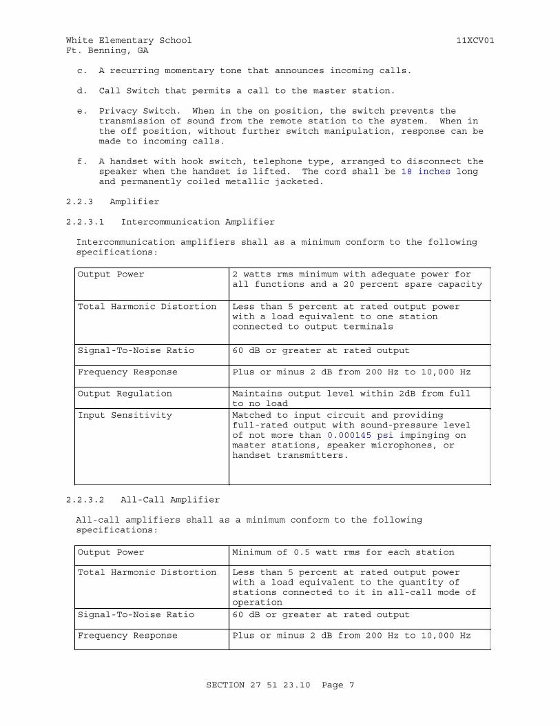
White Elementary School 11XCV01Ft. Benning, GA
c. A recurring momentary tone that announces incoming calls.
d. Call Switch that permits a call to the master station.
e. Privacy Switch. When in the on position, the switch prevents the transmission of sound from the remote station to the system. When in the off position, without further switch manipulation, response can be made to incoming calls.
f. A handset with hook switch, telephone type, arranged to disconnect the speaker when the handset is lifted. The cord shall be 18 inches long and permanently coiled metallic jacketed.
2.2.3 Amplifier
2.2.3.1 Intercommunication Amplifier
Intercommunication amplifiers shall as a minimum conform to the following specifications:
Output Power 2 watts rms minimum with adequate power for all functions and a 20 percent spare capacity
Total Harmonic Distortion Less than 5 percent at rated output power with a load equivalent to one station connected to output terminals
Signal-To-Noise Ratio 60 dB or greater at rated output
Frequency Response Plus or minus 2 dB from 200 Hz to 10,000 Hz
Output Regulation Maintains output level within 2dB from full to no load
Input Sensitivity Matched to input circuit and providing full-rated output with sound-pressure level of not more than 0.000145 psi impinging on master stations, speaker microphones, or handset transmitters.
2.2.3.2 All-Call Amplifier
All-call amplifiers shall as a minimum conform to the following specifications:
Output Power Minimum of 0.5 watt rms for each station
Total Harmonic Distortion Less than 5 percent at rated output power with a load equivalent to the quantity of stations connected to it in all-call mode of operation
Signal-To-Noise Ratio 60 dB or greater at rated output
Frequency Response Plus or minus 2 dB from 200 Hz to 10,000 Hz
SECTION 27 51 23.10 Page 7
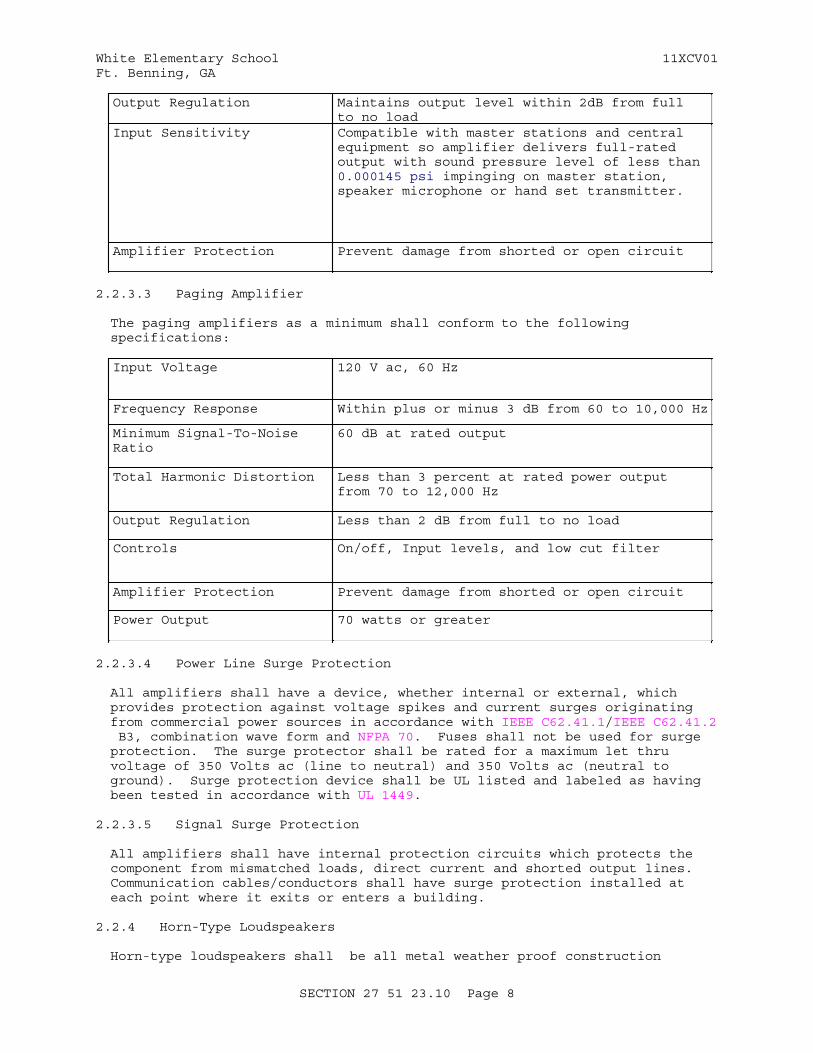
White Elementary School 11XCV01Ft. Benning, GA
Output Regulation Maintains output level within 2dB from full to no load
Input Sensitivity Compatible with master stations and central equipment so amplifier delivers full-rated output with sound pressure level of less than 0.000145 psi impinging on master station, speaker microphone or hand set transmitter.
Amplifier Protection Prevent damage from shorted or open circuit
2.2.3.3 Paging Amplifier
The paging amplifiers as a minimum shall conform to the following specifications:
Input Voltage 120 V ac, 60 Hz
Frequency Response Within plus or minus 3 dB from 60 to 10,000 Hz
Minimum Signal-To-Noise Ratio
60 dB at rated output
Total Harmonic Distortion Less than 3 percent at rated power output from 70 to 12,000 Hz
Output Regulation Less than 2 dB from full to no load
Controls On/off, Input levels, and low cut filter
Amplifier Protection Prevent damage from shorted or open circuit
Power Output 70 watts or greater
2.2.3.4 Power Line Surge Protection
All amplifiers shall have a device, whether internal or external, which provides protection against voltage spikes and current surges originating from commercial power sources in accordance with IEEE C62.41.1/IEEE C62.41.2 B3, combination wave form and NFPA 70. Fuses shall not be used for surge protection. The surge protector shall be rated for a maximum let thru voltage of 350 Volts ac (line to neutral) and 350 Volts ac (neutral to ground). Surge protection device shall be UL listed and labeled as having been tested in accordance with UL 1449.
2.2.3.5 Signal Surge Protection
All amplifiers shall have internal protection circuits which protects the component from mismatched loads, direct current and shorted output lines. Communication cables/conductors shall have surge protection installed at each point where it exits or enters a building.
2.2.4 Horn-Type Loudspeakers
Horn-type loudspeakers shall be all metal weather proof construction
SECTION 27 51 23.10 Page 8
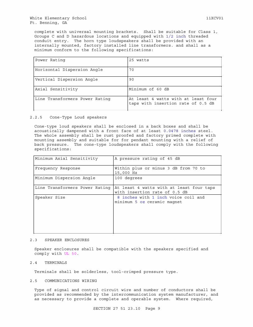
White Elementary School 11XCV01Ft. Benning, GA
complete with universal mounting brackets. Shall be suitable for Class 1, Groups C and D hazardous locations and equipped with 1/2 inch threaded conduit entry. The horn type loudspeakers shall be provided with an internally mounted, factory installed line transformers. and shall as a minimum conform to the following specifications:
Power Rating 25 watts
Horizontal Dispersion Angle 70
Vertical Dispersion Angle 90
Axial Sensitivity Minimum of 60 dB
Line Transformers Power Rating At least 4 watts with at least four taps with insertion rate of 0.5 dB
2.2.5 Cone-Type Loud speakers
Cone-type loud speakers shall be enclosed in a back boxes and shall be acoustically dampened with a front face of at least 0.0478 inches steel. The whole assembly shall be rust proofed and factory primed complete with mounting assembly and suitable for for pendant mounting with a relief of back pressure. The cone-type loudspeakers shall comply with the following specifications:
Minimum Axial Sensitivity A pressure rating of 45 dB
Frequency Response Within plus or minus 3 dB from 70 to 15,000 Hz
Minimum Dispersion Angle 100 degrees
Line Transformers Power Rating At least 4 watts with at least four taps with insertion rate of 0.5 dB
Speaker Size 8 inches with 1 inch voice coil and minimum 5 oz ceramic magnet
2.3 SPEAKER ENCLOSURES
Speaker enclosures shall be compatible with the speakers specified and comply with UL 50.
2.4 TERMINALS
Terminals shall be solderless, tool-crimped pressure type.
2.5 COMMUNICATIONS WIRING
Type of signal and control circuit wire and number of conductors shall be provided as recommended by the intercommunication system manufacturer, and as necessary to provide a complete and operable system. Where required,
SECTION 27 51 23.10 Page 9
White Elementary School 11XCV01Ft. Benning, GA
cable shall be UL classified low smoke and low flame for use in air plenums in accordance with NFPA 70.
2.6 SURGE PROTECTION
Major components of the system such as Master Stations, Amplifiers, and Remote Stations, shall have a device, either internal or external, which shall provide protection against voltage spikes and current surges.
2.7 Bell System, Wireless Clocks; Software
Provide Bell and Wireless Clock System as shown on Drawings. Bell / Sound / Clock Systems shall be integrated together and shall include at minimum wireless clocks, power supplies, wireless transmitters and receivers and surge protection. provide software to be reviewed and approved by DDESS.
2.8 Two-way Communication System and Software
Provide two way communication system (Aiphone or equal) as shown on Drawings. System shall include devices, power supply and cabling. All software shall be reviewed and approved by DDESS.
2.9 Enhanced Sound System
Provide enhanced sound system as shown on Drawings. System shall include speakers, amplifiers, sound rack and cabling.
PART 3 EXECUTION
3.1 EXAMINATION
After becoming familiar with the details of the work and working conditions, verify dimensions in the field, and advise the Contracting Officer of any discrepancies before performing the work.
3.2 INSTALLATION
Submit detail drawings consisting of illustrations, schedules, performance charts, instructions, brochures, diagrams, catalog cuts, manufacturer's data, materials and equipment lists, and operational and general maintenance instructions, including the overall system and for each major component. Illustrate on the drawings how each item of equipment has been coordinated to function properly in the system. Include on detail drawings an overall system schematic indicating relationship of intercommunication units on one diagram and showing power source, system controls, impedance matches, plus number, size, and maximum lengths of interconnecting wires and indicate clearances required for maintenance and operation. Provide calculations for power requirements of equipment to show that the proper power levels are provided for the specified equipment. Install all system components and appurtenances in accordance with the manufacturer's instructions and as specified and shown. Units to be mounted outside or subject to inclement conditions shall be weatherproof or be mounted in weatherproof enclosures.
3.2.1 Signal and Control Circuits Wiring
Install signal and control circuits in accordance with NFPA 70 and as indicated. The conductors shall be separated as recommended by the equipment manufacturer.
SECTION 27 51 23.10 Page 10
White Elementary School 11XCV01Ft. Benning, GA
3.2.2 Conduit, Cable Tray and Tubing Systems
Install wiring in rigid conduit, intermediate metal conduits, cable trays, or electric metallic tubing as specified in Section 26 20 00 INTERIOR DISTRIBUTION SYSTEM.
3.3 GROUNDING
Perform the connection of interfacing components through the use of transformers and the tying of interconnecting lines to a unit ground bus at one end only. The ground and distribution ground buses shall be solid copper wire with insulating covering.
3.4 TRAINING
Conduct a training course for 40 members of the operating staff and for 10 members of the maintenance staff as designated by the Contracting Officer. The training course will be given at the installation during normal working hours for a total of 8 hours for the operating staff and 16 hours for the maintenance staff, and shall start after the system is functionally complete but prior to final acceptance tests. The field instructions shall cover all of the items contained in the approved operating and maintenance instructions, as well as the demonstration of routine maintenance operations. The Contracting Officer shall be notified at least 14 days prior to the start of the training course.
3.5 INTERCOMMUNICATION SYSTEMACCEPTANCE TESTS
After installation has been completed, conduct an acceptance test, using the approved test plan, to demonstrate that the equipment operates in accordance with specification requirements. Submit test plan and procedures for the acceptance test explaining in detail step-by-step actions and expected results to demonstrate compliance with the requirements specified. The procedures shall also explain methods for simulating the necessary conditions of operation to demonstrate system performance. Notify the Contracting Officer 30 days prior to the performance of tests. In no case shall notice be given until after the Contractor has received written approval of the test plans. The acceptance tests shall include as a minimum the following tests:
a. Operational Test: Test originating station-to-station, all call, and page messages at each intercommunication station. Verify proper routing and volume levels and that the system is free of noise and distortion. Test available message path from each station on system.
b. Frequency Response Test: Determine frequency response of two transmission paths, including all-call, and paging, by transmitting and recording audio tones. Minimum acceptable performance is within 3dB from 150 to 2500 Hz.
c. Signal-to-Noise Ratio Test: Measure signal-to-noise ratio of complete system at normal gain setting as follows:
(1) Disconnect speaker microphone and replace it in the circuit with a signal generator using a 1000 Hz signal. Measure signal-to-noise ratio at paging speakers.
(2) Repeat test for four speaker microphones and for each separately
SECTION 27 51 23.10 Page 11
White Elementary School 11XCV01Ft. Benning, GA
controlled zone of paging loudspeakers.
(3) Minimum acceptable ratio is 35 dB.
d. Distortion Test: Measure distortion at normal gain settings and rated power. Feed signals at frequencies of 150, 200, 400, 1000, and 2500 Hz into each paging and all-call amplifier, and a minimum of 2 selected intercommunication amplifiers. For each frequency, measure distortion in the paging and all-call amplifier outputs. Maximum acceptable distortion at any frequency is 5 percent total harmonics.
e. Acoustic Coverage Test: Feed pink noise into system using octaves centered at 500 and 4000 Hz. Use sound level meter with octave band filters to measure level at three locations in each paging zone. Maximum permissible variation in level is plus or minus 3 dB; in levels between adjacent zones, plus or minus 5 dB.
f. Power output Test: Measure electrical power output of each paging amplifier at normal gain setting of 150, 1000 and 2500 Hz. Maximum variation in power output at these frequencies is plus or minus 3 dB.
g. Submit test reports in booklet form, upon completion and testing of the installed system, showing all field tests performed to adjust each component and to prove compliance with the specified performance criteria. Include in each test report the final position of controls and operating mode of the system. Include the manufacturer, model number, and serial number of test equipment used in each test.
3.6 Clock, Bell System, Intercom Test
Test each clock and provide documentation that clocks, bell and sound system operate properly. Upon completeion of installation and testing, and before building acceptance, demonstrate operation of all system functions Government.
3.7 Two-way Communication System Test
Upon completion of the installation and before acceptance, the installer shall demonstrate the operation of the two-way communication system to Owner.
3.8 Enhanced Sound System Test
Upon completion of the installation and before acceptance, the enhanced sound system shall be tested and installer shall demonstrate the operation of the enhanced sound system to Owner.
-- End of Section --
SECTION 27 51 23.10 Page 12
White Elementary School 11XCV01Ft. Benning, GA
SECTION TABLE OF CONTENTS
DIVISION 28 - ELECTRONIC SAFETY AND SECURITY
SECTION 28 31 76
INTERIOR FIRE ALARM AND MASS NOTIFICATION SYSTEM
08/11
PART 1 GENERAL
1.1 RELATED SECTIONS 1.2 REFERENCES 1.3 DEFINITIONS 1.4 SYSTEM DESCRIPTION 1.4.1 Scope 1.4.2 Technical Data and Computer Software 1.4.3 Keys 1.5 SUBMITTALS 1.6 QUALITY ASSURANCE 1.6.1 Qualifications 1.6.1.1 Design Services 1.6.1.2 Supervisor 1.6.1.3 Technician 1.6.1.4 Installer 1.6.1.5 Test Personnel 1.6.1.6 Manufacturer's Representative 1.6.1.7 Manufacturer 1.6.2 Regulatory Requirements 1.6.2.1 Requirements for Fire Protection Service 1.6.2.2 Fire Alarm/Mass Notification System 1.6.2.3 Fire alarm Testing Services or Laboratories 1.7 DELIVERY, STORAGE, AND HANDLING 1.8 OPERATION AND MAINTENANCE (O&M) INSTRUCTIONS 1.9 EXTRA MATERIALS 1.9.1 Repair Service/Replacement Parts 1.9.2 Interchangeable Parts 1.9.3 Spare Parts 1.9.4 Special Tools
PART 2 PRODUCTS
2.1 MATERIALS AND EQUIPMENT 2.1.1 Standard Products 2.1.2 Nameplates 2.2 GENERAL PRODUCT REQUIREMENT 2.3 SYSTEM OPERATION 2.3.1 Alarm Initiating Devices and Notification Appliances (Visual,
Voice, Textural) 2.3.2 Functions and Operating Features 2.4 SYSTEM MONITORING 2.4.1 Valves 2.4.2 Independent Fire Detection System 2.5 MASS NOTIFICATION SYSTEM FUNCTIONS 2.5.1 Notification Appliance Network
SECTION 28 31 76 Page 1
White Elementary School 11XCV01Ft. Benning, GA
2.5.2 Strobes 2.5.3 Text Displays 2.5.4 Wide Area MNS 2.5.5 Voice Notification 2.5.6 Installation-Wide Control 2.6 OVERVOLTAGE AND SURGE PROTECTION 2.6.1 Signaling Line Circuit Surge Protection 2.6.2 Sensor Wiring Surge Protection 2.7 ADDRESSABLE INTERFACE DEVICES 2.8 ADDRESSABLE CONTROL MODULE 2.9 ISOLATION MODULES 2.10 SMOKE SENSORS 2.10.1 Photoelectric Smoke Sensors 2.10.2 Omitted 2.10.3 Omitted 2.10.4 Duct Smoke Sensors 2.10.5 Smoke Sensor Testing 2.11 HEAT DETECTORS 2.11.1 Heat Detectors 2.11.1.1 Combination Fixed-Temperature and Rate-of-Rise Detectors 2.11.1.2 Omitted 2.11.1.3 Omitted 2.11.2 Self-Test Routines 2.11.3 Operator Access 2.11.4 Operator Control 2.12 Omitted 2.13 Omitted 2.14 ELECTRIC POWER 2.14.1 Primary Power 2.15 SECONDARY POWER SUPPLY 2.15.1 Batteries 2.15.1.1 Capacity 2.15.1.2 Battery Power Calculations 2.15.2 Battery Chargers 2.16 FIRE ALARM CONTROL UNIT AND MASS NOTIFICATION CONTROL UNIT (FMCP) 2.16.1 Cabinet 2.16.2 Control Modules 2.16.3 Silencing Switches 2.16.3.1 Alarm Silencing Switch 2.16.3.2 Supervisory/Trouble Silencing Switch 2.16.4 Non-Interfering 2.16.5 Audible Notification System 2.16.5.1 Outputs and Operational Modules 2.16.5.2 Mass Notification 2.16.6 Memory 2.16.7 Field Programmability 2.16.8 Input/Output Modifications 2.16.9 Resetting 2.16.10 Instructions 2.16.11 Walk Test 2.16.12 History Logging 2.16.13 Remote LCD Text Display 2.17 REMOTE FIRE ALARM/MASS NOTIFICATION CONTROL UNITS 2.17.1 Cabinet 2.17.2 Control Modules 2.17.3 Silencing Switches 2.17.4 Non-Interfering 2.17.5 Memory 2.17.6 Field Programmability
SECTION 28 31 76 Page 2
White Elementary School 11XCV01Ft. Benning, GA
2.17.7 Input/Output Modifications 2.17.8 Resetting 2.17.9 Instructions 2.17.10 Walk Test 2.17.11 History Logging 2.18 AMPLIFIERS, PREAMPLIFIERS, TONE GENERATORS 2.18.1 Omitted 2.18.2 Construction 2.18.3 Inputs 2.18.4 Tone Generator 2.18.5 Protection Circuits 2.19 Omitted 2.20 ANNUNCIATOR 2.20.1 Annunciator Panel 2.20.2 Programming 2.21 MANUAL STATIONS 2.22 NOTIFICATION APPLIANCES 2.22.1 Fire Alarm/Mass Notification Speakers 2.22.2 Visual Notification Appliances 2.23 ENVIRONMENTAL ENCLOSURES OR GUARDS 2.24 INTERFACE TO THE BASE WIDE MASS NOTIFICATION NETWORK 2.25 AUTOMATIC FIRE TRANSMITTERS 2.25.1 Omitted 2.25.2 Digital Alarm Communicator Transmitter (DACT) 2.25.3 Signals to Be Transmitted to the Base Receiving Station 2.26 WIRING 2.26.1 Alarm Wiring
PART 3 EXECUTION
3.1 INSTALLATION OF FIRE ALARM INITIATING DEVICES AND NOTIFICATION APPLIANCES
3.1.1 FMCP 3.1.2 Manual Stations: 3.1.3 Notification Appliance Devices 3.1.4 Smoke and Heat Sensors 3.1.5 Annunciator 3.1.6 Water Flow Detectors and Tamper Switches 3.1.7 Firefighter Telephones 3.1.8 Local Operating Console (LOC) 3.2 SYSTEM FIELD WIRING 3.2.1 Wiring within Cabinets, Enclosures, and Boxes 3.2.2 Terminal Cabinets 3.2.3 Alarm Wiring 3.2.4 Conductor Terminations 3.3 Omitted 3.4 CONNECTION OF NEW SYSTEM 3.5 FIRESTOPPING 3.6 PAINTING 3.7 FIELD QUALITY CONTROL 3.7.1 Testing Procedures 3.7.2 Tests Stages 3.7.2.1 Preliminary Testing 3.7.2.2 Request for Formal Inspection and Tests 3.7.2.3 Final Testing 3.7.2.4 System Acceptance 3.7.3 Minimum System Tests 3.7.3.1 Intelligibility Tests 3.8 INSTRUCTION OF GOVERNMENT EMPLOYEES
SECTION 28 31 76 Page 3

White Elementary School 11XCV01Ft. Benning, GA
3.8.1 Instructor 3.8.2 Required Instruction Time 3.8.2.1 Technical Training 3.9 Technical Data and Computer Software
-- End of Section Table of Contents --
SECTION 28 31 76 Page 4
White Elementary School 11XCV01Ft. Benning, GA
SECTION 28 31 76
INTERIOR FIRE ALARM AND MASS NOTIFICATION SYSTEM08/11
PART 1 GENERAL
1.1 RELATED SECTIONS
Section 26 20 00.00 INTERIOR DISTRIBUTION SYSTEM, applies to this section, with the additions and modifications specified herein. In addition, refer to the following sections for related work and coordination:
Section 21 13 13.00 10 WET PIPE SPRINKLER SYSTEM, FIRE PROTECTION
Section 08 71 00 DOOR HARDWARE for door release and additional work related to finish hardware.Section 07 84 00 FIRESTOPPING for additional work related to firestopping.
1.2 REFERENCES
The publications listed below form a part of this specification to the extent referenced. The publications are referred to within the text by the basic designation only.
ACOUSTICAL SOCIETY OF AMERICA (ASA)
ASA S3.2 (2009) Method for Measuring the Intelligibility of Speech Over Communication Systems (ASA 85)
FM GLOBAL (FM)
FM APP GUIDE (updated on-line) Approval Guide http://www.approvalguide.com/
INSTITUTE OF ELECTRICAL AND ELECTRONICS ENGINEERS (IEEE)
IEEE C62.41.1 (2002; R 2008) Guide on the Surges Environment in Low-Voltage (1000 V and Less) AC Power Circuits
IEEE C62.41.2 (2002) Recommended Practice on Characterization of Surges in Low-Voltage (1000 V and Less) AC Power Circuits
INTERNATIONAL ELECTROTECHNICAL COMMISSION (IEC)
IEC 60268-16 (2003; ED 4.0) Sound System Equipment - Part 16: Objective Rating Of Speech Intelligibility By Speech Transmission Index
SECTION 28 31 76 Page 5
White Elementary School 11XCV01Ft. Benning, GA
INTERNATIONAL ORGANIZATION FOR STANDARDIZATION (ISO)
ISO 7240-16 (2007) Fire Detection And Alarm Systems — Part 16: Sound System Control And Indicating Equipment
ISO 7240-19 (2007) Fire Detection and Alarm Systems — Part 19: Design, Installation, Commissioning and Service of Sound Systems for Emergency Purposes
NATIONAL FIRE PROTECTION ASSOCIATION (NFPA)
NFPA 170 (2012) Standard for Fire Safety and Emergency Symbols
NFPA 70 (2014) National Electrical Code
NFPA 72 (2013) National Fire Alarm and Signaling Code
NFPA 90A (2012) Standard for the Installation of Air Conditioning and Ventilating Systems
U.S. DEPARTMENT OF DEFENSE (DOD)
UFC 3-601-02 (2010) Operations and Maintenance: Inspection, Testing, and Maintenance of Fire Protection Systems
UNDERWRITERS LABORATORIES (UL)
UL 1480 (2003; Reprint Oct 2012) Standard for Speakers for Fire Alarm, Emergency, and Commercial and Professional Use
UL 1638 (2001; Reprint Oct 2008) Visual Signaling Appliances - Private Mode Emergency and General Utility Signaling
UL 1971 (2002; Reprint Oct 2008) Signaling Devices for the Hearing Impaired
UL 2017 (2008; Reprint May 2011) General-Purpose Signaling Devices and Systems
UL 268 (2009) Smoke Detectors for Fire Alarm Systems
UL 464 (2009; Reprint Apr 2012) Standard for Audible Signal Appliances
UL 521 (1999; Reprint May 2010) Heat Detectors for Fire Protective Signaling Systems
UL 864 (2003; Reprint Aug 2012) Standard for Control Units and Accessories for Fire Alarm Systems
SECTION 28 31 76 Page 6
White Elementary School 11XCV01Ft. Benning, GA
UL Electrical Constructn (2012) Electrical Construction Equipment Directory
UL Fire Prot Dir (2012) Fire Protection Equipment Directory
1.3 DEFINITIONS
Wherever mentioned in this specification or on the drawings, the equipment, devices, and functions shall be defined as follows:
a. Interface Device: An addressable device that interconnects hard wired systems or devices to an analog/addressable system.
b. Remote Fire Alarm and Mass Notification Control Unit: A control panel, electronically remote from the fire alarm and mass notification control panel, that receives inputs from automatic and manual fire alarm devices; may supply power to detection devices and interface devices; may provide transfer of power to the notification appliances; may provide transfer of condition to relays or devices connected to the control unit; and reports to and receives signals from the fire alarm control panel.
c. Fire Alarm Control Unit and Mass Notification Autonomous Control Unit (FMCP): A master control panel having the features of a fire alarm and mass notification control unit and fire alarm and mass notification control units are interconnected. The panel has central processing, memory, input and output terminals, and LCD, LED Display units
d. Local Operating Console (LOC): A unit designed to allow emergency responders and/or building occupants to operate the MNS including delivery or recorded and/or live messages, initiate strobe and textural visible appliance operation and other relayed functions.
e. Terminal Cabinet: A steel cabinet with locking, hinge-mounted door that terminal strips are securely mounted.
1.4 SYSTEM DESCRIPTION
1.4.1 Scope
a. This work includes completion of design and providing a new, complete, fire alarm and mass notification system as described herein and on the contract drawings for the Faith Middle School. Include in the system wiring, raceways, pull boxes, terminal cabinets, outlet and mounting boxes, control equipment, alarm, and supervisory signal initiating devices, alarm notification appliances, supervising station fire alarm system transmitter, and other accessories and miscellaneous items required for a complete operating system even though each item is not specifically mentioned or described. Provide system complete and ready for operation.
b. Provide equipment, materials, installation, workmanship, inspection, and testing in strict accordance with the required and advisory provisions of NFPA 72, ISO 7240-16, IEC 60268-16, except as modified herein. The system layout on the drawings show the intent of coverage and are shown in suggested locations. Submit plan view drawing showing device locations, terminal cabinet locations, junction boxes, other related equipment, conduit routing, wire counts, circuit identification in each conduit, and circuit layouts for all floors. Drawings shall
SECTION 28 31 76 Page 7
White Elementary School 11XCV01Ft. Benning, GA
comply with the requirements of NFPA 170. Final quantity, system layout, and coordination are the responsibility of the Contractor.
c. Where remote fire alarm control units are needed, they shall be provided at a terminal cabinet location. Each remote fire alarm control unit shall be powered from a wiring riser specifically for that use or from a local emergency power panel located on the same floor as the remote fire alarm control unit. Where remote fire control units are provided, equipment for notification appliances may be located in the remote fire alarm control units.
1.4.2 Technical Data and Computer Software
Technical data and computer software (meaning technical data that relates to computer software) that are specifically identified in this project, and may be defined/required in other specifications, shall be delivered, strictly in accordance with the CONTRACT CLAUSES. Identify data delivered by reference to the particular specification paragraph against which it is furnished. Data to be submitted shall include complete system, equipment, and software descriptions. Descriptions shall show how the equipment will operate as a system to meet the performance requirements of this contract. The data package shall also include the following:
a. Identification of programmable portions of system equipment and capabilities.
b. Description of system revision and expansion capabilities and methods of implementation detailing both equipment and software requirements.
c. Provision of operational software data on all modes of programmable portions of the fire alarm and detection system.
d. Description of Fire Alarm and Mass Notification Control Panel equipment operation.
e. Description of auxiliary and remote equipment operations.
f. Library of application software.
g. Operation and maintenance manuals.
1.4.3 Keys
Keys and locks for equipment shall be identical. Provide not less than six keys of each type required. .
LOC is not permitted to be locked or lockable.
1.5 SUBMITTALS
Government approval is required for submittals with a "G" designation; submittals not having a "G" designation are for information only. When used, a designation following the "G" designation identifies the office that will review the submittal for the Government. Submit the following in accordance with Section 01 33 00 SUBMITTAL PROCEDURES:
SD-02 Shop Drawings
Nameplates; G, AE
SECTION 28 31 76 Page 8
White Elementary School 11XCV01Ft. Benning, GA
Instructions; G, AEWiring Diagrams; G, AESystem Layout; G, AESystem Operation; G, AENotification Appliances; G, AEAmplifiers; G, AE
SD-03 Product Data
Technical Data And Computer Software; G, AEFire Alarm Control Unit and Mass Notification Control Unit (FMCP); GLCD, LED Display Unit (VDU); G, AETerminal cabinets; G, AEManual stations; G, AETransmitters (including housing); G, AEBatteries; G, AEBattery chargers; G, AESmoke sensors; G, AEHeat detectors; G, AENotification appliances; G, AEAddressable interface devices; G, AEAmplifiers; G, AETone generators; G, AEDigitalized voice generators; G, AERemote Fire Alarm/Mass Notification Control Units; G, AE
Digital alarm communicator transmitter (DACT); G, AELocal Operating Console (LOC); G, AE
SD-05 Design Data
Battery power; G, AEBattery chargers; G, AE
SD-06 Test Reports
Field Quality ControlTesting Procedures; G, AESmoke sensor testing procedures; G, AE
SD-07 Certificates
InstallerFormal Inspection and TestsFinal Testing
SD-09 Manufacturer's Field Reports
System Operation; G, AEFire Alarm/Mass Notification System
SD-10 Operation and Maintenance Data
Operation and Maintenance (O&M) Instructions; G, AEInstruction of Government Employees
SD-11 Closeout Submittals
SECTION 28 31 76 Page 9

White Elementary School 11XCV01Ft. Benning, GA
As-Built Drawings
1.6 QUALITY ASSURANCE
Equipment and devices shall be compatible and operable with existing station fire alarm system and shall not impair reliability or operational functions of existing supervising station fire alarm system. The supervising equipment is existing and consists of a digital alarm communicator receiver (DACR). Provide equipment compatible with the existing system. Coordinate with the existing system. Coordinate FACP DACT requirements with the base fire alarm and mass notification system..
a. In NFPA publications referred to herein, consider advisory provisions to be mandatory, as though the word "shall" had been substituted for "should" wherever it appears; interpret reference to "authority having jurisdiction" to mean the Fort Benning Fire Marshall, Corps of Engineers Savannah District Fire Protection Engineer.
b. The recommended practices stated in the manufacturer's literature or documentation shall be considered as mandatory requirements.
c. Devices and equipment for fire alarm service shall be listed by UL Fire Prot Dir or approved by FM APP GUIDE.
1.6.1 Qualifications
1.6.1.1 Design Services
Installations requiring completion of installation drawings and specification or modifications of fire detection, fire alarm, mass notification system, fire suppression systems or mass notification systems shall require the services and review of a qualified engineer. For the purposes of meeting this requirement, a qualified engineer is defined as an individual meeting one of the following conditions:
a. A registered professional engineer having a Bachelor of Science or Masters of Science Degree in Fire Protection Engineering from an accredited university engineering program, plus a minimum of four years work experience in fire protection engineering.
b. A registered professional engineer (P.E.) in fire protection engineering.
c. Registered Professional Engineer with verification of experience and at least five years of current experience in the design of the fire protection and detection systems.
1.6.1.2 Supervisor
NICET Fire Alarm Technicians to perform the installation of the system. A NICET Level 3 Fire Alarm Technician shall supervise the installation of the fire alarm system/mass notification system. The Fire Alarm technicians supervising the installation of equipment shall be factory trained in the installation, adjustment, testing, and operation of the equipment specified herein and on the drawings.
1.6.1.3 Technician
Fire Alarm Technicians with a minimum of four years of experience utilized
SECTION 28 31 76 Page 10
White Elementary School 11XCV01Ft. Benning, GA
to install and terminate fire alarm/mass notification devices, cabinets and panels. The Fire Alarm technicians installing the equipment shall be factory trained in the installation, adjustment, testing, and operation of the equipment specified herein and on the drawings.
1.6.1.4 Installer
NICET Level II technician to assist in the installation of fire alarm/mass notification devices, cabinets and panels. An electrician shall be allowed to install wire, cable, conduit and backboxes for the fire alarm system/mass notification system. The Fire Alarm installer shall be factory trained in the installation, adjustment, testing, and operation of the equipment specified herein and on the drawings.
1.6.1.5 Test Personnel
Fire Alarm Technicians with a minimum of eight years of experience (NICET Level III)utilized to test and certify the installation of the fire alarm/mass notification devices, cabinets and panels. The Fire Alarm technicians testing the equipment shall be factory trained in the installation, adjustment, testing, and operation of the equipment specified herein and on the drawings.
1.6.1.6 Manufacturer's Representative
The fire alarm and mass notification equipment manufacturer's representative shall be present for the connection of wiring to the control panel. The Manufacturer's Representative shall be an employee of the manufacturer with necessary technical training (NICET Level III)on the system being installed.
1.6.1.7 Manufacturer
Components shall be of current design and shall be in regular and recurrent production at the time of installation. Provide design, materials, and devices for a protected premises fire alarm system, complete, conforming to NFPA 72, except as otherwise or additionally specified herein.
1.6.2 Regulatory Requirements
1.6.2.1 Requirements for Fire Protection Service
Equipment and material shall have been tested by UL and listed in UL Fire Prot Dir or approved by FM and listed in FM APP GUIDE. Where the terms "listed" or "approved" appear in this specification, they shall mean listed in UL Fire Prot Dir or FM APP GUIDE. The omission of these terms under the description of any item of equipment described shall not be construed as waiving this requirement. All listings or approval by testing laboratories shall be from an existing ANSI or UL published standard.
1.6.2.2 Fire Alarm/Mass Notification System
Furnish equipment that is compatible and is UL listed, FM approved, or listed by a nationally recognized testing laboratory for the intended use. All listings by testing laboratories shall be from an existing ANSI or UL published standard. Submit a unique identifier for each device, including the control panel and initiating and indicating devices, with an indication of test results, and signature of the factory-trained technician of the control panel manufacturer and equipment installer. With reports on
SECTION 28 31 76 Page 11

White Elementary School 11XCV01Ft. Benning, GA
preliminary tests, include printer information. Include the NFPA 72 Record of Completion and NFPA 72 Inspection and Testing Form, with the appropriate test reports.
1.6.2.3 Fire alarm Testing Services or Laboratories
construct fire alarm and fire detection equipment in accordance with UL Fire Prot Dir, UL Electrical Constructn, or FM APP GUIDE.
1.7 DELIVERY, STORAGE, AND HANDLING
Protect equipment delivered and placed in storage from the weather, humidity, and temperature variation, dirt and dust, and other contaminants.
1.8 OPERATION AND MAINTENANCE (O&M) INSTRUCTIONS
Submit 6 copies of the Operation and Maintenance Instructions, indexed and in booklet form. The Operation and Maintenance Instructions shall be a single volume or in separate volumes, and may be submitted as a Technical Data Package. Manuals shall be approved prior to training. The Interior Fire Alarm And Mass Notification System Operation and Maintenance Instructions shall include:
a. "Manufacturer Data Package 5" as specified in Section 01 78 23 OPERATION AND MAINTENANCE DATA.
b. Operating manual outlining step-by-step procedures required for system startup, operation, and shutdown. The manual shall include the manufacturer's name, model number, service manual, parts list, and complete description of equipment and their basic operating features.
c. Maintenance manual listing routine maintenance procedures, possible breakdowns and repairs, and troubleshooting guide. The manuals shall include conduit layout, equipment layout and simplified wiring, and control diagrams of the system as installed.
d. The manuals shall include complete procedures for system revision and expansion, detailing both equipment and software requirements.
e. Software delivered for this project shall be provided, on each type of CD/DVD media utilized.
f. Printouts of configuration settings for all devices.
g. Routine maintenance checklist. The routine maintenance checklist shall be arranged in a columnar format. The first column shall list all installed devices, the second column shall state the maintenance activity or state no maintenance required, the third column shall state the frequency of the maintenance activity, and the fourth column for additional comments or reference. All data (devices, testing frequencies, etc.) shall comply with UFC 3-601-02.
1.9 EXTRA MATERIALS
1.9.1 Repair Service/Replacement Parts
Repair services and replacement parts for the system shall be available for a period of 10 years after the date of final acceptance of this work by the Contracting Officer. During guarantee period, the service technician shall
SECTION 28 31 76 Page 12
White Elementary School 11XCV01Ft. Benning, GA
be on-site within 24 hours after notification. All repairs shall be completed within 24 hours of arrival on-site.
1.9.2 Interchangeable Parts
Spare parts furnished shall be directly interchangeable with the corresponding components of the installed system. Spare parts shall be suitably packaged and identified by nameplate, tagging, or stamping. Spare parts shall be delivered to the Contracting Officer at the time of the final acceptance testing.
1.9.3 Spare Parts
Furnish the following spare parts and accessories:
a. Four fuses for each fused circuit
b. Two of each type of notification appliance in the system (e.g. speaker, FA strobe, MNS strobe, etc.)
c. Two of each type of initiating device included in the system (e.g. smoke detector, thermal detector, manual station, etc.)
1.9.4 Special Tools
Software, connecting cables and proprietary equipment, necessary for the maintenance, testing, and reprogramming of the equipment shall be furnished to the Contracting Officer.
PART 2 PRODUCTS
2.1 MATERIALS AND EQUIPMENT
Submit annotated catalog data as required in the paragraph SUBMITTAL, in table format on the drawings, showing manufacturer's name, model, voltage, and catalog numbers for equipment and components. Submitted shop drawings shall not be smaller than ISO A1. Also provide UL or FM listing cards for equipment provided.
2.1.1 Standard Products
Provide materials, equipment, and devices that have been tested by a nationally recognized testing laboratory, such as UL or FM Approvals, LLC (FM), and listed or approved for fire protection service when so required by NFPA 72 or this specification. Select material from one manufacturer, where possible, and not a combination of manufacturers, for any particular classification of materials. Material and equipment shall be the standard products of a manufacturer regularly engaged in the manufacture of the products for at least two years prior to bid opening.
2.1.2 Nameplates
Major components of equipment shall have the manufacturer's name, address, type or style, model or serial number, catalog number, date of installation, installing Contractor's name and address, and the contract number provided on a new plate permanently affixed to the item or equipment. Major components include, but are not limited to, the following:
a. FMCPs
SECTION 28 31 76 Page 13
White Elementary School 11XCV01Ft. Benning, GA
b. Automatic transmitter/transceiver
c. Terminal Cabinet
Furnish nameplate illustrations and data to obtain approval by the Contracting Officer before installation. Obtain approval by the Contracting Officer for installation locations. Nameplates shall be etched metal or plastic, permanently attached by screws to panels or adjacent walls.
2.2 GENERAL PRODUCT REQUIREMENT
All fire alarm and mass notification equipment shall be listed for use under the applicable reference standards. Interfacing of Listed UL 864 or similar approved industry listing with Mass Notification Panels listed to UL 2017 shall be done in a laboratory listed configuration, if the software programming features cannot provide a listed interface control. If a field modification is needed, such as adding equipment like relays, the manufacturer of the panels being same or different brand from manufacturer shall provide the installing contractor for review and confirmation by the installing contractor. As part of the submittal documents, provide this information.
2.3 SYSTEM OPERATION
The Addressable Interior Fire Alarm and Mass Notification System shall be a complete, supervised, noncoded, analog/addressable fire alarm and mass notification system conforming to NFPA 72, UL 864 , and UL 2017. The system shall be activated into the alarm mode by actuation of any alarm initiating device. The system shall remain in the alarm mode until the initiating device is reset and the control panel is reset and restored to normal. The system may be placed in the alarm mode by local microphones, LOC, or remotely from authorized locations/users.
Submit data on each circuit to indicate that there is at least 50 percent spare capacity for notification appliances, 50 percent spare capacity for initiating devices. Annotate data for each circuit on the drawings. Submit a complete description of the system operation in matrix format on the drawings. Submit a complete list of device addresses and corresponding messages.
2.3.1 Alarm Initiating Devices and Notification Appliances (Visual, Voice, Textural)
a. Connect alarm initiating devices to initiating device circuits (IDC) Class "A" , or to signal line circuits (SLC) Class "A" and installed in accordance with NFPA 72.
b. Connect alarm notification appliances and speakers to notification appliance circuits (NAC) Class "A .
c. The system shall operate in the alarm mode upon actuation of any alarm initiating device or a mass notification signal. The system shall remain in the alarm mode until initiating device(s) or mass notification signal is/are reset and the control panel is manually reset and restored to normal. Audible, and visual appliances and systems shall comply with NFPA 72 and as specified herein. Fire alarm system/mass notification system components requiring power, except for
SECTION 28 31 76 Page 14

White Elementary School 11XCV01Ft. Benning, GA
the control panel power supply, shall operate on 24 Volts dc.
2.3.2 Functions and Operating Features
The system shall provide the following functions and operating features:
a. The FMCP shall provide power, annunciation, supervision, and control for the system. Addressable systems shall be microcomputer (microprocessor or microcontroller) based with a minimum word size of eight bits with sufficient memory to perform as specified.
b. For Class "A" or "X" circuits with conductor lengths of 3m (10 feet) or less, the conductors shall be permitted to be installed in the same raceway in accordance with NFPA 72.
c. Provide signaling line circuits for each floor.
d. Provide signaling line circuits for the network.
e. Provide notification appliance circuits. The visual alarm notification appliances shall have the flash rates synchronized as required by NFPA 72.
f. Provide electrical supervision of the primary power (AC) supply, presence of the battery, battery voltage, and placement of system modules within the control panel.
g. Provide an audible and visual trouble signal to activate upon a single break or open condition, or ground fault (or short circuit for Class "X"). The trouble signal shall also operate upon loss of primary power (AC) supply, absence of a battery supply, low battery voltage, or removal of alarm or supervisory panel modules. Provide a trouble alarm silence feature that shall silence the audible trouble signal, without affecting the visual indicator. After the system returns to normal operating conditions, the trouble signal shall again sound until the trouble is acknowledged. A smoke sensor in the process of being verified for the actual presence of smoke shall not initiate a trouble condition.
h. Provide program capability via switches in a locked portion of the FACP to bypass the automatic notification appliance circuits, fire reporting systemair handler shutdowndoor release features. Operation of this programming shall indicate this action on the FACP display and printer output.
i. Alarm, supervisory, and/or trouble signals shall be automatically transmitted to the Base Central Station. Contractor is responsible for providing all equipment necessary to interface with existing monitoring system...
j. Alarm functions shall override trouble or supervisory functions. Supervisory functions shall override trouble functions.
k. The system shall be capable of being programmed from the panels keyboard. Programmed information shall be stored in non-volatile memory.
l. The system shall be capable of operating, supervising, and/or monitoring both addressable and non-addressable alarm and supervisory
SECTION 28 31 76 Page 15
White Elementary School 11XCV01Ft. Benning, GA
devices.
m. There shall be no limit, other than maximum system capacity, as to the number of addressable devices, that may be in alarm simultaneously.
n. Where the fire alarm/mass notification system is responsible for initiating an action in another emergency control device or system, such as an HVAC system, the addressable fire alarm relay shall be in the vicinity of the emergency control device.
o. An alarm signal shall automatically initiate the following functions:
(1) Transmission of an alarm signal to the Base Central Station. .
(2) Visual indication of the device operated on the control panel (FACP/MNCP), . Indication shall be by floor, zone or circuit, and type of device.
(3) Continuous actuation of all alarm notification appliances.
(4) Recording of the event via electronically in the history log of the fire control system unit.
(5) Release of doors held open by electromagnetic devices.
(6) Omitted.
(7) Release of power to electric locks (delayed egress locks) on doors that are part of the means of egress.
(8) Operation of a smoke sensor in an elevator lobby or other location associated with the automatic recall of elevators, shall recall the elevators in addition to other requirements of this paragraph.
(9) Operation of a duct smoke sensor shall shut down the appropriate air handler in accordance with NFPA 90A in addition to other requirements of this paragraph and as allowed by NFPA 72.
(10) Omitted .
(11) Omitted.
(12) Operation of an interface, that operates vibrating pagers worn by hearing-impaired occupants.
p. A supervisory signal shall automatically initiate the following functions:
(1) Visual indication of the device operated on the FACP and sound the audible alarm at the respective panel.
(2) Transmission of a supervisory signal to the Base Central Station. .
(3) Recording of the event electronically in the history log of the control unit.
q. A trouble condition shall automatically initiate the following
SECTION 28 31 76 Page 16
White Elementary School 11XCV01Ft. Benning, GA
functions:
(1) Visual indication of the system trouble on the FACP and sound the audible alarm at the respective panel.
(2) Transmission of a trouble signal to the Base Central Station. .
(3) Recording of the event in the history log of the control unit.
r. The maximum permissible elapsed time between the actuation of an initiating device and its indication at the FACP is 10 seconds.
s. The maximum elapsed time between the occurrence of the trouble condition and its indication at the FACP is 200 seconds.
t. Activation of a LOC pushbutton shall activate the audible and visual alarms in the facility. The audible message shall be the one associated with the pushbutton activated. The Base Central Station will automatically be notified that a pre-recorded message has been activated. A means will also be provided such that Base Central Station is aware of which specific message has been deployed.
2.4 SYSTEM MONITORING
2.4.1 Valves
Each valve affecting the proper operation of a fire protection system, including automatic sprinkler control valves, standpipe control valves, sprinkler service entrance valve, isolating valves for pressure type waterflow or supervision switches, and valves at backflow preventers, whether supplied under this contract or existing, shall be electrically monitored to ensure its proper position. Provide each tamper switch with a separate address.
2.4.2 Independent Fire Detection System
Each existing independent smoke detection subsystem, kitchen fire extinguishing system, and releasing system (e.g. AFFF) shall be monitored both for the presence of an alarm condition and for a trouble condition. Provide each monitored condition with a separate address.
2.5 MASS NOTIFICATION SYSTEM FUNCTIONS
2.5.1 Notification Appliance Network
The audible notification appliance network consists of speakers located to provide intelligible instructions at all locations in the building. The Mass Notification System announcements shall take priority over all other audible announcements of the system including the output of the fire alarm system in a normal or alarm state. When a mass notification announcement is activated during a fire alarm, all fire alarm system functions shall continue in an alarm state except for the output signals of the fire alarm audible and visual notification appliances.
2.5.2 Strobes
Provide strobes to alert hearing-impaired occupants.
SECTION 28 31 76 Page 17
White Elementary School 11XCV01Ft. Benning, GA
2.5.3 Text Displays
LED text displays (textural visible appliances) for hearing impaired occupants. The textual displays shall be programmable and shall display the same content of the voice message being played. The signs shall be able to provide a minimum of100 mm 4 inch high letters and be located in high traffic areas easily seen by building occupants. The system shall interface with the Programmable sign controller to activate the proper message.
2.5.4 Wide Area MNS
The Wide Area MNS system (if available) in the area of the building shall not be activated by the in-building MNS.
2.5.5 Voice Notification
An autonomous voice notification control unit is used to monitor and control the notification appliance network and provide consoles for local operation. Using a console, personnel in the building can initiate delivery of pre-recorded voice messages, provide live voice messages and instructions, and initiate visual strobe and optional textual message notification appliances. The autonomous voice notification control unit will temporarily override audible fire alarm notification while delivering Mass Notification messages to ensure they are intelligible.
2.5.6 Installation-Wide Control
If an installation-wide control system for mass notification exists on the base, the autonomous control unit shall communicate with the central control unit of the installation-wide system. The autonomous control unit shall receive commands/messages from the central control unit and provide status information.
2.6 OVERVOLTAGE AND SURGE PROTECTION
2.6.1 Signaling Line Circuit Surge Protection
For systems having circuits located outdoors, communications equipment shall be protected against surges induced on any signaling line circuit and shall comply with the applicable requirements of IEEE C62.41.1 and IEEE C62.41.2. Cables and conductors, that serve as communications links, shall have surge protection circuits installed at each end that meet the following waveform(s):
a. A 10 microsecond by 1000 microsecond waveform with a peak voltage of 1500 volts and a peak current of 60 amperes.
b. An 8 microsecond by 20 microsecond waveform with a peak voltage of 1000 volts and a peak current of 500 amperes. Protection shall be provided at the equipment. Additional triple electrode gas surge protectors, rated for the application, shall be installed on each wireline circuit within 3 feet of the building cable entrance. Fuses shall not be used for surge protection.
2.6.2 Sensor Wiring Surge Protection
Digital and analog inputs and outputs shall be protected against surges induced by sensor wiring installed outdoors and as shown. The inputs and
SECTION 28 31 76 Page 18
White Elementary School 11XCV01Ft. Benning, GA
outputs shall be tested with the following waveforms:
a. A 10 by 1000 microsecond waveform with a peak voltage of 1500 volts and a peak current of 60 amperes.
b. An 8 by 20 microsecond waveform with a peak voltage of 1000 volts and a peak current of 500 amperes. Fuses shall not be used for surge protection.
2.7 ADDRESSABLE INTERFACE DEVICES
The initiating device being monitored shall be configured as a Class "A" initiating device circuits. The system shall be capable of defining any module as an alarm module and report alarm trouble, loss of polling, or as a supervisory module, and reporting supervisory short, supervisory open or loss of polling such as waterflow switches, valve supervisory switches, fire pump monitoring, independent smoke detection systems, relays for output function actuation, etc. The module shall be UL or FM listed as compatible with the control panel. The monitor module shall provide address setting means compatible with the control panel's SLC supervision and store an internal identifying code. Monitor module shall contain an integral LED that flashes each time the monitor module is polled and is visible through the device cover plate. Pull stations with a monitor module in a common backbox are not required to have an LED.
2.8 ADDRESSABLE CONTROL MODULE
The control module shall be capable of operating as a relay (dry contact form C) for interfacing the control panel with other systems, and to control door holders or initiate elevator fire service. The module shall be UL or FM listed as compatible with the control panel. The indicating device or the external load being controlled shall be configured as a Class "B" notification appliance circuits. The system shall be capable of supervising, audible, visual and dry contact circuits. The control module shall have both an input and output address. The supervision shall detect a short on the supervised circuit and shall prevent power from being applied to the circuit. The control model shall provide address setting means compatible with the control panel's SLC supervision and store an internal identifying code. The control module shall contain an integral LED that flashes each time the control module is polled and is visible through the device cover plate. Control Modules shall be located in environmental areas that reflect the conditions to which they were listed.
2.9 ISOLATION MODULES
Provide isolation modules to subdivide each signaling line circuit into groups of not more than 20 addressable devices between adjacent isolation modules.
2.10 SMOKE SENSORS
2.10.1 Photoelectric Smoke Sensors
Provide addressable photoelectric smoke sensors as follows:
a. Provide analog/addressable photoelectric smoke sensors utilizing the photoelectric light scattering principle for operation in accordance with UL 268. Smoke sensors shall be listed for use with the fire alarm control panel.
SECTION 28 31 76 Page 19
White Elementary School 11XCV01Ft. Benning, GA
b. Provide self-restoring type sensors that do not require any readjustment after actuation at the FACP to restore them to normal operation. Sensors shall be UL listed as smoke-automatic fire sensors.
c. Components shall be rust and corrosion resistant. Vibration shall have no effect on the sensor's operation. Protect the detection chamber with a fine mesh metallic screen that prevents the entrance of insects or airborne materials. The screen shall not inhibit the movement of smoke particles into the chamber.
d. Provide twist lock bases for the sensors. The sensors shall maintain contact with their bases without the use of springs. Provide companion mounting base with screw terminals for each conductor. Terminate field wiring on the screw terminals. The sensor shall have a visual indicator to show actuation.
e. The sensor address shall identify the particular unit, its location within the system, and its sensitivity setting. Sensors shall be of the low voltage type rated for use on a 24 VDC system.
f. An operator at the control panel, having a proper access level, shall have the capability to manually access the following information for each initiating device.
(1) Primary status
(2) Device type
(3) Present average value
(4) Present sensitivity selected
(5) Sensor range (normal, dirty, etc.)
2.10.2 Omitted
2.10.3 Omitted
2.10.4 Duct Smoke Sensors
Duct-mounted photoelectric smoke detectors shall be furnished and installed where indicated and in accordance with NFPA 90A. Units shall consist of a smoke detector as specified in paragraph Photoelectric Detectors, mounted in a special housing fitted with duct sampling tubes. Detector circuitry shall be mounted in a metallic enclosure exterior to the duct. (It is not permitted to cut the duct insulation to install the duct detector directly on the duct). Detectors shall have a manual reset. Detectors shall be rated for air velocities that include air flows between 500 and 3,500 fpm. Detectors shall be powered from the fire alarm panel.
a. Sampling tubes shall run the full width of the duct. The duct detector package shall conform to the requirements of NFPA 90A, UL 268A, and shall be UL listed for use in air-handling systems. The control functions, operation, reset, and bypass shall be controlled from the fire alarm control panel.
SECTION 28 31 76 Page 20
White Elementary School 11XCV01Ft. Benning, GA
b. Lights to indicate the operation and alarm condition; and the test and reset buttons shall be visible and accessible with the unit installed and the cover in place. Remote indicators shall be provided where required by NFPA 72 and these shall be provided with test and reset switches.
c. Remote lamps and switches as well as the affected fan units shall be properly identified in etched plastic placards. Detectors shall provide for control of auxiliary contacts that provide control, interlock, and shutdown functions specified in Section 28 31 76 INTERIOR FIRE ALARM AND MASS NOTIFICATION SYSTEM. Auxiliary contacts provide for this function shall be located within 3 feet of the controlled circuit or appliance. The detectors shall be supplied by the fire alarm system manufacturer to ensure complete system compatibility.
2.10.5 Smoke Sensor Testing
Smoke sensors shall be tested in accordance with NFPA 72 and manufacturer's recommended calibrated test method. Submit smoke sensor testing procedures for approval. In addition to the NFPA 72 requirements, smoke detector sensitivity shall be tested during the preliminary tests.
2.11 HEAT DETECTORS
2.11.1 Heat Detectors
Heat detectors shall be designed for detection of fire by combination fixed temperature and rate-of-rise principle . The alarm condition shall be determined by comparing sensor valve with the stored values. Heat detector spacing shall be rated in accordance with UL 521. Detectors located in areas subject to moisture, exterior atmospheric conditions, or hazardous locations as defined by NFPA 70, shall be types approved for such locations.
2.11.1.1 Combination Fixed-Temperature and Rate-of-Rise Detectors
Detectors shall be designed for surface outlet box mounting and supported independently of wiring connections. Contacts shall be self-resetting after response to rate-of-rise principle. Under fixed temperature actuation, the detector shall have a permanent external indication that is readily visible. Detector units located in boiler rooms, showers, or other areas subject to abnormal temperature changes shall operate on fixed temperature principle only. The UL 521 test rating for the fixed temperature portion shall be 135 degrees F. The UL 521 test rating for the Rate-of-Rise detectors shall be rated for 50 by 50 feet.
2.11.1.2 Omitted
2.11.1.3 Omitted
2.11.2 Self-Test Routines
Automatic self-test routines shall be performed on each sensor that will functionally check sensor sensitivity electronics and ensure the accuracy of the value being transmitted. Any sensor that fails this test shall indicate a trouble condition with the sensor location at the control panel.
SECTION 28 31 76 Page 21
White Elementary School 11XCV01Ft. Benning, GA
2.11.3 Operator Access
An operator at the control panel, having the proper access level, shall have the capability to manually access the following information for each heat sensor:
a. Primary status
b. Device type
c. Present average value
d. Sensor range ()
2.11.4 Operator Control
An operator at the control panel, having the proper access level, shall have the capability to manually control the following information for each heat sensor:
a. Alarm detection sensitivity values
b. Enable or disable the point/device
c. Control sensors relay driver output
2.12 Omitted
2.13 Omitted
2.14 ELECTRIC POWER
2.14.1 Primary Power
Power shall be 120 VAC service for the FMCP from the AC service to the building in accordance with NFPA 72.
2.15 SECONDARY POWER SUPPLY
Provide for system operation in the event of primary power source failure. Transfer from normal to auxiliary (secondary) power or restoration from auxiliary to normal power shall be automatic and shall not cause transmission of a false alarm.
2.15.1 Batteries
Provide sealed, maintenance-free, sealed lead acid batteries as the source for emergency power to the FMCP. Batteries shall contain suspended electrolyte. The battery system shall be maintained in a fully charged condition by means of a solid state battery charger. Provide an automatic transfer switch to transfer the load to the batteries in the event of the failure of primary power.
2.15.1.1 Capacity
Battery size shall be the greater of the following two capacities.
SECTION 28 31 76 Page 22
White Elementary School 11XCV01Ft. Benning, GA
a. Sufficient capacity to operate the fire alarm system under supervisory and trouble conditions, including audible trouble signal devices for 24 hours and audible and visual signal devices under alarm conditions for an additional 15 minutes.
b. Sufficient capacity to operate the mass notification for 60 minutes after loss of AC power.
2.15.1.2 Battery Power Calculations
a. Verify that battery capacity exceeds supervisory and alarm power requirements.
(1) Substantiate the battery calculations for alarm, alert, and supervisory power requirements. Include ampere-hour requirements for each system component and each panel component, and compliance with UL 864.
(2) Provide complete battery calculations for both the alarm, alert, and supervisory power requirements. Submit ampere-hour requirements for each system component with the calculations.
(3) A voltage drop calculation to indicate that sufficient voltage is available for proper operation of the system and all components, at the minimum rated voltage of the system operating on batteries.
b. For battery calculations use the following assumptions: Assume a starting voltage of 24 VDC for starting the calculations to size the batteries. Calculate the required Amp-Hours for the specified standby time, and then calculate the required Amp-Hours for the specified alarm time. Calculate the nominal battery voltage after operation on batteries for the specified time period. Using this voltage perform a voltage drop calculation for circuit containing device and/or appliances remote from the power sources.
2.15.2 Battery Chargers
Provide a solid state, fully automatic, variable charging rate battery charger. The charger shall be capable of providing 120 percent of the connected system load and shall maintain the batteries at full charge. In the event the batteries are fully discharged (20.4 Volts dc), the charger shall recharge the batteries back to 95 percent of full charge within 48 hours after a single discharge cycle as described in paragraph CAPACITY above. Provide pilot light to indicate when batteries are manually placed on a high rate of charge as part of the unit assembly if a high rate switch is provided.
2.16 FIRE ALARM CONTROL UNIT AND MASS NOTIFICATION CONTROL UNIT (FMCP)
Provide a complete control panel fully enclosed in a lockable steel cabinet as specified herein. Operations required for testing or for normal care and maintenance of the systems shall be performed from the front of the enclosure. If more than a single unit is required at a location to form a complete control panel, the unit cabinets shall match exactly.
a. Each control unit shall provide power, supervision, control, and logic for the entire system, utilizing solid state, modular components, internally mounted and arranged for easy access. Each control unit
SECTION 28 31 76 Page 23
White Elementary School 11XCV01Ft. Benning, GA
shall be suitable for operation on a 120 volt, 60 hertz, normal building power supply. Provide each panel with supervisory functions for power failure, internal component placement, and operation.
b. Visual indication of alarm, supervisory, or trouble initiation on the fire alarm control panel shall be by liquid crystal display or similar means with a minimum of 80 characters. The mass notification control unit shall have the capability of temporarily deactivate the fire alarm audible notification appliances while delivering voice messages.
c. Provide secure operator console for initiating recorded messages, strobes and displays; and for delivering live voice messages. Provide capacity for at least nine pre-recorded messages. Provide the ability to automatically repeat pre-recorded messages. Provide a secure microphone for delivering live messages. Provide adequate discrete outputs to temporarily deactivate fire alarm audible notification, and initiate/synchronize strobes. Provide a complete set of self-diagnostics for controller and appliance network. Provide local diagnostic information display and local diagnostic information and system event log file. Provide a means to notify the Base Central Station of which pre-recorded message has been activated.
2.16.1 Cabinet
Install control panel components in cabinets large enough to accommodate all components and also to allow ample gutter space for interconnection of panels as well as field wiring. The enclosure shall be identified by an engraved laminated phenolic resin nameplate. Lettering on the nameplate shall say "Fire Alarm and Mass Notification Control Panel" and shall not be less than 1 inch high. Provide prominent rigid plastic or metal identification plates for lamps, circuits, meters, fuses, and switches. The cabinet shall be provided in a sturdy steel housing, complete with back box, hinged steel door with cylinder lock, and surface mounting provisions.
2.16.2 Control Modules
Provide power and control modules to perform all functions of the FACP. Provide audible signals to indicate any alarm, supervisory, or trouble condition. The alarm signals shall be different from the trouble signal. Connect circuit conductors entering or leaving the panel to screw-type terminals with each terminal marked for identification. Locate diodes and resistors, if any, on screw terminals in the FACP. Circuits operating at 24 VDC shall not operate at less than the UL listed voltage at the sensor or appliance connected. Circuits operating at any other voltage shall not have a voltage drop exceeding 10 percent of nominal voltage
2.16.3 Silencing Switches
2.16.3.1 Alarm Silencing Switch
Provide an alarm silencing switch at the FMCP that shall silence the audible and visual. This switch shall be overridden upon activation of a subsequent alarm.
2.16.3.2 Supervisory/Trouble Silencing Switch
Provide supervisory and trouble silencing switch that shall silence the audible trouble and supervisory signal, but not extinguish the visual indicator. This switch shall be overridden upon activation of a subsequent
SECTION 28 31 76 Page 24
White Elementary School 11XCV01Ft. Benning, GA
alarm, supervision, or trouble condition. Audible trouble indication must resound automatically every 24 hours after the silencing feature has been operated.
2.16.4 Non-Interfering
Power and supervise each circuit such that a signal from one device does not prevent the receipt of signals from any other device. Circuits shall be manually reset by switch from the FACP after the initiating device or devices have been restored to normal.
2.16.5 Audible Notification System
The Audible Notification System shall comply with the requirements of NFPA 72 for Emergency Voice/Alarm Communications System requirements ISO 7240-16, IEC 60268-16, except as specified herein. The system shall be a two-way multi-channel voice notification system incorporating user selectability of a minimum eight distinct sounds for tone signaling, and the incorporation of a voice module for delivery of prerecorded messages. Audible appliances shall produce a temporal code 3 tone for three cycles followed by a voice message that is repeated until the control panel is reset or silenced. Automatic messages shall be broadcast through speakers throughout the building/facility but not in stairs or elevator cabs. A live voice message shall override the automatic audible output through use of a microphone input at the control panel or the LOC.
a. When using the microphone, live messages shall be broadcast throughout a selected floor or floors or all call The system shall be capable of operating all speakers at the same time. The microprocessor shall actively interrogate circuitry, field wiring, and digital coding necessary for the immediate and accurate rebroadcasting of the stored voice data into the appropriate amplifier input. Loss of operating power, supervisory power, or any other malfunction that could render the digitalized voice module inoperative shall automatically cause the code 3 temporal tone to take over all functions assigned to the failed unit in the event an alarm is activated.
b. The Mass Notification functions shall override the manual or automatic fire alarm notification or Public Address (PA) functions. Other fire alarm functions including transmission of a signal(s) to the fire department shall remain operational. The system shall have the capability of utilizing LOC with redundant controls of the notification system control panel. Notification Appliance Circuits (NAC) shall be provided for the activation of strobe appliances. The activation of the NAC Circuits shall follow the operation of the speaker NAC circuits. Audio output shall be selectable for line level. Amplifier outputs shall be not greater than 100 watts RMS output. The strobe NAC Circuits shall provide at least 2 amps of 24 VDC power to operate strobes and have the ability to synchronize all strobes. A hand held microphone shall be provided and, upon activation, shall take priority over any tone signal, recorded message or PA microphone operation in progress, while maintaining the strobe NAC Circuits activation.
2.16.5.1 Outputs and Operational Modules
All outputs and operational modules shall be fully supervised with on-board diagnostics and trouble reporting circuits. Provide form "C" contacts for system alarm and trouble conditions. Provide circuits for operation of auxiliary appliance during trouble conditions. During a Mass Notification
SECTION 28 31 76 Page 25
White Elementary School 11XCV01Ft. Benning, GA
event the panel shall not generate nor cause any trouble alarms to be generated with the Fire Alarm system.
2.16.5.2 Mass Notification
a. The Control Panel for the Voice Notification System shall be independent of the Fire alarm system and shall be capable of autonomous operation. The system shall be housed in a separate panel that contains an independent power supply and batteries, as specified above. Mass Notification functions shall take precedence over all other function performed by the Voice Notification System. Mass Notification Devices shall have the following priorities: MNS Main Panel Mic, LOCs, MNS Main Panel prerecorded message circuits 1-9 with circuit one the highest priority to circuit eight, fire alarm system, and then general PA system. Messages shall utilize a female voice and shall be listed in the priority below verbatim
(1) [CHEMICAL THREAT] 1000 Hz tones (1 sec on, 1/2 second off, 1 second on, 1/2 second off, 1 second on)"May I have your attention please. Please execute Shelter-In-Place procedures and wait for further instructions. Stay inside buildings and close windows and doors unless advised by authorities to evacuate. Please shutdown your HVAC system. Stay inside buildings and close windows and doors unless advised by authorities to evacuate area. Please shutdown your HVAC system."
(2) [BOMB THREAT] 1000 Hz tones (1 sec on, 1/2 second off, 1 second on, 1/2 second off, 1 second on)"May I have your attention please. Please evacuate in an orderly fashion to your rally point. I repeat, please evacuate in an orderly fashion to your rally point."
(3) [INTRUDER] 1000 Hz tones (1 sec on, 1/2 second off, 1 second on, 1/2 second off, 1 second on)"May I have your attention please. Lockdown, Lockdown, Lockdown. Please lock all windows and doors immediately. Only admit authorized personnel. Attention. Lockdown, Lockdown, Lockdown. Please lock all windows and doors immediately. Only admit authorized personnel."
(4) [SEVERE WEATHER] 1000 Hz tones (1 sec on, 1/2 second off, 1 second on, 1/2 second off, 1 second on)"May I have your attention please. A severe weather warning has been issued for area. Seek shelter immediately."
(5) [SECONDARY EXIT] 1000 Hz tones (1 sec on, 1/2 second off, 1 second on, 1/2 second off, 1 second on)"May I have your attention please. An emergency has been reported in the facility. Please exit the facility through the secondary exits. Please do not use the main entrance."
(6) [FIRE] 1000 Hz tones (1 sec on, 1/2 second off, 1 second on, 1/2 second off, 1 second on)"May I have your attention please. A fire emergency has been reported in the facility. While this is being verified, please leave the building by the nearest exit and report to your rally point."
(7) [TEST] 1000 Hz tones (1 sec on, 1/2 second off, 1 second on, 1/2
SECTION 28 31 76 Page 26
White Elementary School 11XCV01Ft. Benning, GA
second off, 1 second on)"May I have you attention please. This is a test. This is a test of the emergency warning system. This is only a test. This is a test. This is a test of the emergency warning system. This is only a test."
(8) [ALL CLEAR] 1000 Hz tones (1 sec on, 1/2 second off, 1 second on, 1/2 second off, 1 second on)"May I have your attention please. All clear, the emergency is over. I repeat, all clear, the emergency is over. Resume your normal duties."
(9) [CARBON MONOXIDE] 1000 Hz tones (1 sec on, 1/2 second off, 1 second on, 1/2 second off, 1 second on)"May I have your attention please. An elevated level of Carbon Monoxide has been detected in the facility. While this is being verified, please leave the building by the nearest exit."
b. Include ALL installation specific message in this section.
c. The LOC shall incorporate a Push-To-Talk (PTT) microphone, redundant controls and system status indicators of/for the system. The unit shall incorporate microphone override of any tone generation or prerecorded messages. The unit shall provide remote shutdown of the HVAC system. The unit shall be fully supervised from the control panel. The housing shall contain a latch (not lock).
d. Auxiliary Input Module shall be designed to be an outboard expansion module to either expand the number of optional LOC's, or allow a telephone interface.
e. Omitted.
f. When an installation has more than one LOC, the LOC's shall be programmed to allow only one LOC to be available for page or messaging at a time. Once one LOC becomes active, all other LOC's will have an indication that the system is busy (Amber Busy Light)and cannot be used at that time. This is to avoid two messages being given at the same time. Also, it must be possible to override or lockout the LOC's from the Master Command Panel (in accordance with NFPA 72.)
2.16.6 Memory
Provide each control unit with non-volatile memory and logic for all functions. The use of long life batteries, capacitors, or other age-dependent devices shall not be considered as equal to non-volatile processors, PROMS, or EPROMS.
2.16.7 Field Programmability
Provide control units and control panels that are fully field programmable for control, initiation, notification, supervisory, and trouble functions of both input and output. The system program configuration shall be menu driven. System changes shall be password protected and shall be accomplished using personal computer based equipment. Any proprietary equipment and proprietary software needed by qualified technicians to implement future changes to the fire alarm system shall be provided as part of this contract.
SECTION 28 31 76 Page 27
White Elementary School 11XCV01Ft. Benning, GA
2.16.8 Input/Output Modifications
The FMCP shall contain features that allow the bypassing of input devices from the system or the modification of system outputs. These control features shall consist of a panel mounted keypad. Any bypass or modification to the system shall indicate a trouble condition on the FMCP.
2.16.9 Resetting
Provide the necessary controls to prevent the resetting of any alarm, supervisory, or trouble signal while the alarm, supervisory or trouble condition on the system still exists.
2.16.10 Instructions
Provide a typeset printed or typewritten instruction card mounted behind a Lexan plastic or glass cover in a stainless steel or aluminum frame. Install the frame in a conspicuous location observable from the FACP. The card shall show those steps to be taken by an operator when a signal is received as well as the functional operation of the system under all conditions, normal, alarm, supervisory, and trouble. The instructions shall be approved by the Contracting Officer before being posted.
2.16.11 Walk Test
The FACP shall have a walk test feature. When using this feature, operation of initiating devices shall result in limited system outputs, so that the notification appliances operate for only a few seconds and the event is indicated on the system printer, but no other outputs occur.
2.16.12 History Logging
In addition to the required printer output, the control panel shall have the ability to store a minimum of 400 events in a log. These events shall be stored in a battery-protected memory and shall remain in the memory until the memory is downloaded or cleared manually. Resetting of the control panel shall not clear the memory.
2.16.13 Remote LCD Text Display
An LCD text display shall be provided at locations as shown on the drawings. The size shall not exceed 16 inches length by 3 inches deep with a height necessary to meet the requirements of Chapter 24 of NFPA 72). The text display shall as a minimum meet the following requirements:
a. Two lines of information for high priority messaging.
b. Minimum of 20 characters per line (40 total) displayed.
c. Text shall be no less than height requirements in Table 24.4.2.20.14.5 of NFPA 72 and color/contrast requirements of 24.4.2.20 of NFPA 72.
d. 32K character memory.
e. Display shall be wall or ceiling mounted.
f. Mounting brackets for a convenient wall/cubicle mount.
SECTION 28 31 76 Page 28
White Elementary School 11XCV01Ft. Benning, GA
g. During non-emergency periods, display date and time.
h. All programming shall be accomplished from the Mass Notification network. No user programming shall be required.
An LCD text display shall be provided at locations as shown on the drawings. The LCD text display shall spell out the words "EVACUATE" and "ANNOUNCEMENT" and the remainder of the emergency instructions. The design of LCD text display shall be such that it cannot be read when not illuminated.
2.17 REMOTE FIRE ALARM/MASS NOTIFICATION CONTROL UNITS
Provide complete remote control units fully enclosed in a lockable steel enclosure as specified herein. Operations required for testing or for normal care and maintenance of the control units shall be performed from the front of the enclosure. If more than a single unit is required at a location to form a complete control panel, the unit enclosures shall match exactly. Each control unit shall provide power, supervision, control, and logic for its portion of the entire system, utilizing solid state, modular components, internally mounted and arranged for easy access. Each control unit shall be suitable for operation on a 120 volt, 60 hertz, normal building power supply. Provide each unit with supervisory functions for power failure, internal component placement, and operation.
2.17.1 Cabinet
Install remote control unit components in cabinets large enough to accommodate components and also to allow ample gutter space for interconnection of units as well as field wiring. The enclosure shall be identified by an engraved laminated phenolic resin nameplate. Lettering on the nameplate shall be labeled "Remote Fire Alarm/Mass Notification Control Unit" and shall not be less than one inch high. Provide prominent rigid plastic or metal identification plates for lamps, circuits, meters, fuses, and switches. The cabinet shall be provided in a sturdy steel housing, complete with back box, hinged steel door with cylinder lock (keyed the same as the FMCP), and surface mounting provisions.
2.17.2 Control Modules
Provide power and control modules to perform all functions of the remote control unit. Provide audible signals to indicate any alarm or trouble condition. The alarm signals shall be different from the trouble signal. Connect circuit conductors entering or leaving the panel to screw-type terminals with each terminal marked for identification. Locate diodes and relays, if any, on screw terminals in the remote control unit. Circuits shall not have a voltage drop exceeding 10 percent of nominal voltage. Circuits shall be arranged so that there is 25 percent spare capacity for any circuit.
2.17.3 Silencing Switches
Provide an alarm silencing switch at the remote control unit that shall silence the audible signal and extinguish the visual alarms. This switch shall be overridden upon activation of a subsequent alarm. Provide trouble and supervisory silencing switch that shall silence the audible trouble and supervisory signal, but not extinguish the visual indicator. This switch shall be overridden upon activation of a subsequent trouble or supervisory signal. Audible trouble indication must resound automatically every 24
SECTION 28 31 76 Page 29
White Elementary School 11XCV01Ft. Benning, GA
hours after the silencing feature has been operated.
2.17.4 Non-Interfering
Power and supervise each circuit such that a signal from one device does not prevent the receipt of signals from any other device. Circuits shall be manually resettable by switch from the remote control unit after the initiating device or devices have been restored to normal.
2.17.5 Memory
Provide each control unit with non-volatile memory and logic for all functions. The use of long life batteries, capacitors, or other age-dependent devices shall not be considered as equal to non-volatile processors, PROMS, or EPROMS.
2.17.6 Field Programmability
Provide control units that are fully field programmable for control, initiating, supervisory, and trouble functions of both input and output. The system program configuration shall be menu driven. System changes shall be password protected and shall be accomplished using personal computer based equipment. Any proprietary equipment and proprietary software needed by qualified technicians to implement future changes to the fire alarm system shall be provided as part of this contract.
2.17.7 Input/Output Modifications
Each remote control unit shall contain features that allow the elimination of input devices from the system or the modification of system outputs. Any such modifications shall indicate a trouble condition on the remote control unit, the FACP, and a printed output of the trouble condition.
2.17.8 Resetting
Provide the necessary controls to prevent the resetting of any alarm, supervisory, or trouble signal while the alarm, supervisory, or trouble condition on the system still exists.
2.17.9 Instructions
Provide a typeset printed or typewritten instruction card mounted behind a Lexan plastic or glass cover in a stainless steel or aluminum frame. Install the frame in a conspicuous location observable from the remote fire alarm control unit. Install the frame in a conspicuous location observable from the remote fire alarm control unit. The card shall show those steps to be taken by an operator when a signal is received as well as the functional operation of the system under all conditions, normal, alarm, supervisory, and trouble. The instructions shall be approved by the Contracting Officer before being posted.
2.17.10 Walk Test
Each remote control unit shall have a walk test feature. When using this feature, operation of initiating devices shall result in limited system outputs, so that the notification appliances operate for only a few seconds and the event is indicated on the system printer, but no other outputs occur.
SECTION 28 31 76 Page 30
White Elementary School 11XCV01Ft. Benning, GA
2.17.11 History Logging
In addition to the required printer output, the control panel shall have the ability to store a minimum of 1000 events in a log. These events shall be stored in a battery-protected memory and shall remain in the memory until the memory is downloaded or cleared manually. Resetting of the control panel shall not clear the memory.
2.18 AMPLIFIERS, PREAMPLIFIERS, TONE GENERATORS
Any amplifiers, preamplifiers, tone generators, digitalized voice generators, and other hardware necessary for a complete, operational, textual audible circuit conforming to NFPA 72 shall be housed in a remote FMCP, terminal cabinet, or in the FMCP. Submit data to indicate that the amplifiers have sufficient capacity to simultaneously drive all notification speakers at the maximum rating plus 50 percent spare capacity. Annotate data for each circuit on the drawings.
2.18.1 Omitted
2.18.2 Construction
Amplifiers shall utilize computer grade solid state components and shall be provided with output protection devices sufficient to protect the amplifier against any transient up to 10 times the highest rated voltage in the system.
2.18.3 Inputs
Equip each system with separate inputs for the tone generator, digitalized voice driver and panel mounted microphone . Microphone inputs shall be of the low impedance, balanced line type. Both microphone and tone generator input shall be operational on any amplifier.
2.18.4 Tone Generator
The tone generator shall be of the modular, plug-in type with securely attached labels to identify the component as a tone generator and to identify the specific tone it produces. The tone generator shall produce a code 3 temporal tone and shall be constantly repeated until interrupted by either the digitalized voice message, the microphone input, or the alarm silence mode as specified. The tone generator shall be single channel with an automatic backup generator per channel such that failure of the primary tone generator causes the backup generator to automatically take over the functions of the failed unit and also causes transfer of the common trouble relay.
2.18.5 Protection Circuits
Each amplifier shall be constantly supervised for any condition that could render the amplifier inoperable at its maximum output. Failure of any component shall cause automatic transfer to a designated backup amplifier, illumination of a visual "amplifier trouble" indicator on the control panel, appropriate logging of the condition on the system printer, and other actions for trouble conditions as specified.
SECTION 28 31 76 Page 31
White Elementary School 11XCV01Ft. Benning, GA
2.19 Omitted
2.20 ANNUNCIATOR
2.20.1 Annunciator Panel
Provide an annunciator that includes an LCD display. The display shall indicate the device in trouble/alarm or any supervisory device. Display the device name, address, and actual building location.
A building floor plan shall be provided mounted (behind plexiglass or similar protective material) at the annunciator location. The floor plan shall indicate all rooms by name and number including the locations of stairs and elevators. The floor plan shall show all devices and their programmed address to facilitate their physical location from the LCD display information.
2.20.2 Programming
Where programming for the operation of the annunciator is accomplished by a separate software program than the software for the FMCP, the software program shall not require reprogramming after loss of power. The software shall be reprogrammable in the field.
2.21 MANUAL STATIONS
Provide metal or plastic, semi-flush mounted, double action, addressable manual stations, that are not subject to operation by jarring or vibration. Stations shall be equipped with screw terminals for each conductor. Stations that require the replacement of any portion of the device after activation are not permitted. Stations shall be finished in fire-engine red with molded raised lettering operating instructions of contrasting color. The use of a key or wrench shall be required to reset the station. Manual stations shall be mounted at 42 inches. Stations shall have a separate screw terminal for each conductor.
2.22 NOTIFICATION APPLIANCES
2.22.1 Fire Alarm/Mass Notification Speakers
Audible appliances shall conform to the applicable requirements of UL 464. Appliances shall be connected into notification appliance circuits. Audible fire alarm appliances shall be painted red with white lettering. Audible mass notification appliances shall be painted white with red lettering. .
a. Speakers shall conform to the applicable requirements of UL 1480. Speakers shall have six different sound output levels and operate with audio line input levels of 70.7 VRMs and 25 VRMs, by means of selectable tap settings. Tap settings shall include taps of 1/8, 1/4, 1/2, 1, and 2 watt. Speakers shall incorporate a high efficiency speaker for maximum output at minimum power across a frequency range of 150 Hz to 10,000 Hz, and shall have a sealed back construction. Speakers shall be capable of installation on standard 4 inch square electrical boxes. Where speakers and strobes are provided in the same location, they may be combined into a single unit. All inputs shall be polarized for compatibility with standard reverse polarity supervision of circuit wiring via the FMCP.
SECTION 28 31 76 Page 32
White Elementary School 11XCV01Ft. Benning, GA
b. Provide speaker mounting plates constructed of cold rolled steel having a minimum thickness of 16 gauge or molded high impact plastic and equipped with mounting holes and other openings as needed for a complete installation. Fabrication marks and holes shall be ground and finished to provide a smooth and neat appearance for each plate. Each plate shall be primed and painted.
c. Speakers shall utilize screw terminals for termination of all field wiring.
2.22.2 Visual Notification Appliances
Visual notification appliances shall conform to the applicable requirements of UL 1971 and conform to the Architectural Barriers Act (ABA). Colored lens, such as amber, shall comply with UL 1638. The manufacturer shall have the color lens tested to the full UL 1971 polar plotting criteria, voltage drop, and temperature rise as stated in 1971. Fire Alarm Notification Appliances shall have clear high intensity optic lens, xenon flash tubes, and be marked "Fire" in red letters.Mass Notification Appliances shall have amber high intensity optic lens, xenon flash tubes, and output white light and be marked "ALERT" in red letters. The light pattern shall be disbursed so that it is visible above and below the strobe and from a 90 degree angle on both sides of the strobe. Strobe flash rate shall be 1 flash per second and a minimum of 15 candela (actual output after derating for tinted lens) based on the UL 1971 test. Strobe shall be semi-flush mounted. Where more than two appliances are located in the same room or corridor or field of view, provide synchronized operation. Devices shall use screw terminals for all field wiring.
2.23 ENVIRONMENTAL ENCLOSURES OR GUARDS
Environmental enclosures shall be provided to permit Fire Alarm or Mass Notification components to be used in areas that exceed the environmental limits of the listing. The enclosure shall be listed for the device or appliance as either a manufactured part number or as a listed compatible accessory for the UL category that the component is currently listed. Guards required to deter mechanical damage shall be either a listed manufactured part or a listed accessory for the category of the initiating device or notification appliance.
2.24 INTERFACE TO THE BASE WIDE MASS NOTIFICATION NETWORK
No means currently exist for connection to the base-wide Mass Notification System Network. For this project, provide a means for future connection to the base-wide MNS.
2.25 AUTOMATIC FIRE TRANSMITTERS
2.25.1 Omitted
2.25.2 Digital Alarm Communicator Transmitter (DACT)
Provide DACT that is compatible with the existing supervising station fire alarm system. Transmitter shall have a means to transmit point identification of alarm, supervisory, and trouble conditions (including specified points for pre-recorded voice messages) via a single transmitter. Transmitter shall have a source of power for operation that
SECTION 28 31 76 Page 33
White Elementary School 11XCV01Ft. Benning, GA
conforms to NFPA 72. Transmitter shall be capable of initiating a test signal daily at any selected time. Transmitter shall be arranged to seize telephone circuits in accordance with NFPA 72.
2.25.3 Signals to Be Transmitted to the Base Receiving Station
The following signals shall be sent to the base receiving station:
a. Sprinkler water flow
b. Manual pull stations
c. Smoke detectors
d. Duct smoke detectors
e. Pre-recorded voice messages
f. Heat detectors
g. Fire Extinguishing System
h. Sprinkler valve supervision
2.26 WIRING
Provide wiring materials under this section as specified in Section 26 20 00 INTERIOR DISTRIBUTION SYSTEM with the additions and modifications specified herein. NFPA 70 accepted fire alarm cables that do not require the use of raceways except as modified herein are permitted.
2.26.1 Alarm Wiring
The SLC wiring shall be fiber optic or solid copper cable in accordance with the manufacturers requirements. Copper signaling line circuits and initiating device circuit field wiring shall be No. 16 AWG size twisted and shielded solid conductors at a minimum. Visual notification appliance circuit conductors, that contain audible alarm appliances, shall be solid copper No. 14 AWG size conductors at a minimum. Speaker circuits shall be copper No. 14 AWG size twisted and shielded conductors at a minimum. Wire size shall be sufficient to prevent voltage drop problems. Circuits operating at 24 VDC shall not operate at less than the UL listed voltages for the sensors and/or appliances. Power wiring, operating at 120 VAC minimum, shall be a minimum No. 12 AWG solid copper having similar insulation. Acceptable power-limited cables are FPL, FPLR or FPLP as appropriate with red colored covering. Nonpower-limited cables shall comply with NFPA 70.
PART 3 EXECUTION
3.1 INSTALLATION OF FIRE ALARM INITIATING DEVICES AND NOTIFICATION APPLIANCES
3.1.1 FMCP
Locate the FMCP where indicated on the drawings. Semi-recess the enclosure
SECTION 28 31 76 Page 34
White Elementary School 11XCV01Ft. Benning, GA
with the top of the cabinet 6 feet above the finished floor or center the cabinet at 5 feet, whichever is lower. Conductor terminations shall be labeled and a drawing containing conductors, their labels, their circuits, and their interconnection shall be permanently mounted in the FMCP.
3.1.2 Manual Stations:
Locate manual stations as required by NFPA 72 and as shown on the drawings. Mount stations so that their operating handles are 4 feet above the finished floor. Mount stations so they are located no farther than 5 feet from the exit door they serve, measured horizontally.
3.1.3 Notification Appliance Devices
Locate notification appliance devices as required by NFPA 72. Mount assemblies on walls as required by NFPA 72 and to meet the intelligibility requirements. Ceiling mounted speakers shall conform to NFPA 72.
3.1.4 Smoke and Heat Sensors
Locate sensors as required by NFPA 72 and their listings on a 4 inch mounting box. Locate smoke and heat sensors on the ceiling. Install heat sensors not less than 4 inches from a side wall to the near edge. Heat sensors located on the wall shall have the top of the sensor at least 4 inches below the ceiling, but not more than 12 inches below the ceiling. Smoke sensors are permitted to be on the wall no lower than 12 inches from the ceiling with no minimum distance from the ceiling. In raised floor spaces, install the smoke sensors to protect 225 square feet per sensor. Install smoke sensors no closer than 5 feet from air handling supply outlets.
3.1.5 Annunciator
Locate the annunciator as shown on the drawings. Surface mount the panel, with the top of the panel 6 feet above the finished floor or center the panel at 5 feet, whichever is lower.
3.1.6 Water Flow Detectors and Tamper Switches
Connect to water flow detectors and tamper switches. Locate water flow detectors and tamper switches at each supervised sprinkler valve station.
3.1.7 Firefighter Telephones
Locate wall mounted in each stair at each floor landing, in each elevator lobby, and in each elevator cab 4 feet above the finished floor.
3.1.8 Local Operating Console (LOC)
Locate the LOC as required by NFPA 72 and as indicated. Mount the console so that the top message button is no higher than 44 inches above the floor.
3.2 SYSTEM FIELD WIRING
3.2.1 Wiring within Cabinets, Enclosures, and Boxes
Provide wiring installed in a neat and workmanlike manner and installed parallel with or at right angles to the sides and back of any box, enclosure, or cabinet. Conductors that are terminated, spliced, or
SECTION 28 31 76 Page 35
White Elementary School 11XCV01Ft. Benning, GA
otherwise interrupted in any enclosure, cabinet, mounting, or junction box shall be connected to screw-type terminal blocks. Mark each terminal in accordance with the wiring diagrams of the system. The use of wire nuts or similar devices is prohibited. Conform wiring to NFPA 70.
Indicate the following in the wiring diagrams.
a. Point-to-point wiring diagrams showing the points of connection and terminals used for electrical field connections in the system, including interconnections between the equipment or systems that are supervised or controlled by the system. Diagrams shall show connections from field devices to the FACP and remote fire alarm control units, initiating circuits, switches, relays and terminals.
b. Complete riser diagrams indicating the wiring sequence of devices and their connections to the control equipment. Include a color code schedule for the wiring. Include floor plans showing the locations of devices and equipment.
3.2.2 Terminal Cabinets
Provide a terminal cabinet at the base of any circuit riser, on each floor at each riser, and where indicated on the drawings. Terminal size shall be appropriate for the size of the wiring to be connected. Conductor terminations shall be labeled and a drawing containing conductors, their labels, their circuits, and their interconnection shall be permanently mounted in the terminal cabinet. Minimum size is 8 inches by 8 inches. Only screw-type terminals are permitted.
3.2.3 Alarm Wiring
Voltages shall not be mixed in any junction box, housing, or device, except those containing power supplies and control relays. Electrical metallic tubing conduit is acceptable in dry locations not enclosed in concrete or where not subject to mechanical damage. Conceal conduit in finished areas of new construction and wherever practicable in existing construction. The use of flexible conduit not exceeding a 6 foot length shall be permitted in initiating device or notification appliance circuits. Run conduit or tubing (rigid, IMC, EMT, FMC, etc. as permitted by NFPA 72 and NFPA 70) concealed unless specifically indicated otherwise.
Utilize shielded wiring where recommended by the manufacturer. For shielded wiring, ground the shield at only one point, that is in or adjacent to the FMCP. Pigtail or T-tap connections to signal line circuits, initiating device circuits, supervisory alarm circuits, and notification appliance circuits are prohibited. Color coding is required for circuits and shall be maintained throughout the circuit. Conductors used for the same functions shall be similarly color coded. Conform wiring to NFPA 70.
3.2.4 Conductor Terminations
Labeling of conductors at terminal blocks in terminal cabinets, FMCP, and remote FMCP and the LOC shall be provided at each conductor connection. Each conductor or cable shall have a shrink-wrap label to provide a unique and specific designation. Each terminal cabinet, FMCP, and remote FMCP shall contain a laminated drawing that indicates each conductor, its label, circuit, and terminal. The laminated drawing shall be neat, using 12 point lettering minimum size, and mounted within each cabinet, panel, or unit so
SECTION 28 31 76 Page 36
White Elementary School 11XCV01Ft. Benning, GA
that it does not interfere with the wiring or terminals. Maintain existing color code scheme where connecting to existing equipment.
3.3 Omitted
3.4 CONNECTION OF NEW SYSTEM
The following new system connections shall be made during the last phase of construction, at the beginning of the preliminary tests. New system connections shall include:
a. Connection of new system transmitter to existing base fire reporting system.
Once these connections are made, system shall be left energized and new audio/visual devices deactivated. Report immediately to the Contracting Officer, coordination and field problems resulting from the connection of the above components.
3.5 FIRESTOPPING
Provide firestopping for holes at conduit penetrations through floor slabs, fire rated walls, partitions with fire rated doors, corridor walls, and vertical service shafts in accordance with Section 07 84 00 FIRESTOPPING.
3.6 PAINTING
Paint exposed electrical, fire alarm conduit, and surface metal raceway to match adjacent finishes in exposed areas. Paint junction boxes red in unfinished areas and conduits and surface metal raceways shall be painted with a 1-inch wide red band every 10 feet in unfinished areas.. Painting shall comply with Section 09 90 00 PAINTS AND COATINGS.
3.7 FIELD QUALITY CONTROL
3.7.1 Testing Procedures
Submit detailed test procedures, prepared and signed by a Registered Professional Engineer or a NICET Level 3 Fire Alarm Technician, and signed by representative of the installing company, for the fire detection and alarm system 60 days prior to performing system tests. Detailed test procedures shall list all components of the installed system such as initiating devices and circuits, notification appliances and circuits, signaling line devices and circuits, control devices/equipment, batteries, transmitting and receiving equipment, power sources/supply, annunciators, special hazard equipment, emergency communication equipment, interface equipment, Guard's Tour equipment, and transient (surge) suppressors. Test procedures shall include sequence of testing, time estimate for each test, and sample test data forms. The test data forms shall be in a check-off format (pass/fail with space to add applicable test data; similar to the forma in NFPA 72) and shall be used for the preliminary testing and the acceptance testing. The test data forms shall record the test results and shall:
a. Identify the NFPA Class of all Initiating Device Circuits (IDC), Notification Appliance Circuits (NAC), Voice Notification System Circuits (NAC Audio), and Signaling Line Circuits (SLC).
SECTION 28 31 76 Page 37
White Elementary School 11XCV01Ft. Benning, GA
b. Identify each test required by NFPA 72 Test Methods and required test herein to be performed on each component, and describe how this test shall be performed.
c. Identify each component and circuit as to type, location within the facility, and unique identity within the installed system. Provide necessary floor plan sheets showing each component location, test location, and alphanumeric identity.
d. Identify all test equipment and personnel required to perform each test (including equipment necessary for testing smoke detectors using real smoke).
e. Provide space to identify the date and time of each test. Provide space to identify the names and signatures of the individuals conducting and witnessing each test.
3.7.2 Tests Stages
3.7.2.1 Preliminary Testing
Conduct preliminary tests to ensure that devices and circuits are functioning properly. Tests shall meet the requirements of paragraph entitled "Minimum System Tests." After preliminary testing is complete, provide a letter certifying that the installation is complete and fully operable. The letter shall state that each initiating and indicating device was tested in place and functioned properly. The letter shall also state that panel functions were tested and operated properly. The letter shall include the names and titles of the witnesses to the preliminary tests. The Contractor and an authorized representative from each supplier of equipment shall be in attendance at the preliminary testing to make necessary adjustments.
3.7.2.2 Request for Formal Inspection and Tests
When tests have been completed and corrections made, submit a signed, dated certificate with a request for formal inspection and tests to the Contracting Offices Designated Representative (COR).
3.7.2.3 Final Testing
Notify the Contracting Officer in writing when the system is ready for final acceptance testing. Submit request for test at least 15 calendar days prior to the test date. The tests shall be performed in accordance with the approved test procedures in the presence of the Contracting Officer. Furnish instruments and personnel required for the tests. A final acceptance test will not be scheduled until the following are provided at the job site:
a. The systems manufacturer's technical representative
b. Marked-up red line drawings of the system as actually installed
c. Megger test results
d. Loop resistance test results
e. Complete program printout including input/output addresses
SECTION 28 31 76 Page 38

White Elementary School 11XCV01Ft. Benning, GA
The final tests will be witnessed by the Contracting Offices Designated Representative (COR). At this time, any and all required tests shall be repeated at their discretion.
3.7.2.4 System Acceptance
Following acceptance of the system, as-built drawings and O&M manuals shall be delivered to the Contracting Officer for review and acceptance. Submit six sets of detailed as-built drawings. The drawings shall show the system as installed, including deviations from both the project drawings and the approved shop drawings. These drawings shall be submitted within two weeks after the final acceptance test of the system. At least one set of as-built (marked-up) drawings shall be provided at the time of, or prior to the final acceptance test.
a. Furnish one set of CD or DVD discs containing software back-up and CAD based drawings in latest version of AutoCAD and DXF format of as-built drawings and schematics.
b. Include complete wiring diagrams showing connections between devices and equipment, both factory and field wired.
c. Include a riser diagram and drawings showing the as-built location of devices and equipment.
3.7.3 Minimum System Tests
Test the system in accordance with the procedures outlined in NFPA 72, ISO 7240-16, IEC 60268-16. The required tests are as follows:
a. Megger Tests: After wiring has been installed, and prior to making any connections to panels or devices, wiring shall be megger tested for insulation resistance, grounds, and/or shorts. Conductors with 300 volt rated insulation shall be tested at a minimum of 250 VDC. Conductors with 600 volt rated insulation shall be tested at a minimum of 500 VDC. The tests shall be witnessed by the Contracting Officer and test results recorded for use at the final acceptance test.
b. Loop Resistance Tests: Measure and record the resistance of each circuit with each pair of conductors in the circuit short-circuited at the farthest point from the circuit origin. The tests shall be witnessed by the Contracting Officer and test results recorded for use at the final acceptance test.
c. Verify the absence of unwanted voltages between circuit conductors and ground. The tests shall be accomplished at the preliminary test with results available at the final system test.
d. Verify that the control unit is in the normal condition as detailed in the manufacturer's O&M manual.
e. Test each initiating device and notification appliance and circuit for proper operation and response at the control unit. Smoke sensors shall be tested in accordance with manufacturer's recommended calibrated test method. Use of magnets is prohibited. Testing of duct smoke detectors shall comply with the requirements of NFPA 72 except that, for item 12(e) (Supervision) in Table 14.4.2.2, disconnect at least 20 percent of devices. If there is a failure at these devices, then supervision shall be tested at each device.
SECTION 28 31 76 Page 39
White Elementary School 11XCV01Ft. Benning, GA
f. Test the system for specified functions in accordance with the contract drawings and specifications and the manufacturer's O&M manual.
g. Test both primary power and secondary power. Verify, by test, the secondary power system is capable of operating the system for the time period and in the manner specified.
h. Determine that the system is operable under trouble conditions as specified.
i. Visually inspect wiring.
j. Test the battery charger and batteries.
k. Verify that software control and data files have been entered or programmed into the FACP. Hard copy records of the software shall be provided to the Contracting Officer.
l. Verify that red-line drawings are accurate.
m. Measure the current in circuits to ensure there is the calculated spare capacity for the circuits.
n. Measure voltage readings for circuits to ensure that voltage drop is not excessive.
o. Disconnect the verification feature for smoke sensors during tests to minimize the amount of smoke needed to activate the sensor. Testing of smoke sensors shall be conducted using real smoke or the use of canned smoke which is permitted.
p. Measure the voltage drop at the most remote appliance (based on wire length) on each notification appliance circuit.
3.7.3.1 Intelligibility Tests
Intelligibility testing of the System shall be accomplished in accordance with NFPA 72 for Voice Evacuation Systems, IEC 60268-16, and ASA S3.2. Following are the specific requirements for intelligibility tests:
a. Intelligibility Requirements: Verify intelligibility by measurement after installation.
b. Ensure that a CIS value greater than the required minimum value is provided in each area where building occupants typically could be found. The measured CIS value must be between 0.75 and 0.84.
c. Areas of the building provided with hard wall and ceiling surfaces (such as metal or concrete) that are found to cause excessive sound reflections may be permitted to have a CIS score less than the minimum required value if approved by the DOD installation, and if building occupants in these areas can determine that a voice signal is being broadcast and they must walk no more than 33 feet to find a location with at least the minimum required CIS value within the same area.
d. Areas of the building where occupants are not expected to be normally present are permitted to have a CIS score less than the minimum required value if personnel can determine that a voice signal is being
SECTION 28 31 76 Page 40
White Elementary School 11XCV01Ft. Benning, GA
broadcast and they must walk no more than 50 feet to a location with at least the minimum required CIS value within the same area.
e. Take measurements near the head level applicable for most personnel in the space under normal conditions (e.g., standing, sitting, sleeping, as appropriate).
f. The distance the occupant must walk to the location meeting the minimum required CIS value shall be measured on the floor or other walking surface as follows:
(1) Along the centerline of the natural path of travel, starting from any point subject to occupancy with less than the minimum required CIS value.
(2) Curving around any corners or obstructions, with a 12 inches clearance there from.
(3) Terminating directly below the location where the minimum required CIS value has been obtained.
Use commercially available test instrumentation to measure intelligibility as specified by ISO 7240-19 and ISO 7240-16 as applicable. Use the mean value of at least three readings to compute the intelligibility score at each test location.
3.8 INSTRUCTION OF GOVERNMENT EMPLOYEES
3.8.1 Instructor
Include in the project the services of an instructor, who has received specific training from the manufacturer for the training of other persons regarding the inspection, testing, and maintenance of the system provided. The instructor shall train the Government employees designated by the Contracting Officer, in the care, adjustment, maintenance, and operation of the fire alarm and carbon monoxide detection system. Each instructor shall be thoroughly familiar with all parts of this installation. The instructor shall be trained in operating theory as well as in practical O&M work. Submit the instructors information and qualifications including the training history.
3.8.2 Required Instruction Time
Provide 8 hours of instruction after final acceptance of the system. The instruction shall be given during regular working hours on such dates and times as are selected by the Contracting Officer. The instruction may be divided into two or more periods at the discretion of the Contracting Officer. The training shall allow for rescheduling for unforeseen maintenance and/or fire department responses.
3.8.2.1 Technical Training
Equipment manufacturer or a factory representative shall provide 3 days of on site technical training Training shall allow for classroom instruction as well as individual hands on programming, troubleshooting and diagnostics exercises. training shall occur within 6 months of system acceptance.
SECTION 28 31 76 Page 41

White Elementary School 11XCV01Ft. Benning, GA
3.9 Technical Data and Computer Software
Provide, in manual format, lesson plans, operating instructions, maintenance procedures, and training data for the training courses. The operations training shall familiarize designated government personnel with proper operation of the installed system. The maintenance training course shall provide the designated government personnel adequate knowledge required to diagnose, repair, maintain, and expand functions inherent to the system.
-- End of Section --
SECTION 28 31 76 Page 42

White Elementary School 11XCV01Ft. Benning, GA
SECTION TABLE OF CONTENTS
DIVISION 31 - EARTHWORK
SECTION 31 00 00
EARTHWORK
08/08
PART 1 GENERAL
1.1 CRITERIA FOR BIDDING 1.2 REFERENCES 1.3 DEFINITIONS 1.3.1 Satisfactory Materials 1.3.1.1 Earthwork, Roadwork, and Utilities Systems (excepth beneath
buildings) 1.3.1.2 Beneath Buildings 1.3.2 Unsatisfactory Materials 1.3.2.1 Earthwork, Roadwork, and Utilities Systems (except beneath
buildings) 1.3.2.2 Beneath Buildings 1.3.3 Cohesionless and Cohesive Materials 1.3.4 Degree of Compaction 1.3.5 Topsoil 1.3.6 Hard/Unyielding Materials 1.3.7 Rock 1.3.8 Unstable Material 1.3.9 Select Granular Material 1.3.9.1 General Requirements 1.3.10 Initial Backfill Material 1.3.11 Expansive Soils 1.3.12 Pile Supported Structure 1.3.13 Maximum Dry Density 1.4 SYSTEM DESCRIPTION 1.4.1 Classification of Excavation 1.4.1.1 Common Excavation 1.4.1.2 Rock Excavation 1.4.2 Blasting 1.4.3 Dewatering Work Plan 1.5 SUBMITTALS
PART 2 PRODUCTS
2.1 REQUIREMENTS FOR OFFSITE SOILS 2.2 BURIED WARNING AND IDENTIFICATION TAPE 2.2.1 Warning Tape for Metallic Piping 2.2.2 Detectable Warning Tape for Non-Metallic Piping 2.3 DETECTION WIRE FOR NON-METALLIC PIPING 2.4 MATERIAL FOR RIP-RAP 2.4.1 Bedding Material 2.4.2 Rock 2.5 CAPILLARY WATER BARRIER 2.6 PIPE CASING 2.6.1 Casing Pipe
SECTION 31 00 00 Page 1
White Elementary School 11XCV01Ft. Benning, GA
2.6.2 Wood Supports
PART 3 EXECUTION
3.1 STRIPPING OF TOPSOIL 3.2 GENERAL EXCAVATION 3.2.1 Ditches, Gutters, and Channel Changes 3.2.2 Drainage Structures 3.2.3 Drainage 3.2.4 Dewatering 3.2.5 Trench Excavation Requirements 3.2.5.1 Bottom Preparation 3.2.5.2 Removal of Unyielding Material 3.2.5.3 Removal of Unstable Material 3.2.5.4 Excavation for Appurtenances 3.2.5.5 Jacking, Boring, and Tunneling 3.2.6 Underground Utilities 3.2.7 Structural Excavation 3.3 SELECTION OF BORROW MATERIAL 3.4 OPENING AND DRAINAGE OF EXCAVATION 3.5 SHORING 3.5.1 General Requirements 3.5.2 Geotechnical Engineer 3.6 GRADING AREAS 3.7 FINAL GRADE OF SURFACES TO SUPPORT CONCRETE 3.8 GROUND SURFACE PREPARATION 3.8.1 General Requirements 3.8.1.1 Subgrade Preparation for Building Sites 3.8.2 Frozen Material 3.9 UTILIZATION OF EXCAVATED MATERIALS 3.10 BURIED TAPE AND DETECTION WIRE 3.10.1 Buried Warning and Identification Tape 3.10.2 Buried Detection Wire 3.11 MOISTURE CONTENT 3.12 GENERAL EARTHWORK 3.12.1 Earth Embankments 3.12.2 Subgrade Preparation 3.12.2.1 Proof Rolling 3.12.2.2 Construction 3.12.2.3 Compaction 3.12.2.4 Subgrade for Pavements 3.12.2.5 Subgrade for Shoulders 3.12.3 Shoulder Construction 3.13 FILLING AND BACKFILLING FOR BUILDINGS 3.13.1 General 3.13.2 Placement 3.13.3 Compaction 3.14 BACKFILLING AND COMPACTION FOR UTILITIES SYSTEMS 3.14.1 Trench Backfill 3.14.1.1 Replacement of Unyielding Material 3.14.1.2 Replacement of Unstable Material 3.14.1.3 Initial Backfill 3.14.1.4 Final Backfill 3.14.2 Backfill for Appurtances 3.15 SPECIAL REQUIREMENTS 3.15.1 Gas Distribution 3.15.2 Water Lines 3.15.3 Heat Distribution System 3.15.4 Electrical Distribution System
SECTION 31 00 00 Page 2

White Elementary School 11XCV01Ft. Benning, GA
3.15.5 Sewage Absorption Trenches or Pits 3.15.5.1 Porous Fill 3.15.6 Pipeline Casing 3.15.6.1 Bore Holes 3.15.6.2 Cleaning 3.15.6.3 End Seals 3.15.7 Rip-Rap Construction 3.15.7.1 Bedding Placement 3.15.7.2 Stone Placement 3.15.7.3 Grouting 3.16 FINISHING 3.16.1 Subgrade and Embankments 3.16.2 Capillary Water Barrier 3.16.3 Grading Around Structures 3.17 PLACING TOPSOIL 3.18 TESTING 3.18.1 Fill and Backfill Material Gradation, Classification, and
Moisture Content 3.18.2 Compaction 3.18.3 Test Required on Material Prior to Placement 3.18.3.1 General 3.18.3.2 Classification Tests 3.18.3.3 Compaction Tests 3.18.3.4 Moisture Content Tests 3.18.4 Tests Required During Placement 3.18.4.1 In-Place Density Tests for General Earthwork 3.18.4.2 In-Place Tests for Buildings 3.18.4.3 In-Place Density Tests for Utility Systems 3.18.4.4 In-Place Density Tests for Retaining Walls 3.18.4.5 Moisture Content 3.18.4.6 Optimum Moisture and Laboratory Maximum Density 3.18.4.7 Time and Location of Tests 3.18.4.8 Field Density Control 3.18.5 Compaction Control 3.18.6 Compaction Procedures 3.18.6.1 General 3.18.6.2 One-Point Compaction Method 3.18.6.3 Two-Point Compaction Method 3.18.7 Tolerance Tests for Subgrades 3.18.8 Displacement of Sewers 3.19 DISPOSITION OF SURPLUS MATERIAL 3.20 PROTECTION
ATTACHMENTS:
Figure 1
Figure 2
-- End of Section Table of Contents --
SECTION 31 00 00 Page 3
White Elementary School 11XCV01Ft. Benning, GA
SECTION 31 00 00
EARTHWORK08/08
PART 1 GENERAL
1.1 CRITERIA FOR BIDDING
Base bids on the following criteria:
a. Surface elevations are as indicated.
b. Pipes or other artificial obstructions, except those indicated, will not be encountered.
c. Ground water elevations indicated by the boring log were those existing at the time subsurface investigations were made and do not necessarily represent ground water elevation at the time of construction.
1.2 REFERENCES
The publications listed below form a part of this specification to the extent referenced. The publications are referred to within the text by the basic designation only.
AMERICAN ASSOCIATION OF STATE HIGHWAY AND TRANSPORTATION OFFICIALS (AASHTO)
AASHTO T 180 (2009) Moisture-Density Relations of Soils Using a 4.54-kg (10-lb) Rammer and an 457-mm (18-in) Drop
AASHTO T 224 (2001; R 2004) Correction for Coarse Particles in the Soil Compaction Test
AMERICAN WELDING SOCIETY (AWS)
AWS D1.1/D1.1M (2008; Errata 2009) Structural Welding Code - Steel
AMERICAN WOOD PROTECTION ASSOCIATION (AWPA)
AWPA C2 (2003) Lumber, Timber, Bridge Ties and Mine Ties - Preservative Treatment by Pressure Processes
AWPA P5 (2009) Standard for Waterborne Preservatives
ASTM INTERNATIONAL (ASTM)
ASTM A 139/A 139M (2004) Standard Specification for Electric-Fusion (ARC)-Welded Steel Pipe (NPS 4 and over)
SECTION 31 00 00 Page 4

White Elementary School 11XCV01Ft. Benning, GA
ASTM A 252 (1998; R 2007) Standard Specification for Welded and Seamless Steel Pipe Piles
ASTM C 136 (2006) Standard Test Method for Sieve Analysis of Fine and Coarse Aggregates
ASTM C 33/C 33M (2008) Standard Specification for Concrete Aggregates
ASTM D 1140 (2000; R 2006) Amount of Material in Soils Finer than the No. 200 (75-micrometer) Sieve
ASTM D 1556 (2007) Density and Unit Weight of Soil in Place by the Sand-Cone Method
ASTM D 1557 (2009) Standard Test Methods for Laboratory Compaction Characteristics of Soil Using Modified Effort (56,000 ft-lbf/ft3) (2700 kN-m/m3)
ASTM D 2216 (2005) Laboratory Determination of Water (Moisture) Content of Soil and Rock by Mass
ASTM D 2434 (1968; R 2006) Permeability of Granular Soils (Constant Head)
ASTM D 2487 (2006e1) Soils for Engineering Purposes (Unified Soil Classification System)
ASTM D 422 (1963; R 2007) Particle-Size Analysis of Soils
ASTM D 4318 (2005) Liquid Limit, Plastic Limit, and Plasticity Index of Soils
ASTM D 698 (2007e1) Laboratory Compaction Characteristics of Soil Using Standard Effort (12,400 ft-lbf/cu. ft. (600 kN-m/cu. m.))
U.S. ARMY CORPS OF ENGINEERS (USACE)
EM 385-1-1 (2008) Safety and Health Requirements Manual
U.S. ENVIRONMENTAL PROTECTION AGENCY (EPA)
EPA 600/4-79/020 (1983) Methods for Chemical Analysis of Water and Wastes
EPA SW-846.3-3 (1999, Third Edition, Update III-A) Test Methods for Evaluating Solid Waste: Physical/Chemical Methods
SECTION 31 00 00 Page 5
White Elementary School 11XCV01Ft. Benning, GA
1.3 DEFINITIONS
1.3.1 Satisfactory Materials
1.3.1.1 Earthwork, Roadwork, and Utilities Systems (excepth beneath buildings)
Satisfactory materials comprise any materials classified by ASTM D 2487 as GW, GP, GM, GP-GM, GW-GM, GC, GP-GC, GM-GC, SW, SP, SM, SW-SM, SC, SW-SC, SP-SM, SP-SC, CL, ML, and CL-ML. Satisfactory materials for grading shall be free from roots and other organic matter, trash, debris, frozen material, and stones larger than 3 inches in any dimension.
1.3.1.2 Beneath Buildings
a. Natural In Situ Soil: Satisfactory materials for natural in situ soil supporting building foundations and/or slabs shall be limited to materials classified in ASTM D 2487 as GW, GP, GM, GP-GM, GW-GM, GC, GP-GC, GM-GC, SW, SP, SM, SW-SM, SC, SW-SC, SP-SM, SP-SC, CL, ML, CL-ML, CH, MH, and shall be free of trash, debris, roots or other organic matter, frozen material, and stones larger than 3 inches in any dimension.
b. Foundation Fill or Backfill: Satisfactory materials for fill or backfill supporting building foundations and/or slabs shall be limited to materials classified in ASTM D 2487 as GW, GP, GM, GP-GM, GW-GM, GC, GP-GC, GM-GC, SW, SP, SM, SW-SM, SC, SW-SC, SP-SM, SP-SC, CL, ML, CL-ML, and shall be free of trash, debris, roots or other organic matter, frozen material, and stones larger than 3 inches in any dimesion.
c. Fill or Backfill Adjacent to Walls: Satisfactory materials for fill or backfill adjacent to walls shall be limited to cohesionless, free draining materials classified in ASTM D 2487 as GW, GP, GM, SW, SP, SM, SP-SM, and shall be free of trash, debris, roots or other organic matter, frozen material, and stones larger than 3 inches in any dimension.
1.3.2 Unsatisfactory Materials
1.3.2.1 Earthwork, Roadwork, and Utilities Systems (except beneath buildings)
Materials which do not comply with the requirements for satisfactory materials are unsatisfactory. Unsatisfactory marerials also include manmade fills; trash; refuse; backfills from previous construction; demolition debris; and material classified as satisfactory which contains root and other organic matter or frozen material. The Contracting Officer shall be notified of any contaminated materials.
1.3.2.2 Beneath Buildings
a. Natural In Situ Soil: Unsatisfactory materials for supporting building foundations and/or slabs shall be materials classified in ASTM D 2487 as Pt, OH, and OL and any other materials not defined as satisfactory. The Contracting Officer shall be notified of any contaminated materials.
b. Foundation Fill or Backfill: Unsatisfactory materials for fill or
SECTION 31 00 00 Page 6
White Elementary School 11XCV01Ft. Benning, GA
backfill supporting building foundations and/or slabs shall be materials classified in ASTM D 2487 as Pt, OH, OL, CH, and MH.
c. Fill or Backfill Adjacent to Walls: Unsatisfactory materials for fill or backfill adjacent to walls shall be materials classified in accordance with ASTM D 2487 as Pt, OH, OL, GC, SC, CL, CH, ML, MH, GP-GM, GW-GM, GC, GP-GC, GM-GC, SW-SM, SC, SW-SC, SP-SC, CL, ML, and CL-ML.
d. Wet or Soft Materials: Materials deterimined by the Contracting Officer as too wet or too soft to provide a stable subgrade, foundation, or fill will be classified as unsatisfactory regardless of classification. However, if such materials do meet the appropriate ASTM D 2487 classification, the Contractor shall at no additional cost to the Government, recondition the materials.
1.3.3 Cohesionless and Cohesive Materials
Cohesionless materials include materials classified in ASTM D 2487 as GW, GP, SW, and SP. Cohesive materials include materials classified as GC, SC, ML, CL, MH, and CH. Materials classified as GM and SM will be identified as cohesionless only when the fines are nonplastic. Perform testing, required for classifying materials, in accordance with ASTM D 4318, ASTM C 136, ASTM D 422, and ASTM D 1140.
1.3.4 Degree of Compaction
Degree of compaction required, except as noted in the second sentence, is expressed as a percentage of the maximum density obtained by the test procedure presented in ASTM D 1557 abbreviated as a percent of laboratory maximum density. Since ASTM D 1557 applies only to soils that have 30 percent or less by weight of their particles retained on the 3/4 inch sieve, express the degree of compaction for material having more than 30 percent by weight of their particles retained on the 3/4 inch sieve as a percentage of the maximum density in accordance with AASHTO T 180 and corrected with AASHTO T 224. To maintain the same percentage of coarse material, use the "remove and replace" procedure as described in NOTE 8 of Paragraph 7.2 in AASHTO T 180.
1.3.5 Topsoil
Material suitable for topsoil is defined as: Natural, friable soil representative of productive, well-drained soils in the area, free of subsoil, stumps, rocks larger than one inch diameter, brush, weeds, toxic substances, and other material detrimental to plant growth. Amend topsoil pH range to obtain a pH of 5.5 to 7.
1.3.6 Hard/Unyielding Materials
Hard/Unyielding materials comprise weathered rock, dense consolidated deposits, or conglomerate materials which are not included in the definition of "rock" with stones greater than 3 inch in any dimension or as defined by the pipe manufacturer, whichever is smaller. These materials usually require the use of heavy excavation equipment, ripper teeth, or jack hammers for removal.
1.3.7 Rock
Solid homogeneous interlocking crystalline material with firmly cemented,
SECTION 31 00 00 Page 7
White Elementary School 11XCV01Ft. Benning, GA
laminated, or foliated masses or conglomerate deposits, neither of which can be removed without systematic drilling and blasting, drilling and the use of expansion jacks or feather wedges, or the use of backhoe-mounted pneumatic hole punchers or rock breakers; also large boulders, buried masonry, or concrete other than pavement exceeding 1/2 cubic yard in volume. Removal of hard material will not be considered rock excavation because of intermittent drilling and blasting that is performed merely to increase production.
1.3.8 Unstable Material
Unstable materials are too wet to properly support the utility pipe, conduit, or appurtenant structure.
1.3.9 Select Granular Material
1.3.9.1 General Requirements
Select granular material consist of materials classified as GW, GP, SW, SP, or SM by ASTM D 2487 where indicated. The liquid limit of such material must not exceed 35 percent when tested in accordance with ASTM D 4318. The plasticity index must not be greater than 12 percent when tested in accordance with ASTM D 4318, and not more than 35 percent by weight may be finer than No. 200 sieve when tested in accordance with ASTM D 1140. Provide a minimum coefficient of permeability of 0.002 feet per minute when tested in accordance with ASTM D 2434.
1.3.10 Initial Backfill Material
Initial backfill consists of select granular material or satisfactory materials free from rocks 1 inch or larger in any dimension or free from rocks of such size as recommended by the pipe manufacturer, whichever is smaller. When the pipe is coated or wrapped for corrosion protection, free the initial backfill material of stones larger than 1 inch in any dimension or as recommended by the pipe manufacturer, whichever is smaller.
1.3.11 Expansive Soils
Expansive soils are defined as soils that have a plasticity index equal to or greater than 50 when tested in accordance with ASTM D 4318.
1.3.12 Pile Supported Structure
As used herein, a structure where both the foundation and floor slab are pile supported.
1.3.13 Maximum Dry Density
The maximum dry density is expressed as the maximum density obtained when the soil is compacted in accordance with ASTM D 1557, abbreviated as laboratory maximum density.
1.4 SYSTEM DESCRIPTION
1.4.1 Classification of Excavation
No consideration will be given to the nature of the materials, and all excavation will be designated as unclassified excavation. Finish the specified excavation on a classified basis, in accordance with the
SECTION 31 00 00 Page 8
White Elementary School 11XCV01Ft. Benning, GA
following designations and classifications.
1.4.1.1 Common Excavation
Include common excavation with the satisfactory removal and disposal of all materials not classified as rock excavation.
1.4.1.2 Rock Excavation
Include rock excavation with blasting, excavating, grading, disposing of material classified as rock, and the satisfactory removal and disposal of boulders 1/2 cubic yard or more in volume; solid rock; rock material that is in ledges, bedded deposits, and unstratified masses, which cannot be removed without systematic drilling and blasting; firmly cemented conglomerate deposits possessing the characteristics of solid rock impossible to remove without systematic drilling and blasting; and hard materials (see Definitions). Include the removal of any concrete or masonry structures, except pavements, exceeding 1/2 cubic yard in volume that may be encountered in the work in this classification. If at any time during excavation, including excavation from borrow areas, the Contractor encounters material that may be classified as rock excavation, uncover such material and notify the Contracting Officer. Do not proceed with the excavation of this material until the Contracting Officer has classified the materials as common excavation or rock excavation and has taken cross sections as required. Failure on the part of the Contractor to uncover such material, notify the Contracting Officer, and allow ample time for classification and cross sectioning of the undisturbed surface of such material will cause the forfeiture of the Contractor's right of claim to any classification or volume of material to be paid for other than that allowed by the Contracting Officer for the areas of work in which such deposits occur.
1.4.2 Blasting
Perform blasting in accordance with EM 385-1-1 and in conformance with Federal, State, and local safety regulations. Submit a Blasting Plan, prepared and sealed by a registered professional engineer that includes calculations for overpressure and debris hazard. Provide blasting mats and use the non-electric blasting caps. Obtain written approval prior to performing any blasting and notify the Contracting Officer 24 hours prior to blasting. Include provisions for storing, handling and transporting explosives as well as for the blasting operations in the plan. The Contractor is responsible for damage caused by blasting operations.
1.4.3 Dewatering Work Plan
Submit procedures for accomplishing dewatering work.
1.5 SUBMITTALS
Government approval is required for submittals with a "G" designation; submittals not having a "G" designation are for information only. When used, a designation following the "G" designation identifies the office that will review the submittal for the Government. Submit the following in accordance with Section 01 33 00 SUBMITTAL PROCEDURES:
SD-01 Preconstruction Submittals
Shoring
SECTION 31 00 00 Page 9
White Elementary School 11XCV01Ft. Benning, GA
Blasting
PART 2 PRODUCTS
2.1 REQUIREMENTS FOR OFFSITE SOILS
Test offsite soils brought in for use as backfill for Total Petroleum Hydrocarbons (TPH), Benzene, Toluene, Ethyl Benzene, and Xylene (BTEX) and full Toxicity Characteristic Leaching Procedure (TCLP) including ignitability, corrosivity and reactivity. Backfill shall contain a maximum of 100 parts per million (ppm) of total petroleum hydrocarbons (TPH) and a maximum of 10 ppm of the sum of Benzene, Toluene, Ethyl Benzene, and Xylene (BTEX) and shall pass the TCPL test. Determine TPH concentrations by using EPA 600/4-79/020 Method 9071. Determine BTEX concentrations by using EPA SW-846.3-3 Method EPA 8260b. Perform TCLP in accordance with EPA SW-846.3-3 Method 1311. Provide Borrow Site Testing for TPH, BTEX and TCLP from a composite sample of material from the borrow site, with at least one test from each borrow site. Do not bring material onsite until tests have been approved by the Contracting Officer.
2.2 BURIED WARNING AND IDENTIFICATION TAPE
Provide metallic core or metallic-faced, acid- and alkali-resistant, polyethylene plastic warning tape manufactured specifically for warning and identification of buried utility lines. Provide tape on rolls, 3 inches minimum width, color coded as specified below for the intended utility with warning and identification imprinted in bold black letters continuously over the entire tape length. Warning and identification to read, "CAUTION, BURIED (intended service) LINE BELOW" or similar wording. Provide permanent color and printing, unaffected by moisture or soil.
Warning Tape Color Codes
Red: Electric Yellow: Gas, Oil; Dangerous Materials Orange: Telephone and Other Communications Blue: Water Systems Green: Sewer Systems White: Steam Systems Gray: Compressed Air
2.2.1 Warning Tape for Metallic Piping
Provide acid and alkali-resistant polyethylene plastic tape conforming to the width, color, and printing requirements specified above, with a minimum thickness of 0.003 inch and a minimum strength of 1500 psi lengthwise, and 1250 psi crosswise, with a maximum 350 percent elongation.
2.2.2 Detectable Warning Tape for Non-Metallic Piping
Provide polyethylene plastic tape conforming to the width, color, and printing requirements specified above, with a minimum thickness of 0.004 inch, and a minimum strength of 1500 psi lengthwise and 1250 psi crosswise. Manufacture tape with integral wires, foil backing, or other means of enabling detection by a metal detector when tape is buried up to 3 feet deep. Encase metallic element of the tape in a protective jacket or provide with other means of corrosion protection.
SECTION 31 00 00 Page 10
White Elementary School 11XCV01Ft. Benning, GA
2.3 DETECTION WIRE FOR NON-METALLIC PIPING
Insulate a single strand, solid copper detection wire with a minimum of 12 AWG.
2.4 MATERIAL FOR RIP-RAP
2.4.1 Bedding Material
Provide bedding material consisting of sand, gravel, or crushed rock, well graded, with a maximum particle size of 2 inches. Compose material of tough, durable particles. Allow fines passing the No. 200 standard sieve with a plasticity index less than six.
2.4.2 Rock
Provide rock fragments sufficiently durable to ensure permanence in the structure and the environment in which it is to be used. Use rock fragments free from cracks, seams, and other defects that would increase the risk of deterioration from natural causes. Provide fragments sized so that no individual fragment exceeds a weight of 150 pounds and that no more than 10 percent of the mixture, by weight, consists of fragments weighing 2 pounds or less each. Provide rock with a minimum specific gravity of 2.50.
2.5 CAPILLARY WATER BARRIER
Provide capillary water barrier of clean, poorly graded crushed rock, crushed gravel, or uncrushed gravel placed beneath a building slab with or without a vapor barrier to cut off the capillary flow of pore water to the area immediately below. Conform to ASTM C 33/C 33M for fine aggregate grading with a maximum of 3 percent by weight passing ASTM D 1140, No. 200 sieve.
2.6 PIPE CASING
2.6.1 Casing Pipe
ASTM A 139/A 139M, Grade B, or ASTM A 252, Grade 2, smooth wall pipe.
2.6.2 Wood Supports
Locally available, rough, structural grade. Provide wood with nonleaching water-borne pressure preservative (ACA or CCA) and treatment conforming to AWPA P5 and AWPA C2, respectively. Secure wood supports to carrier pipe with stainless steel or zinc-coated steel bands.
PART 3 EXECUTION
3.1 STRIPPING OF TOPSOIL
All areas to receive pavement, structures or fill material shall be stripped of organic material and topsoil prior to the commencement of site grading. The zone of stripping shall extend a minimum of 10 feet beyond the outer edges of structures and pavements or as directed. Spread topsoil on areas already graded and prepared for topsoil, or transported and deposited in stockpiles convenient to areas that are to receive application of the topsoil later, or at locations indicated or specified. Keep topsoil separate from other excavated materials, brush, litter, objectionable
SECTION 31 00 00 Page 11

White Elementary School 11XCV01Ft. Benning, GA
weeds, roots, stones larger than 2 inches in diameter, and other materials that would interfere with planting and maintenance operations. Remove from the site any surplus of topsoil from excavations and gradings.
3.2 GENERAL EXCAVATION
Perform excavation of every type of material encountered within the limits of the project to the lines, grades, and elevations indicated and as specified. Perform the grading in accordance with the typical sections shown and the tolerances specified in paragraph FINISHING. Transport satisfactory excavated materials and place in fill or embankment within the limits of the work. Excavate unsatisfactory materials encountered within the limits of the work below grade and replace with satisfactory materials as directed. Include such excavated material and the satisfactory material ordered as replacement in excavation. Dispose surplus satisfactory excavated material not required for fill or embankment in areas approved for surplus material storage or designated waste areas. Dispose unsatisfactory excavated material in designated waste or spoil areas. During construction, perform excavation and fill in a manner and sequence that will provide proper drainage at all times. Excavate material required for fill or embankment in excess of that produced by excavation within the grading limits from the borrow areas indicated or from other approved areas selected by the Contractor as specified.
3.2.1 Ditches, Gutters, and Channel Changes
Finish excavation of ditches, gutters, and channel changes by cutting accurately to the cross sections, grades, and elevations shown on Civil Construction Plans. Do not excavate ditches and gutters below grades shown. Backfill the excessive open ditch or gutter excavation with satisfactory, thoroughly compacted, material or with suitable stone or cobble to grades shown. Dispose excavated material as shown or as directed, except in no case allow material be deposited a maximum 4 feet from edge of a ditch. Maintain excavations free from detrimental quantities of leaves, brush, sticks, trash, and other debris until final acceptance of the work.
3.2.2 Drainage Structures
Make excavations to the lines, grades, and elevations shown, or as directed. Provide trenches and foundation pits of sufficient size to permit the placement and removal of forms for the full length and width of structure footings and foundations as shown. Clean rock or other hard foundation material of loose debris and cut to a firm, level, stepped, or serrated surface. Remove loose disintegrated rock and thin strata. Do not disturb the bottom of the excavation when concrete or masonry is to be placed in an excavated area. Do not excavate to the final grade level until just before the concrete or masonry is to be placed. Where pile foundations are to be used, stop the excavation of each pit at an elevation 1 foot above the base of the footing, as specified, before piles are driven. After the pile driving has been completed, remove loose and displaced material and complete excavation, leaving a smooth, solid, undisturbed surface to receive the concrete or masonry.
3.2.3 Drainage
Provide for the collection and disposal of surface and subsurface water encountered during construction. Completely drain construction site during periods of construction to keep soil materials sufficiently dry. Construct
SECTION 31 00 00 Page 12
White Elementary School 11XCV01Ft. Benning, GA
storm drainage features (ponds/basins) at the earliest stages of site development, and throughout construction grade the construction area to provide positive surface water runoff away from the construction activity and provide temporary ditches, swales, and other drainage features and equipment as required to maintain dry soils. When unsuitable working platforms for equipment operation and unsuitable soil support for subsequent construction features develop, remove unsuitable material and provide new soil material as specified herein. It is the responsibility of the Contractor to assess the soil and ground water conditions presented by the plans and specifications and to employ necessary measures to permit construction to proceed.
3.2.4 Dewatering
Control groundwater flowing toward or into excavations to prevent sloughing of excavation slopes and walls, boils, uplift and heave in the excavation and to eliminate interference with orderly progress of construction. Do not permit French drains, sumps, ditches or trenches within 3 feet of the foundation of any structure, except with specific written approval, and after specific contractual provisions for restoration of the foundation area have been made. Take control measures by the time the excavation reaches the water level in order to maintain the integrity of the in situ material. While the excavation is open, maintain the water level continuously, at least 2 feet below the working level. Operate dewatering system continuously until construction work below existing water levels is complete. Submit performance records weekly. Measure and record performance of dewatering system at same time each day by use of observation wells or piezometers installed in conjunction with the dewatering system. Relieve hydrostatic head in previous zones below subgrade elevation in layered soils to prevent uplift.
3.2.5 Trench Excavation Requirements
Excavate the trench as recommended by the manufacturer of the pipe to be installed. Slope trench walls below the top of the pipe, or make vertical, and of such width as recommended in the manufacturer's printed installation manual. Provide vertical trench walls where no manufacturer's printed installation manual is available. Shore trench walls more than 5 feet high, cut back to a stable slope, or provide with equivalent means of protection for employees who may be exposed to moving ground or cave in. Shore vertical trench walls more than 8 feet high. Excavate trench walls which are cut back to at least the angle of repose of the soil. Give special attention to slopes which may be adversely affected by weather or moisture content. Do not exceed the trench width below the pipe top of 24 inches plus pipe outside diameter (O.D.) for pipes of less than 24 inches inside diameter, and do not exceed 36 inches plus pipe outside diameter for sizes larger than 24 inches inside diameter. Where recommended trench widths are exceeded, provide redesign, stronger pipe, or special installation procedures by the Contractor. The Contractor is responsible for the cost of redesign, stronger pipe, or special installation procedures without any additional cost to the Government.
3.2.5.1 Bottom Preparation
Grade the bottoms of trenches accurately to provide uniform bearing and support for the bottom quadrant of each section of the pipe. Excavate bell holes to the necessary size at each joint or coupling to eliminate point bearing. Remove stones of 3 inch or greater in any dimension, or as recommended by the pipe manufacturer, whichever is smaller, to avoid point
SECTION 31 00 00 Page 13
White Elementary School 11XCV01Ft. Benning, GA
bearing.
3.2.5.2 Removal of Unyielding Material
Where unyielding material is encountered in the bottom of the trench, remove such material 4 inch below the required grade and replaced with suitable materials as provided in paragraph BACKFILLING AND COMPACTION.
3.2.5.3 Removal of Unstable Material
Where unstable material is encountered in the bottom of the trench, remove such material to the depth directed and replace it to the proper grade with select granular material as provided in paragraph BACKFILLING AND COMPACTION. When removal of unstable material is required due to the Contractor's fault or neglect in performing the work, the Contractor is responsible for excavating the resulting material and replacing it without additional cost to the Government.
3.2.5.4 Excavation for Appurtenances
Provide excavation for manholes, catch-basins, inlets, or similar structures sufficient to leave at least 12 inches clear between the outer structure surfaces and the face of the excavation or support members. Clean rock or loose debris and cut to a firm surface either level, stepped, or serrated, as shown or as directed. Remove loose disintegrated rock and thin strata. Specify removal of unstable material. When concrete or masonry is to be placed in an excavated area, take special care not to disturb the bottom of the excavation. Do not excavate to the final grade level until just before the concrete or masonry is to be placed.
3.2.5.5 Jacking, Boring, and Tunneling
Unless otherwise indicated, provide excavation by open cut except that sections of a trench may be jacked, bored, or tunneled if, in the opinion of the Contracting Officer, the pipe, cable, or duct can be safely and properly installed and backfill can be properly compacted in such sections.
3.2.6 Underground Utilities
The Contractor is responsible for movement of construction machinery and equipment over pipes and utilities during construction. Perform work adjacent to non-Government utilities as indicated in accordance with procedures outlined by utility company. Excavation made with power-driven equipment is not permitted within two feet of known Government-owned utility or subsurface construction. For work immediately adjacent to or for excavations exposing a utility or other buried obstruction, excavate by hand. Start hand excavation on each side of the indicated obstruction and continue until the obstruction is uncovered or until clearance for the new grade is assured. Support uncovered lines or other existing work affected by the contract excavation until approval for backfill is granted by the Contracting Officer. Report damage to utility lines or subsurface construction immediately to the Contracting Officer.
3.2.7 Structural Excavation
Ensure that footing subgrades have been inspected and approved by the Contracting Officer prior to concrete placement. Excavate to bottom of pile cap prior to placing or driving piles, unless authorized otherwise by the Contracting Officer. Backfill and compact over excavations and changes
SECTION 31 00 00 Page 14
White Elementary School 11XCV01Ft. Benning, GA
in grade due to pile driving operations to 95 percent of ASTM D 698 maximum density.
3.3 SELECTION OF BORROW MATERIAL
Select borrow material to meet the requirements and conditions of the particular fill or embankment for which it is to be used. There are no borrow sites available for Contractor use on the installation. Unless otherwise provided in the contract, the Contractor is responsible for obtaining the right to procure material, pay royalties and other charges involved, and bear the expense of developing the sources, including rights-of-way for hauling from the owners. Unless specifically provided, do not obtain borrow within the limits of the project site without prior written approval. Consider necessary clearing, grubbing, and satisfactory drainage of borrow pits and the disposal of debris thereon related operations to the borrow excavation.
3.4 OPENING AND DRAINAGE OF EXCAVATION
There are no borrow sites available for Contractor use on the installation. New pits shall not be opened on the installation. Except as otherwise permitted, excavated areas shall be adequately drained. Transport overburden and other spoil material to designated spoil areas or otherwise dispose of as directed. Ensure that excavation of any area or dumping of spoil material results in minimum detrimental effects on natural environmental conditions.
3.5 SHORING
3.5.1 General Requirements
Submit a Shoring and Sheeting plan for approval 15 days prior to starting work. Submit drawings and calculations, certified by a registered professional engineer, describing the methods for shoring and sheeting of excavations. Finish shoring, including sheet piling, and install as necessary to protect workmen, banks, adjacent paving, structures, and utilities. Remove shoring, bracing, and sheeting as excavations are backfilled, in a manner to prevent caving.
3.5.2 Geotechnical Engineer
Hire a Professional Geotechnical Engineer to provide inspection of excavations and soil/groundwater conditions throughout construction. The Geotechnical Engineer is responsible for performing pre-construction and periodic site visits throughout construction to assess site conditions. The Geotechnical Engineer is responsible for updating the excavation, sheeting and dewatering plans as construction progresses to reflect changing conditions and submit an updated plan if necessary. Submit a monthly written report, informing the Contractor and Contracting Officer of the status of the plan and an accounting of the Contractor's adherence to the plan addressing any present or potential problems. The Contracting Officer is responsible for arranging meetings with the Geotechnical Engineer at any time throughout the contract duration.
3.6 GRADING AREAS
Where indicated, divide work into grading areas within which satisfactory excavated material will be placed in embankments, fills, and required backfills. Do not haul satisfactory material excavated in one grading area
SECTION 31 00 00 Page 15
White Elementary School 11XCV01Ft. Benning, GA
to another grading area except when so directed in writing. Keep stockpiles in a neat and well drained condition, giving due consideration to drainage at all times. Clear, grub, and seal by rubber-tired equipment, the ground surface at stockpile locations; separately stockpile excavated satisfactory and unsatisfactory materials. Protect stockpiles of satisfactory materials from contamination which may destroy the quality and fitness of the stockpiled material. If the Contractor fails to protect the stockpiles, and any material becomes unsatisfactory, remove and replace such material with satisfactory material from approved sources.
3.7 FINAL GRADE OF SURFACES TO SUPPORT CONCRETE
Do not excavate to final grade until just before concrete is to be placed. For pile foundations, stop the excavation at an elevation of from 6 to 12 inches above the bottom of the footing before driving piles. After pile driving has been completed, complete the remainder of the excavation to the elevations shown. Only use excavation methods that will leave the foundation rock in a solid and unshattered condition. Roughen the level surfaces, and cut the sloped surfaces, as indicated, into rough steps or benches to provide a satisfactory bond. Protect shales from slaking and all surfaces from erosion resulting from ponding or water flow.
3.8 GROUND SURFACE PREPARATION
3.8.1 General Requirements
Ground surface on which fill is to be placed shall be stripped of live, dead, or decayed vegetation, rubbish, debris, and other unsatisfactory material; plowed, disked, or otherwise broken up to a depth of 8 inches; pulverized; moistened or aerated as necessary to plus or minus 2.5 percent of optimum moisture; thoroughly mixed; and compacted to at least 92 percent laboratory maximum density. Compaction shall be accomplished by sheepsfoot rollers, pneumatic-tired rollers, steel-wheeled rollers, vibratory compactors, or other approved equipment. The prepared ground surface shall be scarified and moistened or aerated as required just prior to placement of embankment materials to assure adequate bond between embankment material and the prepared ground surface.
3.8.1.1 Subgrade Preparation for Building Sites
Unsatisfactory material in surfaces to received fill or in excavated areas shall be removed and replaced with satisfactory materials as directed by the Contracting Officer. The surface shall be scarified to a depth of6 inches before the fill is started. Sloped surfaces steeper than 1 vertical to 4 horizontal shall be plowed, stepped, benched, or broken up so that the fill material will bond with the existing material. When subgrades are less than the specified density, the ground surface shall be broken up to a minimum depth of 6 inches, pulverized, and compacted to teh specified density. When the subgrade is part fill and part excavation or natural ground, the excavated or natural ground portion shall be scarified to a depth of 12 inches and compacted as specified for the adjacent fill. Compaction shall be accomplished by sheepsfoot rollers, pneumatic-tired rollers, steel-wheeled rollers, or other approved equipment well suited to the soil being compacted. Material shall be moistened or aerated as necessary to plus or minus 2.5 percent of optimum moisture. Minimum subgrade density shall be as specified in paragraph FILLING AND BACKFILLING.
SECTION 31 00 00 Page 16
White Elementary School 11XCV01Ft. Benning, GA
3.8.2 Frozen Material
Do not place material on surfaces that are muddy, frozen, or contain frost. Finish compaction by sheepsfoot rollers, pneumatic-tired rollers, steel-wheeled rollers, or other approved equipment well suited to the soil being compacted. Provide the moisture content that will readily facilitate obtaining the specified compaction with the equipment used.
3.9 UTILIZATION OF EXCAVATED MATERIALS
Dispose unsatisfactory materials removing from excavations into designated waste disposal or spoil areas. Use satisfactory material removed from excavations, insofar as practicable, in the construction of fills, embankments, subgrades, shoulders, bedding (as backfill), and for similar purposes. Do not waste any satisfactory excavated material without specific written authorization. Dispose of satisfactory material, authorized to be wasted, in designated areas approved for surplus material storage or designated waste areas as directed. Clear and grub newly designated waste areas on Government-controlled land before disposal of waste material thereon. Stockpile and use coarse rock from excavations for constructing slopes or embankments adjacent to streams, or sides and bottoms of channels and for protecting against erosion. Do not dispose excavated material to obstruct the flow of any stream, endanger a partly finished structure, impair the efficiency or appearance of any structure, or be detrimental to the completed work in any way.
3.10 BURIED TAPE AND DETECTION WIRE
3.10.1 Buried Warning and Identification Tape
Provide buried utility lines with utility identification tape. Bury tape 1.5 feet below finished grade; under pavements and slabs, bury tape 12 inches below top of subgrade.
3.10.2 Buried Detection Wire
Bury detection wire directly above non-metallic piping at a distance not to exceed 12 inches above the top of pipe. Extend the wire continuously and unbroken, from manhole to manhole. Terminate the ends of the wire inside the manholes at each end of the pipe, with a minimum of 3 feet of wire, coiled, remaining accessible in each manhole. Furnish insulated wire over it's entire length. Install wires at manholes between the top of the corbel and the frame, and extend up through the chimney seal between the frame and the chimney seal. For force mains, terminate the wire in the valve pit at the pump station end of the pipe.
3.11 MOISTURE CONTENT
Satisfactory materials in each layer of fill shall contain the amount of moisture within the limits specified below. Materials that are not within the specified limits after compaction shall be reworked regardless of density. The moisture content after compaction shall be as uniform as practicable throughout any one layer and shall be within the limits of 2.5 percentage points above optimum moisture content and 2.5 percentage points below optimum moisture content. Materials which are too wet shall be disked, harrowed, plowed, bladed, or otherwise manipulated to reduce the moisture content to within the specified limits. Materials which are too dry shall be broken up, sprinkled, and thoroughly mixed to bring the moisture content uniformly up to within specified limits of moisture
SECTION 31 00 00 Page 17
White Elementary School 11XCV01Ft. Benning, GA
content specified above, the Contractor shall either adjust the moisture content to bring it within the specified limits or remove it from the fill.
3.12 GENERAL EARTHWORK
3.12.1 Earth Embankments
Earth embankments shall be constructed from satisfactory materials free of organic or frozen material and rocks with any dimension greater than3 inches. The material shall be placed in successive horizontal layers of loose material not more than 8 inches in depth. Each layer shall be spread uniformly on a soil surface that has been moistened or aerated as necessary, and scarified or otherwise broken up so that the fill will bond with the surface on which it is placed. After spreading, each layer shall be plowed, disked, or otherwise broken up; moistened or aerated as necessary; thoroughly mixed; and compacted to at least 92 percent laboratory maximum density. Compaction requirements for the upper portion of earth embankments forming subgrade for pavements shall be identical with those requirements specified in paragraph SUBGRADE PREPARATION. Compaction shall be accomplished by sheepsfoot rollers, pneumatic-tired rollers, steel-wheeled rollers, vibratory compactors, or other approved equipment.
3.12.2 Subgrade Preparation
3.12.2.1 Proof Rolling
Proof rolling shall be done on an exposed subgrade free of surface water water (wet conditions resulting from rainfall) which would promote degradation of an otherwise acceptable subgrade. After stripping, proof roll the existing subgrade of all areas to remain at grade or to receive structural fill with a fully loaded tandem axle dump truck or similar rubber-tired equipment. Cut areas shall be proof rolled once rough subgrade has been reached. Operate the truck in a systematic manner to ensure the number of passes over all areas, and at speeds between 2 1/2 to 3 1/2 mph. When proof rolling, one-half of the passes made with the roller shall be in a direction perpendicular to the other passes. Notify the Contracting Officer a minimum of 3 days prior to proof rolling. Proof rolling shall be performed in the presence of the Contracting Officer. Rutting or pumping of material shall be stabilized as directed by the Contracting Officer.
3.12.2.2 Construction
Subgrade shall be shaped to line, grade, and cross section, and compacted as specified. This operation shall include plowing, disking, and any moistening or aerating required to obtain specified compaction. Materials shall be moistened or aerated as necessary to plus or minus 2.5 percent of optimum moisture. Soft or otherwise unsatisfactory material shall be removed and replaced with satisfactory excavated material or other approved material as directed. Rock encountered in the cut section shall be excavated to a depth of 6 inches below finished grade for the subgrade. Low areas resulting from removal of unsatisfactory material or excavation of rock shall be brought up to required grade with satisfactory materials, and the entire subgrade shall be shaped to line, grade, and cross section and compacted as specified. When the subgrade is in cut, the top 8 inches of subgrade shall be scarified, windrowed, moistened or aerated as necessary to plus or minus 2.5 percent of optimum moisture, thoroughly blended, reshaped, and compacted. The elevation of the finish subgrade shall not vary more than 0.05 foot from the established grade and cross
SECTION 31 00 00 Page 18
White Elementary School 11XCV01Ft. Benning, GA
section.
3.12.2.3 Compaction
Compaction shall be accomplished by sheepsfoot rollers, pneumatic-tired rollers, steel-wheeled rollers, vibratory compactors, or other approved equipment.
3.12.2.4 Subgrade for Pavements
Subgrade for pavements shall be compacted to at least 95 percent laboratory maximum density for the depth below the subgrade of 12 inches in fill or backfill and 8 inches in undisturbed native soil or cut.
3.12.2.5 Subgrade for Shoulders
Subgrade for shoulders shall be compacted to at least 92 percent laboratory maximum density for a depth of 8 inches below finish grade. In areas where the shoulder is to be grassed the top 8 inches shall be compacted to a density of at least 92 percent laboratory maximum density.
3.12.3 Shoulder Construction
Shoulders shall be constructed of satisfactory excavated or borrow material or as otherwise shown or specified. Shoulders shall be constructed as soon as possible after adjacent paving is complete, but in the case of rigid pavements, shoulders shall not be constructed until permission of the Contracting Officer has been obtained. The entire shoulder area shall be compacted to at least the percentage of maximum density as specified in paragraph SUBGRADE PREPARATION above, for specific ranges of depth below the surface of the shoulder. Compaction shall be accomplished by sheepsfoot rollers, pneumatic-tired rollers, steel-wheeled rollers, vibratory compactors, or other approved equipment. Shoulder construction shall be done in proper sequence in such a manner that adjacent ditches will be drained effectively and that no damage of any kind is done to the adjacent completed pavement. The completed shoulders shall be true to alignment and grade and shaped to drain in conformity with the cross section shown.
3.13 FILLING AND BACKFILLING FOR BUILDINGS
3.13.1 General
Filling and backfilling shall not begin until construction below finish grade has been approved, underground utilities systems have been inspected, tested and approved, forms removed and the excavation cleaned of trash and debris. Backfill shall not be placed in areas that are wet, muddy, contain organic materials or are otherwise unacceptable to the Contracting Officer. Satisfactory materials shall be used in bringing fills and backfills to the lines and grades indicated and for replacing unsatisfactory materials. Satisfactory material shall be free from roots and other organic matter, trash, debris, frozen materials, and stones larger than 3 inches in any dimension. Where pipe and/or utility lines are coated or wrapped for protection against corrosion, the backfill material up to an elevation of 2 feet above sewer lines and 1 foot above other utility lines shall be free from stones larger than 1 inch in any dimension.
SECTION 31 00 00 Page 19
White Elementary School 11XCV01Ft. Benning, GA
3.13.2 Placement
Satisfactory materials shall be placed in horizontal layers not exceeding 8 inches in loose thickness, or 4 inches in loose thickness where hand-operated compactors are used. After placing, each layer shall be plowed, disked, or otherwise broken up, moistened or aerated as necessary, thoroughly mixed and compacted as specified. Backfill shall be brought to the indicated finish grade. Heavy equipment for spreading and compacting backfill shall not be operated closer to foundation or retaining walls than a distance equal to the height of backfill above the top of footing; the area remaining shall be compacted in layers not more than 4 inches in loose thickness with power-driven hand tampers suitable for the material being compacted. Backfill shall be placed carefully around pipes or tanks to avoid damage to coatings, wrappings, or tanks. Backfill shall not be placed against foundation walls prior to 7 days after completion of each compaction, each layer shall be thoroughly and uniformly blended throughout its entire thickness by disking.
3.13.3 Compaction
Compaction shall be accomplished by sheepsfoot roller, pneumatic-tired rollers, smooth-drum vibratory rollers or other approved equipment well suited to the soil being compacted. Generally, sheepsfoot rollers are best suited for compacting cohesive material while smooth-drum vibratory rollers are best suited for compacting cohesionless materials. In areas inaccessible to heavy equipment, or where in the opinion of the Contracting Officer, use of heavy equipment may cause damage to pipes, conduits, or structures, approved power-driven hand tampers suitable for the material being compacted shall be used. Each layer of fill and backfill shall be compacted to not less than the percentage of maximum density specified below.
Fill, Embankment, and Backfill Percent Laboratory Maximum Density
Under structures, steps, and in trenches
92
Beside structures, footings, and walls
92
Under sidewalks and grassed areas 85
Subgrade (Top of Fill, Embankment, and Backfill)Under building slabs, steps, and footings, top 12 inches
92
Under paved areas, top 12 inches 95
Under sidewalks and grassed areas, t 6 i h
85
Subgrade (Undisturbed Native Soil or Cut)Under building slabs, steps, and footings, top 8 inches
92
Under paved areas, top 8 inches 95
Under sidewalks and grassed areas, t 6 i h
85
Approved compacted subgrades that are disturbed by the Contractor's operations or adverse weather shall be scarified and recompacted to the required density prior to further construction thereon. Recompaction over
SECTION 31 00 00 Page 20
White Elementary School 11XCV01Ft. Benning, GA
underground utilities and heating lines shall be by hand tamping. For compacted subgrades and/or any lift of fill or backfill that fails to meet the specified density and/or moisture requirements, the entire subgrade and/or entire lift of fill shall be broken up to a minimum depth of 8 inches, pulverized, the moisture content adjusted as necessary, and recompacted to the specified density, even if this action requires the removal and replacement of subsequently placed satisfactory lifts of fill. Tests on recompacted areas shall be performed to determine conformance with specification requirements. Lifts of fill placed without being field density tested will not be accepted as satisfactory under any circumstances.
3.14 BACKFILLING AND COMPACTION FOR UTILITIES SYSTEMS
Backfill material shall consist of satisfactory material, select granular material, or initial backfill material as required. Backfill shall be placed in layers not exceeding 6 inches loose thickness for compaction by hand operated machine compactors, and 8 inches loose thickness for other than hand operated machines, unless otherwise specified. Each layer shall be compacted to at least 92 percent maximum density, unless otherwise specified.
3.14.1 Trench Backfill
Trenches shall be backfilled to the grade shown. The trench shall be backfilled to 2 feet above the top of pipe prior to performing the required pressure tests. The joints and couplings shall be left uncovered during the pressure test. The trench shall not be backfilled until all specified tests are performed.
3.14.1.1 Replacement of Unyielding Material
Unyielding material removed from the bottom of the trench shall be replaced with select granular material or initial backfill material.
3.14.1.2 Replacement of Unstable Material
Unstable material removed from the bottom of the trench or excavation shall be replaced with select granular material placed in layers not exceeding 6 inches loose thickness.
3.14.1.3 Initial Backfill
Initial backfill material shall be placed and compacted with approved tampers to a height of at least 1 foot above the utility pipe or conduit. The backfill shall be brought up evenly on both sides of the pipe for the full length of the pipe. Care shall be taken to ensure thorough compaction of the fill under the haunches of the pipe.
3.14.1.4 Final Backfill
The remainder of the trench, except for special materials for roadways, railroads, and airfields, shall be filled with satisfactory material. Backfill material shall be placed and compacted as follows:
a. Roadways, Railroads, and Airfields: Backfill shall be placed up to the required elevation as specified. Water flooding or jetting methods of compaction will not be permitted.
b. Sidewalks, Turfed or Seeded Areas, and Miscellaneous Areas:
SECTION 31 00 00 Page 21
White Elementary School 11XCV01Ft. Benning, GA
Backfill shall be deposited in layers of a maximum of 1 foot loose thickness, and compacted to 85 percent maximum density. Compaction by water flooding or jetting will not be permitted. This requirement shall also apply to all other areas not specifically designated above.
3.14.2 Backfill for Appurtances
After the manhole, catchbasin, inlet, or similar structure has been constructed and the concrete has been allowed to cure for 7 days, place backfill in such a manner that the structure is not damaged by the shock of falling earth. Deposit the backfill material, compact it as specified for final backfill, and bring up the backfill evenly on all sides of the structure to prevent eccentric loading and excessive stress.
3.15 SPECIAL REQUIREMENTS
Special requirements for both excavation and backfill relating to the specific utilities are as follows:
3.15.1 Gas Distribution
Excavate trenches to a depth that will provide a minimum 18 inches of cover in rock excavation and a minimum 24 inch of cover in other excavation.
3.15.2 Water Lines
Excavate trenches to a depth that provides a minimum cover of 3 feet from the existing ground surface, or from the indicated finished grade, whichever is lower, to the top of the pipe.
3.15.3 Heat Distribution System
Free initial backfill material of stones larger than 1/4 inch in any dimension.
3.15.4 Electrical Distribution System
Provide a minimum cover of 24 inches from the finished grade to direct burial cable and conduit or duct line, unless otherwise indicated.
3.15.5 Sewage Absorption Trenches or Pits
3.15.5.1 Porous Fill
Provide backfill material consisting of clean crushed rock or gravel.
3.15.6 Pipeline Casing
3.15.6.1 Bore Holes
Mechanically bore holes and case through the soil with a cutting head on a continuous auger mounted inside the casing pipe. Weld lengths of pipe together in accordance with AWS D1.1/D1.1M. Do not use water or other fluids in connection with the boring operation.
3.15.6.2 Cleaning
Clean inside of the pipeline casing of dirt, weld splatters, and other foreign matter which would interfere with insertion of the piped utilities
SECTION 31 00 00 Page 22
White Elementary School 11XCV01Ft. Benning, GA
by attaching a pipe cleaning plug to the boring rig and passing it through the pipe.
3.15.6.3 End Seals
After installation of piped utilities in pipeline casing, provide watertight end seals at each end of pipeline casing between pipeline casing and piping utilities.
3.15.7 Rip-Rap Construction
Construct rip-rap on filter fabric in the areas indicated. Trim and dress indicated areas to conform to cross sections, lines and grades shown within a tolerance of 0.1 foot.
3.15.7.1 Bedding Placement
Spread filter fabric bedding material uniformly to a thickness of at least 3 inches on prepared subgrade as indicated. Compaction of bedding is not required. Finish bedding to present even surface free from mounds and windrows.
3.15.7.2 Stone Placement
Place rock for rip-rap on prepared bedding material to produce a well graded mass with the minimum practicable percentage of voids in conformance with lines and grades indicated. Distribute larger rock fragments, with dimensions extending the full depth of the rip-rap throughout the entire mass and eliminate "pockets" of small rock fragments. Rearrange individual pieces by mechanical equipment or by hand as necessary to obtain the distribution of fragment sizes specified above. For grouted rip-rap, hand-place surface rock with open joints to facilitate grouting and do not fill smaller spaces between surface rock with finer material. Provide at least one "weep hole" through grouted rip-rap for every 50 square feet of finished surface. Provide weep holes with columns of bedding material, 4 inches in diameter, extending up to the rip-rap surface without grout.
3.15.7.3 Grouting
Prior to grouting, wet rip-rap surfaces. Grout rip-rap in successive longitudinal strips, approximately 10 feet in width, commencing at the lowest strip and working up the slope. Distribute grout to place of final deposit and work into place between stones with brooms, spades, trowels, or vibrating equipment. Take precautions to prevent grout from penetrating bedding layer. Protect and cure surface for a minimum of 7 days.
3.16 FINISHING
Finish the surface of excavations, embankments, and subgrades to a smooth and compact surface in accordance with the lines, grades, and cross sections or elevations shown. Provide the degree of finish for graded areas within 0.1 foot of the grades and elevations indicated except that the degree of finish for subgrades specified in paragraph SUBGRADE PREPARATION. Finish gutters and ditches in a manner that will result in effective drainage. Finish the surface of areas to be turfed from settlement or washing to a smoothness suitable for the application of turfing materials. Repair graded, topsoiled, or backfilled areas prior to acceptance of the work, and re-established grades to the required elevations and slopes.
SECTION 31 00 00 Page 23
White Elementary School 11XCV01Ft. Benning, GA
3.16.1 Subgrade and Embankments
During construction, keep embankments and excavations shaped and drained. Maintain ditches and drains along subgrade to drain effectively at all times. Do not disturb the finished subgrade by traffic or other operation. Protect and maintain the finished subgrade in a satisfactory condition until ballast, subbase, base, or pavement is placed. Do not permit the storage or stockpiling of materials on the finished subgrade. Do not lay subbase, base course, ballast, or pavement until the subgrade has been checked and approved, and in no case place subbase, base, surfacing, pavement, or ballast on a muddy, spongy, or frozen subgrade.
3.16.2 Capillary Water Barrier
Place a capillary water barrier under concrete floor and area-way slabs grade directly on the subgrade and compact with a minimum of two passes of a hand-operated plate-type vibratory compactor.
3.16.3 Grading Around Structures
Construct areas within 5 feet outside of each building and structure line true-to-grade, shape to drain, and maintain free of trash and debris until final inspection has been completed and the work has been accepted.
3.17 PLACING TOPSOIL
On areas to receive topsoil, prepare the compacted subgrade soil to a 2 inches depth for bonding of topsoil with subsoil. Spread topsoil evenly to a thickness of 4 inch and grade to the elevations and slopes shown. Do not spread topsoil when frozen or excessively wet or dry. Obtain material required for topsoil in excess of that produced by excavation within the grading limits from offsite areas.
3.18 TESTING
Testing shall be the responsibility of hte Contractor and shall be performed at no additional cost to the Government. Tests shall be performed by an approved commercial testing laboratory. Field in-place density shall be determined in accordance with ASTM D 1556. When test results indicate that compaction is not as specified, the material shall be removed, replaced, and recompacted to meet specification requirements. Tests on recompacted areas shall be performed to determine comformance with specification requirements. Inspections and test results shall be certified by a registered professional civil engineer. These certifications shall state that the tests and observations were performed by or under the direct supervision of the engineer and that the results are representative of the materials or conditions being certified by the tests. The following number of tests, if performed at the appropriate time, will be the minimum acceptable for each type operation.
3.18.1 Fill and Backfill Material Gradation, Classification, and Moisture Content
One test per 150 cubic yards stockpiled or in-place source material. Gradation of fill and backfill material shall be determined in accordance with ASTM D 422 and ASTM D 1140 (wash 0.003 inches, without hydrometer). Liquid limit and plasticity index shall be determined in accordance with ASTM D 4318. Classification of soils shall be in accordance with
SECTION 31 00 00 Page 24
White Elementary School 11XCV01Ft. Benning, GA
ASTM D 2487. Moisture content shall be determined in accordance with ASTM D 2216.
3.18.2 Compaction
Compaction tests shall be performed by the test procedure presented in ASTM D 1557. Adequate testing shall be conducted to establish at least five points with at least one point falling within plus or minus 1.5 percentage points of the plotted optimum moisture content.
3.18.3 Test Required on Material Prior to Placement
3.18.3.1 General
All material from required excavations and borrow shall be tested prior to incorporation into the permanent work. The tests shall be performed on samples representative of the various materials to be utilized. Samples shall be carefully selected to represent the full range of materials to be used as fill and/or backfill. The following minimum number of tests shall be performed on the materials prior to the placement of the materials in the work. Additional tests of these types shall be performed when materials of different classification or compaction characteristics are encountered to determine the properties of the materials. The Contracting Officer reserves the right to direct additional testing as required.
3.18.3.2 Classification Tests
Classification tests shall be performed to determine the acceptability of materials in accordance with paragraph MATERIALS. Such tests on materials proposed for use as fill and/or backfill shall be performed prior to their use. Sufficient classification tests shall be performed to define the full range of all materials proposed for use. A minimum of two classification tests shall be performed on each material classified as satisfactory for use. The Contracting Officer may at any time require additional classification tests to confirm material acceptability.
3.18.3.3 Compaction Tests
Compaction tests shall be performed prior to commencement of construction in order to determine the moisture-density relationships of all satisfactory materials proposed for use as fill and/or backfill. For each compaction test performed, an associated or companion classification test and moisture content test shall be performed. Compaction tests shall be performed in sufficient number to establish the full range of maximum dry density and optimum water content. A minimum of 8 compaction tests shall be performed on materials classified as satisfactory for use. Samples for these tests shall not be obtained from the same locations. The Contracting Officer reserves the right to direct where samples for additional compaction tests are obtained. In the event that the compaction characteristics of materials having the same classification vary appreciably, additional compaction tests shall be performed.
3.18.3.4 Moisture Content Tests
Moisture content tests shall be performed on all materials proposed for use as fill and/or backfill to determine their suitability for use in accordance with paragraph Moisture Content. Moisture content tests shall be performed in sufficient number to determine the full range of moisture contents. Moisture content test shall be performed for each compaction
SECTION 31 00 00 Page 25
White Elementary School 11XCV01Ft. Benning, GA
test and as required to determine acceptability of material prior to placement. Not less than two moisture content tests shall be performed on each material classified as satisfactory for use.
3.18.4 Tests Required During Placement
3.18.4.1 In-Place Density Tests for General Earthwork
a. One test per 10,000 square feet, or fraction thereof, of each lift of fill or backfill areas compacted by other than hand-operated machines.
b. One test per 100 square feet, or fraction thereof, of each lift of fill or backfill areas compacted by hand-operated machines.
c. One test per 100 linear feet, or fraction therof, of each lift of embankment or backfill for roads.
d. One test per 7,500 square feet, or fraction thereof, of subgrade in native soil or cut in all area, excluding roads.
e. One test per 50 linear feet, or fraction thereof, of subgrade in embankment or backfill, and in native soil or cut in roads.
3.18.4.2 In-Place Tests for Buildings
Acceptance of the compacted materials shall be determined by the results of field in-place density tests. Density tests in randomly selected locations shall be performed in the material and at the minimum frequency specified below:
Material Type
Location of Material Minimum of Test Frequency
Fill, embankment, and backfill
Beneath structures, to the 5-foot building line
One test per lift per each increment or fraction of 4,000 square feet
Fill and backfill
Areas beside structures, footings, walls, and areas enclosed by grade beams that are compacted by hand-operated compaction equipment
One test per foot of depth per each increment or fraction of 200 square feet,or for each 50 linear feet or long, narrow (less than 3 feet wide) fills
Subgrade Under building slabs on grade and paved
One test per each increment or fraction of 2,500 square feet
Subgrade Under footings One test per every fifth column footing and for each increment or fraction of 75 linear feet of wall footings
3.18.4.3 In-Place Density Tests for Utility Systems
Tests shall be performed in sufficient numbers to ensure that the specified density is being obtained. A minimum of one field densty test per lift of
SECTION 31 00 00 Page 26
White Elementary School 11XCV01Ft. Benning, GA
backfill for every 150 linear feet, or fraction thereof, of installation shall be performed.
3.18.4.4 In-Place Density Tests for Retaining Walls
One test per 100 linear feet as measured along the length of the wall or one test per 4,000 square feet, whichever is more stringent, of each lift in the select granular backfill behind retaining walls or the geosynthetic-reinforced zone behind mechanically stabilized earth retaining walls.
3.18.4.5 Moisture Content
In the stockpile(s), excavation, or borrow areas, a minimum of two tests, each with a one-point or two-point compaction test, shall be performed per day per type of material or source of material being placed during stable weather conditions. During unstable weather, tests shall be made as dictated by the local conditions to ensure the moisture content of the placed materials is within the specified limits.
3.18.4.6 Optimum Moisture and Laboratory Maximum Density
One representative test shall be performed per 200 cubic yards of fill, embankment, and backfill, or when any change in material occurs which may affect the optimum moisture content of laboratory maximum density.
3.18.4.7 Time and Location of Tests
The Government reserves the right to specify the location of any test. Whenever there is doubt as to the adequacy of the testing or validity of results, the Contracting Officer may direct that additional tests be performed, at not additional cost to the Government. The field density tests shall be performed at times and locations which will assure the specified compaction is being obtained throughout each lift for all materials placed. Additional field density tests shall be performed in areas where the Contracting Officer determines there is reason to doubt the adequacy of the natural subgrade.
3.18.4.8 Field Density Control
The results of field density tests shall be compared to results of compaction tests performed as required elsewhere in these specifications by the use of the appropriate procedures described in the following paragraphs.
3.18.5 Compaction Control
For fine grained (clayey and silty) soils and for sands with appreciable fines such that normal shaped compaction curves are obtained, results of all compaction tests shall be plotted on a common plot as a family of curves. For each field density test performed, a one-point compaction test, with additional points as needed, shall be performed on the same material on which the field density test was conducted. The one-point compaction test shall be performed on the dry side of the optimum moisture content. For comparison of field density data to the proper laboratory compaction test results, the procedures for the one-point and/or two-point compaction control methods as described in paragraph Compaction Procedure, shall be used. Compaction curves plotted on the family of curves shall be of such a scale that the optimum moisture content can be interpreted to the nearest 0.1 percent and the maximum dry density can be interpreted to the
SECTION 31 00 00 Page 27
White Elementary School 11XCV01Ft. Benning, GA
nearest 0.5 pounds per cubic foot. When a one-point test plots outside the range of the family of curves, an additional five-point compaction test shall be performed.
3.18.6 Compaction Procedures
3.18.6.1 General
The following paragraphs describe methods of relating field density data to desired or specified values. Compaction control of soils requires comparison of fill water content and/or dry density values obtained in field density tests with optimum water content and/or maximum dry density. At a minimum, control shall be in accordance with the One-Point Compaction Method. Where conditions require, the Two-Point Compaction Method shall be used.
3.18.6.2 One-Point Compaction Method
The material from the field density test is allowed to dry to a water content on the dry side of estimated optimum, and then compacted using the same equipment and procedures used in the five-point compaction test. Thorough mixing is required to obtain uniform drying; otherwise, results obtained may be erroneous. The water content and dry density of the compacted sample are determined and then used to estimate its optimum water content and maximum dry density as illustrated in Figure 1 at the end of this section. In Figure 1, the line of optimums is well defined and the compaction curves are approximately parallel to each other, consequently, the one-point compaction method could be used with a relatively high degree of confidence. However, in Figure 2 at the end of this section, the curves are not parallel to each other and in several instances will cross if extended on the dry side. Consequently, the correct curve cannot be determined from the one-point method; therefore, the two-point compaction method should be used. The one-point method should be used only when the data define a relatively good line of optimums.
3.18.6.3 Two-Point Compaction Method
In the two-point test, one sample of material from the location of the field density test is compacted at the fill water content if thought to be at or on the dry side of optimum water content (otherwise, reduced by drying to this condition) using the same equipment and procedures used in the five-point compaction test. A second sample of material is allowed to dry back about 2 to 3 percentage points dry of the water content of the first sample and then compacted in the same manner. At least one point shall fall within 3 percent of the line of optimum. After compaction, the water contents and dry densities for the two samples are determined. The results are used to identify the appropriate compaction curve for the material being tested as shown in Figure 2 at the end of this section. The data shown in Figure 2 warrant the use of the two-point compaction test because the five-point compaction curves are not parallel. Using point A only, as in the one-point test method, would result in appreciable error as the shape of the curve would not be defined. The estimated compaction curve can be more accurately defined by two compaction points.
3.18.7 Tolerance Tests for Subgrades
Perform continuous checks on the degree of finish specified in paragraph SUBGRADE PREPARATION during construction of the subgrades.
SECTION 31 00 00 Page 28
White Elementary School 11XCV01Ft. Benning, GA
3.18.8 Displacement of Sewers
After other required tests have been performed and the trench backfill compacted to 2 feet above the top of the pipe, inspect the pipe to determine whether significant displacement has occurred. Conduct this inspection in the presence of the Contracting Officer. Inspect pipe sizes larger than 36 inches, while inspecting smaller diameter pipe by shining a light or laser between manholes or manhole locations, or by the use of television cameras passed through the pipe. If, in the judgment of the Contracting Officer, the interior of the pipe shows poor alignment or any other defects that would cause improper functioning of the system, replace or repair the defects as directed at no additional cost to the Government.
3.19 DISPOSITION OF SURPLUS MATERIAL
Provide surplus material or other soil material not required or suitable for filling or backfilling, and brush, refuse, stumps, roots, and timber as directed by the Contracting Officer.
3.20 PROTECTION
Settlement or washing that occurs in graded, topsoiled, or backfilled areas prior to acceptance of the work, shall be repaired and grades reestablished to the required elevations and slopes.
-- End of Section --
SECTION 31 00 00 Page 29

White Elementary School 11XCV01Ft. Benning, GA
SECTION TABLE OF CONTENTS
DIVISION 31 - EARTHWORK
SECTION 31 11 00
CLEARING AND GRUBBING
08/08
PART 1 GENERAL
1.1 SUBMITTALS
PART 2 PRODUCTS (NOT APPLICABLE)
PART 3 EXECUTION
3.1 PROTECTION 3.1.1 Roads 3.1.2 Trees and Vegetation 3.1.3 Utility Lines 3.2 CLEARING 3.3 GRUBBING 3.4 TIMBER 3.4.1 Timber Harvesting in Wetlands and Streamside Management Zones 3.4.2 Slash and Residual Tree Removal
-- End of Section Table of Contents --
SECTION 31 11 00 Page 1
White Elementary School 11XCV01Ft. Benning, GA
SECTION 31 11 00
CLEARING AND GRUBBING08/08
PART 1 GENERAL
1.1 SUBMITTALS
Government approval is required for submittals with a "G" designation; submittals not having a "G" designation are for information only. When used, a designation following the "G" designation identifies the office that will review the submittal for the Government. Submit the following in accordance with Section 01 33 00 SUBMITTAL PROCEDURES:
SD-03 Product Data
Materials Other Than Saleable Timber
Written permission to dispose of cleared and grubbed material on private property shall be filed with the Contracting Officer.
PART 2 PRODUCTS (NOT APPLICABLE)
PART 3 EXECUTION
3.1 PROTECTION
3.1.1 Roads
Keep roads free of construction and/or timber harvest-related dirt and debris at all times.
3.1.2 Trees and Vegetation
Trees and vegetation to be left standing shall be protected from damage incident to clearing, grubbing, and construction operations by the erection of barriers or by such other means as the circumstances require.
3.1.3 Utility Lines
Protect existing utility lines that are indicated to remain from damage. Notify the Contracting Officer immediately of damage to or an encounter with an unknown existing utility line. The Contractor is responsible for the repairs of damage to existing utility lines that are indicated or made known to the Contractor prior to start of clearing and grubbing operations. When utility lines which are to be removed are encountered within the area of operations, notify the Contracting Officer in ample time to minimize interruption of the service.
3.2 CLEARING
Clearing shall consist of the felling, trimming, and cutting of trees into sections and the satisfactory disposal of the trees and other vegetation designated for removal, including downed timber, snags, brush, and rubbish occurring within the areas to be cleared. Clearing shall also include the removal and disposal of structures that obtrude, encroach upon, or
SECTION 31 11 00 Page 2
White Elementary School 11XCV01Ft. Benning, GA
otherwise obstruct the work. Trees, stumps, roots, brush, and other vegetation in areas to be cleared shall be cut off flush with or below the original ground surface, except such trees and vegetation as may be indicated or directed to be left standing. Any application of any herbicide or pesticide must be pre-approved by the IMPC in EMD prior to the application. See Section 02360 for more on pesticides.
3.3 GRUBBING
Grubbing shall consist of the removal and disposal of stumps, roots larger than 3 inches in diameter, and matted roots from the designated grubbing areas, which are all areas to be improved, including Trails, Targets, Buildings, Roadways, etc. Material to be grubbed, together with logs and other organic or metallic debris not suitable for foundation purposes, shall be removed to a depth of not less than 18 inches below the original surface level of the ground in areas indicated to be grubbed and in areas indicated as construction areas under this contract, such as areas for buildings target emplacements, trails, roads, drains, battle positions, electrical/data distribution, camera towers, graded areas, etc. Depressions made by grubbing shall be filled with suitable material and compacted to make the surface conform with the original adjacent surface of the ground.
3.4 TIMBER
The Construction Contractor shall submit a tree removal plan to the Government as soon as possible after receiving Notice-to-Proceed for design. The Construction Contractor shall show the new tree line on a site layout plan. The new tree line should take into account all buffer requirements, roads, wetlands, streams, etc. The trees on the project site are Government property and therefore the Government through the established Fort Benning timber disposal process will sell all merchantable trees identified and approved for removal. The Construction Contractor will delineate the clearing limits by surveying and flagging the perimeter trees with red flagging tape. The Construction Contractor will notify the Government when this has been accomplished. A representative knowledgeable about the clearing limit surveying and flagging will be designated by the Construction Contractor to answer any questions that may arise regarding clearing limits. The Government and Construction Contractor will determine the site start point of the clearing operation. Once the clearing limits are delineated by the Construction Contractor, the Government will determine the volume of merchantable timber to be harvested and then advertise, sell, and remove all merchantable timber within 120 days of notification of the clearing limits delineation. Merchantable / saleable timber classification is driven by local market conditions and the discretion of the government timber harvester. Pine and hardwood trees greater than 6 inches in diameter at 4.5 feet above the ground (DBH) and at least 25 feet to a 3 inch top shall be considered as merchantable timber. Trees maybe classified as non-merchantable due to size (too small or too large), deformities, accessibility to harvest the trees, metal contamination, and/or any other factor that may affect the timber harvest contractor's ability to efficiently harvest, transport, and sale the trees. Timber harvesting to include removal of non-merchantable trees as fuel wood can be implemented before the issuance of a NPDES permit, provided that the guidelines established by the Georgia's Best Management Practices (BMP's) for Forestry Manual are followed, and no ground disturbing activities in areas to be constructed or developed (to include grading and grubbing) occur until the NPDES permit and soil erosion control plan is in order.
SECTION 31 11 00 Page 3
White Elementary School 11XCV01Ft. Benning, GA
Note: These guidelines were developed to minimize non-point source (soil erosion and stream sedimentation) and thermal pollution in order to adhere to the Federal Water Pollution Control Act. Ground disturbance activities and guidelines for the stabilization of sites such as but not limited to roads, stream crossings, log decks, skid trails, firebreaks and others must follow the Georgia Forestry BMP's manual recommendations.
Begin clearing and grubbing after the Government has completed timber harvesting and the required environmental permits are in place. After the Timber Harvest Contractor has completed his operations all trees or portions of trees remaining shall be considered to be non-merchantable and are to be removed by the Construction Contractor.
3.4.1 Timber Harvesting in Wetlands and Streamside Management Zones
Harvestable timber will be removed by the Government prior to on-site activities by the Contractor.
3.4.2 Slash and Residual Tree Removal
The Construction Contractor shall submit to the Government a written plan for disposal of all remaining timber. This plan shall be submitted at least 15 days prior to any removal. The plan will indicate the method of disposal and the location. The disposal will occur in one of the following ways unless approved otherwise by the Government:
o Chip the debris and haul off Fort Benning.o Chip the debris and use as mulch for landscaping. Chips used for this
purpose cannot exceed a depth of 3 inches.o Haul debris to a non-government landfill off of Fort Benning.o Pile debris in trenches and burn at high temperatures using an air
curtain destructor or similar equipment able to achieve high temperatures outlined in GA Rules for Air Quality Control Chapter 391-3-1. The incinerated material would be buried in the trench. This process would require monitoring by and coordination with the Contracting Officer Representative and the Fort Benning Environmental office. This process would need to meet any Title V Permit or other federal, State, and local air permits or regulatory requirements. The Construction Contractor shall keep records of the amount of debris burned, location of trenches, weather conditions, and other data as required by the Government. All proposed locations for this method of disposal must be approved by the Government.
-- End of Section --
SECTION 31 11 00 Page 4
White Elementary School 11XCV01Ft. Benning, GA
SECTION TABLE OF CONTENTS
DIVISION 31 - EARTHWORK
SECTION 31 31 16
SOIL TREATMENT FOR SUBTERRANEAN TERMITE CONTROL
08/08
PART 1 GENERAL
1.1 REFERENCES 1.2 SUBMITTALS 1.3 QUALITY ASSURANCE 1.3.1 Qualifications 1.3.2 Safety Requirements 1.4 DELIVERY, STORAGE, AND HANDLING 1.4.1 Delivery 1.4.2 Inspection 1.4.3 Storage 1.4.4 Handling 1.5 SITE CONDITIONS 1.5.1 Soil Moisture 1.5.2 Runoff and Wind Drift 1.5.2.1 Vapor Barriers and Waterproof Membranes 1.5.2.2 Utilities and Vents 1.5.3 Placement of Concrete 1.6 WARRANTY
PART 2 PRODUCTS
2.1 TERMITICIDES
PART 3 EXECUTION
3.1 VERIFICATION OF MEASUREMENT 3.2 TECHNICAL REPRESENTATIVE 3.3 SITE PREPARATION 3.3.1 Ground Preparation 3.3.2 Verification 3.3.3 Foundation Exterior 3.3.4 Utilities and Vents 3.3.5 Application Plan 3.4 TERMITICIDE TREATMENT 3.4.1 Equipment Calibration and Tank Measurement 3.4.2 Mixing and Application 3.4.3 Treatment Method 3.4.3.1 Surface Application 3.4.3.2 Rodding and Trenching 3.4.4 Sampling 3.5 CLEAN UP, DISPOSAL, AND PROTECTION 3.5.1 Clean Up 3.5.2 Disposal of Termiticide 3.5.3 Protection of Treated Area 3.6 CONDITIONS FOR SATISFACTORY TREATMENT
SECTION 31 31 16 Page 1

White Elementary School 11XCV01Ft. Benning, GA
3.6.1 Equipment Calibrations and Measurements 3.6.2 Testing 3.6.3 Disturbance of Treated Soils 3.6.4 Termites Found Within the Warranty Period 3.7 RE-TREATMENT
-- End of Section Table of Contents --
SECTION 31 31 16 Page 2
White Elementary School 11XCV01Ft. Benning, GA
SECTION 31 31 16
SOIL TREATMENT FOR SUBTERRANEAN TERMITE CONTROL08/08
PART 1 GENERAL
1.1 REFERENCES
The publications listed below form a part of this specification to the extent referenced. The publications are referred to within the text by the basic designation only.
U.S. ENVIRONMENTAL PROTECTION AGENCY (EPA)
7 USC Section 136 Federal Insecticide, Fungicide, and Rodenticide Act
1.2 SUBMITTALS
Government approval is required for submittals with a "G" designation; submittals not having a "G" designation are for information only. Submit the following in accordance with Section 01 33 00 SUBMITTAL PROCEDURES:
SD-03 Product Data
Termiticide Application Plan; GTermiticidesFoundation ExteriorUtilities and VentsVerification of MeasurementApplication EquipmentWarranty
SD-04 Samples
Termiticides
SD-06 Test Reports
Equipment Calibration and Tank MeasurementSoil MoistureQuality Assurance
SD-07 Certificates
Qualifications
1.3 QUALITY ASSURANCE
Comply with 7 USC Section 136 for requirements on Contractor's licensing, certification, and record keeping. Maintain daily records using Pest Management Maintenance Record, DD Form 1532-1 and submit copies of records when requested by the Contracting Officer. These forms may be obtained from the main web site:
SECTION 31 31 16 Page 3
White Elementary School 11XCV01Ft. Benning, GA
http://www.dtic.mil/whs/directives/infomgt/forms/ddforms1500-1999.htm
Upon completion of this work, submit Pest Management Report DD Form 1532 signed by an officer of the Contractor,identifying target pest, type of operation, brand name and manufacturer of pesticide, formulation, concentration or rate of application used.
1.3.1 Qualifications
For the application of pesticides, use the services of a applicator whose principal business is pest control. The applicator shall be licensed and certified in the state where the work is to be performed. Termiticide applicators shall also be certified in the U.S. Environmental Protection Agency (EPA) pesticide applicator category which includes structural pest control. Submit the qualifications and state license number of the termiticide applicator.
The Contractor shall: a. Have personnel with a State of Georgia certification as required.b. Provide a submittal with the following information to Contracting
Officer and the IPMC:1. Quantity of pesticide used.2. Rate of dispersion.3. Percent of use. 4. Total amount used.
c. The Contractor must coordinate with the Pest Management QAE at 545-1350 or 545-3224, at least 48 hours prior to application of pesticides. The PMQAE has to be onsite to observe the mixing and preparation and application of chemical and to ensure that at the time of any soil treatment application, the soil is in a condition with low moisture to allow uniform distribution of the treatment solution throughout the soil. Treatment can not occur without this coordination.
1.3.2 Safety Requirements
Formulate, treat, and dispose of termiticides and their containers in accordance with label directions. Draw water for formulating only from sites designated by the Contracting Officer, and fit the filling hose with a backflow preventer meeting local plumbing codes or standards. The filling operation shall be under the direct and continuous observation of a contractor's representative to prevent overflow. Secure pesticides and related materials under lock and key when unattended. Ensure that proper protective clothing and equipment are worn and used during all phases of termiticide application. Dispose of used pesticide containers off Government property.
1.4 DELIVERY, STORAGE, AND HANDLING
1.4.1 Delivery
Deliver termiticide material to the site in the original unopened containers bearing legible labels indicating the EPA registration number and manufacturer's registered uses. All other materials, to be used on site for the purpose of termite control, shall be delivered in new or otherwise good condition as supplied by the manufacturer or formulator.
1.4.2 Inspection
Inspect termiticides upon arrival at the job site for conformity to type
SECTION 31 31 16 Page 4
White Elementary School 11XCV01Ft. Benning, GA
and quality in accordance with paragraph TERMITICIDES. Each label shall bear evidence of registration under the Federal Insecticide, Fungicide, and Rodenticide Act (FIFRA), as amended or under appropriate regulations of the host county. Other materials shall be inspected for conformance with specified requirements. Remove unacceptable materials from the job site.
1.4.3 Storage
Store materials in designated areas and in accordance with manufacturer's labels. Termiticides and related materials shall be kept under lock and key when unattended.
1.4.4 Handling
Observe manufacturer's warnings and precautions. Termiticides shall be handled in accordance with manufacturer's labels, preventing contamination by dirt, water, and organic material. Protect termiticides from sunlight as recommended by the manufacturer.
1.5 SITE CONDITIONS
The following conditions will determine the time of application.
1.5.1 Soil Moisture
Soils to be treated shall be tested immediately before application. Test soil moisture content to a minimum depth of 3 inches. The soil moisture shall be as recommended by the termiticide manufacturer. The termiticide will not be applied when soil moisture exceeds manufacturer's recommendations because termiticides do not adhere to the soil particles in saturated soils.
1.5.2 Runoff and Wind Drift
Do not apply termiticide during or immediately following heavy rains. Applications shall not be performed when conditions may cause runoff or create an environmental hazard. Applications shall not be performed when average wind speed exceeds 10 miles per hour. The termiticide shall not be allowed to enter water systems, aquifers, or endanger humans or animals.
1.5.2.1 Vapor Barriers and Waterproof Membranes
Termiticide shall be applied prior to placement of a vapor barrier or waterproof membrane.
1.5.2.2 Utilities and Vents
Prior to application, HVAC ducts and vents located in treatment area shall be turned off and blocked to protect people and animals from termiticide. Submit written verification that utilities and vents have been located and treated as specified.
1.5.3 Placement of Concrete
Place concrete covering treated soils as soon as the termiticide has reached maximum penetration into the soil. Time for maximum penetration shall be as recommended by the manufacturer.
SECTION 31 31 16 Page 5
White Elementary School 11XCV01Ft. Benning, GA
1.6 WARRANTY
Submit a copy of Contractor's 5-year written warranty against infestations or reinfestations by subterranean termites of the buildings or building additions constructed under this contract. Warranty shall include annual inspections of the buildings or building additions. If live subterranean termite infestation or subterranean termite damage is discovered during the warranty period, and the soil and building conditions have not been altered in the interim:
a. Retreat the soil and perform other treatment as may be necessary for elimination of subterranean termite infestation;
b. Repair damage caused by termite infestation; and
c. Reinspect the building approximately 180 days after the retreatment.
PART 2 PRODUCTS
2.1 TERMITICIDES
Submit manufacturer's label and Material Safety Data Sheet (MSDS) for termiticides proposed for use. Provide termiticides currently registered by the EPA or approved for such use by the appropriate agency of the host county. Select non-repellant termiticide for maximum effectiveness and duration after application. The selected termiticide shall be suitable for the soil and climatic conditions at the project site. Submit samples of the pesticides used in this work. The Contracting Officer may draw, at any time and without prior notice, from stocks at the job site; should analysis, performed by the Government, indicate such samples to contain less than the amount of active ingredient specified on the label, work performed with such products shall be repeated, with pesticides conforming to this specification, at no additional cost to the Government.
PART 3 EXECUTION
3.1 VERIFICATION OF MEASUREMENT
Once termiticide application has been completed, measure tank contents to determine the remaining volume. The total volume measurement of used contents for the application shall equal the established application rate for the project site conditions. Provide written verification that the volume of termiticide used meets the application rate.
3.2 TECHNICAL REPRESENTATIVE
The certified installation pest management coordinator shall be the technical representative, shall be present at all meetings concerning treatment measures for subterranean termites, and may be present during treatment application. The command Pest Control Coordinator shall be contacted prior to starting work.
3.3 SITE PREPARATION
Prepare the site in accordance with Sections 31 11 00.10 CLEARING AND GRUBBING, 31 00 00.10 EARTHWORK, 32 92 19 SEEDING, 32 92 23 SODDING, 32 92 26 SPRIGGING, and 32 93 00 EXTERIOR PLANTS. Work related to final grades, landscape plantings, foundations, or any other alterations to finished construction which might alter the condition of treated soils,
SECTION 31 31 16 Page 6
White Elementary School 11XCV01Ft. Benning, GA
must be coordinated with this specification.
3.3.1 Ground Preparation
Eliminate food sources by removing debris from clearing and grubbing and post construction wood scraps such as ground stakes, form boards, and scrap lumber from the site, before termiticide application begins.
3.3.2 Verification
Before work starts, verify that final grades are as indicated and smooth grading has been completed in accordance with Section 31 00 00.10 EARTHWORK. Soil particles shall be finely graded with particles no larger than 1 inch and compacted to eliminate soil movement to the greatest degree.
3.3.3 Foundation Exterior
Provide written verification that final grading and landscape planting operations will not disturb treatment of the soil on the exterior sides of foundation walls, grade beams, and similar structures.
3.3.4 Utilities and Vents
Provide written verification that the location and identity of HVAC ducts and vents, water and sewer lines, and plumbing have been accomplished prior to the termiticide application.
3.3.5 Application Plan
Submit a Termiticide Application Plan with proposed sequence of treatment work with dates and times for approval before starting the specified treatment. Include the termiticide trade name, EPA registration number, chemical composition, formulation, concentration of original and diluted material, application rate of active ingredients, method of application, area/volume treated, amount applied; and the name and state license number of the state certified applicator.
3.4 TERMITICIDE TREATMENT
3.4.1 Equipment Calibration and Tank Measurement
Submit a listing of equipment to be used. Immediately prior to commencement of termiticide application, calibration tests shall be conducted on the application equipment to be used and the application tank shall be measured to determine the volume and contents. These tests shall confirm that the application equipment is operating within the manufacturer's specifications and will meet the specified requirements. Submit written certification of the equipment calibration test results within 1 week of testing.
3.4.2 Mixing and Application
Formulating, mixing, and application shall be performed in the presence of the Contracting Officer or the technical representative. A closed system is recommended as it prevents the termiticide from coming into contact with the applicator or other persons. Water for formulating shall only come from designated locations. Filling hoses shall be fitted with a backflow preventer meeting local plumbing codes or standards. Overflow shall be prevented during the filling operation. Prior to each day of use, the
SECTION 31 31 16 Page 7
White Elementary School 11XCV01Ft. Benning, GA
equipment used for applying termiticides shall be inspected for leaks, clogging, wear, or damage. Any repairs are to be performed immediately.
3.4.3 Treatment Method
For areas to be treated, establish complete and unbroken vertical and/or horizontal soil poison barriers between the soil and all portions of the intended structure which may allow termite access to wood and wood related products. Application shall not be made to areas which serve as crawl spaces or for use as a plenum air space.
3.4.3.1 Surface Application
Use surface application for establishing horizontal barriers. Surface applicants shall be applied as a coarse spray and provide uniform distribution over the soil surface. Termiticide shall penetrate a minimum of 1 inch into the soil, or as recommended by the manufacturer.
3.4.3.2 Rodding and Trenching
Use rodding and trenching for establishing vertical soil barriers. Trenching shall be to the depth of the foundation footing. Width of trench shall be as recommended by the manufacturer, or as indicated. Rodding or other approved method may be implemented for saturating the base of the trench with termiticide. Immediately after termiticide has reached maximum penetration as recommended by the manufacturer, backfilling of the trench shall commence. Backfilling shall be in 6 inch rises or layers. Each rise shall be treated with termiticide.
3.4.4 Sampling
The Contracting Officer may draw from stocks at the job site, at any time and without prior notice, take samples of the termiticides used to determine if the amount of active ingredient specified on the label is being applied.
3.5 CLEAN UP, DISPOSAL, AND PROTECTION
Once application has been completed, proceed with clean up and protection of the site without delay.
3.5.1 Clean Up
The site shall be cleaned of all material associated with the treatment measures, according to label instructions, and as indicated. Excess and waste material shall be removed and disposed off site.
3.5.2 Disposal of Termiticide
Dispose of residual termiticides and containers off Government property, and in accordance with label instructions and EPA criteria.
3.5.3 Protection of Treated Area
Immediately after the application, the area shall be protected from other use by erecting barricades and providing signage as required or directed. Signage shall be in accordance with Section 10 14 01 EXTERIOR SIGNAGE. Signage shall be placed inside the entrances to crawl spaces and shall identify the space as treated with termiticide and not safe for children
SECTION 31 31 16 Page 8
White Elementary School 11XCV01Ft. Benning, GA
and animals.
3.6 CONDITIONS FOR SATISFACTORY TREATMENT
3.6.1 Equipment Calibrations and Measurements
Where results from the equipment calibration and tank measurements tests are unsatisfactory, re-treatment will be required.
3.6.2 Testing
Should an analysis, performed by a third party, indicate that the samples of the applied termiticide contain less than the amount of active ingredient specified on the label, and/or if soils are treated to a depth less than specified or approved, re-treatment will be required.
3.6.3 Disturbance of Treated Soils
Soil and fill material disturbed after treatment shall be re-treated before placement of slabs or other covering structures.
3.6.4 Termites Found Within the Warranty Period
If live subterranean termite infestation or termite damage is discovered during the warranty period, re-treat the site.
3.7 RE-TREATMENT
Where re-treatment is required, comply with the requirements specified in paragraph WARRANTY.
-- End of Section --
SECTION 31 31 16 Page 9

White Elementary School 11XCV01Ft. Benning, GA
SECTION TABLE OF CONTENTS
DIVISION 31 - EARTHWORK
SECTION 31 32 11
SOIL SURFACE EROSION CONTROL
08/08
PART 1 GENERAL
1.1 REFERENCES 1.2 SYSTEM DESCRIPTION 1.3 QUALITY ASSURANCE 1.3.1 Installer's Qualification 1.3.2 Erosion Potential 1.3.3 Substitutions 1.3.4 SUSTAINABLE DESIGN REQUIREMENTS 1.3.4.1 Local/Regional Materials 1.3.4.2 Biobased Materials 1.4 DELIVERY, STORAGE, AND HANDLING 1.5 SCHEDULING 1.6 WARRANTY
PART 2 PRODUCTS
2.1 BINDERS 2.1.1 Synthetic Soil Binders 2.1.2 Geosynthetic Binders 2.2 MULCH 2.2.1 Straw 2.2.2 Hay 2.2.3 Wood Cellulose Fiber 2.2.4 Paper Fiber 2.2.5 Shredded Bark 2.2.6 Wood By-Products 2.2.7 Asphalt Adhesive 2.2.8 Mulch Control Netting and Filter Fabric 2.3 GEOTEXTILE FABRICS 2.4 EROSION CONTROL BLANKETS 2.4.1 Erosion Control Blankets Type V 2.4.2 Staples 2.5 WATER
PART 3 EXECUTION
3.1 WEATHER CONDITIONS 3.1.1 Finished Grade 3.1.2 Placement of Erosion Control Blankets 3.2 SITE PREPARATION 3.2.1 Soil Test 3.2.2 Layout 3.2.3 Protecting Existing Vegetation 3.2.4 Obstructions Below Ground 3.3 INSTALLATION
SECTION 31 32 11 Page 1

White Elementary School 11XCV01Ft. Benning, GA
3.3.1 Mulch Installation 3.3.2 Erosion Control Blankets 3.4 CLEAN-UP 3.5 WATERING SEED 3.6 MAINTENANCE RECORD 3.6.1 Maintenance 3.6.2 Maintenance Instructions 3.6.3 Patching and Replacement
-- End of Section Table of Contents --
SECTION 31 32 11 Page 2
White Elementary School 11XCV01Ft. Benning, GA
SECTION 31 32 11
SOIL SURFACE EROSION CONTROL
08/08
PART 1 GENERAL
1.1 REFERENCES
The publications listed below form a part of this specification to the extent referenced. The publications are referred to within the text by the basic designation only.
ASTM INTERNATIONAL (ASTM)
ASTM D1560 (2009a) Resistance to Deformation and Cohesion of Bituminous Mixtures by Means of Hveem Apparatus
ASTM D1777 (1996e1; R 2011) Thickness of Textile Materials
ASTM D2028/D2028M (2010) Cutback Asphalt (Rapid-Curing Type)
ASTM D2844 (2007e1) Resistance R-Value and Expansion Pressure of Compacted Soils
ASTM D3776/D3776M (2009ae1e2) Standard Test Method for Mass Per Unit Area (Weight) of Fabric
ASTM D3787 (2007; R 2011) Bursting Strength of Textiles - Constant-Rate-of-Traverse (CRT), Ball Burst Test
ASTM D3884 (2009) Abrasion Resistance of Textile Fabrics (Rotary Platform, Double-Head Method)
ASTM D4355 (2007) Deterioration of Geotextiles from Exposure to Light, Moisture and Heat in a Xenon-Arc Type Apparatus
ASTM D4491 (1999a; R 2009) Water Permeability of Geotextiles by Permittivity
ASTM D4533 (2011) Trapezoid Tearing Strength of Geotextiles
ASTM D4632 (2008) Grab Breaking Load and Elongation of Geotextiles
ASTM D4751 (2004) Determining Apparent Opening Size of a Geotextile
ASTM D4833 (2007) Index Puncture Resistance of
SECTION 31 32 11 Page 3

White Elementary School 11XCV01Ft. Benning, GA
Geotextiles, Geomembranes, and Related Products
ASTM D4972 (2001; R 2007) pH of Soils
ASTM D5268 (2007) Topsoil Used for Landscaping Purposes
ASTM D5852 (2000; R 2007) Standard Test Method for Erodibility Determination of Soil in the Field or in the Laboratory by the Jet Index Method
ASTM D6629 (2001; R 2007) Selection of Methods for Estimating Soil Loss by Erosion
ASTM D977 (2012) Emulsified Asphalt
U.S. GREEN BUILDING COUNCIL (USGBC)
LEED GBDC (2009) LEED Reference Guide for Green Building Design and Construction
1.2 SYSTEM DESCRIPTION
The work consists of furnishing and installing temporary and permanent soil surface erosion control materials to prevent the pollution of air, water, and land, including fine grading, blanketing, stapling, mulching, vegetative measures, structural measures, and miscellaneous related work, within project limits and in areas outside the project limits where the soil surface is disturbed from work under this contract at the designated locations. This work includes all necessary materials, labor, supervision and equipment for installation of a complete system. Submit a listing of equipment to be used for the application of erosion control materials. Coordinate this section with the requirements of Section 31 00 00.10 EARTHWORK and Section 32 92 19 SEEDING. Complete backfilling the openings in synthetic grid systems and articulating cellular concrete block systems a maximum 7 days after placement to protect the material from ultraviolet radiation.
1.3 QUALITY ASSURANCE
1.3.1 Installer's Qualification
The installer shall be certified by the manufacturer for training and experience installing the material. Submit the installer's company name and address, and/or certification.
1.3.2 Erosion Potential
Assess potential effects of soil management practices on soil loss in accordance with ASTM D6629. Assess erodibility of soil with dominant soil structure less than 2.8 to 3.1 inches in accordance with ASTM D5852.
1.3.3 Substitutions
Substitutions will not be allowed without written request and approval from the Contracting Officer.
SECTION 31 32 11 Page 4
White Elementary School 11XCV01Ft. Benning, GA
1.3.4 SUSTAINABLE DESIGN REQUIREMENTS
1.3.4.1 Local/Regional Materials
Submit LEED documentation relative to local/regional materials credit in accordance with LEED GBDC. Submit documentation indicating distance between manufacturing facility and the project site. Indicate distance of raw material origin from the project site. Indicate relative dollar value of local/regional materials to total dollar value of products included in project. See Section 01 33 29.10 LEED(tm) DOCUMENTATION for cumulative total local material requirements. Erosion control materials may be locally available.
1.3.4.2 Biobased Materials
Submit documentation indicating type of biobased material in product and biobased content. Use biobased materials when feasible and as specified.
1.4 DELIVERY, STORAGE, AND HANDLING
Prior to delivery of materials, submit certificates of compliance attesting that materials meet the specified requirements. Store materials in designated areas and as recommended by the manufacturer protected from the elements, direct exposure, and damage. Do not drop containers from trucks. Material shall be free of defects that would void required performance or warranty. Deliver geosynthetic binders and synthetic soil binders in the manufacturer's original sealed containers and stored in a secure area.
a. Furnish erosion control blankets and geotextile fabric in rolls with suitable wrapping to protect against moisture and extended ultraviolet exposure prior to placement. Label erosion control blanket and geotextile fabric rolls to provide identification sufficient for inventory and quality control purposes.
b. All synthetic grids, synthetic sheets, and articulating cellular concrete block grids shall be sound and free of defects that would interfere with the proper placing of the block or impair the strength or permanence of the construction. Minor cracks in synthetic grids and concrete cellular block, incidental to the usual methods of manufacture, or resulting from standard methods of handling in shipment and delivery, will not be deemed grounds for rejection.
c. Inspect seed upon arrival at the jobsite for conformity to species and quality. Seed that is wet, moldy, or bears a test date five months or older, shall be rejected.
d. Submit the following materials and items in the quantities specified:
1. Geosynthetic and synthetic binding material; 1 quart.
2. Standard mulch; 2 pounds.
3. Hydraulic mulch; 2 pounds.
4. Geotextile fabrics; 6 inch square.
5. Erosion control blankets; 6 inch square.
SECTION 31 32 11 Page 5
White Elementary School 11XCV01Ft. Benning, GA
6. Synthetic grid systems; One sample grid.
7. Articulating cellular concrete block systems; 100 square feet area.
8. Two color charts displaying the colors and finishes for the articulating cellular concrete block system.
e. For items listed in this section, certified copies of the material certificates shall include the following:
1). Certification of recycled content or,
2). Statement of recycled content.
3). Certification of origin including the name, address and telephone number of manufacturer.
1.5 SCHEDULING
Submit a construction work sequence schedule, with the approved erosion control plan a minimum of 30 days prior to start of construction. The work schedule shall coordinate the timing of land disturbing activities with the provision of erosion control measures to reduce on-site erosion and off-site sedimentation. Coordinate installation of temporary erosion control features with the construction of permanent erosion control features to assure effective and continuous control of erosion, pollution, and sediment deposition. Include a vegetative plan with planting and seeding dates and fertilizer, lime, and mulching rates. Distribute copies of the work schedule and erosion control plan to site subcontractors. Address the following in the erosion control plan:
a. Statement of erosion control and stormwater control objectives.
b. Description of temporary and permanent erosion control, stormwater control, and air pollution control measures to be implemented on site.
c. Description of the type and frequency of maintenance activities required for the chosen erosion control methods.
d. Comparison of proposed post-development stormwater runoff conditions with predevelopment conditions.
1.6 WARRANTY
Erosion control material shall have a warranty for use and durable condition for project specific installations. Temporary erosion control materials shall carry a minimum eighteen month warranty. Permanent erosion control materials shall carry a minimum three year warranty.
PART 2 PRODUCTS
2.1 BINDERS
2.1.1 Synthetic Soil Binders
Calcium chloride, or other standard manufacturer's spray on adhesives designed for dust suppression. Submit certification for binders showing
SECTION 31 32 11 Page 6
White Elementary School 11XCV01Ft. Benning, GA
EPA registered uses, toxicity levels, and application hazards.
2.1.2 Geosynthetic Binders
Geosynthetic binders shall be manufactured in accordance with ASTM D1560, ASTM D2844; and shall be referred to as products manufactured for use as modified emulsions for the purpose of erosion control and soil stabilization. Emulsions shall be manufactured from all natural materials and provide a hard durable finish.
2.2 MULCH
Mulch shall be free from weeds, mold, and other deleterious materials. Mulch materials shall be native to the region.
2.2.1 Straw
Straw shall be stalks from oats, wheat, rye, barley, or rice, furnished in air-dry condition and with a consistency for placing with commercial mulch-blowing equipment.
2.2.2 Hay
Hay shall be native hay, sudan-grass hay, broomsedge hay, or other herbaceous mowings, furnished in an air-dry condition suitable for placing with commercial mulch-blowing equipment.
2.2.3 Wood Cellulose Fiber
Submit certification stating that wood components were obtained from managed forests. Wood cellulose fiber shall be 100 percent recycled material and shall not contain any growth or germination-inhibiting factors and shall be dyed with non-toxic, biodegradable dye an appropriate color to facilitate placement during application. Composition on air-dry weight basis: a minimum 9 to a maximum 15 percent moisture, and between a minimum 4.5 to a maximum 6.0 pH. Wood cellulose fiber shall not contain environmentally hazardous levels of heavy metals. Materials may be bulk tested or tested by toxicity characteristic leaching procedure (TCLP).
2.2.4 Paper Fiber
Paper fiber mulch shall be 100 percent post-consumer recycled news print that is shredded for the purpose of mulching seed. See Section 01 33 29.10 LEED(tm) DOCUMENTATION for cumulative total recycled content requirements.
2.2.5 Shredded Bark
Locally shredded material shall be treated to retard the growth of mold and fungi.
2.2.6 Wood By-Products
Submit composition, source, and particle size. Products shall be free from toxic chemicals or hazardous material. Wood locally chipped or ground bark shall be treated to retard the growth of mold and fungi. Gradation: A maximum 2 inch wide by 4 inch long.
SECTION 31 32 11 Page 7
White Elementary School 11XCV01Ft. Benning, GA
2.2.7 Asphalt Adhesive
Asphalt adhesive shall conform to the following: Emulsified asphalt, conforming to ASTM D977, Grade SS-1; and cutback asphalt, conforming to ASTM D2028/D2028M, Designation RC-70.
2.2.8 Mulch Control Netting and Filter Fabric
Mulch control netting and filter fabric may be constructed of lightweight recycled plastic, cotton, or paper or organic fiber. The recycled plastic shall be a woven or nonwoven polypropylene, nylon, or polyester containing stabilizers and/or inhibitors to make the fabric resistant to deterioration from UV, and with the following properties:
a. Minimum grab tensile strength (TF 25 #1/ASTM D4632), 180 pounds.
b. Minimum Puncture (TF 25 #4/ASTM D3787), 75 psi in the weakest direction.
c. Apparent opening sieve size of a minimum 40 and maximum 80 (U.S. Sieve Size).
d. Minimum Trapezoidal tear strength (TF 25 #2/ASTM D4533), 50 pounds.
2.3 GEOTEXTILE FABRICS
Geotextile fabrics shall be woven of polypropylene filaments formed into a stable network so that the filaments retain their relative position to each other. See Section 01 33 29.10 LEED(tm) DOCUMENTATION for cumulative total recycled content requirements. Geotextile fabric may contain post-consumer or post-industrial recycled content. Sewn seams shall have strength equal to or greater than the geotextile itself. Install fabric to withstand maximum velocity flows as recommended by the manufacturer. The geotextile shall conform to the following minimum average roll values:
Property Performance Test Method
Weight ASTM D3776/D3776M Thickness ASTM D1777 Permeability ASTM D4491 Abrasion Resistance, 58 percent X Type (percent strength 81 percent ASTM D3884 retained) Tensile Grab Strength 1,467 N X 1, ASTM D4632 933 N Grab Elongation 15percent X ASTM D4632 20percent
Burst Strength 5,510 kN/m2 ASTM D3787 Puncture Strength 733 N ASTM D4833 Trapezoid Tear 533 N X 533 N ASTM D4533 Apparent Opening Size 40 US Std Sieve ASTM D4751 UV Resistance @ 500 hrs 90 percent ASTM D4355
2.4 EROSION CONTROL BLANKETS
2.4.1 Erosion Control Blankets Type V
Erosion control blanket shall be a machine-produced mat of 100 percent straw. The blanket shall be of consistent thickness with the straw evenly
SECTION 31 32 11 Page 8
White Elementary School 11XCV01Ft. Benning, GA
distributed over the entire area of the mat. Cover the blanket on the top side with polypropylene netting having an approximate 1/2 by 1/2 inch mesh with photodegradable accelerators to provide breakdown of the netting within approximately 45 days, depending upon geographic location and elevation. Cover the bottom with a polypropylene netting having an approximate 1/2 by 1/2 inch mesh with photo accelerators. Sew the blanket together on 1.5 inch centers with degradable thread. The erosion control blanket shall have the following properties:
Material Content
Straw 100 percent with approximately
0.5 lb/yd2 weight.
Netting Top side lightweight photodegradable with photo accelerators with approximately
1.64 lb/1,000 ft2 weight.
Thread Bottom side lightweight photodegradable with photo accelerators and approximately
1.64 lb/1,000 ft2 weight.
NOTE: Photodegradable life a minimum of 10 months with a minimum 90 percent light penetration. Apply to slopes up to a maximum 2:1 gradient.
2.4.2 Staples
Staples shall be as recommended by the manufacturer.
2.5 WATER
Unless otherwise directed, water is the responsibility of the Contractor. Water shall be potable or supplied by an existing irrigation system.
PART 3 EXECUTION
3.1 WEATHER CONDITIONS
Perform erosion control operations under favorable weather conditions; when excessive moisture, frozen ground or other unsatisfactory conditions prevail, the work shall be stopped as directed. When special conditions warrant a variance to earthwork operations, submit a revised construction schedule for approval. Do not apply erosion control materials in adverse weather conditions which could affect their performance.
3.1.1 Finished Grade
Provide condition of finish grade status prior to installation, location of underground utilities and facilities. Verify that finished grades are as indicated on the drawings; complete finish grading and compaction in accordance with Section 31 00 00.10 EARTHWORK, prior to the commencement of the work. Verify and mark the location of underground utilities and facilities in the area of the work. Repair damage to underground utilities and facilities at the Contractor's expense.
SECTION 31 32 11 Page 9
White Elementary School 11XCV01Ft. Benning, GA
3.1.2 Placement of Erosion Control Blankets
Before placing the erosion control blankets, ensure the subgrade has been graded smooth; has no depressed, void areas; is free from obstructions, such as tree roots, projecting stones or other foreign matter. Verify that mesh does not include invasive species. Vehicles will not be permitted directly on the blankets.
3.2 SITE PREPARATION
3.2.1 Soil Test
Test soil in accordance with ASTM D5268 and ASTM D4972 for determining the particle size and mechanical analysis. Sample collection onsite shall be random over the entire site. The test shall determine the soil particle size as compatible for the specified material.
3.2.2 Layout
Erosion control material locations may be adjusted to meet field conditions. When soil tests result in unacceptable particle sizes, a shop drawing shall be submitted indicating the corrective measures. Submit scale drawings defining areas to receive recommended materials as required by federal, state or local regulations.
3.2.3 Protecting Existing Vegetation
When there are established lawns in the work area, the turf shall be covered and/or protected or replaced after construction operations. Identify existing trees, shrubs, plant beds, and landscape features that are to be preserved on site by appropriate tags and barricade with reusable, high-visibility fencing along the dripline. Mitigate damage to existing trees at no additional cost to the Government. Damage shall be assessed by a state certified arborist or other approved professional using the National Arborist Association's tree valuation guideline.
3.2.4 Obstructions Below Ground
When obstructions below ground affect the work, submit shop drawings showing proposed adjustments to placement of erosion control material for approval.
3.3 INSTALLATION
Immediately stabilize exposed soil. Stabilize areas for construction access immediately as specified in the paragraph Construction Entrance. Install principal sediment basins and traps before any major site grading takes place. Provide additional sediment traps and sediment fences as grading progresses. Provide inlet and outlet protection at the ends of new drainage systems. Remove temporary erosion control measures at the end of construction and provide permanent seeding.
3.3.1 Mulch Installation
install mulch in the areas indicated.
3.3.2 Erosion Control Blankets
a. Install erosion control blankets as indicated and in
SECTION 31 32 11 Page 10
White Elementary School 11XCV01Ft. Benning, GA
accordance with manufacturer's recommendations. The extent of erosion control blankets shall be as shown on drawings.
b. Orient erosion control blankets in vertical strips and anchored with staples, as indicated. Abut adjacent strips to allow for installation of a common row of staples. Overlap horizontal joints between erosion control blankets sufficiently to accommodate a common row of staples with the uphill end on top.
c. Where exposed to overland sheet flow, locate a trench at the uphill termination. Staple the erosion control blanket to the bottom of the trench. Backfill and compact the trench as required.
d. Where terminating in a channel containing an installed blanket, the erosion control blanket shall overlap installed blanket sufficiently to accommodate a common row of staples.
3.4 CLEAN-UP
Dispose of excess material, debris, and waste materials offsite at an approved landfill or recycling center. Clear adjacent paved areas. Immediately upon completion of the installation in an area, protect the area against traffic or other use by erecting barricades and providing signage as required, or as directed.
3.5 WATERING SEED
Apply water to supplement rainfall at a sufficient rate to ensure moist soil conditions to a minimum 1 inch depth. Prevent run-off and puddling. Do no drive watering trucks over turf areas, unless otherwise directed. Prevent watering of other adjacent areas or plant material.
3.6 MAINTENANCE RECORD
Furnish a record describing the maintenance work performed, record of measurements and findings for product failure, recommendations for repair, and products replaced.
3.6.1 Maintenance
Maintenance shall include eradicating weeds; protecting embankments and ditches from surface erosion; maintaining the performance of the erosion control materials and mulch; protecting installed areas from traffic.
3.6.2 Maintenance Instructions
Furnish written instructions containing drawings and other necessary information, describing the care of the installed material; including, when and where maintenance should occur, and the procedures for material replacement. Submit instruction for year-round care of installed material. Include manufacturer supplied spare parts.
3.6.3 Patching and Replacement
Unless otherwise directed, material shall be placed, seamed or patched as recommended by the manufacturer. Remove material not meeting the required performance as a result of placement, seaming or patching from the site. Replace the unacceptable material at no additional cost to the Government.
SECTION 31 32 11 Page 11

White Elementary School 11XCV01Ft. Benning, GA
-- End of Section --
SECTION 31 32 11 Page 12
White Elementary School 11XCV01Ft. Benning, GA
SECTION TABLE OF CONTENTS
DIVISION 32 - EXTERIOR IMPROVEMENTS
SECTION 32 01 19
FIELD MOLDED SEALANTS FOR SEALING JOINTS IN RIGID PAVEMENTS
08/08
PART 1 GENERAL
1.1 REFERENCES 1.2 SYSTEM DESCRIPTION 1.2.1 Joint Cleaning Equipment 1.2.1.1 Concrete Saw 1.2.1.2 Sandblasting Equipment 1.2.1.3 Waterblasting Equipment 1.2.1.4 Hand Tools 1.2.2 Sealing Equipment 1.2.2.1 Cold-Applied, Single-Component Sealing Equipment 1.3 QUALITY ASSURANCE 1.3.1 Trial Joint Sealant Installation 1.4 DELIVERY, STORAGE, AND HANDLING 1.5 ENVIRONMENTAL REQUIREMENTS
PART 2 PRODUCTS
2.1 SEALANTS 2.2 PRIMERS 2.3 BACKUP MATERIALS
PART 3 EXECUTION
3.1 PREPARATION OF JOINTS 3.1.1 Back-Up Material 3.1.2 Bond Breaking Tape 3.1.3 Rate of Progress of Joint Preparation 3.2 PREPARATION OF SEALANT 3.2.1 Single-Component, Cold-Applied Sealants 3.3 INSTALLATION OF SEALANT 3.3.1 Time of Application 3.3.2 Sealing Joints 3.4 INSPECTION 3.4.1 Joint Cleaning 3.4.2 Joint Sealant Application Equipment 3.4.3 Joint Sealant 3.5 CLEAN-UP
-- End of Section Table of Contents --
SECTION 32 01 19 Page 1
White Elementary School 11XCV01Ft. Benning, GA
SECTION 32 01 19
FIELD MOLDED SEALANTS FOR SEALING JOINTS IN RIGID PAVEMENTS08/08
PART 1 GENERAL
1.1 REFERENCES
The publications listed below form a part of this specification to the extent referenced. The publications are referred to within the text by the basic designation only.
ASTM INTERNATIONAL (ASTM)
ASTM C509 (2006; R 2011) Elastomeric Cellular Preformed Gasket and Sealing Material
ASTM D5893/D5893M (2010) Cold Applied, Single Component, Chemically Curing Silicone Joint Sealant for Portland Cement Concrete Pavements
ASTM D789 (2007; E 2010) Determination of Relative Viscosity and Moisture Content of Polyamide (PA)
1.2 SYSTEM DESCRIPTION
Machines, tools, and equipment used in the performance of the work required by this section shall be approved before the work is started maintained in satisfactory condition at all times. Submit a list of proposed equipment to be used in performance of construction work including descriptive data, 14 days prior to use on the project.
1.2.1 Joint Cleaning Equipment
1.2.1.1 Concrete Saw
Provide a self-propelled power saw, with water-cooled diamond or abrasive saw blades, for cutting joints to the depths and widths specified or for refacing joints or cleaning sawed joints where sandblasting does not provide a clean joint.
1.2.1.2 Sandblasting Equipment
Include with the sandblasting equipment an air compressor, hose, and long-wearing venturi-type nozzle of proper size, shape and opening. The maximum nozzle opening should not exceed 1/4 inch. The air compressor shall be portable and capable of furnishing not less than 150 cfm and maintaining a line pressure of not less than 90 psi at the nozzle while in use. Demonstrate compressor capability, under job conditions, before approval. The compressor shall be equipped with traps that will maintain the compressed air free of oil and water. The nozzle shall have an adjustable guide that will hold the nozzle aligned with the joint approximately 1 inch above the pavement surface. Adjust the height, angle of inclination and the size of the nozzle as necessary to secure
SECTION 32 01 19 Page 2
White Elementary School 11XCV01Ft. Benning, GA
satisfactory results.
1.2.1.3 Waterblasting Equipment
Include with the waterblasting equipment a trailer-mounted water tank, pumps, high-pressure hose, wand with safety release cutoff control, nozzle, and auxiliary water resupply equipment. Provide water tank and auxiliary resupply equipment of sufficient capacity to permit continuous operations. The nozzle shall have an adjustable guide that will hold the nozzle aligned with the joint approximately 1 inch above the pavement surface. Adjust the height, angle of inclination and the size of the nozzle as necessary to obtain satisfactory results. A pressure gauge mounted at the pump shall show at all times the pressure in psi at which the equipment is operating.
1.2.1.4 Hand Tools
Hand tools may be used, when approved, for removing defective sealant from a crack and repairing or cleaning the crack faces.
1.2.2 Sealing Equipment
1.2.2.1 Cold-Applied, Single-Component Sealing Equipment
The equipment for installing ASTM D5893/D5893M single component joint sealants shall consist of an extrusion pump, air compressor, following plate, hoses, and nozzle for transferring the sealant from the storage container into the joint opening. The dimension of the nozzle shall be such that the tip of the nozzle will extend into the joint to allow sealing from the bottom of the joint to the top. Maintain the initially approved equipment in good working condition, serviced in accordance with the supplier's instructions, and unaltered in any way without obtaining prior approval. Small hand-held air-powered equipment (i.e., caulking guns) may be used for small applications.
1.3 QUALITY ASSURANCE
1.3.1 Trial Joint Sealant Installation
Prior to the cleaning and sealing of the joints for the entire project, prepare a test section at least 200 feet long using the specified materials and approved equipment, so as to demonstrate the proposed joint preparation and sealing of all types of joints in the project. Following the completion of the test section and before any other joint is sealed, inspect the test section to determine that the materials and installation meet the requirements specified. If it is determined that the materials or installation do not meet the requirements, remove the materials, and reclean and reseal the joints at no cost to the Government.
1.4 DELIVERY, STORAGE, AND HANDLING
Inspect materials delivered to the job site for defects, unload, and store them with a minimum of handling to avoid damage. Provide storage facilities at the job site for maintaining materials at the temperatures and conditions recommended by the manufacturer.
1.5 ENVIRONMENTAL REQUIREMENTS
The ambient air temperature and the pavement temperature within the joint wall shall be a minimum of 50 degrees F and rising at the time of
SECTION 32 01 19 Page 3
White Elementary School 11XCV01Ft. Benning, GA
application of the materials. Do not apply sealant if moisture is observed in the joint.
PART 2 PRODUCTS
2.1 SEALANTS
Materials for sealing cracks in the various paved areas indicated on the drawings.
2.2 PRIMERS
When primers are recommended by the manufacturer of the sealant, use them in accordance with the recommendation of the manufacturer.
2.3 BACKUP MATERIALS
Provide backup material that is a compressible, nonshrinking, nonstaining, nonabsorbing material, nonreactive with the joint sealant. The material shall have a melting point at least 5 degrees F greater than the pouring temperature of the sealant being used when tested in accordance with ASTM D789. The material shall have a water absorption of not more than 5 percent of the sample weight when tested in accordance with ASTM C509. The backup material shall be 25 plus or minus 5 percent larger in diameter than the nominal width of the crack.
PART 3 EXECUTION
3.1 PREPARATION OF JOINTS
Immediately before the installation of the sealant, thoroughly clean the joints to remove all laitance, curing compound, filler, protrusions of hardened concrete, and old sealant from the sides and upper edges of the joint space to be sealed.
3.1.1 Back-Up Material
When the joint opening is of a greater depth than indicated for the sealant depth, plug or seal off the lower portion of the joint opening using a back-up material to prevent the entrance of the sealant below the specified depth. Take care to ensure that the backup material is placed at the specified depth and is not stretched or twisted during installation.
3.1.2 Bond Breaking Tape
Where inserts or filler materials contain bitumen, or the depth of the joint opening does not allow for the use of a backup material, insert a bond breaker separating tape to prevent incompatibility with the filler materials and three-sided adhesion of the sealant. Securely bond the tape to the bottom of the joint opening so it will not float up into the new sealant.
3.1.3 Rate of Progress of Joint Preparation
Limit the stages of joint preparation, which include sandblasting, air pressure cleaning and placing of the back-up material to only that lineal footage that can be sealed during the same day.
SECTION 32 01 19 Page 4
White Elementary School 11XCV01Ft. Benning, GA
3.2 PREPARATION OF SEALANT
3.2.1 Single-Component, Cold-Applied Sealants
Inspect the ASTM D5893/D5893M sealant and containers prior to use. Reject any materials that contain water, hard caking of any separated constituents, nonreversible jell, or materials that are otherwise unsatisfactory. Settlement of constituents in a soft mass that can be readily and uniformly remixed in the field with simple tools will not be cause for rejection.
3.3 INSTALLATION OF SEALANT
3.3.1 Time of Application
Seal joints immediately following final cleaning of the joint walls and following the placement of the separating or backup material. Open joints, that cannot be sealed under the conditions specified, or when rain interrupts sealing operations shall be recleaned and allowed to dry prior to installing the sealant.
3.3.2 Sealing Joints
Immediately preceding, but not more than 50 feet ahead of the joint sealing operations, perform a final cleaning with compressed air. Fill the joints from the bottom up to 1/8 inch plus or minus 1/16 inch below the pavement surface. Remove and discard excess or spilled sealant from the pavement by approved methods. Install the sealant in such a manner as to prevent the formation of voids and entrapped air. In no case shall gravity methods or pouring pots be used to install the sealant material. Traffic shall not be permitted over newly sealed pavement until authorized by the Contracting Officer. When a primer is recommended by the manufacturer, apply it evenly to the joint faces in accordance with the manufacturer's instructions. Check the joints frequently to ensure that the newly installed sealant is cured to a tack-free condition within the time specified.
3.4 INSPECTION
3.4.1 Joint Cleaning
Inspect joints during the cleaning process to correct improper equipment and cleaning techniques that damage the concrete pavement in any manner. Cleaned joints will be approved prior to installation of the separating or back-up material and joint sealant.
3.4.2 Joint Sealant Application Equipment
Inspect the application equipment to ensure conformance to temperature requirements, proper proportioning and mixing (if two-component sealant) and proper installation. Evidences of bubbling, improper installation, failure to cure or set will be cause to suspend operations until causes of the deficiencies are determined and corrected.
3.4.3 Joint Sealant
Inspect the joint sealant for proper rate of cure and set, bonding to the joint walls, cohesive separation within the sealant, reversion to liquid, entrapped air and voids. Sealants exhibiting any of these deficiencies at any time prior to the final acceptance of the project shall be removed from
SECTION 32 01 19 Page 5

White Elementary School 11XCV01Ft. Benning, GA
the joint, wasted, and replaced as specified herein at no additional cost to the Government.
3.5 CLEAN-UP
Upon completion of the project, remove all unused materials from the site and leave the pavement in a clean condition.
-- End of Section --
SECTION 32 01 19 Page 6

White Elementary School 11XCV01Ft. Benning, GA
SECTION TABLE OF CONTENTS
DIVISION 32 - EXTERIOR IMPROVEMENTS
SECTION 32 05 33
LANDSCAPE ESTABLISHMENT
02/10
PART 1 GENERAL
1.1 REFERENCES 1.2 DEFINITIONS 1.2.1 Pesticide 1.2.2 Stand of Turf 1.2.3 Planter Beds 1.3 RELATED REQUIREMENTS 1.4 SUBMITTALS 1.5 DELIVERY, STORAGE AND HANDLING 1.5.1 Delivery 1.5.2 Storage 1.5.2.1 Fertilizer, Lime, Iron, Mulch Storage 1.5.2.2 Antidessicants Storage 1.5.3 Handling 1.6 SUSTAINABLE DESIGN REQUIREMENTS 1.6.1 Local/Regional Materials 1.7 MAINTENANCE
PART 2 PRODUCTS
2.1 POST-PLANT FERTILIZER 2.1.1 Granular Fertilizer 2.2 WATER 2.2.1 Hose 2.3 MULCHES TOPDRESSING 2.3.1 Organic Mulch Materials 2.3.2 Recycled Organic Mulch 2.4 PESTICIDES
PART 3 EXECUTION
3.1 EXTENT OF WORK 3.1.1 Policing 3.1.2 Drainage System Maintenance 3.2 IRRIGATION ESTABLISHMENT PERIOD 3.2.1 Water Restrictions 3.2.2 Fire Hydrants 3.2.3 Final Acceptance 3.3 GROUNDCOVER ESTABLISHMENT PERIOD 3.3.1 Frequency of Maintenance 3.3.2 Promotion of Growth 3.3.3 Mowing 3.3.3.1 Turf 3.3.4 Turf Edging and Trimming 3.3.5 Post-Fertilizer Application
SECTION 32 05 33 Page 1
White Elementary School 11XCV01Ft. Benning, GA
3.3.6 Turf Watering 3.3.7 Turf Aeration 3.3.8 Turf Clearance Area 3.3.9 Replanting 3.3.10 Final Inspection and Acceptance 3.3.11 Unsatisfactory Work 3.4 EXTERIOR PLANT ESTABLISHMENT PERIOD 3.4.1 Frequency of Maintenance 3.4.2 Promotion of Plant Growth and Vigor 3.4.3 Planter Bed Maintenance 3.4.3.1 Shrub Selective Maintenance 3.4.3.2 Tree Maintenance 3.4.4 Slope Erosion Control Maintenance 3.4.5 Removal of Dying or Dead Plants 3.4.6 Tracking of Unhealthy Plants 3.4.7 Final Inspection 3.4.7.1 Total Plants on Site 3.4.7.2 Mulching and Weeding 3.4.7.3 Tree Supports 3.4.7.4 Remedial Work 3.4.8 Unsatisfactory Work 3.5 FIELD QUALITY CONTROL 3.5.1 Maintenance Inspection Report 3.5.2 Plant Quantities 3.5.3 Tree Staking and Guying Removal
-- End of Section Table of Contents --
SECTION 32 05 33 Page 2
White Elementary School 11XCV01Ft. Benning, GA
SECTION 32 05 33
LANDSCAPE ESTABLISHMENT02/10
PART 1 GENERAL
1.1 REFERENCES
The publications listed below form a part of this specification to the extent referenced. The publications are referred to within the text by the basic designation only.
ASTM INTERNATIONAL (ASTM)
ASTM D2103 (2010) Standard Specification for Polyethylene Film and Sheeting
ASTM D5851 (1995; R 2011) Planning and Implementing a Water Monitoring Program
TREE CARE INDUSTRY ASSOCIATION (TCIA)
TCIA Z133.1 (2006) American National Standard for Arboricultural Operations - Pruning, Repairing, Maintaining, and Removing Trees, and Cutting Brush - Safety Requirements
U.S. GREEN BUILDING COUNCIL (USGBC)
LEED (2009) Leadership in Energy and Environmental Design(tm) for Schools Rating System
1.2 DEFINITIONS
1.2.1 Pesticide
Any substance or mixture of substances, including biological control agents, that may prevent, destroy, repel, or mitigate pests and are specifically labeled for use by the U.S. Environmental Protection Agency (EPA). Also, any substance used as a plant regulator, defoliant, disinfectant, or biocide. Examples of pesticides include fumigants, herbicides, insecticides, fungicides, nematicides, molluscicides and rodenticides.
1.2.2 Stand of Turf
100 percent ground cover of the established species.
1.2.3 Planter Beds
A planter bed is defined as an area containing one or a combination of the following plant types: shrubs, vines, wildflowers, annuals, perennials, ground cover, and a mulch topdressing excluding turf. Trees may also be found in planter beds.
SECTION 32 05 33 Page 3
White Elementary School 11XCV01Ft. Benning, GA
1.3 RELATED REQUIREMENTS
Section 32 92 19 SEEDING applies to this section for installation of seed requirements, with additions and modifications herein.
Section 32 92 23 SODDING applies to this section for installation of sod requirements, with additions and modifications herein.
Section 32 93 00 EXTERIOR PLANTS applies to this section for installation of trees, shrubs, ground cover, vines, and wildflower, with additions and modifications herein.
1.4 SUBMITTALS
Government approval is required for submittals with a "G" designation; submittals not having a "G" designation are for information only. When used, a designation following the "G" designation identifies the office that will review the submittal for the Government. The following shall be submitted in accordance with Section 01 33 00 SUBMITTAL PROCEDURES:
SD-01 Preconstruction Submittals
Integrated Pest Management Plan; G
SD-03 Product Data
Local/Regional Materials; (LEED)
Submit documentation indicating distance between manufacturing facility and the project site. Indicate distance of raw material origin from the project site. Indicate relative dollar value of local/regional materials to total dollar value of products included in project.
Fertilizer; G
Hose; (LEED)Mulches Topdressing; (LEED)
Submit documentation indicating percentage of post-industrial and post-consumer recycled content per unit of product. Indicate relative dollar value of recycled content products to total dollar value of products included in project.
Organic Mulch Materials
Submit documentation indicating type of biobased material in product and biobased content. Indicate relative dollar value of biobased content products to total dollar value of products included in project.
SD-07 Certificates
Maintenance inspection report
Plant quantities; G
SECTION 32 05 33 Page 4
White Elementary School 11XCV01Ft. Benning, GA
SD-10 Operation and Maintenance Data
Maintenance
SD-11 Closeout Submittals
Tree, staking and guying removal
1.5 DELIVERY, STORAGE AND HANDLING
1.5.1 Delivery
Deliver fertilizer to the site in original containers bearing manufacturer's chemical analysis, name, trade name, or trademark, and indication of conformance to state and federal laws. Instead of containers, fertilizer may be furnished in bulk with a certificate indicating the above information.
1.5.2 Storage
1.5.2.1 Fertilizer, Lime, Iron, Mulch Storage
Material shall be stored in designated areas. Lime and fertilizer shall be stored in cool, dry locations away from contaminants.
1.5.2.2 Antidessicants Storage
Do not store with fertilizers or other landscape maintenance materials.
1.5.3 Handling
Do not drop or dump materials from vehicles.
1.6 SUSTAINABLE DESIGN REQUIREMENTS
1.6.1 Local/Regional Materials
Use materials or products extracted, harvested, or recovered, as well as manufactured, within a 500 mile radius from the project site, if available from a minimum of three sources. See Section 01 33 29 LEED(tm) DOCUMENTATION for cumulative total local material requirements. Landscaping materials may be locally available.
1.7 MAINTENANCE
Submit Operation and Maintenance (O&M) Manuals for planting materials. Include instructions indicating procedures during one typical year including variations of maintenance for climatic conditions throughout the year. Provide instructions and procedures for watering; promotion of growth, including fertilizing, pruning, and mowing; and integrated pest management. O&M Manuals shall include pictures of planting materials cross referenced to botanical and common names, with a description of the normal appearance in each season.
Develop a water monitoring program for surface and ground water on the project site in accordance with ASTM D5851 and consistent with the water management program utilized during construction operations.
SECTION 32 05 33 Page 5
White Elementary School 11XCV01Ft. Benning, GA
PART 2 PRODUCTS
2.1 POST-PLANT FERTILIZER
Fertilizer for groundcover, wildflowers, and grasses is not permitted. Fertilizer for trees, plants, and shrubs shall be as recommended by plant supplier, except synthetic chemical fertilizers are not permitted. Fertilizers containing petrochemical additives or that have been treated with pesticides or herbicides are not permitted.
2.1.1 Granular Fertilizer
Organic, granular controlled release fertilizer containing the following minimum percentages, by weight, of plant food nutrients:
20 percent available nitrogen0 percent available phosphorus0 percent available potassium5 percent sulfur5 percent iron
2.2 WATER
Source of water shall be approved by the Contracting Officer, and be of suitable quality for irrigation. Use collected storm water or graywater when available.
2.2.1 Hose
Hoses used for watering shall be a minimum of 60 percent post-consumer rubber or plastic.
2.3 MULCHES TOPDRESSING
Free from noxious weeds, mold, pesticides, or other deleterious materials.
2.3.1 Organic Mulch Materials
Ground or shredded bark and shredded hardwood from site when available. Biobased content shall be a minimum of 100 percent. Wood cellulose fiber shall be processed to contain no growth or germination-inhibiting factors, dyed with non-toxic, biodegradable dye to an appropriate color to facilitate visual metering of materials application. Paper-based hydraulic mulch shall contain a minimum of 100 percent post-consumer recycled content. Wood-based hydraulic mulch shall contain a minimum of 100 percent recycled material.
2.3.2 Recycled Organic Mulch
Recycled mulch may include compost, tree trimmings, or pine needles with a gradation that passes through a 2-1/2 by 2-1/2 inch screen. It shall be cleaned of all sticks a minimum 1 inch in diameter and plastic materials a minimum 3 inch length. The material shall be treated to retard the growth of mold and fungi.
2.4 PESTICIDES
Pesticides and herbicides are not permitted. Use black sheet polyethylene conforming to ASTM D2103, minimum thickness 5/32 inch. Submit an Integrated
SECTION 32 05 33 Page 6
White Elementary School 11XCV01Ft. Benning, GA
Pest Management Plan, including weed and pest management strategies and proposed alternatives to herbicides and pesticides. Use biological pest controls as approved in the Plan.
PART 3 EXECUTION
3.1 EXTENT OF WORK
Provide landscape construction maintenance to include mowing, edging, overseeding, aeration, fertilizing, watering, weeding, pruning, and stake and guy adjusting for all newly installed landscape areas and existing plant material, unless indicated otherwise, and at all areas inside or outside the limits of the construction that are disturbed by the Contractor's operations.
3.1.1 Policing
The Contractor shall police all landscaped areas. Policing includes removal of leaves, branches and limbs regardless of length or diameter, dead vegetation, paper, trash, cigarette butts, garbage, rocks or other debris. Collected debris shall be promptly removed and disposed of at an approved disposal site.
3.1.2 Drainage System Maintenance
The Contractor shall remove all obstructions from surface and subsurface drain lines to allow water to flow unrestricted in swales, gutters, catch basins, storm drain curb inlets, and yard drains. Remove grates and clear debris in catch basins. Open drainage channels are to be maintained free of all debris and vegetation at all times. Edges of these channels shall be clear of any encroachment by vegetation.
3.2 IRRIGATION ESTABLISHMENT PERIOD
3.2.1 Water Restrictions
The Contractor shall abide by state, local or other water conservation regulations in force during the establishment period. Automatic controller shall be adjusted to comply with the water conservation regulations schedule.
3.2.2 Fire Hydrants
To use a fire hydrant for irrigation, the Contractor shall obtain prior clearance from the Contracting Officer and provide the tools and connections approved for use on fire hydrants. If a fire hydrant is used, Contractor shall provide a reduced pressure backflow preventer for each connection between hose and fire hydrant. Backflow preventer used shall be tested once per month by a certified backflow preventer tester.
3.2.3 Final Acceptance
Upon completion of the irrigation establishment period and final acceptance of groundcover and exterior plants, irrigation equipment shall be removed.
3.3 GROUNDCOVER ESTABLISHMENT PERIOD
Groundcover establishment period will commence on the date that inspection by the Contracting Officer shows that the new turf furnished under this
SECTION 32 05 33 Page 7

White Elementary School 11XCV01Ft. Benning, GA
contract has been satisfactorily installed to a 100 percent stand of coverage. The establishment period shall continue for a period of 365 days.
3.3.1 Frequency of Maintenance
Begin maintenance immediately after turf has been installed. Inspect areas once a week during the installation and establishment period and perform needed maintenance promptly.
3.3.2 Promotion of Growth
Groundcover shall be maintained in a manner that promotes proper health, growth, natural color.Turf shall have a neat uniform manicured appearance, free of bare areas, ruts, holes, weeds, pests, dead vegetation, debris, and unwanted vegetation that present an unsightly appearance. Mow, remove excess clippings, eradicate weeds, water, fertilize, overseed, aerate, topdress and perform other operations necessary to promote growth, as approved by Contracting Officer and consistent with approved Integrated Pest Management Plan. Remove noxious weeds common to the area from planting areas by mechanical means.
3.3.3 Mowing
3.3.3.1 Turf
Turf shall be mowed at a uniform finished height. Mow turfed areas to a minimum average height of 3 inches when average height of grass becomes 4 inches for spring/summer maintenance and to a minimum average height of 3 inches when the average height of grass reaches 4 inches for fall and winter maintenance. The height of turf is measured from the soil. Mowing of turf shall be performed in a manner that prevents scalping, rutting, bruising, uneven and rough cutting. Prior to mowing, all rubbish, debris, trash, leaves, rocks, paper, and limbs or branches on a turf area shall be picked up and disposed. Adjacent paved areas shall be swept/vacuumed clean.
3.3.4 Turf Edging and Trimming
Perimeter of planter bed edges, sidewalks, driveways, curbs, and other paved surfaces shall be edged. Uniformly edge these areas to prevent encroachment of vegetation onto paved surfaces and to provide a clear cut division line between planter beds, turf, and ground cover. Edging is to be accomplished in a manner that prevents scalping, rutting, bruising, uneven and rough cutting. Edging shall be performed on the same day that turf is mowed. Use of string line trimmers is permitted in "soft" areas such as an edge between turfgrass and a planter bed. Care shall be exercised to avoid damage to any plant materials, structures, and other landscape features.
Trimming around trees, fences, poles, walls and other similar objects is to be accomplished to match the height and appearance of surrounding mowed turf growth. Trimming shall be performed on the same day the turf's mowed. Care shall be exercised to avoid "Girdling" trees located in turf areas. The use of protective tree collars on trees in turf areas may be utilized as a temporary means to avoid injury to tree trunks. At the end of the plant establishment period Contractor will be responsible for removing all protective tree collars.
SECTION 32 05 33 Page 8

White Elementary School 11XCV01Ft. Benning, GA
3.3.5 Post-Fertilizer Application
Do not fertilize wildflowers, groundcover, and grasses. Apply turf fertilizer in a manner that promotes health, growth, vigor, color and appearance of cultivated turf areas. The method of application, fertilizer type and frequencies shall be determined by the laboratory soil analysis results the requirements of the particular turf species. Fertilizer shall be applied by approved methods in accordance with the manufacturer's recommendations.
3.3.6 Turf Watering
The Contractor shall perform irrigation in a manner that promotes the health, growth, color and appearance of cultivated vegetation and that complies with all Federal, State, and local water agencies and authorities directives. The Contractor shall be responsible to prevent over watering, water run-off, erosion, and ponding due to excessive quantities or rate of application. The Contractor shall abide by state, local or other water conservation regulations or restrictions in force during the establishment period.
3.3.7 Turf Aeration
Upon completion of weed eradication operations and Contracting Officer's approval to proceed, aerate turf areas by approved device. Core, by pulling soil plugs, to a minimum depth of 6 inches. Leave all soil plugs that are produced in the turf area.
3.3.8 Turf Clearance Area
Trees located in turf areas shall be maintained with a growth free clearance of 6' from the tree trunk base. The use of mechanical weed whips to accomplish the turf growth free bed area is prohibited.
3.3.9 Replanting
Replant in accordance with Section 32 92 19 SEEDING, Section 32 92 23 SODDING and within specified planting dates areas which do not have a satisfactory stand of turf. Replant areas which do not have a satisfactory stand of other groundcover and grasses.
3.3.10 Final Inspection and Acceptance
Final inspection will be make upon written request from the Contractor at least 10 days prior to the last day of the turf establishment period. Final turf acceptance will be based upon a satisfactory stand of turf. Final acceptance of wildflower and grass areas will be based upon a stand of 95 percent groundcover of established species.
3.3.11 Unsatisfactory Work
When work is found to not meet design intent and specifications, maintenance period will be extended at no additional cost to the Government until work has been completed, inspected and accepted by Contracting Officer.
3.4 EXTERIOR PLANT ESTABLISHMENT PERIOD
The exterior plant establishment period will commence on the date that
SECTION 32 05 33 Page 9
White Elementary School 11XCV01Ft. Benning, GA
inspection by the Contracting Officer shows that the new plants furnished under this contract have been satisfactorily installed and shall continue for a period of 365 days.
3.4.1 Frequency of Maintenance
Begin maintenance immediately after plants have been installed. Inspect exterior plants at least once a week during the installation and establishment period and perform needed maintenance promptly.
3.4.2 Promotion of Plant Growth and Vigor
Water, prune, fertilize, mulch, adjust stakes, guys and turnbuckles, eradicate weeds and perform other operations necessary to promote plant growth, and vigor.
3.4.3 Planter Bed Maintenance
Planter beds shall be weeded, fertilized, irrigated, kept pest free, turf free, pruned, and mulch levels maintained. Planter beds will not be allowed to encroach into turf areas. A definite break shall be maintained between turf areas and planter beds. Fertilize exterior planting materials to promote healthy plant growth without encouraging excessive top foliar growth. Remove noxious weeds common to the area from planting areas by mechanical means.
3.4.3.1 Shrub Selective Maintenance
In addition to the above requirements, shrubs shall be selectively pruned, and shaped for health and safety when the following conditions exist: Remove growth in front of windows, over entrance ways or walks, and any growth which will obstruct vision at street intersections or of security personnel; Remove dead, damaged or diseased branches or limbs; where shrub growth obstructs pedestrian walkways; where shrub growth is found growing against or over structures; where shrub growth permits concealment of unauthorized persons. All pruning debris shall be disposed of in a proper manner.
3.4.3.2 Tree Maintenance
Tree maintenance shall include adjustment of stakes, ties, guy supports, watering, fertilizing, pest control, mulching, and pruning for health and safety. Fertilize exterior trees to promote healthy plant growth without encouraging excessive top foliar growth. Stakes, ties, guy supports shall be inspected and adjusted to avoid girdling and promote natural development. All trees within the project boundaries, regardless of caliper, shall be selectively pruned for safety and health reasons. These include but are not limited to removal of dead and broken branches and correction of structural defects. Prune trees according to their natural growth characteristics leaving trees well shaped and balanced. Pruning of all trees including palm trees shall be accomplished by or in the presence of a certified member of the International Society of Arboriculture and in accordance with TCIA Z133.1. All pruning debris generated shall be disposed of in a proper manner.
3.4.4 Slope Erosion Control Maintenance
The Contractor shall provide slope erosion control maintenance to prevent undermining of all slopes in newly landscaped and natural growth areas.
SECTION 32 05 33 Page 10
White Elementary School 11XCV01Ft. Benning, GA
Maintenance tasks include immediate repairs to weak spots in sloped areas, and maintaining clean, clear culverts, and graded berms, and terraces to intercept and direct water flow to prevent development of large gullies and slope erosion. Eroded areas shall be filled with amended topsoil and replanted with the same plant species. Erosion control blankets damaged due to slope erosion shall be reinstalled.
3.4.5 Removal of Dying or Dead Plants
Remove dead and dying plants and provide new plants immediately upon commencement of the specified planting season, and replace stakes, guys, mulch and eroded earth mound water basins. No additional plant establishment period will be required for replacement plants beyond the original warranty period. A tree shall be considered dying or dead when the main leader has died back, or a minimum of 20 percent of the crown has died. A shrub or ground cover shall be considered dying or dead when a minimum of 20 percent of the plant has died. This condition shall be determined by scraping on a branch an area 1/16 inch square, maximum, to determine the cause for dying plant material and shall provide recommendations for replacement. The Contractor shall determine the cause for dying plant material and provide recommendations for replacement.
3.4.6 Tracking of Unhealthy Plants
Note plants not in healthy growing condition, as determined by the Contracting Officer, and as soon as seasonal conditions permit, remove and replace with plants of the same species and sizes as originally specified. Install replacement plantings in accordance with Section 32 93 00 EXTERIOR PLANTS.
3.4.7 Final Inspection
Final inspection will be made upon written request from the Contractor at least 10 days prior to the last day of the establishment period. Final inspection will be based upon satisfactory health and growth of plants and on the following:
3.4.7.1 Total Plants on Site
Plants have been accepted and required number of replacements have been installed.
3.4.7.2 Mulching and Weeding
Planter beds and earth mound water basins are properly mulched and free of weeds.
3.4.7.3 Tree Supports
Guys and turnbuckles are in good condition.
3.4.7.4 Remedial Work
Remedial measures directed by the Contracting Officer to ensure plant material survival and promote healthy growth have been completed.
3.4.8 Unsatisfactory Work
When work is found to not meet design intent and specifications,
SECTION 32 05 33 Page 11
White Elementary School 11XCV01Ft. Benning, GA
maintenance period will be extended at no additional cost to the Government until work has been completed, inspected and accepted by Contracting Officer.
3.5 FIELD QUALITY CONTROL
3.5.1 Maintenance Inspection Report
Provide maintenance inspection report to assure that landscape maintenance is being performed in accordance with the specifications and in the best interest of plant growth and survivability. Site observations shall be documented at the start of the establishment period, then quarterly following the start, and at the end of establishment period. Results of site observation visits shall be submitted to the Contracting Officer within 7 calendar days of each site observation visit.
3.5.2 Plant Quantities
The Contractor shall provide Contracting Officer with the number of plant quantities. In addition, provide total exterior area of hardscape and landscaping such as turf and total number of shrubs.
3.5.3 Tree Staking and Guying Removal
The Contractor shall provide a certified letter that all stakes and guys are removed from all project trees at the end of the establishment period.
-- End of Section --
SECTION 32 05 33 Page 12

White Elementary School 11XCV01Ft. Benning, GA
SECTION TABLE OF CONTENTS
DIVISION 32 - EXTERIOR IMPROVEMENTS
SECTION 32 11 24
GRADED CRUSHED AGGREGATE BASE COURSE FOR PAVEMENT
11/11
PART 1 GENERAL
1.1 REFERENCES 1.2 SUBMITTALS 1.3 DELIVERY AND STORAGE 1.4 WEATHER LIMITATIONS 1.5 CONSTRUCTION EQUIPMENT 1.6 SUSTAINABLE DESIGN REQUIREMENTS 1.6.1 Local/Regional Materials
PART 2 PRODUCTS
2.1 MATERIALS 2.1.1 Aggregates
PART 3 EXECUTION
3.1 BASE COURSE 3.2 PLACING 3.3 COMPACTING AND FINISHING 3.4 PROOF ROLLING 3.5 FINISHING AT EDGES OF BASE COURSE 3.6 FIELD QUALITY CONTROL 3.6.1 Sampling 3.6.1.1 Aggregates at the Source 3.6.1.2 During Construction 3.6.1.3 Sample Identification 3.6.2 Testing 3.6.2.1 Aggregates 3.6.2.2 Smoothness Tests 3.6.2.3 Field Density Tests 3.6.2.4 Laboratory Density Tests 3.6.2.5 Thickness Tests 3.7 MAINTENANCE
-- End of Section Table of Contents --
SECTION 32 11 24 Page 1
White Elementary School 11XCV01Ft. Benning, GA
SECTION 32 11 24
GRADED CRUSHED AGGREGATE BASE COURSE FOR PAVEMENT11/11
PART 1 GENERAL
1.1 REFERENCES
The publications listed below form a part of this specification to the extent referenced. The publications are referred to within the text by the basic designation only.
ASTM INTERNATIONAL (ASTM)
ASTM C117 (2004) Standard Test Method for Materials Finer than 75-um (No. 200) Sieve in Mineral Aggregates by Washing
ASTM C136 (2006) Standard Test Method for Sieve Analysis of Fine and Coarse Aggregates
ASTM D1556 (2007) Density and Unit Weight of Soil in Place by the Sand-Cone Method
ASTM D1557 (2009) Standard Test Methods for Laboratory Compaction Characteristics of Soil Using Modified Effort (56,000 ft-lbf/ft3) (2700 kN-m/m3)
ASTM D1883 (2007e2) CBR (California Bearing Ratio) of Laboratory-Compacted Soils
ASTM D2217 (1985; R 1998) Wet Preparation of Soil Samples for Particle-Size Analysis and Determination of Soil Constants
ASTM D4318 (2010) Liquid Limit, Plastic Limit, and Plasticity Index of Soils
ASTM D6938 (2010) Standard Test Method for In-Place Density and Water Content of Soil and Soil-Aggregate by Nuclear Methods (Shallow Depth)
ASTM D75/D75M (2009) Standard Practice for Sampling Aggregates
U.S. GREEN BUILDING COUNCIL (USGBC)
LEED (2009) Leadership in Energy and Environmental Design(tm) for Schools Rating System
SECTION 32 11 24 Page 2

White Elementary School 11XCV01Ft. Benning, GA
1.2 SUBMITTALS
Government approval is required for submittals with a "G" designation; submittals not having a "G" designation are for information only. When used, a designation following the "G" designation identifies the office that will review the submittal for the Government. The following shall be submitted in accordance with Section 01 33 00 SUBMITTAL PROCEDURES:
SD-03 Product Data
Aggregates; (LEED)
Submit documentation indicating percentage of post-industrial and post-consumer recycled content per unit of product. Indicate relative dollar value of recycled content products to total dollar value of products included in project.
Local/Regional Materials; (LEED)
Submit documentation indicating distance between manufacturing facility and the project site. Indicate distance of raw material origin from the project site. Indicate relative dollar value of local/regional materials to total dollar value of products included in project.
SD-06 Test Reports
Gradation
Bearing ratio
Liquid limit
Plasticity index
Density
Gradation
Smoothness
Density
Thickness
1.3 DELIVERY AND STORAGE
Inspect materials delivered to site for damage and store as to prevent segregation and contamination.
1.4 WEATHER LIMITATIONS
Do not construct base course when atmospheric temperature is below 35 degrees F or when rainfall or other weather conditions detrimentally affect the quality of the finished course.
1.5 CONSTRUCTION EQUIPMENT
Equipment shall be dependable and adequate for the purpose intended.
SECTION 32 11 24 Page 3
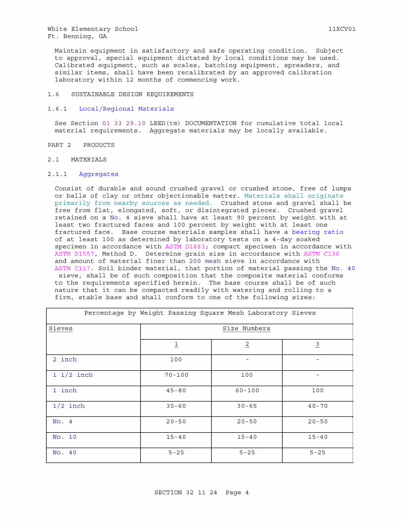
White Elementary School 11XCV01Ft. Benning, GA
Maintain equipment in satisfactory and safe operating condition. Subject to approval, special equipment dictated by local conditions may be used. Calibrated equipment, such as scales, batching equipment, spreaders, and similar items, shall have been recalibrated by an approved calibration laboratory within 12 months of commencing work.
1.6 SUSTAINABLE DESIGN REQUIREMENTS
1.6.1 Local/Regional Materials
See Section 01 33 29.10 LEED(tm) DOCUMENTATION for cumulative total local material requirements. Aggregate materials may be locally available.
PART 2 PRODUCTS
2.1 MATERIALS
2.1.1 Aggregates
Consist of durable and sound crushed gravel or crushed stone, free of lumps or balls of clay or other objectionable matter. Materials shall originate primarily from nearby sources as needed. Crushed stone and gravel shall be free from flat, elongated, soft, or disintegrated pieces. Crushed gravel retained on a No. 4 sieve shall have at least 90 percent by weight with at least two fractured faces and 100 percent by weight with at least one fractured face. Base course materials samples shall have a bearing ratio of at least 100 as determined by laboratory tests on a 4-day soaked specimen in accordance with ASTM D1883; compact specimen in accordance with ASTM D1557, Method D. Determine grain size in accordance with ASTM C136 and amount of material finer than 200 mesh sieve in accordance with ASTM C117. Soil binder material, that portion of material passing the No. 40 sieve, shall be of such composition that the composite material conforms to the requirements specified herein. The base course shall be of such nature that it can be compacted readily with watering and rolling to a firm, stable base and shall conform to one of the following sizes:
Percentage by Weight Passing Square Mesh Laboratory Sieves
Sieves Size Numbers
1 2 3
2 inch 100 - -
1 1/2 inch 70-100 100 -
1 inch 45-80 60-100 100
1/2 inch 30-60 30-65 40-70
No. 4 20-50 20-50 20-50
No. 10 15-40 15-40 15-40
No. 40 5-25 5-25 5-25
SECTION 32 11 24 Page 4
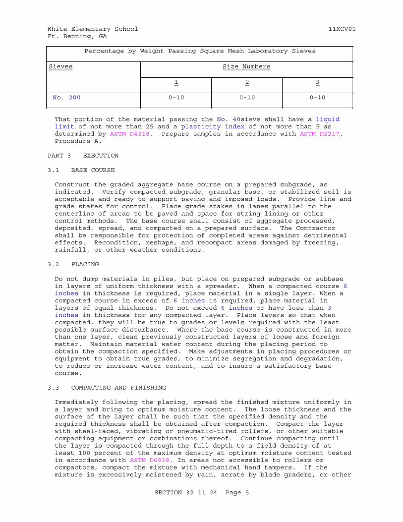
White Elementary School 11XCV01Ft. Benning, GA
Percentage by Weight Passing Square Mesh Laboratory Sieves
Sieves Size Numbers
1 2 3
No. 200 0-10 0-10 0-10
That portion of the material passing the No. 40sieve shall have a liquid limit of not more than 25 and a plasticity index of not more than 5 as determined by ASTM D4318. Prepare samples in accordance with ASTM D2217, Procedure A.
PART 3 EXECUTION
3.1 BASE COURSE
Construct the graded aggregate base course on a prepared subgrade, as indicated. Verify compacted subgrade, granular base, or stabilized soil is acceptable and ready to support paving and imposed loads. Provide line and grade stakes for control. Place grade stakes in lanes parallel to the centerline of areas to be paved and space for string lining or other control methods. The base course shall consist of aggregate processed, deposited, spread, and compacted on a prepared surface. The Contractor shall be responsible for protection of completed areas against detrimental effects. Recondition, reshape, and recompact areas damaged by freezing, rainfall, or other weather conditions.
3.2 PLACING
Do not dump materials in piles, but place on prepared subgrade or subbase in layers of uniform thickness with a spreader. When a compacted course 6 inches in thickness is required, place material in a single layer. When a compacted course in excess of 6 inches is required, place material in layers of equal thickness. Do not exceed 6 inches or have less than 3 inches in thickness for any compacted layer. Place layers so that when compacted, they will be true to grades or levels required with the least possible surface disturbance. Where the base course is constructed in more than one layer, clean previously constructed layers of loose and foreign matter. Maintain material water content during the placing period to obtain the compaction specified. Make adjustments in placing procedures or equipment to obtain true grades, to minimize segregation and degradation, to reduce or increase water content, and to insure a satisfactory base course.
3.3 COMPACTING AND FINISHING
Immediately following the placing, spread the finished mixture uniformly in a layer and bring to optimum moisture content. The loose thickness and the surface of the layer shall be such that the specified density and the required thickness shall be obtained after compaction. Compact the layer with steel-faced, vibrating or pneumatic-tired rollers, or other suitable compacting equipment or combinations thereof. Continue compacting until the layer is compacted through the full depth to a field density of at least 100 percent of the maximum density at optimum moisture content tested in accordance with ASTM D6938. In areas not accessible to rollers or compactors, compact the mixture with mechanical hand tampers. If the mixture is excessively moistened by rain, aerate by blade graders, or other
SECTION 32 11 24 Page 5
White Elementary School 11XCV01Ft. Benning, GA
suitable equipment. Aerate until the moisture content of the material is that needed to obtain the required density. Finish the surface of the layer by a combination of rolling and blading. Final surface shall be smooth and free from waves, irregularities, and ruts or soft yielding spots.
3.4 PROOF ROLLING
In addition to compacting the base course to the required density, proof roll the top surface of the completed base course by making coverages with a heavy rubber-tired roller. A coverage is defined as one application of one tire print over each point in the surface of the designated area. When under the action of the proof rolling, the base course yields, pumps, or otherwise fails, remove, replace with suitable materials, and recompact materials in the base course or in the underlying layers indicated to be unsatisfactory. The speed of the roller shall not exceed 5 miles per hour. Obtain approval upon completion of the proof rolling of the base course.
3.5 FINISHING AT EDGES OF BASE COURSE
Place earth or other approved materials along the edges of the base course in such quantity that it will compact to the thickness of the course being constructed. When the course is being constructed in two or more layers, place material to the thickness of each layer. In each operation, allow at least a one foot width of the shoulder to be rolled and compacted simultaneously with the rolling and compacting of each layer.
3.6 FIELD QUALITY CONTROL
Approve materials and material sources in advance of the use of such materials in the work. Replace base where samples are removed.
3.6.1 Sampling
3.6.1.1 Aggregates at the Source
Prior to production and delivery of aggregates, take at least one initial sample in accordance with ASTM D75/D75M. Collect each sample by taking three incremental samples at random from the source material to make a composite sample of not less than 50 pounds. Repeat above sampling when source of material is changed or when unacceptable deficiencies or variations from specified grading of materials are found in testing.
3.6.1.2 During Construction
Take one random sample from each 1000 tons of completed course material, but not less than one random sample per day's run. Take samples in accordance with ASTM D75/D75M.
3.6.1.3 Sample Identification
Place each sample in a clean container, securely fastened to prevent loss of material. Tag each sample for identification and with the following information:
Contract No._______________________________________Sample No._____________________ Quality __________Date of Sample_____________________________________Sampler____________________________________________Source_____________________________________________
SECTION 32 11 24 Page 6
White Elementary School 11XCV01Ft. Benning, GA
Intended Use_______________________________________For Testing________________________________________
3.6.2 Testing
3.6.2.1 Aggregates
Test each sample of base course material without delay. Make gradationtests from each sample in accordance with ASTM C136. Make sieve analysis on material passing the No. 200 sieve in accordance with ASTM C117.
3.6.2.2 Smoothness Tests
Test with a 10 foot straightedge, applied parallel with and at right angles to the center line of the paved area. Correct deviations in the surface in excess of 3/8 inch by loosening, adding or removing material, reshaping, watering, and compacting. The smoothness requirements specified herein apply only to the top layer when base course is constructed in more than one layer.
3.6.2.3 Field Density Tests
ASTM D1556 or ASTM D6938. Take one test for each 500 square yards of each layer of base course.
3.6.2.4 Laboratory Density Tests
In accordance with ASTM D1557, Method D.
3.6.2.5 Thickness Tests
Measure thickness of base course at intervals such that there will be a depth measurement for at least each 500 square yards of complete base course. Make depth measurements by test holes, at least 3 inches in diameter, through the base course. Where base course deficiency is more than 1/2 inch, correct by scarifying, adding mixture of proper gradation, reblading, and recompacting. Where the measured thickness is more than 1/2 inch thicker than indicated, consider it as the indicated thickness plus 1/2 inch for determining the average. The average thickness is the average of the depth measurements and shall not underrun the thickness indicated.
3.7 MAINTENANCE
After construction is completed, maintain the base course throughout, except where portion of the succeeding course is under construction thereon. Maintenance includes drainage, rolling, shaping, and watering, as necessary, to maintain the course in proper condition. Correct deficiencies in thickness, composition, construction, smoothness, and density, which develop during the maintenance, to conform to the requirements specified herein. Maintain sufficient moisture by light sprinkling with water at the surface to prevent a dusty condition.
-- End of Section --
SECTION 32 11 24 Page 7
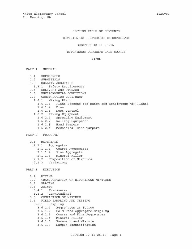
White Elementary School 11XCV01Ft. Benning, GA
SECTION TABLE OF CONTENTS
DIVISION 32 - EXTERIOR IMPROVEMENTS
SECTION 32 11 26.16
BITUMINOUS CONCRETE BASE COURSE
04/06
PART 1 GENERAL
1.1 REFERENCES 1.2 SUBMITTALS 1.3 QUALITY ASSURANCE 1.3.1 Safety Requirements 1.4 DELIVERY AND STORAGE 1.5 ENVIRONMENTAL CONDITIONS 1.6 CONSTRUCTION EQUIPMENT 1.6.1 Mixing Plant 1.6.1.1 Plant Screens for Batch and Continuous Mix Plants 1.6.1.2 Bins 1.6.1.3 Dust Control 1.6.2 Paving Equipment 1.6.2.1 Spreading Equipment 1.6.2.2 Rolling Equipment 1.6.2.3 Hand Tampers 1.6.2.4 Mechanical Hand Tampers
PART 2 PRODUCTS
2.1 MATERIALS 2.1.1 Aggregates 2.1.1.1 Coarse Aggregates 2.1.1.2 Fine Aggregate 2.1.1.3 Mineral Filler 2.1.2 Composition of Mixtures 2.1.3 Variations
PART 3 EXECUTION
3.1 MIXING 3.2 TRANSPORTATION OF BITUMINOUS MIXTURES 3.3 PLACING 3.4 JOINTS 3.4.1 Transverse 3.4.2 Longitudinal 3.5 COMPACTION OF MIXTURE 3.6 FIELD SAMPLING AND TESTING 3.6.1 Sampling 3.6.1.1 Aggregates at Source 3.6.1.2 Cold Feed Aggregate Sampling 3.6.1.3 Coarse and Fine Aggregates 3.6.1.4 Mineral Filler 3.6.1.5 Pavement and Mixture 3.6.1.6 Sample Identification
SECTION 32 11 26.16 Page 1

White Elementary School 11XCV01Ft. Benning, GA
3.6.2 Testing 3.6.2.1 Aggregate 3.6.2.2 Bituminous Mix 3.6.2.3 Pavement Course
-- End of Section Table of Contents --
SECTION 32 11 26.16 Page 2

White Elementary School 11XCV01Ft. Benning, GA
SECTION 32 11 26.16
BITUMINOUS CONCRETE BASE COURSE04/06
PART 1 GENERAL
1.1 REFERENCES
The publications listed below form a part of this specification to the extent referenced. The publications are referred to within the text by the basic designation only.
ASTM INTERNATIONAL (ASTM)
ASTM C131 (2006) Standard Test Method for Resistance to Degradation of Small-Size Coarse Aggregate by Abrasion and Impact in the Los Angeles Machine
ASTM C136 (2006) Standard Test Method for Sieve Analysis of Fine and Coarse Aggregates
ASTM C183 (2008) Standard Practice for Sampling and the Amount of Testing of Hydraulic Cement
ASTM D1073 (2011) Fine Aggregate for Bituminous Paving Mixtures
ASTM D1188 (2007e1) Bulk Specific Gravity and Density of Compacted Bituminous Mixtures Using Paraffin-Coated Specimens
ASTM D1559 (1989) Resistance to Plastic Flow of Bituminous Mixtures Using Marshall Apparatus
ASTM D2172/D2172M (2011) Quantitative Extraction of Bitumen from Bituminous Paving Mixtures
ASTM D242/D242M (2009) Mineral Filler for Bituminous Paving Mixtures
ASTM D2726 (2011) Bulk Specific Gravity and Density of Non-Absorptive Compacted Bituminous Mixtures
ASTM D3625 (1996; R 2005) Standard Practice for Effect of Water on Bituminous-Coated Aggregate Using Boiling Water
ASTM D546 (2010) Sieve Analysis of Mineral Filler for Bituminous Paving Mixtures
ASTM D692/D692M (2009) Coarse Aggregate for Bituminous Paving Mixtures
SECTION 32 11 26.16 Page 3
White Elementary School 11XCV01Ft. Benning, GA
ASTM D75/D75M (2009) Standard Practice for Sampling Aggregates
ASTM D979/D979M (2012) Sampling Bituminous Paving Mixtures
ASTM D995 (1995b; R 2002) Mixing Plants for Hot-Mixed, Hot-Laid Bituminous Paving Mixtures
1.2 SUBMITTALS
Government approval is required for submittals with a "G" designation; submittals not having a "G" designation are for information only. When used, a designation following the "G" designation identifies the office that will review the submittal for the Government. The following shall be submitted in accordance with Section 01 33 00 SUBMITTAL PROCEDURES:
SD-05 Design Data
Bituminous material job-mix formula
Submit a job-mix formula prior to preparing and placing bituminous mixture. Formula shall indicate definite percentage of each sieve fraction, percentage of bitumen, percentage of each aggregate, temperature of mixture leaving mixer, number of blows of compaction per side of molded specimen, stability, flow, percent of voids total mix, percent of voids in mineral aggregate, and temperature/viscosity relationship of asphalt cement.
SD-06 Test Reports
Abrasion test reports on aggregate
Stripping test reports on aggregate
Bituminous mix test reports
Density test reports
Thickness test reports
Smoothness test reports
1.3 QUALITY ASSURANCE
1.3.1 Safety Requirements
Provide adequate and safe stairways with handrails to mixer platform and safe and protected ladders or other means for accessibility to plant operations. Guard equipment and exposed steam or other high temperature lines which endanger personnel or create a fire hazard or cover with a suitable type of insulation. Provide hearing protection to Contractor employees and roller and spreader operators in vicinity of equipment which may emit hazardous noise levels.
1.4 DELIVERY AND STORAGE
Inspect materials delivered to the site for damage and store to prevent segregation.
SECTION 32 11 26.16 Page 4
White Elementary School 11XCV01Ft. Benning, GA
1.5 ENVIRONMENTAL CONDITIONS
Construct bituminous courses when underlaying course is dry and do not construct when atmospheric temperature is below 40 degrees F.
1.6 CONSTRUCTION EQUIPMENT
Calibrated equipment, such as asphalt distributors, scales, batching equipment, spreaders and similar equipment, shall have been recalibrated by an approved calibration laboratory within 12 months of commencing work.
1.6.1 Mixing Plant
Design, coordinate, and operate mixing plant to produce a mixture within job-mix formula tolerances. The mixing plant shall meet requirements of ASTM D995, except as specified otherwise herein. The plant shall be a batch type, continuous mixing type, or drum dryer-mixer type with a minimum capacity of 100 tons per hour. Mixing plant and equipment shall remain accessible at all times for checking its adequacy, inspecting its operation, verifying weights, proportions, character of materials, and checking mixture temperatures.
1.6.1.1 Plant Screens for Batch and Continuous Mix Plants
Use screens to obtain accurate gradation. Allow no bin to contain more than 10 percent oversize or undersize. Inspect screens each day prior to commencing work for plugged, worn or broken screens. Clean plugged screens and replace worn or broken screens with new screens prior to beginning operations.
1.6.1.2 Bins
Divide bins into at least three compartments arranged to insure separate and adequate storage of appropriate fractions of aggregate.
1.6.1.3 Dust Control
Equip plant with a dust collector designed to waste or return in a constant flow all or part of the material collected. Recover quantity as necessary to provide and maintain composition specified. Plant shall have a mixer cover and such additional housing to insure proper control of dust.
1.6.2 Paving Equipment
1.6.2.1 Spreading Equipment
Self-propelled electronically controlled type, unless other equipment is authorized . Equip spreading equipment of the self-propelled electronically controlled type with hoppers, tamping or vibrating devices, distributing screws, electronically adjustable screeds, and equalizing devices. Capable of spreading hot bituminous mixtures without tearing, shoving, or gouging and to produce a finished surface of specified grade and smoothness. Operate spreaders, when laying mixture, at variable speeds between 5 and 45 feet per minute. Design spreader with a quick and efficient steering device; a forward and reverse traveling speed; and automatic devices to adjust to grade and confine the edges of the mixture to true lines. The use of a spreader that leaves indented areas or other objectionable irregularities in the fresh laid mix during operations will
SECTION 32 11 26.16 Page 5
White Elementary School 11XCV01Ft. Benning, GA
not be permitted.
1.6.2.2 Rolling Equipment
Self-propelled pneumatic-tired rollers supplemented by three-wheel and tandem type steel wheel rollers. The number, type and weight of rollers shall be sufficient to compact the mixture to the required density without detrimentally affecting the compacted material. All rollers shall be suitable for rolling hot-mix bituminous pavements and capable of reversing without backlash. Pneumatic-tired rollers shall be capable of being operated both forward and backward without turning on the mat, and without loosening the surface being rolled. Equip rollers with suitable devices and apparatus to keep the rolling surfaces wet and prevent adherence of bituminous mixture.
Vibratory Rollers: At the Contractor's option, vibratory rollers especially designed for bituminous concrete compaction may be used provided rollers do not impair stability of pavement structure and any underlying layers. Repair depressions in pavement surfaces resulting from use of vibratory rollers at no cost to the Government. Rollers shall be self-propelled, single or dual vibrating drums, and steel drive wheels, as applicable; equipped with variable amplitude and separate controls for energy and propulsion.
1.6.2.3 Hand Tampers
Hand tampers shall weigh not less than 25 pounds and have a tamping face of not more than 50 square inches.
1.6.2.4 Mechanical Hand Tampers
Commercial type, operated by pneumatic pressure or by internal combustion.
PART 2 PRODUCTS
2.1 MATERIALS
2.1.1 Aggregates
Grade and proportion aggregates and filler such that combined mineral aggregate conforms to grading specified herein.
2.1.1.1 Coarse Aggregates
ASTM D692/D692M, except as modified herein. Crushed gravel shall have at least 75 percent by weight of pieces having two or more fractured faces. Percentage of wear (Los Angeles abrasion test), except for slag, shall not exceed 50 at 500 revolutions in accordance with ASTM C131. Weight of slag shall be not less than 70 pounds per cubic foot. Reject aggregates which show stripping when tested in accordance with ASTM D3625. However, "anti-stripping" agent(s) may be used subject to certified laboratory performance test(s) on the aggregate to be used and approval of the Contracting Officer.
2.1.1.2 Fine Aggregate
ASTM D1073, except gradation as specified herein.
SECTION 32 11 26.16 Page 6
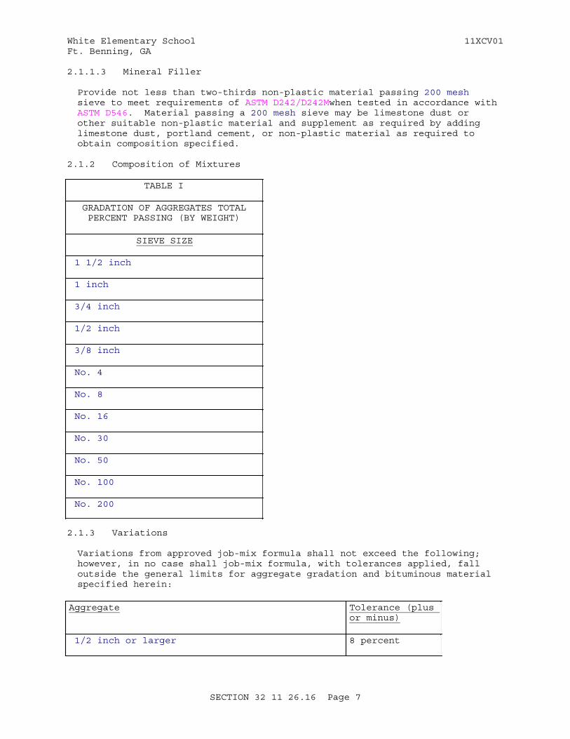
White Elementary School 11XCV01Ft. Benning, GA
2.1.1.3 Mineral Filler
Provide not less than two-thirds non-plastic material passing 200 mesh sieve to meet requirements of ASTM D242/D242Mwhen tested in accordance with ASTM D546. Material passing a 200 mesh sieve may be limestone dust or other suitable non-plastic material and supplement as required by adding limestone dust, portland cement, or non-plastic material as required to obtain composition specified.
2.1.2 Composition of Mixtures
TABLE I
GRADATION OF AGGREGATES TOTALPERCENT PASSING (BY WEIGHT)
SIEVE SIZE
1 1/2 inch
1 inch
3/4 inch
1/2 inch
3/8 inch
No. 4
No. 8
No. 16
No. 30
No. 50
No. 100
No. 200
2.1.3 Variations
Variations from approved job-mix formula shall not exceed the following; however, in no case shall job-mix formula, with tolerances applied, fall outside the general limits for aggregate gradation and bituminous material specified herein:
Aggregate Tolerance (plus or minus)
1/2 inch or larger 8 percent
SECTION 32 11 26.16 Page 7
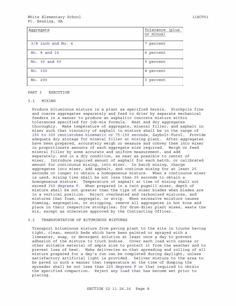
White Elementary School 11XCV01Ft. Benning, GA
Aggregate Tolerance (plus or minus)
3/8 inch and No. 4 7 percent
No. 8 and 16 6 percent
No. 30 and 50 5 percent
No. 100 4 percent
No. 200 3 percent
PART 3 EXECUTION
3.1 MIXING
Produce bituminous mixture in a plant as specified herein. Stockpile fine and coarse aggregates separately and feed to drier by separate mechanical feeders in a manner to produce an asphaltic concrete mixture within tolerances specified for job-mix formula. Heat and dry aggregates thoroughly. Make temperature of aggregate, mineral filler, and asphalt in mixer such that viscosity of asphalt in mixture shall be in the range of 150 to 300 centistokes kinematic or 75-150 seconds, Saybolt-Furol. Provide adequate dry storage for mineral filler at mixing plant. After aggregates have been prepared, accurately weigh or measure and convey them into mixer in proportionate amounts of each aggregate size required. Weigh or feed mineral filler by some accurate and uniform measurement, and add separately, and in a dry condition, as near as possible to center of mixer. Introduce required amount of asphalt for each batch, or calibrated amount for continuous mixing, into mixer. In batch mixing, charge aggregates into mixer, add asphalt, and continue mixing for at least 25 seconds or longer to obtain a homogeneous mixture. When a continuous mixer is used, mixing time shall be not less than 30 seconds to obtain a homogeneous mixture. Temperature of asphalt at time of mixing shall not exceed 350 degrees F. When prepared in a twin pugmill mixer, depth of mixture shall be not greater than the tips of mixer blades when blades are in a vertical position. Reject overheated and carbonized mixtures, and mixtures that foam, segregate, or strip. When excessive moisture causes foaming, segregation, or stripping, remove all aggregates in hot bins and place in their respective stockpiles; for drum-drier plant mixes, waste the mix, except as otherwise approved by the Contracting Officer.
3.2 TRANSPORTATION OF BITUMINOUS MIXTURES
Transport bituminous mixture from paving plant to the site in trucks having tight, clean, smooth beds which have been painted or sprayed with a limewater, soap, or detergent solution at least once a day to prevent adhesion of the mixture to truck bodies. Cover each load with canvas or other suitable material of ample size to protect it from the weather and to prevent loss of heat. Make deliveries so that spreading and rolling of all mixture prepared for a day's run can be completed during daylight, unless satisfactory artificial light is provided. Deliver mixture to the area to be paved in such a manner that temperature at the time of dumping the spreader shall be not less than 225 degrees F or that required to obtain the specified compaction. Reject any load that has become wet prior to placing.
SECTION 32 11 26.16 Page 8

White Elementary School 11XCV01Ft. Benning, GA
3.3 PLACING
Provide line and grade stakes as necessary for control. Place grade stakes in lanes parallel to centerline of area to be paved, and suitably space for string lines. Place and compact bituminous courses in such thicknesses to achieve density and smoothness requirements. Maximum lift of bituminous base course shall not exceed 6 inches. Prior to laying the base course, clean underlying course of foreign and objectionable matter with power blowers, power brooms, or hand brooms in places inaccessible to power equipment, and inspect for compaction and smoothness requirements. The range of temperatures of the mixtures at the time of spreading shall be between 225 degrees F and 300 degrees F. Reject bituminous mixture having a temperature outside these limits when dumped into the hopper of the spreader. Adjust mechanical spreader and regulate speed so that the surface of the course is smooth, and when compacted conforms to depth, cross sections, grades, and contours indicated. When irregularities of surface or deficiency in depth is more than specified tolerances, remove defective work and replace with new material. Whenever possible, place the mixture in strips not less than 10 feet wide. Overlap rolling to previously placed strip and extend to overlap first strip. Place mixture as continuously as possible. Shovelers and rakers shall follow spreading equipment, adding hot mixture and raking as required to produce a course that, when completed, shall conform to requirements specified. In areas where the use of machine spreading is impractical, mixture may be spread by hand. Distribute mixture into place from dump boards by means of hot shovels and spread with hot rakes in a uniformly loose layer of such thickness that, when completed, it conforms to required grade and thickness. Do not dump loads any faster than they can be handled by shovelers and rakers. Paint contact surfaces of previously constructed curbs, manholes, and similar structures with a thin coat of emulsion or other approved bituminous material prior to placing the bituminous mixture.
3.4 JOINTS
All joints shall present the same texture, density, and smoothness as other portions of the course. Carefully make joints between old and new pavements or within new pavements in a manner as to ensure a thorough and continuous bond between old and new sections of the course. Paint all vertical contact surfaces of previously constructed sections with a thin uniform coat of emulsion or other approved bituminous material just before the fresh mixture is placed.
3.4.1 Transverse
The roller shall pass over the unprotected end of the freshly laid mixture only when the laying of the course is to be discontinued. Except when an approved bulkhead is used, cut back the edge of the previously laid course to expose an even, vertical surface for the full thickness of the course. When required, rake fresh mixture against the joints, thoroughly tamp with hot tampers, smooth with hot smoothers, and roll. In all cases, transverse joints in adjacent lanes shall be offset a minimum of 2 feet.
3.4.2 Longitudinal
Place longitudinal joints so that they shall not coincide with that of underlying course and shall be separated by at least one foot. When edges of longitudinal joints are irregular, honeycombed, or poorly compacted, cut back unsatisfactory sections of joint to expose an even, vertical surface for the full thickness of the course. Prior to placing adjacent asphalt
SECTION 32 11 26.16 Page 9
White Elementary School 11XCV01Ft. Benning, GA
concrete, roll joint first, then proceed to opposite side and roll, moving each time toward the joint.
3.5 COMPACTION OF MIXTURE
Affect compaction by rolling. Begin rolling as soon after placing as the mixture will bear the roller without undue displacement. Delays in rolling freshly spread mixture will not be tolerated. Start rolling longitudinally at extreme sides of lanes and proceed toward center of pavement, overlapping on successive strips by at least one-half the width of rear wheel of roller. Alternate trips of roller shall be slightly different lengths. Affect initial longitudinal rolling by the use of steel roller. Make tests for conformity with specified crown, grade, and smoothness immediately after initial compression. Before continuing rolling, correct any variations by removing or adding materials, then roll course using pneumatic-tired rollers or tandem rollers, while mixture is hot and in condition suitable for proper compaction. Speed of rollers shall not exceed 3 miles per hour and at all times be slow enough to avoid displacement of hot mixture. Correct any displacement of mixture at once by use of rakes and apply fresh mixture or remove mixture as required. Continue rolling until all roller marks are eliminated and course has a density of at least 100 percent of that attained in a laboratory specimen of the same mixture prepared in accordance with ASTM D1559. During rolling, moisten rollers to prevent adhesion of mixture to rolling surfaces, but do not permit an excess of water. Provide sufficient rollers for each spreading machine in operation on the job and to handle plant output. In places not accessible to rollers, compact mixture with hot pneumatic or manual hand tampers. Skin patching of an area that has been rolled is not permitted. Remove any mixture that becomes mixed with foreign material or is defective, replace with fresh mixture, and compact to density of surrounding area. Roller shall pass over unprotected edge of course only when laying of course is to be discontinued for a length of time to permit mixture to become cold. Contractor shall provide workmen who are capable of performing work incidental to correction of pavement irregularities. After final rolling, permit no traffic of any kind on the pavement until the surface temperature has cooled to at least 120 degrees F. Measure surface temperature with surface thermometers or other satisfactory methods.
3.6 FIELD SAMPLING AND TESTING
3.6.1 Sampling
3.6.1.1 Aggregates at Source
Prior to production and delivery of aggregates, take at least one initial sample in accordance with ASTM D75/D75M from each stockpile. Collect each sample by taking three incremental samples at random from source material to make a composite sample of not less than 50 pounds. Make repetition of the above sampling when source of material is changed or when unacceptable deficiencies or variations from specified grading of materials are found in testing.
3.6.1.2 Cold Feed Aggregate Sampling
Take two samples daily from belt conveying materials from cold feed. Collect materials in three increments at random to make a representative composite sample of not less than 50 pounds. Take samples in accordance with ASTM D75/D75M.
SECTION 32 11 26.16 Page 10
White Elementary School 11XCV01Ft. Benning, GA
3.6.1.3 Coarse and Fine Aggregates
Take 50 pounds sample from cold feed at least once daily for sieve analyses and specific gravity tests. Additional samples may be required to perform more frequent tests on mineral fillers, or will be required when analyses show deficiencies, or unacceptable variances or deviations. Method of sampling is as described herein for aggregates.
3.6.1.4 Mineral Filler
ASTM C183. Take samples large enough to provide ample material for testing.
3.6.1.5 Pavement and Mixture
Take samples for the determination of mix properties, thickness and density of the completed pavements. Furnish all tools, labor and material for samples and for satisfactory replacement of pavement. Take samples and test at not less than frequency specified hereinafter and at the beginning of plant operations; for each day's work as a minimum; each change in the mix or equipment; and as often as directed. Accomplish sampling in accordance with ASTM D979/D979M.
3.6.1.6 Sample Identification
Furnish each sample in a clean container, securely fastened to prevent loss of material. Tag each sample for identification. Tag shall contain the following information:
Contract No._______________________________________Sample No. ___________________Quantity_____________Date of Sample_____________________________________Sample ____________________________________________Source ____________________________________________Intended use_______________________________________For testing________________________________________
3.6.2 Testing
3.6.2.1 Aggregate
a. Gradation: ASTM C136 for fine and coarse aggregate. ASTM D546 for mineral filler.
b. Abrasion: ASTM C131 for wear (Los Angeles test). Perform one test initially prior to incorporation into work and whenever source is changed.
c. Stripping Test: ASTM D3625. Perform a stripping test initially on all aggregate prior to incorporation into work and whenever source is changed.
3.6.2.2 Bituminous Mix
ASTM D2172/D2172M. Test one sample for each 500 tons, or fraction thereof, of the uncompacted mix for extraction. Sieve analysis per ASTM C136. Test one sample for each 500 tons, or fraction thereof, for stability and flow in accordance with ASTM D1559.
SECTION 32 11 26.16 Page 11
White Elementary School 11XCV01Ft. Benning, GA
3.6.2.3 Pavement Course
a. Density: For each 1000 tons of bituminous course placed, determine the representative laboratory density by averaging the density of 4 laboratory specimens prepared in accordance with ASTM D1559;samples for these specimens shall be taken from trucks delivering mixture to the site; the Contractor shall record in an approved manner the project areas represented by the laboratory densities. From each representative area so recorded, determine field density of the pavement by averaging the densities of 4 inchdiameter cores obtained from the base course; take one core for each 2000 square yards or fraction thereof of course placed. Determine density of the laboratory prepared specimens and the cored samples in accordance with ASTM D1188 or ASTM D2726, as applicable. The maximum allowable deficiency at any point shall not be more than 2 percent less than the specified density. The average density shall be not less than the specified density. When the deficiency is more than the specified tolerances, the Contractor shall correct each such representative area or areas by removing the pavement in question and replacing with new pavement.
b. Thickness: Determine thickness of the course from samples taken for the field density test. The maximum allowable deficiency at any point shall not be more than 1/4 inch less than the indicated thickness for the course. The average thickness of the course shall be not less than the indicated thickness. Where the deficiency is more than the specified tolerances, the contractor shall correct each such representative area or areas by removing the pavement in question and replacing with new pavement.
c. Smoothness: Straightedge test the compacted surface of the course as the work progresses. Apply straightedge parallel with and at right angles to the centerline after final rolling. Unevenness of the course shall not vary more than plus or minus 1/4 inch in 10 feet. Correct any portion of the pavement showing irregularities greater than that specified.
-- End of Section --
SECTION 32 11 26.16 Page 12
White Elementary School 11XCV01Ft. Benning, GA
SECTION TABLE OF CONTENTS
DIVISION 32 - EXTERIOR IMPROVEMENTS
SECTION 32 12 16
HOT-MIX ASPHALT (HMA) FOR ROADS
08/09
PART 1 GENERAL
1.1 REFERENCES 1.2 SYSTEM DESCRIPTION 1.2.1 Asphalt Mixing Plant 1.2.2 Hauling Equipment 1.2.3 Asphalt Pavers 1.2.3.1 Receiving Hopper 1.2.4 Rollers 1.3 SUBMITTALS 1.4 ENVIRONMENTAL REQUIREMENTS
PART 2 PRODUCTS
2.1 AGGREGATES 2.1.1 Coarse Aggregate 2.1.2 Fine Aggregate 2.1.3 Mineral Filler 2.1.4 Aggregate Gradation 2.2 ASPHALT CEMENT BINDER
PART 3 EXECUTION
3.1 PREPARATION OF ASPHALT BINDER MATERIAL 3.2 PREPARATION OF MINERAL AGGREGATE 3.3 PREPARATION OF HOT-MIX ASPHALT MIXTURE 3.4 PREPARATION OF THE UNDERLYING SURFACE 3.5 TESTING LABORATORY 3.6 TRANSPORTING AND PLACING 3.6.1 Transporting 3.6.2 Placing 3.7 COMPACTION OF MIXTURE 3.8 JOINTS 3.8.1 Transverse Joints 3.8.2 Longitudinal Joints 3.9 CONTRACTOR QUALITY CONTROL 3.9.1 General Quality Control Requirements 3.9.2 Quality Control Testing 3.9.2.1 Temperatures 3.9.2.2 Grade and Smoothness 3.9.2.3 Additional Testing 3.9.2.4 QC Monitoring 3.9.3 Sampling 3.10 MATERIAL ACCEPTANCE 3.10.1 Additional Sampling and Testing 3.10.2 Grade
SECTION 32 12 16 Page 1

White Elementary School 11XCV01Ft. Benning, GA
3.10.3 Surface Smoothness 3.10.3.1 Smoothness Requirements 3.10.3.2 Testing Method
-- End of Section Table of Contents --
SECTION 32 12 16 Page 2
White Elementary School 11XCV01Ft. Benning, GA
SECTION 32 12 16
HOT-MIX ASPHALT (HMA) FOR ROADS08/09
PART 1 GENERAL
1.1 REFERENCES
The publications listed below form a part of this specification to the extent referenced. The publications are referred to within the text by the basic designation only.
STATE OF CALIFORNIA DEPARTMENT OF TRANSPORTATION (CALTRANS)
CTM 526 (2002) Operation of California Profilograph and Evaluation of Profiles
GEORGIA DEPARTMENT OF TRANSPORTATION (GDOT)
Section 400 Hot Mix Asphaltic Concrete Construction
1.2 SYSTEM DESCRIPTION
Perform the work consisting of pavement courses composed of mineral aggregate and asphalt material heated and mixed in a central mixing plant and placed on a prepared course. HMA designed and constructed in accordance with this section shall conform to the lines, grades, thicknesses, and typical cross sections shown on the drawings. Construct each course to the depth, section, or elevation required by the drawings and roll, finish, and approve it before the placement of the next course.
1.2.1 Asphalt Mixing Plant
Plants used for the preparation of hot-mix asphalt shall conform to the requirements of Section 400.
1.2.2 Hauling Equipment
Provide trucks for hauling hot-mix asphalt having tight, clean, and smooth metal beds. To prevent the mixture from adhering to them, the truck beds shall be lightly coated with a minimum amount of paraffin oil, lime solution, or other approved material. Petroleum based products shall not be used as a release agent. Each truck shall have a suitable cover to protect the mixture from adverse weather. When necessary to ensure that the mixture will be delivered to the site at the specified temperature, truck beds shall be insulated or heated and covers (tarps) shall be securely fastened.
1.2.3 Asphalt Pavers
Provide asphalt pavers which are self-propelled, with an activated screed, heated as necessary, and capable of spreading and finishing courses of hot-mix asphalt which will meet the specified thickness, smoothness, and grade. The paver shall have sufficient power to propel itself and the hauling equipment without adversely affecting the finished surface.
SECTION 32 12 16 Page 3
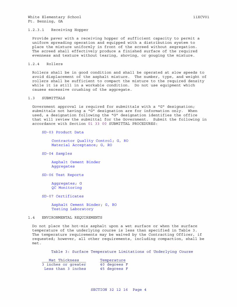
White Elementary School 11XCV01Ft. Benning, GA
1.2.3.1 Receiving Hopper
Provide paver with a receiving hopper of sufficient capacity to permit a uniform spreading operation and equipped with a distribution system to place the mixture uniformly in front of the screed without segregation. The screed shall effectively produce a finished surface of the required evenness and texture without tearing, shoving, or gouging the mixture.
1.2.4 Rollers
Rollers shall be in good condition and shall be operated at slow speeds to avoid displacement of the asphalt mixture. The number, type, and weight of rollers shall be sufficient to compact the mixture to the required density while it is still in a workable condition. Do not use equipment which causes excessive crushing of the aggregate.
1.3 SUBMITTALS
Government approval is required for submittals with a "G" designation; submittals not having a "G" designation are for information only. When used, a designation following the "G" designation identifies the office that will review the submittal for the Government. Submit the following in accordance with Section 01 33 00 SUBMITTAL PROCEDURES:
SD-03 Product Data
Contractor Quality Control; G, ROMaterial Acceptance; G, RO
SD-04 Samples
Asphalt Cement BinderAggregates
SD-06 Test Reports
Aggregates; GQC Monitoring
SD-07 Certificates
Asphalt Cement Binder; G, ROTesting Laboratory
1.4 ENVIRONMENTAL REQUIREMENTS
Do not place the hot-mix asphalt upon a wet surface or when the surface temperature of the underlying course is less than specified in Table 3. The temperature requirements may be waived by the Contracting Officer, if requested; however, all other requirements, including compaction, shall be met.
Table 3: Surface Temperature Limitations of Underlying Course
Mat Thickness Temperature 3 inches or greater 40 degrees F Less than 3 inches 45 degrees F
SECTION 32 12 16 Page 4
White Elementary School 11XCV01Ft. Benning, GA
PART 2 PRODUCTS
2.1 AGGREGATES
Provide aggregates consisting of crushed stone, crushed gravel, crushed slag, screenings, natural sand and mineral filler, in accordance with Section 400.
2.1.1 Coarse Aggregate
Provide coarse aggregate consisting of sound, tough, durable particles, free from films of material that would prevent thorough coating and bonding with the asphalt material and free from organic matter and other deleterious substances. All individual coarse aggregate sources shall meet Section 400 requirements.
2.1.2 Fine Aggregate
Fine aggregate shall consist of clean, sound, tough, durable particles free from coatings of clay, silt, or any objectionable material and containing no clay balls and shall meet Section 400 requirements.
2.1.3 Mineral Filler
Mineral filler shall be nonplastic material meeting the requirements of Section 400.
2.1.4 Aggregate Gradation
The combined aggregate gradation shall conform to Section 400.
2.2 ASPHALT CEMENT BINDER
Submit a 5 gallon sample for mix design verification. Asphalt cement binder shall conform to Section 400. Test data indicating grade certification shall be provided by the supplier at the time of delivery of each load to the mix plant. Submit copies of these certifications to the Contracting Officer. The supplier is defined as the last source of any modification to the binder. The Contracting Officer may sample and test the binder at the mix plant at any time before or during mix production. Obtain samples for this verification testing in accordance with Section 400 and in the presence of the Contracting Officer. Furnish these samples to the Contracting Officer for the verification testing, which shall be at no cost to the Contractor. Submit samples of the asphalt cement specified for approval not less than 14 days before start of the test section. Submit copies of certified test data, amount, type and description of any modifiers blended into the asphalt cement binder.
PART 3 EXECUTION
3.1 PREPARATION OF ASPHALT BINDER MATERIAL
Heat the asphalt cement material avoiding local overheating and providing a continuous supply of the asphalt material to the mixer at a uniform temperature. The temperature of unmodified asphalts shall be no more than 325 degrees F when added to the aggregates. Performance-Graded (PG) asphalts shall be within the temperature range of 275 - 325 degrees F when added to the aggregate.
SECTION 32 12 16 Page 5
White Elementary School 11XCV01Ft. Benning, GA
3.2 PREPARATION OF MINERAL AGGREGATE
Heat and dry the aggregate for the mixture prior to mixing. No damage shall occur to the aggregates due to the maximum temperature and rate of heating used. The temperature of the aggregate and mineral filler shall not exceed 350 degrees F when the asphalt cement is added. The temperature shall not be lower than is required to obtain complete coating and uniform distribution on the aggregate particles and to provide a mixture of satisfactory workability.
3.3 PREPARATION OF HOT-MIX ASPHALT MIXTURE
The aggregates and the asphalt cement shall be weighed or metered and introduced into the mixer in the amount specified in accordance with Section 400.
3.4 PREPARATION OF THE UNDERLYING SURFACE
Immediately before placing the hot mix asphalt, clean the underlying course of dust and debris. Apply a prime coat and/or tack coat in accordance with Section 400.
3.5 TESTING LABORATORY
Submit certification of compliance and Plant Scale Calibration Certification. Use a laboratory to develop the JMF that meets the requirements of Section 400 requirements.
a. Evidence of participation in the AASHTO Materials Reference Laboratory (AMRL) program.
3.6 TRANSPORTING AND PLACING
3.6.1 Transporting
Transport the hot-mix asphalt from the mixing plant to the site in clean, tight vehicles. Schedule deliveries so that placing and compacting of mixture is uniform with minimum stopping and starting of the paver. Provide adequate artificial lighting for night placements. Hauling over freshly placed material will not be permitted until the material has been compacted as specified, and allowed to cool to 140 degrees F. To deliver mix to the paver, use a material transfer vehicle operated to produce continuous forward motion of the paver.
3.6.2 Placing
Place and compact the mix at a temperature suitable for obtaining density, surface smoothness, and other specified requirements. Upon arrival, place the mixture to the full width by an asphalt paver; it shall be struck off in a uniform layer of such depth that, when the work is completed, it will have the required thickness and conform to the grade and contour indicated. Regulate the speed of the paver to eliminate pulling and tearing of the asphalt mat. Unless otherwise permitted, placement of the mixture shall begin along the centerline of a crowned section or on the high side of areas with a one-way slope. Place the mixture in consecutive adjacent strips having a minimum width of 10 feet. The longitudinal joint in one course shall offset the longitudinal joint in the course immediately below by at least 1 foot; however, the joint in the surface course shall be at the centerline of the pavement. Transverse joints in one course shall
SECTION 32 12 16 Page 6
White Elementary School 11XCV01Ft. Benning, GA
be offset by at least 10 feet from transverse joints in the previous course. Transverse joints in adjacent lanes shall be offset a minimum of 10 feet. On isolated areas where irregularities or unavoidable obstacles make the use of mechanical spreading and finishing equipment impractical, the mixture may be spread and luted by hand tools.
3.7 COMPACTION OF MIXTURE
After placing, the mixture shall be thoroughly and uniformly compacted by rolling. Compact the surface as soon as possible without causing displacement, cracking or shoving. The sequence of rolling operations and the type of rollers used shall be at the discretion of the Contractor. The speed of the roller shall, at all times, be sufficiently slow to avoid displacement of the hot mixture and be effective in compaction. Any displacement occurring as a result of reversing the direction of the roller, or from any other cause, shall be corrected at once. Furnish sufficient rollers to handle the output of the plant. Continue rolling until the surface is of uniform texture, true to grade and cross section, and the required field density is obtained. To prevent adhesion of the mixture to the roller, keep the wheels properly moistened but excessive water will not be permitted. In areas not accessible to the roller, the mixture shall be thoroughly compacted with hand tampers. Any mixture that becomes loose and broken, mixed with dirt, contains check-cracking, or is in any way defective shall be removed full depth, replaced with fresh hot mixture and immediately compacted to conform to the surrounding area. This work shall be done at the Contractor's expense. Skin patching will not be allowed.
3.8 JOINTS
The formation of joints shall be performed ensuring a continuous bond between the courses and to obtain the required density. All joints shall have the same texture as other sections of the course and meet the requirements for smoothness and grade.
3.8.1 Transverse Joints
Do not pass the roller over the unprotected end of the freshly laid mixture, except when necessary to form a transverse joint. When necessary to form a transverse joint, it shall be made by means of placing a bulkhead or by tapering the course. The tapered edge shall be cut back to its full depth and width on a straight line to expose a vertical face prior to placing material at the joint. Remove the cutback material from the project. In both methods, all contact surfaces shall be given a light tack coat of asphalt material before placing any fresh mixture against the joint.
3.8.2 Longitudinal Joints
Longitudinal joints which are irregular, damaged, uncompacted, cold (less than 175 degrees F at the time of placing adjacent lanes), or otherwise defective, shall be cut back a maximum of 3 inches from the top of the course with a cutting wheel to expose a clean, sound vertical surface for the full depth of the course. All cutback material shall be removed from the project. All contact surfaces shall be given a light tack coat of asphalt material prior to placing any fresh mixture against the joint. The Contractor will be allowed to use an alternate method if it can be demonstrated that density, smoothness, and texture can be met.
SECTION 32 12 16 Page 7
White Elementary School 11XCV01Ft. Benning, GA
3.9 CONTRACTOR QUALITY CONTROL
3.9.1 General Quality Control Requirements
Develop and submit a Quality Control Plan for approval. Submit aggregate and QC test results. Do not produce hot-mix asphalt for payment until the quality control plan has been approved addressing all elements which affect the quality of the pavement including, but not limited to:
a. Mix Design
b. Aggregate Grading
c. Quality of Materials
d. Stockpile Management
e. Proportioning
f. Mixing and Transportation
g. Mixture Volumetrics
h. Moisture Content of Mixtures
i. Placing and Finishing
j. Joints
k. Compaction
l. Surface Smoothness
3.9.2 Quality Control Testing
Perform all quality control tests applicable to these specifications and as set forth in the Quality Control Program. The testing program shall include, but shall not be limited to, tests for the control of asphalt content, aggregate gradation, temperatures, aggregate moisture, moisture in the asphalt mixture, laboratory air voids, stability (NA for Superpave), flow (NA for Superpave), in-place density, grade and smoothness. Develop a Quality Control Testing Plan as part of the Quality Control Program.
3.9.2.1 Temperatures
Check temperatures at least four times per lot, at necessary locations, to determine the temperature at the dryer, the asphalt cement in the storage tank, the asphalt mixture at the plant, and the asphalt mixture at the job site.
3.9.2.2 Grade and Smoothness
Conduct the necessary checks to ensure the grade and smoothness requirements are met in accordance with paragraphs MATERIAL ACCEPTANCE and PERCENT PAYMENT.
3.9.2.3 Additional Testing
Any additional testing, which the Contractor deems necessary to control the
SECTION 32 12 16 Page 8
White Elementary School 11XCV01Ft. Benning, GA
process, may be performed at the Contractor's option.
3.9.2.4 QC Monitoring
Submit all QC test results to the Contracting Officer on a daily basis as the tests are performed. The Contracting Officer reserves the right to monitor any of the Contractor's quality control testing and to perform duplicate testing as a check to the Contractor's quality control testing.
3.9.3 Sampling
When directed by the Contracting Officer, sample and test any material which appears inconsistent with similar material being produced, unless such material is voluntarily removed and replaced or deficiencies corrected by the Contractor. All sampling shall be in accordance with standard procedures specified.
3.10 MATERIAL ACCEPTANCE
Testing for acceptability of work will be performed by an independent laboratory hired by the Contractor. Forward test results and payment calculations daily to the Contracting Officer. Acceptance of the plant produced mix and in-place requirements will be on a lot to lot basis. A standard lot for all requirements will be equal to 8 hours of production. Where appropriate, adjustment in payment for individual lots of hot-mix asphalt will be made based on in-place density, laboratory air voids, grade and smoothness in accordance with the following paragraphs. Grade and surface smoothness determinations will be made on the lot as a whole. Exceptions or adjustments to this will be made in situations where the mix within one lot is placed as part of both the intermediate and surface courses, thus grade and smoothness measurements for the entire lot cannot be made. In order to evaluate laboratory air voids and in-place (field) density, each lot will be divided into four equal sublots.
3.10.1 Additional Sampling and Testing
The Contracting Officer reserves the right to direct additional samples and tests for any area which appears to deviate from the specification requirements. The cost of any additional testing will be paid for by the Government. Testing in these areas will be in addition to the lot testing, and the requirements for these areas will be the same as those for a lot.
3.10.2 Grade
The final wearing surface of pavement shall conform to the elevations and cross sections shown and shall vary not more than 0.05 foot from the plan grade established and approved at site of work. Finished surfaces at juncture with other pavements shall coincide with finished surfaces of abutting pavements. Deviation from the plan elevation will not be permitted in areas of pavements where closer conformance with planned elevation is required for the proper functioning of drainage and other appurtenant structures involved. The grade will be determined by running lines of levels at intervals of 25 feet, or less, longitudinally and transversely, to determine the elevation of the completed pavement surface. Within 5 working days, after the completion of a particular lot incorporating the final wearing surface, test the final wearing surface of the pavement for conformance with the specified plan grade. Diamond grinding may be used to remove high spots to meet grade requirements. Skin patching for correcting low areas or planing or milling for correcting high
SECTION 32 12 16 Page 9
White Elementary School 11XCV01Ft. Benning, GA
areas will not be permitted.
3.10.3 Surface Smoothness
Use one of the following methods to test and evaluate surface smoothness of the pavement. Perform all testing in the presence of the Contracting Officer. Keep detailed notes of the results of the testing and furnish a copy to the Government immediately after each day's testing. Where drawings show required deviations from a plane surface (crowns, drainage inlets, etc.), the surface shall be finished to meet the approval of the Contracting Officer.
3.10.3.1 Smoothness Requirements
a. Straightedge Testing: The finished surfaces of the pavements shall have no abrupt change of 1/4 inch or more, and all pavements shall be within the tolerances of 1/4 inch in both the longitudinal and transverse directions, when tested with an approved 12 feet straightedge.
b. Profilograph Testing: The finished surfaces of the pavements shall have no abrupt change of 1/8 inch or more, and each 0.1 mile segment of each pavement lot shall have a Profile Index not greater than 9 inches/mile when tested with an approved California-type profilograph. If the extent of the pavement in either direction is less than 200 feet, that direction shall be tested by the straightedge method and shall meet requirements specified above.
3.10.3.2 Testing Method
After the final rolling, but not later than 24 hours after placement, test the surface of the pavement in each entire lot in such a manner as to reveal all surface irregularities exceeding the tolerances specified above. Separate testing of individual sublots is not required. If any pavement areas are ground, these areas shall be retested immediately after grinding. Test each lot of the pavement in both a longitudinal and a transverse direction on parallel lines. Set the transverse lines 15 feet or less apart, as directed. The longitudinal lines shall be at the centerline of each paving lane for lanes less than 20 feet wide and at the third points for lanes 20 feet or wider. Also test other areas having obvious deviations. Longitudinal testing lines shall be continuous across all joints.
a. Straightedge Testing. Hold the straightedge in contact with the surface and move it ahead one-half the length of the straightedge for each successive measurement. Determine the amount of surface irregularity by placing the freestanding (unleveled) straightedge on the pavement surface and allowing it to rest upon the two highest spots covered by its length, and measuring the maximum gap between the straightedge and the pavement surface in the area between these two high points.
b. Profilograph Testing. Perform profilograph testing using approved equipment and procedures described in CTM 526. The equipment shall utilize electronic recording and automatic computerized reduction of data to indicate "must-grind" bumps and the Profile Index for each 0.1 mile segment of each pavement lot. Grade breaks on parking lots shall be accommodated by breaking the profile segment into shorter sections and repositioning the blanking band on each segment. The "blanking
SECTION 32 12 16 Page 10

White Elementary School 11XCV01Ft. Benning, GA
band" shall be 0.2 inches wide and the "bump template" shall span 1 inch with an offset of 0.3 inch. Compute the Profile Index for each pass of the profilograph in each 0.1 mile segment. The Profile Index for each segment shall be the average of the Profile Indices for each pass in each segment. The profilograph shall be operated by a DOT approved operator. Furnish a copy of the reduced tapes to the Government at the end of each day's testing.
-- End of Section --
SECTION 32 12 16 Page 11
White Elementary School 11XCV01Ft. Benning, GA
SECTION TABLE OF CONTENTS
DIVISION 32 - EXTERIOR IMPROVEMENTS
SECTION 32 13 13.06
PORTLAND CEMENT CONCRETE PAVEMENT FOR ROADS AND SITE FACILITIES
11/11
PART 1 GENERAL
1.1 REFERENCES 1.2 SUBMITTALS 1.3 DELIVERY, STORAGE, AND HANDLING 1.4 QUALITY ASSURANCE 1.4.1 Ready-mixed Concrete Plant Certification 1.4.2 Contractor Qualifications 1.4.3 Required Information 1.4.4 Batch Tickets 1.4.5 Field-Constructed Mockup 1.5 SUSTAINABLE DESIGN REQUIREMENTS 1.5.1 Local/Regional Materials
PART 2 PRODUCTS
2.1 MATERIALS 2.1.1 Cementitious Materials 2.1.1.1 Cement 2.1.1.2 Water 2.1.2 Aggregate 2.1.2.1 Alkali Reactivity Test 2.1.2.2 Fine Aggregates 2.1.2.3 Coarse Aggregates 2.1.3 Admixtures 2.1.4 Reinforcement 2.1.4.1 Tie Bars 2.1.4.2 Reinforcement 2.1.5 Curing Materials 2.1.5.1 White-Burlap-Polyethylene Sheet 2.2 CONCRETE PAVEMENT 2.2.1 Joint Layout Drawings 2.2.2 Albedo 2.3 CONTRACTOR-FURNISHED MIX DESIGN
PART 3 EXECUTION
3.1 FORMS 3.1.1 Construction 3.1.2 Coating 3.1.3 Grade and Alignment 3.2 MEASURING, MIXING, CONVEYING, AND PLACING CONCRETE 3.2.1 Measuring 3.2.2 Mixing 3.2.3 Conveying 3.2.4 Placing
SECTION 32 13 13.06 Page 1
White Elementary School 11XCV01Ft. Benning, GA
3.2.5 Vibration 3.2.5.1 Vibrating Equipment 3.2.6 Cold Weather 3.2.7 Hot Weather 3.3 PAVING 3.3.1 Consolidation 3.3.2 Operation 3.3.3 Required Results 3.3.4 Fixed Form Paving 3.3.5 Slipform Paving 3.3.6 Placing Reinforcing Steel 3.3.7 Placing Tie Bars 3.3.7.1 Contraction Joints 3.3.7.2 Construction Joints-Fixed Form Paving 3.4 FINISHING CONCRETE 3.4.1 Side Form Finishing 3.4.1.1 Equipment Operation 3.4.1.2 Joint Finish 3.4.1.3 Hand Finishing 3.4.1.4 Longitudinal Floating 3.4.2 Texturing 3.4.2.1 Brooming 3.4.3 Edging 3.4.4 Repair of Surface Defects 3.5 CURING AND PROTECTION 3.5.1 White-Burlap-Polyethylene Sheet 3.5.2 Liquid Membrane-Forming Compound Curing 3.5.2.1 Protection of Treated Surfaces 3.5.3 Liquid Chemical Sealer-Hardener 3.6 FIELD QUALITY CONTROL 3.6.1 Sampling 3.6.2 Consistency Tests 3.6.3 Strength Tests 3.6.3.1 Flexural Strength Tests 3.6.3.2 Compressive Strength Tests (Optional) 3.6.4 Air Content Tests 3.6.5 Surface Testing 3.6.5.1 Surface Smoothness Requirements 3.6.5.2 Surface Smoothness Testing Method 3.6.6 Plan Grade Testing and Conformance 3.6.7 Test for Pavement Thickness 3.6.8 Reinforcement 3.7 WASTE MANAGEMENT
-- End of Section Table of Contents --
SECTION 32 13 13.06 Page 2
White Elementary School 11XCV01Ft. Benning, GA
SECTION 32 13 13.06
PORTLAND CEMENT CONCRETE PAVEMENT FOR ROADS AND SITE FACILITIES11/11
PART 1 GENERAL
1.1 REFERENCES
The publications listed below form a part of this specification to the extent referenced. The publications are referred to within the text by the basic designation only.
AMERICAN CONCRETE INSTITUTE INTERNATIONAL (ACI)
ACI 211.1 (1991; R 2009) Standard Practice for Selecting Proportions for Normal, Heavyweight and Mass Concrete
ACI 301 (2010) Specifications for Structural Concrete
ACI 305R (2010) Guide to Hot Weather Concreting
ACI 306.1 (1990; R 2002) Standard Specification for Cold Weather Concreting
ASTM INTERNATIONAL (ASTM)
ASTM A184/A184M (2006e1) Standard Specification for Fabricated Deformed Steel Bar Mats for Concrete Reinforcement
ASTM A615/A615M (2012) Standard Specification for Deformed and Plain Carbon-Steel Bars for Concrete Reinforcement
ASTM A966/A966M (2008; R 2012) Standard Test Method for Magnetic Particle Examination of Steel Forgings Using Alternating Current
ASTM C1077 (2011c) Standard Practice for Laboratories Testing Concrete and Concrete Aggregates for Use in Construction and Criteria for Laboratory Evaluation
ASTM C1260 (2007) Standard Test Method for Potential Alkali Reactivity of Aggregates (Mortar-Bar Method)
ASTM C143/C143M (2010a) Standard Test Method for Slump of Hydraulic-Cement Concrete
ASTM C150/C150M (2011) Standard Specification for Portland Cement
ASTM C1567 (2011) Standard Test Method for Potential
SECTION 32 13 13.06 Page 3
White Elementary School 11XCV01Ft. Benning, GA
Alkali-Silica Reactivity of Combinations of Cementitious Materials and Aggregate (Accelerated Mortar-Bar Method)
ASTM C1602/C1602M (2012) Standard Specification for Mixing Water Used in Production of Hydraulic Cement Concrete
ASTM C171 (2007) Standard Specification for Sheet Materials for Curing Concrete
ASTM C172/C172M (2010) Standard Practice for Sampling Freshly Mixed Concrete
ASTM C231/C231M (2010) Standard Test Method for Air Content of Freshly Mixed Concrete by the Pressure Method
ASTM C260/C260M (2010a) Standard Specification for Air-Entraining Admixtures for Concrete
ASTM C31/C31M (2010) Standard Practice for Making and Curing Concrete Test Specimens in the Field
ASTM C33/C33M (2011a) Standard Specification for Concrete Aggregates
ASTM C494/C494M (2011) Standard Specification for Chemical Admixtures for Concrete
ASTM C78/C78M (2010) Standard Test Method for Flexural Strength of Concrete (Using Simple Beam with Third-Point Loading)
ASTM C94/C94M (2012) Standard Specification for Ready-Mixed Concrete
1.2 SUBMITTALS
Government approval is required for submittals with a "G" designation; submittals not having a "G" designation are for information only. When used, a designation following the "G" designation identifies the office that will review the submittal for the Government. The following shall be submitted in accordance with Section 01 33 00 SUBMITTAL PROCEDURES:
SD-03 Product Data; G
Curing materials
Admixtures
Dowel
Reinforcement
Submit a complete list of materials including type, brand and applicable reference specifications.
Cementitious Materials; (LEED)
SECTION 32 13 13.06 Page 4
White Elementary School 11XCV01Ft. Benning, GA
Aggregate; (LEED)
Submit documentation indicating percentage of post-industrial and post-consumer recycled content per unit of product. Indicate relative dollar value of recycled content products to total dollar value of products included in project.
Local/Regional Materials; (LEED)
Submit documentation indicating distance between manufacturing facility and the project site. Indicate distance of raw material origin from the project site. Indicate relative dollar value of local/regional materials to total dollar value of products included in project.
Albedo; (LEED)
Provide information identifying the reflectance of the pavement.
SD-04 Samples
Field-Constructed Mockup
SD-05 Design Data
Concrete mix design
Thirty days minimum prior to concrete placement, submit a mix design, with applicable tests, for each strength and type of concrete for approval. Submit a complete list of materials including type; brand; source and amount of cement, fly ash, slag, and admixtures; and applicable reference specifications. Provide mix proportion data using at least three different water-cement ratios for each type of mixture, which will produce a range of strength encompassing those required for each class and type of concrete required. Submittal shall clearly indicate where each mix design will be used when more than one mix design is submitted. Obtain acknowledgement of approvals prior to concrete placement. Submit a new mix design for each material source change.
SD-06 Test Reports
Aggregate tests
Concrete slump tests
Air content tests
Flexural strength tests
Cementitious materials
SD-07 Certificates
Ready-mixed concrete plant
Batch tickets
SECTION 32 13 13.06 Page 5
White Elementary School 11XCV01Ft. Benning, GA
Cementitious materials
SD-11 Closeout Submittals
Local/Regional Materials; (LEED)
LEED documentation relative to local/regional materials credit in accordance with LEED Reference Guide. Include in LEED Documentation Notebook.
Cementitious Materials; (LEED)
Aggregate; (LEED)
LEED documentation relative to recycled content credit in accordance with LEED Reference Guide. Include in LEED Documentation Notebook.
Albedo; (LEED)
LEED documentation relative to heat island effect - non-roof credit in accordance with LEED Reference Guide. Include in LEED Documentation Notebook.
1.3 DELIVERY, STORAGE, AND HANDLING
ASTM C94/C94M.
1.4 QUALITY ASSURANCE
1.4.1 Ready-mixed Concrete Plant Certification
Unless otherwise approved by the Contracting Officer, ready mixed concrete shall be produced and provided by a National Ready-Mix Concrete Association (NRMCA) certified plant. If a volumetric mobile mixer is used to produce the concrete, rather than ready-mixed concrete, the mixer(s) must conform to the standards of the Volumetric Mixer Manufacturers Bureau (VMMB). Verification shall be made by a current VMMB conformance plate affixed to the volumetric mixer equipment.
1.4.2 Contractor Qualifications
Unless waived by the Contracting Officer, the Contractor shall meet one of the following criteria:
a. Contractor shall have at least one National Ready Mixed Concrete Association (NMRCA) certified concrete craftsman on site, overseeing each placement crew during all concrete placement.
b. Contractor shall have no less than three NRMCA certified concrete
installers, who shall be on site working as members of each placement crew during all concrete placement.
1.4.3 Required Information
Submit copies of laboratory test reports showing that the mix has been successfully tested to produce concrete with the properties specified and that mix will be suitable for the job conditions. The laboratory test
SECTION 32 13 13.06 Page 6
White Elementary School 11XCV01Ft. Benning, GA
reports shall include mill test and all other test for cementitious materials, aggregates, and admixtures. Provide maximum nominal aggregate size, combined aggregate gradation analysis, percentage retained and passing sieve, and a graph of percentage retained verses sieve size. Test reports shall be submitted along with the concrete mix design. Sampling and testing of materials, concrete mix design, sampling and testing in the field shall be performed by a commercial testing laboratory which conforms to ASTM C1077. The laboratory shall be approved in writing by the Government.
1.4.4 Batch Tickets
ASTM C94/C94M. Submit mandatory batch ticket information for each load of ready-mixed concrete.
1.4.5 Field-Constructed Mockup
Install a minimum 400 square feet to demonstrate typical joints, surface finish, texture, color, thickness, and standard of workmanship. Test panels shall be placed using the mixture proportions, materials, and equipment as proposed for the project. Test mock up panels in accordance with requirements in FIELD QUALITY CONTROL.
When a test panel does not meet one or more of the requirements, the test panel shall be rejected, removed, and replaced at the Contractor's expense. If the test panels are acceptable, they may be incorporated into the project with the approval of the Contracting Officer.
1.5 SUSTAINABLE DESIGN REQUIREMENTS
1.5.1 Local/Regional Materials
See Section 01 33 29.10 LEED(tm) DOCUMENTATION for cumulative total local material requirements. Pavement materials may be locally available.
PART 2 PRODUCTS
2.1 MATERIALS
2.1.1 Cementitious Materials
Cementitious materials in concrete mix shall be 20 to 50 percent non-portland cement pozzolanic materials by weight.
2.1.1.1 Cement
ASTM C150/C150M, Type I or II.
2.1.1.2 Water
Water shall conform to ASTM C1602/C1602M. Hot water shall not be used unless approved by the Contracting Officer.
2.1.2 Aggregate
Coarse aggregate shall consist of crushed or uncrushed gravel, crushed stone, or a combination thereof. Aggregates, as delivered to the mixers, shall consist of clean, hard, uncoated particles. Coarse aggregate shall be washed. Washing shall be sufficient to remove dust and other coatings.
SECTION 32 13 13.06 Page 7

White Elementary School 11XCV01Ft. Benning, GA
Fine aggregate shall consist of natural sand, manufactured sand, or a combination of the two, and shall be composed of clean, hard, durable particles. Both coarse and fine aggregates shall meet the requirements of ASTM C33/C33M.
2.1.2.1 Alkali Reactivity Test
Aggregates to be used in all concrete in projects over 50,000 SFin size shall be evaluated and tested by the Contractor for alkali-aggregate reactivity in accordance with ASTM C1260. The types of aggregates shall be evaluated in a combination which matches the contractors' proposed mix design, utilizing ASTM C1567. Test results of the combination shall have a measured expansion of less than 0.08 percent at 28 days. Should the test data indicate an expansion of greater than 0.08%, the aggregate(s) shall be rejected and the contractor shall submit new aggregate sources for retesting or may submit additional test results incorporating Lithium Nitrate for consideration.
2.1.2.2 Fine Aggregates
ASTM C33/C33M.
2.1.2.3 Coarse Aggregates
ASTM C33/C33M.
2.1.3 Admixtures
ASTM C494/C494M: Type A, water reducing; Type B, retarding; Type C, accelerating; Type D, water-reducing and retarding; and Type E, water-reducing and accelerating admixture. Do not use calcium chloride admixtures. Where not shown or specified, the use of admixtures is subject to written approval of the Contracting Officer.
ASTM C260/C260M: Air-entraining.
2.1.4 Reinforcement
2.1.4.1 Tie Bars
Bars shall be billet or axle steel deformed bars and conform to ASTM A615/A615M or ASTM A966/A966M Grade 60.
2.1.4.2 Reinforcement
Deformed steel bar mats shall conform to ASTM A184/A184M. Bar reinforcement shall conform to ASTM A966/A966M, Grade 60.
2.1.5 Curing Materials
2.1.5.1 White-Burlap-Polyethylene Sheet
ASTM C171, 0.004 inch thick white opaque polyethylene bonded to 10 oz/linear yard (40 inch) wide burlap.
SECTION 32 13 13.06 Page 8
White Elementary School 11XCV01Ft. Benning, GA
2.2 CONCRETE PAVEMENT
2.2.1 Joint Layout Drawings
The contractor shall submit a joint layout plan shop drawing to the Contracting Officer for approval. No work shall be allowed to start until the joint layout plan is approved. The joint layout plan shall indicate and describe in the detail the proposed jointing plan for contraction joints, expansion joints, and construction joints, in accordance with the following:
a. Indicate locations of contraction joints, construction joints, and expansion joints. Spacing between contraction joints shall not exceed 15 feet unless noted otherwise or approved by the Contracting Officer.
b. The larger dimension of a panel shall not be greater than 125% of the smaller dimension.
c. The minimum angle between two intersecting joints shall be 80 degrees, unless noted otherwise or approved by the Contracting Officer.
d. Joints shall intersect pavement-free edges at a 90 degree angle the pavement edge and shall extend straight for a minimum of 1.5 feet from the pavement edge, where possible.
e. Align joints of adjacent panels.
f. Align joints in attached curbs with joints in pavement when possible.
g. Ensure joint depth, widths, and dimensions are specified.
h. Minimum contraction joint depth shall be 1/4 of the pavement thickness. The minimum joint width shall be 1/8 inch.
i. Use expansion joints only where pavement abuts buildings, foundations, manholes, and other fixed objects.
2.2.2 Albedo
Installed system must meet the requirements of LEED heat island effect non-roof credit.
2.3 CONTRACTOR-FURNISHED MIX DESIGN
Contractor-furnished mix design concrete shall be designed in accordance with ACI 211.1 except as modified herein, and the mix design shall be as specified herein under paragraph entitled "Submittals." The concrete shall have a minimum flexural strength of 650 pounds per square inch at 28 days. The concrete may be air entrained. If air entrainment is to be determined by a registered professional engineer. Maximum size aggregate for slip forming shall be 1.5 inches. The minimum cementitious factor is 564 lbs per cubic yard and slump shall be 1 to 3 inches (or less when slip form is used).
If the cementitious material is not sufficient to produce concrete of the flexural strength required it shall be increased as necessary, without additional compensation under the contract.
SECTION 32 13 13.06 Page 9
White Elementary School 11XCV01Ft. Benning, GA
PART 3 EXECUTION
3.1 FORMS
3.1.1 Construction
Construct forms to be removable without damaging the concrete.
3.1.2 Coating
Before placing the concrete, coat the contact surfaces of forms except existing pavement sections where bonding is required, with a non-staining mineral oil, non-staining form coating compound, or two coats of nitro-cellulose lacquer.
3.1.3 Grade and Alignment
Check and correct grade elevations and alignment of the forms immediately before placing the concrete.
3.2 MEASURING, MIXING, CONVEYING, AND PLACING CONCRETE
3.2.1 Measuring
ASTM C94/C94M.
3.2.2 Mixing
ASTM C94/C94M, except as modified herein. Begin mixing within 30 minutes after cement has been added to aggregates. When the air temperature is greater than 85 degrees F, place concrete within 60 minutes. With the approval of the Contracting Officer, a hydration stabilizer admixture meeting the requirements of ASTM C494/C494M Type D, may be used to extend the placement time to 90 minutes. Additional water may be added to bring slump within required limits as specified in Section 11.7 of ASTM C94/C94M, provided that the specified water-cement ratio is not exceeded.
3.2.3 Conveying
ASTM C94/C94M.
3.2.4 Placing
Follow guidance of ACI 301, except as modified herein. Do not exceed a free vertical drop of 5 feet from the point of discharge. Deposit concrete either directly from the transporting equipment or by conveyor on to the pre-wetted subgrade or subbase, unless otherwise specified. Do not place concrete on frozen subgrade or subbase. Deposit the concrete between the forms to an approximately uniform height. Place concrete continuously at a uniform rate, with minimum amount of segregation, without damage to the grade and without unscheduled stops except for equipment failure or other emergencies. If this occurs within 10 feet of a previously placed expansion joint, remove concrete back to joint, repair any damage to grade, install a construction joint and continue placing concrete only after cause of the stop has been corrected.
3.2.5 Vibration
Immediately after spreading concrete, consolidate concrete with internal
SECTION 32 13 13.06 Page 10
White Elementary School 11XCV01Ft. Benning, GA
type vibrating equipment along the boundaries of all slabs regardless of slab thickness, and interior of all concrete slabs 6 inches or more in thickness. Limit duration of vibration to that necessary to produce consolidation of concrete. Excessive vibration will not be permitted. Vibrators shall not be operated in concrete at one location for more than 15 seconds. At the option of the Contractor, vibrating equipment of a type approved by the Contracting Officer may be used to consolidate concrete in unreinforced pavement slabs less than 6 inches thick.
3.2.5.1 Vibrating Equipment
Operate equipment, except hand-manipulated equipment, ahead of the finishing machine. Select the number of vibrating units and power of each unit to properly consolidate the concrete. Mount units on a frame that is capable of vertical movement and, when necessary, radial movement, so vibrators may be operated at any desired depth within the slab or be completely withdrawn from the concrete. Clear distance between frame-mounted vibrating units that have spuds that extend into the slab at intervals across the paving lane shall not exceed 30 inches. Distance between end of vibrating tube and side form shall not exceed 2 inches. For pavements less than 10 inches thick, operate vibrators at mid-depth parallel with or at a slight angle to the subbase. For thicker pavements, angle vibrators toward the vertical, with vibrator tip preferably about 2 inches from subbase, and top of vibrator a few inches below pavement surface. Vibrators may be pneumatic, gas driven, or electric, and shall be operated at frequencies within the concrete of not less than 8,000 vibrations per minute. Amplitude of vibration shall be such that noticeable vibrations occur at 1.5 foot radius when the vibrator is inserted in the concrete to the depth specified.
3.2.6 Cold Weather
Except with authorization, do not place concrete when ambient temperature is below 40 degrees F or when concrete is likely to be subjected to freezing temperatures within 24 hours. When authorized, when concrete is likely to be subjected to freezing within 24 hours after placing, heat concrete materials so that temperature of concrete when deposited is between 65 and 80 degrees F. Methods of heating materials are subject to approval of the Contracting Officer. Do not heat mixing water above 165 degrees F. Remove lumps of frozen material and ice from aggregates before placing aggregates in mixer. Follow practices found in ACI 306.1.
3.2.7 Hot Weather
Maintain required concrete temperature in accordance with Figure 2.1.5 in ACI 305R to prevent evaporation rate from exceeding 0.2 pound of water per square foot of exposed concrete per hour. Cool ingredients before mixing or use other suitable means to control concrete temperature and prevent rapid drying of newly placed concrete. After placement, use fog spray, apply monomolecular film, or use other suitable means to reduce the evaporation rate. Start curing when surface of fresh concrete is sufficiently hard to permit curing without damage. Cool underlying material by sprinkling lightly with water before placing concrete. Follow practices found in ACI 305R.
3.3 PAVING
Pavement shall be constructed with paving and finishing equipment.
SECTION 32 13 13.06 Page 11
White Elementary School 11XCV01Ft. Benning, GA
3.3.1 Consolidation
The paver vibrators shall be inserted into the concrete not closer to the underlying material than 2 inches. The vibrators or any tamping units in front of the paver shall be automatically controlled so that they shall be stopped immediately as forward motion ceases. Excessive vibration shall not be permitted. Concrete in small, odd-shaped slabs or in locations inaccessible to the paver mounted vibration equipment shall be vibrated with a hand-operated immersion vibrator. Vibrators shall not be used to transport or spread the concrete.
3.3.2 Operation
When the paver is operated between or adjacent to previously constructed pavement (fill-in lanes), provisions shall be made to prevent damage to the previously constructed pavement, including keeping the existing pavement surface free of any debris, and placing rubber mats beneath the paver tracks. Transversely oscillating screeds and extrusion plates shall overlap the existing pavement the minimum possible, but in no case more than 8 inches.
3.3.3 Required Results
The paver-finisher shall be operated to produce a thoroughly consolidated slab throughout, true to line and grade within specified tolerances. The paver-finishing operation shall produce a surface finish free of irregularities, tears, voids of any kind, and any other discontinuities. It shall produce only a very minimum of paste at the surface. Multiple passes of the paver-finisher shall not be permitted. The equipment and its operation shall produce a finished surface requiring no hand finishing, other than the use of cutting straightedges, except in very infrequent instances. No water, other than true fog sprays (mist), shall be applied to the concrete surface during paving and finishing.
3.3.4 Fixed Form Paving
Forms shall be steel, except that wood forms may be used for curves having a radius of 150 feet or less, and for fillets. Forms may be built up with metal or wood, added only to the base, to provide an increase in depth of not more than 25 percent. The base width of the form shall be not less than eight-tenths of the vertical height of the form, except that forms 8 inches or less in vertical height shall have a base width not less than the vertical height of the form. Wood forms for curves and fillets shall be adequate in strength and rigidly braced. Forms shall be set on firm material cut true to grade so that each form section when placed will be firmly in contact with the underlying layer for its entire base. Forms shall not be set on blocks or on built-up spots of underlying material. Forms shall remain in place at least 12 hours after the concrete has been placed. Forms shall be removed without injuring the concrete.
3.3.5 Slipform Paving
The slipform paver shall shape the concrete to the specified and indicated cross section in one pass, and shall finish the surface and edges so that only a very minimum amount of hand finishing is required. Dowels shall not be installed by dowel inserters attached to the paver or by any other means of inserting the dowels into the plastic concrete. If a keyway is required, a 26 gauge thick metal keyway liner shall be installed as the keyway is extruded.
SECTION 32 13 13.06 Page 12
White Elementary School 11XCV01Ft. Benning, GA
3.3.6 Placing Reinforcing Steel
Reinforcement shall be positioned on suitable chairs securely fastened to the subgrade prior to concrete placement.
3.3.7 Placing Tie Bars
Tie bars in joints shall be omitted when the center of the tie bar is located within a horizontal distance from an intersecting joint equal to or less than one-fourth of the slab thickness.
3.3.7.1 Contraction Joints
Tie bars in longitudinal and transverse contraction joints within the paving lane shall be held securely in place by means of rigid metal basket assemblies. The tie bars shall be welded to the assembly or held firmly by mechanical locking arrangements that will prevent them from becoming distorted during paving operations. The basket assemblies shall be held securely in the proper location by means of suitable anchors.
3.3.7.2 Construction Joints-Fixed Form Paving
Installation of tie bars shall be by the bonded-in-place method, supported by means of devices fastened to the forms. Installation by removing and replacing in preformed holes will not be permitted.
3.4 FINISHING CONCRETE
Start finishing operations immediately after placement of concrete. Use finishing machine, except hand finishing may be used in emergencies and for concrete slabs in inaccessible locations or of such shapes or sizes that machine finishing is impracticable. Finish pavement surface on both sides of a joint to the same grade. Finish formed joints from a securely supported transverse bridge. Provide hand finishing equipment for use at all times. Transverse and longitudinal surface tolerances shall be 1/4 inch in 10 feet.
3.4.1 Side Form Finishing
Strike off and screed concrete to the required slope and cross-section by a power-driven transverse finishing machine. Transverse rotating tube or pipe shall not be permitted unless approved by the Contracting Officer. Elevation of concrete shall be such that, when consolidated and finished, pavement surface will be adequately consolidated and at the required grade. Equip finishing machine with two screeds which are readily and accurately adjustable for changes in pavement slope and compensation for wear and other causes. Make as many passes over each area of pavement and at such intervals as necessary to give proper compaction, retention of coarse aggregate near the finished surface, and a surface of uniform texture, true to grade and slope. Do not permit excessive operation over an area, which will result in an excess of mortar and water being brought to the surface.
3.4.1.1 Equipment Operation
Maintain the travel of machine on the forms without lifting, wobbling, or other variation of the machine which tend to affect the precision of concrete finish. Keep the tops of the forms clean by a device attached to
SECTION 32 13 13.06 Page 13
White Elementary School 11XCV01Ft. Benning, GA
the machine. During the first pass of the finishing machine, maintain a uniform ridge of concrete ahead of the front screed for its entire length.
3.4.1.2 Joint Finish
Before concrete is hardened, correct edge slump of pavement, exclusive of edge rounding, in excess of 0.02 foot. Finish concrete surface on each side of construction joints to the same plane, and correct deviations before newly placed concrete has hardened.
3.4.1.3 Hand Finishing
Strike-off and screed surface of concrete to elevations slightly above finish grade so that when concrete is consolidated and finished pavement surface is at the indicated elevation. Vibrate entire surface until required compaction and reduction of surface voids is secured with a strike-off template.
3.4.1.4 Longitudinal Floating
After initial finishing, further smooth and consolidate concrete by means of hand-operated longitudinal floats. Use floats that are not less than 12 feet long and 6 inches wide and stiffened to prevent flexing and warping.
3.4.2 Texturing
3.4.2.1 Brooming
Finish the surface of the slab by brooming the surface with a new wire broom at least 18 inches wide. Gently pull the broom over the surface of the pavement from edge to edge just before the concrete becomes non-plastic. Slightly overlap adjacent strokes of the broom. Broom perpendicular to centerline of pavement so that corrugations produced will be uniform in character and width, and not more than 1/16 inch in depth. Broomed surface shall be free from porous spots, irregularities, depressions, and small pockets or rough spots such as may be caused by accidentally disturbing particles of coarse aggregate embedded near the surface.
3.4.3 Edging
At the time the concrete has attained a degree of hardness suitable for edging, carefully finish slab edges, including edges at formed joints, with an edge having a maximum radius of one-eighth inch. When brooming is specified for the final surface finish, edge transverse joints before starting brooming, then operate broom to obliterate as much as possible the mark left by the edging tool without disturbing the rounded corner left by the edger. Clean by removing loose fragments and soupy mortar from corners or edges of slabs which have crumbled and areas which lack sufficient mortar for proper finishing. Refill voids solidly with a mixture of suitable proportions and consistency and refinish. Remove unnecessary tool marks and edges. Remaining edges shall be smooth and true to line.
3.4.4 Repair of Surface Defects
Follow guidance of ACI 301.
SECTION 32 13 13.06 Page 14
White Elementary School 11XCV01Ft. Benning, GA
3.5 CURING AND PROTECTION
Protect concrete adequately from injurious action by sun, rain, flowing water, frost, mechanical injury, tire marks and oil stains, and do not allow it to dry out from the time it is placed until the expiration of the minimum curing periods specified herein. Use White-Burlap-Polyethylene Sheet or liquid membrane-forming compound, except as specified otherwise herein. Do not use membrane-forming compound on surfaces where its appearance would be objectionable, on surfaces to be painted, where coverings are to be bonded to concrete, or on concrete to which other concrete is to be bonded. Maintain temperature of air next to concrete above 40 degrees F for the full curing periods.
3.5.1 White-Burlap-Polyethylene Sheet
Wet entire exposed surface thoroughly with a fine spray of water, saturate burlap but do not have excessive water dripping off the burlap and then cover concrete with White-Burlap-Polyethylene Sheet, burlap side down. Lay sheets directly on concrete surface and overlap 12 inches. Make sheeting not less than 18 inches wider than concrete surface to be cured, and weight down on the edges and over the transverse laps to form closed joints. Repair or replace sheets when damaged during curing. Check daily to assure burlap has not lost all moisture. If moisture evaporates, resaturate burlap and re-place on pavement (re-saturation and re-placing shall take no longer than 10 minutes per sheet). Leave sheeting on concrete surface to be cured for at least 7 days.
3.5.2 Liquid Membrane-Forming Compound Curing
Apply compound immediately after surface loses its water sheen and has a dull appearance and before joints are sawed. Agitate curing compound thoroughly by mechanical means during use and apply uniformly in a two-coat continuous operation by suitable power-spraying equipment. Total coverage for the two coats shall be at least one gallon of undiluted compound per 200 square feet. Compound shall form a uniform, continuous, coherent film that will not check, crack, or peel and shall be free from pinholes or other imperfections. Apply an additional coat of compound immediately to areas where film is defective. Respray concrete surfaces that are subject to heavy rainfall within 3 hours after curing compound has been applied in the same manner.
3.5.2.1 Protection of Treated Surfaces
Keep concrete surfaces to which liquid membrane-forming compounds have been applied free from vehicular traffic and other sources of abrasion for not less than 72 hours. Foot traffic is allowed after 24 hours for inspection purposes. Maintain continuity of coating for entire curing period and repair damage to coating immediately.
3.5.3 Liquid Chemical Sealer-Hardener
Apply sealer-hardener to interior floors not receiving floor covering and floors located under access flooring. Apply the sealer-hardener in accordance with manufacturer's recommendations. Seal or cover joints and openings in which joint sealant is to be applied as required by the joint sealant manufacturer. The sealer-hardener shall not be applied until the concrete has been moist cured and has aged for a minimum of 30 days. Apply a minimum of two coats of sealer-hardener.
SECTION 32 13 13.06 Page 15

White Elementary School 11XCV01Ft. Benning, GA
3.6 FIELD QUALITY CONTROL
3.6.1 Sampling
The Contractor's approved laboratory shall collect samples of fresh concrete in accordance with ASTM C172/C172M during each working day as required to perform tests specified herein. Make test specimens in accordance with ASTM C31/C31M.
3.6.2 Consistency Tests
The Contractor's approved laboratory shall perform concrete slump tests in accordance with ASTM C143/C143M. Take samples for slump determination from concrete during placement. Perform tests at the beginning of a concrete placement operation and and for each batch (minimum) or every 20 cubic yards (maximum) of concrete to ensure that specification requirements are met. In addition, perform tests each time test beams and cylinders are made.
3.6.3 Strength Tests
Perform Flexural Strength Tests, or for concrete with a mix design that has been proven to produce concrete with the specified flexural strength, perform Compressive Strength Tests. Prior to placement, written approval from the Contracting Officer will be required for compressive strength test results to be used as a means of acceptance of the in-place concrete pavement. At a minimum, mold at least on set of test specimens, for flexural or compressive strength for each 75 cubic yards or portion thereof of concrete pavement placed each day.
3.6.3.1 Flexural Strength Tests
The Contractor's approved laboratory shall test for flexural strength in accordance with ASTM C78/C78M. Make four test specimens for each set of tests. Test two specimens at 7 days, and the other two at 28 days. Concrete strength will be considered satisfactory when the minimum of the 28-day test results equals or exceeds the specified 28-day flexural strength, and no individual strength test is less than 550 pounds per square inch. If the ratio of the 7-day strength test to the specified 28-day strength is less than 65 percent, make necessary adjustments for conformance.
3.6.3.2 Compressive Strength Tests (Optional)
For concrete with a mix design that has been proven, to the satisfaction of the Contracting Officer, to produce concrete with the specified flexural strength, test for compressive strength at 7 and 28 days for each design mix. Concrete test specimens shall conform to ASTM C31/C31M. Perform compressive strength testing conforming to ASTM C39/C39M.
3.6.4 Air Content Tests
Test air-entrained concrete for air content at the same frequency as specified for slump tests. Determine percentage of air in accordance with ASTM C231/C231M on samples taken during placement of concrete in forms.
SECTION 32 13 13.06 Page 16
White Elementary School 11XCV01Ft. Benning, GA
3.6.5 Surface Testing
3.6.5.1 Surface Smoothness Requirements
The finished surfaces of the pavements shall have no abrupt change of 1/8 inch or more, and all pavements shall be within the tolerances specified when checked with a 12 foot straightedge: 1/5 inch longitudinal and 1/4 inch transverse directions for roads and streets and 1/4 inch for both directions for other concrete surfaces, such as parking areas.
3.6.5.2 Surface Smoothness Testing Method
The surface of the pavement shall be tested with the straightedge to identify all surface irregularities exceeding the tolerances specified above. The entire area of the pavement shall be tested in both a longitudinal and a transverse direction on parallel lines approximately 15 feet apart. The straightedge shall be held in contact with the surface and moved ahead one-half the length of the straightedge for each successive measurement. The amount of surface irregularity shall be determined by placing the straightedge on the pavement surface and allowing it to rest upon the two highest spots covered by its length and measuring the maximum gap between the straightedge and the pavement surface, in the area between these two high points.
3.6.6 Plan Grade Testing and Conformance
The surfaces shall vary not more than 0.06 foot above or below the plan grade line or elevation indicated. Each pavement category shall be checked by the Contractor for conformance with plan grade requirements by running lines of levels at intervals to determine the elevation at each joint intersection.
3.6.7 Test for Pavement Thickness
Measure during concrete placement to determine in-place thickness of concrete pavement.
3.6.8 Reinforcement
Inspect reinforcement prior to installation to assure it is free of loose flaky rust, loose scale, oil, mud, or other objectionable material.
3.7 WASTE MANAGEMENT
In accordance with the Waste Management Plan.
-- End of Section --
SECTION 32 13 13.06 Page 17
White Elementary School 11XCV01Ft. Benning, GA
SECTION TABLE OF CONTENTS
DIVISION 32 - EXTERIOR IMPROVEMENTS
SECTION 32 16 13
CONCRETE SIDEWALKS AND CURBS AND GUTTERS
04/08
PART 1 GENERAL
1.1 REFERENCES 1.2 SYSTEM DESCRIPTION 1.2.1 General Requirements 1.2.2 Slip Form Equipment 1.3 SUBMITTALS 1.4 ENVIRONMENTAL REQUIREMENTS 1.4.1 Placing During Cold Weather 1.4.2 Placing During Warm Weather
PART 2 PRODUCTS
2.1 CONCRETE 2.1.1 Air Content 2.1.2 Slump 2.2 CONCRETE CURING MATERIALS 2.2.1 Impervious Sheet Materials 2.2.2 Burlap 2.2.3 White Pigmented Membrane-Forming Curing Compound 2.3 CONCRETE PROTECTION MATERIALS 2.4 JOINT FILLER STRIPS 2.4.1 Contraction Joint Filler for Curb and Gutter 2.4.2 Expansion Joint Filler, Premolded 2.5 JOINT SEALANTS 2.6 FORM WORK 2.6.1 Sidewalk Forms 2.6.2 Curb and Gutter Forms
PART 3 EXECUTION
3.1 SUBGRADE PREPARATION 3.1.1 Sidewalk Subgrade 3.1.2 Curb and Gutter Subgrade 3.1.3 Maintenance of Subgrade 3.2 FORM SETTING 3.2.1 Sidewalks 3.2.2 Curbs and Gutters 3.3 SIDEWALK CONCRETE PLACEMENT AND FINISHING 3.3.1 Formed Sidewalks 3.3.2 Concrete Finishing 3.3.3 Edge and Joint Finishing 3.3.4 Surface and Thickness Tolerances 3.4 CURB AND GUTTER CONCRETE PLACEMENT AND FINISHING 3.4.1 Formed Curb and Gutter 3.4.2 Curb and Gutter Finishing
SECTION 32 16 13 Page 1

White Elementary School 11XCV01Ft. Benning, GA
3.4.3 Concrete Finishing 3.4.4 Joint Finishing 3.4.5 Surface and Thickness Tolerances 3.5 SIDEWALK JOINTS 3.5.1 Sidewalk Contraction Joints 3.5.2 Sidewalk Expansion Joints 3.6 CURB AND GUTTER JOINTS 3.6.1 Contraction Joints 3.6.2 Expansion Joints 3.7 CURING AND PROTECTION 3.7.1 General Requirements 3.7.1.1 Mat Method 3.7.1.2 Impervious Sheeting Method 3.7.1.3 Membrane Curing Method 3.7.2 Backfilling 3.7.3 Protection 3.8 FIELD QUALITY CONTROL 3.8.1 General Requirements 3.8.2 Concrete Testing 3.8.2.1 Strength Testing 3.8.2.2 Air Content 3.8.2.3 Slump Test 3.8.3 Thickness Evaluation 3.8.4 Surface Evaluation 3.9 SURFACE DEFICIENCIES AND CORRECTIONS 3.9.1 Thickness Deficiency 3.9.2 High Areas 3.9.3 Appearance
-- End of Section Table of Contents --
SECTION 32 16 13 Page 2
White Elementary School 11XCV01Ft. Benning, GA
SECTION 32 16 13
CONCRETE SIDEWALKS AND CURBS AND GUTTERS04/08
PART 1 GENERAL
1.1 REFERENCES
The publications listed below form a part of this specification to the extent referenced. The publications are referred to within the text by the basic designation only.
AMERICAN ASSOCIATION OF STATE HIGHWAY AND TRANSPORTATION OFFICIALS (AASHTO)
AASHTO M 182 (2005; R 2009) Standard Specification for Burlap Cloth Made from Jute or Kenaf and Cotton Mats
ASTM INTERNATIONAL (ASTM)
ASTM C143/C143M (2010a) Standard Test Method for Slump of Hydraulic-Cement Concrete
ASTM C171 (2007) Standard Specification for Sheet Materials for Curing Concrete
ASTM C172/C172M (2010) Standard Practice for Sampling Freshly Mixed Concrete
ASTM C173/C173M (2010b) Standard Test Method for Air Content of Freshly Mixed Concrete by the Volumetric Method
ASTM C231/C231M (2010) Standard Test Method for Air Content of Freshly Mixed Concrete by the Pressure Method
ASTM C309 (2011) Standard Specification for Liquid Membrane-Forming Compounds for Curing Concrete
ASTM C31/C31M (2010) Standard Practice for Making and Curing Concrete Test Specimens in the Field
ASTM C920 (2011) Standard Specification for Elastomeric Joint Sealants
ASTM D1751 (2004; R 2008) Standard Specification for Preformed Expansion Joint Filler for Concrete Paving and Structural Construction (Nonextruding and Resilient Bituminous Types)
ASTM D1752 (2004a; R 2008) Standard Specification for
SECTION 32 16 13 Page 3
White Elementary School 11XCV01Ft. Benning, GA
Preformed Sponge Rubber Cork and Recycled PVC Expansion
ASTM D5893/D5893M (2010) Cold Applied, Single Component, Chemically Curing Silicone Joint Sealant for Portland Cement Concrete Pavements
1.2 SYSTEM DESCRIPTION
1.2.1 General Requirements
Provide plant, equipment, machines, and tools used in the work subject to approval and maintained in a satisfactory working condition at all times. The equipment shall have the capability of producing the required product, meeting grade controls, thickness control and smoothness requirements as specified. Use of the equipment shall be discontinued if it produces unsatisfactory results. The Contracting Officer shall have access at all times to the plant and equipment to ensure proper operation and compliance with specifications.
1.2.2 Slip Form Equipment
Slip form paver or curb forming machine, will be approved based on trial use on the job and shall be self-propelled, automatically controlled, crawler mounted, and capable of spreading, consolidating, and shaping the plastic concrete to the desired cross section in 1 pass.
1.3 SUBMITTALS
Government approval is required for submittals with a "G" designation; submittals not having a "G" designation are for information only. When used, a designation following the "G" designation identifies the office that will review the submittal for the Government. Submit the following in accordance with Section 01 33 00 SUBMITTAL PROCEDURES:
SD-03 Product Data
Concrete
SD-06 Test Reports
Field Quality Control
1.4 ENVIRONMENTAL REQUIREMENTS
1.4.1 Placing During Cold Weather
Do not place concrete when the air temperature reaches 40 degrees F and is falling, or is already below that point. Placement may begin when the air temperature reaches 35 degrees F and is rising, or is already above 40 degrees F. Make provisions to protect the concrete from freezing during the specified curing period. If necessary to place concrete when the temperature of the air, aggregates, or water is below 35 degrees F, placement and protection shall be approved in writing. Approval will be contingent upon full conformance with the following provisions. The underlying material shall be prepared and protected so that it is entirely free of frost when the concrete is deposited. Mixing water shall be heated as necessary to result in the temperature of the in-place concrete being between 50 and 85 degrees F. Methods and equipment for heating shall be
SECTION 32 16 13 Page 4
White Elementary School 11XCV01Ft. Benning, GA
approved. The aggregates shall be free of ice, snow, and frozen lumps before entering the mixer. Covering and other means shall be provided for maintaining the concrete at a temperature of at least 50 degrees F for not less than 72 hours after placing, and at a temperature above freezing for the remainder of the curing period.
1.4.2 Placing During Warm Weather
The temperature of the concrete as placed shall not exceed85 degrees F except where an approved retarder is used. The mixing water and/or aggregates shall be cooled, if necessary, to maintain a satisfactory placing temperature. The placing temperature shall not exceed95 degrees F at any time.
PART 2 PRODUCTS
2.1 CONCRETE
Provide concrete conforming to the applicable requirements of Section 03 30 00 CAST-IN-PLACE CONCRETE except as otherwise specified. Concrete shall have a minimum compressive strength of 3500 psi at 28 days. Maximum size of aggregate shall be 1-1/2 inches. Submit copies of certified delivery tickets for all concrete used in the construction.
2.1.1 Air Content
Mixtures shall have air content by volume of concrete of 5 to 7 percent, based on measurements made immediately after discharge from the mixer.
2.1.2 Slump
The concrete slump shall be 2 inches plus or minus 1 inch where determined in accordance with ASTM C143/C143M.
2.2 CONCRETE CURING MATERIALS
2.2.1 Impervious Sheet Materials
Impervious sheet materials shall conform to ASTM C171, type optional, except that polyethylene film, if used, shall be white opaque.
2.2.2 Burlap
Burlap shall conform to AASHTO M 182.
2.2.3 White Pigmented Membrane-Forming Curing Compound
White pigmented membrane-forming curing compound shall conform to ASTM C309, Type 2.
2.3 CONCRETE PROTECTION MATERIALS
Concrete protection materials shall be a linseed oil mixture of equal parts, by volume, of linseed oil and either mineral spirits, naphtha, or turpentine. At the option of the Contractor, commercially prepared linseed oil mixtures, formulated specifically for application to concrete to provide protection against the action of deicing chemicals may be used, except that emulsified mixtures are not acceptable.
SECTION 32 16 13 Page 5
White Elementary School 11XCV01Ft. Benning, GA
2.4 JOINT FILLER STRIPS
2.4.1 Contraction Joint Filler for Curb and Gutter
Contraction joint filler for curb and gutter shall consist of hard-pressed fiberboard.
2.4.2 Expansion Joint Filler, Premolded
Expansion joint filler, premolded, shall conform to ASTM D1751 or ASTM D1752, 1/2 inch thick, unless otherwise indicated.
2.5 JOINT SEALANTS
Joint sealant, cold-applied shall conform to ASTM C920 or ASTM D5893/D5893M.
2.6 FORM WORK
Design and construct form work to ensure that the finished concrete will conform accurately to the indicated dimensions, lines, and elevations, and within the tolerances specified. Forms shall be of wood or steel, straight, of sufficient strength to resist springing during depositing and consolidating concrete. Wood forms shall be surfaced plank, 2 inches nominal thickness, straight and free from warp, twist, loose knots, splits or other defects. Wood forms shall have a nominal length of 10 feet. Radius bends may be formed with 3/4 inch boards, laminated to the required thickness. Steel forms shall be channel-formed sections with a flat top surface and with welded braces at each end and at not less than two intermediate points. Ends of steel forms shall be interlocking and self-aligning. Steel forms shall include flexible forms for radius forming, corner forms, form spreaders, and fillers. Steel forms shall have a nominal length of 10 feet with a minimum of 3 welded stake pockets per form. Stake pins shall be solid steel rods with chamfered heads and pointed tips designed for use with steel forms.
2.6.1 Sidewalk Forms
Sidewalk forms shall be of a height equal to the full depth of the finished sidewalk.
2.6.2 Curb and Gutter Forms
Curb and gutter outside forms shall have a height equal to the full depth of the curb or gutter. The inside form of curb shall have batter as indicated and shall be securely fastened to and supported by the outside form. Rigid forms shall be provided for curb returns, except that benders or thin plank forms may be used for curb or curb returns with a radius of 10 feet or more, where grade changes occur in the return, or where the central angle is such that a rigid form with a central angle of 90 degrees cannot be used. Back forms for curb returns may be made of 1-1/2 inch benders, for the full height of the curb, cleated together. In lieu of inside forms for curbs, a curb "mule" may be used for forming and finishing this surface, provided the results are approved.
PART 3 EXECUTION
3.1 SUBGRADE PREPARATION
The subgrade shall be constructed to the specified grade and cross section
SECTION 32 16 13 Page 6
White Elementary School 11XCV01Ft. Benning, GA
prior to concrete placement. Subgrade shall be placed and compacted as directed.
3.1.1 Sidewalk Subgrade
The subgrade shall be tested for grade and cross section with a template extending the full width of the sidewalk and supported between side forms.
3.1.2 Curb and Gutter Subgrade
The subgrade shall be tested for grade and cross section by means of a template extending the full width of the curb and gutter. The subgrade shall be of materials equal in bearing quality to the subgrade under the adjacent pavement.
3.1.3 Maintenance of Subgrade
The subgrade shall be maintained in a smooth, compacted condition in conformity with the required section and established grade until the concrete is placed. The subgrade shall be in a moist condition when concrete is placed. The subgrade shall be prepared and protected to produce a subgrade free from frost when the concrete is deposited.
3.2 FORM SETTING
Set forms to the indicated alignment, grade and dimensions. Hold forms rigidly in place by a minimum of 3 stakes per form placed at intervals not to exceed 4 feet. Corners, deep sections, and radius bends shall have additional stakes and braces, as required. Clamps, spreaders, and braces shall be used where required to ensure rigidity in the forms. Forms shall be removed without injuring the concrete. Bars or heavy tools shall not be used against the concrete in removing the forms. Any concrete found defective after form removal shall be promptly and satisfactorily repaired. Forms shall be cleaned and coated with form oil each time before concrete is placed. Wood forms may, instead, be thoroughly wetted with water before concrete is placed, except that with probable freezing temperatures, oiling is mandatory.
3.2.1 Sidewalks
Set forms for sidewalks with the upper edge true to line and grade with an allowable tolerance of 1/8 inch in any 10 foot long section. After forms are set, grade and alignment shall be checked with a 10 foot straightedge. Forms shall have a transverse slope as indicated with the low side adjacent to the roadway. Side forms shall not be removed for 12 hours after finishing has been completed.
3.2.2 Curbs and Gutters
The forms of the front of the curb shall be removed not less than 2 hours nor more than 6 hours after the concrete has been placed. Forms back of curb shall remain in place until the face and top of the curb have been finished, as specified for concrete finishing. Gutter forms shall not be removed while the concrete is sufficiently plastic to slump in any direction.
SECTION 32 16 13 Page 7
White Elementary School 11XCV01Ft. Benning, GA
3.3 SIDEWALK CONCRETE PLACEMENT AND FINISHING
3.3.1 Formed Sidewalks
Place concrete in the forms in one layer. When consolidated and finished, the sidewalks shall be of the thickness indicated. After concrete has been placed in the forms, a strike-off guided by side forms shall be used to bring the surface to proper section to be compacted. The concrete shall be consolidated by tamping and spading or with an approved vibrator, and the surface shall be finished to grade with a strike off.
3.3.2 Concrete Finishing
After straightedging, when most of the water sheen has disappeared, and just before the concrete hardens, finish the surface with a wood or magnesium float or darby to a smooth and uniformly fine granular or sandy texture free of waves, irregularities, or tool marks. A scored surface shall be produced by brooming with a fiber-bristle brush in a direction transverse to that of the traffic, followed by edging.
3.3.3 Edge and Joint Finishing
All slab edges, including those at formed joints, shall be finished with an edger having a radius of 1/8 inch. Transverse joint shall be edged before brooming, and the brooming shall eliminate the flat surface left by the surface face of the edger. Corners and edges which have crumbled and areas which lack sufficient mortar for proper finishing shall be cleaned and filled solidly with a properly proportioned mortar mixture and then finished.
3.3.4 Surface and Thickness Tolerances
Finished surfaces shall not vary more than 5/16 inch from the testing edge of a 10-foot straightedge. Permissible deficiency in section thickness will be up to 1/4 inch.
3.4 CURB AND GUTTER CONCRETE PLACEMENT AND FINISHING
3.4.1 Formed Curb and Gutter
Concrete shall be placed to the section required in a single lift. Consolidation shall be achieved by using approved mechanical vibrators. Curve shaped gutters shall be finished with a standard curb "mule".
3.4.2 Curb and Gutter Finishing
Approved slipformed curb and gutter machines may be used in lieu of hand placement.
3.4.3 Concrete Finishing
Exposed surfaces shall be floated and finished with a smooth wood float until true to grade and section and uniform in texture. Floated surfaces shall then be brushed with a fine-hair brush with longitudinal strokes. The edges of the gutter and top of the curb shall be rounded with an edging tool to a radius of 1/2 inch. Immediately after removing the front curb form, the face of the curb shall be rubbed with a wood or concrete rubbing block and water until blemishes, form marks, and tool marks have been removed. The front curb surface, while still wet, shall be brushed in the
SECTION 32 16 13 Page 8
White Elementary School 11XCV01Ft. Benning, GA
same manner as the gutter and curb top. The top surface of gutter and entrance shall be finished to grade with a wood float.
3.4.4 Joint Finishing
Curb edges at formed joints shall be finished as indicated.
3.4.5 Surface and Thickness Tolerances
Finished surfaces shall not vary more than 1/4 inch from the testing edge of a 10-foot straightedge. Permissible deficiency in section thickness will be up to 1/4 inch.
3.5 SIDEWALK JOINTS
Sidewalk joints shall be constructed to divide the surface into rectangular areas. Transverse contraction joints shall be spaced at a distance equal to the sidewalk width or 5 feet on centers, whichever is less, and shall be continuous across the slab. Longitudinal contraction joints shall be constructed along the centerline of all sidewalks 10 feet or more in width. Transverse expansion joints shall be installed at sidewalk returns and opposite expansion joints in adjoining curbs. Where the sidewalk is not in contact with the curb, transverse expansion joints shall be installed as indicated. Expansion joints shall be formed about structures and features which project through or into the sidewalk pavement, using joint filler of the type, thickness, and width indicated. Expansion joints are not required between sidewalks and curb that abut the sidewalk longitudinally.
3.5.1 Sidewalk Contraction Joints
The contraction joints shall be formed in the fresh concrete by cutting a groove in the top portion of the slab to a depth of at least one-fourth of the sidewalk slab thickness, using a jointer to cut the groove, or by sawing a groove in the hardened concrete with a power-driven saw, unless otherwise approved. Sawed joints shall be constructed by sawing a groove in the concrete with a 1/8 inch blade to the depth indicated. An ample supply of saw blades shall be available on the job before concrete placement is started, and at least one standby sawing unit in good working order shall be available at the jobsite at all times during the sawing operations.
3.5.2 Sidewalk Expansion Joints
Expansion joints shall be formed with 1/2 inch joint filler strips. Joint filler in expansion joints surrounding structures and features within the sidewalk may consist of preformed filler material conforming to ASTM D1752 or building paper. Joint filler shall be held in place with steel pins or other devices to prevent warping of the filler during floating and finishing. Immediately after finishing operations are completed, joint edges shall be rounded with an edging tool having a radius of 1/8 inch, and concrete over the joint filler shall be removed. At the end of the curing period, expansion joints shall be cleaned and filled with cold-applied joint sealant. Joint sealant shall be gray or stone in color. The joint opening shall be thoroughly cleaned before the sealing material is placed. Sealing material shall not be spilled on exposed surfaces of the concrete. Concrete at the joint shall be surface dry and atmospheric and concrete temperatures shall be above 50 degrees F at the time of application of joint sealing material. Excess material on exposed surfaces of the
SECTION 32 16 13 Page 9
White Elementary School 11XCV01Ft. Benning, GA
concrete shall be removed immediately and concrete surfaces cleaned.
3.6 CURB AND GUTTER JOINTS
Curb and gutter joints shall be constructed at right angles to the line of curb and gutter.
3.6.1 Contraction Joints
Contraction joints shall be constructed directly opposite contraction joints in abutting portland cement concrete pavements and spaced so that monolithic sections between curb returns will not be less than 5 feet nor greater than 15 feet in length.
a. Contraction joints (except for slip forming) shall be constructed by means of 1/8 inch thick separators and of a section conforming to the cross section of the curb and gutter. Separators shall be removed as soon as practicable after concrete has set sufficiently to preserve the width and shape of the joint and prior to finishing.
b. When slip forming is used, the contraction joints shall be cut in the top portion of the gutter/curb hardened concrete in a continuous cut across the curb and gutter, using a power-driven saw. The depth of cut shall be at least one-fourth of the gutter/curb depth and 1/8 inch in width.
3.6.2 Expansion Joints
Expansion joints shall be formed by means of preformed expansion joint filler material cut and shaped to the cross section of curb and gutter. Expansion joints shall be provided in curb and gutter directly opposite expansion joints of abutting portland cement concrete pavement, and shall be of the same type and thickness as joints in the pavement. Where curb and gutter do not abut portland cement concrete pavement, expansion joints at least 1/2 inch in width shall be provided at intervals not less than 30 feet nor greater than 120 feet. Expansion joints shall be provided in nonreinforced concrete gutter at locations indicated. Expansion joints shall be sealed immediately following curing of the concrete or as soon thereafter as weather conditions permit. Expansion joints and the top 1 inch depth of curb and gutter contraction-joints shall be sealed with joint sealant. The joint opening shall be thoroughly cleaned before the sealing material is placed. Sealing material shall not be spilled on exposed surfaces of the concrete. Concrete at the joint shall be surface dry and atmospheric and concrete temperatures shall be above 50 degrees F at the time of application of joint sealing material. Excess material on exposed surfaces of the concrete shall be removed immediately and concrete surfaces cleaned.
3.7 CURING AND PROTECTION
3.7.1 General Requirements
Protect concrete against loss of moisture and rapid temperature changes for at least 7 days from the beginning of the curing operation. Protect unhardened concrete from rain and flowing water. All equipment needed for adequate curing and protection of the concrete shall be on hand and ready for use before actual concrete placement begins. Protection shall be provided as necessary to prevent cracking of the pavement due to temperature changes during the curing period.
SECTION 32 16 13 Page 10
White Elementary School 11XCV01Ft. Benning, GA
3.7.1.1 Mat Method
The entire exposed surface shall be covered with 2 or more layers of burlap. Mats shall overlap each other at least 6 inches. The mat shall be thoroughly wetted with water prior to placing on concrete surface and shall be kept continuously in a saturated condition and in intimate contact with concrete for not less than 7 days.
3.7.1.2 Impervious Sheeting Method
The entire exposed surface shall be wetted with a fine spray of water and then covered with impervious sheeting material. Sheets shall be laid directly on the concrete surface with the light-colored side up and overlapped 12 inches when a continuous sheet is not used. The curing medium shall not be less than 18-inches wider than the concrete surface to be cured, and shall be securely weighted down by heavy wood planks, or a bank of moist earth placed along edges and laps in the sheets. Sheets shall be satisfactorily repaired or replaced if torn or otherwise damaged during curing. The curing medium shall remain on the concrete surface to be cured for not less than 7 days.
3.7.1.3 Membrane Curing Method
A uniform coating of white-pigmented membrane-curing compound shall be applied to the entire exposed surface of the concrete as soon after finishing as the free water has disappeared from the finished surface. Formed surfaces shall be coated immediately after the forms are removed and in no case longer than 1 hour after the removal of forms. Concrete shall not be allowed to dry before the application of the membrane. If any drying has occurred, the surface of the concrete shall be moistened with a fine spray of water and the curing compound applied as soon as the free water disappears. Curing compound shall be applied in two coats by hand-operated pressure sprayers at a coverage of approximately 200 square feet/gallon for the total of both coats. The second coat shall be applied in a direction approximately at right angles to the direction of application of the first coat. The compound shall form a uniform, continuous, coherent film that will not check, crack, or peel and shall be free from pinholes or other imperfections. If pinholes, abrasion, or other discontinuities exist, an additional coat shall be applied to the affected areas within 30 minutes. Concrete surfaces that are subjected to heavy rainfall within 3 hours after the curing compound has been applied shall be resprayed by the method and at the coverage specified above. Areas where the curing compound is damaged by subsequent construction operations within the curing period shall be resprayed. Necessary precautions shall be taken to insure that the concrete is properly cured at sawed joints, and that no curing compound enters the joints. The top of the joint opening and the joint groove at exposed edges shall be tightly sealed before the concrete in the region of the joint is resprayed with curing compound. The method used for sealing the joint groove shall prevent loss of moisture from the joint during the entire specified curing period. Approved standby facilities for curing concrete pavement shall be provided at a location accessible to the jobsite for use in the event of mechanical failure of the spraying equipment or other conditions that might prevent correct application of the membrane-curing compound at the proper time. Concrete surfaces to which membrane-curing compounds have been applied shall be adequately protected during the entire curing period from pedestrian and vehicular traffic, except as required for joint-sawing operations and surface tests, and from any other possible damage to the continuity of the
SECTION 32 16 13 Page 11
White Elementary School 11XCV01Ft. Benning, GA
membrane.
3.7.2 Backfilling
After curing, debris shall be removed and the area adjoining the concrete shall be backfilled, graded, and compacted to conform to the surrounding area in accordance with lines and grades indicated.
3.7.3 Protection
Completed concrete shall be protected from damage until accepted. Repair damaged concrete and clean concrete discolored during construction. Concrete that is damaged shall be removed and reconstructed for the entire length between regularly scheduled joints. Refinishing the damaged portion will not be acceptable. Removed damaged portions shall be disposed of as directed.
3.8 FIELD QUALITY CONTROL
Submit copies of all test reports within 24 hours of completion of the test.
3.8.1 General Requirements
Perform the inspection and tests described and meet the specified requirements for inspection details and frequency of testing. Based upon the results of these inspections and tests, take the action and submit reports as required below, and any additional tests to insure that the requirements of these specifications are met.
3.8.2 Concrete Testing
3.8.2.1 Strength Testing
Provide molded concrete specimens for strength tests. Samples of concrete placed each day shall be taken not less than once a day nor less than once for every 250 cubic yards of concrete. The samples for strength tests shall be taken in accordance with ASTM C172/C172M. Cylinders for acceptance shall be molded in conformance with ASTM C31/C31M by an approved testing laboratory. Each strength test result shall be the average of 2 test cylinders from the same concrete sample tested at 28 days, unless otherwise specified or approved. Concrete specified on the basis of compressive strength will be considered satisfactory if the averages of all sets of three consecutive strength test results equal or exceed the specified strength, and no individual strength test result falls below the specified strength by more than 500 psi.
3.8.2.2 Air Content
Determine air content in accordance with ASTM C173/C173M or ASTM C231/C231M. ASTM C231/C231M shall be used with concretes and mortars made with relatively dense natural aggregates. Two tests for air content shall be made on randomly selected batches of each class of concrete placed during each shift. Additional tests shall be made when excessive variation in concrete workability is reported by the placing foreman or the Government inspector. If results are out of tolerance, the placing foreman shall be notified and he shall take appropriate action to have the air content corrected at the plant. Additional tests for air content will be performed on each truckload of material until such time as the air content is within the tolerance specified.
SECTION 32 16 13 Page 12
White Elementary School 11XCV01Ft. Benning, GA
3.8.2.3 Slump Test
Two slump tests shall be made on randomly selected batches of each class of concrete for every 250 cubic yards, or fraction thereof, of concrete placed during each shift. Additional tests shall be performed when excessive variation in the workability of the concrete is noted or when excessive crumbling or slumping is noted along the edges of slip-formed concrete.
3.8.3 Thickness Evaluation
The anticipated thickness of the concrete shall be determined prior to placement by passing a template through the formed section or by measuring the depth of opening of the extrusion template of the curb forming machine. If a slip form paver is used for sidewalk placement, the subgrade shall be true to grade prior to concrete placement and the thickness will be determined by measuring each edge of the completed slab.
3.8.4 Surface Evaluation
The finished surface of each category of the completed work shall be uniform in color and free of blemishes and form or tool marks.
3.9 SURFACE DEFICIENCIES AND CORRECTIONS
3.9.1 Thickness Deficiency
When measurements indicate that the completed concrete section is deficient in thickness by more than 1/4 inch the deficient section will be removed, between regularly scheduled joints, and replaced.
3.9.2 High Areas
In areas not meeting surface smoothness and plan grade requirements, high areas shall be reduced either by rubbing the freshly finished concrete with carborundum brick and water when the concrete is less than 36 hours old or by grinding the hardened concrete with an approved surface grinding machine after the concrete is 36 hours old or more. The area corrected by grinding the surface of the hardened concrete shall not exceed 5 percent of the area of any integral slab, and the depth of grinding shall not exceed 1/4 inch. Pavement areas requiring grade or surface smoothness corrections in excess of the limits specified above shall be removed and replaced.
3.9.3 Appearance
Exposed surfaces of the finished work will be inspected by the Government and any deficiencies in appearance will be identified. Areas which exhibit excessive cracking, discoloration, form marks, or tool marks or which are otherwise inconsistent with the overall appearances of the work shall be removed and replaced.
-- End of Section --
SECTION 32 16 13 Page 13

White Elementary School 11XCV01Ft. Benning, GA
SECTION TABLE OF CONTENTS
DIVISION 32 - EXTERIOR IMPROVEMENTS
SECTION 32 17 23.00 20
PAVEMENT MARKINGS
04/06
PART 1 GENERAL
1.1 REFERENCES 1.2 SUBMITTALS 1.3 DELIVERY AND STORAGE 1.4 WEATHER LIMITATIONS 1.5 EQUIPMENT 1.5.1 Mobile and Maneuverable 1.5.2 Paint Application Equipment 1.5.2.1 Hand-Operated, Push-Type Machines 1.5.3 Surface Preparation Equipment 1.5.3.1 Waterblast Equipment 1.5.4 Marking Removal Equipment 1.5.5 Traffic Controls 1.6 MAINTENANCE OF TRAFFIC 1.6.1 Roads, Streets, and Parking Areas 1.7 WEATHER LIMITATIONS FOR REMOVAL 1.8 QUALIFICATIONS
PART 2 PRODUCTS
2.1 MATERIALS 2.1.1 Paints for Roads and Streets 2.1.2 Reflective Media for Roads and Streets 2.1.3 High Build Acrylic Coating (HBAC) 2.1.3.1 Preapproved HBAC Vendors and Materials
PART 3 EXECUTION
3.1 SURFACE PREPARATION 3.1.1 Early Painting of Rigid Pavements 3.2 APPLICATION 3.2.1 Testing for Moisture 3.2.2 Rate of Application 3.2.2.1 Nonreflective Markings 3.2.3 Painting 3.3 FIELD TESTING, INSPECTION, AND DEMONSTRATIONS 3.3.1 Sampling and Testing 3.3.2 Inspection 3.3.3 Surface Preparations and Application Procedures 3.3.3.1 Surface Preparation Demonstration 3.3.3.2 Test Stripe Demonstration 3.3.3.3 Application Rate Demonstration 3.3.3.4 Level of Performance Demonstration 3.4 TRAFFIC CONTROL AND PROTECTION 3.5 QUALITY ASSURANCE
SECTION 32 17 23.00 20 Page 1

White Elementary School 11XCV01Ft. Benning, GA
-- End of Section Table of Contents --
SECTION 32 17 23.00 20 Page 2
White Elementary School 11XCV01Ft. Benning, GA
SECTION 32 17 23.00 20
PAVEMENT MARKINGS04/06
PART 1 GENERAL
1.1 REFERENCES
The publications listed below form a part of this specification to the extent referenced. The publications are referred to in the text by the basic designation only.
ASTM INTERNATIONAL (ASTM)
ASTM D2240 (2005; R 2010) Standard Test Method for Rubber Property - Durometer Hardness
ASTM D2621 (1987; R 2011) Infrared Identification of Vehicle Solids from Solvent-Reducible Paints
ASTM D2697 (2003; R 2008) Volume Nonvolatile Matter in Clear or Pigmented Coatings
ASTM D3335 (1985a; R 2009) Low Concentrations of Lead, Cadmium, and Cobalt in Paint by Atomic Absorption Spectroscopy
ASTM D3718 (1985a; R 2010) Low Concentrations of Chromium in Paint by Atomic Absorption Spectroscopy
ASTM D3924 (1980; R 2011) Standard Environment for Conditioning and Testing Paint, Varnish, Lacquer, and Related Materials
ASTM D3960 (2005) Determining Volatile Organic Compound (VOC) Content of Paints and Related Coatings
ASTM D4541 (2009e1) Pull-Off Strength of Coatings Using Portable Adhesion Testers
ASTM D471 (2012) Standard Test Method for Rubber Property - Effect of Liquids
ASTM D522 (1993a; R 2008) Mandrel Bend Test of Attached Organic Coatings
ASTM D711 (2010) No-Pick-Up Time of Traffic Paint
ASTM G154 (2006) Standard Practice for Operating Fluorescent Light Apparatus for UV Exposure of Nonmetallic Materials
SECTION 32 17 23.00 20 Page 3
White Elementary School 11XCV01Ft. Benning, GA
INTERNATIONAL CONCRETE REPAIR INSTITUTE (ICRI)
ICRI 03732 (1997) Selecting and Specifying Concrete Surface Preparation for Sealers, Coatings, and Polymer Overlays
U.S. GENERAL SERVICES ADMINISTRATION (GSA)
CID A-A-2886 (Rev B) Paint, Traffic, Solvent Based
FED-STD-595 (Rev C; Notice 1) Colors Used in Government Procurement
FS TT-B-1325 (Rev D; Notice 1) Beads (Glass Spheres) Retro-Reflective (Metric)
FS TT-P-1952 (Rev E) Paint, Traffic and Airfield Markings, Waterborne
1.2 SUBMITTALS
Government approval is required for submittals with a "G" designation; submittals not having a "G" designation are for information only or as otherwise designated. When used, a designation following the "G" designation identifies the office that will review the submittal for the Government. The following shall be submitted in accordance with Section 01 33 00 SUBMITTAL PROCEDURES:
SD-03 Product Data
Lists of proposed equipment, including descriptive data, and notifications of proposed Contractor actions as specified in this section. List of removal equipment shall include descriptive data indicating area of coverage per pass, pressure adjustment range, tank and flow capacities, and safety precautions required for the equipment operation.
Qualifications
Documentation on personnel qualifications, as specified.
SD-07 Certificates
Reflective media for roads and streets
Paints for roads and streets
Volatile Organic Compound, (VOC)
Certificate stating that the proposed pavement marking paint meets the VOC regulations of the local Air Pollution Control District having jurisdiction over the geographical area in which the project is located.
Construction equipment list
SD-08 Manufacturer's Instructions
Paints for roads and streets
SECTION 32 17 23.00 20 Page 4
White Elementary School 11XCV01Ft. Benning, GA
Submit manufacturer's Material Safety Data Sheets.
1.3 DELIVERY AND STORAGE
Deliver paints, paint materials and thermoplastic compound materials in original sealed containers that plainly show the designated name, specification number, batch number, color, date of manufacture, manufacturer's directions, and name of manufacturer. Provide storage facilities at the job site, only in areas approved by the Contracting Officer or authorized representative, for maintaining materials at temperatures recommended by the manufacturer. Notify the Contracting Officer when paint is available for sampling.
1.4 WEATHER LIMITATIONS
Apply paint to clean, dry surfaces, and unless otherwise approved, only when the air and pavement surface temperature is at least 5 degrees above the dew point and the air and pavement temperatures are above 40 degrees F and less than 95 degrees F for oil-based materials; above 50 degrees F and less than 110 degrees F for water-based materials. Maintain paint temperature within these same limits.
1.5 EQUIPMENT
Machines, tools, and equipment used in the performance of the work shall be approved by the Contracting Officer and maintained in satisfactory operating condition. Submit construction equipment list for approval by the Contracting Officer.
1.5.1 Mobile and Maneuverable
Application equipment shall be mobile and maneuverable to the extent that straight lines can be followed and normal curves can be made in a true arc.
1.5.2 Paint Application Equipment
1.5.2.1 Hand-Operated, Push-Type Machines
Provide hand-operated push-type applicator machine of a type commonly used for application of paint to pavement surfaces. Paint applicator machine shall be acceptable for marking small street and parking areas. Applicator machine shall be equipped with the necessary paint tanks and spraying nozzles, and shall be capable of applying paint uniformly at coverage specified. Applicator for water-based markings shall be equipped with non-stick coated hoses; metal parts in contact with the paint material shall be constructed of grade 302, 304, 316, or equal stainless steel.
1.5.3 Surface Preparation Equipment
1.5.3.1 Waterblast Equipment
The water pressure shall be specified at 2600 psi at 140 degrees F in order to adequately clean the surfaces to be marked. The Contractor shall install a gate valve and a back-flow prevention device on the fire hydrant tap. The Contractor shall furnish all equipment, material, and labor required to obtain and deliver water from the designated fire hydrant to the work area(s).
SECTION 32 17 23.00 20 Page 5
White Elementary School 11XCV01Ft. Benning, GA
1.5.4 Marking Removal Equipment
Equipment shall be mounted on rubber tires and shall be capable of removing markings from the pavement without damaging the pavement surface or joint sealant. Waterblasting equipment shall be capable of producing an adjustable, pressurized stream of water. Sandblasting equipment shall include an air compressor, hoses, and nozzles. The compressor shall be equipped with traps to maintain the air free of oil and water.
1.5.5 Traffic Controls
Suitable warning signs shall be placed near the beginning of the worksite and well ahead of the worksite for alerting approaching traffic from both directions. Small markers shall be placed along newly painted lines or freshly placed raised markers to control traffic and prevent damage to newly painted surfaces or displacement of raised pavement markers. Painting equipment shall be marked with large warning signs indicating slow-moving painting equipment in operation.
1.6 MAINTENANCE OF TRAFFIC
1.6.1 Roads, Streets, and Parking Areas
When traffic must be rerouted or controlled to accomplish the work, the necessary warning signs, flagpersons, and related equipment for the safe passage of vehicles shall be provided.
1.7 WEATHER LIMITATIONS FOR REMOVAL
Pavement surface shall be free of snow, ice, or slush. Surface temperature shall be at least 40 degrees F and rising at the beginning of operations, except those involving shot or sand blasting. Operation shall cease during thunderstorms. Operation shall cease during rainfall, except for waterblasting and removal of previously applied chemicals. Waterblasting shall cease where surface water accumulation alters the effectiveness of material removal.
1.8 QUALIFICATIONS
The Contractor shall submit documentation certifying that pertinent personnel are qualified for equipment operation and handling of chemicals.
PART 2 PRODUCTS
2.1 MATERIALS
Provide materials conforming to the requirements specified herein.
2.1.1 Paints for Roads and Streets
CID A-A-2886 and FS TT-P-1952 High Build Acrylic Coating (HBAC) , color as indicated.
2.1.2 Reflective Media for Roads and Streets
FS TT-B-1325, Type I, Gradation A.
SECTION 32 17 23.00 20 Page 6
White Elementary School 11XCV01Ft. Benning, GA
2.1.3 High Build Acrylic Coating (HBAC)
2.1.3.1 Preapproved HBAC Vendors and Materials
Table II presents a partial list of HBAC vendors and materials. Up to specifications's date of issue, preapproved materials met specification requirements. It is the user's responsibility to confirm preapproved material formulations have not changed and specification requirements will be met. Other products may meet HBAC requirements.
PART 3 EXECUTION
3.1 SURFACE PREPARATION
Allow new pavement surfaces to cure for a period of not less than 30 days before application of marking materials. Thoroughly clean surfaces to be marked before application of the paint. Remove dust, dirt, and other granular surface deposits by sweeping, blowing with compressed air, rinsing with water, or a combination of these methods as required. Remove rubber deposits, existing paint markings, residual curing compounds, and other coatings adhering to the pavement by water blasting. For Portland Cement Concrete pavement, grinding, light shot blasting, and light scarification, to a resulting profile equal to ICRI 03732 CSP 2, CSP 3, and CSP 4, respectively, can be used in addition to water blasting, to either remove existing coatings or for surface preparation on most pavements. Scrub affected areas, where oil or grease is present on old pavements to be marked, with several applications of trisodium phosphate solution or other approved detergent or degreaser and rinse thoroughly after each application. After cleaning oil-soaked areas, seal with shellac or primer recommended by the manufacturer to prevent bleeding through the new paint. Do not commence painting in any area until pavement surfaces are dry and clean.
3.1.1 Early Painting of Rigid Pavements
Pretreat rigid pavements that require early painting with an aqueous solution containing 3 percent phosphoric acid and 2 percent zinc chloride. Apply the solution to the areas to be marked.
3.2 APPLICATION
3.2.1 Testing for Moisture
Apply pavement markings to dry pavement only. The Contractor shall test the pavement surface for moisture before beginning work after each period of rainfall, fog, high humidity, or cleaning, or when the ambient temperature has fallen below the dew point. Do not commence marking until the pavement is sufficiently dry and the pavement condition has been approved by the CO or authorized representative. Employ the "plastic wrap method" to test the pavement for moisture as follows: Cover the pavement with a 12 inch by 12 inch section of clear plastic wrap and seal the edges with tape. After 15 minutes, examine the plastic wrap for any visible moisture accumulation inside the plastic. Do not begin marking operations until the test can be performed with no visible moisture accumulation inside the plastic wrap.
SECTION 32 17 23.00 20 Page 7
White Elementary School 11XCV01Ft. Benning, GA
3.2.2 Rate of Application
3.2.2.1 Nonreflective Markings
Apply paint evenly to the pavement surface to be coated at a rate of 105 plus or minus 5 square feet per gallon. Apply High Build Acrylic Coating (HBAC) at a rate of 50 square feet per gallon.
3.2.3 Painting
Apply paint pneumatically with approved equipment at rate of coverage specified herein. Provide guidelines and templates as necessary to control paint application. Take special precautions in marking numbers, letters, and symbols. Manually paint numbers, letters, and symbols. Sharply outline all edges of markings. The maximum drying time requirements of the paint specifications will be strictly enforced, to prevent undue softening of bitumen, and pickup, displacement, or discoloration by tires of traffic. Discontinue painting operations if there is a deficiency in drying of the markings until cause of the slow drying is determined and corrected.
3.3 FIELD TESTING, INSPECTION, AND DEMONSTRATIONS
3.3.1 Sampling and Testing
As soon as the paint materials are available for sampling, obtain by random selection from the sealed containers, two quart samples of each batch in the presence of the Contracting Officer. Accomplish adequate mixing prior to sampling to ensure a uniform, representative sample. A batch is defined as that quantity of material processed by the manufacturer at one time and identified by number on the label. Clearly identify samples by designated name, specification number, batch number, project contract number, intended use, and quantity involved. At the discretion of the Contracting Officer, samples provided may be tested by the Government for verification.
3.3.2 Inspection
Examine material at the job site to determine that it is the material referenced in the report of test results or certificate of compliance. A certificate of compliance shall be accompanied by test results substantiating conformance to the specified requirements.
3.3.3 Surface Preparations and Application Procedures
Surface preparations and application procedures will be examined by the Contracting Officer to determine conformance with the requirements specified. Approve each separate operation prior to initiation of subsequent operations.
3.3.3.1 Surface Preparation Demonstration
Prior to surface preparation, demonstrate surface preparation using the proposed methods and equipment according to the procedures. Prepare areas large enough to determine adhesion of remaining coating and rate of cleaning.
3.3.3.2 Test Stripe Demonstration
Prior to paint application, demonstrate test stripe application within the work area using the proposed materials and equipment. Apply separate test
SECTION 32 17 23.00 20 Page 8
White Elementary School 11XCV01Ft. Benning, GA
stripes in each of the line widths and configurations required herein using the proposed equipment. The test stripes shall be long enough to determine the proper speed and operating pressures for the vehicle(s) and machinery, but not less than 50 feet long.
3.3.3.3 Application Rate Demonstration
During the Test Stripe Demonstration, demonstrate compliance with the application rates specified herein. Document the equipment speed and operating pressures required to meet the specified rates in each configuration of the equipment and provide a copy of the documentation to the Contracting Officer or authorized representative 7 days prior to proceeding with the work.
3.3.3.4 Level of Performance Demonstration
The Contracting Officer or authorized representative will be present the application demonstrations to observe the results obtained and to validate the operating parameters of the vehicle(s) and equipment. If accepted by the Contracting Officer or authorized representative, the test stripe shall be the measure of performance required for this project. Work shall not proceed until the demonstration results are satisfactory to the Contracting Officer or authorized representative.
3.4 TRAFFIC CONTROL AND PROTECTION
Place warning signs near the beginning of the work site and well ahead of the work site for alerting approaching traffic from both directions. Place small markers along newly painted lines to control traffic and prevent damage to newly painted surfaces. Mark painting equipment with large warning signs indicating slow-moving painting equipment in operation. Do not use foil-backed material for temporary pavement marking because of its potential to conduct electricity during accidents involving downed power lines.
3.5 QUALITY ASSURANCE
Demonstrate success of bond of reflective media, new paint marking and the pavement surface, vacuum cured surface of new marking after a seven (7) day dry time. Inspect newly applied markings for signs of bond failure based on visual inspection and comparison to results from Test Stripe Demonstration paragraph.
SECTION 32 17 23.00 20 Page 9
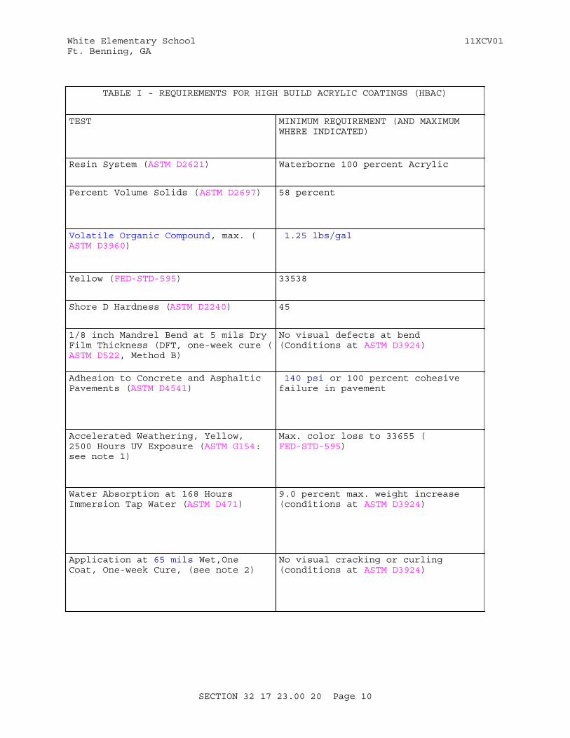
White Elementary School 11XCV01Ft. Benning, GA
TABLE I - REQUIREMENTS FOR HIGH BUILD ACRYLIC COATINGS (HBAC)
TEST MINIMUM REQUIREMENT (AND MAXIMUM WHERE INDICATED)
Resin System (ASTM D2621) Waterborne 100 percent Acrylic
Percent Volume Solids (ASTM D2697) 58 percent
Volatile Organic Compound, max. (ASTM D3960)
1.25 lbs/gal
Yellow (FED-STD-595) 33538
Shore D Hardness (ASTM D2240) 45
1/8 inch Mandrel Bend at 5 mils Dry Film Thickness (DFT, one-week cure (ASTM D522, Method B)
No visual defects at bend (Conditions at ASTM D3924)
Adhesion to Concrete and Asphaltic Pavements (ASTM D4541)
140 psi or 100 percent cohesive failure in pavement
Accelerated Weathering, Yellow, 2500 Hours UV Exposure (ASTM G154: see note 1)
Max. color loss to 33655 (FED-STD-595)
Water Absorption at 168 Hours Immersion Tap Water (ASTM D471)
9.0 percent max. weight increase (conditions at ASTM D3924)
Application at 65 mils Wet,One Coat, One-week Cure, (see note 2)
No visual cracking or curling (conditions at ASTM D3924)
SECTION 32 17 23.00 20 Page 10
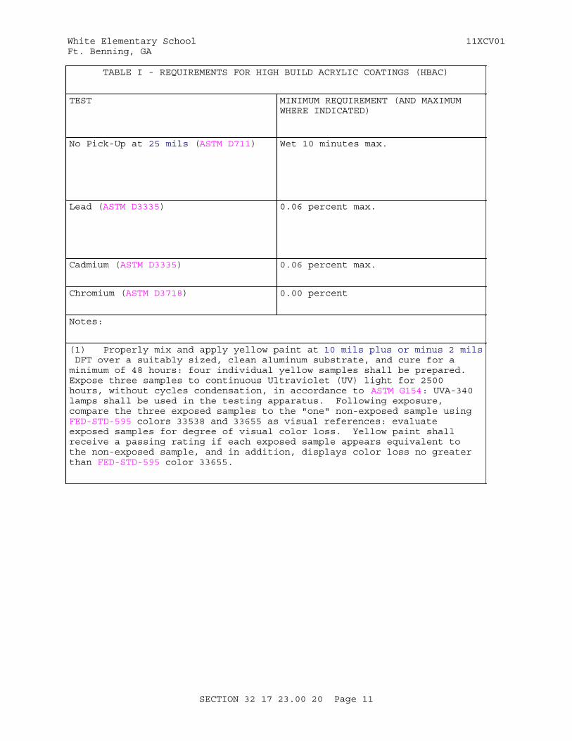
White Elementary School 11XCV01Ft. Benning, GA
TABLE I - REQUIREMENTS FOR HIGH BUILD ACRYLIC COATINGS (HBAC)
TEST MINIMUM REQUIREMENT (AND MAXIMUM WHERE INDICATED)
No Pick-Up at 25 mils (ASTM D711) Wet 10 minutes max.
Lead (ASTM D3335) 0.06 percent max.
Cadmium (ASTM D3335) 0.06 percent max.
Chromium (ASTM D3718) 0.00 percent
Notes:
(1) Properly mix and apply yellow paint at 10 mils plus or minus 2 mils DFT over a suitably sized, clean aluminum substrate, and cure for a minimum of 48 hours: four individual yellow samples shall be prepared. Expose three samples to continuous Ultraviolet (UV) light for 2500 hours, without cycles condensation, in accordance to ASTM G154: UVA-340 lamps shall be used in the testing apparatus. Following exposure, compare the three exposed samples to the "one" non-exposed sample using FED-STD-595 colors 33538 and 33655 as visual references: evaluate exposed samples for degree of visual color loss. Yellow paint shall receive a passing rating if each exposed sample appears equivalent to the non-exposed sample, and in addition, displays color loss no greater than FED-STD-595 color 33655.
SECTION 32 17 23.00 20 Page 11

White Elementary School 11XCV01Ft. Benning, GA
TABLE I - REQUIREMENTS FOR HIGH BUILD ACRYLIC COATINGS (HBAC)
TEST MINIMUM REQUIREMENT (AND MAXIMUM WHERE INDICATED)
(2) Using double-stick, foam mounting tape (or equal) with a nominal thickness of 65 mils, apply a rectangular mold with inner dimensions of 3 in by 10 in to a clean aluminum sample approximately sized at 6 in by 12 in by 1/8 in. Do not remove the tape's plastic backing. Mix and apply excess paint into mold. Remove excess paint, by squeegee or other appropriate draw down technique, to a uniform thickness equal to the tape's height. Paint application and draw down shall be performed within a period of no more than 60 seconds. Approximately one to two minutes following the draw down, remove tape from sample and allow coating to cure for a minimum period of one week ASTM D3924. Using a micrometer or other appropriate device, measure cured coating thickness (less sample thickness) to confirm resulting coating application was at or above 38 mils DFT. Inspect coating for visual signs of cracking and curling. Following a one week cure, coating shall receive a passing rating if applied greater than 38 mils DFT and visually free of both cracking and curling.
SECTION 32 17 23.00 20 Page 12
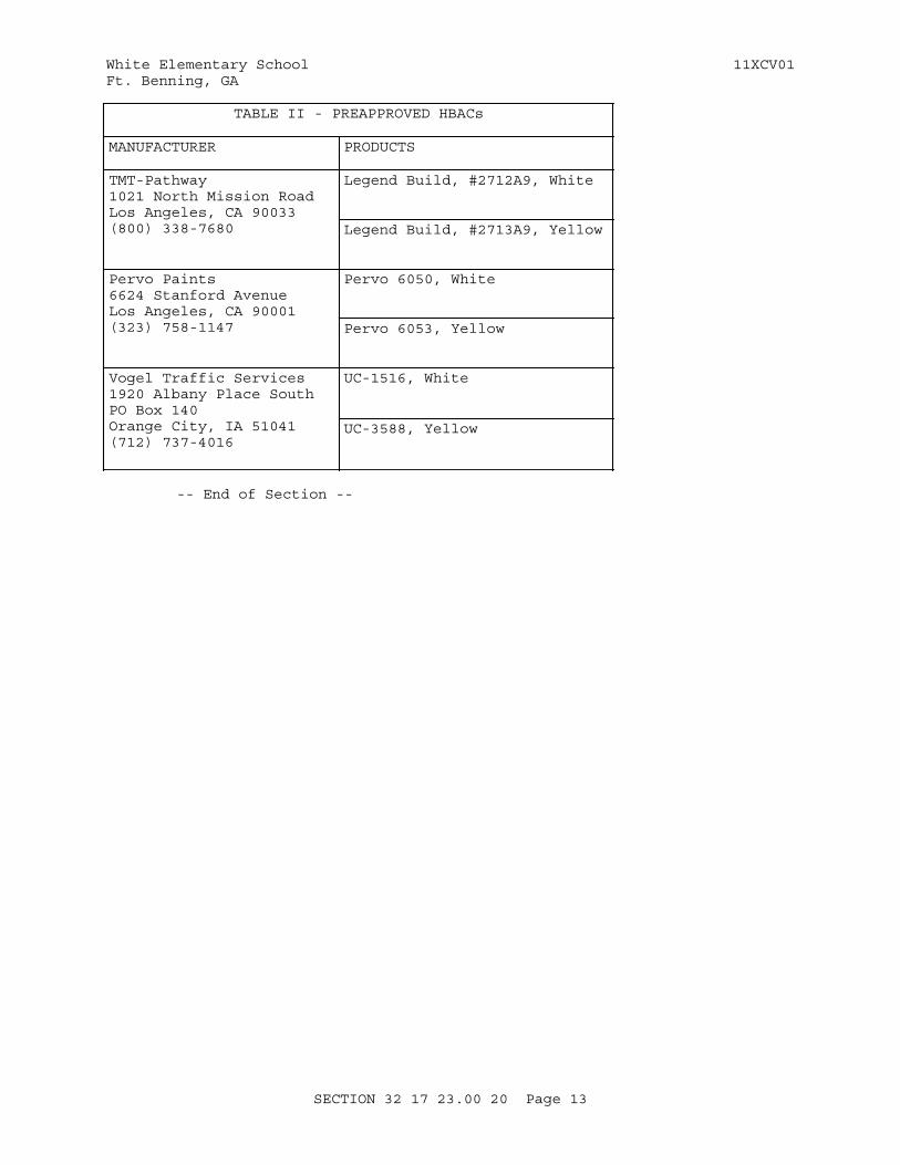
White Elementary School 11XCV01Ft. Benning, GA
TABLE II - PREAPPROVED HBACs
MANUFACTURER PRODUCTS
TMT-Pathway1021 North Mission RoadLos Angeles, CA 90033(800) 338-7680
Legend Build, #2712A9, White
Legend Build, #2713A9, Yellow
Pervo Paints6624 Stanford AvenueLos Angeles, CA 90001(323) 758-1147
Pervo 6050, White
Pervo 6053, Yellow
Vogel Traffic Services1920 Albany Place SouthPO Box 140Orange City, IA 51041(712) 737-4016
UC-1516, White
UC-3588, Yellow
-- End of Section --
SECTION 32 17 23.00 20 Page 13
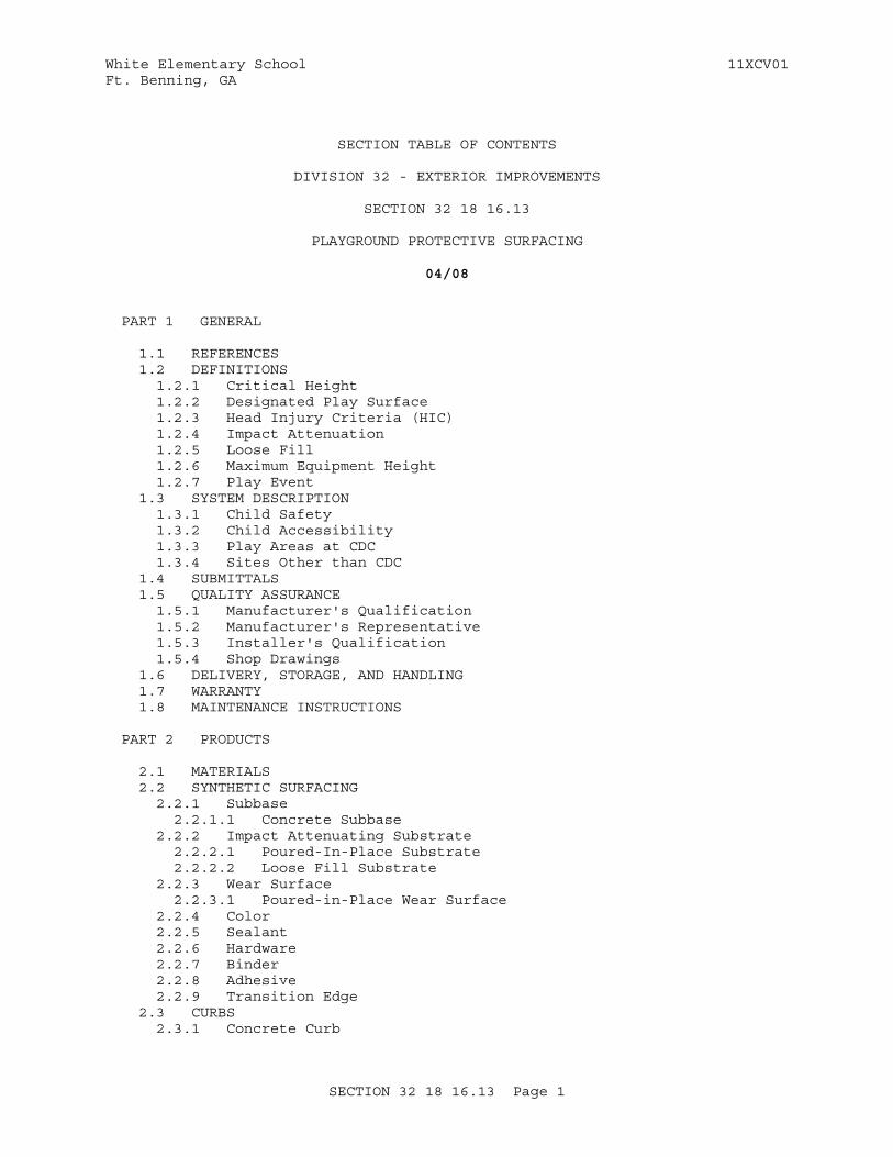
White Elementary School 11XCV01Ft. Benning, GA
SECTION TABLE OF CONTENTS
DIVISION 32 - EXTERIOR IMPROVEMENTS
SECTION 32 18 16.13
PLAYGROUND PROTECTIVE SURFACING
04/08
PART 1 GENERAL
1.1 REFERENCES 1.2 DEFINITIONS 1.2.1 Critical Height 1.2.2 Designated Play Surface 1.2.3 Head Injury Criteria (HIC) 1.2.4 Impact Attenuation 1.2.5 Loose Fill 1.2.6 Maximum Equipment Height 1.2.7 Play Event 1.3 SYSTEM DESCRIPTION 1.3.1 Child Safety 1.3.2 Child Accessibility 1.3.3 Play Areas at CDC 1.3.4 Sites Other than CDC 1.4 SUBMITTALS 1.5 QUALITY ASSURANCE 1.5.1 Manufacturer's Qualification 1.5.2 Manufacturer's Representative 1.5.3 Installer's Qualification 1.5.4 Shop Drawings 1.6 DELIVERY, STORAGE, AND HANDLING 1.7 WARRANTY 1.8 MAINTENANCE INSTRUCTIONS
PART 2 PRODUCTS
2.1 MATERIALS 2.2 SYNTHETIC SURFACING 2.2.1 Subbase 2.2.1.1 Concrete Subbase 2.2.2 Impact Attenuating Substrate 2.2.2.1 Poured-In-Place Substrate 2.2.2.2 Loose Fill Substrate 2.2.3 Wear Surface 2.2.3.1 Poured-in-Place Wear Surface 2.2.4 Color 2.2.5 Sealant 2.2.6 Hardware 2.2.7 Binder 2.2.8 Adhesive 2.2.9 Transition Edge 2.3 CURBS 2.3.1 Concrete Curb
SECTION 32 18 16.13 Page 1
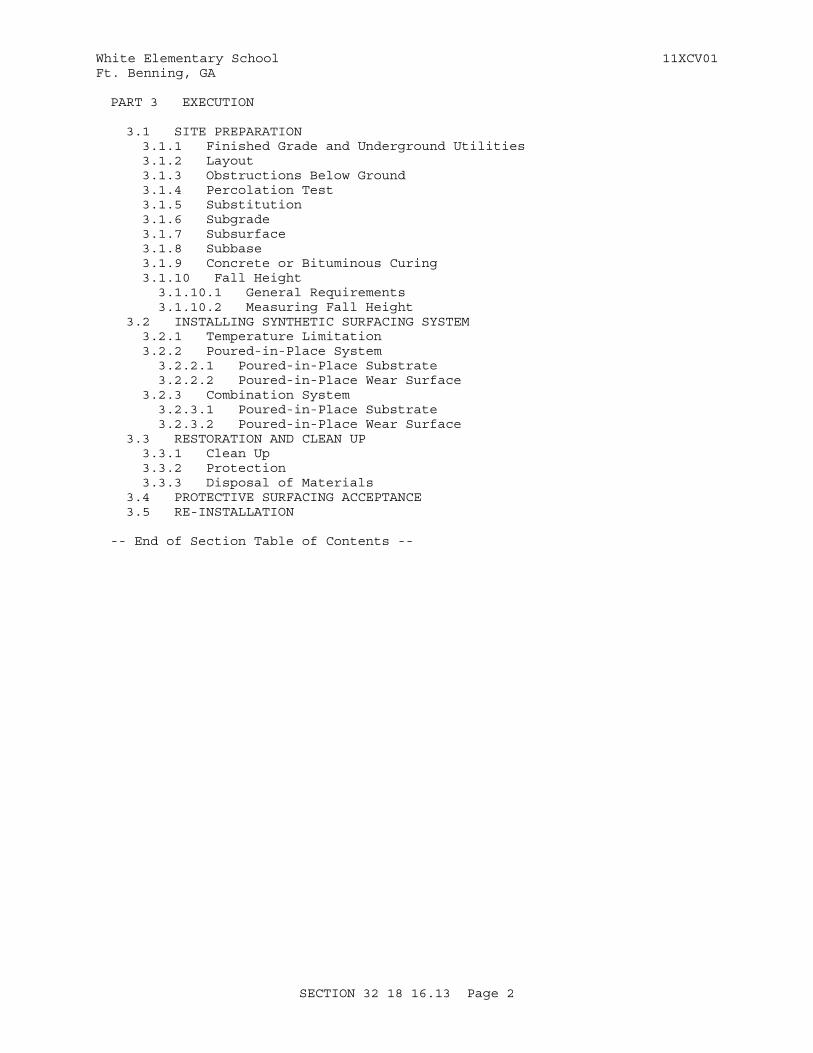
White Elementary School 11XCV01Ft. Benning, GA
PART 3 EXECUTION
3.1 SITE PREPARATION 3.1.1 Finished Grade and Underground Utilities 3.1.2 Layout 3.1.3 Obstructions Below Ground 3.1.4 Percolation Test 3.1.5 Substitution 3.1.6 Subgrade 3.1.7 Subsurface 3.1.8 Subbase 3.1.9 Concrete or Bituminous Curing 3.1.10 Fall Height 3.1.10.1 General Requirements 3.1.10.2 Measuring Fall Height 3.2 INSTALLING SYNTHETIC SURFACING SYSTEM 3.2.1 Temperature Limitation 3.2.2 Poured-in-Place System 3.2.2.1 Poured-in-Place Substrate 3.2.2.2 Poured-in-Place Wear Surface 3.2.3 Combination System 3.2.3.1 Poured-in-Place Substrate 3.2.3.2 Poured-in-Place Wear Surface 3.3 RESTORATION AND CLEAN UP 3.3.1 Clean Up 3.3.2 Protection 3.3.3 Disposal of Materials 3.4 PROTECTIVE SURFACING ACCEPTANCE 3.5 RE-INSTALLATION
-- End of Section Table of Contents --
SECTION 32 18 16.13 Page 2
White Elementary School 11XCV01Ft. Benning, GA
SECTION 32 18 16.13
PLAYGROUND PROTECTIVE SURFACING04/08
PART 1 GENERAL
1.1 REFERENCES
The publications listed below form a part of this specification to the extent referenced. The publications are referred to within the text by the basic designation only.
ASTM INTERNATIONAL (ASTM)
ASTM D1557 (2009) Standard Test Methods for Laboratory Compaction Characteristics of Soil Using Modified Effort (56,000 ft-lbf/ft3) (2700 kN-m/m3)
ASTM D2047 (2011) Static Coefficient of Friction of Polish-Coated Floor Surfaces as Measured by the James Machine
ASTM D412 (2006ae2) Standard Test Methods for Vulcanized Rubber and Thermoplastic Elastomers - Tension
ASTM E1912 (1998; R 2004) Accelerated Site Characterization for Confirmed or Suspected Petroleum Releases
ASTM F1292 (2009) Impact Attenuation of Surface Systems Under and Around Playground Equipment
ASTM F1487 (2011) Playground Equipment for Public Use
CONSUMER PRODUCT SAFETY COMMISSION (CPSC)
CPSC Pub No 325 (1997) Handbook for Public Playground Safety
1.2 DEFINITIONS
1.2.1 Critical Height
The fall height at which the protective surfacing meets the requirements of ASTM F1292.
1.2.2 Designated Play Surface
Any elevated surface for standing, walking, sitting, or climbing; or a flat surface a minimum 2 inches wide having up to a maximum 30 degree angle from horizontal. In some play events the platform surface will be the same as the designated play surface. However, the terms should not be interchanged
SECTION 32 18 16.13 Page 3
White Elementary School 11XCV01Ft. Benning, GA
as they do not define the same point of measurement according to ASTM F1487.
1.2.3 Head Injury Criteria (HIC)
A measure of impact severity that considers the duration over which the most critical section of the deceleration pulse persists as well as the peak level of that deceleration. Head impact injuries are not believed to be life threatening if the HIC does not exceed a value of 1,000.
1.2.4 Impact Attenuation
The ability of protective surfacing to reduce and dissipate the energy of an impacting body.
1.2.5 Loose Fill
Consisting of small independent movable components such as sand, gravel, or wood chip. The percent of fine material in the loose fill affects its compression properties from rainfall.
1.2.6 Maximum Equipment Height
The highest point on the equipment (i.e.: roof ridge, top of support pole).
1.2.7 Play Event
A piece of manufactured playground equipment that supports one or more play activities.
1.3 SYSTEM DESCRIPTION
Measure the perimeters of the play event use zone in accordance with the requirements of Section 11 68 13 PLAYGROUND EQUIPMENT.
1.3.1 Child Safety
Meet or exceed the impact attenuating performance requirements of synthetic surfacing and loose-fill surfacing systems, installed in the use zones, as follows. The surfacing critical height value shall yield up to both a maximum 200 G's peak deceleration, and a maximum 1,000 Head Injury Criteria (HIC) value for a head-first fall from the play event in accordance with CPSC Pub No 325 and ASTM F1292. The protective surfacing should have a minimum critical height value equal to the height of the highest designated play surface. Measuring fall heights for play events is defined in paragraph FALL HEIGHT. Sand, gravel, and wood products shall not be installed over a concrete or bituminous subsurface in accordance with CPSC Pub No 325.
1.3.2 Child Accessibility
The accessibility requirement in accordance with ASTM F1487 includes the following: When the play event use zone consists of a protective surfacing rated as inaccessible, at least one accessible route shall be provided from the use zone perimeter to the play event. When there is more than one of the same play activity provided, only one shall meet accessibility requirements (i.e.: one swing seat or one spring rocking play event). When the access and egress points are not the same for a play event, an accessible route shall be provided to both. The accessible route shall access all accessible play events and elements. The protective surfacings
SECTION 32 18 16.13 Page 4
White Elementary School 11XCV01Ft. Benning, GA
that meet accessibility are synthetic surfacing and engineered wood fiber in accordance with ASTM E1912. When the accessible surface is within the use zone, it shall meet the requirements of paragraph CHILD SAFETY
1.3.3 Play Areas at CDC
The technical representative for outdoor play areas at CDC shall be the installation Child Development Services (CDS) Coordinator. The design of the CDC outdoor play area shall be based on the developmental play program for the age groups accommodated at the CDC. The play area is designed to support the CDC program and to provide a stage set for creative play. Developmental activities are selected which promote the intellectual, social, emotional and physical growth of the children. The developmental play program is developed by the MACOM CDS Director, installation CDS Coordinator and CDC Director. They are responsible for the developmental play program, child safety and accessibility to meet that program.
1.3.4 Sites Other than CDC
The technical representative for outdoor play areas on sites other than CDCs shall be the Director of Public Works or designated representative. The design of these outdoor play areas shall be based on the play program and the age groups to be accommodated as determined by the play area committee.
1.4 SUBMITTALS
Government approval is required for submittals with a "G" designation; submittals not having a "G" designation are for information only. When used, a designation following the "G" designation identifies the office that will review the submittal for the Government. Submit the following in accordance with Section 01 33 00 SUBMITTAL PROCEDURES:
SD-02 Shop Drawings
Shop Drawings.Finished Grade and Underground Utilities
SD-03 Product Data
Synthetic SurfacingManufacturer's QualificationSite PreparationTemperature LimitationAdhesiveColor
SD-04 Samples
Synthetic Surfacing
SD-06 Test Reports
Percolation TestSynthetic Surfacing
SD-07 Certificates
Materials
SECTION 32 18 16.13 Page 5
White Elementary School 11XCV01Ft. Benning, GA
Manufacturer's QualificationManufacturer's RepresentativeInstaller's QualificationSubstitutionProtective Surfacing Acceptance
SD-10 Operation and Maintenance Data
Maintenance Instructions
1.5 QUALITY ASSURANCE
1.5.1 Manufacturer's Qualification
Submit name of the owner or user; service or preventive maintenance provider; date of the installation; point of contact and telephone number; and address for 10 sites. Protective surfacing should have been installed in a minimum 10 sites and been in successful service for a minimum 5 year calendar period. The manufacturer shall provide a Certificate of Insurance AA rated for a minimum one million dollars covering both product and general liability.
1.5.2 Manufacturer's Representative
Submit the individual's name, company name and address, and playground safety training certificate. The manufacturer's certified playground safety inspector or the manufacturer's designated certified playground safety representative shall supervise the installation and adjustment of the protective surfacing to verify the installation meets the requirements of the manufacturer, this specification, and paragraphs CHILD SAFETY and CHILD ACCESSIBILITY.
1.5.3 Installer's Qualification
Submit the installer's company name and address, training and experience certification. The installer shall be certified by the manufacturer for training and experience installing the protective surfacing.
1.5.4 Shop Drawings
When the use zone perimeter and play event configuration conflict with the requirements and paragraphs CHILD SAFETY and CHILD ACCESSIBILITY, submit scale drawings defining corrective measures to include the following: Adjustment to the play event with the use zone perimeter; use zone perimeter overlaps; fall height and critical height value.
1.6 DELIVERY, STORAGE, AND HANDLING
Provide a delivery schedule at least 10 calendar days prior to the first day of delivery. Deliver, handle, and store protective surfacing material in accordance with the manufacturer's recommendations. The storage area shall be as designated. Store the materials in a dry, covered area until installed. Inspect protective surfacing material, upon arrival at the job site, for meeting specified quality. Unacceptable materials shall be removed from the job site.
1.7 WARRANTY
Furnish protective surfacing with a minimum 1 year calendar period warranty.
SECTION 32 18 16.13 Page 6
White Elementary School 11XCV01Ft. Benning, GA
1.8 MAINTENANCE INSTRUCTIONS
Submit 2 bound copies of the manufacturer's operation and maintenance manual describing the recommended preventive maintenance, inspection frequency and techniques, periodic adjustments, lubricants, and cleaning requirements. Furnish protective surfacing spare parts provided by the manufacturer.
PART 2 PRODUCTS
2.1 MATERIALS
Prior to the delivery of materials, submit certificates of compliance attesting that materials meet the specified requirements. Certified copies of the material certificates shall include composition and tests to which the material has been subjected. Submit manufacturer's descriptive data; catalogue cuts; and the latest edition of ASTM F1487 and CPSC Pub No 325. Provide materials which are the standard products of a manufacturer regularly engaged in the manufacture of protective surfacing and that are similar to surfacing in satisfactory use a minimum 5 year calendar period. Protective surfacing consists of two systems; synthetic surfacing and loose fill surfacing.
2.2 SYNTHETIC SURFACING
Submit a minimum 2 by 2 inch sample. Submit impact attenuation and critical height performance for each thickness of synthetic surfacing and loose fill surfacing provided. Submit delivery schedule and manufacturer's name for synthetic surfacing and loose fill surfacing plus delivery, storage and handling information. Furnish a list to include part numbers of furnished protective surfacing materials and components for synthetic surfacing and loose fill surfacing and manufacturer's specifications, handling and storage requirements, installation procedures, and safety data sheets to include warnings and critical height performance standards for synthetic surfacing and loose fill surfacing. Synthetic surfacing includes the following: poured-in-place system; tile system; and combination system. The synthetic surfacing consists of either impact attenuating substrate covered by a wear surface bonded to produce a unified system; a shredded rubber or aggregate substrate covered by a polyethylene plastic woven sheet wear surface; or a uniform material manufactured in such a way that the top portion meets the requirements specified for wear surface. Submit chemical composition, color granule percentage, and test results to which material has been subjected, identifying each material and component containing recycled materials and showing the estimated percentage of recovered material content. Furnish freezing temperature life-cycle durability.
2.2.1 Subbase
The subbase for synthetic surfacing shall be concrete.
2.2.1.1 Concrete Subbase
Provide concrete material.
2.2.2 Impact Attenuating Substrate
Provide a substrate compatible with the wear surface, and consisting of
SECTION 32 18 16.13 Page 7
White Elementary School 11XCV01Ft. Benning, GA
modular units; poured-in-place; or loose fill. Recycled materials shall conform to EPA requirements in accordance with Section 01 62 35.10 RECYCLED / RECOVERED MATERIALS.
2.2.2.1 Poured-In-Place Substrate
Poured-in-place substrate shall consist of a 100 percent recycled, shredded, styrene butadiene rubber (SBR) adhered with a 100 percent solid polyurethane binder to form a resilient, porous material or shredded rubber. Strands of SBR may vary from a minimum 1/50 inch to a maximum 2/25 inch thickness; by a minimum 1/8 inch to a maximum 4/5 inch length. Binder shall be between a minimum 12 percent and a maximum 16 percent of the total weight of the mixture of rubber and urethane; and shall provide 100 percent coating of the particles. Foam rubber will not be accepted in the substrate.
2.2.2.2 Loose Fill Substrate
The loose fill substrate shall consist of 100 percent recycled shredded rubber produced from recycled vehicle tires without non-steel belts. Loose-fill strands may vary from a minimum 1/8 inch to a maximum 1/4 inch thickness; a minimum 1/8 inch to a maximum 1/2 inch width; and a minimum 1/2 inch to a maximum 2 inch length.
2.2.3 Wear Surface
Wear surfaces consist of the following: a poured-in-place durable, weather-resistant, ultraviolet stable, water permeable material top-coat; an integral component of a tile system; synthetic turf wear surface; rubber sheet wear surface; or a polyethylene woven plastic sheet wear surface. The wear surface shall meet requirements of ASTM D2047 for a minimum 0.8 coefficient of friction.
2.2.3.1 Poured-in-Place Wear Surface
Poured-in-place wear surface consists of ethylene propylene diene monomer (EPDM) particles adhered with a polyurethane binder formulated to produce an even, uniform surface. Particles of EPDM shall meet ASTM D412 for tensile strength and elongation, and contain a minimum 25 percent of rubber hydrocarbons. Particles of EPDM shall be peroxide or sulfur cured in accordance with the manufacturer. Size of rubber particles shall be between a minimum 1/32 inch, and a maximum 1/8 inch diameter. Binder shall be between a minimum 16 percent and a maximum 21 percent total weight of rubber used in the wear surface, and shall provide 100 percent coating of the particles. Wear surface shall be a minimum 3/8 inch thick. The wear surface shall be porous.
2.2.4 Color
Submit 2 color charts displaying surfacing colors, color granule percentages and finishes. The color shall be selected by the Contracting Officer's Representative from the manufacturer's standard color palette. An EPDM wear surface is preferred for color retention. Black or the following dark colored SBR wear surfaces retain heat and are not acceptable: color combinations containing more than 10 percent black; or color combinations averaging more than 10 percent dark colors.
SECTION 32 18 16.13 Page 8
White Elementary School 11XCV01Ft. Benning, GA
2.2.5 Sealant
Sealant for tile or combined protective surface systems shall be compatible with the protective surfacing, and shall match the color of the wear surface.
2.2.6 Hardware
Hardware, anchors or fasteners shall be corrosion resistant stainless steel or galvanized steel to anchor the surfacing system securely, in accordance with manufacturer's instructions. Hardware shall provide or be recessed to provide a flat surface and shall be covered by the required depth of protective surfacing.
2.2.7 Binder
Binder for synthetic surfacing shall be nontoxic, weather-resistant, ultraviolet stable, non-hardening, and retaining impact-attenuating performance. It shall be 100 percent solids containing polyurethane, methylene diphenel isocyanate (MDI), or as recommended by the manufacturer. A maximum 2 percent of toluene diphenel isocyanate (TDI) shall be used. Weight of polyurethane shall be between a minimum 8.5 lbs/gal and a maximum 9.5 lbs/gal. Coloring pigments shall be inorganic oxides.
2.2.8 Adhesive
Adhesive shall be a two component polyurethane providing extremely high impact resistant bond and shall be installed as recommended by the manufacturer. The adhesive shall be non-toxic, resistant to ultraviolet light, and safe for children. Adhesive shall conform to EPA registered uses, toxicity levels, and application hazards.
2.2.9 Transition Edge
The transition edge shall be designed to maintain the protective surfacing performance, support the surfacing between changes of material, and shall be concrete in accordance with paragraph CONCRETE CURB. The face of the edge to the subgrade shall be covered with the impact attenuating surface and meet the requirements of paragraph CHILD SAFETY.
2.3 CURBS
2.3.1 Concrete Curb
Concrete curbs shall conform to Section 32 16 13 CONCRETE SIDEWALKS AND CURBS AND GUTTERS.
PART 3 EXECUTION
3.1 SITE PREPARATION
Prior to installing the protective surfacing, verify the playground equipment and site furnishings are installed in accordance with Section 11 68 13 PLAYGROUND EQUIPMENT, and Section 12 93 00 SITE FURNISHINGS.
3.1.1 Finished Grade and Underground Utilities
Submit finished grade, underground utilities, storm-drainage system and
SECTION 32 18 16.13 Page 9
White Elementary School 11XCV01Ft. Benning, GA
irrigation system status; and location of underground utilities and facilities. Verify that finished grades are as indicated; the smooth grading has been completed in accordance with Section 31 00 00 EARTHWORK; installation of the underground utilities through the area has been completed in accordance with Section 31 00 00 EARTHWORK; installation of the storm-drainage system through the area has been completed in accordance with Section 33 40 00 STORM DRAINAGE. The location of underground utilities and facilities in the area of the operation shall be verified. Damage to underground utilities and facilities shall be repaired at the Contractor's expense.
3.1.2 Layout
The layout of the entire use zone perimeter shall be staked before excavation begins. The location of all elements shall be staked to include the following: All play event configuration access and egress points; and use zone perimeters. The use zone is defined as the area beneath and immediately adjacent to a play structure or equipment that is designated for unrestricted circulation around equipment; and on whose surface it is predicted that a user would land when falling from or exiting the equipment. Also, the use zone is associated with the following terms; "Clear Area," and "Fall Zone". The use zone shall be free of hard surfaces, objects or obstacles that a child could run into or fall on top of and be injured. Use zone perimeters shall not overlap hard surfaces. The use zone perimeter shall meet or exceed the requirements of paragraphs CHILD SAFETY and CHILD ACCESSIBILITY. Use zone perimeters shall not overlap except for certain play events as defined in ASTM F1487.
3.1.3 Obstructions Below Ground
When obstructions below ground affect the work, shop drawings showing proposed adjustments shall be provided.
3.1.4 Percolation Test
Submit a certified report of inspection, test method used and compliance with recognized test standard shall be described. A test for percolation shall be done to determine positive drainage, to include the lowest elevation of the subgrade in the areas containing the following: sand; gravel; wood by-products; or synthetic surfacing installed over a pervious base. A positive percolation shall consist of a minimum 1 inch per 3 hour period. When a negative percolation test occurs, a shop drawing shall be provided to indicate the corrective measures.
3.1.5 Substitution
Under no circumstances are substitutions to be allowed or protective surfacing to be selected without written approval from the technical representative. Evaluate manufacturer substitutions for the critical height value with meeting the site conditions and paragraph FALL HEIGHT.
3.1.6 Subgrade
Correct subgrade irregularities to ensure the required depth of protective surfacing is provided. The subgrade elevation shall be as required by the manufacturer.
SECTION 32 18 16.13 Page 10
White Elementary School 11XCV01Ft. Benning, GA
3.1.7 Subsurface
Install the subsurface in a true, even plane, and sloped to provide positive drainage as indicated.
3.1.8 Subbase
Tolerance of the concrete or bituminous subbase shall be within a maximum 1/4 inch in 10 feet. Tolerance of aggregate subbase shall be within a maximum similar to 1/4 inch in 10 feet. Compact aggregate subbase to a maximum 95 percent, ASTM D1557. The compaction shall be completed in accordance with Section 31 00 00 EARTHWORK. Sand, gravel, and wood products shall not be installed over a concrete, aggregate, or bituminous subbase, in accordance with paragraph CHILD SAFETY.
3.1.9 Concrete or Bituminous Curing
Bituminous or concrete subbase shall be cured in accordance with the manufacturer's requirements. Curing compounds and other deleterious substances that adversely affect adhesion shall be removed. Surface shall be clean and dry.
3.1.10 Fall Height
3.1.10.1 General Requirements
The fall height is defined as the vertical distance between the finished elevation of the designated play surface and the finished elevation of the protective surfacing beneath it. For some play events the fall height and platform height are the same, while for other play events the fall height and maximum equipment height are the same, Section 11 68 13 PLAYGROUND EQUIPMENT. When the furnished play event fall height varies from the play event shown, shop drawings shall be provided defining the revised depth or type of protective surfacing to meet or exceed the requirements of paragraphs CHILD SAFETY and CHILD ACCESSIBILITY.
3.1.10.2 Measuring Fall Height
EQUIPMENT MEASURING FALL HEIGHT
Composite Equipment Structure: For a platform surrounded by protective barriers, measure from the platform finished elevation.
For a platform surrounded by guardrails, measure from the guardrail top elevation.
Infant Crawl Area: A maximum 24 inch height, measured from the crawl wall or barrier finished elevation.
Playhouse, Nonclimbable: Measure from the designated play surface finished elevation.
Spring Rocking Equipment: Measure from the seat top elevation.
SECTION 32 18 16.13 Page 11
White Elementary School 11XCV01Ft. Benning, GA
EQUIPMENT MEASURING FALL HEIGHT Stationary Equipment, Climbable: Measure from the maximum equipment height finished elevation.
Stationary Equipment, Nonclimbable: Measure from the designated play surface finished elevation.
Swing: Measure from the bottom of the pivot point.
3.2 INSTALLING SYNTHETIC SURFACING SYSTEM
Surfacing edges shall fully adhere to the subsurface. Fully cover the subsurface to ensure no hard surfaces are exposed through displacement of loose fill. Rolled or beveled containment curb or transition edges shall maintain the full thickness required to meet paragraphs CHILD SAFETY and CHILD ACCESSIBILITY. Material shall cover foundation and cutouts around elements penetrating the surface. Seams shall be the minimum necessary and shall be tight.
3.2.1 Temperature Limitation
Provide temperature limitations for applying adhesive.
3.2.2 Poured-in-Place System
Components of the poured-in-place system shall be mixed mechanically on site in accordance with manufacturer's recommendations. Hand-mixing is prohibited. Installation of poured-in-place surfacing shall be seamless and completely bonded to subsurface. Material shall cover foundations and shall be tight around elements penetrating the surface. Add a minimum 1/16 inch depth to the required surfacing depth to ensure the full depth of material is installed to meet paragraph CHILD SAFETY.
3.2.2.1 Poured-in-Place Substrate
The substrate layer of the poured-in-place system shall be installed in one continuous pour on the same day. When a second pour is required, the edge of the previous work shall be fully coated with polyurethane binder to ensure 100 percent bond with new work. Adhesive shall be applied in small quantities so that new substrate can be placed before the adhesive dries.
3.2.2.2 Poured-in-Place Wear Surface
Wear surface shall be bonded to substrate. Adhesive shall be applied to substrate in small quantities so that wear surface can be applied before adhesive dries. Surface shall be hand troweled to a smooth, even finish. When wear surface is composed of different color patterns, pour shall be continuous and seamless. When seams are required due to color change or field conditions, the adjacent wear surface shall be placed as soon as possible, before initial pour has cured. The edge of initial pour shall be coated with adhesive and wear surface mixture shall be immediately applied.
SECTION 32 18 16.13 Page 12
White Elementary School 11XCV01Ft. Benning, GA
3.2.3 Combination System
3.2.3.1 Poured-in-Place Substrate
Same as paragraph POURED-IN-PLACE SYSTEM.
3.2.3.2 Poured-in-Place Wear Surface
Same as paragraph POURED-IN-PLACE SYSTEM.
3.3 RESTORATION AND CLEAN UP
When the operation has been completed, clean up and protect the site. Existing areas that have been damaged from the operation shall be restored to original condition at the Contractor's expense.
3.3.1 Clean Up
The site and play events shall be cleaned of all materials associated with the operation. Play events and surfaces shall be cleaned of dirt, stains, filings, and other blemishes occurring from shipment and installation. Cleaning methods and agents shall be as recommended by the manufacturer.
3.3.2 Protection
The area shall be protected as required or directed by providing barricades and signage. Signage shall be in accordance with Section 10 14 00.20 INTERIOR SIGNAGE
3.3.3 Disposal of Materials
Excess and waste material shall be removed and disposed of off Government property.
3.4 PROTECTIVE SURFACING ACCEPTANCE
Submit record of measurements and findings by the certified playground safety inspector. When the protective surfacing is installed, the play events and protective surfacing shall be thoroughly inspected and measured to verify the playground meets manufacturer's recommendations, paragraphs CHILD SAFETY and CHILD ACCESSIBILITY, and paragraph FALL HEIGHT as follows: 1) secure anchoring; 2) all hardware and connectors are tight and below the wear surface; 3) sharp points, edges, and protrusions; 4) entanglement; and 5) pinch, crush, and shear points.
a. Measure use zone distances to determine the area is free of hard surfaces, objects or obstacles. Determine exceptions to use zone overlaps occur in accordance with ASTM F1487. Measure play event fall height and compare to critical height value for the thickness of installed synthetic surfacing. Measure play event fall height and depth of loose fill protective surfacing.
b. Ensure installed chopped tire material is free from steel belts. Ensure the slide exit region has the required clear zone. Swing seat clearances are measured while occupied by a maximum user for the age group using the equipment.
c. The finished installation shall have the appearance of a single covering. Protective surfacing that does not comply shall be
SECTION 32 18 16.13 Page 13
White Elementary School 11XCV01Ft. Benning, GA
reinstalled. Hardware that does not comply shall be replaced. Ensure positive drainage for the area and the lowest elevation of protective surfacing subgrade has been provided.
d. A written report describing the results of the evaluation shall be provided.
3.5 RE-INSTALLATION
When re-installation is required, the following shall be accomplished. Re-install the product as specified. Provide new replacement materials supplied by the manufacturer (material acquisition of replacement parts is the responsibility of the Contractor). Damage caused by the failed installation shall be repaired at the Contractor's expense.
-- End of Section --
SECTION 32 18 16.13 Page 14
White Elementary School 11XCV01Ft. Benning, GA
SECTION TABLE OF CONTENTS
DIVISION 32 - EXTERIOR IMPROVEMENTS
SECTION 32 18 17
POURED-IN-PLACE RUBBER SURFACING
03/13
PART 1 GENERAL
1.1 SYSTEM DESCRIPTION 1.2 REFERENCES 1.3 SUBMITTALS 1.4 QUALITY ASSURANCE 1.4.1 Test Results 1.4.2 Contractor Pre-Qualifications 1.5 DELIVERY, STORAGE, AND HANDLING 1.6 PROJECT/SITE CONDITIONS 1.7 WARRANTY
PART 2 PRODUCTS
2.1 MATERIALS 2.1.1 Polyurethane Binder 2.1.2 EPDM (Wear Surface)
PART 3 EXECUTION
3.1 EXAMINATION 3.2 PREPARATION 3.3 INSTALLATION 3.4 ADJUSTING AND CLEANING 3.5 PROTECTION
-- End of Section Table of Contents --
SECTION 32 18 17 Page 1
White Elementary School 11XCV01Ft. Benning, GA
SECTION 32 18 17
POURED-IN-PLACE RUBBER SURFACING03/13
PART 1 GENERAL
1.1 SYSTEM DESCRIPTION
This work includes furnishing and installing the Rubber Surfacing for multi-purpose applications. The surfacing manufacturer/installer shall be responsible for all labour, materials, tools, equipment to perform all work and services for the installation of the surface.
The rubber Surfacing shall be poured-in-place and trowelled to provide for a resilient, seamless rubber surface installed over the specified rigid base and composed of premium quality EPDM rubber mixed with a non-flammable, non-shrinking, one part moisture cured polyurethane adhesive as recommended by the manufacturer and capable of bonding to concrete.
The rubber Surfacing shall be stable and slip resistant to comply with, meet or exceed all requirements set forth in the Americans with Disabilities Act (ADA) and the American Standard Testing Methods (ASTM and Consumer Products Safety Commission (CPSC) for manufactured Safety Surface as detailed below.
1.2 REFERENCES
The publications listed below form a part of this specification to the extent referenced. The publications are referred to within the text by the basic designation only.
ASTM INTERNATIONAL (ASTM)
ASTM D 412 (2006ae2) Standard Test Methods for Vulcanized Rubber and Thermoplastic Elastomers - Tension
ASTM D 2047 (2004) Static Coefficient of Friction of Polish-Coated Floor Surfaces as Measured by the James Machine
ASTM D 2240 (2005; R 2010) Standard Test Method for Rubber Property - Durometer Hardness
ASTM D 2859 (2006) Ignition Characteristics of Finished Textile Floor Covering Materials
ASTM E 303 (2013) Standard Test Method for Measuring Surface Frictional Properties Using the British Pendulum Tester
1.3 SUBMITTALS
Government approval is required for submittals with a "G" designation; submittals not having a "G" designation are for information only. When used, a designation following the "G" designation identifies the office
SECTION 32 18 17 Page 2
White Elementary School 11XCV01Ft. Benning, GA
that will review the submittal for the Government. Submit the following in accordance with Section 01 33 00 SUBMITTAL PROCEDURES:
SD-01 Preconstruction Submittals
One original hard copy of the submittal package will be supplied with additional copies on individual CD's.
SD-02 Shop Drawings
Manufacturer's details showing depths of wear surface and sub-base materials, anchoring systems and edge details.
SD-03 Product Data
Manufacturer's descriptive data and installation instructions. A list of all materials and components to be installed, including manufacturer's name, storage requirements, and precautions, and shall state chemical composition and test results to which material has been subjected, in compliance with these specifications.
SD-04 Samples
A sample specimen of safety surface proposed for this project.
SD-06 Test Reports
Test results to substantiate that the product meets or exceeds all ASTM & ADA requirements. Test must be performed and certified by an independent laboratory.
SD-08 Manufacturer's Instructions
SD-10 Operation and Maintenance Data
1.4 QUALITY ASSURANCE
All materials under this section shall be installed by the Manufacturer or its Certified Installers. The surfacing installation shall not be performed by anyone other than the product Manufacturer or its Certified Installers.
1.4.1 Test Results
Coefficient of Friction - ASTM D 2047: All products must meet minimum standard on coefficient of friction of 0.7-wet, 0.9-dry. No exceptions will be made to this requirement in an effort to ensure ample slip-resistant conditions.
Surface Frictional Properties & Skid Resistance - ASTM E 303: All products shall meet or exceed 90 BPN when tested Dry and 64 BPN when tested Wet.
Permeability: Product shall meet or exceed a coefficient of permeability of seven (7) feet per minute. NOTE: From a geotechnical standpoint, the permeability of a material is a measure of the velocity at which water will flow through the void spaces or pores under a given hydraulic gradient. The product shall handle a minimum of 8" of rainfall per hour.
SECTION 32 18 17 Page 3
White Elementary School 11XCV01Ft. Benning, GA
Flammability of Finished Floor Cover - ASTM D 2859: Product shall pass flammability.
Statement signed by the Manufacturer of the synthetic safety surfacing attesting that all materials under this section shall be installed by the Manufacturer or its Certified Installers.
A listing of at least twenty five (25) installations where products similar to those proposed for use have been installed and have been in successful service for a minimum period of three (3) years. This list shall include owner or purchaser, address of installation, date of installation, contact person, and phone number.
A list of all organizations and affiliations of the company offering the product(s).
1.4.2 Contractor Pre-Qualifications
A list of twenty five (25) surfacing projects completed with a similar product. List shall include names of project representatives and respective telephone numbers. At least five (5) of these projects must be at least five (5) years old. This list shall also contain projects which require the same level of difficulty, size of project, type of project, e.g. color transitions and special graphics.
1.5 DELIVERY, STORAGE, AND HANDLING
Materials and equipment shall be delivered and/or stored in accordance with the Manufacturer's recommendations.
1.6 PROJECT/SITE CONDITIONS
Synthetic safety surfacing shall be installed on a dry subsurface, with no prospect of rain within the initial drying period, at temperatures recommended by the manufacturer.
Installation in weather condition of extreme heat, temperatures less than 40 degrees (F), and/or high humidity may impact cure time, and/or the structural integrity of the final product. Immediate surroundings of the site shall be reasonably free of dust conditions and poor particulate air quality will impact the final surface look.
Surface installation shall be coordinated by the project manager or designated individual of water play equipment and sub-base installation, with the manufacturer's local production manager and in accordance with manufacturer's sub-base requirements.
1.7 WARRANTY
Surfacing shall maintain required characteristics and be guaranteed against defects in workmanship and material for a period of no less than five (5) years or as specified and agreed upon per contract.
SECTION 32 18 17 Page 4
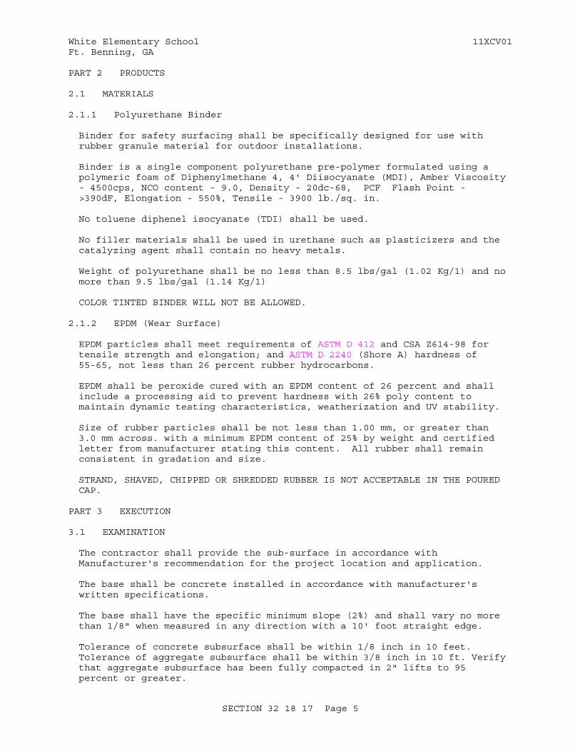
White Elementary School 11XCV01Ft. Benning, GA
PART 2 PRODUCTS
2.1 MATERIALS
2.1.1 Polyurethane Binder
Binder for safety surfacing shall be specifically designed for use with rubber granule material for outdoor installations.
Binder is a single component polyurethane pre-polymer formulated using a polymeric foam of Diphenylmethane 4, 4' Diisocyanate (MDI), Amber Viscosity - 4500cps, NCO content - 9.0, Density - 20dc-68, PCF Flash Point - >390dF, Elongation - 550%, Tensile - 3900 lb./sq. in.
No toluene diphenel isocyanate (TDI) shall be used.
No filler materials shall be used in urethane such as plasticizers and the catalyzing agent shall contain no heavy metals.
Weight of polyurethane shall be no less than 8.5 lbs/gal (1.02 Kg/1) and no more than 9.5 lbs/gal (1.14 Kg/1)
COLOR TINTED BINDER WILL NOT BE ALLOWED.
2.1.2 EPDM (Wear Surface)
EPDM particles shall meet requirements of ASTM D 412 and CSA Z614-98 for tensile strength and elongation; and ASTM D 2240 (Shore A) hardness of 55-65, not less than 26 percent rubber hydrocarbons.
EPDM shall be peroxide cured with an EPDM content of 26 percent and shall include a processing aid to prevent hardness with 26% poly content to maintain dynamic testing characteristics, weatherization and UV stability.
Size of rubber particles shall be not less than 1.00 mm, or greater than 3.0 mm across. with a minimum EPDM content of 25% by weight and certified letter from manufacturer stating this content. All rubber shall remain consistent in gradation and size.
STRAND, SHAVED, CHIPPED OR SHREDDED RUBBER IS NOT ACCEPTABLE IN THE POURED CAP.
PART 3 EXECUTION
3.1 EXAMINATION
The contractor shall provide the sub-surface in accordance with Manufacturer's recommendation for the project location and application.
The base shall be concrete installed in accordance with manufacturer's written specifications.
The base shall have the specific minimum slope (2%) and shall vary no more than 1/8" when measured in any direction with a 10' foot straight edge.
Tolerance of concrete subsurface shall be within 1/8 inch in 10 feet. Tolerance of aggregate subsurface shall be within 3/8 inch in 10 ft. Verify that aggregate subsurface has been fully compacted in 2" lifts to 95 percent or greater.
SECTION 32 18 17 Page 5
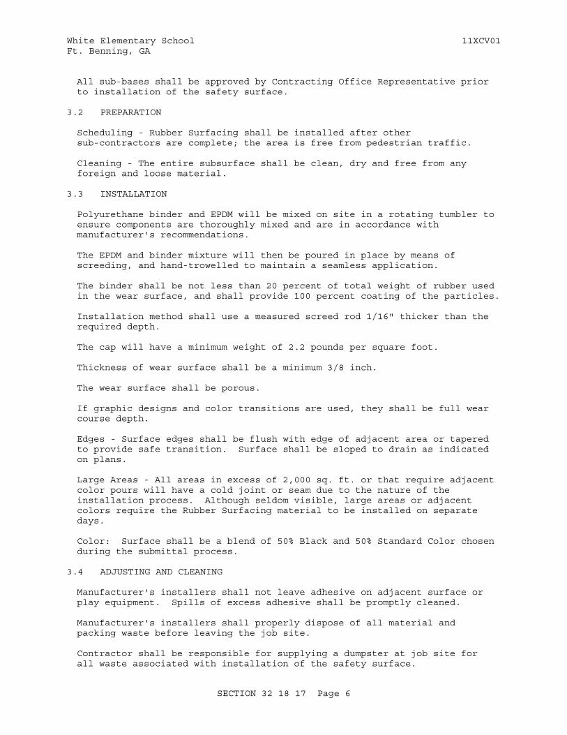
White Elementary School 11XCV01Ft. Benning, GA
All sub-bases shall be approved by Contracting Office Representative prior to installation of the safety surface.
3.2 PREPARATION
Scheduling - Rubber Surfacing shall be installed after other sub-contractors are complete; the area is free from pedestrian traffic.
Cleaning - The entire subsurface shall be clean, dry and free from any foreign and loose material.
3.3 INSTALLATION
Polyurethane binder and EPDM will be mixed on site in a rotating tumbler to ensure components are thoroughly mixed and are in accordance with manufacturer's recommendations.
The EPDM and binder mixture will then be poured in place by means of screeding, and hand-trowelled to maintain a seamless application.
The binder shall be not less than 20 percent of total weight of rubber used in the wear surface, and shall provide 100 percent coating of the particles.
Installation method shall use a measured screed rod 1/16" thicker than the required depth.
The cap will have a minimum weight of 2.2 pounds per square foot.
Thickness of wear surface shall be a minimum 3/8 inch.
The wear surface shall be porous.
If graphic designs and color transitions are used, they shall be full wear course depth.
Edges - Surface edges shall be flush with edge of adjacent area or tapered to provide safe transition. Surface shall be sloped to drain as indicated on plans.
Large Areas - All areas in excess of 2,000 sq. ft. or that require adjacent color pours will have a cold joint or seam due to the nature of the installation process. Although seldom visible, large areas or adjacent colors require the Rubber Surfacing material to be installed on separate days.
Color: Surface shall be a blend of 50% Black and 50% Standard Color chosen during the submittal process.
3.4 ADJUSTING AND CLEANING
Manufacturer's installers shall not leave adhesive on adjacent surface or play equipment. Spills of excess adhesive shall be promptly cleaned.
Manufacturer's installers shall properly dispose of all material and packing waste before leaving the job site.
Contractor shall be responsible for supplying a dumpster at job site for all waste associated with installation of the safety surface.
SECTION 32 18 17 Page 6
White Elementary School 11XCV01Ft. Benning, GA
3.5 PROTECTION
The synthetic safety surface shall be allowed to fully cure in accordance with manufacturer's instructions. The surface shall be protected by the owner from all traffic during the curing period of 48 to 72 hours after surface installation is complete, or as instructed by the manufacturer.
Surface installation crew shall be responsible for the protection of the rubber surfacing during the installation process. Owner or general contractor shall be responsible for the protection of the surface during the crew's off hours and during the curing period upon completion of the installation.
-- End of Section --
SECTION 32 18 17 Page 7
White Elementary School 11XCV01Ft. Benning, GA
SECTION TABLE OF CONTENTS
DIVISION 32 - EXTERIOR IMPROVEMENTS
SECTION 32 31 13
WIRE MESH FENCES AND GATES
08/10
PART 1 GENERAL
1.1 REFERENCES 1.2 SUBMITTALS 1.3 ASSEMBLY AND INSTALLATION INSTRUCTIONS 1.4 DELIVERY, STORAGE, AND HANDLING 1.5 QUALITY ASSURANCE 1.5.1 Required Report Data 1.5.2 Certificates of Compliance
PART 2 PRODUCTS
2.1 GENERAL 2.2 ZINC COATING 2.3 FABRIC 2.4 TOP AND BOTTOM SELVAGES 2.5 POSTS, TOP RAILS, BOTTOM RAILS AND BRACES 2.6 LINE POSTS 2.7 END, CORNER, AND PULL POSTS 2.8 TOP RAIL 2.9 STRETCHER BARS 2.10 POST TOPS 2.11 STRETCHER BAR BANDS 2.12 GATE POSTS 2.13 GATES 2.14 GATE HARDWARE AND ACCESSORIES 2.15 MISCELLANEOUS HARDWARE 2.16 WIRE TIES 2.17 CONCRETE
PART 3 EXECUTION
3.1 GENERAL 3.2 EXCAVATION 3.3 SETTING POSTS 3.3.1 Bracing 3.4 CONCRETE STRENGTH 3.5 TOP RAILS 3.6 BRACE ASSEMBLY 3.7 FABRIC INSTALLATION 3.8 STRETCHER BAR INSTALLATION 3.9 GATE INSTALLATION 3.10 TIE WIRES 3.11 FASTENERS 3.12 ZINC-COATING REPAIR 3.13 TOLERANCES
SECTION 32 31 13 Page 1

White Elementary School 11XCV01Ft. Benning, GA
3.14 SITE PREPARATION 3.14.1 Clearing and Grading 3.15 FENCE INSTALLATION 3.15.1 Post Spacing 3.16 ACCESSORIES INSTALLATION 3.16.1 Post Caps 3.17 GROUNDING 3.18 CLEANUP
-- End of Section Table of Contents --
SECTION 32 31 13 Page 2
White Elementary School 11XCV01Ft. Benning, GA
SECTION 32 31 13
WIRE MESH FENCES AND GATES08/10
PART 1 GENERAL
1.1 REFERENCES
The publications listed below form a part of this specification to the extent referenced. The publications are referred to within the text by the basic designation only.
ASTM INTERNATIONAL (ASTM)
ASTM A116 (2011) Standard Specification for Metallic-Coated, Steel Woven Wire Fence Fabric
ASTM A153/A153M (2009) Standard Specification for Zinc Coating (Hot-Dip) on Iron and Steel Hardware
ASTM A702 (1989; R 2006) Standard Specification for Steel Fence Posts and Assemblies, Hot Wrought
ASTM A780/A780M (2009) Standard Practice for Repair of Damaged and Uncoated Areas of Hot-Dip Galvanized Coatings
ASTM A90/A90M (2011) Standard Test Method for Weight of Coating on Iron and Steel Articles with Zinc or Zinc-Alloy Coatings
ASTM C94/C94M (2012) Standard Specification for Ready-Mixed Concrete
ASTM F1043 (2011a) Strength and Protective Coatings on Metal Industrial Chain-Link Fence Framework
ASTM F1083 (2010) Standard Specification for Pipe, Steel, Hot-Dipped Zinc Coated (Galvanized) Welded, for Fence Structures
ASTM F567 (2011a) Standard Practice for Installation of Chain Link Fence
ASTM F626 (2008) Standard Specification for Fence Fittings
U.S. GENERAL SERVICES ADMINISTRATION (GSA)
FS RR-F-191 (Rev K) Fencing, Wire and Post Metal (and Gates, Chain-Link Fence Fabric, and Accessories)
SECTION 32 31 13 Page 3
White Elementary School 11XCV01Ft. Benning, GA
FS RR-F-191/1 (Rev F) Fencing, Wire and Post, Metal (Chain-Link Fence Fabric)
FS RR-F-191/2 (Rev E) Fencing, Wire and Post, Metal (Chain-Link Fence Gates)
FS RR-F-191/3 (Rev E; Am 1) Fencing, Wire and Post, Metal (Chain-Link Fence Posts, Top Rails and Braces)
1.2 SUBMITTALS
Government approval is required for submittals with a "G" designation; submittals not having a "G" designation are for information only. When used, a designation following the "G" designation identifies the office that will review the submittal for the Government. Submit the following in accordance with Section 01 33 00 SUBMITTAL PROCEDURES:
SD-02 Shop Drawings
Fence Assembly; G
Location of Gate, Corner, End, and Pull Posts; G
Gate Assembly; G
Gate Hardware and Accessories; G
Erection/Installation Drawings; G
SD-03 Product Data
Fence Assembly; G
Gate Assembly; G
Gate Hardware and Accessories; G
Recycled Material Content; G
Zinc Coating; G
Fabric; G
Stretcher Bars; G
Concrete; G
SD-04 Samples
Fabric; G
Posts; G
Braces; G
Line Posts; G
SECTION 32 31 13 Page 4
White Elementary School 11XCV01Ft. Benning, GA
Top Rail; G
Stretcher Bars; G
Gate Posts; G
Gate Hardware and Accessories; G
Wire Ties; G
SD-07 Certificates
Certificates of Compliance; G
SD-08 Manufacturer's Instructions
Fence Assembly; G
Gate Assembly; G
Hardware Assembly; G
Accessories; G
1.3 ASSEMBLY AND INSTALLATION INSTRUCTIONS
Submit manufacturer's erection/installation drawings and instructions that detail proper assembly and materials in the design for fence, gate, hardware and accessories.
Submit erection/installation drawings along with manufacturer's catalog data for complete fence assembly, gate assembly, hardware assembly and accessories.
1.4 DELIVERY, STORAGE, AND HANDLING
Deliver materials to site in an undamaged condition. Store materials off the ground to provide protection against oxidation caused by ground contact.
1.5 QUALITY ASSURANCE
1.5.1 Required Report Data
Submit reports of listing of fencing and accessories regarding weight in ounces for zinc coating.
1.5.2 Certificates of Compliance
Submit certificates of compliance in accordance with the applicable reference standards and descriptions of this section for the following:
a. Zinc coating
b. Fabric
c. Stretcher bars
d. Gate hardware and accessories
SECTION 32 31 13 Page 5
White Elementary School 11XCV01Ft. Benning, GA
e. Concrete
PART 2 PRODUCTS
2.1 GENERAL
Provide fencing materials conforming to the requirements of ASTM A116, ASTM A702, ASTM F626, and as specified.
Submit manufacturer's data indicating percentage of recycled material content in protective fence materials, including fence, fabric, and gates to verify affirmative procurement compliance.
2.2 ZINC COATING
Provide hot-dip galvanized (after fabrication) ferrous-metal components and accessories, except as otherwise specified.
Provide zinc coating of weight not less than 1.94 ounces per square foot, as determined from the average result of two specimens, when tested in accordance with ASTM A90/A90M.
Provide zinc coating conforming to the requirements of the following:
a. Pipe: FS RR-F-191/3 Class 1 Grade A in accordance with ASTM F1083.
b. Hardware and accessories: ASTM A153/A153M, Table 1
c. Surface: ASTM F1043
d. External: Type B-B surface zinc with organic coating, 0.97 ounce per square foot minimum thickness of acrylated polymer.
e. Internal: Surface zinc coating of 0.97 ounce per square foot minimum.
Provide galvanizing repair material that is cold-applied zinc-rich coating conforming to ASTM A780/A780M.
2.3 FABRIC
FS RR-F-191 and detailed specifications as referenced and other requirements as specified.
FS RR-F-191/1; Type I, zinc-coated steel, 6 gage. Mesh size, as indicated. Provide selvage knuckled at both selvages. Height of fabric, as indicated.
Provide fabric consisting of No. 6-gage wires woven into a 2-inch vertical by 6-inch horizontal mesh, with dimensions of fabric and wire conforming to ASTM A116, ASTM A702 and ASTM F626, with 1.20 ounces per square foot zinc galvanizing.
Provide one-piece fabric widths for fence heights up to 12 feet.
2.4 TOP AND BOTTOM SELVAGES
Provide knuckled selvages at top and bottom for fabric with 2 inch mesh and up to 60 inches high, and if over 60 inches high, provide twisted and barbed top selvage and knuckled bottom selvage.
SECTION 32 31 13 Page 6
White Elementary School 11XCV01Ft. Benning, GA
Knuckle top and bottom selvages for 1-3/4-inch and 1-inch mesh fabric.
2.5 POSTS, TOP RAILS, BOTTOM RAILS AND BRACES
FS RR-F-191/3 line posts; Class 1, steel pipe, Grade A. End, corner, and pull posts; Class 1, steel pipe, Grade A. Braces and rails; Class 1, steel pipe, Grade A, in minimum sizes listed in FS RR-F-191/3 for each class and grade.
2.6 LINE POSTS
Minimum acceptable line posts are as follows:
Up to 6-feet high:
Grade A: 1.900 inch O.D. pipe weighing 2.72 pounds per linear foot.
2.7 END, CORNER, AND PULL POSTS
Provide minimally acceptable end, corner, and pull posts as follows:
Up to 6 feet high:
Grade A: 2.375 inch O.D. pipe weighing 3.65 pounds per linear foot.
2.8 TOP RAIL
Provide a minimum of 1.660 inches O.D. pipe rails. Grade A weighing 2.27 pounds per linear foot. Provide expansion couplings 6-inches long at each joint in top rails.
2.9 STRETCHER BARS
Provide bars that have one-piece lengths equal to the full height of the fabric with a minimum cross section of 3/16 by 3/4 inch, in accordance with ASTM A116, ASTM A702 and ASTM F626.
2.10 POST TOPS
Provide tops that are steel, wrought iron, or malleable iron designed as a weathertight closure cap. Provide one cap for each post, unless equal protection is provided by a combination post-cap and barbed-wire supporting arm. Provide caps with an opening to permit through passage of the top rail.
2.11 STRETCHER BAR BANDS
Provide bar bands for securing stretcher bars to posts that are steel, wrought iron, or malleable iron spaced not over 15 inches on center. Bands may also be used in conjunction with special fittings for securing rails to posts. Provide bands with projecting edges chamfered or eased.
2.12 GATE POSTS
Provide a gate post for supporting each gate leaf as follows:
Up to 6-feet wide:
SECTION 32 31 13 Page 7
White Elementary School 11XCV01Ft. Benning, GA
2.875 inch O.D. pipe Grade A weighing 5.79 pounds per linear foot.
2.13 GATES
FS RR-F-191/2; Type I, single swing and type II, double swing. Shape and size of gate frame, as indicated. Framing and bracing members, round of steel alloy. Steel member finish, zinc-coated. Provide gate frames and braces of minimum sizes listed in FS RR-F-191/3 for each Class and Grade, except that steel pipe frames are a minimum of 1.90 inches o.d., 0.120 inches minimum wall thickness and aluminum pipe frames and intermediate braces are 1.869 inches o.d. minimum, 0.940 lb/ft of length. Gate fabric, is as specified for fencing fabric. Coating for steel latches, stops, hinges, keepers, and accessories, galvanized. Provide fork type gate latches. Provide intermediate members as necessary for gate leaves more than 8 feet wide, to provide rigid construction, free from sag or twist. Provide truss rods or intermediate braces for gate leaves less than 8 feet wide. Attach gate fabric to gate frame in accordance with manufacturer's standards, except that welding is not permitted. Arrange padlocking latches to be accessible from both sides of gate, regardless of latching arrangement.
Provide gate frame assembly that is welded or assembled with special malleable or pressed-steel fittings and rivets to provide rigid connections. Install fabric with stretcher bars at vertical edges; stretcher bars may also be used at top and bottom edges. Attach stretcher bars and fabric to gate frames on all sides at intervals not exceeding 15 inches. Attach hardware with rivets or by other means which provides equal security against breakage or removal.
Provide diagonal cross-bracing, consisting of 3/8-inch diameter adjustable-length truss rods on welded gate frames, where necessary to obtain frame rigidity without sag or twist. Provide nonwelded gate frames with diagonal bracing.
2.14 GATE HARDWARE AND ACCESSORIES
Provide gate hardware and accessories that conforms to ASTM A116, ASTM A702, ASTM F626, and be as specified:
Provide pressed steel hinges to suit gate size, non-lift-off type, offset to permit 180-degree opening.
Provide latch that permits operation from either side of the gate, with a padlock eye provided as an integral part of the latch.
Provide stops and holders of malleable iron for vehicular gates. Provide stops that automatically engage the gate and hold it in the open position until manually released.
Provide double gates with a cane bolt and ground-set keeper, with latch or locking device and padlock eye designed as an integral part.
2.15 MISCELLANEOUS HARDWARE
Provide miscellaneous hot-dip galvanized hardware as required.
SECTION 32 31 13 Page 8
White Elementary School 11XCV01Ft. Benning, GA
2.16 WIRE TIES
Provide 16-gage galvanized steel wire for tying fabric to line posts,spaced 12 inches on center. For tying fabric to rails and braces, space wire ties 24 inches on center. For tying fabric to tension wire, space 0.105-inch hog rings 24 inches on center.
Manufacturer's standard procedure will be accepted if of equal strength and durability.
2.17 CONCRETE
Provide concrete conforming to ASTM C94/C94M, and obtaining a minimum 28-day compressive strength of 3,000 psi.
PART 3 EXECUTION
Provide complete installation conforming to ASTM F567.
3.1 GENERAL
Ensure final grading and established elevations are complete prior to commencing fence installation.
3.2 EXCAVATION
Provide excavations for post footings which are drilled holes in virgin or compacted soil, of minimum sizes as indicated.
Space footings for line posts 10 feet on center maximum and at closer intervals when indicated, with bottoms of the holes approximately 3-inches below the bottoms of the posts. Set bottom of each post not less than 36-inches below finished grade when in firm, undisturbed soil. Set posts deeper, as required, in soft and problem soils and for heavy, lateral loads.
Remove excavated soil from Government property.
3.3 SETTING POSTS
Remove loose and foreign materials from holes and the soil moistened prior to placing concrete.
Provide tops of footings that are trowel finished and sloped or domed to shed water away from posts. Set hold-open devices, sleeves, and other accessories in concrete.
Keep exposed concrete moist for at least 7 calendar days after placement or cured with a membrane curing material, as approved.
Maintain vertical alignment of posts set in concrete construction until concrete has set.
3.3.1 Bracing
Brace gate, corner, end, and pull posts to nearest post with a horizontal brace used as a compression member, placed at least 12 inches below top of fence, and a diagonal tension rod.
SECTION 32 31 13 Page 9
White Elementary School 11XCV01Ft. Benning, GA
3.4 CONCRETE STRENGTH
Provide concrete that has attained at least 75 percent of its minimum 28-day compressive strength, but in no case sooner than 7 calendar days after placement, before rails, tension wire, or fabric are installed. Do not stretch fabric and wires or hang gates until the concrete has attained its full design strength.
3.5 TOP RAILS
Provide top rails that run continuously through post caps or extension arms, bending to radius for curved runs. Provide expansion couplings as recommended by the fencing manufacturer.
3.6 BRACE ASSEMBLY
Provide bracing assemblies at end and gate posts and at both sides of corner and pull posts, with the horizontal brace located at midheight of the fabric.
Install brace assemblies so posts are plumb when the diagonal rod is under proper tension.
Provide two complete brace assemblies at corner and pull posts where required for stiffness and as indicated.
3.7 FABRIC INSTALLATION
Provide fabric in single lengths between stretch bars with bottom barbs placed approximately 1-1/2-inches above the ground line. Pull fabric taut and tied to posts, rails, and tension wire with wire ties and bands.
Install fabric on the security side of fence, unless otherwise directed.
Ensure fabric remains under tension after the pulling force is released.
3.8 STRETCHER BAR INSTALLATION
Thread stretcher bars through or clamped to fabric 4 inches on center and secured to posts with metal bands spaced 15 inches on center.
3.9 GATE INSTALLATION
Install gates plumb, level, and secure, with full opening without interference. Install ground set items in concrete for anchorage as recommended by the fence manufacturer. Adjust hardware for smooth operation and lubricated where necessary.
3.10 TIE WIRES
Provide tie wires that are U-shaped to the pipe diameters to which attached. Twist ends of tie wires not less than two full turns and bent so as not to present a hazard.
3.11 FASTENERS
Install nuts for tension bands and hardware on the side of the fence opposite the fabric side. Peen ends of bolts to prevent removal of nuts.
SECTION 32 31 13 Page 10
White Elementary School 11XCV01Ft. Benning, GA
3.12 ZINC-COATING REPAIR
Clean and repair galvanized surfaces damaged by welding or abrasion, and cut ends of fabric, or other cut sections with specified galvanizing repair material applied in strict conformance with the manufacturer's printed instructions.
3.13 TOLERANCES
Provide posts that are straight and plumb within a vertical tolerance of 1/4 inch after the fabric has been stretched. Provide fencing and gates that are true to line with no more than 1/2 inch deviation from the established centerline between line posts. Repair defects as directed.
3.14 SITE PREPARATION
3.14.1 Clearing and Grading
Clear fence line of trees, brush, and other obstacles to install fencing. Establish a graded, compacted fence line prior to fencing installation.
3.15 FENCE INSTALLATION
Install fence on prepared surfaces to line and grade indicated. Allow for proper operation of components. Install fence in accordance with fence manufacturer's written installation instructions except as modified herein.
3.15.1 Post Spacing
Provide line posts spaced equidistantly apart, not exceeding 10 feeton center. Provide gate posts spaced as necessary for size of gate openings. Do not exceed 500 feet on straight runs between braced posts. Provide corner or pull posts, with bracing in both directions, for changes in direction of 15 degrees or more, or for abrupt changes in grade. Provide drawings showing location of gate, corner, end, and pull posts.
3.16 ACCESSORIES INSTALLATION
3.16.1 Post Caps
Design post caps to accommodate top rail. Install post caps as recommended by the manufacturer.
3.17 GROUNDING
Ground fencing as specified.
Ground all fences crossed by overhead powerlines in excess of 600 volts, and all electrical equipment attached to the fence. Ground fences on each side of all gates, at each corner, at the closest approach to each building located within 50 feet of the fence, and where the fence alignment changes more than 15 degrees. Grounding locations can not exceed 650 feet. Bond each gate panel with a flexible bond strap to its gate post. Ground fences crossed by powerlines of 600 volts or more at or near the point of crossing and at distances not exceeding 150 feet on each side of crossing. Provide ground conductor consisting of No. 6 AWG solid copper wire. Provide copper-clad steel rod grounding electrodes 3/4 inch by 10 foot long. Drive electrodes into the earth so that the top of the electrode is at least 6 inches below the grade. Where driving is impracticable, bury electrodes
SECTION 32 31 13 Page 11
White Elementary School 11XCV01Ft. Benning, GA
a minimum of 12 inches deep and radially from the fence, with top of the electrode not less than 2 feet or more than 8 feet from the fence. Clamp ground conductor to the fence and electrodes with bronze grounding clamps to create electrical continuity between fence posts, fence fabric, and ground rods. Total resistance of the fence to ground cannot exceed 25 ohms.
3.18 CLEANUP
Remove waste fencing materials and other debris from the work site.
-- End of Section --
SECTION 32 31 13 Page 12

White Elementary School 11XCV01Ft. Benning, GA
SECTION TABLE OF CONTENTS
DIVISION 32 - EXTERIOR IMPROVEMENTS
SECTION 32 31 19
STEEL ORNAMENTAL FENCE SYSTEM
11/12
PART 1 GENERAL
1.1 REFERENCES 1.2 SECTION INCLUDES 1.3 RELATED SECTIONS 1.4 SUBMITTALS 1.5 QUALITY ASSURANCE 1.6 PRODUCT STORAGE AND HANDLING
PART 2 PRODUCTS
2.1 SYSTEM DESCRIPTION 2.2 MANUFACTURER 2.3 MATERIALS 2.4 FABRICATION
PART 3 EXECUTION
3.1 PREPARATION 3.2 FENCE INSTALLATION 3.3 FENCE INSTALLATION MAINTENANCE 3.4 GATE INSTALLATION 3.5 CLEANING
-- End of Section Table of Contents --
SECTION 32 31 19 Page 1
White Elementary School 11XCV01Ft. Benning, GA
SECTION 32 31 19
STEEL ORNAMENTAL FENCE SYSTEM11/12
PART 1 GENERAL
1.1 REFERENCES
The publications listed below form a part of this specification to the extent referenced. The publications are referred to within the text by the basic designation only.
ASTM
ASTM F2408 (2011) Standard Specification for Ornamental Fences Employing Galvanized Steel Tubular Pickets
1.2 SECTION INCLUDES
The Contractor shall provide all labor, materials and all necessary items for the installation of the ornamental fence system defined herein.
1.3 RELATED SECTIONS
Section 03 30 00: CAST-IN-PLACE CONCRETE
1.4 SUBMITTALS
The manufacturer's submittal package shall be submitted prior to installation to confirm compliance with all requirements for materials specified in this section.
1.5 QUALITY ASSURANCE
The Contractor shall provide laborers and supervisors who are thoroughly familiar with the type of construction involved and the materials specified.
1.6 PRODUCT STORAGE AND HANDLING
Upon receipt at the job site, all materials shall be checked to ensure that no damages occurred during shipping or handling. Materials shall be stored in such a manner to ensure proper ventilation and drainage and to protect against damage, weather, vandalism and theft.
PART 2 PRODUCTS
2.1 SYSTEM DESCRIPTION
The manufacturer shall supply a total fencing system. The system shall include top, bottom, and intermediate rails. The system shall include all components (i.e., pickets, posts, rails, gates and hardware) required.
2.2 MANUFACTURER
The ornamental fence system shall conform to the Drawings and
SECTION 32 31 19 Page 2
White Elementary School 11XCV01Ft. Benning, GA
Specifications.
2.3 MATERIALS
Steel material for fence framework (i.e., tubular pickets, rails and posts) shall conform to the requirements of ASTM A653/A653M, with a minimum yield strength of 45,000 psi and a minimum zinc coating of 0.90 oz/ft2.
Pickets shall be 1" square x 14 gauge tubing. Horizontal rails shall be 1.75" x 1.75 x .105". The number of rails shall vary with the style, height and strength as determined by manufacturer. Fence posts and gate posts shall meet the minimum size requirements of Table 1.
2.4 FABRICATION
Pickets, rails and posts shall be pre-cut to specified lengths. Rails shall be pre-punched to accept pickets.
Pickets shall be inserted into the pre-punched holes in the rails and shall be aligned to standard spacing using a specially calibrated alignment fixture. The aligned pickets and rails shall be joined at each picket-to-rail intersection by fusion welding, thus completing the rigid panel assembly (Note: The process produces a virtually seamless, spatter-free good-neighbor appearance, equally attractive from either side of the panel).
The manufactured panels and posts shall be subjected to an inline electrodeposition coating (E-Coat) process consisting of a multi-stage pretreatment/wash (with zinc phosphate), followed by a duplex application of an epoxy primer and an acrylic topcoat. The minimum cumulative coating thickness of epoxy and acrylic shall be 2 mils. The color shall be Black. The coated panels and posts shall be capable of meeting the performance requirements for each quality characteristic shown in Table 2 (Note: The requirements in Table 2 meet or exceed the coating performance criteria of ASTM F2408).
The manufactured fence system shall be capable of meeting the vertical load, horizontal load, and infill performance requirements for Industrial weight fences under ASTM F2408.
Swing gates shall be fabricated using 1.75 inch x 14 ga. double channel rail, 2 inch sq. x 11ga. gate ends, and 1 inch sq. x 14 ga. pickets. Gates that exceed 6 feet in width will have a 1.75 inch sq. x 14 ga. intermediate upright. All rail and upright intersections shall be joined by welding. All picket and rail intersections shall also be joined by welding. Gusset plates will be welded at each upright to rail intersection. Cable kits will be provided for additional trussing for all gates leaves over 6 feet.
a. Single Gates: Gates shall have a stop lip and double hole lock box. Contractor shall install dead bolt and door knob to match building doors. Gate shall also have a gate spring.
b. Double Gates: Gates shall have one locking drop rod and one gate with stop lip and double hole lock box. Contractor shall install dead bolt and door knob to match building.
SECTION 32 31 19 Page 3
White Elementary School 11XCV01Ft. Benning, GA
PART 3 EXECUTION
3.1 PREPARATION
All new installation shall be laid out by the Contractor in accordance with the construction plans. The Contractor shall adjust column and post spacing as required to fit pre-manufactured panels as recommended by manufacturer.
3.2 FENCE INSTALLATION
Fence post shall be spaced according to Table 3, plus or minus 1/2 inch. For installations that must be raked to follow sloping grades, the post spacing dimension must be measured along the grade. Fence panels shall be attached to posts with brackets supplied by the manufacturer. Posts shall be set in concrete footers having a minimum depth of 36 inches (Note: In some cases, local restrictions of freezing weather conditions may require a greater depth). The "EARTHWORK" and "CONCRETE" sections of this specification shall govern material requirements for the concrete footer. Posts setting by other methods such as plated posts or grouted core-drilled footers are permissible only if shown by engineering analysis to be sufficient in strength for the intended application.
3.3 FENCE INSTALLATION MAINTENANCE
When cutting/drilling rails or posts adhere to the following steps to seal the exposed surfaces:
1) Remove all metal shavings from cut area.
2) Apply zinc-rich primer to thoroughly cover cut edge and/or drilled hole; let dry.
3) Apply 2 coats of custom finish paint matching fence color.
Failure to seal exposed surfaces per steps 1-3 above will negate warranty. Spray cans or paint pens shall be used to finish exposed surfaces; it is recommended that paint pens be used to prevent overspray.
3.4 GATE INSTALLATION
Gate posts shall be spaced according to the manufacturers' gate drawings, dependent on standard out-to-out gate leaf dimensions and gate hardware selected. Type and quantity of gate hinges shall be based on the application; weight, height, and number of gate cycles. The manufacturers' gate drawings shall identify the necessary gate hardware required for the application. Gate hardware shall be provided by the manufacture of the gate and shall be installed per manufacturer's recommendations.
3.5 CLEANING
The Contractor shall clean the jobsite of excess materials; post-hole excavations shall be scattered uniformly away from posts.
TABLE 1 - MINIMUM SIZES FOR POSTS
SECTION 32 31 19 Page 4
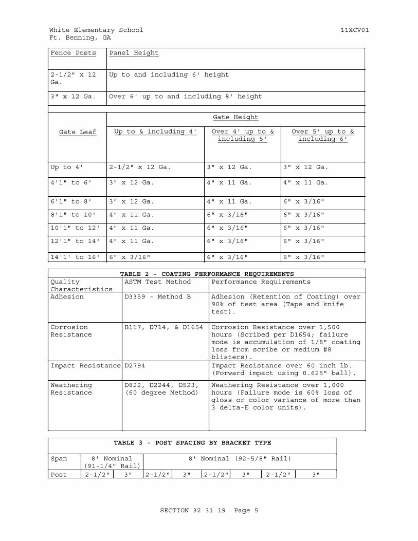
White Elementary School 11XCV01Ft. Benning, GA
Fence Posts Panel Height
2-1/2" x 12 Ga.
Up to and including 6' height
3" x 12 Ga. Over 6' up to and including 8' height
Gate Leaf
Gate Height
Up to & including 4' Over 4' up to &including 5'
Over 5' up to &including 6'
Up to 4' 2-1/2" x 12 Ga. 3" x 12 Ga. 3" x 12 Ga.
4'1" to 6' 3" x 12 Ga. 4" x 11 Ga. 4" x 11 Ga.
6'1" to 8' 3" x 12 Ga. 4" x 11 Ga. 6" x 3/16"
8'1" to 10' 4" x 11 Ga. 6" x 3/16" 6" x 3/16"
10'1" to 12' 4" x 11 Ga. 6" x 3/16" 6" x 3/16"
12'1" to 14' 4" x 11 Ga. 6" x 3/16" 6" x 3/16"
14'1' to 16' 6" x 3/16" 6" x 3/16" 6" x 3/16"
TABLE 2 - COATING PERFORMANCE REQUIREMENTSQuality Characteristics
ASTM Test Method Performance Requirements
Adhesion D3359 - Method B Adhesion (Retention of Coating) over 90% of test area (Tape and knife test).
Corrosion Resistance
B117, D714, & D1654 Corrosion Resistance over 1,500 hours (Scribed per D1654; failure mode is accumulation of 1/8" coating loss from scribe or medium #8 blisters).
Impact Resistance D2794 Impact Resistance over 60 inch lb. (Forward impact using 0.625" ball).
Weathering Resistance
D822, D2244, D523, (60 degree Method)
Weathering Resistance over 1,000 hours (Failure mode is 60% loss of gloss or color variance of more than 3 delta-E color units).
TABLE 3 - POST SPACING BY BRACKET TYPE
Span 8' Nominal(91-1/4" Rail)
8' Nominal (92-5/8" Rail)
Post 2-1/2" 3" 2-1/2" 3" 2-1/2" 3" 2-1/2" 3"
SECTION 32 31 19 Page 5

White Elementary School 11XCV01Ft. Benning, GA
TABLE 3 - POST SPACING BY BRACKET TYPE
Bracket Type
IndustrialFlat Mount
IndustrialUniversal
IndustrialFlat Mount
Industrial Swivel
Post Settings±1/2" O.C.
94-1/2" 95" 96" 96-1/2" 96" 96-1/2" *96" *96-1/2"
*Note: When using BB304 swivel brackets on either or both ends of a panel installation, care must be taken to ensure the spacing between post and adjoining pickets meets applicable codes. This will require trimming one or both ends of the panel.
-- End of Section --
SECTION 32 31 19 Page 6
White Elementary School 11XCV01Ft. Benning, GA
SECTION TABLE OF CONTENTS
DIVISION 32 - EXTERIOR IMPROVEMENTS
SECTION 32 92 19
SEEDING
10/06
PART 1 GENERAL
1.1 REFERENCES 1.2 DEFINITIONS 1.2.1 Stand of Turf 1.3 RELATED REQUIREMENTS 1.4 SUBMITTALS 1.5 DELIVERY, STORAGE, AND HANDLING 1.5.1 Delivery 1.5.1.1 Seed Protection 1.5.1.2 Fertilizer, Gypsum, Sulfur, Iron, and Lime Delivery 1.5.2 Storage 1.5.2.1 Seed, Fertilizer, Gypsum, Sulfur, Iron, and, Lime Storage 1.5.2.2 Topsoil 1.5.2.3 Handling 1.6 TIME RESTRICTIONS AND PLANTING CONDITIONS 1.6.1 Restrictions 1.7 TIME LIMITATIONS 1.7.1 Seed
PART 2 PRODUCTS
2.1 SEED 2.1.1 Classification 2.1.2 Planting Dates 2.1.3 Seed Purity 2.2 TOPSOIL 2.2.1 On-Site Topsoil 2.2.2 Off-Site Topsoil 2.2.3 Composition 2.3 SOIL CONDITIONERS 2.3.1 Lime 2.3.2 Aluminum Sulfate 2.3.3 Sulfur 2.3.4 Iron 2.3.5 Peat 2.3.6 Sand 2.3.7 Perlite 2.3.8 Composted Derivatives 2.3.8.1 Particle Size 2.3.8.2 Nitrogen Content 2.3.9 Gypsum 2.3.10 Calcined Clay 2.4 FERTILIZER 2.4.1 Granular Fertilizer 2.4.2 Hydroseeding Fertilizer
SECTION 32 92 19 Page 1
White Elementary School 11XCV01Ft. Benning, GA
2.5 MULCH 2.5.1 Straw 2.5.2 Hay 2.5.3 Wood Cellulose Fiber Mulch 2.6 WATER 2.7 EROSION CONTROL MATERIALS 2.7.1 Erosion Control Blanket 2.7.2 Erosion Control Material Anchors
PART 3 EXECUTION
3.1 PREPARATION 3.1.1 EXTENT OF WORK 3.1.1.1 Topsoil 3.1.1.2 Soil Conditioner Application Rates 3.1.1.3 Fertilizer Application Rates 3.2 SEEDING 3.2.1 Seed Application Seasons and Conditions 3.2.2 Seed Application Method 3.2.2.1 Broadcast and Drop Seeding 3.2.2.2 Drill Seeding 3.2.2.3 Hydroseeding 3.2.3 Mulching 3.2.3.1 Mechanical Anchor 3.2.3.2 Non-Asphaltic Tackifier 3.2.4 Rolling 3.2.5 Erosion Control Material 3.2.6 Watering 3.3 PROTECTION OF TURF AREAS 3.4 RENOVATION OF EXISTING TURF AREA 3.4.1 Aeration 3.4.2 Overseeding 3.5 RESTORATION
-- End of Section Table of Contents --
SECTION 32 92 19 Page 2
White Elementary School 11XCV01Ft. Benning, GA
SECTION 32 92 19
SEEDING10/06
PART 1 GENERAL
1.1 REFERENCES
The publications listed below form a part of this specification to the extent referenced. The publications are referred to within the text by the basic designation only.
ASTM INTERNATIONAL (ASTM)
ASTM C602 (2007) Agricultural Liming Materials
ASTM D4427 (2007) Peat Samples by Laboratory Testing
ASTM D4972 (2001; R 2007) pH of Soils
U.S. DEPARTMENT OF AGRICULTURE (USDA)
AMS Seed Act (1940; R 1988; R 1998) Federal Seed Act
DOA SSIR 42 (1996) Soil Survey Investigation Report No. 42, Soil Survey Laboratory Methods Manual, Version 3.0
1.2 DEFINITIONS
1.2.1 Stand of Turf
95 percent ground cover of the established species.
1.3 RELATED REQUIREMENTS
Section 31 00 00 EARTHWORK, Section 32 92 23 SODDING, Section 32 93 00 EXTERIOR PLANTS, and Section 32 05 33 LANDSCAPE ESTABLISHMENT applies to this section for pesticide use and plant establishment requirements, with additions and modifications herein.
1.4 SUBMITTALS
Government approval is required for submittals with a "G" designation; submittals not having a "G" designation are for information only. When used, a designation following the "G" designation identifies the office that will review the submittal for the Government. The following shall be submitted in accordance with Section 01 33 00 SUBMITTAL PROCEDURES:
SD-03 Product Data
Wood cellulose fiber mulch
Fertilizer
Include physical characteristics, and recommendations.
SECTION 32 92 19 Page 3
White Elementary School 11XCV01Ft. Benning, GA
SD-06 Test Reports
Topsoil composition tests (reports and recommendations).
SD-07 Certificates
State certification and approval for seed
SD-08 Manufacturer's Instructions
Erosion Control Materials
1.5 DELIVERY, STORAGE, AND HANDLING
1.5.1 Delivery
1.5.1.1 Seed Protection
Protect from drying out and from contamination during delivery, on-site storage, and handling.
1.5.1.2 Fertilizer, Gypsum, Sulfur, Iron, and Lime Delivery
Deliver to the site in original, unopened containers bearing manufacturer's chemical analysis, name, trade name, trademark, and indication of conformance to state and federal laws. Instead of containers, fertilizer, gypsum, sulphur, iron, and lime may be furnished in bulk with certificate indicating the above information.
1.5.2 Storage
1.5.2.1 Seed, Fertilizer, Gypsum, Sulfur, Iron, and, Lime Storage
Store in cool, dry locations away from contaminants.
1.5.2.2 Topsoil
Prior to stockpiling topsoil, treat growing vegetation with application of appropriate specified non-selective herbicide. Clear and grub existing vegetation three to four weeks prior to stockpiling topsoil.
1.5.2.3 Handling
Do not drop or dump materials from vehicles.
1.6 TIME RESTRICTIONS AND PLANTING CONDITIONS
1.6.1 Restrictions
Do not plant when the ground is frozen, snow covered, muddy, or when air temperature exceeds 90 degrees Fahrenheit.
1.7 TIME LIMITATIONS
1.7.1 Seed
Apply seed within twenty four hours after seed bed preparation.
SECTION 32 92 19 Page 4
White Elementary School 11XCV01Ft. Benning, GA
PART 2 PRODUCTS
2.1 SEED
2.1.1 Classification
Provide State-approved seed of the latest season's crop delivered in original sealed packages, bearing producer's guaranteed analysis for percentages of mixtures, purity, germination, weedseed content, and inert material. Label in conformance with AMS Seed Act and applicable state seed laws. Wet, moldy, or otherwise damaged seed will be rejected. Field mixes will be acceptable when field mix is performed on site in the presence of the Contracting Officer.
2.1.2 Planting Dates
Planting Season Planting Dates
Season 1 May 15 to August 31 for Centipede grass.
Temporary Seeding If establishment cannot be made by September 15th, overseed all areas with annual rye grass.
2.1.3 Seed Purity
Botanical Name
Common Name
Minimum Percent Pure Seed
Minimum Percent Germination and Hard Seed
Maximum Percent Weed Seed
EremochloaOphioroide
Centipede 85 95 0.5
Lolium multifluru
Annual rye
85 95 0.5
2.2 TOPSOIL
2.2.1 On-Site Topsoil
Surface soil stripped and stockpiled on site and modified as necessary to meet the requirements specified for topsoil in paragraph entitled "Composition." When available topsoil shall be existing surface soil stripped and stockpiled on-site in accordance with Section 31 00 00 EARTHWORK.
2.2.2 Off-Site Topsoil
Conform to requirements specified in paragraph entitled "Composition." Additional topsoil shall be furnished by the Contractor.
SECTION 32 92 19 Page 5
White Elementary School 11XCV01Ft. Benning, GA
2.2.3 Composition
Containing from 5 to 10 percent organic matter as determined by the topsoil composition tests of the Organic Carbon, 6A, Chemical Analysis Method described in DOA SSIR 42. Maximum particle size, 3/4 inch, with maximum 3 percent retained on 1/4 inch screen. The pH shall be tested in accordance with ASTM D4972. Topsoil shall be free of sticks, stones, roots, and other debris and objectionable materials. Other components shall conform to the following limits:
Silt 25-50 percent
Clay 10-30 percent
Sand 20-35 percent
pH 5.5 to 7.0
Soluble Salts 600 ppm maximum
2.3 SOIL CONDITIONERS
Add conditioners to topsoil as required to bring into compliance with "composition" standard for topsoil as specified herein.
2.3.1 Lime
Commercial grade hydrate or burnt limestone containing a calcium carbonate equivalent (C.C.E.) as specified in ASTM C602 of not less than 80 percent.
2.3.2 Aluminum Sulfate
Commercial grade.
2.3.3 Sulfur
100 percent elemental
2.3.4 Iron
100 percent elemental
2.3.5 Peat
Natural product of peat moss derived from a freshwater site and conforming to ASTM D4427. Shred and granulate peat to pass a 1/2 inch mesh screen and condition in storage pile for minimum 6 months after excavation.
2.3.6 Sand
Clean and free of materials harmful to plants.
2.3.7 Perlite
Horticultural grade.
SECTION 32 92 19 Page 6
White Elementary School 11XCV01Ft. Benning, GA
2.3.8 Composted Derivatives
Ground bark, nitrolized sawdust, humus or other green wood waste material free of stones, sticks, and soil stabilized with nitrogen and having the following properties:
2.3.8.1 Particle Size
Minimum percent by weight passing:
No. 4 mesh screen 95No. 8 mesh screen 80
2.3.8.2 Nitrogen Content
Minimum percent based on dry weight:
Fir Sawdust 0.7Fir or Pine Bark 1.0
2.3.9 Gypsum
Coarsely ground gypsum comprised of calcium sulfate dihydrate 61 percent, calcium 22 percent, sulfur 17 percent; minimum 96 percent passing through 20 mesh screen, 100 percent passing thru 16 mesh screen.
2.3.10 Calcined Clay
Calcined clay shall be granular particles produced from montmorillonite clay calcined to a minimum temperature of 1200 degrees F. Gradation: A minimum 90 percent shall pass a No. 8 sieve; a minimum 99 percent shall be retained on a No. 60 sieve; and a maximum 2 percent shall pass a No. 100 sieve. Bulk density: A maximum 40 pounds per cubic foot.
2.4 FERTILIZER
2.4.1 Granular Fertilizer
Synthetic, granular controlled release fertilizer containing the following minimum percentages, by weight, of plant food nutrients:
20 percent available nitrogen0 percent available phosphorus0 percent available potassium2 percent sulfur2 percent iron
2.4.2 Hydroseeding Fertilizer
Controlled release fertilizer, to use with hydroseeding and composed of pills coated with plastic resin to provide a continuous release of nutrients for at least 6 months and containing the following minimum percentages, by weight, of plant food nutrients.
20 percent available nitrogen0 percent available phosphorus0 percent available potassium2 percent sulfur2 percent iron
SECTION 32 92 19 Page 7
White Elementary School 11XCV01Ft. Benning, GA
2.5 MULCH
Mulch shall be free from noxious weeds, mold, and other deleterious materials.
2.5.1 Straw
Stalks from oats, wheat, rye, barley, or rice. Furnish in air-dry condition and of proper consistency for placing with commercial mulch blowing equipment. Straw shall contain no fertile seed.
2.5.2 Hay
Air-dry condition and of proper consistency for placing with commercial mulch blowing equipment. Hay shall be sterile, containing no fertile seed.
2.5.3 Wood Cellulose Fiber Mulch
Use recovered materials of either paper-based (100 percent) or wood-based (100 percent) hydraulic mulch. Processed to contain no growth or germination-inhibiting factors and dyed an appropriate color to facilitate visual metering of materials application. Composition on air-dry weight basis: 9 to 15 percent moisture, pH range from 5.5 to 8.2. Use with hydraulic application of grass seed and fertilizer.
2.6 WATER
Source of water shall be approved by Contracting Officer and of suitable quality for irrigation, containing no elements toxic to plant life.
2.7 EROSION CONTROL MATERIALS
Erosion control material shall conform to the following:
2.7.1 Erosion Control Blanket
70 percent agricultural straw/30 percent coconut fiber matrix stitched with a degradable nettings, designed to degrade within 12 months.
2.7.2 Erosion Control Material Anchors
Erosion control anchors shall be as recommended by the manufacturer.
PART 3 EXECUTION
3.1 PREPARATION
3.1.1 EXTENT OF WORK
Provide soil preparation (including soil conditioners as required), fertilizing, seeding, and surface topdressing of all newly graded finished earth surfaces, unless indicated otherwise, and at all areas inside or outside the limits of construction that are disturbed by the Contractor's operations.
3.1.1.1 Topsoil
Provide 4 inches of on-site topsoil to meet indicated finish grade. After
SECTION 32 92 19 Page 8
White Elementary School 11XCV01Ft. Benning, GA
areas have been brought to indicated finish grade, incorporate fertilizer, pH adjusters and soil conditioners into soil a minimum depth of 4 inches by disking, harrowing, tilling or other method approved by the Contracting Officer. Remove debris and stones larger than 3/4 inch in any dimension remaining on the surface after finish grading. Correct irregularities in finish surfaces to eliminate depressions. Protect finished topsoil areas from damage by vehicular or pedestrian traffic.
3.1.1.2 Soil Conditioner Application Rates
Apply soil conditioners at rates as determined by laboratory soil analysis of the soils at the job site.
3.1.1.3 Fertilizer Application Rates
Apply fertilizer at rates as determined by laboratory soil analysis of the soils at the job site.
3.2 SEEDING
3.2.1 Seed Application Seasons and Conditions
Immediately before seeding, restore soil to proper grade. Do not seed when ground is muddy, frozen, snow covered or in an unsatisfactory condition for seeding. If special conditions exist that may warrant a variance in the above seeding dates or conditions, submit a written request to the Contracting Officer stating the special conditions and proposed variance. Apply seed within twenty four hours after seedbed preparation. Sow seed by approved sowing equipment. Sow one-half the seed in one direction, and sow remainder at right angles to the first sowing.
3.2.2 Seed Application Method
Seeding method shall be drill seeding or hydroseeding.
3.2.2.1 Broadcast and Drop Seeding
Seed shall be uniformly broadcast at the rate of 2-1/2 pounds per 1000 square feet. Use broadcast or drop seeders. Sow one-half the seed in one direction, and sow remainder at right angles to the first sowing. Cover seed uniformly to a maximum depth of 1/4 inch in clay soils and 1/2 inch in sandy soils by means of spike-tooth harrow, cultipacker, raking or other approved devices.
3.2.2.2 Drill Seeding
Seed shall be drilled at the rate of 2-1/2 pounds per 1000 square feet. Use grass seed drills. Drill seed uniformly to average depth of 1/2 inch.
3.2.2.3 Hydroseeding
First, mix water and fiber. Wood cellulose fiber, paper fiber, or recycled paper shall be applied as part of the hydroseeding operation. Fiber shall be added at 1,000 pounds, dry weight, per acre. Then add and mix seed and fertilizer to produce a homogeneous slurry. Seed shall be mixed to ensure broadcasting at the rate of 2-1/2 pounds per 1000 square feet. When hydraulically sprayed on the ground, material shall form a blotter like cover impregnated uniformly with grass seed. Spread with one application with no second application of mulch.
SECTION 32 92 19 Page 9
White Elementary School 11XCV01Ft. Benning, GA
3.2.3 Mulching
3.2.3.1 Mechanical Anchor
Mechanical anchor shall be a V-type-wheel land packer; a scalloped-disk land packer designed to force mulch into the soil surface; or other suitable equipment.
3.2.3.2 Non-Asphaltic Tackifier
Hydrophilic colloid shall be applied at the rate recommended by the manufacturer, using hydraulic equipment suitable for thoroughly mixing with water. A uniform mixture shall be applied over the area.
3.2.4 Rolling
Immediately after seeding, firm entire area except for slopes in excess of 3 to 1 with a roller not exceeding 90 pounds for each foot of roller width. If seeding is performed with cultipacker-type seeder or by hydroseeding, rolling may be eliminated.
3.2.5 Erosion Control Material
Install in accordance with manufacturer's instructions, where indicated or as directed by the Contracting Officer.
3.2.6 Watering
Start watering areas seeded as required by temperature and wind conditions. Apply water at a rate sufficient to insure thorough wetting of soil to a depth of 2 inches without run off. During the germination process, seed is to be kept actively growing and not allowed to dry out.
3.3 PROTECTION OF TURF AREAS
Immediately after turfing, protect area against traffic and other use.
3.4 RENOVATION OF EXISTING TURF AREA
3.4.1 Aeration
Upon completion of weed eradication operations and Contracting Officer's approval to proceed, aerate turf areas indicated , by approved device. Core, by pulling soil plugs, to a minimum depth of 6 inches.
3.4.2 Overseeding
Apply seed in accordance with applicable portions of paragraph entitled "Seed Application Method" at rates in accordance with paragraph entitled "Seed Composition."
3.5 RESTORATION
Restore to original condition existing turf areas which have been damaged
SECTION 32 92 19 Page 10

White Elementary School 11XCV01Ft. Benning, GA
during turf installation operations at the Contractor's expense. Keep clean at all times at least one paved pedestrian access route and one paved vehicular access route to each building. Clean other paving when work in adjacent areas is complete.
-- End of Section --
SECTION 32 92 19 Page 11
White Elementary School 11XCV01Ft. Benning, GA
SECTION TABLE OF CONTENTS
DIVISION 32 - EXTERIOR IMPROVEMENTS
SECTION 32 92 23
SODDING
04/06
PART 1 GENERAL
1.1 REFERENCES 1.2 DEFINITIONS 1.2.1 Stand of Turf 1.3 RELATED REQUIREMENTS 1.4 SUBMITTALS 1.5 DELIVERY, STORAGE, AND HANDLING 1.5.1 Delivery 1.5.1.1 Sod Protection 1.5.1.2 Fertilizer, Gypsum, Sulfur, Iron, and Lime Delivery 1.5.2 Storage 1.5.2.1 Sod Storage 1.5.2.2 Topsoil 1.5.2.3 Handling 1.6 TIME RESTRICTIONS AND PLANTING CONDITIONS 1.6.1 Restrictions 1.7 TIME LIMITATIONS 1.7.1 Sod
PART 2 PRODUCTS
2.1 SODS 2.1.1 Classification 2.1.2 Purity 2.1.3 Planting Dates 2.1.4 Composition 2.1.4.1 Proportion 2.1.4.2 Sod Farm Overseeding 2.2 TOPSOIL 2.2.1 On-Site Topsoil 2.2.2 Off-Site Topsoil 2.2.3 Composition 2.3 SOIL CONDITIONERS 2.3.1 Lime 2.3.2 Aluminum Sulfate 2.3.3 Sulfur 2.3.4 Iron 2.3.5 Peat 2.3.6 Sand 2.3.7 Perlite 2.3.8 Composted Derivatives 2.3.8.1 Particle Size 2.3.8.2 Nitrogen Content 2.3.9 Gypsum 2.3.10 Calcined Clay
SECTION 32 92 23 Page 1
White Elementary School 11XCV01Ft. Benning, GA
2.4 FERTILIZER 2.4.1 Granular Fertilizer 2.5 WATER
PART 3 EXECUTION
3.1 PREPARATION 3.1.1 Extent Of Work 3.1.2 Soil Preparation 3.1.2.1 Soil Conditioner Application Rates 3.1.2.2 Fertilizer Application Rates 3.2 SODDING 3.2.1 Finished Grade and Topsoil 3.2.2 Placing 3.2.3 Sodding Slopes and Ditches 3.2.4 Finishing 3.2.5 Rolling 3.2.6 Watering 3.3 PROTECTION OF TURF AREAS 3.4 RENOVATION OF EXISTING TURF AREA 3.4.1 Aeration 3.5 RESTORATION
-- End of Section Table of Contents --
SECTION 32 92 23 Page 2
White Elementary School 11XCV01Ft. Benning, GA
SECTION 32 92 23
SODDING04/06
PART 1 GENERAL
1.1 REFERENCES
The publications listed below form a part of this specification to the extent referenced. The publications are referred to within the text by the basic designation only.
ASTM INTERNATIONAL (ASTM)
ASTM C602 (2007) Agricultural Liming Materials
ASTM D4427 (2007) Peat Samples by Laboratory Testing
ASTM D4972 (2001; R 2007) pH of Soils
TURFGRASS PRODUCERS INTERNATIONAL (TPI)
TPI GSS (1995) Guideline Specifications to Turfgrass Sodding
U.S. DEPARTMENT OF AGRICULTURE (USDA)
DOA SSIR 42 (1996) Soil Survey Investigation Report No. 42, Soil Survey Laboratory Methods Manual, Version 3.0
1.2 DEFINITIONS
1.2.1 Stand of Turf
100 percent ground cover of the established species.
1.3 RELATED REQUIREMENTS
Section 31 00 00 EARTHWORK, Section 32 92 19 SEEDING, Section 32 93 00 EXTERIOR PLANTS, and Section 32 05 33 LANDSCAPE ESTABLISHMENT applies to this section for pesticide use and plant establishment requirements, with additions and modifications herein.
1.4 SUBMITTALS
Government approval is required for submittals with a "G" designation; submittals not having a "G" designation are for information only. When used, a designation following the "G" designation identifies the office that will review the submittal for the Government. The following shall be submitted in accordance with Section 01 33 00 SUBMITTAL PROCEDURES:
SD-03 Product Data
Fertilizer
SECTION 32 92 23 Page 3
White Elementary School 11XCV01Ft. Benning, GA
Include physical characteristics, and recommendations.
SD-06 Test Reports
Topsoil composition tests (reports and recommendations).
SD-07 Certificates
Sod farm certification for sods. Indicate type of sod in accordance with TPI GSS.
1.5 DELIVERY, STORAGE, AND HANDLING
1.5.1 Delivery
1.5.1.1 Sod Protection
Protect from drying out and from contamination during delivery, on-site storage, and handling.
1.5.1.2 Fertilizer, Gypsum, Sulfur, Iron, and Lime Delivery
Deliver to the site in original, unopened containers bearing manufacturer's chemical analysis, name, trade name, trademark, and indication of conformance to state and federal laws. Instead of containers, fertilizer, gypsum, sulphur, iron, and lime may be furnished in bulk with certificate indicating the above information.
1.5.2 Storage
1.5.2.1 Sod Storage
Lightly sprinkle with water, cover with moist burlap, straw, or other approved covering; and protect from exposure to wind and direct sunlight until planted. Provide covering that will allow air to circulate so that internal heat will not develop. Do not store sod longer than 24 hours. Do not store directly on concrete or bituminous surfaces.
1.5.2.2 Topsoil
Prior to stockpiling topsoil, treat growing vegetation with application of appropriate specified non-selective herbicide. Clear and grub existing vegetation three to four weeks prior to stockpiling topsoil.
1.5.2.3 Handling
Do not drop or dump materials from vehicles.
1.6 TIME RESTRICTIONS AND PLANTING CONDITIONS
1.6.1 Restrictions
Do not plant when the ground is frozen, snow covered, muddy, or when air temperature exceeds 90 degrees Fahrenheit.
SECTION 32 92 23 Page 4
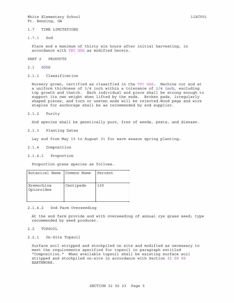
White Elementary School 11XCV01Ft. Benning, GA
1.7 TIME LIMITATIONS
1.7.1 Sod
Place sod a maximum of thirty six hours after initial harvesting, in accordance with TPI GSS as modified herein.
PART 2 PRODUCTS
2.1 SODS
2.1.1 Classification
Nursery grown, certified as classified in the TPI GSS. Machine cut sod at a uniform thickness of 3/4 inch within a tolerance of 1/4 inch, excluding top growth and thatch. Each individual sod piece shall be strong enough to support its own weight when lifted by the ends. Broken pads, irregularly shaped pieces, and torn or uneven ends will be rejected.Wood pegs and wire staples for anchorage shall be as recommended by sod supplier.
2.1.2 Purity
Sod species shall be genetically pure, free of weeds, pests, and disease.
2.1.3 Planting Dates
Lay sod from May 15 to August 31 for warm season spring planting.
2.1.4 Composition
2.1.4.1 Proportion
Proportion grass species as follows.
Botanical Name Common Name Percent
Eremochloa Opioroides
Centipede 100
2.1.4.2 Sod Farm Overseeding
At the sod farm provide sod with overseeding of annual rye grass seed; type recommended by seed producer.
2.2 TOPSOIL
2.2.1 On-Site Topsoil
Surface soil stripped and stockpiled on site and modified as necessary to meet the requirements specified for topsoil in paragraph entitled "Composition." When available topsoil shall be existing surface soil stripped and stockpiled on-site in accordance with Section 31 00 00 EARTHWORK.
SECTION 32 92 23 Page 5
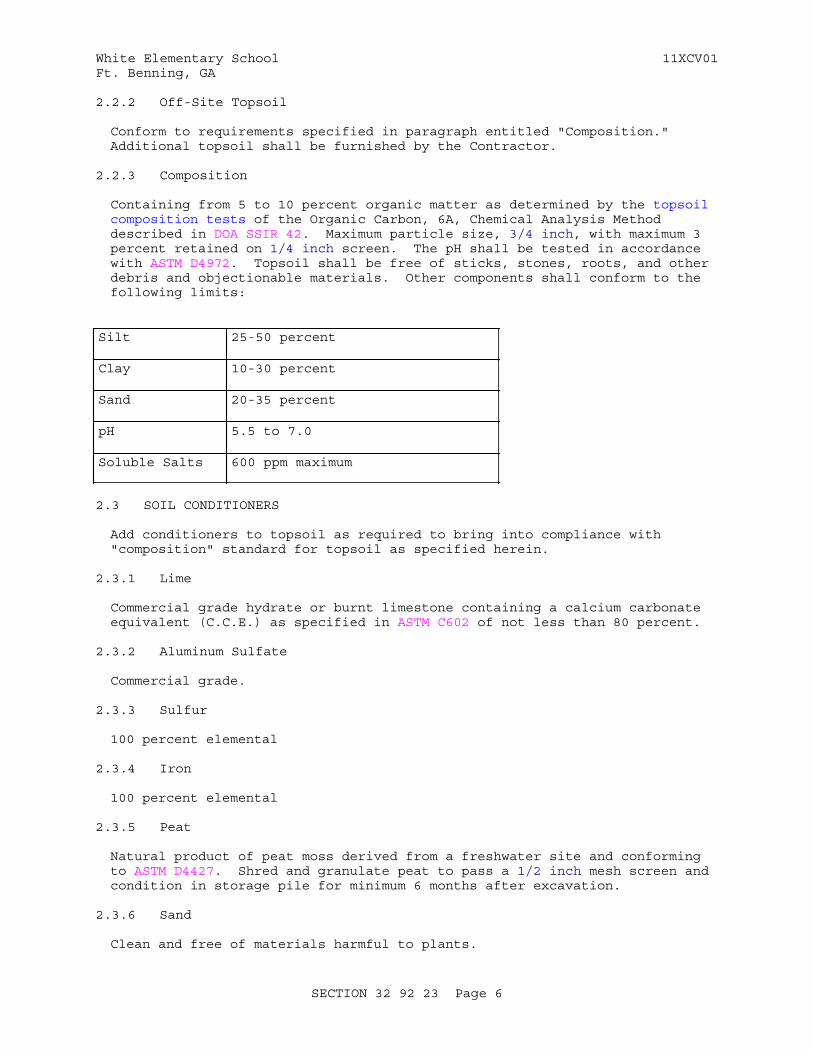
White Elementary School 11XCV01Ft. Benning, GA
2.2.2 Off-Site Topsoil
Conform to requirements specified in paragraph entitled "Composition." Additional topsoil shall be furnished by the Contractor.
2.2.3 Composition
Containing from 5 to 10 percent organic matter as determined by the topsoil composition tests of the Organic Carbon, 6A, Chemical Analysis Method described in DOA SSIR 42. Maximum particle size, 3/4 inch, with maximum 3 percent retained on 1/4 inch screen. The pH shall be tested in accordance with ASTM D4972. Topsoil shall be free of sticks, stones, roots, and other debris and objectionable materials. Other components shall conform to the following limits:
Silt 25-50 percent
Clay 10-30 percent
Sand 20-35 percent
pH 5.5 to 7.0
Soluble Salts 600 ppm maximum
2.3 SOIL CONDITIONERS
Add conditioners to topsoil as required to bring into compliance with "composition" standard for topsoil as specified herein.
2.3.1 Lime
Commercial grade hydrate or burnt limestone containing a calcium carbonate equivalent (C.C.E.) as specified in ASTM C602 of not less than 80 percent.
2.3.2 Aluminum Sulfate
Commercial grade.
2.3.3 Sulfur
100 percent elemental
2.3.4 Iron
100 percent elemental
2.3.5 Peat
Natural product of peat moss derived from a freshwater site and conforming to ASTM D4427. Shred and granulate peat to pass a 1/2 inch mesh screen and condition in storage pile for minimum 6 months after excavation.
2.3.6 Sand
Clean and free of materials harmful to plants.
SECTION 32 92 23 Page 6
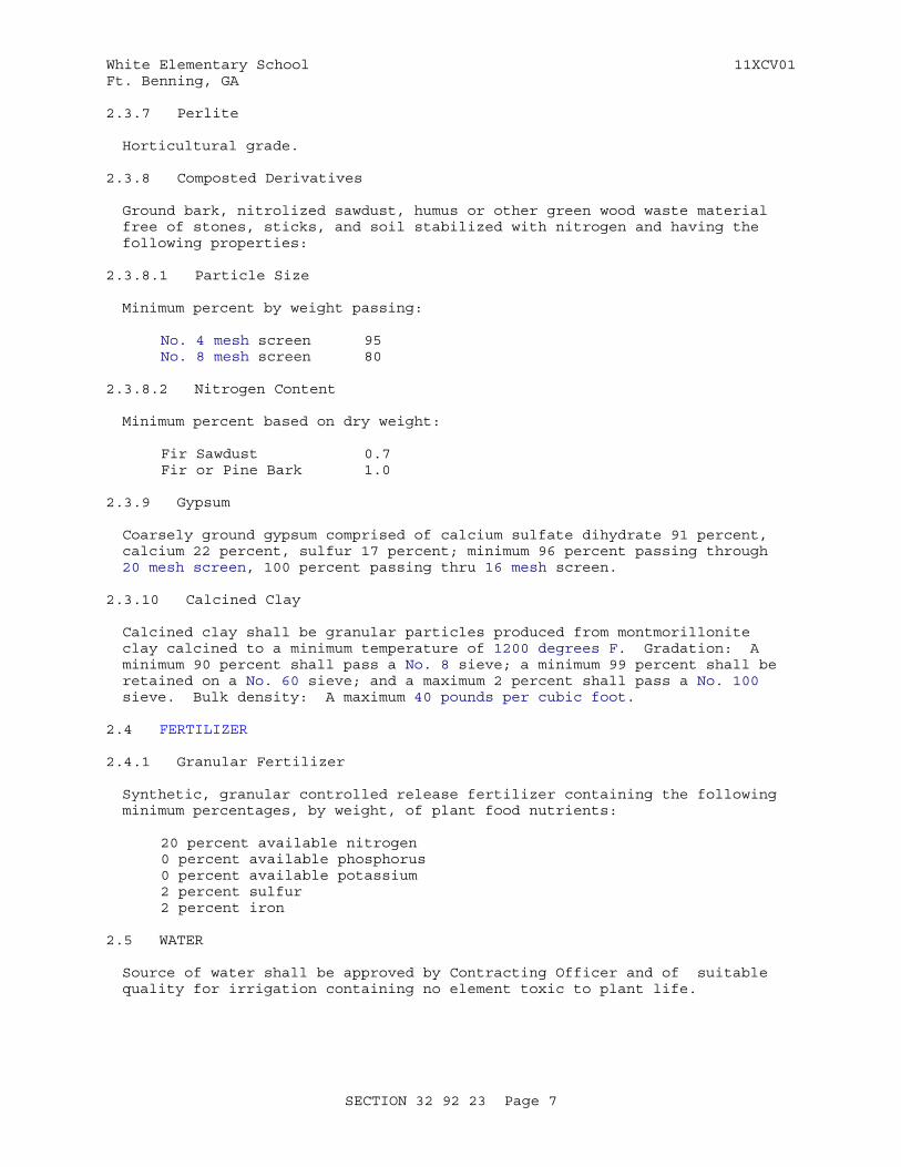
White Elementary School 11XCV01Ft. Benning, GA
2.3.7 Perlite
Horticultural grade.
2.3.8 Composted Derivatives
Ground bark, nitrolized sawdust, humus or other green wood waste material free of stones, sticks, and soil stabilized with nitrogen and having the following properties:
2.3.8.1 Particle Size
Minimum percent by weight passing:
No. 4 mesh screen 95No. 8 mesh screen 80
2.3.8.2 Nitrogen Content
Minimum percent based on dry weight:
Fir Sawdust 0.7Fir or Pine Bark 1.0
2.3.9 Gypsum
Coarsely ground gypsum comprised of calcium sulfate dihydrate 91 percent, calcium 22 percent, sulfur 17 percent; minimum 96 percent passing through 20 mesh screen, 100 percent passing thru 16 mesh screen.
2.3.10 Calcined Clay
Calcined clay shall be granular particles produced from montmorillonite clay calcined to a minimum temperature of 1200 degrees F. Gradation: A minimum 90 percent shall pass a No. 8 sieve; a minimum 99 percent shall be retained on a No. 60 sieve; and a maximum 2 percent shall pass a No. 100 sieve. Bulk density: A maximum 40 pounds per cubic foot.
2.4 FERTILIZER
2.4.1 Granular Fertilizer
Synthetic, granular controlled release fertilizer containing the following minimum percentages, by weight, of plant food nutrients:
20 percent available nitrogen0 percent available phosphorus0 percent available potassium2 percent sulfur2 percent iron
2.5 WATER
Source of water shall be approved by Contracting Officer and of suitable quality for irrigation containing no element toxic to plant life.
SECTION 32 92 23 Page 7
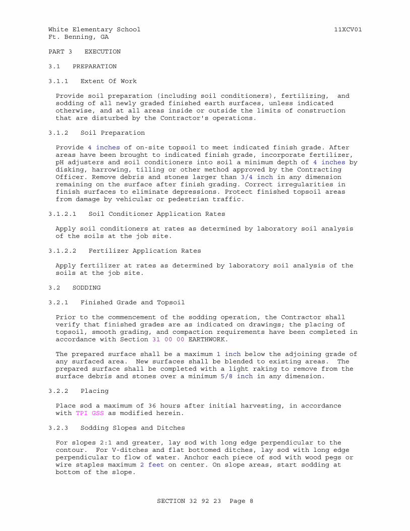
White Elementary School 11XCV01Ft. Benning, GA
PART 3 EXECUTION
3.1 PREPARATION
3.1.1 Extent Of Work
Provide soil preparation (including soil conditioners), fertilizing, and sodding of all newly graded finished earth surfaces, unless indicated otherwise, and at all areas inside or outside the limits of construction that are disturbed by the Contractor's operations.
3.1.2 Soil Preparation
Provide 4 inches of on-site topsoil to meet indicated finish grade. After areas have been brought to indicated finish grade, incorporate fertilizer, pH adjusters and soil conditioners into soil a minimum depth of 4 inches by disking, harrowing, tilling or other method approved by the Contracting Officer. Remove debris and stones larger than 3/4 inch in any dimension remaining on the surface after finish grading. Correct irregularities in finish surfaces to eliminate depressions. Protect finished topsoil areas from damage by vehicular or pedestrian traffic.
3.1.2.1 Soil Conditioner Application Rates
Apply soil conditioners at rates as determined by laboratory soil analysis of the soils at the job site.
3.1.2.2 Fertilizer Application Rates
Apply fertilizer at rates as determined by laboratory soil analysis of the soils at the job site.
3.2 SODDING
3.2.1 Finished Grade and Topsoil
Prior to the commencement of the sodding operation, the Contractor shall verify that finished grades are as indicated on drawings; the placing of topsoil, smooth grading, and compaction requirements have been completed in accordance with Section 31 00 00 EARTHWORK.
The prepared surface shall be a maximum 1 inch below the adjoining grade of any surfaced area. New surfaces shall be blended to existing areas. The prepared surface shall be completed with a light raking to remove from the surface debris and stones over a minimum 5/8 inch in any dimension.
3.2.2 Placing
Place sod a maximum of 36 hours after initial harvesting, in accordance with TPI GSS as modified herein.
3.2.3 Sodding Slopes and Ditches
For slopes 2:1 and greater, lay sod with long edge perpendicular to the contour. For V-ditches and flat bottomed ditches, lay sod with long edge perpendicular to flow of water. Anchor each piece of sod with wood pegs or wire staples maximum 2 feet on center. On slope areas, start sodding at bottom of the slope.
SECTION 32 92 23 Page 8
White Elementary School 11XCV01Ft. Benning, GA
3.2.4 Finishing
After completing sodding, blend edges of sodded area smoothly into surrounding area. Air pockets shall be eliminated and a true and even surface shall be provided. Frayed edges shall be trimmed and holes and missing corners shall be patched with sod.
3.2.5 Rolling
Immediately after sodding, firm entire area except for slopes in excess of 3 to 1 with a roller not exceeding 90 pounds for each foot of roller width.
3.2.6 Watering
Start watering areas sodded as required by daily temperature and wind conditions. Apply water at a rate sufficient to ensure thorough wetting of soil to minimum depth of 6 inches. Run-off, puddling, and wilting shall be prevented. Unless otherwise directed, watering trucks shall not be driven over turf areas. Watering of other adjacent areas or plant material shall be prevented.
3.3 PROTECTION OF TURF AREAS
Immediately after turfing, protect area against traffic and other use.
3.4 RENOVATION OF EXISTING TURF AREA
3.4.1 Aeration
Upon completion of weed eradication operations and Contracting Officer's approval to proceed, aerate turf areas indicated , by approved device. Core, by pulling soil plugs, to a minimum depth of 6 inches. Leave all soil plugs, that are produced, in the turf area.
Keep clean at all times at least one paved pedestrian access route and one paved vehicular access route to each building. Clean all soil plugs off of other paving when work is complete.
3.5 RESTORATION
Restore to original condition existing turf areas which have been damaged during turf installation operations. Keep clean at all times at least one paved pedestrian access route and one paved vehicular access route to each building. Clean other paving when work in adjacent areas is complete.
-- End of Section --
SECTION 32 92 23 Page 9

White Elementary School 11XCV01Ft. Benning, GA
SECTION TABLE OF CONTENTS
DIVISION 32 - EXTERIOR IMPROVEMENTS
SECTION 32 93 00
EXTERIOR PLANTS
02/10
PART 1 GENERAL
1.1 REFERENCES 1.2 RELATED REQUIREMENTS 1.3 SUBMITTALS 1.4 QUALITY ASSURANCE 1.4.1 Topsoil Composition Tests 1.4.2 Nursery Certifications 1.4.3 State Landscape Contractor's License 1.4.4 Plant Material Photographs 1.4.5 Percolation Test 1.4.6 Erosion Assessment 1.4.7 Pre-Installation Meeting 1.5 DELIVERY, STORAGE, AND HANDLING 1.5.1 Delivery 1.5.1.1 Branched Plant Delivery 1.5.1.2 Soil Amendment Delivery 1.5.1.3 Plant Labels 1.5.2 Storage 1.5.2.1 Plant Storage and Protection 1.5.2.2 Fertilizer, Gypsum, pH Adjusters and Mulch Storage 1.5.2.3 Topsoil 1.5.2.4 Weed Control Fabric 1.5.3 Handling 1.5.4 TIME LIMITATION 1.6 TIME RESTRICTIONS AND PLANTING CONDITIONS 1.6.1 Planting Dates 1.6.1.1 Deciduous Material 1.6.1.2 Evergreen Material 1.6.2 Restrictions 1.7 GUARANTEE 1.8 SUSTAINABLE DESIGN REQUIREMENTS 1.8.1 Local/Regional Materials 1.8.2 Plastic Identification 1.8.3 Forest Stewardship Council (FSC) Certification
PART 2 PRODUCTS
2.1 PLANTS 2.1.1 Regulations and Varieties 2.1.2 Shape and Condition 2.1.2.1 Deciduous Trees and Shrubs 2.1.2.2 Evergreen Trees and Shrubs 2.1.2.3 Ground Covers and Vines 2.1.3 Plant Size 2.1.4 Root Ball Size
SECTION 32 93 00 Page 1

White Elementary School 11XCV01Ft. Benning, GA
2.1.4.1 Mycorrhizal fungi inoculum 2.1.5 Growth of Trunk and Crown 2.1.5.1 Deciduous Trees 2.1.5.2 Deciduous Shrubs 2.1.5.3 Coniferous Evergreen Plant Material 2.1.5.4 Broadleaf Evergreen Plant Material 2.1.5.5 Ground Cover and Vine Plant Material 2.2 TOPSOIL 2.2.1 Existing Soil 2.2.2 On-Site Topsoil 2.2.3 Off-Site Topsoil 2.2.4 Composition 2.3 SOIL CONDITIONERS 2.3.1 Lime 2.3.2 Aluminum Sulfate 2.3.3 Sulfur 2.3.4 Iron 2.3.5 Peat 2.3.6 Sand 2.3.7 Perlite 2.3.8 Composted Derivatives 2.3.8.1 Particle Size 2.3.8.2 Nitrogen Content 2.3.8.3 Biobased Content 2.3.9 Gypsum 2.3.10 Vermiculite 2.3.11 Rotted Manure 2.4 PLANTING SOIL MIXTURES 2.5 FERTILIZER 2.5.1 Granular Fertilizer 2.5.2 Fertilizer Tablets 2.6 WEED CONTROL FABRIC 2.6.1 Roll Type Polypropylene or Polyester Mats 2.7 MULCH 2.7.1 Organic Mulch Materials 2.7.2 Recycled Organic Mulch 2.8 STAKING AND GUYING MATERIAL 2.8.1 Staking Material 2.8.1.1 Tree Support Stakes 2.8.2 Guying Material 2.8.2.1 Guying Wire 2.8.2.2 Guying Cable 2.8.3 Hose Chafing Guards 2.8.4 Flags 2.8.5 Turnbuckles 2.9 EDGING MATERIAL 2.9.1 Concrete Edging 2.10 ANTIDESICCANTS 2.11 EROSION CONTROL MATERIALS 2.11.1 Erosion Control Blanket 2.11.2 Erosion Control Fabric 2.11.3 Erosion Control Material Anchors 2.12 WATER 2.12.1 Hose 2.13 SOURCE QUALITY CONTROL
PART 3 EXECUTION
3.1 EXTENT OF WORK
SECTION 32 93 00 Page 2
White Elementary School 11XCV01Ft. Benning, GA
3.2 ALTERNATIVE HERBICIDE TREATMENT (SOLARIZING SOIL) 3.3 PREPARATION 3.3.1 Protection 3.3.2 Layout 3.3.3 Erosion Control 3.3.4 Soil Preparation 3.3.4.1 pH Adjuster Application Rates 3.3.4.2 Soil Conditioner Application Rates 3.3.4.3 Fertilizer Application Rates 3.4 PLANT BED PREPARATION 3.5 PLANT INSTALLATION 3.5.1 Individual Plant Pit Excavation 3.5.2 Plant Beds with Multiple Plants 3.5.3 Handling and Setting 3.5.3.1 Balled and Burlapped Stock 3.5.3.2 Container Grown Stock 3.5.3.3 Ground Covers and Vines 3.5.4 Earth Mounded Watering Basin for Individual Plant Pits 3.5.5 Weed Control Fabric Installation 3.5.6 Erosion Control Material 3.5.7 Placement of Mulch Topdressing 3.5.8 Mulch Topdressing 3.5.9 Installation of Edging 3.5.10 Fertilization 3.5.10.1 Fertilizer Tablets 3.5.10.2 Granular Fertilizer 3.5.11 Watering 3.5.12 Staking and Guying 3.5.12.1 Staking 3.5.12.2 Chafing Guards 3.5.12.3 Flags 3.5.13 Pruning 3.5.13.1 Trees and Shrubs 3.5.13.2 Wound Dressing 3.6 RESTORATION AND CLEAN UP 3.6.1 Restoration 3.6.2 Clean Up
-- End of Section Table of Contents --
SECTION 32 93 00 Page 3
White Elementary School 11XCV01Ft. Benning, GA
SECTION 32 93 00
EXTERIOR PLANTS02/10
PART 1 GENERAL
1.1 REFERENCES
The publications listed below form a part of this specification to the extent referenced. The publications are referred to within the text by the basic designation only.
AMERICAN NURSERY & LANDSCAPE ASSOCIATION (ANLA)
ANSI/ANLA Z60.1 (1996; R 2004) American Standard for Nursery Stock
ASTM INTERNATIONAL (ASTM)
ASTM A580/A580M (2012a) Standard Specification for Stainless Steel Wire
ASTM C602 (2007) Agricultural Liming Materials
ASTM D1972 (1997; R 2005) Standard Practice for Generic Marking of Plastic Products
ASTM D4427 (2007) Peat Samples by Laboratory Testing
ASTM D4972 (2001; R 2007) pH of Soils
ASTM D5268 (2007) Topsoil Used for Landscaping Purposes
ASTM D5852 (2000; R 2007) Standard Test Method for Erodibility Determination of Soil in the Field or in the Laboratory by the Jet Index Method
ASTM D6629 (2001; R 2007) Selection of Methods for Estimating Soil Loss by Erosion
FOREST STEWARDSHIP COUNCIL (FSC)
FSC STD 01 001 (2000) Principles and Criteria for Forest Stewardship
L.H. BAILEY HORTORIUM (LHBH)
LHBH (1976) Hortus Third
TREE CARE INDUSTRY ASSOCIATION (TCIA)
TCIA A300P1 (2008) ANSI A300 Part1: Tree Care Operations - Trees, Shrubs and Other Woody Plant Maintenance Standard Practices -
SECTION 32 93 00 Page 4
White Elementary School 11XCV01Ft. Benning, GA
Pruning
TCIA Z133.1 (2006) American National Standard for Arboricultural Operations - Pruning, Repairing, Maintaining, and Removing Trees, and Cutting Brush - Safety Requirements
U.S. DEPARTMENT OF AGRICULTURE (USDA)
DOA SSIR 42 (1996) Soil Survey Investigation Report No. 42, Soil Survey Laboratory Methods Manual, Version 3.0
U.S. GREEN BUILDING COUNCIL (USGBC)
LEED (2009) Leadership in Energy and Environmental Design(tm) for Schools Rating System
1.2 RELATED REQUIREMENTS
Section 31 00 00 EARTHWORK, Section 32 92 19 SEEDING, Section 32 92 23 SODDING, and Section 32 05 33 LANDSCAPE ESTABLISHMENT applies to this section for pesticide use and plant establishment requirements, with additions and modifications herein.
1.3 SUBMITTALS
Government approval is required for submittals with a "G" designation; submittals not having a "G" designation are for information only. When used, a designation following the "G" designation identifies the office that will review the submittal for the Government. The following shall be submitted in accordance with Section 01 33 00 SUBMITTAL PROCEDURES:
SD-01 Preconstruction Submittals
State Landscape Contractor's License
Time Restrictions and Planting Conditions
Indicate anticipated dates and locations for each type of planting.
SD-03 Product Data
Local/Regional Materials; (LEED)
Submit documentation indicating distance between manufacturing facility and the project site. Indicate distance of raw material origin from the project site. Indicate relative dollar value of local/regional materials to total dollar value of products included in project.
PeatComposted DerivativesRotted ManureOrganic Mulch Materials
Submit documentation indicating type of biobased material in
SECTION 32 93 00 Page 5
White Elementary School 11XCV01Ft. Benning, GA
product and biobased content. Indicate relative dollar value of biobased content products to total dollar value of products included in project.
Gypsum; (LEED)Mulch; GHose; (LEED)
Submit documentation indicating percentage of post-industrial and post-consumer recycled content per unit of product. Indicate relative dollar value of recycled content products to total dollar value of products included in project.
Fertilizer
Weed control fabric; G
Staking Material
Submit documentation certifying products are from salvaged/recovered lumber sources and indicating percentage of salvaged/recovered content per unit of product.
Antidesiccants
Erosion control materials
SD-04 Samples
Mulch; G
Submit one pint of mulch.
Photographs; Submit photographs of all plant material.
SD-06 Test Reports
Topsoil composition tests; Soil Test of proposed area
Percolation Test; Percolation Test of proposed area
SD-07 Certificates
Forest Stewardship Council (FSC) Certification; (LEED)
Nursery certifications
Indicate names of plants in accordance with the LHBH, including type, quality, and size.
SD-10 Operation and Maintenance Data
Plastic Identification
When not labeled, identify types in Operation and Maintenance Manual.
SECTION 32 93 00 Page 6
White Elementary School 11XCV01Ft. Benning, GA
1.4 QUALITY ASSURANCE
1.4.1 Topsoil Composition Tests
Commercial test from an independent testing laboratory including basic soil groups (moisture and saturation percentages, Nitrogen-Phosphorus-Potassium (N-P-K) ratio, pH (ASTM D4972), soil salinity), secondary nutrient groups (calcium, magnesium, sodium, Sodium Absorption Ratio (SAR)), micronutrients (zinc, manganese, iron, copper), toxic soil elements (boron, chloride, sulfate), cation exchange and base saturation percentages, and soil amendment and fertilizer recommendations with quantities for plant material being transplanted. Soil required for each test shall include a maximum depth of 18 inches of approximately 1 quart volume for each test. Areas sampled should not be larger than 1 acre and should contain at least 6-8 cores for each sample area and be thoroughly mixed. Problem areas should be sampled separately and compared with samples taken from adjacent non-problem areas. The location of the sample areas should be noted and marked on a parcel or planting map for future reference.
1.4.2 Nursery Certifications
a. Indicate on nursery letterhead the name of plants in accordance with the LHBH, including botanical common names, quality, and size.
1.4.3 State Landscape Contractor's License
Construction company shall hold a landscape contractors license in the state where the work is performed and have a minimum of five years landscape construction experience. Submit copy of license and three references for similar work completed in the last five years.
1.4.4 Plant Material Photographs
Contractor shall submit nursery photographs, for government approval prior to ordering, for each tree larger than 24-inch box/ 2-inch caliper size.
1.4.5 Percolation Test
Immediately following rough grading operation, identify a typical location for one of the largest trees and or shrubs and excavate a pit per the project details. Fill the pit with water to a depth of 12 inches. The length of time required for the water to percolate into the soil, leaving the pit empty, shall be measured by the project Landscape Architect and verified by the Contracting Officer. Within six hours of the time the water has drained from the pit, the Contractor, with the Contracting Officer and project Landscape Architect present, shall again fill the pit with water to a depth of 12 inches. If the water does not completely percolate into the soil within 9 hours, a determination shall be made whether a drainage system or a soil penetrant will be required for each tree and or shrub being transplanted.
1.4.6 Erosion Assessment
Assess potential effects of soil management practices on soil loss in accordance with ASTM D6629. Assess erodibility of soil with dominant soil structure less than 2.8 to 3.1 inches in accordance with ASTM D5852.
SECTION 32 93 00 Page 7
White Elementary School 11XCV01Ft. Benning, GA
1.4.7 Pre-Installation Meeting
Convene a pre-installation meeting a minimum of one week prior to commencing work of this section. Require attendance of parties directly affecting work of this section. Review conditions of operations, procedures and coordination with related work. Agenda shall include the following:
a. Tour, inspect, and discuss conditions of planting materials.
b. Review planting schedule and maintenance.
c. Review required inspections.
d. Review environmental procedures.
1.5 DELIVERY, STORAGE, AND HANDLING
1.5.1 Delivery
1.5.1.1 Branched Plant Delivery
Deliver with branches tied and exposed branches covered with material which allows air circulation. Prevent damage to branches, trunks, root systems, and root balls and desiccation of leaves.
1.5.1.2 Soil Amendment Delivery
Deliver to the site in original, unopened containers bearing manufacturer's chemical analysis, name, trade name, or trademark, and indication of conformance to state and federal laws. Instead of containers, fertilizer, gypsum, sulfur, iron, and lime may be furnished in bulk with a certificate indicating the above information. Store in dry locations away from contaminates.
1.5.1.3 Plant Labels
Deliver plants with durable waterproof labels in weather-resistant ink. Provide labels stating the correct botanical and common plant name and variety as applicable and size as specified in the list of required plants. Attach to plants, bundles, and containers of plants. Groups of plants may be labeled by tagging one plant. Labels shall be legible for a minimum of 60 days after delivery to the planting site.
1.5.2 Storage
1.5.2.1 Plant Storage and Protection
Store and protect plants not planted on the day of arrival at the site as follows:
a. Shade and protect plants in outside storage areas from the wind and direct sunlight until planted.
b. Heel-in bare root plants.
c. Protect balled and burlapped plants from freezing or drying out by covering the balls or roots with moist burlap, sawdust, wood chips, shredded bark, peat moss, or other approved material. Provide covering
SECTION 32 93 00 Page 8
White Elementary School 11XCV01Ft. Benning, GA
which allows air circulation.
d. Keep plants in a moist condition until planted by watering with a fine mist spray.
e. Do not store plant material directly on concrete or bituminous surfaces.
1.5.2.2 Fertilizer, Gypsum, pH Adjusters and Mulch Storage
Store in dry locations away from contaminants.
1.5.2.3 Topsoil
Prior to stockpiling topsoil, eradicate on site undesirable growing vegetation. Clear and grub existing vegetation three to four weeks prior to stockpiling existing topsoil.
1.5.2.4 Weed Control Fabric
Store materials on site in enclosures or under protective covering in dry location. Store under cover out of direct sunlight. Do not store materials directly on ground.
1.5.3 Handling
Do not drop or dump plants from vehicles. Avoid damaging plants being moved from nursery or storage area to planting site. Handle boxed, balled and burlapped container plants carefully to avoid damaging or breaking the earth ball or root structure. Do not handle plants by the trunk or stem. Remove damaged plants from the site.
1.5.4 TIME LIMITATION
Except for container-grown plant material, the time limitation from digging to installing plant material shall be a maximum of 90 days. The time limitation between installing the plant material and placing the mulch shall be a maximum of 24 hours.
1.6 TIME RESTRICTIONS AND PLANTING CONDITIONS
Coordinate installation of planting materials during optimal planting seasons for each type of plant material required.
1.6.1 Planting Dates
Plant all plants from May 15th to October 15th.
1.6.1.1 Deciduous Material
Deciduous material from May 15th to August 31st for spring /summer planting and from September 1st to December 1st for fall /winter planting.
1.6.1.2 Evergreen Material
Evergreen material from May 15th to August 31st for spring /summer planting and from September 1st to December 1st for fall /winter planting.
SECTION 32 93 00 Page 9
White Elementary School 11XCV01Ft. Benning, GA
1.6.2 Restrictions
Do not plant when ground is frozen, snow covered, muddy, or when air temperature exceeds 90 degrees Fahrenheit
1.7 GUARANTEE
All plants shall be guaranteed for one year beginning on the date of inspection by the Contracting Officer to commence the plant establishment period, against defects including death and unsatisfactory growth, except for defects resulting from lack of adequate maintenance, neglect, or abuse by the Government or by weather conditions unusual for the warranty period.
Remove and replace dead planting materials immediately unless required to plant in the succeeding planting season. At end of warranty period, replace planting materials that die or have 25 percent or more of their branches that die during the construction operations or the guarantee period.
1.8 SUSTAINABLE DESIGN REQUIREMENTS
1.8.1 Local/Regional Materials
Use materials or products extracted, harvested, or recovered, as well as manufactured, within a 500 mile radius from the project site, if available from a minimum of three sources. See Section 01 33 29 LEED(tm) DOCUMENTATION for cumulative total local material requirements. Landscaping materials may be locally available.
1.8.2 Plastic Identification
Verify that plastic products to be incorporated into the project are labeled in accordance with ASTM D1972. Where products are not labeled, provide product data indicating polymeric information in Operation and Maintenance Manual.Type 1: Polyethylene Terephthalate (PET, PETE).Type 2: High Density Polyethylene (HDPE).Type 3: Vinyl (Polyvinyl Chloride or PVC).Type 4: Low Density Polyethylene (LDPE).Type 5: Polypropylene (PP).Type 6: Polystyrene (PS).Type 7: Other. Use of this code indicates that the package in question is made with a resin other than the six listed above, or is made of more than one resin listed above, and used in a multi-layer combination.
1.8.3 Forest Stewardship Council (FSC) Certification
Use FSC-certified wood where specified. Provide letter of certification signed by lumber supplier. Indicate compliance with FSC STD 01 001 and identify certifying organization. Submit FSC certification numbers; identify each certified product on a line-item basis. Submit copies of invoices bearing the FSC certification numbers.
SECTION 32 93 00 Page 10
White Elementary School 11XCV01Ft. Benning, GA
PART 2 PRODUCTS
2.1 PLANTS
2.1.1 Regulations and Varieties
Existing trees and shrubs to remain shall be protected and a planting plan be arranged around them. Furnish nursery stock in accordance with ANSI/ANLA Z60.1, except as otherwise specified or indicated. Each plant or group of planting shall have a "key" number indicated on the nursery certifications of the plant schedule. Furnish plants, including turf grass, grown under climatic conditions similar to those in the locality of the project. Plants specified shall be low maintenance varieties, tolerant of site's existing soils and climate without supplemental irrigation or fertilization once established. Plants of the same specified size shall be of uniform size and character of growth. Plants shall be chosen with their mature size and growth habit in mind to avoid over-planting and conflict with other plants, structures or underground utility lines. All plants shall comply with all Federal and State Laws requiring inspection for plant diseases and infestation.
2.1.2 Shape and Condition
Well-branched, well-formed, sound, vigorous, healthy planting stock free from disease, sunscald, windburn, abrasion, and harmful insects or insect eggs and having a healthy, normal, and undamaged root system.
2.1.2.1 Deciduous Trees and Shrubs
Symmetrically developed and of uniform habit of growth, with straight boles or stems, and free from objectionable disfigurements.
2.1.2.2 Evergreen Trees and Shrubs
Well developed symmetrical tops with typical spread of branches for each particular species or variety.
2.1.2.3 Ground Covers and Vines
Number and length of runners and clump sizes indicated, and of the proper age for the grade of plants indicated, furnished in removable containers, integral containers, or formed homogeneous soil section.
2.1.3 Plant Size
Minimum sizes measured after pruning and with branches in normal position, shall conform to measurements indicated, based on the average width or height of the plant for the species as specified in ANSI/ANLA Z60.1. Plants larger in size than specified may be provided with approval of the Contracting Officer. When larger plants are provided, increase the ball of earth or spread of roots in accordance with ANSI/ANLA Z60.1.
2.1.4 Root Ball Size
All box-grown, field potted, field boxed, collected, plantation grown, bare root, balled and burlapped, container grown, processed-balled, and in-ground fabric bag-grown root balls shall conform to ANSI/ANLA Z60.1. All wrappings and ties shall be biodegradable. Root growth in container grown plants shall be sufficient to hold earth intact when removed from
SECTION 32 93 00 Page 11
White Elementary School 11XCV01Ft. Benning, GA
containers. Root bound plants will not be accepted.
2.1.4.1 Mycorrhizal fungi inoculum
Before shipment, root systems shall contain mycorrhizal fungi inoculum.
2.1.5 Growth of Trunk and Crown
2.1.5.1 Deciduous Trees
A height to caliper relationship shall be provided in accordance with ANSI/ANLA Z60.1. Height of branching shall bear a relationship to the size and species of tree specified and with the crown in good balance with the trunk. The trees shall not be "poled" or the leader removed.
a. Single stem: The trunk shall be reasonably straight and symmetrical with crown and have a persistent main leader.
b. Multi-stem: All countable stems, in aggregate, shall average the size specified. To be considered a stem, there shall be no division of the trunk which branches more than 6 inches from ground level.
2.1.5.2 Deciduous Shrubs
Deciduous shrubs shall have the height and number of primary stems recommended by ANSI/ANLA Z60.1. Acceptable plant material shall be well shaped, with sufficient well-spaced side branches, and recognized by the trade as typical for the species grown in the region of the project.
2.1.5.3 Coniferous Evergreen Plant Material
Coniferous Evergreen plant material shall have the height-to-spread ratio recommended by ANSI/ANLA Z60.1. The coniferous evergreen trees shall not be "poled" or the leader removed. Acceptable plant material shall be exceptionally heavy, well shaped and trimmed to form a symmetrical and tightly knit plant. The form of growth desired shall be as indicated.
2.1.5.4 Broadleaf Evergreen Plant Material
Broadleaf evergreen plant material shall have the height-to-spread ratio recommended by ANSI/ANLA Z60.1. Acceptable plant material shall be well shaped and recognized by the trade as typical for the variety grown in the region of the project.
2.1.5.5 Ground Cover and Vine Plant Material
Ground cover and vine plant material shall have the minimum number of runners and length of runner recommended by ANSI/ANLA Z60.1. Plant material shall have heavy, well developed and balanced crown with vigorous, well developed root system and shall be furnished in containers.
2.2 TOPSOIL
2.2.1 Existing Soil
Modify to conform to requirements specified in paragraph entitled "Composition."
SECTION 32 93 00 Page 12
White Elementary School 11XCV01Ft. Benning, GA
2.2.2 On-Site Topsoil
Surface soil stripped and stockpiled on site and modified as necessary to meet the requirements specified for topsoil in paragraph entitled "Composition." When available topsoil shall be existing surface soil stripped and stockpiled on-site in accordance with Section 31 00 00 EARTHWORK FOR STRUCTURES.
2.2.3 Off-Site Topsoil
Conform to requirements specified in paragraph entitled "Composition." Additional topsoil shall be furnished by the Contractor.
2.2.4 Composition
Evaluate soil for use as topsoil in accordance with ASTM D5268. From 5 to 10 percent organic matter as determined by the topsoil composition tests of the Organic Carbon, 6A, Chemical Analysis Method described in DOA SSIR 42. Maximum particle size, 3/4 inch, with maximum 3 percent retained on 1/4 inch screen. The pH shall be tested in accordance with ASTM D4972. Topsoil shall be free of sticks, stones, roots, plants, and other debris and objectionable materials. Other components shall conform to the following limits:
Silt 25-50 percent
Clay 10-30 percent
Sand 20-35 percent
pH 5.5 to 7.0
Soluble Salts 600 ppm maximum
2.3 SOIL CONDITIONERS
Provide singly or in combination as required to meet specified requirements for topsoil. Soil conditioners shall be nontoxic to plants.
2.3.1 Lime
Commercial grade hydrated or burnt limestone containing a calcium carbonate equivalent (C.C.E.) as specified in ASTM C602 of not less than 80 percent.
2.3.2 Aluminum Sulfate
Commercial grade.
2.3.3 Sulfur
100 percent elemental
2.3.4 Iron
100 percent elemental
SECTION 32 93 00 Page 13
White Elementary School 11XCV01Ft. Benning, GA
2.3.5 Peat
Natural product of peat moss derived from a freshwater site and conforming to ASTM D4427. Shred and granulate peat to pass a 1/2 inch mesh screen and condition in storage pile for minimum 6 months after excavation. Biobased content shall be a minimum of 100 percent. Peat shall not contain invasive species, including seeds.
2.3.6 Sand
Clean and free of materials harmful to plants.
2.3.7 Perlite
Horticultural grade.
2.3.8 Composted Derivatives
Ground bark, nitrolized sawdust, humus or other green wood waste material free of stones, sticks, invasive species, including seeds, and soil stabilized with nitrogen and having the following properties:
2.3.8.1 Particle Size
Minimum percent by weight passing:
No. 4 mesh screen 95No. 8 mesh screen 80
2.3.8.2 Nitrogen Content
Minimum percent based on dry weight:
Fir Sawdust 0.7Fir or Pine Bark 1.0
2.3.8.3 Biobased Content
Minimum 100 percent.
2.3.9 Gypsum
Coarsely ground gypsum from recycled scrap gypsum board comprised of calcium sulfate dihydrate 91 percent, calcium 22 percent, sulfur 17 percent; minimum 96 percent passing through 20 mesh screen, 100 percent passing thru 16 mesh screen.
2.3.10 Vermiculite
Horticultural grade for planters.
2.3.11 Rotted Manure
Well rotted horse or cattle manure containing maximum 25 percent by volume of straw, sawdust, or other bedding materials; free of seeds, stones, sticks, soil, and other invasive species.
SECTION 32 93 00 Page 14
White Elementary School 11XCV01Ft. Benning, GA
2.4 PLANTING SOIL MIXTURES
100 percent on-site topsoil.
2.5 FERTILIZER
Fertilizer for groundcover, wildflowers and grasses is not permitted.Fertilizer for trees, plants, and shrubs shall be as recommended by plant supplier, except synthetic chemical fertilizers are not permitted. Fertilizers containing petrochemical additives or that have been treated with pesticides or herbicides are not permitted.
2.5.1 Granular Fertilizer
Organic, granular controlled release fertilizer containing the following minimum percentages, by weight, of plant food nutrients:
20 percent available nitrogen0 percent available phosphorus0 percent available potassium5 percent sulfur5 percent iron
2.5.2 Fertilizer Tablets
Organic, plant tablets composed of tightly compressed fertilizer chips forming a tablet that is insoluble in water, is designed to provide a continuous release of nutrients for at least 24 months and contains the following minimum percentages, by weight, of plant food nutrients:
20 percent available nitrogen20 percent available phosphorus5 percent available potassium
2.6 WEED CONTROL FABRIC
2.6.1 Roll Type Polypropylene or Polyester Mats
Fabric shall be woven, needle punched or non-woven and treated for protection against deterioration due to ultraviolet radiation. Fabric shall be minimum 99 percent opaque to prevent photosynthesis and seed germination from occurring, yet allowing air, water and nutrients to pass thru to the roots. Minimum weight shall be 5 ounces per square yard with a minimum thickness of 20 mils with a 20 year (minimum) guarantee.
2.7 MULCH
Free from noxious weeds, mold, pesticides, or other deleterious materials.
2.7.1 Organic Mulch Materials
Ground or shredded bark from site when available. Biobased content shall be a minimum of 100 percent. Wood cellulose fiber shall be processed to contain no growth or germination-inhibiting factors, dyed with non-toxic, biodegradable dye to an appropriate color to facilitate visual metering of materials application. Paper-based hydraulic mulch shall contain a minimum of 100 percent post-consumer recycled content. Wood-based hydraulic mulch shall contain a minimum of 100 percent recycled material.
SECTION 32 93 00 Page 15
White Elementary School 11XCV01Ft. Benning, GA
2.7.2 Recycled Organic Mulch
Recycled mulch may include compost, tree trimmings, or pine needles with a gradation that passes through a 2-1/2 by 2-1/2 inchscreen. It shall be cleaned of all sticks a minimum 1 inch in diameter and plastic materials a minimum 3 inches length. The material shall be treated to retard the growth of mold and fungi.
2.8 STAKING AND GUYING MATERIAL
2.8.1 Staking Material
2.8.1.1 Tree Support Stakes
Rough sawn FSC-certified or salvaged hard wood free of knots, rot, cross grain, bark, long slivers, or other defects that impair strength. Stakes shall be minimum 2 inches square or 2 1/2 inch diameter by 8 feet long, pointed at one end.
2.8.2 Guying Material
2.8.2.1 Guying Wire
12 gauge annealed galvanized steel, ASTM A580/A580M.
2.8.2.2 Guying Cable
Minimum five-strand, 3/16 inch diameter galvanized steel cable plastic coated.
2.8.3 Hose Chafing Guards
New or used 2 ply 3/4 inch diameter reinforced rubber or plastic hose, black or dark green, all of same color.
2.8.4 Flags
White surveyor's plastic tape, long, fastened to guying wires or cables.
2.8.5 Turnbuckles
Galvanized or cadmium-plated steel with minimum 3 inch long openings fitted with screw eyes. Eye bolts shall be galvanized or cadmium-plated steel with one inch diameter eyes and screw length 1 1/2 inches, minimum.
2.9 EDGING MATERIAL
2.9.1 Concrete Edging
Cast-in-place 6 by 6 inch concrete mowstrip. Provide tooled contraction joints to a depth of 3/4 inch after the surface has been finished. Provide joints every 5 lineal feet. Provide 1/2 inch thick expansion joints at change of direction and where mowstrip abuts rigid pavement. Provide #4 reinforcement bar and other devices necessary to install and secure reinforcement. Provide a floated finish, then finish with a flexible bristle broom. 3,000 psi compressive concrete strength at 28 days as specified under Section 32 16 13 CONCRETE SIDEWALKS AND CURBS AND GUTTERS.
SECTION 32 93 00 Page 16
White Elementary School 11XCV01Ft. Benning, GA
2.10 ANTIDESICCANTS
Sprayable, water insoluble vinyl-vinledine complex which produce a moisture retarding barrier not removable by rain or snow. Film shall form at temperatures commonly encountered out of doors during planting season and have a moisture vapor transmission rate (MVT) of the resultant film of maximum 10 grams per 24 hours at 70 percent humidity.
2.11 EROSION CONTROL MATERIALS
Erosion control material shall conform to the following:
2.11.1 Erosion Control Blanket
70 percent agricultural straw/30 percent coconut fiber matrix stitched with a degradable nettings, designed to degrade within 12 months.
2.11.2 Erosion Control Fabric
Fabric shall be knitted construction of polypropylene yarn with uniform mesh openings 3/4 to 1 inch square with strips of biodegradable paper. Filler paper strips shall have a minimum life of 6 months.
2.11.3 Erosion Control Material Anchors
Erosion control anchors shall be as recommended by the manufacturer.
2.12 WATER
Source of water to be approved by Contracting Officer and suitable quality for irrigation and shall not contain elements toxic to plant life, including acids, alkalis, salts, chemical pollutants, and organic matter. Use collected storm water or graywater when available.
2.12.1 Hose
Hoses used for watering shall be a minimum of 60 percent post-consumer rubber or plastic.
2.13 SOURCE QUALITY CONTROL
The Contracting Officer and Landscape Architect of Record will inspect plant materials at the project site and approve them. Tag plant materials for size and quality.
PART 3 EXECUTION
3.1 EXTENT OF WORK
Provide soil preparation, fertilizing, tree, shrub, vine, groundcover, and planting, edging, staking and guying, weed control fabric, erosion control material and a mulch topdressing of all newly graded finished earth surfaces, unless indicated otherwise, and at all areas inside or outside the limits of construction that are disturbed by the Contractor's operations.
3.2 ALTERNATIVE HERBICIDE TREATMENT (SOLARIZING SOIL)
Within 48 hours of subsoil preparation, saturate soil with water to a depth
SECTION 32 93 00 Page 17
White Elementary School 11XCV01Ft. Benning, GA
of 3 feet. Immediately stake polyethylene sheeting over area to be planted. Stake tightly to surface of soil. Maintain sheeting in place for a minimum of 6 weeks. Immediately after removing sheeting, cover area to be planted with topsoil. Do not till soil prior to applying topsoil.
3.3 PREPARATION 3.3.1 Protection
Protect existing and proposed landscape features, elements, and sites from damage or contamination. Protect trees, vegetation, and other designated features by erecting high-visibility, reusable construction fencing. Locate fence no closer to trees than the drip line. Plan equipment and vehicle access to minimize and confine soil disturbance and compaction to areas indicated on Drawings.
3.3.2 Layout
Stake out approved plant material locations and planter bed outlines on the project site before digging plant pits or beds. The Contracting Officer reserves the right to adjust plant material locations to meet field conditions. Do not plant closer than 12 inches to a building wall, pavement edge, fence or wall edge and other similar structures. Provide on-site locations for excavated rock, soil, and vegetation.
3.3.3 Erosion Control
Provide erosion control and seeding with native plant species to protect slopes.
3.3.4 Soil Preparation
3.3.4.1 pH Adjuster Application Rates
Apply pH adjuster at rates as determined by laboratory soil analysis of the soils at the job site.
3.3.4.2 Soil Conditioner Application Rates
Apply soil conditioners at rates as determined by laboratory soil analysis of the soils at the job site.
3.3.4.3 Fertilizer Application Rates
Apply fertilizer at rates as determined by laboratory soil analysis of the soils at the job site.
3.4 PLANT BED PREPARATION
Verify location of underground utilities prior to excavation. Protect existing adjacent turf before excavations are made. Do not disturb topsoil and vegetation in areas outside those indicated on Drawings. Where planting beds occur in existing turf areas, remove turf to a depth that will ensure removal of entire root system. Measure depth of plant pits from finished grade. Depth of plant pit excavation shall be as indicated and provide proper relation between top of root ball and finished grade. Install plant material as specified in paragraph entitled "Plant Installation." Do not install trees within 10 feet of any utility lines or building walls.
SECTION 32 93 00 Page 18
White Elementary School 11XCV01Ft. Benning, GA
3.5 PLANT INSTALLATION
3.5.1 Individual Plant Pit Excavation
Excavate pits at least twice as large in diameter as the size of ball or container to depth shown.
3.5.2 Plant Beds with Multiple Plants
Excavate plant beds continuously throughout entire bed as outlined to depth shown.
3.5.3 Handling and Setting
Move plant materials only by supporting the root ball or container. Set plants on hand compacted layer of prepared backfill soil mixture 6 inches thick and hold plumb in the center of the pit until soil has been tamped firmly around root ball. Set plant materials, in relation to surrounding finish grade, one to 2 inches above depth at which they were grown in the nursery, collecting field or container. Replace plant material whose root balls are cracked or damaged either before or during the planting process.
Plant material shall be set in plant beds according to the drawings. Backfill soil mixture shall be placed on previously scarified subsoil to completely surround the root balls, and shall be brought to a smooth and even surface, blending to existing areas.
3.5.3.1 Balled and Burlapped Stock
Backfill with topsoil to approximately half the depth of ball and then tamp and water. Carefully remove or fold back excess burlap and tying materials from the top a minimum 1/3 depth from the top of the rootball. Tamp and complete backfill, place mulch topdressing, and water. Remove wires and non-biodegradable materials from plant pit prior to backfill operations.
3.5.3.2 Container Grown Stock
Remove from container and prevent damage to plant or root system.
3.5.3.3 Ground Covers and Vines
Do not remove plant materials from flats or containers until immediately before planting. Space at intervals indicated. Plant at a depth to sufficiently cover all roots. Start watering areas planted as required by temperature and wind conditions. Apply water at a rate sufficient to ensure thorough wetting of soil to a depth of 6 inches without run off or puddling. Smooth planting areas after planting to provide even, smooth finish. Mulch as indicated.
Smooth planting areas before planting to provide even, smooth finish. Plant after placing weed control fabric and mulch topdressing. Do not remove plant material from flats or containers until immediately before planting. Space at the intervals indicated. Plant at a depth to sufficiently cover all roots. Start watering areas planted as required by temperature and wind conditions. Apply water at a rate sufficient to ensure thorough wetting of soil to a depth of 6 inches without run off or puddling. Add mulch topdressing as needed.
SECTION 32 93 00 Page 19
White Elementary School 11XCV01Ft. Benning, GA
3.5.4 Earth Mounded Watering Basin for Individual Plant Pits
Form with topsoil around each plant by replacing a mound of topsoil around the edge of each plant pit. Watering basins shall be 6 inches deep for trees and 4 inches deep for shrubs. Eliminate basins around plants in plant beds containing multiple plants.
3.5.5 Weed Control Fabric Installation
Remove grass and weed vegetation, including roots, from within the area enclosed by edging. Completely cover areas enclosed by edging with specified weed control fabric prior to placing mulch layer. Overlap cut edges 6 inches.
3.5.6 Erosion Control Material
Install in accordance with manufacturer's instructions.
3.5.7 Placement of Mulch Topdressing
Place specified mulch topdressing on top of weed control fabric covering total area enclosed by edging. Place mulch topdressing to a depth of 3 inches.
3.5.8 Mulch Topdressing
Provide mulch topdressing over entire planter bed surfaces and individual plant surfaces including earth mound watering basin around plants to a depth of 3 inches after completion of plant installation and before watering. Keep mulch out of the crowns of shrubs. Place mulch a minimum 2 to 3 inches away from trunk of shrub or tree. Place on top of any weed control fabric.
3.5.9 Installation of Edging
Uniformly edge beds of plants to provide a clear cut division line between planted area and adjacent lawn. Construct bed shapes as indicated. Install concrete edging material as indicated. Install edging with minimum one inch left above ground level.
3.5.10 Fertilization
3.5.10.1 Fertilizer Tablets
Place fertilizer planting tablets evenly spaced around the plant pits to the manufacturer's recommended depth.
3.5.10.2 Granular Fertilizer
Apply granular fertilizer as a top coat prior to placing mulch layer and water thoroughly.
3.5.11 Watering
Start watering areas planted as required by temperature and wind conditions. Slow deep watering shall be used. Apply water at a rate sufficient to ensure thorough wetting of soil to a depth of 12 inches without run off or puddling. Watering of other plant material or adjacent areas shall be prevented.
SECTION 32 93 00 Page 20
White Elementary School 11XCV01Ft. Benning, GA
3.5.12 Staking and Guying
3.5.12.1 Staking
Stake plants with the number of stakes indicated complete with double strand of 12 gage guy wire as detailed. Attach guy wire half the tree height but not more than 5 feet high. Drive stakes to a depth of 2 1/2 to 3 feet into the ground outside the plant pit. Do not injure the root ball. Use hose chafer guards where guy wire comes in contact with tree trunk.
3.5.12.2 Chafing Guards
Use hose chafing guards, as specified where guy wire will contact the plant.
3.5.12.3 Flags
Securely fasten flags on each guy wire approximately two-thirds of the distance up from ground level.
3.5.13 Pruning
Prune in accordance with safety requirement of TCIA Z133.1.
3.5.13.1 Trees and Shrubs
Remove dead and broken branches. Prune to correct structural defects only. Retain typical growth shape of individual plants with as much height and spread as practical. Do not cut central leader on trees. Make cuts with sharp instruments. Do not flush cut with trunk or adjacent branches. Collars shall remain in place. Pruning shall be accomplished by trained and experienced personnel and shall be accordance with TCIA A300P1.
3.5.13.2 Wound Dressing
Do not apply tree wound dressing to cuts.
3.6 RESTORATION AND CLEAN UP
3.6.1 Restoration
Turf areas, pavements and facilities that have been damaged from the planting operation shall be restored to original condition at the Contractor's expense.
3.6.2 Clean Up
Excess and waste material shall be removed from the installed area and shall be disposed offsite at an approved landfill, recycling center, or composting center. Separate and recycle or reuse the following landscape waste materials: wire, ball wrap, burlap, and wood stakes. Adjacent paved areas shall be cleared.
-- End of Section --
SECTION 32 93 00 Page 21
White Elementary School 11XCV01Ft. Benning, GA
SECTION TABLE OF CONTENTS
DIVISION 33 - UTILITIES
SECTION 33 11 00
WATER DISTRIBUTION
02/11
PART 1 GENERAL
1.1 REFERENCES 1.2 DESIGN REQUIREMENTS 1.2.1 Water Distribution Mains and Service Lines 1.3 SUBMITTALS 1.4 DELIVERY, STORAGE, AND HANDLING 1.4.1 Delivery and Storage 1.4.2 Handling
PART 2 PRODUCTS
2.1 WATER DISTRIBUTION MAIN MATERIALS 2.1.1 Piping Materials 2.1.1.1 Ductile-Iron Piping 2.2 WATER SERVICE LINE MATERIALS 2.2.1 Water Service Line Appurtenances 2.2.1.1 Disinfection 2.3 Indicator Posts
PART 3 EXECUTION
3.1 INSTALLATION OF PIPELINES 3.1.1 General Requirements for Installation of Pipelines 3.1.1.1 Location of Water Lines 3.1.1.2 Pipe Laying and Jointing 3.1.1.3 Installation of Tracer Wire 3.1.1.4 Connections to Existing Water Lines 3.1.2 Installation of Water Service Piping 3.1.2.1 Location 3.1.2.2 Service Line Connections to Water Mains 3.1.3 Special Requirements for Installation of Water Service Piping 3.1.3.1 Service Lines for Sprinkler Supplies 3.1.3.2 Location of Meters 3.1.4 Disinfection 3.2 FIELD QUALITY CONTROL 3.2.1 Field Tests and Inspections 3.2.2 Testing Procedure 3.3 CLEANUP
-- End of Section Table of Contents --
SECTION 33 11 00 Page 1
White Elementary School 11XCV01Ft. Benning, GA
SECTION 33 11 00
WATER DISTRIBUTION02/11
PART 1 GENERAL
1.1 REFERENCES
The publications listed below form a part of this specification to the extent referenced. The publications are referred to within the text by the basic designation only.
AMERICAN WATER WORKS ASSOCIATION (AWWA)
AWWA B300 (2010; Addenda 2011) Hypochlorites
AWWA B301 (2010) Liquid Chlorine
AWWA C651 (2005; Errata 2005) Standard for Disinfecting Water Mains
NATIONAL FIRE PROTECTION ASSOCIATION (NFPA)
NFPA 24 (2010) Standard for the Installation of Private Fire Service Mains and Their Appurtenances
1.2 DESIGN REQUIREMENTS
1.2.1 Water Distribution Mains and Service Lines
Provide water distribution mains, gate valves, hydrants and accessories as specified in the Columbus Water Works (CWW) standards and specifications. CWW specofications shall superceed these specifications where conflicts may exist. ALL WATER TAPS MUST BE MADE BY AN APPROVED COLUMBUS WATER WORKS CONTRACTOR
1.3 SUBMITTALS
Government approval is required for submittals with a "G" designation; submittals not having a "G" designation are for information only. When used, a designation following the "G" designation identifies the office that will review the submittal for the Government. The following shall be submitted in accordance with Section 01 33 00 SUBMITTAL PROCEDURES:
SD-06 Test Reports
Bacteriological Disinfection; G, PO.
Test results from commercial laboratory verifying disinfection
SD-07 Certificates
Water distribution main piping, fittings, joints, valves, and coupling
SECTION 33 11 00 Page 2
White Elementary School 11XCV01Ft. Benning, GA
Water service line piping, fittings, joints, valves, and coupling
Certificates shall attest that tests set forth in each applicable referenced publication have been performed, whether specified in that publication to be mandatory or otherwise and that production control tests have been performed at the intervals or frequency specified in the publication. Other tests shall have been performed within 3 years of the date of submittal of certificates on the same type, class, grade, and size of material as is being provided for the project.
SD-08 Manufacturer's Instructions
Delivery, storage, and handling
Installation procedures for water piping
1.4 DELIVERY, STORAGE, AND HANDLING
1.4.1 Delivery and Storage
Inspect materials delivered to site for damage. Unload and store with minimum handling. Store materials on site in enclosures or under protective covering. Do not store materials directly on the ground. Keep inside of pipes, fittings, valves and hydrants free of dirt and debris.
1.4.2 Handling
Handle pipe, fittings, valves, hydrants, and other accessories in a manner to ensure delivery to the trench in sound undamaged condition. Take special care to avoid injury to coatings and linings on pipe and fittings; make repairs if coatings or linings are damaged. Do not place any other material or pipe inside a pipe or fitting after the coating has been applied. Carry, do not drag pipe to the trench. Use of pinch bars and tongs for aligning or turning pipe will be permitted only on the bare ends of the pipe. The interior of pipe and accessories shall be thoroughly cleaned of foreign matter before being lowered into the trench and shall be kept clean during laying operations by plugging or other approved method. Before installation, the pipe shall be inspected for defects. Material found to be defective before or after laying shall be replaced with sound material without additional expense to the Government. Store rubber gaskets that are not to be installed immediately, under cover out of direct sunlight.
PART 2 PRODUCTS
2.1 WATER DISTRIBUTION MAIN MATERIALS
2.1.1 Piping Materials
2.1.1.1 Ductile-Iron Piping
All pipe, joints, joining material, hydrants, valves and accessories shall conform to CWW standards and specifications.
SECTION 33 11 00 Page 3
White Elementary School 11XCV01Ft. Benning, GA
2.2 WATER SERVICE LINE MATERIALS
2.2.1 Water Service Line Appurtenances
2.2.1.1 Disinfection
Chlorinating materials shall conform to the following:
Chlorine, Liquid: AWWA B301.
Hypochlorite, Calcium and Sodium: AWWA B300.
2.3 Indicator Posts
Locate indicator posts as shown on drawings.
PART 3 EXECUTION
3.1 INSTALLATION OF PIPELINES
3.1.1 General Requirements for Installation of Pipelines
These requirements shall apply to all pipeline installation except where specific exception is made in the "Special Requirements..." paragraphs.
3.1.1.1 Location of Water Lines
Terminate the work covered by this section at a point approximately 5 feet from the building. Where the location of the water line is not clearly defined by dimensions on the drawings, do not lay water line closer horizontally than 10 feet from any sewer line. Where water lines cross under gravity sewer lines, encase sewer line fully in concrete for a distance of at least 10 feet on each side of the crossing, unless sewer line is made of pressure pipe with rubber-gasketed joints and no joint is located within 3 feet horizontally of the crossing. When joints in the sewer line are closer than 3 feet horizontally from the water line, encase these joints in concrete. Do not lay water lines in the same trench with gas lines, fuel lines, or electric wiring. Copper tubing shall not be installed in the same trench with ferrous piping materials. Where nonferrous metallic pipe, e.g. copper tubing, cross any ferrous piping, provide a minimum vertical separation of 12 inches between pipes.
Where water piping is required to be installed within 1 m 3 feet of existing structures, the water pipe shall be sleeved as required in Paragraph "Casting Pipe". The Contractor shall install the water pipe and sleeve ensuring that there will be no damage to the structures and no settlement or movement of foundations or footings.
3.1.1.2 Pipe Laying and Jointing
Remove fins and burrs from pipe and fittings. Before placing in position, clean pipe, fittings, valves, and accessories, and maintain in a clean condition. Provide proper facilities for lowering sections of pipe into trenches. Do not under any circumstances drop or dump pipe, fittings, valves, or any other water line material into trenches. Cut pipe in a neat workmanlike manner accurately to length established at the site and work into place without springing or forcing. Replace by one of the proper length any pipe or fitting that does not allow sufficient space for proper installation of jointing material. Blocking or wedging between bells and
SECTION 33 11 00 Page 4
White Elementary School 11XCV01Ft. Benning, GA
spigots will not be permitted. Lay bell-and-spigot pipe with the bell end pointing in the direction of laying. Grade the pipeline in straight lines; avoid the formation of dips and low points. Support pipe at proper elevation and grade. Secure firm, uniform support. Wood support blocking will not be permitted. Lay pipe so that the full length of each section of pipe and each fitting will rest solidly on the pipe bedding; excavate recesses to accommodate bells, joints, and couplings. Provide anchors and supports where necessary for fastening work into place. Make proper provision for expansion and contraction of pipelines. Keep trenches free of water until joints have been properly made. At the end of each work day, close open ends of pipe temporarily with wood blocks or bulkheads. Do not lay pipe when conditions of trench or weather prevent installation.
3.1.1.3 Installation of Tracer Wire
Install a continuous length of tracer wire for the full length of each run of nonmetallic pipe. Attach wire to top of pipe in such manner that it will not be displaced during construction operations.
3.1.1.4 Connections to Existing Water Lines
Make connections to existing water lines after approval is obtained and with a minimum interruption of service on the existing line in the presence of CWW representative. Only Columbus Water Works approved contractors may make taps. See Columbus Water Works complete specifications.
3.1.2 Installation of Water Service Piping
3.1.2.1 Location
Connect water service piping to the building service where the building service has been installed. Where building service has not been installed, terminate water service lines approximately 5 feet from the building line at the point indicated; such water service lines shall be closed with plugs or caps.
3.1.2.2 Service Line Connections to Water Mains
Service lines shall be installed as per Columbus Water Works specifications.
3.1.3 Special Requirements for Installation of Water Service Piping
3.1.3.1 Service Lines for Sprinkler Supplies
Water service lines used to supply building sprinkler systems for fire protection shall be connected to the water distribution main in accordance with NFPA 24.
3.1.3.2 Location of Meters
Meters and meter boxes shall be installed at the locations shown on the drawings. The meters shall be centered in the boxes to allow for reading and ease of removal or maintenance.
3.1.4 Disinfection
Prior to disinfection, obtain Contracting Officer approval of the proposed method for disposal of waste water from disinfection procedures. Disinfect new water piping and existing water piping affected by Contractor's
SECTION 33 11 00 Page 5
White Elementary School 11XCV01Ft. Benning, GA
operations in accordance with AWWA C651. Fill piping systems with solution containing minimum of 50 parts per million of available chlorine and allow solution to stand for minimum of 24 hours. Flush solution from the systems with domestic water until maximum residual chlorine content is within the range of 0.2 and 0.5 parts per million, or the residual chlorine content of domestic water supply. Obtain at least two consecutive satisfactory bacteriological samples from new water piping, analyze by a certified laboratory, and submit the results prior to the new water piping being placed into service. Disinfection of systems supplying nonpotable water is not required.
3.2 FIELD QUALITY CONTROL
3.2.1 Field Tests and Inspections
Prior to hydrostatic testing, obtain Contracting Officer approval of the proposed method for disposal of waste water from hydrostatic testing. The Contracting Officer will conduct field inspections and witness field tests specified in this section. The Contractor shall perform field tests, and provide labor, equipment, and incidentals required for testing. The Contractor shall produce evidence, when required, that any item of work has been constructed in accordance with the drawings and specifications. Do not begin testing on any section of a pipeline where concrete thrust blocks have been provided until at least 5 days after placing of the concrete.
3.2.2 Testing Procedure
Test water mains and water service lines in accordance with Columbus Water Works Specifications.
3.3 CLEANUP
Upon completion of the installation of water lines, and appurtenances, all debris and surplus materials resulting from the work shall be removed.
-- End of Section --
SECTION 33 11 00 Page 6
White Elementary School 11XCV01Ft. Benning, GA
SECTION TABLE OF CONTENTS
DIVISION 33 - UTILITIES
SECTION 33 30 00
SANITARY SEWERS
04/08
PART 1 GENERAL
1.1 SYSTEM DESCRIPTION 1.1.1 USACE Project 1.2 QUALITY ASSURANCE 1.2.1 Installer Qualifications 1.2.2 Drawings 1.3 DELIVERY, STORAGE, AND HANDLING 1.3.1 Delivery and Storage 1.3.1.1 Piping 1.3.1.2 Metal Items 1.3.1.3 Cement, Aggregate, and Reinforcement 1.3.2 Handling 1.4 PROJECT/SITE CONDITIONS
PART 2 PRODUCTS
2.1 PIPELINE MATERIALS
PART 3 EXECUTION
3.1 INSTALLATION OF PIPELINES AND APPURTENANT CONSTRUCTION 3.1.1 General Requirements for Installation of Pipelines 3.1.1.1 Location 3.1.1.2 Earthwork 3.1.1.3 Pipe Laying and Jointing 3.1.1.4 Connections to Existing Lines 3.1.2 Manhole Construction 3.1.3 Miscellaneous Construction and Installation 3.1.3.1 Connecting to Existing Manholes 3.2 FIELD QUALITY CONTROL 3.2.1 Field Tests and Inspections
-- End of Section Table of Contents --
SECTION 33 30 00 Page 1

White Elementary School 11XCV01Ft. Benning, GA
SECTION 33 30 00
SANITARY SEWERS04/08
PART 1 GENERAL
1.1 SYSTEM DESCRIPTION
1.1.1 USACE Project
The construction required herein shall include appurtenant structures and building sewers to points of connection with the building drains 5 feet outside the building to which the sewer system is to be connected. Backfilling shall be accomplished after inspection by the Contracting Officer. Before, during, and after installation, plastic pipe and fittings shall be protected from any environment that would result in damage or deterioration to the material. Keep a copy of the manufacturer's instructions available at the construction site at all times and shall follow these instructions unless directed otherwise by the Contracting Officer. Solvents, solvent compounds, lubricants, elastomeric gaskets, and any similar materials required to install the plastic pipe shall be stored in accordance with the manufacturer's recommendation and shall be discarded if the storage period exceeds the recommended shelf life. Solvents in use shall be discarded when the recommended pot life is exceeded.
1.2 QUALITY ASSURANCE
1.2.1 Installer Qualifications
Install specified materials by a licensed underground utility Contractor.
1.2.2 Drawings
a. Submit Installation Drawings showing complete detail, both plan and side view details with proper layout and elevations.
b. Submit As-Built Drawings for the complete sanitary sewer system showing complete detail with all dimensions, both above and below grade, including invert elevation.
1.3 DELIVERY, STORAGE, AND HANDLING
1.3.1 Delivery and Storage
1.3.1.1 Piping
Inspect materials delivered to site for damage; store with minimum of handling. Store materials on site in enclosures or under protective coverings. Store plastic piping and jointing materials and rubber gaskets under cover out of direct sunlight. Do not store materials directly on the ground. Keep inside of pipes and fittings free of dirt and debris.
1.3.1.2 Metal Items
Check upon arrival; identify and segregate as to types, functions, and
SECTION 33 30 00 Page 2
White Elementary School 11XCV01Ft. Benning, GA
sizes. Store off the ground in a manner affording easy accessibility and not causing excessive rusting or coating with grease or other objectionable materials.
1.3.1.3 Cement, Aggregate, and Reinforcement
As specified in Section 03 30 00 CAST-IN-PLACE CONCRETE.
1.3.2 Handling
Handle pipe, fittings, and other accessories in such manner as to ensure delivery to the trench in sound undamaged condition. Take special care not to damage linings of pipe and fittings; if lining is damaged, make satisfactory repairs. Carry, do not drag, pipe to trench.
1.4 PROJECT/SITE CONDITIONS
Submit drawings of existing conditions, after a thorough inspection of the area in the presence of the Contracting Officer. Details shall include the environmental conditions of the site and adjacent areas. Submit copies of the records for verification before starting work.
PART 2 PRODUCTS
2.1 PIPELINE MATERIALS
Submit manufacturer's standard drawings or catalog cuts.
PART 3 EXECUTION
3.1 INSTALLATION OF PIPELINES AND APPURTENANT CONSTRUCTION
3.1.1 General Requirements for Installation of Pipelines
3.1.1.1 Location
The work covered by this section shall terminate at a point approximately 5 feet from the building. Where the location of the sewer is not clearly defined by dimensions on the drawings, do not lay sewer line closer horizontally than 10 feet to a water main or service line. Where sanitary sewer lines pass below water lines, lay pipe so that no joint in the sewer line will be closer than 3 feet, horizontal distance, to the water line.
a. Sanitary piping installation parallel with water line:
(1) Normal conditions: Sanitary piping or manholes shall be laid at least 10 feet horizontally from a water line whenever possible. The distance shall be measured edge-to-edge.
(2) Unusual conditions: When local conditions prevent a horizontal separation of 10 feet, the sanitary piping or manhole may be laid closer to a water line provided that:
(a) The top (crown) of the sanitary piping shall be at least 18 inches below the bottom (invert) of the water main.
(b) Where this vertical separation cannot be obtained, the sanitary piping shall be constructed of AWWA-approved ductile iron water pipe pressure tested in place without leakage prior to
SECTION 33 30 00 Page 3
White Elementary School 11XCV01Ft. Benning, GA
backfilling.
(c) The sewer manhole shall be of watertight construction and tested in place.
b. Installation of sanitary piping crossing a water line:
(1) Normal conditions: Lay sanitary sewer piping by crossing under water lines to provide a separation of at least 18 inches between the top of the sanitary piping and the bottom of the water line whenever possible.
(2) Unusual conditions: When local conditions prevent a vertical separation described above, use the following construction:
(a) Sanitary piping passing over or under water lines shall be constructed of AWWA-approved ductile iron water pipe, pressure tested in place without leakage prior to backfilling.
(b) Sanitary piping passing over water lines shall, in addition, be protected by providing:
(1) A vertical separation of at least 18 inches between the bottom of the sanitary piping and the top of the water line.
(2) Adequate structural support for the sanitary piping to prevent excessive deflection of the joints and the settling on and breaking of the water line.
(3) That the length, minimum 20 feet, of the sanitary piping be centered at the point of the crossing so that joints shall be equidistant and as far as possible from the water line.
c. Sanitary sewer manholes: No water piping shall pass through or come in contact with any part of a sanitary sewer manhole.
3.1.1.2 Earthwork
Perform earthwork operations in accordance with Section 31 00 00.10 EARTHWORK.
3.1.1.3 Pipe Laying and Jointing
Inspect each pipe and fitting before and after installation; replace those found defective and remove from site. Provide proper facilities for lowering sections of pipe into trenches. At the end of each work day, close open ends of pipe temporarily with wood blocks or bulkheads. Provide batterboards not more than 25 feet apart in trenches for checking and ensuring that pipe invert elevations are as indicated. Laser beam method may be used in lieu of batterboards for the same purpose. Branch connections shall be made by use of regular fittings or solvent cemented saddles as approved.
3.1.1.4 Connections to Existing Lines
Obtain approval from the Contracting Officer before making connection to existing line. Conduct work so that there is minimum interruption of service on existing line. See Columbus Water Works for Complete Specifications and contractor requirements prior to construction.
SECTION 33 30 00 Page 4
White Elementary School 11XCV01Ft. Benning, GA
3.1.2 Manhole Construction
Construct base slab of cast-in-place concrete or use precast concrete base sections. Make inverts in cast-in-place concrete and precast concrete bases with a smooth-surfaced semi-circular bottom conforming to the inside contour of the adjacent sewer sections. For changes in direction of the sewer and entering branches into the manhole, make a circular curve in the manhole invert of as large a radius as manhole size will permit. For cast-in-place concrete construction, either pour bottom slabs and walls integrally or key and bond walls to bottom slab. No parging will be permitted on interior manhole walls. For precast concrete construction, make joints between manhole sections with the gaskets specified for this purpose; install in the manner specified for installing joints in concrete piping. Parging will not be required for precast concrete manholes. Cast-in-place concrete work shall be in accordance with the requirements specified under paragraph entitled "Concrete Work" of this section. Make joints between concrete manholes and pipes entering manholes with the resilient connectors specified for this purpose; install in accordance with the recommendations of the connector manufacturer.
3.1.3 Miscellaneous Construction and Installation
3.1.3.1 Connecting to Existing Manholes
Pipe connections to existing manholes shall be made so that finish work will conform as nearly as practicable to the applicable requirements specified for new manholes, including all necessary concrete work, cutting, and shaping. The connection shall be centered on the manhole. Holes for the new pipe shall be of sufficient diameter to allow packing cement mortar around the entire periphery of the pipe but no larger than 1.5 times the diameter of the pipe. Cutting the manhole shall be done in a manner that will cause the least damage to the walls.
3.2 FIELD QUALITY CONTROL
3.2.1 Field Tests and Inspections
The Contracting Officer will conduct field inspections and witness field tests specified in this section. Perform field tests and provide labor, equipment, and incidentals required for testing. Be able to produce evidence, when required, that each item of work has been constructed in accordance with the drawings and specifications.
-- End of Section --
SECTION 33 30 00 Page 5
White Elementary School 11XCV01Ft. Benning, GA
SECTION TABLE OF CONTENTS
DIVISION 33 - UTILITIES
SECTION 33 40 00
STORM DRAINAGE UTILITIES
02/10
PART 1 GENERAL
1.1 REFERENCES 1.2 SUBMITTALS 1.3 DELIVERY, STORAGE, AND HANDLING 1.3.1 Delivery and Storage 1.3.2 Handling
PART 2 PRODUCTS
2.1 PIPE FOR CULVERTS AND STORM DRAINS 2.1.1 Concrete Pipe 2.1.2 Perforated Piping 2.1.2.1 HDPE Pipe 2.1.3 HDPE Pipe 2.1.3.1 HDPE 12-inch Through 30-inch Pipe Requirements 2.1.3.1.1 HDPE Joint Performance 2.1.3.1.2 HDPE Fittings 2.1.3.1.3 HDPE Field Pipe and Joint Performance 2.1.3.1.4 HDPE Material Properties 2.1.3.2 HDPE 4-inch Through 10-inch Pipe Requirements 2.1.3.2.1 Joint Performance 2.1.3.2.2 Fittings 2.1.3.2.3 Field Pipe and Joint Performance 2.1.3.2.4 Material Properties 2.1.3.3 HDPE Perforated Pipe 2.1.3.3.1 Joint Performance 2.1.3.3.2 Fittings 2.1.3.3.3 Material Properties 2.2 DRAINAGE STRUCTURES 2.2.1 Precast Reinforced Concrete Box 2.3 MISCELLANEOUS MATERIALS 2.3.1 Concrete 2.3.2 Brick 2.3.3 Precast Reinforced Concrete Manholes 2.3.4 Frame and Cover for Gratings 2.3.5 Joints 2.3.5.1 Smooth Wall PE Plastic Pipe 2.4 DOWNSPOUT BOOTS
PART 3 EXECUTION
3.1 EXCAVATION FOR PIPE CULVERTS, STORM DRAINS, AND DRAINAGE STRUCTURES 3.1.1 Trenching 3.1.2 Removal of Rock 3.1.3 Removal of Unstable Material
SECTION 33 40 00 Page 1
White Elementary School 11XCV01Ft. Benning, GA
3.2 BEDDING 3.2.1 Concrete Pipe Requirements 3.3 PLACING PIPE 3.3.1 Concrete 3.4 JOINTING 3.4.1 Concrete Pipe 3.4.1.1 Flexible Watertight Joints 3.5 DRAINAGE STRUCTURES 3.5.1 Manholes and Inlets 3.5.2 Walls and Headwalls 3.6 BACKFILLING 3.6.1 Backfilling Pipe in Trenches 3.6.2 Backfilling Pipe in Fill Sections 3.6.3 Movement of Construction Machinery 3.6.4 Compaction 3.6.4.1 General Requirements 3.6.4.2 Minimum Density 3.6.5 Determination of Density 3.7 PIPELINE TESTING 3.7.1 Deflection Testing 3.7.2 Post-Installation Inspection
-- End of Section Table of Contents --
SECTION 33 40 00 Page 2
White Elementary School 11XCV01Ft. Benning, GA
SECTION 33 40 00
STORM DRAINAGE UTILITIES02/10
PART 1 GENERAL
1.1 REFERENCES
The publications listed below form a part of this specification to the extent referenced. The publications are referred to within the text by the basic designation only.
ASTM INTERNATIONAL (ASTM)
ASTM C1433 (2010) Standard Specification for Precast Reinforced Concrete Box Sections for Culverts, Storm Drains, and Sewers
ASTM C231/C231M (2010) Standard Test Method for Air Content of Freshly Mixed Concrete by the Pressure Method
ASTM C32 (2011) Standard Specification for Sewer and Manhole Brick (Made from Clay or Shale)
ASTM C478 (2012) Standard Specification for Precast Reinforced Concrete Manhole Sections
ASTM C55 (2011) Concrete Brick
ASTM C62 (2010) Building Brick (Solid Masonry Units Made from Clay or Shale)
ASTM C76 (2011) Standard Specification for Reinforced Concrete Culvert, Storm Drain, and Sewer Pipe
ASTM D1557 (2009) Standard Test Methods for Laboratory Compaction Characteristics of Soil Using Modified Effort (56,000 ft-lbf/ft3) (2700 kN-m/m3)
ASTM D1751 (2004; R 2008) Standard Specification for Preformed Expansion Joint Filler for Concrete Paving and Structural Construction (Nonextruding and Resilient Bituminous Types)
ASTM D1752 (2004a; R 2008) Standard Specification for Preformed Sponge Rubber Cork and Recycled PVC Expansion
ASTM D2167 (2008) Density and Unit Weight of Soil in Place by the Rubber Balloon Method
SECTION 33 40 00 Page 3
White Elementary School 11XCV01Ft. Benning, GA
ASTM D2729 (2011) Poly(Vinyl Chloride) (PVC) Sewer Pipe and Fittings
ASTM D6938 (2010) Standard Test Method for In-Place Density and Water Content of Soil and Soil-Aggregate by Nuclear Methods (Shallow Depth)
1.2 SUBMITTALS
Government approval is required for submittals with a "G" designation; submittals not having a "G" designation are for information only. When used, a designation following the "G" designation identifies the office that will review the submittal for the Government.
SD-03 Product Data
Placing Pipe
SD-04 Samples
Pipe for Culverts and Storm Drains
SD-07 Certificates
Resin CertificationPipeline TestingDetermination of DensityFrame and Cover for Gratings
1.3 DELIVERY, STORAGE, AND HANDLING
1.3.1 Delivery and Storage
Materials delivered to site shall be inspected for damage, unloaded, and stored with a minimum of handling. Materials shall not be stored directly on the ground. The inside of pipes and fittings shall be kept free of dirt and debris. Before, during, and after installation, plastic pipe and fittings shall be protected from any environment that would result in damage or deterioration to the material. Keep a copy of the manufacturer's instructions available at the construction site at all times and follow these instructions unless directed otherwise by the Contracting Officer. Solvents, solvent compounds, lubricants, elastomeric gaskets, and any similar materials required to install plastic pipe shall be stored in accordance with the manufacturer's recommendations and shall be discarded if the storage period exceeds the recommended shelf life. Solvents in use shall be discarded when the recommended pot life is exceeded.
1.3.2 Handling
Materials shall be handled in a manner that ensures delivery to the trench in sound, undamaged condition. Pipe shall be carried to the trench, not dragged.
PART 2 PRODUCTS
2.1 PIPE FOR CULVERTS AND STORM DRAINS
Pipe for culverts and storm drains shall be of the sizes indicated and
SECTION 33 40 00 Page 4

White Elementary School 11XCV01Ft. Benning, GA
shall conform to the requirements specified.
2.1.1 Concrete Pipe
Manufactured in accordance with and conforming to ASTM C76, Class III and IV.
2.1.2 Perforated Piping
2.1.2.1 HDPE Pipe
ASTM D2729.
2.1.3 HDPE Pipe
Submit the pipe manufacturer's resin certification, indicating the cell classification of PE used to manufacture the pipe, prior to installation of the pipe.
2.1.3.1 HDPE 12-inch Through 30-inch Pipe Requirements
12- through 30-inch (300 to 750 mm) pipe shall have a smooth interior and annular exterior corrugations.
12- through 30-inch (300 to 750 mm) pipe shall have a minimum pipe stiffness of 46 pii when tested in accordance with ASTM D2412.
Manning’s “n” value for use in design shall be 0.012.
2.1.3.1.1 HDPE Joint Performance
Pipe shall be joined with a gasketed integral bell & spigot joint.12- through 30-inch shall be watertight according to the requirements of ASTM D3212. Spigot shall have two gaskets meeting the requirements of ASTM F477. Gaskets shall be installed by the pipe manufacturer and covered with a removable, protective wrap to ensure the gaskets are free from debris. A joint lubricant available from the manufacturer shall be used on the gasket and bell during assembly.
2.1.3.1.2 HDPE Fittings
Bell & spigot connections shall utilize a spun-on, welded or integral bell and spigot with gaskets meeting ASTM F477. Fitting joints shall meet the watertight joint performance requirements of ASTM D3212.
2.1.3.1.3 HDPE Field Pipe and Joint Performance
To assure watertightness, field performance verification may be accomplished by testing in accordance with ASTM F2487. Appropriate safety precautions must be used when field-testing any pipe material. Contact the manufacturer for recommended leakage rates.
2.1.3.1.4 HDPE Material Properties
Virgin material for pipe and fitting production shall be impact modified copolymer polypropylene conforming to the requirements of ASTM D4101.
SECTION 33 40 00 Page 5
White Elementary School 11XCV01Ft. Benning, GA
2.1.3.2 HDPE 4-inch Through 10-inch Pipe Requirements
N-12 WT IB pipe (per AASHTO) shall have a smooth interior and annular exterior corrugations.
4- through 10-inch (100 to 250 mm) shall meet AASHTO M252, Type S.
2.1.3.2.1 Joint Performance
Pipe shall be joined with the N-12 WT IB joint meeting the requirements of AASHTO M252, AASHTO M294, or ASTM F2306.
4- through 10-inch shall be watertight according to the requirements of ASTM D3212.
Gaskets shall meet the requirements of ASTM F477. Gaskets shall be installed by the pipe manufacturer and covered with a removable, protective wrap to ensure the gasket is free from debris. A joint lubricant availablefrom the manufacturer shall be used on the gasket and bell during assembly.
2.1.3.2.2 Fittings
Fittings shall conform to AASHTO M252, AASHTO M294, or ASTM F2306. Bell and spigot connections shall utilize a spun-on or welded bell and valley or saddle gasket meeting the watertight joint performance requirements of AASHTO M252, AASHTO M294 or ASTM F2306.
2.1.3.2.3 Field Pipe and Joint Performance
To assure watertightness, field performance verification may be accomplished by testing in accordance with ASTM F2487. Appropriate safety precautions must be used when field-testing any pipe material. Contact themanufacturer for recommended leakage rates.
2.1.3.2.4 Material Properties
Virgin material for pipe and fitting production shall be high-density polyethylene conforming with the minimum requirements of cell classification 424420C for 4- through 10-inch (100 to 250 mm) diameters.
2.1.3.3 HDPE Perforated Pipe
4-inch shall meet AASHTO M252, Type S.
2.1.3.3.1 Joint Performance
Pipe shall be joined with coupling bands covering at least two full corrugations on each end of the pipe or bell-bell couplers. Standard connections shall meet or exceed the soil-tight requirements of AASHTO M252, AASHTO M294, or ASTM F2306. Gasketed connections shall incorporate a closed-cell synthetic expanded rubber gasket.
2.1.3.3.2 Fittings
Fittings shall conform to AASHTO M294 or ASTM F2306. Fabricated fittings shall be welded at all accessible interior and exterior junctions.
SECTION 33 40 00 Page 6
White Elementary School 11XCV01Ft. Benning, GA
2.1.3.3.3 Material Properties
Pipe and fittings shall be made of virgin polyethylene compounds that comply with the cell classification 424420C, as defined and described in ASTM D3350, except that carbon black content should not exceed 4%.
2.2 DRAINAGE STRUCTURES
2.2.1 Precast Reinforced Concrete Box
Manufactured in accordance with and conforming to ASTM C1433.
2.3 MISCELLANEOUS MATERIALS
2.3.1 Concrete
Unless otherwise specified, concrete and reinforced concrete shall conform to the requirements for 3000 psi concrete under Section 03 30 00 CAST-IN-PLACE CONCRETE. The concrete mixture shall have air content by volume of concrete, based on measurements made immediately after discharge from the mixer, of 5 to 7 percent when maximum size of coarse aggregate exceeds 1-1/2 inches. Air content shall be determined in accordance with ASTM C231/C231M. The concrete covering over steel reinforcing shall not be less than 1 inch thick for covers and not less than 1-1/2 inches thick for walls and flooring. Concrete covering deposited directly against the ground shall have a thickness of at least 3 inches between steel and ground. Expansion-joint filler material shall conform to ASTM D1751, or ASTM D1752, or shall be resin-impregnated fiberboard conforming to the physical requirements of ASTM D1752.
2.3.2 Brick
Brick shall conform to ASTM C62, Grade SW; ASTM C55, Grade S-I or S-II; or ASTM C32, Grade MS. Mortar for jointing and plastering shall consist of one part portland cement and two parts fine sand. Lime may be added to the mortar in a quantity not more than 25 percent of the volume of cement. The joints shall be filled completely and shall be smooth and free from surplus mortar on the inside of the structure. Brick structures shall be plastered with 1/2 inch of mortar over the entire outside surface of the walls. For square or rectangular structures, brick shall be laid in stretcher courses with a header course every sixth course. For round structures, brick shall be laid radially with every sixth course a stretcher course.
2.3.3 Precast Reinforced Concrete Manholes
Conform to ASTM C478. Joints between precast concrete risers and tops shall be full-bedded in cement mortar and shall be smoothed to a uniform surface on both interior and exterior of the structure.
2.3.4 Frame and Cover for Gratings
Submit certification on the ability of frame and cover or gratings to carry the imposed live load. Weight, shape, size, and waterway openings for grates and curb inlets shall be as indicated on the plans. The word "Storm Sewer" shall be stamped or cast into covers so that it is plainly visible.
SECTION 33 40 00 Page 7
White Elementary School 11XCV01Ft. Benning, GA
2.3.5 Joints
2.3.5.1 Smooth Wall PE Plastic Pipe
Pipe shall be joined using butt fusion method as recommended by the pipe manufacturer.
2.4 DOWNSPOUT BOOTS
Shape and size shall be as indicated.
PART 3 EXECUTION
3.1 EXCAVATION FOR PIPE CULVERTS, STORM DRAINS, AND DRAINAGE STRUCTURES
Excavation of trenches, and for appurtenances and backfilling for culverts and storm drains, shall be in accordance with the applicable portions of Section 31 00 00.10 EARTHWORK and the requirements specified below.
3.1.1 Trenching
Sheeting and bracing, where required, shall be placed within the trench width as specified, without any overexcavation. Where trench widths are exceeded, redesign with a resultant increase in cost of stronger pipe or special installation procedures will be necessary. Cost of this redesign and increased cost of pipe or installation shall be borne by the Contractor without additional cost to the Government.
3.1.2 Removal of Rock
Rock in either ledge or boulder formation shall be replaced with suitable materials to provide a compacted earth cushion. Where bell-and-spigot pipe is used, the cushion shall be maintained under the bell as well as under the straight portion of the pipe.
3.1.3 Removal of Unstable Material
Where wet or otherwise unstable soil incapable of properly supporting the pipe, as determined by the Contracting Officer, is unexpectedly encountered in the bottom of a trench, such material shall be removed to the depth required and replaced to the proper grade with select granular material, compacted as provided in paragraph BACKFILLING. When removal of unstable material is due to the fault or neglect of the Contractor while performing shoring and sheeting, water removal, or other specified requirements, such removal and replacement shall be performed at no additional cost to the Government.
3.2 BEDDING
The bedding surface for the pipe shall provide a firm foundation of uniform density throughout the entire length of the pipe.
3.2.1 Concrete Pipe Requirements
When no bedding class is specified or detailed on the drawings, concrete pipe shall be bedded in granular material minimum 4 inch in depth in trenches with soil foundation. Depth of granular bedding in trenches with rock foundation shall be 1/2 inch in depth per foot of depth of fill, minimum depth of bedding shall be 8 inch up to maximum depth of 24 inches.
SECTION 33 40 00 Page 8
White Elementary School 11XCV01Ft. Benning, GA
The middle third of the granular bedding shall be loosely placed. Bell holes and depressions for joints shall be removed and formed so entire barrel of pipe is uniformly supported. The bell hole and depressions for the joints shall be not more than the length, depth, and width required for properly making the particular type of joint.
3.3 PLACING PIPE
Submit printed copies of the manufacturer's recommendations for installation procedures of the material being placed, prior to installation.
Each pipe shall be thoroughly examined before being laid; defective or damaged pipe shall not be used. Plastic pipe shall be protected from exposure to direct sunlight prior to laying, if necessary to maintain adequate pipe stiffness and meet installation deflection requirements. Pipelines shall be laid to the grades and alignment indicated. Proper facilities shall be provided for lowering sections of pipe into trenches. Lifting lugs in vertically elongated metal pipe shall be placed in the same vertical plane as the major axis of the pipe. Pipe shall not be laid in water, and pipe shall not be laid when trench conditions or weather are unsuitable for such work. Diversion of drainage or dewatering of trenches during construction shall be provided as necessary. Deflection of installed flexible pipe shall not exceed the following limits:
MAXIMUM ALLOWABLE TYPE OF PIPE DEFLECTION (%)
Plastic (PVC & HDPE) 5
Note post installation requirements of paragraph 'Deflection Testing' in PART 3 of this specification for all pipe products including deflection testing requirements for flexible pipe.
3.3.1 Concrete
Laying shall proceed upgrade with spigot ends of bell-and-spigot pipe and tongue ends of tongue-and-groove pipe pointing in the direction of the flow.
3.4 JOINTING
3.4.1 Concrete Pipe
3.4.1.1 Flexible Watertight Joints
Gaskets and jointing materials shall be as recommended by the particular manufacturer in regard to use of lubricants, cements, adhesives, and other special installation requirements. Surfaces to receive lubricants, cements, or adhesives shall be clean and dry. Gaskets and jointing materials shall be affixed to the pipe not more than 24 hours prior to the installation of the pipe, and shall be protected from the sun, blowing dust, and other deleterious agents at all times. Gaskets and jointing materials shall be inspected before installing the pipe; any loose or improperly affixed gaskets and jointing materials shall be removed and replaced. The pipe shall be aligned with the previously installed pipe, and the joint pushed home. If, while the joint is being made the gasket becomes visibly dislocated the pipe shall be removed and the joint remade.
SECTION 33 40 00 Page 9
White Elementary School 11XCV01Ft. Benning, GA
3.5 DRAINAGE STRUCTURES
3.5.1 Manholes and Inlets
Construction shall be of reinforced concrete, plain concrete, brick, precast reinforced concrete, precast concrete segmental blocks, prefabricated corrugated metal, or bituminous coated corrugated metal; complete with frames and covers or gratings; and with fixed galvanized steel ladders where indicated. Pipe studs and junction chambers of prefabricated corrugated metal manholes shall be fully bituminous-coated and paved when the connecting branch lines are so treated. Pipe connections to concrete manholes and inlets shall be made with flexible, watertight connectors.
3.5.2 Walls and Headwalls
Construction shall be as indicated.
3.6 BACKFILLING
3.6.1 Backfilling Pipe in Trenches
After the pipe has been properly bedded, selected material from excavation or borrow, at a moisture content that will facilitate compaction, shall be placed along both sides of pipe in layers not exceeding 6 inches in compacted depth. The backfill shall be brought up evenly on both sides of pipe for the full length of pipe. The fill shall be thoroughly compacted under the haunches of the pipe. Each layer shall be thoroughly compacted with mechanical tampers or rammers. This method of filling and compacting shall continue until the fill has reached an elevation equal to the midpoint (spring line) of RCP or has reached an elevation of at least 12 inches above the top of the pipe for flexible pipe. The remainder of the trench shall be backfilled and compacted by spreading and rolling or compacted by mechanical rammers or tampers in layers not exceeding 6 inches. Tests for density shall be made as necessary to ensure conformance to the compaction requirements specified below. Where it is necessary, in the opinion of the Contracting Officer, that sheeting or portions of bracing used be left in place, the contract will be adjusted accordingly. Untreated sheeting shall not be left in place beneath structures or pavements.
3.6.2 Backfilling Pipe in Fill Sections
For pipe placed in fill sections, backfill material and the placement and compaction procedures shall be as specified below. The fill material shall be uniformly spread in layers longitudinally on both sides of the pipe, not exceeding 6 inches in compacted depth, and shall be compacted by rolling parallel with pipe or by mechanical tamping or ramming. Prior to commencing normal filling operations, the crown width of the fill at a height of 12 inches above the top of the pipe shall extend a distance of not less than twice the outside pipe diameter on each side of the pipe or 12 feet, whichever is less. After the backfill has reached at least 12 inches above the top of the pipe, the remainder of the fill shall be placed and thoroughly compacted in layers not exceeding 6 inches. Use select granular material for this entire region of backfill for flexible pipe installations.
SECTION 33 40 00 Page 10
White Elementary School 11XCV01Ft. Benning, GA
3.6.3 Movement of Construction Machinery
When compacting by rolling or operating heavy equipment parallel with the pipe, displacement of or injury to the pipe shall be avoided. Movement of construction machinery over a culvert or storm drain at any stage of construction shall be at the Contractor's risk. Any damaged pipe shall be repaired or replaced.
3.6.4 Compaction
3.6.4.1 General Requirements
Cohesionless materials include gravels, gravel-sand mixtures, sands, and gravelly sands. Cohesive materials include clayey and silty gravels, gravel-silt mixtures, clayey and silty sands, sand-clay mixtures, clays, silts, and very fine sands. When results of compaction tests for moisture-density relations are recorded on graphs, cohesionless soils will show straight lines or reverse-shaped moisture-density curves, and cohesive soils will show normal moisture-density curves.
3.6.4.2 Minimum Density
Backfill over and around the pipe and backfill around and adjacent to drainage structures shall be compacted at the approved moisture content to the applicable minimum density.
3.6.5 Determination of Density
Testing is the responsibility of the Contractor and performed at no additional cost to the Government. Testing shall be performed by an approved commercial testing laboratory or by the Contractor subject to approval. Tests shall be performed in sufficient number to ensure that specified density is being obtained. Laboratory tests for moisture-density relations shall be made in accordance with ASTM D1557 except that mechanical tampers may be used provided the results are correlated with those obtained with the specified hand tamper. Field density tests shall be determined in accordance with ASTM D2167 or ASTM D6938. When ASTM D6938 is used, the calibration curves shall be checked and adjusted, if necessary, using the sand cone method as described in paragraph Calibration of the referenced publications. ASTM D6938 results in a wet unit weight of soil and ASTM D6938 shall be used to determine the moisture content of the soil. The calibration curves furnished with the moisture gauges shall be checked along with density calibration checks as described in ASTM D6938. Test results shall be furnished the Contracting Officer. The calibration checks of both the density and moisture gauges shall be made at the beginning of a job on each different type of material encountered and at intervals as directed.
3.7 PIPELINE TESTING
3.7.1 Deflection Testing
No sooner than 30 days after completion of installation and final backfill, an initial post installation inspection shall be accomplished. Clean or flush all lines prior to inspection. Perform a deflection test on entire length of installed flexible pipeline on completion of work adjacent to and over the pipeline, including leakage tests, backfilling, placement of fill, grading, paving, concreting, and any other superimposed loads. Deflection of pipe in the installed pipeline under external loads shall not exceed
SECTION 33 40 00 Page 11
White Elementary School 11XCV01Ft. Benning, GA
limits in paragraph PLACING PIPE above as percent of the average inside diameter of pipe. Determine whether the allowable deflection has been exceeded by use of a laser profiler or mandrel.
a. Laser Profiler Inspection: If deflection readings in excess of the allowable deflection of average inside diameter of pipe are obtained, remove pipe which has excessive deflection, and replace with new pipe. Initial post installation inspections of the pipe interior with laser profiling equipment shall utilize low barrel distortion video equipment for pipe sizes 48 inches or less. Use a camera with lighting suitable to allow a clear picture of the entire periphery of the pipe interior. Center the camera in the pipe both vertically and horizontally and be able to pan and tilt to a 90 degree angle with the axis of the pipe rotating 360 degrees. Use equipment to move the camera through the pipe that will not obstruct the camera's view or interfere with proper documentation of the pipe's condition. The video image shall be clear, focused, and relatively free from roll static or other image distortion qualities that would prevent the reviewer from evaluating the condition of the pipe.
b. Deflection measuring device: Shall be approved by the Contracting Officer prior to use.
c. Warranty period test: Pipe found to have a deflection of greater than allowable deflection in paragraph PLACING PIPE above, just prior to end of one-year warranty period shall be replaced with new pipe and tested as specified for leakage and deflection. Inspect 100 percent of all pipe systems under the travel lanes, including curb and gutter. Random inspections of the remaining pipe system outside of the travel lanes shall represent at least 10 percent of the total pipe footage of each pipe size. Inspections shall be made, depending on the pipe size, with video camera or visual observations. In addition, for flexible pipe installations, perform deflection testing on 100 percent of all pipes under the travel lanes, including curb and gutter, with either a laser profiler or 9-fin mandrel. For flexible pipe, random deflection inspections of the pipe system outside of the travel lanes shall represent at least 10 percent of the total pipe footage of each pipe size. When mandrels are utilized to verify deflection of flexible pipe products during the final post installation inspection, the Government will verify the mandrel OD through the use of proving rings.
3.7.2 Post-Installation Inspection
One hundred percent of all reinforced concrete pipe installations shall be checked for joint separations, soil migration through the joint, cracks greater than 0.01 inches, settlement and alignment. One hundred percent of all flexible pipes (HDPE, PVC, CMP) shall be checked for rips, tears, joint separations, soil migration through the joint, cracks, localized bucking, bulges, settlement and alignment.
a. Replace pipes having cracks greater than 0.1 inches in width or deflection greater than 5 percent deflection. An engineer shall evaluate all pipes with cracks greater than 0.01 inches but less than 0.10 inches to determine if any remediation or repair is required. RCP with crack width less than 0.10 inches and located in a non-corrosive environment (pH 5.5) are generally acceptable. Repair or replace any pipe with crack exhibiting displacement across the crack, exhibiting bulges, creases, tears, spalls, or delamination.
SECTION 33 40 00 Page 12

White Elementary School 11XCV01Ft. Benning, GA
b. Reports: The deflection results and finial post installation inspection report shall include: a copy of all video taken, pipe location identification, equipment used for inspection, inspector name, deviation from design, grade, deviation from line, deflection and deformation of flexible pipe systems, inspector notes, condition of joints, condition of pipe wall (e.g. distress, cracking, wall damage dents, bulges, creases, tears, holes, etc.).
-- End of Section --
SECTION 33 40 00 Page 13
White Elementary School 11XCV01Ft. Benning, GA
SECTION TABLE OF CONTENTS
DIVISION 33 - UTILITIES
SECTION 33 82 00
TELECOMMUNICATIONS OUTSIDE PLANT (OSP)
04/06
PART 1 GENERAL
1.1 REFERENCES 1.2 RELATED REQUIREMENTS 1.3 DEFINITIONS 1.3.1 Campus Distributor (CD) 1.3.2 Entrance Facility (EF) (Telecommunications) 1.3.3 Entrance Room (ER) (Telecommunications) 1.3.4 Building Distributor (BD) 1.3.5 Pathway 1.4 SYSTEM DESCRIPTION 1.5 SUBMITTALS 1.6 QUALITY ASSURANCE 1.6.1 Shop Drawings 1.6.1.1 Telecommunications Outside Plant Shop Drawings 1.6.1.2 Telecommunications Entrance Facility Drawings 1.6.2 Telecommunications Qualifications 1.6.2.1 Telecommunications Contractor Qualifications 1.6.2.2 Key Personnel Qualifications 1.6.2.3 Minimum Manufacturer's Qualifications 1.6.3 Outside Plant Test Plan 1.6.4 Standard Products 1.6.4.1 Alternative Qualifications 1.6.4.2 Material and Equipment Manufacturing Date 1.6.5 Regulatory Requirements 1.6.5.1 Independent Testing Organization Certificate 1.7 DELIVERY, STORAGE, AND HANDLING 1.8 MAINTENANCE 1.8.1 Record Documentation 1.8.2 Spare Parts 1.9 WARRANTY
PART 2 PRODUCTS
2.1 MATERIALS AND EQUIPMENT 2.2 TELECOMMUNICATIONS ENTRANCE FACILITY 2.2.1 Building Protector Assemblies 2.2.2 Protector Modules 2.2.3 Fiber Optic Terminations 2.3 CLOSURES 2.3.1 Copper Conductor Closures 2.3.1.1 Underground Cable Closures 2.3.2 Fiber Optic Closures 2.3.2.1 In Vault or Manhole 2.4 CABLE SPLICES, AND CONNECTORS 2.4.1 Copper Cable Splices
SECTION 33 82 00 Page 1

White Elementary School 11XCV01Ft. Benning, GA
2.4.2 Copper Cable Splice Connector 2.4.3 Fiber Optic Cable Splices 2.4.4 Fiber Optic Splice Organizer 2.4.5 Shield Connectors 2.5 PLASTIC INSULATING TAPE 2.6 WIRE AND CABLE 2.6.1 Copper Conductor Cable 2.6.1.1 Underground 2.6.2 Fiber Optic Cable 2.6.2.1 Strength Members 2.6.2.2 Shielding or Other Metallic Covering 2.6.2.3 Performance Requirements 2.6.3 Grounding and Bonding Conductors 2.7 CABLE TAGS IN MANHOLES, HANDHOLES, AND VAULTS 2.7.1 Polyethylene Cable Tags 2.8 BURIED WARNING AND IDENTIFICATION TAPE 2.9 GROUNDING BRAID 2.10 MANUFACTURER'S NAMEPLATE 2.11 FIELD FABRICATED NAMEPLATES 2.12 TESTS, INSPECTIONS, AND VERIFICATIONS 2.12.1 Factory Reel Test Data
PART 3 EXECUTION
3.1 INSTALLATION 3.1.1 Contractor Damage 3.1.2 Cable Inspection and Repair 3.1.3 Direct Burial System 3.1.3.1 Cable Placement 3.1.3.2 Identification Slabs Markers 3.1.3.3 Backfill for Rocky Soil 3.1.4 Cable Protection 3.1.4.1 Cable End Caps 3.1.5 Underground Duct 3.1.6 Reconditioning of Surfaces 3.1.7 Penetrations 3.1.8 Cable Pulling 3.1.8.1 Cable Tensions 3.1.8.2 Pulling Eyes 3.1.8.3 Installation of Cables in Manholes, Handholes, and Vaults 3.1.9 Cable Splicing 3.1.9.1 Copper Conductor Splices 3.1.9.2 Fiber Optic Splices 3.1.10 Surge Protection 3.1.11 Grounding 3.1.11.1 Telecommunications Master Ground Bar (TMGB) 3.1.11.2 Incoming Cable Shields 3.1.11.3 Campus Distributor Grounding 3.1.12 Cut-Over 3.2 LABELING 3.2.1 Labels 3.2.2 Cable Tag Installation 3.2.3 Termination Hardware 3.3 FIELD APPLIED PAINTING 3.3.1 Cleaning 3.3.2 Priming 3.3.3 Finish Coat 3.4 FIELD FABRICATED NAMEPLATE MOUNTING 3.5 FIELD QUALITY CONTROL
SECTION 33 82 00 Page 2

White Elementary School 11XCV01Ft. Benning, GA
3.5.1 Pre-Installation Tests 3.5.1.1 Cable Capacitance 3.5.1.2 Loop Resistance 3.5.1.3 Pre-Installation Test Results 3.5.2 Acceptance Tests 3.5.2.1 Copper Conductor Cable 3.5.2.2 Fiber Optic Cable 3.5.3 Soil Density Tests
-- End of Section Table of Contents --
SECTION 33 82 00 Page 3
White Elementary School 11XCV01Ft. Benning, GA
SECTION 33 82 00
TELECOMMUNICATIONS OUTSIDE PLANT (OSP)04/06
PART 1 GENERAL
1.1 REFERENCES
The publications listed below form a part of this specification to the extent referenced. The publications are referred to in the text by the basic designation only.
ASTM INTERNATIONAL (ASTM)
ASTM B1 (2013) Standard Specification for Hard-Drawn Copper Wire
ASTM B8 (2011) Standard Specification for Concentric-Lay-Stranded Copper Conductors, Hard, Medium-Hard, or Soft
ASTM D1557 (2012) Standard Test Methods for Laboratory Compaction Characteristics of Soil Using Modified Effort (56,000 ft-lbf/ft3) (2700 kN-m/m3)
ASTM D709 (2013) Laminated Thermosetting Materials
INSTITUTE OF ELECTRICAL AND ELECTRONICS ENGINEERS (IEEE)
IEEE 100 (2000; Archived) The Authoritative Dictionary of IEEE Standards Terms
IEEE C2 (2012; Errata 2012; INT 1-4 2012; INT 5-6 2013) National Electrical Safety Code
INSULATED CABLE ENGINEERS ASSOCIATION (ICEA)
ICEA S-87-640 (2011) Optical Fiber Outside Plant Communications Cable; 4th Edition
ICEA S-98-688 (2012) Broadband Twisted Pair Telecommunication Cable, Aircore, Polyolefin Insulated, Copper Conductors Technical Requirements
ICEA S-99-689 (2012) Broadband Twisted Pair Telecommunication Cable Filled, Polyolefin Insulated, Copper Conductors Technical Requirements
NATIONAL ELECTRICAL MANUFACTURERS ASSOCIATION (NEMA)
ANSI C62.61 (1993) American National Standard for Gas Tube Surge Arresters on Wire Line Telephone Circuits
SECTION 33 82 00 Page 4

White Elementary School 11XCV01Ft. Benning, GA
NATIONAL FIRE PROTECTION ASSOCIATION (NFPA)
NFPA 70 (2014; AMD 1 2013; Errata 2013; AMD 2 2013) National Electrical Code
TELECOMMUNICATIONS INDUSTRY ASSOCIATION (TIA)
TIA-455-107 (1999a) FOTP-107 Determination of Component Reflectance or Link/System Return Loss using a Loss Test Set
TIA-455-78-B (2002) FOTP-78 Optical Fibres - Part 1-40: Measurement Methods and Test Procedures - Attenuation
TIA-472D000 (2007b) Fiber Optic Communications Cable for Outside Plant Use
TIA-492CAAA (1998; R 2002) Detail Specification for Class IVa Dispersion-Unshifted Single-Mode Optical Fibers
TIA-526-14 (2010b) OFSTP-14A Optical Power Loss Measurements of Installed Multimode Fiber Cable Plant
TIA-526-7 (2002; R 2008) OFSTP-7 Measurement of Optical Power Loss of Installed Single-Mode Fiber Cable Plant
TIA-568-C.1 (2009; Add 2 2011; Add 1 2012) Commercial Building Telecommunications Cabling Standard
TIA-568-C.2 (2009; Errata 2010) Balanced Twisted-Pair Telecommunications Cabling and Components Standards
TIA-568-C.3 (2008; Add 1 2011) Optical Fiber Cabling Components Standard
TIA-569 (2012c; Addendum 1 2013; Errata 2013) Commercial Building Standard for Telecommunications Pathways and Spaces
TIA-590 (1997a) Standard for Physical Location and Protection of Below Ground Fiber Optic Cable Plant
TIA-606 (2012b) Administration Standard for the Telecommunications Infrastructure
TIA-607 (2011b) Generic Telecommunications Bonding and Grounding (Earthing) for Customer Premises
TIA-758 (2012b) Customer-Owned Outside Plant Telecommunications Infrastructure Standard
SECTION 33 82 00 Page 5

White Elementary School 11XCV01Ft. Benning, GA
TIA/EIA-455 (1998b) Standard Test Procedure for Fiber Optic Fibers, Cables, Transducers, Sensors, Connecting and Terminating Devices, and Other Fiber Optic Components
TIA/EIA-455-204 (2000) Standard for Measurement of Bandwidth on Multimode Fiber
TIA/EIA-598 (2005c) Optical Fiber Cable Color Coding
THE SOCIETY FOR PROTECTIVE COATINGS (SSPC)
SSPC SP 6/NACE No.3 (2007) Commercial Blast Cleaning
U.S. DEPARTMENT OF AGRICULTURE (USDA)
RUS 1755 Telecommunications Standards and Specifications for Materials, Equipment and Construction
RUS Bull 1751F-630 (1996) Design of Aerial Plant
RUS Bull 1751F-643 (2002) Underground Plant Design
RUS Bull 1751F-815 (1979) Electrical Protection of Outside Plant
RUS Bull 1753F-201 (1997) Acceptance Tests of Telecommunications Plant (PC-4)
RUS Bull 1753F-401 (1995) Splicing Copper and Fiber Optic Cables (PC-2)
RUS Bull 345-65 (1985) Shield Bonding Connectors (PE-65)
RUS Bull 345-83 (1979; Rev Oct 1982) Gas Tube Surge Arrestors (PE-80)
UNDERWRITERS LABORATORIES (UL)
UL 497 (2001; Reprint Jul 2013) Protectors for Paired Conductor Communication Circuits
UL 510 (2005; Reprint Jul 2013) Polyvinyl Chloride, Polyethylene and Rubber Insulating Tape
UL 83 (2008) Thermoplastic-Insulated Wires and Cables
1.2 RELATED REQUIREMENTS
Section 27 10 00, BUILDING TELECOMMUNICATIONS CABLING SYSTEM, 1.3 DEFINITIONS
Unless otherwise specified or indicated, electrical and electronics terms used in this specification shall be as defined in TIA-568-C.1, TIA-568-C.2, TIA-568-C.3, TIA-569, TIA-606, and IEEE 100 and herein.
SECTION 33 82 00 Page 6
White Elementary School 11XCV01Ft. Benning, GA
1.3.1 Campus Distributor (CD)
A distributor from which the campus backbone cabling emanates. (International expression for main cross-connect - (MC).)
1.3.2 Entrance Facility (EF) (Telecommunications)
An entrance to the building for both private and public network service cables (including antennae) including the entrance point at the building wall and continuing to the entrance room or space.
1.3.3 Entrance Room (ER) (Telecommunications)
A centralized space for telecommunications equipment that serves the occupants of a building. Equipment housed therein is considered distinct from a telecommunications room because of the nature of its complexity.
1.3.4 Building Distributor (BD)
A distributor in which the building backbone cables terminate and at which connections to the campus backbone cables may be made. (International expression for intermediate cross-connect - (IC).)
1.3.5 Pathway
A physical infrastructure utilized for the placement and routing of telecommunications cable.
1.4 SYSTEM DESCRIPTION
The telecommunications outside plant consists of cable, conduit, manholes, poles, etc. required to provide signal paths from the closest point of presence to the new facility, including free standing frames or backboards, interconnecting hardware, terminating cables, lightning and surge protection modules at the entrance facility. The work consists of providing, testing and making operational cabling, interconnecting hardware and lightning and surge protection necessary to form a complete outside plant telecommunications system for continuous use.
1.5 SUBMITTALS
Government approval is required for submittals with a "G" designation; submittals not having a "G" designation are for information only. When used, a designation following the "G" designation identifies the office that will review the submittal for the Government. The following shall be submitted in accordance with Section 01 33 00 SUBMITTAL PROCEDURES:
SD-02 Shop Drawings
Telecommunications Outside Plant; G
Telecommunications Entrance Facility Drawings; G
In addition to Section 01 33 00 SUBMITTAL PROCEDURES, provide shop drawings in accordance with paragraph SHOP DRAWINGS.
SD-03 Product Data
SECTION 33 82 00 Page 7

White Elementary School 11XCV01Ft. Benning, GA
Wire and cable; G
Cable splices, and connectors; G
Closures; G
Building protector assemblies; G
Protector modules; G
Spare Parts; G
Submittals shall include the manufacturer's name, trade name, place of manufacture, and catalog model or number. Submittals shall also include applicable federal, military, industry, and technical society publication references. Should manufacturer's data require supplemental information for clarification, the supplemental information shall be submitted as specified in paragraph REGULATORY REQUIREMENTS and as required for certificates in Section 01 33 00 SUBMITTAL PROCEDURES.
SD-06 Test Reports
Pre-installation tests; G
Acceptance tests; G
Outside Plant Test Plan; G
SD-07 Certificates
Telecommunications Contractor Qualifications; G
Key Personnel Qualifications; G
Minimum Manufacturer's Qualifications; G
SD-08 Manufacturer's Instructions
Building protector assembly installation; G
Cable tensions; G
Fiber Optic Splices; G
Submit instructions prior to installation.
SD-09 Manufacturer's Field Reports
Factory Reel Test Data; G
SD-10 Operation and Maintenance Data
Telecommunications outside plant (OSP), Data Package 5; G
Commercial off-the-shelf manuals shall be provided for operation, installation, configuration, and maintenance of products provided as a part of the telecommunications outside plant (OSP). Submit
SECTION 33 82 00 Page 8

White Elementary School 11XCV01Ft. Benning, GA
operations and maintenance data in accordance with Section 01 78 23, OPERATION AND MAINTENANCE DATA and as specified herein not later than 2 months prior to the date of beneficial occupancy. In addition to requirements of Data package 5, include the requirements of paragraphs TELECOMMUNICATIONS OUTSIDE PLANT SHOP DRAWINGS and TELECOMMUNICATIONS ENTRANCE FACILITY DRAWINGS.
SD-11 Closeout Submittals
Record Documentation; G
In addition to other requirements, provide in accordance with paragraph RECORD DOCUMENTATION.
1.6 QUALITY ASSURANCE
1.6.1 Shop Drawings
Include wiring diagrams and installation details of equipment indicating proposed location, layout and arrangement, control panels, accessories, piping, ductwork, and other items that must be shown to ensure a coordinated installation. Wiring diagrams shall identify circuit terminals and indicate the internal wiring for each item of equipment and the interconnection between each item of equipment. Drawings shall indicate adequate clearance for operation, maintenance, and replacement of operating equipment devices. Submittals shall include the nameplate data, size, and capacity. Submittals shall also include applicable federal, military, industry, and technical society publication references.
1.6.1.1 Telecommunications Outside Plant Shop Drawings
Provide Outside Plant Design in accordance with TIA-758, RUS Bull 1751F-630 for aerial system design, and RUS Bull 1751F-643 for underground system design. Provide T0 shop drawings that show the physical and logical connections from the perspective of an entire campus, such as actual building locations, exterior pathways and campus backbone cabling on plan view drawings, major system nodes, and related connections on the logical system drawings in accordance with TIA-606. Drawings shall include wiring and schematic diagrams for fiber optic and copper cabling and splices, copper conductor gauge and pair count, fiber pair count and type, pathway duct and innerduct arrangement, associated construction materials, and any details required to demonstrate that cable system has been coordinated and will properly support the switching and transmission system identified in specification and drawings. Provide Registered Communications Distribution Designer (RCDD) approved drawings of the telecommunications outside plant. Update existing telecommunication Outside Plant T0 drawings to include information modified, deleted or added as a result of this installation in accordance with TIA-606. The telecommunications outside plant (OSP) shop drawings shall be included in the operation and maintenance manuals.
1.6.1.2 Telecommunications Entrance Facility Drawings
Provide T3 drawings for EF Telecommunications in accordance with TIA-606 that include telecommunications entrance facility plan views, pathway layout (cable tray, racks, ladder-racks, etc.), mechanical/electrical layout, and cabinet, rack, backboard and wall elevations. Drawings shall show layout of applicable equipment including incoming cable stub or connector blocks, building protector assembly, outgoing cable connector blocks, patch panels and equipment spaces and cabinet/racks. Drawings
SECTION 33 82 00 Page 9
White Elementary School 11XCV01Ft. Benning, GA
shall include a complete list of equipment and material, equipment rack details, proposed layout and anchorage of equipment and appurtenances, and equipment relationship to other parts of the work including clearance for maintenance and operation. Drawings may also be an enlargement of a congested area of T1 or T2 drawings. The telecommunications entrance facility shop drawings shall be included in the operation and maintenance manuals.
1.6.2 Telecommunications Qualifications
Work under this section shall be performed by and the equipment shall be provided by the approved telecommunications contractor and key personnel. Qualifications shall be provided for: the telecommunications system contractor, the telecommunications system installer, the supervisor (if different from the installer), and the cable splicing and terminating personnel. A minimum of 30 days prior to installation, submit documentation of the experience of the telecommunications contractor and of the key personnel.
1.6.2.1 Telecommunications Contractor Qualifications
The telecommunications contractor shall be a firm which is regularly and professionally engaged in the business of the applications, installation, and testing of the specified telecommunications systems and equipment. The telecommunications contractor shall demonstrate experience in providing successful telecommunications systems that include outside plant and broadband cabling within the past 3 years. Submit documentation for a minimum of three and a maximum of five successful telecommunication system installations for the telecommunications contractor. Each of the key personnel shall demonstrate experience in providing successful telecommunications systems in accordance with TIA-758 within the past 3 years.
1.6.2.2 Key Personnel Qualifications
Provide key personnel who are regularly and professionally engaged in the business of the application, installation and testing of the specified telecommunications systems and equipment. There may be one key person or more key persons proposed for this solicitation depending upon how many of the key roles each has successfully provided. Each of the key personnel shall demonstrate experience in providing successful telecommunications systems within the past 3 years.
Cable splicing and terminating personnel assigned to the installation of this system or any of its components shall have training in the proper techniques and have a minimum of 3 years experience in splicing and terminating the specified cables. Modular splices shall be performed by factory certified personnel or under direct supervision of factory trained personnel for products used.
Supervisors and installers assigned to the installation of this system or any of its components shall have factory or factory approved certification from each equipment manufacturer indicating that they are qualified to install and test the provided products.
Submit documentation for a minimum of three and a maximum of five successful telecommunication system installations for each of the key personnel. Documentation for each key person shall include at least two successful system installations provided that are equivalent in system size
SECTION 33 82 00 Page 10
White Elementary School 11XCV01Ft. Benning, GA
and in construction complexity to the telecommunications system proposed for this solicitation. Include specific experience in installing and testing telecommunications outside plant systems, including broadband cabling, and provide the names and locations of at least two project installations successfully completed using optical fiber and copper telecommunications cabling systems. All of the existing telecommunications system installations offered by the key persons as successful experience shall have been in successful full-time service for at least 18 months prior to the issuance date for this solicitation. Provide the name and role of the key person, the title, location, and completed installation date of the referenced project, the referenced project owner point of contact information including name, organization, title, and telephone number, and generally, the referenced project description including system size and construction complexity.
Indicate that all key persons are currently employed by the telecommunications contractor, or have a commitment to the telecommunications contractor to work on this project. All key persons shall be employed by the telecommunications contractor at the date of issuance of this solicitation, or if not, have a commitment to the telecommunications contractor to work on this project by the date that the bid was due to the Contracting Officer.
Note that only the key personnel approved by the Contracting Officer in the successful proposal shall do work on this solicitation's telecommunications system. Key personnel shall function in the same roles in this contract, as they functioned in the offered successful experience. Any substitutions for the telecommunications contractor's key personnel requires approval from The Contracting Officer.
1.6.2.3 Minimum Manufacturer's Qualifications
Cabling, equipment and hardware manufacturers shall have a minimum of 3 years experience in the manufacturing, assembly, and factory testing of components which comply with, TIA-568-C.1, TIA-568-C.2 and TIA-568-C.3. In addition, cabling manufacturers shall have a minimum of 3 years experience in the manufacturing and factory testing of cabling which comply with ICEA S-87-640, ICEA S-98-688, and ICEA S-99-689.
1.6.3 Outside Plant Test Plan
Prepare and provide a complete and detailed test plan for field tests of the outside plant including a complete list of test equipment for the copper conductor and optical fiber cables, components, and accessories for approval by the Contracting Officer. Include a cut-over plan with procedures and schedules for relocation of facility station numbers without interrupting service to any active location. Submit the plan at least 30 days prior to tests for Contracting Officer approval. Provide outside plant testing and performance measurement criteria in accordance with TIA-568-C.1 and RUS Bull 1753F-201. Include procedures for certification, validation, and testing that includes fiber optic link performance criteria.
1.6.4 Standard Products
Provide materials and equipment that are standard products of manufacturers regularly engaged in the production of such products which are of equal material, design and workmanship and shall be the manufacturer's latest standard design that has been in satisfactory commercial or industrial use for at least 2 years prior to bid opening. The 2-year period shall include
SECTION 33 82 00 Page 11
White Elementary School 11XCV01Ft. Benning, GA
applications of equipment and materials under similar circumstances and of similar size. The product shall have been on sale on the commercial market through advertisements, manufacturers' catalogs, or brochures during the 2-year period. Products supplied shall be specifically designed and manufactured for use with outside plant telecommunications systems. Where two or more items of the same class of equipment are required, these items shall be products of a single manufacturer; however, the component parts of the item need not be the products of the same manufacturer unless stated in this section.
1.6.4.1 Alternative Qualifications
Products having less than a 2-year field service record will be acceptable if a certified record of satisfactory field operation for not less than 6000 hours, exclusive of the manufacturers' factory or laboratory tests, is provided.
1.6.4.2 Material and Equipment Manufacturing Date
Products manufactured more than 3 years prior to date of delivery to site shall not be used, unless specified otherwise.
1.6.5 Regulatory Requirements
In each of the publications referred to herein, consider the advisory provisions to be mandatory, as though the word, "shall" had been substituted for "should" wherever it appears. Interpret references in these publications to the "authority having jurisdiction," or words of similar meaning, to mean the Contracting Officer. Equipment, materials, installation, and workmanship shall be in accordance with the mandatory and advisory provisions of NFPA 70 unless more stringent requirements are specified or indicated.
1.6.5.1 Independent Testing Organization Certificate
In lieu of the label or listing, submit a certificate from an independent testing organization, competent to perform testing, and approved by the Contracting Officer. The certificate shall state that the item has been tested in accordance with the specified organization's test methods and that the item complies with the specified organization's reference standard.
1.7 DELIVERY, STORAGE, AND HANDLING
Ship cable on reels in 1000 feet length with a minimum overage of 10 percent. Radius of the reel drum shall not be smaller than the minimum bend radius of the cable. Wind cable on the reel so that unwinding can be done without kinking the cable. Two meters of cable at both ends of the cable shall be accessible for testing. Attach permanent label on each reel showing length, cable identification number, cable size, cable type, and date of manufacture. Provide water resistant label and the indelible writing on the labels. Apply end seals to each end of the cables to prevent moisture from entering the cable. Reels with cable shall be suitable for outside storage conditions when temperature ranges from minus 40 degrees C to plus 65 degrees C, with relative humidity from 0 to 100 percent. Equipment, other than cable, delivered and placed in storage shall be stored with protection from weather, humidity and temperature variation, dirt and dust, or other contaminants in accordance with manufacturer's requirements.
SECTION 33 82 00 Page 12
White Elementary School 11XCV01Ft. Benning, GA
1.8 MAINTENANCE
1.8.1 Record Documentation
Provide the activity responsible for telecommunications system maintenance and administration a single complete and accurate set of record documentation for the entire telecommunications system with respect to this project.
Provide T5 drawings including documentation on cables and termination hardware in accordance with TIA-606. T5 drawings shall include schedules to show information for cut-overs and cable plant management, patch panel layouts, cross-connect information and connecting terminal layout as a minimum. T5 drawings shall be provided in hard copy format on electronic media using Windows based computer cable management software. Provide the following T5 drawing documentation as a minimum:
a. Cables - A record of installed cable shall be provided in accordance with TIA-606. The cable records shall include the required data fields for each cable and complete end-to-end circuit report for each complete circuit from the assigned outlet to the entry facility in accordance with TIA-606. Include manufacture date of cable with submittal.
b. Termination Hardware - Provide a record of installed patch panels, cross-connect points, campus distributor and terminating block arrangements and type in accordance with TIA-606. Documentation shall include the required data fields as a minimum in accordance with TIA-606.
Provide record documentation as specified in Section 27 10 00 BUILDING TELECOMMUNICATIONS CABLING SYSTEM.
1.8.2 Spare Parts
In addition to the requirements of Section 01 78 23 OPERATION AND MAINTENANCE DATA, provide a complete list of parts and supplies, with current unit prices and source of supply, and a list of spare parts recommended for stocking. Spare parts shall be provided no later than the start of field testing.
1.9 WARRANTY
The equipment items shall be supported by service organizations which are reasonably convenient to the equipment installation in order to render satisfactory service to the equipment on a regular and emergency basis during the warranty period of the contract.
PART 2 PRODUCTS
2.1 MATERIALS AND EQUIPMENT
Products supplied shall be specifically designed and manufactured for use with outside plant telecommunications systems.
2.2 TELECOMMUNICATIONS ENTRANCE FACILITY
2.2.1 Building Protector Assemblies
Provide self-contained 5 pin unit supplied with a field cable stub factory connected to protector socket blocks to terminate and accept protector
SECTION 33 82 00 Page 13
White Elementary School 11XCV01Ft. Benning, GA
modules for 100 pairs of outside cable. Building protector assembly shall have interconnecting hardware for connection to interior cabling at full capacity. Provide manufacturers instructions for building protector assembly installation. Provide copper cable interconnecting hardware as specified in Section 27 10 00 BUILDING TELECOMMUNICATIONS CABLING SYSTEM.
2.2.2 Protector Modules
Provide in accordance with UL 497 two-electrode gas tube or solid state type 5 pin rated for the application. Provide gas tube protection modules in accordance with RUS Bull 345-83 and shall be heavy duty, A>10kA, B>400, C>65A where A is the maximum single impulse discharge current, B is the impulse life and C is the AC discharge current in accordance with ANSI C62.61. The gas modules shall shunt high voltage to ground, fail short, and be equipped with an external spark gap and heat coils in accordance with UL 497. Provide the number of surge protection modules equal to the number of pairs of exterior cable of the building protector assembly.
2.2.3 Fiber Optic Terminations
Provide fiber optic cable terminations as specified in 27 10 00 BUILDING TELECOMMUNICATIONS CABLING SYSTEM.
2.3 CLOSURES
2.3.1 Copper Conductor Closures
2.3.1.1 Underground Cable Closures
a. Aboveground: Provide aboveground closures constructed of not less than 14 gauge steel and acceptable for pole mounting in accordance with RUS 1755.910. Closures shall be sized and contain a marker as indicated. Covers shall be secured to prevent unauthorized entry.
2.3.2 Fiber Optic Closures
2.3.2.1 In Vault or Manhole
Provide underground closure suitable to house splice organizer in a protective housing into which can be poured an encapsulating compound. Closure shall be of thermoplastic, thermoset, or stainless steel material supplying structural strength necessary to pass the mechanical and electrical requirements in a vault or manhole environment. Encapsulating compound shall be reenterable and shall not alter the chemical stability of the closure.
2.4 CABLE SPLICES, AND CONNECTORS
2.4.1 Copper Cable Splices
Provide multipair, splices of a moisture resistant, two-wire connector held rigidly in place to assure maximum continuity in accordance with RUS Bull 1753F-401. Cables greater than 25 pairs shall be spliced using multipair splicing connectors, which accommodate 25 pairs of conductors at a time. Provide correct connector size to accommodate the cable gauge of the supplied cable.
SECTION 33 82 00 Page 14
White Elementary School 11XCV01Ft. Benning, GA
2.4.2 Copper Cable Splice Connector
Provide splice connectors with a polycarbonate body and cap and a tin-plated brass contact element. Connector shall accommodate 22 to 26 AWG solid wire with a maximum insulation diameter of 0.065 inch. Fill connector with sealant grease to make a moisture resistant connection, in accordance with RUS Bull 1753F-401.
2.4.3 Fiber Optic Cable Splices
Provide fiber optic cable splices and splicing materials for fusion methods at locations shown on the construction drawings. The splice insertion loss shall be 0.3 dB maximum when measured in accordance with TIA-455-78-B using an Optical Time Domain Reflectometer (OTDR). Splices shall be designed for a return loss of 40.0 db max for single mode fiber when tested in accordance with TIA-455-107. Physically protect each fiber optic splice by a splice kit specially designed for the splice.
2.4.4 Fiber Optic Splice Organizer
Provide splice organizer suitable for housing fiber optic splices in a neat and orderly fashion. Splice organizer shall allow for a minimum of 3 feet of fiber for each fiber within the cable to be neatly stored without kinks or twists. Splice organizer shall accommodate individual strain relief for each splice and allow for future maintenance or modification, without damage to the cable or splices. Provide splice organizer hardware, such as splice trays, protective glass shelves, and shield bond connectors in a splice organizer kit.
2.4.5 Shield Connectors
Provide connectors with a stable, low-impedance electrical connection between the cable shield and the bonding conductor in accordance with RUS Bull 345-65.
2.5 PLASTIC INSULATING TAPE
UL 510.
2.6 WIRE AND CABLE
2.6.1 Copper Conductor Cable
Solid copper conductors, covered with an extruded solid insulating compound. Insulated conductors shall be twisted into pairs which are then stranded or oscillated to form a cylindrical core. For special high frequency applications, the cable core shall be separated into compartments. Cable shall be completed by the application of a suitable core wrapping material, a corrugated copper or plastic coated aluminum shield, and an overall extruded jacket. Telecommunications contractor shall verify distances between splice points prior to ordering cable in specific cut lengths. Gauge of conductor shall determine the range of numbers of pairs specified; 19 gauge (6 to 400 pairs), 22 gauge (6 to 1200 pairs), 24 gauge (6 to 2100 pairs), and 26 gauge (6 to 3000 pairs). Copper conductor shall conform to the following:
2.6.1.1 Underground
Provide filled cable meeting the requirements of ICEA S-99-689 and RUS 1755.390.
SECTION 33 82 00 Page 15
White Elementary School 11XCV01Ft. Benning, GA
2.6.2 Fiber Optic Cable
Provide single-mode, 8/125-um, 0.10 aperture 1310 nm fiber optic cable in accordance with TIA-492CAAA, TIA-472D000, and ICEA S-87-640 including any special requirements made necessary by a specialized design. Provide optical fibers as indicated. Fiber optic cable shall be specifically designed for outside use with loose buffer construction. Provide fiber optic color code in accordance with TIA/EIA-598
2.6.2.1 Strength Members
Provide central, strength members with sufficient tensile strength for installation and residual rated loads to meet the applicable performance requirements in accordance with ICEA S-87-640. The strength member is included to serve as a cable core foundation to reduce strain on the fibers, and shall not serve as a pulling strength member.
2.6.2.2 Shielding or Other Metallic Covering
Provide copper, copper alloy or copper and steel laminate, dual tape covering or shield in accordance with ICEA S-87-640.
2.6.2.3 Performance Requirements
Provide fiber optic cable with optical and mechanical performance requirements in accordance with ICEA S-87-640.
2.6.3 Grounding and Bonding Conductors
Provide grounding and bonding conductors in accordance with RUS 1755.200, TIA-607, IEEE C2, and NFPA 70. Solid bare copper wire meeting the requirements of ASTM B1 for sizes No. 8 AWG and smaller and stranded bare copper wire meeting the requirements of ASTM B8, for sizes No. 6 AWG and larger. Insulated conductors shall have 600-volt, Type TW insulation meeting the requirements of UL 83.
2.7 CABLE TAGS IN MANHOLES, HANDHOLES, AND VAULTS
Provide tags for each telecommunications cable or wire located in manholes, handholes, and vaults. Cable tags shall be polyethylene and labeled in accordance with TIA-606. Handwritten labeling is unacceptable.
2.7.1 Polyethylene Cable Tags
Provide tags of polyethylene that have an average tensile strength of 3250 pounds per square inch; and that are 0.08 inch thick (minimum), non-corrosive non-conductive; resistive to acids, alkalis, organic solvents, and salt water; and distortion resistant to 170 degrees F. Provide 0.05 inch (minimum) thick black polyethylene tag holder. Provide a one-piece nylon, self-locking tie at each end of the cable tag. Ties shall have a minimum loop tensile strength of 175 pounds. The cable tags shall have black block letters, numbers, and symbols one inch high on a yellow background. Letters, numbers, and symbols shall not fall off or change positions regardless of the cable tags' orientation.
2.8 BURIED WARNING AND IDENTIFICATION TAPE
Provide fiber optic media marking and protection in accordance with TIA-590.
SECTION 33 82 00 Page 16
White Elementary School 11XCV01Ft. Benning, GA
Provide color, type and depth of tape as specified.
2.9 GROUNDING BRAID
Provide grounding braid that provides low electrical impedance connections for dependable shield bonding in accordance with RUS 1755.200. Braid shall be made from flat tin-plated copper.
2.10 MANUFACTURER'S NAMEPLATE
Each item of equipment shall have a nameplate bearing the manufacturer's name, address, model number, and serial number securely affixed in a conspicuous place; the nameplate of the distributing agent will not be acceptable.
2.11 FIELD FABRICATED NAMEPLATES
Provide laminated plastic nameplates in accordance with ASTM D709 for each patch panel, protector assembly, rack, cabinet and other equipment or as indicated on the drawings. Each nameplate inscription shall identify the function and, when applicable, the position. Nameplates shall be melamine plastic, 0.125 inch thick, white with black center core. Surface shall be matte finish. Corners shall be square. Accurately align lettering and engrave into the core. Minimum size of nameplates shall be one by 2.5 inches. Lettering shall be a minimum of 0.25 inch high normal block style.
2.12 TESTS, INSPECTIONS, AND VERIFICATIONS
2.12.1 Factory Reel Test Data
Test 100 percent OTDR test of FO media at the factory in accordance with TIA-568-C.1 and TIA-568-C.3. Use TIA-526-7 for single mode fiber and TIA-526-14 Method B for multi mode fiber measurements. Calibrate OTDR to show anomalies of 0.2 dB minimum. Enhanced performance filled OSP copper cables, referred to as Broadband Outside Plant (BBOSP), shall meet the requirements of ICEA S-99-689. Enhanced performance air core OSP copper cables shall meet the requirements of ICEA S-98-688. Submit test reports, including manufacture date for each cable reel and receive approval before delivery of cable to the project site.
PART 3 EXECUTION
3.1 INSTALLATION
Install all system components and appurtenances in accordance with manufacturer's instructions IEEE C2, NFPA 70, and as indicated. Provide all necessary interconnections, services, and adjustments required for a complete and operable telecommunications system.
3.1.1 Contractor Damage
Promptly repair indicated utility lines or systems damaged during site preparation and construction. Damages to lines or systems not indicated, which are caused by Contractor operations, shall be treated as "Changes" under the terms of the Contract Clauses. When Contractor is advised in writing of the location of a nonindicated line or system, such notice shall provide that portion of the line or system with "indicated" status in determining liability for damages. In every event, immediately notify the Contracting Officer of damage.
SECTION 33 82 00 Page 17
White Elementary School 11XCV01Ft. Benning, GA
3.1.2 Cable Inspection and Repair
Handle cable and wire provided in the construction of this project with care. Inspect cable reels for cuts, nicks or other damage. Damaged cable shall be replaced or repaired to the satisfaction of the Contracting Officer. Reel wraps shall remain intact on the reel until the cable is ready for placement.
3.1.3 Direct Burial System
3.1.3.1 Cable Placement
a. Separate cables crossing other cables or metal piping from the other cables or pipe by not less than 3 inches of well tamped earth. Do not install circuits for communications under or above traffic signal loops.
b. Cables shall be in one piece without splices between connections except where the distance exceeds the lengths in which the cable is furnished.
c. Avoid bends in cables of small radii and twists that might cause damage. Do not bend cable and wire in a radius less than 10 times the outside diameter of the cable or wire.
d. Leave a horizontal slack of approximately 3 feet in the ground on each end of cable runs, on each side of connection boxes, and at points where connections are brought aboveground. Where cable is brought aboveground, leave additional slack to make necessary connections.
3.1.3.2 Identification Slabs Markers
Provide a marker at each change of direction of the cable, over the ends of ducts or conduits which are installed under paved areas and roadways and over each splice. Identification markers shall be of concrete, approximately 20 inches square by 6 inches thick.
3.1.3.3 Backfill for Rocky Soil
When placing cable in a trench in rocky soil, the cable shall be cushioned by a fill of sand or selected soil at least 2 inches thick on the floor of the trench before placing the cable or wire. The backfill for at least 4 inches above the wire or cable shall be free from stones, rocks, or other hard or sharp materials which might damage the cable or wire.
3.1.4 Cable Protection
All conduits shall be sealed on each end. Where additional protection is required, cable may be placed in galvanized iron pipe (GIP) sized on a maximum fill of 40 percent of cross-sectional area, or in concrete encased 4 inches PVC pipe. Conduit may be installed by jacking or trenching. Trenches shall be backfilled with earth and mechanically tamped at 6 inches lift so that the earth is restored to the same density, grade and vegetation as adjacent undisturbed material.
3.1.4.1 Cable End Caps
Cable ends shall be sealed at all times with coated heat shrinkable end
SECTION 33 82 00 Page 18
White Elementary School 11XCV01Ft. Benning, GA
caps. Cables ends shall be sealed when the cable is delivered to the job site, while the cable is stored and during installation of the cable. The caps shall remain in place until the cable is spliced or terminated. Sealing compounds and tape are not acceptable substitutes for heat shrinkable end caps. Cable which is not sealed in the specified manner at all times will be rejected.
3.1.5 Underground Duct Provide underground duct and connections to existing manholes, and existing ducts as specified.
3.1.6 Reconditioning of Surfaces Provide reconditioning of surfaces as specified.
3.1.7 Penetrations
Caulk and seal cable access penetrations in walls, ceilings and other parts of the building. Seal openings around electrical penetrations through fire resistance-rated wall, partitions, floors, or ceilings in accordance with Section 07 84 00 FIRESTOPPING.
3.1.8 Cable Pulling
Test duct lines with a mandrel and swab out to remove foreign material before the pulling of cables. Avoid damage to cables in setting up pulling apparatus or in placing tools or hardware. Do not step on cables when entering or leaving the manhole. Do not place cables in ducts other than those shown without prior written approval of the Contracting Officer. Roll cable reels in the direction indicated by the arrows painted on the reel flanges. Set up cable reels on the same side of the manhole as the conduit section in which the cable is to be placed. Level the reel and bring into proper alignment with the conduit section so that the cable pays off from the top of the reel in a long smooth bend into the duct without twisting. Under no circumstances shall the cable be paid off from the bottom of a reel. Check the equipment set up prior to beginning the cable pulling to avoid an interruption once pulling has started. Use a cable feeder guide of suitable dimensions between cable reel and face of duct to protect cable and guide cable into the duct as it is paid off the reel. As cable is paid off the reel, lubricate and inspect cable for sheath defects. When defects are noticed, stop pulling operations and notify the Contracting Officer to determine required corrective action. Cable pulling shall also be stopped when reel binds or does not pay off freely. Rectify cause of binding before resuming pulling operations. Provide cable lubricants recommended by the cable manufacturer. Avoid bends in cables of small radii and twists that might cause damage. Do not bend cable and wire in a radius less than 10 times the outside diameter of the cable or wire.
3.1.8.1 Cable Tensions
Obtain from the cable manufacturer and provide to the Contracting Officer, the maximum allowable pulling tension. This tension shall not be exceeded.
3.1.8.2 Pulling Eyes
Equip cables 1.25 inches in diameter and larger with cable manufacturer's factory installed pulling-in eyes. Provide cables with diameter smaller than 1.25 inches with heat shrinkable type end caps or seals on cable ends
SECTION 33 82 00 Page 19
White Elementary School 11XCV01Ft. Benning, GA
when using cable pulling grips. Rings to prevent grip from slipping shall not be beaten into the cable sheath. Use a swivel of 3/4 inch links between pulling-in eyes or grips and pulling strand.
3.1.8.3 Installation of Cables in Manholes, Handholes, and Vaults
Do not install cables utilizing the shortest route, but route along those walls providing the longest route and the maximum spare cable lengths. Form cables to closely parallel walls, not to interfere with duct entrances, and support cables on brackets and cable insulators at a maximum of 4 feet. In existing manholes, handholes, and vaults where new ducts are to be terminated, or where new cables are to be installed, modify the existing installation of cables, cable supports, and grounding as required with cables arranged and supported as specified for new cables. Identify each cable with corrosion-resistant embossed metal tags.
3.1.9 Cable Splicing
3.1.9.1 Copper Conductor Splices
Perform splicing in accordance with requirements of RUS Bull 1753F-401 except that direct buried splices and twisted and soldered splices are not allowed. Exception does not apply for pairs assigned for carrier application.
3.1.9.2 Fiber Optic Splices
Fiber optic splicing shall be in accordance with manufacturer's recommendation and shall exhibit an insertion loss not greater than 0.2 dB for fusion splices.
3.1.10 Surge Protection
All cables and conductors, except fiber optic cable, which serve as communication lines through off-premise lines, shall have surge protection installed at each end which meet the requirements of RUS Bull 1751F-815.
3.1.11 Grounding
Provide grounding and bonding in accordance with RUS 1755.200, TIA-607, IEEE C2, and NFPA 70. Ground exposed noncurrent carrying metallic parts of telephone equipment, cable sheaths, cable splices, and terminals.
3.1.11.1 Telecommunications Master Ground Bar (TMGB)
The TMGB is the hub of the basic telecommunications grounding system providing a common point of connection for ground from outside cable, CD, and equipment. Establish a TMGB for connection point for cable stub shields to connector blocks and CD protector assemblies as specified in Section 26 20 00 INTERIOR DISTRIBUTION SYSTEM.
3.1.11.2 Incoming Cable Shields
Shields shall not be bonded across the splice to the cable stubs. Ground shields of incoming cables in the EF Telecommunications to the TMGB.
3.1.11.3 Campus Distributor Grounding
a. Protection assemblies: Mount CD protector assemblies directly on the
SECTION 33 82 00 Page 20
White Elementary School 11XCV01Ft. Benning, GA
telecommunications backboard in the telecommunications rackcabinet. Connect assemblies mounted on each vertical frame with No. 6 AWG copper conductor to provide a low resistance path to TMGB.
b. TMGB connection: Connect TMGB to TGB with copper conductor with a total resistance of less than 0.01 ohms.
3.1.12 Cut-Over
All necessary transfers and cut-overs, shall be accomplished by the telecommunications contractor.
3.2 LABELING
3.2.1 Labels
Provide labeling for new cabling and termination hardware located within the facility in accordance with TIA-606. Handwritten labeling is unacceptable. Stenciled lettering for cable and termination hardware shall be provided using thermal ink transfer process laser printer.
3.2.2 Cable Tag Installation
Install cable tags for each telecommunications cable or wire located in manholes, handholes, and vaults including each splice. Tag new wire and cable provided under this contract and existing wire and cable which are indicated to have splices and terminations provided by this contract. The labeling of telecommunications cable tag identifiers shall be as indicated in accordance with TIA-606. Tag legend shall be as indicated. Do not provide handwritten letters. Install cable tags so that they are clearly visible without disturbing any cabling or wiring in the manholes, handholes, and vaults.
3.2.3 Termination Hardware
Label patch panels, distribution panels, connector blocks and protection modules using color coded labels with identifiers in accordance with TIA-606.
3.3 FIELD APPLIED PAINTING
Provide ferrous metallic enclosure finishes in accordance with the following procedures. Ensure that surfaces are dry and clean when the coating is applied. Coat joints and crevices. Prior to assembly, paint surfaces which will be concealed or inaccessible after assembly. Apply primer and finish coat in accordance with the manufacturer's recommendations.
3.3.1 Cleaning
Clean surfaces in accordance with SSPC SP 6/NACE No.3.
3.3.2 Priming
Prime with a two component polyamide epoxy primer which has a bisphenol-A base, a minimum of 60 percent solids by volume, and an ability to build up a minimum dry film thickness on a vertical surface of 5.0 mils. Apply in two coats to a total dry film thickness of 5 to 8 mils.
SECTION 33 82 00 Page 21
White Elementary School 11XCV01Ft. Benning, GA
3.3.3 Finish Coat
Finish with a two component urethane consisting of saturated polyester polyol resin mixed with aliphatic isocyanate which has a minimum of 50 percent solids by volume. Apply to a minimum dry film thickness of 2 to 3 mils. Color shall be the manufacturer's standard.
3.4 FIELD FABRICATED NAMEPLATE MOUNTING
Provide number, location, and letter designation of nameplates as indicated. Fasten nameplates to the device with a minimum of two sheet-metal screws or two rivets.
3.5 FIELD QUALITY CONTROL
Provide the Contracting Officer 10 working days notice prior to each test. Provide labor, equipment, and incidentals required for testing. Correct defective material and workmanship disclosed as the results of the tests. Furnish a signed copy of the test results to the Contracting Officer within 3 working days after the tests for each segment of construction are completed. Perform testing as construction progresses and do not wait until all construction is complete before starting field tests.
3.5.1 Pre-Installation Tests
Perform the following tests on cable at the job site before it is removed from the cable reel. For cables with factory installed pulling eyes, these tests shall be performed at the factory and certified test results shall accompany the cable.
3.5.1.1 Cable Capacitance
Perform capacitance tests on at least 10 percent of the pairs within a cable to determine if cable capacitance is within the limits specified.
3.5.1.2 Loop Resistance
Perform DC-loop resistance on at least 10 percent of the pairs within a cable to determine if DC-loop resistance is within the manufacturer's calculated resistance.
3.5.1.3 Pre-Installation Test Results
Provide results of pre-installation tests to the Contracting Officer at least 5 working days before installation is to start. Results shall indicate reel number of the cable, manufacturer, size of cable, pairs tested, and recorded readings. When pre-installation tests indicate that cable does not meet specifications, remove cable from the job site.
3.5.2 Acceptance Tests
Perform acceptance testing in accordance with RUS Bull 1753F-201 and as further specified in this section. Provide personnel, equipment, instrumentation, and supplies necessary to perform required testing. Notification of any planned testing shall be given to the Contracting Officer at least 14 days prior to any test unless specified otherwise. Testing shall not proceed until after the Contractor has received written Contracting Officer's approval of the test plans as specified. Test plans shall define the tests required to ensure that the system meets technical,
SECTION 33 82 00 Page 22
White Elementary School 11XCV01Ft. Benning, GA
operational, and performance specifications. The test plans shall define milestones for the tests, equipment, personnel, facilities, and supplies required. The test plans shall identify the capabilities and functions to be tested. Provide test reports in booklet form showing all field tests performed, upon completion and testing of the installed system. Measurements shall be tabulated on a pair by pair or strand by strand basis.
3.5.2.1 Copper Conductor Cable
Perform the following acceptance tests in accordance with TIA-758:
a. Wire map (pin to pin continuity)
b. Continuity to remote end
c. Crossed pairs
d. Reversed pairs
e. Split pairs
f. Shorts between two or more conductors 3.5.2.2 Fiber Optic Cable
Test fiber optic cable in accordance with TIA/EIA-455 and as further specified in this section. Two optical tests shall be performed on all optical fibers: Optical Time Domain Reflectometry (OTDR) Test, and Attenuation Test. In addition, a Bandwidth Test shall be performed on all multimode optical fibers. These tests shall be performed on the completed end-to-end spans which include the near-end pre-connectorized single fiber cable assembly, outside plant as specified, and the far-end pre-connectorized single fiber cable assembly.
a. OTDR Test: The OTDR test shall be used to determine the adequacy of the cable installations by showing any irregularities, such as discontinuities, micro-bendings or improper splices for the cable span under test. Hard copy fiber signature records shall be obtained from the OTDR for each fiber in each span and shall be included in the test results. The OTDR test shall be measured in both directions. A reference length of fiber, 66 feet minimum, used as the delay line shall be placed before the new end connector and after the far end patch panel connectors for inspection of connector signature. Conduct OTDR test and provide calculation or interpretation of results in accordance with TIA-526-7 for single-mode fiber and TIA-526-14 for multimode fiber. Splice losses shall not exceed 0.3 db.
b. Attenuation Test: End-to-end attenuation measurements shall be made on all fibers, in both directions, using a 1300 nanometer light source at one end and the optical power meter on the other end to verify that the cable system attenuation requirements are met in accordance with TIA-526-7 for single-mode fiber optic cables. The measurement method shall be in accordance with TIA-455-78-B. Attenuation losses shall not exceed 0.5 db/km at 1310 nm and 1550 nm for single-mode fiber. Attenuation losses shall not exceed 5.0 db/km at 850 nm and 1.5 db/km at 1300 nm for multimode fiber.
c. Bandwidth Test: The end-to-end bandwidth of all multimode fiber span
SECTION 33 82 00 Page 23

White Elementary School 11XCV01Ft. Benning, GA
links shall be measured by the frequency domain method. The bandwidth shall be measured in both directions on all fibers. The bandwidth measurements shall be in accordance with TIA/EIA-455-204.
3.5.3 Soil Density Tests
a. Determine soil-density relationships for compaction of backfill material in accordance with ASTM D1557, Method D.
-- End of Section --
SECTION 33 82 00 Page 24

(Added by RFPLetter_R1)
*1 APPENDIX A
GEOTECHNICAL REPORT
SUBSURFACE EXPLORATION AND GEOTECHNICAL ENGINEERING REPORT
WHITE ELEMENTARY SCHOOL REPLACEMENT FY 14, LI AM00050
Fort Benning, Georgia
By Soils Section
Geotechnical & HTRW Branch U.S. Army Engineer District, Savannah
January 2014

This report was prepared by the Savannah District of the U.S. Army Corps of Engineers. The initials or signatures and registration designation of individuals appear on these documents within the scope of their employment as required by the Engineer Regulation 1110-1-8152. Date: 31 January 2014 Leland H. Schuman, P.E. Georgia Registration No. 25134 Expiration Date: 31 December 2014
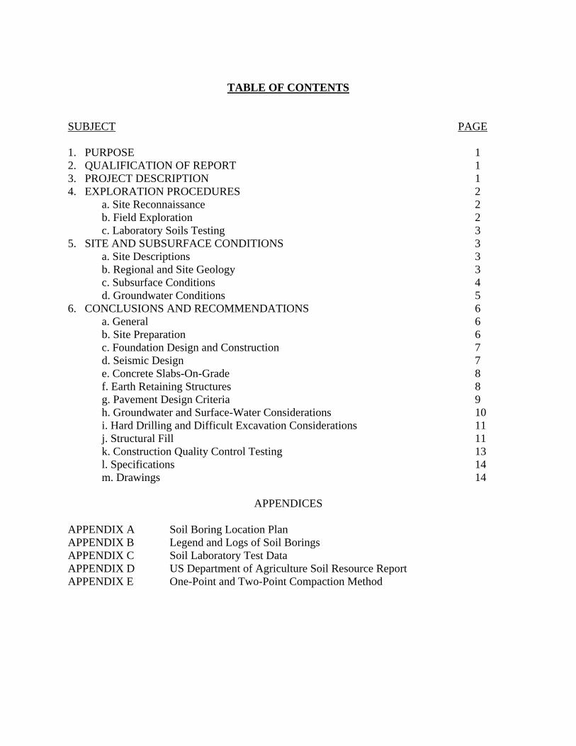
TABLE OF CONTENTS
SUBJECT PAGE 1. PURPOSE 1 2. QUALIFICATION OF REPORT 1 3. PROJECT DESCRIPTION 1 4. EXPLORATION PROCEDURES 2 a. Site Reconnaissance 2 b. Field Exploration 2 c. Laboratory Soils Testing 3 5. SITE AND SUBSURFACE CONDITIONS 3 a. Site Descriptions 3 b. Regional and Site Geology 3 c. Subsurface Conditions 4 d. Groundwater Conditions 5 6. CONCLUSIONS AND RECOMMENDATIONS 6 a. General 6 b. Site Preparation 6 c. Foundation Design and Construction 7 d. Seismic Design 7 e. Concrete Slabs-On-Grade 8 f. Earth Retaining Structures 8 g. Pavement Design Criteria 9 h. Groundwater and Surface-Water Considerations 10 i. Hard Drilling and Difficult Excavation Considerations 11 j. Structural Fill 11 k. Construction Quality Control Testing 13 l. Specifications 14 m. Drawings 14
APPENDICES
APPENDIX A Soil Boring Location Plan APPENDIX B Legend and Logs of Soil Borings APPENDIX C Soil Laboratory Test Data APPENDIX D US Department of Agriculture Soil Resource Report APPENDIX E One-Point and Two-Point Compaction Method
SUBSURFACE EXPLORATION AND
GEOTECHNICAL ENGINEERING REPORT
White Elementary School Replacement FY 14, LI AM00050
Fort Benning, Georgia 1. PURPOSE
This report has been prepared for the design of the new White Elementary School at Fort Benning, Georgia. The purpose of this report is to provide recommendations for the geotechnical design of the various components of the project. The recommendations included in this report are based on the project information provided by the AE firm, Parkhill, Smith & Cooper of Lubbock, Texas. The finished floor elevations and maximum column loads for the buildings were provided in the Design Analysis and Foundation Data Form 363. Any change in site layout, structural system, loads, or finished floor or finished grade elevations may affect the recommendations. The Soils Section, Geotechnical, and HTRW Branch of the Savannah District should be notified immediately of the change(s) and provided the necessary information regarding any change(s) so that the new information can be reviewed. The recommendations in this report may then change as appropriate for the proposed project. 2. QUALIFICATION OF REPORT
The field exploration performed for this report was made to determine the subsurface soil and groundwater conditions and was not intended to serve as a comprehensive assessment of site environmental conditions. No effort was made to define, delineate, or designate any area of environmental concern or of contamination. Any recommendations regarding drainage and earthwork construction are made on the basis that such work can be performed in accordance with applicable laws pertaining to environmental contamination. 3. PROJECT DESCRIPTION
The purpose of this project is to construct a new two-story elementary school approximately 385 feet by 200 feet in plan dimension. Supporting facilities, components, and infrastructure include paved parking and drive areas, underground utilities - water, sewer, gas, and electric, storm water quality features, and retaining walls. Also included are fire protection systems, playground areas and equipment, exterior lighting, sidewalks, signage, fencing, site improvements and landscaping. The proposed elementary school building will be constructed with load bearing walls using structural steel frame with structural masonry walls and gravity columns founded on spread and wall footings with a slab on grade flooring system. The 2nd story elevated floors will be supported on composite bar joists under composite concrete decking. The roof system will consist primarily of metal deck on open-web steel joists. Anticipated maximum column and wall loads are 220 kips and 5.2 kips/foot, respectively. According to the grading

Subsurface Exploration and Geotechnical Report January 2014 White Elementary School Replacement FY 14, LI AM00050 Ft. Benning, Georgia
2
plan provided by Parkhill, Smith & Cooper, the finish floor elevation of the proposed school will be 396.5 feet mean sea level (msl) for the western portion and 411.5 feet msl for the eastern portion. Finish grades in the parking and drive areas will range from approximately 385 to 425 feet msl. These elevations will result in vertical cuts and fills of approximately 40 feet. 4. EXPLORATION PROCEDURES
a. Site Reconnaissance
Prior to the field exploration, a geotechnical engineer visually inspected the site and its surrounding areas. The observations were used in planning the exploration, in determining areas of special interest, and in relating site conditions to known geologic conditions in the area.
b. Field Exploration
(1) Subsurface conditions at the project site were explored by soil test borings at 32
locations (designated as B-1 through B-32). The locations of the borings performed for this investigation are shown on the plan included in Appendix A.
(2) The locations of the soil test borings were established by an engineer in the field using a
hand-held global positioning system (GPS) device having sub-meter accuracy. The ground surface elevation at each boring location was determined by interpolation from available site topography survey data. Since the measurements were not precise, the locations shown on the boring layout plans and the elevations on the drilling logs should be considered approximate.
(3) The soil test borings were drilled by Savannah District with a CME 550x rubber tire
all terrain vehicle (ATV) drill rig. The drill rig utilized hollow stem augers with a 3.25-inch inside diameter (I.D.) to advance the boreholes and an automatic hammer for standard penetration testing. Split-barrel sampling for standard penetration testing was performed at intervals shown on the boring logs. All soil sampling and SPT borings were performed in accordance with ASTM D 1586. In SPT borings, a soil sample (split spoon sample) is obtained with a standard 1 3/8-inch I.D. by 2-inch outside diameter (O.D.) split-barrel sampler. The sampler is first seated 6 inches and then driven an additional 12 inches with blows from a 140 lb. hammer falling a distance of 30 inches. The number of blows required to drive the sampler the final 12 inches is recorded and is termed the “standard penetration resistance,” or the “N-value.” Penetration resistance, when properly evaluated, is an index of the soil’s strength, density, and foundation support capability.
(4) The soil samples obtained from the SPT soil test borings were examined by a
geologist and a geotechnical engineer and visually field classified in accordance with ASTM D 2488 (Visual-Manual Procedure for Description of Soils). The soil classifications include the use of the Unified Soil Classification System described in ASTM D 2487 (Classification of Soils for Engineering Purposes). Since the soil descriptions and classifications indicated on the logs are based on visual examination and manual tests, they should be considered approximate. Logs of the soil borings with standard penetration resistance values and graphical depictions of the soil descriptions are included in Appendix B.
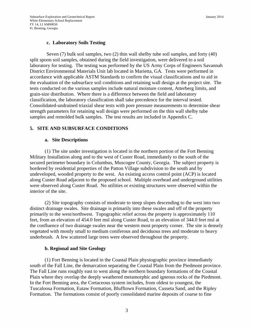
Subsurface Exploration and Geotechnical Report January 2014 White Elementary School Replacement FY 14, LI AM00050 Ft. Benning, Georgia
3
c. Laboratory Soils Testing Seven (7) bulk soil samples, two (2) thin wall shelby tube soil samples, and forty (40)
split spoon soil samples, obtained during the field investigation, were delivered to a soil laboratory for testing. The testing was performed by the US Army Corps of Engineers Savannah District Environmental Materials Unit lab located in Marietta, GA. Tests were performed in accordance with applicable ASTM Standards to confirm the visual classifications and to aid in the evaluation of the subsurface soil conditions and retaining wall design at the project site. The tests conducted on the various samples include natural moisture content, Atterberg limits, and grain-size distribution. Where there is a difference between the field and laboratory classification, the laboratory classification shall take precedence for the interval tested. Consolidated-undrained triaxial shear tests with pore pressure measurements to determine shear strength parameters for retaining wall design were performed on the thin wall shelby tube samples and remolded bulk samples. The test results are included in Appendix C. 5. SITE AND SUBSURFACE CONDITIONS
a. Site Descriptions
(1) The site under investigation is located in the northern portion of the Fort Benning
Military Installation along and to the west of Custer Road, immediately to the south of the secured perimeter boundary in Columbus, Muscogee County, Georgia. The subject property is bordered by residential properties of the Patton Village subdivision to the south and by undeveloped, wooded property to the west. An existing access control point (ACP) is located along Custer Road adjacent to the proposed school. Multiple overhead and underground utilities were observed along Custer Road. No utilities or existing structures were observed within the interior of the site.
(2) Site topography consists of moderate to steep slopes descending to the west into two
distinct drainage swales. Site drainage is primarily into these swales and off of the property primarily to the west/northwest. Topographic relief across the property is approximately 110 feet, from an elevation of 454.0 feet msl along Custer Road, to an elevation of 344.0 feet msl at the confluence of two drainage swales near the western most property corner. The site is densely vegetated with mostly small to medium coniferous and deciduous trees and moderate to heavy underbrush. A few scattered large trees were observed throughout the property.
b. Regional and Site Geology (1) Fort Benning is located in the Coastal Plain physiographic province immediately
south of the Fall Line, the demarcation separating the Coastal Plain from the Piedmont province. The Fall Line runs roughly east to west along the northern boundary formations of the Coastal Plain where they overlap the deeply weathered metamorphic and igneous rocks of the Piedmont. In the Fort Benning area, the Cretaceous system includes, from oldest to youngest, the Tuscaloosa Formation, Eutaw Formation, Blufftown Formation, Cusseta Sand, and the Ripley Formation. The formations consist of poorly consolidated marine deposits of coarse to fine
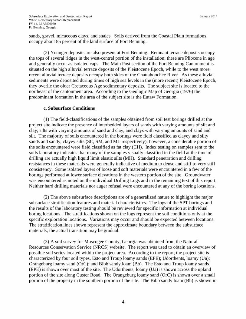
Subsurface Exploration and Geotechnical Report January 2014 White Elementary School Replacement FY 14, LI AM00050 Ft. Benning, Georgia
4
sands, gravel, micaceous clays, and shales. Soils derived from the Coastal Plain formations occupy about 85 percent of the land surface of Fort Benning.
(2) Younger deposits are also present at Fort Benning. Remnant terrace deposits occupy
the tops of several ridges in the west-central portion of the installation; these are Pliocene in age and generally occur as isolated caps. The Main Post section of the Fort Benning Cantonment is situated on the high alluvial terrace deposits of the Pleistocene Epoch, while to the west more recent alluvial terrace deposits occupy both sides of the Chattahoochee River. As these alluvial sediments were deposited during times of high sea levels in the (more recent) Pleistocene Epoch, they overlie the older Cretaceous Age sedimentary deposits. The subject site is located to the northeast of the cantonment area. According to the Geologic Map of Georgia (1976) the predominant formation in the area of the subject site is the Eutaw Formation.
c. Subsurface Conditions (1) The field-classifications of the samples obtained from soil test borings drilled at the
project site indicate the presence of interbedded layers of sands with varying amounts of silt and clay, silts with varying amounts of sand and clay, and clays with varying amounts of sand and silt. The majority of soils encountered in the borings were field classified as clayey and silty sands and sandy, clayey silts (SC, SM, and ML respectively); however, a considerable portion of the soils encountered were field classified as fat clay (CH). Index testing on samples sent to the soils laboratory indicates that many of the samples visually classified in the field at the time of drilling are actually high liquid limit elastic silts (MH). Standard penetration and drilling resistances in these materials were generally indicative of medium to dense and stiff to very stiff consistency. Some isolated layers of loose and soft materials were encountered in a few of the borings performed at lower surface elevations in the western portion of the site. Groundwater was encountered as noted on the individual Drilling Logs and in the remaining text of this report. Neither hard drilling materials nor auger refusal were encountered at any of the boring locations.
(2) The above subsurface descriptions are of a generalized nature to highlight the major
subsurface stratification features and material characteristics. The logs of the SPT borings and the results of the laboratory testing should be reviewed for specific information at individual boring locations. The stratifications shown on the logs represent the soil conditions only at the specific exploration locations. Variations may occur and should be expected between locations. The stratification lines shown represent the approximate boundary between the subsurface materials; the actual transition may be gradual.
(3) A soil survey for Muscogee County, Georgia was obtained from the Natural Resources Conservation Service (NRCS) website. The report was used to obtain an overview of possible soil series located within the project area. According to the report, the project site is characterized by four soil types, Esto and Troup loamy sands (EPE); Udorthents, loamy (Ua); Orangeburg loamy sand (OrC); and Bibb sandy loam (Bh). The Esto and Troup loamy sands (EPE) is shown over most of the site. The Udorthents, loamy (Ua) is shown across the upland portion of the site along Custer Road. The Orangeburg loamy sand (OrC) is shown over a small portion of the property in the southern portion of the site. The Bibb sandy loam (Bh) is shown in
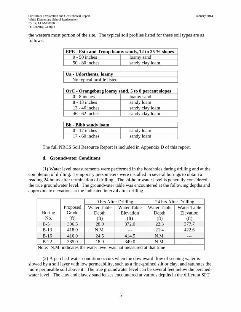
Subsurface Exploration and Geotechnical Report January 2014 White Elementary School Replacement FY 14, LI AM00050 Ft. Benning, Georgia
5
the western most portion of the site. The typical soil profiles listed for these soil types are as follows:
EPE - Esto and Troup loamy sands, 12 to 25 % slopes 0 - 50 inches loamy sand 50 - 80 inches sandy clay loam
Ua - Udorthents, loamy
No typical profile listed
OrC - Orangeburg loamy sand, 5 to 8 percent slopes 0 - 8 inches loamy sand 8 - 13 inches sandy loam 13 - 46 inches sandy clay loam 46 - 62 inches sandy clay loam
Bh - Bibb sandy loam
0 - 17 inches sandy loam 17 - 60 inches sandy loam
The full NRCS Soil Resource Report is included in Appendix D of this report.
d. Groundwater Conditions
(1) Water level measurements were performed in the boreholes during drilling and at the
completion of drilling. Temporary piezometers were installed in several borings to obtain a reading 24 hours after termination of drilling. The 24-hour water level is generally considered the true groundwater level. The groundwater table was encountered at the following depths and approximate elevations at the indicated interval after drilling.
Boring No.
Proposed
Grade (ft)
0 hrs After Drilling 24 hrs After Drilling Water Table
Depth (ft)
Water Table Elevation
(ft)
Water Table Depth
(ft)
Water Table Elevation
(ft) B-5 396.5 28.0 372.0 22.3 377.7 B-13 418.0 N.M. --- 21.4 422.6 B-16 416.0 24.5 414.5 N.M. --- B-22 385.0 18.0 349.0 N.M. ---
Note: N.M. indicates the water level was not measured at that time (2) A perched-water condition occurs when the downward flow of seeping water is
slowed by a soil layer with low permeability, such as a fine-grained silt or clay, and saturates the more permeable soil above it. The true groundwater level can be several feet below the perched-water level. The clay and clayey sand lenses encountered at various depths in the different SPT
Subsurface Exploration and Geotechnical Report January 2014 White Elementary School Replacement FY 14, LI AM00050 Ft. Benning, Georgia
6
borings indicate that conditions favorable for perched water exist and could potentially occur during or after construction.
(3) Groundwater levels will fluctuate with seasonal and climatic variations, variations in
subsurface soil conditions, and construction operations. Therefore, future groundwater conditions and groundwater conditions at other locations on the site may differ from the conditions encountered at the SPT boring locations on the dates they were performed. 6. CONCLUSIONS AND RECOMMENDATIONS
a. General
The following conclusions and recommendations are based on the information available on the proposed structures as provided by the AE firm, Parkhill, Smith & Cooper of Lubbock, Texas. The recommendations are also based on observations made at the project site, interpretation of the data obtained from the soil test borings, and previous experience with soils and subsurface conditions similar to those encountered at the site.
b. Site Preparation
(1) Following clearing and removal of trees, structures, pavement, etc., the construction area should be grubbed and stripped of all vegetation, topsoil, organics, and other deleterious materials. Clean topsoil can be stockpiled and reused in landscaped areas. It is recommended that the zone of stripping extend a minimum of 10 feet beyond the outer edges of structures and pavements. Any utilities in the project area should be located and rerouted, as necessary.
(2) All areas to remain at grade or to receive fill and excavated subgrade areas of
buildings and pavements should be prepared as follows. Surface areas containing poorly graded sands or silty sands should be densified by compaction of a vibratory roller weighing at least 7 tons. Areas of cohesive soils such as clayey sands and clays should be proof rolled with a fully loaded tandem-axle dump truck or similar rubber-tired equipment. Soils which are observed to rut or deflect excessively under the moving loads should be excavated down to firm soil and backfilled with properly compacted, suitable soils. The proof rolling should be performed only during and following a period of dry weather.
(3) Soft/loose surface soils were encountered in the central portion of the site to depths of 1.0 to 2.0 feet beneath the existing ground surface as evidenced by borings B-7, B-9, and B-23. Soft/loose surface soils may also be present at other locations across the site. It is likely that some of these soft soils will be removed during site stripping and grading operations; however, any remaining soft soils should be stabilized by compaction or undercut and replaced with suitable compacted fill.
(4) Loose to very loose consistency silty sand was encountered at boring location B-25 to a depth of approximately 6.0 feet beneath the existing ground surface. Boring B-25 was performed in the base of a drainage swale in the westernmost portion of the site. Based on the
Subsurface Exploration and Geotechnical Report January 2014 White Elementary School Replacement FY 14, LI AM00050 Ft. Benning, Georgia
7
most recent grading plan, this area is not anticipated to receive fill or structures. The soft soils encountered at boring B-25 should not be of consequence during site grading.
c. Foundation Design and Construction (1) Allowable Bearing Pressure and Footing Dimensions. Given the proposed site
and structures and based on past experience with similar sites in the region, shallow spread foundations can be used for support of the proposed building. Net allowable soil bearing pressures should not exceed 3,000 pounds per square foot (psf). Minimum dimensions of 30 inches for all column footings and 24 inches for all load-bearing continuous footings shall be used in foundation design to reduce the possibility of bearing capacity failure. These footings shall be embedded a minimum depth of 24 inches, as measured from the finish floor or finish grade, whichever is lower, to the bottom of the footing. All non load-bearing wall footings shall have a minimum width of 18 inches and the minimum depth shall be 18 inches, as measured from finish floor or finish grade, whichever is lower, to the bottom of the footing. Post construction total foundation settlements are not expected to exceed an inch. Differential settlement is estimated to be less than one-half inch.
(2) Footings with Uplift. The resistance of footings to be subjected to uplift from
transient live loads should be represented by the total of weight of concrete in the footing and the weight of soil in the vertical column directly above the footing. The effect of a groundwater table on the uplift resistance of footings should be considered. The effect of the groundwater (or buoyancy) can be taken into account by subtracting from the total weight of concrete and soil, the weight of water represented by the block of concrete and soil which is located below the groundwater level and above the bottom of the footing. The level of the groundwater should be the highest anticipated during the life of the structure. The factor of safety against uplift should be not less than 1.5.
(3) Foundation Construction. Foundation excavations should be concreted as soon as
practical following excavation as exposure to the environment could weaken the soils at the footing bearing level should the foundation excavations remain open for an extended period of time. Bottoms of foundation excavations should be inspected immediately prior to placement of reinforcing steel and concrete to verify that adequate bearing soils are present and that all debris, mud, and loose, frozen, or water-softened soils are removed. If the bearing surface soils have been softened by surface-water intrusion or by exposure, the softened soils must be removed to firm bearing, and replaced with additional concrete during the concreting, or replaced to design subgrade with No. 57 or No. 67 stone, compacted to a non-yielding condition. To minimize exposure, the final excavation (4 to 6 inches) to design subgrade should be delayed until just prior to placement of reinforcing steel and concreting.
d. Seismic Design
Seismic loads should be computed in accordance with IBC 2012. For the purpose of
determining maximum considered earthquake spectral response accelerations, the project site is classified as Site Class D based on observed SPT N-values and on previous experience with soils in the general area.
Subsurface Exploration and Geotechnical Report January 2014 White Elementary School Replacement FY 14, LI AM00050 Ft. Benning, Georgia
8
e. Concrete Slabs-On-Grade
(1) Previous experience and the subsurface conditions encountered at the site indicate
concrete floor slabs could be supported on in-situ soils and/or on fill soils placed and compacted in accordance with the recommendations presented in this report regarding structural fill. During subgrade preparation some conditioning in the cut areas should be anticipated once rough subgrade has been reached. Due to the presence of high liquid limit elastic sandy silts (MH materials), undercutting and backfilling with select fill or stabilization/modification by blending cement, lime, fly ash, or combinations of these materials to the soil should be anticipated.
(2) Provided that the upper 12 inches of suitable subgrade will be prepared as recommended in this report, a vertical modulus of subgrade reaction (k) of 125 pci should be used for the design of the slab-on-grade. All concrete slabs-on-grade should be underlain by a minimum of 4 inches of open graded, washed pea gravel or stone, to be referred to as “capillary water barrier,” to prevent the capillary rise of the groundwater. Nos. 57, 67, 78, or 89 stone should be used. All drawings should be consistently labeled with the term “capillary water barrier,” since this is the term utilized in Section EARTHWORK of the Specifications. Additionally, a moisture barrier consisting of lapped polyethylene sheeting having a minimum thickness of 10 mils should be provided beneath building floor slabs to reduce the potential for slab dampness from soil moisture. The capillary water barrier material may be omitted under slabs-on-grade in unenclosed areas; however, the slab should be provided with a vapor barrier. Concrete slabs should be jointed around columns and along supported walls to minimize cracking due to possible differential movement.
(3) The design of thickened slabs on grade to support line loads (such as partitions and light wall loads) should be in accordance with UFC 3-301-01 Structural Engineering.
(4) Construction activities and exposure to the environment often cause deterioration of
the prepared slab-on-grade subgrade. The subgrade soils upon which slabs would be placed should be inspected and evaluated immediately prior to floor slab construction. The evaluation should include a combination of visual observations, hand rod probing, and field density tests to verify that the subgrade has been properly prepared. If unstable soils are revealed, the affected area should be excavated to firm bearing, and material removed should be replaced to design subgrade with suitable structural fill soil placed and compacted as recommended or replaced with additional capillary water barrier material.
f. Earth Retaining Structures
(1) Based on the current plans, retaining walls will be required in the eastern and western portions of the site and a foundation wall will be required as part of the proposed building to transition between the upper and lower building levels. For the design and construction of retaining walls with no sloping backfill and other below grade or earth retaining structures, the following earth pressure coefficients and soil parameters should be used:
Subsurface Exploration and Geotechnical Report January 2014 White Elementary School Replacement FY 14, LI AM00050 Ft. Benning, Georgia
9
*Coefficient of at-rest earth pressure (Ko) = 0.5 *Coefficient of active earth pressure (Ka) = 0.33 *Coefficient of passive earth pressure (Kp) = 3.00 *Coefficient of friction (soil -vs- concrete) (μf) = 0.35 *Unit weight of soil (moist) = 120 lbs/ft3
*Unit weight of soil (saturated) = 125 lbs/ft3
*Unit weight of soil (buoyant) = 63 lbs/ft3 (2) Drainage features such as weep holes, longitudinal drains, prefabricated geocomposite
drains, and porous backfill should be utilized. Based on the groundwater depth measured at boring locations B-13 and B-16 additional drainage measures such as blanket and/or chimney drains will need to be included in the design of the proposed retaining walls in the eastern portion of the site. Compaction of backfill within 10.0 feet of walls should be performed with hand operated equipment, such as walk behind compactors (“whacker packers” or sled tamps). If sloping backfill or toe conditions exist, the Soils Section, Geotechnical, and HTRW Branch of the Savannah District should be consulted for additional recommendations.
(3) Any mechanically stabilized earth (MSE) walls proposed at the subject site shall be designed using the American Association of State Highway and Transportation Officials (AASHTO) design methodology as published in the Federal Highway Administration (FHWA) publication “Mechanically Stabilized Earth Walls and Reinforced Soil Slope Design and Construction Guidelines (FHWA NHI-00-043, March 2001)”. Wall designs using National Concrete Masonry Association (NCMA) design methodology will not be acceptable.
(4) To adequately reduce potential for time-dependent movement (creep deformation), fine grained soils such as ML, CL, MH, and CH will not be allowed for use with MSE walls and/or slopes. Well compacted, select granular fill shall be used in the reinforced zone of any MSE walls and/or slopes. Due to the abundance of high liquid limit elastic sandy silts (MH materials) encountered throughout the site and the limited amount of silty and clayey sands (SM and SC materials), a large quantity of select granular backfill materials will have to be imported to the site for use as backfill. This will add significant costs to the construction of mechanically stabilized earth (MSE) walls. For this reason, consideration should be given to other wall types such as reinforced concrete cantilever, or shotcrete faced, soil tie-back walls.
(5) It is preferred that backfill to be placed against reinforced concrete retaining/foundation walls consist of free draining granular materials and that fine grained soils such as ML, CL, MH, and CH not be used. Where free draining granular backfill is not used, the installation of additional drainage measures to provide an adequate factor of safety against the buildup of hydrostatic pressures shall be incorporated into the design. Drains shall be adequately protected by a filter medium so that seepage water is admitted freely but movement of the soil backfill into the drain will not occur.
g. Pavement Design Criteria
(1) Based on the subsurface investigations and previous experience in the general area, the soil types expected to be encountered during construction activities are high liquid limit elastic
Subsurface Exploration and Geotechnical Report January 2014 White Elementary School Replacement FY 14, LI AM00050 Ft. Benning, Georgia
10
sandy silts (MH materials). These soil types are typically considered un-satisfactory material for pavement subgrade. Any unsatisfactory subgrade soils that are encountered shall be removed and replaced with satisfactory soils or stabilized by blending cement, lime, fly ash, or combinations of these materials to the soil. The following subgrade values and other listed parameters are recommended for design of the pavements:
(a) Flexible (Asphaltic Concrete) Pavement: Compacted subgrade, use CBR of 4.
(b) Rigid (Portland Cement Concrete) Pavement: i. Use a corrected modulus of subgrade reaction, K of 100 psi per inch with at
least 4 inches of compacted aggregate base course. ii. The concrete should have a minimum design 28-day compressive strength of
at least 4000 pounds per square inch with a mix design that has been proven to produce concrete with a flexural strength of at least 650 psi.
(2) Where subgrade soils are stabilized by blending cement, lime, fly ash, or combinations
of these materials, the above listed values can be adjusted to permit a reduction in thickness of the design pavement section.
h. Groundwater and Surface-Water Considerations (1) Groundwater was encountered at boring locations B-5, B-13, B-16, and B-22 at the
depths and elevations listed in the table shown in item d. of the SITE AND SUBSURFACE CONDITIONS section of this report. The ground water encountered at boring locations B-5 and B-22 are well below anticipated final grades and should not be of consequence during general site grading of this project. The groundwater encountered at boring locations B-13 and B-16, however, are below or very near proposed final grades.
(2) Borings B-13 and B-16 were performed in the eastern portion of the site along the proposed retaining wall location in the portion of the site to receive cuts of approximately 40 feet to reach design grades. The installation of a system of french drains at the base of the retaining wall located between the proposed school structure and Custer Road will be necessary for control of ground water across this portion of the site. According to the provided grading plan there appears to be enough fall across the site for the french drains to gravity drain into a nearby storm water inlet structure. The french drains should have a constant slope of at least 0.5% to allow for positive drainage and consist of a 6 inch diameter perforated pipe embedded in a 24 inch wide by 24 inch deep layer of free draining crushed stone wrapped in a filter grade non-woven geotextile. Storm sewer lines proposed for this area should also be bedded in free draining crushed stone. The stone bedding placed around storm water lines can be utilized as part of the french drain system. The excavation for french drains should be at least five feet beneath proposed final grades. Stabilization by use of geotextile and coarse crushed stone should also be anticipated for the parking and drive subgrade areas along the base of the retaining wall. Additional drainage measures such as blanket and/or chimney drains will also need to be included in the design of the proposed retaining walls in the eastern portion of the site. A final decision regarding the actual
Subsurface Exploration and Geotechnical Report January 2014 White Elementary School Replacement FY 14, LI AM00050 Ft. Benning, Georgia
11
extent of french drain installation required and the need for stabilization of the parking and drives in this area can be made during grading once rough subgrade elevation has been reached.
(3) Although groundwater should not be of consequence during general site grading in the remaining portions of the site, excavations near or below the groundwater table may be necessary during underground utility line installation and during placement of storm water drainage pipes to be placed in the lower, western portions of the site. Temporary dewatering by the use of sumps and limited undercutting and the use of bedding stone should be anticipated if trench excavations extend into groundwater. A final decision regarding the actual need for undercutting and bedding stone use can be made during construction once rough subgrade elevation has been reached.
(4) Based on the sandy soils with varying amounts of fines as well as the fine-grained soils that were encountered at relatively shallow depths in the borings, and on the low saturated hydraulic conductivities that are typical for the types of materials encountered across the site, it is possible that “perched water” conditions could be encountered. The accumulation of run-off water or seepage at the base of excavations may thus occur during foundation construction and site work. Water should not be allowed to collect near the foundation or on floor slab areas of the building either during or after construction. Undercut or excavated areas should be sloped toward one corner to facilitate removal of any collected rainwater, groundwater, or surface runoff. Positive site drainage should be provided to reduce infiltration of surface water around the perimeter of the building and beneath floor slabs. The following notes should be added to an appropriate structural foundation plate of the contract drawings:
"Drainage and Dewatering: All excavations shall be performed so that the site and the area immediately surrounding the site which affects construction operations will be continually and effectively drained. The Contractor shall provide drainage and dewatering as required to ensure that all footing excavations are accomplished with the subgrade soils remaining dry and firm until after footings are placed and backfilled. Removal of surface water, groundwater, and any perched water conditions which might be encountered during excavations, shall be accomplished by approved means. Refer to specification Section 31 00 00 EARTHWORK for additional requirements."
i. Hard Drilling and Difficult Excavation Considerations Neither hard drilling materials nor auger refusal was encountered at any of the boring
locations. Rock removal is not anticipated during construction. j. Structural Fill
(1) Based on the soil test borings, excavated on-site soils (excluding any organics/topsoil
and debris) can be used as structural fill. Some moisture content adjustment will be necessary to achieve proper compaction. Based on laboratory results of most of the bulk soil samples obtained in the cut areas located in the central and eastern portions of the site, the natural water content is well above the optimum water content as determined by Modified Proctor determination, ASTM D1557. These materials will require extensive aeration and drying prior
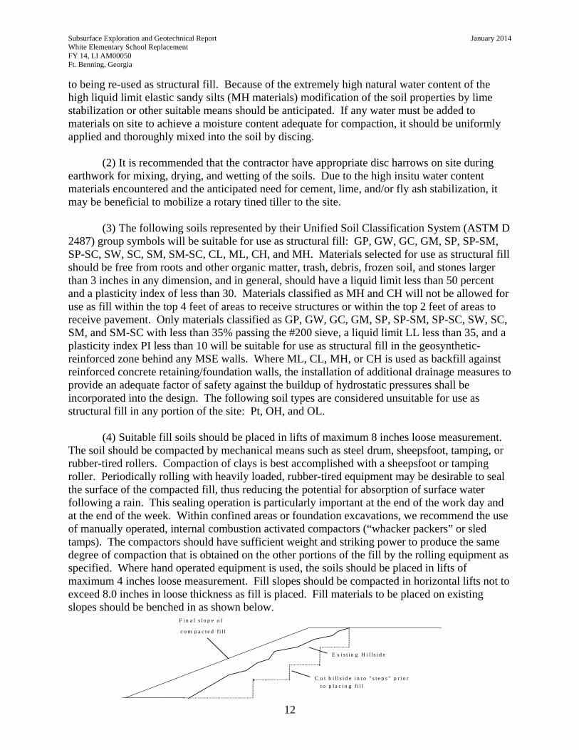
Subsurface Exploration and Geotechnical Report January 2014 White Elementary School Replacement FY 14, LI AM00050 Ft. Benning, Georgia
12
to being re-used as structural fill. Because of the extremely high natural water content of the high liquid limit elastic sandy silts (MH materials) modification of the soil properties by lime stabilization or other suitable means should be anticipated. If any water must be added to materials on site to achieve a moisture content adequate for compaction, it should be uniformly applied and thoroughly mixed into the soil by discing.
(2) It is recommended that the contractor have appropriate disc harrows on site during earthwork for mixing, drying, and wetting of the soils. Due to the high insitu water content materials encountered and the anticipated need for cement, lime, and/or fly ash stabilization, it may be beneficial to mobilize a rotary tined tiller to the site.
(3) The following soils represented by their Unified Soil Classification System (ASTM D 2487) group symbols will be suitable for use as structural fill: GP, GW, GC, GM, SP, SP-SM, SP-SC, SW, SC, SM, SM-SC, CL, ML, CH, and MH. Materials selected for use as structural fill should be free from roots and other organic matter, trash, debris, frozen soil, and stones larger than 3 inches in any dimension, and in general, should have a liquid limit less than 50 percent and a plasticity index of less than 30. Materials classified as MH and CH will not be allowed for use as fill within the top 4 feet of areas to receive structures or within the top 2 feet of areas to receive pavement. Only materials classified as GP, GW, GC, GM, SP, SP-SM, SP-SC, SW, SC, SM, and SM-SC with less than 35% passing the #200 sieve, a liquid limit LL less than 35, and a plasticity index PI less than 10 will be suitable for use as structural fill in the geosynthetic-reinforced zone behind any MSE walls. Where ML, CL, MH, or CH is used as backfill against reinforced concrete retaining/foundation walls, the installation of additional drainage measures to provide an adequate factor of safety against the buildup of hydrostatic pressures shall be incorporated into the design. The following soil types are considered unsuitable for use as structural fill in any portion of the site: Pt, OH, and OL.
(4) Suitable fill soils should be placed in lifts of maximum 8 inches loose measurement. The soil should be compacted by mechanical means such as steel drum, sheepsfoot, tamping, or rubber-tired rollers. Compaction of clays is best accomplished with a sheepsfoot or tamping roller. Periodically rolling with heavily loaded, rubber-tired equipment may be desirable to seal the surface of the compacted fill, thus reducing the potential for absorption of surface water following a rain. This sealing operation is particularly important at the end of the work day and at the end of the week. Within confined areas or foundation excavations, we recommend the use of manually operated, internal combustion activated compactors (“whacker packers” or sled tamps). The compactors should have sufficient weight and striking power to produce the same degree of compaction that is obtained on the other portions of the fill by the rolling equipment as specified. Where hand operated equipment is used, the soils should be placed in lifts of maximum 4 inches loose measurement. Fill slopes should be compacted in horizontal lifts not to exceed 8.0 inches in loose thickness as fill is placed. Fill materials to be placed on existing slopes should be benched in as shown below.
F i n a l s l o p e o f
c o m p a c t e d f i l l
C u t h i l l s i d e i n t o " s t e p s " p r i o rt o p l a c i n g f i l l
E x i s t i n g H i l l s i d e
Subsurface Exploration and Geotechnical Report January 2014 White Elementary School Replacement FY 14, LI AM00050 Ft. Benning, Georgia
13
(5) It is recommended that the structural fill and subgrades be compacted to the following
minimum percents of the modified Proctor maximum dry density (ASTM D 1557):
In trenches and except the top 12 inches beneath structures and building slabs, to 5 feet beyond building and structure line.
92 percent
Beneath paved areas, except top 12 inches 92 percent Top 12 inches beneath structures and paved areas 95 percent Within the geosynthetic-reinforced zone behind retaining walls 92 percent
Beneath shoulders 90 percent Beneath sidewalks and grassed areas 85 percent Base course beneath paved areas 100 percent
k. Construction Quality Control Testing (1) Prior to initiating any structural fill placement and/or compaction operations, it is
recommended that representative samples of the soils which will be used as structural fill or subgrade, both suitable on-site soils and off-site soils (borrow), be obtained and tested to determine their classification and compaction characteristics. The samples should be carefully selected to represent the full range of soil types to be used. The moisture content, maximum dry density, optimum moisture content, grain-size, and plasticity characteristics should be determined. These tests are required to determine if the fill and subgrade soils are acceptable and for compaction quality control of the subgrades and structural fill. Tests for the above soil properties should be in accordance with the following:
Moisture Content ASTM D 2216 Maximum Dry Density and Optimum Moisture ASTM D 1557 Grain-Size (Wash No. 200, less hydrometer) ASTM D 422 and D 1140 Plasticity ASTM D 4318
(2) A representative number of in-place field density tests should be performed in the
subgrade of compacted on-site soils and in the structural fill and backfill to confirm that the required degree of compaction has been obtained. In-place density tests should be performed in accordance with the sand cone method as prescribed in ASTM D1556, the drive ring method as prescribed in ASTM D2937, or by utilizing a nuclear density meter as prescribed in ASTM D6938. It is recommend that at least one density test be performed for each 5,000 square feet and 12,500 square feet, or portion thereof, for buildings and pavements, respectively, of compacted native soil subgrade and in each lift of compacted structural fill. It is also recommended that at least one density test be performed for each 100 linear feet in the bearing level soils of continuous footings. Density tests should be performed at 100-foot intervals along roadway subgrades. In addition, a density test should be performed for each 100 linear feet of backfill placed per 8 inch loose lift behind earth retaining walls and per foot of depth in trenches for utilities systems. Where other areas are compacted separately by manually operated
Subsurface Exploration and Geotechnical Report January 2014 White Elementary School Replacement FY 14, LI AM00050 Ft. Benning, Georgia
14
compactors, a minimum of one density test should be performed for every 250 square feet, or portion thereof, of fill placed per foot of depth.
(3) Compaction control of soils requires the comparison of fill water content and dry density values obtained in the field density tests with optimum water content and maximum dry density determined in a laboratory compaction test performed on the same soil. It may, however, not be feasible to do this as the testing could not keep pace with fill construction. It is, therefore, recommended that compaction control of the earthwork construction be performed using a “family” of compaction curves and the one-point or two-point compaction methods described in Appendix E.
(4) Any area that does not meet the required compaction criteria should be reworked and retested. If the moisture content of the soil is within the recommended range, additional compaction may be all that is necessary to increase the density. If the moisture content is not within the recommended range, the moisture content should be adjusted to within the range and the area recompacted.
(5) All laboratory and field density testing and other specified construction materials testing and inspections should be performed by a commercial testing laboratory that has been validated by the Engineer Research and Development Center Materials Testing Center (MTC) under the Corps of Engineers laboratory inspection and validation program. Based on the site geometry, the amount of earthwork necessary to develop the site, and the soil types encountered during the investigation, this project is going to require more oversight than typical projects of similar size and scope. The services of an experienced Geotechnical Engineer should be included in the scope of the specified construction materials testing and inspections.
l. Specifications It is recommended that the Savannah District’s 31 00 00 “EARTHWORK” specification
and the Unified Facilities Guide Specifications 31 31 16 “SOIL TREATMENT FOR SUBTERRANEAN TERMITE CONTROL” be used when editing the specifications for this project.
m. Drawings
The locations of all of the soil borings performed at the proposed site for this project are shown on the boring location plan in APPENDIX A. These boring locations are also to be shown on the appropriate site grading and drainage plates of the contract drawings. The appropriate symbols for SPT boring locations (circle with the right half filled in) are also to be placed in the civil legend. Soil boring logs are shown in APPENDIX B. MicroStation drawings containing the soil boring logs are to be directly inserted into the project drawings with the plate titles included in the index.

APPENDICES
-
APPENDIX A Soil Boring Location Plan
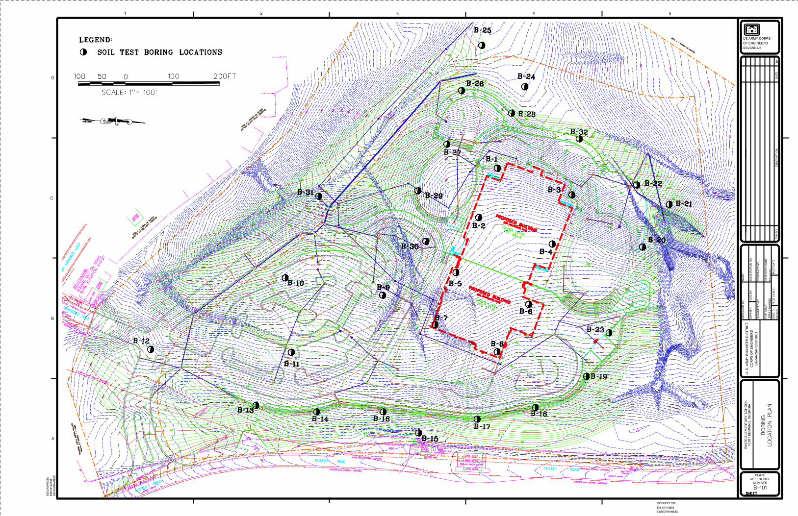
-
APPENDIX B Legend and Logs of Soil Borings
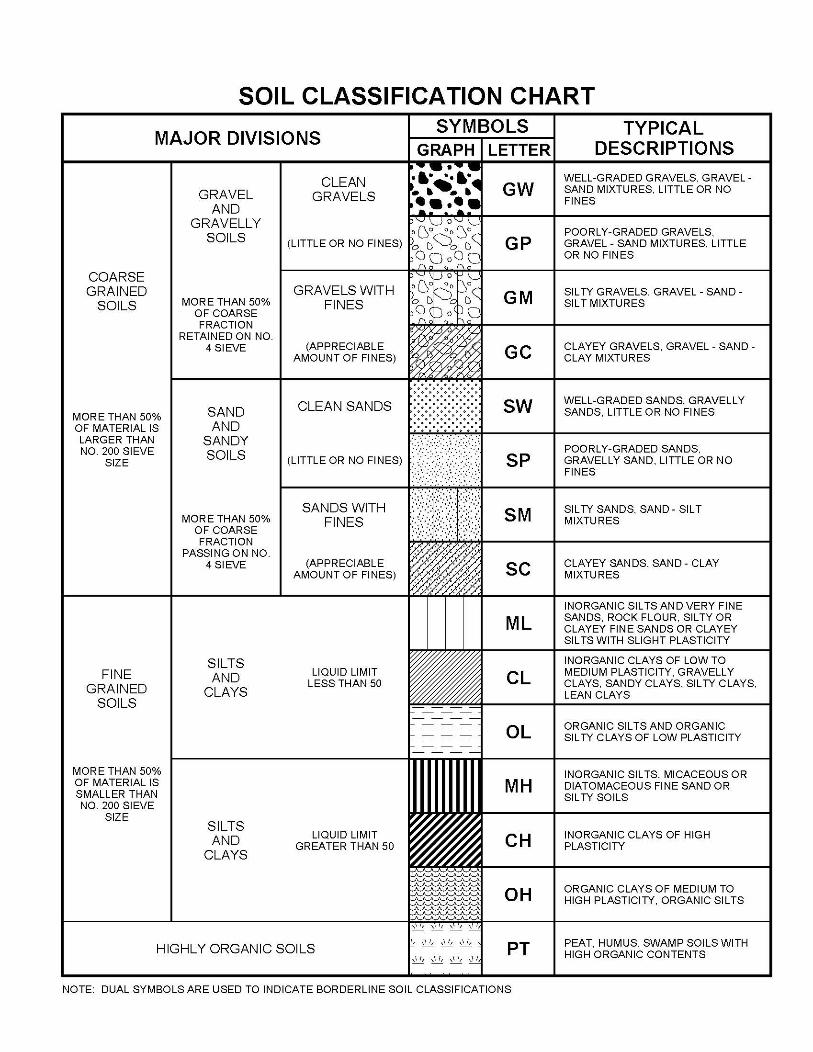
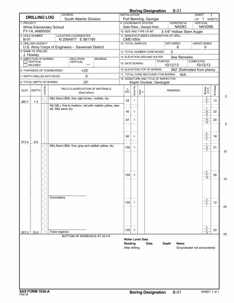
6
10
10
9
14
11
5
8
Water Level Data
7
12
10
9
17
15
7
12
53
40
67
60
100
100
100
100
380.7
373.4
357.0
1.3
8.6
25.0
Silty Sand (SM), fine; light brown, rootlets; dry
Silt (ML), fine to medium; red with reddish yellow, leansilt, little sand; dry
Silty Sand (SM), fine; gray and reddish yellow; dry
Concretions
Trace organics
BOTTOM OF BOREHOLE AT 25.0 ft
13
22
20
18
31
26
12
20
4
7
7
6
7
8
3
5
1
2
3
4
5
6
7
8
Reading Depth NotesDateAfter drilling Groundwater not encountered
N/A
14. ELEVATION GROUND WATER
SHEET
---
Fort Benning, Georgia
DISTURBED
6. THICKNESS OF OVERBURDEN
7. DEPTH DRILLED INTO ROCK
8. TOTAL DEPTH OF BORING
STARTEDVERTICAL
1. PROJECT
UNDISTURBED
NAVD88
2. HOLE NUMBER
18. SIGNATURE AND TITLE OF INSPECTOR
CME-550x
BEARING
3. DRILLING AGENCY
11
OF
COMPLETED15. DATE BORING
DEG FROMVERTICAL
HORIZONTAL
3-1/4" Hollow Stem Auger
INSTALLATION
08 0
INCLINED
U.S. Army Corps of Engineers - Savannah District4. NAME OF DRILLER
5. DIRECTION OF BORING
9. COORDINATE SYSTEM
10. SIZE AND TYPE OF BIT
NAD83White Elementary SchoolFY-14, AM00050
>25'
0'
25'
N 2064977 E 881180LOCATION COORDINATES
16. ELEVATION TOP OF BORING
VERTICAL
J. Howley
17. TOTAL CORE RECOVERY FOR BORING
10/12/13
SHEETSDRILLING LOG
12. TOTAL SAMPLES
13. TOTAL NUMBER CORE BOXES
B-01
DIVISION
11. MANUFACTURER'S DESIGNATION OF DRILL
South Atlantic Division
382' (Estimated from plans)
See Remarks
10/12/13
Kaylin Dunbar, Geologist
State Plane - Georgia West
0
5
10
15
20
25
Boring Designation B-01
FEB 08
%RECELEV
LEG
EN
D
DEPTH
SAS FORM 1836-A
FIELD CLASSIFICATION OF MATERIALS(Description)
N-V
alue
Boring Designation B-01 SHEET 1 of 1
REMARKS
Blo
ws/
0.5
ft
RQ
D%
Sam
p N
o.
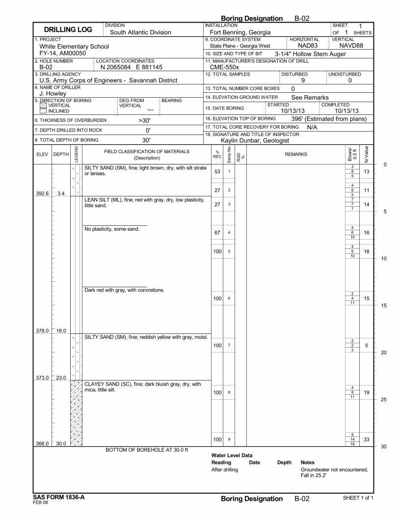
8
6
7
6
6
4
2
8
14
Water Level Data
5
5
7
10
10
11
3
11
19
53
27
27
67
100
100
100
100
100
392.6
378.0
373.0
366.0
3.4
18.0
23.0
30.0
SILTY SAND (SM), fine; light brown, dry, with silt strataor lenses.
LEAN SILT (ML), fine; red with gray, dry, low plasticity,little sand.
No plasticity, some sand.
Dark red with gray, with concretions.
SILTY SAND (SM), fine; reddish yellow with gray, moist.
CLAYEY SAND (SC), fine; dark bluish gray, dry, withmica, little silt.
BOTTOM OF BOREHOLE AT 30.0 ft
13
11
14
16
16
15
5
19
33
3
4
7
4
4
2
2
4
8
1
2
3
4
5
6
7
8
9
Reading Depth NotesDateAfter drilling Groundwater not encountered,
Fall in 25.2'
N/A
14. ELEVATION GROUND WATER
SHEET
---
Fort Benning, Georgia
DISTURBED
6. THICKNESS OF OVERBURDEN
7. DEPTH DRILLED INTO ROCK
8. TOTAL DEPTH OF BORING
STARTEDVERTICAL
1. PROJECT
UNDISTURBED
NAVD88
2. HOLE NUMBER
18. SIGNATURE AND TITLE OF INSPECTOR
CME-550x
BEARING
3. DRILLING AGENCY
11
OF
COMPLETED15. DATE BORING
DEG FROMVERTICAL
HORIZONTAL
3-1/4" Hollow Stem Auger
INSTALLATION
09 0
INCLINED
U.S. Army Corps of Engineers - Savannah District4. NAME OF DRILLER
5. DIRECTION OF BORING
9. COORDINATE SYSTEM
10. SIZE AND TYPE OF BIT
NAD83White Elementary SchoolFY-14, AM00050
>30'
0'
30'
N 2065084 E 881145LOCATION COORDINATES
16. ELEVATION TOP OF BORING
VERTICAL
J. Howley
17. TOTAL CORE RECOVERY FOR BORING
10/13/13
SHEETSDRILLING LOG
12. TOTAL SAMPLES
13. TOTAL NUMBER CORE BOXES
B-02
DIVISION
11. MANUFACTURER'S DESIGNATION OF DRILL
South Atlantic Division
396' (Estimated from plans)
See Remarks
10/13/13
Kaylin Dunbar, Geologist
State Plane - Georgia West
0
5
10
15
20
25
30
Boring Designation B-02
FEB 08
%RECELEV
LEG
EN
D
DEPTH
SAS FORM 1836-A
FIELD CLASSIFICATION OF MATERIALS(Description)
N-V
alue
Boring Designation B-02 SHEET 1 of 1
REMARKS
Blo
ws/
0.5
ft
RQ
D%
Sam
p N
o.
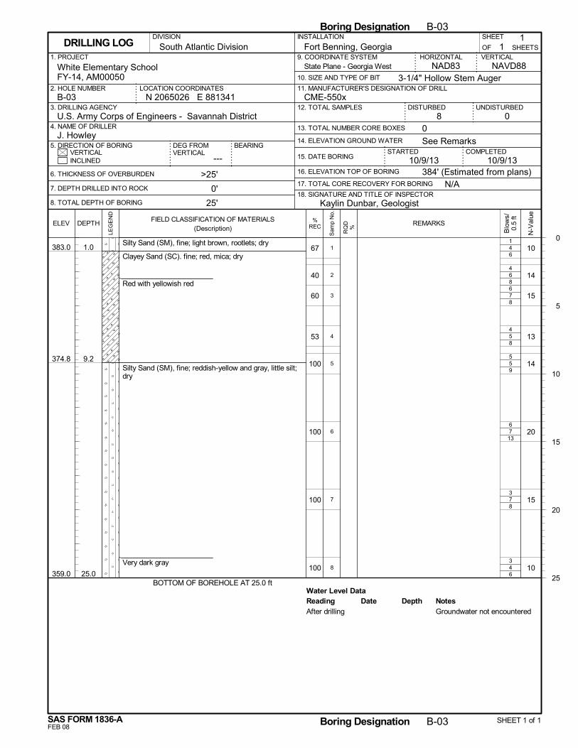
4
6
7
5
5
7
7
4
Water Level Data
6
8
8
8
9
13
8
6
67
40
60
53
100
100
100
100
383.0
374.8
359.0
1.0
9.2
25.0
Silty Sand (SM), fine; light brown, rootlets; dry
Clayey Sand (SC). fine; red, mica; dry
Red with yellowish red
Silty Sand (SM), fine; reddish-yellow and gray, little silt;dry
Very dark gray
BOTTOM OF BOREHOLE AT 25.0 ft
10
14
15
13
14
20
15
10
1
4
6
4
5
6
3
3
1
2
3
4
5
6
7
8
Reading Depth NotesDateAfter drilling Groundwater not encountered
N/A
14. ELEVATION GROUND WATER
SHEET
---
Fort Benning, Georgia
DISTURBED
6. THICKNESS OF OVERBURDEN
7. DEPTH DRILLED INTO ROCK
8. TOTAL DEPTH OF BORING
STARTEDVERTICAL
1. PROJECT
UNDISTURBED
NAVD88
2. HOLE NUMBER
18. SIGNATURE AND TITLE OF INSPECTOR
CME-550x
BEARING
3. DRILLING AGENCY
11
OF
COMPLETED15. DATE BORING
DEG FROMVERTICAL
HORIZONTAL
3-1/4" Hollow Stem Auger
INSTALLATION
08 0
INCLINED
U.S. Army Corps of Engineers - Savannah District4. NAME OF DRILLER
5. DIRECTION OF BORING
9. COORDINATE SYSTEM
10. SIZE AND TYPE OF BIT
NAD83White Elementary SchoolFY-14, AM00050
>25'
0'
25'
N 2065026 E 881341LOCATION COORDINATES
16. ELEVATION TOP OF BORING
VERTICAL
J. Howley
17. TOTAL CORE RECOVERY FOR BORING
10/9/13
SHEETSDRILLING LOG
12. TOTAL SAMPLES
13. TOTAL NUMBER CORE BOXES
B-03
DIVISION
11. MANUFACTURER'S DESIGNATION OF DRILL
South Atlantic Division
384' (Estimated from plans)
See Remarks
10/9/13
Kaylin Dunbar, Geologist
State Plane - Georgia West
0
5
10
15
20
25
Boring Designation B-03
FEB 08
%RECELEV
LEG
EN
D
DEPTH
SAS FORM 1836-A
FIELD CLASSIFICATION OF MATERIALS(Description)
N-V
alue
Boring Designation B-03 SHEET 1 of 1
REMARKS
Blo
ws/
0.5
ft
RQ
D%
Sam
p N
o.
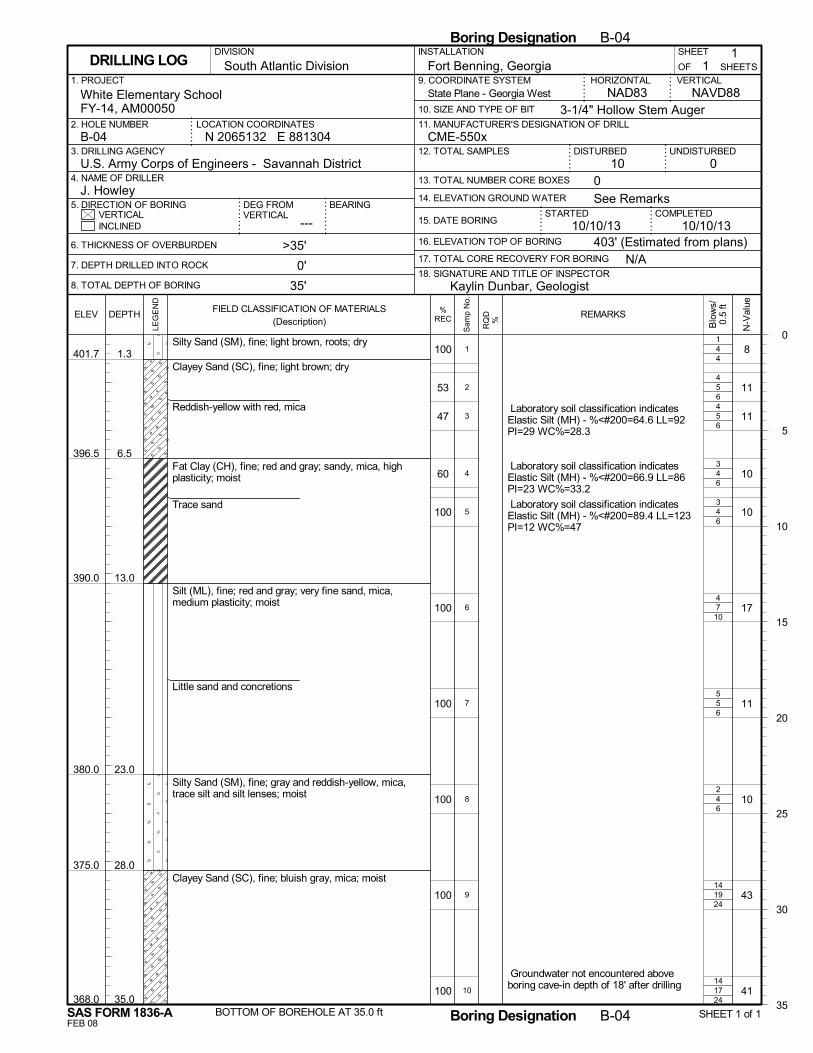
4
5
5
4
4
7
5
4
19
17
4
6
6
6
6
10
6
6
24
24
100
53
47
60
100
100
100
100
100
100
401.7
396.5
390.0
380.0
375.0
368.0
1.3
6.5
13.0
23.0
28.0
35.0
Silty Sand (SM), fine; light brown, roots; dry
Clayey Sand (SC), fine; light brown; dry
Reddish-yellow with red, mica
Fat Clay (CH), fine; red and gray; sandy, mica, highplasticity; moist
Trace sand
Silt (ML), fine; red and gray; very fine sand, mica,medium plasticity; moist
Little sand and concretions
Silty Sand (SM), fine; gray and reddish-yellow, mica,trace silt and silt lenses; moist
Clayey Sand (SC), fine; bluish gray, mica; moist
BOTTOM OF BOREHOLE AT 35.0 ft
8
11
11
10
10
17
11
10
43
41
Laboratory soil classification indicatesElastic Silt (MH) - %<#200=64.6 LL=92PI=29 WC%=28.3
Laboratory soil classification indicatesElastic Silt (MH) - %<#200=66.9 LL=86PI=23 WC%=33.2
Laboratory soil classification indicatesElastic Silt (MH) - %<#200=89.4 LL=123PI=12 WC%=47
Groundwater not encountered aboveboring cave-in depth of 18' after drilling
1
4
4
3
3
4
5
2
14
14
1
2
3
4
5
6
7
8
9
10
N/A
14. ELEVATION GROUND WATER
SHEET
---
Fort Benning, Georgia
DISTURBED
6. THICKNESS OF OVERBURDEN
7. DEPTH DRILLED INTO ROCK
8. TOTAL DEPTH OF BORING
STARTEDVERTICAL
1. PROJECT
UNDISTURBED
NAVD88
2. HOLE NUMBER
18. SIGNATURE AND TITLE OF INSPECTOR
CME-550x
BEARING
3. DRILLING AGENCY
11
OF
COMPLETED15. DATE BORING
DEG FROMVERTICAL
HORIZONTAL
3-1/4" Hollow Stem Auger
INSTALLATION
010 0
INCLINED
U.S. Army Corps of Engineers - Savannah District4. NAME OF DRILLER
5. DIRECTION OF BORING
9. COORDINATE SYSTEM
10. SIZE AND TYPE OF BIT
NAD83White Elementary SchoolFY-14, AM00050
>35'
0'
35'
N 2065132 E 881304LOCATION COORDINATES
16. ELEVATION TOP OF BORING
VERTICAL
J. Howley
17. TOTAL CORE RECOVERY FOR BORING
10/10/13
SHEETSDRILLING LOG
12. TOTAL SAMPLES
13. TOTAL NUMBER CORE BOXES
B-04
DIVISION
11. MANUFACTURER'S DESIGNATION OF DRILL
South Atlantic Division
403' (Estimated from plans)
See Remarks
10/10/13
Kaylin Dunbar, Geologist
State Plane - Georgia West
0
5
10
15
20
25
30
35
Boring Designation B-04
FEB 08
%RECELEV
LEG
EN
D
DEPTH
SAS FORM 1836-A
FIELD CLASSIFICATION OF MATERIALS(Description)
N-V
alue
Boring Designation B-04 SHEET 1 of 1
REMARKS
Blo
ws/
0.5
ft
RQ
D%
Sam
p N
o.
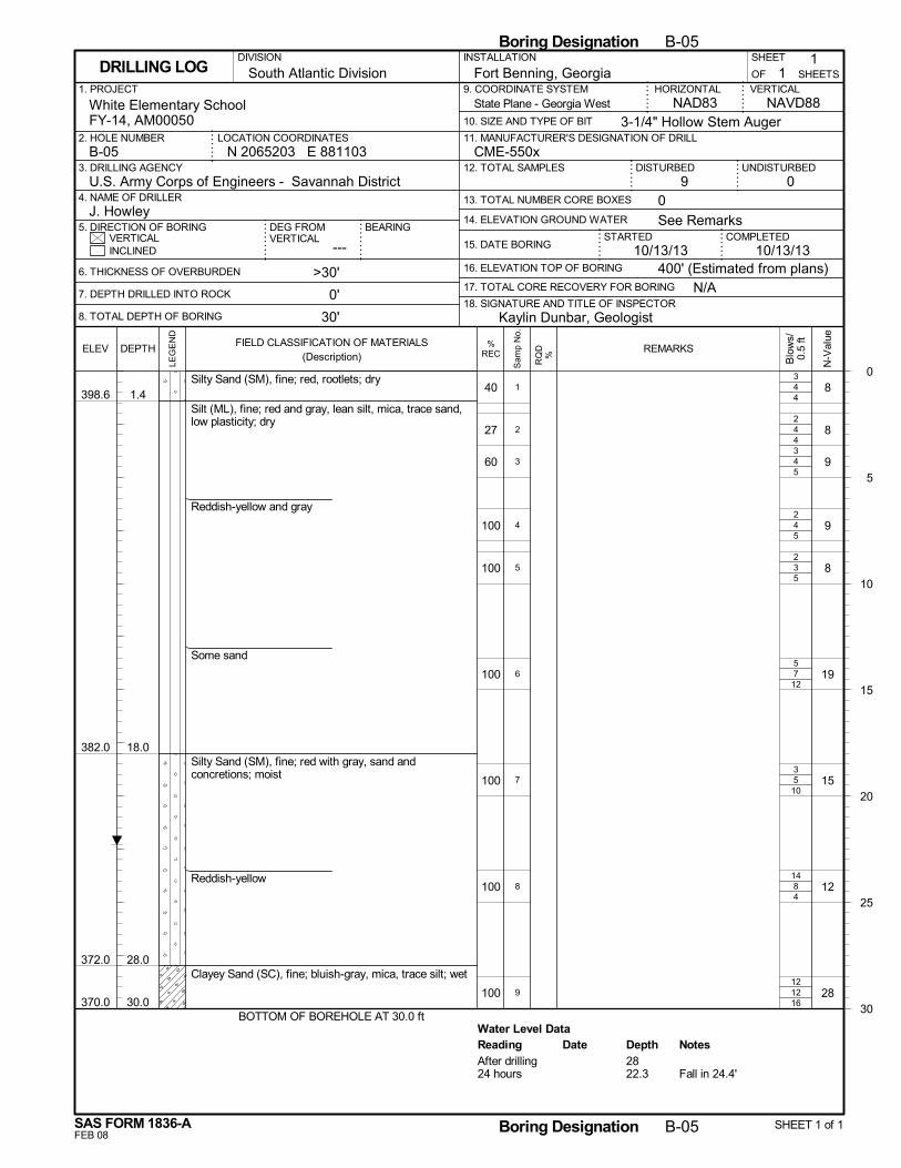
4
4
4
4
3
7
5
8
12
Water Level Data
4
4
5
5
5
12
10
4
16
40
27
60
100
100
100
100
100
100
398.6
382.0
372.0
370.0
1.4
18.0
28.0
30.0
Silty Sand (SM), fine; red, rootlets; dry
Silt (ML), fine; red and gray, lean silt, mica, trace sand,low plasticity; dry
Reddish-yellow and gray
Some sand
Silty Sand (SM), fine; red with gray, sand andconcretions; moist
Reddish-yellow
Clayey Sand (SC), fine; bluish-gray, mica, trace silt; wet
BOTTOM OF BOREHOLE AT 30.0 ft
8
8
9
9
8
19
15
12
28
3
2
3
2
2
5
3
14
12
1
2
3
4
5
6
7
8
9
Reading Depth NotesDateAfter drilling 2824 hours 22.3 Fall in 24.4'
N/A
14. ELEVATION GROUND WATER
SHEET
---
Fort Benning, Georgia
DISTURBED
6. THICKNESS OF OVERBURDEN
7. DEPTH DRILLED INTO ROCK
8. TOTAL DEPTH OF BORING
STARTEDVERTICAL
1. PROJECT
UNDISTURBED
NAVD88
2. HOLE NUMBER
18. SIGNATURE AND TITLE OF INSPECTOR
CME-550x
BEARING
3. DRILLING AGENCY
11
OF
COMPLETED15. DATE BORING
DEG FROMVERTICAL
HORIZONTAL
3-1/4" Hollow Stem Auger
INSTALLATION
09 0
INCLINED
U.S. Army Corps of Engineers - Savannah District4. NAME OF DRILLER
5. DIRECTION OF BORING
9. COORDINATE SYSTEM
10. SIZE AND TYPE OF BIT
NAD83White Elementary SchoolFY-14, AM00050
>30'
0'
30'
N 2065203 E 881103LOCATION COORDINATES
16. ELEVATION TOP OF BORING
VERTICAL
J. Howley
17. TOTAL CORE RECOVERY FOR BORING
10/13/13
SHEETSDRILLING LOG
12. TOTAL SAMPLES
13. TOTAL NUMBER CORE BOXES
B-05
DIVISION
11. MANUFACTURER'S DESIGNATION OF DRILL
South Atlantic Division
400' (Estimated from plans)
See Remarks
10/13/13
Kaylin Dunbar, Geologist
State Plane - Georgia West
0
5
10
15
20
25
30
Boring Designation B-05
FEB 08
%RECELEV
LEG
EN
D
DEPTH
SAS FORM 1836-A
FIELD CLASSIFICATION OF MATERIALS(Description)
N-V
alue
Boring Designation B-05 SHEET 1 of 1
REMARKS
Blo
ws/
0.5
ft
RQ
D%
Sam
p N
o.
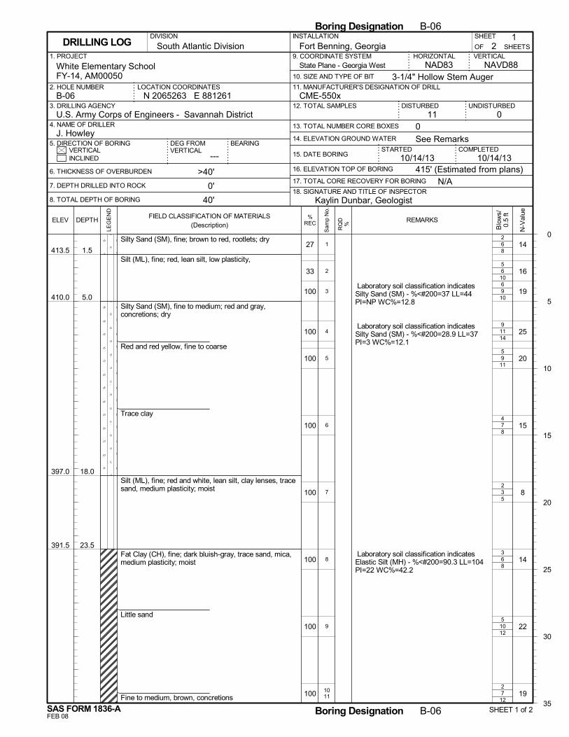
6
6
9
11
9
7
3
6
10
7
8
10
10
14
11
8
5
8
12
12
27
33
100
100
100
100
100
100
100
100
413.5
410.0
397.0
391.5
1.5
5.0
18.0
23.5
Silty Sand (SM), fine; brown to red, rootlets; dry
Silt (ML), fine; red, lean silt, low plasticity,
Silty Sand (SM), fine to medium; red and gray,concretions; dry
Red and red yellow, fine to coarse
Trace clay
Silt (ML), fine; red and white, lean silt, clay lenses, tracesand, medium plasticity; moist
Fat Clay (CH), fine; dark bluish-gray, trace sand, mica,medium plasticity; moist
Little sand
Fine to medium, brown, concretions
14
16
19
25
20
15
8
14
22
19
Laboratory soil classification indicatesSilty Sand (SM) - %<#200=37 LL=44PI=NP WC%=12.8
Laboratory soil classification indicatesSilty Sand (SM) - %<#200=28.9 LL=37PI=3 WC%=12.1
Laboratory soil classification indicatesElastic Silt (MH) - %<#200=90.3 LL=104PI=22 WC%=42.2
2
5
6
9
5
4
2
3
5
2
1
2
3
4
5
6
7
8
9
1011
N/A
14. ELEVATION GROUND WATER
SHEET
---
Fort Benning, Georgia
DISTURBED
6. THICKNESS OF OVERBURDEN
7. DEPTH DRILLED INTO ROCK
8. TOTAL DEPTH OF BORING
STARTEDVERTICAL
1. PROJECT
UNDISTURBED
NAVD88
2. HOLE NUMBER
18. SIGNATURE AND TITLE OF INSPECTOR
CME-550x
BEARING
3. DRILLING AGENCY
21
OF
COMPLETED15. DATE BORING
DEG FROMVERTICAL
HORIZONTAL
3-1/4" Hollow Stem Auger
INSTALLATION
011 0
INCLINED
U.S. Army Corps of Engineers - Savannah District4. NAME OF DRILLER
5. DIRECTION OF BORING
9. COORDINATE SYSTEM
10. SIZE AND TYPE OF BIT
NAD83White Elementary SchoolFY-14, AM00050
>40'
0'
40'
N 2065263 E 881261LOCATION COORDINATES
16. ELEVATION TOP OF BORING
VERTICAL
J. Howley
17. TOTAL CORE RECOVERY FOR BORING
10/14/13
SHEETSDRILLING LOG
12. TOTAL SAMPLES
13. TOTAL NUMBER CORE BOXES
B-06
DIVISION
11. MANUFACTURER'S DESIGNATION OF DRILL
South Atlantic Division
415' (Estimated from plans)
See Remarks
10/14/13
Kaylin Dunbar, Geologist
State Plane - Georgia West
0
5
10
15
20
25
30
35
Boring Designation B-06
FEB 08
%RECELEV
LEG
EN
D
DEPTH
SAS FORM 1836-A
FIELD CLASSIFICATION OF MATERIALS(Description)
N-V
alue
Boring Designation B-06 SHEET 1 of 2
REMARKS
Blo
ws/
0.5
ft
RQ
D%
Sam
p N
o.
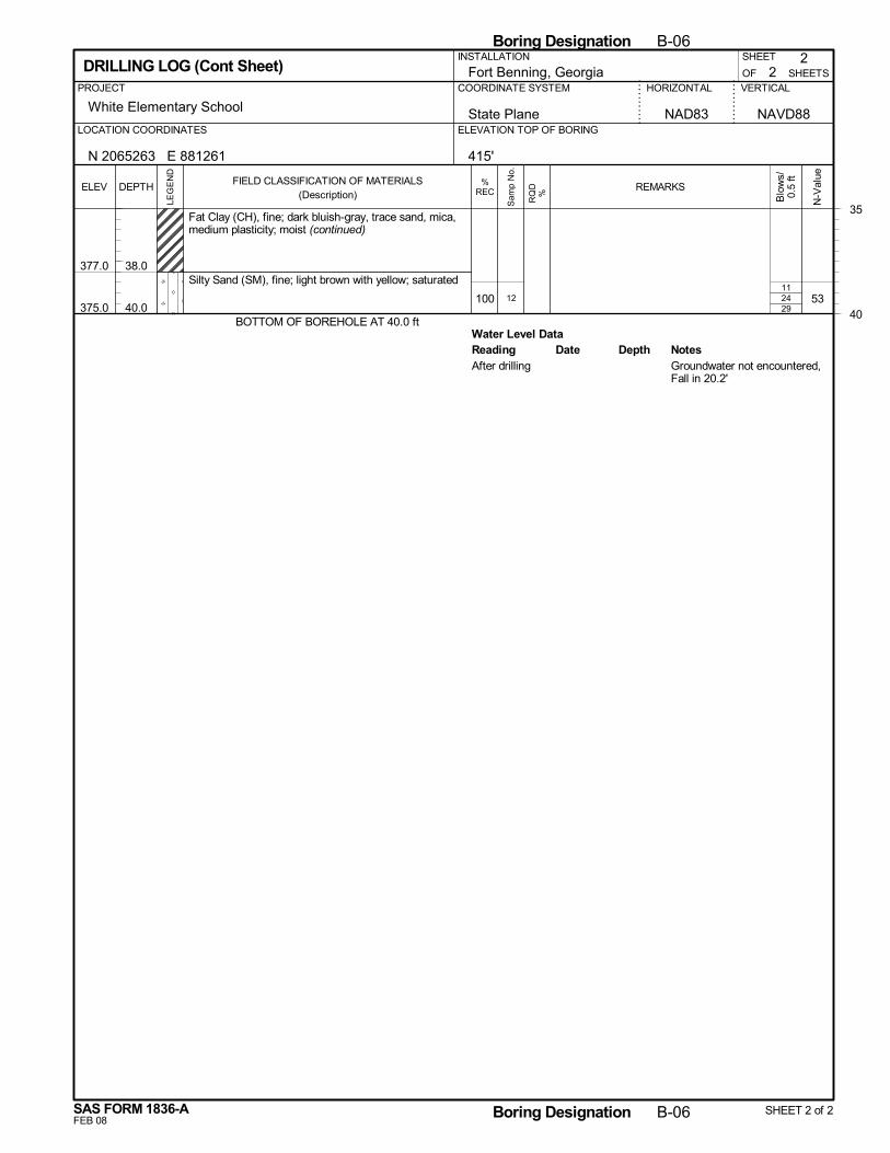
24
Water Level Data
29100
377.0
375.0
38.0
40.0
Fat Clay (CH), fine; dark bluish-gray, trace sand, mica,medium plasticity; moist (continued)
Silty Sand (SM), fine; light brown with yellow; saturated
BOTTOM OF BOREHOLE AT 40.0 ft
5311
12
Reading Depth NotesDateAfter drilling Groundwater not encountered,
Fall in 20.2'
2
White Elementary School
SHEETS
HORIZONTAL VERTICALPROJECT
SHEET
OFFort Benning, GeorgiaCOORDINATE SYSTEM
2
State Plane NAVD88ELEVATION TOP OF BORINGLOCATION COORDINATES
DRILLING LOG (Cont Sheet)
NAD83
N 2065263 E 881261
INSTALLATION
415'
35
40
Boring Designation B-06
FEB 08
%RECELEV
LEG
EN
D
DEPTH
SAS FORM 1836-A
FIELD CLASSIFICATION OF MATERIALS(Description)
N-V
alue
Boring Designation B-06 SHEET 2 of 2
REMARKS
Blo
ws/
0.5
ft
RQ
D%
Sam
p N
o.
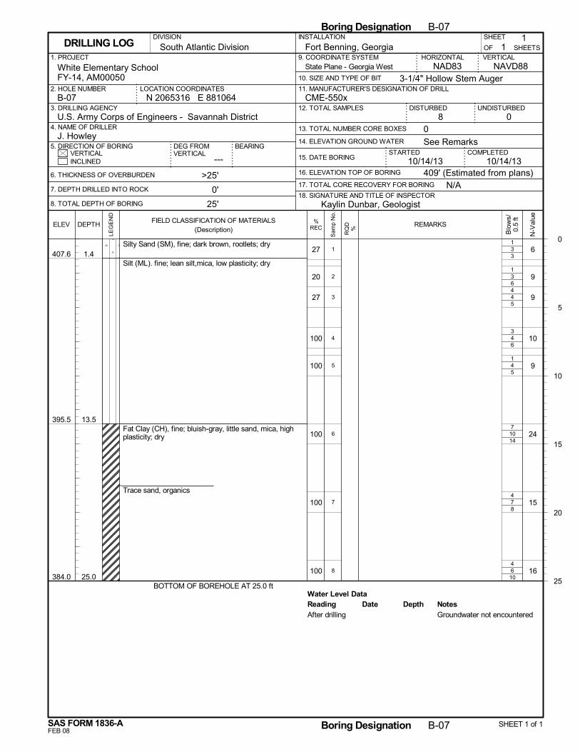
3
3
4
4
4
10
7
6
Water Level Data
3
6
5
6
5
14
8
10
27
20
27
100
100
100
100
100
407.6
395.5
384.0
1.4
13.5
25.0
Silty Sand (SM), fine; dark brown, rootlets; dry
Silt (ML). fine; lean silt,mica, low plasticity; dry
Fat Clay (CH), fine; bluish-gray, little sand, mica, highplasticity; dry
Trace sand, organics
BOTTOM OF BOREHOLE AT 25.0 ft
6
9
9
10
9
24
15
16
1
1
4
3
1
7
4
4
1
2
3
4
5
6
7
8
Reading Depth NotesDateAfter drilling Groundwater not encountered
N/A
14. ELEVATION GROUND WATER
SHEET
---
Fort Benning, Georgia
DISTURBED
6. THICKNESS OF OVERBURDEN
7. DEPTH DRILLED INTO ROCK
8. TOTAL DEPTH OF BORING
STARTEDVERTICAL
1. PROJECT
UNDISTURBED
NAVD88
2. HOLE NUMBER
18. SIGNATURE AND TITLE OF INSPECTOR
CME-550x
BEARING
3. DRILLING AGENCY
11
OF
COMPLETED15. DATE BORING
DEG FROMVERTICAL
HORIZONTAL
3-1/4" Hollow Stem Auger
INSTALLATION
08 0
INCLINED
U.S. Army Corps of Engineers - Savannah District4. NAME OF DRILLER
5. DIRECTION OF BORING
9. COORDINATE SYSTEM
10. SIZE AND TYPE OF BIT
NAD83White Elementary SchoolFY-14, AM00050
>25'
0'
25'
N 2065316 E 881064LOCATION COORDINATES
16. ELEVATION TOP OF BORING
VERTICAL
J. Howley
17. TOTAL CORE RECOVERY FOR BORING
10/14/13
SHEETSDRILLING LOG
12. TOTAL SAMPLES
13. TOTAL NUMBER CORE BOXES
B-07
DIVISION
11. MANUFACTURER'S DESIGNATION OF DRILL
South Atlantic Division
409' (Estimated from plans)
See Remarks
10/14/13
Kaylin Dunbar, Geologist
State Plane - Georgia West
0
5
10
15
20
25
Boring Designation B-07
FEB 08
%RECELEV
LEG
EN
D
DEPTH
SAS FORM 1836-A
FIELD CLASSIFICATION OF MATERIALS(Description)
N-V
alue
Boring Designation B-07 SHEET 1 of 1
REMARKS
Blo
ws/
0.5
ft
RQ
D%
Sam
p N
o.
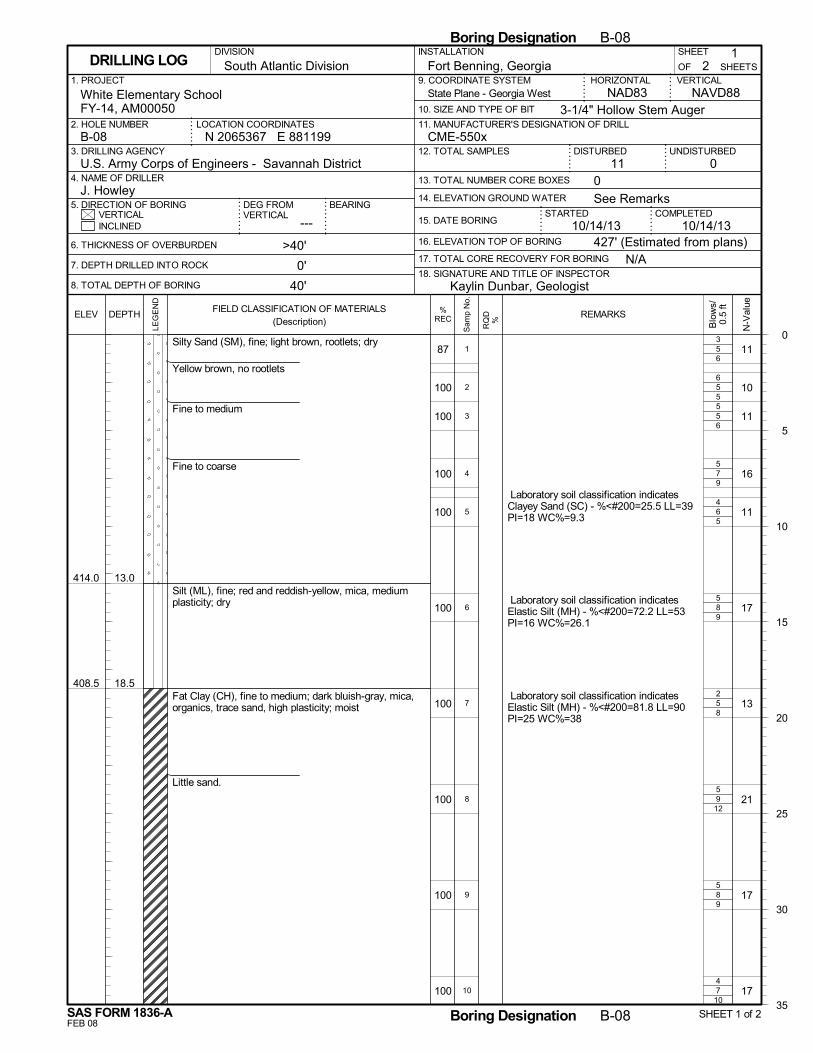
5
5
5
7
6
8
5
9
8
7
6
5
6
9
5
9
8
12
9
10
87
100
100
100
100
100
100
100
100
100
414.0
408.5
13.0
18.5
Silty Sand (SM), fine; light brown, rootlets; dry
Yellow brown, no rootlets
Fine to medium
Fine to coarse
Silt (ML), fine; red and reddish-yellow, mica, mediumplasticity; dry
Fat Clay (CH), fine to medium; dark bluish-gray, mica,organics, trace sand, high plasticity; moist
Little sand.
11
10
11
16
11
17
13
21
17
17
Laboratory soil classification indicatesClayey Sand (SC) - %<#200=25.5 LL=39PI=18 WC%=9.3
Laboratory soil classification indicatesElastic Silt (MH) - %<#200=72.2 LL=53PI=16 WC%=26.1
Laboratory soil classification indicatesElastic Silt (MH) - %<#200=81.8 LL=90PI=25 WC%=38
3
6
5
5
4
5
2
5
5
4
1
2
3
4
5
6
7
8
9
10
N/A
14. ELEVATION GROUND WATER
SHEET
---
Fort Benning, Georgia
DISTURBED
6. THICKNESS OF OVERBURDEN
7. DEPTH DRILLED INTO ROCK
8. TOTAL DEPTH OF BORING
STARTEDVERTICAL
1. PROJECT
UNDISTURBED
NAVD88
2. HOLE NUMBER
18. SIGNATURE AND TITLE OF INSPECTOR
CME-550x
BEARING
3. DRILLING AGENCY
21
OF
COMPLETED15. DATE BORING
DEG FROMVERTICAL
HORIZONTAL
3-1/4" Hollow Stem Auger
INSTALLATION
011 0
INCLINED
U.S. Army Corps of Engineers - Savannah District4. NAME OF DRILLER
5. DIRECTION OF BORING
9. COORDINATE SYSTEM
10. SIZE AND TYPE OF BIT
NAD83White Elementary SchoolFY-14, AM00050
>40'
0'
40'
N 2065367 E 881199LOCATION COORDINATES
16. ELEVATION TOP OF BORING
VERTICAL
J. Howley
17. TOTAL CORE RECOVERY FOR BORING
10/14/13
SHEETSDRILLING LOG
12. TOTAL SAMPLES
13. TOTAL NUMBER CORE BOXES
B-08
DIVISION
11. MANUFACTURER'S DESIGNATION OF DRILL
South Atlantic Division
427' (Estimated from plans)
See Remarks
10/14/13
Kaylin Dunbar, Geologist
State Plane - Georgia West
0
5
10
15
20
25
30
35
Boring Designation B-08
FEB 08
%RECELEV
LEG
EN
D
DEPTH
SAS FORM 1836-A
FIELD CLASSIFICATION OF MATERIALS(Description)
N-V
alue
Boring Designation B-08 SHEET 1 of 2
REMARKS
Blo
ws/
0.5
ft
RQ
D%
Sam
p N
o.
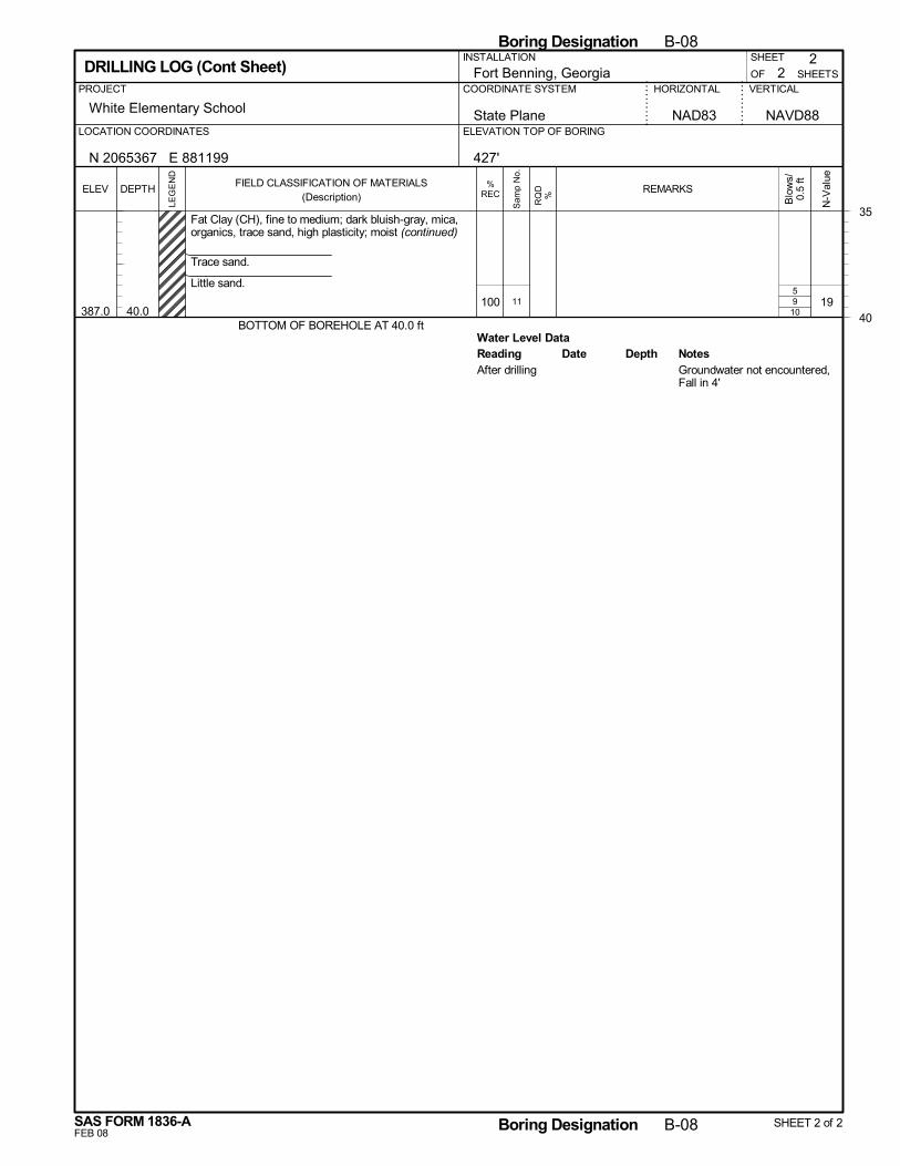
9
Water Level Data
10100
387.0 40.0
Fat Clay (CH), fine to medium; dark bluish-gray, mica,organics, trace sand, high plasticity; moist (continued)
Trace sand.
Little sand.
BOTTOM OF BOREHOLE AT 40.0 ft
195
11
Reading Depth NotesDateAfter drilling Groundwater not encountered,
Fall in 4'
2
White Elementary School
SHEETS
HORIZONTAL VERTICALPROJECT
SHEET
OFFort Benning, GeorgiaCOORDINATE SYSTEM
2
State Plane NAVD88ELEVATION TOP OF BORINGLOCATION COORDINATES
DRILLING LOG (Cont Sheet)
NAD83
N 2065367 E 881199
INSTALLATION
427'
35
40
Boring Designation B-08
FEB 08
%RECELEV
LEG
EN
D
DEPTH
SAS FORM 1836-A
FIELD CLASSIFICATION OF MATERIALS(Description)
N-V
alue
Boring Designation B-08 SHEET 2 of 2
REMARKS
Blo
ws/
0.5
ft
RQ
D%
Sam
p N
o.
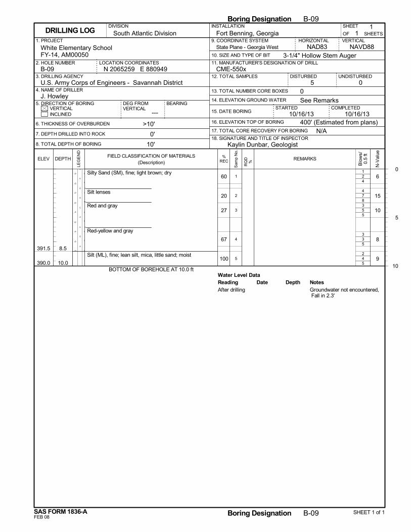
2
7
5
3
4
Water Level Data
4
8
5
5
5
60
20
27
67
100
391.5
390.0
8.5
10.0
Silty Sand (SM), fine; light brown; dry
Silt lenses
Red and gray
Red-yellow and gray
Silt (ML), fine; lean silt, mica, little sand; moist
BOTTOM OF BOREHOLE AT 10.0 ft
6
15
10
8
9
1
4
3
3
2
1
2
3
4
5
Reading Depth NotesDateAfter drilling Groundwater not encountered,
Fall in 2.3'
N/A
14. ELEVATION GROUND WATER
SHEET
---
Fort Benning, Georgia
DISTURBED
6. THICKNESS OF OVERBURDEN
7. DEPTH DRILLED INTO ROCK
8. TOTAL DEPTH OF BORING
STARTEDVERTICAL
1. PROJECT
UNDISTURBED
NAVD88
2. HOLE NUMBER
18. SIGNATURE AND TITLE OF INSPECTOR
CME-550x
BEARING
3. DRILLING AGENCY
11
OF
COMPLETED15. DATE BORING
DEG FROMVERTICAL
HORIZONTAL
3-1/4" Hollow Stem Auger
INSTALLATION
05 0
INCLINED
U.S. Army Corps of Engineers - Savannah District4. NAME OF DRILLER
5. DIRECTION OF BORING
9. COORDINATE SYSTEM
10. SIZE AND TYPE OF BIT
NAD83White Elementary SchoolFY-14, AM00050
>10'
0'
10'
N 2065259 E 880949LOCATION COORDINATES
16. ELEVATION TOP OF BORING
VERTICAL
J. Howley
17. TOTAL CORE RECOVERY FOR BORING
10/16/13
SHEETSDRILLING LOG
12. TOTAL SAMPLES
13. TOTAL NUMBER CORE BOXES
B-09
DIVISION
11. MANUFACTURER'S DESIGNATION OF DRILL
South Atlantic Division
400' (Estimated from plans)
See Remarks
10/16/13
Kaylin Dunbar, Geologist
State Plane - Georgia West
0
5
10
Boring Designation B-09
FEB 08
%RECELEV
LEG
EN
D
DEPTH
SAS FORM 1836-A
FIELD CLASSIFICATION OF MATERIALS(Description)
N-V
alue
Boring Designation B-09 SHEET 1 of 1
REMARKS
Blo
ws/
0.5
ft
RQ
D%
Sam
p N
o.
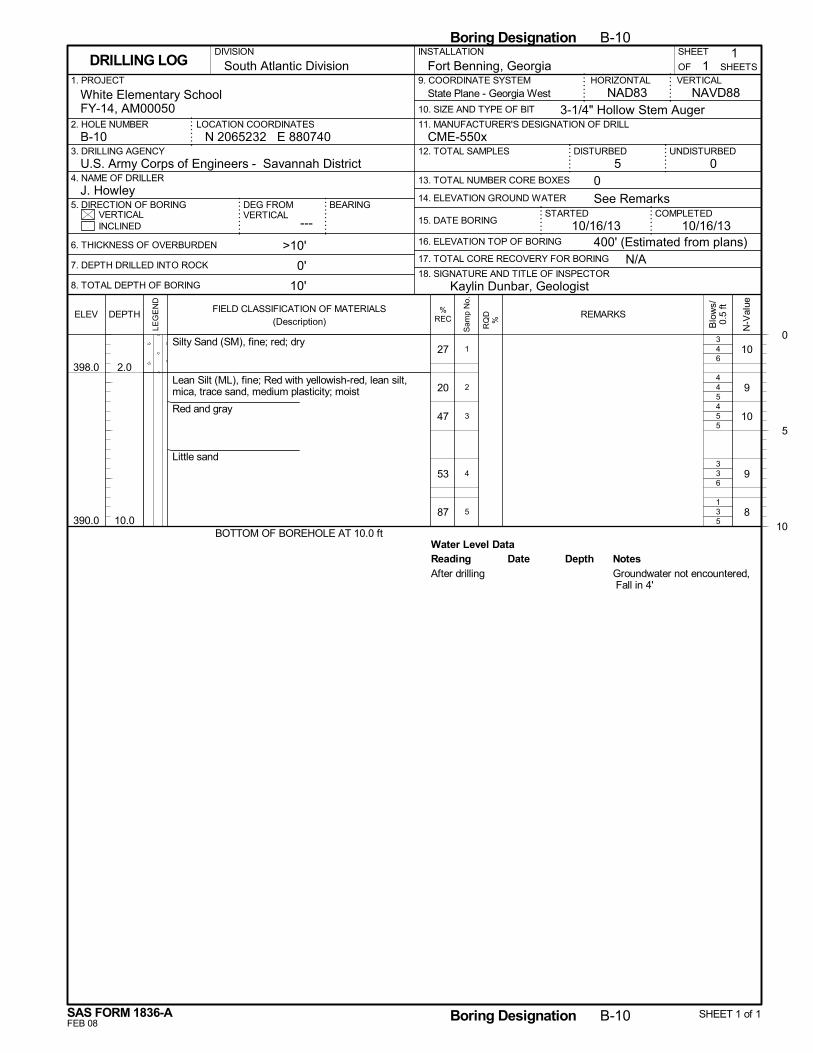
4
4
5
3
3
Water Level Data
6
5
5
6
5
27
20
47
53
87
398.0
390.0
2.0
10.0
Silty Sand (SM), fine; red; dry
Lean Silt (ML), fine; Red with yellowish-red, lean silt,mica, trace sand, medium plasticity; moist
Red and gray
Little sand
BOTTOM OF BOREHOLE AT 10.0 ft
10
9
10
9
8
3
4
4
3
1
1
2
3
4
5
Reading Depth NotesDateAfter drilling Groundwater not encountered,
Fall in 4'
N/A
14. ELEVATION GROUND WATER
SHEET
---
Fort Benning, Georgia
DISTURBED
6. THICKNESS OF OVERBURDEN
7. DEPTH DRILLED INTO ROCK
8. TOTAL DEPTH OF BORING
STARTEDVERTICAL
1. PROJECT
UNDISTURBED
NAVD88
2. HOLE NUMBER
18. SIGNATURE AND TITLE OF INSPECTOR
CME-550x
BEARING
3. DRILLING AGENCY
11
OF
COMPLETED15. DATE BORING
DEG FROMVERTICAL
HORIZONTAL
3-1/4" Hollow Stem Auger
INSTALLATION
05 0
INCLINED
U.S. Army Corps of Engineers - Savannah District4. NAME OF DRILLER
5. DIRECTION OF BORING
9. COORDINATE SYSTEM
10. SIZE AND TYPE OF BIT
NAD83White Elementary SchoolFY-14, AM00050
>10'
0'
10'
N 2065232 E 880740LOCATION COORDINATES
16. ELEVATION TOP OF BORING
VERTICAL
J. Howley
17. TOTAL CORE RECOVERY FOR BORING
10/16/13
SHEETSDRILLING LOG
12. TOTAL SAMPLES
13. TOTAL NUMBER CORE BOXES
B-10
DIVISION
11. MANUFACTURER'S DESIGNATION OF DRILL
South Atlantic Division
400' (Estimated from plans)
See Remarks
10/16/13
Kaylin Dunbar, Geologist
State Plane - Georgia West
0
5
10
Boring Designation B-10
FEB 08
%RECELEV
LEG
EN
D
DEPTH
SAS FORM 1836-A
FIELD CLASSIFICATION OF MATERIALS(Description)
N-V
alue
Boring Designation B-10 SHEET 1 of 1
REMARKS
Blo
ws/
0.5
ft
RQ
D%
Sam
p N
o.
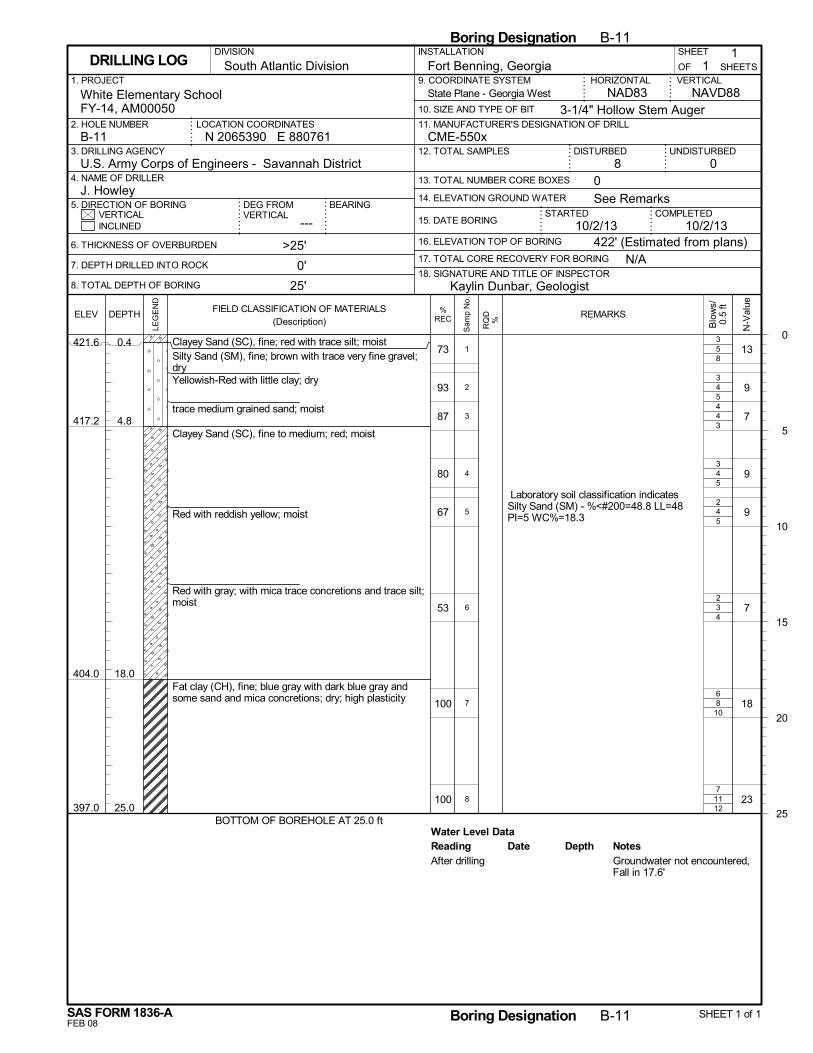
5
4
4
4
4
3
8
11
Water Level Data
8
5
3
5
5
4
10
12
73
93
87
80
67
53
100
100
421.6
417.2
404.0
397.0
0.4
4.8
18.0
25.0
Clayey Sand (SC), fine; red with trace silt; moistSilty Sand (SM), fine; brown with trace very fine gravel;dryYellowish-Red with little clay; dry
trace medium grained sand; moist
Clayey Sand (SC), fine to medium; red; moist
Red with reddish yellow; moist
Red with gray; with mica trace concretions and trace silt;moist
Fat clay (CH), fine; blue gray with dark blue gray andsome sand and mica concretions; dry; high plasticity
BOTTOM OF BOREHOLE AT 25.0 ft
13
9
7
9
9
7
18
23
Laboratory soil classification indicatesSilty Sand (SM) - %<#200=48.8 LL=48PI=5 WC%=18.3
3
3
4
3
2
2
6
7
1
2
3
4
5
6
7
8
Reading Depth NotesDateAfter drilling Groundwater not encountered,
Fall in 17.6'
N/A
14. ELEVATION GROUND WATER
SHEET
---
Fort Benning, Georgia
DISTURBED
6. THICKNESS OF OVERBURDEN
7. DEPTH DRILLED INTO ROCK
8. TOTAL DEPTH OF BORING
STARTEDVERTICAL
1. PROJECT
UNDISTURBED
NAVD88
2. HOLE NUMBER
18. SIGNATURE AND TITLE OF INSPECTOR
CME-550x
BEARING
3. DRILLING AGENCY
11
OF
COMPLETED15. DATE BORING
DEG FROMVERTICAL
HORIZONTAL
3-1/4" Hollow Stem Auger
INSTALLATION
08 0
INCLINED
U.S. Army Corps of Engineers - Savannah District4. NAME OF DRILLER
5. DIRECTION OF BORING
9. COORDINATE SYSTEM
10. SIZE AND TYPE OF BIT
NAD83White Elementary SchoolFY-14, AM00050
>25'
0'
25'
N 2065390 E 880761LOCATION COORDINATES
16. ELEVATION TOP OF BORING
VERTICAL
J. Howley
17. TOTAL CORE RECOVERY FOR BORING
10/2/13
SHEETSDRILLING LOG
12. TOTAL SAMPLES
13. TOTAL NUMBER CORE BOXES
B-11
DIVISION
11. MANUFACTURER'S DESIGNATION OF DRILL
South Atlantic Division
422' (Estimated from plans)
See Remarks
10/2/13
Kaylin Dunbar, Geologist
State Plane - Georgia West
0
5
10
15
20
25
Boring Designation B-11
FEB 08
%RECELEV
LEG
EN
D
DEPTH
SAS FORM 1836-A
FIELD CLASSIFICATION OF MATERIALS(Description)
N-V
alue
Boring Designation B-11 SHEET 1 of 1
REMARKS
Blo
ws/
0.5
ft
RQ
D%
Sam
p N
o.
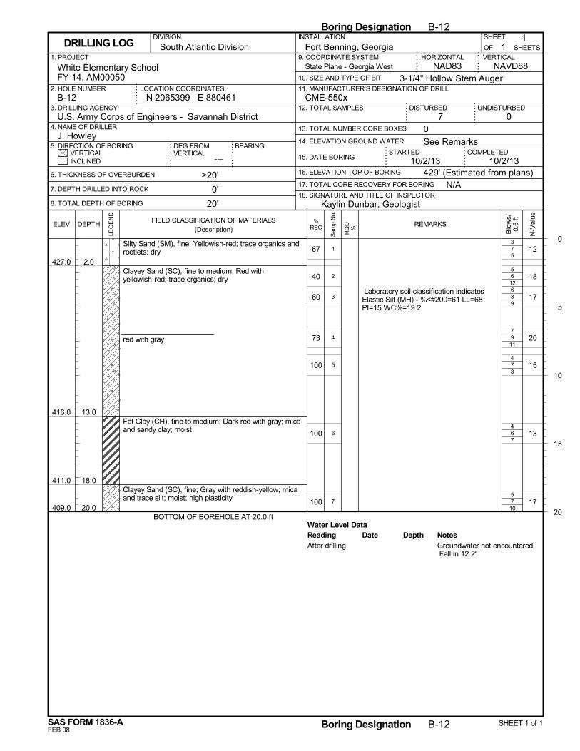
7
6
8
9
7
6
7
Water Level Data
5
12
9
11
8
7
10
67
40
60
73
100
100
100
427.0
416.0
411.0
409.0
2.0
13.0
18.0
20.0
Silty Sand (SM), fine; Yellowish-red; trace organics androotlets; dry
Clayey Sand (SC), fine to medium; Red withyellowish-red; trace organics; dry
red with gray
Fat Clay (CH), fine to medium; Dark red with gray; micaand sandy clay; moist
Clayey Sand (SC), fine; Gray with reddish-yellow; micaand trace silt; moist; high plasticity
BOTTOM OF BOREHOLE AT 20.0 ft
12
18
17
20
15
13
17
Laboratory soil classification indicatesElastic Silt (MH) - %<#200=61 LL=68PI=15 WC%=19.2
3
5
6
7
4
4
5
1
2
3
4
5
6
7
Reading Depth NotesDateAfter drilling Groundwater not encountered,
Fall in 12.2'
N/A
14. ELEVATION GROUND WATER
SHEET
---
Fort Benning, Georgia
DISTURBED
6. THICKNESS OF OVERBURDEN
7. DEPTH DRILLED INTO ROCK
8. TOTAL DEPTH OF BORING
STARTEDVERTICAL
1. PROJECT
UNDISTURBED
NAVD88
2. HOLE NUMBER
18. SIGNATURE AND TITLE OF INSPECTOR
CME-550x
BEARING
3. DRILLING AGENCY
11
OF
COMPLETED15. DATE BORING
DEG FROMVERTICAL
HORIZONTAL
3-1/4" Hollow Stem Auger
INSTALLATION
07 0
INCLINED
U.S. Army Corps of Engineers - Savannah District4. NAME OF DRILLER
5. DIRECTION OF BORING
9. COORDINATE SYSTEM
10. SIZE AND TYPE OF BIT
NAD83White Elementary SchoolFY-14, AM00050
>20'
0'
20'
N 2065399 E 880461LOCATION COORDINATES
16. ELEVATION TOP OF BORING
VERTICAL
J. Howley
17. TOTAL CORE RECOVERY FOR BORING
10/2/13
SHEETSDRILLING LOG
12. TOTAL SAMPLES
13. TOTAL NUMBER CORE BOXES
B-12
DIVISION
11. MANUFACTURER'S DESIGNATION OF DRILL
South Atlantic Division
429' (Estimated from plans)
See Remarks
10/2/13
Kaylin Dunbar, Geologist
State Plane - Georgia West
0
5
10
15
20
Boring Designation B-12
FEB 08
%RECELEV
LEG
EN
D
DEPTH
SAS FORM 1836-A
FIELD CLASSIFICATION OF MATERIALS(Description)
N-V
alue
Boring Designation B-12 SHEET 1 of 1
REMARKS
Blo
ws/
0.5
ft
RQ
D%
Sam
p N
o.
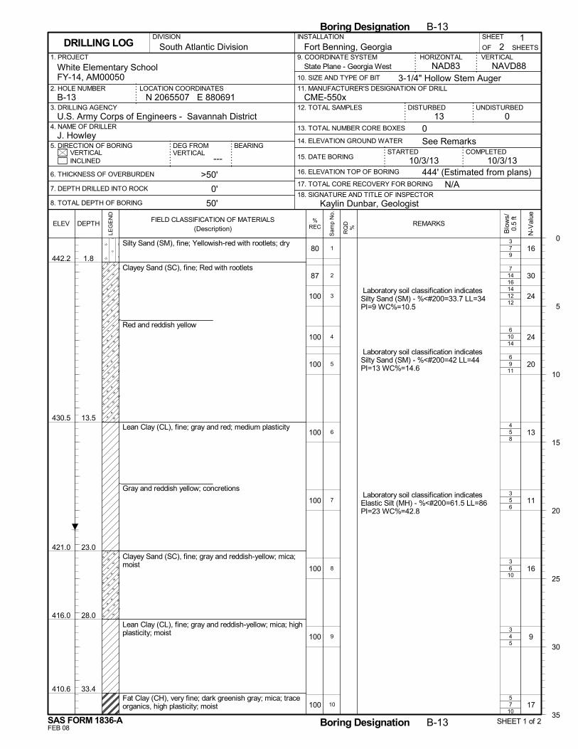
7
14
12
10
9
5
5
6
4
7
9
16
12
14
11
8
6
10
5
10
80
87
100
100
100
100
100
100
100
100
442.2
430.5
421.0
416.0
410.6
1.8
13.5
23.0
28.0
33.4
Silty Sand (SM), fine; Yellowish-red with rootlets; dry
Clayey Sand (SC), fine; Red with rootlets
Red and reddish yellow
Lean Clay (CL), fine; gray and red; medium plasticity
Gray and reddish yellow; concretions
Clayey Sand (SC), fine; gray and reddish-yellow; mica;moist
Lean Clay (CL), fine; gray and reddish-yellow; mica; highplasticity; moist
Fat Clay (CH), very fine; dark greenish gray; mica; traceorganics, high plasticity; moist
16
30
24
24
20
13
11
16
9
17
Laboratory soil classification indicatesSilty Sand (SM) - %<#200=33.7 LL=34PI=9 WC%=10.5
Laboratory soil classification indicatesSilty Sand (SM) - %<#200=42 LL=44PI=13 WC%=14.6
Laboratory soil classification indicatesElastic Silt (MH) - %<#200=61.5 LL=86PI=23 WC%=42.8
3
7
14
6
6
4
3
3
3
5
1
2
3
4
5
6
7
8
9
10
N/A
14. ELEVATION GROUND WATER
SHEET
---
Fort Benning, Georgia
DISTURBED
6. THICKNESS OF OVERBURDEN
7. DEPTH DRILLED INTO ROCK
8. TOTAL DEPTH OF BORING
STARTEDVERTICAL
1. PROJECT
UNDISTURBED
NAVD88
2. HOLE NUMBER
18. SIGNATURE AND TITLE OF INSPECTOR
CME-550x
BEARING
3. DRILLING AGENCY
21
OF
COMPLETED15. DATE BORING
DEG FROMVERTICAL
HORIZONTAL
3-1/4" Hollow Stem Auger
INSTALLATION
013 0
INCLINED
U.S. Army Corps of Engineers - Savannah District4. NAME OF DRILLER
5. DIRECTION OF BORING
9. COORDINATE SYSTEM
10. SIZE AND TYPE OF BIT
NAD83White Elementary SchoolFY-14, AM00050
>50'
0'
50'
N 2065507 E 880691LOCATION COORDINATES
16. ELEVATION TOP OF BORING
VERTICAL
J. Howley
17. TOTAL CORE RECOVERY FOR BORING
10/3/13
SHEETSDRILLING LOG
12. TOTAL SAMPLES
13. TOTAL NUMBER CORE BOXES
B-13
DIVISION
11. MANUFACTURER'S DESIGNATION OF DRILL
South Atlantic Division
444' (Estimated from plans)
See Remarks
10/3/13
Kaylin Dunbar, Geologist
State Plane - Georgia West
0
5
10
15
20
25
30
35
Boring Designation B-13
FEB 08
%RECELEV
LEG
EN
D
DEPTH
SAS FORM 1836-A
FIELD CLASSIFICATION OF MATERIALS(Description)
N-V
alue
Boring Designation B-13 SHEET 1 of 2
REMARKS
Blo
ws/
0.5
ft
RQ
D%
Sam
p N
o.
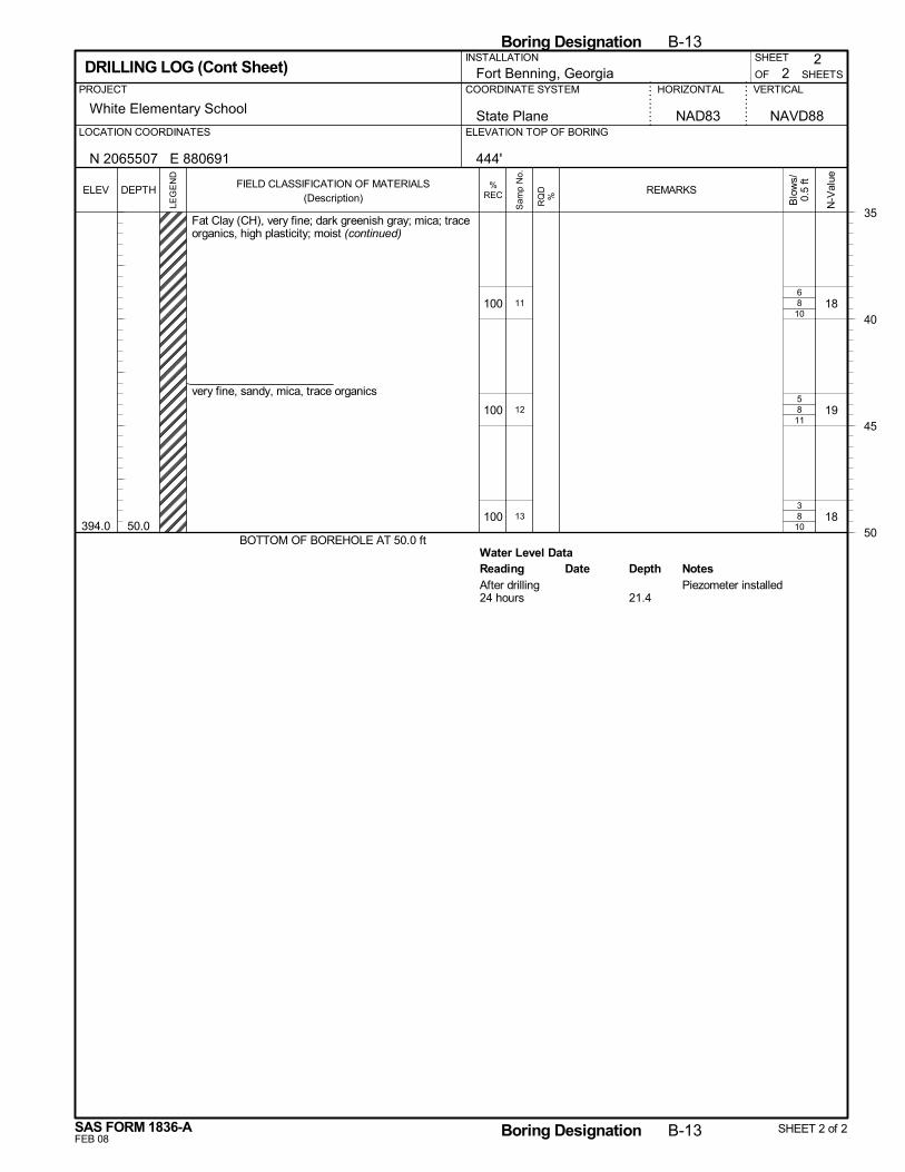
8
8
8
Water Level Data
10
11
10
100
100
100394.0 50.0
Fat Clay (CH), very fine; dark greenish gray; mica; traceorganics, high plasticity; moist (continued)
very fine, sandy, mica, trace organics
BOTTOM OF BOREHOLE AT 50.0 ft
18
19
18
6
5
3
11
12
13
Reading Depth NotesDateAfter drilling Piezometer installed24 hours 21.4
2
White Elementary School
SHEETS
HORIZONTAL VERTICALPROJECT
SHEET
OFFort Benning, GeorgiaCOORDINATE SYSTEM
2
State Plane NAVD88ELEVATION TOP OF BORINGLOCATION COORDINATES
DRILLING LOG (Cont Sheet)
NAD83
N 2065507 E 880691
INSTALLATION
444'
35
40
45
50
Boring Designation B-13
FEB 08
%RECELEV
LEG
EN
D
DEPTH
SAS FORM 1836-A
FIELD CLASSIFICATION OF MATERIALS(Description)
N-V
alue
Boring Designation B-13 SHEET 2 of 2
REMARKS
Blo
ws/
0.5
ft
RQ
D%
Sam
p N
o.
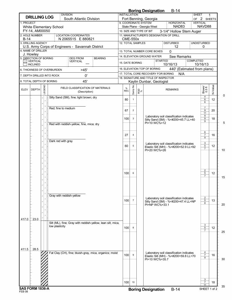
6
9
9
7
5
5
5
5
7
7
6
11
9
9
7
7
8
7
9
11
80
67
100
27
60
100
100
100
100
100
417.0
411.5
23.0
28.5
Silty Sand (SM), fine; light brown; dry
Red; fine to medium
Red with reddish-yellow, fine, mica; dry
Dark red with gray
Gray with reddish-yellow
Silt (ML), fine; Gray with reddish-yellow, lean silt, mica,low plasticity
Fat Clay (CH), fine; bluish-gray, mica, organics; moist
12
20
18
16
12
12
13
12
16
18
Laboratory soil classification indicatesSilty Sand (SM) - %<#200=45.7 LL=40PI=10 WC%=12
Laboratory soil classification indicatesElastic Silt (MH) - %<#200=52.9 LL=92PI=20 WC%=26
Laboratory soil classification indicatesSilty Sand (SM) - %<#200=47.4 LL=NPPI=NP WC%=33.1
Laboratory soil classification indicatesElastic Silt (MH) - %<#200=59.8 LL=70PI=10 WC%=35.7
4
7
9
6
3
2
2
3
4
3
1
2
3
4
5
6
7
8
9
10
N/A
14. ELEVATION GROUND WATER
SHEET
---
Fort Benning, Georgia
DISTURBED
6. THICKNESS OF OVERBURDEN
7. DEPTH DRILLED INTO ROCK
8. TOTAL DEPTH OF BORING
STARTEDVERTICAL
1. PROJECT
UNDISTURBED
NAVD88
2. HOLE NUMBER
18. SIGNATURE AND TITLE OF INSPECTOR
CME-550x
BEARING
3. DRILLING AGENCY
21
OF
COMPLETED15. DATE BORING
DEG FROMVERTICAL
HORIZONTAL
3-1/4" Hollow Stem Auger
INSTALLATION
012 0
INCLINED
U.S. Army Corps of Engineers - Savannah District4. NAME OF DRILLER
5. DIRECTION OF BORING
9. COORDINATE SYSTEM
10. SIZE AND TYPE OF BIT
NAD83White Elementary SchoolFY-14, AM00050
>45'
0'
45'
N 2065515 E 880821LOCATION COORDINATES
16. ELEVATION TOP OF BORING
VERTICAL
J. Howley
17. TOTAL CORE RECOVERY FOR BORING
10/16/13
SHEETSDRILLING LOG
12. TOTAL SAMPLES
13. TOTAL NUMBER CORE BOXES
B-14
DIVISION
11. MANUFACTURER'S DESIGNATION OF DRILL
South Atlantic Division
440' (Estimated from plans)
See Remarks
10/16/13
Kaylin Dunbar, Geologist
State Plane - Georgia West
0
5
10
15
20
25
30
35
Boring Designation B-14
FEB 08
%RECELEV
LEG
EN
D
DEPTH
SAS FORM 1836-A
FIELD CLASSIFICATION OF MATERIALS(Description)
N-V
alue
Boring Designation B-14 SHEET 1 of 2
REMARKS
Blo
ws/
0.5
ft
RQ
D%
Sam
p N
o.
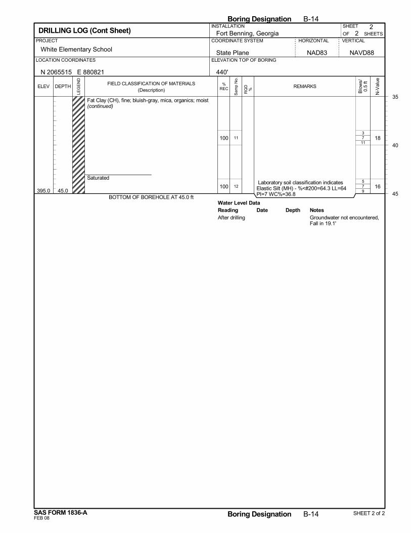
7
7
Water Level Data
11
9
100
100395.0 45.0
Fat Clay (CH), fine; bluish-gray, mica, organics; moist(continued)
Saturated
BOTTOM OF BOREHOLE AT 45.0 ft
18
16 Laboratory soil classification indicatesElastic Silt (MH) - %<#200=64.3 LL=64PI=7 WC%=36.8
3
5
11
12
Reading Depth NotesDateAfter drilling Groundwater not encountered,
Fall in 19.1'
2
White Elementary School
SHEETS
HORIZONTAL VERTICALPROJECT
SHEET
OFFort Benning, GeorgiaCOORDINATE SYSTEM
2
State Plane NAVD88ELEVATION TOP OF BORINGLOCATION COORDINATES
DRILLING LOG (Cont Sheet)
NAD83
N 2065515 E 880821
INSTALLATION
440'
35
40
45
Boring Designation B-14
FEB 08
%RECELEV
LEG
EN
D
DEPTH
SAS FORM 1836-A
FIELD CLASSIFICATION OF MATERIALS(Description)
N-V
alue
Boring Designation B-14 SHEET 2 of 2
REMARKS
Blo
ws/
0.5
ft
RQ
D%
Sam
p N
o.
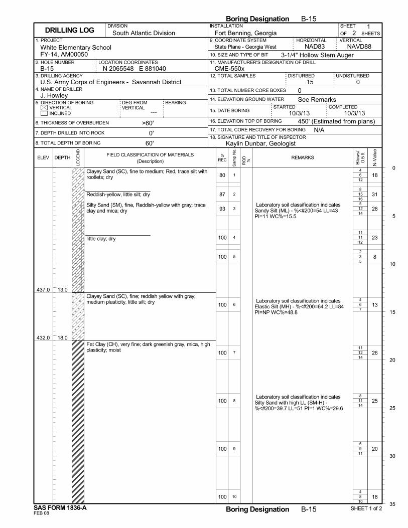
6
15
12
11
3
6
12
11
9
8
12
16
14
12
5
7
14
14
11
10
80
87
93
100
100
100
100
100
100
100
437.0
432.0
13.0
18.0
Clayey Sand (SC), fine to medium; Red, trace silt withrootlets; dry
Reddish-yellow, little silt; dry
Silty Sand (SM), fine, Reddish-yellow with gray; traceclay and mica; dry
little clay; dry
Clayey Sand (SC), fine; reddish yellow with gray;medium plasticity, little silt; dry
Fat Clay (CH), very fine; dark greenish gray, mica, highplasticity; moist
18
31
26
23
8
13
26
25
20
18
Laboratory soil classification indicatesSandy Silt (ML) - %<#200=54 LL=43PI=11 WC%=15.5
Laboratory soil classification indicatesElastic Silt (MH) - %<#200=64.2 LL=84PI=NP WC%=48.8
Laboratory soil classification indicatesSilty Sand with high LL (SM-H) -%<#200=39.7 LL=51 PI=1 WC%=29.6
4
8
5
11
2
4
11
8
5
4
1
2
3
4
5
6
7
8
9
10
N/A
14. ELEVATION GROUND WATER
SHEET
---
Fort Benning, Georgia
DISTURBED
6. THICKNESS OF OVERBURDEN
7. DEPTH DRILLED INTO ROCK
8. TOTAL DEPTH OF BORING
STARTEDVERTICAL
1. PROJECT
UNDISTURBED
NAVD88
2. HOLE NUMBER
18. SIGNATURE AND TITLE OF INSPECTOR
CME-550x
BEARING
3. DRILLING AGENCY
21
OF
COMPLETED15. DATE BORING
DEG FROMVERTICAL
HORIZONTAL
3-1/4" Hollow Stem Auger
INSTALLATION
015 0
INCLINED
U.S. Army Corps of Engineers - Savannah District4. NAME OF DRILLER
5. DIRECTION OF BORING
9. COORDINATE SYSTEM
10. SIZE AND TYPE OF BIT
NAD83White Elementary SchoolFY-14, AM00050
>60'
0'
60'
N 2065548 E 881040LOCATION COORDINATES
16. ELEVATION TOP OF BORING
VERTICAL
J. Howley
17. TOTAL CORE RECOVERY FOR BORING
10/3/13
SHEETSDRILLING LOG
12. TOTAL SAMPLES
13. TOTAL NUMBER CORE BOXES
B-15
DIVISION
11. MANUFACTURER'S DESIGNATION OF DRILL
South Atlantic Division
450' (Estimated from plans)
See Remarks
10/3/13
Kaylin Dunbar, Geologist
State Plane - Georgia West
0
5
10
15
20
25
30
35
Boring Designation B-15
FEB 08
%RECELEV
LEG
EN
D
DEPTH
SAS FORM 1836-A
FIELD CLASSIFICATION OF MATERIALS(Description)
N-V
alue
Boring Designation B-15 SHEET 1 of 2
REMARKS
Blo
ws/
0.5
ft
RQ
D%
Sam
p N
o.
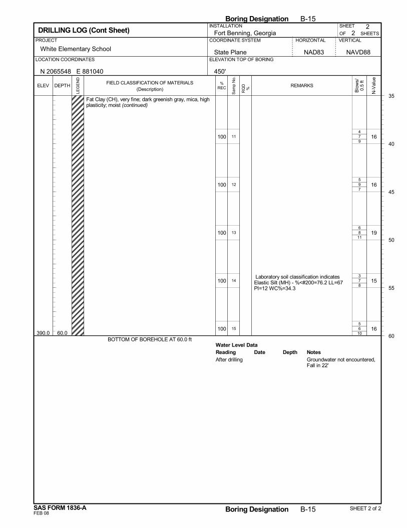
7
9
8
7
6
Water Level Data
9
7
11
8
10
100
100
100
100
100390.0 60.0
Fat Clay (CH), very fine; dark greenish gray, mica, highplasticity; moist (continued)
BOTTOM OF BOREHOLE AT 60.0 ft
16
16
19
15
16
Laboratory soil classification indicatesElastic Silt (MH) - %<#200=76.2 LL=67PI=12 WC%=34.3
4
5
6
3
5
11
12
13
14
15
Reading Depth NotesDateAfter drilling Groundwater not encountered,
Fall in 22'
2
White Elementary School
SHEETS
HORIZONTAL VERTICALPROJECT
SHEET
OFFort Benning, GeorgiaCOORDINATE SYSTEM
2
State Plane NAVD88ELEVATION TOP OF BORINGLOCATION COORDINATES
DRILLING LOG (Cont Sheet)
NAD83
N 2065548 E 881040
INSTALLATION
450'
35
40
45
50
55
60
Boring Designation B-15
FEB 08
%RECELEV
LEG
EN
D
DEPTH
SAS FORM 1836-A
FIELD CLASSIFICATION OF MATERIALS(Description)
N-V
alue
Boring Designation B-15 SHEET 2 of 2
REMARKS
Blo
ws/
0.5
ft
RQ
D%
Sam
p N
o.
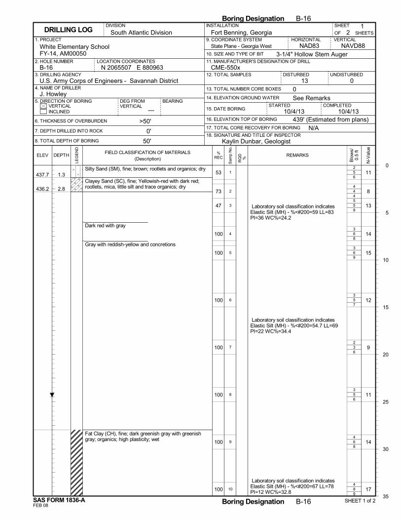
5
4
5
6
6
5
3
5
6
8
6
4
8
8
9
7
6
6
8
9
53
73
47
100
100
100
100
100
100
100
437.7
436.2
1.3
2.8
Silty Sand (SM), fine; brown; rootlets and organics; dry
Clayey Sand (SC), fine; Yellowish-red with dark red;rootlets, mica, little silt and trace organics; dry
Dark red with gray
Gray with reddish-yellow and concretions
Fat Clay (CH), fine; dark greenish gray with greenishgray; organics; high plasticity; wet
11
8
13
14
15
12
9
11
14
17
Laboratory soil classification indicatesElastic Silt (MH) - %<#200=59 LL=83PI=36 WC%=24.2
Laboratory soil classification indicatesElastic Silt (MH) - %<#200=54.7 LL=69PI=22 WC%=34.4
Laboratory soil classification indicatesElastic Silt (MH) - %<#200=67 LL=78PI=12 WC%=32.8
2
4
5
3
3
3
2
3
4
4
1
2
3
4
5
6
7
8
9
10
N/A
14. ELEVATION GROUND WATER
SHEET
---
Fort Benning, Georgia
DISTURBED
6. THICKNESS OF OVERBURDEN
7. DEPTH DRILLED INTO ROCK
8. TOTAL DEPTH OF BORING
STARTEDVERTICAL
1. PROJECT
UNDISTURBED
NAVD88
2. HOLE NUMBER
18. SIGNATURE AND TITLE OF INSPECTOR
CME-550x
BEARING
3. DRILLING AGENCY
21
OF
COMPLETED15. DATE BORING
DEG FROMVERTICAL
HORIZONTAL
3-1/4" Hollow Stem Auger
INSTALLATION
013 0
INCLINED
U.S. Army Corps of Engineers - Savannah District4. NAME OF DRILLER
5. DIRECTION OF BORING
9. COORDINATE SYSTEM
10. SIZE AND TYPE OF BIT
NAD83White Elementary SchoolFY-14, AM00050
>50'
0'
50'
N 2065507 E 880963LOCATION COORDINATES
16. ELEVATION TOP OF BORING
VERTICAL
J. Howley
17. TOTAL CORE RECOVERY FOR BORING
10/4/13
SHEETSDRILLING LOG
12. TOTAL SAMPLES
13. TOTAL NUMBER CORE BOXES
B-16
DIVISION
11. MANUFACTURER'S DESIGNATION OF DRILL
South Atlantic Division
439' (Estimated from plans)
See Remarks
10/4/13
Kaylin Dunbar, Geologist
State Plane - Georgia West
0
5
10
15
20
25
30
35
Boring Designation B-16
FEB 08
%RECELEV
LEG
EN
D
DEPTH
SAS FORM 1836-A
FIELD CLASSIFICATION OF MATERIALS(Description)
N-V
alue
Boring Designation B-16 SHEET 1 of 2
REMARKS
Blo
ws/
0.5
ft
RQ
D%
Sam
p N
o.
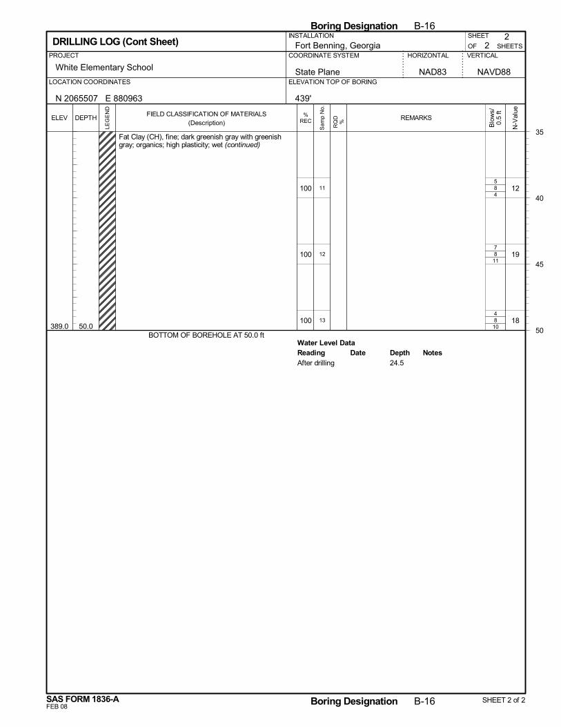
8
8
8
Water Level Data
4
11
10
100
100
100389.0 50.0
Fat Clay (CH), fine; dark greenish gray with greenishgray; organics; high plasticity; wet (continued)
BOTTOM OF BOREHOLE AT 50.0 ft
12
19
18
5
7
4
11
12
13
Reading Depth NotesDateAfter drilling 24.5
2
White Elementary School
SHEETS
HORIZONTAL VERTICALPROJECT
SHEET
OFFort Benning, GeorgiaCOORDINATE SYSTEM
2
State Plane NAVD88ELEVATION TOP OF BORINGLOCATION COORDINATES
DRILLING LOG (Cont Sheet)
NAD83
N 2065507 E 880963
INSTALLATION
439'
35
40
45
50
Boring Designation B-16
FEB 08
%RECELEV
LEG
EN
D
DEPTH
SAS FORM 1836-A
FIELD CLASSIFICATION OF MATERIALS(Description)
N-V
alue
Boring Designation B-16 SHEET 2 of 2
REMARKS
Blo
ws/
0.5
ft
RQ
D%
Sam
p N
o.
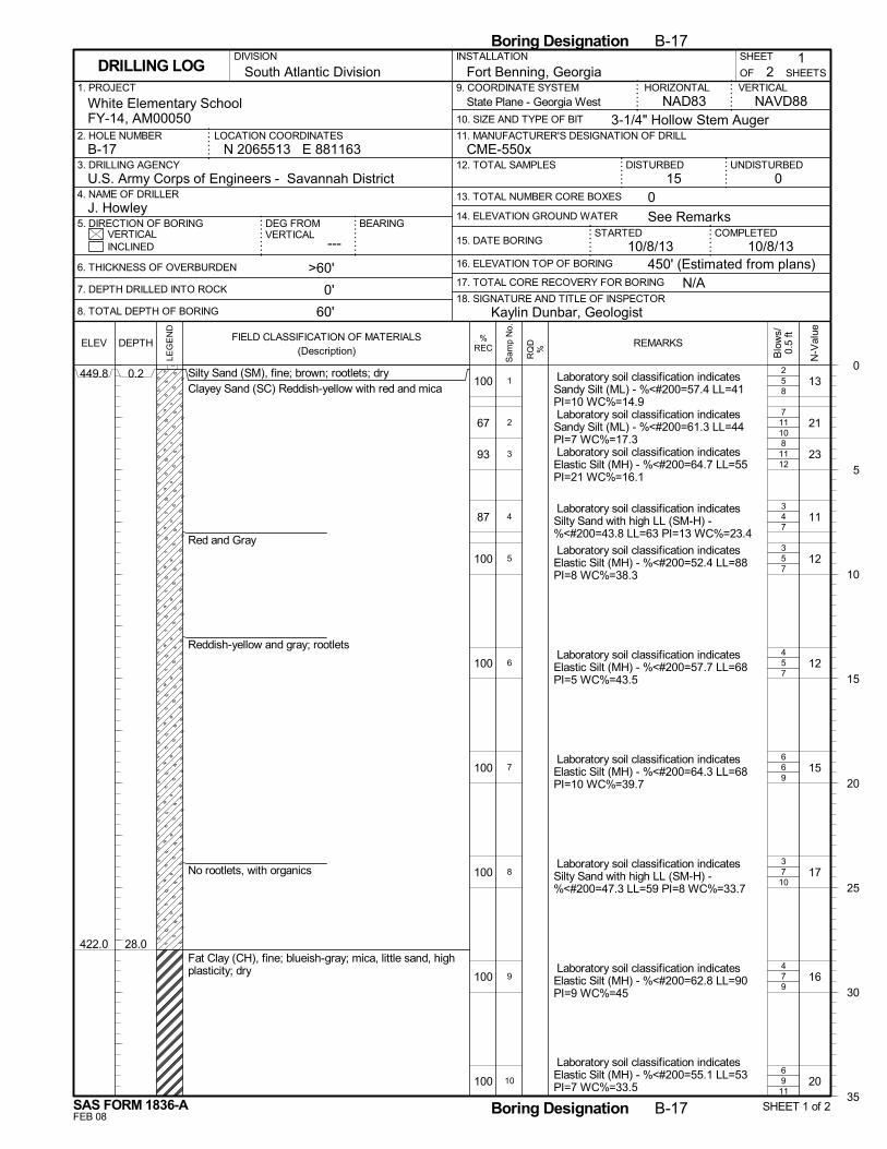
5
11
11
4
5
5
6
7
7
9
8
10
12
7
7
7
9
10
9
11
100
67
93
87
100
100
100
100
100
100
449.8
422.0
0.2
28.0
Silty Sand (SM), fine; brown; rootlets; dryClayey Sand (SC) Reddish-yellow with red and mica
Red and Gray
Reddish-yellow and gray; rootlets
No rootlets, with organics
Fat Clay (CH), fine; blueish-gray; mica, little sand, highplasticity; dry
13
21
23
11
12
12
15
17
16
20
Laboratory soil classification indicatesSandy Silt (ML) - %<#200=57.4 LL=41PI=10 WC%=14.9 Laboratory soil classification indicatesSandy Silt (ML) - %<#200=61.3 LL=44PI=7 WC%=17.3 Laboratory soil classification indicatesElastic Silt (MH) - %<#200=64.7 LL=55PI=21 WC%=16.1
Laboratory soil classification indicatesSilty Sand with high LL (SM-H) -%<#200=43.8 LL=63 PI=13 WC%=23.4
Laboratory soil classification indicatesElastic Silt (MH) - %<#200=52.4 LL=88PI=8 WC%=38.3
Laboratory soil classification indicatesElastic Silt (MH) - %<#200=57.7 LL=68PI=5 WC%=43.5
Laboratory soil classification indicatesElastic Silt (MH) - %<#200=64.3 LL=68PI=10 WC%=39.7
Laboratory soil classification indicatesSilty Sand with high LL (SM-H) -%<#200=47.3 LL=59 PI=8 WC%=33.7
Laboratory soil classification indicatesElastic Silt (MH) - %<#200=62.8 LL=90PI=9 WC%=45
Laboratory soil classification indicatesElastic Silt (MH) - %<#200=55.1 LL=53PI=7 WC%=33.5
2
7
8
3
3
4
6
3
4
6
1
2
3
4
5
6
7
8
9
10
N/A
14. ELEVATION GROUND WATER
SHEET
---
Fort Benning, Georgia
DISTURBED
6. THICKNESS OF OVERBURDEN
7. DEPTH DRILLED INTO ROCK
8. TOTAL DEPTH OF BORING
STARTEDVERTICAL
1. PROJECT
UNDISTURBED
NAVD88
2. HOLE NUMBER
18. SIGNATURE AND TITLE OF INSPECTOR
CME-550x
BEARING
3. DRILLING AGENCY
21
OF
COMPLETED15. DATE BORING
DEG FROMVERTICAL
HORIZONTAL
3-1/4" Hollow Stem Auger
INSTALLATION
015 0
INCLINED
U.S. Army Corps of Engineers - Savannah District4. NAME OF DRILLER
5. DIRECTION OF BORING
9. COORDINATE SYSTEM
10. SIZE AND TYPE OF BIT
NAD83White Elementary SchoolFY-14, AM00050
>60'
0'
60'
N 2065513 E 881163LOCATION COORDINATES
16. ELEVATION TOP OF BORING
VERTICAL
J. Howley
17. TOTAL CORE RECOVERY FOR BORING
10/8/13
SHEETSDRILLING LOG
12. TOTAL SAMPLES
13. TOTAL NUMBER CORE BOXES
B-17
DIVISION
11. MANUFACTURER'S DESIGNATION OF DRILL
South Atlantic Division
450' (Estimated from plans)
See Remarks
10/8/13
Kaylin Dunbar, Geologist
State Plane - Georgia West
0
5
10
15
20
25
30
35
Boring Designation B-17
FEB 08
%RECELEV
LEG
EN
D
DEPTH
SAS FORM 1836-A
FIELD CLASSIFICATION OF MATERIALS(Description)
N-V
alue
Boring Designation B-17 SHEET 1 of 2
REMARKS
Blo
ws/
0.5
ft
RQ
D%
Sam
p N
o.
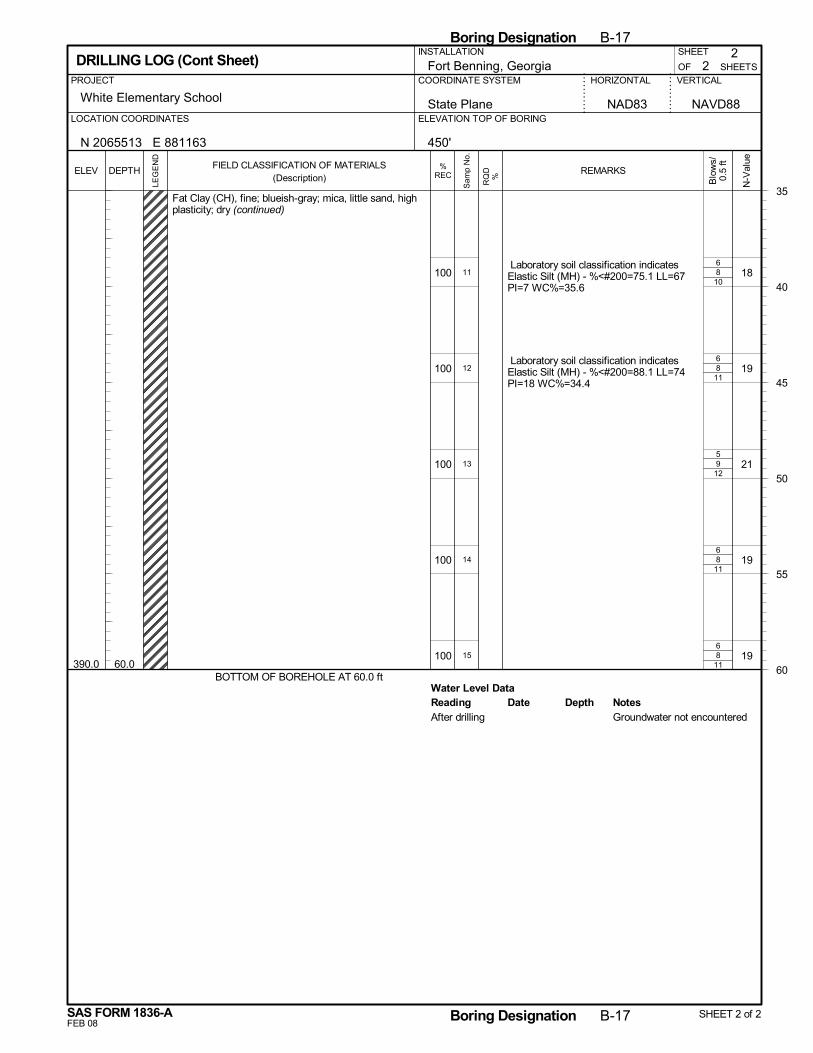
8
8
9
8
8
Water Level Data
10
11
12
11
11
100
100
100
100
100390.0 60.0
Fat Clay (CH), fine; blueish-gray; mica, little sand, highplasticity; dry (continued)
BOTTOM OF BOREHOLE AT 60.0 ft
18
19
21
19
19
Laboratory soil classification indicatesElastic Silt (MH) - %<#200=75.1 LL=67PI=7 WC%=35.6
Laboratory soil classification indicatesElastic Silt (MH) - %<#200=88.1 LL=74PI=18 WC%=34.4
6
6
5
6
6
11
12
13
14
15
Reading Depth NotesDateAfter drilling Groundwater not encountered
2
White Elementary School
SHEETS
HORIZONTAL VERTICALPROJECT
SHEET
OFFort Benning, GeorgiaCOORDINATE SYSTEM
2
State Plane NAVD88ELEVATION TOP OF BORINGLOCATION COORDINATES
DRILLING LOG (Cont Sheet)
NAD83
N 2065513 E 881163
INSTALLATION
450'
35
40
45
50
55
60
Boring Designation B-17
FEB 08
%RECELEV
LEG
EN
D
DEPTH
SAS FORM 1836-A
FIELD CLASSIFICATION OF MATERIALS(Description)
N-V
alue
Boring Designation B-17 SHEET 2 of 2
REMARKS
Blo
ws/
0.5
ft
RQ
D%
Sam
p N
o.
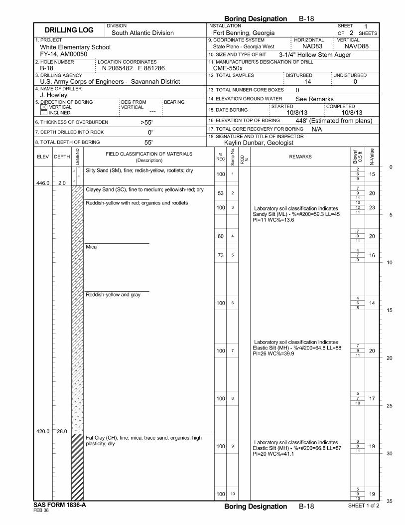
6
9
12
9
7
6
9
7
8
9
9
11
11
11
9
8
11
10
11
10
100
53
100
60
73
100
100
100
100
100
446.0
420.0
2.0
28.0
Silty Sand (SM), fine; redish-yellow, rootlets; dry
Clayey Sand (SC), fine to medium; yellowish-red; dry
Reddish-yellow with red; organics and rootlets
Mica
Reddish-yellow and gray
Fat Clay (CH), fine; mica, trace sand, organics, highplasticity; dry
15
20
23
20
16
14
20
17
19
19
Laboratory soil classification indicatesSandy Silt (ML) - %<#200=59.3 LL=45PI=11 WC%=13.6
Laboratory soil classification indicatesElastic Silt (MH) - %<#200=64.8 LL=88PI=26 WC%=39.9
Laboratory soil classification indicatesElastic Silt (MH) - %<#200=66.8 LL=87PI=20 WC%=41.1
2
7
10
7
4
4
7
5
6
5
1
2
3
4
5
6
7
8
9
10
N/A
14. ELEVATION GROUND WATER
SHEET
---
Fort Benning, Georgia
DISTURBED
6. THICKNESS OF OVERBURDEN
7. DEPTH DRILLED INTO ROCK
8. TOTAL DEPTH OF BORING
STARTEDVERTICAL
1. PROJECT
UNDISTURBED
NAVD88
2. HOLE NUMBER
18. SIGNATURE AND TITLE OF INSPECTOR
CME-550x
BEARING
3. DRILLING AGENCY
21
OF
COMPLETED15. DATE BORING
DEG FROMVERTICAL
HORIZONTAL
3-1/4" Hollow Stem Auger
INSTALLATION
014 0
INCLINED
U.S. Army Corps of Engineers - Savannah District4. NAME OF DRILLER
5. DIRECTION OF BORING
9. COORDINATE SYSTEM
10. SIZE AND TYPE OF BIT
NAD83White Elementary SchoolFY-14, AM00050
>55'
0'
55'
N 2065482 E 881286LOCATION COORDINATES
16. ELEVATION TOP OF BORING
VERTICAL
J. Howley
17. TOTAL CORE RECOVERY FOR BORING
10/8/13
SHEETSDRILLING LOG
12. TOTAL SAMPLES
13. TOTAL NUMBER CORE BOXES
B-18
DIVISION
11. MANUFACTURER'S DESIGNATION OF DRILL
South Atlantic Division
448' (Estimated from plans)
See Remarks
10/8/13
Kaylin Dunbar, Geologist
State Plane - Georgia West
0
5
10
15
20
25
30
35
Boring Designation B-18
FEB 08
%RECELEV
LEG
EN
D
DEPTH
SAS FORM 1836-A
FIELD CLASSIFICATION OF MATERIALS(Description)
N-V
alue
Boring Designation B-18 SHEET 1 of 2
REMARKS
Blo
ws/
0.5
ft
RQ
D%
Sam
p N
o.
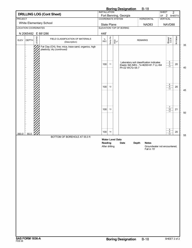
9
9
10
9
Water Level Data
11
11
11
11
100
100
100
100393.0 55.0
Fat Clay (CH), fine; mica, trace sand, organics, highplasticity; dry (continued)
BOTTOM OF BOREHOLE AT 55.0 ft
20
20
21
20
Laboratory soil classification indicatesElastic Silt (MH) - %<#200=81.7 LL=84PI=22 WC%=34.7
6
6
7
5
11
12
13
14
Reading Depth NotesDateAfter drilling Groundwater not encountered,
Fall in 15'
2
White Elementary School
SHEETS
HORIZONTAL VERTICALPROJECT
SHEET
OFFort Benning, GeorgiaCOORDINATE SYSTEM
2
State Plane NAVD88ELEVATION TOP OF BORINGLOCATION COORDINATES
DRILLING LOG (Cont Sheet)
NAD83
N 2065482 E 881286
INSTALLATION
448'
35
40
45
50
55
Boring Designation B-18
FEB 08
%RECELEV
LEG
EN
D
DEPTH
SAS FORM 1836-A
FIELD CLASSIFICATION OF MATERIALS(Description)
N-V
alue
Boring Designation B-18 SHEET 2 of 2
REMARKS
Blo
ws/
0.5
ft
RQ
D%
Sam
p N
o.
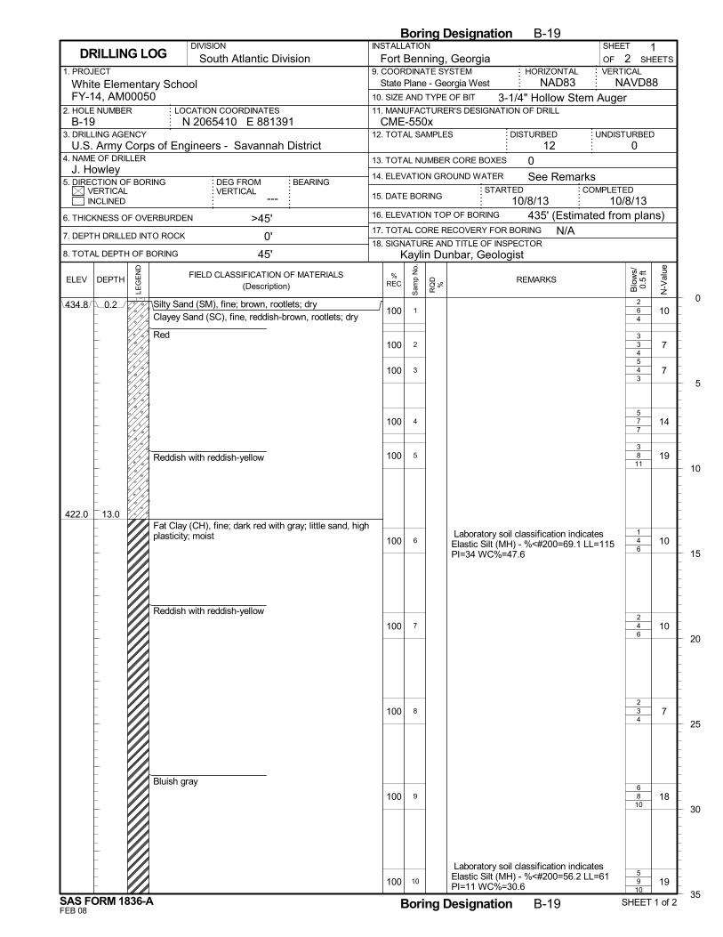
6
3
4
7
8
4
4
3
8
9
4
4
3
7
11
6
6
4
10
10
100
100
100
100
100
100
100
100
100
100
434.8
422.0
0.2
13.0
Silty Sand (SM), fine; brown, rootlets; dryClayey Sand (SC), fine, reddish-brown, rootlets; dry
Red
Reddish with reddish-yellow
Fat Clay (CH), fine; dark red with gray; little sand, highplasticity; moist
Reddish with reddish-yellow
Bluish gray
10
7
7
14
19
10
10
7
18
19
Laboratory soil classification indicatesElastic Silt (MH) - %<#200=69.1 LL=115PI=34 WC%=47.6
Laboratory soil classification indicatesElastic Silt (MH) - %<#200=56.2 LL=61PI=11 WC%=30.6
2
3
5
5
3
1
2
2
6
5
1
2
3
4
5
6
7
8
9
10
N/A
14. ELEVATION GROUND WATER
SHEET
---
Fort Benning, Georgia
DISTURBED
6. THICKNESS OF OVERBURDEN
7. DEPTH DRILLED INTO ROCK
8. TOTAL DEPTH OF BORING
STARTEDVERTICAL
1. PROJECT
UNDISTURBED
NAVD88
2. HOLE NUMBER
18. SIGNATURE AND TITLE OF INSPECTOR
CME-550x
BEARING
3. DRILLING AGENCY
21
OF
COMPLETED15. DATE BORING
DEG FROMVERTICAL
HORIZONTAL
3-1/4" Hollow Stem Auger
INSTALLATION
012 0
INCLINED
U.S. Army Corps of Engineers - Savannah District4. NAME OF DRILLER
5. DIRECTION OF BORING
9. COORDINATE SYSTEM
10. SIZE AND TYPE OF BIT
NAD83White Elementary SchoolFY-14, AM00050
>45'
0'
45'
N 2065410 E 881391LOCATION COORDINATES
16. ELEVATION TOP OF BORING
VERTICAL
J. Howley
17. TOTAL CORE RECOVERY FOR BORING
10/8/13
SHEETSDRILLING LOG
12. TOTAL SAMPLES
13. TOTAL NUMBER CORE BOXES
B-19
DIVISION
11. MANUFACTURER'S DESIGNATION OF DRILL
South Atlantic Division
435' (Estimated from plans)
See Remarks
10/8/13
Kaylin Dunbar, Geologist
State Plane - Georgia West
0
5
10
15
20
25
30
35
Boring Designation B-19
FEB 08
%RECELEV
LEG
EN
D
DEPTH
SAS FORM 1836-A
FIELD CLASSIFICATION OF MATERIALS(Description)
N-V
alue
Boring Designation B-19 SHEET 1 of 2
REMARKS
Blo
ws/
0.5
ft
RQ
D%
Sam
p N
o.
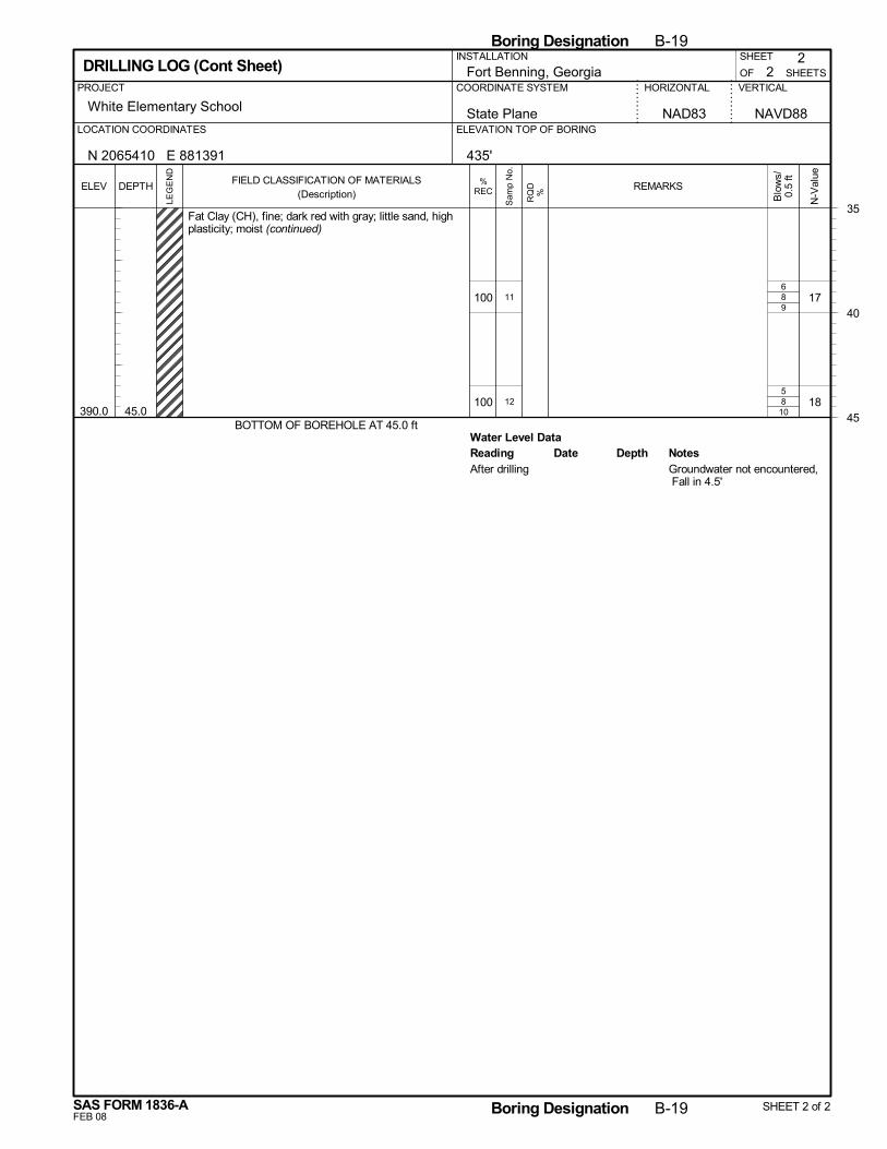
8
8
Water Level Data
9
10
100
100390.0 45.0
Fat Clay (CH), fine; dark red with gray; little sand, highplasticity; moist (continued)
BOTTOM OF BOREHOLE AT 45.0 ft
17
18
6
5
11
12
Reading Depth NotesDateAfter drilling Groundwater not encountered,
Fall in 4.5'
2
White Elementary School
SHEETS
HORIZONTAL VERTICALPROJECT
SHEET
OFFort Benning, GeorgiaCOORDINATE SYSTEM
2
State Plane NAVD88ELEVATION TOP OF BORINGLOCATION COORDINATES
DRILLING LOG (Cont Sheet)
NAD83
N 2065410 E 881391
INSTALLATION
435'
35
40
45
Boring Designation B-19
FEB 08
%RECELEV
LEG
EN
D
DEPTH
SAS FORM 1836-A
FIELD CLASSIFICATION OF MATERIALS(Description)
N-V
alue
Boring Designation B-19 SHEET 2 of 2
REMARKS
Blo
ws/
0.5
ft
RQ
D%
Sam
p N
o.
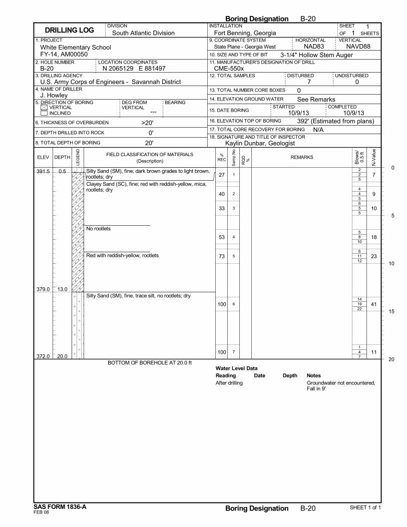
2
4
5
8
11
19
4
Water Level Data
5
5
5
10
12
22
7
27
40
33
53
73
100
100
391.5
379.0
372.0
0.5
13.0
20.0
Silty Sand (SM), fine; dark brown grades to light brown,rootlets; dryClayey Sand (SC), fine; red with reddish-yellow, mica,rootlets; dry
No rootlets
Red with reddish-yellow, rootlets
Silty Sand (SM), fine, trace silt, no rootlets; dry
BOTTOM OF BOREHOLE AT 20.0 ft
7
9
10
18
23
41
11
2
4
6
5
6
14
1
1
2
3
4
5
6
7
Reading Depth NotesDateAfter drilling Groundwater not encountered,
Fall in 9'
N/A
14. ELEVATION GROUND WATER
SHEET
---
Fort Benning, Georgia
DISTURBED
6. THICKNESS OF OVERBURDEN
7. DEPTH DRILLED INTO ROCK
8. TOTAL DEPTH OF BORING
STARTEDVERTICAL
1. PROJECT
UNDISTURBED
NAVD88
2. HOLE NUMBER
18. SIGNATURE AND TITLE OF INSPECTOR
CME-550x
BEARING
3. DRILLING AGENCY
11
OF
COMPLETED15. DATE BORING
DEG FROMVERTICAL
HORIZONTAL
3-1/4" Hollow Stem Auger
INSTALLATION
07 0
INCLINED
U.S. Army Corps of Engineers - Savannah District4. NAME OF DRILLER
5. DIRECTION OF BORING
9. COORDINATE SYSTEM
10. SIZE AND TYPE OF BIT
NAD83White Elementary SchoolFY-14, AM00050
>20'
0'
20'
N 2065129 E 881497LOCATION COORDINATES
16. ELEVATION TOP OF BORING
VERTICAL
J. Howley
17. TOTAL CORE RECOVERY FOR BORING
10/9/13
SHEETSDRILLING LOG
12. TOTAL SAMPLES
13. TOTAL NUMBER CORE BOXES
B-20
DIVISION
11. MANUFACTURER'S DESIGNATION OF DRILL
South Atlantic Division
392' (Estimated from plans)
See Remarks
10/9/13
Kaylin Dunbar, Geologist
State Plane - Georgia West
0
5
10
15
20
Boring Designation B-20
FEB 08
%RECELEV
LEG
EN
D
DEPTH
SAS FORM 1836-A
FIELD CLASSIFICATION OF MATERIALS(Description)
N-V
alue
Boring Designation B-20 SHEET 1 of 1
REMARKS
Blo
ws/
0.5
ft
RQ
D%
Sam
p N
o.
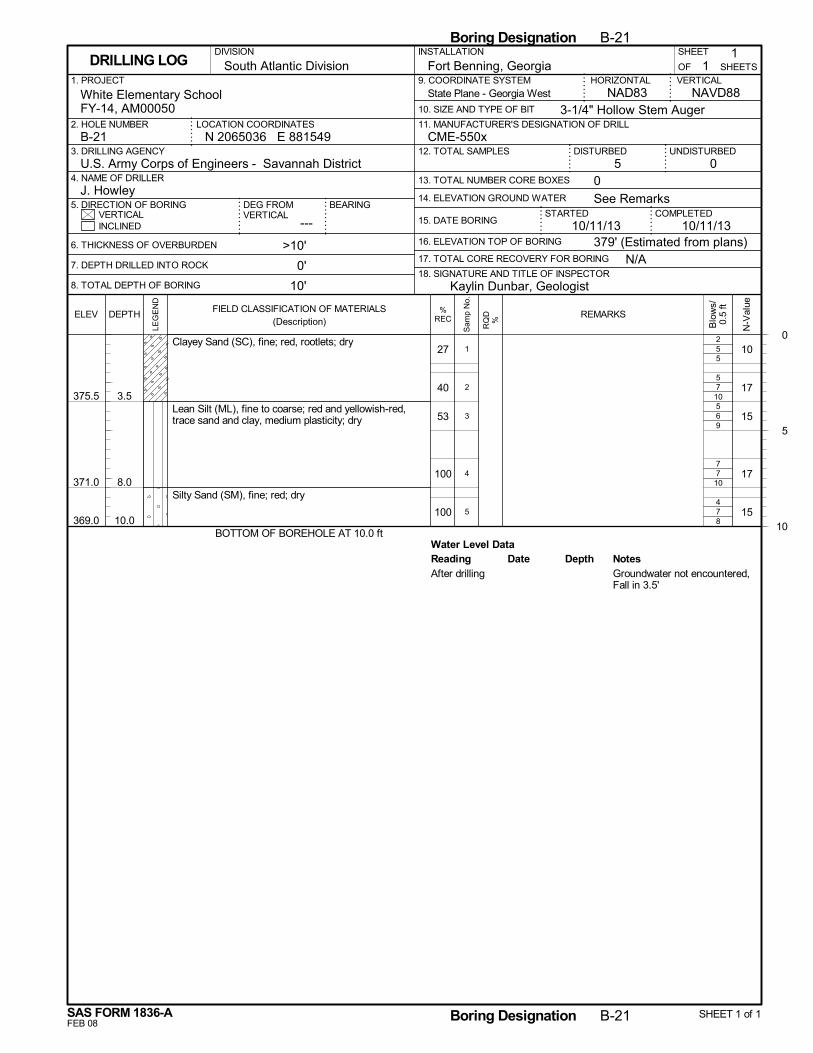
5
7
6
7
7
Water Level Data
5
10
9
10
8
27
40
53
100
100
375.5
371.0
369.0
3.5
8.0
10.0
Clayey Sand (SC), fine; red, rootlets; dry
Lean Silt (ML), fine to coarse; red and yellowish-red,trace sand and clay, medium plasticity; dry
Silty Sand (SM), fine; red; dry
BOTTOM OF BOREHOLE AT 10.0 ft
10
17
15
17
15
2
5
5
7
4
1
2
3
4
5
Reading Depth NotesDateAfter drilling Groundwater not encountered,
Fall in 3.5'
N/A
14. ELEVATION GROUND WATER
SHEET
---
Fort Benning, Georgia
DISTURBED
6. THICKNESS OF OVERBURDEN
7. DEPTH DRILLED INTO ROCK
8. TOTAL DEPTH OF BORING
STARTEDVERTICAL
1. PROJECT
UNDISTURBED
NAVD88
2. HOLE NUMBER
18. SIGNATURE AND TITLE OF INSPECTOR
CME-550x
BEARING
3. DRILLING AGENCY
11
OF
COMPLETED15. DATE BORING
DEG FROMVERTICAL
HORIZONTAL
3-1/4" Hollow Stem Auger
INSTALLATION
05 0
INCLINED
U.S. Army Corps of Engineers - Savannah District4. NAME OF DRILLER
5. DIRECTION OF BORING
9. COORDINATE SYSTEM
10. SIZE AND TYPE OF BIT
NAD83White Elementary SchoolFY-14, AM00050
>10'
0'
10'
N 2065036 E 881549LOCATION COORDINATES
16. ELEVATION TOP OF BORING
VERTICAL
J. Howley
17. TOTAL CORE RECOVERY FOR BORING
10/11/13
SHEETSDRILLING LOG
12. TOTAL SAMPLES
13. TOTAL NUMBER CORE BOXES
B-21
DIVISION
11. MANUFACTURER'S DESIGNATION OF DRILL
South Atlantic Division
379' (Estimated from plans)
See Remarks
10/11/13
Kaylin Dunbar, Geologist
State Plane - Georgia West
0
5
10
Boring Designation B-21
FEB 08
%RECELEV
LEG
EN
D
DEPTH
SAS FORM 1836-A
FIELD CLASSIFICATION OF MATERIALS(Description)
N-V
alue
Boring Designation B-21 SHEET 1 of 1
REMARKS
Blo
ws/
0.5
ft
RQ
D%
Sam
p N
o.
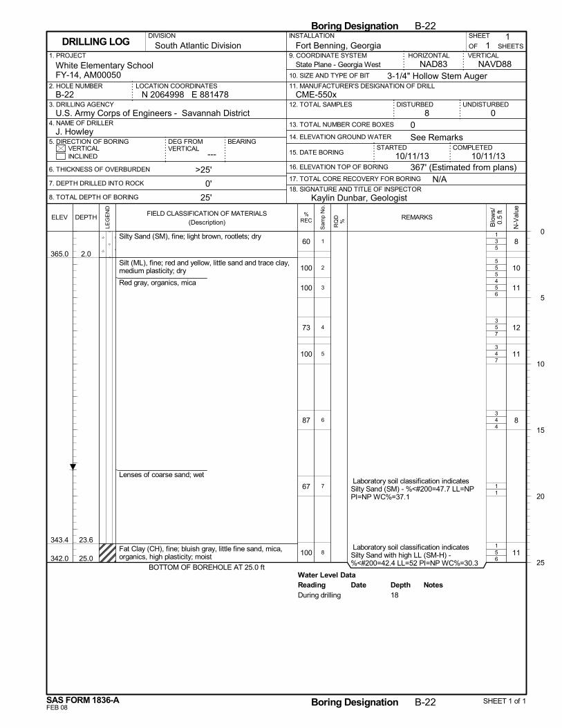
3
5
5
5
4
4
1
5
Water Level Data
5
5
6
7
7
4
1
6
60
100
100
73
100
87
67
100
365.0
343.4
342.0
2.0
23.6
25.0
Silty Sand (SM), fine; light brown, rootlets; dry
Silt (ML), fine; red and yellow, little sand and trace clay,medium plasticity; dry
Red gray, organics, mica
Lenses of coarse sand; wet
Fat Clay (CH), fine; bluish gray, little fine sand, mica,organics, high plasticity; moist
BOTTOM OF BOREHOLE AT 25.0 ft
8
10
11
12
11
8
11
Laboratory soil classification indicatesSilty Sand (SM) - %<#200=47.7 LL=NPPI=NP WC%=37.1
Laboratory soil classification indicatesSilty Sand with high LL (SM-H) -%<#200=42.4 LL=52 PI=NP WC%=30.3
1
5
4
3
3
3
1
1
2
3
4
5
6
7
8
Reading Depth NotesDateDuring drilling 18
N/A
14. ELEVATION GROUND WATER
SHEET
---
Fort Benning, Georgia
DISTURBED
6. THICKNESS OF OVERBURDEN
7. DEPTH DRILLED INTO ROCK
8. TOTAL DEPTH OF BORING
STARTEDVERTICAL
1. PROJECT
UNDISTURBED
NAVD88
2. HOLE NUMBER
18. SIGNATURE AND TITLE OF INSPECTOR
CME-550x
BEARING
3. DRILLING AGENCY
11
OF
COMPLETED15. DATE BORING
DEG FROMVERTICAL
HORIZONTAL
3-1/4" Hollow Stem Auger
INSTALLATION
08 0
INCLINED
U.S. Army Corps of Engineers - Savannah District4. NAME OF DRILLER
5. DIRECTION OF BORING
9. COORDINATE SYSTEM
10. SIZE AND TYPE OF BIT
NAD83White Elementary SchoolFY-14, AM00050
>25'
0'
25'
N 2064998 E 881478LOCATION COORDINATES
16. ELEVATION TOP OF BORING
VERTICAL
J. Howley
17. TOTAL CORE RECOVERY FOR BORING
10/11/13
SHEETSDRILLING LOG
12. TOTAL SAMPLES
13. TOTAL NUMBER CORE BOXES
B-22
DIVISION
11. MANUFACTURER'S DESIGNATION OF DRILL
South Atlantic Division
367' (Estimated from plans)
See Remarks
10/11/13
Kaylin Dunbar, Geologist
State Plane - Georgia West
0
5
10
15
20
25
Boring Designation B-22
FEB 08
%RECELEV
LEG
EN
D
DEPTH
SAS FORM 1836-A
FIELD CLASSIFICATION OF MATERIALS(Description)
N-V
alue
Boring Designation B-22 SHEET 1 of 1
REMARKS
Blo
ws/
0.5
ft
RQ
D%
Sam
p N
o.
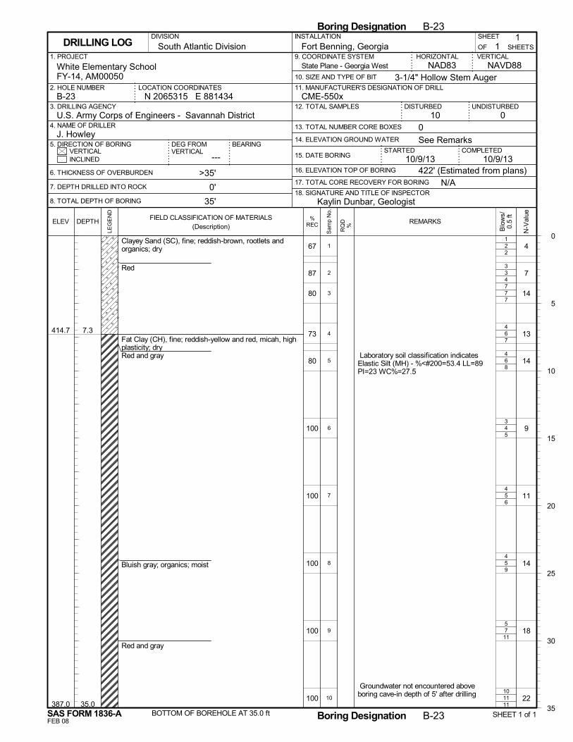
2
3
7
6
6
4
5
5
7
11
2
4
7
7
8
5
6
9
11
11
67
87
80
73
80
100
100
100
100
100
414.7
387.0
7.3
35.0
Clayey Sand (SC), fine; reddish-brown, rootlets andorganics; dry
Red
Fat Clay (CH), fine; reddish-yellow and red, micah, highplasticity; dryRed and gray
Bluish gray; organics; moist
Red and gray
BOTTOM OF BOREHOLE AT 35.0 ft
4
7
14
13
14
9
11
14
18
22
Laboratory soil classification indicatesElastic Silt (MH) - %<#200=53.4 LL=89PI=23 WC%=27.5
Groundwater not encountered aboveboring cave-in depth of 5' after drilling
1
3
7
4
4
3
4
4
5
10
1
2
3
4
5
6
7
8
9
10
N/A
14. ELEVATION GROUND WATER
SHEET
---
Fort Benning, Georgia
DISTURBED
6. THICKNESS OF OVERBURDEN
7. DEPTH DRILLED INTO ROCK
8. TOTAL DEPTH OF BORING
STARTEDVERTICAL
1. PROJECT
UNDISTURBED
NAVD88
2. HOLE NUMBER
18. SIGNATURE AND TITLE OF INSPECTOR
CME-550x
BEARING
3. DRILLING AGENCY
11
OF
COMPLETED15. DATE BORING
DEG FROMVERTICAL
HORIZONTAL
3-1/4" Hollow Stem Auger
INSTALLATION
010 0
INCLINED
U.S. Army Corps of Engineers - Savannah District4. NAME OF DRILLER
5. DIRECTION OF BORING
9. COORDINATE SYSTEM
10. SIZE AND TYPE OF BIT
NAD83White Elementary SchoolFY-14, AM00050
>35'
0'
35'
N 2065315 E 881434LOCATION COORDINATES
16. ELEVATION TOP OF BORING
VERTICAL
J. Howley
17. TOTAL CORE RECOVERY FOR BORING
10/9/13
SHEETSDRILLING LOG
12. TOTAL SAMPLES
13. TOTAL NUMBER CORE BOXES
B-23
DIVISION
11. MANUFACTURER'S DESIGNATION OF DRILL
South Atlantic Division
422' (Estimated from plans)
See Remarks
10/9/13
Kaylin Dunbar, Geologist
State Plane - Georgia West
0
5
10
15
20
25
30
35
Boring Designation B-23
FEB 08
%RECELEV
LEG
EN
D
DEPTH
SAS FORM 1836-A
FIELD CLASSIFICATION OF MATERIALS(Description)
N-V
alue
Boring Designation B-23 SHEET 1 of 1
REMARKS
Blo
ws/
0.5
ft
RQ
D%
Sam
p N
o.
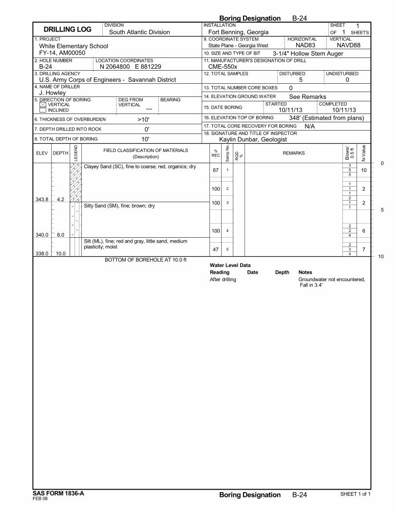
5
1
1
2
3
Water Level Data
5
1
1
4
4
67
100
100
100
47
343.8
340.0
338.0
4.2
8.0
10.0
Clayey Sand (SC), fine to coarse; red, organics; dry
Silty Sand (SM), fine; brown; dry
Silt (ML), fine; red and gray, little sand, mediumplasticity; moist
BOTTOM OF BOREHOLE AT 10.0 ft
10
2
2
6
7
3
1
2
2
2
1
2
3
4
5
Reading Depth NotesDateAfter drilling Groundwater not encountered,
Fall in 3.4'
N/A
14. ELEVATION GROUND WATER
SHEET
---
Fort Benning, Georgia
DISTURBED
6. THICKNESS OF OVERBURDEN
7. DEPTH DRILLED INTO ROCK
8. TOTAL DEPTH OF BORING
STARTEDVERTICAL
1. PROJECT
UNDISTURBED
NAVD88
2. HOLE NUMBER
18. SIGNATURE AND TITLE OF INSPECTOR
CME-550x
BEARING
3. DRILLING AGENCY
11
OF
COMPLETED15. DATE BORING
DEG FROMVERTICAL
HORIZONTAL
3-1/4" Hollow Stem Auger
INSTALLATION
05 0
INCLINED
U.S. Army Corps of Engineers - Savannah District4. NAME OF DRILLER
5. DIRECTION OF BORING
9. COORDINATE SYSTEM
10. SIZE AND TYPE OF BIT
NAD83White Elementary SchoolFY-14, AM00050
>10'
0'
10'
N 2064800 E 881229LOCATION COORDINATES
16. ELEVATION TOP OF BORING
VERTICAL
J. Howley
17. TOTAL CORE RECOVERY FOR BORING
10/11/13
SHEETSDRILLING LOG
12. TOTAL SAMPLES
13. TOTAL NUMBER CORE BOXES
B-24
DIVISION
11. MANUFACTURER'S DESIGNATION OF DRILL
South Atlantic Division
348' (Estimated from plans)
See Remarks
10/11/13
Kaylin Dunbar, Geologist
State Plane - Georgia West
0
5
10
Boring Designation B-24
FEB 08
%RECELEV
LEG
EN
D
DEPTH
SAS FORM 1836-A
FIELD CLASSIFICATION OF MATERIALS(Description)
N-V
alue
Boring Designation B-24 SHEET 1 of 1
REMARKS
Blo
ws/
0.5
ft
RQ
D%
Sam
p N
o.

3
1
2
4
4
Water Level Data
1
0
2
5
5
53
60
100
93
100
336.6
333.0
6.4
10.0
Silty Sand (SM), fine; red, organic and rootlets; dry
Red with brownLight brown with dark brown, no rootlets
Silt (ML), fine; dark brown and gray, trace sand, mediumplasticity; moist
Red and gray
BOTTOM OF BOREHOLE AT 10.0 ft
4
1
4
9
9
1
1
1
4
3
1
2
3
4
5
Reading Depth NotesDateAfter drilling Groundwater not encountered,
Fall in 4.2'
N/A
14. ELEVATION GROUND WATER
SHEET
---
Fort Benning, Georgia
DISTURBED
6. THICKNESS OF OVERBURDEN
7. DEPTH DRILLED INTO ROCK
8. TOTAL DEPTH OF BORING
STARTEDVERTICAL
1. PROJECT
UNDISTURBED
NAVD88
2. HOLE NUMBER
18. SIGNATURE AND TITLE OF INSPECTOR
CME-550x
BEARING
3. DRILLING AGENCY
11
OF
COMPLETED15. DATE BORING
DEG FROMVERTICAL
HORIZONTAL
3-1/4" Hollow Stem Auger
INSTALLATION
05 0
INCLINED
U.S. Army Corps of Engineers - Savannah District4. NAME OF DRILLER
5. DIRECTION OF BORING
9. COORDINATE SYSTEM
10. SIZE AND TYPE OF BIT
NAD83White Elementary SchoolFY-14, AM00050
>10'
0'
10'
N 2064717 E 881134LOCATION COORDINATES
16. ELEVATION TOP OF BORING
VERTICAL
J. Howley
17. TOTAL CORE RECOVERY FOR BORING
10/12/13
SHEETSDRILLING LOG
12. TOTAL SAMPLES
13. TOTAL NUMBER CORE BOXES
B-25
DIVISION
11. MANUFACTURER'S DESIGNATION OF DRILL
South Atlantic Division
343' (Estimated from plans)
See Remarks
10/12/13
Kaylin Dunbar, Geologist
State Plane - Georgia West
0
5
10
Boring Designation B-25
FEB 08
%RECELEV
LEG
EN
D
DEPTH
SAS FORM 1836-A
FIELD CLASSIFICATION OF MATERIALS(Description)
N-V
alue
Boring Designation B-25 SHEET 1 of 1
REMARKS
Blo
ws/
0.5
ft
RQ
D%
Sam
p N
o.
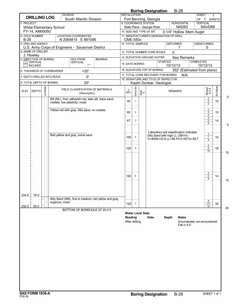
4
5
5
7
8
6
21
Water Level Data
6
5
9
8
10
8
14
40
60
67
100
100
100
100
334.0
332.0
18.0
20.0
Silt (ML), fine; yellowish-red, lean silt, trace sand,rootlets, low plasticity; moist
Yellow red with gray, little sand, no rootlets
Red yellow and gray, some sand
Silty Sand (SM), fine to medium; red yellow and gray,organics; moist
BOTTOM OF BOREHOLE AT 20.0 ft
10
10
14
15
18
14
35
Laboratory soil classification indicatesSilty Sand with high LL (SM-H) -%<#200=32.8 LL=56 PI=5 WC%=28.7
2
4
4
3
6
5
9
1
2
3
4
5
6
7
Reading Depth NotesDateAfter drilling Groundwater not encountered,
Fall in 8.5'
N/A
14. ELEVATION GROUND WATER
SHEET
---
Fort Benning, Georgia
DISTURBED
6. THICKNESS OF OVERBURDEN
7. DEPTH DRILLED INTO ROCK
8. TOTAL DEPTH OF BORING
STARTEDVERTICAL
1. PROJECT
UNDISTURBED
NAVD88
2. HOLE NUMBER
18. SIGNATURE AND TITLE OF INSPECTOR
CME-550x
BEARING
3. DRILLING AGENCY
11
OF
COMPLETED15. DATE BORING
DEG FROMVERTICAL
HORIZONTAL
3-1/4" Hollow Stem Auger
INSTALLATION
07 0
INCLINED
U.S. Army Corps of Engineers - Savannah District4. NAME OF DRILLER
5. DIRECTION OF BORING
9. COORDINATE SYSTEM
10. SIZE AND TYPE OF BIT
NAD83White Elementary SchoolFY-14, AM00050
>20'
0'
20'
N 2064815 E 881096LOCATION COORDINATES
16. ELEVATION TOP OF BORING
VERTICAL
J. Howley
17. TOTAL CORE RECOVERY FOR BORING
10/12/13
SHEETSDRILLING LOG
12. TOTAL SAMPLES
13. TOTAL NUMBER CORE BOXES
B-26
DIVISION
11. MANUFACTURER'S DESIGNATION OF DRILL
South Atlantic Division
352' (Estimated from plans)
See Remarks
10/12/13
Kaylin Dunbar, Geologist
State Plane - Georgia West
0
5
10
15
20
Boring Designation B-26
FEB 08
%RECELEV
LEG
EN
D
DEPTH
SAS FORM 1836-A
FIELD CLASSIFICATION OF MATERIALS(Description)
N-V
alue
Boring Designation B-26 SHEET 1 of 1
REMARKS
Blo
ws/
0.5
ft
RQ
D%
Sam
p N
o.
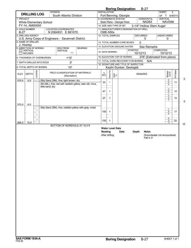
5
5
5
8
9
Water Level Data
6
7
7
9
11
33
47
27
100
100
375.5
370.0
366.0
0.5
6.0
10.0
Silty Sand (SM), fine; light brown; drySilt (ML), fine; red with reddish-yellow, lean silt, mica,little sand; dry
Silty Sand (SM), fine; reddish-yellow with gray; moist
BOTTOM OF BOREHOLE AT 10.0 ft
11
12
12
17
20
2
3
4
7
5
1
2
3
4
5
Reading Depth NotesDateAfter drilling Groundwater not encountered,
Fall in 3'
N/A
14. ELEVATION GROUND WATER
SHEET
---
Fort Benning, Georgia
DISTURBED
6. THICKNESS OF OVERBURDEN
7. DEPTH DRILLED INTO ROCK
8. TOTAL DEPTH OF BORING
STARTEDVERTICAL
1. PROJECT
UNDISTURBED
NAVD88
2. HOLE NUMBER
18. SIGNATURE AND TITLE OF INSPECTOR
CME-550x
BEARING
3. DRILLING AGENCY
11
OF
COMPLETED15. DATE BORING
DEG FROMVERTICAL
HORIZONTAL
3-1/4" Hollow Stem Auger
INSTALLATION
05 0
INCLINED
U.S. Army Corps of Engineers - Savannah District4. NAME OF DRILLER
5. DIRECTION OF BORING
9. COORDINATE SYSTEM
10. SIZE AND TYPE OF BIT
NAD83White Elementary SchoolFY-14, AM00050
>10'
0'
10'
N 2064931 E 881070LOCATION COORDINATES
16. ELEVATION TOP OF BORING
VERTICAL
J. Howley
17. TOTAL CORE RECOVERY FOR BORING
10/12/13
SHEETSDRILLING LOG
12. TOTAL SAMPLES
13. TOTAL NUMBER CORE BOXES
B-27
DIVISION
11. MANUFACTURER'S DESIGNATION OF DRILL
South Atlantic Division
376' (Estimated from plans)
See Remarks
10/12/13
Kaylin Dunbar, Geologist
State Plane - Georgia West
0
5
10
Boring Designation B-27
FEB 08
%RECELEV
LEG
EN
D
DEPTH
SAS FORM 1836-A
FIELD CLASSIFICATION OF MATERIALS(Description)
N-V
alue
Boring Designation B-27 SHEET 1 of 1
REMARKS
Blo
ws/
0.5
ft
RQ
D%
Sam
p N
o.
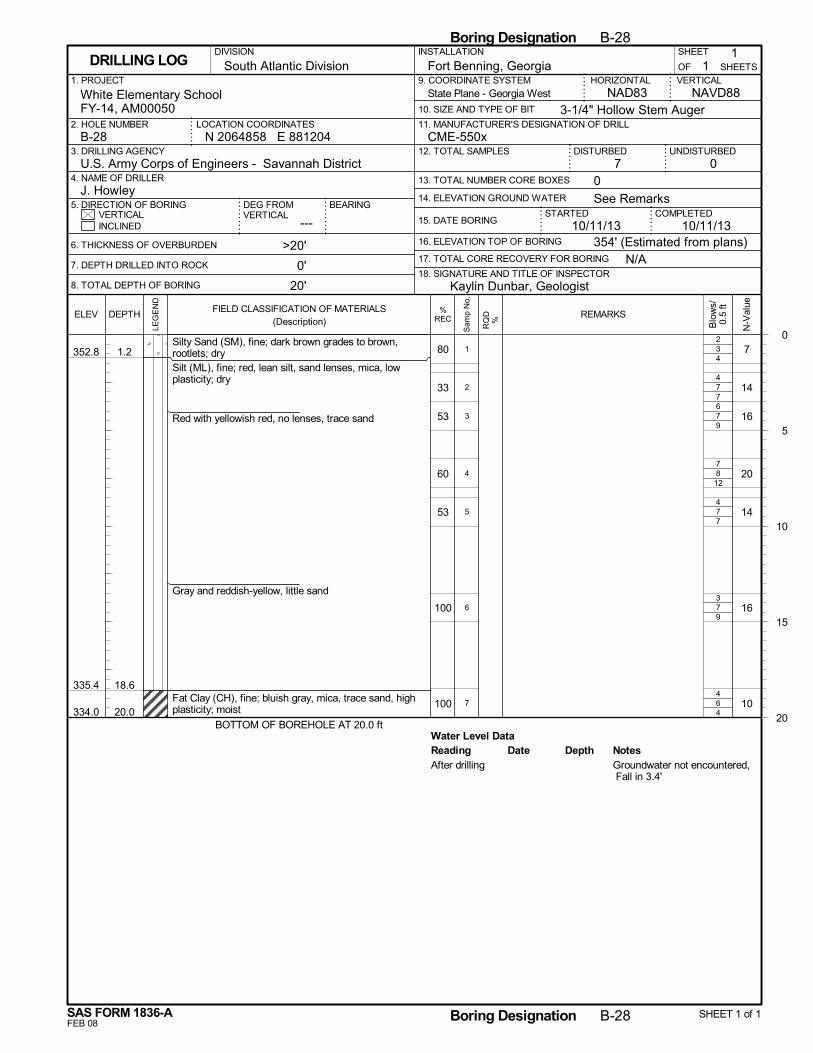
3
7
7
8
7
7
6
Water Level Data
4
7
9
12
7
9
4
80
33
53
60
53
100
100
352.8
335.4
334.0
1.2
18.6
20.0
Silty Sand (SM), fine; dark brown grades to brown,rootlets; drySilt (ML), fine; red, lean silt, sand lenses, mica, lowplasticity; dry
Red with yellowish red, no lenses, trace sand
Gray and reddish-yellow, little sand
Fat Clay (CH), fine; bluish gray, mica, trace sand, highplasticity; moist
BOTTOM OF BOREHOLE AT 20.0 ft
7
14
16
20
14
16
10
2
4
6
7
4
3
4
1
2
3
4
5
6
7
Reading Depth NotesDateAfter drilling Groundwater not encountered,
Fall in 3.4'
N/A
14. ELEVATION GROUND WATER
SHEET
---
Fort Benning, Georgia
DISTURBED
6. THICKNESS OF OVERBURDEN
7. DEPTH DRILLED INTO ROCK
8. TOTAL DEPTH OF BORING
STARTEDVERTICAL
1. PROJECT
UNDISTURBED
NAVD88
2. HOLE NUMBER
18. SIGNATURE AND TITLE OF INSPECTOR
CME-550x
BEARING
3. DRILLING AGENCY
11
OF
COMPLETED15. DATE BORING
DEG FROMVERTICAL
HORIZONTAL
3-1/4" Hollow Stem Auger
INSTALLATION
07 0
INCLINED
U.S. Army Corps of Engineers - Savannah District4. NAME OF DRILLER
5. DIRECTION OF BORING
9. COORDINATE SYSTEM
10. SIZE AND TYPE OF BIT
NAD83White Elementary SchoolFY-14, AM00050
>20'
0'
20'
N 2064858 E 881204LOCATION COORDINATES
16. ELEVATION TOP OF BORING
VERTICAL
J. Howley
17. TOTAL CORE RECOVERY FOR BORING
10/11/13
SHEETSDRILLING LOG
12. TOTAL SAMPLES
13. TOTAL NUMBER CORE BOXES
B-28
DIVISION
11. MANUFACTURER'S DESIGNATION OF DRILL
South Atlantic Division
354' (Estimated from plans)
See Remarks
10/11/13
Kaylin Dunbar, Geologist
State Plane - Georgia West
0
5
10
15
20
Boring Designation B-28
FEB 08
%RECELEV
LEG
EN
D
DEPTH
SAS FORM 1836-A
FIELD CLASSIFICATION OF MATERIALS(Description)
N-V
alue
Boring Designation B-28 SHEET 1 of 1
REMARKS
Blo
ws/
0.5
ft
RQ
D%
Sam
p N
o.
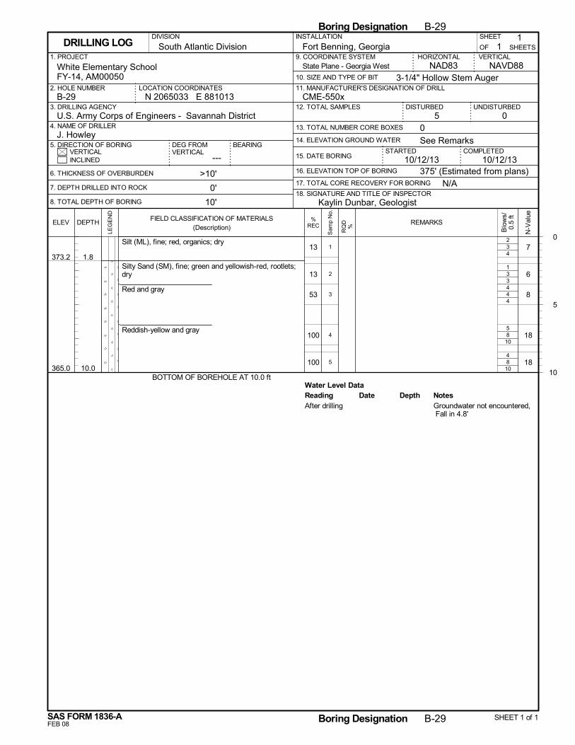
3
3
4
8
8
Water Level Data
4
3
4
10
10
13
13
53
100
100
373.2
365.0
1.8
10.0
Silt (ML), fine; red, organics; dry
Silty Sand (SM), fine; green and yellowish-red, rootlets;dry
Red and gray
Reddish-yellow and gray
BOTTOM OF BOREHOLE AT 10.0 ft
7
6
8
18
18
2
1
4
5
4
1
2
3
4
5
Reading Depth NotesDateAfter drilling Groundwater not encountered,
Fall in 4.8'
N/A
14. ELEVATION GROUND WATER
SHEET
---
Fort Benning, Georgia
DISTURBED
6. THICKNESS OF OVERBURDEN
7. DEPTH DRILLED INTO ROCK
8. TOTAL DEPTH OF BORING
STARTEDVERTICAL
1. PROJECT
UNDISTURBED
NAVD88
2. HOLE NUMBER
18. SIGNATURE AND TITLE OF INSPECTOR
CME-550x
BEARING
3. DRILLING AGENCY
11
OF
COMPLETED15. DATE BORING
DEG FROMVERTICAL
HORIZONTAL
3-1/4" Hollow Stem Auger
INSTALLATION
05 0
INCLINED
U.S. Army Corps of Engineers - Savannah District4. NAME OF DRILLER
5. DIRECTION OF BORING
9. COORDINATE SYSTEM
10. SIZE AND TYPE OF BIT
NAD83White Elementary SchoolFY-14, AM00050
>10'
0'
10'
N 2065033 E 881013LOCATION COORDINATES
16. ELEVATION TOP OF BORING
VERTICAL
J. Howley
17. TOTAL CORE RECOVERY FOR BORING
10/12/13
SHEETSDRILLING LOG
12. TOTAL SAMPLES
13. TOTAL NUMBER CORE BOXES
B-29
DIVISION
11. MANUFACTURER'S DESIGNATION OF DRILL
South Atlantic Division
375' (Estimated from plans)
See Remarks
10/12/13
Kaylin Dunbar, Geologist
State Plane - Georgia West
0
5
10
Boring Designation B-29
FEB 08
%RECELEV
LEG
EN
D
DEPTH
SAS FORM 1836-A
FIELD CLASSIFICATION OF MATERIALS(Description)
N-V
alue
Boring Designation B-29 SHEET 1 of 1
REMARKS
Blo
ws/
0.5
ft
RQ
D%
Sam
p N
o.

3
6
7
3
4
Water Level Data
5
7
7
6
6
27
27
47
33
100
382.8
377.0
373.0
0.2
6.0
10.0
Silty Sand (SM), fine; brown, rootletsSilt (ML), fine; red, lean silt, little sand, organics,
Silty Sand (SM), fine; reddish-yellow and gray, siltlayers; moist
Silt layers
BOTTOM OF BOREHOLE AT 10.0 ft
8
13
14
9
10
2
5
6
3
2
1
2
3
4
5
Reading Depth NotesDateAfter drilling Groundwater not encountered,
Fall in 2.8'
N/A
14. ELEVATION GROUND WATER
SHEET
---
Fort Benning, Georgia
DISTURBED
6. THICKNESS OF OVERBURDEN
7. DEPTH DRILLED INTO ROCK
8. TOTAL DEPTH OF BORING
STARTEDVERTICAL
1. PROJECT
UNDISTURBED
NAVD88
2. HOLE NUMBER
18. SIGNATURE AND TITLE OF INSPECTOR
CME-550x
BEARING
3. DRILLING AGENCY
11
OF
COMPLETED15. DATE BORING
DEG FROMVERTICAL
HORIZONTAL
3-1/4" Hollow Stem Auger
INSTALLATION
05 0
INCLINED
U.S. Army Corps of Engineers - Savannah District4. NAME OF DRILLER
5. DIRECTION OF BORING
9. COORDINATE SYSTEM
10. SIZE AND TYPE OF BIT
NAD83White Elementary SchoolFY-14, AM00050
>10'
0'
10'
N 2065140 E 881035LOCATION COORDINATES
16. ELEVATION TOP OF BORING
VERTICAL
J. Howley
17. TOTAL CORE RECOVERY FOR BORING
10/12/13
SHEETSDRILLING LOG
12. TOTAL SAMPLES
13. TOTAL NUMBER CORE BOXES
B-30
DIVISION
11. MANUFACTURER'S DESIGNATION OF DRILL
South Atlantic Division
383' (Estimated from plans)
See Remarks
10/12/13
Kaylin Dunbar, Geologist
State Plane - Georgia West
0
5
10
Boring Designation B-30
FEB 08
%RECELEV
LEG
EN
D
DEPTH
SAS FORM 1836-A
FIELD CLASSIFICATION OF MATERIALS(Description)
N-V
alue
Boring Designation B-30 SHEET 1 of 1
REMARKS
Blo
ws/
0.5
ft
RQ
D%
Sam
p N
o.
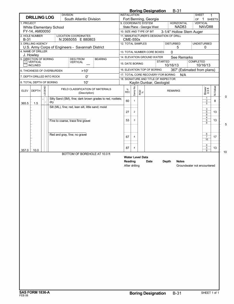
3
5
5
7
5
Water Level Data
5
8
8
10
8
60
27
53
67
87
365.5
357.0
1.5
10.0
Silty Sand (SM), fine; dark brown grades to red, rootlets;dry
Silt (ML), fine; red, lean silt, little sand; moist
Fine to coarse, trace fine gravel
Red and gray, fine; no gravel
BOTTOM OF BOREHOLE AT 10.0 ft
8
13
13
17
13
1
3
4
6
4
1
2
3
4
4
Reading Depth NotesDateAfter drilling Groundwater not encountered
N/A
14. ELEVATION GROUND WATER
SHEET
---
Fort Benning, Georgia
DISTURBED
6. THICKNESS OF OVERBURDEN
7. DEPTH DRILLED INTO ROCK
8. TOTAL DEPTH OF BORING
STARTEDVERTICAL
1. PROJECT
UNDISTURBED
NAVD88
2. HOLE NUMBER
18. SIGNATURE AND TITLE OF INSPECTOR
CME-550x
BEARING
3. DRILLING AGENCY
11
OF
COMPLETED15. DATE BORING
DEG FROMVERTICAL
HORIZONTAL
3-1/4" Hollow Stem Auger
INSTALLATION
05 0
INCLINED
U.S. Army Corps of Engineers - Savannah District4. NAME OF DRILLER
5. DIRECTION OF BORING
9. COORDINATE SYSTEM
10. SIZE AND TYPE OF BIT
NAD83White Elementary SchoolFY-14, AM00050
>10'
0'
10'
N 2065055 E 880803LOCATION COORDINATES
16. ELEVATION TOP OF BORING
VERTICAL
J. Howley
17. TOTAL CORE RECOVERY FOR BORING
10/16/13
SHEETSDRILLING LOG
12. TOTAL SAMPLES
13. TOTAL NUMBER CORE BOXES
B-31
DIVISION
11. MANUFACTURER'S DESIGNATION OF DRILL
South Atlantic Division
367' (Estimated from plans)
See Remarks
10/16/13
Kaylin Dunbar, Geologist
State Plane - Georgia West
0
5
10
Boring Designation B-31
FEB 08
%RECELEV
LEG
EN
D
DEPTH
SAS FORM 1836-A
FIELD CLASSIFICATION OF MATERIALS(Description)
N-V
alue
Boring Designation B-31 SHEET 1 of 1
REMARKS
Blo
ws/
0.5
ft
RQ
D%
Sam
p N
o.
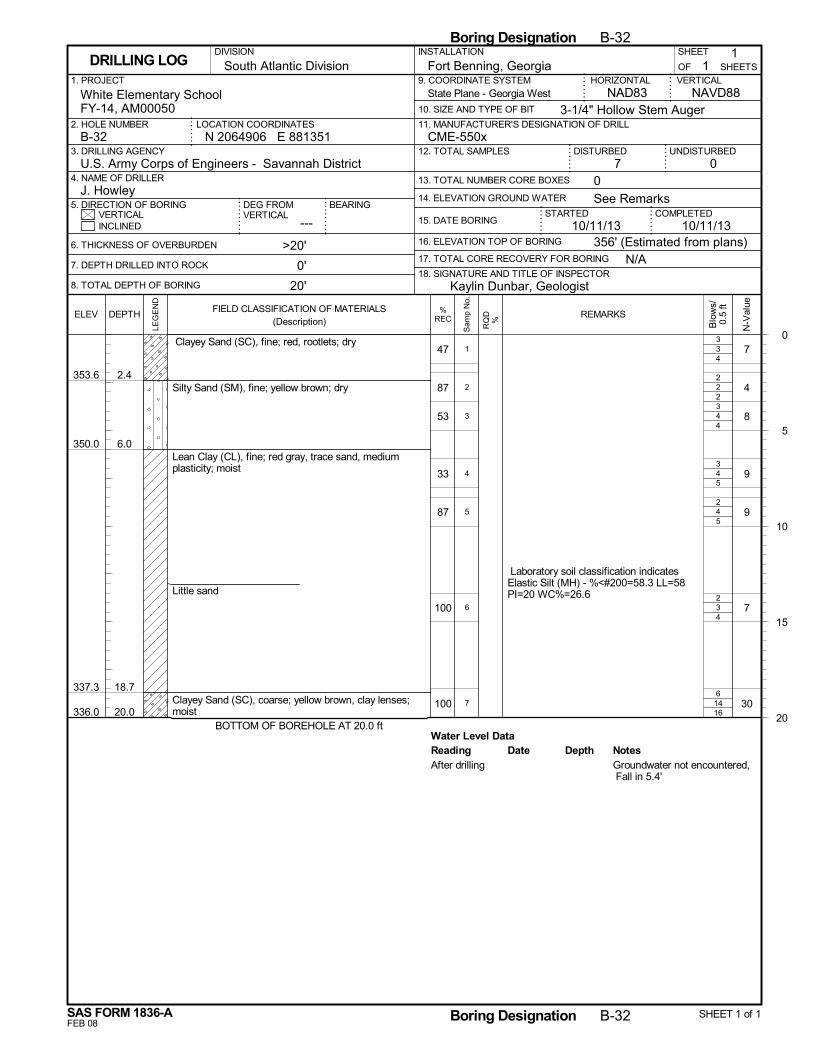
3
2
4
4
4
3
14
Water Level Data
4
2
4
5
5
4
16
47
87
53
33
87
100
100
353.6
350.0
337.3
336.0
2.4
6.0
18.7
20.0
Clayey Sand (SC), fine; red, rootlets; dry
Silty Sand (SM), fine; yellow brown; dry
Lean Clay (CL), fine; red gray, trace sand, mediumplasticity; moist
Little sand
Clayey Sand (SC), coarse; yellow brown, clay lenses;moist
BOTTOM OF BOREHOLE AT 20.0 ft
7
4
8
9
9
7
30
Laboratory soil classification indicatesElastic Silt (MH) - %<#200=58.3 LL=58PI=20 WC%=26.6
3
2
3
3
2
2
6
1
2
3
4
5
6
7
Reading Depth NotesDateAfter drilling Groundwater not encountered,
Fall in 5.4'
N/A
14. ELEVATION GROUND WATER
SHEET
---
Fort Benning, Georgia
DISTURBED
6. THICKNESS OF OVERBURDEN
7. DEPTH DRILLED INTO ROCK
8. TOTAL DEPTH OF BORING
STARTEDVERTICAL
1. PROJECT
UNDISTURBED
NAVD88
2. HOLE NUMBER
18. SIGNATURE AND TITLE OF INSPECTOR
CME-550x
BEARING
3. DRILLING AGENCY
11
OF
COMPLETED15. DATE BORING
DEG FROMVERTICAL
HORIZONTAL
3-1/4" Hollow Stem Auger
INSTALLATION
07 0
INCLINED
U.S. Army Corps of Engineers - Savannah District4. NAME OF DRILLER
5. DIRECTION OF BORING
9. COORDINATE SYSTEM
10. SIZE AND TYPE OF BIT
NAD83White Elementary SchoolFY-14, AM00050
>20'
0'
20'
N 2064906 E 881351LOCATION COORDINATES
16. ELEVATION TOP OF BORING
VERTICAL
J. Howley
17. TOTAL CORE RECOVERY FOR BORING
10/11/13
SHEETSDRILLING LOG
12. TOTAL SAMPLES
13. TOTAL NUMBER CORE BOXES
B-32
DIVISION
11. MANUFACTURER'S DESIGNATION OF DRILL
South Atlantic Division
356' (Estimated from plans)
See Remarks
10/11/13
Kaylin Dunbar, Geologist
State Plane - Georgia West
0
5
10
15
20
Boring Designation B-32
FEB 08
%RECELEV
LEG
EN
D
DEPTH
SAS FORM 1836-A
FIELD CLASSIFICATION OF MATERIALS(Description)
N-V
alue
Boring Designation B-32 SHEET 1 of 1
REMARKS
Blo
ws/
0.5
ft
RQ
D%
Sam
p N
o.

-
APPENDIX C Soil Laboratory Test Data
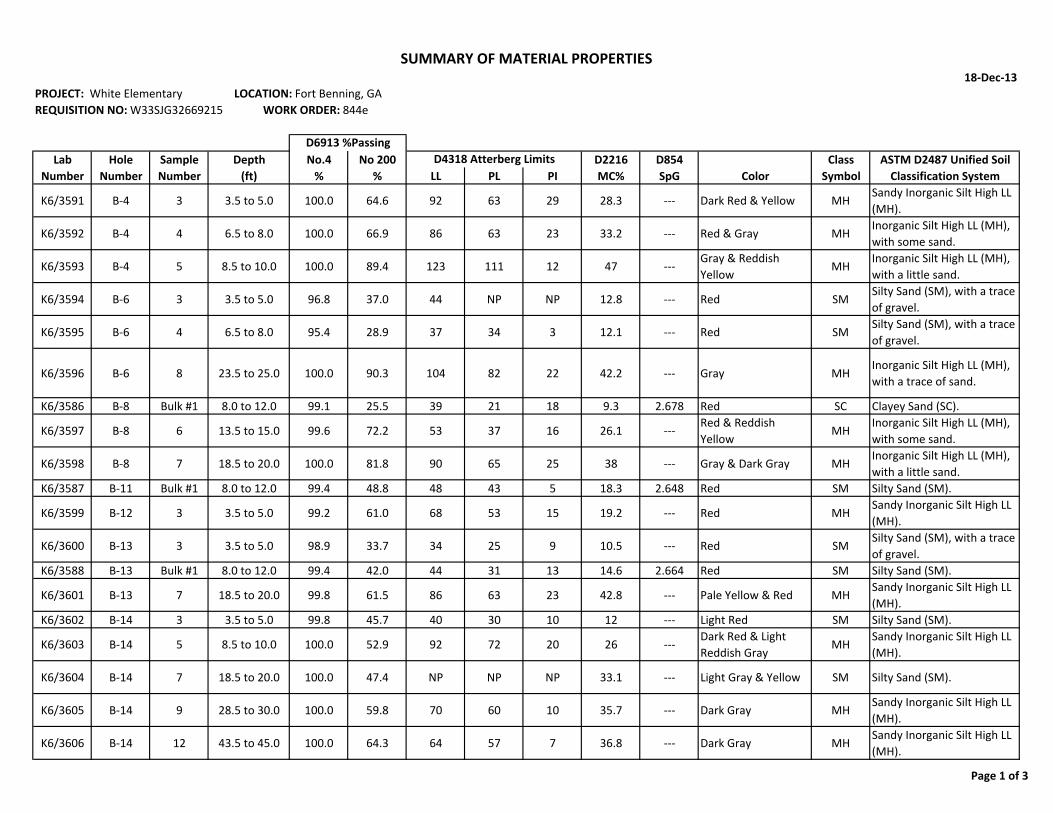
18‐Dec‐13PROJECT: White Elementary LOCATION: Fort Benning, GAREQUISITION NO: W33SJG32669215 WORK ORDER: 844e
Lab Hole Sample Depth No.4 No 200 D2216 D854 Class ASTM D2487 Unified SoilNumber Number Number (ft) % % LL PL PI MC% SpG Color Symbol Classification System
K6/3591 B‐4 3 3.5 to 5.0 100.0 64.6 92 63 29 28.3 ‐‐‐ Dark Red & Yellow MHSandy Inorganic Silt High LL (MH).
K6/3592 B‐4 4 6.5 to 8.0 100.0 66.9 86 63 23 33.2 ‐‐‐ Red & Gray MHInorganic Silt High LL (MH), with some sand.
K6/3593 B‐4 5 8.5 to 10.0 100.0 89.4 123 111 12 47 ‐‐‐Gray & Reddish Yellow
MHInorganic Silt High LL (MH), with a little sand.
K6/3594 B‐6 3 3.5 to 5.0 96.8 37.0 44 NP NP 12.8 ‐‐‐ Red SMSilty Sand (SM), with a trace of gravel.
K6/3595 B‐6 4 6.5 to 8.0 95.4 28.9 37 34 3 12.1 ‐‐‐ Red SMSilty Sand (SM), with a trace of gravel.
K6/3596 B‐6 8 23.5 to 25.0 100.0 90.3 104 82 22 42.2 ‐‐‐ Gray MHInorganic Silt High LL (MH), with a trace of sand.
K6/3586 B‐8 Bulk #1 8.0 to 12.0 99.1 25.5 39 21 18 9.3 2.678 Red SC Clayey Sand (SC).
K6/3597 B‐8 6 13.5 to 15.0 99.6 72.2 53 37 16 26.1 ‐‐‐Red & Reddish Yellow
MHInorganic Silt High LL (MH), with some sand.
K6/3598 B‐8 7 18.5 to 20.0 100.0 81.8 90 65 25 38 ‐‐‐ Gray & Dark Gray MHInorganic Silt High LL (MH), with a little sand.
K6/3587 B‐11 Bulk #1 8.0 to 12.0 99.4 48.8 48 43 5 18.3 2.648 Red SM Silty Sand (SM).
K6/3599 B‐12 3 3.5 to 5.0 99.2 61.0 68 53 15 19.2 ‐‐‐ Red MHSandy Inorganic Silt High LL (MH).
K6/3600 B‐13 3 3.5 to 5.0 98.9 33.7 34 25 9 10.5 ‐‐‐ Red SMSilty Sand (SM), with a trace of gravel.
K6/3588 B‐13 Bulk #1 8.0 to 12.0 99.4 42.0 44 31 13 14.6 2.664 Red SM Silty Sand (SM).
K6/3601 B‐13 7 18.5 to 20.0 99.8 61.5 86 63 23 42.8 ‐‐‐ Pale Yellow & Red MHSandy Inorganic Silt High LL (MH).
K6/3602 B‐14 3 3.5 to 5.0 99.8 45.7 40 30 10 12 ‐‐‐ Light Red SM Silty Sand (SM).
K6/3603 B‐14 5 8.5 to 10.0 100.0 52.9 92 72 20 26 ‐‐‐Dark Red & Light Reddish Gray
MHSandy Inorganic Silt High LL (MH).
K6/3604 B‐14 7 18.5 to 20.0 100.0 47.4 NP NP NP 33.1 ‐‐‐ Light Gray & Yellow SM Silty Sand (SM).
K6/3605 B‐14 9 28.5 to 30.0 100.0 59.8 70 60 10 35.7 ‐‐‐ Dark Gray MHSandy Inorganic Silt High LL (MH).
K6/3606 B‐14 12 43.5 to 45.0 100.0 64.3 64 57 7 36.8 ‐‐‐ Dark Gray MHSandy Inorganic Silt High LL (MH).
D4318 Atterberg LimitsD6913 %Passing
SUMMARY OF MATERIAL PROPERTIES
Page 1 of 3
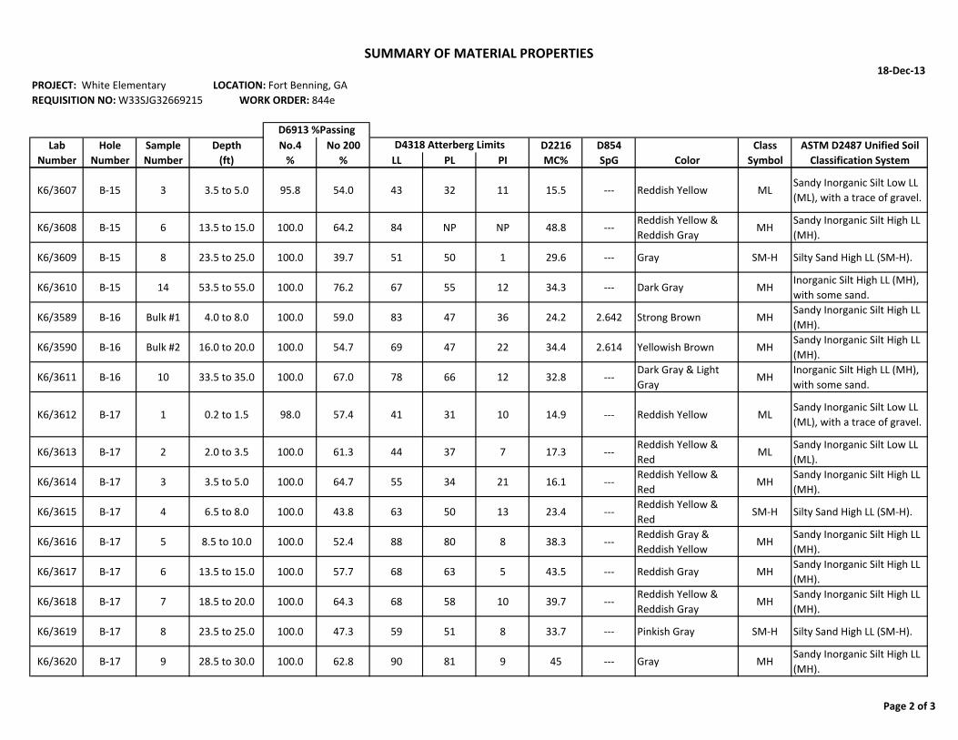
18‐Dec‐13PROJECT: White Elementary LOCATION: Fort Benning, GAREQUISITION NO: W33SJG32669215 WORK ORDER: 844e
Lab Hole Sample Depth No.4 No 200 D2216 D854 Class ASTM D2487 Unified SoilNumber Number Number (ft) % % LL PL PI MC% SpG Color Symbol Classification System
D4318 Atterberg LimitsD6913 %Passing
SUMMARY OF MATERIAL PROPERTIES
K6/3607 B‐15 3 3.5 to 5.0 95.8 54.0 43 32 11 15.5 ‐‐‐ Reddish Yellow MLSandy Inorganic Silt Low LL (ML), with a trace of gravel.
K6/3608 B‐15 6 13.5 to 15.0 100.0 64.2 84 NP NP 48.8 ‐‐‐Reddish Yellow & Reddish Gray
MHSandy Inorganic Silt High LL (MH).
K6/3609 B‐15 8 23.5 to 25.0 100.0 39.7 51 50 1 29.6 ‐‐‐ Gray SM‐H Silty Sand High LL (SM‐H).
K6/3610 B‐15 14 53.5 to 55.0 100.0 76.2 67 55 12 34.3 ‐‐‐ Dark Gray MHInorganic Silt High LL (MH), with some sand.
K6/3589 B‐16 Bulk #1 4.0 to 8.0 100.0 59.0 83 47 36 24.2 2.642 Strong Brown MHSandy Inorganic Silt High LL (MH).
K6/3590 B‐16 Bulk #2 16.0 to 20.0 100.0 54.7 69 47 22 34.4 2.614 Yellowish Brown MHSandy Inorganic Silt High LL (MH).
K6/3611 B‐16 10 33.5 to 35.0 100.0 67.0 78 66 12 32.8 ‐‐‐Dark Gray & Light Gray
MHInorganic Silt High LL (MH), with some sand.
K6/3612 B‐17 1 0.2 to 1.5 98.0 57.4 41 31 10 14.9 ‐‐‐ Reddish Yellow MLSandy Inorganic Silt Low LL (ML), with a trace of gravel.
K6/3613 B‐17 2 2.0 to 3.5 100.0 61.3 44 37 7 17.3 ‐‐‐Reddish Yellow & Red
MLSandy Inorganic Silt Low LL (ML).
K6/3614 B‐17 3 3.5 to 5.0 100.0 64.7 55 34 21 16.1 ‐‐‐Reddish Yellow & Red
MHSandy Inorganic Silt High LL (MH).
K6/3615 B‐17 4 6.5 to 8.0 100.0 43.8 63 50 13 23.4 ‐‐‐Reddish Yellow & Red
SM‐H Silty Sand High LL (SM‐H).
K6/3616 B‐17 5 8.5 to 10.0 100.0 52.4 88 80 8 38.3 ‐‐‐Reddish Gray & Reddish Yellow
MHSandy Inorganic Silt High LL (MH).
K6/3617 B‐17 6 13.5 to 15.0 100.0 57.7 68 63 5 43.5 ‐‐‐ Reddish Gray MHSandy Inorganic Silt High LL (MH).
K6/3618 B‐17 7 18.5 to 20.0 100.0 64.3 68 58 10 39.7 ‐‐‐Reddish Yellow & Reddish Gray
MHSandy Inorganic Silt High LL (MH).
K6/3619 B‐17 8 23.5 to 25.0 100.0 47.3 59 51 8 33.7 ‐‐‐ Pinkish Gray SM‐H Silty Sand High LL (SM‐H).
K6/3620 B‐17 9 28.5 to 30.0 100.0 62.8 90 81 9 45 ‐‐‐ Gray MHSandy Inorganic Silt High LL (MH).
Page 2 of 3
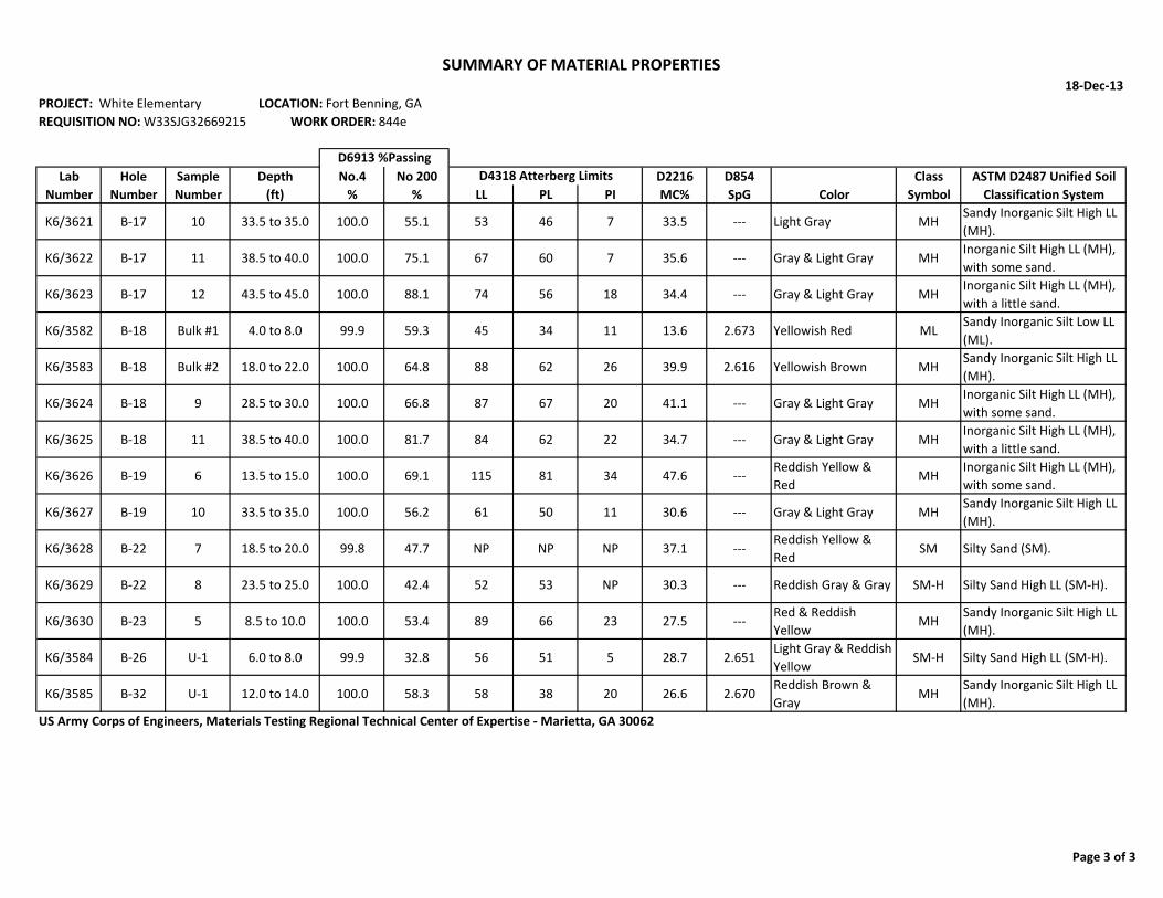
18‐Dec‐13PROJECT: White Elementary LOCATION: Fort Benning, GAREQUISITION NO: W33SJG32669215 WORK ORDER: 844e
Lab Hole Sample Depth No.4 No 200 D2216 D854 Class ASTM D2487 Unified SoilNumber Number Number (ft) % % LL PL PI MC% SpG Color Symbol Classification System
D4318 Atterberg LimitsD6913 %Passing
SUMMARY OF MATERIAL PROPERTIES
K6/3621 B‐17 10 33.5 to 35.0 100.0 55.1 53 46 7 33.5 ‐‐‐ Light Gray MHSandy Inorganic Silt High LL (MH).
K6/3622 B‐17 11 38.5 to 40.0 100.0 75.1 67 60 7 35.6 ‐‐‐ Gray & Light Gray MHInorganic Silt High LL (MH), with some sand.
K6/3623 B‐17 12 43.5 to 45.0 100.0 88.1 74 56 18 34.4 ‐‐‐ Gray & Light Gray MHInorganic Silt High LL (MH), with a little sand.
K6/3582 B‐18 Bulk #1 4.0 to 8.0 99.9 59.3 45 34 11 13.6 2.673 Yellowish Red MLSandy Inorganic Silt Low LL (ML).
K6/3583 B‐18 Bulk #2 18.0 to 22.0 100.0 64.8 88 62 26 39.9 2.616 Yellowish Brown MHSandy Inorganic Silt High LL (MH).
K6/3624 B‐18 9 28.5 to 30.0 100.0 66.8 87 67 20 41.1 ‐‐‐ Gray & Light Gray MHInorganic Silt High LL (MH), with some sand.
K6/3625 B‐18 11 38.5 to 40.0 100.0 81.7 84 62 22 34.7 ‐‐‐ Gray & Light Gray MHInorganic Silt High LL (MH), with a little sand.
K6/3626 B‐19 6 13.5 to 15.0 100.0 69.1 115 81 34 47.6 ‐‐‐Reddish Yellow & Red
MHInorganic Silt High LL (MH), with some sand.
K6/3627 B‐19 10 33.5 to 35.0 100.0 56.2 61 50 11 30.6 ‐‐‐ Gray & Light Gray MHSandy Inorganic Silt High LL (MH).
K6/3628 B‐22 7 18.5 to 20.0 99.8 47.7 NP NP NP 37.1 ‐‐‐Reddish Yellow & Red
SM Silty Sand (SM).
K6/3629 B‐22 8 23.5 to 25.0 100.0 42.4 52 53 NP 30.3 ‐‐‐ Reddish Gray & Gray SM‐H Silty Sand High LL (SM‐H).
K6/3630 B‐23 5 8.5 to 10.0 100.0 53.4 89 66 23 27.5 ‐‐‐Red & Reddish Yellow
MHSandy Inorganic Silt High LL (MH).
K6/3584 B‐26 U‐1 6.0 to 8.0 99.9 32.8 56 51 5 28.7 2.651Light Gray & Reddish Yellow
SM‐H Silty Sand High LL (SM‐H).
K6/3585 B‐32 U‐1 12.0 to 14.0 100.0 58.3 58 38 20 26.6 2.670Reddish Brown & Gray
MHSandy Inorganic Silt High LL (MH).
US Army Corps of Engineers, Materials Testing Regional Technical Center of Expertise ‐ Marietta, GA 30062
Page 3 of 3

0
10
20
30
40
50
60
70
80
90
100
0.0010.010.1110100
20
100
U.S. STANDARD SIEVE OPENING IN INCHES
MEDIUM
63
SANDCOARSE
6 14
Hole No.
Soil Testing Fort Benning, GA
GRAVEL
3
500 50 5
REQUISITION: W33SJG32669215
10
B-4
COBBLESFINE
100 140 200
Depth (ft) Classification
DEPARTMENT OF THE ARMY, SAVANNAH DISTRICT, ENVIRONMENTAL AND MATERIALS UNIT
U.S. STANDARD SIEVE NUMBERS
WORK ORDER: 844e
White ElementaryASTM D2487
3/8 3 4
PL
PE
RC
EN
T C
OA
RS
ER
BY
WE
IGH
T
6 4
GRADATION CURVES
CORPS OF ENGINEERS, 200 N. COBB PARKWAY, BLDG 400 SUITE 404, MARIETTA, GA. 30062
0
10
20
30
40
50
60
70
80
90
B-4
PE
RC
EN
T F
INE
R B
Y W
EIG
HT
Sample No.
Date
FINE COARSESILT OR CLAY
29
12/18/13
3.5 to 5.0
0.5 0.05 0.005
Dark Red & Yellow, Sandy Inorganic Silt High LL (MH).
Nat w%
40 50 703 2 1.5 1 3/4 1/2
PIProject
LL
Lab No.
92
30
28.3
HYDROMETER
GRAIN SIZE IN MILLIMETERS
8 16
Other tests, when reported, were conducted in general accordance with
ASTM's D2216, D4318, & D6913.
K6/3591

0
10
20
30
40
50
60
70
80
90
100
0.0010.010.1110100
20
100
U.S. STANDARD SIEVE OPENING IN INCHES
MEDIUM
63
SANDCOARSE
6 14
Hole No.
Soil Testing Fort Benning, GA
GRAVEL
4
500 50 5
REQUISITION: W33SJG32669215
10
B-4
COBBLESFINE
100 140 200
Depth (ft) Classification
DEPARTMENT OF THE ARMY, SAVANNAH DISTRICT, ENVIRONMENTAL AND MATERIALS UNIT
U.S. STANDARD SIEVE NUMBERS
WORK ORDER: 844e
White ElementaryASTM D2487
3/8 3 4
PL
PE
RC
EN
T C
OA
RS
ER
BY
WE
IGH
T
6 4
GRADATION CURVES
CORPS OF ENGINEERS, 200 N. COBB PARKWAY, BLDG 400 SUITE 404, MARIETTA, GA. 30062
0
10
20
30
40
50
60
70
80
90
B-4
PE
RC
EN
T F
INE
R B
Y W
EIG
HT
Sample No.
Date
FINE COARSESILT OR CLAY
23
12/18/13
6.5 to 8.0
0.5 0.05 0.005
Red & Gray, Inorganic Silt High LL (MH), with some sand.
Nat w%
40 50 703 2 1.5 1 3/4 1/2
PIProject
LL
Lab No.
86
30
33.2
HYDROMETER
GRAIN SIZE IN MILLIMETERS
8 16
Other tests, when reported, were conducted in general accordance with
ASTM's D2216, D4318, & D6913.
K6/3592

0
10
20
30
40
50
60
70
80
90
100
0.0010.010.1110100
20
100
U.S. STANDARD SIEVE OPENING IN INCHES
MEDIUM
111
SANDCOARSE
6 14
Hole No.
Soil Testing Fort Benning, GA
GRAVEL
5
500 50 5
REQUISITION: W33SJG32669215
10
B-4
COBBLESFINE
100 140 200
Depth (ft) Classification
DEPARTMENT OF THE ARMY, SAVANNAH DISTRICT, ENVIRONMENTAL AND MATERIALS UNIT
U.S. STANDARD SIEVE NUMBERS
WORK ORDER: 844e
White ElementaryASTM D2487
3/8 3 4
PL
PE
RC
EN
T C
OA
RS
ER
BY
WE
IGH
T
6 4
GRADATION CURVES
CORPS OF ENGINEERS, 200 N. COBB PARKWAY, BLDG 400 SUITE 404, MARIETTA, GA. 30062
0
10
20
30
40
50
60
70
80
90
B-4
PE
RC
EN
T F
INE
R B
Y W
EIG
HT
Sample No.
Date
FINE COARSESILT OR CLAY
12
12/18/13
8.5 to 10.0
0.5 0.05 0.005
Gray & Reddish Yellow, Inorganic Silt High LL (MH), with a little
sand.
Nat w%
40 50 703 2 1.5 1 3/4 1/2
PIProject
LL
Lab No.
123
30
47.0
HYDROMETER
GRAIN SIZE IN MILLIMETERS
8 16
Other tests, when reported, were conducted in general accordance with
ASTM's D2216, D4318, & D6913.
K6/3593
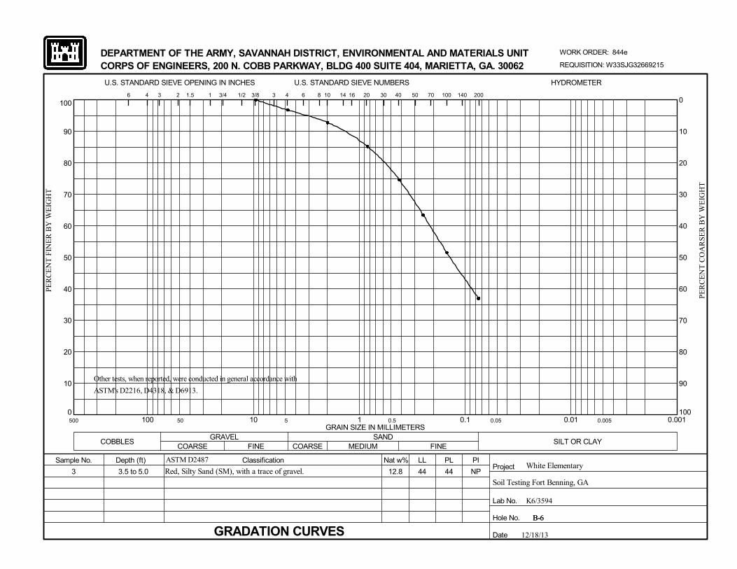
0
10
20
30
40
50
60
70
80
90
100
0.0010.010.1110100
20
100
U.S. STANDARD SIEVE OPENING IN INCHES
MEDIUM
44
SANDCOARSE
6 14
Hole No.
Soil Testing Fort Benning, GA
GRAVEL
3
500 50 5
REQUISITION: W33SJG32669215
10
B-6
COBBLESFINE
100 140 200
Depth (ft) Classification
DEPARTMENT OF THE ARMY, SAVANNAH DISTRICT, ENVIRONMENTAL AND MATERIALS UNIT
U.S. STANDARD SIEVE NUMBERS
WORK ORDER: 844e
White ElementaryASTM D2487
3/8 3 4
PL
PE
RC
EN
T C
OA
RS
ER
BY
WE
IGH
T
6 4
GRADATION CURVES
CORPS OF ENGINEERS, 200 N. COBB PARKWAY, BLDG 400 SUITE 404, MARIETTA, GA. 30062
0
10
20
30
40
50
60
70
80
90
B-6
PE
RC
EN
T F
INE
R B
Y W
EIG
HT
Sample No.
Date
FINE COARSESILT OR CLAY
NP
12/18/13
3.5 to 5.0
0.5 0.05 0.005
Red, Silty Sand (SM), with a trace of gravel.
Nat w%
40 50 703 2 1.5 1 3/4 1/2
PIProject
LL
Lab No.
44
30
12.8
HYDROMETER
GRAIN SIZE IN MILLIMETERS
8 16
Other tests, when reported, were conducted in general accordance with
ASTM's D2216, D4318, & D6913.
K6/3594
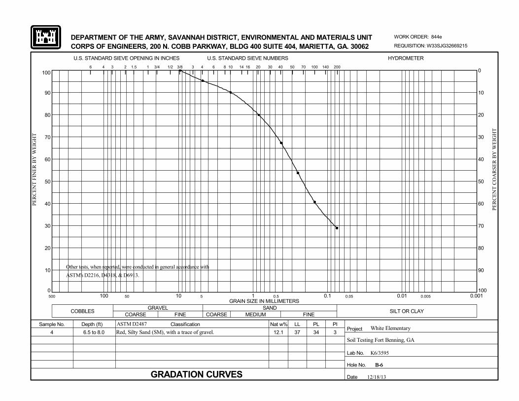
0
10
20
30
40
50
60
70
80
90
100
0.0010.010.1110100
20
100
U.S. STANDARD SIEVE OPENING IN INCHES
MEDIUM
34
SANDCOARSE
6 14
Hole No.
Soil Testing Fort Benning, GA
GRAVEL
4
500 50 5
REQUISITION: W33SJG32669215
10
B-6
COBBLESFINE
100 140 200
Depth (ft) Classification
DEPARTMENT OF THE ARMY, SAVANNAH DISTRICT, ENVIRONMENTAL AND MATERIALS UNIT
U.S. STANDARD SIEVE NUMBERS
WORK ORDER: 844e
White ElementaryASTM D2487
3/8 3 4
PL
PE
RC
EN
T C
OA
RS
ER
BY
WE
IGH
T
6 4
GRADATION CURVES
CORPS OF ENGINEERS, 200 N. COBB PARKWAY, BLDG 400 SUITE 404, MARIETTA, GA. 30062
0
10
20
30
40
50
60
70
80
90
B-6
PE
RC
EN
T F
INE
R B
Y W
EIG
HT
Sample No.
Date
FINE COARSESILT OR CLAY
3
12/18/13
6.5 to 8.0
0.5 0.05 0.005
Red, Silty Sand (SM), with a trace of gravel.
Nat w%
40 50 703 2 1.5 1 3/4 1/2
PIProject
LL
Lab No.
37
30
12.1
HYDROMETER
GRAIN SIZE IN MILLIMETERS
8 16
Other tests, when reported, were conducted in general accordance with
ASTM's D2216, D4318, & D6913.
K6/3595

0
10
20
30
40
50
60
70
80
90
100
0.0010.010.1110100
20
100
U.S. STANDARD SIEVE OPENING IN INCHES
MEDIUM
82
SANDCOARSE
6 14
Hole No.
Soil Testing Fort Benning, GA
GRAVEL
8
500 50 5
REQUISITION: W33SJG32669215
10
B-6
COBBLESFINE
100 140 200
Depth (ft) Classification
DEPARTMENT OF THE ARMY, SAVANNAH DISTRICT, ENVIRONMENTAL AND MATERIALS UNIT
U.S. STANDARD SIEVE NUMBERS
WORK ORDER: 844e
White ElementaryASTM D2487
3/8 3 4
PL
PE
RC
EN
T C
OA
RS
ER
BY
WE
IGH
T
6 4
GRADATION CURVES
CORPS OF ENGINEERS, 200 N. COBB PARKWAY, BLDG 400 SUITE 404, MARIETTA, GA. 30062
0
10
20
30
40
50
60
70
80
90
B-6
PE
RC
EN
T F
INE
R B
Y W
EIG
HT
Sample No.
Date
FINE COARSESILT OR CLAY
22
12/18/13
23.5 to 25.0
0.5 0.05 0.005
Gray, Inorganic Silt High LL (MH), with a trace of sand.
Nat w%
40 50 703 2 1.5 1 3/4 1/2
PIProject
LL
Lab No.
104
30
42.2
HYDROMETER
GRAIN SIZE IN MILLIMETERS
8 16
Other tests, when reported, were conducted in general accordance with
ASTM's D2216, D4318, & D6913.
K6/3596
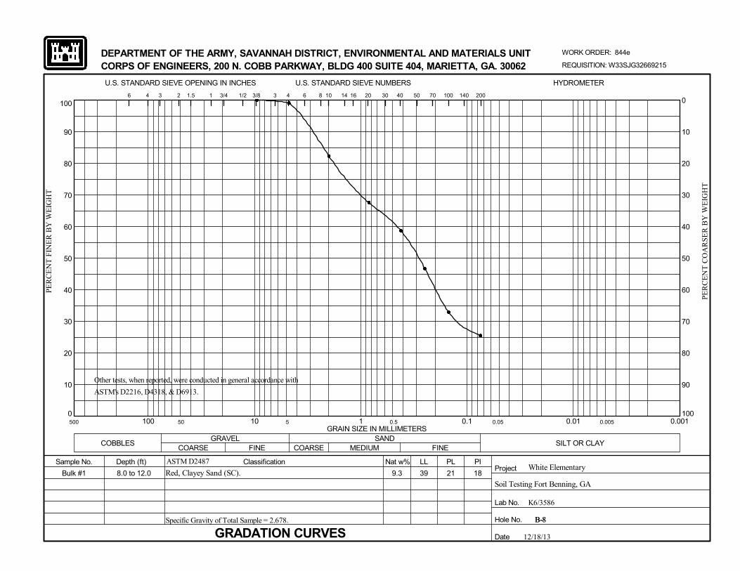
0
10
20
30
40
50
60
70
80
90
100
0.0010.010.1110100
20
100
U.S. STANDARD SIEVE OPENING IN INCHES
MEDIUM
21
SANDCOARSE
6 14
Hole No.
Soil Testing Fort Benning, GA
GRAVEL
Bulk #1
500 50 5
REQUISITION: W33SJG32669215
10
B-8
COBBLESFINE
100 140 200
Depth (ft) Classification
DEPARTMENT OF THE ARMY, SAVANNAH DISTRICT, ENVIRONMENTAL AND MATERIALS UNIT
U.S. STANDARD SIEVE NUMBERS
WORK ORDER: 844e
White ElementaryASTM D2487
3/8 3 4
PL
PE
RC
EN
T C
OA
RS
ER
BY
WE
IGH
T
6 4
GRADATION CURVESSpecific Gravity of Total Sample = 2.678.
CORPS OF ENGINEERS, 200 N. COBB PARKWAY, BLDG 400 SUITE 404, MARIETTA, GA. 30062
0
10
20
30
40
50
60
70
80
90
B-8
PE
RC
EN
T F
INE
R B
Y W
EIG
HT
Sample No.
Date
FINE COARSESILT OR CLAY
18
12/18/13
8.0 to 12.0
0.5 0.05 0.005
Red, Clayey Sand (SC).
Nat w%
40 50 703 2 1.5 1 3/4 1/2
PIProject
LL
Lab No.
39
30
9.3
HYDROMETER
GRAIN SIZE IN MILLIMETERS
8 16
Other tests, when reported, were conducted in general accordance with
ASTM's D2216, D4318, & D6913.
K6/3586

0
10
20
30
40
50
60
70
80
90
100
0.0010.010.1110100
20
100
U.S. STANDARD SIEVE OPENING IN INCHES
MEDIUM
37
SANDCOARSE
6 14
Hole No.
Soil Testing Fort Benning, GA
GRAVEL
6
500 50 5
REQUISITION: W33SJG32669215
10
B-8
COBBLESFINE
100 140 200
Depth (ft) Classification
DEPARTMENT OF THE ARMY, SAVANNAH DISTRICT, ENVIRONMENTAL AND MATERIALS UNIT
U.S. STANDARD SIEVE NUMBERS
WORK ORDER: 844e
White ElementaryASTM D2487
3/8 3 4
PL
PE
RC
EN
T C
OA
RS
ER
BY
WE
IGH
T
6 4
GRADATION CURVES
CORPS OF ENGINEERS, 200 N. COBB PARKWAY, BLDG 400 SUITE 404, MARIETTA, GA. 30062
0
10
20
30
40
50
60
70
80
90
B-8
PE
RC
EN
T F
INE
R B
Y W
EIG
HT
Sample No.
Date
FINE COARSESILT OR CLAY
16
12/18/13
13.5 to 15.0
0.5 0.05 0.005
Red & Reddish Yellow, Inorganic Silt High LL (MH), with some
sand.
Nat w%
40 50 703 2 1.5 1 3/4 1/2
PIProject
LL
Lab No.
53
30
26.1
HYDROMETER
GRAIN SIZE IN MILLIMETERS
8 16
Other tests, when reported, were conducted in general accordance with
ASTM's D2216, D4318, & D6913.
K6/3597

0
10
20
30
40
50
60
70
80
90
100
0.0010.010.1110100
20
100
U.S. STANDARD SIEVE OPENING IN INCHES
MEDIUM
65
SANDCOARSE
6 14
Hole No.
Soil Testing Fort Benning, GA
GRAVEL
7
500 50 5
REQUISITION: W33SJG32669215
10
B-8
COBBLESFINE
100 140 200
Depth (ft) Classification
DEPARTMENT OF THE ARMY, SAVANNAH DISTRICT, ENVIRONMENTAL AND MATERIALS UNIT
U.S. STANDARD SIEVE NUMBERS
WORK ORDER: 844e
White ElementaryASTM D2487
3/8 3 4
PL
PE
RC
EN
T C
OA
RS
ER
BY
WE
IGH
T
6 4
GRADATION CURVES
CORPS OF ENGINEERS, 200 N. COBB PARKWAY, BLDG 400 SUITE 404, MARIETTA, GA. 30062
0
10
20
30
40
50
60
70
80
90
B-8
PE
RC
EN
T F
INE
R B
Y W
EIG
HT
Sample No.
Date
FINE COARSESILT OR CLAY
25
12/18/13
18.5 to 20.0
0.5 0.05 0.005
Gray & Dark Gray, Inorganic Silt High LL (MH), with a little sand.
Nat w%
40 50 703 2 1.5 1 3/4 1/2
PIProject
LL
Lab No.
90
30
38.0
HYDROMETER
GRAIN SIZE IN MILLIMETERS
8 16
Other tests, when reported, were conducted in general accordance with
ASTM's D2216, D4318, & D6913.
K6/3598
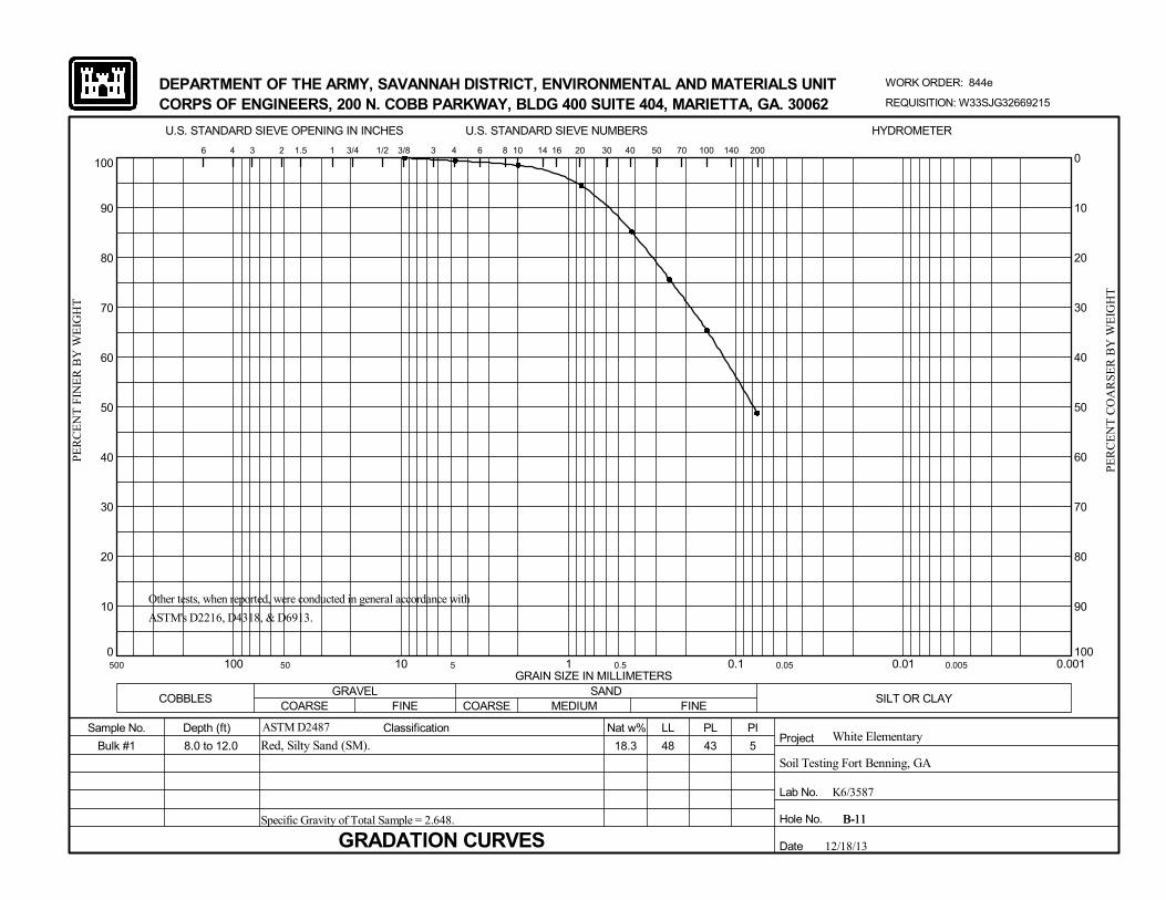
0
10
20
30
40
50
60
70
80
90
100
0.0010.010.1110100
20
100
U.S. STANDARD SIEVE OPENING IN INCHES
MEDIUM
43
SANDCOARSE
6 14
Hole No.
Soil Testing Fort Benning, GA
GRAVEL
Bulk #1
500 50 5
REQUISITION: W33SJG32669215
10
B-11
COBBLESFINE
100 140 200
Depth (ft) Classification
DEPARTMENT OF THE ARMY, SAVANNAH DISTRICT, ENVIRONMENTAL AND MATERIALS UNIT
U.S. STANDARD SIEVE NUMBERS
WORK ORDER: 844e
White ElementaryASTM D2487
3/8 3 4
PL
PE
RC
EN
T C
OA
RS
ER
BY
WE
IGH
T
6 4
GRADATION CURVESSpecific Gravity of Total Sample = 2.648.
CORPS OF ENGINEERS, 200 N. COBB PARKWAY, BLDG 400 SUITE 404, MARIETTA, GA. 30062
0
10
20
30
40
50
60
70
80
90
B-11
PE
RC
EN
T F
INE
R B
Y W
EIG
HT
Sample No.
Date
FINE COARSESILT OR CLAY
5
12/18/13
8.0 to 12.0
0.5 0.05 0.005
Red, Silty Sand (SM).
Nat w%
40 50 703 2 1.5 1 3/4 1/2
PIProject
LL
Lab No.
48
30
18.3
HYDROMETER
GRAIN SIZE IN MILLIMETERS
8 16
Other tests, when reported, were conducted in general accordance with
ASTM's D2216, D4318, & D6913.
K6/3587

0
10
20
30
40
50
60
70
80
90
100
0.0010.010.1110100
20
100
U.S. STANDARD SIEVE OPENING IN INCHES
MEDIUM
53
SANDCOARSE
6 14
Hole No.
Soil Testing Fort Benning, GA
GRAVEL
3
500 50 5
REQUISITION: W33SJG32669215
10
B-12
COBBLESFINE
100 140 200
Depth (ft) Classification
DEPARTMENT OF THE ARMY, SAVANNAH DISTRICT, ENVIRONMENTAL AND MATERIALS UNIT
U.S. STANDARD SIEVE NUMBERS
WORK ORDER: 844e
White ElementaryASTM D2487
3/8 3 4
PL
PE
RC
EN
T C
OA
RS
ER
BY
WE
IGH
T
6 4
GRADATION CURVES
CORPS OF ENGINEERS, 200 N. COBB PARKWAY, BLDG 400 SUITE 404, MARIETTA, GA. 30062
0
10
20
30
40
50
60
70
80
90
B-12
PE
RC
EN
T F
INE
R B
Y W
EIG
HT
Sample No.
Date
FINE COARSESILT OR CLAY
15
12/18/13
3.5 to 5.0
0.5 0.05 0.005
Red, Sandy Inorganic Silt High LL (MH).
Nat w%
40 50 703 2 1.5 1 3/4 1/2
PIProject
LL
Lab No.
68
30
19.2
HYDROMETER
GRAIN SIZE IN MILLIMETERS
8 16
Other tests, when reported, were conducted in general accordance with
ASTM's D2216, D4318, & D6913.
K6/3599

0
10
20
30
40
50
60
70
80
90
100
0.0010.010.1110100
20
100
U.S. STANDARD SIEVE OPENING IN INCHES
MEDIUM
25
SANDCOARSE
6 14
Hole No.
Soil Testing Fort Benning, GA
GRAVEL
3
500 50 5
REQUISITION: W33SJG32669215
10
B-13
COBBLESFINE
100 140 200
Depth (ft) Classification
DEPARTMENT OF THE ARMY, SAVANNAH DISTRICT, ENVIRONMENTAL AND MATERIALS UNIT
U.S. STANDARD SIEVE NUMBERS
WORK ORDER: 844e
White ElementaryASTM D2487
3/8 3 4
PL
PE
RC
EN
T C
OA
RS
ER
BY
WE
IGH
T
6 4
GRADATION CURVES
CORPS OF ENGINEERS, 200 N. COBB PARKWAY, BLDG 400 SUITE 404, MARIETTA, GA. 30062
0
10
20
30
40
50
60
70
80
90
B-13
PE
RC
EN
T F
INE
R B
Y W
EIG
HT
Sample No.
Date
FINE COARSESILT OR CLAY
9
12/18/13
3.5 to 5.0
0.5 0.05 0.005
Red, Silty Sand (SM), with a trace of gravel.
Nat w%
40 50 703 2 1.5 1 3/4 1/2
PIProject
LL
Lab No.
34
30
10.5
HYDROMETER
GRAIN SIZE IN MILLIMETERS
8 16
Other tests, when reported, were conducted in general accordance with
ASTM's D2216, D4318, & D6913.
K6/3600
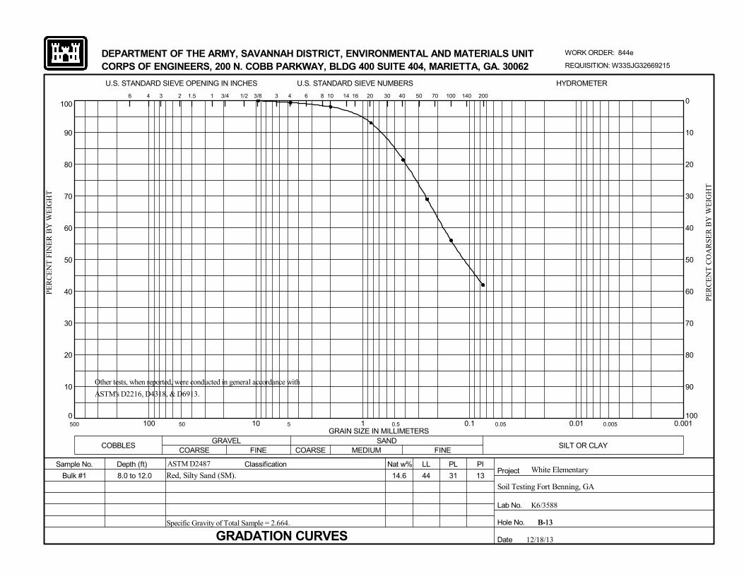
0
10
20
30
40
50
60
70
80
90
100
0.0010.010.1110100
20
100
U.S. STANDARD SIEVE OPENING IN INCHES
MEDIUM
31
SANDCOARSE
6 14
Hole No.
Soil Testing Fort Benning, GA
GRAVEL
Bulk #1
500 50 5
REQUISITION: W33SJG32669215
10
B-13
COBBLESFINE
100 140 200
Depth (ft) Classification
DEPARTMENT OF THE ARMY, SAVANNAH DISTRICT, ENVIRONMENTAL AND MATERIALS UNIT
U.S. STANDARD SIEVE NUMBERS
WORK ORDER: 844e
White ElementaryASTM D2487
3/8 3 4
PL
PE
RC
EN
T C
OA
RS
ER
BY
WE
IGH
T
6 4
GRADATION CURVESSpecific Gravity of Total Sample = 2.664.
CORPS OF ENGINEERS, 200 N. COBB PARKWAY, BLDG 400 SUITE 404, MARIETTA, GA. 30062
0
10
20
30
40
50
60
70
80
90
B-13
PE
RC
EN
T F
INE
R B
Y W
EIG
HT
Sample No.
Date
FINE COARSESILT OR CLAY
13
12/18/13
8.0 to 12.0
0.5 0.05 0.005
Red, Silty Sand (SM).
Nat w%
40 50 703 2 1.5 1 3/4 1/2
PIProject
LL
Lab No.
44
30
14.6
HYDROMETER
GRAIN SIZE IN MILLIMETERS
8 16
Other tests, when reported, were conducted in general accordance with
ASTM's D2216, D4318, & D6913.
K6/3588

0
10
20
30
40
50
60
70
80
90
100
0.0010.010.1110100
20
100
U.S. STANDARD SIEVE OPENING IN INCHES
MEDIUM
63
SANDCOARSE
6 14
Hole No.
Soil Testing Fort Benning, GA
GRAVEL
7
500 50 5
REQUISITION: W33SJG32669215
10
B-13
COBBLESFINE
100 140 200
Depth (ft) Classification
DEPARTMENT OF THE ARMY, SAVANNAH DISTRICT, ENVIRONMENTAL AND MATERIALS UNIT
U.S. STANDARD SIEVE NUMBERS
WORK ORDER: 844e
White ElementaryASTM D2487
3/8 3 4
PL
PE
RC
EN
T C
OA
RS
ER
BY
WE
IGH
T
6 4
GRADATION CURVES
CORPS OF ENGINEERS, 200 N. COBB PARKWAY, BLDG 400 SUITE 404, MARIETTA, GA. 30062
0
10
20
30
40
50
60
70
80
90
B-13
PE
RC
EN
T F
INE
R B
Y W
EIG
HT
Sample No.
Date
FINE COARSESILT OR CLAY
23
12/18/13
18.5 to 20.0
0.5 0.05 0.005
Pale Yellow & Red, Sandy Inorganic Silt High LL (MH).
Nat w%
40 50 703 2 1.5 1 3/4 1/2
PIProject
LL
Lab No.
86
30
42.8
HYDROMETER
GRAIN SIZE IN MILLIMETERS
8 16
Other tests, when reported, were conducted in general accordance with
ASTM's D2216, D4318, & D6913.
K6/3601

0
10
20
30
40
50
60
70
80
90
100
0.0010.010.1110100
20
100
U.S. STANDARD SIEVE OPENING IN INCHES
MEDIUM
30
SANDCOARSE
6 14
Hole No.
Soil Testing Fort Benning, GA
GRAVEL
3
500 50 5
REQUISITION: W33SJG32669215
10
B-14
COBBLESFINE
100 140 200
Depth (ft) Classification
DEPARTMENT OF THE ARMY, SAVANNAH DISTRICT, ENVIRONMENTAL AND MATERIALS UNIT
U.S. STANDARD SIEVE NUMBERS
WORK ORDER: 844e
White ElementaryASTM D2487
3/8 3 4
PL
PE
RC
EN
T C
OA
RS
ER
BY
WE
IGH
T
6 4
GRADATION CURVES
CORPS OF ENGINEERS, 200 N. COBB PARKWAY, BLDG 400 SUITE 404, MARIETTA, GA. 30062
0
10
20
30
40
50
60
70
80
90
B-14
PE
RC
EN
T F
INE
R B
Y W
EIG
HT
Sample No.
Date
FINE COARSESILT OR CLAY
10
12/18/13
3.5 to 5.0
0.5 0.05 0.005
Light Red, Silty Sand (SM).
Nat w%
40 50 703 2 1.5 1 3/4 1/2
PIProject
LL
Lab No.
40
30
12.0
HYDROMETER
GRAIN SIZE IN MILLIMETERS
8 16
Other tests, when reported, were conducted in general accordance with
ASTM's D2216, D4318, & D6913.
K6/3602

0
10
20
30
40
50
60
70
80
90
100
0.0010.010.1110100
20
100
U.S. STANDARD SIEVE OPENING IN INCHES
MEDIUM
72
SANDCOARSE
6 14
Hole No.
Soil Testing Fort Benning, GA
GRAVEL
5
500 50 5
REQUISITION: W33SJG32669215
10
B-14
COBBLESFINE
100 140 200
Depth (ft) Classification
DEPARTMENT OF THE ARMY, SAVANNAH DISTRICT, ENVIRONMENTAL AND MATERIALS UNIT
U.S. STANDARD SIEVE NUMBERS
WORK ORDER: 844e
White ElementaryASTM D2487
3/8 3 4
PL
PE
RC
EN
T C
OA
RS
ER
BY
WE
IGH
T
6 4
GRADATION CURVES
CORPS OF ENGINEERS, 200 N. COBB PARKWAY, BLDG 400 SUITE 404, MARIETTA, GA. 30062
0
10
20
30
40
50
60
70
80
90
B-14
PE
RC
EN
T F
INE
R B
Y W
EIG
HT
Sample No.
Date
FINE COARSESILT OR CLAY
20
12/18/13
8.5 to 10.0
0.5 0.05 0.005
Dark Red & Light Reddish Gray, Sandy Inorganic Silt High LL
(MH).
Nat w%
40 50 703 2 1.5 1 3/4 1/2
PIProject
LL
Lab No.
92
30
26.0
HYDROMETER
GRAIN SIZE IN MILLIMETERS
8 16
Other tests, when reported, were conducted in general accordance with
ASTM's D2216, D4318, & D6913.
K6/3603
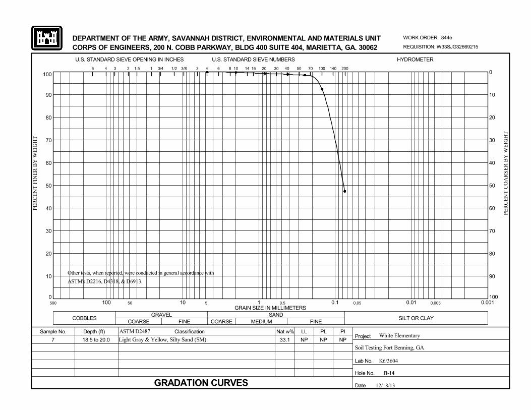
0
10
20
30
40
50
60
70
80
90
100
0.0010.010.1110100
20
100
U.S. STANDARD SIEVE OPENING IN INCHES
MEDIUM
NP
SANDCOARSE
6 14
Hole No.
Soil Testing Fort Benning, GA
GRAVEL
7
500 50 5
REQUISITION: W33SJG32669215
10
B-14
COBBLESFINE
100 140 200
Depth (ft) Classification
DEPARTMENT OF THE ARMY, SAVANNAH DISTRICT, ENVIRONMENTAL AND MATERIALS UNIT
U.S. STANDARD SIEVE NUMBERS
WORK ORDER: 844e
White ElementaryASTM D2487
3/8 3 4
PL
PE
RC
EN
T C
OA
RS
ER
BY
WE
IGH
T
6 4
GRADATION CURVES
CORPS OF ENGINEERS, 200 N. COBB PARKWAY, BLDG 400 SUITE 404, MARIETTA, GA. 30062
0
10
20
30
40
50
60
70
80
90
B-14
PE
RC
EN
T F
INE
R B
Y W
EIG
HT
Sample No.
Date
FINE COARSESILT OR CLAY
NP
12/18/13
18.5 to 20.0
0.5 0.05 0.005
Light Gray & Yellow, Silty Sand (SM).
Nat w%
40 50 703 2 1.5 1 3/4 1/2
PIProject
LL
Lab No.
NP
30
33.1
HYDROMETER
GRAIN SIZE IN MILLIMETERS
8 16
Other tests, when reported, were conducted in general accordance with
ASTM's D2216, D4318, & D6913.
K6/3604

0
10
20
30
40
50
60
70
80
90
100
0.0010.010.1110100
20
100
U.S. STANDARD SIEVE OPENING IN INCHES
MEDIUM
60
SANDCOARSE
6 14
Hole No.
Soil Testing Fort Benning, GA
GRAVEL
9
500 50 5
REQUISITION: W33SJG32669215
10
B-14
COBBLESFINE
100 140 200
Depth (ft) Classification
DEPARTMENT OF THE ARMY, SAVANNAH DISTRICT, ENVIRONMENTAL AND MATERIALS UNIT
U.S. STANDARD SIEVE NUMBERS
WORK ORDER: 844e
White ElementaryASTM D2487
3/8 3 4
PL
PE
RC
EN
T C
OA
RS
ER
BY
WE
IGH
T
6 4
GRADATION CURVES
CORPS OF ENGINEERS, 200 N. COBB PARKWAY, BLDG 400 SUITE 404, MARIETTA, GA. 30062
0
10
20
30
40
50
60
70
80
90
B-14
PE
RC
EN
T F
INE
R B
Y W
EIG
HT
Sample No.
Date
FINE COARSESILT OR CLAY
10
12/18/13
28.5 to 30.0
0.5 0.05 0.005
Dark Gray, Sandy Inorganic Silt High LL (MH).
Nat w%
40 50 703 2 1.5 1 3/4 1/2
PIProject
LL
Lab No.
70
30
35.7
HYDROMETER
GRAIN SIZE IN MILLIMETERS
8 16
Other tests, when reported, were conducted in general accordance with
ASTM's D2216, D4318, & D6913.
K6/3605

0
10
20
30
40
50
60
70
80
90
100
0.0010.010.1110100
20
100
U.S. STANDARD SIEVE OPENING IN INCHES
MEDIUM
57
SANDCOARSE
6 14
Hole No.
Soil Testing Fort Benning, GA
GRAVEL
12
500 50 5
REQUISITION: W33SJG32669215
10
B-14
COBBLESFINE
100 140 200
Depth (ft) Classification
DEPARTMENT OF THE ARMY, SAVANNAH DISTRICT, ENVIRONMENTAL AND MATERIALS UNIT
U.S. STANDARD SIEVE NUMBERS
WORK ORDER: 844e
White ElementaryASTM D2487
3/8 3 4
PL
PE
RC
EN
T C
OA
RS
ER
BY
WE
IGH
T
6 4
GRADATION CURVES
CORPS OF ENGINEERS, 200 N. COBB PARKWAY, BLDG 400 SUITE 404, MARIETTA, GA. 30062
0
10
20
30
40
50
60
70
80
90
B-14
PE
RC
EN
T F
INE
R B
Y W
EIG
HT
Sample No.
Date
FINE COARSESILT OR CLAY
7
12/18/13
43.5 to 45.0
0.5 0.05 0.005
Dark Gray, Sandy Inorganic Silt High LL (MH).
Nat w%
40 50 703 2 1.5 1 3/4 1/2
PIProject
LL
Lab No.
64
30
36.8
HYDROMETER
GRAIN SIZE IN MILLIMETERS
8 16
Other tests, when reported, were conducted in general accordance with
ASTM's D2216, D4318, & D6913.
K6/3606
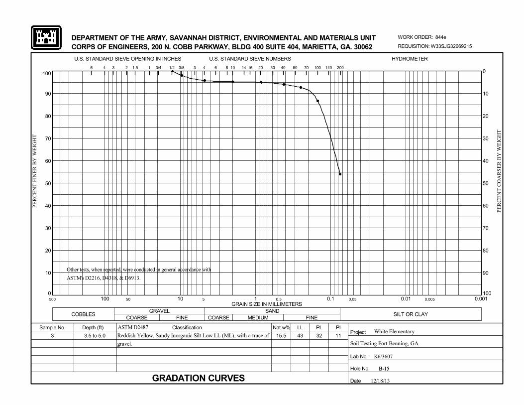
0
10
20
30
40
50
60
70
80
90
100
0.0010.010.1110100
20
100
U.S. STANDARD SIEVE OPENING IN INCHES
MEDIUM
32
SANDCOARSE
6 14
Hole No.
Soil Testing Fort Benning, GA
GRAVEL
3
500 50 5
REQUISITION: W33SJG32669215
10
B-15
COBBLESFINE
100 140 200
Depth (ft) Classification
DEPARTMENT OF THE ARMY, SAVANNAH DISTRICT, ENVIRONMENTAL AND MATERIALS UNIT
U.S. STANDARD SIEVE NUMBERS
WORK ORDER: 844e
White ElementaryASTM D2487
3/8 3 4
PL
PE
RC
EN
T C
OA
RS
ER
BY
WE
IGH
T
6 4
GRADATION CURVES
CORPS OF ENGINEERS, 200 N. COBB PARKWAY, BLDG 400 SUITE 404, MARIETTA, GA. 30062
0
10
20
30
40
50
60
70
80
90
B-15
PE
RC
EN
T F
INE
R B
Y W
EIG
HT
Sample No.
Date
FINE COARSESILT OR CLAY
11
12/18/13
3.5 to 5.0
0.5 0.05 0.005
Reddish Yellow, Sandy Inorganic Silt Low LL (ML), with a trace of
gravel.
Nat w%
40 50 703 2 1.5 1 3/4 1/2
PIProject
LL
Lab No.
43
30
15.5
HYDROMETER
GRAIN SIZE IN MILLIMETERS
8 16
Other tests, when reported, were conducted in general accordance with
ASTM's D2216, D4318, & D6913.
K6/3607

0
10
20
30
40
50
60
70
80
90
100
0.0010.010.1110100
20
100
U.S. STANDARD SIEVE OPENING IN INCHES
MEDIUM
NP
SANDCOARSE
6 14
Hole No.
Soil Testing Fort Benning, GA
GRAVEL
6
500 50 5
REQUISITION: W33SJG32669215
10
B-15
COBBLESFINE
100 140 200
Depth (ft) Classification
DEPARTMENT OF THE ARMY, SAVANNAH DISTRICT, ENVIRONMENTAL AND MATERIALS UNIT
U.S. STANDARD SIEVE NUMBERS
WORK ORDER: 844e
White ElementaryASTM D2487
3/8 3 4
PL
PE
RC
EN
T C
OA
RS
ER
BY
WE
IGH
T
6 4
GRADATION CURVES
CORPS OF ENGINEERS, 200 N. COBB PARKWAY, BLDG 400 SUITE 404, MARIETTA, GA. 30062
0
10
20
30
40
50
60
70
80
90
B-15
PE
RC
EN
T F
INE
R B
Y W
EIG
HT
Sample No.
Date
FINE COARSESILT OR CLAY
84
12/18/13
13.5 to 15.0
0.5 0.05 0.005
Reddish Yellow & Reddish Gray, Sandy Inorganic Silt High LL
(MH).
Nat w%
40 50 703 2 1.5 1 3/4 1/2
PIProject
LL
Lab No.
84
30
48.8
HYDROMETER
GRAIN SIZE IN MILLIMETERS
8 16
Other tests, when reported, were conducted in general accordance with
ASTM's D2216, D4318, & D6913.
K6/3608

0
10
20
30
40
50
60
70
80
90
100
0.0010.010.1110100
20
100
U.S. STANDARD SIEVE OPENING IN INCHES
MEDIUM
50
SANDCOARSE
6 14
Hole No.
Soil Testing Fort Benning, GA
GRAVEL
8
500 50 5
REQUISITION: W33SJG32669215
10
B-15
COBBLESFINE
100 140 200
Depth (ft) Classification
DEPARTMENT OF THE ARMY, SAVANNAH DISTRICT, ENVIRONMENTAL AND MATERIALS UNIT
U.S. STANDARD SIEVE NUMBERS
WORK ORDER: 844e
White ElementaryASTM D2487
3/8 3 4
PL
PE
RC
EN
T C
OA
RS
ER
BY
WE
IGH
T
6 4
GRADATION CURVES
CORPS OF ENGINEERS, 200 N. COBB PARKWAY, BLDG 400 SUITE 404, MARIETTA, GA. 30062
0
10
20
30
40
50
60
70
80
90
B-15
PE
RC
EN
T F
INE
R B
Y W
EIG
HT
Sample No.
Date
FINE COARSESILT OR CLAY
1
12/18/13
23.5 to 25.0
0.5 0.05 0.005
Gray, Silty Sand High LL (SM-H).
Nat w%
40 50 703 2 1.5 1 3/4 1/2
PIProject
LL
Lab No.
51
30
29.6
HYDROMETER
GRAIN SIZE IN MILLIMETERS
8 16
Other tests, when reported, were conducted in general accordance with
ASTM's D2216, D4318, & D6913.
K6/3609

0
10
20
30
40
50
60
70
80
90
100
0.0010.010.1110100
20
100
U.S. STANDARD SIEVE OPENING IN INCHES
MEDIUM
55
SANDCOARSE
6 14
Hole No.
Soil Testing Fort Benning, GA
GRAVEL
14
500 50 5
REQUISITION: W33SJG32669215
10
B-15
COBBLESFINE
100 140 200
Depth (ft) Classification
DEPARTMENT OF THE ARMY, SAVANNAH DISTRICT, ENVIRONMENTAL AND MATERIALS UNIT
U.S. STANDARD SIEVE NUMBERS
WORK ORDER: 844e
White ElementaryASTM D2487
3/8 3 4
PL
PE
RC
EN
T C
OA
RS
ER
BY
WE
IGH
T
6 4
GRADATION CURVES
CORPS OF ENGINEERS, 200 N. COBB PARKWAY, BLDG 400 SUITE 404, MARIETTA, GA. 30062
0
10
20
30
40
50
60
70
80
90
B-15
PE
RC
EN
T F
INE
R B
Y W
EIG
HT
Sample No.
Date
FINE COARSESILT OR CLAY
12
12/18/13
53.5 to 55.0
0.5 0.05 0.005
Dark Gray, Inorganic Silt High LL (MH), with some sand.
Nat w%
40 50 703 2 1.5 1 3/4 1/2
PIProject
LL
Lab No.
67
30
34.3
HYDROMETER
GRAIN SIZE IN MILLIMETERS
8 16
Other tests, when reported, were conducted in general accordance with
ASTM's D2216, D4318, & D6913.
K6/3610

0
10
20
30
40
50
60
70
80
90
100
0.0010.010.1110100
20
100
U.S. STANDARD SIEVE OPENING IN INCHES
MEDIUM
47
SANDCOARSE
6 14
Hole No.
Soil Testing Fort Benning, GA
GRAVEL
Bulk #1
500 50 5
REQUISITION: W33SJG32669215
10
B-16
COBBLESFINE
100 140 200
Depth (ft) Classification
DEPARTMENT OF THE ARMY, SAVANNAH DISTRICT, ENVIRONMENTAL AND MATERIALS UNIT
U.S. STANDARD SIEVE NUMBERS
WORK ORDER: 844e
White ElementaryASTM D2487
3/8 3 4
PL
PE
RC
EN
T C
OA
RS
ER
BY
WE
IGH
T
6 4
GRADATION CURVESSpecific Gravity of Total Sample = 2.642.
CORPS OF ENGINEERS, 200 N. COBB PARKWAY, BLDG 400 SUITE 404, MARIETTA, GA. 30062
0
10
20
30
40
50
60
70
80
90
B-16
PE
RC
EN
T F
INE
R B
Y W
EIG
HT
Sample No.
Date
FINE COARSESILT OR CLAY
36
12/18/13
4.0 to 8.0
0.5 0.05 0.005
Strong Brown, Sandy Inorganic Silt High LL (MH).
Nat w%
40 50 703 2 1.5 1 3/4 1/2
PIProject
LL
Lab No.
83
30
24.2
HYDROMETER
GRAIN SIZE IN MILLIMETERS
8 16
Other tests, when reported, were conducted in general accordance with
ASTM's D2216, D4318, & D6913.
K6/3589

0
10
20
30
40
50
60
70
80
90
100
0.0010.010.1110100
20
100
U.S. STANDARD SIEVE OPENING IN INCHES
MEDIUM
47
SANDCOARSE
6 14
Hole No.
Soil Testing Fort Benning, GA
GRAVEL
Bulk #2
500 50 5
REQUISITION: W33SJG32669215
10
B-16
COBBLESFINE
100 140 200
Depth (ft) Classification
DEPARTMENT OF THE ARMY, SAVANNAH DISTRICT, ENVIRONMENTAL AND MATERIALS UNIT
U.S. STANDARD SIEVE NUMBERS
WORK ORDER: 844e
White ElementaryASTM D2487
3/8 3 4
PL
PE
RC
EN
T C
OA
RS
ER
BY
WE
IGH
T
6 4
GRADATION CURVESSpecific Gravity of Total Sample = 2.614.
CORPS OF ENGINEERS, 200 N. COBB PARKWAY, BLDG 400 SUITE 404, MARIETTA, GA. 30062
0
10
20
30
40
50
60
70
80
90
B-16
PE
RC
EN
T F
INE
R B
Y W
EIG
HT
Sample No.
Date
FINE COARSESILT OR CLAY
22
12/18/13
16.0 to 20.0
0.5 0.05 0.005
Yellowish Brown, Sandy Inorganic Silt High LL (MH).
Nat w%
40 50 703 2 1.5 1 3/4 1/2
PIProject
LL
Lab No.
69
30
34.4
HYDROMETER
GRAIN SIZE IN MILLIMETERS
8 16
Other tests, when reported, were conducted in general accordance with
ASTM's D2216, D4318, & D6913.
K6/3590

0
10
20
30
40
50
60
70
80
90
100
0.0010.010.1110100
20
100
U.S. STANDARD SIEVE OPENING IN INCHES
MEDIUM
66
SANDCOARSE
6 14
Hole No.
Soil Testing Fort Benning, GA
GRAVEL
10
500 50 5
REQUISITION: W33SJG32669215
10
B-16
COBBLESFINE
100 140 200
Depth (ft) Classification
DEPARTMENT OF THE ARMY, SAVANNAH DISTRICT, ENVIRONMENTAL AND MATERIALS UNIT
U.S. STANDARD SIEVE NUMBERS
WORK ORDER: 844e
White ElementaryASTM D2487
3/8 3 4
PL
PE
RC
EN
T C
OA
RS
ER
BY
WE
IGH
T
6 4
GRADATION CURVES
CORPS OF ENGINEERS, 200 N. COBB PARKWAY, BLDG 400 SUITE 404, MARIETTA, GA. 30062
0
10
20
30
40
50
60
70
80
90
B-16
PE
RC
EN
T F
INE
R B
Y W
EIG
HT
Sample No.
Date
FINE COARSESILT OR CLAY
12
12/18/13
33.5 to 35.0
0.5 0.05 0.005
Dark Gray & Light Gray, Inorganic Silt High LL (MH), with some
sand.
Nat w%
40 50 703 2 1.5 1 3/4 1/2
PIProject
LL
Lab No.
78
30
32.8
HYDROMETER
GRAIN SIZE IN MILLIMETERS
8 16
Other tests, when reported, were conducted in general accordance with
ASTM's D2216, D4318, & D6913.
K6/3611

0
10
20
30
40
50
60
70
80
90
100
0.0010.010.1110100
20
100
U.S. STANDARD SIEVE OPENING IN INCHES
MEDIUM
31
SANDCOARSE
6 14
Hole No.
Soil Testing Fort Benning, GA
GRAVEL
1
500 50 5
REQUISITION: W33SJG32669215
10
B-17
COBBLESFINE
100 140 200
Depth (ft) Classification
DEPARTMENT OF THE ARMY, SAVANNAH DISTRICT, ENVIRONMENTAL AND MATERIALS UNIT
U.S. STANDARD SIEVE NUMBERS
WORK ORDER: 844e
White ElementaryASTM D2487
3/8 3 4
PL
PE
RC
EN
T C
OA
RS
ER
BY
WE
IGH
T
6 4
GRADATION CURVES
CORPS OF ENGINEERS, 200 N. COBB PARKWAY, BLDG 400 SUITE 404, MARIETTA, GA. 30062
0
10
20
30
40
50
60
70
80
90
B-17
PE
RC
EN
T F
INE
R B
Y W
EIG
HT
Sample No.
Date
FINE COARSESILT OR CLAY
10
12/18/13
0.2 to 1.5
0.5 0.05 0.005
Reddish Yellow, Sandy Inorganic Silt Low LL (ML), with a trace of
gravel.
Nat w%
40 50 703 2 1.5 1 3/4 1/2
PIProject
LL
Lab No.
41
30
14.9
HYDROMETER
GRAIN SIZE IN MILLIMETERS
8 16
Other tests, when reported, were conducted in general accordance with
ASTM's D2216, D4318, & D6913.
K6/3612
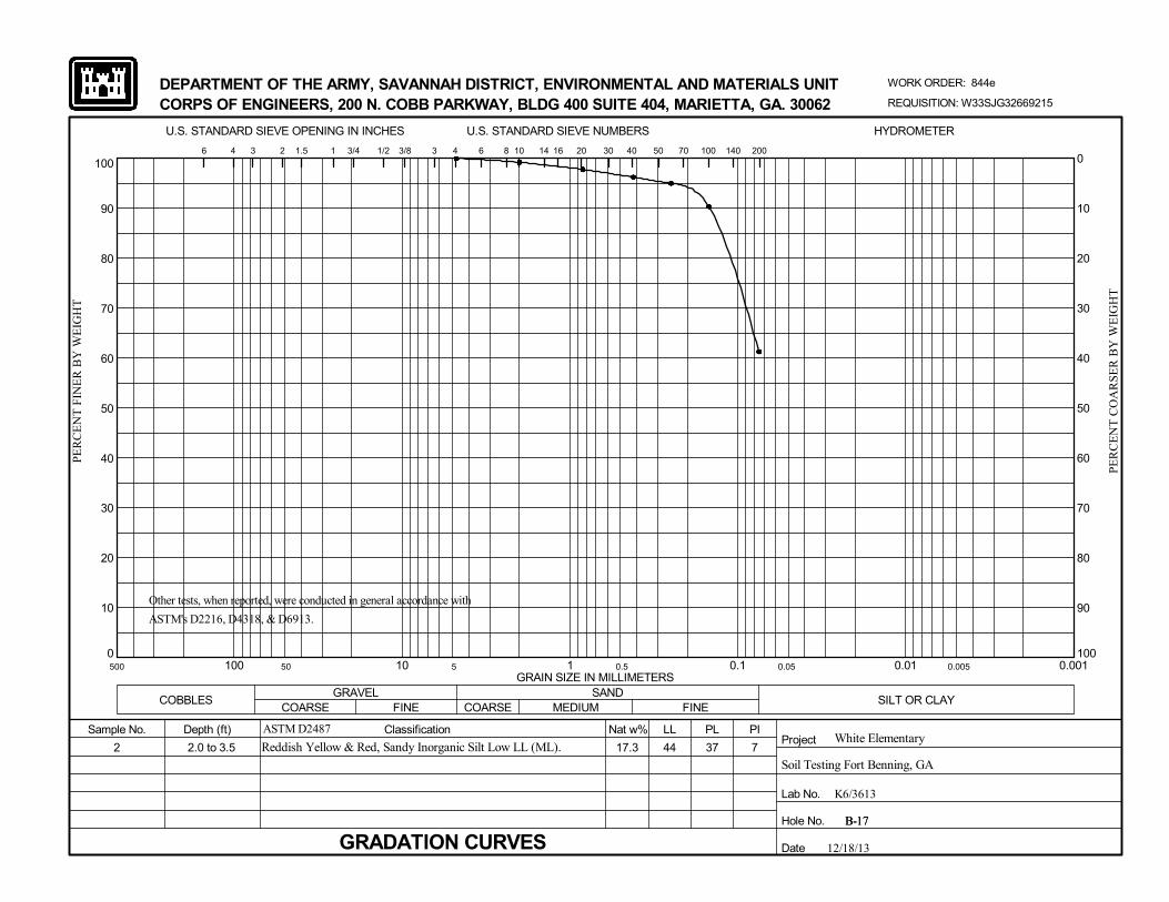
0
10
20
30
40
50
60
70
80
90
100
0.0010.010.1110100
20
100
U.S. STANDARD SIEVE OPENING IN INCHES
MEDIUM
37
SANDCOARSE
6 14
Hole No.
Soil Testing Fort Benning, GA
GRAVEL
2
500 50 5
REQUISITION: W33SJG32669215
10
B-17
COBBLESFINE
100 140 200
Depth (ft) Classification
DEPARTMENT OF THE ARMY, SAVANNAH DISTRICT, ENVIRONMENTAL AND MATERIALS UNIT
U.S. STANDARD SIEVE NUMBERS
WORK ORDER: 844e
White ElementaryASTM D2487
3/8 3 4
PL
PE
RC
EN
T C
OA
RS
ER
BY
WE
IGH
T
6 4
GRADATION CURVES
CORPS OF ENGINEERS, 200 N. COBB PARKWAY, BLDG 400 SUITE 404, MARIETTA, GA. 30062
0
10
20
30
40
50
60
70
80
90
B-17
PE
RC
EN
T F
INE
R B
Y W
EIG
HT
Sample No.
Date
FINE COARSESILT OR CLAY
7
12/18/13
2.0 to 3.5
0.5 0.05 0.005
Reddish Yellow & Red, Sandy Inorganic Silt Low LL (ML).
Nat w%
40 50 703 2 1.5 1 3/4 1/2
PIProject
LL
Lab No.
44
30
17.3
HYDROMETER
GRAIN SIZE IN MILLIMETERS
8 16
Other tests, when reported, were conducted in general accordance with
ASTM's D2216, D4318, & D6913.
K6/3613

0
10
20
30
40
50
60
70
80
90
100
0.0010.010.1110100
20
100
U.S. STANDARD SIEVE OPENING IN INCHES
MEDIUM
34
SANDCOARSE
6 14
Hole No.
Soil Testing Fort Benning, GA
GRAVEL
3
500 50 5
REQUISITION: W33SJG32669215
10
B-17
COBBLESFINE
100 140 200
Depth (ft) Classification
DEPARTMENT OF THE ARMY, SAVANNAH DISTRICT, ENVIRONMENTAL AND MATERIALS UNIT
U.S. STANDARD SIEVE NUMBERS
WORK ORDER: 844e
White ElementaryASTM D2487
3/8 3 4
PL
PE
RC
EN
T C
OA
RS
ER
BY
WE
IGH
T
6 4
GRADATION CURVES
CORPS OF ENGINEERS, 200 N. COBB PARKWAY, BLDG 400 SUITE 404, MARIETTA, GA. 30062
0
10
20
30
40
50
60
70
80
90
B-17
PE
RC
EN
T F
INE
R B
Y W
EIG
HT
Sample No.
Date
FINE COARSESILT OR CLAY
21
12/18/13
3.5 to 5.0
0.5 0.05 0.005
Reddish Yellow & Red, Sandy Inorganic Silt High LL (MH).
Nat w%
40 50 703 2 1.5 1 3/4 1/2
PIProject
LL
Lab No.
55
30
16.1
HYDROMETER
GRAIN SIZE IN MILLIMETERS
8 16
Other tests, when reported, were conducted in general accordance with
ASTM's D2216, D4318, & D6913.
K6/3614

0
10
20
30
40
50
60
70
80
90
100
0.0010.010.1110100
20
100
U.S. STANDARD SIEVE OPENING IN INCHES
MEDIUM
50
SANDCOARSE
6 14
Hole No.
Soil Testing Fort Benning, GA
GRAVEL
4
500 50 5
REQUISITION: W33SJG32669215
10
B-17
COBBLESFINE
100 140 200
Depth (ft) Classification
DEPARTMENT OF THE ARMY, SAVANNAH DISTRICT, ENVIRONMENTAL AND MATERIALS UNIT
U.S. STANDARD SIEVE NUMBERS
WORK ORDER: 844e
White ElementaryASTM D2487
3/8 3 4
PL
PE
RC
EN
T C
OA
RS
ER
BY
WE
IGH
T
6 4
GRADATION CURVES
CORPS OF ENGINEERS, 200 N. COBB PARKWAY, BLDG 400 SUITE 404, MARIETTA, GA. 30062
0
10
20
30
40
50
60
70
80
90
B-17
PE
RC
EN
T F
INE
R B
Y W
EIG
HT
Sample No.
Date
FINE COARSESILT OR CLAY
13
12/18/13
6.5 to 8.0
0.5 0.05 0.005
Reddish Yellow & Red, Silty Sand High LL (SM-H).
Nat w%
40 50 703 2 1.5 1 3/4 1/2
PIProject
LL
Lab No.
63
30
23.4
HYDROMETER
GRAIN SIZE IN MILLIMETERS
8 16
Other tests, when reported, were conducted in general accordance with
ASTM's D2216, D4318, & D6913.
K6/3615

0
10
20
30
40
50
60
70
80
90
100
0.0010.010.1110100
20
100
U.S. STANDARD SIEVE OPENING IN INCHES
MEDIUM
80
SANDCOARSE
6 14
Hole No.
Soil Testing Fort Benning, GA
GRAVEL
5
500 50 5
REQUISITION: W33SJG32669215
10
B-17
COBBLESFINE
100 140 200
Depth (ft) Classification
DEPARTMENT OF THE ARMY, SAVANNAH DISTRICT, ENVIRONMENTAL AND MATERIALS UNIT
U.S. STANDARD SIEVE NUMBERS
WORK ORDER: 844e
White ElementaryASTM D2487
3/8 3 4
PL
PE
RC
EN
T C
OA
RS
ER
BY
WE
IGH
T
6 4
GRADATION CURVES
CORPS OF ENGINEERS, 200 N. COBB PARKWAY, BLDG 400 SUITE 404, MARIETTA, GA. 30062
0
10
20
30
40
50
60
70
80
90
B-17
PE
RC
EN
T F
INE
R B
Y W
EIG
HT
Sample No.
Date
FINE COARSESILT OR CLAY
8
12/18/13
8.5 to 10.0
0.5 0.05 0.005
Reddish Gray & Reddish Yellow, Sandy Inorganic Silt High LL
(MH).
Nat w%
40 50 703 2 1.5 1 3/4 1/2
PIProject
LL
Lab No.
88
30
38.3
HYDROMETER
GRAIN SIZE IN MILLIMETERS
8 16
Other tests, when reported, were conducted in general accordance with
ASTM's D2216, D4318, & D6913.
K6/3616

0
10
20
30
40
50
60
70
80
90
100
0.0010.010.1110100
20
100
U.S. STANDARD SIEVE OPENING IN INCHES
MEDIUM
63
SANDCOARSE
6 14
Hole No.
Soil Testing Fort Benning, GA
GRAVEL
6
500 50 5
REQUISITION: W33SJG32669215
10
B-17
COBBLESFINE
100 140 200
Depth (ft) Classification
DEPARTMENT OF THE ARMY, SAVANNAH DISTRICT, ENVIRONMENTAL AND MATERIALS UNIT
U.S. STANDARD SIEVE NUMBERS
WORK ORDER: 844e
White ElementaryASTM D2487
3/8 3 4
PL
PE
RC
EN
T C
OA
RS
ER
BY
WE
IGH
T
6 4
GRADATION CURVES
CORPS OF ENGINEERS, 200 N. COBB PARKWAY, BLDG 400 SUITE 404, MARIETTA, GA. 30062
0
10
20
30
40
50
60
70
80
90
B-17
PE
RC
EN
T F
INE
R B
Y W
EIG
HT
Sample No.
Date
FINE COARSESILT OR CLAY
5
12/18/13
13.5 to 15.0
0.5 0.05 0.005
Reddish Gray, Sandy Inorganic Silt High LL (MH).
Nat w%
40 50 703 2 1.5 1 3/4 1/2
PIProject
LL
Lab No.
68
30
43.5
HYDROMETER
GRAIN SIZE IN MILLIMETERS
8 16
Other tests, when reported, were conducted in general accordance with
ASTM's D2216, D4318, & D6913.
K6/3617

0
10
20
30
40
50
60
70
80
90
100
0.0010.010.1110100
20
100
U.S. STANDARD SIEVE OPENING IN INCHES
MEDIUM
58
SANDCOARSE
6 14
Hole No.
Soil Testing Fort Benning, GA
GRAVEL
7
500 50 5
REQUISITION: W33SJG32669215
10
B-17
COBBLESFINE
100 140 200
Depth (ft) Classification
DEPARTMENT OF THE ARMY, SAVANNAH DISTRICT, ENVIRONMENTAL AND MATERIALS UNIT
U.S. STANDARD SIEVE NUMBERS
WORK ORDER: 844e
White ElementaryASTM D2487
3/8 3 4
PL
PE
RC
EN
T C
OA
RS
ER
BY
WE
IGH
T
6 4
GRADATION CURVES
CORPS OF ENGINEERS, 200 N. COBB PARKWAY, BLDG 400 SUITE 404, MARIETTA, GA. 30062
0
10
20
30
40
50
60
70
80
90
B-17
PE
RC
EN
T F
INE
R B
Y W
EIG
HT
Sample No.
Date
FINE COARSESILT OR CLAY
10
12/18/13
18.5 to 20.0
0.5 0.05 0.005
Reddish Yellow & Reddish Gray, Sandy Inorganic Silt High LL
(MH).
Nat w%
40 50 703 2 1.5 1 3/4 1/2
PIProject
LL
Lab No.
68
30
39.7
HYDROMETER
GRAIN SIZE IN MILLIMETERS
8 16
Other tests, when reported, were conducted in general accordance with
ASTM's D2216, D4318, & D6913.
K6/3618
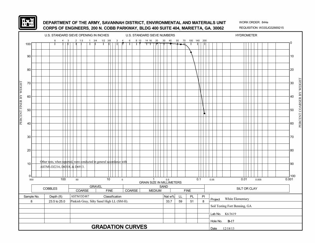
0
10
20
30
40
50
60
70
80
90
100
0.0010.010.1110100
20
100
U.S. STANDARD SIEVE OPENING IN INCHES
MEDIUM
51
SANDCOARSE
6 14
Hole No.
Soil Testing Fort Benning, GA
GRAVEL
8
500 50 5
REQUISITION: W33SJG32669215
10
B-17
COBBLESFINE
100 140 200
Depth (ft) Classification
DEPARTMENT OF THE ARMY, SAVANNAH DISTRICT, ENVIRONMENTAL AND MATERIALS UNIT
U.S. STANDARD SIEVE NUMBERS
WORK ORDER: 844e
White ElementaryASTM D2487
3/8 3 4
PL
PE
RC
EN
T C
OA
RS
ER
BY
WE
IGH
T
6 4
GRADATION CURVES
CORPS OF ENGINEERS, 200 N. COBB PARKWAY, BLDG 400 SUITE 404, MARIETTA, GA. 30062
0
10
20
30
40
50
60
70
80
90
B-17
PE
RC
EN
T F
INE
R B
Y W
EIG
HT
Sample No.
Date
FINE COARSESILT OR CLAY
8
12/18/13
23.5 to 25.0
0.5 0.05 0.005
Pinkish Gray, Silty Sand High LL (SM-H).
Nat w%
40 50 703 2 1.5 1 3/4 1/2
PIProject
LL
Lab No.
59
30
33.7
HYDROMETER
GRAIN SIZE IN MILLIMETERS
8 16
Other tests, when reported, were conducted in general accordance with
ASTM's D2216, D4318, & D6913.
K6/3619

0
10
20
30
40
50
60
70
80
90
100
0.0010.010.1110100
20
100
U.S. STANDARD SIEVE OPENING IN INCHES
MEDIUM
81
SANDCOARSE
6 14
Hole No.
Soil Testing Fort Benning, GA
GRAVEL
9
500 50 5
REQUISITION: W33SJG32669215
10
B-17
COBBLESFINE
100 140 200
Depth (ft) Classification
DEPARTMENT OF THE ARMY, SAVANNAH DISTRICT, ENVIRONMENTAL AND MATERIALS UNIT
U.S. STANDARD SIEVE NUMBERS
WORK ORDER: 844e
White ElementaryASTM D2487
3/8 3 4
PL
PE
RC
EN
T C
OA
RS
ER
BY
WE
IGH
T
6 4
GRADATION CURVES
CORPS OF ENGINEERS, 200 N. COBB PARKWAY, BLDG 400 SUITE 404, MARIETTA, GA. 30062
0
10
20
30
40
50
60
70
80
90
B-17
PE
RC
EN
T F
INE
R B
Y W
EIG
HT
Sample No.
Date
FINE COARSESILT OR CLAY
9
12/18/13
28.5 to 30.0
0.5 0.05 0.005
Gray, Sandy Inorganic Silt High LL (MH).
Nat w%
40 50 703 2 1.5 1 3/4 1/2
PIProject
LL
Lab No.
90
30
45.0
HYDROMETER
GRAIN SIZE IN MILLIMETERS
8 16
Other tests, when reported, were conducted in general accordance with
ASTM's D2216, D4318, & D6913.
K6/3620

0
10
20
30
40
50
60
70
80
90
100
0.0010.010.1110100
20
100
U.S. STANDARD SIEVE OPENING IN INCHES
MEDIUM
46
SANDCOARSE
6 14
Hole No.
Soil Testing Fort Benning, GA
GRAVEL
10
500 50 5
REQUISITION: W33SJG32669215
10
B-17
COBBLESFINE
100 140 200
Depth (ft) Classification
DEPARTMENT OF THE ARMY, SAVANNAH DISTRICT, ENVIRONMENTAL AND MATERIALS UNIT
U.S. STANDARD SIEVE NUMBERS
WORK ORDER: 844e
White ElementaryASTM D2487
3/8 3 4
PL
PE
RC
EN
T C
OA
RS
ER
BY
WE
IGH
T
6 4
GRADATION CURVES
CORPS OF ENGINEERS, 200 N. COBB PARKWAY, BLDG 400 SUITE 404, MARIETTA, GA. 30062
0
10
20
30
40
50
60
70
80
90
B-17
PE
RC
EN
T F
INE
R B
Y W
EIG
HT
Sample No.
Date
FINE COARSESILT OR CLAY
7
12/18/13
33.5 to 35.0
0.5 0.05 0.005
Light Gray, Sandy Inorganic Silt High LL (MH).
Nat w%
40 50 703 2 1.5 1 3/4 1/2
PIProject
LL
Lab No.
53
30
33.5
HYDROMETER
GRAIN SIZE IN MILLIMETERS
8 16
Other tests, when reported, were conducted in general accordance with
ASTM's D2216, D4318, & D6913.
K6/3621
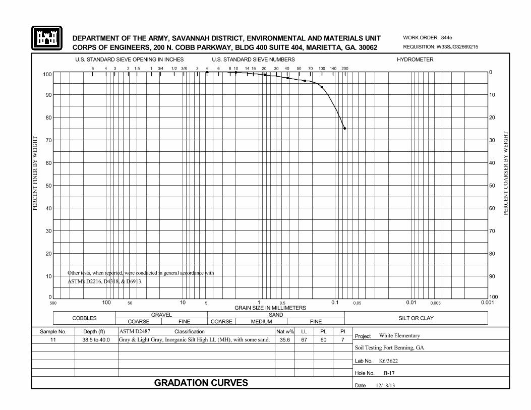
0
10
20
30
40
50
60
70
80
90
100
0.0010.010.1110100
20
100
U.S. STANDARD SIEVE OPENING IN INCHES
MEDIUM
60
SANDCOARSE
6 14
Hole No.
Soil Testing Fort Benning, GA
GRAVEL
11
500 50 5
REQUISITION: W33SJG32669215
10
B-17
COBBLESFINE
100 140 200
Depth (ft) Classification
DEPARTMENT OF THE ARMY, SAVANNAH DISTRICT, ENVIRONMENTAL AND MATERIALS UNIT
U.S. STANDARD SIEVE NUMBERS
WORK ORDER: 844e
White ElementaryASTM D2487
3/8 3 4
PL
PE
RC
EN
T C
OA
RS
ER
BY
WE
IGH
T
6 4
GRADATION CURVES
CORPS OF ENGINEERS, 200 N. COBB PARKWAY, BLDG 400 SUITE 404, MARIETTA, GA. 30062
0
10
20
30
40
50
60
70
80
90
B-17
PE
RC
EN
T F
INE
R B
Y W
EIG
HT
Sample No.
Date
FINE COARSESILT OR CLAY
7
12/18/13
38.5 to 40.0
0.5 0.05 0.005
Gray & Light Gray, Inorganic Silt High LL (MH), with some sand.
Nat w%
40 50 703 2 1.5 1 3/4 1/2
PIProject
LL
Lab No.
67
30
35.6
HYDROMETER
GRAIN SIZE IN MILLIMETERS
8 16
Other tests, when reported, were conducted in general accordance with
ASTM's D2216, D4318, & D6913.
K6/3622

0
10
20
30
40
50
60
70
80
90
100
0.0010.010.1110100
20
100
U.S. STANDARD SIEVE OPENING IN INCHES
MEDIUM
56
SANDCOARSE
6 14
Hole No.
Soil Testing Fort Benning, GA
GRAVEL
12
500 50 5
REQUISITION: W33SJG32669215
10
B-17
COBBLESFINE
100 140 200
Depth (ft) Classification
DEPARTMENT OF THE ARMY, SAVANNAH DISTRICT, ENVIRONMENTAL AND MATERIALS UNIT
U.S. STANDARD SIEVE NUMBERS
WORK ORDER: 844e
White ElementaryASTM D2487
3/8 3 4
PL
PE
RC
EN
T C
OA
RS
ER
BY
WE
IGH
T
6 4
GRADATION CURVES
CORPS OF ENGINEERS, 200 N. COBB PARKWAY, BLDG 400 SUITE 404, MARIETTA, GA. 30062
0
10
20
30
40
50
60
70
80
90
B-17
PE
RC
EN
T F
INE
R B
Y W
EIG
HT
Sample No.
Date
FINE COARSESILT OR CLAY
18
12/18/13
43.5 to 45.0
0.5 0.05 0.005
Gray & Light Gray, Inorganic Silt High LL (MH), with a little sand.
Nat w%
40 50 703 2 1.5 1 3/4 1/2
PIProject
LL
Lab No.
74
30
34.4
HYDROMETER
GRAIN SIZE IN MILLIMETERS
8 16
Other tests, when reported, were conducted in general accordance with
ASTM's D2216, D4318, & D6913.
K6/3623

0
10
20
30
40
50
60
70
80
90
100
0.0010.010.1110100
20
100
U.S. STANDARD SIEVE OPENING IN INCHES
MEDIUM
34
SANDCOARSE
6 14
Hole No.
Soil Testing Fort Benning, GA
GRAVEL
Bulk #1
500 50 5
REQUISITION: W33SJG32669215
10
B-18
COBBLESFINE
100 140 200
Depth (ft) Classification
DEPARTMENT OF THE ARMY, SAVANNAH DISTRICT, ENVIRONMENTAL AND MATERIALS UNIT
U.S. STANDARD SIEVE NUMBERS
WORK ORDER: 844e
White ElementaryASTM D2487
3/8 3 4
PL
PE
RC
EN
T C
OA
RS
ER
BY
WE
IGH
T
6 4
GRADATION CURVESSpecific Gravity of Total Sample = 2.673.
CORPS OF ENGINEERS, 200 N. COBB PARKWAY, BLDG 400 SUITE 404, MARIETTA, GA. 30062
0
10
20
30
40
50
60
70
80
90
B-18
PE
RC
EN
T F
INE
R B
Y W
EIG
HT
Sample No.
Date
FINE COARSESILT OR CLAY
11
12/18/13
4.0 to 8.0
0.5 0.05 0.005
Yellowish Red, Sandy Inorganic Silt Low LL (ML).
Nat w%
40 50 703 2 1.5 1 3/4 1/2
PIProject
LL
Lab No.
45
30
13.6
HYDROMETER
GRAIN SIZE IN MILLIMETERS
8 16
Other tests, when reported, were conducted in general accordance with
ASTM's D2216, D4318, & D6913.
K6/3582

0
10
20
30
40
50
60
70
80
90
100
0.0010.010.1110100
20
100
U.S. STANDARD SIEVE OPENING IN INCHES
MEDIUM
62
SANDCOARSE
6 14
Hole No.
Soil Testing Fort Benning, GA
GRAVEL
Bulk #2
500 50 5
REQUISITION: W33SJG32669215
10
B-18
COBBLESFINE
100 140 200
Depth (ft) Classification
DEPARTMENT OF THE ARMY, SAVANNAH DISTRICT, ENVIRONMENTAL AND MATERIALS UNIT
U.S. STANDARD SIEVE NUMBERS
WORK ORDER: 844e
White ElementaryASTM D2487
3/8 3 4
PL
PE
RC
EN
T C
OA
RS
ER
BY
WE
IGH
T
6 4
GRADATION CURVESSpecific Gravity of Total Sample = 2.616.
CORPS OF ENGINEERS, 200 N. COBB PARKWAY, BLDG 400 SUITE 404, MARIETTA, GA. 30062
0
10
20
30
40
50
60
70
80
90
B-18
PE
RC
EN
T F
INE
R B
Y W
EIG
HT
Sample No.
Date
FINE COARSESILT OR CLAY
26
12/18/13
18.0 to 22.0
0.5 0.05 0.005
Yellowish Brown, Sandy Inorganic Silt High LL (MH).
Nat w%
40 50 703 2 1.5 1 3/4 1/2
PIProject
LL
Lab No.
88
30
39.9
HYDROMETER
GRAIN SIZE IN MILLIMETERS
8 16
Other tests, when reported, were conducted in general accordance with
ASTM's D2216, D4318, & D6913.
K6/3583

0
10
20
30
40
50
60
70
80
90
100
0.0010.010.1110100
20
100
U.S. STANDARD SIEVE OPENING IN INCHES
MEDIUM
67
SANDCOARSE
6 14
Hole No.
Soil Testing Fort Benning, GA
GRAVEL
9
500 50 5
REQUISITION: W33SJG32669215
10
B-18
COBBLESFINE
100 140 200
Depth (ft) Classification
DEPARTMENT OF THE ARMY, SAVANNAH DISTRICT, ENVIRONMENTAL AND MATERIALS UNIT
U.S. STANDARD SIEVE NUMBERS
WORK ORDER: 844e
White ElementaryASTM D2487
3/8 3 4
PL
PE
RC
EN
T C
OA
RS
ER
BY
WE
IGH
T
6 4
GRADATION CURVES
CORPS OF ENGINEERS, 200 N. COBB PARKWAY, BLDG 400 SUITE 404, MARIETTA, GA. 30062
0
10
20
30
40
50
60
70
80
90
B-18
PE
RC
EN
T F
INE
R B
Y W
EIG
HT
Sample No.
Date
FINE COARSESILT OR CLAY
20
12/18/13
28.5 to 30.0
0.5 0.05 0.005
Gray & Light Gray, Inorganic Silt High LL (MH), with some sand.
Nat w%
40 50 703 2 1.5 1 3/4 1/2
PIProject
LL
Lab No.
87
30
41.1
HYDROMETER
GRAIN SIZE IN MILLIMETERS
8 16
Other tests, when reported, were conducted in general accordance with
ASTM's D2216, D4318, & D6913.
K6/3624

0
10
20
30
40
50
60
70
80
90
100
0.0010.010.1110100
20
100
U.S. STANDARD SIEVE OPENING IN INCHES
MEDIUM
62
SANDCOARSE
6 14
Hole No.
Soil Testing Fort Benning, GA
GRAVEL
11
500 50 5
REQUISITION: W33SJG32669215
10
B-18
COBBLESFINE
100 140 200
Depth (ft) Classification
DEPARTMENT OF THE ARMY, SAVANNAH DISTRICT, ENVIRONMENTAL AND MATERIALS UNIT
U.S. STANDARD SIEVE NUMBERS
WORK ORDER: 844e
White ElementaryASTM D2487
3/8 3 4
PL
PE
RC
EN
T C
OA
RS
ER
BY
WE
IGH
T
6 4
GRADATION CURVES
CORPS OF ENGINEERS, 200 N. COBB PARKWAY, BLDG 400 SUITE 404, MARIETTA, GA. 30062
0
10
20
30
40
50
60
70
80
90
B-18
PE
RC
EN
T F
INE
R B
Y W
EIG
HT
Sample No.
Date
FINE COARSESILT OR CLAY
22
12/18/13
38.5 to 40.0
0.5 0.05 0.005
Gray & Light Gray, Inorganic Silt High LL (MH), with a little sand.
Nat w%
40 50 703 2 1.5 1 3/4 1/2
PIProject
LL
Lab No.
84
30
34.7
HYDROMETER
GRAIN SIZE IN MILLIMETERS
8 16
Other tests, when reported, were conducted in general accordance with
ASTM's D2216, D4318, & D6913.
K6/3625

0
10
20
30
40
50
60
70
80
90
100
0.0010.010.1110100
20
100
U.S. STANDARD SIEVE OPENING IN INCHES
MEDIUM
81
SANDCOARSE
6 14
Hole No.
Soil Testing Fort Benning, GA
GRAVEL
6
500 50 5
REQUISITION: W33SJG32669215
10
B-19
COBBLESFINE
100 140 200
Depth (ft) Classification
DEPARTMENT OF THE ARMY, SAVANNAH DISTRICT, ENVIRONMENTAL AND MATERIALS UNIT
U.S. STANDARD SIEVE NUMBERS
WORK ORDER: 844e
White ElementaryASTM D2487
3/8 3 4
PL
PE
RC
EN
T C
OA
RS
ER
BY
WE
IGH
T
6 4
GRADATION CURVES
CORPS OF ENGINEERS, 200 N. COBB PARKWAY, BLDG 400 SUITE 404, MARIETTA, GA. 30062
0
10
20
30
40
50
60
70
80
90
B-19
PE
RC
EN
T F
INE
R B
Y W
EIG
HT
Sample No.
Date
FINE COARSESILT OR CLAY
34
12/18/13
13.5 to 15.0
0.5 0.05 0.005
Reddish Yellow & Red, Inorganic Silt High LL (MH), with some
sand.
Nat w%
40 50 703 2 1.5 1 3/4 1/2
PIProject
LL
Lab No.
115
30
47.6
HYDROMETER
GRAIN SIZE IN MILLIMETERS
8 16
Other tests, when reported, were conducted in general accordance with
ASTM's D2216, D4318, & D6913.
K6/3626

0
10
20
30
40
50
60
70
80
90
100
0.0010.010.1110100
20
100
U.S. STANDARD SIEVE OPENING IN INCHES
MEDIUM
50
SANDCOARSE
6 14
Hole No.
Soil Testing Fort Benning, GA
GRAVEL
10
500 50 5
REQUISITION: W33SJG32669215
10
B-19
COBBLESFINE
100 140 200
Depth (ft) Classification
DEPARTMENT OF THE ARMY, SAVANNAH DISTRICT, ENVIRONMENTAL AND MATERIALS UNIT
U.S. STANDARD SIEVE NUMBERS
WORK ORDER: 844e
White ElementaryASTM D2487
3/8 3 4
PL
PE
RC
EN
T C
OA
RS
ER
BY
WE
IGH
T
6 4
GRADATION CURVES
CORPS OF ENGINEERS, 200 N. COBB PARKWAY, BLDG 400 SUITE 404, MARIETTA, GA. 30062
0
10
20
30
40
50
60
70
80
90
B-19
PE
RC
EN
T F
INE
R B
Y W
EIG
HT
Sample No.
Date
FINE COARSESILT OR CLAY
11
12/18/13
33.5 to 35.0
0.5 0.05 0.005
Gray & Light Gray, Sandy Inorganic Silt High LL (MH).
Nat w%
40 50 703 2 1.5 1 3/4 1/2
PIProject
LL
Lab No.
61
30
30.6
HYDROMETER
GRAIN SIZE IN MILLIMETERS
8 16
Other tests, when reported, were conducted in general accordance with
ASTM's D2216, D4318, & D6913.
K6/3627

0
10
20
30
40
50
60
70
80
90
100
0.0010.010.1110100
20
100
U.S. STANDARD SIEVE OPENING IN INCHES
MEDIUM
NP
SANDCOARSE
6 14
Hole No.
Soil Testing Fort Benning, GA
GRAVEL
7
500 50 5
REQUISITION: W33SJG32669215
10
B-22
COBBLESFINE
100 140 200
Depth (ft) Classification
DEPARTMENT OF THE ARMY, SAVANNAH DISTRICT, ENVIRONMENTAL AND MATERIALS UNIT
U.S. STANDARD SIEVE NUMBERS
WORK ORDER: 844e
White ElementaryASTM D2487
3/8 3 4
PL
PE
RC
EN
T C
OA
RS
ER
BY
WE
IGH
T
6 4
GRADATION CURVES
CORPS OF ENGINEERS, 200 N. COBB PARKWAY, BLDG 400 SUITE 404, MARIETTA, GA. 30062
0
10
20
30
40
50
60
70
80
90
B-22
PE
RC
EN
T F
INE
R B
Y W
EIG
HT
Sample No.
Date
FINE COARSESILT OR CLAY
NP
12/18/13
18.5 to 20.0
0.5 0.05 0.005
Reddish Yellow & Red, Silty Sand (SM).
Nat w%
40 50 703 2 1.5 1 3/4 1/2
PIProject
LL
Lab No.
NP
30
37.1
HYDROMETER
GRAIN SIZE IN MILLIMETERS
8 16
Other tests, when reported, were conducted in general accordance with
ASTM's D2216, D4318, & D6913.
K6/3628

0
10
20
30
40
50
60
70
80
90
100
0.0010.010.1110100
20
100
U.S. STANDARD SIEVE OPENING IN INCHES
MEDIUM
53
SANDCOARSE
6 14
Hole No.
Soil Testing Fort Benning, GA
GRAVEL
8
500 50 5
REQUISITION: W33SJG32669215
10
B-22
COBBLESFINE
100 140 200
Depth (ft) Classification
DEPARTMENT OF THE ARMY, SAVANNAH DISTRICT, ENVIRONMENTAL AND MATERIALS UNIT
U.S. STANDARD SIEVE NUMBERS
WORK ORDER: 844e
White ElementaryASTM D2487
3/8 3 4
PL
PE
RC
EN
T C
OA
RS
ER
BY
WE
IGH
T
6 4
GRADATION CURVES
CORPS OF ENGINEERS, 200 N. COBB PARKWAY, BLDG 400 SUITE 404, MARIETTA, GA. 30062
0
10
20
30
40
50
60
70
80
90
B-22
PE
RC
EN
T F
INE
R B
Y W
EIG
HT
Sample No.
Date
FINE COARSESILT OR CLAY
NP
12/18/13
23.5 to 25.0
0.5 0.05 0.005
Reddish Gray & Gray, Silty Sand High LL (SM-H).
Nat w%
40 50 703 2 1.5 1 3/4 1/2
PIProject
LL
Lab No.
52
30
30.3
HYDROMETER
GRAIN SIZE IN MILLIMETERS
8 16
Other tests, when reported, were conducted in general accordance with
ASTM's D2216, D4318, & D6913.
K6/3629

0
10
20
30
40
50
60
70
80
90
100
0.0010.010.1110100
20
100
U.S. STANDARD SIEVE OPENING IN INCHES
MEDIUM
66
SANDCOARSE
6 14
Hole No.
Soil Testing Fort Benning, GA
GRAVEL
5
500 50 5
REQUISITION: W33SJG32669215
10
B-23
COBBLESFINE
100 140 200
Depth (ft) Classification
DEPARTMENT OF THE ARMY, SAVANNAH DISTRICT, ENVIRONMENTAL AND MATERIALS UNIT
U.S. STANDARD SIEVE NUMBERS
WORK ORDER: 844e
White ElementaryASTM D2487
3/8 3 4
PL
PE
RC
EN
T C
OA
RS
ER
BY
WE
IGH
T
6 4
GRADATION CURVES
CORPS OF ENGINEERS, 200 N. COBB PARKWAY, BLDG 400 SUITE 404, MARIETTA, GA. 30062
0
10
20
30
40
50
60
70
80
90
B-23
PE
RC
EN
T F
INE
R B
Y W
EIG
HT
Sample No.
Date
FINE COARSESILT OR CLAY
23
12/18/13
8.5 to 10.0
0.5 0.05 0.005
Red & Reddish Yellow, Sandy Inorganic Silt High LL (MH).
Nat w%
40 50 703 2 1.5 1 3/4 1/2
PIProject
LL
Lab No.
89
30
27.5
HYDROMETER
GRAIN SIZE IN MILLIMETERS
8 16
Other tests, when reported, were conducted in general accordance with
ASTM's D2216, D4318, & D6913.
K6/3630

0
10
20
30
40
50
60
70
80
90
100
0.0010.010.1110100
20
100
U.S. STANDARD SIEVE OPENING IN INCHES
MEDIUM
51
SANDCOARSE
6 14
Hole No.
Soil Testing Fort Benning, GA
GRAVEL
U-1
500 50 5
REQUISITION: W33SJG32669215
10
B-26
COBBLESFINE
100 140 200
Depth (ft) Classification
DEPARTMENT OF THE ARMY, SAVANNAH DISTRICT, ENVIRONMENTAL AND MATERIALS UNIT
U.S. STANDARD SIEVE NUMBERS
WORK ORDER: 844e
White ElementaryASTM D2487
3/8 3 4
PL
PE
RC
EN
T C
OA
RS
ER
BY
WE
IGH
T
6 4
GRADATION CURVESSpecific Gravity of Total Sample = 2.651.
CORPS OF ENGINEERS, 200 N. COBB PARKWAY, BLDG 400 SUITE 404, MARIETTA, GA. 30062
0
10
20
30
40
50
60
70
80
90
B-26
PE
RC
EN
T F
INE
R B
Y W
EIG
HT
Sample No.
Date
FINE COARSESILT OR CLAY
5
12/18/13
6.0 to 8.0
0.5 0.05 0.005
Light Gray & Reddish Yellow, Silty Sand High LL (SM-H).
Nat w%
40 50 703 2 1.5 1 3/4 1/2
PIProject
LL
Lab No.
56
30
28.7
HYDROMETER
GRAIN SIZE IN MILLIMETERS
8 16
Other tests, when reported, were conducted in general accordance with
ASTM's D2216, D4318, & D6913.
K6/3584

0
10
20
30
40
50
60
70
80
90
100
0.0010.010.1110100
20
100
U.S. STANDARD SIEVE OPENING IN INCHES
MEDIUM
38
SANDCOARSE
6 14
Hole No.
Soil Testing Fort Benning, GA
GRAVEL
U-1
500 50 5
REQUISITION: W33SJG32669215
10
B-32
COBBLESFINE
100 140 200
Depth (ft) Classification
DEPARTMENT OF THE ARMY, SAVANNAH DISTRICT, ENVIRONMENTAL AND MATERIALS UNIT
U.S. STANDARD SIEVE NUMBERS
WORK ORDER: 844e
White ElementaryASTM D2487
3/8 3 4
PL
PE
RC
EN
T C
OA
RS
ER
BY
WE
IGH
T
6 4
GRADATION CURVESSpecific Gravity of Total Sample = 2.670.
CORPS OF ENGINEERS, 200 N. COBB PARKWAY, BLDG 400 SUITE 404, MARIETTA, GA. 30062
0
10
20
30
40
50
60
70
80
90
B-32
PE
RC
EN
T F
INE
R B
Y W
EIG
HT
Sample No.
Date
FINE COARSESILT OR CLAY
20
12/18/13
12.0 to 14.0
0.5 0.05 0.005
Reddish Brown & Gray, Sandy Inorganic Silt High LL (MH).
Nat w%
40 50 703 2 1.5 1 3/4 1/2
PIProject
LL
Lab No.
58
30
26.6
HYDROMETER
GRAIN SIZE IN MILLIMETERS
8 16
Other tests, when reported, were conducted in general accordance with
ASTM's D2216, D4318, & D6913.
K6/3585
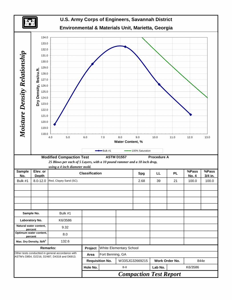
Environmental & Materials Unit, Marietta, GeorgiaU.S. Army Corps of Engineers, Savannah District
Moi
stu
re D
ensi
ty R
elat
ion
ship
118.0
119.0
120.0
121.0
122.0
123.0
124.0
125.0
126.0
127.0
128.0
129.0
130.0
131.0
132.0
133.0
134.0
4.0 5.0 6.0 7.0 8.0 9.0 10.0 11.0 12.0 13.0
Dry
Den
sity
, lbs
/cu.
ft.
Water Content, %
Bulk #1 100% Saturation
using a 4 inch diameter mold.Sample
No.Elev. or Depth Spg LL PL %Pass
No. 4%Pass 3/4 in.
Bulk #1 8.0-12.0 2.68 39 21 100.0 100.0
Project
Area
Hole No. Lab No.
Optimum water content, percent
Bulk #1
Remarks:Other tests conductted in general accordance with ASTM's D854, D2216, D2487, D4318 and D6913.
Compaction Test Report
White Elementary School
B-8 K6/3586
Max. Dry Density, lb/ft3
Requisition No.
K6/3586
9.32
8.0
132.6
Procedure A25 Blows per each of 5 Layers, with a 10 pound rammer and a 18 inch drop,
Modified Compaction Test ASTM D1557
Sample No.
Laboratory No.
Natural water content, percent
W33SJG32669215 Work Order No. 844e
Fort Benning, GA
Classification
Red, Clayey Sand (SC).
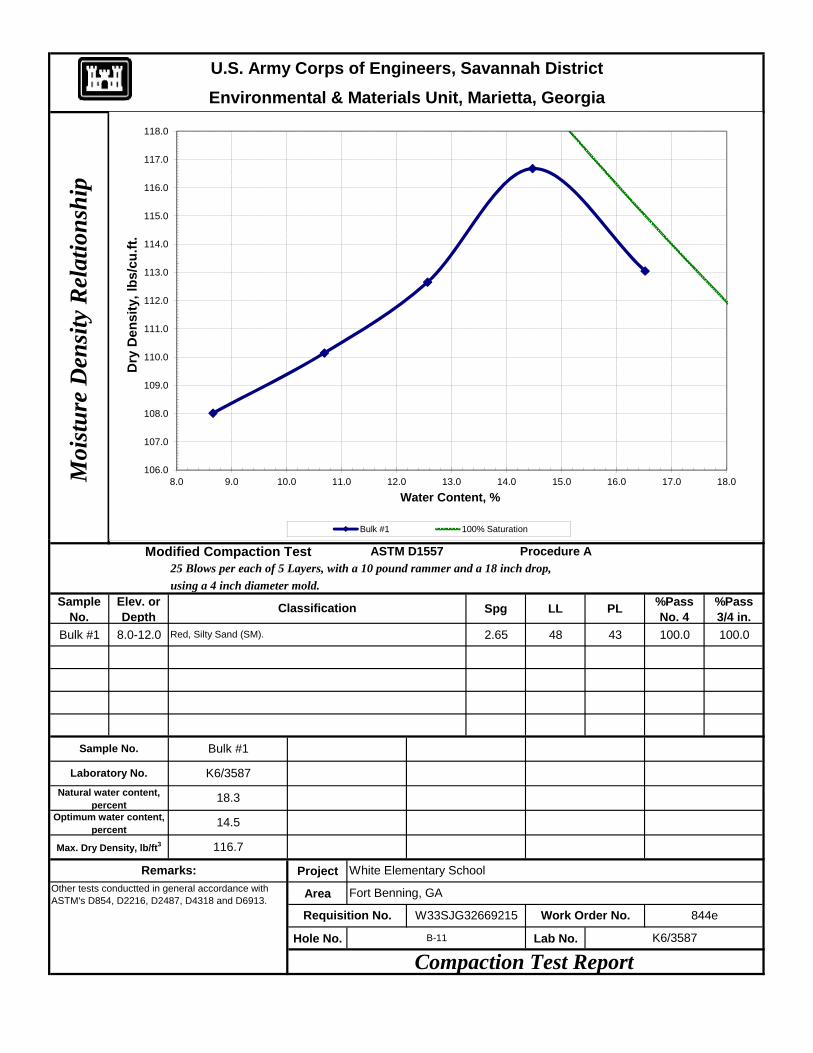
Environmental & Materials Unit, Marietta, GeorgiaU.S. Army Corps of Engineers, Savannah District
Moi
stu
re D
ensi
ty R
elat
ion
ship
106.0
107.0
108.0
109.0
110.0
111.0
112.0
113.0
114.0
115.0
116.0
117.0
118.0
8.0 9.0 10.0 11.0 12.0 13.0 14.0 15.0 16.0 17.0 18.0
Dry
Den
sity
, lbs
/cu.
ft.
Water Content, %
Bulk #1 100% Saturation
using a 4 inch diameter mold.Sample
No.Elev. or Depth Spg LL PL %Pass
No. 4%Pass 3/4 in.
Bulk #1 8.0-12.0 2.65 48 43 100.0 100.0
Project
Area
Hole No. Lab No.
Optimum water content, percent
Bulk #1
Remarks:Other tests conductted in general accordance with ASTM's D854, D2216, D2487, D4318 and D6913.
Compaction Test Report
White Elementary School
B-11 K6/3587
Max. Dry Density, lb/ft3
Requisition No.
K6/3587
18.3
14.5
116.7
Procedure A25 Blows per each of 5 Layers, with a 10 pound rammer and a 18 inch drop,
Modified Compaction Test ASTM D1557
Sample No.
Laboratory No.
Natural water content, percent
W33SJG32669215 Work Order No. 844e
Fort Benning, GA
Classification
Red, Silty Sand (SM).
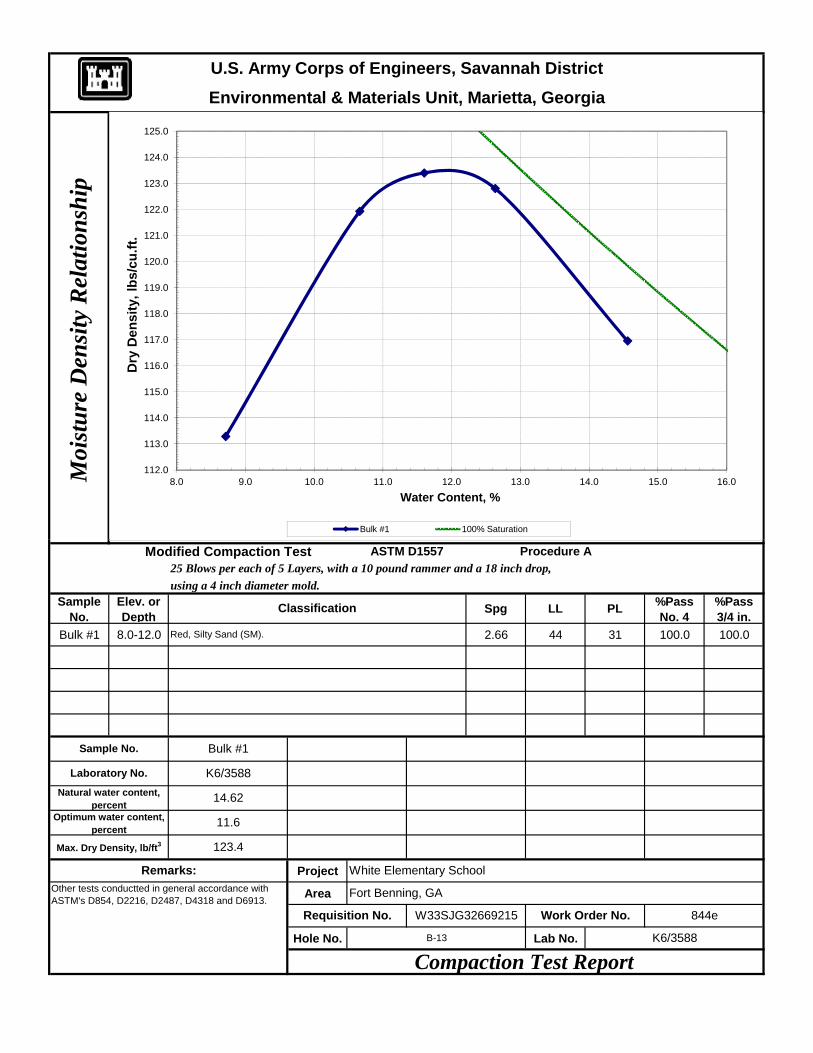
U.S. Army Corps of Engineers, Savannah DistrictM
oist
ure
Den
sity
Rel
atio
nsh
ipEnvironmental & Materials Unit, Marietta, Georgia
112.0
113.0
114.0
115.0
116.0
117.0
118.0
119.0
120.0
121.0
122.0
123.0
124.0
125.0
8.0 9.0 10.0 11.0 12.0 13.0 14.0 15.0 16.0
Dry
Den
sity
, lbs
/cu.
ft.
Water Content, %
Bulk #1 100% Saturation
using a 4 inch diameter mold.Sample
No.Elev. or Depth Spg LL PL %Pass
No. 4%Pass 3/4 in.
Bulk #1 8.0-12.0 2.66 44 31 100.0 100.0
Project
Area
Hole No. Lab No.
W33SJG32669215 Work Order No. 844e
Fort Benning, GA
Classification
Red, Silty Sand (SM).
Procedure A25 Blows per each of 5 Layers, with a 10 pound rammer and a 18 inch drop,
Modified Compaction Test ASTM D1557
Sample No.
Laboratory No.
Natural water content, percent
K6/3588
14.62
11.6
123.4
Optimum water content, percent
Bulk #1
Remarks:Other tests conductted in general accordance with ASTM's D854, D2216, D2487, D4318 and D6913.
Compaction Test Report
White Elementary School
B-13 K6/3588
Max. Dry Density, lb/ft3
Requisition No.
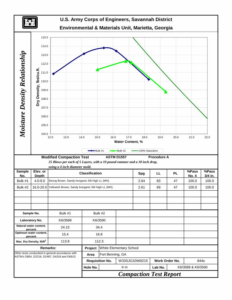
U.S. Army Corps of Engineers, Savannah DistrictM
oist
ure
Den
sity
Rel
atio
nsh
ipEnvironmental & Materials Unit, Marietta, Georgia
104.0
105.0
106.0
107.0
108.0
109.0
110.0
111.0
112.0
113.0
114.0
115.0
12.0 13.0 14.0 15.0 16.0 17.0 18.0 19.0 20.0 21.0 22.0
Dry
Den
sity
, lbs
/cu.
ft.
Water Content, %
Bulk #1 Bulk #2 100% Saturation
using a 4 inch diameter mold.Sample
No.Elev. or Depth Spg LL PL %Pass
No. 4%Pass 3/4 in.
Bulk #1 4.0-8.0 2.64 83 47 100.0 100.0
Bulk #2 16.0-20.0 2.61 69 47 100.0 100.0
Project
Area
Hole No. Lab No.
W33SJG32669215 Work Order No. 844e
Fort Benning, GA
Classification
Strong Brown, Sandy Inorganic Silt High LL (MH).
Yellowish Brown, Sandy Inorganic Silt High LL (MH).
Bulk #2
34.4
16.8
112.3
Procedure A25 Blows per each of 5 Layers, with a 10 pound rammer and a 18 inch drop,
Modified Compaction Test ASTM D1557
Sample No.
Laboratory No.
Natural water content, percent
K6/3589
24.15
15.4
113.8
K6/3590
Optimum water content, percent
Bulk #1
Remarks:Other tests conductted in general accordance with ASTM's D854, D2216, D2487, D4318 and D6913.
Compaction Test Report
White Elementary School
B-16 K6/3589 & K6/3590
Max. Dry Density, lb/ft3
Requisition No.
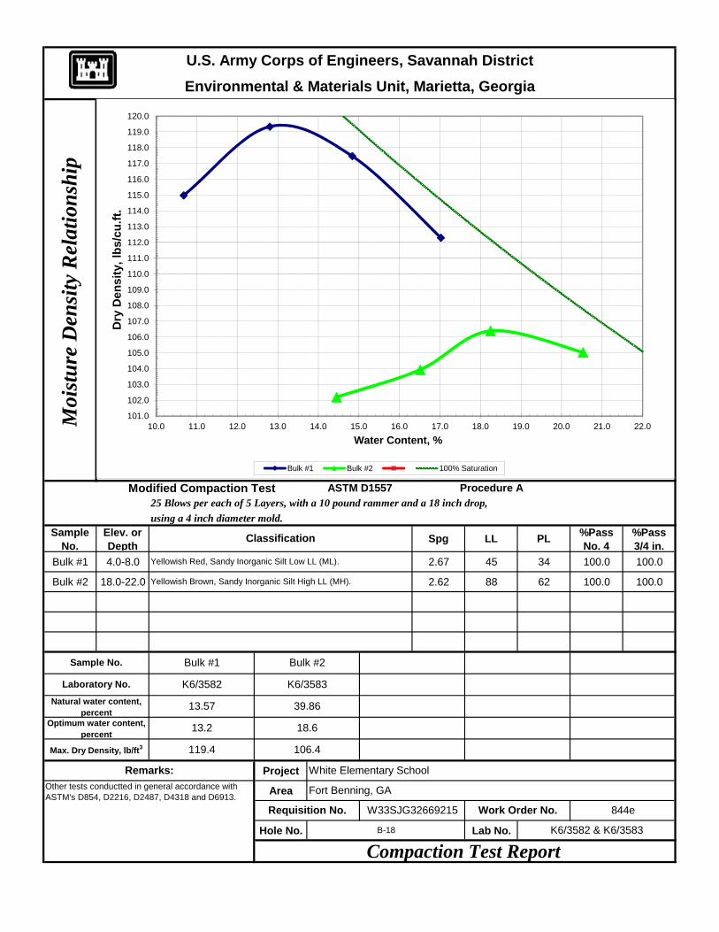
Environmental & Materials Unit, Marietta, GeorgiaU.S. Army Corps of Engineers, Savannah District
Moi
stu
re D
ensi
ty R
elat
ion
ship
101.0
102.0
103.0
104.0
105.0
106.0
107.0
108.0
109.0
110.0
111.0
112.0
113.0
114.0
115.0
116.0
117.0
118.0
119.0
120.0
10.0 11.0 12.0 13.0 14.0 15.0 16.0 17.0 18.0 19.0 20.0 21.0 22.0
Dry
Den
sity
, lbs
/cu.
ft.
Water Content, %
Bulk #1 Bulk #2 100% Saturation
using a 4 inch diameter mold.Sample
No.Elev. or Depth Spg LL PL %Pass
No. 4%Pass 3/4 in.
Bulk #1 4.0-8.0 2.67 45 34 100.0 100.0
Bulk #2 18.0-22.0 2.62 88 62 100.0 100.0
Project
Area
Hole No. Lab No.
Optimum water content, percent
Bulk #1
Remarks:Other tests conductted in general accordance with ASTM's D854, D2216, D2487, D4318 and D6913.
Compaction Test Report
White Elementary School
B-18 K6/3582 & K6/3583
Max. Dry Density, lb/ft3
Requisition No.
K6/3582
13.57
13.2
119.4
K6/3583
Procedure A25 Blows per each of 5 Layers, with a 10 pound rammer and a 18 inch drop,
Modified Compaction Test ASTM D1557
Sample No.
Laboratory No.
Natural water content, percent
W33SJG32669215 Work Order No. 844e
Fort Benning, GA
Classification
Yellowish Red, Sandy Inorganic Silt Low LL (ML).
Yellowish Brown, Sandy Inorganic Silt High LL (MH).
Bulk #2
39.86
18.6
106.4
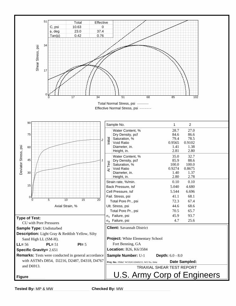
Tested By: MP & MW Checked By: MW
TRIAXIAL SHEAR TEST REPORT
U.S. Army Corp of Engineers
Client: Savannah District
Project: White Elementary School
Fort Benning, GA
Location: B26, K6/3584
Sample Number: U-1 Depth: 6.0 - 8.0
Proj. No.: PR&C W33SJG32669215, WO No. 844e Date Sampled:
Type of Test: CU with Pore Pressures
Sample Type: Undisturbed
Description: Light Gray & Reddish Yellow, Silty
Sand High LL (SM-H).
LL= 56 PI= 5PL= 51
Specific Gravity= 2.651
Remarks: Tests were conducted in general accordance
with ASTM's D854, D2216, D2487, D4318, D4767
and D6913.
Figure
Sample No.
Water Content, %Dry Density, pcfSaturation, %Void RatioDiameter, in.Height, in.Water Content, %Dry Density, pcfSaturation, %Void RatioDiameter, in.Height, in.
Total Pore Pr., psi
Total Pore Pr., psi
Strain rate, %/min.Back Pressure, tsfCell Pressure, tsfFail. Stress, psi
Ult. Stress, psi
s1 Failure, psis3 Failure, psi
Initia
lAt
Tes
t
1
28.784.679.4
0.95651.412.81
35.085.9
100.00.9274
1.402.80
0.105.0405.544
41.172.344.670.5
4.745.9
2
27.086.678.5
0.91021.382.80
32.788.6
100.00.8675
1.372.78
0.104.6806.696
68.167.468.665.7
25.693.7
Dev
iato
r Stre
ss, p
si
0
15
30
45
60
75
90
Axial Strain, %
0 5 10 15 20
1
2
Shea
r Stre
ss, p
si
0
17
34
51
Total Normal Stress, psi Effective Normal Stress, psi
0 17 34 51 68 85 102
C, psi f, deg Tan(f)
Total Effective10.63
23.00.42
037.40.76
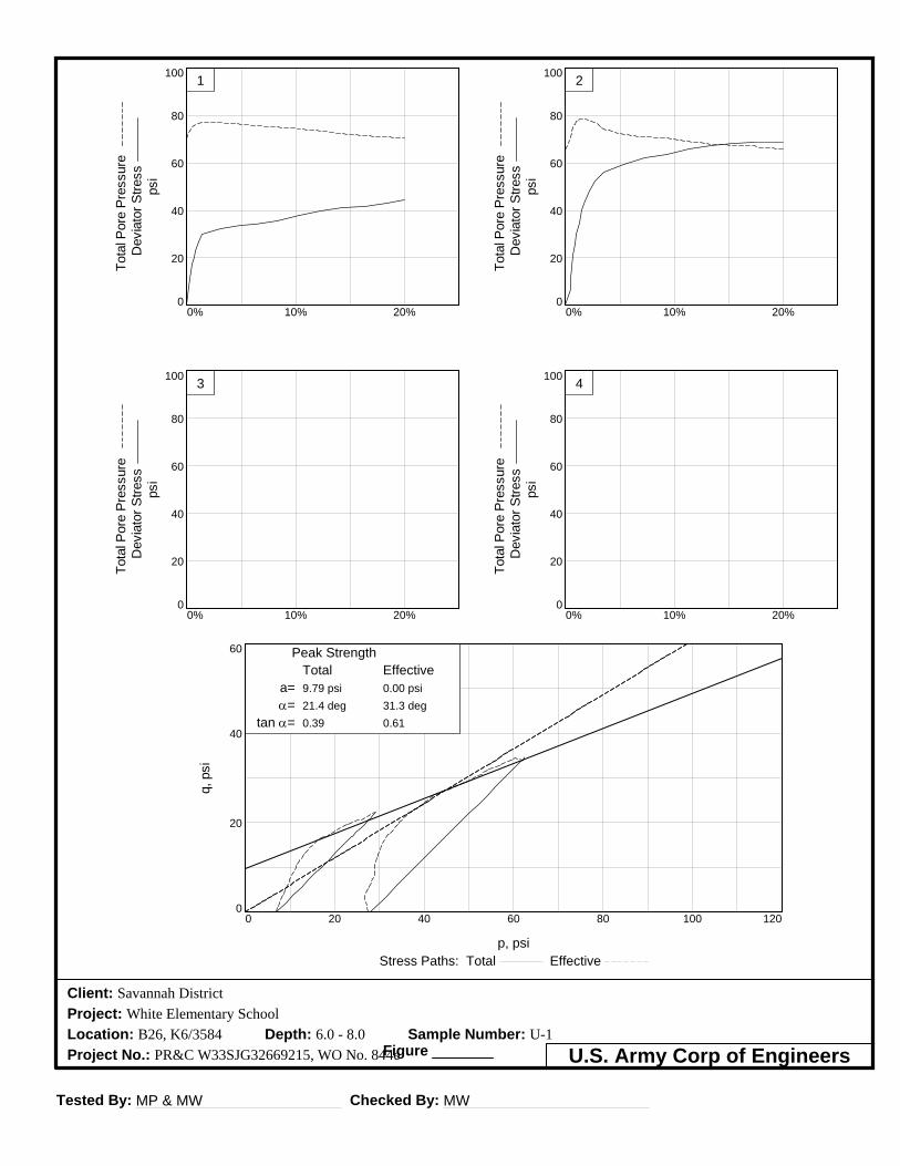
Tested By: MP & MW Checked By: MW
Client: Savannah District
Project: White Elementary School
Location: B26, K6/3584 Depth: 6.0 - 8.0 Sample Number: U-1
Project No.: PR&C W33SJG32669215, WO No. 844eFigure U.S. Army Corp of Engineers
q, p
si
0
20
40
60
p, psiStress Paths: Total Effective
0 20 40 60 80 100 120
Peak StrengthTotal Effective
a=a=
tan a=
9.79 psi21.4 deg0.39
0.00 psi31.3 deg0.61
Tota
l Por
e Pr
essu
re
Dev
iato
r Stre
ss
psi
0
20
40
60
80
100
0% 10% 20%
1
Tota
l Por
e Pr
essu
re
Dev
iato
r Stre
ss
psi
0
20
40
60
80
100
0% 10% 20%
3
Tota
l Por
e Pr
essu
re
Dev
iato
r Stre
ss
psi
0
20
40
60
80
100
0% 10% 20%
2
Tota
l Por
e Pr
essu
re
Dev
iato
r Stre
ss
psi
0
20
40
60
80
100
0% 10% 20%
4
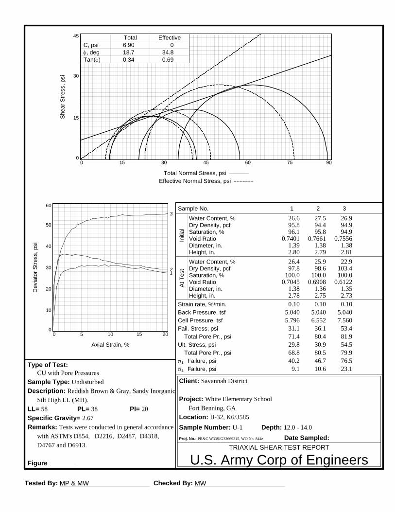
Tested By: MP & MW Checked By: MW
TRIAXIAL SHEAR TEST REPORT
U.S. Army Corp of Engineers
Client: Savannah District
Project: White Elementary School
Fort Benning, GA
Location: B-32, K6/3585
Sample Number: U-1 Depth: 12.0 - 14.0
Proj. No.: PR&C W33SJG32669215, WO No. 844e Date Sampled:
Type of Test: CU with Pore Pressures
Sample Type: Undisturbed
Description: Reddish Brown & Gray, Sandy Inorganic
Silt High LL (MH).
LL= 58 PI= 20PL= 38
Specific Gravity= 2.67
Remarks: Tests were conducted in general accordance
with ASTM's D854, D2216, D2487, D4318,
D4767 and D6913.
Figure
Sample No.
Water Content, %Dry Density, pcfSaturation, %Void RatioDiameter, in.Height, in.Water Content, %Dry Density, pcfSaturation, %Void RatioDiameter, in.Height, in.
Total Pore Pr., psi
Total Pore Pr., psi
Strain rate, %/min.Back Pressure, tsfCell Pressure, tsfFail. Stress, psi
Ult. Stress, psi
s1 Failure, psis3 Failure, psi
Initia
lAt
Tes
t
1
26.695.896.1
0.74011.392.80
26.497.8
100.00.7045
1.382.78
0.105.0405.796
31.171.429.868.8
9.140.2
2
27.594.495.8
0.76611.382.79
25.998.6
100.00.6908
1.362.75
0.105.0406.552
36.180.430.980.5
10.646.7
3
26.994.994.9
0.75561.382.81
22.9103.4100.0
0.61221.352.73
0.105.0407.560
53.481.954.579.9
23.176.5
Dev
iato
r Stre
ss, p
si
0
10
20
30
40
50
60
Axial Strain, %
0 5 10 15 20
12
3
Shea
r Stre
ss, p
si
0
15
30
45
Total Normal Stress, psi Effective Normal Stress, psi
0 15 30 45 60 75 90
C, psi f, deg Tan(f)
Total Effective6.9018.70.34
034.80.69

Tested By: MP & MW Checked By: MW
Client: Savannah District
Project: White Elementary School
Location: B-32, K6/3585 Depth: 12.0 - 14.0 Sample Number: U-1
Project No.: PR&C W33SJG32669215, WO No. 844eFigure U.S. Army Corp of Engineers
q, p
si
0
20
40
60
p, psiStress Paths: Total Effective
0 20 40 60 80 100 120
Peak StrengthTotal Effective
a=a=
tan a=
6.54 psi17.8 deg0.32
0.00 psi29.7 deg0.57
Tota
l Por
e Pr
essu
re
Dev
iato
r Stre
ss
psi
0
20
40
60
80
100
0% 10% 20%
1
Tota
l Por
e Pr
essu
re
Dev
iato
r Stre
ss
psi
0
20
40
60
80
100
0% 10% 20%
3
Tota
l Por
e Pr
essu
re
Dev
iato
r Stre
ss
psi
0
20
40
60
80
100
0% 10% 20%
2
Tota
l Por
e Pr
essu
re
Dev
iato
r Stre
ss
psi
0
20
40
60
80
100
0% 10% 20%
4
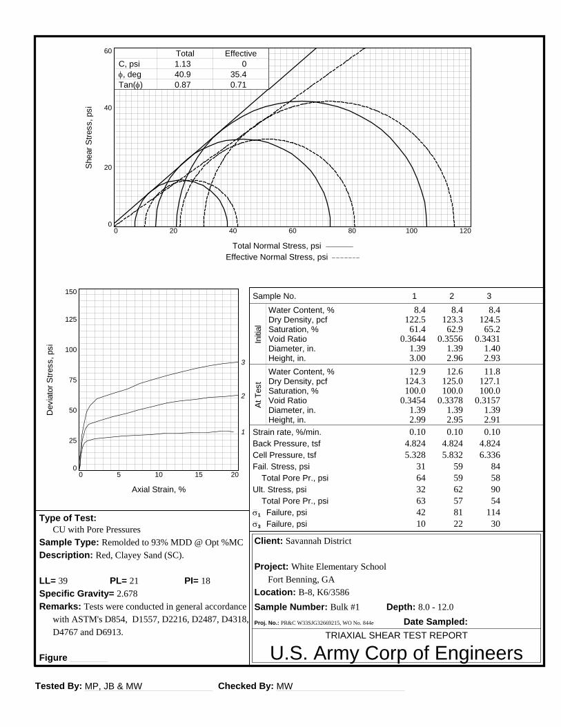
Tested By: MP, JB & MW Checked By: MW
TRIAXIAL SHEAR TEST REPORT
U.S. Army Corp of Engineers
Client: Savannah District
Project: White Elementary School
Fort Benning, GA
Location: B-8, K6/3586
Sample Number: Bulk #1 Depth: 8.0 - 12.0
Proj. No.: PR&C W33SJG32669215, WO No. 844e Date Sampled:
Type of Test: CU with Pore Pressures
Sample Type: Remolded to 93% MDD @ Opt %MC
Description: Red, Clayey Sand (SC).
LL= 39 PI= 18PL= 21
Specific Gravity= 2.678
Remarks: Tests were conducted in general accordance
with ASTM's D854, D1557, D2216, D2487, D4318,
D4767 and D6913.
Figure
Sample No.
Water Content, %Dry Density, pcfSaturation, %Void RatioDiameter, in.Height, in.Water Content, %Dry Density, pcfSaturation, %Void RatioDiameter, in.Height, in.
Total Pore Pr., psi
Total Pore Pr., psi
Strain rate, %/min.Back Pressure, tsfCell Pressure, tsfFail. Stress, psi
Ult. Stress, psi
s1 Failure, psis3 Failure, psi
Initia
lAt
Tes
t
1
8.4122.5
61.40.3644
1.393.00
12.9124.3100.0
0.34541.392.99
0.104.8245.328
31643263
1042
2
8.4123.3
62.90.3556
1.392.96
12.6125.0100.0
0.33781.392.95
0.104.8245.832
59596257
2281
3
8.4124.5
65.20.3431
1.402.93
11.8127.1100.0
0.31571.392.91
0.104.8246.336
84589054
30114
Dev
iato
r Stre
ss, p
si
0
25
50
75
100
125
150
Axial Strain, %
0 5 10 15 20
1
2
3
Shea
r Stre
ss, p
si
0
20
40
60
Total Normal Stress, psi Effective Normal Stress, psi
0 20 40 60 80 100 120
C, psi f, deg Tan(f)
Total Effective1.1340.90.87
035.40.71
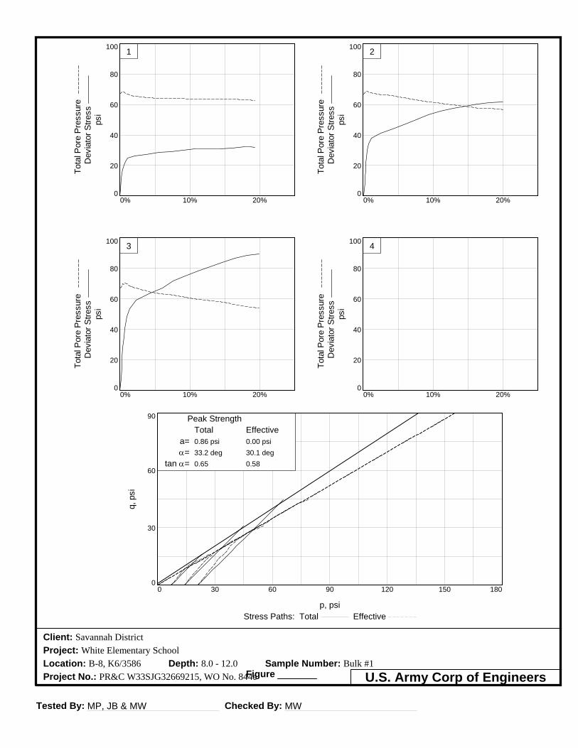
Tested By: MP, JB & MW Checked By: MW
Client: Savannah District
Project: White Elementary School
Location: B-8, K6/3586 Depth: 8.0 - 12.0 Sample Number: Bulk #1
Project No.: PR&C W33SJG32669215, WO No. 844eFigure U.S. Army Corp of Engineers
q, p
si
0
30
60
90
p, psiStress Paths: Total Effective
0 30 60 90 120 150 180
Peak StrengthTotal Effective
a=a=
tan a=
0.86 psi33.2 deg0.65
0.00 psi30.1 deg0.58
Tota
l Por
e Pr
essu
re
Dev
iato
r Stre
ss
psi
0
20
40
60
80
100
0% 10% 20%
1
Tota
l Por
e Pr
essu
re
Dev
iato
r Stre
ss
psi
0
20
40
60
80
100
0% 10% 20%
3
Tota
l Por
e Pr
essu
re
Dev
iato
r Stre
ss
psi
0
20
40
60
80
100
0% 10% 20%
2
Tota
l Por
e Pr
essu
re
Dev
iato
r Stre
ss
psi
0
20
40
60
80
100
0% 10% 20%
4
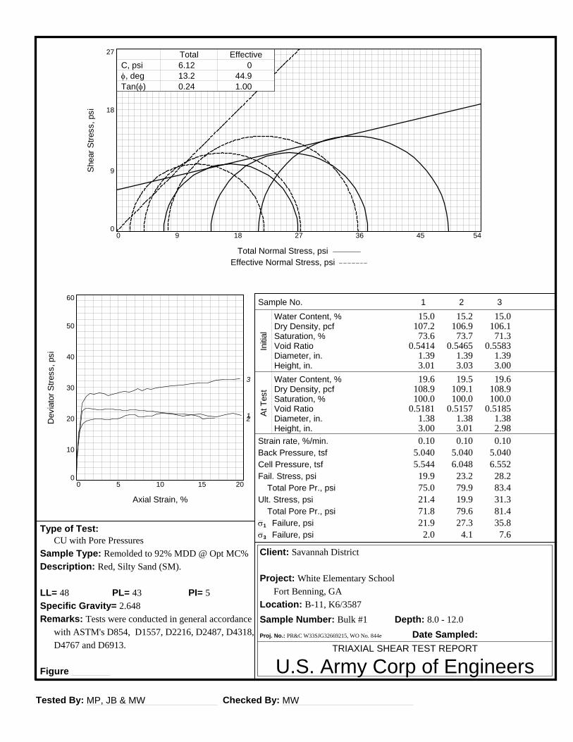
Tested By: MP, JB & MW Checked By: MW
TRIAXIAL SHEAR TEST REPORT
U.S. Army Corp of Engineers
Client: Savannah District
Project: White Elementary School
Fort Benning, GA
Location: B-11, K6/3587
Sample Number: Bulk #1 Depth: 8.0 - 12.0
Proj. No.: PR&C W33SJG32669215, WO No. 844e Date Sampled:
Type of Test: CU with Pore Pressures
Sample Type: Remolded to 92% MDD @ Opt MC%
Description: Red, Silty Sand (SM).
LL= 48 PI= 5PL= 43
Specific Gravity= 2.648
Remarks: Tests were conducted in general accordance
with ASTM's D854, D1557, D2216, D2487, D4318,
D4767 and D6913.
Figure
Sample No.
Water Content, %Dry Density, pcfSaturation, %Void RatioDiameter, in.Height, in.Water Content, %Dry Density, pcfSaturation, %Void RatioDiameter, in.Height, in.
Total Pore Pr., psi
Total Pore Pr., psi
Strain rate, %/min.Back Pressure, tsfCell Pressure, tsfFail. Stress, psi
Ult. Stress, psi
s1 Failure, psis3 Failure, psi
Initia
lAt
Tes
t
1
15.0107.2
73.60.5414
1.393.01
19.6108.9100.0
0.51811.383.00
0.105.0405.544
19.975.021.471.8
2.021.9
2
15.2106.9
73.70.5465
1.393.03
19.5109.1100.0
0.51571.383.01
0.105.0406.048
23.279.919.979.6
4.127.3
3
15.0106.1
71.30.5583
1.393.00
19.6108.9100.0
0.51851.382.98
0.105.0406.552
28.283.431.381.4
7.635.8
Dev
iato
r Stre
ss, p
si
0
10
20
30
40
50
60
Axial Strain, %
0 5 10 15 20
12
3
Shea
r Stre
ss, p
si
0
9
18
27
Total Normal Stress, psi Effective Normal Stress, psi
0 9 18 27 36 45 54
C, psi f, deg Tan(f)
Total Effective6.1213.20.24
044.91.00

Tested By: MP, JB & MW Checked By: MW
Client: Savannah District
Project: White Elementary School
Location: B-11, K6/3587 Depth: 8.0 - 12.0 Sample Number: Bulk #1
Project No.: PR&C W33SJG32669215, WO No. 844eFigure U.S. Army Corp of Engineers
q, p
si
0
8
16
24
p, psiStress Paths: Total Effective
0 8 16 24 32 40 48
Peak StrengthTotal Effective
a=a=
tan a=
5.95 psi12.9 deg0.23
0.00 psi35.2 deg0.71
Tota
l Por
e Pr
essu
re
Dev
iato
r Stre
ss
psi
0
20
40
60
80
100
0% 10% 20%
1
Tota
l Por
e Pr
essu
re
Dev
iato
r Stre
ss
psi
0
20
40
60
80
100
0% 10% 20%
3
Tota
l Por
e Pr
essu
re
Dev
iato
r Stre
ss
psi
0
20
40
60
80
100
0% 10% 20%
2
Tota
l Por
e Pr
essu
re
Dev
iato
r Stre
ss
psi
0
20
40
60
80
100
0% 10% 20%
4
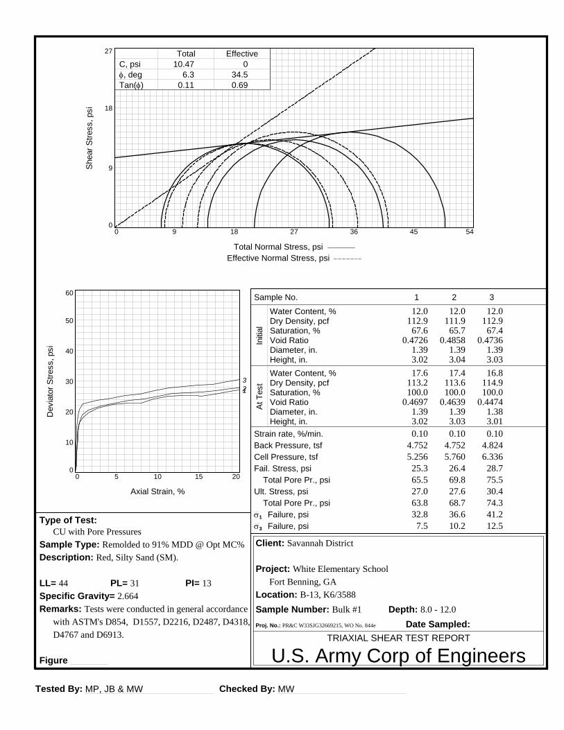
Tested By: MP, JB & MW Checked By: MW
TRIAXIAL SHEAR TEST REPORT
U.S. Army Corp of Engineers
Client: Savannah District
Project: White Elementary School
Fort Benning, GA
Location: B-13, K6/3588
Sample Number: Bulk #1 Depth: 8.0 - 12.0
Proj. No.: PR&C W33SJG32669215, WO No. 844e Date Sampled:
Type of Test: CU with Pore Pressures
Sample Type: Remolded to 91% MDD @ Opt MC%
Description: Red, Silty Sand (SM).
LL= 44 PI= 13PL= 31
Specific Gravity= 2.664
Remarks: Tests were conducted in general accordance
with ASTM's D854, D1557, D2216, D2487, D4318,
D4767 and D6913.
Figure
Sample No.
Water Content, %Dry Density, pcfSaturation, %Void RatioDiameter, in.Height, in.Water Content, %Dry Density, pcfSaturation, %Void RatioDiameter, in.Height, in.
Total Pore Pr., psi
Total Pore Pr., psi
Strain rate, %/min.Back Pressure, tsfCell Pressure, tsfFail. Stress, psi
Ult. Stress, psi
s1 Failure, psis3 Failure, psi
Initia
lAt
Tes
t
1
12.0112.9
67.60.4726
1.393.02
17.6113.2100.0
0.46971.393.02
0.104.7525.256
25.365.527.063.8
7.532.8
2
12.0111.9
65.70.4858
1.393.04
17.4113.6100.0
0.46391.393.03
0.104.7525.760
26.469.827.668.7
10.236.6
3
12.0112.9
67.40.4736
1.393.03
16.8114.9100.0
0.44741.383.01
0.104.8246.336
28.775.530.474.3
12.541.2
Dev
iato
r Stre
ss, p
si
0
10
20
30
40
50
60
Axial Strain, %
0 5 10 15 20
123
Shea
r Stre
ss, p
si
0
9
18
27
Total Normal Stress, psi Effective Normal Stress, psi
0 9 18 27 36 45 54
C, psi f, deg Tan(f)
Total Effective10.47
6.30.11
034.50.69
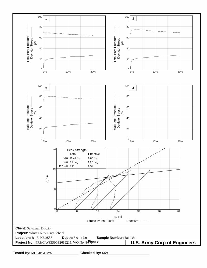
Tested By: MP, JB & MW Checked By: MW
Client: Savannah District
Project: White Elementary School
Location: B-13, K6/3588 Depth: 8.0 - 12.0 Sample Number: Bulk #1
Project No.: PR&C W33SJG32669215, WO No. 844eFigure U.S. Army Corp of Engineers
q, p
si
0
8
16
24
p, psiStress Paths: Total Effective
0 8 16 24 32 40 48
Peak StrengthTotal Effective
a=a=
tan a=
10.41 psi6.2 deg0.11
0.00 psi29.6 deg0.57
Tota
l Por
e Pr
essu
re
Dev
iato
r Stre
ss
psi
0
20
40
60
80
100
0% 10% 20%
1
Tota
l Por
e Pr
essu
re
Dev
iato
r Stre
ss
psi
0
20
40
60
80
100
0% 10% 20%
3
Tota
l Por
e Pr
essu
re
Dev
iato
r Stre
ss
psi
0
20
40
60
80
100
0% 10% 20%
2
Tota
l Por
e Pr
essu
re
Dev
iato
r Stre
ss
psi
0
20
40
60
80
100
0% 10% 20%
4
-
APPENDIX D US Department of Agriculture Soil Resource Reports
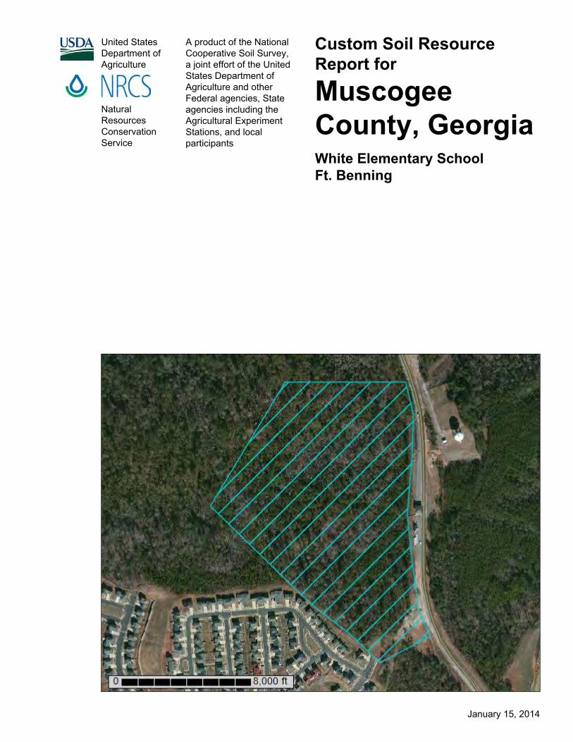
United StatesDepartment ofAgriculture
A product of the NationalCooperative Soil Survey,a joint effort of the UnitedStates Department ofAgriculture and otherFederal agencies, Stateagencies including theAgricultural ExperimentStations, and localparticipants
Custom Soil ResourceReport for
MuscogeeCounty, GeorgiaWhite Elementary SchoolFt. Benning
NaturalResourcesConservationService
January 15, 2014

PrefaceSoil surveys contain information that affects land use planning in survey areas. Theyhighlight soil limitations that affect various land uses and provide information aboutthe properties of the soils in the survey areas. Soil surveys are designed for manydifferent users, including farmers, ranchers, foresters, agronomists, urban planners,community officials, engineers, developers, builders, and home buyers. Also,conservationists, teachers, students, and specialists in recreation, waste disposal,and pollution control can use the surveys to help them understand, protect, or enhancethe environment.
Various land use regulations of Federal, State, and local governments may imposespecial restrictions on land use or land treatment. Soil surveys identify soil propertiesthat are used in making various land use or land treatment decisions. The informationis intended to help the land users identify and reduce the effects of soil limitations onvarious land uses. The landowner or user is responsible for identifying and complyingwith existing laws and regulations.
Although soil survey information can be used for general farm, local, and wider areaplanning, onsite investigation is needed to supplement this information in some cases.Examples include soil quality assessments (http://www.nrcs.usda.gov/wps/portal/nrcs/main/soils/health/) and certain conservation and engineering applications. Formore detailed information, contact your local USDA Service Center (http://offices.sc.egov.usda.gov/locator/app?agency=nrcs) or your NRCS State SoilScientist (http://www.nrcs.usda.gov/wps/portal/nrcs/detail/soils/contactus/?cid=nrcs142p2_053951).
Great differences in soil properties can occur within short distances. Some soils areseasonally wet or subject to flooding. Some are too unstable to be used as afoundation for buildings or roads. Clayey or wet soils are poorly suited to use as septictank absorption fields. A high water table makes a soil poorly suited to basements orunderground installations.
The National Cooperative Soil Survey is a joint effort of the United States Departmentof Agriculture and other Federal agencies, State agencies including the AgriculturalExperiment Stations, and local agencies. The Natural Resources ConservationService (NRCS) has leadership for the Federal part of the National Cooperative SoilSurvey.
Information about soils is updated periodically. Updated information is availablethrough the NRCS Web Soil Survey, the site for official soil survey information.
The U.S. Department of Agriculture (USDA) prohibits discrimination in all its programsand activities on the basis of race, color, national origin, age, disability, and whereapplicable, sex, marital status, familial status, parental status, religion, sexualorientation, genetic information, political beliefs, reprisal, or because all or a part of anindividual's income is derived from any public assistance program. (Not all prohibitedbases apply to all programs.) Persons with disabilities who require alternative means
2

for communication of program information (Braille, large print, audiotape, etc.) shouldcontact USDA's TARGET Center at (202) 720-2600 (voice and TDD). To file acomplaint of discrimination, write to USDA, Director, Office of Civil Rights, 1400Independence Avenue, S.W., Washington, D.C. 20250-9410 or call (800) 795-3272(voice) or (202) 720-6382 (TDD). USDA is an equal opportunity provider andemployer.
3
ContentsPreface....................................................................................................................2How Soil Surveys Are Made..................................................................................5Soil Map..................................................................................................................7
Soil Map................................................................................................................8Legend..................................................................................................................9Map Unit Legend................................................................................................10Map Unit Descriptions........................................................................................10
Muscogee County, Georgia............................................................................12Bh—Bibb sandy loam..................................................................................12EPE—Esto and Troup loamy sands, 12 to 25 percent slopes....................12OrC—Orangeburg loamy sand, 5 to 8 percent slopes................................14Ua—Udorthents, loamy...............................................................................15
References............................................................................................................16
4

How Soil Surveys Are MadeSoil surveys are made to provide information about the soils and miscellaneous areasin a specific area. They include a description of the soils and miscellaneous areas andtheir location on the landscape and tables that show soil properties and limitationsaffecting various uses. Soil scientists observed the steepness, length, and shape ofthe slopes; the general pattern of drainage; the kinds of crops and native plants; andthe kinds of bedrock. They observed and described many soil profiles. A soil profile isthe sequence of natural layers, or horizons, in a soil. The profile extends from thesurface down into the unconsolidated material in which the soil formed or from thesurface down to bedrock. The unconsolidated material is devoid of roots and otherliving organisms and has not been changed by other biological activity.
Currently, soils are mapped according to the boundaries of major land resource areas(MLRAs). MLRAs are geographically associated land resource units that sharecommon characteristics related to physiography, geology, climate, water resources,soils, biological resources, and land uses (USDA, 2006). Soil survey areas typicallyconsist of parts of one or more MLRA.
The soils and miscellaneous areas in a survey area occur in an orderly pattern that isrelated to the geology, landforms, relief, climate, and natural vegetation of the area.Each kind of soil and miscellaneous area is associated with a particular kind oflandform or with a segment of the landform. By observing the soils and miscellaneousareas in the survey area and relating their position to specific segments of thelandform, a soil scientist develops a concept, or model, of how they were formed. Thus,during mapping, this model enables the soil scientist to predict with a considerabledegree of accuracy the kind of soil or miscellaneous area at a specific location on thelandscape.
Commonly, individual soils on the landscape merge into one another as theircharacteristics gradually change. To construct an accurate soil map, however, soilscientists must determine the boundaries between the soils. They can observe onlya limited number of soil profiles. Nevertheless, these observations, supplemented byan understanding of the soil-vegetation-landscape relationship, are sufficient to verifypredictions of the kinds of soil in an area and to determine the boundaries.
Soil scientists recorded the characteristics of the soil profiles that they studied. Theynoted soil color, texture, size and shape of soil aggregates, kind and amount of rockfragments, distribution of plant roots, reaction, and other features that enable them toidentify soils. After describing the soils in the survey area and determining theirproperties, the soil scientists assigned the soils to taxonomic classes (units).Taxonomic classes are concepts. Each taxonomic class has a set of soilcharacteristics with precisely defined limits. The classes are used as a basis forcomparison to classify soils systematically. Soil taxonomy, the system of taxonomicclassification used in the United States, is based mainly on the kind and character ofsoil properties and the arrangement of horizons within the profile. After the soilscientists classified and named the soils in the survey area, they compared the
5

individual soils with similar soils in the same taxonomic class in other areas so thatthey could confirm data and assemble additional data based on experience andresearch.
The objective of soil mapping is not to delineate pure map unit components; theobjective is to separate the landscape into landforms or landform segments that havesimilar use and management requirements. Each map unit is defined by a uniquecombination of soil components and/or miscellaneous areas in predictableproportions. Some components may be highly contrasting to the other components ofthe map unit. The presence of minor components in a map unit in no way diminishesthe usefulness or accuracy of the data. The delineation of such landforms andlandform segments on the map provides sufficient information for the development ofresource plans. If intensive use of small areas is planned, onsite investigation isneeded to define and locate the soils and miscellaneous areas.
Soil scientists make many field observations in the process of producing a soil map.The frequency of observation is dependent upon several factors, including scale ofmapping, intensity of mapping, design of map units, complexity of the landscape, andexperience of the soil scientist. Observations are made to test and refine the soil-landscape model and predictions and to verify the classification of the soils at specificlocations. Once the soil-landscape model is refined, a significantly smaller number ofmeasurements of individual soil properties are made and recorded. Thesemeasurements may include field measurements, such as those for color, depth tobedrock, and texture, and laboratory measurements, such as those for content ofsand, silt, clay, salt, and other components. Properties of each soil typically vary fromone point to another across the landscape.
Observations for map unit components are aggregated to develop ranges ofcharacteristics for the components. The aggregated values are presented. Directmeasurements do not exist for every property presented for every map unitcomponent. Values for some properties are estimated from combinations of otherproperties.
While a soil survey is in progress, samples of some of the soils in the area generallyare collected for laboratory analyses and for engineering tests. Soil scientists interpretthe data from these analyses and tests as well as the field-observed characteristicsand the soil properties to determine the expected behavior of the soils under differentuses. Interpretations for all of the soils are field tested through observation of the soilsin different uses and under different levels of management. Some interpretations aremodified to fit local conditions, and some new interpretations are developed to meetlocal needs. Data are assembled from other sources, such as research information,production records, and field experience of specialists. For example, data on cropyields under defined levels of management are assembled from farm records and fromfield or plot experiments on the same kinds of soil.
Predictions about soil behavior are based not only on soil properties but also on suchvariables as climate and biological activity. Soil conditions are predictable over longperiods of time, but they are not predictable from year to year. For example, soilscientists can predict with a fairly high degree of accuracy that a given soil will havea high water table within certain depths in most years, but they cannot predict that ahigh water table will always be at a specific level in the soil on a specific date.
After soil scientists located and identified the significant natural bodies of soil in thesurvey area, they drew the boundaries of these bodies on aerial photographs andidentified each as a specific map unit. Aerial photographs show trees, buildings, fields,roads, and rivers, all of which help in locating boundaries accurately.
Custom Soil Resource Report
6

Soil MapThe soil map section includes the soil map for the defined area of interest, a list of soilmap units on the map and extent of each map unit, and cartographic symbolsdisplayed on the map. Also presented are various metadata about data used toproduce the map, and a description of each soil map unit.
7
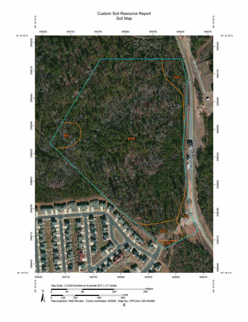
8
Custom Soil Resource ReportSoil Map
3588
640
3588
710
3588
780
3588
850
3588
920
3588
990
3589
060
3589
130
3589
200
3588
640
3588
710
3588
780
3588
850
3588
920
3588
990
3589
060
3589
130
3589
200
695650 695720 695790 695860 695930 696000 696070
695650 695720 695790 695860 695930 696000 696070
32° 25' 22'' N84
° 5
5' 1
0'' W
32° 25' 22'' N
84° 5
4' 5
2'' W
32° 25' 2'' N
84° 5
5' 1
0'' W
32° 25' 2'' N
84° 5
4' 5
2'' W
N
Map projection: Web Mercator Corner coordinates: WGS84 Edge tics: UTM Zone 16N WGS840 100 200 400 600
Feet0 40 80 160 240
MetersMap Scale: 1:2,930 if printed on A portrait (8.5" x 11") sheet.
MAP LEGEND MAP INFORMATION
Area of Interest (AOI)Area of Interest (AOI)
SoilsSoil Map Unit Polygons
Soil Map Unit Lines
Soil Map Unit Points
Special Point FeaturesBlowout
Borrow Pit
Clay Spot
Closed Depression
Gravel Pit
Gravelly Spot
Landfill
Lava Flow
Marsh or swamp
Mine or Quarry
Miscellaneous Water
Perennial Water
Rock Outcrop
Saline Spot
Sandy Spot
Severely Eroded Spot
Sinkhole
Slide or Slip
Sodic Spot
Spoil Area
Stony Spot
Very Stony Spot
Wet Spot
Other
Special Line Features
Water FeaturesStreams and Canals
TransportationRails
Interstate Highways
US Routes
Major Roads
Local Roads
BackgroundAerial Photography
The soil surveys that comprise your AOI were mapped at 1:15,800.
Warning: Soil Map may not be valid at this scale.
Enlargement of maps beyond the scale of mapping can causemisunderstanding of the detail of mapping and accuracy of soil lineplacement. The maps do not show the small areas of contrastingsoils that could have been shown at a more detailed scale.
Please rely on the bar scale on each map sheet for mapmeasurements.
Source of Map: Natural Resources Conservation ServiceWeb Soil Survey URL: http://websoilsurvey.nrcs.usda.govCoordinate System: Web Mercator (EPSG:3857)
Maps from the Web Soil Survey are based on the Web Mercatorprojection, which preserves direction and shape but distortsdistance and area. A projection that preserves area, such as theAlbers equal-area conic projection, should be used if more accuratecalculations of distance or area are required.
This product is generated from the USDA-NRCS certified data as ofthe version date(s) listed below.
Soil Survey Area: Muscogee County, GeorgiaSurvey Area Data: Version 8, Dec 21, 2013
Soil map units are labeled (as space allows) for map scales 1:50,000or larger.
Date(s) aerial images were photographed: Apr 4, 2010—Jan 21,2011
The orthophoto or other base map on which the soil lines werecompiled and digitized probably differs from the backgroundimagery displayed on these maps. As a result, some minor shiftingof map unit boundaries may be evident.
Custom Soil Resource Report
9
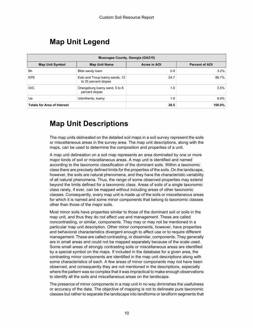
Map Unit Legend
Muscogee County, Georgia (GA215)
Map Unit Symbol Map Unit Name Acres in AOI Percent of AOI
Bh Bibb sandy loam 0.9 3.2%
EPE Esto and Troup loamy sands, 12to 25 percent slopes
24.7 86.7%
OrC Orangeburg loamy sand, 5 to 8percent slopes
1.0 3.5%
Ua Udorthents, loamy 1.9 6.6%
Totals for Area of Interest 28.5 100.0%
Map Unit DescriptionsThe map units delineated on the detailed soil maps in a soil survey represent the soilsor miscellaneous areas in the survey area. The map unit descriptions, along with themaps, can be used to determine the composition and properties of a unit.
A map unit delineation on a soil map represents an area dominated by one or moremajor kinds of soil or miscellaneous areas. A map unit is identified and namedaccording to the taxonomic classification of the dominant soils. Within a taxonomicclass there are precisely defined limits for the properties of the soils. On the landscape,however, the soils are natural phenomena, and they have the characteristic variabilityof all natural phenomena. Thus, the range of some observed properties may extendbeyond the limits defined for a taxonomic class. Areas of soils of a single taxonomicclass rarely, if ever, can be mapped without including areas of other taxonomicclasses. Consequently, every map unit is made up of the soils or miscellaneous areasfor which it is named and some minor components that belong to taxonomic classesother than those of the major soils.
Most minor soils have properties similar to those of the dominant soil or soils in themap unit, and thus they do not affect use and management. These are callednoncontrasting, or similar, components. They may or may not be mentioned in aparticular map unit description. Other minor components, however, have propertiesand behavioral characteristics divergent enough to affect use or to require differentmanagement. These are called contrasting, or dissimilar, components. They generallyare in small areas and could not be mapped separately because of the scale used.Some small areas of strongly contrasting soils or miscellaneous areas are identifiedby a special symbol on the maps. If included in the database for a given area, thecontrasting minor components are identified in the map unit descriptions along withsome characteristics of each. A few areas of minor components may not have beenobserved, and consequently they are not mentioned in the descriptions, especiallywhere the pattern was so complex that it was impractical to make enough observationsto identify all the soils and miscellaneous areas on the landscape.
The presence of minor components in a map unit in no way diminishes the usefulnessor accuracy of the data. The objective of mapping is not to delineate pure taxonomicclasses but rather to separate the landscape into landforms or landform segments that
Custom Soil Resource Report
10

have similar use and management requirements. The delineation of such segmentson the map provides sufficient information for the development of resource plans. Ifintensive use of small areas is planned, however, onsite investigation is needed todefine and locate the soils and miscellaneous areas.
An identifying symbol precedes the map unit name in the map unit descriptions. Eachdescription includes general facts about the unit and gives important soil propertiesand qualities.
Soils that have profiles that are almost alike make up a soil series. Except fordifferences in texture of the surface layer, all the soils of a series have major horizonsthat are similar in composition, thickness, and arrangement.
Soils of one series can differ in texture of the surface layer, slope, stoniness, salinity,degree of erosion, and other characteristics that affect their use. On the basis of suchdifferences, a soil series is divided into soil phases. Most of the areas shown on thedetailed soil maps are phases of soil series. The name of a soil phase commonlyindicates a feature that affects use or management. For example, Alpha silt loam, 0to 2 percent slopes, is a phase of the Alpha series.
Some map units are made up of two or more major soils or miscellaneous areas.These map units are complexes, associations, or undifferentiated groups.
A complex consists of two or more soils or miscellaneous areas in such an intricatepattern or in such small areas that they cannot be shown separately on the maps. Thepattern and proportion of the soils or miscellaneous areas are somewhat similar in allareas. Alpha-Beta complex, 0 to 6 percent slopes, is an example.
An association is made up of two or more geographically associated soils ormiscellaneous areas that are shown as one unit on the maps. Because of present oranticipated uses of the map units in the survey area, it was not considered practicalor necessary to map the soils or miscellaneous areas separately. The pattern andrelative proportion of the soils or miscellaneous areas are somewhat similar. Alpha-Beta association, 0 to 2 percent slopes, is an example.
An undifferentiated group is made up of two or more soils or miscellaneous areas thatcould be mapped individually but are mapped as one unit because similarinterpretations can be made for use and management. The pattern and proportion ofthe soils or miscellaneous areas in a mapped area are not uniform. An area can bemade up of only one of the major soils or miscellaneous areas, or it can be made upof all of them. Alpha and Beta soils, 0 to 2 percent slopes, is an example.
Some surveys include miscellaneous areas. Such areas have little or no soil materialand support little or no vegetation. Rock outcrop is an example.
Custom Soil Resource Report
11
Muscogee County, Georgia
Bh—Bibb sandy loam
Map Unit SettingElevation: 50 to 450 feetMean annual precipitation: 40 to 60 inchesMean annual air temperature: 59 to 72 degrees FFrost-free period: 200 to 240 days
Map Unit CompositionBibb and similar soils: 100 percent
Description of Bibb
SettingLandform: Flood plainsDown-slope shape: LinearAcross-slope shape: LinearParent material: Alluvium
Properties and qualitiesSlope: 0 to 2 percentDepth to restrictive feature: More than 80 inchesDrainage class: Poorly drainedCapacity of the most limiting layer to transmit water (Ksat): Moderately high to high
(0.57 to 1.98 in/hr)Depth to water table: About 6 to 12 inchesFrequency of flooding: FrequentFrequency of ponding: NoneAvailable water capacity: Moderate (about 9.0 inches)
Interpretive groupsFarmland classification: Not prime farmlandLand capability (nonirrigated): 5wHydrologic Soil Group: B/D
Typical profile0 to 17 inches: Sandy loam17 to 60 inches: Sandy loam
EPE—Esto and Troup loamy sands, 12 to 25 percent slopes
Map Unit SettingElevation: 150 to 450 feetMean annual precipitation: 48 to 64 inchesMean annual air temperature: 63 to 66 degrees FFrost-free period: 220 to 240 days
Map Unit CompositionEsto and similar soils: 75 percent
Custom Soil Resource Report
12
Troup and similar soils: 25 percent
Description of Esto
SettingLandform: HillsLandform position (two-dimensional): BackslopeLandform position (three-dimensional): Side slopeDown-slope shape: LinearAcross-slope shape: LinearParent material: Marine deposits
Properties and qualitiesSlope: 12 to 15 percentDepth to restrictive feature: More than 80 inchesDrainage class: Well drainedCapacity of the most limiting layer to transmit water (Ksat): Moderately low to
moderately high (0.06 to 0.20 in/hr)Depth to water table: More than 80 inchesFrequency of flooding: NoneFrequency of ponding: NoneAvailable water capacity: Moderate (about 8.3 inches)
Interpretive groupsFarmland classification: Not prime farmlandLand capability (nonirrigated): 6eHydrologic Soil Group: C
Typical profile0 to 9 inches: Loamy sand9 to 60 inches: Clay
Description of Troup
SettingLandform: HillsLandform position (two-dimensional): BackslopeLandform position (three-dimensional): Side slopeDown-slope shape: LinearAcross-slope shape: LinearParent material: Marine deposits
Properties and qualitiesSlope: 12 to 25 percentDepth to restrictive feature: More than 80 inchesDrainage class: Somewhat excessively drainedCapacity of the most limiting layer to transmit water (Ksat): Moderately high to high
(0.57 to 1.98 in/hr)Depth to water table: More than 80 inchesFrequency of flooding: NoneFrequency of ponding: NoneAvailable water capacity: Moderate (about 6.2 inches)
Interpretive groupsFarmland classification: Not prime farmlandLand capability (nonirrigated): 7eHydrologic Soil Group: A
Custom Soil Resource Report
13
Typical profile0 to 50 inches: Loamy sand50 to 80 inches: Sandy clay loam
OrC—Orangeburg loamy sand, 5 to 8 percent slopes
Map Unit SettingElevation: 170 to 500 feetMean annual precipitation: 42 to 53 inchesMean annual air temperature: 63 to 68 degrees FFrost-free period: 215 to 270 days
Map Unit CompositionOrangeburg and similar soils: 100 percent
Description of Orangeburg
SettingLandform: HillsLandform position (two-dimensional): Backslope, shoulderLandform position (three-dimensional): Side slopeDown-slope shape: ConvexAcross-slope shape: LinearParent material: Marine deposits
Properties and qualitiesSlope: 5 to 8 percentDepth to restrictive feature: More than 80 inchesDrainage class: Well drainedCapacity of the most limiting layer to transmit water (Ksat): Moderately high to high
(0.57 to 1.98 in/hr)Depth to water table: More than 80 inchesFrequency of flooding: NoneFrequency of ponding: NoneAvailable water capacity: Moderate (about 7.3 inches)
Interpretive groupsFarmland classification: All areas are prime farmlandLand capability (nonirrigated): 3eHydrologic Soil Group: B
Typical profile0 to 8 inches: Loamy sand8 to 13 inches: Sandy loam13 to 46 inches: Sandy clay loam46 to 62 inches: Sandy clay loam
Custom Soil Resource Report
14

Ua—Udorthents, loamy
Map Unit CompositionUdorthents and similar soils: 100 percent
Description of Udorthents
Properties and qualitiesDepth to restrictive feature: More than 80 inchesDepth to water table: More than 80 inchesFrequency of flooding: NoneFrequency of ponding: None
Custom Soil Resource Report
15

ReferencesAmerican Association of State Highway and Transportation Officials (AASHTO). 2004.Standard specifications for transportation materials and methods of sampling andtesting. 24th edition.
American Society for Testing and Materials (ASTM). 2005. Standard classification ofsoils for engineering purposes. ASTM Standard D2487-00.
Cowardin, L.M., V. Carter, F.C. Golet, and E.T. LaRoe. 1979. Classification ofwetlands and deep-water habitats of the United States. U.S. Fish and Wildlife ServiceFWS/OBS-79/31.
Federal Register. July 13, 1994. Changes in hydric soils of the United States.
Federal Register. September 18, 2002. Hydric soils of the United States.
Hurt, G.W., and L.M. Vasilas, editors. Version 6.0, 2006. Field indicators of hydric soilsin the United States.
National Research Council. 1995. Wetlands: Characteristics and boundaries.
Soil Survey Division Staff. 1993. Soil survey manual. Soil Conservation Service. U.S.Department of Agriculture Handbook 18. http://www.nrcs.usda.gov/wps/portal/nrcs/detail/national/soils/?cid=nrcs142p2_054262
Soil Survey Staff. 1999. Soil taxonomy: A basic system of soil classification for makingand interpreting soil surveys. 2nd edition. Natural Resources Conservation Service,U.S. Department of Agriculture Handbook 436. http://www.nrcs.usda.gov/wps/portal/nrcs/detail/national/soils/?cid=nrcs142p2_053577
Soil Survey Staff. 2010. Keys to soil taxonomy. 11th edition. U.S. Department ofAgriculture, Natural Resources Conservation Service. http://www.nrcs.usda.gov/wps/portal/nrcs/detail/national/soils/?cid=nrcs142p2_053580
Tiner, R.W., Jr. 1985. Wetlands of Delaware. U.S. Fish and Wildlife Service andDelaware Department of Natural Resources and Environmental Control, WetlandsSection.
United States Army Corps of Engineers, Environmental Laboratory. 1987. Corps ofEngineers wetlands delineation manual. Waterways Experiment Station TechnicalReport Y-87-1.
United States Department of Agriculture, Natural Resources Conservation Service.National forestry manual. http://www.nrcs.usda.gov/wps/portal/nrcs/main/national/landuse/forestry/pub/
United States Department of Agriculture, Natural Resources Conservation Service.National range and pasture handbook. http://www.nrcs.usda.gov/wps/portal/nrcs/detail/national/landuse/rangepasture/?cid=stelprdb1043084
16

United States Department of Agriculture, Natural Resources Conservation Service.National soil survey handbook, title 430-VI. http://www.nrcs.usda.gov/wps/portal/nrcs/detail/soils/scientists/?cid=nrcs142p2_054242
United States Department of Agriculture, Natural Resources Conservation Service.2006. Land resource regions and major land resource areas of the United States, theCaribbean, and the Pacific Basin. U.S. Department of Agriculture Handbook 296.http://www.nrcs.usda.gov/wps/portal/nrcs/detail/national/soils/?cid=nrcs142p2_053624
United States Department of Agriculture, Soil Conservation Service. 1961. Landcapability classification. U.S. Department of Agriculture Handbook 210. http://www.nrcs.usda.gov/Internet/FSE_DOCUMENTS/nrcs142p2_052290.pdf
Custom Soil Resource Report
17

-
APPENDIX E One-Point and Two-Point Compaction Method

Compaction Control For fine grained (clayey and silty) soils and for sands with appreciable fines such that normal shaped compaction curves are obtained, results of all compaction tests shall be plotted on a common plot as a family of curves. For each field density test performed, a one-point compaction test, with additional points as needed, shall be performed on the same material on which the field density test was conducted. The one-point compaction test shall be performed on the dry side of the optimum moisture content. For comparison of field density data to the proper laboratory compaction test results, the procedures for the one-point and/or two-point compaction control methods as described in paragraph Compaction Procedure, shall be used. Compaction curves plotted on the family of curves shall be of such a scale that the optimum moisture content can be interpreted to the nearest 0.1 percent and the maximum dry density can be interpreted to the nearest 0.1 pcf (or 2 kg/m3). When a one-point test plots outside the range of the family of curves, an additional five-point compaction test shall be performed. Compaction Procedure General The following paragraphs describe methods of relating field density data to desired or specified values. Compaction control of soils requires comparison of fill water content and/or dry density values obtained in field density tests with optimum water content and/or maximum dry density. At a minimum, control shall be in accordance with the One-Point Compaction Method. Where conditions require, the Two-Point Compaction Method shall be used. One-Point Compaction Method The material from the field density test is allowed to dry to a water content on the dry side of estimated optimum, and then compacted using the same equipment and procedures used in the five-point compaction test. Thorough mixing is required to obtain uniform drying; otherwise, results obtained may be erroneous. The water content and dry density of the compacted sample are determined and then used to estimate its optimum water content and maximum dry density as illustrated in Figure 1 at the end of this section. In Figure 1, the line of optimums is well defined and the compaction curves are approximately parallel to each other, consequently, the one-point compaction method could be used with a relatively high degree of confidence. However, in Figure 2 at the end of this section, the curves are not parallel to each other and in several instances will cross if extended on the dry side. Consequently, the correct curve cannot be determined from the one-point method; therefore, the two-point compaction method should be used. The one-point method should be used only when the data define a relatively good line of optimums. Two-Point Compaction Method

In the two-point test, one sample of material from the location of the field density test is compacted at the fill water content if thought to be at or on the dry side of optimum water content (otherwise, reduced by drying to this condition) using the same equipment and procedures used in the five-point compaction test. A second sample of material is allowed to dry back about 2 to 3 percentage points dry of the water content of the first sample and then compacted in the same manner. At least one point shall fall within 3 percent of the line of optimums. After compaction, the water contents and dry densities for the two samples are determined. The results are used to identify the appropriate compaction curve for the material being tested as shown in Figure 2 at the end of this section. The data shown in Figure 2 warrant the use of the two-point compaction test because the five-point compaction curves are not parallel. Using point A only, as in the one-point test method, would result in appreciable error as the shape of the curve would not be defined. The estimated compaction curve can be more accurately defined by two compaction points.
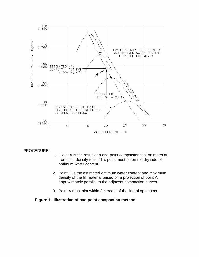
PROCEDURE: 1. Point A is the result of a one-point compaction test on material
from field density test. This point must be on the dry side of optimum water content.
2. Point O is the estimated optimum water content and maximum
density of the fill material based on a projection of point A approximately parallel to the adjacent compaction curves.
3. Point A must plot within 3 percent of the line of optimums.
Figure 1. Illustration of one-point compaction method.
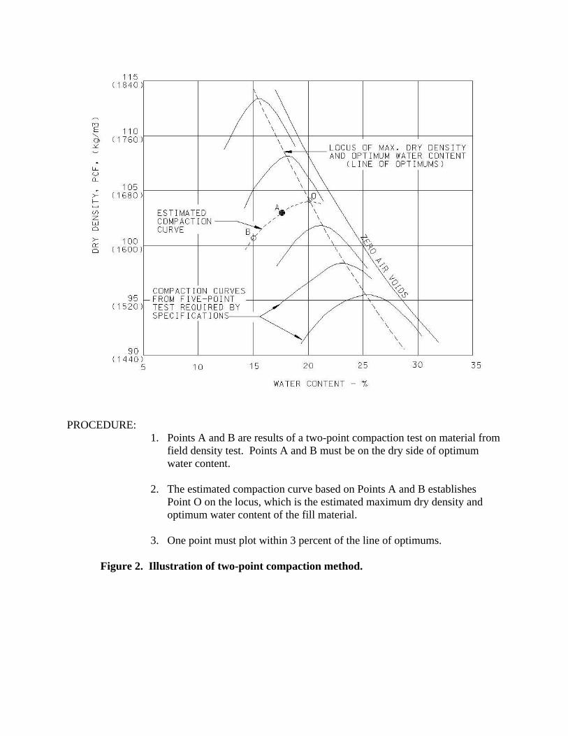
PROCEDURE: 1. Points A and B are results of a two-point compaction test on material from
field density test. Points A and B must be on the dry side of optimum water content.
2. The estimated compaction curve based on Points A and B establishes
Point O on the locus, which is the estimated maximum dry density and optimum water content of the fill material.
3. One point must plot within 3 percent of the line of optimums.
Figure 2. Illustration of two-point compaction method.
Related Documents