Formula SAE Paddle Shift System Senior Design II Report Group 5 Group Members Richard Pittman Musab Hmeidan Sean Feschak Kevin Castillo Fall 2015

Welcome message from author
This document is posted to help you gain knowledge. Please leave a comment to let me know what you think about it! Share it to your friends and learn new things together.
Transcript

Formula SAE Paddle Shift System
Senior Design II Report
Group 5
Group Members
Richard Pittman Musab Hmeidan
Sean Feschak
Kevin Castillo
Fall 2015

i
TABLE OF CONTENTS
1.0 Executive Summary 1
2.0 Project Description 2
2.1 Project Motivation 3
2.2 Goals and Objectives 4
2.3 Requirements Specifications 5
2.3.1 List of Requirements 5
2.3.2 Electrical Hardware 6
2.3.3 Internal Software 7
2.3.4 External Software 8
2.3.5 Mechanical Hardware 8
2.3.6 Physical Description 8
2.4 Project Function 10
2.5 Group Dynamics 11
2.5.1 Division of Labor 11
2.5.2 Project Schedule 12
2.5.3 Project Budget 13
3.0 Research related to Project Definition 14
3.1 Existing Similar Projects and Products 15
3.2 Relevant Technologies 19
3.2.1 Flat Shifting 20
3.2.2 Correct Shift Detection 20
3.2.3 System Monitoring 21
3.3 Strategic Components 21
3.3.1 Actuator 21
3.3.2 Power 27
3.3.3 Display 28
3.3.4 MCU 29
3.3.5 Driver Controls 30
3.3.6 Gear Position Sensor 31
3.3.7 Wiring Harness 34
3.3.8 GPS Module 58
3.3.9 Data Logging/ SD Card Slot 59
3.4 Possible Architectures and Related Diagrams 62

ii
3.4.1 Power 63
3.4.2 Display 68
3.4.4 Data Logging 75
3.4.5 Wiring Harness 77
3.4.6 MCU 79
3.4.7 GPS Module 82
4.0 Related Standards 88
4.1 MCU Standards 89
4.2 SAE Standards 90
4.3 Vehicle Standards 91
4.4 Design impact of relevant standards 92
4.5 FMVSS transmission standard 93
5.0 Realistic Design Constraints 93
5.1 Economic and Time constraints 94
5.2 Environmental, Social, and Political constraints 94
5.3 Ethical, Health, and Safety constraints 95
5.4 Manufacturability and Sustainability constraints 95
6.0 Project Hardware and Software Design Details 96
6.1 Initial Design Architectures 96
6.2 Actuator Subsystem 96
6.2.1 Important Function 97
6.2.2 Packaging 98
6.3 Power Subsystem 98
6.3.1 Important Function 99
6.3.2 Packaging 99
6.4 GPS Subsystem 100
6.4.1 Important Function 100
6.4.2 Packaging 101
6.5 Display Subsystem 101
6.5.1 Important Function 101
6.5.2 Packaging 101
6.6 MCU Subsystem 102
6.6.1 Important Function 102
6.6.2 Packaging 103

iii
6.7 Gear Position Subsystem 103
6.7.1 Important Function 104
6.7.2 Packaging 105
6.8 Data Logging Subsystem 106
6.8.1 Important Function 106
6.8.2 Packaging 106
6.9 Wire Harness Subsystem 107
6.9.1 Important Function 107
6.9.2 Packaging 108
6.10 Steering Wheel Button Subsystem 108
6.10.1 Important Function 108
6.10.2 Packaging 109
7.0 Project Prototype Construction and Coding 109
7.1 Prototype Circuit Board 110
7.2 Assembled PCB 112
7.2 Final Coding Plan 113
8.0 Project Prototype Testing 114
8.1 Hardware Test Environment 114
8.2 Hardware Specific Testing 115
8.3 Software Test Environment 117
8.4 Software Specific Testing 117
9.0 Administrative Content 118
9.1 Milestone Discussion 119
9.2 Budget and Finance Discussion 120
9.3 Project Consultants and Suppliers 121
10.0 Project Summary and Conclusion 122
Appendices iv
Appendix A - Copyright Permissions iv
Appendix B - Datasheets viii
Appendix C - Figures ix
Appendix D – References xii
1
1.0 Executive Summary Formula SAE is an international competition organized by the Society of Automotive Engineers where college students design, manufacture and compete with a formula style car. The car built by UCF’s Formula SAE team uses a 2006-2007 Suzuki GSX-R600 engine that has a 6-speed sequential gearbox. The gears can only shift sequentially in order, and shifts are actuated by the rotation of a lever at the gearbox. The current shifting system is completely mechanical and is actuated by a lever mounted to the driver’s left side. This lever is attached to a push-pull cable which runs the length of the car to the gearbox. When a shift is needed the driver is required to remove his or her hand from the wheel, grab the lever, and push or pull it. This system is problematic in a few specific ways. The time taken between when the shift is needed to when it is actuated is somewhat slow due to the driver’s need to remove his or her hand from the wheel. The lever also proved to be difficult to actuate at certain critical times. On a Formula SAE competition course with many turns, frequent shifting is required to maximize performance. If a shift is needed during a turn the driver would have to make the turn with one hand on the steering wheel or simply wait until after the turn and lose time while the engine was in a bad RPM range. Both situations lead to a decrease in overall performance.
The goal of this project is to design and implement an electronic paddle shift system to address these issues and eliminate the detriment of the push-pull system to overall performance in a race. With paddle shifting, the driver would be able to actuate a shift without removing his or her hand from the steering wheel, increasing control at every point in the race. As well, the amount of energy required by the driver to actuate the shift is minimized to reduce the fatigue of the driver during a race. This would ideally lead to faster shift times, a decrease in weight, and better performance overall. The system will be designed with increased performance, light weight, and reliability as the driving parameters. When finalized, it will allow the driver to actuate a shift almost instantaneously without losing any control of the car.
Conducting research prior to initiating the project would help gain familiarity and confidence towards completing the project successfully due to the information learned about which method would be superior over another that improves performance and reliability. Through research, a few techniques have risen that have been marginally investigated to best fit the desired requirements and specifications set. The team has come across a few features to be added that would make the project more proficient and would make both the vehicle and driver perform better such as adding more information to the dash display for the driver to analyze such as rpm, time, location, etc. Different microcontrollers have been introduced to the team which been investigated to pick the ones that seem to do the job. Different actuating systems have been investigated and the electric solenoid system have proven to be the most simple and inexpensive one over the hydraulic and pneumatic systems.
2
The electronic shift system is designed for the Formula SAE car so that the driver would be able to actuate a shift without removing his or her hand from the steering wheel, increasing control at every point in the race. As well, the amount of energy required by the driver to actuate the shift is minimized to reduce the fatigue of the driver during a race as compared to the current push-pull lever system being used. This leads to faster shift times, better performance overall and better driver control increasing the safety of the vehicle. The system is designed with long term performance and easy transferability in mind so that it can be easily transferred to the next year’s Formula SAE vehicle. The display system being used is to easily be read by the driver and it will inform them of which gear they are in as well as a shift indicator and will be able to withstand the harsh environments it will be exposed to. The system will also be logging the location of the vehicle, the rpms, gear and time so that the driver can review this information later and improve upon their performance.
The United States Department of Transportation’s Federal Motor Vehicle Safety Standards and Regulations Standard No. 102 states,
“This standard specifies the requirements for the transmission shift lever sequence, a starter interlock, and for a braking effect of automatic transmissions, to reduce the likelihood of shifting errors, starter engagement with vehicle in drive position, and to provide supplemental braking at speeds below 40 km/h (25 mph)”
A safety standard that may have to be adhered in order to maintain high levels of safety and low levels of error when operating the vehicle. Also, in 2006 the National Highway Traffic Safety Administration formally agreed with the Alliance of Automobile Manufacturers and the Association of International Automobile Manufacturers on a standard that states, “All vehicles sold in the U.S. with automatic transmissions will be equipped with brake transmission system interlocks to prevent children from moving the shift mechanisms out of park.” This aforementioned standard does not apply directly to this paddle shifter design due to the fact that children will never be operating the vehicle.
2.0 Project Description The Formula SAE vehicle has been in the need of a better shift system since they still use a manual shifter. This system is slow and hard to use, as the driver has to remove their hand from the steering wheel, hold the clutch and move the lever. The purpose of this project is to remove the need for the driver to take their hands off the steering wheel so they can put more focus on driving. The system will also increase shift times substantially. Typically it takes the driver 1-2 seconds to perform a complete shift. The electronic shift system will allow the driver to be able to complete a shift in under half a second. The shift system will also use a MCU unit so that the driver never has to remove their foot from the gas pedal as the MCU will tell the ECU to kill spark for the time it takes the actuator to shift into gear,

3
at which point the MCU will then tell the ECU to allow spark again and the engine will again be able to put power to the track again.
2.1 Project Motivation The motivation for the development of an electronic paddle shift system initially came from the SAE team. The affection and enthusiasm that the group has towards motor vehicles and experience around this type of machine and electrical developments had an impact on the motivation of implementing this project. The theories and models that this project requires in order for it to be executed successfully had motivated the group to implement this idea. Among these theories that were applied in this project and that attracted the attention of the group's members are digital/wireless communication, power systems, PCB, embedded systems, electromechanical systems, and sensors. Once these concepts are all incorporated into a complete design it would make a challenge for the group since there's a very limited and minimal implementation of any or some of the mentioned models by the group's members but would make a good educational experience that would add more tools to the toolbox of the group's members to utilize in any possible future projects that are similar to this one or in the work place.
Some of the motivation comes from the need to replace the current mechanical push-pull cable system with a shifting system that is more consistent and increases the performance of the driver in return increasing the overall performance of the formula car. And to do this the concepts taught during the engineering educational career and those that are necessary to implement to have a successfully functional design as stated previously are to be applied to the project which could mean having to initiate research to really understand the aspects of the engineering development behind this idea to make a functional design which could also mean having a challenge and complexity that towards this project that would motivate the group and require significant effort from the members to execute this project.
This project represents a product that would make a useful real-world applications. And that is what also had motivated the group to initiate this project. These real-world applications that this product can intervene with are that of the handicapped commuters specifically the handicapped racers that enjoy racing but have a limit due to their physical situations, professional driver or riders that need to perform better on the track, and regular commuters that find the normal H shifting pattern inconvenient to use. This product would greatly benefit all commuters and get rid of the issue of having the old inconvenient system that requires more energy and time to apply a gear shift in order for a vehicle to run properly. The benefit of the new design is to make shifting easier and increase the performance of the drivers due to the increase of consistency of the system. An additional benefit is the ease of use of this system and less effort is required to properly run this system correctly.
This project would be much more undesirable by the group and there would be a negative unfavorable impact on the total aftermath of the project if the concepts utilized in this project didn’t attract the attention of the members of the group.

4
Therefore, one of the most important motivation for deciding to design and implement the idea of this of project was that the members had complete interest in the theories and subsystems that make up this design. The establishment of the paddle shifters would not be possible and would not meet the intent to learn and gain experience through completing this project if there wasn’t an initial interest in the subsystems and models of the project. Since some members have experience around motor vehicles and vehicle electronics and have dealt with electromechanical cases and others are thinking about working for companies that do work related to SAE and others have previously dealt with handicapped individuals, the project's real-world use are relevant to the group which makes a positive motivation towards completing this project and have an overall positive outcome and better performance and experience. Furthermore, the use of the product that this project represents in the real-world and the theories that interested the members played a major role in motivating the group to design and complete a working useful product that would benefit many individuals.
2.2 Goals and Objectives It has been planned to aim for the design and production of a durable and high quality product through this project and in order for this to happen a few specific goals and objective have been declared. And these goals and objectives are essential for the project to be successfully implemented and functional and are essential to be accomplished in order for the product to be significant and useful to the subjects. These objectives will be the defining elements of the fundamental of the project. The objectives for the project are to be accessible and easy to use, to be reliable and highly durable, to be maintainable, to be controllable, to be transferable, and to be safe.
Accessible and ease of use - the electronic paddle shifters need to be a shifting system that does not require the driver to remove a hand from the steering wheel to perform a shift. This would make it very accessible for the driver so that he would feel comfortable with the system and be convenient to the driver. The paddles used to shift will be located at the fingers of the driver in a comfortable position to make it more accessible.
Reliable and highly durable - one of the most important objective is to have a system that is extremely reliable and has the ability to perform shifts with exact repeatability without the system having to fail very often. That is why it was decided to make the metal component of the system out of aluminum since it is durable. And this is to ensure that the system would not break or fail during action.
Maintainable - Another important goal of the project is to ensure that the design is driven by the practical considerations that the team will face when building and using the system, this also includes the cost and availability of replacement parts. The system should be easily maintained and have parts that are easy and fast to replace if they need to not limit the vehicle's performance on the tracks.

5
Controllable - The system that is to be designed and produced will have an important function of being extremely controllable, which means that it shouldn't be a struggle for the driver to shift and steer the wheel at the same time so that the shifting process would be faster and would improve the performance of both the vehicle and driver. When the system is controllable energy necessary from the driver to actuate the shift is minimized which reduces the fatigue of the driver during a race. Transferable - since it is a vital to test this product and the restrain of having just one complete product, the product being transferable is very important. The maintenance team of the SAE car have to be granted the ability to take off the steering wheel with ease to fix any problems that might have occur during a race or on regular days. Since the SAE team is required to have a new vehicle designed every year differently than that of the previous year the electronic paddle shifter system has to be easy to remove and install. Safe - having a system that is completely safe and meet the requirements of the definition of safe is a necessity of all designs and products. However, in this case this system must be extremely safe to the driver since it is widely known that driving and speeding is a dangerous combination and so this system must be perfect to prevent any failures that could cause harm to the driver.
2.3 Requirements Specifications The electronic shift system for the formula SAE vehicle has many requirements designed by the team and by rules and regulations set forth by SAE standards and requirements. The Requirements are meant to keep the system safe and overall increase the performance of the formula SAE vehicle. These requirements are also in place because the vehicle is already built and designed. Therefore, the system will have to fit into the existing vehicle with very minor modification.
2.3.1 List of Requirements Below is chart Table 1 that represents the general list of requirements which this project should meet during the making of the design. Each and every one of these requirements shall be examined, tested and confirmed that they are met as specified and are in working condition and are included in the complete design. These specifications are set based off of group discussions and restrictions set by the SAE rules and by the vehicle's physical limitations.

6
Requirement
ID Requirement Description
EPS. 1 The system's display dimension shall be not greater than 5" in width and 2.5" in length to be able to fit on the steering wheel.
EPS. 2 The system's display brightness shall be about 400 nits to ensure it is clear to see the screen in any condition.
EPS. 3 The system's display shall be capable of withstanding 80oC since the vehicle will be under heat on tracks.
EPS. 4 The system shall have data log of engine speed, temperature, gear position, etc.
EPS. 5 Complete system shall not exceed 10 pounds to prevent adding weight to the vehicle.
EPS. 6 The system’s components must be able to work in the approximate temperature range of 20º to 120º F.
EPS. 7
The system must be waterproof as well as being operational in different weathers.
EPS. 8
The paddle system shall rotate shifter shaft by approximately 20o to ensure the correct shifting process.
EPS. 9
The paddles shall withstand excessive force without failing of up to 20lb-inches.
EPS. 10
The system shall operate based of an electric actuator that is of linear specifications.
EPS. 11
The GPS system will record the vehicles speed and position and map the track route.
EPS. 12
The GPS system shall be Bluetooth enabled to have data
available wirelessly.
EPS. 13
The system shall have RPM sensor to assist in determining
when to shift.
EPS. 14
The system shall have a removable SD card attached to the
microcontroller board to store data.
EPS. 15
The system will have the ability to shift into neutral from first
gear using a special button mounted on the steering wheel. Table 1: Requirements Chart
2.3.2 Electrical Hardware There are multiple options to use for the power source for this project. The most common considerable sources would be the batteries. The use of batteries can be considered and has been used in previous projects, therefore this source of power is known to be achievable to meet the design specifications. The main source of power that the system will run on is the battery of the vehicle itself. The battery which runs on the motorcycle engine that the SAE team chose has a measured value of 12 volts. Since it was discovered that current vehicle’s electrical system motor operates approximately to its maximum current capacity, the electric solenoid actuation has been taken into consideration for the design. The system
7
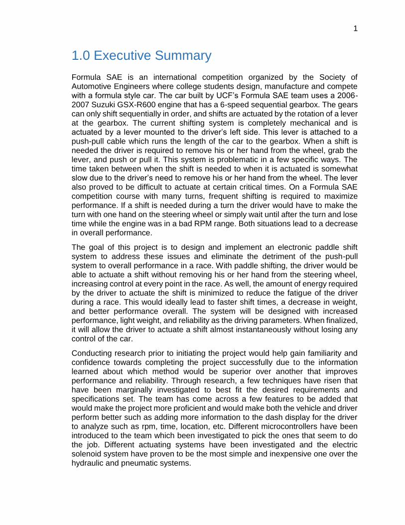
had to power many components that it was not meant to power. Since the some of the microcontrollers and other components needed to be used to implement certain functions such as the automatic up-shift system, the voltage delivered from the 12 volts battery had to be reduced because some of these components can only handle inputs less than or equal to 5 volts. Furthermore, a voltage regulator has been closely observed and studied to be able to draw out certain amounts of voltage from the battery that the components could only take without damaging them. As shown in the Figure 1 below, this is what the circuit looks like that would be implemented in situations where for some sensors and control boards a certain amount of voltage could be inputted to these low voltage demanding components.
Figure 1: 7805 voltage regulator circuit
All of the battery supply connections and voltage reduction circuits that might need to be used are thrown on a custom made PCB design with the connections made to the microcontrollers and sensors.
2.3.3 Internal Software The software that would be created shall be of good functionality under heavy and rapid use of the paddle shifting system where it must be created to aid in the execution and completion of a quick shift in a second or less to ensure that the software wouldn't have any problems while providing data. The fast shifting process is required to be able to observe and eliminate any problems since it is created purposely to handle fast data coming in and out. As mentioned before the software is going to have data run through externally to a data storage to have it saved with specific formatting and layout that the group wishes to design. Some of the data saved to the external storage would be shown to the user through a device such as basic information about the current status of the vehicle and the environment around.
The internal software of the system would also have to take in consideration of specific technologies that would be implemented into the system based on group discussions. The main microcontroller software shall be able to communicate with
8
other software where needed such as the gear position sensor software. This software is designed to designate the behavior of the gear position sensor where it would take certain actions depending on the voltage and resistance received when undertaking a shifting process that would be measured by a device such as a potentiometer. The software has to determine what gear position the vehicle is currently running on and output the results to the display for the user to interact with by detecting the voltage from the sensor.
The software should give the microcontroller chosen for this design to communicate with the global positioning system at the same time when there is a shifting process in action so that data would be saved in memory device such as an SD card. The software should be created so that it would coexist with the conditions of having a vehicle that moves speeds up to 60mph and so it should have to move the GPS at the same speed and read location and speed every certain short period of time measured in milliseconds to ensure that data is flowing rapidly and regularly and updated for the user to interact with.
2.3.4 External Software The external software is an important functionality of the system and without it no data received from the ECU to create logs. The software created that is associated with the receiving devices shall be able to receive data in UART customary up to 8-bits and convert that into a more comprehensible data to be disposable for the user to use. Serial data is going to be read through an open source terminal software that the external software is going to be made out of. And so the user should be able to create archives of data by creating logs through this open source terminal software to log data from the vehicle such as temperature, engine speed, gear position, etc.
2.3.5 Mechanical Hardware The actuator that is going to be used to implement this design regardless of what type of actuator it is, is considered a mechanical hardware. Since actuators consist of a motor that is responsible for moving or controlling a mechanism or system, it can be declared a mechanical part. The paddle shifters need to exhibit a certain amount of force measured in pounds to be able to actuate to the next gear by rotating the selector shaft to some amount of degrees depending on the requirements of the transmission. A solenoid is an important element to this project without it, the project wouldn’t be a success and therefore a solenoid can be a vital mechanical hardware depending on the type of solenoid used.
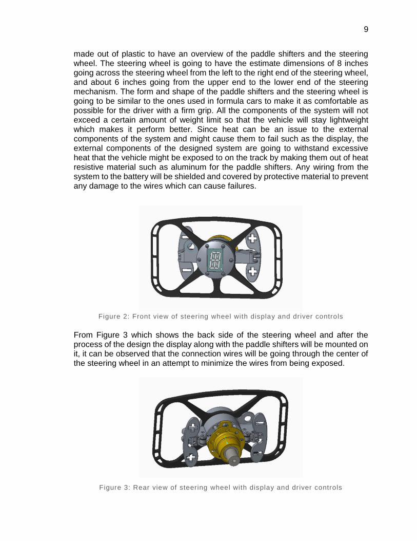
2.3.6 Physical Description As shown in Figure 2 below, the general description of the system is very simple since this type of system has become of a common use by many individuals. A prototype of the paddle shifters will be printed by a 3D printer with the material
9
made out of plastic to have an overview of the paddle shifters and the steering wheel. The steering wheel is going to have the estimate dimensions of 8 inches going across the steering wheel from the left to the right end of the steering wheel, and about 6 inches going from the upper end to the lower end of the steering mechanism. The form and shape of the paddle shifters and the steering wheel is going to be similar to the ones used in formula cars to make it as comfortable as possible for the driver with a firm grip. All the components of the system will not exceed a certain amount of weight limit so that the vehicle will stay lightweight which makes it perform better. Since heat can be an issue to the external components of the system and might cause them to fail such as the display, the external components of the designed system are going to withstand excessive heat that the vehicle might be exposed to on the track by making them out of heat resistive material such as aluminum for the paddle shifters. Any wiring from the system to the battery will be shielded and covered by protective material to prevent any damage to the wires which can cause failures.
Figure 2: Front view of steering wheel with display and driver controls
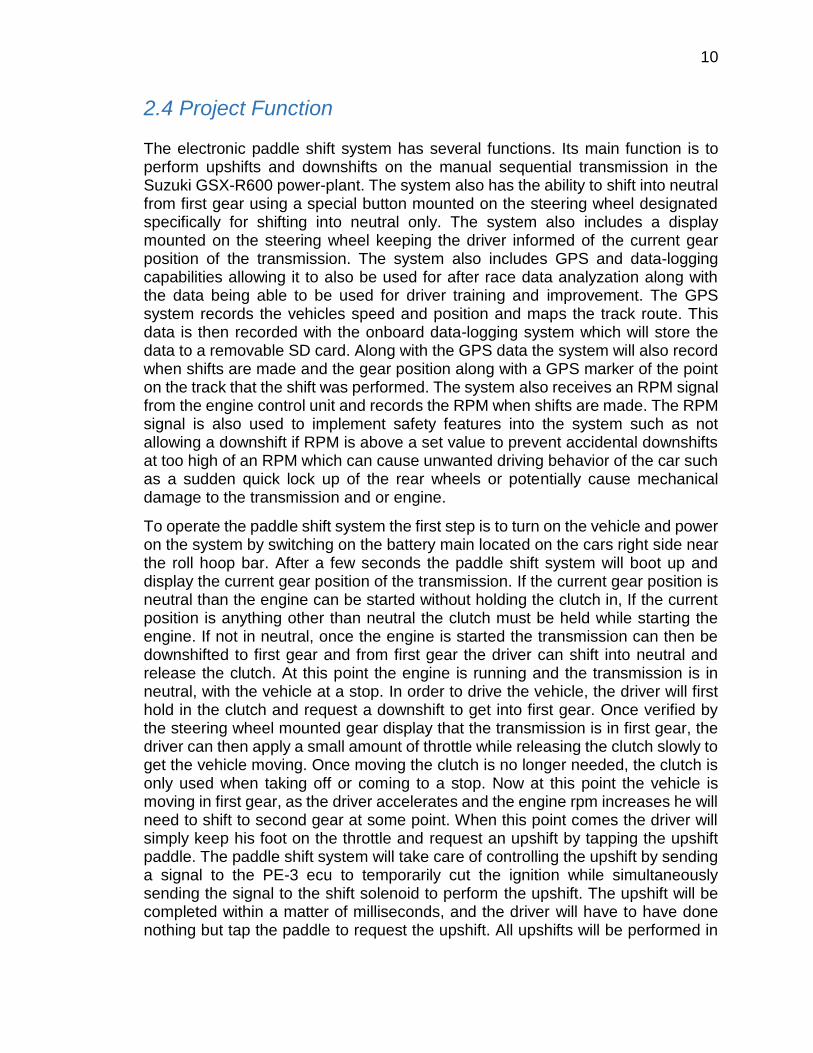
From Figure 3 which shows the back side of the steering wheel and after the process of the design the display along with the paddle shifters will be mounted on it, it can be observed that the connection wires will be going through the center of the steering wheel in an attempt to minimize the wires from being exposed.
Figure 3: Rear view of steering wheel with display and driver controls
10
2.4 Project Function The electronic paddle shift system has several functions. Its main function is to perform upshifts and downshifts on the manual sequential transmission in the Suzuki GSX-R600 power-plant. The system also has the ability to shift into neutral from first gear using a special button mounted on the steering wheel designated specifically for shifting into neutral only. The system also includes a display mounted on the steering wheel keeping the driver informed of the current gear position of the transmission. The system also includes GPS and data-logging capabilities allowing it to also be used for after race data analyzation along with the data being able to be used for driver training and improvement. The GPS system records the vehicles speed and position and maps the track route. This data is then recorded with the onboard data-logging system which will store the data to a removable SD card. Along with the GPS data the system will also record when shifts are made and the gear position along with a GPS marker of the point on the track that the shift was performed. The system also receives an RPM signal from the engine control unit and records the RPM when shifts are made. The RPM signal is also used to implement safety features into the system such as not allowing a downshift if RPM is above a set value to prevent accidental downshifts at too high of an RPM which can cause unwanted driving behavior of the car such as a sudden quick lock up of the rear wheels or potentially cause mechanical damage to the transmission and or engine.
To operate the paddle shift system the first step is to turn on the vehicle and power on the system by switching on the battery main located on the cars right side near the roll hoop bar. After a few seconds the paddle shift system will boot up and display the current gear position of the transmission. If the current gear position is neutral than the engine can be started without holding the clutch in, If the current position is anything other than neutral the clutch must be held while starting the engine. If not in neutral, once the engine is started the transmission can then be downshifted to first gear and from first gear the driver can shift into neutral and release the clutch. At this point the engine is running and the transmission is in neutral, with the vehicle at a stop. In order to drive the vehicle, the driver will first hold in the clutch and request a downshift to get into first gear. Once verified by the steering wheel mounted gear display that the transmission is in first gear, the driver can then apply a small amount of throttle while releasing the clutch slowly to get the vehicle moving. Once moving the clutch is no longer needed, the clutch is only used when taking off or coming to a stop. Now at this point the vehicle is moving in first gear, as the driver accelerates and the engine rpm increases he will need to shift to second gear at some point. When this point comes the driver will simply keep his foot on the throttle and request an upshift by tapping the upshift paddle. The paddle shift system will take care of controlling the upshift by sending a signal to the PE-3 ecu to temporarily cut the ignition while simultaneously sending the signal to the shift solenoid to perform the upshift. The upshift will be completed within a matter of milliseconds, and the driver will have to have done nothing but tap the paddle to request the upshift. All upshifts will be performed in

11
the same manner in order to upshift through all the gears. At some point on the track the driver will have to brake and downshift to go through a turn, when this point comes the driver will simply request a downshift by tapping the downshift paddle when the rpm drops to the correct point for the downshift. Downshifts will require a little more driver skill as it is up to the driver to request the downshift at the proper rpm, if rpm is deemed too high by the control unit it will simply ignore the drivers request. The control unit also has some other safety features implemented in the code such as not letting the system perform a downshift if it is already in first gear, as well as not letting the system upshift if it is already in sixth gear. The system will also only let the driver go into neutral gear from first gear only, therefore if the transmission is in any other gear other than first and a neutral shift is requested it will ignore it. The entire time the paddle shift system is on the gps system will be recording to map the vehicles driving route. This gps data along with the other data the system records such as gear position and vehicle speed are all recorded to the removable micro SD card. To view the data after a competition or practice event, simply open the lid to the control unit and remove the SD card from its slot. The data is placed into a text file and organized by lap to aid in analyzing it afterwards using the free gps visualizer online resource.
2.5 Group Dynamics There are four members in Group 5 of the fall 2015 Senior Design II for Computer and Electrical Engineers class. These people are Richard Pittman (EE), Sean Feschak (EE/ME), Musab Hmeidan (EE) and Kevin Castillo (CpE).
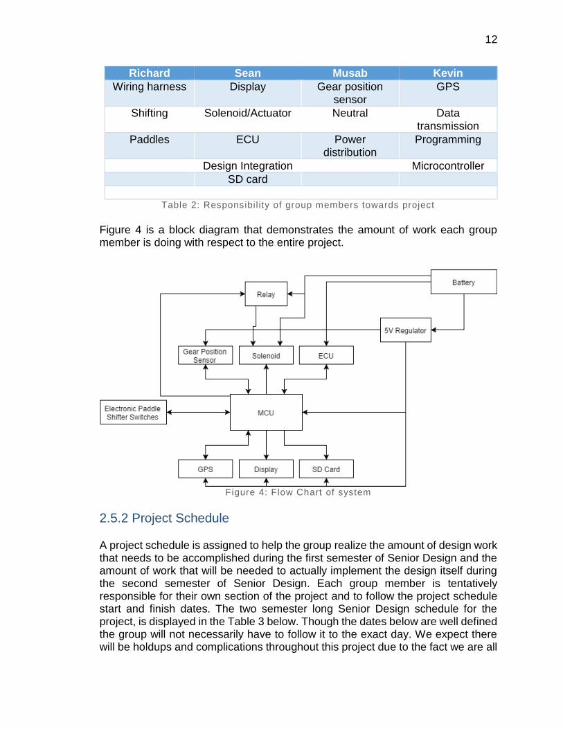
2.5.1 Division of Labor Richard will be responsible for the dynamics of the paddle shifters and the shifting dynamics of such a system, using the previously mounted steering wheel to fit the paddles shifters on it. The wiring harness that was designed by Richard during the duration of this project will be used to wire all necessary components of the system. Kevin is responsible for the vehicle’s data gathering and location using GPS coordinates. The GPS will send the coordinates via Bluetooth technology and use the web to map out the track on the display to pinpoint the coordinates of the vehicle on the track. Musab is responsible for the car’s gear position sensor and its data transmission to the ECU. The gear position data will be sent to a microcontroller and then transmitted to the display for the driver to see. Sean is responsible for the engine control unit along with the shift solenoid that performs the shifting procedure. An electric solenoid actuator will be used to process a shift in the transmission. All four members will work together on microcontroller programming, subsystem integration, and PCB design as well as the SD card to be attached to the microcontroller. Table 2 specifically breaks down, what each group member did.
12
Richard Sean Musab Kevin
Wiring harness Display Gear position sensor
GPS
Shifting Solenoid/Actuator Neutral Data transmission
Paddles ECU Power distribution
Programming
Design Integration Microcontroller
SD card
Table 2: Responsibil ity of group members towards project
Figure 4 is a block diagram that demonstrates the amount of work each group member is doing with respect to the entire project.
Figure 4: Flow Chart of system
2.5.2 Project Schedule A project schedule is assigned to help the group realize the amount of design work that needs to be accomplished during the first semester of Senior Design and the amount of work that will be needed to actually implement the design itself during the second semester of Senior Design. Each group member is tentatively responsible for their own section of the project and to follow the project schedule start and finish dates. The two semester long Senior Design schedule for the project, is displayed in the Table 3 below. Though the dates below are well defined the group will not necessarily have to follow it to the exact day. We expect there will be holdups and complications throughout this project due to the fact we are all

13
entry level engineers designing our first full project. Keep in mind that not all of the tasks listed in this table and the meeting dates will be accurate specifically for those of the next semester events since that is in the future and it’s hard to tell what could occur and so some of the schedule organized below is a prediction and kind of an encouragement to complete tasks on time for next semester.
Table 3: Project Schedule
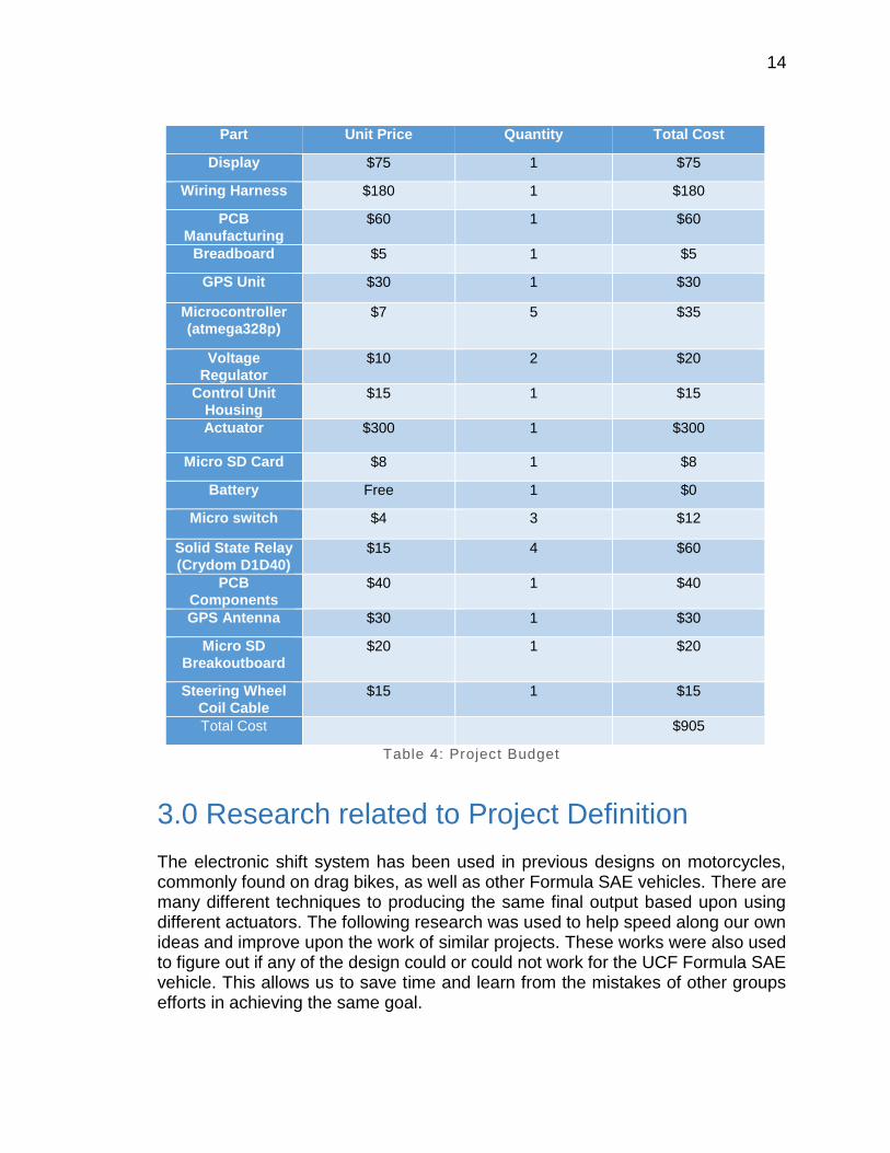
2.5.3 Project Budget The initial project budget was generated after the general design of the electronic paddle shift system project was conducted. Each part, its quantity, and cost, was added up and the total cost of the project was initially estimated at approximately $800. Upon completion of the project our total budget came out to be approximately $905. The breakdown of our budget can be seen in the table below, Table 4. We exceeded our initial budget by only a little over $100 which really is not too bad considering we gave ourselves a relatively low budget to start with. We also received $500 from the Formula SAE team, which covered the cost of the actuator, wiring harness, and gear position sensor. Leaving each group member only responsible for about $100.
Task Name Start End
Senior Design Project Plan 2-Jun 15-Dec
Meeting to initiate project 2-Jun 2-Jun
Design flowchart and define role 4-Jun 4-Jun
Research microcontrollers 8-Jun 11-Jun
Research actuators/solenoids 12-Jun 15-Jun
Research displays 16-Jun 20-Jun
Research GPS technolgies 21-Jun 23-Jun
Meeting to summeraize research 24-Jun 24-Jun
Design paper and continue research 27-Jun 1-Jul
Meeting to revise paper written so far 2-Jul 2-Jul
Continue design paper 3-Jul 10-Jul
Design paddles and 3D print 11-Jul 13-Jul
Learn EAGLE PCB 13-Jul 16-Jul
Design wiring harness 17-Jul 20-Jul
Design upshift and downshift circuit 21-Jul 24-Jul
Design GPS system 24-Jul 28-Jul
Meeting before rough draft 23-Jul 23-Jul
Finish and edit paper 29-Jul 6-Aug
Order parts 6-Aug 8-Aug
Break between semesters 7-Aug 23-Aug
Begin senior design 2 24-Aug 24-Aug
Revise ordered parts 25-Aug 25-Aug
Implement GPS system/display 26-Aug 9-Sep
Implement paddles 9-Sep 23-Sep
Implement gear position sensor/neutral button 23-Sep 7-Oct
Implement actuator/solenoid 7-Oct 12-Oct
Design and test Software 12-Oct 19-Oct
Design and test GPS/display 19-Oct 26-Oct
Design and test paddles 26-Oct 2-Nov
Design and test gear position sensor and neutral 2-Nov 9-Nov
Design and test actuator and solenoid 9-Nov 23-Nov
Put system together 23-Nov 7-Dec
Test the final system 7-Dec 14-Dec
Finish documents 7-Dec 15-Dec
Present project
14
Part Unit Price Quantity Total Cost
Display $75 1 $75
Wiring Harness $180 1 $180
PCB
Manufacturing $60 1 $60
Breadboard $5 1 $5
GPS Unit $30 1 $30
Microcontroller (atmega328p)
$7 5 $35
Voltage
Regulator $10 2 $20
Control Unit Housing
$15 1 $15
Actuator $300 1 $300
Micro SD Card $8 1 $8
Battery Free 1 $0
Micro switch $4 3 $12
Solid State Relay
(Crydom D1D40) $15 4 $60
PCB
Components $40 1 $40
GPS Antenna $30 1 $30
Micro SD
Breakoutboard $20 1 $20
Steering Wheel
Coil Cable $15 1 $15
Total Cost $905
Table 4: Project Budget
3.0 Research related to Project Definition
The electronic shift system has been used in previous designs on motorcycles, commonly found on drag bikes, as well as other Formula SAE vehicles. There are many different techniques to producing the same final output based upon using different actuators. The following research was used to help speed along our own ideas and improve upon the work of similar projects. These works were also used to figure out if any of the design could or could not work for the UCF Formula SAE vehicle. This allows us to save time and learn from the mistakes of other groups efforts in achieving the same goal.

15
3.1 Existing Similar Projects and Products Electronic paddle shifters is a common technology that have been used for a while now and so many projects related to this one have been completed by engineers, students, researchers, and automotive companies. Companies along with engineers have been always trying to improve this type of technology on their vehicles to improve the performance and safety of this technology when applied to the vehicle. Students and other SAE teams at different schools seems to be getting much more common and will try to apply this technology to their team’s vehicle since it is much easier to use than the regular sequential shifting system and to much improve their vehicle’s performance and to try to perform very well in a competition that is demanding. Everyone that is involved in this technology seems to make more features to be added alongside with the electronic paddle shifters such as GPS, design it to be waterproof or even making it operate wirelessly.
The UVic FSAE team at University of Victoria that is supervised under Dr. Ashoka K.S. Bhat have created and applied this technology to their team’s vehicle which is powered by a Honda 600cc CBR F4i engine which all contains the same paddle shifters principle of removing the mechanical lever and adding the paddles along with other components that operate on the 12V battery. The design was chosen to be electronic over pneumatic since the two 12V batteries along with the wires that have been used to power the on-board electronics already exist in the current design of the car. The batteries during normal operation are charged by the alternator. The team decided to use a high powered, bi-directional solenoid over a DC motor to actuate the gear change. Taking consideration of either using an extendable connector versus a removable connector for the steering wheel, the design chose the ¼ inch jack inserted into a single channel socket, which is a removable connector since it is required by SAE rules that the steering wheel needs to be removable. The F28069 Piccolo controlSTICK from TI was used as the design’s microcontroller. It was used because it features a dedicated PWM outputs and pre-written code for moto/solenoid control which helps us take this microcontroller into consideration for our design. The linear actuator of a minimum force of 16.5kgF was used to ensure the guaranteed force that will always shift the transmission since the maximum force measured to shift is 11kgF. [1]
Another electronic paddle shifters design that was made by Team Raptor at University of California Berkeley which uses the electric solenoid and relays concept. This electronic paddle shifter features the use of a momentary rocker-type switch. This switch is activated when the flexure is pressed towards the wheel. The flexures were designed to perform as a restoring force which goes back to the normal position after it’s been deformed to actuate a shift. The switch sends signal to the ECU once it has been activated, where the ECU regulates the type of shift that has been undertaking based on the switch activated. The ECU decides to send current through relay to the electric solenoid that has a duty of actuating the shift. The current that has been sent generates a magnetic field inside the solenoid which makes the mechanical components move in certain directions depending on the current’s direction. In their design, the selector shaft must rotate about 15o to
16
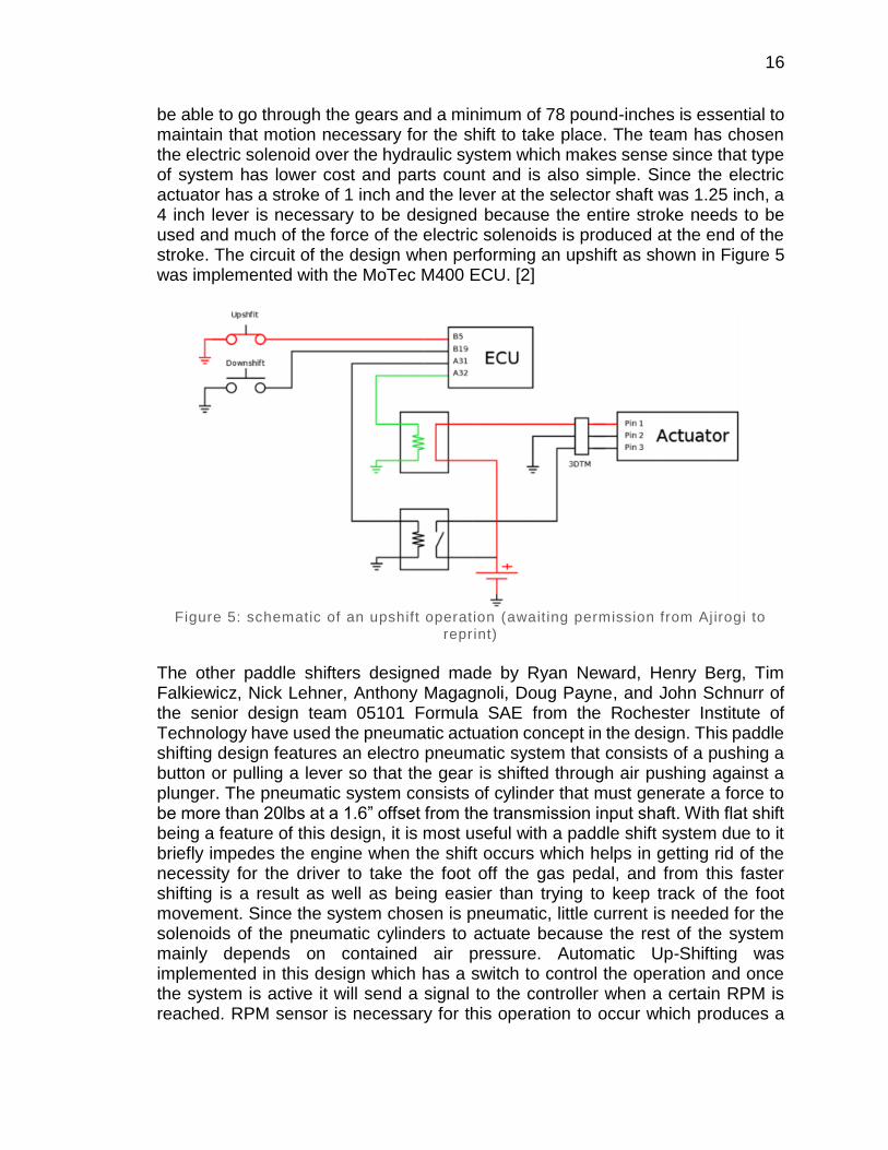
be able to go through the gears and a minimum of 78 pound-inches is essential to maintain that motion necessary for the shift to take place. The team has chosen the electric solenoid over the hydraulic system which makes sense since that type of system has lower cost and parts count and is also simple. Since the electric actuator has a stroke of 1 inch and the lever at the selector shaft was 1.25 inch, a 4 inch lever is necessary to be designed because the entire stroke needs to be used and much of the force of the electric solenoids is produced at the end of the stroke. The circuit of the design when performing an upshift as shown in Figure 5 was implemented with the MoTec M400 ECU. [2]
Figure 5: schematic of an upshift operation (awaiting permission from Ajirogi to
reprint)
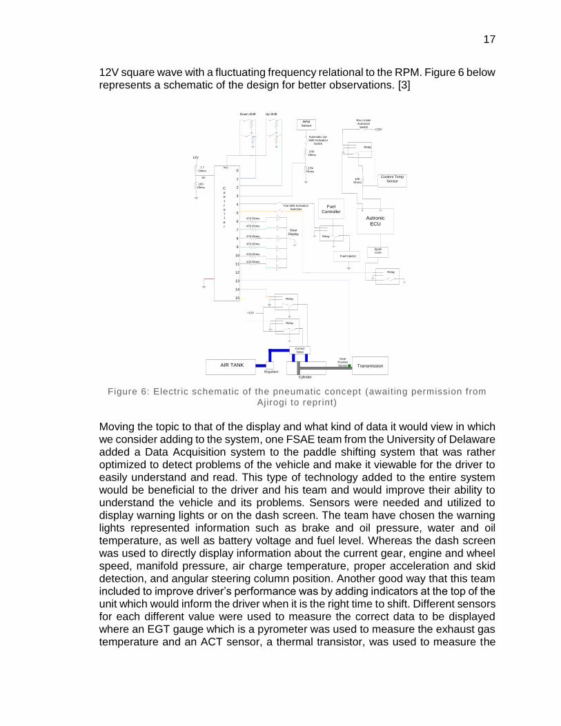
The other paddle shifters designed made by Ryan Neward, Henry Berg, Tim Falkiewicz, Nick Lehner, Anthony Magagnoli, Doug Payne, and John Schnurr of the senior design team 05101 Formula SAE from the Rochester Institute of Technology have used the pneumatic actuation concept in the design. This paddle shifting design features an electro pneumatic system that consists of a pushing a button or pulling a lever so that the gear is shifted through air pushing against a plunger. The pneumatic system consists of cylinder that must generate a force to be more than 20lbs at a 1.6” offset from the transmission input shaft. With flat shift being a feature of this design, it is most useful with a paddle shift system due to it briefly impedes the engine when the shift occurs which helps in getting rid of the necessity for the driver to take the foot off the gas pedal, and from this faster shifting is a result as well as being easier than trying to keep track of the foot movement. Since the system chosen is pneumatic, little current is needed for the solenoids of the pneumatic cylinders to actuate because the rest of the system mainly depends on contained air pressure. Automatic Up-Shifting was implemented in this design which has a switch to control the operation and once the system is active it will send a signal to the controller when a certain RPM is reached. RPM sensor is necessary for this operation to occur which produces a
17
12V square wave with a fluctuating frequency relational to the RPM. Figure 6 below represents a schematic of the design for better observations. [3]
Figure 6: Electr ic schematic of the pneumatic concept (awaiting permission from
Ajirogi to reprint)
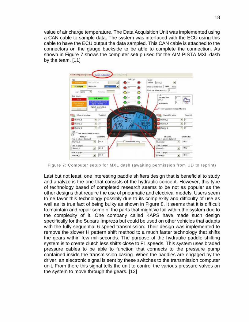
Moving the topic to that of the display and what kind of data it would view in which we consider adding to the system, one FSAE team from the University of Delaware added a Data Acquisition system to the paddle shifting system that was rather optimized to detect problems of the vehicle and make it viewable for the driver to easily understand and read. This type of technology added to the entire system would be beneficial to the driver and his team and would improve their ability to understand the vehicle and its problems. Sensors were needed and utilized to display warning lights or on the dash screen. The team have chosen the warning lights represented information such as brake and oil pressure, water and oil temperature, as well as battery voltage and fuel level. Whereas the dash screen was used to directly display information about the current gear, engine and wheel speed, manifold pressure, air charge temperature, proper acceleration and skid detection, and angular steering column position. Another good way that this team included to improve driver’s performance was by adding indicators at the top of the unit which would inform the driver when it is the right time to shift. Different sensors for each different value were used to measure the correct data to be displayed where an EGT gauge which is a pyrometer was used to measure the exhaust gas temperature and an ACT sensor, a thermal transistor, was used to measure the
0
1
2
3
4
5
6
7
8
9
10
11
12
13
14
15
AIR TANK
Regulator
Control
Valve
Cylinder
Transmission
+12V
12V
7.7
Ohms
100
Ohms
RPM
Sensor
3.5k
Ohms
2.5k
Ohms
Autronic
ECU
Fuel
Controller
Fuel Injector
Spark
Coils
Coolent Temp
Sensor
+12V
100
Ohms
6 17
Down Shift Up Shift
C
o
n
t
r
o
l
l
e
r
Gear
Position
Sensor
Rev Limiter
Activation
Switch
Flat Shift Activation
Switches
Automatic Up-
Shift Activation
Switch
Gear
Display
9V
Relay
Relay
Relay
Relay
Relay
Vcc
470 Ohms
470 Ohms
470 Ohms
470 Ohms
470 Ohms
470 Ohms
18
value of air charge temperature. The Data Acquisition Unit was implemented using a CAN cable to sample data. The system was interfaced with the ECU using this cable to have the ECU output the data sampled. This CAN cable is attached to the connectors on the gauge backside to be able to complete the connection. As shown in Figure 7 shows the computer setup used for the AIM PISTA MXL dash by the team. [11]
Figure 7: Computer setup for MXL dash (awaiting permission from UD to reprint)
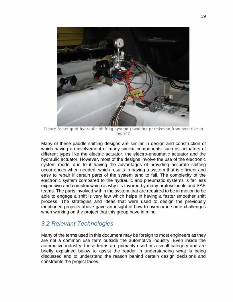
Last but not least, one interesting paddle shifters design that is beneficial to study and analyze is the one that consists of the hydraulic concept. However, this type of technology based of completed research seems to be not as popular as the other designs that require the use of pneumatic and electrical models. Users seem to ne favor this technology possibly due to its complexity and difficulty of use as well as its true fact of being bulky as shown in Figure 8. It seems that it is difficult to maintain and repair some of the parts that might’ve fail within the system due to the complexity of it. One company called KAPS have made such design specifically for the Subaru Impreza but could be used on other vehicles that adapts with the fully sequential 6 speed transmission. Their design was implemented to remove the slower H pattern shift method to a much faster technology that shifts the gears within few milliseconds. The purpose of the hydraulic paddle shifting system is to create clutch less shifts close to F1 speeds. This system uses braded pressure cables to be able to function that connects to the pressure pump contained inside the transmission casing. When the paddles are engaged by the driver, an electronic signal is sent by these switches to the transmission computer unit. From there this signal tells the unit to control the various pressure valves on the system to move through the gears. [12]
19
Figure 8: setup of hydraulic shift ing system (awaiting permission from sssdrive to
reprint)
Many of these paddle shifting designs are similar in design and construction of which having an involvement of many similar components such as actuators of different types like the electric actuator, the electro-pneumatic actuator and the hydraulic actuator. However, most of the designs involve the use of the electronic system model due to it having the advantages of providing accurate shifting occurrences when needed, which results in having a system that is efficient and easy to repair if certain parts of the system tend to fail. The complexity of the electronic system compared to the hydraulic and pneumatic systems is far less expensive and complex which is why it’s favored by many professionals and SAE teams. The parts involved within the system that are required to be in motion to be able to engage a shift is very few which helps in having a faster smoother shift process. The strategies and ideas that were used to design the previously mentioned projects above gave an insight of how to overcome some challenges when working on the project that this group have in mind.
3.2 Relevant Technologies Many of the terms used in this document may be foreign to most engineers as they are not a common use term outside the automotive industry. Even inside the automotive industry, these terms are primarily used or a small category and are briefly explained below to assist the reader in understanding what is being discussed and to understand the reason behind certain design decisions and constraints the project faces.
20
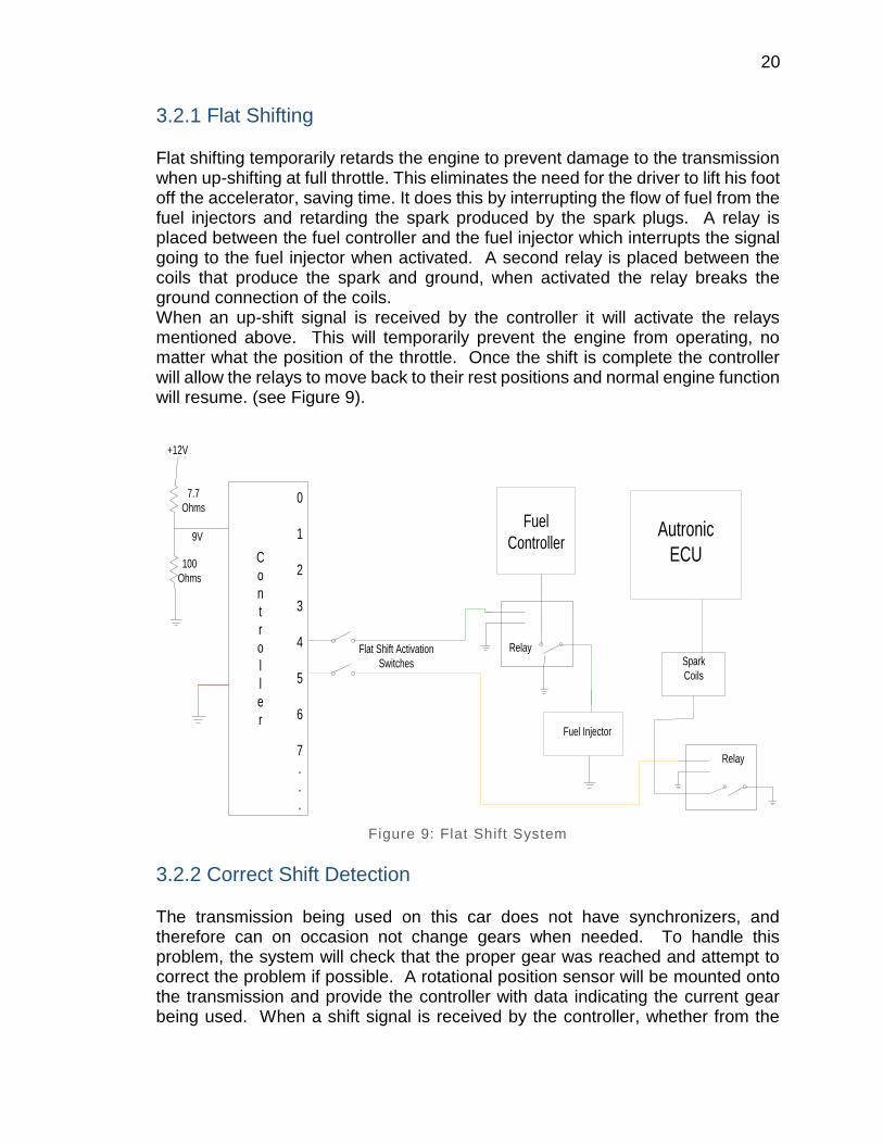
3.2.1 Flat Shifting Flat shifting temporarily retards the engine to prevent damage to the transmission when up-shifting at full throttle. This eliminates the need for the driver to lift his foot off the accelerator, saving time. It does this by interrupting the flow of fuel from the fuel injectors and retarding the spark produced by the spark plugs. A relay is placed between the fuel controller and the fuel injector which interrupts the signal going to the fuel injector when activated. A second relay is placed between the coils that produce the spark and ground, when activated the relay breaks the ground connection of the coils. When an up-shift signal is received by the controller it will activate the relays mentioned above. This will temporarily prevent the engine from operating, no matter what the position of the throttle. Once the shift is complete the controller will allow the relays to move back to their rest positions and normal engine function will resume. (see Figure 9).
Figure 9: Flat Shift System
3.2.2 Correct Shift Detection The transmission being used on this car does not have synchronizers, and therefore can on occasion not change gears when needed. To handle this problem, the system will check that the proper gear was reached and attempt to correct the problem if possible. A rotational position sensor will be mounted onto the transmission and provide the controller with data indicating the current gear being used. When a shift signal is received by the controller, whether from the
0
1
2
3
4
5
6
7
.
.
.
7.7
Ohms
100
Ohms
C
o
n
t
r
o
l
l
e
r
9V
Flat Shift Activation
Switches
Fuel
Controller
Fuel Injector
Relay
Autronic
ECU
Spark
Coils
Relay
+12V
21
driver or automatic up-shift system, the controller will activate a shift. The current gear sensor will then be looked at by the controller to ensure the shift took place. If the shift was not successful the controller will send another shift signal to the pneumatic system. This will continue until the proper gear is reached or it has failed a given number of times. This system will also be used to prevent a shift from occurring when it is not possible.
3.2.3 System Monitoring One of the inherent problems with the shifting of the motorcycle transmission used (and its lack of synchronizers), is that sometimes when a shift is asked for, the next sequential gear does not engage and the transmission remains in the current gear. This can be felt by the driver currently with the existing shift lever, but with a paddle shift system, it might take the driver longer to react to such a problem. This would obviously cause a loss of time, so a countermeasure is necessary. A rotary potentiometer would be mounted to the shift drum, which rotates a set amount for each gear change could be used. A small hole would be drilled in the side of the transmission case, to allow for the potentiometer to calculate how much the drum has rotated. If a shift is asked for, and the system does not detect enough rotation, it will automatically retry the shift, up to five times. This could also be used to keep the driver from trying to up-shift or downshift when in the highest (sixth) or lowest gear (first), respectively. The signal from the sensor can also be used with a gear indicator on the dashboard to help the driver keep track of what gear that he is in.
3.3 Strategic Components There are many parts that must work in sync to allow the electronic shift system to be successful. The most important of these system is the actuator. But without the microcontroller and related power support systems, the actuator would not be as effective as it will be with the added components. Choosing the correct type of system was also very challenging and much research was done in order for the best parts to be chosen to work together to achieve a successful design.
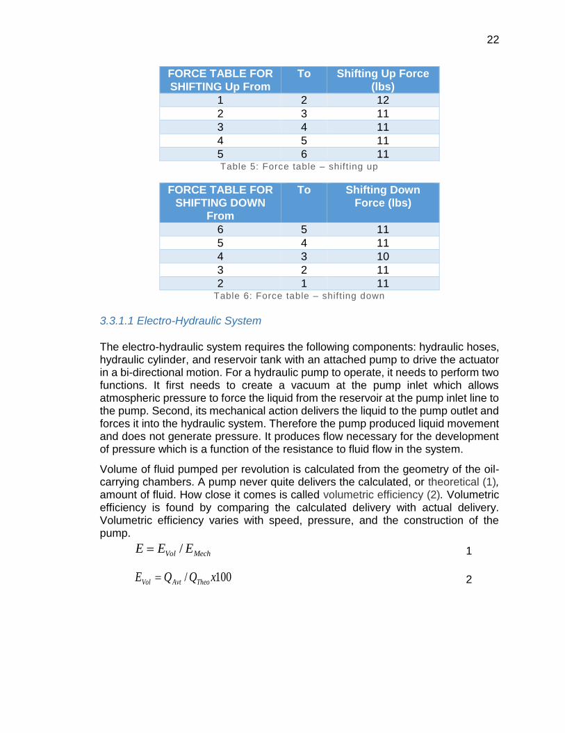
3.3.1 Actuator The motion required to shift the gears of the engine is a simple bi-directional linear throw. It connects directly to the transmission shift mechanism and functions to replace the force genera ted by a human operator moving a mechanical lever. In light of this, a significant amount of testing and research was directed towards choosing an appropriate linear actuator. In order to help us with selection of a linear actuator, we made a series of force measurements, as seen by Table 5 and Table 6. Both shifting up and shifting down forces were measured:
22
FORCE TABLE FOR
SHIFTING Up From
To Shifting Up Force
(lbs)
1 2 12
2 3 11
3 4 11
4 5 11
5 6 11 Table 5: Force table – shift ing up
FORCE TABLE FOR SHIFTING DOWN
From
To Shifting Down Force (lbs)
6 5 11
5 4 11
4 3 10
3 2 11
2 1 11 Table 6: Force table – shift ing down
3.3.1.1 Electro-Hydraulic System
The electro-hydraulic system requires the following components: hydraulic hoses, hydraulic cylinder, and reservoir tank with an attached pump to drive the actuator in a bi-directional motion. For a hydraulic pump to operate, it needs to perform two functions. It first needs to create a vacuum at the pump inlet which allows atmospheric pressure to force the liquid from the reservoir at the pump inlet line to the pump. Second, its mechanical action delivers the liquid to the pump outlet and forces it into the hydraulic system. Therefore the pump produced liquid movement and does not generate pressure. It produces flow necessary for the development of pressure which is a function of the resistance to fluid flow in the system.
Volume of fluid pumped per revolution is calculated from the geometry of the oil-carrying chambers. A pump never quite delivers the calculated, or theoretical (1), amount of fluid. How close it comes is called volumetric efficiency (2). Volumetric efficiency is found by comparing the calculated delivery with actual delivery. Volumetric efficiency varies with speed, pressure, and the construction of the pump.
1
2
MechVol EEE /
100/ xQQE TheoAvtVol
23
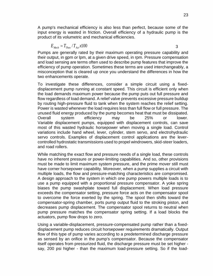
A pump's mechanical efficiency is also less than perfect, because some of the input energy is wasted in friction. Overall efficiency of a hydraulic pump is the product of its volumetric and mechanical efficiencies.
3
Pumps are generally rated by their maximum operating pressure capability and their output, in gpm or lpm, at a given drive speed, in rpm. Pressure compensation and load sensing are terms often used to describe pump features that improve the efficiency of pump operation. Sometimes these terms are used interchangeably, a misconception that is cleared up once you understand the differences in how the two enhancements operate.
To investigate these differences, consider a simple circuit using a fixed-displacement pump running at constant speed. This circuit is efficient only when the load demands maximum power because the pump puts out full pressure and flow regardless of load demand. A relief valve prevents excessive pressure buildup by routing high-pressure fluid to tank when the system reaches the relief setting. Power is wasted whenever the load requires less than full flow or full pressure. The unused fluid energy produced by the pump becomes heat that must be dissipated. Overall system efficiency may be 25% or lower. Variable displacement pumps, equipped with displacement controls, can save most of this wasted hydraulic horsepower when moving a single load. Control variations include hand wheel, lever, cylinder, stem servo, and electrohydraulic servo controls. Examples of displacement control applications are the lever-controlled hydrostatic transmissions used to propel windrowers, skid-steer loaders, and road rollers.
While matching the exact flow and pressure needs of a single load, these controls have no inherent pressure or power-limiting capabilities. And so, other provisions must be made to limit maximum system pressure, and the prime mover still must have corner horsepower capability. Moreover, when a pump supplies a circuit with multiple loads, the flow and pressure-matching characteristics are compromised. A design approach to the system in which one pump powers multiple loads is to use a pump equipped with a proportional pressure compensator. A yoke spring biases the pump swashplate toward full displacement. When load pressure exceeds the compensator setting, pressure force acts on the compensator spool to overcome the force exerted by the spring. The spool then shifts toward the compensator-spring chamber, ports pump output fluid to the stroking piston, and decreases pump displacement. The compensator spool returns to neutral when pump pressure matches the compensator spring setting. If a load blocks the actuators, pump flow drops to zero.
Using a variable-displacement, pressure-compensated pump rather than a fixed-displacement pump reduces circuit horsepower requirements dramatically. Output flow of this type of pump varies according to a predetermined discharge pressure as sensed by an orifice in the pump's compensator. Because the compensator itself operates from pressurized fluid, the discharge pressure must be set higher - say, 200 psi higher - than the maximum load-pressure setting. So if the load-
100/ xTTE ActTheoMech
24
pressure setting of a pressure-compensated pump is 1,100 psi, the pump will increase or decrease its displacement (and output flow) based on a 1,300-psi discharge pressure.
If the variable orifice is a manually operated flow control valve, the system can operate in a load-matched mode at the direction of an operator. As he opens the flow control valve, flow increases proportionally (constant pressure drop across an increasing-diameter orifice), at a pressure slightly above load pressure. Wasted power is very low with a load-sensing variable volume pump compensator. Since the control senses pressure drop and not absolute pressure, a relief valve or other means of limiting pressure must be provided. This problem is solved by a load-sensing/pressure-limiting control. This control functions as the load-sensing control previously described, until load pressure reaches the pressure limiter setting. At that point, the limiter portion of the compensator overrides the load-sensing control to destroke the pump. Again, the prime mover must have corner horsepower capability.
The main problem would be powering the hydraulic pump. It would either have to be run off the engine, which robs it of horsepower and is very complicated, or electrically, which would bring the recurring problem of requiring more current than is provided. If the system were to fail and leak, it would cause a large mess, as well as a fire hazard. This eliminated the hydraulic system.
3.3.1.2 Pneumatic Actuator System
The pneumatic system requires the following components: tank, regulator, cylinder, and solenoid. A carbon or Kevlar-wrapped tank would be used for weight considerations. Tanks are available that hold considerable amounts of pressure. This should allow the tank to be significantly smaller. The size and construction of the tank (and thus its maximum pressure capability) has a great impact on the price of the tank. A tank must be chosen that has the best compromise between shift capability and cost. A regulator is required to keep the amount of pressure going to the cylinder consistent. An adjustable pressure regulator would be chosen for initial development, with the assumption that tuning would start at a pressure of 100 psi. Most of the air cylinders have specifications given for a 100 psi operating pressure. This would also yield a decent margin of safety to tune with before the maximum solenoid pressure of 150 psi is reached. This should also make analysis more accurate due to the fact that the specs given will hold true at this operating pressure. With the given lever arm of 1.6” on the shift shaft, a 100 psi operating pressure would yield 5/8” as a necessary cylinder bore to provide more than the necessary shift force in both directions. This is a good size for packaging reasons. It was decided to keep the lever arm length on the shift shaft that came from the factory. This allows for tighter packaging, and makes it easier to retain the existing arm for use with the existing shift linkage system. The cylinder will have to be a double acting cylinder as it needs to control up, and downshifts. The solenoid controls the flow of the air. A four-way, three-position solenoid will be necessary to allow for the cylinder to have up-shift, downshift and rest positions. It also needs
25
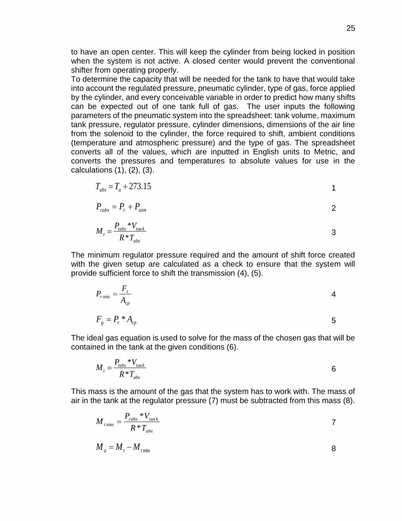
to have an open center. This will keep the cylinder from being locked in position when the system is not active. A closed center would prevent the conventional shifter from operating properly. To determine the capacity that will be needed for the tank to have that would take into account the regulated pressure, pneumatic cylinder, type of gas, force applied by the cylinder, and every conceivable variable in order to predict how many shifts can be expected out of one tank full of gas. The user inputs the following parameters of the pneumatic system into the spreadsheet: tank volume, maximum tank pressure, regulator pressure, cylinder dimensions, dimensions of the air line from the solenoid to the cylinder, the force required to shift, ambient conditions (temperature and atmospheric pressure) and the type of gas. The spreadsheet converts all of the values, which are inputted in English units to Metric, and converts the pressures and temperatures to absolute values for use in the calculations (1), (2), (3).
1
2
3
The minimum regulator pressure required and the amount of shift force created with the given setup are calculated as a check to ensure that the system will provide sufficient force to shift the transmission (4), (5).
4
5
The ideal gas equation is used to solve for the mass of the chosen gas that will be contained in the tank at the given conditions (6).
6
This mass is the amount of the gas that the system has to work with. The mass of air in the tank at the regulator pressure (7) must be subtracted from this mass (8).
7
8
15.273 aabs TT
atmrrabs PPP
abs
ktabst
TR
VPM
*
* tan
cp
s
rA
FP min
cprg APF *
abs
ktabst
TR
VPM
*
* tan
abs
krabs
tTR
VPM
*
* tan
min
mintta MMM
26
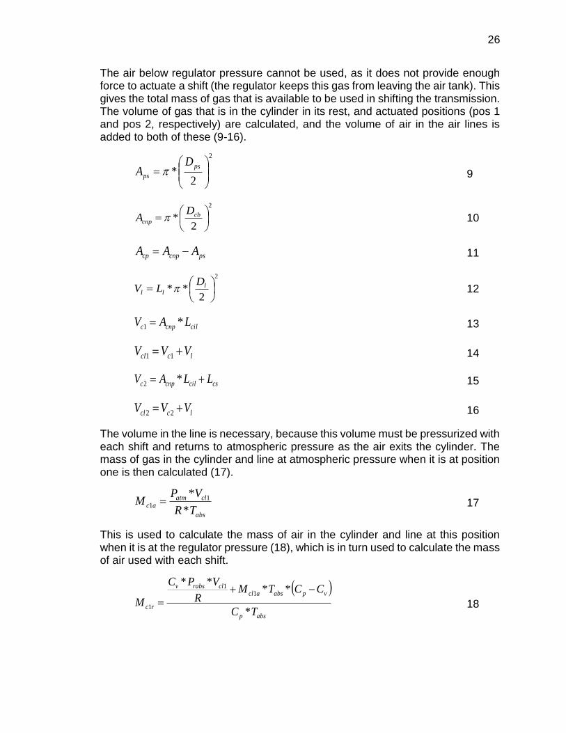
The air below regulator pressure cannot be used, as it does not provide enough force to actuate a shift (the regulator keeps this gas from leaving the air tank). This gives the total mass of gas that is available to be used in shifting the transmission. The volume of gas that is in the cylinder in its rest, and actuated positions (pos 1 and pos 2, respectively) are calculated, and the volume of air in the air lines is added to both of these (9-16).
9
10
11
12
13
14
15
16
The volume in the line is necessary, because this volume must be pressurized with each shift and returns to atmospheric pressure as the air exits the cylinder. The mass of gas in the cylinder and line at atmospheric pressure when it is at position one is then calculated (17).
17
This is used to calculate the mass of air in the cylinder and line at this position when it is at the regulator pressure (18), which is in turn used to calculate the mass of air used with each shift.
18
2
2*
ps
ps
DA
2
2*
cb
cnp
DA
pscnpcp AAA
2
2**
l
ll
DLV
cilcnpc LAV *1
lccl VVV 11
cscilcnpc LLAV *2
lccl VVV 22
abs
clatmac
TR
VPM
*
* 11
absp
vpabsaclclrabsv
rcTC
CCTMR
VPC
M*
****
11
1
27
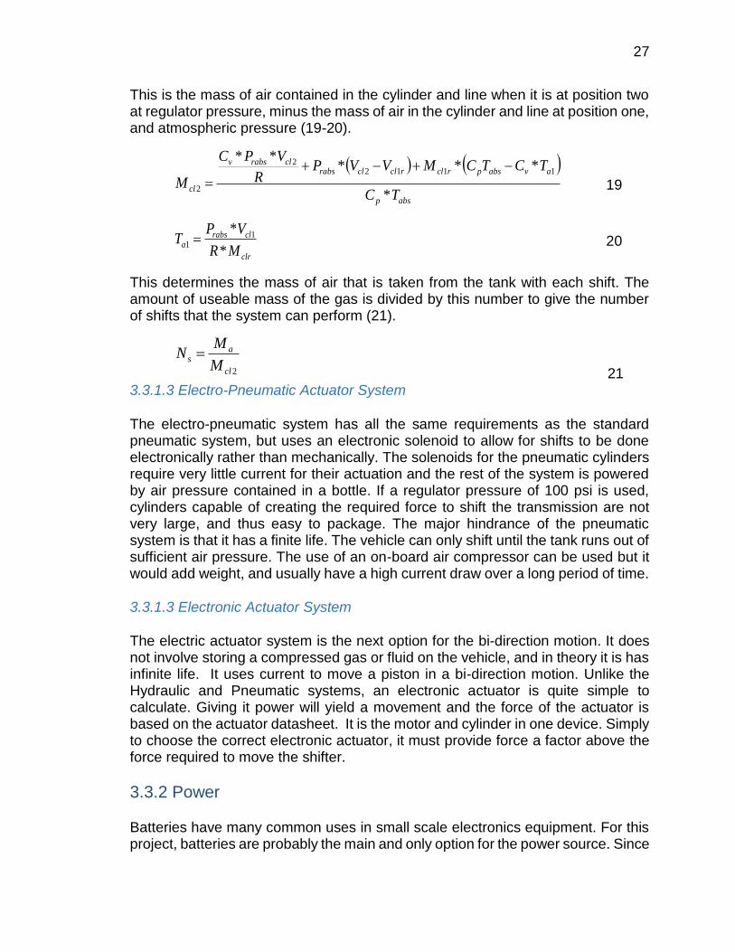
This is the mass of air contained in the cylinder and line when it is at position two at regulator pressure, minus the mass of air in the cylinder and line at position one, and atmospheric pressure (19-20).
19
20
This determines the mass of air that is taken from the tank with each shift. The amount of useable mass of the gas is divided by this number to give the number of shifts that the system can perform (21).
21
3.3.1.3 Electro-Pneumatic Actuator System
The electro-pneumatic system has all the same requirements as the standard pneumatic system, but uses an electronic solenoid to allow for shifts to be done electronically rather than mechanically. The solenoids for the pneumatic cylinders require very little current for their actuation and the rest of the system is powered by air pressure contained in a bottle. If a regulator pressure of 100 psi is used, cylinders capable of creating the required force to shift the transmission are not very large, and thus easy to package. The major hindrance of the pneumatic system is that it has a finite life. The vehicle can only shift until the tank runs out of sufficient air pressure. The use of an on-board air compressor can be used but it would add weight, and usually have a high current draw over a long period of time. 3.3.1.3 Electronic Actuator System
The electric actuator system is the next option for the bi-direction motion. It does not involve storing a compressed gas or fluid on the vehicle, and in theory it is has infinite life. It uses current to move a piston in a bi-direction motion. Unlike the Hydraulic and Pneumatic systems, an electronic actuator is quite simple to calculate. Giving it power will yield a movement and the force of the actuator is based on the actuator datasheet. It is the motor and cylinder in one device. Simply to choose the correct electronic actuator, it must provide force a factor above the force required to move the shifter.
3.3.2 Power Batteries have many common uses in small scale electronics equipment. For this project, batteries are probably the main and only option for the power source. Since
absp
avabsprclrclclrabsclrabsv
clTC
TCTCMVVPR
VPC
M*
*****
11122
2
clr
clrabsa
MR
VPT
*
* 11
2cl
as
M
MN
28
this project includes a high voltage and low voltage power obligations for the components to be powered where the microcontroller requests to be power-driven by low voltage and other components of the vehicle require high voltage to be operational such as the headlights and the ECU, voltage regulators are a necessity for this type of situation. In this project, when using the term high voltage it is meant that it would be around the borders of 12 to 14 volts, since the vehicle will not be using high voltage rates at 700 volts and low voltage would mean 2-5 volts. A supply voltage in the standard range of 3.3 to 5 volts could be easily designed for the microcontroller using amplifiers, resistors, regulators, or other components to ensure the steady supply voltage. However, regulators seem to be the one component that is mostly favorable and useable by individuals. Even though it wouldn’t be necessary to use and that the original 12 volt battery would be enough for power, but a battery pack could be used to supply the high current and voltage components within the vehicle. Another option is to step up transformers to step up the voltage coming out of the battery and use it to directly supply components and deices that require more than 12 volts within the vehicle. For this project, power conversion might need to be done to deliver the right amount of voltages and power up all components within the vehicle without any failures or burnouts. The only type of conversion that would necessary in this project is the DC-to-DC conversion since the vehicle’s main source of power is the 12 volt battery which is obviously a DC power source and the components of the system such as some of the microcontrollers needs to be supplied with 3.3 or 5 volts.
3.3.3 Display The function of the display for the shift system is to inform the driver or what gear they are currently in. There are two options for such a result. One being a LED segment display preferably one of 14-Segment or 16-Segment so that the letter N can be represented. The other option is for use of an LCD or TFT Display that would be able to send out any visual information we needed it to, depending on the resolution chosen. 3.3.3.1 LCD Display
A display screen made with TFT technology is a liquid crystal display, common in notebook and laptop computers, that has a transistor for each pixel. Having a transistor at each pixel means that the current that triggers pixel illumination can be smaller and therefore can be switched on and off more quickly. TFT is also known as active matrix display technology and contrasts with "passive matrix" which does not have a transistor at each pixel. A TFT or active matrix display is more responsive to change. For example, when you move your mouse across the screen, a TFT display is fast enough to reflect the movement of the mouse cursor. With a passive matrix display, the cursor temporarily disappears until the display can "catch up."
29
A TFT screen is commonly not very bright for a small size and the brightness for such a screen is called a nit or candela per square meter (cd/m2). The standard phone at max brightness is around 400-500nits. Using this information, we concluded that a minimum screen brightness for a TFT Display would have to be.
3.3.3.2 LED Segment Display
A fourteen-segment display is a type of display based on 14 segments that can be turned on or off to produce letters and numerals. It is an expansion of the more common seven-segment display, having an additional four diagonal and two vertical segments with the middle horizontal segment broken in half. A seven-segment display suffices for numerals and certain letters, but rendering the basic alphabet requires more detail. A slight variation is the sixteen-segment display which allows additional legibility in displaying letters or other symbols.
A decimal point or comma may be present as an additional segment, or pair of segments; the comma (used for triple-digit groupings or as a decimal separator in many regions) is commonly formed by combining the decimal point with a closely 'attached' leftwards-descending arc-shaped segment. An Example of a 14-segment display can be seen below. Note unbroken top and bottom segments in comparison with a sixteen-segment display.
Electronic alphanumeric displays may use LEDs, LCDs, or vacuum fluorescent display devices. The LED variant is typically manufactured in single or dual character packages, allowing the system designer to choose the number of characters suiting the application.
Often a character generator is used to translate 7-bit ASCII character codes to the 14 bits that indicate which of the 14 segments to turn on or off.
3.3.4 MCU
Immediately prior to shift actuation, both spark and fuel need to be restricted so that a ‘flat shift’ can be performed. Flat shift is a term which describes the event where the engine speed is retarded, eliminating the need for the driver to lift off of the accelerator while shifting. This function will allow for a faster and more accurate shift when compared to conventional means where the driver must lift off of the accelerator.
The microcontroller, which will serve as the intelligent control. The controller must be able to use both input and output signals to control both electrical input as well as output requirements.
The controller must also run a program that is intuitive to modify and execute. In addition the microprocessor subsystem must be able to interface with the high
30
current and voltage ignition and fuel systems of the car. Along with the fuel and spark subsystems, the microprocessor needs an input from the transmission shift drum in order to confirm an accurate shift has occurred.
3.3.5 Driver Controls
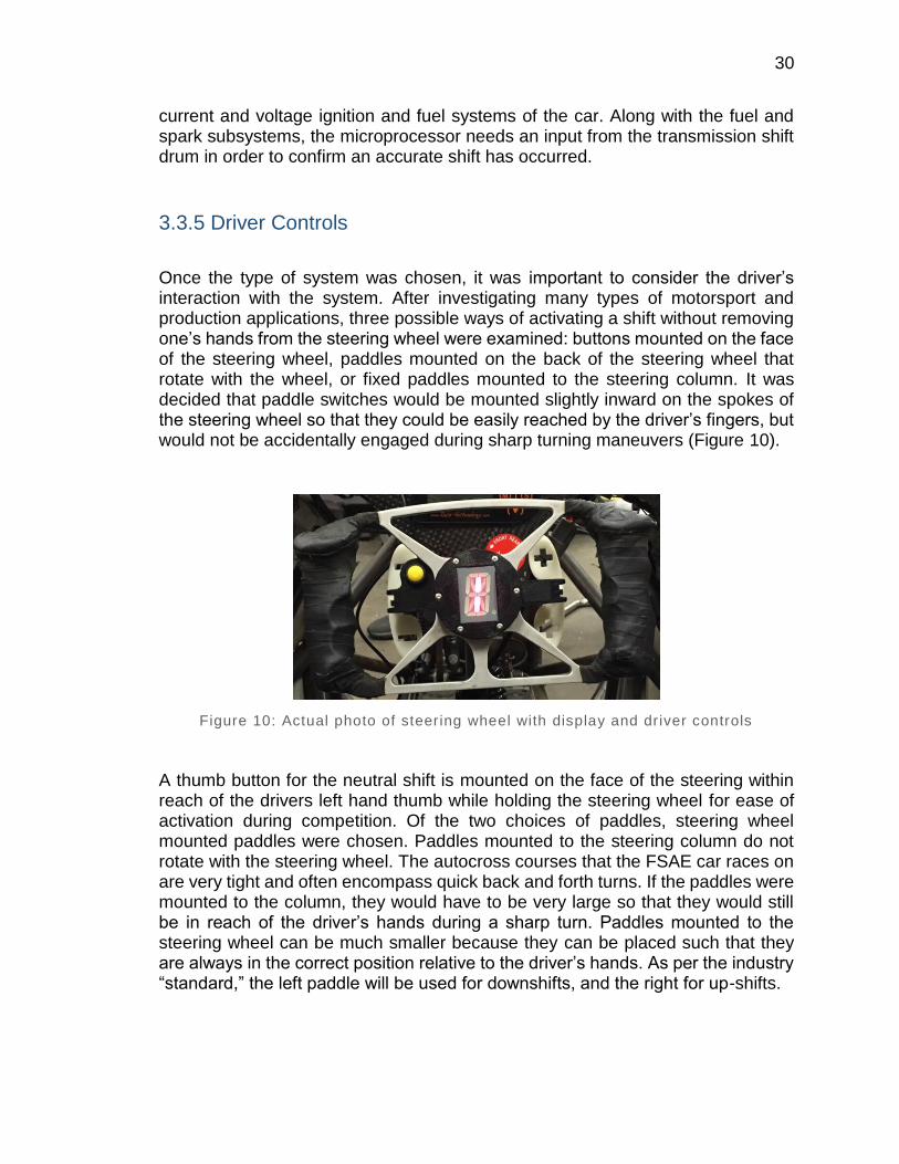
Once the type of system was chosen, it was important to consider the driver’s interaction with the system. After investigating many types of motorsport and production applications, three possible ways of activating a shift without removing one’s hands from the steering wheel were examined: buttons mounted on the face of the steering wheel, paddles mounted on the back of the steering wheel that rotate with the wheel, or fixed paddles mounted to the steering column. It was decided that paddle switches would be mounted slightly inward on the spokes of the steering wheel so that they could be easily reached by the driver’s fingers, but would not be accidentally engaged during sharp turning maneuvers (Figure 10).
Figure 10: Actual photo of steering wheel with display and driver controls
A thumb button for the neutral shift is mounted on the face of the steering within reach of the drivers left hand thumb while holding the steering wheel for ease of activation during competition. Of the two choices of paddles, steering wheel mounted paddles were chosen. Paddles mounted to the steering column do not rotate with the steering wheel. The autocross courses that the FSAE car races on are very tight and often encompass quick back and forth turns. If the paddles were mounted to the column, they would have to be very large so that they would still be in reach of the driver’s hands during a sharp turn. Paddles mounted to the steering wheel can be much smaller because they can be placed such that they are always in the correct position relative to the driver’s hands. As per the industry “standard,” the left paddle will be used for downshifts, and the right for up-shifts.
31
3.3.6 Gear Position Sensor
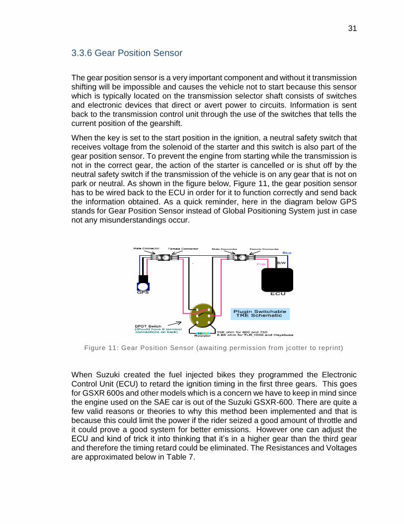
The gear position sensor is a very important component and without it transmission shifting will be impossible and causes the vehicle not to start because this sensor which is typically located on the transmission selector shaft consists of switches and electronic devices that direct or avert power to circuits. Information is sent back to the transmission control unit through the use of the switches that tells the current position of the gearshift.
When the key is set to the start position in the ignition, a neutral safety switch that receives voltage from the solenoid of the starter and this switch is also part of the gear position sensor. To prevent the engine from starting while the transmission is not in the correct gear, the action of the starter is cancelled or is shut off by the neutral safety switch if the transmission of the vehicle is on any gear that is not on park or neutral. As shown in the figure below, Figure 11, the gear position sensor has to be wired back to the ECU in order for it to function correctly and send back the information obtained. As a quick reminder, here in the diagram below GPS stands for Gear Position Sensor instead of Global Positioning System just in case not any misunderstandings occur.
Figure 11: Gear Posit ion Sensor (awaiting permission from jcotter to reprint)
When Suzuki created the fuel injected bikes they programmed the Electronic Control Unit (ECU) to retard the ignition timing in the first three gears. This goes for GSXR 600s and other models which is a concern we have to keep in mind since the engine used on the SAE car is out of the Suzuki GSXR-600. There are quite a few valid reasons or theories to why this method been implemented and that is because this could limit the power if the rider seized a good amount of throttle and it could prove a good system for better emissions. However one can adjust the ECU and kind of trick it into thinking that it’s in a higher gear than the third gear and therefore the timing retard could be eliminated. The Resistances and Voltages are approximated below in Table 7.
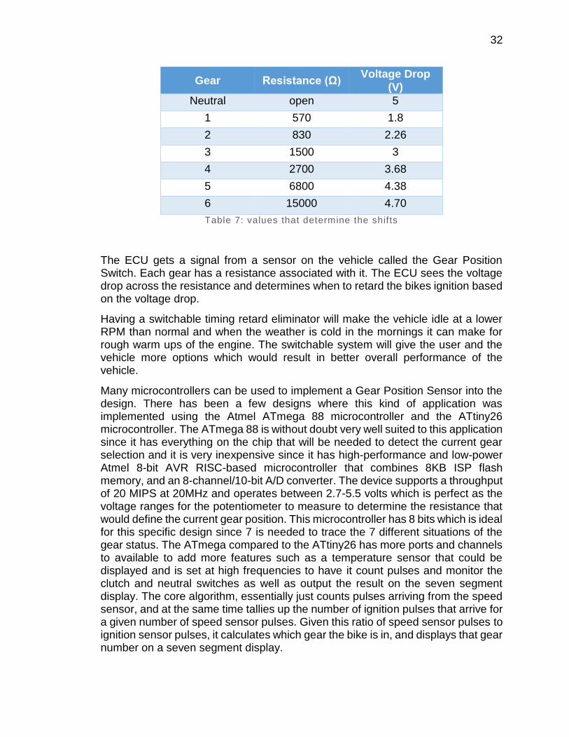
32
Gear Resistance (Ω) Voltage Drop
(V)
Neutral open 5
1 570 1.8
2 830 2.26
3 1500 3
4 2700 3.68
5 6800 4.38
6 15000 4.70
Table 7: values that determine the shifts
The ECU gets a signal from a sensor on the vehicle called the Gear Position Switch. Each gear has a resistance associated with it. The ECU sees the voltage drop across the resistance and determines when to retard the bikes ignition based on the voltage drop.
Having a switchable timing retard eliminator will make the vehicle idle at a lower RPM than normal and when the weather is cold in the mornings it can make for rough warm ups of the engine. The switchable system will give the user and the vehicle more options which would result in better overall performance of the vehicle.
Many microcontrollers can be used to implement a Gear Position Sensor into the design. There has been a few designs where this kind of application was implemented using the Atmel ATmega 88 microcontroller and the ATtiny26 microcontroller. The ATmega 88 is without doubt very well suited to this application since it has everything on the chip that will be needed to detect the current gear selection and it is very inexpensive since it has high-performance and low-power Atmel 8-bit AVR RISC-based microcontroller that combines 8KB ISP flash memory, and an 8-channel/10-bit A/D converter. The device supports a throughput of 20 MIPS at 20MHz and operates between 2.7-5.5 volts which is perfect as the voltage ranges for the potentiometer to measure to determine the resistance that would define the current gear position. This microcontroller has 8 bits which is ideal for this specific design since 7 is needed to trace the 7 different situations of the gear status. The ATmega compared to the ATtiny26 has more ports and channels to available to add more features such as a temperature sensor that could be displayed and is set at high frequencies to have it count pulses and monitor the clutch and neutral switches as well as output the result on the seven segment display. The core algorithm, essentially just counts pulses arriving from the speed sensor, and at the same time tallies up the number of ignition pulses that arrive for a given number of speed sensor pulses. Given this ratio of speed sensor pulses to ignition sensor pulses, it calculates which gear the bike is in, and displays that gear number on a seven segment display.
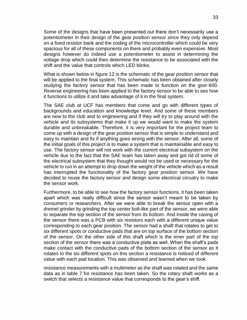
33
Some of the designs that have been presented out there don’t necessarily use a potentiometer in their design of the gear position sensor since they only depend on a fixed resistor bank and the coding of the microcontroller which could be very spacious for all of these components on there and probably even expensive. Most designs however do indeed use a potentiometer to assist in determining the voltage drop which could then determine the resistance to be associated with the shift and the value that controls which LED blinks.
What is shown below in figure 12 is the schematic of the gear position sensor that will be applied to the final system. This schematic has been obtained after closely studying the factory sensor that has been made to function on the gsxr-600. Reverse engineering has been applied to the factory sensor to be able to see how it functions to utilize it and take advantage of it in the final system.
The SAE club at UCF has members that come and go with different types of backgrounds and education and knowledge level. And some of these members are new to the club and to engineering and if they will try to play around with the vehicle and its subsystems that make it up we would want to make the system durable and unbreakable. Therefore, it is very important for the project team to come up with a design of the gear position sensor that is simple to understand and easy to maintain and fix if anything goes wrong with the sensor. After all, some of the initial goals of this project is to make a system that is maintainable and easy to use. The factory sensor will not work with the current electrical subsystem on the vehicle due to the fact that the SAE team has taken away and got rid of some of the electrical subsystem that they thought would not be used or necessary for the vehicle to run in an attempt to drop down the weight of the vehicle which as a result has interrupted the functionality of the factory gear position sensor. We have decided to reuse the factory sensor and design some electrical circuitry to make the sensor work.
Furthermore, to be able to see how the factory sensor functions, it has been taken apart which was really difficult since the sensor wasn’t meant to be taken by consumers or researchers. After we were able to break the sensor open with a dremel grinder by grinding the top center bolt-like part of the sensor, we were able to separate the top section of the sensor from its bottom. And inside the casing of the sensor there was a PCB with six resistors each with a different unique value corresponding to each gear position. The sensor had a shaft that rotates to get to six different spots or conductive pads that are on top surface of the bottom section of the sensor. On the other side of this shaft which is the inner part of the top section of the sensor there was a conductive plate as well. When the shaft’s pads make contact with the conductive pads of the bottom section of the sensor as it rotates to the six different spots on this section a resistance is noticed of different value with each pad location. This was observed and learned when we took
resistance measurements with a multimeter as the shaft was rotated and the same data as in table 7 for resistance has been taken. So the rotary shaft works as a switch that selects a resistance value that corresponds to the gear’s shift.
34
Figure 12: Schematic of gear positon sensor using factory model
The senor is made up of a three wire connection to make it operational. One wire runs from the sensor to the ECU while the other two are ground and a wire that comes from the electrical subsystem of the vehicle. However, in our case the wire that runs through the sensor to the ECU will be going to the microcontroller via one of the pins of the microcontroller. The wire that comes from the electrical subsystem to the senor in the factory design will be connected to a power source for our design to be able to power the sensor. And the ground wire in the factory design will remain ground in our system’s design as well.
To be able to obtain the same voltage values as the factory voltage data which are shown in table 7, we had to use a resistor with a value of 1kΩ and connect it in parallel with the gear signal that goes to the microcontroller and the resistor that will be selected depending on the gear’s position when a shift is made. Basically a voltage divider has been established to realize the same values of the table 7 above. So if the vehicle’s transmission is running on the first gear the sensor will make a connection between the resistor that corresponds to the first gear which is the 560Ω resistor and the gear signal that goes to the microcontroller and the 5-volt source that powers up the sensor with the 1kΩ resistor. And so the voltage divider formula Vout= Z2Vin/(Z1+Z2) has been used to come up with the values that would be sent to the microcontroller as a voltage signal through one of its pins to output a number that corresponds to the gear’s shift on the 14-segment display.
3.3.7 Wiring Harness
The electronic paddle shift system will require a wiring harness to connect all the components of the system that can withstand the demands of a motorsports environment. Getting electrical signals from point A to B is a pretty standard thing,
35
but when it comes to a motorsports environment it is extremely important that the harness is constructed out of the most reliable and lightweight components. It is very common in the professional motorsports industry for wiring harnesses to be referred to as "mil-spec" (or military specification). This has evolved from aircraft and military specifications wherein lightweight and reliability are of the utmost importance. As motorsports evolved into an increasingly more sophisticated and expensive professional endeavor, specific motorsport connectors have evolved which are even lighter and smaller than their aerospace counterparts. These products don't have to meet oem production testing requirements, they just have to be reliable in a racing environment which is not the same as the demands required by oem's.
Anything that can slow the car down is the enemy..... weight of the wires, weight of the connectors, and any kind of outright failure, or worse, intermittent failure, which is much more difficult to isolate and diagnose. These are reasons it is absolutely critical to have a wiring harness that is well built out of the proper materials and components. A true mil-spec harness will only be made using high quality harnessing components and the proper tools and techniques. Some of the materials and components that are common in mil-spec/motorsports wiring harness builds are Tefzel wire, Raychem DR-25 heat-shrink tubing, Deutsch connectors, Raychem boots and transitions, ResinTech RT125 harness epoxy, low static Kapton tape, and braided Kevlar lacing cord.
Tefzel wire is coated with ETFE, which is a plastic that was designed to be both resistant to corrosion and to maintain strength over a wide range of temperatures. Tefzel is a brand name for the Ethylene Tetrafluoroehtylene by DuPont. Tefzel is the registered trademark of E.I. DuPont. Tefzel wire is primarily used in high stress and high reliability situations. Mostly used in the aviation, aerospace and military industries, but it is also very common for use in motorsports applications as well. Tefzel ETFE fluoropolymer resin is a melt-proccessable, modified copolymer of ethylene and tetrafluoroethylene, which produces a high-performance resin with an excellent balance of properties. Compared to other fluoropolymer resins, Tefzel ETFE features superior mechanical toughness, outstanding chemical inertness and easy proccessibility at relatively high rates. ETFE has a relatively high melting temperature, excellent chemical resistance, electrical and high energy radiation resistance properties. The figure below, Figure 13, shows an example of Tefzel wire vs standard wire. The Tefzel wire is the one with the green insulation and the standard wire has white insulation. It can be seen that the Tefzel wire has many more strands of wire for the conductor compared to the standard wire. It can also be seen that the Tefzel wire has a tinned copper conductor, where as the standard wire is a solid copper wire. Copper itself is a great metal choice when it comes to electrical engineering.

36
Figure 13: Comparison of Tefzel wire vs standard wire
Everything from your car to your house, even city lights finds its current running through a copper wire or cable. Copper has great conductivity, a durable tensile strength and is easy to machine into wire and other specialty wire and cables. For these reasons, copper finds itself being used to create many alloys that are used for electrical work. However, even with the fairly high resistance to corrosion that copper has, wet environments or other places with high humidity it is very common to find the copper wire corroding and losing performance. So items such as a motorsports wiring harness, it is not quite ideal to use a solid copper wire due to the risk of corrosion. That’s where tinned copper wire comes into play. Tin plating helps to make a sort of specialty wire and cable. Where many plated wires, such as gold or nickel plated wires can be more for cosmetic purposes such as in jewelry wire wrapping, tin is a much more practical choice. Tin is useful for copper plating because it not only helps to boost coppers properties, it also helps the wire to last much longer that it would normally. In fact, a tin plated copper wire can last up to ten times longer than a similar gauge solid copper wire. As tin resists corrosion and doesn’t oxidize the plating helps to protect the copper underneath. This wards off additional wear and tear that would detract years off the life of a solid copper wire. This is especially so in instances where the operating temperatures of the wire exceed 100 degrees Celsius. At higher temperatures, the corrosion resistance of copper declines, making a tin coating valuable for protecting the wire in this state. It is also highly desirable for military and motorsport applications. Tinned wires are also desirable for soldering as they make connections and soldering an easy task given tin is a primary component in solder. Tin also helps to strengthen the copper wire underneath, making it more resilient to breakage or lost connections while also boosting coppers conductivity. So while tinned copper wire is more expensive that solid copper wire, it is often considered to be a very worthwhile investment in the long run. Given that simple tin plating can drastically

37
increase the life of copper, as well as ensure its effectiveness in high humidity areas, it pays for itself with strong performance and a lot less maintenance.
Tefzel wire conforms to military specification M22759. Wire meeting military specification M22759 is appropriate for aerospace applications which require minimal weight and tight diameters. This makes wires meeting military specification M22759 also ideal for the motorsports industry. The wires ETFE insulation provides excellent radiation and chemical resistance. It is also mechanically tough. The figure below, Figure 14, shows a comparison of Tefzel wire versus standard wire after being held above the open flame from a lighter for 10 seconds. As seen in the photo the insulation of the standard wire is completely charred and burned, whereas the ETFE insulation of the Tefzel wire is only slightly deformed with minimal burn markings. This small experiment clearly demonstrates the durability of the Tefzel wire.
Figure 14: Comparison of Tefzel wire vs standard wire after being held above an
open flame for 10 seconds
In a motorsports environment it is essential to make sure that the wires in the harness are protected and safe from chemicals and heat in a sheathing that is also lightweight and flexible. DR-25 is a lightweight, heat shrinkable tubing suitable for jacketing of cables and wiring looms. DR-25 provides excellent abrasion resistance. It features a 2:1 shrink ratio, is flexible and flame retardant. Raychem DR-25 is specially formulated for optimum high temperature fluid resistance, and long term heat resistance. DR-25 is resistant to aviation and diesel fuels, hydraulic fluids and lubricating oils. Raychem DR-25 is particularly suitable as a jacketing material for military ground vehicle cables and harnesses. It is also well suited for the demands of motorsport harnesses. When used in conjunction with System 25 heat shrinkable molded boots and high performance adhesive, these products provide a complete cable harness system. The physical properties of DR-25 tubing
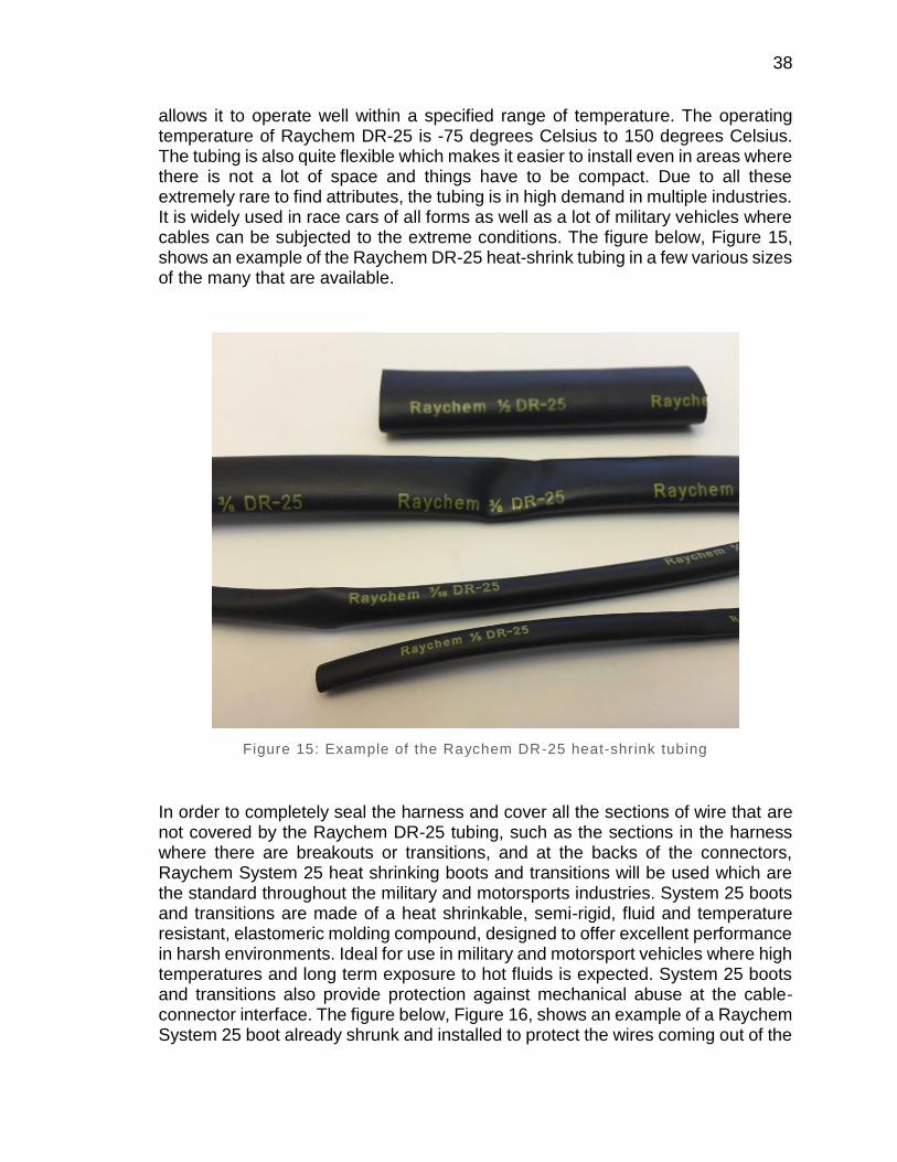
38
allows it to operate well within a specified range of temperature. The operating temperature of Raychem DR-25 is -75 degrees Celsius to 150 degrees Celsius. The tubing is also quite flexible which makes it easier to install even in areas where there is not a lot of space and things have to be compact. Due to all these extremely rare to find attributes, the tubing is in high demand in multiple industries. It is widely used in race cars of all forms as well as a lot of military vehicles where cables can be subjected to the extreme conditions. The figure below, Figure 15, shows an example of the Raychem DR-25 heat-shrink tubing in a few various sizes of the many that are available.
Figure 15: Example of the Raychem DR-25 heat-shrink tubing
In order to completely seal the harness and cover all the sections of wire that are not covered by the Raychem DR-25 tubing, such as the sections in the harness where there are breakouts or transitions, and at the backs of the connectors, Raychem System 25 heat shrinking boots and transitions will be used which are the standard throughout the military and motorsports industries. System 25 boots and transitions are made of a heat shrinkable, semi-rigid, fluid and temperature resistant, elastomeric molding compound, designed to offer excellent performance in harsh environments. Ideal for use in military and motorsport vehicles where high temperatures and long term exposure to hot fluids is expected. System 25 boots and transitions also provide protection against mechanical abuse at the cable-connector interface. The figure below, Figure 16, shows an example of a Raychem System 25 boot already shrunk and installed to protect the wires coming out of the
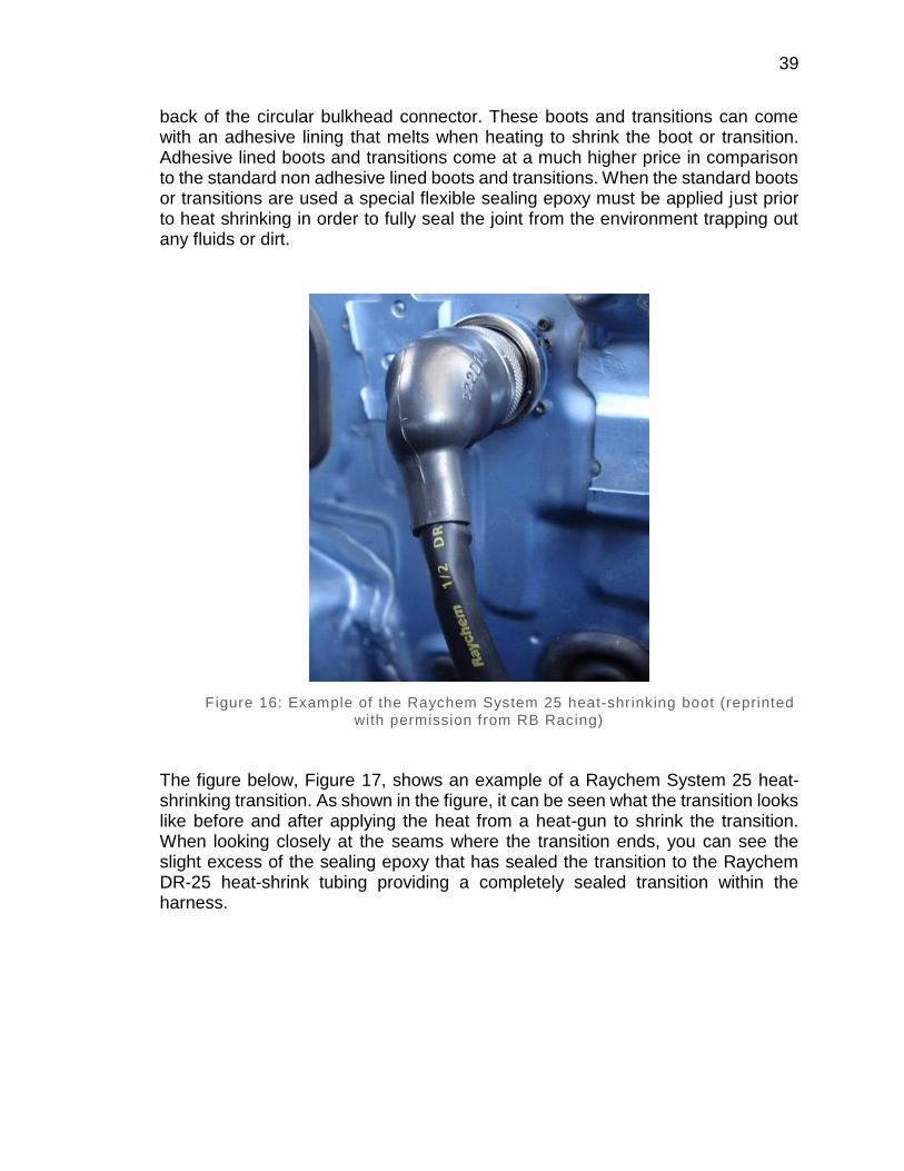
39
back of the circular bulkhead connector. These boots and transitions can come with an adhesive lining that melts when heating to shrink the boot or transition. Adhesive lined boots and transitions come at a much higher price in comparison to the standard non adhesive lined boots and transitions. When the standard boots or transitions are used a special flexible sealing epoxy must be applied just prior to heat shrinking in order to fully seal the joint from the environment trapping out any fluids or dirt.
Figure 16: Example of the Raychem System 25 heat-shrinking boot (reprinted
with permission from RB Racing)
The figure below, Figure 17, shows an example of a Raychem System 25 heat-shrinking transition. As shown in the figure, it can be seen what the transition looks like before and after applying the heat from a heat-gun to shrink the transition. When looking closely at the seams where the transition ends, you can see the slight excess of the sealing epoxy that has sealed the transition to the Raychem DR-25 heat-shrink tubing providing a completely sealed transition within the harness.
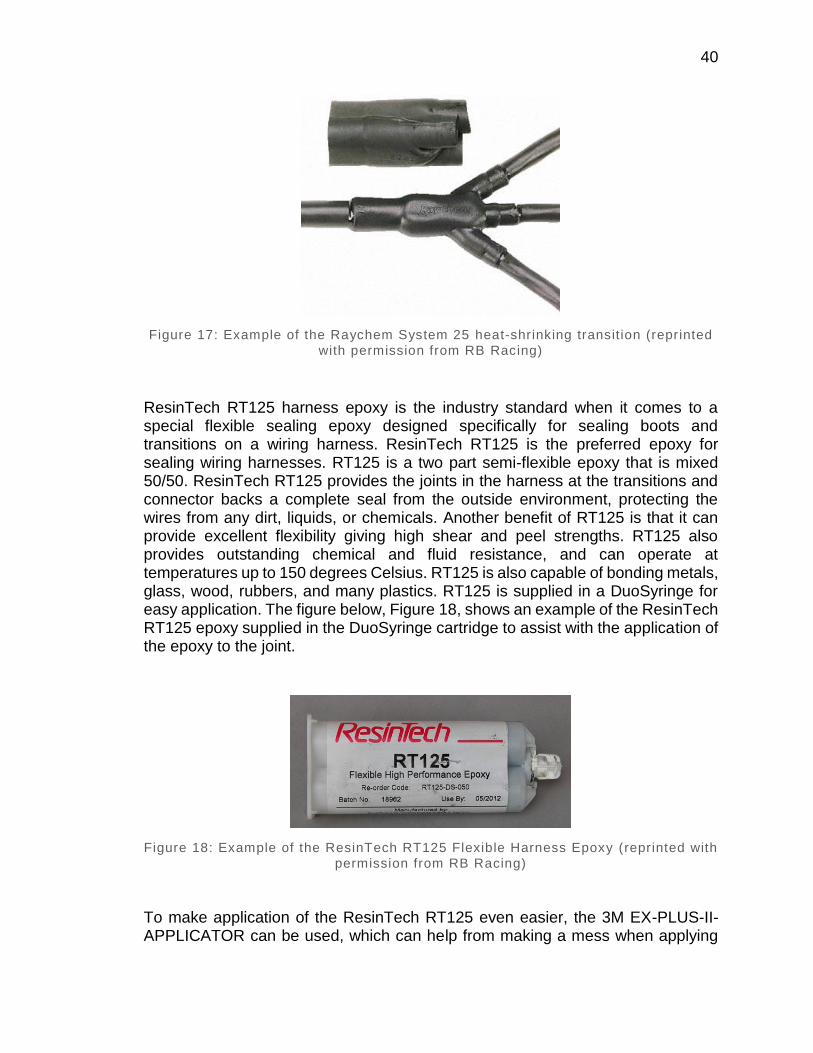
40
Figure 17: Example of the Raychem System 25 heat-shrinking transit ion (reprinted
with permission from RB Racing)
ResinTech RT125 harness epoxy is the industry standard when it comes to a special flexible sealing epoxy designed specifically for sealing boots and transitions on a wiring harness. ResinTech RT125 is the preferred epoxy for sealing wiring harnesses. RT125 is a two part semi-flexible epoxy that is mixed 50/50. ResinTech RT125 provides the joints in the harness at the transitions and connector backs a complete seal from the outside environment, protecting the wires from any dirt, liquids, or chemicals. Another benefit of RT125 is that it can provide excellent flexibility giving high shear and peel strengths. RT125 also provides outstanding chemical and fluid resistance, and can operate at temperatures up to 150 degrees Celsius. RT125 is also capable of bonding metals, glass, wood, rubbers, and many plastics. RT125 is supplied in a DuoSyringe for easy application. The figure below, Figure 18, shows an example of the ResinTech RT125 epoxy supplied in the DuoSyringe cartridge to assist with the application of the epoxy to the joint.
Figure 18: Example of the ResinTech RT125 Flexible Harness Epoxy (reprinted with
permission from RB Racing)
To make application of the ResinTech RT125 even easier, the 3M EX-PLUS-II-APPLICATOR can be used, which can help from making a mess when applying
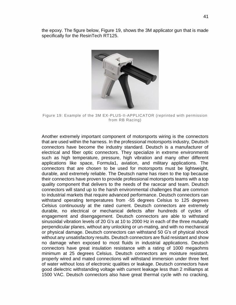
41
the epoxy. The figure below, Figure 19, shows the 3M applicator gun that is made specifically for the ResinTech RT125.
Figure 19: Example of the 3M EX-PLUS-II-APPLICATOR (reprinted with permission
from RB Racing)
Another extremely important component of motorsports wiring is the connectors that are used within the harness. In the professional motorsports industry, Deutsch connectors have become the industry standard. Deutsch is a manufacturer of electrical and fiber optic connectors. They specialize in extreme environments such as high temperature, pressure, high vibration and many other different applications like space, Formula1, aviation, and military applications. The connectors that are chosen to be used for motorsports must be lightweight, durable, and extremely reliable. The Deutsch name has risen to the top because their connectors have proven to provide professional motorsports teams with a top quality component that delivers to the needs of the racecar and team. Deutsch connectors will stand up to the harsh environmental challenges that are common to industrial markets that require advanced performance. Deutsch connectors can withstand operating temperatures from -55 degrees Celsius to 125 degrees Celsius continuously at the rated current. Deutsch connectors are extremely durable, no electrical or mechanical defects after hundreds of cycles of engagement and disengagement. Deutsch connectors are able to withstand sinusoidal vibration levels of 20 G's at 10 to 2000 Hz in each of the three mutually perpendicular planes, without any unlocking or un-mating, and with no mechanical or physical damage. Deutsch connectors can withstand 50 G's of physical shock without any unsatisfactory results. Deutsch connectors are fluid resistant and show no damage when exposed to most fluids in industrial applications. Deutsch connectors have great insulation resistance with a rating of 1000 megaohms minimum at 25 degrees Celsius. Deutsch connectors are moisture resistant, properly wired and mated connections will withstand immersion under three feet of water without loss of electronic qualities or leakage. Deutsch connectors have good dielectric withstanding voltage with current leakage less than 2 milliamps at 1500 VAC. Deutsch connectors also have great thermal cycle with no cracking,

42
chipping or leaking after 20 test cycles from -55 degrees Celsius to 125 degrees Celsius. The figure below, Figure 20, shows an example of some of the few connectors available from Deutsch. In the figure it can be seen that the connectors have rubber seals at the tip of the plug and also at the backs of both the plugs and receptacles where the wires go through providing a complete seal from the environment.
Figure 20: Example of some of the various connectors available from Deutsch
The contacts that Deutsch connectors use are used interchangeably across most of the Deutsch connector product lines. This commonality improves performance, reliability, and maintainability by reducing changes in the assembly of the wiring harness. The use of the same contact systems eliminates many of the failures reported in harnesses where hundreds of different terminations are used. The solid contacts are designed for use where wire termination is of primary concern along with reliability of the electrical circuit. The figure below, Figure 21, shows the Deutsch pin and socket contacts that are used within various Deutsch connectors. All of the Deutsch pin and socket contacts are made from 98% pure copper and then plated. Standard plating is Nickel. For critical circuits, pins and sockets are plated with Nickel and then Gold. For lighting, power and control circuits, choose Nickel. For critical and very low voltage and amperage circuits such as oxygen sensors that operate at 0-1 volt (narrowband) or 0-5 volts (wideband) and for data transmission circuits that operate at 5 volts, choose Gold.
Figure 21: Example of the Nickel plated pin and socket contacts that are used
within the Deutsch connectors
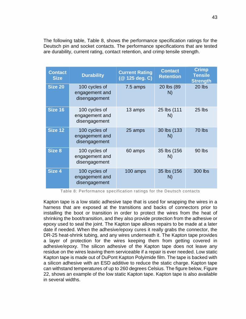
43
The following table, Table 8, shows the performance specification ratings for the Deutsch pin and socket contacts. The performance specifications that are tested are durability, current rating, contact retention, and crimp tensile strength.
Contact
Size Durability
Current Rating
(@ 125 deg. C)
Contact Retention
Crimp Tensile
Strength
Size 20 100 cycles of engagement and
disengagement
7.5 amps 20 lbs (89 N)
20 lbs
Size 16 100 cycles of engagement and disengagement
13 amps 25 lbs (111 N)
25 lbs
Size 12 100 cycles of engagement and disengagement
25 amps 30 lbs (133 N)
70 lbs
Size 8 100 cycles of engagement and disengagement
60 amps 35 lbs (156 N)
90 lbs
Size 4 100 cycles of engagement and disengagement
100 amps 35 lbs (156 N)
300 lbs
Table 8: Performance specif ication ratings for the Deutsch contacts
Kapton tape is a low static adhesive tape that is used for wrapping the wires in a harness that are exposed at the transitions and backs of connectors prior to installing the boot or transition in order to protect the wires from the heat of shrinking the boot/transition, and they also provide protection from the adhesive or epoxy used to seal the joint. The Kapton tape allows repairs to be made at a later date if needed. When the adhesive/epoxy cures it really grabs the connector, the DR-25 heat-shrink tubing, and any wires underneath it. The Kapton tape provides a layer of protection for the wires keeping them from getting covered in adhesive/epoxy. The silicon adhesive of the Kapton tape does not leave any residue on the wires leaving them serviceable if a repair is ever needed. Low static Kapton tape is made out of DuPont Kapton Polyimide film. The tape is backed with a silicon adhesive with an ESD additive to reduce the static charge. Kapton tape can withstand temperatures of up to 260 degrees Celsius. The figure below, Figure 22, shows an example of the low static Kapton tape. Kapton tape is also available in several widths.
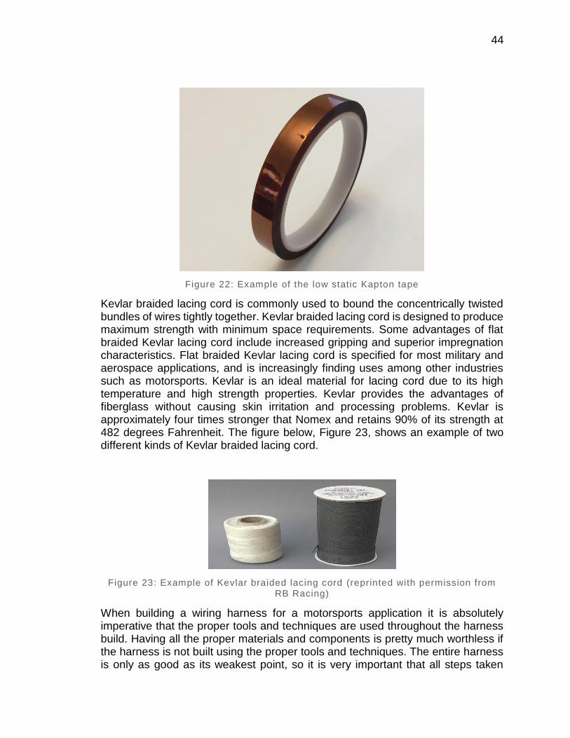
44
Figure 22: Example of the low static Kapton tape
Kevlar braided lacing cord is commonly used to bound the concentrically twisted bundles of wires tightly together. Kevlar braided lacing cord is designed to produce maximum strength with minimum space requirements. Some advantages of flat braided Kevlar lacing cord include increased gripping and superior impregnation characteristics. Flat braided Kevlar lacing cord is specified for most military and aerospace applications, and is increasingly finding uses among other industries such as motorsports. Kevlar is an ideal material for lacing cord due to its high temperature and high strength properties. Kevlar provides the advantages of fiberglass without causing skin irritation and processing problems. Kevlar is approximately four times stronger that Nomex and retains 90% of its strength at 482 degrees Fahrenheit. The figure below, Figure 23, shows an example of two different kinds of Kevlar braided lacing cord.
Figure 23: Example of Kevlar braided lacing cord (reprinted with permission from RB Racing)
When building a wiring harness for a motorsports application it is absolutely imperative that the proper tools and techniques are used throughout the harness build. Having all the proper materials and components is pretty much worthless if the harness is not built using the proper tools and techniques. The entire harness is only as good as its weakest point, so it is very important that all steps taken
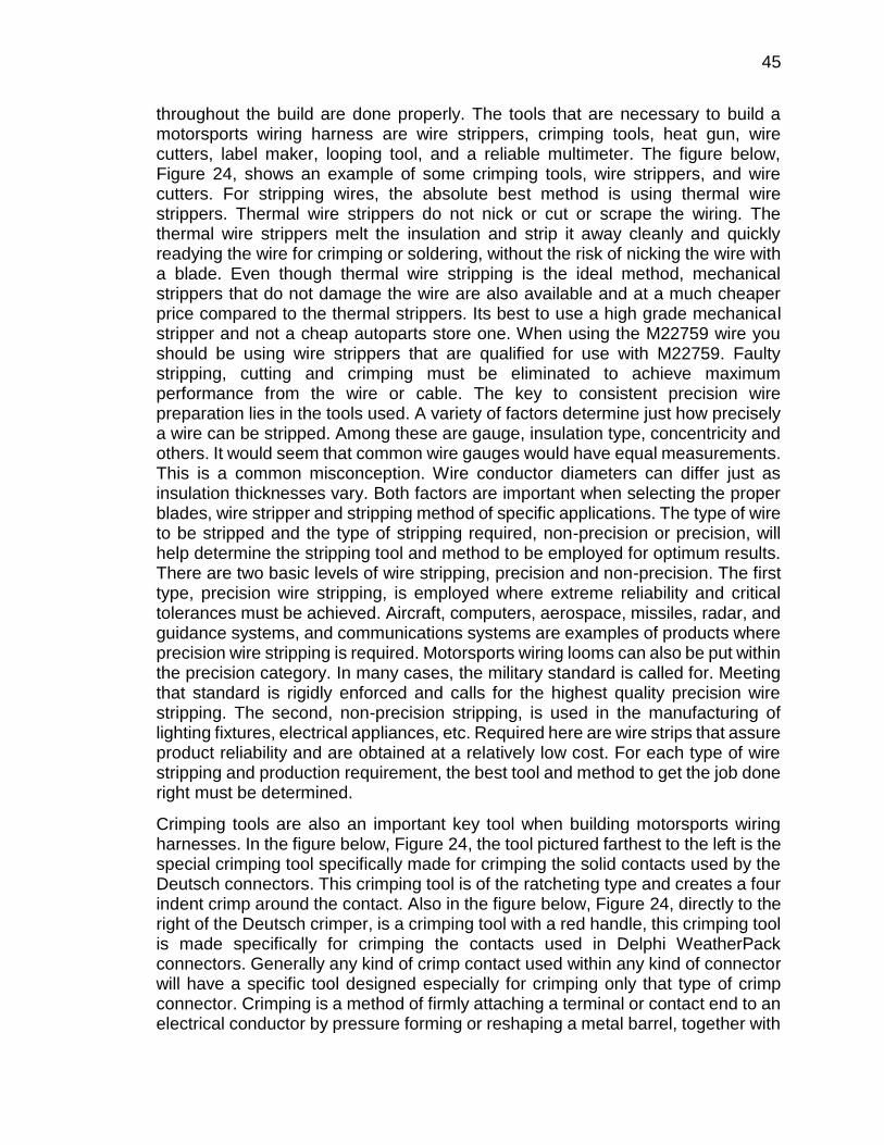
45
throughout the build are done properly. The tools that are necessary to build a motorsports wiring harness are wire strippers, crimping tools, heat gun, wire cutters, label maker, looping tool, and a reliable multimeter. The figure below, Figure 24, shows an example of some crimping tools, wire strippers, and wire cutters. For stripping wires, the absolute best method is using thermal wire strippers. Thermal wire strippers do not nick or cut or scrape the wiring. The thermal wire strippers melt the insulation and strip it away cleanly and quickly readying the wire for crimping or soldering, without the risk of nicking the wire with a blade. Even though thermal wire stripping is the ideal method, mechanical strippers that do not damage the wire are also available and at a much cheaper price compared to the thermal strippers. Its best to use a high grade mechanical stripper and not a cheap autoparts store one. When using the M22759 wire you should be using wire strippers that are qualified for use with M22759. Faulty stripping, cutting and crimping must be eliminated to achieve maximum performance from the wire or cable. The key to consistent precision wire preparation lies in the tools used. A variety of factors determine just how precisely a wire can be stripped. Among these are gauge, insulation type, concentricity and others. It would seem that common wire gauges would have equal measurements. This is a common misconception. Wire conductor diameters can differ just as insulation thicknesses vary. Both factors are important when selecting the proper blades, wire stripper and stripping method of specific applications. The type of wire to be stripped and the type of stripping required, non-precision or precision, will help determine the stripping tool and method to be employed for optimum results. There are two basic levels of wire stripping, precision and non-precision. The first type, precision wire stripping, is employed where extreme reliability and critical tolerances must be achieved. Aircraft, computers, aerospace, missiles, radar, and guidance systems, and communications systems are examples of products where precision wire stripping is required. Motorsports wiring looms can also be put within the precision category. In many cases, the military standard is called for. Meeting that standard is rigidly enforced and calls for the highest quality precision wire stripping. The second, non-precision stripping, is used in the manufacturing of lighting fixtures, electrical appliances, etc. Required here are wire strips that assure product reliability and are obtained at a relatively low cost. For each type of wire stripping and production requirement, the best tool and method to get the job done right must be determined.
Crimping tools are also an important key tool when building motorsports wiring harnesses. In the figure below, Figure 24, the tool pictured farthest to the left is the special crimping tool specifically made for crimping the solid contacts used by the Deutsch connectors. This crimping tool is of the ratcheting type and creates a four indent crimp around the contact. Also in the figure below, Figure 24, directly to the right of the Deutsch crimper, is a crimping tool with a red handle, this crimping tool is made specifically for crimping the contacts used in Delphi WeatherPack connectors. Generally any kind of crimp contact used within any kind of connector will have a specific tool designed especially for crimping only that type of crimp connector. Crimping is a method of firmly attaching a terminal or contact end to an electrical conductor by pressure forming or reshaping a metal barrel, together with
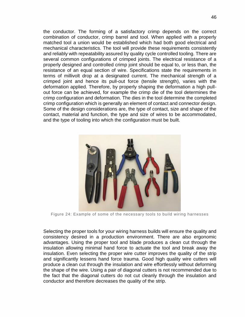
46
the conductor. The forming of a satisfactory crimp depends on the correct combination of conductor, crimp barrel and tool. When applied with a properly matched tool a union would be established which had both good electrical and mechanical characteristics. The tool will provide these requirements consistently and reliably with repeatability assured by quality cycle controlled tooling. There are several common configurations of crimped joints. The electrical resistance of a properly designed and controlled crimp joint should be equal to, or less than, the resistance of an equal section of wire. Specifications state the requirements in terms of millivolt drop at a designated current. The mechanical strength of a crimped joint and hence its pull-out force (tensile strength), varies with the deformation applied. Therefore, by properly shaping the deformation a high pull-out force can be achieved, for example the crimp die of the tool determines the crimp configuration and deformation. The dies in the tool determine the completed crimp configuration which is generally an element of contact and connector design. Some of the design considerations are, the type of contact, size and shape of the contact, material and function, the type and size of wires to be accommodated, and the type of tooling into which the configuration must be built.
Figure 24: Example of some of the necessary tools to build wir ing harnesses
Selecting the proper tools for your wiring harness builds will ensure the quality and consistency desired in a production environment. There are also ergonomic advantages. Using the proper tool and blade produces a clean cut through the insulation allowing minimal hand force to actuate the tool and break away the insulation. Even selecting the proper wire cutter improves the quality of the strip and significantly lessens hand force trauma. Good high quality wire cutters will produce a clean cut through the insulation and wire effortlessly without deforming the shape of the wire. Using a pair of diagonal cutters is not recommended due to the fact that the diagonal cutters do not cut cleanly through the insulation and conductor and therefore decreases the quality of the strip.
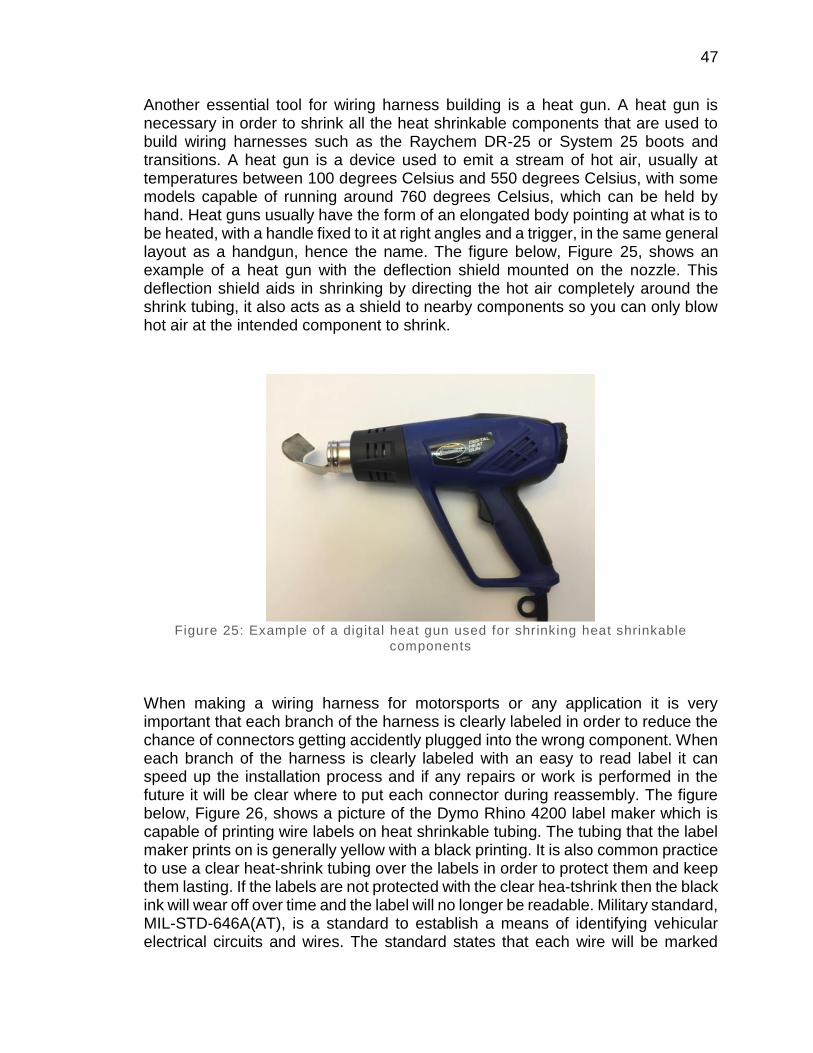
47
Another essential tool for wiring harness building is a heat gun. A heat gun is necessary in order to shrink all the heat shrinkable components that are used to build wiring harnesses such as the Raychem DR-25 or System 25 boots and transitions. A heat gun is a device used to emit a stream of hot air, usually at temperatures between 100 degrees Celsius and 550 degrees Celsius, with some models capable of running around 760 degrees Celsius, which can be held by hand. Heat guns usually have the form of an elongated body pointing at what is to be heated, with a handle fixed to it at right angles and a trigger, in the same general layout as a handgun, hence the name. The figure below, Figure 25, shows an example of a heat gun with the deflection shield mounted on the nozzle. This deflection shield aids in shrinking by directing the hot air completely around the shrink tubing, it also acts as a shield to nearby components so you can only blow hot air at the intended component to shrink.
Figure 25: Example of a digital heat gun used for shrinking heat shrinkable
components
When making a wiring harness for motorsports or any application it is very important that each branch of the harness is clearly labeled in order to reduce the chance of connectors getting accidently plugged into the wrong component. When each branch of the harness is clearly labeled with an easy to read label it can speed up the installation process and if any repairs or work is performed in the future it will be clear where to put each connector during reassembly. The figure below, Figure 26, shows a picture of the Dymo Rhino 4200 label maker which is capable of printing wire labels on heat shrinkable tubing. The tubing that the label maker prints on is generally yellow with a black printing. It is also common practice to use a clear heat-shrink tubing over the labels in order to protect them and keep them lasting. If the labels are not protected with the clear hea-tshrink then the black ink will wear off over time and the label will no longer be readable. Military standard, MIL-STD-646A(AT), is a standard to establish a means of identifying vehicular electrical circuits and wires. The standard states that each wire will be marked
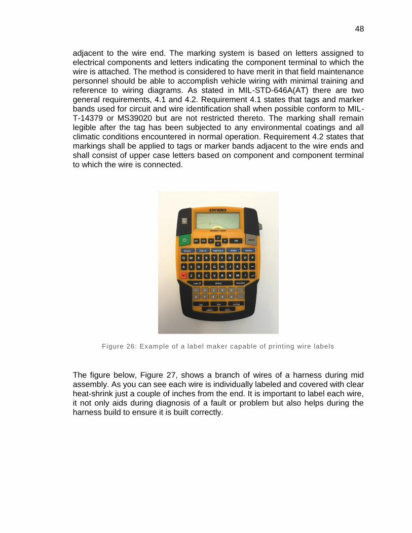
48
adjacent to the wire end. The marking system is based on letters assigned to electrical components and letters indicating the component terminal to which the wire is attached. The method is considered to have merit in that field maintenance personnel should be able to accomplish vehicle wiring with minimal training and reference to wiring diagrams. As stated in MIL-STD-646A(AT) there are two general requirements, 4.1 and 4.2. Requirement 4.1 states that tags and marker bands used for circuit and wire identification shall when possible conform to MIL-T-14379 or MS39020 but are not restricted thereto. The marking shall remain legible after the tag has been subjected to any environmental coatings and all climatic conditions encountered in normal operation. Requirement 4.2 states that markings shall be applied to tags or marker bands adjacent to the wire ends and shall consist of upper case letters based on component and component terminal to which the wire is connected.
Figure 26: Example of a label maker capable of printing wire labels
The figure below, Figure 27, shows a branch of wires of a harness during mid assembly. As you can see each wire is individually labeled and covered with clear heat-shrink just a couple of inches from the end. It is important to label each wire, it not only aids during diagnosis of a fault or problem but also helps during the harness build to ensure it is built correctly.
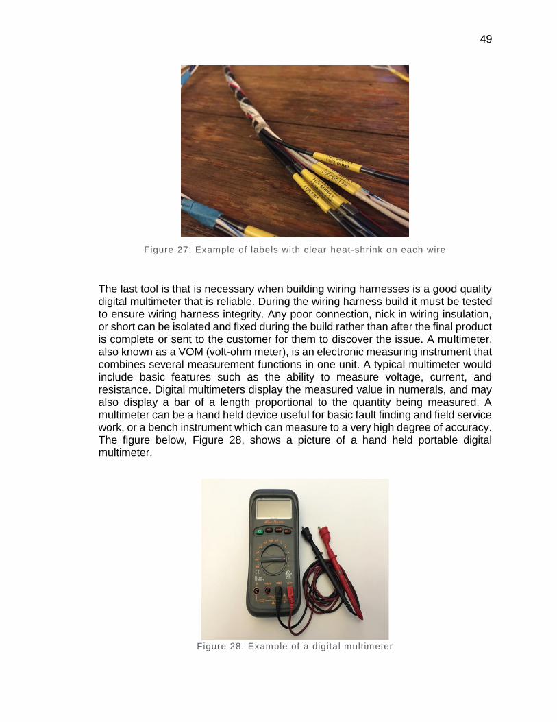
49
Figure 27: Example of labels with clear heat-shrink on each wire
The last tool is that is necessary when building wiring harnesses is a good quality digital multimeter that is reliable. During the wiring harness build it must be tested to ensure wiring harness integrity. Any poor connection, nick in wiring insulation, or short can be isolated and fixed during the build rather than after the final product is complete or sent to the customer for them to discover the issue. A multimeter, also known as a VOM (volt-ohm meter), is an electronic measuring instrument that combines several measurement functions in one unit. A typical multimeter would include basic features such as the ability to measure voltage, current, and resistance. Digital multimeters display the measured value in numerals, and may also display a bar of a length proportional to the quantity being measured. A multimeter can be a hand held device useful for basic fault finding and field service work, or a bench instrument which can measure to a very high degree of accuracy. The figure below, Figure 28, shows a picture of a hand held portable digital multimeter.
Figure 28: Example of a digital multimeter
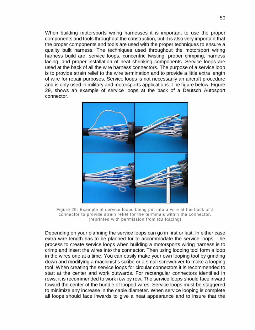
50
When building motorsports wiring harnesses it is important to use the proper components and tools throughout the construction, but it is also very important that the proper components and tools are used with the proper techniques to ensure a quality built harness. The techniques used throughout the motorsport wiring harness build are; service loops, concentric twisting, proper crimping, harness lacing, and proper installation of heat shrinking components. Service loops are used at the back of all the wire harness connectors. The purpose of a service loop is to provide strain relief to the wire termination and to provide a little extra length of wire for repair purposes. Service loops is not necessarily an aircraft procedure and is only used in military and motorsports applications. The figure below, Figure 29, shows an example of service loops at the back of a Deutsch Autosport connector.
Figure 29: Example of service loops being put into a wire at the back of a connector to provide strain relief for the terminals within the connector.
(reprinted with permission from RB Racing)
Depending on your planning the service loops can go in first or last. In either case extra wire length has to be planned for to accommodate the service loops. The process to create service loops when building a motorsports wiring harness is to crimp and insert the wires into the connector. Then using looping tool form a loop in the wires one at a time. You can easily make your own looping tool by grinding down and modifying a machinist’s scribe or a small screwdriver to make a looping tool. When creating the service loops for circular connectors it is recommended to start at the center and work outwards. For rectangular connectors identified in rows, it is recommended to work row by row. The service loops should face inward toward the center of the bundle of looped wires. Service loops must be staggered to minimize any increase in the cable diameter. When service looping is complete all loops should face inwards to give a neat appearance and to insure that the
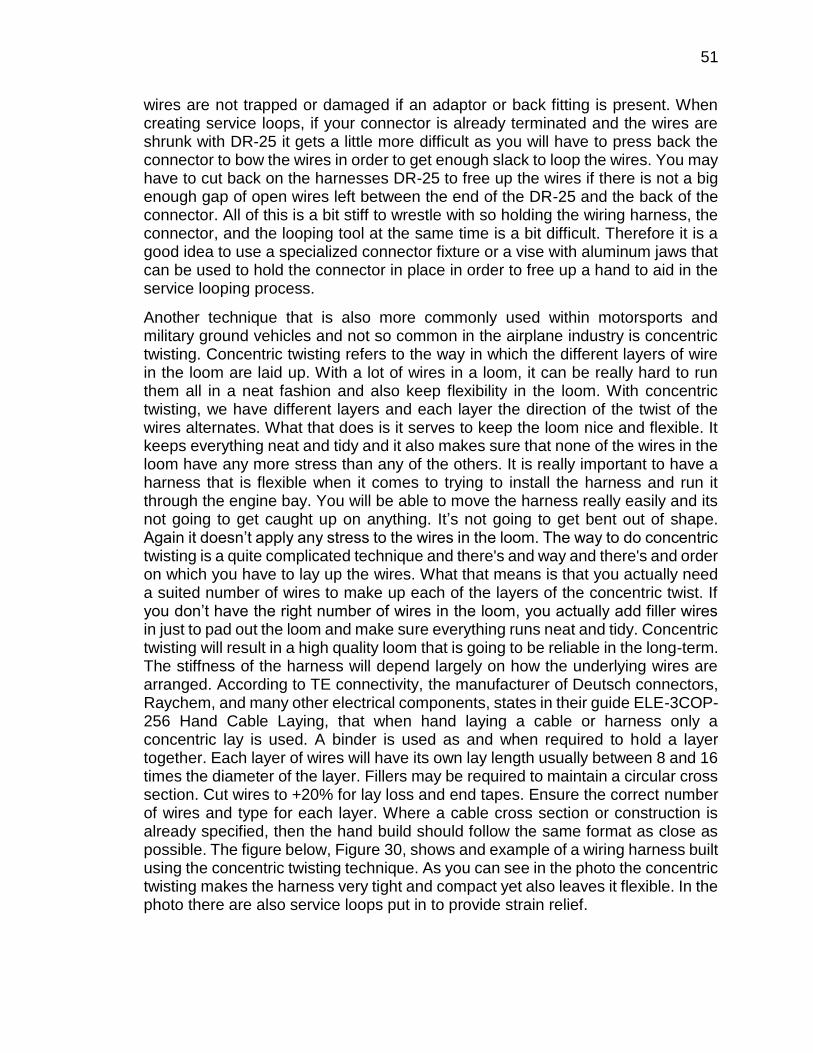
51
wires are not trapped or damaged if an adaptor or back fitting is present. When creating service loops, if your connector is already terminated and the wires are shrunk with DR-25 it gets a little more difficult as you will have to press back the connector to bow the wires in order to get enough slack to loop the wires. You may have to cut back on the harnesses DR-25 to free up the wires if there is not a big enough gap of open wires left between the end of the DR-25 and the back of the connector. All of this is a bit stiff to wrestle with so holding the wiring harness, the connector, and the looping tool at the same time is a bit difficult. Therefore it is a good idea to use a specialized connector fixture or a vise with aluminum jaws that can be used to hold the connector in place in order to free up a hand to aid in the service looping process.
Another technique that is also more commonly used within motorsports and military ground vehicles and not so common in the airplane industry is concentric twisting. Concentric twisting refers to the way in which the different layers of wire in the loom are laid up. With a lot of wires in a loom, it can be really hard to run them all in a neat fashion and also keep flexibility in the loom. With concentric twisting, we have different layers and each layer the direction of the twist of the wires alternates. What that does is it serves to keep the loom nice and flexible. It keeps everything neat and tidy and it also makes sure that none of the wires in the loom have any more stress than any of the others. It is really important to have a harness that is flexible when it comes to trying to install the harness and run it through the engine bay. You will be able to move the harness really easily and its not going to get caught up on anything. It’s not going to get bent out of shape. Again it doesn’t apply any stress to the wires in the loom. The way to do concentric twisting is a quite complicated technique and there's and way and there's and order on which you have to lay up the wires. What that means is that you actually need a suited number of wires to make up each of the layers of the concentric twist. If you don’t have the right number of wires in the loom, you actually add filler wires in just to pad out the loom and make sure everything runs neat and tidy. Concentric twisting will result in a high quality loom that is going to be reliable in the long-term. The stiffness of the harness will depend largely on how the underlying wires are arranged. According to TE connectivity, the manufacturer of Deutsch connectors, Raychem, and many other electrical components, states in their guide ELE-3COP-256 Hand Cable Laying, that when hand laying a cable or harness only a concentric lay is used. A binder is used as and when required to hold a layer together. Each layer of wires will have its own lay length usually between 8 and 16 times the diameter of the layer. Fillers may be required to maintain a circular cross section. Cut wires to +20% for lay loss and end tapes. Ensure the correct number of wires and type for each layer. Where a cable cross section or construction is already specified, then the hand build should follow the same format as close as possible. The figure below, Figure 30, shows and example of a wiring harness built using the concentric twisting technique. As you can see in the photo the concentric twisting makes the harness very tight and compact yet also leaves it flexible. In the photo there are also service loops put in to provide strain relief.
52
Figure 30: Example of concentric twisting and service loops (reprinted with
permission from RB Racing)
When building a motorsports wiring harness or any kind of harness or electrical component it is absolutely essential to use proper crimping techniques to ensure contact reliability. Once the correct terminal is selected, proper attachment to the wire is critical. One indication of the importance of proper crimping is evidenced in a study for the space shuttle program that traced 28% of all defects to improperly assembled wiring and connectors. Mechanical as well as electrical connections are important. The result of a properly crimped joint is a reliable mechanical and electrical connection. The mechanical connection is the crimping of the terminal to the conductor. The desired result is sufficient force on the outside of the barrel to tightly form it around the conductor. It must be secure enough not to vibrate loose or to be pulled off through normal use. The electrical characteristics are just as important. The major concern is the amount of electrical resistance caused by the mechanical joint. The electrical resistance will determine the crimped joints ability to conduct current. To achieve a positive relationship between the mechanical and electrical connection in the crimped joint, the following conditions are required, the terminal must be of sufficient cross section size and conductive material that it is as good an electrical conductor as the wire, and the surfaces of the wire and terminal that will be pressed into contact in the crimp must be clean and free of heavy, non-conductive films such as oxides, sulfides, and similar substances. Some reasons for failure of crimped joints to meet minimum tensile requirements include nicked wires, nicked or ruptured strands, strand turn back at crimp joint, and ruptured wires outside of the crimped terminal. To avoid these problems, use the correct size wire for the barrel, prepare your wire carefully, and use the proper crimping tool. The table below, Table 9, shows the UL and military specifications, MIL-T-7928, for various wire sizes. The table shows the tensile strength in pound-force, it indicates the minimum acceptable force to break or separate a terminal from the conductor.
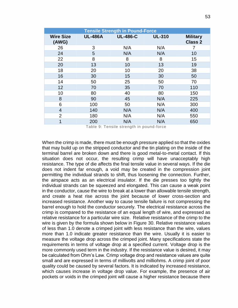
53
Tensile Strength in Pound-Force
Wire Size (AWG)
UL-486A UL-486-C UL-310 Military Class 2
26 3 N/A N/A 7
24 5 N/A N/A 10
22 8 8 8 15
20 13 10 13 19
18 20 10 20 38
16 30 15 30 50
14 50 25 50 70
12 70 35 70 110
10 80 40 80 150
8 90 45 N/A 225
6 100 50 N/A 300
4 140 N/A N/A 400
2 180 N/A N/A 550
1 200 N/A N/A 650 Table 9: Tensile strength in pound-force
When the crimp is made, there must be enough pressure applied so that the oxides that may build up on the stripped conductor and the tin plating on the inside of the terminal barrel are broken down and there is good metal-to-metal contact. If this situation does not occur, the resulting crimp will have unacceptably high resistance. The type of die affects the final tensile value in several ways. If the die does not indent far enough, a void may be created in the compression joint permitting the individual strands to shift, thus loosening the connection. Further, the airspace acts as an electrical insulator. If the die presses too tightly the individual strands can be squeezed and elongated. This can cause a weak point in the conductor, cause the wire to break at a lower than allowable tensile strength, and create a heat rise across the joint because of lower cross-section and increased resistance. Another way to cause tensile failure is not compressing the barrel enough to hold the conductor securely. The electrical resistance across the crimp is compared to the resistance of an equal length of wire, and expressed as relative resistance for a particular wire size. Relative resistance of the crimp to the wire is given by the formula shown below in Figure 30. Relative resistance values of less than 1.0 denote a crimped joint with less resistance than the wire, values more than 1.0 indicate greater resistance than the wire. Usually it is easier to measure the voltage drop across the crimped joint. Many specifications state the requirements in terms of voltage drop at a specified current. Voltage drop is the more commonly used term in the industry. If the resistance value is desired, it may be calculated from Ohm’s Law. Crimp voltage drop and resistance values are quite small and are expressed in terms of millivolts and milliohms. A crimp joint of poor quality could be caused by several factors. It is indicated by increased resistance, which causes increase in voltage drop value. For example, the presence of air pockets or voids in the crimped joint will cause a higher resistance because there
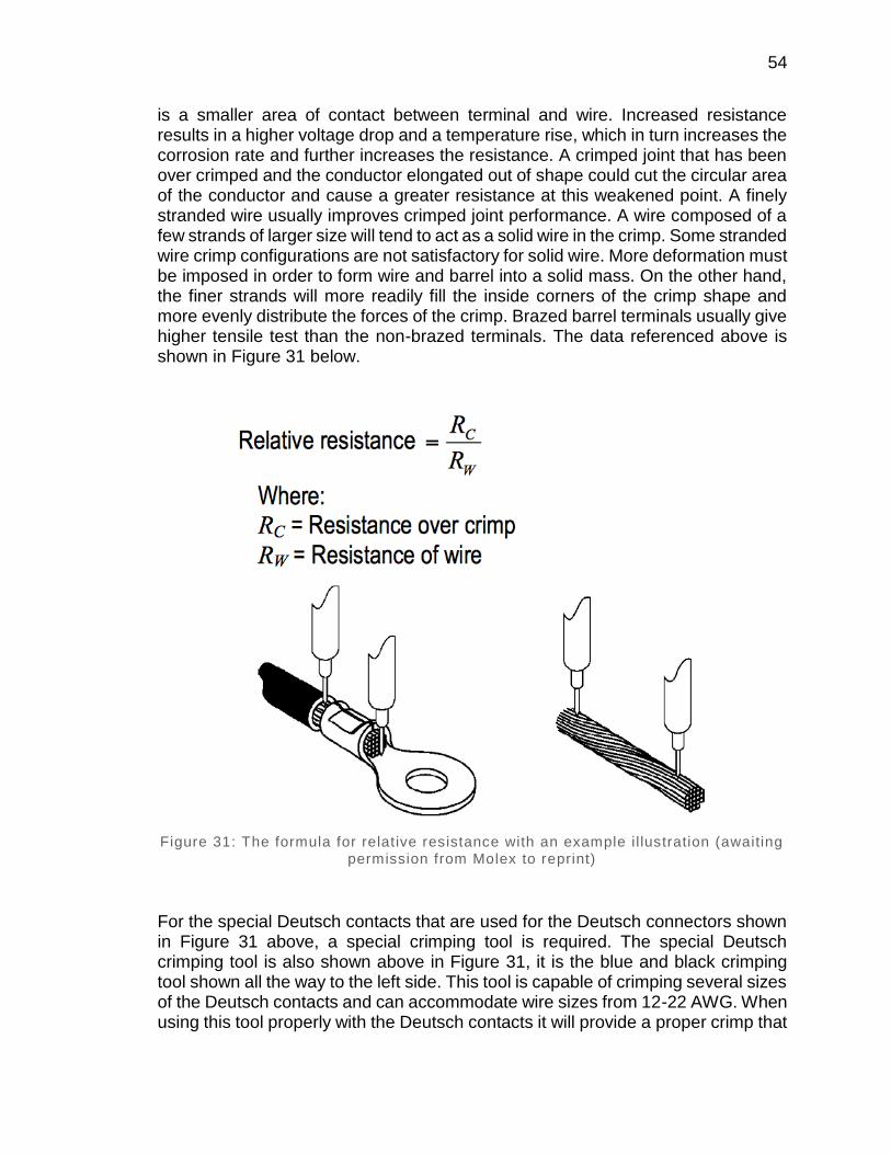
54
is a smaller area of contact between terminal and wire. Increased resistance results in a higher voltage drop and a temperature rise, which in turn increases the corrosion rate and further increases the resistance. A crimped joint that has been over crimped and the conductor elongated out of shape could cut the circular area of the conductor and cause a greater resistance at this weakened point. A finely stranded wire usually improves crimped joint performance. A wire composed of a few strands of larger size will tend to act as a solid wire in the crimp. Some stranded wire crimp configurations are not satisfactory for solid wire. More deformation must be imposed in order to form wire and barrel into a solid mass. On the other hand, the finer strands will more readily fill the inside corners of the crimp shape and more evenly distribute the forces of the crimp. Brazed barrel terminals usually give higher tensile test than the non-brazed terminals. The data referenced above is shown in Figure 31 below.
Figure 31: The formula for relative resistance with an example il lustration (awaiting permission from Molex to reprint)
For the special Deutsch contacts that are used for the Deutsch connectors shown in Figure 31 above, a special crimping tool is required. The special Deutsch crimping tool is also shown above in Figure 31, it is the blue and black crimping tool shown all the way to the left side. This tool is capable of crimping several sizes of the Deutsch contacts and can accommodate wire sizes from 12-22 AWG. When using this tool properly with the Deutsch contacts it will provide a proper crimp that
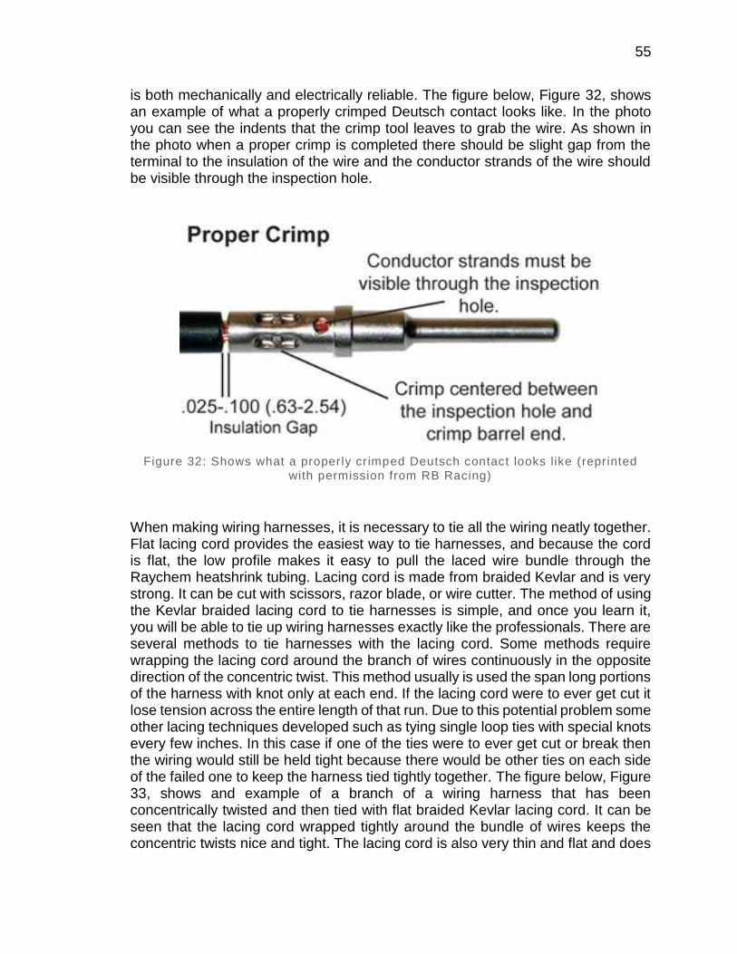
55
is both mechanically and electrically reliable. The figure below, Figure 32, shows an example of what a properly crimped Deutsch contact looks like. In the photo you can see the indents that the crimp tool leaves to grab the wire. As shown in the photo when a proper crimp is completed there should be slight gap from the terminal to the insulation of the wire and the conductor strands of the wire should be visible through the inspection hole.
Figure 32: Shows what a properly crimped Deutsch contact looks like (reprinted
with permission from RB Racing)
When making wiring harnesses, it is necessary to tie all the wiring neatly together. Flat lacing cord provides the easiest way to tie harnesses, and because the cord is flat, the low profile makes it easy to pull the laced wire bundle through the Raychem heatshrink tubing. Lacing cord is made from braided Kevlar and is very strong. It can be cut with scissors, razor blade, or wire cutter. The method of using the Kevlar braided lacing cord to tie harnesses is simple, and once you learn it, you will be able to tie up wiring harnesses exactly like the professionals. There are several methods to tie harnesses with the lacing cord. Some methods require wrapping the lacing cord around the branch of wires continuously in the opposite direction of the concentric twist. This method usually is used the span long portions of the harness with knot only at each end. If the lacing cord were to ever get cut it lose tension across the entire length of that run. Due to this potential problem some other lacing techniques developed such as tying single loop ties with special knots every few inches. In this case if one of the ties were to ever get cut or break then the wiring would still be held tight because there would be other ties on each side of the failed one to keep the harness tied tightly together. The figure below, Figure 33, shows and example of a branch of a wiring harness that has been concentrically twisted and then tied with flat braided Kevlar lacing cord. It can be seen that the lacing cord wrapped tightly around the bundle of wires keeps the concentric twists nice and tight. The lacing cord is also very thin and flat and does
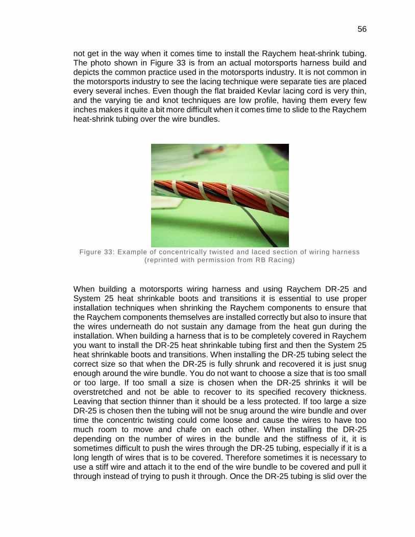
56
not get in the way when it comes time to install the Raychem heat-shrink tubing. The photo shown in Figure 33 is from an actual motorsports harness build and depicts the common practice used in the motorsports industry. It is not common in the motorsports industry to see the lacing technique were separate ties are placed every several inches. Even though the flat braided Kevlar lacing cord is very thin, and the varying tie and knot techniques are low profile, having them every few inches makes it quite a bit more difficult when it comes time to slide to the Raychem heat-shrink tubing over the wire bundles.
Figure 33: Example of concentrically twisted and laced section of wir ing harness
(reprinted with permission from RB Racing)
When building a motorsports wiring harness and using Raychem DR-25 and System 25 heat shrinkable boots and transitions it is essential to use proper installation techniques when shrinking the Raychem components to ensure that the Raychem components themselves are installed correctly but also to insure that the wires underneath do not sustain any damage from the heat gun during the installation. When building a harness that is to be completely covered in Raychem you want to install the DR-25 heat shrinkable tubing first and then the System 25 heat shrinkable boots and transitions. When installing the DR-25 tubing select the correct size so that when the DR-25 is fully shrunk and recovered it is just snug enough around the wire bundle. You do not want to choose a size that is too small or too large. If too small a size is chosen when the DR-25 shrinks it will be overstretched and not be able to recover to its specified recovery thickness. Leaving that section thinner than it should be a less protected. If too large a size DR-25 is chosen then the tubing will not be snug around the wire bundle and over time the concentric twisting could come loose and cause the wires to have too much room to move and chafe on each other. When installing the DR-25 depending on the number of wires in the bundle and the stiffness of it, it is sometimes difficult to push the wires through the DR-25 tubing, especially if it is a long length of wires that is to be covered. Therefore sometimes it is necessary to use a stiff wire and attach it to the end of the wire bundle to be covered and pull it through instead of trying to push it through. Once the DR-25 tubing is slid over the
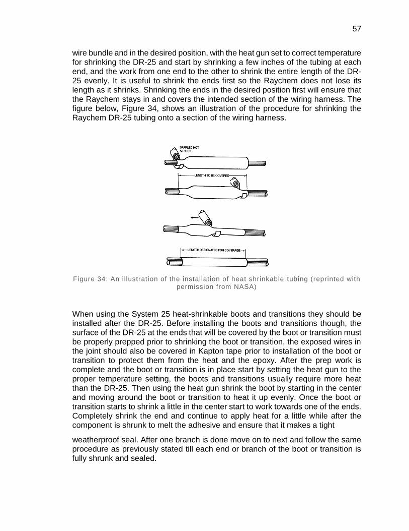
57
wire bundle and in the desired position, with the heat gun set to correct temperature for shrinking the DR-25 and start by shrinking a few inches of the tubing at each end, and the work from one end to the other to shrink the entire length of the DR-25 evenly. It is useful to shrink the ends first so the Raychem does not lose its length as it shrinks. Shrinking the ends in the desired position first will ensure that the Raychem stays in and covers the intended section of the wiring harness. The figure below, Figure 34, shows an illustration of the procedure for shrinking the Raychem DR-25 tubing onto a section of the wiring harness.
Figure 34: An illustration of the installation of heat shrinkable tubing (reprinted with permission from NASA)
When using the System 25 heat-shrinkable boots and transitions they should be installed after the DR-25. Before installing the boots and transitions though, the surface of the DR-25 at the ends that will be covered by the boot or transition must be properly prepped prior to shrinking the boot or transition, the exposed wires in the joint should also be covered in Kapton tape prior to installation of the boot or transition to protect them from the heat and the epoxy. After the prep work is complete and the boot or transition is in place start by setting the heat gun to the proper temperature setting, the boots and transitions usually require more heat than the DR-25. Then using the heat gun shrink the boot by starting in the center and moving around the boot or transition to heat it up evenly. Once the boot or transition starts to shrink a little in the center start to work towards one of the ends. Completely shrink the end and continue to apply heat for a little while after the component is shrunk to melt the adhesive and ensure that it makes a tight
weatherproof seal. After one branch is done move on to next and follow the same procedure as previously stated till each end or branch of the boot or transition is fully shrunk and sealed.

58
3.3.8 GPS Module
The electronic paddle shift system will make use of a GPS subsystem to allow the driver to see where they can make improvements around a track. To test what their best times around an individual turn would be and to try to improve their overall time. For this a GPS Module will be needed as well as a system to convert the data from the module into relevant data.
Overlaying your tracks in Google Earth can be achieved after you have logged your positions to the openlog. Removing the SD card or storage device and connecting it to your computer. You will see a config file and at least one log file. Open the log file with a text editor, like Notepad in Windows. You will see a bunch of text in the form of NMEA sentences or something in a similar format. The NMEA sentences contain, among other data, your position and time.
All you need to do now is convert the file to a Google Earth file with a kml or kmz file extension. The website to convert the text file to a Google Earth file is GPSVisualizer. If you click on the Google Earth KML link in the middle of the homepage you can configure settings. Figure 34 illustrates this point.
The settings used are shown below in figure 35. Once you have loaded your data into this page, hit the Create KML file. You will then be presented with a link. You can either click it and, if you have Google Earth installed, it will zoom to your tracks or you can right click and save as to save for future use or to show your friends.
If the txt files are over 3MB, you will not be able to use GPSVisualizer. GPSBabel is another site you can try if you have really big log files.
Figure 35: An illustration of the GPSVisualizer track mapping (awaiting permission
from GPSVisualizer to reprint)
In order to draw the track on Google Maps using GPSVisualizer a txt file was used. The txt file consisted of parsed and formatted NMEA 0983 sentences that were received from the GPS module. By uploading the aforementioned formatted data

59
to GPSVisualizer’s webpage a graphical representation of a track run is created. In the illustration above the colors of the track denote the speed of the vehicle where red is the slowest and blue is the fastest.
3.3.9 Data Logging/ SD Card Slot
In order for the paddle shift system to serve multiple functions other than just shifting the transmission, such as being used for data analysis and driver feedback and training, the system will need the ability to log the data and a method for transferring the data to a computer to be analyzed. These are the reasons it will be necessary for the paddle shift system to have data logging capabilities with the data being stored to a removable SD card in order to retrieve and analyze the data. A data logging system is defined as one or more electronic devices whose primary purpose is to acquire data. Typically a data logging system involves at least three main components. First, sensors that respond to a certain physical condition and transmit signals or change electrical properties such as resistance, for example, a thermistor which is a two wire temperature sensor that basically has an internal resistor that changes resistance based on temperature. Second, a data logger measures the electrical signal, converts it to a number and stores either that value or some statistics on that value, for example average, maximum, minimum, standard deviation, etc. Third, a computer uses some type of communications link such as serial port, phone modem, Bluetooth, etc. to retrieve the data from the logger. For our system we will be storing the data to a removable SD card and then using a computer we can read the data from the card. The resulting data is only as good as the sensors can measure and the data logger can resolve. A stand-alone data logging system is one which can be completely removed from the vehicle, without affecting the vehicles ability to run. For our project the system will not be considered stand-alone because it will be integrated into part of the paddle shift system control unit and without the shift control system the vehicle would not be capable of driving, therefore the function of the vehicle will depend on the paddle shift system control unit. Data acquisition systems are commonly used by racing teams, in fact it is almost absolutely necessary to continually improve and be competitive. The information collected gives engineers, mechanics, and drivers useful feedback and data to quickly and accurately gauge, and improve the vehicle’s performance.
The purpose for the data logging capabilities of the paddle shift control system is to provide data for analysis of the driver and the vehicles performance to further enhance the vehicles capabilities. The data logging system will log GPS coordinates in order to map out the track route, it will also log gear position and rpm. All of this data will be stored to a removable SD card. Therefore the paddle shift system control unit needs to have a built in SD card slot interface and wired for ability to write the data to the card. Currently two different SD card interfaces are being evaluated for prototype use, the MicroSD Card breakout board+ from adafruit.com, and the SD Card BoosterPack for Launchpad available from

60
43oh.com. There are a few things to look out for when interacting with SD cards, one is that they are strictly 3.3V devices and the power draw when writing to the card can be fairly high, up to 100mA or more. That means that you must have a very good 3.3V power supply for the card. Also you must also have 3.3V logic to interface to the pins. SD cards are fairly sensitive about the interface pins. The newest cards are edge triggered and require very square transitions. Things like voltage dividers and long wires will have a negative effect on the transition speed, so it’s best to keep wires short, and avoid using voltage dividers for the 3.3V logic lines. Instead of voltage dividers it is best to use level shifter chips. Secondly, there are two ways to interface with SD cards, SPI mode and SDIO mode. SDIO mode is faster, but is more complex and requires signing non-disclosure documents. For that reason, it is likely you will never encounter SDIO mode interface code. Instead, every SD card has a lower speed SPI mode that is easy for any microcontroller to use. SPI mode requires four pins, which is nice because it’s not pin heavy like some parallel-interface components. SD cards come in two sizes, microSD and SD. The interface, code, structure, etc. is all the same. The only difference is the size. MicroSD are much smaller in physical size. Third, SD cards are raw storage. They are just sectors in a flash chip, there’s no structure that you have to use. That means you could format an SD card to be a Linux filesystem, FAT (DOS) filesystem, or a MAC filesystem. You could also not have any filesystem at all. However, 99% of computers, cameras, MP3 players, GPS loggers, etc. require FAT16 or FAT32 for the filesystem. The tradeoff here is that for smaller microcontrollers the addition of the complex file format handling can take a lot of flash storage and RAM. Even though you can use your SD card raw, it’s most convenient to format the card to a filesystem. For nearly every SD library, the card must be formatted FAT16 or FAT32 filesystems. If you have a very small SD card, for example an 8-32 Megabytes you might find it is formatted FAT12. These cards will have to be reformatted. Either way, it’s always a good idea to format the card before using, even if it’s a brand new card. When formatting an SD card it is strongly recommended to use the official SD card formatter utility, written by the SD association it solves many problems that come with bad formatting.
The microSD card breakout board+ from adafruit.com is shown in the figure below, Figure 36. This SD card breakout board is not just a simple breakout board, this microSD adapter goes the extra mile and is designed for the ease of use. The breakout board features an onboard 5V to 3V regulator which provides 150 mA for power-hungry cards. The breakout board features 3V level shifting which means you can use this breakout board with ease on either 3V or 5V systems. It uses a proper level shifting chip, not resistors, therefore it will provide less problems and faster read/write access. The breakout board only requires the use of 3 or 4 digital pins to read and write 2 Gb+ of storage. The breakout board features and activity LED which lights up when the SD card is being read or written. The breakout board features four #2 mounting holes in the corners of the board. The SD card socket is of the push-push type and is mounted slightly over the edge of the PCB so it’s easy to insert and remove. The breakout board comes with 0.1” header unattached so you can get it on a breadboard or use wires. When it comes to wiring up the breakout board, it’s pretty simple as the board itself already takes care of most of
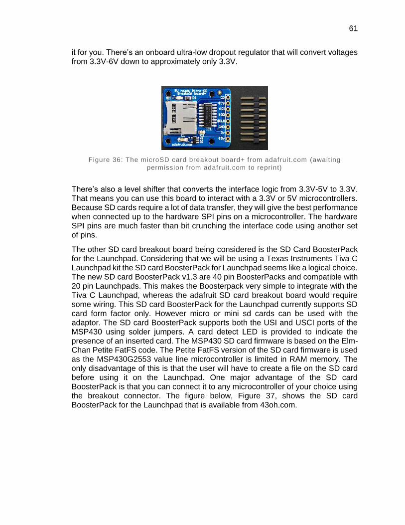
61
it for you. There’s an onboard ultra-low dropout regulator that will convert voltages from 3.3V-6V down to approximately only 3.3V.
Figure 36: The microSD card breakout board+ from adafruit.com (awaiting
permission from adafruit.com to reprint)
There’s also a level shifter that converts the interface logic from 3.3V-5V to 3.3V. That means you can use this board to interact with a 3.3V or 5V microcontrollers. Because SD cards require a lot of data transfer, they will give the best performance when connected up to the hardware SPI pins on a microcontroller. The hardware SPI pins are much faster than bit crunching the interface code using another set of pins.
The other SD card breakout board being considered is the SD Card BoosterPack for the Launchpad. Considering that we will be using a Texas Instruments Tiva C Launchpad kit the SD card BoosterPack for Launchpad seems like a logical choice. The new SD card BoosterPack v1.3 are 40 pin BoosterPacks and compatible with 20 pin Launchpads. This makes the Boosterpack very simple to integrate with the Tiva C Launchpad, whereas the adafruit SD card breakout board would require some wiring. This SD card BoosterPack for the Launchpad currently supports SD card form factor only. However micro or mini sd cards can be used with the adaptor. The SD card BoosterPack supports both the USI and USCI ports of the MSP430 using solder jumpers. A card detect LED is provided to indicate the presence of an inserted card. The MSP430 SD card firmware is based on the Elm-Chan Petite FatFS code. The Petite FatFS version of the SD card firmware is used as the MSP430G2553 value line microcontroller is limited in RAM memory. The only disadvantage of this is that the user will have to create a file on the SD card before using it on the Launchpad. One major advantage of the SD card BoosterPack is that you can connect it to any microcontroller of your choice using the breakout connector. The figure below, Figure 37, shows the SD card BoosterPack for the Launchpad that is available from 43oh.com.
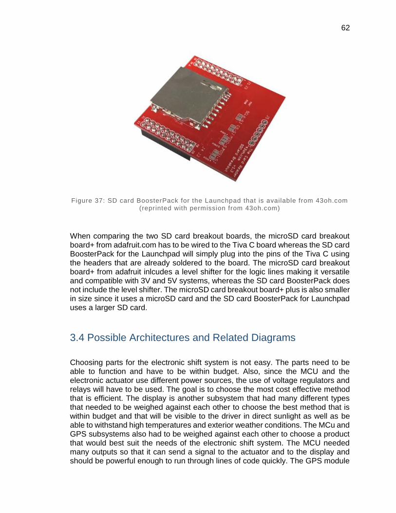
62
Figure 37: SD card BoosterPack for the Launchpad that is available from 43oh.com (reprinted with permission from 43oh.com)
When comparing the two SD card breakout boards, the microSD card breakout board+ from adafruit.com has to be wired to the Tiva C board whereas the SD card BoosterPack for the Launchpad will simply plug into the pins of the Tiva C using the headers that are already soldered to the board. The microSD card breakout board+ from adafruit inlcudes a level shifter for the logic lines making it versatile and compatible with 3V and 5V systems, whereas the SD card BoosterPack does not include the level shifter. The microSD card breakout board+ plus is also smaller in size since it uses a microSD card and the SD card BoosterPack for Launchpad uses a larger SD card.
3.4 Possible Architectures and Related Diagrams
Choosing parts for the electronic shift system is not easy. The parts need to be able to function and have to be within budget. Also, since the MCU and the electronic actuator use different power sources, the use of voltage regulators and relays will have to be used. The goal is to choose the most cost effective method that is efficient. The display is another subsystem that had many different types that needed to be weighed against each other to choose the best method that is within budget and that will be visible to the driver in direct sunlight as well as be able to withstand high temperatures and exterior weather conditions. The MCu and GPS subsystems also had to be weighed against each other to choose a product that would best suit the needs of the electronic shift system. The MCU needed many outputs so that it can send a signal to the actuator and to the display and should be powerful enough to run through lines of code quickly. The GPS module

63
can also be difficult to choose as many models are alike and differ very slightly based upon the needs of the customers it was designed for. The best GPS for this project will be the one that will perform accurately so that it can be used while on a track for later viewing. The sections below discuss the possible parts for each subsystem and describe the product information of each part.
3.4.1 Power
As mentioned before, having to power up the whole system is not as complex and challenging as building the system itself. A DC to DC power converter regulates the voltage prior to charging the battery. And since the design contain several subsystems or sub-circuits where each one has its own voltage requirement to be applied with that would be different than the requirement which would be needed to power the vehicle. Using the method of having DC to DC power converters helps to adjust voltage from a different battery voltage which is essential in this project because it saves space instead of using multiple batteries or any power source to be able to power up the whole system.
A step up converter would increase the input voltage and generate a higher output and on the other hand a step down converter would decrease the input voltage which would generate a lower output relative to the input. This project is going to consist of two DC to DC step down voltage regulators where the first step down voltage regulator will be needed to convert the 12-volts coming out of the battery to 5-volts which has the duty of delivering power to the microcontroller and display. The other step down voltage regulator will be included in the design to have the same 12-volt input voltage to be converted to 5-volts to power up some of the microcontrollers of certain subsystems and the GPS communication system.
There are areas where we have to be careful with what type of power and voltage is necessary to have that certain component or subsystem to be powered up and running. Most likely, this project would not require us to have AC to DC power converters since power will be drawn out from the main source of power of the 12-volts battery that the motorcycle runs on. And most components such as microcontrollers and sensors that would be chosen and implemented in this project need DC power to be delivered to it so that they can be functional. Therefore, DC to DC power converters or DC step-down such as voltage regulators are of necessity to be able to adjust the 12-volts DC power input to much less voltage that are necessary for the microcontrollers to power up without having excessive power and voltage that might cause failures of the system.
There are many conversion methods that involve the alteration of the input voltage signal to meet the output voltage signal requirement of certain circuits within the system. One of the most well-known method is the electronic conversion method. Of the electronic methods there is linear, switched-mode conversion which could consist of magnetic and capacitive, electromechanical and electrochemical.

64
One of the conversion technology that would most likely be considered for use in this project is the linear regulators. Linear regulators can only output at a lower voltages from the input and are extremely inefficient once the voltage drop is enormous and the current is running at a high rate since these regulators do indeed disintegrate heat equivalent to the artifact of the output current and the voltage drop and from this it can be declared that this type of technology are not ordinarily used when there is a combination of both large voltage drop and high current applications.
Linear regulators are advantageous if the current is little and having the power dissipated at minor rates, although it could still remain a large portion of the entire power consumed. These regulators are frequently utilized as a chunk of a simple controlled power supply for greater currents where a transformer produces a voltage that when or if it’s rectified it would be a slightly higher than that desired to bias the linear regulator. The linear regulator gets rid of the surplus voltage which as a result would diminish hum-generating ripple current and deliver a continuous output voltage that is sovereign of normal oscillations of the unregulated input voltage from the transformer or bridge rectifier circuit and of the load current.
Linear regulators are generally known to be economical where some of these regulators would cost a few pennies, if good heat sinks are used they would be steadfast and reliable and much simpler than switching regulators and therefore linear regulators do not create switching noise. As part of a power supply they may require a transformer, which is larger for a given power level than that required by a switch-mode power supply. Linear regulators can provide a very low-noise output voltage, and are very suitable for powering noise-sensitive low-power analog and radio frequency circuits.
A linear voltage regulator has been applied to simulation to see how it behaves under certain circumstances. Figure 38 below shows that the circuit has been implemented and designed such that it would output 3-volts using the 7805 linear voltage regulator. Now the resistor values can be adjusted in such a way that any desired output voltage can be obtained such as 5-volts to power up the MCU.
Figure 38: Linear voltage regulator
Electronic switch-mode DC to DC converters are supposed to transform a DC voltage level to another through storing the input energy momentarily then
65
discharge the energy to the output at a dissimilar voltage. The storage could exist in both magnetic field storage components and electric field storage components. This conversion method is more power efficient than linear voltage regulation which disintegrates undesirable power such as heat. This proficiency is favorable to increasing the running time of battery operated devices. Since the technology of FET has been introduced they are able to switch at high frequency more capably than bipolar transistors that actually sustain more switching losses and necessitate a more dense drive circuit. An important improvement in DC-DC converters is the usage of synchronous rectification substituting the flywheel diode with a FET that is low on resistance which aids in the reduction of switching losses.
Most DC-to-DC converters are intended to transport power from the input to the output in simply one direction. Nevertheless, entirely all switching regulator topologies may be prepared bi-directional by interchanging the diodes with individually controlled active rectification. A bi-directional converter may be able to transfer power in whichever direction making it being useful in procedures demanding regenerative braking. Some of the disadvantages of switching converters comprise of electronic noise, complication, and to some degree the cost of such technology. These factors could make the switching-mode conversion method less favorable due to the fact that it is more expensive and complicated than the linear regulator. And since these type of converters have energy being occasionally stored and released from a magnetic field in an inductor or a transformer which could have a frequency range of 300 kHz to 10 MHz, it can be less considerable to be used in the project since the subsystems are made of components that generally don’t operate under such high frequencies.
The electromechanical conversion method consists of the use of a motor and a generator coupled together which has rotor coils and generator wound around a single rotor which shares the same outer field coils or magnet. This method seems very unreasonable and inconvenient to use since it is of large components and very inefficient to a point where it can’t be applied to the design.
The linear regulator and the switching regulators technology seems very promising to be used in completing the project to function the way it’s designed to function since the characteristics of this specific technology agree with the requirements and specifications of some of the subsystems that this design has within. Most of the components that would be designed have characteristics of low current and low power dissipation, which these regulator works well under such circumstances.
3.4.1.1 5V Voltage Regulator
One of the most convenient and favorable technology in adjusting a voltage signal among the designers is the voltage regulators due to its simplicity and ease of implementation and being inexpensive. A 5-volts voltage regulator is among the possible technologies that would be chosen to be implemented in this project. This voltage regulator is supposed to output a constant voltage signal of 5-volts from a

66
much higher voltage input and in this case it would be the 12-volt battery. These voltage regulators can be considered as DC to DC power converters which would convert a DC signal to a different DC signal depending on the system that would be implemented on. In this project, a 5-volt regulator is necessary to be implemented in the circuit design in order for some of the microcontrollers to function properly.
Depending on the microcontrollers that would be used in this project, a 5-volt voltage regulator need to be added to ensure no failures occur during the designing, prototyping, and testing process of the system. Some of these microcontrollers that will be chosen among other microcontrollers have operating voltage specification of 0.9-volts under the 30MHz and 1.2-volts under the 120MHz and current consumption of 45mA when the microcontroller controller is active and 1.38 µA when it is hibernating. Either of these conditions that the microcontroller will be exposed to, it can be seen that the voltage is way much smaller than the power source of 12-volts and it is like that with all of the microcontrollers that are considered for use of this project.
The displays that are listed for being a possibility to be chosen for the implementation of the project also have power requirements and consumption that require the manipulation of the input voltage signal so that these displays would be able to function without any problems. One of the displays that are considered for use is the PSA23-11GWA which has power consumption of 62.5-milliwatts and current consumption of 20-milliamps which when applying the power formula in this case, which is P = IxV and solving for V, a voltage requirement of about 3-volts is necessary to agree with the power and current consumption and the power formula.
However, for some of the displays that are considered a possibility to be included in this project don’t need a 5-volt voltage regulator to be associated with it since some of these displays have high voltage requirements. For instance, the PSC08-11SRWA have that is considered for use along with this project have power consumption of 75-milliwatts and current consumption of 10-milliamps and if the power formula is applied here once more a voltage computation of 7.5-volts is obtained in order for this specific display to function properly without any damages taken. And so a different type of method is to be approached and studied well in some of the special cases like this one.
The parts LM2672 and LM7805, which are compared in the Table 10 above, would best suit the DC to DC step down converters or voltage regulators for the electronic paddle shifters project. Both of these voltage regulators regulate the desired voltage input of 12-volts to 5-volts which is the exact amount needed to power up the PCB board and some of the subsystem microcontrollers. However, the LM2672 has a few more additional input and output ranges which means it could make the design of combining microcontrollers and features like sensors more flexible. The high peak efficiency percentage and smaller dimension of the LM2672 voltage regulator makes it more promising than the LM7805 voltage regulator. However, overall circuit protection is tremendously essential and the LM7805 proposes a
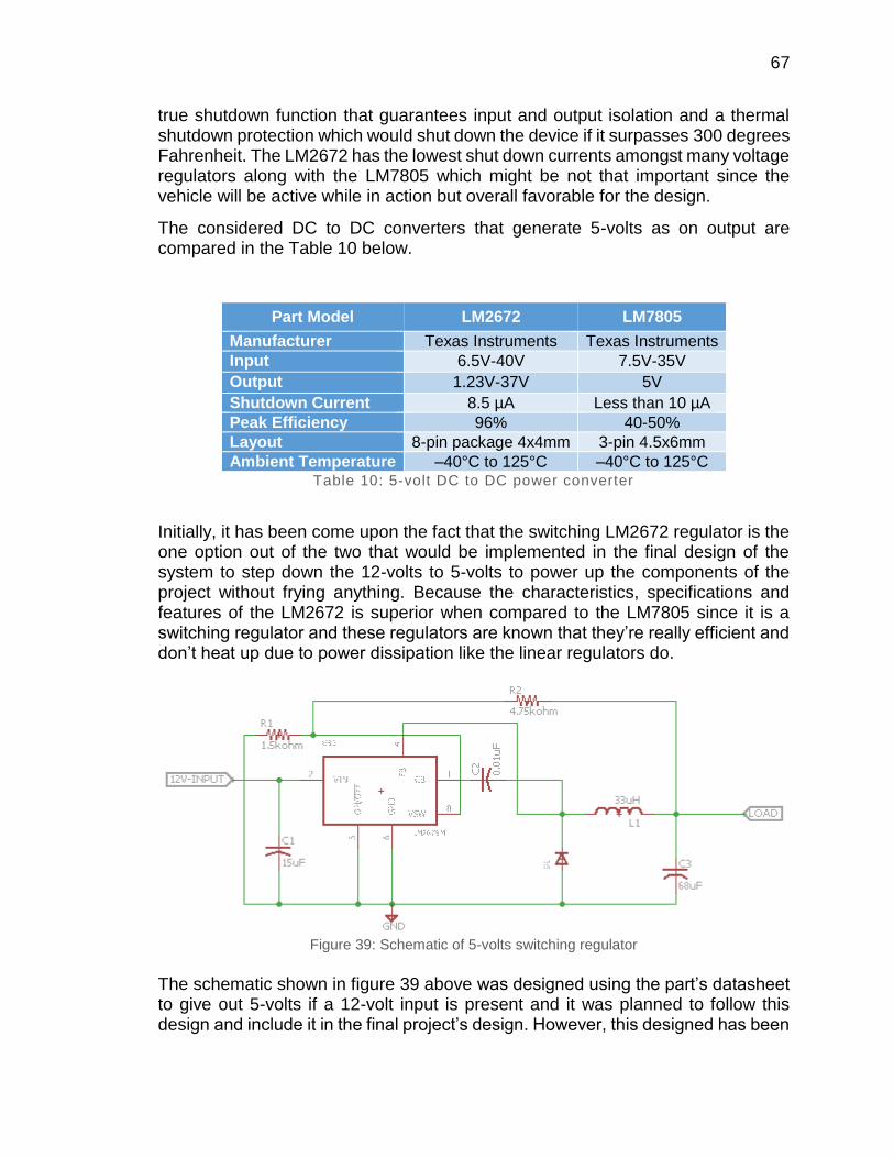
67
true shutdown function that guarantees input and output isolation and a thermal shutdown protection which would shut down the device if it surpasses 300 degrees Fahrenheit. The LM2672 has the lowest shut down currents amongst many voltage regulators along with the LM7805 which might be not that important since the vehicle will be active while in action but overall favorable for the design.
The considered DC to DC converters that generate 5-volts as on output are compared in the Table 10 below.
Part Model LM2672 LM7805
Manufacturer Texas Instruments Texas Instruments
Input 6.5V-40V 7.5V-35V
Output 1.23V-37V 5V
Shutdown Current 8.5 µA Less than 10 µA
Peak Efficiency 96% 40-50%
Layout 8-pin package 4x4mm 3-pin 4.5x6mm
Ambient Temperature –40°C to 125°C –40°C to 125°C Table 10: 5-volt DC to DC power converter
Initially, it has been come upon the fact that the switching LM2672 regulator is the one option out of the two that would be implemented in the final design of the system to step down the 12-volts to 5-volts to power up the components of the project without frying anything. Because the characteristics, specifications and features of the LM2672 is superior when compared to the LM7805 since it is a switching regulator and these regulators are known that they’re really efficient and don’t heat up due to power dissipation like the linear regulators do.
Figure 39: Schematic of 5-volts switching regulator
The schematic shown in figure 39 above was designed using the part’s datasheet to give out 5-volts if a 12-volt input is present and it was planned to follow this design and include it in the final project’s design. However, this designed has been

68
abandoned due to the fact that it is too complex for the people at SAE to understand and fix if something goes wrong because in order for this circuit to work it is necessary to follow the datasheet closely and the design is very specific. For example, if the junction of the resistors are not close to the VSW pin and the inductor is not away from the feedback node the regulator will not function the way it’s supposed to be. The people at SAE are diverse and some don’t have knowledge about such technology so it was decided that the linear regulator is to be selected for powering up the system. And so the linear regulator LM7805 was chosen for implementation even though it is not as efficient as the switching regulator and would heat up more than the LM2672 because the voltage difference is 9V which means there will be a lot of heat dissipation and there could be a risk of thermal shutdown. However more than one regulator will be used to distribute the load so that it wouldn’t heat up as much as it would when the whole load is powered by only one regulator. And this regulator, the LM7805, as shown in figure 1 is very simple and easy to comprehend for the members of the SAE and if something goes wrong with it, it is easy to maintain and replace to make it work again. Two capacitors were used of 0.1uF on both the input and output terminals of the regulator to not allow any AC signal, if any is present, passing through the regulator and to smooth out the DC output.
3.4.2 Display
The Display is used primarily for showing what gear the formula SAE vehicle is in as well as if it is in neutral gear. The display will be in a visible area for the driver to see as well as has to be able to survive the elements if exposed. Must also be bright enough for the driver to see in bright sunlight conditions. The display must also be small as it will be located on the steering wheel of the Formula SAE vehicle because the vehicle already has the data logging display located on the dash of the vehicle.
3.4.2.1 16-Segment LED Display
The segment displays use multiple LED line segments to create a numerical or alphabetical character. The more segments used, the more lines that are needed to connect but give more options as to what characters can be used. A 7 segment display can only display numbers, but for the electronic shift system we need it to also show the letter ‘N’. Therefore a 14 or 16 segment LED must be used. The LED displays are also very bright and come in different colors so that the one that can be seen the best in direct sunlight will be used.
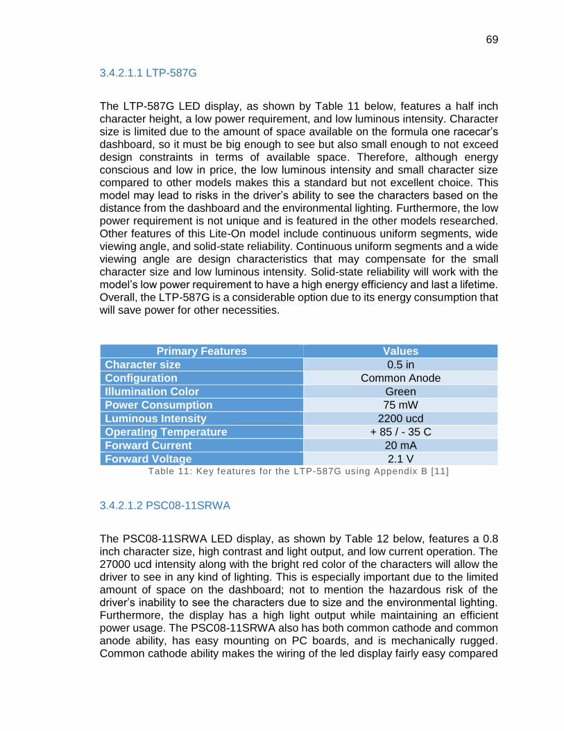
69
3.4.2.1.1 LTP-587G
The LTP-587G LED display, as shown by Table 11 below, features a half inch character height, a low power requirement, and low luminous intensity. Character size is limited due to the amount of space available on the formula one racecar’s dashboard, so it must be big enough to see but also small enough to not exceed design constraints in terms of available space. Therefore, although energy conscious and low in price, the low luminous intensity and small character size compared to other models makes this a standard but not excellent choice. This model may lead to risks in the driver’s ability to see the characters based on the distance from the dashboard and the environmental lighting. Furthermore, the low power requirement is not unique and is featured in the other models researched. Other features of this Lite-On model include continuous uniform segments, wide viewing angle, and solid-state reliability. Continuous uniform segments and a wide viewing angle are design characteristics that may compensate for the small character size and low luminous intensity. Solid-state reliability will work with the model’s low power requirement to have a high energy efficiency and last a lifetime. Overall, the LTP-587G is a considerable option due to its energy consumption that will save power for other necessities.
Primary Features Values
Character size 0.5 in
Configuration Common Anode
Illumination Color Green
Power Consumption 75 mW
Luminous Intensity 2200 ucd
Operating Temperature + 85 / - 35 C
Forward Current 20 mA
Forward Voltage 2.1 V Table 11: Key features for the LTP-587G using Appendix B [11]
3.4.2.1.2 PSC08-11SRWA
The PSC08-11SRWA LED display, as shown by Table 12 below, features a 0.8 inch character size, high contrast and light output, and low current operation. The 27000 ucd intensity along with the bright red color of the characters will allow the driver to see in any kind of lighting. This is especially important due to the limited amount of space on the dashboard; not to mention the hazardous risk of the driver’s inability to see the characters due to size and the environmental lighting. Furthermore, the display has a high light output while maintaining an efficient power usage. The PSC08-11SRWA also has both common cathode and common anode ability, has easy mounting on PC boards, and is mechanically rugged. Common cathode ability makes the wiring of the led display fairly easy compared

70
to common anode. In addition, a stress-free mounting design will make constructing a breeze. Mechanically rugged equipment are also important due to the intense movement the car may undertake. All in all, this Kingbright model is an excellent option with the greatest advantages because of its power consumption, high visibility, and simple assembly.
Primary Features Values
Character size 0.8 in
Configuration Common Cathode
Illumination Color Red
Power Consumption 75 mW
Luminous Intensity 27000 ucd
Operating Temperature + 85 / - 40 C
Number of Digits 1
Forward Current 10 mA
Forward Voltage 1.85 V
Mounting Style Through Hole
Brand Kingbright Table 12: Key features for the PSC08-11SRWA using Appendix B [12]
3.4.2.1.3 LTP-3862G
The LTP-3262G LED display, as shown by Table 13 below, features a 0.3 in character height, low power requirement, and excellent character appearance. The most appealing aspect of this model is the two digit format. This will decrease overall price for the characters and simplify the assembly. In addition, the power requirement is just as low as the other models even though it is double digit. However, the characters size is incredibly small, which will cause issues with the driver being able to see them. Also, the luminous intensity is the lowest of all researched models. Other characteristics of the LTP-3262G include continuous uniform segments, wide viewing angle, and solid state reliability. Continuous uniform segments and a wide viewing angle are design characteristics that improve visibility of the characters for the driver but are most likely not enough to compensate. Solid-state reliability will work with the model’s low power requirement to have a high energy efficiency and last a lifetime, though. With safety and efficiency in mind, the overall impaired visibility of these characters makes this model a poor choice.
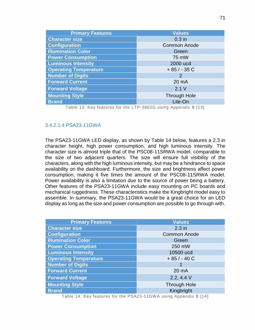
71
Primary Features Values
Character size 0.3 in
Configuration Common Anode
Illumination Color Green
Power Consumption 75 mW
Luminous Intensity 2000 ucd
Operating Temperature + 85 / - 35 C
Number of Digits 2
Forward Current 20 mA
Forward Voltage 2.1 V
Mounting Style Through Hole
Brand Lite-On Table 13: Key features for the LTP-3862G using Appendix B [13]
3.4.2.1.4 PSA23-11GWA
The PSA23-11GWA LED display, as shown by Table 14 below, features a 2.3 in character height, high power consumption, and high luminous intensity. The character size is almost triple that of the PSC08-11SRWA model, comparable to the size of two adjacent quarters. The size will ensure full visibility of the characters, along with the high luminous intensity, but may be a hindrance to space availability on the dashboard. Furthermore, the size and brightness affect power consumption, making it five times the amount of the PSC08-11SRWA model. Power availability is also a limitation due to the source of power being a battery. Other features of the PSA23-11GWA include easy mounting on PC boards and mechanical ruggedness. These characteristics make the Kingbright model easy to assemble. In summary, the PSA23-11GWA would be a great choice for an LED display as long as the size and power consumption are possible to go through with.
Primary Features Values
Character size 2.3 in
Configuration Common Anode
Illumination Color Green
Power Consumption 250 mW
Luminous Intensity 10500 ucd
Operating Temperature + 85 / - 40 C
Number of Digits 1
Forward Current 20 mA
Forward Voltage 2.2, 4.4 V
Mounting Style Through Hole
Brand Kingbright Table 14: Key features for the PSA23-11GWA using Appendix B [14]
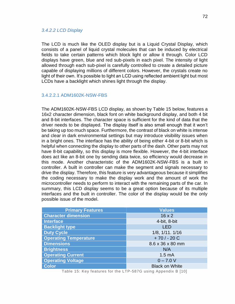
72
3.4.2.2 LCD Display
The LCD is much like the OLED display but is a Liquid Crystal Display, which consists of a panel of liquid crystal molecules that can be induced by electrical fields to take certain patterns which block light or allow it through. Color LCD displays have green, blue and red sub-pixels in each pixel. The intensity of light allowed through each sub-pixel is carefully controlled to create a detailed picture capable of displaying millions of different colors. However, the crystals create no light of their own. It’s possible to light an LCD using reflected ambient light but most LCDs have a backlight which shines light through the display.
3.4.2.2.1 ADM1602K-NSW-FBS
The ADM1602K-NSW-FBS LCD display, as shown by Table 15 below, features a 16x2 character dimension, black font on white background display, and both 4 bit and 8-bit interfaces. The character space is sufficient for the kind of data that the driver needs to be displayed. The display itself is also small enough that it won’t be taking up too much space. Furthermore, the contrast of black on white is intense and clear in dark environmental settings but may introduce visibility issues when in a bright ones. The interface has the ability of being either 4-bit or 8-bit which is helpful when connecting the display to other parts of the dash. Other parts may not have 8-bit capability, so this display is more flexible. However, the 4-bit interface does act like an 8-bit one by sending data twice, so efficiency would decrease in this mode. Another characteristic of the ADM1602K-NSW-FBS is a built in controller. A built in controller can make the segment and signals necessary to drive the display. Therefore, this feature is very advantageous because it simplifies the coding necessary to make the display work and the amount of work the microcontroller needs to perform to interact with the remaining parts of the car. In summary, this LCD display seems to be a great option because of its multiple interfaces and the built in controller. The color of the display would be the only possible issue of the model.
Primary Features Values
Character dimension 16 x 2
Interface 4-bit, 8-bit
Backlight type LED
Duty Cycle 1/8, 1/11. 1/16
Operating Temperature + 70 / - 20 C
Dimensions 8.6 x 36 x 80 mm
Brightness N/A
Operating Current 1.5 mA
Operating Voltage 0 – 7.0 V
Color Black on White Table 15: Key features for the LTP-587G using Appendix B [10]
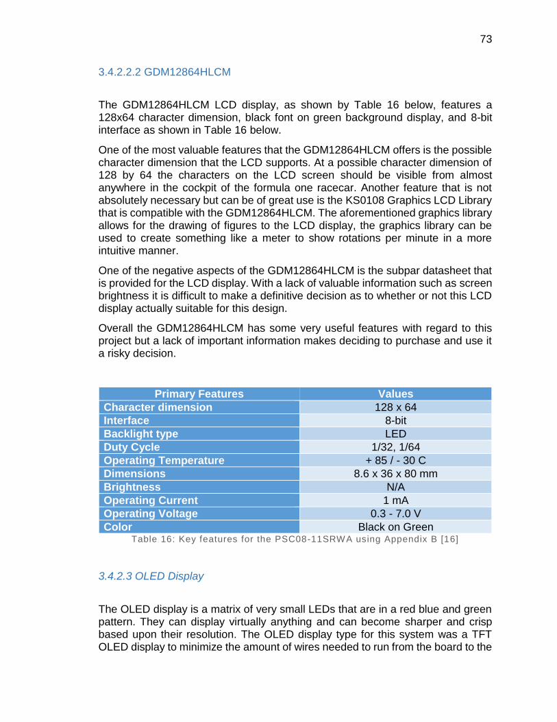
73
3.4.2.2.2 GDM12864HLCM
The GDM12864HLCM LCD display, as shown by Table 16 below, features a 128x64 character dimension, black font on green background display, and 8-bit interface as shown in Table 16 below.
One of the most valuable features that the GDM12864HLCM offers is the possible character dimension that the LCD supports. At a possible character dimension of 128 by 64 the characters on the LCD screen should be visible from almost anywhere in the cockpit of the formula one racecar. Another feature that is not absolutely necessary but can be of great use is the KS0108 Graphics LCD Library that is compatible with the GDM12864HLCM. The aforementioned graphics library allows for the drawing of figures to the LCD display, the graphics library can be used to create something like a meter to show rotations per minute in a more intuitive manner.
One of the negative aspects of the GDM12864HLCM is the subpar datasheet that is provided for the LCD display. With a lack of valuable information such as screen brightness it is difficult to make a definitive decision as to whether or not this LCD display actually suitable for this design.
Overall the GDM12864HLCM has some very useful features with regard to this project but a lack of important information makes deciding to purchase and use it a risky decision.
Primary Features Values
Character dimension 128 x 64
Interface 8-bit
Backlight type LED
Duty Cycle 1/32, 1/64
Operating Temperature + 85 / - 30 C
Dimensions 8.6 x 36 x 80 mm
Brightness N/A
Operating Current 1 mA
Operating Voltage 0.3 - 7.0 V
Color Black on Green Table 16: Key features for the PSC08-11SRWA using Appendix B [16]
3.4.2.3 OLED Display
The OLED display is a matrix of very small LEDs that are in a red blue and green pattern. They can display virtually anything and can become sharper and crisp based upon their resolution. The OLED display type for this system was a TFT OLED display to minimize the amount of wires needed to run from the board to the
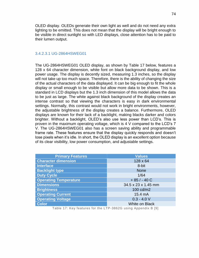
74
OLED display. OLEDs generate their own light as well and do not need any extra lighting to be emitted. This does not mean that the display will be bright enough to be visible in direct sunlight so with LED displays, close attention has to be paid to their lumen output.
3.4.2.3.1 UG-2864HSWEG01
The UG-2864HSWEG01 OLED display, as shown by Table 17 below, features a 128 x 64 character dimension, white font on black background display, and low power usage. The display is decently sized, measuring 1.3 inches, so the display will not take up too much space. Therefore, there is the ability of changing the size of the actual characters of the data displayed. It can be big enough to fit the whole display or small enough to be visible but allow more data to be shown. This is a standard in LCD displays but the 1.3 inch dimension of this model allows the data to be just as large. The white against black background of the display creates an intense contrast so that viewing the characters is easy in dark environmental settings. Normally, this contrast would not work in bright environments, however, the adjustable brightness of the display creates a balance. Furthermore, OLED displays are known for their lack of a backlight, making blacks darker and colors brighter. Without a backlight, OLED’s also use less power than LCD’s. This is proven in the maximum operating voltage, which is 4 V compared to the LCD’s 7 V. The UG-2864HSWEG01 also has a screen saving ability and programmable frame rate. These features ensure that the display quickly responds and doesn’t lose pixels when it’s idle. In short, the OLED display is an excellent option because of its clear visibility, low power consumption, and adjustable settings.
Primary Features Values
Character dimension 128 x 64
Interface 8-bit
Backlight type None
Duty Cycle 1/64
Operating Temperature + 85 / - 40 C
Dimensions 34.5 x 23 x 1.45 mm
Brightness 100 cd/m2
Operating Current 15.4 mA
Operating Voltage 0.3 - 4.0 V
Color White on Black Table 17: Key features for the LTP-3862G using Appendix B [9]

75
3.4.4 Data Logging
One of the possible data logging architectures is SD card adapters. SD card adapters are considered a peripheral that one can connect to an MCU in order to write and read data to and from an MCU to an SD card. Another possible data logging architecture are built-in data loggers. Some MCUs and MCU peripherals are designed with data logging capabilities. With features like FLASH memory and data logging libraries there is no need for any peripherals that are strictly for data logging.
3.4.4.1 SD Card Adapter
The SD card adapter is a peripheral that can be connected to an MCU so that said MCU can write and read data to an SD card. One of the benefits of working with an SD card adapter is the amount of options one has in terms of storage size. SD cards can range in storage capacity from 2 GB to 32 GB, even though storage upwards of 2 GB for this design may be more than is ever needed the option and relative ease of use makes SD card adapters a decent choice for this design.
3.4.4.1.1 Adafruit MicroSD Card Breakout Board+
The Adafruit MicroSD Card Breakout Board+ is a microSD adapter that has been designed with ease of use in mind.
The Adafruit MicroSD Card Breakout Board+ provides 150 mA for microSD cards that may require more power than the average microSD card. The aforementioned high current capacity is extremely helpful due to the fact that some high power microSD cards may be preferred because of faster read and write times they may provide. The adapter also provides 3 V level shifting which allows implementation on 3 V systems or 5 V systems. The previously mentioned 3 V level shifting is very helpful to this design because depending on what microcontroller or GPS module is chosen incompatibilities may arise. Incompatibilities that may be common when attempting to integrate a storage system to a design with many other peripherals, but with the 3 V level shifting the chances of said incompatibilities influencing the design of this system are minimized. The Adafruit MicroSD Card Breakout Board+ also comes equipped with an activity LED that will light up when the SD card is actively being written to or read from, a feature that is more of a luxury than a necessity. The Adafruit MicroSD Card Breakout Board+ also comes with a breakout board which is very beneficial to this project because with the breakout board there is no need to solder the component to the microcontroller in order to make the microSD adapter function. Ultimately, by eliminating the need to solder the component onto the microcontroller there is a considerable reduction in the amount of possible error in terms of integrating this component into the design.
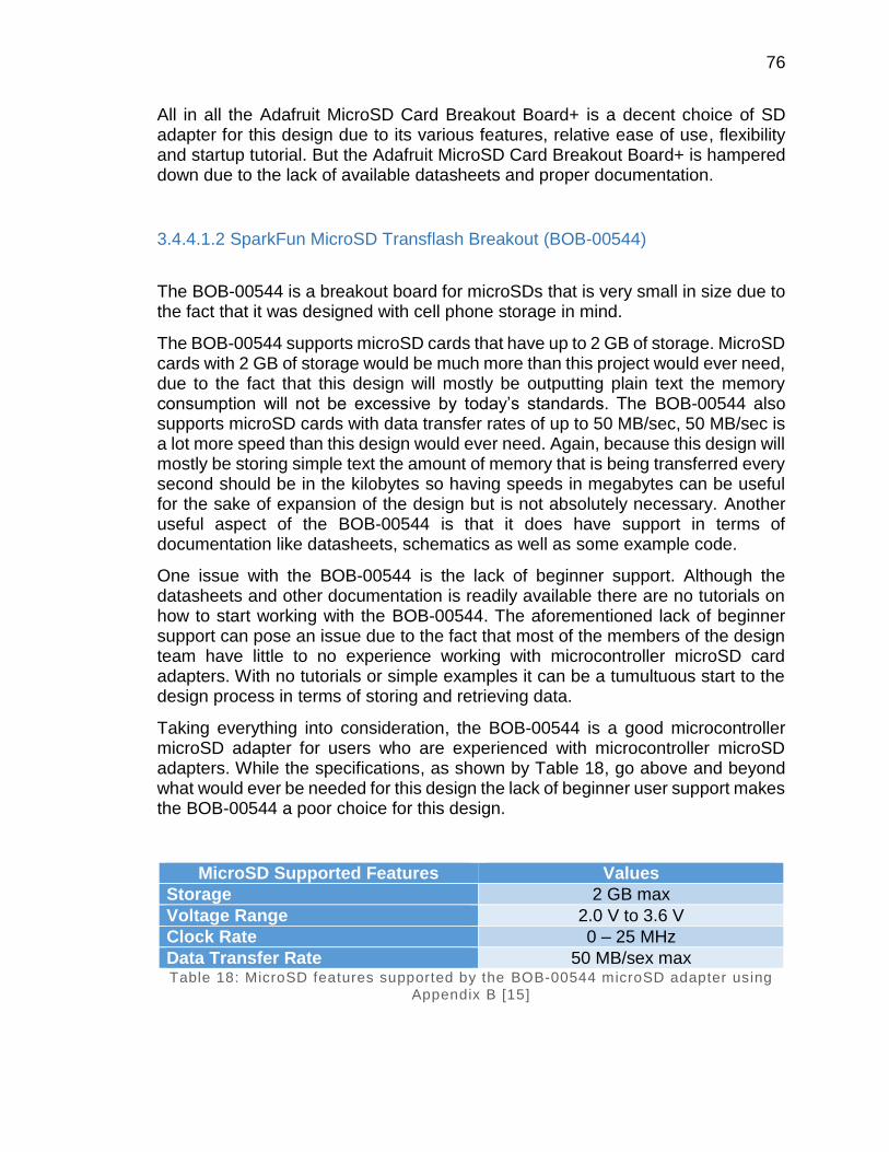
76
All in all the Adafruit MicroSD Card Breakout Board+ is a decent choice of SD adapter for this design due to its various features, relative ease of use, flexibility and startup tutorial. But the Adafruit MicroSD Card Breakout Board+ is hampered down due to the lack of available datasheets and proper documentation.
3.4.4.1.2 SparkFun MicroSD Transflash Breakout (BOB-00544)
The BOB-00544 is a breakout board for microSDs that is very small in size due to the fact that it was designed with cell phone storage in mind.
The BOB-00544 supports microSD cards that have up to 2 GB of storage. MicroSD cards with 2 GB of storage would be much more than this project would ever need, due to the fact that this design will mostly be outputting plain text the memory consumption will not be excessive by today’s standards. The BOB-00544 also supports microSD cards with data transfer rates of up to 50 MB/sec, 50 MB/sec is a lot more speed than this design would ever need. Again, because this design will mostly be storing simple text the amount of memory that is being transferred every second should be in the kilobytes so having speeds in megabytes can be useful for the sake of expansion of the design but is not absolutely necessary. Another useful aspect of the BOB-00544 is that it does have support in terms of documentation like datasheets, schematics as well as some example code.
One issue with the BOB-00544 is the lack of beginner support. Although the datasheets and other documentation is readily available there are no tutorials on how to start working with the BOB-00544. The aforementioned lack of beginner support can pose an issue due to the fact that most of the members of the design team have little to no experience working with microcontroller microSD card adapters. With no tutorials or simple examples it can be a tumultuous start to the design process in terms of storing and retrieving data.
Taking everything into consideration, the BOB-00544 is a good microcontroller microSD adapter for users who are experienced with microcontroller microSD adapters. While the specifications, as shown by Table 18, go above and beyond what would ever be needed for this design the lack of beginner user support makes the BOB-00544 a poor choice for this design.
MicroSD Supported Features Values
Storage 2 GB max
Voltage Range 2.0 V to 3.6 V
Clock Rate 0 – 25 MHz
Data Transfer Rate 50 MB/sex max Table 18: MicroSD features supported by the BOB-00544 microSD adapter using
Appendix B [15]
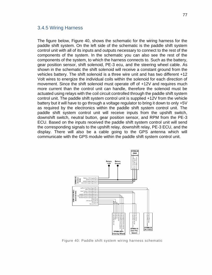
77
3.4.5 Wiring Harness
The figure below, Figure 40, shows the schematic for the wiring harness for the paddle shift system. On the left side of the schematic is the paddle shift system control unit with all of its inputs and outputs necessary to connect to the rest of the components of the system. In the schematic you can also see the rest of the components of the system, to which the harness connects to. Such as the battery, gear position sensor, shift solenoid, PE-3 ecu, and the steering wheel cable. As shown in the schematic the shift solenoid will receive a constant ground from the vehicles battery. The shift solenoid is a three wire unit and has two different +12 Volt wires to energize the individual coils within the solenoid for each direction of movement. Since the shift solenoid must operate off of +12V and requires much more current than the control unit can handle, therefore the solenoid must be actuated using relays with the coil circuit controlled through the paddle shift system control unit. The paddle shift system control unit is supplied +12V from the vehicle battery but it will have to go through a voltage regulator to bring it down to only +5V as required by the electronics within the paddle shift system control unit. The paddle shift system control unit will receive inputs from the upshift switch, downshift switch, neutral button, gear position sensor, and RPM from the PE-3 ECU. Based on the inputs received the paddle shift system control unit will send the corresponding signals to the upshift relay, downshift relay, PE-3 ECU, and the display. There will also be a cable going to the GPS antenna which will communicate with the GPS module within the paddle shift system control unit.
Figure 40: Paddle shift system wiring harness schematic
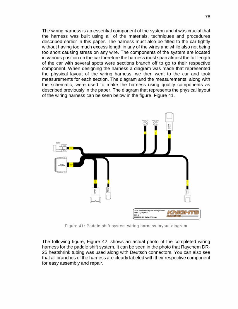
78
The wiring harness is an essential component of the system and it was crucial that the harness was built using all of the materials, techniques and procedures described earlier in this paper. The harness must also be fitted to the car tightly without having too much excess length in any of the wires and while also not being too short causing stress on any wire. The components of the system are located in various position on the car therefore the harness must span almost the full length of the car with several spots were sections branch off to go to their respective component. When designing the harness a diagram was made that represented the physical layout of the wiring harness, we then went to the car and took measurements for each section. The diagram and the measurements, along with the schematic, were used to make the harness using quality components as described previously in the paper. The diagram that represents the physical layout of the wiring harness can be seen below in the figure, Figure 41.
Figure 41: Paddle shift system wiring harness layout diagram
The following figure, Figure 42, shows an actual photo of the completed wiring harness for the paddle shift system. It can be seen in the photo that Raychem DR-25 heatshrink tubing was used along with Deutsch connectors. You can also see that all branches of the harness are clearly labeled with their respective component for easy assembly and repair.
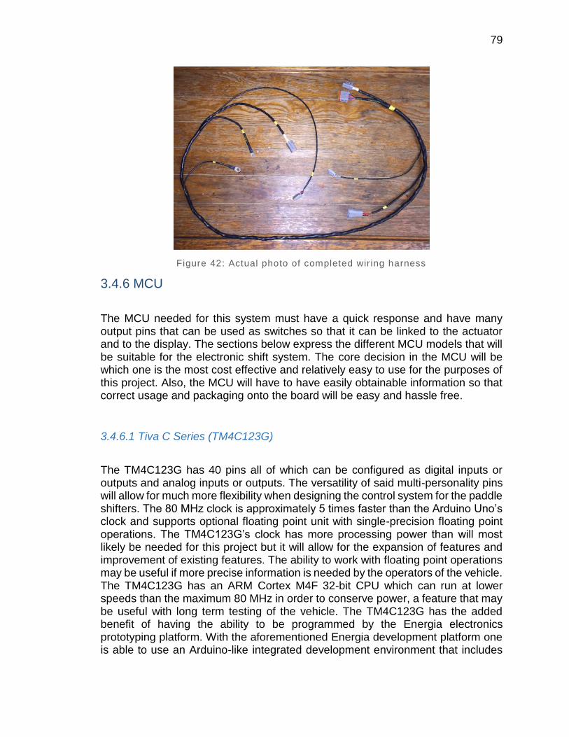
79
Figure 42: Actual photo of completed wir ing harness
3.4.6 MCU
The MCU needed for this system must have a quick response and have many output pins that can be used as switches so that it can be linked to the actuator and to the display. The sections below express the different MCU models that will be suitable for the electronic shift system. The core decision in the MCU will be which one is the most cost effective and relatively easy to use for the purposes of this project. Also, the MCU will have to have easily obtainable information so that correct usage and packaging onto the board will be easy and hassle free.
3.4.6.1 Tiva C Series (TM4C123G)
The TM4C123G has 40 pins all of which can be configured as digital inputs or outputs and analog inputs or outputs. The versatility of said multi-personality pins will allow for much more flexibility when designing the control system for the paddle shifters. The 80 MHz clock is approximately 5 times faster than the Arduino Uno’s clock and supports optional floating point unit with single-precision floating point operations. The TM4C123G’s clock has more processing power than will most likely be needed for this project but it will allow for the expansion of features and improvement of existing features. The ability to work with floating point operations may be useful if more precise information is needed by the operators of the vehicle. The TM4C123G has an ARM Cortex M4F 32-bit CPU which can run at lower speeds than the maximum 80 MHz in order to conserve power, a feature that may be useful with long term testing of the vehicle. The TM4C123G has the added benefit of having the ability to be programmed by the Energia electronics prototyping platform. With the aforementioned Energia development platform one is able to use an Arduino-like integrated development environment that includes

80
various libraries with many different applications. The above data was referenced from Table 19 as well as Figure 43, shown below.
Figure 43: TM4C123G block diagram from Appendix B [6]
Primary Features Values
Clock 80 MHz
Flash Memory 256 KB
SRAM 32 KB
Operating Voltage 0.9V, 30 MHz
1.2V, 120 MHz
Extended Temperature
-40 - 125
Power Consumption 45 mA, active
1.38 µA, hibernate Table 19: Key features for the TM4C123G using Appendix B [6]
3.4.6.2 MSP-EXP430G2
The MSP-EXP430G2 is considered an ultra-low power MCU. With low power consumption and the performance of a 16-bit microcontroller, this MCU excels in smaller projects and applications where power is very limited, as shown by Table 20. The MSP-EXP430G2 has an operating temperature of -55 to 125 the latter will have merit in the project due to the fact that the formula one car will be tested outdoors where the unit may become hotter than 50 with ambient temperature. The MSP-EXP430G2 has a 16-bit system with a 16 MHz clock which should be enough performance to handle the core aspects of the system control but does not leave much room for expansion. The above data was referenced from Figure 44, shown below.
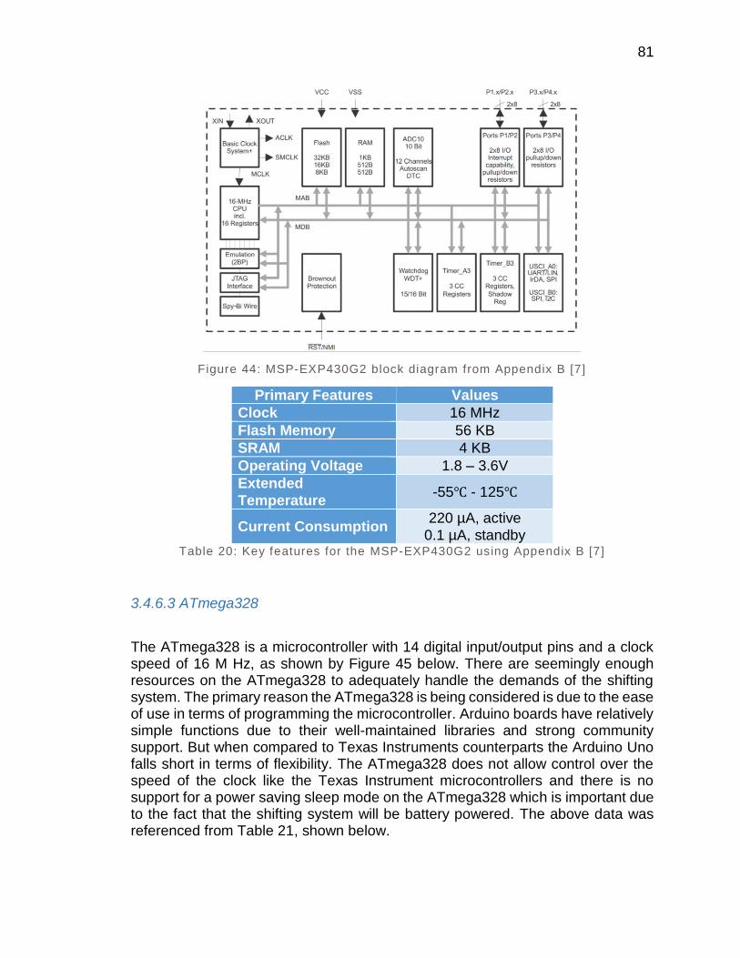
81
Figure 44: MSP-EXP430G2 block diagram from Appendix B [7]
Primary Features Values
Clock 16 MHz
Flash Memory 56 KB
SRAM 4 KB
Operating Voltage 1.8 – 3.6V
Extended
Temperature -55 - 125
Current Consumption 220 µA, active
0.1 µA, standby Table 20: Key features for the MSP-EXP430G2 using Appendix B [7]
3.4.6.3 ATmega328
The ATmega328 is a microcontroller with 14 digital input/output pins and a clock speed of 16 M Hz, as shown by Figure 45 below. There are seemingly enough resources on the ATmega328 to adequately handle the demands of the shifting system. The primary reason the ATmega328 is being considered is due to the ease of use in terms of programming the microcontroller. Arduino boards have relatively simple functions due to their well-maintained libraries and strong community support. But when compared to Texas Instruments counterparts the Arduino Uno falls short in terms of flexibility. The ATmega328 does not allow control over the speed of the clock like the Texas Instrument microcontrollers and there is no support for a power saving sleep mode on the ATmega328 which is important due to the fact that the shifting system will be battery powered. The above data was referenced from Table 21, shown below.
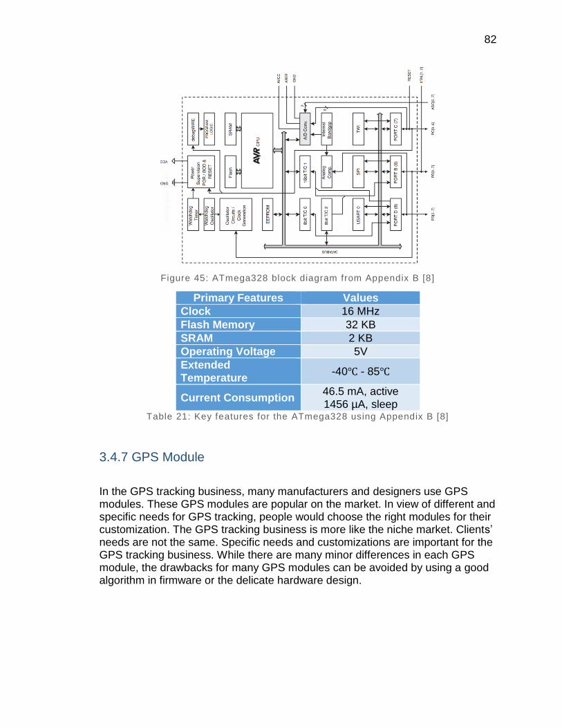
82
Figure 45: ATmega328 block diagram from Appendix B [8]
Primary Features Values
Clock 16 MHz
Flash Memory 32 KB
SRAM 2 KB
Operating Voltage 5V
Extended Temperature
-40 - 85
Current Consumption 46.5 mA, active 1456 µA, sleep
Table 21: Key features for the ATmega328 using Appendix B [8]
3.4.7 GPS Module
In the GPS tracking business, many manufacturers and designers use GPS modules. These GPS modules are popular on the market. In view of different and specific needs for GPS tracking, people would choose the right modules for their customization. The GPS tracking business is more like the niche market. Clients’ needs are not the same. Specific needs and customizations are important for the GPS tracking business. While there are many minor differences in each GPS module, the drawbacks for many GPS modules can be avoided by using a good algorithm in firmware or the delicate hardware design.
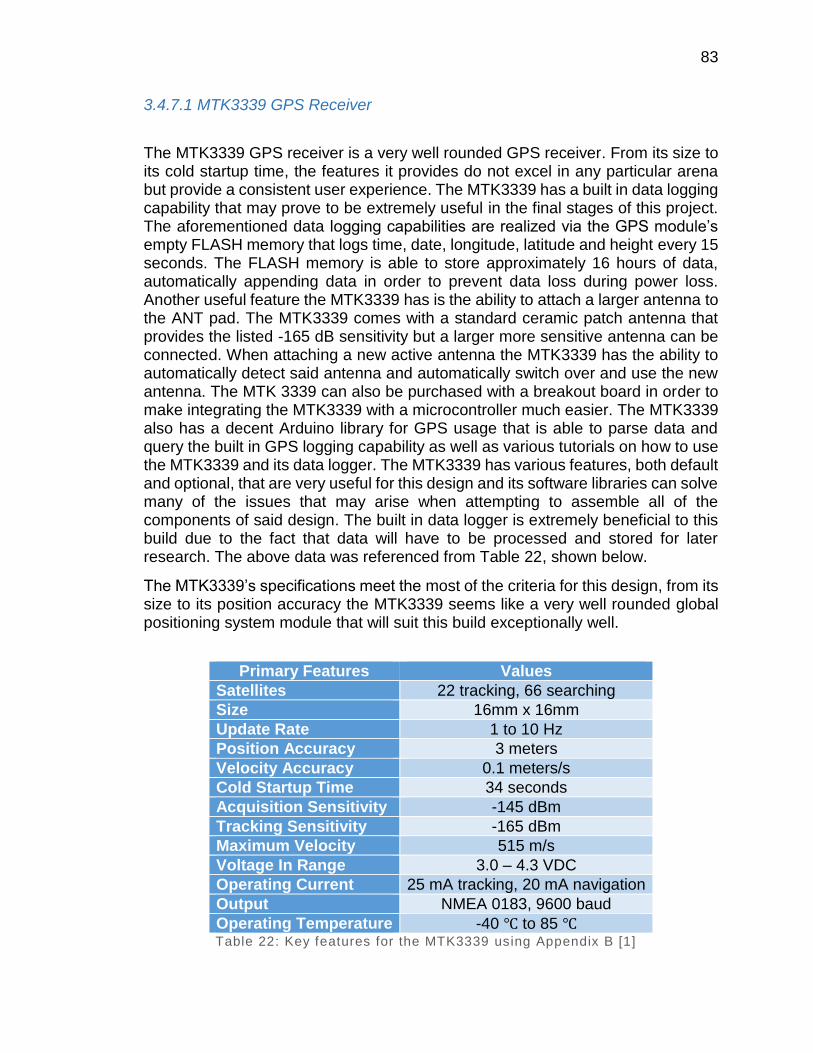
83
3.4.7.1 MTK3339 GPS Receiver
The MTK3339 GPS receiver is a very well rounded GPS receiver. From its size to its cold startup time, the features it provides do not excel in any particular arena but provide a consistent user experience. The MTK3339 has a built in data logging capability that may prove to be extremely useful in the final stages of this project. The aforementioned data logging capabilities are realized via the GPS module’s empty FLASH memory that logs time, date, longitude, latitude and height every 15 seconds. The FLASH memory is able to store approximately 16 hours of data, automatically appending data in order to prevent data loss during power loss. Another useful feature the MTK3339 has is the ability to attach a larger antenna to the ANT pad. The MTK3339 comes with a standard ceramic patch antenna that provides the listed -165 dB sensitivity but a larger more sensitive antenna can be connected. When attaching a new active antenna the MTK3339 has the ability to automatically detect said antenna and automatically switch over and use the new antenna. The MTK 3339 can also be purchased with a breakout board in order to make integrating the MTK3339 with a microcontroller much easier. The MTK3339 also has a decent Arduino library for GPS usage that is able to parse data and query the built in GPS logging capability as well as various tutorials on how to use the MTK3339 and its data logger. The MTK3339 has various features, both default and optional, that are very useful for this design and its software libraries can solve many of the issues that may arise when attempting to assemble all of the components of said design. The built in data logger is extremely beneficial to this build due to the fact that data will have to be processed and stored for later research. The above data was referenced from Table 22, shown below.
The MTK3339’s specifications meet the most of the criteria for this design, from its size to its position accuracy the MTK3339 seems like a very well rounded global positioning system module that will suit this build exceptionally well.
Primary Features Values
Satellites 22 tracking, 66 searching
Size 16mm x 16mm
Update Rate 1 to 10 Hz
Position Accuracy 3 meters
Velocity Accuracy 0.1 meters/s
Cold Startup Time 34 seconds
Acquisition Sensitivity -145 dBm
Tracking Sensitivity -165 dBm
Maximum Velocity 515 m/s
Voltage In Range 3.0 – 4.3 VDC
Operating Current 25 mA tracking, 20 mA navigation
Output NMEA 0183, 9600 baud
Operating Temperature -40 to 85 Table 22: Key features for the MTK3339 using Appendix B [1]
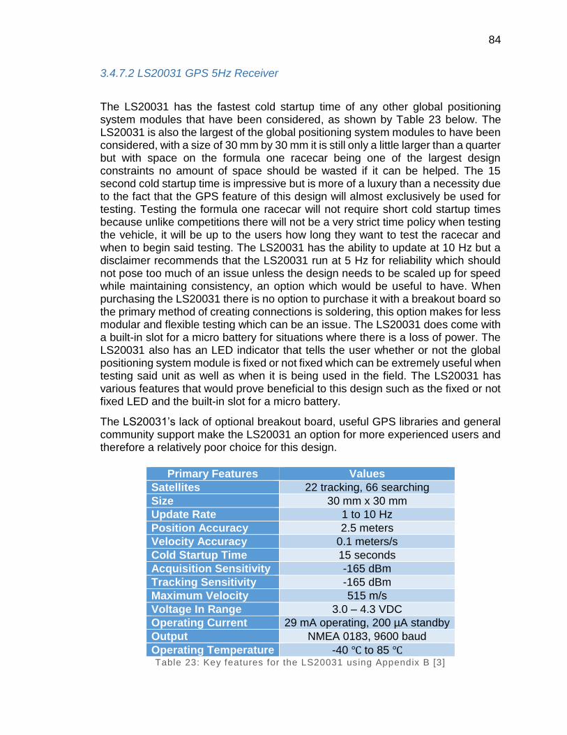
84
3.4.7.2 LS20031 GPS 5Hz Receiver
The LS20031 has the fastest cold startup time of any other global positioning system modules that have been considered, as shown by Table 23 below. The LS20031 is also the largest of the global positioning system modules to have been considered, with a size of 30 mm by 30 mm it is still only a little larger than a quarter but with space on the formula one racecar being one of the largest design constraints no amount of space should be wasted if it can be helped. The 15 second cold startup time is impressive but is more of a luxury than a necessity due to the fact that the GPS feature of this design will almost exclusively be used for testing. Testing the formula one racecar will not require short cold startup times because unlike competitions there will not be a very strict time policy when testing the vehicle, it will be up to the users how long they want to test the racecar and when to begin said testing. The LS20031 has the ability to update at 10 Hz but a disclaimer recommends that the LS20031 run at 5 Hz for reliability which should not pose too much of an issue unless the design needs to be scaled up for speed while maintaining consistency, an option which would be useful to have. When purchasing the LS20031 there is no option to purchase it with a breakout board so the primary method of creating connections is soldering, this option makes for less modular and flexible testing which can be an issue. The LS20031 does come with a built-in slot for a micro battery for situations where there is a loss of power. The LS20031 also has an LED indicator that tells the user whether or not the global positioning system module is fixed or not fixed which can be extremely useful when testing said unit as well as when it is being used in the field. The LS20031 has various features that would prove beneficial to this design such as the fixed or not fixed LED and the built-in slot for a micro battery.
The LS20031’s lack of optional breakout board, useful GPS libraries and general community support make the LS20031 an option for more experienced users and therefore a relatively poor choice for this design.
Primary Features Values
Satellites 22 tracking, 66 searching
Size 30 mm x 30 mm
Update Rate 1 to 10 Hz
Position Accuracy 2.5 meters
Velocity Accuracy 0.1 meters/s
Cold Startup Time 15 seconds
Acquisition Sensitivity -165 dBm
Tracking Sensitivity -165 dBm
Maximum Velocity 515 m/s
Voltage In Range 3.0 – 4.3 VDC
Operating Current 29 mA operating, 200 µA standby
Output NMEA 0183, 9600 baud
Operating Temperature -40 to 85 Table 23: Key features for the LS20031 using Appendix B [3]
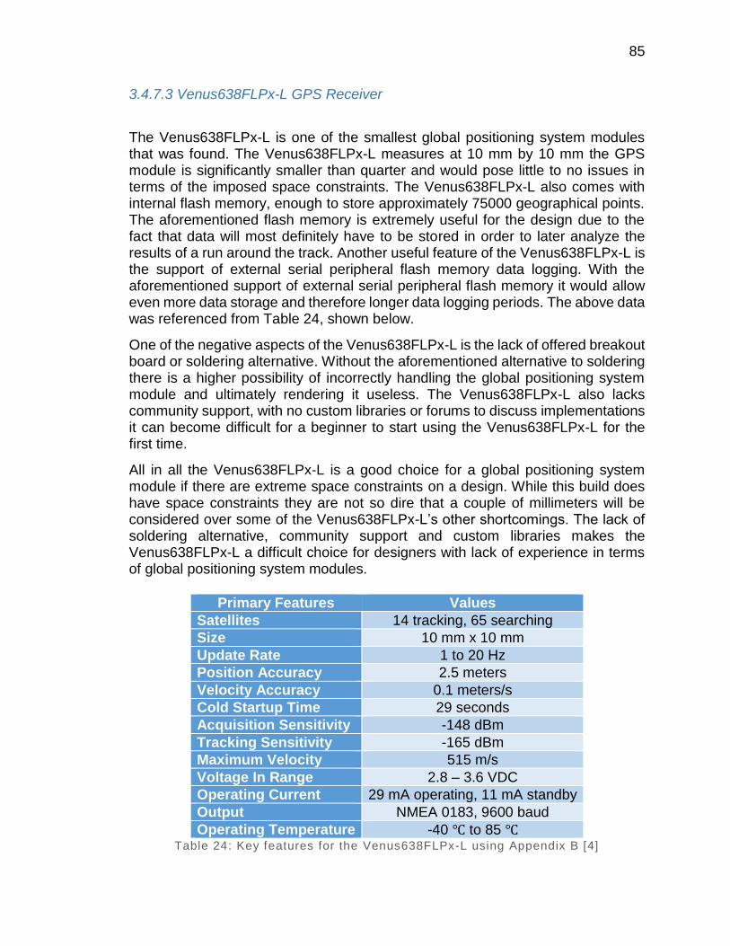
85
3.4.7.3 Venus638FLPx-L GPS Receiver
The Venus638FLPx-L is one of the smallest global positioning system modules that was found. The Venus638FLPx-L measures at 10 mm by 10 mm the GPS module is significantly smaller than quarter and would pose little to no issues in terms of the imposed space constraints. The Venus638FLPx-L also comes with internal flash memory, enough to store approximately 75000 geographical points. The aforementioned flash memory is extremely useful for the design due to the fact that data will most definitely have to be stored in order to later analyze the results of a run around the track. Another useful feature of the Venus638FLPx-L is the support of external serial peripheral flash memory data logging. With the aforementioned support of external serial peripheral flash memory it would allow even more data storage and therefore longer data logging periods. The above data was referenced from Table 24, shown below.
One of the negative aspects of the Venus638FLPx-L is the lack of offered breakout board or soldering alternative. Without the aforementioned alternative to soldering there is a higher possibility of incorrectly handling the global positioning system module and ultimately rendering it useless. The Venus638FLPx-L also lacks community support, with no custom libraries or forums to discuss implementations it can become difficult for a beginner to start using the Venus638FLPx-L for the first time.
All in all the Venus638FLPx-L is a good choice for a global positioning system module if there are extreme space constraints on a design. While this build does have space constraints they are not so dire that a couple of millimeters will be considered over some of the Venus638FLPx-L’s other shortcomings. The lack of soldering alternative, community support and custom libraries makes the Venus638FLPx-L a difficult choice for designers with lack of experience in terms of global positioning system modules.
Primary Features Values
Satellites 14 tracking, 65 searching
Size 10 mm x 10 mm
Update Rate 1 to 20 Hz
Position Accuracy 2.5 meters
Velocity Accuracy 0.1 meters/s
Cold Startup Time 29 seconds
Acquisition Sensitivity -148 dBm
Tracking Sensitivity -165 dBm
Maximum Velocity 515 m/s
Voltage In Range 2.8 – 3.6 VDC
Operating Current 29 mA operating, 11 mA standby
Output NMEA 0183, 9600 baud
Operating Temperature -40 to 85 Table 24: Key features for the Venus638FLPx-L using Appendix B [4]

86
3.4.7.4 GP-2106 SiRF IV GPS Receiver
The GP-2106 SiRF IV module has a medium size but has a defined rectangular shape instead of the more traditional square global positioning system modules. The aforementioned rectangular shape although not much smaller at 22 mm length can be beneficial when mounting the GP-2106 SiRF IV module. With a width of 7.5 mm the rectangular module may fit in certain positions that other global positioning system modules might not. The GP-2106 SiRF IV has a built-in hibernate feature that allows the global positioning system module to maintain an operating current of 30 µA while maintaining a one second hot start. The aforementioned hibernate mode could prove extremely useful for this design due to the substantial power conservation in a power sensitive system. The one second hot start that is tied to the hibernate mode is a very helpful feature to have due to the fact that at competitions users can turn on the GP-2106 SiRF IV, test it once to assure it is running correctly and let the global positioning system module sit in hibernate mode until the competition has started. With the previously mentioned one second hot start users will not have to wait 25 or more seconds for a cold startup like with other global positioning system modules. One of the downfalls of the GP-2106 SiRF IV is the amount of searching channels that the module is able to handle. As seen below in Table 25.
Primary Features Values
Satellites 22 tracking, 48 searching
Size 22 mm x 7.5 mm
Update Rate 1 Hz
Position Accuracy 2.5 meters
Velocity Accuracy 0.1 meters/s
Cold Startup Time 35 seconds
Acquisition Sensitivity -163 dBm
Tracking Sensitivity -163 dBm
Maximum Velocity 514 m/s
Voltage In 1.8 VDC
Operating Current 65 mA operating, 30 µA hibernate
Output NMEA 0183, 4800 baud (default)
Operating Temperature -40 to 85 Table 25: Key features for the GP-2106 SiRF IV using Appendix B [5]
With 48 searching satellites as opposed to the commonplace 65 searching satellites there could be a noticeable slowdown in terms of the GP-2106 SiRF IV’s time to first fix. The previously mentioned time to first fix slowdown due to lower amount of searching satellites can pose a minor issue when starting up the system in a time intensive scenario such as a competition or showcase. The startup time of the system is not a major issue due to the fact that the system can be booted
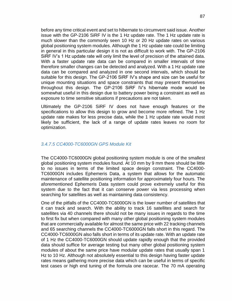
87
before any time critical event and set to hibernate to circumvent said issue. Another issue with the GP-2106 SiRF IV is the 1 Hz update rate. The 1 Hz update rate is much slower than the commonly seen 10 Hz or 20 Hz update rates on various global positioning system modules. Although the 1 Hz update rate could be limiting in general in this particular design it is not as difficult to work with. The GP-2106 SiRF IV’s 1 Hz update rate will only limit the level of precision of the attained data. With a faster update rate data can be compared in smaller intervals of time therefore smaller changes can be detected and analyzed. With a 1 Hz update rate data can be compared and analyzed in one second intervals, which should be suitable for this design. The GP-2106 SiRF IV’s shape and size can be useful for unique mounting situations and space constraints that may present themselves throughout this design. The GP-2106 SiRF IV’s hibernate mode would be somewhat useful in this design due to battery power being a constraint as well as exposure to time sensitive situations if precautions are not taken.
Ultimately the GP-2106 SiRF IV does not have enough features or the specifications to allow this design to grow and become more refined. The 1 Hz update rate makes for less precise data, while the 1 Hz update rate would most likely be sufficient, the lack of a range of update rates leaves no room for optimization.
3.4.7.5 CC4000-TC6000GN GPS Module Kit
The CC4000-TC6000GN global positioning system module is one of the smallest global positioning system modules found. At 10 mm by 9 mm there should be little to no issues in terms of the limited space design constraint. The CC4000-TC6000GN includes Ephemeris Data, a system that allows for the automatic maintenance of satellite positioning information for approximately four hours. The aforementioned Ephemeris Data system could prove extremely useful for this system due to the fact that it can conserve power via less processing when searching for satellites as well as maintaining data consistency.
One of the pitfalls of the CC4000-TC6000GN is the lower number of satellites that it can track and search. With the ability to track 16 satellites and search for satellites via 40 channels there should not be many issues in regards to the time to first fix but when compared with many other global positioning system modules that are commercially available for almost the same price with 22 tracking channels and 65 searching channels the CC4000-TC6000GN falls short in this regard. The CC4000-TC6000GN also falls short in terms of its update rate. With an update rate of 1 Hz the CC4000-TC6000GN should update rapidly enough that the provided data should suffice for average testing but many other global positioning system modules of about the same price have modular update rates that usually span 1 Hz to 10 Hz. Although not absolutely essential to this design having faster update rates means gathering more precise data which can be useful in terms of specific test cases or high end tuning of the formula one racecar. The 70 mA operating
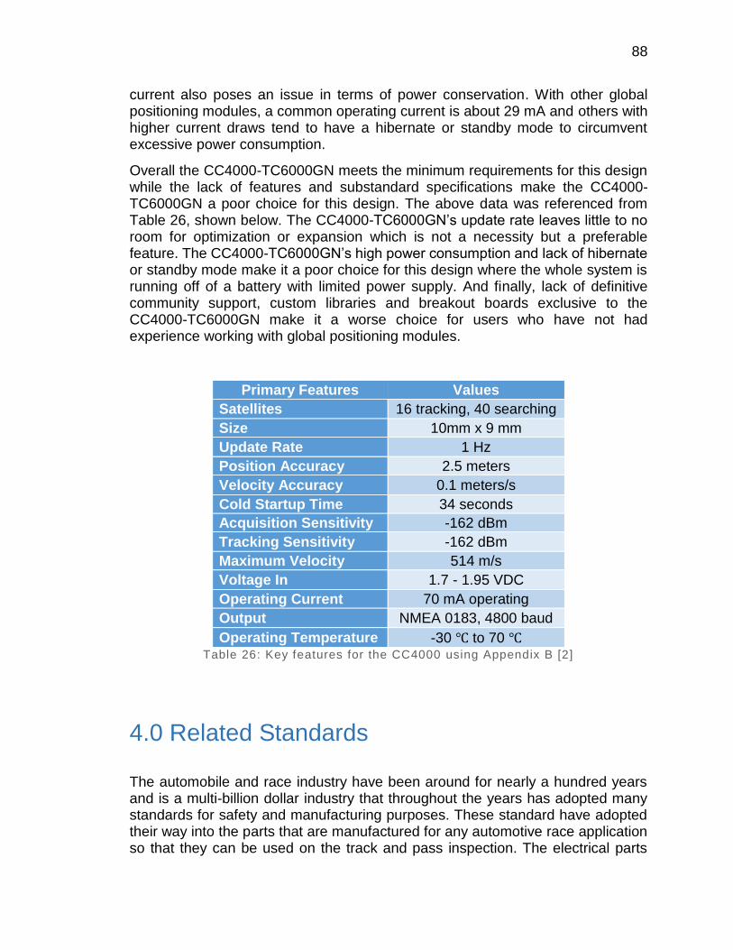
88
current also poses an issue in terms of power conservation. With other global positioning modules, a common operating current is about 29 mA and others with higher current draws tend to have a hibernate or standby mode to circumvent excessive power consumption.
Overall the CC4000-TC6000GN meets the minimum requirements for this design while the lack of features and substandard specifications make the CC4000-TC6000GN a poor choice for this design. The above data was referenced from Table 26, shown below. The CC4000-TC6000GN’s update rate leaves little to no room for optimization or expansion which is not a necessity but a preferable feature. The CC4000-TC6000GN’s high power consumption and lack of hibernate or standby mode make it a poor choice for this design where the whole system is running off of a battery with limited power supply. And finally, lack of definitive community support, custom libraries and breakout boards exclusive to the CC4000-TC6000GN make it a worse choice for users who have not had experience working with global positioning modules.
Primary Features Values
Satellites 16 tracking, 40 searching
Size 10mm x 9 mm
Update Rate 1 Hz
Position Accuracy 2.5 meters
Velocity Accuracy 0.1 meters/s
Cold Startup Time 34 seconds
Acquisition Sensitivity -162 dBm
Tracking Sensitivity -162 dBm
Maximum Velocity 514 m/s
Voltage In 1.7 - 1.95 VDC
Operating Current 70 mA operating
Output NMEA 0183, 4800 baud
Operating Temperature -30 to 70 Table 26: Key features for the CC4000 using Appendix B [2]
4.0 Related Standards
The automobile and race industry have been around for nearly a hundred years and is a multi-billion dollar industry that throughout the years has adopted many standards for safety and manufacturing purposes. These standard have adopted their way into the parts that are manufactured for any automotive race application so that they can be used on the track and pass inspection. The electrical parts

89
such as the GPS module and MCU also have their own standards as well so that those who work on the parts will be able to understand how to use any part that is similar.
4.1 MCU Standards
The AEC-Q100 Test Requirements are:
“a set of reliability stress tests defined by the Automotive Electronics Council for the purpose of qualifying integrated circuits (ICs) for automotive applications. Linear qualifies products based on AEC-Q100 guidelines and guarantees that all automotive products exceed current AEC- Q100 requirements by conducting additional device and package level stress tests.” [27]
Some of the aforementioned tests are: power cycling, instant solder shock and 100% oxide stress test.
In order to mimic worst case field and environmental operating conditions reliability tests using more rigorous test conditions such as longer test durations or greater temperature ranges. One of the more rigorous mechanical stress tests that the AEC-Q100 puts MCUs through is 1000 hours of high temperature storage at 150
or 175 . One of the more demanding voltage bias stress tests that the AEC-Q100 provides is the 168 hour humidity bias test where the MCU is subjected to
temperatures of 130 or higher with a relative humidity of 85% for 168 consecutive hours.
The AEC-Q100 provides a product grade for the operating temperature range of MCUs as shown by Table 27 below. Many of the commercially available MCUs are considered Grade 1 but some lower end models can go as low as Grade 3.
Operating Temperature Range
Grade 0 -40 +150
Grade 1 -40 +125
Grade 2 -40 +105
Grade 3 -40 +85
Grade 4 0 +70
Table 27: AEC-Q100 MCU operating temperature grades from Appendix D [27]
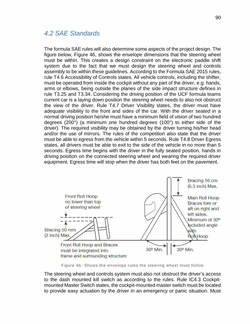
90
4.2 SAE Standards
The formula SAE rules will also determine some aspects of the project design. The figure below, Figure 46, shows the envelope dimensions that the steering wheel must be within. This creates a design constraint on the electronic paddle shift system due to the fact that we must design the steering wheel and controls assembly to be within these guidelines. According to the Formula SAE 2015 rules, rule T4.6 Accessibility of Controls states, All vehicle controls, including the shifter, must be operated from inside the cockpit without any part of the driver, e.g. hands, arms or elbows, being outside the planes of the side impact structure defines in rule T3.25 and T3.34. Considering the driving position of the UCF formula teams current car is a laying down position the steering wheel needs to also not obstruct the view of the driver. Rule T4.7 Driver Visibility states, the driver must have adequate visibility to the front and sides of the car. With the driver seated in a normal driving position he/she must have a minimum field of vision of two hundred degrees (200°) (a minimum one hundred degrees (100°) to either side of the driver). The required visibility may be obtained by the driver turning his/her head and/or the use of mirrors. The rules of the competition also state that the driver must be able to egress from the vehicle within 5 seconds. Rule T4.8 Driver Egress states, all drivers must be able to exit to the side of the vehicle in no more than 5 seconds. Egress time begins with the driver in the fully seated position, hands in driving position on the connected steering wheel and wearing the required driver equipment. Egress time will stop when the driver has both feet on the pavement.
Figure 46: Shows the envelope rules the steering wheel must follow
The steering wheel and controls system must also not obstruct the driver’s access to the dash mounted kill switch as according to the rules. Rule IC4.3 Cockpit-mounted Master Switch states, the cockpit-mounted master switch must be located to provide easy actuation by the driver in an emergency or panic situation. Must
91
be located within easy reach of the belted-in driver, alongside the steering wheel, and unobstructed by the steering wheel or any other part of the car. It is suggested that it be placed on the same side of the steering wheel as the shifter mechanism. Must be a push/pull Emergency switch with a minimum diameter of 24mm. The switch must be installed such that, from the ON position, pushing on the switch will disable power to the ignition and all fuel pumps, and from the OFF position, pulling on the switch will enable power to the ignition and fuel pump. Switches that require a twist or twist and pull to enable power are acceptable. May act through a relay.
4.3 Vehicle Standards
Standard J3104 is related to electronic actuators and drivetrain. This SAE document covers most common applications of electric and electronic actuators used for controlling on-demand AWD disconnect systems used in passenger (car and light truck) vehicles. The specification will provide consistent definition, terminology, test methods and reporting methods. This technical specification will provide a common and consistent description of the different types of actuators used for on-demand driveline disconnect systems. Currently, different and often inconsistent naming conventions, descriptions, and test nomenclature are used to describe the function, testing and reporting methods for different actuators.
The Standard Specifications for Automotive Spark-Ignition Engine Fuel covers the establishment of requirements of automotive fuels for ground vehicles equipped with spark-ignition engines.
Standard Specification 1.2 for Automotive Spark-Ignition Engine Fuel states that, This specification describes various characteristics of automotive fuels for use over a wide range of operating conditions. It provides for a variation of the volatility and water tolerance of automotive fuel in accordance with seasonal climatic changes at the locality where the fuel is used. For the period May 1 through Sept. 15, the maximum vapor pressure limits issued by the United States (U.S.) Environmental Protection Agency (EPA) are specified for each geographical area except Alaska and Hawaii. Variation of the antiknock index with seasonal climatic changes and altitude. This specification neither necessarily includes all types of fuels that are satisfactory for automotive vehicles, nor necessarily excludes fuels that can perform unsatisfactorily under certain operating conditions or in certain equipment.
Standard Specification 1.3 for Automotive Spark-Ignition Engine Fuel states that, the spark-ignition engine fuels covered in this specification are gasoline and its blends with oxygenates, such as alcohols and ethers. This specification does not apply to fuels that contain an oxygenate as the primary component, such as Fuel Methanol (M85). The concentrations and types of oxygenates are not specifically limited in this specification. However, depending on oxygenate type, as oxygenate content increases above some threshold level, the likelihood for vehicle problems also increases. The composition of both unleaded and leaded fuel is limited by

92
economic, legal, and technical consideration, but their properties, including volatility, are defined by this specification. In addition, the composition of unleaded fuel is subject to the rules, regulations, and Clean Air Act waivers of the U.S. Environmental Protection Agency (EPA). With regard to fuel properties, including volatility, this specification can be more or less restrictive than the EPA rules, regulations, and waivers. Contact the EPA for the latest versions of the rules and additional requirements.
The Standard Specification for Data Format describes a data file format for racing applications.
The Standard Specification for Data Format 1.2 states that, the variables and sizes of all data that will be stored in the file. The file is in binary format, and is fully documented in this specification.
The Standard Specification for Data Format 1.3 states that, the design is to be independent of hardware platforms, computer languages, and Operating System (OS).
4.4 Design impact of relevant standards
One of the design impacts that the AEC-Q100 Test Requirements brings about manifest itself in the form of heat optimization. The AEC-Q100 puts MCUs through
1000 hours of high temperature storage at 150 or 175 even though a 1000 hour reliability test might be excessive for this design, total consistency in a high temperature environment is absolutely essential to this design. In order to meet the highest MCU operating temperature range overheating the MCU is an issue which will have to be handled via design. In order to reach the highest grade of operating temperature range heat ventilation and possibly a simple cooling system would need to be implemented for the MCU. Also, if the MCU is going to be encased for impact and element resistance, heating has to be kept in mind. The aforementioned casing must have some sort of release for the MCU’s built up heat.
Another design impact of the AEC-Q100 Test Requirements is a method of humidity control. The AEC-Q100 puts MCUs in an environment with ambient
temperatures of 130 or more and 85% humidity for 168 consecutive hours. The aforementioned heat and humidity test is a somewhat more realistic in terms of the situation actually occurring, because the formula one racecar and most of its components will usually be stored in a garage or operate in outdoor environments where consistently high temperatures are present as well as high levels of humidity. Due to the fact that this project can be stored or will operate in some very humid environments humidity control is an issue that will have to be handled via design. If left unchecked excess humidity can cause water damage to various components of the MCU, a design oversight that can render the MCU useless. In

93
order to prevent issues in terms of humidity and heat a casing that allows for proper ventilation but maintains a certain degree of waterproofness may need to be designed or purchased.
The AEC-Q100 uses some extremely rigorous test to ensure the reliability of the MCU in high stress automobile scenarios. Although the AEC-Q100’s standards may be excessively high in terms of this design, an attempt to meet said standards will most likely result in a very consistent MCU subsystem.
4.5 FMVSS transmission standard
The United States Department of Transportation’s Federal Motor Vehicle Safety Standards and Regulations Standard No. 102 states,
“This standard specifies the requirements for the transmission shift lever sequence, a starter interlock, and for a braking effect of automatic transmissions, to reduce the likelihood of shifting errors, starter engagement with vehicle in drive position, and to provide supplemental braking at speeds below 40 km/h (25 mph)”
A safety standard that may have to be adhered in order to maintain high levels of safety and low levels of error when operating the vehicle. Also, in 2006 the National Highway Traffic Safety Administration formally agreed with the Alliance of Automobile Manufacturers and the Association of International Automobile Manufacturers on a standard that states, “All vehicles sold in the U.S. with automatic transmissions will be equipped with brake transmission system interlocks to prevent children from moving the shift mechanisms out of park.” This aforementioned standard does not apply directly to this paddle shifter design due to the fact that children will never be operating the vehicle.
5.0 Realistic Design Constraints
There are many constraints for the electronic shift system as the system is going into a fully developed vehicle. Also, SAE has many safety standards and regulations that the system had to be in compliance with. The system was designed with cost, safety and efficiency in mind. It also had to be built and designed to be transferrable between different Formula SAE vehicles as the vehicle have to change for the following year’s race. Since it is for a race vehicle, it also needs to be fast and have a high success rate.
94
5.1 Economic and Time constraints
The budget of the Formula SAE team is small but it is also split between another SAE group making it even smaller. The amount allocated towards this project was $1000.00 in which it is ideal to be closer to $500.00 which is very feasible. The most expensive part that will be needed is the electronic actuator. There are many actuators out there but not many that are designed for this exact purpose. Many of the other actuators will be slower or too little lbs of force. The display was also a possibly costly purchase as well as being very time consuming for a small group to have it properly display certain information. In order to have a display that was bright enough and able to withstand corrosive conditions, the cost of the displays increased significantly. Every subsystem had a competive method to achieve the same goal but in the end the designs or products that were chosen were based upon their cost and the effectiveness and ease of use.
Since this is a Senior Design Project, we are given 2 months to device the parts and design of the electronic shift system. After the designs and parts are chosen. Then we will have 3 months to buy the parts, assemble them together to make the system and test it. If any tests fail then we will have to apply any changes so that the project is successful. The group has decided to order parts during the school break and if possible begin testing and coding during the break so that when the next semester begins, we can get to the assembly and testing stages sooner so that the project can be properly fine-tuned. During fine tuning there is also the chance of a part failing or needed to be replaced for a better performing part or for a small change in design as well so a two week period has been set aside after testing to make sure that the shift system will be ready to race.
5.2 Environmental, Social, and Political constraints
The vehicle should have very high performance in terms of acceleration, braking and handling and be sufficiently durable to successfully complete all the events described in the Formula SAE Rules and held at the Formula SAE competitions. The vehicle must accommodate drivers whose stature ranges from 5th percentile female to 95th percentile male and must satisfy the requirements of the Formula SAE Rules. Additional design factors to be considered include: aesthetics, cost, ergonomics, maintainability, manufacturability, and reliability. Once the vehicle has been completed and tested, the design firm will attempt to “sell” the design to a “corporation” that is considering the production of a competition vehicle. The challenge to the design team is to develop a prototype car that best meets the FSAE vehicle design goals and which can be profitably marketed.
The Formula SAE vehicle is run by a UCF student base and competes in nationwide competitions against other schools. It is where students go to learn the automotive industry and test their skills and knowledge and put it to the test. UCF’s

95
SAE department is funded by SGA but is a small group so very little funding is given each year for competition. This means we have a small budget to work with but have high hopes to increase the placement of the UCF Formula SAE car so that the budget can be increased for years to come.
5.3 Ethical, Health, and Safety constraints
There are many safety constraints that are important for the design of the electronic shift system. Since this is a school program and also is a race vehicle, many precautions are added for the safety of the driver since high speeds, high temperatures and part failures are high since they are put to their max constantly.
FSAE has many safety rules in place for the vehicle, but there are only a few that will affect that added electronic shift system. The maximum power drawn from the battery must not exceed 80kW. This will be checked by evaluating the Energy Meter data. The maximum voltage in the tractive system must not exceed the voltage defined in EV1.1.2. This will be checked by evaluating the Energy Meter data. A violation is defined as using more than 80kW or exceeding the specified voltage for more than 100ms continuously or using more than 80kW or exceeding the specified voltage, after a moving average over 500ms is applied.
The Formula SAE vehicle has already been designed with the following rules that we cannot make any changes to so that it is able to compete in competition. The vehicle must have two steel roll hoops of designated thickness and alloy, regardless of the composition of the rest of the chassis. There must be an impact attenuator in the nose, and impact testing data on this attenuator must be submitted prior to competing. Cars must also have two hydraulic brake circuits, full five-point racing harnesses, and must meet geometric templates for driver location in the cockpit for all drivers competing. Tilt-tests ensure that no fluids will spill from the car under heavy cornering, and there must be no line-of-sight between the driver and fuel, coolant, or oil lines.
5.4 Manufacturability and Sustainability constraints
SAE has very few rules regarding manufacturing and sustainability constraints that affect the electronic shift system. Only electrical motors are allowed. Any type of electrical motor is allowed. The number of motors is not limited. The rotating part of the motor must be contained within a structural casing where the thickness is at least 2.0 mm (0.080 inch) for steel. The motor casing can be the original motor casing, a team built motor casing or the original casing with additional material added to achieve the minimum required thickness. If lower grade Aluminum Alloys is used then the material must be thicker to provide an equivalent strength. The weight of the vehicle is a large constraint that does not affect whether the vehicle

96
can compete in a completion, but instead allows the vehicle to better perform. This means all subsystems for this project must be light weight so that the power to weight ratio is not effected much.
6.0 Project Hardware and Software Design
Details
The electronic shift system design was concluded after much research was conducted and the design and parts were chosen that would best serve the project as well as being very cost effective. This system is composed of many subsystems that each serve a very crucial role in the success of the system as a whole. The order of the subsystems listed below are not in any order of importance.
6.1 Initial Design Architectures
The initial design of the electronic shift system was to use an electronic actuator controlled by a microcontroller that was given an input from two switches. We then decided to add a small display as well as a GPS module so that it would be easier for the driver and allow for improving track times by seeing where the driver may be weaker at using the GPS module and Google Earth. This system however is not straight forward where everything will simply be able to connect to each other and work. Regulators and relays are needed because of the 2 different voltage requirements of the actuator and MCU. Each subsystem below has an important role that without that subsystem, the system in general would not be able to function the same.
6.2 Actuator Subsystem
The actuator is the basis of the system and works by being given a 12V power source to push or pull the lever of the transmission. There is a total of 3 wires going to the actuator. Two of the wires are power wires and differ based upon the direction the action is to move. One wire will push the actuator while the other power wire will pull the lever. The third wire is a ground wire to close the circuit. However, simply applying a 12V power supply to the actuator would not work as it will need time for the actuator to complete its full motion. Having power go to the actuator for too long puts many stresses on the transmission and the actuator and can shorten the life of the actuator by being overwork. The opposite of not using the 12V power supply long enough means the lever may not have moved enough and therefore would not have shifted into gear. If a simple switch would be applied
97
so that the driver had to hold it long enough for the actuator to complete a shift, too much focus would be taken away from the driver giving only a small increase in overall track speed. Therefore, the actuator will need a microcontroller to be programmed to the timing needed to complete a proper shift.
6.2.1 Important Function
The function of the actuator is to push or pull the level for the gear shifter on the transmission. If the actuator is to push the level down, the gear position will drop by one. If the actuator is to pull the lever up, then the gear position will go up by one. To shift into neutral, the actuator will have to do a half cycle from 1st to 2nd gear. This will require fine tuning as it is not exactly half.
Based upon the tests concluded for each gear, it will take a minimum of 11lbs of force for the lever to shift into first or second gear. The actuator chosen has 35lbs of force in both the push and pull functions. This means that the actuators force is greater than twice the required force so that a shift will occur. The actuator also needs to travel 1 1/8” in both directions for a shift to occur. The actuator chosen has a travel of 1 ½” in both directions making it ideal for shifting as it will not push too far past the required amount adding extra stress on the transmission.
A very important requirement for the actuator is speed. It must be able to shift up and down very fast so that shift occur faster. The faster a shift occurs, the less time the engine will sit in idle and the sooner the vehicle can begin accelerating. Since the current method used in the SAE car is a manual shift using a long lever, it takes about a second for the driver to shift gears all while having to take a hand off the wheel to move the lever. This leads to requiring more driver focus on shifting and less on traversing the terrain of the course. The actuator system will minimize the drivers focus on producing the shift where instead the driver will quickly hit a switch for either and up shift or downshift and the actuator will do the rest.
The current draw of the actuator is also very important for the function of the gear shifts. If the actuator was to have too big of a current draw, then the power supply may not be able to consistently provide 12V to the actuator resulting in a substantial loss of lbs force that the actuator is designed to supply and therefor a proper gear shift may not occur. Since the actuator does use a large current but over a short amount of time, this allows the battery to charge during the time that the actuator is not in use. Based upon the courses that the Formula SAE vehicle is driven on, the vehicle shifts primarily between 2nd and 3rd gear. 2nd gear is primarily used around cornering and 3rd gear is used on straight aways to achieve the highest possible top speed.
98
6.2.2 Packaging
The actuator will be connected to the frame of the Formula SAE vehicle for a strong support. A bracket will be made out of aluminum to keep the weight of the system low and will connect directly to the transmission lever for sequential shifting. Since the actuator has three wires, two being power wires and 1 ground wire, the ground wire will be grounded either securely to the frame or directly to the battery. Before any power is added, full testing of the ground wire will be tested if used to the frame to check for a solid ground connection. This will be done by using an Ohm meter to read the resistance of the connected wire from a position before it is grounded to the frame and check with the ground terminal on the batter. If a low Ohm reading is read, then installation can continue. If not, then a better ground will have to be secured.
After properly grounded, the two power wires will then be connected to a 12V relay. Since the microcontroller can only supply a 5V power output at very low amperage a relay is needed. The relay will be connected to the 5V power output of the microcontroller as a switch and will be amped up to 12V for the 12V relay to be able to switch from the signal. The Relay will also be connected to the battery where the proper size wiring based upon the amperage required by the actuator will be used. This will allow the microcontroller to control how long the 12V power supply is going to the actuator. The same will be done for the other power wire as one wire is for the pull direction of the actuator and the other wire is for the push function of the actuator. This also means that the microcontroller will need two outputs for the actuator. One output to control the push function and one output to control the pull function. Both the push and pull functions of the actuator will need to use a relay to power properly power the system.
The actuator will be exposed to the elements, but all wires will be properly coated and secured. All wiring junctions will use a male to female connection so that a secure connection is achieved but also easy to change and remove to be used on the following years Formula SAE vehicle. The actuator itself if composed of a chrome plating so that it can be exposed to the elements while not degrading at an increased rate over time.
6.3 Power Subsystem
The power subsystem is a supplied 12V battery that is currently used on the Formula SAE vehicle. It is charged by the generator that uses the revolutions produced by the motor to create power that is stored by the battery. The 12V battery is used to power many other subsystems such as the Microcontroller, the GPS unit, the actuator as well as the many systems already in place on the vehicle. Many of these systems do not work off of the 12V charge so regulators and relays will be used so that these devices can work together off a common power source.

99
6.3.1 Important Function
The primary function of the power system is to power the actuator and the microcontroller to be able to function. The power supply is already located on the formula SAE vehicle and is charged by a generator connected to the motor. The power supply is a small 12V battery that is used for powering every device on the vehicle such as the ECU, the ignition system and the added electronic shift system.
The shift system does have components that use a 5V power source. The microcontroller will need to use a 5V regulator from the power source so that it will always get a steady 5V supply. Typically on power generated from a motor, the generators will supply the battery with a 13.5V charge so without a regulator, the MCU may receive a higher voltage than it can sustain.
Since the MCU uses a 5V power input, all outputs are also 5V with very little current. So to power the actuator from the MCU, a 12V relay is used. The 5V output from the MCU will be amped up to 12V using a simple circuit and a 12V regulator. This will then be connected to a relay in which the output from the MCU will act as a switch for the actuator to either turn on or off in the push or pull direction.
The power supply will also power the GPS system and the data logger that will be used to help improve course time after a trial run is achieved and can later be studied. These systems both need a 5V power source so that same 5V power regulator used for the microcontroller will be used. Since the microcontroller, GPS and data logger all use a very small amount of power, they can all take the 5V power after the 5V regulator meaning only one is needed.
6.3.2 Packaging
The power supply is already something that is mounted securely inside of the formula SAE vehicle. The power regulator will be designed on the board that will be connected to the MCU, the GPS module and the data logger. The 5V regulator will be designed and built onto the board as well. The relay however will be placed in a secure location between the battery, the actuator and the MCU. If is very important that the connection between these are very strong, able to resist vibrations and the environment since it will be an exposed wire that is securely fastened to the vehicle. If possible, the wire and the relay will be hidden near the side of the inside of the formula SAE vehicle in a safe location. Everything will need to be able to withstand high heat and must be very water resistant.
100
6.4 GPS Subsystem
The GPS subsystem is a global positioning system module that works as a peripheral to the microcontroller subsystem. The GPS subsystem will receive its power via the microcontroller subsystem with voltages between 1.7 VDC to 4.3 VDC. The GPS subsystem will track the geographical location of the formula one racecar via communication with at least four or more satellites simultaneously as well as various mathematical calculations. The GPS subsystem will then produce data that is the latitude, longitude and height of the vehicle. The aforementioned data can then be stored in an external micro SD or on the actual GPS module if said GPS module has data logging capabilities. That stored data can then be used to track the formula one racecar along any geographical location.
6.4.1 Important Function
One of the primary functions of the GPS subsystem is to track the formula one racecar along any geographical location. The GPS subsystem will track the formula one racecar via communication with four or more satellites at the same time.
The GPS subsystem’s GPS module receives a timestamp from each of the visible satellites as well as data that tells the GPS module where in space the satellite is located such as: the time on the satellite’s atomic clock, the satellite’s orbital position, and the satellite’s arrival times at different points in space. With all of the aforementioned data from the visible satellites the GPS module is able to calculate the distance from the GPS module to each visible satellite and ultimately compute its longitude, latitude and height in order to pinpoint its geographical location.
An important feature of the GPS subsystem is accuracy. The GPS subsystem will have to consistently provide location accuracy with an error threshold of about three meters. GPS accuracy is mostly dependent upon signal to noise ratio, which can cause error of up to ten meters. Another factor that affects GPS accuracy is physical obstructions like buildings, mountains or any other structures that may obstruct the route from the GPS module to the satellite. If present the aforementioned physical obstructions can cause error of up to 30 meters which is very detrimental to the fidelity of the data obtained from the GPS subsystem.
Another important feature of the GPS subsystem is the update rate that the GPS module can sustain. The update rate that the GPS module can sustain will directly affect the test run result’s level of precision. Due to the fact that the data obtained from the GPS module will be cross referenced with other data that the microcontroller will obtain the more often the GPS module can obtain a new geographical location the more often said geographical location can be cross referenced with shifting data and times in order to refine driver and vehicle efficiency.
101
6.4.2 Packaging
The GPS subsystem will be connected to the microcontroller subsystem and mounted somewhere in the cockpit of the formula one racecar, preferably somewhere with little to no physical obstruction for optimal functionality of the GPS module. An optional peripheral that may be added to the GPS subsystem is an external antenna. In the situation that there is no space or method to properly mount the GPS module an external antenna can be connected to said module and create a situation where the GPS module is safely mounted and is still able to function with an optimal signal to noise ratio.
6.5 Display Subsystem
The formula SAE vehicle already has a display system with the data acquisition system that is used for tuning the vehicle. This system already gives them the standard information that is needed, such as speed and RPMs. It however does not display the gear position. The display system will be used primarily to show the driver what gear they are in and will be in a very visible location. Since the display will need to be readable in fractions of a second in direct sunlight, the display should be very clear and visible even in bad conditions.
6.5.1 Important Function
Based upon needing to be bright and to save cost, a 16 segment display will be used. It will have all the functions needed and is very visible and can display large characters. The segment display was much cheaper than the TFT LED displays that were above 450 cd/m2, which was the brightness that was determined to be visible quickly in direct sunlight. Also, the TFT displays that were above 450 cd/m2 were also larger than 4” where it would become a size constraint issue.
The 16 segment display will also be very easy to program and the group is already experienced with working with segment displays. It will be programmed to display 1-6 numerical values as well as an ‘N’ character.
6.5.2 Packaging
There are two good places to put the Display system for visibility. One location would be on the dash which is common practice in most vehicle. The other location would be on the steering wheel since the display is small and the seating of the driver is different than in a common vehicle. Since the formula SAE vehicle already

102
has a display system located on the dash, to avoid clutter the location of the steering wheel will be used.
The display will be placed on the center of the steering wheel and be connected to the MCU using a quick release connector for safety reasons. The steering wheel needs to be able to be removed so that the driver can quickly exit the vehicle in under 3 seconds.
6.6 MCU Subsystem
The MCU subsystem will consist of a microcontroller that will control various peripherals as well as serve as a communication center for the aforementioned peripherals. The peripherals that the MCU subsystem will control will actually be other subsystems from this design such as the GPS subsystem and the actuator subsystem. By programming the microcontroller that is the center of the MCU subsystem many of the peripheral’s tasks can be automated and made to run efficiently and extremely fast. Peripheral automation can be, parsing data from the GPS subsystem and organizing said data before outputting that data to external memory as well as simultaneously updating the LED or LCD display with relevant information. The MCU subsystem will be at the center of this entire design taking inputs from other subsystems and outputting data to other subsystems in order to create a more automated environment. An automated environment where the driver of the formula one racecar is able to focus on driving while the MCU subsystem abstracts many of the repetitive smaller tasks it takes to run the entire system.
6.6.1 Important Function
The MCU subsystem’s primary function is to handle inputs and send outputs to and from other subsystems.
The MCU subsystem will serve as the primary point of communication between most other subsystems such as the display subsystem and the gear position subsystem. In the aforementioned instance where the display subsystem and the gear position subsystem communicate via the microcontroller what would take place is: the gear position subsystem would transmit data telling the microcontroller what position the gear is in, then the MCU would process said data into a format that works with the display subsystem ultimately displaying the current gear position of the formula one racecar. Another subsystem communication that will take place via the MCU subsystem is the communication between the GPS subsystem and the data logging subsystem.
One of the important features of the MCU is the clock frequency, with higher available frequencies the MCU can generally execute programs faster. Some of

103
the tradeoffs of introducing higher frequency clock rates are lower levels of reliability, higher power consumption and heat buildup. Another important feature of the MCU is the amount of Flash memory it can support. The more flash memory the microcontroller has the more data can be stored on said microcontroller. With the amount of data logging that will occur in this design a decent amount of Flash memory will be extremely useful when engineering the software that will drive the data logging.
6.6.2 Packaging
The MCU subsystem will be mounted somewhere in the cockpit of the formula one racecar, preferably in a location that the microcontroller is able to receive proper ventilation for the sake of cooling the microcontroller. The microcontroller mounting location should also be in a position where it will not come in direct contact with the elements, such as rain or sunshine, in order to prevent overheating and water damage. An optional addition when packaging the microcontroller is to create a case for the microcontroller in order to protect it from accidental impact or direct contact with the elements. One issue that may arise when creating a custom casing for the microcontroller is proper ventilation. If the microcontroller is used at higher frequencies heating can become an issue and encasing the microcontroller in a confined space without proper ventilation can cause the microcontroller to overheat and malfunction.
6.7 Gear Position Subsystem
Even though the current vehicle has a gear positon sensor on it that came from factory, it cannot be used since the ECU and MCU are customized since the SAE team has adjusted the ECU to do certain actions that they wanted the vehicle to perform at the time. Therefore, a new gear position subsystem have to be designed that involves potentiometers, circuitry work and microcontrollers that would control the signal flow and behavior from the ECU and the transmission that would have a wire carrying voltage ranging from 0 to 5 volts. This subsystem is intended to basically measure the voltages associated with each gear and when a shift is undertaken.
The designed gear position sensor is essential to the overall project since it would assist the driver to improve performance. There are a few ways to develop such a system which were discussed previously. The use of the potentiometer that would be associated with the circuit along with the microcontroller can be implemented to measure and read the voltage to determine the correct gear that is associated with this shift. Another method is the use of the analog to digital converter to read that voltage measurement and convert it to a gear number with the application of the microcontroller as well.

104
The ATmega microcontroller has been chosen to be responsible for the control of the subsystem. The circuit schematic shown below in Figure 47 is a detailed schematic of how the system would be interconnected with the display. This schematic doesn’t involve any potentiometers or analog to digital converters to read the voltage associated with the gearshift but instead only shows how the gear number would be indicated.
Figure 47: Detailed schematic of gear positon indicator
6.7.1 Important Function
The main function of the gear position sensor is to communicate the gearshift’s position to the vehicle’s electric system which would prevent the vehicle from starting when the gearshift is in other gears except Neutral. The gear position sensor also helps in determining which gearshift the vehicle is currently running on. Without a gear position senor associated with the system would make allow the vehicle to start no matter what gearshift the transmission is on. If the vehicle is in first gear and the driver accidentally turns on the engine the vehicle would possibly not function right and turn off the second it’s turned on.
The response of the gear positon subsystem has to be really fast and work with the entire system in a matter of seconds. The gear position sensor has to be able to detect and read the voltage associated with the gearshift through the wire that comes out of the transmission which carries a voltage ranging from 0 to 5 volts depending on what gear the transmission is running on. This voltage wire would then be measured using the microcontroller’s analog to digital converter so that the system can read the voltage measurement and be able to convert this signal to a gear number.
105
The gear position subsystem will have a software associated with it that is responsible for the behavior of the subsystem. The software is going to be developed along with the ATmega microcontroller since this microcontroller is intended for such tasks. The control program is written in C language which is about 1500 lines of code. The software was written to have the functionality of counting pulses, monitoring the neutral and clutch switches, and output a result on the display.
The subsystem is entirely controlled by ATmega microcontroller which the device can be powered from 5V to 20V. There can be a temperature measured and displayed for the driver which is measured by a one wire temperature sensor. And as mentioned before, the microcontroller must display a gear number without delay in a matter of seconds with the gear box interface modified. The design uses two analog to digital converter lines associated with the microcontroller where one of them accepts voltage from 0 to 5 volts and the second one accepts voltage from 0 to 12 volts for other inquires since the 0 to 5 volts line is assigned for the gear.
The gear position subsystem will function based of the output voltages from the sensor. Where the first gear has voltage drop of 1.8V, second gear 2.26V, third gear 3V, fourth gear 3.68V, fifth gear 4.38V, sixth gear 4.70V and Neutral has voltage drop of 5V. So a 5-volts voltage regulator would be suitable for this task to ensure that reference voltages don’t vary with source voltage.
6.7.2 Packaging
The gear position subsystem is going to be put in the transmission gearbox since it would be the most suitable place for it because the wire that carries voltage ranging from 0 to 5 volts is coming out of the transmission. A 5 volt voltage regulator would be needed to be connected between the main voltage supply and the microcontroller of the gear position subsystem. The potentiometer is going to measure the voltage whenever a gearshift takes place by which will then be associated with the gear lever. The voltage signal measured by the potentiometer is going to be interconnected with the ADC of the microcontroller. The microcontroller should have an analog to digital converter to convert the voltage signal into a gear number by associating the written code with the voltage measured. There will be seven resistors pin connected to the microcontroller to form a ladder that breaks up the 5 volts from the voltage regulator into reference signals. The gear position subsystem will be exposed to heat coming from the engine and the weather itself, and that’s why such system will be located in the gear box to have it protected and all of its wires that run to the ECU will be appropriately secured and covered for more protection. In order to attain secured connection and as shown previously in Figure 3.3.6, the wiring joints will use a male-to-female linkage and this will also make it easy to separate the device if needs to be serviced.

106
6.8 Data Logging Subsystem
The data logging subsystem will serve as a system to collect and store data such as GPS location, rotations per minute and gear position all at any given point in time. The data logging system must be able to collect and store all of the aforementioned data at a relatively rapid rate and must have enough memory to store at least an hour’s worth of data without overflowing. The data logging subsystem will serve as the primary point of reference when looking for all of the accumulated data that will allow the formula one racecar designers to optimize their designs and techniques.
6.8.1 Important Function
An important function of the data logging subsystem is the ability to write data at a relatively rapid rate as well as to later read data at a decent rate. Because the data logger subsystem may be subjected to relatively high frequency GPS data transmissions the data logger must be able to write data the same frequency or at a faster frequency. The rate at which the data logger reads data does not need to be nearly as fast due to the fact that data will only be read from the data logging subsystem after any time critical event where time is no longer a constraint.
Another important function of the data logger subsystem is the ability write data to memory from multiple sources simultaneously. The data logger will be receiving data from the GPS subsystem, the gear positon subsystem, an RPM sensor and possibly other sources the data logger must be able to take in all of this information very rapidly and parse it in a relatively organized manner.
The final crucial type of functionality that the data logging subsystem needs to have is enough storage capacity to store at least one hour of logged data from all sources. Due to the fact that the formula one racecar will be active in competitive environments where time is a constraint having a data logger that can log data for at least a continuous hour is essential. Having the memory capacity for at least an hour of data logging is essential because the formula one racecar designers should not be burdened with the task of manually extracting the data from the data logging subsystem more often than once an hour.
6.8.2 Packaging
The data logging subsystem can be packaged in multiple manners. The first way the data logging subsystem can be packaged is by having a microSD adapter with a microSD card connected to which all data is ultimately written to after being processed by the MCU subsystem. The microSD adapter will then have to be
107
mounted somewhere on the formula one racecar preferably somewhere where it cannot come into direct contact with sunlight or rain. If need be the microcontroller can be placed inside some sort of casing that is resilient enough to absorb relatively low force impacts, not allow sunlight to affect the microSD adapter and microSD card and maintain a high level of waterproofness.
The second manner in which the data logging subsystem can be packaged is by using built in data logging functions that are available in other subsystems. With this method of data logging the microcontroller would need to have some sort of data logging feature. The microcontroller could then process all of the data that it receives, parse it and write the parsed data into whatever memory is available to the microcontroller.
As a slight alternative to the second manner of packaging the data logging subsystem, a GPS module with built in data logging can be introduced to supplement the built in microcontroller data logging. By having the GPS module log its own data such as geographical points and the specific times when those geographical points were logged the microcontroller will not have to be burdened with the task of receiving rapid data from another simultaneous source. After the microcontroller has finished logging all of the other data it needs such as shift positions, rotations per minute and specific times when those shift positions and rotations per minute were in place. Then, the GPS locations and times can be read from the GPS module data logger. Finally, the microcontroller can automatically cross reference times in order to produce a coherent data sheet with geographical locations, gear positions and rotations per minute all tied together via a common point in time.
6.9 Wire Harness Subsystem
In order for the paddle shift system to work it must have a wiring harness to connect the components together in order for the main control unit to send and receive signals. The wiring harness must be built to be reliable and withstand a motorsports environment. The wiring harness for the electronic paddle shift system will be built using quality components and techniques as stated previously such as Tefzel wire, Racychem DR-25 and System 25 boots and transitions, Duetsch connectors, and proper techniques will be used during the build.
6.9.1 Important Function
The important function of the wiring harness is to transmit the signals to and from the paddle shift system control unit to control the functions of the system. Without a wiring harness the system could not operate as it relays on the electrical signals.

108
This is why it is very important to have a harness that is extremely reliable. If something within the harness fails then the system could fail to work leaving the car un-drivable.
6.9.2 Packaging
The packing for the wiring harness is an important aspect of the wiring harness design because you want to route the wires in as short a distance as possible in order to save weight, but the harness also needs to be routed where it is away from any potential components that could cause damage to the harness. Therefore sometimes is it better to route the harness in a safer location even if it requires more length, the little bit of extra weight that it adds is worth the tradeoff for being much more reliable. These design practices will be strictly followed when designing and building the wiring harness for the electronic paddle shift system.
6.10 Steering Wheel Button Subsystem
The steering wheel button subsystem includes the upshift, downshift, and neutral button which will all be mounted on or near the steering wheel. The neutral button will be a simple momentary push button that will be mounted on the front face of the steering wheel with easy access by the drivers left hand thumb while holding the steering wheel. The upshift and downshift buttons are actually going to be snap acting micro switches that will be mounted in a bracket behind the steering wheel. The snap acting micro switches will have paddle shifting levers that attach and pivot on the bracket that holds the snap acting micro switches. These levers will be in contact with the lever for the snap acting micro switch, causing the switch to be activated when the lever is pulled. The paddle shifting levers will be reachable by the driver when holding both hands on the wheel giving the driver better steering control when shifting.
6.10.1 Important Function
The important function of the steering wheel button subsystem is to send the signals from the steering wheel mounted shifting controls to the paddle shift system control unit. The steering wheel button subsystem is important because it is the link between the driver and the paddle shift system control unit. Without it the driver would not be able to control the system. This is also a reason why it is important for the steering wheel button subsystem to be ergonomic and comfortable for the driver.
109
6.10.2 Packaging
The packaging of the steering wheel button subsystem needs to be considered as it is an important aspect of the system. The steering wheel button subsystem must be integrated into the formula cars existing steering wheel setup. The steering wheel button subsystem also needs to be designed to be lightweight as possible while still holding up to the demands of a motorsports environment. The paddles for the upshift and downshift controls need to be located in a comfortable position that is easily reachable by the driver while both hands are on the steering wheel. The paddle location is also restricted by the limited space that is between the back of the steering wheel and the dash panel on the formula car. As part of the rules the driver must be able to exit the vehicle within 5 seconds, for this reason, and ease of access, the steering wheel is equipped with a quick release allowing it to be completely removed within a second. This quick release is also something that must be taken into consideration when designing and packaging the steering wheel button subsystem as it also needs to be easily accessed without the paddles getting in the way. Another important packaging consideration to keep in mind when designing the steering wheel button subsystem is the wiring that is necessary to send and receive the signals from the buttons. Since the steering wheel needs to have the freedom to turn and be removed so the driver can enter and exit the vehicle, the steering wheel button subsystem must use a coil cable to connect the buttons. The coil cable will be flexible, allowing the steering wheel to turn freely and allowing the steering wheel to be removed and set aside so the driver can enter and exit freely.
7.0 Project Prototype Construction and Coding
Prototyping for the electronic shift system will primarily be based around the steering wheel since the steering wheel is custom built. The paddle shifters will be designed and prototyped and tested for fitment and placement before the end part is made. This will be done by creating a 3-D model of the shifter paddles in a CAD program and sending them to be printed by a 3-D printer. When the part fits and is the correct sizing and placement, it will be built using aluminum.
Coding for the project will be coded first based upon the individual needs of the subsystems using the specific program required by the MCU. Once each subsystem functions and works properly, it will then be linked together and tested to be sure it works. Coding will have to have a few inputs from the ECU and GPS Module and output to the data logging system, display and electronic actuator.

110
7.1 Prototype Circuit Board
The PCB for this project was constructed for the Atmega328P-20 MCU and the Max6969 display driver. The PCB for the Atmega was constructed with the voltage regulator on it to convert the 12V power supply from the battery to 5V required to run the Atmega and the other components. The PCB portion for the display was constructed with the Max6969 driver and the required path for the specific 16 segment used.
Figure 48: Detailed layout of MCU PCB
Component List:
1x double sided PCB board 1x ATmega328P (28 pin DIL) 1x LM1086 Linear Voltage Regulator 1x IC socket 28 pin DIL (optional) 2x 6×1 0.1” female pin header 2x 8×1 0.1” female pin header 1x 6×1 0.1” pin header (FTDI connector) 1x 10k resistor (reset pull up – 1/4W) 2x 1k resistor (power and pin 13 LED – 1/4W) 1x Green 3mm LED (pin 13) 1x Blue 3mm LED (power) 1x 16 MHz crystal (0.2” pitch) 2x 20pF decoupling caps 1x 6mm miniature switch (reset) 4x 0.1uF decoupling cap 0.1/0.2”(ARef and power) 1x 1uF cap 0.1/0.2” (optional if power is good)
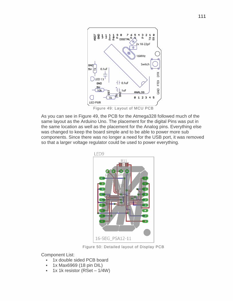
111
Figure 49: Layout of MCU PCB
As you can see in Figure 49, the PCB for the Atmega328 followed much of the same layout as the Arduino Uno. The placement for the digital Pins was put in the same location as well as the placement for the Analog pins. Everything else was changed to keep the board simple and to be able to power more sub components. Since there was no longer a need for the USB port, it was removed so that a larger voltage regulator could be used to power everything.
Figure 50: Detailed layout of Display PCB
Component List: 1x double sided PCB board 1x Max6969 (18 pin DIL) 1x 1k resistor (RSet – 1/4W)
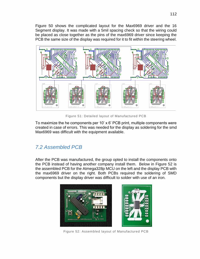
112
Figure 50 shows the complicated layout for the Max6969 driver and the 16 Segment display. It was made with a 5mil spacing check so that the wiring could be placed as close together as the pins of the max6969 driver since keeping the PCB the same size of the display was required for it to fit within the steering wheel.
Figure 51: Detailed layout of Manufactured PCB
To maximize the he components per 10’ x 6’ PCB print, multiple components were created in case of errors. This was needed for the display as soldering for the smd Max6969 was difficult with the equipment available.
7.2 Assembled PCB
After the PCB was manufactured, the group opted to install the components onto the PCB instead of having another company install them. Below in Figure 52 is the assembled PCB for the Atmega328p MCU on the left and the display PCB with the max6969 driver on the right. Both PCBs required the soldering of SMD components but the display driver was difficult to solder with use of an iron.
Figure 52: Assembled layout of Manufactured PCB

113
7.2 Final Coding Plan
The software development method that will be adopted for this design is an Agile software development approach.
One of the reasons for the aforementioned Agile software development approach is the fact that it allows for much more flexibility and agility when working on relatively large and complex projects. The fact that many members of the group have never worked with global positioning modules and data logging means that the program’s specifications will constantly entail change in order to meet the design requirements and work with various design constraints. Developing in an Agile manner will also allow the design team to work with the fixed timescale that is provided via the Senior Design II due date. Agile development will allow the program to evolve and adapt with more ease as requirements are modified and the project moves forward. Another benefit of adopting an Agile development method is the fact that the software is tested continuously throughout its development cycle. The aforementioned integrated testing is essential to this design due to the fact that the design team is relatively inexperienced with global positioning software design as well as microcontroller programming at the scale of this project. The relatively limited timeframe of this project means that integrated testing will be crucial to refining the project’s software design due to the fact that there may not be sufficient time when the project is near completion to adequately test and fix the project’s software. The Agile software development style also works very well with the design team dynamic that is in place. The previously mentioned design team dynamic is one where the members of a small team are all committed to the project, constantly involved in the project and are consistently communicating in a relatively casual manner about the project and its design. The Agile development format will also allow for active involvement of an outside party such as a supervising professor or members of the University of Central Florida formula one SAE club. The relative ease of rapid modification that agile provides will be useful when working with outside parties because it will allow said parties to suggest changes or additions to the project software and ultimately allow the design team to actually implement said changes or additions in a timely and effective manner.
All in all an Agile software design approach suits this project extremely well. From the small team dynamics that are in place to the rapid modification of project guidelines an Agile software design approach accommodates the aforementioned requirements and ultimately streamlines the development of the software for this project. Figure 53 outlines the processes that the MCU software will go through in order to function properly.
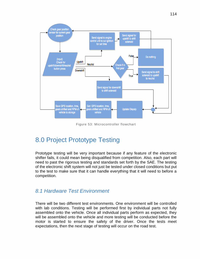
114
Figure 53: Microcontroller f lowchart
8.0 Project Prototype Testing
Prototype testing will be very important because if any feature of the electronic shifter fails, it could mean being disqualified from competition. Also, each part will need to past the rigorous testing and standards set forth by the SAE. The testing of the electronic shift system will not just be tested under closed conditions but put to the test to make sure that it can handle everything that it will need to before a competition.
8.1 Hardware Test Environment
There will be two different test environments. One environment will be controlled with lab conditions. Testing will be performed first by individual parts not fully assembled onto the vehicle. Once all individual parts perform as expected, they will be assembled onto the vehicle and more testing will be conducted before the motor is started to ensure the safety of the driver. Once the tests meet expectations, then the next stage of testing will occur on the road test.

115
The next stage of testing will be conducted not only on a large straight section of road but also with a series of very fast and sharp turns to simulate conditions on a track. Currently an empty lot with cones will be used but collaboration with a track has begun and we are hoping that we will be able to test to vehicle for a few hours on the track.
8.2 Hardware Specific Testing
In order to ensure the shifting system meets all of the metrics and target values agreed upon by the team, a test plan had to be generated. First, to test the overall weight of the system, all of the components were weighed. This included the actuator, controller, shift lever, switches, paddles, and all mounting brackets, but not the battery as it would be required of the car without electronic shift system. The total weight of the system is estimated to be 10.5s pounds. This value is trusted, if not verified, by using two different scales and obtaining the same weight. This is better than the target value and demonstrates success of this goal. It is noted that the bulk of the weight comes from the actuator, though its weight is comparable to competitive actuators. Also, this system is lighter than if the team had gone with a pneumatically controlled system, which had been considered in the earlier design stages of the project.
Testing the reliability of the system fully requires extended use in the car. To test the shift systems reliability, the shifting system will be shifted 1000 times over a seven day period. Testing up to this target value for shifting ensures that the system will be reliable for the competition. The shifts that completely go into gear will be logged as a successful shift and the shifts that do not go into gear will be counted as unsuccessful. The shift reliability will need to be above 98%, guaranteeing that during the race, the car will shift as desired.
SAE has a series of tests that they perform before a competition as well. These test can be seen in the Table 28 below that correlate to the addition of the electronic shift system and is taken directly from the FSAE International Rules. All of these test must be able to be passed to be able to compete so testing each one individually before a competition will be a must.
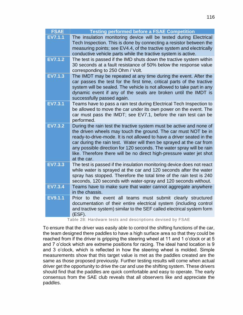
116
FSAE Testing performed before a FSAE Competition
EV7.1.1 The insulation monitoring device will be tested during Electrical Tech Inspection. This is done by connecting a resistor between the measuring points; see EV4.4, of the tractive system and electrically conductive vehicle parts while the tractive system is active.
EV7.1.2 The test is passed if the IMD shuts down the tractive system within 30 seconds at a fault resistance of 50% below the response value corresponding to 250 Ohm / Volt.
EV7.1.3 The IMDT may be repeated at any time during the event. After the car passes the test for the first time, critical parts of the tractive system will be sealed. The vehicle is not allowed to take part in any dynamic event if any of the seals are broken until the IMDT is successfully passed again.
EV7.3.1 Teams have to pass a rain test during Electrical Tech Inspection to be allowed to move the car under its own power on the event. The car must pass the IMDT; see EV7.1, before the rain test can be performed.
EV7.3.2 During the rain test the tractive system must be active and none of the driven wheels may touch the ground. The car must NOT be in ready-to-drive-mode. It is not allowed to have a driver seated in the car during the rain test. Water will then be sprayed at the car from any possible direction for 120 seconds. The water spray will be rain like. Therefore there will be no direct high-pressure water jet shot at the car.
EV7.3.3 The test is passed if the insulation monitoring device does not react while water is sprayed at the car and 120 seconds after the water spray has stopped. Therefore the total time of the rain test is 240 seconds, 120 seconds with water-spray and 120 seconds without.
EV7.3.4 Teams have to make sure that water cannot aggregate anywhere in the chassis.
EV9.1.1 Prior to the event all teams must submit clearly structured documentation of their entire electrical system (including control and tractive system) similar to the SEF called electrical system form (ESF).
Table 28: Hardware tests and descriptions devised by FSAE
To ensure that the driver was easily able to control the shifting functions of the car, the team designed there paddles to have a high surface area so that they could be reached from if the driver is gripping the steering wheel at 11 and 1 o’clock or at 5 and 7 o’clock which are extreme positions for racing. The ideal hand location is 9 and 3 o’clock, which is reflected in how the steering wheel is molded. Simple measurements show that this target value is met as the paddles created are the same as those proposed previously. Further testing results will come when actual driver get the opportunity to drive the car and use the shifting system. These drivers should find that the paddles are quick comfortable and easy to operate. The early consensus from the SAE club reveals that all observers like and appreciate the paddles.

117
8.3 Software Test Environment
The programming environment that the software will be tested on will most likely be Code Composer Studio version 5.3.0. As an alternative programming environment Energia may be used if Arduino libraries are necessary or preferred. The aforementioned development software would run on a 64 bit Windows 8.1 machine. The physical environment that the software will be tested on will be outdoors in open air with minimal overhead obstructions. The reasoning for such a specific testing environment is that it will replicate the racetrack environment in which the software will actually be used. The preliminary testing environment would involve simple movement of the device via walking small distances or placing the device in a personal automobile and driving short distances. The final testing environment would be a Society of Automotive Engineers certified racetrack where the microcontroller is mounted on the formula one vehicle and all of the peripherals are connected properly. The aforementioned final software test environment represents where the software must perform almost perfectly, due to the fact that the formula one vehicle that the paddle shifting system is applied to will most likely be competing in various Society of Automotive Engineers events in this type of environment.
8.4 Software Specific Testing
The software for the microcontroller will be tested via rapid use of the paddle shifting system. Multiple tests are outlined in Table 29. Performing a complete shift approximately once per second will provide enough data to determine if there are any discrepancies in the software. Shifting rapidly will also determine the ability of the software to handle a relatively large amount of rapid data input and output. The microcontroller software will also have to simultaneously communicate with the global positioning system software in order to quickly save the data in a formatted manner in a peripheral memory device.
Another software feature that will have to be tested almost exclusively are the functions of the global positioning system software. Preliminary testing of the global positioning system software will involve: moving the global positioning system module short distances and moving the global positioning system short distances at a rapid pace, both of the aforementioned cases may take place on foot or in an automobile. By moving the global positioning system module short distances the precision and accuracy of the global positioning system software can be tested via correct data outputs. As a reference point for accuracy and precision testing the results of the global positioning system’s outputs can be cross referenced with those of Google Earth or Google Maps which have been proven to provide results with a horizontal position accuracy of 2.64 meters root mean square error and a vertical position accuracy of 1.63 meters root mean square error with respect to a high accurate terrain model. [14]
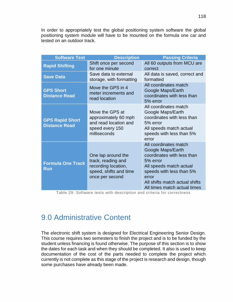
118
In order to appropriately test the global positioning system software the global positioning system module will have to be mounted on the formula one car and tested on an outdoor track.
Software Test Description Passing Criteria
Rapid Shifting Shift once per second
for one minute
All 60 outputs from MCU are
correct
Save Data Save data to external
storage, with formatting
All data is saved, correct and
formatted
GPS Short
Distance Read
Move the GPS in 4
meter increments and
read location
All coordinates match
Google Maps/Earth
coordinates with less than 5% error
GPS Rapid Short
Distance Read
Move the GPS at
approximately 60 mph and read location and
speed every 150 milliseconds
All coordinates match Google Maps/Earth
coordinates with less than 5% error
All speeds match actual speeds with less than 5% error
Formula One Track Run
One lap around the track, reading and recording location,
speed, shifts and time once per second
All coordinates match Google Maps/Earth
coordinates with less than 5% error All speeds match actual
speeds with less than 5% error
All shifts match actual shifts All times match actual times
Table 29: Software tests with description and criteria for correctness
9.0 Administrative Content
The electronic shift system is designed for Electrical Engineering Senior Design. This course requires two semesters to finish the project and is to be funded by the student unless financing is found otherwise. The purpose of this section is to show the dates for each task and when they should be completed. It also is used to keep documentation of the cost of the parts needed to complete the project which currently is not complete as this stage of the project is research and design, though some purchases have already been made.

119
9.1 Milestone Discussion
The milestone timeline for Senior Design I and II is shown in Figure 54. Since none of the group members have assembled anything like this it was tough to define appraisals for the projects milestones even though the design of the project seemed manageable in theory. The members decided to overemphasize the time to thorough each assignment to offer some margin and evade time constraints in order to evade being overwhelmed as a group by this project. The first portion of the plan involved research of each different fragment and how it would be suitable with the rest of the project.
Figure 54: Senior Design Milestone
The research took about a month so that everything as a whole is entirely understood. Making sure this step is fulfilled in important since it would define the project and would help in making sure everything would go as planned. The next task was to order most of the chosen components and see how everything works independently. Working around the schedule to leave good amount of time for testing was very important to the whole project since sometime things tend to fail. Even though most of the group had a decent understanding of software development and electronics but most of the members haven’t truly applied such a complex system and so the biggest restrictions of this project would be lack of experience.

120
9.2 Budget and Finance Discussion
This project was supported by the University of Central Florida’s Society of Automotive Engineers formula division. The budget is shown in Table 30, below. The University of Central Florida Student Automotive Engineers organization has funded this project in order to improve the design and overall performance of their formula one racecar. The University of Central Florida Student Automotive Engineers organization receives their funding directly from The University of Central Florida Student Government Association. Every school year The University of Central Florida Student Automotive Engineers organization reapplies for funding from The University of Central Florida Student Government Association and is approved based on a written request from Student Automotive Engineers organization officers.
There are some bare minimum things that you will need to begin your project. First you need a budget that reflects the total cost of the project. Be sure to include entry fees, food, transportation and hotel accommodations in the budget. The next things you need are attractive pictures of a car to include with funding proposals. Prints are expensive for this purpose. Color copies work well. People like to see what their money will be spent on. If you have not built a car yet, create a drawing of one. Group photos of the team with a car are also good, assuming the team is more than 3 or 4 people. Once sponsors have committed cash, materials, or services and you've actually received them, about 60% of your fund raising work is done. You need to maintain a good relationship with your sponsors so you will have their continuing support. You need their enthusiasm for your project, future contributions to the team, and even job offers for team members. It takes an ongoing effort. Sponsors will tell you one of the biggest frustrations of contributing to student groups is that once a contribution has been made, they never hear from anyone again until the next request for more donations. Start a newsletter for your sponsors and other interested parties. The newsletter needs to go out regularly, at a minimum of every quarter. It should be short. Most of the people you are sending it to are busy and have a lot to read. Two or three pages are good. The newsletter should include, but not be limited to, updates on the progress of the car, announcement of new sponsors, and exciting things happening at the university. The point is to maintain contact with them over the course of the project and make them want to stay involved. You should also start and maintain an interesting World Wide Web site for the team, updated with new content fairly often to keep people coming back to look at it.
A good sponsorship campaign doesn't just happen. It takes time and practice. Often when a member gets to the point of being a good fundraiser, he or she graduates and the knowledge is no longer available. The team can benefit from having one or two sophomore or junior students involved each year who can carry forward the team's collective knowledge about fund raising. It is wise to keep organized and detailed records of which companies were approached, who you talked to in each company, and what results were obtained. Don't make future

121
teams go down the same dead ends. If some organization or person cannot or will not contribute, make note of it. It makes the team and the university look stupid if the same questions and/or requests come each year no matter how many times someone refuses.
Part Unit Price
Quantity Total Cost
Display $4 4 $16
Wiring Harness $180 1 $180
PCB Manufacturing $66 1 $60
Breadboard $5 1 $5
GPS Unit $15 2 $30
Microcontroller (atmega328p) $7 5 $35
Voltage Regulator $10 2 $20
Control Unit Housing $15 1 $15
Actuator $300 1 $300
Micro SD Card $8 1 $8
Battery Free 1 $0
Micro switch $5 3 $15
Solid State Relay (Crydom D1D40) $15 4 $60
PCB Components $40 1 $40
GPS Antenna $30 1 $30
Micro SD Breakoutboard $20 1 $20
Steering Wheel Coil Cable $15 1 $15
Rulon J Sleeve Bearing $2 4 $8
8-32 Thread, 1-3/4" Long Socket Head Cap Screw $2 3 $6
8-32 Thread thin nylon-insert locknut $0.50 3 $1.50
8-32 Thread, 3/16" diameter x 1/2" long shoulder $9 2 $18
8-32 Thread, 5/16" long, thread-locking socket head cap screw
$0.50 2 $1
6-32 Thread, 5/8" long, low profile socket head cap screw
$1.50 4 $6
Gear Position Sensor $30 1 $30
Total Cost $919.50
Table 30: Budget Table
9.3 Project Consultants and Suppliers
The Electronic Paddle Shifter System project was sponsored in part from the SAE club at UCF via a member from the senior design team that was also a member of the SAE club that was in charge of the electrical system of the car. During the prototyping and testing of the project we went to the TI lab and consulted with some of the staff there to assist in determining the technology approach used in the factory gear position sensor as well as learning about the functionality of the switching regulators. All other problems and difficulties we solved through open source material found online from Arduino to be able to work with the
122
microcontroller. We were able to solve a problem during testing that was due to the failure of the regulator which was damaging the microcontroller and the bugs that were in the software that prevented the system to function well.
The project consisted of a wide range of disciplines and as a result multiple suppliers were used. The electronic components used for the system and the PCB components were purchased through Mouser and Digi-Key. The microcontroller and the GPS system as well as the SD card were picked up inline through adafruit. The components needed for controlling the shifts such as the relays and the diodes used with the relays were purchased from Skycraft, while the soleniod was purchased through Pingel. Some miscellaneous parts were purchased from eBay, Amazon and Skycraft.
10.0 Project Summary and Conclusion
In conclusion, the Electronic Paddle Shifter System was a project that greatly improved our understanding of concepts involved in the engineering process. Throughout the project we encountered many obstacles and problems in the researching, designing, prototyping, and testing stages. The fact that we had to overcome these challenges helped further improve our knowledge in certain areas of electrical engineering since we had to put time and effort in figuring out the problem and that made us learn more about certain concepts and technologies.
One of the problems that the team has encountered during testing was the failure of the voltage regulator. Since the team has decided to go from the initial plan and design of the switching regulator to the linear regulator due to the fact that it is much simpler and easy to maintain for the members of the SAE club which was a last-minute decision and the team didn’t have much time to carefully research for regulators, the linear regulator used had a very low thermal shutdown and when it got warm it stopped regulating and the microcontroller was receiving 12-volts input instead of 5-volts and as a result it was getting fried. The problem was fixed by choosing the popular LM7805 regulator which has a characteristic of withstanding higher temperatures and so it was regulating voltage properly.
Another problem the team came upon was the coding design of the system which had bugs within it. These bugs caused the system to function improperly due to the fact that it was interfering with the shifting controls and timing. This problem was solved by revising the code and proof-reading it to clean it up.
We were able to acclimate and overcome such difficulties through research and cooperation during the total time period of the project. The procedures the team under took gave a final product with features that include paddle shifters, gear positon senor with display, GPS and data logger and PCB design.
gh

123
The previous two semesters seemed to be very valuable and a good experience for the team. Being forced to work in an environment where correlation between others a team has given the chance for the individual members to promote important skills that will be needed in pursuing our individual goals in the future. Of the many skills attained from this project are writing technical papers, performing presentations and most importantly, working coherently in a group setting. One of the most rewarding experiences was understating and appreciating the amount of work and research that went into designing and building the system. Also an important note to point out is of the fact that previous information taught and discovered that has been attained in the past coursework all these years during the educational career has been implemented by the help of working on this project.

iv
Appendices
Appendix A - Copyright Permissions

v

vi

vii
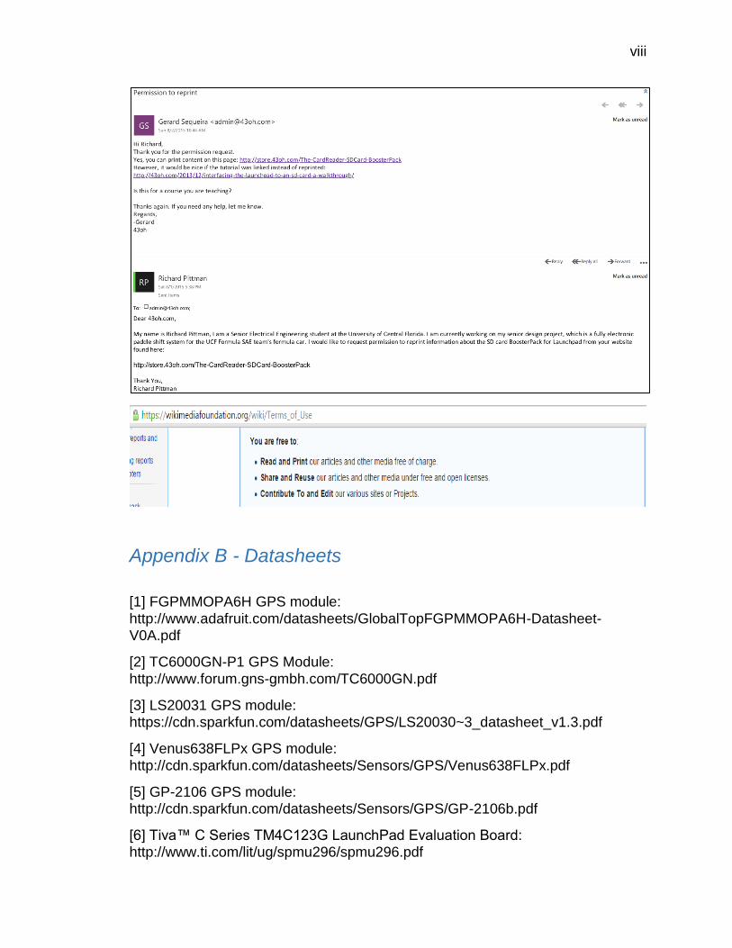
viii
Appendix B - Datasheets
[1] FGPMMOPA6H GPS module:
http://www.adafruit.com/datasheets/GlobalTopFGPMMOPA6H-Datasheet-V0A.pdf
[2] TC6000GN-P1 GPS Module:
http://www.forum.gns-gmbh.com/TC6000GN.pdf
[3] LS20031 GPS module: https://cdn.sparkfun.com/datasheets/GPS/LS20030~3_datasheet_v1.3.pdf
[4] Venus638FLPx GPS module:
http://cdn.sparkfun.com/datasheets/Sensors/GPS/Venus638FLPx.pdf
[5] GP-2106 GPS module: http://cdn.sparkfun.com/datasheets/Sensors/GPS/GP-2106b.pdf
[6] Tiva™ C Series TM4C123G LaunchPad Evaluation Board: http://www.ti.com/lit/ug/spmu296/spmu296.pdf
ix
[7] MSP-EXP430G2 LaunchPad Evaluation Kit: http://www.ti.com/lit/ug/slau318f/slau318f.pdf
[8] ATmega328 Microcontroller Board:
http://www.atmel.com/dyn/resources/prod_documents/doc8161.pdf
[9] UG-2864HSWEG01 OLED Display: http://www.adafruit.com/datasheets/UG-2864HSWEG01.pdf
[10] ADM1602K-NSW-FBS LED Display:
https://www.sparkfun.com/datasheets/LCD/ADM1602K-NSW-FBS-3.3v.pdf
[11] LTP-587G 16-segment LED Display: http://www.mouser.com/ds/2/239/S_110_P587G-473073.pdf
[12] PSC08-11SRWA 16-segment LED Display:
http://www.mouser.com/ds/2/216/PSC08-11SRWA-82798.pdf
[13] LTP-3862G 16-segment LED Display: http://www.mouser.com/ds/2/239/liteon_LTP-3862G-491712.pdf
[14] PSA23-11GWA 16-segment LED Display: http://www.mouser.com/ds/2/216/PSA23-11GWA-70239.pdf
[15] BOB-00544 microSD Transflash Breakout: http://cdn.sparkfun.com/datasheets/Components/General/SDSpec.pdf
[16] GDM12864HLCM Liquid Crystal Display Module https://www.sparkfun.com/datasheets/LCD/GDM12864H.pdf
Appendix C - Figures
Table 1: Requirements Chart................................................................................ 6 Table 2: Responsibility of group members towards project ................................ 12 Table 3: Project Schedule .................................................................................. 13
Table 4: Initial Project Budget ............................................................................. 14 Table 5: Force table – shifting up ....................................................................... 22 Table 6: Force table – shifting down ................................................................... 22
Table 7: Values that determine the shifts ........................................................... 32 Table 8: Performance specification ratings for the Deutsch contacts ................. 43 Table 9: Tensile strength in pound-force ............................................................ 53 Table 10: 5-volt DC to DC power converter ........................................................ 67
Table 11: Key features for the LTP-587G using Appendix B [11] ....................... 69 Table 12: Key features for the PSC08-11SRWA using Appendix B [12] ............ 70 Table 13: Key features for the LTP-3862G using Appendix B [13] ..................... 71 Table 14: Key features for the PSA23-11GWA using Appendix B [14] ............... 71 Table 15: Key features for the LTP-587G using Appendix B [10] ....................... 72 Table 16: Key features for the PSC08-11SRWA using Appendix B [16] ............ 73
x
Table 17: Key features for the LTP-3862G using Appendix B [9] ....................... 74 Table 18: MicroSD features supported by the BOB-00544 microSD adapter using Appendix B [15] .................................................................................................. 76
Table 19: Key features for the TM4C123G using Appendix B [6] ....................... 80 Table 20: Key features for the MSP-EXP430G2 using Appendix B [7] ............... 81 Table 21: Key features for the ATmega328 using Appendix B [8] ...................... 82 Table 22: Key features for the MTK3339 using Appendix B [1] .......................... 83 Table 23: Key features for the LS20031 using Appendix B [3] ........................... 84
Table 24: Key features for the Venus638FLPx-L using Appendix B [4] .............. 85 Table 25: Key features for the GP-2106 SiRF IV using Appendix B [5] .............. 86 Table 26: Key features for the CC4000 using Appendix B [2] ............................ 88 Table 27: AEC-Q100 MCU operating temperature grades from Appendix D [27] ........................................................................................................................... 89 Table 28: Hardware tests and descriptions devised by FSAE .......................... 116 Table 29: Software tests with description and criteria for correctness .............. 118
Table 30: Budget Table .................................................................................... 121
Figure 1: 7805 voltage regulator circuit ................................................................ 7 Figure 2: Front view of steering wheel with display and driver controls ................ 9
Figure 3: Rear view of steering wheel with display and driver controls ................. 9 Figure 4: Flow Chart of System .......................................................................... 12
Figure 5: Schematic of an upshift operation (awaiting permission from Ajirogi to reprint) ................................................................................................................ 16 Figure 6: Electric schematic of the pneumatic concept (awaiting permission from Ajirogi to reprint) ................................................................................................. 17
Figure 7: Computer setup for MXL dash (awaiting permission from UD to reprint) ........................................................................................................................... 18 Figure 8: Setup of hydraulic shifting system (awaiting permission from sssdrive to reprint) ................................................................................................................ 19 Figure 9: Flat Shift System ............................................................................... 200
Figure 10: Actual photo of steering wheel with display and driver controls ......... 30 Figure 11: Gear Position Sensor (awaiting permission from jcotter to reprint) .. 311 Figure 12: Schematic of gear position sensor using factory model………………35 Figure 13: Comparison of Tefzel wire vs standard wire ...................................... 36 Figure 14: Comparison of Tefzel wire vs standard wire after being held above an open flame for 10 seconds ................................................................................. 37
Figure 15: Example of the Raychem DR-25 heat-shrink tubing .......................... 38
Figure 16: Example of the Raychem System 25 heat-shrinking boot (reprinted with permission from RB Racing) ............................................................................... 39 Figure 17: Example of the Raychem System 25 heat-shrinking transition (reprinted with permission from RB Racing) ....................................................................... 40 Figure 18: Example of the ResinTech RT125 Flexible Harness Epoxy (reprinted with permission from RB Racing) ....................................................................... 40 Figure 19: Example of the 3M EX-PLUS-II-APPLICATOR (reprinted with permission from RB Racing) ............................................................................... 41
Figure 20: Example of some of the various connectors available from Deutsch 42
xi
Figure 21: Example of the Nickel plated pin and socket contacts that are used within the Deutsch connectors .......................................................................... 422 Figure 22: Example of the low static Kapton tape ............................................... 44
Figure 23: Example of Kevlar braided lacing cord (reprinted with permission from RB Racing) ....................................................................................................... 444 Figure 24: Example of some of the necessary tools to build wiring harnesses . 466 Figure 25: Example of a digital heat gun used for shrinking heat shrinkable components ...................................................................................................... 477
Figure 26: Example of a label maker capable of printing wire labels ................ 488 Figure 27: Example of labels with clear heat-shrink on each wire ...................... 49 Figure 28: Example of a digital multimeter ......................................................... 49 Figure 29: Example of service loops being put into a wire at the back of a connector to provide strain relief for the terminals within the connector. ........................... 500 Figure 30: Example of concentric twisting and service loops (reprinted with permission from RB Racing) ............................................................................... 52
Figure 31: The formula for relative resistance with an example illustration (awaiting permission from Molex to reprint) ....................................................................... 54 Figure 32: Shows what a properly crimped Deutsch contact looks like (reprinted with permission from RB Racing) ....................................................................... 55
Figure 33: Example of concentrically twisted and laced section of wiring harness (reprinted with permission from RB Racing) ....................................................... 56
Figure 34: An illustration of the installation of heat shrinkable tubing (reprinted with permission from NASA) ...................................................................................... 57 Figure 35: An illustration of the GPSVisualizer settings (awaiting permission from GPSVisualizer to reprint) .................................................................................... 58
Figure 36: The microSD card breakout board+ from adafruit.com (awaiting permission from adafruit.com to reprint) ............................................................. 61 Figure 37: SD card BoosterPack for the Launchpad that is available from 43oh.com (reprinted with permission from 43oh.com) ........................................................ 62 Figure 38: Linear voltage regulator ..................................................................... 64 Figure 39: Schematic of 5-volts switching regulator……………………………….67 Figure 40: Paddle shift system wiring harness schematic………………………...77 Figure 41: Paddle shift system wiring harness layout diagram………………...…78 Figure 42: Actual photo of completed wiring harness…………………………..…79 Figure 43: TM4C123G block diagram from Appendix B [6] ................................ 80 Figure 44: MSP-EXP430G2 block diagram from Appendix B [7] ........................ 81
Figure 45: ATmega328 block diagram from Appendix B [8] ............................... 82
Figure 46: Shows the envelope rules the steering wheel must follow ................. 90 Figure 47: Detailed schematic of gear positon indicator ................................... 104 Figure 48: Detailed layout of MCU PCB……………………………………...……110 Figure 49: Layout of MCU PCB……………………………………...……………..111 Figure 50: Detailed layout of Display PCB………………………………………...111 Figure 51: Detailed layout of Manufactured PCB………………………………...112 Figure 52: Assembled layout of manufactured PCB ......................................... 112 Figure 53: Microcontroller Flowchart ............................................................... 114 Figure 54: Senior Design 1 Milestone ............................................................... 119

xii
Appendix D – References
[1] Lee Redstone, Lewis Weston, Jason Deglint. (2012). FSAE Electronic Shifter. Retrieved 13 July, 2015, from http://electronicshifter.wordpress.com
[2] Andrew Ajirogi, Ben Aldern, John Odlum, Johnny Chang. (2011). Team Raptor
Paddle Shifters. Retrieved 13 July, 2015, from http://www.me.berkeley.edu/ME102B/Past_Proj/f11/7%20Paddle%20Shifter/Pad
dle%20Shifter.pdf
[3] Ryan Neward, Henry Berg, Tim Falkiewicz, Nick Lehner, Anthony Magagnoli,
Doug Payne, and John Schnurr. (2011). Formula SAE Racecar Driver Aids. Retrieved 13 July, 2015, from http://edge.rit.edu/edge/OldEDGE/public/Archives/P05101/files/SD%20presentati
on_05101.ppt.
[4] Fox, Robert W. and Alan T. McDonald. Introduction to Fluid Mechanics, 5th Ed. NY: John Wiley & Sons, 1998.
[5] Rob Ramsdale. (2004). Engineers' Handbook - Your Guide to Mechanical
Design. Retrieved 13 July, 2015, from http://www.engineershandbook.com/Tables/fluidpowerformulas.htm
[6] Nancy K. Friedrich, Michael Browne, Alan Hitchcox, Jack L. Johnson, P.E.,
Robert J. Sheaf, Jr. (2012). Fundamentals of hydraulic pumps. Retrieved 15 July, 2015, from http://hydraulicspneumatics.com/200/TechZone/HydraulicPumpsM/Article/False/
6401/TechZone-HydraulicPumpsM
[7] GEARS Educational Systems. (2009). Pressure in pneumatic systems. Retrieved 20 July, 2015 from
http://www.gearseds.com/files/Pneumatics_Sample_Lessons.pdf
[8] Fluid and Mechanical Engineering Systems Department of Management and Engineering Link¨oping University. (2010). Formula Book for Hydraulics and
Pneumatics. Retrieved 21 July, 2015 from
https://www.iei.liu.se/flumes/tmhp02/filarkiv/exchangestud/1.540792/FormulaBook_HydraulicsPneum.pdf
[9] Thermal wire and cable. (2010). Tefzel Wire. Retrieved 24 July, 2015 from
http://www.thermalwire.com/tefzel-wire.html
[10] Chemours. (2015). Tefzel EFTE. Retrieved 25 July, 2015 from https://www.chemours.com/cabling_solutions/en_US/products/tefzel_etfe.html
xiii
[11] Driver Controls, University of Delaware. (2010). Performance Validation & Path Forward. Retrieved 13 July, 2015, from
http://sites.udel.edu/meeg401/files/2011/08/FSAE_Driver_Controls_Final_NN.pdf
[12] Sequential Shifting System. (2007-2015). KAPS Transmissions Hydraulic Technology. Retrieved 13 July, 2015, from
http://www.sssdrive.com/news_eng.php?id=946
[13] LADD Distribution. (2014). DT Series Overview. Retrieved 28 July, 2015 from https://www.laddinc.com/dt-series-overview/
[14] Christian Benker, Richard P. Langford, Terry L. Pavlis. (2011). Geocarto International. Retrieved 22 July, 2015 from
http://www.tandfonline.com/doi/full/10.1080/10106049.2011.568125#abstract
[15] Resintech. (2010). Flexible High Performance Epoxy Adhesive. Retrieved 29 July, 2015 from http://www.resintech.co.uk/downloads/tds/RT125.pdf
[16] Western Filament. (2012). Non-Adhesive Tapes and Cord. Retrieved August
1, 2015 from http://www.electro-wind.com%2Fsuppliers-pdfs%2FWestern-Filament%2FWestern-Filament-Lacing-Tapes-Cords-Non-
Adhesives%2Fwestern-filament-tape-guide.pdf
[17] RB Racing. (1999). Professional Mil-Spec Motorsport ECU Wiring Harness Construction. Retrieved August 1, 2015 from https://www.rbracing-rsr.com/wiring_ecu.html
[18] LADD Distribution. (2014). DEUTSCH Contacts. Retrieved from August 2,
2015 from https://laddinc.com/deutsch-contacts/
[19] J Cotter. (2006). Timing Retard Eliminator. Retrieved August 2, 2015 from http://www.maxlean.com/motorcyclepages/tre.htm#Instructions
[20] Department of Defense. (1968). ELECTRICAL CIRCUIT (WIRE MARKING)
IDENTIFICATION FOR TACTICAL MILITARY VEHICLES. Retrieved July 21, 2015 from http://www.everyspec.com/MIL-STD/MIL-STD-0500-0699/MIL-STD-646A_6519/
[21] TE connectivity. (2001). Hand Cable Laying. Retrieved 19 July, 2015 from
https://www.rbracing-rsr.com/downloads/wiring_pdfs/twisted_harness.pdf
[22] Molex. (2002). INDUSTRIAL CRIMP QUALITY HANDBOOK. Retrieved July 30, 2015 from http://www.molex.com/pdm_docs/ats/TM-640160065.pdf
[23] NASA. (2009). CRIMPING, INTERCONNECTING CABLES, HARNESSES,
AND WIRING. Retrieved July 30, 2015 from http://www.hq.nasa.gov/office/codeq/doctree/87394.pdf
[24] Adafruit. (2014). MicroSD card breakout board+. Retrieved August 1, 2015
from http://www.adafruit.com/products/254

xiv
[25] Wikipedia. (2012). DC-to-DC converter. Retrieved August 1, 2015 from https://en.wikipedia.org/wiki/DC-to-DC_converter
[26] 43oh. (2015). The CardReader- SDCard BoosterPack. Retrieved August 2,
2015 from http://store.43oh.com/The-CardReader-SDCard-BoosterPack
[27] Linear Technology. (2011). Linear Technology Corporation Reliability Test Criteria For Automotive Grade Products. Retrieved August 3, 2015 from
http://cds.linear.com/docs/en/quality/Automotive%20reliability%20test.pdf
Related Documents