Formation of vertical cracks in solution-precursor plasma-sprayed thermal barrier coatings Liangde Xie a, ⁎ ,1 , Dianying Chen a , Eric H. Jordan b , Alper Ozturk b , Fang Wu a , Xinqing Ma c , Baki M. Cetegen b , Maurice Gell a a Department of Materials Science and Engineering, Institute of Materials Science, University of Connecticut, Storrs, CT 06269-3136, United States b Department of Mechanical Engineering, Institute of Materials Science, University of Connecticut, Storrs, CT 06269-3136, United States c Inframat Corporation, Farmington, CT 06032, United States Received 18 June 2005; accepted in revised form 12 January 2006 Available online 23 February 2006 Abstract When tailored to make durable thermal barrier coatings (TBCs), the Solution Precursor Plasma Spray (SPPS) process produces a microstructure containing uniformly vertical cracks. These cracks provide a high degree of strain tolerance to the ceramic top coat. In order to understand the formation of vertical crack in SPPS process, coatings of various thicknesses were deposited on a variety of substrates with vastly different thermal properties. These coatings were characterized in the as-sprayed state and after heat treatment. It has been determined that the tensile stress derived from the pyrolysis of precursor occurring during coating deposition or post heat-treatment is the major driving force for the formation of vertical cracks in SPPS TBCs. © 2006 Elsevier B.V. All rights reserved. Keywords: Thermal barrier coatings; Plasma spray; Solution precursor plasma spray; Vertical cracks 1. Introduction Ceramic thermal barrier coatings (TBCs) of 6 ∼ g wt.% Y 2 O 3 − ZrO 2 (7YSZ) are widely used to protect and to insulate metallic components in gas-turbine engines from high tem- peratures, which can prolong the lifetime of the component and/ or increase the allowable operating temperatures (see, e.g., overview articles by Miller [1,2], Jones [3], Evans et al. [4], and Padture et al. [5] and references therein). TBCs are subjected to cyclic thermal environment in service. As a result, residual stresses are generated in the coating due to the differences in the coefficient of thermal expansion (CTE) between the ceramic coating and the metallic substrate. In order to achieve high durability in TBCs, the ceramic top-coat is required to have some capability to tolerate the resulting thermal strain or to be “strain tolerant”. The two commercial processes used for the deposition of TBCs are air plasma spray (APS) and electron-beam physical- vapor deposition (EB-PVD). APS TBCs are relatively low-cost, have lower thermal conductivities relative to EB-PVD TBCs, but are generally less durable [1–5]. In order to increase the durability of APS TBCs by improving the strain tolerance of the coating, Taylor [6] developed dense vertically cracked (DVC) APS TBCs. The DVC TBCs have a density greater than 88% of the theoretical density. A majority of vertical cracks runs normal to the ceramic/metal interface and has a length greater than half of the coating thickness. Improved thermal cyclic durability has been reported for the DVC TBCs compared to the normal APS TBCs [6]. In the APS process, the coating is formed by the accumulation of splat layers deposited each time the plasma torch passes over the substrate. The vertical cracks in DVC TBCs are generated through the alignment of micro vertical cracks produced in each splat layer due to shrinkage of the deposited splats [6]. It was found that if the coating density is less than about 88% of the theoretical density, the shrinkage strain can be absorbed or compensated by the porosity, which prevents the formation of the vertical cracks [6]. The improved stain tolerance of DVC TBCs is partially offset by the higher thermal conductivity associated with the higher coating density. Surface & Coatings Technology 201 (2006) 1058 – 1064 www.elsevier.com/locate/surfcoat ⁎ Corresponding author. Tel.: +1 516 338 2516; fax: +1 860 338 2488. E-mail address: [email protected] (L. Xie). 1 Currently with Sulzer Metco (US) Inc., Westbury, NY 11590, United States. 0257-8972/$ - see front matter © 2006 Elsevier B.V. All rights reserved. doi:10.1016/j.surfcoat.2006.01.020

Welcome message from author
This document is posted to help you gain knowledge. Please leave a comment to let me know what you think about it! Share it to your friends and learn new things together.
Transcript

201 (2006) 1058–1064www.elsevier.com/locate/surfcoat
Surface & Coatings Technology
Formation of vertical cracks in solution-precursor plasma-sprayedthermal barrier coatings
Liangde Xie a,⁎,1, Dianying Chen a, Eric H. Jordan b, Alper Ozturk b, Fang Wu a,Xinqing Ma c, Baki M. Cetegen b, Maurice Gell a
a Department of Materials Science and Engineering, Institute of Materials Science, University of Connecticut, Storrs, CT 06269-3136, United Statesb Department of Mechanical Engineering, Institute of Materials Science, University of Connecticut, Storrs, CT 06269-3136, United States
c Inframat Corporation, Farmington, CT 06032, United States
Received 18 June 2005; accepted in revised form 12 January 2006Available online 23 February 2006
Abstract
When tailored to make durable thermal barrier coatings (TBCs), the Solution Precursor Plasma Spray (SPPS) process produces amicrostructure containing uniformly vertical cracks. These cracks provide a high degree of strain tolerance to the ceramic top coat. In order tounderstand the formation of vertical crack in SPPS process, coatings of various thicknesses were deposited on a variety of substrates with vastlydifferent thermal properties. These coatings were characterized in the as-sprayed state and after heat treatment. It has been determined that thetensile stress derived from the pyrolysis of precursor occurring during coating deposition or post heat-treatment is the major driving force for theformation of vertical cracks in SPPS TBCs.© 2006 Elsevier B.V. All rights reserved.
Keywords: Thermal barrier coatings; Plasma spray; Solution precursor plasma spray; Vertical cracks
1. Introduction
Ceramic thermal barrier coatings (TBCs) of 6∼g wt.%Y2O3−ZrO2 (7YSZ) are widely used to protect and to insulatemetallic components in gas-turbine engines from high tem-peratures, which can prolong the lifetime of the component and/or increase the allowable operating temperatures (see, e.g.,overview articles by Miller [1,2], Jones [3], Evans et al. [4], andPadture et al. [5] and references therein). TBCs are subjected tocyclic thermal environment in service. As a result, residualstresses are generated in the coating due to the differences in thecoefficient of thermal expansion (CTE) between the ceramiccoating and the metallic substrate. In order to achieve highdurability in TBCs, the ceramic top-coat is required to havesome capability to tolerate the resulting thermal strain or to be“strain tolerant”.
The two commercial processes used for the deposition ofTBCs are air plasma spray (APS) and electron-beam physical-
⁎ Corresponding author. Tel.: +1 516 338 2516; fax: +1 860 338 2488.E-mail address: [email protected] (L. Xie).
1 Currently with Sulzer Metco (US) Inc., Westbury, NY 11590, United States.
0257-8972/$ - see front matter © 2006 Elsevier B.V. All rights reserved.doi:10.1016/j.surfcoat.2006.01.020
vapor deposition (EB-PVD). APS TBCs are relatively low-cost,have lower thermal conductivities relative to EB-PVD TBCs,but are generally less durable [1–5]. In order to increase thedurability of APS TBCs by improving the strain tolerance of thecoating, Taylor [6] developed dense vertically cracked (DVC)APS TBCs. The DVC TBCs have a density greater than 88% ofthe theoretical density. A majority of vertical cracks runs normalto the ceramic/metal interface and has a length greater than halfof the coating thickness. Improved thermal cyclic durability hasbeen reported for the DVC TBCs compared to the normal APSTBCs [6].
In the APS process, the coating is formed by the accumulationof splat layers deposited each time the plasma torch passes overthe substrate. The vertical cracks in DVC TBCs are generatedthrough the alignment of micro vertical cracks produced in eachsplat layer due to shrinkage of the deposited splats [6]. It wasfound that if the coating density is less than about 88% of thetheoretical density, the shrinkage strain can be absorbed orcompensated by the porosity, which prevents the formation ofthe vertical cracks [6]. The improved stain tolerance of DVCTBCs is partially offset by the higher thermal conductivityassociated with the higher coating density.

Table 1Thermal properties of the three different substrates and dense 7YSZ measured atroom temperature [14,15]
Coefficient of thermal expansion(×10−6/°C)
Thermal conductivity(W/m K)
Cu 20.3 401.0Superalloy(CMSX-4)
16.0 20.0
Alumina 8.0 11.87YSZ 9.0 3.0
1059L. Xie et al. / Surface & Coatings Technology 201 (2006) 1058–1064
Recently, it has been demonstrated that Solution PrecursorPlasma Sprayed (SPPS) TBCs also possess vertical cracks [7–10], which contribute to their superior thermal cyclic durability[11,12]. In the SPPS process, an aqueous chemical precursor,containing Zr and Y, is injected directly into the plasma jet. Theatomized precursor droplets undergo rapid evaporation andbreakup in the plasma flame. This is followed by precipitationor gelation, pyrolysis and melting in the plasma flame. Togetherwith the pyrolyzed and/or molten 7YSZ ceramic particles ordroplets, precursor at various reaction stages also reaches thesubstrate. When a coating thicker than 150 μm is sprayed, mostof the precursor on the substrate is pyrolyzed during coatingdeposition process due to the continuous heating of the plasmaflame. In contrast to DVC coatings, the vertical cracks areformed in SPPS TBCs when the density of the coating is lessthan 85% of the theoretical limit [7–12]. Therefore, themechanism for vertical crack formation in SPPS TBCs appearsto be different from what is observed in the DVC TBCs. Thisresearch is aimed at understanding the mechanism for verticalcrack formation in SPPS TBCs.
2. Experimental procedures
In order to understand the mechanism of vertical crackformation in SPPS TBCs, a series of experiments have beenconducted where substrate material, coating thickness, and post-coating heat treatment were systematically varied.
All coatings were sprayed using a direct current (DC) plasmatorch (Metco 9 MB, Sulzer Metco, Westbury, NY). The plasmapower used was in the range 35 to 45 kW.Ar andH2were used asthe primary and the secondary plasma gases, respectively,
50 µm
50 µm
(a)
(c)
TBC
Bond Coat
Substrate
VerticalCrack
Fig. 1. Microstructure of SPPS TBC on bond coated supe
whereas N2 was used as the solution-precursor atomizing gas.The precursor used here was aqueous acetate and nitrate salts, toresult in a 7 wt.% Y2O3−ZrO2 (7YSZ) in the coating [7].Substrates used in this work include: (i) copper, (ii) bond-coated Ni-base superalloy (NiCoCrAlY bond-coat, CMSX-4single crystal superalloy), and (iii) fully-dense polycrystallinealumina. The thermal physical properties of these substrates,along with 7YSZ ceramic, are presented in Table 1. Thethicknesses of the coatings were varied from 70 to 200 μm.The coatings on bond-coated Ni-base superalloy substrateswere heat-treated at 300, 600, or 1121 °C for 1 h. All SPPSTBCs are deposited under the same processing conditions, thedetails of which can be found in previous publications [7–10].
All as-sprayed and heat-treated SPPS TBCs were cut toprepare the cross-sections. These cross-sections were thenpolished to a 1 μm finish using routine metallographic methods.The polished cross-sections of the SPPS TBCs were character-ized using a scanning electron microscope (SEM) (ESEM 2020,Philips Electron Optics, Eindhoven, The Netherlands). Hard-ness measurements (Vickers indenter, 100 g load) were per-formed at random locations on the polished cross-section of the
50 µm
(b)
Bond Coat
VerticalCrack
ralloy substrate. (a) 70 μm, (b) 100 μm, (c) 200 μm.
0
50
100
150
200
250
300
70 100 160 200
As-SprayedHeat-Treated
Cra
ck S
paci
ng (
µm)
Coating Thickness (µm)
8
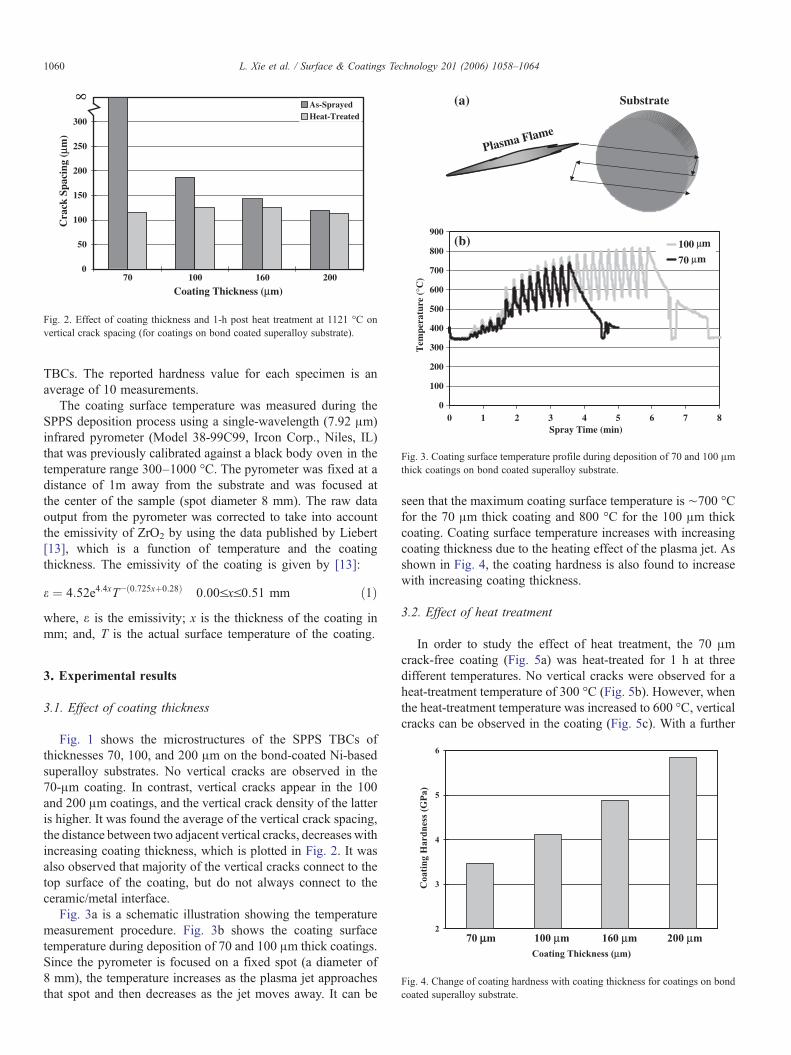
Fig. 2. Effect of coating thickness and 1-h post heat treatment at 1121 °C onvertical crack spacing (for coatings on bond coated superalloy substrate).
0
100
200
300
400
500
600
700
800
900
0 1 2 3 4 5 6 7 8
100
70
µm
µm
Tem
pera
ture
(°C
)Spray Time (min)
(b)
Substrate
Plasma Flame
(a)
Fig. 3. Coating surface temperature profile during deposition of 70 and 100 μmthick coatings on bond coated superalloy substrate.
1060 L. Xie et al. / Surface & Coatings Technology 201 (2006) 1058–1064
TBCs. The reported hardness value for each specimen is anaverage of 10 measurements.
The coating surface temperature was measured during theSPPS deposition process using a single-wavelength (7.92 μm)infrared pyrometer (Model 38-99C99, Ircon Corp., Niles, IL)that was previously calibrated against a black body oven in thetemperature range 300–1000 °C. The pyrometer was fixed at adistance of 1m away from the substrate and was focused atthe center of the sample (spot diameter 8 mm). The raw dataoutput from the pyrometer was corrected to take into accountthe emissivity of ZrO2 by using the data published by Liebert[13], which is a function of temperature and the coatingthickness. The emissivity of the coating is given by [13]:
e ¼ 4:52e4:4xT−ð0:725xþ0:28Þ 0:00VxV0:51 mm ð1Þwhere, ε is the emissivity; x is the thickness of the coating inmm; and, T is the actual surface temperature of the coating.
70 µµm 100 µm 160 µm 200 µm
Co
ati
ng
Ha
rdn
ess
(GP
a)
Coating Thickness (µm)
2
3
4
5
6
Fig. 4. Change of coating hardness with coating thickness for coatings on bondcoated superalloy substrate.
3. Experimental results
3.1. Effect of coating thickness
Fig. 1 shows the microstructures of the SPPS TBCs ofthicknesses 70, 100, and 200 μm on the bond-coated Ni-basedsuperalloy substrates. No vertical cracks are observed in the70-μm coating. In contrast, vertical cracks appear in the 100and 200 μm coatings, and the vertical crack density of the latteris higher. It was found the average of the vertical crack spacing,the distance between two adjacent vertical cracks, decreases withincreasing coating thickness, which is plotted in Fig. 2. It wasalso observed that majority of the vertical cracks connect to thetop surface of the coating, but do not always connect to theceramic/metal interface.
Fig. 3a is a schematic illustration showing the temperaturemeasurement procedure. Fig. 3b shows the coating surfacetemperature during deposition of 70 and 100 μm thick coatings.Since the pyrometer is focused on a fixed spot (a diameter of8 mm), the temperature increases as the plasma jet approachesthat spot and then decreases as the jet moves away. It can be
seen that the maximum coating surface temperature is ∼700 °Cfor the 70 μm thick coating and 800 °C for the 100 μm thickcoating. Coating surface temperature increases with increasingcoating thickness due to the heating effect of the plasma jet. Asshown in Fig. 4, the coating hardness is also found to increasewith increasing coating thickness.
3.2. Effect of heat treatment
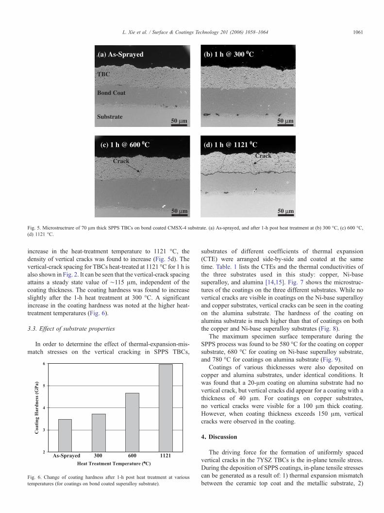
In order to study the effect of heat treatment, the 70 μmcrack-free coating (Fig. 5a) was heat-treated for 1 h at threedifferent temperatures. No vertical cracks were observed for aheat-treatment temperature of 300 °C (Fig. 5b). However, whenthe heat-treatment temperature was increased to 600 °C, verticalcracks can be observed in the coating (Fig. 5c). With a further
(a) As-Sprayed
(c) 1 h @ 600 0C (d) 1 h @ 1121 0C
(b) 1 h @ 300 0C
50 µm 50 µm
50 µm 50 µm
TBC
Bond Coat
Substrate
CrackCrack
Fig. 5. Microstructrure of 70 μm thick SPPS TBCs on bond coated CMSX-4 substrate. (a) As-sprayed, and after 1-h post heat treatment at (b) 300 °C, (c) 600 °C,(d) 1121 °C.
1061L. Xie et al. / Surface & Coatings Technology 201 (2006) 1058–1064
increase in the heat-treatment temperature to 1121 °C, thedensity of vertical cracks was found to increase (Fig. 5d). Thevertical-crack spacing for TBCs heat-treated at 1121 °C for 1 h isalso shown in Fig. 2. It can be seen that the vertical-crack spacingattains a steady state value of ∼115 μm, independent of thecoating thickness. The coating hardness was found to increaseslightly after the 1-h heat treatment at 300 °C. A significantincrease in the coating hardness was noted at the higher heat-treatment temperatures (Fig. 6).
3.3. Effect of substrate properties
In order to determine the effect of thermal-expansion-mis-match stresses on the vertical cracking in SPPS TBCs,
Co
ati
ng
Ha
rdn
ess
(GP
a)
Heat Treatment Temperature (°°C)
As-Sprayed 300 600 11212
3
4
5
6
Fig. 6. Change of coating hardness after 1-h post heat treatment at varioustemperatures (for coatings on bond coated superalloy substrate).
substrates of different coefficients of thermal expansion(CTE) were arranged side-by-side and coated at the sametime. Table. 1 lists the CTEs and the thermal conductivities ofthe three substrates used in this study: copper, Ni-basesuperalloy, and alumina [14,15]. Fig. 7 shows the microstruc-tures of the coatings on the three different substrates. While novertical cracks are visible in coatings on the Ni-base superalloyand copper substrates, vertical cracks can be seen in the coatingon the alumina substrate. The hardness of the coating onalumina substrate is much higher than that of coatings on boththe copper and Ni-base superalloy substrates (Fig. 8).
The maximum specimen surface temperature during theSPPS process was found to be 580 °C for the coating on coppersubstrate, 680 °C for coating on Ni-base superalloy substrate,and 780 °C for coatings on alumina substrate (Fig. 9).
Coatings of various thicknesses were also deposited oncopper and alumina substrates, under identical conditions. Itwas found that a 20-μm coating on alumina substrate had novertical crack, but vertical cracks did appear for a coating with athickness of 40 μm. For coatings on copper substrates,no vertical cracks were visible for a 100 μm thick coating.However, when coating thickness exceeds 150 μm, verticalcracks were observed in the coating.
4. Discussion
The driving force for the formation of uniformly spacedvertical cracks in the 7YSZ TBCs is the in-plane tensile stress.During the deposition of SPPS coatings, in-plane tensile stressescan be generated as a result of: 1) thermal expansion mismatchbetween the ceramic top coat and the metallic substrate, 2)

50 µm
Al2O350 µm
50 µm
(a)
(c)
(b)
TBC
Bond Coat
CMSX-4
Crack
TBC
Cu
TBC
Fig. 7. SPPS TBCs of 70 μm thick on different types of substrate. (a) Bond coated superalloy, (b) Cu, (c) Al2O3.
1062 L. Xie et al. / Surface & Coatings Technology 201 (2006) 1058–1064
transient cooling following deposition, and 3) pyrolysis ofprecursor incorporated into the coating. Stresses from thermalexpansion mismatch and transient cooling are generated in APScoatings, as well. However, APS coatings deposited undersimilar conditions do not have vertical cracks. Therefore,stresses from pyrolysis of precursor incorporated into thecoating are probably the major driving force for the formationof vertical cracks in SPPS TBCs. In order to confirm thisconclusion, the contribution to vertical-crack formation of thestresses generated from the above-mentioned three sources areanalyzed in the following section.
4.1. Thermal expansion mismatch stress
The thermal expansion coefficient of metallic substrate(16×10−6 to 20×10−6 °C−1) is larger than that of the 7YSZ
Co
ati
ng
Ha
rdn
ess
(GP
a)
Type of Substrate
Al2O3 CMSX-4 Cu3
4
5
6
7
Fig. 8. Coating hardness of 70 μm thick SPPS TBCs on different types ofsubstrate.
top-coat (9×10⁻⁶ °C−1) [14,15]. Therefore, thermal expansionmismatch stresses will be generated during coating depositionwhen the ceramic coating and metallic substrate are heated andcooled during successive passes of the plasma torch and afterfinal cooling to room temperature.
During deposition, the temperature of the substrate and thecoating increase with time (Fig. 9). As a result, in-plane tensilestresses are generated in the coating due to the larger CTE of thesubstrate. In order to investigate the contribution of tensilestress from substrate expansion, three substrates havingdifferent coefficients of thermal expansion (CTE) were plasmasprayed at the same time with a 70 μm thick coating. It shouldbe mentioned that since the coating is thin and compliantcompared to the substrate, the elastic modulus of the substrate isnot important. For copper and superalloy substrates, theresultant stress is tensile upon heating since their CTE is larger
Tem
pera
ture
(°C
)
Spray Time (min)
200
300
400
500
600
700
800
900
0.0 1.0 2.0 3.0 4.0
Alumina
CMSX-4
Copper
Fig. 9. Coating surface temperature profiles during deposition of 70 μm thickcoatings on different types of substrate.

1063L. Xie et al. / Surface & Coatings Technology 201 (2006) 1058–1064
than that of YSZ. The stress is compressive for the coating onthe Al2O3 substrate due to Al2O3's smaller CTE relative to thatof YSZ.
If the tensile stress from substrate expansion on heating is themajor driving force for vertical crack formation, it would beexpected that vertical cracks would form most readily on thesample where the difference in CTE with the substrate multipliedby the temperature change is the largest, which in the present casewould be the copper substrate. However, the results indicate thatthe coating on the Cu substrate, the onewith largest CTE, containsno vertical cracks; while the coating on theAl2O3 substrate, whichhas the lowest CTE, has many vertical cracks. This observationindicates that thermal expansion mismatch stress generatedduring coating deposition when the ceramic coating and themetallic substrate are heated is not a major driving force for theformation of vertical cracks in SPPS coatings.
After the completion of coating deposition, the ceramic topcoat and substrate are cooled from 400∼800 °C to room tem-perature. The resulting thermal expansion mismatch stress in thecoating on the metallic substrates is compressive since the CTEof substrate is larger than that of YSZ. Therefore, this thermalexpansion mismatch stress on cooling will not contribute to theformation of vertical cracks.
Based on the above analysis, it can be concluded that thermalexpansion mismatch stresses are not a major driving force forthe formation of vertical cracks in SPPS TBCs.
4.2. Transient cooling stress
As it can be seen in Fig. 9, the coating surface temperatureincreases and then decreases rapidly when the plasma torch passesover the coating. During the transient cooling stage, the coatingsurface cools down first and the resulting contraction is restrictedby the relatively hotter underlayer, which leads to the generationof in-plane tensile stresses. The amplitude of this stress dependson the temperature gradient through the coating thickness, giventhe same CTE of the coating. Since the temperature gradient iscaused by the repetitive heating of the plasma flame and surfacecooling, the gradient is determined by the heating capability of theplasma flame and the surface cooling condition. Hotter plasmaand stronger surface cooling give rise to higher temperaturegradients through the coating during the transient cooling stage.For the same processing condition, the temperature differencebetween the coating surface and substrate generated duringtransient cooling is less than 40 °C and not sufficient to explaincracking by itself. In addition, for 100-μm and 70-μm coatings,the temperature difference between coating surface and thesubstrate is similar. However, the 100-μm coating has verticalcracks while the 70-μm coating does not, which suggests that thetensile stress generated during transient cooling, as a result of thethermal gradient, is not the major driving force for the formationof vertical cracks in SPPS TBCs.
4.3. Precursor pyrolysis stress
In SPPS process, precursor at various reactions stages, likeevaporation and gelation, reaches the substrate. The deposition of
unpyrolized precursor has been confirmed by TGA and DTAanalysis [7]. Unpyrolized precursor starts to decompose attemperatures above ∼350 °C [7]. When the unpyrolized pre-cursor is exposed to a temperature higher than 350 °C, duringdeposition or post-deposition heat-treatment, the precursor willdecompose and crystallize (pyrolysis). However, pyrolysis of theprecursor will not be completed until a much higher temperature,like 700 °C at a heating rate of 20 °C/min, due to kinetics of thereactions. As a result, unpyrolyzed precursor was observed in thinSPPS coatings though the maximum coating temperature ishigher than 350 °C (Figs. 3 and 9).
The pyrolysis of precursor is accompanied by large volumeshrinkage due to the evaporation of remaining water and py-rolysis of acetate and nitrate salts [7,8]. The extent of volumeshrinkage depends on the nature and amount of the unpyrolizedprecursor in the coating. Both factors can change rapidly duringthe deposition process. It is estimated that the volume shrinkagecan be as large as 2% to 3%, based on thermogravimetric (TGA)analysis of crushed free-standing SPPS coatings [7]. This wouldresult in an in-plane tensile stress of the order of 400 MPa,assuming an elastic modulus of 40 GPa for the SPPS coating.The tensile strength of SPPS TBCs is about 25 MPa [12],therefore, the stress resulting from precursor pyrolysis in thecoating is sufficient to create vertical cracks in SPPS TBCs.
It is also consistent with experimental observations thatstresses from precursor pyrolysis in the coating play a dominantrole in the formation of vertical cracks in SPPS TBCs. Verticalcracks are generated in coatings with a thickness larger than acritical value that increases with the thermal conductivity of thesubstrate, as described in Section 3.3. During coating de-position, the coating temperature is higher than the precursordecomposition temperature (∼350 °C) [7] after the first 2∼3passes and it increases with time. Therefore, precursorincorporated into the coating will start to decompose duringcoating deposition. Precursor pyrolysis occurs more extensivelyin thicker coatings due to longer spraying time and highercoating temperature (Fig. 3), which leads to the generation ofhigher tensile stress that promotes the formation of verticalcracks. The coatings on substrates of lower thermal conductivityexperience higher temperatures during coating deposition;therefore, the critical coating thickness for vertical crackgeneration is smaller.
Moreover, the effect of precursor pyrolysis on vertical crackformation is verified in post-heat treatment experiments. Whena 70 μm thick crack-free sample is subjected to heat-treatment attemperature (300 °C) below the precursor decompositiontemperature (350 °C), no vertical cracks are generated afterthe heat-treatment due to the absence of tensile stress resultingfrom pyrolysis. If the heat-treatment temperature is higherthan the precursor decomposition temperature, e.g., 600 and1121 °C, vertical cracks are generated in identical samplesdue to the pyrolysis of precursor remaining in the coating. Inaddition, APS coatings on identical substrates do not containvertical cracks after same post-heat treatment.
Based on the experimental observations and the abovediscussion, the following mechanism of vertical crackformation is proposed. During deposition, the unpyrolyzed

1064 L. Xie et al. / Surface & Coatings Technology 201 (2006) 1058–1064
precursor incorporated into the coating starts to decomposewhen the coating temperature is higher than the precursordecomposition temperature. Precursor decomposition pro-duces shrinkage and tensile stress which is the primarycause of cracking in the coating acting in conjunction withother sources of tensile stress mention above. Once the totaltensile stress primarily caused by the precursor decompositionexceeds the tensile strength of the coating, vertical cracksform at the external surface of the coating (Figs. 1b and 5c).These cracks extend further into the coating with thecontinuation of precursor decomposition during depositionor post heat treatment (Figs. 1c and 5d).
5. Summary and conclusions
Coatings of various thicknesses were deposited on a variety ofsubstrates with vastly different thermal properties. These coatingswere characterized in the as-sprayed state and after heat treatment.It has been determined that the tensile stress, derived from thepyrolysis of precursor occurring during coating deposition or postheat-treatment, is the major driving force for the formation of thevertical cracks in SPPS TBCs. It is proposed that duringdeposition, the precursor in the coating starts to decomposewhen the coating temperature is higher than the precursordecomposition temperature. Once the tensile stress caused by theprecursor decomposition exceeds the tensile strength of thecoating, vertical cracks form at the top surface. These cracksextend further toward the coating/substrate interface with thecontinuation of precursor decomposition during deposition orpost heat treatment.
Acknowledgement
Thiswork is supported byU.S. Office ofNaval Research underGrant No. N000014-02-1-0171, managed by Drs. LawrenceKabacoff and Steven Fishman.
References
[1] S. Miller, Mater. World 4 (1996) 446.[2] R.A. Miller, J. Therm. Spray Technol. 6 (1997) 35.[3] R.L. Jones, in: K.H. Stern (Ed.), Thermal barrier coatings, Metall. Ceram.
Prot. Coat., Chapman & Hall, London, 1996, p. 194.[4] A.G. Evans, D.R. Mumm, J.W. Hutchinson, G.H. Meier, F.S. Pettit, Prog.
Mater. Sci. 46 (2001) 505.[5] N.P. Padture, M. Gell, E.H. Jordan, Science 296 (2002) 280.[6] T.A. Taylor, U. S. Patent No. 5073433, 1991.[7] L. Xie, X. Ma, E.H. Jordan, N.P. Padture, D. Xiao, M. Gell, Mater. Sci.
Eng., A Struct. Mater.: Prop. Microstruct. Process. 362 (2003) 204.[8] L. Xie, X. Ma, E.H. Jordan, N.P. Padture, D. Xiao, M. Gell, J. Mater. Sci.
39 (2004) 1639.[9] L. Xie, X. Ma, A. Ozturk, E.H. Jordan, N.P. Padture, B. Cetegen, D. Xiao,
M. Gell, Surf. Coat. Technol. 183 (2004).[10] N.P. Padture, K.W. Schlichting, T. Bhatia, A. Ozturk, B. Cetegen, E.H.
Jordan, M. Gell, S. Jiang, T.D. Xiao, P.R. Strutt, E. Garcia, P. Miranzo,M.I. Osendi, Acta Mater. 49 (2001) 2251.
[11] E.H. Jordan, L. Xie, X. Ma, M. Gell, N.P. Padture, B. Cetegen, J. Therm.Spray Technol 13 (2004) 57.
[12] M. Gell, L. Xie, X. Ma, E.H. Jordan, N.P. Padture, Surf. Coat. Technol.177–178 (2004) 97.
[13] C.H. Liebert, Thin Solid Films 53 (1978) 235.[14] Y.S. Touloukian, R.W. Powell, C.Y. Ho, P.G. Clemens, Thermophysical
Properties of Matter, vol. 1–2, Plenum, New York, 1970.[15] Y.S. Touloukian, R.K. Kirby, R.E. Taylon, et al., Thermophysical
Properties of Matter, vol. 12–13, Plenum, New York, 1975.
Related Documents