Formation of saucer-shaped sills A. MALTHE-SORENSSEN 1, S. PLANKE 2, H. SVENSEN 1 & B. JAMTVEIT 1 aphysics of Geological Processes, Department of Physics, University of Oslo, Box 1048 Blindern, N-0316 Oslo, Norway (e-mail: malthe@fys, uio.no) 2Volcanic Basin Petroleum Research AS, Forskningsparken, Gaustadalleen 21, N-0349 Oslo, Norway Abstract: We have developed a coupled model for sill emplacement in sedimentary basins. The intruded sedimentary strata are approximated as an elastic material modelled using a discrete element method. A non-viscous fluid is used to approximate the intruding mag- matic sill. The model has been used to study quasi-static sill emplacement in simple basin geometries. The simulations show that saucer-shaped sill complexes are formed in the sim- plest basin configurations defined as having homogeneous infill and initial isotropic stress conditions. Anisotropic stress fields are formed around the sill tips during the emplacement due to uplift of the overburden. The introduction of this stress asymmetry leads to the for- mation of transgressive sill segments when the length of the horizontal segment exceeds two to three times the overburden thickness. New field and seismic observations corrobo- rate the results obtained from the modelling. Recent fieldwork in undeformed parts of the Karoo Basin, South Africa, shows that saucer-shaped sills are common in the middle and upper parts of the basin. Similar saucer shaped sill complexes are also mapped on new two- and three-dimensional seismic data offshore of Mid-Norway and on the NW Australian shelf, whereas planar and segmented sheet intrusions are more common in structured and deep basin provinces. The emplacement of magmatic sills in sedi- mentary basins has major implications on the development and structure of the basins. The introduction of hot melt into the sedimentary sequence will cause heating, expulsion of pore fluids, and associated metamorphic reactions. The solidified and cold sills will subsequently influence the basin rheology, strength, and per- meability structure. These magmatic processes will also influence the petroleum prospectivity through enhanced maturation, and formation of migration pathways (Schutter 2003). Sheet intrusions, such as dykes, sills, and laccoliths, are important for rapid magma transport in the Earth's crust (e.g. Rubin 1995). Dykes are near-vertical magma-filled fractures driven primarily by the buoyancy of hot magma. Sills are dominantly layer-parallel sheets with transgressive segments. An impressive Jurassic sill complex is found in the Karoo Basin, South Africa, including extensive saucer-shaped sills (e.g. Du Toit 1920; Bradley 1965; Chevallier & Woodford 1999). A review of sill geometries and emplacement mechanisms is given by Francis (1982). Laccoliths are layer-parallel intrusions with a flat bottom and a dome-shaped top. The term was introduced by Gilbert (1877) based on studies in the Henry Mountains, Utah. Lacco- liths in the Henry Mountains and elsewhere in the North America have subsequently been studied by, for example, Johnson & Pollard (1973) and Corry (1988). Sill-sediment bound- aries represent high-impedance contrasts, and sill complexes are therefore well imaged on seismic reflection data. Recently, a number of studies on the 2D and 3D geometries of sill com- plexes have been made, in particular along the volcanic margins of the NE Atlantic (Skogseid et al. 1992; Berndt et al. 2000; Smallwood & Maresh 2002). The wide range of sill complex geometries found in the field and from seismic data has generally not been addressed in theoretical studies, which have concentrated on the 2D shape of single dykes or sills, mostly in two dimensions (Pollard & Johnson 1973; Lister & Kerr 1991). The main focus of this work has been on the flow of viscous magma and the interplay between the viscous fluid flow and fracturing. In particular, various models on the effects of viscous pressure-drop along the sill and the frac- turing of fluid-filled cracks have been discussed (Lister & Kerr 1991). The limitations of linear elastic fracture mechanics in studies of the propagation of an individual dykes or sills have also been addressed (Rubin 1993; Khazan & Fialko 1995). Various authors have addressed mechanisms responsible for the dyke to sill transition, but with few quantitative modelling results to From: BREITKREUZ, C. & PETFORD, N. (eds) 2004. PhysicalGeologyof High-LevelMagmaticSystems. Geological Society, London, Special Publications, 234, 215-227.0305-8719/04/$15.00 © The Geological Society of London 2004.

Welcome message from author
This document is posted to help you gain knowledge. Please leave a comment to let me know what you think about it! Share it to your friends and learn new things together.
Transcript
Formation of saucer-shaped sills
A. M A L T H E - S O R E N S S E N 1, S. P L A N K E 2, H. S V E N S E N 1 & B. J A M T V E I T 1 aphysics of Geological Processes, Department of Physics, University of Oslo, Box 1048
Blindern, N-0316 Oslo, Norway (e-mail: malthe@fys, uio.no) 2Volcanic Basin Petroleum Research AS, Forskningsparken, Gaustadalleen 21,
N-0349 Oslo, Norway
Abstract: We have developed a coupled model for sill emplacement in sedimentary basins. The intruded sedimentary strata are approximated as an elastic material modelled using a discrete element method. A non-viscous fluid is used to approximate the intruding mag- matic sill. The model has been used to study quasi-static sill emplacement in simple basin geometries. The simulations show that saucer-shaped sill complexes are formed in the sim- plest basin configurations defined as having homogeneous infill and initial isotropic stress conditions. Anisotropic stress fields are formed around the sill tips during the emplacement due to uplift of the overburden. The introduction of this stress asymmetry leads to the for- mation of transgressive sill segments when the length of the horizontal segment exceeds two to three times the overburden thickness. New field and seismic observations corrobo- rate the results obtained from the modelling. Recent fieldwork in undeformed parts of the Karoo Basin, South Africa, shows that saucer-shaped sills are common in the middle and upper parts of the basin. Similar saucer shaped sill complexes are also mapped on new two- and three-dimensional seismic data offshore of Mid-Norway and on the NW Australian shelf, whereas planar and segmented sheet intrusions are more common in structured and deep basin provinces.
The emplacement of magmatic sills in sedi- mentary basins has major implications on the development and structure of the basins. The introduction of hot melt into the sedimentary sequence will cause heating, expulsion of pore fluids, and associated metamorphic reactions. The solidified and cold sills will subsequently influence the basin rheology, strength, and per- meability structure. These magmatic processes will also influence the petroleum prospectivity through enhanced maturation, and formation of migration pathways (Schutter 2003).
Sheet intrusions, such as dykes, sills, and laccoliths, are impor tan t for rapid magma transport in the Earth's crust (e.g. Rubin 1995). Dykes are near-vertical magma-filled fractures driven primarily by the buoyancy of hot magma. Sills are dominantly layer-parallel sheets with transgressive segments. An impressive Jurassic sill complex is found in the Karoo Basin, South Africa, including extensive saucer-shaped sills (e.g. Du Toit 1920; Bradley 1965; Chevallier & Woodford 1999). A review of sill geometries and emplacement mechanisms is given by Francis (1982). Laccoliths are layer-parallel intrusions with a flat bottom and a dome-shaped top. The term was introduced by Gilbert (1877) based on studies in the Henry Mountains, Utah. Lacco- liths in the Henry Mountains and elsewhere in the North America have subsequently been
studied by, for example, Johnson & Pollard (1973) and Corry (1988). Sill-sediment bound- aries represent high-impedance contrasts, and sill complexes are therefore well imaged on seismic reflection data. Recently, a number of studies on the 2D and 3D geometries of sill com- plexes have been made, in particular along the volcanic margins of the NE Atlantic (Skogseid et al. 1992; Berndt et al. 2000; Smallwood & Maresh 2002).
The wide range of sill complex geometries found in the field and from seismic data has generally not been addressed in theoret ical studies, which have concentrated on the 2D shape of single dykes or sills, mostly in two dimensions (Pollard & Johnson 1973; Lister & Kerr 1991). The main focus of this work has been on the flow of viscous magma and the interplay between the viscous fluid flow and fracturing. In particular, various models on the effects of viscous pressure-drop along the sill and the frac- turing of fluid-filled cracks have been discussed (Lister & Kerr 1991). The limitations of linear elastic fracture mechanics in studies of the propagation of an individual dykes or sills have also been addressed (Rubin 1993; Khazan & Fialko 1995).
Various authors have addressed mechanisms responsible for the dyke to sill transition, but with few quant i ta t ive modell ing results to
From: BREITKREUZ, C. & PETFORD, N. (eds) 2004. Physical Geology of High-Level Magmatic Systems. Geological Society, London, Special Publications, 234, 215-227.0305-8719/04/$15.00 © The Geological Society of London 2004.
216 A. MALTHE-SORENSSEN E T A L .
support the ideas. The studies of laccolith and sill intrusions in the Henry Mountains (Johnson & Pollard 1973; Pollard & Johnson 1973) showed how linear elasticity theory could be applied to study the shape and development of sheet intru- sions. Further theoretical studies of the interplay between structure, stress heterogeneities, and dyke and sill shapes (Pollard et al. 1975) have further shown that linear elasticity theory can bring important insights into dyke and sill emplacement without a full treatment of the effects of viscous magma or the detailed pro- cesses near the propagating dyke tip.
However, the advances in the study of flow in a single dyke have little significance for under- standing the complex interaction between the intruding sill and the surrounding sediments, interactions between different sills, and the internal dynamics during emplacement. Effects such as magma-tectonism and inflation-defla- tion cycles have not previously been addressed by theoretical fluid-mechanical models.
In this paper, we focus on the interactions between sill emplacement and sediment defor- mation. We have developed a numerical model that can be used to study complexities of sill emplacement in heterogeneous materials. Our main emphasis here is to find the simplest possible model that contains only the essential physical processes needed to reproduce the most important phenomena observed without describing the whole process in detail.
Sill emplacement modelling For dykes propagating upwards through the crust, the main driving forces are buoyancy, due to density difference between magma and host rock, and magma overpressure in the reservoir (Lister & Kerr 1991). It has been suggested that the injection of sills from dykes are driven by a pressure head due to the overshooting of dykes (Francis 1982), or that sills are fed laterally by dykes (Chevallier & Woodford 1999). In this article we will focus on the sill emplacement mechanism without considering how magma is supplied in detail. This is a reasonable assump- tion when studying several aspects of sill emplacement, such as the final sill geometry and tectonic effects of sill emplacment, in particular because these have proved very difficult if not impossible to infer the injection point of a sill complex based on geometries found in seismic data, or from field data. The focus is on provid- ing the simplest possible model that contains the necessary mechanisms to provide an expla- nation for particular, observed characteristics of sill emplacement.
The sill emplacement is a coupled process
where the flowing magma deforms and affects the surrounding matrix, and the deformation and fracturing of the matrix affects the flow of magma. A model of sill emplacement must take into account this fully coupled process: the magma should be represented by a fluid moving in a geometry determined by the deformation of the surrounding matrix, which will deform, and possibly change its material properties, due to the magma emplacement process.
We model this coupled process by represent- ing the matrix as an elastic material and the magma as a fluid. The assumption of elasticity is reasonable at large length-scales and at shallow depths, that is at depths less than 5 km (Atkin- son 1984). The elastic material can be rep- resented by a discrete element model. Such models are well suited to study coupled pro- cesses, such as fracture-enhanced transport in eclogitization processes (Jamtveit et al. 2000) and hydro-fracturing processes (FlekkCy et al. 2002). Discrete element models also provide a simple, physical framework for studying dynamic fracture processes in which the surface geometry changes continuously during defor- mation. Discrete element models are also equally well suited for quantitative calculations, as other discretization approaches to continuum elasticity theory (Monette & Anderson 1994).
We initially make the assumption that the magma can be modelled as a non-viscous fluid with a constant pressure. This is a reasonable assumption for a slow deformation process, in which the viscous forces are small, and the rate of deformation due to magma injection is small compared to the time-scale of elastic equilibra- tion in the host rock. It is also a reasonable assumption for a solidifying magma when the flow velocities are very small. The use of non- viscous fluid to model the magma implies that there is no pressure drop from the inlet along the length of the sill, and there are no shear forces on the boundaries. However, the actual thickness of a sill will depend on the viscosity, and therefore also on the rate of injection and the rate of solid- ification. Viscous effects are also important to understand the rate of emplacement, but may not be similarly important for modelling the shape of the sill or the deformation of the host rock during the emplacement. The effects of viscosity can, however, be studied in detail when the location of the injection point is known, and viscous effects can be approximated by a gradual change in the pressure in the sill away from the inlet.
Discrete element modelling The sedimentary basin is modelled as a linear elastic material using a discrete element model
FORMATION OF SAUCER-SHAPED SILLS 217
(DEM). The DEM model is a discrete realiza- tion of the linear elastic continuum formulation of the problem (FlekkCy et al. 2002). However, the DEM model deviates from the continuum formulat ion in the choice of boundary con- ditions. In the D E M approach, the elastic material is modelled as a network of elements - spheres - connected by elastic bonds in the form of springs or beams.
We have demonstrated that the equilibrium configuration of a triangular lattice of linear springs is equivalent to the equilibrium solution to the linear elasticity problem for an isotropic material (Flekkcy et al. 2002). Thus, as a first- order approach we have used a triangular lattice with springs to model the elastic sediments. The forces acting on a particle can be decomposed in an interaction force, f~', due to inter-particle interactions, and interaction with boundaries, gravity, f/g, and external forces, fe, such as the force transfer from the magma:
n n + g e f i = f i f i + f i" (1)
For a network of springs, the force due to inter- particle interactions is:
fn=~. ki, j(( Xi-xj )-'i,j)ui, j (2) I
where the sum is over all connected neighbours j, xj is the position of node j, lid is the equilibrium length for the connection between nodes i and j, and uid is a unit vector pointing from the centre of node i to the centre of node j.
The spring constant kid may vary locally for a heterogeneous material. This corresponds to local variations in the Young's modulus for the material. Typically, we assume that the material has homogeneous elastic properties, that is, kid = k. However, the method presented here can easily be extended to model heterogeneous elastic properties.
The gravitational term f/g describes the gravi- tational force on the particle. For a particle of mass density Pi, the gravitational force in a two- dimensional system is:
f g = piJrr2i WzgUy (3)
where r i is the radius of particle i, and w z is the thickness in the third dimension. The mass density for the particle is related to the mass density of the elastic material Pm through the porosity ~b of the packing: Pm (l - 4~) = Pi.
The external force fe, is due to the coupling of the elastic material to the magma flow. For the case of a non-viscous magma, the only coupling force is the pressure gradient, given by the pressure (P) in the magma. However, the
method presented here is easily extended to include both normal and shear forces in viscous magma. The pressure force acts in the direction of the local surface normal, which is calculated from the local configuration of elements as illus- trated in Figure 1. This results in a force:
f e = P A i u ~ (4)
where P is the local pressure in the magma, A i represents the local surface area, and u/e is the local surface normal to the sill-matrix inter- face.
The magma pressure P includes the effect of hydrostatic pressure in the magma with a given magma density Ps, P = Po + psg(h - y) , where h and P0 corresponds to the level of injection.
For a system with small displacements, that is, a system which is at the linear elastic limit, we need only consider deviations from the litho- static pressure. In this model, the effect of gravity is included in a lithostatic term for the stresses, and the hydrostatic pressure term in the magma pressure depends only on the difference in densities: P = Po + Apg(h - y ) . This method is used for the calculations, and all illustrations display the calculated stresses minus the litho- static pressure. However, the gravitational term will be included in the equations in order to illus- trate its role in non-isotropic and non-homo- geneous systems.
The equations should be non-dimensionalized in order to show how the simulation parameters relate to real-world parameters. We introduce the non-dimensional parameters: x = x ' l and kid = k'i ,jk, where l is the length corresponding to a diameter of the simulation particle. The spring constant normalization factor k can be related to the Young's modulus of the material for a trian- gular lattice of nodes (Flekk0y et al. 2002):
F U
= EWz (5) 2
where E = Eo2/v/3 is the Young's modulus of the material, and w z corresponds to the thickness of the two-dimensional sample used in the simu- lation. It can be demonstrated that the value of w z does not have any significance for simulation parameters or stresses, and is only needed for dimensional consistency. The surface area is rescaled using both l and wz: A i = wzlZ ' i .
The resulting equation for the force on par- ticle is thus:
f i = E o w l k i , j x i - x j l - l i , j ui, j (6)
~rplg (r, i] P i ~ + P A,i~i PI Eo " p z (7) !
218 A. MALTHE-SORENSSEN E T A L .
°
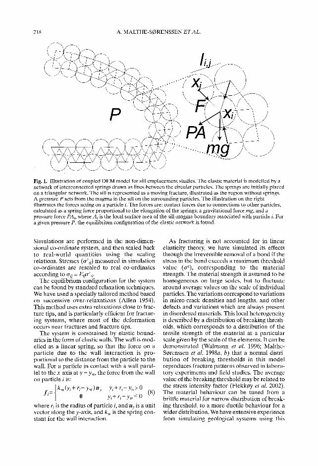
Fig. 1. Illustration of coupled DEM model for sill emplacement studies. The elastic material is modelled by a network of interconnected springs drawn as lines between the circular particles. The springs are initially placed on a triangular network. The sill is represented as a moving fracture, illustrated as the region without springs. A pressure P acts from the magma in the sill on the surrounding particles. The illustration on the right illustrates the forces acting on a particle i. The forces are: contact forces due to connections to other particles, calculated as a spring force proportional to the elongation of the springs; a gravitational force rag, and a pressure force PAi, where A i is the local surface area of the sill-magma boundary associated with particle i. For a given pressure P, the equilibrium configuration of the elastic network is found.
Simulations are pe r fo rmed in the non-d imen- sional co-ordinate system, and then scaled back to r ea l -wor ld quant i t i es using the scaling relations. Stresses (~'ij) measured in simulat ion co-ordinates are rescaled to real co-ordinates according to crij = Eo~r'q.
The equi l ibr ium configuration for the system can be found by s tandard relaxation techniques. We have used a specially tai lored m e t h o d based on successive over - re laxa t ions (Al len 1954). This m e t h o d uses extra relaxations close to frac- ture tips, and is particularly efficient for fractur- ing systems, where most of the de fo rma t ion occurs near fractures and fracture tips.
The system is constra ined by elastic bound- aries in the form of elastic walls. The wall is mod- elled as a l inear spring, so that the force on a par t ic le due to the wall in te rac t ion is pro- port ional to the distance from the particle to the wall. For a particle in contact with a wall paral- lel to the x-axis at y = Yw, the force f rom the wall on particle i is:
= I kw (Yi + r i - Yw ) uy Yi + r i - Yw > 0 f i 0 Yi + r i - Yw < 0 (8) L
where r i is the radius of particle i, and uy is a unit vector along the y-axis, and kw is the spring con- stant for the wall interaction.
As fracturing is not accounted for in l inear elasticity theory, we have simulated its effects through the irreversible removal of a bond if the stress in the bond exceeds a max imum threshold value (o-C), co r r e spond ing to the mater ia l strength. The material strength is assumed to be homogeneous on large scales, but to fluctuate around average values on the scale of individual particles. The variations correspond to variations in micro-crack densities and lengths, and other defects and variations which are always present in disordered materials. This local he te rogenei ty is described by a distribution of breaking thresh- olds, which corresponds to a distribution of the tensile strength of the material at a particular scale given by the scale of the elements. It can be demons t r a t ed (Walmann et al. 1996; Mal the- SCrenssen et al. 1998a, b) that a normal distri- bu t ion of b reak ing th resholds in this m o d e l reproduces fracture patterns observed in labora- tory experiments and field studies. The average value of the breaking threshold may be related to the stress intensity factor (Flekk0y et al. 2002). The material behaviour can be tuned from a brittle material for narrow distribution of break- ing threshold, to a more ductile behaviour for a wider distribution. We have extensive experience from simulating geological systems using this
FORMATION OF SAUCER-SHAPED SILLS 219
model, and this experience was used in selecting realistic distributions of breaking thresholds. Typical values for the breaking threshold corre- spond to breaking strains ec = 2 × 10 -3 to 2 × 10 .2 (Fyfe et al. 1978). A value corresponding to a strain of 2 x 10 .3 has been used in the simulations presented here.
The simulation procedure corresponds to a quasi-static driving mechanism of sill emplace- ment. Initially, the breaking strength of a short line is reduced by a factor of 10 in order to ini- tialize sill emplacement in the horizontal direc- tion. Sill injection is simulated by gradually increasing the pressure P0 until a fracture occurs in the surrounding matrix. A bond is removed, and the fluid is allowed to fill the new volume. This reduces the pressure in the fluid according to linear relationship between change in fluid volume and pressure, with a magma compress- ibility corresponding to the elastic stiffness of the surrounding matrix. This computational scheme ensures that the sill propagates in small steps, and not as a runaway brittle fracture. A new equilibrium configuration is found for the elastic material for the pressure P0. The pro- cedure is then repeated by slowly increasing the pressure. Snapshots of the sill geometry and the stresses around it illustrate the growth of the sill and the emplacement process.
Modelling results The coupled model is used to study the mechan- isms for the formation of saucer-shaped sills in an undeformed, homogeneous basin. The basin is represented as an initially homogeneous material with an isotropic lithostatic stress. The sill was emplaced at a depth h corresponding to the level of neutral buoyancy for the magma. The width of the simulated region of the basin was 40 km, and typical values for the depth h were i to 5 km. Other material parameters were selected within the range of typical properties of a sedimentary basin: E = 2 GPa, zip = 0.25 Mg m -3, e c = 2 × 10 -3 (Atkinson 1984).
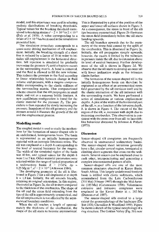
The developing geometry of the sill is illus- trated in Figure 2 for a sill emplaced at at depth h = 1.8 km. Initially, the sill extends linearly, retaining its original orientation. In this regime, illustrated in Figure 2a, the sill is short compared to the thickness of the overburden. The shape of the sill and the stress field extending from the tips of the sill is approximately symmetrical, and the sill emplacement is not affected by the asym- metrical boundary conditions.
When the sill reaches a length of approxi- mately the thickness of the overburden, the shape of the sill starts to become asymmetrical.
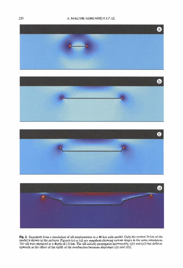
This is illustrated by a plot of the position of the upper and lower sill surfaces shown in Figure 3. As a consequence, the stress in front of the sill tips becomes asymmetrical. Figure 2b illustrates the stress field immediately before the sill starts bending upwards.
The sill branches upwards due to the asym- metry of the stress field caused by the uplift of the overburden. This is illustrated in Figure 2c. Initially, the sill propagates steeply upwards; however, the ascent is limited by the reduction in pressure inside the sill, due to extension above its level of neutral buoyancy. Further develop- ment of the sill is shown in Figure 2d. We observe that the sill starts to develop an outer sill with lower inclination angle as the intrusion climbs further.
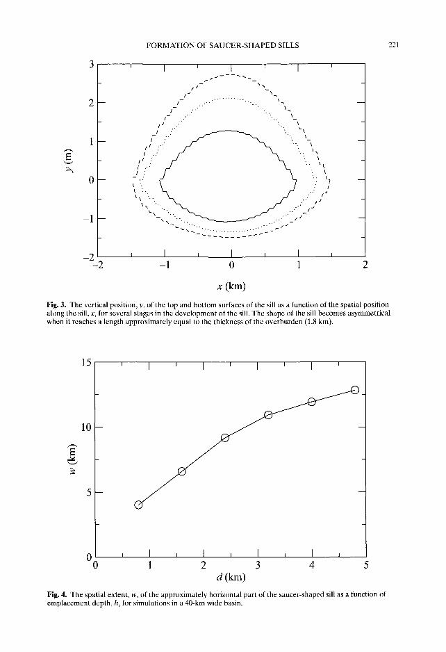
The formation of the saucer-shaped sill in the initially homogeneous basin can therefore be explained as an effect of an asymmetrical stress field generated by the sill intrusion itself and by the elastic interaction of the sill intrusion with the surrounding matrix. We have performed a series of simulations at various emplacement depths. A plot of the width of the horizontal part of the sill, w, as a function of the intrusion depth, h, is shown in Figure 4. The extent of the flat region of the sill, w, increases with depth due to increasing overburden. This observation is con- sistent with the cross-over from sill- to laccolith- like behaviour discussed by Johnson & Pollard (1973).
Discussion Saucer-shaped sill complexes are frequently observed in unstructured sedimentary basins. The saucer-shaped sheet intrusions generally have a flat, circular central region, terminated at climbing sheet segments that cross-cut the sedi- ments. Several saucers can be emplaced close to each other, interpenetrating and generating a complex interconnected pattern of sills.
Saucer-shaped sills are one of the most common structures observed in Karoo Basin, South Africa. This largely undeformed foreland basin is infilled with clastic sediments, which accumulated from the Late Carboniferous (310 Ma) (Vissner 1997) through the Mid-Juras- sic (185 Ma) (Catuneaunu 1998). Voluminous extrusive and intrusive complexes were emplaced in the Karoo Basin at c. 183 Ma (Duncan et al. 1997).
The saucer-shaped sills control to a large extent the geomorphology of the landscape (Du Toit 1920; Chevallier & Woodford 1999). Figure 5a shows a sketch of the typical morphology of a ring structure. The Golden Valley (Fig. 5b) near
220 A. MALTHE-SORENSSEN E T A L .
O : . ~L
Fig. 2. Snapshots from a simulation of sill emplacement in a 40-km wide model. Only the central 20 km of the model is shown in the pictures. Figures (a) to (d) are snapshots showing various stages in the same simulation. The sill was emplaced at a depth of 1.8 km. The sill initially propagates horizontally, ((b) and (a)) but deflects upwards as the effect of the uplift of the overburden becomes important ((c) and (d)).
FORMATION OF SAUCER-SHAPED SILLS 221
0 - -
__] - -
- 2 - 2
' I ' I ' I
£/-- \'~ ., \
I
i "" "'" \'-' ..
i j ,'" ,., \ I " ' ~ ". ~'~ / ~ .." ~ " - - ~ "", ",, ,.." '- /./.." '... ~a
/':./ \ ...',,, ~ ",.. .." J , , , . . \ / . . . , /
",., "~... ~ ~ . . . ' - " ' - "
, I i I , I , - 1 0 1 2
x (km)
Fig. 3. The vertical position, y, of the top and bottom surfaces of the sill as a function of the spatial position along the sill, x, for several stages in the development of the sill. The shape of the sill becomes asymmetrical when it reaches a length approximately equal to the thickness of the overburden (1.8 km).
1 5
10
' ' I ' I ' I '
i I , I i I i I , 0 1 2 3 4 5
d(km) Fig. 4. The spatial extent, w, of the approximately horizontal part of the saucer-shaped sill as a function of emplacement depth, h, for simulations in a 40-km wide basin.
222 A. MALTHE-SORENSSEN E T A L .
Outer sill
Inclined sheet (ring)
I
Feeder dyke
¸ ¸ ¸ ¸ 4
¢ - o ,¢"
a
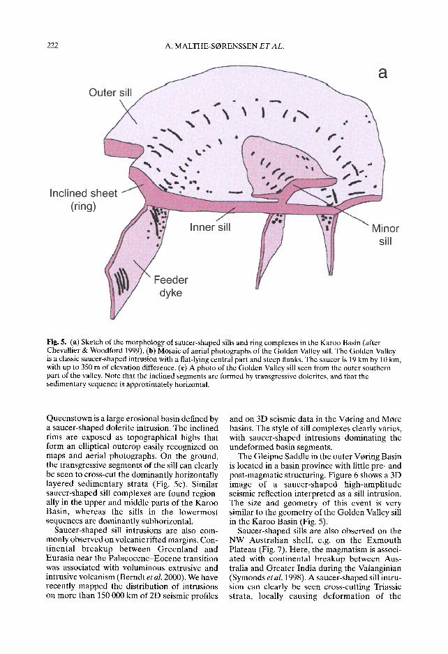
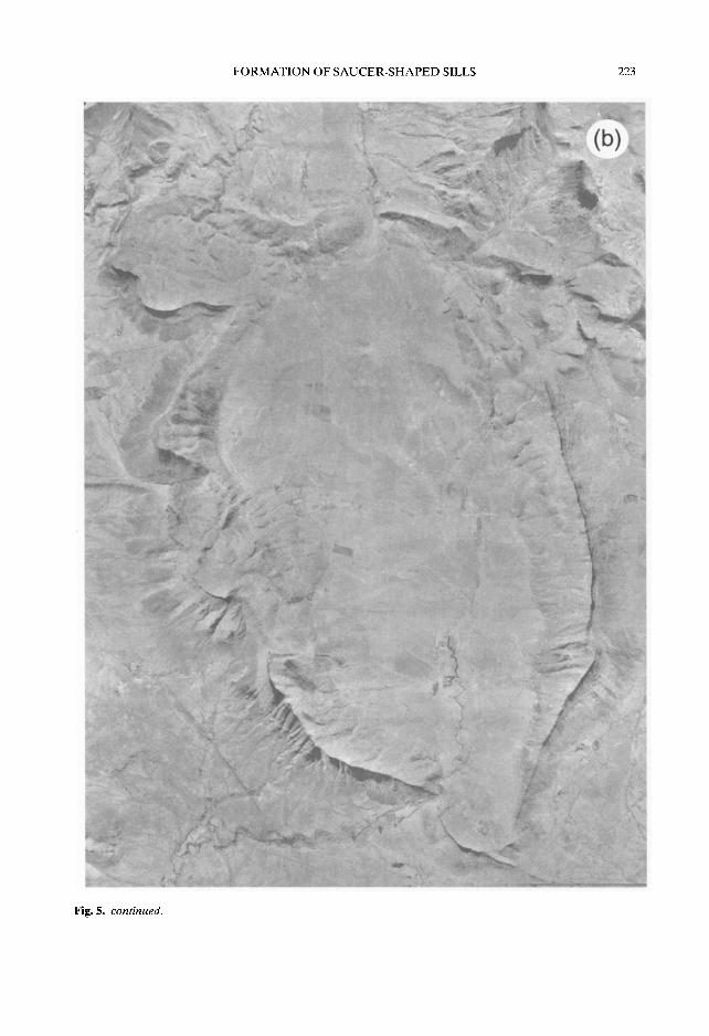
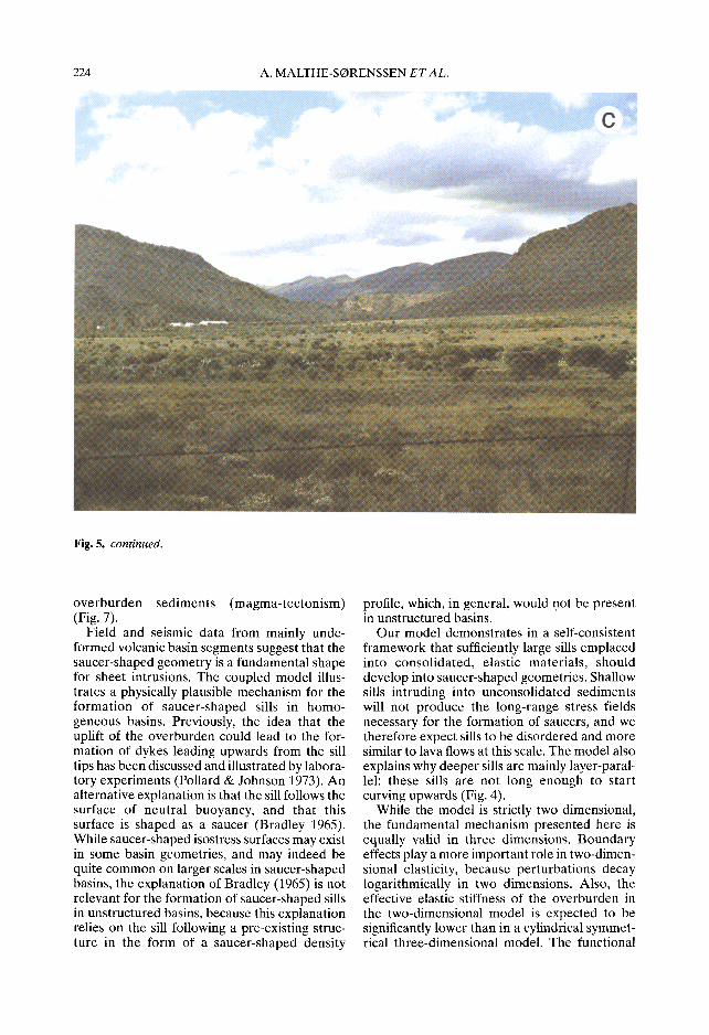
Fig. 5. (a) Sketch of the morphology of saucer-shaped sills and ring complexes in the Karoo Basin (after Chevallier & Woodford 1999). (b) Mosaic of aerial photographs of the Golden Valley sill. The Golden Valley is a classic saucer-shaped intrusion with a flat-lying central part and steep flanks. The saucer is 19 km by 10 kin, with up to 350 m of elevation difference. (c) A photo of the Golden Valley sill seen from the outer southern part of the valley. Note that the inclined segments are formed by transgressive dolerites, and that the sedimentary sequence is approximately horizontal.
Queenstown is a large erosional basin defined by a saucer-shaped dolerite intrusion. The inclined rims are exposed as topographical highs that form an elliptical outcrop easily recognized on maps and aerial photographs. On the ground, the transgressive segments of the sill can clearly be seen to cross-cut the dominantly horizontally layered sedimentary strata (Fig. 5c). Similar saucer-shaped sill complexes are found region- ally in the upper and middle parts of the Karoo Basin, whereas the sills in the lowermost sequences are dominantly subhorizontal.
Saucer-shaped sill intrusions are also com- monly observed on volcanic rifted margins. Con- t inental breakup between Greenland and Eurasia near the Palaeocene-Eocene transition was associated with voluminous extrusive and intrusive volcanism (Berndt et al. 2000). We have recently mapped the distribution of intrusions on more than 150 000 km of 2D seismic profiles
and on 3D seismic data in the V0ring and MOre basins. The style of sill complexes clearly varies, with saucer-shaped intrusions dominating the undeformed basin segments.
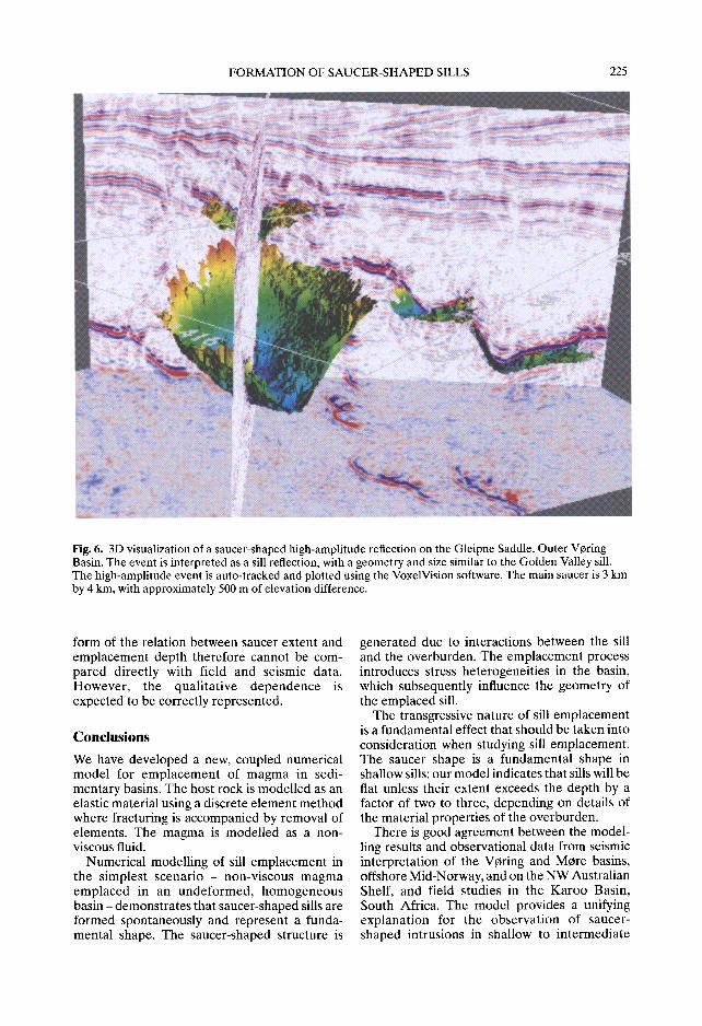
The Gleipne Saddle in the outer V0ring Basin is located in a basin province with little pre- and post-magmatic structuring. Figure 6 shows a 3D image of a saucer-shaped high-ampli tude seismic reflection interpreted as a sill intrusion. The size and geometry of this event is very similar to the geometry of the Golden Valley sill in the Karoo Basin (Fig. 5).
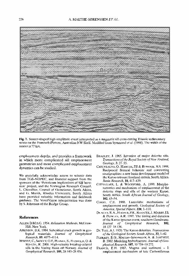
Saucer-shaped sills are also observed on the NW Austral ian shelf, e.g. on the Exmouth Plateau (Fig. 7). Here, the magmatism is associ- ated with continental breakup between Aus- tralia and Greater India during the Valanginian (Symonds et al. 1998). A saucer-shaped sill intru- sion can clearly be seen cross-cutting Triassic strata, locally causing deformat ion of the
FORMATION OF SAUCER-SHAPED SILLS 223
Fig. 5. continued.
224 A. MALTHE-SC)RENSSEN E T A L .
Fig. 5. continued.
overburden sediments (magma-tectonism) (Fig. 7).
Field and seismic data from mainly unde- formed volcanic basin segments suggest that the saucer-shaped geometry is a fundamental shape for sheet intrusions. The coupled model illus- trates a physically plausible mechanism for the formation of saucer-shaped sills in homo- geneous basins. Previously, the idea that the uplift of the overburden could lead to the for- mation of dykes leading upwards from the sill tips has been discussed and illustrated by labora- tory experiments (Pollard & Johnson 1973). An alternative explanation is that the sill follows the surface of neutral buoyancy, and that this surface is shaped as a saucer (Bradley 1965). While saucer-shaped isostress surfaces may exist in some basin geometries, and may indeed be quite common on larger scales in saucer-shaped basins, the explanation of Bradley (1965) is not relevant for the formation of saucer-shaped sills in unstructured basins, because this explanation relies on the sill following a pre-existing struc- ture in the form of a saucer-shaped density
profile, which, in general, would not be present in unstructured basins.
Our model demonstrates in a self-consistent framework that sufficiently large sills emplaced into consolidated, elastic materials, should develop into saucer-shaped geometries. Shallow sills intruding into unconsolidated sediments will not produce the long-range stress fields necessary for the formation of saucers, and we therefore expect sills to be disordered and more similar to lava flows at this scale. The model also explains why deeper sills are mainly layer-paral- lel: these sills are not long enough to start curving upwards (Fig. 4).
While the model is strictly two dimensional, the fundamental mechanism presented here is equally valid in three dimensions. Boundary effects play a more important role in two-dimen- sional elasticity, because perturbations decay logarithmically in two dimensions. Also, the effective elastic stiffness of the overburden in the two-dimensional model is expected to be significantly lower than in a cylindrical symmet- rical three-dimensional model. The functional
FORMATION OF SAUCER-SHAPED SILLS 225
l l l l . ~ - ~̧ / " ~ ~
: %
Fig. 6. 3D visualization of a saucer-shaped high-amplitude reflection on the Gleipne Saddle, Outer Vcring Basin. The event is interpreted as a sill reflection, with a geometry and size similar to the Golden Valley sill. The high-amplitude event is auto-tracked and plotted using the VoxelVision software. The main saucer is 3 km by 4 km, with approximately 500 m of elevation difference.
form of the relation between saucer extent and emplacement depth therefore cannot be com- pared directly with field and seismic data. However, the quali tative dependence is expected to be correctly represented.
Conclusions We have developed a new, coupled numerical model for emplacement of magma in sedi- mentary basins. The host rock is modelled as an elastic material using a discrete element method where fracturing is accompanied by removal of elements. The magma is modelled as a non- viscous fluid.
Numerical modelling of sill emplacement in the simplest scenario - non-viscous magma emplaced in an undeformed, homogeneous basin - demonstrates that saucer-shaped sills are formed spontaneously and represent a funda- mental shape. The saucer-shaped structure is
generated due to interactions between the sill and the overburden. The emplacement process introduces stress heterogeneities in the basin, which subsequently influence the geometry of the emplaced sill.
The transgressive nature of sill emplacement is a fundamental effect that should be taken into consideration when studying sill emplacement. The saucer shape is a fundamental shape in shallow sills: our model indicates that sills will be fiat unless their extent exceeds the depth by a factor of two to three, depending on details of the material properties of the overburden.
There is good agreement between the model- ling results and observational data from seismic interpretation of the Vcring and Mere basins, offshore Mid-Norway, and on the NW Australian Shelf, and field studies in the Karoo Basin, South Africa. The model provides a unifying explanat ion for the observation of saucer- shaped intrusions in shallow to intermediate
226 A. MALTHE-SORENSSEN ETAL.
Fig. 7. Saucer-shaped high-amplitude event interpreted as a magmatic sill cross-cutting Triassic sedimentary strata on the Exmouth Plateau, Australian NW Shelf. Modified from Symmond et al. (1998). The width of the saucer is 27 km.
e m p l a c e m e n t depths, and provides a f r amework in which m o r e compl ica ted sill e m p l a c e m e n t geometr ies and more compl ica ted e m p l a c e m e n t dynamics can be studied.
We gratefully acknowledge access to seismic data from TGS-NOPEC, and financial support from the sponsors of the 'Petroleum Implications of Sill Intru- sion' project, and the Norwegian Research Council. L. Chevallier, Council of Geoscience, South Africa, and G. Marsh, Rhodes University, South Africa have provided valuable information and fieldwork guidance. The VoxelVision interpretation was done by S. Johansen of the Bridge Group.
R e f e r e n c e s ALLEN, D.M.D.G. 1954. Relaxation Methods. McGraw-
Hill, New York. ATKINSON, B.K. 1984. Subcritical crack growth in geo-
logical materials. Journal of Geophysical Research, 89, 4077-4114.
BERNDT, C., SKOGLY, O.P., PLANKE, S., ELDHOLM, O. & MJELDE, R. 2000. High-velocity breakup-related sills in the Vcring Basin off Norway. Journal of Geophysical Research, 105, 28 443-28 454.
BRADLEY, J. 1965. Intrusion of major dolerite sills. Transactions of the Royal Society of New Zealand, Geology, 3, 27-55.
CATUNEAUNU, O., HANCOX, P.J. & RUBIDGE, B.S. 1998. Reciprocal flexural behavior and contrasting stratigraphies: a new basin development model of the Karoo retroarc foreland system, South Africa. Basin Research, 10, 417-439.
CHEVALLIER, L. & WOODFORD, A. 1999. Morpho- tectonics and mechanism of emplacement of the dolerite rings and sills of the western Karoo, South Africa. South African Journal of Geology, 102, 43-54.
CORRY, C.E. 1988. Laccoliths: mechanisms of emplacement and growth. Geological Society of America, Special Papers, 220, 1-110.
DUNCAN, R.A., HOOPER, ER., REHACEK, J., MARSH, J.S. & DUNCAN, A.R. 1997. The timing and duration of the Karoo igneous event, southern Gondwana. Journal of Geophysical Research, 102, 18 127-18 138.
Du TOIT, A.I. 1920. The Karoo dolerites. Transactions of the Geological Society South Africa, 33, 1-42.
FLEKKOY, E.G., MALTHE-SORENSSEN, A. & JAMTVEIT, B. 2002. Modeling hydrofracture. Journal of Geo- physical Research, 107, 10 259-10 272.
FRANCIS, E.H. 1982. Magma and sediment - I: emplacement mechanism of late Carboniferous
FORMATION OF SAUCER-SHAPED SILLS 227
tholeiite sills in the northern Britain. Journal of the Geological Society of London, 139, 1-20.
FYFE, W.S., PRICE, N. & THOMPSON, A.V. 1978. Fluids in the Earth's crust. Elsevier Science, New York.
GILBERT, G.K. 1877. Geology of the Henry Mountains, in the U.S. Geographical and Geological Survey of the Rocky Mountain Region, U.S. Government Printing Office, Washington, D.C., USA.
JAMTVEIT, B., AUSTRHEIM, H. & MALTHE-SORENSSEN, A. 2000. Accelerated hydration of the Earth's deep crust induced by stress perturbations. Nature, 107, 10 259-10 272.
JOHNSON, A.M. & POLLARD, D.D. 1973. Mechanics of growth of some laccolithic intrusions in the Henry Mountains, Utah, 1. Tectonophysics, 18, 261-309.
KHAZAN, Y.M. & FIALKO, Y.A. 1995. Fracture criteria at the tip of fluid-driven cracks in the earth. Geo- physical Research Letters, 22, 2541-2544.
LISTER, J.R. • KERR, R.C. 1991. Fluid-mechanics models of crack propagation and their application to magma transport in dykes. Journal of Geo- physical Research, 96, 10 049-10 077.
MALTHE-S~RENSSEN, A., WALMANN, T., FEDER, J., JOSSANG, T., MEAKIN, E & HARDY, H.H. 1998a. Simulation of extensional clay fractures. Physical Review E, 58, 5548-5564.
MALTHE-SORENSSEN, A., WALMANN, Z., JAMTVEIT, B., FEDER, J. & J~SSANG, T. 1998b. Modeling and characterization of fracture patterns in the Vatna- j6kull glacier. Geology, 26, 931-934.
MONETFE, L. & ANDERSON, M.P. 1994. Elastic and fracture properties of the 2-dimensional triangu- lar and square lattices. Modelling and Simulation in: Materials Science and Engineering, 2, 53-73.
POLLARD, D.D. & JOHNSON, A.M. 1973. Mechanics of growth of some laccolithic intrusions in the Henry Mountains, Utah, 2. Tectonophysics, 18, 311-354.
POLLARD, D.D., MULLER, O.H. & DOCKSTADER, D.R. 1975. The form and growth of fingered sheet
intrusions. Geological Society of America Bulletin, 86, 351-363.
RUBIN, A.M. 1993. Tensile fracture of rock at high confining pressure: implications for dike propa- gation. Journal of Geophysical Research, 98, 15 919-15 935.
RUBIN, A.M. 1995. Propagation of magma-filled cracks. Annual Review, Earth Planetary Sciences, 23, 287-336.
SCHUrrER, S.R. 2003. Hydrocarbon Occurrence and Exploration in and Around Igneous Rocks. Geo- logical Society, London, Special Publications, 214.
SKOGSEID, J., PEDERSEN, T., ELDHOLM, O. & LARSEN, B. 1992. Tectonism and magmatism during NE Atlantic continental break-up: the Vcring margin. Geological Society, London, Special Publications, 68, 305-320.
SMALLWOOD, J. & MARESH, J. 2002. The Properties, Morphology and Distribution of Igneous Sills: Modelling, Borehole Data and 3d Seismic from the Faroe-Shetland Area. Geological Society, London, Special Publications, 197.
SYMONDS, RA., PLANKE, S., FREY, ~. & SKOGSEID, J. 1998. Volcanic development of the Western Aus- tralian continental margin and its implications for basin development. In: PURCELL, P.G. & PURCELL, R.R. (eds) The Sedimentary Basins of Western Australia 2, Proceedings of the Petroleum Explo- ration Society of Australia, Symposium, Oxford, Petroleum Exploration Society of Australia, Perth, Australia, 33-54.
VISSNER, J.N.J. 1997. Geography and climatology of the Late Carboniferous to Jurassic Karoo Basin in the south-western Gondwana. South African Journal of Geology, 100, 233-236.
WALMANN, Y., MALTHE-SORENSSEN, A., FEDER, J., JOSSANG, Y., MEAKIN, P. & HARDY, H.H. 1996. Scaling relations for the lengths and widths of fractures. Physical Review Letters, 77, 5393-5396.
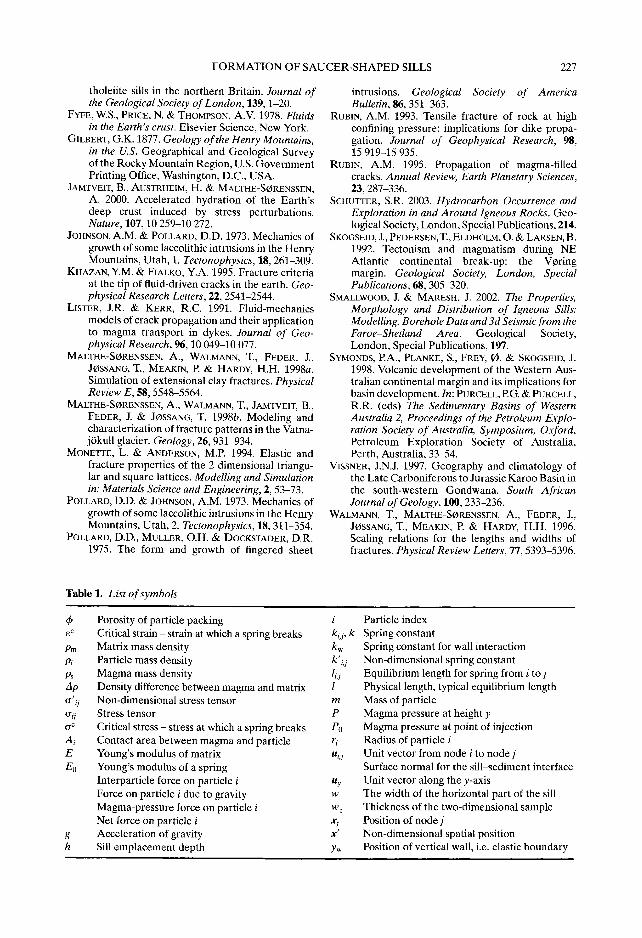
Table 1. Lbst of symbols
~b Porosity of particle packing e c Critical strain - strain at which a spring breaks Pm Matrix mass density Pi Particle mass density Ps Magma mass density Ap Density difference between magma and matrix 0", 7 Non-dimensional stress tensor o-ij Stress tensor o -c Critical stress - stress at which a spring breaks A i Contact area between magma and particle E Young's modulus of matrix E0 Young's modulus of a spring
Interparticle force on particle i Force on particle i due to gravity Magma-pressure force on particle i Net force on particle i
g Acceleration of gravity h Sill emplacement depth
i Particle index ki,j, k Spring constant kw Spring constant for wall interaction k'i, j Non-dimensional spring constant lij Equilibrium length for spring from i to j l Physical length, typical equilibrium length m Mass of particle P Magma pressure at height y P0 Magma pressure at point of injection r i Radius of particle i uij Unit vector from node i to node j
Surface normal for the sill-sediment interface Uy Unit vector along the y-axis w The width of the horizontal part of the sill w z Thickness of the two-dimensional sample xj Position of node j x' Non-dimensional spatial position Yw Position of vertical wall, i.e. elastic boundary
Related Documents