Formality ® User Guide Version D-2010.03, March 2010

Welcome message from author
This document is posted to help you gain knowledge. Please leave a comment to let me know what you think about it! Share it to your friends and learn new things together.
Transcript

Formality®
User GuideVersion D-2010.03, March 2010

Formality User Guide, version D-2010.03 ii
Copyright Notice and Proprietary InformationCopyright © 2010 Synopsys, Inc. All rights reserved. This software and documentation contain confidential and proprietary information that is the property of Synopsys, Inc. The software and documentation are furnished under a license agreement and may be used or copied only in accordance with the terms of the license agreement. No part of the software and documentation may be reproduced, transmitted, or translated, in any form or by any means, electronic, mechanical, manual, optical, or otherwise, without prior written permission of Synopsys, Inc., or as expressly provided by the license agreement.
Right to Copy DocumentationThe license agreement with Synopsys permits licensee to make copies of the documentation for its internal use only. Each copy shall include all copyrights, trademarks, service marks, and proprietary rights notices, if any. Licensee must assign sequential numbers to all copies. These copies shall contain the following legend on the cover page:
“This document is duplicated with the permission of Synopsys, Inc., for the exclusive use of __________________________________________ and its employees. This is copy number __________.”
Destination Control StatementAll technical data contained in this publication is subject to the export control laws of the United States of America. Disclosure to nationals of other countries contrary to United States law is prohibited. It is the reader’s responsibility to determine the applicable regulations and to comply with them.
DisclaimerSYNOPSYS, INC., AND ITS LICENSORS MAKE NO WARRANTY OF ANY KIND, EXPRESS OR IMPLIED, WITH REGARD TO THIS MATERIAL, INCLUDING, BUT NOT LIMITED TO, THE IMPLIED WARRANTIES OF MERCHANTABILITY AND FITNESS FOR A PARTICULAR PURPOSE.
Registered Trademarks (®)Synopsys, AMPS, Astro, Behavior Extracting Synthesis Technology, Cadabra, CATS, Certify, CHIPit, Design Compiler, DesignWare, Formality, HDL Analyst, HSIM, HSPICE, Identify, Leda, MAST, ModelTools, NanoSim, OpenVera, PathMill, Physical Compiler, PrimeTime, SCOPE, Simply Better Results, SiVL, SNUG, SolvNet, Syndicated, Synplicity, Synplify, Synplify Pro, Synthesis Constraints Optimization Environment, TetraMAX, the Synplicity logo, UMRBus, VCS, Vera, and YIELDirector are registered trademarks of Synopsys, Inc.
Trademarks (™)AFGen, Apollo, Astro-Rail, Astro-Xtalk, Aurora, AvanWaves, BEST, Columbia, Columbia-CE, Confirma, Cosmos, CosmosLE, CosmosScope, CRITIC, CustomExplorer, CustomSim, DC Expert, DC Professional, DC Ultra, Design Analyzer, Design Vision, DesignerHDL, DesignPower, DFTMAX, Direct Silicon Access, Discovery, Eclypse, Encore, EPIC, Galaxy, Galaxy Custom Designer, HANEX, HAPS, HapsTrak, HDL Compiler, Hercules, Hierarchical Optimization
Technology, High-performance ASIC Prototyping System, HSIMplus
, i-Virtual Stepper, IICE, in-Sync, iN-Tandem, Jupiter, Jupiter-DP, JupiterXT, JupiterXT-ASIC, Liberty, Libra-Passport, Library Compiler, Magellan, Mars, Mars-Rail, Mars-Xtalk, Milkyway, ModelSource, Module Compiler, MultiPoint, Physical Analyst, Planet, Planet-PL, Polaris, Power Compiler, Raphael, Saturn, Scirocco, Scirocco-i, Star-RCXT, Star-SimXT, StarRC, System Compiler, System Designer, Taurus, TotalRecall, TSUPREM-4, VCS Express, VCSi, VHDL Compiler, VirSim, and VMC are trademarks of Synopsys, Inc.
Service Marks (SM)MAP-in, SVP Café, and TAP-in are service marks of Synopsys, Inc.
SystemC is a trademark of the Open SystemC Initiative and is used under license.ARM and AMBA are registered trademarks of ARM Limited.Saber is a registered trademark of SabreMark Limited Partnership and is used under license.All other product or company names may be trademarks of their respective owners.

Contents
What’s New in This Release . . . . . . . . . . . . . . . . . . . . . . . . . . . . . . . . . . . . . . . . . . . xiv
About This User Guide . . . . . . . . . . . . . . . . . . . . . . . . . . . . . . . . . . . . . . . . . . . . . . . xiv
Customer Support. . . . . . . . . . . . . . . . . . . . . . . . . . . . . . . . . . . . . . . . . . . . . . . . . . . xvii
1. Introduction to Formality
What is Formality? . . . . . . . . . . . . . . . . . . . . . . . . . . . . . . . . . . . . . . . . . . . . . . . . . . 1-2
What is Formal Verification? . . . . . . . . . . . . . . . . . . . . . . . . . . . . . . . . . . . . . . . 1-2
General Verification Process. . . . . . . . . . . . . . . . . . . . . . . . . . . . . . . . . . . . . . . . . . . 1-3
Individual Verification . . . . . . . . . . . . . . . . . . . . . . . . . . . . . . . . . . . . . . . . . . . . . 1-3
ASIC Verification Flow . . . . . . . . . . . . . . . . . . . . . . . . . . . . . . . . . . . . . . . . . . . . 1-3
Equivalence Checking Verification Process . . . . . . . . . . . . . . . . . . . . . . . . . . . . . . . 1-5
Design Read and Elaboration . . . . . . . . . . . . . . . . . . . . . . . . . . . . . . . . . . . . . . 1-5Concept of Reference and Implementation Designs . . . . . . . . . . . . . . . . . 1-5Concept of Logic Cones . . . . . . . . . . . . . . . . . . . . . . . . . . . . . . . . . . . . . . . 1-6
Setup to Preempt Differences . . . . . . . . . . . . . . . . . . . . . . . . . . . . . . . . . . . . . . 1-6Concept of Guidance . . . . . . . . . . . . . . . . . . . . . . . . . . . . . . . . . . . . . . . . . 1-6Concept of Black Boxes . . . . . . . . . . . . . . . . . . . . . . . . . . . . . . . . . . . . . . . 1-7Concept of Constraints . . . . . . . . . . . . . . . . . . . . . . . . . . . . . . . . . . . . . . . . 1-7
Matching . . . . . . . . . . . . . . . . . . . . . . . . . . . . . . . . . . . . . . . . . . . . . . . . . . . . . . 1-7Concept of Compare Points . . . . . . . . . . . . . . . . . . . . . . . . . . . . . . . . . . . . 1-8Concept of Name-Based and Non-Name-Based Matching . . . . . . . . . . . . 1-8Concept of User Matches . . . . . . . . . . . . . . . . . . . . . . . . . . . . . . . . . . . . . . 1-9
Verification . . . . . . . . . . . . . . . . . . . . . . . . . . . . . . . . . . . . . . . . . . . . . . . . . . . . . 1-10Concept of Consistency and Equality . . . . . . . . . . . . . . . . . . . . . . . . . . . . . 1-10
iii

Formality User Guide D-2010.03Formality User Guide Version D-2010.03
Interpret Results . . . . . . . . . . . . . . . . . . . . . . . . . . . . . . . . . . . . . . . . . . . . . . . . . . . . 1-10
2. Formality Use Model
Formality Process Flow. . . . . . . . . . . . . . . . . . . . . . . . . . . . . . . . . . . . . . . . . . . . . . . 2-2
Invocation . . . . . . . . . . . . . . . . . . . . . . . . . . . . . . . . . . . . . . . . . . . . . . . . . . . . . . . . . 2-3
Guidance . . . . . . . . . . . . . . . . . . . . . . . . . . . . . . . . . . . . . . . . . . . . . . . . . . . . . . . . . 2-3
Load Designs . . . . . . . . . . . . . . . . . . . . . . . . . . . . . . . . . . . . . . . . . . . . . . . . . . . . . . 2-4
Perform Setup. . . . . . . . . . . . . . . . . . . . . . . . . . . . . . . . . . . . . . . . . . . . . . . . . . . . . . 2-4
Match Compare Points . . . . . . . . . . . . . . . . . . . . . . . . . . . . . . . . . . . . . . . . . . . . . . . 2-5
Run Verification and Interpret Results . . . . . . . . . . . . . . . . . . . . . . . . . . . . . . . . . . . 2-5
Debug . . . . . . . . . . . . . . . . . . . . . . . . . . . . . . . . . . . . . . . . . . . . . . . . . . . . . . . . . . . . 2-6
Tutorial . . . . . . . . . . . . . . . . . . . . . . . . . . . . . . . . . . . . . . . . . . . . . . . . . . . . . . . . . . . 2-6
Library Verification Mode . . . . . . . . . . . . . . . . . . . . . . . . . . . . . . . . . . . . . . . . . . . . . 2-6
3. Invocation
Introduction . . . . . . . . . . . . . . . . . . . . . . . . . . . . . . . . . . . . . . . . . . . . . . . . . . . . . . . . 3-3
Specify the Executable File Location . . . . . . . . . . . . . . . . . . . . . . . . . . . . . . . . . 3-3
Specify License Environment Variable. . . . . . . . . . . . . . . . . . . . . . . . . . . . . . . . 3-3
Basic Usage . . . . . . . . . . . . . . . . . . . . . . . . . . . . . . . . . . . . . . . . . . . . . . . . . . . . . . . 3-3
Invoke the Formality Shell . . . . . . . . . . . . . . . . . . . . . . . . . . . . . . . . . . . . . . . . . 3-4Synopsys Setup File . . . . . . . . . . . . . . . . . . . . . . . . . . . . . . . . . . . . . . . . . . 3-5Redirect Standard Output . . . . . . . . . . . . . . . . . . . . . . . . . . . . . . . . . . . . . . 3-6
Invoke the Formality GUI . . . . . . . . . . . . . . . . . . . . . . . . . . . . . . . . . . . . . . . . . . 3-6
Get Help. . . . . . . . . . . . . . . . . . . . . . . . . . . . . . . . . . . . . . . . . . . . . . . . . . . . . . . 3-6
Interrupt Formality . . . . . . . . . . . . . . . . . . . . . . . . . . . . . . . . . . . . . . . . . . . . . . . 3-8
Advanced Usage. . . . . . . . . . . . . . . . . . . . . . . . . . . . . . . . . . . . . . . . . . . . . . . . . . . . 3-9
Commands . . . . . . . . . . . . . . . . . . . . . . . . . . . . . . . . . . . . . . . . . . . . . . . . . . . . 3-9Enter Commands . . . . . . . . . . . . . . . . . . . . . . . . . . . . . . . . . . . . . . . . . . . . 3-9Argument Lists . . . . . . . . . . . . . . . . . . . . . . . . . . . . . . . . . . . . . . . . . . . . . . 3-10Edit From the Command Line. . . . . . . . . . . . . . . . . . . . . . . . . . . . . . . . . . . 3-11History . . . . . . . . . . . . . . . . . . . . . . . . . . . . . . . . . . . . . . . . . . . . . . . . . . . . 3-12Aliasing . . . . . . . . . . . . . . . . . . . . . . . . . . . . . . . . . . . . . . . . . . . . . . . . . . . . 3-14Redirection . . . . . . . . . . . . . . . . . . . . . . . . . . . . . . . . . . . . . . . . . . . . . . . . . 3-15Command Log Files . . . . . . . . . . . . . . . . . . . . . . . . . . . . . . . . . . . . . . . . . . 3-16
Contents iv

Formality User Guide Version D-2010.03
GUI Environment . . . . . . . . . . . . . . . . . . . . . . . . . . . . . . . . . . . . . . . . . . . . . . . . 3-16Windows . . . . . . . . . . . . . . . . . . . . . . . . . . . . . . . . . . . . . . . . . . . . . . . . . . . 3-16Prompt . . . . . . . . . . . . . . . . . . . . . . . . . . . . . . . . . . . . . . . . . . . . . . . . . . . . 3-17Copy Text . . . . . . . . . . . . . . . . . . . . . . . . . . . . . . . . . . . . . . . . . . . . . . . . . . 3-17Save Transcript . . . . . . . . . . . . . . . . . . . . . . . . . . . . . . . . . . . . . . . . . . . . . . 3-18
Script Files . . . . . . . . . . . . . . . . . . . . . . . . . . . . . . . . . . . . . . . . . . . . . . . . . . . . . 3-18
Messages . . . . . . . . . . . . . . . . . . . . . . . . . . . . . . . . . . . . . . . . . . . . . . . . . . . . . 3-19Control Message Types . . . . . . . . . . . . . . . . . . . . . . . . . . . . . . . . . . . . . . . 3-19Set Thresholds . . . . . . . . . . . . . . . . . . . . . . . . . . . . . . . . . . . . . . . . . . . . . . 3-21
Output Files . . . . . . . . . . . . . . . . . . . . . . . . . . . . . . . . . . . . . . . . . . . . . . . . . . . . 3-21
Control File Names Generated by Formality . . . . . . . . . . . . . . . . . . . . . . . . . . . 3-23
4. Tutorial
Before You Start . . . . . . . . . . . . . . . . . . . . . . . . . . . . . . . . . . . . . . . . . . . . . . . . . . . . 4-2
Create Tutorial Directories . . . . . . . . . . . . . . . . . . . . . . . . . . . . . . . . . . . . . . . . . 4-2
Tutorial Directory Contents . . . . . . . . . . . . . . . . . . . . . . . . . . . . . . . . . . . . . . . . 4-3
Invoke the Formality Shell . . . . . . . . . . . . . . . . . . . . . . . . . . . . . . . . . . . . . . . . . 4-3
Verify fifo.vg Against fifo.v . . . . . . . . . . . . . . . . . . . . . . . . . . . . . . . . . . . . . . . . . . . . . 4-4
Load Automated Setup File . . . . . . . . . . . . . . . . . . . . . . . . . . . . . . . . . . . . . . . . 4-4
Specify the Reference Design . . . . . . . . . . . . . . . . . . . . . . . . . . . . . . . . . . . . . . 4-5
Specify the Implementation Design . . . . . . . . . . . . . . . . . . . . . . . . . . . . . . . . . . 4-5
Set Up the Design . . . . . . . . . . . . . . . . . . . . . . . . . . . . . . . . . . . . . . . . . . . . . . . 4-6
Match Compare Points . . . . . . . . . . . . . . . . . . . . . . . . . . . . . . . . . . . . . . . . . . . 4-6
Verify the Designs . . . . . . . . . . . . . . . . . . . . . . . . . . . . . . . . . . . . . . . . . . . . . . . 4-6
Debug . . . . . . . . . . . . . . . . . . . . . . . . . . . . . . . . . . . . . . . . . . . . . . . . . . . . . . . . 4-7Graphical User Interface. . . . . . . . . . . . . . . . . . . . . . . . . . . . . . . . . . . . . . . 4-7
Verify fifo_with_scan.v Against fifo_mod.vg . . . . . . . . . . . . . . . . . . . . . . . . . . . . . . . 4-12
Verify fifo_jtag.v Against fifo_with_scan.v . . . . . . . . . . . . . . . . . . . . . . . . . . . . . . . . . 4-15
Debug Using Diagnosis . . . . . . . . . . . . . . . . . . . . . . . . . . . . . . . . . . . . . . . . . . . 4-17
For More Information . . . . . . . . . . . . . . . . . . . . . . . . . . . . . . . . . . . . . . . . . . . . . . . . 4-19
5. Guidance
What is Guidance? . . . . . . . . . . . . . . . . . . . . . . . . . . . . . . . . . . . . . . . . . . . . . . . . . . 5-2
Basic Usage . . . . . . . . . . . . . . . . . . . . . . . . . . . . . . . . . . . . . . . . . . . . . . . . . . . . . . . 5-4
Create an Automated Setup File . . . . . . . . . . . . . . . . . . . . . . . . . . . . . . . . . . . . 5-4
Chapter ii: Contentsii-vContents v

Formality User Guide D-2010.03Formality User Guide Version D-2010.03
Automated Setup Mode . . . . . . . . . . . . . . . . . . . . . . . . . . . . . . . . . . . . . . . . . . . 5-5
Read Automated Setup File. . . . . . . . . . . . . . . . . . . . . . . . . . . . . . . . . . . . . . . . 5-7
Guidance Summary. . . . . . . . . . . . . . . . . . . . . . . . . . . . . . . . . . . . . . . . . . . . . . 5-8
Advanced Usage. . . . . . . . . . . . . . . . . . . . . . . . . . . . . . . . . . . . . . . . . . . . . . . . . . . . 5-9
Guidance Directory/File Structure . . . . . . . . . . . . . . . . . . . . . . . . . . . . . . . . . . . 5-9
Guidance Reports . . . . . . . . . . . . . . . . . . . . . . . . . . . . . . . . . . . . . . . . . . . . . . . 5-10
Guidance Messages . . . . . . . . . . . . . . . . . . . . . . . . . . . . . . . . . . . . . . . . . . . . . 5-11Automated Setup File Messaging. . . . . . . . . . . . . . . . . . . . . . . . . . . . . . . . 5-11Automated Setup File Diagnostic Messages . . . . . . . . . . . . . . . . . . . . . . . 5-12
Read in Multiple Guidance Files . . . . . . . . . . . . . . . . . . . . . . . . . . . . . . . . . . . . 5-12
Automated Setup File Conversion to Text . . . . . . . . . . . . . . . . . . . . . . . . . . . . . 5-13
6. Load Designs
Introduction . . . . . . . . . . . . . . . . . . . . . . . . . . . . . . . . . . . . . . . . . . . . . . . . . . . . . . . . 6-3
Load Design Steps . . . . . . . . . . . . . . . . . . . . . . . . . . . . . . . . . . . . . . . . . . . . . . 6-3
Top-Level Design . . . . . . . . . . . . . . . . . . . . . . . . . . . . . . . . . . . . . . . . . . . . . . . 6-5
Concept of Containers . . . . . . . . . . . . . . . . . . . . . . . . . . . . . . . . . . . . . . . . . . . . 6-5
Basic Usage. . . . . . . . . . . . . . . . . . . . . . . . . . . . . . . . . . . . . . . . . . . . . . . . . . . . . . . 6-7
Load Reference Design . . . . . . . . . . . . . . . . . . . . . . . . . . . . . . . . . . . . . . . . . . 6-7Read Technology Libraries . . . . . . . . . . . . . . . . . . . . . . . . . . . . . . . . . . . . . 6-7Read Designs . . . . . . . . . . . . . . . . . . . . . . . . . . . . . . . . . . . . . . . . . . . . . . . 6-8Set Top-Level Design . . . . . . . . . . . . . . . . . . . . . . . . . . . . . . . . . . . . . . . . . 6-11
Load Implementation Design . . . . . . . . . . . . . . . . . . . . . . . . . . . . . . . . . . . . . . . 6-12
Advanced Usage. . . . . . . . . . . . . . . . . . . . . . . . . . . . . . . . . . . . . . . . . . . . . . . . . . . . 6-12
Read Technology Libraries . . . . . . . . . . . . . . . . . . . . . . . . . . . . . . . . . . . . . . . . 6-13Use of 'celldefine Verilog Attribute . . . . . . . . . . . . . . . . . . . . . . . . . . . . . . . 6-13Read SystemVerilog, Verilog, and VHDL Cell Definition . . . . . . . . . . . . . . 6-13Verilog Simulation Data . . . . . . . . . . . . . . . . . . . . . . . . . . . . . . . . . . . . . . . 6-15Library Loading Order. . . . . . . . . . . . . . . . . . . . . . . . . . . . . . . . . . . . . . . . . 6-16
Set Top-Level Design. . . . . . . . . . . . . . . . . . . . . . . . . . . . . . . . . . . . . . . . . . . . . 6-16Set Parameters on Top-Level Design . . . . . . . . . . . . . . . . . . . . . . . . . . . . . 6-17Generate Simulation/Synthesis Mismatch Report . . . . . . . . . . . . . . . . . . . 6-18Link Automatically Top-Level Design . . . . . . . . . . . . . . . . . . . . . . . . . . . . . 6-18
Set Up and Manage Containers . . . . . . . . . . . . . . . . . . . . . . . . . . . . . . . . . . . . 6-19
Variables Controlled by Setup Free Flow. . . . . . . . . . . . . . . . . . . . . . . . . . . . . . 6-21Variables to Control Bus Names. . . . . . . . . . . . . . . . . . . . . . . . . . . . . . . . . 6-21Variables to Control Parameter Names . . . . . . . . . . . . . . . . . . . . . . . . . . . 6-21
Contents vi

Formality User Guide Version D-2010.03
Variables to Control Case Behavior . . . . . . . . . . . . . . . . . . . . . . . . . . . . . . 6-22
7. Perform Setup
Common Operations. . . . . . . . . . . . . . . . . . . . . . . . . . . . . . . . . . . . . . . . . . . . . . . . . 7-3
Black Boxes . . . . . . . . . . . . . . . . . . . . . . . . . . . . . . . . . . . . . . . . . . . . . . . . . . . . 7-3Load Design Interfaces. . . . . . . . . . . . . . . . . . . . . . . . . . . . . . . . . . . . . . . . 7-5Mark a Design as a Black Box for Verification . . . . . . . . . . . . . . . . . . . . . . 7-6Report Black Boxes . . . . . . . . . . . . . . . . . . . . . . . . . . . . . . . . . . . . . . . . . . 7-6Perform Identity Checks . . . . . . . . . . . . . . . . . . . . . . . . . . . . . . . . . . . . . . . 7-7Set Pin and Port Directions for Unresolved Black Boxes . . . . . . . . . . . . . . 7-7
Constants. . . . . . . . . . . . . . . . . . . . . . . . . . . . . . . . . . . . . . . . . . . . . . . . . . . . . . 7-8Define Constants . . . . . . . . . . . . . . . . . . . . . . . . . . . . . . . . . . . . . . . . . . . . 7-9Remove User-Defined Constants . . . . . . . . . . . . . . . . . . . . . . . . . . . . . . . . 7-9List User-Defined Constants. . . . . . . . . . . . . . . . . . . . . . . . . . . . . . . . . . . . 7-10Report Setup Status . . . . . . . . . . . . . . . . . . . . . . . . . . . . . . . . . . . . . . . . . . 7-10
External Constraints . . . . . . . . . . . . . . . . . . . . . . . . . . . . . . . . . . . . . . . . . . . . . 7-11Define an External Constraint. . . . . . . . . . . . . . . . . . . . . . . . . . . . . . . . . . . 7-12Create a Constraint Type . . . . . . . . . . . . . . . . . . . . . . . . . . . . . . . . . . . . . . 7-12Remove an External Constraint . . . . . . . . . . . . . . . . . . . . . . . . . . . . . . . . . 7-13Remove a Constraint Type . . . . . . . . . . . . . . . . . . . . . . . . . . . . . . . . . . . . . 7-14Report Constraint Information . . . . . . . . . . . . . . . . . . . . . . . . . . . . . . . . . . 7-14Report Information About Constraint Types . . . . . . . . . . . . . . . . . . . . . . . . 7-14
Combinational Design Changes . . . . . . . . . . . . . . . . . . . . . . . . . . . . . . . . . . . . 7-15Disable Scan Logic . . . . . . . . . . . . . . . . . . . . . . . . . . . . . . . . . . . . . . . . . . . 7-15Disable Boundary Scan in Your Designs . . . . . . . . . . . . . . . . . . . . . . . . . . 7-16Manage Clock Tree Buffering . . . . . . . . . . . . . . . . . . . . . . . . . . . . . . . . . . . 7-17
Sequential Design Changes . . . . . . . . . . . . . . . . . . . . . . . . . . . . . . . . . . . . . . . 7-18Set Clock Gating. . . . . . . . . . . . . . . . . . . . . . . . . . . . . . . . . . . . . . . . . . . . . 7-18Enable an Inversion Push . . . . . . . . . . . . . . . . . . . . . . . . . . . . . . . . . . . . . . 7-23Instance-Based Inversion Push . . . . . . . . . . . . . . . . . . . . . . . . . . . . . . . . . 7-24Environmental Inversion Push . . . . . . . . . . . . . . . . . . . . . . . . . . . . . . . . . . 7-24
Retimed Designs . . . . . . . . . . . . . . . . . . . . . . . . . . . . . . . . . . . . . . . . . . . . . . . . 7-25Retime Using Design Compiler. . . . . . . . . . . . . . . . . . . . . . . . . . . . . . . . . . 7-25Retime Using Other Tools. . . . . . . . . . . . . . . . . . . . . . . . . . . . . . . . . . . . . . 7-27
Low Power Designs . . . . . . . . . . . . . . . . . . . . . . . . . . . . . . . . . . . . . . . . . . . . . . 7-27load_upf Command . . . . . . . . . . . . . . . . . . . . . . . . . . . . . . . . . . . . . . . . . . 7-28Verification of Power-Down States . . . . . . . . . . . . . . . . . . . . . . . . . . . . . . . 7-29
Less Common Operations . . . . . . . . . . . . . . . . . . . . . . . . . . . . . . . . . . . . . . . . . . . . 7-30
Manage Asynchronous Bypass Logic . . . . . . . . . . . . . . . . . . . . . . . . . . . . . . . . 7-31
Chapter ii: Contentsii-viiContents vii

Formality User Guide D-2010.03Formality User Guide Version D-2010.03
Asynchronous State-Holding Loops . . . . . . . . . . . . . . . . . . . . . . . . . . . . . . . . . 7-33
Re-Encoded Finite State Machines . . . . . . . . . . . . . . . . . . . . . . . . . . . . . . . . . . 7-34Automated Setup File for FSM Re-Encoding . . . . . . . . . . . . . . . . . . . . . . . 7-34Read a User-Supplied FSM State File . . . . . . . . . . . . . . . . . . . . . . . . . . . . 7-35Define FSM States Individually. . . . . . . . . . . . . . . . . . . . . . . . . . . . . . . . . . 7-35Multiple Re-Encoded FSMs in a Single Module . . . . . . . . . . . . . . . . . . . . . 7-36List State Encoding Information . . . . . . . . . . . . . . . . . . . . . . . . . . . . . . . . . 7-36FSMs Re-Encoded in Design Compiler . . . . . . . . . . . . . . . . . . . . . . . . . . . 7-37
Equivalences . . . . . . . . . . . . . . . . . . . . . . . . . . . . . . . . . . . . . . . . . . . . . . . . . . . 7-37Define an Equivalence . . . . . . . . . . . . . . . . . . . . . . . . . . . . . . . . . . . . . . . . 7-38Remove User-Defined Equivalences . . . . . . . . . . . . . . . . . . . . . . . . . . . . . 7-38List User-Defined Equivalences . . . . . . . . . . . . . . . . . . . . . . . . . . . . . . . . . 7-39
Hierarchical Designs . . . . . . . . . . . . . . . . . . . . . . . . . . . . . . . . . . . . . . . . . . . . . 7-41Set the Flattened Hierarchy Separator Character. . . . . . . . . . . . . . . . . . . . 7-41Propagate Constants . . . . . . . . . . . . . . . . . . . . . . . . . . . . . . . . . . . . . . . . . 7-42
Nets With Multiple Drivers . . . . . . . . . . . . . . . . . . . . . . . . . . . . . . . . . . . . . . . . . 7-43
Retention Registers Outside Low-Power Design Flow . . . . . . . . . . . . . . . . . . . 7-46
Single State Holding Elements . . . . . . . . . . . . . . . . . . . . . . . . . . . . . . . . . . . . . 7-47
Multiplier Architectures . . . . . . . . . . . . . . . . . . . . . . . . . . . . . . . . . . . . . . . . . . . 7-48Set the Multiplier Architecture. . . . . . . . . . . . . . . . . . . . . . . . . . . . . . . . . . . 7-48Report Your Multiplier Architecture . . . . . . . . . . . . . . . . . . . . . . . . . . . . . . . 7-50
Multibit Library Cells . . . . . . . . . . . . . . . . . . . . . . . . . . . . . . . . . . . . . . . . . . . . . 7-51
8. Match Compare Points
Introduction . . . . . . . . . . . . . . . . . . . . . . . . . . . . . . . . . . . . . . . . . . . . . . . . . . . . . . . . 8-3
Basic Usage . . . . . . . . . . . . . . . . . . . . . . . . . . . . . . . . . . . . . . . . . . . . . . . . . . . . . . . 8-4
Perform Compare Point Matching . . . . . . . . . . . . . . . . . . . . . . . . . . . . . . . . . . . 8-4
Report Unmatched Points . . . . . . . . . . . . . . . . . . . . . . . . . . . . . . . . . . . . . . . . . 8-5
Advanced Usage. . . . . . . . . . . . . . . . . . . . . . . . . . . . . . . . . . . . . . . . . . . . . . . . . . . . 8-6
Debug Unmatched Points . . . . . . . . . . . . . . . . . . . . . . . . . . . . . . . . . . . . . . . . . 8-6
Undo Matched Points. . . . . . . . . . . . . . . . . . . . . . . . . . . . . . . . . . . . . . . . . . . . . 8-8
How Formality Matches Compare Points. . . . . . . . . . . . . . . . . . . . . . . . . . . . . . 8-8Exact-Name Matching . . . . . . . . . . . . . . . . . . . . . . . . . . . . . . . . . . . . . . . . 8-9Name Filtering . . . . . . . . . . . . . . . . . . . . . . . . . . . . . . . . . . . . . . . . . . . . . . 8-10Reverse the Bit Order in Multibit Registers. . . . . . . . . . . . . . . . . . . . . . . . . 8-11Topological Equivalence . . . . . . . . . . . . . . . . . . . . . . . . . . . . . . . . . . . . . . . 8-12Signature Analysis . . . . . . . . . . . . . . . . . . . . . . . . . . . . . . . . . . . . . . . . . . . 8-12Compare Point Matching Based on Net Names . . . . . . . . . . . . . . . . . . . . . 8-14
Contents viii

Formality User Guide Version D-2010.03
Commands and Variables Which Cannot be Changed in Match Mode . . . 8-15
9. Run Verify and Interpret Results
Introduction . . . . . . . . . . . . . . . . . . . . . . . . . . . . . . . . . . . . . . . . . . . . . . . . . . . . . . . . 9-3
Basic Usage . . . . . . . . . . . . . . . . . . . . . . . . . . . . . . . . . . . . . . . . . . . . . . . . . . . . . . . 9-3
Verify a Design. . . . . . . . . . . . . . . . . . . . . . . . . . . . . . . . . . . . . . . . . . . . . . . . . . 9-3
Report and Interpret Results . . . . . . . . . . . . . . . . . . . . . . . . . . . . . . . . . . . . . . . 9-5
Interrupting Verification . . . . . . . . . . . . . . . . . . . . . . . . . . . . . . . . . . . . . . . . . . . 9-7
Advanced Usage. . . . . . . . . . . . . . . . . . . . . . . . . . . . . . . . . . . . . . . . . . . . . . . . . . . . 9-8
Verify a Single Compare Point . . . . . . . . . . . . . . . . . . . . . . . . . . . . . . . . . . . . . . 9-8
Control Verification Runtimes . . . . . . . . . . . . . . . . . . . . . . . . . . . . . . . . . . . . . . 9-9
Distributed Verification Processes . . . . . . . . . . . . . . . . . . . . . . . . . . . . . . . . . . . 9-10Set Up the Distributed Environment . . . . . . . . . . . . . . . . . . . . . . . . . . . . . 9-10Verify Your Environment . . . . . . . . . . . . . . . . . . . . . . . . . . . . . . . . . . . . . . . 9-13
Perform Hierarchical Verification . . . . . . . . . . . . . . . . . . . . . . . . . . . . . . . . . . . . 9-14
Use Batch Jobs . . . . . . . . . . . . . . . . . . . . . . . . . . . . . . . . . . . . . . . . . . . . . . . . . 9-15Start Verification for Batch Jobs . . . . . . . . . . . . . . . . . . . . . . . . . . . . . . . . . 9-16Control Verification for Batch Jobs . . . . . . . . . . . . . . . . . . . . . . . . . . . . . . . 9-17Verification Progress Reporting for Batch Jobs . . . . . . . . . . . . . . . . . . . . . 9-17
Verify Blocks Under a Certain Level Independently. . . . . . . . . . . . . . . . . . . . . . 9-17
Removing Compare Points From the Verification Set . . . . . . . . . . . . . . . . . . . . 9-18
10. Debug Verification
Introduction . . . . . . . . . . . . . . . . . . . . . . . . . . . . . . . . . . . . . . . . . . . . . . . . . . . . . . . . 10-3
Debug Process Flow . . . . . . . . . . . . . . . . . . . . . . . . . . . . . . . . . . . . . . . . . . . . . 10-3
Gather Information. . . . . . . . . . . . . . . . . . . . . . . . . . . . . . . . . . . . . . . . . . . . . . . 10-5
Debug a Failing Verification . . . . . . . . . . . . . . . . . . . . . . . . . . . . . . . . . . . . . . . . . . . 10-5
Determine Failure Causes . . . . . . . . . . . . . . . . . . . . . . . . . . . . . . . . . . . . . . . . . 10-6
Debug Using Diagnosis . . . . . . . . . . . . . . . . . . . . . . . . . . . . . . . . . . . . . . . . . . . 10-8
Debug Using Logic Cones . . . . . . . . . . . . . . . . . . . . . . . . . . . . . . . . . . . . . . . . . 10-9
Eliminate Setup Possibilities . . . . . . . . . . . . . . . . . . . . . . . . . . . . . . . . . . . . . . . 10-10Black Boxes . . . . . . . . . . . . . . . . . . . . . . . . . . . . . . . . . . . . . . . . . . . . . . . . 10-11Unmatched Points. . . . . . . . . . . . . . . . . . . . . . . . . . . . . . . . . . . . . . . . . . . . 10-11Design Transformations . . . . . . . . . . . . . . . . . . . . . . . . . . . . . . . . . . . . . . . 10-20
Schematics . . . . . . . . . . . . . . . . . . . . . . . . . . . . . . . . . . . . . . . . . . . . . . . . . . . . 10-20View Schematics . . . . . . . . . . . . . . . . . . . . . . . . . . . . . . . . . . . . . . . . . . . . 10-21
Chapter ii: Contentsii-ixContents ix

Formality User Guide D-2010.03Formality User Guide Version D-2010.03
Traverse Design Hierarchy . . . . . . . . . . . . . . . . . . . . . . . . . . . . . . . . . . . . . 10-25Find a Particular Object . . . . . . . . . . . . . . . . . . . . . . . . . . . . . . . . . . . . . . . 10-26Generate Lists . . . . . . . . . . . . . . . . . . . . . . . . . . . . . . . . . . . . . . . . . . . . . . 10-26Zoom In and Out of a View . . . . . . . . . . . . . . . . . . . . . . . . . . . . . . . . . . . . . 10-27View RTL Source Code . . . . . . . . . . . . . . . . . . . . . . . . . . . . . . . . . . . . . . . 10-28
Logic Cones. . . . . . . . . . . . . . . . . . . . . . . . . . . . . . . . . . . . . . . . . . . . . . . . . . . . 10-28Prune Logic . . . . . . . . . . . . . . . . . . . . . . . . . . . . . . . . . . . . . . . . . . . . . . . . 10-34Group Hierarchy in a Logic Cone . . . . . . . . . . . . . . . . . . . . . . . . . . . . . . . . 10-35Probe Points . . . . . . . . . . . . . . . . . . . . . . . . . . . . . . . . . . . . . . . . . . . . . . . . 10-35Multicolor Highlighting. . . . . . . . . . . . . . . . . . . . . . . . . . . . . . . . . . . . . . . . . 10-36Cell Coloring . . . . . . . . . . . . . . . . . . . . . . . . . . . . . . . . . . . . . . . . . . . . . . . . 10-37
Failing Patterns . . . . . . . . . . . . . . . . . . . . . . . . . . . . . . . . . . . . . . . . . . . . . . . . . 10-37Save Failing Patterns . . . . . . . . . . . . . . . . . . . . . . . . . . . . . . . . . . . . . . . . . 10-39Run Previously Saved Failing Patterns. . . . . . . . . . . . . . . . . . . . . . . . . . . . 10-40
Debug a Hard Verification . . . . . . . . . . . . . . . . . . . . . . . . . . . . . . . . . . . . . . . . . . . . . 10-41
Check Guidance Summary . . . . . . . . . . . . . . . . . . . . . . . . . . . . . . . . . . . . . . . . 10-42
Create List of Hard Points . . . . . . . . . . . . . . . . . . . . . . . . . . . . . . . . . . . . . . . . . 10-44
Determine Cause of Hard Points . . . . . . . . . . . . . . . . . . . . . . . . . . . . . . . . . . . . 10-44
11. Library Verification Mode
Introduction . . . . . . . . . . . . . . . . . . . . . . . . . . . . . . . . . . . . . . . . . . . . . . . . . . . . . . . . 11-2
Library Verification Mode . . . . . . . . . . . . . . . . . . . . . . . . . . . . . . . . . . . . . . . . . . . . . 11-3
Load the Reference Library . . . . . . . . . . . . . . . . . . . . . . . . . . . . . . . . . . . . . . . . . . . 11-4
Load the Implementation Library . . . . . . . . . . . . . . . . . . . . . . . . . . . . . . . . . . . . . . . 11-5
List the Cells . . . . . . . . . . . . . . . . . . . . . . . . . . . . . . . . . . . . . . . . . . . . . . . . . . . . . . . 11-5
Specify a Customized Cell List . . . . . . . . . . . . . . . . . . . . . . . . . . . . . . . . . . . . . . . . . 11-6
Elaborate Library Cells . . . . . . . . . . . . . . . . . . . . . . . . . . . . . . . . . . . . . . . . . . . . . . . 11-7
Perform Library Verification. . . . . . . . . . . . . . . . . . . . . . . . . . . . . . . . . . . . . . . . . . . . 11-7
Report and Interpret Verification Results . . . . . . . . . . . . . . . . . . . . . . . . . . . . . . . . . 11-10
Debug Failed Library Cells . . . . . . . . . . . . . . . . . . . . . . . . . . . . . . . . . . . . . . . . . . . . 11-10
Appendix A. Tcl Syntax as Applied to Formality Shell Commands
Use Application Commands . . . . . . . . . . . . . . . . . . . . . . . . . . . . . . . . . . . . . . . . . . . A-3
Summary of the Command Syntax . . . . . . . . . . . . . . . . . . . . . . . . . . . . . . . . . . A-4
Contents x

Formality User Guide Version D-2010.03
Use Special Characters . . . . . . . . . . . . . . . . . . . . . . . . . . . . . . . . . . . . . . . . . . . A-5
Use Return Types . . . . . . . . . . . . . . . . . . . . . . . . . . . . . . . . . . . . . . . . . . . . . . . A-5
Quote Values . . . . . . . . . . . . . . . . . . . . . . . . . . . . . . . . . . . . . . . . . . . . . . . . . . . . . . A-6
Use Built-In Commands . . . . . . . . . . . . . . . . . . . . . . . . . . . . . . . . . . . . . . . . . . . . . . A-6
Use Procedures . . . . . . . . . . . . . . . . . . . . . . . . . . . . . . . . . . . . . . . . . . . . . . . . . . . . A-7
Use Lists . . . . . . . . . . . . . . . . . . . . . . . . . . . . . . . . . . . . . . . . . . . . . . . . . . . . . . . . . . A-7
Use Other Tcl Utilities . . . . . . . . . . . . . . . . . . . . . . . . . . . . . . . . . . . . . . . . . . . . . . . . A-8
Use Environment Variables. . . . . . . . . . . . . . . . . . . . . . . . . . . . . . . . . . . . . . . . . . . . A-9
Nest Commands . . . . . . . . . . . . . . . . . . . . . . . . . . . . . . . . . . . . . . . . . . . . . . . . . . . . A-10
Evaluate Expressions . . . . . . . . . . . . . . . . . . . . . . . . . . . . . . . . . . . . . . . . . . . . . . . . A-10
Use Control Flow Commands. . . . . . . . . . . . . . . . . . . . . . . . . . . . . . . . . . . . . . . . . . A-10
Use the if Command . . . . . . . . . . . . . . . . . . . . . . . . . . . . . . . . . . . . . . . . . . . . . A-11
Use while and for Loops . . . . . . . . . . . . . . . . . . . . . . . . . . . . . . . . . . . . . . . . . . A-11Use while Loops . . . . . . . . . . . . . . . . . . . . . . . . . . . . . . . . . . . . . . . . . . . . . A-11Use for Loops . . . . . . . . . . . . . . . . . . . . . . . . . . . . . . . . . . . . . . . . . . . . . . . A-12
Iterating Over a List: foreach . . . . . . . . . . . . . . . . . . . . . . . . . . . . . . . . . . . . . . . A-12
Terminate a Loop: break and continue . . . . . . . . . . . . . . . . . . . . . . . . . . . . . . . A-13
Use the switch Command . . . . . . . . . . . . . . . . . . . . . . . . . . . . . . . . . . . . . . . . . A-13
Create Procedures . . . . . . . . . . . . . . . . . . . . . . . . . . . . . . . . . . . . . . . . . . . . . . . . . . A-13
Program Default Values for Arguments . . . . . . . . . . . . . . . . . . . . . . . . . . . . . . . A-14
Specify a Varying Number of Arguments. . . . . . . . . . . . . . . . . . . . . . . . . . . . . . A-14
Appendix B. Reference Lists
Shell Variables . . . . . . . . . . . . . . . . . . . . . . . . . . . . . . . . . . . . . . . . . . . . . . . . . . . . . B-2
Shell Commands . . . . . . . . . . . . . . . . . . . . . . . . . . . . . . . . . . . . . . . . . . . . . . . . . . . B-9
Index
Chapter ii: Contentsii-xiContents xi

Formality User Guide D-2010.03Formality User Guide Version D-2010.03
Contents xii

Preface
This preface includes the following sections:
• What’s New in This Release
• About This User Guide
• Customer Support
xiii

Formality User Guide D-2010.03Formality User Guide Version D-2010.03
What’s New in This Release
Information about new features, enhancements, and changes, along with known problems and limitations and resolved Synopsys Technical Action Requests (STARs), is available in the Formality Release Notes in SolvNet.
To see the Formality Release Notes,
1. Go to the release notes page on SolvNet located at the following address:
https://solvnet.synopsys.com/ReleaseNotes
If prompted, enter your user name and password. If you do not have a Synopsys user name and password, follow the instructions to register with SolvNet.
2. Select Formality, and then select a release in the list that appears at the bottom.
About This User Guide
The Formality User Guide provides information about Formality concepts, procedures, file types, menu items, and methodologies with a hands-on tutorial to get you started with the tool.
Audience
This manual is written for engineers who use the Formality product on a UNIX workstation to perform equivalence checking.
Additionally, you need to understand the following concepts:
• Logic design and timing principles
• Logic simulation tools
• UNIX operating system
PrefaceWhat’s New in This Release xiv

Formality User Guide Version D-2010.03
Related Publications
For additional information about Formality, see Documentation on the Web, which is available through SolvNet at the following address:
https://solvnet.synopsys.com/DocsOnWeb
You might also want to refer to the documentation for the following related Synopsys products:
• ESP (see the Formality ESP User Guide)
• Design Compiler
• HDL Compiler
• PrimeTime
Chapter iii: PrefaceAbout This User Guide iii-xvPrefaceAbout This User Guide xv

Formality User Guide D-2010.03Formality User Guide Version D-2010.03
Conventions
The following conventions are used in Synopsys documentation.
Convention Description
Courier Indicates command syntax.
Courier italic Indicates a user-defined value in Synopsys syntax, such as object_name. (A user-defined value that is not Synopsys syntax, such as a user-defined value in a Verilog or VHDL statement, is indicated by regular text font italic.)
Courier bold Indicates user input—text you type verbatim—in Synopsys syntax and examples. (User input that is not Synopsys syntax, such as a user name or password you enter in a GUI, is indicated by regular text font bold.)
[ ] Denotes optional parameters, such as pin1 [pin2 ... pinN]
| Indicates a choice among alternatives, such as low | medium | high(This example indicates that you can enter one of three possible values for an option: low, medium, or high.)
_ Connects terms that are read as a single term by the system, such as set_annotated_delay
Control-c Indicates a keyboard combination, such as holding down the Control key and pressing c.
\ Indicates a continuation of a command line.
/ Indicates levels of directory structure.
Edit > Copy Indicates a path to a menu command, such as opening the Edit menu and choosing Copy.
PrefaceAbout This User Guide xvi

Formality User Guide Version D-2010.03
Customer Support
Customer support is available through SolvNet online customer support and through contacting the Synopsys Technical Support Center.
Accessing SolvNet
SolvNet includes an electronic knowledge base of technical articles and answers to frequently asked questions about Synopsys tools. SolvNet also gives you access to a wide range of Synopsys online services including software downloads, documentation on the Web, and “Enter a Call to the Support Center.”
To access SolvNet, go to the SolvNet Web page at the following address:
https://solvnet.synopsys.com
If prompted, enter your user name and password. If you do not have a Synopsys user name and password, follow the instructions to register with SolvNet.
If you need help using SolvNet, click HELP in the top-right menu bar or in the footer.
Contacting the Synopsys Technical Support Center
If you have problems, questions, or suggestions, you can contact the Synopsys Technical Support Center in the following ways:
• Open a call to your local support center from the Web by going to https://solvnet.synopsys.com (Synopsys user name and password required), and then clicking “Enter a Call to the Support Center.”
• Send an e-mail message to your local support center.
• E-mail [email protected] from within North America.
• Find other local support center e-mail addresses at http://www.synopsys.com/Support/GlobalSupportCenters/Pages
• Telephone your local support center.
• Call (800) 245-8005 from within the continental United States.
• Call (650) 584-4200 from Canada.
• Find other local support center telephone numbers at http://www.synopsys.com/Support/GlobalSupportCenters/Pages
Chapter iii: PrefaceCustomer Support iii-xviiPrefaceCustomer Support xvii

Formality User Guide D-2010.03Formality User Guide Version D-2010.03
PrefaceCustomer Support xviii

1Introduction to Formality 1
This chapter introduces you to the Formality application. It includes the following sections:
• What is Formality?
• General Verification Process
• Equivalence Checking Verification Process
• Interpret Results
1-1

Formality User Guide D-2010.03Formality User Guide Version D-2010.03
What is Formality?
The purpose of Formality is to detect unexpected differences that may have been introduced into a design during development. It utilizes a formal verification comparison engine to prove or disprove the equivalence of two given designs and presents any differences for follow-on detailed analysis.
What is Formal Verification?Formal verification is an alternative to verification through simulation. Verification through simulation applies a large number of input vectors to the circuit and then compares the resulting output vectors to expected values. As designs become larger and more complex and require more simulation vectors, regression testing with traditional simulation tools becomes a bottleneck in the design flow.
The bottleneck is caused by these factors:
• Large numbers of simulation vectors are needed to provide confidence that the design meets the required specifications.
• Logic simulators must process more events for each stimulus vector because of increased design size and complexity.
• More vectors and larger design sizes cause increased memory swapping, thereby slowing down performance.
Formal verification utilizes mathematical techniques to compare the logic to be verified against either a logical specification or a reference design. Unlike verification through simulation, formal verification does not require input vectors. As formal verification considers only logical functions during comparisons, it is independent of the design's physical properties, such as layout and timing.
The real strength of formal verification is its ability to reveal unexpected differences without relying on vector sets, which enables it to prove large designs faster than simulation while providing 100 percent coverage.
Formal verification consists of two different basic tools: Equivalence checkers and Model checkers. Equivalence checkers prove or disprove that one design representation is logically equivalent to another. That is to say, they are used to prove that two circuits will exhibit the same exact behavior under all conditions despite different representations. They do this using Formal methods and require no simulation vectors. Formality is an Equivalence checker.
Model checkers, on the other hand, prove or disprove that a design adheres to a specified set of logical properties.
Chapter 1: Introduction to FormalityWhat is Formality? 1-2

Formality User Guide Version D-2010.03
General Verification Process
Formality elaborates and compares two sets of design files before and after some design methodology process has been carried out. Formality is used throughout the design flow to make sure that the integrity of the design descriptions are still logically equivalent as they go through different representations.
Individual VerificationFigure 1-1 shows the basic flow for the verification of a single design process. Formality reads in the files representing the reference Design A, and does the same for the implementation Design B. In doing this, it establishes which points in the design are candidates to be compared, matches them between the two designs as appropriate, and performs the formal equivalence check, reporting back any differences that are detected.
Figure 1-1 Verification Flow Using Formality
ASIC Verification FlowEach individual verification is just one of many that are performed during a general ASIC verification flow. The following diagram shows how this verification chain parallels that of the design process, originating from the initial RTL description.
Design A
Design B
DesignProcess
Equivalent?Yes / No
Formality
Chapter 1: Introduction to FormalityGeneral Verification Process 1-3Chapter 1: Introduction to FormalityGeneral Verification Process 1-3

Formality User Guide D-2010.03Formality User Guide Version D-2010.03
Figure 1-2 ASIC Verification Flow Using Formality
As this design flow accumulates details, the verification chain ensures that each new representation of the design is free of unexpected changes.
RTL FunctionalSimulation
TimingConstraints
Static TimingAnalysis
Netlist
Static TimingAnalysis
Netlist
Static TimingAnalysis
Netlist
Synthesis andOptimization
PhysicalDesign
Scan-chainStitching
FormalVerification
FormalVerification
FormalVerification
Formality
Formality
Formality
Design Compiler
DFT Compiler
PrimeTime
PrimeTime
PrimeTime
ReferenceDesign
ReferenceDesign
ReferenceDesign
Test Bench
Test BenchVCS
Vera
RTL Verilog, VHDL, orSystemVerilog
Chapter 1: Introduction to FormalityGeneral Verification Process 1-4

Formality User Guide Version D-2010.03
Equivalence Checking Verification Process
Design verification using equivalence checking is a four-phase process:
1. Read and elaborate language descriptions into logical representations
2. Set up to preempt differences
3. Map corresponding signals between pairs of designs (Matching)
4. Compare the logic cones that drive the mapped signals (Verification)
Design Read and ElaborationFormality begins a verification by reading a set of user-defined design and library files and elaborates them into a format ready for equivalency checking that fully represents the logic of the user-defined top-level model. During this phase, you establish the reference and implementation designs, along with corresponding compare points and logic cones.
Concept of Reference and Implementation DesignsThe reference design and implementation design are tested by Formality for equivalence.
After Formality proves the equivalence of the implementation design to a known reference design, you can establish the implementation design as the new reference design. Using this technique during regression testing keeps overall verification times to a minimum. Conversely, working through an entire design methodology and then verifying the sign-off netlist against the original RTL can result in difficult verifications and in longer overall verification times.
In the Formality command-line interface, fm_shell, or GUI environment, you can designate a design you have read into Formality as the implementation or as the reference design. There are no special requirements to restrict your designation. However, at any given time, you can have only one implementation design and one reference design in the Formality environment.
Reference design This design is the golden design, the standard against which Formality tests for equivalence.
Implementation design This design is the changed design. It is the design whose correctness you want to prove. For example, a newly synthesized design is an implementation of the source RTL design
Chapter 1: Introduction to FormalityEquivalence Checking Verification Process 1-5Chapter 1: Introduction to FormalityEquivalence Checking Verification Process 1-5

Formality User Guide D-2010.03Formality User Guide Version D-2010.03
Concept of Logic ConesA logic cone consists of combinational logic originating from a specific design object and fanning backward to terminate at certain design object outputs. The design objects where logic cones originate are those used by Formality to create compare points. Compare points are primary outputs, internal registers, black box input pins, or nets driven by multiple drivers where at least one driver is a port or black box. The design objects at which logic cones terminate are primary inputs or compare points. Figure 1-3 illustrates the logic cone concept.
Figure 1-3 Logic Cone
In Figure 1-3, the compare point is a primary output. Formality compares the logic function of this primary output to the logic function of the matching primary output in another design during verification. The shaded area of the figure represents the logic cone for the primary output. The cone begins at the input net of the port and works back toward the termination points. In this illustration, the termination points are nets connected to primary inputs.
Setup to Preempt DifferencesThere may be intended functional differences in the two designs being compared. In these cases, perform setup to account for these differences to avoid false-failures. An example is adding scan logic to the implementation design. You can still check that the non-scan functionality of the implementation design matches that of the reference design by setting a constant in the implementation design that disables the scan logic.
Concept of GuidanceGuidance helps an equivalence-checking tool to understand and process design changes caused by other tools that were used in the design flow. Formality uses guidance information to assist compare-point matching, set up verification correctly without user intervention, and understand complex arithmetic transformations better.
PrimaryOutput
PrimaryInputs
Chapter 1: Introduction to FormalityEquivalence Checking Verification Process 1-6

Formality User Guide Version D-2010.03
Concept of Black BoxesA black box is an instance of a design whose function is unknown. Black boxes are commonly used for components of a design that are not synthesized. Examples of common black boxes include RAMs, ROMS, analog circuits, and hard IP blocks. The inputs to black boxes are treated as compare points and the outputs of the black boxes are treated as input points to other logic cones.
When black boxes are used in equivalence checking, it is important to make sure that there is a one-to-one mapping in the reference and implementation design; otherwise compare point failures will result. Formality allows you some control over how the tool handles black boxes. These techniques are outlined in “Black Boxes” on page 7-3.
Concept of ConstraintsYou can limit the number of input value combinations that will be considered during verification in Formality by setting external constraints. Setting constraints can be useful to reduce verification time and eliminate potential false failures that can result from verification that considers unused or illegal combinations of input values.
By setting constraints on the allowed values of and relationships between primary inputs, registers, and black box outputs and by allowing the verification engine to use this information, the resulting verification is restricted to identifying only those differences between the reference and implementation designs that result from the allowed states.
For more information on constraints, see “External Constraints” on page 7-11.
MatchingPrior to design verification, Formality tries to match each primary output, sequential element, black box input pin, and qualified net in the implementation design with a comparable design object in the reference design. For more information about how compare points are matched, see Chapter 8, “Match Compare Points.”
For Formality to perform a complete verification, all compare points must be verifiable. There must be a one-to-one correspondence between the design objects in the reference and implementation designs. There are cases, however, that do not require a one-to-one correspondence to attain complete verification when you are testing for design consistency.
For example:
• An implementation design that contains extra primary outputs.
• Either the implementation design or reference design contains extra registers, and no compare points fail during verification.
Chapter 1: Introduction to FormalityEquivalence Checking Verification Process 1-7Chapter 1: Introduction to FormalityEquivalence Checking Verification Process 1-7

Formality User Guide D-2010.03Formality User Guide Version D-2010.03
Compare points are primarily matched by object names in the designs. If the object names in the designs are different, Formality uses various methods to match up these compare points automatically. You can also manually match these object names when all automatic methods fail.
Concept of Compare PointsA compare point is a design object used as a combinational logic endpoint during verification. A compare point can be an output port, register, latch, black box input pin, or net driven by multiple drivers.
Formality uses the following design objects to create compare points automatically:
• Primary outputs
• Sequential elements
• Black box input pins
• Nets driven by multiple drivers, where at least one driver is a port or black box
Formality verifies a compare point by comparing the logic cone from a compare point in the implementation design against a logic cone for a matching compare point from the reference design, as shown in Figure 1-4.
Concept of Name-Based and Non-Name-Based MatchingCompare-point matching techniques in Formality can be broadly divided into two categories:
• Name-based matching techniques
• Non-name-based matching techniques
Unmatched design objects from either the implementation or reference design are reported as failing compare points, with a note indicating that there is no comparable design object in the reference design.
Sometimes you might have to provide information so that Formality can match all design objects before performing verification. For example, the implementation and reference designs might contain design objects that differ in name but are otherwise comparable. However, Formality is not able to match them by using its matching algorithms, including signature analysis. In such cases, you can map design object names yourself using several methods. For more information about matching design objects with different names, see “Debug Unmatched Points” on page 8-6.
Chapter 1: Introduction to FormalityEquivalence Checking Verification Process 1-8

Formality User Guide Version D-2010.03
Figure 1-4 shows an example of how the combination of automatic and user-defined compare points results in complete verification. Automatically created compare points result when Formality can match the name and type of two design objects by using normal matching techniques or signature analysis. User-defined compare points result when you take steps to map names between design objects.
Figure 1-4 Constructing Compare Points
For compare point status messages, see “Report and Interpret Results” on page 9-5.
Concept of User MatchesFormality automatically matches as many ports and components as possible between the implementation design and reference design during verification. If these automatic methods fail to determine a match, you can use commands to create these matches manually.
For example, the implementation and reference designs might contain design objects that differ in name but are otherwise comparable. However, Formality is not able to match them by using its matching algorithms, including signature analysis. In such cases, you can map design object names yourself using several methods. For more information about matching design objects with different names, see “Match With User-Supplied Names” on page 10-11.
Implementation Reference
Register
Primary Output
a
Register
x_1
y
x
Register
a
Register
Primary Output
y_1
Automatically Defined ComparePoints
User-Defined Compare Points
1
2
1
2
2
b
Register
b
Register
1
Chapter 1: Introduction to FormalityEquivalence Checking Verification Process 1-9Chapter 1: Introduction to FormalityEquivalence Checking Verification Process 1-9

Formality User Guide D-2010.03Formality User Guide Version D-2010.03
VerificationVerification is the primary function of equivalence checking. By default, Formality checks for design consistency when you verify a design or technology library.
Concept of Consistency and EqualityThe term design equivalence refers to the verification test objective. Formality can test for two types of design equivalence: design consistency and design equality.
Design Consistency
For every input pattern for which the reference design defines a 1 or 0 response, the implementation design gives the same response. If a don’t care (X) condition exists in the reference design, verification passes if there is a 0 or a 1 at the equivalent point in the implementation design.
Design Equality
Includes design consistency with additional requirements. The functions of the implementation and reference designs must be defined for exactly the same set of input patterns. If a don’t care (X) condition exists in the reference design, verification passes only when there is an X at the equivalent point in the implementation design.
Interpret Results
When functions defining the cones of logic for a matched pair of compare points (one from the reference design and one from the implementation design) are proved by Formality to be functionally equivalent, the result is that the compare points in both the reference and implementation designs have passing status. If all compare points in the reference design pass verification, the final verification result for the entire design is a successful verification.
Chapter 1: Introduction to FormalityInterpret Results 1-10

2Formality Use Model 2
The Formality use model follows the same flow as the general verification process discussed in Chapter 1 and Figure 2-1 illustrates it.
This chapter includes the following sections:
• Formality Process Flow
• Invocation
• Guidance
• Load Designs
• Perform Setup
• Match Compare Points
• Run Verification and Interpret Results
• Debug
• Tutorial
• Library Verification Mode
2-1

Formality User Guide D-2010.03Formality User Guide Version D-2010.03
Formality Process Flow
Figure 2-1 outlines the design verification process flow for Formality.
Figure 2-1 Design Verification Process Flow Overview
InterpretResults
PerformSetup
RunVerify
Success?No
Yes
Done
MatchCompare Points
LoadReference
LoadImplementation
Debug
LoadGuidance
Debug
Chapter 3
Chapter 5
Chapter 6
Chapter 9
Chapter 7
Chapter 8
Chapter 10
Additional Chapters: Chapter 4 - TutorialChapter 11 - Library Verification Mode
Invocation
Guidance
Load Designs
Perform Setup
Match Compare Points
Run Verification and
Debug
StartFormality
Interpret Results
Chapter 2: Formality Use ModelFormality Process Flow 2-2

Formality User Guide Version D-2010.03
This flow chart represents the steps specific to performing an equivalence check using Formality. Each of the following chapters of this user guide describes one or more steps, first providing the basics and then elaborating with more detail.
Invocation
Enter the Formality environment by typing fm_shell at the UNIX prompt. You can use the quit or exit commands at any time to exit.
% fm_shell...fm_shell (setup)>
The word (setup) indicates the mode that you are currently in when using commands. The modes that are available are guide, setup, match, and verify. When you invoke Formality, you begin in the setup mode.
Note: You can also invoke the GUI from the shell command prompt at this point using the start_gui command.
You must first set up environment variables, paths, and licenses in order to do this. These topics, along with other invocation options and basic shell features, are discussed in detail in Chapter 3, “Invocation.”
Guidance
The load guidance step of the Formality process flow is the point at which you can opt to provide setup information about design changes caused by other tools used in the design flow.
% fm_shell...fm_shell (setup)> set_svf design.svf
Files containing this guidance information are known as automated setup files, and they generally end with the .svf suffix. Each such file loaded into Formality enables the tool to process the content and store data for use during the matching step that will follow. This part of the process is recommended in a Synopsys design implementation flow, while guidance is optional when verifying designs modified by non-Synopsys tools.
For further information on guidance, see Chapter 5, “Guidance.”
Chapter 2: Formality Use ModelInvocation 2-3Chapter 2: Formality Use ModelInvocation 2-3

Formality User Guide D-2010.03Formality User Guide Version D-2010.03
Load Designs
In order for Formality to perform verification, you must first provide it with two designs. The golden design, the one that is known to be functionally correct, is called the reference design. The second design is called the implementation design; it is a modified version of the reference design that you want to verify as functionally equivalent to the reference design.
% fm_shell...fm_shell (setup)> read_verilog -r top.v
Formality can be used to verify two RTL designs against each other, two gate-level designs against each other, or an RTL design against a gate-level design.
The design files that you load into Formality can use only synthesizable SystemVerilog, Verilog, or VHDL constructs or can be in the Synopsys internal database format (.db, .ddc, or Milkyway database).
Once designs are loaded into Formality in this step of the process flow, you can control certain aspects of the verification process, such as establishing environmental parameters.
For further information on loading and managing designs, see Chapter 6, “Load Designs.”
Perform Setup
The setup step involves supplying information to Formality in order to account for design-specific issues that were not taken care of automatically with the guidance step.
% fm_shell...fm_shell (setup)> set_constant -type port r:/WORK/top/scanmode 0
The types of design transformations that may need setup include internal scan, boundary scan, clock-gating, finite state machine (FSM) re-encoding, blackboxes, and pipeline retiming. The setup information will allow Formality to verify designs accurately which have been transformed in a way that would otherwise cause them to be reported as nonequivalent.
For more information about setup possibilities, see Chapter 7, “Perform Setup.”
Chapter 2: Formality Use ModelLoad Designs 2-4

Formality User Guide Version D-2010.03
Match Compare Points
The match compare points step in the Formality flow is the process by which Formality attempts to match each compare point in the reference design with a corresponding compare point in the implementation design.
% fm_shell...fm_shell (setup)> match
Accurate matching is required for accurate verification. Matching ensures that there are no mismatched logic cones and allows Formality to proceed with verifying the implementation design for functionality.
For further information about matching compare points, see Chapter 8, “Match Compare Points.”
Run Verification and Interpret Results
The verification step of the Formality process flow follows when all the loading, setup, and compare point matching steps are in place. Formality attempts to prove design equivalence between the implementation design and the reference design.
% fm_shell...fm_shell (setup)> verify
At the end of the verification process or at any point during it if you choose to interrupt the process before completion, Formality will report on the functional equivalence of your design. The verification results will be reported as PASS (all compare points are equivalent), FAIL (some compare points are not equivalent), or INCONCLUSIVE (some compare points are either unverified or aborted).
For further information on running verification and interpreting the results, see Chapter 9, “Run Verify and Interpret Results.”
Chapter 2: Formality Use ModelMatch Compare Points 2-5Chapter 2: Formality Use ModelMatch Compare Points 2-5

Formality User Guide D-2010.03Formality User Guide Version D-2010.03
Debug
The debug step of the Formality process flow is required if the design verification is not successful. Debugging is that part of the process in which you use the verification results to pinpoint either failing or inconclusive results. During the debug step you may determine where and possibly why the results were unsuccessful.
The design may have failed due to a setup problem or because of a logical difference between the designs. Different causes of failure require different debugging solutions, so a number of debugging strategies are available. These range from manually matching unmatched compare points to debugging through GUI-based analysis. The same holds true for inconclusive verifications.
For further information on debugging, see Chapter 10, “Debug Verification.”
Tutorial
For a tutorial that shows the Formality process flow, see Chapter 4, “Tutorial.”
Library Verification Mode
For further information on library verification, see Chapter 11, “Library Verification Mode.”
Chapter 2: Formality Use ModelDebug 2-6

3Invocation 3
Formality offers two working environments: the Formality shell (a command-line-based user interface) and the Formality GUI (a graphical windows-based interface). This chapter describes how to invoke these environments and how to use interface elements, such as the command log file and the help facility.
The chapter includes the following sections:
• Introduction
• Basic Usage
• Advanced Usage
Figure 3-1 outlines the timing of invoking and starting Formality within the design verification process flow. This chapter focuses on how to invoke and start Formality.
3-1

Formality User Guide D-2010.03Formality User Guide Version D-2010.03
Figure 3-1 Invoking Formality in the Design Verification Process Flow Overview
InterpretResults
PerformSetup
RunVerify
Success?No
Yes
Done
MatchCompare Points
LoadReference
LoadImplementation
Debug
StartFormality
LoadGuidance
Debug
StartFormality
Chapter 3: Invocation3-2

Formality User Guide Version D-2010.03
Introduction
All Formality descriptions and operations assume that Formality was properly installed and licensed and that it meets computational requirements.
Prior to invoking Formality, you need to set up the user environment. You do this by specifying the location of the executable file and setting the license environment variable.
For information about the Synopsys setup file, see the Formality Installation Notes.
Specify the Executable File LocationTo set up a new Formality tool user, add the Formality directory containing the executable file to the PATH environment variable.
If you are using the C shell, add the following line to the .cshrc file:
set path=($SYNOPSYS/bin $path)
If you are using the Bourne, Korn, or Bash shell, add the following line to the .profile, .kshrc, or .bashrc file:
PATH=$SYNOPSYS/bin:$PATHexport PATH
Specify License Environment VariableYou must install the Synopsys Common Licensing (SCL) software and define the SNPSLMD_LICENSE_FILE variable before you can verify the Formality installation. For information about downloading SCL, installing SCL, or setting the license variable, see Installing Synopsys Tools at http://www.synopsys.com/Support/Licensing/Installation/Pages/default.aspx.
Basic Usage
The Formality shell, fm_shell, is the command-line interface. The fm_shell commands are made up of command names, arguments, and variable assignments. Commands use the tool command language that is used in many applications in the EDA industry.
The Formality GUI is the graphical, menu-driven interface. It allows you to perform verification and provides schematic and logic cone views to help you debug failed verifications.
Chapter 3: InvocationIntroduction 3-3Chapter 3: InvocationIntroduction 3-3

Formality User Guide D-2010.03Formality User Guide Version D-2010.03
Invoke the Formality ShellTo start fm_shell, enter the following command at the operating system prompt (%):
% fm_shell...fm_shell (setup)>
The Formality copyright or license notice, program header, and fm_shell prompt appear in the window where you started Formality.
You can use the following command-line options when starting fm_shell:
-file filename Invokes Formality in a shell and runs a batch script.
For example,
% fm_shell -file my_init_script.fms
-x command_string Executes command_string (a string of one or more fm_shell commands separated by semi-colons) before displaying the initial fm_shell prompt and before executing a -file script. If the last statement in command_string is quit, no prompt displays and the command shell exits.
-no_init Prevents setup files from being automatically read upon invocation. This is useful when you have a command log or other script file that you want to use to reproduce a previous Formality session.
For example,
% fm_shell -no_init -f fm_shell_command.log.copy
-64bit | -32bit Invokes Formality using the 64-bit binary executable on platforms that support it. The default is 32 bits. Use 64 bits only when Formality runs out of memory running with the default 32-bit executable.
-overwrite Overwrites existing FM_WORK, formality.log, and fm_shell_command.log files.
Chapter 3: InvocationBasic Usage 3-4

Formality User Guide Version D-2010.03
Synopsys Setup FileEach time you invoke Formality, it executes the commands in the Formality setup files, all named .synopsys_fm.setup. These setup files can reside in three directories that Formality reads in a specific order. You can use these files to set variables automatically to your preferred settings.
The following list shows the order in which Formality reads the files:
1. Synopsys root directory. For example, if the release tree root is
/usr/synopsys, the setup file is
/usr/synopsys/admin/setup/.synopsys_fm.setup
2. Your home directory. You create this .synopsys_fm.setup file, and it applies to all sessions that you start.
3. The directory where you have invoked Formality (current working directory). You create this .synopsys_fm.setup file and customize it for a particular design.
If a particular variable is set in more than one file, the last file read overwrites the previous setting.
-name_suffix filename_suffix Appends the suffix to the log files created by Formality.
For example,
% fm_shell -name_suffix tmp files
This command generates files named FM_WORK_tmp, formality_tmp.log, and fm_shell_command_tmp.
-version Prints the version of Formality and then exits.
-session session_file_name Specifies a previously saved Formality session.
-gui Starts the Formality graphical user interface.
-work_path Specifies the location of FM_WORK and other temporary directories. Using this option, you can specify a UNIX path where FM_WORK and other temporary directories are created. If the UNIX path you specify does not exist, Formality creates the specified folder.
Chapter 3: InvocationBasic Usage 3-5Chapter 3: InvocationBasic Usage 3-5

Formality User Guide D-2010.03Formality User Guide Version D-2010.03
Redirect Standard OutputFormality will write to stdout the full transcript of the verification run. This transcript should be saved to a file at invocation time. This can be accomplished by piping the fm_shell command to the UNIX command tee -i. (-i is used so that interrupts within Formality will not exit the fm_shell). For example,
fm_shell -f my_script.tcl |tee -i my_transcript.out
Invoke the Formality GUIWhen you start Formality, you are provided with a transcript window containing the Formality banner. Immediately after the banner is displayed, Formality lists two key features for the current release.
To invoke the Formality GUI from the fm_shell command, with the Formality shell environment and command-line interface running, execute the following command:
% fm_shell (setup)> start_gui
Alternatively, you can start the GUI from the fm_shell command by executing:
% fm_shell -gui
If you use the Formality GUI, a pop-up window appears, listing all the key features for the current release. You can hide this window for future releases. To access these key features at any time, choose Help > Release Highlights.
You can choose to display or hide primary sections of the GUI session window. For example, to hide or display the toolbar or status bar, use the View menu. In the menu, select an option to display or hide the corresponding area of the session window. A check mark is shown next to the menu item if that section is currently being displayed in the window.
The lower area of the window contains the command console, Formality prompt, and status bar. Use the Log, Errors, Warnings, History, and Last Command options above the Formality prompt to display different types of information in the command console.
You can exit the GUI without exiting the Formality session by selecting File > Close GUI, or issuing the stop_gui command from the command line in the Formality GUI window.
Get HelpFormality provides various forms of online help, such as the help and man commands.
Chapter 3: InvocationBasic Usage 3-6

Formality User Guide Version D-2010.03
You can use a wildcard pattern as the argument for the help command. The available wildcards are:
Use the help command to list all commands alphabetically:
fm_shell (setup)> help
The following command uses a wildcard character to display all commands that start with the word find:
fm_shell > help find*
You can use the -help option to display syntax information for any command:
fm_shell (setup)> current_container -helpUsage: current_container # Set or get the current (default) container [containerID] (Container ID)fm_shell (setup)>
Man pages are supplied for each Formality shell command. For more information about a specific command, use the man command in the following form to see the man page for that command:
fm_shell (setup)> man command_name
You can also see the man page for a command by selecting it in the transcript window and then either clicking the man page viewer in the toolbar or choosing Man Pages from the Help menu.
To display the man page for an environment variable, use the printvar command followed by the variable name. For example,
* Matches any number of characters.
? Matches exactly one character.
find_cells #Find the specified cells
find_nets #Find the specified nets
find_pins #Find the specified pins
find_ports #Find the specified ports
find_references #Find design references of the specified design
Chapter 3: InvocationBasic Usage 3-7Chapter 3: InvocationBasic Usage 3-7

Formality User Guide D-2010.03Formality User Guide Version D-2010.03
fm_shell (setup)> printvar verification_auto_loop_break
The following command displays a detailed description of the cputime command:
fm_shell (setup)> man cputime
NAMEcputime
Returns the CPU time used by the Formality shell. SYNTAX
cputime
DESCRIPTIONUse this command to return cputime used by theFormality shell. The time is rounded to the nearesthundredth of a second.
RETURN VALUESThe cputime command returns the following:
* 0 for failure * The CPU time rounded to the nearest hundredth of
a second for success
EXAMPLESThis example shows the output produced by the cputime command:
fm_shell (setup)> cputime 3.73fm_shell (setup)>
Interrupt FormalityIn fm_shell, you can interrupt Formality by pressing Control-c. The response depends on what Formality is doing currently.
• If Formality is processing a script, script processing stops.
• If Formality is in the middle of a process, the following message appears:
Interrupt detected: Stopping current operation
Depending on the design, it can take Formality one or two minutes to respond to Control-c.
• If Formality is waiting for a command (not in the middle of a process), the following message appears:
Interrupt detected: Application exits after three ^C interrupts
Chapter 3: InvocationBasic Usage 3-8

Formality User Guide Version D-2010.03
In this case, you can exit Formality and return to the UNIX shell by pressing Control-c two more times within 20 seconds, with no more than 10 seconds between each press.
In the GUI, when you run a verification, a progress bar appears in the status bar. You can interrupt the process by clicking Stop. Processing might not stop immediately.
Advanced Usage
As you have seen above, there are essentially two approaches to invoking Formality through the command line or through the GUI. Consequently, this section on invocation details is broken into the following topics:
• Commands
• GUI Environment
• Script Files
• Messages
• Output Files
• Control File Names Generated by Formality
CommandsWorking through the fm_shell command line is a powerful way to use the product. You can enter and edit commands, options, and arguments; view and reuse previously-entered commands; create and manipulate aliases; and even redirect the output to another file. You can also keep track of your work in any Formality session by generating a log file.
Enter CommandsFormality considers case when it processes fm_shell commands. All command names, option names, and arguments are case-sensitive. For example, the following two commands are equivalent but refer to two different containers, named r and R
fm_shell (setup)> read_verilog -container r top.vfm_shell (setup)> read_verilog -container R top.v
Each Formality command returns a result that is always a string. The result can be passed directly to another command, or it can be used in a conditional expression. For example, the following command uses an expression to derive the right side of the resulting equation:
fm_shell (setup)> echo 3+4+[expr 3+4]3+4=7
Chapter 3: InvocationAdvanced Usage 3-9Chapter 3: InvocationAdvanced Usage 3-9

Formality User Guide D-2010.03Formality User Guide Version D-2010.03
When you enter a long command with many options and arguments, you can extend the command across more than one line by using the backslash (\) continuation character. During a continuing command input, or in other incomplete input situations, Formality displays a secondary prompt, the question mark (?). Here is an example:
fm_shell (setup)> read_verilog -r “top.v \? bottom.v”Loading verilog file...Current container set to ‘r’1fm_shell (setup)>
Argument ListsWhen you supply more than one argument for a given Formality command, adhere to Tcl rules. Most publications about Tcl contain extensive discussions about specifying lists of arguments with commands. This section highlights some important concepts.
• Because command arguments and results are represented as strings, lists are also represented as strings, but with a specific structure.
• Lists are typically entered by enclosing a string in braces, as shown in the following example:
{file_1 file_2 file_3 file_4}
In this example, however, the string inside the braces is equivalent to the following list:
[list file_1 file_2 file_3 file_4]
Note: Do not use commas to separate list items.
If you are attempting to perform command or variable substitution, the form with braces does not work. For example, the following command reads a single file that contains designs in the Synopsys internal .db format. The file is located in a directory defined by the DESIGNS variable.
fm_shell (setup)> read_db $DESIGN/my_file.dbLoading db file '/u/project/designs/my_file.db'No target library specified, default is WORK1fm_shell (setup)>
Chapter 3: InvocationAdvanced Usage 3-10

Formality User Guide Version D-2010.03
Attempting to read two files with the following command will fail because the variable is not expanded within the braces:
fm_shell (setup)> read_db {$DESIGNS/f1.db $DESIGNS/f2.db}Error: Can't open file $DESIGNS/f1.db.0fm_shell (setup)>
Using the list command expands the variables.
fm_shell (setup)> read_db [list $DESIGNS/f1.db $DESIGNS/f2.db]Loading db file '/u/designs/f1.db'No target library specified, default is WORKLoading db file '/u/designs/f2.db'No target library specified, default is WORK1fm_shell (setup)>
You can also enclose the design list in double quotation marks to expand the variables.
fm_shell (setup)> read_db “$DESIGNS/f1.db $DESIGNS/f2.db”Loading db file '/u/designs/f1.db'No target library specified, default is WORKLoading db file '/u/designs/f2.db'No target library specified, default is WORK1fm_shell (setup)>
Edit From the Command Line You can use the command-line editing capabilities in Formality to complete commands, options, variables, and files that have a unique abbreviation. This line-editing capability is useful by allowing you to use the shortcuts and options available in the Emacs or vi editor. Use the list_key_bindings command to display current key bindings and the current edit mode. To change the edit mode, set the sh_line_editing_mode variable in either the .synopsys_fm.setup file or directly in the shell. To disable this feature, you must set the sh_enable_line_editing variable to false in your .synopsys_fm.setup file. It is set to true by default.
If you type part of a command or variable and then press the tab key, the editor completes the words or file for you. A space is added to the end if one does not already exist to speed typing and provide a visual indicator of successful completion. Completed text pushes the rest of the line to the right. If there are multiple matches, all matching commands and variables are automatically listed. If no match is found (for example, if the partial command name you have typed is not unique), the terminal bell rings.
Chapter 3: InvocationAdvanced Usage 3-11Chapter 3: InvocationAdvanced Usage 3-11

Formality User Guide D-2010.03Formality User Guide Version D-2010.03
HistoryThe history command with a numeric argument (n) lists the last n commands that you entered. By default, the history command without an argument lists the most recent 20 commands.
The following syntax is used for the history command:
history [keep number_of_lines] [info number_of_entries]
[-h] [-r]
The options and variables used for the history command are explained as follows:
For example, use the following command to review the 20 most recent commands entered:
fm_shell (setup)> history 1 alias warning_only "set message_level_mode warning" 2 include commands.pt 3 warnings_only 4 help set 5 history -help 6 alias warnings_only "set message_level_mode warning" 7 warnings_only 8 ls -al 9 unalias warning_only 10 unalias warnings_only 11 historyfm_shell (setup)>
You can use the keep argument to change the length of the history buffer. To specify a buffer length of 50 commands, enter the following command:
fm_shell (setup)> history keep 50
keep number_of_lines Changes the length of the history buffer to the number of lines you specify.
info number_of_entries Limits the number of lines displayed to the specified number.
-h Shows the list of commands without loading numbers.
-r Shows the history of commands in reverse order.
Chapter 3: InvocationAdvanced Usage 3-12

Formality User Guide Version D-2010.03
You can limit the number of entries displayed, regardless of the buffer length, by using the info argument. For example, enter
fm_shell (setup)> history info 3 10 unalias warnings_only 11 history 12 history info 3fm_shell (setup)>
You can also redirect the output of the history command to create a file to use as the basis for a command script. For example, the following command saves a history of commands to the file my_script:
fm_shell (setup)> redirect my_script { history }
Recall CommandsUse these UNIX-style shortcuts to recall and execute previously entered commands:
The Formality shell displays the mode that you are currently in when using a particular command. The common modes that are available are guide, setup, match, and verify. The following example recalls and runs the most recent verification command:
fm_shell (verify)> !ververify ref:/WORK/CORE impl:/WORK/CORE
.
.
.
fm_shell (verify)>
This example recalls and starts the most recently run command:
fm_shell (setup)> !! 1 unalias warnings_only 2 read_verilog -r top.vfm_shell (setup)>
!! Recalls the last command.
!-n Recalls the nth command from the last.
!n Recalls the command numbered n (from a history list).
!text Recalls the most recent command that started with text; text can begin with a letter or underscore (_) and can contain numbers.
Chapter 3: InvocationAdvanced Usage 3-13Chapter 3: InvocationAdvanced Usage 3-13

Formality User Guide D-2010.03Formality User Guide Version D-2010.03
AliasingYou can use aliases to create short forms for the commands you commonly use. For example, the following command creates an alias called err_only that invokes the set command:
fm_shell (setup)> alias err_only “set message_level_mode error”
After creating the alias, you can use it by entering err_only at the fm_shell prompt.
The following points apply to alias behavior and use:
• Aliases are recognized only when they are the first word of a command.
• Alias definitions take effect immediately and last only while the Formality session is active.
• Formality reads the .synopsys_fm.setup file when you invoke it; therefore, define commonly used aliases in the setup file.
• You cannot use an existing command name as an alias name. However, aliases can refer to other aliases.
• You can supply arguments when defining an alias by surrounding the entire definition for the alias in quotation marks.
Use the alias CommandUse the following syntax for the alias command:
alias [name [definition ] ]
When you create an alias for a command containing dash options, enclose the whole command in quotation marks.
name Represents the name (short form) of the alias you are creating (if a definition is supplied) or listing (if no definition is supplied). The name can contain letters, digits, and the underscore character (_). If no name is given, all aliases are listed.
definition Represents the command and list of options for which you are creating an alias. If an alias is already specified, definition overwrites the existing definition. If no definition is specified, the definition of the named alias is displayed.
Chapter 3: InvocationAdvanced Usage 3-14

Formality User Guide Version D-2010.03
Use the unalias CommandThe unalias command removes alias definitions. The following syntax for the unalias command applies:
unalias [pattern... ]
For example, use the following command to remove the set_identity_check alias:
fm_shell (setup)> unalias set_identity_check
RedirectionYou can cause Formality to redirect the output of a command or a script to a specified file by using the Tcl redirect command or using the > and >> operators.
Use the redirect command in the following form to redirect output to a file:
fm_shell(setup)> redirect file_name “command_string”
Use a command in the following form to redirect output to a file by using the > operator:
fm_shell(setup)> command > file
If the file does not exist, Formality creates it. If the file does exist, Formality overwrites it with new output.
Use a command in the following form to append output to a file:
fm_shell (setup)> command >> file
If the file does not exist, Formality creates it. If the file does exist, Formality adds the output to the end of the file.
Unlike UNIX, Formality treats the > and >> operators as arguments to a command. Consequently, you must use spaces to separate the operator from the command and from the target file. In the following example, the first line is incorrect:
fm_shell (setup)> echo $my_variable>>file.outfm_shell (setup)> echo $my_variable >> file.out
Note: The Tcl built-in command puts does not redirect output. Formality provides a similar command, echo, that allows output redirection.
pattern Lists one or more patterns that match existing aliases whose definitions you want removed.
Chapter 3: InvocationAdvanced Usage 3-15Chapter 3: InvocationAdvanced Usage 3-15

Formality User Guide D-2010.03Formality User Guide Version D-2010.03
Command Log FilesThe Formality command log file is called fm_shell_commandn.log (where n is an integer indicating more than one invocation of Formality from the same directory). This command log file records the fm_shell commands in a Formality session, including setup file commands and variable assignments.
You can use the command log file in the following situations:
• After a Formality session to keep a record of the design analysis
• By sourcing it as a script to duplicate a Formality session
If you have problems using Formality, save this command log file for reference when you contact Synopsys. Move the command log file to another file name to prevent it from being overwritten by the next fm_shell session.
GUI EnvironmentThis section includes the following topics that relate to using the Formality GUI:
• Windows
• Prompt
• Copy Text
• Save Transcript
WindowsThe Formality GUI uses multiple windows to display different types of information, such as schematics and logic cones. These windows are opened by certain menu commands in the GUI.
The Window menu lists the GUI windows that are present and lets you manage those windows. Selecting any window in the list activates that window (restores the window from icon form, if necessary, and moves it to the front).
Chapter 3: InvocationAdvanced Usage 3-16

Formality User Guide Version D-2010.03
PromptThe Formality prompt allows you to run fm_shell commands without leaving the GUI.
To run an fm_shell command from within the GUI, follow these steps:
1. Enter the desired command in the text area at the Formality prompt. You can use any of these methods:
• Type the command directly.
• Click History, and then copy and paste commands into the text box.
2. Press the Enter key to execute the command.
After you perform these steps, Formality runs the command and adds it to the command history list. The transcript area displays the command results.
You can use multiple lines at the prompt by pressing Shift-Enter to move to the next line. Specify a “\” at the end of each line to indicate that the text continues on the next line.
Press the Shift-Up Arrow or Shift-Down Arrow key to cycle through the command history.
Copy TextYou can copy text to another application window by following these steps:
1. To display the transcript, click Log.
2. Select the text in the transcript area you want to copy.
3. Right-click and choose Copy.
4. Move the pointer to a shell window outside the Formality tool, or to another open application, and execute the Paste command.
In addition, you can use the UNIX-style method of selecting with the left-mouse button and pasting with the middle-mouse button to transfer text into a shell window.
You can copy text from an application window to the Formality prompt by following these steps:
1. Select the text you want to copy.
2. Use the Copy command to place the highlighted text on the clipboard.
3. Locate the pointer in the command bar where you want the text to appear, and execute the Paste command.
In addition, you can use the UNIX-style method of selecting with the left-mouse button and pasting with the middle-mouse button to transfer text from a shell window to the prompt line.
Chapter 3: InvocationAdvanced Usage 3-17Chapter 3: InvocationAdvanced Usage 3-17

Formality User Guide D-2010.03Formality User Guide Version D-2010.03
Save TranscriptTo save the transcript area, follow these steps:
1. Choose File > Save Transcript to open the Save Transcript File dialog box.
2. Enter a file name or use the browser to select the file in which to save the transcript text.
3. Click Save.
Script FilesYou can use the source command to run scripts in Formality. A script file, also called a command script, is a sequence of fm_shell commands in a text file. The syntax of the source command is:
fm_shell (setup)> source [-echo] [-verbose] script_file_name
Table 3-1 lists some of the tasks you can perform with script files.
-echo Displays each command in the script as it is run.
-verbose Displays the result of each command in the script.
script_file_name Represents the name of the script file to be run.
Table 3-1 Script File Actions
Task Description Example
Add comments Add block comments by beginning comment lines with the pound sign (#).
Add inline comments by using a semicolon to end a command, and then using a pound sign to begin the comment.
## Set the new string#set newstr "New"; # comment
Continue processing after an error
If an error occurs during the script execution, by default Formality discontinues processing the script. To force Formality to continue processing in this situation, set the sh_continue_on_error variable to true. (This is generally not recommended because the results might be invalid if an error has occurred.)
set sh_continue_on_error true
Chapter 3: InvocationAdvanced Usage 3-18

Formality User Guide Version D-2010.03
MessagesIn fm_shell, you can interrupt Formality by pressing Control-c. The response depends on what Formality is doing currently.
• If Formality is processing a script, script processing stops.
• If Formality is in the middle of a process, the following message appears:
Interrupt detected: Stopping current operation
Depending on the design, it can take Formality one or two minutes to respond to Control-c.
• If Formality is waiting for a command (not in the middle of a process), the following message appears:
Interrupt detected: Application exits after three ^C interrupts
In this case, you can exit Formality and return to the UNIX shell by pressing Control-c two more times within 20 seconds, with no more than 10 seconds between each press.
In the GUI, when you run a verification, a progress bar appears in the status bar. You can interrupt the process by clicking Stop. Processing might not stop immediately.
Control Message TypesFormality issues messages in certain formats and during certain situations. You can control the types of messages Formality displays.
Formality generates messages in one of two formats:
severity: message (code)
severity: message
Find scripts using the search_path variable
Set the sh_source_uses_search_path variable to true.
set sh_source_uses_search_path true
severity: message (code) Represents the level of severity (note, warning, or error) as described in Table 3-2.
Table 3-1 Script File Actions (Continued)
Task Description Example
Chapter 3: InvocationAdvanced Usage 3-19Chapter 3: InvocationAdvanced Usage 3-19

Formality User Guide D-2010.03Formality User Guide Version D-2010.03
In the following example, Formality displays an error-level message as a result of an incorrectly entered read_db command:
fm_shell (setup)> read_db -myfileError: unknown option '-myfile' (CMD-010)Error: Required argument 'file_names' was not found (CMD-007)fm_shell (setup)>
Table 3-2 describes the different error message levels.
Each message is identified by a code, such as CMD-010. To obtain more information about a message, see the man page for the code. For example, if Formality reports “Error: Can’t open file xxxx (FM-016),” you can obtain more information by entering man FM-016.
severity: message The text of the message.
code Helps identify the source of the message. The code is separated into a prefix and a number. The prefix is two, three, or four letters, such as INT-2. For information about a particular message code, use the man command (for example, man INT-2).
Formality has three specific message prefixes, FM-, FMR-, and FML-. The prefix indicates the type of Formality function involved: a general Formality function, the Verilog RTL reader, or the Verilog library reader, respectively.
Table 3-2 Message Severities
Severity Description Example
Note Notifies you of an item of general interest. No action is necessary.
^C Interrupt detected: Stopping current operation
Warning Appears when Formality encounters an unexpected, but not necessarily serious, condition.
Warning: License for “DW-IP-Consultant” has expired. (SEC-6)
Error Appears when Formality encounters an unexpected condition that is more serious than a warning. Commands in progress are not completed when an error is detected. An error can cause a script to terminate.
Error: Required argument “file_names” was not found (CMD-007).
Chapter 3: InvocationAdvanced Usage 3-20

Formality User Guide Version D-2010.03
Set ThresholdsYou can establish a message-reporting threshold that remains effective during the Formality session. This threshold can cause Formality to display error messages only, warnings and error messages only, or notes, warnings, and error messages.
By default, Formality issues the three levels of messages described in Table 3-2. A fourth message type, fatal error, occurs when Formality encounters a situation that causes the tool to exit. Regardless of the threshold setting, Formality always issues a fatal error message before it exits the tool and returns control to the shell.
To set the message threshold, do one of the following:
Output FilesFormality generates several types of output files, as illustrated in Figure 3-2.
Figure 3-2 Generated Output
fm_shell GUI
Specify:
set message_level_mode threshold
Specify error, warning, info, or none for threshold.
1. Choose Edit > Formality Tcl Variables or the Modify Formality Tcl Variables toolbar option.The Formality Tcl Variable Editor dialog box appears.
2. From Setup, select the message_level_mode variable.
3. In the Choose a value text box, select error, warning, info, or none.
4. Choose File > Close.
Formality
Saved containers
Saved session
Formality reportsFailing patterns
Formality work directory
Formality log files
Chapter 3: InvocationAdvanced Usage 3-21Chapter 3: InvocationAdvanced Usage 3-21

Formality User Guide D-2010.03Formality User Guide Version D-2010.03
The output files generated by Formality are described as follows:
Generated Output Description
Failing patterns A file that contains failing input vectors of the most recent failed verification or diagnosis, or the most recent application of a set of previously saved failing patterns.
For information about simulating previously failing patterns, see “Run Previously Saved Failing Patterns” on page 10-40.
Formality reports ASCII files you produce by redirecting output from the Formality reporting feature. These reports contain information about all aspects of the verification and diagnosis.
Saved session A file that contains the state of the verification session. You create this file by saving the Formality session.
For information about saving a Formality session, see page 4-4.
Saved containers The Formality internal representation of a container. You create these files by saving individual containers.
For information about saving containers, see “Set Up and Manage Containers” on page 6-19.
Formality work directory The Formality work directory named FM_WORK. Formality creates this directory upon invocation. It contains containers and shared technology libraries.
Formality log files Formality maintains two log files: formality.log and fm_shell_command.log. The formality.log file contains verbose information not printed to the transcript. For example, during verification, the transcript might print an informational message indicating that constants were propagated in the reference design and directing you to the formality.log file for more information. The fm_shell_command.log file contains a history of Formality shell commands that have been run during the session.
If multiple sessions of Formality are running, the working directory and log files are named using the following scheme, where n is an integer value:
FM_WORKn
formalityn.log
fm_shell_commandn.log
Chapter 3: InvocationAdvanced Usage 3-22

Formality User Guide Version D-2010.03
Note: Exiting abnormally from Formality can clutter your file system with locked files associated with Formality logs and with the Formality working directory. You can safely delete these files when the Formality session associated with them is no longer running.
Control File Names Generated by FormalityFormality allows you to control the naming of its files and directory names. These names can be appended with a unique suffix for each verification run.
Specifying a unique name can be useful for correlating the Formality transcript with the Formality log file when you run multiple verifications within the same directory.
Use the fm_shell -name_suffix suffix command to specify unique file names. Formality constructs the file names and directories as follows:
• formality_suffix.log
• fm_shell_command_suffix.log
• formality_suffix_svf
• FM_WORK_suffix
In addition, the -overwrite option allows you to overwrite existing files. If you use the -name_suffix option and a file with the same suffix already exists, Formality generates an error message. If you want to overwrite any existing files, use the -overwrite option with the fm_shell command.
You can access (read only) the following two tool command language (Tcl) variables to see the new file names for the formality.log file and the fm_shell_command.log file:
• formality_log_name
• sh_command_log_file
Chapter 3: InvocationAdvanced Usage 3-23Chapter 3: InvocationAdvanced Usage 3-23

Formality User Guide D-2010.03Formality User Guide Version D-2010.03
Chapter 3: InvocationAdvanced Usage 3-24

4Tutorial 4
This tutorial explains first how to prepare for running Formality and then works through three examples of using the tool. This chapter includes the following sections:
• Before You Start
• Verify fifo_with_scan.v Against fifo_mod.vg
• Verify fifo_jtag.v Against fifo_with_scan.v
• Verify fifo.vg Against fifo.v
• For More Information
4-1

Formality User Guide D-2010.03Formality User Guide Version D-2010.03
Before You Start
Before you begin this tutorial, ensure that Formality is properly installed on your system. Your .cshrc file should set the path to include the bin directory of the Formality installation. For example, if your installation directory is /u/admin/formality and your platform type is sparcOS5, specify the set path statement, where /u/admin/formality represents the Formality installation location on your system:
set path = ($path /u/admin/formality/bin)
You do not need a separate executable path for each platform. The Formality invocation script automatically determines which platform you are using and calls the correct binary. To enable the tool to do this, however, you must make sure all platforms needed are installed in one Formality tree. Install Formality in its own directory tree, separate from other Synopsys tools such as Design Compiler.
Create Tutorial DirectoriesAfter installing Formality, the files needed for the design examples are located in the fm_install_path/doc/fm/tutorial directory. You must copy the necessary files to your home directory.
To create a tutorial directory with all of its subdirectories, do the following:
1. Change to your home directory.
% cd $HOME
2. Use the following command to copy the tutorial data, where fm_install_path is the location of the Formality software:
% cp -r fm_install_path/doc/fm/tutorial $HOME
3. Change to the new tutorial directory.
% cd tutorial
Chapter 4: TutorialBefore You Start 4-2
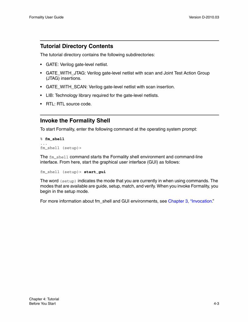
Formality User Guide Version D-2010.03
Tutorial Directory ContentsThe tutorial directory contains the following subdirectories:
• GATE: Verilog gate-level netlist.
• GATE_WITH_JTAG: Verilog gate-level netlist with scan and Joint Test Action Group (JTAG) insertions.
• GATE_WITH_SCAN: Verilog gate-level netlist with scan insertion.
• LIB: Technology library required for the gate-level netlists.
• RTL: RTL source code.
Invoke the Formality ShellTo start Formality, enter the following command at the operating system prompt:
% fm_shell...fm_shell (setup)>
The fm_shell command starts the Formality shell environment and command-line interface. From here, start the graphical user interface (GUI) as follows:
fm_shell (setup)> start_gui
The word (setup) indicates the mode that you are currently in when using commands. The modes that are available are guide, setup, match, and verify. When you invoke Formality, you begin in the setup mode.
For more information about fm_shell and GUI environments, see Chapter 3, “Invocation.”
Chapter 4: TutorialBefore You Start 4-3Chapter 4: TutorialBefore You Start 4-3

Formality User Guide D-2010.03Formality User Guide Version D-2010.03
Verify fifo.vg Against fifo.v
In this portion of the tutorial you verify a synthesized design named fifo.vg, which is a pure Verilog gate-level netlist, against an RTL reference design named fifo.v.
At any time, you can exit and save the current Formality session by executing the following command
fm_shell > save_session session_file_name
To invoke that session again, execute
fm_shell > restore_session session_file_name
Load Automated Setup FileBefore specifying the reference and implementation designs, you can optionally load an automated setup file (.svf) into Formality. The automated setup file helps Formality process design changes caused by other tools used in the design flow. Formality uses this file to assist the compare point matching and verification process. This information facilitates alignment of compare points in the designs that you are verifying. For each automated setup file that you load, Formality processes the content and stores the information for use during the name-based compare point matching period.
To load the automated setup file, do the following
fm_shell > set_svf svf_file_name.svf
Note: If you want to pass additional constraint and nonconstraint information from Design Compiler to Formality, set the automated setup mode before reading the automated setup file.
Note: This tutorial does not use an automated setup file, so this information is given here for reference only.
Chapter 4: TutorialVerify fifo.vg Against fifo.v 4-4

Formality User Guide Version D-2010.03
Specify the Reference DesignSpecifying the reference design involves the reading in of design files, optionally reading in technology libraries, and setting the top-level design.
The reference design is the design against which you compare the transformed (implementation) design. The reference design in this case is the RTL source file named fifo.v.
It is necessary to specify that the DesignWare root directory for fifo.v contains a DesignWare instantiated RAM block. As needed, enter getenv SYNOPSYS at the Formality prompt to obtain the path name of the root directory.
Set the search path to the RTL and LIBS directories as follows,
fm_shell > set hdlin_dwroot <path to DesignCompiler install>
Now load in all the reference Verilog files,
fm_shell > read_verilog -r { fifo.v gray2bin.v gray_counter.v
pop_ctrl.v push_ctrl.v rs_flop }
Note the reference does not need any specific technology file to which to map, so the top-level design for the reference can now be defined.
Setting the top-level design starts the linking and elaboration process on all files and reports if there are any missing files. Formality searches for the DesignWare RAM automatically:
fm_shell > set_top fifo
Specify the Implementation DesignThe procedure for specifying the implementation design is identical to that for specifying the reference design. In this case though, there is no need for a technology library to which to map.
fm_shell> read_db -i lsi_10k.db
We will use a Verilog gate-level design for the GATE directory to compare to the reference.
fm_shell > read_verilog -i GATE/fifo.vg
To define the top level of the implementation use this command:
fm_shell > set_top fifo
Chapter 4: TutorialVerify fifo.vg Against fifo.v 4-5Chapter 4: TutorialVerify fifo.vg Against fifo.v 4-5

Formality User Guide D-2010.03Formality User Guide Version D-2010.03
Set Up the DesignYou often need to specify additional setup information to account for designer knowledge not contained in the design netlist or to achieve optimal performance.
This step involves supplying information to Formality. For example, you might need to set constants if the design underwent transformations such as scan or JTAG insertion. In this case, only fifo.vg was synthesized; therefore, you can move on to the next step, Match.
For more information about setup possibilities, see Chapter 7, “Perform Setup.”
Match Compare PointsMatch compare points is the process by which Formality segments the reference and implementation designs into logical units, called logic cones. Each logic cone feeds a compare point, and each compare point in the implementation design must match each compare point in the reference design or else verification fails. Matching ensures that there are no mismatched logic cones and allows Formality to proceed with verifying the implementation design for functionality.
For conceptual information about compare points, see “Concept of Compare Points” on page 1-8. For more information about how Formality matches compare points, see Chapter 8, “Match Compare Points.”
To match compare points between fifo.v and fifo.vg, do the following:
fm_shell > match
Verify the DesignsTo verify the designs:
fm_shell > verify
In this case, verification fails. This test case includes a deliberate design error to introduce you to the debug capabilities of Formality.
Chapter 4: TutorialVerify fifo.vg Against fifo.v 4-6

Formality User Guide Version D-2010.03
DebugThe challenge for most users is debugging failed verifications. That is, you must find the exact points in the designs that exhibit the difference in functionality and then fix them.
Using the GUI for debuggin is much more intuitive. The following command invokes the GUI:
fm_shell > start_gui
Before proceeding with debugging in this tutorial, the next section briefly goes over some aspects of the GUI.
Graphical User InterfaceThis section explains how to use the graphical user interface in Formality in the following subsections:
• Main GUI Session Window
• Debug Through the GUI
• Verify fifo_with_scan.v Against fifo_mod.vg
• Verify fifo_jtag.v Against fifo_with_scan.v
• Debug Using Diagnosis
• For More Information
Main GUI Session WindowThe main GUI session window contains the following window areas, as shown in Figure 4-1.
Chapter 4: TutorialVerify fifo.vg Against fifo.v 4-7Chapter 4: TutorialVerify fifo.vg Against fifo.v 4-7

Formality User Guide D-2010.03Formality User Guide Version D-2010.03
Figure 4-1 GUI Session Window
The window areas are described as follows:
Window Area Description
Design bar Displays the path for the reference and implementation WORK libraries.
Menu bar GUI commands, some of which are duplicated in the toolbar and right-click options.
Toolbar Easy-access options to common GUI commands. The contents of the toolbar change depending on the view displayed in the context pane.
Menu bar Toolbar Flow-based toolbar
Context pane Command console Formality prompt
Design bar
Status bar
Chapter 4: TutorialVerify fifo.vg Against fifo.v 4-8

Formality User Guide Version D-2010.03
Debug Through the GUITo debug the implementation design, fifo.vg, take the following steps:
1. On the flow-based toolbar, click the Debug tab if it is not already selected.
The context pane displays the Failing Points report. Groups of failing points with similar names might appear, except for the last elements. For example, you might see *_[reg0], *_[reg1], *_[reg2], and *_[reg3]. Typically, a group of failing points is caused by a single error.
2. To run diagnosis on the failing points, click Analyze.
During diagnosis, Formality analyzes a set of compare points and finds the error candidates. When Formality completes the diagnosis run, the Error Candidates window appears displaying the error candidates found in your design.
Note: Although this is not shown in this tutorial, if while debugging you get an error stating there was a diagnosis failure due to too many errors (and you know the error is not caused by setup problems), select a group of failing points with similar names and click Diagnose Selected Points. This might help to direct diagnosis down to a specific section of the design.
Flow-based toolbar Options that indicate the correct flow to employ to perform formal verification. The options become highlighted to indicate where you are in the flow. Each option displays a new view in the context pane. By default, the GUI opens at the first step, Guidance, with the guidance work area displayed in the context pane.
When you use fm_shell to perform steps and then invoke the GUI, the GUI opens with the option highlighted to indicate where you are in the flow. This also occurs when you continue a previously saved Formality session.
Context pane The main working area. From here, you perform the actions necessary to perform verification. This is also where you view reports.
Command console Displays transcripts and other information, depending on the option selected below this area.
Formality prompt Text box that allows you to enter Formality prompts and environment variables that are not available through the GUI interface.
Status bar Current state of the tool.
Window Area Description
Chapter 4: TutorialVerify fifo.vg Against fifo.v 4-9Chapter 4: TutorialVerify fifo.vg Against fifo.v 4-9

Formality User Guide D-2010.03Formality User Guide Version D-2010.03
3. From the Error Candidates Window, right-click on the error U81 and select Show Logic Cones.
You see a list of related failing points for that error, from which you select one of those points (for this example, use push_logic/pop_count_svd_reg[0]) and then double-click it to bring up the logic cone.
The Cone Schematics window appears displaying reference (top screen) and implementation (bottom screen) schematics for the logic cone. It highlights and zooms to the error candidate inverter, U81, in the implementation cone. The reference schematic highlights the matching region corresponding to the error candidate in the implementation design.
The error candidate is highlighted in orange. The corresponding matching region in the reference design is highlighted in yellow. To view the error region in isolation, click Isolate Error Candidate Pruning Mode in the cone view. This prunes away all the logic and shows the error inverter.
This is done by selecting Edit > Isolate Error Candidates.
You can view the cone inputs that have been pruned away in the Pattern Window.
Colors in the schematics window have different meanings depending on the color mode selected. The color modes are none (the default), constants, simulation values, and error candidates.
• None – The default color mode.
• Constants – Nets with a constant logic value 0 are blue, nets with logic 1 are orange, and the remaining nets are gray. The remaining objects are colored in the default color mode.
• Simulation values – Nets with simulation logic 0 are blue, nets with simulation logic 1 are orange, and the remaining objects are colored in the default color mode.
• Error candidates – Error drivers corresponding to the error candidates are highlighted orange. The corresponding matching region is highlighted in yellow.
4. Observe the patterns annotated on the CLK net. The reference design shows logic 0, while the implementation design shows logic 1.
To discover the cause for this functional difference, take these steps:
• Select the net in the implementation design.
• Right-click and select Isolate Subcone.
• Select the net in the reference design.
• Right-click and select Isolate Subcone.
Chapter 4: TutorialVerify fifo.vg Against fifo.v 4-10

Formality User Guide Version D-2010.03
The screens change to display just the net in question. Notice that the logic driving the implementation CLK pin includes an inverter. During synthesis an inverter might have been inserted to fix hold time problems.
You can zoom in by clicking the Zoom In Tool toolbar option and then clicking in the schematic. Deselect the option to return to the pointer.
You can copy selected objects in design and cone schematics. From the context pane, you can highlight the object, select Edit, and then, from the Copy menu, select Instance Name, Library Name, or Design Name. You can paste these names into the Formality prompt or any other editable text box by pressing Control-v or by right-clicking the mouse and choosing Paste.
5. Fix the error by editing the netlist or resynthesizing the design to generate a new netlist free of errors in clock tree manipulations.
The fifo_mod.vg file in the GATE directory contains the corrected netlist. Execute the following command at the Formality prompt to view the difference:
% diff fifo.v fifo.mod.vg
You can see that the modified netlist removes the inverter.
6. After closing the Cone Schematics window, verify the corrected implementation design, fifo_mod.vg, against the reference design. First, specify fifo_mod.vg again as the new implementation design as follows:
• On the flow-based toolbar, click Implementation.
• From the Read Design Files tab, click the Verilog tab, and then click the Verilog option.
• Click Yes to remove the current implementation design data.
Note: Clicking Yes permanently removes the current implementation design data. In practice, you should save the data prior to specifying a new implementation (or reference) design.
• Navigate to the GATE subdirectory, and select the fifo_mod.vg file.
• Click Open.
• Click Load Files.
Skip the Read DB Libraries tab because the technology library is shared.
• Click the Set Top Design tab.
• Make sure that WORK and fifo are selected and click Set Top.
Chapter 4: TutorialVerify fifo.vg Against fifo.v 4-11Chapter 4: TutorialVerify fifo.vg Against fifo.v 4-11

Formality User Guide D-2010.03Formality User Guide Version D-2010.03
7. As before, skip the Setup step. In this case, you can also skip the Match step because you did not change the setup, which could alter compare points, and you did not appreciably change the implementation design by removing the inverter. In addition, you know that all the compare points matched previously.
8. From the Verify tab, click Verify.
Formality performs automatic compare point matching prior to verification when you do not perform the Match step beforehand. Verification is successful.
Now that you have completed this section of the tutorial, prepare the GUI as follows for the next section:
1. From the Designs menu, select Remove Reference, and then click Yes.
2. From the Designs menu, select Remove Implementation, and then click Yes.
Note:
Clicking Yes permanently removes the current reference and implementation data. In practice, be sure to save (as necessary) prior to removing design data.
3. At the Formality prompt, enter the following command:
remove_library -all
The transcript says Removed shared technology library ‘LSI_10K’.
You now have the equivalent of a fresh session with which to execute the next section of the tutorial.
Verify fifo_with_scan.v Against fifo_mod.vg
Note: At any time, you can exit and save the current Formality session by selecting File > Save Session. To invoke that session again, select File > Restore Session.
In this portion of the tutorial, you specify the successfully verified netlist, fifo_mod.vg, as the reference design. You then verify a design that went through a design transformation against it. The fifo_with_scan.v implementation design, as the name suggests, had scan logic inserted.
Chapter 4: TutorialVerify fifo_with_scan.v Against fifo_mod.vg 4-12

Formality User Guide Version D-2010.03
To go through the verification steps (reference, implementation, setup, match, verify, and debug) in one continuous flow, execute the following steps:
Note: In this tutorial, the load reference and implementation steps are done via the GUI. Though not typical, it is done this way here to show the GUI steps since it was done from the shell in the first tutorial section. Doing it from the fm_shell is left as an exercise for the user.
1. On the flow-based toolbar, click the Reference tab.
By default, the Read Design File tab and Verilog tab are active.
2. Click Verilog.
3. Navigate to the fifo_mod.vg file in the GATE directory, click Open, and then click Load Files.
4. Click the Read DB Libraries tab and make sure that the “Read as a shared library” option is selected.
Because this is a gate-to-gate verification, the technology library needs to be available for both fifo_mod.vg and fifo_with_scan.v. By default, DB technology libraries are shared.
If you use a Verilog or VHDL technology library, you must specify the read_verilog -tech or read_vhdl -tech command at the Formality prompt, because they are not shared libraries.
5. Click DB, then navigate to the technology library named lsi_10k.db in the LIB directory.
6. Click Open.
7. Click Load Files.
8. Click the Set Top Design tab and ensure that the fifo design inside the WORK library is selected as the top-level design.
9. Click Set Top.
Next you specify the implementation design, a procedure similar to the one described in “Specify the Implementation Design” on page 4-5.
10.On the flow-based toolbar, click the Implementation tab.
The Read Design Files and Verilog tab are selected by default.
11.Click Verilog.
12.In the Add Verilog Files dialog box, navigate to the fifo_with_scan.v design file located in the GATE_WITH_SCAN directory. Click Open.
13.Click Load Files.
Chapter 4: TutorialVerify fifo_with_scan.v Against fifo_mod.vg 4-13Chapter 4: TutorialVerify fifo_with_scan.v Against fifo_mod.vg 4-13

Formality User Guide D-2010.03Formality User Guide Version D-2010.03
14.Click the Set Top Design tab and make sure that the fifo design inside the WORK library is selected as the top-level design.
15.Click Set Top.
You skipped the Read DB Libraries step because you had previously specified lsi_10k.db as a shared technology library.
16.Click the Setup tab.
Unlike the verification you performed between fifo.vg and fifo.v, in which you skipped the setup phase, the implementation design you just specified must have its inserted scan disabled prior to verification.
17.Click the Constants tab, then click Set.
The Set Constant dialog box appears. It lists all the input, output, and bidirectional ports within the fifo_with_scan.v design file.
18.Click the Implementation tab and make sure that fifo is selected and that Ports appears in the dropdown box near the top of the display area. You may need to remove a check from the Hide Objects box for Inputs dialog box, if checked.
19.Scroll or search for the port named test_se and select it.
You can use the Search text box to locate the signal you want to change.
20.In the Constant Value area at the bottom of the dialog box, select 0, then click OK.
Setting the test signal, test_se, to a constant zero state disables the scan logic in the fifo_with_scan.v design file. Notice that test_se now appears in the Command console.
21.On the flow-based toolbar, click the Match tab, then click Run Matching.
Matching yields one unmatched compare point that you need to analyze and fix if necessary.
22.Click OK to remove the Information dialog box, and then select the Unmatched Points tab.
You see a report on the unmatched points, test_se, test_si1, and test_si2. These are extra compare points in the implementation design, related to the inserted scan that you previously disabled. In this case, extra compare points are expected in the implementation design. Therefore, you can ignore them and continue to the verification process.
Note: Extra compare points in the reference design are not expected. Therefore, you must debug them as outlined in “Debug” on page 4-7.
23.On the flow-based toolbar, click the Verify tab, then click Verify.
Chapter 4: TutorialVerify fifo_with_scan.v Against fifo_mod.vg 4-14

Formality User Guide Version D-2010.03
The verification is successful. The scan insertion did not alter the implementation design features. However, if you had not disabled the test signal test_se in step 19, verification would have failed.
Now that you have completed this section of the tutorial, prepare the GUI as follows for the next section:
1. From the Designs menu, select Remove Reference, and then click Yes.
2. From the Designs menu, select Remove Implementation, and then click Yes.
Note:
Clicking Yes permanently removes the current reference and implementation data. In practice, be sure to save prior to removing design data (as necessary).
3. At the Formality prompt, enter the following command:
remove_library -all
The transcript says “Removed shared technology library ‘LSI_10K’.”
This is now the equivalent of a fresh session with which to execute the next section of the tutorial.
Verify fifo_jtag.v Against fifo_with_scan.v
Next, you specify the successfully verified scan-inserted netlist, fifo_with_scan.v, as the reference design. You then verify a design that went through a different type of design transformation against it. The fifo_jtag.v implementation design includes a JTAG insertion and a scan insertion.
To go through the verification steps (reference, implementation, setup, match, verify, and debug) in one continuous flow, execute the following steps:
1. On the flow-based toolbar, click the Reference tab.
By default, the Read Design File tab and Verilog tab are active.
2. Click Verilog.
The Add Verilog Files dialog box appears.
3. Navigate to the fifo_with_scan.v file in the GATE_WITH_SCAN directory, highlight it, and click Open.
4. Click Load Files.
5. From the Read DB Libraries tab, make sure that the “Read as a shared library” option is selected.
Chapter 4: TutorialVerify fifo_jtag.v Against fifo_with_scan.v 4-15Chapter 4: TutorialVerify fifo_jtag.v Against fifo_with_scan.v 4-15

Formality User Guide D-2010.03Formality User Guide Version D-2010.03
Because this is a gate-to-gate verification, the technology library needs to be available for both the fifo_with_scan.v and fifo_jtag.v files.
6. Click DB, and then navigate to and highlight the technology library file, lsi_10k.db, in the LIB directory. Click Open.
7. Click Load Files.
8. From the Set Top Design tab, make sure that the fifo design inside the WORK library is selected as the top-level design, then click Set Top.
9. On the flow-based toolbar, click the Implementation tab.
10.From the Verilog tab, click Verilog.
The Add Verilog Files dialog box appears.
11.Navigate to the fifo_jtag.v design file located in the GATE_WITH_JTAG directory, highlight it, and click Open.
12.Click Load Files.
13.From the Set Top Design tab, ensure that the fifo design inside the WORK library is selected as the top-level design and click Set Top.
Notice that because of the inserted JTAG modules listed at the top of the choose-a-design pane, it might be necessary to scroll down to find the fifo design.
Note: If the wrong design is accidentally set as the top-level design, it is necessary to redefine the implementation (or reference) design by first removing the reference and implementation designs and starting again.
The Read DB Libraries step is skipped as lsi_10k.db was previously specified as a shared technology library.
14.On the flow-based toolbar, click the Setup tab.
For this verification, disable the scan in fifo_with_scan.v just as in the previous section of the tutorial. Remember that this design is now the reference design. It is also necessary to disable JTAG signals in the implementation design.
15.From the Constants tab, click Set.
The Set Constant dialog box appears with the Reference tab selected.
16.Make sure that fifo is selected and that Ports appears in the dropdown box near the top of the display area.
17.Scroll or search for the port named test_se and select it.
If necessary, use the Search text box to locate the signal that needs to be changed.
18.In the Constant Value area at the bottom of the dialog box, select 0 and click Apply.
Chapter 4: TutorialVerify fifo_jtag.v Against fifo_with_scan.v 4-16

Formality User Guide Version D-2010.03
19.Click the Implementation tab and make sure that fifo is selected and that Ports appears in the drop down box near the top of the display area.
20.Repeat steps 17 and 18 to disable the test_se test signal for the implementation design.
21.In a similar process, disable the JTAG signals, jtag_trst, and jtag_tms, by setting them to constant 0. Click OK to close the dialog box.
The Constants report lists the four disabled signals, one for the reference design and three for the implementation design.
22.On the flow-based toolbar, select the Match tab and then click Run Matching.
Matching yields 171 unmatched compare points that you must analyze and fix, if necessary.
23.Click OK to close the Information dialog box.
24.From the Unmatched Points tab, evaluate the compare points.
You see that the extra compare points are located in the implementation design and related to the inserted JTAG that you previously disabled. Specifically, JTAG insertion results in the addition of a large logic block called a tap controller. Therefore, extra compare points are expected in the implementation design. You can ignore them and move on to verification.
25.On the flow-based toolbar, click the Verify tab, then click Verify.
The verification is successful. The JTAG insertion did not alter the implementation design features.
Debug Using DiagnosisIn some designs, you can reach a point where you have fixed all setup problems in your design or determined that no setup problems exist. Therefore, the failure must have occurred because Formality found functional differences between the implementation and reference designs.
Use the following steps to isolate the problem (assuming that you are working in the GUI).
1. On the flow-based toolbar, click the Debug tab.
2. Click the Failing Points tab to view the failing points.
During verification, Formality creates a set of failing patterns for each failing point. These patterns show the differences between the implementation and reference designs. Diagnosis is the process of analyzing these patterns and identifying error candidates that might be responsible for the failure. Sometimes the design can have multiple errors and, therefore, an error candidate can have multiple locations.
Chapter 4: TutorialVerify fifo_jtag.v Against fifo_with_scan.v 4-17Chapter 4: TutorialVerify fifo_jtag.v Against fifo_with_scan.v 4-17

Formality User Guide D-2010.03Formality User Guide Version D-2010.03
3. Run a diagnosis on all of the failing points listed in this window by clicking Analyze.
Note: After clicking Analyze, you might get a warning (FM-417) stating that too many error locations caused the diagnosis to fail (if the error locations exceed five). If this occurs and you have already verified that no setup problems exist, select a group of failing points (such as a group of buses with common names), and click Diagnose Selected Points. This can help the diagnosis by paring down the failing points to a specific section in the design. Finally, if the group diagnosis fails, select a single failing point and run the selected diagnosis.
When the diagnosis is complete, the Error Candidate window appears.
4. Click the Error Candidates tab to view the error candidates.
You see a list of error candidates in this window. An error candidate can have multiple distinct errors associated with it. For each of the errors, the number of related failing points is reported.
There can be alternate error candidates apart from the recommended ones shown in this window. You can inspect the alternate candidates by using Next and Previous. You can reissue the error candidate report anytime after running the diagnosis by using the report_error_candidates command.
5. Select an error with the maximum number of failing points. Right-click that error, and then select View Logic Cones.
If there are multiple failing points, a list appears, from which you can choose a particular failing point to view. Errors are the drivers to the design whose function can be changed to fix the failing compare point.
The schematic shows the error highlighted in the implementation design along with the associated matching region of the reference design.
Note: Changing the function of an error location can sometimes cause previously passing input patterns to fail.
Examine the logic cone for the driver causing the failure. The problem driver is highlighted in orange. To view the error region in isolation, click Isolate Error Candidates Pruning Mode. You can also prune the associated matching region of the reference design. You can undo this pruning mode by choosing the Undo option from the Edit menu.
Note: You can employ the previous diagnosis method by setting the diagnosis_enable_error_isolation variable to false and then rerunning the verification.
Chapter 4: TutorialVerify fifo_jtag.v Against fifo_with_scan.v 4-18

Formality User Guide Version D-2010.03
For More Information
For more information about each stage of the formal verification process demonstrated in the tutorial, see the following chapters:
• Chapter 3, “Invocation,” which describes the user interfaces and describes how to invoke the tool.
• Chapter 6, “Load Designs,” which describes how to read in designs and libraries, and how to define the reference and implementation designs.
• Chapter 7, “Perform Setup,” which describes how to set design-specific parameters to help Formality perform verification and to optimize your design for verification.
• Chapter 8, “Match Compare Points,” which describes how to match compare points.
• Chapter 9, “Run Verify and Interpret Results,” which describes how to perform verification.
• Chapter 10, “Debug Verification,” which describes diagnostic procedures that can help you locate areas in the design that caused failure.
• Chapter 11, “Library Verification Mode,” which describes how to compare two technology libraries.
• Appendix A, “Tcl Syntax as Applied to Formality Shell Commands,” which describes Tcl syntax as it relates to more advanced tasks run from fm_shell. Topics include application commands, built-in commands, procedures, control flow commands, and variables.
• Appendix B, “Reference Lists,” which provides reference tables listing Formality application commands and environment variables.
Chapter 4: TutorialFor More Information 4-19Chapter 4: TutorialFor More Information 4-19

Formality User Guide D-2010.03Formality User Guide Version D-2010.03
Chapter 4: TutorialFor More Information 4-20

5Guidance 5
The chapter includes the following sections:
• What is Guidance?
• Basic Usage
• Advanced Usage
5-1

Formality User Guide D-2010.03Formality User Guide Version D-2010.03
What is Guidance?
Guidance is the process by which an implementation tool, such as Design Compiler, provides setup information to the verification tool Formality. This is supplied in the form of an automated setup file (.svf), an approach that has the benefit of providing the information automatically.
Guidance helps Formality understand and process design changes caused by other tools that were used in the design flow. Formality uses this information to assist compare point matching and correctly set up verification without user intervention. It eliminates the need to enter setup information manually, a task that is time consuming and error prone. For example, during synthesis, the phase of a register might be inverted. This change is recorded in the automated setup file. When you read the automated setup file into Formality, the tool can account for the phase inversion during compare point matching and verification.
Figure 5-1 outlines the timing of the load guidance step in the Formality design verification process flow. This chapter focuses on how to load guidance into Formality.
Chapter 5: GuidanceWhat is Guidance? 5-2

Formality User Guide Version D-2010.03
Figure 5-1 Load Guidance in the Design Verification Process Flow
InterpretResults
PerformSetup
RunVerify
Success?No
Yes
Done
MatchCompare Points
LoadReference
LoadImplementation
Debug
StartFormality
LoadGuidance
Debug
StartFormality
Chapter 5: GuidanceWhat is Guidance? 5-3Chapter 5: GuidanceWhat is Guidance? 5-3

Formality User Guide D-2010.03Formality User Guide Version D-2010.03
Basic Usage
Note that loading your automated setup file information and enabling the Automated Setup Mode is an important part of the process which comes before these steps. These steps are discussed in detail in Chapter 3, “Invocation.”
This section on guidance basics is broken into the following topics:
• Create an Automated Setup File
• Automated Setup Mode
• Read Automated Setup File
• Guidance Summary
Create an Automated Setup FileThe first step in the automated setup flow is to create the automated setup file during synthesis. Both Design Compiler and Presto record data in the automated setup file that Formality can use. Next, instruct Formality to read this file at the start of the verification process.
You would usually obtain an automated setup file from other tools, such as Design Compiler. In Design Compiler, you can write out an automated setup file that describes the design changes. Design Compiler automatically creates an automated setup file called default.svf during a synthesis session.
To change the name of the file, use the set_svf Design Compiler command as follows:
dc_shell> set_svf myfile.svf
When Presto or Design Compiler performs an optimization that Formality needs to know about, the relevant Formality guidance commands are added to the automated setup file. If you choose to use the set_svf command to specify the name of the automated setup file, you must do this before optimization takes place. Otherwise, those optimizations are not written to the user-specified automated setup file.
To append the setup information to an existing automated setup file, use the following syntax:
dc_shell> set_svf -append myfile2.svf
You can use the -append argument if you compile a design using multiple invocations of Design Compiler. You may want to keep all the setup information in a single file rather than using a separate automated setup file for each Design Compiler invocation.
Chapter 5: GuidanceBasic Usage 5-4

Formality User Guide Version D-2010.03
Automated Setup ModeTo use automated setup mode, the synopsys_auto_setup variable must be set to true before the set_svf command is used. If the synopsys_auto_setup variable is set to true, the following Formality variables will be set as follows:
You can override any individual variable setting of the automated setup mode by manually setting any of those variables after the synopsys_auto_setup variable has been set.
Note: If the verification_verify_directly_undriven_output variable is set to true (default), Formality will verify directly undriven output ports, which will typically fail verification. In a Synopsys synthesis/verification flow, directly undriven output ports are typically created for later insertion of scan test circuitry. Usually, it is desired not to verify these undriven output ports.
By setting the verification_verify_directly_undriven_output variable to false, Formality will ignore (and not verify) the directly undriven output ports. Formality issues the set_dont_verify -directly_undriven_output command at the beginning of the match phase. This prevents these undriven outputs in the reference design from causing a failing verification. Formality ignores them.
Formality can automatically use setup information provided by Design Compiler, including clock-gating recognition and scan insertion disabling.
hdlin_ignore_parallel_case = false
hdlin_ignore_full_case = false
verification_set_undriven_signals = 0:X
hdlin_error_on_mismatch_message = false
svf_ignore_unqualified_fsm_information = false (only changed when there are guide_fsm_reencoding commands in the automated setup file)
verification_verify_directly_undriven_output = true
Chapter 5: GuidanceBasic Usage 5-5Chapter 5: GuidanceBasic Usage 5-5

Formality User Guide D-2010.03Formality User Guide Version D-2010.03
Formality recognizes the following commands if they appear in the automated setup file when the synopsys_auto_setup variable is set to true before the set_svf command is issued:
If clock gating is inserted by Design Compiler or Power Compiler, a guide_environment command is issued by Design Compiler to the automated setup file. Formality will set the value of the verification_clock_gate_hold_mode variable to the any value.
Formality will always use the following variable values in the guide_environment command in the automated setup file regardless of the automated setup mode setting:
guide_environment
guide_scan_input
guide_port_constant
bus_dimension_separator_style
bus_extraction_style
bus_naming_style
bus_range_separator_style
hdl_naming_threshold
hdlin_array_instance_naming_style
hdlin_cell_naming_style
hdlin_generate_naming_style
hdlin_generate_separator_style
hdlin_sv_packages
hdlin_while_loop_iterations
template_naming_style
template_parameter_style
template_separator_style
hdlin_dyn_array_bnd_check (only if synopsys_auto_setup is set to true)
Chapter 5: GuidanceBasic Usage 5-6

Formality User Guide Version D-2010.03
Any of the variable values changed by the synopsys_auto_setup variable can be changed by the user after the set_svf command is completed and will retain the user-defined values.
Designs compiled using Design Compiler version Z-2007.03 and later contain the automated setup file commands mentioned above. To ensure setup is complete, synopsys_auto_setup must be set to true before issuing the set_svf command.
A summary report will be generated and included in the Formality transcript listing all non-default variable settings and external constraint information passed via the automated setup file.
Read Automated Setup FileTo read an automated setup file into Formality, use the set_svf command. You must read in the automated setup file before you read in any design data. Formality uses the information in the setup file during matching as well as verification. Formality automatically converts these binary files into text. It creates a directory named formality_svf which will contain a text file named svf.txt representing all automated setup files read in and also any subdirectories for any automated setup file netlists that you encounter.
The following example reads in the automated setup file, myfile.svf.
fm_shell> set_svf myfile.svfSVF set to '/home/my/designs/myfile.svf'.1fm_shell>
The set_svf command returns 1 if the command succeeds or 0 if the command fails. If you use the set_svf command without specifying the automated setup file (.svf) to use, Formality resets the automated setup file. However, the appropriate method for removing the stored setup data is to use the remove_guidance command.
Note: You can also invoke the set_svf command from the Guidance tab in the GUI.
Chapter 5: GuidanceBasic Usage 5-7Chapter 5: GuidanceBasic Usage 5-7
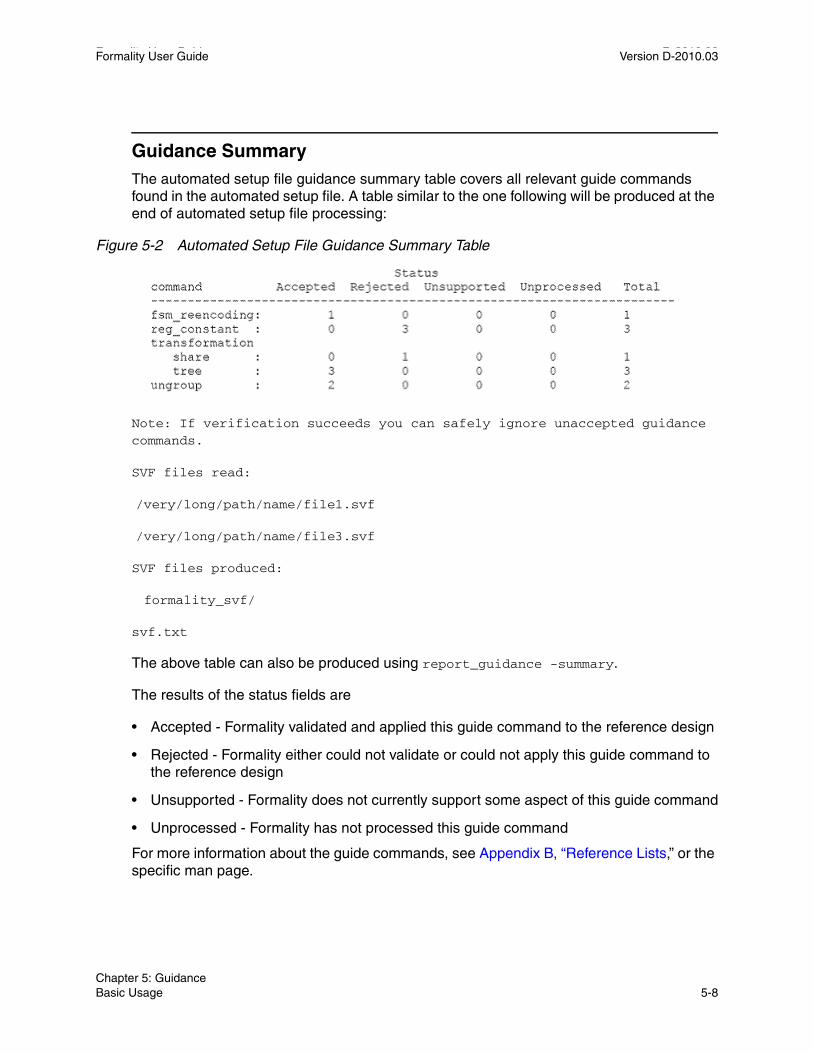
Formality User Guide D-2010.03Formality User Guide Version D-2010.03
Guidance SummaryThe automated setup file guidance summary table covers all relevant guide commands found in the automated setup file. A table similar to the one following will be produced at the end of automated setup file processing:
Figure 5-2 Automated Setup File Guidance Summary Table
Note: If verification succeeds you can safely ignore unaccepted guidance commands.
SVF files read:
/very/long/path/name/file1.svf
/very/long/path/name/file3.svf
SVF files produced:
formality_svf/
svf.txt
The above table can also be produced using report_guidance -summary.
The results of the status fields are
• Accepted - Formality validated and applied this guide command to the reference design
• Rejected - Formality either could not validate or could not apply this guide command to the reference design
• Unsupported - Formality does not currently support some aspect of this guide command
• Unprocessed - Formality has not processed this guide command
For more information about the guide commands, see Appendix B, “Reference Lists,” or the specific man page.
Chapter 5: GuidanceBasic Usage 5-8

Formality User Guide Version D-2010.03
Advanced Usage
This section on guidance details is broken into the following topics:
• Guidance Directory/File Structure
• Guidance Reports
• Guidance Messages
• Read in Multiple Guidance Files
• Automated Setup File Conversion to Text
Guidance Directory/File StructureRegardless of the number of .svf files read in, Formality will create a single auto-decrypted text automated setup file (svf.txt) which represents the ordered automated setup file guide commands read in. All messages related to guide commands generated will reference this file. This file, along with all decrypted dwsvf netlists, will be placed under a single directory (formality_svf) in the current working directory.
Users can easily examine the automated setup file contents if needed. In addition, if test cases are ever required, a single directory will contain all the relevant guide commands and associated netlist directories.
The name of the formality_svf directory will be tied to the name of the formality.log file and will follow the same numbering suffix that it uses. The integer number will always match that of the formality.log file, for example:
set_svf foo1.svf foo2.svf foo3.svf
Formality will create:
formality.logformality_svf/
svf.txtnetlists/……
The formality_svf directory is self-contained and can be moved elsewhere without need of modification.
Chapter 5: GuidanceAdvanced Usage 5-9Chapter 5: GuidanceAdvanced Usage 5-9

Formality User Guide D-2010.03Formality User Guide Version D-2010.03
Guidance ReportsSeveral commands in Formality aid in reporting automated setup file information.
find_svf_operation:
The find_svf_operation command takes guidance command names and automated setup file processing status as arguments and returns a list of operation IDs.
Usage:
find_svf_operation # Get a list of automated setup file operation IDs
[-command ](Find operations of the specified command type(s))
[-status ](Find operations with the specified status(es))
For command arguments, use what is found in the automated setup file summary table. Note that you do not include the guide_ prefix. When specifying transformation types, simply use the values map, tree, share, or merge.
For status arguments, use one of the following values: unprocessed, accepted, rejected, unsupported, or unaccepted.
Refer to the man page for details on find_svf_operation.
report_svf_operation:
The report_svf_operation command will take a list of operation IDs and produce information regarding the same.
Usage:
report_svf_operation # Report information about specified operations
[-command] List of guide_* commands for which to search of ID numbers for commands that have the specified status
[-status] List of ID numbers for commands that have the specified status
[-guide] Report only the guide command itself
[-message] Report only the messages associated with the operation
Chapter 5: GuidanceAdvanced Usage 5-10

Formality User Guide Version D-2010.03
Refer to the man page for details on the report_svf_operation command.
report_guidance:
There are two main uses of the report_guidance command.
1.) It produces a summary table.
This is the same as what is produced automatically after automated setup file processing.
report_guidance -summary
2.) It produces a user-defined text version of the automated setup file.
report_guidance -to ascii.svf.txt
This version is very similar to the automatically generated formality_svf/svf.txt file but not formatted exactly the same way. For this reason using this file is not a reliable way to correlate error messages for the current run, but it could be used as input for any subsequent runs.
Guidance MessagesAt the end of the load guidance step, the information generated by Formality is available to you in a number of different formats. The information is output as a summary table or in a log file.
Automated Setup File MessagingThe automated setup file flow information in Formality is correlated in a summary table and all relevant information is stored in a single directory (formality_svf). Any messages produced via report commands or in the formality.log file will reference line numbers/operations within the single svf.txt file automatically produced in the formality_svf directory.
[-summary] Report a summary table of the specified operations
operationID_list List of operation ID numbers
Chapter 5: GuidanceAdvanced Usage 5-11Chapter 5: GuidanceAdvanced Usage 5-11

Formality User Guide D-2010.03Formality User Guide Version D-2010.03
Automated Setup File Diagnostic MessagesFormality places detailed automated setup file diagnostic messages in the formality.log file. Only messages pertaining to unaccepted guidance are produced and the line numbers correspond to line numbers in the formality_svf/svf.txt file.
The following example is a formality.log file message:
SVF Operation 4 (line 47) - fsmInfo: Cannot find reference cell 'in_cur_reg[3]'.
Read in Multiple Guidance FilesThe commands in the automated setup files describe transformations in an incremental way. The transformations occur in the order in which the commands were applied as the RTL design was processed through design implementation or optimization. Therefore, the ability to read in multiple automated setup files is important because no command in the file can be viewed completely independently. It describes the incremental transformation and relies on the context in which it is applied.
You can read multiple automated setup files into Formality using the set_svf command. To read multiple automated setup files, use the following syntax:
fm_shell> set_svf mysvf1.svf mysvf2.svf mysvf3.svf
You can use the -ordered option to indicate that the list of automated setup files you specify is already ordered and that timestamp should not reorder them. If you use the -ordered option and list a directory or directories where the setup files are located, Formality can order the directory files in any order.
The following example sets the order of two automated setup files, bot.svf and top.svf, for Formality to process:
set_svf -ordered bot.svf top.svf
You can use the -extension option to load and automatically order all matching files in the directory you define, based on the extension that you define. For example, Formality automatically looks for files with the .svf extension. If you have automated setup files in a directory with extensions other than .svf, you use this option to instruct Formality to read and order those files with that extension. The ordering of the files is done using time stamp information typically found in the setup file header. Formality does not require the time stamp information to be in the header and can use specific guide commands for passing time stamp information directly.
Chapter 5: GuidanceAdvanced Usage 5-12

Formality User Guide Version D-2010.03
The following example instructs Formality to load and order setup files ending in fm in the fmdir directory:
set_svf -extenstion fm fmdir
Automated Setup File Conversion to TextFor every run, Formality will create the formality_svf/svf.txt file which is a concatenated version of all svf that have been read in. This file is to be used to correlate any messages produced during the run.
Formality can also be instructed to convert automatically the encrypted automated setup file information into ASCII text in place during the execution of the set_svf command. That is, a decrypted automated setup file has the suffix .txt appended to the original file name in the original file location. To do this, enable the following variable which is disabled by default.
Set svf_auto_decrypt to true.
Chapter 5: GuidanceAdvanced Usage 5-13Chapter 5: GuidanceAdvanced Usage 5-13

Formality User Guide D-2010.03Formality User Guide Version D-2010.03
Chapter 5: GuidanceAdvanced Usage 5-14

6Load Designs 6
This chapter contains the following sections:
• Introduction
• Basic Usage
• Advanced Usage
Figure 6-1 outlines the placing of loading reference and implementation designs in Formality’s design verification process flow. This chapter focuses on loading designs into Formality.
6-1

Formality User Guide D-2010.03Formality User Guide Version D-2010.03
Figure 6-1 Loading Designs in the Design Verification Process Flow
InterpretResults
PerformSetup
RunVerify
Success?No
Yes
Done
MatchCompare Points
LoadReference
LoadImplementation
Debug
StartFormality
LoadGuidance
Debug
StartFormality
Chapter 6: Load Designs6-2

Formality User Guide Version D-2010.03
Introduction
This section describes some of the necessary setup processes that you must do prior to loading the reference and implementation designs. This section contains the following subsections:
• Load Design Steps
• Top-Level Design
• Concept of Containers
Load Design StepsThis section describes the steps you use to load in your libraries and designs. Specific commands are described in the sections that follow.
Figure 6-2 expands upon the relevant portion of Figure 6-1 to elaborate the steps involved in the load reference and load implementation process flow in Formality.
Chapter 6: Load DesignsIntroduction 6-3Chapter 6: Load DesignsIntroduction 6-3

Formality User Guide D-2010.03Formality User Guide Version D-2010.03
Figure 6-2 Formality Read Design Process Flow
To run Formality, you must read in both a reference and an implementation design and any related technology libraries. Note, optionally, you can first pass additional setup information from Design Compiler to Formality by using the automated setup file information via set_svf and/or automated setup file mode as described in Chapter 5, “Guidance.”
ReadTechnology
Libraries
ReadTechnology
Libraries
ReadReferenceDesigns
ReadImplementation
Designs
SetTop-Level
Design
SetTop-Level
Design
LoadReference
LoadImplementation
Chapter 6: Load DesignsIntroduction 6-4

Formality User Guide Version D-2010.03
As shown in Figure 6-2, you first read in the libraries and designs that are needed for the reference, and then immediately specify its top-level design. You must set the top-level design for the reference design before proceeding to the implementation design. Next, you read in the libraries and designs that you need for the implementation design, and then immediately specify its top-level design.
Top-Level Design Specifying the top-level design causes Formality to resolve named references, which is crucial for proper verification. This linking process appears in the transcript window. If Formality cannot resolve references, the tool issues a link error by default. When Formality resolves all references, linking is completed successfully. If the design is an RTL (VHDL or Verilog) design, Formality then performs elaboration.
You can use the hdlin_unresolved_modules environment variable to cause Formality to create black boxes when it encounters unresolved or empty designs during linking.
Concept of ContainersA container is a complete, self-contained space into which Formality reads designs. It is typical for one container to hold the reference design while another holds the implementation design. In general, you do not need to concern yourself with containers. You simply load designs in as either reference or implementation. This is described in “Load Reference Design” on page 6-7.
A container typically includes a set of related technology libraries and design libraries that fully describe a design that is to be compared against another design. A technology library is a collection of parts associated with a particular vendor and design technology. A design library is a collection of designs associated with a single design effort. Designs contain design objects such as cells, ports, nets, and pins. A cell can be a primitive or an instance of another design.
Figure 6-3 and Figure 6-4 illustrate the concept of containers.
Chapter 6: Load DesignsIntroduction 6-5Chapter 6: Load DesignsIntroduction 6-5

Formality User Guide D-2010.03Formality User Guide Version D-2010.03
Figure 6-3 Containers in a Hierarchical Design
In general, to perform a design comparison, you should load all of the information about one design into a container (the reference), and all the information about the other design into another container (the implementation).
You can create, name, reuse, delete, open, and close containers. In some cases, Formality automatically creates a container when you read data into the Formality environment.
Each container can hold many design and technology libraries, and each library can hold many designs and cells. Components of a hierarchical design must reside in the same container. Figure 6-4 illustrates this concept.
Figure 6-4 Containers
In Formality, one container is always considered the current container. Unless you specifically set the current container, Formality uses the last container into which a design is read. That container remains the current container until you specifically change it or you create a new container. Many Formality commands operate on the current container by default (when you do not specify a specific container).
For more information about containers, see “Set Up and Manage Containers” on page 6-19.
Design objects
Design
Design library
Container
Cells
NetsPorts
Pins
Completedesign
information
ContainerDesignFilesDesign
Files
DesignFilesDesign
FilesDesignlibraries
TechnologyTechnology
Technologylibraries
Chapter 6: Load DesignsIntroduction 6-6

Formality User Guide Version D-2010.03
Basic Usage
Loading designs into Formality consists of three main steps:
• Load the technology libraries (optional, as needed)
• Load the design files
• Set the top-level block to compare
These three steps are done for both the reference and implementation designs and are nearly identical in process. This section is, therefore, broken into the following two subsections, with most of the details captured solely in the load reference design section.
• Load Reference Design
• Load Implementation Design
Load Reference Design This section describes in detail the steps required for loading the reference design, as shown in Figure 6-2. These steps include reading the technology libraries, reading the reference designs, and setting the top-level design.
Read Technology LibrariesAs needed, read in the technology libraries that support your reference design. If you do not specify a technology library name with the commands described in the following section, Formality uses the default name, TECH_WORK.
Read Synopsys (.db) FormatSynopsys internal database (.db) library files are shared by default. If you read in a file without specifying whether it applies to the reference or implementation design, it applies to both.
Chapter 6: Load DesignsBasic Usage 6-7Chapter 6: Load DesignsBasic Usage 6-7

Formality User Guide D-2010.03Formality User Guide Version D-2010.03
To read cell definition information contained in .db files, do the following
Formality can read in other formats as technology libraries, see “Read SystemVerilog, Verilog, and VHDL Cell Definition.” on page 6-13 for details.
Read DesignsRead a reference design into Formality based on the language that represents it. At it's most basic, do one of the following (where the -r option indicates the reference design)
For more information about the fm_shell command options, see the man pages.
In the Formality shell, you represent the design hierarchy by using a designID argument. The designID argument is a path name whose elements indicate the container (by default, r or i), library, and design name.
fm_shell
Specify:
read_db file_list
[-libname library_name ]
[-merge ]
[-replace_black_box ]
fm_shell
Specify one of the following, depending on your design type:
read_verilog -r files
read_sverilog -r files
read_vhdl -r files
read_ddc -r files
read_milkyway -r files
read_db -r files
Chapter 6: Load DesignsBasic Usage 6-8

Formality User Guide Version D-2010.03
Read in Verilog and SystemVerilog DesignsVerilog and SystemVerilog descriptions information must be in the form of synthesizable RTL or a structural netlist.
When reading in Verilog designs, you can use the hdlin_auto_netlist variable to specify that Formality automatically use the Verilog netlist reader. The default is to use the netlist reader. Using the Verilog netlist reader can decrease loading times. If the Verilog netlist reader is unsuccessful, Formality uses the default Verilog reader.
Use the VCS options -v and -y if you have Verilog simulation libraries or design modules you want to link to the reference or implementation designs. These options tell Formality to search in the specified library or file for unresolved module references. These options do not support Verilog technology library cells with mixed user-defined primitives and synthesizable constructs.
fm_shell
Specify:
read_verilog
[-r | -i | -con containerID ]
[-libname library_name ]
[-netlist ]
[-01 ] [-95 ] file_list
or
read_sverilog
[-r | -i | -con containerID ]
[-technology_libname ]
[-libname library_name ]
[-01 ] [-95 ] file_list
Chapter 6: Load DesignsBasic Usage 6-9Chapter 6: Load DesignsBasic Usage 6-9

Formality User Guide D-2010.03Formality User Guide Version D-2010.03
Read in VHDL DesignsVHDL cell definition information must be in the form of synthesizable RTL or a structural netlist.
When you specify more than one VHDL file to be read with a single read_vhdl command, Formality automatically attempts to read your files in the correct order. If the list of files includes VHDL configurations, this feature does not work. Disable it by setting the hdlin_vhdl_strict_libs variable to false before using the read_vhdl command. If you are using multiple read_vhdl commands, you must issue them in the correct compilation order.
Read in .ddc DesignsTo read design netlists and technology libraries from .ddc databases, you use the read_ddc command. This command allows Formality to read design information, including netlists and technology libraries, from .ddc databases produced by Design Compiler.
To read designs from a .ddc database into a container, do the following
Formality reads in files formatted as Synopsys .ddc database designs. Formality returns a 1 if the design is successfully read; it returns a 0 if the design is not successfully read into the destination container. In situations where existing designs are present in the destination container, Formality overwrites them with the designs being read.
fm_shell
Specify:
read_vhdl
[-r | -i | -con containerID ]
[-libname library_name ]
[-87 | -93 ]
file_list
fm_shell
Specify:
read_ddc
[-r | -i | -container containerID ]
[-libname library_name ]
[-technology_library ] file_list
Chapter 6: Load DesignsBasic Usage 6-10

Formality User Guide Version D-2010.03
Read in Milkyway DesignsTo read design netlists and technology libraries from Milkyway, you use the read_milkyway command. This command allow Formality to read design information, including netlists and technology libraries, from Milkyway databases produced by Astro.
Use the mw_logic0_net and mw_logic1_net variables to specify the name of the Milkyway ground and power net, respectively.
Read in .db DesignsSee “Read Synopsys (.db) Format” on page 6-7 for information on reading in .db design files.
Set Top-Level DesignTo set the top-level design for the reference design, do the following
If you are elaborating VHDL and you have more than one architecture, use the -vhdl_architecture option.
fm_shell
Specify:
read_milkyway
[-r | -i | -container containerID ]
[-libname library_name ]
[-technology_library ]
[-version version_number ]
-cell_name mw_cell_name
mw_db_path
fm_shell
Specify:
set_top
[-vhdl_arch name ]
[moduleName | designID | -auto ]
[-parameter value ]
Chapter 6: Load DesignsBasic Usage 6-11Chapter 6: Load DesignsBasic Usage 6-11

Formality User Guide D-2010.03Formality User Guide Version D-2010.03
The set_top command tells Formality to set and link the top-level design. If you are using the default r and i containers, this command also sets the top-level design as the reference or implementation design.
For additional information about setting parameters, see “Set Top-Level Design” on page 6-15.
Load Implementation DesignThis section provides an overview of the read-design process flow for the implementation design. The process for loading the implementation design is broadly similar to that described in “Load Reference Design” on page 6-7. See that section for more information.
Note: If you already specified a .db library for the reference design, it is automatically shared with the implementation design.
Many Formality shell commands can operate on either the reference or implementation design. These commands all have a switch to indicate which design container is used for that command. The -r switch refers to the reference design or container. The -i switch refers to the implementation design or container. Reading the implementation design uses the same procedures and commands as reading the reference design, only the switch is different. You can use the -i option to specify the implementation container or use the -c container_name option to provide a specific container name. From within the GUI, use the Implementation tab to read an implementation design.
For information about the fm_shell commands and their options, see the man pages. For information about special Verilog considerations, see “Verilog Simulation Data” on page 6-14. Otherwise, if you have Verilog simulation data, use the -vcs options with the read_verilog command.
Advanced Usage
There is a range of optional functionality available to you through use of the containers into which the Formality designs are read. The Setup Free Flow also allows you to control certain variables. The functionality associated with these options are discussed under the following headings
• Read Technology Libraries
• Set Top-Level Design
• Set Up and Manage Containers
• Variables Controlled by Setup Free Flow
Chapter 6: Load DesignsAdvanced Usage 6-12

Formality User Guide Version D-2010.03
Read Technology LibrariesSystemVerilog, Verilog, and VHDL cell definition information must be in the form of synthesizable RTL or a structural netlist. In general, Formality cannot use behavioral constructs or simulation models, such as VHDL VITAL models.
Note: Unlike .db files, SystemVerilog, Verilog, and VHDL technology files are not shared. You must read them in for the reference design and then for the implementation design by including the -r and -i options, respectively.
Use of 'celldefine Verilog AttributeWhen reading libraries in Formality, you use the ‘celldefine Verilog attribute to indicate that a logic description is a library cell. This attribute might be necessary to take advantage of the extra processing needed to build the correct logical behavior. However, because ‘celldefine is not required by Verilog, many libraries do not include it in the source file. Using it would require modifications to your source file, which is not always possible. The hdlin_library_files and hdlin_library_directory variables provide you with an easier mechanism for defining a library to Formality.
Read SystemVerilog, Verilog, and VHDL Cell DefinitionTo read cell definition information contained in SystemVerilog, Verilog, or VHDL RTL files, do the following
fm_shell
Specify:
set hdlin_library_file file
set hdlin_library_directory directory
read_verilog
[-r | -i | -con containerID ]
[-technology_library ]
[-libname library_name ]
[-01 ] [-95 ] file_list
or
Chapter 6: Load DesignsAdvanced Usage 6-13Chapter 6: Load DesignsAdvanced Usage 6-13

Formality User Guide D-2010.03Formality User Guide Version D-2010.03
The hdlin_library_file variable designates all designs contained within a file or set of files as technology libraries. The value you set for this variable is a space-delimited list of files.
The hdlin_library_directory variable designates all designs contained within directories as technology libraries. The value you set for this variable is a space-delimited list of directories. After you mark a design for library processing, any subdesign would also go through that processing.
The fm_shell commands are not listed with all their options. The options listed in this table pertain to reading in technology library data only. For more information about the options, see the man pages.
Use the -technology_library option to specify that the data goes into a technology library rather than a design library. This option does not support mixed Verilog and VHDL technology libraries. When you specify the -technology_library option, you must also specify -r, -i, or -c.
read_sverilog
[-r | -i | -con containerID ]
[-technology_library ]
[-libname library_name ]
[-01 ] [-95 ] file_list
or
read_vhdl
[-r | -i | -con containerID ]
[-technology_library ]
[-libname library_name ]
[-87 | -93 ]
file_list
fm_shell
Chapter 6: Load DesignsAdvanced Usage 6-14

Formality User Guide Version D-2010.03
Verilog Simulation DataYou generally read in Verilog simulation libraries by specifying VCS options with the read_verilog command when you read in designs, as discussed in “Read Designs” on page 6-8.
To read cell definition information contained in Verilog simulation library files, do the following
The reader extracts the pertinent information from the Verilog library to determine the gate-level behavior of the design and generates a functional description of the Verilog library cells.
To generate the gate-level models, the reader parses the Verilog modules and user-defined primitive descriptions. With this information it creates efficient gate-level models that can be used for verification.
A Verilog simulation library is intended for simulation, not synthesis. Therefore, the reader might make certain assumptions about the intended gate-level functions of the user-defined primitives in the simulation model. The reader generates comprehensive warning messages about these primitives to help you eliminate errors and write a more accurate model.
Each warning message is identified by a code. To obtain more information, look at the man page for the code. For example, if Formality reports ‘Error: Can’t open file xxxx (FM-016),’ you can obtain more information by entering the command man FM-016.
The library reader supports the following features
• Sequential cells (each master-slave element pair is merged into a single sequential element)
• Advanced net types: wand, wor, tri0, tri1, and trireg
• Unidirectional transistor primitives: pmos, nmos, cmos, rpmos, rnmos, and rcmos
• Pull primitives (a pull-up or pull-down element is modeled as an assign statement with a value of 1 or 0)
fm_shell
Specify:
read_verilog -tech -vcs “VCS options”
Chapter 6: Load DesignsAdvanced Usage 6-15Chapter 6: Load DesignsAdvanced Usage 6-15
Formality User Guide D-2010.03Formality User Guide Version D-2010.03
Library Loading OrderFormality has the ability to load and manage multiple definitions of a cell, such as synthesis .db files, simulation .db files, and Verilog/VHDL netlists. The order in which the library files are loaded determines which library model is used by Formality. If the libraries are not loaded in the correct sequence, it can lead to inconsistent or incorrect verification results.
If you are a library provider, you should deliver explicit Formality loading instructions for multiple libraries. One way to do this is to provide a Formality script that loads the library files (such as .db, .v, and .vhd) in the proper order.
Single-Source PackagingIt is better to provide all the required functionality in a single source, either a synthesis (.db) or simulation (.v) file. Using a single source reduces support costs and maintenance requirements. However, you might choose to use multiple sources of functional information.
Multiple-Source PackagingIf you are a silicon vendor who wants to use multiple library sources or augment your synthesis libraries with simulation or RTL descriptions, you should specify the order in which the libraries are to be loaded.
Set Top-Level DesignWhen setting the top-level design, be aware of the following factors:
• After you start reading in a reference or implementation design, you must finish before specifying the set_top command. In addition, you cannot start reading in the implementation design until you have specified set_top for the reference design.
• The set_top command always applies to the design data just previously read into Formality (whether it is the implementation or reference design). You receive an error if you specify a design that you have not loaded.
• You cannot save, restore, or verify a design until you have specified the set_top command.
• Be sure that the module or design you specify is your top design. If not, you must remove the reference design and start over. This also holds true when you are loading the implementation design.
• Use the -auto option if the top-level design is unambiguous. You generally specify a module or design by name in cases where you do not want the actual top-level design to be considered the top for the current session or when you have multiple modules that could be considered at the top level.
Chapter 6: Load DesignsAdvanced Usage 6-16

Formality User Guide Version D-2010.03
• Set the top-level design to the highest level you plan to work with in the current session.
• After you set the top-level design, you cannot change it, whereas you can change the reference or implementation design to be verified with the set_reference_design, set_implementation_design, or verify command. The design you specify must reside within the top-level design.
If you have straightforward designs, such as Verilog designs, you can use the hdlin_auto_top environment variable rather than the set_top command to specify and link the top-level module, but only when you specify one and only one read_verilog command for the container.
To set the top-level design with the hdlin_auto_top variable, do the following
The hdlin_auto_top variable causes Formality to determine the top-level module and automatically link to it. This variable applies only when you are reading in a Verilog design. If you are reading in technology libraries, Formality ignores this variable.
Formality issues an error if it cannot determine the top-level design. In this case, you must explicitly specify the top design with the set_top command.
If there are multiple VHDL configurations or architectures that could be considered the top level, Formality issues a warning and sets the top-level design to the default architecture.
The hdlin_auto_top variable requires you to use a single read command to load the design. You cannot use it for mixed-language designs or for designs that use multiple design libraries or multiple architectures or configurations.
Set Parameters on Top-Level DesignTo set parameters in your top-level design, use the -parameters option to the set_top command. Use this option to specify a new value for your design parameters. You can set the parameter only on the top-level design. Parameters must be Verilog parameters or VHDL generics on the design you are setting them on. The parameter values can either be integers or specified in the format <param_name> <hex value format> <base>’h<value>.
fm_shell
Specify:
set hdlin_auto_top true
Chapter 6: Load DesignsAdvanced Usage 6-17Chapter 6: Load DesignsAdvanced Usage 6-17

Formality User Guide D-2010.03Formality User Guide Version D-2010.03
For VHDL designs, the generics might have the following data types for the parameter value:
For additional information about setting parameters, see the set_top man page.
Generate Simulation/Synthesis Mismatch ReportYou can generate a report on any simulation/synthesis mismatches in your design after setting the top level of your design. Formality automatically generates an RTL report summary describing any simulation/synthesis mismatches when you run set_top (or read_container). Running the report_hdlin_mismatches command after set_top (or read_container) generates a verbose report detailing the various constructs encountered and their state. For more information about reporting simulation/synthesis mismatches, see the report_hdlin_mismatches man page.
Link Automatically Top-Level DesignIf you have straightforward designs, such as Verilog designs, you can use the hdlin_auto_top environment variable rather than the set_top command to specify and link the top-level module, but only when you specify one and only one read_verilog command for the container.
integer
bit
bit_vector
std_ulogic
std_ulogic_vector
std_logic
std_logic_vector
signed (std_logic_arith and numeric_std)
unsigned (std_logic_arith and numeric_std)
Chapter 6: Load DesignsAdvanced Usage 6-18

Formality User Guide Version D-2010.03
To set the top-level design with the hdlin_auto_top variable, do the following
The hdlin_auto_top variable causes Formality to determine the top-level module and automatically link to it. This variable applies only when you are reading in a Verilog design. If you are reading in technology libraries, Formality ignores this variable. Formality issues an error if it cannot determine the top-level design. In this case, you must explicitly specify the top design with the set_top command. If there are multiple VHDL configurations or architectures that could be considered the top level, Formality issues a warning and sets the top-level design to the default architecture.
The hdlin_auto_top variable requires you to use a single read command to load the design. You cannot use it for mixed-language designs or for designs that use multiple design libraries or multiple architectures or configurations
Set Up and Manage ContainersAs described in “Concept of Containers” on page 6-5, a container is a complete, self-contained space into which Formality reads designs. Each design to be verified must be stored in its own container. If you follow the steps described in “Read Technology Libraries” on page 6-7, Formality uses default containers named r and i.
You generally do not need to work directly with containers; however, Formality allows you the option if, for example,
• You want to read your reference and implementation designs into names you specify rather than the default r and i
• You require backwards compatibility with existing Formality scripts
• You apply user-defined external constraints on your designs
Note: The r and i containers exist by default, even if empty. When you specify them as the container ID with the create_containers command, Formality issues a warning that the container already exists.
fm_shell
Specify:
set hdlin_auto_top true
Chapter 6: Load DesignsAdvanced Usage 6-19Chapter 6: Load DesignsAdvanced Usage 6-19
Formality User Guide D-2010.03Formality User Guide Version D-2010.03
To create a container, do the following
Formality uses the containerID string as the name of the new container. If using this command, you must do so before reading in your libraries and designs.
Alternatively, you can specify a container with the -con containerID option to the read_db, read_ddc, read_milkyway, read_sverilog, read_verilog, or read_vhdl command. If you specify a container ID in which to place a technology library, the library can be seen only in that container. This is called an unshared technology library. If you do not specify a container, the technology library can be seen in all current and future containers. This is called a shared technology library. Only the read_db command can be used to read shared technology libraries.
When you create a new container, Formality automatically puts the generic technology (GTECH) library into the container. The GTECH library contains the cell primitives that Formality uses internally to represent RTL designs.
In fm_shell, Formality considers one design to be the current design. When you create or read into a container, it becomes the current container.
After the current container is set, you cannot operate on any other container until you either:
• Specify set_top for the current container
• Specify remove_container to remove the container and its contents. For the default r and i containers, this command merely removes the contents
In the GUI, the concept of a current container does not apply directly. You simply work on the reference and implementation designs. You can execute Formality shell commands that rely on the current container concept. However, the GUI recognizes only the containers that store the reference and implementation designs. To view a third design in the GUI, you must choose it as a reference or implementation design.
Note: When you create a new container, Formality automatically adds any shared technology libraries. If you do not want a particular shared technology library in the new container, you must specifically remove it.
fm_shell
Specify:
create_container
[containerID]
Chapter 6: Load DesignsAdvanced Usage 6-20

Formality User Guide Version D-2010.03
The write_container and save_session commands will not be executed if you have not used the set_top command to link the top-level design.
In the GUI, you can view the reference and implementation containers by choosing Designs > Show Reference and Designs > Show Implementation. To save the design, choose File > Save.
Variables Controlled by Setup Free FlowThere are a number of variables that are controlled by setup free flow. These are discussed under the following headings
• Variables to Control Bus Names
• Variables to Control Parameter Names
• Variables to Control Case Behavior
Variables to Control Bus NamesThe following variables are used to control bus names
bus_dimension_separator_styleFormality will always use the bus_dimension_separator_style value in the guide_environment command in the automated setup file regardless of the automated setup mode setting.
bus_extraction_styleFormality will always use the bus_extraction_style value in the guide_environment command in the automated setup file regardless of the automated setup mode setting.
bus_range_separator_styleFormality will always use the bus_range_separator_style value in the guide_environment command in the automated setup file regardless of the automated setup mode setting.
Variables to Control Parameter NamesThe following variables are used to control parameter names
hdlin_naming_thresholdFormality will always use the hdlin_naming_threshold value in the guide_environment command in the automated setup file regardless of the automated setup mode setting.
Chapter 6: Load DesignsAdvanced Usage 6-21Chapter 6: Load DesignsAdvanced Usage 6-21

Formality User Guide D-2010.03Formality User Guide Version D-2010.03
template_naming_styleFormality will always use the template_naming_style value in the guide_environment command in the automated setup file regardless of the automated setup mode setting.
template_parameter_styleFormality will always use the template_parameter_style value in the guide_environment command in the automated setup file regardless of the automated setup mode setting.
template_separator_starFormality will always use the template_separator_star value in the guide_environment command in the automated setup file regardless of the automated setup mode setting.
Variables to Control Case BehaviorThe following variables are used to control case behavior
hdlin_ignore_parallel_caseIf synopsys_auto_setup variable is set to true, the hdlin_ignore_parallel_case variable is set to false.
hdlin_ignore_full_caseIf synopsys_auto_setup variable is set to true, the hdlin_ignore_full_case variable is set to false.
svf_ignore_unqualified_fsm_informationIf synopsys_auto_setup variable is set to true, the svf_ignore_unqualified_fsm_information variable is set to false.
Chapter 6: Load DesignsAdvanced Usage 6-22

7Perform Setup 7
After reading designs into the Formality environment and linking them, you generally need to set design-specific options to help Formality perform verification. For example, if you are aware of certain areas in a design that Formality cannot verify, you might want to prevent the tool from attempting to verify those areas. Or, if you want to speed up verification, you might declare blocks in two separate designs black boxes.
This chapter points out aspects you should consider in order to optimize your design for verification.
This chapter includes the following sections:
• Common Operations
• Less Common Operations
Figure 7-1 outlines the timing of performing setup within the design verification process flow. This chapter focuses on how to perform setup in Formality.
7-1

Formality User Guide D-2010.03Formality User Guide Version D-2010.03
Figure 7-1 Performing Setup in the Design Verification Process Flow Overview
InterpretResults
PerformSetup
RunVerify
Success?No
Yes
Done
MatchCompare Points
LoadReference
LoadImplementation
Debug
StartFormality
LoadGuidance
Debug
StartFormality
Chapter 7: Perform Setup7-2
Formality User Guide Version D-2010.03
Common Operations
The are a number of operations that are commonly carried out as part of the general setting up of the tool.
This section includes the following subsections:
• Black Boxes
• Constants
• External Constraints
• Combinational Design Changes
• Sequential Design Changes
• Retimed Designs
• Low Power Designs
Black BoxesA black box represents logic whose function is unknown. Black boxes can cause verification failures because input pins become compare points in the design. If black boxes found in the reference design do not match those found in the implementation design, compare points will not match.
In addition, compare point mismatches can occur when black box buses are not normalized in the same manner. When Formality encounters a missing design, it normalizes the bus on the black box to the form WIDTH-1:0. However, when it encounters an empty design, it does not normalize black box buses, and bus indexes are preserved. Therefore, you must either not include a design or use an empty design for both the implementation and the reference design so that buses are normalized in a like manner.
When Formality verifies a design, its default action is to consider a black box in the implementation design equivalent to its counterpart in the reference design. This behavior can be misleading in cases where designs contain many unintentional black boxes, such as in an implementation design that uses black boxes as bus holders to capture the last state placed on a bus. Figure 7-2 shows an example.
Chapter 7: Perform SetupCommon Operations 7-3Chapter 7: Perform SetupCommon Operations 7-3

Formality User Guide D-2010.03Formality User Guide Version D-2010.03
Figure 7-2 Black Boxes
In this example a bidirectional pin is used to connect to the bus. Because this pin is bidirectional, the bus has an extraneous driver. If the reference design does not use similar bus holders, the implementation design fails verification. To solve this problem, you can declare the direction “in.” Assigning the pin a single direction removes the extraneous driver.
By default, Formality stops processing and issues an error if it encounters unresolved designs (those that cannot be found during the linking process) and empty designs (those with an interface only). For example, suppose a VHDL design has three instances of designs whose logic is defined through associated architectures. If the architectures are not in the container, Formality halts.
You can use the hdlin_unresolved_modules environment variable to cause Formality to create black boxes when it encounters unresolved or empty designs during linking. For more information about this variable, see the man page.
Note: Setting the hdlin_unresolved_modules variable to black box can cause verification problems.
The verification_ignore_unmatched_implementation_blackbox_input variable can be used to cause Formality to allow successful verification of unmatched input pins on matched black boxes in the implementation design. For more information about this variable, see the man page.
Because of the uncertainty that black boxes introduce to verification, Formality allows you some control over how the tool handles them. You can
• Load only the design interface (ports and directions) even though the model exists
• Mark a design as a black box for verification even though its model exists and the design is linked
• Report a list of black boxes
Bus holder
Bidirectional pin
Blackbox
Chapter 7: Perform SetupCommon Operations 7-4

Formality User Guide Version D-2010.03
• Perform an identity check between comparable black boxes
• Set the port and pin directions
These techniques are described in the following sections.
Load Design InterfacesIf you know you want an object to be a black box, specify the hdlin_interface_only environment variable rather than loading nothing into Formality. Formality benefits from having the pin names and directions supplied by this variable.
Note: Specify the hdlin_interface_only variable before reading in your designs.
To load only the pin names and directions for designs, do one of the following
The hdlin_interface_only environment variable allows you to load the specified designs as black boxes, even when their models exist. This capability is useful for loading in RAM, intellectual property (IP), and other special models. When you specify report_black_boxes, these designs are attributed with an “I” (interface only) to indicate that you specified this variable.
This variable supports wildcard characters. It ignores syntax violations within specified designs. However, if Formality cannot create an interface-only model due to syntax violations in the pin declarations, it treats the specified design as missing.
Modules names must be simple design names. For example, to mark all RAMs named SRAM01, SRAM02, and so on in a library as black boxes, use the following command:
fm_shell (setup)> set hdlin_interface_only “SRAM*”
This variable is not cumulative. Subsequent specifications cause Formality to override prior specifications. Therefore, if you want to mark all RAMs with names starting with DRAM* and SRAM* as black boxes, for example, specify both on one line.
fm_shell (setup)> set hdlin_interface_only “DRAM* SRAM*”
fm_shell GUI
Specify:
set hdlin_interface_only "designs"
1. Click Reference or Implementation.
2. Click Options.
3. Click the Variables tab.
4. In the “Read interface only for these designs” box, enter list of designs.
5. Click OK.
Chapter 7: Perform SetupCommon Operations 7-5Chapter 7: Perform SetupCommon Operations 7-5

Formality User Guide D-2010.03Formality User Guide Version D-2010.03
Mark a Design as a Black Box for VerificationTo mark a design as a black box for verification, do one of the following
You specify this command for a loaded design. When you specify report_black_boxes, these designs are attributed with an “S” to indicate that you specified this command. To remove this attribute, use the remove_black_box command.
The set_black_box command allows you to specify the designs that you want to mark as black boxes. The designs that you specify with the hdlin_interface_only variable on unresolved references always retain their black box attribute.
Note: It is also possible to mark a design as a black box through the hierarchy browser. This can be done by searching the hierarchy browser to locate and select the design to be black-boxed. Then you set the block as black_box from the GUI by clicking on the appropriate symbol (shaped like a black chip) on the same hierarchy browser.
Report Black BoxesTo report black boxes, do one of the following
By default, this command lists the black boxes for both the reference and implementation designs. Formality issues an error if these are not set. You can restrict the report to only the implementation or reference design, or to a container or design that you specify.
In addition, the report lists a reason, or attribute, code for each black box, as follows
fm_shell GUI
Specify:
set_black_box designID
At the Formality prompt, specify:
set_black_box designID
fm_shell GUI
Specify:
report_black_boxes
[design_list | -r | -i |
-con containerID ] [-all ]
[-unresolved ] [-empty ]
[-interface_only ]
[-set_black_box ]
At the Formality prompt, specify:
report_black_boxes
[design_list | -r | -i |
-con containerID ] [-all ]
[-unresolved ] [-empty ]
[-interface_only ]
[-set_black_box ]
Chapter 7: Perform SetupCommon Operations 7-6

Formality User Guide Version D-2010.03
• U: Unresolved design.
• E: Empty design. An asterisk (*) next to this code indicates that the design is not linked by the set_top command. Once linked, the design might show up as a black box if it is not really empty.
• I: Interface only, as specified by the hdlin_interface_only variable.
• S: Set with the set_black_box command.
You can report only black boxes of a certain attribute by using the -unresolved, -empty, -interface_only, and -set_black_box options. The default -all option reports all four black box types.
The report output during set_top processing also lists black boxes.
Note: Formality places black boxes created due to unresolved designs in the FM_BBOX library.
Perform Identity ChecksTo perform an identity check between two comparable black boxes, do one of the following
The verification_blackbox_match_mode variable causes Formality to perform an identity check between each set of two comparable black boxes, ensuring that both black boxes have the same library and design names. For more information about this variable, see the man page.
Set Pin and Port Directions for Unresolved Black BoxesBy definition, you do not know the function of a black box. For unresolved black boxes, Formality attempts to define pin direction from the connectivity and local geometries. If the tool cannot determine the direction, it assumes that the pin is bidirectional. This assumption could result in an extra driver on a net in one design that does not exist in the other.
fm_shell GUI
Specify:
set verification_blackbox_match_mode identity
1. Choose Edit > Formality Tcl Variables or the Modify Formality Tcl Variables toolbar option.The Formality Tcl Variable Editor dialog box appears.
2. From Matching, select the verification_blackbox_match_mode variable.
3. Select Identity.
4. Choose File > Close.
Chapter 7: Perform SetupCommon Operations 7-7Chapter 7: Perform SetupCommon Operations 7-7
Formality User Guide D-2010.03Formality User Guide Version D-2010.03
To circumvent this failure, you can create a wrapper for the block with the pin directions defined. You can use a Verilog module or VHDL entity declaration. This takes the guesswork out of determining pin direction. You can also use the set_direction command to define pin direction.
To redefine a black box pin or port direction, do one of the following
For objectID, supply the object ID for an unlinked port or pin. (You cannot set the direction of a linked port or pin.) For direction, specify either in, out, or inout. For more information, see the man page.
ConstantsFormality recognizes two types of constants: design and user-defined. Design constants are nets in your design that are tied to a logic 1 or 0 value. User-defined constants are ports or nets to which you attach a logic 1 or 0 value, using Formality commands.
User-defined constants are especially helpful when several problem areas exist in a circuit and you want to isolate a particular trouble spot by disabling an area of logic. For example, suppose your implementation design has scan logic and you do not want to consider it in the verification process. You can assign a constant to the scan-enable input port to disable the scan logic and take it out of the verification process.
You can apply a user-defined constant to a port or net. However, if you assign a constant to a net with a driver, Formality displays a warning message.
Formality tracks all user-defined constants and enables you to generate reports on them. You can specify how Formality propagates constants through different levels of the design hierarchy.
You can manage user-defined constants by performing the tasks in the following sections.
fm_shell GUI
Specify:
set_direction
objectID direction
At the Formality prompt, specify:
set_direction
objectID direction
Chapter 7: Perform SetupCommon Operations 7-8

Formality User Guide Version D-2010.03
Define ConstantsTo set a net, port, cell, or pin to a constant state of 0 or 1, do one of the following
For constant_value, specify either 0 or 1. If more than one design object shares the same name as that of the specified object, use the -type option and specify the object type (either port or net). You can specify an object ID or instance-based path name for instance_path. Use the latter if you want to apply a constant to a single instance of an object instead of all instances. In addition, you can use wildcards to specify objects to be set constant. For more information about the remove_constant command, see the man page.
Remove User-Defined ConstantsTo remove a user-defined constant, do one of the following
If more than one design object shares the same name as that of the specified object, use the -type option and specify port or net (whichever applies) for the type. You can specify an object ID or instance-based path name for object_ID. Use the latter if you want to remove a constant on a single instance of an object instead of all instances. For more information about this command, see the man page.
fm_shell GUI
Specify:
set_constant [-type type ]
instance_path constant_value
1. Choose Setup > Constants.
2. Click Set, and choose the Reference or Implementation tab.
3. Navigate through the tree view to the instance and select it.
4. Click Apply.
fm_shell GUI
Specify:
remove_constant -all
or
remove_constant
[-type ID_type ] object_ID ...
1. Choose Setup > Constants.
2. Select a constant.
3. Click Remove.
Chapter 7: Perform SetupCommon Operations 7-9Chapter 7: Perform SetupCommon Operations 7-9

Formality User Guide D-2010.03Formality User Guide Version D-2010.03
List User-Defined ConstantsTo list user-defined constants, do one of the following
If you omit instance_path, Formality returns a list of all user-defined constants. You can specify an object ID or instance-based path name for instance_path. Each line of the report shows the constant value, design object type, and design object name. For information about this command, see the man page.
Report Setup StatusTo report design statistics, design read warning messages and user specified setup, use the report_setup_status command.
By default, the report_setup_status command lists the critical design setup before running the match and verify commands. You can run this command anytime after reading and linking both the reference and implementation designs.
Use the report_setup_status -design_info command to report design specific settings that are set using the set command and statistics.
Use the report_setup_status -hdl_read_messages command to report the warning information messages that are issued by Formality during design read and linking.
Use the report_setup_status -commands command to report the user-specified setup.
When you do not use any of the available options with the report_setup_status command, a consolidated report with all the information is generated.
fm_shell GUI
Specify:
report_constants
[instance_path ... ]
Choose Setup > Constants.
fm_shell GUI
Specify:
report_setup_status
[-design_info]
[-hdl_read_messages]
[-commands]
At the Formality prompt, specify:
report_setup_status
[-design_info]
[-hdl_read_messages]
[-commands]
Chapter 7: Perform SetupCommon Operations 7-10

Formality User Guide Version D-2010.03
External ConstraintsSometimes you might want to restrict the inputs used for verification by setting an external constraint. By setting an external constraint, you can limit the potential differences between two designs by eliminating unused combinations of input values from consideration, thereby reducing verification time and eliminating potential false failures that can result from verification with the unconstrained values.
When you define the allowed values of, and relationships between, primary inputs, registers, and black box outputs, and allow the verification engine to use this information, the resulting verification is restricted to identify only those differences between the reference and implementation designs that result from the allowed states.
Typical constraint types that you can set are
• One-hot: One control point at logic 1; others at logic 0.
• One-cold: One control point at logic 0; others at logic 1.
• Coupled: Related control points always at the same state.
• Mutually exclusive: Two control points always at opposite states.
• User-defined: You define the legal state of the control points.
The following paragraphs describe three cases where setting external constraints within verification is important.
In the most common case, your designs are part of a larger design, and the larger design defines the operating environment for the designs under verification. You want to verify the equivalence of the two designs only within the context of this operating environment. By using external constraints to limit the verification to the restricted operating conditions, you can eliminate the false negatives that can arise out of the functions not exercised.
In the second case, one of the designs you want to verify was optimized under the assumption that some control point conditions cannot occur. The states outside the assumed legal values can be true don’t care conditions during optimization. If the equivalent behavior does not occur under these invalid stimulus conditions, false negatives can arise during verification. Setting the external constraints prevents Formality from marking these control points as false negatives under these conditions.
In the third case, you want to constrain the allowed output states for a black box component within the designs being verified. Using external constraints eliminates the false negatives that can arise if the black box component is not constrained to a subset of output state combinations.
Chapter 7: Perform SetupCommon Operations 7-11Chapter 7: Perform SetupCommon Operations 7-11

Formality User Guide D-2010.03Formality User Guide Version D-2010.03
You can set and remove external constraints, create and remove constraint types, and report information about the constraints you have set.
Define an External ConstraintTo define an external constraint, do one of the following
For type_name, supply the type of external constraint you want to use. For control_point_list, specify the list of control points (primary inputs, registers, and black box outputs) to which the constraint applies. Use designID to specify a particular design; the default is the current design. For more information about the set_constraint command, see the man page.
Create a Constraint TypeTo create a user-defined (arbitrary) constraint type and establish the mapping between the ports of a design that define the constraint and control points in the constrained design, do one of the following:
For type_name, specify the type of constraint. For designID, specify a particular design; otherwise, the default is the current design. For more information about this command, see the man page.
fm_shell GUI
Specify:
set_constraint type_name
[-name constraint_name
[-map map_list1 map_list2 ]
constraint_type
control_point_list [designID]
At the Formality prompt, specify:
set_constraint type_name
[-name constraint_name
[-map map_list1 map_list2 ]
constraint_type
control_point_list [designID]]
fm_shell GUI
Specify:
create_constraint_type
type_name
[designID ]
At the Formality prompt, specify:
create_constraint_type
type_name
[designID ]
Chapter 7: Perform SetupCommon Operations 7-12

Formality User Guide Version D-2010.03
User-defined constraints allow you to define the allowable states of the control points by specifying a constraint module. The constraint module is a design you create that determines whether the inputs are legal (care) or illegal (don’t care) states. When the output of the constraint module evaluates to 1, the inputs are in a legal state. For information about don’t care cells, see “Concept of Consistency and Equality” on page 1-10.
When you later reference the user-defined constraint from the set_constraint command, Formality automatically hooks the constraint module design into the target of the set_constraint command and uses the output of the module to force the verification to consider only the legal states for control points.
A constraint module has the following characteristics:
• One or more inputs and exactly one output
• Outputs in logic 1 for a legal state; otherwise logic 0
• No inouts (bidirectional ports)
• No sequential logic
• No three-state logic
• No black boxes
Remove an External ConstraintTo remove an external constraint from the control points of a design, do one of the following:
For constraint_name, specify the name of the constraint to remove. For more information about this command, see the man page.
fm_shell GUI
Specify:
remove_constraint
constraint_name
At the Formality prompt, specify:
remove_constraint
constraint_name
Chapter 7: Perform SetupCommon Operations 7-13Chapter 7: Perform SetupCommon Operations 7-13

Formality User Guide D-2010.03Formality User Guide Version D-2010.03
Remove a Constraint TypeTo remove external constraint types, do one of the following
For type_name, specify the type of user-defined constraint to remove. For more information about this command, see the man page.
Report Constraint InformationTo report information about the constraints set in your design, do one of the following
For constraint_name, specify the name of the constraint for which you want to obtain a report. For more information about this command, see the man page.
Report Information About Constraint TypesTo report information about constraint types set in your design, do one of the following
For more information about report_constraint_type command, see the man page.
fm_shell GUI
Specify:
remove_constraint_type type_name
At the Formality prompt, specify:
remove_constraint_type type_name
fm_shell GUI
Specify:
report_constraint
[-long ] constraint_name
At the Formality prompt, specify:
report_constraint
[-long ] constraint_name
fm_shell GUI
Specify:
report_constraint_type
[-long ] type_name
At the Formality prompt, specify:
report_constraint_type
[-long ] type_name
Chapter 7: Perform SetupCommon Operations 7-14

Formality User Guide Version D-2010.03
Combinational Design ChangesThis section describes how to prepare designs that have undergone a combinational transformation. Special attention is required if your design contains combinational design changes, such as
• Internal scan insertions
• Boundary-scan insertions
• Clock tree buffers
Your design can also include sequential transformations. For more information, see “Sequential Design Changes” on page 7-18.
Disable Scan LogicInternal scan insertion is a technique used to make it easier to set and observe the state of registers internal to a design. During scan insertion, scan flops replace flip-flops. The scan flops are then connected into a long shift register. The additional logic added during scan insertion means that the combinational function has changed, as shown in Figure 7-3.
Figure 7-3 Internal Scan Insertion
data_in
clk
DD D QQ Q data_out
data_in
clk
DD D QQ Q data_outscan_in
scan_en
scan_outsise
sosi siso sose se
Pre-Scan
Post-Scan
Chapter 7: Perform SetupCommon Operations 7-15Chapter 7: Perform SetupCommon Operations 7-15

Formality User Guide D-2010.03Formality User Guide Version D-2010.03
After determining which pins disable the scan circuitry, disable the inserted scan logic by specifying the disabling value (either 0 or 1) with the set_constant command. For more information, see the procedure in “Define Constants” on page 7-9.
Disable Boundary Scan in Your DesignsBoundary scan is similar to internal scan in that it involves the addition of logic to a design. This added logic makes it possible to set and observe the logic values at the primary inputs and outputs (the boundaries) of a chip, as shown in Figure 7-4. Boundary scan is also referred to as the IEEE 1149.1 Std. specification.
Figure 7-4 Boundary-Scan Insertion
Designs with boundary-scan registers inserted require setup attention because
• The logic cones at the primary outputs differ
• The boundary-scan design has extra state-holding elements
Boundary scan must be disabled in your design in the following cases:
• If the design contains an optional asynchronous TAP reset pin (such as TRSTZ or TRSTN), use set_constant on the pin to disable the scan cells.
• If the design contains only the four mandatory TAP inputs (TAS, TCK, TDI, and TDO), force an internal net of the design with the set_constant command. For example,
fm_shell (setup)> set_constant gates:/WORK/TSRTS 0fm_shell (setup)> set_constant gates:/WORK/alu/somenet 0
Specify 0 for the set_constant command, as described in the procedure in “Define Constants” on page 7-9.
data 1
data 2
data 3
out1
out2
out3
data 1
data 2
data 3
out1
out2
out3Tapcontroller
Before Boundary Scan After Boundary Scan
D Q
D Q
D Q
Chapter 7: Perform SetupCommon Operations 7-16

Formality User Guide Version D-2010.03
Manage Clock Tree BufferingClock tree buffering is the addition of buffers in the clock path to allow the clock signal to drive large loads, as shown in Figure 7-5.
Figure 7-5 Clock Tree Buffer
Without setup intervention, verification of blocka fails (note, however, that it would succeed with top down verification). As shown in the figure, the clock pin of ff3 is clk in the prebuffer design, while in the postbuffer design the clock pin of ff3 is clk3. The logic cones for ff3 are different, resulting in a failing point.
To counteract clock tree buffering, you must use the set_user_match command to specify that the buffered clock pins are equivalent. With the set_user_match command you can match one object in the reference design to multiple objects in the implementation design (1-to-n matching). For example, if you want to match a clock port, clk, in the reference design to three clock ports in the implementation design, clk, clk1, and clk2, you can use
set_user_match r: /WORK/design/clk i:/WORK/design/clk i:/WORK/
design/clk1 i:/WORK/design/clk2
Alternatively, you can issue multiple commands for each port in the implementation:
set_user_match r: /WORK/design/clk i:/WORK/design/clkset_user_match r: /WORK/design/clk i:/WORK/design/clk1set_user_match r: /WORK/design/clk i:/WORK/design/clk2
If you know a clock port is inverted, use the -inverted option to the set_user_match command. Therefore, if your reference design had a clock port, clk, and your implementation design had a clk port and an inverted clock port, clk_inv, you would use the following command:
clk
clk
clk
clk
ff1
ff2
ff3
QD
QD
QD
blocka
topBefore Buffering After Buffering
clk1
clk3
clk2
ff1
ff2
ff3
QD
QD
QD
blockaclk
clk_buf
top
Chapter 7: Perform SetupCommon Operations 7-17Chapter 7: Perform SetupCommon Operations 7-17

Formality User Guide D-2010.03Formality User Guide Version D-2010.03
set_user_match r:/WORK/design/clk i:/WORK/design/clkset_user_match -inverted r:/WORK/design/clk i:/WORK/design/clk_inv
For more information about the set_user_match command, see the man page.
Sequential Design ChangesLike the combinational design changes described in “Combinational Design Changes” on page 7-15, sequential design changes also require setup prior to verification. Sequential design changes include:
• Clock gating
• Pushing inversions across registers
• Retiming
FSM re-encoding and module retiming are also considered sequential design changes. For more information, see “Re-Encoded Finite State Machines” on page 7-32 and “Retimed Designs” on page 7-24.
Set Clock GatingClock gating can be used to implement load enable signals in synchronous registers. It results in more power-efficient circuits than multiplexer-based solutions. In its simplest form, clock gating is the addition of logic in a register's clock path that disables the clock when the register output is not changing, as shown in Figure 7-6. You use clock gating to save power by not clocking register cells unnecessarily.
Chapter 7: Perform SetupCommon Operations 7-18

Formality User Guide Version D-2010.03
Figure 7-6 Clock Gating
The correct operation of such a circuit imposes timing restrictions, which can be relaxed if clock gating uses latches or flip-flops to eliminate hazards.
The two clock-gating styles that are widely used in designs are combinational clock gating and latch-based clock gating. They are described later in this section. Both techniques often use a single AND or a single OR gate to eliminate unwanted transitions on the clock signal.
The Formality clock-gating support covers clock gating inserted by Power Compiler. Formality can also verify clock gating inserted by other tools or manually. In general, verification of a design with no gating against a design with inserted gating can result in a failure because of extra logic (latches) in the gated design. This possibility exists for both RTL2gate and Gate2Gate verifications.
Clock gating results in the following two failing points:
• A compare point is created for the clock-gating latch. This compare point does not have a matching point in the other design, causing it to fail.
• The logic that feeds the clock input of the register bank changes. Thus, the compare points created at the register bank fail.
D Q Data outData in
01
CLK Register bank
Before Clock Gating
D Q Data out
CLK
Register bank
D Qclken
Data in
GN
After Clock Gating
Chapter 7: Perform SetupCommon Operations 7-19Chapter 7: Perform SetupCommon Operations 7-19

Formality User Guide D-2010.03Formality User Guide Version D-2010.03
To instruct Formality to account for clock-gating logic, do one of the following:
The verification_clock_gate_hold_mode variable can have the following values:
• none (off) is the default.
• low allows clock gating that holds the clock low when inactive.
• high allows clock gating that holds the clock high when inactive.
• any allows both high and low styles of clock gating to be considered within the same design.
• collapse_all_cg_cells has the same effect as the any value, in addition, if a clock-gating cell is in the fanin of a register and in the fanin of a primary output port or black box input pin it will be treated as a clock gating cell in all of those logic cones.
The verification_clock_gate_hold_mode variable affects the entire design. It cannot be placed on a single instance, and enabling it causes slower runtimes.
When you use combinational logic to gate a clock, Formality does not detect glitches. You must use a static timing tool such as PrimeTime to detect glitches.
Combinational Gate ClockingAssume the reference design in Figure 7-7.
fm_shell GUI
Specify:
set verification_clock_gate_hold_mode
[none | low | high | any | collapse_all_cg_cells ]
1. Choose Edit > Formality Tcl Variables or the Formality Tcl Variables toolbar option.
The Formality Tcl Variable Editor dialog box appears.
2. From Verification, select the verification_clock_gate_hold_mode variable.
3. From the “Choose a value” drop down, select the desired level from the menu.
4. Choose File > Close.
Chapter 7: Perform SetupCommon Operations 7-20

Formality User Guide Version D-2010.03
Figure 7-7 Reference Design
The typical combinational clock-gating circuitry is presented in Figure 7-8. The gate has two inputs, en and clk, the output of which feeds a register clock. To the right, you see the corresponding waveforms.
Figure 7-8 Combinational Clock Gating Using AND Gate
You see that if glitches occur on the signal load_en, invalid data can be loaded into the register. Hence, this circuit is functionally nonequivalent to that in Figure 7-7. In default mode, Formality considers this glitch a possible input pattern and produces a failing point. Formality disregards such a nonequivalence if you set the verification_clock_gate_hold_mode variable to low.
Latch-Based Clock GatingThe typical latch-based clock-gating circuitry, such as that used by Power Compiler, is presented in Figure 7-9. The latch has two inputs, en and clk, and one output, q. The clock (clk) is gated with the output of the latch and then feeds the register clock. You can also see the corresponding waveforms.
q
data
load_en
clk
D Qdata
clk
gatedclkload_en
load_en
clk
gated clk
data glitch
Chapter 7: Perform SetupCommon Operations 7-21Chapter 7: Perform SetupCommon Operations 7-21

Formality User Guide D-2010.03Formality User Guide Version D-2010.03
Figure 7-9 Latched-Based Clock Gating Using AND Gate
During verification, when the verification_clock_gate_hold_mode variable is set, Formality recognizes clock-gating latches and takes into account their role in the design under verification.
You can see that whenever load_en goes low, gated clk also goes low. Data coming out of the register is transformed at the same instant and continues to remain there until load_en goes up again. If you set the verification_clock_gate_hold_mode variable to low, Formality determines that this setup is the same as that of a design that has no clock gating (Figure 7-7).
clk
D Q
load_en d q
en
datagated
clkclk
load_en
gated clk
data glitch
Chapter 7: Perform SetupCommon Operations 7-22

Formality User Guide Version D-2010.03
Enable an Inversion PushInversion pushing means moving an inversion across register boundaries, as shown in Figure 7-10.
Figure 7-10 Inversion Push
Inversion pushing causes two failing points, as shown in Figure 7-11.
Figure 7-11 Inversion Push Failing Points
Two techniques are available for handling inversion pushing in Formality: instance-based and environmental. The way you solve the resulting failing points differs depending on the type of inversion push.
D Q D Q
QNQN
In Out
D Q D Q
QNQN
In
Out
D Q D Q
QNQN
In Out
D Q D Q
QNQN
In
Out
Failing pointFailing point
Chapter 7: Perform SetupCommon Operations 7-23Chapter 7: Perform SetupCommon Operations 7-23

Formality User Guide D-2010.03Formality User Guide Version D-2010.03
Instance-Based Inversion PushInstance-based inversion pushing specifies that a specific register had an inversion pushed across it. Formality must push an inversion across the register. This is useful when you know which register had an inverter pushed across it. This method can be applied to library cells. You apply instance-based inversion pushing before verification begins. Next state and Q/QN pins are inverted.
To remedy the resulting failing points, do one of the following:
For example,
fm_shell (setup)> set_inv_push ref:/WORK/alu/z_reg
To indicate an inversion push, you might prefer to use the set_user_match command with the -inverted or -noninverted option. This command with either option handles inverted polarity. Polarity conflicts between set_inv_push and set_user_match applied to the same point are resolved by using the polarity specified by set_user_match.
For more information about the set_inv_push and set_user_match commands, see their respective man pages.
Environmental Inversion PushEach compare point matched pair has a compare polarity that is either inverted or noninverted. Inverted polarities can occur due to the style of vendor libraries, design optimizations by synthesis, or manually generated designs. If environmental inversion pushing is not enabled, Formality matches all compare points with a noninverted compare polarity unless you specify otherwise by using set_user_match -inverted.
Environmental inversion pushing allows Formality to match all state points automatically with the correct polarity during matching. Environmental inversion pushing is off by default. Enable it only after you resolve all setup issues and ensure that differences in the designs are due to inverted state points. If there are failing compare points and environmental inversion pushing is enabled, the tool can spend a long time attempting to find a set of
fm_shell GUI
Specify:
set_inv_push
[-shared_lib]
objectID_list
At the Formality prompt, specify:
set_inv_push
[-shared_lib]
objectID_list
Chapter 7: Perform SetupCommon Operations 7-24
Formality User Guide Version D-2010.03
inverted matches to solve the verification, but this can be impossible because the compare points are not equivalent. Use this variable only if you know an inversion push was used during creation of the implementation design.
Formality can automatically use environmental inversion pushing to match state points with the correct polarity. This is done in the following way:
In the GUI, compare polarity is indicated by “+” for noninverted, “-” for inverted, and “?” for unspecified. In addition, match-related reports now have a column to indicate polarity. The “-” indicates inverted polarity, a space, “ ”, indicates noninverted polarity. For user match reports a “?” indicates unspecified polarity.
Retimed DesignsRetiming a design moves registers across combinational logic in an effort to meet timing or area requirements. Retiming can occur during synthesis or it can be a result of “hand editing” a design. Retiming can change the number of registers in a design and the logic driving the registers.
If the implementation design has been retimed but the reference design has not been retimed, the register compare points become unmatchable. In this case, setup is required to prepare Formality to match and verify the design. If the design has been retimed in Design Compiler, then you can use the automated setup file in Formality to handle retiming automatically. If the design has been retimed with another method, you can set a parameter to instruct Formality to take into account the design changes caused by retiming.
Retime Using Design CompilerWhen using the optimize_registers command in Design Compiler, a set of retiming guidance commands is written into the automated setup file. If you do not specify an automated setup file with the set_svf command, a default file called default.svf is automatically created.
fm_shell GUI
Specify:
set verification_inversion_push true
1. Choose Edit > Formality Tcl Variables or the Modify Formality Tcl Variables toolbar option.
The Formality Tcl Variable Editor dialog box appears.
2. From Verification, select the verification_inversion_push variable.
3. Select “Enable inversion push”
4. Choose File > Close.
Chapter 7: Perform SetupCommon Operations 7-25Chapter 7: Perform SetupCommon Operations 7-25

Formality User Guide D-2010.03Formality User Guide Version D-2010.03
The retiming guidance commands represent the logic through which the retimed registers have moved. When the svf_retiming variable is enabled (the default), Formality adds logic to both the reference and implementation designs that represents the retiming moves. Additionally, Formality adds black boxes that create cutpoints that allow the designs to be properly matched for verification. The additional logic and black boxes enable Formality to verify both the validity of retiming and the equivalence of the designs.
The retiming guidance commands are as follows:
• guide_retiming
• guide_retiming_decompose
• guide_retiming_multibit
• guide_retiming_finished
To retime a design using Design Compiler, implement the following steps:
1. From Design Compiler, use the set_svf command to indicate the automated setup file where the retiming guidance commands are written.
If the set_svf command is not used, a file named default.svf is automatically created.
2. Read into Design Compiler the design you want retimed.
3. Apply the appropriate timing constraints and implement the compile strategy.
4. Use the optimize_registers command to retime the design.
5. After optimization is complete, write out the retimed netlist.
Multiple optimize_registers commands can be accommodated by writing out an additional netlist after each command. After each netlist is written, you must issue a new set_svf command with a unique file name before running the next optimize_registers command. The additional netlists and guide files can then be used in a multistep verification methodology (RTL versus netlist 1, netlist 1 versus netlist 2, netlist 2 versus netlist 3, and so on).
To verify a retimed design with Formality, implement the following steps:
1. In Formality, enable the following variable:
fm_shell (setup)> set svf_retiming true
The svf_retiming variable controls whether Formality processes all retiming guidance commands located in the user-specified automated setup file. A value of true indicates that retiming guidance commands are accepted. A value of false indicates that related retiming guidance commands are ignored. The svf_retiming variable affects only the retiming guidance commands.
Chapter 7: Perform SetupCommon Operations 7-26

Formality User Guide Version D-2010.03
2. Use the set_svf command to tell Formality the location of the automated setup file that contains the retiming guidance commands.
fm_shell (setup)> set_name.svf3. Read the design data into Formality.
Read the original design as the reference design and the retimed netlist as the implementation design.
4. Apply any additional setup requirements for the designs.
5. Perform a verification of the design.
Retime Using Other ToolsFor designs that have been retimed outside of Design Compiler or for pipelined DesignWare parts, specify that the design has been retimed by using one of the following alternatives:
Note: The pipelined DesignWare parts, DW02_mult_n_stage and DW_pipe_mult, are detected and handled automatically by Formality. Therefore, you do not need to set the retimed parameter for these parts.
Low Power DesignsFormality can verify designs which use the IEEE 1801 (UPF) standard to describe the low power intent of the design. It interprets the design in a manner consistent with the behavior specified by the IEEE standard. It also defines a preferred methodology for using these technologies.
A typical flow defined for Synopsys tools involves simulating the design using VCS and MVSIM, followed by synthesis with Design Compiler and then chip layout using IC Compiler. Formality can read UPF at each stage of the design process, allowing verification of the intermediate netlists produced by Design Compiler and IC Compiler.
This includes designs consisting of:
• RTL + UPF file
fm_shell GUI
Specify:
set_parameters -retimed designID
1. Choose Setup > Design Parameters.
2. Click the Reference or Implementation tab.
3. Select a library and a design.
4. Select the “Design has been retimed” box.
Chapter 7: Perform SetupCommon Operations 7-27Chapter 7: Perform SetupCommon Operations 7-27

Formality User Guide D-2010.03Formality User Guide Version D-2010.03
• Design Compiler Netlist + generated UPF file
• IC Compiler Netlist + generated UPF file
• IC Compiler Power Ground connected Netlist
If the UPF specification implements retention behavior, special steps may be required to handle the retention registers in the implementation design. Check Synopsys SolvNet for the latest information on correctly verifying designs with retention registers.
load_upf CommandThe load_upf filename command is used to load and execute the UPF commands in the named UPF file, applying them to the specified container. This command may only be executed in SETUP mode, after doing set_top on the container.
To load UPF information into Formality, do the following:
load_upf [ -container container_name | -r | -i ] [-scope instance_path ] [ -version version_string ] filename
with the options explained as follows:
Option Description
-container container_name Applies the UPF to the named container.
-r Applies the UPF to the reference container.
-i Applies the UPF to the implementation container.
-scope instance_path Sets the initial scope for the UPF to the named instance.
-version version_string Specifies the version string for the UPF file. If there is a upf_version command in the UPF file and it does not exactly match version_string, a warning is issued.
filename Specifies the name of the UPF file to load.
Chapter 7: Perform SetupCommon Operations 7-28

Formality User Guide Version D-2010.03
Verification of Power-Down StatesIn UPF verification, Formality verifies that cells in the implementation power down consistently with the corresponding cells in the reference design. Additional power pin compare points are added to the design at the power pins of implementation power and ground pins (PGPin). Also cut points are placed at the output of each power domain (PDCut).
This behavior is controlled by the verification_verify_power_off_states variable (default is false). To turn on this feature, use the following:
set verification_verify_power_off_states true
Note: In order for this variable to have effect, you have to set compile_power_domain_boundary_optimization to false in Design Compiler before invoking the compile command. If you do not do this, Formality will show PDCut failing points at the power domain boundary where boundary optimization has occurred.
When this variable is used, PDCut and PGPin compare points are added to the Verification Results Summary, for example:
Figure 7-12 Verification Results Summary
The report_always_on_cells command reports the instance path, library and design reference of each implementation always-on cell that causes a failure. It also reports the instance path and library/design reference of every implementation design cell that is allowed to be always on without causing verification failure. This functionality is only available in verify mode and when the verification_verify_power_off_states variable is true. Like any other Formality command that is available only in certain modes, it will report an appropriately informative message when attempted in other modes.
It has three switches:
• -domain <UPF-power-domain-name>: restricts the report to cells within the specified power domain. Multiple -domain switches may appear. By default, all power domains are included.
• -allowed: includes always-on cells that are allowed to be always on without causing verification failure. By default, the report does not include these cells.
Chapter 7: Perform SetupCommon Operations 7-29Chapter 7: Perform SetupCommon Operations 7-29

Formality User Guide D-2010.03Formality User Guide Version D-2010.03
• -disallowed: includes always-on cells whose presence causes verification failure. By default, the report includes such cells if and only if -allowed does not appear.
Within the report, cells are grouped first by allowed or disallowed status and then by power domain. Domain and cell names are sorted alphabetically.
You can use the verification_force_upf_supplies_on variable to check and ensure that there are no supply net optimization issues that are not related to UPF in the implementation design. Formality uses UPF information to identify supply nets in the design. To turn on this mode, use the following command:
fm_shell> set verification_force_upf_supplies_on true
You must use this variable during the setup mode, and you can only use it when both reference and implementation designs use the load_upf command.
When the verification_force_upf_supplies_on variable is set to true, Formality
• Verifies only the states where all UPF supplies are on.
• Ignores all power state table information that is in UPF.
This mode generally runs verification faster than when all states are being verified because only a single power state is being verified. The mode is useful in verifying that there are no supply net problems that are not related to UPF in the implementation design.
Note: If the power state table does not have a state where all the supplies are on, the verification results might include unexpected failing points. Therefore, you must run verification again with the verification_force_upf_supplies_on variable set to false before the design is completely verified.
Less Common Operations
The are a number of operations that are less commonly carried out as part of the setting up of the tool.
This section includes the following subsections:
• Manage Asynchronous Bypass Logic
• Asynchronous State-Holding Loops
• Re-Encoded Finite State Machines
• Equivalences
• Hierarchical Designs
Chapter 7: Perform SetupLess Common Operations 7-30

Formality User Guide Version D-2010.03
• Nets With Multiple Drivers
• Retention Registers Outside Low-Power Design Flow
• Single State Holding Elements
• Multiplier Architectures
• Multibit Library Cells
Manage Asynchronous Bypass LogicA sequential cell where some of the asynchronous inputs have combinational paths to the outputs, bypassing the SEQGEN, is said to have an asynchronous bypass, as shown in Figure 7-13.
Figure 7-13 Asynchronous Bypass Logic
Asynchronous bypass logic can result from
• Mapping from one technology library to another.
• Verilog simulation libraries. The Verilog module instantiates logic, creating a combinational path that directly affects the output of a sequential user-defined primitive (UDP).
• Modeling a flip-flop with RTL code. The RTL has an explicit asynchronous path defined or the RTL specifies that both Q and QN have the same value when Clear and Preset are both active.
Asynchronous bypass logic cannot come from a .lib file that was converted to a .db file. Library Compiler uses a SEQGEN's capability to model asynchronous behavior in order to avoid creating explicit bypass paths around a sequential element.
Asynchronous bypass logic results in a failing point, as shown in Figure 7-14.
D Q Q
rst
D
Chapter 7: Perform SetupLess Common Operations 7-31Chapter 7: Perform SetupLess Common Operations 7-31

Formality User Guide D-2010.03Formality User Guide Version D-2010.03
Figure 7-14 Asynchronous Bypass Failing Point
To prevent an aborted verification due to the downstream failing point, do one of the following
This procedure creates asynchronous bypass logic around every register in the design. Setting verification_asynch_bypass to true can cause the following:
• Longer verification runtimes
• Introduction of loops into the design
• Aborted verification due to design complexity
Asynchronous bypass affects the entire design and cannot be placed on a single instance. In addition, asynchronous bypass is automatically enabled when you verify cells in a technology library; because of the relative simplicity of library cells, no negative effects occur.
fm_shell GUI
Specify:
set verification_asynch_bypass true
1. Choose Edit > Formality Tcl Variables or the Modify Formality Tcl Variables toolbar option.The Formality Tcl Variable Editor dialog box appears.
2. From Verification, select the verification_asynch_bypass variable.
3. Select “Enable asynchronous bypass” to set the variable to true.
4. Choose File > Close.
D Q Q
rst
D
D Q Q
rst
D
Downstream failingpoint
Passing point
Chapter 7: Perform SetupLess Common Operations 7-32

Formality User Guide Version D-2010.03
Asynchronous State-Holding LoopsFormality is used to verify synchronous designs. Therefore your design should not contain asynchronous state-holding loops implemented as combinational logic. Asynchronous state-holding loops can cause some compare points to be aborted, thus giving inconclusive results.
Asynchronous state-holding loops affect Formality in the following ways:
• If Formality establishes that an asynchronous state-holding loop affects a compare point, it aborts that compare point, and that point is not proven equivalent or non equivalent.
• If Formality establishes that an asynchronous state-holding loop has a path that does not affect a compare point, it proves that point equivalent or non equivalent.
• If Formality cannot establish that an asynchronous state-holding loop has a path that does not affect a compare point, it aborts that compare point, and that point is not proven equivalent or non equivalent.
Formality automatically breaks loops during verification if they are identical. To change this behavior, set the verification_auto_loop_break variable to false. For information about this variable, see the man page.
Note: You can also specify the report_loops command after verification. In this case, Formality reports the original loops even if they were automatically broken during verification.
To report asynchronous state-holding loops, do one of the following:
By default, the report_loops command returns a list of nets and pins for loops in both the reference and implementation designs. It reports 10 loops per design and 100 design objects per loop unless you specify otherwise with the -limit option. Objects are reported using instance-based path names.
Use the -unfold option to report subloops embedded within a loop individually. Otherwise, they are reported together.
fm_shell GUI
Specify:
report_loops [-ref ] [-impl ] [-limit N ] [-unfold ]
At the Formality prompt, specify:
report_loops [-ref ] [-impl ] [-limit N ] [-unfold ]
Chapter 7: Perform SetupLess Common Operations 7-33Chapter 7: Perform SetupLess Common Operations 7-33

Formality User Guide D-2010.03Formality User Guide Version D-2010.03
If a loop is completely contained in a technology library cell, this command lists all the nets and pins associated with it. If only part of a loop belongs to a technology library cell, the cell name does not appear in the list. In addition, the report displays the hierarchical structure if a loop crosses boundaries.
For more information about the report_loops command, see the man page.
After you determine the locations of any asynchronous state-holding loops, ensure that Formality successfully verifies the loop circuit by inserting cutpoints.
Re-Encoded Finite State MachinesThe architecture for a finite state machine (FSM) consists of a set of flip-flops for holding the state vector and a combinational logic network that produces the next state vector and the output vector. For more information about FSMs, see the Design Compiler documentation.
Before verifying a re-encoded FSM in the implementation design against its counterpart in the reference design, you must take steps that allow Formality to make verification possible. These steps define the FSM state vectors and establish state names with their respective encoding.
Without your intervention, Formality is unable to verify two FSMs that have different encoding, even if they have the same sequence of states and output vectors.
Formality provides several methods to name flip-flops and define encoding. User-defined encoding is not verified by Formality, so take care to specify the encoding correctly. The easiest method is to use the automated setup file generated by Design Compiler. You can also use a single fm_shell command to read a user-supplied file that contains all the information at once, or you can use two commands to first name state vector flip-flops and then define the state names and their encoding. These methods are described in the following sections.
Automated Setup File for FSM Re-EncodingThe automated setup file generated by Design Compiler contains FSM state vector encoding. This encoding is in the form of guide_fsm_reencoding commands. Use the following variable to tell Formality to use the FSM guidance in the Design Compiler automated setup file:
set svf_ignore_unqualified_fsm_information false
Set this variable before reading the automated setup file. For more information, see “Create an Automated Setup File” on page 5-4. You can also manually perform the guide_fsm_reencoding commands. For more information, see the man page.
Chapter 7: Perform SetupLess Common Operations 7-34

Formality User Guide Version D-2010.03
Read a User-Supplied FSM State FileTo name the FSM state vector flip-flops and provide state names with their encoding simultaneously, do one of the following
This is the recommended method when your FSM has many states. If your FSM has only a few states, consider the method described in the next section.
Note: You must supply FSM information for both the reference and implementation designs for verification to succeed.
The file you supply must conform to certain syntax rules. You can generate a suitable file by using the report_fsm command in Design Compiler and redirecting the report output to a file. For information about the file format and the read_fsm_states command, see the man page.
Define FSM States IndividuallyTo name an FSM state vector flip-flop first and then define the state name and its respective encoding, do one of the following
Using these commands can be convenient when you have just a few flip-flops in the FSMs that store states. You must use the commands in the order shown.
fm_shell GUI
Specify:
read_fsm_states filename
[designID ]
1. Click the View Reference Hierarchy or View Implementation Hierarchy toolbar option.
2. Choose File > Read FSM States.
3. Navigate to and select the FSM state file.
4. Click OK.
fm_shell GUI
Specify:
set_fsm_state_vector flip-flop_list [designID ]
Then specify:
set_fsm_encoding encoding_list
[designID ]
At the Formality prompt, specify:
set_fsm_state_vector flip-flop_list [designID ]
Then specify:
set_fsm_encoding encoding_list
[designID ]
Chapter 7: Perform SetupLess Common Operations 7-35Chapter 7: Perform SetupLess Common Operations 7-35

Formality User Guide D-2010.03Formality User Guide Version D-2010.03
Note: You must supply FSM information for both the reference and implementation designs for verification to succeed.
The first command names the flip-flops, and the second command defines the state names with their encoding. For more information about the set_fsm_state_vector and set_fsm_encoding commands, see the man pages.
Multiple Re-Encoded FSMs in a Single ModuleFormality supports multiple re-encoded FSMs in a single module. FSM re-encoding can occur during synthesis, with the result that the reference and implementation designs have different state registers due to different state-encoded machines. Formality supports these re-encoded FSMs if you provide both the FSM state vector and the state encoding either by using the -name option with the set_fsm_state_vector and set_fsm_encoding commands, or by using the read_fsm command with the FSM information provided in a file you specify.
For example,
set_fsm_state_vector {ff1 ff2} -name fsm1set_fsm_encoding {s1=2#01 s2=2#10} -name fsm1set_fsm_state_vector {ff3 ff4} -name fsm2set_fsm_encoding {s1=2#01 s2=2#10 s3=2#11} -name fsm2
Formality uses this information to verify FSM re-encoded designs as follows: First it modifies the reference design by replacing the original state registers with the new state registers. Then it synthesizes the logic around the new state registers to keep the new reference design functionally equivalent to its original. Finally, Formality can verify the FSM re-encoded designs because the new reference and implementation designs have the same state registers.
List State Encoding InformationTo list FSM state information for a particular design, do one of the following
Formality produces a list of FSM state vector flip-flops and their encoding. For more information about this command, see the man page.
fm_shell GUI
Specify:
report_fsm [designID ]
At the Formality prompt, specify:
report_fsm [designID ]
Chapter 7: Perform SetupLess Common Operations 7-36

Formality User Guide Version D-2010.03
FSMs Re-Encoded in Design CompilerIf you are verifying a design with an FSM that has been re-encoded in Design Compiler, you need to supply the state register mapping and state encoding to Formality first, before matching. If FSMs are present but the encoding has not been changed, no setup information is required.
Several methods are available for addressing FSM setup in Formality if you used Design Compiler to do the re-encoding. These methods are listed in order of preference.
The first, and preferred, method is to write out an automated setup file (.svf) from Design Compiler, then read the file back into Formality.
The second method is to use the fsm_export_formality_state_info command in Design Compiler to write out the module_name.ref and module_name.impl files, then read these files back into Formality using the read_fsm_states command.
The third method is to use the report_fsm command in Design Compiler for both the reference and implementation designs, then read these reports back into Formality using the read_fsm_states command.
Alternatively, if you manually re-encoded your design, or if the re-encoding was done by a tool other than Design Compiler, you can use the following two commands in Formality to specify the state encoding and register state mapping
set_fsm_encodingset_fsm_state_vector
You must use these two commands for both the reference and implementation designs.
EquivalencesYou might want to declare two design objects as equivalent. You can use the set_user_match command to match one object in the reference design to many objects in the implementation design. For example, suppose the reference design has a single clock port, and the implementation design has several clock ports. You would use set_user_match to match all of the implementation ports to the reference port.
To make an equivalence declaration, use the set_equivalence command. The set_equivalence command declares a pair of nets or ports to be equivalent in the reference and implementation designs. You can also declare a pair of ports, pins, or nets in the same design as equivalent; therefore, when two pins are set as equivalent, the second pin uses the value of the first pin.
Chapter 7: Perform SetupLess Common Operations 7-37Chapter 7: Perform SetupLess Common Operations 7-37

Formality User Guide D-2010.03Formality User Guide Version D-2010.03
In the case of a net, Formality disconnects the net from the driver in the implementation design and then reconnects that net to the corresponding driver in the reference design. The net in the implementation design is now driven by the equivalent net in the reference design. Most importantly, this means that any logic driving the net in the implementation design is not verified. The same is true for two input ports declared to be equivalent.
Define an EquivalenceTo make two design objects equivalent, do one of the following
If more than one design object shares the same name with either specified design object, use the -type option and specify port or net, whichever applies, for the object type. For information about this command, see the man page.
Remove User-Defined EquivalencesTo remove a single user-defined equivalence, do one of the following
If more than one design object shares the same name as a specified item, use the -type option and specify port or net (whichever applies) for the type. For more information about this command, see the man page.
fm_shell GUI
Specify:
set_equivalence [-type type ] [-propagate ] [-inverted ] objectID_1 objectID_2
1. Choose Setup > Equivalences.
2. Click Add, and then select Ports or Nets for the object type.
3. In the Reference section, select a library, design, and object.
4. In the Implementation section, select a library, design, and object.
5. (Optional) Select the Propagate or Invert option.
6. Click OK.
fm_shell GUI
Specify:
remove_equivalence [-all ] [-type type ] objectID_1 objectID_2
1. Choose Setup > Equivalences.
2. Select a user-defined equivalence from the list.
3. Click Remove.
Chapter 7: Perform SetupLess Common Operations 7-38

Formality User Guide Version D-2010.03
List User-Defined EquivalencesTo list user-defined equivalences, do one of the following
Formality produces a list of user-defined equivalences for designs, ports, and nets. For more information about this command, see the man page.
Using Verilog 2001 ConstructsYou can perform equivalency checking on designs that incorporate commonly used Verilog 2001 constructs. These constructs include, but are not limited to,
• Indexed vector part
• Signed arithmetic extensions
• Power operator
• Combinational logic sensitivity token
• Automatic width extensions
• Combined port and data type declarations
• American National Standards Institute (ANSI) style of input and output declarations
The following sections describe and provide examples for each of the supported Verilog 2001 constructs.
Indexed Vector Part
Indexed vector part selects are supported. Formality allows indexed part select, a base expression, and an offset direction. For instance, the following is allowed:
[base_expr +: width_expr][base_expr -: width_expr]wire [7:0] byteN = word[byte_num*8 +: 8]
Signed Arithmetic Extensions
Formality accepts signed arithmetic extensions: data type, system function ($signed, $unsigned), and arithmetic shift operators (>>> and <<<). Data type support includes register and net data types and ports and functions to be declared as signed types. System
fm_shell GUI
Specify:
report_equivalences
Choose Setup > Equivalences.
Chapter 7: Perform SetupLess Common Operations 7-39Chapter 7: Perform SetupLess Common Operations 7-39

Formality User Guide D-2010.03Formality User Guide Version D-2010.03
function support includes $signed and $unsigned that are used to convert signed values to unsigned value and vice versa. Arithmetic shift operator support maintains the sign of a value by filling in the signed-bit value as it shifts.
This example shows a signed data type:
reg signed [63a:0] data;wire signed [7:0] vector;input signed [31:0] a;function signed [128:0] alu;
This example shows a system function:
reg [63:0] a; //unsigned data typealways @(a) begin result1 = a + 2; //unsigned result2 = $signed(a) +2; //signedend
This example shows arithmetic shift operators:
D >> 3 //logical shift yields 8’b00010100D >>> 3 //arithmetic shift yields 8;b11110100
Power Operator
Formality accepts a power operator that is similar to the C pow () function. This is useful when you need the power operator to calculate values, such as a2. An example of a power operator is
always @(posedge clock)result = base ** exponent;
Combinational Logic Sensitivity Token
Formality now accepts the combinational logic sensitivity token. This token (@*) represents a logic sensitivity list, indicating that statement groups should automatically be sensitive to changes on any values read in that group. An example of this is
always @* //combinational logicif (sel) y = a;else y = b;
Automatic Width Extensions
Formality can handle automatic width extensions beyond 32 bits. Therefore, an unsized value of Z or X automatically expands to fill the full width of the vector on the left side of the argument. An example showing how Formality handles automatic width extensions is
Chapter 7: Perform SetupLess Common Operations 7-40

Formality User Guide Version D-2010.03
parameter WIDTH = 64;reg [WIDTH-1:0] data;data = ‘bz; //fills with ‘hzzzzzzzzzzzzzzzzzz
Combined Port and Data Type Declarations
Formality accepts declarations that combine the direction of the port and data type of that signal into one statement. The following shows an example of this:
module mux8 (y, a, b, en);output reg [7:0] y;input wire [7:0] a, b;input wire en;
ANSI C-Style Module Input and Output Declarations
Formality supports ANSI C-style port declarations for modules. An example of this is
module mux8 (output reg [7:0) y,output reg [7:0] a,input wire [7:0] b,input wire en );
Hierarchical DesignsYou can control the following two features of hierarchical design verification: the separator character used to create flattened path names and the operating mode for propagating constants throughout hierarchical levels.
Set the Flattened Hierarchy Separator CharacterFormality uses hierarchical information to simplify the verification process, but it verifies designs in a flat context. By default, Formality uses the slash (/) character as the separator in flattened design path names. If this separator character is not consistent with your naming scheme, you can change it.
Chapter 7: Perform SetupLess Common Operations 7-41Chapter 7: Perform SetupLess Common Operations 7-41

Formality User Guide D-2010.03Formality User Guide Version D-2010.03
To establish a character as the flattened path name separator, do one of the following
The name_match_flattened_hierarchy_separator_style variable reads in the design hierarchy, and the character separator allows Formality to understand where the hierarchical boundaries are. For more information about this variable, see the man page.
Propagate ConstantsWhen Formality verifies a design that contains hierarchy, the default behavior is to propagate all constants throughout the hierarchy. For a description of constant types as they apply to Formality, see “Constants” on page 7-8.
In some cases, you might not want to propagate all constants during hierarchical verification. To determine how Formality propagates constants, do one of the following
You can use the verification_constant_prop_mode variable to specify where Formality is to start propagation during verification. In auto mode, the default, Formality traverses up the reference and implementation hierarchy in lockstep to identify automatically the top design from which to propagate constants. Therefore, correspondence between the hierarchy of the two designs affects this mode. Specify top to tell Formality to propagate from the design you set as top with the set_top command. Specify target to instruct Formality to propagate constants from the currently set reference and implementation designs.
fm_shell GUI
Specify:
set name_match_flattened_hierarchy_separator_style character
1. Choose Edit > Formality Tcl Variables or the Modify Formality Tcl Variables toolbar option.
The Formality Tcl Variable Editor dialog box appears.
2. From Matching, select the name_match_flattened_hierarchy_separator_style variable.
3. In the “Enter a single character” box, enter the character separator used in path names when designs are flattened and press Enter.
4. Choose File > Close.
fm_shell GUI
Specify:
set verification_constant_prop_mode mode
At the Formality prompt, specify:
set verification_constant_prop_mode mode
Chapter 7: Perform SetupLess Common Operations 7-42

Formality User Guide Version D-2010.03
Note: Set verification_constant_prop_mode to top or target only if your reference and implementation designs do not have matching hierarchy. Setting the mode to auto when you have different levels of hierarchy can cause Formality to propagate from an incorrect top-level design.
For more information about this variable, see the man page.
Nets With Multiple DriversDuring verification, Formality ensures that each net with more than one driver is resolved to the correct function. At the design level, you can instruct Formality to use resolution functions to resolve these types of nets.
To define net resolution, do one of the following
The -resolution function option defines the behavior of nets that have more than one driver. Formality provides a choice of four resolution functions: consensus, black box, AND, and OR. Not all options of the set_parameters command are shown. For more information about this command, see the man page.
With the consensus resolution function, Formality resolves each net in the same manner as a four-state simulator. Each driver can have any of four output values: 0, 1, X (unknown), or Z (high-impedance state). Formality uses this function by default.
Table 7-1 shows the net resolution results for a net with two drivers. The top row and left column show the possible driver values, and the table entries show the resulting net resolution results.
fm_shell GUI
Specify:
set_parameters [-resolution function ] designID
1. Choose Setup > Design Parameters.
2. Click the Reference or Implementation tab.
3. Select a library, then a design.
4. Click Consensus, Treat Drivers as Black Boxes, Wired AND, or Wired OR.
Chapter 7: Perform SetupLess Common Operations 7-43Chapter 7: Perform SetupLess Common Operations 7-43

Formality User Guide D-2010.03Formality User Guide Version D-2010.03
The consensus resolution function works similarly for nets with more than two drivers. If all drivers on the net have the same output value, the result is that common value. If any two active (non-Z) drivers are in conflict, the result is X.
With the AND resolution function, the result is the logical AND of all active (non-Z) drivers on the net. Similarly, with the OR resolution function, the result is the logical OR of all active drivers on the net.
Note: If you want to use AND or OR resolution types, your designs must support wired-AND and wired-OR functionality. Do not use these resolution types with CMOS technology.
With the black box resolution function, Formality creates a black box for each net with multiple drivers. It connects the net to the output of the black box, connects the net drivers to the inputs of the black box, and makes the net a compare point. The inputs to the black box are treated just like the inputs to any other compare point. In other words, to pass verification, the inputs need to be matched between the two designs and the logic cones feeding these inputs need to be equivalent.
If you do not specify how to resolve nets having more than one driver, Formality looks at the types of drivers on the net. If none of the drivers are primary input ports or black box outputs, Formality uses the consensus resolution function. However, if any driver is a primary input port or the output of a black box, Formality cannot determine the value of that driver. In that case, Formality inserts a black box function at that point, driven by the primary input port or by the existing black box, and uses the consensus resolution function to combine the output of the inserted black box function with any other drivers on the net.
Using the consensus function causes Formality to resolve the value of the net according to a set of consensus rules. For information about these rules, see the set_parameters man page.
Table 7-1 Consensus Resolution for a Net With Two Drivers
0 1 X Z
0 0 X X 0
1 X 1 X 1
X X X X X
Z 0 1 X Z
Chapter 7: Perform SetupLess Common Operations 7-44

Formality User Guide Version D-2010.03
In Figure 7-15, a single net is driven by two three-state devices, an inverter, and a black box component. By default, Formality attempts to use the consensus resolution function to resolve the net at the shaded area. In this case, one of the drivers comes from a black box component. Because Formality cannot determine the state of a driver that originates from a black box component or an input port, it cannot use the consensus resolution.
Figure 7-15 Default Resolution Function: Part One
Figure 7-16 shows how Formality resolves the net in this case. The three drivers at the bottom of the circuit can be resolved by the consensus function. That function in turn drives a black box resolution function that ultimately drives the register.
Figure 7-16 Default Resolution Function: Part Two
Black boxcomponent Net with multiple
driversRegister
Black boxcomponent
Register
Black boxresolution
Consensusresolution
Net with multipledrivers
Chapter 7: Perform SetupLess Common Operations 7-45Chapter 7: Perform SetupLess Common Operations 7-45

Formality User Guide D-2010.03Formality User Guide Version D-2010.03
Retention Registers Outside Low-Power Design FlowFormality supports the verification of designs with retention registers. For information about retention registers, see the Power Compiler User Guide. To verify a netlist with retention registers against RTL code without retention registers, you must disable all retention registers’ sleep mode. To disable their sleep mode, set a constant on the sleep pins on the retention registers.
Formality reads design information describing retention registers from RTL, technology libraries, and implementation netlists produced by Power Compiler. During compare point matching, Formality checks retention registers in the reference design against matching registers in the implementation design for the power_gating_style attribute. Set the enable_power_gating variable to true to enable Formality to check retention registers. The default is false.
You can define the power of the gating style by using the set_power_gating_style command. To apply different retention registers to different HDL blocks, use the command set_power_gating_style -hdl_blocks block_label -type type_name. The -hdl_blocks option is required for this command. The value of block_label should match the Verilog name always blocks or VHDL processes. The type_name argument should name the power_gating_cell attribute value.
To have Formality issue a retention register check report, use the report_power_gating command. This report summarizes matching register pairs without power-gating attributes, with compatible power-gating attributes, and with incompatible power-gating attributes.
Chapter 7: Perform SetupLess Common Operations 7-46

Formality User Guide Version D-2010.03
Single State Holding ElementsA level-sensitive scan design (LSSD) cell is a single-state holding element that consists of two latches arranged in a master-slave configuration. LSSD cells occur frequently when you use IBM libraries.
LSSD cells result in two compare points in the gate-level design, as shown in Figure 7-17. The RTL design contains a SEQGEN that results in one compare point. The dotted line separates the reference design from the implementation design.
Figure 7-17 LSSD Cells
Two criteria must be met in order for Formality to determine that a latch is part of an LSSD cell:
• The latch pair must reside within a single technology library cell.
• The latches must be matched to a flip-flop using a name-based solution, such as the exact name, fuzzy name match, rename_object, or compare rule. Signature analysis cannot be used.
The two latches can be verified against a single sequential element if they meet the LSSD cell criteria.
D Q D Qdata Q
Load Loadclk2clk1
D Qdata
CLKclk
QRTL Design
Gate Design Using LSSD Cell
Chapter 7: Perform SetupLess Common Operations 7-47Chapter 7: Perform SetupLess Common Operations 7-47

Formality User Guide D-2010.03Formality User Guide Version D-2010.03
Multiplier ArchitecturesFor cases where you know the architecture of the multiplier, but there is no guidance, this section may help Formality have a conclusive verification. For more information on how multiplier architecture information is used in Formality, see Chapter 5, “Guidance.”
Formality uses the arithmetic generator feature automatically to improve the performance and ability to solve designs where multipliers have been flattened into gate-level netlists. Use of the arithmetic generator in Formality creates multipliers of a specific type so that the synthesized representation of the reference RTL more closely matches the gate implementation. Therefore, assisting in the verification of difficult datapath problems.
The arithmetic generator can create the following multiplier architectures:
• Carry-save array (csa)
• Non-Booth Wallace tree (nbw)
• Booth-encoded Wallace tree (wall)
Set the Multiplier ArchitectureYou can set the multiplier architecture either for your entire design or on particular instances of cells in your design. The following sections describe both methods for setting the multiplier architecture.
Set the Multiplier Architecture on an Entire Design You can manually instruct Formality to use a specific multiplier architecture for your entire design file by using your RTL source and the hdlin_multiplier_architecture and enable_multiplier_architecture Tcl variables.
To instruct Formality to use a specific multiplier architecture for a specific design file, do one of the following
fm_shell GUI
Specify:
set hdlin_multiplier_architecture csa
set enable_multiplier_generation true
read_verilog myfile.v
At the Formality prompt, specify:
set hdlin_multiplier_architecture csa
set enable_multiplier_generation true
read_verilog myfile.v
Chapter 7: Perform SetupLess Common Operations 7-48

Formality User Guide Version D-2010.03
The default value for the hdlin_multiplier_architecture variable is none. The arithmetic generator attempts to duplicate the architecture Design Compiler used in determining which architecture is appropriate. Formality uses the value defined in the dw_foundation_threshold Tcl variable to help select the architecture. If you do not want Formality to determine the architecture, set the value of the hdlin_multiplier_architecture variable to your preferred architecture.
For more information about the hdlin_multiplier_architecture and dw_foundation_threshold variables, see the man pages.
Note: You also have the choice of setting the multiplier architecture by using the architecture_selection_precedence Tcl variable. With this variable you can define which mechanism takes precedence.
Set the Multiplier Architecture on a Specific Cell InstanceYou can replace the architecture for a specific multiplier ObjectID. While you are in setup mode and after elaboration, use the enable_multiplier_generation variable and the set_architecture command with the specific cell ObjectID and specific architecture to set the desired multiplier architecture.
To instruct Formality to use a specific multiplier architecture for a specific ObjectID, do one of the following
For more information about the enable_multiplier_generation variable and the set_architecture command, see the man pages.
An alternative to setting the multiplier architecture while in setup mode is to set a compiler directive in your VHDL or Verilog source code that sets the multiplier architecture for a specific cell instance. The following section explains how to do this.
fm_shell GUI
Specify:
set enable_multiplier_generation true
set_architecture ObjectID [csa | nbw | wall ]
At the Formality prompt, specify:
set enable_multiplier_generation true
set_architecture ObjectID [csa | nbw | wall ]
Chapter 7: Perform SetupLess Common Operations 7-49Chapter 7: Perform SetupLess Common Operations 7-49

Formality User Guide D-2010.03Formality User Guide Version D-2010.03
Set the Multiplier Architecture by Using Compiler DirectivesYou can use a compiler directive to set the multiplier architecture by annotating your RTL source code with the architecture desired for a given instance. This compiler directive is a constant in the RTL source that appears immediately before the multiplier instance when you set
formality multiplier [csa | nbw | wall ]
When present in a comment, the compiler directive causes Formality to use the specified architecture to synthesize the next multiplier instance in the RTL source. If multiple compiler directives are present before a single multiplier instance, the arithmetic generator builds the architecture with the compiler directive preceding it.
The compiler directive can be in Verilog or VHDL source. The following shows an example of each type
Verilog
// formality multiplier nbwz <= a*b;
VHDL
-- formality multiplier nbwz <= a*b;
In both instances, this compiler directive informs the arithmetic generator to use a non-Booth Wallace tree architecture (nbw) for the “a * b” multiplier instance.
Report Your Multiplier ArchitectureTo report the architecture used to implement a certain ObjectID, as well as what caused that ObjectID to be selected, you can use the report_architecture command.
To instruct Formality to report on the multiplier architecture used in your design, do one of the following
For more information about the report_architecture command and its options, see the man page.
fm_shell GUI
Specify:
report_architecture -all
At the Formality prompt, specify:
report_architecture -all
Chapter 7: Perform SetupLess Common Operations 7-50

Formality User Guide Version D-2010.03
Multibit Library CellsFormality supports the use of multibit library cells. You can control multibit component inference in Design Compiler by using the hdlin_infer_multibit variable. For more information, see the man page on the hdlin_infer_multibit variable in Design Compiler. If you choose not to use this capability in Design Compiler, and you manually group register bits into library cells instead, then you need to follow certain naming rules. Otherwise, Formality can encounter difficulties in matching compare points where the multibit components are used.
The following naming rules apply for manually grouping register bits into library cells:
• When you group registers into multibit cells, use the syntax name_number to number to name the grouped cell. For example, the name my_reg_7to0 maps to the eight registers named my_reg_0, my_reg_1, ... my_reg_7 in the other design.
• If the grouped register contains multiple elements that are not in sequential order, you can use syntax in the form of name_number to number,number,number... For example, the name treg_6to4,2 maps to the four registers named treg_6, treg_5, treg_4, and treg_2 in the other design. In this syntax, a comma separates the individual elements of the multibit cell.
Chapter 7: Perform SetupLess Common Operations 7-51Chapter 7: Perform SetupLess Common Operations 7-51

Formality User Guide D-2010.03Formality User Guide Version D-2010.03
Chapter 7: Perform SetupLess Common Operations 7-52

8Match Compare Points 8
After you have prepared your verification environment and set up your design, you are ready to match compare points.
This chapter contains the following sections
• Introduction
• Basic Usage
• Advanced Usage
Figure 8-1 outlines the placing of compare point matching in the Formality design verification process flow. This chapter focuses on matching compare points in Formality.
8-1

Formality User Guide D-2010.03Formality User Guide Version D-2010.03
Figure 8-1 Compare Point Matching in the Design Verification Process Flow
InterpretResults
PerformSetup
RunVerify
Success?No
Yes
Done
MatchCompare Points
LoadReference
LoadImplementation
Debug
StartFormality
LoadGuidance
Debug
StartFormality
Chapter 8: Match Compare Points8-2

Formality User Guide Version D-2010.03
Introduction
Prior to verification, Formality must match compare points in the designs as described in “Matching” on page 1-7. This matching occurs automatically when you specify the verify command. If automatic matching results in unmatched points, you must then view and troubleshoot the results. Unmatched compare points can result in nonequivalence of the two designs.
Formality allows you to match compare points in a separate step prior to verification by specifying the match command. Consequently, you can iteratively debug unmatched compare points, as follows:
1. Perform compare point matching.
2. Report unmatched points.
3. Modify or undo results of the match, as needed.
4. Debug the unmatched compare points.
5. Repeat these steps incrementally, as needed, until all compare points are matched.
Performing compare point matching changes the operational mode from setup to match even if matching was incomplete. Ensure that you have properly set up your design as specified (see Chapter 7, “Perform Setup”).
You can return to setup mode by using the setup command, but this causes all points matched during match mode to become unmatched.
Chapter 8: Match Compare PointsIntroduction 8-3Chapter 8: Match Compare PointsIntroduction 8-3

Formality User Guide D-2010.03Formality User Guide Version D-2010.03
Basic Usage
At its most basic, the steps involved in compare point matching are as follows:
• Perform Compare Point Matching
• Report Unmatched Points
Perform Compare Point MatchingTo match compare points, do one of the following
This command attempts to match only unmatched points. Previously matched points are not processed again. Prior to compare point matching, you can create compare rules. For more information, see “Match With Compare Rules” on page 10-14.
The matching results from incremental matching can differ from those you receive when you run the match command once after fixing all setup problems. For example, suppose your last setup change implements a compare rule that helps match the last remaining unmatched points. This same rule can force incorrect matches or prevent matches if you had implemented it at the beginning of the matching process.
You can interrupt matching by pressing Control-c. All matched points from the interrupted run remain matched.
To return to setup mode, specify the setup command in the Formality shell or at the Formality prompt within the GUI. You can use commands and variables disabled in the matched state. This command does not remove any compare rules or user matches. Use the remove_compare_rules command and the remove_user_match command to get rid of those previously set values. Existing compare rules and user matches are used again during the next match.
fm_shell GUI
Specify:
match
1. Click the Match tab.
2. Click Run Matching.
Chapter 8: Match Compare PointsBasic Usage 8-4

Formality User Guide Version D-2010.03
Report Unmatched PointsAn unmatched point is a compare point in one design that was not matched to a corresponding point in the other design. You must match all compare points before a verification succeeds unless the unmatched compare points do not affect downstream logic. After each match iteration, examine the results to see which compare points remain unmatched.
To report unmatched points, do one of the following
This command reports compare points, input points, and higher-level matchable objects that are unmatched. Use the options to filter the report as desired.
Note that the same can be done for matched points by executing the report_matched_points command or (in the GUI) clicking Match > Matched. This report shows matched design objects (such as inputs) as well as matched compare points. You can specify a filter to report only the matched compare points or (in the GUI) click Match > Summary.
fm_shell GUI
Specify:
report_unmatched_points
[-compare_rules ] [-datapath ]
[-substring string ]
[-point_type point_type ]
[-status status ]
[-except_status status ]
[-method matching_method ]
[-last ]
[[-type ID_type ] compare_point...]
Click Match > Unmatched
Chapter 8: Match Compare PointsBasic Usage 8-5Chapter 8: Match Compare PointsBasic Usage 8-5

Formality User Guide D-2010.03Formality User Guide Version D-2010.03
Advanced Usage
At a more advanced level, the steps involved in compare point matching are as follows:
• Debug Unmatched Points
• Undo Matched Points
• How Formality Matches Compare Points
Debug Unmatched PointsUnmatched compare points are often caused by design transformations incurred during Design Compiler processing. The intent of these transformations is not to change the features of the design, but to optimize it for speed or by area, or to prepare the design for back-end tools. Unfortunately, such design transformations can cause severe compare point matching problems because object names often change significantly.
Common transformations include moving features up and down the design hierarchy, explicitly applying name rules to objects in the design, and eliminating constant registers.
Note: In Verilog and VHDL files, unmatched compare points can be caused by a difference between the bus naming scheme and the default naming conventions.
If the number of unmatched points in the reference and implementation designs is the same, the likely cause is an object name change.
If the number of unmatched points in the reference and implementation designs is different, you might need to perform additional setup steps. For example,
• You might have a black box in one design but not in the other.
• An extra compare point in the implementation design can be caused by a design transformation that created extra logic.
• An extra compare point in the reference design can be a result of ignoring a full_case directive in the RTL code.
Chapter 8: Match Compare PointsAdvanced Usage 8-6

Formality User Guide Version D-2010.03
Table 8-1 shows the actions you can take for unmatched compare points.
Table 8-1 Unmatched Compare Points Action
Symptom Possible cause Action
Same number of unmatched points in reference and implementation designs
Names have undergone a transformation
Use set_user_match command
Write and test compare rule
Modify name match variables
Turn on signature analysis
For all, see “Report Unmatched Points” on page 8-5
More unmatched points in reference than in implementation design
Unused cells No action necessary
full_case directive in RTL code ignored
Set hdlin_ignore_full_case to false
Black box created for missing cells
Reread reference design, including the missing cells
Make black box in implementation design
More unmatched points in the implementation design than in the reference design
Design transformation created extra logic
Account for design transformation;
see “Design Transformations” on page 10-20
Black box created for missing cells
Reread reference design, including the missing cells
Make black box in reference design
Chapter 8: Match Compare PointsAdvanced Usage 8-7Chapter 8: Match Compare PointsAdvanced Usage 8-7

Formality User Guide D-2010.03Formality User Guide Version D-2010.03
Undo Matched PointsTo undo the results of the match command, do one of the following
This command is especially useful when you have made changes that did not achieve the results you desired for compare point matching. It returns all points matched during the most recent match command back to their unmatched state. Use the -all option to undo all matches.
You remain in the matched state even if you undo the first match command or specify the -all option.
To return to the setup state, specify the setup command in fm_shell or in the GUI choose the Setup button.
How Formality Matches Compare PointsAs described in “Concept of Name-Based and Non-Name-Based Matching” on page 1-8, compare point matching is either named-based or non-name-based.
The following matching techniques occur by default when you match compare points, and they are executed in this given order:
1. Exact-name matching (name-based matching).
2. Name filtering (name-based matching).
3. Topological equivalence (non-name-based matching).
4. Signature analysis (non-name-based matching).
5. Compare point matching based on net names (name-based matching).
After a technique succeeds in matching a compare point in one design to a compare point in the other design, that compare point becomes exempt from processing by other matching techniques.
The following sections describe each default compare point matching technique.
fm_shell GUI
Specify:
undo_match [-all]
At the Formality prompt, specify:
undo_match [-all]
Chapter 8: Match Compare PointsAdvanced Usage 8-8

Formality User Guide Version D-2010.03
Table 8-2 lists variables that control matching. Some are described in the following sections. For more information about these variables, see the man pages.
Exact-Name MatchingFormality matches unmatched compare points by exact case-sensitive name matching, and then by exact case-insensitive name matching. The exact-name matching technique is used by default in every verification. With this algorithm, Formality matches all compare points that have the same name both in reference and implementation designs.
For example, the following design objects are matched automatically by the Formality exact-name matching technique:
Reference: /WORK/top/memreg(56)Implementation: /WORK/top/MemReg(56)
Table 8-2 Variables for Compare Point Matching
Variable name Default
name_match all
name_match_allow_subset_match strict
name_match_based_on_nets true
name_match_filter_chars ‘~!@#$%^&*()_+=|\{}[]”:;<>?,./
name_match_flattened_hierarchy_separator_style /
name_match_multibit_register_reverse_order false
name_match_use_filter true
signature_analysis_match_primary_input true
signature_analysis_match_primary_output false
signature_analysis_match_compare_points true
verification_blackbox_match_mode any
Chapter 8: Match Compare PointsAdvanced Usage 8-9Chapter 8: Match Compare PointsAdvanced Usage 8-9

Formality User Guide D-2010.03Formality User Guide Version D-2010.03
To control whether compare point matching uses object names or relies solely on function and topology to match compare points, specify the name_match variable, as follows
The default value, all, enables all name-based matching. Use none to disable all name-based matching except for the primary inputs. Use port to enable name-based matching of top-level output ports. Use cell to enable name-based matching of registers and other cells, including black box input and output pins.
Name FilteringAfter exact-name matching, Formality attempts filtered case-insensitive name matching. Compare points are matched by filtering out some characters in the object names.
To turn off the default filtered-name matching behavior, do one of the following
fm_shell GUI
Specify:
set name_match
[all | none | port | cell ]
1. Click Match.
2. Choose Edit > Formality Tcl Variables or the Modify Formality Tcl Variables toolbar option.The Formality Tcl Variable Editor dialog box appears.
3. From Matching, select the name_match variable.
4. In the “Choose a value” list, select all, none, port, or cell.
5. Choose Edit > Close.
fm_shell GUI
Specify:
set name_match_use_filter false
1. Click Match.
2. Choose Edit > Formality Tcl Variables or the Modify Formality Tcl Variables toolbar option.The Formality Tcl Variable Editor dialog box appears.
3. From Matching, select the name_match_use_filter variable.
4. Deselect “Use name matching filter.”
5. Choose File > Close.
Chapter 8: Match Compare PointsAdvanced Usage 8-10

Formality User Guide Version D-2010.03
The name_match_use_filter variable is supported by the name_match_filter_chars variable that lists all the characters that are replaced by an underscore (_) character during the name-matching process.
Filtered name matching requires that any nonterminating sequence of one or more filtered characters in a name must be matched by a sequence of one or more filtered characters in the matched name.
For example, the following design object pairs are matched automatically by the Formality name-filtering algorithms:
Reference: /WORK/top/memreg__[56][1]Implementation: /WORK/top/MemReg_56_1
Reference: /WORK/top/BUS/A[0]Implementation: /WORK/top/bus__a_0
The following design objects are not matched by the Formality name-filtering algorithms:
Reference: /WORK/top/BUS/A[0]Implementation: /WORK/top/busa_0
You can remove or append characters in the name_match_filter_chars variable. The default character list is:
`~!@#$%^&*()_-+=|\[]{}”':;<>?,./
For example, the following command resets the filter characters list to include V:
fm_shell (match)> set name_match_filter_chars \{~!@#$%^&*()_-+=|\[]{}"':;<>?,./V}
Reverse the Bit Order in Multibit RegistersYou can use the name_match_multibit_register_reverse_order variable to reverse the bit order of the bits of multibit registers during compare point matching. The default is false, meaning that the order of the bits of multibit registers is not reversed. Formality automatically matches multibit registers to their corresponding single-bit counterparts, based on their name and bit order. If the bit order has been changed after synthesis, you must set this variable to true, so that the order of the bits of multibit registers will be reversed. For more information about Formality multibit support, see “Multibit Library Cells” on page 7-51. In the GUI, you can access this variable from the Formality Tcl Variable Editor dialog box by choosing Edit > Formality Tcl Variables, and then from Matching, select the variable.
Chapter 8: Match Compare PointsAdvanced Usage 8-11Chapter 8: Match Compare PointsAdvanced Usage 8-11

Formality User Guide D-2010.03Formality User Guide Version D-2010.03
Topological EquivalenceFormality attempts to match the remaining unmatched compare points by topological equivalence. In other words, if the cones of logic driving two unmatched compare points are topologically equivalent, those compare points are matched.
Signature AnalysisSignature analysis is an iterative analysis of the compare points’ functional and topological signatures. Functional signatures are derived from random pattern simulation; topological signatures are derived from fanin cone topology.
The signature analysis algorithm uses simulation to produce output data patterns, or signatures, of output values at registers. The simulation process in signature analysis is used to identify uniquely a controlled node.
For example, if a vector makes a register pair go to a 1 and all other controlled registers go to a 0 in both designs, signature analysis has completed one match.
For signature analysis to work, the primary input ports from both designs must have matching names or you must have manually matched them by using the set_user_match, set_compare_rule, or rename_object command.
During signature analysis, Formality also automatically attempts to match previously unmatched datapath and hierarchical blocks and their pins. To turn off automatic matching of datapath blocks and pins, set the signature_analysis_match_datapath variable to false. To turn off automatic matching of hierarchical blocks and pins, set the signature_analysis_match_hierarchy variable to false. For the latter case, if you notice a performance decrease when running hierarchical verification, you can change the setting of signature_analysis_match_hierarchy to false.
Chapter 8: Match Compare PointsAdvanced Usage 8-12

Formality User Guide Version D-2010.03
Signature analysis in Formality works well if the number of unmatched objects is limited, but the algorithm is less likely to work if there are thousands of compare point mismatches. To save time in such a case, you can turn off the algorithm by doing one of the following
By default, signature analysis does not try to match primary output ports. However, you can specify the matching of primary outputs by setting the signature_analysis_match_primary_output variable to true. In addition, signature analysis does try to match primary input ports.
You might reduce matching runtimes by writing a compare rule rather than disabling signature analysis. Compare rules, for example, work well if there are extra registers in both the reference and implementation designs. For more information, see “Match With Compare Rules” on page 10-14.
fm_shell GUI
Specify:
set signature_analysis_match_compare_points false
1. Click Match.
2. Choose Edit > Formality Tcl Variables or the Modify Formality Tcl Variables toolbar option.The Formality Tcl Variable Editor dialog box appears.
3. From Matching, select the signature_analysis_match_compare_points variable.
4. Deselect “Use signature analysis.”
5. Choose File > Close.
Chapter 8: Match Compare PointsAdvanced Usage 8-13Chapter 8: Match Compare PointsAdvanced Usage 8-13

Formality User Guide D-2010.03Formality User Guide Version D-2010.03
Compare Point Matching Based on Net NamesFormality matches any remaining unmatched compare points by exact and filtered matching on their attached nets. Matches can be made through either directly attached driven or driving nets.
To turn off net name-based compare point matching, do one of the following
For example, the following design objects have different names
Reference: /WORK/top/memreg(56)Implementation: /WORK/top/MR(56)
Formality cannot match them by using the exact-name matching technique. If nets driven by output of these registers have the same name, Formality matches the registers successfully.
fm_shell GUI
Specify:
set name_match_based_on_nets false
1. Click Match.
2. Choose Edit > Formality Tcl Variables or the Modify Formality Tcl Variables toolbar option.The Formality Tcl Variable Editor dialog box appears.
3. From Matching, select the name_match_based_on_nets variable.
4. Deselect “Use net names.”
5. Choose File > Close.
Chapter 8: Match Compare PointsAdvanced Usage 8-14

Formality User Guide Version D-2010.03
Commands and Variables Which Cannot be Changed in Match ModeThe following commands and variables cannot be changed in the matched state:
set_cutpointremove_black_boxremove_constantremove_cutpointremove_designremove_inv_pushremove_objectremove_parameters -resolution -retimed -all_parametersremove_resistive_driversrename_objectset_black_boxset_constantset_directionset_equivalenceset_fsm_encodingset_fsm_state_vectorset_inv_pushset_parameters -resolution -retimedungroupuniquifyverification_assume_reg_initverification_auto_loop_breakverification_clock_gate_hold_modeverification_constant_prop_modeverification_inversion_pushverification_merge_duplicated_registersverification_set_undriven_signalsverification_use_partial_modeled_cells
Chapter 8: Match Compare PointsAdvanced Usage 8-15Chapter 8: Match Compare PointsAdvanced Usage 8-15

Formality User Guide D-2010.03Formality User Guide Version D-2010.03
Chapter 8: Match Compare PointsAdvanced Usage 8-16

9Run Verify and Interpret Results 9
After you have matched your compare points, you are ready to verify the design and interpret the results. This chapter describes how to verify one design against another. It also offers some tips for batch verifications, interpreting results, and saving data.
This chapter contains the following sections
• Introduction
• Basic Usage
• Advanced Usage
Figure 9-1 outlines the placing of run verification and interpretation of results in the Formality design verification process flow. This chapter focuses on running the verification and interpreting the results in Formality.
9-1

Formality User Guide D-2010.03Formality User Guide Version D-2010.03
Figure 9-1 Run Verify and Interpret Results in the Design Verification Process Flow
InterpretResults
PerformSetup
RunVerify
Success?No
Yes
Done
MatchCompare Points
LoadReference
LoadImplementation
Debug
StartFormality
LoadGuidance
Debug
StartFormality
Chapter 9: Run Verify and Interpret Results9-2

Formality User Guide Version D-2010.03
Introduction
When you issue the verify command, Formality attempts to prove design equivalence between an implementation design and a reference design. This section describes how to verify a design or a single compare point, as well as how to perform traditional hierarchical verification and batch verifications.
Basic Usage
At its most basic, the steps involved in running verification and interpreting the results are as follows:
• Verify a Design
• Report and Interpret Results
Verify a DesignTo verify the implementation design against the reference design, do one of the following:
If you omit the reference and implementation design IDs from the command, Formality uses the reference and implementation designs that you specified when you read in your designs. For more information, see “Read Designs” on page 6-8.
If you did not match compare points prior to verification as described in Chapter 8, “Match Compare Points,” the verify command first matches compare points and then checks equivalence. If all compare points are matched and no setup changes have been made, verification moves directly to equivalence checking without rematching.
If matching was performed but there are unmatched points or the setup was altered, Formality attempts to match remaining unmatched points prior to equivalence checking. The verify command does not rematch already matched compare points.
fm_shell GUI
Specify:
verify
[reference_designID ]
[implementation_designID ]
1. Click Verify.
2. Click Verify All.
Chapter 9: Run Verify and Interpret ResultsIntroduction 9-3Chapter 9: Run Verify and Interpret ResultsIntroduction 9-3

Formality User Guide D-2010.03Formality User Guide Version D-2010.03
To force the verify command to rematch everything, specify the undo_match -all command beforehand.
Formality makes an initial super-low-effort verification attempt on all compare points before proceeding to the remaining compare points with matching hierarchy by signature analysis and high-effort verification. This initial attempt can significantly improve performance by quickly verifying the easy-to-solve compare points located throughout your designs. It also quickly finds most points that are not equivalent. Afterwards, Formality proceeds with verifying the remaining compare points by partitioning (grouping) related points and verifying each partition in turn.
Verification automatically runs in incremental mode, controlled by the verification_incremental_mode variable (true by default). Each verify command attempts to verify only compare points in the unverified state. This means that after the verification is completed or has stopped, upon reissue of verify, the status of previously passing and failing points is retained and verification continues for unverified points. If matching setup has changed through the use of set_user_match or set_compare_rule, Formality determines which compare points are affected, moves them to the unverified state, and reverifies them. In addition, if the verification effort level has been raised, points that were aborted due to complexity are also verified again. To force verify to reverify all compare points, use the command’s -restart option.
The following is an example of a verification results summary:
--------------------------------------------------------------------------------Matched Compare Points BBPin Loop BBNet Cut Port DFF LAT TOTAL--------------------------------------------------------------------------------Passing (equivalent) 336 0 144 0 1946 43832 390 46648Failing (not equivalent) 0 0 0 0 15 0 0 15Aborted Hard (too complex) 0 0 0 0 0 2 0 2Not Compared Constant reg 1113 212 1325 Don't verify 0 0 0 0 29 0 0 29 Unread 1 0 0 0 0 899 0 900********************************************************************************
Chapter 9: Run Verify and Interpret ResultsBasic Usage 9-4

Formality User Guide Version D-2010.03
Report and Interpret ResultsAs part of your troubleshooting efforts, Formality allows you to report on passing, failing, unverified, and aborted compare points. Do one of the following
Use the -point_type option to filter the reports for specific object types, such as ports and black box cells. For a complete list of objects that you can specify, see the man pages.
In the GUI, by clicking the display name, you can display compare points with either their original names or the names that they were mapped to due to the compare rules.
From the command line, this can be achieved by using the report_* -mapped command.
From the Formality shell, Formality displays information to standard output. This information is updated as the verification proceeds. From the transcript, you can see which design is being processed and observe the results of the verification. In the GUI, the transcript is displayed in the transcript area. In addition, a progress bar will grow across the bottom of the window during verification.
fm_shell GUI
Specify any of the following commands:
report_passing_points
[-point_type point_type ]
report_failing_points
[-point_type point_type ]
report_aborted_points
[-point_type point_type ]
report_failing_unverified
[-point_type point_type ]
report_not_verified
[-point_type point_type ]
1. Click Debug.
2. Click the Passing Points, Failing Points, Aborted Points, Unverified Points, or Not Verified tab.
Chapter 9: Run Verify and Interpret ResultsBasic Usage 9-5Chapter 9: Run Verify and Interpret ResultsBasic Usage 9-5

Formality User Guide D-2010.03Formality User Guide Version D-2010.03
During verification, Formality assigns one of five types of status messages for each compare point it identifies:
Status Message Description
Passing A passing point represents a compare point match that passes verification. Passing verification means that Formality determined that the functions that define the values of the two compare point design objects are functionally equivalent.
Failing A failing point represents a compare point match that does not pass verification or does not consist of two design objects. Failing verification means that Formality determined that the two design objects that constitute the compare point are not functionally equivalent.
Aborted An aborted point represents a compare point that Formality did not determine to be either passing or failing. The cause can be either a combinational loop that Formality cannot break automatically or a compare point that is too difficult to verify.
Unverified An unverified point represents a compare point that has not yet been verified. Unverified points occur during the verification process when the failing point limit has been reached or a wall-clock time limit is exceeded. Formality normally stops verification after 20 failing points have been found.
Not Verified A Not Verified, or Not Run, point appears if there was some error that prevented verification from running.
Chapter 9: Run Verify and Interpret ResultsBasic Usage 9-6

Formality User Guide Version D-2010.03
Based on the preceding categories, Formality classifies final verification results in one of the following ways:
For information about failing or inconclusive verification due to aborted points, see “Determine Failure Causes” on page 10-6, and for information about how to handle aborted points due to loops, see “Asynchronous State-Holding Loops” on page 7-33.
If a verification is inconclusive because it was interrupted, you might get partial verification results. You can create reports on the partial verification results.
Interrupting VerificationTo interrupt verification, press Control-c. Formality preserves the state of the verification at the point you interrupted processing, and you can report the results. You also can interrupt Formality during automatic compare-point matching.
Classification Description
Succeeded The implementation design was determined to be functionally equivalent to the reference design. All compare points passed verification.
Failed The implementation design was determined to be not functionally equivalent to the reference design. Formality found at least one compare point object in the implementation design that was determined as being nonequivalent to its comparable object in the reference design. These points are called failing compare points.
If verification is interrupted, either because you press Control-c or a user-defined time-out occurs, such as the verification_timeout_limit variable, and if at least one failing point was detected prior to the interruption, Formality reports a verification result of failed.
Inconclusive Formality could not determine whether the reference and implementation designs are equivalent. This situation occurs in the following cases:
- A matched pair of compare points was too difficult to verify, causing an “aborted” compare point, and no failing points were found elsewhere in the design.
- The verification was interrupted, either because you pressed Control-c or a user-defined time-out occurred, and no failing compare points were detected prior to the interruption. This will result in “unverified” compare points.
Chapter 9: Run Verify and Interpret ResultsBasic Usage 9-7Chapter 9: Run Verify and Interpret ResultsBasic Usage 9-7

Formality User Guide D-2010.03Formality User Guide Version D-2010.03
Advanced Usage
The advanced steps involved in running verification and interpreting the results are as follows:
• Verify a Single Compare Point
• Control Verification Runtimes
• Distributed Verification Processes
• Perform Hierarchical Verification
• Use Batch Jobs
• Verify Blocks Under a Certain Level Independently
• Removing Compare Points From the Verification Set
Verify a Single Compare PointSingle compare point verification is useful when you have trouble verifying a complete design and you have isolated problem areas in the implementation design.
To verify a single compare point, do one of the following:
Sometimes design objects of different types share the same name. If this is the case, change the -type option to the unique object type. For more information about this command, see the man page.
Besides verifying single compare points between two designs, you can also verify two points in the same design or verify an inverted relationship between two points. To verify that a certain output port has the same value as a certain input port in the same design, use the command
verify $impl/input_port $impl/output_port
fm_shell GUI
Specify:
verify [-type type ]
objectID_1 objectID_2
-inverted
[-constant0 | -constant1 ]
1. Click Verify.
2. Select a compare point in the list.
3. Click Verify Selected Point.
Chapter 9: Run Verify and Interpret ResultsAdvanced Usage 9-8

Formality User Guide Version D-2010.03
To verify an inverted relationship between two given points, use the -inverted switch to the verify command.
In addition, you can verify a single compare point with a constant 1 or 0. Using either the -constant0 or -constant1 option of the verify command causes Formality to treat a point that evaluates to a constant as a special single compare point during verification. You can access this functionality through the GUI when you are in the Match or Verify steps by using the Run menu from the main window’s menu bar. For more information about the -constant option, see the verify command man page.
To verify a subset of compare points, see “Removing Compare Points From the Verification Set” on page 9-18. For information about interpreting results, see “Report and Interpret Results” on page 9-5.
Control Verification RuntimesTo control the total verification runtime, you can specify how long Formality is allowed to run the verification process by doing the following:
The verification_timeout_limit variable sets a maximum wall-clock time (not CPU time) limit on the verification run. Be careful when using this variable, because Formality halts the verification when it reaches the limit regardless of the state of the verification. For more information about this environment variable, see the man pages.
fm_shell GUI
Specify:
set verification_timeout_limit value
1. Click Verify.
2. Choose Edit > Formality Tcl Variables or the Modify Formality Tcl Variables toolbar option.The Formality Tcl Variable Editor dialog box appears.
3. From Verification, select the verification_timeout_limit variable.
4. In the Enter a time box, enter none for no limit or specify a time in (hh:mm:ss) format and press Enter.
5. Choose File > Close.
Chapter 9: Run Verify and Interpret ResultsAdvanced Usage 9-9Chapter 9: Run Verify and Interpret ResultsAdvanced Usage 9-9

Formality User Guide D-2010.03Formality User Guide Version D-2010.03
Distributed Verification ProcessesYou can execute Formality verification processes in parallel across several CPUs to increase performance. The following sections describe a typical user flow for working with parallel verification.
Set Up the Distributed Environment You can specify what remote shell command to use to start the slave processes by using the set_host_options command. Run the command before using the add_distributed_processors command and running verification. The set_host_options command enables you to run distributed verification successfully on secure networks that only allow the use of the ssh or remsh commands to create remote shells.
The syntax to use the set_host_options command is
fm_shell (setup)> set_host_options -submit_command [ rsh | ssh | remsh ]
The default is the rsh command. The set_host_options command returns 1 to indicate success.
You must set the default working directory to FM_WORK/server which is the storage area for all the files required for exchanging data and information between the various machines. Make sure that the directory is accessible to each machine involved in the distributed process and that each machine is able to read from and write to this directory. If this directory is not accessible from any one of the servers, or if you want to use another directory as a working directory, you must change the working directory with the distributed_work_directory Tcl variable. For example,
fm_shell (setup)> set distributed_work_directory /home/myname/dist/work
You specify the working directory by using an absolute path name starting from the root of the system. Relative paths are not supported.
After you set the working directory, you have two options for specifying distribution. First, you can populate the distributed servers list. For example,
fm_shell (setup)> add_distributed_processors {pandora hermes}
After defining the distributed servers list, you receive messages from Formality similar to the following:
Arch: sparc-64, Users: 22, Load: 2.18 2.14 2.17 Arch: sparc-64, Users: 1, Load: 1.45 1.41 1.40
Chapter 9: Run Verify and Interpret ResultsAdvanced Usage 9-10

Formality User Guide Version D-2010.03
For each machine, Formality checks that fm_shell can be started on the remote machine; that the release version matches the master; and that the distributed work directory is accessible. Formality prints the type of platform (architecture), the number of users currently logged on to that machine, and the load average. There is a limit to the number of servers you can add; you can have one master, with four additional CPUs during verification. To avoid starting more distributed servers than the number of available processors, determine the number of processors on that machine.
A second option for specifying distribution is to specify an LSF executable along with the number of servers. For example,
add_distributed_processors -lsf bsub_exec -nservers d -toptions
"optionslist"
If using the -lsf option, you need to specify the path to the LSF submission executable.
You can use the report_distributed_processors command to report the list of servers. For example,
fm_shell (setup)> report_distributed_processors Working directory ==> ``/remote/dtg654/fm/dfs'' (32bit) -------****-------MACHINE: pandora [ARCH: sparc-64] MACHINE: hermes [ARCH: sparc-64] -------****-------
Formality lists the name of the machine and its architecture, with one line per server. It also displays the working directory in the report along with the type of executable in use (32-bit or 64-bit). The master machine automatically determines the executable type, subject to the setting of the distributed_64bit_mode Tcl variable. This variable is false by default; therefore, spawned servers run a 32-bit executable by default.
On occasion you might want to remove a server from the server list, for instance if you have an overloaded machine. In this situation, you use the remove_distributed_processors command to remove servers from the server list. For example,
fm_shell (setup)> remove_distributed_processors pandora fm_shell (setup)> report_distributed_processors Working directory ==> ``/remote/dtg654/fm/dfs'' (32bit)-------****-------MACHINE: hermes [ARCH: sparc-64] -------****-------2.3.2 Starting Distributed Equivalence Checking
When you add servers and set the distributed_verification_mode to enable (the default) Tcl variable, the verify command is executed in distributed mode:
fm_shell (setup)> verify ref:/WORK/test imp:/WORK/test
Chapter 9: Run Verify and Interpret ResultsAdvanced Usage 9-11Chapter 9: Run Verify and Interpret ResultsAdvanced Usage 9-11

Formality User Guide D-2010.03Formality User Guide Version D-2010.03
At the end of the verification, Formality reports verification results in the same format as in serial process mode.
If unexpectedly one server process stops, for example, due to an internal error or system problem, the entire verify command is immediately terminated.
Chapter 9: Run Verify and Interpret ResultsAdvanced Usage 9-12

Formality User Guide Version D-2010.03
Verify Your EnvironmentWhenever Formality starts a distributed server, it executes the fm_shell command. Your $PATH environment variable must find the fm_shell command on each distributed host.
Remote Shell ConsiderationsFormality relies on the rsh UNIX command to start a process on a remote machine. This command runs the login shell on the remote host and executes your shell initialization file. Interactive commands, runtime errors, and environment settings can cause remote execution to fail. The following notes can help diagnose such problems.
You need to have special privileges to start a distributed process with an rsh or remsh command. In many UNIX installations, those privileges are given by default. However, the system administrator might have changed them. If you experience a problem starting servers and suspect it is due to a problem with rsh, you can test remote execution from the UNIX shell command prompt by doing the following
% rsh distributed_server_machine fm_shell
If you get an error message, its cause can be either commands or environment settings in your shell initialization file or privilege settings that prevent you from executing a remote shell.
Tune the Shell Resource FileBe aware of what is in your shell initialization file, such as .cshrc and .profile, to avoid having shell commands that have the following behavior:
• They interact with the user (that is, the shell asks you to enter something from the keyboard). Because you do not have the ability to answer (distributed processes are not interactive), the process might hang while waiting for an answer to a question it does not see.
• They require some GUI display. The DISPLAY environment variable is not set on the servers. X Windows clients fail.
If you have any trouble using add_distributed_processors, you might want to have a dedicated shell initialization file for running distributed tasks.
Chapter 9: Run Verify and Interpret ResultsAdvanced Usage 9-13Chapter 9: Run Verify and Interpret ResultsAdvanced Usage 9-13

Formality User Guide D-2010.03Formality User Guide Version D-2010.03
Perform Hierarchical VerificationBy default, Formality incorporates a hybrid verification methodology that combines the easy setup associated with flat verification with the benefits of traditional hierarchical performance capacities. From a user perspective, Formality appears to be performing a flat verification, regardless of the design hierarchy, and all results are presented in the context of the flat top-level design.
Formality allows you to perform a traditional hierarchical verification that is helpful when you want to view explicit, block-by-block hierarchical results.
To perform traditional hierarchical verification, do one of the following
This command generates an editable Tcl script that you can source to perform traditional hierarchical verification. You can customize this script to verify specific blocks, as well as to specify constraining context information about instantiated blocks. For more information about this command, see the man page.
The Tcl script instructs the tool to attempt verification on comparable lower hierarchical blocks initially in their isolated context. Verification starts at the lowest levels of hierarchy and works upward. Explicit setup commands are generated to capture top-level context.
The script specifies that each block be verified once, regardless of the number of instantiations. It reports the verification result for each block in a text file that is concatenated to the transcript.
fm_shell GUI
Specify:
write_hierarchical_verification_script
[-replace ]
[-noconstant ]
[-noequivalence ]
[-match type ]
[-match type ]
[-save_directory pathname ]
[-save_file_limit integer ]
[-level integer ] filename
Specify:
write_hierarchical_verification_script
[-replace ]
[-noconstant ]
[-noequivalence ]
[-match type ]
[-match type ]
[-save_directory pathname ]
[-save_file_limit integer ]
[-level integer ] filename
Chapter 9: Run Verify and Interpret ResultsAdvanced Usage 9-14

Formality User Guide Version D-2010.03
By default, for each matched block for the current top-level implementation and reference designs, the Tcl script:
• Generates black boxes for matched subdesigns.
• Removes unused compare points.
• Sets port matches for ports matched by means other than their names.
• Sets input port constants. Override this behavior by specifying the -noconstant option.
• Sets input port equivalences for unmatched input ports known to be equivalent to other matched ports. Override this behavior by specifying the -noequivalence option.
• Verifies the target block as a top-level design.
• Saves the Formality session if the verification fails. Override this behavior by specifying the -save_file_limit option.
The script ignores inconsistent setup information for port matches, constants, and equivalencies, and a comment appears in the generated script.
The script produced by the write_hierarchical_verification_script command is designed to run in the same session that it is created. If you run the hierarchical verification script separately, you must manually insert commands that read and link the reference and implementation designs.
Use Batch JobsRunning Formality shell commands in a batch job can save you time in situations where you have to verify the same design more than once. You can assemble a stream of commands, or script, that sets up the environment, loads the appropriate designs and libraries, performs the verification, and tests for a successful verification. Any time you want to control verification through automatic processing, you can run a batch job.
Chapter 9: Run Verify and Interpret ResultsAdvanced Usage 9-15Chapter 9: Run Verify and Interpret ResultsAdvanced Usage 9-15

Formality User Guide D-2010.03Formality User Guide Version D-2010.03
Start Verification for Batch JobsGiven a sequence of fm_shell commands, you can start the batch job in several different ways:
• Enter fm_shell commands one at a time as redirected input. For example, from the shell, use commands in the following form:
% fm_shell << !? shell_command? shell_command? shell_command
.
.
.? shell_command? !
• Store the sequence of commands in a file and source the file using the Tcl source command. For example, from the shell, use a command in the following form and supply a .csh file that contains your sequence of fm_shell commands:
% source file
Note: Be sure your .csh file starts by invoking Formality and includes the appropriate controls to redirect input.
• Submit the file as an argument to the -f option when you invoke Formality from the shell. For example, from the shell, use a command in the following form and supply a text file that contains your sequence of fm_shell commands:
% fm_shell -f my_commands.fms
The output Formality produces during a batch job is identical to that of a verification performed from the shell or GUI. For information about interpreting results, see “Report and Interpret Results” on page 9-5.
Chapter 9: Run Verify and Interpret ResultsAdvanced Usage 9-16

Formality User Guide Version D-2010.03
Control Verification for Batch JobsIn your script, you can provide control statements that are useful in concluding verification. In particular, you can take advantage of the fact that fm_shell commands return a 1 for success and a 0 for failure. Given this, the following set of commands at the end of your script can direct Formality to perform diagnosis, report the failing compare points, and save the session, should verification fail:
if {[verify]!=1} {diagnosereport_failing_pointscd ..save_session ./saved_state
}
Verification Progress Reporting for Batch JobsYou can specify how much time is allowed to elapse between each progress report by using the verification_progress_report_interval variable. During long verifications, Formality issues a progress report every 30 minutes, by default. For updates at different intervals, you can set the value of this variable to n minutes.
Verify Blocks Under a Certain Level IndependentlyIf you do not want Formality to verify blocks under a certain level independently, use the -level option. This option causes Formality to ignore hierarchical boundaries below the level you set. You should use this option only if you have a reason to know that certain hierarchical boundaries below the level you specified have not been preserved. Use this option with caution because if you use it incorrectly, it can negatively impact verification performance.
Chapter 9: Run Verify and Interpret ResultsAdvanced Usage 9-17Chapter 9: Run Verify and Interpret ResultsAdvanced Usage 9-17

Formality User Guide D-2010.03Formality User Guide Version D-2010.03
Removing Compare Points From the Verification SetYou can elect to remove any matched compare points from the verification set. This is useful when you know that certain compare points are not equivalent, but want the rest of the verification to proceed and ignore those points.
To prevent Formality from checking for design equivalence between two objects that constitute a matched compare point, do one of the following:
When you specify an object belonging to a matched compare point set, the second object is automatically disabled. Sometimes design objects of different types share the same name. If this is the case, change the -type option to the unique object type. For more information, see the man page.
Specify instance-based path names or object IDs for compare points in the reference and implementation designs. Although black boxes and hierarchical blocks are not compare points, black box input pins are compare points.
Specify the remove_dont_verify_point command to undo the effect of set_dont_verify_point on specified objects; that is, to add them to the verification set again.
Specify the report_dont_verify_points command to view a list of points disabled by set_dont_verify_point.
These commands accept instance-based path names or object IDs. For more information about these commands, see the man pages.
fm_shell GUI
Specify:
set_dont_verify_point
[-type ID_type ]
[object_1 [object_2 ] ...]
At the Formality prompt, specify:
set_dont_verify_point
[-type ID_type ]
[object_1 [object_2 ] ...]
Chapter 9: Run Verify and Interpret ResultsAdvanced Usage 9-18

10Debug Verification 10
There are two main verification results that require debugging, specifically those with failing points and those verifications for which Formality did not come to a conclusive result because of the complexity of the design.
This chapter includes the following sections:
• Introduction
• Debug a Failing Verification
• Debug a Hard Verification
Figure 10-1 outlines the timing of the debugging step within the design verification process flow. This chapter focuses on how to debug failing designs in Formality.
10-1

Formality User Guide D-2010.03Formality User Guide Version D-2010.03
Figure 10-1 Debug in the Design Verification Process Flow Overview
InterpretResults
PerformSetup
RunVerify
Success?No
Yes
Done
MatchCompare Points
LoadReference
LoadImplementation
Debug
StartFormality
LoadGuidance
Debug
StartFormality
Chapter 10: Debug Verification10-2

Formality User Guide Version D-2010.03
Introduction
Prior to debugging the specific instances of a failing verification or a hard verification, you should understand how the general debug process works and what information can be gleaned from it.
This chapter includes the following sections:
• Debug Process Flow
• Gather Information
Debug Process FlowFigure 10-2 shows an overview of the debugging process as described in this chapter. The A in the diagram symbolizes a wire connection. The debugging process for technology library verification is described in Chapter 11, “Library Verification Mode.”
Chapter 10: Debug VerificationIntroduction 10-3Chapter 10: Debug VerificationIntroduction 10-3

Formality User Guide D-2010.03Formality User Guide Version D-2010.03
Figure 10-2 Debug Process Flow Overview
MatchPoints
Verify
GatherInformation
Determine
ResolveBlack
ApplyFailing Patterns
Account forDesign
RunDiagnosis
DisplayLogic Cone
UnmatchedNo
Yes
Change
Setup No
Yes
Issue?
Verify
Boxes
Transformations
Schematics
Inputs?
PruneLogic
IsolateDifference
Clues in
No
YesPattern?
Verify
Design
A
AFailure Cause
ReportFailing Points
Examine Error
Candidates
Chapter 10: Debug VerificationIntroduction 10-4

Formality User Guide Version D-2010.03
Gather InformationWhen a verification run reports that the designs are not equivalent, failure is due either to an incorrect setup or to a logical design difference between the two designs. Formality provides information that can help you determine the cause of the verification failure. The following sources provide you with this information:
• The transcript window provides information about verification status, black box creation, and simulation/synthesis mismatches.
• The formality.log file provides a complete list of black boxes in the design, assumptions made about directions of black box pins, and a list of multiply driven nets.
• Reports contain data on every compare point that affects the verification output. These reports are named report_failing, report_passing, and report_aborted.
This chapter describes when and how to use the various information sources during the debugging process.
Debug a Failing Verification
Occasionally, Formality encounters a design that cannot be verified because it is particularly complex. For example, asynchronous state-holding loops can cause Formality to abort verification if you did not check for their existence prior to executing the verify command. For more information, see “Asynchronous State-Holding Loops” on page 7-33.
The following steps provide a strategy to apply when verification does not finish due to a design difficulty. Note that these steps are different from those presented in “Determine Failure Causes” on page 10-6, which describes what to do when verification finishes but fails.
Note: Incomplete verifications can occur when Formality reaches a prespecified number of failing compare points. This limit causes Formality to stop processing. Use the verification_failing_point_limit variable to adjust the limit as needed.
1. If you have both aborted points and failing points, locate and fix the failing compare points. For strategies about debugging failed compare points, see “Debug Unmatched Points” on page 8-6.
2. Verify the design again. Fixing the failing compare points can sometimes eliminate the aborted points.
3. After eliminating all failing compare points, isolate the problem in the design to the smallest possible block.
Chapter 10: Debug VerificationDebug a Failing Verification 10-5Chapter 10: Debug VerificationDebug a Failing Verification 10-5

Formality User Guide D-2010.03Formality User Guide Version D-2010.03
4. Declare the failing blocks as black boxes by using the set_black_box command. The set_black_box command allows you to specify the designs that you want to black box.
Alternatively, you can insert cutpoint black boxes to simplify hard-to-verify designs, as described in “Retime Using Design Compiler” on page 7-25.
5. Verify the implementation design again. This time the verification should finish. However, the problem block remains unverified.
6. Use an alternative method to prove the functionality of the isolated problem block. For example, in a multiplier example, use a conventional simulation tool to prove that the multiplier having the different architecture in the implementation design is functionally equivalent to the multiplier in the reference design.
At this point, you have proved the problem block to be equivalent and you have proved the rest of the implementation design equivalent. One proof is accomplished through a conventional simulation tool, and the other is accomplished through Formality. Both proofs combined are sufficient to verify the designs as equal.
Establish the existing implementation design as the new reference design. This substitution follows the recommended incremental verification technique described in Figure 1-1 on page 1-3.
7. Prior to running verification a second time, match by hand any equivalent multipliers that Formality has not automatically matched in the reference and implementation designs. Manually matching the multipliers aids the solver in successfully matching remaining multipliers. Use the report_unmatched_points -datapath command to identify the unmatched multipliers.
8. Preverification might have timed out due to the effort level set in the verification_datapath_effort_level variable. You can set this limit to a higher effort level to allow Formality more time to preverify any black box equivalent datapath blocks successfully.
Determine Failure CausesTo debug your design, you must first determine whether a failing verification is due to a setup problem or a logical difference between the designs.
Use the analyze_points -failing command to have Formality examine the failing points and to determine if there is a possible setup problem. After executing this command, Formality will generate a report of possible setup issues and recommend next steps to take to resolve the issues. If it is the case that the verification failed due to a setup problem, you should start the debug process by looking for obvious problems, such as forgetting to disable scan.
Chapter 10: Debug VerificationDebug a Failing Verification 10-6

Formality User Guide Version D-2010.03
Sometimes you can determine the failure cause by examining the number of failing, aborted, and unmatched points, as shown in Table 10-1.
Setup problems that can cause a failed verification include unmatched primary inputs and compare points, missing library models and design modules, and incorrect variable settings.
The following steps describe how to make sure design setup did not cause the verification failure:
If you determine that your design contains setup errors, skip to “Eliminate Setup Possibilities” on page 10-10 to help you fix them. You must fix setup problems and then reverify the implementation design before debugging any problems caused by logical differences between the designs.
1. If you automatically matched compare points with the verify command, look at the unmatched-points report by specifying the report_unmatched_points command in fm_shell or choosing Match > Unmatched in the GUI. The report shows matched design objects, such as inputs, as well as matched compare points; use the filtering options included with the command to view only the unmatched compare points.
Use the iterative compare point matching technique described in “Match Compare Points” on page 2-5 to resolve the unmatched points.
A likely consequence of an unmatched compare point, especially a register, is that downstream compare points fail due to their unmatched inputs.
2. Specify the report_black_boxes command in fm_shell or at the GUI’s Formality prompt to check for unmatched black boxes. During verification, Formality treats comparable black boxes as equivalent objects. However, to be considered equivalent, a black box in the implementation design must map one to one with a black box in the reference design. In general, use black box models for large macrocells, such as RAMs and microprocessor cores, or when you are running a bottom-up verification.
Note: Black boxes that do not match one-to-one result in unmatched compare points.
Table 10-1 Determining Failure Cause
Unmatched Failing Aborted Possible cause
Number of points in each category:
Large - - Compare point matching problem, or black boxes
Very small Some Small Logical difference
Very small Some Large Setup problem
Very small None Some Complex circuits, combinational loops, or limits reached
Chapter 10: Debug VerificationDebug a Failing Verification 10-7Chapter 10: Debug VerificationDebug a Failing Verification 10-7

Formality User Guide D-2010.03Formality User Guide Version D-2010.03
For information about handling black boxes in your design, see “Black Boxes” on page 7-3.
3. Check for incorrect environment variable settings, especially for the design transformations listed in “Design Transformations” on page 10-20. To view a list of current variable settings, use the printvar command.
Debug Using DiagnosisAt this point, you have fixed all setup problems in your design or determined that no setup problems exist. Consequently, the failure occurred because Formality found functional differences between the implementation and reference designs. Use the following steps to isolate the problem. This section assumes you are working in the GUI. For more information about the Formality verification and debugging processes, see Chapter 2, “Formality Use Model.”
After you have run verification, debug your design by taking the following steps:
1. From the Debug tab, click the Failing Points tab to view the failing points.
2. Run diagnosis on all of the failing points listed in this window by clicking Analyze.
Note: After clicking Analyze, you might get a warning (FM-417) stating that too many distinct errors caused diagnosis to fail (if the number of distinct errors exceeds five). If this occurs, and you have already verified that no setup problems exist, try selecting a group of failing points, such as a group of buses with common names, and click Diagnose Selected Points. If the group diagnosis also fails, select a single failing point and run selected diagnosis.
After the diagnosis is complete, the Error Candidate window displays a list of error candidates. An error candidate can have multiple distinct errors associated with it. For each error, the number of related failing points is reported. There can be alternate error candidates apart from the recommended ones shown in this window.
3. Inspect the alternate candidates by using Next and Previous. You can reissue the error candidate report anytime after running diagnosis by using the report_error_candidates Tcl command.
4. Select an error with the maximum number of failing points. Right-click that error, and then choose View Logic Cones. If there are multiple failing points, a list appears from which you can select a particular failing point to view. Errors are the drivers in the design whose function can be changed to fix the failing compare point.
The schematic shows the error highlighted in the implementation design along with the associated matching region of the reference design.
Chapter 10: Debug VerificationDebug a Failing Verification 10-8

Formality User Guide Version D-2010.03
Examine the logic cone for the driver causing the failure. The problem driver is highlighted in orange. You can select the Isolate Error Candidates Pruning Mode option to view the error region in isolation. You can also prune the associated matching region of the reference design. To undo the pruning mode, choose Edit > Undo. For more information about pruning, see “Prune Logic” on page 10-34.
Debug Using Logic ConesYou want to debug the failing point that shows the design difference as quickly and easily as possible. Start with the primary outputs. You know that the designs are equivalent at primary outputs, whereas internal points could have different logic cones due to changes such as boundary optimization or retiming. Pick the smallest cone to debug. Look for a point that is not part of a vector.
You can open a logic cone view of a failing compare point to help you debug design nonequivalencies. Use the following techniques to debug failing points in your design from the logic cone view:
1. To show the entire set of failing input patterns, click the Show Patterns toolbar option in the logic cone window.
A pattern view window appears. Click the number above a column to view the pattern in the logic cone view. For each pattern applied to the inputs, Formality displays logic values on each pin of every instance in the logic cone.
Check the logic cone for unmatched inputs. Look for unmatched inputs in the columns in both the reference and implementation designs. For example, if you see two adjacent unmatched cone inputs (one in the references and one in the implementation design) that have opposite values on all patterns, these unmatched cone inputs should probably be matched.
Alternatively, you can also specify the report_unmatched_points compare_point command at the Formality prompt, or check the pattern view window for inputs that appear in one design but not the other.
There are two types of unmatched inputs:
• Unmatched in cone
This input is not matched to any input in the corresponding cone for the other design. The logic for this cone might be functionally different. The point might have been matched incorrectly.
• Globally unmatched
This input is not matched to any input anywhere in the other design. The point might need to be matched using name-matching techniques. The point might represent extra logic that is in one design but not in the other.
Chapter 10: Debug VerificationDebug a Failing Verification 10-9Chapter 10: Debug VerificationDebug a Failing Verification 10-9

Formality User Guide D-2010.03Formality User Guide Version D-2010.03
Unmatched inputs indicate a possible setup problem not previously fixed. For more information about fixing problems, see “Eliminate Setup Possibilities” on page 10-10. If you change the setup, you must reverify the implementation design before continuing the debugging process.
For more information about failing input patterns and the pattern view window, see “Failing Patterns” on page 10-37.
2. Bring up a logic cone view of your design.
A pattern view window appears. Click the number above a column to view the pattern in the logic cone view. For each pattern applied to the inputs, Formality displays logic values on each pin of every instance in the logic cone.
For more information about displaying your design in a logic cone, see “Logic Cones” on page 10-28.
3. Look for clues in the input patterns. These clues can sometimes indicate that the implementation design has undergone a transformation of some kind.
For a list of design transformations that require setup prior to verification, see “Design Transformations” on page 10-20.
4. Prune the logic cones and subcones, as needed, better to isolate the problem.
For more information, see “Prune Logic” on page 10-34.
After you have isolated the difference between the implementation and reference designs, change the original design using these procedures and reverify it.
If the problem is in the gate-level design, a one-to-one correspondence between the symbols in the logic cone and the instances in the gate netlist should help you pinpoint where to make changes in the netlist.
To help you further when debugging designs, click the Zoom Full toolbar option to view a failing point in the context of the entire design. Return to the previous view by pressing Shift-a.
Eliminate Setup PossibilitiesAs discussed in the “Determine Failure Causes” on page 10-6 section, you must resolve setup problems as part of the debugging process. If your design has setup problems, you should check the areas discussed in the following sections (listed in order of importance):
1. Black Boxes
2. Unmatched Points
3. Design Transformations
Chapter 10: Debug VerificationDebug a Failing Verification 10-10

Formality User Guide Version D-2010.03
Black BoxesIf the evidence points to a setup problem, check for black boxes. You can do this by
• Viewing the transcript
• Checking the formality.log file
• Executing report_unmatched -point_type bbox command
• Executing the report_black_boxes command in the Formality shell or Formality prompt from within the GUI. For more information about this command, see the man pages.
For more information about black boxes, see “Black Boxes” on page 10-11.
Unmatched PointsAs described in “Debug Unmatched Points” on page 8-6, you might need to match compare points manually by using the techniques described in this section. Normally, you do this during the compare point matching process, prior to running verification.
Match With User-Supplied NamesYou can force Formality to verify two design objects by setting two compare points to match. For example, if your reference and implementation designs have comparable output ports with different names, creating a compare point match that consists of the two ports forces Formality to match the object names.
Note: Use caution when matching compare points. Avoid creating a situation where two design objects not intended to form a match are used as compare points. Understanding the design and using the reporting feature in Formality can help you avoid this situation.
Chapter 10: Debug VerificationDebug a Failing Verification 10-11Chapter 10: Debug VerificationDebug a Failing Verification 10-11

Formality User Guide D-2010.03Formality User Guide Version D-2010.03
To force an object in the reference to match an object in the implementation design, do one of the following:
Sometimes design objects of different types share the same name. If this is the case, change the -type option to the unique object type. For more information about the set_user_match command, see the man page.
You can set the -inverted or -noninverted option to handle cases of inverted polarities of state points. Inverted polarities of state registers can be caused by the style of design libraries, design optimizations by synthesis, or manually generated designs. The -inverted option matches the specified objects with inverted polarity; the -noninverted option matches the specified objects with noninverted polarity. Polarity is indicated in the GUI with a “+” for noninverted, “-” for inverted, and “?” for unspecified.
The set_user_match command accepts instance-based path names and object IDs. You can match objects such as black box cells and cell instances, pins on black boxes or cell instances, registers, and latches. The two objects should be comparable in type and location.
Along with matching individual points in comparable designs, you can use this command to match multiple implementation objects to a single reference object (1-to-n matching). You do this by issuing set_user_match, matching each implementation object to the reference object. You cannot, however, match multiple reference objects to one implementation object. Doing so would cause an error. For example, the following command sets several implementation objects to one reference object, datain[55]:
set_user_match $ref/CORE/RAMBLK/DRAM_64x16/I_TOP/datain[55] \$impl/CORE/RAMBLK/DRAM_64x16/I_TOP/datain[55] \$impl/CORE/RAMBLK/DRAM_64x16/I_TOP/datain[55]_0 \$impl/CORE/RAMBLK/DRAM_64x16/I_TOP/datain[56]_0 \$impl/CORE/RAMBLK/DRAM_64x16/I_TOP/datain[59]_0 \$impl/CORE/RAMBLK/DRAM_64x16/I_TOP/datain[60]_0
fm_shell GUI
Specify:
set_user_match
[-type ID_type ]
[-inverted ]
[-noninverted ]
object_1 object_2 [... ]
1. Click Match > Unmatched Points.
2. Select a point in the reference list.
3. Select a point in the implementation list.
4. Select +, -, or ?.
5. Click the User Match Setup tab to view the list of user-specified matches.
Chapter 10: Debug VerificationDebug a Failing Verification 10-12

Formality User Guide Version D-2010.03
The set_user_match command allows you to match an individual point in a design, a useful technique if you do not see multiple similar mismatches. Note that this command does not change the names in the database. For example, the following design objects are not matched by the Formality name-matching algorithms
reference:/WORK/CORE/carry_inimplementation:/WORK/CORE/cin
You can use the set_user_match command to match these design objects as follows:
fm_shell (verify)> set_user_match ref:/WORK/CORE/carry_in \impl:/WORK/
CORE/cin
1. Remove User-Matched Compare Points
To unmatch objects previously matched by the set_user_match command, do one of the following:
This command accepts instance-based path names and object IDs. For more information about the remove_user_match command, see the man page.
2. List User-Matched Compare Points
You can generate a list of points matched by the set_user_match command. Do one of the following:
fm_shell GUI
Specify:
remove_user_match
[-all ] [-type type ]
instance_path
At the Formality prompt, specify:
remove_user_match
[-all ] [-type type ]
instance_path
fm_shell GUI
Specify:
report_user_matches [-inverted | -noninverted | -unknown ]
At the Formality prompt, specify:
report_user_matches [-inverted | -noninverted | -unknown ]
Chapter 10: Debug VerificationDebug a Failing Verification 10-13Chapter 10: Debug VerificationDebug a Failing Verification 10-13

Formality User Guide D-2010.03Formality User Guide Version D-2010.03
The -inverted option reports only user-specified inverted matches. The -noninverted option reports only user-specified noninverted matches. The -unknown option reports user matches with unspecified polarity. The GUI displays polarity of these points using “-” to indicate inverted user match, “+” to indicate noninverted user match, and “?” to indicate unspecified user match.
Match With Compare RulesAs described in “Perform Compare Point Matching” on page 8-4, compare rules are user-defined regular expressions that Formality uses to translate the names in one design before applying any name-matching methods. This approach is especially useful if names changed in a predictable way and many compare points are unmatched as a result.
Note: Because a single compare rule can map several design object names between the implementation and reference designs, use caution when defining compare rules. Regular expressions with loose matching criteria can affect many design object names.
Defining a compare rule allows you to affect many design objects during compare point matching. For example, suppose the implementation design uses a register naming scheme where all registers end in the string _r_0, while the reference design uses a scheme where all registers end in _reg. One compare rule could successfully map all register names between the two designs.
Compare rules are applied during the compare point matching step of the verification process.
1. Define Compare Rules
To create a compare rule, do one of the following:
fm_shell GUI
Specify:
set_compare_rule
-from search_pattern
-to replace_pattern
designID
1. Click the Match > Compare Rule tab.
2. Click Add, and then click the Reference or Implementation tab.
3. Select a library, and select a design as needed.
4. Type the initial search pattern in the Search value box, and type the replacement search pattern in the Replace value box.
5. Select the object type: Any, Port, Cell, or Net.
6. Click OK.
Chapter 10: Debug VerificationDebug a Failing Verification 10-14

Formality User Guide Version D-2010.03
Supply “from” and “to” patterns to define a single compare rule, and specify the design ID to be affected by the compare rule. For the patterns you can supply any regular expression or arithmetic operator. You need to use \(and \) as delimiters for arithmetic expressions, and you can use +, -, *, /, and % for operators.
The set_compare_rule command does not permanently rename objects; it “virtually” renames compare points for matching purposes. The report commands are available for use after compare point matching is completed.
Compare rules are additive in nature so they should be written in such a way that rules do not overlap. Overlap can cause unwanted changes to object names that can negatively affect subsequent compare rules. The rules are applied one at a time throughout the design.
For example, the following registers are unmatched when two designs are verified:
reference:/WORK/top_mod/cntr_reg0..reference:/WORK/top_mod/cntr_reg9
implementation:/WORK/top_mod/cntr0..implementation:/WORK/top_mod/cntr9
You can use a single set_compare_rule command to match up all these points, as follows:
fm_shell (verify)> set_compare_rule ref:/WORK/top_mod \-from {_reg\([0-9]*\)$} \-to {\1}
In this example, the rule is applied on the reference design. Hence, all _reg# format object names in the reference design are transformed to # format during compare point matching.
In the following example, assume that the registers are unmatched when two designs are verified:
RTL:/WORK/P_SCHED/MC_CONTROL/FIFO_reg2[0][0]RTL:/WORK/P_SCHED/MC_CONTROL/FIFO_reg2[0][1]RTL:/WORK/P_SCHED/MC_CONTROL/FIFO_reg2[1][1]
GATE:/WORK/P_SCHED/MC_CONTROL/FIFO_reg20_0GATE:/WORK/P_SCHED/MC_CONTROL/FIFO_reg20_1GATE:/WORK/P_SCHED/MC_CONTROL/FIFO_reg21_1
A single set_compare_rule matches up all these points:
fm_shell (verify)> set_compare_rule $ref \-from {_reg2\[\([0-1]\)\]\[\([0-1]\)\]$} \-to {\1_reg2\1_\2}
Chapter 10: Debug VerificationDebug a Failing Verification 10-15Chapter 10: Debug VerificationDebug a Failing Verification 10-15

Formality User Guide D-2010.03Formality User Guide Version D-2010.03
This rule transforms all objects in the reference design that follow the format name_reg#[#][#] to name_reg##_#, where # is restricted to only 0 and 1 values. This rule is applied on the reference design, but it also can be changed so that it can be applied on the implementation design.
You can use \(and \) as delimiters for arithmetic expressions and then use +, -, *, /, and % operators inside the delimiters to determine them unambiguously to be arithmetic operators. For example, to reverse a vector from the reference bus [15:0] to the implementation bus [0:15] using an arithmetic expression, use the following command:
fm_shell (verify)> set_compare_rule ref:/WORK/design_name \-from {bus\[\([0-9]*\)\]} \-to {bus\[\(15-\1\)\]}
The “-” operator in the replace pattern means arithmetic minus.
2. Test Compare Rules
You can test name translation rules on unmatched points or arbitrary user-defined names by doing one of the following:
fm_shell GUI
Specify:
test_compare_rule
[-designID | -r | -i ]
-from search_pattern
-to replace_pattern
[-substring string]
[-type type]
Or
test_compare_rule
-from search_pattern
-to replace_pattern
-name list_of_names
1. Click the Match > Compare Rule Setup tab.
2. Click Set.
3. Set the rule on a specific design by clicking either the Reference or Implementation tab.
4. Set the object name, and type the search pattern and replace pattern in their respective boxes.
5. Click the test button and select Test With Unmatched Points or Test With Specified Names.- If you select the Test With Unmatched Points tab, you can optionally type a substring that restricts the test to those unmatched points that contain the inputted substring.- If you select the Test With Specified Names tab, you must add a name or list of names in the “Enter a name to test against” box, then click Add.
6. Click Test.
Chapter 10: Debug VerificationDebug a Failing Verification 10-16

Formality User Guide Version D-2010.03
You can test a single compare rule on a specific design or arbitrary points. You can also use this command to check the syntactic correctness of your regular and arithmetic expressions. To do so, you supply “from” and “to” patterns, specify the name to be mapped, indicate the substring and the point type, and specify the design ID to be affected by the proposed compare rule. A string that shows the results from applying the compare point rule is displayed with 0 for failure and 1 for success.
3. Remove Compare Rules
To remove all compare rules from a design, do one of the following:
Currently it is not possible to remove a single compare rule. For more information about the remove_compare_rules command, see the man page.
4. List Compare Rules
To track compare rules, you can generate reports that list them by doing one of the following:
Each line of output displays the search value followed by the replace value for the specified design. For more information about the report_compare_rules command, see the man page.
Match With Name SubsetDuring subset matching, each name is viewed as a series of tokens, separated by characters in the name_match_filter_chars variable. Formality performs a best-match analysis to match names containing shared tokens. If an object in either design has a name that is a subset of an object name in the other design, Formality can match those two objects by using subset-matching algorithms. If multiple potential matches are equally good, no matching occurs.
fm_shell GUI
Specify:
remove_compare_rules [designID ]
1. Click the Match > Compare Rules tab.
2. Click Remove.
3. Select a design, and then click OK.
fm_shell GUI
Specify:
report_compare_rules [designID ]
Click the Match > Compare Rules tab.
Chapter 10: Debug VerificationDebug a Failing Verification 10-17Chapter 10: Debug VerificationDebug a Failing Verification 10-17

Formality User Guide D-2010.03Formality User Guide Version D-2010.03
Digits are special cases, and mismatches involving digits lead to an immediate string mismatch. An exception is made if there is a hierarchy difference between the two strings and that hierarchy name contains digits.
Use the name_match_allow_subset_match variable to specify whether to use a subset(token)-based name matching method and to specify which particular name to use. By default, the variable value is set to strict. Strict subset matching should automatically match many of the uniform name changes that might otherwise require a compare rule. This is particularly helpful in designs that have extensive, albeit fairly uniform, name changes resulting in an unreasonably high number of unmatched points for signature analysis to handle. The strict value ignores the delimiter characters and alphabetic tokens that appear in at least 90 percent of all names of a given type of object (as long as doing so does not cause name collision issues).
If the value of the name_match_use_filter variable is false, subset matching is not performed regardless of the value of the name_match_allow_subset_match variable.
For example, the following design object pairs are matched by the subset-matching algorithms:
reference:/WORK/top/stateimplementation:/WORK/top/state_reg
reference:/WORK/a/b/cimplementation:/WORK/a/c
reference:/WORK/cntr/state2/regimplementation:/WORK/cntr/reg
The following design object pairs would not be matched by the subset-matching algorithms:
reference:/WORK/top/state_2implementation:/WORK/top/statereg_2
reference:/WORK/cntr/state_2/reg_3implementation:/WORK/cntr/state/reg[3]
The first pair fails because state is not separated from statereg with a “/” or “_”. In the second pair, the presence of digit 2 in state2 causes the mismatch.
Chapter 10: Debug VerificationDebug a Failing Verification 10-18

Formality User Guide Version D-2010.03
Rename User-Supplied Names or Mapping FileRenaming design objects is generally used for matching primary input and outputs.
To rename design objects, do one of the following:
This command permanently renames any object in the database. The new name is used by all subsequent commands and operations, including all name-matching methods. Supply a file whose format matches that of the report_names command in Design Compiler. For more information about the rename_object command, see the man page.
Note: To rename multiple design objects from a file, select the -file option. The file format should match that of the report_names command in Design Compiler.
The rename_object command also allows you to rename design objects that are not verification compare points. For example, you can use this command to rename the input ports of a design so that they match the input port names in the other design. Input ports must be matched to obtain a successful verification. This command supplies exact name pairs so you know the exact change that is going to take place.
For example, the following rename_object command renames a port called clk_in to clockin to match the primary inputs:
fm_shell (verify)> rename_object impl:/*/am2910/clk_in clockin
You can use the rename_object command to change the name of a hierarchical cell, possibly benefiting the automatic compare point matching algorithms. In addition, you can use it on primary ports to make a verification succeed where the ports have been renamed (possibly inadvertently).
fm_shell GUI
Specify:
rename_object
-file file_name
[-type object_type ]
[-shared_lib ]
[-container container_name ]
[-reverse ] objectID
[new_name ]
At the Formality prompt, specify:
rename_object
-file file_name
[-type object_type ]
[-shared_lib ]
[-container container_name ]
[-reverse ] objectID
[new_name ]
Chapter 10: Debug VerificationDebug a Failing Verification 10-19Chapter 10: Debug VerificationDebug a Failing Verification 10-19

Formality User Guide D-2010.03Formality User Guide Version D-2010.03
You can also use the change_names command in Design Compiler to change the names in the gate-level netlist. However, depending on the complexity of name changes, Formality might match the compare points successfully when verifying two designs (one before and one after the use of the change_names command). To work around this problem, obtain the changed-names report from Design Compiler and supply it to Formality with the rename_object command for compare point matching.
For example, the following rename_object command uses a file to rename objects in a design:
fm_shell (verify)> rename_object -file names.rpt \ -container impl -reverse
Design TransformationsVarious combinational and sequential transformations can cause problems if you do not perform the proper setup before verification. Setup requirements are discussed in Chapter 7, “Perform Setup,” for the following common design transformations:
• Internal scan insertion on page 7-15.
• Boundary scan on page 7-15.
• Clock tree buffering on page 7-17.
• Asynchronous bypass logic on page 7-31.
• Clock gating on page 7-18.
• Inversion push on page 7-23.
• Re-encoded finite state machines on page 7-34.
• Retimed designs on page 7-25.
SchematicsViewing cells and other design objects in the context of the overall design can help you locate and understand failing areas of the design. This section describes how to use schematics to help you debug failing compare points. It pertains to the GUI only.
Chapter 10: Debug VerificationDebug a Failing Verification 10-20

Formality User Guide Version D-2010.03
View SchematicsIn any type of report window, you can view a schematic for any object described in the report. This feature lets you quickly find the area in your design related to an item described in the report.
To generate a schematic view, do the following
• Right-click in a design in any of the following report windows
Verify
Match > Unmatched and Match > Unmatched
Debug > Failing Points, Debug > Passing Points, Debug > Aborted Points
• Choose View > View Reference Object or View > View Implementation Object.
After you perform these steps, a schematic view window appears that shows the selected object in the context of its parent design. The object is highlighted and centered in the schematic view window.
From the schematic view window you can zoom in and zoom out of a view, print schematics, and search for objects. You can also use the schematic view window menus to move up and down through the design hierarchy of the design.
To change the text size in a schematic, choose View > Preferences > Increase Font Size or Decrease Font Size. Increasing or decreasing the font size changes the menu and window text, but not the text in the schematic. Schematic text automatically increases or decreases as you zoom in or out.
Figure 10-3 shows a schematic view window.
Chapter 10: Debug VerificationDebug a Failing Verification 10-21Chapter 10: Debug VerificationDebug a Failing Verification 10-21

Formality User Guide D-2010.03Formality User Guide Version D-2010.03
Figure 10-3 Schematic View Window
Some of the more important areas are the following:
Chapter 10: Debug VerificationDebug a Failing Verification 10-22

Formality User Guide Version D-2010.03
Toolbar
The toolbar contains tools that act as shortcuts to some menu selections. The schematic viewer supports the following tool options.
Set Select Mode (Esc) - Click to select particular sections of the design.
Zoom In Tool (=) - Click to increase the magnification applied to the schematic area by two times 2X.
Zoom Out Tool (-) - Click to decrease the magnification applied to the schematic area by approximately 2X.
Zoom Full (F) - Click to redraw the displayed schematic sheet so that all logic is viewable.
Back to previous view (Shift+A) - Click to view the previous view.
Forward to next view (A) - Click to view the next view.
Push Design (P) - Click to push into the selected level of hierarchy.
Pop Design (Shift+P) - Click to pop out of the current level of hierarchy.
Chapter 10: Debug VerificationDebug a Failing Verification 10-23Chapter 10: Debug VerificationDebug a Failing Verification 10-23

Formality User Guide D-2010.03Formality User Guide Version D-2010.03
Find Net Driver (D) - Click to find the driver for the selected net.
Find Net Load (L) - Click to find the load on the selected net.
Find By Name (F3) - Click to display the object finder dialog box to find an object by name in the schematic.
Highlight Selected (Ctrl+=) - Click to set highlighting on the selected objects.
Clear Selected (Ctrl+-) - Click to remove highlighting from the selected objects.
Clear Current Color - Click to clear highlighting from all objects that are highlighted with the current color.
Clear All (C) - Click to clear highlighting from all objects.
Next Color - Click to change color to the next color or click the pulldown menu to select a color.
Chapter 10: Debug VerificationDebug a Failing Verification 10-24

Formality User Guide Version D-2010.03
Schematic area
The schematic area displays a digital logic schematic of the design. You can select an object in the design by clicking it. To select multiple objects, hold down the Shift key. Selected objects are highlighted in yellow.
Traverse Design HierarchyFrom a schematic view window, you can move freely through a design’s hierarchy.
You can use either of these methods to traverse a design’s hierarchy:
• To move down the hierarchy, select a cell and then click the Push Design toolbar option. Formality displays the schematic for the selected instance. This option is dimmed when there is nothing inside the selected cell.
• To move up the hierarchy, select a cell and then click the Pop Design toolbar option. Formality displays the design containing the instance of the current design, selects that instance in the new schematic, and zooms in on it.
To retain selection of a port, pin, or net when traversing hierarchy, use the following method:
• To move down the hierarchy, select both the desired pin or net and the corresponding cell, using Control-click. Next, click the Push Design toolbar option.
• To move up the hierarchy, select a port or corresponding net, and then click the Pop Design toolbar option.
Name Visibility… (N) - Click to display the name visibility dialog box where you can control object visibility.
Help Window (F1) - Click to bring up help for the schematic view window.
Chapter 10: Debug VerificationDebug a Failing Verification 10-25Chapter 10: Debug VerificationDebug a Failing Verification 10-25

Formality User Guide D-2010.03Formality User Guide Version D-2010.03
Find a Particular ObjectTo find an object in the currently displayed design, do the following:
1. In the schematic view window, choose Edit > Find by Name. This opens the Find By Name dialog box, which lists the objects contained in the design.
2. In the top text box, select Cells, Ports, or Nets. Objects of the selected type are displayed in the list box, which you can scroll through.
3. Select an object from the list.
4. Click OK.
Formality zooms in on the object, putting it at the center of the view; the object is selected and highlighted in yellow.
Generate ListsUsing the object finder, you can interact with a schematic through dynamic lists of drivers, loads, nets, cells, and ports. Click Find Driver, Find Load, Find X, or Find By Name on the toolbar, or choose the corresponding item from the menu, to open the dialog box that you use to generate your preferred list.
For example, to get a list of loads for a net, follow these steps:
1. Click to select the desired net in your schematic.
2. On the toolbar, click Find Load.
The Object Finder dialog box appears with a list of loads for the net you selected.
Note: If the net has a single load and you click Find Load, the GUI takes you directly to the load without bringing up the dialog box. This is also true when you are using Find Driver.
3. Click one of the loads from the list.
Notice that the schematic has centered on and highlighted that cell.
You can also switch to a list of drivers from that cell by using Find Driver and selecting a driver from the list provided. Likewise, you can switch to a list of all cells, nets, or ports, and select one of those instead.
Chapter 10: Debug VerificationDebug a Failing Verification 10-26

Formality User Guide Version D-2010.03
Zoom In and Out of a ViewThe schematic view window provides three tools that allow you quickly to size the logic in the window: Zoom In, Zoom Out, and Zoom Full.
Formality tracks each schematic view window’s display history beginning with creation of the window. You can use the “Back to previous view” toolbar option to step back through views and the “Forward to next view” option to return.
To display the entire design, use the Zoom Full tool. There are four ways to invoke this tool:
• Choose View > Zoom Full.
• Right-click in the schematic window and choose Zoom Full.
• Click the Zoom Full toolbar option.
• Press the letter f on the keyboard.
Similarly, to zoom in or zoom out, choose View > Zoom In Tool or Zoom Out Tool, and click where you want the new view to be centered.
To zoom into a design repeatedly, do the following:
1. Place the pointer in the schematic area.
2. Press the equal sign key (=) to activate the Zoom In tool. The pointer changes to a magnifying glass icon with a plus symbol as if you had clicked the Zoom In Tool toolbar option.
3. Place the pointer where you want to zoom in, and then click.
4. Keep clicking as needed, to zoom in further.
To zoom out of a design repeatedly, follow the same steps used to zoom into a design, except press the minus (–) key to activate the Zoom Out tool.
To zoom in on a small area quickly, invoke the Zoom In tool to display the magnifying glass pointer. Hold down the left mouse button and drag a box around the area of interest.
You can print the schematic from a schematic view window or a report from a report window.
Chapter 10: Debug VerificationDebug a Failing Verification 10-27Chapter 10: Debug VerificationDebug a Failing Verification 10-27

Formality User Guide D-2010.03Formality User Guide Version D-2010.03
To print a schematic, do the following:
1. In the schematic window, choose Schematic > Print. Make sure the schematic appears as you want it to print. You can use the Zoom In and Zoom Out toolbar buttons to get different views of the schematic.
2. In the Setup Printer dialog box, select the print options as desired, and then click OK. If you print to a file, you are asked to specify the file name.
After spooling the job to the printer, Formality restores the schematic view.
The procedure is the same for printing a schematic from a schematic window or a report from a report window. Use File > Print.
View RTL Source CodeYou can select an object from any schematic view (or logic cone view) and view its corresponding RTL source data. Source browsing works with all RTL and netlist source files.
To view RTL source code, do the following:
• In the schematic, select a design object, such as a net.
• Right-click and choose View Source.
A window opens with the RTL source code. The selected object is highlighted in red. The previous and next toolbar arrows allow you to cycle through instances of the selected object.
In addition, in any report window, you can right-click a design and then choose View Reference Source or View Implementation Source.
Logic ConesAs described in step 2 of “Debug Using Logic Cones” on page 10-9, you can open a logic cone view of a failing compare point to help you debug design nonequivalencies.
To open a logic cone view,
1. Select a design object in a report window (passing points, failing points, aborted points, or verified points).
2. Right-click and choose View Logic Cones.
A logic cone window appears, as shown in Figure 10-4.
Chapter 10: Debug VerificationDebug a Failing Verification 10-28

Formality User Guide Version D-2010.03
Figure 10-4 Logic Cone View Window
In the Logic Cone View window, the toolbar contains tool buttons that act as shortcuts to some menu selections. The schematic viewer supports the following tool buttons
Set Select Mode (Esc) - Click to select particular sections of the design.
Zoom In Tool (=) - Click to increase the magnification applied to the schematic area by approximately 2X.
Chapter 10: Debug VerificationDebug a Failing Verification 10-29Chapter 10: Debug VerificationDebug a Failing Verification 10-29

Formality User Guide D-2010.03Formality User Guide Version D-2010.03
Zoom Out Tool (-) - Click to decrease the magnification applied to the schematic area by approximately 2X.
Zoom Full (F) - Click to redraw the displayed schematic sheet so that all logic is viewable.
Back to previous view (Shift+A) - Click to view the previous view.
Forward to next view (A) - Click to view the next view.
Find Net Driver (D) - Click to find the driver for the selected net.
Find Net Load (L) - Click to find the load on the selected net.
Find X Sources (X) - Click to find all net sources of the selected net with logic value X.
Find Compare Point (.) - Click to find and zoom to the compare point in the schematic.
Find Matching Object (M) - Click to find point in opposing window to match selected point in double-cone schematic.
Chapter 10: Debug VerificationDebug a Failing Verification 10-30

Formality User Guide Version D-2010.03
Find By Name (F3) - Click to display the object finder dialog box to find an object by name in the schematic.
Highlight Selected (Ctrl+=) - Click to set highlighting on the selected objects.
Clear Selected (Ctrl+-) - Click to remove highlighting from the selected objects.
Clear Current Color - Click to clear highlighting from all objects that are highlighted with the current color.
Clear All (C) - Click to clear highlighting from all objects.
Next Color - Click to change current color to next color or click the pulldown menu to select a color.
Name Visibility… (N) - Click to display the name visibility dialog box where you can control object’s visibility.
Help Window (F1) - Click to bring up help for the logic cone view window.
Next Pattern - Click to show the next pattern values on the schematic.
Chapter 10: Debug VerificationDebug a Failing Verification 10-31Chapter 10: Debug VerificationDebug a Failing Verification 10-31

Formality User Guide D-2010.03Formality User Guide Version D-2010.03
Previous Pattern - Click to show the previous pattern values on the schematic.
Show Patterns - Click to open the patterns viewer window to show all patterns for current compare point.
Show Matching Tool - Click to bring up the matching analysis tool for this compare point.
Remove Non-Controlling Logic (F5) - Click to find point in opposing window to match selected point in double-cone schematic.
Remove Subcone of Selected Net (F6) - Click to remove the subcone of the selected net.
Isolate Subcone of Selected Net (F7) - Click to isolate the subcone of the selected net.
Isolate Error Candidates (F8) - Click to prune logic and isolate error candidates.
Return Selected Cone (Ctrl+F6) - Click to return the logic of the selected subcone.
Group All by Parent (Ctrl+G) - Click to group all cells into their highest level of hierarchy.
Chapter 10: Debug VerificationDebug a Failing Verification 10-32

Formality User Guide Version D-2010.03
In the Logic Cone View window, the two schematics display the logic cones, one for the reference design and one for the implementation design. The logic areas display object symbols, object names, object connections, applied states, and port names. To obtain information about an object in the logic area, place the mouse pointer on it.
Formality displays the wire connections in different colors to represent the different coverage percentages of the error candidates. Nets and registers highlighted in magenta denote objects set with user-defined constants. The constant value is annotated next to the object.
The following annotations are displayed next to failed registers:
• Failure Cause Data: One register loads a 0 while the other loads a 1.
• Failure Cause Clock: One clock is triggered by a signal change, while the other is not.
• Failure Cause Asynch: One asynchronous reset line is high, while the other is low.
To view the logic cone schematic for any cone input register, do the following:
1. From the cone schematic window, select the cone input register for which you want the schematic.
2. Right-click to open the Context menu.
3. Choose View Logic Cones from this menu.
A single cone schematic window appears containing the cone of logic feeding the input.
Group Selected by Parent (G) - Click to group the selected cell and its siblings into the next highest level of hierarchy.
Ungroup Selected (U) - Click to ungroup the selected hierarchy.
Undo last cone edit (Z) - Click to undo the last edit cone operation.
Revert to original one (Shift+Z) - Click to revert to the original cone before editing operations.
Chapter 10: Debug VerificationDebug a Failing Verification 10-33Chapter 10: Debug VerificationDebug a Failing Verification 10-33

Formality User Guide D-2010.03Formality User Guide Version D-2010.03
Prune LogicLogic pruning reduces the complexity of a schematic so that you can better isolate circuitry pertinent to the failure. You generally prune logic toward the end of the debugging process, as noted in step 4 in “Debug Using Diagnosis” on page-8.
To change the logic cone view to show only the logic that controls the output results, click the Remove Non-Controlling toolbar option. This command prunes away logic that does not have an effect on the output for the current input pattern, thus simplifying the schematic for analysis. Logic that has been pruned away will be replaced with a cone symbol to indicate the change. To filter the pruned cone inputs, select the Filter pruned cone schematic inputs check box. You can see the filtered cone inputs in the Pattern window.
To aid in finding differences in the full schematic, remove the non-controlling logic from the reference or implementation schematic and keep the full view in the other schematic.
To restore the full logic cone view, click the “Undo last cone edit” or “Revert to original” toolbar option, as applicable. The Undo button undoes the last change, while the Revert button restores the original logic cone view. It is also possible to restore a single subcone. Select the cone symbol of the subcone you wish to restore, and click the “Return Selected Cone” toolbar option.
Sometimes looking at part of a logic cone is useful. Within Formality, a part of a cone is called a subcone. When you view logic in the logic area, you might be interested only in a particular subcone. You can remove and restore individual subcones in the display area.
To remove a subcone, take the following steps:
1. In the schematic window, click the net from which you want the subcone removed. The selected net is highlighted in yellow.
2. Click the “Remove Subcone of selected net or pin” toolbar option.
Formality redraws the logic without the subcone leading up to the selected net. The removed logic is replaced with a cone symbol.
To isolate a subcone, take the following steps:
1. Click the net whose logic cone you want to isolate. The selected net is highlighted in white.
2. Click the “Isolate subcone of selected pin or net” toolbar option.
Formality redraws the logic with only the subcone of the selected net visible. The logic for the subcones that are removed are replaced with cone symbols.
Chapter 10: Debug VerificationDebug a Failing Verification 10-34

Formality User Guide Version D-2010.03
To return a subcone, take the following steps:
1. Click the cone symbol for the subcone you want to restore. The selected subcone is highlighted in white.
2. Click the “Return selected cone” toolbar option.
Group Hierarchy in a Logic ConeGrouping hierarchy within a logic cone is another method to reduce complexity in a schematic to aid in debugging. To change the logic cone view to group all cells into their highest level of hierarchy, click the “Group All By Parent” toolbar option. This command examines the hierarchy of all cells in the logic cone and replaces cells in a common level of hierarchy with a block.
During debugging, you may find that it would be helpful to group a single level of hierarchy. To do this, select a cell and click the “Group Selected By Parent” toolbar option. This command will examine the selected cell for its next highest level of hierarchy, find all other cells in the logic cone belonging to the same hierarchical level, and replace them with a single block.
To return logic that has been grouped, first select the hierarchical block you want to ungroup. Then click the “Ungroup Selected” toolbar option. This will restore the logic that was previously replaced with the hierarchical block.
Probe PointsThe probing feature facilitates easier debugging of failing or hard verifications by allowing you to select two nets in a logic cone called probe points (one from the reference design and one from the implementation design) and determine if the logic is equivalent up to those probe points.
This probing feature introduces probe compare points that are kept separate from the existing set of compare points. Setting probe points can be done anytime in Formality after both designs have been read-in and linked. You can specify one or many probe points. However, the verification of probe points can only be done when in the Formality verify mode.
The verification of these probe points will not destroy, nor alter, the current compare point matching and overall verification results.
Probe verification is performed using the existing matching information and will not change the existing set of compare point matches. It is also important to note that probe compare points do not terminate the cones of their downstream compare points. They are compared like normal compare points but will never be considered as input points of a logic cone.
Chapter 10: Debug VerificationDebug a Failing Verification 10-35Chapter 10: Debug VerificationDebug a Failing Verification 10-35

Formality User Guide D-2010.03Formality User Guide Version D-2010.03
In the GUI, there is a Probe Points tab under the Debug tab. This tab displays all known probe point pairs and their verification status. You can use this tab to verify probe points or to remove them selectively from the list.
You can create Probe Points while viewing the logic cones of either failing compare points, passing compare points, aborted compare point, unverified compare points, or even other probe points. Simply select (highlight) the appropriate reference and implementation nets while viewing the logic cone of a compare point. Then, right-mouse-click to invoke the popup menu, and select Set Probe. You can also create the probe points by clicking on the Set Probe Point icon in the logic cone window. The selected nets appear in a list under the Probe Points tab. The appropriate command also appears in the transcript window. You can specify probe points that include one reference net that matches several implementation nets.
In shell mode, the applicable commands and options for this feature are as follows:
set_probe_points <ref_net> <impl_net>report_probe_pointsremove_probe_points <net> | -allreport_probe_statusverify -probe
You can use the set_probe_points -inverted command to specify that a pair of probe points has an inverted relationship. The syntax to use the set_probe_points -inverted command is
fm_shell (verify)> set_probe_points -inverted reference_net
implementation_net
You can use the report_probe_status -status command to filter the probe report based on probe verification status. The arguments for the -status option are pass | fail | abort | notrun. This command enables you to filter the report to see only the passing, failing, aborted, or the not-run probe verifications.
The shell commands will also work interactively in the command window of the GUI.
Multicolor HighlightingTo change the color of objects within the logic cone design, you can use the highlighting toolbar options. To make a highlight, first select the object(s) you wish to highlight. Then click the “Highlight Selected” toolbar option. This will change the color of the selected object(s) to the current color shown in toolbar.
To change the current color, click the “Next Color” toolbar option. This will change the current color to the next color in the list. To choose a specific color from the list, click the pulldown menu next to the “Next Color” toolbar option and select one of the eleven colors. To cycle the
Chapter 10: Debug VerificationDebug a Failing Verification 10-36

Formality User Guide Version D-2010.03
colors automatically with each highlight, click the pulldown menu and choose “Auto Cycle Colors.” Each time you click the “Highlight Selected” button, the current color will automatically change to the next color in the list.
To remove highlighting from selected object(s), click the “Clear Selected” toolbar option.
To remove highlighting of objects that are highlighted the current color, click the “Clear Current Color” toolbar option.
To remove all highlighting, click the “Clear All” toolbar option.
Cell ColoringThere are two modes of cell coloring in a cone schematic. In the menu bar, there is a pull-down menu which allows you to select one of the following modes:
Failing PatternsFormality keeps track of the set of input patterns, 0s and 1s only, that cause verification and diagnosis operations to fail. From the logic cone view window, you can simulate the logic by applying single vectors from this set.
By default, Formality uses up to 256 failing patterns to perform diagnosis. When more than one failing compare point exists, Formality selects and uses a set of failing pattern vectors from the patterns of all failing compare points.
A pattern is automatically applied to a displayed logic cone for both the implementation and the reference design. Formality applies the first pattern to both logic areas and displays the state values associated with the logic cones. When the displayed pattern is not helpful for debugging, you can experiment with other failing patterns.
To show a pattern, do the following:
1. In the logic cone view, click the Show Patterns toolbar option.
The failing pattern view window appears. Inputs are those that normally would not make the compare point fail. Figure 10-5 shows an example of the pattern view window.
Mode Description
Standard Standard coloring colors all cells green, except the compare point which is colored red.
Power Domain When Power Domain coloring is selected, all cells will be colored according to their power domain, except the compare point which is colored red.
Chapter 10: Debug VerificationDebug a Failing Verification 10-37Chapter 10: Debug VerificationDebug a Failing Verification 10-37
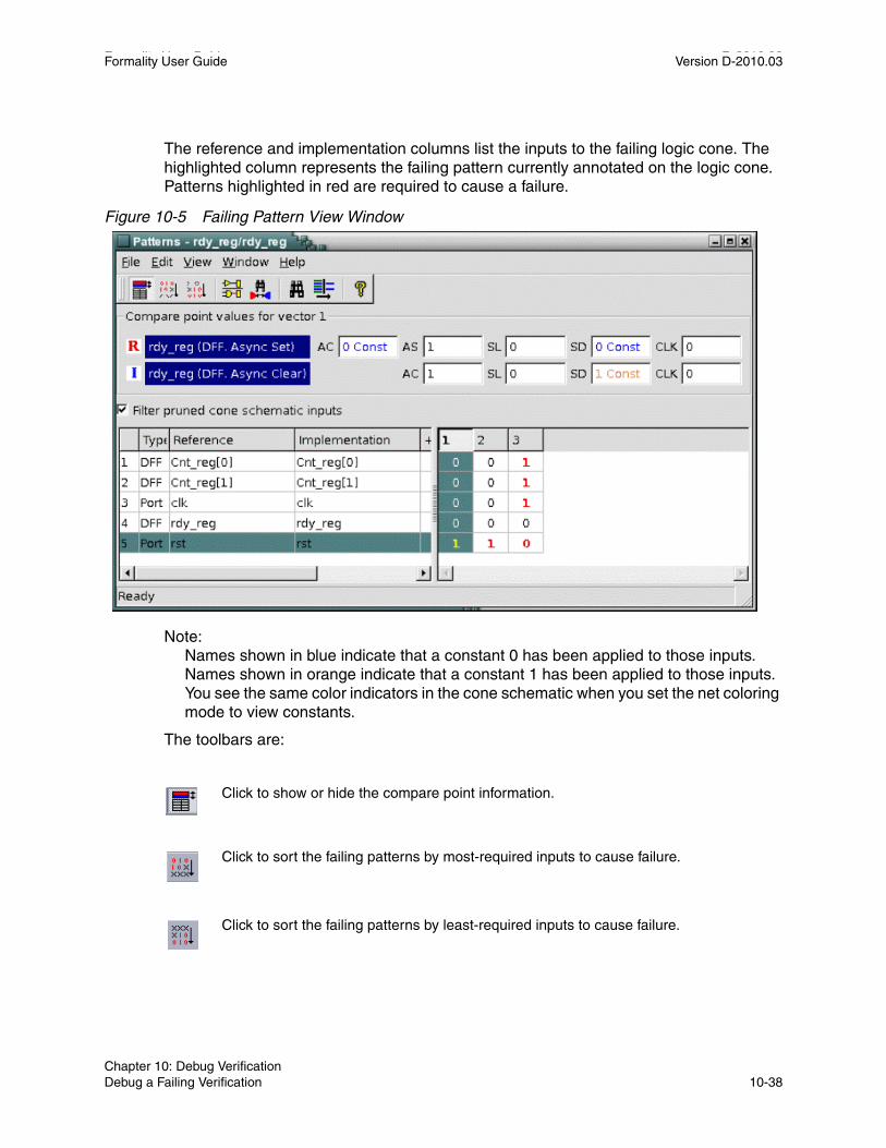
Formality User Guide D-2010.03Formality User Guide Version D-2010.03
The reference and implementation columns list the inputs to the failing logic cone. The highlighted column represents the failing pattern currently annotated on the logic cone. Patterns highlighted in red are required to cause a failure.
Figure 10-5 Failing Pattern View Window
Note: Names shown in blue indicate that a constant 0 has been applied to those inputs. Names shown in orange indicate that a constant 1 has been applied to those inputs. You see the same color indicators in the cone schematic when you set the net coloring mode to view constants.
The toolbars are:
Click to show or hide the compare point information.
Click to sort the failing patterns by most-required inputs to cause failure.
Click to sort the failing patterns by least-required inputs to cause failure.
Chapter 10: Debug VerificationDebug a Failing Verification 10-38

Formality User Guide Version D-2010.03
2. To move forward through the current set of previously failing patterns, click the Next Pattern toolbar option. To move backward, use the Previous Pattern toolbar option. Each command updates the display with a new set of logic values.
Applying a pattern to the logic cone causes the logic area to be redrawn with the new states marked on each pin of each instance. The patterns are applied at the inputs.
You can move through patterns only when the failed verification or completed diagnosis operation has identified more than one failing pattern for the displayed logic cone. If only one pattern exists, the Next Pattern and Previous Pattern options in the View menu are inactive (dimmed).
Save Failing PatternsFormality retains the set of failing patterns for the most recently failed verification. You can save these patterns for use in simulation at a later time.
To save the current set of failing patterns, do one of the following:
Click to display the logic cone view for the selected input pair.
Click to show the matching tool that provides a report of the matched hierarchical pins and simulation values in the logic cone for the selected failing pattern.
Click to find an input in the reference or implementation list.
Click to filter the reference or implementation list.
Click to show help for the pattern view window.
fm_shell GUI
Specify:
write_failing_patterns
[-diagnosis_patterns ]
[-verilog ]
[-replace ] file_name
1. Choose File > Save Failing Patterns.
2. In the “File name” box, type the file name.
3. Select Save Diagnosis Patterns Only (to save a diagnosis pattern subset) or Save Patterns in Verilog Format.
4. Click OK.
Chapter 10: Debug VerificationDebug a Failing Verification 10-39Chapter 10: Debug VerificationDebug a Failing Verification 10-39

Formality User Guide D-2010.03Formality User Guide Version D-2010.03
This command saves failing patterns to an external file (*.fpt). For more information about this command, see the man page.
Note: Be sure that the verification section of the transcript shows that verification failed.
Run Previously Saved Failing PatternsTo simulate the implementation and reference designs with a set of previously saved failing patterns, do one of the following:
Note: The file containing previous failing patterns must be readable by Formality, not saved as a text file. If you save the failing patterns in Verilog format, you cannot use the resulting file with the simulate_patterns command.
You can follow two courses with previously saved failing patterns:
• Simulate your top-level design by applying the entire set of patterns.
• Apply single patterns from the set to the design while viewing a particular logic cone.
When you run a set of previously failing patterns, Formality performs logic simulation on the implementation and reference designs. Using failing patterns as input vectors can help you determine whether changes you have made to the implementation design have fixed a problem found during verification.
After applying the patterns, Formality reports the success of the simulation by refreshing the verification section of the information bar. A report created at this point reflects the state of the completed simulation; it does not reflect the state of the most recently failed verification.
Note: Passing simulation performed with a set of previously failing patterns is not sufficient to prove design equivalence. For functional equivalence to be proved, the implementation design must pass verification.
fm_shell GUI
Specify:
simulate_patterns file
At the Formality prompt, specify:
simulate_patterns file
Chapter 10: Debug VerificationDebug a Failing Verification 10-40

Formality User Guide Version D-2010.03
Debug a Hard Verification
A verification is considered hard when Formality cannot completely verify all compare points. The user becomes aware that a verification is hard when either the transcript shows no apparent progress for hours or days or when the verification aborts due to design complexity. Usually this involves datapath intensive designs, but sometimes could involve non-datapath causes, such as CRC, parity generators, XOR trees, or simply very large cones of logic.
The following transcript example extract shows a hard verification due to the tool being hung or stuck:
*********************** Matching Results ****************************32 Compare points matched by name0 Compare points matched by signature analysis0 Compare points matched by topology96 Matched primary inputs, black-box outputs0(0) Unmatched reference(implementation) compare points0(0) Unmatched reference(implementation) primary inputs, black-box outputs15(0) Unmatched reference(implementation) unread points********************************************************************
Status: Verifying
Status: Matching Hierarchy
Status: Verifying...
....................... 0F/0A/3P/29U (9%) 04/14/09 04:17 417MB/1747.02sec
....................... 0F/0A/3P/29U (9%) 04/14/09 04:47 417MB/3528.72sec
....................... 0F/0A/3P/29U (9%) 04/14/09 05:17 417MB/5665.33sec
....................... 0F/0A/3P/29U (9%) 04/14/09 05:47 417MB/7379.30sec
From reading the transcript example you can see that there are unverified compare points if the verification is interrupted.
The next transcript example extract shows a hard verification because the tool is aborting because of complexity:
Compare point mix[23] is aborted Compare point mix[24] is aborted Compare point mix[25] is aborted Compare point mix[26] is aborted Compare point mix[27] is aborted Compare point mix[28] is aborted
Chapter 10: Debug VerificationDebug a Hard Verification 10-41Chapter 10: Debug VerificationDebug a Hard Verification 10-41

Formality User Guide D-2010.03Formality User Guide Version D-2010.03
Compare point mix[29] is aborted Compare point mix[30] is aborted Compare point mix[31] is aborted ************************** Verification Results *************************Verification INCONCLUSIVE(Equivalence checking aborted due to complexity)------------------------------------------------ Reference design: r:/WORK/test Implementation design: i:/WORK/test 3 Passing compare points 29 Aborted compare points 0 Unverified compare points------------------------------------------------------------------------Matched Compare Points BBPin Loop BBNet Cut Port DFF LAT TOTAL------------------------------------------------------------------------Passing (equivalent) 0 0 0 0 3 0 0 3Failing (not equivalent) 0 0 0 0 0 0 0 0Aborted Hard (too complex) 0 0 0 0 29 0 0 29*************************************************************************
The basic hard verification debugging flow involves examining the transcript for obvious problems, creating a list of hard points, finding the cause of hard points, and finally attempting to resolve the hard points.
From reading the above transcript example extract you can see that verification was attempted on all compare points and that there were 29 aborted compare points causing the hard verification failure due to complexity.
Check Guidance SummaryFirst look at the guidance summary, which is displayed in the transcript. Note that it is also available on demand using the report_guidance -summary command.
Initially, you should look for any high-level issue. For instance, the guidance summary that follows shows that all guide datapath commands were rejected, due to the architectural netlist command being rejected. This is a good indication of a global issue that needs to be addressed.
*************************** Guidance Summary *************************** StatusCommand Accepted Rejected Unsupported Unprocessed Total-------------------------------------------------------------------------
Chapter 10: Debug VerificationDebug a Hard Verification 10-42

Formality User Guide Version D-2010.03
architecture_netlist: 0 1 0 0 1datapath : 0 87 0 0 87
More typically though, the guidance summary will not show a global issue, as illustrated in the following example extract:
*************************** Guidance Summary *************************** StatusCommand Accepted Rejected Unsupported Unprocessed Total-------------------------------------------------------------------------architecture_netlist: 1 0 0 0 1datapath : 79 22 0 0 101environment : 1 0 0 0 1instance_map : 93 0 0 0 93merge : 87 14 0 0 73multiplier : 2 0 0 0 2replace : 758 0 0 0 758scan_input : 2 0 0 0 2uniquify : 2 0 0 0 2ununiquify : 2 0 0 0
2
Some or all of these rejections can contribute to the resulting hard verification. You need to investigate only those rejections that might have lead to the hard verification. To do this, you must first investigate the hard points themselves.
Chapter 10: Debug VerificationDebug a Hard Verification 10-43Chapter 10: Debug VerificationDebug a Hard Verification 10-43

Formality User Guide D-2010.03Formality User Guide Version D-2010.03
Create List of Hard PointsThere are two Formality report commands which are used to determine your current hard points in the verification.
• report_unverified_points
• report_aborted_points
An example of this is shown as follows:
fm_shell (verify) > report_unverified
21 unverified compare points: 21 unverified because of interrupt or timeout 0 unverified because failing point limit reached 0 affected by matching changes
Ref DFF r:/WORK/dp/angle_reg[10]Impl DFF i:/WORK/dp/angle_reg[10]
Ref DFF r:/WORK/dp/angle_reg[11]Impl DFF i:/WORK/dp/angle_reg[11] …
Determine Cause of Hard PointsUse the -aborted and -unverified options for the analyze_points command to have Formality examine the aborted and unverified points, respectively. Formality will generate a report of possible causes of the hard points and recommend next steps to take to resolve the issues. The command also recommends which options to use with the set_verification_priority Design Compiler command.
Chapter 10: Debug VerificationDebug a Hard Verification 10-44

Formality User Guide Version D-2010.03
For additional information, use the report_svf_operation command to determine if there is any relevant rejected datapath guidance in the cones of the hard points. Always start with the -summary option to get an upper level view of what is contained in the cone.
report_svf_operation <hard_compare_point(s)>
fm_shell (verify) > report_svf_operation \-summary r:/WORK/dp/angle_reg[10]
Operation Line Command Status------------------------------------------------------------------
6 55 replace accepted 7 72 replace rejected 8 91 transformation_merge rejected10 164 boundary accepted11 440 constraints accepted13 453 datapath accepted15 462 replace accepted16 515 boundary accepted17 865 constraints accepted19 878 datapath accepted
You should only be concerned with the rejected guidance.
Many times, guide commands can be dependent upon the acceptance of previous guide commands; in the example jsut presented, the rejection of the guide_replace command should be investigated first.
To get more details on the above on the two guide commands of interest, you can use the -rejected option without the -summary command, or simply enter the command number of interest to the report_svf_operation command.
Chapter 10: Debug VerificationDebug a Hard Verification 10-45Chapter 10: Debug VerificationDebug a Hard Verification 10-45

Formality User Guide D-2010.03Formality User Guide Version D-2010.03
Chapter 10: Debug VerificationDebug a Hard Verification 10-46

11Library Verification Mode 11
Formality allows you to verify a reference design with an implementation design in the process described in Chapters 3 through 10. There are, however, some procedures in Formality which do not necessarily fall in the standard flow of operation. This chapter will elaborate on these in the following sections:
• Introduction
• Library Verification Mode
• Load the Reference Library
• Load the Implementation Library
• List the Cells
• Specify a Customized Cell List
• Elaborate Library Cells
• Perform Library Verification
• Report and Interpret Verification Results
• Debug Failed Library Cells
For additional information about verifying libraries, see the Formality ESP User Guide in the ESP documentation suite.
11-1

Formality User Guide D-2010.03Formality User Guide Version D-2010.03
Introduction
This chapter assumes that you understand Formality concepts and the general process for Formality design verification. From here, it discusses compare technology (or cell) libraries.
The process flow for library verification mode is broadly similar to that of Formality itself. Figure 11-1 shows the general flow for verifying two technology libraries. This chapter describes all the steps in the library verification process.
Figure 11-1 Technology Library Verification Process Flow
InterpretResults
RunVerify
Success?No
Yes
Done
GenerateCell List
LoadReference
LoadImplementation
DebugDebug
Library
Library
FormalityLibrary Verification
Mode
Chapter 11: Library Verification ModeIntroduction 11-2

Formality User Guide Version D-2010.03
During technology library verification, Formality compares all the cells in a reference library to all the cells in an implementation library. The process allows you to compare Verilog simulation and Synopsys (.db) synthesis libraries.
Library verification is similar to design verification in that you must load both a reference library and an implementation library. The principle difference is that, because the specified libraries contain multiple designs (cells), Formality must first match the cells to be verified from each library. This matching occurs when you load the reference and implementation designs. Formality then performs compare point matching and verification one cell-pair at a time.
The Formality add-on tool, Formality ESP, extends the functional equivalence checking provided by Formality. For more information about functional equivalence for full-custom transistor-level memory macros, datapath macros, and library cells, see the Formality ESP User Guide.
Library Verification Mode
To verify two libraries, you must be in the library_verification mode. If you are one of the other modes (setup, match, verify, or debug mode), you must first switch to the library_verification mode. If it is running, the GUI closes. Library verification is a command-line-driven process. Each time you enter (or leave) library verification mode, Formality empties the contents of the r and i containers in readiness for a new library (or design) verification session.
To enter library verification mode, specify the library_verification command, as follows
fm_shell (setup)> library_verification argument
You can specify one of the following options for argument:
The first design type in the preceding examples defines the reference library; the second type defines the implementation library. If you specify none, Formality returns to setup mode.
verilog_verilog
db_db
verilog_db
db_verilog
none
Chapter 11: Library Verification ModeLibrary Verification Mode 11-3Chapter 11: Library Verification ModeLibrary Verification Mode 11-3

Formality User Guide D-2010.03Formality User Guide Version D-2010.03
The fm_shell prompt changes to
fm_shell (library_setup)>
When you set this mode, Formality sets the following variable
set verification_passing_mode equality
When you exit library verification mode, Formality sets the variable back to its default value, consistency.
Note: Unsupported synthesis library formats must be translated by Library Compiler before being read into Formality.
Load the Reference Library
As with the design verification process described in Chapter 4, “Tutorial,” you must specify the reference library prior to the implementation library.
To specify the reference library, use one of the following read commands, depending on the library format:
fm_shell (library_setup)> read_db -r file_listfm_shell (library_setup)> read_verilog -r [-tech] file_list
As described in the man pages, the read_db and read_verilog commands have several options that do not apply to library verification. Use the read_verilog -tech option if you have a UDP file.
Formality loads the reference library into the r container. You cannot rename this container.
In the Formality shell, you represent the design hierarchy by using a designID argument. The designID argument is a path name whose elements indicate the container (r or i), library, and design name.
Unlike with the design verification process, you do not specify the set_top command because multiple top cells are available.
Chapter 11: Library Verification ModeLoad the Reference Library 11-4
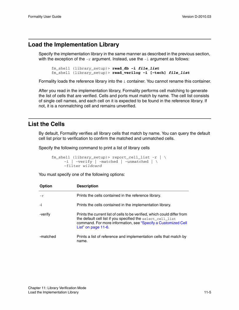
Formality User Guide Version D-2010.03
Load the Implementation Library
Specify the implementation library in the same manner as described in the previous section, with the exception of the -r argument. Instead, use the -i argument as follows:
fm_shell (library_setup)> read_db -i file_listfm_shell (library_setup)> read_verilog -i [-tech] file_list
Formality loads the reference library into the i container. You cannot rename this container.
After you read in the implementation library, Formality performs cell matching to generate the list of cells that are verified. Cells and ports must match by name. The cell list consists of single cell names, and each cell on it is expected to be found in the reference library. If not, it is a nonmatching cell and remains unverified.
List the Cells
By default, Formality verifies all library cells that match by name. You can query the default cell list prior to verification to confirm the matched and unmatched cells.
Specify the following command to print a list of library cells
fm_shell (library_setup)> report_cell_list -r | \-i | -verify | -matched | -unmatched | \-filter wildcard
You must specify one of the following options:
Option Description
-r Prints the cells contained in the reference library.
-i Prints the cells contained in the implementation library.
-verify Prints the current list of cells to be verified, which could differ from the default cell list if you specified the select_cell_list command. For more information, see “Specify a Customized Cell List” on page 11-6.
-matched Prints a list of reference and implementation cells that match by name.
Chapter 11: Library Verification ModeLoad the Implementation Library 11-5Chapter 11: Library Verification ModeLoad the Implementation Library 11-5

Formality User Guide D-2010.03Formality User Guide Version D-2010.03
In the rare case that the libraries contain no matching cells, follow these steps:
1. Return to setup mode by entering the library_verification none command.
2. Edit the cell names so they match.
3. Return to library verification mode by entering the library_verification mode command.
4. Reload the updated library by using the applicable read command.
Specify a Customized Cell List
When you load the libraries with the read_ commands, Formality elaborates all matched cells in preparation for verification. After reporting the matched cells with the report_cell_list command, you can refine the default cell list as necessary.
To customize the default cell list, specify the following command:
fm_shell (library_setup)> select_cell_list [-file filename] \
[-add cell_names] [-clear] [-remove cell_names] cell_names
You can use the following options as needed:
-unmatched Prints the names of cells that did not match in the reference and implementation containers. This option is dynamic depending on the select_cell_list command specification.
-filter wildcard Filters the report to include cells that match the specified wildcard. Always specify this option in conjunction with one of the preceding options.
Option Description
-file filename Specifies a file that contains a list of cells to be verified.
-add cell_names Adds the specified cells to the cell list.
-clear Clears the cell list.
-remove cell_names Removes the specified cells from the cell list.
Option Description
Chapter 11: Library Verification ModeSpecify a Customized Cell List 11-6

Formality User Guide Version D-2010.03
This command supports wildcard characters for cell names. Enclose lists of cells in braces. For example,
fm_shell (library_setup)> select_cell_list {AND5 OR2 JFKLP}fm_shell (library_setup)> select_cell_list ra*
As part of the debugging process, use this command to specify only those cells that previously failed verification.
Elaborate Library Cells
Formality automatically elaborates your library cells when running the verify command. You might want to elaborate your library cells prior to verification to apply constraints to specific cells. To elaborate these library cells, run the elaborate_library_cells command.
If you do not want to apply constraints to individual library cells, proceed directly to verification. For more information about using the elaborate_library_cells command, see the man page.
Perform Library Verification
Proceed to verification after optionally refining your cell list. As with the design verification process, specify the verify command:
fm_shell (library_setup)> verify
Formality performs compare point matching and verification for each cell-pair as described in Chapter 8, “Match Compare Points and Chapter 9, “Run Verify and Interpret Results.” However, because Formality assumes that all cell and ports match by name, compare point matching errors do not occur; for this reason, the optional match command does not apply to library verification.
As described in the man page, the verify command has additional options that do not apply to library verification.
After verification, Formality outputs a transcripted summary of the passing, failing, and aborted cell counts.
The following script performs library verification. This script sets hdlin_unresolved_modules to ‘black box’ as a precaution; generally technology libraries should not contain unresolved modules. These are not required settings. Remember that verification_passing_mode and inversion_push are set automatically.
Chapter 11: Library Verification ModeElaborate Library Cells 11-7Chapter 11: Library Verification ModeElaborate Library Cells 11-7

Formality User Guide D-2010.03Formality User Guide Version D-2010.03
#---------------------------------------------------------# Sets the directories where Formality will search for files#---------------------------------------------------------
set search_path "./db ./verilog/cells ./verilog_udp"#---------------------------------------------------------# Sets variables#---------------------------------------------------------
set hdlin_unresolved_modules black_boxlibrary_verification VERILOG_DB
#---------------------------------------------------------# Reads into container 'r'#---------------------------------------------------------# Read UDP using -tech
read_verilog -r -tech { UDP_encodecod.v UDP_mux2.v UDP_mux2_1.v UDP_mux2_1_I.v UDP_mux2_2.v }
# Read library cells
read_verilog -r { and2A.vand2B.vand2C.vao11A.vao11C.vao12A.vbufferA.vbufferAE.vbufferAF.vdelay1.vencode3A.vxor1A.vxor1B.vxor1C.vfull_add1AA.vhalf_add1A.vmux21HA.vmux31HA.vmux41HA.vmux61HA.vmux81HA.vmux21LA.vnotA.vnotAD.vnotAE.v
Chapter 11: Library Verification ModePerform Library Verification 11-8

Formality User Guide Version D-2010.03
nand2A.vnand2B.vnand2C.vnor2A.vnor2B.vnor2C.vnxor3A.vor_and21A.vor2A.v}#---------------------------------------------------------# Reads into container 'i'#---------------------------------------------------------
read_db -i synth_lib.db
## Report which library cells will be verified#
report_cell_list -vreport_cell_list -mreport_cell_list -u
#---------------------------------------------------------# Verifies libraries#---------------------------------------------------------
verify
#---------------------------------------------------------# Reports on passing and full_addiling cells#---------------------------------------------------------
report_status -p report_status -f report_status -a
#---------------------------------------------------------# Exits#---------------------------------------------------------
exit
Chapter 11: Library Verification ModePerform Library Verification 11-9Chapter 11: Library Verification ModePerform Library Verification 11-9

Formality User Guide D-2010.03Formality User Guide Version D-2010.03
Report and Interpret Verification Results
After verification, use the following command to report the verification results:
fm_shell (library_setup)> report_status [-passing] \
[-failing] [-aborting]
If you specify no arguments, Formality reports the passing, failing, and aborted cell counts. The following table describes the use of the three options, along with an explanation of the type of status message assigned to each one during verification:
Debug Failed Library Cells
Use the following procedure to debug failed library cells:
1. Choose a failing cell from the status report and specify the following command:
fm_shell (library_setup)> debug_library_cell cell_name
Formality reports the failing cells but retains the verification results from the last cell verified (which could be a passing cell). This command repopulates Formality with the verification data for the specified cell, which then enables you to debug the cell from within the same session. You can specify the name of only one unique cell.
2. Specify the following command to view the failed cell’s logic:
Option Description Status Message for Library Cell-Pairs
-passing Returns a list of all passing cells.
A passing library cell-pair is one in which all its compare points are functionally equivalent.
-failing Returns a list of all failing cells.
A failing library cell-pair is one in which at least one compare point is not functionally equivalent.
-aborting Returns a list of all aborted cells.
Verification stops. This occurs most often when Formality reaches a user-defined failing limit. For example, Formality halts verification on a cell after 20 failing points have been found in the cell.
In addition, any cells that fail elaboration are aborted, and a cell can be aborted if Formality cannot determine whether one of its compare points passes or fails. Aborted points can occur when Formality is interrupted during the verification process.
Chapter 11: Library Verification ModeReport and Interpret Verification Results 11-10

Formality User Guide Version D-2010.03
fm_shell (library_setup)> report_truth_table signal \[-fanin signal_list] [-constraint signal_list=[0|1]] \[-display_fanin] [-nb_lines number] \[-max_line length]
This command generates a Boolean logic truth table that you can use to check the failed cell’s output signals. Often, this is sufficient information to fix the failed cell. Use the arguments as follows:
After fixing the cell, you can reverify it by customizing the cell list to include only the fixed cell and then specifying the verify command.
3. If further investigation is required to fix a failed cell, specify the following command:
fm_shell (library_setup)> write_library_debug_scripts \ [-dir filename]
This command generates individual Tcl scripts for each failed cell and places them in the DEBUG directory unless you specify the -dir option. The DEBUG directory is located in the current working directory.
Argument Description
-signal Specifies the signal you want to check. For example, specify the path name as follows:r:/lib/NAND/z
-fanin signal_list Filters the truth table for the specified fanin signals, where the list is enclosed in braces ({ }).
-constraint signal_list=[0|1] Applies the specified constraint value (0 or 1) at the input and displays the output values on the truth table.
-display_fanin Returns the fanin signals for the specified signal.
-nb_lines_number Specifies the maximum number of lines allowed for the truth table.
-max_line length Specifies the maximum length for each table line.
Chapter 11: Library Verification ModeDebug Failed Library Cells 11-11Chapter 11: Library Verification ModeDebug Failed Library Cells 11-11

Formality User Guide D-2010.03Formality User Guide Version D-2010.03
If you attempt to view library cells in the Formality GUI, you see only a black box. As shown in the following example, the Tcl scripts direct Formality to treat the library cells as designs and perform traditional verification. You can then investigate the failure results with the Formality GUI.
## --This is a run script generated by Formality library verification mode --set verification_passing_mode Equalityset verification_inversion_push trueset search_path "DEBUG"read_container -r lib_ref.fscread_container -i lib_impl.fscset_ref r:/*/mux21set_impl i:/*/mux21verify
4. Run one of the Tcl scripts and specify the start_gui command to view the results. When you have fixed the cell, go to each of the scripts until you have debugged them all. For information about using the GUI for debugging, see the following sections
• “Debug Using Diagnosis” on page 10-8
• “Schematics” on page 10-20
• “Logic Cones” on page 10-28
• “Failing Patterns” on page 10-37
5. Reverify cells that you fixed from within the GUI. You must begin a new session by re initializing the library verification mode and reloading the reference and implementation libraries.
Chapter 11: Library Verification ModeDebug Failed Library Cells 11-12

ATcl Syntax as Applied to Formality Shell Commands A
This appendix describes the characteristics of Tcl syntax as applied to Formality shell commands. For instructions about using the Formality shell, see “Invoke the Formality Shell” on page 3-4.
Tcl has a straightforward language syntax. Every Tcl script is a series of commands separated by a new-line character or semicolon. Each command consists of a command name and a series of arguments.
This appendix includes the following sections
• Use Application Commands
• Quote Values
• Use Built-In Commands
• Use Procedures
• Use Lists
• Use Other Tcl Utilities
• Use Environment Variables
• Nest Commands
A-1

Formality User Guide D-2010.03Formality User Guide Version D-2010.03
• Evaluate Expressions
• Use Control Flow Commands
• Create Procedures
Appendix A: Tcl Syntax as Applied to Formality Shell CommandsA-2

Formality User Guide Version D-2010.03
Use Application Commands
Application commands are specific to Formality. You can abbreviate all application command names, but you cannot abbreviate most built-in commands or procedures. Formality commands have the following syntax:
command_name -option1 arg1 -option2 arg2 parg1 parg2command_name
Names the application command.
-option1 arg1 -option2 arg2
Specifies options and their respective arguments.
parg1 parg2
Specifies positional arguments.
Chapter A: Tcl Syntax as Applied to Formality Shell CommandsUse Application Commands A-3Appendix A: Tcl Syntax as Applied to Formality Shell CommandsUse Application Commands A-3

Formality User Guide D-2010.03Formality User Guide Version D-2010.03
Summary of the Command SyntaxTable A-1 summarizes the components of the syntax.
Table A-1 Command Components
Component Description
Command name If you enter an ambiguous command, Formality attempts to find the correct command.
fm_shell> report_p
Error: ambiguous command “report_p” matched two commands: (report_parameters, report_passing_points) (CMD-006)
Formality lists as many as three of the ambiguous commands in its warning.
To list the commands that match the ambiguous abbreviation, use the help function with a wildcard pattern.
fm_shell> help report_p*
Options Many Formality commands use options. A hyphen (-) precedes an option. Some options require a value argument. For example, in the following command my_lib is a value argument of the -libname option.
fm_shell> read_db -libname my_lib
Other options, such as -help, are Boolean options without arguments. You can abbreviate an option name to the shortest unambiguous (unique) string. For example, you can abbreviate -libname to -lib.
Positional arguments Some Formality commands have positional (or unswitched) arguments. For example, in the set_equivalence command, the object1 and object2 arguments are positional.
fm_shell> set_equivalence object1 object2
Appendix A: Tcl Syntax as Applied to Formality Shell CommandsUse Application Commands A-4

Formality User Guide Version D-2010.03
Use Special CharactersThe characters in Table A-2 have special meaning for Tcl in certain contexts.
Use Return TypesFormality commands have a single return type that is a string. Commands return a result. With nested commands, the result can be used as any of the following
• Conditional statement in a control structure
• Argument to a procedure
• Value to which a variable is set
Here is an example of a return type:
if {[verify -nolink]!=1} {diagnosereport_failing_pointssave_session ./failed_run
}
Table A-2 Special Characters
Character Meaning
$ Dereferences a Tcl variable.
( ) Groups expressions.
[ ] Denotes a nested command.
\ Indicates escape quoting.
“ ” Denotes weak quoting. Nested commands and variable substitutions occur.
{ } Denotes rigid quoting. There are no substitutions.
; Ends a command.
# Begins a comment.
Chapter A: Tcl Syntax as Applied to Formality Shell CommandsUse Application Commands A-5Appendix A: Tcl Syntax as Applied to Formality Shell CommandsUse Application Commands A-5

Formality User Guide D-2010.03Formality User Guide Version D-2010.03
Quote Values
You can surround values in quotation marks in several ways:
• Escape individual special characters by using the backslash character (\) so that the characters are interpreted literally.
• Group a set of words separated by spaces by using double quotation marks (“ ”). This syntax is referred to as weak quoting because variable, command, and backslash substitutions can occur.
• Enclose a set of words that are separated by spaces by using braces ({ }). This technique is called rigid quoting. Variable, command, and backslash substitutions do not occur within rigid quoting.
The following commands are valid but yield different results. Assuming that variable a is set to 5, Formality yields the following:
fm_shell> set s “temp = data[$a]”temp = data[5]
fm_shell> set s {temp = data[$a]}temp = data[$a]
Use Built-In Commands
Most built-in commands are intrinsic to Tcl. Their arguments do not necessarily conform to the Formality argument syntax. For example, many Tcl commands have options that do not begin with a hyphen, yet the commands use a value argument.
Formality adds semantics to certain Tcl built-in commands and imposes restrictions on some elements of the language. Generally, Formality implements all of the Tcl intrinsic commands and is compatible with them.
The Tcl string command has a compare option that is used like this:
string compare string1 string2
Appendix A: Tcl Syntax as Applied to Formality Shell CommandsQuote Values A-6

Formality User Guide Version D-2010.03
Use Procedures
Formality comes with several procedures that are created through the /usr/synopsys/admin/setup/.synopsys_fm.setup file during installation. You can see what procedures are included with Formality by entering the following command:
help
The help command returns a list of procedures, built-in commands, and application commands.
Procedures are user-defined commands that work like built-in commands. You can create your own procedures for Formality by following the instructions in “Create Procedures” on page A-12.
Procedures follow the same general syntax as application commands
command_name -option1 arg1 -option2 arg2 parg1 parg2
For a description of the syntax, see “Use Application Commands” on page A-3.
Use Lists
Lists are an important part of Tcl. Lists represent collections of items and provide a convenient way to distribute the collections. Tcl list elements can consist of strings or other lists.
The Tcl commands you can use with lists are:
• list
• concat
• join
• lappend
• lindex
• linsert
• llength
• lrange
• lreplace
• lsearch
Chapter A: Tcl Syntax as Applied to Formality Shell CommandsUse Procedures A-7Appendix A: Tcl Syntax as Applied to Formality Shell CommandsUse Procedures A-7

Formality User Guide D-2010.03Formality User Guide Version D-2010.03
• lsort
• split
While most publications about Tcl contain extensive discussions about lists and the commands that operate on lists, these Tcl commands highlight two important concepts:
• Because command arguments and results are represented as strings, lists are also represented as strings, but with a specific structure.
• Lists are typically entered by enclosing a string in braces, as follows
{a b c d}
In this example, however, the string inside the braces is equivalent to the command [list a b c d].
Note: Do not use commas to separate list items, as you do in Design Compiler.
If you are attempting to perform command or variable substitution, the form with braces does not work. For example, this command sets the variable a to 5.
fm_shell> set a 55
These next two commands yield different results because the command surrounded by braces does not expand the variable, whereas the command surrounded by square brackets (the second command) does.
fm_shell> set b {c d $a [list $a z]}c d $a [list $a z]
fm_shell> set b [list c d $a [list $a z]]c d 5 {5 z}
Lists can be nested, as shown in the previous example. You can use the concat command (or other Tcl commands) to concatenate lists.
Use Other Tcl Utilities
Tcl contains several other commands that handle
• Strings and regular expressions (such as format, regexp, regsub, scan, and string)
• File operations (such as file, open, and close)
• Launching system subprocesses (such as exec)
Appendix A: Tcl Syntax as Applied to Formality Shell CommandsUse Other Tcl Utilities A-8

Formality User Guide Version D-2010.03
Use Environment Variables
Formality supports any number of user-defined variables. Variables are either scalar or arrays. The syntax of an array reference is
array_name (element_name)
Table A-3 summarizes several ways for using variables.
The following commands show how variables are set and referenced:
fm_shell> set search_path ". /usr/synopsys/libraries" . /usr/synopsys/librariesfm_shell> adir = "/usr/local/lib"/usr/local/libfm_shell> set my_path "$adir $search_path"/usr/local/lib . /usr/synopsys/librariesfm_shell> unset adirfm_shell> unset my_path
Note: You can also set and unset environment variables in the GUI by entering them into the command bar or selecting File > Environment from the console window.
Table A-3 Examples of Using Variables
Task Description
Setting variables Use the set command to set variables. For compatibility with dc_shell and pt_shell, fm_shell also supports a limited version of the a = b syntax. For example,
set x 27 or x = 27
set y $x or y = $x
Removing variables Use the unset command to remove variables.
Referencing variables Substitute the value of a variable into a command by dereferencing it with the dollar sign ($), as in echo $flag. In some cases, however, you must use the name of a value, such as unset flag, instead of the dollar sign.
Chapter A: Tcl Syntax as Applied to Formality Shell CommandsUse Environment Variables A-9Appendix A: Tcl Syntax as Applied to Formality Shell CommandsUse Environment Variables A-9

Formality User Guide D-2010.03Formality User Guide Version D-2010.03
Nest Commands
You can nest commands within other commands (also known as command substitution) by enclosing the nested commands within square brackets ([ ]). Tcl imposes a depth limit of 1,000 for command nesting.
The following examples show different ways of nesting a command.
fm_shell> set index [lsearch [set aSort \ [lsort $l1]] $aValue]fm_shell> set title "Gone With The Wind" Gone With The Windfm_shell> set lc_title [string tolower $title] gone with the wind
Formality makes one exception to the use of command nesting with square brackets so that it can recognize netlist objects with bus references. Formality accepts a string, such as data[63], as a name rather than as the word data followed by the result of command 63. Without this exception, data[63] must either be rigidly quoted with the use of braces, as in {data[63]}, or the square brackets have to be escaped, as in data\[63\].
Evaluate Expressions
Tcl supports expressions. However, the base Tcl language syntax does not support arithmetic operators. Instead, the expr command evaluates expressions.
The following examples show the right and wrong ways to use expressions:
set a (12 * $p) ;# Wrong.
set a [expr (12*$p)] ;# Right!
The expr command can also evaluate logical and relational expressions.
Use Control Flow Commands
Control flow commands (if, while, for, foreach, break, continue, and switch) determine the order of other commands. You can use fm_shell commands in a control flow command, including other control flow commands.
The following sections briefly describe the use of the control flow commands.
Appendix A: Tcl Syntax as Applied to Formality Shell CommandsNest Commands A-10

Formality User Guide Version D-2010.03
Use the if CommandAn if command has a minimum of two arguments:
• An expression to evaluate
• A script to start conditionally based on the result of the expression
You can extend the if command to contain an unlimited number of elseif clauses and one else clause. An elseif argument to the if command requires two additional arguments: an expression and a script. An else argument requires only a script.
The following example shows the correct way to specify elseif and else clauses:
if {$x == 0} { echo "Equal"} elseif {$x > 0} { echo "Greater"} else { echo "Less"}
In this example, notice that the else and elseif clauses appear on the same line with the closing brace ( } ). This syntax is required because a new line indicates a new command. Thus, if the elseif clause is on a separate line, it is treated as a command, although it is not one.
Use while and for LoopsThe while and for commands are similar to the same constructs in the C language.
Use while LoopsThe while command has two arguments
• An expression
• A script
The following while command prints squared values from 0 to 10:
set p 0while {$p <= 10} {
echo "$p squared is: [expr $p * $p]"incr p
}
Chapter A: Tcl Syntax as Applied to Formality Shell CommandsUse Control Flow Commands A-11Appendix A: Tcl Syntax as Applied to Formality Shell CommandsUse Control Flow Commands A-11

Formality User Guide D-2010.03Formality User Guide Version D-2010.03
Use for LoopsThe for command uses four arguments:
• An initialization script
• A loop-termination expression
• An iterator script
• An actual working script
The following example shows how the while loop in the previous section is rewritten as a for loop:
for {set p 0} {$p <= 10} {incr p} {echo "$p squared is: [expr $p * $p]"
}
Iterating Over a List: foreachThe foreach command is similar to the same construct in the C language. This command iterates over the elements in a list. The foreach command has three arguments:
• An iterator variable
• A list
• A script to start (the script references the iterator’s variable)
To print an array, enter
foreach el [lsort [array names a]] { echo "a\($el\) = $a($el)"}
To search in the search path for several files and then report whether or not the files are directories, enter
foreach f [which {t1 t2 t3}] { echo -n "File $f is " if { [file isdirectory $f] == 0 } { echo -n "NOT " } echo "a directory"}
Appendix A: Tcl Syntax as Applied to Formality Shell CommandsUse Control Flow Commands A-12

Formality User Guide Version D-2010.03
Terminate a Loop: break and continueThe break and continue commands terminate a loop before the termination condition has been reached. The break command causes the innermost loop to terminate. The continue command causes the current iteration of the innermost loop to terminate.
Use the switch CommandThe switch command is equivalent to an if tree that compares a variable with a number of values. One of a number of scripts is run, based on the value of the variable:
switch $x {a {incr t1}b {incr t2}c {incr t3}}
The switch command has other forms and several complex options. For more examples of the switch command, consult your Tcl documentation.
Create Procedures
A powerful Formality function is the ability to write reusable Tcl procedures. With this function, you can extend the command language. You can write new commands that can use an unlimited number of arguments. The arguments can contain default values, and you can also use a varying number of arguments.
For example, the following procedure prints the contents of an array:
proc array_print {arr} {upvar $arr aforeach el [lsort [array names a]] { echo "$arr\($el) = $a($el)"
}}
Procedures can use any of the commands supported by Formality or other procedures you have defined. Procedures can even be recursive. Procedures can contain local variables and reference variables outside of their scope. Arguments to procedures can be passed by value or by reference.
The following sections provide some examples of procedures. Books on the Tcl language offer additional information about writing procedures.
Chapter A: Tcl Syntax as Applied to Formality Shell CommandsCreate Procedures A-13Appendix A: Tcl Syntax as Applied to Formality Shell CommandsCreate Procedures A-13

Formality User Guide D-2010.03Formality User Guide Version D-2010.03
Program Default Values for ArgumentsTo set up a default value for an argument, you must locate the argument in a sublist that contains two elements: the name of the argument and the default value.
For example, the following procedure reads a favorite library by default, but reads a specific library if given:
proc read_lib { {lname favorite.db} } {read_db $lname
}
Specify a Varying Number of ArgumentsYou can specify a varying number of arguments by using the args argument. You can enforce that at least some arguments are passed into a procedure, and then handle the remaining arguments as you see fit.
For example, to report the square of at least one number, use the following procedure:
proc squares {num args} { set nlist $num append nlist " " append nlist $args foreach n $nlist { echo "Square of $n is [expr $n*$n]" }}
Appendix A: Tcl Syntax as Applied to Formality Shell CommandsCreate Procedures A-14

BReference Lists B
This appendix provides reference tables that describe Formality shell variables and commands.
This appendix includes the following sections:
• Shell Variables
• Shell Commands
B-1

Formality User Guide D-2010.03Formality User Guide Version D-2010.03
Shell Variables
Table B-1 lists the Tcl variables you can use to condition the environment from the Formality shell.
Table B-1 Shell Variables
Variable Description
architecture_selection_precedence string
Informs the arithmetic generator which architecture selection method takes precedence. Change only during setup mode.
bus_dimension_separator_style string Sets the VHDL/Verilog read option that controls the bus dimension separator style used with multidimensional buses.
bus_extraction_style string Sets the VHDL/Verilog read option that controls the bus extraction style.
bus_naming_style string Sets the VHDL/Verilog read option that controls the bus naming style.
bus_range_separator_style string Sets the VHDL/Verilog read option that controls the bus range separator style.
synopsys_auto_setup Sets certain conservative Formality default variables to values that better conform to Design Compiler behavior. Certain guide commands are also accepted, instead of ignored. Set this variable before reading the automated setup file (.svf).
diagnosis_enable_error_isolation true | false Enables the precise diagnosis engine in Formality that enables you to run diagnosis manually.
diagnosis_enable_find_matching_candidates true | false
Determines if the diagnose command identifies matching candidates in the other design.
diagnosis_pattern_limit integer Sets the maximum number of failing patterns that Formality uses during diagnosis.
distributed_64bit_mode true | false Determines which type of server executable to use on 64-bit capable machines.
distributed_verification_mode string Allows Formality to perform distributed verification using the verify command. Formality is in distributed mode when this variable is set to enable and there are valid servers in the server list. Default is enabled.
distributed_work_directory string Sets the directory that is used for the communication between the master and the servers.
dw_foundation_threshold integer Defines the input width where Formality switches from generating nbw to wall architectures for multiplier instances. Available only during the setup mode.
Appendix B: Reference ListsShell Variables B-2

Formality User Guide Version D-2010.03
enable_multiplier_generation true | false
Enables Formality to generate multiplier architectures based on user directives. Available only during setup mode.
gui_report_length_limit integer Specifies a GUI report size limit.
hdlin_auto_netlist true | false Enables automatic Formality to use the Verilog netlist reader by the read_verilog command.
hdlin_auto_top true | false Enables automatic detection and linking of the top-level design when using the read commands. Unable to select a top-level design if there are multiple candidates.
hdlin_do_inout_port_fixup true | false Controls whether DDX-7 error messages are generated at link time.
hdlin_dwroot string Specifies the path name to the DesignWare synthesis root.
hdlin_dyn_array_bnd_check string Controls whether logic is added to check the validity of array indices.
hdlin_enable_verilog_assert true | false
Controls whether SystemVerilog ASSERT (and related) statements in Verilog 95 and 2001 source files are treated as errors (default) or ignored.
hdlin_error_on_mismatch_message true | false
Works with the hdlin_warn_on_mismatch_message variable to control the severity of messages alerting you to possible mismatches between simulation and synthesis.
hdlin_ignore_builtin true | false Controls whether to ignore or not ignore the built_in directive in VHDL files.
hdlin_ignore_dc_script true | false Controls whether to ignore or not ignore the dc_script_begin and dc_script_end pragma directives in Verilog or VHDL files.
hdlin_ignore_full_case true | false Controls whether to ignore or not ignore the full_case directive in Verilog files.
hdlin_ignore_label true | false Controls whether to ignore or not ignore the label directive in VHDL files.
hdlin_ignore_label_applies_to true | false
Controls whether to ignore or not ignore the label_applies_to directive in Verilog or VHDL files.
hdlin_ignore_map_to_entity true | false
Controls whether to ignore or not ignore the map_to_entity directive in VHDL files.
hdlin_ignore_map_to_module true | false
Controls whether to ignore or not ignore the map_to_module attribute in Verilog or VHDL files.
hdlin_ignore_map_to_operator true | false
Controls whether to ignore or not ignore the map_to_operator directive in Verilog or VHDL files.
Table B-1 Shell Variables (Continued)
Variable Description
Chapter B: Reference ListsShell Variables B-3Appendix B: Reference ListsShell Variables B-3

Formality User Guide D-2010.03Formality User Guide Version D-2010.03
hdlin_ignore_parallel_case true | false
Controls whether to ignore or not ignore the parallel_case directive in Verilog files.
hdlin_ignore_resolution_method true | false
Controls whether to ignore or not ignore the resolution_method directive in VHDL files.
hdlin_ignore_synthesis true | false Controls whether to ignore or not ignore the synthesis_off directive in VHDL files.
hdlin_ignore_translate true | false Controls whether to ignore or not ignore the translate_off and translate_on directives in Verilog files.
hdlin_infer_mux default | none | all Specifies how to control the MUX_OP inference for your Verilog or VHDL description.
hdlin_interface_only design Enables the specified reader to produce interface-only designs.
hdlin_library_directory string Designates all designs contained within the specified directories as TECHNOLOGY designs.
hdlin_library_file string Designates all designs contained within the specified files as TECHNOLOGY files.
hdlin_library_report_summary true | false
Controls whether a warning summary is produced for Verilog library files.
hdlin_multiplier_architecture none | csa | nbw | wall | dw_foundation
Defines the architecture generated for multiplier or DW02_multp instances. You must change this variable before reading a design file to affect results.
hdlin_normalize_blackbox_busses true | false
Controls how Formality names black box busses during the link operation.
hdlin_preserve_assignment_direction true | false
Forces Formality to preserve assignment direction for all Verilog assign statements. Affects either RTL interpretation or netlist interpretation. Use on containers before performing set_top.
hdlin_sv_port_name_style complex | vector
Controls the naming of ports that are of a complex data type, such as multidimensional arrays (MDA), structs, and unions, in a SystemVerilog design.
hdlin_unresolved_modules black_box | error
Controls black box creation for Verilog and VHDL descriptions of references that are unresolved during set_top.
hdlin_verilog_95 true | false Controls the default Verilog language interpretation of the Formality RTL reader.
hdlin_verilog_wired_net_interpretation simulation | synthesis
Specifies whether nonwire nets are resolved using a simulation or a synthesis interpretation.
hdlin_vhdl_87 true | false Controls the default VHDL language interpretation of the Formality RTL reader.
Table B-1 Shell Variables (Continued)
Variable Description
Appendix B: Reference ListsShell Variables B-4

Formality User Guide Version D-2010.03
hdlin_vhdl_auto_file_order true | false
Enables the read_vhdl command to order the specified files automatically.
hdlin_vhdl_forgen_inst_naming mode0 | mode1 | mode2
Specifies the scheme that should be used to name component instances within VHDL for -generate statements.
hdlin_vhdl_fsm_encoding binary | 1hot Specifies the FSM encoding for your VHDL description.
hdlin_vhdl_integer_range_constraint true | false
Controls whether Formality adds logic to constrain the value of integer ports and registers to match the integer range constraint specified in the VHDL.
hdlin_vhdl_others_covers_extra_states true | false
Controls if others clauses are used to determine how unreachable states are handled.
hdlin_vhdl_presto_naming true | false Controls the generation of operator names inferred from VHDL.
hdlin_vhdl_presto_shift_div true | false
Controls the implementation of a divide by a constant power of two.
hdlin_vhdl_strict_libs true | false Controls whether a strict mapping of VHDL libraries is used during synthesis.
hdlin_vhdl_use_87_concat true | false Controls whether the IEEE Std 1076-1987 style concatenations are used in the IEEE Std 1076-1993 VHDL code.
hdlin_warn_on_mismatch_message message_id_list
Works with the hdlin_error_on_mismatch_message variable to control the types of messages displayed when Formality detects a mismatch between simulation and synthesis.
impl Indicates the current implementation design.
message_level_mode error | warning | info
Sets the message severity threshold that Formality uses during verification.
mw_logic0_net string Specifies the name of the Milkyway ground net.
mw_logic1_net string Specifies the name of the Milkyway power net.
name_match all | none | port | cell Controls whether compare point matching uses object names or relies solely on function and topology to match compare points.
name_match_allow_subset_match strict | any | none
Specifies whether to use subset (token)-based name matching, and if so, what method to use.
name_match_based_on_nets true | false Controls whether compare point matching is based on net names.
name_match_filter_chars char_list Specifies the characters that should be ignored when the name matching filter is used.
Table B-1 Shell Variables (Continued)
Variable Description
Chapter B: Reference ListsShell Variables B-5Appendix B: Reference ListsShell Variables B-5

Formality User Guide D-2010.03Formality User Guide Version D-2010.03
name_match_flattened_hierarchy_separator_style char
Specifies the separator used in path names that Formality creates when it flattens a design during hierarchical verification.
name_match_multibit_register_reverse_order true | false
Specifies to reverse the bit order of the bits of a multibit register.
name_match_net Specifies whether name matching attempts to reference nets to implementation nets.
name_match_pin_net Specifies whether name matching attempts to match hierarchical pins to nets
name_match_use_filter true | false Specifies whether the built-in name matching filter should be used.
ref Indicates the current reference design.
schematic_expand_logic_cone auto | true | false
Specifies the schematic view of the logic cone display the internals of techlib cells and DesignWare components.
search_path dirlist Specifies directories searched for design and library files specified without directory names.
sh_arch Indicates the current system architecture of the machine you are using.
sh_continue_on_error true | false Controls whether processing continues when errors occur.
sh_enable_page_mode true | false Specifies to display long reports one screen at a time.
sh_product_version value Specifies the version of the application.
sh_source_uses_search_path true | false
Causes the source command to use the search_path variable to search for files.
signature_analysis_allow_net_match Specifies whether signature analysis utilizes net-based matching methods.
signature_analysis_allow_subset_match Specifies whether signature analysis uses subset matching methods.
signature_analysis_match_blackbox_input true | false
Specifies whether signature analysis attempts to match previously unmatched black box inputs.
signature_analysis_match_blackbox_output true | false
Specifies whether signature analysis attempts to match previously unmatched black box outputs.
signature_analysis_match_compare_points true | false
Specifies whether signature analysis attempts to match compare points.
signature_analysis_match_datapath true | false
Controls whether to attempt to match previously unmatched datapath blocks and their pins during signature analysis automatically.
Table B-1 Shell Variables (Continued)
Variable Description
Appendix B: Reference ListsShell Variables B-6

Formality User Guide Version D-2010.03
signature_analysis_match_hierarchy true | false
Controls whether to attempt to match previously unmatched hierarchy blocks and their pins during signature analysis automatically.
signature_analysis_match_net true | false
Controls whether signature analysis attempts to match reference nets to implementation nets.
signature_analysis_match_pin_net true | false
Controls whether signature analysis attempts to match hierarchical pins to nets.
signature_analysis_match_primary_input true | false
Controls whether signature analysis attempts to match previously unmatched primary inputs or not.
signature_analysis_match_primary_output true | false
Controls whether signature analysis attempts to match previously unmatched primary outputs or not.
signature_analysis_match_compare_points true | false
Controls whether signature analysis attempts to match compare points.
svf_datapath true | false Controls whether Formality processes the transformations found in the automated setup file.
synopsys_root pathname Sets the value of the $SYNOPSYS environment variable.
verification_assume_reg_init auto | none | conservative | liberal | liberal0 | liberal1
Controls the assumptions that Formality makes about the initial state of registers.
verification_asynch_bypass true | false
Controls the verification of registers with asynchronous controls that operate by creating a combinational bypass around the register against registers with asynchronous controls that operate only by setting the register state.
verification_auto_loop_break true | false
Performs simple loop breaking by cutting the nets.
verification_blackbox_match_mode any | identity
Defines how Formality matches comparable black boxes during verification.
verification_clock_gate_hold_mode none | low | high | any
Specifies whether Formality should allow the next state of a flip-flop whose clock is gated to be considered equivalent to that of a flip-flop whose clock is not gated.
verification_constant_prop_mode all | user | none
Specifies how Formality propagates constants during linking from the top level to a lower level when verifying a lower-level block.
verification_datapath_effort_level low | medium | high | unlimited | automatic
Defines the effort level Formality applies during datapath block verification.
verification_effort_level Specifies the effort level to use when verifying two designs.
Table B-1 Shell Variables (Continued)
Variable Description
Chapter B: Reference ListsShell Variables B-7Appendix B: Reference ListsShell Variables B-7

Formality User Guide D-2010.03Formality User Guide Version D-2010.03
verification_failing_point_limit value Specifies the number of failing compare points identified before Formality halts the verification process.
verification_ignore_unmatched_implementation_blackbox_input true | false
Defines whether Formality allows unmatched implementation black box input pins in a succeeding verification.
verification_incremental_mode true | false
Controls whether the verify command runs verification incrementally.
verification_inversion_push true | false
Defines whether Formality attempts to correct failing verifications by checking for cases where data inversion has been moved across register boundaries.
verification_match_undriven_signals true | false
Specifies whether Formality should identify and match undriven signals.
verification_merge_duplicated_registers true | false
Specifies whether Formality should identify and merge duplicated registers.
verification_parameter_checking true | false
Enables parameter checking for technology library register cells and black box cells.
verification_partition_timeout_limit Causes Formality to terminate processing of any partition after the time-out limit is reached.
verification_passing_mode consistency | equality
Sets the verification mode.
verification_progress_report_interval integer
Specifies the interval between progress reports during verification, in minutes.
verification_propagate_const_reg_x true | false
Specifies how Formality propagates dont_care states through reconvergent-fanout-dependent constant-disabled registers.
verification_set_undriven_signals X | Z | 0 | 1 | 0:X I BINARY | BINARY:X | PI
Specifies how Formality treats undriven nets and pins during verification.
verification_status Returns the status of the most recent verification, if any.
verification_super_low_effort_first_pass true | false
Controls whether Formality makes a preliminary super-low-effort verification attempt on all compare points.
verification_timeout_limit value Specifies a wall-clock time limit for how long Formality spends in verification.
verification_use_partial_modeled_cells true | false
Directs Formality to use the partial modeled cells behavior as the function of test cells, if no other function is present.
verification_verify_unread_bbox_inputs true | false
Allows the matching and verification of unread black-box input pins.
Table B-1 Shell Variables (Continued)
Variable Description
Appendix B: Reference ListsShell Variables B-8

Formality User Guide Version D-2010.03
Shell Commands
Table B-2 lists the shell commands that you can invoke from within Formality.
verification_verify_unread_compare_points true | false
Controls whether or not Formality verifies unread compare points.
verification_verify_unread_tech_cell_pins true | false
Allows individual unread input pins of tech library cells in the reference design to be matched with the corresponding cells in the implementation design and treated as primary outputs for verification.
Table B-2 Shell Commands
Command Description
add_distributed_processors [machine machine... ] [-lsf ] -nservers -options
Sets up a distributed processing environment and allows distributed equivalence checking verification.
alias [name] [def] Creates a pseudo-command that expands to one or more words, or lists current alias definitions.
cputime Returns the CPU time used by the Formality shell.
create_constraint_type type_name designID
Creates a named user-defined (arbitrary) constraint type.
create_container containerID Creates a new container.
create_cutpoint_blackbox This command is obsolete with the 2004.06 release. Use the set_cutpoint command instead.
current_container [containerID ] Establishes or reports the current container.
current_design [designID ] Establishes or reports the current design.
debug_library_cell [cell_name ] Runs a diagnosis on the most recent verification.
diagnose [-all | failing_points_list ] [-effort_level low|medium|high ] [-pattern_limit limit ] [-r ]
Runs a diagnosis on the most recent verification.
echo [-n] [Iargument...] Echoes arguments to standard output.
elaborate_library_cells Resolves cell references before verifying the library.
error_info Prints extended information about errors from last command.
exit Exits the Formality shell.
find_cells [-of_object objectID ] [-library_cells | -nolibrary_cells ] [-type ID_type ] [cellID_list ]
Lists cells in the current design.
Table B-1 Shell Variables (Continued)
Variable Description
Chapter B: Reference ListsShell Commands B-9Appendix B: Reference ListsShell Commands B-9
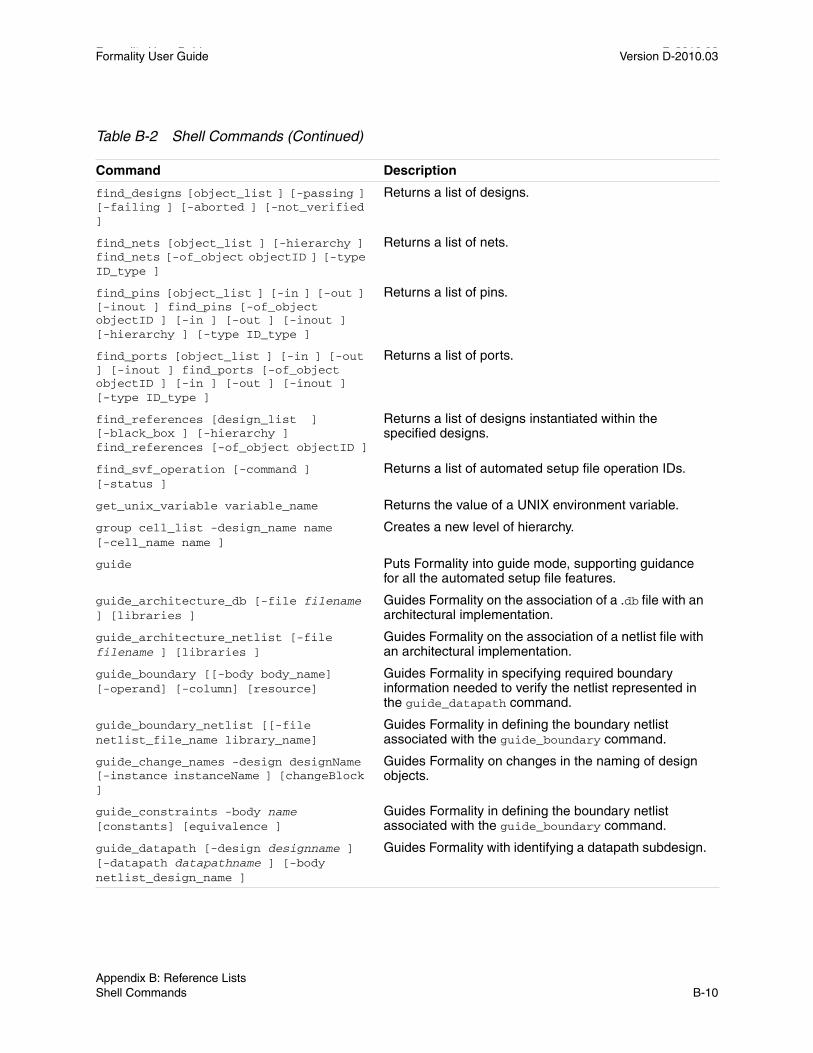
Formality User Guide D-2010.03Formality User Guide Version D-2010.03
find_designs [object_list ] [-passing ] [-failing ] [-aborted ] [-not_verified ]
Returns a list of designs.
find_nets [object_list ] [-hierarchy ] find_nets [-of_object objectID ] [-type ID_type ]
Returns a list of nets.
find_pins [object_list ] [-in ] [-out ] [-inout ] find_pins [-of_object objectID ] [-in ] [-out ] [-inout ] [-hierarchy ] [-type ID_type ]
Returns a list of pins.
find_ports [object_list ] [-in ] [-out ] [-inout ] find_ports [-of_object objectID ] [-in ] [-out ] [-inout ] [-type ID_type ]
Returns a list of ports.
find_references [design_list ] [-black_box ] [-hierarchy ] find_references [-of_object objectID ]
Returns a list of designs instantiated within the specified designs.
find_svf_operation [-command ] [-status ]
Returns a list of automated setup file operation IDs.
get_unix_variable variable_name Returns the value of a UNIX environment variable.
group cell_list -design_name name [-cell_name name ]
Creates a new level of hierarchy.
guide Puts Formality into guide mode, supporting guidance for all the automated setup file features.
guide_architecture_db [-file filename ] [libraries ]
Guides Formality on the association of a .db file with an architectural implementation.
guide_architecture_netlist [-file filename ] [libraries ]
Guides Formality on the association of a netlist file with an architectural implementation.
guide_boundary [[-body body_name] [-operand] [-column] [resource]
Guides Formality in specifying required boundary information needed to verify the netlist represented in the guide_datapath command.
guide_boundary_netlist [[-file netlist_file_name library_name]
Guides Formality in defining the boundary netlist associated with the guide_boundary command.
guide_change_names -design designName [-instance instanceName ] [changeBlock ]
Guides Formality on changes in the naming of design objects.
guide_constraints -body name [constants] [equivalence ]
Guides Formality in defining the boundary netlist associated with the guide_boundary command.
guide_datapath [-design designname ] [-datapath datapathname ] [-body netlist_design_name ]
Guides Formality with identifying a datapath subdesign.
Table B-2 Shell Commands (Continued)
Command Description
Appendix B: Reference ListsShell Commands B-10

Formality User Guide Version D-2010.03
guide_fsm_reencoding -design designName -previous_state_vector prevList -current_state_vector currList -state_reencoding stateList
Guides Formality on the changes in the encoding of the finite-state machine.
guide_group-design designName[-instance instanceName][-cells cellList ]-new_design newDesignName-new_instance newInstanceName[groupBlock ]
Guides Formality on the hierarchy created around design objects.
guide_inv_push-design designName-register registerName
Guides Formality on a register that has a logical inversion push across it. Register inversions are created during synthesis when phase inversion is turned on.
guide_mc-design designName
Guides Formality on identifying a subdesign generated by Module Compiler.
guide_multiplier-design designName[-instance instanceName ]-arch arch-body fileName
Guides Formality on identifying a subdesign as a multiplier with a specific architecture.
guide_reg_constant[-design designName ]instanceNameconstantVal
Guides Formality on the architecture of the constant register information stored in the automated setup file (.svf).
guide_reg_duplication[-design designName ] -from fromReg -to toList
Guides Formality on the architecture of the duplicate register information stored in the automated setup file (.svf).
guide_reg_encoding[-design designName ] -from fromStyle -to toStyle {bit:bit:[:bit]*}
Guides Formality on identifying the registers whose encoding has changed.
guide_reg_merging[-design designName ] -from fromReg -to toReg
Guides Formality on the architecture of the merged register information stored in the automated setup file (.svf).
guide_replace[-body name]inputoutputpre_graphpost_graph
Guides Formality on the transformation that takes place during datapath optimizations.
Table B-2 Shell Commands (Continued)
Command Description
Chapter B: Reference ListsShell Commands B-11Appendix B: Reference ListsShell Commands B-11

Formality User Guide D-2010.03Formality User Guide Version D-2010.03
guide_retiming[-design designName ] -direction direction -libCell cellName -input cellInput -output cellOutput -resetStateDontCare
Guides Formality on an atomic register move over a library cell or net fork. It records the library cell, register names before and after the move, and direction of the move.
guide_retiming_decompose[-design designName ] -preName previousName -postName changedName -classChanged
Guides Formality that a synchronous enable register in the reference has been decomposed (changed to a D flip-flop with a feedback MUX) in the implementation.
guide_retiming_finished Guides Formality that the current group of retiming guidance commands are finished.
guide_retiming_multibit[-design designName ] -multiName previousName -splitNames newName
Guides Formality that a multibit register has been split into individual one-bit registers.
guide_transformation -design designName -type type -input inputList -output outputList[-control controlList][-virtual virtualList][-pre_resource preResourceList][-pre-assign preAssignList][-post_resource post_ResourceList][-post_assign postAssignList][-datapath datapathList]
Guides Formality on the structure of datapath transformations.
guide_ungroup-design designName[-instance instanceName ][-cells cellList ][-all ][-small ][-flatten ][-start level ][ungroupBlock
Guides Formality on removing hierarchy from design objects.
guide_uniquify -design designName [uniquifyBlock ]
Guides Formality creating unique instances for design objects.
guide_ununiquify-design designName [ununiquifyBlock ]
Integrates uniquified instances back to their original designs.
help [command ] Returns information about Formality shell commands.
Table B-2 Shell Commands (Continued)
Command Description
Appendix B: Reference ListsShell Commands B-12

Formality User Guide Version D-2010.03
history [-h] [-r] [args...] Displays or modifies the commands recorded in the history list.
library_verification mode Transfers Formality from one of the design verification modes to technology library verification mode.
list_libraries Lists technology libraries currently loaded.
list_key_bindings Displays all the key bindings and edit mode of the current shell session.
man [command ] Displays man pages for Formality shell commands.
match [-datapath ] [-hierarchy ] Matches compare points.
memory Reports memory used by the Formality shell.
printenv variable_name Prints the values of environment variables.
printvar pattern Prints the values of one or more variables.
proc_args proc_name Displays the formal parameters of a procedure.
proc_body proc_name Displays the body of a procedure.
quit Exits the Formality shell.
read_container [-r | -i | -container containerID ][-replace ] file
Reads a previously written container into the Formality environment.
read_db[-r | -i | -container containerID ] [-libname library_name ][-technology_library ] [-merge ] [-replace_black_box ] file_list
Reads Synopsys .db designs or technology (cell) libraries.
read_ddc[-r | -i | -container containerID ] [-libname library_name ] [-technology_library ] file_list
Reads designs from a .ddc database.
read_fsm_states fie [designID ] Reads finite state machine (FSM) states.
read_milkyway[-r | -i | -container containerID][-libname library_name ] [-technology_library ] version version_number-cell_name mw_cell_name mw_db_path
Reads designs from a Milkyway design library.
Table B-2 Shell Commands (Continued)
Command Description
Chapter B: Reference ListsShell Commands B-13Appendix B: Reference ListsShell Commands B-13

Formality User Guide D-2010.03Formality User Guide Version D-2010.03
read_sverilog[-container container_name] [-r | -i ] [-libname libname ] [-technology_library ][-work_library libname ] [-vcs “VCS options” ][-define defines ][-f filename ][-file_names]
Reads one or more SystemVerilog design files or technology (cell) libraries into the Formality environment.
read_verilog[-r | -i | -container containerID ] [-libname library_name ] [-work_library library_name ] [-netlist ] [-technology_library ][-f vcs_option_file ] [-define ][-vcs “VCS options” ][-01 | -95 ] file_list ]
Reads one or more Verilog design files or technology (cell) libraries into the Formality environment.
read_vhdl[-r | -i | -container containerID ][-libname library_name ] [-work_library library_name ] [-technology_library ] [-87 | -93 ] file_list
Reads one or more VHDL files into the Formality environment.
redirect [-append ] file_name { command }string file_namestring command
Redirects the output of a command to a file.
remove_black_box[design_list ] -all
Undoes the set_black_box command.
remove_compare_rules [designID ]
Removes all user-defined compare rules.
remove_constant -all [-type ID_type ] instance_path ...
Removes specified or all user-defined constants.
remove_constraint constraint_name
Removes external constraints from the control points of a design.
remove_constraint_type type_name
Removes named user-defined external constraint types created using the create_constraint_type command.
remove_container container_list -all
Removes one or more containers from the Formality environment.
remove_cutpointobject_list [-type objectID_type ] -all
Removes the specified or all user-defined cutpoints. Formality accepts this command only in setup mode.
Table B-2 Shell Commands (Continued)
Command Description
Appendix B: Reference ListsShell Commands B-14

Formality User Guide Version D-2010.03
remove_design [-hierarchy ] [-shared_lib ] design_list
Removes designs from the Formality environment and replaces them with a black box.
remove_design_library library_list -all
Removes one or more design libraries from the Formality environment.
remove_distributed_processors machine machine ... | -all
Removes servers for the distributed processing that were added using add_distributed_processors.
remove_dont_verify_point [-type ID_type ][object_1 [object_2 ] ...] [-all ]
Undoes the set_dont_verify_point command for the specified objects.
remove_equivalence [-type ID_type ] item1 item2 -all
Removes one or all user-defined equivalences.
remove_guidance[-id <name>] -design <design_name>{ <cell_name>:<new_design_name> ...}
Removes all automated setup file (.svf) information that was previously entered through guidance commands or through the set_svf command.
remove_inv_push [-shared_lib ] objectIDlist -all
Removes user-defined inversion push.
remove_library library_list -all Removes one or more technology libraries from the Formality environment.
remove_object objectID [-shared_lib ] [-type ID_type ]
Removes one or more technology libraries from the Formality environment.
remove_parameters parameter_list [designID_list ... ]-all_designs
Removes user-defined, design-specific parameters.
remove_resistive_drivers Removes pull-ups, pulldowns, and bus holders.
remove_user_match [-all ] [-type type][instance_path ]
Un-matches objects previously matched by the set_user_match command.
rename_object objectID -file filename[new_name ][-type ID_type ] [-shared_lib] [-reverse ] [-container containerID ]
Renames one or more design objects.
report_aborted_points[-compare_rule ] [-loop ] [-hard ] [-unverified ] [-substring string ] [-point_type point_type ][-status status ]
Produces information about compare points not verified.
report_architecture[-set_architecture |[-hdlin_multiplier_architecture | -fm_pragma | -all | ObjectID ]
Displays the architecture used to implement the specified ObjectID as well as what caused the selection of that ObjectID.
Table B-2 Shell Commands (Continued)
Command Description
Chapter B: Reference ListsShell Commands B-15Appendix B: Reference ListsShell Commands B-15

Formality User Guide D-2010.03Formality User Guide Version D-2010.03
report_black_boxes[design_list | -r | -i | -con containerID ][-all | -unresolved | -interface_only | -empty | -set_black_box ]
Lists all the black boxes in a design.
report_cell_list [-r | -i ] [-matched ] [-unmatched ] [-verify ] [-passing ] [-failing ] [-aborting ] [-filter wildcard_pattern ]
Reports library cells depending on the option specified. This command is available only in the library verification mode.
report_compare_rules [designID ] Produces information about user-defined compare rules.
report_constants [objectID ... ] Produces information about user-defined constants.
report_constraint [constraint_name] [-long]
Provides information about constraints.
report_constraint_type [type_name] [-long ]
Provides information about constraint types.
report_containers Produces a list of containers.
report_cutpoints Reports all user-specified cutpoints.
report_design_libraries [item_list ] Produces information about design libraries.
report_designs [item_list ] Produces information about designs.
report_diagnosed_matching_region Reports information about matching regions for the most recent diagnosis. Matching regions are drivers in the matched design and are identified in the nondiagnosed design.
report_distributed_processors Reports all servers currently in the list of distributed servers and identifies the distributed working directory.
report_dont_verify_points Reports compare points disabled by the set_dont_verify_points command.
report_environment Produces information about user-defined parameters that affect the verification and simulation environment. Thi
s command becomes obsolete in a future release. It is recommended that you use the printvar Tcl command instead of using this command.
report_equivalences Produces information about user-defined equivalences.
report_error_candidates[-match ] [-expand ]
Produces information about error candidates for the most recent verification.
Table B-2 Shell Commands (Continued)
Command Description
Appendix B: Reference ListsShell Commands B-16

Formality User Guide Version D-2010.03
report_failing_points [-compare_rule] [-matched ] [-unmatched ][-substring string ][-point_type point_type ][-status status ]
Produces information about compare points that fail verification.
report_fsm [designID | -name FSM_name] Produces information about state encoding.
report_guidance[-datapath [-long ] ] [-to filename]
Reports to the transcript, or optionally to a file, all automated setup file (.svf) information that was previously entered through guidance commands or through the SVF command.
report_hdlin_mismatches [-summary | -verbose ] [-reference ] [-implementation ] [-container container_name ]
Reports and summarizes the RTL simulation/synthesis mismatches encountered during design linking.
report_hierarchy [designID ] Produces information about the hierarchy of a design.
report_inv_push [designID ] Produces information about user-defined inversion push.
report_libraries [-short ] [library_list ]
Produces information about technology libraries.
report_loops [-ref | -impl ][-limit N ][-unfold ]
Reports loops or portions of loops in either the reference or implementation.
report_matched_points[-compare_rule ] [-datapath ][-substring string ][-point_type point_type ] [-status status ] [-except_status status ][-method matching_method ] [-last ][[-type ID_type ] objectID...]
Reports all design objects (including compare points) matched by the match command.
report_parameters [design_list ] Produces information about user-defined parameters.
report_passing_points[-compare_rule ][-substring string ][-point_type point_type ][-status status ]
Produces information about compare points that passed the most recent verification.
report_status [-pass ] [-fail ] [-abort ]
Reports the current status of verification.
report_svf_operation[-guide ] [-message ] [-summary ] [-operationID_list ]
Reports information about specified operations.
Table B-2 Shell Commands (Continued)
Command Description
Chapter B: Reference ListsShell Commands B-17Appendix B: Reference ListsShell Commands B-17

Formality User Guide D-2010.03Formality User Guide Version D-2010.03
report_truth_table[-display fanin ][-fanin {list of signals} ][-constraints {signal=[0/1] }+ ][-nb_lins int ][-max_line int ][-max_fanin int ]
Generates and prints a truth table for a given signal.
report_unmatched_points[-compare_rule ] [-datapath ][-substring string ][-point_type point_type ] [-reference ][-implementation ] [-status status ][-except_status status ] [[-type ID_type ] objectID ...]
Reports points that have not been matched.
report_unverified_points[-compare_rule ][-substring string ][-point_type point_type ][-cause cause][-status status ][-inputs input_type]
Generates information about compare points that you have verified.
report_user_matches [-inverted | -noninverted | -unknown ]
Generates a list of points matched by the set_user_match command.
report_vhdl[-switches ] [-name ] [configuration ] [-entity ] [-package ]
Produces a list of VHDL configurations, entities, architectures, and associated generics and their default values.
restore_session file Restores a previously saved Formality session.
save_session [-replace ] filename Saves the current Formality session, including a design matched state.
select_cell_list[-cellNames/wildcards ][-filename ][-add cellNames/wildcards ][-remove cellNames/wildcards ][-clear ]
Selects library cells depending on the option specified.
set_architecture [ObjectID ] [csa | nbw | wall ]
Instructs Formality to specify the architecture for multiplier ObjectID or for a DesignWare partial product multiplier (DW02_multp) ObjectID. This command is available only during setup mode
set_black_box [designID_list ] Specifies to treat the specified design object as a black box for verification.
set_compare_rule [designID ] -from search_pattern -to replace_pattern [-type ID_type ] -file filename
Adds a name-matching rule that Formality applies to a design before creating compare points.
Table B-2 Shell Commands (Continued)
Command Description
Appendix B: Reference ListsShell Commands B-18

Formality User Guide Version D-2010.03
set_constant [-type ID_type ] instance_path state
Creates a user-defined constant by setting the logic state of a design object to 0 or 1.
set_constraint type_name control_point_list [designID ] [-name constraint_name ] [-map mapping_list ]
Creates an external constraint on a design.
set_cutpoint [-type ID_type ] objectID
Specifies that the given hierarchical pin or net is a hard cut point that should be verified independently and can be used as a free variable for verification of downstream compare points.
set_direction [-type ID_type ] objectID direction [-shared_lib ]
Defines port or pin directions.
set_dont_verify_point [-type ID_type ]-directly_undriven_output[objectID_list]
Prevents Formality from checking for design equivalence between two objects that constitute a compare point.
set_equivalence [-type ID_type ] [-propagate ] [-inverted ] objectID_1 objectID_2
Declares that two nets or ports have equivalent functions.
set_fsm_encoding encoding_list [designID ]
Enumerates FSM state names and their encodings.
set_fsm_state_vector flip-flop_list [designID ]
Names state vector flip-flops in an FSM.
set_implementation_design[designID ]
Establishes the implementation design.
set_inv_push [-shared_lib ] objectIDlist
Adds a sequential object to the list of objects through which Formality transports inverters for verification.
set_parameters [-flatten ] [-resolution function ] [-retimed ] [designID ]
Establishes verification parameters for a specific design.
set_power_gating_style [-hld_blocks name ] -type type
Sets the power_gating_style attribute on designs or HDL blocks, specifying the kind of retention register cells expected.
set_reference_design [designID ] Establishes the reference design.
set_svf [-append ] [-ordered ] [-extension name ] [filedirnames ]
Specifies the automated setup file (.svf) name (setup verification for Formality).
set_top[-vhdl_arch architecture_name ][designID | -auto ] [-parameter value ]
Sets and links the top-level reference or implementation design.
set_unix_variable variable_name new_value
Sets the value of a UNIX environment variable.
Table B-2 Shell Commands (Continued)
Command Description
Chapter B: Reference ListsShell Commands B-19Appendix B: Reference ListsShell Commands B-19

Formality User Guide D-2010.03Formality User Guide Version D-2010.03
set_user_match [-type ID_type ][-inverted ] [-noninverted ]object_1 object_2
Forces an object in the reference design to match an object in the implementation design during compare point matching.
setup Reverts a design from a MATCHED to a SETUP state.
sh [args ] Executes a command in a child process.
simulate_patterns [-no_link ] file Simulates the implementation and reference designs by using previously failing patterns as input vectors.
source [-echo] [-verbose] file Reads a file and evaluates it as a Tcl script.
start_gui Invokes the Formality GUI.
stop_gui Exits the Formality GUI.
test_compare_rule [-designID | -r | -i ] -from search_pattern -to search_pattern-name name [...][-substring string]
Tests a name matching rule on current unmatched points or user-specified names.
translate_instance_pathname [-type ID_type ] pathname
Translates an instance-based path name to a Formality designID or objectID.
unalias pattern Removes one or more aliases.
undo_match [-all ] Undoes the results of the match command.
ungroup cell_list | -all [-prefix prefix_name ] [-flatten ] [-simple_names ]
Removes a level of hierarchy.
uniquify [designID ] Creates unique design names for multiply instantiated designs in hierarchical designs.
verify [designID_1 designID_2 ] [[-inverted] | [-type ID_type ] objectID_1 objectID_2 ][[-constant0 | constant1 ][-type ID_type ] objectID ][-restart | -incremental ][-level integer ]]
Causes Formality to prove or disprove functional equivalence given two designs or two comparable design objects.
which filename_list Locates a file and displays its path name.
write_container [-r | -i | -container container_name ][-replace ] [-quiet ] filename
Saves the information in the current or specified container to a file.
write_failing_patterns [-diagnosis_patterns ] [-verilog ] [-replace ] filename
Saves failing patterns from the most recent diagnosis.
Table B-2 Shell Commands (Continued)
Command Description
Appendix B: Reference ListsShell Commands B-20

Formality User Guide Version D-2010.03
write_hierarchical_verification_script[-replace ] [-noconstant ][-noequivalence ] [-match type ][-save_directory pathname ][-save_file_limit integer ][-save_time_limit integer ][-level integer ] filename
Creates a hierarchical verification Tcl script that may be subsequently executed. You can use it to isolate verification issues to hierarchical subblocks.
write_library_debug_scripts[-dir directory_name ]
Debugs failing cells from library verification mode in the standard Formality design format.
Table B-2 Shell Commands (Continued)
Command Description
Chapter B: Reference ListsShell Commands B-21Appendix B: Reference ListsShell Commands B-21

Formality User Guide D-2010.03Formality User Guide Version D-2010.03
Appendix B: Reference ListsShell Commands B-22

Formality User Guide Version D-2010.03
Chapter B: Reference ListsShell Commands B-23Appendix B: Reference ListsShell Commands B-23

Formality User Guide D-2010.03Formality User Guide Version D-2010.03
Appendix B: Reference ListsShell Commands B-24

Formality User Guide Version D-2010.03
Chapter B: Reference ListsShell Commands B-25Appendix B: Reference ListsShell Commands B-25

Formality User Guide D-2010.03Formality User Guide Version D-2010.03
Appendix B: Reference ListsShell Commands B-26

Formality User Guide Version D-2010.03
Chapter B: Reference ListsShell Commands B-27Appendix B: Reference ListsShell Commands B-27

Formality User Guide D-2010.03Formality User Guide Version D-2010.03
Appendix B: Reference ListsShell Commands B-28

Formality User Guide Version D-2010.03
Chapter B: Reference ListsShell Commands B-29Appendix B: Reference ListsShell Commands B-29

Formality User Guide D-2010.03Formality User Guide Version D-2010.03
Appendix B: Reference ListsShell Commands B-30

Formality User Guide Version D-2010.03
Chapter B: Reference ListsShell Commands B-31Appendix B: Reference ListsShell Commands B-31

Formality User Guide D-2010.03Formality User Guide Version D-2010.03
Appendix B: Reference ListsShell Commands B-32

Formality User Guide Version D-2010.03
Chapter B: Reference ListsShell Commands B-33Appendix B: Reference ListsShell Commands B-33

Formality User Guide D-2010.03Formality User Guide Version D-2010.03
Appendix B: Reference ListsShell Commands B-34

Formality User Guide Version D-2010.03
Chapter B: Reference ListsShell Commands B-35Appendix B: Reference ListsShell Commands B-35

Formality User Guide D-2010.03Formality User Guide Version D-2010.03
Appendix B: Reference ListsShell Commands B-36

Formality User Guide Version D-2010.03
Chapter B: Reference ListsShell Commands B-37Appendix B: Reference ListsShell Commands B-37

Formality User Guide D-2010.03Formality User Guide Version D-2010.03
Appendix B: Reference ListsShell Commands B-38

Formality User Guide Version D-2010.03
Chapter B: Reference ListsShell Commands B-39Appendix B: Reference ListsShell Commands B-39

Formality User Guide D-2010.03Formality User Guide Version D-2010.03
Appendix B: Reference ListsShell Commands B-40

Index
Symbols> operator 3-15>> operator 3-15
Aaborted compare points
defined 9-6during verification 9-7
add_distributed_processors command 9-10, B-9
alias command 3-14, B-9aliases 3-14analyze_points command 10-6, 10-44AND resolution function 7-43, 7-44application commands A-3architecture_selection_precedence variable
B-2arguments
designID 6-8positional A-4programming default values A-14varying the number of A-14
arithmetic generatorcreating multiplier architectures 7-48
ASIC verification flow diagram 1-3, 1-4asynchronous bypass logic 7-31
asynchronous state-holding loops 7-33attributes, black box 7-6automated setup file
creating 5-4reading 5-7reading multiple 5-12
automaticcreating compare points 1-7, 7-48creating containers 6-6
Bbatch mode
controlling verification 9-17overview 9-15preparing for 9-15running 9-16scripts 9-15
black boxattributes 7-6controlling 7-4debugging 10-11identity check 3-21, 7-5, 7-7loading design interfaces 7-5locating 10-7marking designs 7-6overview 7-3redefining 7-8
IN-1IN-1

Formality User Guide Version D-2010.03
reporting 7-6resolution function 7-43, 7-44setting pins and port directions 7-8unresolved 7-7verifying 7-3, 10-7
boundary scan 7-16built-in commands A-6bus holders 7-4bus_dimension_separator_style variable B-2bus_extraction_style variable B-2bus_naming_style variable B-2bus_range_separator_style variable B-2
Ccell
defined 6-5library verification 11-1
change_names command 10-20clock gating 7-18clock tree buffering 7-17collapse_all_cg_cells value 7-20color-coding
error candidates 10-25schematic area 10-25
combinational design changes 7-15boundary scan 7-16clock tree buffering 7-17internal scan insertion 7-15
command alias 3-14command log file 3-16command names, syntax A-4command results, returning A-5command shortcuts 3-13commands
add_distributed_processors 9-10, B-9alias 3-14, B-9application, using A-3built-in A-6case-sensitivity 3-9
change_names 10-20commenting A-5cputime 3-8, B-9create_constraint_type 7-12, B-9create_container 3-21, 3-22, 6-19, 6-20, 7-7,
7-8, 7-43, B-9create_cutpoint_blackbox 10-40, B-9current_container B-9current_design B-9debug_library_cell 11-10, B-9diagnose B-9echo 3-15, B-9elaborate_library_cells 11-7, B-9entering commands 3-9error_info B-9exit B-9find_cells B-9find_designs B-10find_nets B-10find_pins B-10find_ports B-10find_references B-10flow control, Tcl A-11fm_shell 3-4, 3-23get_unix_variable B-10getting syntax information 3-7, 3-8group B-10guide B-9, B-10guide_architecture_db B-10guide_architecture_netlist B-9, B-10guide_change_names B-9, B-10guide_datapath B-9, B-10guide_fsm_reencoding B-11guide_group B-11guide_multiplier B-11guide_reg_constant B-11guide_reg_duplication B-11guide_reg_merging B-11guide_transformation B-12guide_ungroup B-12guide_uniquify B-12guide_ununiquify B-12
IN-2Index IN-2

Formality User Guide Version D-2010.03
help 3-7, A-7, B-12-help option 3-7, 3-8history 3-12, B-13interrupting 3-8, 3-19library_verification 11-3, B-13line breaks 3-10list_key_bindings B-13list_libraries B-13man 3-7, 3-8, B-13match 8-4, B-13memory B-13multiline shell commands 3-10nesting A-5positional arguments A-4printenv B-13printvar B-13proc_args B-13proc_body B-13procedures A-7puts 3-15quit B-13read_container B-13read_db 6-8, 11-4, 11-5, B-13read_ddc 6-10, B-13read_fsm_states 7-35, B-13read_milkyway 6-9, 6-10, 6-11read_verilog 6-13, 6-14, 11-4, B-14read_vhdl 6-13, 6-14, B-14recalling 3-13redirect 3-15, B-14remove_black_box B-14remove_compare_rules 8-4, 10-17, B-14remove_constant B-14remove_constraint 7-13, B-14remove_constraint_type 7-14, B-14remove_container B-14remove_cutpoint_blackbox B-14remove_design B-15remove_design_library B-15remove_distributed_processors 9-11, B-15remove_dont_verify_point 9-18, B-15remove_equivalence 7-38, 7-39, B-15
remove_guidance B-15remove_inv_push B-15remove_library B-15remove_parameters B-15remove_resistive_drivers B-15remove_user_match 8-4, 10-13, B-15rename_object 10-19, B-15report_aborted_points 9-5, B-15report_architecture 7-50, B-15report_black_boxes 7-6, B-16report_cell_list 11-5, B-16report_compare_rules 10-17, B-16report_constants 7-10, B-16report_constraint 7-14, B-16report_constraint_type 7-14, B-16report_containers B-16report_cutpoints B-16report_design_libraries B-16report_designs B-16report_diagnosed_matching_region B-16report_distributed_processors 9-11, B-16report_dont_verify_points 9-18, B-16report_environment B-16report_equivalences B-16report_error_candidates B-16report_failing_points 9-5, B-17report_fsm 7-36, B-17report_guidance B-17report_hdlin_mismatches B-17report_hierarchy B-17report_inv_push B-17report_libraries B-17report_loops 7-33, B-17report_parameters B-17report_passing_points B-17report_power_gating 7-46report_status 11-10, B-17report_truth_table 11-11, B-18report_unmatched_inputs 10-7report_unmatched_points 8-5, B-17, B-18report_unverified_points B-18report_user_matches 10-13, B-18
IN-3Index IN-3

Formality User Guide Version D-2010.03
restore_session B-18returning results 3-9save_session B-18select_cell_list 11-6, B-18set_architecture 7-49, B-18set_black_box 7-6, B-18set_compare_rule 10-14, B-18set_constant 7-9, B-19set_constraint 7-12, B-19set_cutpoint B-19set_direction B-19set_dont_verify_point 9-18, B-19set_equivalence 7-37, 7-38, B-19set_fsm_encoding 7-35, B-19set_fsm_state_vector 7-35, B-19set_implementation_design B-19set_inv_push 7-24, B-19set_parameters 7-27, 7-28, B-19set_power_gating_style 7-46, B-19set_reference_design B-19set_svf 5-4, B-19set_top B-19set_unix_variable B-19set_user_match 7-17, 10-12, B-20setup 8-4, B-20sh B-20simulate_patterns B-20source 3-18, B-20special characters A-5start_gui B-20stop_gui B-20Tcl syntax A-1test_compare_rule 10-16translate_instance_pathname B-20unalias 3-15, B-20undo_match 8-8, B-20ungroup B-20uniquify B-20verify 9-3, 9-5, 9-8, 11-7, B-20which B-20write_container B-20write_failing_patterns 10-39, B-20
write_hierarchical_verification_script 9-14, B-21
write_library_debug_scripts 11-11, B-21commenting commands A-5compare points
aborted 9-6, 9-7automatic creation of 1-7, 7-48debugging 10-11debugging unmatched 8-6defining your own 1-8exact-name matching 8-9example 1-9failing 9-6listing user-matched points 10-13mapping names between 1-8matched state 8-3matching 8-4
flow 8-3related variables 8-9techniques 1-8, 8-8
name filtering 8-10name-based matching 8-8net-name matching 8-14non-name-based matching 8-8not verified 9-6objects used to create 1-8overview 1-8passing 9-6removing 10-13signature analysis 8-12status messages 9-6topological equivalence 8-12undoing match command 8-8unmatched, reporting 8-5unverified 9-6verifying single 9-3, 9-8
compare rules 10-14defining 10-14listing 10-17removing 10-17testing 10-16
IN-4Index IN-4

Formality User Guide Version D-2010.03
compile_power_domain_boundary_optimization command 7-29
complete verification 1-7concepts
black boxes 7-3compare points 1-8constants 7-8containers 6-5current container 6-20design equivalence 1-10design objects 6-5external constraints 7-11FSMs 7-34implementation design 1-5logic cones 1-6LSSD cell 7-47reference design 1-5resolution functions 7-43signature analysis 8-12verification 9-3
consensus, resolution function 7-43consistency, defined 1-10console window
toolbar 10-23constants
defining 7-8listing 7-10overview 7-8propagating 7-8, 7-42removing 7-9types 7-8user-defined 7-8
constraint module 7-13containers
automatic creation 6-6contents 6-5creating 6-6, 6-20current 6-6, 6-20listing 6-20naming 6-20overview 6-5
reading data into 6-6control flow commands, Tcl A-11control statements 9-17Control-c interrupt 3-8, 3-19, 9-7controlling
black boxes 7-4coverage percentage 10-33cputime command 3-8, B-9create_constraint_type command 7-12, B-9create_container command 3-21, 3-22, 6-19,
6-20, 7-7, 7-8, 7-43, B-9create_cutpoint_blackbox command 10-40,
B-9creating
automated setup files 5-4constraint types 7-12containers 6-6, 6-20multiplier architectures 7-48procedures A-13tutorial directories 4-2
.cshrc 4-2current
container 6-6, 6-20design 6-20
current_container command B-9current_design command B-9
Ddata
containers 6-5failing patterns 10-40.fpt files 10-40output file types 3-21, 3-22
.ddc databasesdesigns from 6-10, 6-11reading designs 6-10
.ddc files 6-10, 6-11debug_library_cell command 11-10, B-9debugging
IN-5Index IN-5

Formality User Guide Version D-2010.03
black boxes 10-11compare points 10-11determining failure causes 10-6eliminating setup possibilities 10-10failing patterns 10-39gathering information 10-5library cells 11-10matching with compare rules 10-14renaming objects 10-19setting compare points to match 10-11strategies 10-5subset matching 10-17unmatched compare points 8-6using diagnosis 10-8using logic cones 10-9working with subcones 10-34
definingcompare points 1-8constants 7-8FSM states 7-34
dereferencing variables A-5design equivalence 7-37
overview 1-10design objects
finding 10-26generating lists 10-26overview 6-5renaming 10-19unmatched 1-8used in compare point creation 1-8
designID, argument 6-8designs
constants 7-8current 6-20designID 6-8failing patterns, simulating 10-40flattened 7-41hierarchy separator style 7-42implementation 1-5linking (with set_top) 6-5locating problem areas 10-5
marking as black boxes 7-6propagating constants 7-8reference 1-5retiming 7-25retiming using Design Compiler 7-25retiming with other tools 7-27setting the top-level design 6-17setting up 7-1
diagnose command B-9diagnosis
debugging with 10-8interrupting 3-8, 3-19
diagnosis_enable_error_isolation variable B-2diagnosis_enable_find_matching_candidates
variable B-2diagnosis_pattern_limit variable B-2directory
creating for tutorial 4-2distributed verification process 9-10
setting up environment 9-10verifying environment 9-13
distributed_64bit_mode variable B-2distributed_verification_mode variable B-2distributed_work_directory variable B-2don’t care information
verification modes 1-10dw_foundation_threshold variable B-2
Eecho command 3-15, B-9elaborate_library_cells command 11-7, B-9enable_mulitplier_generation variable B-3enable_multiplier_generation variable 7-49enable_power_gating variable 7-46equivalences 7-37
defining 7-38listing user-defined 7-39removing 7-38
error candidates
IN-6Index IN-6

Formality User Guide Version D-2010.03
color-coding 10-25coverage percentage 10-33
error messages 3-19, 3-20error_info command B-9escape quoting A-5exact-name compare point matching 8-9examples
bus holder 7-4compare point, creation 1-9logic cone 1-6multiply-driven nets 7-45resolution function 7-45schematic view window 10-21
exit command B-9expressions
evaluation, Tcl A-10grouping A-5
external constraintscreating constraint types 7-12overview 7-11removing 7-13removing constraint type 7-14reporting 7-14reporting constraint types 7-14setting 7-12types 7-11user-defined 7-13
Ffailing compare points, defined 9-6failing patterns
applying from logic cone window 10-39applying in the logic cone view window 10-28coverage percentage 10-33default number 10-37limiting 10-37saving 10-39simulating 10-40
filesbatch script 9-15
command log 3-16.ddc 6-10, 6-11failing patterns 10-40fm_shell_command log 3-23formality.log 10-5.fpt type 10-40log 3-23output 3-21, 3-22reading automated setup 5-7session log 3-16state files for FSMs 7-35
find_cells command B-9find_designs command B-10find_nets command B-10find_pins command B-10find_ports command B-10find_references command B-10find_svf_operation command 5-10, B-10finding
design objects 10-26lists of design objects 10-26unmatched black boxes 10-7
finite state machines (FSMs)defining states individually 7-34, 7-35listing state encoding information 7-36overview 7-34preparing for verification 7-34state files 7-35
flattening designsconstant propagation 7-42during verification 7-41separator style 7-42
fm_shellgetting help 3-6listing commands 3-7starting 3-4
fm_shell command 3-4, 3-23-f option 9-16syntax A-3within GUI 3-17
for loops, Tcl flow control A-12
IN-7Index IN-7

Formality User Guide Version D-2010.03
foreach command, Tcl flow control A-12Formality
generated file names, controlling 3-23log files 10-5
formality_svf directory 5-11formality.log file 10-5.fpt files 10-40FSM reencoding 7-34
Gget_unix_variable command B-10golden design 1-5group command B-10grouping expressions A-5grouping words, Tcl commands A-6GUI
current container 6-20failing pattern view window 10-38highlighting toolbar 10-36logic cone view window 10-28, 10-29overview 3-16Probe Points tab 10-36schematic view window 10-21starting 3-6
gui_report_length_limit variable B-3guidance summary 5-8, 10-42guide command B-9, B-10guide_architecture_db command B-10guide_architecture_netlist command B-9, B-10guide_change_names command B-9, B-10guide_datapath command B-9, B-10guide_fsm_reencoding command B-11guide_group command B-11guide_inv_push variable B-11guide_multiplier command B-11guide_reg_constant command B-11guide_reg_duplication command B-11guide_reg_encoding variable B-9, B-11
guide_reg_merging command B-11guide_retiming variable B-12guide_retiming_decompose variable B-12guide_retiming_finished variable B-12guide_retiming_multibit variable B-12guide_transformation command B-12guide_ungroup command B-12guide_uniquify command B-12guide_ununiquify command B-12
Hhdlin_auto_netlist variable B-3hdlin_auto_top variable 6-17, B-3hdlin_do_inout_port_fixup variable B-3hdlin_dwroot variable B-3hdlin_dyn_array_bnd_check variable B-3hdlin_enable_verilog_assert variable B-3hdlin_error_on_mismatch_message variable
B-2, B-3hdlin_ignore_builtin variable B-2, B-3hdlin_ignore_dc_script variable B-3hdlin_ignore_full_case variable B-3hdlin_ignore_label variable B-3hdlin_ignore_label_applies_to variable B-3hdlin_ignore_map_to_entity variable B-3hdlin_ignore_map_to_module variable B-3hdlin_ignore_map_to_operator variable B-2,
B-3hdlin_ignore_parallel_case variable B-4hdlin_ignore_resolution_method variable B-4hdlin_ignore_synthesis variable B-4hdlin_ignore_translate variable B-4hdlin_infer_multibit variable 7-51hdlin_infer_mux variable B-4hdlin_interface_only variable B-4hdlin_interface_only variables 3-4, 3-5, 3-7,
3-12, 3-13, 3-14, 3-15, 3-18, 3-19, 3-20, 7-5
IN-8Index IN-8

Formality User Guide Version D-2010.03
hdlin_library_directory variable 6-13, B-4hdlin_library_file variable 6-13, B-4hdlin_library_report_summary variable B-4hdlin_multiplier_architecture variable 7-48, B-4hdlin_normalize_blackbox_busses variable
B-2, B-4hdlin_synroot variable B-4hdlin_unresolved_modules variable B-4hdlin_verilog_95 variable B-4hdlin_verilog_wired_net_interpretation
variable B-4hdlin_vhdl_87 variable B-4hdlin_vhdl_auto_file_order variable B-5hdlin_vhdl_forgen_inst_naming variable B-5hdlin_vhdl_fsm_encoding variable B-5hdlin_vhdl_integer_range_constraint variable
B-5hdlin_vhdl_others_covers_extra_states
variable B-5hdlin_vhdl_presto_naming variable B-5hdlin_vhdl_presto_shift_div variable B-5hdlin_vhdl_strict_libs variable B-5hdlin_vhdl_use_87_concat variable B-5hdlin_warn_on_mismatch_message variable
B-5help
command 3-7, A-7, B-12fm_shell commands 3-6
-help, options 3-7hierarchical designs 7-41
GUI representation 6-8hierarchy separator style 7-42propagating constants 7-42storaging 6-6traversing 10-21, 10-25
hierarchical separator character, defining 7-42hierarchical verification 9-14history command 3-12, B-13
Iidentity check, black boxes 3-21, 7-5, 7-7if command, Tcl flow control A-11impl variable B-5implementation design
establishing 1-5overview 1-5
implementation libraries 11-5install directory 4-2installation 2-3, 4-2interfaces
GUI 3-16internal scan insertion 7-15interpreting verification results 9-16interrupting
diagnosis 3-8, 3-19fm_shell commands 3-8, 3-19verification 9-7
introduction to Formality 1-1inversion push 7-23
environmental 7-24instance-based 7-24
invokingfm_shell 3-4GUI 3-6
isolatingsubcones 10-34
Llibraries
Verilog simulation 6-15library verification 11-1
debugging process 11-7, 11-10implementation library 11-5initializing 11-3process flow 11-2reference library 11-4reporting library cells 11-5reporting status 11-10
IN-9Index IN-9

Formality User Guide Version D-2010.03
sample Tcl script 11-7specifying the cells to verify 11-6supported formats 6-12, 6-21, 6-22, 11-3truth tables 11-10verifying the libraries 11-7versus design verification 11-3, 11-4, 11-7
library_verification command 11-3, B-13limiting
failing patterns 10-37messages 3-21
linking designs 6-5list_key_bindings command B-13list_libraries command B-13listing
constants 7-10design objects 10-26fm_shell commands 3-7previously entered commands 3-12
lists in Tcl A-7loading design interfaces, black boxes 7-5locating
design objects 10-26design problems 10-5lists of design objects 10-26problems 7-8unmatched black boxes 10-7
log file 3-16log files 3-23
formality.log 10-5Logic Cone
grouping hierarchyGrouping Hierarchylogic cone 10-35
logic cone view windowapplying failed patterns 10-28overview 10-28subcones 10-34
logic cone, diagnose 10-9logic cones 10-37
originating point 1-6overview 1-6
termination points 1-6viewing 10-28
loops, Tcl A-11LSSD cell, defined 7-47
Mman command 3-7, 3-8, B-13man page overview 3-7managing, black boxes 7-4mapping names
compare points 1-8design objects 10-19
marking designs as black boxes 7-6match command 8-4, B-13matched verification status 8-3matching compare points 8-4memory command B-13message thresholds, setting 3-21message_level_mode variable B-5messages
error 3-19limiting 3-21setting threshold 3-21syntax 3-19types 3-21
Milkyway databasesreading 6-10, 6-11
multibit support 7-51mw_logic0_net variable 6-11, B-5mw_logic1_net variable 6-11, B-5
Nname filtering compare point matching 8-10name_match variable 8-9, 8-10, B-5name_match_allow_subset_match variable
8-9, 10-18, B-5name_match_based_on_nets variable 8-9,
8-14, B-5
IN-10Index IN-10

Formality User Guide Version D-2010.03
name_match_filter_chars variable 8-9, 8-11, 10-17, B-5
name_match_flattend_hierarchy_separator_style variable B-6
name_match_flattened_hierarchy_separator_style variable 8-9
name_match_multibit_register_reverse_order variable 8-9, 8-11, B-6
name_match_net variable B-6name_match_pin_net variable B-6name_match_use_filter variable 8-9, 8-10,
10-18, B-6name_matched_flattened_hierarchy_separato
r_style variables 7-42nesting commands A-5, A-10net-name compare point matching 8-14nets
constant value 7-8setting to a constant 7-9with multiple drivers 7-43
not verified compare points 9-6
Ooptions, syntax A-4OR resolution function 7-43, 7-44output
file types 3-21, 3-22redirecting 3-15
overviewblack boxes 7-3compare points 1-8constants 7-8containers 6-5design equivalence 1-10design objects 6-5external constraints 7-11finite state machines (FSMs) 7-34implementation design 1-5library verification 11-2logic cones 1-6
man pages 3-7reference design 1-5resolution functions 7-43verification 9-3
overwriting file names 3-23
Pparameters
automatically flattening designs 7-41constant propagation 7-42design 7-1hierarchical separator style 7-42identity check, black boxes 3-21, 7-7message threshold 3-21multiply-driven net resolution 7-44
passing compare points 9-6path, setting 4-2pins
defining direction 7-8ports
constant value 7-8defining direction 7-8direction, black boxes 7-4setting to a constant 7-9
positional arguments with, commands A-4power domain, cell coloring 10-37previous session, sourcing 3-16printenv command B-13printing
schematics 10-27printvar command B-13Probe points 10-35problem areas, see troubleshootingproc_args command B-13proc_body command B-13procedures
creating A-13default A-7
propagating constants 7-8, 7-42
IN-11Index IN-11

Formality User Guide Version D-2010.03
puts built-in command 3-15
Qquick-start tutorial 2-1, 4-1, 4-7quit command B-13quotation marks, using A-6quotes, using A-6
Rread_container command B-13read_db command 6-8, 11-4, 11-5, B-13read_ddc command 6-10, B-13read_fsm_states command 7-35, B-13read_milkyway command 6-9, 6-10, 6-11read_verilog command 6-13, 6-14, 11-4, B-14read_vhdl command 6-13, 6-14, B-14reading
.ddc databases 6-10, 6-11FSM states 7-35mutliple automated setup files 5-12
redefiningblack boxes 7-8
redirect command 3-15, B-14redirecting
output 3-15ref variable B-6reference design
establishing 1-5overview 1-5
reference libraries 11-4regression testing 1-5remove_black_box command B-14remove_compare_rules command 8-4, 10-17,
B-14remove_constant command B-14
-type option 7-9remove_constraint command 7-13, B-14
remove_constraint_type command 7-14, B-14remove_container command B-14remove_cutpoint_blackbox command B-14remove_design command B-15remove_design_library command B-15remove_distributed_processors command
9-11, B-15remove_dont_verify_point command 9-18,
B-15remove_equivalence command 7-38, 7-39,
B-15remove_guidance command B-15remove_inv_push command B-15remove_library command B-15remove_parameters command B-15remove_resistive_drivers command B-15remove_user_match command 8-4, 10-13,
B-15removing
subcones 10-34rename_object command 10-19, B-15renaming design objects 10-19report_aborted_points command 9-5, B-15report_always_on_cells command 7-29report_architecture command 7-50, B-15report_black_boxes command 7-6, B-16report_cell_list command 11-5, B-16report_compare_rules command 10-17, B-16report_constants command 7-10, B-16report_constraint command 7-14, B-16report_constraint_type command 7-14, B-16report_containers command B-16report_cutpoints command B-16report_design_libraries command B-16report_designs command B-16report_diagnosed_matching_region command
B-16report_distributed_processors command 9-11,
B-16
IN-12Index IN-12

Formality User Guide Version D-2010.03
report_dont_verify_points command 9-18, B-16
report_environment command B-16report_equivalences command B-16report_error_candidates command B-16report_failing_points command 9-5, B-17report_fsm command 7-36, B-17report_guidance command 5-10, 5-11, B-17report_hdlin_mismatches command B-17report_hierarchy command B-17report_inv_push command B-17report_libraries command B-17report_loops command 7-33, B-17report_parameters command B-17report_passing_points command B-17report_power_gating command 7-46report_status command 11-10, B-17report_svf_operation command 10-45report_truth_table command 11-11, B-18report_unmatched_inputs command 10-7report_unmatched_points command 8-5,
B-17, B-18report_unverified_points command B-18report_user_matches command 10-13, B-18reporting
black boxes 10-7reporting black boxes 7-6reports 10-5
compare rules 10-17constants, user-defined 7-10containers 6-20equivalences, user-defined 7-39finite state machine (FSMs) information 7-36library cells 11-5library verification results 11-10truth tables 11-10
resolution functionsmultiply-driven nets 7-43overview 7-43
resolving
multiply-driven nets 7-43nets with multiple drivers 7-43
restore_session command B-18results 9-7retimed designs, working with 7-25retiming designs
using Design Compiler 7-25using other tools 7-27verifying with Formality 7-26
returningsubcones 10-35
returning shell command results A-5rigid quoting A-5
Ssave_session command B-18saving
failing patterns 10-39schematic view window
example 10-21zooming 10-27
schematic_expand_logic_cone variable B-6schematics
printing 10-27viewing logic cones 10-28
script filebatch jobs 9-15sourcing 3-18, 9-16tasks 3-18
search_path variable B-6select_cell_list command 11-6, B-18separating list items, Tcl commands A-8sequential design changes 7-18
asynchronous bypass logic 7-31clock gating 7-18inversion push 7-23
set_architecture command 7-49, B-18set_black_box command 7-6, B-18set_compare_rule command 10-14, B-18
IN-13Index IN-13

Formality User Guide Version D-2010.03
set_constant command 7-9, B-19-type option 7-9
set_constraint command 7-12, B-19set_cutpoint command B-19set_direction command B-19set_dont_verify_point command 9-18, B-19set_equivalence command 7-37, 7-38, B-19set_fsm_encoding command 7-35, B-19set_fsm_state_vector command 7-35, B-19set_implementation_design command B-19set_inv_push command 7-24, B-19set_parameters command 7-27, 7-28, B-19set_power_gating_style command 7-46, B-19set_probe_points command 10-36set_reference_design command B-19set_svf command 5-4, B-19set_top command B-19
conditions 6-12set_unix_variable command B-19set_user_match command 7-17, 10-12, B-20setting
implementation design 1-5message thresholds 3-21pins and port directions 7-8reference design 1-5top-level design 6-17
setup command 8-4, B-20severity rating for messages 3-21sh command B-20sh_arch variable B-6sh_continue_on_error variable B-6sh_enable_page_mode variable B-6sh_product_version variable B-6sh_source_uses_search_path variable B-6shell interface, starting 3-4signature analysis 8-12signature_analysis_allow_net_match variable
B-2, B-6
signature_analysis_allow_subset_match variable B-6
signature_analysis_match_blackbox_input variable B-6
signature_analysis_match_blackbox_output variable B-6
signature_analysis_match_compare_point variable B-6
signature_analysis_match_compare_points variable B-7
signature_analysis_match_datapath variable B-7
signature_analysis_match_hierarchy variable B-6
signature_analysis_match_net variable B-7signature_analysis_match_primary_input
variable 8-9, B-2, B-7signature_analysis_match_primary_output
variable 8-9, 8-13, B-7signature_analysis_matching variable 8-9,
8-13simulate_patterns command B-20simulating previously failing patterns 10-40single-state holding elements 7-47source command B-20
batch jobs 9-16syntax 3-18
sourcingprevious sessions 3-16script files 3-18, 9-16
special charactersTcl A-5
start_gui command B-20starting
fm_shell 3-4GUI 3-6
state files for FSMs 7-35stop_gui command B-20subcones 10-34, 10-35succeeded verification 9-7svf_datapath variable B-7
IN-14Index IN-14

Formality User Guide Version D-2010.03
svf_ignore_unqualified_fsm_information variable 7-34
switch command, Tcl flow control A-13synopsys_auto_setup variable B-2synopsys_root variable B-7syntax
fm_shell commands A-4procedures A-7
TTcl
arguments, varying the number of A-14break command A-13commands that support lists A-7continue command A-13control flow commands A-11expression evaluation A-10for loops A-12foreach command A-12grouping words A-6lists A-7nesting commands A-10overview A-1quoting values A-6separating list items 3-10, A-8special characters A-5switch command A-13user-defined variables A-9while command A-11
Tcl variablesdistributed_64bit_mode 9-11distributed_verification_mode 9-11distributed_work_directory 9-10
TECH_WORK library 6-7technology libraries
default name 6-7shared 6-20unshared 6-20verifying 11-1
terminating loops, Tcl A-13
test_compare_rule command 10-16thresholds, message level 3-21toolbar, console window 10-23top-level designs 6-5topological equivalence 8-12transcript window 10-5translate_instance_pathname command B-20traversing hierarchical designs 10-21, 10-25troubleshooting
asynchronous state-holding loops 7-33black boxes 10-7, 10-11determining failure cause 10-5, 10-6eliminating setup possibilities 10-10extraneous bus drivers 7-4failing patterns 10-39failing patterns, simulating 10-40gathering information 10-5incomplete verification 10-5locating problems 7-8logic cones, viewing 1-6matching with compare rules 10-14problem areas, locating 10-5renaming objects 10-19setting compare points to match 10-11subset matching 10-17unmatched compare points 8-6using diagnosis 10-8using logic cones 10-9working with subcones 10-34
truth table 11-11tutorial 2-1tutorial directories
creating 4-2
Uunalias command 3-15, B-20undo_match command 8-8, B-20ungroup command B-20uniquify command B-20
IN-15Index IN-15

Formality User Guide Version D-2010.03
unmatched compare points 8-5unverified compare points, defined 9-6UPF
IEEE 1801 (UPF) 7-27Low Power Designs 7-27
user-definedcompare points 1-8constants 7-8
removing 7-9reporting 7-10
equivalences 7-37variables, Tcl A-9
user-defined equivalence, removing 7-38user-specified file names 3-23
Vvalues, quoting A-6variables
architecture_selection_precedence B-2bus_dimension_separator_style B-2bus_extraction_style B-2bus_naming_style B-2bus_range_separator_style B-2dereferencing A-5diagnosis_enable_error_isolation B-2diagnosis_enable_find_matching_candidate
s B-2diagnosis_pattern_limit B-2distributed_64bit_mode B-2distributed_verification_mode B-2distributed_work_directory B-2dw_foundation_threshold B-2enable_multiplier_generation 7-49, B-3enable_power_gating 7-46get_unix_variable B-10gui_report_length_limit B-3guide_inv_push B-11guide_reg_encoding B-9, B-11guide_retiming B-12guide_retiming_decompose B-12
guide_retiming_finished B-12guide_retiming_multibit B-12hdlin_auto_netlist B-3hdlin_auto_top 6-17, B-3hdlin_do_inout_port_fixup B-3hdlin_dwroot B-3hdlin_dyn_array_bnd_check B-3hdlin_enable_verilog_assert B-3hdlin_error_on_mismatch_message B-2,
B-3hdlin_ignore_builtin B-2, B-3hdlin_ignore_dc_script B-3hdlin_ignore_full_case B-3hdlin_ignore_label B-3hdlin_ignore_label_applies_to B-3hdlin_ignore_map_to_entity B-3hdlin_ignore_map_to_module B-3hdlin_ignore_map_to_operator B-2, B-3hdlin_ignore_parallel_case B-4hdlin_ignore_resolution_method B-4hdlin_ignore_synthesis B-4hdlin_ignore_translate B-4hdlin_infer_multibit 7-51hdlin_infer_mux B-4hdlin_interface_only 3-4, 3-5, 3-7, 3-12,
3-13, 3-14, 3-15, 3-18, 3-19, 3-20, 7-5, B-4
hdlin_library_directory 6-13, B-4hdlin_library_file 6-13, B-4hdlin_library_report_summar B-4hdlin_multiplier architecture 7-48hdlin_multiplier_architecture B-4hdlin_normalize_blackbox_busses B-2, B-4hdlin_synroot B-4hdlin_unresolved_modules B-4hdlin_verilog_95 B-4hdlin_verilog_wired_net_interpretation B-4hdlin_vhdl_87 B-4hdlin_vhdl_auto_file_order B-5hdlin_vhdl_forgen_inst_naming B-5hdlin_vhdl_fsm_encoding B-5hdlin_vhdl_integer_range_constraint B-5
IN-16Index IN-16

Formality User Guide Version D-2010.03
hdlin_vhdl_others_covers_extra_states B-5hdlin_vhdl_presto_naming B-5hdlin_vhdl_presto_shift_div B-5hdlin_vhdl_strict_libs B-5hdlin_vhdl_use_87_concat B-5hdlin_warn_on_mismatch_message B-5impl B-5message_level_mode B-5mw_logic0_net 6-11, B-5mw_logic1_net 6-11, B-5name_match 8-9, 8-10, B-5name_match_allow_subset_match 8-9,
10-18, B-5name_match_based_on_nets 8-9, 8-14, B-5name_match_filter_chars 8-9, 8-11, 10-17,
B-5name_match_flattened_hierarchy_separator
_style 8-9, B-6name_match_multibit_register_reverse_ord
er 8-9, 8-11, B-6name_match_net B-6name_match_pin_net B-6name_match_use_filter 8-10, 10-18, B-6name_match_user_filter 8-9name_matched_flattened_hierarchy_separa
tor_style 7-42ref B-6schematic_expand_logic_cone B-6search_path B-6sh_arch B-6sh_continue_on_error B-6sh_enable_page_mode B-6sh_product_version B-6sh_source_uses_search_path B-6signature_analysis_allow_net_match B-2,
B-6signature_analysis_allow_subset_match
B-6signature_analysis_match_blackbox_input
B-6signature_analysis_match_blackbox_output
B-6
signature_analysis_match_compare_point B-6
signature_analysis_match_compare_points B-7
signature_analysis_match_datapath B-7signature_analysis_match_hierarchy B-6signature_analysis_match_net B-7signature_analysis_match_primary_input
8-9, B-2, B-7signature_analysis_match_primary_output
8-9, 8-13, B-7signature_analysis_matching 8-9, 8-13svf_datapath B-7svf_ignore_unqualified_fsm_information
7-34synopsys_root B-7verification_assume_reg_init B-7verification_asynch_bypass 7-32, B-7verification_auto_loop_break B-7verification_blackbox_match_mode 8-9, B-7verification_clock_gate_hold_mode 7-20,
7-22, B-7verification_constant_prop_mode 7-42, B-7verification_datapath_effort_level B-7verification_effort_level B-7verification_failing_point_limit B-8verification_ignore_unmatched_implementat
ion_blackbox_input B-8verification_incremental_mode 9-4, B-8verification_inversion_push 7-25, B-8verification_match_undriven_signals B-8verification_merge_duplicated_registers B-8verification_parameter_checking B-8verification_partition_timeout_limit B-8verification_passing_mode B-8verification_progress_report_interval B-8verification_propagate_const_reg_x B-8verification_set_undriven_signals B-8verification_status B-8verification_super_low_effort_first_pass B-8verification_timeout_limit 9-9, B-8verification_use_partial_modeled_cells B-8
IN-17Index IN-17

Formality User Guide Version D-2010.03
verification_verify_unread_bbox_inputs B-8verification_verify_unread_compare_points
B-9verification_verify_unread_tech_cells B-9
verificationbatch mode 9-15boundary scan 7-16cell libraries 11-1clock tree buffering 7-17compare point matching 8-8complete 1-7consistency 1-10constant propagation 7-8, 7-42controlling 9-17CPU time 1-5design equality 1-10establishing environment 3-1, 5-1, 7-1failed 10-7finite state machines 7-34flattened designs 7-41hierarchical 9-14hierarchical designs 7-41inserting cutpoints 7-34internal scan insertion 7-15interrupting 9-7LSSD cells 7-47overview 1-10, 9-3performing 8-1, 9-1problem areas, locating 10-5reporting progress 9-17reporting results 9-5results 9-16sequential design changes 7-18setting external constraints 7-11single compare point 9-3, 9-8starting 9-3status messages 9-6, 9-7succeeded status 9-7technology libraries 11-1transformed designs 7-15troubleshooting 10-5using diagnosis 10-8
using logic cones 10-9viewing results 9-6
verification_assume_reg_init variable B-7verification_asynch_bypass variable 7-32, B-7verification_auto_loop_break variable B-7verification_blackbox_match_mode variable
8-9, B-7verification_clock_gate_hold_mode variable
7-20, 7-22, B-7verification_constant_prop_mode variable
7-42, B-7verification_datapath_effort_level variable B-7verification_effort_level variable B-7verification_failing_point_limit variable B-8verification_ignore_unmatched_implementatio
n_blackbox_input variable B-8verification_incremental_mode variable 9-4,
B-8verification_inversion_push variable 7-25, B-8verification_match_undriven_signals variable
B-8verification_merge_duplicated_registers
variable B-8verification_parameter_checking variable B-8verification_partition_timeout_limit variable
B-8verification_passing_mode variable B-8verification_progress_report_interval variable
B-8verification_propagate_const_reg_x variable
B-8verification_set_undriven_signals variable B-8verification_status variable B-8verification_super_low_effort_first_pass
variable B-8verification_timeout_limit variable 9-9, B-8verification_use_partial_modeled_cells
variable B-8verification_verify_directly_undriven_output
variable 5-5
IN-18Index IN-18

Formality User Guide Version D-2010.03
verification_verify_power_off_states variable 7-29
verification_verify_unread_bbox_inputs variable B-8
verification_verify_unread_compare_points variable B-9
verification_verify_unread_tech_cells variable B-9
verify command 9-3, 9-5, 9-8, 11-7, B-20verifying
black box behavior 7-3black boxes 7-3designs 9-3marking design as black box 7-6single compare point 9-8
Verilog simulation, library files 6-15viewing logic cones 10-28
Wweak quoting A-5which command B-20wildcard characters 3-7write_container command B-20write_failing_patterns command 10-39, B-20write_hierarchical_verification_script
command 9-14, B-21write_library_debug_scripts command 11-11,
B-21
Zzooming in and out 10-27
IN-19Index IN-19
Related Documents