1 All Rights Reserved Printed in the USA W 2005 by The Toro Company 8111 Lyndale Avenue South Bloomington, MN 55420-1196 Flow Combining Kit Groundsmaster ) 580–D Model No. 30586 Form No. 3315–596 Installation Instructions Note: If a front–mounted implement, such as a broom or snowthrower, is used with the Groundsmaster 580–D, the Flow Combining Kit must be installed on the machine. The Flow Combining Kit lets you direct all the oil flow to the front implement by shutting off the flow of oil to the wing units. Complete oil flow to the front implement is required to assure the implement gets maximum power. Remove the Rear Panel and the Battery 1. Park the machine on a level surface, lower all the cutting units, shut the off and engage the parking brake 2. Open the hood and prop it up. Unlatch and remove the left and right engine panels. Figure 1 1. Left engine panel 2. Right engine panel 3. Rear panel 3. Remove the (6) flangehead screws securing the rear panel to the frame (Fig. 1). Set the rear panel aside. 4. Remove the (2) flangehead screws retaining the battery tray to the battery base (Fig. 2). Slide the battery tray out to the side. This gives you more space to work on the hydraulic system. Drain the Oil from the Pump and Remove the Elbows 1. Put an oil pan below the fixed tandem oil gear pump. 2. Disconnect the hoses from the fittings on the right front and the rear of the pump (Fig. 3). Also, disconnect the right front hose, which is not needed, from the straight fitting on the PTO manifold (Fig. 3). Figure 2 1. Battery tray 2. Battery base Figure 3 1. Pump 2. PTO Manifold

Welcome message from author
This document is posted to help you gain knowledge. Please leave a comment to let me know what you think about it! Share it to your friends and learn new things together.
Transcript
1All Rights Reserved
Printed in the USA
� 2005 by The Toro Company8111 Lyndale Avenue SouthBloomington, MN 55420-1196
Flow Combining KitGroundsmaster� 580–DModel No. 30586
Form No. 3315–596
Installation Instructions
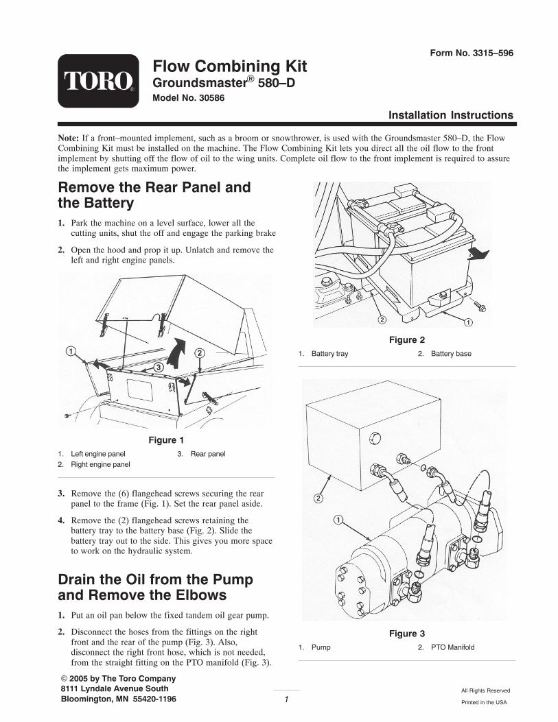
Note: If a front–mounted implement, such as a broom or snowthrower, is used with the Groundsmaster 580–D, the FlowCombining Kit must be installed on the machine. The Flow Combining Kit lets you direct all the oil flow to the frontimplement by shutting off the flow of oil to the wing units. Complete oil flow to the front implement is required to assurethe implement gets maximum power.
Remove the Rear Panel andthe Battery1. Park the machine on a level surface, lower all the
cutting units, shut the off and engage the parking brake
2. Open the hood and prop it up. Unlatch and remove theleft and right engine panels.
Figure 11. Left engine panel2. Right engine panel
3. Rear panel
3. Remove the (6) flangehead screws securing the rearpanel to the frame (Fig. 1). Set the rear panel aside.
4. Remove the (2) flangehead screws retaining thebattery tray to the battery base (Fig. 2). Slide thebattery tray out to the side. This gives you more spaceto work on the hydraulic system.
Drain the Oil from the Pumpand Remove the Elbows1. Put an oil pan below the fixed tandem oil gear pump.
2. Disconnect the hoses from the fittings on the rightfront and the rear of the pump (Fig. 3). Also,disconnect the right front hose, which is not needed,from the straight fitting on the PTO manifold (Fig. 3).
Figure 21. Battery tray 2. Battery base
Figure 31. Pump 2. PTO Manifold

2
3. Remove the 90 degree fitting from the right front andthe rear of the pump because they will not be used(Fig. 4). However, the two–piece mounting flange thatheld the rear fitting to the pump will be used later. Theother two–piece mounting flange will not be used.
Figure 41. 90 degree fitting 2. Mounting flange
Install the Flow CombiningValve1. The flow combining valve (Fig. 5) has an arrow
marked on its upper right side. With the arrow pointingup, install the 90 degree fitting and the O–ring into therear port on the valve. Also, install the straight fittingand the O–ring into the front port on the valve.
Figure 51. Flow combining valve2. 90 degree fitting3. O–ring
4. Straight fitting5. O–ring6. Socket head capscrew
Note: The 90 degree fitting may need a slight adjustmentwhen the hydraulic hose is eventually installed.
2. Mount the flow combining valve to the front port, onthe side of the pump, with a O–ring and (4) sockethead capscrews. the arrow on the valve must point upto assure proper installation.
Install the Fittings andU–Shaped Hydraulic Tube1. Install the T–fitting and the O–ring in the port at the
left rear of the pump, using existing two–piecemounting flange, (4) lockwashers and capscrews(Fig. 6).
Figure 61. T–fittings2. O–rings3. Mounting flange4. Pump
5. Capscrew/lockwasher6. Hydraulic tube7. Flow combining valve
2. Connect the U–shaped hydraulic tube and the O–ringsto the end of the T–fitting and the straight fitting at thefront of the flow combining valve (Fig. 6).
3. Remove the bottom right plug from the end of the flowcombiner. Install the 90 degree fitting and the O–ringinto the port (Fig. 7).
Figure 71. Hydraulic tube2. Straight fitting3. T–fitting
4. 90 degree fitting5. O–ring
Note: The 90 degree fitting may need a slight adjustmentwhen the hydraulic hose is eventually installed.

3
4. Install the 90 degree fitting and the O–ring into the topleft rear port in the PTO manifold (Fig. 8).
5. Assemble the regulator valve, 90 degree swivel fitting,straight fitting and O–rings (Fig. 8).
Figure 81. PTO manifold2. 90 fitting w/o–ring3. 90 fitting w/o–ring
4. Regulator valve w/o–ring5. Straight fitting w/o–ring
6. Screw the swivel fitting into the 90 degree fitting,installed in step 2 (Fig. 8).
Connect the Hydraulic HosesNote: After the hydraulic hoses are installed, it may benecessary to slightly adjust each fitting.
1. Connect hose “A” and the O–rings to the regulatorvalve and to the 90 degree fitting at the rear end of theflow combining valve.
2. Connect hose “B” and the O–rings to the 90 degreefittings on the end of the flow combining valve and thestraight fitting on the PTO manifold.
3. Connect the existing hose “C” and O–rings from PTOmanifold to the top of the T–fitting at the rear of thepump.
Install Metal Tag and Decals1. Affix the warning decal to one side of the metal tag
and the operating decal to the other side. Install themetal tag to the flow combining regulator with a cabletire (Fig. 9).
2. Affix the warning decal to the center of the front framebelow the steering tower.
Figure 91. Hose “A”2. Hose “B”
3. Hose “C”4. Metal tag w/decals
Install the Flow Control ValveThe purpose of the flow control valve is to regulate therate at which the front implement is lowered.
1. Disconnect and remove the hydraulic tube secured tothe tank return and the lift cylinder bulkhead fittings(Fig. 10).
Figure 101. Old hydraulic tube
2. Assemble the hydraulic fittings to the flow controlvalve (Fig. 11).
Figure 111. Flow control valve2. Fitting (2)
3. O–ring

4
3. Loosely secure the new hydraulic tube assembly to theflow control valve (Fig. 12). The arrow on the flowcontrol must point in the direction of the tube to thetank return.
Figure 12
Note: Make sure all O–rings are properly positioned whenmaking connections (Fig. 11).
4. Tighten all connections.
Check the Hydraulic System1. If all three cutting units are still on the machine, make
sure to completely close the flow combining valve.
2. Make sure all hydraulic fittings are tight.
Danger
Keep body and hands away from pin hole leaks ornozzles that elect high pressure hydraulic fluid.Use cardboard or paper, not hands, to search forall leaks. Highly pressurized hydraulic fluid thatis escaping can penetrate skin and cause seriousinjury. If fluid is accidentally injected into theskin, it must be surgically removed within a fewhours by a doctor familiar with this type of injury,otherwise gangrene may occur.
3. Start the engine, lower the cutting units and engage thedeck drive/PTO switch. All cutting units should beoperating at the same speed. If the side cutting unitsare not operating, disengage switch immediately andassure that the flow combining valve is completelyclosed.
4. With the engine running and all other controlsdisengaged, check for leaks around the newly installedhydraulic parts.
5. After checking for leaks, shut the engine off.
Operating InstructionsThe Flow Combining Kit, by means of an in–lineregulator valve between the flow combiner and themanifold, controls the flow of oil to the front and sidehydraulic motors.
1. Using a front–mounted Implement – Attachments,such as snowthrowers and brooms that are powered bythe front hydraulic motor, require maximum oil flowto operate properly. To assure maximum oil flow to thefront hydraulic motor and attachment, turn theregulator valve counterclockwise until it is completelyopen to combine flow.
2. Using three cutting units – Three cutting unitsattached to the hydraulic motors require equal oil flowand power so the blades operate at the same speed. Toseparate flow and assure equal oil flow to all threehydraulic motors, turn regulator valve clockwise untilit is completely closed.
If the flow combining regulator valve isaccidentally allowed to remain open:
• the front cutting unit blades will spinexcessively fast and be very noisy
• the side cutting units will not engage.
Failure to close the regulator valve may result inserious injury to the operator of the machine,and/or bystanders, especially from thrown objects.Whenever you notice the blades spinningexcessively fast, disengage the deck drive/PTOswitch immediately. Then have a qualifiedmechanic close the regulator valve before youresume operating the cutting units.
Caution
3. Adjusting the Implement Drop Rate (Flow ControlValve) – Rotate the flow control knob 1/4 turncounterclockwise, if front implement is dropping tooslow or 1/4 turn clockwise it front implement isdropping too fast.
Note: Allow hydraulic oil to reach full operatingtemperature before adjusting flow control valve.
Important DO NOT CLOSE VALVECOMPLETELY! Doing so will restrict fluid flow andprevent front implement from being lowered.
Related Documents