REPORT DOCUMENTATION PAGE Form Approved OMB No. 074-0188 Public reporting burden for this collection of information is estimated to average 1 hour per response, including the time for reviewing instructions, searching existing data sources, gathering and maintaining the data needed, and completing and reviewing this collection of information. Send comments regarding this burden estimate or any other aspect of this collection of information, including suggestions for reducing this burden to Washington Headquarters Services, Directorate for Information Operations and Reports, 1215 Jefferson Davis Highway, Suite 1204, Arlington, VA 22202-4302, and to the Office of Management and Budget, Paperwork Reduction Project (0704-0188), Washington, DC 20503 1. AGENCY USE ONLY (Leave blank) 2. REPORT DATE August 20,1998 3. REPORT TYPE AND DATES COVERED Technical Report 4. TITLE AND SUBTITLE Initial Designs of Electric-Discharge Non-Thermal Plasma Field-Pilot Demonstration Units for NOx Removal in Jet-Engine Exhaust: White Paper for SERDP Project CP-1038 5. FUNDING NUMBERS N/A . 6. AUTHOR(S) L.A. Rosocha, J.-S. Chang, A.W. Miziolek 7. PERFORMING ORGANIZATION NAME(S) AND ADDRESS(ES) Los Alamos National Laboratory Los Alamos, NM 8. PERFORMING ORGANIZATION REPORT NUMBER LA-UR-98-5345 9. SPONSORING / MONITORING AGENCY NAME(S) AND ADDRESS(ES) SERDP 901 North Stuart St. Suite 303 Arlington, VA 22203 10. SPONSORING / MONITORING AGENCY REPORT NUMBER N/A 11. SUPPLEMENTARY NOTES Submitted to: Strategic Environmental Research & Development Program (SERDP), Compliance Program. The United States Government has a royalty-free license throughout the world in all copyrightable material contained herein. All other rights are reserved by the copyright owner. 12a. DISTRIBUTION / AVAILABILITY STATEMENT Approved for public release: distribution is unlimited. 12b. DISTRIBUTION CODE A 13. ABSTRACT (Maximum 200 Words) Incentives for implementing new pollution-control technologies are both regulatory and economic. Given considerable regulatory pressure, e.g., the promulgation of a NESHAPS for NOx emissions in CY 2000, new de-NOx technologies are being explored. This project is currently evaluating non-thermal plasma (NTP) technologies for treating jet-engine exhaust and other hazardous air pollutants. To meet a project milestone this White Paper will present our initial design options for NTP reactor systems for a field-pilot demonstratiion on Cruise Missile Test Cell (CMTC) exhaust at Tinker AFB. The field-pilot demonstration is necessary to provide further data and operating experience to more fully evaluate economic and performance projections for NTP de-NOx technology and to design larger systems with confidence. From the design options presented here, we will downselect the set to 2 treatment systems and consider fielding both. If the budget is not sufficient for 2 reactor systems, only one will be fielded. This paper will discuss the exhaust stream to be addressed, the test setup, the candidate reactor systems, and projected operating parameters and specifications for the field- pilot units Because the cost and logistics of using an electron-beam NTP reactor are, respectively, too high and too complicated for this project, we have limited our candidate systems to those based on electric-discharge-driven NTP reactors (which previous economic analyses have shown to be more cost effective). 14. SUBJECT TERMS Tinker AFB; CMTC; JETC; nonthermal plasma; NTP; NOx; SERDP; SERDP Collection 15. NUMBER OF PAGES 15 16. PRICE CODE N/A 17. SECURITY CLASSIFICATION OF REPORT unclass. 18. SECURITY CLASSIFICATION OF THIS PAGE unclass. 19. SECURITY CLASSIFICATION OF ABSTRACT unclass. 20. LIMITATION OF ABSTRACT UL NSN 7540-01-280-5500 Standard Form 298 (Rev. 2-89) Prescribed by ANSI Std. Z39-18 298-102

Welcome message from author
This document is posted to help you gain knowledge. Please leave a comment to let me know what you think about it! Share it to your friends and learn new things together.
Transcript

REPORT DOCUMENTATION PAGE Form Approved
OMB No. 074-0188 Public reporting burden for this collection of information is estimated to average 1 hour per response, including the time for reviewing instructions, searching existing data sources, gathering and maintaining the data needed, and completing and reviewing this collection of information. Send comments regarding this burden estimate or any other aspect of this collection of information, including suggestions for reducing this burden to Washington Headquarters Services, Directorate for Information Operations and Reports, 1215 Jefferson Davis Highway, Suite 1204, Arlington, VA 22202-4302, and to the Office of Management and Budget, Paperwork Reduction Project (0704-0188), Washington, DC 20503
1. AGENCY USE ONLY (Leave blank) 2. REPORT DATE August 20,1998
3. REPORT TYPE AND DATES COVERED Technical Report
4. TITLE AND SUBTITLE Initial Designs of Electric-Discharge Non-Thermal Plasma Field-Pilot Demonstration Units for NOx Removal in Jet-Engine Exhaust: White Paper for SERDP Project CP-1038
5. FUNDING NUMBERS
N/A .
6. AUTHOR(S) L.A. Rosocha, J.-S. Chang, A.W. Miziolek
7. PERFORMING ORGANIZATION NAME(S) AND ADDRESS(ES)
Los Alamos National Laboratory Los Alamos, NM
8. PERFORMING ORGANIZATION REPORT NUMBER
LA-UR-98-5345
9. SPONSORING / MONITORING AGENCY NAME(S) AND ADDRESS(ES)
SERDP 901 North Stuart St. Suite 303 Arlington, VA 22203
10. SPONSORING / MONITORING AGENCY REPORT NUMBER
N/A
11. SUPPLEMENTARY NOTES Submitted to: Strategic Environmental Research & Development Program (SERDP), Compliance Program. The United States Government has a royalty-free license throughout the world in all copyrightable material contained herein. All other rights are reserved by the copyright owner.
12a. DISTRIBUTION / AVAILABILITY STATEMENT Approved for public release: distribution is unlimited.
12b. DISTRIBUTION CODE A
13. ABSTRACT (Maximum 200 Words) Incentives for implementing new pollution-control technologies are both regulatory and economic. Given considerable regulatory
pressure, e.g., the promulgation of a NESHAPS for NOx emissions in CY 2000, new de-NOx technologies are being explored. This project is currently evaluating non-thermal plasma (NTP) technologies for treating jet-engine exhaust and other hazardous air pollutants. To meet a project milestone this White Paper will present our initial design options for NTP reactor systems for a field-pilot demonstratiion on Cruise Missile Test Cell (CMTC) exhaust at Tinker AFB. The field-pilot demonstration is necessary to provide further data and operating experience to more fully evaluate economic and performance projections for NTP de-NOx technology and to design larger systems with confidence. From the design options presented here, we will downselect the set to 2 treatment systems and consider fielding both. If the budget is not sufficient for 2 reactor systems, only one will be fielded. This paper will discuss the exhaust stream to be addressed, the test setup, the candidate reactor systems, and projected operating parameters and specifications for the field- pilot units Because the cost and logistics of using an electron-beam NTP reactor are, respectively, too high and too complicated for this project, we have limited our candidate systems to those based on electric-discharge-driven NTP reactors (which previous economic analyses have shown to be more cost effective). 14. SUBJECT TERMS Tinker AFB; CMTC; JETC; nonthermal plasma; NTP; NOx; SERDP; SERDP Collection
15. NUMBER OF PAGES 15
16. PRICE CODE N/A
17. SECURITY CLASSIFICATION OF REPORT
unclass.
18. SECURITY CLASSIFICATION
OF THIS PAGE unclass.
19. SECURITY CLASSIFICATION OF ABSTRACT
unclass.
20. LIMITATION OF ABSTRACT UL
NSN 7540-01-280-5500 Standard Form 298 (Rev. 2-89) Prescribed by ANSI Std. Z39-18 298-102
LA-UR- 98-5345 Approved for public release; distribution is unlimited.
Title:
Author(s):
Submitted to:
INITIAL DESIGNS OF ELECTRIC-DISCHARGE NON-THERMAL PLASMA FIELD-PILOT DEMONSTRATION UNITS FOR NOX REMOVAL FN JET-ENGFNE EXHAUST: WHITE PAPER FOR SERDP PROJECT CP-1038
L.A. Rosocha (Los Alamos National Laboratory), J.-S. Chang (McMaster University), and A.W. Miziolek (Army Research Laboratory)
Strategic Environmental Research & Development Program (SERDP), Compliance Program
Los Alamos NATIONAL LABORATORY
Los Alamos National Laboratory, an affirmative action/equal opportunity employer, is operated by the University of California for the U.S. Department of Energy under contract W-7405-ENG-36. By acceptance of this article, the publisher recognizes that the U.S. Government retains a nonexclusive, royalty-free license to publish or reproduce the published form of this contribution, or to allow others to do so, for U.S. Government purposes. Los Alamos National Laboratory requests that the publisher identify this article as work performed under the auspices of the U.S. Department of Energy. Los Alamos National Laboratory strongly supports academic freedom and a researcher's right to publish; as an institution, however, the Laboratory does not endorse the viewpoint of a publication or guarantee its technical correctness.
Form 836 (10/96)
DTIC QUALITY DJSPECJTBD

Initial Designs of Electric-Discharge Non-Thermal Plasma Field-Pilot Demonstration Units for NOx Removal in Jet-Engine Exhaust:
White Paper for SERDP Project CP-1038
Louis A. Rosocha Principal Investigator
Los Alamos National Laboratory
J.-S. Chang Technical Contractor McMaster University
Andrzej W. Miziolek Co-Principal Investigator
Army Research Laboratory
November 18,1998
Abstract
Incentives for implementing new pollution-control technologies are both regulatory and economic. Given considerable regulatory pressure, e.g., the promulgation of a NESHAPS (National Emissions Standard for Hazardous Air Pollutants) for NOx emissions in CY 2000, new de-NOx technologies are being explored. This project is currently evaluating non-thermal plasma (NTP) technologies for treating jet-engine exhaust and other hazardous air pollutants. To meet a project milestone (viz., document initial field-pilot designs), this White Paper will present our initial design options for NTP reactor systems for a field-pilot demonstration on Cruise Missile Test Cell (CMTC) exhaust at Tinker Air Force Base (currently scheduled for September 1999). The field- pilot demonstration is necessary to provide further data and operating experience to more fully evaluate economic and performance projections for NTP de-NOx technology and to design larger systems with confidence. From the design options presented here, we will downselect the set to two treatment systems and consider fielding both, if the projected costs of fabrication and demonstration fit our project budget. If the budget is not sufficient for two reactor systems, only one will be fielded. This paper will discuss the exhaust stream to be addressed, the test setup, the candidate reactor systems, and projected operating parameters and specifications for the field-pilot units. Because the cost and logistics of using an electron-beam NTP reactor are, respectively, too high and too complicated for this project, we have limited our candidate systems to those based on electric-discharge-driven NTP reactors (which previous economic analyses have shown to be more cost effective).

Outline
Abstract
Introduction (Purpose of White Paper and Main Topics Covered)
Exhaust Stream to be Addressed
Test Setup
Candidate Designs for Field-Pilot Demonstration Equipment
Pulsed Corona Plasma Reactor System Dielectric-Barrier Discharge Plasma Reactor System Hybrid NTP Reactor-Adsorber System Corona Radical Shower Plasma Reactor System
Projected Operating Specifications
Conclusions/Summary
References
Introduction (Purpose of White Paper and Main Topics Covered) The purpose of SERDP project CP-1038 is to evaluate and develop non-thermal plasma
(NTP) reactor technology for Department of Defense (DoD) air emissions control applications. The primary focus is on oxides of nitrogen (NOJ and a secondary focus on hazardous air pollutants (HAPs), especially volatile organic compounds (VOCs). Example NOx sources are jet engine test cells (JETCs) and diesel-engine powered electrical generators. Example VOCs are organic solvents used in painting, paint-stripping, and parts cleaning.
A project milestone for FY99 is to document initial designs for NTP reactor systems that are candidates for a field-pilot demonstration on the treatment of jet-engine exhaust [1]. This White Paper will offer four candidate system designs based on electric-discharge-driven NTP reactor systems for emissions control (given the scope and budget for Project CP-1038, we do not consider an electron-beam system to be a field-pilot demonstration candidate for this work). The exhaust stream to be addressed, the test setup, salient features of the design of the candidate systems, and the projected operating specifications for the systems will be presented.
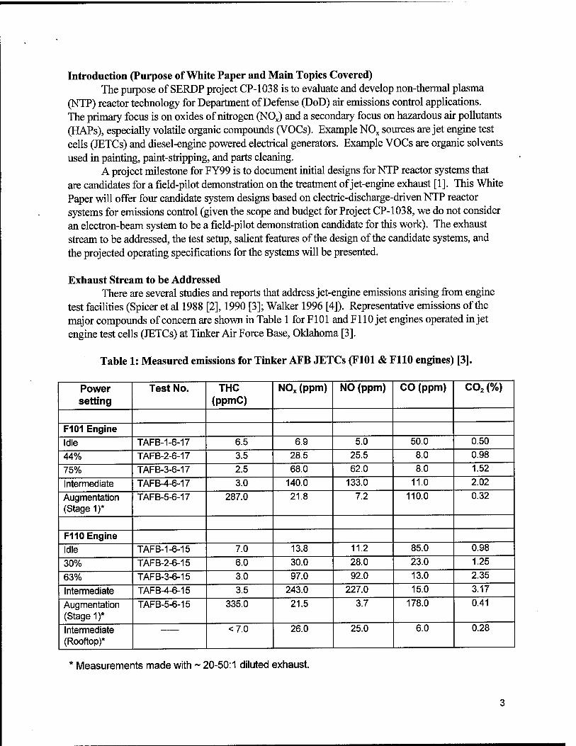
Exhaust Stream to be Addressed There are several studies and reports that address jet-engine emissions arising from engine
test facilities (Spicer et al 1988 [2], 1990 [3]; Walker 1996 [4]). Representative emissions of the major compounds of concern are shown in Table 1 for F101 and F110 jet engines operated in jet engine test cells (JETCs) at Tinker Air Force Base, Oklahoma [3].
Table 1: Measured emissions for Tinker AFB JETCs (F101 & F110 engines) [3].
Power setting
Test No. THC (ppmC)
NOx (ppm) NO (ppm) CO (ppm) C02 (%)
F101 Engine Idle TAFB-1-6-17 6.5 6.9 5.0 50.0 0.50
44% TAFB-2-6-17 3.5 28.5 25.5 8.0 0.98
75% TAFB-3-6-17 2.5 68.0 62.0 8.0 1.52
Intermediate TAFB-4-6-17 3.0 140.0 133.0 11.0 2.02
Augmentation (Stage 1)*
TAFB-5-6-17 287.0 21.8 7.2 110.0 0.32
F110 Engine
Idle TAFB-1-6-15 7.0 13.8 11.2 85.0 0.98
30% TAFB-2-6-15 6.0 30.0 28.0 23.0 1.25
63% TAFB-3-6-15 3.0 97.0 92.0 13.0 2.35
Intermediate TAFB-4-6-15 3.5 243.0 227.0 15.0 3.17
Augmentation (Stage 1)*
TAFB-5-6-15 335.0 21.5 3.7 178.0 0.41
Intermediate (Rooftop)*
<7.0 26.0 25.0 6.0 0.28
Measurements made with ~ 20-50:1 diluted exhaust.

It should be noted that the exhaust streams form JETCs and CMTCs are diluted by factors in the range of 10-50 with air added at the engine exhaust duct/augmentor intakes. Typically, this reduces the concentration of pollutants (e.g., to 10s ppm NOx and hydrocarbons) but increases the overall exhaust-gas flow discharged to the atmosphere.
Table 2 shows a summary emissions inventory for Tinker AFB JETCs 1-12 for the year 1995; when 3,414,836 gallons of JP-5 fuel were consumed in a time period of 4420 hours of operation [4]. The emissions were calculated on the basis of fuel consumption but not directly measured.
Table 2: Calculated emissions inventory for twelve JETCs at Tinker AFB for CY1995.
Compound Emission Inventory (ton/yr) NOx 113.01
SOx 30.71
Aggregate hydrocarbons 100.45
CO 156.34
Particulates 26.72
PM-10 4.45
Based on the data taken from Spicer 1990 [3] and Walker 1996 [4], a model emissions profile for a representative JETC can be defined. However, our plans for a field-pilot demonstration for this project call for testing NTP jet-engine emissions treatment on a Cruise Missile Test Cell (CMTC) at Tinker AFB (which employs F107 and Fl 12 engines). In contrast to the Tinker JETCs, the actual emissions from the CMTCs have not been characterized. Therefore, our approach is to: 1) work with Tinker to have the emissions characterized for a CMTC; and 2) formulate a model emissions profile, based on the measured and calculated profiles for JETCs. These items will be used in setting the final operating parameters for the field-pilot equipment and in making cost-analysis and economic projections for the treatment of jet-engine emissions by NTP systems and in making comparisons with conventional flue-gas treatment technologies.
NTP technology probably has applications for treating air emissions from other sources of interest to the DoD; e.g., industrial boilers and furnaces; Aerospace Ground Equipment (AGE), including diesel-powered electrical generators, compressors, hydraulic test stands, and weapons loading units; and emergency electrical power generators. Means of calculating inventories for air pollutants arising from such sources have been formulated and documented by Jagielski et al 1994 [5].
The exhaust from JETCs has been extensively characterized by Spicer et al. However, the CMTC emissions have not been characterized. In the absence of exhaust-gas sampling and characterization, a CMTC will be assumed to have similar concentrations of emitted pollutants. But the gas flows, both that coming directly out of the engine and the diluted flow, have lower flow rates because the CMTC engines are smaller than those normally employed in JETCs. Before actual field tests, Tinker AFB will arrange for sampling and characterization of the CMTC emissions. Table 3 lists the exhaust-gas parameters that we will use for initial designs of the field- pilot equipment.
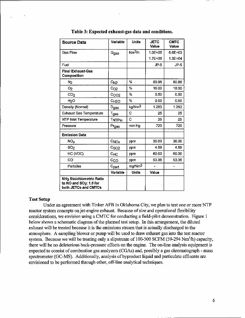
Table 3: Expected exhaust-gas data and conditions.
Source Data Variable Units JETC Value
CMTC Value
Gas Flow Qgas Nm3/h 1.0E+05
1.7E+06
6.6E+03
1.3E+04
Fuel JP-5 JP-5
Final Exhaust-Gas Composition
N2 CN2 % 80.98 80.98
02 C02 % 18.00 18.00
C02 CC02 % 0.50 0.50
H2O CH20 % 0.50 0.50
Density (Normal) Dgas kg/Nm3 1.283 1.283
Exhaust Gas Temperature Tgas C 25 25
NTP Inlet Temperature TNTPin C 25 25
Pressure Pfgas mmHg 720 720
Emission Data
N0X CNOX ppm 36.00 36.00
SO2 CS02 ppm 4.59 4.59
HC (VOC) CHC ppm 60.00 60.00
CO ceo ppm 53.36 53.36
Particles Opart mg/Nm3 - -
Variable Units Value
NH3 Stoichiometric Ratio toNOandS02:1.5 for both JETCs and CMTCs
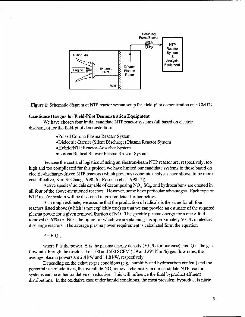
Test Setup Under an agreement with Tinker AFB in Oklahoma City, we plan to test one or more NTP
reactor system concepts on jet-engine exhaust. Because of size and operational flexibility considerations, we envision using a CMTC for conducting a field-pilot demonstration. Figure 1 below shows a schematic diagram of the planned test setup. In this arrangement, the diluted exhaust will be treated because it is the emissions stream that is actually discharged to the atmosphere. A sampling blower or pump will be used to draw exhaust gas into the test reactor system. Because we will be treating only a slipstream of 100-500 SCFM (59-294 Nm3/h) capacity, there will be no deleterious back-pressure effects on the engine. The on-line analysis equipment is expected to consist of combustion gas analyzers (CGAs) and, possibly a gas Chromatograph - mass spectrometer (GC-MS). Additionally, analysis of byproduct liquid and particulate effluents are envisioned to be performed through other, off-line analytical techniques.
Sampling Pump/Blower
NTP Reactor System
& Analysis
Equipment
Figure 1: Schematic diagram of NTP reactor system setup for field-pilot demonstration on a CMTC.
Candidate Designs for Field-Pilot Demonstration Equipment We have chosen four initial candidate NTP reactor systems (all based on electric
discharges) for the field-pilot demonstration:
•Pulsed Corona Plasma Reactor System •Dielectric-Barrier (Silent Discharge) Plasma Reactor System •Hybrid/NTP Reactor-Adsorber System •Corona Radical Shower Plasma Reactor System.
Because the cost and logistics of using an electron-beam NTP reactor are, respectively, too high and too complicated for this project, we have limited our candidate systems to those based on electric-discharge-driven NTP reactors (which previous economic analyses have shown to be more cost effective, Kim & Chang 1998 [6], Rosocha et al 1998 [7]).
Active species/radicals capable of decomposing NOx, SOx, and hydrocarbons are created in all four of the above-mentioned reactors. However, some have particular advantages. Each type of NTP reactor system will be discussed in greater detail further below.
As a rough estimate, we assume that the production of radicals is the same for all four reactors listed above (which is not explicitly true) so that we can provide an estimate of the required plasma power for a given removal fraction of NO. The specific plasma energy for a one e-fold removal (~ 63%) of NO - the figure for which we are planning - is approximately 50 J/L in electric discharge reactors. The average plasma power requirement is calculated form the equation
P = EQ,
where P is the power, E is the plasma energy density (50 J/L for our case), and Q is the gas flow rate through the reactor. For 100 and 500 SCFM ( 59 and 294 Nm3/h) gas flow rates, the average plasma powers are 2.4 kW and 11.8 kW, respectively.
Depending on the exhaust-gas conditions (e.g., humidity and hydrocarbon content) and the potential use of additives, the overall de-NOx removal chemistry in our candidate NTP reactor systems can be either oxidative or reductive. This will influence the final byproduct effluent distributions. In the oxidative case under humid conditions, the most prevalent byproduct is nitric
acid (HN03), which dictates the use of base scrubbers to neutralize the acid. Under dry conditions, the formation of N02 is favored. However N02 is more easily adsorbed by activated carbon and can be captured and subjected to further treatment. With additives such as ammonia (NH3), methane (CH4), ethylene (C2H4), or part of the actual exhaust gas, the product distribution can be shifted to particles (e.g., useful agricultural fertilizer like ammonium nitrate - NH4N03) which can be collected with an electrostatic precipitator.
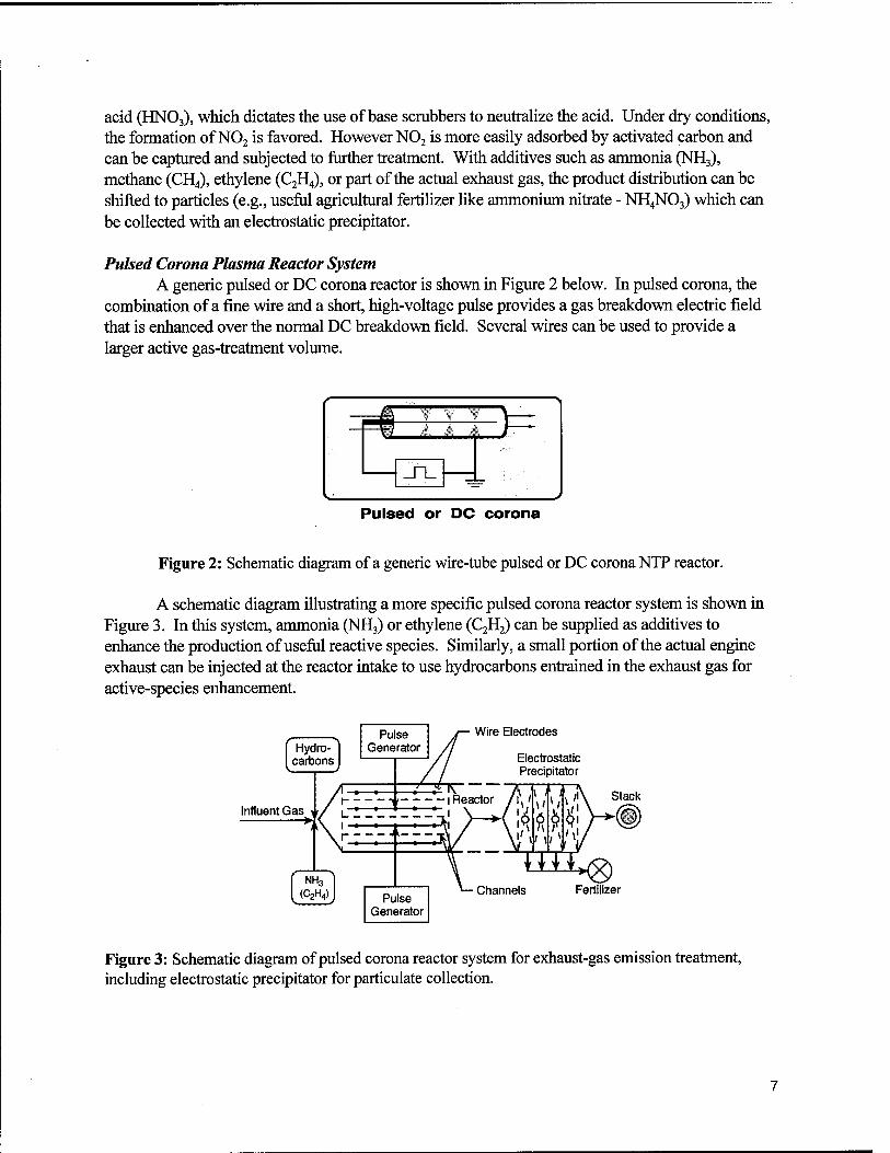
Pulsed Corona Plasma Reactor System A generic pulsed or DC corona reactor is shown in Figure 2 below. In pulsed corona, the
combination of a fine wire and a short, high-voltage pulse provides a gas breakdown electric field that is enhanced over the normal DC breakdown field. Several wires can be used to provide a larger active gas-treatment volume.
r
^ Ü. * 4 \~~
^ .• Pulsed or DC corona
Figure 2: Schematic diagram of a generic wire-tube pulsed or DC corona NTP reactor.
A schematic diagram illustrating a more specific pulsed corona reactor system is shown in Figure 3. In this system, ammonia (NH3) or ethylene (C2H2) can be supplied as additives to enhance the production of useful reactive species. Similarly, a small portion of the actual engine exhaust can be injected at the reactor intake to use hydrocarbons entrained in the exhaust gas for active-species enhancement.
Hydro- carbons
Pulse Generator
Influent Gas
(C2H4)
Wire Electrodes
Electrostatic Precipitator
Stack
Pulse Generator
Channels Fertilizer
Figure 3: Schematic diagram of pulsed corona reactor system for exhaust-gas emission treatment, including electrostatic precipitator for particulate collection.

Dielectric-Barrier Discharge Plasma Reactor System A generic dielectric-barrier (silent discharge) reactor is shown in Figure 4 below. In an AC-
driven barrier discharge, the buildup of charge on the dielectric automatically terminates the microdischarge streamers, thus producing a short, electron-energetic pulse and eliminating the need for more expensive and/or more complicated pulsed power supplies.
Silent discharge (dielectric-barrier discharge)
Figure 4: Simple schematic diagram for a dielectric-barrier discharge reactor.
At Los Alamos, the dielectric-barrier reactor has been extensively studied for the decomposition of VOCs (especially chlorinated hydrocarbons) and four field-pilot demonstrations have been carried out with modular reactors. Reactor banks with average plasma power as much as 10 kW have been employed in such tests (Rosocha 1997 [8]). Commercialization of the technology for VOC/air toxics treatment under specific fields of use is now in progress with a commercial partner. Figure 5 shows an illustration of a mobile unit that was employed at McClellan AFB in an innovative-technology demonstration on treating multiple VOCs and other chemicals entrained in the soil. Similar units were also employed at the DOE Savannah River Site for treating VOCs entrained in soil and groundwater [9] and at Tinker AFB for treating low-concentration VOCs extracted from groundwater [10].
18-kW Power Supi
Influent Pipe i
Vacuum Pump "
HV Transformer Effluent Pipe
Cold Plasma Processor \
Control & Data System \
-In M
=rs J SHI ■* Qas Extraction Well Heat Exchanger
Figure 5: Illustration of mobile dielectric-barrier NTP reactor system employed for VOC decomposition tests at McClellan AFB. Each plasma reactor tank operated at up to 10 kW of plasma power.

An example of an NTP reactor that has been commercialized for flue-gas treatment is the Tecolytic™ modified dielectric-barrier reactor + lime scrubber system (from Thermo-Power Corp., Bittenson & Breault 1998 [11]). The company's stated objective is to "develop a zero discharge NOx control process using no hazardous reagents or catalysts". Figure 6 shows a schematic diagram of the system. The NTP reactor consists of a housing to hold a large array of metal rods covered by ceramic-dielectric insulators and to hold the associated high-voltage insulated feedthroughs. The rods are essentially arranged such that a high-voltage electrode is surrounded by four grounded nearest-neighbor rods. The high-voltage "corona" rods are connected to a HV/AC power supply to supply the necessary voltage and current to produce an electrical discharge in the gas space between the rods. Flue gas is flown across the electrodes, entering the reactor housing at one end and exiting the opposite end. The NTP-treated gas is then sent to a wet scrubber, using Mg(OH)2 and slaked Mg-enhanced lime, which scrubs out S02 to make gypsum (CaS04 • 2H20), which is a salable commodity. In humid flue gas, much of the NOx is converted in nitrate products (e.g., acids which can be neutralized or collected as products). Clean effluent gas is vented to the atmosphere.
Metal rods covered with ceramic- — dielectric tubes
ToAC/HV power supply
Clean stack gas
Gas influent
Insulated feed-throughs
Tecolytic™ NTP reactor
Secondary scrubber effluent
Figure 6: Schematic diagram of commercial Tecolytic™ modified dielectrc-barrier NTP reactor system for de-NOx/SOx (flue-gas treatment).
Within the past few months, one of these systems has been installed on the Miami Fort power-plant facility and field tests are in progress. Data from these tests will be highly useful in establishing further benchmarks for the economic model and in lending further credence for the acceptance of NTP technology as an alternative to conventional de-NOx methods.
Hybrid NTP Reactor-Adsorber Systems We define a hybrid NTP emissions-control system as a combination of one or more NTP
reactors with an adsorber, a catalyst, or another NTP reactor. Our interest in hybrid systems arises from the fact: if the operating lifetime and/or effectiveness of GAC can be improved, the treatment costs will decrease.
There are two simple ways to combine an NTP stage with a GAC stage: place the NTP stage in series with the GAC stage, thus lessening the load on the GAC; or place the NTP stage in
parallel with the GAC stage and use it to regenerate the GAC under more favorable conditions than the heat/steam regeneration methods typically employed. The expected advantages of such an NTP-GAC hybrid system are:
• Prolonged life of GAC filters (with an associated operating cost reduction) • Application to a broader range of exhaust-gas flow rates, types of pollutants, and
pollutant concentrations • Potential for reducing the dependence of treatment cost on pollutant concentration • Pollutants are destroyed by the NTP stage, rather than simply captured • NTP system can incorporate feedback to aid in optimizing the treatment efficiency
and costs.
For many applications, end-of-pipe emissions treatment is the norm. However, one can also conceive of restricting the treatment closer to the point-of-use, or integrating the emissions treatment equipment directly into the process which produces the emissions. For the purposes of this report, an end-of-pipe application will sufficiently illustrate the hybrid system concept.
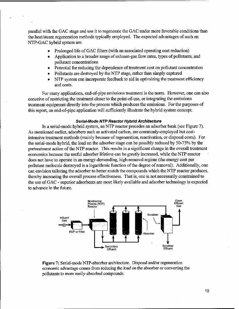
Serial-Mode NTP Reactor Hybrid Architecture In a serial-mode hybrid system, an NTP reactor precedes an adsorber bank (see Figure 7).
As mentioned earlier, adsorbers such as activated carbon, are commonly-employed but cost- intensive treatment methods (mainly because of regeneration, reactivation, or disposal costs). For the serial-mode hybrid, the load on the adsorber stage can be possibly reduced by 50-75% by the pretreatment action of the NTP reactor. This results in a significant change in the overall treatment economics because the useful adsorber lifetime can be greatly increased, while the NTP reactor does not have to operate in an energy-demanding, high-removal regime (the energy cost per pollutant molecule destroyed is a logarithmic function of the degree of removal). Additionally, one can envision tailoring the adsorber to better match the compounds which the NTP reactor produces, thereby increasing the overall process effectiveness. That is, one is not necessarily constrained to the use of GAC - superior adsorbents are most likely available and adsorber technology is expected to advance in the future.
Influent Gas
Nonthermal Plasma (NTP) Reactor
. Secondary Effluent
Figure 7: Serial-mode NTP-absorber architecture. Disposal and/or regeneration economic advantage comes from reducing the load on the absorber or converting the pollutants to more easily-absorbed compounds.
10
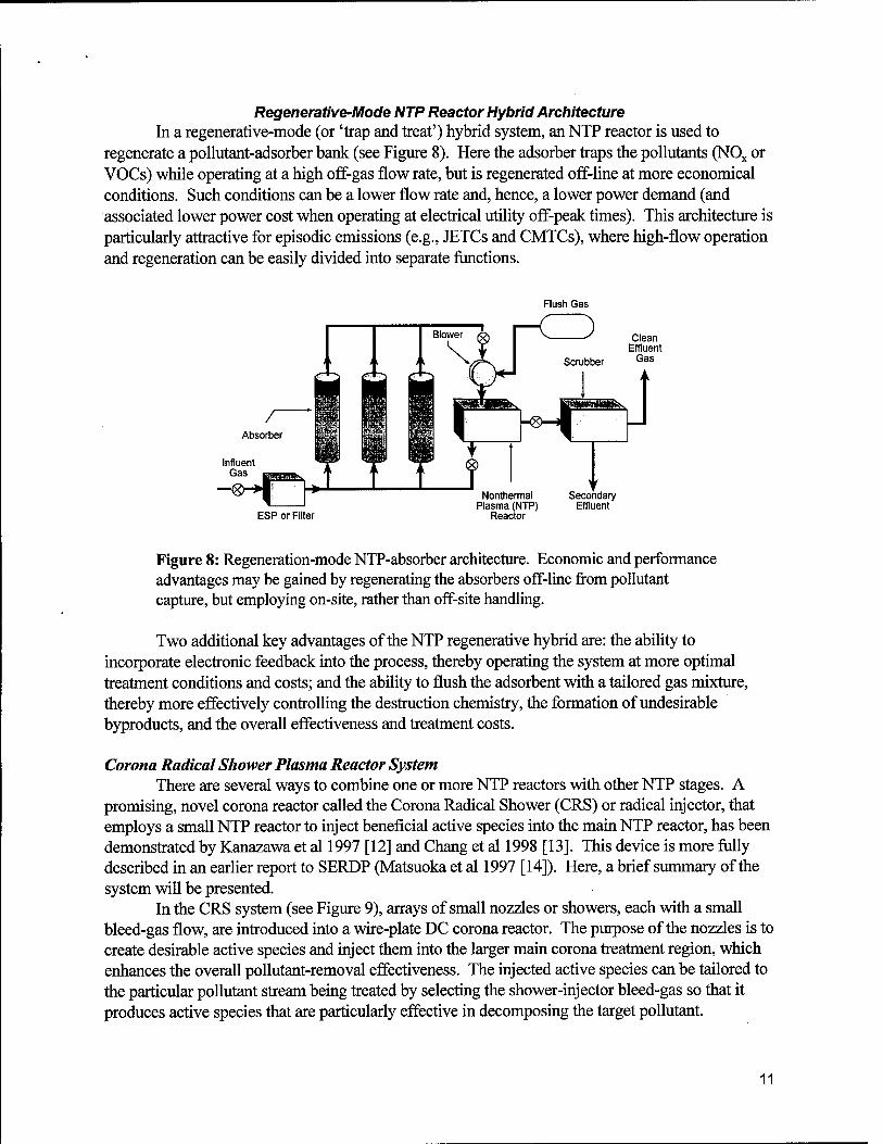
Regenerative-Mode NTP Reactor Hybrid Architecture In a regenerative-mode (or 'trap and treat') hybrid system, an NTP reactor is used to
regenerate a pollutant-adsorber bank (see Figure 8). Here the adsorber traps the pollutants (NOx or VOCs) while operating at a high off-gas flow rate, but is regenerated off-line at more economical conditions. Such conditions can be a lower flow rate and, hence, a lower power demand (and associated lower power cost when operating at electrical utility off-peak times). This architecture is particularly attractive for episodic emissions (e.g., JETCs and CMTCs), where high-flow operation and regeneration can be easily divided into separate functions.
Flush Gas
r<Z)
Influent "mw w «e™
ESP or Filter
Nonthermal Plasma (NTP)
Reactor
Secondary Effluent
Figure 8: Regeneration-mode NTP-absorber architecture. Economic and performance advantages may be gained by regenerating the absorbers off-line from pollutant capture, but employing on-site, rather than off-site handling.
Two additional key advantages of the NTP regenerative hybrid are: the ability to incorporate electronic feedback into the process, thereby operating the system at more optimal treatment conditions and costs; and the ability to flush the adsorbent with a tailored gas mixture, thereby more effectively controlling the destruction chemistry, the formation of undesirable byproducts, and the overall effectiveness and treatment costs.
Corona Radical Shower Plasma Reactor System There are several ways to combine one or more NTP reactors with other NTP stages. A
promising, novel corona reactor called the Corona Radical Shower (CRS) or radical injector, that employs a small NTP reactor to inject beneficial active species into the main NTP reactor, has been demonstrated by Kanazawa et al 1997 [12] and Chang et al 1998 [13]. This device is more fully described in an earlier report to SERDP (Matsuoka et al 1997 [14]). Here, a brief summary of the system will be presented.
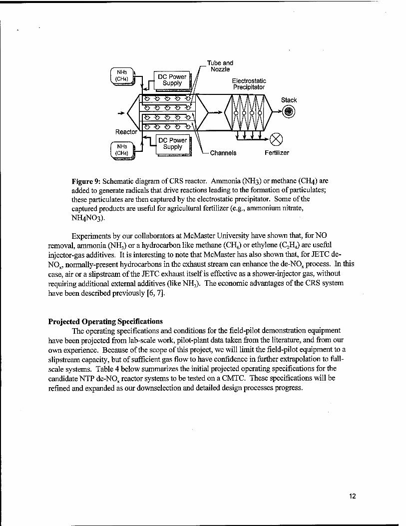
In the CRS system (see Figure 9), arrays of small nozzles or showers, each with a small bleed-gas flow, are introduced into a wire-plate DC corona reactor. The purpose of the nozzles is to create desirable active species and inject them into the larger main corona treatment region, which enhances the overall pollutant-removal effectiveness. The injected active species can be tailored to the particular pollutant stream being treated by selecting the shower-injector bleed-gas so that it produces active species that are particularly effective in decomposing the target pollutant.
11
Tube and Nozzle
Electrostatic Precipitator
Stack
Channels Fertilizer
Figure 9: Schematic diagram of CRS reactor. Ammonia (NH3) or methane (CH4) are added to generate radicals that drive reactions leading to the formation of particulates; these particulates are then captured by the electrostatic precipitator. Some of the captured products are useful for agricultural fertilizer (e.g., ammonium nitrate, NH4NO3).
Experiments by our collaborators at McMaster University have shown that, for NO removal, ammonia (NH3) or a hydrocarbon like methane (CH4) or ethylene (C2H4) are useful injector-gas additives. It is interesting to note that McMaster has also shown that, for JETC de- NOx, normally-present hydrocarbons in the exhaust stream can enhance the de-NOx process. In this case, air or a slipstream of the JETC exhaust itself is effective as a shower-injector gas, without requiring additional external additives (like NH3). The economic advantages of the CRS system have been described previously [6, 7].
Projected Operating Specifications The operating specifications and conditions for the field-pilot demonstration equipment
have been projected from lab-scale work, pilot-plant data taken from the literature, and from our own experience. Because of the scope of this project, we will limit the field-pilot equipment to a slipstream capacity, but of sufficient gas flow to have confidence in further extrapolation to full- scale systems. Table 4 below summarizes the initial projected operating specifications for the candidate NTP de-NOx reactor systems to be tested on a CMTC. These specifications will be refined and expanded as our downselection and detailed design processes progress.
12
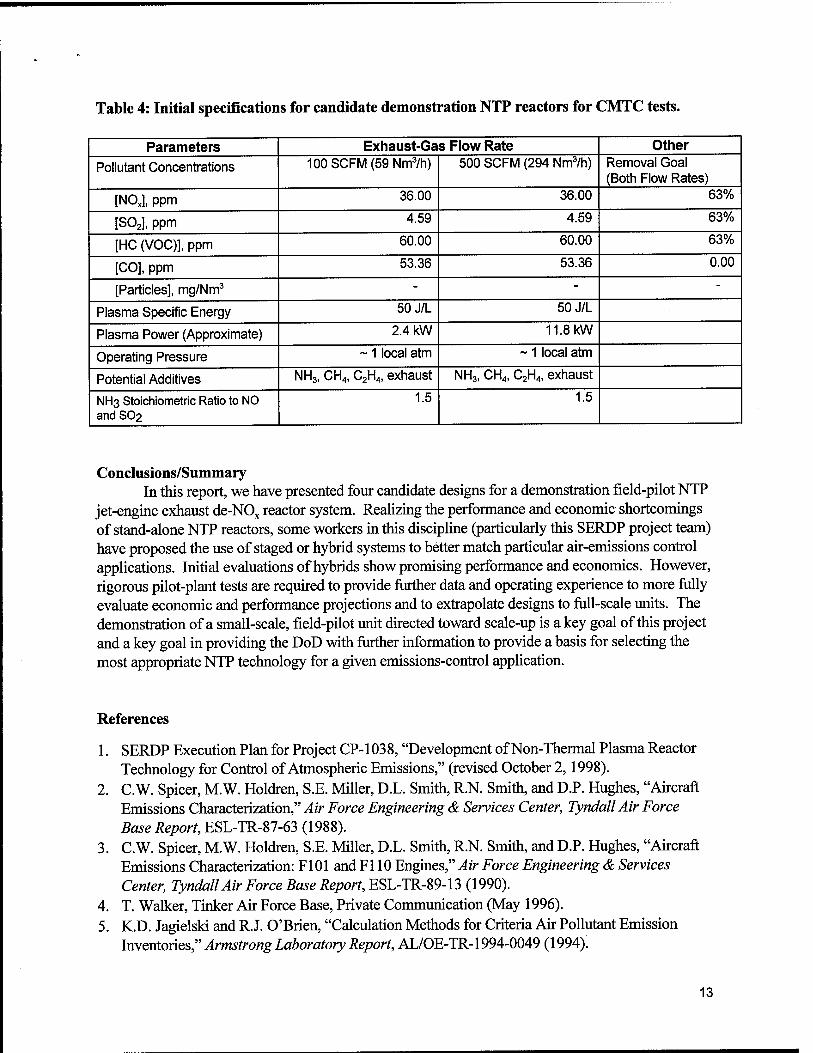
Table 4: Initial specifications for candidate demonstration NTP reactors for CMTC tests.
Parameters Exhaust-Gas Flow Rate Other
Pollutant Concentrations 100SCFM(59Nm3/h) 500 SCFM (294 Nm3/h) Removal Goal (Both Flow Rates)
[NOJ, ppm 36.00 36.00 63%
[S02], ppm 4.59 4.59 63%
[HC (VOC)], ppm 60.00 60.00 63%
[CO], ppm 53.36 53.36 0.00
[Particles], mg/Nm3 - - -
Plasma Specific Energy 50J/L 50J/L
Plasma Power (Approximate) 2.4 kW 11.8 kW
Operating Pressure ~ 1 local atm ~ 1 local atm
Potential Additives NH3, CH4, C2H4, exhaust NH3, CH4, C2H4, exhaust
NH3 Stoichiometric Ratio to NO and SO2
1.5 1.5
Conclusions/Summary In this report, we have presented four candidate designs for a demonstration field-pilot NTP
jet-engine exhaust de-NOx reactor system. Realizing the performance and economic shortcomings of stand-alone NTP reactors, some workers in this discipline (particularly this SERDP project team) have proposed the use of staged or hybrid systems to better match particular air-emissions control applications. Initial evaluations of hybrids show promising performance and economics. However, rigorous pilot-plant tests are required to provide further data and operating experience to more fully evaluate economic and performance projections and to extrapolate designs to full-scale units. The demonstration of a small-scale, field-pilot unit directed toward scale-up is a key goal of this project and a key goal in providing the DoD with further information to provide a basis for selecting the most appropriate NTP technology for a given emissions-control application.
References
1. SERDP Execution Plan for Project CP-1038, "Development of Non-Thermal Plasma Reactor Technology for Control of Atmospheric Emissions," (revised October 2,1998).
2. C.W. Spicer, M.W. Holdren, S.E. Miller, D.L. Smith, R.N. Smith, and D.P. Hughes, "Aircraft Emissions Characterization," Air Force Engineering & Services Center, TyndallAir Force Base Report, ESL-TR-87-63 (1988).
3. C.W. Spicer, M.W. Holdren, S.E. Miller, D.L. Smith, R.N. Smith, and D.P. Hughes, "Aircraft Emissions Characterization: F101 and Fl 10 Engines," Air Force Engineering & Services Center, TyndallAir Force Base Report, ESL-TR-89-13 (1990).
4. T. Walker, Tinker Air Force Base, Private Communication (May 1996). 5. K.D. Jagielski and R.J. O'Brien, "Calculation Methods for Criteria Air Pollutant Emission
Inventories," Armstrong Laboratory Report, AL/OE-TR-1994-0049 (1994).
13
6. S.J. Kim and J.-S. Chang, "SUENTP Code Simulation of Scaleup and Economic Evaluation of Non-Thermal Plasma Technology for Exhaust Gas Emission Control of Coal Fired Power Plants," submitted to International Conference on Electrostatic Precipitators (held 20-25 September 1998, Korea).
7. L.A. Rosocha, "Cost Analysis and Economic Assessment of Proposed Electric-Discharge Non- Thermal Plasma Processes for NOx Removal in Jet-Engine Exhaust: White Paper for SERDP Project CP-1038, Los Alamos National Laboratory Report, LA-UR-98-4926 (October 29, 1998).
8. LA. Rosocha, "Processing of Hazardous Chemicals Using Silent Electrical Discharge Plasmas," Chapter 11 in Environmental Aspects in Plasma Science, edited by W. Manheimer, L.E. Sugiyama, and T.H. Stix, American Institute of Physics Press, Woodbury, NY (1997).
9. LA. Rosocha, JJ. Coogan, RA. Korzekwa, DA. Seeker, R.F. Riemers, P.G. Herrmann, P.J. Chase, M.P. Gross, and M.R. Jones, "Field Demonstration and Commercialization of Silent Discharge Plasma Air Pollutant Control Technology", Proceedings of 2nd International EPRI/NSF Symposium on Environmental Applications of Advanced Oxidation Technologies, pp. (Section 5) 107-121, Electric Power Research Institute (September 1997).
10. RA. Korzekwa and LA. Rosocha, "Small-Scale Demonstration of Nonthermal Plasma VOC Treatment at Tinker AFB," Los Alamos National Laboratory Report, LA-UR-96-3859 (October 22,1996).
11. S.N. Bittenson and R.W. Breault, "Nonthermal Plasmas for NOx Control," Presented at 4th International Conf. On Advanced Oxidation Technologies for Water and Air Remediation (June 1998).
12. S. Kanazawa, J.-S. Chang, G.F. Round, G. Sheng, T. Ohkubo, Y. Nomoto and T. Adachi, "Removal of NOx from Flue Gas by Corona Discharge Activated Methane Radical Showers," J. of Electrostatics, 40 & 41, pp. 651-656 (1997).
13. J.-S. Chang, K Urashima, M. Arquilla and T. Ito," Reduction of NOx from Combustion Flue Gases by Corona Discharge Activated Methane Radical Injections," Combust. Sei. and Tech., 133, pp. 29-45 (1998).
14. M. Matsuoka, S.J. Kim, P.C. Looy, and J.S. Chang, "Development of Scaling and Economic- Evaluation Algorithms for Non-Thermal Plasma Reactors for Control of NOx Emissions,", McMaster University (October 1997).
14
Related Documents