V&T Technologies Co., Ltd. http://www.EcoDriveCN.com Foreword The V5−H series inverter is a kind of high-performance vector control inverter provided by V&T Technologies Co., Ltd. The product adopts speed sensorless vector control technology technology, the internationally leading technology, to offer excellent control performance and combines the application characteristics of China to further enhance the product reliability, environment adaptability and customized and industrialized design. It can better meet the demands of the various drive applications.

Welcome message from author
This document is posted to help you gain knowledge. Please leave a comment to let me know what you think about it! Share it to your friends and learn new things together.
Transcript

V&T Technologies Co., Ltd. http://www.EcoDriveCN.com
Foreword The V5−H series inverter is a kind of high-performance vector control inverter
provided by V&T Technologies Co., Ltd. The product adopts speed sensorless
vector control technology technology, the internationally leading technology, to
offer excellent control performance and combines the application
characteristics of China to further enhance the product reliability, environment
adaptability and customized and industrialized design. It can better meet the
demands of the various drive applications.
V&T Technologies Co., Ltd. http://www.EcoDriveCN.com
Excellent Performance
Control Mode
Vector Control 1: Offering excellent vector control performance and insensitive to motor parameters. Startup torque: 0.50Hz 180% rated torque Speed adjustment range: 1:100 Speed stabilization precision: ± 0.5% 0.50Hz controlble motor stable operation with 150% rated torque Vector Control 2: Precise speed sensorless vector control technology realizes AC motor decoupling, enabling the DC motorization of operation control. Startup torque: 0.25Hz 180% rated torque Speed adjustment range: 1:200 Speed stabilization precision: ± 0.2%
Excellent Control Performance under Speed Sensorless Vector Control Mode
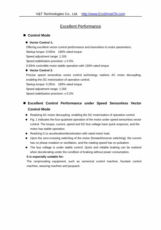
Realizing AC motor decoupling, enabling the DC motorization of operation control. Fig. 1 indicates the four-quadrant operation of the motor under speed sensorless vector
control. The torque, current, speed and DC bus voltage have quick response, and the motor has stable operation.
Realizing 0.1s acceleration/deceleration with rated motor load. Upon the zero-crossing switching of the motor (forward/reverse switching), the current
has no phase mutation or oscillation, and the rotating speed has no pulsation. The bus voltage is under stable control. Quick and reliable braking can be realized
when decelerating under the condition of braking without power consumption. It is especially suitable for: The reciprocating equipment, such as numerical control machine, fountain control machine, weaving machine and jacquard.
V&T Technologies Co., Ltd. http://www.EcoDriveCN.com
Fig. 1 Quick acceleration/deceleration four-quadrant running in the form of 0Hz
→Forward running 50Hz→0Hz→Reverse running 50Hz→0Hz
Realizing Real Tripless Operation
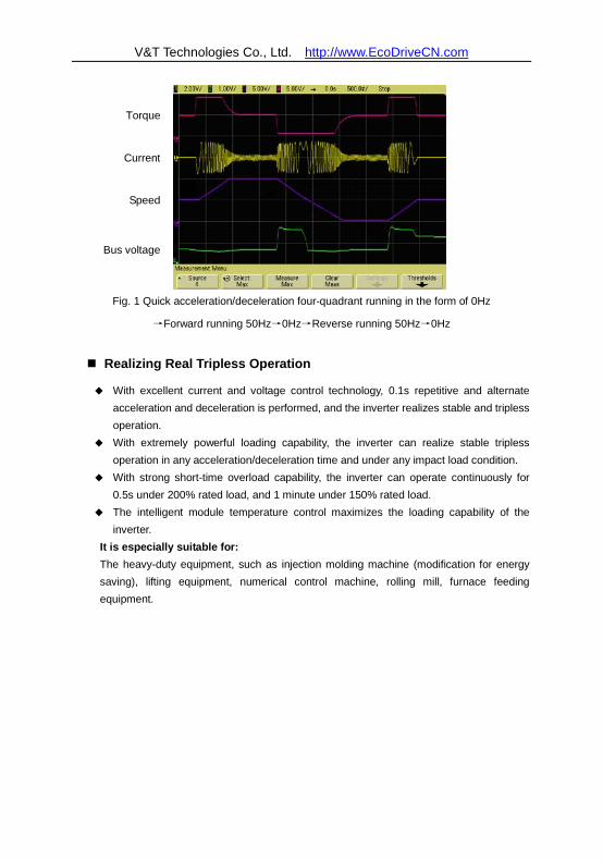
With excellent current and voltage control technology, 0.1s repetitive and alternate acceleration and deceleration is performed, and the inverter realizes stable and tripless operation.
With extremely powerful loading capability, the inverter can realize stable tripless operation in any acceleration/deceleration time and under any impact load condition.
With strong short-time overload capability, the inverter can operate continuously for 0.5s under 200% rated load, and 1 minute under 150% rated load.
The intelligent module temperature control maximizes the loading capability of the inverter.
It is especially suitable for: The heavy-duty equipment, such as injection molding machine (modification for energy saving), lifting equipment, numerical control machine, rolling mill, furnace feeding equipment.
Speed
Current
Bus voltage
Torque
V&T Technologies Co., Ltd. http://www.EcoDriveCN.com
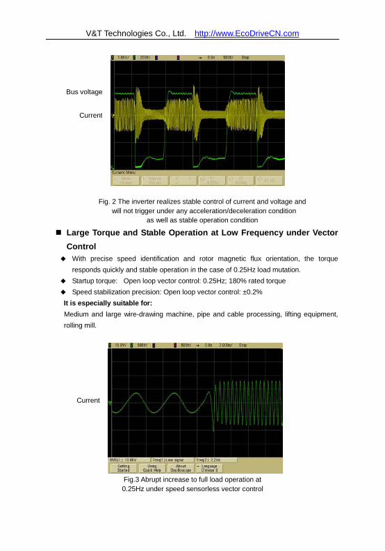
Fig. 2 The inverter realizes stable control of current and voltage and will not trigger under any acceleration/deceleration condition
as well as stable operation condition
Large Torque and Stable Operation at Low Frequency under Vector Control
With precise speed identification and rotor magnetic flux orientation, the torque responds quickly and stable operation in the case of 0.25Hz load mutation.
Startup torque: Open loop vector control: 0.25Hz; 180% rated torque Speed stabilization precision: Open loop vector control: ±0.2% It is especially suitable for: Medium and large wire-drawing machine, pipe and cable processing, lifting equipment, rolling mill.
Fig.3 Abrupt increase to full load operation at 0.25Hz under speed sensorless vector control
Current
Bus voltage
Current
V&T Technologies Co., Ltd. http://www.EcoDriveCN.com
Unique Instantaneous Mains Failure Reaction
Upon the instantaneous mains failure, the energy of the motor feedback bus will keep the inverter running till the mains resumes normal.
When shutdown is caused by long-term power-failure during the operation of the inverter, the inverter will provide alarm message after power resumes normal.
It supports the automatic operation after power-up. The deceleration time during the power failure and the acceleration time after the
power recovery can be set independently. It is especially suitable for: Instantaneous power-failure startup equipment, such as chemical fiber and weaving equipment, multi-point synchronization linkage equipment, fan/pump, etc.
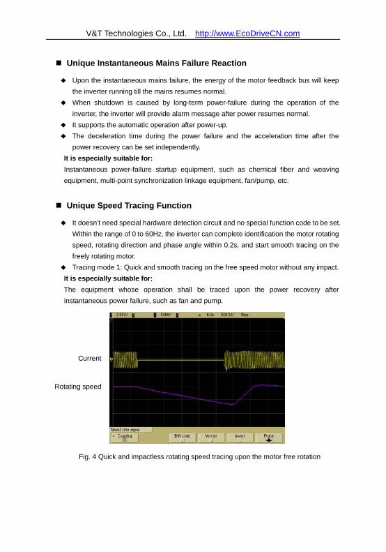
Unique Speed Tracing Function
It doesn’t need special hardware detection circuit and no special function code to be set. Within the range of 0 to 60Hz, the inverter can complete identification the motor rotating speed, rotating direction and phase angle within 0.2s, and start smooth tracing on the freely rotating motor.
Tracing mode 1: Quick and smooth tracing on the free speed motor without any impact. It is especially suitable for: The equipment whose operation shall be traced upon the power recovery after instantaneous power failure, such as fan and pump.
Fig. 4 Quick and impactless rotating speed tracing upon the motor free rotation
Current
Rotating speed

V&T Technologies Co., Ltd. http://www.EcoDriveCN.com
Tracing mode 2: Impactlessly pull down the motor from high-speed to low speed and then accelerate to normal speed.
Fig. 5 Tracing and smooth startup after frequency reduction upon the motor high-speed
free rotation
Unique Quick DC Braking
Within the range of 0 to 300Hz, the inverter can realize back electromotive force elimination and quick DC braking within 0.3s.
DC current input in the most efficient way to improve the braking capability. There is no initial waiting time for the DC braking. Special function code of the initial waiting time for DC braking setting is cancelled. It is especially suitable for: Lifting equipment, invertible roll table for rolling mill, weaving machine, paper making production line.
Current
Rotating speed
V&T Technologies Co., Ltd. http://www.EcoDriveCN.com
High Reliability Design
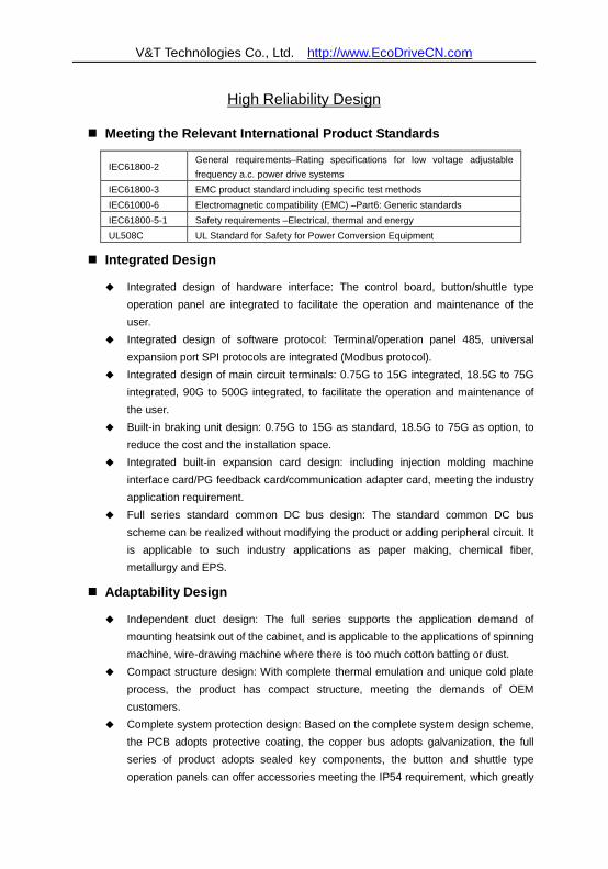
Meeting the Relevant International Product Standards
IEC61800-2 General requirements–Rating specifications for low voltage adjustable frequency a.c. power drive systems
IEC61800-3 EMC product standard including specific test methods IEC61000-6 Electromagnetic compatibility (EMC) –Part6: Generic standards IEC61800-5-1 Safety requirements –Electrical, thermal and energy UL508C UL Standard for Safety for Power Conversion Equipment
Integrated Design
Integrated design of hardware interface: The control board, button/shuttle type operation panel are integrated to facilitate the operation and maintenance of the user.
Integrated design of software protocol: Terminal/operation panel 485, universal expansion port SPI protocols are integrated (Modbus protocol).
Integrated design of main circuit terminals: 0.75G to 15G integrated, 18.5G to 75G integrated, 90G to 500G integrated, to facilitate the operation and maintenance of the user.
Built-in braking unit design: 0.75G to 15G as standard, 18.5G to 75G as option, to reduce the cost and the installation space.
Integrated built-in expansion card design: including injection molding machine interface card/PG feedback card/communication adapter card, meeting the industry application requirement.
Full series standard common DC bus design: The standard common DC bus scheme can be realized without modifying the product or adding peripheral circuit. It is applicable to such industry applications as paper making, chemical fiber, metallurgy and EPS.
Adaptability Design
Independent duct design: The full series supports the application demand of mounting heatsink out of the cabinet, and is applicable to the applications of spinning machine, wire-drawing machine where there is too much cotton batting or dust.
Compact structure design: With complete thermal emulation and unique cold plate process, the product has compact structure, meeting the demands of OEM customers.
Complete system protection design: Based on the complete system design scheme, the PCB adopts protective coating, the copper bus adopts galvanization, the full series of product adopts sealed key components, the button and shuttle type operation panels can offer accessories meeting the IP54 requirement, which greatly
V&T Technologies Co., Ltd. http://www.EcoDriveCN.com
improve the protection capability of the system. It is applicable to the applications with dusty and corrosive environment, such as wire-drawing machine, printing and dyeing and ceramics.
Wide voltage range design: the DC operating voltage range is DC 360−720V, with mains voltage fluctuation recording function.
Precise current detection and protection: The full series adopts precise Hall sensor to detect the output current, meeting the quick real time control and protection requirement of software and hardware, ensuring the performance and reliability of the system.
Independent power supply for control: The system provides independent switching power DC input port. External UPS power supply can be realized through option card. It is applicable to the applications of oilfield, chemical industry and printing and dyeing industry.
Power-up self-detection function: It realizes the power-up detection on the peripheral circuit, such as motor grounding, disconnection, greatly improving the reliability of the system.
Comprehensive system protection function: software/hardware current limiting protection, overcurrent and overvoltage protection, grounding short circuit protection, overload protection, IGBT short circuit protection, abnormal current detection protection, abnormal relay contact protection.
Perfect terminal protection function: short circuit and overload protection for the +24V and +10V power supply of the control terminal, operation panel cable reverse connection protection, input signal cable disconnection and abnormal analog input protection.
Over-temperature prealarm protection function: Automatic adjustment will be made according to the temperature to ensure the reliable operation of the product, and maximum operating temperature will be recorded.
Comprehensive switching power protection function: including switching power output short circuit protection, overload protection, power-up walk-in function, open loop self-locking and voltage limiting protection function, ensuring the reliability of the system.
V&T Technologies Co., Ltd. http://www.EcoDriveCN.com
Rich and Flexible Functions
Multiple Frequency Reference Modes, Flexible and Convenient for Operation
Operation panel reference (digital reference). The operation panel can be used to conduct ∨/∧ adjustment on the frequency reference.
Terminal reference: 1) Analog AI1/AI2: 0 to 10V or 0 to 20mA 2) Analog AI3: -10V to 10V 3) Pulse frequency X7/DI: 0.2Hz to 50kHz 4) Xi terminal: UP/DN mode independent, able to superpose with any other
frequency reference mode Communication mode reference: International standard Modbus protocol. The above reference modes can be switched online.
Multiple Channels for Reference and Feedback Under the open loop mode and analog feedback close loop mode, the reference value
can define the main and auxiliary calculation relation: 1) Main reference + auxiliary reference 2) Main reference - auxiliary reference 3) Main reference + auxiliary reference -50% 4) Max (main reference, auxiliary reference) 5) Min (main reference, auxiliary reference)
The sign of the main and auxiliary reference calculation (positive or negative) can automatically determine the rotation direction of the motor.
Under the analog feedback close loop mode, the feedback value can also define the main and auxiliary calculation relation before it enters the process PID for adjustment control.
It is especially suitable for: The continuous and automatic production lines, such as paper making, printing and dyeing, packaging and printing. The temperature difference and pressure difference applications, such as the chilled water control of the central air conditioner, the water supply system.
Digital Operation Panel Button type and shuttle type selectable, RS485 communication mode, standard
network port connection. The button layout complies with the human engineering principle. One-button function
code access and exit, making it easy for the operation. The standard configuration operation panel can realize parameter copy and remote
control function (maximum length: 500m).
V&T Technologies Co., Ltd. http://www.EcoDriveCN.com
With unique multifunctional button M, the following functions can be defined: 1) JOG 2) Emergency shutdown 1 (fastest shutdown) 3) Emergency shutdown 2 (free shutdown) 4) Reference mode switch through operating command (operation panel reference
→terminal reference→host computer reference →operation panel reference) 5) FASt/bASE menu switch 6) Menu mode switching (bASE→FASt→ndFt→LASt→bASE)
Host Computer Communication The operation panel and terminals provide 485 ports, the communication protocol is
Modbus, and host computer monitoring software is provided. Master slave communication control among several inverters can be realized. Parameter upload and download can be realized. Cascade transmission of operating frequencies for several inverters can be realized to
provide digital frequency divider functions.
V&T Technologies Co., Ltd. http://www.EcoDriveCN.com
Customized Functions
Multiple Function Code Display Modes
bASE: Basic menu mode (refer to 5.1 basic menu function code parameter table), displays all the function codes.
FASt: Fast menu mode, is especially suitable for the naive users. ndFt: Non-leave-factory value menu mode, it only displays the function codes different
from the leave-factory values to facilitate the inquiry and commissioning. LASt: Last change menu mode, it displays the 10 functions codes that are recently
changed and P0.02 to facilitate the inquiry and commissioning. The users can define the function codes for inquiry and modification by themselves.
Multiple Function Code Encryption Modes (to Protect the Intellectual Property of the Customers)
The user can encrypt any group function codes by themselves. The user can lock operation panel. The user can set function parameter password protection. The technical secrets, such as system specific process parameters, cannot be copied.
User Self-defined Parameter Display Function
The user can choose the common parameters displayed by the operation panel and use to >> key switch such parameters.
The user can define the parameters displayed upon running and stopping respectively. The user can define such parameters as pressure, temperature, flux and line speed.
The User can Make Secondary Development
Universal expansion port is provided as standard. Physical port SPI bus, software protocol Modbus. The ports provide +24V, ±15V and 5V power supply and two ways of A/D input. The CPU expansion scheme can realize PLC function. It supports the programming by user to realize process control.
Enhanced Function
The software filtering time for the AI1, AI2 and AI3 analog input is settable to enhance the anti-interference capability.
Independent multi-section modification can be made on the AI1, AI2, AI3 and DI analog input curve.
Multi-section speed setting is provided, with 16 speeds as standard, and up to 23 speeds.
With a maximum output frequency of 3000Hz, it is applicable to such equipment as

V&T Technologies Co., Ltd. http://www.EcoDriveCN.com
vacuum pump, grinding machine, female thread extrusion machine. With the acceleration/deceleration time up to 10 hours, it is applicable to the bobbiner
and other equipment of the textile industry. It supports the overload protection with motor temperature feedback. Customized timed shutdown, with the duration up to 100 hours. The user can select button type or shuttle type operation panel according to their
preference. Independent high-speed pulse input and output ports are provided to realize
high-speed pulse cascade function.
V&T Technologies Co., Ltd. http://www.EcoDriveCN.com
Typical industry applications
Digital Control Machine Tool
Compact structure: The size is equal to 70% of the inverter of the same power. Low speed precise processing: The excellent low-frequency torque performance can
meet the processing demand of the machine main shaft in low speed condition (when it is operating in motoring state, it can realize a frequency as low as 0.25Hz and output 180% rated torque).
Torque and rotating speed index: It can meet the sudden loading and unloading requirement upon the cutting processing, with the dynamic torque response time <20ms and speed stabilization precision of ±0.2%.
Special Function for Wire-drawing Machine
Operation without swing link: It adopts open loop tension control to realize operation without swing link under speed sensorless control mode.
Operation with swing link: The user does not need to adjust the position of the swing link manually. When the system starts up, the swing link will get to the proper position automatically.
Powerful tensile capability: It is suitable for the applications of large and medium wire-drawing machine. It features large torque upon low frequency operation and high speed stabilization precision.
Double conversion scheme: It can realize the inverter application of the same power class with precise current control and does not need to upgrade the level.
Environment adaptability: Independent duct design, protective coating treatment, high-temperature operation, and digital protection function.
Special Function for Textile
Traverse operation function: It can effectively lead the yarn into the yarn carrier on the yarn and chemical fiber equipment to prevent the overlapping of the yarn and facilitate the unreeling.
Constant line speed mode: It can effectively prevent the uneven tightness of the yarns from the high speed cone winder to maintain the constant tension.
Fixed length calculation: It is convenient for the user to calculate the thread length. When the thread length reaches the preset value, the equipment will be shut down automatically.
Fixed diameter shutdown: The spindle diameter can be detected by inputting analog signal. When the preset value is reached, the equipment will be shut down automatically.
Crawling positioning: When the spinning is interrupted or ended, it can decelerate the equipment to designated frequency for low-speed operation and then shut down the
V&T Technologies Co., Ltd. http://www.EcoDriveCN.com
equipment when receiving the positioning signal.
Extrusion Machine Energy Saving
Extrusion machine interface board: It can realize best flow and pressure distribution relation in different processes by receiving the extrusion machine feedback signal to realize the optimized energy saving control of the motor.
Customized process curve: The user does not need to change the inverter parameter when replacing the moulds. The process curve memory can be easily realized.
Wide range torque output: Within the set range of pressure and flow, the motor torque output is stable to ensure the quality of the workpiece.
Tripless: With extremely powerful loading capability, the inverter can realize stable tripless operation in any acceleration/deceleration time and under any impact load condition.
Green output: It adopts advanced power module drive mode to reduce the interference to the extrusion machine control circuit and sensor.
Lifting Control
Step torque response: It can quickly follow the equipment load change to prevent the runaway situation and ensure the safe production.
Four quadrant operations: It can smoothly and quickly switch the forward and reverse motoring and generating state of the equipment.
Torque monitoring: It can adjust, limit, display and switch the torque output, so as to monitor the operating state of the equipment.
V&T Technologies Co., Ltd. http://www.EcoDriveCN.com
Safety Precautions Description of safety marks:
Danger: The misuse may cause fire, severe injury, even death.
Note: The misuse may cause medium or minor injury and equipment damage.
Use
DangerDanger
This series of inverter is used to control the variable speed operation of three-phase motor and cannot be used for single-phase motor or other applications. Otherwise, inverter failure or fire may be caused.
This series of inverter cannot be simply used in the applications directly related to the human safety, such as the medical equipment.
This series of inverter is produced under strict quality management system. If the inverter failure may cause severe accident or loss, safety measures, such as redundancy or bypass, shall be taken.
Goods Arrival Inspection
NoteNote If the inverter is found to be damaged or lack parts, the inverter cannot be installed.
Otherwise, accident may be caused. Installation
NoteNote When handling and installing the product, please hold the product bottom. Do not hold
the enclosure only. Otherwise, your feet may be injured and the inverter may be damaged because of dropping.
The inverter shall be mounted on the fire retardant surface, such as metal, and kept far away from the inflammables and heat source.
Keep the drilling scraps from falling into the inside of the inverter during the installation; otherwise, inverter failure may be caused.
When the inverter is installed inside the cabinet, the electricity control cabinet shall be equipped with fan and ventilation port. And ducts for radiation shall be constructed in the cabinet.
V&T Technologies Co., Ltd. http://www.EcoDriveCN.com
Wiring
DangerDanger
The wiring must be conducted by qualified electricians. Otherwise, there exists the risk of electric shock or inverter damage.
Before wiring, confirm that the power supply is disconnected. Otherwise, there exists the risk of electric shock or fire.
The grounding terminal PE must be reliably grounded, otherwise, the inverter enclosure may become live.
Please do not touch the main circuit terminal. The wires of the inverter main circuit terminals must not contact the enclosure. Otherwise, there exists the risk of electric shock.
The connecting terminals for the braking resistor are ⊕2/B 1 and B 2. P lease do not
connect terminals other than these two. Otherwise, fire may be caused. The leakage current of the inverter system is more than 3.5mA, and the specific value of
the leakage current is determined by the use conditions. To ensure the safety, the inverter and the motor must be grounded. Wiring
NoteNote
The three-phase power supply cannot connect to output terminals U/T1, V/T2 and W/T3, otherwise, the inverter will be damaged.
It is forbidden to connect the output terminal of the inverter to the capacitor or LC/RC noise filter with phase lead, otherwise, the internal components of the inverter may be damaged.
Please confirm that the power supply phases, rated voltage are consistent with that of the nameplate, otherwise, the inverter may be damaged.
Do not perform dielectric strength test on the inverter, otherwise, the inverter may be damaged.
The wires of the main circuit terminals and the wires of the control circuit terminals shall be laid separately or in a square-crossing mode, otherwise, the control signal may be interfered.
The wires of the main circuit terminals shall adopt lugs with insulating sleeves. The inverter input and output cables with proper sectional area shall be selected
according to the inverter power. When the length of the cables between the inverter and the motor is more than 100m, it
is suggested to use output reactor to avoid the inverter failure caused by the overcurrent of the distribution capacitor.
The inverter which equipped with DC reactor must connect with DC reactor between the terminal of + 1、+ 2, otherwise the inverter will not display after power on.
V&T Technologies Co., Ltd. http://www.EcoDriveCN.com
Operation
DangerDanger
Power supply can only be connected after the wiring is completed and the cover is installed. It is forbidden to remove the cover in live condition; otherwise, there exists the risk of electric shock.
When auto failure reset function or restart function is set, isolation measures shall be taken for the mechanical equipment, otherwise, personal injury may be caused.
When the inverter is powered on, even when it is in the stop state, the terminals of the inverter are still live. Do not touch the inverter terminals; otherwise electric shock may be caused.
The failure and alarm signal can only be reset after the running command has been cut off. Otherwise, personal injury may be caused.
NoteNote
Do not start or shut down the inverter by switching on or off the power supply, otherwise, the inverter may be damaged.
Before operation, please confirm if the motor and equipment are in the allowable use range, otherwise, the equipment may be damaged.
The heatsink and the braking resistor have high temperature. Please do not touch such device; otherwise, you may be burnt.
When it is used on lifting equipment, mechanical contracting brake shall also be equipped.
Please do not change the inverter parameter randomly. Most of the factory set parameters of the inverter can meet the operating requirement, and the user only needs to set some necessary parameters. Any random change of the parameter may cause the damage of the mechanical equipment.
In the applications with industrial frequency and variable frequency switching, the two contactors for controlling the industrial frequency and variable frequency switching shall be interlocked.
Maintenance, Inspection
DangerDanger
In the power-on state, please do not touch the inverter terminals; otherwise, there exists the risk of electric shock.
If cover is to be removed, the power supply must be disconnected first. Wait for at least 10 minutes after power off or confirm that the CHARGE LED is off
before maintenance and inspection to prevent the harm caused by the residual voltage of the main circuit electrolytic capacitor to persons.
The components shall be maintained, inspected or replaced by qualified electricians.

V&T Technologies Co., Ltd. http://www.EcoDriveCN.com
NoteNote
The circuit boards have large scale CMOS IC. Please do not touch the board to avoid the circuit board damage caused by electro static.
Others
DangerDanger
It is forbidden to modify the inverter unauthorizedly; otherwise, personal injury may be caused.
V&T Technologies Co., Ltd. http://www.EcoDriveCN.com
Contents
Chapter 1 Introduction to V5-H Series Inverter ..................................................................................11.1 Product Model Description ..................................................................................................................11.2 Product Nameplate Description ..........................................................................................................11.3 Product Series ....................................................................................................................................21.4 Technical Specifications of Product .....................................................................................................41.5 Product Component Name .................................................................................................................61.6 Product Outline, Mounting Dimension, and Weight .............................................................................61.7 Operation Panel Outline and Mounting Dimension ..............................................................................91.8 Pallet Outline and Mounting Dimension ..............................................................................................91.9 Braking Resistor Lectotype ............................................................................................................... 10Chapter 2 Inverter Installation ........................................................................................................... 112.1 Environment for Product Installation ................................................................................................. 112.2 Mounting Direction and Space .......................................................................................................... 112.3 Removal and Mounting of Operation Panel and Cover ...................................................................... 12Chapter 3 Wiring of Inverter .............................................................................................................. 163.1 Connection of the Product and Peripheral Devices ........................................................................... 163.2 Description of Peripheral Devices for Main Circuit ............................................................................. 173.3 Lectotype of mMain Circuit Peripheral Devices ................................................................................. 173.4 Product Terminal Configuration ......................................................................................................... 193.5 Functions of Main Circuit Terminal .................................................................................................... 193.6 Attention for Main Circuit Wiring ........................................................................................................ 203.7 Terminal Wiring ................................................................................................................................ 243.8 Functions of Control Circuit Terminals ............................................................................................... 253.9 Schematic Diagram of Control Board ................................................................................................ 283.10 Lectotype of Control Circuit Peripheral Devices .............................................................................. 293.11 Description of Jumper Function ....................................................................................................... 29Chapter 4 Using Instructions of Operation Panel ............................................................................ 304.1 Introduction to Operation Panel ........................................................................................................ 304.2 Descriptions of Indicators ................................................................................................................. 304.3 Description of Keys on Operation Panel ............................................................................................ 314.4 Menu Style ....................................................................................................................................... 324.5 Password Operation ......................................................................................................................... 374.6 Lock/Unlock Keys ............................................................................................................................. 384.7 Operation Panel Display and Key Operation ..................................................................................... 394.8 Operation Example ........................................................................................................................... 404.9 Running for the First Time ................................................................................................................ 41Chapter 5 List of Parameters ............................................................................................................ 435.1 List of Basic Menu Function Codes ................................................................................................... 43
V&T Technologies Co., Ltd. http://www.EcoDriveCN.com
5.2 User’s Parameter Record ................................................................................................................. 605.3 User’s Connection Diagram .............................................................................................................. 61Chapter 6 Parameter Description ...................................................................................................... 626.1 Basic Function Parameter (Group P0) .............................................................................................. 626.2 Main and Auxiliary Reference Parameter (Group P1) ........................................................................ 676.3 Key and Display Parameters (Group P2) .......................................................................................... 716.4 Startup/stop Parameter (Group P3) .................................................................................................. 746.5 Multi-section Parameter (Group P4) ................................................................................................. 766.6 Multi-functional Input Parameter (Group P5) ..................................................................................... 796.7 Analog Reference Parameter (Group P6) ......................................................................................... 866.8 Multi-function Output Parameter (Group P7) ..................................................................................... 906.9 Process PID Close Loop Parameters (Group P8) ............................................................................. 966.10 Motor Parameter (Group P9) .......................................................................................................... 986.11 Control Parameter (Group PA) ...................................................................................................... 1026.12 Enhanced Function Parameter (Group Pb) ................................................................................... 1086.13 Communication Parameters (Group PC) ....................................................................................... 1126.14 Vector Control 2 Parameters (Group Pd) ...................................................................................... 1136.15 Failure Record Parameters (Group d0) ......................................................................................... 1176.16 Product Identity Parameters (Group d1) ........................................................................................ 1176.17 Use of Display Parameters (Group d2) ......................................................................................... 119Chapter 7 Fault Diagnosis ............................................................................................................... 1217.1 List of Fault and Alarm Information ................................................................................................. 1217.2 Troubleshooting Procedures ........................................................................................................... 127Chapter 8 Routine Repair and Maintenance ..................................................................................... 1288.1 Routine Maintenance ..................................................................................................................... 1288.2 Periodic Maintenance ..................................................................................................................... 1298.3 Component Replacement ............................................................................................................... 1298.4 Insulation Test ................................................................................................................................ 129Appendix A Modbus Communication Protocol .............................................................................. 131Appendix B Control Mode Setting Process .................................................................................... 1401. Setting Process for Auto-tuning ........................................................................................................ 1402. Setting Process for Open Loop ......................................................................................................... 1413. Setting Process for Closed Loop ...................................................................................................... 143Appendix C FAQ .............................................................................................................................. 146
V&T Technologies Co., Ltd. http://www.EcoDriveCN.com
Chapter 1 Introduction to V5−H Series Inverter 1
Chapter 1 Introduction to V5−H Series Inverter
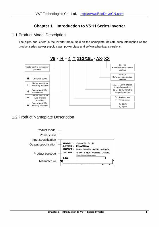
1.1 Product Model Description
The digits and letters in the inverter model field on the nameplate indicate such information as the product series, power supply class, power class and software/hardware versions.
V5 - H 4 T 11G/15L - AX XX
Vector control technology platform
2:200V4:400V
S:Single-praseT:Three-prase
00~99Hardware nonstandard
version
A0~Z9Software nonstandard
version
11G:11kW Constant torque/heavy-duty
15 L:15kW Variable torque/light-duty
-
Universal series
Series special for wire-drawing
machine
Series special for moulding machine
Series special for weaving machine
Series special for machine toolM
T
I
W
H
-
1.2 Product Nameplate Description
Product model Power class
Input specification Output specification
Product barcode
Manufacture
V&T Technologies Co., Ltd. http://www.EcoDriveCN.com
Chapter 1 Introduction to V5−H Series Inverter 2
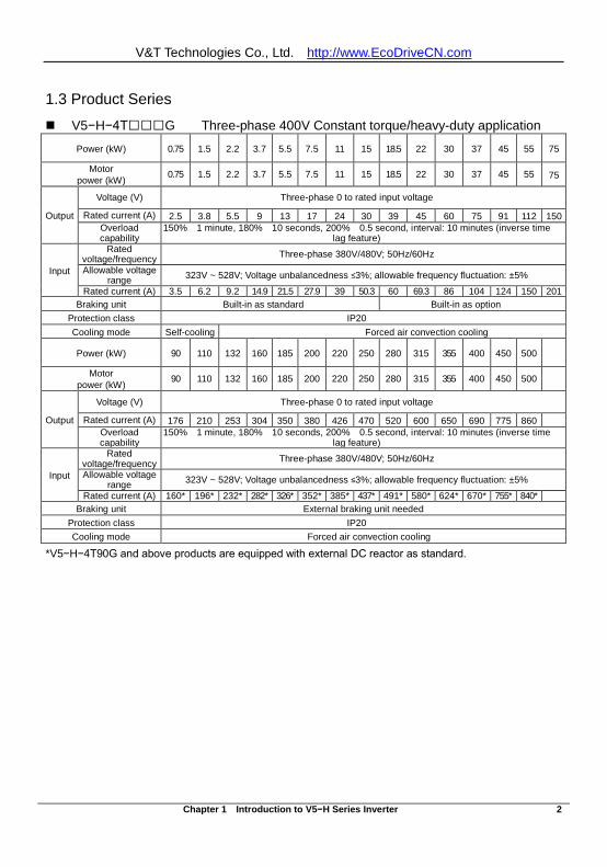
1.3 Product Series
V5−H−4TG Three-phase 400V Constant torque/heavy-duty application
Power (kW) 0.75 1.5 2.2 3.7 5.5 7.5 11 15 18.5 22 30 37 45 55 75
Motor power (kW) 0.75 1.5 2.2 3.7 5.5 7.5 11 15 18.5 22 30 37 45 55 75
Output
Voltage (V) Three-phase 0 to rated input voltage
Rated current (A) 2.5 3.8 5.5 9 13 17 24 30 39 45 60 75 91 112 150 Overload capability
150% 1 minute, 180% 10 seconds, 200% 0.5 second, interval: 10 minutes (inverse time lag feature)
Input
Rated voltage/frequency Three-phase 380V/480V; 50Hz/60Hz
Allowable voltage range 323V ~ 528V; Voltage unbalancedness ≤3%; allowable frequency fluctuation: ±5%
Rated current (A) 3.5 6.2 9.2 14.9 21.5 27.9 39 50.3 60 69.3 86 104 124 150 201 Braking unit Built-in as standard Built-in as option
Protection class IP20 Cooling mode Self-cooling Forced air convection cooling
Power (kW) 90 110 132 160 185 200 220 250 280 315 355 400 450 500
Motor power (kW) 90 110 132 160 185 200 220 250 280 315 355 400 450 500
Output
Voltage (V) Three-phase 0 to rated input voltage
Rated current (A) 176 210 253 304 350 380 426 470 520 600 650 690 775 860 Overload capability
150% 1 minute, 180% 10 seconds, 200% 0.5 second, interval: 10 minutes (inverse time lag feature)
Input
Rated voltage/frequency Three-phase 380V/480V; 50Hz/60Hz
Allowable voltage range 323V ~ 528V; Voltage unbalancedness ≤3%; allowable frequency fluctuation: ±5%
Rated current (A) 160* 196* 232* 282* 326* 352* 385* 437* 491* 580* 624* 670* 755* 840* Braking unit External braking unit needed
Protection class IP20 Cooling mode Forced air convection cooling
*V5−H−4T90G and above products are equipped with external DC reactor as standard.
V&T Technologies Co., Ltd. http://www.EcoDriveCN.com
Chapter 1 Introduction to V5−H Series Inverter 3
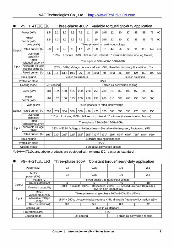
V5−H−4TL Three-phase 400V Variable torque/light-duty application Power (kW) 1.5 2.2 3.7 5.5 7.5 11 15 18.5 22 30 37 45 55 75 90
Motor power (kW) 1.5 2.2 3.7 5.5 7.5 11 15 18.5 22 30 37 45 55 75 90
Output
Voltage (V) Three-phase 0 to rated input voltage
Rated current (A) 3.3 5.0 7.5 11 17 22 30 37 44 56 72 91 110 142 176
Overload capability 115% 1 minute, 160% 0.5 second, interval: 10 minutes (inverse time lag feature)
Input
Rated voltage/frequency Three-phase 380V/480V; 50Hz/60Hz
Allowable voltage fluctuation range 323V ~ 528V; Voltage unbalancedness: ≤3%; allowable frequency fluctuation: ±5%
Rated current (A) 5.6 8.1 13.5 19.5 26 39 50.3 60 69.3 86 104 124 150 190 235 Braking unit Built-in as standard Built-in as option
Protection class IP20 Cooling mode Self-cooling Forced air convection cooling
Power (kW) 110 132 160 185 200 220 250 280 315 355 400 450 500 560
Motor power (kW)
110 132 160 185 200 220 250 280 315 355 400 450 500 560
Output
Voltage (V) Three-phase 0 to rated input voltage
Rated current (A) 210 253 304 350 380 426 470 520 600 650 690 775 860 950 Overload capability 115% 1 minute, 160% 0.5 second, interval: 10 minutes (inverse time lag feature)
Input
Rated voltage/frequency Three-phase 380V/480V; 50Hz/60Hz
Allowable voltage range 323V ~ 528V; Voltage unbalancedness ≤3%; allowable frequency fluctuation: ±5%
Rated current (A) 196* 232* 282* 326* 352* 385* 437* 491* 580* 624* 670* 755* 840* 920*
Braking unit External braking unit needed Protection class IP20 Cooling mode Forced air convection cooling
*V5−H−4T110L and above products are equipped with external DC reactor as standard. V5−H−2TG Three-phase 200V Constant torque/heavy-duty application
Power (kW) 0.4 0.75 1.5 2.2
Motor power (kW) 0.4 0.75 1.5 2.2
Output
Voltage (V) Three-phase 0 to rated input voltage Rated current (A) 3 5 7.5 10
Overload capability 150% 1 minute, 180% 10 seconds, 200% 0.5 second, interval: 10 minutes (inverse time lag feature)
Input
Rated voltage/frequency Three-phase or single-phase 200V~240V; 50Hz/60Hz
Allowable voltage range 180V ~ 260V; Voltage unbalancedness ≤3%; allowable frequency fluctuation: ±5%
Rated current (A) 3.8 5.5 8.3 12 Braking unit Built-in as standard
Protection class IP20 Cooling mode Self-cooling Forced air convection cooling
V&T Technologies Co., Ltd. http://www.EcoDriveCN.com
Chapter 1 Introduction to V5−H Series Inverter 4
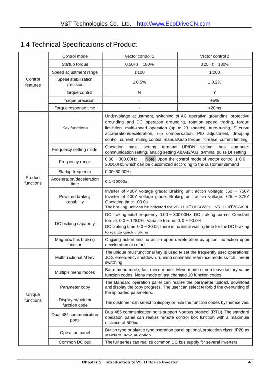
1.4 Technical Specifications of Product
Control features
Control mode Vector control 1 Vector control 2
Startup torque 0.50Hz 180% 0.25Hz 180%
Speed adjustment range 1:100 1:200
Speed stabilization precision ± 0.5% ± 0.2%
Torque control N Y
Torque precision - ±5%
Torque response time - <20ms
Product functions
Key functions
Undervoltage adjustment, switching of AC operation grounding, protective grounding and DC operation grounding, rotation speed tracing, torque limitation, multi-speed operation (up to 23 speeds), auto-tuning, S curve acceleration/deceleration, slip compensation, PID adjustment, drooping control, current limiting control, manual/auto torque increase, current limiting.
Frequency setting mode Operation panel setting, terminal UP/DN setting, host computer communication setting, analog setting AI1/AI2/AI3, terminal pulse DI setting
Frequency range 0.00 ~ 300.00Hz Note: Upon the control mode of vector control 1 0.0 ~ 3000.0Hz, which can be customized according to the customer demand
Startup frequency 0.00~60.00Hz
Acceleration/deceleration time 0.1~36000s
Powered braking capability
Inverter of 400V voltage grade: Braking unit action voltage: 650 ~ 750V Inverter of 400V voltage grade: Braking unit action voltage: 325 ~ 375V Operating time: 100.0s The braking unit can be selected for V5−H−4T18.5G/22L~ V5−H−4T75G/90L
DC braking capability
DC braking initial frequency: 0.00 ~ 300.00Hz; DC braking current: Constant torque: 0.0 ~ 120.0%, Variable torque: 0. 0 ~ 90.0% DC braking time: 0.0 ~ 30.0s; there is no initial waiting time for the DC braking to realize quick braking
Magnetic flux braking function
Ongoing action and no action upon deceleration as option, no action upon deceleration at default
Unique functions
Multifunctional M key The unique multifunctional key is used to set the frequently used operations: JOG, emergency shutdown, running command reference mode switch , menu switching
Multiple menu modes Basic menu mode, fast menu mode. Menu mode of non-leave-factory value function codes, Menu mode of last changed 10 function codes
Parameter copy The standard operation panel can realize the parameter upload, download and display the copy progress. The user can select to forbid the overwriting of the uploaded parameters.
Displayed/hidden function code The customer can select to display or hide the function codes by themselves.
Dual 485 communication ports
Dual 485 communication ports support Modbus protocol (RTU). The standard operation panel can realize remote control box function with a maximum distance of 500m.
Operation panel Button type or shuttle type operation panel optional, protection class: IP20 as standard, IP54 as option
Common DC bus The full series can realize common DC bus supply for several inverters.
V&T Technologies Co., Ltd. http://www.EcoDriveCN.com
Chapter 1 Introduction to V5−H Series Inverter 5
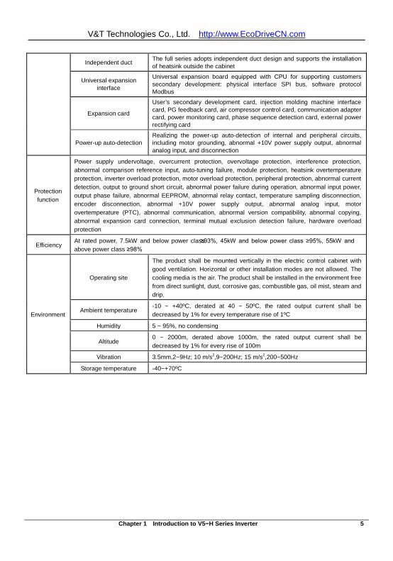
Independent duct The full series adopts independent duct design and supports the installation of heatsink outside the cabinet
Universal expansion interface
Universal expansion board equipped with CPU for supporting customers secondary development: physical interface SPI bus, software protocol Modbus
Expansion card
User’s secondary development card, injection molding machine interface card, PG feedback card, air compressor control card, communication adapter card, power monitoring card, phase sequence detection card, external power rectifying card
Power-up auto-detection Realizing the power-up auto-detection of internal and peripheral circuits, including motor grounding, abnormal +10V power supply output, abnormal analog input, and disconnection
Protection function
Power supply undervoltage, overcurrent protection, overvoltage protection, interference protection, abnormal comparison reference input, auto-tuning failure, module protection, heatsink overtemperature protection, inverter overload protection, motor overload protection, peripheral protection, abnormal current detection, output to ground short circuit, abnormal power failure during operation, abnormal input power, output phase failure, abnormal EEPROM, abnormal relay contact, temperature sampling disconnection, encoder disconnection, abnormal +10V power supply output, abnormal analog input, motor overtemperature (PTC), abnormal communication, abnormal version compatibility, abnormal copying, abnormal expansion card connection, terminal mutual exclusion detection failure, hardware overload protection
Efficiency At rated power, 7.5kW and below power class ≥93%, 45kW and below power class ≥95%, 55kW and above power class ≥98%
Environment
Operating site
The product shall be mounted vertically in the electric control cabinet with good ventilation. Horizontal or other installation modes are not allowed. The cooling media is the air. The product shall be installed in the environment free from direct sunlight, dust, corrosive gas, combustible gas, oil mist, steam and drip.
Ambient temperature -10 ~ +40ºC, derated at 40 ~ 50ºC, the rated output current shall be decreased by 1% for every temperature rise of 1ºC
Humidity 5 ~ 95%, no condensing
Altitude 0 ~ 2000m, derated above 1000m, the rated output current shall be decreased by 1% for every rise of 100m
Vibration 3.5mm,2~9Hz; 10 m/s2,9~200Hz; 15 m/s2,200~500Hz
Storage temperature -40~+70ºC
V&T Technologies Co., Ltd. http://www.EcoDriveCN.com
Chapter 1 Introduction to V5−H Series Inverter 6
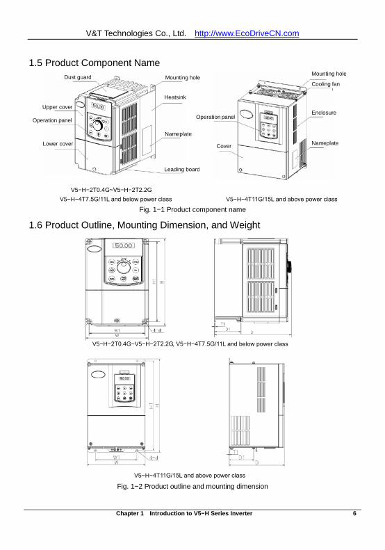
1.5 Product Component Name
V5−H−2T0.4G~V5−H−2T2.2G V5−H−4T7.5G/11L and below power class V5−H−4T11G/15L and above power class
Fig. 1−1 Product component name
1.6 Product Outline, Mounting Dimension, and Weight
Fig. 1−2 Product outline and mounting dimension
V5−H−2T0.4G~V5−H−2T2.2G, V5−H−4T7.5G/11L and below power class
V5−H−4T11G/15L and above power class
Cover
Mounting hole Cooling fan
Nameplate
Operation panel
Cover
Mounting hole Cooling fan
Enclosure
Nameplate
Dust guard
Nameplate
Leading board
Dust guard
Upper cover Operation panel
Lower cover
Heatsink
Mounting hole
V&T Technologies Co., Ltd. http://www.EcoDriveCN.com
Chapter 1 Introduction to V5−H Series Inverter 7
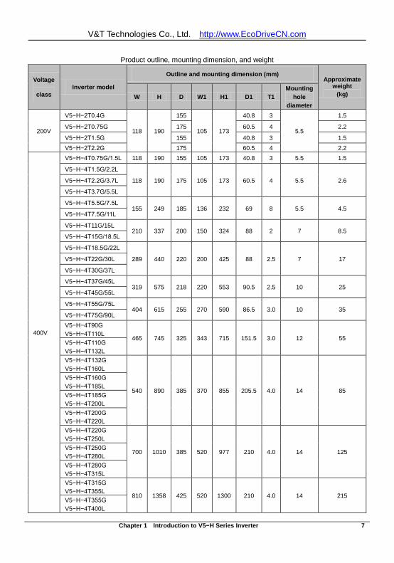
Product outline, mounting dimension, and weight
Voltage
class Inverter model
Outline and mounting dimension (mm) Approximate
weight (kg) W H D W1 H1 D1 T1
Mounting hole
diameter
200V
V5−H−2T0.4G
118 190
155
105 173
40.8 3
5.5
1.5
V5−H−2T0.75G 175 60.5 4 2.2
V5−H−2T1.5G 155 40.8 3 1.5 V5−H−2T2.2G 175 60.5 4 2.2
400V
V5−H−4T0.75G/1.5L 118 190 155 105 173 40.8 3 5.5 1.5
V5−H−4T1.5G/2.2L
118 190 175 105 173 60.5 4 5.5 2.6 V5−H−4T2.2G/3.7L
V5−H−4T3.7G/5.5L
V5−H−4T5.5G/7.5L 155 249 185 136 232 69 8 5.5 4.5
V5−H−4T7.5G/11L
V5−H−4T11G/15L 210 337 200 150 324 88 2 7 8.5
V5−H−4T15G/18.5L
V5−H−4T18.5G/22L
289 440 220 200 425 88 2.5 7 17 V5−H−4T22G/30L
V5−H−4T30G/37L
V5−H−4T37G/45L 319 575 218 220 553 90.5 2.5 10 25
V5−H−4T45G/55L
V5−H−4T55G/75L 404 615 255 270 590 86.5 3.0 10 35
V5−H−4T75G/90L V5−H−4T90G V5−H−4T110L
465 745 325 343 715 151.5 3.0 12 55 V5−H−4T110G V5−H−4T132L V5−H−4T132G V5−H−4T160L
540 890 385 370 855 205.5 4.0 14 85
V5−H−4T160G V5−H−4T185L V5−H−4T185G V5−H−4T200L V5−H−4T200G V5−H−4T220L V5−H−4T220G V5−H−4T250L
700 1010 385 520 977 210 4.0 14 125 V5−H−4T250G V5−H−4T280L V5−H−4T280G V5−H−4T315L V5−H−4T315G V5−H−4T355L
810 1358 425 520 1300 210 4.0 14 215 V5−H−4T355G V5−H−4T400L
V&T Technologies Co., Ltd. http://www.EcoDriveCN.com
Chapter 1 Introduction to V5−H Series Inverter 8
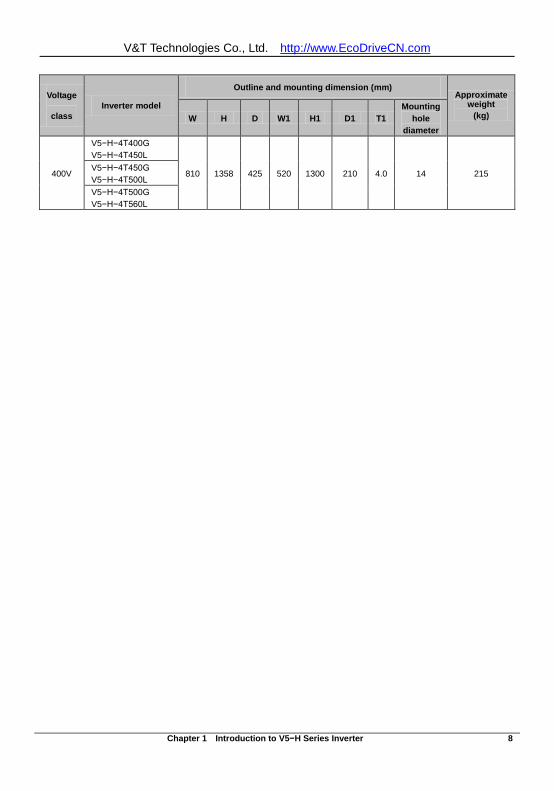
Voltage
class Inverter model
Outline and mounting dimension (mm) Approximate
weight (kg) W H D W1 H1 D1 T1
Mounting hole
diameter
400V
V5−H−4T400G V5−H−4T450L
810 1358 425 520 1300 210 4.0 14 215 V5−H−4T450G V5−H−4T500L V5−H−4T500G V5−H−4T560L
V&T Technologies Co., Ltd. http://www.EcoDriveCN.com
Chapter 1 Introduction to V5−H Series Inverter 9
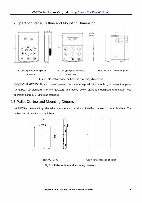
1.7 Operation Panel Outline and Mounting Dimension
Shuttle type operation panel
(V6−DP01)
Button type operation panel
(V6−DP02)
Rear view of operation panel
Fig.1-3 Operation panel outline and mounting dimension
Note: V5−H−4T7.5G/11L and below power class are equipped with shuttle type operation panel
(V6−DP01) as standard, V5−H−4T11G/15L and above power class are equipped with button type
operation panel (V6−DP02) as standard.
1.8 Pallet Outline and Mounting Dimension
V6−DP05 is the mounting pallet when the operation panel is to install on the electric control cabinet. The
outline and dimension are as follows:
Pallet (V6−DP05) Open pore dimension of pallet
Fig.1−4 Pallet outline and mounting dimension
V&T Technologies Co., Ltd. http://www.EcoDriveCN.com
Chapter 1 Introduction to V5−H Series Inverter 10
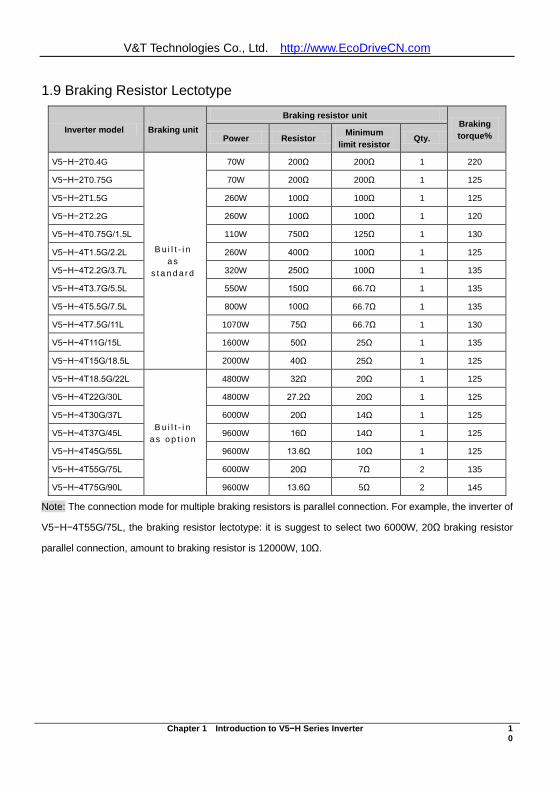
1.9 Braking Resistor Lectotype
Inverter model Braking unit Braking resistor unit
Braking torque% Power Resistor Minimum
limit resistor Qty.
V5−H−2T0.4G
B u i l t - i n a s
s t a n d a r d
70W 200Ω 200Ω 1 220
V5−H−2T0.75G 70W 200Ω 200Ω 1 125
V5−H−2T1.5G 260W 100Ω 100Ω 1 125
V5−H−2T2.2G 260W 100Ω 100Ω 1 120
V5−H−4T0.75G/1.5L 110W 750Ω 125Ω 1 130
V5−H−4T1.5G/2.2L 260W 400Ω 100Ω 1 125
V5−H−4T2.2G/3.7L 320W 250Ω 100Ω 1 135
V5−H−4T3.7G/5.5L 550W 150Ω 66.7Ω 1 135
V5−H−4T5.5G/7.5L 800W 100Ω 66.7Ω 1 135
V5−H−4T7.5G/11L 1070W 75Ω 66.7Ω 1 130
V5−H−4T11G/15L 1600W 50Ω 25Ω 1 135
V5−H−4T15G/18.5L 2000W 40Ω 25Ω 1 125
V5−H−4T18.5G/22L
B u i l t - i n a s o p t i o n
4800W 32Ω 20Ω 1 125
V5−H−4T22G/30L 4800W 27.2Ω 20Ω 1 125
V5−H−4T30G/37L 6000W 20Ω 14Ω 1 125
V5−H−4T37G/45L 9600W 16Ω 14Ω 1 125
V5−H−4T45G/55L 9600W 13.6Ω 10Ω 1 125
V5−H−4T55G/75L 6000W 20Ω 7Ω 2 135
V5−H−4T75G/90L 9600W 13.6Ω 5Ω 2 145
Note: The connection mode for multiple braking resistors is parallel connection. For example, the inverter of
V5−H−4T55G/75L, the braking resistor lectotype: it is suggest to select two 6000W, 20Ω braking resistor
parallel connection, amount to braking resistor is 12000W, 10Ω.
V&T Technologies Co., Ltd. http://www.EcoDriveCN.com
Chapter 2 Inverter Installation 11
Chapter 2 Inverter Installation
2.1 Environment for Product Installation
Avoid installing the product in the sites with oil mist, metal powder and dust. Avoid installing the product in the sites with hazardous gas and liquid, and corrosive, combustible
and explosive gas. Avoid installing the products in salty sites. Do not install the product in the sites with direct sunlight. Do not mount the product on the combustible materials, such as wood. Keep the drilling scraps from falling into the inside of inverter during the installation. Mount the product vertically in the electric control cabinet, mount the cooling fan or air conditioner
to prevent the ambient temperature from rising to above 45 ºC. For the sites with adverse environment, it is recommended to mount the inverter heatsink outside
the cabinet.
2.2 Mounting Direction and Space
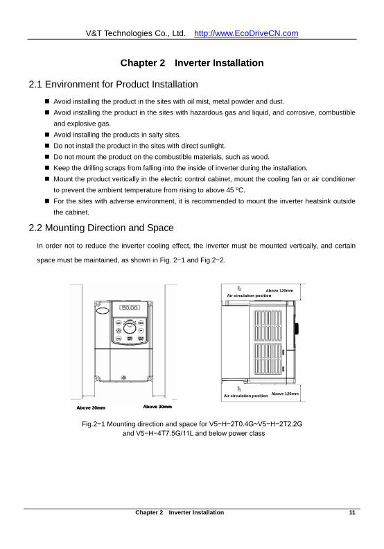
In order not to reduce the inverter cooling effect, the inverter must be mounted vertically, and certain
space must be maintained, as shown in Fig. 2−1 and Fig.2−2.
Fig.2−1 Mounting direction and space for V5−H−2T0.4G~V5−H−2T2.2G and V5−H−4T7.5G/11L and below power class
Air circulation position
Air circulation position
Above 120mm
Above 120mm
Air circulation position
Air circulation position
Above 120mm
Above 120mm
Above 30mm Above 30mm Above 30mm Above 30mm
V&T Technologies Co., Ltd. http://www.EcoDriveCN.com
Chapter 2 Inverter Installation 12
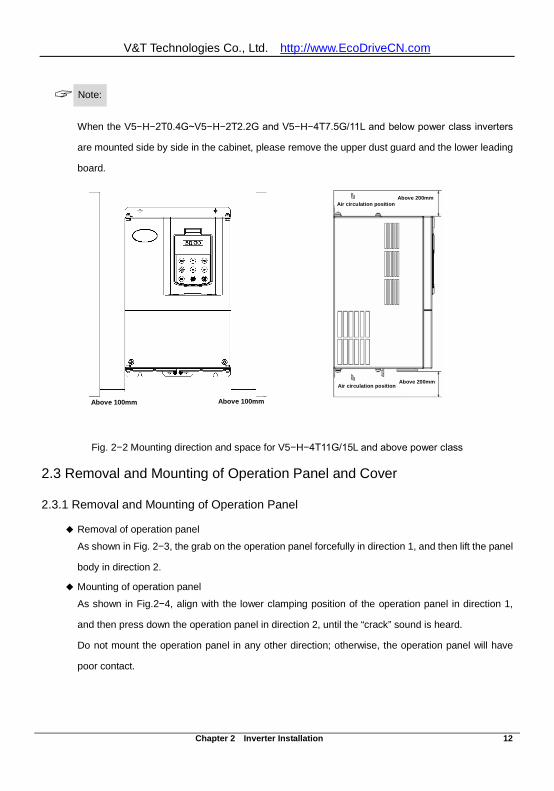
Note:
When the V5−H−2T0.4G~V5−H−2T2.2G and V5−H−4T7.5G/11L and below power class inverters
are mounted side by side in the cabinet, please remove the upper dust guard and the lower leading
board.
Fig. 2−2 Mounting direction and space for V5−H−4T11G/15L and above power class
2.3 Removal and Mounting of Operation Panel and Cover
2.3.1 Removal and Mounting of Operation Panel
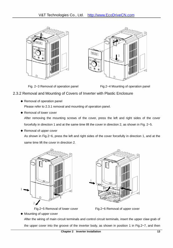
Removal of operation panel
As shown in Fig. 2−3, the grab on the operation panel forcefully in direction 1, and then lift the panel
body in direction 2.
Mounting of operation panel
As shown in Fig.2−4, align with the lower clamping position of the operation panel in direction 1,
and then press down the operation panel in direction 2, until the “crack” sound is heard.
Do not mount the operation panel in any other direction; otherwise, the operation panel will have
poor contact.
Above 100mm Above 100mmAbove 100mm Above 100mm
Air circulation position
Air circulation position Above 200mm
Above 200mm
Air circulation position Above 200mm
Air circulation position
Above 200mm
V&T Technologies Co., Ltd. http://www.EcoDriveCN.com
Chapter 2 Inverter Installation 13
Fig. 2−3 Removal of operation panel Fig.2−4 Mounting of operation panel
2.3.2 Removal and Mounting of Covers of Inverter with Plastic Enclosure
Removal of operation panel
Please refer to 2.3.1 removal and mounting of operation panel.
Removal of lower cover
After removing the mounting screws of the cover, press the left and right sides of the cover
forcefully in direction 1 and at the same time lift the cover in direction 2, as shown in Fig. 2−5.
Removal of upper cover
As shown in Fig.2−6, press the left and right sides of the cover forcefully in direction 1, and at the
same time lift the cover in direction 2.
Fig.2−5 Removal of lower cover Fig.2−6 Removal of upper cover
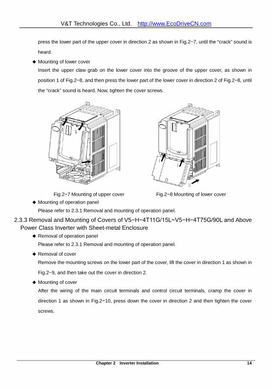
Mounting of upper cover
After the wiring of main circuit terminals and control circuit terminals, insert the upper claw grab of
the upper cover into the groove of the inverter body, as shown in position 1 in Fig.2−7, and then
V&T Technologies Co., Ltd. http://www.EcoDriveCN.com
Chapter 2 Inverter Installation 14
press the lower part of the upper cover in direction 2 as shown in Fig.2−7, until the “crack” sound is
heard.
Mounting of lower cover
Insert the upper claw grab on the lower cover into the groove of the upper cover, as shown in
position 1 of Fig.2−8, and then press the lower part of the lower cover in direction 2 of Fig.2−8, until
the “crack” sound is heard. Now, tighten the cover screws.
Fig.2−7 Mounting of upper cover Fig.2−8 Mounting of lower cover Mounting of operation panel
Please refer to 2.3.1 Removal and mounting of operation panel.
2.3.3 Removal and Mounting of Covers of V5−H−4T11G/15L~V5−H−4T75G/90L and Above Power Class Inverter with Sheet-metal Enclosure
Removal of operation panel
Please refer to 2.3.1 Removal and mounting of operation panel.
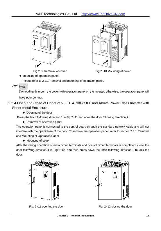
Removal of cover
Remove the mounting screws on the lower part of the cover, lift the cover in direction 1 as shown in
Fig.2−9, and then take out the cover in direction 2.
Mounting of cover
After the wiring of the main circuit terminals and control circuit terminals, cramp the cover in
direction 1 as shown in Fig.2−10, press down the cover in direction 2 and then tighten the cover
screws.
V&T Technologies Co., Ltd. http://www.EcoDriveCN.com
Chapter 2 Inverter Installation 15
Fig.2−9 Removal of cover Fig.2−10 Mounting of cover Mounting of operation panel
Please refer to 2.3.1 Removal and mounting of operation panel.
Note: Do not directly mount the cover with operation panel on the inverter, otherwise, the operation panel will
have poor contact.
2.3.4 Open and Close of Doors of V5−H−4T90G/110L and Above Power Class Inverter with Sheet-metal Enclosure
Opening of the door Press the latch following direction 1 in Fig.2−11 and open the door following direction 2.
Removal of operation panel The operation panel is connected to the control board through the standard network cable and will not interfere with the open/close of the door. To remove the operation panel, refer to section 2.3.1 Removal and Mounting of Operation Panel
Mounting of cover After the wiring operation of main circuit terminals and control circuit terminals is completed, close the door following direction 1 in Fig.2−12, and then press down the latch following direction 2 to lock the door.
Fig. 2−11 opening the door Fig. 2−12 closing the door
V&T Technologies Co., Ltd. http://www.EcoDriveCN.com
Chapter 3 Wiring of Inverter 16
Chapter 3 Wiring of Inverter
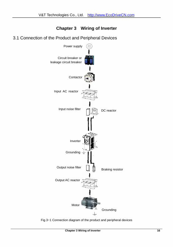
3.1 Connection of the Product and Peripheral Devices
Fig.3−1 Connection diagram of the product and peripheral devices
Power supply
Contactor
Input AC reactor
DC reactor
Inverter
Grounding
Motor Grounding
Circuit breaker or leakage circuit breaker
Input noise filter
Output noise filter
Braking resistor
Output AC reactor
V&T Technologies Co., Ltd. http://www.EcoDriveCN.com
Chapter 3 Wiring of Inverter 17
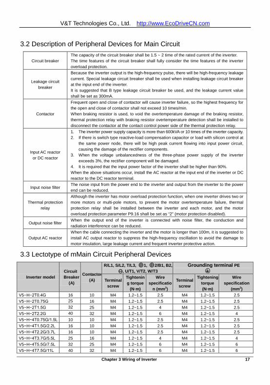
3.2 Description of Peripheral Devices for Main Circuit
Circuit breaker The capacity of the circuit breaker shall be 1.5 ~ 2 time of the rated current of the inverter. The time features of the circuit breaker shall fully consider the time features of the inverter overload protection.
Leakage circuit breaker
Because the inverter output is the high-frequency pulse, there will be high-frequency leakage current. Special leakage circuit breaker shall be used when installing leakage circuit breaker at the input end of the inverter. It is suggested that B type leakage circuit breaker be used, and the leakage current value shall be set as 300mA.
Contactor
Frequent open and close of contactor will cause inverter failure, so the highest frequency for the open and close of contactor shall not exceed 10 times/min. When braking resistor is used, to void the overtemperature damage of the braking resistor, thermal protection relay with braking resistor overtemperature detection shall be installed to disconnect the contactor at the contact control power side of the thermal protection relay.
Input AC reactor or DC reactor
1. The inverter power supply capacity is more than 600kVA or 10 times of the inverter capacity. 2. If there is switch type reactive-load compensation capacitor or load with silicon control at
the same power node, there will be high peak current flowing into input power circuit, causing the damage of the rectifier components.
3. When the voltage unbalancedness of the three-phase power supply of the inverter exceeds 3%, the rectifier component will be damaged.
4. It is required that the input power factor of the inverter shall be higher than 90%. When the above situations occur, install the AC reactor at the input end of the inverter or DC reactor to the DC reactor terminal.
Input noise filter The noise input from the power end to the inverter and output from the inverter to the power end can be reduced.
Thermal protection relay
Although the inverter has motor overload protection function, when one inverter drives two or more motors or multi-pole motors, to prevent the motor overtemperature failure, thermal protection relay shall be installed between the inverter and each motor, and the motor overload protection parameter P9.16 shall be set as “2” (motor protection disabled).
Output noise filter When the output end of the inverter is connected with noise filter, the conduction and radiation interference can be reduced.
Output AC reactor When the cable connecting the inverter and the motor is longer than 100m, it is suggested to install AC output reactor to suppress the high-frequency oscillation to avoid the damage to motor insulation, large leakage current and frequent inverter protective action.
3.3 Lectotype of mMain Circuit Peripheral Devices
Inverter model Circuit
Breaker (A)
Contactor (A)
R/L1, S/L2, T/L3, ⊕1, ⊕2/B1, B2, Ө, U/T1, V/T2, W/T3
Grounding terminal PE
Terminal screw
Tightening torque
(N·m)
Wire specificatio
n (mm2)
Terminal screw
Tightening torque (N·m)
Wire specification
(mm2) V5−H−2T0.4G 16 10 M4 1.2~1.5 2.5 M4 1.2~1.5 2.5 V5−H−2T0.75G 25 16 M4 1.2~1.5 2.5 M4 1.2~1.5 2.5 V5−H−2T1.5G 32 25 M4 1.2~1.5 4 M4 1.2~1.5 2.5 V5−H−2T2.2G 40 32 M4 1.2~1.5 6 M4 1.2~1.5 4 V5−H−4T0.75G/1.5L 10 10 M4 1.2~1.5 2.5 M4 1.2~1.5 2.5 V5−H−4T1.5G/2.2L 16 10 M4 1.2~1.5 2.5 M4 1.2~1.5 2.5 V5−H−4T2.2G/3.7L 16 10 M4 1.2~1.5 2.5 M4 1.2~1.5 2.5 V5−H−4T3.7G/5.5L 25 16 M4 1.2~1.5 4 M4 1.2~1.5 4 V5−H−4T5.5G/7.5L 32 25 M4 1.2~1.5 6 M4 1.2~1.5 6 V5−H−4T7.5G/11L 40 32 M4 1.2~1.5 6 M4 1.2~1.5 6
V&T Technologies Co., Ltd. http://www.EcoDriveCN.com
Chapter 3 Wiring of Inverter 18
Inverter model Circuit
Breaker (A)
Contactor (A)
R/L1, S/L2, T/L3, ⊕1, ⊕2/B1, B2, Ө, U/T1, V/T2, W/T3
Grounding terminal PE
Terminal screw
Tightening torque
(N·m)
Wire specificatio
n (mm2)
Terminal screw
Tightening torque (N·m)
Wire specification
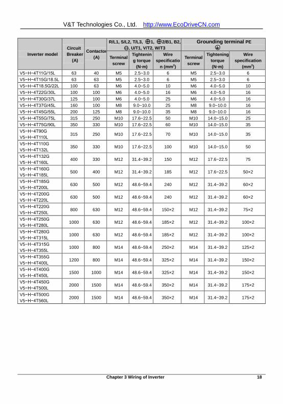
(mm2) V5−H−4T11G/15L 63 40 M5 2.5~3.0 6 M5 2.5~3.0 6 V5−H−4T15G/18.5L 63 63 M5 2.5~3.0 6 M5 2.5~3.0 6 V5−H−4T18.5G/22L 100 63 M6 4.0~5.0 10 M6 4.0~5.0 10 V5−H−4T22G/30L 100 100 M6 4.0~5.0 16 M6 4.0~5.0 16 V5−H−4T30G/37L 125 100 M6 4.0~5.0 25 M6 4.0~5.0 16 V5−H−4T37G/45L 160 100 M8 9.0~10.0 25 M8 9.0~10.0 16 V5−H−4T45G/55L 200 125 M8 9.0~10.0 35 M8 9.0~10.0 16 V5−H−4T55G/75L 315 250 M10 17.6~22.5 50 M10 14.0~15.0 25 V5−H−4T75G/90L 350 330 M10 17.6~22.5 60 M10 14.0~15.0 35 V5−H−4T90G V5−H−4T110L
315 250 M10 17.6~22.5 70 M10 14.0~15.0 35
V5−H−4T110G V5−H−4T132L
350 330 M10 17.6~22.5 100 M10 14.0~15.0 50
V5−H−4T132G V5−H−4T160L
400 330 M12 31.4~39.2 150 M12 17.6~22.5 75
V5−H−4T160G V5−H−4T185L
500 400 M12 31.4~39.2 185 M12 17.6~22.5 50×2
V5−H−4T185G V5−H−4T200L
630 500 M12 48.6~59.4 240 M12 31.4~39.2 60×2
V5−H−4T200G V5−H−4T220L
630 500 M12 48.6~59.4 240 M12 31.4~39.2 60×2
V5−H−4T220G V5−H−4T250L
800 630 M12 48.6~59.4 150×2 M12 31.4~39.2 75×2
V5−H−4T250G V5−H−4T280L
1000 630 M12 48.6~59.4 185×2 M12 31.4~39.2 100×2
V5−H−4T280G V5−H−4T315L
1000 630 M12 48.6~59.4 185×2 M12 31.4~39.2 100×2
V5−H−4T315G V5−H−4T355L
1000 800 M14 48.6~59.4 250×2 M14 31.4~39.2 125×2
V5−H−4T355G V5−H−4T400L
1200 800 M14 48.6~59.4 325×2 M14 31.4~39.2 150×2
V5−H−4T400G V5−H−4T450L
1500 1000 M14 48.6~59.4 325×2 M14 31.4~39.2 150×2
V5−H−4T450G V5−H−4T500L
2000 1500 M14 48.6~59.4 350×2 M14 31.4~39.2 175×2
V5−H−4T500G V5−H−4T560L
2000 1500 M14 48.6~59.4 350×2 M14 31.4~39.2 175×2
V&T Technologies Co., Ltd. http://www.EcoDriveCN.com
Chapter 3 Wiring of Inverter 19
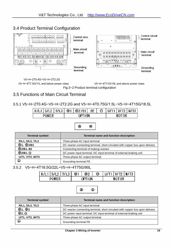
3.4 Product Terminal Configuration
V5−H−2T0.4G~V5−H−2T2.2G
V5−H−4T7.5G/11L and below power class V5−H−4T11G/15L and above power class Fig.3−2 Product terminal configuration
3.5 Functions of Main Circuit Terminal
3.5.1 V5−H−2T0.4G~V5−H−2T2.2G and V5−H−4T0.75G/1.5L~V5−H−4T15G/18.5L
3.5.2 V5−H−4T18.5G/22L~V5−H−4T75G/90L
Terminal symbol Terminal name and function description
R/L1, S/L2, T/L3 Three-phase AC input terminal ⊕1, ⊕2/B1 DC reactor connecting terminal, short circuited with copper bus upon delivery ⊕2/B1, B2 Connecting terminal of braking resistor ⊕2/B1, Ө DC power input terminal; DC input terminal of external braking unit U/T1, V/T2, W/T3 Three-phase AC output terminal
Grounding terminal PE
Terminal symbol Terminal name and function description
R/L1, S/L2, T/L3 Three-phase AC input terminal ⊕1, ⊕2 DC reactor connecting terminal, short circuited with copper bus upon delivery ⊕2, Ө DC power input terminal; DC input terminal of external braking unit U/T1, V/T2, W/T3 Three-phase AC output terminal
Grounding terminal PE
V&T Technologies Co., Ltd. http://www.EcoDriveCN.com
Chapter 3 Wiring of Inverter 20
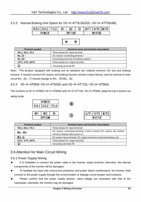
3.5.3 Internal Braking Unit Option for V5−H−4T18.5G/22L~V5−H−4T75G/90L
Terminal symbol Terminal name and function description R/L1, S/L2, T/L3 Three-phase AC input terminal B1, Ө﹡ DC reactor connecting termina﹡ B1, B2﹡ Connecting terminal of braking resistor﹡ U/T1, V/T2, W/T3 Three-phase AC output terminal
Grounding terminal PE
Note:*The product equipped with braking unit as standard can realized common DC bus and braking function, if needed connect DC reactor and braking function should contact factory, and the teminal of main circuit B1、B2、- should change to +1、+
2/B1、B2.
3.5.4 V5−H−4T90G~V5−H−4T500G and V5−H−4T110L~V5−H−4T560L
The inverters of V5−H−4T90G~V5−H−4T500G and V5−H−4T110L~V5−H−4T560L adopt the top in bottom out
wiring mode.
Terminal symbol Terminal name and function description R/L1, S/L2, T/L3 Three-phase AC input terminal
⊕1, ⊕2 DC reactor connecting terminal, if don’t connect DC reactor, the inverter will don’t display after power on.
⊕2, Ө DC power input terminal; DC output terminal of external braking unit U/T1, V/T2, W/T3 Three-phase AC output terminal
Grounding terminal PE
3.6 Attention for Main Circuit Wiring
3.6.1 Power Supply Wiring It is forbidden to connect the power cable to the inverter output terminal, otherwise, the internal
components of the inverter will be damaged. To facilitate the input side overcurrent protection and power failure maintenance, the inverter shall
connect to the power supply through the circuit breaker or leakage circuit breaker and contactor. Please confirm that the power supply phases, rated voltage are consistent with that of the
nameplate, otherwise, the inverter may be damaged.
V&T Technologies Co., Ltd. http://www.EcoDriveCN.com
Chapter 3 Wiring of Inverter 21
3.6.2 Motor Wiring It is forbidden to short circuit or ground the inverter output terminal, otherwise the internal
components of the inverter will be damaged. Avoid short circuit the output cable and the inverter enclosure, otherwise there exists the danger of
electric shock. It is forbidden to connect the output terminal of the inverter to the capacitor or LC/RC noise filter
with phase lead, otherwise, the internal components of the inverter may be damaged. When contactor is installed between the inverter and the motor, it is forbidden to switch on/off the
contactor during the running of the inverter, otherwise, there will be large current flowing into the inverter, triggering the inverter protection action.
Length of cable between the inverter and motor
If the cable between the inverter and the motor is too long, the higher harmonic leakage current of the
output end will cause adverse impact on the inverter and the peripheral devices. It is suggested that
when the motor cable is longer than 100m, output AC reactor be installed. Refer to the following table for
the carrier frequency setting.
Length of cable between the inverter and motor
Less than 50m Less than 100 m More than 100m
Carrier frequency (PA.00) Less than 15kHz Less than 10kHz Less than 5kHz
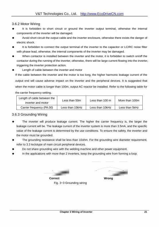
3.6.3 Grounding Wiring
The inverter will produce leakage current. The higher the carrier frequency is, the larger the leakage current will be. The leakage current of the inverter system is more than 3.5mA, and the specific value of the leakage current is determined by the use conditions. To ensure the safety, the inverter and the motor must be grounded.
The grounding resistance shall be less than 10ohm. For the grounding wire diameter requirement, refer to 3.3 lectotype of main circuit peripheral devices.
Do not share grounding wire with the welding machine and other power equipment. In the applications with more than 2 inverters, keep the grounding wire from forming a loop.
Correct Wrong Fig. 3−3 Grounding wiring
V&T Technologies Co., Ltd. http://www.EcoDriveCN.com
Chapter 3 Wiring of Inverter 22
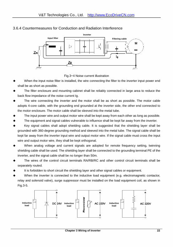
3.6.4 Countermeasures for Conduction and Radiation Interference
Fig.3−4 Noise current illustration When the input noise filter is installed, the wire connecting the filter to the inverter input power end
shall be as short as possible. The filter enclosure and mounting cabinet shall be reliably connected in large area to reduce the
back flow impedance of the noise current Ig. The wire connecting the inverter and the motor shall be as short as possible. The motor cable
adopts 4-core cable, with the grounding end grounded at the inverter side, the other end connected to the motor enclosure. The motor cable shall be sleeved into the metal tube.
The input power wire and output motor wire shall be kept away from each other as long as possible. The equipment and signal cables vulnerable to influence shall be kept far away from the inverter. Key signal cables shall adopt shielding cable. It is suggested that the shielding layer shall be
grounded with 360-degree grounding method and sleeved into the metal tube. The signal cable shall be kept far away from the inverter input wire and output motor wire. If the signal cable must cross the input wire and output motor wire, they shall be kept orthogonal.
When analog voltage and current signals are adopted for remote frequency setting, twinning shielding cable shall be used. The shielding layer shall be connected to the grounding terminal PE of the inverter, and the signal cable shall be no longer than 50m.
The wires of the control circuit terminals RA/RB/RC and other control circuit terminals shall be separately routed.
It is forbidden to short circuit the shielding layer and other signal cables or equipment. When the inverter is connected to the inductive load equipment (e.g. electromagnetic contactor,
relay and solenoid valve), surge suppressor must be installed on the load equipment coil, as shown in Fig.3-5.
Input filterInverter
Filtering cableInput filterInverter
Filtering cable
DC 24V AC 220V AC 220V感性
负载
感性
负载
感性
负载
压敏
电阻
Inductive load
Inductive load
Inductive load
Piez
ores
isto
r
DC 24V AC 220V AC 220V感性
负载
感性
负载
感性
负载
压敏
电阻
Inductive load
Inductive load
Inductive load
Piez
ores
isto
r

V&T Technologies Co., Ltd. http://www.EcoDriveCN.com
Chapter 3 Wiring of Inverter 23
Fig.3−5 Application of inductive load surge suppressor
V&T Technologies Co., Ltd. http://www.EcoDriveCN.com
Chapter 3 Wiring of Inverter 24
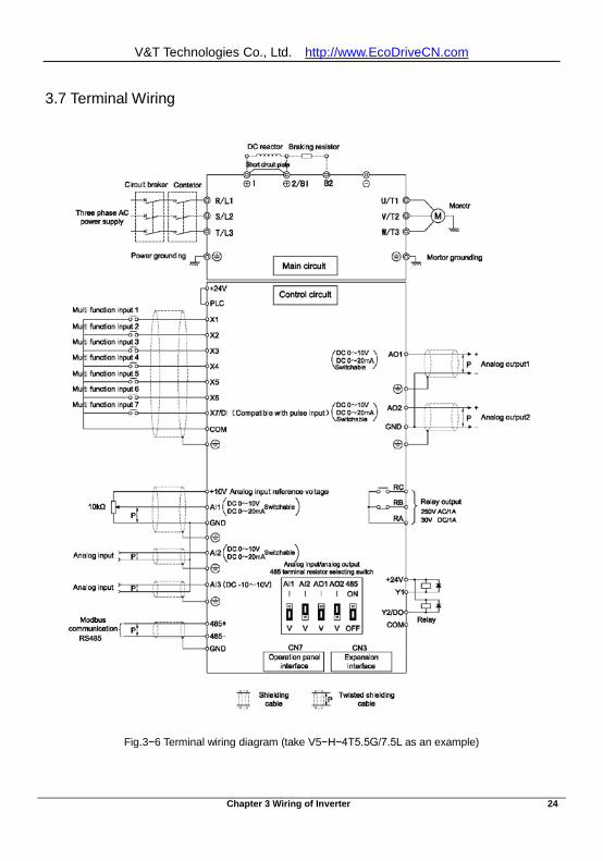
3.7 Terminal Wiring
Fig.3−6 Terminal wiring diagram (take V5−H−4T5.5G/7.5L as an example)
V&T Technologies Co., Ltd. http://www.EcoDriveCN.com
Chapter 3 Wiring of Inverter 25
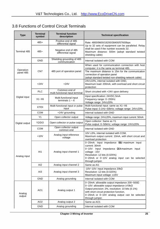
3.8 Functions of Control Circuit Terminals
Type Terminal symbol
Terminal function description Technical specification
Terminal 485
485+ Positive end of 485 differential signal Rate: 4800/9600/19200/38400/57600bps
Up to 32 sets of equipment can be paralleled. Relay shall be used if the number exceeds 32. Maximum distance: 500m (adopt standard twisted shielding cable)
485− Negative end of 485 differential signal
GND Shielding grounding of 485 communication Internal isolated with COM
Operation panel 485 CN7 485 port of operation panel
When used for communication connection with host computer, it is the same as terminal 485. The maximum distance is 15m for the communication connection of operation panel (adopt standard twisted non-shielding network cable)
Digital input
+24V +24V 24V±10%, internal isolated with GND, Maximum load: 200mA, with overload and short circuit protection
PLC Common end of multi-functional input terminal Short circuited with +24V upon delivery
X1~X6 Multi-functional input terminals 1 ~ 6
Input specification: 24VDC,5mA Frequency range: 0~200Hz Voltage range: 24V±20%
X7/DI Multi-functional input or pulse input
Multi-functional input: same as X1~X6 Pulse input: 0.1Hz~50kHz; voltage range: 24V±20%
COM +24V grounding Internal isolated with GND
Digital output
Y1 Open collector output Voltage range: 24V±20%, maximum input current: 50mA
Y2/DO Open collector or pulse output Open collector: Same as Y1 Pulse output: 0~50kHz; voltage range: 24V±20%
COM Open collector output common end Internal isolated with GND
Analog input
+10V Analog input reference voltage
10V ±3%, internal isolated with COM, Maximum output current: 10mA, with short circuit and overload protection
AI1 Analog input channel 1
0~20mA: Input impedance 500Ω, maximum input current: 30mA 0~10V: Input impedance 20kΩ, maximum input voltage : 15V Resolution: 12 bits (0.025%) 0~20mA or 0~10V analog input can be selected through jumper.
AI2 Analog input channel 2 Same as AI1
AI3 Analog input channel 3 -10V~10V: Input impedance 20kΩ Resolution: 12 bits (0.025%) Maximum input voltage: ±15V
GND Analog grounding Internal isolated with COM
Analog output
AO1 Analog output 1
0~20mA: allowable output impedance 200~500Ω 0~10V: allowable output impedance ≥10kΩ Output precision: 2%, resolution: 10 bits (0.1%) with short circuit protection function, 0~20mA or 0~10V analog output can be selected through jumper.
AO2 Analog output 2 Same as AO1
GND Analog grounding Internal isolated with COM
V&T Technologies Co., Ltd. http://www.EcoDriveCN.com
Chapter 3 Wiring of Inverter 26
Type Terminal symbol
Terminal function description Technical specification
Relay output RA/RB/RC Relay output RA-RB: Normally closed RA-RC: Normally open Contact capacity: 250VAC/1A, 30VDC/1A
Note: ﹡ If the user connects adjustable potentiometer between +10V and GND, the resistance of the potentiometer shall be no less than 5kΩ, Note:
1. The arrangement sequence of the control circuit terminals is as follows:
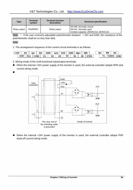
+10V AI1 AI2 AI3 GND AO1 AO2 GND 485+ 485- RA RB RC+24V PLC COM X1 X2 X3 X4 X5 X8 X7/DI Y1 Y2/DO COM
+10V AI1 AI2 AI3 GND AO1 AO2 GND 485+ 485- RA RB RC+24V PLC COM X1 X2 X3 X4 X5 X8 X7/DI Y1 Y2/DO COM
2. Wiring mode of the multi-functional input/output terminals When the internal +24V power supply of the inverter is used, the external controller adopts NPN sink
current wiring mode.
When the internal +24V power supply of the inverter is used, the external controller adopts PNP draw-off current wiring mode.
User controller
Inside of inverter The near end of the shielding
cable is grounded
+24 User Controller
Inside of inverter The near end of the shielding cable
is grounded
+24V
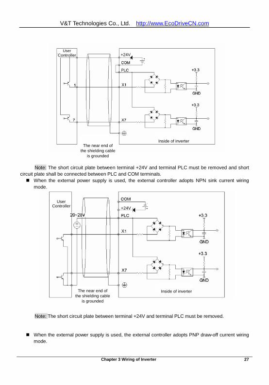
V&T Technologies Co., Ltd. http://www.EcoDriveCN.com
Chapter 3 Wiring of Inverter 27
Note: The short circuit plate between terminal +24V and terminal PLC must be removed and short circuit plate shall be connected between PLC and COM terminals. When the external power supply is used, the external controller adopts NPN sink current wiring
mode.
Note: The short circuit plate between terminal +24V and terminal PLC must be removed.
When the external power supply is used, the external controller adopts PNP draw-off current wiring mode.
User controller
Inside of inverter The near end of the shielding
cable is grounded
+24 User
Controller
Inside of inverter
+24V
The near end of the shielding cable
is grounded
User controller
Inside of inverter The near end of the shielding cable is grounded
+24 User
Controller
Inside of inverter
+24V
The near end of the shielding cable
is grounded
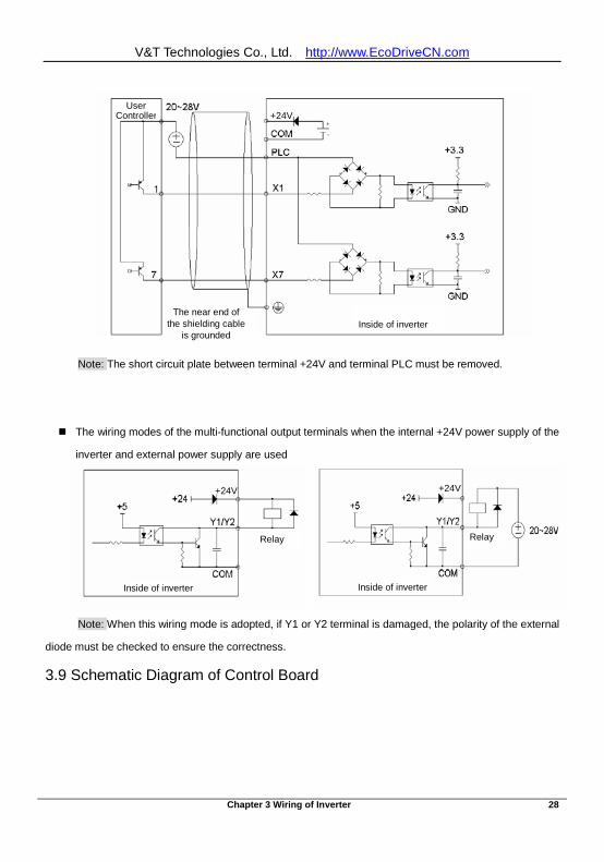
V&T Technologies Co., Ltd. http://www.EcoDriveCN.com
Chapter 3 Wiring of Inverter 28
Note: The short circuit plate between terminal +24V and terminal PLC must be removed.
The wiring modes of the multi-functional output terminals when the internal +24V power supply of the
inverter and external power supply are used
Note: When this wiring mode is adopted, if Y1 or Y2 terminal is damaged, the polarity of the external
diode must be checked to ensure the correctness.
3.9 Schematic Diagram of Control Board
User controller
Inside of inverter The near end of the
+24 +24V
Inside of inverter The near end of
the shielding cable is grounded
User Controller
Inside of inverter
Relay
+24
Inside of inverter
Relay
+24V
Inside of inverter
Relay
+24
Inside of inverter
Relay
+24V
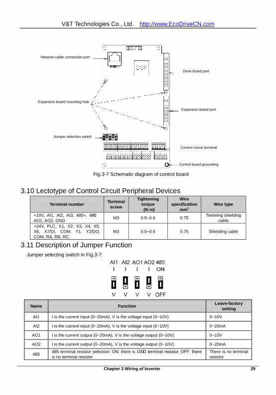
V&T Technologies Co., Ltd. http://www.EcoDriveCN.com
Chapter 3 Wiring of Inverter 29
Fig.3-7 Schematic diagram of control board
3.10 Lectotype of Control Circuit Peripheral Devices
Terminal number Terminal screw
Tightening torque (N·m)
Wire specification
mm2 Wire type
+10V, AI1, AI2, AI3, 485+, 485−, AO1, AO2, GND M3 0.5~0.6 0.75 Twinning shielding
cable +24V, PLC, X1, X2, X3, X4, X5, X6, X7/DI, COM, Y1, Y2/DO, COM, RA, RB, RC
M3 0.5~0.6 0.75 Shielding cable
3.11 Description of Jumper Function Jumper selecting switch in Fig.3-7:
Name Function Leave-factory setting
AI1 I is the current input (0~20mA), V is the voltage input (0~10V) 0~10V
AI2 I is the current input (0~20mA), V is the voltage input (0~10V) 0~20mA
AO1 I is the current output (0~20mA), V is the voltage output (0~10V) 0~10V
AO2 I is the current output (0~20mA), V is the voltage output (0~10V) 0~20mA
485 485 terminal resistor selection: ON: there is 100Ω terminal resistor, OFF: there is no terminal resistor
There is no terminal resistor
Network cable connection port
Expansion board mounting hole
Jumper selection switch
Drive board por
Expansion board port
Control circuit terminal
Network cable connection port
Expansion board mounting hole
Jumper selection switch
Drive board port
Expansion board port
Control circuit terminal
Control board grounding
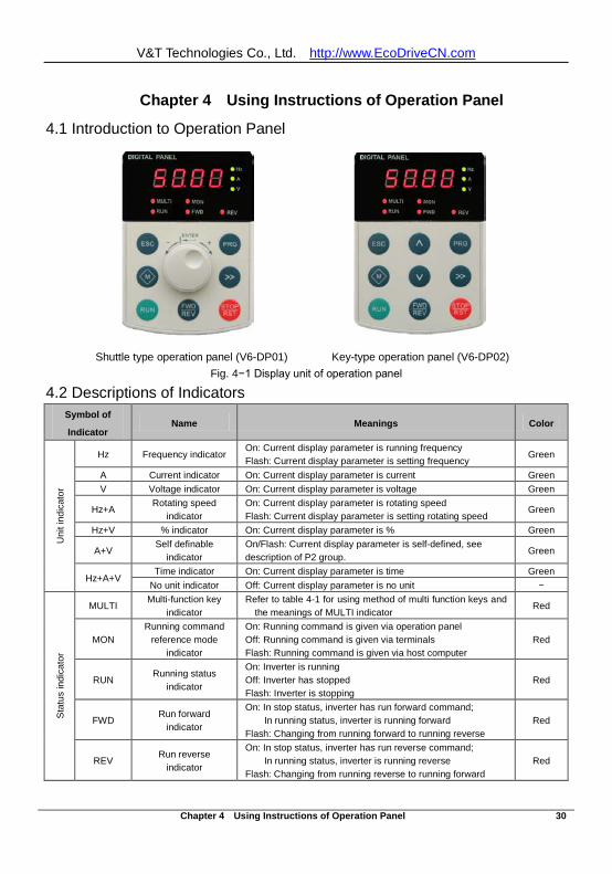
V&T Technologies Co., Ltd. http://www.EcoDriveCN.com
Chapter 4 Using Instructions of Operation Panel 30
Chapter 4 Using Instructions of Operation Panel
4.1 Introduction to Operation Panel Shuttle type operation panel (V6-DP01) Key-type operation panel (V6-DP02)
Fig. 4−1 Display unit of operation panel
4.2 Descriptions of Indicators Symbol of
Indicator Name Meanings Color
Uni
t ind
icat
or
Hz Frequency indicator On: Current display parameter is running frequency Flash: Current display parameter is setting frequency
Green
A Current indicator On: Current display parameter is current Green V Voltage indicator On: Current display parameter is voltage Green
Hz+A Rotating speed
indicator On: Current display parameter is rotating speed Flash: Current display parameter is setting rotating speed
Green
Hz+V % indicator On: Current display parameter is % Green
A+V Self definable
indicator On/Flash: Current display parameter is self-defined, see description of P2 group.
Green
Hz+A+V Time indicator On: Current display parameter is time Green
No unit indicator Off: Current display parameter is no unit −
Sta
tus
indi
cato
r
MULTI Multi-function key
indicator Refer to table 4-1 for using method of multi function keys and
the meanings of MULTI indicator Red
MON Running command
reference mode indicator
On: Running command is given via operation panel Off: Running command is given via terminals Flash: Running command is given via host computer
Red
RUN Running status
indicator
On: Inverter is running Off: Inverter has stopped Flash: Inverter is stopping
Red
FWD Run forward
indicator
On: In stop status, inverter has run forward command; In running status, inverter is running forward
Flash: Changing from running forward to running reverse Red
REV Run reverse
indicator
On: In stop status, inverter has run reverse command; In running status, inverter is running reverse
Flash: Changing from running reverse to running forward Red
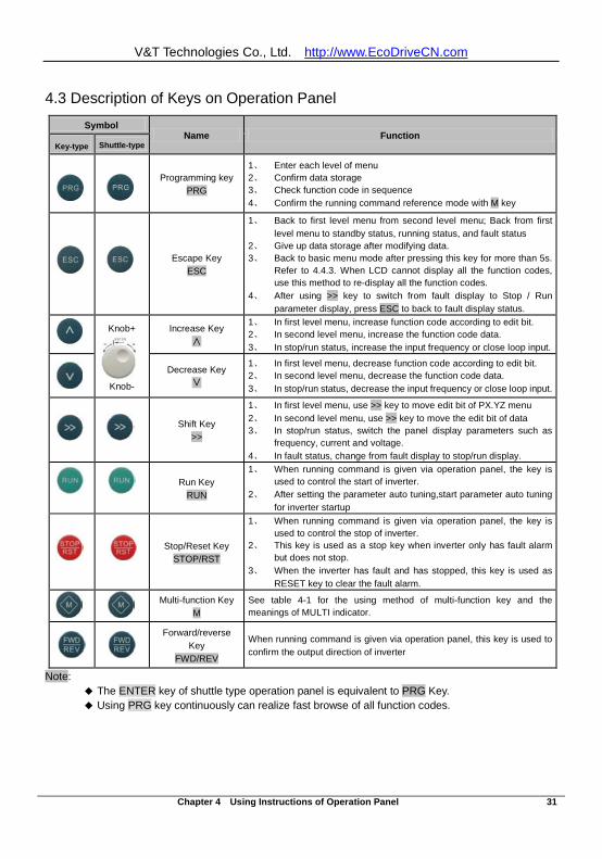
V&T Technologies Co., Ltd. http://www.EcoDriveCN.com
Chapter 4 Using Instructions of Operation Panel 31
4.3 Description of Keys on Operation Panel
Note: The ENTER key of shuttle type operation panel is equivalent to PRG Key. Using PRG key continuously can realize fast browse of all function codes.
Symbol Name Function
Key-type Shuttle-type
Programming key
PRG
1、 Enter each level of menu 2、 Confirm data storage 3、 Check function code in sequence 4、 Confirm the running command reference mode with M key
Escape Key
ESC
1、 Back to first level menu from second level menu; Back from first level menu to standby status, running status, and fault status
2、 Give up data storage after modifying data. 3、 Back to basic menu mode after pressing this key for more than 5s.
Refer to 4.4.3. When LCD cannot display all the function codes, use this method to re-display all the function codes.
4、 After using >> key to switch from fault display to Stop / Run parameter display, press ESC to back to fault display status.
Knob+
Knob-
Increase Key ∧
1、 In first level menu, increase function code according to edit bit. 2、 In second level menu, increase the function code data. 3、 In stop/run status, increase the input frequency or close loop input.
Decrease Key
∨
1、 In first level menu, decrease function code according to edit bit. 2、 In second level menu, decrease the function code data. 3、 In stop/run status, decrease the input frequency or close loop input.
Shift Key
>>
1、 In first level menu, use >> key to move edit bit of PX.YZ menu 2、 In second level menu, use >> key to move the edit bit of data 3、 In stop/run status, switch the panel display parameters such as
frequency, current and voltage. 4、 In fault status, change from fault display to stop/run display.
Run Key
RUN
1、 When running command is given via operation panel, the key is used to control the start of inverter.
2、 After setting the parameter auto tuning,start parameter auto tuning for inverter startup
Stop/Reset Key
STOP/RST
1、 When running command is given via operation panel, the key is used to control the stop of inverter.
2、 This key is used as a stop key when inverter only has fault alarm but does not stop.
3、 When the inverter has fault and has stopped, this key is used as RESET key to clear the fault alarm.
Multi-function Key
M See table 4-1 for the using method of multi-function key and the meanings of MULTI indicator.
Forward/reverse
Key FWD/REV
When running command is given via operation panel, this key is used to confirm the output direction of inverter
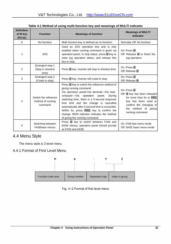
V&T Technologies Co., Ltd. http://www.EcoDriveCN.com
Chapter 4 Using Instructions of Operation Panel 32
Table 4-1 Method of using multi-function key and meanings of MULTI indicator Definition of M key (P2.01)
Function Meanings of function Meanings of MULTI
indicator
0 No function Multi-function key is defined as no function. Normally Off: No function
1 JOG
Used as JOG operation key and is only enabled when running command is given via operation panel. In stop status, press M key to enter jog operation status, and release this key to stop.
On: Press M Off: Release M to finish the
jog operation
2 Emergent stop 1 (Stop in shortest
time) Press M key, inverter will stop in shortest time.
On: Press M Off: Release M
3 Emergent stop 2 (Coast to stop)
Press M key, inverter will coast to stop On: Press M Off: Release M
4 Switch the reference method of running
command
Press M key to switch the reference method of giving running command: Via operation panel→Via terminal→Via host computer→Via operation panel. During switching time, there is a 5-second response time limit and the change is cancelled automatically after 5-second time is exceeded. Within 5s, press PRG key to confirm the change. MON indicator indicates the method of giving the running command.
On: Press M Off: M key has been released
for more than 5s or PRG key has been used to confirm the changing of the method of giving running command
5 Switching between FASt/base menus
Press M key to switch between FASt and bASE menus, operation panel should prompt as FASt and bASE
On: FASt fast menu mode Off: bASE basic menu mode
4.4 Menu Style
The menu style is 2-level menu.
4.4.1 Format of First Level Menu
功能码区 区内组号 组内索引
P X Y Z.
分隔符
Fig. 4−2 Format of first level menu
Function code area Group number Separation sign Index in group
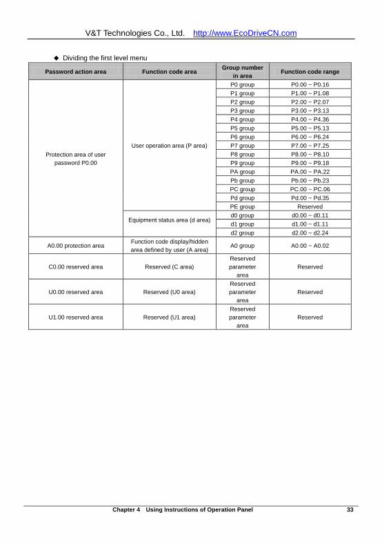
V&T Technologies Co., Ltd. http://www.EcoDriveCN.com
Chapter 4 Using Instructions of Operation Panel 33
Dividing the first level menu
Password action area Function code area Group number in area
Function code range
Protection area of user password P0.00
User operation area (P area)
P0 group P0.00 ~ P0.16 P1 group P1.00 ~ P1.08 P2 group P2.00 ~ P2.07 P3 group P3.00 ~ P3.13 P4 group P4.00 ~ P4.36 P5 group P5.00 ~ P5.13 P6 group P6.00 ~ P6.24 P7 group P7.00 ~ P7.25 P8 group P8.00 ~ P8.10 P9 group P9.00 ~ P9.18 PA group PA.00 ~ PA.22 Pb group Pb.00 ~ Pb.23 PC group PC.00 ~ PC.06 Pd group Pd.00 ~ Pd.35 PE group Reserved
Equipment status area (d area)
d0 group d0.00 ~ d0.11 d1 group d1.00 ~ d1.11 d2 group d2.00 ~ d2.24
A0.00 protection area Function code display/hidden area defined by user (A area)
A0 group A0.00 ~ A0.02
C0.00 reserved area Reserved (C area) Reserved parameter
area Reserved
U0.00 reserved area Reserved (U0 area) Reserved parameter
area Reserved
U1.00 reserved area Reserved (U1 area) Reserved parameter
area Reserved
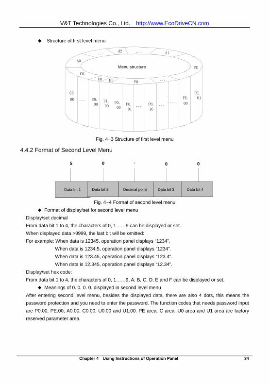
V&T Technologies Co., Ltd. http://www.EcoDriveCN.com
Chapter 4 Using Instructions of Operation Panel 34
Structure of first level menu
... U0.00
U1.00
P0.00
P0.01
... P0.16
......
PE.
00
PE.01
C0.
00
FY
C0
P0
PE
d1
...
...d2
U1
...
A0
菜单结构
U0
Fig. 4−3 Structure of first level menu
4.4.2 Format of Second Level Menu
数据位1 数据位2 数据位3
5 0 0 0.
小数点 数据位4
Fig. 4−4 Format of second level menu Format of display/set for second level menu
Display/set decimal From data bit 1 to 4, the characters of 0, 1……9 can be displayed or set. When displayed data >9999, the last bit will be omitted: For example: When data is 12345, operation panel displays “1234”.
When data is 1234.5, operation panel displays “1234”. When data is 123.45, operation panel displays “123.4”. When data is 12.345, operation panel displays “12.34”.
Display/set hex code: From data bit 1 to 4, the characters of 0, 1……9, A, B, C, D, E and F can be displayed or set.
Meanings of 0. 0. 0. 0. displayed in second level menu After entering second level menu, besides the displayed data, there are also 4 dots, this means the password protection and you need to enter the password. The function codes that needs password input are P0.00, PE.00, A0.00, C0.00, U0.00 and U1.00. PE area, C area, U0 area and U1 area are factory reserved parameter area.
Menu structure
Data bit 1 Data bit 2 Decimal point Data bit 3 Data bit 4
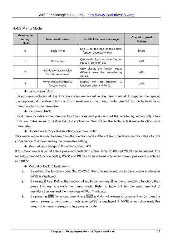
V&T Technologies Co., Ltd. http://www.EcoDriveCN.com
Chapter 4 Using Instructions of Operation Panel 35
4.4.3 Menu Mode
Menu mode setting (P0.02)
Menu mode name Visible function code range Operation panel
display
0 Basic menu See 5.1 for the table of basic menu
function code parameter bASE
1 Fast menu Quickly display the menu function codes in common use FASt
2 Non-leave-factory value
function code menu
Only display the function codes different from the leave-factory values
ndFt
3 Menu of last changed 10
function codes Display the last changed 10 function codes and P0.02
LASt
Basic menu bASE Basic menu includes all the function codes mentioned in this user manual. Except for the special descriptions, all the descriptions of this manual are in this menu mode. See 5.1 for the table of basic menu function code parameter.
Fast menu FASt Fast menu includes some common function codes and you can start the inverter by setting only a few function codes so as to realize the fast application. See 5.2 for the table of fast menu function code parameter.
Non-leave-factory value function code menu ndFt This menu mode is used to search for the function codes different from the leave-factory values for the convenience of understanding the parameter setting.
Menu of last changed 10 function codes LASt If this menu mode is set, it enters password protection status. Only P0.00 and C0.00 can be viewed. The recently changed function codes, P0.00 and P0.02 can be viewed only when correct password is entered into P0.00.
Method of back to basic menu 1. By editing the function code: Set P0.02=0, then the menu returns to basic menu mode after
bASE is displayed. 2. By using M key: Define the function of multi-function key M as menu switching function, then
press this key to switch the menu mode. Refer to table 4-1 for the using method of multi-function key and the meanings of MULTI indicator.
3. By pressing ESC for a long time: Press ESC and do not release it for more than 5s, then the menu returns to basic menu mode after bASE is displayed. If bASE is not displayed, this means the menu is already in basic menu mode.
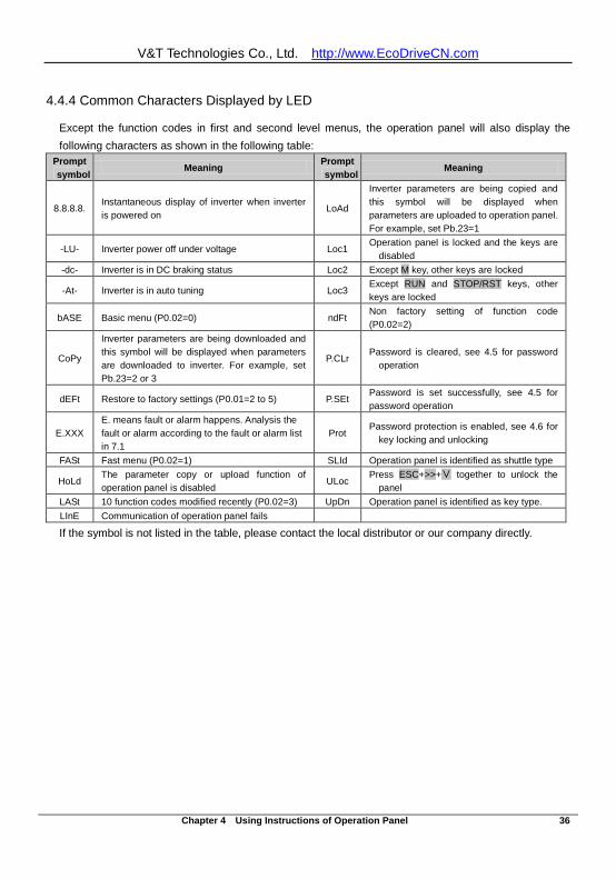
V&T Technologies Co., Ltd. http://www.EcoDriveCN.com
Chapter 4 Using Instructions of Operation Panel 36
4.4.4 Common Characters Displayed by LED
Except the function codes in first and second level menus, the operation panel will also display the following characters as shown in the following table:
Prompt symbol
Meaning Prompt symbol
Meaning
8.8.8.8. Instantaneous display of inverter when inverter is powered on
LoAd
Inverter parameters are being copied and this symbol will be displayed when parameters are uploaded to operation panel. For example, set Pb.23=1
-LU- Inverter power off under voltage Loc1 Operation panel is locked and the keys are
disabled -dc- Inverter is in DC braking status Loc2 Except M key, other keys are locked
-At- Inverter is in auto tuning Loc3 Except RUN and STOP/RST keys, other keys are locked
bASE Basic menu (P0.02=0) ndFt Non factory setting of function code (P0.02=2)
CoPy
Inverter parameters are being downloaded and this symbol will be displayed when parameters are downloaded to inverter. For example, set Pb.23=2 or 3
P.CLr Password is cleared, see 4.5 for password
operation
dEFt Restore to factory settings (P0.01=2 to 5) P.SEt Password is set successfully, see 4.5 for password operation
E.XXX E. means fault or alarm happens. Analysis the fault or alarm according to the fault or alarm list in 7.1
Prot Password protection is enabled, see 4.6 for
key locking and unlocking
FASt Fast menu (P0.02=1) SLId Operation panel is identified as shuttle type
HoLd The parameter copy or upload function of operation panel is disabled
ULoc Press ESC+>>+∨ together to unlock the
panel LASt 10 function codes modified recently (P0.02=3) UpDn Operation panel is identified as key type. LInE Communication of operation panel fails
If the symbol is not listed in the table, please contact the local distributor or our company directly.
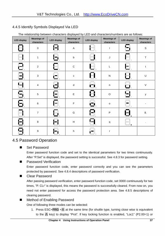
V&T Technologies Co., Ltd. http://www.EcoDriveCN.com
Chapter 4 Using Instructions of Operation Panel 37
4.4.5 Identify Symbols Displayed Via LED
The relationship between characters displayed by LED and characters/numbers are as follows:
LED display Meanings of characters
LED display Meanings of characters
LED display Meanings of characters
LED display Meanings of characters
0
A
I
S
1
b
J
T
2
C
L
t
3
c
N
U
4
d
n
V
5
E
O
y
6
F
o
-
7
G
P
8.
8
H
q
.
9
h
r
4.5 Password Operation
Set Password Enter password function code and set to the identical parameters for two times continuously. After “P.Set” is displayed, the password setting is successful. See 4.8.3 for password setting.
Password Verification Enter password function code, enter password correctly and you can see the parameters protected by password. See 4.8.4 descriptions of password verification.
Clear Password After passing password verification, enter password function code, set 0000 continuously for two times, ”P. CLr” is displayed, this means the password is successfully cleared. From now on, you need not enter password for access the password protection area. See 4.8.5 descriptions of clearing password.
Method of Enabling Password One of following three modes can be selected:
1. Press ESC+PRG +∧ at the same time (for shuttle type, turning close wise is equivalent to the ∧ key) to display “Prot”. If key locking function is enabled, “Loc1” (P2.00=1) or
V&T Technologies Co., Ltd. http://www.EcoDriveCN.com
Chapter 4 Using Instructions of Operation Panel 38
“Loc2”(P2.00=2) or “Loc3”(P2.00=3) is displayed. 2. No key operation for continuous 5 minutes. 3. Power on again
4.6 Lock/Unlock Keys
Lock Keys Set the function of locking keys Select the P2.00 key locking functions:
0: Do not lock the keys on the operation panel and all the keys can be used; 1: Lock the keys on the operation panel and all the keys cannot be used; 2: Except multi-function key M, all the keys cannot be used; 3: Except RUN and STOP/RST keys, all the keys cannot be used.
Key Locking Function is Enabled One of following three modes can be selected:
1. Press ESC+PRG +∧ at the same time (for shuttle type, turning close wise is equivalent to the ∧ key) to display “Loc1” (P2.00=1) or “Loc2”(P2.00=2) or “Loc3”(P2.00=3), the operation panel is locked according to the setting method of P2.00. When P2.00=0, “Prot” is displayed and the operation panel is not locked and only the password protection is enabled.
2. Power on the inverter again to lock the operation panel. 3. If there is no key operation within 5 minutes after setting the function code, the operation
panel is locked automatically. Unlock Keys:
Press ESC+>>+∨ keys at the same time (for shuttle type, turning anti-close wise is equivalent to ∨ key) to unlock.
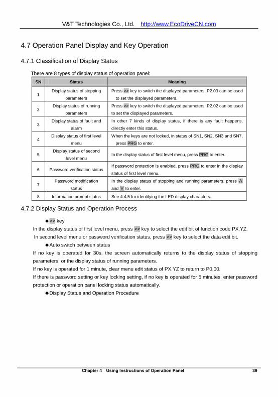
V&T Technologies Co., Ltd. http://www.EcoDriveCN.com
Chapter 4 Using Instructions of Operation Panel 39
4.7 Operation Panel Display and Key Operation
4.7.1 Classification of Display Status
There are 8 types of display status of operation panel: SN Status Meaning
1 Display status of stopping
parameters
Press >> key to switch the displayed parameters, P2.03 can be used
to set the displayed parameters.
2 Display status of running
parameters
Press >> key to switch the displayed parameters, P2.02 can be used
to set the displayed parameters.
3 Display status of fault and
alarm
In other 7 kinds of display status, if there is any fault happens,
directly enter this status.
4 Display status of first level
menu
When the keys are not locked, in status of SN1, SN2, SN3 and SN7,
press PRG to enter.
5 Display status of second
level menu In the display status of first level menu, press PRG to enter.
6 Password verification status If password protection is enabled, press PRG to enter in the display
status of first level menu.
7 Password modification
status
In the display status of stopping and running parameters, press ∧
and ∨ to enter.
8 Information prompt status See 4.4.5 for identifying the LED display characters.
4.7.2 Display Status and Operation Process
>> key In the display status of first level menu, press >> key to select the edit bit of function code PX.YZ. In second level menu or password verification status, press >> key to select the data edit bit.
Auto switch between status If no key is operated for 30s, the screen automatically returns to the display status of stopping parameters, or the display status of running parameters. If no key is operated for 1 minute, clear menu edit status of PX.YZ to return to P0.00. If there is password setting or key locking setting, if no key is operated for 5 minutes, enter password protection or operation panel locking status automatically.
Display Status and Operation Procedure
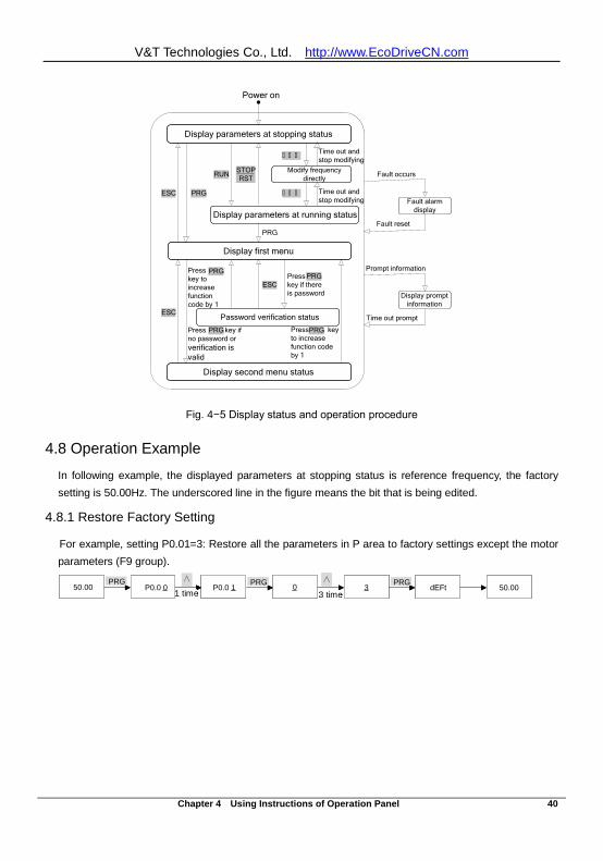
V&T Technologies Co., Ltd. http://www.EcoDriveCN.com
Chapter 4 Using Instructions of Operation Panel 40
Display parameters at stopping status
Modify frequency directly
Time out and stop modifying
Fault occurs
Fault reset
Time out and stop modifying
Display parameters at running status
STOPRSTRUN
PRG
Display first menu
PRGESC
Password verification statusESC
ESC
Press key to increase function code by 1
Press key if there is password
Display second menu status
Press key if no password or verification is valid
Press key to increase function code by 1
Fault alarm display
Prompt information
Time out prompt
Display prompt information
Power on
∧ ∧ ∧
∧ ∧ ∧
PRGPRG
PRG PRG
Fig. 4−5 Display status and operation procedure
4.8 Operation Example
In following example, the displayed parameters at stopping status is reference frequency, the factory setting is 50.00Hz. The underscored line in the figure means the bit that is being edited.
4.8.1 Restore Factory Setting
For example, setting P0.01=3: Restore all the parameters in P area to factory settings except the motor parameters (F9 group).
50.00 P0.0 0 P0.0 1 0 3 dEFt∧
1次 3次50.00
∧PRG PRG PRG1 time 3 time
50.00 P0.0 0 P0.0 1 0 3 dEFt∧
1次 3次50.00
∧PRG PRG PRG1 time 3 time
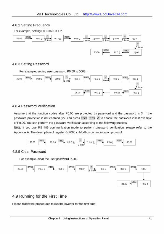
V&T Technologies Co., Ltd. http://www.EcoDriveCN.com
Chapter 4 Using Instructions of Operation Panel 41
4.8.2 Setting Frequency For example, setting P0.05=25.00Hz.
4.8.3 Setting Password
For example, setting user password P0.00 to 0003.
4.8.4 Password Verification
Assume that the function codes after P0.00 are protected by password and the password is 3. If the password protection is not enabled, you can press ESC+PRG+∧ to enable the password in last example of P0.00. You can perform the password verification according to the following process: Note: If you use RS 485 communication mode to perform password verification, please refer to the Appendix A. The description of register 0xF000 in Modbus communication protocol.
4.8.5 Clear Password
For example, clear the user password P0.00.
?25.00 P0.0 0 000 0 P0.0 1 P0.0 0 000 0
1 TimeP.CLr
P0.0 125.00ESC
PRG PRG PRG PRG PRG
4.9 Running for the First Time
Please follow the procedures to run the inverter for the first time:
∧ ∨25.00 P0.0 0 000 0 000 3 P0.0 1 P0.0 0
3次 1次000 0
3次
000 3P.SEtP0.0 1
∧
25.00
PRG PRG PRG PRG
PRGESC
3 time
3 time
1time∧ ∨
25.00 P0.0 0 000 0 000 3 P0.0 1 P0.0 03次 1次
000 0
3次
000 3P.SEtP0.0 1
∧
25.00
PRG PRG PRG PRG
PRGESC
3 time
3 time
1time
>> ∨50.00 P0.0 0 P0.0 5 50.0 0 5 0.00 3 0.00
∧
5次 1次 2次30 .00
1次
>>
5次∨
25.00P0.0 625.00
PRG PRG
PRGESC
5 time
5 time
2 time 1 time1 time>> ∨
50.00 P0.0 0 P0.0 5 50.0 0 5 0.00 3 0.00∧
5次 1次 2次30 .00
1次
>>
5次∨
25.00P0.0 625.00
PRG PRG
PRGESC
5 time
5 time
2 time>> ∨
50.00 P0.0 0 P0.0 5 50.0 0 5 0.00 3 0.00∧
5次 1次 2次30 .00
1次
>>
5次∨
25.00P0.0 625.00
PRG PRG
PRGESC
5 time
5 time
2 time 1 time1 time
∧25.00 P0.0 0 0.0.0. 0. 0.0.0. 3. P0.0 1 25.00
3次
PRG PRG PRG ESC
3 Time
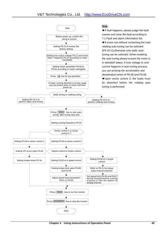
V&T Technologies Co., Ltd. http://www.EcoDriveCN.com
Chapter 4 Using Instructions of Operation Panel 42
Before power up, confirm the wiring is correct
Setting P0.01=5 restore the factory setting
Setting max output voltage P0.12 and motor basic frequency P0.15 according to motor
nameplate
Press M key for jog operation
If motor running direction is wrong, swap any two phase wires of motor and then
power up
Press RUN key to run the inverter
Setting motor parameter P9.00 to P9.04 according to motor nameplate
Press key to stop the inverter
Start
END
STOP/RST
Static tuning or rotating tuning
Setting running frequency P0.05
Vector control 1 or vector control 2 ?
Setting P0.03 to vector control 1 Setting P0.03 to vector control 2
Setting V/F curve input P4.00 Speed control or torque control
Setting Pd.00 to 0 speed control
Setting torque limit value Pd.08 and Pd.09
Adjust speed loop parameters Pd.01 to Pd.05
Setting torque boost P0.16 Setting Pd.00 to 1 torque control
Refer to P6.21 for torque input channel selection
Set speed limit Pd.06 and Pd.07 during forward/reverse running process or limit the speed via analog channel
RUN
Setting P9.15=2 to perform rotating auto-tuning
Press RUN key to start auto tuning, after tuning stop auto
RUN
M
Setting P9.15=1 to perform static auto-tuning
Note: If fault happens, please judge the fault causes and clear the fault according to 7.1 Fault and alarm information list. If motor can without connecting the load rotating auto tuning can be selected (P9.15=2),otherwise only static auto tuning can be selected .When enabling the auto tuning please ensure the motor is in standstill status .If over voltage or over current happens in auto tuning process, you can prolong the acceleration and deceleration times of P0.08 and P0.09. Upon vector control 2, the loads must be detached before the rotating auto tuning is performed.
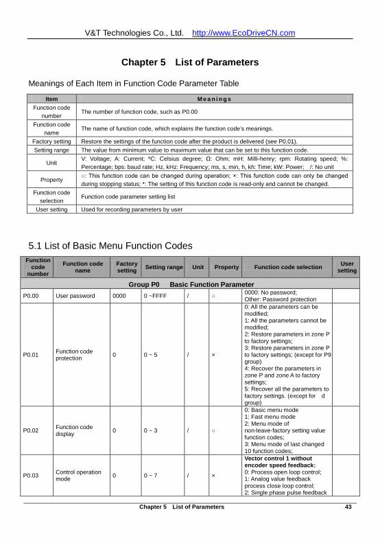
V&T Technologies Co., Ltd. http://www.EcoDriveCN.com
Chapter 5 List of Parameters 43
Chapter 5 List of Parameters
Meanings of Each Item in Function Code Parameter Table
Item M e a n i n g s Function code
number The number of function code, such as P0.00
Function code name
The name of function code, which explains the function code’s meanings.
Factory setting Restore the settings of the function code after the product is delivered (see P0.01). Setting range The value from minimum value to maximum value that can be set to this function code.
Unit V: Voltage; A: Current; ºC: Celsius degree; Ω: Ohm; mH: Milli-henry; rpm: Rotating speed; %: Percentage; bps: baud rate; Hz, kHz: Frequency; ms, s, min, h, kh: Time; kW: Power; /: No unit
Property : This function code can be changed during operation; ×: This function code can only be changed during stopping status; *: The setting of this function code is read-only and cannot be changed.
Function code selection
Function code parameter setting list
User setting Used for recording parameters by user
5.1 List of Basic Menu Function Codes Function
code number
Function code name
Factory setting Setting range Unit Property Function code selection User
setting
Group P0 Basic Function Parameter P0.00 User password 0000 0 ~FFFF / 0000: No password;
Other: Password protection
P0.01 Function code protection 0 0 ~ 5 / ×
0: All the parameters can be modified; 1: All the parameters cannot be modified; 2: Restore parameters in zone P to factory settings; 3: Restore parameters in zone P to factory settings; (except for P9 group) 4: Recover the parameters in zone P and zone A to factory settings; 5: Recover all the parameters to factory settings. (except for d group)
P0.02 Function code display 0 0 ~ 3 /
0: Basic menu mode 1: Fast menu mode 2: Menu mode of non-leave-factory setting value function codes; 3: Menu mode of last changed 10 function codes;
P0.03 Control operation mode 0 0 ~ 7 / ×
Vector control 1 without encoder speed feedback: 0: Process open loop control; 1: Analog value feedback process close loop control; 2: Single phase pulse feedback
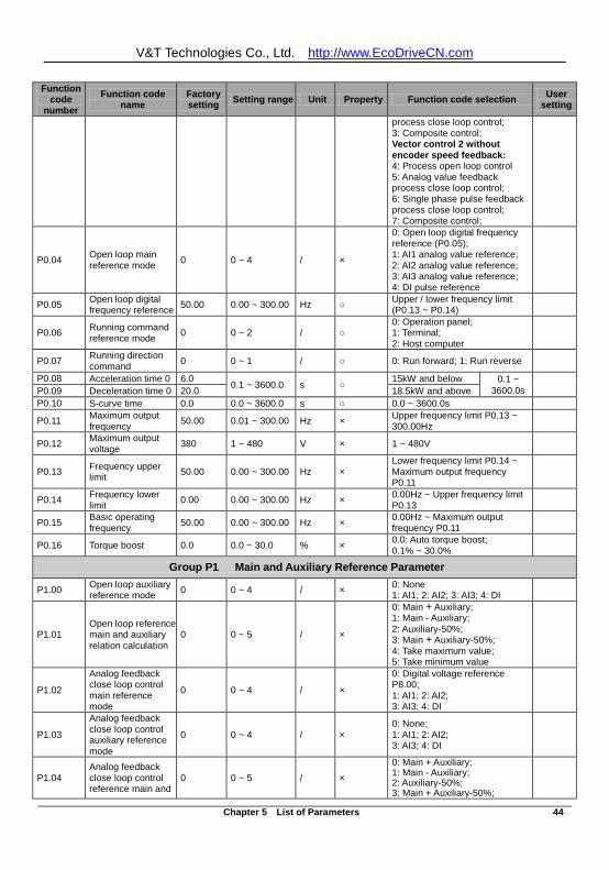
V&T Technologies Co., Ltd. http://www.EcoDriveCN.com
Chapter 5 List of Parameters 44
Function code
number Function code
name Factory setting Setting range Unit Property Function code selection User
setting
process close loop control; 3: Composite control; Vector control 2 without encoder speed feedback: 4: Process open loop control 5: Analog value feedback process close loop control; 6: Single phase pulse feedback process close loop control; 7: Composite control;
P0.04 Open loop main reference mode 0 0 ~ 4 / ×
0: Open loop digital frequency reference (P0.05); 1: AI1 analog value reference; 2: AI2 analog value reference; 3: AI3 analog value reference; 4: DI pulse reference
P0.05 Open loop digital frequency reference 50.00 0.00 ~ 300.00 Hz Upper / lower frequency limit
(P0.13 ~ P0.14)
P0.06 Running command reference mode 0 0 ~ 2 /
0: Operation panel; 1: Terminal; 2: Host computer
P0.07 Running direction command 0 0 ~ 1 / 0: Run forward; 1: Run reverse
P0.08 Acceleration time 0 6.0 0.1 ~ 3600.0 s 15kW and below 0.1 ~ 3600.0s
P0.09 Deceleration time 0 20.0 18.5kW and above P0.10 S-curve time 0.0 0.0 ~ 3600.0 s 0.0 ~ 3600.0s
P0.11 Maximum output frequency 50.00 0.01 ~ 300.00 Hz × Upper frequency limit P0.13 ~
300.00Hz
P0.12 Maximum output voltage 380 1 ~ 480 V × 1 ~ 480V
P0.13 Frequency upper limit 50.00 0.00 ~ 300.00 Hz ×
Lower frequency limit P0.14 ~ Maximum output frequency P0.11
P0.14 Frequency lower limit 0.00 0.00 ~ 300.00 Hz × 0.00Hz ~ Upper frequency limit
P0.13
P0.15 Basic operating frequency 50.00 0.00 ~ 300.00 Hz × 0.00Hz ~ Maximum output
frequency P0.11
P0.16 Torque boost 0.0 0.0 ~ 30.0 % × 0.0: Auto torque boost; 0.1% ~ 30.0%
Group P1 Main and Auxiliary Reference Parameter
P1.00 Open loop auxiliary reference mode 0 0 ~ 4 / × 0: None
1: AI1; 2: AI2; 3: AI3; 4: DI
P1.01 Open loop reference main and auxiliary relation calculation
0 0 ~ 5 / ×
0: Main + Auxiliary; 1: Main - Auxiliary; 2: Auxiliary-50%; 3: Main + Auxiliary-50%; 4: Take maximum value; 5: Take minimum value
P1.02
Analog feedback close loop control main reference mode
0 0 ~ 4 / ×
0: Digital voltage reference P8.00; 1: AI1; 2: AI2; 3: AI3; 4: DI
P1.03
Analog feedback close loop control auxiliary reference mode
0 0 ~ 4 / × 0: None; 1: AI1; 2: AI2; 3: AI3; 4: DI
P1.04 Analog feedback close loop control reference main and
0 0 ~ 5 / × 0: Main + Auxiliary; 1: Main - Auxiliary; 2: Auxiliary-50%; 3: Main + Auxiliary-50%;
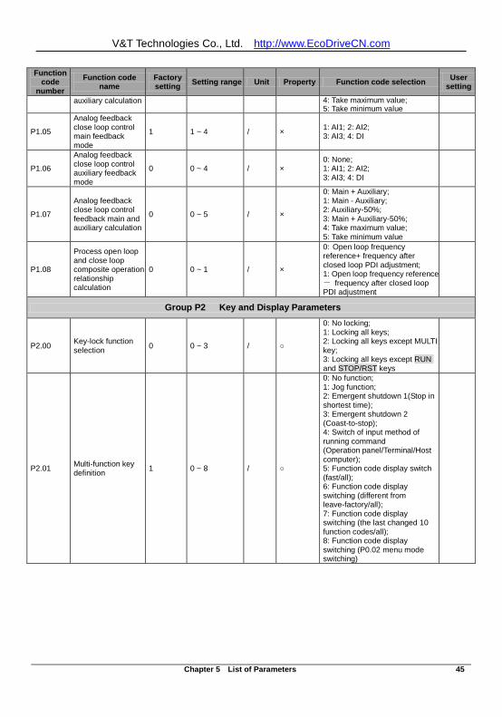
V&T Technologies Co., Ltd. http://www.EcoDriveCN.com
Chapter 5 List of Parameters 45
Function code
number Function code
name Factory setting Setting range Unit Property Function code selection User
setting
auxiliary calculation 4: Take maximum value; 5: Take minimum value
P1.05
Analog feedback close loop control main feedback mode
1 1 ~ 4 / × 1: AI1; 2: AI2; 3: AI3; 4: DI
P1.06
Analog feedback close loop control auxiliary feedback mode
0 0 ~ 4 / × 0: None; 1: AI1; 2: AI2; 3: AI3; 4: DI
P1.07
Analog feedback close loop control feedback main and auxiliary calculation
0 0 ~ 5 / ×
0: Main + Auxiliary; 1: Main - Auxiliary; 2: Auxiliary-50%; 3: Main + Auxiliary-50%; 4: Take maximum value; 5: Take minimum value
P1.08
Process open loop and close loop composite operation relationship calculation
0 0 ~ 1 / ×
0: Open loop frequency reference+ frequency after closed loop PDI adjustment; 1: Open loop frequency reference - frequency after closed loop PDI adjustment
Group P2 Key and Display Parameters
P2.00 Key-lock function selection 0 0 ~ 3 /
0: No locking; 1: Locking all keys; 2: Locking all keys except MULTI key; 3: Locking all keys except RUN and STOP/RST keys
P2.01 Multi-function key definition 1 0 ~ 8 /
0: No function; 1: Jog function; 2: Emergent shutdown 1(Stop in shortest time); 3: Emergent shutdown 2 (Coast-to-stop); 4: Switch of input method of running command (Operation panel/Terminal/Host computer); 5: Function code display switch (fast/all); 6: Function code display switching (different from leave-factory/all); 7: Function code display switching (the last changed 10 function codes/all); 8: Function code display switching (P0.02 menu mode switching)
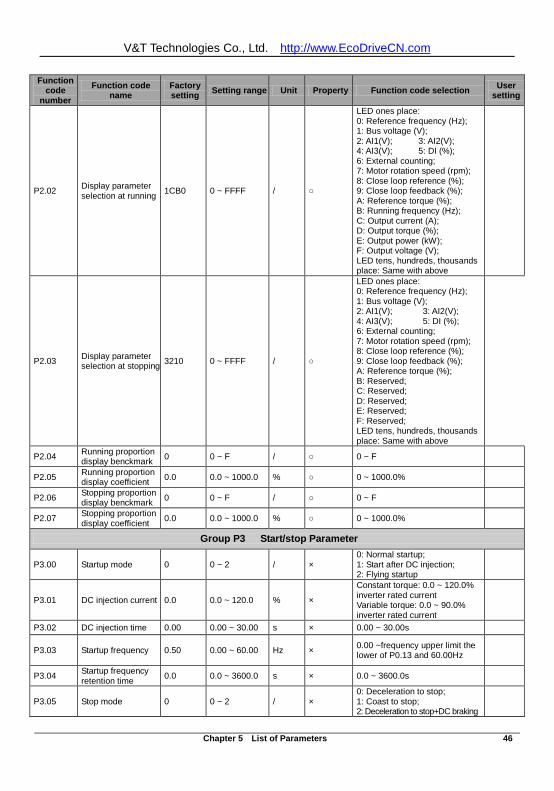
V&T Technologies Co., Ltd. http://www.EcoDriveCN.com
Chapter 5 List of Parameters 46
Function code
number Function code
name Factory setting Setting range Unit Property Function code selection User
setting
P2.02 Display parameter selection at running 1CB0 0 ~ FFFF /
LED ones place: 0: Reference frequency (Hz); 1: Bus voltage (V); 2: AI1(V); 3: AI2(V); 4: AI3(V); 5: DI (%); 6: External counting; 7: Motor rotation speed (rpm); 8: Close loop reference (%); 9: Close loop feedback (%); A: Reference torque (%); B: Running frequency (Hz); C: Output current (A); D: Output torque (%); E: Output power (kW); F: Output voltage (V); LED tens, hundreds, thousands place: Same with above
P2.03 Display parameter selection at stopping 3210 0 ~ FFFF /
LED ones place: 0: Reference frequency (Hz); 1: Bus voltage (V); 2: AI1(V); 3: AI2(V); 4: AI3(V); 5: DI (%); 6: External counting; 7: Motor rotation speed (rpm); 8: Close loop reference (%); 9: Close loop feedback (%); A: Reference torque (%); B: Reserved; C: Reserved; D: Reserved; E: Reserved; F: Reserved; LED tens, hundreds, thousands place: Same with above
P2.04 Running proportion display benckmark 0 0 ~ F / 0 ~ F
P2.05 Running proportion display coefficient 0.0 0.0 ~ 1000.0 % 0 ~ 1000.0%
P2.06 Stopping proportion display benckmark 0 0 ~ F / 0 ~ F
P2.07 Stopping proportion display coefficient 0.0 0.0 ~ 1000.0 % 0 ~ 1000.0%
Group P3 Start/stop Parameter
P3.00 Startup mode 0 0 ~ 2 / × 0: Normal startup; 1: Start after DC injection; 2: Flying startup
P3.01 DC injection current 0.0 0.0 ~ 120.0 % ×
Constant torque: 0.0 ~ 120.0% inverter rated current Variable torque: 0.0 ~ 90.0% inverter rated current
P3.02 DC injection time 0.00 0.00 ~ 30.00 s × 0.00 ~ 30.00s
P3.03 Startup frequency 0.50 0.00 ~ 60.00 Hz × 0.00 ~frequency upper limit the lower of P0.13 and 60.00Hz
P3.04 Startup frequency retention time 0.0 0.0 ~ 3600.0 s × 0.0 ~ 3600.0s
P3.05 Stop mode 0 0 ~ 2 / × 0: Deceleration to stop; 1: Coast to stop; 2: Deceleration to stop+DC braking
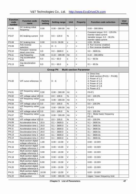
V&T Technologies Co., Ltd. http://www.EcoDriveCN.com
Chapter 5 List of Parameters 47
Function code
number Function code
name Factory setting Setting range Unit Property Function code selection User
setting
P3.06 DC braking initial frequency 0.00 0.00 ~ 300.00 Hz × 0.00 ~ 300.00Hz
P3.07 DC braking current 0.0 0.0 ~ 120.0 % ×
Constant torque: 0.0 ~ 120.0% inverter rated current Variable torque: 0.0 ~ 90.0% inverter rated current
P3.08 DC braking time 0.00 0.0 0~ 30.00 s × 0.00~ 30.00s
P3.09 Anti-reverse selection 1 0 ~ 1 / × 0: Run reverse enabled;
1: Run reverse disabled
P3.10 Forward / reverse dead zone time 0.0 0.0 ~ 3600.0 s × 0.0 ~ 3600.0s
P3.11 Jog frequency 5.00 0.10 ~ 300.00 Hz × 0.10 ~ 300.00Hz
P3.12 Jog acceleration time 6.0 0.1 ~ 60.0 s × 0.1 ~ 60.0s
P3.13 Jog deceleration time 6.0 0.1 ~ 60.0 s × 0.1 ~ 60.0s
Group P4 Multi-section Parameter
P4.00 V/F curve reference 0 0 ~ 6 / ×
0: Direct line; 1: Multi-section (P4.01 ~ P4.08); 2: Power of 1.2; 3: Power of 1.4; 4: Power of 1.6; 5: Power of 1.8; 6: Power of 2
P4.01 V/F frequency value F0 0.00 0.00 ~ 300.00 Hz × F0<F1
P4.02 V/F voltage value V0 0.0 0.0 ~ 100.0 % × 0.0 ~ 100.0%
P4.03 V/F frequency value F1 0.00 0.00 ~ 300.00 Hz × F1<F2
P4.04 V/F voltage value V1 0.0 0.0 ~ 100.0 % × 0.0 ~ 100.0%
P4.05 V/F frequency value F2 0.00 0.00 ~ 300.00 Hz × F2<F3
P4.06 V/F voltage value V2 0.0 0.0 ~ 100.0 % × 0.0 ~ 100.0%
P4.07 V/F frequency value F3 0.00 0.00 ~ 300.00 Hz × F3≤ Motor basic frequency
P0.15
P4.08 V/F voltage value V3 0.0 0.0 ~ 100.0 % × 0.0 ~ 100.0% P4.09 Acceleration time 1 20.0 0.1 ~ 3600.0 s × 0.1 ~ 3600.0s P4.10 Deceleration time 1 20.0 0.1 ~ 3600.0 s × 0.1 ~ 3600.0s P4.11 Acceleration time 2 20.0 0.1 ~ 3600.0 s × 0.1 ~ 3600.0s P4.12 Deceleration time 2 20.0 0.1 ~ 3600.0 s × 0.1 ~ 3600.0s P4.13 Acceleration time 3 20.0 0.1 ~ 3600.0 s × 0.1 ~ 3600.0s P4.14 Deceleration time 3 20.0 0.1 ~ 3600.0 s × 0.1 ~ 3600.0s
P4.15 Multi-section digital voltage reference 1 1.00 0.00 ~ 10.00 V 0.00 ~ 10.00V
P4.16 Multi-section digital voltage reference 2 2.00 0.00 ~ 10.00 V 0.00 ~ 10.00V
P4.17 Multi-section digital voltage reference 3 3.00 0.00 ~ 10.00 V 0.00 ~ 10.00V
P4.18 Multi-section digital voltage reference 4 5.00 0.00 ~ 10.00 V 0.00 ~ 10.00V
P4.19 Multi-section digital voltage reference 5 6.00 0.00 ~ 10.00 V 0.00 ~ 10.00V
P4.20 Multi-section digital voltage reference 6 8.00 0.00 ~ 10.00 V 0.00 ~ 10.00V
P4.21 Multi-section digital voltage reference 7 10.00 0.00 ~ 10.00 V 0.00 ~ 10.00V
P4.22 Multi-section 5.00 0.00 ~ 300.00 Hz Upper / lower frequency limit
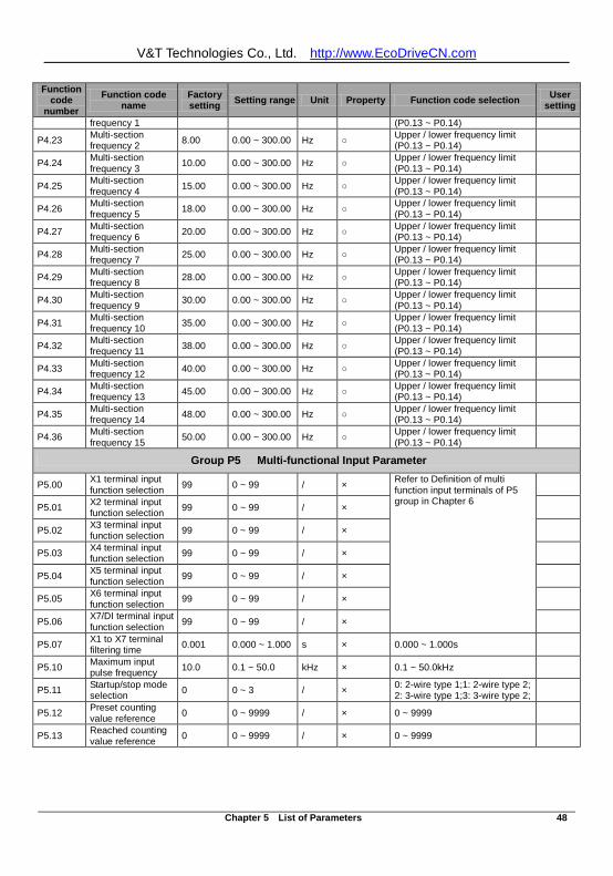
V&T Technologies Co., Ltd. http://www.EcoDriveCN.com
Chapter 5 List of Parameters 48
Function code
number Function code
name Factory setting Setting range Unit Property Function code selection User
setting
frequency 1 (P0.13 ~ P0.14)
P4.23 Multi-section frequency 2 8.00 0.00 ~ 300.00 Hz Upper / lower frequency limit
(P0.13 ~ P0.14)
P4.24 Multi-section frequency 3 10.00 0.00 ~ 300.00 Hz Upper / lower frequency limit
(P0.13 ~ P0.14)
P4.25 Multi-section frequency 4 15.00 0.00 ~ 300.00 Hz Upper / lower frequency limit
(P0.13 ~ P0.14)
P4.26 Multi-section frequency 5 18.00 0.00 ~ 300.00 Hz Upper / lower frequency limit
(P0.13 ~ P0.14)
P4.27 Multi-section frequency 6 20.00 0.00 ~ 300.00 Hz Upper / lower frequency limit
(P0.13 ~ P0.14)
P4.28 Multi-section frequency 7 25.00 0.00 ~ 300.00 Hz Upper / lower frequency limit
(P0.13 ~ P0.14)
P4.29 Multi-section frequency 8 28.00 0.00 ~ 300.00 Hz Upper / lower frequency limit
(P0.13 ~ P0.14)
P4.30 Multi-section frequency 9 30.00 0.00 ~ 300.00 Hz Upper / lower frequency limit
(P0.13 ~ P0.14)
P4.31 Multi-section frequency 10 35.00 0.00 ~ 300.00 Hz Upper / lower frequency limit
(P0.13 ~ P0.14)
P4.32 Multi-section frequency 11 38.00 0.00 ~ 300.00 Hz Upper / lower frequency limit
(P0.13 ~ P0.14)
P4.33 Multi-section frequency 12 40.00 0.00 ~ 300.00 Hz Upper / lower frequency limit
(P0.13 ~ P0.14)
P4.34 Multi-section frequency 13 45.00 0.00 ~ 300.00 Hz Upper / lower frequency limit
(P0.13 ~ P0.14)
P4.35 Multi-section frequency 14 48.00 0.00 ~ 300.00 Hz Upper / lower frequency limit
(P0.13 ~ P0.14)
P4.36 Multi-section frequency 15 50.00 0.00 ~ 300.00 Hz Upper / lower frequency limit
(P0.13 ~ P0.14)
Group P5 Multi-functional Input Parameter
P5.00 X1 terminal input function selection 99 0 ~ 99 / × Refer to Definition of multi
function input terminals of P5 group in Chapter 6
P5.01 X2 terminal input function selection 99 0 ~ 99 / ×
P5.02 X3 terminal input function selection 99 0 ~ 99 / ×
P5.03 X4 terminal input function selection 99 0 ~ 99 / ×
P5.04 X5 terminal input function selection 99 0 ~ 99 / ×
P5.05 X6 terminal input function selection 99 0 ~ 99 / ×
P5.06 X7/DI terminal input function selection 99 0 ~ 99 / ×
P5.07 X1 to X7 terminal filtering time 0.001 0.000 ~ 1.000 s × 0.000 ~ 1.000s
P5.10 Maximum input pulse frequency 10.0 0.1 ~ 50.0 kHz × 0.1 ~ 50.0kHz
P5.11 Startup/stop mode selection 0 0 ~ 3 / × 0: 2-wire type 1;1: 2-wire type 2;
2: 3-wire type 1;3: 3-wire type 2;
P5.12 Preset counting value reference 0 0 ~ 9999 / × 0 ~ 9999
P5.13 Reached counting value reference 0 0 ~ 9999 / × 0 ~ 9999
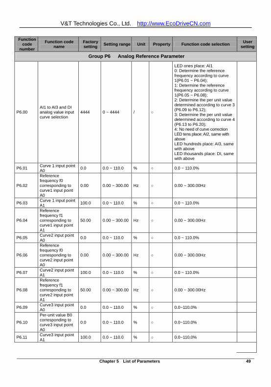
V&T Technologies Co., Ltd. http://www.EcoDriveCN.com
Chapter 5 List of Parameters 49
Function code
number Function code
name Factory setting Setting range Unit Property Function code selection User
setting
Group P6 Analog Reference Parameter
P6.00 AI1 to AI3 and DI analog value input curve selection
4444 0 ~ 4444 /
LED ones place: AI1 0: Determine the reference frequency according to curve 1(P6.01 ~ P6.04); 1: Determine the reference frequency according to curve 1(P6.05 ~ P6.08); 2: Determine the per unit value determined according to curve 3 (P6.09 to P6.12); 3: Determine the per unit value determined according to curve 4 (P6.13 to P6.20); 4: No need of curve correction LED tens place: AI2, same with above LED hundreds place: AI3, same with above LED thousands place: DI, same with above
P6.01 Curve 1 input point A0 0.0 0.0 ~ 110.0 % 0.0 ~ 110.0%
P6.02
Reference frequency f0 corresponding to curve1 input point A0
0.00 0.00 ~ 300.00 Hz 0.00 ~ 300.00Hz
P6.03 Curve 1 input point A1 100.0 0.0 ~ 110.0 % 0.0 ~ 110.0%
P6.04
Reference frequency f1 corresponding to curve1 input point A1
50.00 0.00 ~ 300.00 Hz 0.00 ~ 300.00Hz
P6.05 Curve2 input point A0 0.0 0.0 ~ 110.0 % 0.0 ~ 110.0%
P6.06
Reference frequency f0 corresponding to curve2 input point A0
0.00 0.00 ~ 300.00 Hz 0.00 ~ 300.00Hz
P6.07 Curve2 input point A1 100.0 0.0 ~ 110.0 % 0.0 ~ 110.0%
P6.08
Reference frequency f1 corresponding to curve2 input point A1
50.00 0.00 ~ 300.00 Hz 0.00 ~ 300.00Hz
P6.09 Curve3 input point A0 0.0 0.0 ~ 110.0 % 0.0~110.0%
P6.10
Per-unit value B0 corresponding to curve3 input point A0
0.0 0.0 ~ 110.0 % 0.0~110.0%
P6.11 Curve3 input point A1 100.0 0.0 ~ 110.0 % 0.0~110.0%
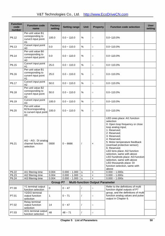
V&T Technologies Co., Ltd. http://www.EcoDriveCN.com
Chapter 5 List of Parameters 50
Function code
number Function code
name Factory setting Setting range Unit Property Function code selection User
setting
P6.12
Per-unit value B1 corresponding to curve3 input point A1
100.0 0.0 ~ 110.0 % 0.0~110.0%
P6.13 Curve4 input point A0 0.0 0.0 ~ 110.0 % 0.0~110.0%
P6.14
Per-unit value B0 corresponding to curve4 input point A0
0.0 0.0 ~ 110.0 % 0.0~110.0%
P6.15 Curve4 input point A1 25.0 0.0 ~ 110.0 % 0.0~110.0%
P6.16
Per-unit value B1 corresponding to curve4 input point A1
25.0 0.0 ~ 110.0 % 0.0~110.0%
P6.17 Curve4 input point A2 50.0 0.0 ~ 110.0 % 0.0~110.0%
P6.18
Per-unit value B2 corresponding to curve4 input point A2
50.0 0.0 ~ 110.0 % 0.0~110.0%
P6.19 Curve4 input point A3 100.0 0.0 ~ 110.0 % 0.0~110.0%
P6.20
Per-unit value B23corresponding to curve4 input point A3
100.0 0.0 ~ 110.0 % 0.0~110.0%
P6.21 AI1~AI3、DI analog channel function selection
0000 0 ~ 6666 / ×
LED ones place: AI1 function selection 0: Open loop frequency or close loop analog input; 1: Reserved; 2: Reserved; 3: Reserved; 4: Reserved; 5: Motor temperature feedback (overload protective sensor); 6: Reserved; LED tens place: AI2 function selection, same with above LED hundreds place: AI3 function selection, same with above LED thousands place: DI function selection, same with above
P6.22 AI1 filtering time 0.004 0.000 ~ 1.000 s × 0.000 ~ 1.000s P6.23 AI2 filtering time 0.004 0.000 ~ 1.000 s × 0.000 ~ 1.000s P6.24 AI3 filtering time 0.004 0.000 ~ 1.000 s × 0.000 ~ 1.000s
Group P7 Multi-function Output Parameter
P7.00 Y1 terminal output function selection 0 0 ~ 47 / Refer to the definitions of multi
function digital outputs of P7 group, and the definitions of multi function analog values and pulse output in Chapter 6.
P7.01 Y2/DO terminal output function selection
1 0 ~ 71 /
P7.02 Relay terminal output function selection
14 0 ~ 47 /
P7.03 AO1 terminal output function selection 48 48 ~ 71 /
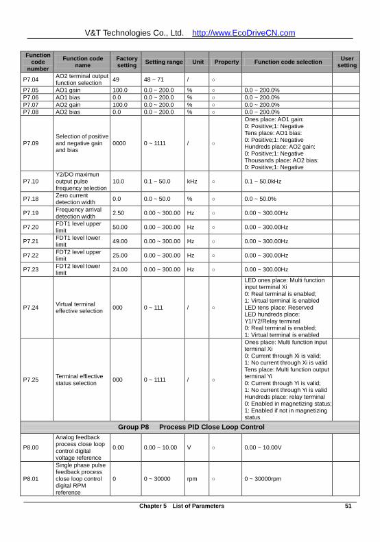
V&T Technologies Co., Ltd. http://www.EcoDriveCN.com
Chapter 5 List of Parameters 51
Function code
number Function code
name Factory setting Setting range Unit Property Function code selection User
setting
P7.04 AO2 terminal output function selection 49 48 ~ 71 /
P7.05 AO1 gain 100.0 0.0 ~ 200.0 % 0.0 ~ 200.0% P7.06 AO1 bias 0.0 0.0 ~ 200.0 % 0.0 ~ 200.0% P7.07 AO2 gain 100.0 0.0 ~ 200.0 % 0.0 ~ 200.0% P7.08 AO2 bias 0.0 0.0 ~ 200.0 % 0.0 ~ 200.0%
P7.09 Selection of positive and negative gain and bias
0000 0 ~ 1111 /
Ones place: AO1 gain: 0: Positive;1: Negative Tens place: AO1 bias: 0: Positive;1: Negative Hundreds place: AO2 gain: 0: Positive;1: Negative Thousands place: AO2 bias: 0: Positive;1: Negative
P7.10 Y2/DO maximun output pulse frequency selection
10.0 0.1 ~ 50.0 kHz 0.1 ~ 50.0kHz
P7.18 Zero current detection width 0.0 0.0 ~ 50.0 % 0.0 ~ 50.0%
P7.19 Frequency arrival detection width 2.50 0.00 ~ 300.00 Hz 0.00 ~ 300.00Hz
P7.20 FDT1 level upper limit 50.00 0.00 ~ 300.00 Hz 0.00 ~ 300.00Hz
P7.21 FDT1 level lower limit 49.00 0.00 ~ 300.00 Hz 0.00 ~ 300.00Hz
P7.22 FDT2 level upper limit 25.00 0.00 ~ 300.00 Hz 0.00 ~ 300.00Hz
P7.23 FDT2 level lower limit 24.00 0.00 ~ 300.00 Hz 0.00 ~ 300.00Hz
P7.24 Virtual terminal effective selection 000 0 ~ 111 /
LED ones place: Multi function input terminal Xi 0: Real terminal is enabled; 1: Virtual terminal is enabled LED tens place: Reserved LED hundreds place: Y1/Y2/Relay terminal 0: Real terminal is enabled; 1: Virtual terminal is enabled
P7.25 Terminal effiective status selection 000 0 ~ 1111 /
Ones place: Multi function input terminal Xi 0: Current through Xi is valid; 1: No current through Xi is valid Tens place: Multi function output terminal Yi 0: Current through Yi is valid; 1: No current through Yi is valid Hundreds place: relay terminal 0: Enabled in magnetizing status; 1: Enabled if not in magnetizing status
Group P8 Process PID Close Loop Control
P8.00
Analog feedback process close loop control digital voltage reference
0.00 0.00 ~ 10.00 V 0.00 ~ 10.00V
P8.01
Single phase pulse feedback process close loop control digital RPM reference
0 0 ~ 30000 rpm 0 ~ 30000rpm
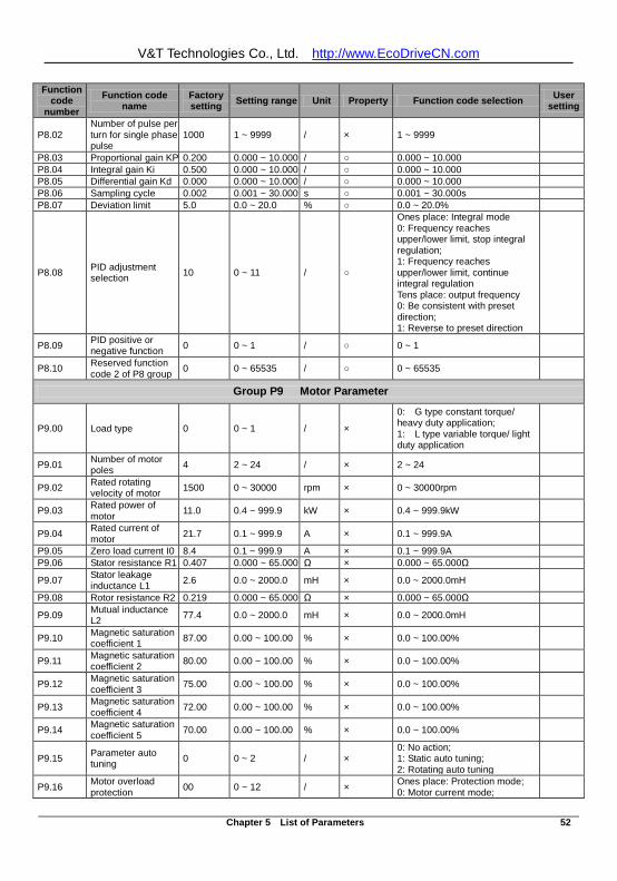
V&T Technologies Co., Ltd. http://www.EcoDriveCN.com
Chapter 5 List of Parameters 52
Function code
number Function code
name Factory setting Setting range Unit Property Function code selection User
setting
P8.02 Number of pulse per turn for single phase pulse
1000 1 ~ 9999 / × 1 ~ 9999
P8.03 Proportional gain KP 0.200 0.000 ~ 10.000 / 0.000 ~ 10.000 P8.04 Integral gain Ki 0.500 0.000 ~ 10.000 / 0.000 ~ 10.000 P8.05 Differential gain Kd 0.000 0.000 ~ 10.000 / 0.000 ~ 10.000 P8.06 Sampling cycle 0.002 0.001 ~ 30.000 s 0.001 ~ 30.000s P8.07 Deviation limit 5.0 0.0 ~ 20.0 % 0.0 ~ 20.0%
P8.08 PID adjustment selection 10 0 ~ 11 /
Ones place: Integral mode 0: Frequency reaches upper/lower limit, stop integral regulation; 1: Frequency reaches upper/lower limit, continue integral regulation Tens place: output frequency 0: Be consistent with preset direction; 1: Reverse to preset direction
P8.09 PID positive or negative function 0 0 ~ 1 / 0 ~ 1
P8.10 Reserved function code 2 of P8 group 0 0 ~ 65535 / 0 ~ 65535
Group P9 Motor Parameter
P9.00 Load type 0 0 ~ 1 / ×
0: G type constant torque/ heavy duty application; 1: L type variable torque/ light duty application
P9.01 Number of motor poles 4 2 ~ 24 / × 2 ~ 24
P9.02 Rated rotating velocity of motor 1500 0 ~ 30000 rpm × 0 ~ 30000rpm
P9.03 Rated power of motor 11.0 0.4 ~ 999.9 kW × 0.4 ~ 999.9kW
P9.04 Rated current of motor 21.7 0.1 ~ 999.9 A × 0.1 ~ 999.9A
P9.05 Zero load current I0 8.4 0.1 ~ 999.9 A × 0.1 ~ 999.9A P9.06 Stator resistance R1 0.407 0.000 ~ 65.000 Ω × 0.000 ~ 65.000Ω
P9.07 Stator leakage inductance L1 2.6 0.0 ~ 2000.0 mH × 0.0 ~ 2000.0mH
P9.08 Rotor resistance R2 0.219 0.000 ~ 65.000 Ω × 0.000 ~ 65.000Ω
P9.09 Mutual inductance L2 77.4 0.0 ~ 2000.0 mH × 0.0 ~ 2000.0mH
P9.10 Magnetic saturation coefficient 1 87.00 0.00 ~ 100.00 % × 0.0 ~ 100.00%
P9.11 Magnetic saturation coefficient 2 80.00 0.00 ~ 100.00 % × 0.0 ~ 100.00%
P9.12 Magnetic saturation coefficient 3 75.00 0.00 ~ 100.00 % × 0.0 ~ 100.00%
P9.13 Magnetic saturation coefficient 4 72.00 0.00 ~ 100.00 % × 0.0 ~ 100.00%
P9.14 Magnetic saturation coefficient 5 70.00 0.00 ~ 100.00 % × 0.0 ~ 100.00%
P9.15 Parameter auto tuning 0 0 ~ 2 / ×
0: No action; 1: Static auto tuning; 2: Rotating auto tuning
P9.16 Motor overload protection 00 0 ~ 12 / × Ones place: Protection mode;
0: Motor current mode;
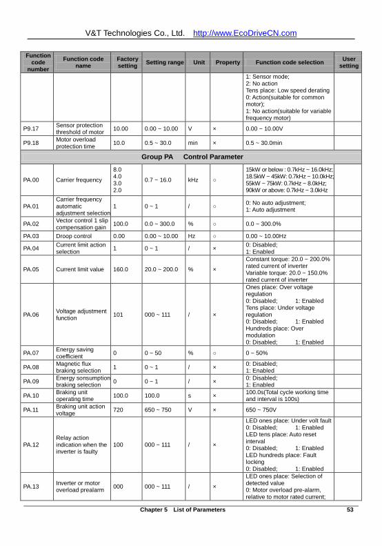
V&T Technologies Co., Ltd. http://www.EcoDriveCN.com
Chapter 5 List of Parameters 53
Function code
number Function code
name Factory setting Setting range Unit Property Function code selection User
setting
1: Sensor mode; 2: No action Tens place: Low speed derating 0: Action(suitable for common motor); 1: No action(suitable for variable frequency motor)
P9.17 Sensor protection threshold of motor 10.00 0.00 ~ 10.00 V × 0.00 ~ 10.00V
P9.18 Motor overload protection time 10.0 0.5 ~ 30.0 min × 0.5 ~ 30.0min
Group PA Control Parameter
PA.00 Carrier frequency
8.0 4.0 3.0 2.0
0.7 ~ 16.0 kHz
15kW or below : 0.7kHz ~ 16.0kHz; 18.5kW ~ 45kW: 0.7kHz ~ 10.0kHz; 55kW ~ 75kW: 0.7kHz ~ 8.0kHz; 90kW or above: 0.7kHz ~ 3.0kHz
PA.01 Carrier frequency automatic adjustment selection
1 0 ~ 1 / 0: No auto adjustment; 1: Auto adjustment
PA.02 Vector control 1 slip compensation gain 100.0 0.0 ~ 300.0 % 0.0 ~ 300.0%
PA.03 Droop control 0.00 0.00 ~ 10.00 Hz 0.00 ~ 10.00Hz
PA.04 Current limit action selection 1 0 ~ 1 / × 0: Disabled;
1: Enabled
PA.05 Current limit value 160.0 20.0 ~ 200.0 % ×
Constant torque: 20.0 ~ 200.0% rated current of inverter Variable torque: 20.0 ~ 150.0% rated current of inverter
PA.06 Voltage adjustment function 101 000 ~ 111 / ×
Ones place: Over voltage regulation 0: Disabled; 1: Enabled Tens place: Under voltage regulation 0: Disabled; 1: Enabled Hundreds place: Over modulation 0: Disabled; 1: Enabled
PA.07 Energy saving coefficient 0 0 ~ 50 % 0 ~ 50%
PA.08 Magnetic flux braking selection 1 0 ~ 1 / × 0: Disabled;
1: Enabled
PA.09 Energy sonsumption braking selection 0 0 ~ 1 / × 0: Disabled;
1: Enabled
PA.10 Braking unit operating time 100.0 100.0 s × 100.0s(Total cycle working time
and interval is 100s)
PA.11 Braking unit action voltage 720 650 ~ 750 V × 650 ~ 750V
PA.12 Relay action indication when the inverter is faulty
100 000 ~ 111 / ×
LED ones place: Under volt fault 0: Disabled; 1: Enabled LED tens place: Auto reset interval 0: Disabled; 1: Enabled LED hundreds place: Fault locking 0: Disabled; 1: Enabled
PA.13 Inverter or motor overload prealarm 000 000 ~ 111 / ×
LED ones place: Selection of detected value 0: Motor overload pre-alarm, relative to motor rated current;
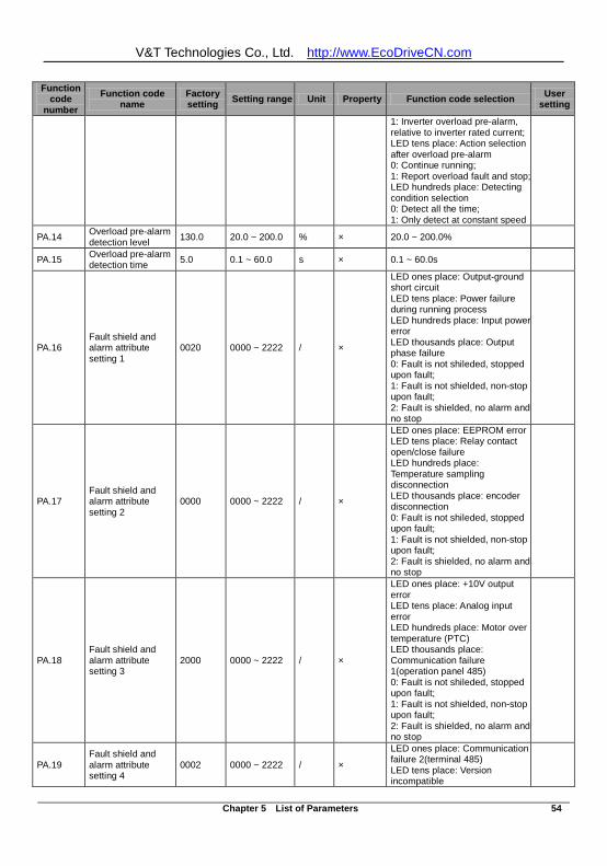
V&T Technologies Co., Ltd. http://www.EcoDriveCN.com
Chapter 5 List of Parameters 54
Function code
number Function code
name Factory setting Setting range Unit Property Function code selection User
setting
1: Inverter overload pre-alarm, relative to inverter rated current; LED tens place: Action selection after overload pre-alarm 0: Continue running; 1: Report overload fault and stop; LED hundreds place: Detecting condition selection 0: Detect all the time; 1: Only detect at constant speed
PA.14 Overload pre-alarm detection level 130.0 20.0 ~ 200.0 % × 20.0 ~ 200.0%
PA.15 Overload pre-alarm detection time 5.0 0.1 ~ 60.0 s × 0.1 ~ 60.0s
PA.16 Fault shield and alarm attribute setting 1
0020 0000 ~ 2222 / ×
LED ones place: Output-ground short circuit LED tens place: Power failure during running process LED hundreds place: Input power error LED thousands place: Output phase failure 0: Fault is not shileded, stopped upon fault; 1: Fault is not shielded, non-stop upon fault; 2: Fault is shielded, no alarm and no stop
PA.17 Fault shield and alarm attribute setting 2
0000 0000 ~ 2222 / ×
LED ones place: EEPROM error LED tens place: Relay contact open/close failure LED hundreds place: Temperature sampling disconnection LED thousands place: encoder disconnection 0: Fault is not shileded, stopped upon fault; 1: Fault is not shielded, non-stop upon fault; 2: Fault is shielded, no alarm and no stop
PA.18 Fault shield and alarm attribute setting 3
2000 0000 ~ 2222 / ×
LED ones place: +10V output error LED tens place: Analog input error LED hundreds place: Motor over temperature (PTC) LED thousands place: Communication failure 1(operation panel 485) 0: Fault is not shileded, stopped upon fault; 1: Fault is not shielded, non-stop upon fault; 2: Fault is shielded, no alarm and no stop
PA.19 Fault shield and alarm attribute setting 4
0002 0000 ~ 2222 / ×
LED ones place: Communication failure 2(terminal 485) LED tens place: Version incompatible
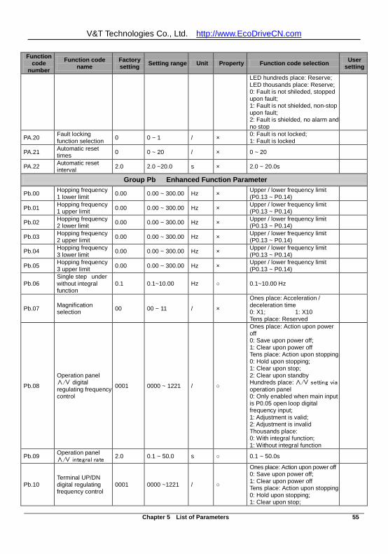
V&T Technologies Co., Ltd. http://www.EcoDriveCN.com
Chapter 5 List of Parameters 55
Function code
number Function code
name Factory setting Setting range Unit Property Function code selection User
setting
LED hundreds place: Reserve; LED thousands place: Reserve; 0: Fault is not shileded, stopped upon fault; 1: Fault is not shielded, non-stop upon fault; 2: Fault is shielded, no alarm and no stop
PA.20 Fault locking function selection 0 0 ~ 1 / × 0: Fault is not locked;
1: Fault is locked
PA.21 Automatic reset times 0 0 ~ 20 / × 0 ~ 20
PA.22 Automatic reset interval 2.0 2.0 ~20.0 s × 2.0 ~ 20.0s
Group Pb Enhanced Function Parameter
Pb.00 Hopping frequency 1 lower limit 0.00 0.00 ~ 300.00 Hz × Upper / lower frequency limit
(P0.13 ~ P0.14)
Pb.01 Hopping frequency 1 upper limit 0.00 0.00 ~ 300.00 Hz × Upper / lower frequency limit
(P0.13 ~ P0.14)
Pb.02 Hopping frequency 2 lower limit 0.00 0.00 ~ 300.00 Hz × Upper / lower frequency limit
(P0.13 ~ P0.14)
Pb.03 Hopping frequency 2 upper limit 0.00 0.00 ~ 300.00 Hz × Upper / lower frequency limit
(P0.13 ~ P0.14)
Pb.04 Hopping frequency 3 lower limit 0.00 0.00 ~ 300.00 Hz × Upper / lower frequency limit
(P0.13 ~ P0.14)
Pb.05 Hopping frequency 3 upper limit 0.00 0.00 ~ 300.00 Hz × Upper / lower frequency limit
(P0.13 ~ P0.14)
Pb.06 Single step under without integral function
0.1 0.1~10.00 Hz 0.1~10.00 Hz
Pb.07 Magnification selection 00 00 ~ 11 / ×
Ones place: Acceleration / deceleration time 0: X1; 1: X10 Tens place: Reserved
Pb.08
Operation panel ∧/∨ digital regulating frequency control
0001 0000 ~ 1221 /
Ones place: Action upon power off 0: Save upon power off; 1: Clear upon power off Tens place: Action upon stopping 0: Hold upon stopping; 1: Clear upon stop; 2: Clear upon standby Hundreds place: ∧/∨ setting via operation panel 0: Only enabled when main input is P0.05 open loop digital frequency input; 1: Adjustment is valid; 2: Adjustment is invalid Thousands place: 0: With integral function; 1: Without integral function
Pb.09 Operation panel ∧/∨ integral rate 2.0 0.1 ~ 50.0 s 0.1 ~ 50.0s
Pb.10 Terminal UP/DN digital regulating frequency control
0001 0000 ~1221 /
Ones place: Action upon power off 0: Save upon power off; 1: Clear upon power off Tens place: Action upon stopping 0: Hold upon stopping; 1: Clear upon stop;
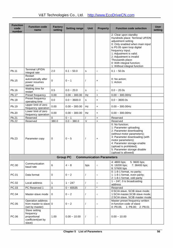
V&T Technologies Co., Ltd. http://www.EcoDriveCN.com
Chapter 5 List of Parameters 56
Function code
number Function code
name Factory setting Setting range Unit Property Function code selection User
setting
2: Clear upon standby Hundreds place: Terminal UP/DN adjustment setting 0: Only enabled when main input is P0.05 open loop digital frequency input; 1: Adjustment is valid; 2: Adjustment is invalid Thousands place: 0: With integral function; 1: Without integral function
Pb.11 Terminal UP/DN integral rate 2.0 0.1 ~ 50.0 s 0.1 ~ 50.0s
Pb.15
Restart automatically after power resumes narmal
0 0 ~ 1 / × 0: No action; 1: Action
Pb.16 Waiting time for restart 0.5 0.0 ~ 20.0 s 0.0 ~ 20.0s
Pb.17 Preset frequency 0.00 0.00 ~ 300.00 Hz × 0.00 ~ 300.00Hz
Pb.18 Preset frequency operating time 0.0 0.0 ~ 3600.0 s × 0.0 ~ 3600.0s
Pb.19 Upper limit of zero frequency operation 0.00 0.00 ~ 300.00 Hz × 0.00 ~ 300.00Hz
Pb.20 Lower limit of zero frequency operation 0.00 0.00 ~ 300.00 Hz × 0.00 ~ 300.00Hz
Pb.21 Reserved 0 0 ~ 1 / × Reserved Pb.22 Reserved 380.0 0.0 ~ 380.0 V × Reserved
Pb.23 Parameter copy 0 0 ~ 5 / ×
0: No function; 1: Parameter uploading; 2: Parameter downloading (without motor parameters); 3: Parameter downloading (with motor parameters); 4: Parameter storage enable (upload is prohibited); 5: Parameter storage disable (upload is allowed)
Group PC Communication Parameters
PC.00 Communication baud rate 6 4 ~ 8 bps
4: 4800 bps; 5: 9600 bps; 6: 19200 bps; 7: 38400 bps; 8: 57600 bps
PC.01 Data format 0 0 ~ 2 / 0: 1-8-1 format, no parity; 1: 1-8-1 format, even parity; 2: 1-8-1 format, odd parity
PC.02 Local address 1 1 ~ 247 / 1 ~ 247, 0 is broadcasting address
PC.03 PC Reserved 1 0 0 ~ 65535 / * Reserved
PC.04 Master-slave mode 0 0 ~ 2 / 0:SCIA slave, SCIB slave mode; 1:SCIA master,SCIB slave mode; 2:SCIA slave, SCIB master mode
PC.05 Operation address from master to slave (set by master)
0 0 ~ 2 / Master preset frequency written in function code of slave 0: P0.05; 1: P8.00; 2: P8.01
PC.06
Slave setting frequency proportional coefficient(set by slave)
1.00 0.00 ~ 10.00 / 0.00 ~ 10.00
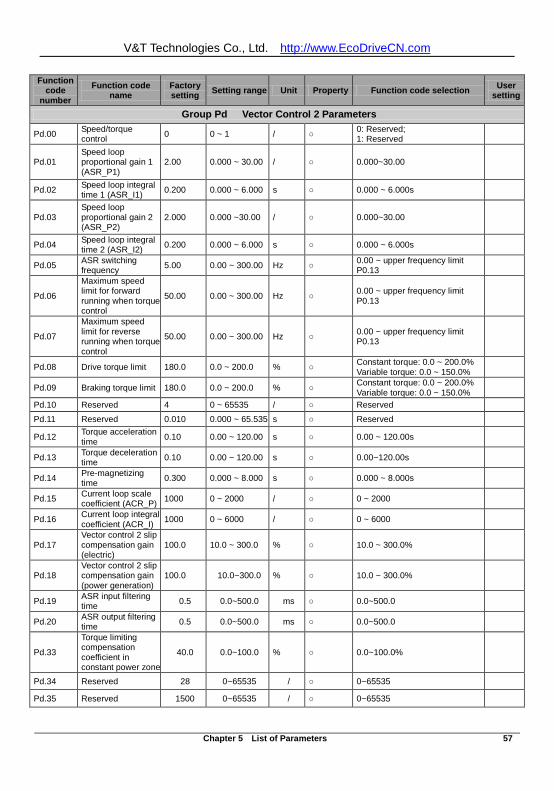
V&T Technologies Co., Ltd. http://www.EcoDriveCN.com
Chapter 5 List of Parameters 57
Function code
number Function code
name Factory setting Setting range Unit Property Function code selection User
setting
Group Pd Vector Control 2 Parameters
Pd.00 Speed/torque control 0 0 ~ 1 / 0: Reserved;
1: Reserved
Pd.01 Speed loop proportional gain 1 (ASR_P1)
2.00 0.000 ~ 30.00 / 0.000~30.00
Pd.02 Speed loop integral time 1 (ASR_I1) 0.200 0.000 ~ 6.000 s 0.000 ~ 6.000s
Pd.03 Speed loop proportional gain 2 (ASR_P2)
2.000 0.000 ~30.00 / 0.000~30.00
Pd.04 Speed loop integral time 2 (ASR_I2) 0.200 0.000 ~ 6.000 s 0.000 ~ 6.000s
Pd.05 ASR switching frequency 5.00 0.00 ~ 300.00 Hz 0.00 ~ upper frequency limit
P0.13
Pd.06
Maximum speed limit for forward running when torque control
50.00 0.00 ~ 300.00 Hz 0.00 ~ upper frequency limit P0.13
Pd.07
Maximum speed limit for reverse running when torque control
50.00 0.00 ~ 300.00 Hz 0.00 ~ upper frequency limit P0.13
Pd.08 Drive torque limit 180.0 0.0 ~ 200.0 % Constant torque: 0.0 ~ 200.0% Variable torque: 0.0 ~ 150.0%
Pd.09 Braking torque limit 180.0 0.0 ~ 200.0 % Constant torque: 0.0 ~ 200.0% Variable torque: 0.0 ~ 150.0%
Pd.10 Reserved 4 0 ~ 65535 / Reserved
Pd.11 Reserved 0.010 0.000 ~ 65.535 s Reserved
Pd.12 Torque acceleration time 0.10 0.00 ~ 120.00 s 0.00 ~ 120.00s
Pd.13 Torque deceleration time 0.10 0.00 ~ 120.00 s 0.00~120.00s
Pd.14 Pre-magnetizing time 0.300 0.000 ~ 8.000 s 0.000 ~ 8.000s
Pd.15 Current loop scale coefficient (ACR_P) 1000 0 ~ 2000 / 0 ~ 2000
Pd.16 Current loop integral coefficient (ACR_I) 1000 0 ~ 6000 / 0 ~ 6000
Pd.17 Vector control 2 slip compensation gain (electric)
100.0 10.0 ~ 300.0 % 10.0 ~ 300.0%
Pd.18 Vector control 2 slip compensation gain (power generation)
100.0 10.0~300.0 % 10.0 ~ 300.0%
Pd.19 ASR input filtering time 0.5 0.0~500.0 ms 0.0~500.0
Pd.20 ASR output filtering time 0.5 0.0~500.0 ms 0.0~500.0
Pd.33
Torque limiting compensation coefficient in constant power zone
40.0 0.0~100.0 % 0.0~100.0%
Pd.34 Reserved 28 0~65535 / 0~65535
Pd.35 Reserved 1500 0~65535 / 0~65535
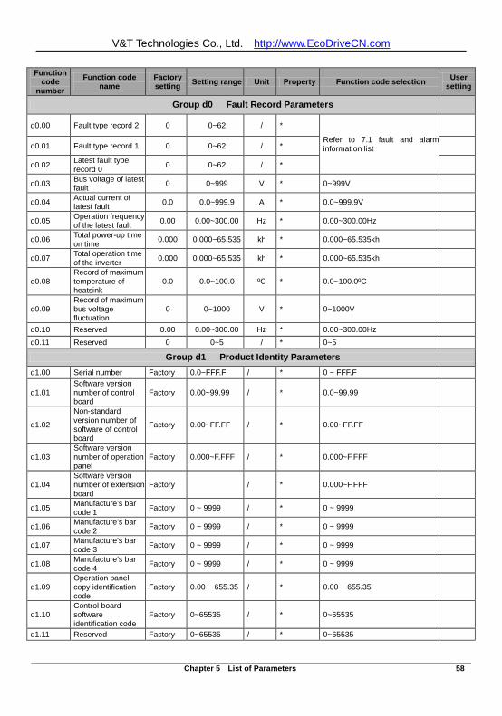
V&T Technologies Co., Ltd. http://www.EcoDriveCN.com
Chapter 5 List of Parameters 58
Function code
number Function code
name Factory setting Setting range Unit Property Function code selection User
setting
Group d0 Fault Record Parameters
d0.00 Fault type record 2 0 0~62 / *
Refer to 7.1 fault and alarm information list
d0.01 Fault type record 1 0 0~62 / *
d0.02 Latest fault type record 0 0 0~62 / *
d0.03 Bus voltage of latest fault 0 0~999 V * 0~999V
d0.04 Actual current of latest fault 0.0 0.0~999.9 A * 0.0~999.9V
d0.05 Operation frequency of the latest fault 0.00 0.00~300.00 Hz * 0.00~300.00Hz
d0.06 Total power-up time on time 0.000 0.000~65.535 kh * 0.000~65.535kh
d0.07 Total operation time of the inverter 0.000 0.000~65.535 kh * 0.000~65.535kh
d0.08 Record of maximum temperature of heatsink
0.0 0.0~100.0 ºC * 0.0~100.0ºC
d0.09 Record of maximum bus voltage fluctuation
0 0~1000 V * 0~1000V
d0.10 Reserved 0.00 0.00~300.00 Hz * 0.00~300.00Hz
d0.11 Reserved 0 0~5 / * 0~5
Group d1 Product Identity Parameters d1.00 Serial number Factory 0.0~FFF.F / * 0 ~ FFF.F
d1.01 Software version number of control board
Factory 0.00~99.99 / * 0.0~99.99
d1.02
Non-standard version number of software of control board
Factory 0.00~FF.FF / * 0.00~FF.FF
d1.03 Software version number of operation panel
Factory 0.000~F.FFF / * 0.000~F.FFF
d1.04 Software version number of extension board
Factory / * 0.000~F.FFF
d1.05 Manufacture’s bar code 1 Factory 0 ~ 9999 / * 0 ~ 9999
d1.06 Manufacture’s bar code 2 Factory 0 ~ 9999 / * 0 ~ 9999
d1.07 Manufacture’s bar code 3 Factory 0 ~ 9999 / * 0 ~ 9999
d1.08 Manufacture’s bar code 4 Factory 0 ~ 9999 / * 0 ~ 9999
d1.09 Operation panel copy identification code
Factory 0.00 ~ 655.35 / * 0.00 ~ 655.35
d1.10 Control board software identification code
Factory 0~65535 / * 0~65535
d1.11 Reserved Factory 0~65535 / * 0~65535
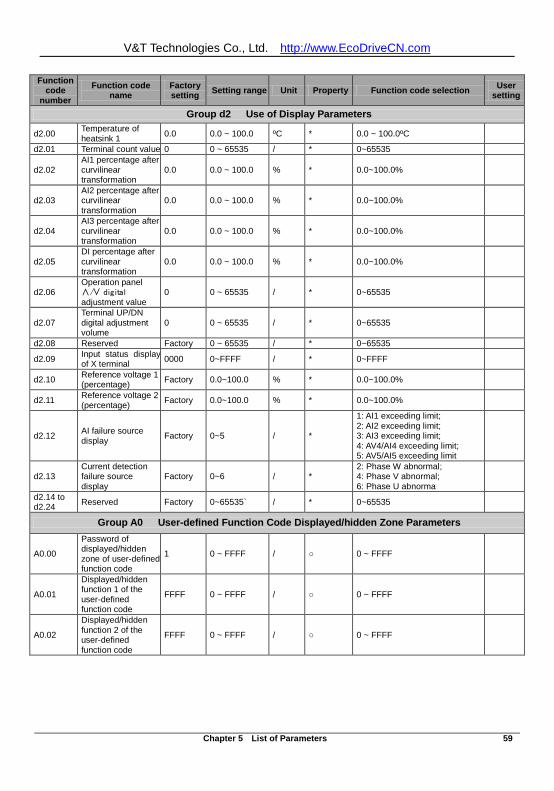
V&T Technologies Co., Ltd. http://www.EcoDriveCN.com
Chapter 5 List of Parameters 59
Function code
number Function code
name Factory setting Setting range Unit Property Function code selection User
setting
Group d2 Use of Display Parameters
d2.00 Temperature of heatsink 1 0.0 0.0 ~ 100.0 ºC * 0.0 ~ 100.0ºC
d2.01 Terminal count value 0 0 ~ 65535 / * 0~65535
d2.02 AI1 percentage after curvilinear transformation
0.0 0.0 ~ 100.0 % * 0.0~100.0%
d2.03 AI2 percentage after curvilinear transformation
0.0 0.0 ~ 100.0 % * 0.0~100.0%
d2.04 AI3 percentage after curvilinear transformation
0.0 0.0 ~ 100.0 % * 0.0~100.0%
d2.05 DI percentage after curvilinear transformation
0.0 0.0 ~ 100.0 % * 0.0~100.0%
d2.06 Operation panel ∧/∨ digital adjustment value
0 0 ~ 65535 / * 0~65535
d2.07 Terminal UP/DN digital adjustment volume
0 0 ~ 65535 / * 0~65535
d2.08 Reserved Factory 0 ~ 65535 / * 0~65535
d2.09 Input status display of X terminal 0000 0~FFFF / * 0~FFFF
d2.10 Reference voltage 1 (percentage) Factory 0.0~100.0 % * 0.0~100.0%
d2.11 Reference voltage 2 (percentage) Factory 0.0~100.0 % * 0.0~100.0%
d2.12 AI failure source display Factory 0~5 / *
1: AI1 exceeding limit; 2: AI2 exceeding limit; 3: AI3 exceeding limit; 4: AV4/AI4 exceeding limit; 5: AV5/AI5 exceeding limit
d2.13 Current detection failure source display
Factory 0~6 / * 2: Phase W abnormal; 4: Phase V abnormal; 6: Phase U abnorma
d2.14 to d2.24 Reserved Factory 0~65535` / * 0~65535
Group A0 User-defined Function Code Displayed/hidden Zone Parameters
A0.00
Password of displayed/hidden zone of user-defined function code
1 0 ~ FFFF / 0 ~ FFFF
A0.01
Displayed/hidden function 1 of the user-defined function code
FFFF 0 ~ FFFF / 0 ~ FFFF
A0.02
Displayed/hidden function 2 of the user-defined function code
FFFF 0 ~ FFFF / 0 ~ FFFF
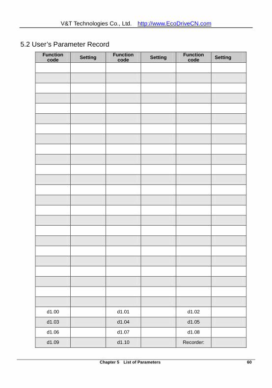
V&T Technologies Co., Ltd. http://www.EcoDriveCN.com
Chapter 5 List of Parameters 60
5.2 User’s Parameter Record
Function code Setting Function
code Setting Function code Setting
d1.00 d1.01 d1.02
d1.03 d1.04 d1.05
d1.06 d1.07 d1.08
d1.09 d1.10 Recorder:
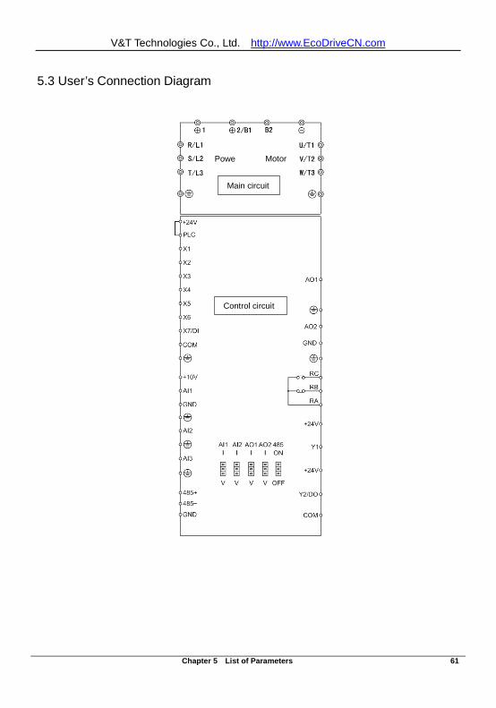
V&T Technologies Co., Ltd. http://www.EcoDriveCN.com
Chapter 5 List of Parameters 61
5.3 User’s Connection Diagram
Control circuit
Powe
Motor
Main circuit
Control circuit
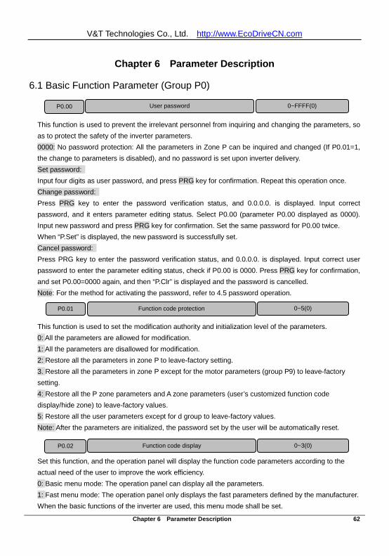
V&T Technologies Co., Ltd. http://www.EcoDriveCN.com
Chapter 6 Parameter Description 62
Chapter 6 Parameter Description
6.1 Basic Function Parameter (Group P0)
This function is used to prevent the irrelevant personnel from inquiring and changing the parameters, so as to protect the safety of the inverter parameters. 0000: No password protection: All the parameters in Zone P can be inquired and changed (If P0.01=1, the change to parameters is disabled), and no password is set upon inverter delivery. Set password: Input four digits as user password, and press PRG key for confirmation. Repeat this operation once. Change password: Press PRG key to enter the password verification status, and 0.0.0.0. is displayed. Input correct password, and it enters parameter editing status. Select P0.00 (parameter P0.00 displayed as 0000). Input new password and press PRG key for confirmation. Set the same password for P0.00 twice. When “P.Set” is displayed, the new password is successfully set. Cancel password: Press PRG key to enter the password verification status, and 0.0.0.0. is displayed. Input correct user password to enter the parameter editing status, check if P0.00 is 0000. Press PRG key for confirmation, and set P0.00=0000 again, and then “P.Clr” is displayed and the password is cancelled. Note: For the method for activating the password, refer to 4.5 password operation.
This function is used to set the modification authority and initialization level of the parameters. 0: All the parameters are allowed for modification. 1: All the parameters are disallowed for modification. 2: Restore all the parameters in zone P to leave-factory setting. 3. Restore all the parameters in zone P except for the motor parameters (group P9) to leave-factory setting. 4: Restore all the P zone parameters and A zone parameters (user’s customized function code display/hide zone) to leave-factory values. 5: Restore all the user parameters except for d group to leave-factory values. Note: After the parameters are initialized, the password set by the user will be automatically reset. Set this function, and the operation panel will display the function code parameters according to the actual need of the user to improve the work efficiency. 0: Basic menu mode: The operation panel can display all the parameters. 1: Fast menu mode: The operation panel only displays the fast parameters defined by the manufacturer. When the basic functions of the inverter are used, this menu mode shall be set.
P0.00 User password 0~FFFF(0)
P0.01 Function code protection 0~5(0)
P0.02 Function code display 0~3(0)
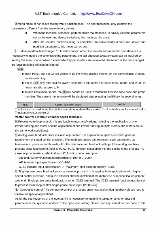
V&T Technologies Co., Ltd. http://www.EcoDriveCN.com
Chapter 6 Parameter Description 63
2: Menu mode of non-leave-factory value function code: The operation panel only displays the parameters different from the leave-factory values.
When the technical personnel perform onsite maintenance, to quickly view the parameters set by the user and detect the failure, this mode can be used.
After the inverter commissioning is completed, to conveniently record and inquire the modified parameters, this mode can be set.
3: Menu mode of last changed 10 function codes: When the inverter has abnormal operation or it is necessary to inquire the commissioning parameters, the last changed 10 parameters can be inquired by setting this menu mode. When the leave-factory parameters are recovered, the record of the last changed 10 function codes will also be cleared.
Note: Both P0.00 and P0.02 are visible in all the menu display modes for the convenience of menu
mode switching. Press ESC key and hold for over 5 seconds, it will restore to basic menu mode, and P0.02 is
automatically restored to 0. In non-basic menu mode, the >> key cannot be used to switch the function zone code and group
number. The current menu mode will be displayed after pressing the >> key for several times.
This function is used to set the control operation mode of the inverter. 0 ~ 3 indicates vector control 1, 4 ~ 7 indicates vector control 2. Vector control 1 without encoder speed feedback: 0: Process open loop control: It is applicable to most applications, including the application of one inverter driving one motor and the application of one inverter driving multiple motors (the motors are in the same work conditions). 1: Analog value feedback process close loop control: It is applicable to applications with general requirement of speed control precision. The feedback analog can represent such parameters as temperature, pressure and humidity. For the reference and feedback setting of the analog feedback process close loop control, refer to P1.02~P1.07 function description. For the setting of the process PID close loop parameters, refer to Group P8 function code description.
AI1 and AI2 terminal input specification: 0~10V or 0~20mA. AI3 terminal input specification: -10~10V; X7/DI terminal input specification: 0~ maximum input pulse frequency P5.10.
2: Single-phase pulse feedback process close loop control: It is applicable to applications with higher speed control precision, and pulse encoder shall be installed at the motor end or mechanical equipment axle end. Single-phase pulse feedback channel: X7/DI terminal: The X7/DI terminal function must be set to process close loop control single-phase pulse input (P5.06=47) . 3:Composite control: The composite control of process open loop and analog feedback closed loop is
suitable for special applications. As for the set frequency of the inverter, if it is necessary to made fine tuning on another physical parameter in the system in addition to the open loop setting, closed loop adjustment can be made to this
P0.03 Control operation mode 0~7(0)
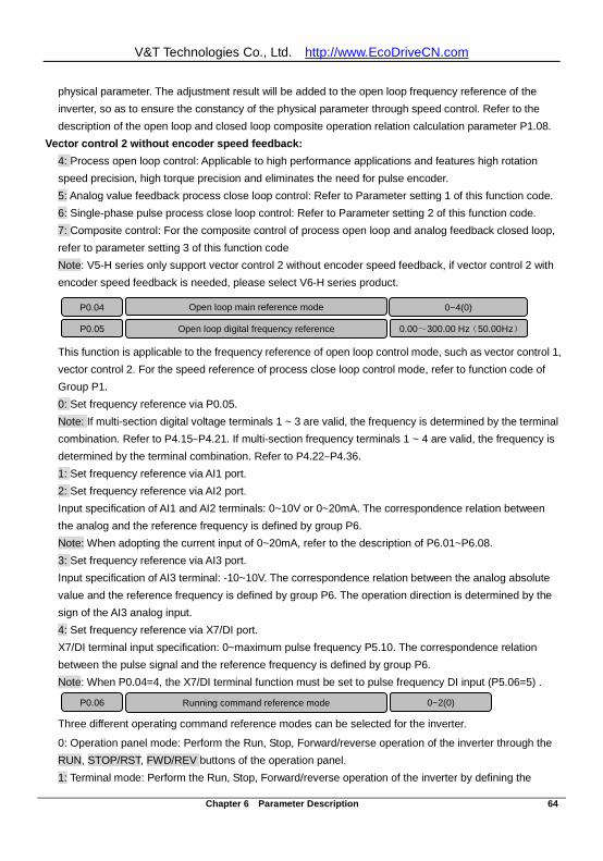
V&T Technologies Co., Ltd. http://www.EcoDriveCN.com
Chapter 6 Parameter Description 64
physical parameter. The adjustment result will be added to the open loop frequency reference of the inverter, so as to ensure the constancy of the physical parameter through speed control. Refer to the description of the open loop and closed loop composite operation relation calculation parameter P1.08.
Vector control 2 without encoder speed feedback: 4: Process open loop control: Applicable to high performance applications and features high rotation speed precision, high torque precision and eliminates the need for pulse encoder. 5: Analog value feedback process close loop control: Refer to Parameter setting 1 of this function code. 6: Single-phase pulse process close loop control: Refer to Parameter setting 2 of this function code. 7: Composite control: For the composite control of process open loop and analog feedback closed loop, refer to parameter setting 3 of this function code Note: V5-H series only support vector control 2 without encoder speed feedback, if vector control 2 with encoder speed feedback is needed, please select V6-H series product.
This function is applicable to the frequency reference of open loop control mode, such as vector control 1, vector control 2. For the speed reference of process close loop control mode, refer to function code of Group P1. 0: Set frequency reference via P0.05. Note: If multi-section digital voltage terminals 1 ~ 3 are valid, the frequency is determined by the terminal combination. Refer to P4.15~P4.21. If multi-section frequency terminals 1 ~ 4 are valid, the frequency is determined by the terminal combination. Refer to P4.22~P4.36. 1: Set frequency reference via AI1 port. 2: Set frequency reference via AI2 port. Input specification of AI1 and AI2 terminals: 0~10V or 0~20mA. The correspondence relation between the analog and the reference frequency is defined by group P6. Note: When adopting the current input of 0~20mA, refer to the description of P6.01~P6.08. 3: Set frequency reference via AI3 port. Input specification of AI3 terminal: -10~10V. The correspondence relation between the analog absolute value and the reference frequency is defined by group P6. The operation direction is determined by the sign of the AI3 analog input. 4: Set frequency reference via X7/DI port. X7/DI terminal input specification: 0~maximum pulse frequency P5.10. The correspondence relation between the pulse signal and the reference frequency is defined by group P6. Note: When P0.04=4, the X7/DI terminal function must be set to pulse frequency DI input (P5.06=5) .
Three different operating command reference modes can be selected for the inverter.
0: Operation panel mode: Perform the Run, Stop, Forward/reverse operation of the inverter through the RUN, STOP/RST, FWD/REV buttons of the operation panel. 1: Terminal mode: Perform the Run, Stop, Forward/reverse operation of the inverter by defining the
P0.04 Open loop main reference mode 0~4(0)
P0.05 Open loop digital frequency reference 0.00~300.00 Hz(50.00Hz)
P0.06 Running command reference mode 0~2(0)
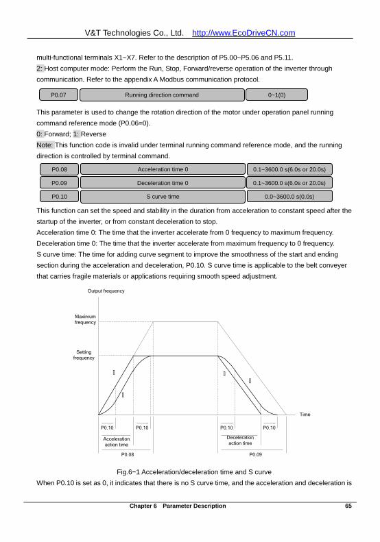
V&T Technologies Co., Ltd. http://www.EcoDriveCN.com
Chapter 6 Parameter Description 65
multi-functional terminals X1~X7. Refer to the description of P5.00~P5.06 and P5.11. 2: Host computer mode: Perform the Run, Stop, Forward/reverse operation of the inverter through communication. Refer to the appendix A Modbus communication protocol.
This parameter is used to change the rotation direction of the motor under operation panel running command reference mode (P0.06=0). 0: Forward; 1: Reverse Note: This function code is invalid under terminal running command reference mode, and the running direction is controlled by terminal command.
This function can set the speed and stability in the duration from acceleration to constant speed after the startup of the inverter, or from constant deceleration to stop. Acceleration time 0: The time that the inverter accelerate from 0 frequency to maximum frequency. Deceleration time 0: The time that the inverter accelerate from maximum frequency to 0 frequency. S curve time: The time for adding curve segment to improve the smoothness of the start and ending section during the acceleration and deceleration, P0.10. S curve time is applicable to the belt conveyer that carries fragile materials or applications requiring smooth speed adjustment.
Setting frequency
P0.08
Acceleration action time
P0.10 P0.10
Output frequency
Maximum frequency
P0.09
Deceleration action time
P0.10 P0.10
∧
∧ ∧
∧
Time
Fig.6−1 Acceleration/deceleration time and S curve When P0.10 is set as 0, it indicates that there is no S curve time, and the acceleration and deceleration is
P0.10 S curve time 0.0~3600.0 s(0.0s)
P0.07 Running direction command 0~1(0)
P0.08 Acceleration time 0 0.1~3600.0 s(6.0s or 20.0s)
P0.09 Deceleration time 0 0.1~3600.0 s(6.0s or 20.0s)
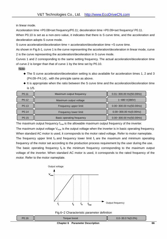
V&T Technologies Co., Ltd. http://www.EcoDriveCN.com
Chapter 6 Parameter Description 66
in linear mode. Acceleration time =P0.08×set frequency/P0.11; deceleration time =P0.09×set frequency/ P0.11. When P0.10 is set as a non-zero value, it indicates that there is S curve time, and the acceleration and deceleration adopts S curve mode. S curve acceleration/deceleration time = acceleration/deceleration time +S curve time. As shown in Fig.6-1, curve 1 is the curve representing the acceleration/deceleration in linear mode, curve 2 is the curve representing the acceleration/deceleration in S curve mode. Curves 1 and 2 corresponding to the same setting frequency. The actual acceleration/deceleration time of curve 2 is longer than that of curve 1 by the time set by P0.10.
Note: The S curve acceleration/deceleration setting is also available for acceleration times 1, 2 and 3
(P4.09~P4.14) , with the principle same as above. It is appropriate when the ratio between the S curve time and the acceleration/deceleration time
is 1/5.
The maximum output frequency fmax is the allowable maximum output frequency of the inverter.
The maximum output voltage Vmax is the output voltage when the inverter is in basic operating frequency. When standard AC motor is used, it corresponds to the motor rated voltage. Refer to motor nameplate. The frequency upper limit fH and frequency lower limit fL are the maximum and minimum operating frequency of the motor set according to the production process requirement by the user during the use. The basic operating frequency fb is the minimum frequency corresponding to the maximum output voltage of the inverter. When standard AC motor is used, it corresponds to the rated frequency of the motor. Refer to the motor nameplate.
Fig.6−2 Characteristic parameter definition
P0.13 Frequency upper limit 0.00~300.00 Hz(50.00Hz)
P0.11 Maximum output frequency 0.01~300.00 Hz(50.00Hz)
P0.12 Maximum output voltage 1~480 V(380V)
P0.14 Frequency lower limit 0.00~300.00 Hz(0.00Hz)
P0.15 Basic operating frequency 0.00~300.00 Hz(50.00Hz)
P0.16 Torque boost 0.0~30.0 %(0.0%)
fL fH输出频率
fb fmax
输出电压
Vmax
Output voltage
Output frequency fL fH输出频率
fb fmax
输出电压
Vmax
Output voltage
Output frequency
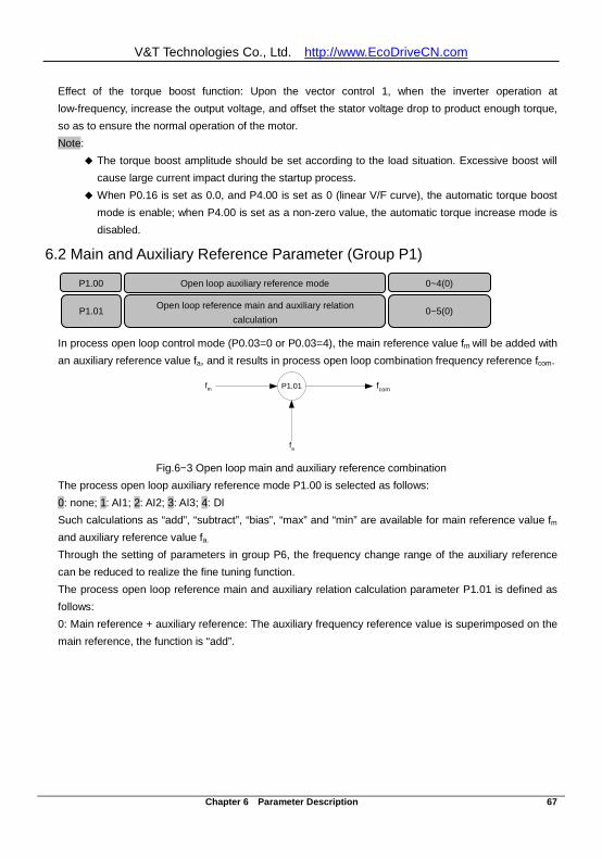
V&T Technologies Co., Ltd. http://www.EcoDriveCN.com
Chapter 6 Parameter Description 67
Effect of the torque boost function: Upon the vector control 1, when the inverter operation at low-frequency, increase the output voltage, and offset the stator voltage drop to product enough torque, so as to ensure the normal operation of the motor. Note:
The torque boost amplitude should be set according to the load situation. Excessive boost will cause large current impact during the startup process.
When P0.16 is set as 0.0, and P4.00 is set as 0 (linear V/F curve), the automatic torque boost mode is enable; when P4.00 is set as a non-zero value, the automatic torque increase mode is disabled.
6.2 Main and Auxiliary Reference Parameter (Group P1)
In process open loop control mode (P0.03=0 or P0.03=4), the main reference value fm will be added with an auxiliary reference value fa, and it results in process open loop combination frequency reference fcom.
P1.01fm
fa
fcom
Fig.6−3 Open loop main and auxiliary reference combination
The process open loop auxiliary reference mode P1.00 is selected as follows: 0: none; 1: AI1; 2: AI2; 3: AI3; 4: DI Such calculations as “add”, “subtract”, “bias”, “max” and “min” are available for main reference value fm and auxiliary reference value fa. Through the setting of parameters in group P6, the frequency change range of the auxiliary reference can be reduced to realize the fine tuning function. The process open loop reference main and auxiliary relation calculation parameter P1.01 is defined as follows: 0: Main reference + auxiliary reference: The auxiliary frequency reference value is superimposed on the main reference, the function is “add”.
P1.00 0~4(0)
P1.01 Open loop reference main and auxiliary relation calculation
0~5(0)
Open loop auxiliary reference mode
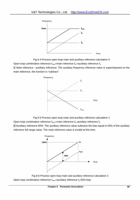
V&T Technologies Co., Ltd. http://www.EcoDriveCN.com
Chapter 6 Parameter Description 68
Fig.6-4 Process open loop main and auxiliary reference calculation 0 Open loop combination reference fcom=main reference fm+auxiliary reference fa 1: Main reference - auxiliary reference: The auxiliary frequency reference value is superimposed on the main reference, the function is “subtract”.
Fig.6-5 Process open loop main and auxiliary reference calculation 1 Open loop combination reference fcom=main reference fm-auxiliary reference fa 2: Auxiliary reference-50%: The auxiliary reference value subtracts the bias equal to 50% of the auxiliary reference full range value. The main reference value is invalid at this time.
Fig.6-6 Process open loop main and auxiliary reference calculation 2 Open loop combination reference fcom=auxiliary reference fa-50% bias
时间
频率
fm
fa
fcomfmax
Frequency
Time 时间
频率
fm
fa
fcomfmax
Frequency
Time
fm
fa
fcom
时间
频率Frequency
Time
fm
fa
fcom
时间
频率Frequency
Time
50%
频率
时间
100% fa
fcom
Frequency
Time
50%
频率
时间
100% fa
fcom
Frequency
Time
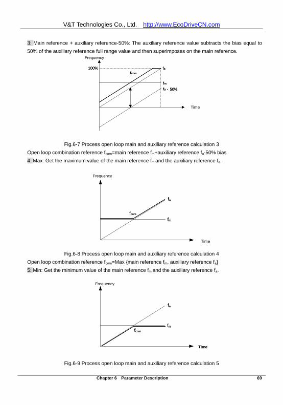
V&T Technologies Co., Ltd. http://www.EcoDriveCN.com
Chapter 6 Parameter Description 69
3: Main reference + auxiliary reference-50%: The auxiliary reference value subtracts the bias equal to 50% of the auxiliary reference full range value and then superimposes on the main reference.
Fig.6-7 Process open loop main and auxiliary reference calculation 3 Open loop combination reference fcom=main reference fm+auxiliary reference fa-50% bias 4: Max: Get the maximum value of the main reference fm and the auxiliary reference fa.
Fig.6-8 Process open loop main and auxiliary reference calculation 4 Open loop combination reference fcom=Max main reference fm, auxiliary reference fa 5: Min: Get the minimum value of the main reference fm and the auxiliary reference fa.
Fig.6-9 Process open loop main and auxiliary reference calculation 5
频率
时间
100%
- 50%fm
fafcom
fa
Frequency
Time
频率
时间
100%
- 50%fm
fafcom
fa
Frequency
Time
fm
fa
fcom
时间
频率Frequency
Time
fm
fa
fcom
时间
频率Frequency
Time
fm
fa
fcom
频率
时间
Frequency
Time
fm
fa
fcom
频率
时间
Frequency
Time
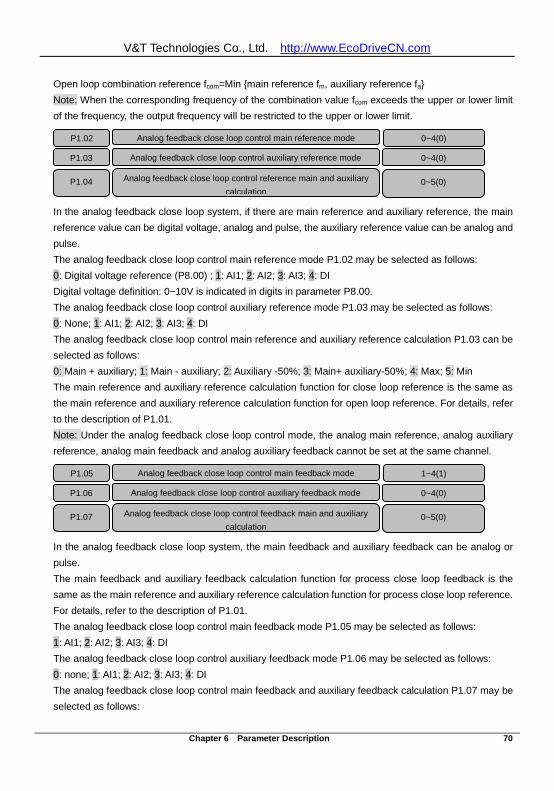
V&T Technologies Co., Ltd. http://www.EcoDriveCN.com
Chapter 6 Parameter Description 70
Open loop combination reference fcom=Min main reference fm, auxiliary reference fa Note: When the corresponding frequency of the combination value fcom exceeds the upper or lower limit of the frequency, the output frequency will be restricted to the upper or lower limit.
In the analog feedback close loop system, if there are main reference and auxiliary reference, the main reference value can be digital voltage, analog and pulse, the auxiliary reference value can be analog and pulse. The analog feedback close loop control main reference mode P1.02 may be selected as follows: 0: Digital voltage reference (P8.00) ; 1: AI1; 2: AI2; 3: AI3; 4: DI Digital voltage definition: 0~10V is indicated in digits in parameter P8.00. The analog feedback close loop control auxiliary reference mode P1.03 may be selected as follows: 0: None; 1: AI1; 2: AI2; 3: AI3; 4: DI The analog feedback close loop control main reference and auxiliary reference calculation P1.03 can be selected as follows: 0: Main + auxiliary; 1: Main - auxiliary; 2: Auxiliary -50%; 3: Main+ auxiliary-50%; 4: Max; 5: Min The main reference and auxiliary reference calculation function for close loop reference is the same as the main reference and auxiliary reference calculation function for open loop reference. For details, refer to the description of P1.01. Note: Under the analog feedback close loop control mode, the analog main reference, analog auxiliary reference, analog main feedback and analog auxiliary feedback cannot be set at the same channel.
In the analog feedback close loop system, the main feedback and auxiliary feedback can be analog or pulse. The main feedback and auxiliary feedback calculation function for process close loop feedback is the same as the main reference and auxiliary reference calculation function for process close loop reference. For details, refer to the description of P1.01. The analog feedback close loop control main feedback mode P1.05 may be selected as follows: 1: AI1; 2: AI2; 3: AI3; 4: DI The analog feedback close loop control auxiliary feedback mode P1.06 may be selected as follows: 0: none; 1: AI1; 2: AI2; 3: AI3; 4: DI The analog feedback close loop control main feedback and auxiliary feedback calculation P1.07 may be selected as follows:
Analog feedback close loop control feedback main and auxiliary calculation
0~5(0)
P1.05 Analog feedback close loop control main feedback mode 1~4(1)
P1.06 Analog feedback close loop control auxiliary feedback mode 0~4(0)
P1.07
Analog feedback close loop control reference main and auxiliary calculation
0~5(0)
P1.02 Analog feedback close loop control main reference mode 0~4(0)
P1.03 Analog feedback close loop control auxiliary reference mode 0~4(0)
P1.04
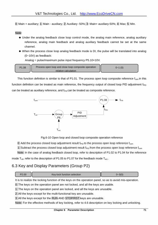
V&T Technologies Co., Ltd. http://www.EcoDriveCN.com
Chapter 6 Parameter Description 71
0: Main + auxiliary; 1: Main - auxiliary; 2: Auxiliary -50%; 3: Main+ auxiliary-50%; 4: Max; 5: Min. Note: Under the analog feedback close loop control mode, the analog main reference, analog auxiliary
reference, analog main feedback and analog auxiliary feedback cannot be set at the same channel.
When the process close loop analog feedback mode is DI, the pulse will be translated into analog (0~10V) as feedback: Analog = pulse/maximum pulse input frequency P5.10×10V.
This function definition is similar to that of P1.01. The process open loop composite reference fcom in this
function definition can be treated as main reference, the frequency output of closed loop PID adjustment fPID
can be treated as auxiliary reference, and fFIN can be treated as composite reference.
fPID
fFINP1.08
Group
P8
PID Adjustment
fcom
Tref
Tact Fig.6-10 Open loop and closed loop composite operation reference
0: Add the process closed loop adjustment result fPID to the process open loop reference fcom 1: Subtract the process closed loop adjustment result fPID from the process open loop reference fcom
Note: In the case of analog feedback closed loop, refer to description of P1.02 to P1.04 for the reference
mode Tref, refer to the description of P1.05 to P1.07 for the feedback mode Tact..
6.3 Key and Display Parameters (Group P2)
It is to realize the locking function of the keys on the operation panel, so as to avoid mis-operation. 0: The keys on the operation panel are not locked, and all the keys are usable. 1: The keys on the operation panel are locked, and all the keys are unusable. 2: All the keys except for the multi-functional key are unusable. 3: All the keys except for the RUN AND STOP/RST keys are unusable. Note: For the effective methods of key locking, refer to 4.6 description on key locking and unlocking.
P1.08 Process open loop and close loop composite operation relation calculation
0~1 (0)
P2.00 Key-lock function selection 0~3(0)
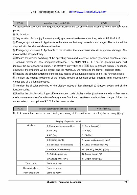
V&T Technologies Co., Ltd. http://www.EcoDriveCN.com
Chapter 6 Parameter Description 72
To facilitate the operation, the frequent operation can be set on the multi-functional key of the operation panel. 0: No function. 1: Jog function: For the jog frequency and jog acceleration/deceleration time, refer to P3.11~P3.13. 2: Emergency shutdown 1: Applicable to the situation that may cause human danger. The motor will be stopped with the shortest deceleration time. 3: Emergency shutdown 2: Applicable to the situation that may cause electric equipment damage. The motor will be stopped freely. 4: Realize the circular switching of the operating command reference modes (operation panel reference →terminal reference→host computer reference). The MON status LED on the operation panel will indicate the corresponding status. It is effective only when the PRG key is pressed within 5 seconds, otherwise, the switching will be invalid, and the MON LED will restore to the former indication state. 5: Realize the circular switching of the display modes of fast function codes and all the function codes. 6: Realize the circular switching of the display modes of function codes different from leave-factory values and all the function codes. 7: Realize the circular switching of the display modes of last changed 10 function codes and all the function codes. 8: Realize the circular switching of different function code display modes (basic menu mode → fast menu mode → menu mode of non-leave-factory value function code→Menu mode of last changed 0 function codes, refer to description of P0.02 for the menu modes.
Up to 4 parameters can be set and display at running status, and viewed circularly by pressing >>key.
Display of operation panel Unit place:
0: Reference frequency (Hz) ; 1: Bus voltage (V) ;
2: AI1 (V) ; 3: AI2 (V) ;
4: AI3 (V) ; 5: DI (%) ;
6: External counts 7: Motor rotation speed (rpm);
8: Close loop reference (%); 9: Close loop feedback (%);
A: Reference torque (%); B: Operating frequency (Hz);
C: Output current (A); D: Output torque (%);
E: Output power (kW); F: Output voltage (V)
Tens place Same as above
Hundreds place Same as above
Thousands place Same as above
P2.01 Multi-functional key definition 0~8(1)
Display parameter selection at running P2.02 0~FFFF(1CB0)
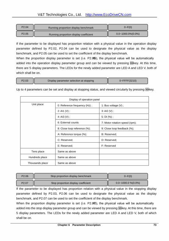
V&T Technologies Co., Ltd. http://www.EcoDriveCN.com
Chapter 6 Parameter Description 73
If the parameter to be displayed has proportion relation with a physical value in the operation display parameter defined by P2.02, P2.04 can be used to designate the physical value as the display benchmark, and P2.05 can be used to set the coefficient of the display benchmark. When the proportion display parameter is set (i.e. P2.05≠0), the physical value will be automatically added into the operation display parameter group and can be viewed by pressing >>key. At this time, there are 5 display parameters. The LEDs for the newly added parameter are LED A and LED V, both of which shall be on.
Up to 4 parameters can be set and display at stopping status, and viewed circularly by pressing >>key.
Display of operation panel Unit place:
0: Reference frequency (Hz) ; 1: Bus voltage (V) ;
2: AI1 (V) ; 3: AI2 (V) ;
4: AI3 (V) ; 5: DI (%) ;
6: External counts 7: Motor rotation speed (rpm);
8: Close loop reference (%); 9: Close loop feedback (%);
A: Reference torque (%); B: Reserved;
C: Reserved; D: Reserved;
E: Reserved; F: Reserved
Tens place Same as above
Hundreds place Same as above
Thousands place Same as above
If the parameter to be displayed has proportion relation with a physical value in the stopping display parameter defined by P2.03, P2.06 can be used to designate the physical value as the display benchmark, and P2.07 can be used to set the coefficient of the display benchmark. When the proportion display parameter is set (i.e. P2.07≠0), the physical value will be automatically added into the stop display parameter group and can be viewed by pressing >>key. At this time, there are 5 display parameters. The LEDs for the newly added parameter are LED A and LED V, both of which shall be on.
P2.03 Display parameter selection at stopping 0~FFFF(3210)
P2.06 Stop proportion display benchmark 0~F(0)
P2.07 Stop proportion display coefficient 0.0~1000.0 %(0.0%)
P2.04 Running proportion display benchmark 0~F(0)
P2.05 Running proportion display coefficient 0.0~1000.0%(0.0%)
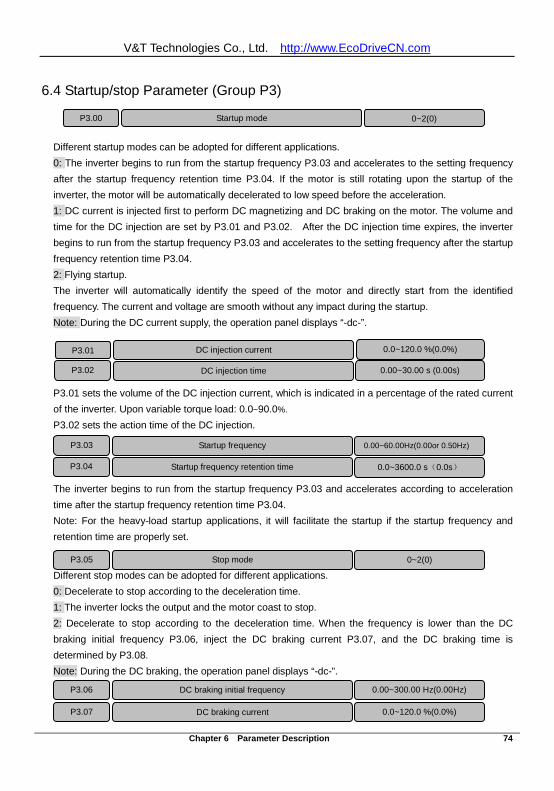
V&T Technologies Co., Ltd. http://www.EcoDriveCN.com
Chapter 6 Parameter Description 74
6.4 Startup/stop Parameter (Group P3)
Different startup modes can be adopted for different applications. 0: The inverter begins to run from the startup frequency P3.03 and accelerates to the setting frequency after the startup frequency retention time P3.04. If the motor is still rotating upon the startup of the inverter, the motor will be automatically decelerated to low speed before the acceleration. 1: DC current is injected first to perform DC magnetizing and DC braking on the motor. The volume and time for the DC injection are set by P3.01 and P3.02. After the DC injection time expires, the inverter begins to run from the startup frequency P3.03 and accelerates to the setting frequency after the startup frequency retention time P3.04. 2: Flying startup. The inverter will automatically identify the speed of the motor and directly start from the identified frequency. The current and voltage are smooth without any impact during the startup. Note: During the DC current supply, the operation panel displays “-dc-”.
P3.01 sets the volume of the DC injection current, which is indicated in a percentage of the rated current of the inverter. Upon variable torque load: 0.0~90.0%. P3.02 sets the action time of the DC injection.
The inverter begins to run from the startup frequency P3.03 and accelerates according to acceleration time after the startup frequency retention time P3.04. Note: For the heavy-load startup applications, it will facilitate the startup if the startup frequency and retention time are properly set.
Different stop modes can be adopted for different applications. 0: Decelerate to stop according to the deceleration time. 1: The inverter locks the output and the motor coast to stop. 2: Decelerate to stop according to the deceleration time. When the frequency is lower than the DC braking initial frequency P3.06, inject the DC braking current P3.07, and the DC braking time is determined by P3.08. Note: During the DC braking, the operation panel displays “-dc-”.
P3.00 Startup mode 0~2(0)
P3.01 DC injection current
0.0~120.0 %(0.0%)
P3.02 DC injection time
0.00~30.00 s (0.00s)
P3.03 Startup frequency 0.00~60.00Hz(0.00or 0.50Hz)
P3.04 Startup frequency retention time 0.0~3600.0 s(0.0s)
P3.05 Stop mode 0~2(0)
P3.06 DC braking initial frequency
0.00~300.00 Hz(0.00Hz)
P3.07 DC braking current
0.0~120.0 %(0.0%)
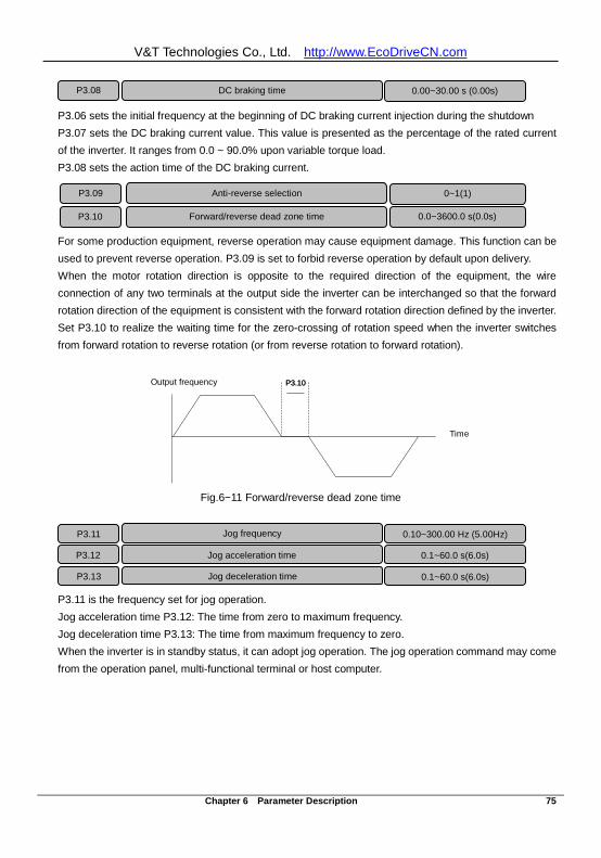
V&T Technologies Co., Ltd. http://www.EcoDriveCN.com
Chapter 6 Parameter Description 75
P3.06 sets the initial frequency at the beginning of DC braking current injection during the shutdown P3.07 sets the DC braking current value. This value is presented as the percentage of the rated current of the inverter. It ranges from 0.0 ~ 90.0% upon variable torque load. P3.08 sets the action time of the DC braking current.
For some production equipment, reverse operation may cause equipment damage. This function can be used to prevent reverse operation. P3.09 is set to forbid reverse operation by default upon delivery. When the motor rotation direction is opposite to the required direction of the equipment, the wire connection of any two terminals at the output side the inverter can be interchanged so that the forward rotation direction of the equipment is consistent with the forward rotation direction defined by the inverter. Set P3.10 to realize the waiting time for the zero-crossing of rotation speed when the inverter switches from forward rotation to reverse rotation (or from reverse rotation to forward rotation).
Fig.6−11 Forward/reverse dead zone time
P3.11 is the frequency set for jog operation. Jog acceleration time P3.12: The time from zero to maximum frequency. Jog deceleration time P3.13: The time from maximum frequency to zero. When the inverter is in standby status, it can adopt jog operation. The jog operation command may come from the operation panel, multi-functional terminal or host computer.
P3.08 DC braking time
0.00~30.00 s (0.00s)
P3.09 Anti-reverse selection 0~1(1)
P3.10 Forward/reverse dead zone time 0.0~3600.0 s(0.0s)
P3.11 Jog frequency 0.10~300.00 Hz (5.00Hz)
P3.12 Jog acceleration time 0.1~60.0 s(6.0s)
P3.13 Jog deceleration time 0.1~60.0 s(6.0s)
输出频率
时间
P3.10Output frequency
Time
输出频率
时间
P3.10Output frequency
Time
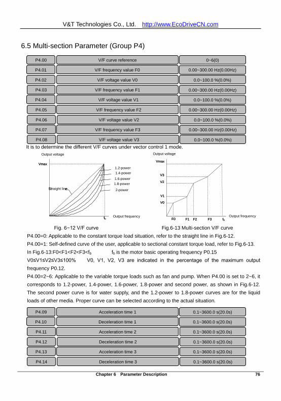
V&T Technologies Co., Ltd. http://www.EcoDriveCN.com
Chapter 6 Parameter Description 76
6.5 Multi-section Parameter (Group P4)
It is to determine the different V/F curves under vector control 1 mode.
Fig. 6−12 V/F curve Fig.6-13 Multi-section V/F curve P4.00=0: Applicable to the constant torque load situation, refer to the straight line in Fig.6-12. P4.00=1: Self-defined curve of the user, applicable to sectional constant torque load, refer to Fig.6-13. In Fig.6-13:F0<F1<F2<F3<fb fb is the motor basic operating frequency P0.15 V0≤V1≤V2≤V3≤100% V0, V1, V2, V3 are indicated in the percentage of the maximum output frequency P0.12. P4.00=2~6: Applicable to the variable torque loads such as fan and pump. When P4.00 is set to 2~6, it corresponds to 1.2-power, 1.4-power, 1.6-power, 1.8-power and second power, as shown in Fig.6-12. The second power curve is for water supply, and the 1.2-power to 1.8-power curves are for the liquid loads of other media. Proper curve can be selected according to the actual situation.
P4.00 V/F curve reference 0~6(0)
P4.01 V/F frequency value F0 0.00~300.00 Hz(0.00Hz)
P4.02 V/F voltage value V0 0.0~100.0 %(0.0%)
P4.03 V/F frequency value F1 0.00~300.00 Hz(0.00Hz)
P4.04 V/F voltage value V1 0.0~100.0 %(0.0%)
P4.05 V/F frequency value F2 0.00~300.00 Hz(0.00Hz)
P4.06 V/F voltage value V2 0.0~100.0 %(0.0%)
P4.07 V/F frequency value F3 0.00~300.00 Hz(0.00Hz)
P4.08 V/F voltage value V3 0.0~100.0 %(0.0%)
P4.09 Acceleration time 1 0.1~3600.0 s(20.0s)
P4.10 Deceleration time 1 0.1~3600.0 s(20.0s)
P4.11 Acceleration time 2 0.1~3600.0 s(20.0s)
P4.12 Deceleration time 2 0.1~3600.0 s(20.0s)
P4.13 Acceleration time 3 0.1~3600.0 s(20.0s)
P4.14 Deceleration time 3 0.1~3600.0 s(20.0s)
Vmax
fbF0 F1 F2 F3
V0
V1
V2
V3
输出电压
输出频率输出频率
输出电压
Vmax
2次幂
1.8次幂
1.6次幂
1.4次幂
1.2次幂
直线
fb
Output voltage Output voltage
1.2-power 1.4-power 1.6-power 1.8-power
2-power
Output frequency Output frequency
Straight line
Vmax
fbF0 F1 F2 F3
V0
V1
V2
V3
输出电压
输出频率输出频率
输出电压
Vmax
2次幂
1.8次幂
1.6次幂
1.4次幂
1.2次幂
直线
fb
Output voltage Output voltage
1.2-power 1.4-power 1.6-power 1.8-power
2-power
Output frequency Output frequency
Straight line
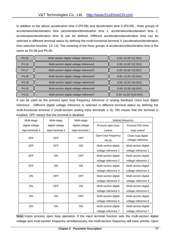
V&T Technologies Co., Ltd. http://www.EcoDriveCN.com
Chapter 6 Parameter Description 77
In addition to the above acceleration time 0 (P0.08) and deceleration time 0 (P0.09) , three groups of acceleration/deceleration time (acceleration/deceleration time 1, acceleration/deceleration time 2, acceleration/deceleration time 3) can be defined. Different acceleration/deceleration time can be selected in different terminal status by defining the multi-functional terminal X (acceleration/deceleration time selection function: 13~14). The meaning of the three groups of acceleration/deceleration time is the same as P0.08 and P0.09.
It can be used as the process open loop frequency reference or analog feedback close loop digital reference. Different digital voltage reference is selected in different terminal status by defining the multi-functional terminal X (multi-section analog input terminals 1~3). ON means that the terminal is enabled, OFF means that the terminal is disabled.
Multi-stage
digital voltage
input terminal 3
Multi-stage
digital voltage
input terminal 2
Multi-stage
digital voltage
input terminal 1
Setting frequency Process open loop
control
Process PID close
loop control
OFF OFF OFF Open loop frequency
P0.05
Close loop digital voltage reference
OFF OFF ON Multi-section digital
voltage reference 1
Multi-section digital
voltage reference 1
OFF ON OFF Multi-section digital
voltage reference 2
Multi-section digital
voltage reference 2
OFF ON ON Multi-section digital
voltage reference 3
Multi-section digital
voltage reference 3
ON OFF OFF Multi-section digital
voltage reference 4
Multi-section digital
voltage reference 4
ON OFF ON Multi-section digital
voltage reference 5
Multi-section digital
voltage reference 5
ON ON OFF Multi-section digital
voltage reference 6
Multi-section digital
voltage reference 6
ON ON ON Multi-section digital
voltage reference 7
Multi-section digital
voltage reference 7
Note: Upon process open loop operation, if the input terminal function sets the multi-section digital voltage and multi-section frequency simultaneously, the multi-section frequency will have priority. Upon
P4.15 Multi-section digital voltage reference 1 0.00~10.00 V(1.00V)
P4.16 Multi-section digital voltage reference2 0.00~10.00 V(2.00V)
P4.17 Multi-section digital voltage reference3 0.00~10.00 V(3.00V)
P4.18 Multi-section digital voltage reference4 0.00~10.00 V(5.00V)
P4.19 Multi-section digital voltage reference5 0.00~10.00 V(6.00V)
P4.20 Multi-section digital voltage reference6 0.00~10.00 V(8.00V)
P4.21 Multi-section digital voltage reference7 0.00~10.00 V(10.00V)
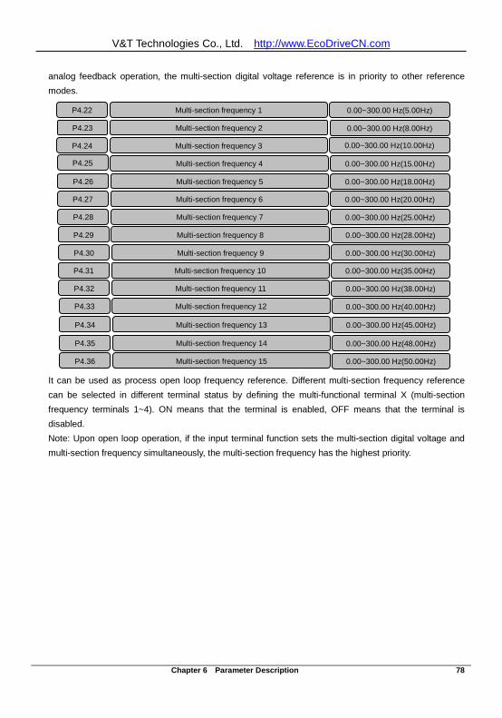
V&T Technologies Co., Ltd. http://www.EcoDriveCN.com
Chapter 6 Parameter Description 78
analog feedback operation, the multi-section digital voltage reference is in priority to other reference modes.
It can be used as process open loop frequency reference. Different multi-section frequency reference can be selected in different terminal status by defining the multi-functional terminal X (multi-section frequency terminals 1~4). ON means that the terminal is enabled, OFF means that the terminal is disabled. Note: Upon open loop operation, if the input terminal function sets the multi-section digital voltage and multi-section frequency simultaneously, the multi-section frequency has the highest priority.
0.00~300.00 Hz(10.00Hz)
P4.25
P4.29 Multi-section frequency 8 0.00~300.00 Hz(28.00Hz)
P4.30 Multi-section frequency 9 0.00~300.00 Hz(30.00Hz)
P4.31 Multi-section frequency 10 0.00~300.00 Hz(35.00Hz)
P4.32 Multi-section frequency 11 0.00~300.00 Hz(38.00Hz)
P4.33 Multi-section frequency 12 0.00~300.00 Hz(40.00Hz)
P4.34 Multi-section frequency 13 0.00~300.00 Hz(45.00Hz)
P4.35 Multi-section frequency 14 0.00~300.00 Hz(48.00Hz)
P4.36 Multi-section frequency 15 0.00~300.00 Hz(50.00Hz)
Multi-section frequency 3 P4.24
0.00~300.00 Hz(8.00Hz)
Multi-section frequency 2 P4.23
0.00~300.00 Hz(5.00Hz) Multi-section frequency 1 P4.22
0.00~300.00 Hz(25.00Hz)
Multi-section frequency 7 P4.28
0.00~300.00 Hz(20.00Hz)
Multi-section frequency 6 P4.27
0.00~300.00 Hz(18.00Hz)
Multi-section frequency 5 P4.26
0.00~300.00 Hz(15.00Hz)
Multi-section frequency 4
P4.36 多段频率 15 0.00~300.00 Hz
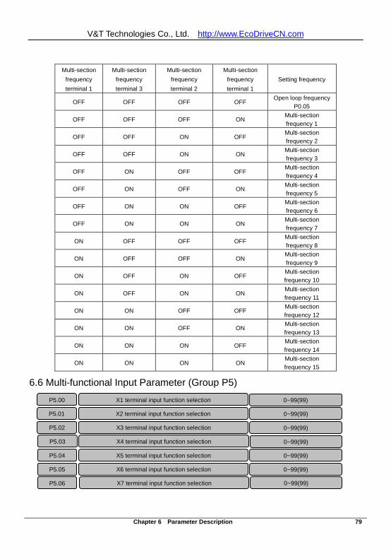
V&T Technologies Co., Ltd. http://www.EcoDriveCN.com
Chapter 6 Parameter Description 79
Multi-section
frequency terminal 1
Multi-section frequency terminal 3
Multi-section frequency terminal 2
Multi-section frequency terminal 1
Setting frequency
OFF OFF OFF OFF Open loop frequency
P0.05
OFF OFF OFF ON Multi-section frequency 1
OFF OFF ON OFF Multi-section frequency 2
OFF OFF ON ON Multi-section frequency 3
OFF ON OFF OFF Multi-section frequency 4
OFF ON OFF ON Multi-section frequency 5
OFF ON ON OFF Multi-section frequency 6
OFF ON ON ON Multi-section frequency 7
ON OFF OFF OFF Multi-section frequency 8
ON OFF OFF ON Multi-section frequency 9
ON OFF ON OFF Multi-section frequency 10
ON OFF ON ON Multi-section frequency 11
ON ON OFF OFF Multi-section frequency 12
ON ON OFF ON Multi-section frequency 13
ON ON ON OFF Multi-section frequency 14
ON ON ON ON Multi-section frequency 15
6.6 Multi-functional Input Parameter (Group P5)
P5.00 X1 terminal input function selection 0~99(99)
P5.01 X2 terminal input function selection 0~99(99) P5.02 X3 terminal input function selection 0~99(99) P5.03 X4 terminal input function selection 0~99(99) P5.04 X5 terminal input function selection 0~99(99) P5.05 X6 terminal input function selection 0~99(99)
0~99(99) X7 terminal input function selection P5.06
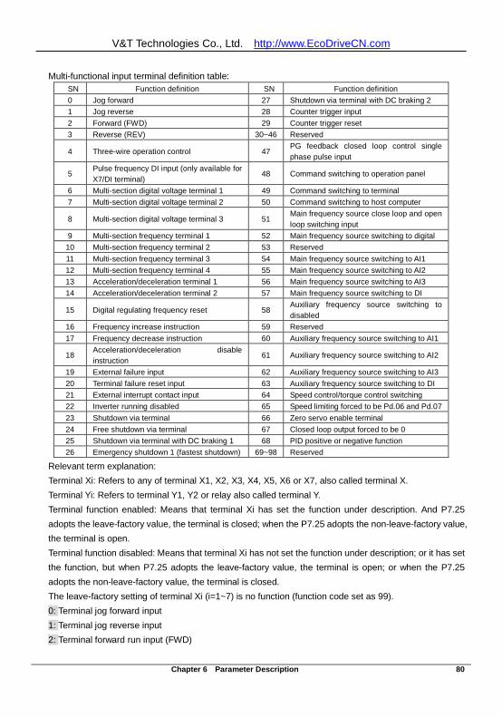
V&T Technologies Co., Ltd. http://www.EcoDriveCN.com
Chapter 6 Parameter Description 80
Multi-functional input terminal definition table: SN Function definition SN Function definition 0 Jog forward 27 Shutdown via terminal with DC braking 2 1 Jog reverse 28 Counter trigger input 2 Forward (FWD) 29 Counter trigger reset 3 Reverse (REV) 30~46 Reserved
4 Three-wire operation control 47 PG feedback closed loop control single phase pulse input
5 Pulse frequency DI input (only available for X7/DI terminal)
48 Command switching to operation panel
6 Multi-section digital voltage terminal 1 49 Command switching to terminal 7 Multi-section digital voltage terminal 2 50 Command switching to host computer
8 Multi-section digital voltage terminal 3 51 Main frequency source close loop and open loop switching input
9 Multi-section frequency terminal 1 52 Main frequency source switching to digital 10 Multi-section frequency terminal 2 53 Reserved 11 Multi-section frequency terminal 3 54 Main frequency source switching to AI1 12 Multi-section frequency terminal 4 55 Main frequency source switching to AI2 13 Acceleration/deceleration terminal 1 56 Main frequency source switching to AI3 14 Acceleration/deceleration terminal 2 57 Main frequency source switching to DI
15 Digital regulating frequency reset 58 Auxiliary frequency source switching to disabled
16 Frequency increase instruction 59 Reserved 17 Frequency decrease instruction 60 Auxiliary frequency source switching to AI1
18 Acceleration/deceleration disable instruction
61 Auxiliary frequency source switching to AI2
19 External failure input 62 Auxiliary frequency source switching to AI3 20 Terminal failure reset input 63 Auxiliary frequency source switching to DI 21 External interrupt contact input 64 Speed control/torque control switching 22 Inverter running disabled 65 Speed limiting forced to be Pd.06 and Pd.07 23 Shutdown via terminal 66 Zero servo enable terminal 24 Free shutdown via terminal 67 Closed loop output forced to be 0 25 Shutdown via terminal with DC braking 1 68 PID positive or negative function 26 Emergency shutdown 1 (fastest shutdown) 69~98 Reserved
Relevant term explanation: Terminal Xi: Refers to any of terminal X1, X2, X3, X4, X5, X6 or X7, also called terminal X. Terminal Yi: Refers to terminal Y1, Y2 or relay also called terminal Y. Terminal function enabled: Means that terminal Xi has set the function under description. And P7.25 adopts the leave-factory value, the terminal is closed; when the P7.25 adopts the non-leave-factory value, the terminal is open. Terminal function disabled: Means that terminal Xi has not set the function under description; or it has set the function, but when P7.25 adopts the leave-factory value, the terminal is open; or when the P7.25 adopts the non-leave-factory value, the terminal is closed. The leave-factory setting of terminal Xi (i=1~7) is no function (function code set as 99). 0: Terminal jog forward input 1: Terminal jog reverse input 2: Terminal forward run input (FWD)
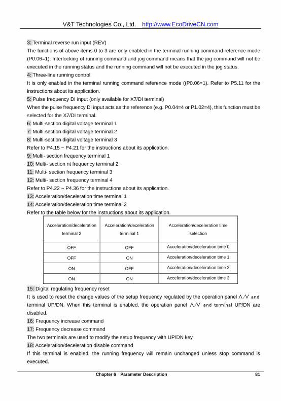
V&T Technologies Co., Ltd. http://www.EcoDriveCN.com
Chapter 6 Parameter Description 81
3: Terminal reverse run input (REV) The functions of above items 0 to 3 are only enabled in the terminal running command reference mode (P0.06=1). Interlocking of running command and jog command means that the jog command will not be executed in the running status and the running command will not be executed in the jog status. 4: Three-line running control It is only enabled in the terminal running command reference mode ((P0.06=1). Refer to P5.11 for the instructions about its application. 5: Pulse frequency DI input (only available for X7/DI terminal) When the pulse frequency DI input acts as the reference (e.g. P0.04=4 or P1.02=4), this function must be selected for the X7/DI terminal. 6: Multi-section digital voltage terminal 1 7: Multi-section digital voltage terminal 2 8: Multi-section digital voltage terminal 3 Refer to P4.15 ~ P4.21 for the instructions about its application. 9: Multi- section frequency terminal 1 10: Multi- section nt frequency terminal 2 11: Multi- section frequency terminal 3 12: Multi- section frequency terminal 4 Refer to P4.22 ~ P4.36 for the instructions about its application. 13: Acceleration/deceleration time terminal 1 14: Acceleration/deceleration time terminal 2 Refer to the table below for the instructions about its application.
Acceleration/deceleration
terminal 2 Acceleration/deceleration
terminal 1 Acceleration/deceleration time
selection
OFF OFF Acceleration/deceleration time 0
OFF ON Acceleration/deceleration time 1
ON OFF Acceleration/deceleration time 2
ON ON Acceleration/deceleration time 3
15: Digital regulating frequency reset It is used to reset the change values of the setup frequency regulated by the operation panel ∧/∨ and
terminal UP/DN. When this terminal is enabled, the operation panel ∧/∨ and terminal UP/DN are disabled. 16: Frequency increase command 17: Frequency decrease command The two terminals are used to modify the setup frequency with UP/DN key. 18: Acceleration/deceleration disable command If this terminal is enabled, the running frequency will remain unchanged unless stop command is executed.
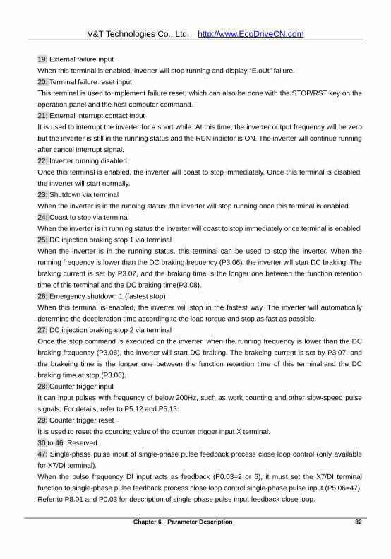
V&T Technologies Co., Ltd. http://www.EcoDriveCN.com
Chapter 6 Parameter Description 82
19: External failure input When this terminal is enabled, inverter will stop running and display “E.oUt” failure. 20: Terminal failure reset input This terminal is used to implement failure reset, which can also be done with the STOP/RST key on the operation panel and the host computer command. 21: External interrupt contact input It is used to interrupt the inverter for a short while. At this time, the inverter output frequency will be zero but the inverter is still in the running status and the RUN indictor is ON. The inverter will continue running after cancel interrupt signal. 22: Inverter running disabled Once this terminal is enabled, the inverter will coast to stop immediately. Once this terminal is disabled, the inverter will start normally. 23: Shutdown via terminal When the inverter is in the running status, the inverter will stop running once this terminal is enabled. 24: Coast to stop via terminal When the inverter is in running status the inverter will coast to stop immediately once terminal is enabled. 25: DC injection braking stop 1 via terminal When the inverter is in the running status, this terminal can be used to stop the inverter. When the running frequency is lower than the DC braking frequency (P3.06), the inverter will start DC braking. The braking current is set by P3.07, and the braking time is the longer one between the function retention time of this terminal and the DC braking time(P3.08). 26: Emergency shutdown 1 (fastest stop) When this terminal is enabled, the inverter will stop in the fastest way. The inverter will automatically determine the deceleration time according to the load torque and stop as fast as possible. 27: DC injection braking stop 2 via terminal Once the stop command is executed on the inverter, when the running frequency is lower than the DC braking frequency (P3.06), the inverter will start DC braking. The brakeing current is set by P3.07, and the brakeing time is the longer one between the function retention time of this terminal.and the DC braking time at stop (P3.08). 28: Counter trigger input It can input pulses with frequency of below 200Hz, such as work counting and other slow-speed pulse signals. For details, refer to P5.12 and P5.13. 29: Counter trigger reset It is used to reset the counting value of the counter trigger input X terminal. 30 to 46: Reserved 47: Single-phase pulse input of single-phase pulse feedback process close loop control (only available for X7/DI terminal). When the pulse frequency DI input acts as feedback (P0.03=2 or 6), it must set the X7/DI terminal function to single-phase pulse feedback process close loop control single-phase pulse input (P5.06=47). Refer to P8.01 and P0.03 for description of single-phase pulse input feedback close loop.
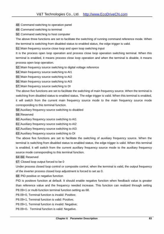
V&T Technologies Co., Ltd. http://www.EcoDriveCN.com
Chapter 6 Parameter Description 83
48: Command switching to operation panel 49: Command switching to terminal 50: Command switching to host computer The above three functions are set to facilitate the switching of running command reference mode. When the terminal is switching from disabled status to enabled status, the edge trigger is valid. 51: Main frequency source close loop and open loop switching input It is the process open loop operation and process close loop operation switching terminal. When this terminal is enabled, it means process close loop operation and when the terminal is disable, it means process open loop operation. 52: Main frequency source switching to digital voltage reference 54: Main frequency source switching to AI1 55: Main frequency source switching to AI2 56: Main frequency source switching to AI3 57: Main frequency source switching to DI The above five functions are set to facilitate the switching of main frequency source. When the terminal is switching from disabled status to enabled status, The edge trigger is valid. When this terminal is enabled, it will switch from the current main frequency source mode to the main frequency source mode corresponding to this terminal function. 58: Auxiliary frequency source switching to disabled 59: Reserved 60: Auxiliary frequency source switching to AI1 61: Auxiliary frequency source switching to AI2 62: Auxiliary frequency source switching to AI3 63: Auxiliary frequency source switching to DI The above five functions are set to facilitate the switching of auxiliary frequency source. When the terminal is switching from disabled status to enabled status, the edge trigger is valid. When this terminal is enabled, it will switch from the current auxiliary frequency source mode to the auxiliary frequency source mode corresponding to this terminal function. 64~66: Reserved 67: Closed loop output forced to be 0 Under process closed loop control or composite control, when the terminal is valid, the output frequency of the inverter process closed loop adjustment is forced to set as 0. 68: PID positive or negative function PID is positeve function at default. It should enable negative function when feedback value is greater than reference value and the frequency needed increase. This function can realized through setting P8.09=1 or multi-function terminal function setting as 68. P8.09=0, Terminal function is invalid: Positive; P8.09=1, Terminal function is valid: Positive; P8.09=1, Terminal function is invalid: Negative; P8.09=0,Terminal function is valid: Negative.
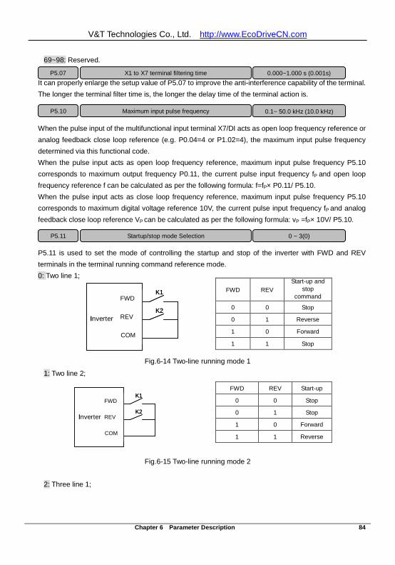
V&T Technologies Co., Ltd. http://www.EcoDriveCN.com
Chapter 6 Parameter Description 84
69~98: Reserved.
It can properly enlarge the setup value of P5.07 to improve the anti-interference capability of the terminal. The longer the terminal filter time is, the longer the delay time of the terminal action is.
When the pulse input of the multifunctional input terminal X7/DI acts as open loop frequency reference or analog feedback close loop reference (e.g. P0.04=4 or P1.02=4), the maximum input pulse frequency determined via this functional code. When the pulse input acts as open loop frequency reference, maximum input pulse frequency P5.10 corresponds to maximum output frequency P0.11, the current pulse input frequency fP and open loop frequency reference f can be calculated as per the following formula: f=fP× P0.11/ P5.10. When the pulse input acts as close loop frequency reference, maximum input pulse frequency P5.10 corresponds to maximum digital voltage reference 10V, the current pulse input frequency fP and analog feedback close loop reference VP can be calculated as per the following formula: vP =fP× 10V/ P5.10.
P5.11 is used to set the mode of controlling the startup and stop of the inverter with FWD and REV terminals in the terminal running command reference mode. 0: Two line 1;
COM
FWD
REV
K1
K2变频器
Inverter
COM
FWD
REV
K1
K2变频器
Inverter
Fig.6-14 Two-line running mode 1
1: Two line 2;
COM
FWD
REV
K1
K2变频器
Inverter
COM
FWD
REV
K1
K2变频器
Inverter
Fig.6-15 Two-line running mode 2 2: Three line 1;
FWD REV Start-up and
stop command
0 0 Stop
0 1 Reverse
1 0 Forward
1 1 Stop
FWD REV Start-up
0 0 Stop
0 1 Stop
1 0 Forward
1 1 Reverse
P5.07
X1 to X7 terminal filtering time 0.000~1.000 s (0.001s)
P5.10 Maximum input pulse frequency 0.1~ 50.0 kHz (10.0 kHz)
P5.11 Startup/stop mode Selection 0 ~ 3(0)
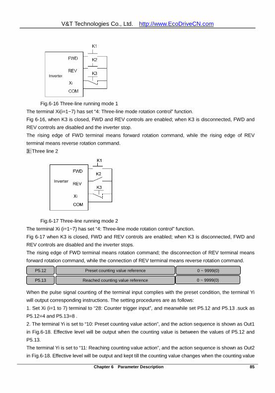
V&T Technologies Co., Ltd. http://www.EcoDriveCN.com
Chapter 6 Parameter Description 85
Fig.6-16 Three-line running mode 1
The terminal Xi(i=1~7) has set “4: Three-line mode rotation control” function. Fig 6-16, when K3 is closed, FWD and REV controls are enabled; when K3 is disconnected, FWD and REV controls are disabled and the inverter stop. The rising edge of FWD terminal means forward rotation command, while the rising edge of REV terminal means reverse rotation command. 3: Three line 2
Inverter Inverter
Fig.6-17 Three-line running mode 2
The terminal Xi (i=1~7) has set “4: Three-line mode rotation control” function. Fig 6-17 when K3 is closed, FWD and REV controls are enabled; when K3 is disconnected, FWD and REV controls are disabled and the inverter stops. The rising edge of FWD terminal means rotation command; the disconnection of REV terminal means forward rotation command, while the connection of REV terminal means reverse rotation command.
When the pulse signal counting of the terminal input complies with the preset condition, the terminal Yi will output corresponding instructions. The setting procedures are as follows: 1. Set Xi (i=1 to 7) terminal to “28: Counter trigger input”, and meanwhile set P5.12 and P5.13 .suck as P5.12=4 and P5.13=8 . 2. The terminal Yi is set to “10: Preset counting value action”, and the action sequence is shown as Out1 in Fig.6-18. Effective level will be output when the counting value is between the values of P5.12 and P5.13. The terminal Yi is set to “11: Reaching counting value action”, and the action sequence is shown as Out2 in Fig.6-18. Effective level will be output and kept till the counting value changes when the counting value
Inverter Inverter
P5.12 Preset counting value reference 0 ~ 9999(0)
P5.13 Reached counting value reference 0 ~ 9999(0)
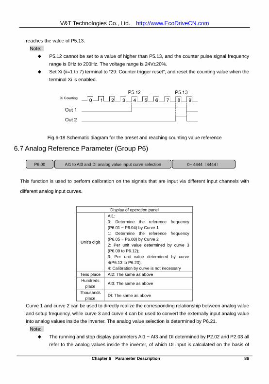
V&T Technologies Co., Ltd. http://www.EcoDriveCN.com
Chapter 6 Parameter Description 86
reaches the value of P5.13. Note:
P5.12 cannot be set to a value of higher than P5.13, and the counter pulse signal frequency range is 0Hz to 200Hz. The voltage range is 24V±20%.
Set Xi (ii=1 to 7) terminal to “29: Counter trigger reset”, and reset the counting value when the terminal Xi is enabled.
Xi Counting Xi Counting
Fig.6-18 Schematic diagram for the preset and reaching counting value reference
6.7 Analog Reference Parameter (Group P6)
This function is used to perform calibration on the signals that are input via different input channels with
different analog input curves.
Display of operation panel
Unit’s digit
AI1: 0: Determine the reference frequency (P6.01 ~ P6.04) by Curve 1 1: Determine the reference frequency (P6.05 ~ P6.08) by Curve 2 2: Per unit value determined by curve 3 (P6.09 to P6.12); 3: Per unit value determined by curve 4(P6.13 to P6.20); 4: Calibration by curve is not necessary
Tens place AI2: The same as above Hundreds
place AI3: The same as above Thousands
place DI: The same as above Curve 1 and curve 2 can be used to directly realize the corresponding relationship between analog value and setup frequency, while curve 3 and curve 4 can be used to convert the externally input analog value into analog values inside the inverter. The analog value selection is determined by P6.21.
Note: The running and stop display parameters AI1 ~ AI3 and DI determined by P2.02 and P2.03 all
refer to the analog values inside the inverter, of which DI input is calculated on the basis of
P6.00 AI1 to AI3 and DI analog value input curve selection 0~ 4444(4444)
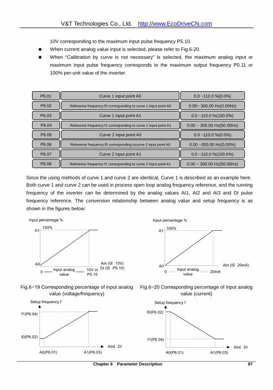
V&T Technologies Co., Ltd. http://www.EcoDriveCN.com
Chapter 6 Parameter Description 87
10V corresponding to the maximum input pulse frequency P5.10. When current analog value input is selected, please refer to Fig.6-20. When “Calibration by curve is not necessary” is selected, the maximum analog input or
maximum input pulse frequency corresponds to the maximum output frequency P0.11 or 100% per-unit value of the inverter.
Since the using methods of curve 1 and curve 2 are identical, Curve 1 is described as an example here. Both curve 1 and curve 2 can be used in process open loop analog frequency reference, and the running frequency of the inverter can be determined by the analog values AI1, AI2 and AI3 and DI pulse frequency reference. The conversion relationship between analog value and setup frequency is as shown in the figures below:
Input percentage %
AIn (0∧ 20mA)A0
A1
20mA
100%
Input analog value0
Input percentage %
AIn (0∧ 10V)DI (0∧ P5.10)
A0
A1
Input analog value0 10V or
P5.10
100%
Fig.6−19 Corresponding percentage of input analog value (voltage/frequency)
Fig.6−20 Corresponding percentage of input analog value (current)
A0(P6.01) A1(P6.03)
f0(P6.02)
f1(P6.04)
AIn∧ DI
Setup frequency f
A0(P6.01) A1(P6.03)
f0(P6.02)
f1(P6.04)
AIn∧ DI
Setup frequency f
P6.01 Curve 1 input point A0 0.0 ~110.0 %(0.0%)
P6.02 Reference frequency f0 corresponding to curve 1 input point A0 0.00~ 300.00 Hz(0.00Hz)
P6.03 Curve 1 input point A1 0.0 ~110.0 %(100.0%)
P6.04 Reference frequency f1 corresponding to curve 1 input point A1 0.00 ~ 300.00 Hz(50.00Hz)
P6.05 Curve 2 input point A0 0.0 ~110.0 %(0.0%)
P6.06 Reference frequency f0 corresponding tocurve 2 input point A0 0.00 ~300.00 Hz(0.00%)
P6.07 Curve 2 input point A1 0.0 ~110.0 %(100.0%)
P6.08 Reference frequency f1 corresponding to curve 2 input point A1 0.00 ~ 300.00 Hz(50.00Hz)
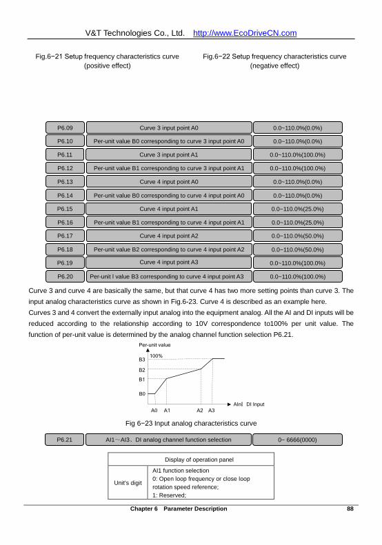
V&T Technologies Co., Ltd. http://www.EcoDriveCN.com
Chapter 6 Parameter Description 88
Fig.6−21 Setup frequency characteristics curve (positive effect)
Fig.6−22 Setup frequency characteristics curve (negative effect)
Curve 3 and curve 4 are basically the same, but that curve 4 has two more setting points than curve 3. The input analog characteristics curve as shown in Fig.6-23. Curve 4 is described as an example here. Curves 3 and 4 convert the externally input analog into the equipment analog. All the AI and DI inputs will be reduced according to the relationship according to 10V correspondence to100% per unit value. The function of per-unit value is determined by the analog channel function selection P6.21.
Fig 6−23 Input analog characteristics curve
Display of operation panel
Unit’s digit AI1 function selection 0: Open loop frequency or close loop rotation speed reference; 1: Reserved;
P6.09
Curve 3 input point A0 0.0~110.0%(0.0%)
P6.13
Curve 4 input point A0 0.0~110.0%(0.0%)
P6.14
Per-unit value B0 corresponding to curve 4 input point A0 0.0~110.0%(0.0%)
P6.15
Curve 4 input point A1 0.0~110.0%(25.0%)
P6.16
Per-unit value B1 corresponding to curve 4 input point A1 0.0~110.0%(25.0%)
P6.17
Curve 4 input point A2 0.0~110.0%(50.0%)
P6.18
Per-unit value B2 corresponding to curve 4 input point A2 0.0~110.0%(50.0%)
P6.19
Curve 4 input point A3
0.0~110.0%(100.0%)
P6.20
Per-unit l value B3 corresponding to curve 4 input point A3 0.0~110.0%(100.0%)
P6.10
Per-unit value B0 corresponding to curve 3 input point A0 0.0~110.0%(0.0%)
P6.11
Curve 3 input point A1 0.0~110.0%(100.0%)
P6.12
Per-unit value B1 corresponding to curve 3 input point A1 0.0~110.0%(100.0%)
P6.21 AI1~AI3、DI analog channel function selection 0~ 6666(0000)
100%
A0 A3
B0
B3
A1 A2
B2
B1
AIn∧ DI Input
Per-unit value
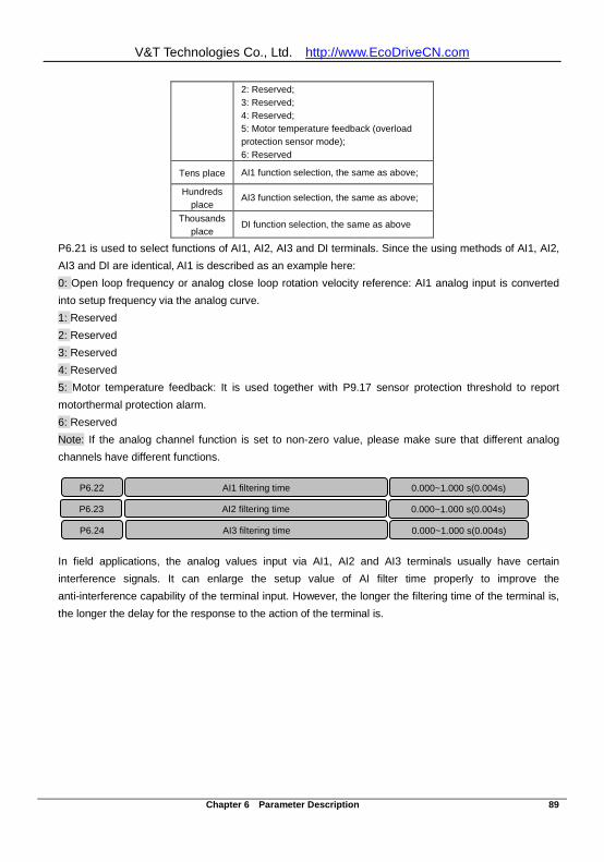
V&T Technologies Co., Ltd. http://www.EcoDriveCN.com
Chapter 6 Parameter Description 89
2: Reserved; 3: Reserved; 4: Reserved; 5: Motor temperature feedback (overload protection sensor mode); 6: Reserved
Tens place AI1 function selection, the same as above;
Hundreds place AI3 function selection, the same as above;
Thousands place DI function selection, the same as above
P6.21 is used to select functions of AI1, AI2, AI3 and DI terminals. Since the using methods of AI1, AI2, AI3 and DI are identical, AI1 is described as an example here: 0: Open loop frequency or analog close loop rotation velocity reference: AI1 analog input is converted into setup frequency via the analog curve. 1: Reserved 2: Reserved 3: Reserved 4: Reserved 5: Motor temperature feedback: It is used together with P9.17 sensor protection threshold to report motorthermal protection alarm. 6: Reserved Note: If the analog channel function is set to non-zero value, please make sure that different analog channels have different functions.
In field applications, the analog values input via AI1, AI2 and AI3 terminals usually have certain interference signals. It can enlarge the setup value of AI filter time properly to improve the anti-interference capability of the terminal input. However, the longer the filtering time of the terminal is, the longer the delay for the response to the action of the terminal is.
P6.22 AI1 filtering time 0.000~1.000 s(0.004s)
P6.23 AI2 filtering time
0.000~1.000 s(0.004s)
P6.24 AI3 filtering time
0.000~1.000 s(0.004s)
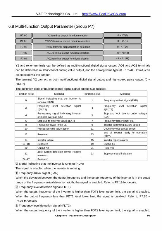
V&T Technologies Co., Ltd. http://www.EcoDriveCN.com
Chapter 6 Parameter Description 90
6.8 Multi-function Output Parameter (Group P7)
Y1 and relay terminals can be defined as multifunctional digital signal output. AO1 and AO2 terminals can be defined as multifunctional analog value output, and the analog value type (0 ~ 10V/0 ~ 20mA) can be selected via the jumper. The terminal Y2 can act as both multifunctional digital signal output and high-speed pulse output (0 ~ 50kHz). The definition table of multifunctional digital signal output is as follows:
Function setup Meaning Function setup Meaning
0 Signal indicating that the inverter is running (RUN)
1 Frequency arrival signal (FAR)
2 Frequency level detection signal 1(FDT1)
3 Frequency level detection signal 2(FDT2)
4 Pre-warning signal indicating inverter or motor overload (OL)
5 Stop and lock due to under voltage (LU)
6 Stop due to external failure (EXT) 7 Frequency upper limit(FHL) 8 Frequency lower limit(FLL) 9 Inverter is running at zero speed 10 Preset counting value action 11 Counting value arrival action
12 Reserved 13 End of Inverter ready for operation (RDY)
14 Inverter failure 15 Inverter reports alarm 16~18 Reserved 19 Output X1
20 Output X2 21 Reserved
22 Zero current detection arrival (relative to motor)
23 Stop command indication
24~47 Reserved
0: Signal indicating that the inverter is running (RUN) The signal is enabled when the inverter is running. 1: Frequency arrival signal (FAR) When the deviation between the output frequency and the setup frequency of the inverter is in the setup range of the frequency arrival detection width, the signal is enabled. Refer to P7.19 for details. 2: Frequency level detection signal (FDT1) When the output frequency of the inverter is higher than FDT1 level upper limit, the signal is enabled. When the output frequency less than FDT1 level lower limit, the signal is disabled. Refer to P7.20 ~ P7.21 for details. 3: Frequency level detection signal (FDT2) When the output frequency of the inverter is higher than FDT2 level upper limit, the signal is enabled.
P7.00 Y1 terminal output function selection 0 ~ 47(0) P7.01 Y2/DO terminal output function selection 0 ~ 71(1) P7.02 Relay terminal output function selection 0 ~47(14) P7.03 AO1 terminal output function selection 48~ 71(48) P7.04 AO2 terminal output function selection 48 ~ 71(49)
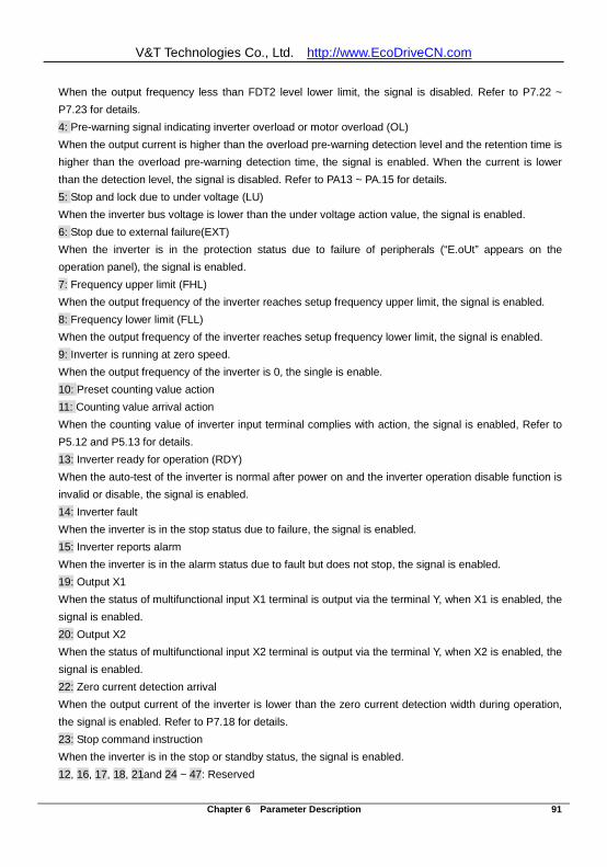
V&T Technologies Co., Ltd. http://www.EcoDriveCN.com
Chapter 6 Parameter Description 91
When the output frequency less than FDT2 level lower limit, the signal is disabled. Refer to P7.22 ~ P7.23 for details. 4: Pre-warning signal indicating inverter overload or motor overload (OL) When the output current is higher than the overload pre-warning detection level and the retention time is higher than the overload pre-warning detection time, the signal is enabled. When the current is lower than the detection level, the signal is disabled. Refer to PA13 ~ PA.15 for details. 5: Stop and lock due to under voltage (LU) When the inverter bus voltage is lower than the under voltage action value, the signal is enabled. 6: Stop due to external failure(EXT) When the inverter is in the protection status due to failure of peripherals (“E.oUt” appears on the operation panel), the signal is enabled. 7: Frequency upper limit (FHL) When the output frequency of the inverter reaches setup frequency upper limit, the signal is enabled. 8: Frequency lower limit (FLL) When the output frequency of the inverter reaches setup frequency lower limit, the signal is enabled. 9: Inverter is running at zero speed. When the output frequency of the inverter is 0, the single is enable. 10: Preset counting value action 11: Counting value arrival action When the counting value of inverter input terminal complies with action, the signal is enabled, Refer to P5.12 and P5.13 for details. 13: Inverter ready for operation (RDY) When the auto-test of the inverter is normal after power on and the inverter operation disable function is invalid or disable, the signal is enabled. 14: Inverter fault When the inverter is in the stop status due to failure, the signal is enabled. 15: Inverter reports alarm When the inverter is in the alarm status due to fault but does not stop, the signal is enabled. 19: Output X1 When the status of multifunctional input X1 terminal is output via the terminal Y, when X1 is enabled, the signal is enabled. 20: Output X2 When the status of multifunctional input X2 terminal is output via the terminal Y, when X2 is enabled, the signal is enabled. 22: Zero current detection arrival When the output current of the inverter is lower than the zero current detection width during operation, the signal is enabled. Refer to P7.18 for details. 23: Stop command instruction When the inverter is in the stop or standby status, the signal is enabled. 12, 16, 17, 18, 21and 24 ~ 47: Reserved
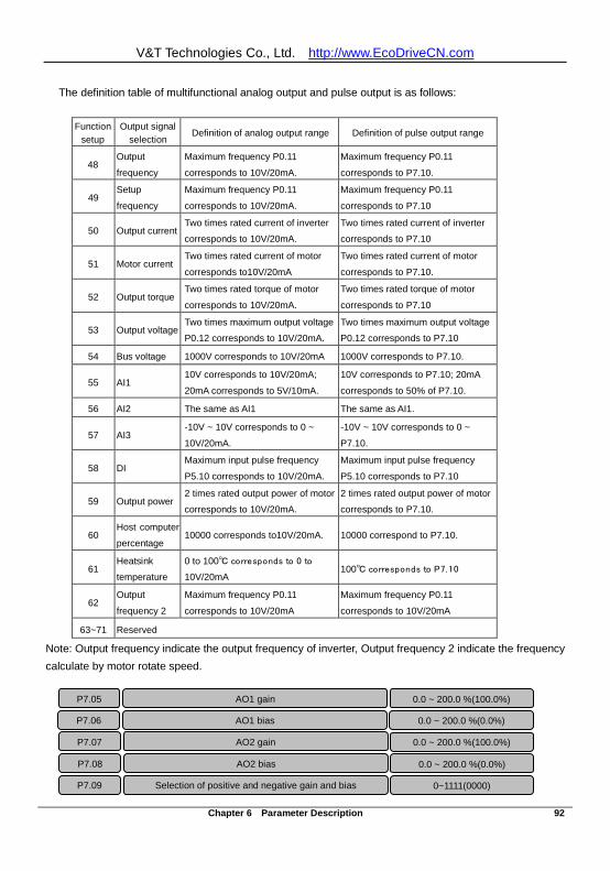
V&T Technologies Co., Ltd. http://www.EcoDriveCN.com
Chapter 6 Parameter Description 92
The definition table of multifunctional analog output and pulse output is as follows:
Function setup
Output signal selection
Definition of analog output range Definition of pulse output range
48 Output
frequency
Maximum frequency P0.11
corresponds to 10V/20mA.
Maximum frequency P0.11
corresponds to P7.10.
49 Setup
frequency
Maximum frequency P0.11
corresponds to 10V/20mA.
Maximum frequency P0.11
corresponds to P7.10
50 Output current Two times rated current of inverter
corresponds to 10V/20mA.
Two times rated current of inverter
corresponds to P7.10
51 Motor current Two times rated current of motor
corresponds to10V/20mA
Two times rated current of motor
corresponds to P7.10.
52 Output torque Two times rated torque of motor
corresponds to 10V/20mA.
Two times rated torque of motor
corresponds to P7.10
53 Output voltage Two times maximum output voltage
P0.12 corresponds to 10V/20mA.
Two times maximum output voltage
P0.12 corresponds to P7.10
54 Bus voltage 1000V corresponds to 10V/20mA 1000V corresponds to P7.10.
55 AI1 10V corresponds to 10V/20mA;
20mA corresponds to 5V/10mA.
10V corresponds to P7.10; 20mA
corresponds to 50% of P7.10.
56 AI2 The same as AI1 The same as AI1.
57 AI3 -10V ~ 10V corresponds to 0 ~
10V/20mA.
-10V ~ 10V corresponds to 0 ~
P7.10.
58 DI Maximum input pulse frequency
P5.10 corresponds to 10V/20mA.
Maximum input pulse frequency
P5.10 corresponds to P7.10
59 Output power 2 times rated output power of motor
corresponds to 10V/20mA.
2 times rated output power of motor
corresponds to P7.10.
60 Host computer
percentage 10000 corresponds to10V/20mA. 10000 correspond to P7.10.
61 Heatsink
temperature
0 to 100 corresponds to 0 to
10V/20mA 100 corresponds to P7.10
62 Output
frequency 2
Maximum frequency P0.11
corresponds to 10V/20mA
Maximum frequency P0.11
corresponds to 10V/20mA
63~71 Reserved
Note: Output frequency indicate the output frequency of inverter, Output frequency 2 indicate the frequency calculate by motor rotate speed.
P7.05 AO1 gain 0.0 ~ 200.0 %(100.0%) P7.06 AO1 bias 0.0 ~ 200.0 %(0.0%)
P7.07 AO2 gain 0.0 ~ 200.0 %(100.0%) P7.08 AO2 bias 0.0 ~ 200.0 %(0.0%) P7.09 Selection of positive and negative gain and bias 0~1111(0000)
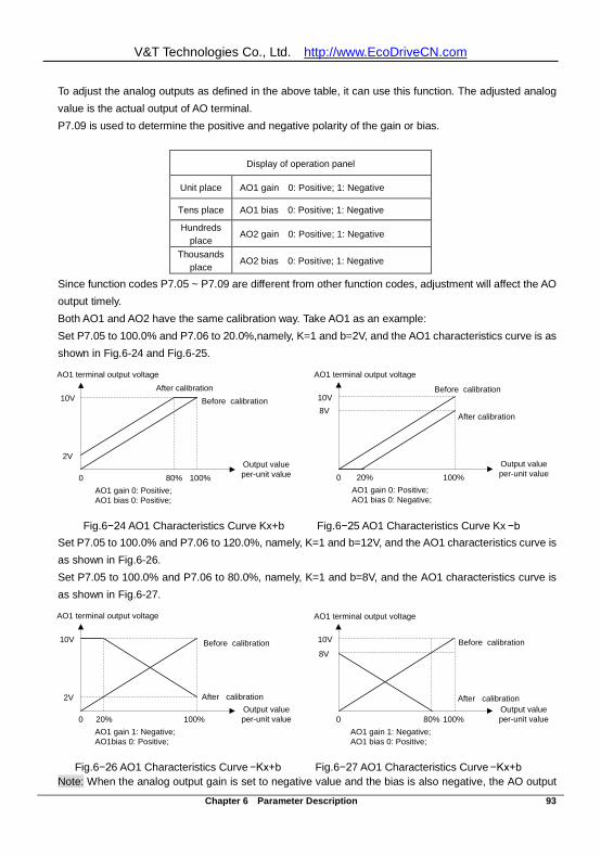
V&T Technologies Co., Ltd. http://www.EcoDriveCN.com
Chapter 6 Parameter Description 93
To adjust the analog outputs as defined in the above table, it can use this function. The adjusted analog value is the actual output of AO terminal. P7.09 is used to determine the positive and negative polarity of the gain or bias.
Display of operation panel
Unit place AO1 gain 0: Positive; 1: Negative Tens place AO1 bias 0: Positive; 1: Negative Hundreds
place AO2 gain 0: Positive; 1: Negative Thousands
place AO2 bias 0: Positive; 1: Negative Since function codes P7.05 ~ P7.09 are different from other function codes, adjustment will affect the AO output timely. Both AO1 and AO2 have the same calibration way. Take AO1 as an example: Set P7.05 to 100.0% and P7.06 to 20.0%,namely, K=1 and b=2V, and the AO1 characteristics curve is as shown in Fig.6-24 and Fig.6-25.
10V
2V
0
Before calibrationAfter calibration
AO1 terminal output voltage
Output value per-unit value
AO1 gain 0: Positive; AO1 bias 0: Positive;
80% 100%
10V8V
0
Before calibration
After calibration
Output value per-unit value
AO1 gain 0: Positive; AO1 bias 0: Negative;
20% 100%
AO1 terminal output voltage
Fig.6−24 AO1 Characteristics Curve Kx+b Fig.6−25 AO1 Characteristics Curve Kx −b
Set P7.05 to 100.0% and P7.06 to 120.0%, namely, K=1 and b=12V, and the AO1 characteristics curve is as shown in Fig.6-26. Set P7.05 to 100.0% and P7.06 to 80.0%, namely, K=1 and b=8V, and the AO1 characteristics curve is as shown in Fig.6-27.
10V
2V
0
Before calibration
After calibrationOutput value per-unit value
AO1 gain 1: Negative; AO1bias 0: Positive;
20% 100%
10V
8V
0
Before calibration
After calibrationOutput value per-unit value
AO1 gain 1: Negative; AO1 bias 0: Positive;
80% 100%
AO1 terminal output voltage AO1 terminal output voltage
Fig.6−26 AO1 Characteristics Curve −Kx+b Fig.6−27 AO1 Characteristics Curve −Kx+b
Note: When the analog output gain is set to negative value and the bias is also negative, the AO output
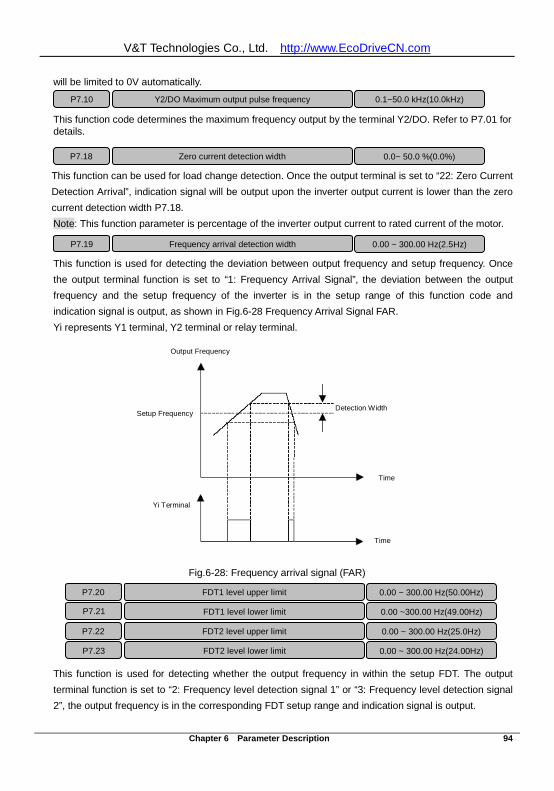
V&T Technologies Co., Ltd. http://www.EcoDriveCN.com
Chapter 6 Parameter Description 94
will be limited to 0V automatically. This function code determines the maximum frequency output by the terminal Y2/DO. Refer to P7.01 for details.
This function can be used for load change detection. Once the output terminal is set to “22: Zero Current Detection Arrival”, indication signal will be output upon the inverter output current is lower than the zero current detection width P7.18. Note: This function parameter is percentage of the inverter output current to rated current of the motor.
This function is used for detecting the deviation between output frequency and setup frequency. Once the output terminal function is set to “1: Frequency Arrival Signal”, the deviation between the output frequency and the setup frequency of the inverter is in the setup range of this function code and indication signal is output, as shown in Fig.6-28 Frequency Arrival Signal FAR. Yi represents Y1 terminal, Y2 terminal or relay terminal.
Output Frequency
Setup Frequency Detection Width
Time
Time
Yi Terminal
Output Frequency
Setup Frequency Detection Width
Time
Time
Yi Terminal
Fig.6-28: Frequency arrival signal (FAR)
This function is used for detecting whether the output frequency in within the setup FDT. The output terminal function is set to “2: Frequency level detection signal 1” or “3: Frequency level detection signal 2”, the output frequency is in the corresponding FDT setup range and indication signal is output.
P7.10
Y2/DO Maximum output pulse frequency 0.1~50.0 kHz(10.0kHz)
P7.18 Zero current detection width 0.0~ 50.0 %(0.0%)
P7.19 Frequency arrival detection width 0.00 ~ 300.00 Hz(2.5Hz)
P7.20 FDT1 level upper limit 0.00 ~ 300.00 Hz(50.00Hz) FDT1 level lower limit 0.00 ~300.00 Hz(49.00Hz)
P7.22 FDT2 level upper limit 0.00 ~ 300.00 Hz(25.0Hz) P7.23 FDT2 level lower limit 0.00 ~ 300.00 Hz(24.00Hz)
P7.21
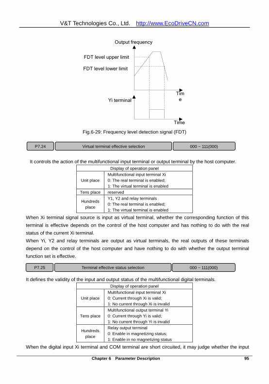
V&T Technologies Co., Ltd. http://www.EcoDriveCN.com
Chapter 6 Parameter Description 95
FDT level lower limit
Output frequency
Time Yi terminal
Time
FDT level upper limit
Fig.6-29: Frequency level detection signal (FDT)
It controls the action of the multifunctional input terminal or output terminal by the host computer. Display of operation panel
Unit place Multifunctional input terminal Xi 0: The real terminal is enabled; 1: The virtual terminal is enabled
Tens place reserved Hundreds
place Y1, Y2 and relay terminals 0: The real terminal is enabled; 1: The virtual terminal is enabled
When Xi terminal signal source is input as virtual terminal, whether the corresponding function of this terminal is effective depends on the control of the host computer and has nothing to do with the real status of the current Xi terminal. When Yi, Y2 and relay terminals are output as virtual terminals, the real outputs of these terminals depend on the control of the host computer and have nothing to do with whether the output terminal function set is effective.
It defines the validity of the input and output status of the multifunctional digital terminals. Display of operation panel
Unit place Multifunctional input terminal Xi 0: Current through Xi is valid; 1: No current through Xi is invalid
Tens place Multifunctional output terminal Yi 0: Current through Yi is valid; 1: No current through Yi is invalid
Hundreds place
Relay output terminal 0: Enable in magnetizing status; 1: Enable in no magnetizing status
When the digital input Xi terminal and COM terminal are short circuited, it may judge whether the input
P7.24 Virtual terminal effective selection 000 ~ 111(000)
P7.25 Terminal effective status selection 000 ~ 111(000)
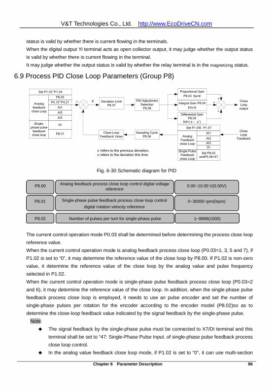
V&T Technologies Co., Ltd. http://www.EcoDriveCN.com
Chapter 6 Parameter Description 96
status is valid by whether there is current flowing in the terminals. When the digital output Yi terminal acts as open collector output, it may judge whether the output status is valid by whether there is current flowing in the terminal. It may judge whether the output status is valid by whether the relay terminal is in the magnetizing status.
6.9 Process PID Close Loop Parameters (Group P8)
Deviation LimitP8.07
PID Adjustment Selection
P8.08
Proportional Gain P8.03 Kp×ε
Integral Gain P8.04ΣKi×ε
Differential Gain P8.05
Kd×( ε - ε′)
Close Loop
output
Close Loop
Feedback
Sampling CycleP8.06
Close Loop Feedback Value
+
-
ε+
+
+
ε´refers to the previous deviation,ε refers to the deviation this time
Analog Feedback close Loop
AI1
AI2AI3DI
Set P8.02andP5.06=47
Single Pulse Feedback close Loop
Analog feedback
close Loop
P8.00
P4.15~P4.21
AI1
AI2
AI3
DI
P8.01
Single-phase pulse
feedback close loop
Set P1.02~P1.04
Set P1.05∧ P1.07
Fig. 6-30 Schematic diagram for PID
The current control operation mode P0.03 shall be determined before determining the process close loop reference value. When the current control operation mode is analog feedback process close loop (P0.03=1, 3, 5 and 7), if P1.02 is set to “0”, it may determine the reference value of the close loop by P8.00. If P1.02 is non-zero value, it determine the reference value of the close loop by the analog value and pulse frequency selected in P1.02. When the current control operation mode is single-phase pulse feedback process close loop (P0.03=2 and 6), it may determine the reference value of the close loop. In addition, when the single-phase pulse feedback process close loop is employed, it needs to use an pulse encoder and set the number of single-phase pulses per rotation for the encoder according to the encoder model (P8.02)so as to determine the close-loop feedback value indicated by the signal feedback by the single-phase pulse.
Note: The signal feedback by the single-phase pulse must be connected to X7/DI terminal and this
terminal shall be set to “47: Single-Phase Pulse Input. of single-phase pulse feedback process close loop control.
In the analog value feedback close loop mode, if P1.02 is set to “0”, it can use multi-section
P8.00 Analog feedback process close loop control digital voltage reference
0.00~10.00 V(0.00V)
P8.01 Single-phase pulse feedback process close loop control digital rotation velocity reference
0~30000 rpm(0rpm)
P8.02 Number of pulses per turn for single-phase pulse 1~9999(1000)
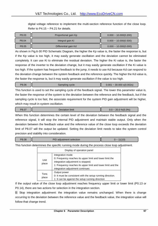
V&T Technologies Co., Ltd. http://www.EcoDriveCN.com
Chapter 6 Parameter Description 97
digital voltage reference to implement the multi-section reference function of the close loop. Refer to P4.15 ~ P4.21 for details.
As shown in Fig.6-30 PID Schematic Diagram, the higher the Kp value is, the faster the response is, but if the Kp value is too high, it may easily generate oscillation and the deviation cannot be eliminated completely. It can use Ki to eliminate the residual deviation. The higher the Ki value is, the faster the response of the inverter to the deviation change, but it may easily generate oscillation if the Ki value is too high. If the system has frequent feedback to the jump, it needs to use Kd because Kd can respond to the deviation change between the system feedback and the reference quickly. The higher the Kd value is, the faster the response is, but it may easily generate oscillation if the value is too high.
This function is used to set the sampling cycle of the feedback signal. The lower this parameter value is, the faster the response of the system to the deviation between the reference and the feedback, but if the sampling cycle is too fast, the associate requirement for the system PID gain adjustment will be higher, which may result in system oscillation.
When this function determines the certain level of the deviation between the feedback signal and the reference signal, it will stop the internal PID adjustment and maintain stable output. Only when the deviation between the feedback value and the reference value of the close loop exceeds the deviation limit of P8.07 will the output be updated. Setting the deviation limit needs to take the system control precision and stability into consideration.
This function determines the specific running mode during the process close loop adjustment.
Display of operation panel
Unit place
Integration mode 0: Frequency reaches its upper limit and lower limit the integration adjustment is stopped; 1: Frequency reaches its upper limit and lower limit and the integration adjustment continues
Tens place
Output power 0: It must be consistent with the setup running direction. 1: It can be against the setup running direction
If the output value of the close loop adjustment reaches frequency upper limit or lower limit (P0.13 or P0.14), there are two actions for selection in the integration section. 0: Stop integration adjustment: the integration value remains unchanged. When there is change occurring to the deviation between the reference value and the feedback value, the integration value will follow that change trend.
P8.03 Proportional gain Kp 0.000 ~ 10.000(0.200) P8.04 Integral gain Ki 0.000 ~ 10.000(0.500) P8.05 Differential gain Kd 0.000 ~ 10.000(0.000)
P8.06 Sampling cycle 0.001 ~ 30.000 s(0.002s)
P8.07 Deviation limit 0.0 ~ 20.0 %(5.0%)
P8.08 PID adjustment selection 0 ~ 11(10)
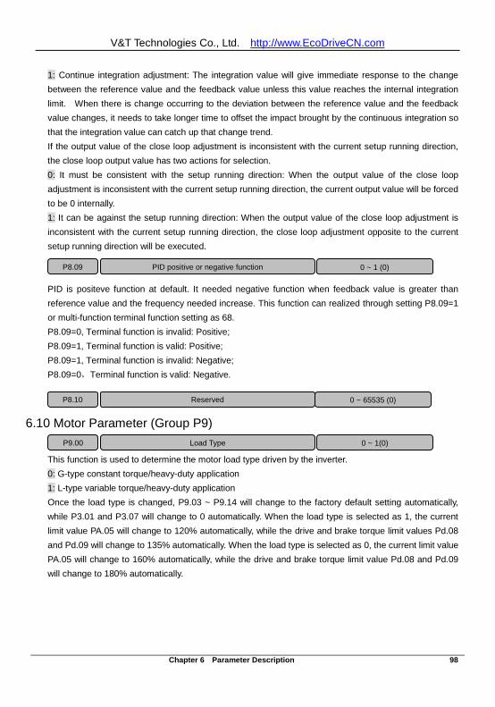
V&T Technologies Co., Ltd. http://www.EcoDriveCN.com
Chapter 6 Parameter Description 98
1: Continue integration adjustment: The integration value will give immediate response to the change between the reference value and the feedback value unless this value reaches the internal integration limit. When there is change occurring to the deviation between the reference value and the feedback value changes, it needs to take longer time to offset the impact brought by the continuous integration so that the integration value can catch up that change trend. If the output value of the close loop adjustment is inconsistent with the current setup running direction, the close loop output value has two actions for selection. 0: It must be consistent with the setup running direction: When the output value of the close loop adjustment is inconsistent with the current setup running direction, the current output value will be forced to be 0 internally. 1: It can be against the setup running direction: When the output value of the close loop adjustment is inconsistent with the current setup running direction, the close loop adjustment opposite to the current setup running direction will be executed. PID is positeve function at default. It needed negative function when feedback value is greater than reference value and the frequency needed increase. This function can realized through setting P8.09=1 or multi-function terminal function setting as 68. P8.09=0, Terminal function is invalid: Positive; P8.09=1, Terminal function is valid: Positive; P8.09=1, Terminal function is invalid: Negative; P8.09=0,Terminal function is valid: Negative.
6.10 Motor Parameter (Group P9)
This function is used to determine the motor load type driven by the inverter. 0: G-type constant torque/heavy-duty application 1: L-type variable torque/heavy-duty application Once the load type is changed, P9.03 ~ P9.14 will change to the factory default setting automatically, while P3.01 and P3.07 will change to 0 automatically. When the load type is selected as 1, the current limit value PA.05 will change to 120% automatically, while the drive and brake torque limit values Pd.08 and Pd.09 will change to 135% automatically. When the load type is selected as 0, the current limit value PA.05 will change to 160% automatically, while the drive and brake torque limit value Pd.08 and Pd.09 will change to 180% automatically.
P9.00 Load Type 0 ~ 1(0)
P8.10 Reserved 0 ~ 65535 (0)
P8.09 PID positive or negative function 0 ~ 1 (0)
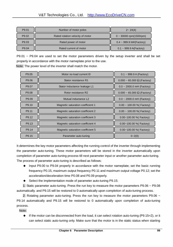
V&T Technologies Co., Ltd. http://www.EcoDriveCN.com
Chapter 6 Parameter Description 99
P9.01 ~ P9.04 are used to set the motor parameters driven by the setup inverter and shall be set properly in accordance with the motor nameplate prior to the use. Note: The power level of the inverter shall match the motor.
It determines the key motor parameters affecting the running control of the inverter through implementing the parameter auto-tuning. These motor parameters will be stored in the inverter automatically upon completion of parameter auto-tuning process till next parameter input or another parameter auto-tuning. The process of parameter auto-tuning is described as follows:
Input P9.00 to P9.04 properly in accordance with the motor nameplate; set the basic running frequency P0.15, maximum output frequency P0.11 and maximum output voltage P0.12; set the acceleration/deceleration time P0.08 and P0.09 properly.
Select the implementation mode of parameter auto-tuning P9.15: 1: Static parameter auto-tuning. Press the run key to measure the motor parameters P9.06 ~ P9.08
automatically. and P9.15 will be restored to 0 automatically upon completion of auto-tuning process. 2: Rotating parameter auto-tuning. Press the run key to measure the motor parameters P9.06 ~
P9.14 automatically and P9.15 will be restored to 0 automatically upon completion of auto-tuning process.
Note: If the motor can be disconnected from the load, it can select rotation auto-tuning (P9.15=2), or it
can select static auto-tuning only. Make sure that the motor is in the static status when starting
P9.01 Number of motor poles 2~ 24(4) P9.02 Rated rotation velocity of motor 0 ~ 30000 rpm(1500rpm) P9.03 Rated power of motor 0.4 ~ 999.9 kW(Factory) P9.04 Rated current of motor 0.1 ~ 999.9 A(Factory)
P9.05 Motor no-load current I0 0.1 ~ 999.9 A (Factory) P9.06 Stator resistance R1 0.000 ~ 65.000 Ω (Factory) P9.07 Stator inductance leakage L1 0.0 ~ 2000.0 mH (Factory) P9.08 Rotor resistance R2 0.000 ~ 65.000 Ω (Factory) P9.09 Mutual inductance L2 0.0 ~ 2000.0 mH (Factory) P9.10 Magnetic saturation coefficient 1 0.00 ~ 100.00 %( Factory) P9.11 Magnetic saturation coefficient 2 0.00 ~ 100.00 %( Factory) P9.12 Magnetic saturation coefficient 3 0.00~100.00 %( Factory) P9.13 Magnetic saturation coefficient 4 0.00~100.00 %( Factory) P9.14 Magnetic saturation coefficient 5 0.00~100.00 %( Factory) P9.15 Parameter auto-tuning 0~2(0)
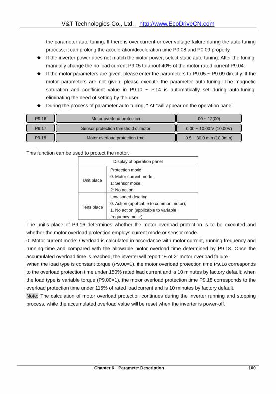
V&T Technologies Co., Ltd. http://www.EcoDriveCN.com
Chapter 6 Parameter Description 100
the parameter auto-tuning. If there is over current or over voltage failure during the auto-tuning process, it can prolong the acceleration/deceleration time P0.08 and P0.09 properly.
If the inverter power does not match the motor power, select static auto-tuning. After the tuning, manually change the no load current P9.05 to about 40% of the motor rated current P9.04.
If the motor parameters are given, please enter the parameters to P9.05 ~ P9.09 directly. If the motor parameters are not given, please execute the parameter auto-tuning. The magnetic saturation and coefficient value in P9.10 ~ P.14 is automatically set during auto-tuning, eliminating the need of setting by the user.
During the process of parameter auto-tuning, “-At-“will appear on the operation panel.
This function can be used to protect the motor. Display of operation panel
Unit place Protection mode 0: Motor current mode; 1: Sensor mode; 2: No action
Tens place Low speed derating 0. Action (applicable to common motor); 1. No action (applicable to variable frequency motor)
The unit’s place of P9.16 determines whether the motor overload protection is to be executed and whether the motor overload protection employs current mode or sensor mode. 0: Motor current mode: Overload is calculated in accordance with motor current, running frequency and running time and compared with the allowable motor overload time determined by P9.18. Once the accumulated overload time is reached, the inverter will report “E.oL2” motor overload failure. When the load type is constant torque (P9.00=0), the motor overload protection time P9.18 corresponds to the overload protection time under 150% rated load current and is 10 minutes by factory default; when the load type is variable torque (P9.00=1), the motor overload protection time P9.18 corresponds to the overload protection time under 115% of rated load current and is 10 minutes by factory default. Note: The calculation of motor overload protection continues during the inverter running and stopping process, while the accumulated overload value will be reset when the inverter is power-off.
P9.16 Motor overload protection 00 ~ 12(00) P9.17 Sensor protection threshold of motor 0.00 ~ 10.00 V (10.00V) P9.18 Motor overload protection time 0.5 ~ 30.0 min (10.0min)
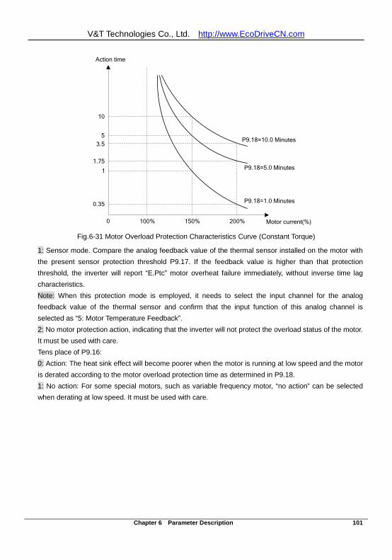
V&T Technologies Co., Ltd. http://www.EcoDriveCN.com
Chapter 6 Parameter Description 101
0.35
1
1.75
3.55
10
100% 150% 200% Motor current(%)
Action time
P9.18=10.0 Minutes
P9.18=5.0 Minutes
P9.18=1.0 Minutes
0 Fig.6-31 Motor Overload Protection Characteristics Curve (Constant Torque)
1: Sensor mode. Compare the analog feedback value of the thermal sensor installed on the motor with the present sensor protection threshold P9.17. If the feedback value is higher than that protection threshold, the inverter will report “E.Ptc” motor overheat failure immediately, without inverse time lag characteristics. Note: When this protection mode is employed, it needs to select the input channel for the analog feedback value of the thermal sensor and confirm that the input function of this analog channel is selected as “5: Motor Temperature Feedback”. 2: No motor protection action, indicating that the inverter will not protect the overload status of the motor. It must be used with care. Tens place of P9.16: 0: Action: The heat sink effect will become poorer when the motor is running at low speed and the motor is derated according to the motor overload protection time as determined in P9.18. 1: No action: For some special motors, such as variable frequency motor, “no action” can be selected when derating at low speed. It must be used with care.
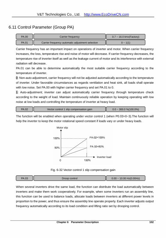
V&T Technologies Co., Ltd. http://www.EcoDriveCN.com
Chapter 6 Parameter Description 102
6.11 Control Parameter (Group PA)
Carrier frequency has an important impact on operations of inverter and motor. When carrier frequency increases, the loss, temperature rise and noise of motor will decrease. If carrier frequency decreases, the temperature rise of inverter itself as well as the leakage current of motor and its interference with external radiation will decrease. PA.01 can be able to determine automatically the most suitable carrier frequency according to the temperature of inverter. 0: Non-auto adjustment, carrier frequency will not be adjusted automatically according to the temperature of inverter. Under favorable circumstances as regards ventilation and heat sink, all loads shall operate with low noise. Set PA.00 with higher carrier frequency and set PA.01 to 0. 1: Auto-adjustment; inverter can adjust automatically carrier frequency through temperature check according to the weight of load. Maintain continuously reliable operation by keeping operating with low noise at low loads and controlling the temperature of inverter at heavy load.
The function will be enabled when operating under vector control 1 (when P0.03=0~3).The function will help the inverter to keep the motor rotational speed constant if loads vary or under heavy loads.
Fig. 6-32 Vector control 1 slip compensation gain
When several inverters drive the same load, the function can distribute the load automatically between inverters and make them work cooperatively. For example, when some inverters run an assembly line, this function can be used to balance loads, allocate loads between inverters at different power levels in proportion to the power, and thus ensure the assembly line operate properly. Each inverter adjusts output frequency automatically according to its load condition and lifting ratio set by drooping control.
Motor slip
Inverter load
Motor slip
Inverter load
PA.00 Carrier frequency 0.7 ~ 16.0 kHz(Factory) PA.01 Carrier frequency automatic adjustment selection 0 ~ 1(1)
PA.02 Vector control 1 slip compensation gain 0.0 ~ 300.0 %(100.0%)
PA.03 Droop control 0.00 ~ 10.00 Hz(0.00Hz)
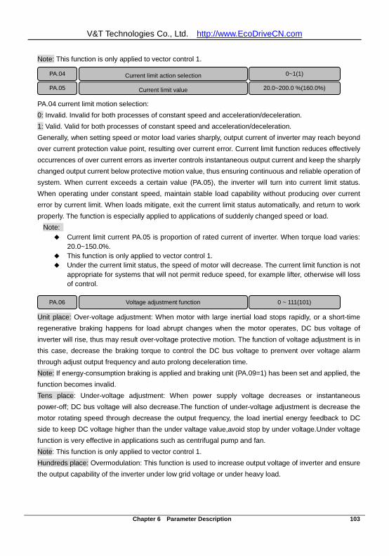
V&T Technologies Co., Ltd. http://www.EcoDriveCN.com
Chapter 6 Parameter Description 103
Note: This function is only applied to vector control 1.
PA.04 current limit motion selection: 0: Invalid. Invalid for both processes of constant speed and acceleration/deceleration. 1: Valid. Valid for both processes of constant speed and acceleration/deceleration. Generally, when setting speed or motor load varies sharply, output current of inverter may reach beyond over current protection value point, resulting over current error. Current limit function reduces effectively occurrences of over current errors as inverter controls instantaneous output current and keep the sharply changed output current below protective motion value, thus ensuring continuous and reliable operation of system. When current exceeds a certain value (PA.05), the inverter will turn into current limit status. When operating under constant speed, maintain stable load capability without producing over current error by current limit. When loads mitigate, exit the current limit status automatically, and return to work properly. The function is especially applied to applications of suddenly changed speed or load.
Note: Current limit current PA.05 is proportion of rated current of inverter. When torque load varies:
20.0~150.0%. This function is only applied to vector control 1. Under the current limit status, the speed of motor will decrease. The current limit function is not
appropriate for systems that will not permit reduce speed, for example lifter, otherwise will loss of control.
Unit place: Over-voltage adjustment: When motor with large inertial load stops rapidly, or a short-time regenerative braking happens for load abrupt changes when the motor operates, DC bus voltage of inverter will rise, thus may result over-voltage protective motion. The function of voltage adjustment is in this case, decrease the braking torque to control the DC bus voltage to prenvent over voltage alarm through adjust output frequency and auto prolong deceleration time. Note: If energy-consumption braking is applied and braking unit (PA.09=1) has been set and applied, the function becomes invalid. Tens place: Under-voltage adjustment: When power supply voltage decreases or instantaneous power-off; DC bus voltage will also decrease.The function of under-voltage adjustment is decrease the motor rotating speed through decrease the output frequency, the load inertial energy feedback to DC side to keep DC voltage higher than the under valtage value,avoid stop by under voltage.Under voltage function is very effective in applications such as centrifugal pump and fan. Note: This function is only applied to vector control 1. Hundreds place: Overmodulation: This function is used to increase output voltage of inverter and ensure the output capability of the inverter under low grid voltage or under heavy load.
PA.04 Current limit action selection 0~1(1) PA.05 Current limit value 20.0~200.0 %(160.0%)
PA.06 Voltage adjustment function
0 ~ 111(101)
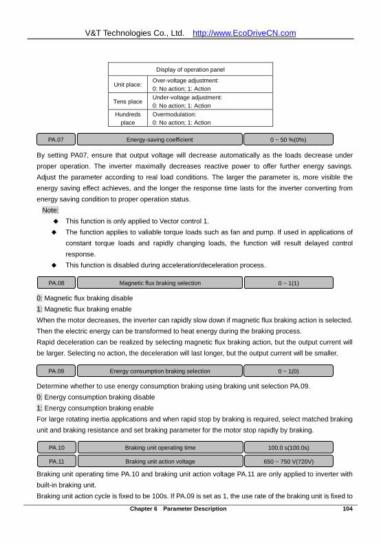
V&T Technologies Co., Ltd. http://www.EcoDriveCN.com
Chapter 6 Parameter Description 104
Display of operation panel
Unit place: Over-voltage adjustment: 0: No action; 1: Action
Tens place Under-voltage adjustment: 0: No action; 1: Action
Hundreds place
Overmodulation: 0: No action; 1: Action
By setting PA07, ensure that output voltage will decrease automatically as the loads decrease under proper operation. The inverter maximally decreases reactive power to offer further energy savings. Adjust the parameter according to real load conditions. The larger the parameter is, more visible the energy saving effect achieves, and the longer the response time lasts for the inverter converting from energy saving condition to proper operation status.
Note: This function is only applied to Vector control 1. The function applies to valiable torque loads such as fan and pump. If used in applications of
constant torque loads and rapidly changing loads, the function will result delayed control response.
This function is disabled during acceleration/deceleration process.
0: Magnetic flux braking disable 1: Magnetic flux braking enable When the motor decreases, the inverter can rapidly slow down if magnetic flux braking action is selected. Then the electric energy can be transformed to heat energy during the braking process. Rapid deceleration can be realized by selecting magnetic flux braking action, but the output current will be larger. Selecting no action, the deceleration will last longer, but the output current will be smaller.
Determine whether to use energy consumption braking using braking unit selection PA.09. 0: Energy consumption braking disable 1: Energy consumption braking enable For large rotating inertia applications and when rapid stop by braking is required, select matched braking unit and braking resistance and set braking parameter for the motor stop rapidly by braking.
Braking unit operating time PA.10 and braking unit action voltage PA.11 are only applied to inverter with built-in braking unit. Braking unit action cycle is fixed to be 100s. If PA.09 is set as 1, the use rate of the braking unit is fixed to
PA.07 Energy-saving coefficient 0 ~ 50 %(0%)
PA.08 Magnetic flux braking selection 0 ~ 1(1)
PA.09 Energy consumption braking selection 0 ~ 1(0)
PA.10 Braking unit operating time
100.0 s(100.0s) PA.11 Braking unit action voltage 650 ~ 750 V(720V)
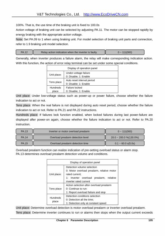
V&T Technologies Co., Ltd. http://www.EcoDriveCN.com
Chapter 6 Parameter Description 105
100%. That is, the use time of the braking unit is fixed to 100.0s Action voltage of braking unit can be selected by adjusting PA.11. The motor can be stopped rapidly by energy braking with the appropriate action voltage. Note: Set PA.09 to 1 when using braking unit. For model selection of braking unit parts and connection, refer to 1.9 braking unit model selection.
Generally, when inverter produces a failure alarm, the relay will make corresponding indication action. With this function, the action of error relay terminal can be set under some special conditions.
Display of operation panel Unit place: Under-voltage failure
0: Disable; 1: Enable Tens place Auto reset interval period
0: Disable; 1: Enable Hundreds
place Failure locked 0: Disable; 1: Enable
Unit place: Under low-voltage status such as power-up or power failure, choose whether the failure indication to act or not. Tens place: When the real failure is not displayed during auto reset period, choose whether the failure indication to act or not. Refer to PA.21 and PA.22 instructions. Hundreds place: If failures lock function enabled, when locked failures during last power-failure are displayed after power-on again, choose whether the failure indication to act or not. Refer to PA.20 instruction.
Overload prealarm function can realize indication of pre-setting overload status or alarm stop. PA.13 determines overload prealarm detection volume and conditions.
Display of operation panel
Unit place:
Detection volume selection 0: Motor overload prealarm, relative motor rated current; 1: Inverter overload prealarm, relative inverter rated current
Tens place Action selection after overload prealarm 0: Continue to run: 1: Report overload failure and stop
Hundreds place
Detection conditions selection 0: Detection all the time; 1: Detection only at constant speed
Unit place: Determine overload detection is motor overload prealarm or inverter overload prealarm. Tens place: Determine inverter continues to run or alarms then stops when the output current exceeds
PA.12 Relay action indication when the inverter is faulty. 0 ~ 111(000)
PA.13 Inverter or motor overload prealarm 0 ~ 111(000) PA.14 Overload prealarm detection level 20.0 ~ 200.0 %(130.0%) PA.15 Overload prealarm detection time 0.1 ~ 60.0 s(5.0s)
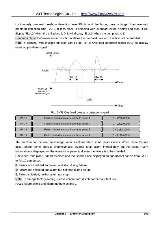
V&T Technologies Co., Ltd. http://www.EcoDriveCN.com
Chapter 6 Parameter Description 106
continuously overload prealarm detection level PA.14 and the lasting time is longer than overload prealarm detection time PA.15. If tens place is selected with overload failure display and stop, it will display “E.oL2” when the unit place is 0, it will display “E.oL1” when the unit place is 1. Hundreds place: Determine under which run status the overload prealarm function will be enabled. Note: Y terminal with multiple function can be set to “4: Overload detection signal (OL)” to display overload prealarm signal.
PA.14
Time
Output current
PA.15 PA.15
Time
Overload prealarm
detection signal
Valid
Fig. 6−33 Overload prealarm detection signal
The function can be used to manage various actions when some failures occur. When these failures occur under some special circumstances, inverter shall alarm immediately but not stop. Alarm information is displayed on the operational panel and even the failure is to be shielded. Unit place, tens place, hundreds place and thousands place displayed on operational panels from PA.16 to PA.19 can be set: 0: Failure not shielded and alarm and stop during failure. 1: Failure not shielded and alarm but not stop during failure. 2: Failure shielded, neither alarm nor stop. Note: To change factory-setting, please contact with distributor or manufacturer. PA.16 failure shield and alarm attribute setting 1
PA.16 Fault shielded and alarm attribute setup 1
0 ~ 2222(0020) PA.17 Fault shielded and alarm attribute setup 2 0 ~ 2222(0000) PA.18 Fault shielded and alarm attribute setup 3 0 ~ 2222(2000) PA.19 Fault shielded and alarm attribute setup 4 0 ~ 2222(0002)
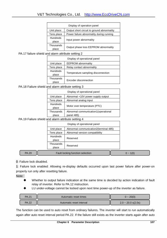
V&T Technologies Co., Ltd. http://www.EcoDriveCN.com
Chapter 6 Parameter Description 107
Display of operation panel Unit place: Output short circuit to ground abnormality Tens place Power failure abnormality during running Hundreds
place Input power abnormality Thousands
place Output phase loss EEPROM abnormality PA.17 failure shield and alarm attribute setting 2
Display of operational panel
Unit place EEPROM abnormality Tens place Relay contact abnormality Hundreds
place Temperature sampling disconnection
Thousands place
Encoder disconnection
PA.18 Failure shield and alarm attribute setting 3 Display of operational panel
Unit place Abnormal +10V power supply output Tens place Abnormal analog input Hundreds
place Motor over-temperature (PTC)
Thousands place
Abnormal communication1(operational panel 485)
PA.19 Failure shield and alarm attribute setting 4 Display of operational panel
Unit place Abnormal communication2(terminal 485) Tens place Abnormal version compatibility Hundreds
place Reserved
Thousands place
Reserved
0: Failure lock disabled. 1: Failure lock enabled: Allowing re-display defaults occurred upon last power failure after power-on properly run only after resetting failure. Note:
Whether to output failure indication at the same time is decided by action indication of fault relay of inverter. Refer to PA.12 instruction.
LU under-voltage cannot be locked upon next time power-up of the inverter as failure.
The function can be used to auto reset from ordinary failures. The inverter will start to run automatically again after auto reset interval period PA.22. If the failure still exists as the inverter starts again after auto
PA.20 Fault locking function selection 0 ~ 1(0)
PA.21 Automatic reset times 0 ~ 20(0) PA.22 Automatic reset interval 2.0 ~ 20.0 s(2.0s)
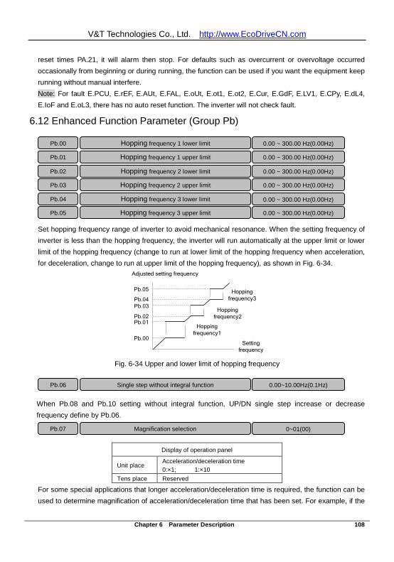
V&T Technologies Co., Ltd. http://www.EcoDriveCN.com
Chapter 6 Parameter Description 108
reset times PA.21, it will alarm then stop. For defaults such as overcurrent or overvoltage occurred occasionally from beginning or during running, the function can be used if you want the equipment keep running without manual interfere. Note: For fault E.PCU, E.rEF, E.AUt, E.FAL, E.oUt, E.ot1, E.ot2, E.Cur, E.GdF, E.LV1, E.CPy, E.dL4, E.IoF and E.oL3, there has no auto reset function. The inverter will not check fault.
6.12 Enhanced Function Parameter (Group Pb)
Set hopping frequency range of inverter to avoid mechanical resonance. When the setting frequency of inverter is less than the hopping frequency, the inverter will run automatically at the upper limit or lower limit of the hopping frequency (change to run at lower limit of the hopping frequency when acceleration, for deceleration, change to run at upper limit of the hopping frequency), as shown in Fig. 6-34.
Adjusted setting frequency
Setting frequency
Pb.00
Pb.01Pb.02
Pb.03Pb.04
Pb.05
Hopping frequency1
Hopping frequency2
Hopping frequency3
Fig. 6-34 Upper and lower limit of hopping frequency
When Pb.08 and Pb.10 setting without integral function, UP/DN single step increase or decrease frequency define by Pb.06.
Display of operation panel
Unit place Acceleration/deceleration time 0:×1; 1:×10
Tens place Reserved
For some special applications that longer acceleration/deceleration time is required, the function can be used to determine magnification of acceleration/deceleration time that has been set. For example, if the
Pb.00 Hopping frequency 1 lower limit 0.00 ~ 300.00 Hz(0.00Hz) Pb.01 Hopping frequency 1 upper limit 0.00 ~ 300.00 Hz(0.00Hz)
Pb.02 Hopping frequency 2 lower limit 0.00 ~ 300.00 Hz(0.00Hz) Pb.03 Hopping frequency 2 upper limit 0.00 ~ 300.00 Hz(0.00Hz) Pb.04 Hopping frequency 3 lower limit 0.00 ~ 300.00 Hz(0.00Hz) Pb.05 Hopping frequency 3 upper limit 0.00 ~ 300.00 Hz(0.00Hz)
Pb.06 Single step without integral function
0.00~10.00Hz(0.1Hz)
Pb.07 Magnification selection 0~01(00)
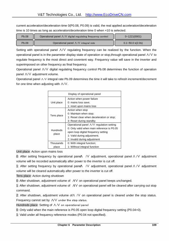
V&T Technologies Co., Ltd. http://www.EcoDriveCN.com
Chapter 6 Parameter Description 109
current acceleration/deceleration time 0(P0.08, P0.09) is valid, the real applied acceleration/deceleration time is 10 times as long as acceleration/deceleration time 0 when ×10 is selected.
Setting with operational panel ∧/∨ regulating frequency can be realized by the function. When the operational panel is in the parameter display state of operation or stop,through operational panel ∧/∨ to regulate frequency is the most direct and covenient way. Frequency value will save in the inverter and superimposed on other frequency as final frequency. Operational panel ∧/∨ digital regulating frequency control Pb.08 determines the function of operation panel ∧/∨ adjustment volume. Operational panel ∧/∨ integral rate Pb.09 determines the time it will take to refresh increment/decrement for one time when adjusting with ∧/∨.
Display of operational panel
Unit place Action when power failure 0: mains loss save; 1: reset upon mains loss
Tens place
Action when stop 0: Maintain when stop; 1: Reset clear when deceleration or stop; 3: Reset during standby
Hundreds place
Operational panel ∧/∨ regulation setting 0: Only valid when main reference is P0.05 open loop digital frequency setting 1: Valid during adjustment; 2: Invalid during adjustment
Thousands place
0: With integral function; 1: Without integral function
Unit place: Action upon mains loss 0: After setting frequency by operational panel ∧ /∨ adjustment, operational panel ∧ /∨ adjustment volume will be recorded automatically after power to the inverter is cut off. 1: After setting frequency by operational panel ∧ /∨ adjustment, operational panel ∧ /∨ adjustment volume will be cleared automatically after power to the inverter is cut off. Tens place: Action during shutdown 0: After shutdown, adjustment volume of ∧/∨ on operational panel keeps unchanged. 1: After shutdown, adjustment volume of ∧/∨ on operational panel will be cleared after carrying out stop command. 2: After shutdown, adjustment volume of ∧ /∨ on operational panel is cleared under the stop status. Frequency cannot set by ∧/∨ under the stop status. Hundreds place: Setting of ∧/∨ on operational panel 0: Only valid when the main reference is P0.05 open loop digital frequency setting (P0.04=0). 1: Valid under all frequency reference modes (P0.04 not specified).
Pb.08 Operational panel ∧/∨ dig ital regulating frequency control 0~1221(0001)
Pb.09 Operational panel ∧/∨ integral rate 0.1~50.0 s(2.0s)
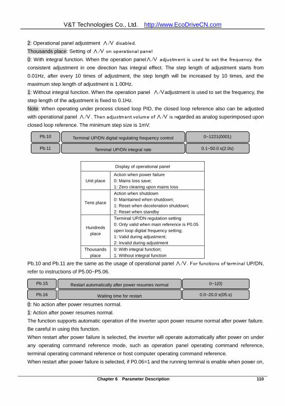
V&T Technologies Co., Ltd. http://www.EcoDriveCN.com
Chapter 6 Parameter Description 110
2: Operational panel adjustment ∧/∨ disabled. Thousands place: Setting of ∧/∨ on operational panel 0: With integral function. When the operation panel ∧/∨ adjustment is used to set the frequency, the
consistent adjustment in one direction has integral effect. The step length of adjustment starts from 0.01Hz, after every 10 times of adjustment, the step length will be increased by 10 times, and the maximum step length of adjustment is 1.00Hz. 1: Without integral function. When the operation panel ∧/∨ adjustment is used to set the frequency, the step length of the adjustment is fixed to 0.1Hz. Note: When operating under process closed loop PID, the closed loop reference also can be adjusted with operational panel ∧/∨. Then adjustment volume of ∧/∨ is regarded as analog superimposed upon closed loop reference. The minimum step size is 1mV.
Display of operational panel
Unit place Action when power failure 0: Mains loss save; 1: Zero clearing upon mains loss
Tens place
Action when shutdown 0: Maintained when shutdown; 1: Reset when deceleration shutdown; 2: Reset when standby
Hundreds place
Terminal UP/DN regulation setting 0: Only valid when main reference is P0.05 open loop digital frequency setting; 1: Valid during adjustment; 2: Invalid during adjustment
Thousands place
0: With integral function; 1: Without integral function
Pb.10 and Pb.11 are the same as the usage of operational panel ∧/∨. For functions of terminal UP/DN, refer to instructions of P5.00~P5.06.
0: No action after power resumes normal. 1: Action after power resumes normal. The function supports automatic operation of the inverter upon power resume normal after power failure. Be careful in using this function. When restart after power failure is selected, the inverter will operate automatically after power on under any operating command reference mode, such as operation panel operating command reference, terminal operating command reference or host computer operating command reference. When restart after power failure is selected, if P0.06=1 and the running terninal is enable when power on,
Pb.10 Terminal UP/DN digital regulating frequency control 0~1221(0001) Pb.11
Terminal UP/DN integral rate 0.1~50.0 s(2.0s)
Pb.15 Restart automatically after power resumes normal 0~1(0) Pb.16
Waiting time for restart 0.0~20.0 s(05.s)
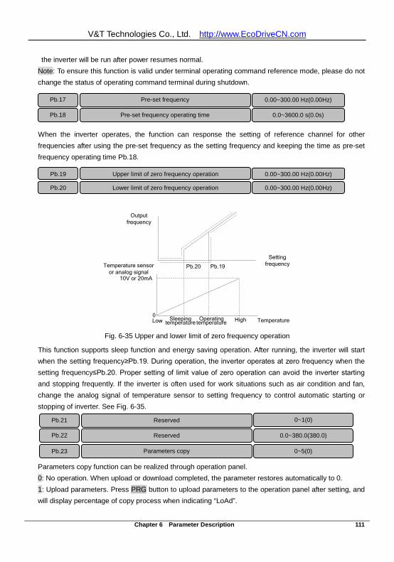
V&T Technologies Co., Ltd. http://www.EcoDriveCN.com
Chapter 6 Parameter Description 111
the inverter will be run after power resumes normal. Note: To ensure this function is valid under terminal operating command reference mode, please do not change the status of operating command terminal during shutdown.
When the inverter operates, the function can response the setting of reference channel for other frequencies after using the pre-set frequency as the setting frequency and keeping the time as pre-set frequency operating time Pb.18.
Temperature sensor or analog signal
0
10V or 20mA
Low TemperatureHighSleeping temperature
Operating temperature
Setting frequency
Output frequency
Pb.19Pb.20
Fig. 6-35 Upper and lower limit of zero frequency operation
This function supports sleep function and energy saving operation. After running, the inverter will start when the setting frequency≥Pb.19. During operation, the inverter operates at zero frequency when the setting frequency≤Pb.20. Proper setting of limit value of zero operation can avoid the inverter starting and stopping frequently. If the inverter is often used for work situations such as air condition and fan, change the analog signal of temperature sensor to setting frequency to control automatic starting or stopping of inverter. See Fig. 6-35.
Parameters copy function can be realized through operation panel. 0: No operation. When upload or download completed, the parameter restores automatically to 0. 1: Upload parameters. Press PRG button to upload parameters to the operation panel after setting, and will display percentage of copy process when indicating “LoAd”.
Pb.17 Pre-set frequency 0.00~300.00 Hz(0.00Hz)
Pb.18 Pre-set frequency operating time 0.0~3600.0 s(0.0s)
Pb.19 Upper limit of zero frequency operation 0.00~300.00 Hz(0.00Hz) Pb.20 Lower limit of zero frequency operation 0.00~300.00 Hz(0.00Hz)
Pb.23 Parameters copy 0~5(0)
Pb.21
Reserved
0~1(0)
Pb.22 Reserved
0.0~380.0(380.0)
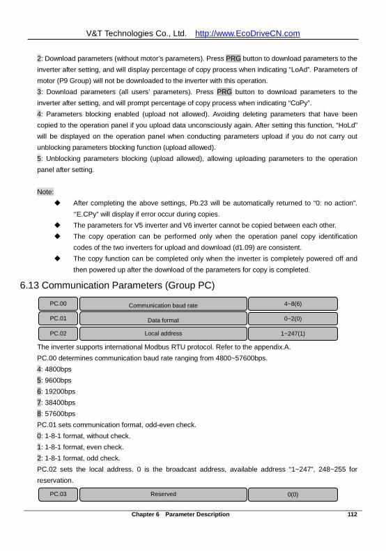
V&T Technologies Co., Ltd. http://www.EcoDriveCN.com
Chapter 6 Parameter Description 112
2: Download parameters (without motor’s parameters). Press PRG button to download parameters to the inverter after setting, and will display percentage of copy process when indicating “LoAd”. Parameters of motor (P9 Group) will not be downloaded to the inverter with this operation. 3: Download parameters (all users’ parameters). Press PRG button to download parameters to the inverter after setting, and will prompt percentage of copy process when indicating “CoPy”. 4: Parameters blocking enabled (upload not allowed). Avoiding deleting parameters that have been copied to the operation panel if you upload data unconsciously again. After setting this function, “HoLd” will be displayed on the operation panel when conducting parameters upload if you do not carry out unblocking parameters blocking function (upload allowed). 5: Unblocking parameters blocking (upload allowed), allowing uploading parameters to the operation panel after setting. Note:
After completing the above settings, Pb.23 will be automatically returned to “0: no action”. ‘’E.CPy” will display if error occur during copies.
The parameters for V5 inverter and V6 inverter cannot be copied between each other. The copy operation can be performed only when the operation panel copy identification
codes of the two inverters for upload and download (d1.09) are consistent. The copy function can be completed only when the inverter is completely powered off and
then powered up after the download of the parameters for copy is completed.
6.13 Communication Parameters (Group PC)
The inverter supports international Modbus RTU protocol. Refer to the appendix.A. PC.00 determines communication baud rate ranging from 4800~57600bps. 4: 4800bps 5: 9600bps 6: 19200bps 7: 38400bps 8: 57600bps PC.01 sets communication format, odd-even check. 0: 1-8-1 format, without check. 1: 1-8-1 format, even check. 2: 1-8-1 format, odd check. PC.02 sets the local address. 0 is the broadcast address, available address “1~247”, 248~255 for reservation.
PC.00 Communication baud rate 4~8(6) PC.01 Data format 0~2(0) PC.02 Local address 1~247(1)
PC.03 Reserved 0(0)
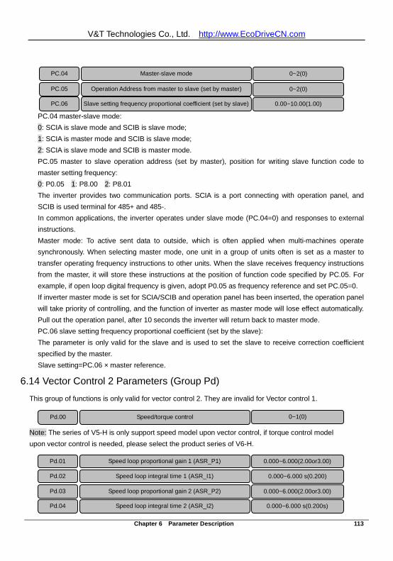
V&T Technologies Co., Ltd. http://www.EcoDriveCN.com
Chapter 6 Parameter Description 113
PC.04 master-slave mode: 0: SCIA is slave mode and SCIB is slave mode; 1: SCIA is master mode and SCIB is slave mode; 2: SCIA is slave mode and SCIB is master mode. PC.05 master to slave operation address (set by master), position for writing slave function code to master setting frequency: 0: P0.05 1: P8.00 2: P8.01 The inverter provides two communication ports. SCIA is a port connecting with operation panel, and SCIB is used terminal for 485+ and 485-. In common applications, the inverter operates under slave mode (PC.04=0) and responses to external instructions. Master mode: To active sent data to outside, which is often applied when multi-machines operate synchronously. When selecting master mode, one unit in a group of units often is set as a master to transfer operating frequency instructions to other units. When the slave receives frequency instructions from the master, it will store these instructions at the position of function code specified by PC.05. For example, if open loop digital frequency is given, adopt P0.05 as frequency reference and set PC.05=0. If inverter master mode is set for SCIA/SCIB and operation panel has been inserted, the operation panel will take priority of controlling, and the function of inverter as master mode will lose effect automatically. Pull out the operation panel, after 10 seconds the inverter will return back to master mode. PC.06 slave setting frequency proportional coefficient (set by the slave): The parameter is only valid for the slave and is used to set the slave to receive correction coefficient specified by the master. Slave setting=PC.06 × master reference.
6.14 Vector Control 2 Parameters (Group Pd)
This group of functions is only valid for vector control 2. They are invalid for Vector control 1. Note: The series of V5-H is only support speed model upon vector control, if torque control model upon vector control is needed, please select the product series of V6-H.
PC.04 Master-slave mode 0~2(0)
PC.05 Operation Address from master to slave (set by master) 0~2(0) PC.06 Slave setting frequency proportional coefficient (set by slave) 0.00~10.00(1.00)
Pd.00
Speed/torque control 0~1(0)
Pd.01
Speed loop proportional gain 1 (ASR_P1) 0.000~6.000(2.00or3.00)
Pd.02 Speed loop integral time 1 (ASR_I1) 0.000~6.000 s(0.200) Pd.03 Speed loop proportional gain 2 (ASR_P2) 0.000~6.000(2.00or3.00) Pd.04 Speed loop integral time 2 (ASR_I2) 0.000~6.000 s(0.200s)
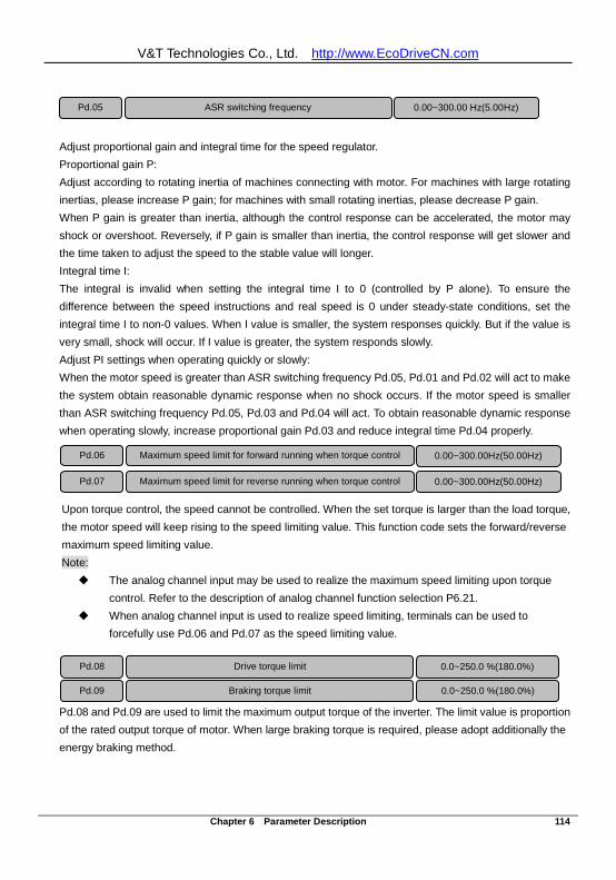
V&T Technologies Co., Ltd. http://www.EcoDriveCN.com
Chapter 6 Parameter Description 114
Adjust proportional gain and integral time for the speed regulator. Proportional gain P: Adjust according to rotating inertia of machines connecting with motor. For machines with large rotating inertias, please increase P gain; for machines with small rotating inertias, please decrease P gain. When P gain is greater than inertia, although the control response can be accelerated, the motor may shock or overshoot. Reversely, if P gain is smaller than inertia, the control response will get slower and the time taken to adjust the speed to the stable value will longer. Integral time I: The integral is invalid when setting the integral time I to 0 (controlled by P alone). To ensure the difference between the speed instructions and real speed is 0 under steady-state conditions, set the integral time I to non-0 values. When I value is smaller, the system responses quickly. But if the value is very small, shock will occur. If I value is greater, the system responds slowly. Adjust PI settings when operating quickly or slowly: When the motor speed is greater than ASR switching frequency Pd.05, Pd.01 and Pd.02 will act to make the system obtain reasonable dynamic response when no shock occurs. If the motor speed is smaller than ASR switching frequency Pd.05, Pd.03 and Pd.04 will act. To obtain reasonable dynamic response when operating slowly, increase proportional gain Pd.03 and reduce integral time Pd.04 properly.
Upon torque control, the speed cannot be controlled. When the set torque is larger than the load torque, the motor speed will keep rising to the speed limiting value. This function code sets the forward/reverse maximum speed limiting value. Note: The analog channel input may be used to realize the maximum speed limiting upon torque
control. Refer to the description of analog channel function selection P6.21. When analog channel input is used to realize speed limiting, terminals can be used to
forcefully use Pd.06 and Pd.07 as the speed limiting value.
Pd.08 and Pd.09 are used to limit the maximum output torque of the inverter. The limit value is proportion of the rated output torque of motor. When large braking torque is required, please adopt additionally the energy braking method.
Pd.05 ASR switching frequency 0.00~300.00 Hz(5.00Hz)
Pd.06 Maximum speed limit for forward running when torque control 0.00~300.00Hz(50.00Hz)
Pd.07 Maximum speed limit for reverse running when torque control 0.00~300.00Hz(50.00Hz)
Pd.08 Drive torque limit 0.0~250.0 %(180.0%) Pd.09 Braking torque limit 0.0~250.0 %(180.0%)
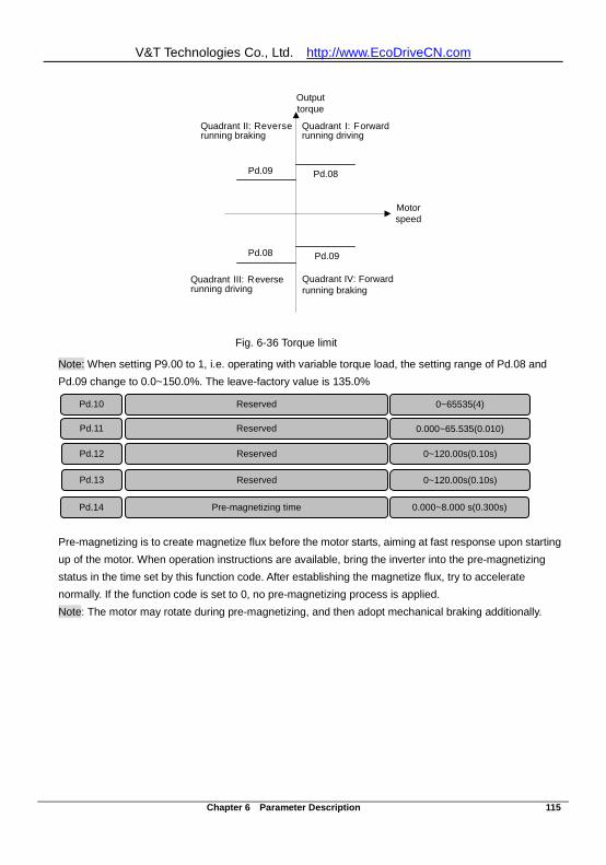
V&T Technologies Co., Ltd. http://www.EcoDriveCN.com
Chapter 6 Parameter Description 115
Quadrant I: Forward running driving
Quadrant II: Reverse running braking
Quadrant III: Reverse running driving
Quadrant IV: Forward running braking
Pd.09 Pd.08
Pd.08 Pd.09
Output torque
Motor speed
Fig. 6-36 Torque limit
Note: When setting P9.00 to 1, i.e. operating with variable torque load, the setting range of Pd.08 and Pd.09 change to 0.0~150.0%. The leave-factory value is 135.0%
Pre-magnetizing is to create magnetize flux before the motor starts, aiming at fast response upon starting up of the motor. When operation instructions are available, bring the inverter into the pre-magnetizing status in the time set by this function code. After establishing the magnetize flux, try to accelerate normally. If the function code is set to 0, no pre-magnetizing process is applied. Note: The motor may rotate during pre-magnetizing, and then adopt mechanical braking additionally.
Pd.10 Reserved 0~65535(4)
Pd.11 Reserved 0.000~65.535(0.010)
Pd.12 Reserved
0~120.00s(0.10s)
Pd.13 Reserved
0~120.00s(0.10s)
Pd.14 Pre-magnetizing time 0.000~8.000 s(0.300s)
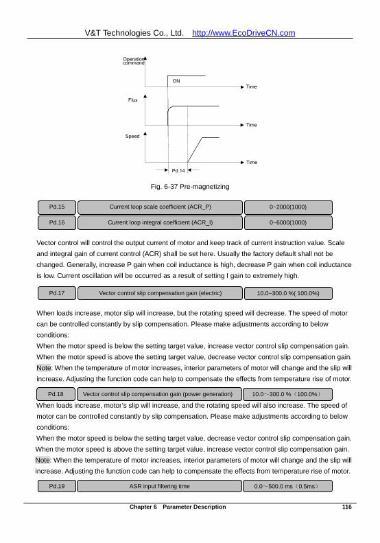
V&T Technologies Co., Ltd. http://www.EcoDriveCN.com
Chapter 6 Parameter Description 116
Time ON
Pd.14
Time
Time
Operation command
Flux
Speed
Fig. 6-37 Pre-magnetizing
Vector control will control the output current of motor and keep track of current instruction value. Scale and integral gain of current control (ACR) shall be set here. Usually the factory default shall not be changed. Generally, increase P gain when coil inductance is high, decrease P gain when coil inductance is low. Current oscillation will be occurred as a result of setting I gain to extremely high.
When loads increase, motor slip will increase, but the rotating speed will decrease. The speed of motor can be controlled constantly by slip compensation. Please make adjustments according to below conditions: When the motor speed is below the setting target value, increase vector control slip compensation gain. When the motor speed is above the setting target value, decrease vector control slip compensation gain. Note: When the temperature of motor increases, interior parameters of motor will change and the slip will increase. Adjusting the function code can help to compensate the effects from temperature rise of motor.
When loads increase, motor’s slip will increase, and the rotating speed will also increase. The speed of motor can be controlled constantly by slip compensation. Please make adjustments according to below conditions: When the motor speed is below the setting target value, decrease vector control slip compensation gain. When the motor speed is above the setting target value, increase vector control slip compensation gain. Note: When the temperature of motor increases, interior parameters of motor will change and the slip will increase. Adjusting the function code can help to compensate the effects from temperature rise of motor.
Pd.15 Current loop scale coefficient (ACR_P) 0~2000(1000) Pd.16 Current loop integral coefficient (ACR_I) 0~6000(1000)
Pd.17 Vector control slip compensation gain (electric) 10.0~300.0 %( 100.0%)
Pd.18 Vector control slip compensation gain (power generation) 10.0~300.0 %(100.0%)
Pd.19 ASR input filtering time 0.0~500.0 ms(0.5ms)
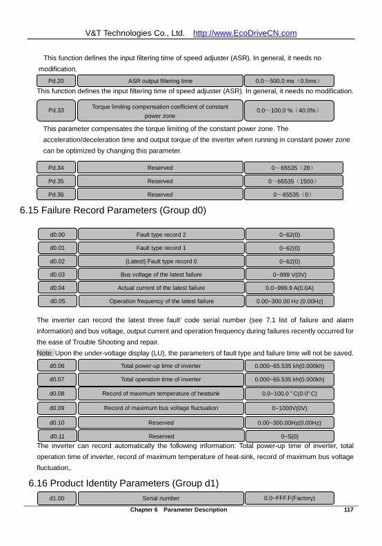
V&T Technologies Co., Ltd. http://www.EcoDriveCN.com
Chapter 6 Parameter Description 117
This function defines the input filtering time of speed adjuster (ASR). In general, it needs no modification. This function defines the input filtering time of speed adjuster (ASR). In general, it needs no modification.
This parameter compensates the torque limiting of the constant power zone. The acceleration/deceleration time and output torque of the inverter when running in constant power zone can be optimized by changing this parameter.
6.15 Failure Record Parameters (Group d0)
The inverter can record the latest three fault' code serial number (see 7.1 list of failure and alarm information) and bus voltage, output current and operation frequency during failures recently occurred for the ease of Trouble Shooting and repair. Note: Upon the under-voltage display (LU), the parameters of fault type and failure time will not be saved.
The inverter can record automatically the following information: Total power-up time of inverter, total operation time of inverter, record of maximum temperature of heat-sink, record of maximum bus voltage fluctuation,.
6.16 Product Identity Parameters (Group d1)
d0.00 Fault type record 2 0~62(0) d0.01 0~62(0) d0.02 (Latest) Fault type record 0 0~62(0) d0.03 Bus voltage of the latest failure 0~999 V(0V) d0.04 Actual current of the latest failure 0.0~999.9 A(0.0A) d0.05 Operation frequency of the latest failure 0.00~300.00 Hz (0.00Hz)
d0.06 Total power-up time of inverter 0.000~65.535 kh(0.000kh)
d0.07 Total operation time of inverter 0.000~65.535 kh(0.000kh)
d0.08
Record of maximum temperature of heatsink 0.0~100.0 ºC(0.0ºC)
d0.09
Record of maximum bus voltage fluctuation 0~1000V(0V)
d0.10
Reserved 0.00~300.00Hz(0.00Hz)
d0.11
Reserved 0~5(0)
d1.00 Serial number 0.0~FFF.F(Factory)
Fault type record 1
Pd.20 ASR output filtering time 0.0~500.0 ms(0.5ms)
Pd.33 Torque limiting compensation coefficient of constant power zone
0.0~100.0 %(40.0%)
Pd.34 Reserved 0~65535(28) Pd.35 0~65535(1500) Pd.36 Reserved
0~65535(0)
Reserved
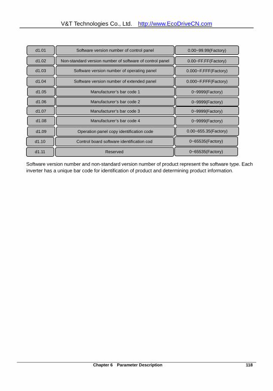
V&T Technologies Co., Ltd. http://www.EcoDriveCN.com
Chapter 6 Parameter Description 118
Software version number and non-standard version number of product represent the software type. Each inverter has a unique bar code for identification of product and determining product information.
d1.01 Software version number of control panel 0.00~99.99(Factory)
d1.02 Non-standard version number of software of control panel 0.00~FF.FF(Factory)
d1.03 Software version number of operating panel 0.000~F.FFF(Factory)
d1.04 Software version number of extended panel 0.000~F.FFF(Factory)
d1.05 Manufacturer’s bar code 1 0~9999(Factory)
d1.06 Manufacturer’s bar code 2 0~9999(Factory)
d1.07 Manufacturer’s bar code 3 0~9999(Factory)
d1.08 Manufacturer’s bar code 4 0~9999(Factory)
d1.09 Operation panel copy identification code 0.00~655.35(Factory)
d1.10 Control board software identification cod 0~65535(Factory)
d1.11 Reserved 0~65535(Factory)
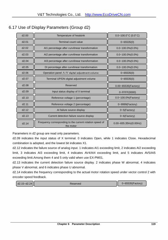
V&T Technologies Co., Ltd. http://www.EcoDriveCN.com
Chapter 6 Parameter Description 119
6.17 Use of Display Parameters (Group d2)
Parameters in d2 group are read only parameters. d2.09 indicates the input status of X terminal. 0 indicates Open, while 1 indicates Close. Hexadecimal combination is adopted, and the lowest bit indicates X1. d2.12 indicates the failure source of analog input. 1 indicates AI1 exceeding limit, 2 indicates AI2 exceeding limit, 3 indicates AI3 exceeding limit, 4 indicates AV4/AI4 exceeding limit, and 5 indicates AV5/AI5 exceeding limit.Among them 4 and 5 only valid when use EX-PM01. d2.13 indicates the current detection failure source display. 2 indicates phase W abnormal, 4 indicates phase V abnormal, and 6 indicates phase U abnormal. d2.14 indicates the frequency corresponding to the actual motor rotation speed under vector control 2 with encoder speed feedback.
d2.00 Temperature of heatsink 0.0~100.0ºC (0.0ºC)
d2.01 Terminal count value
0~65535(0)
d2.02 AI1 percentage after curvilinear transformation
0.0~100.0%(0.0%)
d2.03 AI2 percentage after curvilinear transformation
0.0~100.0%(0.0%)
d2.04 AI3 percentage after curvilinear transformation
0.0~100.0%(0.0%)
d2.05 DI percentage after curvilinear transformation
0.0~100.0%(0.0%)
d2.06 Operation panel ∧/∨ digital adjustment volume
0~65535(0)
d2.07 Terminal UP/DN digital adjustment volume
0~65535(0)
d2.08 Reserved
0.00~65535(Factory)
d2.09 Input status display of X terminal
0~FFFF(0000)
d2.10 Reference voltage 1 (percentage)
0.0~100.0%(Factory)
d2.11 Reference voltage 2 (percentage)
0~9999(Factory)
d2.12 AI failure source display
0~5(Factory)
d2.13 Current detection failure source display
0~6(Factory)
d2.14 Frequency corresponding to the current rotation speed of
the motor
0.00~655.35Hz(0.00Hz)
d2.15~d2.24 Reserved 0~65535(Factory)
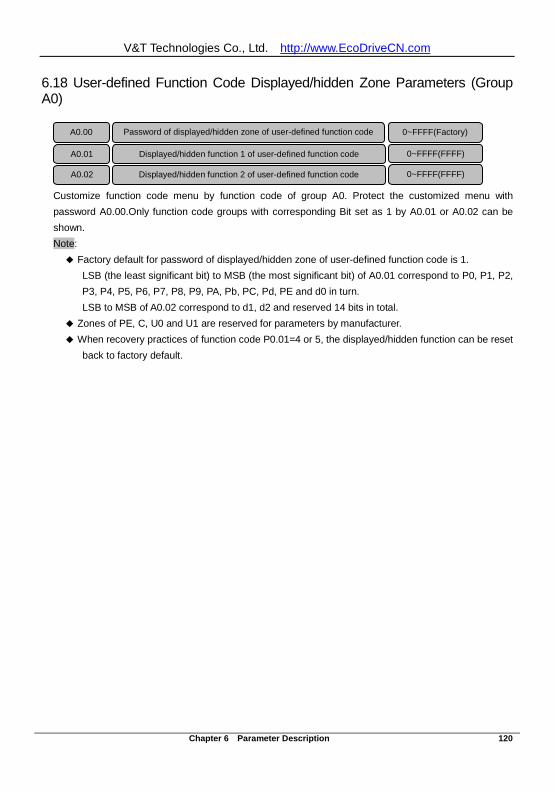
V&T Technologies Co., Ltd. http://www.EcoDriveCN.com
Chapter 6 Parameter Description 120
6.18 User-defined Function Code Displayed/hidden Zone Parameters (Group A0)
Customize function code menu by function code of group A0. Protect the customized menu with password A0.00.Only function code groups with corresponding Bit set as 1 by A0.01 or A0.02 can be shown. Note: Factory default for password of displayed/hidden zone of user-defined function code is 1.
LSB (the least significant bit) to MSB (the most significant bit) of A0.01 correspond to P0, P1, P2, P3, P4, P5, P6, P7, P8, P9, PA, Pb, PC, Pd, PE and d0 in turn. LSB to MSB of A0.02 correspond to d1, d2 and reserved 14 bits in total.
Zones of PE, C, U0 and U1 are reserved for parameters by manufacturer. When recovery practices of function code P0.01=4 or 5, the displayed/hidden function can be reset
back to factory default.
A0.00 Password of displayed/hidden zone of user-defined function code 0~FFFF(Factory)
A0.01 Displayed/hidden function 1 of user-defined function code 0~FFFF(FFFF)
A0.02 Displayed/hidden function 2 of user-defined function code 0~FFFF(FFFF)
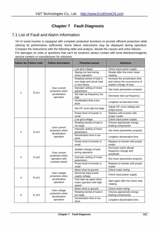
V&T Technologies Co., Ltd. http://www.EcoDriveCN.com
Chapter 7 Fault Diagnosis 121
Chapter 7 Fault Diagnosis
7.1 List of Fault and Alarm Information V5−H serial inverter is equipped with complete protection functions to provide efficient protection while utilizing its performance sufficiently. Some failure instructions may be displayed during operation. Compare the instructions with the following table and analyze, decide the causes and solve failures. For damages on units or questions that can’t be resolved, please contact with local distributors/agents, service centers or manufacturer for solutions.
Failure No. Failure code Failure description Potential causes Solutions
1 E.oc1
Over current protection when
acceleration operation
Low grid voltage Check input power supply Startup too fast during motor operation
Restart after the motor stops rotating
Rotating inertial of load is very large and shock load is very heavy
Increase the acceleration time and reduce the occurrences of sudden change of load
Improper setting of motor parameters Set motor parameters properly
Set start-up frequency too high Decrease start-up frequency
Acceleration time is too short Lengthen acceleration time
Set V/F curve ratio too large Adjust V/F curve setting and torque boost
Power level of inverter is small
Replace with inverter with proper model
2 E.oc2
Over current protection when
deceleration operation
Low grid voltage Check input power supply Rotating inertial of load is too large
Choose appropriate energy braking components
Improper setting of motor parameters Set motor parameters properly
Deceleration time is too short Lengthen deceleration time
Power level of inverter is small
Replace to inverter with proper model
3 E.oc3
Over current protection when operation with
constant speed
Sudden change of load during operation
Decrease load’s abrupt frequency change and amplitude
Improper setting of motor parameters Set motor parameters properly
Power level of inverter is small
Replace to inverter with proper model
4 E.oV1
Over voltage protection when
acceleration operation
Motor short to ground Check motor wiring Abnormal input power supply voltage Check input power supply
Fast start-up again when motor operates with high speed
Start again after the motor stop rotating
5 E.oV2
Over voltage protection when
deceleration operation
Motor short to ground Check motor wiring Rotating inertial of load is too large
Choose appropriate energy braking components
Deceleration time is too short Lengthen deceleration time
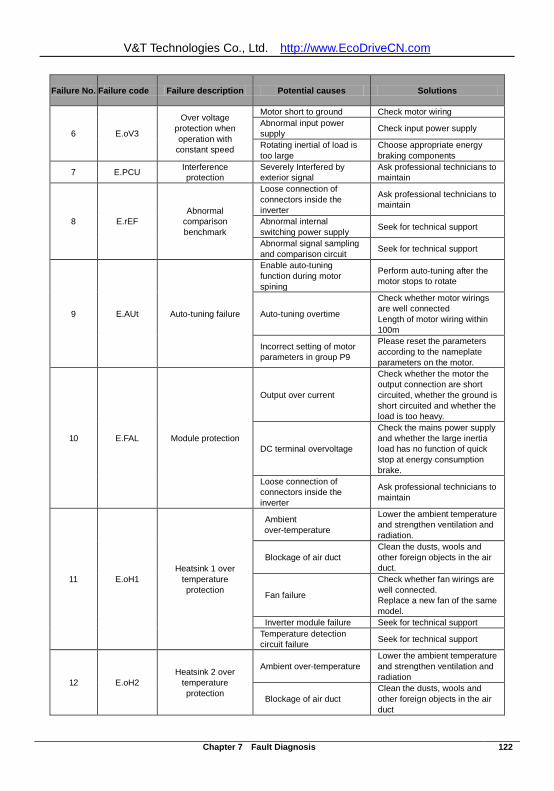
V&T Technologies Co., Ltd. http://www.EcoDriveCN.com
Chapter 7 Fault Diagnosis 122
Failure No. Failure code Failure description Potential causes Solutions
6 E.oV3
Over voltage protection when operation with
constant speed
Motor short to ground Check motor wiring Abnormal input power supply Check input power supply
Rotating inertial of load is too large
Choose appropriate energy braking components
7 E.PCU Interference protection
Severely Interfered by exterior signal
Ask professional technicians to maintain
8 E.rEF Abnormal
comparison benchmark
Loose connection of connectors inside the inverter
Ask professional technicians to maintain
Abnormal internal switching power supply Seek for technical support
Abnormal signal sampling and comparison circuit Seek for technical support
9 E.AUt Auto-tuning failure
Enable auto-tuning function during motor spining
Perform auto-tuning after the motor stops to rotate
Auto-tuning overtime
Check whether motor wirings are well connected Length of motor wiring within 100m
Incorrect setting of motor parameters in group P9
Please reset the parameters according to the nameplate parameters on the motor.
10 E.FAL Module protection
Output over current
Check whether the motor the output connection are short circuited, whether the ground is short circuited and whether the load is too heavy.
DC terminal overvoltage
Check the mains power supply and whether the large inertia load has no function of quick stop at energy consumption brake.
Loose connection of connectors inside the inverter
Ask professional technicians to maintain
11 E.oH1 Heatsink 1 over
temperature protection
Ambient over-temperature
Lower the ambient temperature and strengthen ventilation and radiation.
Blockage of air duct Clean the dusts, wools and other foreign objects in the air duct.
Fan failure
Check whether fan wirings are well connected. Replace a new fan of the same model.
Inverter module failure Seek for technical support Temperature detection circuit failure Seek for technical support
12 E.oH2 Heatsink 2 over
temperature protection
Ambient over-temperature Lower the ambient temperature and strengthen ventilation and radiation
Blockage of air duct Clean the dusts, wools and other foreign objects in the air duct
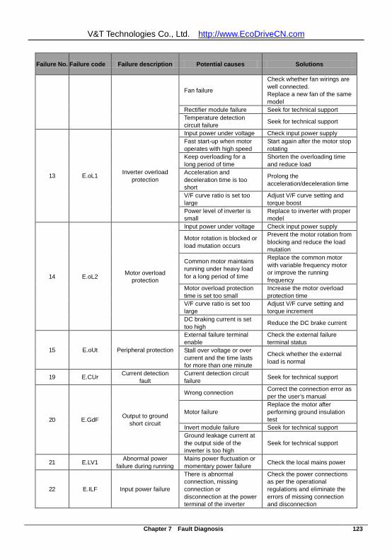
V&T Technologies Co., Ltd. http://www.EcoDriveCN.com
Chapter 7 Fault Diagnosis 123
Failure No. Failure code Failure description Potential causes Solutions
Fan failure
Check whether fan wirings are well connected. Replace a new fan of the same model
Rectifier module failure Seek for technical support Temperature detection circuit failure Seek for technical support
13 E.oL1 Inverter overload protection
Input power under voltage Check input power supply Fast start-up when motor operates with high speed
Start again after the motor stop rotating
Keep overloading for a long period of time
Shorten the overloading time and reduce load
Acceleration and deceleration time is too short
Prolong the acceleration/deceleration time
V/F curve ratio is set too large
Adjust V/F curve setting and torque boost
Power level of inverter is small
Replace to inverter with proper model
14 E.oL2 Motor overload protection
Input power under voltage Check input power supply
Motor rotation is blocked or load mutation occurs
Prevent the motor rotation from blocking and reduce the load mutation
Common motor maintains running under heavy load for a long period of time
Replace the common motor with variable frequency motor or improve the running frequency
Motor overload protection time is set too small
Increase the motor overload protection time
V/F curve ratio is set too large
Adjust V/F curve setting and torque increment
DC braking current is set too high Reduce the DC brake current
15 E.oUt Peripheral protection
External failure terminal enable
Check the external failure terminal status
Stall over voltage or over current and the time lasts for more than one minute
Check whether the external load is normal
19 E.CUr Current detection fault
Current detection circuit failure Seek for technical support
20 E.GdF Output to ground short circuit
Wrong connection Correct the connection error as per the user’s manual
Motor failure Replace the motor after performing ground insulation test
Invert module failure Seek for technical support Ground leakage current at the output side of the inverter is too high
Seek for technical support
21 E.LV1 Abnormal power failure during running
Mains power fluctuation or momentary power failure Check the local mains power
22 E.ILF Input power failure
There is abnormal connection, missing connection or disconnection at the power terminal of the inverter
Check the power connections as per the operational regulations and eliminate the errors of missing connection and disconnection
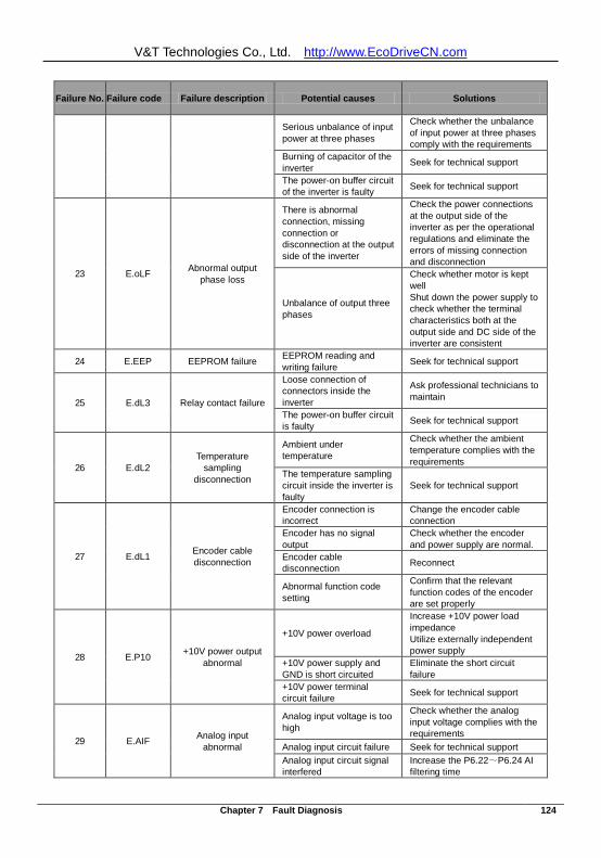
V&T Technologies Co., Ltd. http://www.EcoDriveCN.com
Chapter 7 Fault Diagnosis 124
Failure No. Failure code Failure description Potential causes Solutions
Serious unbalance of input power at three phases
Check whether the unbalance of input power at three phases comply with the requirements
Burning of capacitor of the inverter Seek for technical support
The power-on buffer circuit of the inverter is faulty Seek for technical support
23 E.oLF Abnormal output phase loss
There is abnormal connection, missing connection or disconnection at the output side of the inverter
Check the power connections at the output side of the inverter as per the operational regulations and eliminate the errors of missing connection and disconnection
Unbalance of output three phases
Check whether motor is kept well Shut down the power supply to check whether the terminal characteristics both at the output side and DC side of the inverter are consistent
24 E.EEP EEPROM failure EEPROM reading and writing failure Seek for technical support
25 E.dL3 Relay contact failure
Loose connection of connectors inside the inverter
Ask professional technicians to maintain
The power-on buffer circuit is faulty Seek for technical support
26 E.dL2 Temperature
sampling disconnection
Ambient under temperature
Check whether the ambient temperature complies with the requirements
The temperature sampling circuit inside the inverter is faulty
Seek for technical support
27 E.dL1 Encoder cable disconnection
Encoder connection is incorrect
Change the encoder cable connection
Encoder has no signal output
Check whether the encoder and power supply are normal.
Encoder cable disconnection Reconnect
Abnormal function code setting
Confirm that the relevant function codes of the encoder are set properly
28 E.P10 +10V power output abnormal
+10V power overload
Increase +10V power load impedance Utilize externally independent power supply
+10V power supply and GND is short circuited
Eliminate the short circuit failure
+10V power terminal circuit failure Seek for technical support
29 E.AIF Analog input abnormal
Analog input voltage is too high
Check whether the analog input voltage complies with the requirements
Analog input circuit failure Seek for technical support Analog input circuit signal interfered
Increase the P6.22~P6.24 AI filtering time
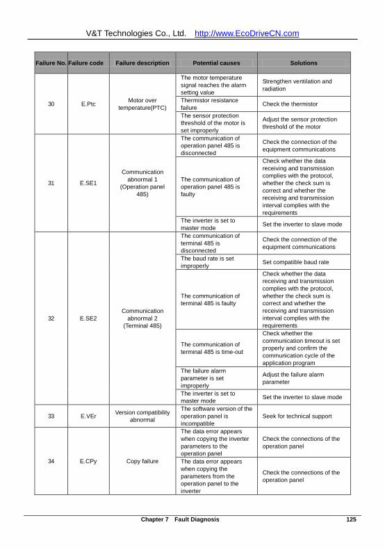
V&T Technologies Co., Ltd. http://www.EcoDriveCN.com
Chapter 7 Fault Diagnosis 125
Failure No. Failure code Failure description Potential causes Solutions
30 E.Ptc Motor over temperature(PTC)
The motor temperature signal reaches the alarm setting value
Strengthen ventilation and radiation
Thermistor resistance failure Check the thermistor
The sensor protection threshold of the motor is set improperly
Adjust the sensor protection threshold of the motor
31 E.SE1
Communication abnormal 1
(Operation panel 485)
The communication of operation panel 485 is disconnected
Check the connection of the equipment communications
The communication of operation panel 485 is faulty
Check whether the data receiving and transmission complies with the protocol, whether the check sum is correct and whether the receiving and transmission interval complies with the requirements
The inverter is set to master mode Set the inverter to slave mode
32 E.SE2 Communication
abnormal 2 (Terminal 485)
The communication of terminal 485 is disconnected
Check the connection of the equipment communications
The baud rate is set improperly Set compatible baud rate
The communication of terminal 485 is faulty
Check whether the data receiving and transmission complies with the protocol, whether the check sum is correct and whether the receiving and transmission interval complies with the requirements
The communication of terminal 485 is time-out
Check whether the communication timeout is set properly and confirm the communication cycle of the application program
The failure alarm parameter is set improperly
Adjust the failure alarm parameter
The inverter is set to master mode Set the inverter to slave mode
33 E.VEr Version compatibility abnormal
The software version of the operation panel is incompatible
Seek for technical support
34 E.CPy Copy failure
The data error appears when copying the inverter parameters to the operation panel
Check the connections of the operation panel
The data error appears when copying the parameters from the operation panel to the inverter
Check the connections of the operation panel
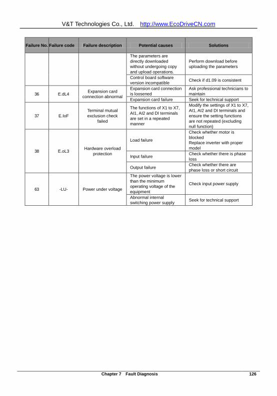
V&T Technologies Co., Ltd. http://www.EcoDriveCN.com
Chapter 7 Fault Diagnosis 126
Failure No. Failure code Failure description Potential causes Solutions
The parameters are directly downloaded without undergoing copy and upload operations.
Perform download before uploading the parameters
Control board software version incompatible Check if d1.09 is consistent
36 E.dL4 Expansion card connection abnormal
Expansion card connection is loosened
Ask professional technicians to maintain
Expansion card failure Seek for technical support
37 E.IoF Terminal mutual exclusion check
failed
The functions of X1 to X7, AI1, AI2 and DI terminals are set in a repeated manner
Modify the settings of X1 to X7, AI1, AI2 and DI terminals and ensure the setting functions are not repeated (excluding null function)
38 E.oL3 Hardware overload protection
Load failure
Check whether motor is blocked Replace inverter with proper model
Input failure Check whether there is phase loss
Output failure Check whether there are phase loss or short circuit
63 -LU- Power under voltage
The power voltage is lower than the minimum operating voltage of the equipment
Check input power supply
Abnormal internal switching power supply Seek for technical support
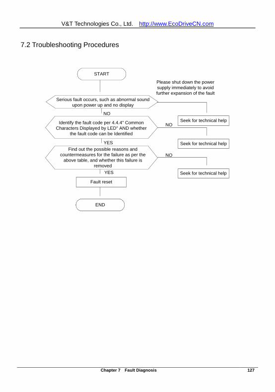
V&T Technologies Co., Ltd. http://www.EcoDriveCN.com
Chapter 7 Fault Diagnosis 127
7.2 Troubleshooting Procedures
START
Seek for technical help
Fault reset
NO
YES
NO
Please shut down the power supply immediately to avoid further expansion of the fault
NO
YES Seek for technical help
Seek for technical help
END
Identify the fault code per 4.4.4" Common Characters Displayed by LED" AND whether
the fault code can be Identified
Find out the possible reasons and countermeasures for the failure as per the
above table, and whether this failure is removed
Serious fault occurs, such as abnormal sound upon power up and no display
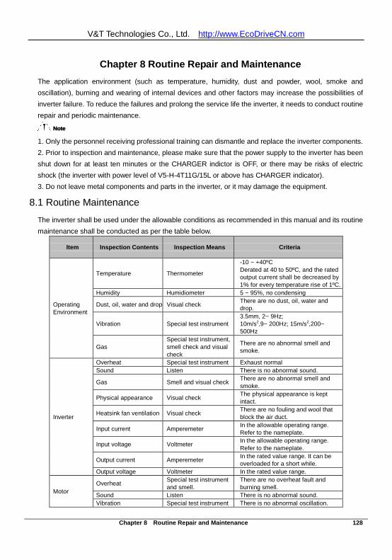
V&T Technologies Co., Ltd. http://www.EcoDriveCN.com
Chapter 8 Routine Repair and Maintenance 128
Chapter 8 Routine Repair and Maintenance The application environment (such as temperature, humidity, dust and powder, wool, smoke and oscillation), burning and wearing of internal devices and other factors may increase the possibilities of inverter failure. To reduce the failures and prolong the service life the inverter, it needs to conduct routine repair and periodic maintenance.
NoteNote 1. Only the personnel receiving professional training can dismantle and replace the inverter components. 2. Prior to inspection and maintenance, please make sure that the power supply to the inverter has been shut down for at least ten minutes or the CHARGER indictor is OFF, or there may be risks of electric shock (the inverter with power level of V5-H-4T11G/15L or above has CHARGER indicator). 3. Do not leave metal components and parts in the inverter, or it may damage the equipment.
8.1 Routine Maintenance
The inverter shall be used under the allowable conditions as recommended in this manual and its routine maintenance shall be conducted as per the table below.
Item Inspection Contents Inspection Means Criteria
Operating Environment
Temperature Thermometer
-10 ~ +40ºC Derated at 40 to 50ºC, and the rated output current shall be decreased by 1% for every temperature rise of 1ºC.
Humidity Humidiometer 5 ~ 95%, no condensing
Dust, oil, water and drop Visual check There are no dust, oil, water and drop.
Vibration Special test instrument 3.5mm, 2~ 9Hz; 10m/s2,9~ 200Hz; 15m/s2,200~ 500Hz
Gas Special test instrument, smell check and visual check
There are no abnormal smell and smoke.
Inverter
Overheat Special test instrument Exhaust normal Sound Listen There is no abnormal sound.
Gas Smell and visual check There are no abnormal smell and smoke.
Physical appearance Visual check The physical appearance is kept intact.
Heatsink fan ventilation Visual check There are no fouling and wool that block the air duct.
Input current Amperemeter In the allowable operating range. Refer to the nameplate.
Input voltage Voltmeter In the allowable operating range. Refer to the nameplate.
Output current Amperemeter In the rated value range. It can be overloaded for a short while.
Output voltage Voltmeter In the rated value range.
Motor Overheat Special test instrument
and smell. There are no overheat fault and burning smell.
Sound Listen There is no abnormal sound. Vibration Special test instrument There is no abnormal oscillation.
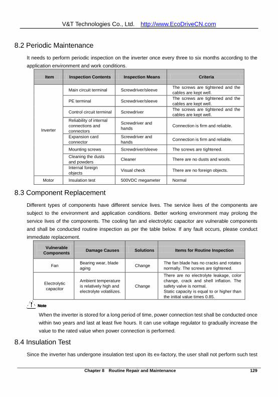
V&T Technologies Co., Ltd. http://www.EcoDriveCN.com
Chapter 8 Routine Repair and Maintenance 129
8.2 Periodic Maintenance
It needs to perform periodic inspection on the inverter once every three to six months according to the application environment and work conditions.
Item Inspection Contents Inspection Means Criteria
Inverter
Main circuit terminal Screwdriver/sleeve The screws are tightened and the cables are kept well.
PE terminal Screwdriver/sleeve The screws are tightened and the cables are kept well.
Control circuit terminal Screwdriver The screws are tightened and the cables are kept well.
Reliability of internal connections and connectors
Screwdriver and hands Connection is firm and reliable.
Expansion card connector
Screwdriver and hands Connection is firm and reliable.
Mounting screws Screwdriver/sleeve The screws are tightened.
Cleaning the dusts and powders Cleaner There are no dusts and wools.
Internal foreign objects Visual check There are no foreign objects.
Motor Insulation test 500VDC megameter Normal
8.3 Component Replacement
Different types of components have different service lives. The service lives of the components are subject to the environment and application conditions. Better working environment may prolong the service lives of the components. The cooling fan and electrolytic capacitor are vulnerable components and shall be conducted routine inspection as per the table below. If any fault occurs, please conduct immediate replacement.
Vulnerable Components Damage Causes Solutions Items for Routine Inspection
Fan Bearing wear, blade aging Change The fan blade has no cracks and rotates
normally. The screws are tightened.
Electrolytic capacitor
Ambient temperature is relatively high and electrolyte volatilizes.
Change
There are no electrolyte leakage, color change, crack and shell inflation. The safety valve is normal. Static capacity is equal to or higher than the initial value times 0.85.
NoteNote When the inverter is stored for a long period of time, power connection test shall be conducted once within two years and last at least five hours. It can use voltage regulator to gradually increase the value to the rated value when power connection is performed.
8.4 Insulation Test
Since the inverter has undergone insulation test upon its ex-factory, the user shall not perform such test
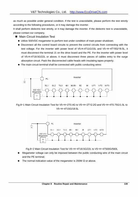
V&T Technologies Co., Ltd. http://www.EcoDriveCN.com
Chapter 8 Routine Repair and Maintenance 130
as much as possible under general condition. If the test is unavoidable, please perform the test strictly according to the following procedures, or it may damage the inverter. It shall perform dielectric test strictly, or it may damage the inverter. If the dielectric test is unavoidable, please contact our company. Main Circuit Insulation Test Utilize 500VDC megameter to perform test under condition of main power shutdown; Disconnect all the control board circuits to prevent the control circuits from connecting with the
test voltage. For the inverter with power level of V5-H-4T11G/15L and V5−H−4T15G/18.5L, it must disconnect the terminal J1 on the drive board and the PE. For the inverter with power level of V5-H-4T18.5G/22L or above, it must disconnect three pieces of cables entry to the surge absorption circuit. Pack the disconnected cable heads with insulating tapes properly;
The main circuit terminal shall be connected with public conducting wires:
Fig.8−1 Main Circuit Insulation Test for V5−H−2T0.4G to V5−H−2T12.2G and V5−H−4T0.75G/1.5L to
V5−H−4T15G/18.5L
Fig.8−2 Main Circuit Insulation Test for V5−H−4T18.5G/22L to V5−H−4T500G/560L
Megameter voltage can only be imposed between the public conducting wire of the main circuit and the PE terminal;
The normal indication value of the megameter is 200M Ω or above.
Inverter
Megameter
Inverter
Megameter
Inverter
Megameter
Inverter
Megameter
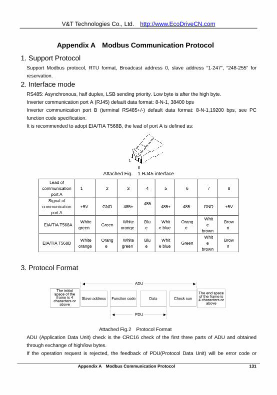
V&T Technologies Co., Ltd. http://www.EcoDriveCN.com
Appendix A Modbus Communication Protocol 131
Appendix A Modbus Communication Protocol
1. Support Protocol Support Modbus protocol, RTU format, Broadcast address 0, slave address “1-247”, “248-255” for reservation.
2. Interface mode RS485: Asynchronous, half duplex, LSB sending priority. Low byte is after the high byte. Inverter communication port A (RJ45) default data format: 8-N-1, 38400 bps Inverter communication port B (terminal RS485+/-) default data format: 8-N-1,19200 bps, see PC function code specification. It is recommended to adopt EIA/TIA T568B, the lead of port A is defined as:
Attached Fig. 1 RJ45 interface
Lead of communication
port A 1 2 3 4 5 6 7 8
Signal of communication
port A +5V GND 485+
485-
485+ 485- GND +5V
EIA/TIA T568A White green Green White
orange Blue
White blue
Orange
White
brown Brow
n
EIA/TIA T568B White orange
Orange
White green
Blue
White blue Green
White
brown Brow
n
3. Protocol Format
Check sun
The initial space of the frame is 4
characters or above
Data Slave address Function code
ADU
PDU
The end space of the frame is 4 characters or
above
Attached Fig.2 Protocol Format
ADU (Application Data Unit) check is the CRC16 check of the first three parts of ADU and obtained through exchange of high/low bytes. If the operation request is rejected, the feedback of PDU(Protocol Data Unit) will be error code or
1
8
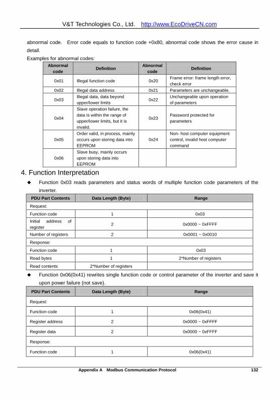
V&T Technologies Co., Ltd. http://www.EcoDriveCN.com
Appendix A Modbus Communication Protocol 132
abnormal code. Error code equals to function code +0x80, abnormal code shows the error cause in detail. Examples for abnormal codes:
Abnormal code
Definition Abnormal code
Definition
0x01 Illegal function code 0x20 Frame error: frame length error, check error
0x02 Illegal data address 0x21 Parameters are unchangeable.
0x03 Illegal data, data beyond upper/lower limits
0x22 Unchangeable upon operation of parameters
0x04
Slave operation failure, the data is within the range of upper/lower limits, but it is invalid.
0x23 Password protected for parameters
0x05 Order valid, in process, mainly occurs upon storing data into EEPROM
0x24 Non- host computer equipment control, invalid host computer command
0x06 Slave busy, mainly occurs upon storing data into EEPROM
4. Function Interpretation Function 0x03 reads parameters and status words of multiple function code parameters of the
inverter. PDU Part Contents Data Length (Byte) Range
Request:
Function code 1 0x03 Initial address of register
2 0x0000 ~ 0xFFFF
Number of registers 2 0x0001 ~ 0x0010
Response:
Function code 1 0x03
Read bytes 1 2*Number of registers
Read contents 2*Number of registers
Function 0x06(0x41) rewrites single function code or control parameter of the inverter and save it upon power failure (not save).
PDU Part Contents Data Length (Byte) Range
Request:
Function code 1 0x06(0x41)
Register address 2 0x0000 ~ 0xFFFF
Register data 2 0x0000 ~ 0xFFFF
Response:
Function code 1 0x06(0x41)
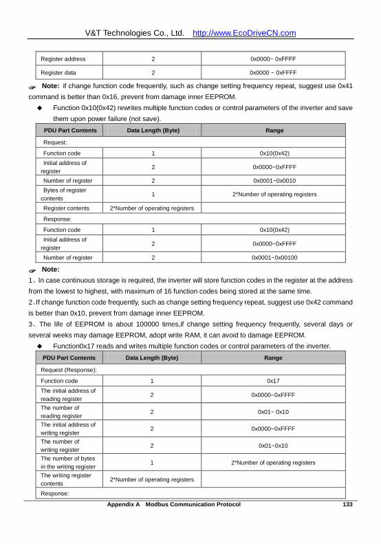
V&T Technologies Co., Ltd. http://www.EcoDriveCN.com
Appendix A Modbus Communication Protocol 133
Register address 2 0x0000~ 0xFFFF
Register data 2 0x0000 ~ 0xFFFF
Note: if change function code frequently, such as change setting frequency repeat, suggest use 0x41 command is better than 0x16, prevent from damage inner EEPROM. Function 0x10(0x42) rewrites multiple function codes or control parameters of the inverter and save
them upon power failure (not save). PDU Part Contents Data Length (Byte) Range
Request:
Function code 1 0x10(0x42) Initial address of
register 2 0x0000~0xFFFF
Number of register 2 0x0001~0x0010 Bytes of register
contents 1 2*Number of operating registers
Register contents 2*Number of operating registers
Response:
Function code 1 0x10(0x42) Initial address of
register 2 0x0000~0xFFFF
Number of register 2 0x0001~0x00100
Note: 1、In case continuous storage is required, the inverter will store function codes in the register at the address from the lowest to highest, with maximum of 16 function codes being stored at the same time. 2、If change function code frequently, such as change setting frequency repeat, suggest use 0x42 command is better than 0x10, prevent from damage inner EEPROM. 3、The life of EEPROM is about 100000 times,if change setting frequency frequently, several days or several weeks may damage EEPROM, adopt write RAM, it can avoid to damage EEPROM. Function0x17 reads and writes multiple function codes or control parameters of the inverter.
PDU Part Contents Data Length (Byte) Range
Request (Response):
Function code 1 0x17
The initial address of reading register
2 0x0000~0xFFFF
The number of reading register
2 0x01~ 0x10
The initial address of writing register
2 0x0000~0xFFFF
The number of writing register
2 0x01~0x10
The number of bytes in the writing register
1 2*Number of operating registers
The writing register contents
2*Number of operating registers
Response:
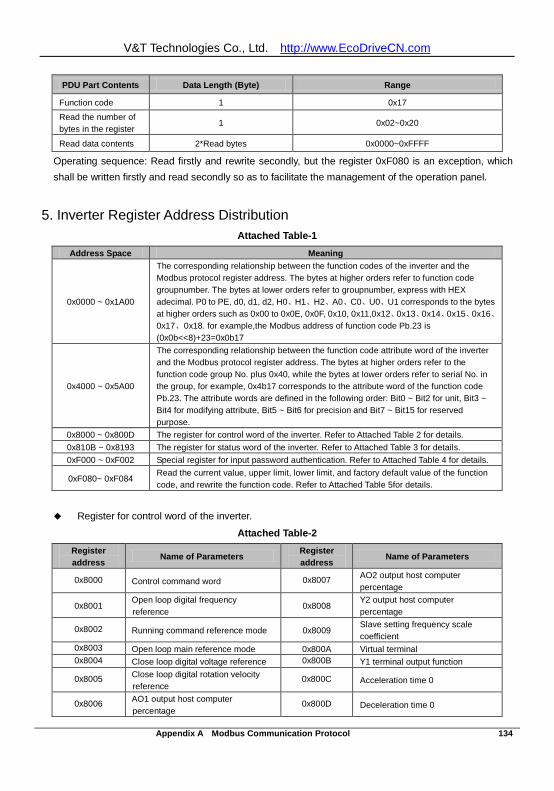
V&T Technologies Co., Ltd. http://www.EcoDriveCN.com
Appendix A Modbus Communication Protocol 134
PDU Part Contents Data Length (Byte) Range
Function code 1 0x17
Read the number of bytes in the register
1 0x02~0x20
Read data contents 2*Read bytes 0x0000~0xFFFF
Operating sequence: Read firstly and rewrite secondly, but the register 0xF080 is an exception, which shall be written firstly and read secondly so as to facilitate the management of the operation panel.
5. Inverter Register Address Distribution
Attached Table-1 Address Space Meaning
0x0000 ~ 0x1A00
The corresponding relationship between the function codes of the inverter and the Modbus protocol register address. The bytes at higher orders refer to function code groupnumber. The bytes at lower orders refer to groupnumber, express with HEX adecimal. P0 to PE, d0, d1, d2, H0、H1、H2、A0、C0、U0、U1 corresponds to the bytes at higher orders such as 0x00 to 0x0E, 0x0F, 0x10, 0x11,0x12、0x13、0x14、0x15、0x16、0x17、0x18. for example,the Modbus address of function code Pb.23 is (0x0b<<8)+23=0x0b17
0x4000 ~ 0x5A00
The corresponding relationship between the function code attribute word of the inverter and the Modbus protocol register address. The bytes at higher orders refer to the function code group No. plus 0x40, while the bytes at lower orders refer to serial No. in the group, for example, 0x4b17 corresponds to the attribute word of the function code Pb.23. The attribute words are defined in the following order: Bit0 ~ Bit2 for unit, Bit3 ~ Bit4 for modifying attribute, Bit5 ~ Bit6 for precision and Bit7 ~ Bit15 for reserved purpose.
0x8000 ~ 0x800D The register for control word of the inverter. Refer to Attached Table 2 for details. 0x810B ~ 0x8193 The register for status word of the inverter. Refer to Attached Table 3 for details. 0xF000 ~ 0xF002 Special register for input password authentication. Refer to Attached Table 4 for details.
0xF080~ 0xF084 Read the current value, upper limit, lower limit, and factory default value of the function code, and rewrite the function code. Refer to Attached Table 5for details.
Register for control word of the inverter.
Attached Table-2 Register address
Name of Parameters Register address
Name of Parameters
0x8000 Control command word 0x8007 AO2 output host computer percentage
0x8001 Open loop digital frequency reference
0x8008 Y2 output host computer percentage
0x8002 Running command reference mode 0x8009 Slave setting frequency scale coefficient
0x8003 Open loop main reference mode 0x800A Virtual terminal 0x8004 Close loop digital voltage reference 0x800B Y1 terminal output function
0x8005 Close loop digital rotation velocity reference
0x800C Acceleration time 0
0x8006 AO1 output host computer percentage
0x800D Deceleration time 0

V&T Technologies Co., Ltd. http://www.EcoDriveCN.com
Appendix A Modbus Communication Protocol 135
Register address
Name of Parameters Register address
Name of Parameters
Note: The virtual terminals from LSB to MSB are X1, X2, X3, X4, X5, X6, X7, AI1, AI2, AI3, Y1, Y2 and relay, bit13 ~ bit15 are reserved.
Register for status word of the inverter.
Attached Table-3
Register Name of Parameters Precision Register Name of Parameters Precision
0x810B Equipment status word 1 0x8114 Display parameters of
stopping status
According to
currently stopping
display
0x810E Equipment status word 4 0x8116 Display parameters of
running status
According to
currently running
display
0x8120 Reference frequency(Hz) 0.01Hz 0x8180 Reference frequency(Hz) 0.01Hz
0x8122 Bus voltage(V) 1V 0x8182 Bus voltage(V) 1V
0x8124 AI1(V) 0.01V 0x8184 AI1(V) 0.01V
0x8126 AI2(V) 0.01V 0x8186 AI2(V) 0.01V
0x8128 AI3(V) 0.01V 0x8188 AI3(V) 0.01V
0x812A DI(%) 0.1% 0x818A DI(%) 0.1%
0x812C External counts 1 0x818C External counts 1
0x812E Rotate speed of motor 1 0x818E Rotate speed of motor 1
0x8130 Close loop reference (%) 0.1% 0x8190 Close loop reference (%) 0.1%
0x8132 Close loop feedback (%) 0.1% 0x8192 Close loop feedback (%) 0.1%
0x8134 Reference torque(%) 0.1% 0x8194 Reference torque (%) 0.1%
0x8136 Operating frequency (Hz) 0.01Hz 0x8196 Reserved
0x8138 Output current(A) 0.1A or
0.01A 0x8198 Reserved
0x813A Output torque(%) 0.1% 0x819A Reserved
0x813C Output power (kW) 0.1kW 0x819C Reserved
0x813E Output voltage(V) 1V 0x819E Reserved
Note:0x8121~0x819Fodd numbers are display attribute word,from LSB to MSB are Hex/Dec for 1bit, precision for 2bit,
modification for 2bit and unit for 3Bit.
The register addresses 0x8120 ~0x813F refer to the display parameters corresponding to P2.02, while the register
addresses 0x8180 ~0x8193 refer to the display parameters corresponding to P2.03.
The inverter of 3.7kw and below,the output current display precision is 0.01A, 5.5kw and above output current
display precision is 0.1A,
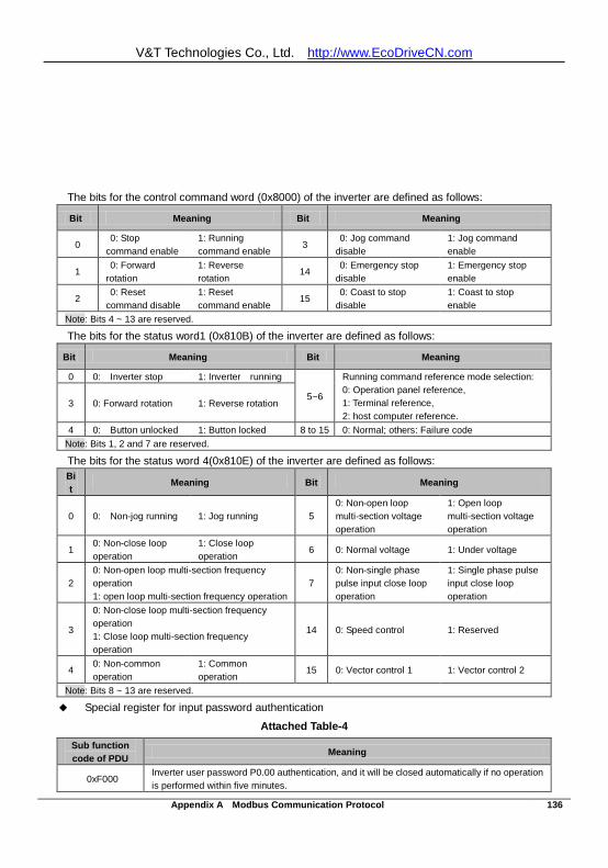
V&T Technologies Co., Ltd. http://www.EcoDriveCN.com
Appendix A Modbus Communication Protocol 136
The bits for the control command word (0x8000) of the inverter are defined as follows:
Bit Meaning Bit Meaning
0 0: Stop
command enable 1: Running command enable
3 0: Jog command
disable 1: Jog command enable
1 0: Forward
rotation 1: Reverse rotation
14 0: Emergency stop
disable 1: Emergency stop enable
2 0: Reset
command disable 1: Reset command enable
15 0: Coast to stop
disable 1: Coast to stop enable
Note: Bits 4 ~ 13 are reserved.
The bits for the status word1 (0x810B) of the inverter are defined as follows:
Bit Meaning Bit Meaning
0 0: Inverter stop 1: Inverter running
5~6
Running command reference mode selection: 0: Operation panel reference, 1: Terminal reference, 2: host computer reference.
3 0: Forward rotation 1: Reverse rotation
4 0: Button unlocked 1: Button locked 8 to 15 0: Normal; others: Failure code Note: Bits 1, 2 and 7 are reserved.
The bits for the status word 4(0x810E) of the inverter are defined as follows: Bit
Meaning Bit Meaning
0 0: Non-jog running 1: Jog running 5 0: Non-open loop multi-section voltage operation
1: Open loop multi-section voltage operation
1 0: Non-close loop operation
1: Close loop operation
6 0: Normal voltage 1: Under voltage
2 0: Non-open loop multi-section frequency operation 1: open loop multi-section frequency operation
7 0: Non-single phase pulse input close loop operation
1: Single phase pulse input close loop operation
3
0: Non-close loop multi-section frequency operation 1: Close loop multi-section frequency operation
14 0: Speed control 1: Reserved
4 0: Non-common operation
1: Common operation
15 0: Vector control 1 1: Vector control 2
Note: Bits 8 ~ 13 are reserved.
Special register for input password authentication
Attached Table-4 Sub function code of PDU Meaning
0xF000 Inverter user password P0.00 authentication, and it will be closed automatically if no operation is performed within five minutes.
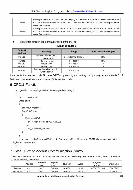
V&T Technologies Co., Ltd. http://www.EcoDriveCN.com
Appendix A Modbus Communication Protocol 137
0xF001 PE.00 password authentication for the display and hidden areas of the specially authenticated function codes of the inverter, and it will be closed automatically if no operation is performed within five minutes.
0xF002 A0.00 password authentication for the display and hidden attributes customized areas of the function codes of the inverter, and it will be closed automatically if no operation is performed within five minutes.
Register for function code characteristics of the inverter
Attached Table-5 Register address Meaning Range Read (R) and Write (W)
0xF080 Relative address of the function code See Attached Table-1 R/W
0xF081 Current value 0 ~ 65535 R/W 0xF082 Upper Limit 0 ~ 65535 R 0xF083 Lower Limit 0 ~ 65535 R
0xF084 Factory default value of the function code 0 ~ 65535 R
It can write the function code No. into 0xF080 by reading and writing multiple register commands 0x17 firstly and then read several attributes of this function code.
6. CRC16 Function unsigned int crc16(unsigned char *data,unsigned char length)
int i,crc_result=0xffff;
while(length--)
crc_result^=*data++;
for(i=0; i<8; i++)
if(crc_result&0x01)
crc_result=(crc_result>>1) ^0xa001;
else
crc_result=crc_result>>1;
return (crc_result=((crc_result&0xff) <<8) |(crc_result>>8) ) ; //Exchange CRC16 check sum and bytes at higher and lower orders
7. Case Study of Modbus Communication Control Start No.1 inverter to perform forward rotation, and set the rotation velocity to 50.00Hz (indicating 5,000 internally) as per the following commands:
Address Function
code Register Address
Number Bytes Register Contents
Check Sum
Request 0x01 0x10 0x8000 0x0002 0x04 0x0001,0x1388 0xCEFF Response 0x01 0x10 0x8000 0x0004 None None 0xE80A
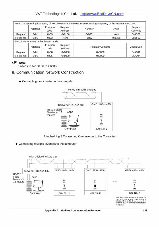
V&T Technologies Co., Ltd. http://www.EcoDriveCN.com
Appendix A Modbus Communication Protocol 138
Read the operating frequency of No.1 inverter and the response operating frequency of the inverter is 50.00Hz:
Address Function
code Register Address
Number Bytes Register Contents
Request 0x01 0x03 0x8136 0x0001 None 0x4C38 Response 0x01 0x03 None 0x02 0x1388 0xB512 No.1 inverter stops in the default mode:
Address Function
code Register Address
Register Contents Check Sum
Request 0x01 0x06 0x8000 0x0000 0xA00A Response 0x01 0x06 0x8000 0x0000 0xA00A
Note:
It needs to set P0.06 to 2 firstly.
8. Communication Network Construction
Connecting one inverter to the computer
Computer
Converter RS232-485
RS232 cableMaximum 15 meters
Site No.1
GND 485+ 485-
Twisted pair with shielded
GND
Attached Fig.3 Connecting One Inverter to the Computer
Connecting multiple inverters to the computer
The switch of terminal resistor of the inverter at the most distant p lace id turn to ON, s tar t , the internal 100Ω terminal compatible resistance
Site No. 2 Site No. nComputer
converter RS232-485RS232 cableMaximum 15 meters
Site No. 1
GND 485+ 485-
With shielded twisted pair
GND
GND 485+ 485-
GND 485+ 485-
······

V&T Technologies Co., Ltd. http://www.EcoDriveCN.com
Appendix A Modbus Communication Protocol 139
Attached Fig.4 Connecting Multiple Inverters to the Computer
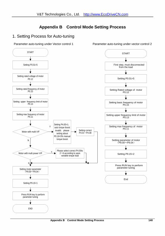
V&T Technologies Co., Ltd. http://www.EcoDriveCN.com
Appendix B Control Mode Setting Process 140
Appendix B Control Mode Setting Process
1. Setting Process for Auto-tuning
Parameter auto-tuning under Vector control 1 Parameter auto-tuning under vector control 2
START
Setting P0.01=5
Setting rated voltage of motor P0.12
Setting rated frequency of motor P0.15
Setting upper frequency limit of motor P0.13
Setting max frequency of motor P0.11
Setting motor parameter (P9.00~P9.04)
Setting P9.15=1
Press RUN key to perform parameter tuning
END
Motor with multi V/F
Setting P4.00=1,auto torque boost invalid, please
setting about P0.16=3% manual
torque boost
Motor with multi power V/F Please select correct P4.00to
2~6 according to upon variable torque load
Setting correct P4.01~P4.08
N
Y
Y
N
START
Setting P0.01=5
Setting Rated voltage of motor P0.12
Setting basic frequency of motor P0.15
Setting upper frequency limit of motor P0.13
Setting max frequency of motor P0.11
Setting parameter of motor (P9.00~P9.04)
Setting P9.15=2
Press RUN key to perform parameter tuning
End
First step, must disconnected from the load
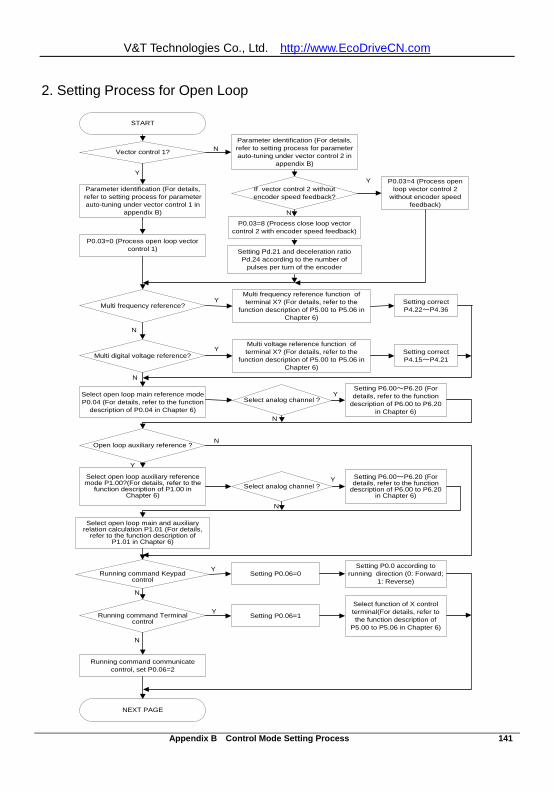
V&T Technologies Co., Ltd. http://www.EcoDriveCN.com
Appendix B Control Mode Setting Process 141
2. Setting Process for Open Loop
START
Parameter identification (For details, refer to setting process for parameter auto-tuning under vector control 1 in
appendix B)
Select open loop main reference mode P0.04 (For details, refer to the function
description of P0.04 in Chapter 6)
Select open loop main and auxiliary relation calculation P1.01 (For details,
refer to the function description of P1.01 in Chapter 6)
Select function of X control terminal(For details, refer to the function description of
P5.00 to P5.06 in Chapter 6)
Open loop auxiliary reference ?
Select open loop auxiliary reference mode P1.00?(For details, refer to the
function description of P1.00 in Chapter 6)
Multi digital voltage reference?
Multi voltage reference function of terminal X? (For details, refer to the
function description of P5.00 to P5.06 in Chapter 6)
Setting correct P4.15~P4.21
Multi frequency reference?
Multi frequency reference function of terminal X? (For details, refer to the
function description of P5.00 to P5.06 in Chapter 6)
Setting correct P4.22~P4.36
Running command Keypad control
Running command Terminal control
Setting P0.06=1
Setting P0.06=0Setting P0.0 according to
running direction (0: Forward; 1: Reverse)
Running command communicate control, set P0.06=2
Select analog channel ?
Select analog channel ?Setting P6.00~P6.20 (For details, refer to the function
description of P6.00 to P6.20 in Chapter 6)
Setting P6.00~P6.20 (For details, refer to the function
description of P6.00 to P6.20 in Chapter 6)
N
Y
N
Y
N
Y
Y
N
Y
N
N
Y
N
Y
NEXT PAGE
Vector control 1?
If vector control 2 without encoder speed feedback?
Parameter identification (For details, refer to setting process for parameter auto-tuning under vector control 2 in
appendix B)
P0.03=0 (Process open loop vector control 1)
P0.03=4 (Process open loop vector control 2
without encoder speed feedback)
P0.03=8 (Process close loop vector control 2 with encoder speed feedback)
Setting Pd.21 and deceleration ratio Pd.24 according to the number of
pulses per turn of the encoder
Y
N
Y
N
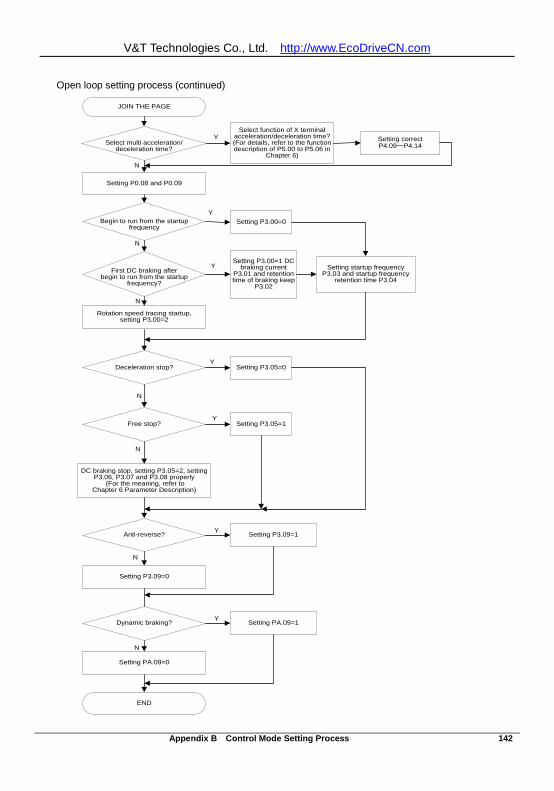
V&T Technologies Co., Ltd. http://www.EcoDriveCN.com
Appendix B Control Mode Setting Process 142
Open loop setting process (continued)
Deceleration stop?
First DC braking after begin to run from the startup
frequency?
Begin to run from the startup frequency
Setting P3.00=0
Setting startup frequency P3.03 and startup frequency
retention time P3.04
Free stop?
Anti-reverse? Setting P3.09=1
DC braking stop, setting P3.05=2, setting P3.06, P3.07 and P3.08 properly
(For the meaning, refer to Chapter 6 Parameter Description)
Dynamic braking?
Setting PA.09=0
Setting P3.00=1 DC braking current
P3.01 and retention time of braking keep
P3.02
Rotation speed tracing startup, setting P3.00=2
Setting P3.05=0
Setting P3.05=1
Setting P3.09=0
Setting PA.09=1
END
N
Y
N
Y
N
Y
N
Y
N
Y
N
Y
Select multi acceleration/deceleration time?
Select function of X terminal acceleration/deceleration time? (For details, refer to the function description of P5.00 to P5.06 in
Chapter 6)
Setting correctP4.09~P4.14
Setting P0.08 and P0.09
N
Y
JOIN THE PAGE
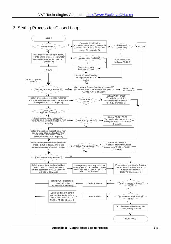
V&T Technologies Co., Ltd. http://www.EcoDriveCN.com
Appendix B Control Mode Setting Process 143
3. Setting Process for Closed Loop
START
Parameter identification (for details, refer to setting process for parameter auto-tuning under vector control 1 in
appendix B)
Select process close loop main reference mode P1.02 (For details, refer to the function
description of P1.02 in Chapter 6)
Select process close loop reference main and auxiliary relation calculation P1.04
(For details, refer to the function description of P1.04 in Chapter 6)
Select function of X control terminal (For details, refer to
the function description of P5.00 to P5.06 in Chapter 6)
Select process close loop auxiliary reference mode P1.03?(For details, refer
to the function description of P1.03 in Chapter 6)
Multi digital voltage reference?Multi voltage reference function of terminal X?(For details, refer to the function description of
P5.00 to P5.06 in Chapter 6)
Setting correct P4.15~P4.21
Running command Keypad control
Running command Terminal control
Setting P0.06=1
Setting P0.06=0Setting P0.07 according to
running direction (0: Forward; 1: Reverse)
Running command communicate control, setting P0.06=2
Select Analog channel ?
Select Analog channel?
Setting P6.00~P6.20 (For details, refer to the function description of P6.00 to P6.20 in
Chapter 6)
Setting P6.00~P6.20 (For details, refer to the
function description of P6.00 to P6.20 in Chapter 6)
N
N
Y
YY
N
N
N
NEXT PAGE
Vector control 1?
Analog value feedback?
Parameter identification (For details, refer to setting process for
parameter auto-tuning under vector control 2 in appendix B)
P0.03=1
P0.03=5
Single-phase pulse feedback, P0.03=6
Y
N
Select process close loop main feedback mode P1.05(For details, refer to the
function description of P1.05 in Chapter 6)
Close loop auxiliary feedback?
Select process close auxiliary feedback mode P1.06 (For details, refer to the
function description of P1.06 and P6.00 to P6.20 in Chapter 6)
Select process close loop main and auxiliary relation calculation p1.07 (For details, refer to the function description
of P1.07 in Chapter 6)
Analog value feedback?
Single-phase pulse feedback,P0.03=2
NY
Setting P5.06=47, setting P8.02 pulse purse-code
number
N
Y
Process close loop relative function code setting (For details, refer to the
function description of GROUP P8 in Chapter 6)
N
Y
Y
Y
N
Y
From composite control a
Setting P6.00~P6.20 (For details, refer to the function description of P6.00 to P6.20 in
Chapter 6)
Select Analog channel ?Y
N
Close loop auxiliary reference ?
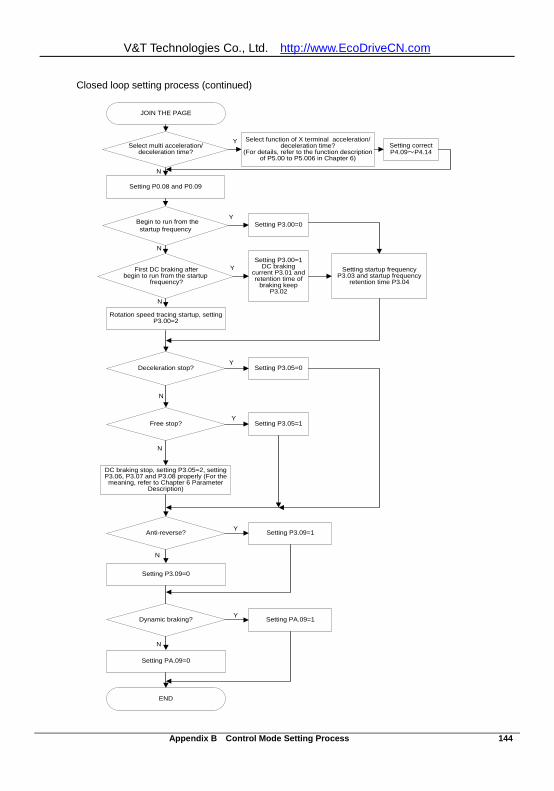
V&T Technologies Co., Ltd. http://www.EcoDriveCN.com
Appendix B Control Mode Setting Process 144
Closed loop setting process (continued)
Deceleration stop?
First DC braking after begin to run from the startup
frequency?
Begin to run from the startup frequency
Setting P3.00=0
Setting startup frequency P3.03 and startup frequency
retention time P3.04
Free stop?
Anti-reverse? Setting P3.09=1
DC braking stop, setting P3.05=2, setting P3.06, P3.07 and P3.08 properly (For the
meaning, refer to Chapter 6 Parameter Description)
Dynamic braking?
Setting PA.09=0
Setting P3.00=1 DC braking
current P3.01 and retention time of
braking keep P3.02
Rotation speed tracing startup, setting P3.00=2
Setting P3.05=0
Setting P3.05=1
Setting P3.09=0
Setting PA.09=1
END
N
Y
N
Y
N
Y
N
Y
N
Y
N
Y
Select multi acceleration/deceleration time?
Select function of X terminal acceleration/deceleration time?
(For details, refer to the function description of P5.00 to P5.006 in Chapter 6)
Setting correctP4.09~P4.14
Setting P0.08 and P0.09
N
Y
JOIN THE PAGE
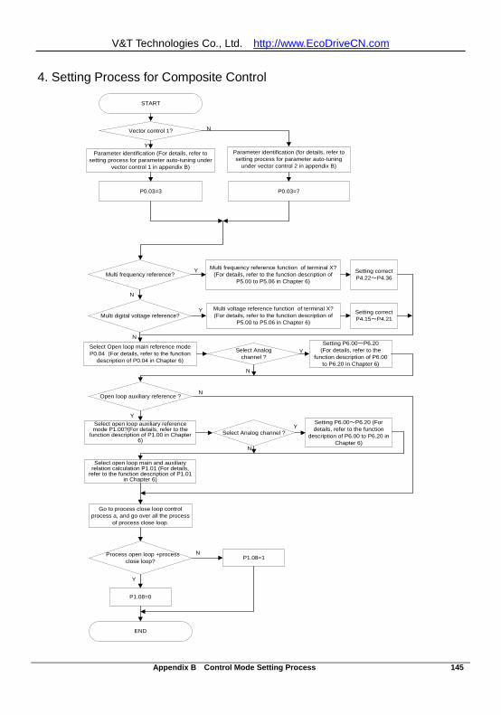
V&T Technologies Co., Ltd. http://www.EcoDriveCN.com
Appendix B Control Mode Setting Process 145
4. Setting Process for Composite Control
START
Parameter identification (For details, refer to setting process for parameter auto-tuning under
vector control 1 in appendix B)
END
Vector control 1?
Parameter identification (for details, refer to setting process for parameter auto-tuning
under vector control 2 in appendix B)
P0.03=3 P0.03=7
Y
N
Go to process close loop control process a, and go over all the process
of process close loop.
Select Open loop main reference modeP0.04 (For details, refer to the function
description of P0.04 in Chapter 6)
Select open loop main and auxiliary relation calculation P1.01 (For details,
refer to the function description of P1.01 in Chapter 6)
Open loop auxiliary reference ?
Select open loop auxiliary reference mode P1.00?(For details, refer to the
function description of P1.00 in Chapter 6)
Multi digital voltage reference?Multi voltage reference function of terminal X? (For details, refer to the function description of
P5.00 to P5.06 in Chapter 6)
Setting correct P4.15~P4.21
Multi frequency reference?Multi frequency reference function of terminal X?
(For details, refer to the function description of P5.00 to P5.06 in Chapter 6)
Setting correct P4.22~P4.36
Select Analogchannel ?
Select Analog channel ?
Setting P6.00~P6.20 (For details, refer to the function
description of P6.00 to P6.20 in Chapter 6)
Setting P6.00~P6.20 (For details, refer to the
function description of P6.00 to P6.20 in Chapter 6)
N
Y
N
Y
N
Y
Y
N
Y
N
Process open loop +process close loop? P1.08=1
P1.08=0
N
Y
V&T Technologies Co., Ltd. http://www.EcoDriveCN.com
Appendix C FAQ 146
Appendix C FAQ
I. In the case of vector control 2, why did the inverter have abnormal operation? A: (1) Check if there exists large difference between the power class of the motor and that of the inverter; A; (2) Check if parameter auto-tuning has been performed under vector control 2. For details, refer to the setting process for parameter auto-tuning in Appendix B. A: (3) Check if the control lines for the V5−H−4T18.5G/22L or current sensor of above power class are loose or dislocated. A II. In the case of vector control 1, why did the inverter have abnormal operation? A: (1) Check if parameter auto-tuning has been performed under vector control1, For details, refer to the setting process for parameter auto-tuning in Appendix B. A: (2) Check if the control lines for the V5−H−4T18.5G/22L or current sensor of above power class are loose or dislocated. III. Why was the operating frequency of the inverter kept at 0Hz upon reverse operation? A: (1) Check if the frequency is set as 0; A: (2) Check if the inverter function code parameter P3.09 is set as 0. If not, change it to 0.
IV. The inverter had been connected with braking resistor featuring dynamic braking, why didn’t it work?
A: (1) Check if the braking resistor is connected between the main circuit terminals B1 and B2; A: (2) Check if the inverter function code parameter PA.09 is set as 1. If not, change it to 1. V. Why was there large deviation on the correspondence relation between the analog input and the set frequency? A: (1) Check if the jumpers of analog input type and control board are properly set. For the analog voltage input, toggle the corresponding channel to the V end of the jumper; for the analog current input, toggle the corresponding channel to the I end of the jumper. A: (2) Calibrate the analog input curve according to function codes P6.00 to P6.2. For details, refer to the description of P6 group in Chapter 6 Parameter Description. VI. Why was there large deviation on the correspondence relation between the analog output and the relevant function output? A: (1) Check if the jumpers of analog output type and control board are properly set. For the analog voltage
output, toggle the corresponding channel to the V end of the jumper; for the analog current output, toggle the corresponding channel to the I end of the jumper.
A: (2) Calibrate the analog output curve according to function codes P7.05 to P7.09. For details, refer to the description of P7 group in Chapter 6 Parameter Description.
V&T Technologies Co., Ltd. http://www.EcoDriveCN.com
Appendix C FAQ 147
VII. Why did the inverter report E.AIF analog input abnormal error? A: (1) Check if the jumpers of analog input type and control board are properly set. For the analog voltage
input, toggle the corresponding channel to the V end of the jumper; for the analog current input, toggle the corresponding channel to the I end of the jumper.
A: (2) Check if the analog input exceeds 11V; A: (3) When using the +10V power supply of the inverter control board, check if the voltage of +10V is lower than 9V or higher than 11V. If yes, check if the resistance value between the +10V and the GND is less than 1KΩ after the inverter is powered off completely. VIII. Why did the inverter report E.P10 abnormal error? A: Check if the voltage of +10V on the inverter control board is lower than 9V or higher than 11V. If yes, check if the resistance value between the +10V and the GND is less than 1KΩ after the inverter is powered off completely. IX. Why did the PLC and inverter have abnormal 485-based communication? A: (1) Check if the data format, address and baud rate of the inverter are consistent with that of the PLC; A: (2) Check if the PLC address needs Add 1 operation; A: (3) Check if the PLC adopts Modbus RTU format; A: (4) Check if the register address of the PLC is converted to hexadecimal format;
(5) Check if the 485 wires are properly connected. X. Why did there exist abnormality upon parameter copying? A: (1) The parameters for V5 inverter and V6 inverter cannot be copied between each other; A: (2) The copy operation can be performed only when the upload and download function codes of the inverter d1.09 (operation panel copy identification code) are consistent; A: (3) The copy function can be completed only when the inverter is completely powered down and then
powered up after the download of the parameters for copy is completed. XI. Why did the keyboard will have “8.8.8.8” display or have no display sometimes? A: (1) Check if the connectors are properly connected when the operation panel is directly connected to the inverter control board; A: (2) Check if the connection wire signals are in one to one correspondence when the keyboard is connected to the operation panel and inverter control board through customized extension wires;
A: (3) Check if the network cable connectors of the operation panel and inverter control board are properly connected when standard network cable is used to connect the operation panel and inverter control board. XII. Why couldn’t display or modify the function codes of the operation panel? A: (1) When the modification could not be performed, check if P0.01 is set as 1. If not, change it to 0. A: (2) When the modification could not be performed, check if the function code has been set as
V&T Technologies Co., Ltd. http://www.EcoDriveCN.com
Appendix C FAQ 148
modification disabled; A: (3) When the modification could not be performed upon running, check if the function code could not modification upon running; A: (4) When display is not available, check if the inverter function code has been encrypted; A: (5) When display is not available, check if the inverter operation panel has been locked; XIII. How to change the direction that the inverter drives the motor to rotate? A: (1) In the case of operation panel control, the direction is determined by P0.07. However, the FWD/REV key on the operation panel can real time change the direction. A: (2) In the case of operation panel control, the direction is determined by P0.07. However, the UP/DN key on the operation panel (or the FWD/REV knob of the shuttle operation panel) can real time change the direction. A: (3) In the case of operation panel control, the positive/negative frequency value resulting from the final frequency calculation for composite control can also change the direction in real time. A: (4) In the case of terminal control, check if the forward/reverse terminal is in one to one correspondence with that of the control equipment (e.g. PLC). XIV. Why did the fans of inverters of certain power classes will rotate upon power up, while others could not? A: The fans of the 15KW inverters and inverters of lower power class are under no control, and they will run when powered up. The operation of the fans of 18.5KW inverters and inverters of higher power class is controlled by the heatsink temperature. When the inverter is powered up under low temperature condition, the fans will not run. XV. What will happen if the CN1 busbar of the control board is loose or damaged? A: If the CN1 busbar of the control board is loose or damaged, the inverter cannot run or will report several errors. For instance, the inverter may display “-LU- ” or “relay/contactor could not pull on “, or report such errors as E.oc1, E.FAL, E.oH1, E.oH2, E.Cur and E.dL3 ect
Related Documents