FOREWORD This manual is an essential part of your vehicle and should remain with the vehicle when resold or otherwise transferred to a new owner or operator. Please read this manual carefully before operating your new MARUTI SUZUKI and review the manual from time to time. It contains important information on safety, operation and maintenance. You are invited to avail the three Free Inspection Services as described in the manual. Three free inspection coupons are attached to this manual. Please show this manual to your dealer workshop while you take your MARUTI SUZUKI for any Service. To prolong the life of your vehicle and reduce maintenance cost, the periodic maintenance must be carried out accord- ing to “PERIODIC MAINTENANCE SCHEDULE” described in “INSPECTION AND MAINTENANCE” section of this man- ual. It is essential for preventing trouble and accidents to ensure your satisfaction and safety. Daily inspection and care as per “DAILY INSPECTION CHECKLIST” described in the “OPERATING YOUR VEHICLE” sec- tion of this manual is essential for prolong- ing the life of the vehicle and for safe driving. Vehicle and the available features/acces- sories therein should be used and plied by the owner/user in accordance with the applicable legal requirements. MARUTI SUZUKI INDIA LIMITED believes in conservation and protection of Earth’s natural resources. To that end, we encourage every vehicle owner to recycle, trade-in or properly dis- pose of, as appropriate, used Engine Oil, coolant and other fluids, batteries and tyres etc. MARUTI SUZUKI INDIA LIMITED All information in this manual is based on the latest product information avail- able at the time of publication. Due to improvements or other changes, there may be discrepancies between informa- tion in this manual and your vehicle. MARUTI SUZUKI INDIA LIMITED reserves the right to make production changes at any time, without notice and without incurring any obligation to make the same or similar changes to vehicles previously built or sold. This vehicle may not comply with stan- dards or regulations of other countries. Before attempting to register this vehi- cle in any other country, check all appli- cable regulations and make any neces- sary modifications.

Welcome message from author
This document is posted to help you gain knowledge. Please leave a comment to let me know what you think about it! Share it to your friends and learn new things together.
Transcript
FOREWORDThis manual is an essential part of yourvehicle and should remain with the vehiclewhen resold or otherwise transferred to anew owner or operator. Please read thismanual carefully before operating yournew MARUTI SUZUKI and review themanual from time to time. It containsimportant information on safety, operationand maintenance. You are invited to availthe three Free Inspection Services asdescribed in the manual. Three freeinspection coupons are attached to thismanual. Please show this manual to yourdealer workshop while you take yourMARUTI SUZUKI for any Service.To prolong the life of your vehicle andreduce maintenance cost, the periodicmaintenance must be carried out accord-ing to “PERIODIC MAINTENANCESCHEDULE” described in “INSPECTIONAND MAINTENANCE” section of this man-ual. It is essential for preventing troubleand accidents to ensure your satisfactionand safety.Daily inspection and care as per “DAILYINSPECTION CHECKLIST” described inthe “OPERATING YOUR VEHICLE” sec-tion of this manual is essential for prolong-ing the life of the vehicle and for safedriving.
Vehicle and the available features/acces-sories therein should be used and plied bythe owner/user in accordance with theapplicable legal requirements.
MARUTI SUZUKI INDIA LIMITED believesin conservation and protection of Earth’snatural resources.To that end, we encourage every vehicleowner to recycle, trade-in or properly dis-pose of, as appropriate, used Engine Oil,coolant and other fluids, batteries andtyres etc.
MARUTI SUZUKI INDIA LIMITED
All information in this manual is basedon the latest product information avail-able at the time of publication. Due toimprovements or other changes, theremay be discrepancies between informa-tion in this manual and your vehicle.MARUTI SUZUKI INDIA LIMITEDreserves the right to make productionchanges at any time, without notice andwithout incurring any obligation tomake the same or similar changes tovehicles previously built or sold.
This vehicle may not comply with stan-dards or regulations of other countries.Before attempting to register this vehi-cle in any other country, check all appli-cable regulations and make any neces-sary modifications.
IMPORTANTWARNING/ CAUTION/NOTICE/
NOTEPlease read this manual and follow itsinstructions carefully. To emphasize spe-cial information, the symbol and the wordsWARNING, CAUTION, NOTICE andNOTE have special meanings. Pay partic-ular attention to messages highlighted bythese signal words:
NOTE:Indicates special information to makemaintenance easier or instructions clearer.
75F135
The circle with a slash in this manualmeans “Don’t do this” or “Don’t let this hap-pen”.
NOTE:• Words like car, model/variant are invari-
ably used in this manual to denote the“Vehicle”.
• Pictorial representations used in thismanual are for reference purposes only.
MODIFICATION WARNING
WARNING
Indicates a potential hazard thatcould result in death or seriousinjury.
CAUTION
Indicates a potential hazard thatcould result in minor or moderateinjury.
NOTICE
Indicates a potential hazard thatcould result in vehicle damage.
WARNING
Do not modify your vehicle. Modifica-tion could adversely affect safety,handling, performance, or durabilityand may violate governmental regula-tions. In addition, damage or perfor-mance problems resulting frommodification shall not be coveredunder warranty.
NOTICE
Improper installation of mobile commu-nication equipment such as cellulartelephones, CB (Citizen’s Band) radiosmay cause electronic interference withyour vehicle’s ignition system, result-ing in vehicle performance problems.Consult your Maruti Suzuki authorisedworkshop or qualified service techni-cian for advice on installing suchmobile communication equipment.
NOTICE
The diagnostic connector of yourvehicle is prepared only for the spe-cific diagnostic tool for inspectionand service purpose. Connecting anyother tool or device may interferewith electronic parts operations andcause running out of batteries.
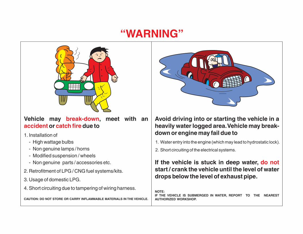
Vehicle may , meet with an or due to
1. Installation of- High wattage bulbs- Non genuine lamps / horns- Modified suspension / wheels- Non genuine parts / accessories etc.
2. Retrofitment of LPG / CNG fuel systems/kits.
3. Usage of domestic LPG.
4. Short circuiting due to tampering of wiring harness.
CAUTION: DO NOT STORE OR CARRY INFLAMMABLE MATERIALS IN THE VEHICLE.
break-downaccident catch fire
Avoid driving into or starting the vehicle in a heavily water logged area. Vehicle may break-down or engine may fail due to1. Water entry into the engine (which may lead to hydrostatic lock).
2. Short circuiting of the electrical systems.
If the vehicle is stuck in deep water, start / crank the vehicle until the level of water drops below the level of exhaust pipe.
NOTE:IF THE VEHICLE IS SUBMERGED IN WATER, REPORT TO THE NEAREST AUTHORIZED WORKSHOP.
do not
“WARNING”
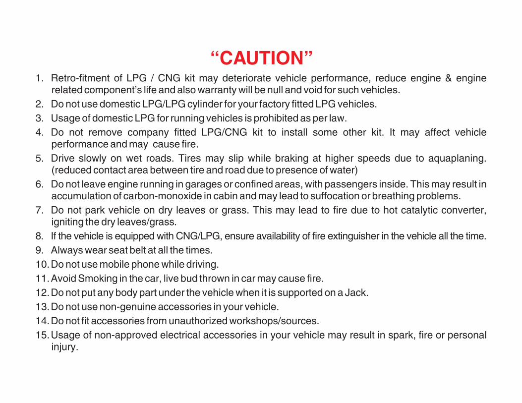
1. Retro-fitment of LPG / CNG kit may deteriorate vehicle performance, reduce engine & enginerelated component’s life and also warranty will be null and void for such vehicles.
2. Do not use domestic LPG/LPG cylinder for your factory fitted LPG vehicles.3. Usage of domestic LPG for running vehicles is prohibited as per law.4. Do not remove company fitted LPG/CNG kit to install some other kit. It may affect vehicle
performance and may cause fire.5. Drive slowly on wet roads. Tires may slip while braking at higher speeds due to aquaplaning.
(reduced contact area between tire and road due to presence of water)6. Do not leave engine running in garages or confined areas, with passengers inside. This may result in
accumulation of carbon-monoxide in cabin and may lead to suffocation or breathing problems.7. Do not park vehicle on dry leaves or grass. This may lead to fire due to hot catalytic converter,
igniting the dry leaves/grass.8. If the vehicle is equipped with CNG/LPG, ensure availability of fire extinguisher in the vehicle all the time.9. Always wear seat belt at all the times.10.Do not use mobile phone while driving.11.Avoid Smoking in the car, live bud thrown in car may cause fire.12.Do not put any body part under the vehicle when it is supported on a Jack.13.Do not use non-genuine accessories in your vehicle.14.Do not fit accessories from unauthorized workshops/sources.15.Usage of non-approved electrical accessories in your vehicle may result in spark, fire or personal
injury.
“CAUTION”
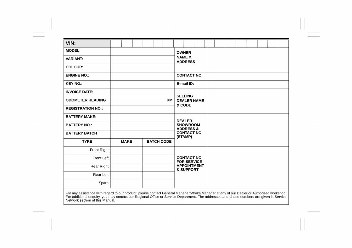
VIN:MODEL:
OWNERNAME & ADDRESS
VARIANT:
COLOUR:
ENGINE NO.: CONTACT NO.
KEY NO.: E-mail ID:
INVOICE DATE:SELLING DEALER NAME & CODE
ODOMETER READING KM
REGISTRATION NO.:
BATTERY MAKE:DEALER SHOWROOM ADDRESS & CONTACT NO. (STAMP)
BATTERY NO.:
BATTERY BATCH
TYRE MAKE BATCH CODE
Front Right
CONTACT NO. FOR SERVICE APPOINTMENT & SUPPORT
Front Left
Rear Right
Rear Left
Spare
For any assistance with regard to our product, please contact General Manager/Works Manager at any of our Dealer or Authorised workshop.For additional enquiry, you may contact our Regional Office or Service Department. The addresses and phone numbers are given in ServiceNetwork section of this Manual.
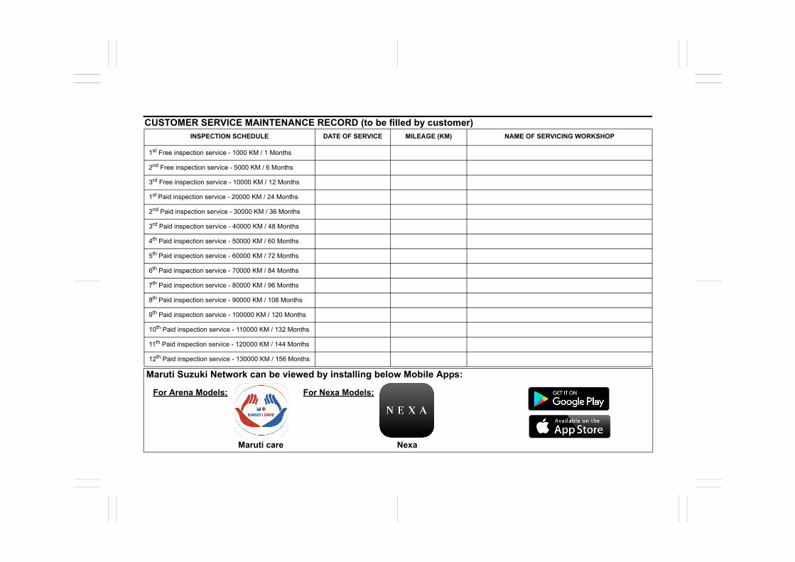
CUSTOMER SERVICE MAINTENANCE RECORD (to be filled by customer)INSPECTION SCHEDULE DATE OF SERVICE MILEAGE (KM) NAME OF SERVICING WORKSHOP
1st Free inspection service - 1000 KM / 1 Months
2nd Free inspection service - 5000 KM / 6 Months
3rd Free inspection service - 10000 KM / 12 Months
1st Paid inspection service - 20000 KM / 24 Months
2nd Paid inspection service - 30000 KM / 36 Months
3rd Paid inspection service - 40000 KM / 48 Months
4th Paid inspection service - 50000 KM / 60 Months
5th Paid inspection service - 60000 KM / 72 Months
6th Paid inspection service - 70000 KM / 84 Months
7th Paid inspection service - 80000 KM / 96 Months
8th Paid inspection service - 90000 KM / 108 Months
9th Paid inspection service - 100000 KM / 120 Months
10th Paid inspection service - 110000 KM / 132 Months
11th Paid inspection service - 120000 KM / 144 Months
12th Paid inspection service - 130000 KM / 156 Months
Maruti Suzuki Network can be viewed by installing below Mobile Apps:
For Arena Models; For Nexa Models;
Maruti care Nexa
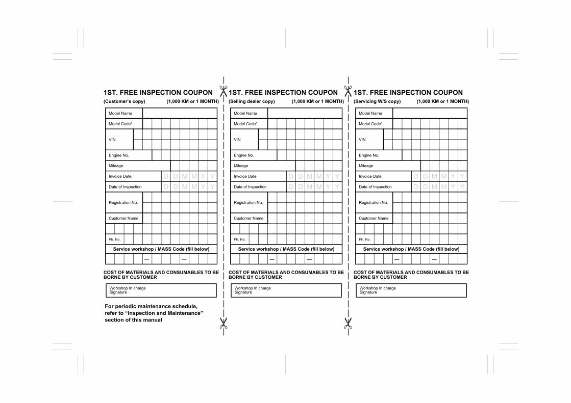
1ST. FREE INSPECTION COUPON (Customer’s copy) (1,000 KM or 1 MONTH)
COST OF MATERIALS AND CONSUMABLES TO BEBORNE BY CUSTOMER
1ST. FREE INSPECTION COUPON (Selling dealer copy) (1,000 KM or 1 MONTH)
COST OF MATERIALS AND CONSUMABLES TO BEBORNE BY CUSTOMER
1ST. FREE INSPECTION COUPON (Servicing W/S copy) (1,000 KM or 1 MONTH)
COST OF MATERIALS AND CONSUMABLES TO BEBORNE BY CUSTOMER
Model Name
Model Code*
VIN
Engine No.
Mileage
Invoice Date
Date of Inspection
Registration No.
Customer Name
Ph. No.
Service workshop / MASS Code (fill below)
Workshop In charge Signature
Model Name
Model Code*
VIN
Engine No.
Mileage
Invoice Date
Date of Inspection
Registration No.
Customer Name
Ph. No.
Service workshop / MASS Code (fill below)
Workshop In charge Signature
Model Name
Model Code*
VIN
Engine No.
Mileage
Invoice Date
Date of Inspection
Registration No.
Customer Name
Ph. No.
Service workshop / MASS Code (fill below)
Workshop In charge Signature
—— —— ——
For periodic maintenance schedule, refer to “Inspection and Maintenance” section of this manual
D D M M Y YD D M M Y Y
D D M M Y YD D M M Y Y
D D M M Y YD D M M Y Y

1ST. FREE INSPECTION COUPON (Servicing W/S copy) (1,000 KM or 1 MONTH)
For Servicing Workshop1. Please Fill up Model codes correctly.2. Please fill up Complete VIN. 3. Please fill up customer name and Phone No.
details legibly and correctly for the latest owner. 4. Free service coupon of selling dealer not
operational at present, should be sent to MSIL onmonthly basis.
Service Division Maruti Suzuki India Limited
1ST. FREE INSPECTION COUPON (Selling dealer copy) (1,000 KM or 1 MONTH)
For Servicing Workshop1. Please Fill up Model codes correctly.2. Please fill up Complete VIN. 3. Please fill up customer name and Phone No.
details legibly and correctly for the latest owner. 4. Free service coupon of selling dealer not
operational at present, should be sent to MSIL onmonthly basis.
Service Division Maruti Suzuki India Limited
1ST. FREE INSPECTION COUPON (Customer’s copy) (1,000 KM or 1 MONTH)
For Servicing Workshop1. Please Fill up Model codes correctly.2. Please fill up Complete VIN. 3. Please fill up customer name and Phone No.
details legibly and correctly for the latest owner. 4. Free service coupon of selling dealer not
operational at present, should be sent to MSIL onmonthly basis.
Service Division Maruti Suzuki India Limited
Stamp of Selling dealer (Code & Full Address)
Stamp of Selling dealer (Code & Full Address)
Stamp of Selling dealer (Code & Full Address)
FOR BAR CODE FOR BAR CODE FOR BAR CODE
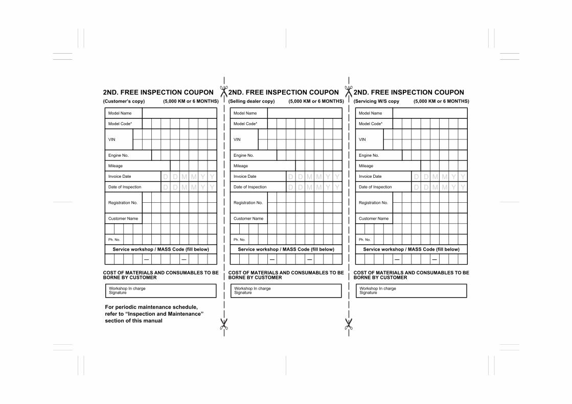
2ND. FREE INSPECTION COUPON (Customer’s copy) (5,000 KM or 6 MONTHS)
COST OF MATERIALS AND CONSUMABLES TO BEBORNE BY CUSTOMER
2ND. FREE INSPECTION COUPON (Selling dealer copy) (5,000 KM or 6 MONTHS)
COST OF MATERIALS AND CONSUMABLES TO BEBORNE BY CUSTOMER
2ND. FREE INSPECTION COUPON (Servicing W/S copy (5,000 KM or 6 MONTHS)
COST OF MATERIALS AND CONSUMABLES TO BEBORNE BY CUSTOMER
Model Name
Model Code*
VIN
Engine No.
Mileage
Invoice Date
Date of Inspection
Registration No.
Customer Name
Ph. No.
Service workshop / MASS Code (fill below)
Workshop In charge Signature
Model Name
Model Code*
VIN
Engine No.
Mileage
Invoice Date
Date of Inspection
Registration No.
Customer Name
Ph. No.
Service workshop / MASS Code (fill below)
Workshop In charge Signature
Model Name
Model Code*
VIN
Engine No.
Mileage
Invoice Date
Date of Inspection
Registration No.
Customer Name
Ph. No.
Service workshop / MASS Code (fill below)
Workshop In charge Signature
For periodic maintenance schedule, refer to “Inspection and Maintenance” section of this manual
—— —— ——
D D M M Y YD D M M Y Y
D D M M Y YD D M M Y Y
D D M M Y YD D M M Y Y
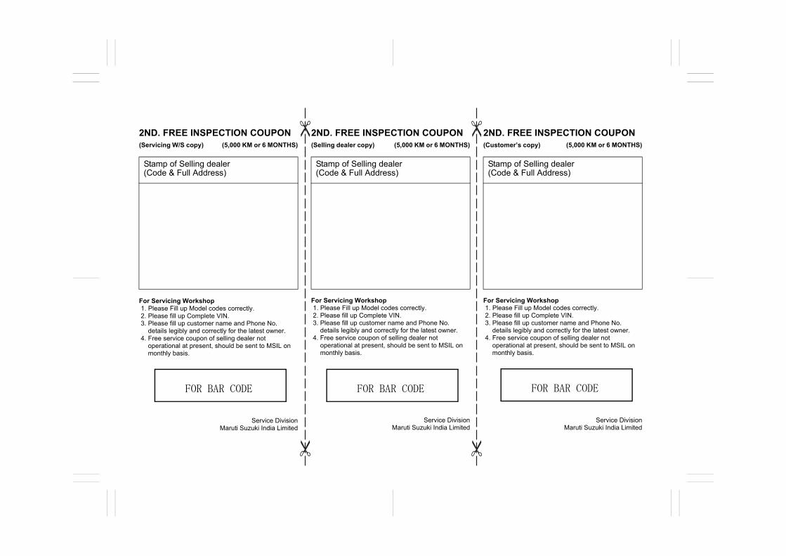
2ND. FREE INSPECTION COUPON (Servicing W/S copy) (5,000 KM or 6 MONTHS)
For Servicing Workshop1. Please Fill up Model codes correctly.2. Please fill up Complete VIN. 3. Please fill up customer name and Phone No.
details legibly and correctly for the latest owner. 4. Free service coupon of selling dealer not
operational at present, should be sent to MSIL onmonthly basis.
Service Division Maruti Suzuki India Limited
2ND. FREE INSPECTION COUPON (Selling dealer copy) (5,000 KM or 6 MONTHS)
For Servicing Workshop1. Please Fill up Model codes correctly.
2. Please fill up Complete VIN. 3. Please fill up customer name and Phone No.
details legibly and correctly for the latest owner. 4. Free service coupon of selling dealer not
operational at present, should be sent to MSIL onmonthly basis.
Service Division Maruti Suzuki India Limited
2ND. FREE INSPECTION COUPON (Customer’s copy) (5,000 KM or 6 MONTHS)
For Servicing Workshop1. Please Fill up Model codes correctly.2. Please fill up Complete VIN. 3. Please fill up customer name and Phone No.
details legibly and correctly for the latest owner. 4. Free service coupon of selling dealer not
operational at present, should be sent to MSIL onmonthly basis.
Service Division Maruti Suzuki India Limited
Stamp of Selling dealer (Code & Full Address)
Stamp of Selling dealer (Code & Full Address)
Stamp of Selling dealer (Code & Full Address)
FOR BAR CODE FOR BAR CODE FOR BAR CODE
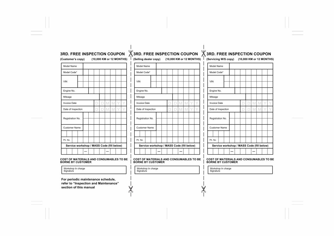
3RD. FREE INSPECTION COUPON (Customer’s copy) (10,000 KM or 12 MONTHS)
COST OF MATERIALS AND CONSUMABLES TO BEBORNE BY CUSTOMER
3RD. FREE INSPECTION COUPON (Selling dealer copy) (10,000 KM or 12 MONTHS)
COST OF MATERIALS AND CONSUMABLES TO BEBORNE BY CUSTOMER
3RD. FREE INSPECTION COUPON (Servicing W/S copy) (10,000 KM or 12 MONTHS)
COST OF MATERIALS AND CONSUMABLES TO BEBORNE BY CUSTOMER
Model Name
Model Code*
VIN
Engine No.
Mileage
Invoice Date
Date of Inspection
Registration No.
Customer Name
Ph. No.
Service workshop / MASS Code (fill below)
Workshop In charge Signature
Model Name
Model Code*
VIN
Engine No.
Mileage
Invoice Date
Date of Inspection
Registration No.
Customer Name
Ph. No.
Service workshop / MASS Code (fill below)
Workshop In charge Signature
Model Name
Model Code*
VIN
Engine No.
Mileage
Invoice Date
Date of Inspection
Registration No.
Customer Name
Ph. No.
Service workshop / MASS Code (fill below)
Workshop In charge Signature
—— —— ——
For periodic maintenance schedule, refer to “Inspection and Maintenance” section of this manual
D D M M Y YD D M M Y Y
D D M M Y YD D M M Y Y
D D M M Y YD D M M Y Y
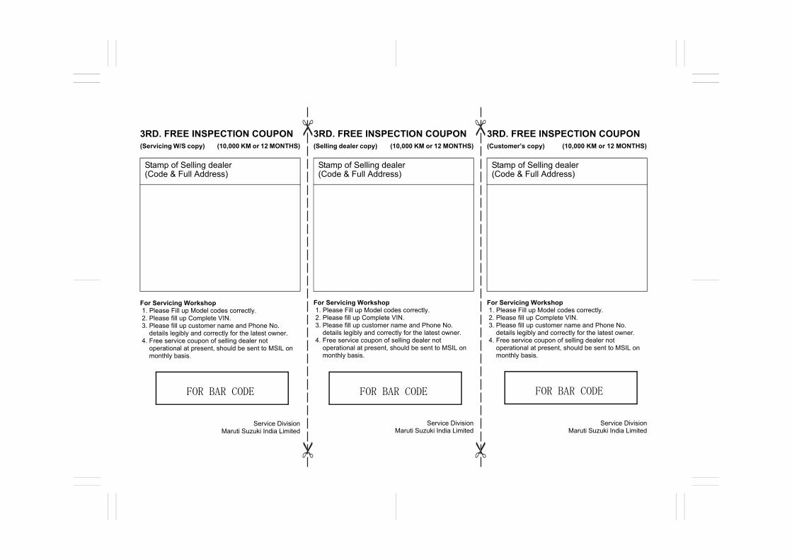
3RD. FREE INSPECTION COUPON (Servicing W/S copy) (10,000 KM or 12 MONTHS)
For Servicing Workshop1. Please Fill up Model codes correctly.2. Please fill up Complete VIN. 3. Please fill up customer name and Phone No.
details legibly and correctly for the latest owner. 4. Free service coupon of selling dealer not
operational at present, should be sent to MSIL onmonthly basis.
Service Division Maruti Suzuki India Limited
3RD. FREE INSPECTION COUPON (Selling dealer copy) (10,000 KM or 12 MONTHS)
For Servicing Workshop1. Please Fill up Model codes correctly.
2. Please fill up Complete VIN. 3. Please fill up customer name and Phone No.
details legibly and correctly for the latest owner. 4. Free service coupon of selling dealer not
operational at present, should be sent to MSIL onmonthly basis.
Service Division Maruti Suzuki India Limited
3RD. FREE INSPECTION COUPON (Customer’s copy) (10,000 KM or 12 MONTHS)
For Servicing Workshop1. Please Fill up Model codes correctly.2. Please fill up Complete VIN. 3. Please fill up customer name and Phone No.
details legibly and correctly for the latest owner. 4. Free service coupon of selling dealer not
operational at present, should be sent to MSIL onmonthly basis.
Service Division Maruti Suzuki India Limited
Stamp of Selling dealer (Code & Full Address)
Stamp of Selling dealer (Code & Full Address)
Stamp of Selling dealer (Code & Full Address)
FOR BAR CODE FOR BAR CODE FOR BAR CODE
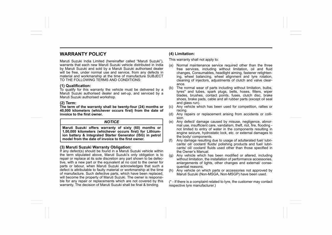
WARRANTY POLICY
Maruti Suzuki India Limited (hereinafter called “Maruti Suzuki”),warrants that each new Maruti Suzuki vehicle distributed in Indiaby Maruti Suzuki and sold by a Maruti Suzuki authorised dealerwill be free, under normal use and service, from any defects inmaterial and workmanship at the time of manufacture SUBJECTTO THE FOLLOWING TERMS AND CONDITIONS:
(1) Qualification:To qualify for this warranty the vehicle must be delivered by aMaruti Suzuki authorised dealer and set-up, and serviced by aMaruti Suzuki authorised workshop.
(2) Term:The term of the warranty shall be twenty-four (24) months or40,000 kilometers (whichever occurs first) from the date ofinvoice to the first owner.
(3) Maruti Suzuki Warranty Obligation:If any defect(s) should be found in a Maruti Suzuki vehicle withinthe term stipulated above, Maruti Suzuki’s only obligation is torepair or replace at its sole discretion any part shown to be defec-tive, with a new part or the equivalent at no cost to the owner forparts or labour, when Maruti Suzuki acknowledges that such adefect is attributable to faulty material or workmanship at the timeof manufacture. Such defective parts, which have been replaced,will become the property of Maruti Suzuki. The owner is responsi-ble for any repair or replacements which are not covered by thiswarranty. The decision of Maruti Suzuki shall be final & binding.
(4) Limitation:
This warranty shall not apply to:
(a) Normal maintenance service required other than the threefree services, including without limitation, oil and fluidchanges, Consumables, headlight aiming, fastener retighten-ing, wheel balancing, wheel alignment and tyre rotation,cleaning of injectors, adjustments of clutch and valve clear-ance.
(b) The normal wear of parts including without limitation, bulbs,tyres* and tubes, spark plugs, belts, hoses, filters, wiperblades, brushes, contact points, fuses, clutch disc, brakeshoes, brake pads, cable and all rubber parts (except oil sealand glass run).
(c) Any vehicle which has been used for competition, rallies orracing.
(d) Any repairs or replacement arising from accidents or colli-sion.
(e) Any defect/ damage caused by misuse, negligence, abnor-mal use, insufficient care, vandalism, theft, riot, fire, flooding -not limited to entry of water in the components resulting inengine seizure, hydrostatic lock, etc. or external damages tothe body/ components.
(f) Any damage resulting due to usage of adulterated fuel/ lubri-cants/ oil/ coolant/ fluids/ polishing products and fuel/ lubri-cants/ oil/ coolant/ fluids used other than those specified inthe Owner’s Manual.
(g) Any vehicle which has been modified or altered, includingwithout limitation, the installation of performance accessories,enlargements of lights, other changes and external/ conse-quential reasons.
(h) Any vehicle on which parts or accessories not approved byMaruti Suzuki (Non-MSGA, Non-MSGP) have been used.
(* - If there is a complaint related to tyre, the customer may contactrespective tyre manufacturer.)
NOTICE
Maruti Suzuki offers warranty of sixty (60) months or1,00,000 kilometers (whichever occurs first) for Lithium-ion battery & Integrated Starter Generator (ISG) in petrolmodel from the date of invoice to the first owner.
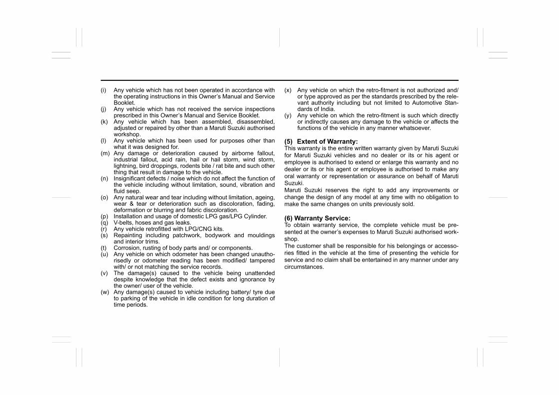
(i) Any vehicle which has not been operated in accordance withthe operating instructions in this Owner’s Manual and ServiceBooklet.
(j) Any vehicle which has not received the service inspectionsprescribed in this Owner’s Manual and Service Booklet.
(k) Any vehicle which has been assembled, disassembled,adjusted or repaired by other than a Maruti Suzuki authorisedworkshop.
(l) Any vehicle which has been used for purposes other thanwhat it was designed for.
(m) Any damage or deterioration caused by airborne fallout,industrial fallout, acid rain, hail or hail storm, wind storm,lightning, bird droppings, rodents bite / rat bite and such otherthing that result in damage to the vehicle.
(n) Insignificant defects / noise which do not affect the function ofthe vehicle including without limitation, sound, vibration andfluid seep.
(o) Any natural wear and tear including without limitation, ageing,wear & tear or deterioration such as discoloration, fading,deformation or blurring and fabric discoloration.
(p) Installation and usage of domestic LPG gas/LPG Cylinder.(q) V-belts, hoses and gas leaks.(r) Any vehicle retrofitted with LPG/CNG kits.(s) Repainting including patchwork, bodywork and mouldings
and interior trims.(t) Corrosion, rusting of body parts and/ or components.(u) Any vehicle on which odometer has been changed unautho-
risedly or odometer reading has been modified/ tamperedwith/ or not matching the service records.
(v) The damage(s) caused to the vehicle being unattendeddespite knowledge that the defect exists and ignorance bythe owner/ user of the vehicle.
(w) Any damage(s) caused to vehicle including battery/ tyre dueto parking of the vehicle in idle condition for long duration oftime periods.
(x) Any vehicle on which the retro-fitment is not authorized and/or type approved as per the standards prescribed by the rele-vant authority including but not limited to Automotive Stan-dards of India.
(y) Any vehicle on which the retro-fitment is such which directlyor indirectly causes any damage to the vehicle or affects thefunctions of the vehicle in any manner whatsoever.
(5) Extent of Warranty:This warranty is the entire written warranty given by Maruti Suzukifor Maruti Suzuki vehicles and no dealer or its or his agent oremployee is authorised to extend or enlarge this warranty and nodealer or its or his agent or employee is authorised to make anyoral warranty or representation or assurance on behalf of MarutiSuzuki.Maruti Suzuki reserves the right to add any improvements orchange the design of any model at any time with no obligation tomake the same changes on units previously sold.
(6) Warranty Service:To obtain warranty service, the complete vehicle must be pre-sented at the owner’s expenses to Maruti Suzuki authorised work-shop.The customer shall be responsible for his belongings or accesso-ries fitted in the vehicle at the time of presenting the vehicle forservice and no claim shall be entertained in any manner under anycircumstances.
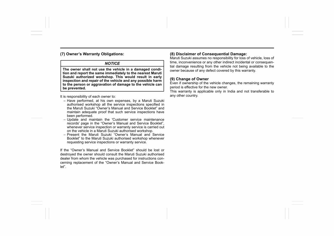
(7) Owner’s Warranty Obligations:
It is responsibility of each owner to:– Have performed, at his own expenses, by a Maruti Suzuki
authorised workshop all the service inspections specified inthe Maruti Suzuki “Owner’s Manual and Service Booklet” andmaintain adequate proof that such service inspections havebeen performed.
– Update and maintain the 'Customer service maintenancerecords' page in the “Owner’s Manual and Service Booklet”,whenever service inspection or warranty service is carried outon the vehicle in a Maruti Suzuki authorised workshop.
– Present the Maruti Suzuki “Owner’s Manual and ServiceBooklet” to the Maruti Suzuki authorised workshop wheneverrequesting service inspections or warranty service.
If the “Owner’s Manual and Service Booklet” should be lost ordestroyed the owner should consult the Maruti Suzuki authoriseddealer from whom the vehicle was purchased for instructions con-cerning replacement of the “Owner’s Manual and Service Book-let”.
(8) Disclaimer of Consequential Damage:Maruti Suzuki assumes no responsibility for loss of vehicle, loss oftime, inconvenience or any other indirect incidental or consequen-tial damage resulting from the vehicle not being available to theowner because of any defect covered by this warranty.
(9) Change of OwnerEven if ownership of the vehicle changes, the remaining warrantyperiod is effective for the new owner.This warranty is applicable only in India and not transferable toany other country.
NOTICE
The owner shall not use the vehicle in a damaged condi-tion and report the same immediately to the nearest MarutiSuzuki authorized workshop. This would result in earlyinspection and repair of the vehicle and any possible harmto the person or aggravation of damage to the vehicle canbe prevented.
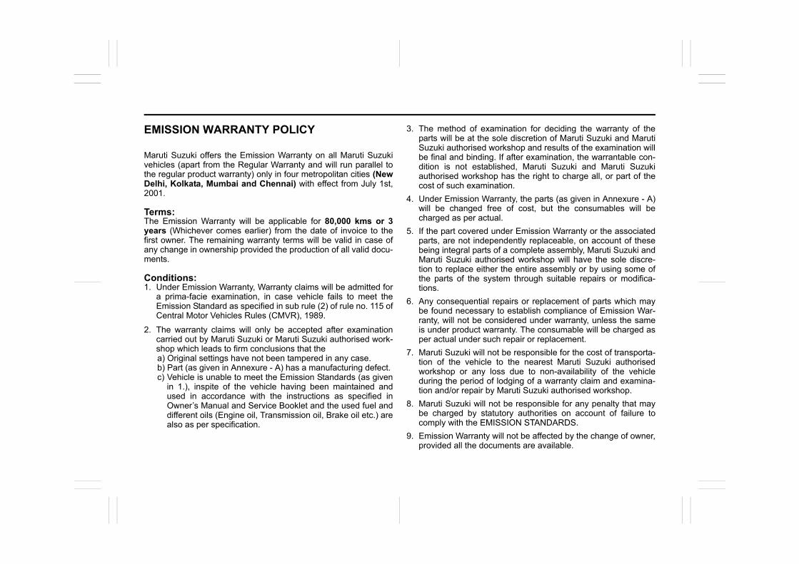
EMISSION WARRANTY POLICY
Maruti Suzuki offers the Emission Warranty on all Maruti Suzukivehicles (apart from the Regular Warranty and will run parallel tothe regular product warranty) only in four metropolitan cities (NewDelhi, Kolkata, Mumbai and Chennai) with effect from July 1st,2001.
Terms:The Emission Warranty will be applicable for 80,000 kms or 3years (Whichever comes earlier) from the date of invoice to thefirst owner. The remaining warranty terms will be valid in case ofany change in ownership provided the production of all valid docu-ments.
Conditions:1. Under Emission Warranty, Warranty claims will be admitted for
a prima-facie examination, in case vehicle fails to meet theEmission Standard as specified in sub rule (2) of rule no. 115 ofCentral Motor Vehicles Rules (CMVR), 1989.
2. The warranty claims will only be accepted after examinationcarried out by Maruti Suzuki or Maruti Suzuki authorised work-shop which leads to firm conclusions that thea) Original settings have not been tampered in any case. b) Part (as given in Annexure - A) has a manufacturing defect. c) Vehicle is unable to meet the Emission Standards (as given
in 1.), inspite of the vehicle having been maintained andused in accordance with the instructions as specified inOwner’s Manual and Service Booklet and the used fuel anddifferent oils (Engine oil, Transmission oil, Brake oil etc.) arealso as per specification.
3. The method of examination for deciding the warranty of theparts will be at the sole discretion of Maruti Suzuki and MarutiSuzuki authorised workshop and results of the examination willbe final and binding. If after examination, the warrantable con-dition is not established, Maruti Suzuki and Maruti Suzukiauthorised workshop has the right to charge all, or part of thecost of such examination.
4. Under Emission Warranty, the parts (as given in Annexure - A)will be changed free of cost, but the consumables will becharged as per actual.
5. If the part covered under Emission Warranty or the associatedparts, are not independently replaceable, on account of thesebeing integral parts of a complete assembly, Maruti Suzuki andMaruti Suzuki authorised workshop will have the sole discre-tion to replace either the entire assembly or by using some ofthe parts of the system through suitable repairs or modifica-tions.
6. Any consequential repairs or replacement of parts which maybe found necessary to establish compliance of Emission War-ranty, will not be considered under warranty, unless the sameis under product warranty. The consumable will be charged asper actual under such repair or replacement.
7. Maruti Suzuki will not be responsible for the cost of transporta-tion of the vehicle to the nearest Maruti Suzuki authorisedworkshop or any loss due to non-availability of the vehicleduring the period of lodging of a warranty claim and examina-tion and/or repair by Maruti Suzuki authorised workshop.
8. Maruti Suzuki will not be responsible for any penalty that maybe charged by statutory authorities on account of failure tocomply with the EMISSION STANDARDS.
9. Emission Warranty will not be affected by the change of owner,provided all the documents are available.
10. All maintenance actions (as specified in the Owner’s Manualand Service Booklet) need to be followed and recorded in themanual for emission warranty.
11. The customer needs to produce the PUC (Pollution UnderControl) certificate valid for the period preceding the testduring which the failure is discovered. The receipts (for themaintenance of the vehicle as per specification in Owner’sManual and Service Booklet from the date of original purchaseof the vehicle) will also be required.
Conditions under which the Emission Warranty is notAPPLICABLE1. In the absence of valid PUC certificate.
2. Vehicle not serviced from Maruti Suzuki authorised workshopas per the schedule specified in the Owner’s Manual.
3. Vehicle subjected to abnormal use (accident, motor race, ral-lies or for the purpose of establishing the records etc).
4. Use of non MSGP (Maruti Suzuki Genuine Part).
5. Vehicle that has been tampered with.
6. Tampering with odometer so that the actual kilometer readingcannot be determined.
7. Use of adulterated fuel and/or unspecified oils (Engine oil,Transmission oil and Brake oil etc).
Annexure - AList of parts (if applicable) covered under Emission Warranty1. Fuel Injection Assembly, Pressure Regulator, Throttle Body
Assembly.2. Electronic Control Module (ECM).3. Intake Manifold.4. EGR valve.5. Ignition Coil.6. Canister Assembly.7. Vapour Liquid Seperator.8. Fuel Tank and Filler Cap.9. PCV (Positive Crankcase Ventilation) Valve.10. Oil Filler Cap.11. Catalytic Convertor.12. Exhaust Manifold.13. All Fuel Injection System related Sensors.14. High Pressure Fuel Pump.15. Glow Plug.16. Glow Plug Controller.

69RH0-74E
TABLE OF CONTENTS FOR SAFE DRIVING 1
BEFORE DRIVING 2
OPERATING YOUR VEHICLE 3
DRIVING TIPS 4
OTHER CONTROLS AND EQUIPMENT 5
INSPECTION AND MAINTENANCE 6
EMERGENCY SERVICE 7
APPEARANCE CARE 8
SPECIFICATIONS 9
SERVICE NETWORK 10

FOR SAFE DRIVING
1
72RH0-74E
65D231S
FOR SAFE DRIVINGFloor Mats ............................................................................ 1-1Front Seats .......................................................................... 1-1Rear Seats ............................................................................ 1-3Seat Belts and Child Restraint Systems ........................... 1-9Child Restraint System for India......................................... 1-19Supplemental Restraint System (airbags) ........................ 1-25Exhaust Gas Warning ......................................................... 1-32
1-1
FOR SAFE DRIVING
72RH0-74E
Floor Mats
60MK020
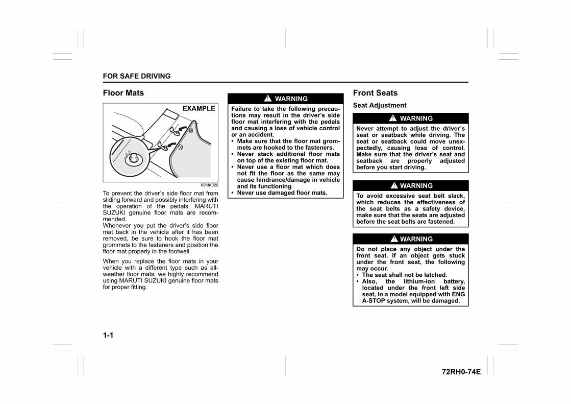
To prevent the driver’s side floor mat fromsliding forward and possibly interfering withthe operation of the pedals, MARUTISUZUKI genuine floor mats are recom-mended.Whenever you put the driver’s side floormat back in the vehicle after it has beenremoved, be sure to hook the floor matgrommets to the fasteners and position thefloor mat properly in the footwell.
When you replace the floor mats in yourvehicle with a different type such as all-weather floor mats, we highly recommendusing MARUTI SUZUKI genuine floor matsfor proper fitting.
Front Seats
Seat AdjustmentEXAMPLE
WARNING
Failure to take the following precau-tions may result in the driver’s sidefloor mat interfering with the pedalsand causing a loss of vehicle controlor an accident.• Make sure that the floor mat grom-
mets are hooked to the fasteners.• Never stack additional floor mats
on top of the existing floor mat.• Never use a floor mat which does
not fit the floor as the same maycause hindrance/damage in vehicleand its functioning
• Never use damaged floor mats.
WARNING
Never attempt to adjust the driver’sseat or seatback while driving. Theseat or seatback could move unex-pectedly, causing loss of control.Make sure that the driver’s seat andseatback are properly adjustedbefore you start driving.
WARNING
To avoid excessive seat belt slack,which reduces the effectiveness ofthe seat belts as a safety device,make sure that the seats are adjustedbefore the seat belts are fastened.
WARNING
Do not place any object under thefront seat. If an object gets stuckunder the front seat, the followingmay occur.• The seat shall not be latched.• Also, the lithium-ion battery,
located under the front left sideseat, in a model equipped with ENGA-STOP system, will be damaged.
1-2
FOR SAFE DRIVING
72RH0-74E
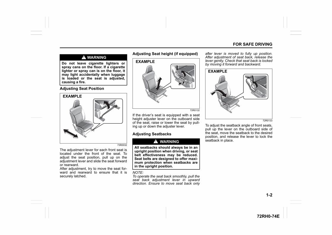
Adjusting Seat Position
73R0032
The adjustment lever for each front seat islocated under the front of the seat. Toadjust the seat position, pull up on theadjustment lever and slide the seat forwardor rearward. After adjustment, try to move the seat for-ward and rearward to ensure that it issecurely latched.
Adjusting Seat height (if equipped)
72R0132
If the driver’s seat is equipped with a seatheight adjuster lever on the outboard sideof the seat, raise or lower the seat by pull-ing up or down the adjuster lever.
Adjusting Seatbacks
NOTE:To operate the seat back smoothly, pull theseat back adjustment lever in upwarddirection. Ensure to move seat back only
after lever is moved to fully up position.After adjustment of seat back, release thelever gently. Check that seat back is lockedby moving it forward and backward.
72R0133
To adjust the seatback angle of front seats,pull up the lever on the outboard side ofthe seat, move the seatback to the desiredposition, and release the lever to lock theseatback in place.
WARNING
Do not leave cigarette lighters orspray cans on the floor. If a cigarettelighter or spray can is on the floor, itmay light accidentally when luggageis loaded or the seat is adjusted,causing a fire.
EXAMPLE
WARNING
All seatbacks should always be in anupright position when driving, or seatbelt effectiveness may be reduced.Seat belts are designed to offer maxi-mum protection when seatbacks arein the upright position.
EXAMPLE
EXAMPLE
1-3
FOR SAFE DRIVING
72RH0-74E
Head Restraints
63J246
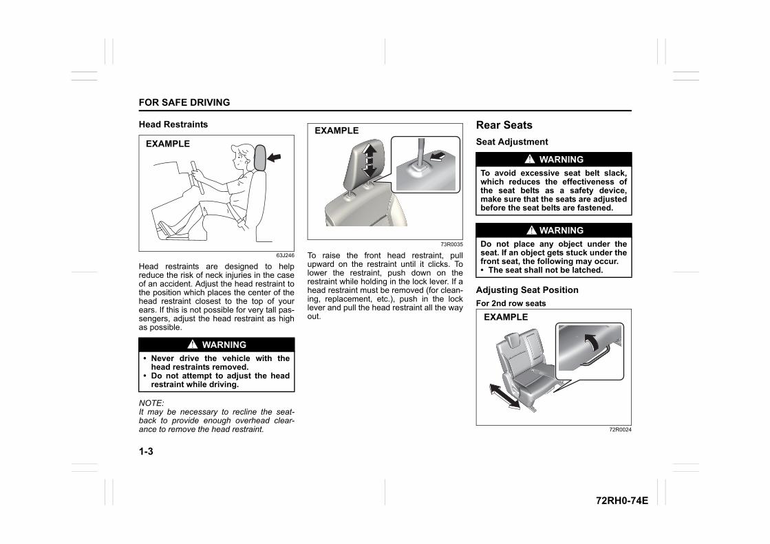
Head restraints are designed to helpreduce the risk of neck injuries in the caseof an accident. Adjust the head restraint tothe position which places the center of thehead restraint closest to the top of yourears. If this is not possible for very tall pas-sengers, adjust the head restraint as highas possible.
NOTE:It may be necessary to recline the seat-back to provide enough overhead clear-ance to remove the head restraint.
73R0035
To raise the front head restraint, pullupward on the restraint until it clicks. Tolower the restraint, push down on therestraint while holding in the lock lever. If ahead restraint must be removed (for clean-ing, replacement, etc.), push in the locklever and pull the head restraint all the wayout.
Rear Seats
Seat Adjustment
Adjusting Seat Position
For 2nd row seats
72R0024
WARNING
• Never drive the vehicle with thehead restraints removed.
• Do not attempt to adjust the headrestraint while driving.
EXAMPLE
EXAMPLE
WARNING
To avoid excessive seat belt slack,which reduces the effectiveness ofthe seat belts as a safety device,make sure that the seats are adjustedbefore the seat belts are fastened.
WARNING
Do not place any object under theseat. If an object gets stuck under thefront seat, the following may occur.• The seat shall not be latched.
EXAMPLE
1-4
FOR SAFE DRIVING
72RH0-74E
The adjustment levers for 2nd row seatsare located under the front of the seats. Toadjust the seat position, pull up on theadjustment lever and slide the seat forwardor rearward. After adjustment, try to move the seat for-ward and rearward to ensure that it issecurely latched.
Adjusting Seatbacks
NOTE:To operate the seat back smoothly, pull theseat back adjustment lever in upwarddirection. Ensure to move seat back onlyafter lever is moved to fully up position.After adjustment of seat back, release thelever gently. Check that seat back is lockedby moving it forward and backward.
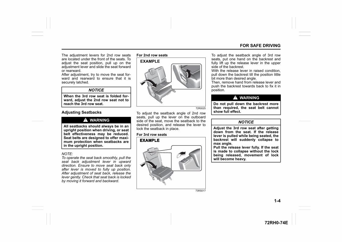
For 2nd row seats
72R0025
To adjust the seatback angle of 2nd rowseats, pull up the lever on the outboardside of the seat, move the seatback to thedesired position, and release the lever tolock the seatback in place.
For 3rd row seats
73RS017
To adjust the seatback angle of 3rd rowseats, put one hand on the backrest andfully lift up the release lever in the upperside of the backrest. With the release lever in raised condition,pull down the backrest till the position littlebit more than desired angle. Then, remove hand from release lever andpush the backrest towards back to fix it inposition.NOTICE
When the 3rd row seat is folded for-ward, adjust the 2nd row seat not toreach the 3rd row seat.
WARNING
All seatbacks should always be in anupright position when driving, or seatbelt effectiveness may be reduced.Seat belts are designed to offer maxi-mum protection when seatbacks arein the upright position.
EXAMPLE
EXAMPLEEXAMPLEEXAMPLE
WARNING
Do not pull down the backrest morethan required, the seat belt cannotshow full effect.
NOTICE
Adjust the 3rd row seat after gettingdown from the seat. If the releaselever is pulled while being seated, thebackrest will suddenly collapse tomax angle.Pull the release lever fully. If the seatis made to collapse without the lockbeing released, movement of lockwill become heavy.
1-5
FOR SAFE DRIVING
72RH0-74E
Walk-in Type Seats
For 2nd row seats
73R0038
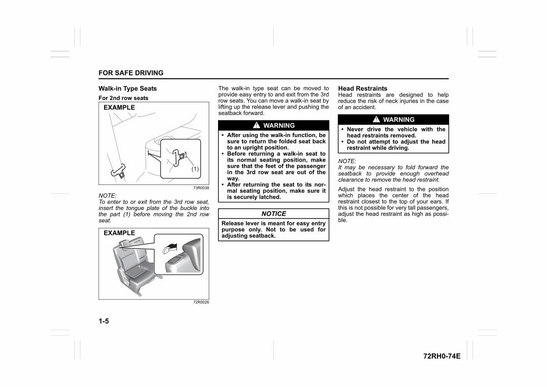
NOTE:To enter to or exit from the 3rd row seat,insert the tongue plate of the buckle intothe part (1) before moving the 2nd rowseat.
72R0026
The walk-in type seat can be moved toprovide easy entry to and exit from the 3rdrow seats. You can move a walk-in seat bylifting up the release lever and pushing theseatback forward.
Head RestraintsHead restraints are designed to helpreduce the risk of neck injuries in the caseof an accident.
NOTE:It may be necessary to fold forward theseatback to provide enough overheadclearance to remove the head restraint.
Adjust the head restraint to the positionwhich places the center of the headrestraint closest to the top of your ears. Ifthis is not possible for very tall passengers,adjust the head restraint as high as possi-ble.
(1)
EXAMPLE
EXAMPLE
WARNING
• After using the walk-in function, besure to return the folded seat backto an upright position.
• Before returning a walk-in seat toits normal seating position, makesure that the feet of the passengerin the 3rd row seat are out of theway.
• After returning the seat to its nor-mal seating position, make sure itis securely latched.
NOTICE
Release lever is meant for easy entrypurpose only. Not to be used foradjusting seatback.
WARNING
• Never drive the vehicle with thehead restraints removed.
• Do not attempt to adjust the headrestraint while driving.
1-6
FOR SAFE DRIVING
72RH0-74E
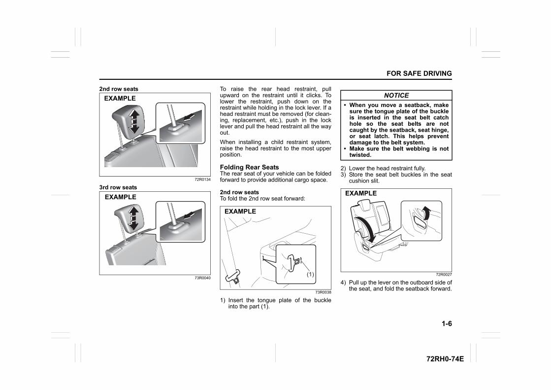
2nd row seats
72R0134
3rd row seats
73R0040
To raise the rear head restraint, pullupward on the restraint until it clicks. Tolower the restraint, push down on therestraint while holding in the lock lever. If ahead restraint must be removed (for clean-ing, replacement, etc.), push in the locklever and pull the head restraint all the wayout.
When installing a child restraint system,raise the head restraint to the most upperposition.
Folding Rear SeatsThe rear seat of your vehicle can be foldedforward to provide additional cargo space.
2nd row seatsTo fold the 2nd row seat forward:
73R0038
1) Insert the tongue plate of the buckleinto the part (1).
2) Lower the head restraint fully.3) Store the seat belt buckles in the seat
cushion slit.
72R0027
4) Pull up the lever on the outboard side ofthe seat, and fold the seatback forward.
EXAMPLE
EXAMPLE
(1)
EXAMPLE
NOTICE
• When you move a seatback, makesure the tongue plate of the buckleis inserted in the seat belt catchhole so the seat belts are notcaught by the seatback, seat hinge,or seat latch. This helps preventdamage to the belt system.
• Make sure the belt webbing is nottwisted.
EXAMPLE
1-7
FOR SAFE DRIVING
72RH0-74E
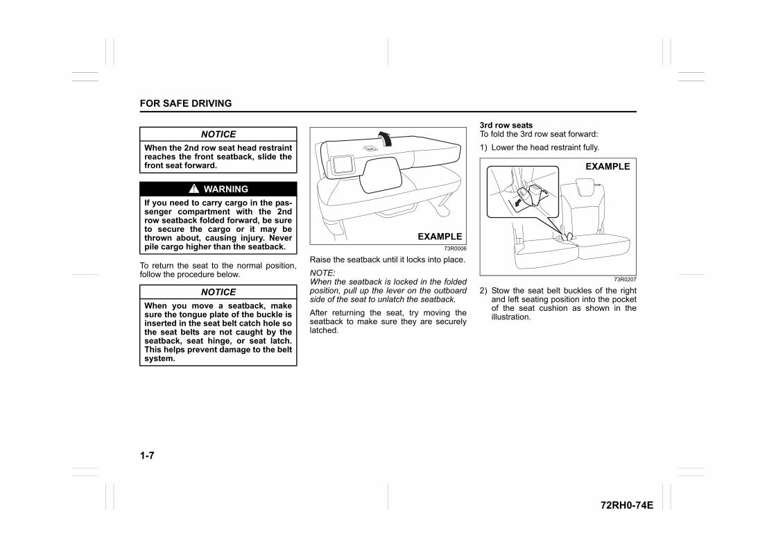
To return the seat to the normal position,follow the procedure below.
73R0006
Raise the seatback until it locks into place.
NOTE:When the seatback is locked in the foldedposition, pull up the lever on the outboardside of the seat to unlatch the seatback.
After returning the seat, try moving theseatback to make sure they are securelylatched.
3rd row seatsTo fold the 3rd row seat forward:
1) Lower the head restraint fully.
73R0207
2) Stow the seat belt buckles of the rightand left seating position into the pocketof the seat cushion as shown in theillustration.
NOTICE
When the 2nd row seat head restraintreaches the front seatback, slide thefront seat forward.
WARNING
If you need to carry cargo in the pas-senger compartment with the 2ndrow seatback folded forward, be sureto secure the cargo or it may bethrown about, causing injury. Neverpile cargo higher than the seatback.
NOTICE
When you move a seatback, makesure the tongue plate of the buckle isinserted in the seat belt catch hole sothe seat belts are not caught by theseatback, seat hinge, or seat latch.This helps prevent damage to the beltsystem.
EXAMPLE
EXAMPLE
1-8
FOR SAFE DRIVING
72RH0-74E
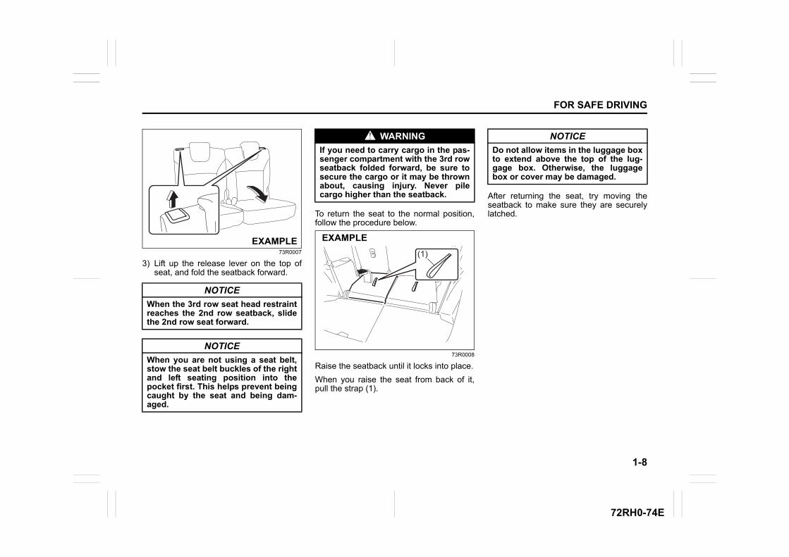
73R0007
3) Lift up the release lever on the top ofseat, and fold the seatback forward.
To return the seat to the normal position,follow the procedure below.
73R0008
Raise the seatback until it locks into place.
When you raise the seat from back of it,pull the strap (1).
After returning the seat, try moving theseatback to make sure they are securelylatched.
NOTICE
When the 3rd row seat head restraintreaches the 2nd row seatback, slidethe 2nd row seat forward.
NOTICE
When you are not using a seat belt,stow the seat belt buckles of the rightand left seating position into thepocket first. This helps prevent beingcaught by the seat and being dam-aged.
EXAMPLE
WARNING
If you need to carry cargo in the pas-senger compartment with the 3rd rowseatback folded forward, be sure tosecure the cargo or it may be thrownabout, causing injury. Never pilecargo higher than the seatback.
(1)
EXAMPLE
NOTICE
Do not allow items in the luggage boxto extend above the top of the lug-gage box. Otherwise, the luggagebox or cover may be damaged.
1-9
FOR SAFE DRIVING
72RH0-74E
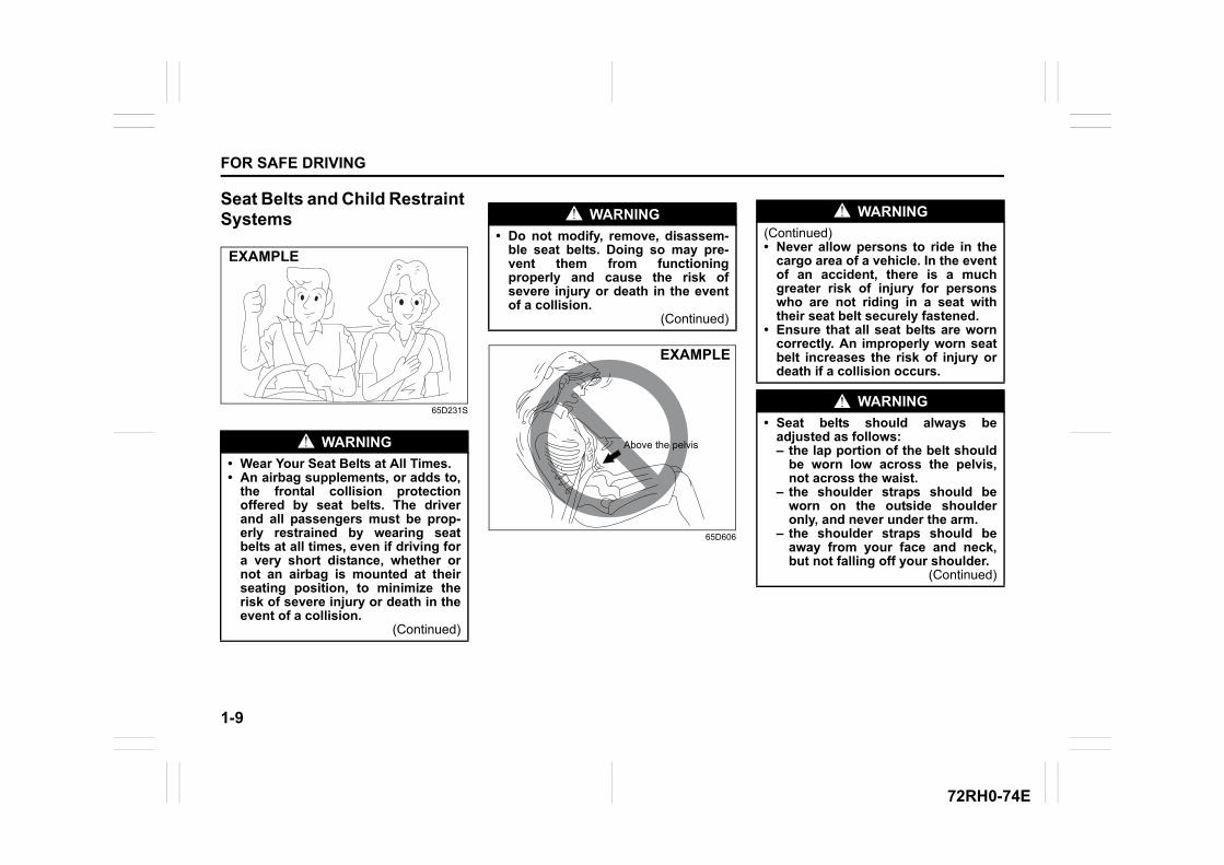
Seat Belts and Child Restraint Systems
65D231S
65D606
WARNING
• Wear Your Seat Belts at All Times.• An airbag supplements, or adds to,
the frontal collision protectionoffered by seat belts. The driverand all passengers must be prop-erly restrained by wearing seatbelts at all times, even if driving fora very short distance, whether ornot an airbag is mounted at theirseating position, to minimize therisk of severe injury or death in theevent of a collision.
(Continued)
EXAMPLE
WARNING
• Do not modify, remove, disassem-ble seat belts. Doing so may pre-vent them from functioningproperly and cause the risk ofsevere injury or death in the eventof a collision.
(Continued)
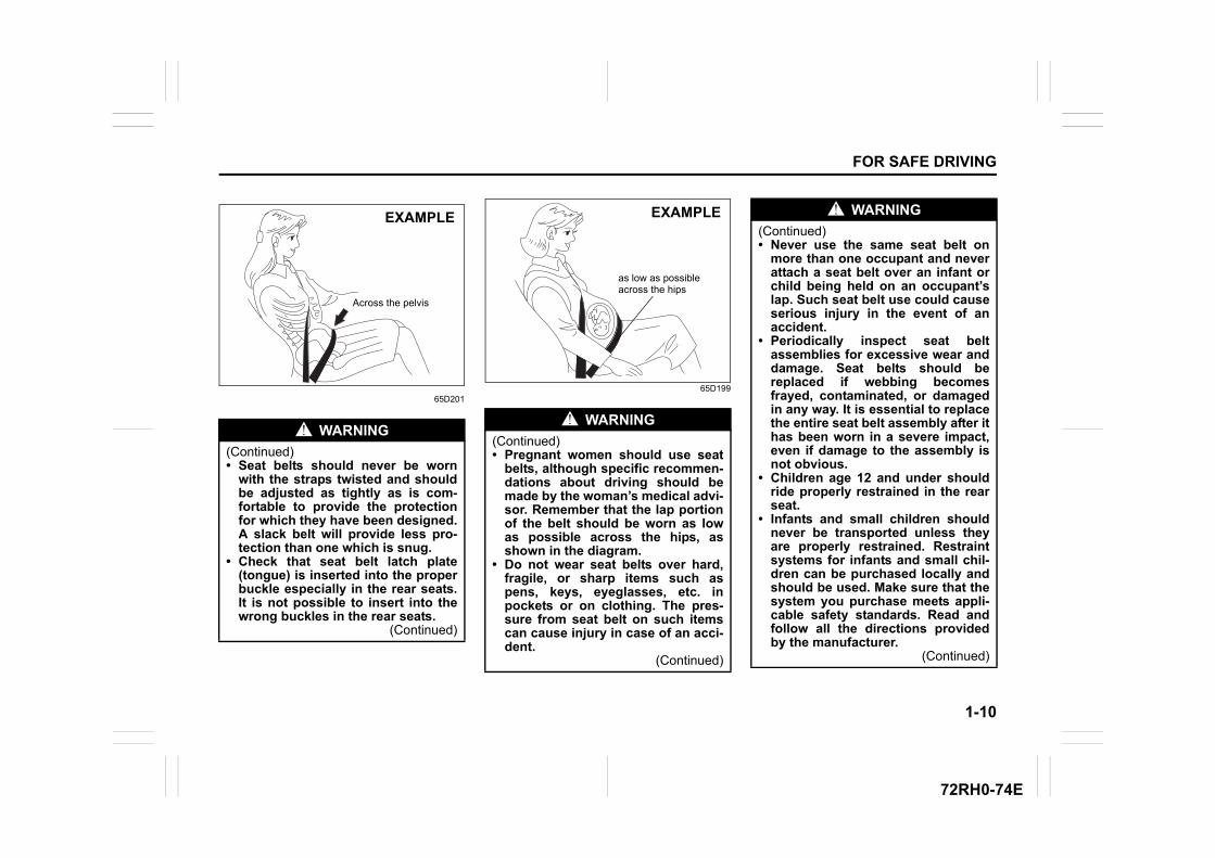
Above the pelvis
EXAMPLE
WARNING
(Continued)• Never allow persons to ride in the
cargo area of a vehicle. In the eventof an accident, there is a muchgreater risk of injury for personswho are not riding in a seat withtheir seat belt securely fastened.
• Ensure that all seat belts are worncorrectly. An improperly worn seatbelt increases the risk of injury ordeath if a collision occurs.
WARNING
• Seat belts should always beadjusted as follows:– the lap portion of the belt should
be worn low across the pelvis,not across the waist.
– the shoulder straps should beworn on the outside shoulderonly, and never under the arm.
– the shoulder straps should beaway from your face and neck,but not falling off your shoulder.
(Continued)
1-10
FOR SAFE DRIVING
72RH0-74E
65D20165D199
WARNING
(Continued)• Seat belts should never be worn
with the straps twisted and shouldbe adjusted as tightly as is com-fortable to provide the protectionfor which they have been designed.A slack belt will provide less pro-tection than one which is snug.
• Check that seat belt latch plate(tongue) is inserted into the properbuckle especially in the rear seats.It is not possible to insert into thewrong buckles in the rear seats.
(Continued)
Across the pelvis
EXAMPLE
WARNING
(Continued)• Pregnant women should use seat
belts, although specific recommen-dations about driving should bemade by the woman’s medical advi-sor. Remember that the lap portionof the belt should be worn as lowas possible across the hips, asshown in the diagram.
• Do not wear seat belts over hard,fragile, or sharp items such aspens, keys, eyeglasses, etc. inpockets or on clothing. The pres-sure from seat belt on such itemscan cause injury in case of an acci-dent.
(Continued)
as low as possible across the hips
EXAMPLE WARNING
(Continued)• Never use the same seat belt on
more than one occupant and neverattach a seat belt over an infant orchild being held on an occupant’slap. Such seat belt use could causeserious injury in the event of anaccident.
• Periodically inspect seat beltassemblies for excessive wear anddamage. Seat belts should bereplaced if webbing becomesfrayed, contaminated, or damagedin any way. It is essential to replacethe entire seat belt assembly after ithas been worn in a severe impact,even if damage to the assembly isnot obvious.
• Children age 12 and under shouldride properly restrained in the rearseat.
• Infants and small children shouldnever be transported unless theyare properly restrained. Restraintsystems for infants and small chil-dren can be purchased locally andshould be used. Make sure that thesystem you purchase meets appli-cable safety standards. Read andfollow all the directions providedby the manufacturer.
(Continued)
1-11
FOR SAFE DRIVING
72RH0-74E
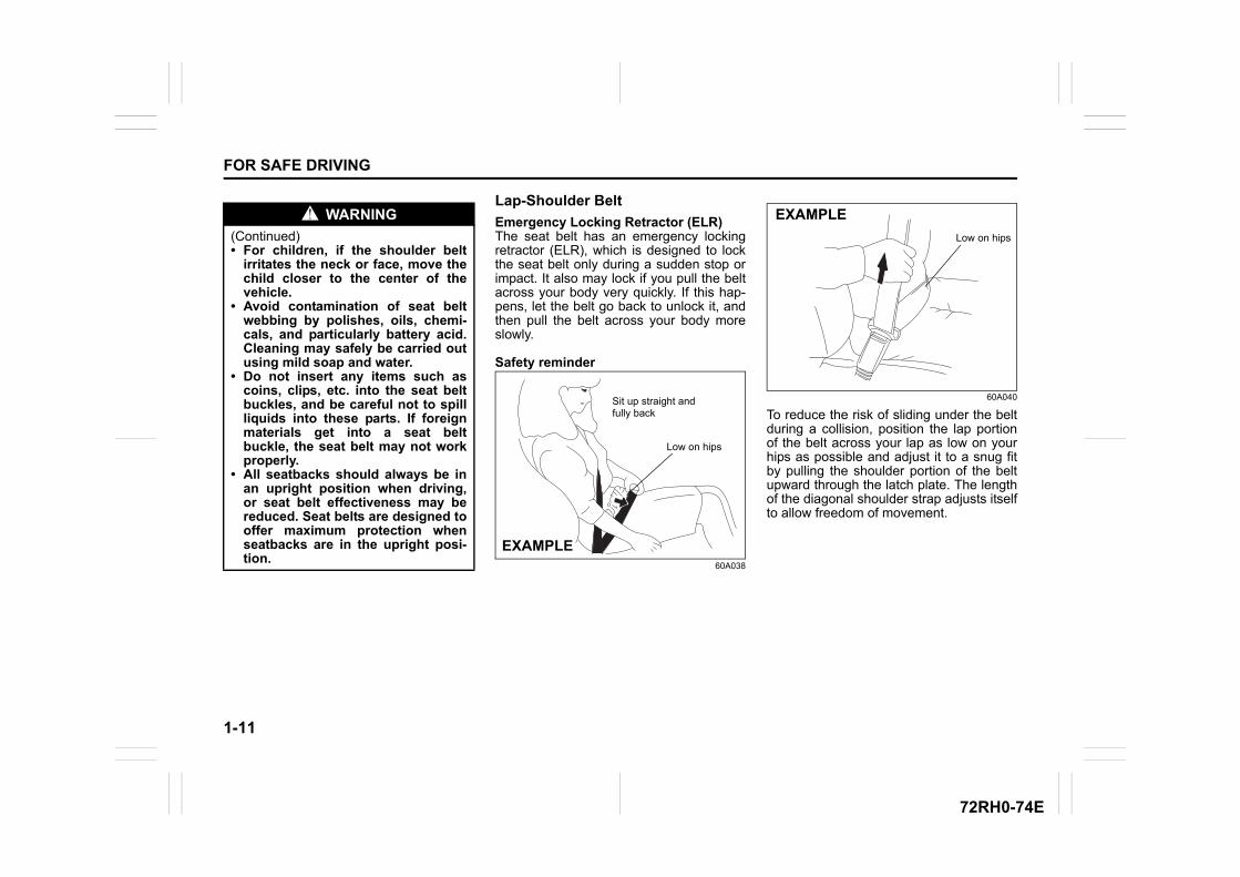
Lap-Shoulder Belt
Emergency Locking Retractor (ELR)The seat belt has an emergency lockingretractor (ELR), which is designed to lockthe seat belt only during a sudden stop orimpact. It also may lock if you pull the beltacross your body very quickly. If this hap-pens, let the belt go back to unlock it, andthen pull the belt across your body moreslowly.
Safety reminder
60A038
60A040
To reduce the risk of sliding under the beltduring a collision, position the lap portionof the belt across your lap as low on yourhips as possible and adjust it to a snug fitby pulling the shoulder portion of the beltupward through the latch plate. The lengthof the diagonal shoulder strap adjusts itselfto allow freedom of movement.
WARNING
(Continued)• For children, if the shoulder belt
irritates the neck or face, move thechild closer to the center of thevehicle.
• Avoid contamination of seat beltwebbing by polishes, oils, chemi-cals, and particularly battery acid.Cleaning may safely be carried outusing mild soap and water.
• Do not insert any items such ascoins, clips, etc. into the seat beltbuckles, and be careful not to spillliquids into these parts. If foreignmaterials get into a seat beltbuckle, the seat belt may not workproperly.
• All seatbacks should always be inan upright position when driving,or seat belt effectiveness may bereduced. Seat belts are designed tooffer maximum protection whenseatbacks are in the upright posi-tion.
Sit up straight and fully back
Low on hips
EXAMPLE
Low on hips
EXAMPLE
1-12
FOR SAFE DRIVING
72RH0-74E
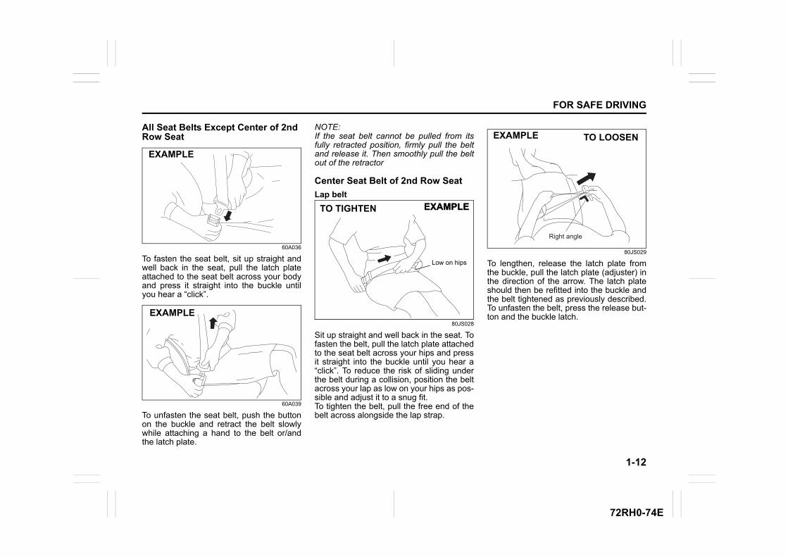
All Seat Belts Except Center of 2nd Row Seat
60A036
To fasten the seat belt, sit up straight andwell back in the seat, pull the latch plateattached to the seat belt across your bodyand press it straight into the buckle untilyou hear a “click”.
60A039
To unfasten the seat belt, push the buttonon the buckle and retract the belt slowlywhile attaching a hand to the belt or/andthe latch plate.
NOTE:If the seat belt cannot be pulled from itsfully retracted position, firmly pull the beltand release it. Then smoothly pull the beltout of the retractor
Center Seat Belt of 2nd Row Seat
Lap belt
80JS028
Sit up straight and well back in the seat. Tofasten the belt, pull the latch plate attachedto the seat belt across your hips and pressit straight into the buckle until you hear a“click”. To reduce the risk of sliding underthe belt during a collision, position the beltacross your lap as low on your hips as pos-sible and adjust it to a snug fit.To tighten the belt, pull the free end of thebelt across alongside the lap strap.
80JS029
To lengthen, release the latch plate fromthe buckle, pull the latch plate (adjuster) inthe direction of the arrow. The latch plateshould then be refitted into the buckle andthe belt tightened as previously described.To unfasten the belt, press the release but-ton and the buckle latch.
EXAMPLE
EXAMPLE
TO TIGHTEN
Low on hips
EXAMPLEEXAMPLE
TO LOOSENEXAMPLE
Right angle
1-13
FOR SAFE DRIVING
72RH0-74E
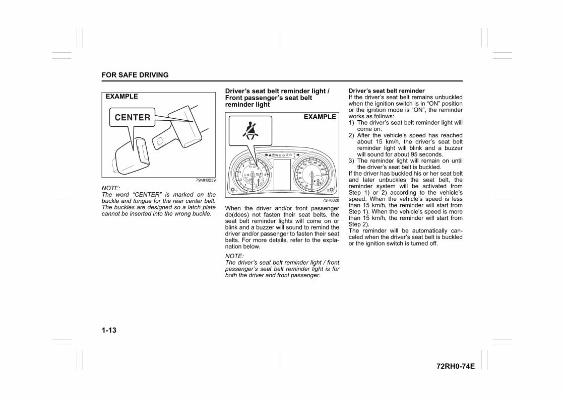
79MH0239
NOTE:The word “CENTER” is marked on thebuckle and tongue for the rear center belt.The buckles are designed so a latch platecannot be inserted into the wrong buckle.
Driver’s seat belt reminder light / Front passenger’s seat belt reminder light
72R0028
When the driver and/or front passengerdo(does) not fasten their seat belts, theseat belt reminder lights will come on orblink and a buzzer will sound to remind thedriver and/or passenger to fasten their seatbelts. For more details, refer to the expla-nation below.
NOTE:The driver’s seat belt reminder light / frontpassenger’s seat belt reminder light is forboth the driver and front passenger.
Driver’s seat belt reminderIf the driver’s seat belt remains unbuckledwhen the ignition switch is in “ON” positionor the ignition mode is “ON”, the reminderworks as follows: 1) The driver’s seat belt reminder light will
come on. 2) After the vehicle’s speed has reached
about 15 km/h, the driver’s seat beltreminder light will blink and a buzzerwill sound for about 95 seconds.
3) The reminder light will remain on untilthe driver’s seat belt is buckled.
If the driver has buckled his or her seat beltand later unbuckles the seat belt, thereminder system will be activated fromStep 1) or 2) according to the vehicle’sspeed. When the vehicle’s speed is lessthan 15 km/h, the reminder will start fromStep 1). When the vehicle’s speed is morethan 15 km/h, the reminder will start fromStep 2).The reminder will be automatically can-celed when the driver’s seat belt is buckledor the ignition switch is turned off.
EXAMPLE
EXAMPLE
1-14
FOR SAFE DRIVING
72RH0-74E
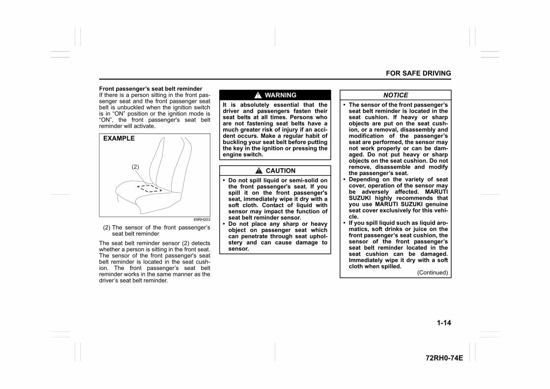
Front passenger’s seat belt reminderIf there is a person sitting in the front pas-senger seat and the front passenger seatbelt is unbuckled when the ignition switchis in “ON” position or the ignition mode is“ON”, the front passenger's seat beltreminder will activate.
69RH203
(2) The sensor of the front passenger’sseat belt reminder
The seat belt reminder sensor (2) detectswhether a person is sitting in the front seat.The sensor of the front passenger's seatbelt reminder is located in the seat cush-ion. The front passenger’s seat beltreminder works in the same manner as thedriver’s seat belt reminder.
(2)
EXAMPLE
WARNING
It is absolutely essential that thedriver and passengers fasten theirseat belts at all times. Persons whoare not fastening seat belts have amuch greater risk of injury if an acci-dent occurs. Make a regular habit ofbuckling your seat belt before puttingthe key in the ignition or pressing theengine switch.
CAUTION
• Do not spill liquid or semi-solid onthe front passenger's seat. If youspill it on the front passenger'sseat, immediately wipe it dry with asoft cloth. Contact of liquid withsensor may impact the function ofseat belt reminder sensor.
• Do not place any sharp or heavyobject on passenger seat whichcan penetrate through seat uphol-stery and can cause damage tosensor.
NOTICE
• The sensor of the front passenger’sseat belt reminder is located in theseat cushion. If heavy or sharpobjects are put on the seat cush-ion, or a removal, disassembly andmodification of the passenger’sseat are performed, the sensor maynot work properly or can be dam-aged. Do not put heavy or sharpobjects on the seat cushion. Do notremove, disassemble and modifythe passenger’s seat.
• Depending on the variety of seatcover, operation of the sensor maybe adversely affected. MARUTISUZUKI highly recommends thatyou use MARUTI SUZUKI genuineseat cover exclusively for this vehi-cle.
• If you spill liquid such as liquid aro-matics, soft drinks or juice on thefront passenger’s seat cushion, thesensor of the front passenger’sseat belt reminder located in theseat cushion can be damaged.Immediately wipe it dry with a softcloth when spilled.
(Continued)
1-15
FOR SAFE DRIVING
72RH0-74E
NOTE:• If you put an object on the passenger’s
seat, the weight of the object will besensed by the sensor and the front pas-senger’s seat belt reminder light willcome on and then the interior buzzermay beep.
• If a child or a small sized person sits onthe front passenger’s seat or the cushionis put on the front passenger’s seat, theweight may not be sensed by the sensorand the interior buzzer may not beep.
• Maruti Suzuki recommends use ofMaruti Suzuki Genuine accessory of“Seat cover”.
Shoulder anchor height adjuster (if equipped)
64J198
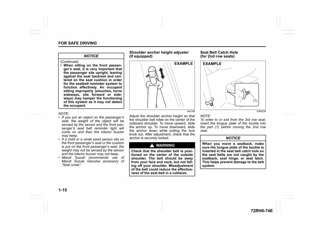
Adjust the shoulder anchor height so thatthe shoulder belt rides on the center of theoutboard shoulder. To move upward, slidethe anchor up. To move downward, slidethe anchor down while pulling the lockknob out. After adjustment, check that theanchor is securely locked.
Seat Belt Catch Hole (for 2nd row seats)
73R0038
NOTE:To enter to or exit from the 3rd row seat,insert the tongue plate of the buckle intothe part (1) before moving the 2nd rowseat.
NOTICE
(Continued) • When sitting on the front passen-
ger’s seat, it is very important thatthe passenger sits upright, leaningagainst the seat backrest and cen-tered on the seat cushion in orderfor the seatbelt reminder system tofunction effectively. An occupantsitting improperly (slouches, turnssideways, sits forward or side-ways) may hamper the functioningof this system as it may not detectthe occupant.
WARNING
Check that the shoulder belt is posi-tioned on the center of the outsideshoulder. The belt should be awayfrom your face and neck, but not fall-ing off your shoulder. Misadjustmentof the belt could reduce the effective-ness of the seat belt in a collision.
EXAMPLE
NOTICE
When you move a seatback, makesure the tongue plate of the buckle isinserted in the seat belt catch hole sothe seat belts are not caught by theseatback, seat hinge, or seat latch.This helps prevent damage to the beltsystem.
(1)
EXAMPLE
1-16
FOR SAFE DRIVING
72RH0-74E
Seat Belt Inspection
65D209S
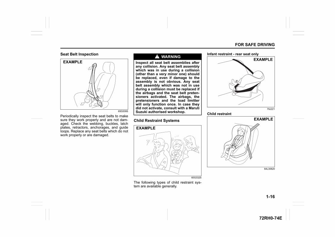
Periodically inspect the seat belts to makesure they work properly and are not dam-aged. Check the webbing, buckles, latchplates, retractors, anchorages, and guideloops. Replace any seat belts which do notwork properly or are damaged.
Child Restraint Systems
60G332S
The following types of child restraint sys-tem are available generally.
Infant restraint - rear seat only
79J221
Child restraint
64L30820
EXAMPLEWARNING
Inspect all seat belt assemblies afterany collision. Any seat belt assemblywhich was in use during a collision(other than a very minor one) shouldbe replaced, even if damage to theassembly is not obvious. Any seatbelt assembly which was not in useduring a collision must be replaced ifthe airbags and the seat belt preten-sioners activated. The airbags, thepretensioners and the load limitterwill only function once. In case theydid not activate, consult with a MarutiSuzuki authorised workshop.
EXAMPLE
EXAMPLE
EXAMPLE
1-17
FOR SAFE DRIVING
72RH0-74E
Booster seat
79J223
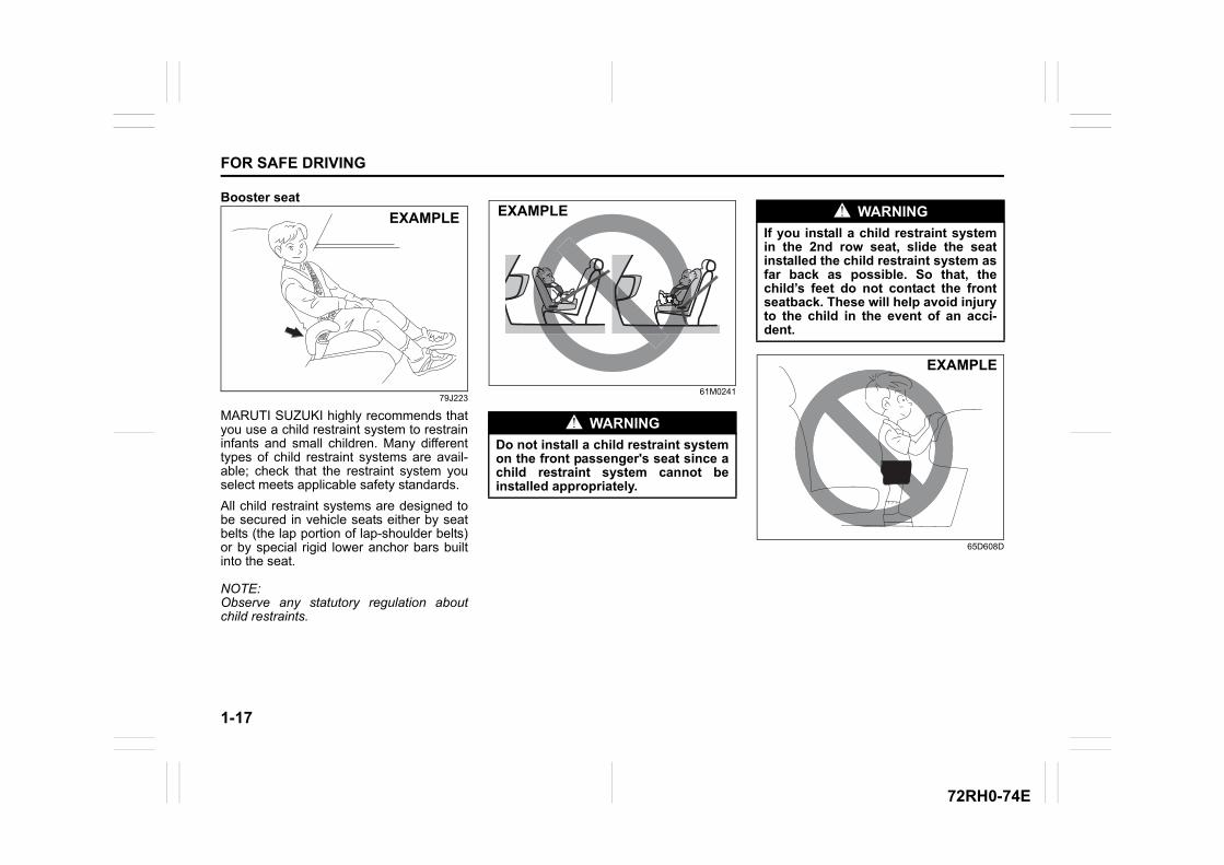
MARUTI SUZUKI highly recommends thatyou use a child restraint system to restraininfants and small children. Many differenttypes of child restraint systems are avail-able; check that the restraint system youselect meets applicable safety standards.
All child restraint systems are designed tobe secured in vehicle seats either by seatbelts (the lap portion of lap-shoulder belts)or by special rigid lower anchor bars builtinto the seat.
NOTE:Observe any statutory regulation aboutchild restraints.
61M0241
65D608D
EXAMPLE
WARNING
Do not install a child restraint systemon the front passenger's seat since achild restraint system cannot beinstalled appropriately.
EXAMPLE WARNING
If you install a child restraint systemin the 2nd row seat, slide the seatinstalled the child restraint system asfar back as possible. So that, thechild’s feet do not contact the frontseatback. These will help avoid injuryto the child in the event of an acci-dent.
EXAMPLE
1-18
FOR SAFE DRIVING
72RH0-74E
65D609S
WARNING
Children could be endangered in acollision if their child restraint sys-tems are not properly secured in thevehicle. When installing a childrestraint system, follow the instruc-tions below. secure the child in therestraint system according to themanufacturer’s instructions.
WARNING
Do not hold a child on a passenger'slap when the vehicle is in motion. Even if the passenger holds the childtightly, he/she would not be sup-ported enough in the event of anaccident and it could result in a seri-ous injury of the child.
EXAMPLE
1-19
FOR SAFE DRIVING
72RH0-74E
Child Restraint System for IndiaChild Restraint
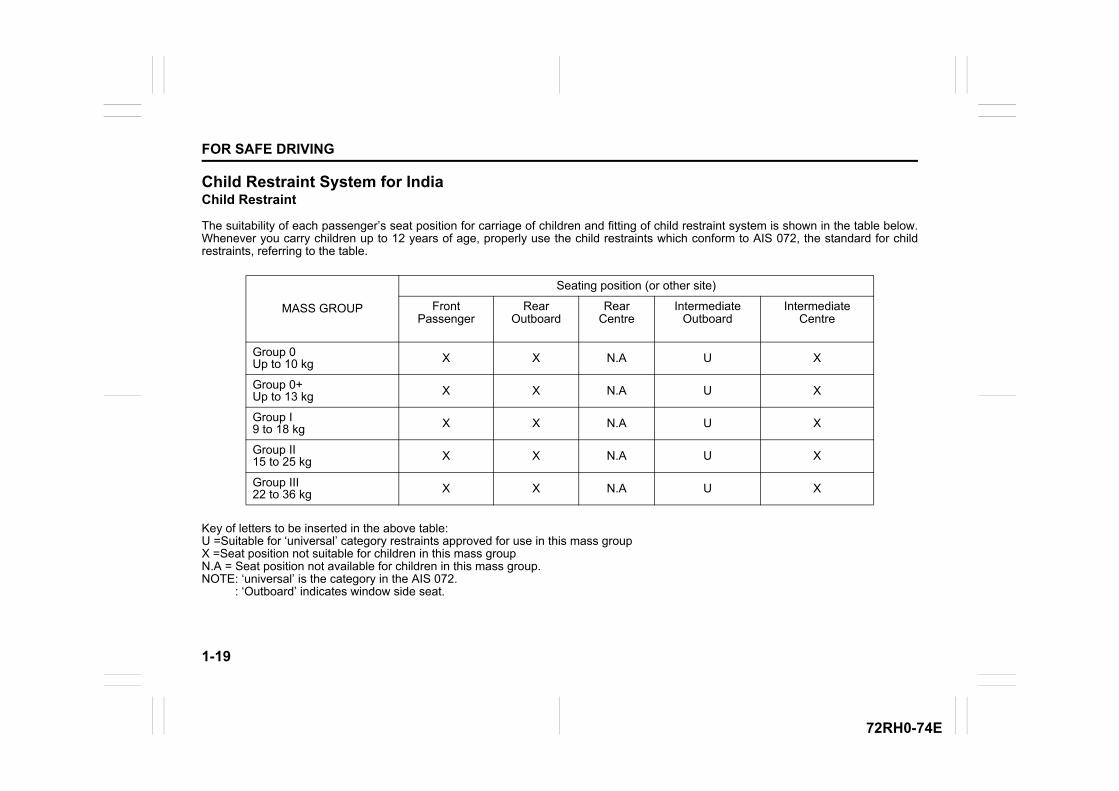
The suitability of each passenger’s seat position for carriage of children and fitting of child restraint system is shown in the table below.Whenever you carry children up to 12 years of age, properly use the child restraints which conform to AIS 072, the standard for childrestraints, referring to the table.
Key of letters to be inserted in the above table:U =Suitable for ‘universal’ category restraints approved for use in this mass groupX =Seat position not suitable for children in this mass groupN.A = Seat position not available for children in this mass group. NOTE: ‘universal’ is the category in the AIS 072. : ‘Outboard’ indicates window side seat.
MASS GROUP
Seating position (or other site)
Front Passenger
Rear Outboard
Rear Centre
Intermediate Outboard
Intermediate Centre
Group 0Up to 10 kg X X N.A U X
Group 0+Up to 13 kg X X N.A U X
Group I9 to 18 kg X X N.A U X
Group II15 to 25 kg X X N.A U X
Group III22 to 36 kg X X N.A U X
1-20
FOR SAFE DRIVING
72RH0-74E
Installation with lap-shoulder seat belts
NOTE:Stow the removed head restraint in the lug-gage compartment so it will not causeinconvenience to the occupants.
ELR type belt
80JC021
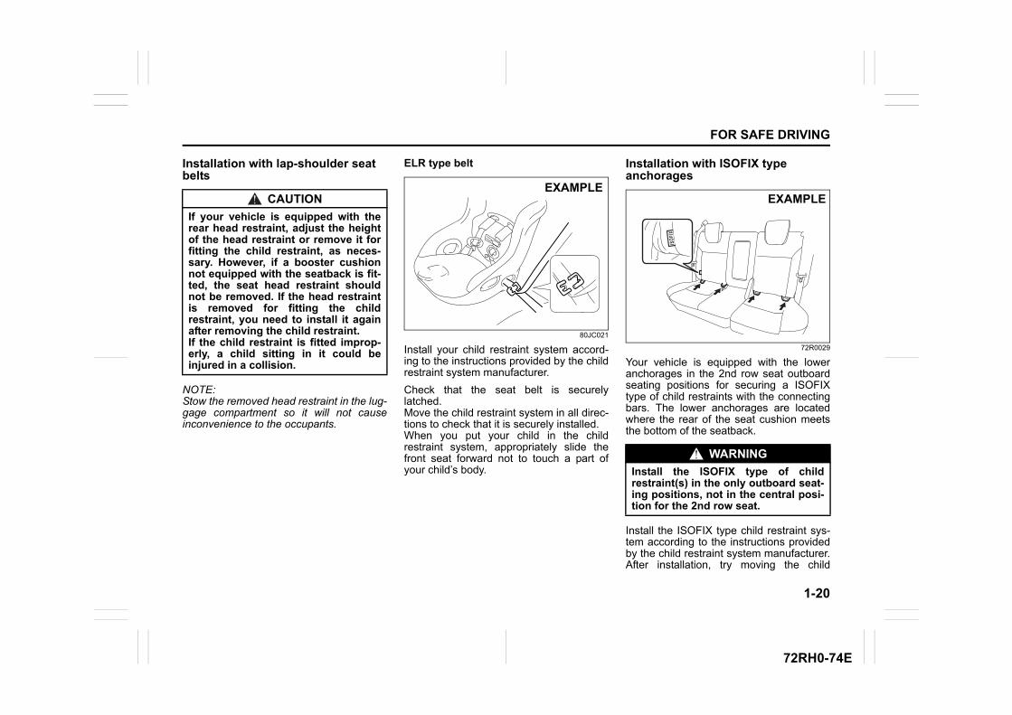
Install your child restraint system accord-ing to the instructions provided by the childrestraint system manufacturer.
Check that the seat belt is securelylatched.Move the child restraint system in all direc-tions to check that it is securely installed.When you put your child in the childrestraint system, appropriately slide thefront seat forward not to touch a part ofyour child’s body.
Installation with ISOFIX type anchorages
72R0029
Your vehicle is equipped with the loweranchorages in the 2nd row seat outboardseating positions for securing a ISOFIXtype of child restraints with the connectingbars. The lower anchorages are locatedwhere the rear of the seat cushion meetsthe bottom of the seatback.
Install the ISOFIX type child restraint sys-tem according to the instructions providedby the child restraint system manufacturer.After installation, try moving the child
CAUTION
If your vehicle is equipped with therear head restraint, adjust the heightof the head restraint or remove it forfitting the child restraint, as neces-sary. However, if a booster cushionnot equipped with the seatback is fit-ted, the seat head restraint shouldnot be removed. If the head restraintis removed for fitting the childrestraint, you need to install it againafter removing the child restraint.If the child restraint is fitted improp-erly, a child sitting in it could beinjured in a collision.
EXAMPLE
WARNING
Install the ISOFIX type of childrestraint(s) in the only outboard seat-ing positions, not in the central posi-tion for the 2nd row seat.
EXAMPLE
1-21
FOR SAFE DRIVING
72RH0-74E
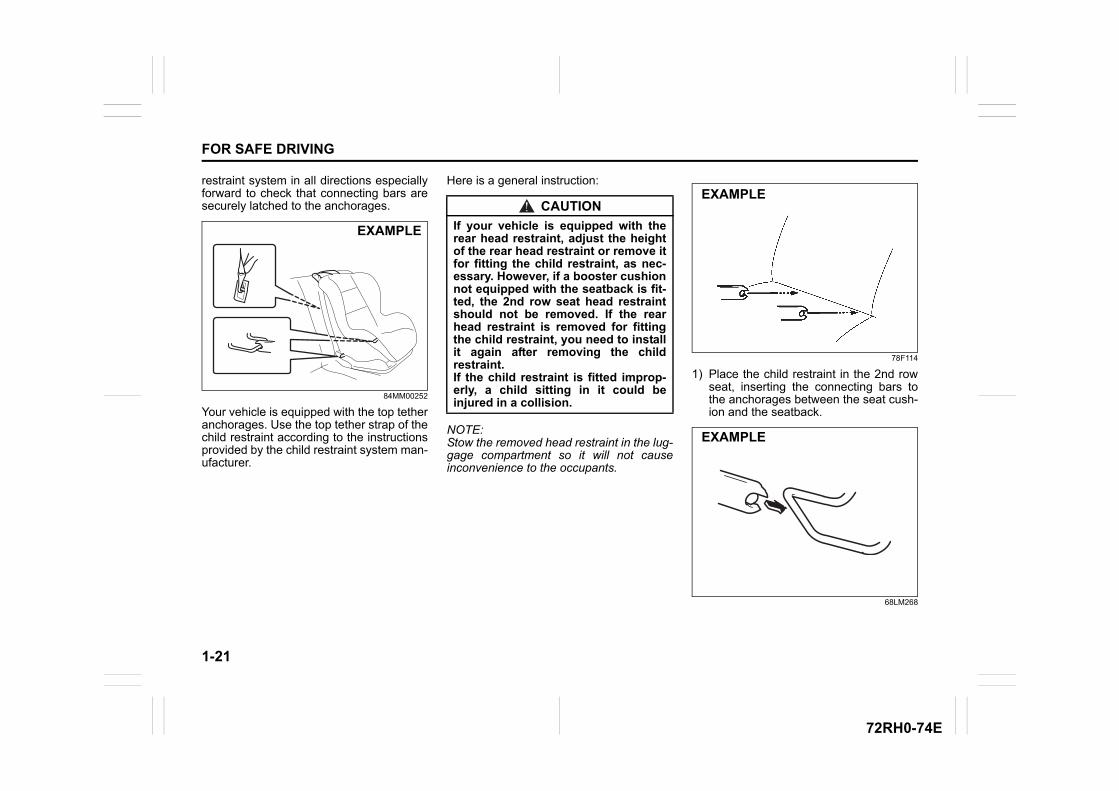
restraint system in all directions especiallyforward to check that connecting bars aresecurely latched to the anchorages.
84MM00252
Your vehicle is equipped with the top tetheranchorages. Use the top tether strap of thechild restraint according to the instructionsprovided by the child restraint system man-ufacturer.
Here is a general instruction:
NOTE:Stow the removed head restraint in the lug-gage compartment so it will not causeinconvenience to the occupants.
78F114
1) Place the child restraint in the 2nd rowseat, inserting the connecting bars tothe anchorages between the seat cush-ion and the seatback.
68LM268
EXAMPLE
CAUTION
If your vehicle is equipped with therear head restraint, adjust the heightof the rear head restraint or remove itfor fitting the child restraint, as nec-essary. However, if a booster cushionnot equipped with the seatback is fit-ted, the 2nd row seat head restraintshould not be removed. If the rearhead restraint is removed for fittingthe child restraint, you need to installit again after removing the childrestraint.If the child restraint is fitted improp-erly, a child sitting in it could beinjured in a collision.
EXAMPLE
EXAMPLE
1-22
FOR SAFE DRIVING
72RH0-74E
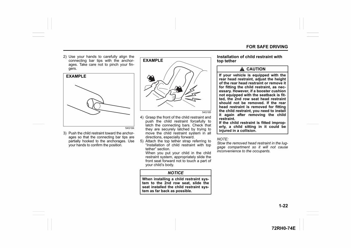
2) Use your hands to carefully align theconnecting bar tips with the anchor-ages. Take care not to pinch your fin-gers.
54G184
3) Push the child restraint toward the anchor-ages so that the connecting bar tips arepartially hooked to the anchorages. Useyour hands to confirm the position.
54G185
4) Grasp the front of the child restraint andpush the child restraint forcefully tolatch the connecting bars. Check thatthey are securely latched by trying tomove the child restraint system in alldirections, especially forward.
5) Attach the top tether strap referring to“Installation of child restraint with toptether” section.When you put your child in the childrestraint system, appropriately slide thefront seat forward not to touch a part ofyour child’s body.
Installation of child restraint with top tether
NOTE:Stow the removed head restraint in the lug-gage compartment so it will not causeinconvenience to the occupants.
EXAMPLE
NOTICE
When installing a child restraint sys-tem to the 2nd row seat, slide theseat installed the child restraint sys-tem as far back as possible.
EXAMPLE
CAUTION
If your vehicle is equipped with therear head restraint, adjust the heightof the rear head restraint or remove itfor fitting the child restraint, as nec-essary. However, if a booster cushionnot equipped with the seatback is fit-ted, the 2nd row seat head restraintshould not be removed. If the rearhead restraint is removed for fittingthe child restraint, you need to installit again after removing the childrestraint.If the child restraint is fitted improp-erly, a child sitting in it could beinjured in a collision.
1-23
FOR SAFE DRIVING
72RH0-74E
73R0175
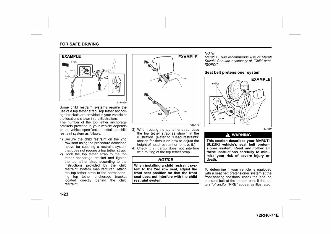
Some child restraint systems require theuse of a top tether strap. Top tether anchor-age brackets are provided in your vehicle atthe locations shown in the illustrations.The number of the top tether anchoragebrackets provided in your vehicle dependson the vehicle specification. Install the childrestraint system as follows:
1) Secure the child restraint on the 2ndrow seat using the procedure describedabove for securing a restraint systemthat does not require a top tether strap.
2) Hook the top tether strap to the toptether anchorage bracket and tightenthe top tether strap according to theinstructions provided by the childrestraint system manufacturer. Attachthe top tether strap to the correspond-ing top tether anchorage bracketlocated directly behind the childrestraint.
73R0176
3) When routing the top tether strap, passthe top tether strap as shown in theillustration. (Refer to “Head restraints”section for details on how to adjust theheight of head restraint or remove it.)
4) Check that cargo does not interferewith routing of the top tether strap.
NOTE:Maruti Suzuki recommends use of MarutiSuzuki Genuine accessory of “Child seat,ISOFIX”.
Seat belt pretensioner system
63J269
To determine if your vehicle is equippedwith a seat belt pretensioner system at thefront seating positions, check the label onthe seat belt at the bottom part. If the let-ters “p” and/or “PRE” appear as illustrated,
Front
EXAMPLE
NOTICE
When installing a child restraint sys-tem to the 2nd row seat, adjust thefront seat position so that the frontseat does not interfere with the childrestraint system.
EXAMPLE
WARNING
This section describes your MARUTISUZUKI vehicle’s seat belt preten-sioner system. Read and follow allthese instructions carefully to mini-mize your risk of severe injury ordeath.
and/or
Label
EXAMPLE
1-24
FOR SAFE DRIVING
72RH0-74E
your vehicle is equipped with the seat beltpretensioner system. You can use the pre-tensioner seat belts in the same manner asordinary seat belts.Read this section and “Supplementalrestraint system (airbags)” section to learnmore about the pretensioner system.
The seat belt pretensioner system workswith the supplemental restraint system (airbags). The collision sensors and the elec-tronic controller of the airbag system alsocontrol the seat belt pretensioners. Thepretensioners are triggered only whenthere is a frontal collision severe enough totrigger the airbags and the seat belts arefastened. For precautions and generalinformation including servicing the preten-sioner system, refer to “Supplementalrestraint system (airbags)” section in addi-tion to this “Seat belt pretensioner system”section, and follow all those precautions.
The pretensioner is located in each frontseat belt retractor. The pretensioner tight-ens the seat belt so the belt fits the occu-pant’s body more snugly in the event of afrontal collision. The retractors will remainlocked after the pretensioners are acti-vated. Upon activation, some noise willoccur and some smoke may bereleased.These conditions are not harmfuland do not indicate a fire in the vehicle.
The driver and all passengers must beproperly restrained by fastening seat beltsat all times, whether or not a pretensioner
is equipped at their seating position, tominimize the risk of severe injury or deathin the event of a collision.
Sit fully back in the seat; sit up straight; donot lean forward or sideways. Adjust thebelt so the lap portion of the belt is wornlow across the pelvis, not across the waist.Please refer to “Seat adjustment” sectionand the instructions and precautions aboutthe seat belts in this “Seat belts and childrestraint systems” section for details onproper seat and seat belt adjustments.
Please note that the pretensioners alongwith the airbags will activate in severe fron-tal collisions. They are not designed toactivate in rear impacts, roll-overs, orminor frontal collisions. The pretensionerscan be activated only once. If the preten-sioners are activated (that is, if the airbagsare activated), have the pretensioner sys-tem serviced by a Maruti Suzuki autho-rised workshop as soon as possible.
The pretensioner system or the airbag sys-tem may not work properly if any of the fol-lowing conditions occurs.• If the air bag light on the instrument clus-
ter does not come on briefly, when theignition switch is turned to the “ON” posi-tion or the engine switch is pressed tochange the ignition mode to “ON”.
• If the air bag light comes on and stays onfor more than 10 seconds, when the igni-tion switch is turned to the “ON” position
or the engine switch is pressed tochange the ignition mode to “ON”.
• If the air bag light comes on while driv-ing.
Have both systems inspected by a MarutiSuzuki authorised workshop as soon aspossible.
Service on or around the pretensioner sys-tem components or wiring must be per-formed only by a Maruti Suzuki authorisedworkshop who is specially trained.Improper service could result in unin-tended activation of pretensioners or couldrender the pretensioner inoperative. Eitherof these two conditions may result in per-sonal injury.
To prevent damage or unintended activa-tion of the pretensioners, check that thelead-acid battery is disconnected and theignition switch has been in LOCK positionor the ignition mode has been LOCK(OFF) for at least 90 seconds before per-forming any electrical service work on yourMARUTI SUZUKI vehicle.
Do not touch pretensioner system compo-nents or wiring. The wires are wrappedwith yellow tape or yellow tubing, and thecouplers are yellow. When scrapping yourMARUTI SUZUKI vehicle, ask a MarutiSuzuki authorised workshop, body repairshop, or scrap yard for assistance.
1-25
FOR SAFE DRIVING
72RH0-74E
Supplemental Restraint System (airbags)
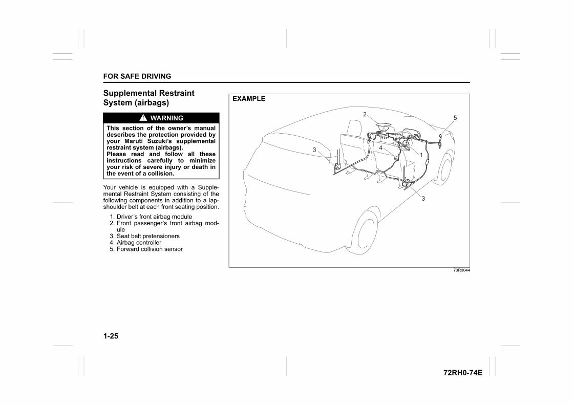
Your vehicle is equipped with a Supple-mental Restraint System consisting of thefollowing components in addition to a lap-shoulder belt at each front seating position.
1. Driver’s front airbag module 2. Front passenger’s front airbag mod-
ule3. Seat belt pretensioners4. Airbag controller5. Forward collision sensor
WARNING
This section of the owner’s manualdescribes the protection provided byyour Maruti Suzuki’s supplementalrestraint system (airbags). Please read and follow all theseinstructions carefully to minimizeyour risk of severe injury or death inthe event of a collision.
73R0044
23
5
14
2 5
14
2
13
EXAMPLE
1-26
FOR SAFE DRIVING
72RH0-74E
AIRBAG light
63J030
If the “AIRBAG” light on the instrumentcluster does not blink or come on when theignition switch is first turned to the ONposition, or the ignition mode is firstchanged to “ON”, or the “AIRBAG” lightstays on, or comes on while driving, theairbag system (or the seat belt preten-sioner system) may not work properly.Have the airbag system inspected by aMaruti Suzuki authorised workshop assoon as possible.
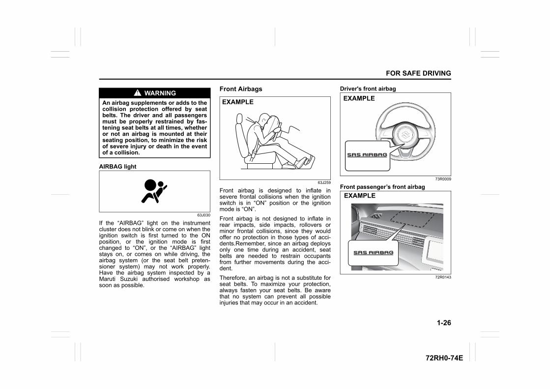
Front Airbags
63J259
Front airbag is designed to inflate insevere frontal collisions when the ignitionswitch is in “ON” position or the ignitionmode is “ON”.
Front airbag is not designed to inflate inrear impacts, side impacts, rollovers orminor frontal collisions, since they wouldoffer no protection in those types of acci-dents.Remember, since an airbag deploysonly one time during an accident, seatbelts are needed to restrain occupantsfrom further movements during the acci-dent.
Therefore, an airbag is not a substitute forseat belts. To maximize your protection,always fasten your seat belts. Be awarethat no system can prevent all possibleinjuries that may occur in an accident.
Driver's front airbag
73R0009
Front passenger’s front airbag
72R0143
WARNING
An airbag supplements or adds to thecollision protection offered by seatbelts. The driver and all passengersmust be properly restrained by fas-tening seat belts at all times, whetheror not an airbag is mounted at theirseating position, to minimize the riskof severe injury or death in the eventof a collision.
EXAMPLE EXAMPLE
EXAMPLE
1-27
FOR SAFE DRIVING
72RH0-74E
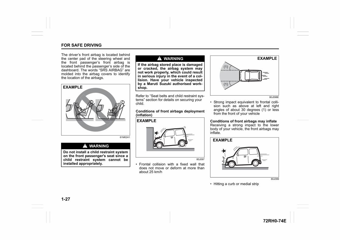
The driver’s front airbag is located behindthe center pad of the steering wheel andthe front passenger’s front airbag islocated behind the passenger’s side of thedashboard. The words “SRS AIRBAG” aremolded into the airbag covers to identifythe location of the airbags.
61M0241
Refer to “Seat belts and child restraint sys-tems” section for details on securing yourchild.
Conditions of front airbags deployment(inflation)
80J097
• Frontal collision with a fixed wall thatdoes not move or deform at more thanabout 25 km/h
80J098E
• Strong impact equivalent to frontal colli-sion such as above at left and rightangles of about 30 degrees (1) or lessfrom the front of your vehicle
Conditions of front airbags may inflateReceiving a strong impact to the lowerbody of your vehicle, the front airbags mayinflate.
80J099
• Hitting a curb or medial strip
WARNING
Do not install a child restraint systemon the front passenger's seat since achild restraint system cannot beinstalled appropriately.
EXAMPLE
WARNING
If the airbag stored place is damagedor cracked, the airbag system maynot work properly, which could resultin serious injury in the event of a col-lision. Have your vehicle inspectedby a Maruti Suzuki authorised work-shop.
EXAMPLE
(1)
(1)
EXAMPLE
EXAMPLE
1-28
FOR SAFE DRIVING
72RH0-74E
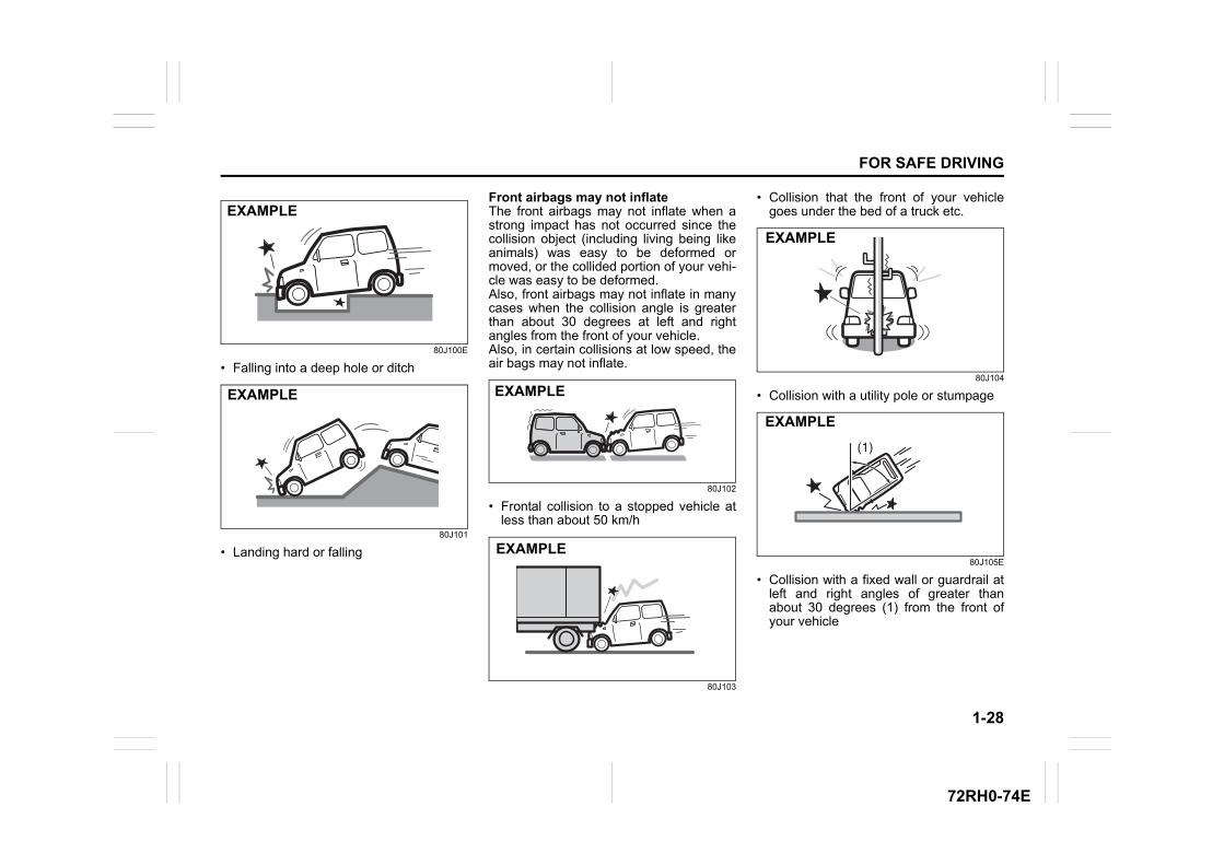
80J100E
• Falling into a deep hole or ditch
80J101
• Landing hard or falling
Front airbags may not inflateThe front airbags may not inflate when astrong impact has not occurred since thecollision object (including living being likeanimals) was easy to be deformed ormoved, or the collided portion of your vehi-cle was easy to be deformed.Also, front airbags may not inflate in manycases when the collision angle is greaterthan about 30 degrees at left and rightangles from the front of your vehicle.Also, in certain collisions at low speed, theair bags may not inflate.
80J102
• Frontal collision to a stopped vehicle atless than about 50 km/h
80J103
• Collision that the front of your vehiclegoes under the bed of a truck etc.
80J104
• Collision with a utility pole or stumpage
80J105E
• Collision with a fixed wall or guardrail atleft and right angles of greater thanabout 30 degrees (1) from the front ofyour vehicle
EXAMPLE
EXAMPLE EXAMPLE
EXAMPLE
EXAMPLE
(1)
EXAMPLE
1-29
FOR SAFE DRIVING
72RH0-74E
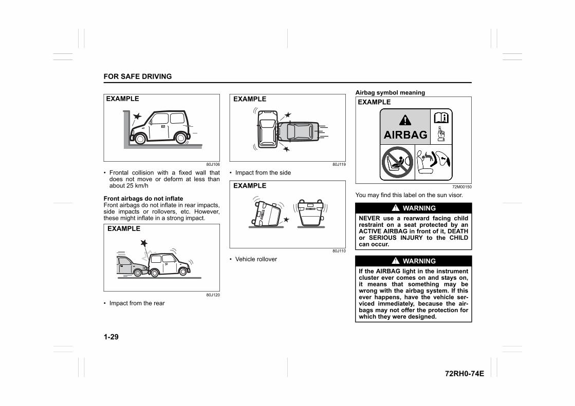
80J106
• Frontal collision with a fixed wall thatdoes not move or deform at less thanabout 25 km/h
Front airbags do not inflateFront airbags do not inflate in rear impacts,side impacts or rollovers, etc. However,these might inflate in a strong impact.
80J120
• Impact from the rear
80J119
• Impact from the side
80J110
• Vehicle rollover
Airbag symbol meaning
72M00150
You may find this label on the sun visor.
EXAMPLE
EXAMPLE
EXAMPLE
EXAMPLE
WARNING
NEVER use a rearward facing childrestraint on a seat protected by anACTIVE AIRBAG in front of it, DEATHor SERIOUS INJURY to the CHILDcan occur.
WARNING
If the AIRBAG light in the instrumentcluster ever comes on and stays on,it means that something may bewrong with the airbag system. If thisever happens, have the vehicle ser-viced immediately, because the air-bags may not offer the protection forwhich they were designed.
EXAMPLE
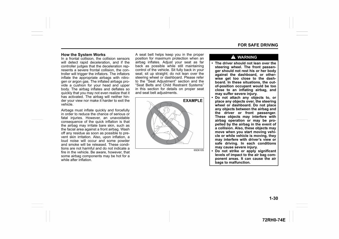
1-30
FOR SAFE DRIVING
72RH0-74E
How the System WorksIn a frontal collision, the collision sensorswill detect rapid deceleration, and if thecontroller judges that the deceleration rep-resents a severe frontal collision, the con-troller will trigger the inflators. The inflatorsinflate the appropriate airbags with nitro-gen or argon gas. The inflated airbags pro-vide a cushion for your head and upperbody. The airbag inflates and deflates soquickly that you may not even realize that ithas activated. The airbag will neither hin-der your view nor make it harder to exit thevehicle.
Airbags must inflate quickly and forcefullyin order to reduce the chance of serious orfatal injuries. However, an unavoidableconsequence of the quick inflation is thatthe airbag may irritate bare skin, such asthe facial area against a front airbag. Washoff any residue as soon as possible to pre-vent skin irritation. Also, upon inflation, aloud noise will occur and some powderand smoke will be released. These condi-tions are not harmful and do not indicate afire in the vehicle. Be aware, however, thatsome airbag components may be hot for awhile after inflation.
A seat belt helps keep you in the properposition for maximum protection when anairbag inflates. Adjust your seat as farback as possible while still maintainingcontrol of the vehicle. Sit fully back in yourseat; sit up straight; do not lean over thesteering wheel or dashboard. Please referto the “Seat Adjustment” section and the“Seat Belts and Child Restraint Systems”in this section for details on proper seatand seat belt adjustments.
65D610S
EXAMPLE
WARNING
• The driver should not lean over thesteering wheel. The front passen-ger should not rest his or her bodyagainst the dashboard, or other-wise get too close to the dash-board. In these situations, the out-of-position occupant would be tooclose to an inflating airbag, andmay suffer severe injury.
• Do not attach any objects to, orplace any objects over, the steeringwheel or dashboard. Do not placeany objects between the airbag andthe driver or front passenger.These objects may interfere withairbag operation or may be pro-pelled by the airbag in the event ofa collision. Also, these objects maymove when you start moving vehi-cle or while vehicle is moving, theymay interfere with driver’s view orsafe driving. In each conditionsmay cause severe injury.
• Do not strike or apply significantlevels of impact to the air bag com-ponent areas. It can cause the airbags to malfunction.
1-31
FOR SAFE DRIVING
72RH0-74E
Note that even though your vehicle may bemoderately damaged in a collision, the col-lision may not have been severe enough totrigger the airbags to inflate. If your vehiclesustains any front-end or side damage,have the airbag system inspected by aMaruti Suzuki authorised workshop toensure it is in proper working order.
Your vehicle is equipped with a diagnosticmodule which records information aboutthe airbag system if the airbags deploy in acollision. The module records informationabout overall system status, which sensorsactivated the deployment, and for a certain
vehicle only, whether the driver’s seat beltwas in use.
Servicing the airbag systemIf the airbags inflate, have the airbags andrelated components replaced by a MarutiSuzuki authorised workshop as soon aspossible.
If your vehicle ever gets in deep water andthe driver’s floor is submerged, the airbagcontroller could be damaged. If it does,have the airbag system inspected by theMaruti Suzuki authorised workshop assoon as possible.
Special procedures are required for servic-ing or replacing an airbag. For that reason,only a Maruti Suzuki authorised workshopshould be allowed to service or replaceyour airbags. Please remind anyone whoservices your MARUTI SUZUKI that it hasairbags.
Service on or around airbag componentsor wiring must be performed only by aMaruti Suzuki authorised workshop.Improper service could result in unin-tended airbag deployment or could renderthe airbag inoperative. Either of these twoconditions may result in severe injury.
To prevent damage or unintended inflationof the airbag system, be sure the lead-acidbattery is disconnected and the ignitionswitch has been in the LOCK position forat least 90 seconds before performing anyelectrical service work on your MARUTI
SUZUKI. Do not touch airbag system com-ponents or wires. The wires are wrappedwith yellow tape or yellow tubing, and thecouplers are yellow for easy identification.
Scrapping a vehicle that has an uninflatedairbag can be hazardous. Ask your dealer,body repair shop or scrap yard for helpwith disposal.
WARNING
• Do not modify the system in anyway including replacing the steer-ing wheel, placing stickers on thesteering wheel pad, painting thesteering wheel, or covering thesteering wheel with a cover.
• Do not place stickers on or paintthe instrument panel. Do not installand set up accessories, air fresh-eners, ETC readers, or portablenavigation systems. Do not standumbrellas or similar in front of air-bags.
• Excluding Maruti Suzuki genuineparts, do not attach accessories tothe front windshield or the rearviewmirror.
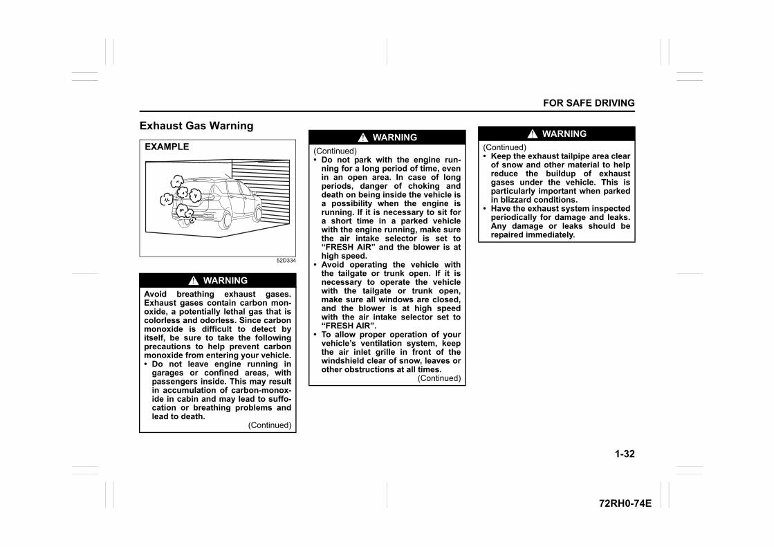
1-32
FOR SAFE DRIVING
72RH0-74E
Exhaust Gas Warning
52D334
WARNING
Avoid breathing exhaust gases.Exhaust gases contain carbon mon-oxide, a potentially lethal gas that iscolorless and odorless. Since carbonmonoxide is difficult to detect byitself, be sure to take the followingprecautions to help prevent carbonmonoxide from entering your vehicle.• Do not leave engine running in
garages or confined areas, withpassengers inside. This may resultin accumulation of carbon-monox-ide in cabin and may lead to suffo-cation or breathing problems andlead to death.
(Continued)
EXAMPLEWARNING
(Continued)• Do not park with the engine run-
ning for a long period of time, evenin an open area. In case of longperiods, danger of choking anddeath on being inside the vehicle isa possibility when the engine isrunning. If it is necessary to sit fora short time in a parked vehiclewith the engine running, make surethe air intake selector is set to“FRESH AIR” and the blower is athigh speed.
• Avoid operating the vehicle withthe tailgate or trunk open. If it isnecessary to operate the vehiclewith the tailgate or trunk open,make sure all windows are closed,and the blower is at high speedwith the air intake selector set to“FRESH AIR”.
• To allow proper operation of yourvehicle’s ventilation system, keepthe air inlet grille in front of thewindshield clear of snow, leaves orother obstructions at all times.
(Continued)
WARNING
(Continued)• Keep the exhaust tailpipe area clear
of snow and other material to helpreduce the buildup of exhaustgases under the vehicle. This isparticularly important when parkedin blizzard conditions.
• Have the exhaust system inspectedperiodically for damage and leaks.Any damage or leaks should berepaired immediately.

72RH0-74E
BEFORE DRIVING
2
72RH0-74E
60G404
Keys ......................................................................................2-1Door Locks ...........................................................................2-2Keyless entry system transmitter /Keyless push start system remote controller(if equipped) .........................................................................2-6Security System (if equipped) ............................................2-15Theft deterrent light .............................................................2-17Windows ...............................................................................2-18Mirrors ..................................................................................2-19Instrument Cluster (Type A) (if equipped) .........................2-22Speedometer ........................................................................2-23
BEFORE DRIVINGTachometer .......................................................................... 2-23Fuel gauge ........................................................................... 2-23Brightness Control .............................................................. 2-24Information Display ............................................................. 2-25Instrument Cluster (Type B) (if equipped) ........................ 2-32Speedometer ....................................................................... 2-33Tachometer .......................................................................... 2-33Fuel gauge ........................................................................... 2-33Temperature Gauge ............................................................ 2-34Brightness Control .............................................................. 2-34Information Display ............................................................. 2-35Warning and Indicator Lights ............................................ 2-58Lighting Control Lever ........................................................ 2-66Front Fog Light Switch (if equipped) ................................ 2-67Headlight Leveling Switch .................................................. 2-68Turn Signal Control Lever .................................................. 2-69Hazard Warning Switch ...................................................... 2-70Windshield Wiper and Washer Lever ................................ 2-70Tilt Steering Lock Lever ..................................................... 2-72Horn ...................................................................................... 2-72Heated Rear Window Switch (if equipped) ....................... 2-73Vehicle Loading ................................................................... 2-73Trailer Towing your vehicle ................................................ 2-74
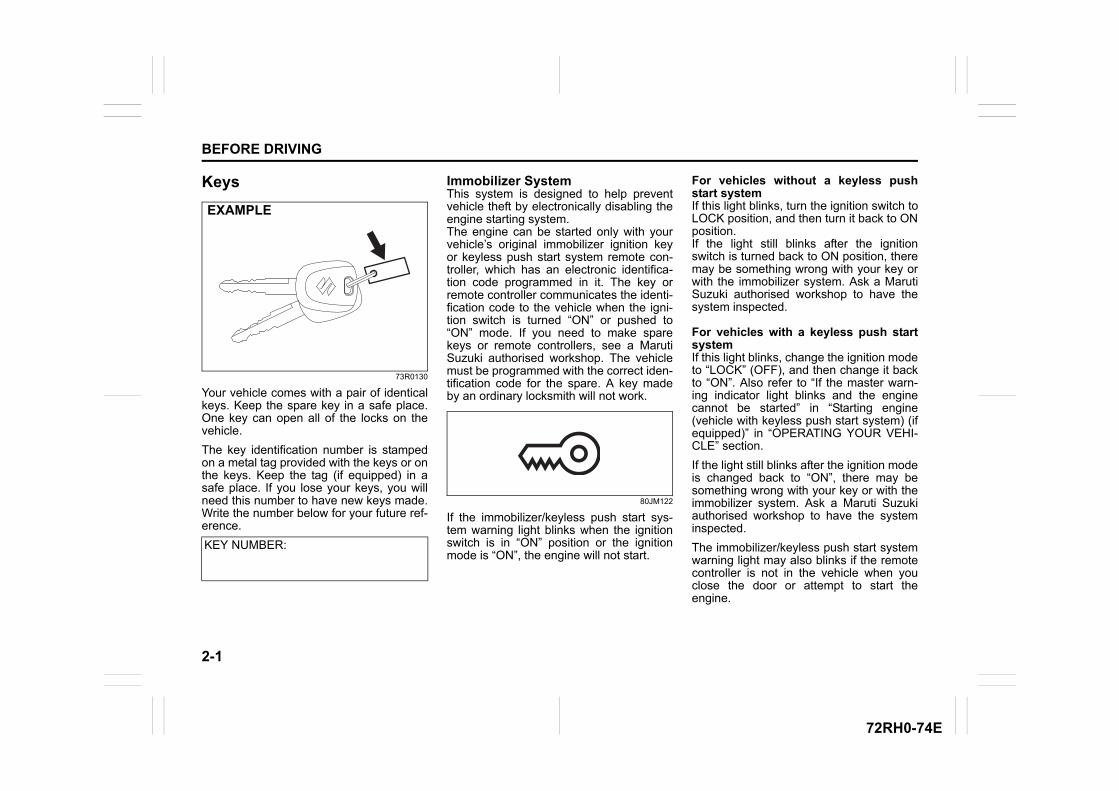
2-1
BEFORE DRIVING
72RH0-74E
Keys
73R0130
Your vehicle comes with a pair of identicalkeys. Keep the spare key in a safe place.One key can open all of the locks on thevehicle.
The key identification number is stampedon a metal tag provided with the keys or onthe keys. Keep the tag (if equipped) in asafe place. If you lose your keys, you willneed this number to have new keys made.Write the number below for your future ref-erence.
Immobilizer System This system is designed to help preventvehicle theft by electronically disabling theengine starting system.The engine can be started only with yourvehicle’s original immobilizer ignition keyor keyless push start system remote con-troller, which has an electronic identifica-tion code programmed in it. The key orremote controller communicates the identi-fication code to the vehicle when the igni-tion switch is turned “ON” or pushed to“ON” mode. If you need to make sparekeys or remote controllers, see a MarutiSuzuki authorised workshop. The vehiclemust be programmed with the correct iden-tification code for the spare. A key madeby an ordinary locksmith will not work.
80JM122
If the immobilizer/keyless push start sys-tem warning light blinks when the ignitionswitch is in “ON” position or the ignitionmode is “ON”, the engine will not start.
For vehicles without a keyless pushstart systemIf this light blinks, turn the ignition switch toLOCK position, and then turn it back to ONposition.If the light still blinks after the ignitionswitch is turned back to ON position, theremay be something wrong with your key orwith the immobilizer system. Ask a MarutiSuzuki authorised workshop to have thesystem inspected.
For vehicles with a keyless push startsystemIf this light blinks, change the ignition modeto “LOCK” (OFF), and then change it backto “ON”. Also refer to “If the master warn-ing indicator light blinks and the enginecannot be started” in “Starting engine(vehicle with keyless push start system) (ifequipped)” in “OPERATING YOUR VEHI-CLE” section.
If the light still blinks after the ignition modeis changed back to “ON”, there may besomething wrong with your key or with theimmobilizer system. Ask a Maruti Suzukiauthorised workshop to have the systeminspected.
The immobilizer/keyless push start systemwarning light may also blinks if the remotecontroller is not in the vehicle when youclose the door or attempt to start theengine.
KEY NUMBER:
EXAMPLE
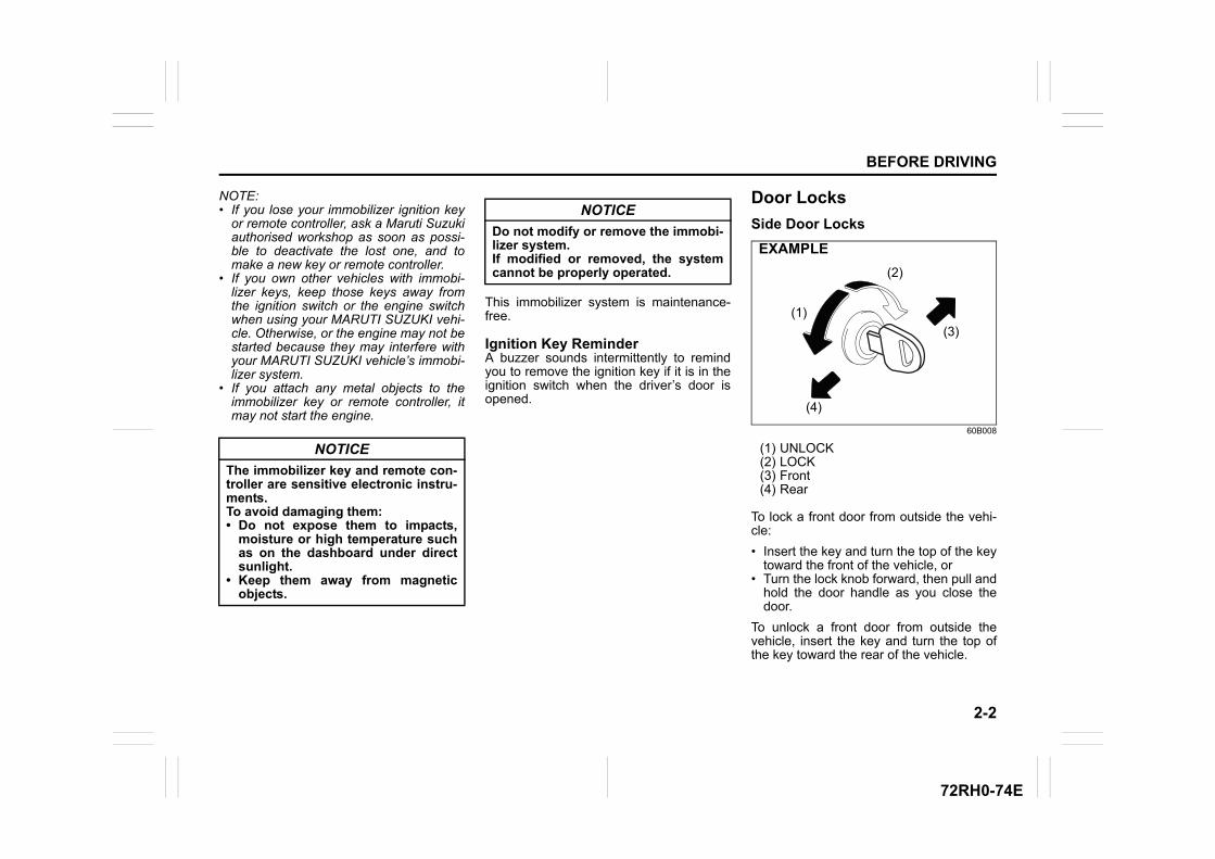
2-2
BEFORE DRIVING
72RH0-74E
NOTE:• If you lose your immobilizer ignition key
or remote controller, ask a Maruti Suzukiauthorised workshop as soon as possi-ble to deactivate the lost one, and tomake a new key or remote controller.
• If you own other vehicles with immobi-lizer keys, keep those keys away fromthe ignition switch or the engine switchwhen using your MARUTI SUZUKI vehi-cle. Otherwise, or the engine may not bestarted because they may interfere withyour MARUTI SUZUKI vehicle’s immobi-lizer system.
• If you attach any metal objects to theimmobilizer key or remote controller, itmay not start the engine.
This immobilizer system is maintenance-free.
Ignition Key ReminderA buzzer sounds intermittently to remindyou to remove the ignition key if it is in theignition switch when the driver’s door isopened.
Door Locks
Side Door Locks
60B008
(1) UNLOCK(2) LOCK(3) Front(4) Rear
To lock a front door from outside the vehi-cle:
• Insert the key and turn the top of the keytoward the front of the vehicle, or
• Turn the lock knob forward, then pull andhold the door handle as you close thedoor.
To unlock a front door from outside thevehicle, insert the key and turn the top ofthe key toward the rear of the vehicle.
NOTICE
The immobilizer key and remote con-troller are sensitive electronic instru-ments.To avoid damaging them:• Do not expose them to impacts,
moisture or high temperature suchas on the dashboard under directsunlight.
• Keep them away from magneticobjects.
NOTICE
Do not modify or remove the immobi-lizer system.If modified or removed, the systemcannot be properly operated. (2)
(1)
(3)
(4)
EXAMPLE
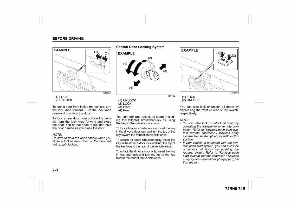
2-3
BEFORE DRIVING
72RH0-74E
73R0001
(1) LOCK(2) UNLOCK
To lock a door from inside the vehicle, turnthe lock knob forward. Turn the lock knobrearward to unlock the door.
To lock a rear door from outside the vehi-cle, turn the lock knob forward and closethe door. You do not need to pull and holdthe door handle as you close the door.
NOTE:Be sure to hold the door handle when youclose a locked front door, or the door willnot remain locked.
Central Door Locking System
54G294
(1) UNLOCK(2) LOCK(3) Front(4) Rear
You can lock and unlock all doors (includ-ing the tailgate) simultaneously by usingthe key in the driver’s door lock.
To lock all doors simultaneously, insert the keyin the driver’s door lock and turn the top of thekey toward the front of the vehicle once.
To unlock all doors simultaneously, insert thekey in the driver’s door lock and turn the top ofthe key toward the rear of the vehicle twice.
To unlock the driver’s door only, insert the keyin that door lock and turn the top of the keytoward the rear of the vehicle once.
73R0002
(1) LOCK(2) UNLOCK
You can also lock or unlock all doors bydepressing the front or rear of the switch,respectively.
NOTE:• You can also lock or unlock all doors by
operating the transmitter or remote con-troller. Refer to “Keyless push start sys-tem remote controller / Keyless entrysystem transmitter (if equipped)” in thissection.
• If your vehicle is equipped with the key-less push start system, you can also lockor unlock all doors by pushing therequest switch. Refer to “Keyless pushstart system remote controller / Keylessentry system transmitter (if equipped)” inthis section.
(2)(1)EXAMPLE
(1)
(2)
(3)
(4)
EXAMPLE(2)
(1)EXAMPLE
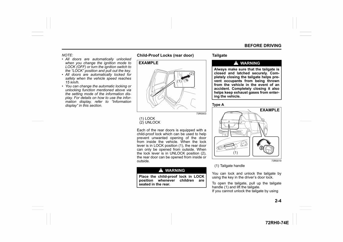
2-4
BEFORE DRIVING
72RH0-74E
NOTE:• All doors are automatically unlocked
when you change the ignition mode toLOCK (OFF) or turn the ignition switch tothe “LOCK” position and pull out the key.
• All doors are automatically locked forsafety when the vehicle speed reaches15 km/h.
• You can change the automatic locking orunlocking function mentioned above viathe setting mode of the information dis-play. For details on how to use the infor-mation display, refer to “Informationdisplay” in this section.
Child-Proof Locks (rear door)
73R0003
(1) LOCK(2) UNLOCK
Each of the rear doors is equipped with achild-proof lock which can be used to helpprevent unwanted opening of the doorfrom inside the vehicle. When the locklever is in LOCK position (1), the rear doorcan only be opened from outside. Whenthe lock lever is in UNLOCK position (2),the rear door can be opened from inside oroutside.
Tailgate
Type A
73R0019
(1) Tailgate handle
You can lock and unlock the tailgate byusing the key in the driver’s door lock.
To open the tailgate, pull up the tailgatehandle (1) and lift the tailgate.If you cannot unlock the tailgate by using
WARNING
Place the child-proof lock in LOCKposition whenever children areseated in the rear.
(2)
(1)
EXAMPLE WARNING
Always make sure that the tailgate isclosed and latched securely. Com-pletely closing the tailgate helps pre-vent occupants from being thrownfrom the vehicle in the event of anaccident. Completely closing it alsohelps keep exhaust gases from enter-ing the vehicle.
(1)
EXAMPLE
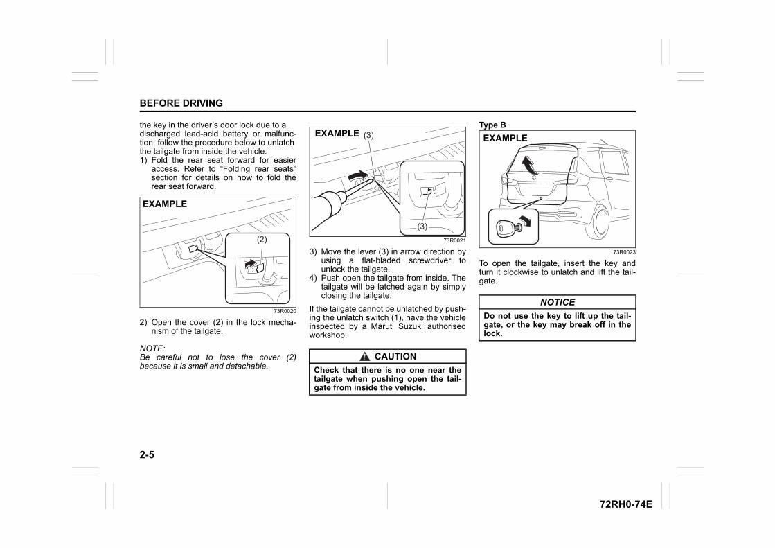
2-5
BEFORE DRIVING
72RH0-74E
the key in the driver’s door lock due to adischarged lead-acid battery or malfunc-tion, follow the procedure below to unlatchthe tailgate from inside the vehicle.1) Fold the rear seat forward for easier
access. Refer to “Folding rear seats”section for details on how to fold therear seat forward.
73R0020
2) Open the cover (2) in the lock mecha-nism of the tailgate.
NOTE:Be careful not to lose the cover (2)because it is small and detachable.
73R0021
3) Move the lever (3) in arrow direction byusing a flat-bladed screwdriver tounlock the tailgate.
4) Push open the tailgate from inside. Thetailgate will be latched again by simplyclosing the tailgate.
If the tailgate cannot be unlatched by push-ing the unlatch switch (1), have the vehicleinspected by a Maruti Suzuki authorisedworkshop.
Type B
73R0023
To open the tailgate, insert the key andturn it clockwise to unlatch and lift the tail-gate.
(2)(2)(2)
EXAMPLE
CAUTION
Check that there is no one near thetailgate when pushing open the tail-gate from inside the vehicle.
(3)(3)(3)
(3)(3)(3)EXAMPLE
NOTICE
Do not use the key to lift up the tail-gate, or the key may break off in thelock.
EXAMPLE
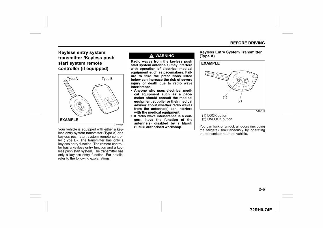
2-6
BEFORE DRIVING
72RH0-74E
Keyless entry system transmitter /Keyless push start system remote controller (if equipped)
73R0166
Your vehicle is equipped with either a key-less entry system transmitter (Type A) or akeyless push start system remote control-ler (Type B). The transmitter has only akeyless entry function. The remote control-ler has a keyless entry function and a key-less push start system. The transmitter hasonly a keyless entry function. For details,refer to the following explanations.
Keyless Entry System Transmitter (Type A)
72R0148
(1) LOCK button(2) UNLOCK button
You can lock or unlock all doors (includingthe tailgate) simultaneously by operatingthe transmitter near the vehicle.
Type A Type B
EXAMPLE
WARNING
Radio waves from the keyless pushstart system antenna(s) may interferewith operation of electrical medicalequipment such as pacemakers. Fail-ure to take the precautions listedbelow can increase the risk of severeinjury or death due to radio waveinterference.• Anyone who uses electrical medi-
cal equipment such as a pace-maker should consult the medicalequipment supplier or their medicaladvisor about whether radio wavesfrom the antenna(s) can interferewith the medical equipment.
• If radio wave interference is a con-cern, have the function of theantenna(s) disabled by a MarutiSuzuki authorised workshop.
(1)(2)
EXAMPLE
2-7
BEFORE DRIVING
72RH0-74E
Central door locking system• To lock all doors, push LOCK button (1)
once.• To unlock only the driver’s door, push
UNLOCK button (2) once.• To unlock other doors, push UNLOCK
button (2) once again.
NOTE:You can switch the function that unlocks alldoors from requiring two pushes to requir-ing one push, and vice versa, via the infor-mation display setting mode. For details onhow to use the information display, refer to“Information display” in this section.
The turn signal lights will flash once andthe siren will sound once when the doorsare locked.
When the doors are unlocked:
• The turn signal lights will flash twice andthe siren will sound twice whenunlocked.
• If the interior light switch is in the“DOOR” position, the interior light willturn on for 15 seconds and then fadeout. If you insert the key into the ignitionswitch during this time, the light will startto fade out immediately.
Be sure the doors are locked after youoperate the LOCK button (1).
NOTE:If no door is opened within about 30 sec-onds after the UNLOCK button (2) is oper-ated, the doors will automatically lockagain.
NOTE:• If the security system was triggered due
to an unauthorized entry into the vehicleand then you unlock the doors using thetransmitter, the siren will sound 4 timesto remind you. If this happens, checkwhether your vehicle has been brokeninto while you were away from it.
• Once you push both of the LOCK button(1) and UNLOCK button (2), then youpush one of the buttons within 5 sec-onds, the siren will not sound.
NOTE:• The maximum operating distance of the
keyless entry system transmitter is about5 m (16 ft.), but this can vary dependingon the surroundings, especially nearother transmitting devices such as radiotowers or CB (Citizen’s Band) radios.
• The door locks cannot be operated withthe transmitter, if the ignition key isinserted in the ignition switch.
• When any door is open, the door lockscan be operated only unlock with thetransmitter.
• If you lose one of the transmitters, ask aMaruti Suzuki authorised workshop assoon as possible for a replacement. Besure to have your dealer program the
new transmitter code in your vehicle’smemory so that the old code is erased.
Car locator alarm functionThis function is to get the attention of oth-ers. Push both of the LOCK button (1) andUNLOCK button (2) for more than 3 sec-onds. The turn signal lights will blink forabout 27.5 seconds. Also, the siren willsound for about 27.5 seconds at the sametime. To cancel the car locator alarm, pressany button (LOCK or UNLOCK). You canalso cancel the car locator alarm by turningthe ignition switch to “ON” position.
NOTE:The car locator alarm function will not acti-vate when the key is in the ignition switch.
NOTICE
The transmitter is a sensitive elec-tronic instrument. To avoid damagingthe transmitter:• Do not expose it to impacts, mois-
ture or high temperature such asby leaving it on the dashboardunder direct sunlight.
• Keep the transmitter away frommagnetic objects such as a televi-sion.
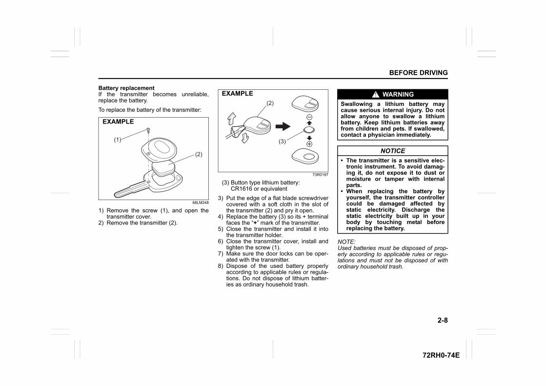
2-8
BEFORE DRIVING
72RH0-74E
Battery replacementIf the transmitter becomes unreliable,replace the battery.
To replace the battery of the transmitter:
68LM248
1) Remove the screw (1), and open thetransmitter cover.
2) Remove the transmitter (2).
73R0197
(3) Button type lithium battery:CR1616 or equivalent
3) Put the edge of a flat blade screwdrivercovered with a soft cloth in the slot ofthe transmitter (2) and pry it open.
4) Replace the battery (3) so its + terminalfaces the “+” mark of the transmitter.
5) Close the transmitter and install it intothe transmitter holder.
6) Close the transmitter cover, install andtighten the screw (1).
7) Make sure the door locks can be oper-ated with the transmitter.
8) Dispose of the used battery properlyaccording to applicable rules or regula-tions. Do not dispose of lithium batter-ies as ordinary household trash.
NOTE:Used batteries must be disposed of prop-erly according to applicable rules or regu-lations and must not be disposed of withordinary household trash.
(1)
(2)
EXAMPLE
(2)
(3)
EXAMPLE WARNING
Swallowing a lithium battery maycause serious internal injury. Do notallow anyone to swallow a lithiumbattery. Keep lithium batteries awayfrom children and pets. If swallowed,contact a physician immediately.
NOTICE
• The transmitter is a sensitive elec-tronic instrument. To avoid damag-ing it, do not expose it to dust ormoisture or tamper with internalparts.
• When replacing the battery byyourself, the transmitter controllercould be damaged affected bystatic electricity. Discharge thestatic electricity built up in yourbody by touching metal beforereplacing the battery.
2-9
BEFORE DRIVING
72RH0-74E
80JM133
(1) Crossed-out wheeled bin symbol
The crossed-out wheeled bin symbol (1)indicates that a used battery should be col-lected separately from ordinary householdtrash.
By ensuring the used battery is disposedof or recycled correctly, you will help pre-vent potential negative consequences forthe environment and human health, whichcould otherwise be caused by inappropri-ate battery disposal. The recycling ofmaterials will help to conserve naturalresources. For more detailed informationabout disposing of or recycling the usedbattery, consult a Maruti Suzuki authorisedworkshop.
Keyless Push Start System Remote Controller (Type B)The remote controller enables the follow-ing operations:
• You can lock or unlock the doors bypushing LOCK/UNLOCK buttons on theremote controller. Refer to the explana-tion in this section.
• You can lock or unlock the doors bypushing the request switch in the frontoutside door handles. For details, referto the explanation in this section.
• You can start the engine without usingan ignition key. For details, refer to“Engine Switch (Vehicle with KeylessPush Start System)” in “OPERATINGYOUR VEHICLE” section.
52RM20060
(1) LOCK button(2) UNLOCK button
You can lock or unlock all doors (includingthe tailgate) simultaneously by operatingthe remote controller near the vehicle.
Central door locking system• To lock all doors, push LOCK button (1)
once.• To unlock only the driver’s door, push
UNLOCK button (2) once.• To unlock other doors, push UNLOCK
button (2) once again.
NOTE:You can switch the function that unlocks alldoors from twice operations to once opera-tion, and vice versa, via the setting modeof the information display. For details onhow to use the information display, refer to“Information Display” in this section.
The turn signal lights will flash once andthe siren will sound once when the doorsare locked.
When the doors are unlocked:
• The turn signal lights will flash twice andthe siren will sound twice.
• If the interior light switch is in the“DOOR” position, the interior light willturn on for 15 seconds and then fadeout. If you press the engine switch duringthis time, the light will start to fade outimmediately.
(1)
EXAMPLE
(1)
(2)
EXAMPLE
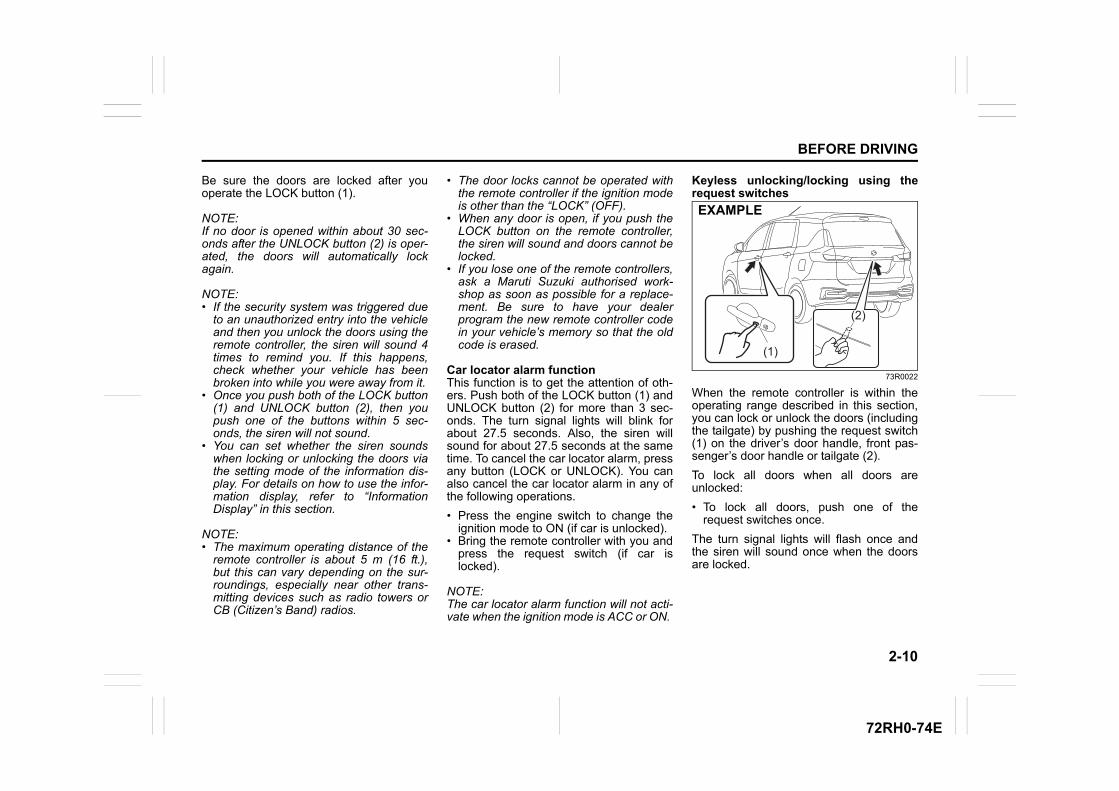
2-10
BEFORE DRIVING
72RH0-74E
Be sure the doors are locked after youoperate the LOCK button (1).
NOTE:If no door is opened within about 30 sec-onds after the UNLOCK button (2) is oper-ated, the doors will automatically lockagain.
NOTE:• If the security system was triggered due
to an unauthorized entry into the vehicleand then you unlock the doors using theremote controller, the siren will sound 4times to remind you. If this happens,check whether your vehicle has beenbroken into while you were away from it.
• Once you push both of the LOCK button(1) and UNLOCK button (2), then youpush one of the buttons within 5 sec-onds, the siren will not sound.
• You can set whether the siren soundswhen locking or unlocking the doors viathe setting mode of the information dis-play. For details on how to use the infor-mation display, refer to “InformationDisplay” in this section.
NOTE:• The maximum operating distance of the
remote controller is about 5 m (16 ft.),but this can vary depending on the sur-roundings, especially near other trans-mitting devices such as radio towers orCB (Citizen’s Band) radios.
• The door locks cannot be operated withthe remote controller if the ignition modeis other than the “LOCK” (OFF).
• When any door is open, if you push theLOCK button on the remote controller,the siren will sound and doors cannot belocked.
• If you lose one of the remote controllers,ask a Maruti Suzuki authorised work-shop as soon as possible for a replace-ment. Be sure to have your dealerprogram the new remote controller codein your vehicle’s memory so that the oldcode is erased.
Car locator alarm functionThis function is to get the attention of oth-ers. Push both of the LOCK button (1) andUNLOCK button (2) for more than 3 sec-onds. The turn signal lights will blink forabout 27.5 seconds. Also, the siren willsound for about 27.5 seconds at the sametime. To cancel the car locator alarm, pressany button (LOCK or UNLOCK). You canalso cancel the car locator alarm in any ofthe following operations.
• Press the engine switch to change theignition mode to ON (if car is unlocked).
• Bring the remote controller with you andpress the request switch (if car islocked).
NOTE:The car locator alarm function will not acti-vate when the ignition mode is ACC or ON.
Keyless unlocking/locking using therequest switches
73R0022
When the remote controller is within theoperating range described in this section,you can lock or unlock the doors (includingthe tailgate) by pushing the request switch(1) on the driver’s door handle, front pas-senger’s door handle or tailgate (2).
To lock all doors when all doors areunlocked:
• To lock all doors, push one of therequest switches once.
The turn signal lights will flash once andthe siren will sound once when the doorsare locked.
(1)
(2)
EXAMPLE
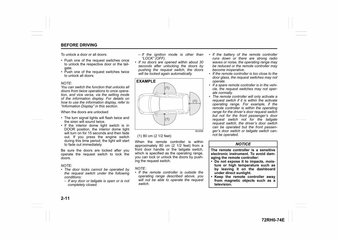
2-11
BEFORE DRIVING
72RH0-74E
To unlock a door or all doors:
• Push one of the request switches onceto unlock the respective door or the tail-gate.
• Push one of the request switches twiceto unlock all doors.
NOTE:You can switch the function that unlocks alldoors from twice operations to once opera-tion, and vice versa, via the setting modeof the information display. For details onhow to use the information display, refer to“Information Display” in this section.
When the doors are unlocked:
• The turn signal lights will flash twice andthe siren will sound twice.
• If the interior dome light switch is inDOOR position, the interior dome lightwill turn on for 15 seconds and then fadeout. If you press the engine switchduring this time period, the light will startto fade out immediately.
Be sure the doors are locked after youoperate the request switch to lock thedoors.
NOTE:• The door locks cannot be operated by
the request switch under the followingconditions: – If any door or tailgate is open or is not
completely closed.
– If the ignition mode is other than“LOCK” (OFF).
• If no doors are opened within about 30seconds after unlocking the doors bypushing the request switch, the doorswill be locked again automatically.
80J056
(1) 80 cm (2 1/2 feet)
When the remote controller is withinapproximately 80 cm (2 1/2 feet) from afront door handle or the tailgate switch,which is specified as the operating range,you can lock or unlock the doors by push-ing the request switch.
NOTE:• If the remote controller is outside the
operating range described above, youwill not be able to operate the requestswitch.
• If the battery of the remote controllerruns down or there are strong radiowaves or noise, the operating range maybe reduced or the remote controller maybecome inoperative.
• If the remote controller is too close to thedoor glass, the request switches may notoperate.
• If a spare remote controller is in the vehi-cle, the request switches may not oper-ate normally.
• The remote controller will only activate arequest switch if it is within the activateoperating range. For example, if theremote controller is within the operatingrange for the driver’s door request switchbut not for the front passenger’s doorrequest switch not for the tailgaterequest switch, the driver’s door switchcan be operated but the front passen-ger’s door switch or tailgate switch can-not be operated.
(1)
(1)
(1)
EXAMPLE
NOTICE
The remote controller is a sensitiveelectronic instrument. To avoid dam-aging the remote controller:• Do not expose it to impacts, mois-
ture or high temperature such asby leaving it on the dashboardunder direct sunlight.
• Keep the remote controller awayfrom magnetic objects such as atelevision.
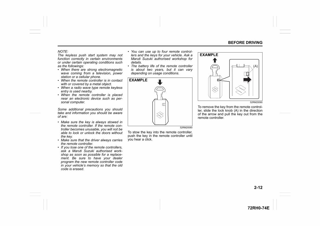
2-12
BEFORE DRIVING
72RH0-74E
NOTE:The keyless push start system may notfunction correctly in certain environmentsor under certain operating conditions suchas the followings:• When there are strong electromagnetic
wave coming from a television, powerstation or a cellular phone.
• When the remote controller is in contactwith or covered by a metal object.
• When a radio wave type remote keylessentry is used nearby.
• When the remote controller is placednear an electronic device such as per-sonal computer.
Some additional precautions you shouldtake and information you should be awareof are:
• Make sure the key is always stowed inthe remote controller. If the remote con-troller becomes unusable, you will not beable to lock or unlock the doors withoutthe key.
• Make sure that the driver always carriesthe remote controller.
• If you lose one of the remote controllers,ask a Maruti Suzuki authorised work-shop as soon as possible for a replace-ment. Be sure to have your dealerprogram the new remote controller codein your vehicle’s memory so that the oldcode is erased.
• You can use up to four remote control-lers and the keys for your vehicle. Ask aMaruti Suzuki authorised workshop fordetails.
• The battery life of the remote controlleris about two years, but it can varydepending on usage conditions.
52RM20080
To stow the key into the remote controller,push the key in the remote controller untilyou hear a click.
52RM20090
To remove the key from the remote control-ler, slide the lock knob (A) in the directionof the arrow and pull the key out from theremote controller.
EXAMPLE
(A)
EXAMPLE
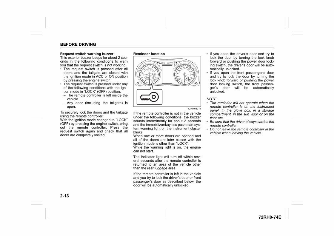
2-13
BEFORE DRIVING
72RH0-74E
Request switch warning buzzerThis exterior buzzer beeps for about 2 sec-onds in the following conditions to warnyou that the request switch is not working:• The request switch is pressed after all
doors and the tailgate are closed withthe ignition mode in ACC or ON positionby pressing the engine switch.
• The request switch is pressed under anyof the following conditions with the igni-tion mode in “LOCK” (OFF) position.– The remote controller is left inside the
vehicle.– Any door (including the tailgate) is
open.
To securely lock the doors and the tailgateusing the remote controller:With the ignition mode changed to “LOCK”(OFF) by pressing the engine switch, bringout the remote controller. Press therequest switch again and check that alldoors are completely locked.
Reminder function
72RM02019
If the remote controller is not in the vehicleunder the following conditions, the buzzersounds intermittently for about 2 secondsand the immobilizer/keyless push start sys-tem warning light on the instrument clusterblinks:When one or more doors are opened andall of the doors are later closed with theignition mode is other than “LOCK”.While the warning light is on, the enginecan not start.
The indicator light will turn off within sev-eral seconds after the remote controller isreturned to an area of the vehicle otherthan the rear luggage area.
If the remote controller is left in the vehicleand you try to lock the driver’s door or frontpassenger’s door as described below, thedoor will be automatically unlocked.
• If you open the driver’s door and try tolock the door by turning the lock knobforward or pushing the power door lock-ing switch, the driver’s door will be auto-matically unlocked.
• If you open the front passenger’s doorand try to lock the door by turning thelock knob forward or pushing the powerdoor locking switch, the front passen-ger’s door will be automaticallyunlocked.
NOTE:• The reminder will not operate when the
remote controller is on the instrumentpanel, in the glove box, in a storagecompartment, in the sun visor or on thefloor etc.
• Be sure that the driver always carries theremote controller.
• Do not leave the remote controller in thevehicle when leaving the vehicle.
EXAMPLE
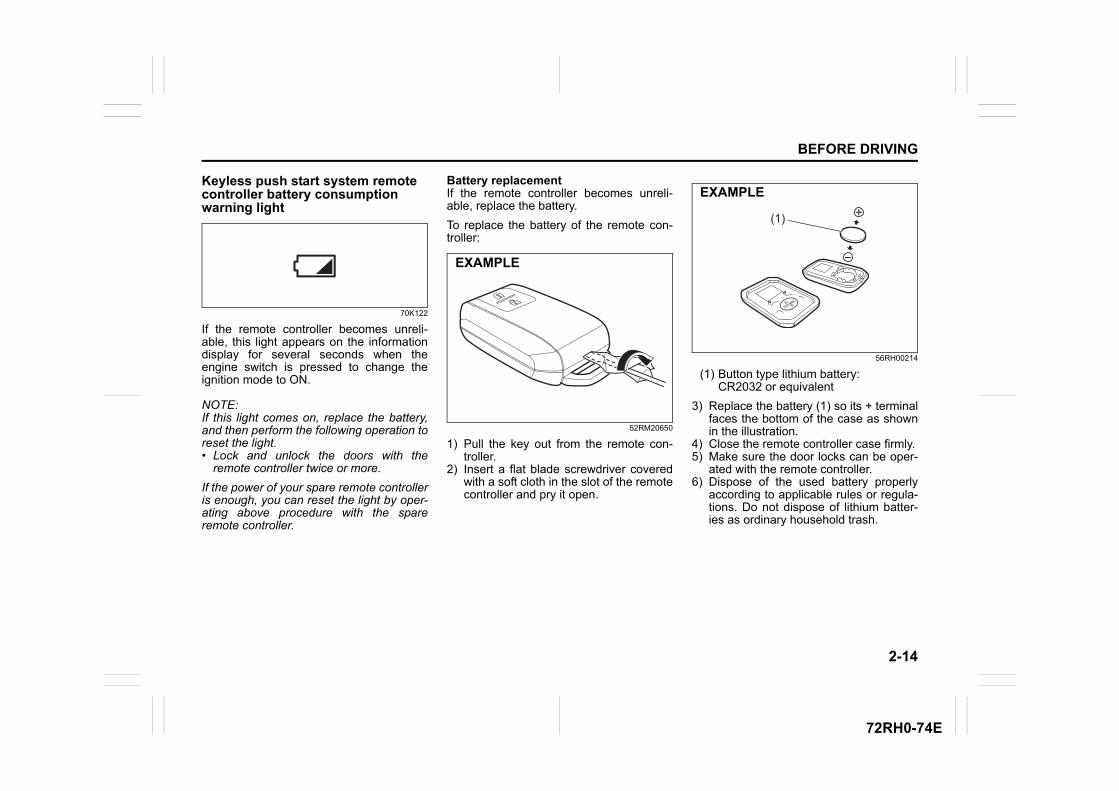
2-14
BEFORE DRIVING
72RH0-74E
Keyless push start system remote controller battery consumption warning light
70K122
If the remote controller becomes unreli-able, this light appears on the informationdisplay for several seconds when theengine switch is pressed to change theignition mode to ON.
NOTE:If this light comes on, replace the battery,and then perform the following operation toreset the light.• Lock and unlock the doors with the
remote controller twice or more.
If the power of your spare remote controlleris enough, you can reset the light by oper-ating above procedure with the spareremote controller.
Battery replacementIf the remote controller becomes unreli-able, replace the battery.
To replace the battery of the remote con-troller:
52RM20650
1) Pull the key out from the remote con-troller.
2) Insert a flat blade screwdriver coveredwith a soft cloth in the slot of the remotecontroller and pry it open.
56RH00214
(1) Button type lithium battery:CR2032 or equivalent
3) Replace the battery (1) so its + terminalfaces the bottom of the case as shownin the illustration.
4) Close the remote controller case firmly.5) Make sure the door locks can be oper-
ated with the remote controller.6) Dispose of the used battery properly
according to applicable rules or regula-tions. Do not dispose of lithium batter-ies as ordinary household trash.
EXAMPLE
(1)
EXAMPLE
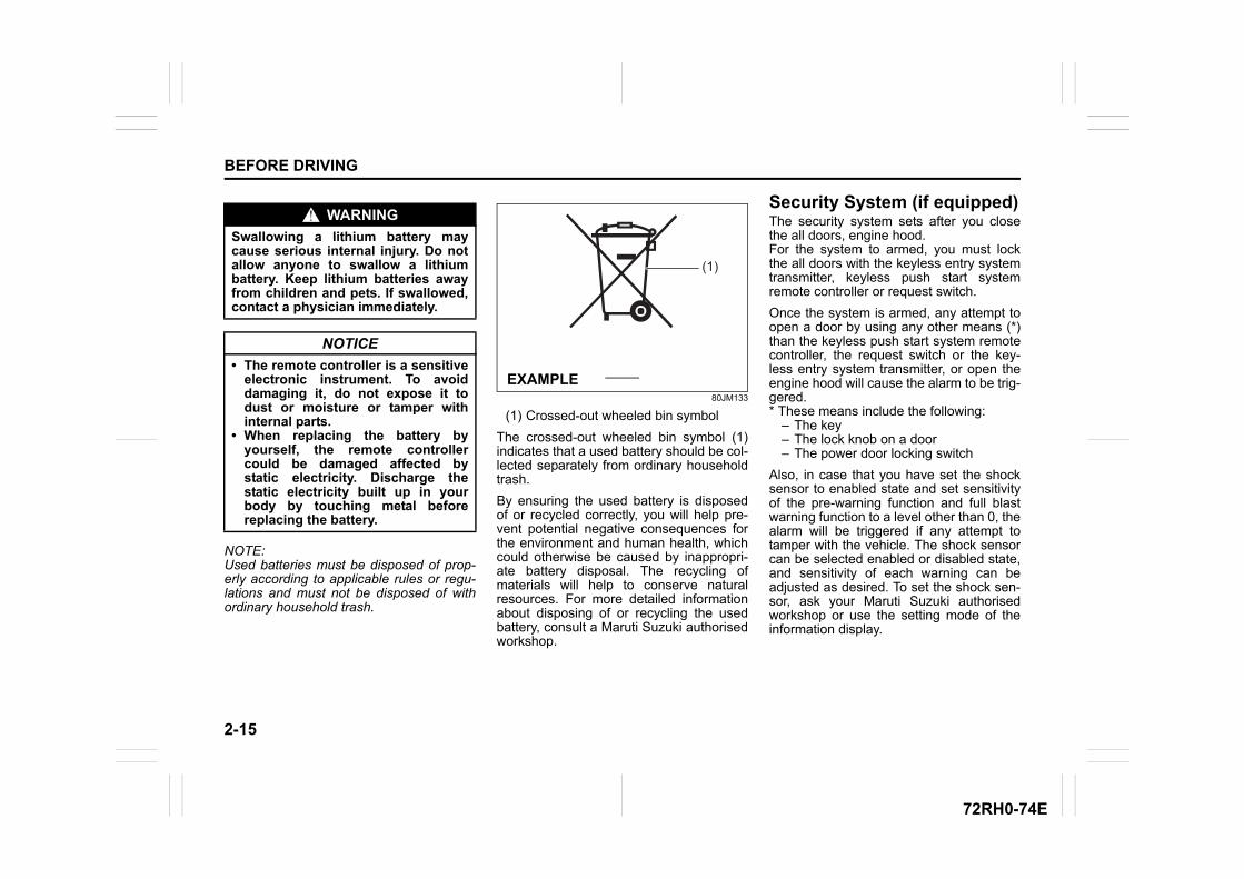
2-15
BEFORE DRIVING
72RH0-74E
NOTE:Used batteries must be disposed of prop-erly according to applicable rules or regu-lations and must not be disposed of withordinary household trash.
80JM133
(1) Crossed-out wheeled bin symbol
The crossed-out wheeled bin symbol (1)indicates that a used battery should be col-lected separately from ordinary householdtrash.
By ensuring the used battery is disposedof or recycled correctly, you will help pre-vent potential negative consequences forthe environment and human health, whichcould otherwise be caused by inappropri-ate battery disposal. The recycling ofmaterials will help to conserve naturalresources. For more detailed informationabout disposing of or recycling the usedbattery, consult a Maruti Suzuki authorisedworkshop.
Security System (if equipped)The security system sets after you closethe all doors, engine hood. For the system to armed, you must lockthe all doors with the keyless entry systemtransmitter, keyless push start systemremote controller or request switch.
Once the system is armed, any attempt toopen a door by using any other means (*)than the keyless push start system remotecontroller, the request switch or the key-less entry system transmitter, or open theengine hood will cause the alarm to be trig-gered. * These means include the following:
– The key– The lock knob on a door– The power door locking switch
Also, in case that you have set the shocksensor to enabled state and set sensitivityof the pre-warning function and full blastwarning function to a level other than 0, thealarm will be triggered if any attempt totamper with the vehicle. The shock sensorcan be selected enabled or disabled state,and sensitivity of each warning can beadjusted as desired. To set the shock sen-sor, ask your Maruti Suzuki authorisedworkshop or use the setting mode of theinformation display.
WARNING
Swallowing a lithium battery maycause serious internal injury. Do notallow anyone to swallow a lithiumbattery. Keep lithium batteries awayfrom children and pets. If swallowed,contact a physician immediately.
NOTICE
• The remote controller is a sensitiveelectronic instrument. To avoiddamaging it, do not expose it todust or moisture or tamper withinternal parts.
• When replacing the battery byyourself, the remote controllercould be damaged affected bystatic electricity. Discharge thestatic electricity built up in yourbody by touching metal beforereplacing the battery.
(1)
EXAMPLE
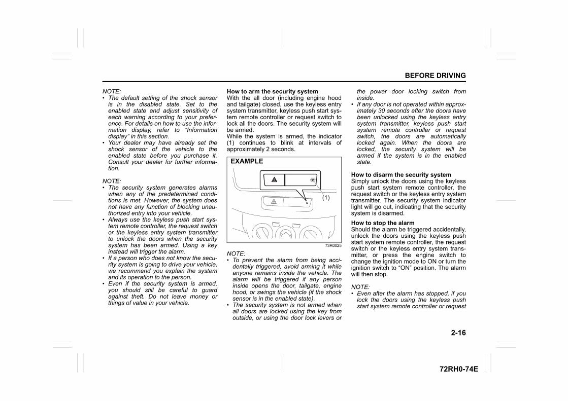
2-16
BEFORE DRIVING
72RH0-74E
NOTE:• The default setting of the shock sensor
is in the disabled state. Set to theenabled state and adjust sensitivity ofeach warning according to your prefer-ence. For details on how to use the infor-mation display, refer to “Informationdisplay” in this section.
• Your dealer may have already set theshock sensor of the vehicle to theenabled state before you purchase it.Consult your dealer for further informa-tion.
NOTE:• The security system generates alarms
when any of the predetermined condi-tions is met. However, the system doesnot have any function of blocking unau-thorized entry into your vehicle.
• Always use the keyless push start sys-tem remote controller, the request switchor the keyless entry system transmitterto unlock the doors when the securitysystem has been armed. Using a keyinstead will trigger the alarm.
• If a person who does not know the secu-rity system is going to drive your vehicle,we recommend you explain the systemand its operation to the person.
• Even if the security system is armed,you should still be careful to guardagainst theft. Do not leave money orthings of value in your vehicle.
How to arm the security systemWith the all door (including engine hoodand tailgate) closed, use the keyless entrysystem transmitter, keyless push start sys-tem remote controller or request switch tolock all the doors. The security system willbe armed.While the system is armed, the indicator(1) continues to blink at intervals ofapproximately 2 seconds.
73R0025
NOTE:• To prevent the alarm from being acci-
dentally triggered, avoid arming it whileanyone remains inside the vehicle. Thealarm will be triggered if any personinside opens the door, tailgate, enginehood, or swings the vehicle (if the shocksensor is in the enabled state).
• The security system is not armed whenall doors are locked using the key fromoutside, or using the door lock levers or
the power door locking switch frominside.
• If any door is not operated within approx-imately 30 seconds after the doors havebeen unlocked using the keyless entrysystem transmitter, keyless push startsystem remote controller or requestswitch, the doors are automaticallylocked again. When the doors arelocked, the security system will bearmed if the system is in the enabledstate.
How to disarm the security systemSimply unlock the doors using the keylesspush start system remote controller, therequest switch or the keyless entry systemtransmitter. The security system indicatorlight will go out, indicating that the securitysystem is disarmed.
How to stop the alarmShould the alarm be triggered accidentally,unlock the doors using the keyless pushstart system remote controller, the requestswitch or the keyless entry system trans-mitter, or press the engine switch tochange the ignition mode to ON or turn theignition switch to “ON” position. The alarmwill then stop.
NOTE:• Even after the alarm has stopped, if you
lock the doors using the keyless pushstart system remote controller or request
(1)
EXAMPLE
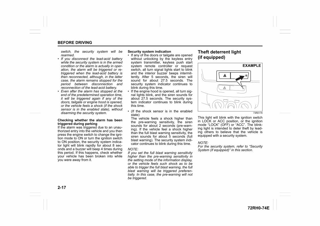
2-17
BEFORE DRIVING
72RH0-74E
switch, the security system will berearmed.
• If you disconnect the lead-acid batterywhile the security system is in the armedcondition or the alarm is actually in oper-ation, the alarm will be triggered or re-triggered when the lead-acid battery isthen reconnected, although, in the lattercase, the alarm remains stopped for theperiod between disconnection andreconnection of the lead-acid battery.
• Even after the alarm has stopped at theend of the predetermined operation time,it will be triggered again if any of thedoors, tailgate or engine hood is opened,or the vehicle feels a shock (if the shocksensor is in the enabled state), withoutdisarming the security system.
Checking whether the alarm has beentriggered during parkingIf the alarm was triggered due to an unau-thorized entry into the vehicle and you thenpress the engine switch to change the igni-tion mode to ON or turn the ignition switchto ON position, the security system indica-tor light will blink rapidly for about 8 sec-onds and a buzzer will beep 4 times duringthis period. If this happens, check whetheryour vehicle has been broken into whileyou were away from it.
Security system indication• If any of the doors or tailgate are opened
without unlocking by the keyless entrysystem transmitter, keyless push startsystem remote controller or requestswitch, all turn signal lights start to blinkand the interior buzzer beeps intermit-tently. After 5 seconds, the siren willsound for about 27.5 seconds. Thesecurity system indicator continues toblink during this time.
• If the engine hood is opened, all turn sig-nal lights blink, and the siren sounds forabout 27.5 seconds. The security sys-tem indicator continues to blink duringthis time.
• (If the shock sensor is in the enabledstate)The vehicle feels a shock higher thanthe pre-warning sensitivity, the sirensounds for about 2 seconds (pre-warn-ing). If the vehicle feel a shock higherthan the full blast warning sensitivity, thesiren sounds for about 5 seconds (fullblast warning). The security system indi-cator continues to blink during this time.
NOTE:If you set the full blast warning sensitivityhigher than the pre-warning sensitivity inthe setting mode of the information display,or the vehicle feels such shock as to beable to trigger the full blast warning, the fullblast warning will be triggered preferen-tially. In this case, the pre-warning will notbe triggered.
Theft deterrent light(if equipped)
73R0178
This light will blink with the ignition switchin LOCK or ACC position, or the ignitionmode “LOCK” (OFF) or “ACC”. The blink-ing light is intended to deter theft by lead-ing others to believe that the vehicle isequipped with a security system.
NOTE:For the security system, refer to “SecuritySystem (if equipped)” in this section.
EXAMPLE
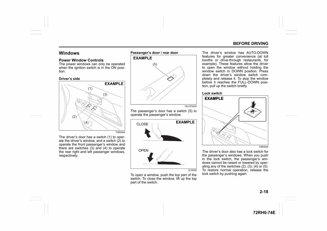
2-18
BEFORE DRIVING
72RH0-74E
Windows
Power Window Controls The power windows can only be operatedwhen the ignition switch is in the ON posi-tion.
Driver’s side
73R0004
The driver’s door has a switch (1) to oper-ate the driver’s window, and a switch (2) tooperate the front passenger’s window andthere are switches (3) and (4) to operatethe rear right and left passenger windows,respectively.
Passenger’s door / rear door
74LHT0205
The passenger’s door has a switch (5) tooperate the passenger’s window.
81A009
To open a window, push the top part of theswitch. To close the window, lift up the toppart of the switch.
The driver’s window has AUTO-DOWNfeatures for greater convenience (at tollbooths or drive-through restaurants, forexample). These features allow the driverto open the window without holding thewindow switch in DOWN position. Pressdown the driver’s window switch com-pletely and release it. To stop the windowbefore it reaches the FULL-DOWN posi-tion, pull up the switch briefly.
Lock switch
73R0005
The driver’s door also has a lock switch forthe passenger’s windows. When you pushin the lock switch, the passenger’s win-dows cannot be raised or lowered by oper-ating any of the switches (2), (3), (4) or (5).To restore normal operation, release thelock switch by pushing again.
(3)
(1)
(2)
(4)
EXAMPLE
(5)
EXAMPLE
CLOSE
OPEN
EXAMPLE
EXAMPLEEXAMPLE
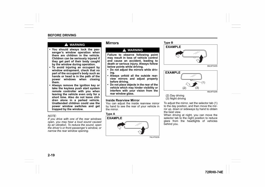
2-19
BEFORE DRIVING
72RH0-74E
NOTE:If you drive with one of the rear windowsopen, you may hear a loud sound causedby air vibration. To reduce the sound, openthe driver’s or front passenger’s window, ornarrow the rear window opening.
Mirrors
Inside Rearview MirrorYou can adjust the inside rearview mirrorby hand to see the rear of your vehicle inthe mirror.
Type A
74LHT0235
Type B
68LMT0205
68LMT0206
(2) Day driving(3) Night driving
To adjust the mirror, set the selector tab (1)to the day position, and then move the mir-ror up, down or sideways by hand to obtainthe best view.When driving at night, you can move theselector tab to the night position to reduceglare from the headlights of vehiclesbehind you.
WARNING
• You should always lock the pas-senger’s window operation whenthere are children in the vehicle.Children can be seriously injured ifthey get part of their body caughtby the window during operation.
• To avoid injuring an occupant bywindow entrapment, check that nopart of the occupant’s body such ashands or head is in the path of thepower windows when closingthem.
• Always remove the ignition key ortake the keyless push start systemremote controller with you whenleaving the vehicle even only for ashort time. Also do not leave chil-dren alone in a parked vehicle.Unattended children could use thepower window switches and gettrapped by the window.
WARNING
Failure to observe following pointmay result in loss of vehicle controland cause an accident, leading todeath or serious injury. Always followbelow points while driving.• Do not adjust the mirrors while driv-
ing.• Always unfold all the outside rear-
view mirrors and adjust properlybefore driving.
• Do not place objects in the rear of thevehicle which may hinder visibility orinterfere with your vision from therear window glass.
EXAMPLE
EXAMPLE
(1)
(2) (3)
EXAMPLE
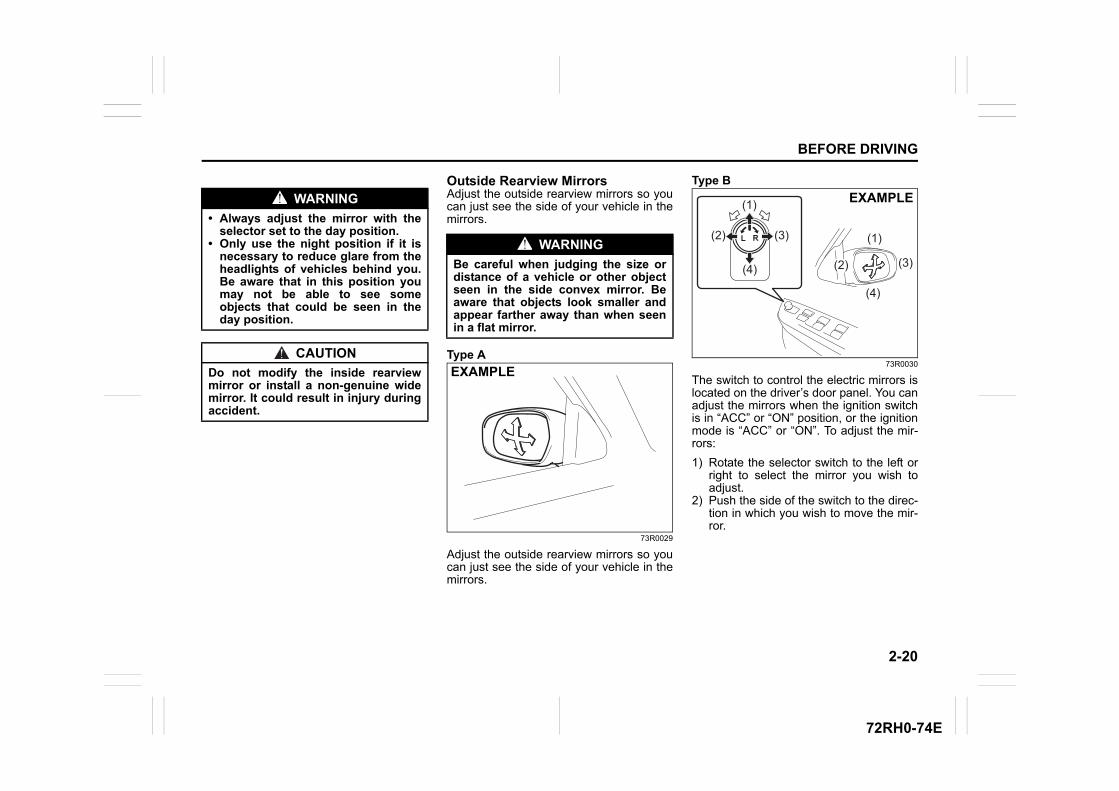
2-20
BEFORE DRIVING
72RH0-74E
Outside Rearview MirrorsAdjust the outside rearview mirrors so youcan just see the side of your vehicle in themirrors.
Type A
73R0029
Adjust the outside rearview mirrors so youcan just see the side of your vehicle in themirrors.
Type B
73R0030
The switch to control the electric mirrors islocated on the driver’s door panel. You canadjust the mirrors when the ignition switchis in “ACC” or “ON” position, or the ignitionmode is “ACC” or “ON”. To adjust the mir-rors:
1) Rotate the selector switch to the left orright to select the mirror you wish toadjust.
2) Push the side of the switch to the direc-tion in which you wish to move the mir-ror.
WARNING
• Always adjust the mirror with theselector set to the day position.
• Only use the night position if it isnecessary to reduce glare from theheadlights of vehicles behind you.Be aware that in this position youmay not be able to see someobjects that could be seen in theday position.
CAUTION
Do not modify the inside rearviewmirror or install a non-genuine widemirror. It could result in injury duringaccident.
WARNING
Be careful when judging the size ordistance of a vehicle or other objectseen in the side convex mirror. Beaware that objects look smaller andappear farther away than when seenin a flat mirror.
EXAMPLE
(1)
(2) (3)
(4)
(1)
(3)
(4)
(2)
EXAMPLE
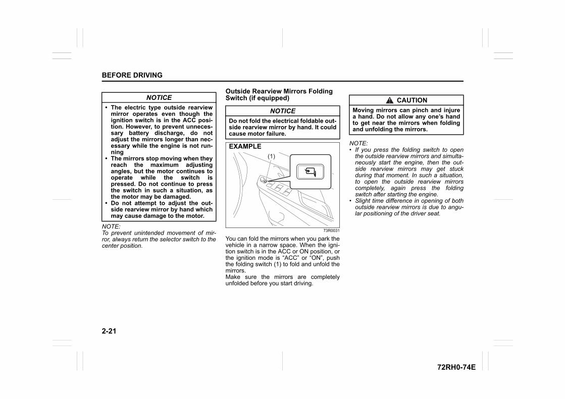
2-21
BEFORE DRIVING
72RH0-74E
NOTE:To prevent unintended movement of mir-ror, always return the selector switch to thecenter position.
Outside Rearview Mirrors Folding Switch (if equipped)
73R0031
You can fold the mirrors when you park thevehicle in a narrow space. When the igni-tion switch is in the ACC or ON position, orthe ignition mode is “ACC” or “ON”, pushthe folding switch (1) to fold and unfold themirrors.Make sure the mirrors are completelyunfolded before you start driving.
NOTE:• If you press the folding switch to open
the outside rearview mirrors and simulta-neously start the engine, then the out-side rearview mirrors may get stuckduring that moment. In such a situation,to open the outside rearview mirrorscompletely, again press the foldingswitch after starting the engine.
• Slight time difference in opening of bothoutside rearview mirrors is due to angu-lar positioning of the driver seat.
NOTICE
• The electric type outside rearviewmirror operates even though theignition switch is in the ACC posi-tion. However, to prevent unneces-sary battery discharge, do notadjust the mirrors longer than nec-essary while the engine is not run-ning
• The mirrors stop moving when theyreach the maximum adjustingangles, but the motor continues tooperate while the switch ispressed. Do not continue to pressthe switch in such a situation, asthe motor may be damaged.
• Do not attempt to adjust the out-side rearview mirror by hand whichmay cause damage to the motor.
NOTICE
Do not fold the electrical foldable out-side rearview mirror by hand. It couldcause motor failure.
(1)EXAMPLE
CAUTION
Moving mirrors can pinch and injurea hand. Do not allow any one’s handto get near the mirrors when foldingand unfolding the mirrors.
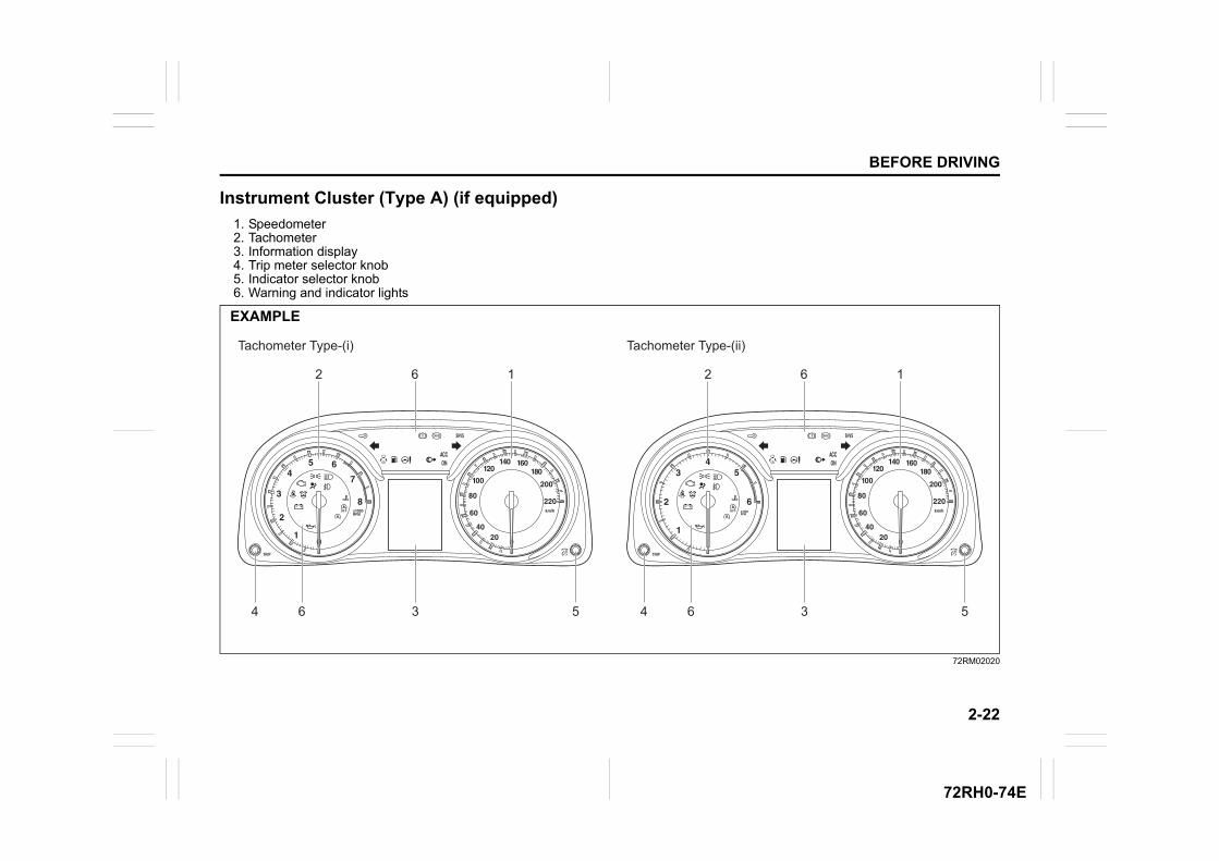
2-22
BEFORE DRIVING
72RH0-74E
Instrument Cluster (Type A) (if equipped)
1. Speedometer2. Tachometer3. Information display4. Trip meter selector knob5. Indicator selector knob6. Warning and indicator lights
72RM02020
EXAMPLE
162
34 6 5
162
34 6 5
Tachometer Type-(i) Tachometer Type-(ii)
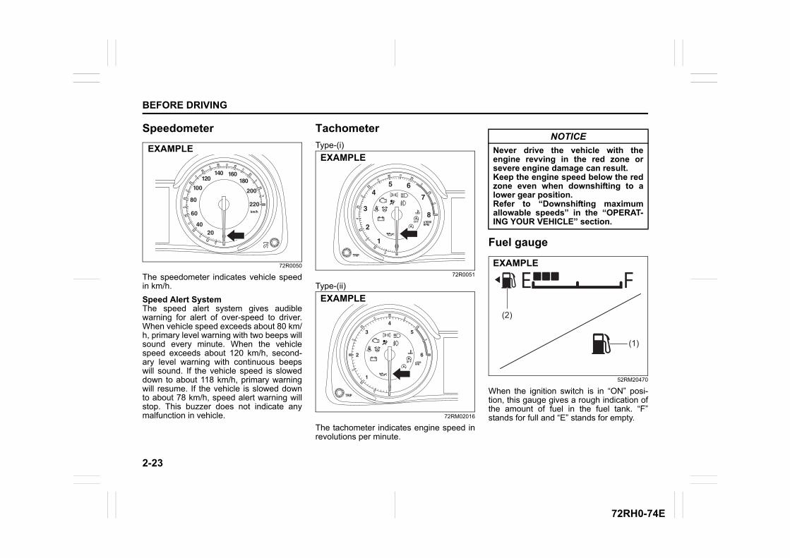
2-23
BEFORE DRIVING
72RH0-74E
Speedometer
72R0050
The speedometer indicates vehicle speedin km/h.
Speed Alert SystemThe speed alert system gives audiblewarning for alert of over-speed to driver.When vehicle speed exceeds about 80 km/h, primary level warning with two beeps willsound every minute. When the vehiclespeed exceeds about 120 km/h, second-ary level warning with continuous beepswill sound. If the vehicle speed is sloweddown to about 118 km/h, primary warningwill resume. If the vehicle is slowed downto about 78 km/h, speed alert warning willstop. This buzzer does not indicate anymalfunction in vehicle.
Tachometer
Type-(i)
72R0051
Type-(ii)
72RM02016
The tachometer indicates engine speed inrevolutions per minute.
Fuel gauge
52RM20470
When the ignition switch is in “ON” posi-tion, this gauge gives a rough indication ofthe amount of fuel in the fuel tank. “F”stands for full and “E” stands for empty.
EXAMPLEEXAMPLE
EXAMPLE
NOTICE
Never drive the vehicle with theengine revving in the red zone orsevere engine damage can result.Keep the engine speed below the redzone even when downshifting to alower gear position.Refer to “Downshifting maximumallowable speeds” in the “OPERAT-ING YOUR VEHICLE” section.
(1)
(2)
EXAMPLE
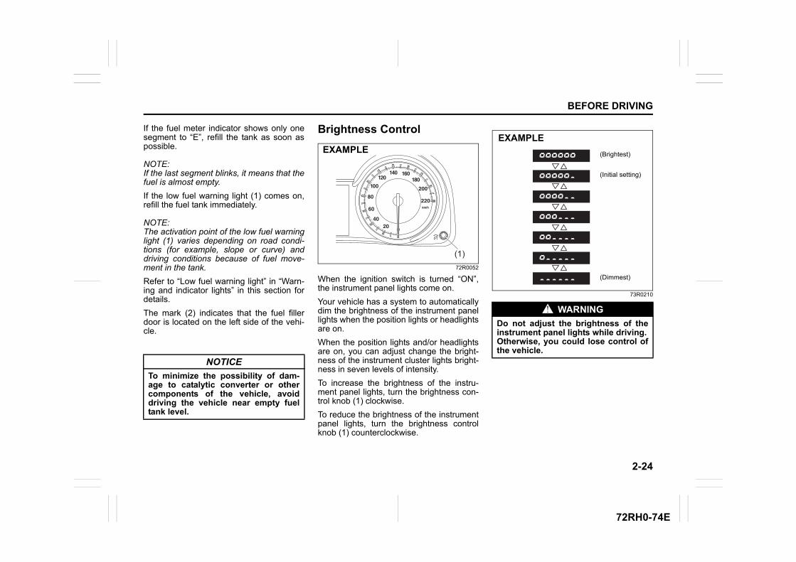
2-24
BEFORE DRIVING
72RH0-74E
If the fuel meter indicator shows only onesegment to “E”, refill the tank as soon aspossible.
NOTE:If the last segment blinks, it means that thefuel is almost empty.
If the low fuel warning light (1) comes on,refill the fuel tank immediately.
NOTE:The activation point of the low fuel warninglight (1) varies depending on road condi-tions (for example, slope or curve) anddriving conditions because of fuel move-ment in the tank.
Refer to “Low fuel warning light” in “Warn-ing and indicator lights” in this section fordetails.
The mark (2) indicates that the fuel fillerdoor is located on the left side of the vehi-cle.
Brightness Control
72R0052
When the ignition switch is turned “ON”,the instrument panel lights come on.
Your vehicle has a system to automaticallydim the brightness of the instrument panellights when the position lights or headlightsare on.
When the position lights and/or headlightsare on, you can adjust change the bright-ness of the instrument cluster lights bright-ness in seven levels of intensity.
To increase the brightness of the instru-ment panel lights, turn the brightness con-trol knob (1) clockwise.
To reduce the brightness of the instrumentpanel lights, turn the brightness controlknob (1) counterclockwise.
73R0210
NOTICE
To minimize the possibility of dam-age to catalytic converter or othercomponents of the vehicle, avoiddriving the vehicle near empty fueltank level.
(1)
EXAMPLE
WARNING
Do not adjust the brightness of theinstrument panel lights while driving.Otherwise, you could lose control ofthe vehicle.
(Brightest)
(Initial setting)
(Dimmest)
EXAMPLE
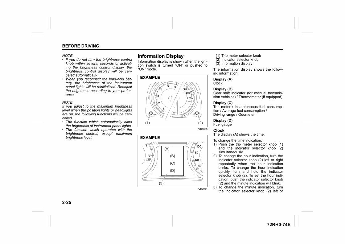
2-25
BEFORE DRIVING
72RH0-74E
NOTE:• If you do not turn the brightness control
knob within several seconds of activat-ing the brightness control display, thebrightness control display will be can-celed automatically.
• When you reconnect the lead-acid bat-tery, the brightness of the instrumentpanel lights will be reinitialized. Readjustthe brightness according to your prefer-ence.
NOTE:If you adjust to the maximum brightnesslevel when the position lights or headlightsare on, the following functions will be can-celled.• The function which automatically dims
the brightness of instrument panel lights.• The function which operates with the
brightness control, except maximumbrightness level.
Information DisplayInformation display is shown when the igni-tion switch is turned “ON” or pushed to“ON” mode.
72R0053
72R0054
(1) Trip meter selector knob(2) Indicator selector knob(3) Information display
The information display shows the follow-ing information.
Display (A)Clock
Display (B)Gear shift indicator (for manual transmis-sion vehicles) / Thermometer (if equipped)
Display (C)Trip meter / Instantaneous fuel consump-tion / Average fuel consumption /Driving range / Odometer
Display (D)Fuel gauge
ClockThe display (A) shows the time.
To change the time indication: 1) Push the trip meter selector knob (1)
and the indicator selector knob (2)simultaneously.
2) To change the hour indication, turn theindicator selector knob (2) left or rightrepeatedly when the hour indicationblinks. To change the hour indicationquickly, turn and hold the indicatorselector knob (2). To set the hour indi-cation, push the indicator selector knob(2) and the minute indication will blink.
3) To change the minute indication, turnthe indicator selector knob (2) left or
(2)(1)
EXAMPLEEXAMPLE
(A)
(C)
(B)
(D)
(3)
EXAMPLE
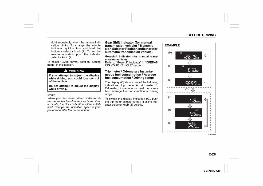
2-26
BEFORE DRIVING
72RH0-74E
right repeatedly when the minute indi-cation blinks. To change the minuteindication quickly, turn and hold theindicator selector knob (2). To set theminute indication, push the indicatorselector knob (2).
To select 12/24H format, refer to “Settingmode” in this section.
NOTE:When you disconnect either of the termi-nals to the lead-acid battery and keep it fora minute, the clock indication will be initial-ized. Change the indication again to yourpreference after the reconnection.
Gear Shift Indicator (for manual transmission vehicle) / Transmis-sion Selector Position Indicator (for automatic transmission vehicle)
Gearshift indicator (for manual trans-mission vehicles)Refer to “Gearshift Indicator” in “OPERAT-ING YOUR VEHICLE” section.
Trip meter / Odometer / Instanta-neous fuel consumption / Average fuel consumption / Driving range
The display (C) shows one of the followingindications; trip meter A, trip meter B,Odometer, instantaneous fuel consump-tion, average fuel consumption or drivingrange.
To switch the display indication (C), pushthe trip meter selector knob (1) or the indi-cator selector knob (2) quickly.
73R0054
WARNING
If you attempt to adjust the displaywhile driving, you could lose controlof the vehicle.
Do not attempt to adjust the displaywhile driving.
(c)
(d)
(e)
(f)
(b)
(g)
EXAMPLE
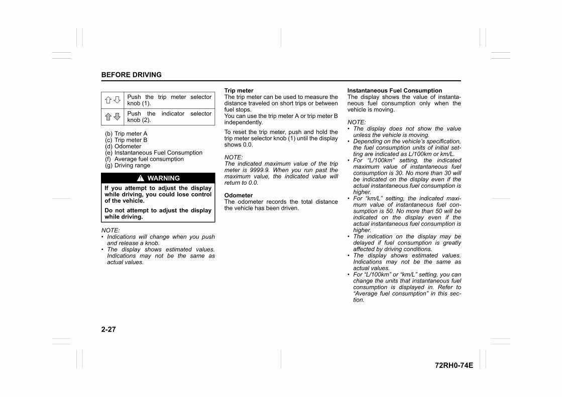
2-27
BEFORE DRIVING
72RH0-74E
(b) Trip meter A(c) Trip meter B(d) Odometer(e) Instantaneous Fuel Consumption(f) Average fuel consumption(g) Driving range
NOTE:• Indications will change when you push
and release a knob.• The display shows estimated values.
Indications may not be the same asactual values.
Trip meterThe trip meter can be used to measure thedistance traveled on short trips or betweenfuel stops.You can use the trip meter A or trip meter Bindependently.
To reset the trip meter, push and hold thetrip meter selector knob (1) until the displayshows 0.0.
NOTE:The indicated maximum value of the tripmeter is 9999.9. When you run past themaximum value, the indicated value willreturn to 0.0.
OdometerThe odometer records the total distancethe vehicle has been driven.
Instantaneous Fuel ConsumptionThe display shows the value of instanta-neous fuel consumption only when thevehicle is moving.
NOTE:• The display does not show the value
unless the vehicle is moving. • Depending on the vehicle’s specification,
the fuel consumption units of initial set-ting are indicated as L/100km or km/L.
• For “L/100km” setting, the indicatedmaximum value of instantaneous fuelconsumption is 30. No more than 30 willbe indicated on the display even if theactual instantaneous fuel consumption ishigher.
• For “km/L” setting, the indicated maxi-mum value of instantaneous fuel con-sumption is 50. No more than 50 will beindicated on the display even if theactual instantaneous fuel consumption ishigher.
• The indication on the display may bedelayed if fuel consumption is greatlyaffected by driving conditions.
• The display shows estimated values.Indications may not be the same asactual values.
• For “L/100km” or “km/L” setting, you canchange the units that instantaneous fuelconsumption is displayed in. Refer to“Average fuel consumption” in this sec-tion.
Push the trip meter selectorknob (1).
Push the indicator selectorknob (2).
WARNING
If you attempt to adjust the displaywhile driving, you could lose controlof the vehicle.
Do not attempt to adjust the displaywhile driving.
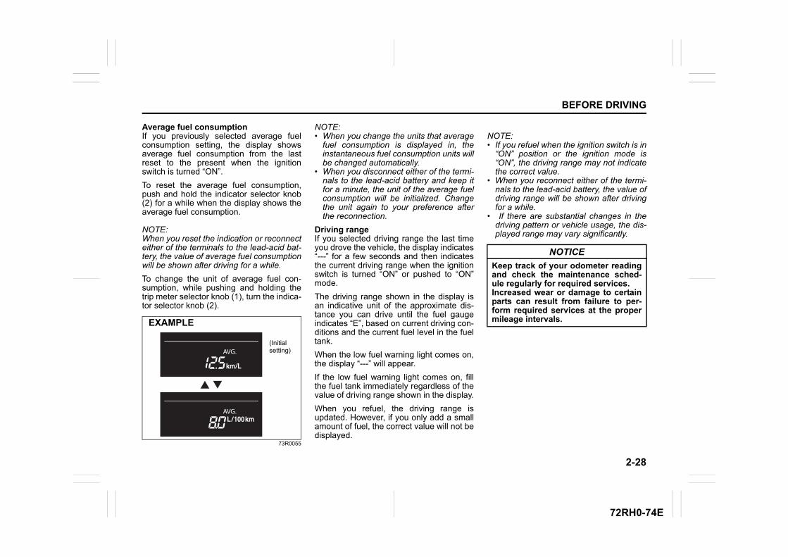
2-28
BEFORE DRIVING
72RH0-74E
Average fuel consumptionIf you previously selected average fuelconsumption setting, the display showsaverage fuel consumption from the lastreset to the present when the ignitionswitch is turned “ON”.
To reset the average fuel consumption,push and hold the indicator selector knob(2) for a while when the display shows theaverage fuel consumption.
NOTE:When you reset the indication or reconnecteither of the terminals to the lead-acid bat-tery, the value of average fuel consumptionwill be shown after driving for a while.
To change the unit of average fuel con-sumption, while pushing and holding thetrip meter selector knob (1), turn the indica-tor selector knob (2).
73R0055
NOTE:• When you change the units that average
fuel consumption is displayed in, theinstantaneous fuel consumption units willbe changed automatically.
• When you disconnect either of the termi-nals to the lead-acid battery and keep itfor a minute, the unit of the average fuelconsumption will be initialized. Changethe unit again to your preference afterthe reconnection.
Driving rangeIf you selected driving range the last timeyou drove the vehicle, the display indicates“---” for a few seconds and then indicatesthe current driving range when the ignitionswitch is turned “ON” or pushed to “ON”mode.
The driving range shown in the display isan indicative unit of the approximate dis-tance you can drive until the fuel gaugeindicates “E”, based on current driving con-ditions and the current fuel level in the fueltank.
When the low fuel warning light comes on,the display “---” will appear.
If the low fuel warning light comes on, fillthe fuel tank immediately regardless of thevalue of driving range shown in the display.
When you refuel, the driving range isupdated. However, if you only add a smallamount of fuel, the correct value will not bedisplayed.
NOTE:• If you refuel when the ignition switch is in
“ON” position or the ignition mode is“ON”, the driving range may not indicatethe correct value.
• When you reconnect either of the termi-nals to the lead-acid battery, the value ofdriving range will be shown after drivingfor a while.
• If there are substantial changes in thedriving pattern or vehicle usage, the dis-played range may vary significantly.
(Initial setting)
EXAMPLE
NOTICE
Keep track of your odometer readingand check the maintenance sched-ule regularly for required services.Increased wear or damage to certainparts can result from failure to per-form required services at the propermileage intervals.
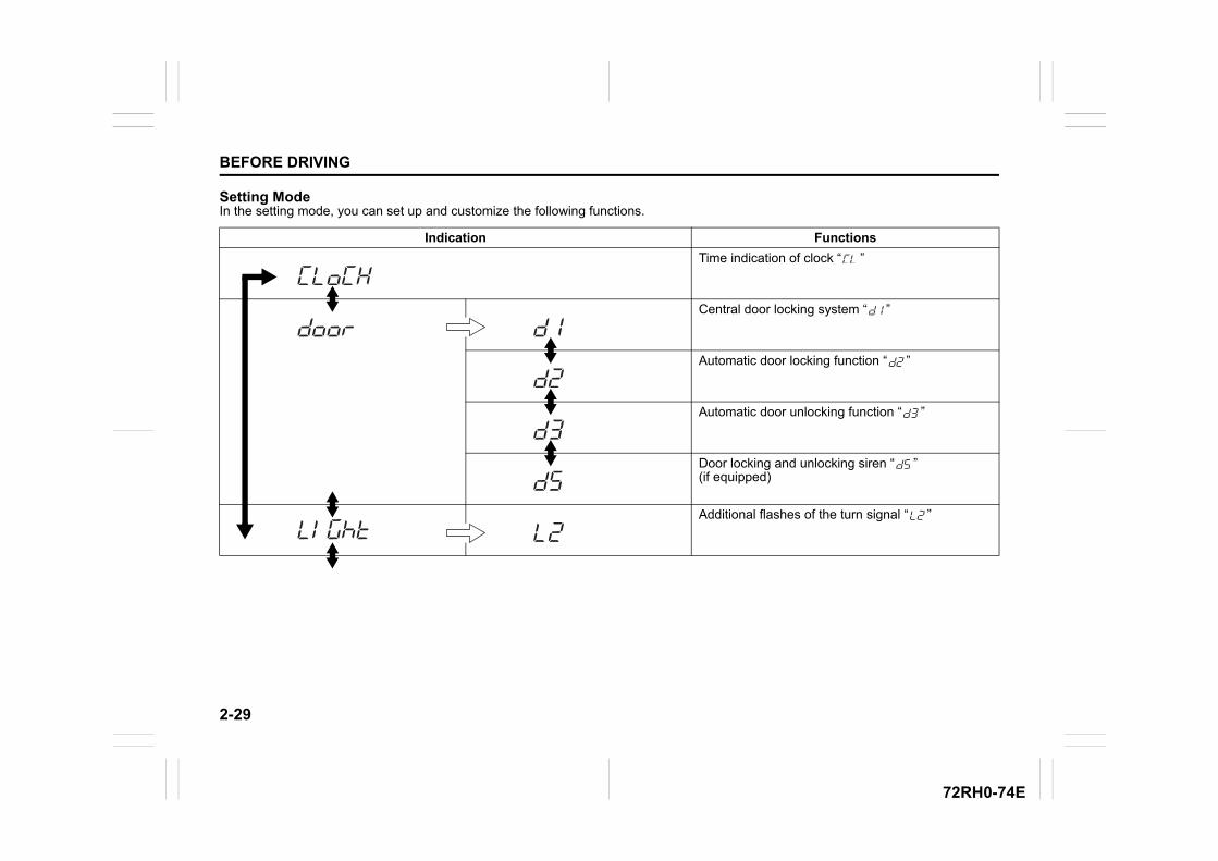
2-29
BEFORE DRIVING
72RH0-74E
Setting ModeIn the setting mode, you can set up and customize the following functions.
Indication Functions
Time indication of clock “ ”
Central door locking system “ ”
Automatic door locking function “ ”
Automatic door unlocking function “ ”
Door locking and unlocking siren “ ”(if equipped)
Additional flashes of the turn signal “ ”
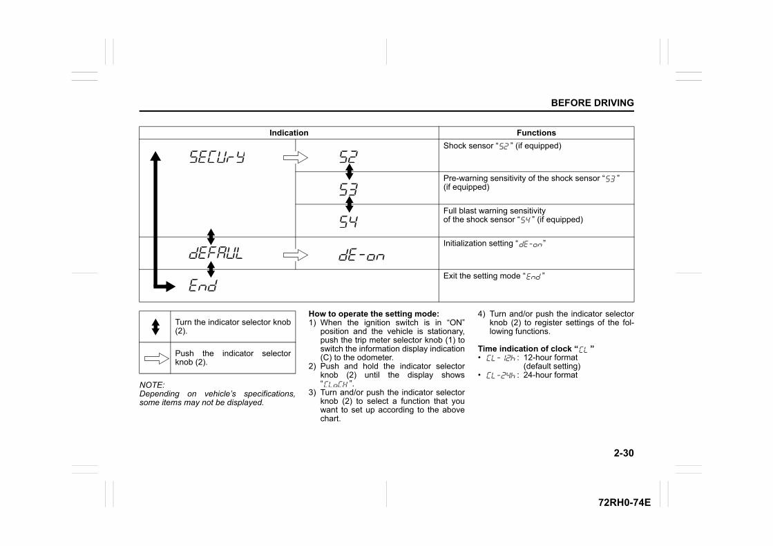
2-30
BEFORE DRIVING
72RH0-74E
NOTE:Depending on vehicle’s specifications,some items may not be displayed.
How to operate the setting mode:1) When the ignition switch is in “ON”
position and the vehicle is stationary,push the trip meter selector knob (1) toswitch the information display indication(C) to the odometer.
2) Push and hold the indicator selectorknob (2) until the display shows“ ”.
3) Turn and/or push the indicator selectorknob (2) to select a function that youwant to set up according to the abovechart.
4) Turn and/or push the indicator selectorknob (2) to register settings of the fol-lowing functions.
Time indication of clock “ ”• : 12-hour format
(default setting)• : 24-hour format
Indication Functions
Shock sensor “ ” (if equipped)
Pre-warning sensitivity of the shock sensor “ ” (if equipped)
Full blast warning sensitivity of the shock sensor “ ” (if equipped)
Initialization setting “ ”
Exit the setting mode “ ”
Turn the indicator selector knob(2).
Push the indicator selectorknob (2).
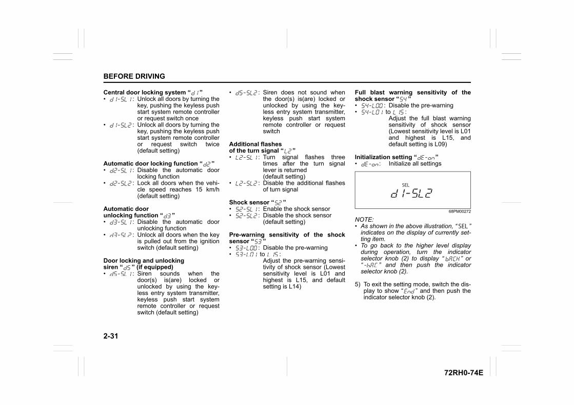
2-31
BEFORE DRIVING
72RH0-74E
Central door locking system “ ”• : Unlock all doors by turning the
key, pushing the keyless pushstart system remote controlleror request switch once
• : Unlock all doors by turning thekey, pushing the keyless pushstart system remote controlleror request switch twice(default setting)
Automatic door locking function “ ”• : Disable the automatic door
locking function• : Lock all doors when the vehi-
cle speed reaches 15 km/h(default setting)
Automatic door unlocking function “ ”• : Disable the automatic door
unlocking function• : Unlock all doors when the key
is pulled out from the ignitionswitch (default setting)
Door locking and unlocking siren “ ” (if equipped)• : Siren sounds when the
door(s) is(are) locked orunlocked by using the key-less entry system transmitter,keyless push start systemremote controller or requestswitch (default setting)
• : Siren does not sound whenthe door(s) is(are) locked orunlocked by using the key-less entry system transmitter,keyless push start systemremote controller or requestswitch
Additional flashes of the turn signal “ ”• : Turn signal flashes three
times after the turn signallever is returned (default setting)
• : Disable the additional flashesof turn signal
Shock sensor “ ”• : Enable the shock sensor• : Disable the shock sensor
(default setting)
Pre-warning sensitivity of the shocksensor “ ”• : Disable the pre-warning• to :
Adjust the pre-warning sensi-tivity of shock sensor (Lowestsensitivity level is L01 andhighest is L15, and defaultsetting is L14)
Full blast warning sensitivity of theshock sensor “ ”• : Disable the pre-warning• to :
Adjust the full blast warningsensitivity of shock sensor(Lowest sensitivity level is L01and highest is L15, anddefault setting is L09)
Initialization setting “ ”• : Initialize all settings
68PM00272
NOTE:• As shown in the above illustration, “ ”
indicates on the display of currently set-ting item.
• To go back to the higher level displayduring operation, turn the indicatorselector knob (2) to display “ ” or“ ” and then push the indicatorselector knob (2).
5) To exit the setting mode, switch the dis-play to show “ ” and then push theindicator selector knob (2).
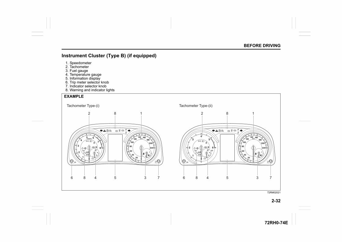
2-32
BEFORE DRIVING
72RH0-74E
Instrument Cluster (Type B) (if equipped)
1. Speedometer2. Tachometer3. Fuel gauge4. Temperature gauge5. Information display6. Trip meter selector knob7. Indicator selector knob8. Warning and indicator lights
72RM02021
EXAMPLE
Tachometer Type-(i) Tachometer Type-(ii)
182
56 8 734
182
56 8 734
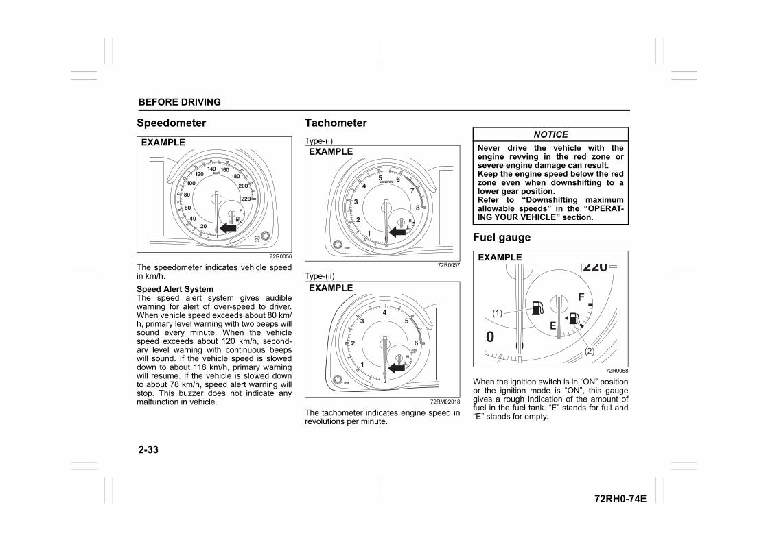
2-33
BEFORE DRIVING
72RH0-74E
Speedometer
72R0056
The speedometer indicates vehicle speedin km/h.
Speed Alert SystemThe speed alert system gives audiblewarning for alert of over-speed to driver.When vehicle speed exceeds about 80 km/h, primary level warning with two beeps willsound every minute. When the vehiclespeed exceeds about 120 km/h, second-ary level warning with continuous beepswill sound. If the vehicle speed is sloweddown to about 118 km/h, primary warningwill resume. If the vehicle is slowed downto about 78 km/h, speed alert warning willstop. This buzzer does not indicate anymalfunction in vehicle.
Tachometer
Type-(i)
72R0057
Type-(ii)
72RM02018
The tachometer indicates engine speed inrevolutions per minute.
Fuel gauge
72R0058
When the ignition switch is in “ON” positionor the ignition mode is “ON”, this gaugegives a rough indication of the amount offuel in the fuel tank. “F” stands for full and“E” stands for empty.
EXAMPLEEXAMPLE
EXAMPLE
NOTICE
Never drive the vehicle with theengine revving in the red zone orsevere engine damage can result.Keep the engine speed below the redzone even when downshifting to alower gear position.Refer to “Downshifting maximumallowable speeds” in the “OPERAT-ING YOUR VEHICLE” section.
(1)
(2)
EXAMPLE
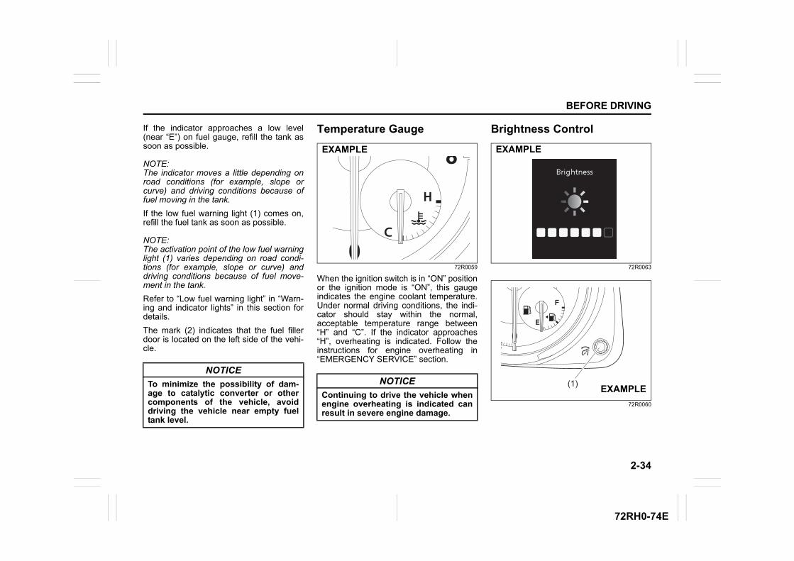
2-34
BEFORE DRIVING
72RH0-74E
If the indicator approaches a low level(near “E”) on fuel gauge, refill the tank assoon as possible.
NOTE:The indicator moves a little depending onroad conditions (for example, slope orcurve) and driving conditions because offuel moving in the tank.
If the low fuel warning light (1) comes on,refill the fuel tank as soon as possible.
NOTE:The activation point of the low fuel warninglight (1) varies depending on road condi-tions (for example, slope or curve) anddriving conditions because of fuel move-ment in the tank.
Refer to “Low fuel warning light” in “Warn-ing and indicator lights” in this section fordetails.
The mark (2) indicates that the fuel fillerdoor is located on the left side of the vehi-cle.
Temperature Gauge
72R0059
When the ignition switch is in “ON” positionor the ignition mode is “ON”, this gaugeindicates the engine coolant temperature.Under normal driving conditions, the indi-cator should stay within the normal,acceptable temperature range between“H” and “C”. If the indicator approaches“H”, overheating is indicated. Follow theinstructions for engine overheating in“EMERGENCY SERVICE” section.
Brightness Control
72R0063
72R0060
NOTICE
To minimize the possibility of dam-age to catalytic converter or othercomponents of the vehicle, avoiddriving the vehicle near empty fueltank level.
NOTICE
Continuing to drive the vehicle whenengine overheating is indicated canresult in severe engine damage.
EXAMPLE EXAMPLE
(1)EXAMPLE
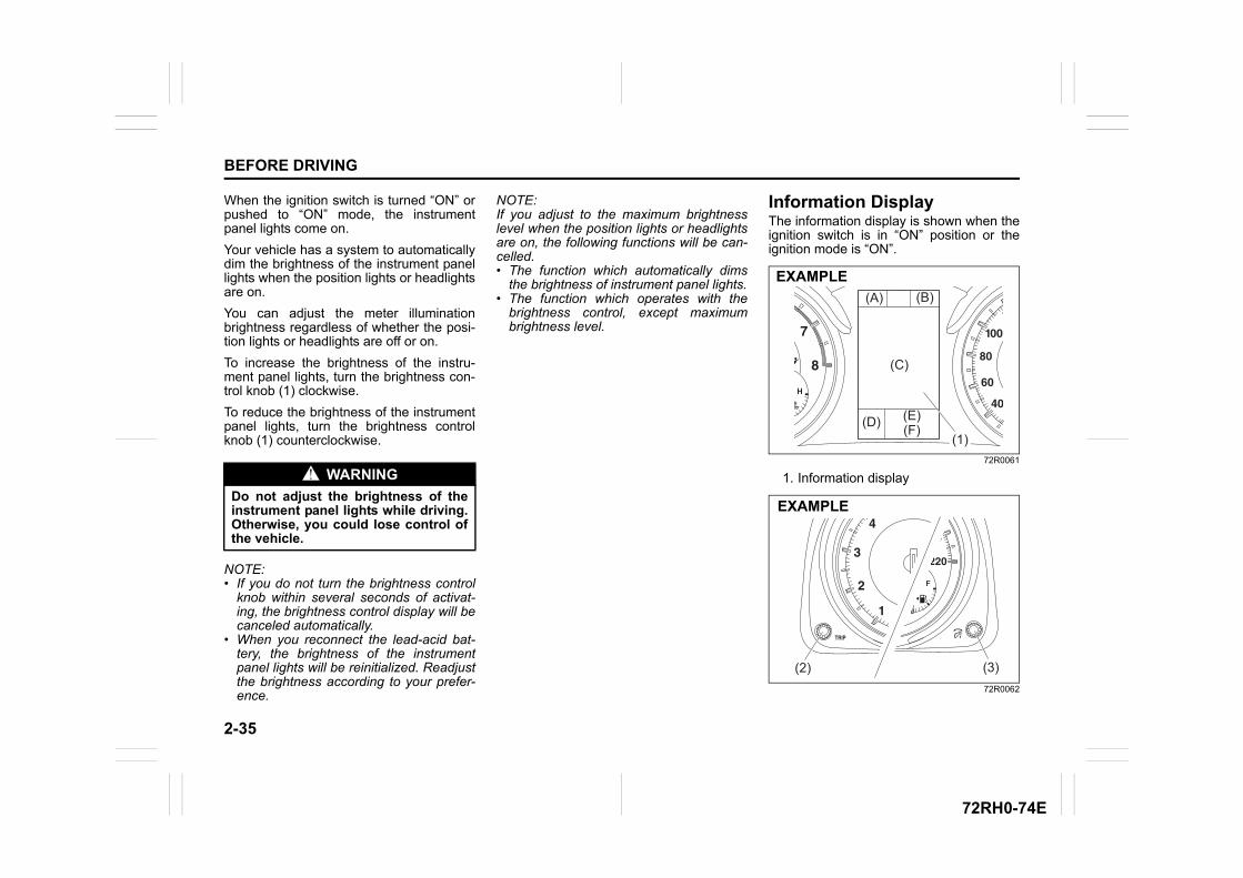
2-35
BEFORE DRIVING
72RH0-74E
When the ignition switch is turned “ON” orpushed to “ON” mode, the instrumentpanel lights come on.
Your vehicle has a system to automaticallydim the brightness of the instrument panellights when the position lights or headlightsare on.
You can adjust the meter illuminationbrightness regardless of whether the posi-tion lights or headlights are off or on.
To increase the brightness of the instru-ment panel lights, turn the brightness con-trol knob (1) clockwise.
To reduce the brightness of the instrumentpanel lights, turn the brightness controlknob (1) counterclockwise.
NOTE:• If you do not turn the brightness control
knob within several seconds of activat-ing, the brightness control display will becanceled automatically.
• When you reconnect the lead-acid bat-tery, the brightness of the instrumentpanel lights will be reinitialized. Readjustthe brightness according to your prefer-ence.
NOTE:If you adjust to the maximum brightnesslevel when the position lights or headlightsare on, the following functions will be can-celled.• The function which automatically dims
the brightness of instrument panel lights.• The function which operates with the
brightness control, except maximumbrightness level.
Information DisplayThe information display is shown when theignition switch is in “ON” position or theignition mode is “ON”.
72R0061
1. Information display
72R0062
WARNING
Do not adjust the brightness of theinstrument panel lights while driving.Otherwise, you could lose control ofthe vehicle.
(D) (E)(F)
(A) (B)
(C)
(1)
EXAMPLE
(2) (3)
EXAMPLE
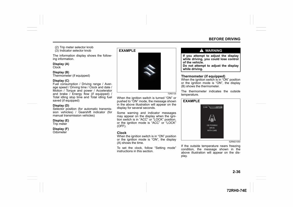
2-36
BEFORE DRIVING
72RH0-74E
(2) Trip meter selector knob(3) Indicator selector knob
The information display shows the follow-ing information.
Display (A)Clock
Display (B)Thermometer (if equipped)
Display (C)Fuel consumption / Driving range / Aver-age speed / Driving time / Clock and date /Motion / Torque and power / Acceleratorand brake / Energy flow (if equipped) /Total idling stop time and Total idling fuelsaved (if equipped)
Display (D)Selector position (for automatic transmis-sion vehicles) / Gearshift indicator (formanual transmission vehicles)
Display (E)Trip meter
Display (F)Odometer
72R0135
When the ignition switch is turned “ON” orpushed to “ON” mode, the message shownin the above illustration will appear on thedisplay for several seconds.
Some warning and indicator messagesmay appear on the display when the igni-tion switch is in “ACC” or “LOCK” position,or the ignition mode is “ACC” or “LOCK”(OFF).
ClockWhen the ignition switch is in “ON” positionor the ignition mode is “ON”, the display(A) shows the time.
To set the clock, follow “Setting mode”instructions in this section.
Thermometer (if equipped)When the ignition switch is in “ON” positionor the ignition mode is “ON”, the display(B) shows the thermometer.
The thermometer indicates the outsidetemperature.
52RM21050
If the outside temperature nears freezingcondition, the message shown in theabove illustration will appear on the dis-play.
EXAMPLE WARNING
If you attempt to adjust the displaywhile driving, you could lose controlof the vehicle.Do not attempt to adjust the displaywhile driving.
EXAMPLE
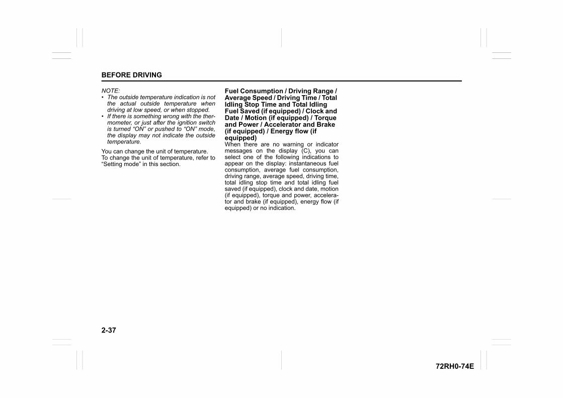
2-37
BEFORE DRIVING
72RH0-74E
NOTE:• The outside temperature indication is not
the actual outside temperature whendriving at low speed, or when stopped.
• If there is something wrong with the ther-mometer, or just after the ignition switchis turned “ON” or pushed to “ON” mode,the display may not indicate the outsidetemperature.
You can change the unit of temperature.To change the unit of temperature, refer to“Setting mode” in this section.
Fuel Consumption / Driving Range / Average Speed / Driving Time / Total Idling Stop Time and Total Idling Fuel Saved (if equipped) / Clock and Date / Motion (if equipped) / Torque and Power / Accelerator and Brake (if equipped) / Energy flow (if equipped)When there are no warning or indicatormessages on the display (C), you canselect one of the following indications toappear on the display: instantaneous fuelconsumption, average fuel consumption,driving range, average speed, driving time,total idling stop time and total idling fuelsaved (if equipped), clock and date, motion(if equipped), torque and power, accelera-tor and brake (if equipped), energy flow (ifequipped) or no indication.
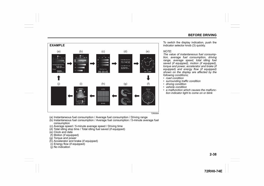
2-38
BEFORE DRIVING
72RH0-74E
72R0064
(a) Instantaneous fuel consumption / Average fuel consumption / Driving range(b) Instantaneous fuel consumption / Average fuel consumption / 5-minute average fuel
consumption(c) Average speed / 5-minute average speed / Driving time(d) Total idling stop time / Total idling fuel saved (if equipped)(e) Clock and date(f) Motion (if equipped)(g) Torque and power(h) Accelerator and brake (if equipped)(i) Energy flow (if equipped)(j) No indication
(j) (i)
(a) (b) (c)
(f)
(e)(d)
(g)(h)
EXAMPLETo switch the display indication, push theindicator selector knob (3) quickly.
NOTE:The value of instantaneous fuel consump-tion, average fuel consumption, drivingrange, average speed, total idling fuelsaved (if equipped), motion (if equipped),torque and power, accelerator and brake (ifequipped) and energy flow (if equipped)shown on the display are affected by thefollowing conditions; • road condition• surrounding traffic condition• driving condition• vehicle condition• a malfunction which causes the malfunc-
tion indicator light to come on or blink
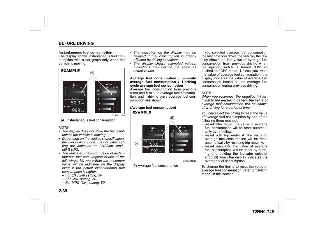
2-39
BEFORE DRIVING
72RH0-74E
Instantaneous fuel consumptionThe display shows instantaneous fuel con-sumption with a bar graph only when thevehicle is moving.
52RM21070
(4) Instantaneous fuel consumption
NOTE:• The display does not show the bar graph
unless the vehicle is moving.• Depending on the vehicle’s specification,
the fuel consumption units of initial set-ting are indicated as L/100km, km/L,MPG (UK).
• The indicated maximum value of instan-taneous fuel consumption is one of thefollowings. No more than the maximumvalue will be indicated on the displayeven if the actual instantaneous fuelconsumption is higher.– For L/100km setting: 30– For km/L setting: 50– For MPG (UK) setting: 80
• The indication on the display may bedelayed if fuel consumption is greatlyaffected by driving conditions.
• The display shows estimated values.Indications may not be the same asactual values.
Average fuel consumption / 5-minuteaverage fuel consumption / 1-drivingcycle average fuel consumptionAverage fuel consumption from previousreset and 5-minute average fuel consump-tion, and 1-driving cycle average fuel con-sumption are shown.
(Average fuel consumption)
52RM21080
(5) Average fuel consumption
If you selected average fuel consumptionthe last time you drove the vehicle, the dis-play shows the last value of average fuelconsumption from previous driving whenthe ignition switch is turned “ON” orpushed to “ON” mode. Unless you resetthe value of average fuel consumption, thedisplay indicates the value of average fuelconsumption based on the average fuelconsumption during previous driving.
NOTE:When you reconnect the negative (–) ter-minal to the lead-acid battery, the value ofaverage fuel consumption will be shownafter driving for a period of time.
You can select the timing to reset the valueof average fuel consumption by one of thefollowing three methods; • Reset after refuel: the value of average
fuel consumption will be reset automati-cally by refueling.
• Reset with trip meter A: the value ofaverage fuel consumption will be resetautomatically by resetting trip meter A.
• Reset manually: the value of averagefuel consumption will be reset by push-ing and holding the indicator selectorknob (3) when the display indicates theaverage fuel consumption.
To change the timing to reset the value ofaverage fuel consumption, refer to “Settingmode” in this section.
(4)EXAMPLE
(5)
(5)
EXAMPLE
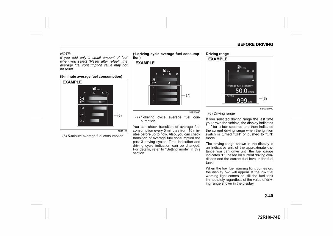
2-40
BEFORE DRIVING
72RH0-74E
NOTE:If you add only a small amount of fuelwhen you select “Reset after refuel”, theaverage fuel consumption value may notbe reset.
(5-minute average fuel consumption)
72R0136
(6) 5-minute average fuel consumption
(1-driving cycle average fuel consump-tion)
52R30840
(7) 1-driving cycle average fuel con-sumption
You can check transition of average fuelconsumption every 5 minutes from 15 min-utes before up to now. Also, you can checktransition of average fuel consumption thepast 3 driving cycles. Time indication anddriving cycle indication can be changed.For details, refer to “Setting mode” in thissection.
Driving range
52RM21090
(8) Driving range
If you selected driving range the last timeyou drove the vehicle, the display indicates“---” for a few seconds and then indicatesthe current driving range when the ignitionswitch is turned “ON” or pushed to “ON”mode.
The driving range shown in the display isan indicative unit of the approximate dis-tance you can drive until the fuel gaugeindicates “E”, based on current driving con-ditions and the current fuel level in the fueltank.
When the low fuel warning light comes on,the display “---” will appear. If the low fuelwarning light comes on, fill the fuel tankimmediately regardless of the value of driv-ing range shown in the display.
(6)
EXAMPLE
(7)
EXAMPLE
(8)
EXAMPLE
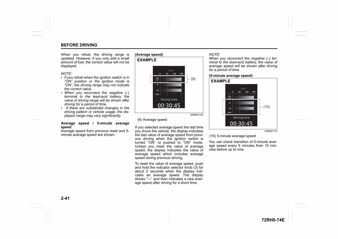
2-41
BEFORE DRIVING
72RH0-74E
When you refuel, the driving range isupdated. However, if you only add a smallamount of fuel, the correct value will not bedisplayed.
NOTE:• If you refuel when the ignition switch is in
“ON” position or the ignition mode is“ON”, the driving range may not indicatethe correct value.
• When you reconnect the negative (–)terminal to the lead-acid battery, thevalue of driving range will be shown afterdriving for a period of time.
• If there are substantial changes in thedriving pattern or vehicle usage, the dis-played range may vary significantly.
Average speed / 5-minute averagespeedAverage speed from previous reset and 5-minute average speed are shown.
(Average speed)
52RM21100
(9) Average speed
If you selected average speed the last timeyou drove the vehicle, the display indicatesthe last value of average speed from previ-ous driving when the ignition switch isturned “ON” or pushed to “ON” mode.Unless you reset the value of averagespeed, the display indicates the value ofaverage speed which includes averagespeed during previous driving.
To reset the value of average speed, pushand hold the indicator selector knob (3) forabout 2 seconds when the display indi-cates an average speed. The displayshows “---” and then indicates a new aver-age speed after driving for a short time.
NOTE:When you reconnect the negative (–) ter-minal to the lead-acid battery, the value ofaverage speed will be shown after drivingfor a period of time.
(5-minute average speed)
52RM21110
(10) 5-minute average speed
You can check transition of 5-minute aver-age speed every 5 minutes from 10 min-utes before up to now.
(9)
EXAMPLE
(10)
EXAMPLE
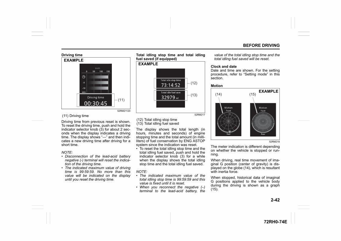
2-42
BEFORE DRIVING
72RH0-74E
Driving time
52RM21120
(11) Driving time
Driving time from previous reset is shown.To reset the driving time, push and hold theindicator selector knob (3) for about 2 sec-onds when the display indicates a drivingtime. The display shows “---” and then indi-cates a new driving time after driving for ashort time.
NOTE:• Disconnection of the lead-acid battery
negative (-) terminal will reset the indica-tion of the driving time.
• The indicated maximum value of drivingtime is 99:59:59. No more than thisvalue will be indicated on the displayuntil you reset the driving time.
Total idling stop time and total idlingfuel saved (if equipped)
52RM217
(12) Total idling stop time(13) Total idling fuel saved
The display shows the total length (inhours, minutes and seconds) of enginestopping time and the total amount (in milli-liters) of fuel conservation by ENG ASTOPsystem since the indication was reset.• To reset the total idling stop time and the
total idling fuel saved, push and hold theindicator selector knob (3) for a whilewhen the display shows the total idlingstop time and the total idling fuel saved.
NOTE:• The indicated maximum value of the
total idling stop time is 99:59:59 and thisvalue is fixed until it is reset.
• When you reconnect the negative (–)terminal to the lead-acid battery, the
value of the total idling stop time and thetotal idling fuel saved will be reset.
Clock and dateDate and time are shown. For the settingprocedure, refer to “Setting mode” in thissection.
Motion
52RM218
The meter indication is different dependingon whether the vehicle is stopped or run-ning.
When driving, real time movement of ima-ginal G position (center of gravity) is dis-played on the globe (14), which is resultantwith inertia force.
When stopped, historical data of imaginalG positions applied to the vehicle bodyduring the driving is shown as a graph(15).
(11)
EXAMPLE
(13)
(12)
EXAMPLE
(14) (15)EXAMPLE
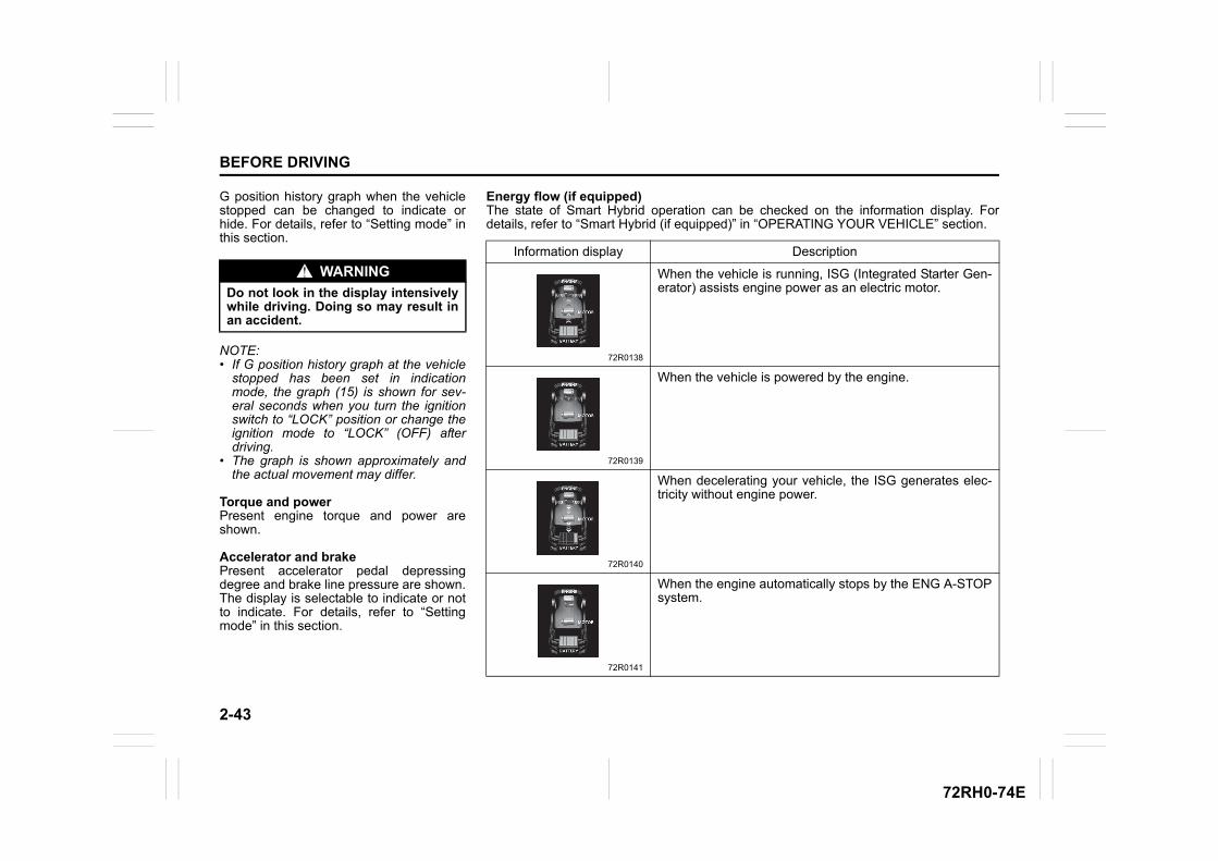
2-43
BEFORE DRIVING
72RH0-74E
G position history graph when the vehiclestopped can be changed to indicate orhide. For details, refer to “Setting mode” inthis section.
NOTE:• If G position history graph at the vehicle
stopped has been set in indicationmode, the graph (15) is shown for sev-eral seconds when you turn the ignitionswitch to “LOCK” position or change theignition mode to “LOCK” (OFF) afterdriving.
• The graph is shown approximately andthe actual movement may differ.
Torque and powerPresent engine torque and power areshown.
Accelerator and brakePresent accelerator pedal depressingdegree and brake line pressure are shown.The display is selectable to indicate or notto indicate. For details, refer to “Settingmode” in this section.
WARNING
Do not look in the display intensivelywhile driving. Doing so may result inan accident.
Energy flow (if equipped)The state of Smart Hybrid operation can be checked on the information display. Fordetails, refer to “Smart Hybrid (if equipped)” in “OPERATING YOUR VEHICLE” section.
Information display Description
72R0138
When the vehicle is running, ISG (Integrated Starter Gen-erator) assists engine power as an electric motor.
72R0139
When the vehicle is powered by the engine.
72R0140
When decelerating your vehicle, the ISG generates elec-tricity without engine power.
72R0141
When the engine automatically stops by the ENG A-STOPsystem.
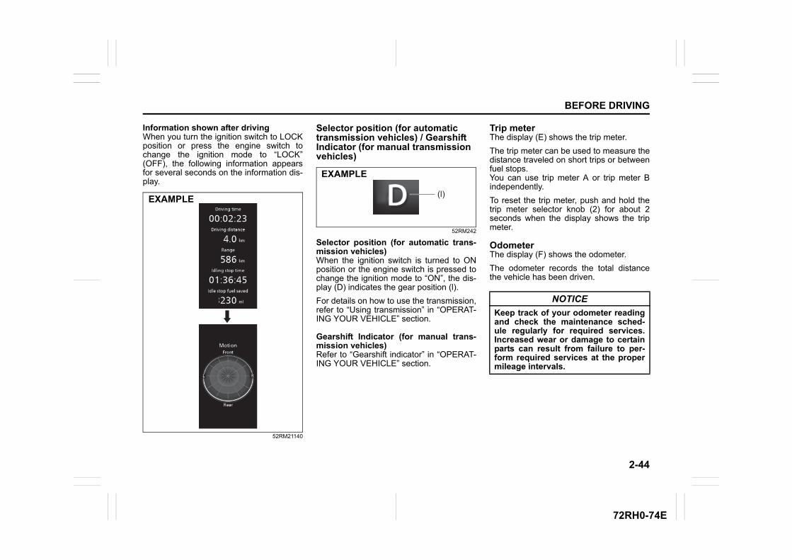
2-44
BEFORE DRIVING
72RH0-74E
Information shown after drivingWhen you turn the ignition switch to LOCKposition or press the engine switch tochange the ignition mode to “LOCK”(OFF), the following information appearsfor several seconds on the information dis-play.
52RM21140
Selector position (for automatic transmission vehicles) / Gearshift Indicator (for manual transmission vehicles)
52RM242
Selector position (for automatic trans-mission vehicles)When the ignition switch is turned to ONposition or the engine switch is pressed tochange the ignition mode to “ON”, the dis-play (D) indicates the gear position (l).
For details on how to use the transmission,refer to “Using transmission” in “OPERAT-ING YOUR VEHICLE” section.
Gearshift Indicator (for manual trans-mission vehicles)Refer to “Gearshift indicator” in “OPERAT-ING YOUR VEHICLE” section.
Trip meterThe display (E) shows the trip meter.
The trip meter can be used to measure thedistance traveled on short trips or betweenfuel stops.You can use trip meter A or trip meter Bindependently.
To reset the trip meter, push and hold thetrip meter selector knob (2) for about 2seconds when the display shows the tripmeter.
OdometerThe display (F) shows the odometer.
The odometer records the total distancethe vehicle has been driven.
EXAMPLE(l)
EXAMPLE
NOTICE
Keep track of your odometer readingand check the maintenance sched-ule regularly for required services.Increased wear or damage to certainparts can result from failure to per-form required services at the propermileage intervals.
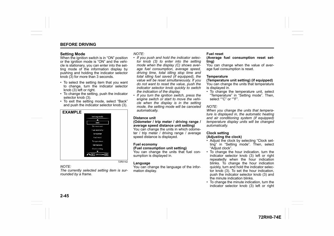
2-45
BEFORE DRIVING
72RH0-74E
Setting ModeWhen the ignition switch is in “ON” positionor the ignition mode is “ON” and the vehi-cle is stationary, you can enter into the set-ting mode of the information display bypushing and holding the indicator selectorknob (3) for more than 3 seconds.
• To select the setting item that you wantto change, turn the indicator selectorknob (3) left or right.
• To change the setting, push the indicatorselector knob (3).
• To exit the setting mode, select “Back”and push the indicator selector knob (3).
72R0142
NOTE:The currently selected setting item is sur-rounded by a frame.
NOTE:• If you push and hold the indicator selec-
tor knob (3) to enter into the settingmode when the display (C) shows aver-age fuel consumption, average speed,driving time, total idling stop time andtotal idling fuel saved (if equipped), thevalue will be reset simultaneously. If youdo not want to reset the value, push theindicator selector knob quickly to switchthe indication of the display.
• If you turn the ignition switch, press theengine switch or start to move the vehi-cle when the display is in the settingmode, the setting mode will be canceledautomatically.
Distance unit(Odometer / trip meter / driving range /average speed distance unit setting)You can change the units in which odome-ter / trip meter / driving range / averagespeed distance is displayed.
Fuel economy(Fuel consumption unit setting)You can change the units that fuel con-sumption is displayed in.
LanguageYou can change the language of the infor-mation display.
Fuel reset(Average fuel consumption reset set-ting)You can change when the value of aver-age fuel consumption is reset.
Temperature(Temperature unit setting) (if equipped)You can change the units that temperatureis displayed in.• To change the temperature unit, select
“Temperature” in “Setting mode”. Then,select “°C” or “°F”.
NOTE:When you change the units that tempera-ture is displayed in, the automatic heatingand air conditioning system (if equipped)temperature display units will be changedautomatically.
Clock setting(Adjusting the clock)• Adjust the clock by selecting “Clock set-
ting” in “Setting mode”. Then, select“Adjust clock”.
• To change the hour indication, turn theindicator selector knob (3) left or rightrepeatedly when the hour indicationblinks. To change the hour indicationquickly, turn and hold the indicator selec-tor knob (3). To set the hour indication,push the indicator selector knob (3) andthe minute indication blinks.
• To change the minute indication, turn theindicator selector knob (3) left or right
EXAMPLE
2-46
BEFORE DRIVING
72RH0-74E
repeatedly when the minute indicationblinks. To change the minute indicationquickly, turn and hold the indicator selec-tor knob (3). To set the minute indication,push the indicator selector knob (3).
(Selecting 12H/24H format)• Switch the time indication between 12-
hour and 24-hour format by selecting“Clock setting” in “Setting mode”. Then,select “12H” or “24H”.
(Adjusting the date)• Adjust the date by selecting “Clock set-
ting” in “Setting mode”. Then select“Adjust date”.
• To adjust year, month and day, operatethe indicator selector knob (3) in thesame way as adjusting the clock.
Door lock (Door lock setting)(Door unlock)• All Doors:
Unlock all doors by turning the key, oroperating the keyless entry systemtransmitter, keyless push start systemremote controller or request switch once
• Driver Door: Unlock all doors by turning the key, oroperating the keyless entry systemtransmitter, keyless push start systemremote controller or request switch twice(default setting)
(Auto lock)• Manual Lock:
Disable the automatic door locking func-tion
• Speed Syncro: Lock all doors when the vehicle speedreaches 15 km/h (default setting)
• Shift Syncro: (For automatic transmission vehicle) Lock all doors when the gearshift lever isin other than “P”.
(Auto unlock)• Syncro Off:
Disable the automatic door unlockingfunction (default setting for the vehiclewith the keyless push start system)
• Shift Syncro: (For automatic transmission vehicle) Unlock all doors when the gearshift leveris moved to the “P” from other position.
• IG-OFF Sync: Unlock all doors when the key is pulledout from the ignition switch or the engineswitch is pressed to change the ignitionmode to LOCK (OFF) (default setting forthe vehicle without the keyless pushstart system)
(Alarm)• You can turn off or on the siren sound
when the door(s) is(are) locked orunlocked.
Lights(Lane change setting)The turn signal and its indicator can be setwhether they flash three times even if youreturn the turn signal control lever immedi-ately after moving it.
Antitheft(Shock sensor system setting)You can change the on/off of the shocksensor.
(Shock sensor P setting)You can adjust the pre-warning sensitivityof shock sensor.
(Shock sensor F setting)You can adjust the full blast warning sensi-tivity of shock sensor.
IS A/C(ENG A-STOP system setting) (if equipped)• When the automatic air conditioning sys-
tem is turned ON (if equipped), you canselect one of the following engine autostop settings.– Standard– Economy– Comfort
• When “Economy” is selected, comparedwith “Standard” the engine auto stopcondition will occur more frequently, thestop time will be longer, leading to reduc-tion of fuel consumption.
• When “Comfort” is selected, comparedwith “Standard” the engine auto stop
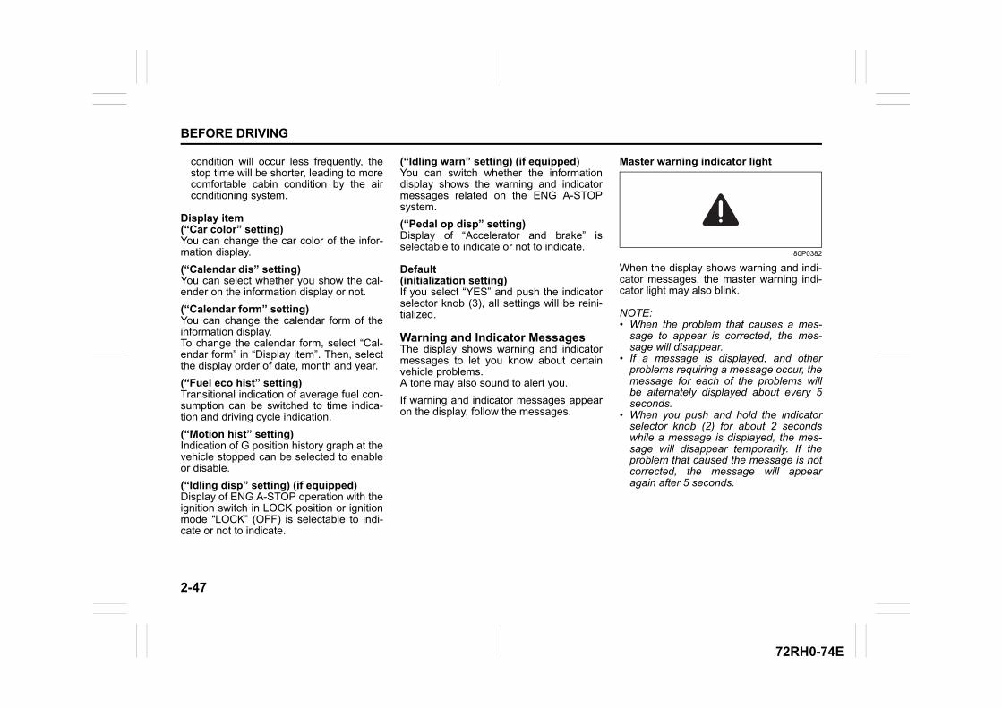
2-47
BEFORE DRIVING
72RH0-74E
condition will occur less frequently, thestop time will be shorter, leading to morecomfortable cabin condition by the airconditioning system.
Display item(“Car color” setting)You can change the car color of the infor-mation display.
(“Calendar dis” setting)You can select whether you show the cal-ender on the information display or not.
(“Calendar form” setting)You can change the calendar form of theinformation display.To change the calendar form, select “Cal-endar form” in “Display item”. Then, selectthe display order of date, month and year.
(“Fuel eco hist” setting)Transitional indication of average fuel con-sumption can be switched to time indica-tion and driving cycle indication.
(“Motion hist” setting)Indication of G position history graph at thevehicle stopped can be selected to enableor disable.
(“Idling disp” setting) (if equipped)Display of ENG A-STOP operation with theignition switch in LOCK position or ignitionmode “LOCK” (OFF) is selectable to indi-cate or not to indicate.
(“Idling warn” setting) (if equipped)You can switch whether the informationdisplay shows the warning and indicatormessages related on the ENG A-STOPsystem.
(“Pedal op disp” setting)Display of “Accelerator and brake” isselectable to indicate or not to indicate.
Default(initialization setting)If you select “YES” and push the indicatorselector knob (3), all settings will be reini-tialized.
Warning and Indicator MessagesThe display shows warning and indicatormessages to let you know about certainvehicle problems.A tone may also sound to alert you.
If warning and indicator messages appearon the display, follow the messages.
Master warning indicator light
80P0382
When the display shows warning and indi-cator messages, the master warning indi-cator light may also blink.
NOTE:• When the problem that causes a mes-
sage to appear is corrected, the mes-sage will disappear.
• If a message is displayed, and otherproblems requiring a message occur, themessage for each of the problems willbe alternately displayed about every 5seconds.
• When you push and hold the indicatorselector knob (2) for about 2 secondswhile a message is displayed, the mes-sage will disappear temporarily. If theproblem that caused the message is notcorrected, the message will appearagain after 5 seconds.
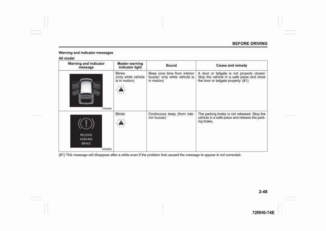
2-48
BEFORE DRIVING
72RH0-74E
Warning and indicator messages
All model
(#1) This message will disappear after a while even if the problem that caused the message to appear is not corrected.
Warning and indicator message
Master warning indicator light Sound Cause and remedy
72RS080
Blinks (only while vehicleis in motion)
Beep (one time from interiorbuzzer; only while vehicle isin motion)
A door or tailgate is not properly closed.Stop the vehicle in a safe place and closethe door or tailgate properly. (#1)
52RS005
Blinks Continuous beep (from inte-rior buzzer)
The parking brake is not released. Stop thevehicle in a safe place and release the park-ing brake.
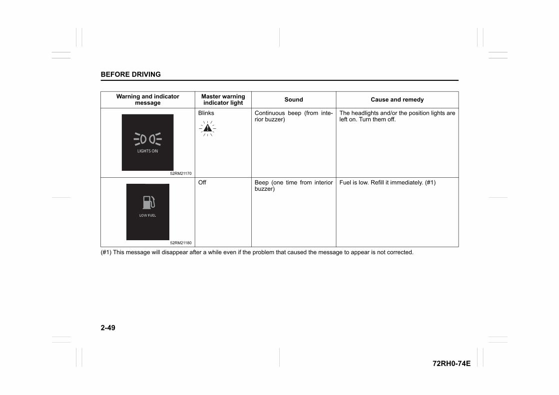
2-49
BEFORE DRIVING
72RH0-74E
(#1) This message will disappear after a while even if the problem that caused the message to appear is not corrected.
Warning and indicator message
Master warning indicator light Sound Cause and remedy
52RM21170
Blinks Continuous beep (from inte-rior buzzer)
The headlights and/or the position lights areleft on. Turn them off.
52RM21180
Off Beep (one time from interiorbuzzer)
Fuel is low. Refill it immediately. (#1)
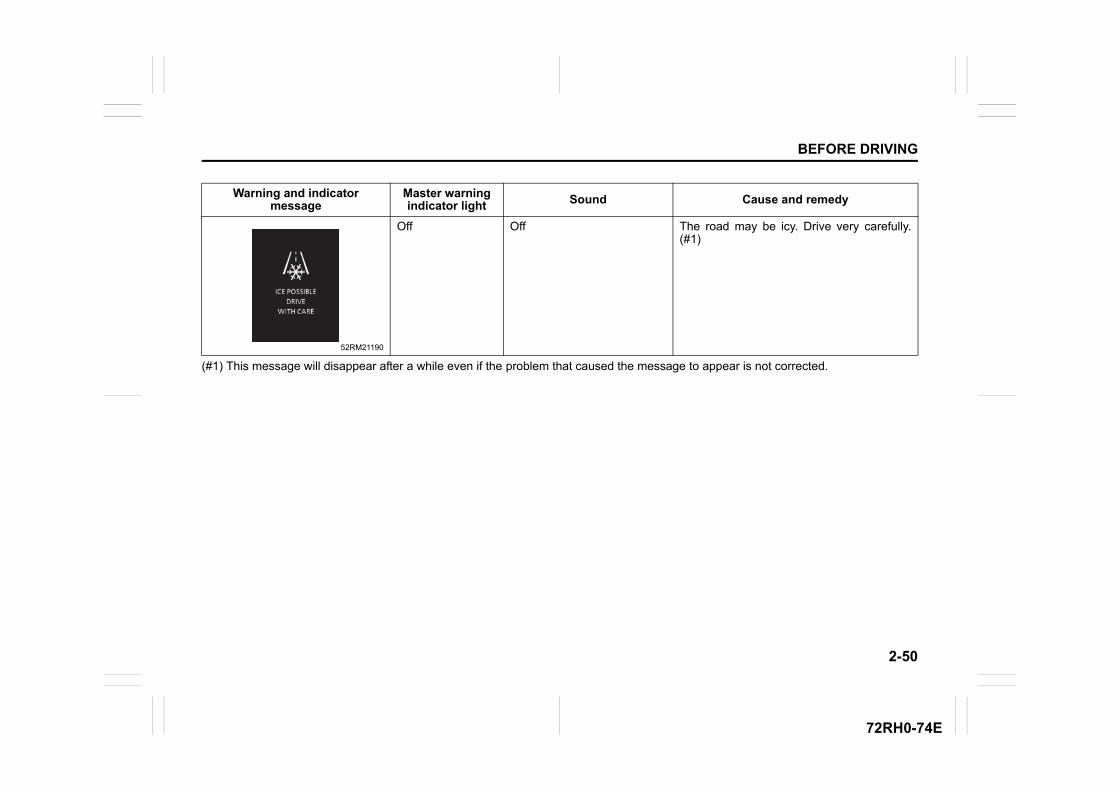
2-50
BEFORE DRIVING
72RH0-74E
(#1) This message will disappear after a while even if the problem that caused the message to appear is not corrected.
Warning and indicator message
Master warning indicator light Sound Cause and remedy
52RM21190
Off Off The road may be icy. Drive very carefully.(#1)
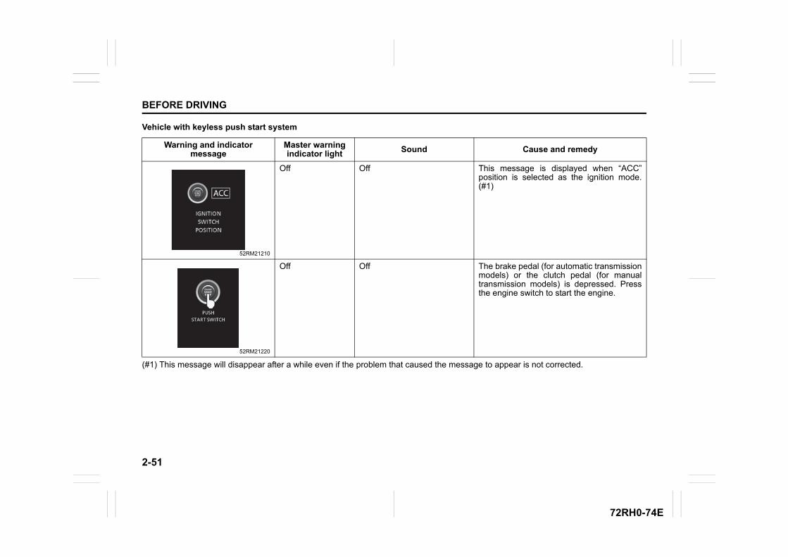
2-51
BEFORE DRIVING
72RH0-74E
Vehicle with keyless push start system
(#1) This message will disappear after a while even if the problem that caused the message to appear is not corrected.
Warning and indicator message
Master warning indicator light Sound Cause and remedy
52RM21210
Off Off This message is displayed when “ACC”position is selected as the ignition mode.(#1)
52RM21220
Off Off The brake pedal (for automatic transmissionmodels) or the clutch pedal (for manualtransmission models) is depressed. Pressthe engine switch to start the engine.
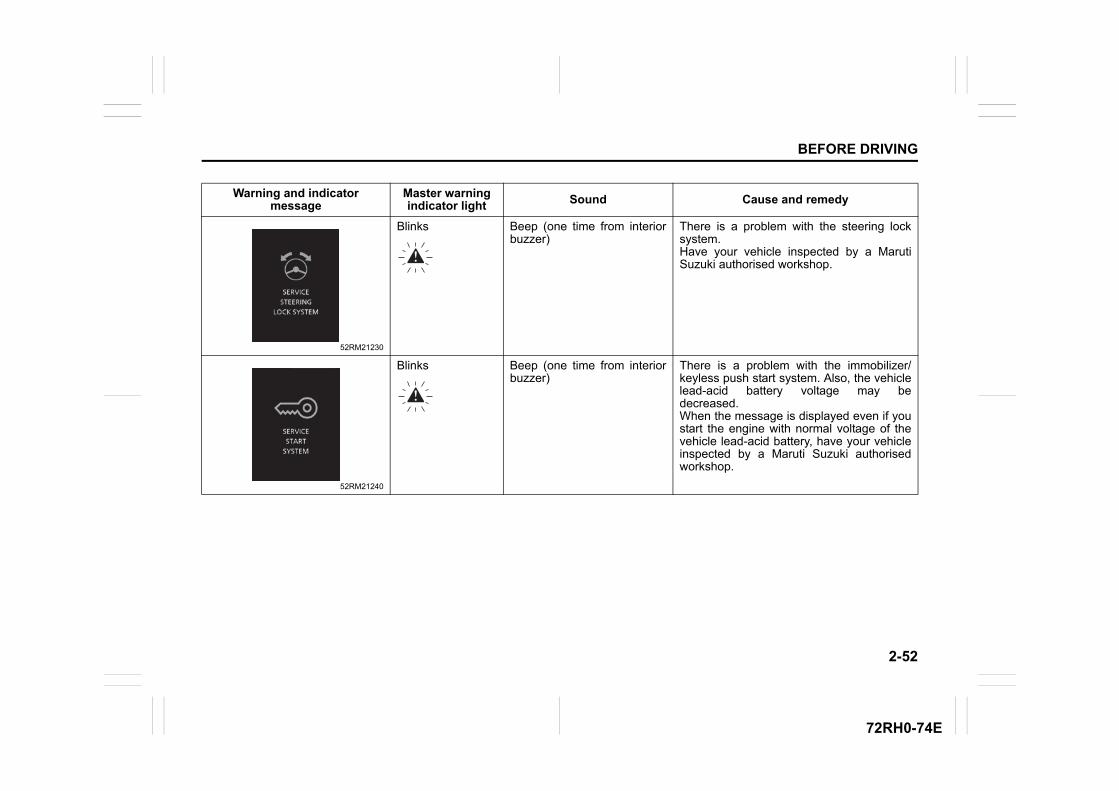
2-52
BEFORE DRIVING
72RH0-74E
Warning and indicator message
Master warning indicator light Sound Cause and remedy
52RM21230
Blinks Beep (one time from interiorbuzzer)
There is a problem with the steering locksystem.Have your vehicle inspected by a MarutiSuzuki authorised workshop.
52RM21240
Blinks Beep (one time from interiorbuzzer)
There is a problem with the immobilizer/keyless push start system. Also, the vehiclelead-acid battery voltage may bedecreased.When the message is displayed even if youstart the engine with normal voltage of thevehicle lead-acid battery, have your vehicleinspected by a Maruti Suzuki authorisedworkshop.
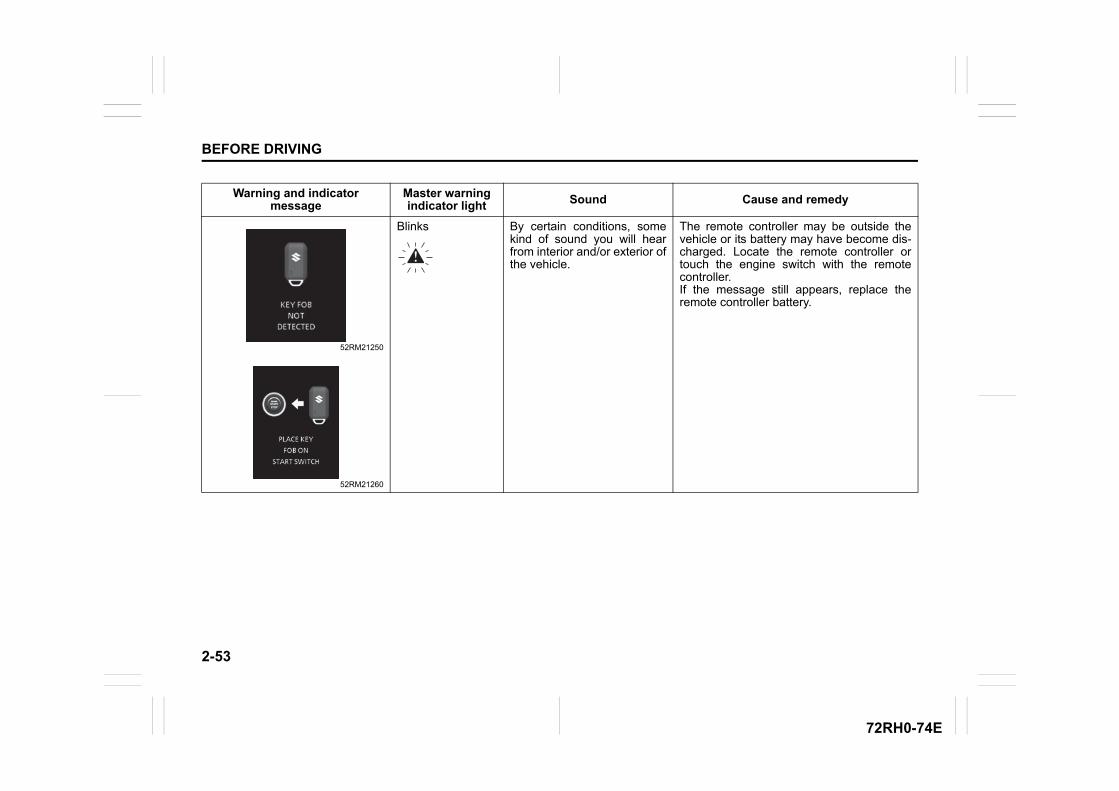
2-53
BEFORE DRIVING
72RH0-74E
Warning and indicator message
Master warning indicator light Sound Cause and remedy
52RM21250
52RM21260
Blinks By certain conditions, somekind of sound you will hearfrom interior and/or exterior ofthe vehicle.
The remote controller may be outside thevehicle or its battery may have become dis-charged. Locate the remote controller ortouch the engine switch with the remotecontroller.If the message still appears, replace theremote controller battery.
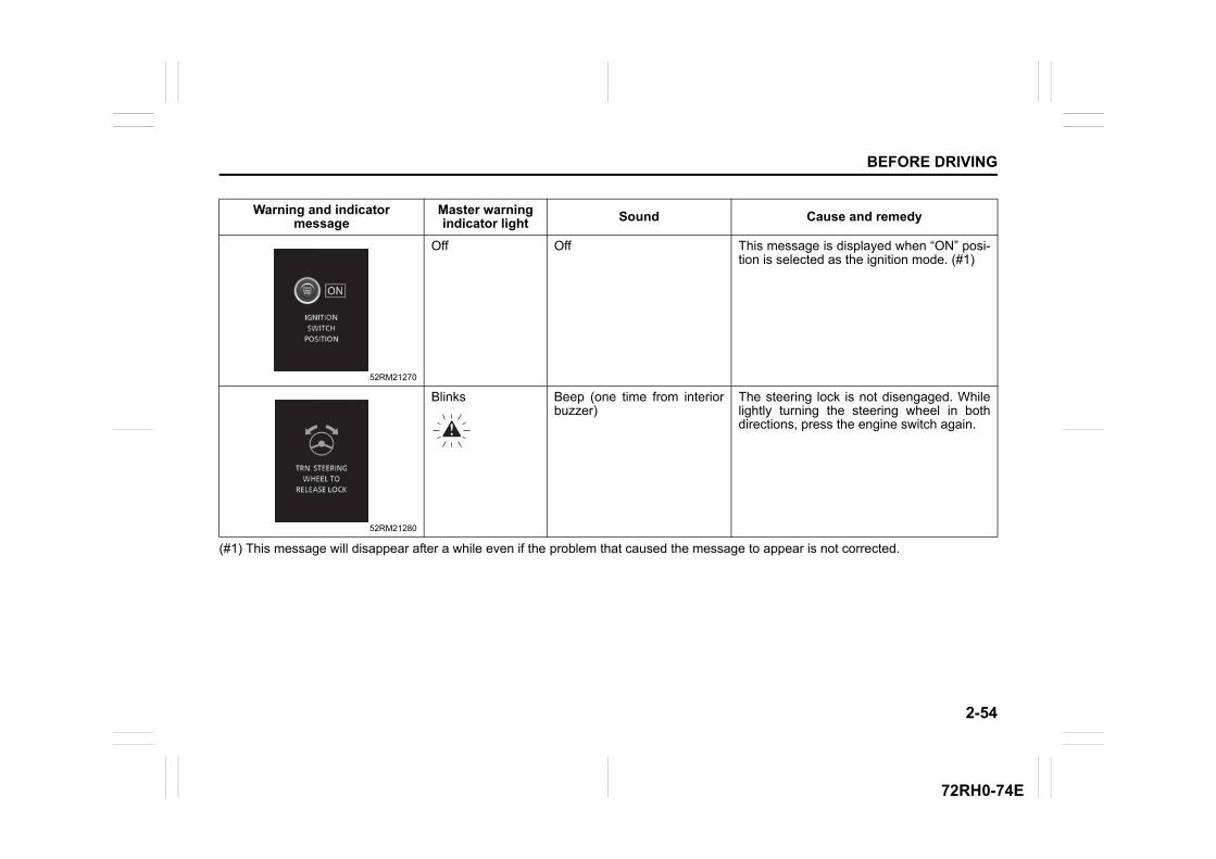
2-54
BEFORE DRIVING
72RH0-74E
(#1) This message will disappear after a while even if the problem that caused the message to appear is not corrected.
Warning and indicator message
Master warning indicator light Sound Cause and remedy
52RM21270
Off Off This message is displayed when “ON” posi-tion is selected as the ignition mode. (#1)
52RM21280
Blinks Beep (one time from interiorbuzzer)
The steering lock is not disengaged. Whilelightly turning the steering wheel in bothdirections, press the engine switch again.
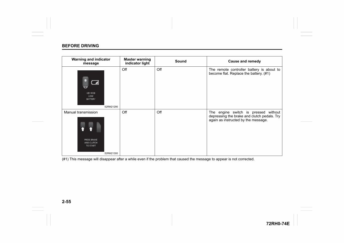
2-55
BEFORE DRIVING
72RH0-74E
(#1) This message will disappear after a while even if the problem that caused the message to appear is not corrected.
Warning and indicator message
Master warning indicator light Sound Cause and remedy
52RM21290
Off Off The remote controller battery is about tobecome flat. Replace the battery. (#1)
Manual transmission
52RM21300
Off Off The engine switch is pressed withoutdepressing the brake and clutch pedals. Tryagain as instructed by the message.
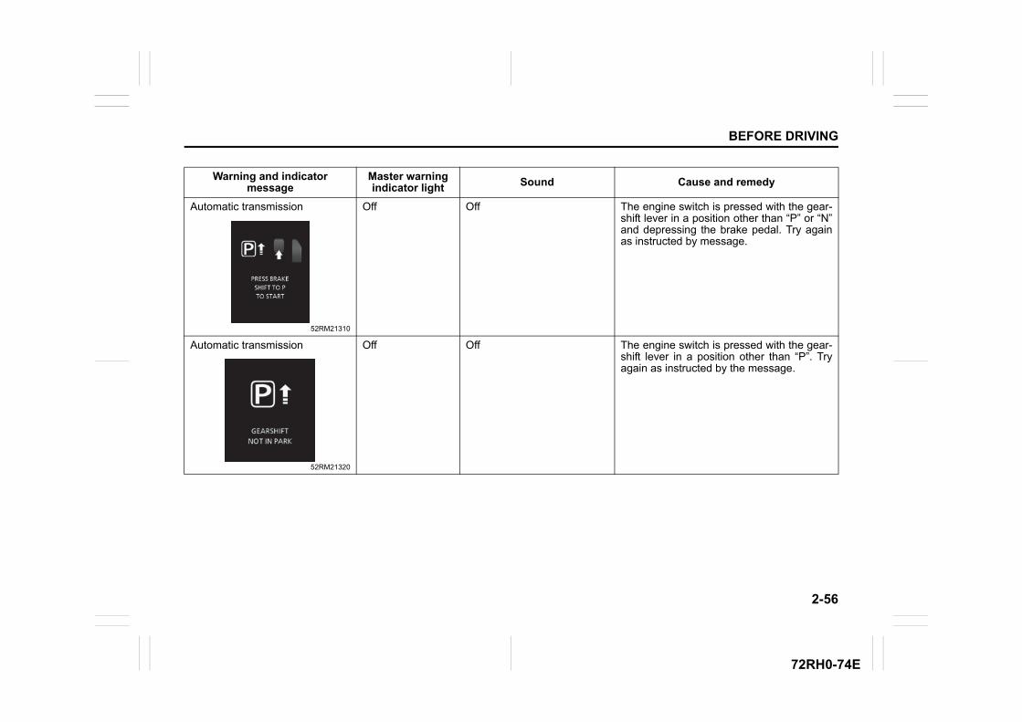
2-56
BEFORE DRIVING
72RH0-74E
Warning and indicator message
Master warning indicator light Sound Cause and remedy
Automatic transmission
52RM21310
Off Off The engine switch is pressed with the gear-shift lever in a position other than “P” or “N”and depressing the brake pedal. Try againas instructed by message.
Automatic transmission
52RM21320
Off Off The engine switch is pressed with the gear-shift lever in a position other than “P”. Tryagain as instructed by the message.
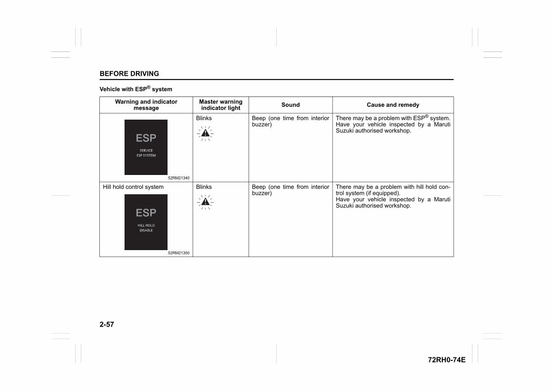
2-57
BEFORE DRIVING
72RH0-74E
Vehicle with ESP® system
Warning and indicator message
Master warning indicator light Sound Cause and remedy
52RM21340
Blinks Beep (one time from interiorbuzzer)
There may be a problem with ESP® system.Have your vehicle inspected by a MarutiSuzuki authorised workshop.
Hill hold control system
52RM21350
Blinks Beep (one time from interiorbuzzer)
There may be a problem with hill hold con-trol system (if equipped).Have your vehicle inspected by a MarutiSuzuki authorised workshop.
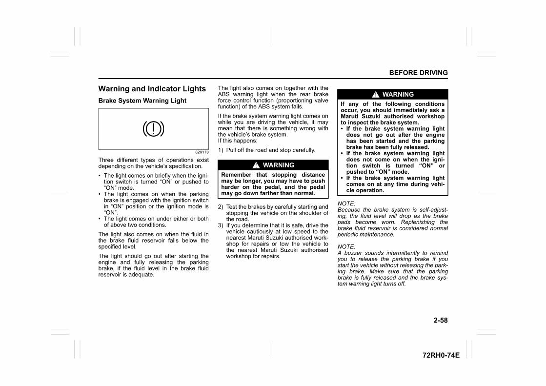
2-58
BEFORE DRIVING
72RH0-74E
Warning and Indicator Lights
Brake System Warning Light
82K170
Three different types of operations existdepending on the vehicle’s specification.
• The light comes on briefly when the igni-tion switch is turned “ON” or pushed to“ON” mode.
• The light comes on when the parkingbrake is engaged with the ignition switchin “ON” position or the ignition mode is“ON”.
• The light comes on under either or bothof above two conditions.
The light also comes on when the fluid inthe brake fluid reservoir falls below thespecified level.
The light should go out after starting theengine and fully releasing the parkingbrake, if the fluid level in the brake fluidreservoir is adequate.
The light also comes on together with theABS warning light when the rear brakeforce control function (proportioning valvefunction) of the ABS system fails.
If the brake system warning light comes onwhile you are driving the vehicle, it maymean that there is something wrong withthe vehicle’s brake system. If this happens:
1) Pull off the road and stop carefully.
2) Test the brakes by carefully starting andstopping the vehicle on the shoulder ofthe road.
3) If you determine that it is safe, drive thevehicle cautiously at low speed to thenearest Maruti Suzuki authorised work-shop for repairs or tow the vehicle tothe nearest Maruti Suzuki authorisedworkshop for repairs.
NOTE:Because the brake system is self-adjust-ing, the fluid level will drop as the brakepads become worn. Replenishing thebrake fluid reservoir is considered normalperiodic maintenance.
NOTE:A buzzer sounds intermittently to remindyou to release the parking brake if youstart the vehicle without releasing the park-ing brake. Make sure that the parkingbrake is fully released and the brake sys-tem warning light turns off.
WARNING
Remember that stopping distancemay be longer, you may have to pushharder on the pedal, and the pedalmay go down farther than normal.
WARNING
If any of the following conditionsoccur, you should immediately ask aMaruti Suzuki authorised workshopto inspect the brake system.• If the brake system warning light
does not go out after the enginehas been started and the parkingbrake has been fully released.
• If the brake system warning lightdoes not come on when the igni-tion switch is turned “ON” orpushed to “ON” mode.
• If the brake system warning lightcomes on at any time during vehi-cle operation.
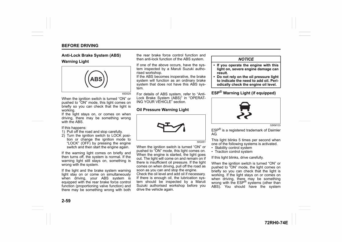
2-59
BEFORE DRIVING
72RH0-74E
Anti-Lock Brake System (ABS)
Warning Light
65D529
When the ignition switch is turned “ON” orpushed to “ON” mode, this light comes onbriefly so you can check that the light isworking.If the light stays on, or comes on whendriving, there may be something wrongwith the ABS.
If this happens: 1) Pull off the road and stop carefully.2) Turn the ignition switch to LOCK posi-
tion or change the ignition mode to“LOCK” (OFF) by pressing the engineswitch and then start the engine again.
If the warning light comes on briefly andthen turns off, the system is normal. If thewarning light still stays on, something iswrong with the system.
If the light and the brake system warninglight stay on or come on simultaneouslywhen driving, your ABS system isequipped with the rear brake force controlfunction (proportioning valve function) andthere may be something wrong with both
the rear brake force control function andthen anti-lock function of the ABS system.
If one of the above occurs, have the sys-tem inspected by a Maruti Suzuki autho-rised workshop.If the ABS becomes inoperative, the brakesystem will function as an ordinary brakesystem that does not have this ABS sys-tem.
For details of ABS system, refer to “Anti-Lock Brake System (ABS)” in “OPERAT-ING YOUR VEHICLE” section.
Oil Pressure Warning Light
50G051
When the ignition switch is turned “ON” orpushed to “ON” mode, this light comes on.When the engine is started, the light goesout. The light will come on and remain on ifthere is insufficient oil pressure. If the lightcomes on when driving, pull off the road assoon as you can and stop the engine. Check the oil level and add oil if necessary.If there is enough oil, the lubrication sys-tem should be inspected by a MarutiSuzuki authorised workshop before youdrive the vehicle again.
ESP® Warning Light (if equipped)
52KM133
ESP® is a registered trademark of DaimlerAG.
This light blinks 5 times per second whenone of the following systems is activated.• Stability control system• Traction control system
If this light blinks, drive carefully.
When the ignition switch is turned “ON” orpushed to “ON” mode, the light comes onbriefly so you can check that the light isworking. If the light stays on or comes onwhen driving, there may be somethingwrong with the ESP® systems (other thanABS). You should have the system
ABS
NOTICE
• If you operate the engine with thislight on, severe engine damage canresult.
• Do not rely on the oil pressure lightto indicate the need to add oil. Peri-odically check the engine oil level.
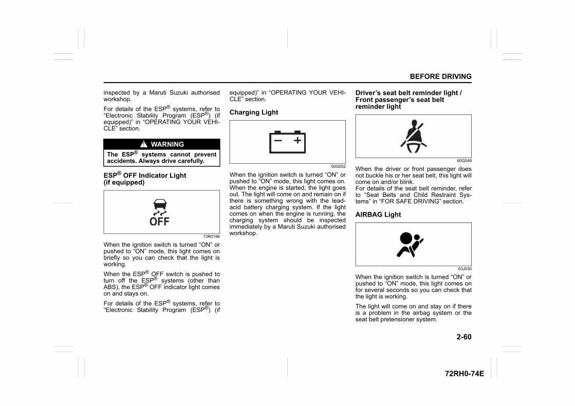
2-60
BEFORE DRIVING
72RH0-74E
inspected by a Maruti Suzuki authorisedworkshop.
For details of the ESP® systems, refer to“Electronic Stability Program (ESP®) (ifequipped)” in “OPERATING YOUR VEHI-CLE” section.
ESP® OFF Indicator Light (if equipped)
73R0196
When the ignition switch is turned “ON” orpushed to “ON” mode, this light comes onbriefly so you can check that the light isworking.
When the ESP® OFF switch is pushed toturn off the ESP® systems (other thanABS), the ESP® OFF indicator light comeson and stays on.
For details of the ESP® systems, refer to“Electronic Stability Program (ESP®) (if
equipped)” in “OPERATING YOUR VEHI-CLE” section.
Charging Light
50G052
When the ignition switch is turned “ON” orpushed to “ON” mode, this light comes on.When the engine is started, the light goesout. The light will come on and remain on ifthere is something wrong with the lead-acid battery charging system. If the lightcomes on when the engine is running, thecharging system should be inspectedimmediately by a Maruti Suzuki authorisedworkshop.
Driver’s seat belt reminder light /Front passenger’s seat belt reminder light
60G049
When the driver or front passenger doesnot buckle his or her seat belt, this light willcome on and/or blink.For details of the seat belt reminder, referto “Seat Belts and Child Restraint Sys-tems” in “FOR SAFE DRIVING” section.
AIRBAG Light
63J030
When the ignition switch is turned “ON” orpushed to “ON” mode, this light comes onfor several seconds so you can check thatthe light is working.
The light will come on and stay on if thereis a problem in the airbag system or theseat belt pretensioner system.
WARNING
The ESP® systems cannot preventaccidents. Always drive carefully.
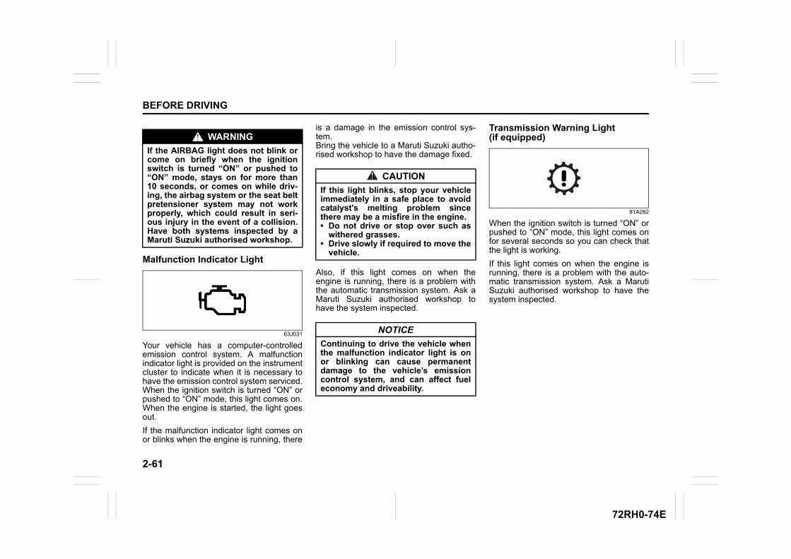
2-61
BEFORE DRIVING
72RH0-74E
Malfunction Indicator Light
63J031
Your vehicle has a computer-controlledemission control system. A malfunctionindicator light is provided on the instrumentcluster to indicate when it is necessary tohave the emission control system serviced.When the ignition switch is turned “ON” orpushed to “ON” mode, this light comes on.When the engine is started, the light goesout.
If the malfunction indicator light comes onor blinks when the engine is running, there
is a damage in the emission control sys-tem.Bring the vehicle to a Maruti Suzuki autho-rised workshop to have the damage fixed.
Also, if this light comes on when theengine is running, there is a problem withthe automatic transmission system. Ask aMaruti Suzuki authorised workshop tohave the system inspected.
Transmission Warning Light (if equipped)
81A262
When the ignition switch is turned “ON” orpushed to “ON” mode, this light comes onfor several seconds so you can check thatthe light is working.
If this light comes on when the engine isrunning, there is a problem with the auto-matic transmission system. Ask a MarutiSuzuki authorised workshop to have thesystem inspected.
WARNING
If the AIRBAG light does not blink orcome on briefly when the ignitionswitch is turned “ON” or pushed to“ON” mode, stays on for more than10 seconds, or comes on while driv-ing, the airbag system or the seat beltpretensioner system may not workproperly, which could result in seri-ous injury in the event of a collision.Have both systems inspected by aMaruti Suzuki authorised workshop.
CAUTION
If this light blinks, stop your vehicleimmediately in a safe place to avoidcatalyst's melting problem sincethere may be a misfire in the engine.• Do not drive or stop over such as
withered grasses.• Drive slowly if required to move the
vehicle.
NOTICE
Continuing to drive the vehicle whenthe malfunction indicator light is onor blinking can cause permanentdamage to the vehicle’s emissioncontrol system, and can affect fueleconomy and driveability.
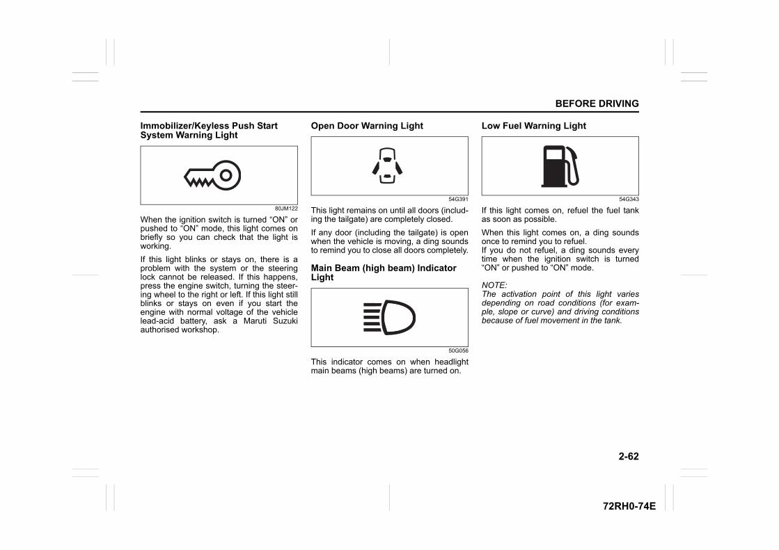
2-62
BEFORE DRIVING
72RH0-74E
Immobilizer/Keyless Push Start System Warning Light
80JM122
When the ignition switch is turned “ON” orpushed to “ON” mode, this light comes onbriefly so you can check that the light isworking.
If this light blinks or stays on, there is aproblem with the system or the steeringlock cannot be released. If this happens,press the engine switch, turning the steer-ing wheel to the right or left. If this light stillblinks or stays on even if you start theengine with normal voltage of the vehiclelead-acid battery, ask a Maruti Suzukiauthorised workshop.
Open Door Warning Light
54G391
This light remains on until all doors (includ-ing the tailgate) are completely closed.
If any door (including the tailgate) is openwhen the vehicle is moving, a ding soundsto remind you to close all doors completely.
Main Beam (high beam) Indicator Light
50G056
This indicator comes on when headlightmain beams (high beams) are turned on.
Low Fuel Warning Light
54G343
If this light comes on, refuel the fuel tankas soon as possible.
When this light comes on, a ding soundsonce to remind you to refuel.If you do not refuel, a ding sounds everytime when the ignition switch is turned“ON” or pushed to “ON” mode.
NOTE:The activation point of this light variesdepending on road conditions (for exam-ple, slope or curve) and driving conditionsbecause of fuel movement in the tank.
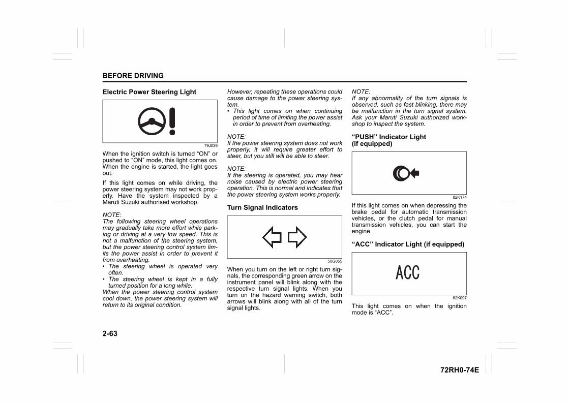
2-63
BEFORE DRIVING
72RH0-74E
Electric Power Steering Light
79J039
When the ignition switch is turned “ON” orpushed to “ON” mode, this light comes on.When the engine is started, the light goesout.
If this light comes on while driving, thepower steering system may not work prop-erly. Have the system inspected by aMaruti Suzuki authorised workshop.
NOTE:The following steering wheel operationsmay gradually take more effort while park-ing or driving at a very low speed. This isnot a malfunction of the steering system,but the power steering control system lim-its the power assist in order to prevent itfrom overheating.• The steering wheel is operated very
often.• The steering wheel is kept in a fully
turned position for a long while.When the power steering control systemcool down, the power steering system willreturn to its original condition.
However, repeating these operations couldcause damage to the power steering sys-tem.• This light comes on when continuing
period of time of limiting the power assistin order to prevent from overheating.
NOTE:If the power steering system does not workproperly, it will require greater effort tosteer, but you still will be able to steer.
NOTE:If the steering is operated, you may hearnoise caused by electric power steeringoperation. This is normal and indicates thatthe power steering system works properly.
Turn Signal Indicators
50G055
When you turn on the left or right turn sig-nals, the corresponding green arrow on theinstrument panel will blink along with therespective turn signal lights. When youturn on the hazard warning switch, botharrows will blink along with all of the turnsignal lights.
NOTE:If any abnormality of the turn signals isobserved, such as fast blinking, there maybe malfunction in the turn signal system.Ask your Maruti Suzuki authorized work-shop to inspect the system.
“PUSH” Indicator Light (if equipped)
82K174
If this light comes on when depressing thebrake pedal for automatic transmissionvehicles, or the clutch pedal for manualtransmission vehicles, you can start theengine.
“ACC” Indicator Light (if equipped)
82K097
This light comes on when the ignitionmode is “ACC”.
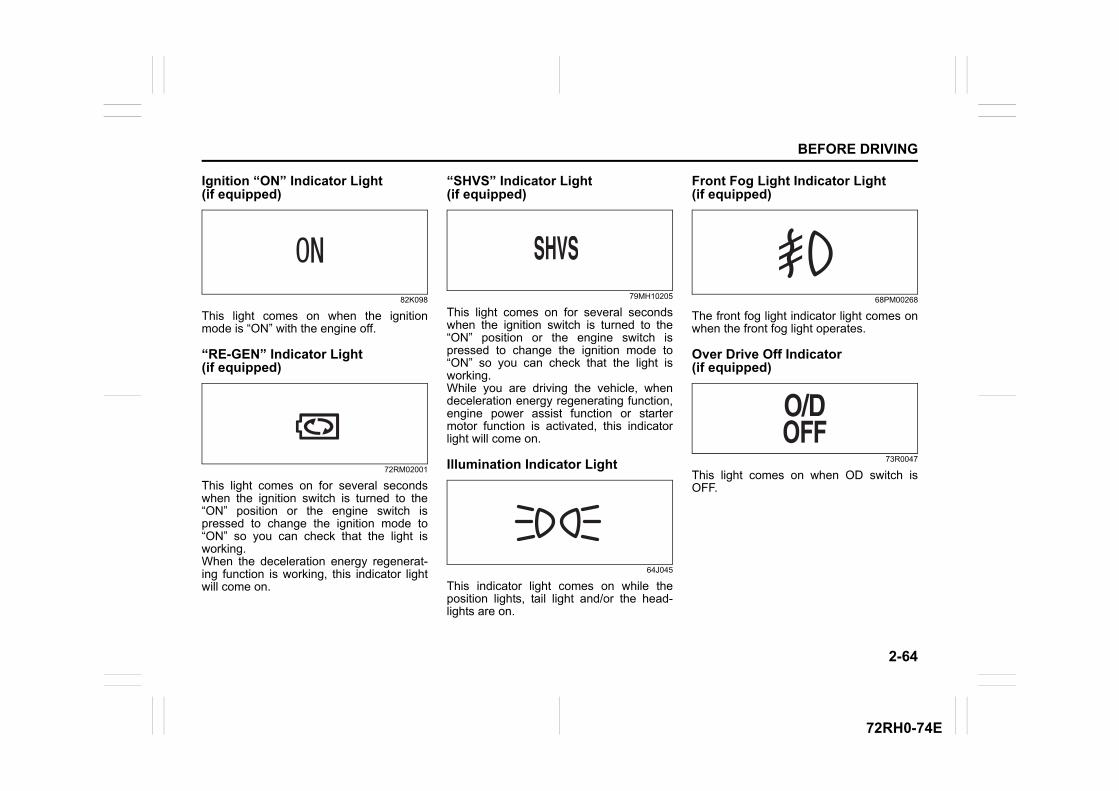
2-64
BEFORE DRIVING
72RH0-74E
Ignition “ON” Indicator Light (if equipped)
82K098
This light comes on when the ignitionmode is “ON” with the engine off.
“RE-GEN” Indicator Light (if equipped)
72RM02001
This light comes on for several secondswhen the ignition switch is turned to the“ON” position or the engine switch ispressed to change the ignition mode to“ON” so you can check that the light isworking.When the deceleration energy regenerat-ing function is working, this indicator lightwill come on.
“SHVS” Indicator Light (if equipped)
79MH10205
This light comes on for several secondswhen the ignition switch is turned to the“ON” position or the engine switch ispressed to change the ignition mode to“ON” so you can check that the light isworking.While you are driving the vehicle, whendeceleration energy regenerating function,engine power assist function or startermotor function is activated, this indicatorlight will come on.
Illumination Indicator Light
64J045
This indicator light comes on while theposition lights, tail light and/or the head-lights are on.
Front Fog Light Indicator Light (if equipped)
68PM00268
The front fog light indicator light comes onwhen the front fog light operates.
Over Drive Off Indicator (if equipped)
73R0047
This light comes on when OD switch isOFF.
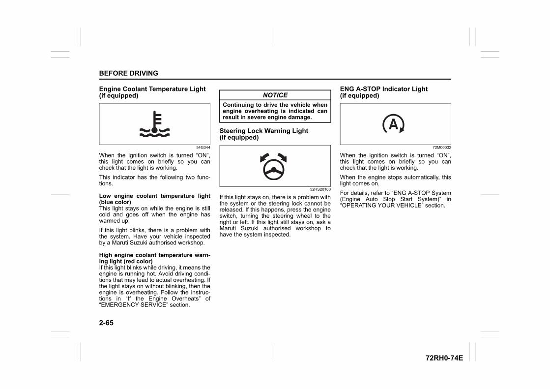
2-65
BEFORE DRIVING
72RH0-74E
Engine Coolant Temperature Light (if equipped)
54G344
When the ignition switch is turned “ON”,this light comes on briefly so you cancheck that the light is working.
This indicator has the following two func-tions.
Low engine coolant temperature light(blue color)This light stays on while the engine is stillcold and goes off when the engine haswarmed up.
If this light blinks, there is a problem withthe system. Have your vehicle inspectedby a Maruti Suzuki authorised workshop.
High engine coolant temperature warn-ing light (red color)If this light blinks while driving, it means theengine is running hot. Avoid driving condi-tions that may lead to actual overheating. Ifthe light stays on without blinking, then theengine is overheating. Follow the instruc-tions in “If the Engine Overheats” of“EMERGENCY SERVICE” section.
Steering Lock Warning Light (if equipped)
52RS20100
If this light stays on, there is a problem withthe system or the steering lock cannot bereleased. If this happens, press the engineswitch, turning the steering wheel to theright or left. If this light still stays on, ask aMaruti Suzuki authorised workshop tohave the system inspected.
ENG A-STOP Indicator Light (if equipped)
72M00032
When the ignition switch is turned “ON”,this light comes on briefly so you cancheck that the light is working.
When the engine stops automatically, thislight comes on.
For details, refer to “ENG A-STOP System(Engine Auto Stop Start System)” in“OPERATING YOUR VEHICLE” section.
NOTICE
Continuing to drive the vehicle whenengine overheating is indicated canresult in severe engine damage.
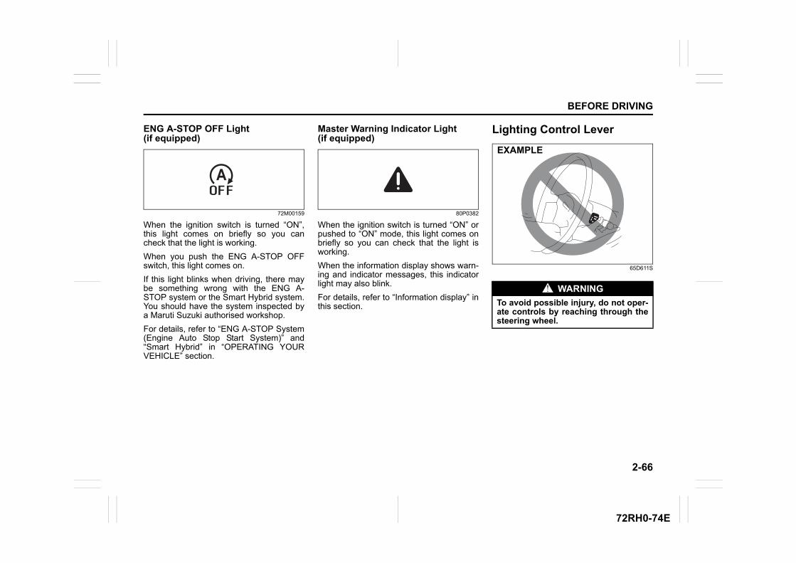
2-66
BEFORE DRIVING
72RH0-74E
ENG A-STOP OFF Light (if equipped)
72M00159
When the ignition switch is turned “ON”,this light comes on briefly so you cancheck that the light is working.
When you push the ENG A-STOP OFFswitch, this light comes on.
If this light blinks when driving, there maybe something wrong with the ENG A-STOP system or the Smart Hybrid system.You should have the system inspected bya Maruti Suzuki authorised workshop.
For details, refer to “ENG A-STOP System(Engine Auto Stop Start System)” and“Smart Hybrid” in “OPERATING YOURVEHICLE” section.
Master Warning Indicator Light (if equipped)
80P0382
When the ignition switch is turned “ON” orpushed to “ON” mode, this light comes onbriefly so you can check that the light isworking.
When the information display shows warn-ing and indicator messages, this indicatorlight may also blink.
For details, refer to “Information display” inthis section.
Lighting Control Lever
65D611S
WARNING
To avoid possible injury, do not oper-ate controls by reaching through thesteering wheel.
EXAMPLE
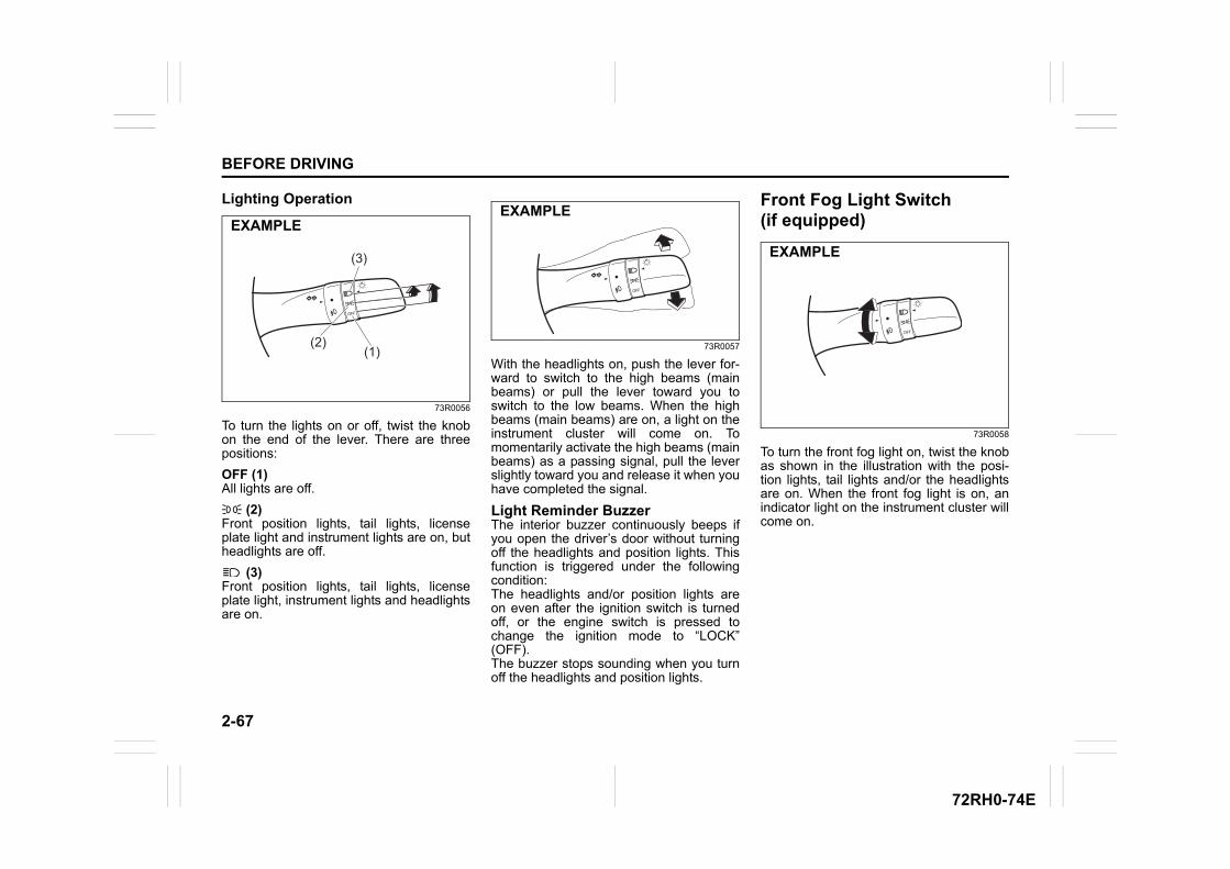
2-67
BEFORE DRIVING
72RH0-74E
Lighting Operation
73R0056
To turn the lights on or off, twist the knobon the end of the lever. There are threepositions:
OFF (1)All lights are off.
(2)Front position lights, tail lights, licenseplate light and instrument lights are on, butheadlights are off.
(3)Front position lights, tail lights, licenseplate light, instrument lights and headlightsare on.
73R0057
With the headlights on, push the lever for-ward to switch to the high beams (mainbeams) or pull the lever toward you toswitch to the low beams. When the highbeams (main beams) are on, a light on theinstrument cluster will come on. Tomomentarily activate the high beams (mainbeams) as a passing signal, pull the leverslightly toward you and release it when youhave completed the signal.
Light Reminder BuzzerThe interior buzzer continuously beeps ifyou open the driver’s door without turningoff the headlights and position lights. Thisfunction is triggered under the followingcondition: The headlights and/or position lights areon even after the ignition switch is turnedoff, or the engine switch is pressed tochange the ignition mode to “LOCK”(OFF). The buzzer stops sounding when you turnoff the headlights and position lights.
Front Fog Light Switch (if equipped)
73R0058
To turn the front fog light on, twist the knobas shown in the illustration with the posi-tion lights, tail lights and/or the headlightsare on. When the front fog light is on, anindicator light on the instrument cluster willcome on.
(3)
(2)(1)
EXAMPLEEXAMPLE
EXAMPLE
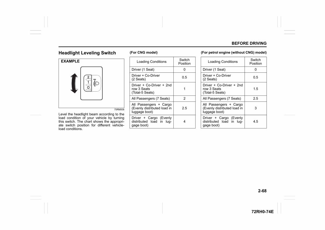
2-68
BEFORE DRIVING
72RH0-74E
Headlight Leveling Switch
75RM008
Level the headlight beam according to theload condition of your vehicle by turningthis switch. The chart shows the appropri-ate switch position for different vehicle-load conditions.
(For CNG model) (For petrol engine (without CNG) model)
EXAMPLE Loading Conditions Switch Position
Driver (1 Seat) 0
Driver + Co-Driver (2 Seats) 0.5
Driver + Co-Driver + 2ndrow 3 Seats (Total-5 Seats)
1
All Passengers (7 Seats) 2
All Passengers + Cargo(Evenly distributed load inluggage boot)
2.5
Driver + Cargo (Evenlydistributed load in lug-gage boot)
4
Loading Conditions Switch Position
Driver (1 Seat) 0
Driver + Co-Driver (2 Seats) 0.5
Driver + Co-Driver + 2ndrow 3 Seats (Total-5 Seats)
1.5
All Passengers (7 Seats) 2.5
All Passengers + Cargo(Evenly distributed load inluggage boot)
3
Driver + Cargo (Evenlydistributed load in lug-gage boot)
4.5
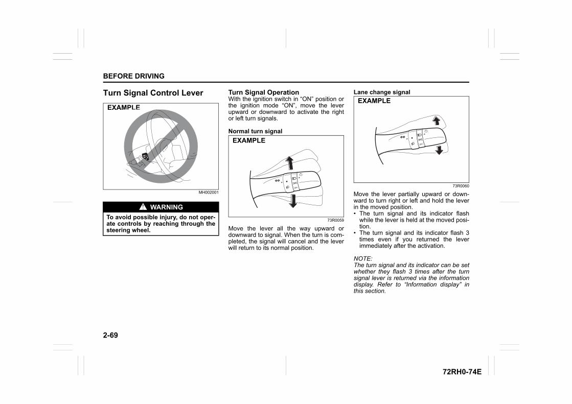
2-69
BEFORE DRIVING
72RH0-74E
Turn Signal Control Lever
MH002001
Turn Signal OperationWith the ignition switch in “ON” position orthe ignition mode “ON”, move the leverupward or downward to activate the rightor left turn signals.
Normal turn signal
73R0059
Move the lever all the way upward ordownward to signal. When the turn is com-pleted, the signal will cancel and the leverwill return to its normal position.
Lane change signal
73R0060
Move the lever partially upward or down-ward to turn right or left and hold the leverin the moved position.• The turn signal and its indicator flash
while the lever is held at the moved posi-tion.
• The turn signal and its indicator flash 3times even if you returned the leverimmediately after the activation.
NOTE:The turn signal and its indicator can be setwhether they flash 3 times after the turnsignal lever is returned via the informationdisplay. Refer to “Information display” inthis section.
WARNING
To avoid possible injury, do not oper-ate controls by reaching through thesteering wheel.
EXAMPLE
EXAMPLE
EXAMPLE
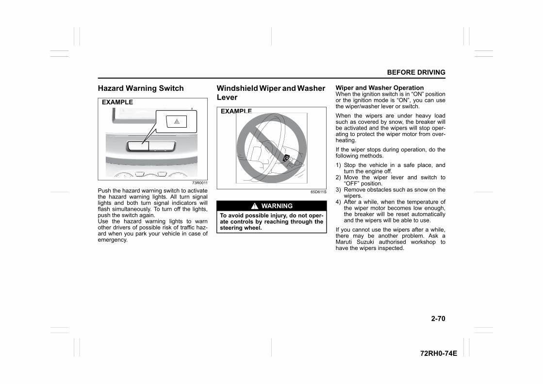
2-70
BEFORE DRIVING
72RH0-74E
Hazard Warning Switch
73R0011
Push the hazard warning switch to activatethe hazard warning lights. All turn signallights and both turn signal indicators willflash simultaneously. To turn off the lights,push the switch again.Use the hazard warning lights to warnother drivers of possible risk of traffic haz-ard when you park your vehicle in case ofemergency.
Windshield Wiper and Washer Lever
65D611S
Wiper and Washer OperationWhen the ignition switch is in “ON” positionor the ignition mode is “ON”, you can usethe wiper/washer lever or switch.
When the wipers are under heavy loadsuch as covered by snow, the breaker willbe activated and the wipers will stop oper-ating to protect the wiper motor from over-heating.
If the wiper stops during operation, do thefollowing methods.
1) Stop the vehicle in a safe place, andturn the engine off.
2) Move the wiper lever and switch to“OFF” position.
3) Remove obstacles such as snow on thewipers.
4) After a while, when the temperature ofthe wiper motor becomes low enough,the breaker will be reset automaticallyand the wipers will be able to use.
If you cannot use the wipers after a while,there may be another problem. Ask aMaruti Suzuki authorised workshop tohave the wipers inspected.
EXAMPLE
WARNING
To avoid possible injury, do not oper-ate controls by reaching through thesteering wheel.
EXAMPLE
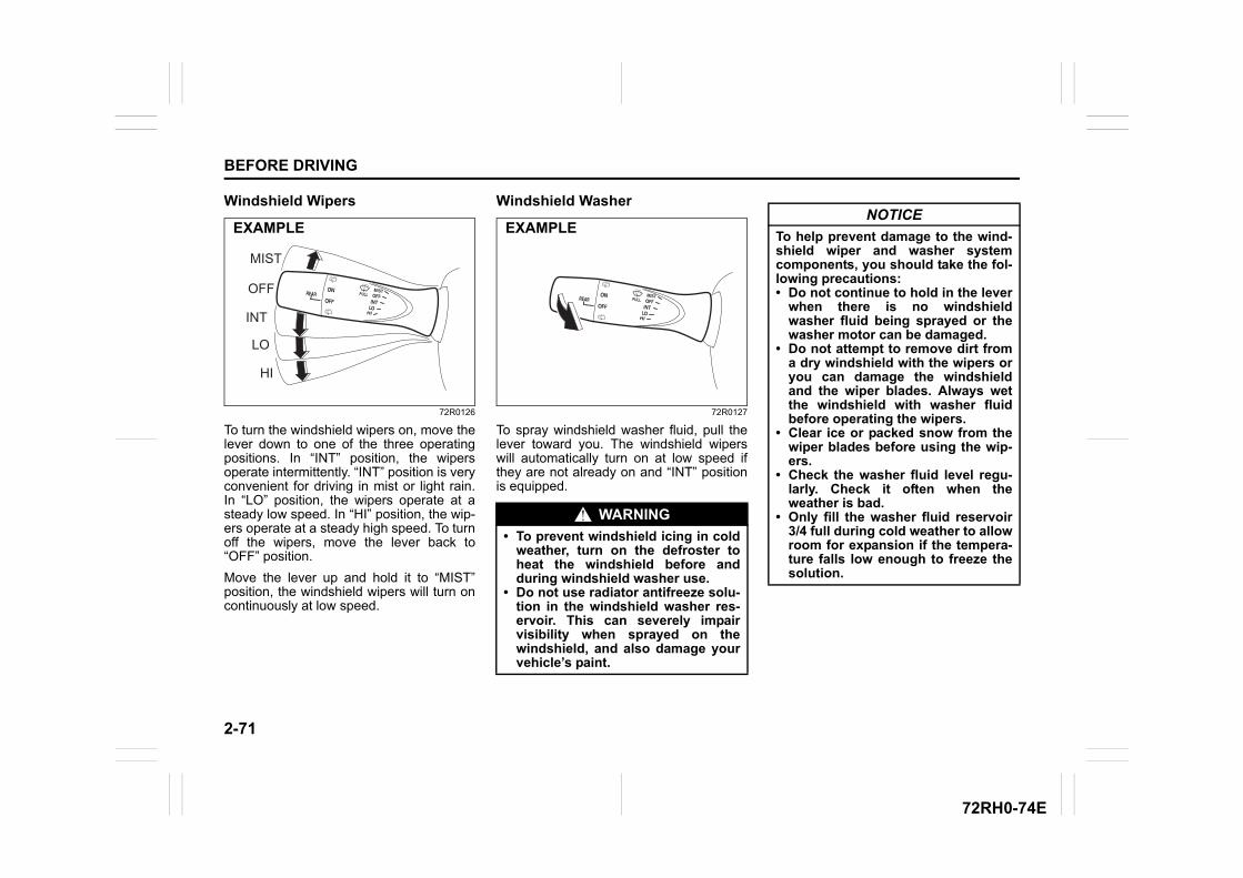
2-71
BEFORE DRIVING
72RH0-74E
Windshield Wipers
72R0126
To turn the windshield wipers on, move thelever down to one of the three operatingpositions. In “INT” position, the wipersoperate intermittently. “INT” position is veryconvenient for driving in mist or light rain.In “LO” position, the wipers operate at asteady low speed. In “HI” position, the wip-ers operate at a steady high speed. To turnoff the wipers, move the lever back to“OFF” position.
Move the lever up and hold it to “MIST”position, the windshield wipers will turn oncontinuously at low speed.
Windshield Washer
72R0127
To spray windshield washer fluid, pull thelever toward you. The windshield wiperswill automatically turn on at low speed ifthey are not already on and “INT” positionis equipped.
MIST
HI
OFF
LO
INT
EXAMPLE
WARNING
• To prevent windshield icing in coldweather, turn on the defroster toheat the windshield before andduring windshield washer use.
• Do not use radiator antifreeze solu-tion in the windshield washer res-ervoir. This can severely impairvisibility when sprayed on thewindshield, and also damage yourvehicle’s paint.
EXAMPLENOTICE
To help prevent damage to the wind-shield wiper and washer systemcomponents, you should take the fol-lowing precautions:• Do not continue to hold in the lever
when there is no windshieldwasher fluid being sprayed or thewasher motor can be damaged.
• Do not attempt to remove dirt froma dry windshield with the wipers oryou can damage the windshieldand the wiper blades. Always wetthe windshield with washer fluidbefore operating the wipers.
• Clear ice or packed snow from thewiper blades before using the wip-ers.
• Check the washer fluid level regu-larly. Check it often when theweather is bad.
• Only fill the washer fluid reservoir3/4 full during cold weather to allowroom for expansion if the tempera-ture falls low enough to freeze thesolution.
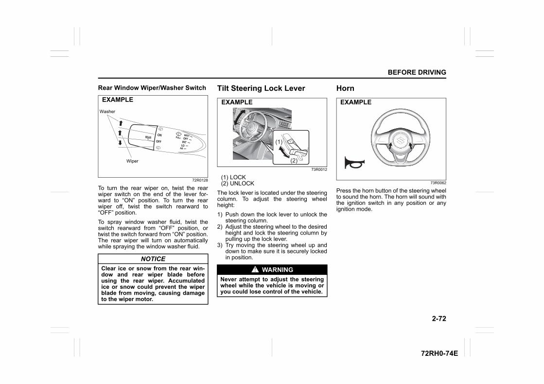
2-72
BEFORE DRIVING
72RH0-74E
Rear Window Wiper/Washer Switch
72R0128
To turn the rear wiper on, twist the rearwiper switch on the end of the lever for-ward to “ON” position. To turn the rearwiper off, twist the switch rearward to“OFF” position.
To spray window washer fluid, twist theswitch rearward from “OFF” position, ortwist the switch forward from “ON” position.The rear wiper will turn on automaticallywhile spraying the window washer fluid.
Tilt Steering Lock Lever
73R0012
(1) LOCK(2) UNLOCK
The lock lever is located under the steeringcolumn. To adjust the steering wheelheight:
1) Push down the lock lever to unlock thesteering column.
2) Adjust the steering wheel to the desiredheight and lock the steering column bypulling up the lock lever.
3) Try moving the steering wheel up anddown to make sure it is securely lockedin position.
Horn
73R0062
Press the horn button of the steering wheelto sound the horn. The horn will sound withthe ignition switch in any position or anyignition mode.
NOTICE
Clear ice or snow from the rear win-dow and rear wiper blade beforeusing the rear wiper. Accumulatedice or snow could prevent the wiperblade from moving, causing damageto the wiper motor.
Washer
Wiper
EXAMPLE
WARNING
Never attempt to adjust the steeringwheel while the vehicle is moving oryou could lose control of the vehicle.
(1)
(2)
EXAMPLE EXAMPLE
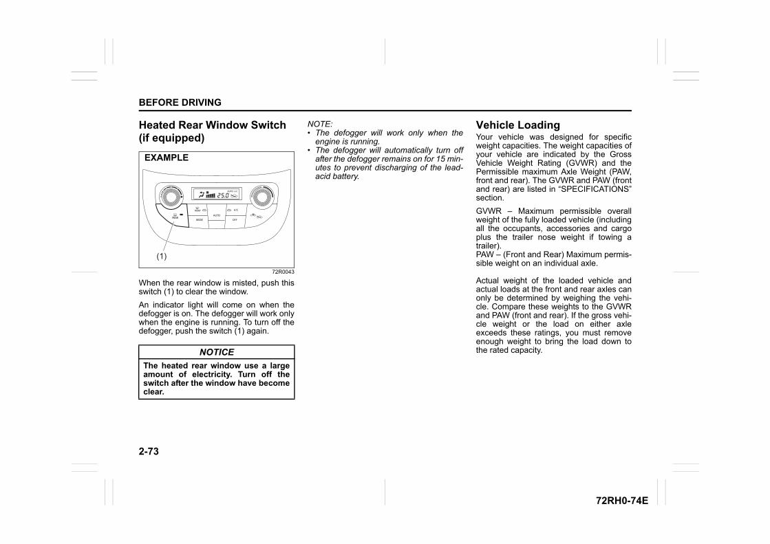
2-73
BEFORE DRIVING
72RH0-74E
Heated Rear Window Switch (if equipped)
72R0043
When the rear window is misted, push thisswitch (1) to clear the window.
An indicator light will come on when thedefogger is on. The defogger will work onlywhen the engine is running. To turn off thedefogger, push the switch (1) again.
NOTE:• The defogger will work only when the
engine is running.• The defogger will automatically turn off
after the defogger remains on for 15 min-utes to prevent discharging of the lead-acid battery.
Vehicle LoadingYour vehicle was designed for specificweight capacities. The weight capacities ofyour vehicle are indicated by the GrossVehicle Weight Rating (GVWR) and thePermissible maximum Axle Weight (PAW,front and rear). The GVWR and PAW (frontand rear) are listed in “SPECIFICATIONS”section.
GVWR – Maximum permissible overallweight of the fully loaded vehicle (includingall the occupants, accessories and cargoplus the trailer nose weight if towing atrailer).PAW – (Front and Rear) Maximum permis-sible weight on an individual axle.
Actual weight of the loaded vehicle andactual loads at the front and rear axles canonly be determined by weighing the vehi-cle. Compare these weights to the GVWRand PAW (front and rear). If the gross vehi-cle weight or the load on either axleexceeds these ratings, you must removeenough weight to bring the load down tothe rated capacity.NOTICE
The heated rear window use a largeamount of electricity. Turn off theswitch after the window have becomeclear.
(1)
EXAMPLE
2-74
BEFORE DRIVING
72RH0-74E
Trailer Towing your vehicleYour MARUTI SUZUKI was originallydesigned to carry people and a normalamount of cargo, not to tow a trailer.
WARNING
Never overload your vehicle. Thegross vehicle weight (sum of theweights of the vehicle, all the occu-pants, accessories, cargo plus trailernose weight if towing a trailer) mustnever exceed the Gross VehicleWeight Rating (GVWR). In addition,never distribute a load so that theweight on either the front or rear axleexceeds the Permissible maximumAxle Weight (PAW).
WARNING
Always distribute cargo evenly. Toavoid personal injury or damage toyour vehicle, always secure cargo toprevent it from shifting if the vehiclemoves suddenly. Place heavierobjects on the floor and as far for-ward in the cargo area as possible.Never pile cargo higher than the topof the seat backs.

72RH0-74E
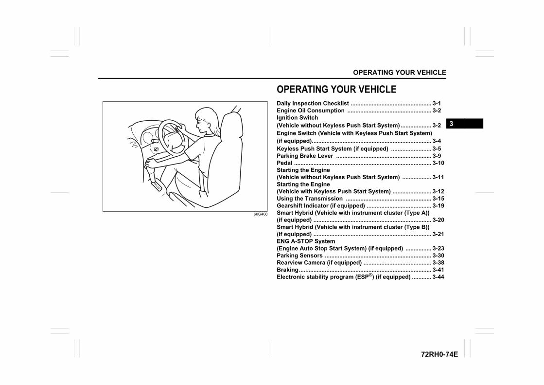
OPERATING YOUR VEHICLE
3
72RH0-74E
60G408
OPERATING YOUR VEHICLEDaily Inspection Checklist .................................................. 3-1Engine Oil Consumption .................................................... 3-2Ignition Switch (Vehicle without Keyless Push Start System) ................... 3-2Engine Switch (Vehicle with Keyless Push Start System) (if equipped).......................................................................... 3-4Keyless Push Start System (if equipped) ......................... 3-5Parking Brake Lever ........................................................... 3-9Pedal ..................................................................................... 3-10Starting the Engine (Vehicle without Keyless Push Start System) .................. 3-11Starting the Engine (Vehicle with Keyless Push Start System) ........................ 3-12Using the Transmission ..................................................... 3-15Gearshift Indicator (if equipped) ........................................ 3-19Smart Hybrid (Vehicle with instrument cluster (Type A)) (if equipped) ......................................................................... 3-20Smart Hybrid (Vehicle with instrument cluster (Type B)) (if equipped) ......................................................................... 3-21ENG A-STOP System (Engine Auto Stop Start System) (if equipped) ................ 3-23Parking Sensors .................................................................. 3-30Rearview Camera (if equipped) .......................................... 3-38Braking.................................................................................. 3-41Electronic stability program (ESP®) (if equipped) ............ 3-44
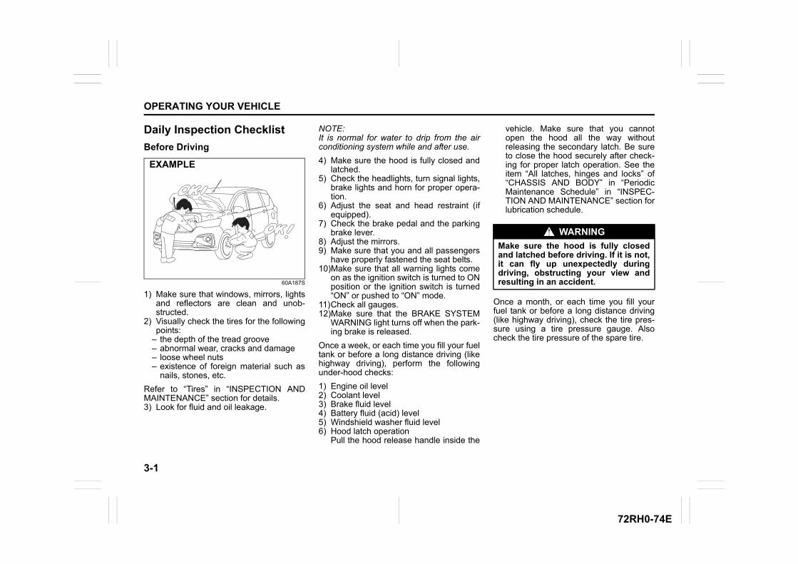
3-1
OPERATING YOUR VEHICLE
72RH0-74E
Daily Inspection Checklist
Before Driving
60A187S
1) Make sure that windows, mirrors, lightsand reflectors are clean and unob-structed.
2) Visually check the tires for the followingpoints:
– the depth of the tread groove– abnormal wear, cracks and damage– loose wheel nuts– existence of foreign material such as
nails, stones, etc.
Refer to “Tires” in “INSPECTION ANDMAINTENANCE” section for details.3) Look for fluid and oil leakage.
NOTE:It is normal for water to drip from the airconditioning system while and after use.
4) Make sure the hood is fully closed andlatched.
5) Check the headlights, turn signal lights,brake lights and horn for proper opera-tion.
6) Adjust the seat and head restraint (ifequipped).
7) Check the brake pedal and the parkingbrake lever.
8) Adjust the mirrors.9) Make sure that you and all passengers
have properly fastened the seat belts.10)Make sure that all warning lights come
on as the ignition switch is turned to ONposition or the ignition switch is turned“ON” or pushed to “ON” mode.
11)Check all gauges.12)Make sure that the BRAKE SYSTEM
WARNING light turns off when the park-ing brake is released.
Once a week, or each time you fill your fueltank or before a long distance driving (likehighway driving), perform the followingunder-hood checks:
1) Engine oil level2) Coolant level3) Brake fluid level4) Battery fluid (acid) level5) Windshield washer fluid level6) Hood latch operation
Pull the hood release handle inside the
vehicle. Make sure that you cannotopen the hood all the way withoutreleasing the secondary latch. Be sureto close the hood securely after check-ing for proper latch operation. See theitem “All latches, hinges and locks” of“CHASSIS AND BODY” in “PeriodicMaintenance Schedule” in “INSPEC-TION AND MAINTENANCE” section forlubrication schedule.
Once a month, or each time you fill yourfuel tank or before a long distance driving(like highway driving), check the tire pres-sure using a tire pressure gauge. Alsocheck the tire pressure of the spare tire.
EXAMPLE
WARNING
Make sure the hood is fully closedand latched before driving. If it is not,it can fly up unexpectedly duringdriving, obstructing your view andresulting in an accident.
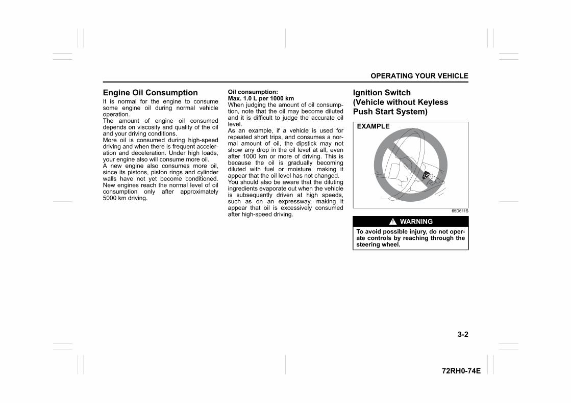
3-2
OPERATING YOUR VEHICLE
72RH0-74E
Engine Oil ConsumptionIt is normal for the engine to consumesome engine oil during normal vehicleoperation.The amount of engine oil consumeddepends on viscosity and quality of the oiland your driving conditions. More oil is consumed during high-speeddriving and when there is frequent acceler-ation and deceleration. Under high loads,your engine also will consume more oil.A new engine also consumes more oil,since its pistons, piston rings and cylinderwalls have not yet become conditioned.New engines reach the normal level of oilconsumption only after approximately5000 km driving.
Oil consumption: Max. 1.0 L per 1000 kmWhen judging the amount of oil consump-tion, note that the oil may become dilutedand it is difficult to judge the accurate oillevel. As an example, if a vehicle is used forrepeated short trips, and consumes a nor-mal amount of oil, the dipstick may notshow any drop in the oil level at all, evenafter 1000 km or more of driving. This isbecause the oil is gradually becomingdiluted with fuel or moisture, making itappear that the oil level has not changed.You should also be aware that the dilutingingredients evaporate out when the vehicleis subsequently driven at high speeds,such as on an expressway, making itappear that oil is excessively consumedafter high-speed driving.
Ignition Switch (Vehicle without Keyless Push Start System)
65D611S
WARNING
To avoid possible injury, do not oper-ate controls by reaching through thesteering wheel.
EXAMPLE
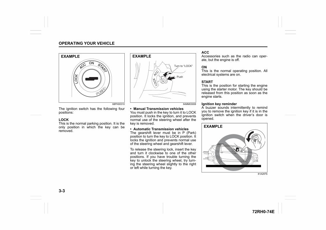
3-3
OPERATING YOUR VEHICLE
72RH0-74E
68PH00310
The ignition switch has the following fourpositions:
LOCKThis is the normal parking position. It is theonly position in which the key can beremoved.
64MM03008
• Manual Transmission vehiclesYou must push in the key to turn it to LOCKposition. It locks the ignition, and preventsnormal use of the steering wheel after thekey is removed.
• Automatic Transmission vehiclesThe gearshift lever must be in P (Park)position to turn the key to LOCK position. Itlocks the ignition and prevents normal useof the steering wheel and gearshift lever.
To release the steering lock, insert the keyand turn it clockwise to one of the otherpositions. If you have trouble turning thekey to unlock the steering wheel, try turn-ing the steering wheel slightly to the rightor left while turning the key.
ACCAccessories such as the radio can oper-ate, but the engine is off.
ONThis is the normal operating position. Allelectrical systems are on.
STARTThis is the position for starting the engineusing the starter motor. The key should bereleased from this position as soon as theengine starts.
Ignition key reminderA buzzer sounds intermittently to remindyou to remove the ignition key if it is in theignition switch when the driver’s door isopened.
81A297S
EXAMPLE
LOC
KACC
Push
Turn to “LOCK”
EXAMPLE
EXAMPLE
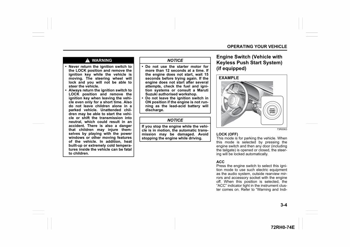
3-4
OPERATING YOUR VEHICLE
72RH0-74E
Engine Switch (Vehicle with Keyless Push Start System) (if equipped)
73R0063
LOCK (OFF)This mode is for parking the vehicle. Whenthis mode is selected by pressing theengine switch and then any door (includingthe tailgate) is opened or closed, the steer-ing will be locked automatically.
ACCPress the engine switch to select this igni-tion mode to use such electric equipmentas the audio system, outside rearview mir-rors and accessory socket with the engineoff. When this position is selected, the“ACC” indicator light in the instrument clus-ter comes on. Refer to “Warning and Indi-
WARNING
• Never return the ignition switch tothe LOCK position and remove theignition key while the vehicle ismoving. The steering wheel willlock and you will not be able tosteer the vehicle.
• Always return the ignition switch toLOCK position and remove theignition key when leaving the vehi-cle even only for a short time. Alsodo not leave children alone in aparked vehicle. Unattended chil-dren may be able to start the vehi-cle or shift the transmission intoneutral, which could result in anaccident. There is also a dangerthat children may injure them-selves by playing with the powerwindows or other moving featuresof the vehicle. In addition, heatbuilt-up or extremely cold tempera-tures inside the vehicle can be fatalto children.
NOTICE
• Do not use the starter motor formore than 12 seconds at a time. Ifthe engine does not start, wait 15seconds before trying again. If theengine does not start after severalattempts, check the fuel and igni-tion systems or consult a MarutiSuzuki authorised workshop.
• Do not leave the ignition switch inON position if the engine is not run-ning as the lead-acid battery willdischarge.
NOTICE
If you stop the engine while the vehi-cle is in motion, the automatic trans-mission may be damaged. Avoidstopping the engine while driving.
EXAMPLE
3-5
OPERATING YOUR VEHICLE
72RH0-74E
cator Lights” in “BEFORE DRIVING”section for details.
ON• With the engine off
You can use such electric equipment asthe power windows and wipers with theengine off. When this ignition mode isselected by pressing the engine switch,the Ignition “ON” indicator light in theinstrument cluster will come on.
• With the engine onAll electric equipment is operational. Thevehicle can be driven when you haveselected this ignition mode by pressingthe engine switch.
STARTManual Transmission – Provided you havethe keyless push start system remote con-troller with you, the engine automaticallystarts when you press the engine switch toselect this ignition mode after shifting to“N” (Neutral) and depressing the brake andclutch pedals.
Automatic Transmission – Provided youhave the keyless push start system remotecontroller with you, the engine automati-cally starts when you press the engineswitch to select this ignition mode afterplacing the gearshift lever in P position anddepressing the brake pedal. (If you need tore-start the engine while the vehicle ismoving, shift into “N”.)
NOTE:You do not need to keep the engine switchpressed to start the engine.
NOTE:• The steering lock may not be released
and the immobilizer/ keyless push startsystem warning light turns on if someload is applied on the steering wheel. Ifthis happens, turn the steering wheel tothe right or left to relieve it from the loadbefore you press the engine switchagain to change to the desired ignitionmode.
• In the presence of strong radio wave ornoise, you may not be able to changethe ignition mode to “ACC” or “ON” or tostart the engine using the engine switch.
Keyless Push Start System (if equipped)Provided the keyless push start systemremote controller is within the interior work-able area (refer to the related explanationin this section), you can use the engineswitch for starting the engine and selectingan ignition mode (“ACC” or “ON”). In addi-tion, the following functions can be used:
• Keyless entry function. Refer to “Keylessentry system transmitter /Keyless pushstart system remote controller (ifequipped)” in “BEFORE DRIVING” sec-tion for details.
• Locking and unlocking doors (includingthe tailgate) using a request switch.Refer to “Keyless entry system transmit-ter /Keyless push start system remotecontroller (if equipped)” in “BEFOREDRIVING” section for details.
• Immobilizer (anti-theft) function. Refer to“Immobilizer System” in “BEFOREDRIVING” section for details.
Engine Switch IlluminationThe engine switch is illuminated (lit) in thefollowing situations:• When the engine is off and the driver’s
door is open, or for 15 seconds after thedriver’s door is closed. The illuminationwill fade out after 15 seconds passed.
• When the engine is off and the positionlights are on. The illumination will go outwhen the position lights are turned off.
NOTICE
Do not leave the engine switch in“ACC” or “ON” mode when theengine is not running. Avoid usingthe radio or other electric accesso-ries for a long time when the engineswitch is in the “ACC” or “ON” modewhen the engine is not running, oth-erwise the lead-acid battery may dis-charge.
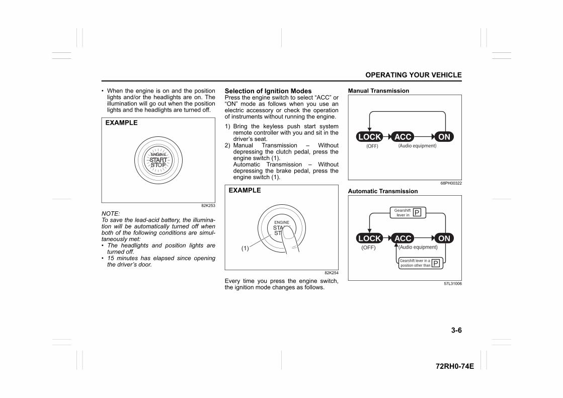
3-6
OPERATING YOUR VEHICLE
72RH0-74E
• When the engine is on and the positionlights and/or the headlights are on. Theillumination will go out when the positionlights and the headlights are turned off.
82K253
NOTE:To save the lead-acid battery, the illumina-tion will be automatically turned off whenboth of the following conditions are simul-taneously met:• The headlights and position lights are
turned off.• 15 minutes has elapsed since opening
the driver’s door.
Selection of Ignition ModesPress the engine switch to select “ACC” or“ON” mode as follows when you use anelectric accessory or check the operationof instruments without running the engine.
1) Bring the keyless push start systemremote controller with you and sit in thedriver’s seat.
2) Manual Transmission – Withoutdepressing the clutch pedal, press theengine switch (1).Automatic Transmission – Withoutdepressing the brake pedal, press theengine switch (1).
82K254
Every time you press the engine switch,the ignition mode changes as follows.
Manual Transmission
68PH00322
Automatic Transmission
57L31006
EXAMPLE
(1)
EXAMPLE
(OFF) (Audio equipment)
P
P
(OFF)
ONACCLOCK(Audio equipment)
Gearshift lever in a position other than
Gearshift lever in
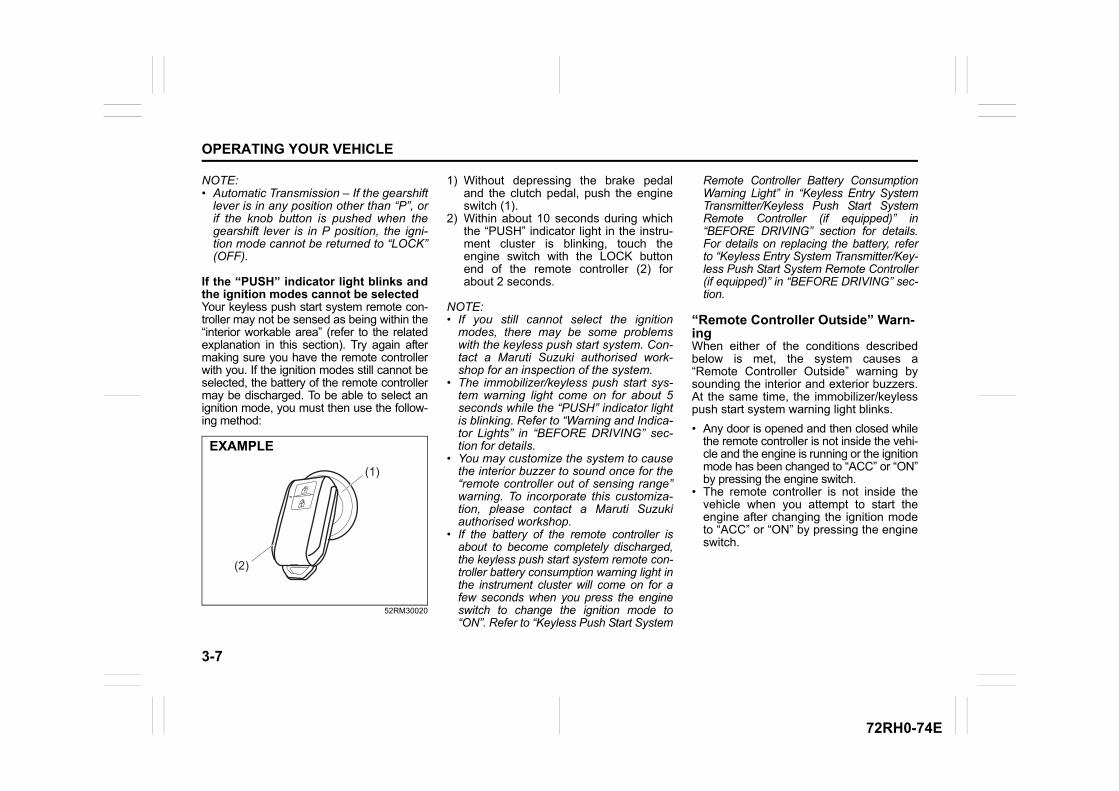
3-7
OPERATING YOUR VEHICLE
72RH0-74E
NOTE:• Automatic Transmission – If the gearshift
lever is in any position other than “P”, orif the knob button is pushed when thegearshift lever is in P position, the igni-tion mode cannot be returned to “LOCK”(OFF).
If the “PUSH” indicator light blinks andthe ignition modes cannot be selectedYour keyless push start system remote con-troller may not be sensed as being within the“interior workable area” (refer to the relatedexplanation in this section). Try again aftermaking sure you have the remote controllerwith you. If the ignition modes still cannot beselected, the battery of the remote controllermay be discharged. To be able to select anignition mode, you must then use the follow-ing method:
52RM30020
1) Without depressing the brake pedaland the clutch pedal, push the engineswitch (1).
2) Within about 10 seconds during whichthe “PUSH” indicator light in the instru-ment cluster is blinking, touch theengine switch with the LOCK buttonend of the remote controller (2) forabout 2 seconds.
NOTE:• If you still cannot select the ignition
modes, there may be some problemswith the keyless push start system. Con-tact a Maruti Suzuki authorised work-shop for an inspection of the system.
• The immobilizer/keyless push start sys-tem warning light come on for about 5seconds while the “PUSH” indicator lightis blinking. Refer to “Warning and Indica-tor Lights” in “BEFORE DRIVING” sec-tion for details.
• You may customize the system to causethe interior buzzer to sound once for the“remote controller out of sensing range”warning. To incorporate this customiza-tion, please contact a Maruti Suzukiauthorised workshop.
• If the battery of the remote controller isabout to become completely discharged,the keyless push start system remote con-troller battery consumption warning light inthe instrument cluster will come on for afew seconds when you press the engineswitch to change the ignition mode to“ON”. Refer to “Keyless Push Start System
Remote Controller Battery ConsumptionWarning Light” in “Keyless Entry SystemTransmitter/Keyless Push Start SystemRemote Controller (if equipped)” in“BEFORE DRIVING” section for details.For details on replacing the battery, referto “Keyless Entry System Transmitter/Key-less Push Start System Remote Controller(if equipped)” in “BEFORE DRIVING” sec-tion.
“Remote Controller Outside” Warn-ingWhen either of the conditions describedbelow is met, the system causes a“Remote Controller Outside” warning bysounding the interior and exterior buzzers.At the same time, the immobilizer/keylesspush start system warning light blinks.
• Any door is opened and then closed whilethe remote controller is not inside the vehi-cle and the engine is running or the ignitionmode has been changed to “ACC” or “ON”by pressing the engine switch.
• The remote controller is not inside thevehicle when you attempt to start theengine after changing the ignition modeto “ACC” or “ON” by pressing the engineswitch.
(1)
(2)
EXAMPLE
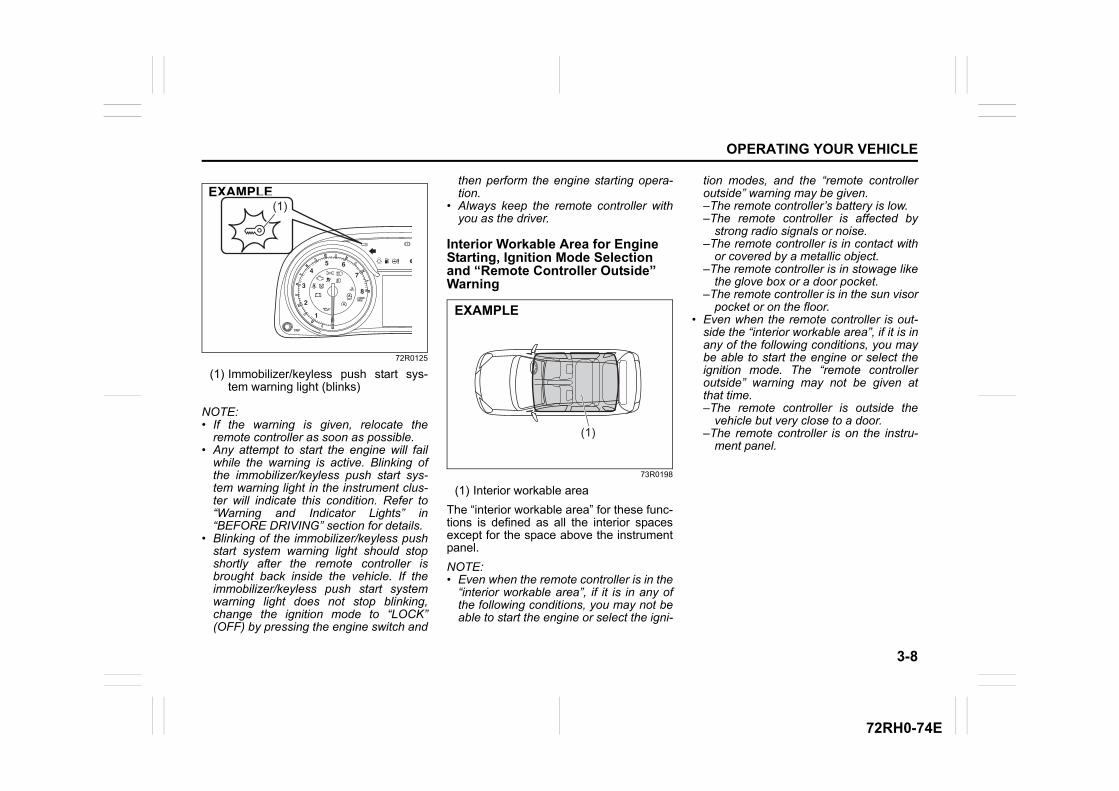
3-8
OPERATING YOUR VEHICLE
72RH0-74E
72R0125
(1) Immobilizer/keyless push start sys-tem warning light (blinks)
NOTE:• If the warning is given, relocate the
remote controller as soon as possible.• Any attempt to start the engine will fail
while the warning is active. Blinking ofthe immobilizer/keyless push start sys-tem warning light in the instrument clus-ter will indicate this condition. Refer to“Warning and Indicator Lights” in“BEFORE DRIVING” section for details.
• Blinking of the immobilizer/keyless pushstart system warning light should stopshortly after the remote controller isbrought back inside the vehicle. If theimmobilizer/keyless push start systemwarning light does not stop blinking,change the ignition mode to “LOCK”(OFF) by pressing the engine switch and
then perform the engine starting opera-tion.
• Always keep the remote controller withyou as the driver.
Interior Workable Area for Engine Starting, Ignition Mode Selection and “Remote Controller Outside” Warning
73R0198
(1) Interior workable area
The “interior workable area” for these func-tions is defined as all the interior spacesexcept for the space above the instrumentpanel.
NOTE:• Even when the remote controller is in the
“interior workable area”, if it is in any ofthe following conditions, you may not beable to start the engine or select the igni-
tion modes, and the “remote controlleroutside” warning may be given.–The remote controller’s battery is low.–The remote controller is affected by
strong radio signals or noise.–The remote controller is in contact with
or covered by a metallic object.–The remote controller is in stowage like
the glove box or a door pocket.–The remote controller is in the sun visor
pocket or on the floor.• Even when the remote controller is out-
side the “interior workable area”, if it is inany of the following conditions, you maybe able to start the engine or select theignition mode. The “remote controlleroutside” warning may not be given atthat time.–The remote controller is outside the
vehicle but very close to a door.–The remote controller is on the instru-
ment panel.
EXAMPLE(1)
(1)
EXAMPLE
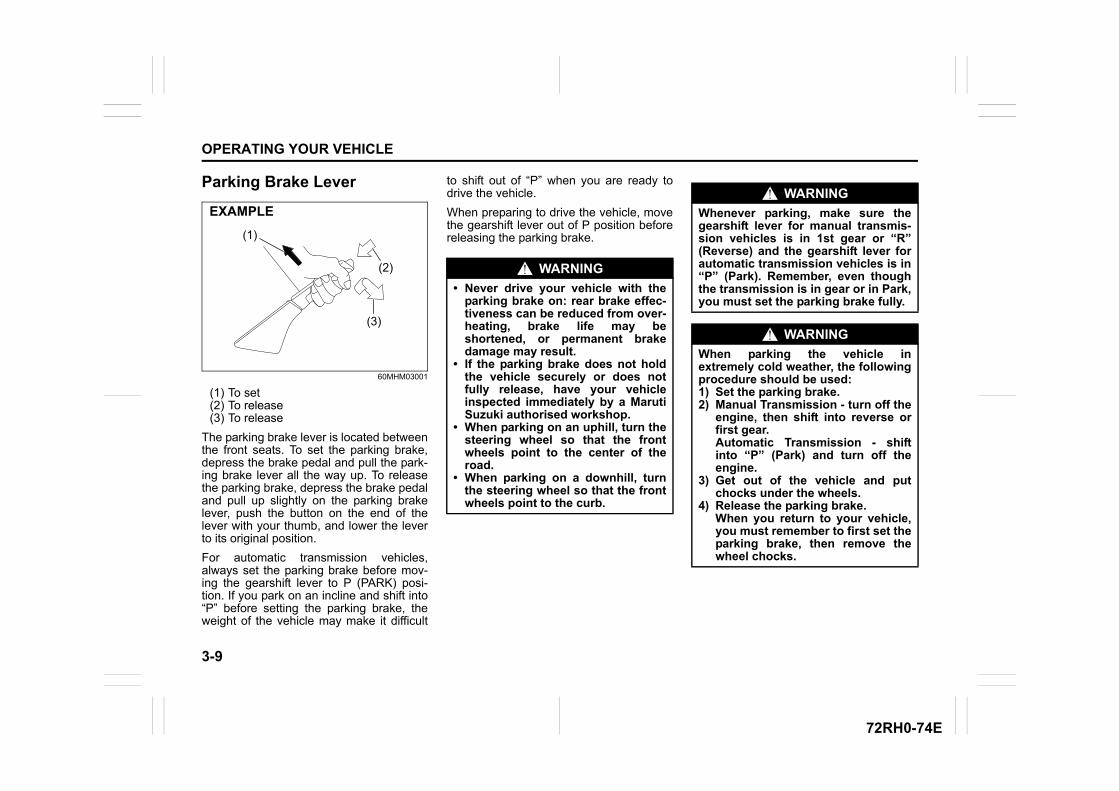
3-9
OPERATING YOUR VEHICLE
72RH0-74E
Parking Brake Lever
60MHM03001
(1) To set(2) To release(3) To release
The parking brake lever is located betweenthe front seats. To set the parking brake,depress the brake pedal and pull the park-ing brake lever all the way up. To releasethe parking brake, depress the brake pedaland pull up slightly on the parking brakelever, push the button on the end of thelever with your thumb, and lower the leverto its original position.
For automatic transmission vehicles,always set the parking brake before mov-ing the gearshift lever to P (PARK) posi-tion. If you park on an incline and shift into“P” before setting the parking brake, theweight of the vehicle may make it difficult
to shift out of “P” when you are ready todrive the vehicle.
When preparing to drive the vehicle, movethe gearshift lever out of P position beforereleasing the parking brake.
EXAMPLE
(1)
(2)
(3)
WARNING
• Never drive your vehicle with theparking brake on: rear brake effec-tiveness can be reduced from over-heating, brake life may beshortened, or permanent brakedamage may result.
• If the parking brake does not holdthe vehicle securely or does notfully release, have your vehicleinspected immediately by a MarutiSuzuki authorised workshop.
• When parking on an uphill, turn thesteering wheel so that the frontwheels point to the center of theroad.
• When parking on a downhill, turnthe steering wheel so that the frontwheels point to the curb.
WARNING
Whenever parking, make sure thegearshift lever for manual transmis-sion vehicles is in 1st gear or “R”(Reverse) and the gearshift lever forautomatic transmission vehicles is in“P” (Park). Remember, even thoughthe transmission is in gear or in Park,you must set the parking brake fully.
WARNING
When parking the vehicle inextremely cold weather, the followingprocedure should be used:1) Set the parking brake.2) Manual Transmission - turn off the
engine, then shift into reverse orfirst gear.Automatic Transmission - shiftinto “P” (Park) and turn off theengine.
3) Get out of the vehicle and putchocks under the wheels.
4) Release the parking brake. When you return to your vehicle,you must remember to first set theparking brake, then remove thewheel chocks.
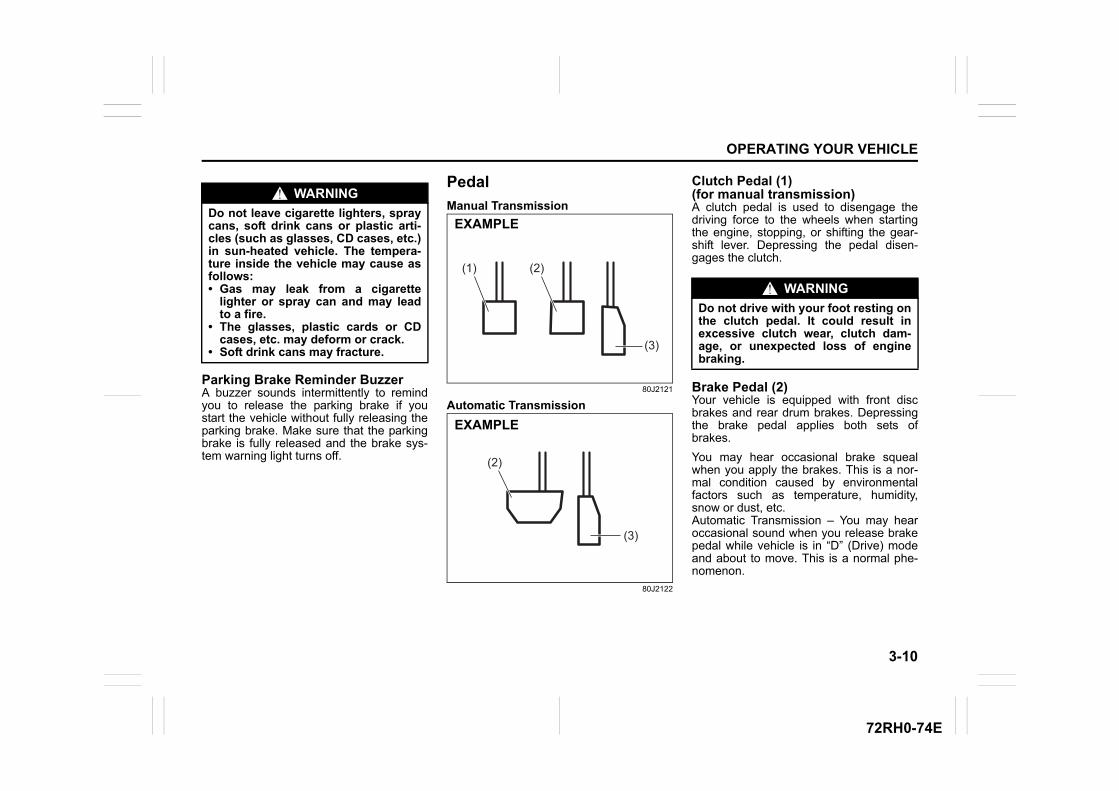
3-10
OPERATING YOUR VEHICLE
72RH0-74E
Parking Brake Reminder BuzzerA buzzer sounds intermittently to remindyou to release the parking brake if youstart the vehicle without fully releasing theparking brake. Make sure that the parkingbrake is fully released and the brake sys-tem warning light turns off.
Pedal
Manual Transmission
80J2121
Automatic Transmission
80J2122
Clutch Pedal (1)(for manual transmission)A clutch pedal is used to disengage thedriving force to the wheels when startingthe engine, stopping, or shifting the gear-shift lever. Depressing the pedal disen-gages the clutch.
Brake Pedal (2)Your vehicle is equipped with front discbrakes and rear drum brakes. Depressingthe brake pedal applies both sets ofbrakes.
You may hear occasional brake squealwhen you apply the brakes. This is a nor-mal condition caused by environmentalfactors such as temperature, humidity,snow or dust, etc.Automatic Transmission – You may hearoccasional sound when you release brakepedal while vehicle is in “D” (Drive) modeand about to move. This is a normal phe-nomenon.
WARNING
Do not leave cigarette lighters, spraycans, soft drink cans or plastic arti-cles (such as glasses, CD cases, etc.)in sun-heated vehicle. The tempera-ture inside the vehicle may cause asfollows:• Gas may leak from a cigarette
lighter or spray can and may leadto a fire.
• The glasses, plastic cards or CDcases, etc. may deform or crack.
• Soft drink cans may fracture.
(2)(1)
(3)
EXAMPLE
(3)
(2)
EXAMPLE
WARNING
Do not drive with your foot resting onthe clutch pedal. It could result inexcessive clutch wear, clutch dam-age, or unexpected loss of enginebraking.
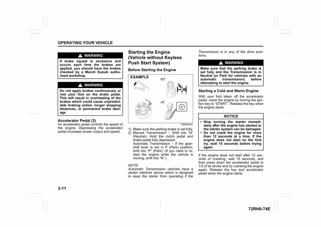
3-11
OPERATING YOUR VEHICLE
72RH0-74E
Accelerator Pedal (3)An accelerator pedal controls the speed ofthe engine. Depressing the acceleratorpedal increases power output and speed.
Starting the Engine (Vehicle without Keyless Push Start System)
Before Starting the Engine
72RM03001
1) Make sure the parking brake is set fully.2) Manual Transmission – Shift into “N”
(Neutral). Hold the clutch pedal andbrake pedal fully depressed.Automatic Transmission – If the gear-shift lever is not in P (Park) position,shift into “P” (Park). (If you need to re-start the engine while the vehicle ismoving, shift into “N”.)
NOTE:Automatic Transmission vehicles have astarter interlock device which is designedto keep the starter from operating if the
Transmission is in any of the drive posi-tions.
Starting a Cold and Warm Engine
With your foot taken off the acceleratorpedal, crank the engine by turning the igni-tion key to “START”. Release the key whenthe engine starts.
If the engine does not start after 12 sec-onds of cranking, wait 15 seconds, andthen press down the accelerator pedal to1/3 of its stroke and try cranking the engineagain. Release the key and acceleratorpedal when the engine starts.
WARNING
If brake squeal is excessive andoccurs each time the brakes areapplied, you should have the brakeschecked by a Maruti Suzuki autho-rised workshop.
WARNING
Do not apply brakes continuously orrest your foot on the brake pedal.This will result in overheating of thebrakes which could cause unpredict-able braking action, longer stoppingdistances, or permanent brake dam-age.
MT
AT
EXAMPLE
WARNING
Make sure that the parking brake isset fully and the Transmission is inNeutral (or Park for vehicles with anautomatic transmission) beforeattempting to start the engine.
NOTICE
• Stop turning the starter immedi-ately after the engine has started orthe starter system can be damaged.
• Do not crank the engine for morethan 12 seconds at a time. If theengine does not start on the firsttry, wait 15 seconds before tryingagain.
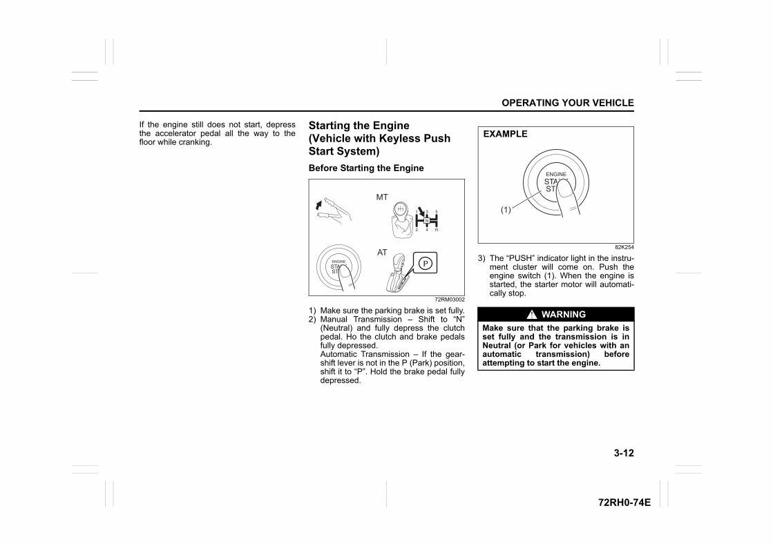
3-12
OPERATING YOUR VEHICLE
72RH0-74E
If the engine still does not start, depressthe accelerator pedal all the way to thefloor while cranking.
Starting the Engine (Vehicle with Keyless Push Start System)
Before Starting the Engine
72RM03002
1) Make sure the parking brake is set fully.2) Manual Transmission – Shift to “N”
(Neutral) and fully depress the clutchpedal. Ho the clutch and brake pedalsfully depressed.Automatic Transmission – If the gear-shift lever is not in the P (Park) position,shift it to “P”. Hold the brake pedal fullydepressed.
82K254
3) The “PUSH” indicator light in the instru-ment cluster will come on. Push theengine switch (1). When the engine isstarted, the starter motor will automati-cally stop.
EXAMPLEMT
AT
WARNING
Make sure that the parking brake isset fully and the transmission is inNeutral (or Park for vehicles with anautomatic transmission) beforeattempting to start the engine.
(1)
EXAMPLE
3-13
OPERATING YOUR VEHICLE
72RH0-74E
NOTE:• You do not need to keep the engine
switch pressed to start the engine.• The engine of a manual transmission
vehicle will not start unless the clutchpedal is depressed.
• Automatic transmission vehicles have astarter interlock device which isdesigned to keep the starter from operat-ing if the transmission is in any of thedrive positions.
• You should turn off such loads as theheadlights and air conditioning system tofacilitate starting of the engine.
• Even if you fail to start the engine, thestarter motor will stop turning automati-cally after a short time. After the startermotor has stopped or if there is someproblem with the system, the starter
motor will rotate only while the engineswitch is being pressed.
Stopping the Engine• Depress the engine switch to stop the
engine after the vehicle stopped com-pletely.
• In case of emergency, you can stop theengine by quickly pushing the engineswitch more than 3 times, or pushingand holding the engine switch for morethan 2 seconds while the vehicle inmotion.
NOTE:Except in cases of emergency, do not stopthe engine while the vehicle is in motion.The steering and braking operation willrequire more effort when the engine isstopped.Refer to “Braking” in this section.
• If the engine remains stopped for whileafter it was stopped unexpectedly or wasraced before stopping, a clicking soundmay be heard from around the enginewhen it is restarted. This is not a mal-
function. Always let the engine idlebefore stopping it.
Starting a Cold and Warm Engine
With your foot taken off the acceleratorpedal, crank the engine by pressing theengine switch to change the ignition modeto “START”.
After pressing the engine switch to changethe ignition mode to “START”, the startercranks the engine for about 12 secondsbefore it can start the engine. If the enginefails to start at the first attempt, wait 15seconds, and then try again while keepingthe engine switch pressed while pressingdown the accelerator pedal to 1/3 of itsstroke. Release the accelerator pedalwhen the engine starts.
If the engine still does not start, try holdingthe accelerator pedal all the way to thefloor while cranking. If you are unable to start the engine usingthis procedure, consult a Maruti Suzukiauthorised workshop.
NOTICE
• Do not depress the acceleratorduring the engine starting proce-dure.
• If the engine does not respondwhen you try to start it with theengine switch or if the engineswitch repeats cycling through“LOCK”(OFF) - “ACC” - “ON”mode, the lead-acid battery may bedischarged. Check the voltage ofthe lead-acid battery before tryingagain.
NOTICE
If you stop the engine while the vehi-cle is in motion, the automatic trans-mission may be damaged.Avoid stopping the engine while driv-ing.
NOTICE
Do not crank the engine for morethan 12 seconds at a time. If the engine does not start on thefirst try, wait 15 seconds before try-ing again.
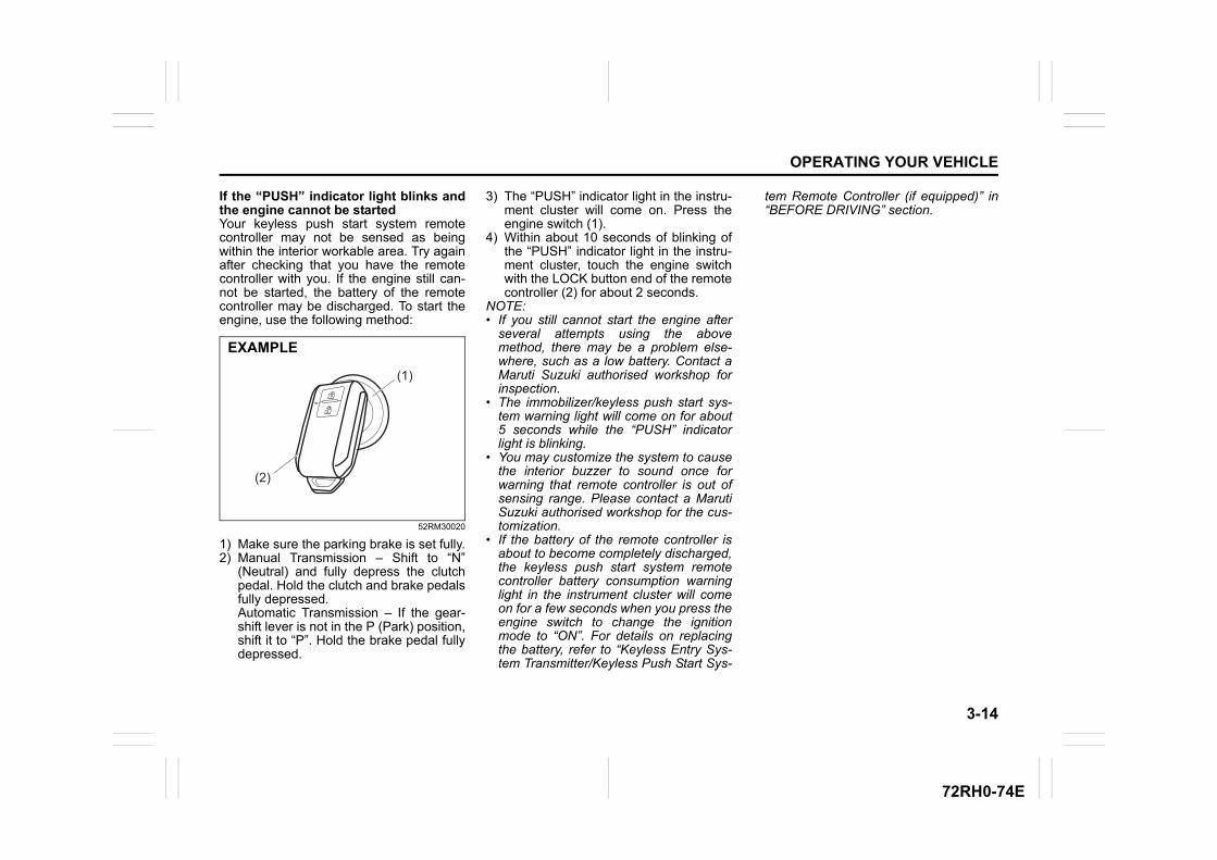
3-14
OPERATING YOUR VEHICLE
72RH0-74E
If the “PUSH” indicator light blinks andthe engine cannot be startedYour keyless push start system remotecontroller may not be sensed as beingwithin the interior workable area. Try againafter checking that you have the remotecontroller with you. If the engine still can-not be started, the battery of the remotecontroller may be discharged. To start theengine, use the following method:
52RM30020
1) Make sure the parking brake is set fully.2) Manual Transmission – Shift to “N”
(Neutral) and fully depress the clutchpedal. Hold the clutch and brake pedalsfully depressed. Automatic Transmission – If the gear-shift lever is not in the P (Park) position,shift it to “P”. Hold the brake pedal fullydepressed.
3) The “PUSH” indicator light in the instru-ment cluster will come on. Press theengine switch (1).
4) Within about 10 seconds of blinking ofthe “PUSH” indicator light in the instru-ment cluster, touch the engine switchwith the LOCK button end of the remotecontroller (2) for about 2 seconds.
NOTE:• If you still cannot start the engine after
several attempts using the abovemethod, there may be a problem else-where, such as a low battery. Contact aMaruti Suzuki authorised workshop forinspection.
• The immobilizer/keyless push start sys-tem warning light will come on for about5 seconds while the “PUSH” indicatorlight is blinking.
• You may customize the system to causethe interior buzzer to sound once forwarning that remote controller is out ofsensing range. Please contact a MarutiSuzuki authorised workshop for the cus-tomization.
• If the battery of the remote controller isabout to become completely discharged,the keyless push start system remotecontroller battery consumption warninglight in the instrument cluster will comeon for a few seconds when you press theengine switch to change the ignitionmode to “ON”. For details on replacingthe battery, refer to “Keyless Entry Sys-tem Transmitter/Keyless Push Start Sys-
tem Remote Controller (if equipped)” in“BEFORE DRIVING” section.
(1)
(2)
EXAMPLE
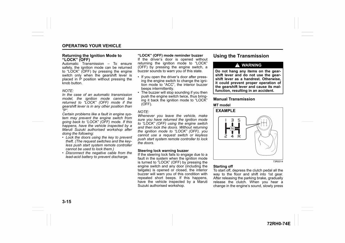
3-15
OPERATING YOUR VEHICLE
72RH0-74E
Returning the Ignition Mode to “LOCK” (OFF)Automatic Transmission – To ensuresafety, the ignition mode can be returnedto “LOCK” (OFF) by pressing the engineswitch only when the gearshift lever isplaced in P position without pressing theknob button.
NOTE:In the case of an automatic transmissionmodel, the ignition mode cannot bereturned to “LOCK” (OFF) mode if thegearshift lever is in any other position than“P”.Certain problems like a fault in engine sys-tem may prevent the engine switch fromgoing back to “LOCK” (OFF) mode. If thishappens, have the vehicle inspected by aMaruti Suzuki authorised workshop afterdoing the following:• Lock the doors using the key to prevent
theft. (The request switches and the key-less push start system remote controllercannot be used to lock them.)
• Disconnect the negative cable from thelead-acid battery to prevent discharge.
“LOCK” (OFF) mode reminder buzzer If the driver’s door is opened withoutreturning the ignition mode to “LOCK”(OFF) by pressing the engine switch, abuzzer sounds to warn you of this state.
• If you open the driver’s door after press-ing the engine switch to change the igni-tion mode to “ACC”, the interior buzzerbeeps intermittently.
• The buzzer will stop sounding if you thenpush the engine switch twice, thus bring-ing it back the ignition mode to “LOCK”(OFF).
NOTE:Whenever you leave the vehicle, makesure you have returned the ignition modeto “LOCK” (OFF) using the engine switchand then lock the doors. Without returningthe ignition mode to “LOCK” (OFF), youcannot use a request switch or keylesspush start system remote controller to lockthe doors.
Steering lock warning buzzerIf the steering lock fails to engage due to afault in the system when the ignition modeis turned to “LOCK” (OFF) by pressing theengine switch and any door (including thetailgate) is opened or closed, the interiorbuzzer will warn you of this condition withrepeated short beeps. If this happens,have the vehicle inspected by a MarutiSuzuki authorised workshop.
Using the Transmission
Manual Transmission
MT model
73R0014
Starting offTo start off, depress the clutch pedal all theway to the floor and shift into 1st gear.After releasing the parking brake, graduallyrelease the clutch. When you hear achange in the engine’s sound, slowly press
WARNING
Do not hang any items on the gear-shift lever and do not use the gear-shift lever as a handrest. Otherwise,it could prevent proper operation ofthe gearshift lever and cause its mal-function, resulting in an accident.
EXAMPLE
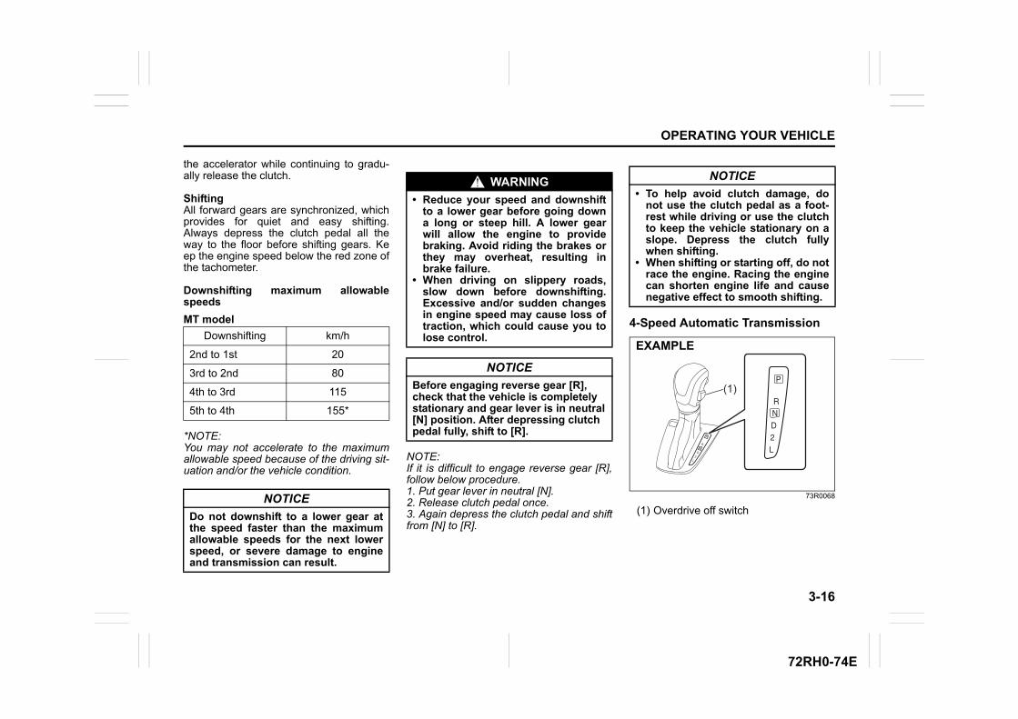
3-16
OPERATING YOUR VEHICLE
72RH0-74E
the accelerator while continuing to gradu-ally release the clutch.
ShiftingAll forward gears are synchronized, whichprovides for quiet and easy shifting.Always depress the clutch pedal all theway to the floor before shifting gears. Keep the engine speed below the red zone ofthe tachometer.
Downshifting maximum allowablespeeds
MT model
*NOTE:You may not accelerate to the maximumallowable speed because of the driving sit-uation and/or the vehicle condition.
NOTE:If it is difficult to engage reverse gear [R],follow below procedure.1. Put gear lever in neutral [N].2. Release clutch pedal once.3. Again depress the clutch pedal and shiftfrom [N] to [R].
4-Speed Automatic Transmission
73R0068
(1) Overdrive off switch
Downshifting km/h
2nd to 1st 20
3rd to 2nd 80
4th to 3rd 115
5th to 4th 155*
NOTICE
Do not downshift to a lower gear atthe speed faster than the maximumallowable speeds for the next lowerspeed, or severe damage to engineand transmission can result.
WARNING
• Reduce your speed and downshiftto a lower gear before going downa long or steep hill. A lower gearwill allow the engine to providebraking. Avoid riding the brakes orthey may overheat, resulting inbrake failure.
• When driving on slippery roads,slow down before downshifting.Excessive and/or sudden changesin engine speed may cause loss oftraction, which could cause you tolose control.
NOTICE
Before engaging reverse gear [R],check that the vehicle is completelystationary and gear lever is in neutral[N] position. After depressing clutchpedal fully, shift to [R].
NOTICE
• To help avoid clutch damage, donot use the clutch pedal as a foot-rest while driving or use the clutchto keep the vehicle stationary on aslope. Depress the clutch fullywhen shifting.
• When shifting or starting off, do notrace the engine. Racing the enginecan shorten engine life and causenegative effect to smooth shifting.
(1)
EXAMPLE
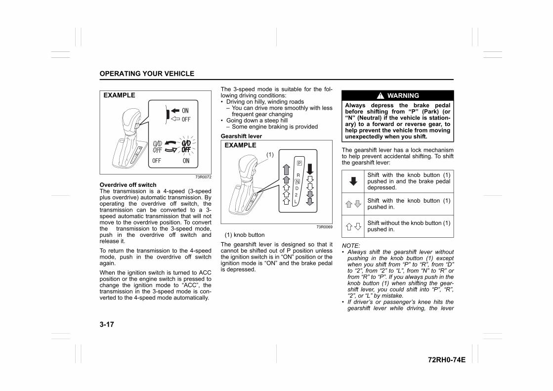
3-17
OPERATING YOUR VEHICLE
72RH0-74E
73R0072
Overdrive off switchThe transmission is a 4-speed (3-speedplus overdrive) automatic transmission. Byoperating the overdrive off switch, thetransmission can be converted to a 3-speed automatic transmission that will notmove to the overdrive position. To convertthe transmission to the 3-speed mode,push in the overdrive off switch andrelease it.
To return the transmission to the 4-speedmode, push in the overdrive off switchagain.
When the ignition switch is turned to ACCposition or the engine switch is pressed tochange the ignition mode to “ACC”, thetransmission in the 3-speed mode is con-verted to the 4-speed mode automatically.
The 3-speed mode is suitable for the fol-lowing driving conditions:• Driving on hilly, winding roads
– You can drive more smoothly with lessfrequent gear changing
• Going down a steep hill– Some engine braking is provided
Gearshift lever
73R0069
(1) knob button
The gearshift lever is designed so that itcannot be shifted out of P position unlessthe ignition switch is in “ON” position or theignition mode is “ON” and the brake pedalis depressed.
The gearshift lever has a lock mechanismto help prevent accidental shifting. To shiftthe gearshift lever:
NOTE:• Always shift the gearshift lever without
pushing in the knob button (1) exceptwhen you shift from “P” to “R”, from “D”to “2”, from “2” to “L”, from “N” to “R” orfrom “R” to “P”. If you always push in theknob button (1) when shifting the gear-shift lever, you could shift into “P”, “R”,“2”, or “L” by mistake.
• If driver’s or passenger’s knee hits thegearshift lever while driving, the lever
EXAMPLE
(1)EXAMPLE
WARNING
Always depress the brake pedalbefore shifting from “P” (Park) (or“N” (Neutral) if the vehicle is station-ary) to a forward or reverse gear, tohelp prevent the vehicle from movingunexpectedly when you shift.
Shift with the knob button (1)pushed in and the brake pedaldepressed.
Shift with the knob button (1)pushed in.
Shift without the knob button (1)pushed in.
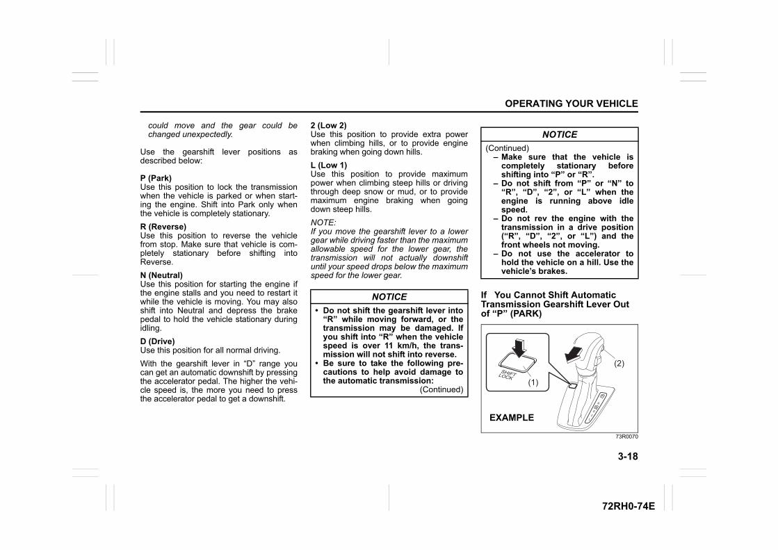
3-18
OPERATING YOUR VEHICLE
72RH0-74E
could move and the gear could bechanged unexpectedly.
Use the gearshift lever positions asdescribed below:
P (Park)Use this position to lock the transmissionwhen the vehicle is parked or when start-ing the engine. Shift into Park only whenthe vehicle is completely stationary.
R (Reverse)Use this position to reverse the vehiclefrom stop. Make sure that vehicle is com-pletely stationary before shifting intoReverse.
N (Neutral)Use this position for starting the engine ifthe engine stalls and you need to restart itwhile the vehicle is moving. You may alsoshift into Neutral and depress the brakepedal to hold the vehicle stationary duringidling.
D (Drive)Use this position for all normal driving.
With the gearshift lever in “D” range youcan get an automatic downshift by pressingthe accelerator pedal. The higher the vehi-cle speed is, the more you need to pressthe accelerator pedal to get a downshift.
2 (Low 2)Use this position to provide extra powerwhen climbing hills, or to provide enginebraking when going down hills.
L (Low 1)Use this position to provide maximumpower when climbing steep hills or drivingthrough deep snow or mud, or to providemaximum engine braking when goingdown steep hills.
NOTE:If you move the gearshift lever to a lowergear while driving faster than the maximumallowable speed for the lower gear, thetransmission will not actually downshiftuntil your speed drops below the maximumspeed for the lower gear.
If You Cannot Shift Automatic Transmission Gearshift Lever Out of “P” (PARK)
73R0070
NOTICE
• Do not shift the gearshift lever into“R” while moving forward, or thetransmission may be damaged. Ifyou shift into “R” when the vehiclespeed is over 11 km/h, the trans-mission will not shift into reverse.
• Be sure to take the following pre-cautions to help avoid damage tothe automatic transmission:
(Continued)
NOTICE
(Continued)– Make sure that the vehicle is
completely stationary beforeshifting into “P” or “R”.
– Do not shift from “P” or “N” to“R”, “D”, “2”, or “L” when theengine is running above idlespeed.
– Do not rev the engine with thetransmission in a drive position(“R”, “D”, “2”, or “L”) and thefront wheels not moving.
– Do not use the accelerator tohold the vehicle on a hill. Use thevehicle’s brakes.
(2)
(1)
EXAMPLE
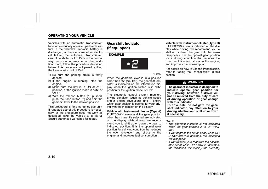
3-19
OPERATING YOUR VEHICLE
72RH0-74E
Vehicles with an automatic Transmissionhave an electrically operated park-lock fea-ture. If the vehicle’s lead-acid battery isdischarged, or there is some other electri-cal failure, the automatic Transmissioncannot be shifted out of Park in the normalway. Jump starting may correct the condi-tion. If not, follow the procedure describedbelow. This procedure will permit shiftingthe transmission out of Park.
1) Be sure the parking brake is firmlyapplied.
2) If the engine is running, stop theengine.
3) Make sure the key is in ON or ACCposition, or the ignition mode is “ON” or“ACC”.
4) With the release button (1) pushed,push the knob button (2) and shift thegearshift lever to the desired position.
This procedure is for emergency use only.If repeated use of this procedure is neces-sary, or the procedure does not work asdescribed, take the vehicle to a MarutiSuzuki authorised workshop for repair.
Gearshift Indicator (if equipped)
72R0074
When the gearshift lever is in a positionother than “N” (Neutral), the gearshift indi-cator is indicated on the information dis-play when the ignition switch is in “ON”position or the ignition mode is “ON”.
The electronic control system monitorsdriving condition (such as vehicle speedand/or engine revolution), and it showswhich gear position is optimal for your driv-ing with the indication on the display.
Vehicle with instrument cluster (Type A)If UP/DOWN arrow and the gear positionother than currently selected are indicatedon the display while driving, we recom-mend you to shift up or down the gear toindicated position. It is the optimal gearposition for a driving condition that reducesthe over revolution and stress to theengine, and improves fuel consumption.
Vehicle with instrument cluster (Type B)If UP/DOWN arrow is indicated on the dis-play while driving, we recommend you toshift up or down the gear until the arrowdisappears. It is the optimal gear positionfor a driving condition that reduces theover revolution and stress to the engine,and improves fuel consumption.
For details on how to use the transmission,refer to “Using the Transmission” in thissection.
NOTE:• The gearshift indicator is not indicated
when the gear position is in “N” (Neu-tral).
• If you depress the clutch pedal while UP/DOWN arrow is indicated, the indicationwill disappear.
• If you release your foot from the acceler-ator pedal while UP arrow is indicated,the indication will display the currently
EXAMPLE
WARNING
The gearshift indicator is designed toindicate optimal gear position foryour driving, however, a driver willnot be relieved from the duty of careof driving operation or gear changewith this indicator.To drive safe, do not gaze the gear-shift indicator, pay attention to yourdriving situation and shift up or downif necessary.
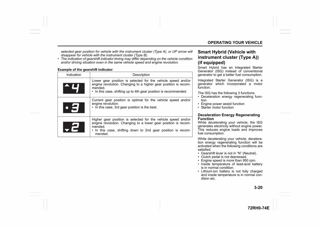
3-20
OPERATING YOUR VEHICLE
72RH0-74E
selected gear position for vehicle with the instrument cluster (Type A), or UP arrow willdisappear for vehicle with the instrument cluster (Type B).
• The indication of gearshift indicator timing may differ depending on the vehicle conditionand/or driving situation even in the same vehicle speed and engine revolution.
Example of the gearshift indicator
Indication Description
Lower gear position is selected for the vehicle speed and/orengine revolution. Changing to a higher gear position is recom-mended.• In this case, shifting up to 4th gear position is recommended.
Current gear position is optimal for the vehicle speed and/orengine revolution.• In this case, 3rd gear position is the best.
Higher gear position is selected for the vehicle speed and/orengine revolution. Changing to a lower gear position is recom-mended. • In this case, shifting down to 2nd gear position is recom-
mended.
Smart Hybrid (Vehicle with instrument cluster (Type A)) (if equipped)Smart Hybrid has an Integrated StarterGenerator (ISG) instead of conventionalgenerator to get a better fuel consumption.
Integrated Starter Generator (ISG) is agenerator which incorporated a motorfunction.
The ISG has the following 3 functions.• Deceleration energy regenerating func-
tion• Engine power assist function• Starter motor function
Deceleration Energy Regenerating FunctionWhile decelerating your vehicle, the ISGgenerates electricity without engine power.This reduces engine loads and improvesfuel consumption.
While decelerating your vehicle, decelera-tion energy regenerating function will beactivated when the following conditions aresatisfied.• Gearshift lever is not in “N” (Neutral).• Clutch pedal is not depressed.• Engine speed is more than 950 rpm.• Inside temperature of lead-acid battery
is in normal condition.• Lithium-ion battery is not fully charged
and inside temperature is in normal con-dition etc.
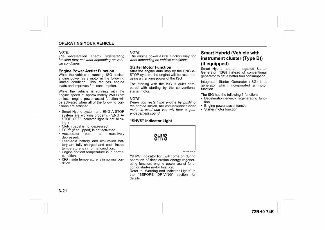
3-21
OPERATING YOUR VEHICLE
72RH0-74E
NOTE:The deceleration energy regeneratingfunction may not work depending on vehi-cle conditions.
Engine Power Assist FunctionWhile the vehicle is running, ISG assistsengine power as a motor in the followinglimited condition. This reduces engineloads and improves fuel consumption.
While the vehicle is running with theengine speed at approximately 2500 rpmor less, engine power assist function willbe activated when all of the following con-ditions are satisfied.
• Smart Hybrid system and ENG A-STOPsystem are working properly. (“ENG A-STOP OFF” indicator light is not blink-ing.)
• Clutch pedal is not depressed.• ESP® (if equipped) is not activated.• Accelerator pedal is excessively
depressed.• Lead-acid battery and lithium-ion bat-
tery are fully charged and each insidetemperature is in normal condition.
• Engine coolant temperature is in normalcondition.
• ISG inside temperature is in normal con-dition.
NOTE:The engine power assist function may notwork depending on vehicle conditions.
Starter Motor FunctionAfter the engine auto stop by the ENG A-STOP system, the engine will be restartedusing a cranking power of the ISG.
The starting with the ISG is quiet com-pared with starting by the conventionalstarter motor.
NOTE:When you restart the engine by pushingthe engine switch, the conventional startermotor is used and you will hear a gearengagement sound.
“SHVS” Indicator Light
79MH10205
“SHVS” indicator light will come on duringoperation of deceleration energy regener-ating function, engine power assist func-tion or starter motor function.Refer to “Warning and Indicator Lights” inthe “BEFORE DRIVING” section fordetails.
Smart Hybrid (Vehicle with instrument cluster (Type B)) (if equipped)Smart Hybrid has an Integrated StarterGenerator (ISG) instead of conventionalgenerator to get a better fuel consumption.
Integrated Starter Generator (ISG) is agenerator which incorporated a motorfunction.
The ISG has the following 3 functions.• Deceleration energy regenerating func-
tion• Engine power assist function• Starter motor function
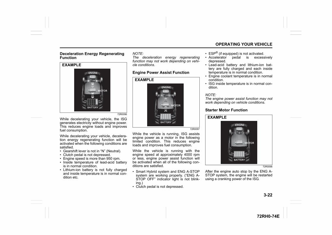
3-22
OPERATING YOUR VEHICLE
72RH0-74E
Deceleration Energy Regenerating Function
72R0096
While decelerating your vehicle, the ISGgenerates electricity without engine power.This reduces engine loads and improvesfuel consumption.
While decelerating your vehicle, decelera-tion energy regenerating function will beactivated when the following conditions aresatisfied.• Gearshift lever is not in “N” (Neutral).• Clutch pedal is not depressed.• Engine speed is more than 950 rpm.• Inside temperature of lead-acid battery
is in normal condition.• Lithium-ion battery is not fully charged
and inside temperature is in normal con-dition etc.
NOTE:The deceleration energy regeneratingfunction may not work depending on vehi-cle conditions.
Engine Power Assist Function
72R0097
While the vehicle is running, ISG assistsengine power as a motor in the followinglimited condition. This reduces engineloads and improves fuel consumption.
While the vehicle is running with theengine speed at approximately 4000 rpmor less, engine power assist function willbe activated when all of the following con-ditions are satisfied.
• Smart Hybrid system and ENG A-STOPsystem are working properly. (“ENG A-STOP OFF” indicator light is not blink-ing.)
• Clutch pedal is not depressed.
• ESP® (if equipped) is not activated.• Accelerator pedal is excessively
depressed.• Lead-acid battery and lithium-ion bat-
tery are fully charged and each insidetemperature is in normal condition.
• Engine coolant temperature is in normalcondition.
• ISG inside temperature is in normal con-dition.
NOTE:The engine power assist function may notwork depending on vehicle conditions.
Starter Motor Function
72R0098
After the engine auto stop by the ENG A-STOP system, the engine will be restartedusing a cranking power of the ISG.
EXAMPLE
EXAMPLE
EXAMPLE
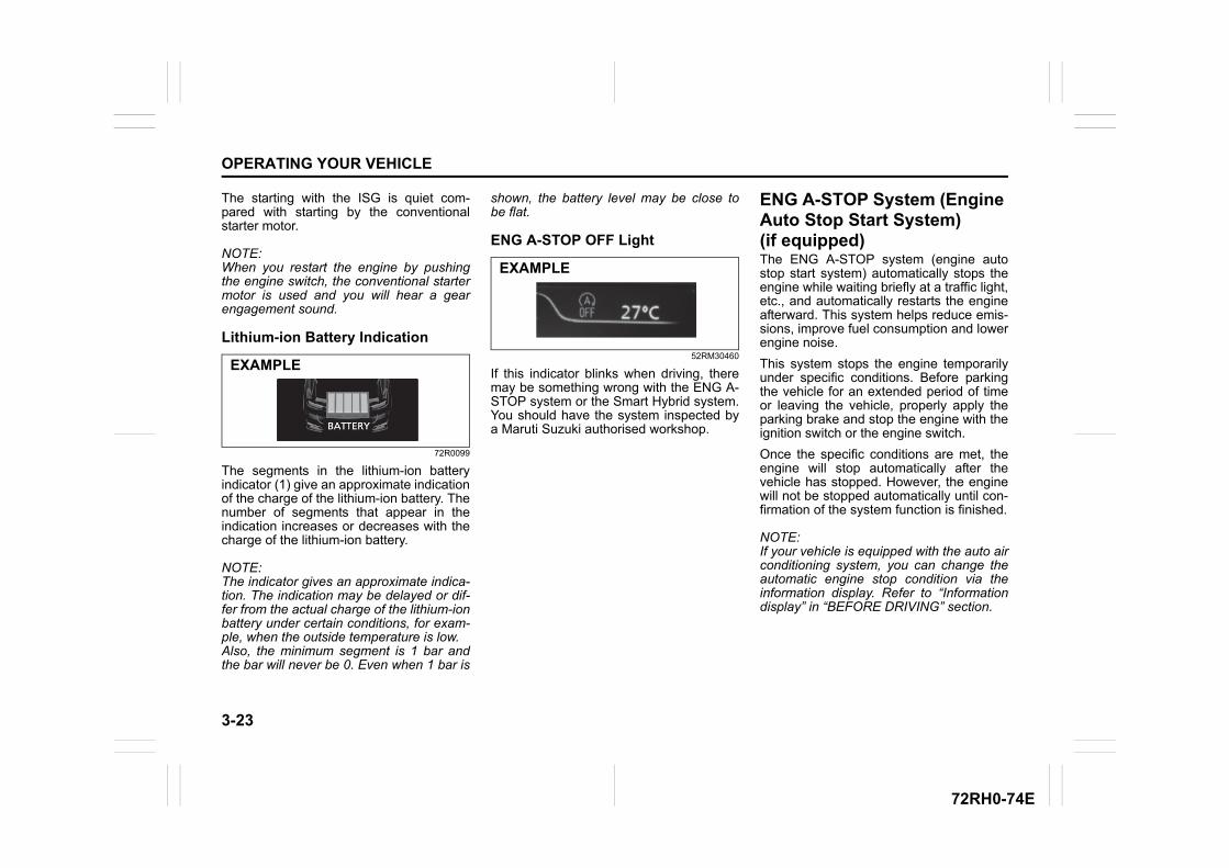
3-23
OPERATING YOUR VEHICLE
72RH0-74E
The starting with the ISG is quiet com-pared with starting by the conventionalstarter motor.
NOTE:When you restart the engine by pushingthe engine switch, the conventional startermotor is used and you will hear a gearengagement sound.
Lithium-ion Battery Indication
72R0099
The segments in the lithium-ion batteryindicator (1) give an approximate indicationof the charge of the lithium-ion battery. Thenumber of segments that appear in theindication increases or decreases with thecharge of the lithium-ion battery.
NOTE:The indicator gives an approximate indica-tion. The indication may be delayed or dif-fer from the actual charge of the lithium-ionbattery under certain conditions, for exam-ple, when the outside temperature is low.Also, the minimum segment is 1 bar andthe bar will never be 0. Even when 1 bar is
shown, the battery level may be close tobe flat.
ENG A-STOP OFF Light
52RM30460
If this indicator blinks when driving, theremay be something wrong with the ENG A-STOP system or the Smart Hybrid system.You should have the system inspected bya Maruti Suzuki authorised workshop.
ENG A-STOP System (Engine Auto Stop Start System) (if equipped)The ENG A-STOP system (engine autostop start system) automatically stops theengine while waiting briefly at a traffic light,etc., and automatically restarts the engineafterward. This system helps reduce emis-sions, improve fuel consumption and lowerengine noise.
This system stops the engine temporarilyunder specific conditions. Before parkingthe vehicle for an extended period of timeor leaving the vehicle, properly apply theparking brake and stop the engine with theignition switch or the engine switch.
Once the specific conditions are met, theengine will stop automatically after thevehicle has stopped. However, the enginewill not be stopped automatically until con-firmation of the system function is finished.
NOTE:If your vehicle is equipped with the auto airconditioning system, you can change theautomatic engine stop condition via theinformation display. Refer to “Informationdisplay” in “BEFORE DRIVING” section.
EXAMPLE
EXAMPLE
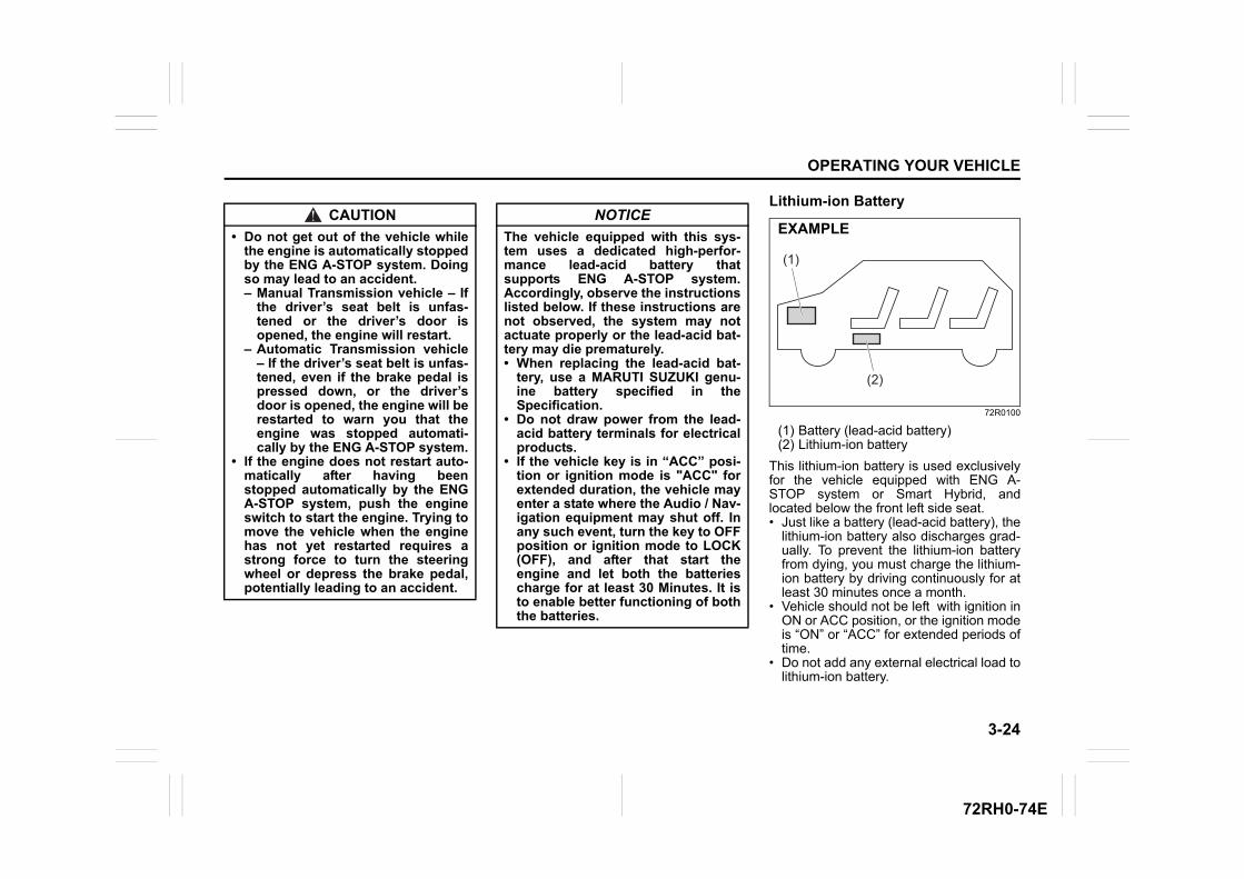
3-24
OPERATING YOUR VEHICLE
72RH0-74E
Lithium-ion Battery
72R0100
(1) Battery (lead-acid battery)(2) Lithium-ion battery
This lithium-ion battery is used exclusivelyfor the vehicle equipped with ENG A-STOP system or Smart Hybrid, andlocated below the front left side seat.• Just like a battery (lead-acid battery), the
lithium-ion battery also discharges grad-ually. To prevent the lithium-ion batteryfrom dying, you must charge the lithium-ion battery by driving continuously for atleast 30 minutes once a month.
• Vehicle should not be left with ignition inON or ACC position, or the ignition modeis “ON” or “ACC” for extended periods oftime.
• Do not add any external electrical load tolithium-ion battery.
CAUTION
• Do not get out of the vehicle whilethe engine is automatically stoppedby the ENG A-STOP system. Doingso may lead to an accident. – Manual Transmission vehicle – If
the driver’s seat belt is unfas-tened or the driver’s door isopened, the engine will restart.
– Automatic Transmission vehicle– If the driver’s seat belt is unfas-tened, even if the brake pedal ispressed down, or the driver’sdoor is opened, the engine will berestarted to warn you that theengine was stopped automati-cally by the ENG A-STOP system.
• If the engine does not restart auto-matically after having beenstopped automatically by the ENGA-STOP system, push the engineswitch to start the engine. Trying tomove the vehicle when the enginehas not yet restarted requires astrong force to turn the steeringwheel or depress the brake pedal,potentially leading to an accident.
NOTICE
The vehicle equipped with this sys-tem uses a dedicated high-perfor-mance lead-acid battery thatsupports ENG A-STOP system.Accordingly, observe the instructionslisted below. If these instructions arenot observed, the system may notactuate properly or the lead-acid bat-tery may die prematurely.• When replacing the lead-acid bat-
tery, use a MARUTI SUZUKI genu-ine battery specified in theSpecification.
• Do not draw power from the lead-acid battery terminals for electricalproducts.
• If the vehicle key is in “ACC” posi-tion or ignition mode is "ACC" forextended duration, the vehicle mayenter a state where the Audio / Nav-igation equipment may shut off. Inany such event, turn the key to OFFposition or ignition mode to LOCK(OFF), and after that start theengine and let both the batteriescharge for at least 30 Minutes. It isto enable better functioning of boththe batteries.
(1)
(2)
EXAMPLE
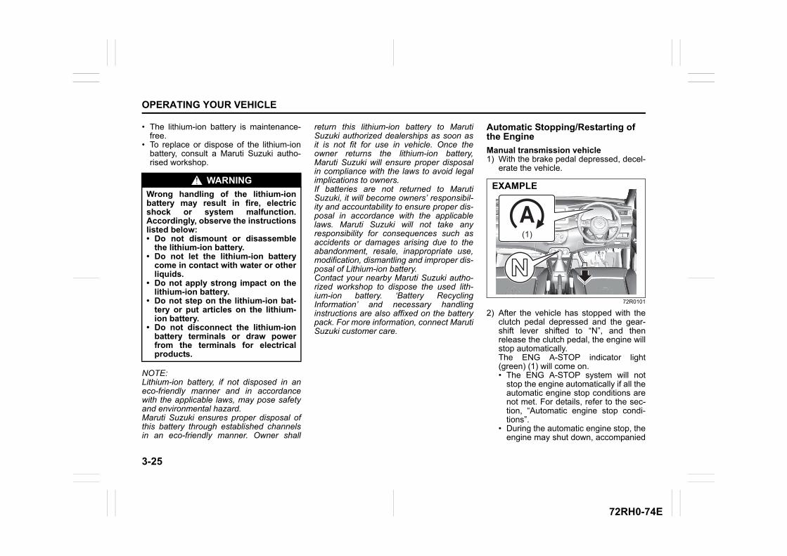
3-25
OPERATING YOUR VEHICLE
72RH0-74E
• The lithium-ion battery is maintenance-free.
• To replace or dispose of the lithium-ionbattery, consult a Maruti Suzuki autho-rised workshop.
NOTE:Lithium-ion battery, if not disposed in aneco-friendly manner and in accordancewith the applicable laws, may pose safetyand environmental hazard. Maruti Suzuki ensures proper disposal ofthis battery through established channelsin an eco-friendly manner. Owner shall
return this lithium-ion battery to MarutiSuzuki authorized dealerships as soon asit is not fit for use in vehicle. Once theowner returns the lithium-ion battery,Maruti Suzuki will ensure proper disposalin compliance with the laws to avoid legalimplications to owners.If batteries are not returned to MarutiSuzuki, it will become owners’ responsibil-ity and accountability to ensure proper dis-posal in accordance with the applicablelaws. Maruti Suzuki will not take anyresponsibility for consequences such asaccidents or damages arising due to theabandonment, resale, inappropriate use,modification, dismantling and improper dis-posal of Lithium-ion battery.Contact your nearby Maruti Suzuki autho-rized workshop to dispose the used lith-ium-ion battery. ‘Battery RecyclingInformation’ and necessary handlinginstructions are also affixed on the batterypack. For more information, connect MarutiSuzuki customer care.
Automatic Stopping/Restarting of the Engine
Manual transmission vehicle1) With the brake pedal depressed, decel-
erate the vehicle.
72R0101
2) After the vehicle has stopped with theclutch pedal depressed and the gear-shift lever shifted to “N”, and thenrelease the clutch pedal, the engine willstop automatically. The ENG A-STOP indicator light(green) (1) will come on. • The ENG A-STOP system will not
stop the engine automatically if all theautomatic engine stop conditions arenot met. For details, refer to the sec-tion, “Automatic engine stop condi-tions”.
• During the automatic engine stop, theengine may shut down, accompanied
WARNING
Wrong handling of the lithium-ionbattery may result in fire, electricshock or system malfunction.Accordingly, observe the instructionslisted below:• Do not dismount or disassemble
the lithium-ion battery.• Do not let the lithium-ion battery
come in contact with water or otherliquids.
• Do not apply strong impact on thelithium-ion battery.
• Do not step on the lithium-ion bat-tery or put articles on the lithium-ion battery.
• Do not disconnect the lithium-ionbattery terminals or draw powerfrom the terminals for electricalproducts.
(1)
EXAMPLE
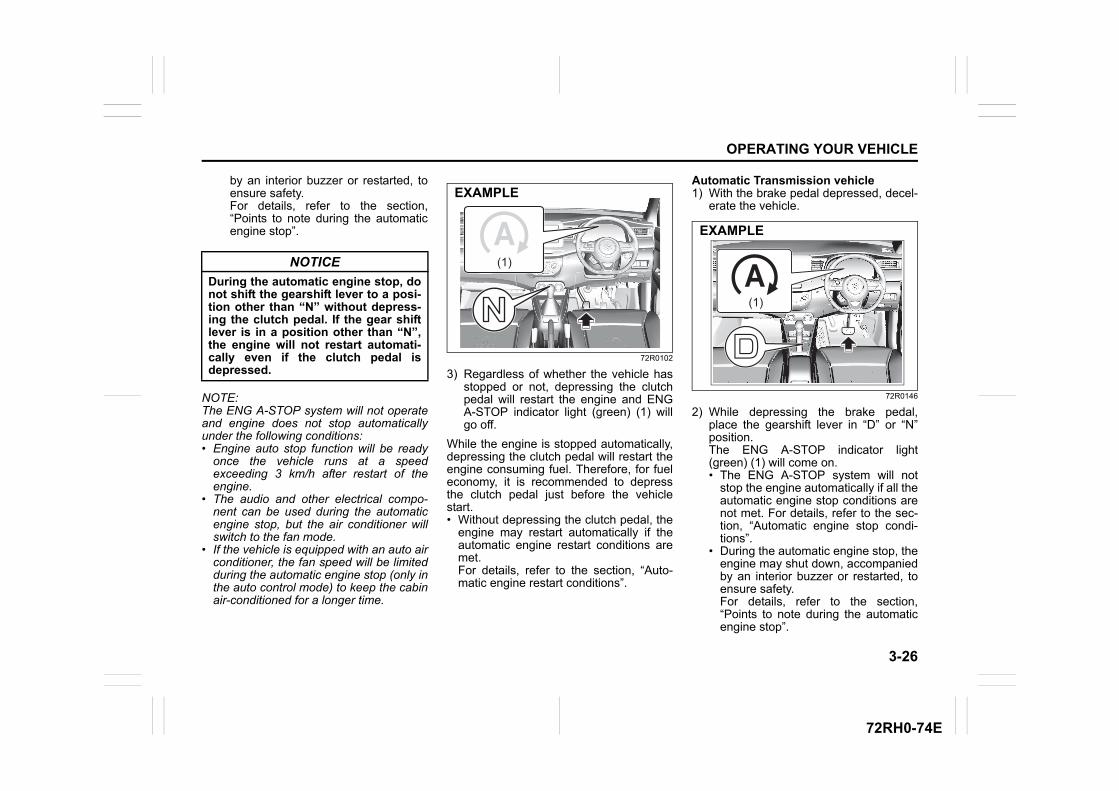
3-26
OPERATING YOUR VEHICLE
72RH0-74E
by an interior buzzer or restarted, toensure safety.For details, refer to the section,“Points to note during the automaticengine stop”.
NOTE:The ENG A-STOP system will not operateand engine does not stop automaticallyunder the following conditions:• Engine auto stop function will be ready
once the vehicle runs at a speedexceeding 3 km/h after restart of theengine.
• The audio and other electrical compo-nent can be used during the automaticengine stop, but the air conditioner willswitch to the fan mode.
• If the vehicle is equipped with an auto airconditioner, the fan speed will be limitedduring the automatic engine stop (only inthe auto control mode) to keep the cabinair-conditioned for a longer time.
72R0102
3) Regardless of whether the vehicle hasstopped or not, depressing the clutchpedal will restart the engine and ENGA-STOP indicator light (green) (1) willgo off.
While the engine is stopped automatically,depressing the clutch pedal will restart theengine consuming fuel. Therefore, for fueleconomy, it is recommended to depressthe clutch pedal just before the vehiclestart.• Without depressing the clutch pedal, the
engine may restart automatically if theautomatic engine restart conditions aremet.For details, refer to the section, “Auto-matic engine restart conditions”.
Automatic Transmission vehicle1) With the brake pedal depressed, decel-
erate the vehicle.
72R0146
2) While depressing the brake pedal,place the gearshift lever in “D” or “N”position. The ENG A-STOP indicator light(green) (1) will come on. • The ENG A-STOP system will not
stop the engine automatically if all theautomatic engine stop conditions arenot met. For details, refer to the sec-tion, “Automatic engine stop condi-tions”.
• During the automatic engine stop, theengine may shut down, accompaniedby an interior buzzer or restarted, toensure safety.For details, refer to the section,“Points to note during the automaticengine stop”.
NOTICE
During the automatic engine stop, donot shift the gearshift lever to a posi-tion other than “N” without depress-ing the clutch pedal. If the gear shiftlever is in a position other than “N”,the engine will not restart automati-cally even if the clutch pedal isdepressed.
(1)
EXAMPLE
(1)
EXAMPLE
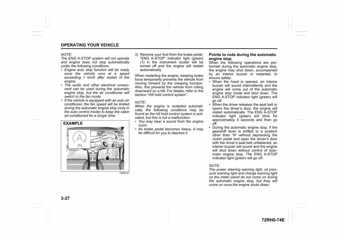
3-27
OPERATING YOUR VEHICLE
72RH0-74E
NOTE:The ENG A-STOP system will not operateand engine does not stop automaticallyunder the following conditions:• Engine auto stop function will be ready
once the vehicle runs at a speedexceeding 1 km/h after restart of theengine.
• The audio and other electrical compo-nent can be used during the automaticengine stop, but the air conditioner willswitch to the fan mode.
• If the vehicle is equipped with an auto airconditioner, the fan speed will be limitedduring the automatic engine stop (only inthe auto control mode) to keep the cabinair-conditioned for a longer time.
72R0147
3) Remove your foot from the brake pedal.“ENG A-STOP” indicator light (green)(1) in the instrument cluster will beturned off and the engine will restartautomatically.
When restarting the engine, keeping brakeforce temporarily prevents the vehicle frommoving forward by the creeping function.Also, this prevents the vehicle from rollingdownward on a hill. For details, refer to thesection “Hill hold control system”.
NOTE:When the engine is restarted automati-cally, the following conditions may befound as the hill hold control system is acti-vated, but this is not a malfunction.• You may hear a sound from the engine
room.• As brake pedal becomes heavy, it may
be difficult for you to depress it.
Points to note during the automatic engine stopWhen the following operations are per-formed during the automatic engine stop,the engine may shut down, accompaniedby an interior buzzer or restarted, toensure safety.• When the hood is opened, an interior
buzzer will sound intermittently and theengine will come out of the automaticengine stop mode and shut down. TheENG A-STOP indicator light (green) willgo off.
• When the driver releases the seat belt oropens the driver’s door, the engine willrestart automatically. The ENG A-STOPindicator light (green) will blink forapproximately 5 seconds and then gooff.
• During the automatic engine stop, if thegearshift lever is shifted to a positionother than “N” without depressing theclutch pedal and open the driver’s doorwith the driver’s seat belt unfastened, aninterior buzzer will sound and the enginewill shut down without control of auto-matic engine stop. The ENG A-STOPindicator light (green) will go off.
NOTE:The power steering warning light, oil pres-sure warning light and charge warning lighton the meter panel do not come on duringthe automatic engine stop, but they willcome on once the engine shuts down.
(1)
EXAMPLE
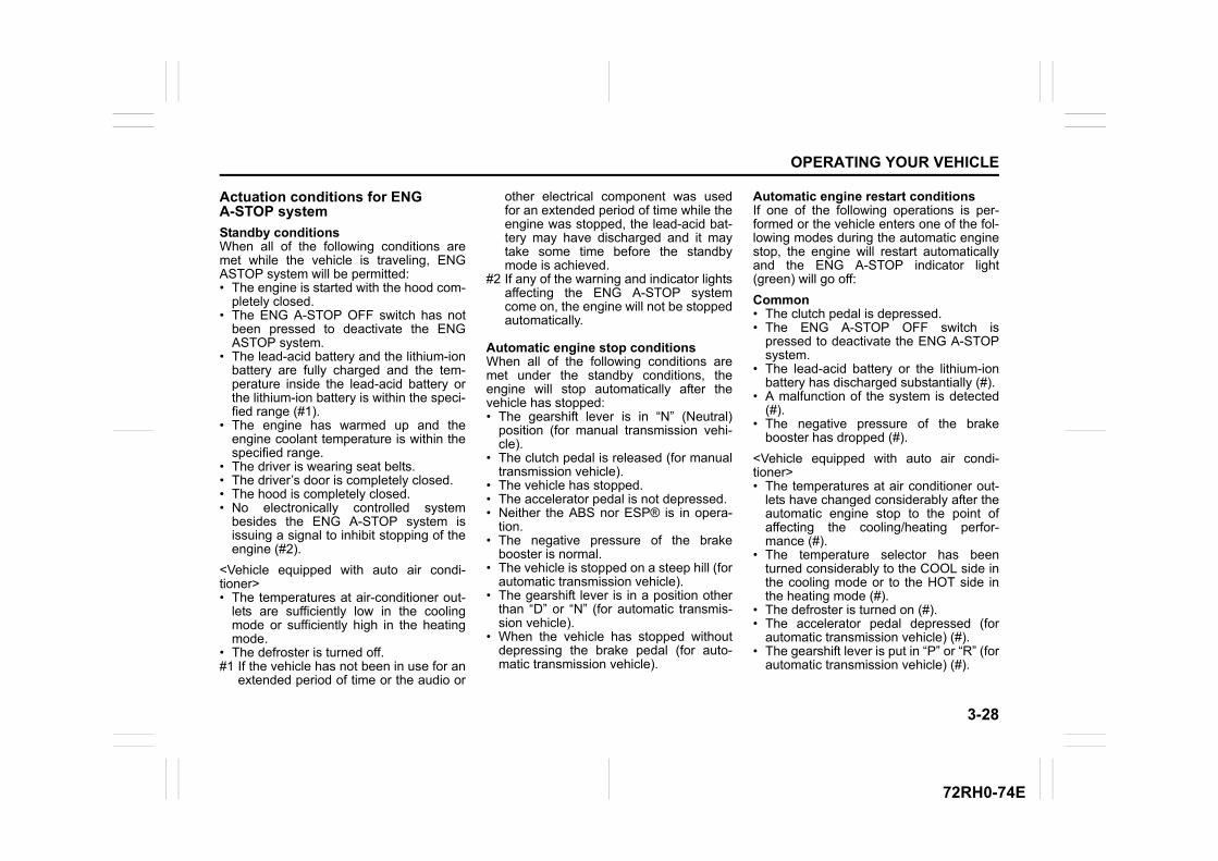
3-28
OPERATING YOUR VEHICLE
72RH0-74E
Actuation conditions for ENG A-STOP system
Standby conditionsWhen all of the following conditions aremet while the vehicle is traveling, ENGASTOP system will be permitted:• The engine is started with the hood com-
pletely closed.• The ENG A-STOP OFF switch has not
been pressed to deactivate the ENGASTOP system.
• The lead-acid battery and the lithium-ionbattery are fully charged and the tem-perature inside the lead-acid battery orthe lithium-ion battery is within the speci-fied range (#1).
• The engine has warmed up and theengine coolant temperature is within thespecified range.
• The driver is wearing seat belts.• The driver’s door is completely closed.• The hood is completely closed.• No electronically controlled system
besides the ENG A-STOP system isissuing a signal to inhibit stopping of theengine (#2).
<Vehicle equipped with auto air condi-tioner>• The temperatures at air-conditioner out-
lets are sufficiently low in the coolingmode or sufficiently high in the heatingmode.
• The defroster is turned off.#1 If the vehicle has not been in use for an
extended period of time or the audio or
other electrical component was usedfor an extended period of time while theengine was stopped, the lead-acid bat-tery may have discharged and it maytake some time before the standbymode is achieved.
#2 If any of the warning and indicator lightsaffecting the ENG A-STOP systemcome on, the engine will not be stoppedautomatically.
Automatic engine stop conditionsWhen all of the following conditions aremet under the standby conditions, theengine will stop automatically after thevehicle has stopped:• The gearshift lever is in “N” (Neutral)
position (for manual transmission vehi-cle).
• The clutch pedal is released (for manualtransmission vehicle).
• The vehicle has stopped.• The accelerator pedal is not depressed.• Neither the ABS nor ESP® is in opera-
tion.• The negative pressure of the brake
booster is normal.• The vehicle is stopped on a steep hill (for
automatic transmission vehicle).• The gearshift lever is in a position other
than “D” or “N” (for automatic transmis-sion vehicle).
• When the vehicle has stopped withoutdepressing the brake pedal (for auto-matic transmission vehicle).
Automatic engine restart conditionsIf one of the following operations is per-formed or the vehicle enters one of the fol-lowing modes during the automatic enginestop, the engine will restart automaticallyand the ENG A-STOP indicator light(green) will go off:
Common• The clutch pedal is depressed.• The ENG A-STOP OFF switch is
pressed to deactivate the ENG A-STOPsystem.
• The lead-acid battery or the lithium-ionbattery has discharged substantially (#).
• A malfunction of the system is detected(#).
• The negative pressure of the brakebooster has dropped (#).
<Vehicle equipped with auto air condi-tioner>• The temperatures at air conditioner out-
lets have changed considerably after theautomatic engine stop to the point ofaffecting the cooling/heating perfor-mance (#).
• The temperature selector has beenturned considerably to the COOL side inthe cooling mode or to the HOT side inthe heating mode (#).
• The defroster is turned on (#).• The accelerator pedal depressed (for
automatic transmission vehicle) (#).• The gearshift lever is put in “P” or “R” (for
automatic transmission vehicle) (#).
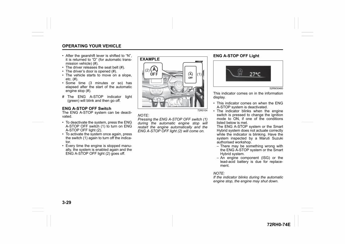
3-29
OPERATING YOUR VEHICLE
72RH0-74E
• After the gearshift lever is shifted to “N”,it is returned to “D” (for automatic trans-mission vehicle) (#).
• The driver releases the seat belt (#).• The driver’s door is opened (#).• The vehicle starts to move on a slope,
etc. (#).• Some time (3 minutes or so) has
elapsed after the start of the automaticengine stop (#).
# The ENG A-STOP indicator light(green) will blink and then go off.
ENG A-STOP OFF SwitchThe ENG A-STOP system can be deacti-vated.
• To deactivate the system, press the ENGA-STOP OFF switch (1) to turn on ENGA-STOP OFF light (2).
• To activate the system once again, pressthe switch (1) again to turn off the indica-tor.
• Every time the engine is stopped manu-ally, the system is enabled again and theENG A-STOP OFF light (2) goes off.
72R0104
NOTE:Pressing the ENG A-STOP OFF switch (1)during the automatic engine stop willrestart the engine automatically and theENG A-STOP OFF light (2) will come on.
ENG A-STOP OFF Light
52RM30460
This indicator comes on in the informationdisplay.
• This indicator comes on when the ENGA-STOP system is deactivated.
• The indicator blinks when the engineswitch is pressed to change the ignitionmode to ON, if one of the conditionslisted below is met.The ENG A-STOP system or the SmartHybrid system does not actuate correctlywhile the indicator is blinking. Have thesystem inspected by a Maruti Suzukiauthorised workshop.– There may be something wrong with
the ENG A-STOP system or the SmartHybrid system.
– An engine component (ISG) or thelead-acid battery is due for replace-ment.
NOTE:If the indicator blinks during the automaticengine stop, the engine may shut down.
(2)(1)
EXAMPLE
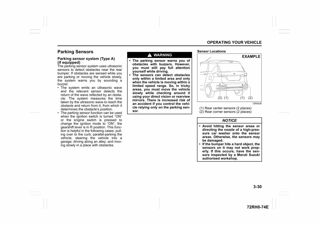
3-30
OPERATING YOUR VEHICLE
72RH0-74E
Parking Sensors
Parking sensor system (Type A)(if equipped)The parking sensor system uses ultrasonicsensors to detect obstacles near the rearbumper. If obstacles are sensed while youare parking or moving the vehicle slowly,the system warns you by sounding abuzzer.• The system emits an ultrasonic wave
and the relevant sensor detects thereturn of the wave reflected by an obsta-cle. The system measures the timetaken by the ultrasonic wave to reach theobstacle and return from it, from which itdetermines the obstacle’s position.
• The parking sensor function can be usedwhen the ignition switch is turned “ON”or the engine switch is pressed tochange the ignition mode to “ON”, thegearshift lever is in R position. This func-tion is helpful in the following cases: pull-ing over to the curb; parallel-parking thevehicle; steering the vehicle into agarage; driving along an alley; and mov-ing slowly in a place with obstacles.
Sensor Locations
72R0036
(1) Rear center sensors (2 places)(2) Rear corner sensors (2 places)
WARNING
• The parking sensor warns you ofobstacles with buzzers. However,you must still pay full attentionyourself while driving.
• The sensors can detect obstaclesonly within a limited area and onlywhen the vehicle is moving within alimited speed range. So, in trickyareas, you must move the vehicleslowly while checking around itusing your direct vision or rearviewmirrors. There is increased risk ofan accident if you control the vehi-cle relying only on the parking sen-sor.
NOTICE
• Avoid hitting the sensor areas ordirecting the nozzle of a high-pres-sure car washer onto the sensorareas. Otherwise, the sensors maybe damaged.
• If the bumper hits a hard object, thesensors on it may not work prop-erly. If this occurs, have the sen-sors inspected by a Maruti Suzukiauthorised workshop.
(1)(2) (1) (2)
EXAMPLE
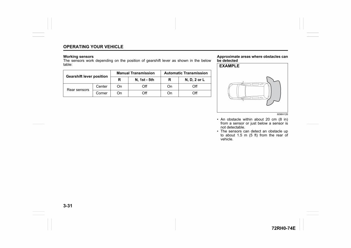
3-31
OPERATING YOUR VEHICLE
72RH0-74E
Working sensorsThe sensors work depending on the position of gearshift lever as shown in the belowtable:
Gearshift lever positionManual Transmission Automatic Transmission
R N, 1st - 5th R N, D, 2 or L
Rear sensorsCenter On Off On Off
Corner On Off On Off
Approximate areas where obstacles canbe detected
60MH126
• An obstacle within about 20 cm (8 in)from a sensor or just below a sensor isnot detectable.
• The sensors can detect an obstacle upto about 1.5 m (5 ft) from the rear ofvehicle.
EXAMPLE
3-32
OPERATING YOUR VEHICLE
72RH0-74E
NOTE:• Thin poles or obstacles lower than the
sensors may become undetectable asthe vehicle moves closer to them even ifthey have been detected from longerdistances.
• The system may calculate the distanceto a road sign or similar obstacle to beshorter than the actual distance.
WARNING
• Under the following conditions, theparking sensor system may notwork normally because the sensorscannot detect obstacles correctly.– Sensors are covered with mud,
ice or other materials. (Suchmaterials must be removed fornormal operation.)
– Sensors are wet from watersplashes or heavy rain.
– Sensors are covered by a hand,sticker, accessory, etc.
– There is an accessory or otherobject attached within the sen-sor’s sensing area.
– Items such as tow hooks, com-mercially available corner poles,radio antenna, etc. are installedon the bumper.
– The height of the bumper ischanged due to alteration to thesuspension or other causes.
– The sensor areas are extremelyhot from direct sunlight or colddue to freezing weather.
– The vehicle is on a rough sur-face, slope, gravel road or grassfield.
– The vehicle is at a steep angle.(Continued)
WARNING
(Continued)– Sensors have intercepted ultra-
sonic noise from another vehi-cle’s horn, engine, air brakingsystem (large vehicles), or park-ing sensor.
– Obstacles are too close to thesensors.
– Sensors are at an angle to ahighly reflective object such asglass. (Ultrasonic waves are notreflected back from the obstacle.)
• Sensors may not be able to cor-rectly detect the following types ofobstacles:– Objects made of a thin material
like wire netting and ropes– Square-shaped curbstones or
other objects with sharp edges– Tall objects with a large upper
part like a road sign– Low-profile objects such as curb-
stones– Sound-absorbing objects such
as cotton and snow
3-33
OPERATING YOUR VEHICLE
72RH0-74E
Obstacle Indication by Parking SensorUpon detecting an obstacle, the parking sensor causes an interior buzzer to sound.• A buzzer located behind the rear seat sounds when a sensor at the rear detects an
obstacle.• Warnings when obstacles such as wall are detected by corner sensors
• Warnings when obstacles such as wall are detected by center sensors
Warning and Indicator Messagesif there is a problem or warning on the parking sensor system, the buzzer sound intermit-tently. If the buzzer does not stop, there may be a problem with the parking sensor sys-tem. Have your vehicle inspected by a Maruti Suzuki authorised workshop
Distance (approx.) Buzzer45 – 60 cm(18 – 24 in) Short beeps at short intervals
35 – 45 cm(14 – 18 in) Short beeps at very short intervals
Less than 35 cm (14 in) Continuous beep
Distance (approx.) Buzzer60 – 150 cm(24 – 59 in) Short beeps at long intervals
45 – 60 cm(18 – 24 in) Short beeps at short intervals
35 – 45 cm(14 – 18 in) Short beeps at very short intervals
Less than 35 cm (14 in) Continuous beep
Parking sensor system (Type B) (if equipped)
The parking sensor system uses ultrasonicsensors to detect obstacles near the rearbumper. If obstacles are sensed while youare parking or moving the vehicle slowly,the system warns you by sounding abuzzer and displaying symbols represent-ing the obstacles on the information dis-play in the instrument cluster.• The system emits an ultrasonic wave
and the relevant sensor detects thereturn of the wave reflected by an obsta-cle. The system measures the timetaken by the ultrasonic wave to reach theobstacle and return from it, from which itdetermines the obstacle’s position.
• The parking sensor function can be usedwhen the ignition switch is turned “ON”or the engine switch is pressed tochange the ignition mode to “ON”, thegearshift lever is in R position. This func-tion is helpful in the following cases: pull-ing over to the curb; parallel-parking thevehicle; steering the vehicle into agarage; driving along an alley; and mov-ing slowly in a place with obstacles.
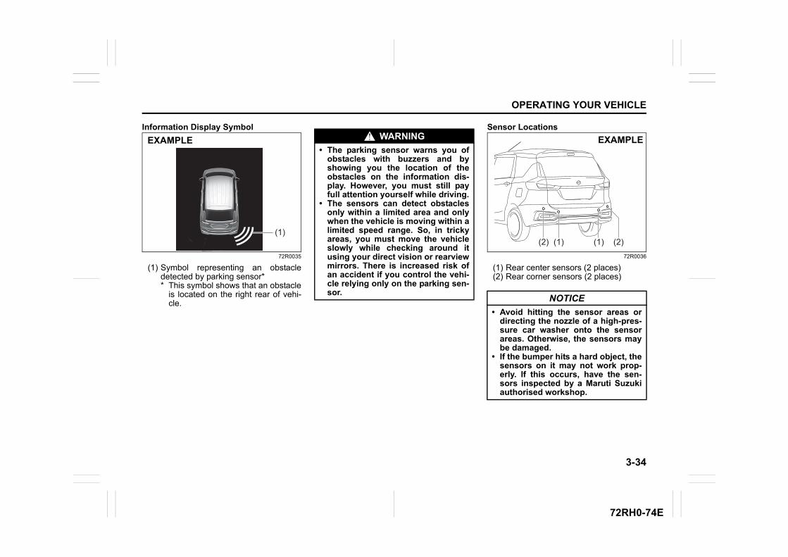
3-34
OPERATING YOUR VEHICLE
72RH0-74E
Information Display Symbol
72R0035
(1) Symbol representing an obstacledetected by parking sensor** This symbol shows that an obstacle
is located on the right rear of vehi-cle.
Sensor Locations
72R0036
(1) Rear center sensors (2 places)(2) Rear corner sensors (2 places)
(1)
EXAMPLE WARNING
• The parking sensor warns you ofobstacles with buzzers and byshowing you the location of theobstacles on the information dis-play. However, you must still payfull attention yourself while driving.
• The sensors can detect obstaclesonly within a limited area and onlywhen the vehicle is moving within alimited speed range. So, in trickyareas, you must move the vehicleslowly while checking around itusing your direct vision or rearviewmirrors. There is increased risk ofan accident if you control the vehi-cle relying only on the parking sen-sor.
NOTICE
• Avoid hitting the sensor areas ordirecting the nozzle of a high-pres-sure car washer onto the sensorareas. Otherwise, the sensors maybe damaged.
• If the bumper hits a hard object, thesensors on it may not work prop-erly. If this occurs, have the sen-sors inspected by a Maruti Suzukiauthorised workshop.
(1)(2) (1) (2)
EXAMPLE
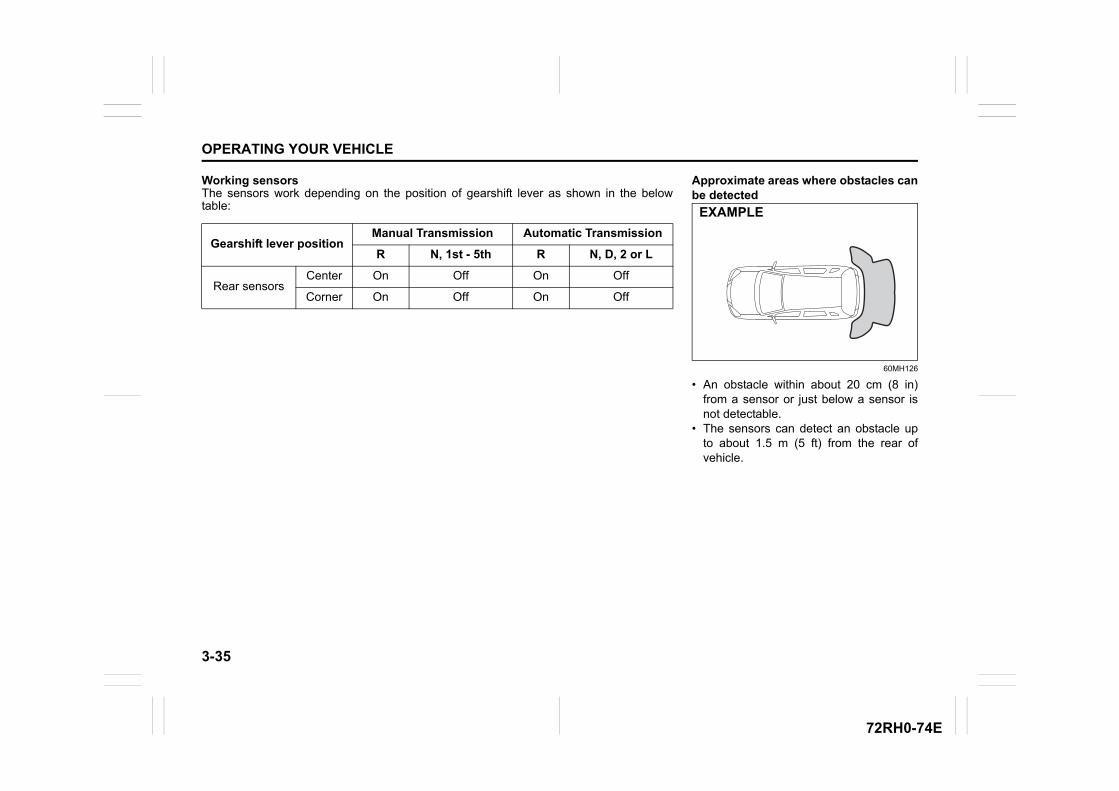
3-35
OPERATING YOUR VEHICLE
72RH0-74E
Working sensorsThe sensors work depending on the position of gearshift lever as shown in the belowtable:
Gearshift lever positionManual Transmission Automatic Transmission
R N, 1st - 5th R N, D, 2 or L
Rear sensorsCenter On Off On Off
Corner On Off On Off
Approximate areas where obstacles canbe detected
60MH126
• An obstacle within about 20 cm (8 in)from a sensor or just below a sensor isnot detectable.
• The sensors can detect an obstacle upto about 1.5 m (5 ft) from the rear ofvehicle.
EXAMPLE

3-36
OPERATING YOUR VEHICLE
72RH0-74E
NOTE:• Thin poles or obstacles lower than the
sensors may become undetectable asthe vehicle moves closer to them even ifthey have been detected from longerdistances.
• The system may calculate the distanceto a road sign or similar obstacle to beshorter than the actual distance.
WARNING
• Under the following conditions, theparking sensor system may notwork normally because the sensorscannot detect obstacles correctly.– Sensors are covered with mud,
ice or other materials. (Suchmaterials must be removed fornormal operation.)
– Sensors are wet from watersplashes or heavy rain.
– Sensors are covered by a hand,sticker, accessory, etc.
– There is an accessory or otherobject attached within the sen-sor’s sensing area.
– Items such as tow hooks, com-mercially available corner poles,radio antenna, etc. are installedon the bumper.
– The height of the bumper ischanged due to alteration to thesuspension or other causes.
– The sensor areas are extremelyhot from direct sunlight or colddue to freezing weather.
– The vehicle is on a rough sur-face, slope, gravel road or grassfield.
– The vehicle is at a steep angle.(Continued)
WARNING
(Continued)– Sensors have intercepted ultra-
sonic noise from another vehi-cle’s horn, engine, air brakingsystem (large vehicles), or park-ing sensor.
– Obstacles are too close to thesensors.
– Sensors are at an angle to ahighly reflective object such asglass. (Ultrasonic waves are notreflected back from the obstacle.)
• Sensors may not be able to cor-rectly detect the following types ofobstacles:– Objects made of a thin material
like wire netting and ropes– Square-shaped curbstones or
other objects with sharp edges– Tall objects with a large upper
part like a road sign– Low-profile objects such as curb-
stones– Sound-absorbing objects such
as cotton and snow
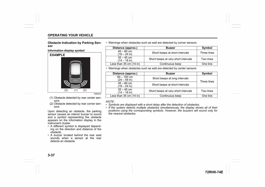
3-37
OPERATING YOUR VEHICLE
72RH0-74E
Obstacle Indication by Parking Sen-sor
Information display symbol
72R0037
(1) Obstacle detected by rear center sen-sors
(2) Obstacle detected by rear corner sen-sors
Upon detecting an obstacle, the parkingsensor causes an interior buzzer to soundand a symbol representing the obstacleappears on the information display in theinstrument cluster.• A different symbol is displayed depend-
ing on the direction and distance of theobstacle.
• A buzzer located behind the rear seatsounds when a sensor at the reardetects an obstacle.
(1) (2)(2)
EXAMPLE
• Warnings when obstacles such as wall are detected by corner sensors
• Warnings when obstacles such as wall are detected by center sensors
NOTE:• Symbols are displayed with a short delay after the detection of obstacles.• If the system detects multiple obstacles simultaneously, the display shows all of their
positions using the corresponding symbols. However, the buzzers will sound only forthe nearest obstacles.
Distance (approx.) Buzzer Symbol45 – 60 cm(18 – 24 in) Short beeps at short intervals Three lines
35 – 45 cm(14 – 18 in) Short beeps at very short intervals Two lines
Less than 35 cm (14 in) Continuous beep One line
Distance (approx.) Buzzer Symbol60 – 150 cm(24 – 59 in) Short beeps at long intervals
Three lines45 – 60 cm(18 – 24 in) Short beeps at short intervals
35 – 45 cm(14 – 18 in) Short beeps at very short intervals Two lines
Less than 35 cm (14 in) Continuous beep One line
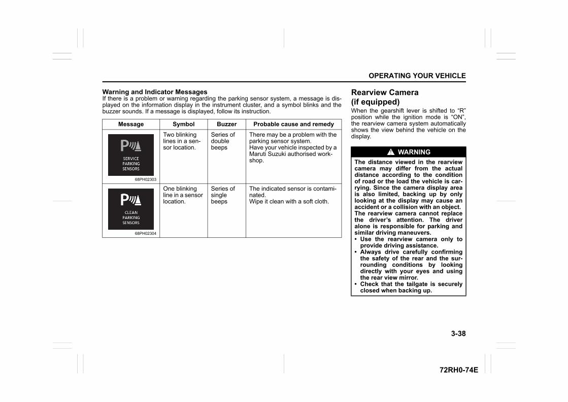
3-38
OPERATING YOUR VEHICLE
72RH0-74E
Warning and Indicator MessagesIf there is a problem or warning regarding the parking sensor system, a message is dis-played on the information display in the instrument cluster, and a symbol blinks and thebuzzer sounds. If a message is displayed, follow its instruction.
Message Symbol Buzzer Probable cause and remedy
68PH02303
Two blinking lines in a sen-sor location.
Series of double beeps
There may be a problem with the parking sensor system. Have your vehicle inspected by a Maruti Suzuki authorised work-shop.
68PH02304
One blinking line in a sensor location.
Series of single beeps
The indicated sensor is contami-nated.Wipe it clean with a soft cloth.
Rearview Camera (if equipped)When the gearshift lever is shifted to “R”position while the ignition mode is “ON”,the rearview camera system automaticallyshows the view behind the vehicle on thedisplay.
WARNING
The distance viewed in the rearviewcamera may differ from the actualdistance according to the conditionof road or the load the vehicle is car-rying. Since the camera display areais also limited, backing up by onlylooking at the display may cause anaccident or a collision with an object. The rearview camera cannot replacethe driver’s attention. The driveralone is responsible for parking andsimilar driving maneuvers.• Use the rearview camera only to
provide driving assistance. • Always drive carefully confirming
the safety of the rear and the sur-rounding conditions by lookingdirectly with your eyes and usingthe rear view mirror.
• Check that the tailgate is securelyclosed when backing up.
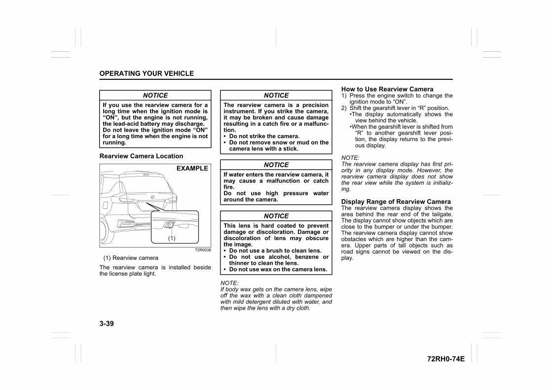
3-39
OPERATING YOUR VEHICLE
72RH0-74E
Rearview Camera Location
72R0038
(1) Rearview camera
The rearview camera is installed besidethe license plate light.
NOTE:If body wax gets on the camera lens, wipeoff the wax with a clean cloth dampenedwith mild detergent diluted with water, andthen wipe the lens with a dry cloth.
How to Use Rearview Camera1) Press the engine switch to change the
ignition mode to “ON”. 2) Shift the gearshift lever in “R” position.
•The display automatically shows theview behind the vehicle.
•When the gearshift lever is shifted from“R” to another gearshift lever posi-tion, the display returns to the previ-ous display.
NOTE:The rearview camera display has first pri-ority in any display mode. However, therearview camera display does not showthe rear view while the system is initializ-ing.
Display Range of Rearview CameraThe rearview camera display shows thearea behind the rear end of the tailgate.The display cannot show objects which areclose to the bumper or under the bumper.The rearview camera display cannot showobstacles which are higher than the cam-era. Upper parts of tall objects such asroad signs cannot be viewed on the dis-play.
NOTICE
If you use the rearview camera for along time when the ignition mode is“ON”, but the engine is not running,the lead-acid battery may discharge.Do not leave the ignition mode “ON”for a long time when the engine is notrunning.
(1)
EXAMPLE
NOTICE
The rearview camera is a precisioninstrument. If you strike the camera,it may be broken and cause damageresulting in a catch fire or a malfunc-tion. • Do not strike the camera.• Do not remove snow or mud on the
camera lens with a stick.
NOTICE
If water enters the rearview camera, itmay cause a malfunction or catchfire.Do not use high pressure wateraround the camera.
NOTICE
This lens is hard coated to preventdamage or discoloration. Damage ordiscoloration of lens may obscurethe image.• Do not use a brush to clean lens. • Do not use alcohol, benzene or
thinner to clean the lens.• Do not use wax on the camera lens.
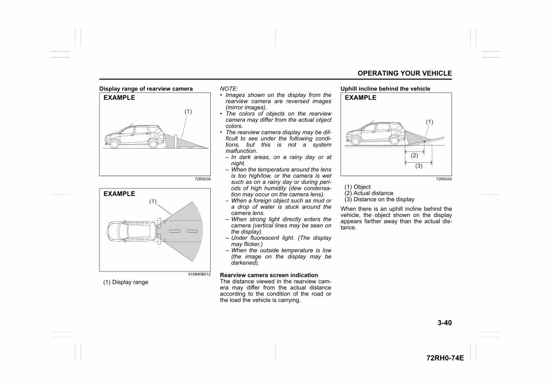
3-40
OPERATING YOUR VEHICLE
72RH0-74E
Display range of rearview camera
72R0039
61MM0B012
(1) Display range
NOTE:• Images shown on the display from the
rearview camera are reversed images(mirror images).
• The colors of objects on the rearviewcamera may differ from the actual objectcolors.
• The rearview camera display may be dif-ficult to see under the following condi-tions, but this is not a systemmalfunction. – In dark areas, on a rainy day or at
night. – When the temperature around the lens
is too high/low, or the camera is wetsuch as on a rainy day or during peri-ods of high humidity (dew condensa-tion may occur on the camera lens).
– When a foreign object such as mud ora drop of water is stuck around thecamera lens.
– When strong light directly enters thecamera (vertical lines may be seen onthe display).
– Under fluorescent light. (The displaymay flicker.)
– When the outside temperature is low(the image on the display may bedarkened).
Rearview camera screen indicationThe distance viewed in the rearview cam-era may differ from the actual distanceaccording to the condition of the road orthe load the vehicle is carrying.
Uphill incline behind the vehicle
72R0040
(1) Object(2) Actual distance(3) Distance on the display
When there is an uphill incline behind thevehicle, the object shown on the displayappears farther away than the actual dis-tance.
(1)
EXAMPLE
(1)EXAMPLE
(1)
(2)
(3)
EXAMPLE
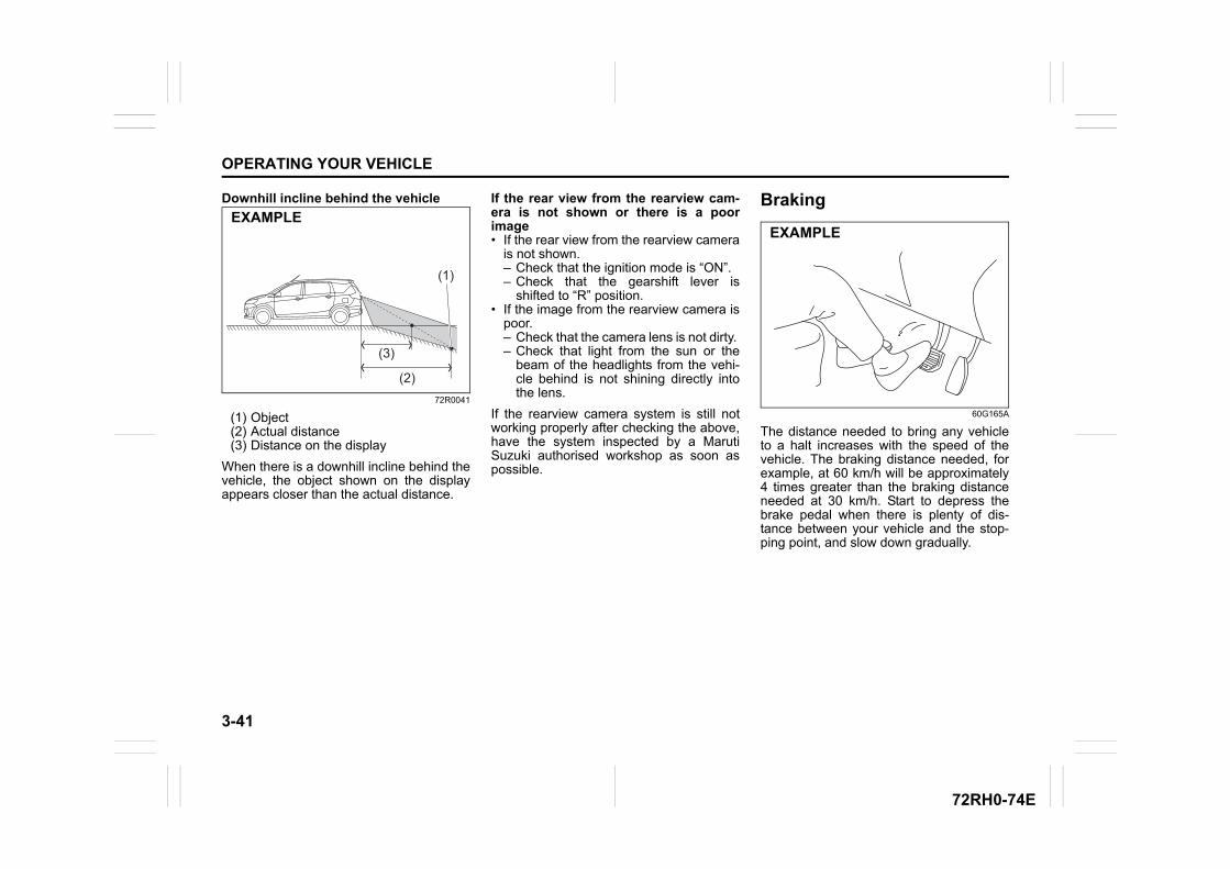
3-41
OPERATING YOUR VEHICLE
72RH0-74E
Downhill incline behind the vehicle
72R0041
(1) Object(2) Actual distance(3) Distance on the display
When there is a downhill incline behind thevehicle, the object shown on the displayappears closer than the actual distance.
If the rear view from the rearview cam-era is not shown or there is a poorimage• If the rear view from the rearview camera
is not shown. – Check that the ignition mode is “ON”.– Check that the gearshift lever is
shifted to “R” position.• If the image from the rearview camera is
poor. – Check that the camera lens is not dirty. – Check that light from the sun or the
beam of the headlights from the vehi-cle behind is not shining directly intothe lens.
If the rearview camera system is still notworking properly after checking the above,have the system inspected by a MarutiSuzuki authorised workshop as soon aspossible.
Braking
60G165A
The distance needed to bring any vehicleto a halt increases with the speed of thevehicle. The braking distance needed, forexample, at 60 km/h will be approximately4 times greater than the braking distanceneeded at 30 km/h. Start to depress thebrake pedal when there is plenty of dis-tance between your vehicle and the stop-ping point, and slow down gradually.
(1)
(3)
(2)
EXAMPLEEXAMPLE
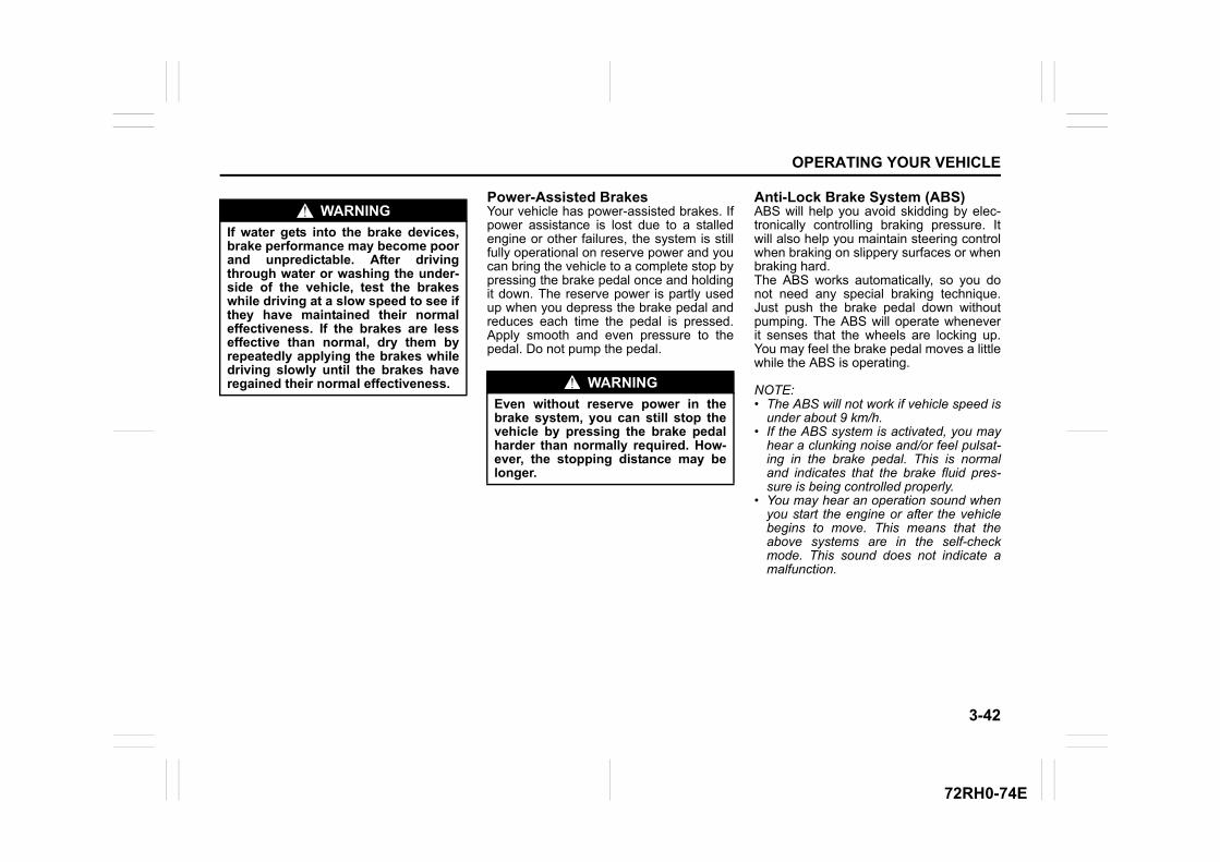
3-42
OPERATING YOUR VEHICLE
72RH0-74E
Power-Assisted BrakesYour vehicle has power-assisted brakes. Ifpower assistance is lost due to a stalledengine or other failures, the system is stillfully operational on reserve power and youcan bring the vehicle to a complete stop bypressing the brake pedal once and holdingit down. The reserve power is partly usedup when you depress the brake pedal andreduces each time the pedal is pressed.Apply smooth and even pressure to thepedal. Do not pump the pedal.
Anti-Lock Brake System (ABS)ABS will help you avoid skidding by elec-tronically controlling braking pressure. Itwill also help you maintain steering controlwhen braking on slippery surfaces or whenbraking hard.The ABS works automatically, so you donot need any special braking technique.Just push the brake pedal down withoutpumping. The ABS will operate wheneverit senses that the wheels are locking up.You may feel the brake pedal moves a littlewhile the ABS is operating.
NOTE:• The ABS will not work if vehicle speed is
under about 9 km/h.• If the ABS system is activated, you may
hear a clunking noise and/or feel pulsat-ing in the brake pedal. This is normaland indicates that the brake fluid pres-sure is being controlled properly.
• You may hear an operation sound whenyou start the engine or after the vehiclebegins to move. This means that theabove systems are in the self-checkmode. This sound does not indicate amalfunction.
WARNING
If water gets into the brake devices,brake performance may become poorand unpredictable. After drivingthrough water or washing the under-side of the vehicle, test the brakeswhile driving at a slow speed to see ifthey have maintained their normaleffectiveness. If the brakes are lesseffective than normal, dry them byrepeatedly applying the brakes whiledriving slowly until the brakes haveregained their normal effectiveness. WARNING
Even without reserve power in thebrake system, you can still stop thevehicle by pressing the brake pedalharder than normally required. How-ever, the stopping distance may belonger.

3-43
OPERATING YOUR VEHICLE
72RH0-74E
54MN069
(1) ABS warning light(2) Brake system warning light
WARNING
• On some types of loose surfaces(such as gravel, snow-coveredroads, etc.), the stopping distancerequired for a vehicle with ABSmay be slightly greater than theone required for a comparable vehi-cle with a conventional brake sys-tem. With a conventional brakesystem, skidding tires are able toplow the gravel or snow layer,shortening the stopping distance.ABS minimizes this resistanceeffect. Allow for extra stopping dis-tance when driving on loose sur-faces.
• On regular paved roads, some driv-ers may be able to obtain slightlyshorter stopping distances withconventional brake systems thanwith ABS.
• In both of the above conditions,ABS will still offer the advantage ofhelping you maintain directionalcontrol. However, remember thatABS will not compensate for badroad or weather conditions or poordriver judgment. Use good judg-ment and do not drive too fast.
(1) (2)
EXAMPLE WARNING
• If the ABS warning light (1) on theinstrument panel comes on andstays on while driving, there maybe a problem with the ABS system.Ask a Maruti Suzuki authorisedworkshop to inspect the ABS sys-tem immediately. If the ABS systembecomes inoperative, the brakesystem will function as an ordinarybrake system that has no ABS.
• If the ABS warning light (1) and theBrake system warning light (2) onthe instrument panel simultane-ously stays on or comes on whiledriving, both anti-lock function andrear brake force control function(proportioning valve function) ofthe ABS system may have failed. Ifso, the rear wheels may easily skidor the vehicle can even spin in theworst case when braking on a slip-pery road or when hard brakingeven on a dry paved road. Ask aMaruti Suzuki authorised workshopto inspect the ABS system immedi-ately. Drive carefully, avoiding hardbraking as much as possible.
3-44
OPERATING YOUR VEHICLE
72RH0-74E
How the ABS WorksA computer continuously monitors wheelspeed. The computer compares thechanges in wheel speed when braking. Ifthe wheels slow suddenly, indicating askidding situation, the computer willchange braking pressure several timeseach second to prevent the wheels fromlocking. When you start your vehicle orwhen you accelerate after a hard stop, youmay hear a momentary motor or clickingnoise as the system resets or checks itself.“This is absolutely normal and indicate thatABS is functioning properly”.
Electronic stability program (ESP®) (if equipped)ESP® is a registered trademark of DaimlerAG.
The Electronic Stability Program (ESP®)helps to control the vehicle during corner-ing if front wheels or rear wheels skid. Italso assists you in maintaining tractionwhile accelerating on loose or slipperyroad surfaces. It does this by regulatingthe engine’s output, and by selectivelyapplying the brakes. In addition, ESP®
helps to avoid skidding by controlling brak-ing pressure.
The ESP® totally manages following foursystems, (stability control, traction control,ABS and Brake assist) to help enhancevehicle stability in response to various driv-ing conditions;
Stability control systemThe vehicle stability control system helpsprovide integrated control of systems suchas anti-lock brakes, traction control, enginecontrol, etc. This system automaticallycontrols the brakes and engine to help pre-vent the vehicle from skidding when cor-nering on a slippery road surface or whenturning the steering wheel abruptly.
Traction control systemThe traction control system automaticallyhelps prevent the spinning of wheels whenthe vehicle is started or accelerated onslippery road surfaces. The system oper-ates only if it senses that some of thewheels are spinning or beginning to losetraction. When this happens, the systemoperates the front or rear brakes andreduces engine power to limit wheel spin.
NOTE:You may hear an operation sound whenyou start the engine or after the vehiclebegins to move. This means that theabove systems are in the self-check mode.This sound does not indicate a malfunc-tion.
WARNING
The ABS may not work properly iftires or wheels other than thosespecified in the owner’s manual areused. This is because the ABS worksby comparing changes in wheelspeed. When replacing tires orwheels, use only the size and typespecified in this owner’s manual.
WARNING
The ESP® cannot enhance the vehi-cle’s driving stability in all situationsand does not control your vehicle’sentire braking system. The ESP® can-not prevent accidents, includingthose resulting from excessive speedin turns, or hydroplaning. Only safeand attentive drive can prevent acci-dents. The capabilities of an ESP®-equipped vehicle must never be usedas a substitute for careful driving.
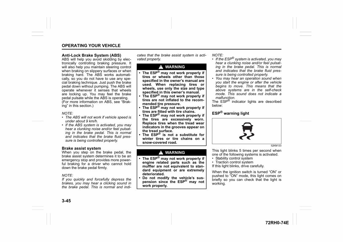
3-45
OPERATING YOUR VEHICLE
72RH0-74E
Anti-Lock Brake System (ABS)ABS will help you avoid skidding by elec-tronically controlling braking pressure. Itwill also help you maintain steering controlwhen braking on slippery surfaces or whenbraking hard. The ABS works automati-cally, so you do not have to use any spe-cial braking technique. Just push the brakepedal down without pumping. The ABS willoperate whenever it senses that wheelsare locking up. You may feel the brakepedal pulsate while the ABS is operating.(For more information on ABS, see “Brak-ing” in this section.)
NOTE:• The ABS will not work if vehicle speed is
under about 9 km/h.• If the ABS system is activated, you may
hear a clunking noise and/or feel pulsat-ing in the brake pedal. This is normaland indicates that the brake fluid pres-sure is being controlled properly.
Brake assist systemWhen you step on the brake pedal, thebrake assist system determines it to be anemergency stop and provides more power-ful braking for a driver who cannot holddown the brake pedal firmly.
NOTE:If you quickly and forcefully depress thebrakes, you may hear a clicking sound inthe brake pedal. This is normal and indi-
cates that the brake assist system is acti-vated properly.
NOTE:• If the ESP® system is activated, you may
hear a clunking noise and/or feel pulsat-ing in the brake pedal. This is normaland indicates that the brake fluid pres-sure is being controlled properly.
• You may hear an operation sound whenyou start the engine or after the vehiclebegins to move. This means that theabove systems are in the self-checkmode. This sound does not indicate amalfunction.
The ESP® indicator lights are describedbelow:
ESP® warning light
52KM133
This light blinks 5 times per second whenone of the following systems is activated.• Stability control system• Traction control systemIf this light blinks, drive carefully.
When the ignition switch is turned “ON” orpushed to “ON” mode, this light comes onbriefly so you can check that the light isworking.
WARNING
• The ESP® may not work properly iftires or wheels other than thosespecified in the owner’s manual areused. When replacing tires orwheels, use only the size and typespecified in this owner’s manual.
• The ESP® may not work properly iftires are not inflated to the recom-mended tire pressure.
• The ESP® may not work properly iftires are fitted with tire chains.
• The ESP® may not work properly ifthe tires are excessively worn.Replace tires when the tread wearindicators in the grooves appear onthe tread surface.
• The ESP® is not a substitute forwinter tires or tire chains on asnow-covered road.
WARNING
• The ESP® may not work properly ifengine related parts such as themuffler are not equivalent to stan-dard equipment or are extremelydeteriorated.
• Do not modify the vehicle’s sus-pension since the ESP® may notwork properly.
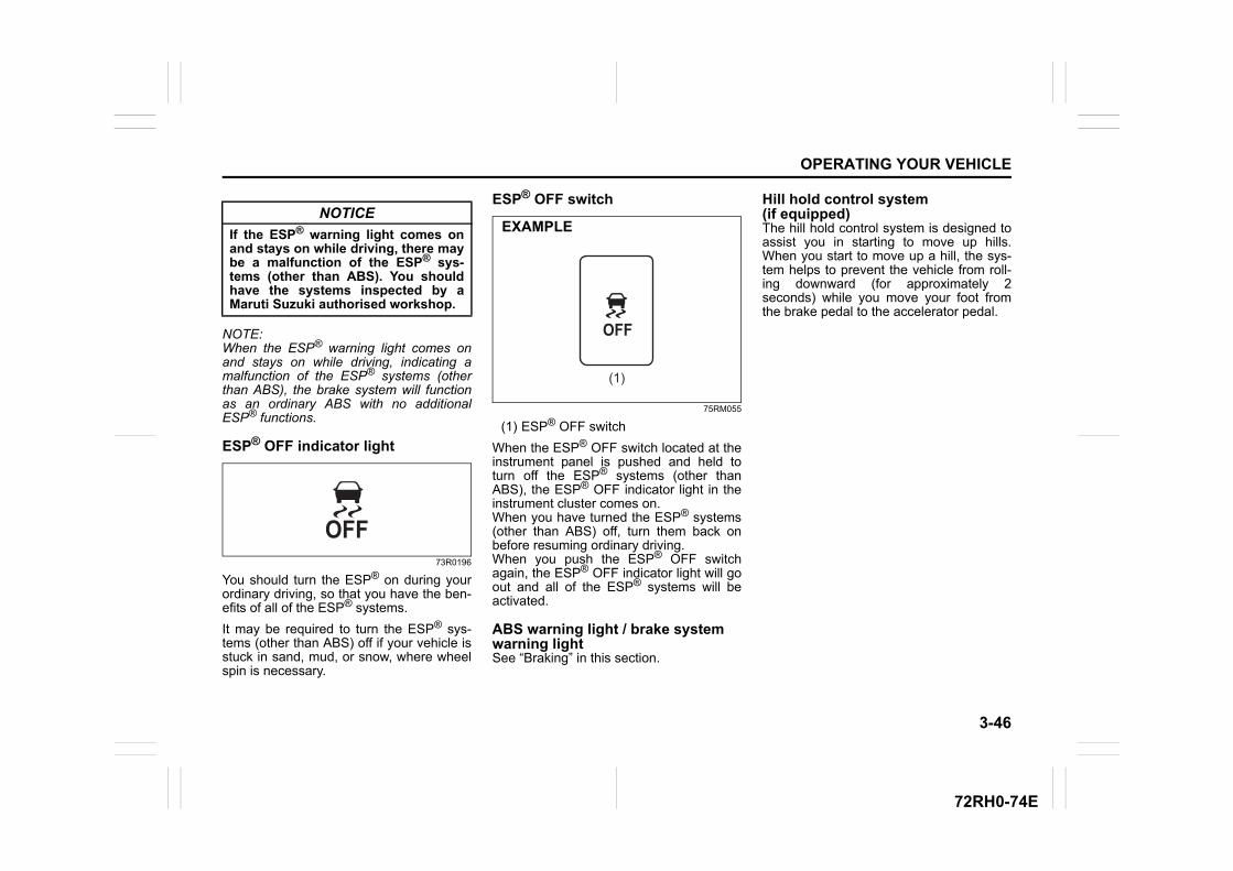
3-46
OPERATING YOUR VEHICLE
72RH0-74E
NOTE:When the ESP® warning light comes onand stays on while driving, indicating amalfunction of the ESP® systems (otherthan ABS), the brake system will functionas an ordinary ABS with no additionalESP® functions.
ESP® OFF indicator light
73R0196
You should turn the ESP® on during yourordinary driving, so that you have the ben-efits of all of the ESP® systems.
It may be required to turn the ESP® sys-tems (other than ABS) off if your vehicle isstuck in sand, mud, or snow, where wheelspin is necessary.
ESP® OFF switch
75RM055
(1) ESP® OFF switch
When the ESP® OFF switch located at theinstrument panel is pushed and held toturn off the ESP® systems (other thanABS), the ESP® OFF indicator light in theinstrument cluster comes on.When you have turned the ESP® systems(other than ABS) off, turn them back onbefore resuming ordinary driving.When you push the ESP® OFF switchagain, the ESP® OFF indicator light will goout and all of the ESP® systems will beactivated.
ABS warning light / brake system warning lightSee “Braking” in this section.
Hill hold control system(if equipped)The hill hold control system is designed toassist you in starting to move up hills.When you start to move up a hill, the sys-tem helps to prevent the vehicle from roll-ing downward (for approximately 2seconds) while you move your foot fromthe brake pedal to the accelerator pedal.
NOTICE
If the ESP® warning light comes onand stays on while driving, there maybe a malfunction of the ESP® sys-tems (other than ABS). You shouldhave the systems inspected by aMaruti Suzuki authorised workshop.
(1)
EXAMPLE
3-47
OPERATING YOUR VEHICLE
72RH0-74E
The hill hold control system activates for amaximum of about 2 seconds if your foot ismoved from the brake pedal when the fol-lowing conditions are all met.
1) The gearshift lever is in a forward gearor reverse gear.
2) The parking brake is released.3) The vehicle is on an upward incline.
On models equipped with the ENG A-STOP system, the hill hold control systemis activated when the engine is restartedafter being stopped automatically, even ifthe previous conditions are not met.
NOTE:When the hill hold control system is acti-vated, the following conditions may befound, but this is not a malfunction.• You may hear a sound from the engine
room.• As brake pedal becomes heavy, it may
be difficult for you to depress it.
WARNING
• Do not rely excessively on the hillhold control system. The hill holdcontrol system may not prevent thevehicle from rolling downward on ahill under all load or road condi-tions. Always be prepared todepress the brake pedal to preventthe vehicle from rolling downward.Failure to pay attention anddepress the brake pedal to hold thevehicle on a hill when necessary,may result in loss of control or anaccident.
• The hill hold control system is notdesigned to stop the vehicle on ahill.
• After you release your foot from thebrake pedal, accelerate the vehicleto move up immediately. If yourelease your foot from the brakepedal over 2 seconds, the hill holdcontrol system will be canceled. Ifso, the vehicle may roll downward,which can result in an accidentdepending on the degree of slope.And, the engine may stall and thepower assist for the steering andbrakes will not work so steeringand braking will be much harderthan usual which can result in anaccident or vehicle damage.
DRIVING TIPS
4
72RH0-74E
72RM04000
DRIVING TIPSRunning-in ........................................................................... 4-1Catalytic Converter ............................................................. 4-1Improving Fuel Economy ................................................... 4-2Highway Driving .................................................................. 4-3Driving on Hills .................................................................... 4-3Driving on Slippery Roads ................................................. 4-4Off-road Driving ................................................................... 4-6When Encountering a Flooded Area ................................. 4-6Do’s and Dont’s for safe driving ........................................ 4-7Margin for safety ................................................................. 4-9
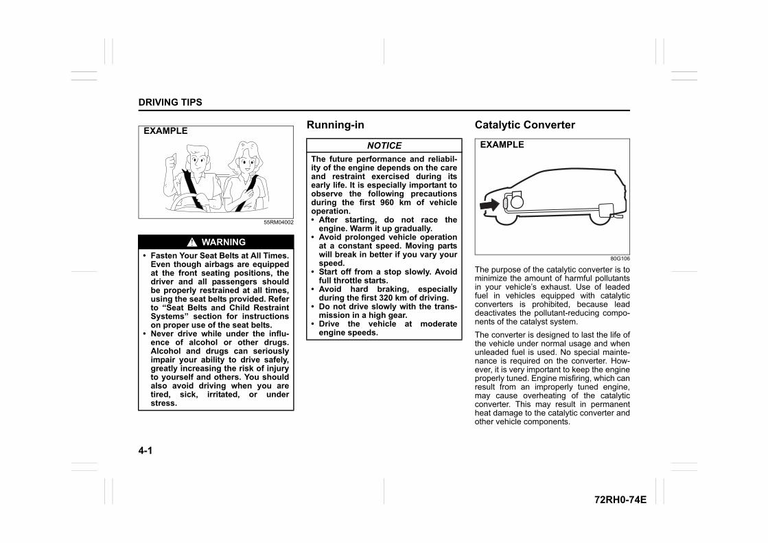
4-1
DRIVING TIPS
72RH0-74E
55RM04002
Running-in Catalytic Converter
80G106
The purpose of the catalytic converter is tominimize the amount of harmful pollutantsin your vehicle’s exhaust. Use of leadedfuel in vehicles equipped with catalyticconverters is prohibited, because leaddeactivates the pollutant-reducing compo-nents of the catalyst system.
The converter is designed to last the life ofthe vehicle under normal usage and whenunleaded fuel is used. No special mainte-nance is required on the converter. How-ever, it is very important to keep the engineproperly tuned. Engine misfiring, which canresult from an improperly tuned engine,may cause overheating of the catalyticconverter. This may result in permanentheat damage to the catalytic converter andother vehicle components.
WARNING
• Fasten Your Seat Belts at All Times.Even though airbags are equippedat the front seating positions, thedriver and all passengers shouldbe properly restrained at all times,using the seat belts provided. Referto “Seat Belts and Child RestraintSystems” section for instructionson proper use of the seat belts.
• Never drive while under the influ-ence of alcohol or other drugs.Alcohol and drugs can seriouslyimpair your ability to drive safely,greatly increasing the risk of injuryto yourself and others. You shouldalso avoid driving when you aretired, sick, irritated, or understress.
EXAMPLE
NOTICE
The future performance and reliabil-ity of the engine depends on the careand restraint exercised during itsearly life. It is especially important toobserve the following precautionsduring the first 960 km of vehicleoperation.• After starting, do not race the
engine. Warm it up gradually.• Avoid prolonged vehicle operation
at a constant speed. Moving partswill break in better if you vary yourspeed.
• Start off from a stop slowly. Avoidfull throttle starts.
• Avoid hard braking, especiallyduring the first 320 km of driving.
• Do not drive slowly with the trans-mission in a high gear.
• Drive the vehicle at moderateengine speeds.
EXAMPLE
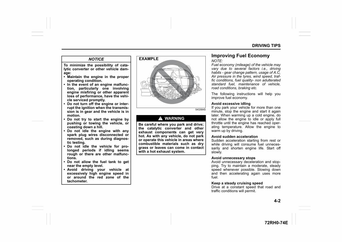
4-2
DRIVING TIPS
72RH0-74E
54G584S
Improving Fuel EconomyNOTE:Fuel economy (mileage) of the vehicle mayvary due to several factors i.e., drivinghabits - gear change pattern, usage of A.C,Air pressure in the tyres, wind speed, traf-fic conditions, fuel quality- non adulteratedstandard fuel, maintenance of vehicle,road conditions, braking etc.
The following instructions will help youimprove fuel economy.
Avoid excessive idlingIf you park your vehicle for more than oneminute, stop the engine and start it againlater. When warming up a cold engine, donot allow the engine to idle or apply fullthrottle until the engine has reached oper-ating temperature. Allow the engine towarm up by driving.
Avoid sudden accelerationSudden acceleration starting from rest orwhile driving will consume fuel unneces-sarily and shorten engine life. Start offslowly.
Avoid unnecessary stopsAvoid unnecessary deceleration and stop-ping. Try to maintain a moderate, steadyspeed whenever possible. Slowing downand then accelerating again uses morefuel.
Keep a steady cruising speedDrive at a constant speed that road andtraffic conditions will permit.
NOTICE
To minimize the possibility of cata-lytic converter or other vehicle dam-age:• Maintain the engine in the proper
operating condition.• In the event of an engine malfunc-
tion, particularly one involvingengine misfiring or other apparentloss of performance, have the vehi-cle serviced promptly.
• Do not turn off the engine or inter-rupt the ignition when the transmis-sion is in gear and the vehicle is inmotion.
• Do not try to start the engine bypushing or towing the vehicle, orcoasting down a hill.
• Do not idle the engine with anyspark plug wires disconnected orremoved, such as during diagnos-tic testing.
• Do not idle the vehicle for pro-longed periods if idling seemsrough or there are other malfunc-tions.
• Do not allow the fuel tank to getnear the empty level.
• Avoid driving your vehicle atexcessively high engine speed inor around the red zone of thetachometer.
WARNING
Be careful where you park and drive;the catalytic converter and otherexhaust components can get veryhot. As with any vehicle, do not parkor operate this vehicle in areas wherecombustible materials such as drygrass or leaves can come in contactwith a hot exhaust system.
EXAMPLE
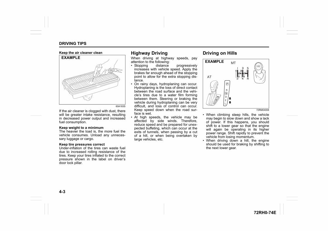
4-3
DRIVING TIPS
72RH0-74E
Keep the air cleaner clean
60A183S
If the air cleaner is clogged with dust, therewill be greater intake resistance, resultingin decreased power output and increasedfuel consumption.
Keep weight to a minimumThe heavier the load is, the more fuel thevehicle consumes. Unload any unneces-sary luggage or cargo.
Keep tire pressures correctUnder-inflation of the tires can waste fueldue to increased rolling resistance of thetires. Keep your tires inflated to the correctpressure shown in the label on driver’sdoor lock pillar.
Highway DrivingWhen driving at highway speeds, payattention to the following:• Stopping distance progressively
increases with vehicle speed. Apply thebrakes far enough ahead of the stoppingpoint to allow for the extra stopping dis-tance.
• On rainy days, hydroplaning can occur.Hydroplaning is the loss of direct contactbetween the road surface and the vehi-cle’s tires due to a water film formingbetween them. Steering or braking thevehicle during hydroplaning can be verydifficult, and loss of control can occur.Keep speed down when the road sur-face is wet.
• At high speeds, the vehicle may beaffected by side winds. Therefore,reduce speed and be prepared for unex-pected buffeting, which can occur at theexits of tunnels, when passing by a cutof a hill, or when being overtaken bylarge vehicles, etc.
Driving on Hills
72RM04008
• When climbing steep hills, the vehiclemay begin to slow down and show a lackof power. If this happens, you shouldshift to a lower gear so that the enginewill again be operating in its higherpower range. Shift rapidly to prevent thevehicle from losing momentum.
• When driving down a hill, the engineshould be used for braking by shifting tothe next lower gear.
EXAMPLEMT
AT
EXAMPLE
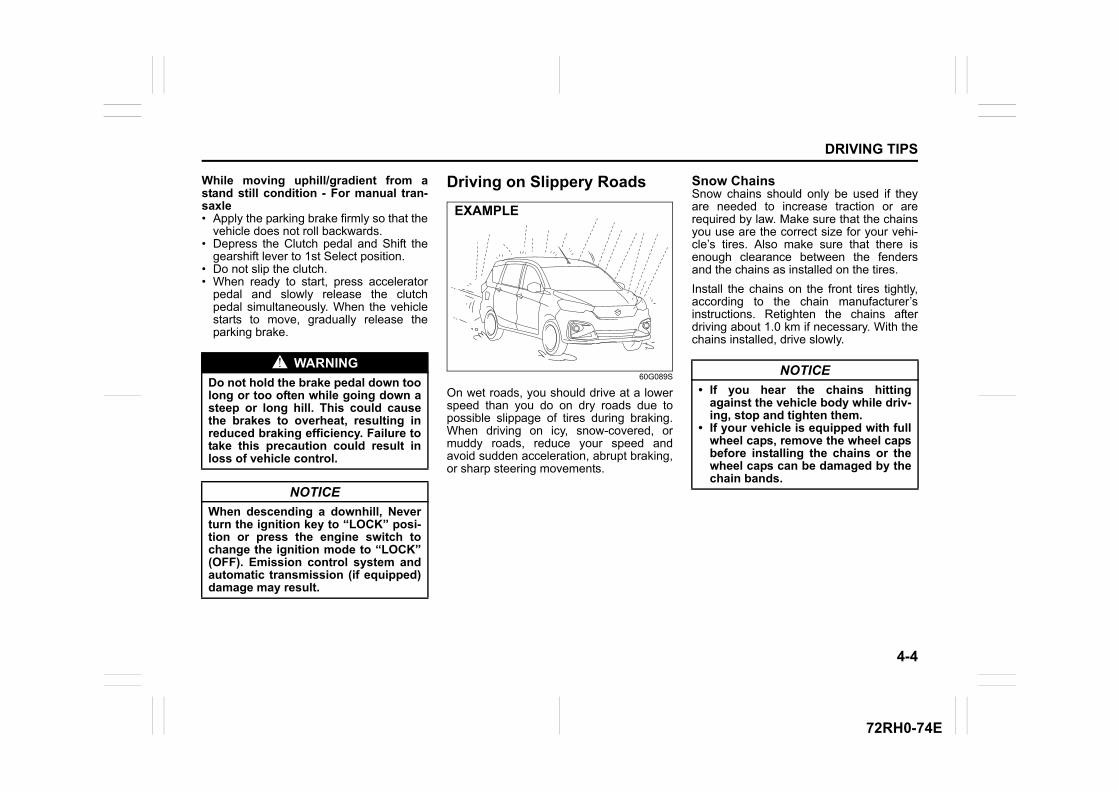
4-4
DRIVING TIPS
72RH0-74E
While moving uphill/gradient from astand still condition - For manual tran-saxle• Apply the parking brake firmly so that the
vehicle does not roll backwards. • Depress the Clutch pedal and Shift the
gearshift lever to 1st Select position. • Do not slip the clutch.• When ready to start, press accelerator
pedal and slowly release the clutchpedal simultaneously. When the vehiclestarts to move, gradually release theparking brake.
Driving on Slippery Roads
60G089S
On wet roads, you should drive at a lowerspeed than you do on dry roads due topossible slippage of tires during braking.When driving on icy, snow-covered, ormuddy roads, reduce your speed andavoid sudden acceleration, abrupt braking,or sharp steering movements.
Snow ChainsSnow chains should only be used if theyare needed to increase traction or arerequired by law. Make sure that the chainsyou use are the correct size for your vehi-cle’s tires. Also make sure that there isenough clearance between the fendersand the chains as installed on the tires.
Install the chains on the front tires tightly,according to the chain manufacturer’sinstructions. Retighten the chains afterdriving about 1.0 km if necessary. With thechains installed, drive slowly.
WARNING
Do not hold the brake pedal down toolong or too often while going down asteep or long hill. This could causethe brakes to overheat, resulting inreduced braking efficiency. Failure totake this precaution could result inloss of vehicle control.
NOTICE
When descending a downhill, Neverturn the ignition key to “LOCK” posi-tion or press the engine switch tochange the ignition mode to “LOCK”(OFF). Emission control system andautomatic transmission (if equipped)damage may result.
EXAMPLE
NOTICE
• If you hear the chains hittingagainst the vehicle body while driv-ing, stop and tighten them.
• If your vehicle is equipped with fullwheel caps, remove the wheel capsbefore installing the chains or thewheel caps can be damaged by thechain bands.
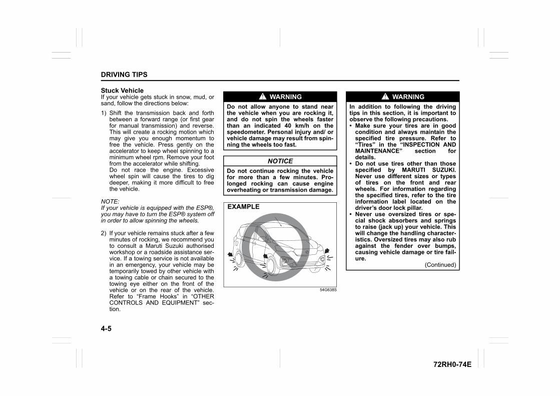
4-5
DRIVING TIPS
72RH0-74E
Stuck VehicleIf your vehicle gets stuck in snow, mud, orsand, follow the directions below:
1) Shift the transmission back and forthbetween a forward range (or first gearfor manual transmission) and reverse.This will create a rocking motion whichmay give you enough momentum tofree the vehicle. Press gently on theaccelerator to keep wheel spinning to aminimum wheel rpm. Remove your footfrom the accelerator while shifting. Do not race the engine. Excessivewheel spin will cause the tires to digdeeper, making it more difficult to freethe vehicle.
NOTE:If your vehicle is equipped with the ESP®,you may have to turn the ESP® system offin order to allow spinning the wheels.
2) If your vehicle remains stuck after a fewminutes of rocking, we recommend youto consult a Maruti Suzuki authorisedworkshop or a roadside assistance ser-vice. If a towing service is not availablein an emergency, your vehicle may betemporarily towed by other vehicle witha towing cable or chain secured to thetowing eye either on the front of thevehicle or on the rear of the vehicle.Refer to “Frame Hooks” in “OTHERCONTROLS AND EQUIPMENT” sec-tion.
54G638S
WARNING
Do not allow anyone to stand nearthe vehicle when you are rocking it,and do not spin the wheels fasterthan an indicated 40 km/h on thespeedometer. Personal injury and/ orvehicle damage may result from spin-ning the wheels too fast.
NOTICE
Do not continue rocking the vehiclefor more than a few minutes. Pro-longed rocking can cause engineoverheating or transmission damage.
EXAMPLE
WARNING
In addition to following the drivingtips in this section, it is important toobserve the following precautions.• Make sure your tires are in good
condition and always maintain thespecified tire pressure. Refer to“Tires” in the “INSPECTION ANDMAINTENANCE” section fordetails.
• Do not use tires other than thosespecified by MARUTI SUZUKI.Never use different sizes or typesof tires on the front and rearwheels. For information regardingthe specified tires, refer to the tireinformation label located on thedriver’s door lock pillar.
• Never use oversized tires or spe-cial shock absorbers and springsto raise (jack up) your vehicle. Thiswill change the handling character-istics. Oversized tires may also rubagainst the fender over bumps,causing vehicle damage or tire fail-ure.
(Continued)
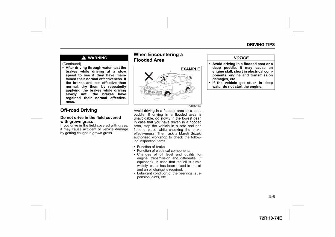
4-6
DRIVING TIPS
72RH0-74E
Off-road Driving
Do not drive in the field covered with grown grassIf you drive in the field covered with grass,it may cause accident or vehicle damageby getting caught in grown grass.
When Encountering a Flooded Area
72RM04007
Avoid driving in a flooded area or a deeppuddle. If driving in a flooded area isunavoidable, go slowly in the lowest gear.In case that you have driven in a floodedarea, stop the vehicle in a safe and nonflooded place while checking the brakeeffectiveness. Then, ask a Maruti Suzukiauthorised workshop to check the follow-ing inspection items.
• Function of brake• Function of electrical components• Changes of oil level and quality for
engine, transmission and differential (ifequipped). In case that the oil is turbidwhitely, water has been mixed in the oiland an oil change is required.
• Lubricant condition of the bearings, sus-pension joints, etc.
WARNING
(Continued)• After driving through water, test the
brakes while driving at a slowspeed to see if they have main-tained their normal effectiveness. Ifthe brakes are less effective thannormal, dry them by repeatedlyapplying the brakes while drivingslowly until the brakes haveregained their normal effective-ness.
EXAMPLE
NOTICE
• Avoid driving in a flooded area or adeep puddle. It may cause anengine stall, short in electrical com-ponents, engine and transmissiondamages, etc.
• If the vehicle get stuck in deepwater do not start the engine.
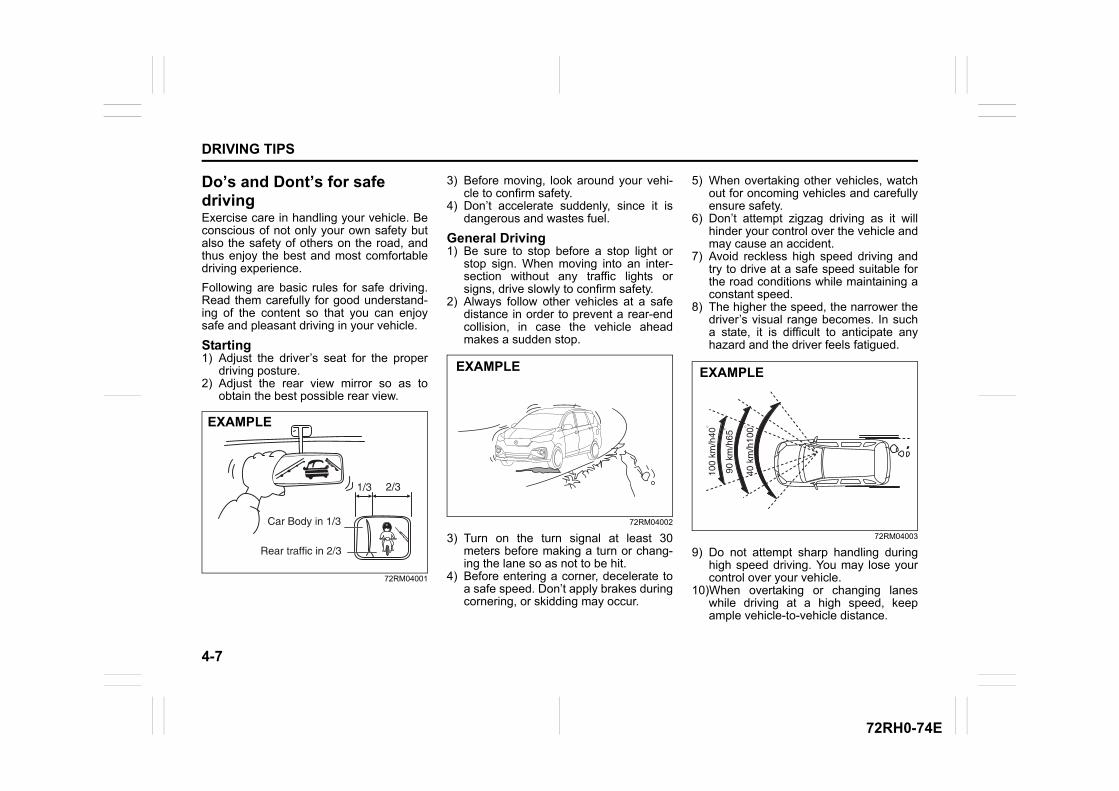
4-7
DRIVING TIPS
72RH0-74E
Do’s and Dont’s for safe drivingExercise care in handling your vehicle. Beconscious of not only your own safety butalso the safety of others on the road, andthus enjoy the best and most comfortabledriving experience.
Following are basic rules for safe driving.Read them carefully for good understand-ing of the content so that you can enjoysafe and pleasant driving in your vehicle.
Starting1) Adjust the driver’s seat for the proper
driving posture.2) Adjust the rear view mirror so as to
obtain the best possible rear view.
72RM04001
3) Before moving, look around your vehi-cle to confirm safety.
4) Don’t accelerate suddenly, since it isdangerous and wastes fuel.
General Driving1) Be sure to stop before a stop light or
stop sign. When moving into an inter-section without any traffic lights orsigns, drive slowly to confirm safety.
2) Always follow other vehicles at a safedistance in order to prevent a rear-endcollision, in case the vehicle aheadmakes a sudden stop.
72RM04002
3) Turn on the turn signal at least 30meters before making a turn or chang-ing the lane so as not to be hit.
4) Before entering a corner, decelerate toa safe speed. Don’t apply brakes duringcornering, or skidding may occur.
5) When overtaking other vehicles, watchout for oncoming vehicles and carefullyensure safety.
6) Don’t attempt zigzag driving as it willhinder your control over the vehicle andmay cause an accident.
7) Avoid reckless high speed driving andtry to drive at a safe speed suitable forthe road conditions while maintaining aconstant speed.
8) The higher the speed, the narrower thedriver’s visual range becomes. In sucha state, it is difficult to anticipate anyhazard and the driver feels fatigued.
72RM04003
9) Do not attempt sharp handling duringhigh speed driving. You may lose yourcontrol over your vehicle.
10)When overtaking or changing laneswhile driving at a high speed, keepample vehicle-to-vehicle distance.
EXAMPLE
EXAMPLE EXAMPLE
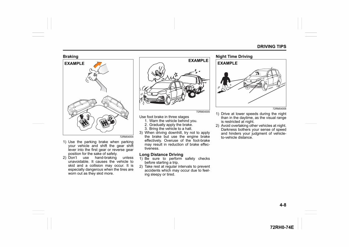
4-8
DRIVING TIPS
72RH0-74E
Braking
72RM04004
1) Use the parking brake when parkingyour vehicle and shift the gear shiftlever into the first gear or reverse gearposition for the sake of safety.
2) Don’t use hand-braking unlessunavoidable. It causes the vehicle toskid and a collision may occur. It isespecially dangerous when the tires areworn out as they skid more.
72RM04005
Use foot brake in three stages1. Warn the vehicle behind you.2. Gradually apply the brake.3. Bring the vehicle to a halt.
3) When driving downhill, try not to applythe brake but use the engine brakeeffectively. Overuse of the foot-brakemay result in reduction of brake effec-tiveness.
Long Distance Driving1) Be sure to perform safety checks
before starting a trip.2) Take rest at regular intervals to prevent
accidents which may occur due to feel-ing sleepy or tired.
Night Time Driving
72RM04006
1) Drive at lower speeds during the nightthan in the daytime, as the visual rangeis restricted at night.
2) Avoid overtaking other vehicles at night.Darkness bothers your sense of speedand hinders your judgment of vehicle-to-vehicle distance.
EXAMPLEEXAMPLE
EXAMPLE
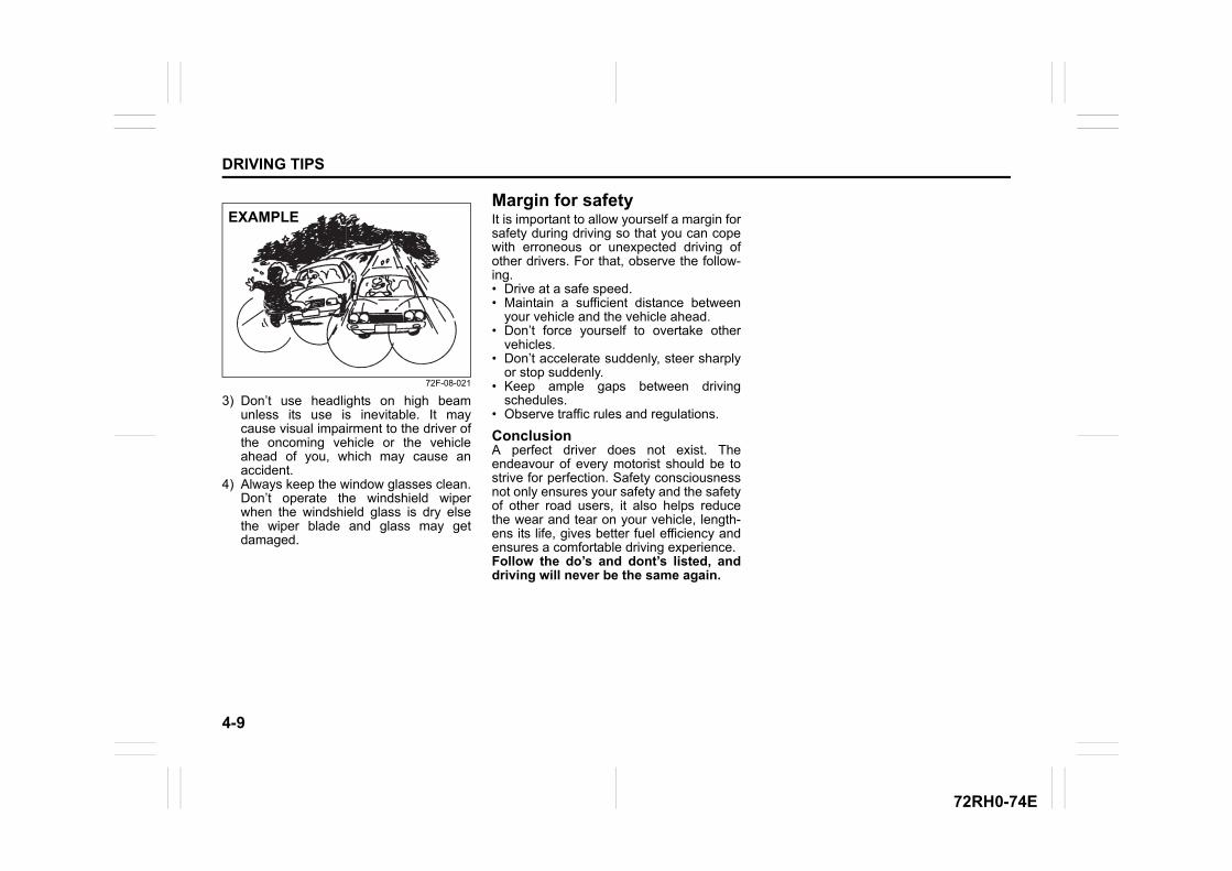
4-9
DRIVING TIPS
72RH0-74E
72F-08-021
3) Don’t use headlights on high beamunless its use is inevitable. It maycause visual impairment to the driver ofthe oncoming vehicle or the vehicleahead of you, which may cause anaccident.
4) Always keep the window glasses clean.Don’t operate the windshield wiperwhen the windshield glass is dry elsethe wiper blade and glass may getdamaged.
Margin for safetyIt is important to allow yourself a margin forsafety during driving so that you can copewith erroneous or unexpected driving ofother drivers. For that, observe the follow-ing.• Drive at a safe speed.• Maintain a sufficient distance between
your vehicle and the vehicle ahead.• Don’t force yourself to overtake other
vehicles.• Don’t accelerate suddenly, steer sharply
or stop suddenly.• Keep ample gaps between driving
schedules.• Observe traffic rules and regulations.
ConclusionA perfect driver does not exist. Theendeavour of every motorist should be tostrive for perfection. Safety consciousnessnot only ensures your safety and the safetyof other road users, it also helps reducethe wear and tear on your vehicle, length-ens its life, gives better fuel efficiency andensures a comfortable driving experience.Follow the do’s and dont’s listed, anddriving will never be the same again.
EXAMPLE
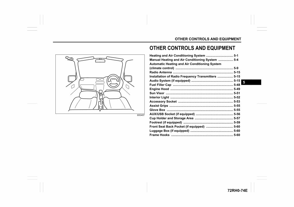
OTHER CONTROLS AND EQUIPMENT
5
72RH0-74E
60G407
OTHER CONTROLS AND EQUIPMENTHeating and Air Conditioning System ............................... 5-1Manual Heating and Air Conditioning System ................. 5-4Automatic Heating and Air Conditioning System (climate control) .................................................................. 5-9Radio Antenna ..................................................................... 5-15Installation of Radio Frequency Transmitters .................. 5-15Audio System (if equipped) ................................................ 5-15Fuel Filler Cap ..................................................................... 5-48Engine Hood ........................................................................ 5-49Sun Visor ............................................................................. 5-51Interior Light ........................................................................ 5-52Accessory Socket ............................................................... 5-53Assist Grips ......................................................................... 5-55Glove Box ............................................................................ 5-55AUX/USB Socket (if equipped) ........................................... 5-56Cup Holder and Storage Area ............................................ 5-57Footrest (if equipped) ......................................................... 5-59Front Seat Back Pocket (if equipped) ............................... 5-60Luggage Box (if equipped) ................................................. 5-60Frame Hooks ....................................................................... 5-60
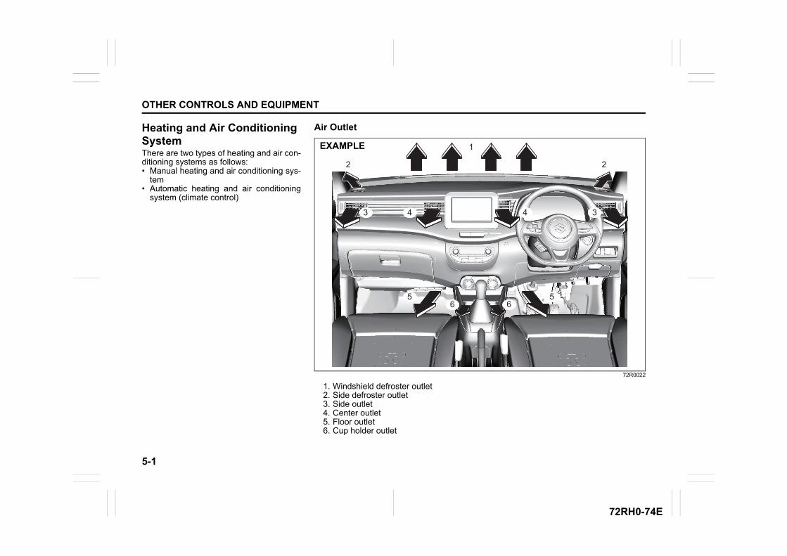
5-1
OTHER CONTROLS AND EQUIPMENT
72RH0-74E
Heating and Air Conditioning SystemThere are two types of heating and air con-ditioning systems as follows: • Manual heating and air conditioning sys-
tem • Automatic heating and air conditioning
system (climate control)
Air Outlet
72R0022
1. Windshield defroster outlet2. Side defroster outlet3. Side outlet4. Center outlet5. Floor outlet6. Cup holder outlet
3
1
2 2
443
556 6
EXAMPLE
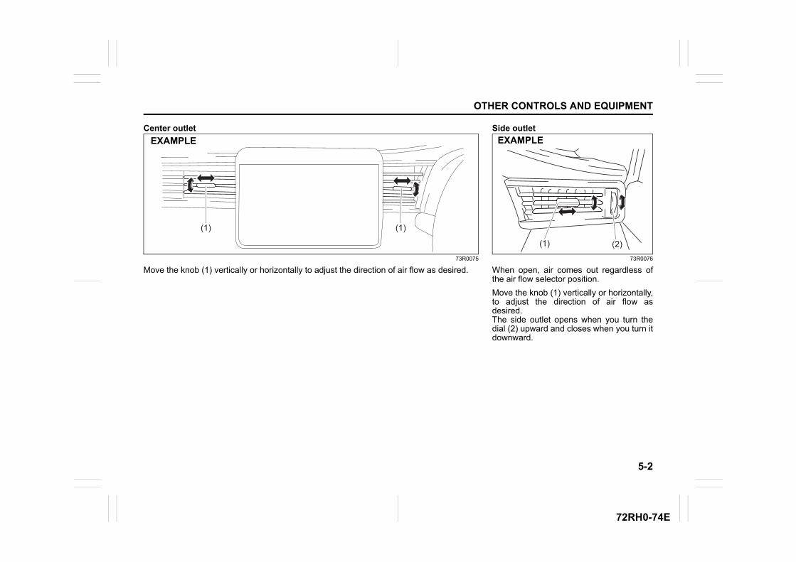
5-2
OTHER CONTROLS AND EQUIPMENT
72RH0-74E
Center outlet
73R0075
Move the knob (1) vertically or horizontally to adjust the direction of air flow as desired.
(1)(1)(1)(1)(1)(1)
EXAMPLESide outlet
73R0076
When open, air comes out regardless ofthe air flow selector position.
Move the knob (1) vertically or horizontally,to adjust the direction of air flow asdesired.The side outlet opens when you turn thedial (2) upward and closes when you turn itdownward.
(2)(2)(2)(1)(1)(1)
EXAMPLE
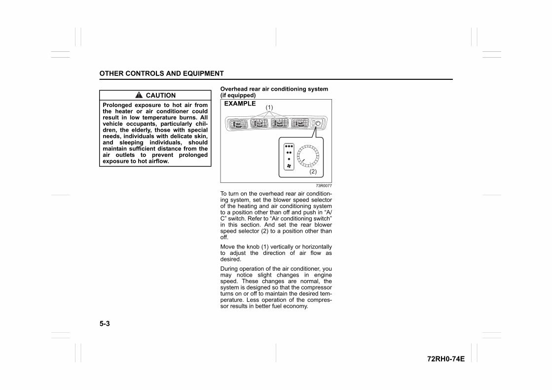
5-3
OTHER CONTROLS AND EQUIPMENT
72RH0-74E
Overhead rear air conditioning system (if equipped)
73R0077
To turn on the overhead rear air condition-ing system, set the blower speed selectorof the heating and air conditioning systemto a position other than off and push in “A/C” switch. Refer to “Air conditioning switch”in this section. And set the rear blowerspeed selector (2) to a position other thanoff.
Move the knob (1) vertically or horizontallyto adjust the direction of air flow asdesired.
During operation of the air conditioner, youmay notice slight changes in enginespeed. These changes are normal, thesystem is designed so that the compressorturns on or off to maintain the desired tem-perature. Less operation of the compres-sor results in better fuel economy.
CAUTION
Prolonged exposure to hot air fromthe heater or air conditioner couldresult in low temperature burns. Allvehicle occupants, particularly chil-dren, the elderly, those with specialneeds, individuals with delicate skin,and sleeping individuals, shouldmaintain sufficient distance from theair outlets to prevent prolongedexposure to hot airflow.
(1)
(2)
EXAMPLE
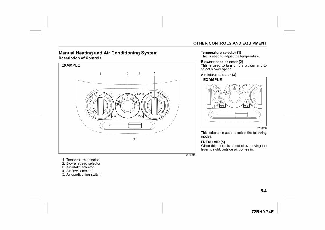
5-4
OTHER CONTROLS AND EQUIPMENT
72RH0-74E
Manual Heating and Air Conditioning SystemDescription of Controls
72R0015
1. Temperature selector2. Blower speed selector3. Air intake selector4. Air flow selector5. Air conditioning switch
2 54 1
3
EXAMPLE
Temperature selector (1)This is used to adjust the temperature.
Blower speed selector (2)This is used to turn on the blower and toselect blower speed.
Air intake selector (3)
72R0016
This selector is used to select the followingmodes.
FRESH AIR (a)When this mode is selected by moving thelever to right, outside air comes in.
(b) (a)
EXAMPLE
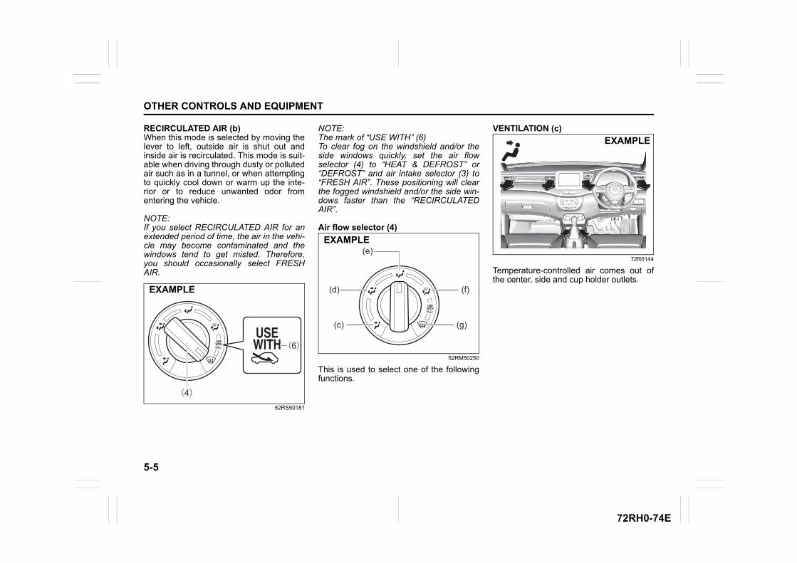
5-5
OTHER CONTROLS AND EQUIPMENT
72RH0-74E
RECIRCULATED AIR (b)When this mode is selected by moving thelever to left, outside air is shut out andinside air is recirculated. This mode is suit-able when driving through dusty or pollutedair such as in a tunnel, or when attemptingto quickly cool down or warm up the inte-rior or to reduce unwanted odor fromentering the vehicle.
NOTE:If you select RECIRCULATED AIR for anextended period of time, the air in the vehi-cle may become contaminated and thewindows tend to get misted. Therefore,you should occasionally select FRESHAIR.
52RS50181
NOTE:The mark of “USE WITH” (6)To clear fog on the windshield and/or theside windows quickly, set the air flowselector (4) to “HEAT & DEFROST” or“DEFROST” and air intake selector (3) to“FRESH AIR”. These positioning will clearthe fogged windshield and/or the side win-dows faster than the “RECIRCULATEDAIR”.
Air flow selector (4)
52RM50250
This is used to select one of the followingfunctions.
VENTILATION (c)
72R0144
Temperature-controlled air comes out ofthe center, side and cup holder outlets.
(6)
(4)
EXAMPLE
(c) (g)
(d) (f)
(e)EXAMPLE
EXAMPLE
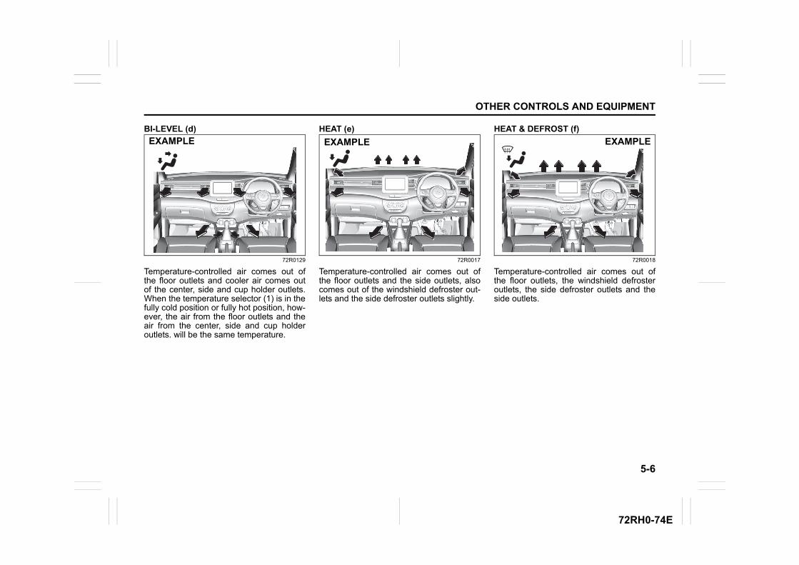
5-6
OTHER CONTROLS AND EQUIPMENT
72RH0-74E
BI-LEVEL (d)
72R0129
Temperature-controlled air comes out ofthe floor outlets and cooler air comes outof the center, side and cup holder outlets.When the temperature selector (1) is in thefully cold position or fully hot position, how-ever, the air from the floor outlets and theair from the center, side and cup holderoutlets. will be the same temperature.
HEAT (e)
72R0017
Temperature-controlled air comes out ofthe floor outlets and the side outlets, alsocomes out of the windshield defroster out-lets and the side defroster outlets slightly.
HEAT & DEFROST (f)
72R0018
Temperature-controlled air comes out ofthe floor outlets, the windshield defrosteroutlets, the side defroster outlets and theside outlets.
EXAMPLE EXAMPLE EXAMPLE
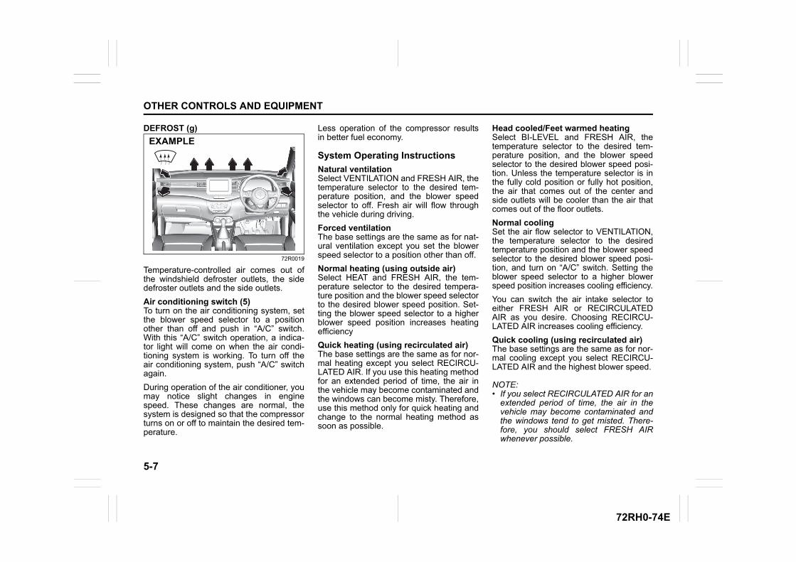
5-7
OTHER CONTROLS AND EQUIPMENT
72RH0-74E
DEFROST (g)
72R0019
Temperature-controlled air comes out ofthe windshield defroster outlets, the sidedefroster outlets and the side outlets.
Air conditioning switch (5)To turn on the air conditioning system, setthe blower speed selector to a positionother than off and push in “A/C” switch.With this “A/C” switch operation, a indica-tor light will come on when the air condi-tioning system is working. To turn off theair conditioning system, push “A/C” switchagain.
During operation of the air conditioner, youmay notice slight changes in enginespeed. These changes are normal, thesystem is designed so that the compressorturns on or off to maintain the desired tem-perature.
Less operation of the compressor resultsin better fuel economy.
System Operating Instructions
Natural ventilationSelect VENTILATION and FRESH AIR, thetemperature selector to the desired tem-perature position, and the blower speedselector to off. Fresh air will flow throughthe vehicle during driving.
Forced ventilationThe base settings are the same as for nat-ural ventilation except you set the blowerspeed selector to a position other than off.
Normal heating (using outside air)Select HEAT and FRESH AIR, the tem-perature selector to the desired tempera-ture position and the blower speed selectorto the desired blower speed position. Set-ting the blower speed selector to a higherblower speed position increases heatingefficiency
Quick heating (using recirculated air)The base settings are the same as for nor-mal heating except you select RECIRCU-LATED AIR. If you use this heating methodfor an extended period of time, the air inthe vehicle may become contaminated andthe windows can become misty. Therefore,use this method only for quick heating andchange to the normal heating method assoon as possible.
Head cooled/Feet warmed heatingSelect BI-LEVEL and FRESH AIR, thetemperature selector to the desired tem-perature position, and the blower speedselector to the desired blower speed posi-tion. Unless the temperature selector is inthe fully cold position or fully hot position,the air that comes out of the center andside outlets will be cooler than the air thatcomes out of the floor outlets.
Normal coolingSet the air flow selector to VENTILATION,the temperature selector to the desiredtemperature position and the blower speedselector to the desired blower speed posi-tion, and turn on “A/C” switch. Setting theblower speed selector to a higher blowerspeed position increases cooling efficiency.
You can switch the air intake selector toeither FRESH AIR or RECIRCULATEDAIR as you desire. Choosing RECIRCU-LATED AIR increases cooling efficiency.
Quick cooling (using recirculated air)The base settings are the same as for nor-mal cooling except you select RECIRCU-LATED AIR and the highest blower speed.
NOTE:• If you select RECIRCULATED AIR for an
extended period of time, the air in thevehicle may become contaminated andthe windows tend to get misted. There-fore, you should select FRESH AIRwhenever possible.
EXAMPLE
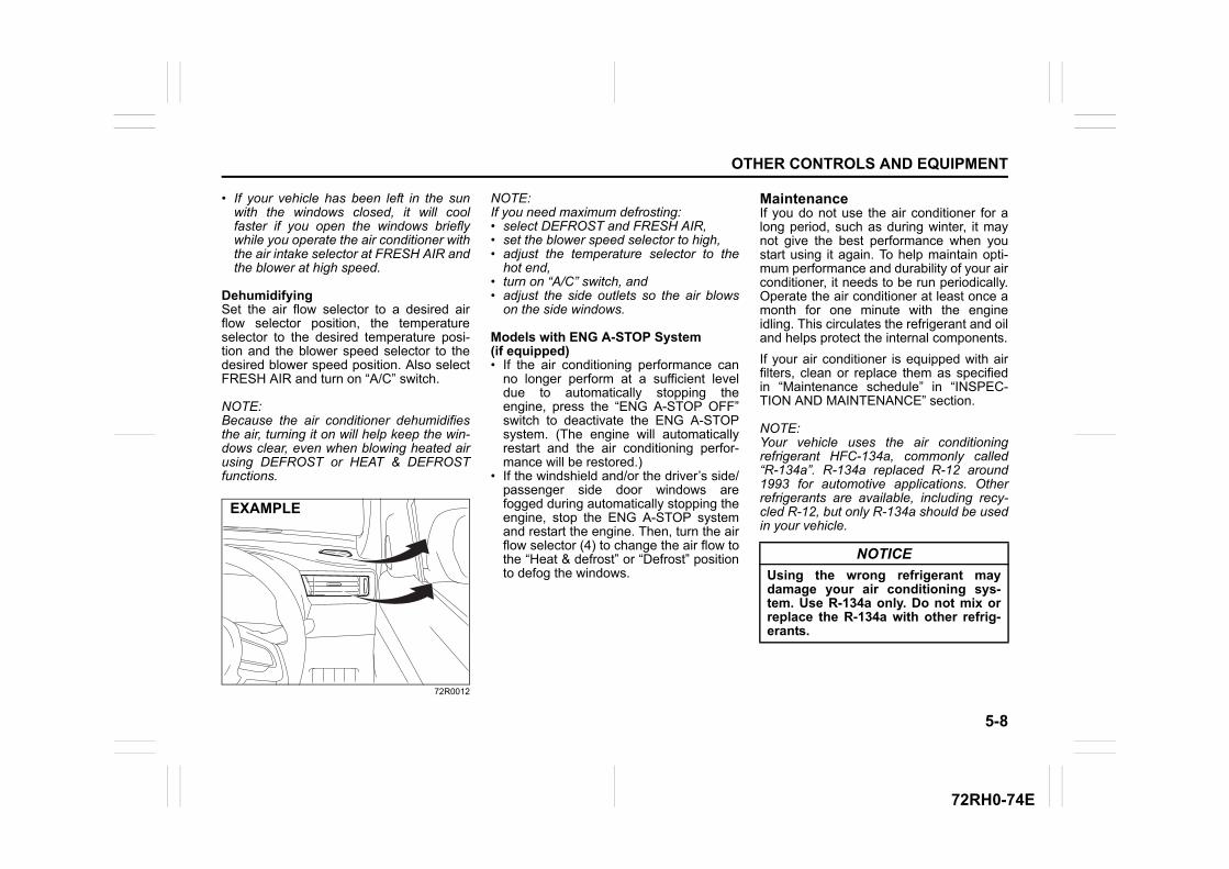
5-8
OTHER CONTROLS AND EQUIPMENT
72RH0-74E
• If your vehicle has been left in the sunwith the windows closed, it will coolfaster if you open the windows brieflywhile you operate the air conditioner withthe air intake selector at FRESH AIR andthe blower at high speed.
DehumidifyingSet the air flow selector to a desired airflow selector position, the temperatureselector to the desired temperature posi-tion and the blower speed selector to thedesired blower speed position. Also selectFRESH AIR and turn on “A/C” switch.
NOTE:Because the air conditioner dehumidifiesthe air, turning it on will help keep the win-dows clear, even when blowing heated airusing DEFROST or HEAT & DEFROSTfunctions.
72R0012
NOTE:If you need maximum defrosting:• select DEFROST and FRESH AIR, • set the blower speed selector to high, • adjust the temperature selector to the
hot end, • turn on “A/C” switch, and • adjust the side outlets so the air blows
on the side windows.
Models with ENG A-STOP System(if equipped)• If the air conditioning performance can
no longer perform at a sufficient leveldue to automatically stopping theengine, press the “ENG A-STOP OFF”switch to deactivate the ENG A-STOPsystem. (The engine will automaticallyrestart and the air conditioning perfor-mance will be restored.)
• If the windshield and/or the driver’s side/passenger side door windows arefogged during automatically stopping theengine, stop the ENG A-STOP systemand restart the engine. Then, turn the airflow selector (4) to change the air flow tothe “Heat & defrost” or “Defrost” positionto defog the windows.
MaintenanceIf you do not use the air conditioner for along period, such as during winter, it maynot give the best performance when youstart using it again. To help maintain opti-mum performance and durability of your airconditioner, it needs to be run periodically.Operate the air conditioner at least once amonth for one minute with the engineidling. This circulates the refrigerant and oiland helps protect the internal components.
If your air conditioner is equipped with airfilters, clean or replace them as specifiedin “Maintenance schedule” in “INSPEC-TION AND MAINTENANCE” section.
NOTE:Your vehicle uses the air conditioningrefrigerant HFC-134a, commonly called“R-134a”. R-134a replaced R-12 around1993 for automotive applications. Otherrefrigerants are available, including recy-cled R-12, but only R-134a should be usedin your vehicle.
EXAMPLE
NOTICE
Using the wrong refrigerant maydamage your air conditioning sys-tem. Use R-134a only. Do not mix orreplace the R-134a with other refrig-erants.
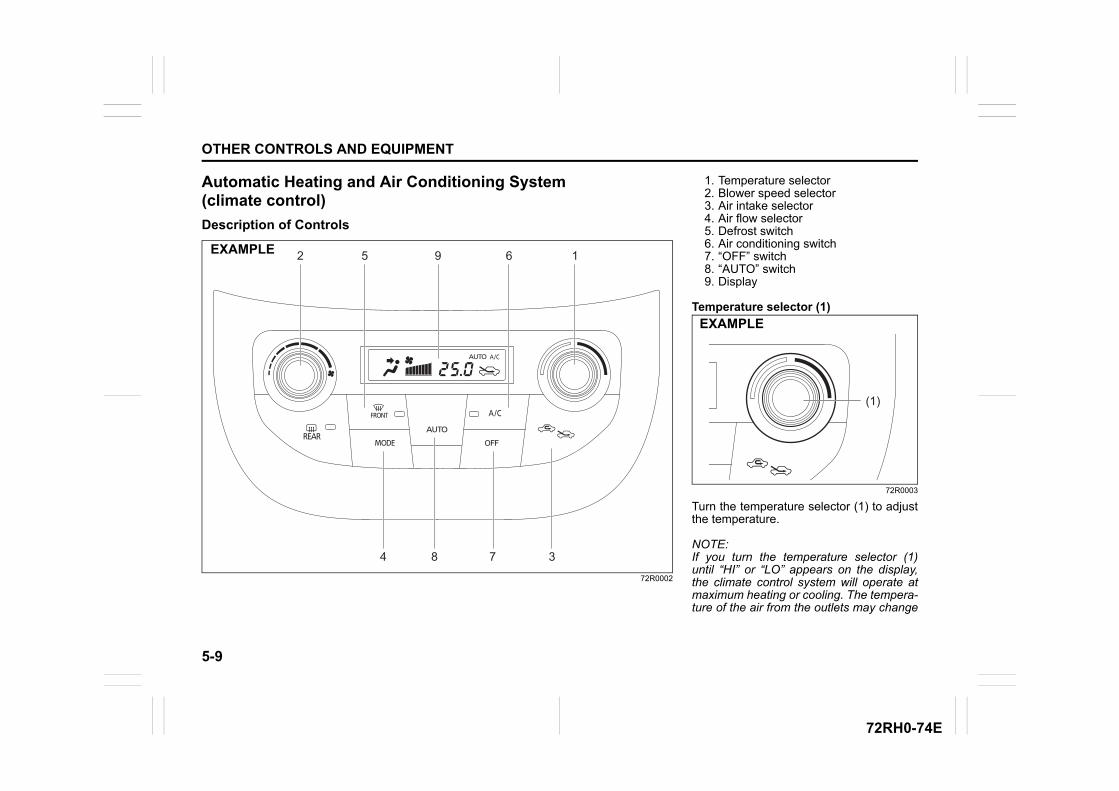
5-9
OTHER CONTROLS AND EQUIPMENT
72RH0-74E
Automatic Heating and Air Conditioning System (climate control)
Description of Controls
72R0002
84
2
7 3
5 9 6 1EXAMPLE
1. Temperature selector2. Blower speed selector3. Air intake selector4. Air flow selector5. Defrost switch6. Air conditioning switch7. “OFF” switch8. “AUTO” switch9. Display
Temperature selector (1)
72R0003
Turn the temperature selector (1) to adjustthe temperature.
NOTE:If you turn the temperature selector (1)until “HI” or “LO” appears on the display,the climate control system will operate atmaximum heating or cooling. The tempera-ture of the air from the outlets may change
(1)
EXAMPLE
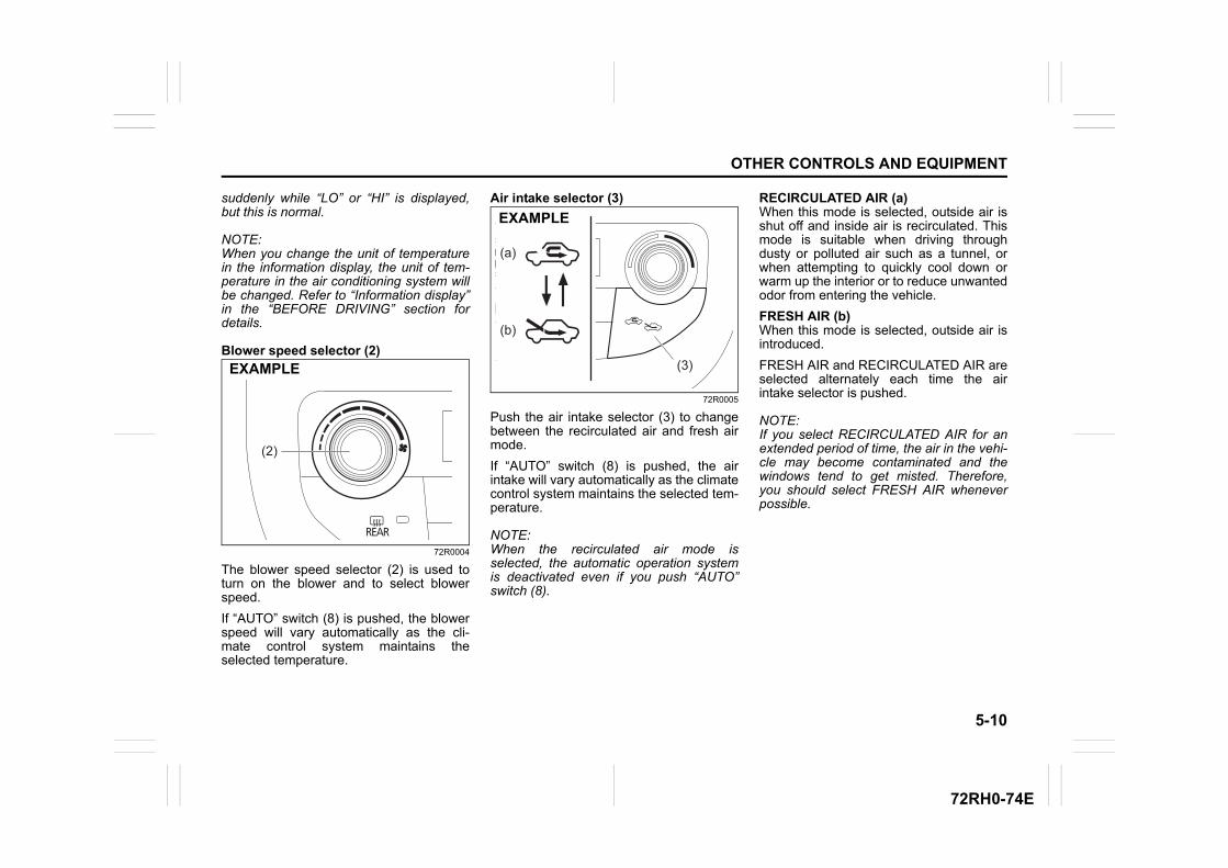
5-10
OTHER CONTROLS AND EQUIPMENT
72RH0-74E
suddenly while “LO” or “HI” is displayed,but this is normal.
NOTE:When you change the unit of temperaturein the information display, the unit of tem-perature in the air conditioning system willbe changed. Refer to “Information display”in the “BEFORE DRIVING” section fordetails.
Blower speed selector (2)
72R0004
The blower speed selector (2) is used toturn on the blower and to select blowerspeed.
If “AUTO” switch (8) is pushed, the blowerspeed will vary automatically as the cli-mate control system maintains theselected temperature.
Air intake selector (3)
72R0005
Push the air intake selector (3) to changebetween the recirculated air and fresh airmode.
If “AUTO” switch (8) is pushed, the airintake will vary automatically as the climatecontrol system maintains the selected tem-perature.
NOTE:When the recirculated air mode isselected, the automatic operation systemis deactivated even if you push “AUTO”switch (8).
RECIRCULATED AIR (a)When this mode is selected, outside air isshut off and inside air is recirculated. Thismode is suitable when driving throughdusty or polluted air such as a tunnel, orwhen attempting to quickly cool down orwarm up the interior or to reduce unwantedodor from entering the vehicle.
FRESH AIR (b)When this mode is selected, outside air isintroduced.
FRESH AIR and RECIRCULATED AIR areselected alternately each time the airintake selector is pushed.
NOTE:If you select RECIRCULATED AIR for anextended period of time, the air in the vehi-cle may become contaminated and thewindows tend to get misted. Therefore,you should select FRESH AIR wheneverpossible.
(2)
EXAMPLE
(a)
(b)
(3)
EXAMPLE
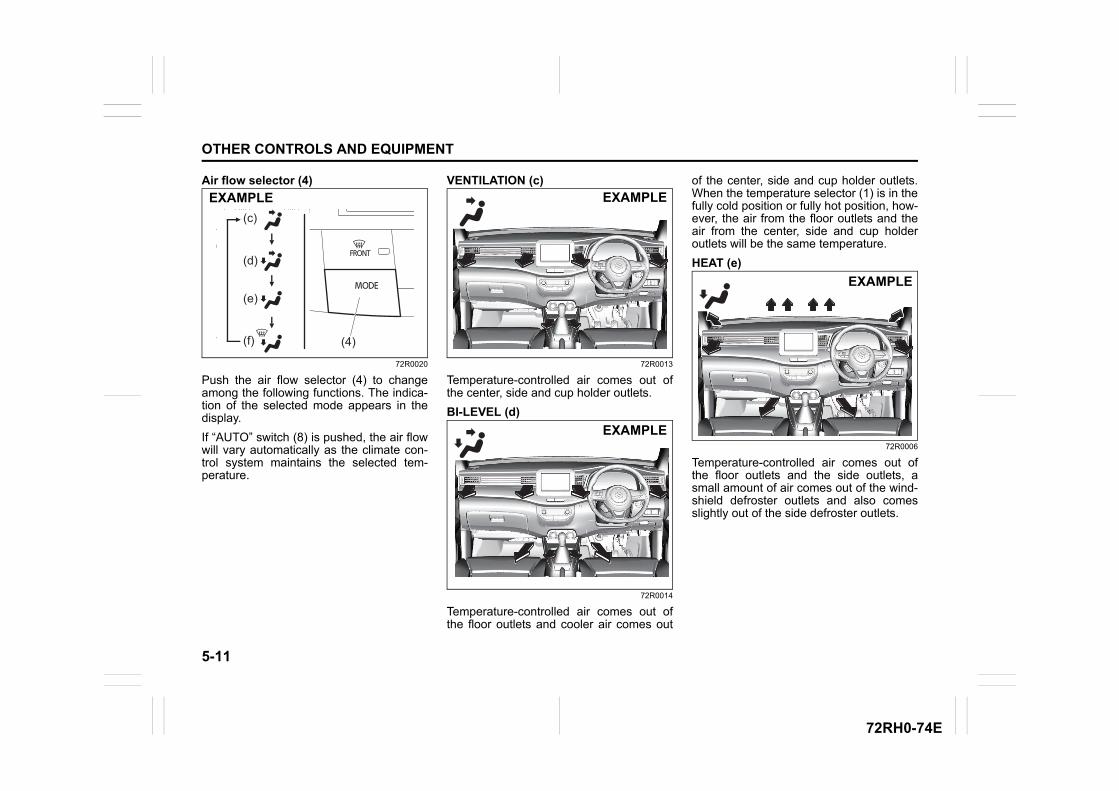
5-11
OTHER CONTROLS AND EQUIPMENT
72RH0-74E
Air flow selector (4)
72R0020
Push the air flow selector (4) to changeamong the following functions. The indica-tion of the selected mode appears in thedisplay.
If “AUTO” switch (8) is pushed, the air flowwill vary automatically as the climate con-trol system maintains the selected tem-perature.
VENTILATION (c)
72R0013
Temperature-controlled air comes out ofthe center, side and cup holder outlets.
BI-LEVEL (d)
72R0014
Temperature-controlled air comes out ofthe floor outlets and cooler air comes out
of the center, side and cup holder outlets.When the temperature selector (1) is in thefully cold position or fully hot position, how-ever, the air from the floor outlets and theair from the center, side and cup holderoutlets will be the same temperature.
HEAT (e)
72R0006
Temperature-controlled air comes out ofthe floor outlets and the side outlets, asmall amount of air comes out of the wind-shield defroster outlets and also comesslightly out of the side defroster outlets.
(c)
(d)
(e)
(f) (4)
EXAMPLE EXAMPLE
EXAMPLE
EXAMPLE
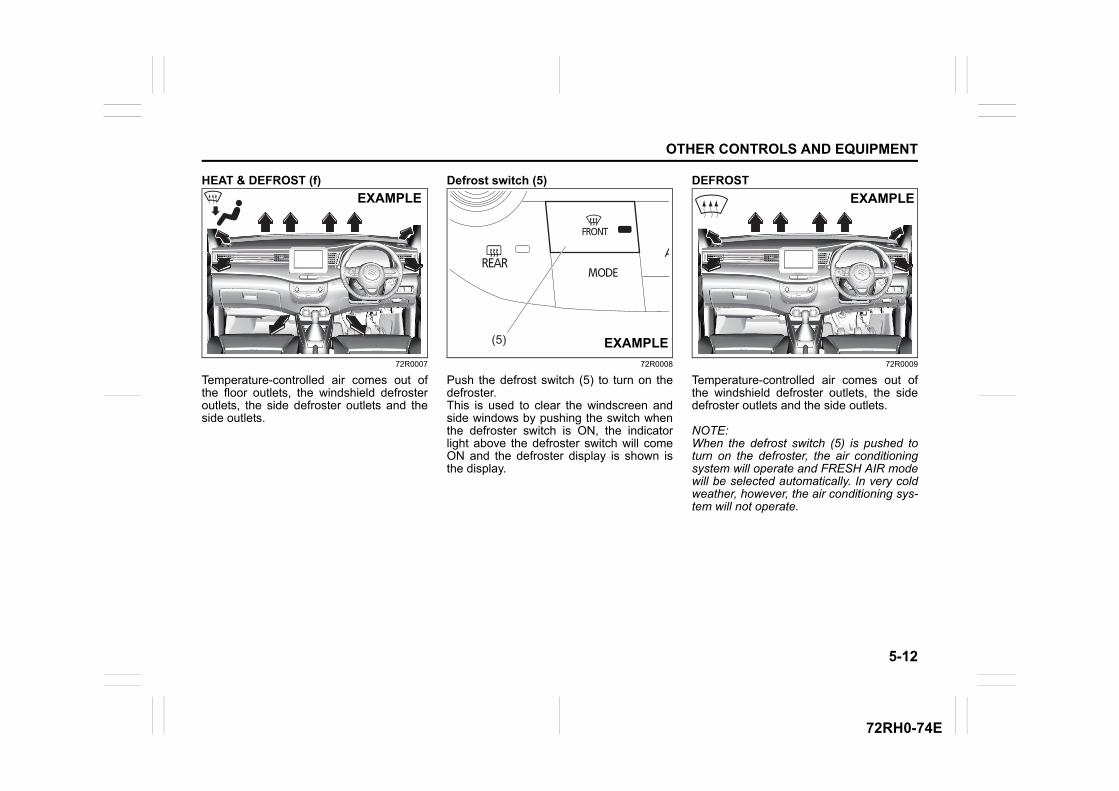
5-12
OTHER CONTROLS AND EQUIPMENT
72RH0-74E
HEAT & DEFROST (f)
72R0007
Temperature-controlled air comes out ofthe floor outlets, the windshield defrosteroutlets, the side defroster outlets and theside outlets.
Defrost switch (5)
72R0008
Push the defrost switch (5) to turn on thedefroster.This is used to clear the windscreen andside windows by pushing the switch whenthe defroster switch is ON, the indicatorlight above the defroster switch will comeON and the defroster display is shown isthe display.
DEFROST
72R0009
Temperature-controlled air comes out ofthe windshield defroster outlets, the sidedefroster outlets and the side outlets.
NOTE:When the defrost switch (5) is pushed toturn on the defroster, the air conditioningsystem will operate and FRESH AIR modewill be selected automatically. In very coldweather, however, the air conditioning sys-tem will not operate.
EXAMPLE
(5) EXAMPLE
EXAMPLE
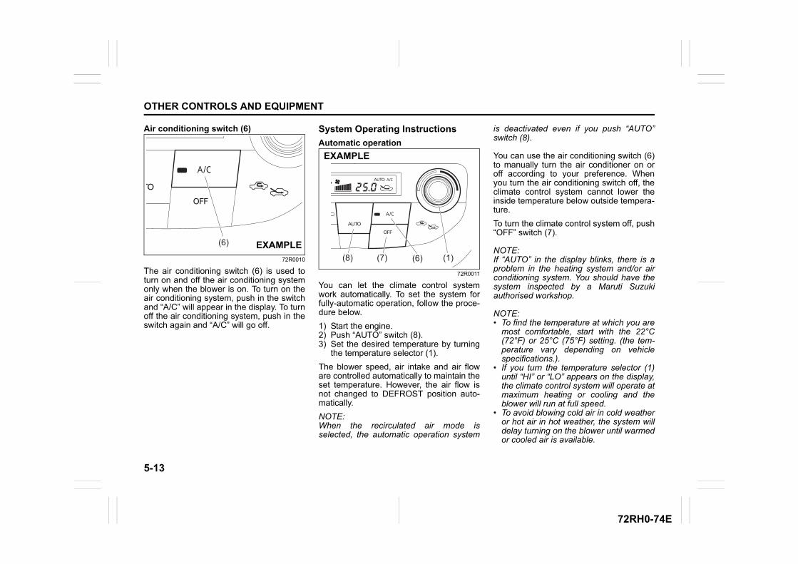
5-13
OTHER CONTROLS AND EQUIPMENT
72RH0-74E
Air conditioning switch (6)
72R0010
The air conditioning switch (6) is used toturn on and off the air conditioning systemonly when the blower is on. To turn on theair conditioning system, push in the switchand “A/C” will appear in the display. To turnoff the air conditioning system, push in theswitch again and “A/C” will go off.
System Operating Instructions
Automatic operation
72R0011
You can let the climate control systemwork automatically. To set the system forfully-automatic operation, follow the proce-dure below.
1) Start the engine.2) Push “AUTO” switch (8).3) Set the desired temperature by turning
the temperature selector (1).
The blower speed, air intake and air floware controlled automatically to maintain theset temperature. However, the air flow isnot changed to DEFROST position auto-matically.
NOTE:When the recirculated air mode isselected, the automatic operation system
is deactivated even if you push “AUTO”switch (8).
You can use the air conditioning switch (6)to manually turn the air conditioner on oroff according to your preference. Whenyou turn the air conditioning switch off, theclimate control system cannot lower theinside temperature below outside tempera-ture.
To turn the climate control system off, push“OFF” switch (7).
NOTE:If “AUTO” in the display blinks, there is aproblem in the heating system and/or airconditioning system. You should have thesystem inspected by a Maruti Suzukiauthorised workshop.
NOTE:• To find the temperature at which you are
most comfortable, start with the 22°C(72°F) or 25°C (75°F) setting. (the tem-perature vary depending on vehiclespecifications.).
• If you turn the temperature selector (1)until “HI” or “LO” appears on the display,the climate control system will operate atmaximum heating or cooling and theblower will run at full speed.
• To avoid blowing cold air in cold weatheror hot air in hot weather, the system willdelay turning on the blower until warmedor cooled air is available.
(6) EXAMPLE(8) (7) (6) (1)
EXAMPLE
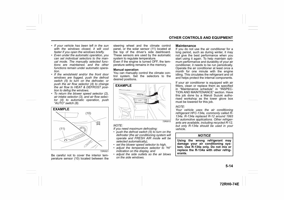
5-14
OTHER CONTROLS AND EQUIPMENT
72RH0-74E
• If your vehicle has been left in the sunwith the windows closed, it will coolfaster if you open the windows briefly.
• Even under the automatic operation, youcan set individual selectors to the man-ual mode. The manually selected func-tions are maintained, and the otherfunctions remain under automatic opera-tion.
• If the windshield and/or the front doorwindows are fogged, push the defrostswitch (5) to turn on the defroster, orpush the air flow selector (4) to changethe air flow to HEAT & DEFROST posi-tion to defog the windows.
• To return the blower speed selector (2),air intake selector (3), and air flow selec-tor (4) to automatic operation, push“AUTO” switch (8).
72R0021
Be careful not to cover the interior tem-perature sensor (10) located between the
steering wheel and the climate controlpanel, or the solar sensor (11) located atthe top of the driver’s side dashboard.These sensors are used by the automaticsystem to regulate temperature.Even if the engine is turned OFF, the tem-perature setting remains in the memory.
Manual operationYou can manually control the climate con-trol system. Set the selectors to thedesired positions.
72R0012
NOTE:If you need maximum defrosting: • push the defrost switch (5) to turn on the
defroster (the air conditioning system willoperate and FRESH AIR mode will beselected automatically),
• set the blower speed selector to high, • adjust the temperature selector to “HI”
indication on the display, and • adjust the side outlets so the air blows
on the side windows.
MaintenanceIf you do not use the air conditioner for along period, such as during winter, it maynot give the best performance when youstart using it again. To help maintain opti-mum performance and durability of your airconditioner, it needs to be run periodically.Operate the air conditioner at least once amonth for one minute with the engineidling. This circulates the refrigerant and oiland helps protect the internal components.
If your air conditioner is equipped with airfilters, clean or replace them as specifiedin “Maintenance schedule” in “INSPEC-TION AND MAINTENANCE” section. Havethis job done by a Maruti Suzuki autho-rised workshop as the lower glove boxmust be lowered for this job.
NOTE:Your vehicle uses the air conditioningrefrigerant HFC-134a, commonly called R-134a. R-134a replaced R-12 around 1993for automotive applications. Other refriger-ants are available, including recycled R-12,but only R-134a should be used in yourvehicle.(11)
(10)EXAMPLE
EXAMPLE
NOTICE
Using the wrong refrigerant maydamage your air conditioning sys-tem. Use R-134a only. Do not mix orreplace the R-134a with other refrig-erants.
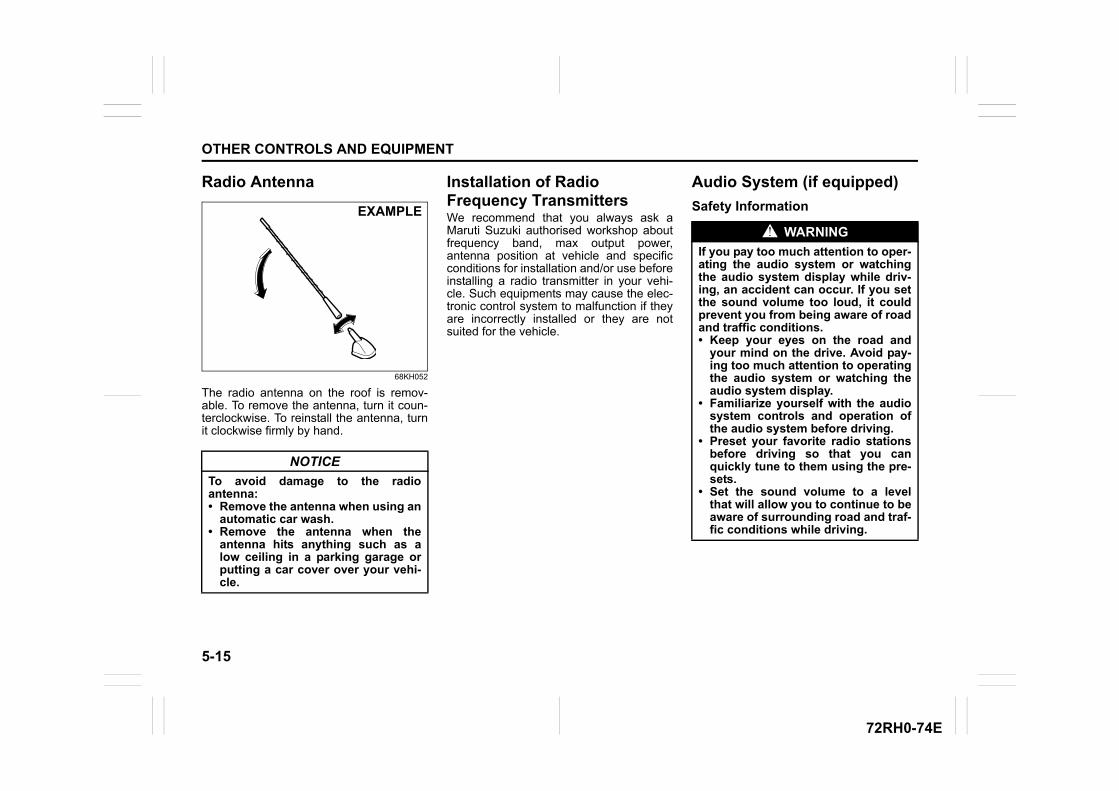
5-15
OTHER CONTROLS AND EQUIPMENT
72RH0-74E
Radio Antenna
68KH052
The radio antenna on the roof is remov-able. To remove the antenna, turn it coun-terclockwise. To reinstall the antenna, turnit clockwise firmly by hand.
Installation of Radio Frequency TransmittersWe recommend that you always ask aMaruti Suzuki authorised workshop aboutfrequency band, max output power,antenna position at vehicle and specificconditions for installation and/or use beforeinstalling a radio transmitter in your vehi-cle. Such equipments may cause the elec-tronic control system to malfunction if theyare incorrectly installed or they are notsuited for the vehicle.
Audio System (if equipped)
Safety Information
NOTICE
To avoid damage to the radioantenna:• Remove the antenna when using an
automatic car wash.• Remove the antenna when the
antenna hits anything such as alow ceiling in a parking garage orputting a car cover over your vehi-cle.
EXAMPLE
WARNING
If you pay too much attention to oper-ating the audio system or watchingthe audio system display while driv-ing, an accident can occur. If you setthe sound volume too loud, it couldprevent you from being aware of roadand traffic conditions.• Keep your eyes on the road and
your mind on the drive. Avoid pay-ing too much attention to operatingthe audio system or watching theaudio system display.
• Familiarize yourself with the audiosystem controls and operation ofthe audio system before driving.
• Preset your favorite radio stationsbefore driving so that you canquickly tune to them using the pre-sets.
• Set the sound volume to a levelthat will allow you to continue to beaware of surrounding road and traf-fic conditions while driving.
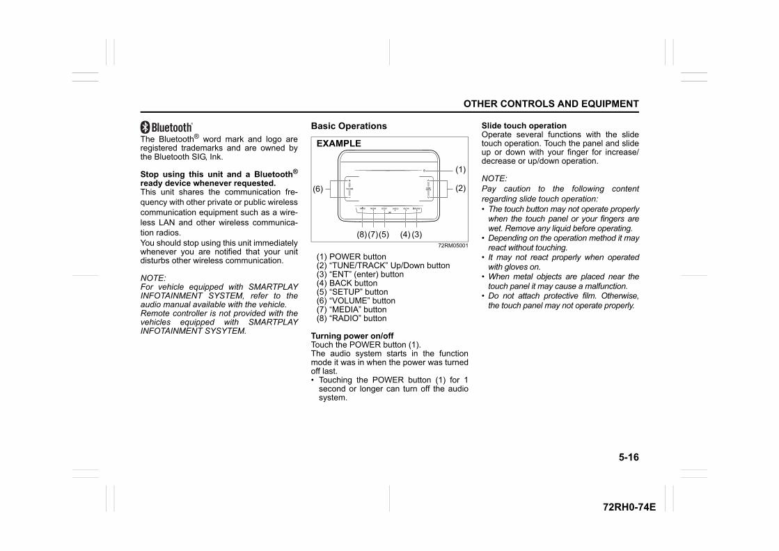
5-16
OTHER CONTROLS AND EQUIPMENT
72RH0-74E
The Bluetooth® word mark and logo areregistered trademarks and are owned bythe Bluetooth SIG, Ink.
Stop using this unit and a Bluetooth®
ready device whenever requested. This unit shares the communication fre-quency with other private or public wirelesscommunication equipment such as a wire-less LAN and other wireless communica-tion radios. You should stop using this unit immediatelywhenever you are notified that your unitdisturbs other wireless communication.
NOTE:For vehicle equipped with SMARTPLAYINFOTAINMENT SYSTEM, refer to theaudio manual available with the vehicle.Remote controller is not provided with thevehicles equipped with SMARTPLAYINFOTAINMENT SYSYTEM.
Basic Operations
72RM05001
(1) POWER button(2) “TUNE/TRACK” Up/Down button(3) “ENT” (enter) button(4) BACK button(5) “SETUP” button(6) “VOLUME” button(7) “MEDIA” button(8) “RADIO” button
Turning power on/offTouch the POWER button (1).The audio system starts in the functionmode it was in when the power was turnedoff last.• Touching the POWER button (1) for 1
second or longer can turn off the audiosystem.
Slide touch operationOperate several functions with the slidetouch operation. Touch the panel and slideup or down with your finger for increase/decrease or up/down operation.
NOTE:Pay caution to the following contentregarding slide touch operation:• The touch button may not operate properly
when the touch panel or your fingers arewet. Remove any liquid before operating.
• Depending on the operation method it mayreact without touching.
• It may not react properly when operatedwith gloves on.
• When metal objects are placed near thetouch panel it may cause a malfunction.
• Do not attach protective film. Otherwise,the touch panel may not operate properly.
(1)
(2)(6)
(3)(4)(5)(7)(8)
EXAMPLE
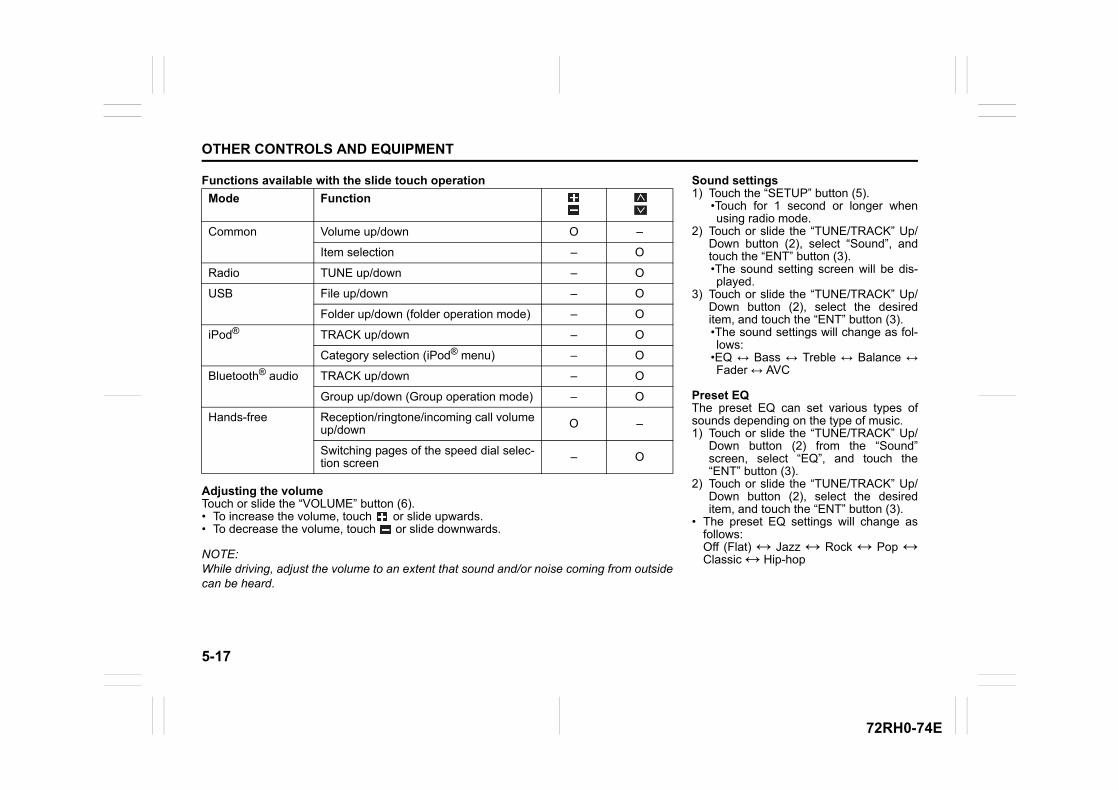
5-17
OTHER CONTROLS AND EQUIPMENT
72RH0-74E
Functions available with the slide touch operation
Adjusting the volumeTouch or slide the “VOLUME” button (6).• To increase the volume, touch or slide upwards.• To decrease the volume, touch or slide downwards.
NOTE:While driving, adjust the volume to an extent that sound and/or noise coming from outsidecan be heard.
Mode Function
Common Volume up/down O –
Item selection – O
Radio TUNE up/down – O
USB File up/down – O
Folder up/down (folder operation mode) – O
iPod® TRACK up/down – O
Category selection (iPod® menu) – O
Bluetooth® audio TRACK up/down – O
Group up/down (Group operation mode) – O
Hands-free Reception/ringtone/incoming call volumeup/down O –
Switching pages of the speed dial selec-tion screen – O
Sound settings1) Touch the “SETUP” button (5).
•Touch for 1 second or longer whenusing radio mode.
2) Touch or slide the “TUNE/TRACK” Up/Down button (2), select “Sound”, andtouch the “ENT” button (3).•The sound setting screen will be dis-played.
3) Touch or slide the “TUNE/TRACK” Up/Down button (2), select the desireditem, and touch the “ENT” button (3).•The sound settings will change as fol-lows:
•EQ ↔ Bass ↔ Treble ↔ Balance ↔Fader ↔ AVC
Preset EQThe preset EQ can set various types ofsounds depending on the type of music.1) Touch or slide the “TUNE/TRACK” Up/
Down button (2) from the “Sound”screen, select “EQ”, and touch the“ENT” button (3).
2) Touch or slide the “TUNE/TRACK” Up/Down button (2), select the desireditem, and touch the “ENT” button (3).
• The preset EQ settings will change asfollows:Off (Flat) ↔ Jazz ↔ Rock ↔ Pop ↔Classic ↔ Hip-hop
5-18
OTHER CONTROLS AND EQUIPMENT
72RH0-74E
Adjusting bass/treble/balance /faderThe preset EQ can set various types ofsounds depending on the type of music.1) Touch or slide the “TUNE/TRACK” Up/
Down button (2) from the “Sound”screen, select “Bass”, “Treble”, “Bal-ance”, or “Fader” and touch the “ENT”button (3).
2) Touch or slide the “TUNE/TRACK” Up/Down button (2), adjust to the desiredsettings and touch the “ENT” button (3).
• “Bass”/“Treble”:– Can be adjusted in stages from -6 to 0
to +6.– Touch to emphasize the low or high
sounds, and touch to quiet.• “Balance”:
– Can be adjusted in 9 stages left toright .
– Touch to emphasize the rightspeaker, and touch to emphasizethe left speaker.
• “Fader”:– Can be adjusted in 9 stages back to
front.– Touch to emphasize the front
speaker, and touch to emphasizethe rear speaker.
Adjusting the AVC (Auto volume con-trol)The Auto Volume Control (AVC) functionautomatically adjusts (increases/decreases) the sound volume in accor-dance with vehicle speed. The AVC controlis provided with three selectable levels(LEVEL OFF, 1, 2, 3). The range of volumeadjustment increases together with theLEVEL number.
1) Touch or slide the “TUNE/TRACK” Up/Down button (2) from the “Sound”screen, select “AVC”, and touch the“ENT” button (3).
2) Touch or slide the “TUNE/TRACK” Up/Down button (2), select the desiredlevel, and touch the “ENT” button (3).
• The AVC will change as follows:Off ↔ Level 1 ↔ Level 2 ↔ Level 3
Switching the mode1) Press the “MEDIA” button (7) for 1 sec-
ond or more in radio mode. You canswitch the radio mode to media mode.
2) Touch the “RADIO” button (8) in mediamode. You can switch the media modeto radio mode.
System settingsChange the “Beep”, “Slide”, and “SW Sen-sitivity” settings.1) Touch the “SETUP” button (5).• Touch for 1 second or longer when using
radio mode.2) Touch or slide the “TUNE/TRACK” Up/
Down button (2), select “System”, andtouch the “ENT” button (3).
• The system setting screen will be dis-played.
3) Touch or slide the “TUNE/TRACK” Up/Down button (2), select the desireditem, and touch the “ENT” button (3).
• The system settings will change as fol-lows:Beep ↔ Slide ↔ SW Sensitivity
BEEP on/off1) Touch or slide the “TUNE/TRACK” Up/
Down button (2) from the “System”screen, select “Beep”, and touch the“ENT” button (3).
2) Touch or slide the “TUNE/TRACK” Up/Down button (2), select on or off, andtouch the “ENT” button (3).
Slide touch operation settingsTurn the slide operation on/off.1) Touch or slide the “TUNE/TRACK” Up/
Down button (2) from the “System”screen, select “Slide”, and touch the“ENT” button (3).
2) Touch or slide the “TUNE/TRACK” Up/Down button (2), select on or off, andtouch the “ENT” button (3).
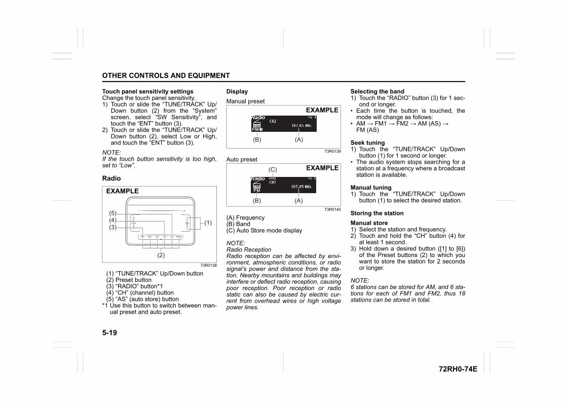
5-19
OTHER CONTROLS AND EQUIPMENT
72RH0-74E
Touch panel sensitivity settingsChange the touch panel sensitivity.1) Touch or slide the “TUNE/TRACK” Up/
Down button (2) from the “System”screen, select “SW Sensitivity”, andtouch the “ENT” button (3).
2) Touch or slide the “TUNE/TRACK” Up/Down button (2), select Low or High,and touch the “ENT” button (3).
NOTE:If the touch button sensitivity is too high,set to “Low”.
Radio
73R0138
(1) “TUNE/TRACK” Up/Down button(2) Preset button(3) “RADIO” button*1(4) “CH” (channel) button(5) “AS” (auto store) button
*1 Use this button to switch between man-ual preset and auto preset.
Display
Manual preset
73R0139
Auto preset
73R0140
(A) Frequency(B) Band(C) Auto Store mode display
NOTE:Radio ReceptionRadio reception can be affected by envi-ronment, atmospheric conditions, or radiosignal’s power and distance from the sta-tion. Nearby mountains and buildings mayinterfere or deflect radio reception, causingpoor reception. Poor reception or radiostatic can also be caused by electric cur-rent from overhead wires or high voltagepower lines.
Selecting the band1) Touch the “RADIO” button (3) for 1 sec-
ond or longer.• Each time the button is touched, the
mode will change as follows:• AM → FM1 → FM2 → AM (AS) →
FM (AS)
Seek tuning1) Touch the “TUNE/TRACK” Up/Down
button (1) for 1 second or longer.• The audio system stops searching for a
station at a frequency where a broadcaststation is available.
Manual tuning1) Touch the “TUNE/TRACK” Up/Down
button (1) to select the desired station.
Storing the station
Manual store1) Select the station and frequency.2) Touch and hold the “CH” button (4) for
at least 1 second. 3) Hold down a desired button ([1] to [6])
of the Preset buttons (2) to which youwant to store the station for 2 secondsor longer.
NOTE:6 stations can be stored for AM, and 6 sta-tions for each of FM1 and FM2, thus 18stations can be stored in total.
(1)(3)(4)(5)
(2)
EXAMPLE
(A)(B)
EXAMPLE
(A)(B)
(C) EXAMPLE
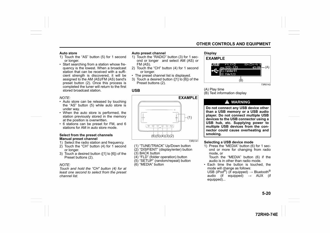
5-20
OTHER CONTROLS AND EQUIPMENT
72RH0-74E
Auto store1) Touch the “AS” button (5) for 1 second
or longer.• Start searching from a station whose fre-
quency is the lowest. When a broadcaststation that can be received with a suffi-cient strength is discovered, it will beassigned to the AM (AS)/FM (AS) band'spreset button (2). Once this process iscompleted the tuner will return to the firststored broadcast station.
NOTE:• Auto store can be released by touching
the “AS” button (5) while auto store isunder way.
• When the auto store is performed, thestation previously stored in the memoryat the position is overwritten.
• 6 stations can be preset for FM, and 6stations for AM in auto store mode.
Select from the preset channelsManual preset channel1) Select the radio station and frequency. 2) Touch the “CH” button (4) for 1 second
or longer.3) Touch a desired button ([1] to [6]) of the
Preset buttons (2).
NOTE:Touch and hold the “CH” button (4) for atleast one second to select from the presetchannel list.
Auto preset channel1) Touch the “RADIO” button (3) for 1 sec-
ond or longer and select AM (AS) orFM (AS).
2) Touch the “CH” button (4) for 1 second or longer.
• The preset channel list is displayed.3) Touch a desired button ([1] to [6]) of the
Preset buttons (2).
USB
73R0141
(1) “TUNE/TRACK” Up/Down button(2) “DISP/ENT” (display/enter) button(3) BACK button(4) “FLD” (folder operation) button(5) “SETUP” (random/repeat) button(6) “MEDIA” button
Display
73R0142
(A) Play time(B) Text information display
Selecting a USB device mode1) Press the “MEDIA” button (6) for 1 sec-
ond or more for changing from radiomode, orTouch the “MEDIA” button (6) if theaudio is in other than radio mode.
• Each time the button is touched, themode will change as follows:USB (iPod®) (if equipped) → Bluetooth®
audio (if equipped) → AUX (ifequipped)...
(1)
(2)(3)(4)(5)(6)
EXAMPLEWARNING
Do not connect any USB device otherthan a USB memory or a USB audioplayer. Do not connect multiple USBdevices to the USB connector using aUSB hub, etc. Supplying power tomultiple USB devices from the con-nector could cause overheating andsmoking.
(A)
(B)
EXAMPLE
5-21
OTHER CONTROLS AND EQUIPMENT
72RH0-74E
Fast forwarding/Rewinding a track1) Hold down the “TUNE/TRACK” Up/
Down button (1).• : Hold down the Up button for 1 sec-
ond or longer to fast forward the track.• : Hold down the Down button for 1
second or longer to fast rewind the track.• Releasing the button can stop the fast
forwarding/rewinding.
Selecting a track1) Touch the “TUNE/TRACK” Up/Down
button (1).• : Touch the Up button to listen to the
next track.• : When the Down button is touched
once, the track currently being playedwill start from the beginning again. Touchthe Down button twice to listen to theprevious track.
Selecting a folder1) Touch the “FLD” (folder operation) but-
ton (4).2) Touch the “TUNE/TRACK” Up/Down
button (1).• : Touch the Up button to move to the
next folder.• : Touch the Down button to move to
the previous folder.
Repeat playback1) Touch the “SETUP” (random/repeat)
button (5).2) Touch or slide the “TUNE/TRACK” Up/
Down button (1), select “Repeat”, andtouch the “DISP/ENT” button (2).
• Each time the “DISP/ENT” button (2) istouched, the mode will change as follows:Off → One song repeat → Folder repeat ...
Random playback1) Touch the “SETUP” (random/repeat)
button (5).2) Touch or slide the “TUNE/TRACK” Up/
Down button (1), select “Random”, andtouch the “DISP/ENT” button (2).Each time the “DISP/ENT” button (2) istouched, the mode will change as fol-lows:Off → Folder random → All random ...
Display change1) Touch the “DISP/ENT” button (2).• Each time the button is touched, display
will change as follows:MP3/AAC:Artist name/Track title → Album name/Track title → Folder name/File name...WMA:Artist name/Track title → Folder name/File name ...
NOTE:• “NO TITLE” will be displayed when there
is no text information in the USB devicecurrently being played.
• “...” is displayed if all text data cannot bedisplayed. Touch and hold the “DISP/ENT” button (2) for at least 1 second toautomatically display the rest of the textdata.
Notes on USB device
Compatible USB devices• USB Mass Storage Class
For details as to whether your USBmemory/USB Audio is compatible withUSB Mass Storage Class, please con-tact the USB memory/USB Audio manu-facturer.
• Audio fileMP3 (.mp3)/WMA (.wma)/AAC (.m4a)/AAC (.aac)
• File SystemFAT 12/16/32,VFAT (supporting long filename)
• USB Standard Compatibility1.1/2.0 Full Speed
• If a USB hub or extension cable is con-nected to the audio system, it may notbe recognized. In this case, directly con-nect the USB device to the audio sys-tem.
• Devices such as MP3 players/mobilephones/digital cameras may not be rec-ognized as audio systems for playingmusic.
5-22
OTHER CONTROLS AND EQUIPMENT
72RH0-74E
USB device connection• When connecting a USB device, make
sure that the connector is pushed all theway into the port.
• Depending on the USB flash drive thatyou are using, (non-brand product, USBflash drive that has been externally dam-aged) it may disable connection orcause unstable operation.
• Do not leave the USB device for longperiods of time in places inside the vehi-cle where the temperature can rise toohigh.
• Back up any important data beforehand.We cannot accept responsibility for anylost data.
• It is recommended not to connect a USBdevice that contains data files other thanMP3/WMA format.
Recording MP3/WMA/AAC files on aUSB device• Playback or display may not be possible
depending on the type of USB device inuse or the condition of the recording.
• Depending on the connected USB mem-ory, the files may be played in differentorder from the order that the files werestored.
• The DRM (Digital Rights Management)file cannot be played.
Compression formatsMP3• Bit rate
MPEG1 Audio Layer III: 32 up to 320 kbpsMPEG2 Audio Layer III: 8 up to 160 kbpsMPEG2.5 Audio Layer III: 8 up to 160kbpsVBR: up to 384 kbps (MAX.)
• Sampling frequencyMPEG1 Audio Layer III: 32/44.1/48 kHzMPEG2 Audio Layer III: 16/22.05/24 kHzMPEG2.5 Audio Layer III: 8/11.025/12 kHz
• ChannelStereo/Joint stereo/Dual channel/Mon-aural
• ID3 tagID3v1.x/ID3v2.x
WMA• Windows Media Audio Ver.7/Ver.8/Ver.9
Standard compliant• Bit rate: 32 up to 320 kbps• VBR: up to 384 kbps (MAX.)• Sampling frequency: 32/44.1/48 kHz• WMA tag: Ver.8.0• Channel: 2 Channels
AAC• Bit rate: 16 up to 320 kbps• VBR: up to 320 kbps (MAX.)• Sampling frequency: 32/44.1/48 kHz• AAC tag: iTunes m4a metadata
Maximum number of files/folders• Maximum number of files: 2500• Maximum number of files in a folder: 255• Maximum number of folders: 255
– Root folder and empty folder areincluded.
• Maximum depth of tree structure: 8
NOTICE
Never use “.mp3”, “.wma” or “.m4a”as a file name extension if it is not inthe MP3/WMA/AAC format file. Fail-ure to observe this may result indamage to the speaker due to noiseproduction.
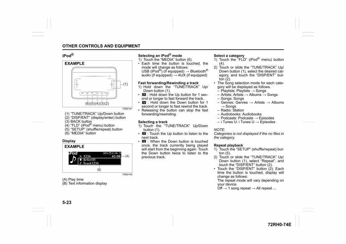
5-23
OTHER CONTROLS AND EQUIPMENT
72RH0-74E
iPod®
73R0141
(1) “TUNE/TRACK” Up/Down button(2) “DISP/ENT” (display/enter) button(3) BACK button(4) “FLD” (iPod® menu) button(5) “SETUP” (shuffle/repeat) button(6) “MEDIA” button
Display
73R0143
(A) Play time(B) Text information display
Selecting an iPod® mode1) Touch the “MEDIA” button (6).• Each time the button is touched, the
mode will change as follows:USB (iPod®) (if equipped) → Bluetooth®
audio (if equipped) → AUX (if equipped)
Fast forwarding/Rewinding a track1) Hold down the “TUNE/TRACK” Up/
Down button (1).• : Hold down the Up button for 1 sec-
ond or longer to fast forward the track.• : Hold down the Down button for 1
second or longer to fast rewind the track.• Releasing the button can stop the fast
forwarding/rewinding.
Selecting a track1) Touch the “TUNE/TRACK” Up/Down
button (1).• : Touch the Up button to listen to the
next track.• : When the Down button is touched
once, the track currently being playedwill start from the beginning again. Touchthe Down button twice to listen to theprevious track.
Select a category1) Touch the “FLD” (iPod® menu) button
(4).2) Touch or slide the “TUNE/TRACK” Up/
Down button (1), select the desired cat-egory, and touch the “DISP/ENT” but-ton (2).
• The Song selection mode for each cate-gory will be displayed as follows.– Playlists: Playlists → Songs– Artists: Artists → Albums → Songs– Songs: Songs– Genres: Genres → Artists → Albums→ Songs
– Radio: Station– Audiobooks: Audiobooks– Podcasts: Podcasts → Episodes– i Tunes U: i Tunes U → Episodes
NOTE:Categories is not displayed if the no files inthe category.
Repeat playback1) Touch the “SETUP” (shuffle/repeat) but-
ton (5).2) Touch or slide the “TUNE/TRACK” Up/
Down button (1), select “Repeat”, andtouch the “DISP/ENT” button (2).
• Touch the “DISP/ENT” button (2). Eachtime the button is touched, display willchange as follows:The repeat mode will vary depending onyour device.Off → 1 song repeat → All repeat ...
(1)
(2)(3)(4)(5)(6)
EXAMPLE
(A)
(B)
EXAMPLE
5-24
OTHER CONTROLS AND EQUIPMENT
72RH0-74E
Random playback1) Touch the “SETUP” (shuffle/repeat) but-
ton (5).2) Touch or slide the “TUNE/TRACK” Up/
Down button (1), select “Shuffle”, andtouch the “DISP/ENT” button (2).
• Touch the “DISP/ENT” button (2). Eachtime the button is touched, display willchange as follows:Off → Shuffle → Album shuffle ...
Display change1) Touch the “DISP/ENT” button (2).• Each time the button is touched, display
will change as follows:Artist name/Track title → Album name/Track title → Playlist name/Track title ...
NOTE:• “NO TITLE” is displayed if the file cur-
rently being played has no text data.• “...” is displayed if all text data cannot be
displayed. Touch and hold the “DISP/ENT” button (2) for at least one secondto automatically display the rest of thetext data.
• “Playlist name/song name” is only dis-played by the “FLD” (Menu) button (4)when music is selected from Playlists.
Notes on iPod®
Supported iPod®
• iPod® nano:– iPod® nano (7th generation)
• iPod® touch:– iPod® touch (6th generation)
• i Pod® touch (5th generation)• iPhone®:
– i Phone® 5– i Phone® 5s– i Phone® 5c– i Phone® 6– i Phone® 6 Plus– i Phone® 6s– i Phone® 6s Plus– i Phone® SE– i Phone® 7– i Phone® 7 Plus– i Phone® 8– i Phone® 8 Plus– i Phone® X
NOTE:Some functions may not be availabledepending on the model of iPod®.
iPod®
73R0217
• “Made for iPod” and “Made for iPhone”means that an electronic accessory hasbeen designed to connect specifically toiPod® or iPhone®, respectively, and hasbeen certified by the developer to meetApple performance standards. Apple isnot responsible for the operation of thisunit or its compliance with safety andregulatory standards.
• Please note that the use of this acces-sory with iPod® or iPhone® may affectwireless performance.
• iPhone®, iPod®, iPod® classic, iPod®
nano, and iPod® touch are trademarksof Apple Inc., registered in the U.S. andother countries.
• Lightning® is a trademark of Apple Inc.
EXAMPLE
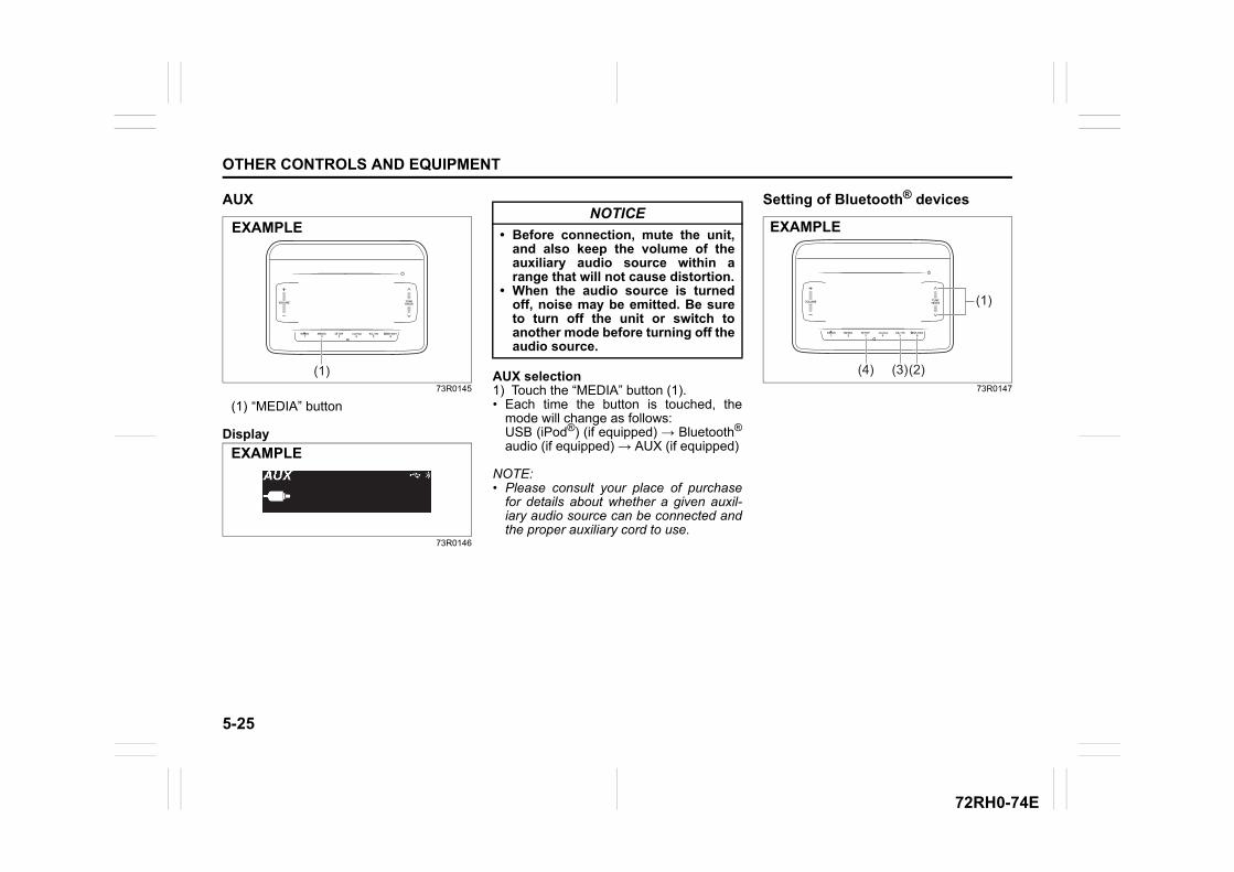
5-25
OTHER CONTROLS AND EQUIPMENT
72RH0-74E
AUX
73R0145
(1) “MEDIA” button
Display
73R0146
AUX selection1) Touch the “MEDIA” button (1).• Each time the button is touched, the
mode will change as follows:USB (iPod®) (if equipped) → Bluetooth®
audio (if equipped) → AUX (if equipped)
NOTE:• Please consult your place of purchase
for details about whether a given auxil-iary audio source can be connected andthe proper auxiliary cord to use.
Setting of Bluetooth® devices
73R0147
(1)
EXAMPLE
EXAMPLE
NOTICE
• Before connection, mute the unit,and also keep the volume of theauxiliary audio source within arange that will not cause distortion.
• When the audio source is turnedoff, noise may be emitted. Be sureto turn off the unit or switch toanother mode before turning off theaudio source.
(1)
(2)(3)(4)
EXAMPLE
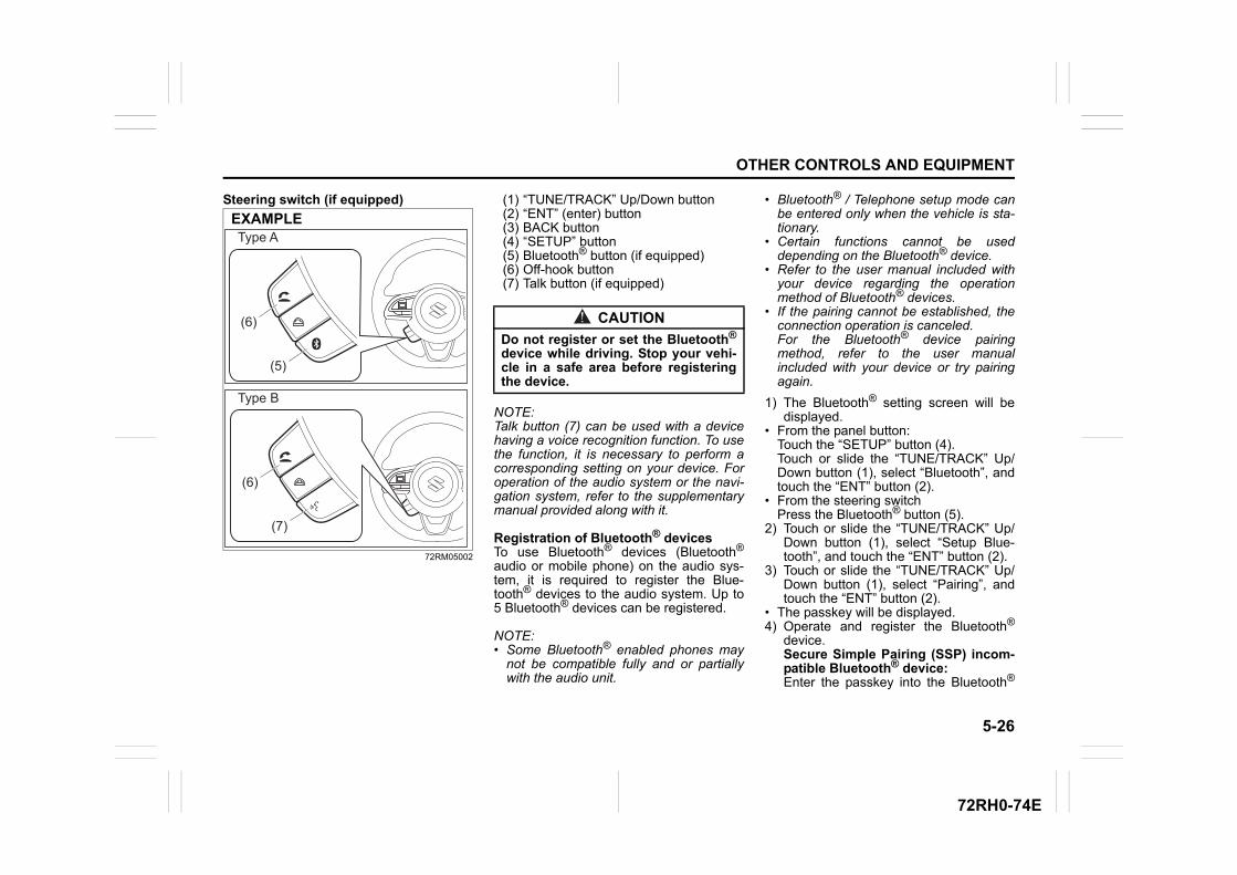
5-26
OTHER CONTROLS AND EQUIPMENT
72RH0-74E
Steering switch (if equipped)
72RM05002
(1) “TUNE/TRACK” Up/Down button(2) “ENT” (enter) button(3) BACK button(4) “SETUP” button(5) Bluetooth® button (if equipped)(6) Off-hook button(7) Talk button (if equipped)
NOTE:Talk button (7) can be used with a devicehaving a voice recognition function. To usethe function, it is necessary to perform acorresponding setting on your device. Foroperation of the audio system or the navi-gation system, refer to the supplementarymanual provided along with it.
Registration of Bluetooth® devicesTo use Bluetooth® devices (Bluetooth®
audio or mobile phone) on the audio sys-tem, it is required to register the Blue-tooth® devices to the audio system. Up to5 Bluetooth® devices can be registered.
NOTE:• Some Bluetooth® enabled phones may
not be compatible fully and or partiallywith the audio unit.
• Bluetooth® / Telephone setup mode canbe entered only when the vehicle is sta-tionary.
• Certain functions cannot be useddepending on the Bluetooth® device.
• Refer to the user manual included withyour device regarding the operationmethod of Bluetooth® devices.
• If the pairing cannot be established, theconnection operation is canceled.For the Bluetooth® device pairingmethod, refer to the user manualincluded with your device or try pairingagain.
1) The Bluetooth® setting screen will bedisplayed.
• From the panel button:Touch the “SETUP” button (4).Touch or slide the “TUNE/TRACK” Up/Down button (1), select “Bluetooth”, andtouch the “ENT” button (2).
• From the steering switchPress the Bluetooth® button (5).
2) Touch or slide the “TUNE/TRACK” Up/Down button (1), select “Setup Blue-tooth”, and touch the “ENT” button (2).
3) Touch or slide the “TUNE/TRACK” Up/Down button (1), select “Pairing”, andtouch the “ENT” button (2).
• The passkey will be displayed.4) Operate and register the Bluetooth®
device.Secure Simple Pairing (SSP) incom-patible Bluetooth® device:Enter the passkey into the Bluetooth®
EXAMPLE
(5)
(6)
Type A
Type B
(7)
(6)
CAUTION
Do not register or set the Bluetooth®
device while driving. Stop your vehi-cle in a safe area before registeringthe device.
5-27
OTHER CONTROLS AND EQUIPMENT
72RH0-74E
device.Secure Simple Pairing (SSP) com-patible Bluetooth® device:Select “Yes” to register the Bluetooth®
device.• It is possible to automatically register
devices depending on the type of Blue-tooth® device.
NOTE:• If the Bluetooth® device contains music
player and mobile phone function, bothfunctions will be registered simultane-ously. When deleting a Bluetooth®
device, both functions will be deletedsimultaneously.
• If a mobile phone is not registered andthe off-hook button (6) is pressed andthe telephone mode is selected, it willautomatically switch to “Pairing”.
• When pairing with a mobile phone isestablished, it is possible to automati-cally transfer the phonebook and callhistory. If you wish to conduct an auto-matic transfer press “YES” and if not,press “NO”.
Set from the list of mobile phonesThe list of paired mobile phones is dis-played and the various settings can bechanged.1) The Bluetooth® setting screen will be
displayed.• From the panel button:
Touch the “SETUP” button (4).Touch or slide the “TUNE/TRACK” Up/
Down button (1), select “Bluetooth”, andtouch the “ENT” button (2).
• From the steering switch:Press the Bluetooth® button (5).
2) Touch or slide the “TUNE/TRACK” Up/Down button (1), select “Setup Blue-tooth”, and touch the “ENT” button (2).
3) Touch or slide the “TUNE/TRACK” Up/Down button (1), select “List Phone”,and touch the “ENT” button (2).
Connect a registered mobile phone1) Touch or slide the “TUNE/TRACK” Up/
Down button (1) from the “List Phone”screen, select the name of the desiredmobile phone, and touch the “ENT” but-ton (2).
2) Touch or slide the “TUNE/TRACK” Up/Down button (1), select “Select”, andtouch the “ENT” button (2).
Disconnect a connected mobile phone1) Touch or slide the “TUNE/TRACK” Up/
Down button (1) from the “List Phone”screen, select the name of the desiredmobile phone, and touch the “ENT” but-ton (2).
2) Touch or slide the “TUNE/TRACK” Up/Down button (1), select “Disconnect”,and touch the “ENT” button (2).
3) Touch or slide the “TUNE/TRACK” Up/Down button (1), select “YES”, andtouch the “ENT” button (2).
Delete a registered mobile phone1) Touch or slide the “TUNE/TRACK” Up/
Down button (1) from the “List Phone”screen, select the name of the desiredmobile phone, and touch the “ENT” but-ton (2).
2) Touch or slide the “TUNE/TRACK” Up/Down button (1), select “Delete”, andtouch the “ENT” button (2).
3) Touch or slide the “TUNE/TRACK” Up/Down button (1), select “YES”, andtouch the “ENT” button (2).
Set from the Bluetooth® audio listThe list of paired Bluetooth® audio is dis-played and the various settings can bechanged.1) The Bluetooth® setting screen will be
displayed.• From the panel button:
Touch the “SETUP” button (4).Touch or slide the “TUNE/TRACK” Up/Down button (1), select “Bluetooth”, andtouch the “ENT” button (2).
• From the steering switch:Press the Bluetooth® button (5).
2) Touch or slide the “TUNE/TRACK” Up/Down button (1), select “Setup Blue-tooth”, and touch the “ENT” button (2).
3) Touch or slide the “TUNE/TRACK” Up/Down button (1), select “List Audio”,and touch the “ENT” button (2).
5-28
OTHER CONTROLS AND EQUIPMENT
72RH0-74E
Connect a registered Bluetooth® audio1) Touch or slide the “TUNE/TRACK” Up/
Down button (1) from the “List Audio”screen, select the name of the desiredBluetooth® audio, and touch the “ENT”button (2).
2) Touch or slide the “TUNE/TRACK” Up/Down button (1), select “Select”, andtouch the “ENT” button (2).
Disconnect a registered Bluetooth®
audio1) Touch or slide the “TUNE/TRACK” Up/
Down button (1) from the “List Audio”screen, select the name of the desiredBluetooth® audio, and touch the “ENT”button (2).
2) Touch or slide the “TUNE/TRACK” Up/Down button (1), select “Disconnect”,and touch the “ENT” button (2).
3) Touch or slide the “TUNE/TRACK” Up/Down button (1), select “YES”, andtouch the “ENT” button (2).
Delete a registered Bluetooth® audio1) Touch or slide the “TUNE/TRACK” Up/
Down button (1) from the “List Audio”screen, select the name of the desiredBluetooth® audio, and touch the “ENT”button (2).
2) Touch or slide the “TUNE/TRACK” Up/Down button (1), select “Delete”, andtouch the “ENT” button (2).
3) Touch or slide the “TUNE/TRACK” Up/Down button (1), select “YES”, andtouch the “ENT” button (2).
NOTE:• In case audio device does not re-con-
nect after following above steps, deleteyour audio device from registered list ofaudio by following steps 1) to 3) of“Delete a registered Bluetooth® audio”mentioned above. Register the audiodevice again by referring to “Registrationof Bluetooth® devices” and follow steps1) to 4).
• Some audio device may not re-connectautomatically. For such cases, followsteps 1) to 2) of “Connect a registeredBluetooth® audio” mentioned in furtherpages of this section.
Select a connection methodIt is possible to switch connection methodswhen the Bluetooth® audio is registered tothe audio system and the audio systemand Bluetooth® audio are not connected.1) Touch or slide the “TUNE/TRACK” Up/
Down button (1) from the “List Audio”screen, select the name of the desiredBluetooth® audio, and touch the “ENT”button (2).
2) Touch or slide the “TUNE/TRACK” Up/Down button (1), select “ConnectMethod”, and touch the “ENT” button(2).
3) Touch or slide the “TUNE/TRACK” Up/Down button (1), select the connectionmethod, and touch the “ENT” button(2).
• From Car:Operate from the audio system to con-nect to the Bluetooth® device.
• From Audio:Operate from the Bluetooth® device toconnect to the audio system.
Change of Passkey1) The Bluetooth® setting screen will be
displayed.• From the panel button:
Touch the “SETUP” button (4).Touch or slide the “TUNE/TRACK” Up/Down button (1), select “Bluetooth”, andtouch the “ENT” button (2).
• From the steering switchPress the Bluetooth® button (5).
2) Touch or slide the “TUNE/TRACK” Up/Down button (1), select “Setup Blue-tooth”, and touch the “ENT” button (2).
3) Touch or slide the “TUNE/TRACK” Up/Down button (1), select “Passkey”, andtouch the “ENT” button (2).
4) Touch or slide the “TUNE/TRACK” Up/Down button (1), select “YES”, andtouch the “ENT” button (2).
5) Touch or slide the “TUNE/TRACK” Up/Down button (1), select a numberbetween 0 and 9, and touch the “ENT”button (2).Repeat this operation several times.
• Enter the passkey one digit by one digit.• The passkey must be between 4 to 8
digits.
5-29
OTHER CONTROLS AND EQUIPMENT
72RH0-74E
• In order to cancel the number that youentered and return to the previous digit,touch the BACK button (3).
• If you do not enter a number that is 4 ormore digits and re-touch the “ENT” but-ton (2), the passkey will be registered.
Automatic connection with the Blue-tooth® deviceIf the “Bluetooth Power” is set to ON, turn-ing the ignition switch to ACC will automat-ically connect the registered Bluetooth®
device.• With the automatic connection, the Blue-
tooth® device that was connected lastwill be prioritized.
1) The Bluetooth® setting screen will bedisplayed.
• From the panel button:Touch the “SETUP” button (4).Touch or slide the “TUNE/TRACK” Up/Down button (1), select “Bluetooth”, andtouch the “ENT” button (2).
• From the steering switch:Press the Bluetooth button (5).
2) Touch or slide the “TUNE/TRACK” Up/Down button (1), select “Setup Blue-tooth”, and touch the “ENT” button (2).
3) Touch or slide the “TUNE/TRACK” Up/Down button (1), select “BluetoothPower”, and touch the “ENT” button (2).
• Touch or slide the “TUNE/TRACK” Up/Down button (1), select “On” or “Off”,and touch the “ENT” button (2).
NOTE:• When “Bluetooth Power” is set to “OFF”,
the audio system disconnects from theregistered Bluetooth® device.
• If “Bluetooth Power” is set to “Off”, theaudio system will not automaticallyreconnect the next time the ignition isswitched on.
The device status will be displayed1) The Bluetooth® setting screen will be
displayed.• From the panel button:
Touch the “SETUP” button (4).Touch or slide the “TUNE/TRACK” Up/Down button (1), select “Bluetooth”, andtouch the “ENT” button (2).
• From the steering switch:Press the Bluetooth button (5).
2) Touch or slide the “TUNE/TRACK” Up/Down button (1), select “Setup Blue-tooth”, and touch the “ENT” button (2).
3) Touch or slide the “TUNE/TRACK” Up/Down button (1), select “BluetoothInfo”, and touch the “ENT” button (2).
4) Touch or slide the “TUNE/TRACK” Up/Down button (1), select the desired sta-tus, and touch the “ENT” button (2).
• To display the device name, select“Device Name”.
• To display the device address, select“Device Address”.
InitializeIt is possible to initialize the audio system'sBluetooth® settings or device information.
1) The Bluetooth® setting screen will bedisplayed.
• From the panel button:Touch the “SETUP” button (4).Touch or slide the “TUNE/TRACK” Up/Down button (1), select “Bluetooth”, andtouch the “ENT” button (2).
• From the steering switch:Press the Bluetooth button (5).
2) Touch or slide the “TUNE/TRACK” Up/Down button (1), select “Setup Blue-tooth”, and touch the “ENT” button (2).
3) Touch or slide the “TUNE/TRACK” Up/Down button (1), select “Initialize”, andtouch the “ENT” button (2).
4) Touch or slide the “TUNE/TRACK” Up/Down button (1), select the item thatyou want to initialize item, and touchthe “ENT” button (2).
CAUTION
• Do not initialize the settings whiledriving. Stop your vehicle in a safearea before initializing the device.
• Initialize with caution. Initializedsettings and history cannot berestored.
5-30
OTHER CONTROLS AND EQUIPMENT
72RH0-74E
• HF Sound Setting: – Reception/ringtone volume– Incoming call volume
• Vehicle Device Info: Passkey
• All Initialize: – Reception/ringtone volume– Incoming call volume– Bluetooth audio volume– Pairing registration– Phonebook/history– Speed dial– Connect Method– Bluetooth Power– Auto Transfer
5) Touch or slide the “TUNE/TRACK” Up/Down button (1), select “YES”, andtouch the “ENT” button (2).
Notes on Bluetooth®
73R0209
• The Bluetooth® word mark and logos areregistered trademarks owned by Blue-tooth SIG, Inc. and any use of suchmarks by Denso Ten Limited is underlicense. Other trademarks and tradenames are those of their respective own-ers.This telecommunication equipment con-forms to the requirements of the NationalTelecommunications Commission.
• Stop using this unit and a Bluetooth®
ready device whenever requested.This unit shares the communication fre-quency with other private or public wire-less communication equipment such asa wireless LAN and other wireless com-munication radios.You should stop using this unit immedi-ately whenever you are notified that yourunit disturbs other wireless communica-tion.
Profile• SSP (Secure Simple Pairing)• PBAP (Phone Book Access Profile)• OPP (Object Push Profile)• HFP (Hand-Free Profile)• A2DP (Advanced Audio Distribution Pro-
file)• AVRCP (Audio/Video Remote Control
Profile)
Disclaimer for Bluetooth® function• Depending on the mobile phone models,
some phones may not be compatiblefully or partially (some function may berestricted).
• Media playback through third-partyapplications may have limited support.
• Playback, display contents, connectivityor voice quality etc. may get affecteddepending on circumstances.
• After the ignition switch is turned to the“ON” position, the audio system takesfew seconds to detect and connect tothe Bluetooth® device (if already paired).
• Make sure that you are aware of allapplicable local laws and accordinglyuse Bluetooth® device.
EXAMPLE
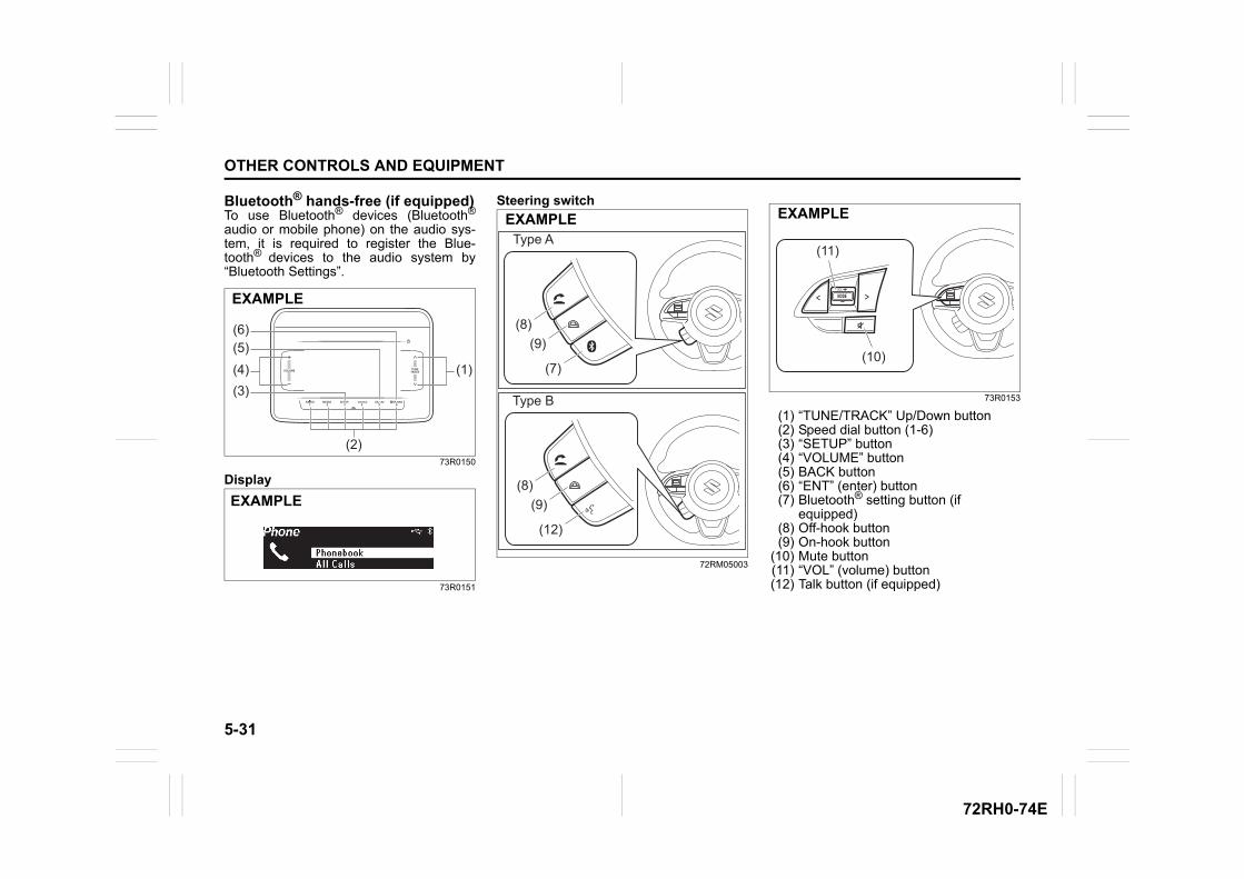
5-31
OTHER CONTROLS AND EQUIPMENT
72RH0-74E
Bluetooth® hands-free (if equipped)To use Bluetooth® devices (Bluetooth®
audio or mobile phone) on the audio sys-tem, it is required to register the Blue-tooth® devices to the audio system by“Bluetooth Settings”.
73R0150
Display
73R0151
Steering switch
72RM05003
73R0153
(1) “TUNE/TRACK” Up/Down button(2) Speed dial button (1-6)(3) “SETUP” button(4) “VOLUME” button(5) BACK button(6) “ENT” (enter) button(7) Bluetooth® setting button (if
equipped)(8) Off-hook button(9) On-hook button
(10) Mute button(11) “VOL” (volume) button(12) Talk button (if equipped)
(1)(4)(3)
(2)
(5)(6)
EXAMPLE
EXAMPLE
EXAMPLE
(7)
(8)(9)
Type A
Type B
(12)
(8)(9)
(11)
(10)
EXAMPLE
5-32
OTHER CONTROLS AND EQUIPMENT
72RH0-74E
NOTE:Talk button (12) can be used with a devicehaving a voice recognition function. To usethe function, it is necessary to perform acorresponding setting on your device. Foroperation of the audio system or the navi-gation system, refer to the supplementarymanual provided along with it.
NOTE:• Please keep your phone volume low.
The person's voice who you are talkingto may be heard outside of the vehicleand increase the voice echo. Whentalking on the phone, speak clearlytowards the microphone.
• In the following cases, your voice maynot be heard clearly by the person on theother line:
– When driving on unpaved roads. (Ifthere is loud traffic noise.)
– When driving at high speeds.– When driving with the window open.– If the air conditioner is blowing directly
towards the microphone.– When the sound of the air conditioner
fan is loud.– When there is an adverse effect to the
sound quality of the phone or networkthat you are using.
• The audio system may not functionunder the following conditions.– When the phone power is not turned
on.– When the mobile phone is out of ser-
vice.– When the mobile phone is not con-
nected.– When the mobile phone battery is low
• The Bluetooth's hands-free operation isdependent upon the mobile phone'scompatibility.
• The Bluetooth's hands-free perfor-mance is affected by the driving condi-tions of mobile phone networks,handsets and vehicles.
• The audio system's performance may berestricted due to the model of yourmobile phone.
It is possible to register a mobile phoneand register the phone number to theaudio system as follows:
• Up to 1,000 phone numbers can besaved for every registered mobilephone.
• Up to 30 phone numbers can be savedto the call history menu (missed calls/incoming/outgoing calls.)– When the call history exceeds 30
calls, they are deleted from the oldestone first, and the latest call historyinformation is displayed in descend-ing order.
• Up to 6 phone numbers can be saved tothe speed dial list.
Answer the phone1) Press the off-hook button (8).• When you press the on-hook button (9)
during an incoming call, you can blockthe call. (Only for compatible phoneunits)
NOTE:• If you receive a call from a registered
phone, the caller's name will appear onthe screen.
• If you receive a call from an unregisteredphone, only the caller’s phone numberwill appear on the screen.
Hang up the phone1) When the call is finished, press the on-
hook button (9).
NOTICE
• Do not leave your mobile phoneinside your vehicle. If the tempera-ture inside the vehicle increases, itmay damage your mobile phone.
• When disposing your vehicle, makesure to delete all personal informa-tion saved to the audio system.
• The following hands-free data mustbe deleted from the audio system.– Speed dial– Reception history/Incoming call
history– Bluetooth® phonebook data
5-33
OTHER CONTROLS AND EQUIPMENT
72RH0-74E
Make a call on call waitingWhen the screen is displayed during a call,it is possible to hold the call and answerthe other incoming call.1) When an incoming call is received
during a call, press the off-hook button(8).
• When the call is on hold, it will connectto the other incoming call.
• To end the call waiting, press the off-hook button (8).
• When the call waiting is completed, thecall on hold will connect.
• When switching the caller, press the off-hook button (8) again while using the callwaiting.
NOTE:This function can only be used with phoneunits that are compatible with call waiting.
Mute the ringtone volume1) Press the mute button (10).• To deactivate the mute volume, press
the mute button (10).
Adjust the volume
Adjust the reception volume1) Touch or slide the “VOLUME” button (4)
or press the “VOL” button (11) during acall.
• To increase the volume, touch orslide upwards.
• To decrease the volume, touch orslide downwards.
NOTE:The volume and microphone sensitivitysettings vary depending on the specifica-tions of each mobile phone.
Adjust the ringtone volume1) Touch or slide the “VOLUME” button (4)
or press the “VOL” button (11) duringan incoming call.
• To increase the volume, touch orslide upwards.
• To decrease the volume, touch orslide downwards.
Adjust the volume with the Bluetooth®
settings1) Display the Bluetooth® setup menu.• From the panel button:
Touch the “SETUP” button (3).Touch or slide the “TUNE/TRACK” Up/Down button (1), select “Bluetooth”, andtouch the “ENT” button (6).
• From the steering switch:Press the Bluetooth® button (7).
2) Touch or slide the “TUNE/TRACK” Up/Down button (1), select “Setup Tele-phone”, and touch the “ENT” button (6).
3) Touch or slide the “TUNE/TRACK” Up/Down button (1), select “HF Sound Set-ting”, and touch the “ENT” button (6).
4) Touch or slide the “TUNE/TRACK” Up/Down button (1), select the item thatyou want to adjust, and touch the “ENT”button (6).
• Call Volume: Reception/ringtone volume• Ringtone Volume: Incoming call volume
5) Touch or slide the “VOLUME” button(4).
• To increase the volume, touch orslide upwards.
• To decrease the volume, touch orslide downwards.
Make a callPress the off-hook button (8) to enter thetelephone mode.
Use the phonebook1) Touch or slide the “TUNE/TRACK” Up/
Down button (1), select “Phonebook”,and touch the “ENT” button (6).
2) Touch or slide the “TUNE/TRACK” Up/Down button (1), select the desired ini-tials, and touch the “ENT” button (6).
3) Touch or slide the “TUNE/TRACK” Up/Down button (1), select the contactnumber, and touch the “ENT” button(6).
• If there are multiple phone numbers for asingle contact, touch or slide the “TUNE/TRACK” Up/Down button (1), select thephone number, and touch the “ENT” but-ton (6).
4) Touch or slide the “TUNE/TRACK” Up/Down button (1), select “Yes”, andtouch the “ENT” button (6) or press theoff-hook button (8).
5-34
OTHER CONTROLS AND EQUIPMENT
72RH0-74E
Use the call history1) Touch or slide the “TUNE/TRACK” Up/
Down button (1), select “All Calls,”“Missed Calls”, “Incoming Calls” or“Outgoing Calls” and touch the “ENT”button (6).
2) Touch or slide the “TUNE/TRACK” Up/Down button (1), select the contactnumber, and touch the “ENT” button(6).
3) Touch or slide the “TUNE/TRACK” Up/Down button (1), select “Yes”, andtouch the “ENT” button (6) or press theoff-hook button (8).
Use the speed dial1) Press the Off-hook button (8) for 1 sec-
ond or longer.2) Touch the desired speed dial button (2)
(1-6).3) Touch or slide the “TUNE/TRACK” Up/
Down button (1), select “YES”, andthen touch the “ENT” button (6) orpress the Off-hook button (8).
NOTE:Speed dial numbers must be registeredbefore this function can be used.
Transfer/delete the phonebook1) Display the Bluetooth® setup menu.• From the panel button:
Touch the “SETUP” button (3).Touch or slide the “TUNE/TRACK” Up/Down button (1), select “Bluetooth”, andtouch the “ENT” button (6).
• From the steering switch: Press the Bluetooth® button (7).
2) Touch or slide the “TUNE/TRACK” Up/Down button (1), select “Setup Tele-phone”, and touch the “ENT” button (6).
3) Touch or slide the “TUNE/TRACK” Up/Down button (1), select “Setup Phone-book”, and touch the “ENT” button (6).
Transfer all contacts from your mobilephone1) Touch or slide the “TUNE/TRACK” Up/
Down button (1) from the “SetupPhonebook” screen, select “Add Con-tacts”, and touch the “ENT” button (6).
2) Touch or slide the “TUNE/TRACK” Up/Down button (1), select “Overwrite All”,and touch the “ENT” button (6).
3) Touch or slide the “TUNE/TRACK” Up/Down button (1), select “YES”, andtouch the “ENT” button (6).
Transfer 1 contact from your mobilephone1) Touch or slide the “TUNE/TRACK” Up/
Down button (1) from the “SetupPhonebook” screen, select “Add Con-tacts”, and touch the “ENT” button (6).
2) Touch or slide the “TUNE/TRACK” Up/Down button (1), select “Add One Con-tact”, and touch the “ENT” button (6).
3) Touch or slide the “TUNE/TRACK” Up/Down button (1), select “YES”, andtouch the “ENT” button (6).
Delete the registered phonebook1) Touch or slide the “TUNE/TRACK” Up/
Down button (1) from the “SetupPhonebook” screen, select “DeleteContacts”, and touch the “ENT” button(6).
2) Touch or slide the “TUNE/TRACK” Up/Down button (1), select the desired ini-tials from the list or “All”, and touch the“ENT” button (6).
• When you select “All”, it will transition tostep 4.
3) Touch or slide the “TUNE/TRACK” Up/Down button (1), select the desiredname from the list, and touch the “ENT”button (6).
4) Touch or slide the “TUNE/TRACK” Up/Down button (1), select “YES”, andtouch the “ENT” button (6).
5-35
OTHER CONTROLS AND EQUIPMENT
72RH0-74E
Transfer/delete the call history1) Display the Bluetooth® setup menu.• From the panel button:
Touch the “SETUP” button (3).Touch or slide the “TUNE/TRACK” Up/Down button (1), select “Bluetooth”, andtouch the “ENT” button (6).
• From the steering switch:Press the Bluetooth® button (7).
2) Touch or slide the “TUNE/TRACK” Up/Down button (1), select “Setup Tele-phone”, and touch the “ENT” button (6).
3) Touch or slide the “TUNE/TRACK” Up/Down button (1), select “Setup Call His-tory”, and touch the “ENT” button (6).
Transfer the call history1) Touch or slide the “TUNE/TRACK” Up/
Down button (1) from the “Setup CallHistory” screen, select “Overwrite His-tory”, and touch the “ENT” button (6).
2) Touch or slide the “TUNE/TRACK” Up/Down button (1), select “YES”, andtouch the “ENT” button (6).
Delete the call history1) Touch or slide the “TUNE/TRACK” Up/
Down button (1) from the “Setup CallHistory” screen, select “Delete His-tory”, and touch the “ENT” button (6).
2) Touch or slide the “TUNE/TRACK” Up/Down button (1), select “All Calls”,“Missed Calls”, “Incoming Calls” or“Outgoing Calls” and touch the “ENT”button (6).
3) Touch or slide the TUNE/TRACK Up/Down button (1), select the desireddata from the history or select “All“, andthen touch the “ENT” button (6).
4) Touch or slide the “TUNE/TRACK” Up/Down button (1), select “YES”, andtouch the “ENT” button (6).
Registration / deletion of speed dial1) Display the Bluetooth® setup menu.• From the panel button:
Touch the “SETUP” button (3).Touch or slide the “TUNE/TRACK” Up/Down button (1), select “Bluetooth”, andtouch the “ENT” button (6).
• From the steering switch:Press the Bluetooth® button (7).
2) Touch or slide the “TUNE/TRACK” Up/Down button (1), select “Setup Tele-phone”, and touch the “ENT” button (6).
3) Touch or slide the “TUNE/TRACK” Up/Down button (1), select “Setup SpeedDials”, and touch the “ENT” button (6).
Registration in speed dial1) Touch or slide the “TUNE/TRACK” Up/
Down button (1) from the “Setup SpeedDials” screen, select “Add Speed Dial”,and touch the “ENT” button (6).
2) Touch or slide the “TUNE/TRACK” Up/Down button (1), select the phonebookor call history, and touch the “ENT” but-ton (6).
• When you select the call history, it willtransition to step 4.
3) Touch or slide the “TUNE/TRACK” Up/Down button (1), select the desired ini-tials from the list and touch the “ENT”button (6).
4) Touch or slide the “TUNE/TRACK” Up/Down button (1), select the contactnumber, and touch the “ENT” button(6).
• If there are multiple phone numbers for asingle contact, touch or slide the “TUNE/TRACK” Up/Down button (1), select thephone number, and touch the “ENT” but-ton (6).
5) Touch or slide the “TUNE/TRACK” Up/Down button (1), select the speed dialnumber that you want to register, andtouch the “ENT” button (6).
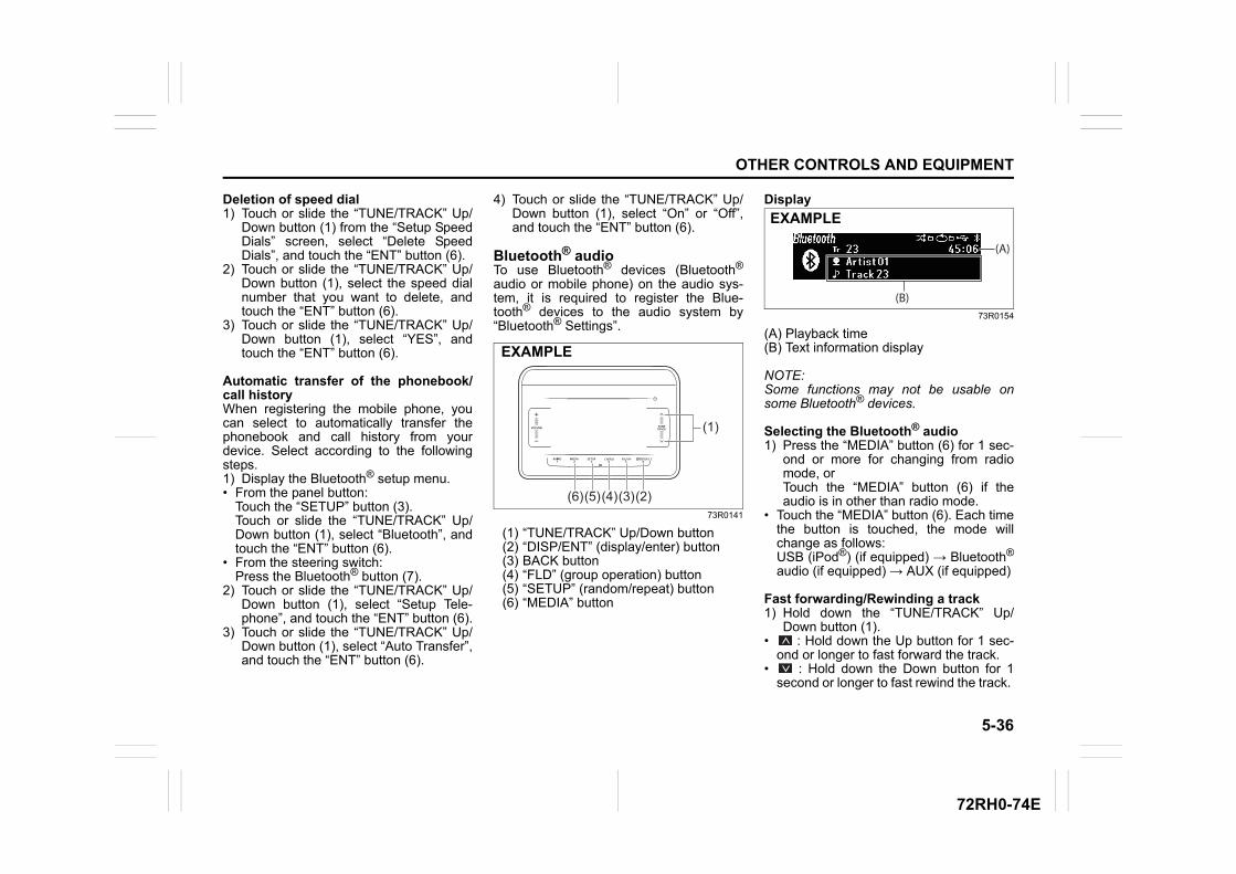
5-36
OTHER CONTROLS AND EQUIPMENT
72RH0-74E
Deletion of speed dial1) Touch or slide the “TUNE/TRACK” Up/
Down button (1) from the “Setup SpeedDials” screen, select “Delete SpeedDials”, and touch the “ENT” button (6).
2) Touch or slide the “TUNE/TRACK” Up/Down button (1), select the speed dialnumber that you want to delete, andtouch the “ENT” button (6).
3) Touch or slide the “TUNE/TRACK” Up/Down button (1), select “YES”, andtouch the “ENT” button (6).
Automatic transfer of the phonebook/call historyWhen registering the mobile phone, youcan select to automatically transfer thephonebook and call history from yourdevice. Select according to the followingsteps.1) Display the Bluetooth® setup menu.• From the panel button:
Touch the “SETUP” button (3).Touch or slide the “TUNE/TRACK” Up/Down button (1), select “Bluetooth”, andtouch the “ENT” button (6).
• From the steering switch:Press the Bluetooth® button (7).
2) Touch or slide the “TUNE/TRACK” Up/Down button (1), select “Setup Tele-phone”, and touch the “ENT” button (6).
3) Touch or slide the “TUNE/TRACK” Up/Down button (1), select “Auto Transfer”,and touch the “ENT” button (6).
4) Touch or slide the “TUNE/TRACK” Up/Down button (1), select “On” or “Off”,and touch the “ENT” button (6).
Bluetooth® audioTo use Bluetooth® devices (Bluetooth®
audio or mobile phone) on the audio sys-tem, it is required to register the Blue-tooth® devices to the audio system by“Bluetooth® Settings”.
73R0141
(1) “TUNE/TRACK” Up/Down button(2) “DISP/ENT” (display/enter) button(3) BACK button(4) “FLD” (group operation) button(5) “SETUP” (random/repeat) button(6) “MEDIA” button
Display
73R0154
(A) Playback time(B) Text information display
NOTE:Some functions may not be usable onsome Bluetooth® devices.
Selecting the Bluetooth® audio1) Press the “MEDIA” button (6) for 1 sec-
ond or more for changing from radiomode, orTouch the “MEDIA” button (6) if theaudio is in other than radio mode.
• Touch the “MEDIA” button (6). Each timethe button is touched, the mode willchange as follows:USB (iPod®) (if equipped) → Bluetooth®
audio (if equipped) → AUX (if equipped)
Fast forwarding/Rewinding a track1) Hold down the “TUNE/TRACK” Up/
Down button (1).• : Hold down the Up button for 1 sec-
ond or longer to fast forward the track.• : Hold down the Down button for 1
second or longer to fast rewind the track.
(1)
(2)(3)(4)(5)(6)
EXAMPLE
(A)
(B)
EXAMPLE
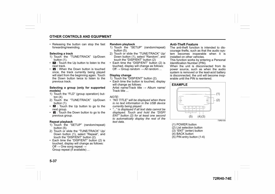
5-37
OTHER CONTROLS AND EQUIPMENT
72RH0-74E
• Releasing the button can stop the fastforwarding/rewinding.
Selecting a track1) Touch the “TUNE/TRACK” Up/Down
button (1).• : Touch the Up button to listen to the
next track.• : When the Down button is touched
once, the track currently being playedwill start from the beginning again. Touchthe Down button twice to listen to theprevious track.
Selecting a group (only for supportedmodels)1) Touch the “FLD” (group operation) but-
ton (4).2) Touch the “TUNE/TRACK” Up/Down
button (1).• : Touch the Up button to go to the
next group.• : Touch the Down button to go to the
previous group.
Repeat playback1) Touch the “SETUP” (random/repeat)
button (5).2) Touch or slide the “TUNE/TRACK” Up/
Down button (1), select “Repeat”, andtouch the “DISP/ENT” button (2).
• Each time the “DISP/ENT” button (2) istouched, display will change as follows:Off → One song repeat → Group repeat (if available) ...
Random playback1) Touch the “SETUP” (random/repeat)
button (5).2) Touch or slide the “TUNE/TRACK” Up/
Down button (1), select “Random”, andtouch the “DISP/ENT” button (2)
• Each time the “DISP/ENT” button (2) istouched, display will change as follows:Off → Group random → All random ...
Display change1) Touch the “DISP/ENT” button (2).• Each time the button is touched, display
will change as follows:Artist name/Track title → Album name/Track title ...
NOTE:• “NO TITLE” will be displayed when there
is no text information in the USB devicecurrently being played.
• “...” is displayed if all text data cannot bedisplayed. Touch and hold the “DISP/ENT” button (2) for at least one secondto automatically display the rest of thetext data.
Anti-Theft FeatureThe anti-theft function is intended to dis-courage thefts, such as that the audio sys-tem becomes inoperable when it isinstalled on other vehicles.This function works by entering a PersonalIdentification Number (PIN).When the unit is disconnected from itspower source, such as when the audiosystem is removed or the lead-acid batteryis disconnected, the unit will become inop-erable until the PIN is reentered.
73R0155
(1) POWER button(2) List selection button(3) “ENT” (enter) button(4) BACK button(5) PIN entry button (1-4)
(1)
(2)
(3)(4)(5)
EXAMPLE
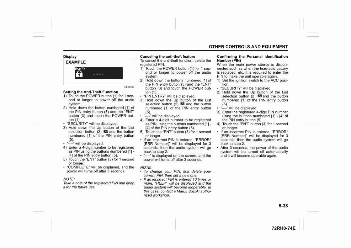
5-38
OTHER CONTROLS AND EQUIPMENT
72RH0-74E
Display
73R0156
Setting the Anti-Theft Function1) Touch the POWER button (1) for 1 sec-
ond or longer to power off the audiosystem.
2) Hold down the button numbered [1] ofthe PIN entry button (5) and the “ENT”button (3) and touch the POWER but-ton (1).
• “SECURITY” will be displayed.3) Hold down the Up button of the List
selection button (2) and the buttonnumbered [1] of the PIN entry button(5).
• “----” will be displayed.4) Enter a 4-digit number to be registered
as PIN using the buttons numbered [1] -[4] of the PIN entry button (5).
5) Touch the “ENT” button (3) for 1 secondor longer.
• “COMPLETE” will be displayed, and thepower will turns off after 3 seconds.
NOTE:Take a note of the registered PIN and keepit for the future use.
Canceling the anti-theft featureTo cancel the anti-theft function, delete theregistered PIN.1) Touch the POWER button (1) for 1 sec-
ond or longer to power off the audiosystem.
2) Hold down the buttons numbered [1] ofthe PIN entry button (5) and the “ENT”button (3) and touch the POWER but-ton (1).
• “PIN ENTRY” will be displayed.3) Hold down the Up button of the List
selection button (2) and the buttonnumbered [1] of the PIN entry button(5).
• “----” will be displayed.4) Enter a 4-digit number to be registered
as PIN using the buttons numbered [1] -[4] of the PIN entry button (5).
5) Touch the “ENT” button (3) for 1 secondor longer.
• If an incorrect PIN is entered, “ERROR*(ERR Number)” will be displayed for 3seconds, then the audio system will goback to step 2.
• “----” is displayed on the screen, and thepower will turns off after 3 seconds.
NOTE:• To change your PIN, first delete your
current PIN, then set a new one.• If an incorrect PIN is entered 10 times or
more, “HELP” will be displayed and theaudio system will become inoperable. Inthis case, contact a Maruti Suzuki autho-rised workshop.
Confirming the Personal IdentificationNumber (PIN)When the main power source is discon-nected such as when the lead-acid batteryis replaced, etc, it is required to enter thePIN to make the unit operable again.1) Set the ignition switch to the ACC posi-
tion.• “SECURITY” will be displayed.2) Hold down the Up button of the List
selection button (2) and the buttonnumbered [1] of the PIN entry button(5).
• “----” will be displayed.3) Enter the registered 4-digit PIN number
using the buttons numbered [1] - [4] ofthe PIN entry button (5).
4) Touch the “ENT” button (3) for 1 secondor longer.
• If an incorrect PIN is entered, “ERROR*(ERR Number)” will be displayed for 3seconds, then the audio system will goback to step 2.
• After 3 seconds, the power of the audiosystem will be turned off automaticallyand it will become operable again.
EXAMPLE
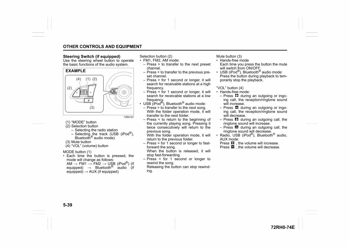
5-39
OTHER CONTROLS AND EQUIPMENT
72RH0-74E
Steering Switch (if equipped)Use the steering wheel button to operatethe basic functions of the audio system.
73R0157
(1) “MODE” button(2) Selection button
– Selecting the radio station– Selecting the track (USB (iPod®),
Bluetooth® audio mode)(3) Mute button(4) “VOL” (volume) button
MODE button (1)• Each time the button is pressed, the
mode will change as follows:AM → FM1 → FM2 → USB (iPod®) (ifequipped) → Bluetooth® audio (ifequipped) → AUX (if equipped)
Selection button (2)• FM1, FM2, AM mode:
– Press > to transfer to the next presetchannel.
– Press < to transfer to the previous pre-set channel.
– Press > for 1 second or longer, it willsearch for receivable stations at a highfrequency.
– Press < for 1 second or longer, it willsearch for receivable stations at a lowfrequency.
• USB (iPod®), Bluetooth® audio mode:– Press > to transfer to the next song.
With the folder operation mode, it willtransfer to the next folder.
– Press < to return to the beginning ofthe currently playing song. Pressing ittwice consecutively will return to theprevious song.With the folder operation mode, it willreturn to the previous folder.
– Press > for 1 second or longer to fast-forward the song.When the button is released, it willstop fast-forwarding.
– Press < for 1 second or longer torewind the song.Releasing the button can stop rewind-ing.
Mute button (3)• Hands-free mode
Each time you press the button the mutewill switch from ON/OFF.
• USB (iPod®), Bluetooth® audio mode:Press the button during playback to tem-porarily stop the playback.
“VOL” button (4)• Hands-free mode:
– Press during an outgoing or ingo-ing call, the reception/ringtone soundwill increase.
– Press during an outgoing or ingo-ing call, the reception/ringtone soundwill decrease.
– Press during an outgoing call, theringtone sound will increase.
– Press during an outgoing call, theringtone sound will decrease.
• Radio, USB (iPod®), Bluetooth® audio,AUX mode:Press , the volume will increase.Press , the volume will decrease.
(4) (1)
(2)
(2)
(3)
EXAMPLE
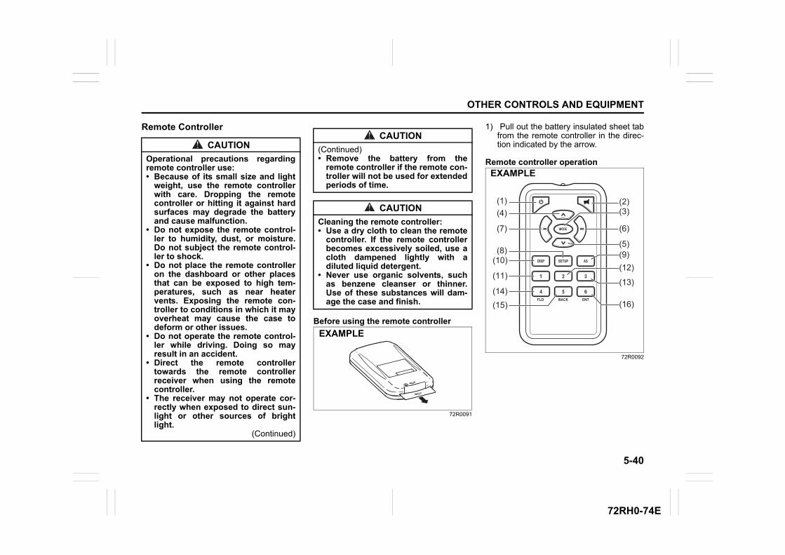
5-40
OTHER CONTROLS AND EQUIPMENT
72RH0-74E
Remote Controller
Before using the remote controller
72R0091
1) Pull out the battery insulated sheet tabfrom the remote controller in the direc-tion indicated by the arrow.
Remote controller operation
72R0092
CAUTION
Operational precautions regardingremote controller use: • Because of its small size and light
weight, use the remote controllerwith care. Dropping the remotecontroller or hitting it against hardsurfaces may degrade the batteryand cause malfunction.
• Do not expose the remote control-ler to humidity, dust, or moisture.Do not subject the remote control-ler to shock.
• Do not place the remote controlleron the dashboard or other placesthat can be exposed to high tem-peratures, such as near heatervents. Exposing the remote con-troller to conditions in which it mayoverheat may cause the case todeform or other issues.
• Do not operate the remote control-ler while driving. Doing so mayresult in an accident.
• Direct the remote controllertowards the remote controllerreceiver when using the remotecontroller.
• The receiver may not operate cor-rectly when exposed to direct sun-light or other sources of brightlight.
(Continued)
CAUTION
(Continued)• Remove the battery from the
remote controller if the remote con-troller will not be used for extendedperiods of time.
CAUTION
Cleaning the remote controller:• Use a dry cloth to clean the remote
controller. If the remote controllerbecomes excessively soiled, use acloth dampened lightly with adiluted liquid detergent.
• Never use organic solvents, suchas benzene cleanser or thinner.Use of these substances will dam-age the case and finish.
EXAMPLE
(1)(4)
(7)
(8)(10)
(11)
(14)(15)
(2)(3)
(6)
(5)(9)(12)
(13)
(16)
EXAMPLE
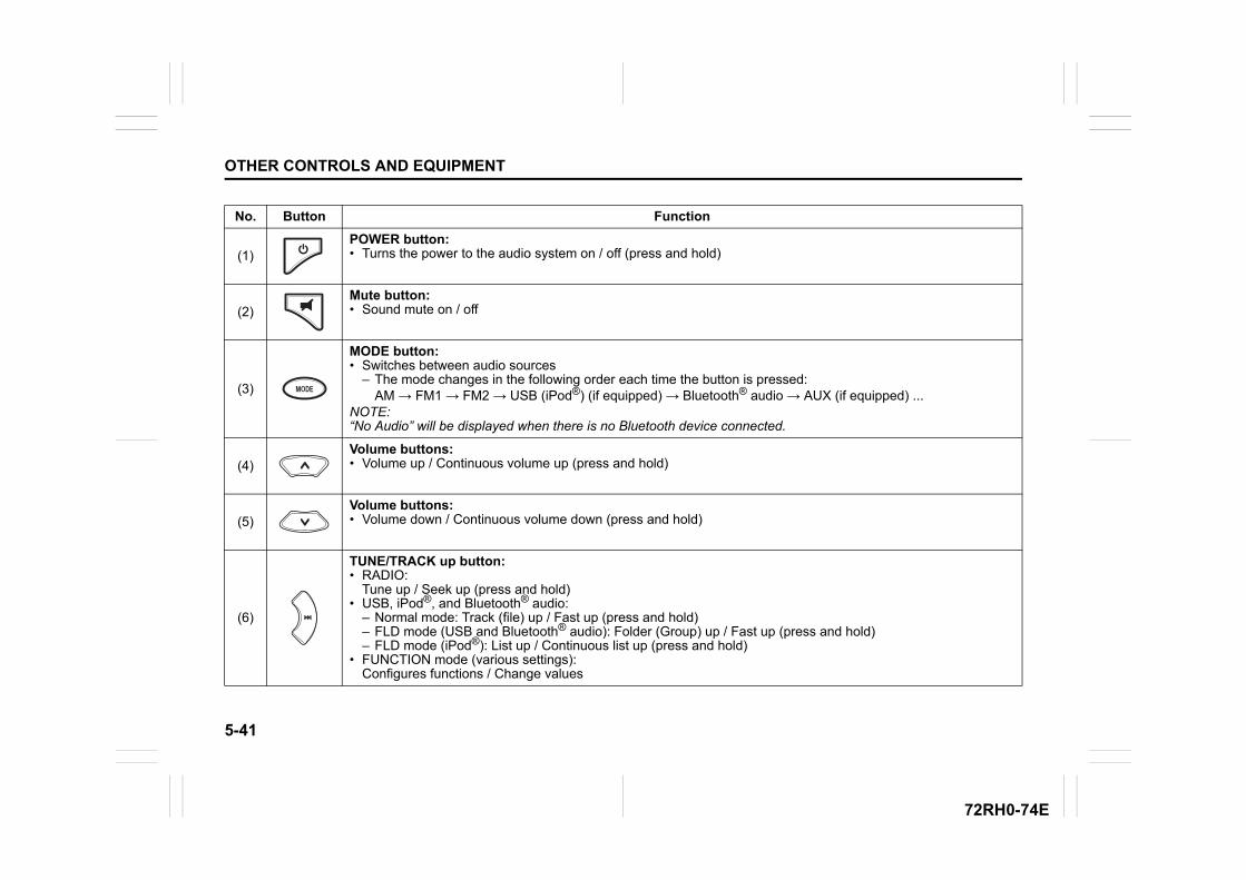
5-41
OTHER CONTROLS AND EQUIPMENT
72RH0-74E
No. Button Function
(1)POWER button: • Turns the power to the audio system on / off (press and hold)
(2)Mute button: • Sound mute on / off
(3)
MODE button: • Switches between audio sources
– The mode changes in the following order each time the button is pressed: AM → FM1 → FM2 → USB (iPod®) (if equipped) → Bluetooth® audio → AUX (if equipped) ...
NOTE:“No Audio” will be displayed when there is no Bluetooth device connected.
(4)Volume buttons: • Volume up / Continuous volume up (press and hold)
(5)Volume buttons: • Volume down / Continuous volume down (press and hold)
(6)
TUNE/TRACK up button: • RADIO:
Tune up / Seek up (press and hold)• USB, iPod®, and Bluetooth® audio:
– Normal mode: Track (file) up / Fast up (press and hold)– FLD mode (USB and Bluetooth® audio): Folder (Group) up / Fast up (press and hold)– FLD mode (iPod®): List up / Continuous list up (press and hold)
• FUNCTION mode (various settings): Configures functions / Change values
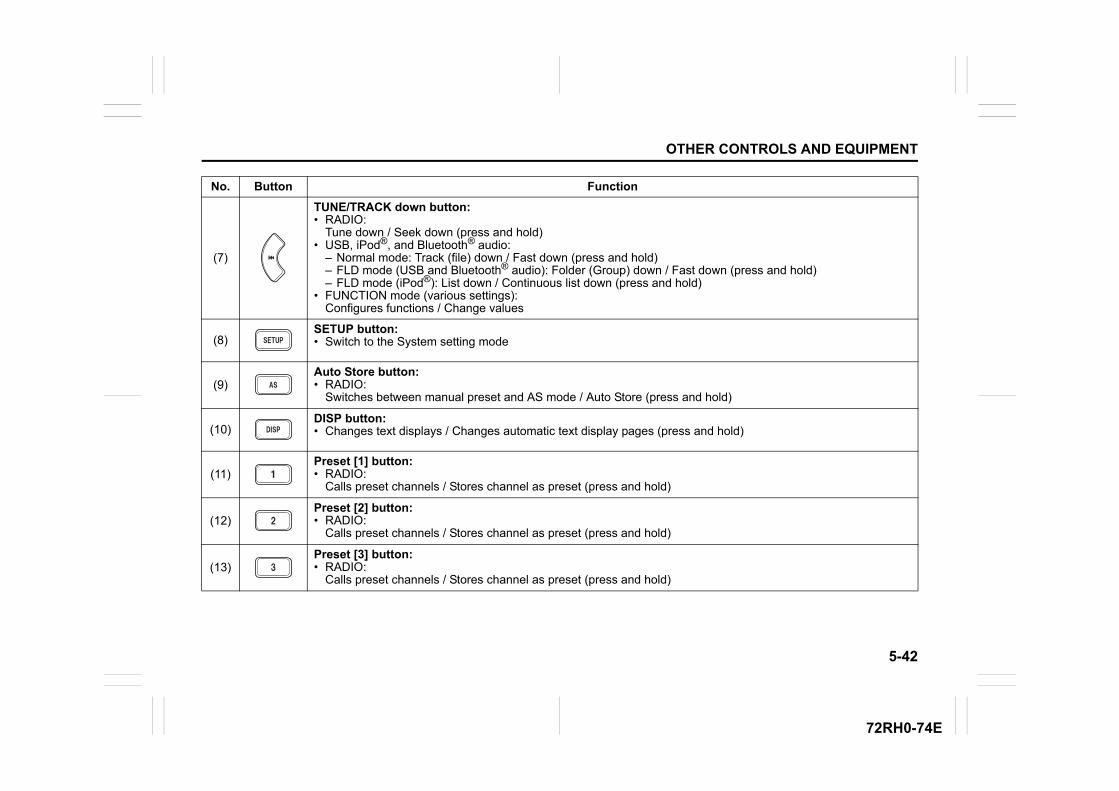
5-42
OTHER CONTROLS AND EQUIPMENT
72RH0-74E
(7)
TUNE/TRACK down button: • RADIO:
Tune down / Seek down (press and hold)• USB, iPod®, and Bluetooth® audio:
– Normal mode: Track (file) down / Fast down (press and hold)– FLD mode (USB and Bluetooth® audio): Folder (Group) down / Fast down (press and hold)– FLD mode (iPod®): List down / Continuous list down (press and hold)
• FUNCTION mode (various settings): Configures functions / Change values
(8)SETUP button: • Switch to the System setting mode
(9)Auto Store button: • RADIO:
Switches between manual preset and AS mode / Auto Store (press and hold)
(10)DISP button: • Changes text displays / Changes automatic text display pages (press and hold)
(11)Preset [1] button: • RADIO:
Calls preset channels / Stores channel as preset (press and hold)
(12)Preset [2] button: • RADIO:
Calls preset channels / Stores channel as preset (press and hold)
(13)Preset [3] button: • RADIO:
Calls preset channels / Stores channel as preset (press and hold)
No. Button Function
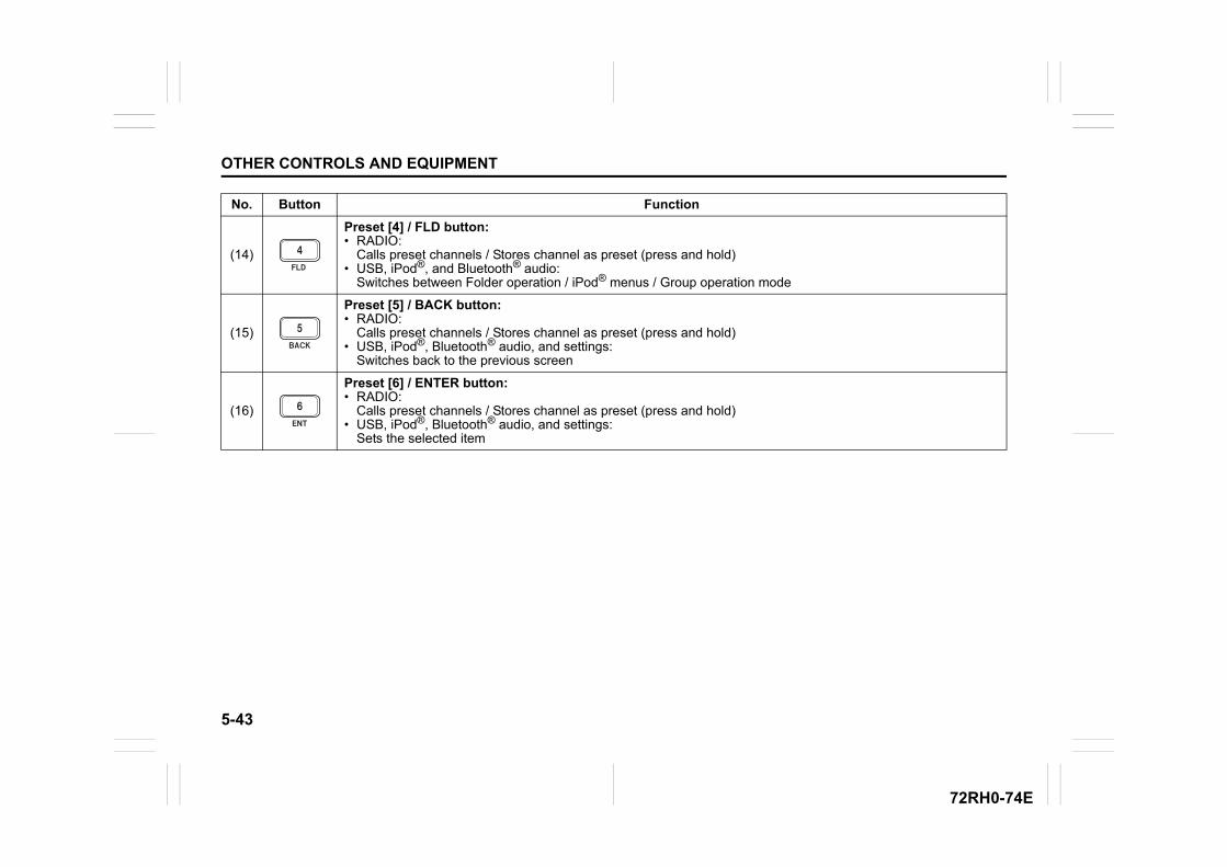
5-43
OTHER CONTROLS AND EQUIPMENT
72RH0-74E
(14)
Preset [4] / FLD button: • RADIO:
Calls preset channels / Stores channel as preset (press and hold)• USB, iPod®, and Bluetooth® audio:
Switches between Folder operation / iPod® menus / Group operation mode
(15)
Preset [5] / BACK button: • RADIO:
Calls preset channels / Stores channel as preset (press and hold)• USB, iPod®, Bluetooth® audio, and settings:
Switches back to the previous screen
(16)
Preset [6] / ENTER button: • RADIO:
Calls preset channels / Stores channel as preset (press and hold)• USB, iPod®, Bluetooth® audio, and settings:
Sets the selected item
No. Button Function

5-44
OTHER CONTROLS AND EQUIPMENT
72RH0-74E
Battery replacement
72R0088
1) Use a Phillips screwdriver (sold sepa-rately) of the proper size to remove thescrew and pull out the battery slot coverin the direction indicated by the arrow.
72R0089
2) Remove the old battery and place thenew battery (CR2025) into the batteryslot cover with the + mark facingupwards.
72R0090
3) Press the battery slot cover to the direc-tion indicated by the arrow completelyand then fully tighten the screw.
CAUTION
• Store batteries in their originalpackaging out of reach of childrenuntil ready for use. Discard usedbatteries immediately. Seek medi-cal attention immediately if swal-lowed.
• Do not place batteries in locationsnear fire or exposed to direct sun-light. Doing so may result in fire,explosion, or excessive heat.
• Do not place the remote controlleron the dashboard or other placesthat can be exposed to high tem-peratures.
• Accidentally replacing batterieswith lithium-ion batteries mayresult in explosion. Always replacebatteries with the same type.
EXAMPLE
EXAMPLE
EXAMPLE
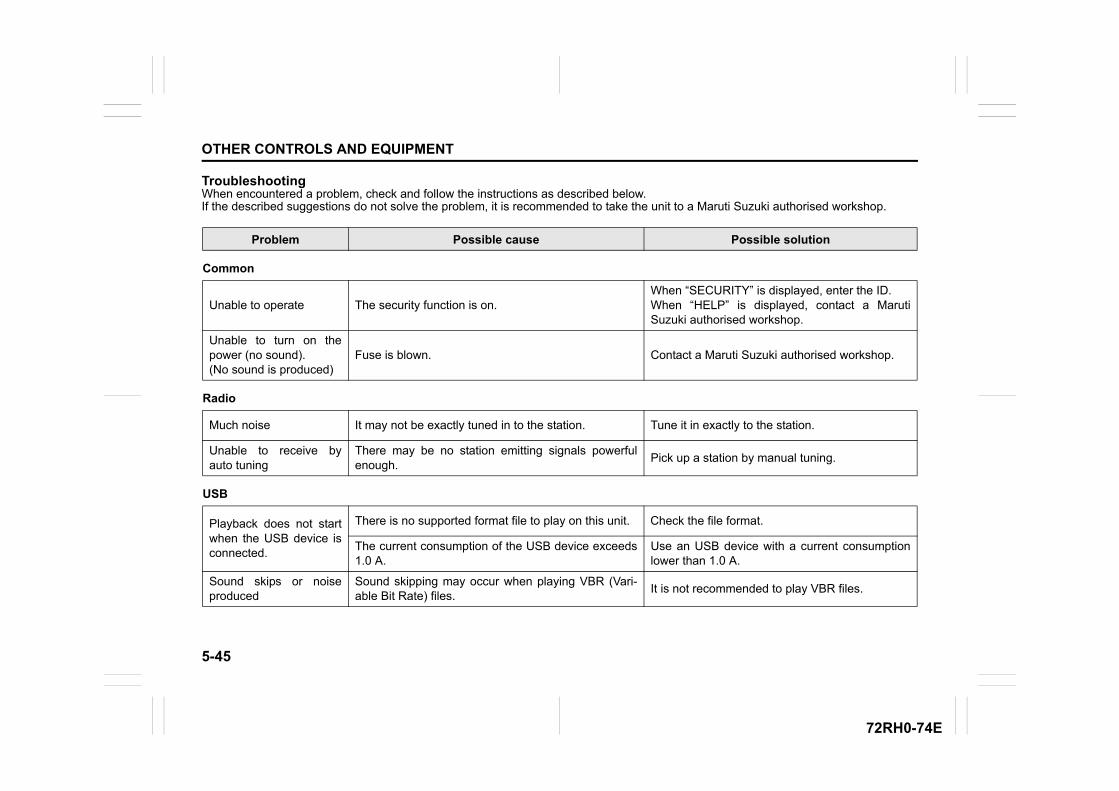
5-45
OTHER CONTROLS AND EQUIPMENT
72RH0-74E
TroubleshootingWhen encountered a problem, check and follow the instructions as described below.If the described suggestions do not solve the problem, it is recommended to take the unit to a Maruti Suzuki authorised workshop.
Problem Possible cause Possible solution
Common
Unable to operate The security function is on.When “SECURITY” is displayed, enter the ID.When “HELP” is displayed, contact a MarutiSuzuki authorised workshop.
Unable to turn on thepower (no sound).(No sound is produced)
Fuse is blown. Contact a Maruti Suzuki authorised workshop.
Radio
Much noise It may not be exactly tuned in to the station. Tune it in exactly to the station.
Unable to receive byauto tuning
There may be no station emitting signals powerfulenough.
Pick up a station by manual tuning.
USB
Playback does not startwhen the USB device isconnected.
There is no supported format file to play on this unit. Check the file format.
The current consumption of the USB device exceeds1.0 A.
Use an USB device with a current consumptionlower than 1.0 A.
Sound skips or noiseproduced
Sound skipping may occur when playing VBR (Vari-able Bit Rate) files.
It is not recommended to play VBR files.
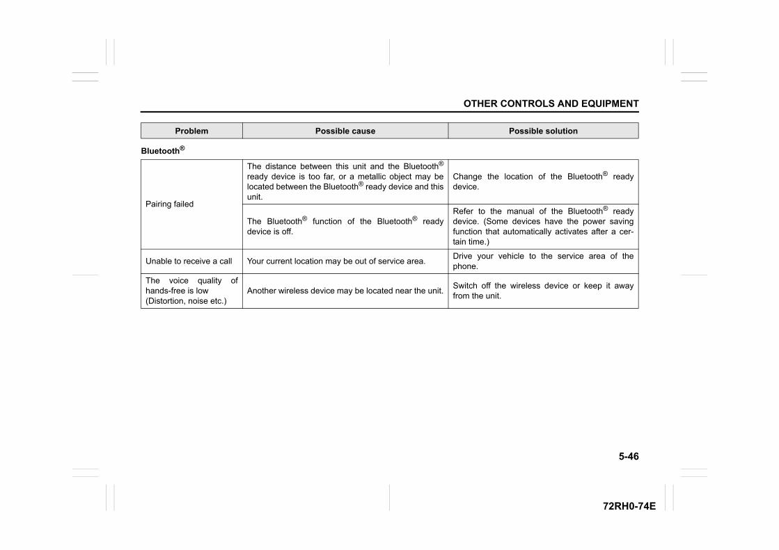
5-46
OTHER CONTROLS AND EQUIPMENT
72RH0-74E
Bluetooth®
Pairing failed
The distance between this unit and the Bluetooth®
ready device is too far, or a metallic object may belocated between the Bluetooth® ready device and thisunit.
Change the location of the Bluetooth® readydevice.
The Bluetooth® function of the Bluetooth® readydevice is off.
Refer to the manual of the Bluetooth® readydevice. (Some devices have the power savingfunction that automatically activates after a cer-tain time.)
Unable to receive a call Your current location may be out of service area.Drive your vehicle to the service area of thephone.
The voice quality ofhands-free is low(Distortion, noise etc.)
Another wireless device may be located near the unit.Switch off the wireless device or keep it awayfrom the unit.
Problem Possible cause Possible solution
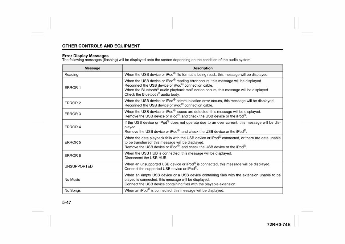
5-47
OTHER CONTROLS AND EQUIPMENT
72RH0-74E
Error Display MessagesThe following messages (flashing) will be displayed onto the screen depending on the condition of the audio system.
Message Description
Reading When the USB device or iPod® file format is being read,, this message will be displayed.
ERROR 1
When the USB device or iPod® reading error occurs, this message will be displayed.Reconnect the USB device or iPod® connection cable.When the Bluetooth® audio playback malfunction occurs, this message will be displayed.Check the Bluetooth® audio body.
ERROR 2When the USB device or iPod® communication error occurs, this message will be displayed.Reconnect the USB device or iPod® connection cable.
ERROR 3When the USB device or iPod® issues are detected, this message will be displayed.Remove the USB device or iPod®, and check the USB device or the iPod®.
ERROR 4If the USB device or iPod® does not operate due to an over current, this message will be dis-played.Remove the USB device or iPod®, and check the USB device or the iPod®.
ERROR 5When the data playback fails with the USB device or iPod® connected, or there are data unableto be transferred, this message will be displayed.Remove the USB device or iPod®, and check the USB device or the iPod®.
ERROR 6When the USB HUB is connected, this message will be displayed.Disconnect the USB HUB.
UNSUPPORTEDWhen an unsupported USB device or iPod® is connected, this message will be displayed.Connect the supported USB device or iPod®.
No MusicWhen an empty USB device or a USB device containing files with the extension unable to beplayed is connected, this message will be displayed.Connect the USB device containing files with the playable extension.
No Songs When an iPod® is connected, this message will be displayed.
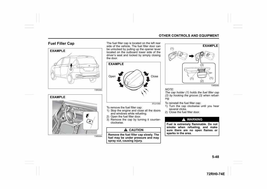
5-48
OTHER CONTROLS AND EQUIPMENT
72RH0-74E
Fuel Filler Cap
73R0083
73R0084
The fuel filler cap is located on the left rearside of the vehicle. The fuel filler door canbe unlocked by pulling up the opener leverlocated on the outboard lower side of thedriver’s seat and locked by simply closingthe door.
57L51093
To remove the fuel filler cap:1) Stop the engine and close all the doors
and windows while refueling.2) Open the fuel filler door.3) Remove the cap by turning it counter-
clockwise.
73R0085
NOTE:The cap holder (1) holds the fuel filler cap(2) by hooking the groove (3) when refuel-ing.
To reinstall the fuel filler cap:1) Turn the cap clockwise until you hear
several clicks.2) Close the fuel filler door.
EXAMPLE
EXAMPLE
CAUTION
Remove the fuel filler cap slowly. Thefuel may be under pressure and mayspray out, causing injury.
Open Close
EXAMPLE
WARNING
Fuel is extremely flammable. Do notsmoke when refueling, and makesure there are no open flames orsparks in the area.
(1)
(1)(2)
(1)
(3)
EXAMPLE
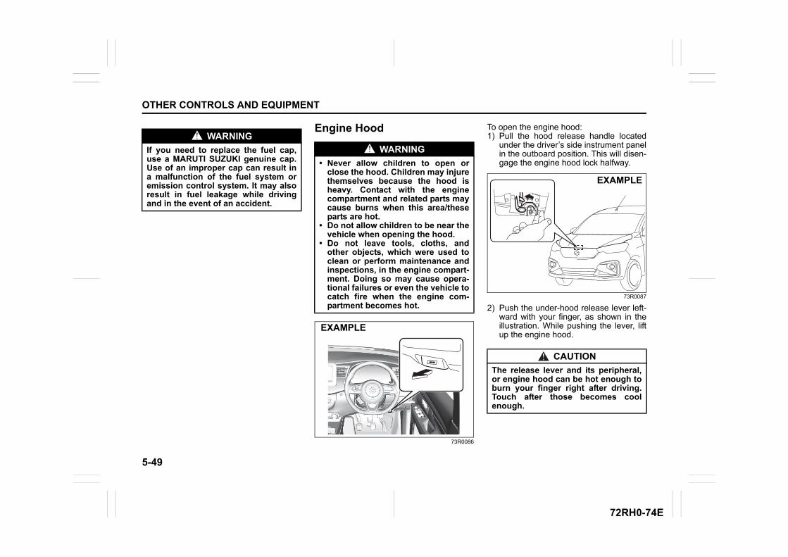
5-49
OTHER CONTROLS AND EQUIPMENT
72RH0-74E
Engine Hood
73R0086
To open the engine hood:1) Pull the hood release handle located
under the driver’s side instrument panelin the outboard position. This will disen-gage the engine hood lock halfway.
73R0087
2) Push the under-hood release lever left-ward with your finger, as shown in theillustration. While pushing the lever, liftup the engine hood.
WARNING
If you need to replace the fuel cap,use a MARUTI SUZUKI genuine cap.Use of an improper cap can result ina malfunction of the fuel system oremission control system. It may alsoresult in fuel leakage while drivingand in the event of an accident.
WARNING
• Never allow children to open orclose the hood. Children may injurethemselves because the hood isheavy. Contact with the enginecompartment and related parts maycause burns when this area/theseparts are hot.
• Do not allow children to be near thevehicle when opening the hood.
• Do not leave tools, cloths, andother objects, which were used toclean or perform maintenance andinspections, in the engine compart-ment. Doing so may cause opera-tional failures or even the vehicle tocatch fire when the engine com-partment becomes hot.
EXAMPLE
CAUTION
The release lever and its peripheral,or engine hood can be hot enough toburn your finger right after driving.Touch after those becomes coolenough.
EXAMPLE
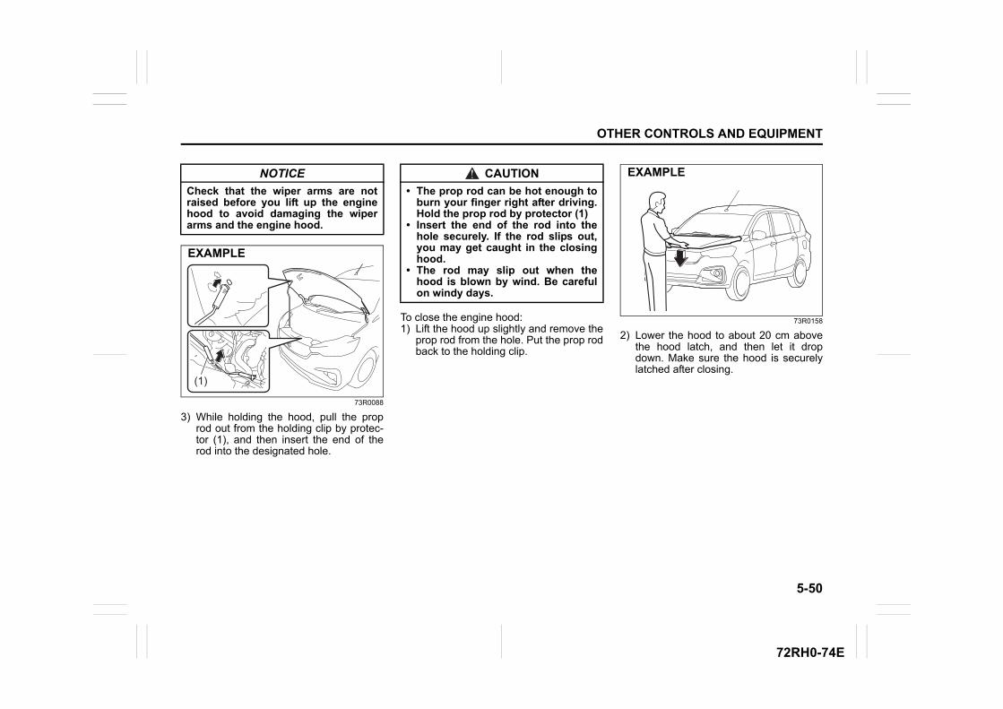
5-50
OTHER CONTROLS AND EQUIPMENT
72RH0-74E
73R0088
3) While holding the hood, pull the proprod out from the holding clip by protec-tor (1), and then insert the end of therod into the designated hole.
To close the engine hood:1) Lift the hood up slightly and remove the
prop rod from the hole. Put the prop rodback to the holding clip.
73R0158
2) Lower the hood to about 20 cm abovethe hood latch, and then let it dropdown. Make sure the hood is securelylatched after closing.
NOTICE
Check that the wiper arms are notraised before you lift up the enginehood to avoid damaging the wiperarms and the engine hood.
(1)
EXAMPLE
CAUTION
• The prop rod can be hot enough toburn your finger right after driving.Hold the prop rod by protector (1)
• Insert the end of the rod into thehole securely. If the rod slips out,you may get caught in the closinghood.
• The rod may slip out when thehood is blown by wind. Be carefulon windy days.
EXAMPLE
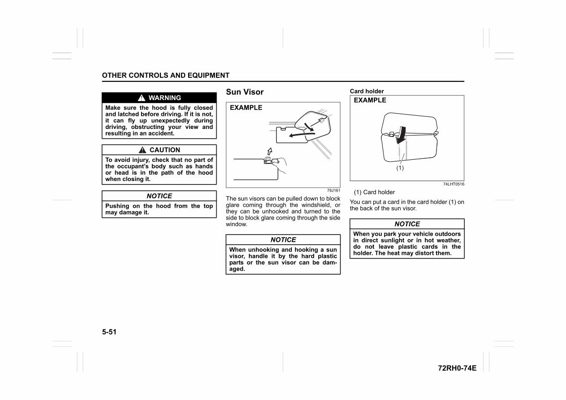
5-51
OTHER CONTROLS AND EQUIPMENT
72RH0-74E
Sun Visor
79J161
The sun visors can be pulled down to blockglare coming through the windshield, orthey can be unhooked and turned to theside to block glare coming through the sidewindow.
Card holder
74LHT0516
(1) Card holder
You can put a card in the card holder (1) onthe back of the sun visor.
WARNING
Make sure the hood is fully closedand latched before driving. If it is not,it can fly up unexpectedly duringdriving, obstructing your view andresulting in an accident.
CAUTION
To avoid injury, check that no part ofthe occupant’s body such as handsor head is in the path of the hoodwhen closing it.
NOTICE
Pushing on the hood from the topmay damage it.
NOTICE
When unhooking and hooking a sunvisor, handle it by the hard plasticparts or the sun visor can be dam-aged.
EXAMPLE
NOTICE
When you park your vehicle outdoorsin direct sunlight or in hot weather,do not leave plastic cards in theholder. The heat may distort them.
(1)
EXAMPLE
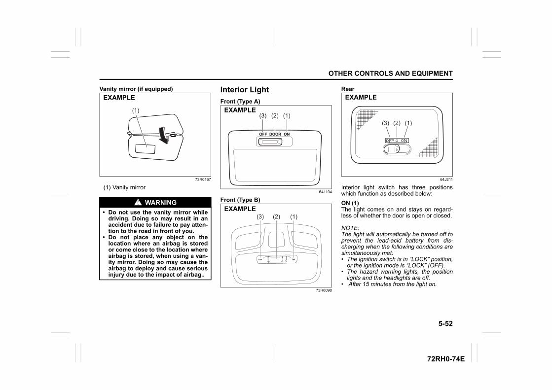
5-52
OTHER CONTROLS AND EQUIPMENT
72RH0-74E
Vanity mirror (if equipped)
73R0167
(1) Vanity mirror
Interior Light
Front (Type A)
64J104
Front (Type B)
73R0090
Rear
64J211
Interior light switch has three positionswhich function as described below:
ON (1)The light comes on and stays on regard-less of whether the door is open or closed.
NOTE:The light will automatically be turned off toprevent the lead-acid battery from dis-charging when the following conditions aresimultaneously met:• The ignition switch is in “LOCK” position,
or the ignition mode is “LOCK” (OFF). • The hazard warning lights, the position
lights and the headlights are off. • After 15 minutes from the light on.
WARNING
• Do not use the vanity mirror whiledriving. Doing so may result in anaccident due to failure to pay atten-tion to the road in front of you.
• Do not place any object on thelocation where an airbag is storedor come close to the location whereairbag is stored, when using a van-ity mirror. Doing so may cause theairbag to deploy and cause seriousinjury due to the impact of airbag..
(1)
EXAMPLE
(1)(2)(3)EXAMPLE
(3) (2) (1)EXAMPLE
(3) (2) (1)
EXAMPLE
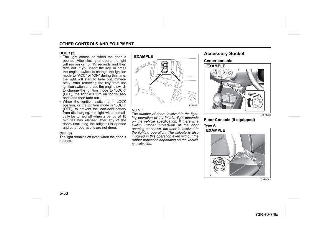
5-53
OTHER CONTROLS AND EQUIPMENT
72RH0-74E
DOOR (2)• The light comes on when the door is
opened. After closing all doors, the lightwill remain on for 15 seconds and thenfade out. If you insert the key, or pressthe engine switch to change the ignitionmode to “ACC” or “ON” during this time,the light will start to fade out immedi-ately. After removing the key from theignition switch or press the engine switchto change the ignition mode to “LOCK”(OFF), the light will turn on for 15 sec-onds and then fade out.
• When the ignition switch is in LOCKposition, or the ignition mode is “LOCK”(OFF), to prevent the lead-acid batteryfrom discharging, the light will automati-cally be turned off when a period of 15minutes has elapsed after any of thedoors (including the tailgate) is openedand other operations are not done.
OFF (3)The light remains off even when the door isopened.
73R0091
NOTE:The number of doors involved in the light-ing operation of the interior light dependson the vehicle specification. If there is aswitch (rubber projection) at the dooropening as shown, the door is involved inthe lighting operation. The tailgate is alsoinvolved in this operation even without therubber projection depending on the vehiclespecification.
Accessory Socket
Center console
73R0092
Floor Console (if equipped)
Type A
73R0093
EXAMPLE
EXAMPLE
EXAMPLE
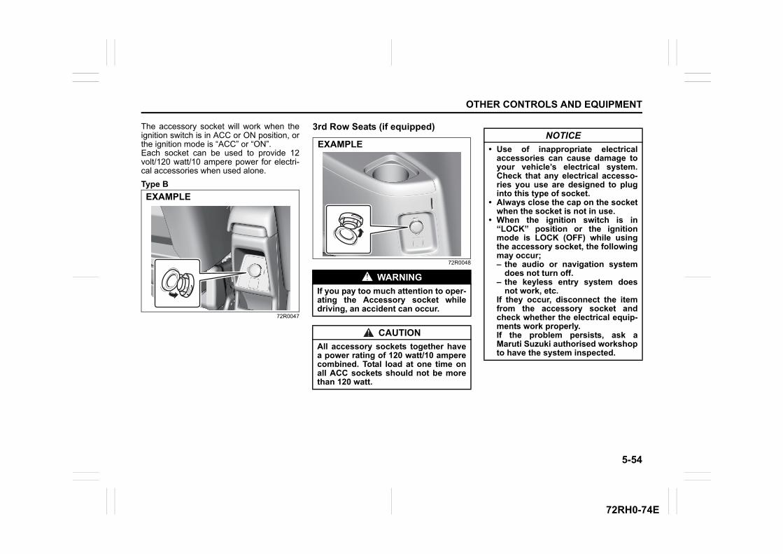
5-54
OTHER CONTROLS AND EQUIPMENT
72RH0-74E
The accessory socket will work when theignition switch is in ACC or ON position, orthe ignition mode is “ACC” or “ON”.Each socket can be used to provide 12volt/120 watt/10 ampere power for electri-cal accessories when used alone.
Type B
72R0047
3rd Row Seats (if equipped)
72R0048
EXAMPLE
WARNING
If you pay too much attention to oper-ating the Accessory socket whiledriving, an accident can occur.
CAUTION
All accessory sockets together havea power rating of 120 watt/10 amperecombined. Total load at one time onall ACC sockets should not be morethan 120 watt.
EXAMPLENOTICE
• Use of inappropriate electricalaccessories can cause damage toyour vehicle’s electrical system.Check that any electrical accesso-ries you use are designed to pluginto this type of socket.
• Always close the cap on the socketwhen the socket is not in use.
• When the ignition switch is in“LOCK” position or the ignitionmode is LOCK (OFF) while usingthe accessory socket, the followingmay occur;– the audio or navigation system
does not turn off.– the keyless entry system does
not work, etc.If they occur, disconnect the itemfrom the accessory socket andcheck whether the electrical equip-ments work properly.If the problem persists, ask aMaruti Suzuki authorised workshopto have the system inspected.
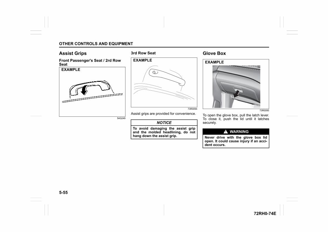
5-55
OTHER CONTROLS AND EQUIPMENT
72RH0-74E
Assist Grips
Front Passenger's Seat / 2rd Row Seat
54G249
3rd Row Seat
73R0094
Assist grips are provided for convenience.
Glove Box
73R0095
To open the glove box, pull the latch lever.To close it, push the lid until it latchessecurely.
EXAMPLE
NOTICE
To avoid damaging the assist gripand the molded headlining, do nothang down the assist grip.
EXAMPLE
WARNING
Never drive with the glove box lidopen. It could cause injury if an acci-dent occurs.
EXAMPLE
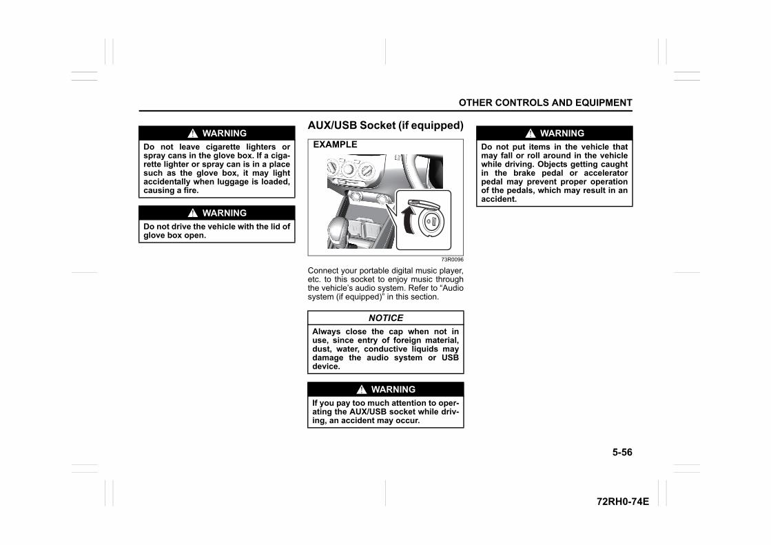
5-56
OTHER CONTROLS AND EQUIPMENT
72RH0-74E
AUX/USB Socket (if equipped)
73R0096
Connect your portable digital music player,etc. to this socket to enjoy music throughthe vehicle’s audio system. Refer to “Audiosystem (if equipped)” in this section.
WARNING
Do not leave cigarette lighters orspray cans in the glove box. If a ciga-rette lighter or spray can is in a placesuch as the glove box, it may lightaccidentally when luggage is loaded,causing a fire.
WARNING
Do not drive the vehicle with the lid ofglove box open.
NOTICE
Always close the cap when not inuse, since entry of foreign material,dust, water, conductive liquids maydamage the audio system or USBdevice.
WARNING
If you pay too much attention to oper-ating the AUX/USB socket while driv-ing, an accident may occur.
EXAMPLEWARNING
Do not put items in the vehicle thatmay fall or roll around in the vehiclewhile driving. Objects getting caughtin the brake pedal or acceleratorpedal may prevent proper operationof the pedals, which may result in anaccident.
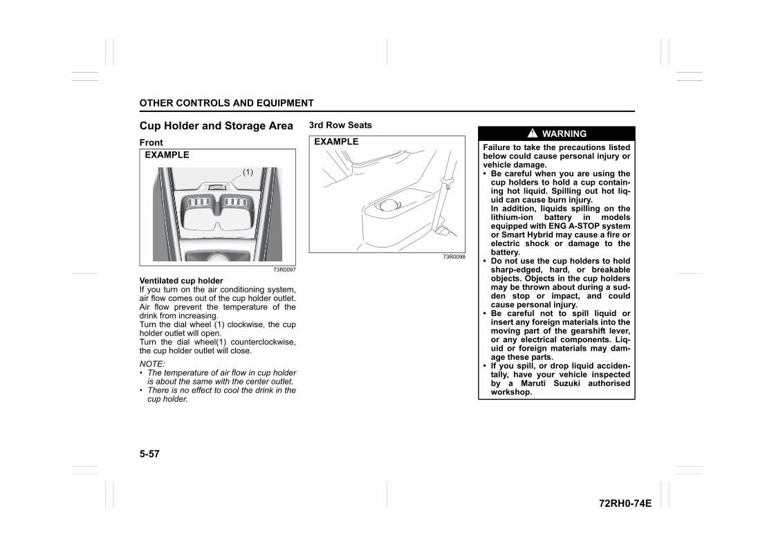
5-57
OTHER CONTROLS AND EQUIPMENT
72RH0-74E
Cup Holder and Storage Area
Front
73R0097
Ventilated cup holderIf you turn on the air conditioning system,air flow comes out of the cup holder outlet.Air flow prevent the temperature of thedrink from increasing.Turn the dial wheel (1) clockwise, the cupholder outlet will open. Turn the dial wheel(1) counterclockwise,the cup holder outlet will close.
NOTE:• The temperature of air flow in cup holder
is about the same with the center outlet. • There is no effect to cool the drink in the
cup holder.
3rd Row Seats
73R0098
(1)
EXAMPLE
EXAMPLEWARNING
Failure to take the precautions listedbelow could cause personal injury orvehicle damage.• Be careful when you are using the
cup holders to hold a cup contain-ing hot liquid. Spilling out hot liq-uid can cause burn injury.In addition, liquids spilling on thelithium-ion battery in modelsequipped with ENG A-STOP systemor Smart Hybrid may cause a fire orelectric shock or damage to thebattery.
• Do not use the cup holders to holdsharp-edged, hard, or breakableobjects. Objects in the cup holdersmay be thrown about during a sud-den stop or impact, and couldcause personal injury.
• Be careful not to spill liquid orinsert any foreign materials into themoving part of the gearshift lever,or any electrical components. Liq-uid or foreign materials may dam-age these parts.
• If you spill, or drop liquid acciden-tally, have your vehicle inspectedby a Maruti Suzuki authorisedworkshop.
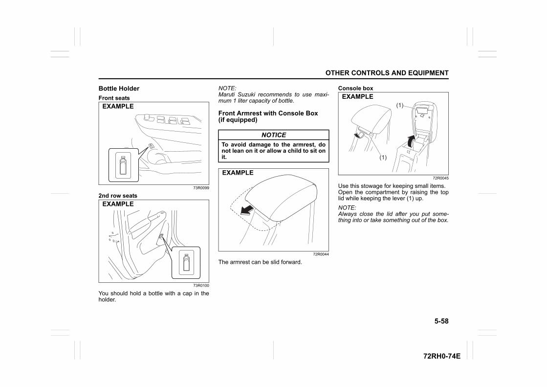
5-58
OTHER CONTROLS AND EQUIPMENT
72RH0-74E
Bottle Holder
Front seats
73R0099
2nd row seats
73R0100
You should hold a bottle with a cap in theholder.
NOTE:Maruti Suzuki recommends to use maxi-mum 1 liter capacity of bottle.
Front Armrest with Console Box (if equipped)
72R0044
The armrest can be slid forward.
Console box
72R0045
Use this stowage for keeping small items.Open the compartment by raising the toplid while keeping the lever (1) up.
NOTE:Always close the lid after you put some-thing into or take something out of the box.
EXAMPLE
EXAMPLE
NOTICE
To avoid damage to the armrest, donot lean on it or allow a child to sit onit.
EXAMPLE
(1)
(1)
EXAMPLE
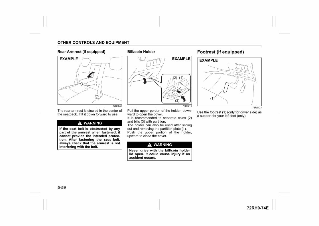
5-59
OTHER CONTROLS AND EQUIPMENT
72RH0-74E
Rear Armrest (if equipped)
72R0046
The rear armrest is stowed in the center ofthe seatback. Tilt it down forward to use.
Bill/coin Holder
73R0216
Pull the upper portion of the holder, down-ward to open the cover.It is recommended to separate coins (2)and bills (3) with partition.The holder can also be used after slidingout and removing the partition plate (1).Push the upper portion of the holder,upward to close the cover.
Footrest (if equipped)
73R0173
Use the footrest (1) (only for driver side) asa support for your left foot (only).
WARNING
If the seat belt is obstructed by anypart of the armrest when fastened, itcannot provide the intended protec-tion. After fastening the seat belt,always check that the armrest is notinterfering with the belt.
EXAMPLE
WARNING
Never drive with the bill/coin holderlid open. It could cause injury if anaccident occurs.
(1)(1)(1)(2)(2)(2)
(3)(3)(3)
EXAMPLE
(1)
EXAMPLE
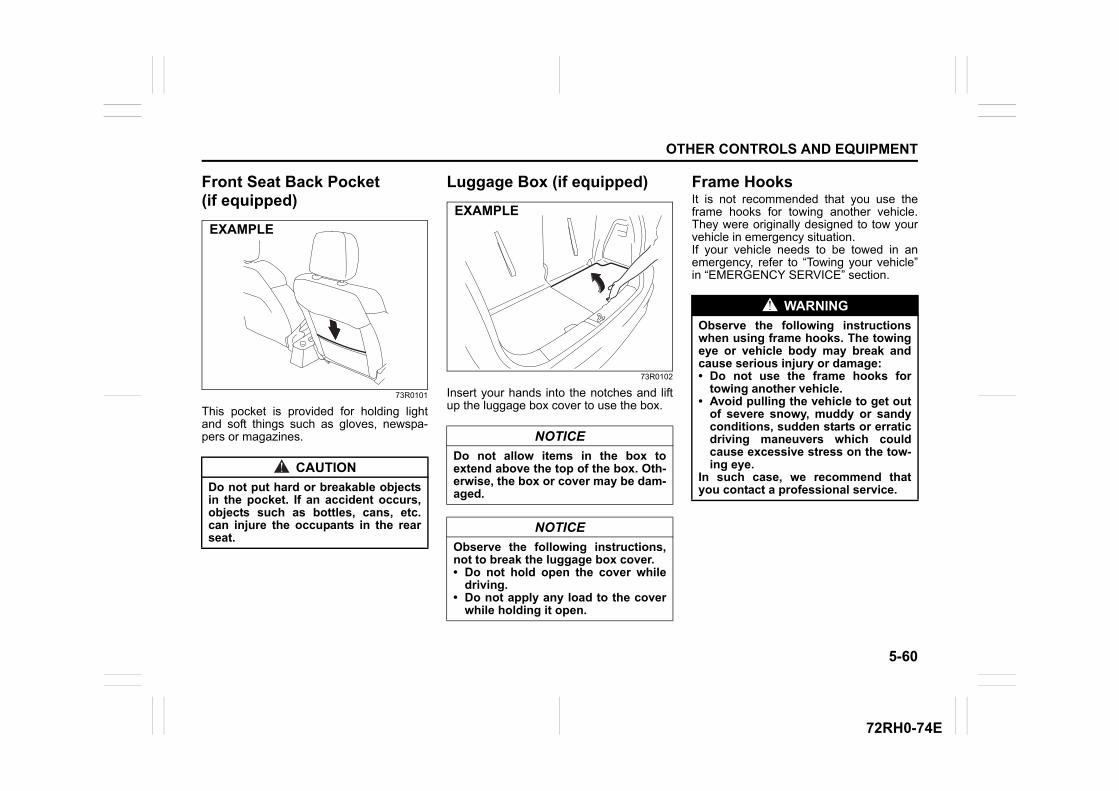
5-60
OTHER CONTROLS AND EQUIPMENT
72RH0-74E
Front Seat Back Pocket (if equipped)
73R0101
This pocket is provided for holding lightand soft things such as gloves, newspa-pers or magazines.
Luggage Box (if equipped)
73R0102
Insert your hands into the notches and liftup the luggage box cover to use the box.
Frame HooksIt is not recommended that you use theframe hooks for towing another vehicle.They were originally designed to tow yourvehicle in emergency situation.If your vehicle needs to be towed in anemergency, refer to “Towing your vehicle”in “EMERGENCY SERVICE” section.
CAUTION
Do not put hard or breakable objectsin the pocket. If an accident occurs,objects such as bottles, cans, etc.can injure the occupants in the rearseat.
EXAMPLE
NOTICE
Do not allow items in the box toextend above the top of the box. Oth-erwise, the box or cover may be dam-aged.
NOTICE
Observe the following instructions,not to break the luggage box cover.• Do not hold open the cover while
driving.• Do not apply any load to the cover
while holding it open.
EXAMPLE
WARNING
Observe the following instructionswhen using frame hooks. The towingeye or vehicle body may break andcause serious injury or damage:• Do not use the frame hooks for
towing another vehicle.• Avoid pulling the vehicle to get out
of severe snowy, muddy or sandyconditions, sudden starts or erraticdriving maneuvers which couldcause excessive stress on the tow-ing eye.
In such case, we recommend thatyou contact a professional service.
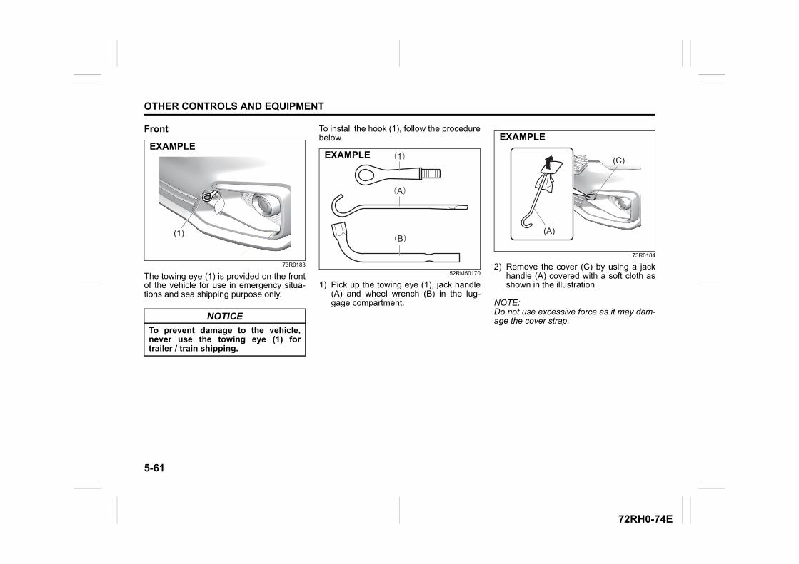
5-61
OTHER CONTROLS AND EQUIPMENT
72RH0-74E
Front
73R0183
The towing eye (1) is provided on the frontof the vehicle for use in emergency situa-tions and sea shipping purpose only.
To install the hook (1), follow the procedurebelow.
52RM50170
1) Pick up the towing eye (1), jack handle(A) and wheel wrench (B) in the lug-gage compartment.
73R0184
2) Remove the cover (C) by using a jackhandle (A) covered with a soft cloth asshown in the illustration.
NOTE:Do not use excessive force as it may dam-age the cover strap.NOTICE
To prevent damage to the vehicle,never use the towing eye (1) fortrailer / train shipping.
(1)
EXAMPLE(1)
(A)
(B)
EXAMPLE
(A)
(C)
EXAMPLE
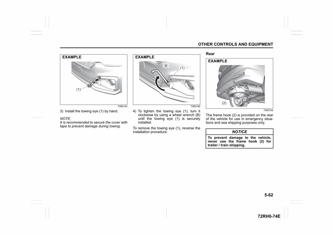
5-62
OTHER CONTROLS AND EQUIPMENT
72RH0-74E
73R0103
3) Install the towing eye (1) by hand.
NOTE:It is recommended to secure the cover withtape to prevent damage during towing.
73R0185
4) To tighten the towing eye (1), turn itclockwise by using a wheel wrench (B)until the towing eye (1) is securelyinstalled.
To remove the towing eye (1), reverse theinstallation procedure.
Rear
73R0104
The frame hook (2) is provided on the rearof the vehicle for use in emergency situa-tions and sea shipping purposes only.
(1)
EXAMPLE
(1)(B)
EXAMPLE
NOTICE
To prevent damage to the vehicle,never use the frame hook (2) fortrailer / train shipping.
(2)
EXAMPLE
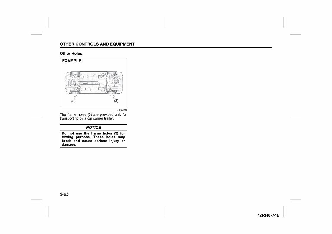
5-63
OTHER CONTROLS AND EQUIPMENT
72RH0-74E
Other Holes
73R0105
The frame holes (3) are provided only fortransporting by a car carrier trailer.
NOTICE
Do not use the frame holes (3) fortowing purpose. These holes maybreak and cause serious injury ordamage.
(3) (3)
EXAMPLE
INSPECTION AND MAINTENANCE
6
72RH0-74E
72RM06000
INSPECTION AND MAINTENANCEMaintenance Schedule ....................................................... 6-2Periodic Maintenance Schedule ........................................ 6-2Drive Belt ............................................................................. 6-6Engine Oil and Filter ........................................................... 6-7Engine Coolant .................................................................... 6-10Air Cleaner ........................................................................... 6-12Spark Plugs ......................................................................... 6-12Gear Oil ................................................................................ 6-14Clutch Pedal ........................................................................ 6-15Fuel Filter ............................................................................. 6-15Automatic Transmission (AT) Fluid .................................. 6-15Brakes .................................................................................. 6-17Steering Wheel .................................................................... 6-19Tires ...................................................................................... 6-19Lead-acid Battery ................................................................ 6-22Fuses .................................................................................... 6-24Headlight Aiming ................................................................. 6-28Bulb Replacement ............................................................... 6-28Wiper Blades ....................................................................... 6-34Windshield Washer Fluid ................................................... 6-36Air Conditioning System .................................................... 6-37
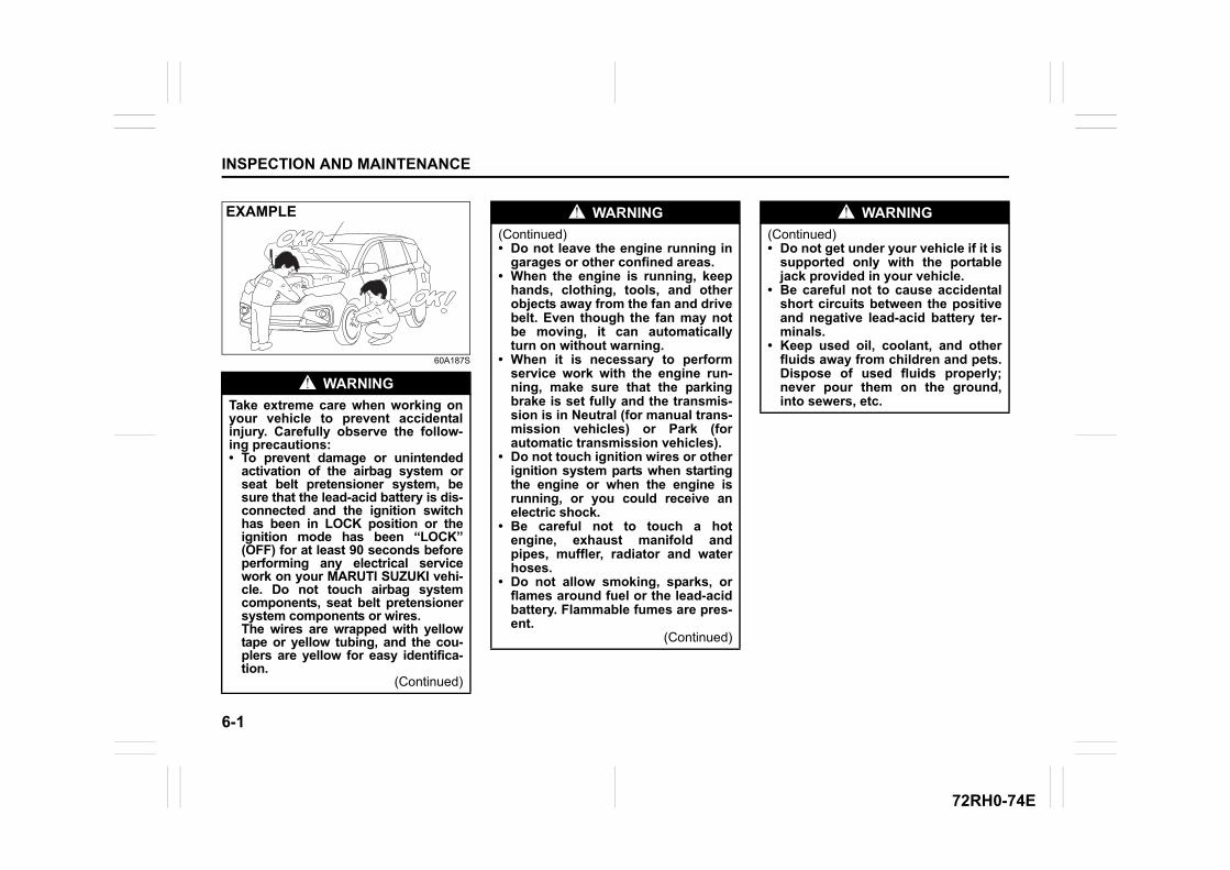
6-1
INSPECTION AND MAINTENANCE
72RH0-74E
60A187S
WARNING
Take extreme care when working onyour vehicle to prevent accidentalinjury. Carefully observe the follow-ing precautions: • To prevent damage or unintended
activation of the airbag system orseat belt pretensioner system, besure that the lead-acid battery is dis-connected and the ignition switchhas been in LOCK position or theignition mode has been “LOCK”(OFF) for at least 90 seconds beforeperforming any electrical servicework on your MARUTI SUZUKI vehi-cle. Do not touch airbag systemcomponents, seat belt pretensionersystem components or wires. The wires are wrapped with yellowtape or yellow tubing, and the cou-plers are yellow for easy identifica-tion.
(Continued)
EXAMPLE WARNING
(Continued)• Do not leave the engine running in
garages or other confined areas.• When the engine is running, keep
hands, clothing, tools, and otherobjects away from the fan and drivebelt. Even though the fan may notbe moving, it can automaticallyturn on without warning.
• When it is necessary to performservice work with the engine run-ning, make sure that the parkingbrake is set fully and the transmis-sion is in Neutral (for manual trans-mission vehicles) or Park (forautomatic transmission vehicles).
• Do not touch ignition wires or otherignition system parts when startingthe engine or when the engine isrunning, or you could receive anelectric shock.
• Be careful not to touch a hotengine, exhaust manifold andpipes, muffler, radiator and waterhoses.
• Do not allow smoking, sparks, orflames around fuel or the lead-acidbattery. Flammable fumes are pres-ent.
(Continued)
WARNING
(Continued)• Do not get under your vehicle if it is
supported only with the portablejack provided in your vehicle.
• Be careful not to cause accidentalshort circuits between the positiveand negative lead-acid battery ter-minals.
• Keep used oil, coolant, and otherfluids away from children and pets.Dispose of used fluids properly;never pour them on the ground,into sewers, etc.
6-2
INSPECTION AND MAINTENANCE
72RH0-74E
Maintenance ScheduleThe following table shows the times whenyou should perform regular maintenanceon your vehicle. This table shows in kilo-meters and months when you should per-form inspections, adjustments, lubricationand other services.
Periodic MaintenanceSchedule“C”: Clean“R”: Replace or Change“I”: Inspect, clean, adjust, lubricate or replace as necessary“L”: Lubricate“T”: Tighten to Specified Torque“O”: Rotate
NOTE:This table includes services as scheduledup to 80,000 km mileage. Beyond 80,000km, carry out the same services at thesame intervals respectively.
WARNING
MARUTI SUZUKI recommends thatmaintenance on your Maruti Suzukivehicle should be performed by aMaruti Suzuki authorised workshop.
NOTICE
Whenever it becomes necessary toreplace parts on your vehicle, it isrecommended that you use MARUTISUZUKI genuine replacement partsor their equivalent.
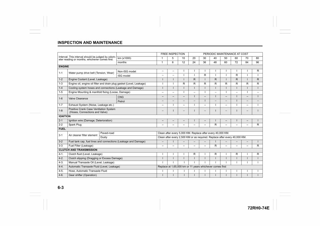
6-3
INSPECTION AND MAINTENANCE
72RH0-74E
Interval: This interval should be judged by odom-eter reading or months, whichever comes first.
FREE INSPECTION PERIODIC MAINTENANCE AT COST
km (x1000) 1 5 10 20 30 40 50 60 70 80
months 1 6 12 24 36 48 60 72 84 96
ENGINE
1-1 Water pump drive belt (Tension, Wear) Non-ISG model – – I I I I I I I R
ISG model – – I I R I I R I I
1-2 Engine Coolant (Level, Leakage) l l l R l R l R l R
1-3 Engine oil, engine oil filter and drain plug gasket (Level, Leakage) l l R R R R R R R R
1-4 Cooling system hoses and connections (Leakage and Damage) l l l l l l l l l l
1-5 Engine Mounting & manifold fixing (Loose, Damage) – – I – I – I – I –
1-6 Valve Clearance CNG – – – I – I – I – I
Petrol – – – – I – – I – –
1-7 Exhaust System (Noise, Leakage etc.) – l – l – I – I – l
1-8Positive Crank Case Ventilation System (Hoses, Connections and Valve)
– I – l – I – I – l
IGNITION
2-1 Ignition wire (Damage, Deterioration) – – – l – l – I – l
2-2 Spark Plug – – – – – R – – – R
FUEL
3-1 Air cleaner filter elementPaved-road Clean after every 5,000 KM. Replace after every 40,000 KM.
Dusty Clean after every 2,500 KM or as required. Replace after every 40,000 KM.
3-2 Fuel tank cap, fuel lines and connections (Leakage and Damage) – l – – – l – – – l
3-3 Fuel Filter (Leakage) – – – – – R – – – R
CLUTCH AND TRANSMISSION
4-1. Clutch fluid (Level, Leakage) l l l R l R l R l R
4-2. Clutch slipping (Dragging or Excess Damage) l l l l l l l l l l
4-3. Manual Transaxle Oil (Level, Leakage) l l l l l l l l l l
4-4. Automatic Transaxle Fluid (Level, Leakage) Replace at 1,65,000 km or 11 years whichever comes first
4-5. Hose, Automatic Transaxle Fluid l l l l l l l l l l
4-6. Gear shifter (Operation) l l l l l l l l l l
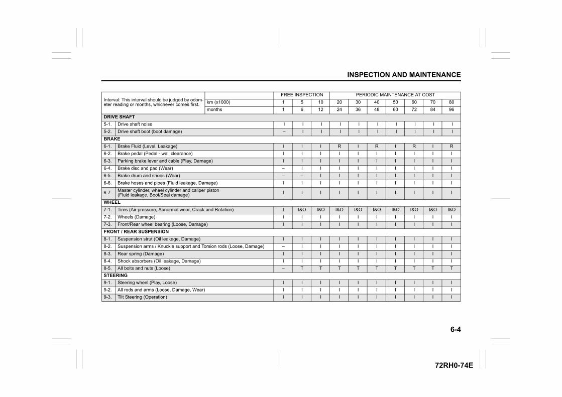
6-4
INSPECTION AND MAINTENANCE
72RH0-74E
Interval: This interval should be judged by odom-eter reading or months, whichever comes first.
FREE INSPECTION PERIODIC MAINTENANCE AT COST
km (x1000) 1 5 10 20 30 40 50 60 70 80
months 1 6 12 24 36 48 60 72 84 96
DRIVE SHAFT
5-1. Drive shaft noise I l l l l l l l l l
5-2. Drive shaft boot (boot damage) – l l l l l l l l l
BRAKE
6-1. Brake Fluid (Level, Leakage) I I I R I R I R I R
6-2. Brake pedal (Pedal - wall clearance) I I I I I I I I I I
6-3. Parking brake lever and cable (Play, Damage) I I I I I I I I I I
6-4. Brake disc and pad (Wear) – I I I I I I I I I
6-5. Brake drum and shoes (Wear) – – I I I I I I I I
6-6. Brake hoses and pipes (Fluid leakage, Damage) I I I I I I I I I I
6-7. Master cylinder, wheel cylinder and caliper piston (Fluid leakage, Boot/Seal damage) I I I I I I I I I I
WHEEL
7-1. Tires (Air pressure, Abnormal wear, Crack and Rotation) I I&O I&O I&O I&O I&O I&O I&O I&O I&O
7-2. Wheels (Damage) I I I I I I I I I I
7-3. Front/Rear wheel bearing (Loose, Damage) I I I I I I I I I I
FRONT / REAR SUSPENSION
8-1. Suspension strut (Oil leakage, Damage) I I I I I I I I I I
8-2. Suspension arms / Knuckle support and Torsion rods (Loose, Damage) – I I I I I I I I I
8-3. Rear spring (Damage) I I I I I I I I I I
8-4. Shock absorbers (Oil leakage, Damage) I I I I I I I I I I
8-5. All bolts and nuts (Loose) – T T T T T T T T T
STEERING
9-1. Steering wheel (Play, Loose) I I I I I I I I I I
9-2. All rods and arms (Loose, Damage, Wear) I I I I I I I I I I
9-3. Tilt Steering (Operation) I I I I I I I I I I
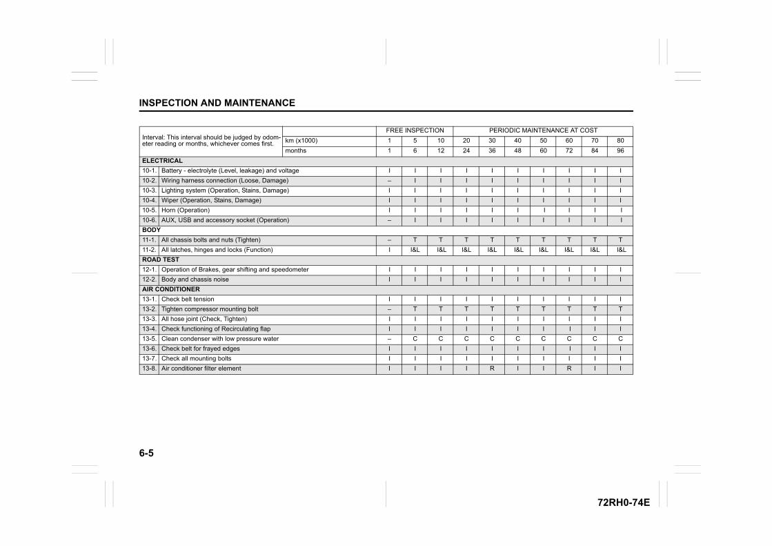
6-5
INSPECTION AND MAINTENANCE
72RH0-74E
Interval: This interval should be judged by odom-eter reading or months, whichever comes first.
FREE INSPECTION PERIODIC MAINTENANCE AT COST
km (x1000) 1 5 10 20 30 40 50 60 70 80
months 1 6 12 24 36 48 60 72 84 96
ELECTRICAL
10-1. Battery - electrolyte (Level, leakage) and voltage I I I I I I I I I I
10-2. Wiring harness connection (Loose, Damage) – I I I I I I I I I
10-3. Lighting system (Operation, Stains, Damage) I I I I I I I I I I
10-4. Wiper (Operation, Stains, Damage) I I I I I I I I I I
10-5. Horn (Operation) I I I I I I I I I I
10-6. AUX, USB and accessory socket (Operation) – I I I I I I I I I
BODY
11-1. All chassis bolts and nuts (Tighten) – T T T T T T T T T
11-2. All latches, hinges and locks (Function) I I&L I&L I&L I&L I&L I&L I&L I&L I&L
ROAD TEST
12-1. Operation of Brakes, gear shifting and speedometer I I I I I I I I I I
12-2. Body and chassis noise I I I I I I I I I I
AIR CONDITIONER
13-1. Check belt tension I I I I I I I I I I
13-2. Tighten compressor mounting bolt – T T T T T T T T T
13-3. All hose joint (Check, Tighten) I I I I I I I I I I
13-4. Check functioning of Recirculating flap I I I I I I I I I I
13-5. Clean condenser with low pressure water – C C C C C C C C C
13-6. Check belt for frayed edges I I I I I I I I I I
13-7. Check all mounting bolts I I I I I I I I I I
13-8. Air conditioner filter element I I I I R I I R I I
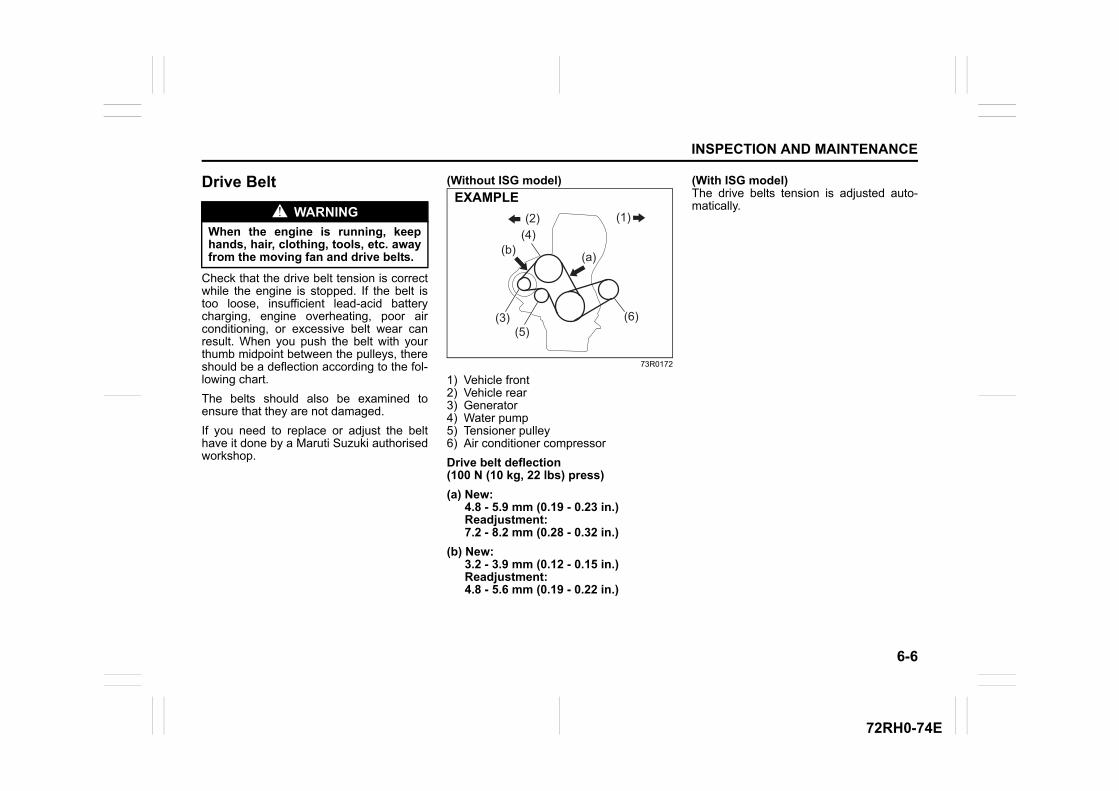
6-6
INSPECTION AND MAINTENANCE
72RH0-74E
Drive Belt
Check that the drive belt tension is correctwhile the engine is stopped. If the belt istoo loose, insufficient lead-acid batterycharging, engine overheating, poor airconditioning, or excessive belt wear canresult. When you push the belt with yourthumb midpoint between the pulleys, thereshould be a deflection according to the fol-lowing chart.
The belts should also be examined toensure that they are not damaged.
If you need to replace or adjust the belthave it done by a Maruti Suzuki authorisedworkshop.
(Without ISG model)
73R0172
1) Vehicle front2) Vehicle rear3) Generator4) Water pump5) Tensioner pulley6) Air conditioner compressor
Drive belt deflection(100 N (10 kg, 22 lbs) press)
(a) New: 4.8 - 5.9 mm (0.19 - 0.23 in.) Readjustment: 7.2 - 8.2 mm (0.28 - 0.32 in.)
(b) New: 3.2 - 3.9 mm (0.12 - 0.15 in.) Readjustment: 4.8 - 5.6 mm (0.19 - 0.22 in.)
(With ISG model)The drive belts tension is adjusted auto-matically.WARNING
When the engine is running, keephands, hair, clothing, tools, etc. awayfrom the moving fan and drive belts.
(2) (1)(4)
(3) (6)
(b) (a)
(5)
EXAMPLE
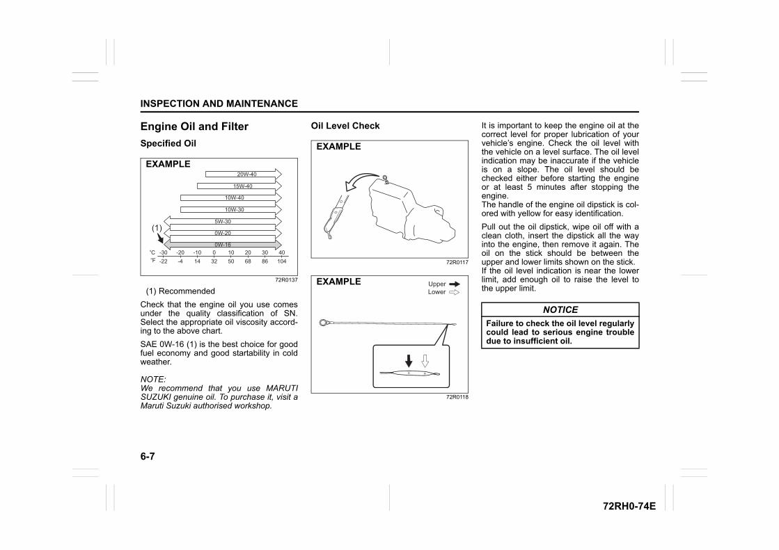
6-7
INSPECTION AND MAINTENANCE
72RH0-74E
Engine Oil and Filter
Specified Oil
72R0137
(1) Recommended
Check that the engine oil you use comesunder the quality classification of SN.Select the appropriate oil viscosity accord-ing to the above chart.
SAE 0W-16 (1) is the best choice for goodfuel economy and good startability in coldweather.
NOTE:We recommend that you use MARUTISUZUKI genuine oil. To purchase it, visit aMaruti Suzuki authorised workshop.
Oil Level Check
72R0117
72R0118
It is important to keep the engine oil at thecorrect level for proper lubrication of yourvehicle’s engine. Check the oil level withthe vehicle on a level surface. The oil levelindication may be inaccurate if the vehicleis on a slope. The oil level should bechecked either before starting the engineor at least 5 minutes after stopping theengine.The handle of the engine oil dipstick is col-ored with yellow for easy identification.
Pull out the oil dipstick, wipe oil off with aclean cloth, insert the dipstick all the wayinto the engine, then remove it again. Theoil on the stick should be between theupper and lower limits shown on the stick.If the oil level indication is near the lowerlimit, add enough oil to raise the level tothe upper limit.
-30 -20 -10 0 10 20 30 40-22 -4 14 32 50 68 86 104
(1)
20W-40
15W-40
10W-40
10W-30
5W-30
0W-20
0W-16oCoF
EXAMPLE
EXAMPLE
UpperLower
EXAMPLE
NOTICE
Failure to check the oil level regularlycould lead to serious engine troubledue to insufficient oil.
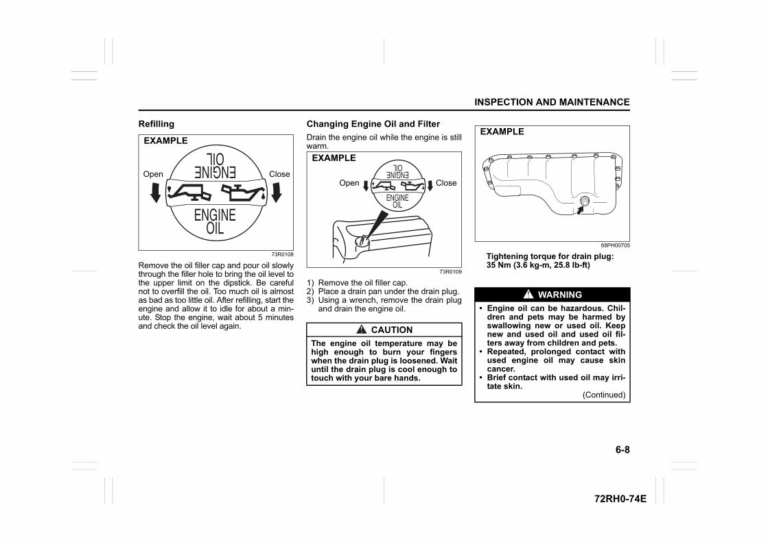
6-8
INSPECTION AND MAINTENANCE
72RH0-74E
Refilling
73R0108
Remove the oil filler cap and pour oil slowlythrough the filler hole to bring the oil level tothe upper limit on the dipstick. Be carefulnot to overfill the oil. Too much oil is almostas bad as too little oil. After refilling, start theengine and allow it to idle for about a min-ute. Stop the engine, wait about 5 minutesand check the oil level again.
Changing Engine Oil and Filter
Drain the engine oil while the engine is stillwarm.
73R0109
1) Remove the oil filler cap.2) Place a drain pan under the drain plug.3) Using a wrench, remove the drain plug
and drain the engine oil.
68PH00705
Tightening torque for drain plug:35 Nm (3.6 kg-m, 25.8 lb-ft)
CloseOpen
EXAMPLE
CAUTION
The engine oil temperature may behigh enough to burn your fingerswhen the drain plug is loosened. Waituntil the drain plug is cool enough totouch with your bare hands.
Open Close
EXAMPLE
WARNING
• Engine oil can be hazardous. Chil-dren and pets may be harmed byswallowing new or used oil. Keepnew and used oil and used oil fil-ters away from children and pets.
• Repeated, prolonged contact withused engine oil may cause skincancer.
• Brief contact with used oil may irri-tate skin.
(Continued)
EXAMPLE
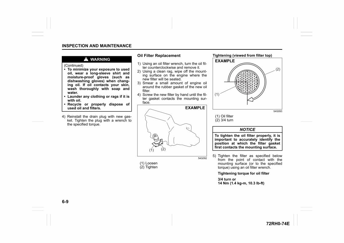
6-9
INSPECTION AND MAINTENANCE
72RH0-74E
4) Reinstall the drain plug with new gas-ket. Tighten the plug with a wrench tothe specified torque.
Oil Filter Replacement
1) Using an oil filter wrench, turn the oil fil-ter counterclockwise and remove it.
2) Using a clean rag, wipe off the mount-ing surface on the engine where thenew filter will be seated.
3) Smear a small amount of engine oilaround the rubber gasket of the new oilfilter.
4) Screw the new filter by hand until the fil-ter gasket contacts the mounting sur-face.
54G092
(1) Loosen(2) Tighten
Tightening (viewed from filter top)
54G093
(1) Oil filter(2) 3/4 turn
5) Tighten the filter as specified belowfrom the point of contact with themounting surface (or to the specifiedtorque) using an oil filter wrench.
Tightening torque for oil filter
3/4 turn or 14 Nm (1.4 kg-m, 10.3 lb-ft)
WARNING
(Continued)• To minimize your exposure to used
oil, wear a long-sleeve shirt andmoisture-proof gloves (such asdishwashing gloves) when chang-ing oil. If oil contacts your skin,wash thoroughly with soap andwater.
• Launder any clothing or rags if it iswith oil.
• Recycle or properly dispose ofused oil and filters.
(1) (2)
EXAMPLE
NOTICE
To tighten the oil filter properly, it isimportant to accurately identify theposition at which the filter gasketfirst contacts the mounting surface.
(1)
(2)
EXAMPLE
6-10
INSPECTION AND MAINTENANCE
72RH0-74E
Refill with Oil and Oil Leakage Check1) Pour oil through the filler hole and
install the filler cap. For the approximate capacity of the oil,refer to “Capacities” in “SPECIFICA-TIONS” section.
2) Start the engine and carefully check theoil filter and the drain plug for leakage.Run the engine at various speeds for atleast 5 minutes.
3) Stop the engine and wait about 5 min-utes. Check the oil level again and addoil if necessary. Check for leakageagain.
Engine Coolant
Selection of CoolantTo maintain optimum performance anddurability of your engine, use MARUTISUZUKI genuine coolant or equivalent.
This type of coolant is the best for coolingsystem for the following reasons:• The coolant helps maintain proper
engine temperature.• It gives proper protection against freez-
ing and boiling.• It gives proper protection against corro-
sion and rust.
Failure to use the proper coolant can dam-age your cooling system, Maruti Suzukiauthorised workshop can help you selectthe proper coolant.
NOTICE
To prevent oil leakage, make surethat the oil filter is tight, but do notover-tighten it.
NOTICE
• When replacing the oil filter, it isrecommended that you use aMARUTI SUZUKI genuine replace-ment filter. If you use an aftermar-ket filter, make sure it is ofequivalent quality and follow themanufacturer’s instructions.
• Oil leakage from the periphery ofthe oil filter or drain plug indicateincorrect installation or gasketdamage. If you find any leakage orare not sure that the filter has beenproperly tightened, have the vehi-cle inspected by a Maruti Suzukiauthorised workshop.
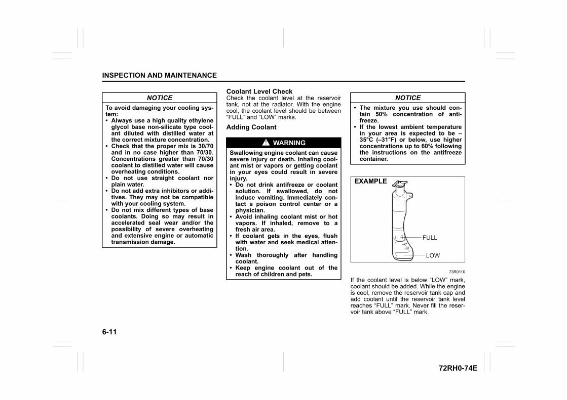
6-11
INSPECTION AND MAINTENANCE
72RH0-74E
Coolant Level CheckCheck the coolant level at the reservoirtank, not at the radiator. With the enginecool, the coolant level should be between“FULL” and “LOW” marks.
Adding Coolant
73R0110
If the coolant level is below “LOW” mark,coolant should be added. While the engineis cool, remove the reservoir tank cap andadd coolant until the reservoir tank levelreaches “FULL” mark. Never fill the reser-voir tank above “FULL” mark.
NOTICE
To avoid damaging your cooling sys-tem:• Always use a high quality ethylene
glycol base non-silicate type cool-ant diluted with distilled water atthe correct mixture concentration.
• Check that the proper mix is 30/70and in no case higher than 70/30.Concentrations greater than 70/30coolant to distilled water will causeoverheating conditions.
• Do not use straight coolant norplain water.
• Do not add extra inhibitors or addi-tives. They may not be compatiblewith your cooling system.
• Do not mix different types of basecoolants. Doing so may result inaccelerated seal wear and/or thepossibility of severe overheatingand extensive engine or automatictransmission damage.
WARNING
Swallowing engine coolant can causesevere injury or death. Inhaling cool-ant mist or vapors or getting coolantin your eyes could result in severeinjury.• Do not drink antifreeze or coolant
solution. If swallowed, do notinduce vomiting. Immediately con-tact a poison control center or aphysician.
• Avoid inhaling coolant mist or hotvapors. If inhaled, remove to afresh air area.
• If coolant gets in the eyes, flushwith water and seek medical atten-tion.
• Wash thoroughly after handlingcoolant.
• Keep engine coolant out of thereach of children and pets.
NOTICE
• The mixture you use should con-tain 50% concentration of anti-freeze.
• If the lowest ambient temperaturein your area is expected to be –35°C (–31°F) or below, use higherconcentrations up to 60% followingthe instructions on the antifreezecontainer.
FULL
LOW
EXAMPLE
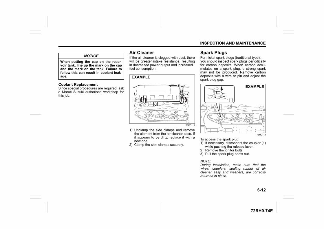
6-12
INSPECTION AND MAINTENANCE
72RH0-74E
Coolant ReplacementSince special procedures are required, aska Maruti Suzuki authorised workshop forthis job.
Air CleanerIf the air cleaner is clogged with dust, therewill be greater intake resistance, resultingin decreased power output and increasedfuel consumption.
73R0112
1) Unclamp the side clamps and removethe element from the air cleaner case. Ifit appears to be dirty, replace it with anew one.
2) Clamp the side clamps securely.
Spark PlugsFor nickel spark plugs (traditional type):You should inspect spark plugs periodicallyfor carbon deposits. When carbon accu-mulates on a spark plug, a strong sparkmay not be produced. Remove carbondeposits with a wire or pin and adjust thespark plug gap.
73R0119
To access the spark plug:1) If necessary, disconnect the coupler (1)
while pushing the release lever.2) Remove the ignitor bolts.3) Pull the spark plug boots out.
NOTE:During installation, make sure that thewires, couplers, sealing rubber of aircleaner assy and washers, are correctlyreturned in place.
NOTICE
When putting the cap on the reser-voir tank, line up the mark on the capand the mark on the tank. Failure tofollow this can result in coolant leak-age. EXAMPLE
(1)
EXAMPLE
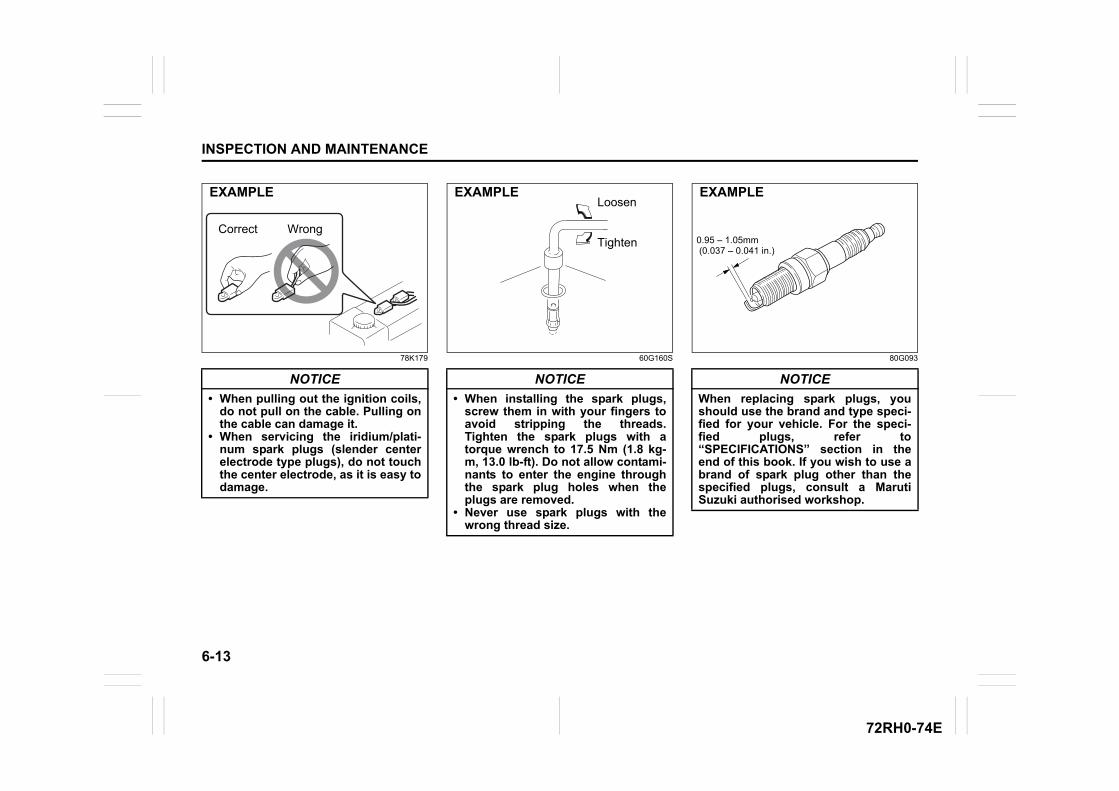
6-13
INSPECTION AND MAINTENANCE
72RH0-74E
78K179 60G160S 80G093
NOTICE
• When pulling out the ignition coils,do not pull on the cable. Pulling onthe cable can damage it.
• When servicing the iridium/plati-num spark plugs (slender centerelectrode type plugs), do not touchthe center electrode, as it is easy todamage.
Correct Wrong
EXAMPLE
NOTICE
• When installing the spark plugs,screw them in with your fingers toavoid stripping the threads.Tighten the spark plugs with atorque wrench to 17.5 Nm (1.8 kg-m, 13.0 lb-ft). Do not allow contami-nants to enter the engine throughthe spark plug holes when theplugs are removed.
• Never use spark plugs with thewrong thread size.
Loosen
Tighten
EXAMPLE
NOTICE
When replacing spark plugs, youshould use the brand and type speci-fied for your vehicle. For the speci-fied plugs, refer to“SPECIFICATIONS” section in theend of this book. If you wish to use abrand of spark plug other than thespecified plugs, consult a MarutiSuzuki authorised workshop.
0.95 – 1.05mm (0.037 – 0.041 in.)
EXAMPLE
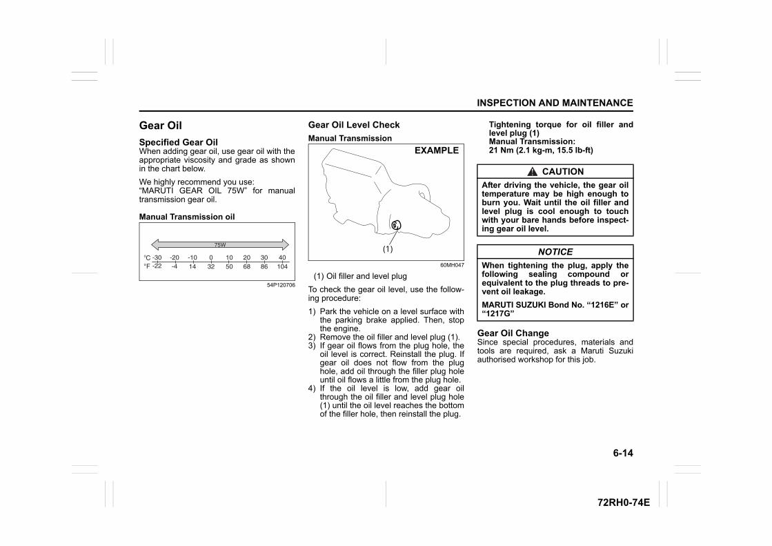
6-14
INSPECTION AND MAINTENANCE
72RH0-74E
Gear Oil
Specified Gear OilWhen adding gear oil, use gear oil with theappropriate viscosity and grade as shownin the chart below.
We highly recommend you use:“MARUTI GEAR OIL 75W” for manualtransmission gear oil.
Manual Transmission oil
54P120706
Gear Oil Level Check
Manual Transmission
60MH047
(1) Oil filler and level plug
To check the gear oil level, use the follow-ing procedure:
1) Park the vehicle on a level surface withthe parking brake applied. Then, stopthe engine.
2) Remove the oil filler and level plug (1).3) If gear oil flows from the plug hole, the
oil level is correct. Reinstall the plug. Ifgear oil does not flow from the plughole, add oil through the filler plug holeuntil oil flows a little from the plug hole.
4) If the oil level is low, add gear oilthrough the oil filler and level plug hole(1) until the oil level reaches the bottomof the filler hole, then reinstall the plug.
Tightening torque for oil filler andlevel plug (1)Manual Transmission:21 Nm (2.1 kg-m, 15.5 lb-ft)
Gear Oil ChangeSince special procedures, materials andtools are required, ask a Maruti Suzukiauthorised workshop for this job.
CFo
o -30-22
-20-4
-1014 32 50 68 86 104
0 10 20 30 40
75W(1)
EXAMPLE
CAUTION
After driving the vehicle, the gear oiltemperature may be high enough toburn you. Wait until the oil filler andlevel plug is cool enough to touchwith your bare hands before inspect-ing gear oil level.
NOTICE
When tightening the plug, apply thefollowing sealing compound orequivalent to the plug threads to pre-vent oil leakage.
MARUTI SUZUKI Bond No. “1216E” or“1217G”
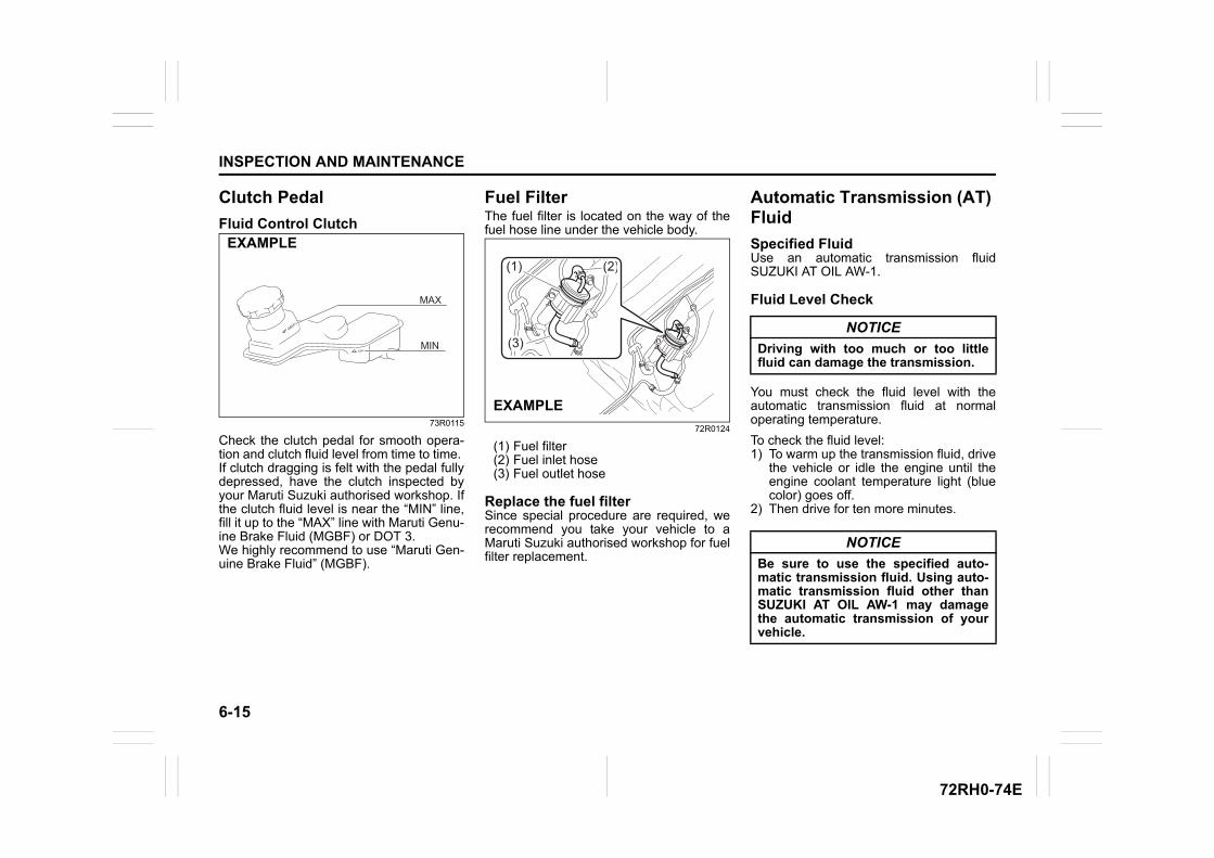
6-15
INSPECTION AND MAINTENANCE
72RH0-74E
Clutch Pedal
Fluid Control Clutch
73R0115
Check the clutch pedal for smooth opera-tion and clutch fluid level from time to time. If clutch dragging is felt with the pedal fullydepressed, have the clutch inspected byyour Maruti Suzuki authorised workshop. Ifthe clutch fluid level is near the “MIN” line,fill it up to the “MAX” line with Maruti Genu-ine Brake Fluid (MGBF) or DOT 3. We highly recommend to use “Maruti Gen-uine Brake Fluid” (MGBF).
Fuel FilterThe fuel filter is located on the way of thefuel hose line under the vehicle body.
72R0124
(1) Fuel filter(2) Fuel inlet hose(3) Fuel outlet hose
Replace the fuel filterSince special procedure are required, werecommend you take your vehicle to aMaruti Suzuki authorised workshop for fuelfilter replacement.
Automatic Transmission (AT) Fluid
Specified FluidUse an automatic transmission fluidSUZUKI AT OIL AW-1.
Fluid Level Check
You must check the fluid level with theautomatic transmission fluid at normaloperating temperature.
To check the fluid level:1) To warm up the transmission fluid, drive
the vehicle or idle the engine until theengine coolant temperature light (bluecolor) goes off.
2) Then drive for ten more minutes.
EXAMPLE
(3)
(2)(1)
EXAMPLE
NOTICE
Driving with too much or too littlefluid can damage the transmission.
NOTICE
Be sure to use the specified auto-matic transmission fluid. Using auto-matic transmission fluid other thanSUZUKI AT OIL AW-1 may damagethe automatic transmission of yourvehicle.
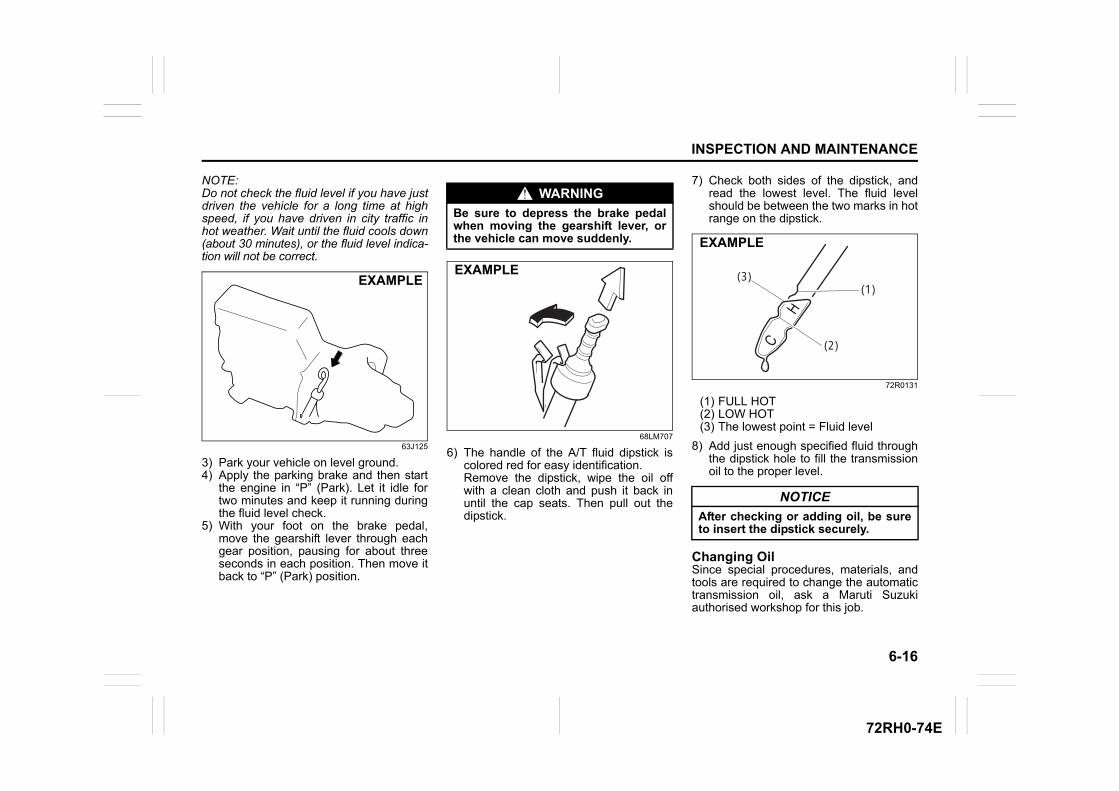
6-16
INSPECTION AND MAINTENANCE
72RH0-74E
NOTE:Do not check the fluid level if you have justdriven the vehicle for a long time at highspeed, if you have driven in city traffic inhot weather. Wait until the fluid cools down(about 30 minutes), or the fluid level indica-tion will not be correct.
63J125
3) Park your vehicle on level ground.4) Apply the parking brake and then start
the engine in “P” (Park). Let it idle fortwo minutes and keep it running duringthe fluid level check.
5) With your foot on the brake pedal,move the gearshift lever through eachgear position, pausing for about threeseconds in each position. Then move itback to “P” (Park) position.
68LM707
6) The handle of the A/T fluid dipstick iscolored red for easy identification.Remove the dipstick, wipe the oil offwith a clean cloth and push it back inuntil the cap seats. Then pull out thedipstick.
7) Check both sides of the dipstick, andread the lowest level. The fluid levelshould be between the two marks in hotrange on the dipstick.
72R0131
(1) FULL HOT(2) LOW HOT(3) The lowest point = Fluid level
8) Add just enough specified fluid throughthe dipstick hole to fill the transmissionoil to the proper level.
Changing OilSince special procedures, materials, andtools are required to change the automatictransmission oil, ask a Maruti Suzukiauthorised workshop for this job.
EXAMPLE
WARNING
Be sure to depress the brake pedalwhen moving the gearshift lever, orthe vehicle can move suddenly.
EXAMPLE
NOTICE
After checking or adding oil, be sureto insert the dipstick securely.
(1)
(2)
(3)
EXAMPLE
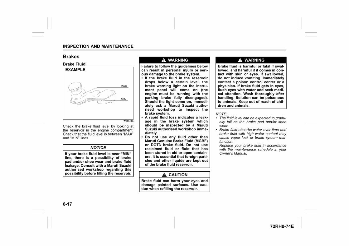
6-17
INSPECTION AND MAINTENANCE
72RH0-74E
Brakes
Brake Fluid
73R0116
Check the brake fluid level by looking atthe reservoir in the engine compartment.Check that the fluid level is between “MAX”and “MIN” lines.
NOTE:• The fluid level can be expected to gradu-
ally fall as the brake pad and/or shoewear.
• Brake fluid absorbs water over time andbrake fluid with high water content maycause vapor lock or brake system mal-function.Replace your brake fluid in accordancewith the maintenance schedule in yourOwner's Manual.
NOTICE
If your brake fluid level is near “MIN”line, there is a possibility of brakepad and/or shoe wear and brake fluidleakage. Consult with a Maruti Suzukiauthorised workshop regarding thispossibility before filling the reservoir.
EXAMPLE
WARNING
Failure to follow the guidelines belowcan result in personal injury or seri-ous damage to the brake system.• If the brake fluid in the reservoir
drops below a certain level, thebrake warning light on the instru-ment panel will come on (theengine must be running with theparking brake fully disengaged).Should the light come on, immedi-ately ask a Maruti Suzuki autho-rised workshop to inspect thebrake system.
• A rapid fluid loss indicates a leak-age in the brake system whichshould be inspected by a MarutiSuzuki authorised workshop imme-diately.
• Do not use any fluid other thanMaruti Genuine Brake Fluid (MGBF)or DOT3 brake fluid. Do not usereclaimed fluid or fluid that hasbeen stored in old or open contain-ers. It is essential that foreign parti-cles and other liquids are kept outof the brake fluid reservoir.
CAUTION
Brake fluid can harm your eyes anddamage painted surfaces. Use cau-tion when refilling the reservoir.
WARNING
Brake fluid is harmful or fatal if swal-lowed, and harmful if it comes in con-tact with skin or eyes. If swallowed,do not induce vomiting. Immediatelycontact a poison control center or aphysician. If brake fluid gets in eyes,flush eyes with water and seek medi-cal attention. Wash thoroughly afterhandling. Solution can be poisonousto animals. Keep out of reach of chil-dren and animals.
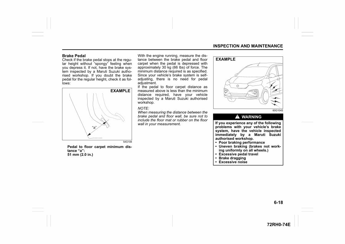
6-18
INSPECTION AND MAINTENANCE
72RH0-74E
Brake PedalCheck if the brake pedal stops at the regu-lar height without “spongy” feeling whenyou depress it. If not, have the brake sys-tem inspected by a Maruti Suzuki autho-rised workshop. If you doubt the brakepedal for the regular height, check it as fol-lows:
54G108
Pedal to floor carpet minimum dis-tance “a”: 51 mm (2.0 in.)
With the engine running, measure the dis-tance between the brake pedal and floorcarpet when the pedal is depressed withapproximately 30 kg (66 lbs) of force. Theminimum distance required is as specified.Since your vehicle’s brake system is self-adjusting, there is no need for pedaladjustment. If the pedal to floor carpet distance asmeasured above is less than the minimumdistance required, have your vehicleinspected by a Maruti Suzuki authorisedworkshop.
NOTE:When measuring the distance between thebrake pedal and floor wall, be sure not toinclude the floor mat or rubber on the floorwall in your measurement.
60G104S
“a”
EXAMPLE
WARNING
If you experience any of the followingproblems with your vehicle’s brakesystem, have the vehicle inspectedimmediately by a Maruti Suzukiauthorised workshop.• Poor braking performance• Uneven braking (brakes not work-
ing uniformly on all wheels.)• Excessive pedal travel• Brake dragging• Excessive noise
EXAMPLE
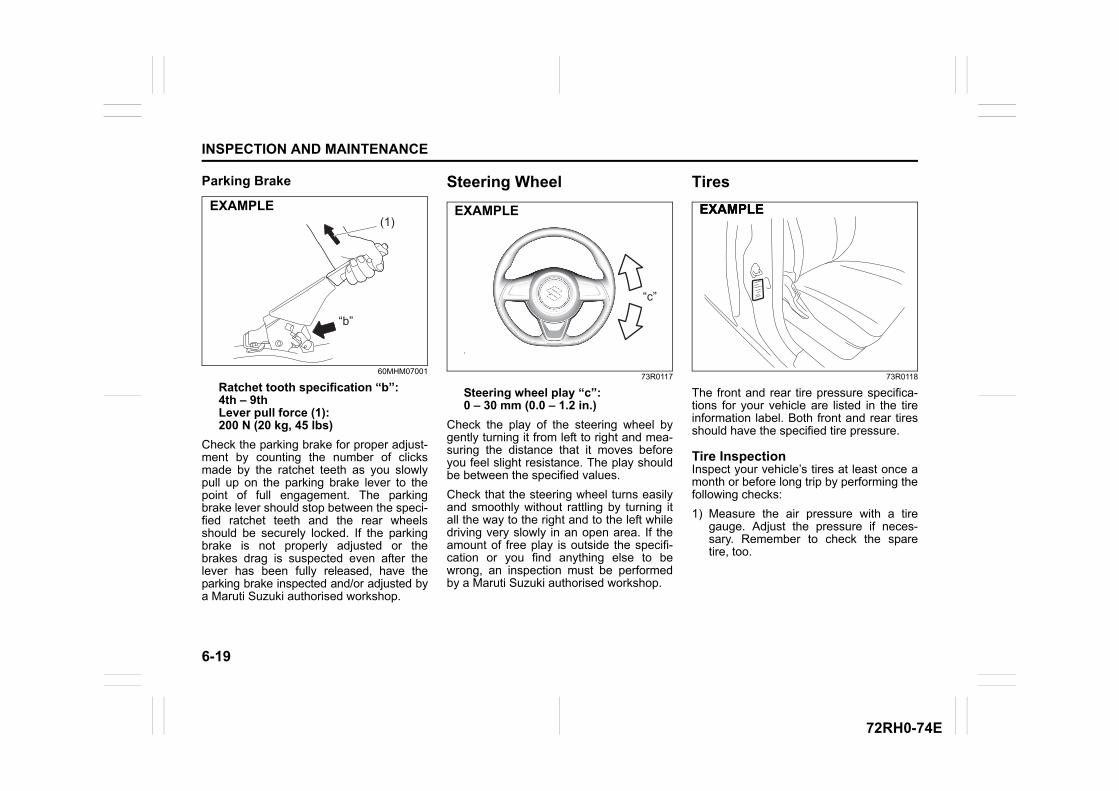
6-19
INSPECTION AND MAINTENANCE
72RH0-74E
Parking Brake
60MHM07001
Ratchet tooth specification “b”: 4th – 9thLever pull force (1):200 N (20 kg, 45 lbs)
Check the parking brake for proper adjust-ment by counting the number of clicksmade by the ratchet teeth as you slowlypull up on the parking brake lever to thepoint of full engagement. The parkingbrake lever should stop between the speci-fied ratchet teeth and the rear wheelsshould be securely locked. If the parkingbrake is not properly adjusted or thebrakes drag is suspected even after thelever has been fully released, have theparking brake inspected and/or adjusted bya Maruti Suzuki authorised workshop.
Steering Wheel
73R0117
Steering wheel play “c”: 0 – 30 mm (0.0 – 1.2 in.)
Check the play of the steering wheel bygently turning it from left to right and mea-suring the distance that it moves beforeyou feel slight resistance. The play shouldbe between the specified values.
Check that the steering wheel turns easilyand smoothly without rattling by turning itall the way to the right and to the left whiledriving very slowly in an open area. If theamount of free play is outside the specifi-cation or you find anything else to bewrong, an inspection must be performedby a Maruti Suzuki authorised workshop.
Tires
73R0118
The front and rear tire pressure specifica-tions for your vehicle are listed in the tireinformation label. Both front and rear tiresshould have the specified tire pressure.
Tire InspectionInspect your vehicle’s tires at least once amonth or before long trip by performing thefollowing checks:
1) Measure the air pressure with a tiregauge. Adjust the pressure if neces-sary. Remember to check the sparetire, too.
(1)
“b”
EXAMPLE
“c”
EXAMPLE EXAMPLEEXAMPLE
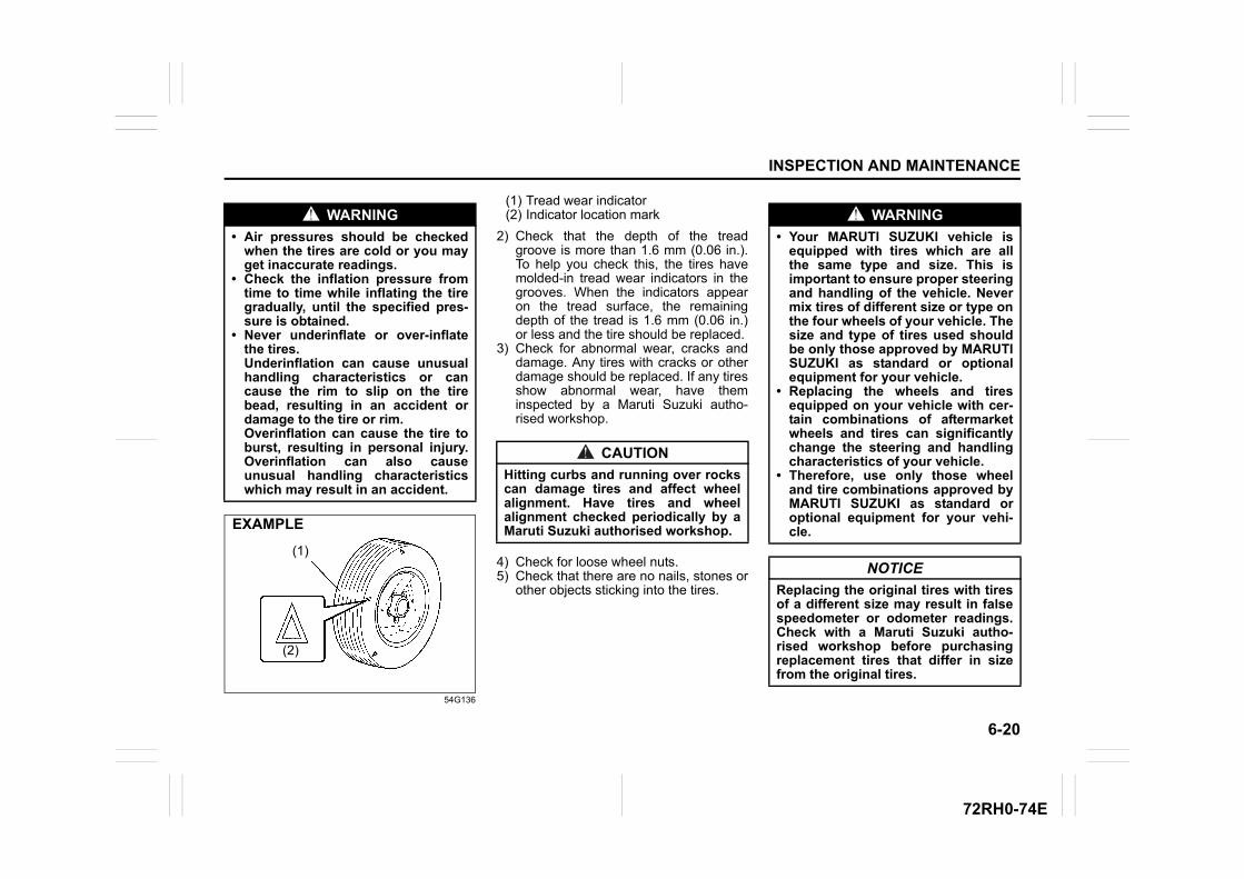
6-20
INSPECTION AND MAINTENANCE
72RH0-74E
54G136
(1) Tread wear indicator(2) Indicator location mark
2) Check that the depth of the treadgroove is more than 1.6 mm (0.06 in.).To help you check this, the tires havemolded-in tread wear indicators in thegrooves. When the indicators appearon the tread surface, the remainingdepth of the tread is 1.6 mm (0.06 in.)or less and the tire should be replaced.
3) Check for abnormal wear, cracks anddamage. Any tires with cracks or otherdamage should be replaced. If any tiresshow abnormal wear, have theminspected by a Maruti Suzuki autho-rised workshop.
4) Check for loose wheel nuts.5) Check that there are no nails, stones or
other objects sticking into the tires.
WARNING
• Air pressures should be checkedwhen the tires are cold or you mayget inaccurate readings.
• Check the inflation pressure fromtime to time while inflating the tiregradually, until the specified pres-sure is obtained.
• Never underinflate or over-inflatethe tires. Underinflation can cause unusualhandling characteristics or cancause the rim to slip on the tirebead, resulting in an accident ordamage to the tire or rim. Overinflation can cause the tire toburst, resulting in personal injury.Overinflation can also causeunusual handling characteristicswhich may result in an accident.
EXAMPLE
(1)
(2)
CAUTION
Hitting curbs and running over rockscan damage tires and affect wheelalignment. Have tires and wheelalignment checked periodically by aMaruti Suzuki authorised workshop.
WARNING
• Your MARUTI SUZUKI vehicle isequipped with tires which are allthe same type and size. This isimportant to ensure proper steeringand handling of the vehicle. Nevermix tires of different size or type onthe four wheels of your vehicle. Thesize and type of tires used shouldbe only those approved by MARUTISUZUKI as standard or optionalequipment for your vehicle.
• Replacing the wheels and tiresequipped on your vehicle with cer-tain combinations of aftermarketwheels and tires can significantlychange the steering and handlingcharacteristics of your vehicle.
• Therefore, use only those wheeland tire combinations approved byMARUTI SUZUKI as standard oroptional equipment for your vehi-cle.
NOTICE
Replacing the original tires with tiresof a different size may result in falsespeedometer or odometer readings.Check with a Maruti Suzuki autho-rised workshop before purchasingreplacement tires that differ in sizefrom the original tires.
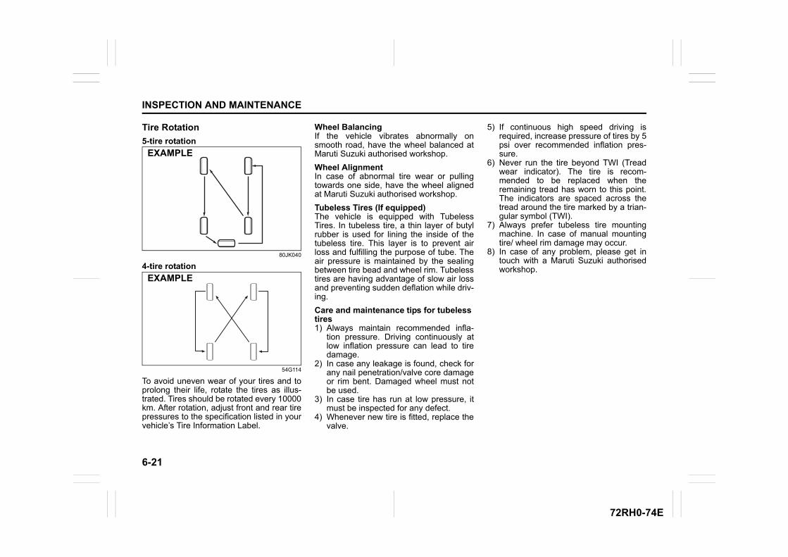
6-21
INSPECTION AND MAINTENANCE
72RH0-74E
Tire Rotation
5-tire rotation
80JK040
4-tire rotation
54G114
To avoid uneven wear of your tires and toprolong their life, rotate the tires as illus-trated. Tires should be rotated every 10000km. After rotation, adjust front and rear tirepressures to the specification listed in yourvehicle’s Tire Information Label.
Wheel BalancingIf the vehicle vibrates abnormally onsmooth road, have the wheel balanced atMaruti Suzuki authorised workshop.
Wheel AlignmentIn case of abnormal tire wear or pullingtowards one side, have the wheel alignedat Maruti Suzuki authorised workshop.
Tubeless Tires (If equipped)The vehicle is equipped with TubelessTires. In tubeless tire, a thin layer of butylrubber is used for lining the inside of thetubeless tire. This layer is to prevent airloss and fulfilling the purpose of tube. Theair pressure is maintained by the sealingbetween tire bead and wheel rim. Tubelesstires are having advantage of slow air lossand preventing sudden deflation while driv-ing.
Care and maintenance tips for tubelesstires1) Always maintain recommended infla-
tion pressure. Driving continuously atlow inflation pressure can lead to tiredamage.
2) In case any leakage is found, check forany nail penetration/valve core damageor rim bent. Damaged wheel must notbe used.
3) In case tire has run at low pressure, itmust be inspected for any defect.
4) Whenever new tire is fitted, replace thevalve.
5) If continuous high speed driving isrequired, increase pressure of tires by 5psi over recommended inflation pres-sure.
6) Never run the tire beyond TWI (Treadwear indicator). The tire is recom-mended to be replaced when theremaining tread has worn to this point.The indicators are spaced across thetread around the tire marked by a trian-gular symbol (TWI).
7) Always prefer tubeless tire mountingmachine. In case of manual mountingtire/ wheel rim damage may occur.
8) In case of any problem, please get intouch with a Maruti Suzuki authorisedworkshop.
EXAMPLE
EXAMPLE
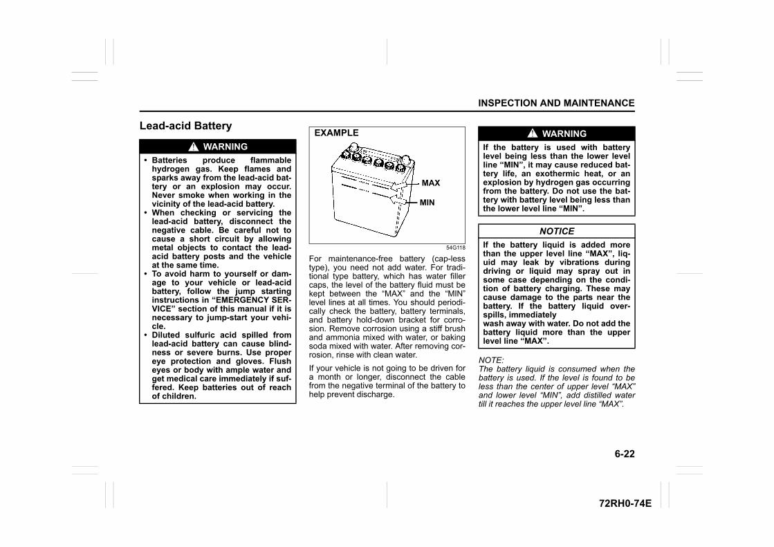
6-22
INSPECTION AND MAINTENANCE
72RH0-74E
Lead-acid Battery
54G118
For maintenance-free battery (cap-lesstype), you need not add water. For tradi-tional type battery, which has water fillercaps, the level of the battery fluid must bekept between the “MAX” and the “MIN”level lines at all times. You should periodi-cally check the battery, battery terminals,and battery hold-down bracket for corro-sion. Remove corrosion using a stiff brushand ammonia mixed with water, or bakingsoda mixed with water. After removing cor-rosion, rinse with clean water.
If your vehicle is not going to be driven fora month or longer, disconnect the cablefrom the negative terminal of the battery tohelp prevent discharge.
NOTE:The battery liquid is consumed when thebattery is used. If the level is found to beless than the center of upper level “MAX”and lower level “MIN”, add distilled watertill it reaches the upper level line “MAX”.
WARNING
• Batteries produce flammablehydrogen gas. Keep flames andsparks away from the lead-acid bat-tery or an explosion may occur.Never smoke when working in thevicinity of the lead-acid battery.
• When checking or servicing thelead-acid battery, disconnect thenegative cable. Be careful not tocause a short circuit by allowingmetal objects to contact the lead-acid battery posts and the vehicleat the same time.
• To avoid harm to yourself or dam-age to your vehicle or lead-acidbattery, follow the jump startinginstructions in “EMERGENCY SER-VICE” section of this manual if it isnecessary to jump-start your vehi-cle.
• Diluted sulfuric acid spilled fromlead-acid battery can cause blind-ness or severe burns. Use propereye protection and gloves. Flusheyes or body with ample water andget medical care immediately if suf-fered. Keep batteries out of reachof children.
EXAMPLE
MAX
MIN
WARNING
If the battery is used with batterylevel being less than the lower levelline “MIN”, it may cause reduced bat-tery life, an exothermic heat, or anexplosion by hydrogen gas occurringfrom the battery. Do not use the bat-tery with battery level being less thanthe lower level line “MIN”.
NOTICE
If the battery liquid is added morethan the upper level line “MAX”, liq-uid may leak by vibrations duringdriving or liquid may spray out insome case depending on the condi-tion of battery charging. These maycause damage to the parts near thebattery. If the battery liquid over-spills, immediatelywash away with water. Do not add thebattery liquid more than the upperlevel line “MAX”.
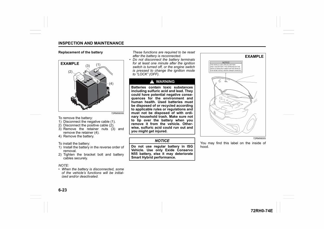
6-23
INSPECTION AND MAINTENANCE
72RH0-74E
Replacement of the battery
72RM06006
To remove the battery:1) Disconnect the negative cable (1).2) Disconnect the positive cable (2).3) Remove the retainer nuts (3) and
remove the retainer (4).4) Remove the battery.
To install the battery:1) Install the battery in the reverse order of
removal.2) Tighten the bracket bolt and battery
cables securely.
NOTE:• When the battery is disconnected, some
of the vehicle’s functions will be initial-ized and/or deactivated.
These functions are required to be resetafter the battery is reconnected.
• Do not disconnect the battery terminalsfor at least one minute after the ignitionswitch is turned off, or the engine switchis pressed to change the ignition modeto “LOCK” (OFF).
72RM06005
You may find this label on the inside ofhood.
(1)
(2)
(3)
(4)
EXAMPLE
WARNING
Batteries contain toxic substancesincluding sulfuric acid and lead. Theycould have potential negative conse-quences for the environment andhuman health. Used batteries mustbe disposed of or recycled accordingto applicable rules or regulations andmust not be disposed of with ordi-nary household trash. Make sure notto tip over the battery when youremove it from the vehicle. Other-wise, sulfuric acid could run out andyou might get injured.
NOTICE
Do not use regular battery in ISGVehicle. Use only Exide ConservoN55 battery, else it may deteriorateSmart Hybrid performance.
NOTICETHIS VEHICLE USES SPECIAL BATTERY.ONLY USE BATTERY TYPE APPROVED BY THEVEHICLE MANUFACTURER FOR THIS VEHICLE.FOR MORE DETAILS REFER OWNER’S MANUAL.
EXAMPLE
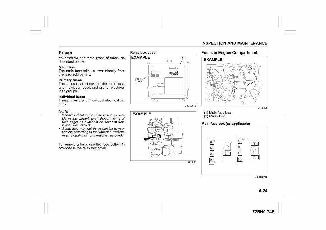
6-24
INSPECTION AND MAINTENANCE
72RH0-74E
FusesYour vehicle has three types of fuses, asdescribed below:
Main fuseThe main fuse takes current directly fromthe lead-acid battery.
Primary fusesThese fuses are between the main fuseand individual fuses, and are for electricalload groups.
Individual fusesThese fuses are for individual electrical cir-cuits.
NOTE:• “Blank” indicates that fuse is not applica-
ble in the variant, even though name offuse might be available on cover of fusebox of your vehicle.
• Some fuse may not be applicable to yourvehicle according to the variant of vehicle,even though it is not mentioned as blank.
To remove a fuse, use the fuse puller (1)provided in the relay box cover.
Relay box cover
72RM06010
63J095
Fuses in Engine Compartment
73R0195
(1) Main fuse box(2) Relay box
Main fuse box (as applicable)
74LHT0715
(1)
SpareFuses
EXAMPLE
EXAMPLE
(2)(1)
EXAMPLE
(5)
(3)
(4)
(2)
(1)
(5)
(4)
(3)
(2)(1)
(6)
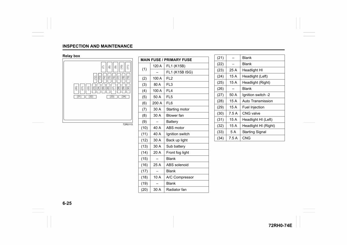
6-25
INSPECTION AND MAINTENANCE
72RH0-74E
Relay box
72R0115(1
9)
(12)
(13)
(14)
(15)
(16)
(17)
(18)
(30)
(11)(7)
(8)
(9)
(10)
(31) (32) (33) (34)
(20)
(21)
(23)
(24)
(25)
(26)
(27)
(28)
(29)
(22)
MAIN FUSE / PRIMARY FUSE
(1)120 A FL1 (K15B)
– FL1 (K15B ISG)
(2) 100 A FL2
(3) 80 A FL3
(4) 100 A FL4
(5) 50 A FL5
(6) 200 A FL6
(7) 30 A Starting motor
(8) 30 A Blower fan
(9) – Battery
(10) 40 A ABS motor
(11) 40 A Ignition switch
(12) 30 A Back up light
(13) 30 A Sub battery
(14) 20 A Front fog light
(15) – Blank
(16) 25 A ABS solenoid
(17) – Blank
(18) 10 A A/C Compressor
(19) – Blank
(20) 30 A Radiator fan
(21) – Blank
(22) – Blank
(23) 25 A Headlight HI
(24) 15 A Headlight (Left)
(25) 15 A Headlight (Right)
(26) – Blank
(27) 50 A Ignition switch -2
(28) 15 A Auto Transmission
(29) 15 A Fuel Injection
(30) 7.5 A CNG valve
(31) 15 A Headlight HI (Left)
(32) 15 A Headlight HI (Right)
(33) 5 A Starting Signal
(34) 7.5 A CNG
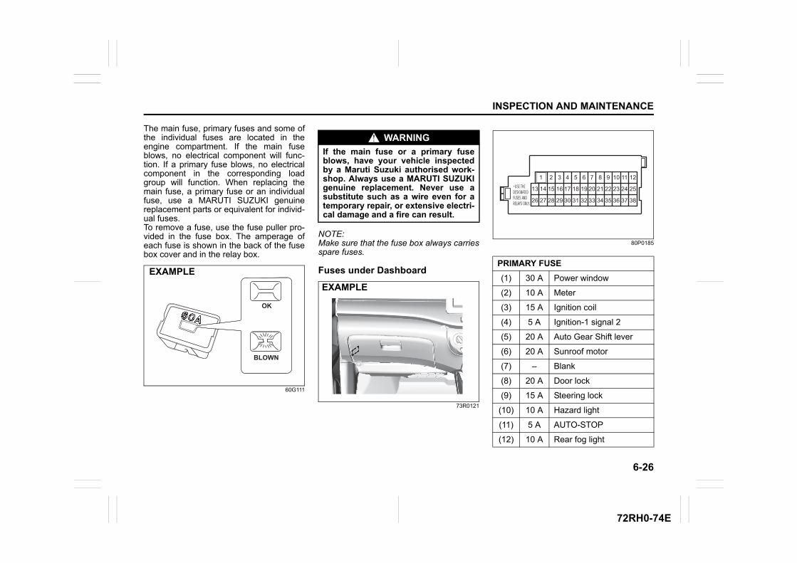
6-26
INSPECTION AND MAINTENANCE
72RH0-74E
The main fuse, primary fuses and some ofthe individual fuses are located in theengine compartment. If the main fuseblows, no electrical component will func-tion. If a primary fuse blows, no electricalcomponent in the corresponding loadgroup will function. When replacing themain fuse, a primary fuse or an individualfuse, use a MARUTI SUZUKI genuinereplacement parts or equivalent for individ-ual fuses.To remove a fuse, use the fuse puller pro-vided in the fuse box. The amperage ofeach fuse is shown in the back of the fusebox cover and in the relay box.
60G111
NOTE:Make sure that the fuse box always carriesspare fuses.
Fuses under Dashboard
73R0121
80P0185
OK
BLOWN
EXAMPLE
WARNING
If the main fuse or a primary fuseblows, have your vehicle inspectedby a Maruti Suzuki authorised work-shop. Always use a MARUTI SUZUKIgenuine replacement. Never use asubstitute such as a wire even for atemporary repair, or extensive electri-cal damage and a fire can result.
EXAMPLE
PRIMARY FUSE
(1) 30 A Power window
(2) 10 A Meter
(3) 15 A Ignition coil
(4) 5 A Ignition-1 signal 2
(5) 20 A Auto Gear Shift lever
(6) 20 A Sunroof motor
(7) – Blank
(8) 20 A Door lock
(9) 15 A Steering lock
(10) 10 A Hazard light
(11) 5 A AUTO-STOP
(12) 10 A Rear fog light
1 2
15
28
14
27
13
26
3
16
29
4
17
30
5
18
31
6
19
32
7
20
33
8
21
34
9
22
35
10
23
36
11
24
37
12
25
38
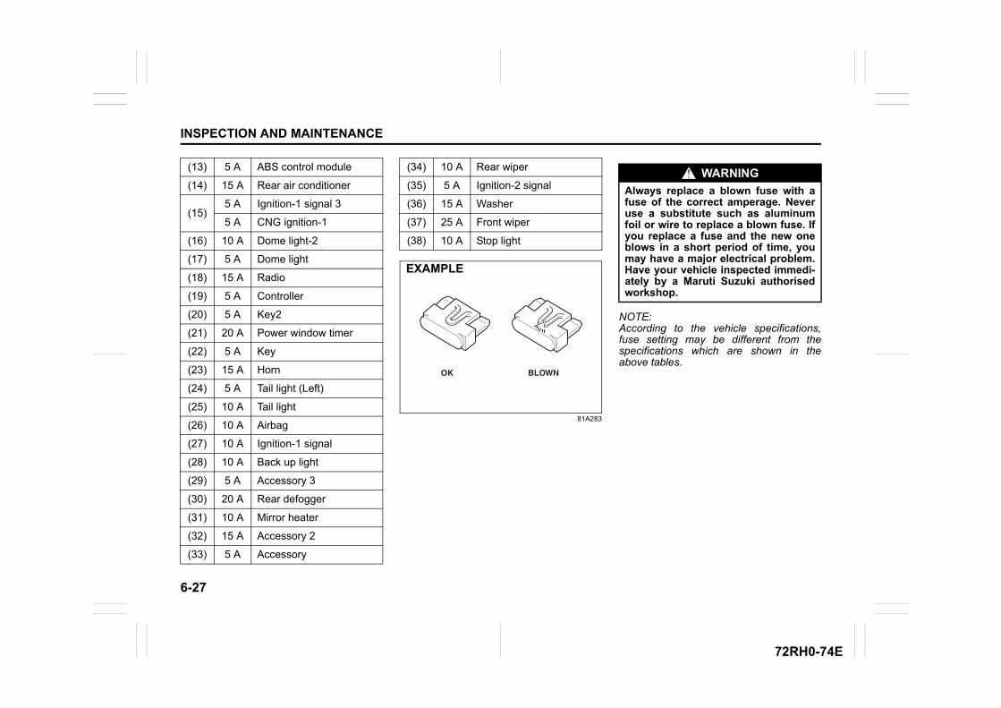
6-27
INSPECTION AND MAINTENANCE
72RH0-74E
81A283
NOTE:According to the vehicle specifications,fuse setting may be different from thespecifications which are shown in theabove tables.
(13) 5 A ABS control module
(14) 15 A Rear air conditioner
(15)5 A Ignition-1 signal 3
5 A CNG ignition-1
(16) 10 A Dome light-2
(17) 5 A Dome light
(18) 15 A Radio
(19) 5 A Controller
(20) 5 A Key2
(21) 20 A Power window timer
(22) 5 A Key
(23) 15 A Horn
(24) 5 A Tail light (Left)
(25) 10 A Tail light
(26) 10 A Airbag
(27) 10 A Ignition-1 signal
(28) 10 A Back up light
(29) 5 A Accessory 3
(30) 20 A Rear defogger
(31) 10 A Mirror heater
(32) 15 A Accessory 2
(33) 5 A Accessory
(34) 10 A Rear wiper
(35) 5 A Ignition-2 signal
(36) 15 A Washer
(37) 25 A Front wiper
(38) 10 A Stop light
BLOWNOK
EXAMPLE
WARNING
Always replace a blown fuse with afuse of the correct amperage. Neveruse a substitute such as aluminumfoil or wire to replace a blown fuse. Ifyou replace a fuse and the new oneblows in a short period of time, youmay have a major electrical problem.Have your vehicle inspected immedi-ately by a Maruti Suzuki authorisedworkshop.
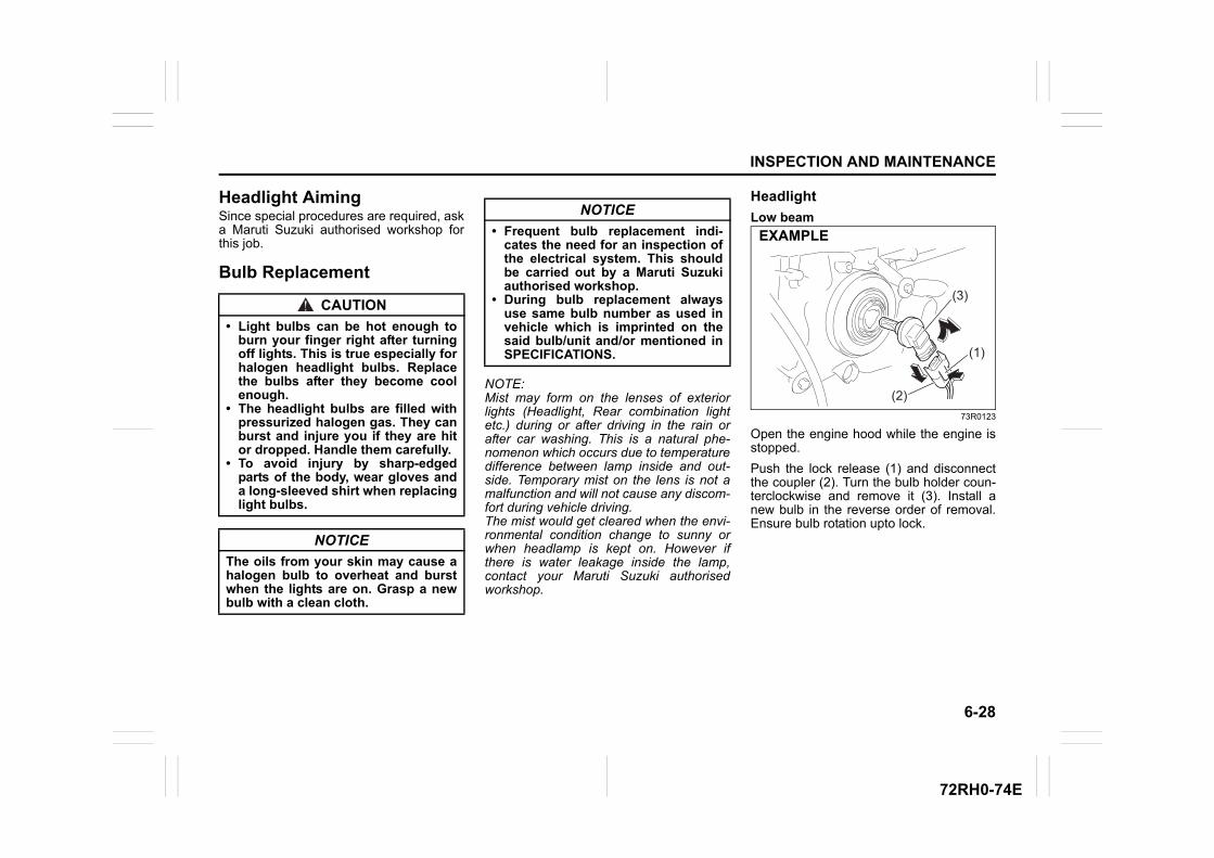
6-28
INSPECTION AND MAINTENANCE
72RH0-74E
Headlight AimingSince special procedures are required, aska Maruti Suzuki authorised workshop forthis job.
Bulb Replacement
NOTE:Mist may form on the lenses of exteriorlights (Headlight, Rear combination lightetc.) during or after driving in the rain orafter car washing. This is a natural phe-nomenon which occurs due to temperaturedifference between lamp inside and out-side. Temporary mist on the lens is not amalfunction and will not cause any discom-fort during vehicle driving. The mist would get cleared when the envi-ronmental condition change to sunny orwhen headlamp is kept on. However ifthere is water leakage inside the lamp,contact your Maruti Suzuki authorisedworkshop.
Headlight
Low beam
73R0123
Open the engine hood while the engine isstopped.
Push the lock release (1) and disconnectthe coupler (2). Turn the bulb holder coun-terclockwise and remove it (3). Install anew bulb in the reverse order of removal.Ensure bulb rotation upto lock.
CAUTION
• Light bulbs can be hot enough toburn your finger right after turningoff lights. This is true especially forhalogen headlight bulbs. Replacethe bulbs after they become coolenough.
• The headlight bulbs are filled withpressurized halogen gas. They canburst and injure you if they are hitor dropped. Handle them carefully.
• To avoid injury by sharp-edgedparts of the body, wear gloves anda long-sleeved shirt when replacinglight bulbs.
NOTICE
The oils from your skin may cause ahalogen bulb to overheat and burstwhen the lights are on. Grasp a newbulb with a clean cloth.
NOTICE
• Frequent bulb replacement indi-cates the need for an inspection ofthe electrical system. This shouldbe carried out by a Maruti Suzukiauthorised workshop.
• During bulb replacement alwaysuse same bulb number as used invehicle which is imprinted on thesaid bulb/unit and/or mentioned inSPECIFICATIONS. (1)
(3)
(2)
EXAMPLE
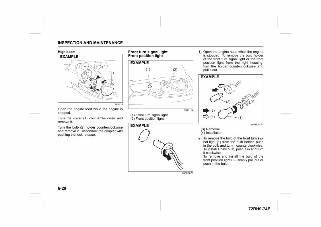
6-29
INSPECTION AND MAINTENANCE
72RH0-74E
High beam
73R0134
Open the engine food while the engine isstopped.
Turn the cover (1) counterclockwise andremove it.
Turn the bulb (2) holder counterclockwiseand remove it. Disconnect the coupler withpushing the lock release.
Front turn signal lightFront position light
73R0124
(1) Front turn signal light(2) Front position light
68PH0073
1) Open the engine hood while the engineis stopped. To remove the bulb holderof the front turn signal light or the frontposition light from the light housing,turn the holder counterclockwise andpull it out.
68PM00721
(3) Removal(4) Installation
2) To remove the bulb of the front turn sig-nal light (1) from the bulb holder, pushin the bulb and turn it counterclockwise.To install a new bulb, push it in and turnit clockwise.To remove and install the bulb of thefront position light (2), simply pull out orpush in the bulb.
(1)
(2)
EXAMPLE
(2)(1)
EXAMPLE
EXAMPLE
(1)
(2)
(3)
(4)
EXAMPLE
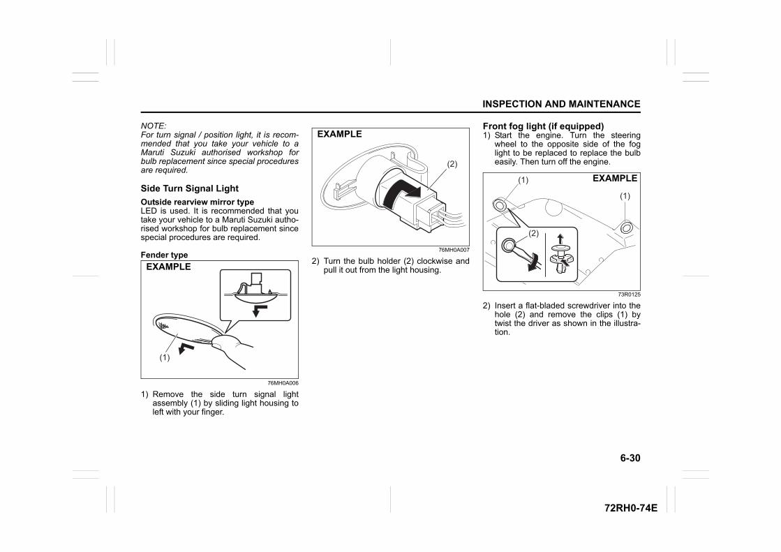
6-30
INSPECTION AND MAINTENANCE
72RH0-74E
NOTE:For turn signal / position light, it is recom-mended that you take your vehicle to aMaruti Suzuki authorised workshop forbulb replacement since special proceduresare required.
Side Turn Signal Light
Outside rearview mirror typeLED is used. It is recommended that youtake your vehicle to a Maruti Suzuki autho-rised workshop for bulb replacement sincespecial procedures are required.
Fender type
76MH0A006
1) Remove the side turn signal lightassembly (1) by sliding light housing toleft with your finger.
76MH0A007
2) Turn the bulb holder (2) clockwise andpull it out from the light housing.
Front fog light (if equipped)1) Start the engine. Turn the steering
wheel to the opposite side of the foglight to be replaced to replace the bulbeasily. Then turn off the engine.
73R0125
2) Insert a flat-bladed screwdriver into thehole (2) and remove the clips (1) bytwist the driver as shown in the illustra-tion.
(1)
EXAMPLE
(2)
EXAMPLE
(2)
(1)
(1) EXAMPLE
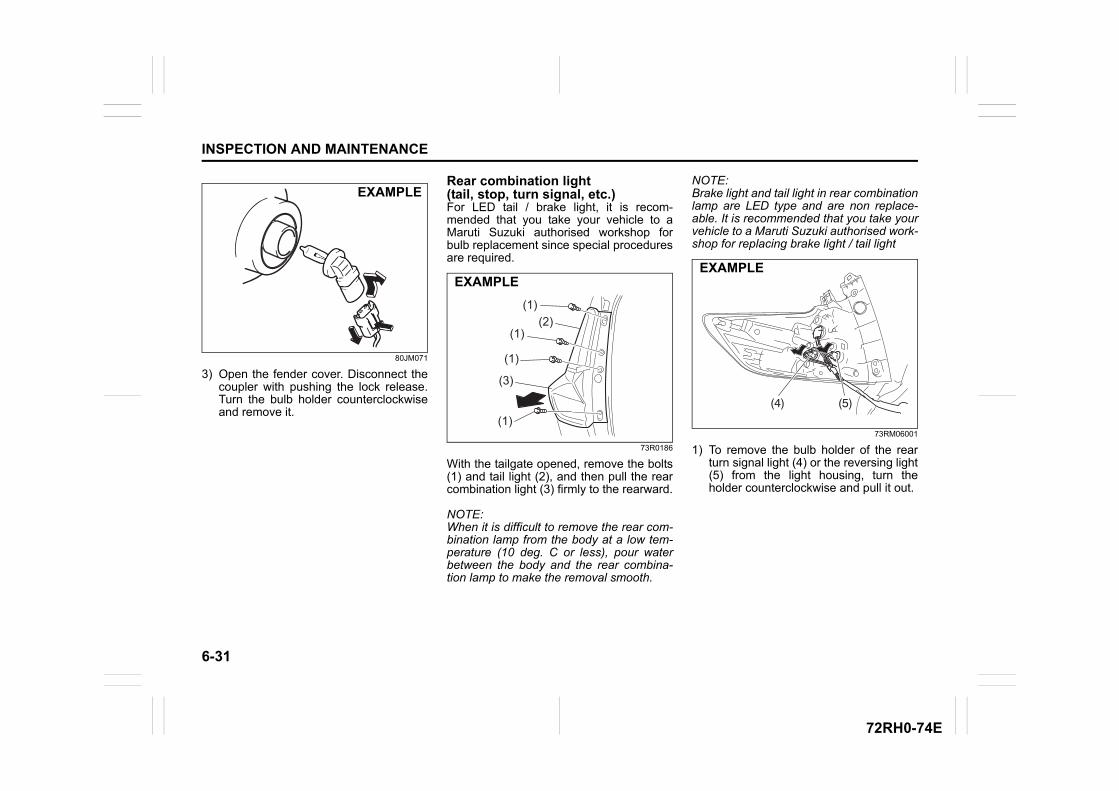
6-31
INSPECTION AND MAINTENANCE
72RH0-74E
80JM071
3) Open the fender cover. Disconnect thecoupler with pushing the lock release.Turn the bulb holder counterclockwiseand remove it.
Rear combination light (tail, stop, turn signal, etc.)For LED tail / brake light, it is recom-mended that you take your vehicle to aMaruti Suzuki authorised workshop forbulb replacement since special proceduresare required.
73R0186
With the tailgate opened, remove the bolts(1) and tail light (2), and then pull the rearcombination light (3) firmly to the rearward.
NOTE:When it is difficult to remove the rear com-bination lamp from the body at a low tem-perature (10 deg. C or less), pour waterbetween the body and the rear combina-tion lamp to make the removal smooth.
NOTE:Brake light and tail light in rear combinationlamp are LED type and are non replace-able. It is recommended that you take yourvehicle to a Maruti Suzuki authorised work-shop for replacing brake light / tail light
73RM06001
1) To remove the bulb holder of the rearturn signal light (4) or the reversing light(5) from the light housing, turn theholder counterclockwise and pull it out.
EXAMPLE
(1)
(1)
(1)
(1)(2)
(3)
EXAMPLE
(4) (5)
EXAMPLE
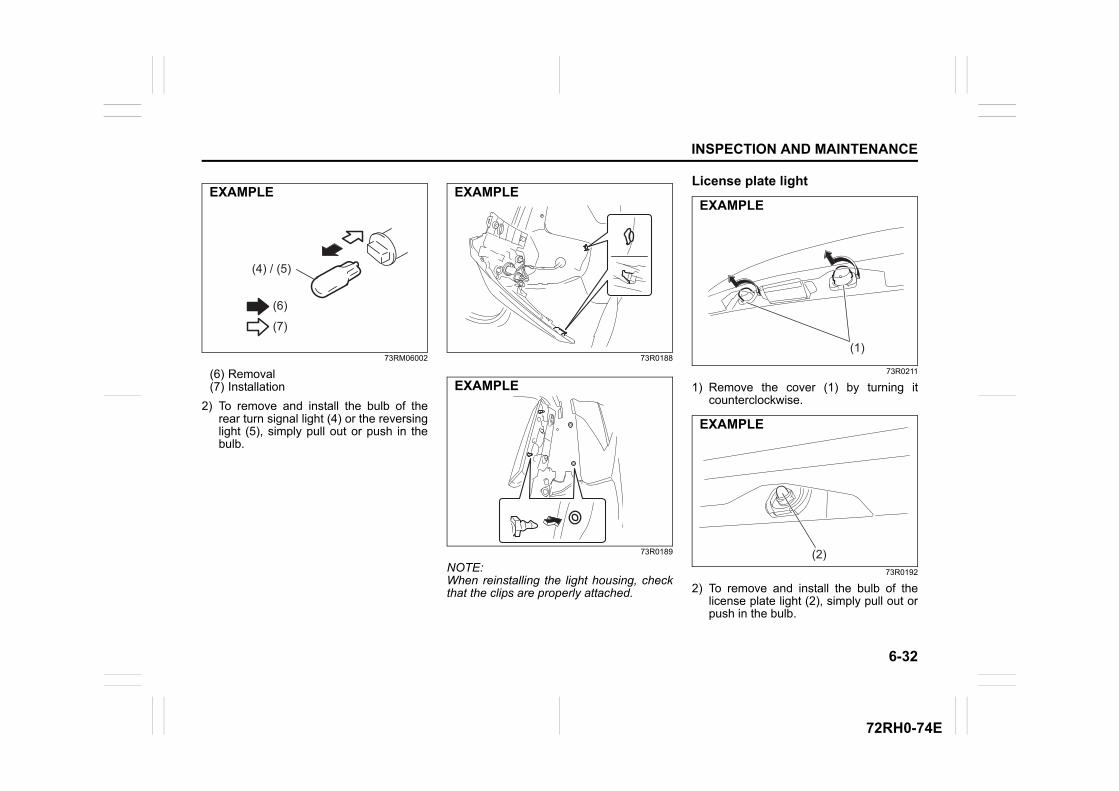
6-32
INSPECTION AND MAINTENANCE
72RH0-74E
73RM06002
(6) Removal(7) Installation
2) To remove and install the bulb of therear turn signal light (4) or the reversinglight (5), simply pull out or push in thebulb.
73R0188
73R0189
NOTE:When reinstalling the light housing, checkthat the clips are properly attached.
License plate light
73R0211
1) Remove the cover (1) by turning itcounterclockwise.
73R0192
2) To remove and install the bulb of thelicense plate light (2), simply pull out orpush in the bulb.
(4) / (5)
(6)
(7)
EXAMPLE EXAMPLE
EXAMPLE
(1)
EXAMPLE
(2)
EXAMPLE
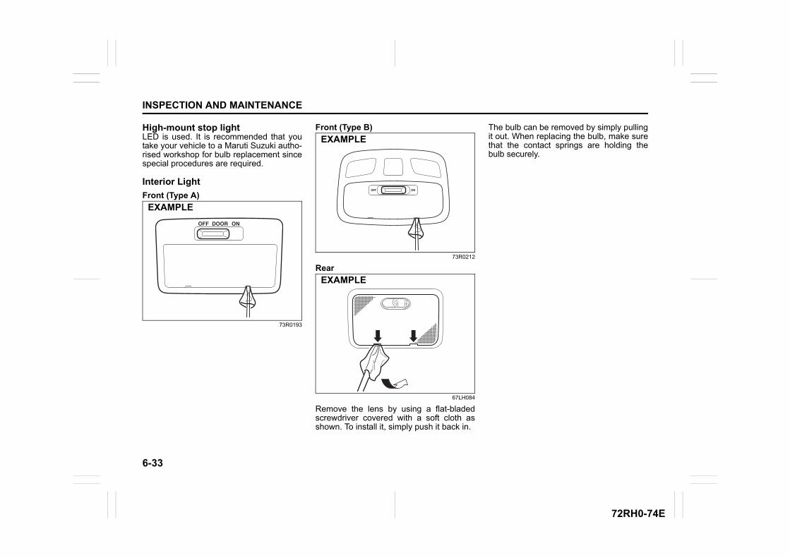
6-33
INSPECTION AND MAINTENANCE
72RH0-74E
High-mount stop lightLED is used. It is recommended that youtake your vehicle to a Maruti Suzuki autho-rised workshop for bulb replacement sincespecial procedures are required.
Interior Light
Front (Type A)
73R0193
Front (Type B)
73R0212
Rear
67LH084
Remove the lens by using a flat-bladedscrewdriver covered with a soft cloth asshown. To install it, simply push it back in.
The bulb can be removed by simply pullingit out. When replacing the bulb, make surethat the contact springs are holding thebulb securely.
EXAMPLE
EXAMPLE
EXAMPLE
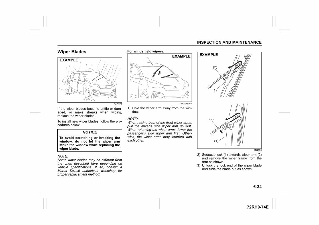
6-34
INSPECTION AND MAINTENANCE
72RH0-74E
Wiper Blades
54G129
If the wiper blades become brittle or dam-aged, or make streaks when wiping,replace the wiper blades.
To install new wiper blades, follow the pro-cedures below.
NOTE:Some wiper blades may be different fromthe ones described here depending onvehicle specifications. If so, consult aMaruti Suzuki authorised workshop forproper replacement method.
For windshield wipers:
72RM06001
1) Hold the wiper arm away from the win-dow.
NOTE:When raising both of the front wiper arms,pull the driver’s side wiper arm up first.When returning the wiper arms, lower thepassenger’s side wiper arm first. Other-wise, the wiper arms may interfere witheach other.
54G130
2) Squeeze lock (1) towards wiper arm (2)and remove the wiper frame from thearm as shown.
3) Unlock the lock end of the wiper bladeand slide the blade out as shown.
NOTICE
To avoid scratching or breaking thewindow, do not let the wiper armstrike the window while replacing thewiper blade.
EXAMPLEEXAMPLE
(2)
(2)
(1)
(1)
EXAMPLE
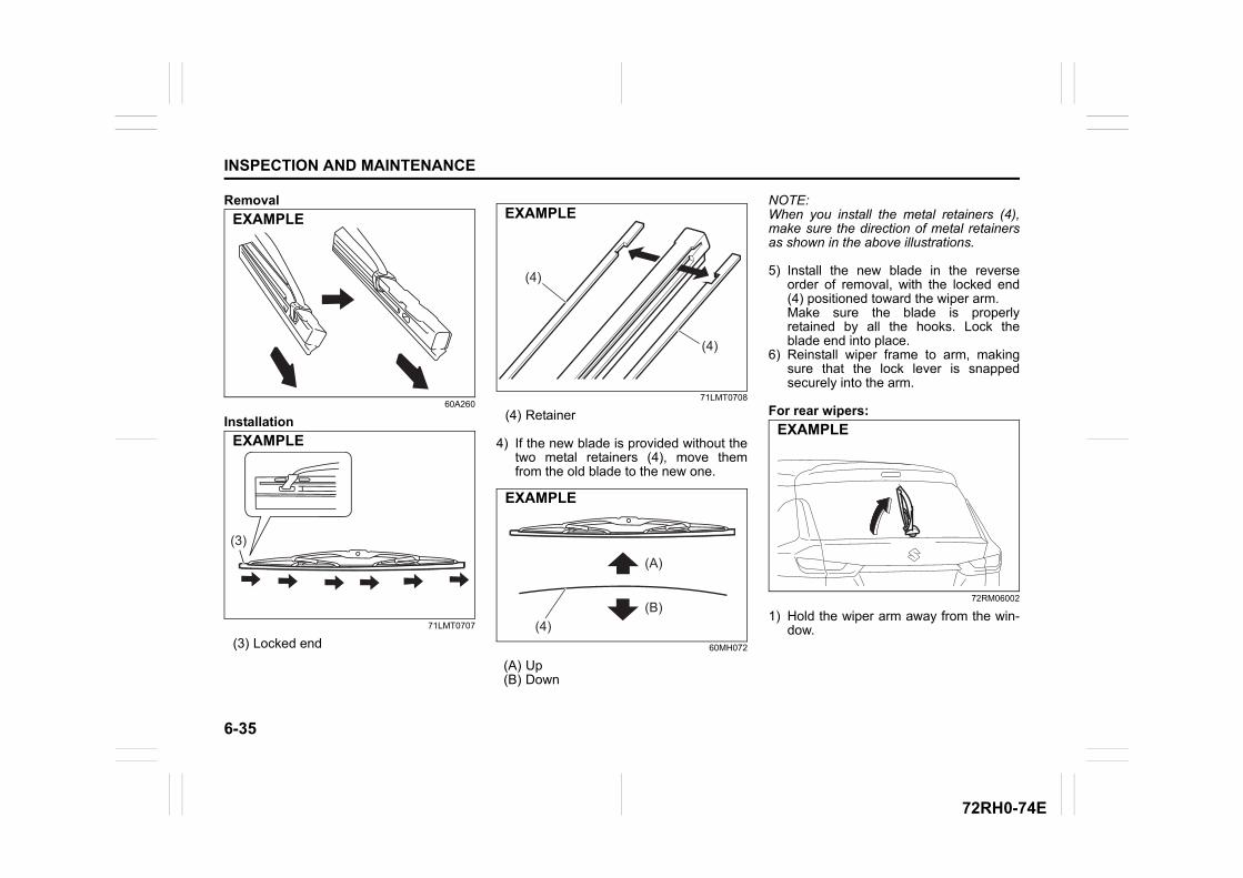
6-35
INSPECTION AND MAINTENANCE
72RH0-74E
Removal
60A260
Installation
71LMT0707
(3) Locked end
71LMT0708
(4) Retainer
4) If the new blade is provided without thetwo metal retainers (4), move themfrom the old blade to the new one.
60MH072
(A) Up(B) Down
NOTE:When you install the metal retainers (4),make sure the direction of metal retainersas shown in the above illustrations.
5) Install the new blade in the reverseorder of removal, with the locked end(4) positioned toward the wiper arm. Make sure the blade is properlyretained by all the hooks. Lock theblade end into place.
6) Reinstall wiper frame to arm, makingsure that the lock lever is snappedsecurely into the arm.
For rear wipers:
72RM06002
1) Hold the wiper arm away from the win-dow.
EXAMPLE
(3)
(3)
EXAMPLE
(4)
(4)
EXAMPLE
(4)
(A)
(B)
EXAMPLE
EXAMPLE
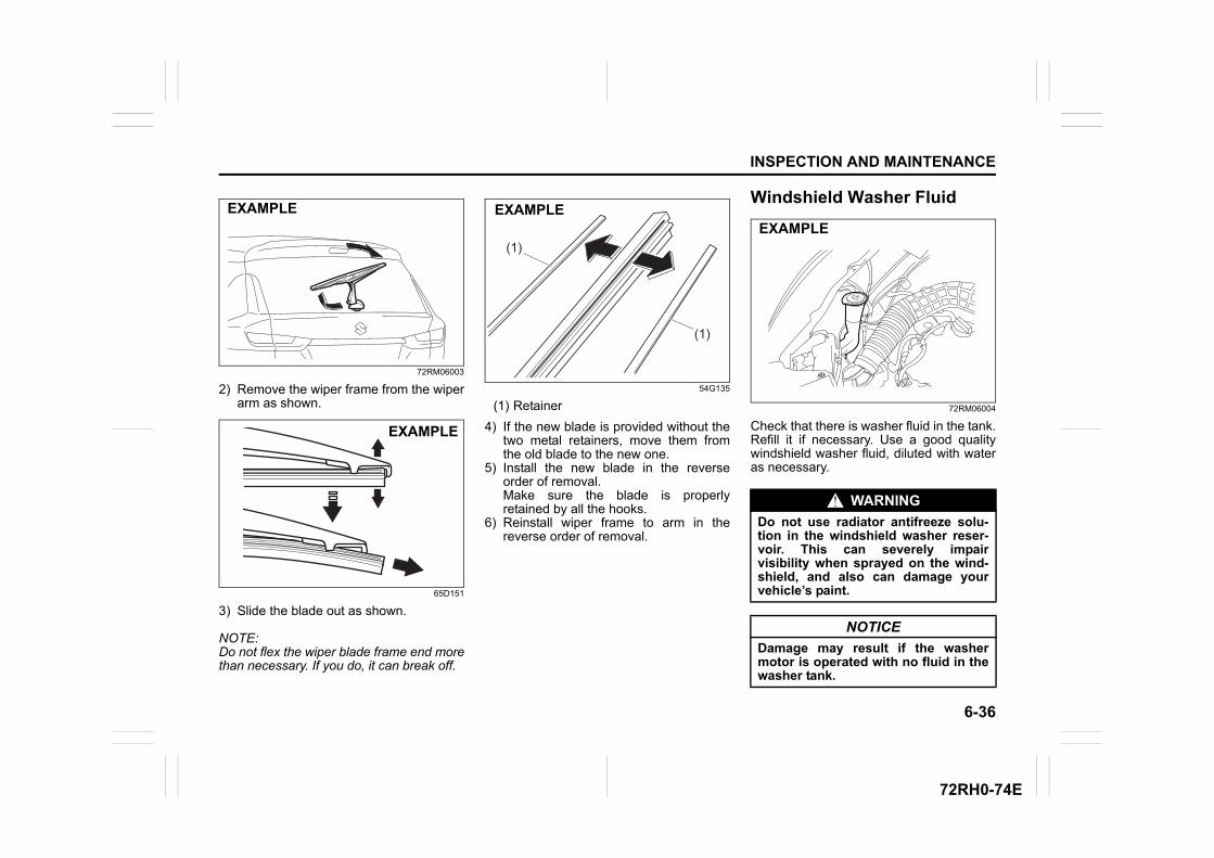
6-36
INSPECTION AND MAINTENANCE
72RH0-74E
72RM06003
2) Remove the wiper frame from the wiperarm as shown.
65D151
3) Slide the blade out as shown.
NOTE:Do not flex the wiper blade frame end morethan necessary. If you do, it can break off.
54G135
(1) Retainer
4) If the new blade is provided without thetwo metal retainers, move them fromthe old blade to the new one.
5) Install the new blade in the reverseorder of removal. Make sure the blade is properlyretained by all the hooks.
6) Reinstall wiper frame to arm in thereverse order of removal.
Windshield Washer Fluid
72RM06004
Check that there is washer fluid in the tank.Refill it if necessary. Use a good qualitywindshield washer fluid, diluted with wateras necessary.
EXAMPLE
EXAMPLE
(1)
(1)
EXAMPLE
WARNING
Do not use radiator antifreeze solu-tion in the windshield washer reser-voir. This can severely impairvisibility when sprayed on the wind-shield, and also can damage yourvehicle’s paint.
NOTICE
Damage may result if the washermotor is operated with no fluid in thewasher tank.
EXAMPLE
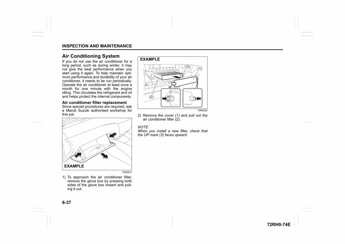
6-37
INSPECTION AND MAINTENANCE
72RH0-74E
Air Conditioning SystemIf you do not use the air conditioner for along period, such as during winter, it maynot give the best performance when youstart using it again. To help maintain opti-mum performance and durability of your airconditioner, it needs to be run periodically.Operate the air conditioner at least once amonth for one minute with the engineidling. This circulates the refrigerant and oiland helps protect the internal components.
Air conditioner filter replacementSince special procedures are required, aska Maruti Suzuki authorised workshop forthis job.
73R0201
1) To approach the air conditioner filter,remove the glove box by pressing bothsides of the glove box inward and pull-ing it out.
73R0202
2) Remove the cover (1) and pull out theair conditioner filter (2).
NOTE:When you install a new filter, check thatthe UP mark (3) faces upward.
EXAMPLE
(1)
(2)
(3)
EXAMPLE
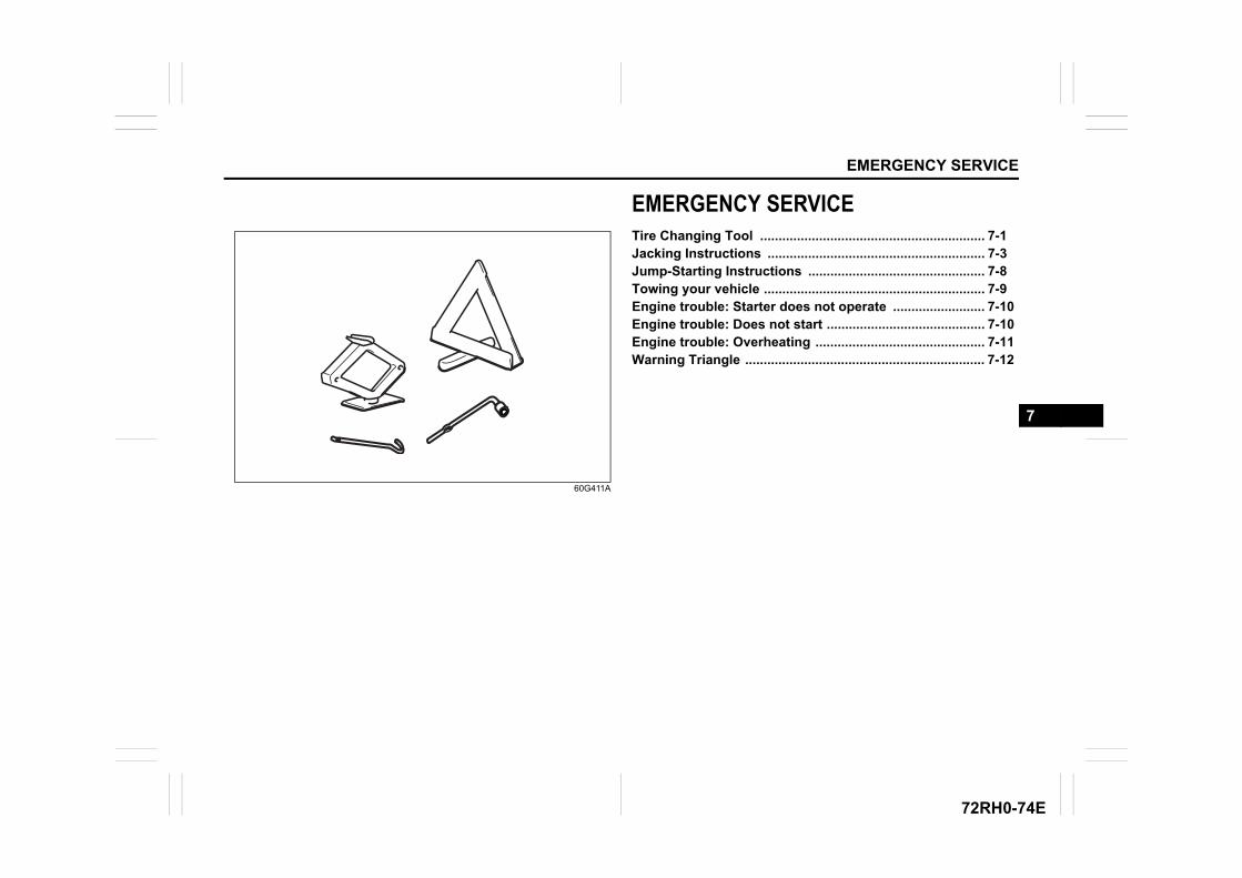
EMERGENCY SERVICE
7
72RH0-74E
60G411A
EMERGENCY SERVICETire Changing Tool ............................................................. 7-1Jacking Instructions ........................................................... 7-3Jump-Starting Instructions ................................................ 7-8Towing your vehicle ............................................................ 7-9Engine trouble: Starter does not operate ......................... 7-10Engine trouble: Does not start ........................................... 7-10Engine trouble: Overheating .............................................. 7-11Warning Triangle ................................................................. 7-12
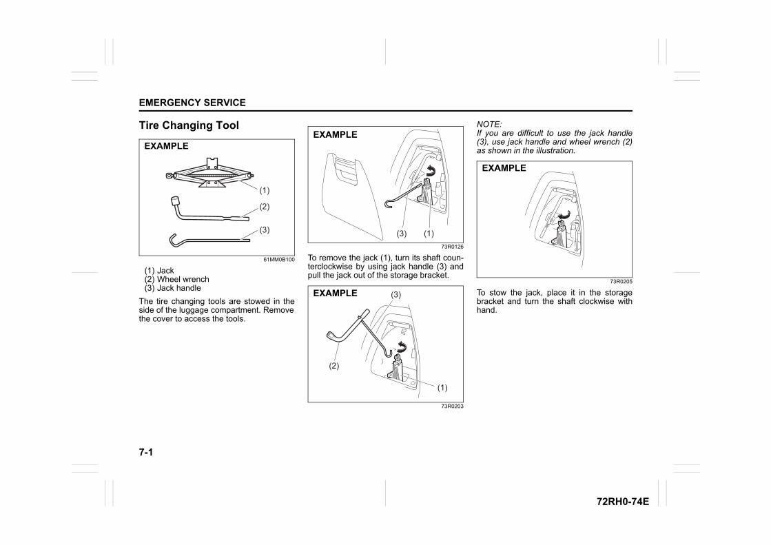
7-1
EMERGENCY SERVICE
72RH0-74E
Tire Changing Tool
61MM0B100
(1) Jack(2) Wheel wrench(3) Jack handle
The tire changing tools are stowed in theside of the luggage compartment. Removethe cover to access the tools.
73R0126
To remove the jack (1), turn its shaft coun-terclockwise by using jack handle (3) andpull the jack out of the storage bracket.
73R0203
NOTE:If you are difficult to use the jack handle(3), use jack handle and wheel wrench (2)as shown in the illustration.
73R0205
To stow the jack, place it in the storagebracket and turn the shaft clockwise withhand.
(3)
(2)
(1)
EXAMPLE
(1)(3)
EXAMPLE
(1)
(3)
(2)
EXAMPLE
EXAMPLE
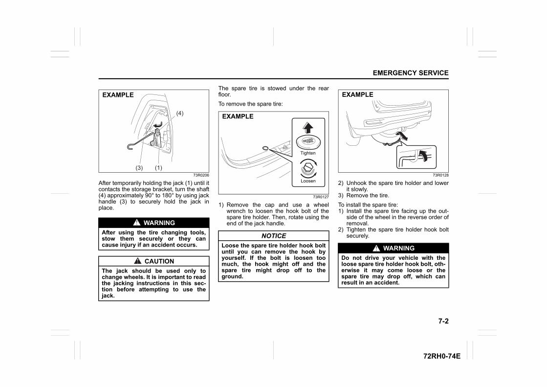
7-2
EMERGENCY SERVICE
72RH0-74E
73R0206
After temporarily holding the jack (1) until itcontacts the storage bracket, turn the shaft(4) approximately 90° to 180° by using jackhandle (3) to securely hold the jack inplace.
The spare tire is stowed under the rearfloor.
To remove the spare tire:
73R0127
1) Remove the cap and use a wheelwrench to loosen the hook bolt of thespare tire holder. Then, rotate using theend of the jack handle.
73R0128
2) Unhook the spare tire holder and lowerit slowly.
3) Remove the tire.
To install the spare tire:1) Install the spare tire facing up the out-
side of the wheel in the reverse order ofremoval.
2) Tighten the spare tire holder hook boltsecurely.
WARNING
After using the tire changing tools,stow them securely or they cancause injury if an accident occurs.
CAUTION
The jack should be used only tochange wheels. It is important to readthe jacking instructions in this sec-tion before attempting to use thejack.
(1)(3)
(4)
EXAMPLE
NOTICE
Loose the spare tire holder hook boltuntil you can remove the hook byyourself. If the bolt is loosen toomuch, the hook might off and thespare tire might drop off to theground.
Tighten
Loosen
EXAMPLE
WARNING
Do not drive your vehicle with theloose spare tire holder hook bolt, oth-erwise it may come loose or thespare tire may drop off, which canresult in an accident.
EXAMPLE
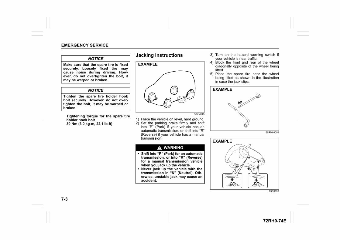
7-3
EMERGENCY SERVICE
72RH0-74E
Tightening torque for the spare tireholder hook bolt30 Nm (3.0 kg-m, 22.1 lb-ft)
Jacking Instructions
52KM119
1) Place the vehicle on level, hard ground.2) Set the parking brake firmly and shift
into “P” (Park) if your vehicle has anautomatic transmission, or shift into “R”(Reverse) if your vehicle has a manualtransmission.
3) Turn on the hazard warning switch ifyour vehicle is near traffic.
4) Block the front and rear of the wheeldiagonally opposite of the wheel beinglifted.
5) Place the spare tire near the wheelbeing lifted as shown in the illustrationin case the jack slips.
66RM08006
73R0190
NOTICE
Make sure that the spare tire is fixedsecurely. Loosely fixed tire maycause noise during driving. How-ever, do not overtighten the bolt, itmay be warped or broken.
NOTICE
Tighten the spare tire holder hookbolt securely. However, do not over-tighten the bolt, it may be warped orbroken.
WARNING
• Shift into “P” (Park) for an automatictransmission, or into “R” (Reverse)for a manual transmission vehiclewhen you jack up the vehicle.
• Never jack up the vehicle with thetransmission in “N” (Neutral). Oth-erwise, unstable jack may cause anaccident.
EXAMPLE
EXAMPLE
EXAMPLE
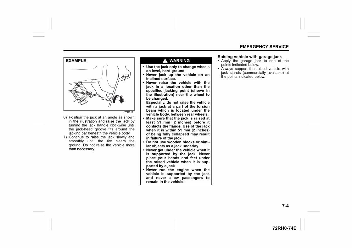
7-4
EMERGENCY SERVICE
72RH0-74E
73R0191
6) Position the jack at an angle as shownin the illustration and raise the jack byturning the jack handle clockwise untilthe jack-head groove fits around thejacking bar beneath the vehicle body.
7) Continue to raise the jack slowly andsmoothly until the tire clears theground. Do not raise the vehicle morethan necessary.
Raising vehicle with garage jack• Apply the garage jack to one of the
points indicated below.• Always support the raised vehicle with
jack stands (commercially available) atthe points indicated below.
EXAMPLE WARNING
• Use the jack only to change wheelson level, hard ground.
• Never jack up the vehicle on aninclined surface.
• Never raise the vehicle with thejack in a location other than thespecified jacking point (shown inthe illustration) near the wheel tobe changed.Especially, do not raise the vehiclewith a jack at a part of the torsionbeam which is located under thevehicle body, between rear wheels.
• Make sure that the jack is raised atleast 51 mm (2 inches) before itcontacts the flange. Use of the jackwhen it is within 51 mm (2 inches)of being fully collapsed may resultin failure of the jack.
• Do not use wooden blocks or simi-lar objects as a jack underlay
• Never get under the vehicle when itis supported by the jack. Neverplace your hands and feet underthe raised vehicle when it is sup-ported by a jack
• Never run the engine when thevehicle is supported by the jackand never allow passengers toremain in the vehicle.
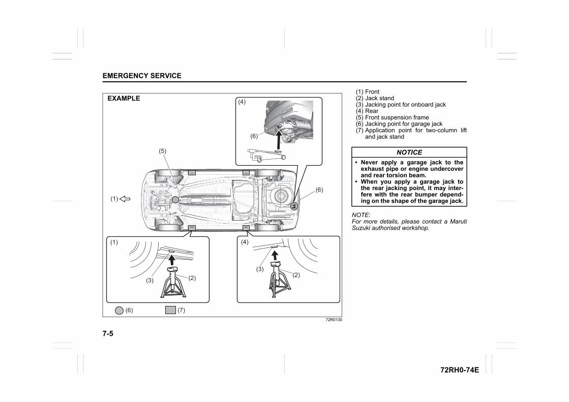
7-5
EMERGENCY SERVICE
72RH0-74E
72R0130
(1)
(1)
(2) (2)(3)
(4)
(5)
(6) (7)
(6)
(4)
(3)
(6)
EXAMPLE(1) Front(2) Jack stand(3) Jacking point for onboard jack(4) Rear(5) Front suspension frame(6) Jacking point for garage jack(7) Application point for two-column lift
and jack stand
NOTE:For more details, please contact a MarutiSuzuki authorised workshop.
NOTICE
• Never apply a garage jack to theexhaust pipe or engine undercoverand rear torsion beam.
• When you apply a garage jack tothe rear jacking point, it may inter-fere with the rear bumper depend-ing on the shape of the garage jack.
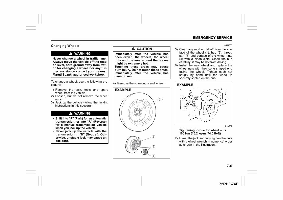
7-6
EMERGENCY SERVICE
72RH0-74E
Changing Wheels
To change a wheel, use the following pro-cedure:
1) Remove the jack, tools and sparewheel from the vehicle.
2) Loosen, but do not remove the wheelnuts.
3) Jack up the vehicle (follow the jackinginstructions in this section).
4) Remove the wheel nuts and wheel.
65J4033
5) Clean any mud or dirt off from the sur-face of the wheel (1), hub (2), threadpart (3) and surface of the wheel nuts(4) with a clean cloth. Clean the hubcarefully; it may be hot from driving.
6) Install the new wheel and replace thewheel nuts with their cone shaped endfacing the wheel. Tighten each nutsnugly by hand until the wheel issecurely seated on the hub.
81A057
Tightening torque for wheel nuts100 Nm (10.2 kg-m, 74.0 lb-ft)
7) Lower the jack and fully tighten the nutswith a wheel wrench in numerical orderas shown in the illustration.
WARNING
Never change a wheel in traffic lane.Always move the vehicle off the roadon level, hard ground away from traf-fic for changing a wheel. For any fur-ther assistance contact your nearestMaruti Suzuki authorised workshop.
WARNING
• Shift into “P” (Park) for an automatictransmission, or into “R” (Reverse)for a manual transmission vehiclewhen you jack up the vehicle.
• Never jack up the vehicle with thetransmission in “N” (Neutral). Oth-erwise, unstable jack may cause anaccident.
CAUTION
Immediately after the vehicle hasbeen driven, the wheels, the wheelnuts and the area around the brakesmight be extremely hot. Touching these areas may causeburn injury. Do not touch these areas,immediately after the vehicle hasbeen driven.
(1)
(2)
(3)
(4)
EXAMPLE
EXAMPLE
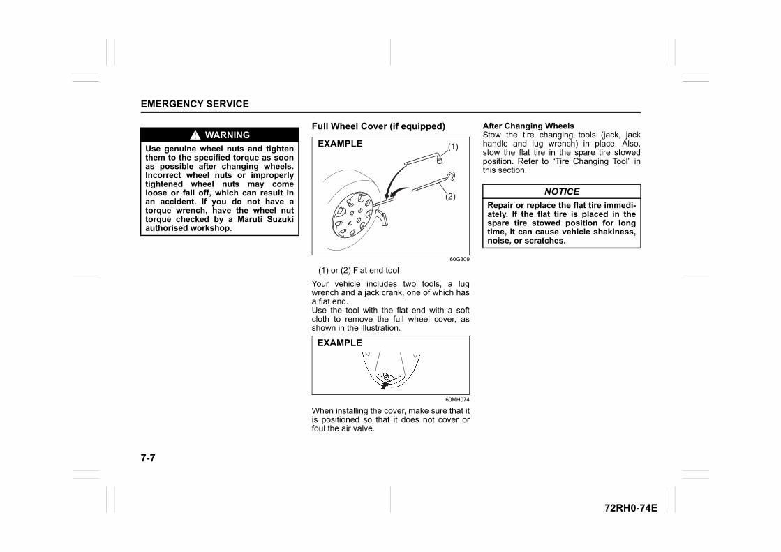
7-7
EMERGENCY SERVICE
72RH0-74E
Full Wheel Cover (if equipped)
60G309
(1) or (2) Flat end tool
Your vehicle includes two tools, a lugwrench and a jack crank, one of which hasa flat end.Use the tool with the flat end with a softcloth to remove the full wheel cover, asshown in the illustration.
60MH074
When installing the cover, make sure that itis positioned so that it does not cover orfoul the air valve.
After Changing WheelsStow the tire changing tools (jack, jackhandle and lug wrench) in place. Also,stow the flat tire in the spare tire stowedposition. Refer to “Tire Changing Tool” inthis section.
WARNING
Use genuine wheel nuts and tightenthem to the specified torque as soonas possible after changing wheels.Incorrect wheel nuts or improperlytightened wheel nuts may comeloose or fall off, which can result inan accident. If you do not have atorque wrench, have the wheel nuttorque checked by a Maruti Suzukiauthorised workshop.
(1)
(2)
EXAMPLE
EXAMPLE
NOTICE
Repair or replace the flat tire immedi-ately. If the flat tire is placed in thespare tire stowed position for longtime, it can cause vehicle shakiness,noise, or scratches.
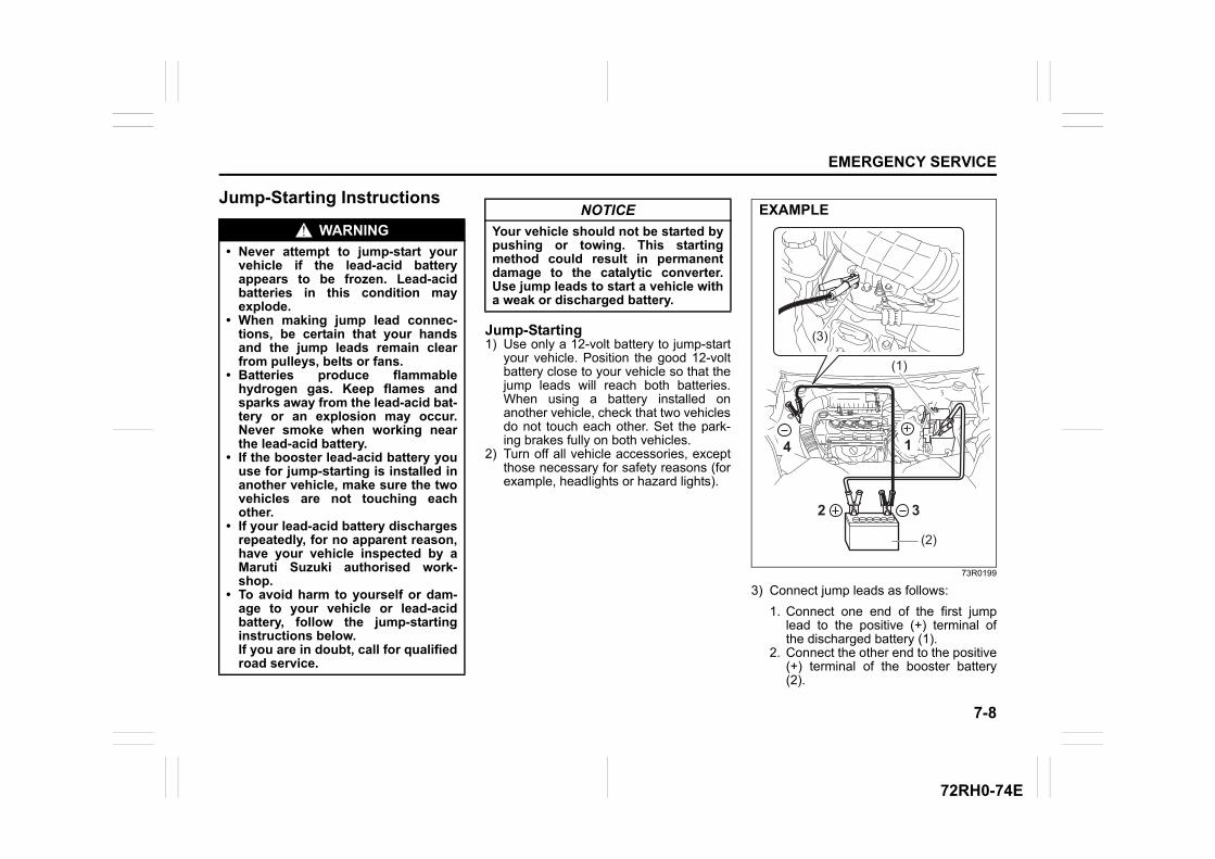
7-8
EMERGENCY SERVICE
72RH0-74E
Jump-Starting Instructions
Jump-Starting1) Use only a 12-volt battery to jump-start
your vehicle. Position the good 12-voltbattery close to your vehicle so that thejump leads will reach both batteries.When using a battery installed onanother vehicle, check that two vehiclesdo not touch each other. Set the park-ing brakes fully on both vehicles.
2) Turn off all vehicle accessories, exceptthose necessary for safety reasons (forexample, headlights or hazard lights).
73R0199
3) Connect jump leads as follows:
1. Connect one end of the first jumplead to the positive (+) terminal ofthe discharged battery (1).
2. Connect the other end to the positive(+) terminal of the booster battery(2).
WARNING
• Never attempt to jump-start yourvehicle if the lead-acid batteryappears to be frozen. Lead-acidbatteries in this condition mayexplode.
• When making jump lead connec-tions, be certain that your handsand the jump leads remain clearfrom pulleys, belts or fans.
• Batteries produce flammablehydrogen gas. Keep flames andsparks away from the lead-acid bat-tery or an explosion may occur.Never smoke when working nearthe lead-acid battery.
• If the booster lead-acid battery youuse for jump-starting is installed inanother vehicle, make sure the twovehicles are not touching eachother.
• If your lead-acid battery dischargesrepeatedly, for no apparent reason,have your vehicle inspected by aMaruti Suzuki authorised work-shop.
• To avoid harm to yourself or dam-age to your vehicle or lead-acidbattery, follow the jump-startinginstructions below. If you are in doubt, call for qualifiedroad service.
NOTICE
Your vehicle should not be started bypushing or towing. This startingmethod could result in permanentdamage to the catalytic converter.Use jump leads to start a vehicle witha weak or discharged battery.
(3)
(1)
32
4 1
(2)
EXAMPLE
7-9
EMERGENCY SERVICE
72RH0-74E
3. Connect one end of the second jumplead to the negative (–) terminal ofthe booster battery (2).
4. Make the final connection to anunpainted, heavy metal part(i.e.engine mount bolt (3)) of theengine of the vehicle with the dis-charged battery (1).
4) If the booster battery you are using isfitted to another vehicle, start theengine of the vehicle with the boosterbattery. Run the engine at moderatespeed.
5) Start the engine of the vehicle with thedischarged lead-acid battery.
6) Remove the jump leads in the exactreverse order in which you connectedthem.
Towing your vehicleIf you need to have your vehicle towed,contact a professional service, MarutiSuzuki authorised workshop can provideyou with detailed towing instructions.
2-Wheel Drive (2WD) Automatic TransmissionAutomatic transmission vehicles may betowed using either of the following meth-ods.
1) From the front, with the front wheelslifted and the rear wheels on theground. Before towing, make sure thatthe parking brake is released.
2) From the rear, with the rear wheelslifted and a dolly under the front wheels.
2-Wheel Drive (2WD) Manual Trans-missionManual transmission vehicles may betowed using either of the following meth-ods.
1) From the front, with the front wheelslifted and the rear wheels on theground. Before towing, make sure thatthe parking brake is released.
2) From the rear, with the rear wheelslifted and the front wheels on theground, provided the steering anddrivetrain are in operational condition.Before towing, make sure that trans-mission is in neutral, the steering wheelis unlocked (vehicle without keylesspush start system - the ignition keyshould be in “ACC” position) (vehiclewith keyless push start system - theignition mode is “ACC”), and the steer-ing wheel is secured with a clampingdevice designed for towing service.
WARNING
Never connect the jump lead directlyto the negative (–) terminal of the dis-charged lead-acid battery, or anexplosion may occur.
CAUTION
Connect the jump lead to the enginemount bolt securely. If the jump leaddisconnects from the engine mountbolt because of vibration at the startof the engine, the jump lead could becaught in the drive belts.
NOTICE
Observe the following instructionswhen towing your vehicle.• To help avoid damage to your vehi-
cle during towing, proper equip-ment and towing procedures mustbe used.
• Using the frame hook, tow yourvehicle on paved roads for shortdistances at low speed.
NOTICE
Towing your vehicle with the frontwheels on the ground can result indamage to the automatic transmis-sion.
7-10
EMERGENCY SERVICE
72RH0-74E
Engine trouble: Starter does not operate1) Try turning the ignition switch to
“START” position or try pressing theengine switch to change the ignitionmode to “START” with the headlightsturned on to determine the lead-acidbattery condition. If the headlights goexcessively dim or go off, it usuallymeans that either the lead-acid batteryis discharged or the lead-acid batteryterminal contact is poor. Recharge thelead-acid battery or correct lead-acidbattery terminal contact as necessary.
2) If the headlights remain bright, checkthe fuses. If the reason for failure of thestarter is not obvious, there may be amajor electrical problem. Have the vehi-cle inspected by a Maruti Suzuki autho-rised workshop.
Engine trouble: Does not startMake sure that your vehicle has enoughfuel and lead-acid battery.If the engine does not start under very coldcondition, press the accelerator pedal allthe way to the floor and hold it while crank-ing the engine.Refer to “Starting engine (vehicle withoutkeyless push start system) (if equipped)”or “Starting engine (vehicle with keylesspush start system) (if equipped)” in operat-ing your vehicle section.If the engine still does not start have yourvehicle inspected at a Maruti Suzuki autho-rised workshop.• Do not operate the starter motor for
more than 12 seconds.
(Vehicle with Keyless Push Start Sys-tem)NOTE:If the engine refuses to start, the startermotor automatically stops after a certainperiod of time. After the starter motor hasautomatically stopped or if there is any-thing abnormal in the engine starting sys-tem, the starter motor runs only while theengine switch is held pressed.
NOTICE
The steering column is not strongenough to withstand shocks trans-mitted from the front wheels duringtowing. Always unlock the steeringwheel before towing.
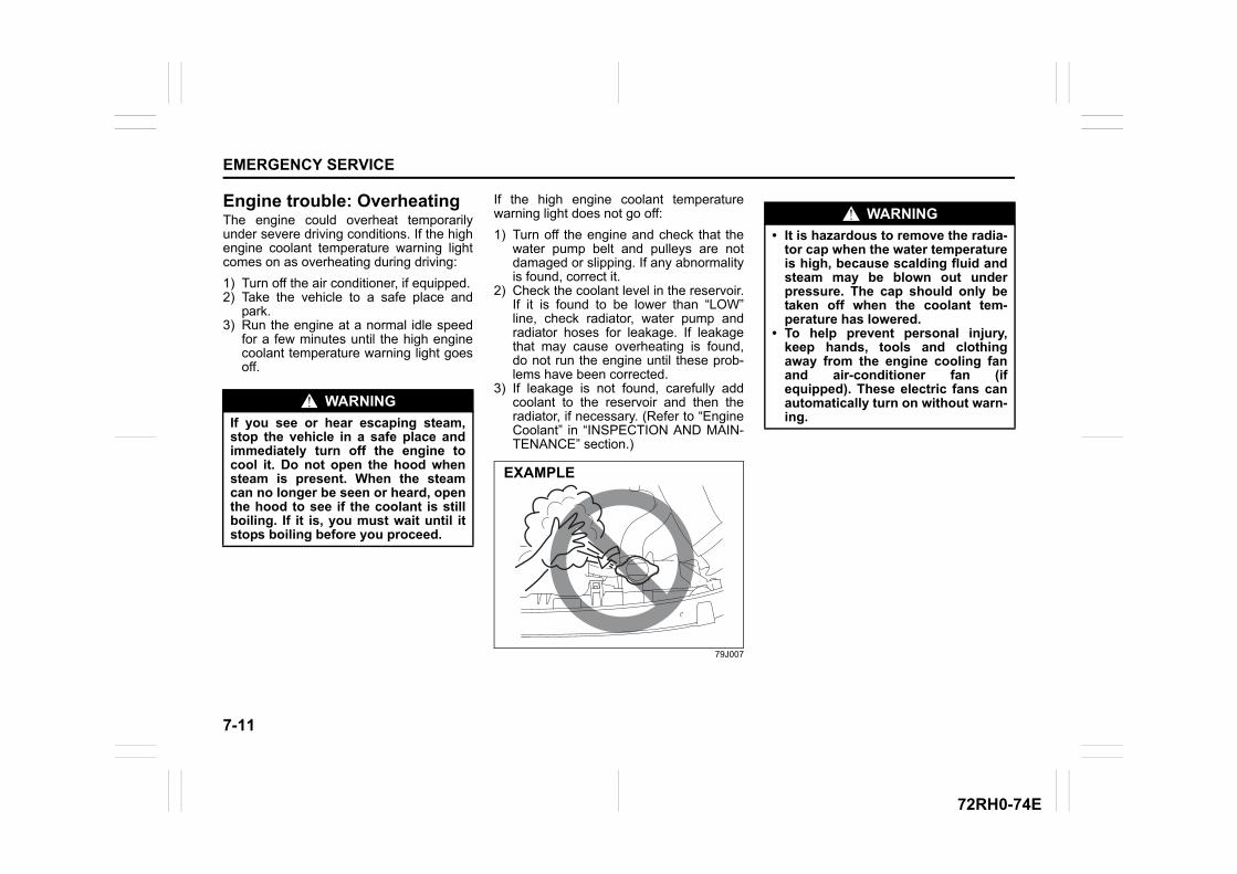
7-11
EMERGENCY SERVICE
72RH0-74E
Engine trouble: OverheatingThe engine could overheat temporarilyunder severe driving conditions. If the highengine coolant temperature warning lightcomes on as overheating during driving:
1) Turn off the air conditioner, if equipped.2) Take the vehicle to a safe place and
park.3) Run the engine at a normal idle speed
for a few minutes until the high enginecoolant temperature warning light goesoff.
If the high engine coolant temperaturewarning light does not go off:
1) Turn off the engine and check that thewater pump belt and pulleys are notdamaged or slipping. If any abnormalityis found, correct it.
2) Check the coolant level in the reservoir.If it is found to be lower than “LOW”line, check radiator, water pump andradiator hoses for leakage. If leakagethat may cause overheating is found,do not run the engine until these prob-lems have been corrected.
3) If leakage is not found, carefully addcoolant to the reservoir and then theradiator, if necessary. (Refer to “EngineCoolant” in “INSPECTION AND MAIN-TENANCE” section.)
79J007
WARNING
If you see or hear escaping steam,stop the vehicle in a safe place andimmediately turn off the engine tocool it. Do not open the hood whensteam is present. When the steamcan no longer be seen or heard, openthe hood to see if the coolant is stillboiling. If it is, you must wait until itstops boiling before you proceed.
EXAMPLE
WARNING
• It is hazardous to remove the radia-tor cap when the water temperatureis high, because scalding fluid andsteam may be blown out underpressure. The cap should only betaken off when the coolant tem-perature has lowered.
• To help prevent personal injury,keep hands, tools and clothingaway from the engine cooling fanand air-conditioner fan (ifequipped). These electric fans canautomatically turn on without warn-ing.
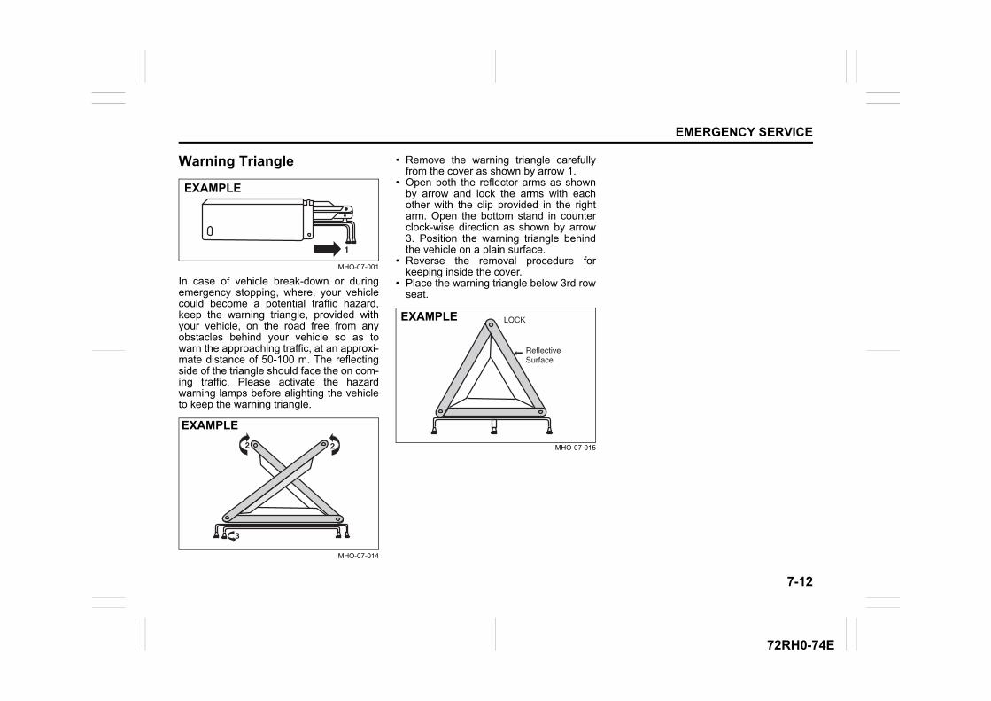
7-12
EMERGENCY SERVICE
72RH0-74E
Warning Triangle
MHO-07-001
In case of vehicle break-down or duringemergency stopping, where, your vehiclecould become a potential traffic hazard,keep the warning triangle, provided withyour vehicle, on the road free from anyobstacles behind your vehicle so as towarn the approaching traffic, at an approxi-mate distance of 50-100 m. The reflectingside of the triangle should face the on com-ing traffic. Please activate the hazardwarning lamps before alighting the vehicleto keep the warning triangle.
MHO-07-014
• Remove the warning triangle carefullyfrom the cover as shown by arrow 1.
• Open both the reflector arms as shownby arrow and lock the arms with eachother with the clip provided in the rightarm. Open the bottom stand in counterclock-wise direction as shown by arrow3. Position the warning triangle behindthe vehicle on a plain surface.
• Reverse the removal procedure forkeeping inside the cover.
• Place the warning triangle below 3rd rowseat.
MHO-07-015
EXAMPLE
EXAMPLE
EXAMPLE

72RH0-74E
APPEARANCE CARE
8
72RH0-74E
72RM08000
APPEARANCE CARECorrosion Prevention ......................................................... 8-1Vehicle Cleaning ................................................................. 8-2
8-1
APPEARANCE CARE
72RH0-74E
Corrosion PreventionIt is important to take good care of yourvehicle to protect it from corrosion. Listedbelow are instructions for how to maintainyour vehicle to prevent corrosion. Pleaseread and follow these instructions carefully.
Important Information about Corro-sion
Common causes of corrosion1) Accumulation of road salt, dirt, mois-
ture, or chemicals in hard-to-reachareas of the vehicle underbody orframe.
2) Chipping, scratches and any damage totreated or painted metal surfacesresulting from minor accidents or abra-sion by stones and gravel.
3) Any or all of the below mentionedpoints:
– continuous exposure to sunlight.– hard water & Sea water coming in
contact with vehicle.– foot rubbing (skirting).
Environmental conditions which accel-erate corrosion1) Road salt, dust control chemicals, sea
breeze or industrial pollution will allaccelerate the corrosion of metal.
2) High humidity will increase the rate ofcorrosion particularly when the tem-perature range is just above the freez-ing point.
3) Moisture in certain areas of a vehiclefor an extended period of time may pro-
mote corrosion even though other bodysections may be completely dry.
4) High temperatures will cause an accel-erated rate of corrosion to parts of thevehicle which are not well-ventilated topermit quick drying.
This information illustrates the necessity ofkeeping your vehicle (particularly theunderbody) as clean and dry as possible. Itis equally important to repair any damageto the paint or protective coatings as soonas possible.
How to Help Prevent Corrosion
Wash your vehicle frequentlyThe best way to preserve the finish on yourvehicle and to help avoid corrosion is tokeep it clean with frequent washing.Wash your vehicle at least once during thewinter and once immediately after the win-ter. Keep your vehicle, particularly theunderside, as clean and dry as possible.If you frequently drive on salted roads,your vehicle should be washed at leastonce a month during the winter. If you livenear the ocean, your vehicle should bewashed at least once a month throughoutthe year.
For washing instructions, refer to “VehicleCleaning” section.
Remove foreign material depositsForeign material such as salts, chemicals,road oil or tar, tree sap, bird droppings andindustrial fall-out may damage the finish of
your vehicle if it is left on painted surfaces.Remove these types of deposits as quicklyas possible. If these deposits are difficult towash off, an additional cleaner may berequired. Be sure that any cleaner you useis not harmful to painted surfaces and isspecifically intended for your purposes.Follow the manufacturer’s directions whenusing these special cleaners.
Repair finish damageCarefully examine your vehicle for damageto the painted surfaces. Should you findany chips or scratches in the paint, touchthem up immediately to prevent corrosionfrom starting. If the chips or scratches havegone through to the bare metal, have aqualified body shop make the repair.
Keep passenger and luggage compart-ments cleanMoisture, dirt or mud can accumulateunder the floor mats and may cause corro-sion. Occasionally, check under thesemats to ensure that this area is clean anddry. More frequent checks are necessary ifthe vehicle is used for off-road driving or inwet weather.Certain cargos such as chemicals, fertiliz-ers, cleaners, salts, etc. are extremely cor-rosive by nature. These products shouldbe transported in sealed containers. If theyare spilled or leaked, clean and dry thearea immediately.
8-2
APPEARANCE CARE
72RH0-74E
Park your vehicle in a dry, well-venti-lated areaPark your vehicle to save it from continu-ous exposure to direct sunlight. Do not park your vehicle in a damp, poorlyventilated area. If you often wash yourvehicle in the garage and place it there inwet condition, your garage may be damp.The high humidity in the garage maycause or accelerate corrosion. A wet vehi-cle may corrode even in a heated garage ifthe ventilation is poor.
Vehicle Cleaning
76G044S
Cleaning Interior
Leather upholsteryRemove loose dirt with a vacuum cleaner.Using a mild soap or saddle soap solution,wipe dirt off with a clean damp soft cloth.To remove soap, wipe the areas again witha soft cloth dampened with water. Wipe theareas dry with a soft dry cloth. Repeat thisuntil the dirt or stain is removed, or use acommercial leather cleaner for tougher dirtor stains. If you use a leather cleaner,carefully follow the manufacturer’s instruc-tions and precautions. Do not use solventtype cleaners or abrasive cleaners.
NOTE:• In order to keep leather upholstery look-
ing good, it should be cleaned at leasttwice a year.
• If leather upholstery becomes wet,immediately wipe it dry with tissue paperor a soft cloth. Water may cause leatherto harden and shrink if it is not wiped off.
• When parking on sunny days, select ashady place or use a sunshade. Ifleather upholstery is exposed to directsunlight for a long time, it may discolorand shrink.
• As is common with natural materials,leather is inherently irregular in grain andcowhide has spots in its natural state.These do not affect the performance ofthe leather in any way.
WARNING
Do not apply additional undercoatingor rust preventive coating on oraround exhaust system componentssuch as the catalytic converter,exhaust pipes, etc. A fire could bestarted if the undercoating substancebecomes overheated.
WARNING
When cleaning the interior or exteriorof the vehicle, do not use flammablesolvents such as lacquer thinners,petrol and benzene. Also, do not usecleaning materials such as bleachesand strong household detergents.The materials could cause personalinjury or damage to the vehicle.
EXAMPLE
8-3
APPEARANCE CARE
72RH0-74E
Vinyl upholsteryPrepare a solution of soap or mild deter-gent mixed with warm water. Apply thesolution to the vinyl with a sponge or softcloth and let it soak for a few minutes toloosen dirt.Rub the surface with a clean, damp clothto remove dirt and the soap solution. Ifsome dirt still remains on the surface,repeat this procedure.
Fabric upholstery (Except front passen-ger seat)Remove loose dirt with a vacuum cleaner.Using a mild soap solution, rub stainedareas with a clean damp cloth. To removesoap, rub the areas again with a clothdampened with water. Repeat this until thestain is removed, or use a commercial fab-ric cleaner for tougher stains. If you use afabric cleaner, carefully follow the manu-facturer’s instructions and precautions.
Fabric upholstery (For front passengerseat)Do not use liquid for cleaning as it maypenetrate the fabric and damage the seatsensor.
Seat beltsClean seat belts with a mild soap andwater. Do not use bleach or dye on thebelts. They may weaken the fabric in thebelts.
Vinyl floor matsOrdinary dirt can be removed from vinylwith water or mild soap. Use a brush tohelp loosen dirt. After the dirt is loosened,rinse the mat thoroughly with water anddry it in the shade.
CarpetsRemove dirt and soil as much as possiblewith a vacuum cleaner. Using a mild soapsolution, rub stained areas with a cleandamp cloth. To remove soap, rub the areasagain with a cloth dampened with water.Repeat this until the stain is removed, oruse a commercial carpet cleaner fortougher stains. If you use a carpet cleaner,carefully follow the manufacturer’s instruc-tions and precautions.
Instrument panel and consoleRemove loose dirt with a vacuum cleaner.Gently wipe dirt off with a tightly squeezeddamp clean cloth. Repeat this until the dirtis removed.
CAUTION
• Do not spill liquid or semi-solid onthe front passenger's seat. If youspill it on the front passenger'sseat, immediately wipe it dry with asoft cloth. Contact of liquid withsensor may impact the function ofseat belt reminder sensor.
• Do not place any sharp or heavyobject on passenger seat whichcan penetrate through seat uphol-stery and can cause damage tosensor.
NOTICE
Do not use chemical products thatcontain silicon to wipe electricalcomponents such as the air condi-tioning system, audio, navigationsystem, or other switches. These willcause damage to the components.
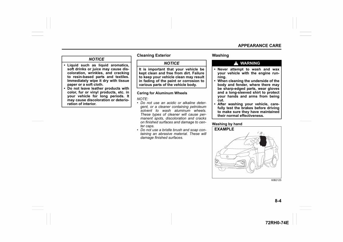
8-4
APPEARANCE CARE
72RH0-74E
Cleaning Exterior
Caring for Aluminum Wheels
NOTE:• Do not use an acidic or alkaline deter-
gent, or a cleaner containing petroleumsolvent to wash aluminum wheels.These types of cleaner will cause per-manent spots, discoloration and crackson finished surfaces and damage to cen-ter caps.
• Do not use a bristle brush and soap con-taining an abrasive material. These willdamage finished surfaces.
Washing
Washing by hand
60B212S
NOTICE
• Liquid such as liquid aromatics,soft drinks or juice may cause dis-coloration, wrinkles, and crackingto resin-based parts and textiles.Immediately wipe it dry with tissuepaper or a soft cloth.
• Do not leave leather products withcolor, fur or vinyl products, etc. inyour vehicle for long periods. Itmay cause discoloration or deterio-ration of interior.
NOTICE
It is important that your vehicle bekept clean and free from dirt. Failureto keep your vehicle clean may resultin fading of the paint or corrosion tovarious parts of the vehicle body.
WARNING
• Never attempt to wash and waxyour vehicle with the engine run-ning.
• When cleaning the underside of thebody and fender, where there maybe sharp-edged parts, wear glovesand a long-sleeved shirt to protectyour hands and arms from beingcut.
• After washing your vehicle, care-fully test the brakes before drivingto make sure they have maintainedtheir normal effectiveness.
EXAMPLE
8-5
APPEARANCE CARE
72RH0-74E
When washing the vehicle, park it in theplace where direct sunlight does not fall onit as much as possible and follow theinstructions below:1) Flush the underside of body and wheel
housings with pressurized water toremove mud and debris. Use plenty ofwater.
2) Rinse the body to loosen the dirt.Remove dirt and mud from the bodyexterior with running water. You mayuse a soft sponge or brush. Do not usehard materials which can scratch thepaint or plastic. Remember that theheadlight covers or lenses are made ofplastic in many cases.
3) Wash the entire exterior with a milddetergent or car wash soap using asponge or soft cloth. The sponge orcloth should be frequently soaked in thesoap solution.
4) Once the dirt has been completelyremoved, rinse off the detergent withrunning water.
5) Wipe off the vehicle body with a wetchamois or cloth and allow it to dry inthe shade.
6) Check carefully for damage to paintedsurfaces. If there is any damage, touchup the damage following the procedurebelow:1. Clean all damaged spots and allow
them to dry.2. Stir the paint and touch up the dam-
aged spots lightly using a smallbrush.
3. Allow the paint to dry completely.
Washing by an automatic car wash
Washing by a high-pressure cleanerNOTICE
When washing the vehicle:• Avoid directing steam or hot water
of more than 80°C (176°F) on plas-tic parts.
• To avoid damaging engine compo-nents, do not use pressurizedwater in the engine compartment.
NOTICE
To avoid damage to the paint or plas-tic surface, do not wipe the dirt offwithout ample water. Follow theabove procedure.
NOTICE
When using a commercial car washproduct, observe the cautions speci-fied by the manufacturer. Never usestrong household detergents orsoaps.
NOTICE
If you use an automatic car wash,make sure that your vehicle’s bodyparts, such as spoilers, cannot bedamaged. If you are in doubt, consultthe car wash operator for advice.
NOTICE
If you use a high-pressure cleaner,keep away the nozzle from your vehi-cle sufficiently.• Bringing the nozzle to your vehicle
too close or pointing the nozzle tothe opening of front grill or bumperetc. can cause damage and mal-function of the vehicle body andparts.
• Pointing the nozzle to the weather-strip of door glasses and doors canallow water to enter the cabin.
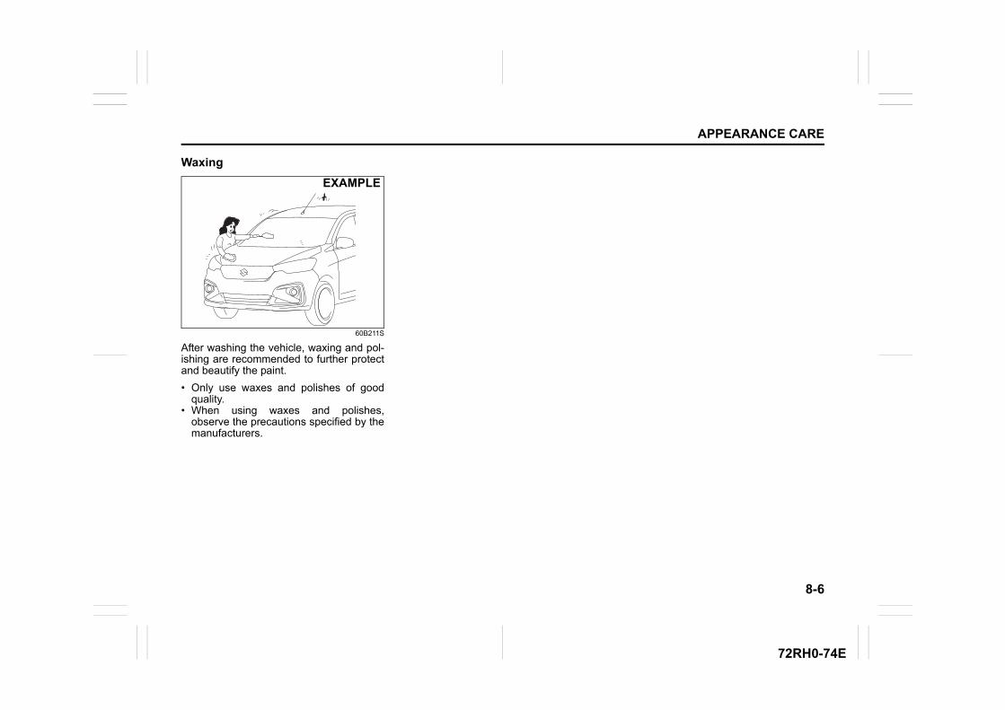
8-6
APPEARANCE CARE
72RH0-74E
Waxing
60B211S
After washing the vehicle, waxing and pol-ishing are recommended to further protectand beautify the paint.
• Only use waxes and polishes of goodquality.
• When using waxes and polishes,observe the precautions specified by themanufacturers.
EXAMPLE
8-7
APPEARANCE CARE
72RH0-74E
SPECIFICATIONS
9
72RH0-74E
81MM01001
SPECIFICATIONSVehicle Identification .......................................................... 9-1FASTag (if equipped) ........................................................... 9-1High Security Registration Plate (HSRP) .......................... 9-2Fuel ....................................................................................... 9-3SPECIFICATIONS ................................................................ 9-5
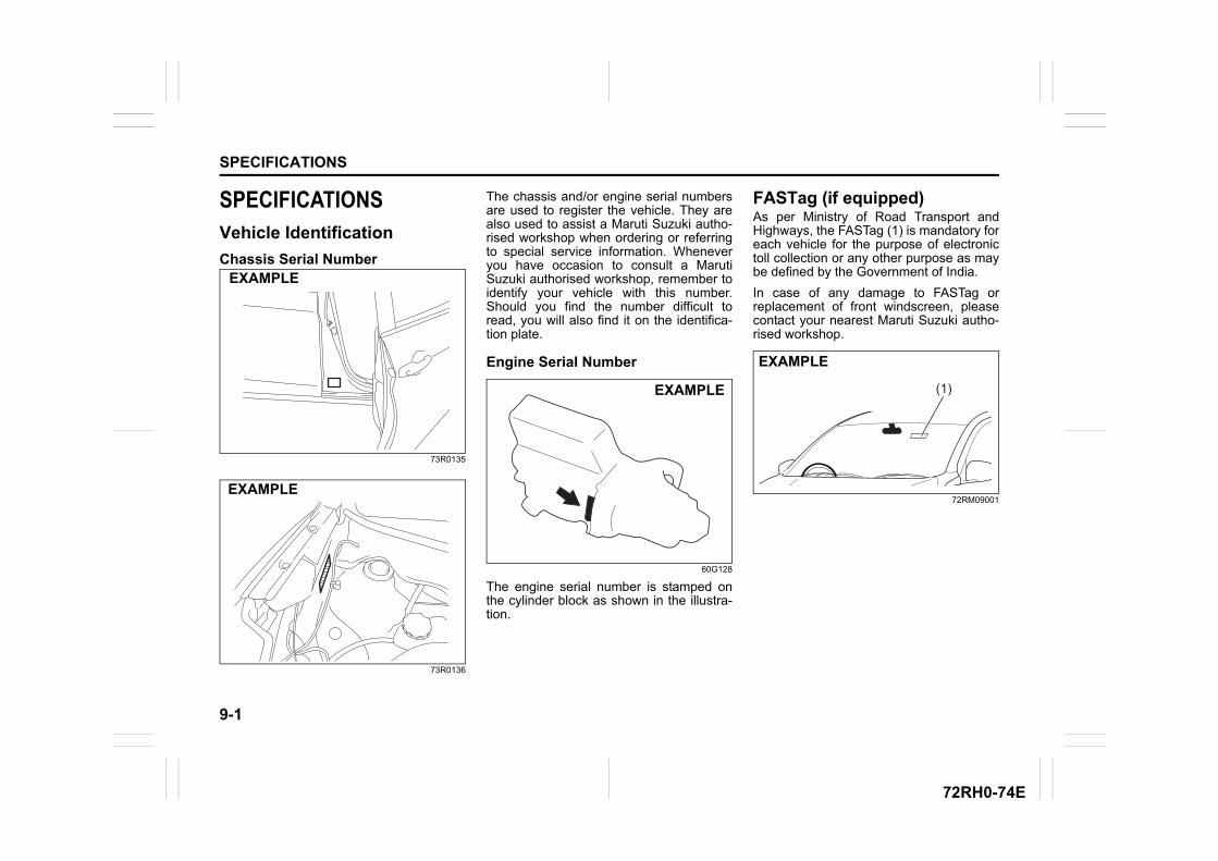
9-1
SPECIFICATIONS
72RH0-74E
SPECIFICATIONSVehicle Identification
Chassis Serial Number
73R0135
73R0136
The chassis and/or engine serial numbersare used to register the vehicle. They arealso used to assist a Maruti Suzuki autho-rised workshop when ordering or referringto special service information. Wheneveryou have occasion to consult a MarutiSuzuki authorised workshop, remember toidentify your vehicle with this number.Should you find the number difficult toread, you will also find it on the identifica-tion plate.
Engine Serial Number
60G128
The engine serial number is stamped onthe cylinder block as shown in the illustra-tion.
FASTag (if equipped)As per Ministry of Road Transport andHighways, the FASTag (1) is mandatory foreach vehicle for the purpose of electronictoll collection or any other purpose as maybe defined by the Government of India.
In case of any damage to FASTag orreplacement of front windscreen, pleasecontact your nearest Maruti Suzuki autho-rised workshop.
72RM09001
EXAMPLE
EXAMPLE
EXAMPLE
EXAMPLE
(1)
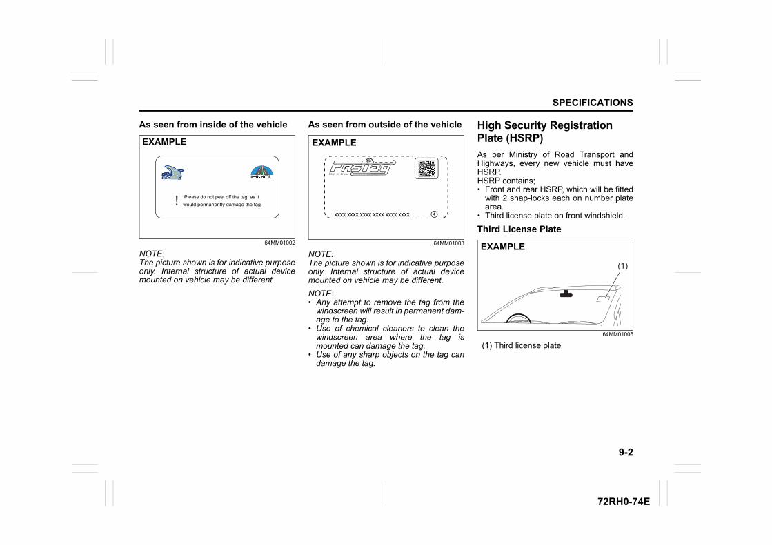
9-2
SPECIFICATIONS
72RH0-74E
As seen from inside of the vehicle
64MM01002
NOTE:The picture shown is for indicative purposeonly. Internal structure of actual devicemounted on vehicle may be different.
As seen from outside of the vehicle
64MM01003
NOTE:The picture shown is for indicative purposeonly. Internal structure of actual devicemounted on vehicle may be different.
NOTE:• Any attempt to remove the tag from the
windscreen will result in permanent dam-age to the tag.
• Use of chemical cleaners to clean thewindscreen area where the tag ismounted can damage the tag.
• Use of any sharp objects on the tag candamage the tag.
High Security Registration Plate (HSRP)
As per Ministry of Road Transport andHighways, every new vehicle must haveHSRP.HSRP contains;• Front and rear HSRP, which will be fitted
with 2 snap-locks each on number platearea.
• Third license plate on front windshield.
Third License Plate
64MM01005
(1) Third license plate
EXAMPLE
Please do not peel off the tag, as itwould permanently damage the tag!
EXAMPLE
4xxxx xxxx xxxx xxxx xxxx xxxx
Easy to Cruise
(1)
EXAMPLE
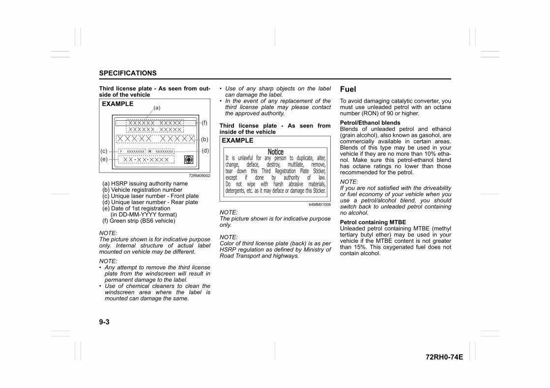
9-3
SPECIFICATIONS
72RH0-74E
Third license plate - As seen from out-side of the vehicle
72RM09002
(a) HSRP issuing authority name (b) Vehicle registration number (c) Unique laser number - Front plate (d) Unique laser number - Rear plate (e) Date of 1st registration (in DD-MM-YYYY format) (f) Green strip (BS6 vehicle)
NOTE:The picture shown is for indicative purposeonly. Internal structure of actual labelmounted on vehicle may be different.
NOTE:• Any attempt to remove the third license
plate from the windscreen will result inpermanent damage to the label.
• Use of chemical cleaners to clean thewindscreen area where the label ismounted can damage the same.
• Use of any sharp objects on the labelcan damage the label.
• In the event of any replacement of thethird license plate may please contactthe approved authority.
Third license plate - As seen frominside of the vehicle
64MM01009
NOTE:The picture shown is for indicative purposeonly.
NOTE:Color of third license plate (back) is as perHSRP regulation as defined by Ministry ofRoad Transport and highways.
Fuel
To avoid damaging catalytic converter, youmust use unleaded petrol with an octanenumber (RON) of 90 or higher.
Petrol/Ethanol blendsBlends of unleaded petrol and ethanol(grain alcohol), also known as gasohol, arecommercially available in certain areas.Blends of this type may be used in yourvehicle if they are no more than 10% etha-nol. Make sure this petrol-ethanol blendhas octane ratings no lower than thoserecommended for the petrol.
NOTE:If you are not satisfied with the driveabilityor fuel economy of your vehicle when youuse a petrol/alcohol blend, you shouldswitch back to unleaded petrol containingno alcohol.
Petrol containing MTBEUnleaded petrol containing MTBE (methyltertiary butyl ether) may be used in yourvehicle if the MTBE content is not greaterthan 15%. This oxygenated fuel does notcontain alcohol.
RXXXXXXXXF R XXXXXXXX::
(a)
(b)
(c) (d)
(f)
(e) - -
EXAMPLE
It is unlawful for any person to duplicate, alter,change, deface, destroy, multilate, remove, tear down this Third Registration Plate Sticker, except if done by authority of law.Do not wipe with harsh abrasive materials,detergents, etc. as it may deface or damage this Sticker.
NoticeNoticeEXAMPLE
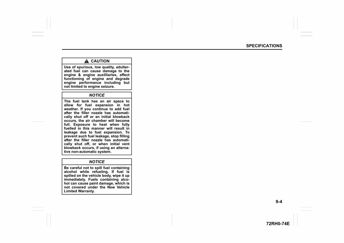
9-4
SPECIFICATIONS
72RH0-74E
CAUTION
Use of spurious, low quality, adulter-ated fuel can cause damage to theengine & engine auxilliaries, affectfunctioning of engine and degradeengine performance including butnot limited to engine seizure.
NOTICE
The fuel tank has an air space toallow for fuel expansion in hotweather. If you continue to add fuelafter the filler nozzle has automati-cally shut off or an initial blowbackoccurs, the air chamber will becomefull. Exposure to heat when fullyfuelled in this manner will result inleakage due to fuel expansion. Toprevent such fuel leakage, stop fillingafter the filler nozzle has automati-cally shut off, or when initial ventblowback occurs, if using an alterna-tive non-automatic system.
NOTICE
Be careful not to spill fuel containingalcohol while refueling. If fuel isspilled on the vehicle body, wipe it upimmediately. Fuels containing alco-hol can cause paint damage, which isnot covered under the New VehicleLimited Warranty.
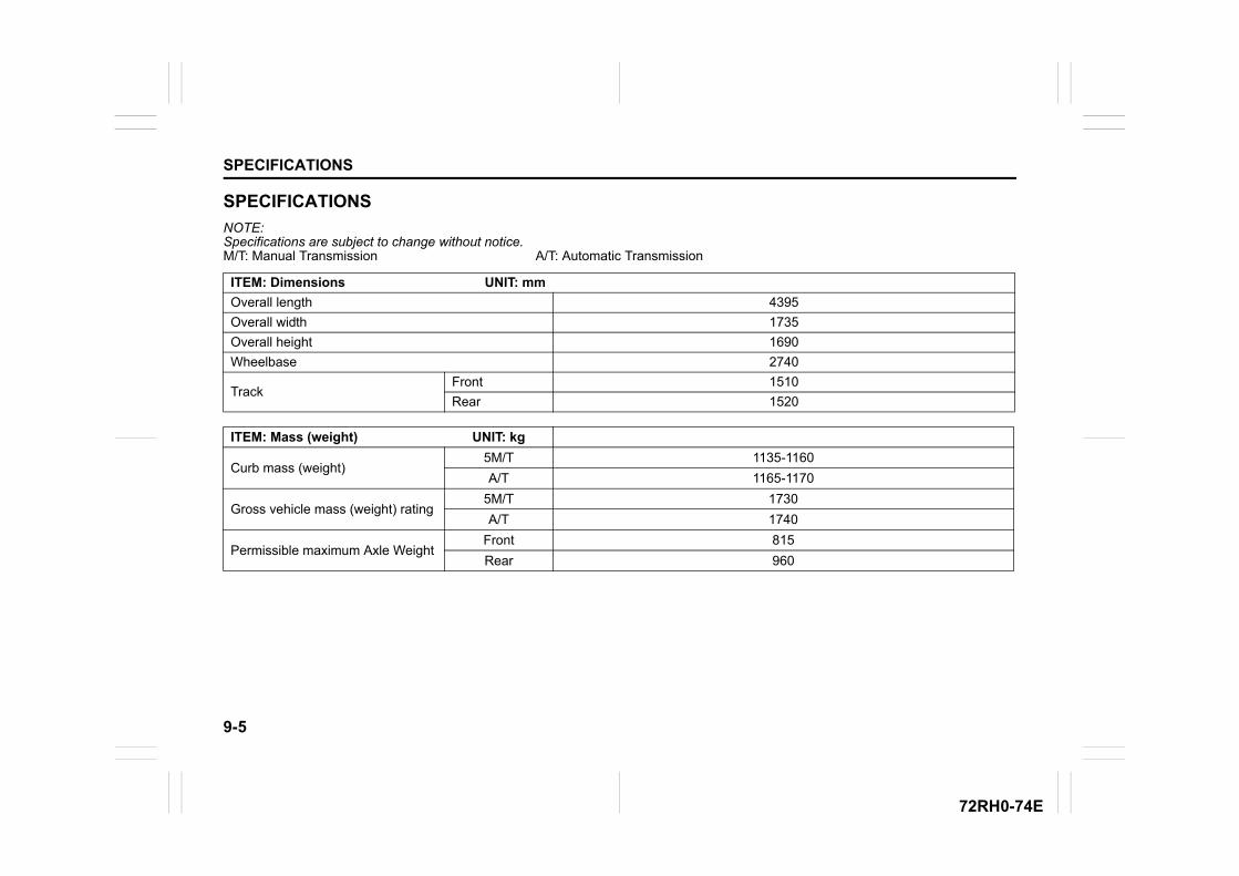
9-5
SPECIFICATIONS
72RH0-74E
SPECIFICATIONS
NOTE:Specifications are subject to change without notice.M/T: Manual Transmission A/T: Automatic Transmission
ITEM: Dimensions UNIT: mm
Overall length 4395
Overall width 1735
Overall height 1690
Wheelbase 2740
TrackFront 1510
Rear 1520
ITEM: Mass (weight) UNIT: kg
Curb mass (weight)5M/T 1135-1160
A/T 1165-1170
Gross vehicle mass (weight) rating5M/T 1730
A/T 1740
Permissible maximum Axle WeightFront 815
Rear 960
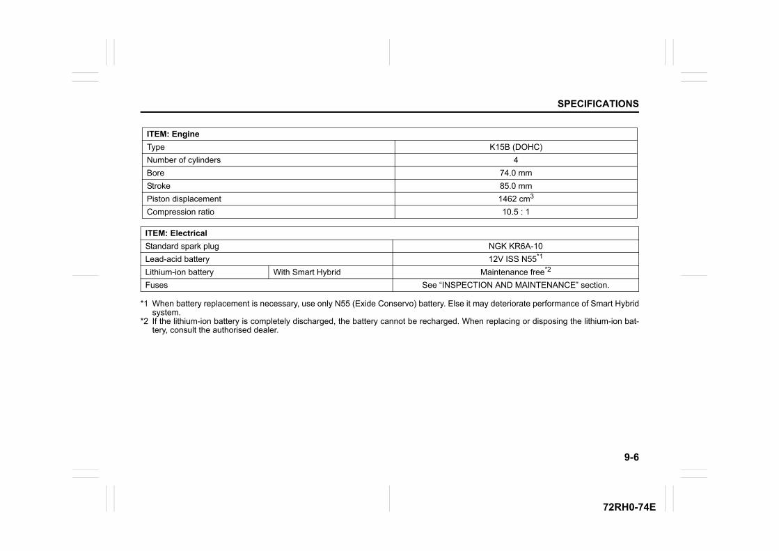
9-6
SPECIFICATIONS
72RH0-74E
*1 When battery replacement is necessary, use only N55 (Exide Conservo) battery. Else it may deteriorate performance of Smart Hybridsystem.
*2 If the lithium-ion battery is completely discharged, the battery cannot be recharged. When replacing or disposing the lithium-ion bat-tery, consult the authorised dealer.
ITEM: Engine
Type K15B (DOHC)
Number of cylinders 4
Bore 74.0 mm
Stroke 85.0 mm
Piston displacement 1462 cm3
Compression ratio 10.5 : 1
ITEM: Electrical
Standard spark plug NGK KR6A-10
Lead-acid battery 12V ISS N55*1
Lithium-ion battery With Smart Hybrid Maintenance free*2
Fuses See “INSPECTION AND MAINTENANCE” section.
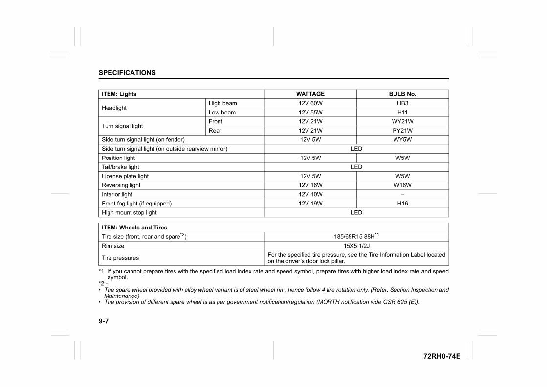
9-7
SPECIFICATIONS
72RH0-74E
*1 If you cannot prepare tires with the specified load index rate and speed symbol, prepare tires with higher load index rate and speedsymbol.
*2 -• The spare wheel provided with alloy wheel variant is of steel wheel rim, hence follow 4 tire rotation only. (Refer: Section Inspection and
Maintenance)• The provision of different spare wheel is as per government notification/regulation (MORTH notification vide GSR 625 (E)).
ITEM: Lights WATTAGE BULB No.
HeadlightHigh beam 12V 60W HB3
Low beam 12V 55W H11
Turn signal lightFront 12V 21W WY21W
Rear 12V 21W PY21W
Side turn signal light (on fender) 12V 5W WY5W
Side turn signal light (on outside rearview mirror) LED
Position light 12V 5W W5W
Tail/brake light LED
License plate light 12V 5W W5W
Reversing light 12V 16W W16W
Interior light 12V 10W –
Front fog light (if equipped) 12V 19W H16
High mount stop light LED
ITEM: Wheels and Tires
Tire size (front, rear and spare*2) 185/65R15 88H*1
Rim size 15X5 1/2J
Tire pressures For the specified tire pressure, see the Tire Information Label locatedon the driver’s door lock pillar.
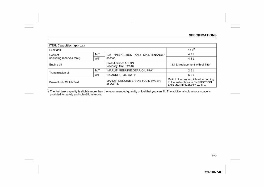
9-8
SPECIFICATIONS
72RH0-74E
# The fuel tank capacity is slightly more than the recommended quantity of fuel that you can fill. The additional voluminous space is provided for safety and scientific reasons.
ITEM: Capacities (approx.)
Fuel tank 45 L#
Coolant (including reservoir tank)
M/T See “INSPECTION AND MAINTENANCE”section.
4.7 L
A/T 4.6 L
Engine oil Classification: API SNViscosity: SAE 0W-16 3.1 L (replacement with oil filter)
Transmission oilM/T “MARUTI GENUINE GEAR OIL 75W” 2.6 L
A/T “SUZUKI AT OIL AW-1” 5.0 L
Brake fluid / Clutch fluid MARUTI GENUINE BRAKE FLUID (MGBF) or DOT 3.
Refill to the proper oil level according to the instructions in “INSPECTION AND MAINTENANCE” section.

72RH0-74E
Related Documents