Controlled versions of Department of Forensic Biology Manuals only exist electronically on the Forensic Biology network. All printed versions are non-controlled copies. FORENSIC BIOLOGY PROTOCOLS FOR FORENSIC STR ANALYSIS Approving Authority: Eugene Y. Lien, Technical Leader – Nuclear DNA Operations Working version as of 08/14/2015 Highlighted sections indicate a new revision to that procedure Table of Contents General Guidelines for DNA Casework.................................................................6 Laboratory organization .............................................................................................................. 6 Work Place Preparation .............................................................................................................. 6 Microcentrifuge tube and pipette handling ................................................................................. 6 Sample handling.......................................................................................................................... 7 Body fluid identification ............................................................................................................. 8 DNA Extraction Guidelines ........................................................................................................ 9 Extraction Negative Flow Charts .......................................................................................... 11 Controls for PCR analysis......................................................................................................... 17 Concordant analyses and “duplicate rule” ................................................................................ 17 Exogenous DNA Policy ............................................................................................................ 20 DNA storage ............................................................................................................................. 22 DNA Extraction ......................................................................................................24 Chelex Extraction from Blood and Buccal Swabs .................................................................... 24 Chelex Extraction from Soft Tissue (e.g. Fetus Samples) ........................................................ 26 Chelex DNA Extraction from Epithelial Cells ......................................................................... 27 Non-differential Chelex DNA Extraction from Semen Stains or Swabs.................................. 29 Differential Chelex DNA Extraction from Semen Stains or Swabs ......................................... 30 DNA Extraction from Hair ....................................................................................................... 34 Archived Document Control Coordinator 12/24/2015

Welcome message from author
This document is posted to help you gain knowledge. Please leave a comment to let me know what you think about it! Share it to your friends and learn new things together.
Transcript

Controlled versions of Department of Forensic Biology Manuals only exist electronically on the Forensic Biology network. All printed versions are non-controlled copies.
FORENSIC BIOLOGY PROTOCOLS FOR FORENSIC STR ANALYSIS
Approving Authority: Eugene Y. Lien, Technical Leader – Nuclear DNA Operations
Working version as of 08/14/2015
Highlighted sections indicate a new revision to that procedure
Table of Contents General Guidelines for DNA Casework ................................................................. 6
Laboratory organization .............................................................................................................. 6
Work Place Preparation .............................................................................................................. 6
Microcentrifuge tube and pipette handling ................................................................................. 6
Sample handling.......................................................................................................................... 7
Body fluid identification ............................................................................................................. 8
DNA Extraction Guidelines ........................................................................................................ 9
Extraction Negative Flow Charts .......................................................................................... 11
Controls for PCR analysis ......................................................................................................... 17
Concordant analyses and “duplicate rule” ................................................................................ 17
Exogenous DNA Policy ............................................................................................................ 20
DNA storage ............................................................................................................................. 22
DNA Extraction ......................................................................................................24
Chelex Extraction from Blood and Buccal Swabs .................................................................... 24
Chelex Extraction from Soft Tissue (e.g. Fetus Samples) ........................................................ 26
Chelex DNA Extraction from Epithelial Cells ......................................................................... 27
Non-differential Chelex DNA Extraction from Semen Stains or Swabs .................................. 29
Differential Chelex DNA Extraction from Semen Stains or Swabs ......................................... 30
DNA Extraction from Hair ....................................................................................................... 34
Archive
d
Docum
ent C
ontro
l Coo
rdina
tor 12
/24/20
15

Controlled versions of Department of Forensic Biology Manuals only exist electronically on the Forensic Biology network. All printed versions are non-controlled copies.
Organic Extraction .................................................................................................................... 35
High Yield DNA Extraction ..................................................................................................... 48
Extraction of Exogenous DNA from Nails ............................................................................... 53
MagAttract DNA Extraction from Bloodstains and Exemplars ............................................... 58
A. Setting up M48 Test Batch and Saving Sample Name List ....................................... 58
B. Sample Preparation and Incubation ............................................................................ 58
C. BioRobot M48 Software and Platform Set-Up........................................................... 59
D. Importing Sample Names ........................................................................................... 63
E. Verifying Robot Set-Up and Starting the Purification ............................................... 63
F. Saving Extraction Report Page ................................................................................... 64
G. Post-Extraction Clean Up and UV Sterilization ......................................................... 65
H. BioRobot M48 Platform Diagram .............................................................................. 67
I. Troubleshooting .......................................................................................................... 68
Reduced Volume Magattract DNA Extraction from Bloodstains & Other Casework Samples69
A. Setting up M48 Test Batch and Saving Sample Name List ....................................... 69
B. Sample Preparation and Incubation ............................................................................ 69
C. BioRobot M48 Software and Platform Set-Up........................................................... 70
D. Importing Sample Names ........................................................................................... 75
E. Verifying Robot Set-Up and Starting the Purification ............................................... 76
F. Saving Extraction Report Page ................................................................................... 77
G. Post-Extraction ........................................................................................................... 77
H. Clean Up and UV Sterilization ................................................................................... 77
I. BioRobot M48 Platform Diagram .................................................................................. 79
J. Purification and Concentration ................................................................................... 80
K. Troubleshooting .......................................................................................................... 82
DNA Extraction of Bone Samples ............................................................................................ 84
Bone Processing .................................................................................................................... 84
Large Volume Demineralization Extraction Procedure with Qiagen M48 Low Elution ..... 90
Microcon DNA Fast Flow DNA Concentration and Purification ...................102 I. LIMS Pre-Processing ....................................................................................................... 103
II. Assay Preparation ......................................................................................................... 104
III. LIMS Post Processing I ................................................................................................ 110
Quantifiler ® Trio DNA Quantification Kit ...............................................112
IV. LIMS Pre-Processing ................................................................................................... 112
V. Assay Preparation ......................................................................................................... 114
VI. Software Operations ..................................................................................................... 117
VII. Exporting Results ......................................................................................................... 118
VIII. LIMS Post Processing I ............................................................................................ 119
IX. Interpretation ................................................................................................................ 120
QC Summary Flagging Guide ............................................................................................ 123
X. LIMS Post Processing II .............................................................................................. 124
Estimation of DNA Quantity using the RotorgeneTM .......................................125
A. Work Place Preparation ................................................................................................ 125
B. Sample Dilution............................................................................................................ 125
C. Remove reagents for the master mix from the reagent freezer/refrigerator ................. 127
D. Standard Curve Preparation ......................................................................................... 127
Archive
d
Docum
ent C
ontro
l Coo
rdina
tor 12
/24/20
15

Controlled versions of Department of Forensic Biology Manuals only exist electronically on the Forensic Biology network. All printed versions are non-controlled copies.
E. Sample Preparation ...................................................................................................... 128
F. Master Mix preparation.................................................................................................... 129
G. Sample Addition .......................................................................................................... 130
H. Software Operation ...................................................................................................... 131
I. Clean Up ......................................................................................................................... 133
J. Sample and Data Storage ................................................................................................ 133
K. Analysis ....................................................................................................................... 134
L. Report .......................................................................................................................... 135
M. Assay Interpretation ..................................................................................................... 136
N. Creating a Rotorgene Summary Page for LIMS Import .............................................. 138
O. LIMS import ................................................................................................................ 139
P. Sample Interpretation ...................................................................................................... 139
References: .............................................................................................................................. 142
General Guidelines for Fluorescent STR Analysis ...........................................143
Batch processing ................................................................................................................. 143
Sample handling.................................................................................................................. 143
Instrument and computer maintenance ............................................................................... 144
Identifler Kit .........................................................................................................145
Identifiler Sample Preparation for Amplification ................................................................... 145
Identifiler – Sample and Amplification Set-up ................................................................... 146
Samples and Controls ......................................................................................................... 147
Thermal Cycling – all amplification systems ..................................................................... 149
Amplification Troubleshooting ........................................................................................... 151
Identifiler Analysis on the ABI 3130xl Genetic Analyzer...................................................... 155
A. Setting Up A 3130xl Run.......................................................................................... 155
B. Creating a Test Batch ............................................................................................... 159
C. Foundation Data Collection (Importing Plate Record)............................................. 161
D. Preparing and Running the DNA Samples ............................................................... 162
E. Denature/Chill - For All Systems After Sample Addition ....................................... 169
F. Turning the Oven on and Setting the Temperature .................................................. 169
G. Placing the Plate onto the Autosampler (Linking and Unlinking Plate) .................. 171
H. Viewing the Run Schedule ....................................................................................... 173
I. Collecting Data ............................................................................................................ 176
J. Re-injecting Plates........................................................................................................ 176
K. Water Wash and POP Change .................................................................................. 177
TROUBLESHOOTING GUIDE ........................................................................................ 178
YFiler Kit TM ..........................................................................................................182
Amplification using the YfilerTM System ............................................................................... 182
I. General Information for Amplification ........................................................................ 182
II. Generation of Amplification Test Batches ............................................................... 183
III. PCR Amplification – Sample Preparation ................................................................ 183
IV. Thermal Cycling ....................................................................................................... 186
Yfiler TM – Capillary Electrophoresis ...................................................................................... 190
A. Preparation of 3130xl Batch ..................................................................................... 190
B. Mastermix and Sample Addition for Yfiler™ .......................................................... 191
C. Denature/Chill - For Yfiler™ After Sample Addition: ............................................ 192
Archive
d
Docum
ent C
ontro
l Coo
rdina
tor 12
/24/20
15

Controlled versions of Department of Forensic Biology Manuals only exist electronically on the Forensic Biology network. All printed versions are non-controlled copies.
D. 3130xl Settings ......................................................................................................... 192
Minifiler Kit ..........................................................................................................194
Amplification using the Minifiler System .............................................................................. 194
I. General Information for AmpFℓSTR® MiniFiler™ PCR Amplification ..................... 194
II. Generation of Amplification Sets ............................................................................. 195
III. PCR Amplification – Sample Preparation ................................................................ 196
IV. Thermal Cycling ....................................................................................................... 198
Minifiler – Capillary Electrophoresis ..................................................................................... 201
A. Preparation of 3130xl batch ...................................................................................... 201
B. Master Mix and Sample Addition for MiniFiler™ .................................................. 201
C. Adding Samples:....................................................................................................... 202
D. Denature/Chill – For MiniFiler™ After Sample Addition: ...................................... 202
E. 3130xl Settings ......................................................................................................... 203
Genemapper ID Analysis ....................................................................................205
A. CREATING A NEW PROJECT .................................................................................. 205
B. ANALYSIS SETTINGS .............................................................................................. 207
C. VIEWING ANALYZED DATA ................................................................................. 209
D. SIZING ......................................................................................................................... 210
E. PLOT VIEWS .............................................................................................................. 212
F. EDITING ......................................................................................................................... 214
G. EDITING - REVIEWER .............................................................................................. 220
H. PRINTING AND ELECTROPHEROGRAM GENERATION ........................................ 222
Quality Flags ........................................................................................................................... 226
Editing Codes .......................................................................................................................... 229
ReRun Codes .......................................................................................................................... 230
Genemapper ID Analysis Method Editor Settings .................................................................. 231
Identifiler Analysis Settings:............................................................................................... 231
MiniFiler Analysis Settings: ............................................................................................... 232
YFiler Analysis Settings: .................................................................................................... 233
Genemapper ID-Troubleshooting Guide ................................................................................ 234
1. REDEFINING THE SIZE STANDARD ................................................................. 234
2. ADJUSTING THE ANALYSIS DATA START POINT AND STOP POINT RANGE ............................................................................................................................... 238
3. Genotypes Plot – Locus Specific Quality Flags ....................................................... 240
4. PRINTING................................................................................................................ 243
5. ALLELIC LADDER ................................................................................................ 244
6. ALLELE HISTORY ................................................................................................. 245
7. SAMPLE HISTORY ................................................................................................ 246
8. TYPOGRAPHICAL ERROR IN SAMPLE............................................................. 247
9. TABLE ERRORS ..................................................................................................... 247
References –Allelic Ladders, Controls, and Size Standards ................................................... 248
Identifiler Allelic Ladder .................................................................................................... 248
Identifiler Positive Control ................................................................................................. 249
LIZ-250-340 ........................................................................................................................ 250
MiniFiler Allelic Ladder ..................................................................................................... 251
MiniFiler Positive Control .................................................................................................. 252
Archive
d
Docum
ent C
ontro
l Coo
rdina
tor 12
/24/20
15

Controlled versions of Department of Forensic Biology Manuals only exist electronically on the Forensic Biology network. All printed versions are non-controlled copies.
YFiler Allelic Ladder .......................................................................................................... 253
YFiler Positive Control ....................................................................................................... 254
YFiler Size Standard (LIZ GS500) ..................................................................................... 255
Default Table and Plot Settings .............................................................................................. 256
STR Results Interpretation .................................................................................302
I. Allele Calling Criteria ...................................................................................................... 302
II. Manual Removal of Non Allelic Peaks ........................................................................ 303
III. Detection of Rare Alleles ............................................................................................. 307
IV. Interpretation of STR Data ........................................................................................... 308
V. Interpretation of controls .............................................................................................. 310
VI. Reporting Procedures ................................................................................................... 320
VII. Guidelines for Interpretation of Results ....................................................................... 322
VIII. Guidelines for reporting samples amplified with Identifiler for 31 cycles ............... 344
Additional Interpretations of Y-STR Results and Complex Y-STR Results .352 Population Frequencies for STR’s .....................................................................354
I. Random Match Probability for Autosomal STRs ............................................................ 354
II. Frequency for Y STRs.................................................................................................. 355
III. Combined Probability of Inclusion (CPI) for Mixtures ............................................... 357
Forensic Statistical Tool (FST) ...........................................................................359
I. A comparison profile must be available in order to use FST .......................................... 359
II. Sample Criteria for using the FST ............................................................................... 359
III. Hypothesis building...................................................................................................... 362
IV. User defined factors that affect the drop-out and drop-in rates.................................... 364
V. Instructions ................................................................................................................... 366
A. Creating Evidence, Comparison, and Known Contributor Files for FST ................ 366
B. FST Home Screen ..................................................................................................... 369
C. Uploading Files and Running FST ........................................................................... 374
D. Interpretation of Results ........................................................................................... 380
Sample Comparisons ...........................................................................................384
Autosomal STR Results .......................................................................................................... 384
Y-STR Results ........................................................................................................................ 390
Paternity Analysis ................................................................................................392
References .............................................................................................................394
DNA-View for Paternity and Kinship Analysis ................................................399
I. Creating a DNA-View Worksheet and Import Record .................................................... 399
II. Importing profiles into DNA-View .............................................................................. 401
III. Performing Paternity or Kinship Analysis ................................................................... 408
IV. Importing Raw Data ..................................................................................................... 423
V. Troubleshooting DNA-View ........................................................................................ 430
Appendix ...............................................................................................................445
Identifiler loci and approximate size range ......................................................................... 445
MiniFiler loci and approximate size range ......................................................................... 446
YFiler loci and approximate size range .............................................................................. 447
Macro Filter functions - Allele Filters ................................................................................ 448
Archive
d
Docum
ent C
ontro
l Coo
rdina
tor 12
/24/20
15

FORENSIC BIOLOGY PROTOCOLS FOR FORENSIC STR ANALYSIS
GENERAL GUIDELINES FOR DNA CASEWORK
DATE EFFECTIVE 08-14-2015
APPROVING AUTHORITY NUCLEAR DNA TECHNICAL LEADER
PAGE 6 OF 451
Back to Table of contents
Controlled versions of Department of Forensic Biology Manuals only exist electronically on the
Forensic Biology network. All printed versions are non-controlled copies.
General Guidelines for DNA Casework Laboratory organization 1. To minimize the potential for carry-over contamination, the laboratory is organized so
that the areas for DNA extraction, PCR set-up, and handling amplified DNA are physically isolated from each other.
2. Based on need, microcentrifuge tube racks have been placed in sample handling areas.
These racks should only leave their designated area to transport samples to the next designated area. Immediately after transporting samples, the racks should be cleaned and returned to their designated area.
3. Dedicated equipment such as pipettors should not leave their designated areas. Only the
samples in designated racks should move between areas. 4. Analysts in each work area must wear appropriate personal protective equipment (PPE).
Contamination preventive equipment (CPE) must be worn where available. All PPE and CPE shall be donned in the bio-vestibules.
Required PPE and CPE for each laboratory are posted conspicuously in each bio-vestibule.
Work Place Preparation
1. Apply 10% bleach followed by water and/or 70% Ethanol to the entire work surface, cap opener, pipettes, and computer keyboard/mouse (when appropriate).
2. Obtain clean racks and cap openers, and irradiated microcentrifuge tubes, and UltraPure
water from storage. Arrange work place to minimize crossover. Position gloves nearby with 10% Bleach/70% Ethanol/water in order to facilitate frequent glove changes and cleaning of equipment. Microcentrifuge tube and pipette handling 1. Microcentrifuge tubes, Microcon collection tubes, Dolphin tubes, and M48 tubes must be
irradiated prior to use.
Archive
d
Docum
ent C
ontro
l Coo
rdina
tor 12
/24/20
15

FORENSIC BIOLOGY PROTOCOLS FOR FORENSIC STR ANALYSIS
GENERAL GUIDELINES FOR DNA CASEWORK
DATE EFFECTIVE 08-14-2015
APPROVING AUTHORITY NUCLEAR DNA TECHNICAL LEADER
PAGE 7 OF 451
Back to Table of contents
Controlled versions of Department of Forensic Biology Manuals only exist electronically on the
Forensic Biology network. All printed versions are non-controlled copies.
2. Avoid splashes and aerosols. Centrifuge all liquid to the bottom of a closed
microcentrifuge tube before opening it. 3. Avoid touching the inside surface of the tube caps with pipettors, gloves, or lab coat
sleeves. 4. Use the correct pipettor for the volume to be pipetted. For pipettors with a maximum
volume of 20µL or over, the range begins at 10% of its maximum volume (i.e., a 100µL pipette can be used for volumes of 10-100µL). For pipettors with a maximum volume of 10µL or under, the range begins at 5% of its maximum volume (i.e., a 10µL pipette can be used for volumes of 0.5-10µL).
5. Filter pipette tips must be used when pipetting DNA and they should be used, whenever
possible, for other reagents. Use the appropriate size filter tips for the different pipettors; the tip of the pipette should never touch the filter.
6. Always change pipette tips between handling each sample. 7. Never “blow out” the last bit of sample from a pipette. Blowing out increases the
potential for aerosols, this may contaminate a sample with DNA from other samples. The accuracy of liquid volume delivered is not critical enough to justify blowing out.
8. Discard pipette tips if they accidentally touch the bench paper or any other surface. 9. Wipe the outside of the pipette with 10% bleach solution followed by a 70% ethanol
solution if the barrel goes inside a tube. Sample handling 1. Samples that have not yet been amplified should never come in contact with equipment in
the amplified DNA work area. Samples that have been amplified should never come in contact with equipment in the unamplified work area.
Archive
d
Docum
ent C
ontro
l Coo
rdina
tor 12
/24/20
15

FORENSIC BIOLOGY PROTOCOLS FOR FORENSIC STR ANALYSIS
GENERAL GUIDELINES FOR DNA CASEWORK
DATE EFFECTIVE 08-14-2015
APPROVING AUTHORITY NUCLEAR DNA TECHNICAL LEADER
PAGE 8 OF 451
Back to Table of contents
Controlled versions of Department of Forensic Biology Manuals only exist electronically on the
Forensic Biology network. All printed versions are non-controlled copies.
2. The DNA extraction and PCR setup of evidence samples should be performed at a separate time from the DNA extraction and PCR setup of exemplars. This precaution helps to prevent potential cross-contamination between evidence samples and exemplars.
3. Use disposable bench paper to prevent the accumulation of human DNA on permanent
work surfaces. 10% bleach followed by 70% ethanol should always be used to decontaminate all work surfaces before and after each procedure.
4. Limit the quantity of samples handled in a single run to a manageable number. This
precaution will reduce the risk of sample mix-up and the potential for sample-to-sample contamination.
5. Change gloves frequently to avoid sample-to-sample contamination. Change them
whenever they might have been contaminated with DNA and whenever exiting a sample handling area.
6. Make sure the necessary documentation is completely filled out, and that the analyst’s ID
is properly associated with the notations. Body fluid identification 1. The general laboratory policy is to identify the stain type (i.e., blood, semen, or saliva)
before individualization is attempted on serious cases such as sexual assaults, homicides, robberies, and assaults. However, circumstances may exist when this will not be possible. For example, on most property crime cases when a swab of an item is submitted for testing, the analyst will cut the swab directly for individualization rather than testing the swab for body fluid identification.
2. A positive screening test for blood followed by the detection of DNA in a real-time PCR
assay is indicative of the presence of human blood.
Archive
d
Docum
ent C
ontro
l Coo
rdina
tor 12
/24/20
15

FORENSIC BIOLOGY PROTOCOLS FOR FORENSIC STR ANALYSIS
GENERAL GUIDELINES FOR DNA CASEWORK
DATE EFFECTIVE 08-14-2015
APPROVING AUTHORITY NUCLEAR DNA TECHNICAL LEADER
PAGE 9 OF 451
Back to Table of contents
Controlled versions of Department of Forensic Biology Manuals only exist electronically on the
Forensic Biology network. All printed versions are non-controlled copies.
3. High Copy Number (HCN) testing is performed when the samples have a quantitation value ≥10.0 pg/uL for YFiler (at least 100 pg per amp), ≥20 pg/µL for Identifiler 28 cycles (at least 100 pg per amp) or ≥10 pg/uL for Minifiler (at least 100pg per amp).
High Sensitivity DNA testing (Identifiler 31 cycles) can be performed if samples have a quantitation value of less than 7.5 pg/µL (or 20 pg/µL) and greater than 1 pg/µL.
DNA Extraction Guidelines Slightly different extraction procedures may be required for each type of specimen. Due to the varied nature of evidence samples, the user may need to modify procedures. 1. All tube set-ups must be witnessed/ confirmed prior to starting the extraction. 2. Use lint free wipes or a tube opener to open tubes containing samples; only one tube
should be uncapped at a time. 3. When pouring or pipetting Chelex solutions, the resin beads must be distributed evenly in
solution. This can be achieved by shaking or vortexing the tubes containing the Chelex stock solution before aliquoting.
4. For pipetting Chelex, the pipette tip used must have a relatively large bore – 1 mL pipette
tips are adequate. 5. Be aware of small particles of fabric, which may cling to the outside of tubes. 6. With the exception of the Mitochondrial DNA Team, two extraction negative controls (E-
neg) must be included with each batch of extractions to demonstrate extraction integrity. The first E-Neg will typically be subjected to a micro-con and will be consumed to ensure that an E-neg associated with each extraction set will be extracted concurrently with the samples, and run using the same instrument model and under the same or more sensitive injection conditions as the samples. The second E-Neg will ensure that the samples in that extraction set can be sent on for further testing in another team or in a future kit. In the Mitochondrial DNA Team, only one extraction negative control is needed.
Refer to the end of this section for flow charts.
Archive
d
Docum
ent C
ontro
l Coo
rdina
tor 12
/24/20
15

FORENSIC BIOLOGY PROTOCOLS FOR FORENSIC STR ANALYSIS
GENERAL GUIDELINES FOR DNA CASEWORK
DATE EFFECTIVE 08-14-2015
APPROVING AUTHORITY NUCLEAR DNA TECHNICAL LEADER
PAGE 10 OF 451
Back to Table of contents
Controlled versions of Department of Forensic Biology Manuals only exist electronically on the
Forensic Biology network. All printed versions are non-controlled copies.
The extraction negative control contains all solutions used in the extraction process but no biological fluid or sample. For samples that will be amplified in Identifiler (28 or 31 cycles), YFiler or MiniFiler, the associated extraction negative should be re-quantified to confirm any quantitation value of 0.2 pg/µL or greater.
7. If a sample is found to contain less than 20 pg/µL of DNA, then the sample should not be
amplified in Identifiler (28 cycles); if a sample is found to contain less than 10 pg/µL of DNA, then the sample should not be amplified in YFiler; if a sample is found to contain less than 10 pg/µL of DNA, then the sample should not be amplified in MiniFiler. Samples that cannot be amplified may be re-extracted, reported as containing insufficient DNA, concentrated using a Microcon (see Section 3 of the STR manual), or possibly submitted for High Sensitivity testing. The interpreting analyst shall consult with a supervisor to determine how to proceed. Other DNA samples may also be concentrated and purified using a Microconif the DNA is suspected of being degraded or shows inhibition or background fluorescence during quantitation. Samples that are 1 pg/µL to 20pg/µL may be submitted for High Sensitivity testing with a supervisor’s permission.
8. After extraction, the tubes containing the unamplified DNA should be transferred to a
box and stored in the appropriate refrigerator or freezer. The tubes should not be stored in the extraction racks.
9. All tubes must have a LIMS label and/or the complete case number, sample identifier and
IA initials on the side of the tube. This includes aliquots submitted for quantitation.
Archive
d
Docum
ent C
ontro
l Coo
rdina
tor 12
/24/20
15

FORENSIC BIOLOGY PROTOCOLS FOR FORENSIC STR ANALYSIS
GENERAL GUIDELINES FOR DNA CASEWORK
DATE EFFECTIVE 08-14-2015
APPROVING AUTHORITY NUCLEAR DNA TECHNICAL LEADER
PAGE 11 OF 451
Back to Table of contents
Controlled versions of Department of Forensic Biology Manuals only exist electronically on the
Forensic Biology network. All printed versions are non-controlled copies.
Extraction Negative Flow Charts HSC and PC – EXTRACTION NEGATIVE FLOW
AUTOSOMAL STR TESTING
Archive
d
Docum
ent C
ontro
l Coo
rdina
tor 12
/24/20
15

FORENSIC BIOLOGY PROTOCOLS FOR FORENSIC STR ANALYSIS
GENERAL GUIDELINES FOR DNA CASEWORK
DATE EFFECTIVE 08-14-2015
APPROVING AUTHORITY NUCLEAR DNA TECHNICAL LEADER
PAGE 12 OF 451
Back to Table of contents
Controlled versions of Department of Forensic Biology Manuals only exist electronically on the
Forensic Biology network. All printed versions are non-controlled copies.
HYBRID – EXTRACTION NEGATIVE FLOW AUTOSOMAL STR TESTING
All Extractions for
Autosomal STR
Testing to start
with an "ENeg1"
and an "ENeg2"
"ENeg2" to remain
untouched.
"ENeg1" to be
aliquotted for
quantitation,
amp’ed, and run
alongside the
samples in “ID28
High.”
Run the Microconned
"ENeg1" in “ID31 High”
Parameters
Samples in same set
can be microconned
and run in “ID31 High”
Parameters.
If any extract needs to
go to Y-STR, "ENeg2"
will be used as per Y-
STR protocols.
Refer to the STR
Results Interpretation
procedure for
guidance
FAIL
PASS
"ENeg1" to be
Microconned to 20uL.
All Samples pass.
"ENeg1" Passes
All Samples fail.
Samples to be re-
extracted.
"ENeg1" Fails
Archive
d
Docum
ent C
ontro
l Coo
rdina
tor 12
/24/20
15

FORENSIC BIOLOGY PROTOCOLS FOR FORENSIC STR ANALYSIS
GENERAL GUIDELINES FOR DNA CASEWORK
DATE EFFECTIVE 08-14-2015
APPROVING AUTHORITY NUCLEAR DNA TECHNICAL LEADER
PAGE 13 OF 451
Back to Table of contents
Controlled versions of Department of Forensic Biology Manuals only exist electronically on the
Forensic Biology network. All printed versions are non-controlled copies.
Y-STR TESTING (HSC, PC, and HYBRID) EXTRACTION NEGATIVE FLOW
All Extractions for
Y-STR Testing to
start with an
"ENeg1" and an
"ENeg2"
"ENeg2" to remain
untouched.
"ENeg1" to be
aliquotted for
quantitation,
amp’ed, and run
alongside the
samples in
“Normal.”
Run the Microconned
"ENeg1" in “Y-STR
Re-run” Parameters
Samples in same set
can be microconned
and run in any Y-STR
Parameter.
"ENeg2" is left
untouched and can be
used under certain
circumstances (ex: If
"ENeg1" Microcon Re-
run fails, then "ENeg2"
can be run Microcon in
“Normal” to determine
pass or fail).
No samples in the
same extraction set
can be microconned
and run in “Y-STR Re-
run” parameters
FAIL
PASS
"ENeg1" to be
Microconned to 50uL.
Any sample can
be run in “ID28
Normal”
"ENeg1" Passes
All Samples fail.
Samples to be re-
extracted.
"ENeg1" Fails
5uL of "ENeg1"
amp’ed and run in
“ID Normal”
No samples in the
same extraction set
can be sent to ID
"ENeg1" Fails in ID28
"ENeg1" Passes
Archive
d
Docum
ent C
ontro
l Coo
rdina
tor 12
/24/20
15

FORENSIC BIOLOGY PROTOCOLS FOR FORENSIC STR ANALYSIS
GENERAL GUIDELINES FOR DNA CASEWORK
DATE EFFECTIVE 08-14-2015
APPROVING AUTHORITY NUCLEAR DNA TECHNICAL LEADER
PAGE 14 OF 451
Back to Table of contents
Controlled versions of Department of Forensic Biology Manuals only exist electronically on the
Forensic Biology network. All printed versions are non-controlled copies.
X-TEAM – EXTRACTION NEGATIVE FLOW AUTOSOMAL STR TESTING
Archive
d
Docum
ent C
ontro
l Coo
rdina
tor 12
/24/20
15

FORENSIC BIOLOGY PROTOCOLS FOR FORENSIC STR ANALYSIS
GENERAL GUIDELINES FOR DNA CASEWORK
DATE EFFECTIVE 08-14-2015
APPROVING AUTHORITY NUCLEAR DNA TECHNICAL LEADER
PAGE 15 OF 451
Back to Table of contents
Controlled versions of Department of Forensic Biology Manuals only exist electronically on the
Forensic Biology network. All printed versions are non-controlled copies.
X-TEAM – EXTRACTION NEGATIVE FLOW Y-STR TESTING
Archive
d
Docum
ent C
ontro
l Coo
rdina
tor 12
/24/20
15

FORENSIC BIOLOGY PROTOCOLS FOR FORENSIC STR ANALYSIS
GENERAL GUIDELINES FOR DNA CASEWORK
DATE EFFECTIVE 08-14-2015
APPROVING AUTHORITY NUCLEAR DNA TECHNICAL LEADER
PAGE 16 OF 451
Back to Table of contents
Controlled versions of Department of Forensic Biology Manuals only exist electronically on the
Forensic Biology network. All printed versions are non-controlled copies.
X-TEAM – EXTRACTION NEGATIVE FLOW MINI-STR TESTING
“ENeg2" to be amp’ed,
and run.
If sample(s) need to be
microconned, then
“ENeg2” to be
Microconned to 20uL
"ENeg2" Fails
Samples in same
extraction set can be run
in Mini-STR."ENeg2" Passes
No samples in the
same extraction set
can be sent to Mini-
STRs
Microconned “ENeg2" to
be amp’ed and run.
No samples in the
same extraction set
can be microconned
for Mini-STRs
Samples in same
extraction set can be
microconned and run in
Mini-STR.
"ENeg2" Passes
"ENeg2" Fails
IMPORTANT NOTE:
X-Team samples from the same extraction set may be
run in autosomal and Y-STR or Mini-STR only, not both.
If both Y-STR and Mini-STR testing is needed, re-
extract sample for the appropriate kit.
Archive
d
Docum
ent C
ontro
l Coo
rdina
tor 12
/24/20
15

FORENSIC BIOLOGY PROTOCOLS FOR FORENSIC STR ANALYSIS
GENERAL GUIDELINES FOR DNA CASEWORK
DATE EFFECTIVE 08-14-2015
APPROVING AUTHORITY NUCLEAR DNA TECHNICAL LEADER
PAGE 17 OF 451
Back to Table of contents
Controlled versions of Department of Forensic Biology Manuals only exist electronically on the
Forensic Biology network. All printed versions are non-controlled copies.
Controls for PCR analysis The following controls must be processed alongside the sample analysis: 1. A positive control is a DNA sample where the STR alleles for the relevant STR loci are
known. The positive control tests the success and the specificity of the amplification, and during the detection and analysis stage the correct allele calling by the software.
2. An extraction negative control consists of all reagents used in the extraction process and
is necessary to detect DNA contamination of these reagents. Note: Since the Y STR system only detects male DNA, one cannot infer from a clean Y STR extraction negative the absence of female DNA. Therefore, an extraction negative control originally typed in Y STRs must be retested if the samples are amped in Identifiler.
3. Samples that were extracted together should all be amplified together, so that every
sample is run parallel to its associated extraction negative control. 4. An amplification negative control consists of only amplification reagents without the
addition of DNA, and is used to detect DNA contamination of the amplification reagents. Failure of any of the controls does not automatically invalidate the test. Under certain circumstances it is acceptable to retest negative and positive controls. See STR Results Interpretation Procedure for rules on retesting of control samples. Concordant analyses and “duplicate rule” The general laboratory policy is to confirm DNA results either by having concordant DNA results within a case, or by duplicating the DNA results for a particular sample with a separate extraction and/or aliquot, amplification, and electrophoresis plate. Concordant and duplicate analyses are used to detect sample mix-up (including false exclusions). 1. For evidence samples, concordance and/or duplication is designed to confirm a match or
exclusion within a case or to detect sample mix up . The following guidelines apply:
a. Identical single source DNA profiles among at least two items (two evidence samples or one evidence sample plus an exemplar) within a case are considered internally concordant results (“duplicate rule”).
Archive
d
Docum
ent C
ontro
l Coo
rdina
tor 12
/24/20
15

FORENSIC BIOLOGY PROTOCOLS FOR FORENSIC STR ANALYSIS
GENERAL GUIDELINES FOR DNA CASEWORK
DATE EFFECTIVE 08-14-2015
APPROVING AUTHORITY NUCLEAR DNA TECHNICAL LEADER
PAGE 18 OF 451
Back to Table of contents
Controlled versions of Department of Forensic Biology Manuals only exist electronically on the
Forensic Biology network. All printed versions are non-controlled copies.
b. If a sample does not match any other sample in the case, it must be duplicated by a second amplification. If the only result was obtained using Y-STRs, this must be duplicated in the Y system.
c. If the sample consists of a mixture of DNA, several scenarios must be considered.
Further analysis steps have to be decided based on the nature of each case. Consult with your supervisor if you encounter a situation that is not represented in the following examples:
1) If the alleles in a mixture are consistent with coming from any of the known or
unknown samples in the case, e.g. a victim and a semen source, no further concordance testing is needed.
2) If two or more mixtures in a case are consistent with each other and display
substantially the same allele combinations, they are considered duplicated. 3) If there is a sample in the case that results in a mixture of DNA and does not
satisfy situation 1 or 2 above, the results need to be confirmed by a second amplification.
4) Consider duplicating mixed samples containing a low template amount of DNA
(less than 250pg amplified). 5) Inconclusive samples and minor components of mixed samples that cannot be
used for comparison (as defined in the STR Results Interpretation Procedure) do not require duplication.
d. Another method to satisfy this policy is if two different kits with overlapping loci are
used. At least two (2) autosomal loci must be duplicated to confirm results. (For example, using Identifiler/MiniFiler on the same evidence sample.)
e. Automatic duplication designed to streamline testing of any evidence samples is also permitted.
2. For exemplar samples, duplication is designed to rule out false exclusions based on
sample mix-up. Duplication must start with a second independent extraction, with the exemplar cut and submitted for extraction at a different time. The two resulting extracts must be aliquotted for amplification separately at different times, and aliquotted for electrophoresis separately and run on separate plates. If there is no additional exemplar material available for extraction, the duplication may begin at the amplification stage. For exemplars, the following guidelines apply:
Archive
d
Docum
ent C
ontro
l Coo
rdina
tor 12
/24/20
15

FORENSIC BIOLOGY PROTOCOLS FOR FORENSIC STR ANALYSIS
GENERAL GUIDELINES FOR DNA CASEWORK
DATE EFFECTIVE 08-14-2015
APPROVING AUTHORITY NUCLEAR DNA TECHNICAL LEADER
PAGE 19 OF 451
Back to Table of contents
Controlled versions of Department of Forensic Biology Manuals only exist electronically on the
Forensic Biology network. All printed versions are non-controlled copies.
a. Duplication of a victim’s exemplar is not required in the following situations:
1) A negative case (no DNA alleles detected in evidence samples). 2) A case which contains only samples which are inconclusive/not suitable for
comparison. 3) There is no reasonable expectation to detect the victim’s DNA on an item of
evidence, i.e. a crime where a hat was seen being dropped by fleeing suspect. 4) A case with a female victim where the only samples processed yielded male
DNA. 5) If the DNA profile of a victim’s exemplar matches any of the DNA profiles of
evidence in the case, or is present in a mixture, the exemplar does not have to be duplicated.
b. If the DNA profile of a victim’s exemplar does not match any of the DNA profiles of
evidence samples in the case, including mixtures, and the case did not meet any of the criteria listed in a., the victim’s exemplar must be duplicated to eliminate the possibility of an exemplar mix-up.
c. Since duplicate exemplar analyses are performed to confirm the exclusion, a partial DNA profile (at least one complete locus) that demonstrates an exclusion is sufficient.
d. Non-victim elimination exemplars (such as consensual partners, homeowners, business employees) will not be routinely duplicated. Duplication may be performed for specific cases, if necessary.
e. Duplication of a suspect’s exemplar is not required in the following situations:
1) If the DNA profile of a suspect’s exemplar does not match any of the DNA
profiles in the case, or in the local database, the exemplar does not have to be duplicated.
2) If a suspect exemplar is submitted to the laboratory for testing following a CODIS
offender match and subsequent testing matches the offender profile, the exemplar does not have to be duplicated.
3) Pseudo exemplars do not have to be duplicated, regardless if the DNA profile
Archive
d
Docum
ent C
ontro
l Coo
rdina
tor 12
/24/20
15

FORENSIC BIOLOGY PROTOCOLS FOR FORENSIC STR ANALYSIS
GENERAL GUIDELINES FOR DNA CASEWORK
DATE EFFECTIVE 08-14-2015
APPROVING AUTHORITY NUCLEAR DNA TECHNICAL LEADER
PAGE 20 OF 451
Back to Table of contents
Controlled versions of Department of Forensic Biology Manuals only exist electronically on the
Forensic Biology network. All printed versions are non-controlled copies.
matches any of the DNA profiles in the case. Detection of a mixture on a pseudo-exemplar should be confirmed with a rerun or reamp of the sample.
4) If a suspect exemplar is submitted to the laboratory for testing following the
testing of a pseudo exemplar and the profiles match, this serves as duplication.
f . If the DNA profile of a suspect’s exemplar matches any of the DNA profiles in the case, or in the local database, and none of the criteria in e. are met, the suspect’s exemplar must be duplicated to eliminate the possibility of an exemplar mix-up.
4. Partial profiles can satisfy the duplication policy. Consistent DNA typing results from at
least one overlapping locus in a different amplification using the same kit is considered a concordant analysis.
5. For Y-STR testing, the sample does not have to be reamplified if the concordance
policy/duplication rule has been met, or if the Y-STR results are concordant with the autosomal results: confirming an exclusion or inclusion, confirming the presence of male DNA, and/or confirming the number of male donors. Based on the case scenario it might be necessary to reamplify in order to confirm the exact Y-STR allele calls. There might not be sufficient autosomal data to establish concordance.
Exogenous DNA Policy Exogenous DNA is defined as the addition of DNA/biological fluid to evidence or controls subsequent to the crime. Sources of exogenous DNA could be first responders, EMT’s, crime scene technicians, MLI’s, ME’s, ADA’s, NYPD personnel, or laboratory personnel.
1. Medical treatment and decontamination of hazardous materials are the first priority.
Steps should be taken to minimize exogenous DNA as much as possible. 2. The source of any exogenous DNA should be identified so that samples can be properly
interpreted. It may be possible to identify the source by:
a. Examining other samples from the same batch for similar occurrences. b. Examining samples from different batches, handled or processed at approximately
the same time for possible similar occurrences (such as from dirty equipment or surfaces).
Archive
d
Docum
ent C
ontro
l Coo
rdina
tor 12
/24/20
15

FORENSIC BIOLOGY PROTOCOLS FOR FORENSIC STR ANALYSIS
GENERAL GUIDELINES FOR DNA CASEWORK
DATE EFFECTIVE 08-14-2015
APPROVING AUTHORITY NUCLEAR DNA TECHNICAL LEADER
PAGE 21 OF 451
Back to Table of contents
Controlled versions of Department of Forensic Biology Manuals only exist electronically on the
Forensic Biology network. All printed versions are non-controlled copies.
c. Processing elimination samples to look for exogenous DNA occurring in the field or by laboratory personnel
Samples should be routinely compared to case specific elimination samples, personnel databases, and the local CODIS database for possible matches. Mixtures may have to be manually compared. If a negative or positive control contains exogenous DNA, all the associated samples are deemed inconclusive and their alleles are not listed in the report. The samples should be re-extracted or re-amplified, if possible.
3. If a clean result cannot be obtained or the sample cannot be repeated then the summary section of the reports should state “The following sample(s) can not be used for comparison due to quality control reasons.”
4. Once exogenous DNA has been discovered, the first step is to try to find an alternate sample. a. As appropriate, a new extraction, amplification, or electrophoresis of the same
sample can serve as an alternate for the affected sample. For this type of alternate sample the discovery of exogenous DNA is not noted in the report. However all case notes related to the discovery of exogenous DNA are retained in the case file for review by the quality assurance group, forensic biology staff, attorneys and outside experts. A form is created that identifies the source of the exogenous DNA by Lab Type ID Number, if known, and stating which samples were affected.
b. If there are other samples from the crime scene which would serve the same
purpose, they could be used as an alternate sample. For example, in a blood trail or a blood spatter, another sample from the same source should be used. Another swab or underwear cutting should be used for a sexual assault. In this scenario, the sample containing the exogenous DNA should be listed in the summary section of the report as follows: “The [sample] can not be used for comparison because it appears to contain DNA consistent with a {NYPD member, OCME [laboratory] member, medical responder}. Instead please see [alternate sample] for comparison”. No names for the possible source(s) of the exogenous DNA are listed in the report. All case notes related to the event are retained in the case file for review by attorneys and their experts. A form is created that identifies the source of the exogenous DNA by Lab Type ID Number, if known, and stating which samples were affected.
Archive
d
Docum
ent C
ontro
l Coo
rdina
tor 12
/24/20
15

FORENSIC BIOLOGY PROTOCOLS FOR FORENSIC STR ANALYSIS
GENERAL GUIDELINES FOR DNA CASEWORK
DATE EFFECTIVE 08-14-2015
APPROVING AUTHORITY NUCLEAR DNA TECHNICAL LEADER
PAGE 22 OF 451
Back to Table of contents
Controlled versions of Department of Forensic Biology Manuals only exist electronically on the
Forensic Biology network. All printed versions are non-controlled copies.
5. If an alternate sample cannot be found then only samples containing a partial profile of
the exogenous DNA can be interpreted. Interpreting samples containing a full profile of the exogenous DNA could lead to erroneous conclusions due to the masking effect of significant amounts of DNA.
a. If a sample has a single source of DNA and this DNA appears to be exogenous
DNA then the following should be listed in the summary section of the report: “The [sample] will not be used for comparison because it appears to contain DNA consistent with a {NYPD member, OCME [laboratory] member, medical responder}.” No names for the possible source(s) of exogenous DNA are listed in the report. All case notes related to the event are retained in the case file for review by the quality assurance group, forensic biology staff, attorneys, and outside experts. A form is created that identifies the source of the exogenous DNA by Lab Type ID Number and stating which samples were contaminated.
b. If a sample contains a mixture of DNA and ALL of the alleles from the source of
the exogenous DNA appear in the mixture then the following should be listed in the summary section of the report. “The [sample] contains a mixture of DNA. The mixture is consistent with a {NYPD member, OCME [laboratory] member, medical responder} and at least [#] other individual(s).” The [sample] will not be used for comparison.” No names for the possible source(s) of exogenous DNA are listed in the report. All case notes related to the event are retained in the case file for review by the quality assurance group, forensic biology staff, attorneys, and outside experts. A form is created that identifies the source of the exogenous DNA by Lab Type ID Number and stating which samples were affected.
DNA storage 1. Store evidence and unamplified DNA in a separate refrigerator or freezer from the
amplified DNA. 2. During analysis, all evidence, unamplified DNA, and amplified DNA should be stored
refrigerated or frozen. Freezing is generally better for long term storage. 3. Amplified DNA is discarded after the Genotyper analysis is completed. 4. DNA extracts are retained refrigerated for a period of time, then frozen for long-term
storage.
Archive
d
Docum
ent C
ontro
l Coo
rdina
tor 12
/24/20
15

FORENSIC BIOLOGY PROTOCOLS FOR FORENSIC STR ANALYSIS
GENERAL GUIDELINES FOR DNA CASEWORK
DATE EFFECTIVE 08-14-2015
APPROVING AUTHORITY NUCLEAR DNA TECHNICAL LEADER
PAGE 23 OF 451
Back to Table of contents
Controlled versions of Department of Forensic Biology Manuals only exist electronically on the
Forensic Biology network. All printed versions are non-controlled copies.
THIS PAGE INTENTIONALLY LEFT BLANK Revision History: March 24, 2010 – Initial version of procedure. September 27, 2010 – Added X-Team Extraction Negative Flow Charts (Pages 9, 10, and 11) to reflect practice. October 28, 2010 – Added section on “Unresolved Discrepancies.” February 2, 2012 – HSC and PC Extraction Negative Flowchart for Autosomal STR Testing modified to allow for the use of
Extraction Negative #2 in Y-STR Testing. July 16, 2012 – Specific worksheets were removed and replaced with generic terminology to accommodate LIMS. October 1, 2012 – X-Team Extraction Negative Flowchart for Autosomal STR Testing (Page 9) modified with an addition
of Extraction Negative #3 for use in Mitochondrial DNA Testing. February 11, 2013 – Non-victim elimination samples will no longer be routinely duplicated. This is reflected in the addition
of 2.e and the revision of 2.f in the “Concordant analyses and ‘duplicate rule’” section. April 1, 2014 – Procedure revised to include information for YFiler; concordant analysis policy was revised for clarification
and to allow for fewer duplicate amplifications. May 21, 2014 - Updated to make reference to, and make use of, the “Unresolved Discrepancies Documentation” form. September 1, 2014 – Removed “Unresolved Discrepancies” section. November 24, 2014 – Changed all instances of “irradiated” or “sterile” water to UltraPure water. August 14, 2015 – Updated guidelines to follow current practices, including, but not limited to, removal of YM1 and
PowerPlex Y references. Updated the concordance policy.
Archive
d
Docum
ent C
ontro
l Coo
rdina
tor 12
/24/20
15

FORENSIC BIOLOGY PROTOCOLS FOR FORENSIC STR ANALYSIS
CHELEX DNA EXTRACTION FROM BLOOD AND BUCCAL SWABS
DATE EFFECTIVE 05-01-2015
APPROVED BY NUCLEAR DNA TECHNICAL LEADER
PAGE 24 OF 451
Back to Table of contents
Controlled versions of Department of Forensic Biology Manuals only exist electronically on the Forensic Biology network. All printed versions are non-controlled copies.
DNA Extraction
Chelex Extraction from Blood and Buccal Swabs Sample sizes for Chelex extraction should be approximately 3µL of liquid blood or saliva, 1/3 of a swab, or a 3x3mm cutting of a bloodstain. 1. Review batch setup. 2. Remove the samples from the refrigerator. Extract either evidence or exemplars.
3. Have a witness confirm the tube label and entire LIMS input sample ID match for each
sample and that the samples are in the correct order. 4. Have a witness confirm the names and order of the samples. 5. Obtain reagents and record lot numbers. 6. Pipette 1 mL of sterile or Ultrapure water into each of the samples. 7. Mix the tubes by inversion or vortexing. 8. Incubate in a shaker (at approx. 1000 rpm) at room temperature for 15 to 30 minutes. 9. Spin in a microcentrifuge for 2 to 3 minutes at 10,000 to 15,000 x g (13,200 rpm). 10. Carefully remove supernatant (all but 30 to 50 µL). If the sample is a bloodstain or swab,
leave the substrate in the tube with pellet. 11. Add 175 µL of 5% Chelex from a well-resuspended Chelex solution using a P1000 µL
Pipetman. 12. Incubate at 56°C for 15 to 30 minutes. 13. Vortex at high speed for 5 to 10 seconds. 14. Incubate at 100°C for 8 minutes using a screw-down rack. 15. Vortex at high speed for 5 to 10 seconds.
Archive
d
Docum
ent C
ontro
l Coo
rdina
tor 12
/24/20
15

FORENSIC BIOLOGY PROTOCOLS FOR FORENSIC STR ANALYSIS
CHELEX DNA EXTRACTION FROM BLOOD AND BUCCAL SWABS
DATE EFFECTIVE 05-01-2015
APPROVED BY NUCLEAR DNA TECHNICAL LEADER
PAGE 25 OF 451
Back to Table of contents
Controlled versions of Department of Forensic Biology Manuals only exist electronically on the Forensic Biology network. All printed versions are non-controlled copies.
16. Spin in a microcentrifuge for 2 to 3 minutes at 10,000 to 15,000 x g (13,200 rpm). 17. Place the LIMS output sample labels on the proper tubes. Confirm that the tube label and
entire LIMS output sample ID match for each sample. 18. Pipette aliquots of neat and/or diluted extract (using TE-4) into microcentrifuge tubes for
real-time PCR analysis to determine human DNA concentration as needed (refer to the DNA quantitation procdure(s) in the STR manual).
19. Store the extracts at 2 to 8°C or frozen. 20. Ensure all required fields in the test batch have been filled out and review the assay. Revision History: March 24, 2010 – Initial version of procedure. July 16, 2012 – Information added to accommodate LIMS. November 24, 2014 – Changed all instances of “irradiated” or “sterile” water to UltraPure water. February 2, 2015 – Clarified witness step and added a step to confirm output sample tube labels. Removed need for supervisor review of assay. May 1, 2015 – Revised procedure to include a more detailed LIMS workflow.
Archive
d
Docum
ent C
ontro
l Coo
rdina
tor 12
/24/20
15

FORENSIC BIOLOGY PROTOCOLS FOR FORENSIC STR ANALYSIS
CHELEX DNA EXTRACTION FROM BLOOD AND BUCCAL SWABS
DATE EFFECTIVE 02-02-2015
APPROVED BY NUCLEAR DNA TECHNICAL LEADER
PAGE 26 OF 451
Back to Table of contents
Controlled versions of Department of Forensic Biology Manuals only exist electronically on the Forensic Biology network. All printed versions are non-controlled copies.
Chelex Extraction from Soft Tissue (e.g. Fetus Samples) Sample sizes for this Chelex extraction should be approximately a 3x3mm cutting of tissue.
1. Remove the extraction rack from the refrigerator. Extract either evidence or exemplars. Obtain tubes for the extraction negatives and label them. Have a witness confirm the order of the samples.
2. Have a witness confirm that the tube label and entire LIMS input sample ID match for each sample and that the samples are in the correct order.
3. Obtain reagents and record lot numbers. 4. Pipette 1 mL of sterile or UltraPure deionized water into each of the tubes in the
extraction rack. Mix the tubes by inversion or vortexing. 5. Incubate at room temperature for 15 to 30 minutes. Mix occasionally by inversion or
vortexing. 6. Spin in a microcentrifuge for 2 to 3 minutes at 10,000 to 15,000 x g (13,200 rpm). 7. Carefully remove supernatant (all but 30 to 50 µL). 8. To each tube add: 200 µL of 5% Chelex (from a well-resuspended Chelex solution).
1 µLof 20 mg/mL Proteinase K 9. Mix using pipette tip. 10. Incubate at 56°C for 60 minutes. 11. Vortex at high speed for 5 to 10 seconds. 12. Incubate at 100°C for 8 minutes using a screw down rack. 13. Vortex at high speed for 5 to 10 seconds. 14. Spin in a microcentrifuge for 2 to 3 minutes at 10,000 to 15,000 x g (13,200 rpm). 15. Place the LIMS output sample labels on the proper tubes. Confirm that the tube label and
entire LIMS output sample ID match for each sample. 16. As needed, pipette aliquots of a neat, 1/100 dilution and a 1/10,000 dilution (using TE-4)
into microcentrifuge tubes for real-time PCR analysis to determine human DNA concentration (refer to Section 4 of the STR manual).
17. Store the extracts at 2 to 8°C or frozen. 18. In the LIMS system, navigate to the Data Entry page, assign the samples to a storage unit
(cryobox), and indicate which samples are completed.
Revision History: March 24, 2010 – Initial version of procedure. July 16, 2012 – Revised procedure to accommodate LIMS. November 24, 2014 – Changed all instances of “irradiated” or “sterile” water to UltraPure water. February 2, 2015 – Clarified witness step and added a step to confirm output sample tube labels. Removed need for supervisor review of assay.
Archive
d
Docum
ent C
ontro
l Coo
rdina
tor 12
/24/20
15

FORENSIC BIOLOGY PROTOCOLS FOR FORENSIC STR ANALYSIS
CHELEX DNA EXTRACTION FROM EPITHELIAL CELLS
DATE EFFECTIVE 05-01-2015
APPROVED BY NUCLEAR DNA TECHNICAL LEADER
PAGE 27 OF 451
Back to Table of contents
Controlled versions of Department of Forensic Biology Manuals only exist electronically on the Forensic Biology network. All printed versions are non-controlled copies.
Chelex DNA Extraction from Epithelial Cells
(FOR AMYLASE POSITIVE STAINS OR SWABS, CIGARETTE BUTTS, SCRAPINGS )
Sample sizes for this Chelex extraction should be approximately a 5x5mm cutting or 50% of the scrapings recovered from an item. 1. Review batch setup. 2. Remove the samples from the refrigerator. Extract either evidence or exemplars. 3. Obtain two tubes for the extraction negatives and label them. 4. Have a witness confirm that the tube label and entire LIMS input sample ID match for
each sample and that the samples are in the correct order. 5. Have a witness confirm the order of the samples. 6. To each tube add: 200 µL of 5% Chelex (from a well-resuspended Chelex solution). 1 µL of 20 mg/mL Proteinase K
(Note: For very large cuttings, the reaction can be scaled up to 4 times this amount. This must be documented. Scaling up any higher requires permission from the supervisor and/or IA of the case. The final extract may need to be Microcon concentrated.)
7. Mix using pipette tip. 8. Incubate at 56°C for 60 minutes. 9. Vortex at high speed for 5 to 10 seconds. 10. Incubate at 100°C for 8 minutes using a screw down rack. 11. Vortex at high speed for 5 to 10 seconds. 12. Spin in a microcentrifuge for 2 to 3 minutes at 10,000 to 15,000 x g (13,200 rpm). 13. Place the LIMS output sample labels on the proper tubes. Confirm that the tube label and
entire LIMS output sample ID match for each sample.
Archive
d
Docum
ent C
ontro
l Coo
rdina
tor 12
/24/20
15

FORENSIC BIOLOGY PROTOCOLS FOR FORENSIC STR ANALYSIS
CHELEX DNA EXTRACTION FROM EPITHELIAL CELLS
DATE EFFECTIVE 05-01-2015
APPROVED BY NUCLEAR DNA TECHNICAL LEADER
PAGE 28 OF 451
Back to Table of contents
Controlled versions of Department of Forensic Biology Manuals only exist electronically on the Forensic Biology network. All printed versions are non-controlled copies.
14. As needed, pipette aliquots of neat and/or diluted extract (using TE-4) into
microcentrifuge tubes for real-time PCR analysis to determine human DNA concentration [refer to the DNA quantitation procedure(s) in the STR manual].
15. Store the remainder of the supernatant at 2 to 8°C or frozen. 16. Ensure all required fields in the test batch have been filled out and review the assay. Revision History: March 24, 2010 – Initial version of procedure. July 16, 2012 – Information added to accommodate LIMS. April 4, 2013 – The wording regarding the concentration of the aliquots needed for the RotorGene was changed to allow
more flexibility. February 2, 2015 – Clarified witness step and added a step to confirm output sample tube labels. Removed need for supervisor review of assay. May 1, 2015 – Revised procedure to include a more detailed LIMS workflow.
Archive
d
Docum
ent C
ontro
l Coo
rdina
tor 12
/24/20
15

FORENSIC BIOLOGY PROTOCOLS FOR FORENSIC STR ANALYSIS
NON-DIFFERENTIAL CHELEX DNA EXTRACTION FROM SEMEN STAINS OR SWABS
DATE EFFECTIVE 02-02-2015
APPROVED BY NUCLEAR DNA TECHNICAL LEADER
PAGE 29 OF 451
Back to Table of contents
Controlled versions of Department of Forensic Biology Manuals only exist electronically on the Forensic Biology network. All printed versions are non-controlled copies.
Non-differential Chelex DNA Extraction from Semen Stains or Swabs
NOTE: For very large cuttings 200 µL of Chelex might not be enough to provide enough suspension of the sample. The reaction can be scaled up and reconcentrated using Microcon concentrators.
Sample sizes for non-differential Chelex extractions depend on the circumstances of the case. Regularly 1/3 of a swab or a 3x3mm cutting of a stain should be used. For cases where semen is present but no sperm cells were detected, the sample size can be increased. 1. Remove the extraction rack from the refrigerator. Obtain tubes for the extraction
negatives and label them. 2. Have a witness confirm that the tube label and entire LIMS input sample ID match for each
sample and that the samples are in the correct order. 3. Obtain reagents and record lot numbers. 4. To each tube add: 200 µL of 5% Chelex (from a well-resuspended Chelex solution). 1 µL of 20 mg/mL Proteinase K 7 µL of 1 M DTT
5. Use the pipette tip when adding the DTT to thoroughly mix the contents of the tubes. 6. Incubate at 56°C for approximately 2 hours. 7. Vortex at high speed for 10 to 30 seconds. 8. Incubate at 100°C for 8 minutes using a screw down rack. 9. Vortex at high speed for 10 to 30 seconds. 10. Spin in a microcentrifuge for 2 to 3 minutes at 10,000 to 15,000 x g (13,200 rpm). 10. Place the LIMS output sample labels on the proper tubes. Confirm that the tube label and entire
LIMS output sample ID match for each sample. 12. As needed, pipette aliquots of neat and/or diluted extract (using TE-4) into
microcentrifuge tubes for real-time PCR analysis to determine human DNA concentration (refer to the current Quantitation procedure in the STR manual).
13. Store the extracts at 2 to 8°C or frozen. 14. In the LIMS system, navigate to the Data Entry page, assign the samples to a storage unit
(cryobox), and indicate which samples are completed. Revision History: March 24, 2010 – Initial version of procedure. July 16, 2012 – Information added to accommodate LIMS.
April 4, 2013 – The wording regarding the concentration of the aliquots needed for the RotorGene was changed to allow more flexibility.
February 2, 2015 – Clarified witness step and added a step to confirm output sample tube labels. Removed need for supervisor review of assay.
Archive
d
Docum
ent C
ontro
l Coo
rdina
tor 12
/24/20
15

FORENSIC BIOLOGY PROTOCOLS FOR FORENSIC STR ANALYSIS
DIFFERENTIAL CHELEX DNA EXTRACTION FROM SEMEN STAINS OR SWABS
DATE EFFECTIVE 05-01-2015
APPROVED BY NUCLEAR DNA TECHNICAL LEADER
PAGE 30 OF 451
Back to Table of contents
Controlled versions of Department of Forensic Biology Manuals only exist electronically on the Forensic Biology network. All printed versions are non-controlled copies.
Differential Chelex DNA Extraction from Semen Stains or Swabs Approximately 1/3 of a swab or a 3x3mm cutting of a stain should be used for this type of extraction.
1. LIMS Pre-Processing
a. In the Analytical Testing » Test Batches tram stop, select the appropriate
extraction assay and Click Edit
Note: If you are creating a new extraction test batch use the New Test Batch tram stop followed by the create new test batch wizard. In that wizard include the following information: description, functional group, analysis, batch configuration, and test batch type (case test batch).
b. If necessary, Click Add Unknowns and select any samples that need to be
included on the test batch. Controls are present in the batch configuration. If additional controls are needed, Click Add QC Samples
c. Select All Input Samples » Click Add Output Sample » » Diff Ext SWR»
Click Select and Return » Click Ok» Click Create
2. Review batch setup.
3. Remove the samples from the refrigerator. Obtain two tubes for the sperm cell fraction
(SF) extraction negatives and label them. 4. Have a witness confirm the names and order of the samples (from the Input Samples in
LIMS).
5. Obtain reagents and record lot numbers. 6. Pipette 1 mL of PBS into each sample tube, including tubes for SF extraction negative
controls, in the extraction rack. 7. Mix by inversion or vortexing. 8. Incubate at room temperature (25ºC) overnight or for a minimum of 1 hour using a
shaking platform (at approx. 1000 rpm).
Archive
d
Docum
ent C
ontro
l Coo
rdina
tor 12
/24/20
15

FORENSIC BIOLOGY PROTOCOLS FOR FORENSIC STR ANALYSIS
DIFFERENTIAL CHELEX DNA EXTRACTION FROM SEMEN STAINS OR SWABS
DATE EFFECTIVE 05-01-2015
APPROVED BY NUCLEAR DNA TECHNICAL LEADER
PAGE 31 OF 451
Back to Table of contents
Controlled versions of Department of Forensic Biology Manuals only exist electronically on the Forensic Biology network. All printed versions are non-controlled copies.
9. Label the SF extraction negative tubes and re-label all SF sample tubes with the DNA
extract output labels.
10. Obtain tubes for the epithelial cell fraction (EC) samples, epithelial cell fraction extraction negatives and substrate remains fraction (SR) samples. Label all with DNA extract output labels.
11. Vortex or sonicate the substrate or swab for at least 2 minutes to agitate the cells off of the substrate or swab.
12. Have a witness confirm the names and order of the samples (from the Output Samples in
LIMS)
13. Sterilize tweezers with 10% bleach, distilled water, and 70% ethanol before the removal of each sample. Remove the swab or other substrate from the SF sample tube(s), one tube at a time, using sterile tweezers and close tube. Place swab/ substrate in the sterile labeled SR fraction tube. Attempt to remove as much liquid as possible from the swab or substrate and transfer this liquid back to the SF sample tube. This can be done by pressing down on the material with a pipette tip and drawing up any liquid remaining in the material. Set the SR and EC tubes aside.
14. Spin the SF sample tubes and SF extraction negative tubes in a microcentrifuge for 5
minutes at 10,000 to 15,000 x g (13,200 rpm).
15. Without disturbing the pellet, remove and discard all but 50µL of the supernatant from the SF sample tubes and SF extraction negative tubes into a waste container containing 10% bleach.
16. Add 150µL sterile or UltraPure deionized water (final volume of 200µL) to the
approximately 50µL of cell debris pellet in the SF sample tubes and SF extraction negative tubes.
17. Add 1µL of 20 mg/mL Proteinase K to SF sample tubes and SF extraction negative tubes.
Vortex briefly to re-suspend the pellet. 18. Incubate SF sample tubes and SF extraction negative tubes at 56°C for about 60 minutes
to lyse epithelial cells, but for no more than 75 minutes, to minimize sperm lysis. 19. Spin the SF samples and SF extraction negative tubes in a microcentrifuge at 10,000 to
Archive
d
Docum
ent C
ontro
l Coo
rdina
tor 12
/24/20
15

FORENSIC BIOLOGY PROTOCOLS FOR FORENSIC STR ANALYSIS
DIFFERENTIAL CHELEX DNA EXTRACTION FROM SEMEN STAINS OR SWABS
DATE EFFECTIVE 05-01-2015
APPROVED BY NUCLEAR DNA TECHNICAL LEADER
PAGE 32 OF 451
Back to Table of contents
Controlled versions of Department of Forensic Biology Manuals only exist electronically on the Forensic Biology network. All printed versions are non-controlled copies.
15,000 x g (13,200 rpm) for 5 minutes. 20. During the spin, add 50µL of 20% Chelex (from a well-suspended Chelex Solution) to
each EC sample tube and EC extraction negative tube using a P1000 pipettor; close tubes. 21. Add 150µL of the supernatant from each SF sample and the SF extraction negatives to its
respective EC sample or EC extraction negative tube. Store at 4°C or on ice until step 20. **Do not disturb pellet. If disturbed by accident, re-centrifuge the tube at 10,000 to 15,000 x g (13,200 rpm) for 5 minutes**
22. Wash the sperm pellet in the SF sample tubes and the SF extraction negative tubes with
Digest Buffer as follows: a. Resuspend the pellet in 0.5 mL Digest Buffer. b. Vortex briefly to resuspend pellet. c. Spin in a microcentrifuge at 10,000 to 15,000 x g (13,200 rpm) for 5 minutes. d. Remove all but 50 µL of the supernatant and discard the supernatant. e. Repeat steps a-d for a total of 5 times.
23. Wash the sperm pellet in the SF sample tubes and the SF extraction negative tubes once
with sterile or UltraPure dH2O as follows: f. Resuspend the pellet in 1 mL sterile or UltraPure dH2O. g. Vortex briefly to resuspend pellet. h. Spin in a microcentrifuge at 10,000 to 15,000 x g (13,200 rpm) for 5 minutes. i. Remove all but 50 µL of the supernatant and discard the supernatant.
24. To the approximately 50µL SF sample tubes, the SF extraction negative tubes, and to SR
sample tubes, add 150µL of 5% Chelex, 1µL of 20 mg/mL Proteinase K, and 7µL of 1M DTT.
25. Vortex both the EC and SF sample tubes as well as the extraction negative tubes.
The following steps apply to all fractions. 26. Incubate samples at 56°C for approximately 60 minutes. 27. Vortex at high speed for 5 to 10 seconds. 28. Incubate samples at 100°C for 8 minutes using a screw down rack.
Archive
d
Docum
ent C
ontro
l Coo
rdina
tor 12
/24/20
15

FORENSIC BIOLOGY PROTOCOLS FOR FORENSIC STR ANALYSIS
DIFFERENTIAL CHELEX DNA EXTRACTION FROM SEMEN STAINS OR SWABS
DATE EFFECTIVE 05-01-2015
APPROVED BY NUCLEAR DNA TECHNICAL LEADER
PAGE 33 OF 451
Back to Table of contents
Controlled versions of Department of Forensic Biology Manuals only exist electronically on the Forensic Biology network. All printed versions are non-controlled copies.
29. Vortex at high speed for 5 to 10 seconds. 30. Spin in a microcentrifuge for 2 to 3 minutes at 10,000 to 15,000 x g (13,200 rpm). 31. Sperm Fractions (SF) and Substrate Remains Fractions (SR) must be microconned prior to
quantitation with Quantifiler Trio. To avoid excess re-quantitation, elute SFs to approximately 25uL and SRs to approximately 50uL. Skip this step if Quantifiler Trio will not be used.
32. As needed, pipette aliquots of neat and/or diluted extract (using TE-4) into
microcentrifuge tubes for real-time PCR analysis to determine human DNA concentration.
33. Store the extracts at 2 to 8°C or frozen. 34. In the LIMS system, navigate to the Data Entry page, assign the samples to a storage unit
(cryobox), and indicate which samples are completed.
35. Ensure all required fields in the test batch have been filled out and review the assay. Revision History: March 24, 2010 – Initial version of procedure. July 16, 2012 – Information added to accommodate LIMS.
April 4, 2013 – The wording regarding the concentration of the aliquots needed for the RotorGene was changed to allow more flexibility.
November 24, 2014 – Changed all instances of “irradiated” or “sterile” water to UltraPure water. February 2, 2014 – Revised witnessing procedure and set up workflow to accommodate LIMS. Removed need for
supervisor review of assay. May 1, 2015 – Revised procedure to include more detailed LIMS workflow and microcon step for SF and SR fractions using
Quantifiler Trio.
Archive
d
Docum
ent C
ontro
l Coo
rdina
tor 12
/24/20
15

FORENSIC BIOLOGY PROTOCOLS FOR FORENSIC STR ANALYSIS
DNA EXTRACTION FROM HAIR
DATE EFFECTIVE 03-24-2010
APPROVED BY NUCLEAR DNA TECHNICAL LEADER
PAGE 34 OF 451
Back to Table of contents
Controlled versions of Department of Forensic Biology Manuals only exist electronically on the Forensic Biology network. All printed versions are non-controlled copies.
DNA Extraction from Hair Refer to the following sections of the Protocols for Forensic Mitochondrial DNA Analysis: Hair Examination Mitochondrial and Nuclear DNA Hair Extraction
Mideo Macro/Microscopic Digital Imaging Revision History: March 24, 2010 – Initial version of procedure.
Archive
d
Docum
ent C
ontro
l Coo
rdina
tor 12
/24/20
15

FORENSIC BIOLOGY PROTOCOLS FOR FORENSIC STR ANALYSIS
ORGANIC EXTRACTION
DATE EFFECTIVE 04-01-2014
APPROVED BY DNA TECHNICAL LEADERS
PAGE 35 OF 451
Back to Table of contents
Controlled versions of Department of Forensic Biology Manuals only exist electronically on the Forensic Biology network. All printed versions are non-controlled copies.
Organic Extraction Sample Preparation
Liquid/dry blood, bone marrow, oral swab and tissue sample preparation Stained substrates and oral swabs should be cut into small pieces (3 x 3 mm). Tissues
should be minced into small pieces in a weigh boat using a sterile scalpel or razor blade. Place samples in 1.5mL microcentrifuge tubes or conical tubes when appropriate. See table below for various sample types.
Proceed to Section B: Sample Incubation
Sample type Amount
Liquid blood 100 to 500 µL
Bone marrow 0.5 x 0.5 cm to 1.5 x 1.5cm
Oral swab 1/3 to a whole swab
Blood stain 0.5 x 0.5 cm to 1.5 x 1.5cm
Soft tissue 0.5 x 0.5 cm to 1.5 x 1.5cm
Paraffin embedded tissue 0.3 x 0.3 cm to 1.0 x 1.0 cm
Bone preparation
Before extraction, a bone or tooth specimen should be cleaned entirely of soft tissue and dirt using a range of methods, such as scraping, rinsing and sonication. A combination of sterile scalpels, sterile toothbrushes and running water should be used to clean the specimen. For a sonication bath, the sample is placed in a conical tube and covered with a 5% Terg-a-zyme solution. For additional cleaning, the sonication step may be repeated multiple times by decanting the liquid and replacing with fresh Terg-a-zyme solution. After cleaning, the sample is usually rinsed with distilled water and dried using a 56°C incubator (drying time may vary from a few hours to overnight).
Note: Terg-a-zyme is an enzyme-active powdered detergent. A 5% solution should
be made fresh prior to bone preparation and cleaning. Refer to Appendix A in the Quality Assurance Manual. Once prepared, the reagent will only be effective for up to 16 hours.
Archive
d
Docum
ent C
ontro
l Coo
rdina
tor 12
/24/20
15

FORENSIC BIOLOGY PROTOCOLS FOR FORENSIC STR ANALYSIS
ORGANIC EXTRACTION
DATE EFFECTIVE 04-01-2014
APPROVED BY DNA TECHNICAL LEADERS
PAGE 36 OF 451
Back to Table of contents
Controlled versions of Department of Forensic Biology Manuals only exist electronically on the Forensic Biology network. All printed versions are non-controlled copies.
1. Photograph bone or tooth sample after cleaning. Measure and weigh specimen prior to sampling.
2. If several bones are available, generally compact bone is preferred, such as
humerus, femur, or tibia.
**WARNING** Protective eyewear, lab coats, cut resistant gloves, sleeve protectors, and HEPA-filtered facial masks should be worn when cutting bone. Avoid breathing bone dust. All cutting of bone must be done under a biological hood.
3. Using an autopsy saw or a Dremel tool equipped with a 409 or 420 cutting wheel,
cut the bone specimen into approximately 5x5x5mm size pieces. Take enough cuttings for an end weight of approximately 2g. For older or compromised bones, several aliquots of 2g can be extracted and combined during the Microcon step. For tooth samples, the whole root should be taken. Note: The cutting wheel should be disposed of after each use and the Dremel and hood should be completely wiped down with bleach and ethanol.
4. Place bone cuttings in 50mL conical tubes labeled with the FB case number,
ME#, PM item #, initials, and date.
5. Cover bone cuttings with 5% Terg-a-zyme solution and sonicate samples for 30-45 minutes. Note: Ensure water level in the sonicator is 1-2 inches from the top.
6. Decant the Terg-a-zyme and wash with distilled water until no detergent bubbles
remain.
7. If necessary, repeat with fresh changes of 5% Terg-a-zyme and water washes until the dirt has been removed.
8. Place the clean cuttings in a weigh boat on a small Kim Wipe. Cover with
another weigh boat. Label the weight boat with the FB case number, ME#, PM item #, initials, and date.
9. Seal with evidence tape.
10. Dry in a 56°C incubator for a few hours or overnight. After sufficient drying,
Archive
d
Docum
ent C
ontro
l Coo
rdina
tor 12
/24/20
15

FORENSIC BIOLOGY PROTOCOLS FOR FORENSIC STR ANALYSIS
ORGANIC EXTRACTION
DATE EFFECTIVE 04-01-2014
APPROVED BY DNA TECHNICAL LEADERS
PAGE 37 OF 451
Back to Table of contents
Controlled versions of Department of Forensic Biology Manuals only exist electronically on the Forensic Biology network. All printed versions are non-controlled copies.
weigh bone cuttings. The bone sample must be completely dry before milling. Sample milling with the SPEX Certiprep 6750 Freezer Mill
All freezer mill parts that come into contact with bone specimens, such as the cylinders, metal end plugs and impactors, should be cleaned, dried and sterilized prior to use. See Step 22 for appropriate cleaning procedure.
1. Assemble specimen vials in the following order: metal bottom, plastic cylinder,
impactor, and metal top.
2. Place under UV light for a minimum of 15 minutes.
3. Label metal bottoms with a case identifier using a blue ink Sharpie.
4. Add bone cuttings to specimen vial around impactor using decontaminated forceps. Cover with metal top. Note: Shake specimen vial and ensure that the impactor can move back and forth.
5. Wipe down inside of mill with a wet paper towel. Do not use bleach or ethanol.
6. Plug in mill and switch ON.
7. Obtain liquid nitrogen from tank by filling transfer container. Be aware that the
liquid nitrogen tank may be empty when the detector level reads anywhere from “¼” to “empty”.
**WARNING** Liquid Nitrogen can be hazardous. Use cryogenic gloves, protective eyewear/face shield and lab coats when handling. Avoid liquid nitrogen splashes to face and hands.
8. Open the freezer mill lid. Add liquid nitrogen slowly into the mill up to the FILL
LINE to avoid splashing and boiling over. 9. Place the specimen vial into the round chamber. If processing more than one
bone sample it is possible to save pre-cooling time by placing up to two vials in the mesh container inside the mill.
10. Change cycle number to match total number of samples plus two (n + 2).
Archive
d
Docum
ent C
ontro
l Coo
rdina
tor 12
/24/20
15

FORENSIC BIOLOGY PROTOCOLS FOR FORENSIC STR ANALYSIS
ORGANIC EXTRACTION
DATE EFFECTIVE 04-01-2014
APPROVED BY DNA TECHNICAL LEADERS
PAGE 38 OF 451
Back to Table of contents
Controlled versions of Department of Forensic Biology Manuals only exist electronically on the Forensic Biology network. All printed versions are non-controlled copies.
11. Adjust mill settings as follows:
Cycle set to # of samples + 2 Time T1 (milling)
T2 (pause) T3 (pre-cool)
2.0 min 2.0 min 15.0 min
Rate Bones – 8-10 Teeth – 6-8
12. Close cover slowly to avoid any liquid nitrogen splashes and press RUN to start
the mill. Pre-cooling will begin followed by the milling cycle. 13. During the 2-minute pause phase, it is now possible to open the mill and remove
the finished sample using cryogenic gloves.
14. Place one of the pre-cooled specimens waiting in the dock in the round chamber.
15. If liquid nitrogen level is below the FILL LINE , refill. A loud noise during milling means that the liquid nitrogen level is low. If liquid nitrogen is not refilled, damage to the mill, mill parts, and cylinder can occur.
16. Close the lid and press RUN again. Repeat from Step 11 until all samples are
processed.
17. Inspect each sample after removal from the mill. If sample is sufficiently pulverized, remove the metal top using the Spex Certi-Prep opening device. Note: Samples may be reinserted into the mill for additional grinding.
18. Using decontaminated tweezers, remove impactor from vial and submerge in 10%
bleach.
19. Empty bone dust into labeled 50mL Falcon tube. Ensure complete dust transfer by tapping bottom of cylinder. Weigh bone dust and document.
20. Soak metal end parts and plastic cylinder in 10% Bleach.
21. When milling is complete, switch mill to OFF and unplug. Leave cover open for
liquid nitrogen to evaporate. The next day, lower cover and place in storage until next use.
Archive
d
Docum
ent C
ontro
l Coo
rdina
tor 12
/24/20
15

FORENSIC BIOLOGY PROTOCOLS FOR FORENSIC STR ANALYSIS
ORGANIC EXTRACTION
DATE EFFECTIVE 04-01-2014
APPROVED BY DNA TECHNICAL LEADERS
PAGE 39 OF 451
Back to Table of contents
Controlled versions of Department of Forensic Biology Manuals only exist electronically on the Forensic Biology network. All printed versions are non-controlled copies.
22. Mill Parts -Clean Up: Mill parts must be cleaned immediately after processing. If this is not possible, steps a-b must be completed before leaving overnight. a. Rinse off with 10% bleach. b. Soak all parts in 0.1% SDS. c. Brush parts with a new toothbrush to remove any residual bone dust. d. Rinse with water. e. Soak parts in 10% bleach and brush each part in bleach individually. f. Rinse with water. g. Separate the plastic cylinders from the metal parts. h. Rinse in 100% ethanol. ONLY the metal top, metal bottom, and
compactor can be rinsed in 100% ethanol. DO NOT rinse the plastic cylinder in ethanol as it will cause the plastic cylinder to break.
i. Use isopropanol to remove any identifying marks made with a Sharpie on the tops or bottoms of the cylinders.
j. Dry and expose the parts to UV light for a minimum of 2 hours. The UV light in a biological hood or a StrataLinker can be used.
23. Proceed to Section B: Sample Incubation.
Laser Microdissection of Products of Conception
1. Initial processing The product of conception (POC) can be received in different stages of
preparation:
a) POC scrapings in saline buffer: Remove tissue from liquid either by filtration or centrifugation:
� Transfer liquid to 50mL falcon tube � Spin sample in a bench top Eppendorf or IEC Centra CL3R at
1000 RPM for 5 minutes � Discard liquid supernatant
Submit sample to the Histology department for tissue processing according to the OCME Histology Procedure Manual section E. Then proceed as for b).
Archive
d
Docum
ent C
ontro
l Coo
rdina
tor 12
/24/20
15

FORENSIC BIOLOGY PROTOCOLS FOR FORENSIC STR ANALYSIS
ORGANIC EXTRACTION
DATE EFFECTIVE 04-01-2014
APPROVED BY DNA TECHNICAL LEADERS
PAGE 40 OF 451
Back to Table of contents
Controlled versions of Department of Forensic Biology Manuals only exist electronically on the Forensic Biology network. All printed versions are non-controlled copies.
b) POC fixated and embedded in paraffin blocks:
Contact histology department and ask them to prepare microscope slides
from the paraffin block using the following precautions:
� Use disposable blades for the microtome and discard after each case.
� Clean working surface on microtome by wiping with 10% bleach and alcohol before and after each case.
� Use individual floating chambers for each case � Use uncharged microscope slides
The slides then should be stained with hematoxylin and eosin-phloxine (H&E technique) as described in the OCME Histology Procedure Manual. But again during the staining procedure, separate sets of jars have to be used for each case.
c) Stained or unstained microscope slides from POC blocks:
If the slides are unstained, ask the histology department to stain them as described above. Otherwise proceed with the microdissection technique. Attention: for slides that were prepared by a histology laboratory outside of the OCME, foreign DNA not from the mother and the fetus might be present on the slide.
2. PixCell IIe Laser Capture Microdissection
A trained pathologist has to be present to distinguish decidual tissue from chorionic villi and operate the laser. After the slide has been placed on the microscope platform the pathologist will visually identify the area of interest, mark this area for the laser, and activate the laser. The laser setting is specified in the Arcturus instrument manual. The Forensic Biology Criminalist needs to be present during the complete procedure to maintain chain of custody of the evidence.
An area of chorionic villi and an area of maternal tissue should be collected on separate CapSure caps. The caps can be stored and transported in 50 ml Falcon tubes. A third unused CapSure cap should be extracted as an extraction negative control.
Archive
d
Docum
ent C
ontro
l Coo
rdina
tor 12
/24/20
15

FORENSIC BIOLOGY PROTOCOLS FOR FORENSIC STR ANALYSIS
ORGANIC EXTRACTION
DATE EFFECTIVE 04-01-2014
APPROVED BY DNA TECHNICAL LEADERS
PAGE 41 OF 451
Back to Table of contents
Controlled versions of Department of Forensic Biology Manuals only exist electronically on the Forensic Biology network. All printed versions are non-controlled copies.
Use new scalpel and clean forceps to remove the film from the cap and transfer the film to a fresh 1.5mL microcentrifuge tube containing 500µL of organic extraction buffer, DTT, SDS and Proteinase K as described below.
Sample Incubation
1. Process an extraction negative with every batch of extractions. 2. Prepare the master mix in microcentrifuge tube or conical tube and mix
thoroughly by swirling or vortexing very briefly. For liquid blood, dry blood and bone marrow samples:
1 Sample 5 Samples 10 Samples 15 Samples
Organic extraction buffer 400 µL 2.0 mL 4.0 mL 6.0 mL
20% SDS 10µL 50 µL 100µL 150 µL
Proteinase K (20 mg/mL) 13.6 µL 68 µL 136 µL 204 µL
Total Incubation Volume per sample: 400 µL
For bone samples:
Per bone (~2g dust)
1 sample (N+ 2)
3 samples (N+ 2)
5 samples (N+ 2)
Organic Extraction Buffer 2370 µL 7.11 mL 11.85 mL 16.59 mL
20% SDS 300 µL 900 µL 1.5 mL 2.1 mL
1.0 M DTT 120 µL 360 µL 600 µL 840 µL
Proteinase K (20 mg/mL) 210 µL 630 µL 1.05 mL 1.47 mL
Total Incubation Volume per sample: 3000 µL
Archive
d
Docum
ent C
ontro
l Coo
rdina
tor 12
/24/20
15

FORENSIC BIOLOGY PROTOCOLS FOR FORENSIC STR ANALYSIS
ORGANIC EXTRACTION
DATE EFFECTIVE 04-01-2014
APPROVED BY DNA TECHNICAL LEADERS
PAGE 42 OF 451
Back to Table of contents
Controlled versions of Department of Forensic Biology Manuals only exist electronically on the Forensic Biology network. All printed versions are non-controlled copies.
For teeth samples:
Per tooth 1 sample (N+ 2)
3 samples (N+ 2)
5 samples (N+ 2)
Organic Extraction Buffer 790 µL 2.37 mL 3.95 mL 5.53 mL
20% SDS 100 µL 300 µL 500 µL 700 µL
1.0 M DTT 40 µL 120 µL 200 µL 280 µL
Proteinase K (20 mg/mL) 70 µL 210 µL 350 µL 490 µL
Total Incubation Volume per sample: 1000 µL For tissues and paraffin embedded tissue (e.g. microdissection) samples:
Per tissue 1 sample (N+ 2)
3 samples (N+ 2)
Organic extraction buffer 395 µL 1185 µL 1975 µL
20% SDS 50 µL 150 µL 250 µL
1.0 M DTT 20 µL 60 µL 100 µL
Proteinase K (20 mg/mL) 35 µL 105 µL 175 µL
Total Incubation Volume per sample: 500 µL 3. Add the appropriate incubation volume of master mix to each sample tube and
eneg tube. Vortex tubes briefly. Make certain the substrate, tissue, or swab is totally submerged. Note: Reagent volumes may be adjusted in order to accommodate the size or nature of a particular sample.
4. Place tubes in a shaking 56°C heat block and incubate overnight.
5. Proceed to Section C: Phenol Chloroform Extraction and Microcon® cleanup.
Archive
d
Docum
ent C
ontro
l Coo
rdina
tor 12
/24/20
15

FORENSIC BIOLOGY PROTOCOLS FOR FORENSIC STR ANALYSIS
ORGANIC EXTRACTION
DATE EFFECTIVE 04-01-2014
APPROVED BY DNA TECHNICAL LEADERS
PAGE 43 OF 451
Back to Table of contents
Controlled versions of Department of Forensic Biology Manuals only exist electronically on the Forensic Biology network. All printed versions are non-controlled copies.
C. Phenol Chloroform and Microcon Clean up Set Up
Remove the Phenol:Chloroform:Isoamyl Alcohol (25:24:1) (PCIA) from the refrigerator. Obtain organic waste jug for disposal of any tubes or pipette tips that come in contact with PCIA.
**WARNING** Phenol Chloroform is toxic. Protective eyewear, mask, lab coat, and nitrile gloves should be worn when handling. All work must be conducted under a chemical fume hood.
For samples possibly needing mtDNA or High Sensitivity DNA testing: Place one Microcon® collection tube and one 1.5 mL microcentrifuge tube for each sample, including the extraction negative, in the StrataLinker for at least 15 minutes. Note: Irradiate multiple tubes (4-6) per bone sample to accommodate the total volume of incubation buffer. 1. Vortex and centrifuge the incubated microcentrifuge tube samples at high speed
for 1 minute. Vortex and centrifuge bone dust, incubated in 50 mL conical tubes, for 5-10 minutes at 1000 RPM in Eppendorf Centrifuge Model 5810.
2. Obtain and label one prepared Eppendorf Phase Lock Gel (PLG) tube per sample,
including the extraction negative. PLG tubes make phase separation easier and are optional.
NOTE: For bone samples, label as many tubes to accommodate the total
volume of incubation buffer per sample. For example, if you incubated 2g of bone dust with 3 mL of incubation buffer, you will need 6 PLG tubes.
NOTE: See section D for PLG tube preparation instructions.
3. Centrifuge PLG tubes at maximum speed for 30 seconds.
4. Label Microcon® filters for each sample. Prepare the Microcon® concentrators by
adding 100 µL of TE-4 to the filter side (top) of each concentrator. Set aside until step 11.
Archive
d
Docum
ent C
ontro
l Coo
rdina
tor 12
/24/20
15

FORENSIC BIOLOGY PROTOCOLS FOR FORENSIC STR ANALYSIS
ORGANIC EXTRACTION
DATE EFFECTIVE 04-01-2014
APPROVED BY DNA TECHNICAL LEADERS
PAGE 44 OF 451
Back to Table of contents
Controlled versions of Department of Forensic Biology Manuals only exist electronically on the Forensic Biology network. All printed versions are non-controlled copies.
5. Add a volume of Phenol:Chloroform:Isoamyl Alcohol 25:24:1 (PCIA) to the PLG tube which is equal to the volume of incubation buffer (typically 400 µL) to be added from the sample. Note: When pipetting PCIA, you must penetrate the top buffer layer and only aliquot the desired amount from the lower, clear organic layer. Place used pipette tips in the organic waste bottle.
6. Have someone witness your sample tubes, PLG tubes, and Microcon® tubes.
7. Pipette the sample supernatant (typically 400 µL) to the PLG tube already
containing PCIA. For bone dust samples, pipette several aliquots of the supernatant into multiple PLG tubes. Note: Do not disturb bone pellet.
8. Shake the PLG tube vigorously by hand or by inversion to form a milky colored
emulsion. Note: Do NOT vortex the PLG tube. 9. Centrifuge samples for 2 minutes at maximum speed to achieve phase separation.
(On Eppendorf Centrifuge Model 5415D, spin at 16.1 RCF or 13.2 RPM).
10. If the sample is discolored, contains particles in the aqueous phase, or contains a lot of fatty tissue, transfer the top layer (aqueous phase) to a new PLG tube and repeat Steps 7-9. Note: The aqueous layer from bone and teeth will usually be discolored. Only repeat the phenol-chloroform clean-up steps if any dust or particles are present in the aqueous layer. If it is not necessary to repeat the clean-up step, go to Step 11.
11. Carefully transfer the aqueous phase (top layer) to the prepared Microcon®
concentrator. Be careful not to let the pipette tip touch the gel. Note: Discard used PLG tubes into the organic waste bottle.
12. Spin the Microcon® concentrators for 12-24 minutes at 500 x g, which is
approximately 2500 RPM. (On Eppendorf Centrifuge Model 5415D, spin at 0.6 RCF or 2600 RPM). Note: Ensure that all fluid has passed through filter. If it has not, spin for additional time, in 8-minute increments. If fluid still remains, transfer sample to a new filter and microcon again.
13. Discard the wash tubes and place the concentrators into a new collection tube.
14. Add 400 µL of TE-4 to the filter side of each Microcon® concentrator.
Archive
d
Docum
ent C
ontro
l Coo
rdina
tor 12
/24/20
15

FORENSIC BIOLOGY PROTOCOLS FOR FORENSIC STR ANALYSIS
ORGANIC EXTRACTION
DATE EFFECTIVE 04-01-2014
APPROVED BY DNA TECHNICAL LEADERS
PAGE 45 OF 451
Back to Table of contents
Controlled versions of Department of Forensic Biology Manuals only exist electronically on the Forensic Biology network. All printed versions are non-controlled copies.
15. Spin again for 12 minutes at 500 x g. (On Eppendorf Centrifuge Model 5415D, spin at 0.6 RCF or 2600 RPM). Note: Ensure that all fluid has passed through filter. If it has not, spin for additional time, in 8-minute increments. If fluid still remains, transfer sample to a new filter and microcon again.
16. Add 40 µL of TE-4 to the filter side of each Microcon® concentrator. Note: For
bone samples, add only 10-20 µL of TE -4 to each filter side to ensure smallest elution volume.
17. Invert sample reservoir and place into a new labeled collection tube. (For
samples possibly needing mtDNA or High Sensitivity DNA testing, invert sample reservoirs into irradiated collection tubes). Spin at 1000 x g, which is approximately 3500 RPM, for 3 minutes. (On Eppendorf Centrifuge Model 5415D, spin at 1.2 RCF or 3600 RPM).
18. Measure the approximate volume recovered and record the value. Note:
Combine bone elutants before measuring volume.
19. Discard sample reservoir and adjust sample volume depending on the starting amount and expected DNA content as follows using TE-4. Note: Samples may be microcon’ed again to further concentrate low DNA content samples.
Sample type Final Volume
High DNA content (Large amounts of blood, fresh tissue, bone marrow, oral swabs, and dried bloodstains)
400 µL
Medium DNA content (Small amounts of blood, fresh tissue, bone marrow, oral swabs, and dried bloodstains); differential lysis samples
200 µL
Low DNA content (Formalin fixed tissue, dried bone, teeth, samples from decomposed or degraded remains, some reference samples)
100 µL
Archive
d
Docum
ent C
ontro
l Coo
rdina
tor 12
/24/20
15

FORENSIC BIOLOGY PROTOCOLS FOR FORENSIC STR ANALYSIS
ORGANIC EXTRACTION
DATE EFFECTIVE 04-01-2014
APPROVED BY DNA TECHNICAL LEADERS
PAGE 46 OF 451
Back to Table of contents
Controlled versions of Department of Forensic Biology Manuals only exist electronically on the Forensic Biology network. All printed versions are non-controlled copies.
20. Transfer samples to newly labeled 1.5mL microcentrifuge tubes for storage. (For samples possibly needing mtDNA or High Sensitivity DNA testing, transfer samples to irradiated 1.5 mL microcentrifuge tubes). Record the approximate final volume.
21. As needed, pipette aliquots of neat and/or diluted extract (using TE-4) into
microcentrifuge tubes for real-time PCR analysis to determine human DNA concentration.
22. Store the extracts at 2 to 8°C or frozen. 23. In the LIMS system, navigate to the Data Entry page, assign the samples to a
storage unit (cryobox), and indicate which samples are complete. 24. Have a supervisor review the assay.
.
NOTE: See Microcon® troubleshooting (in the appropriate section of the STR manual) as needed.
D. Preparation of Phase Lock Gel (PLG) tubes
Make sure the plasticware being used is resistant to phenol and chloroform.
1. Without putting pressure on the plunger, twist off the orange cap and discard. Attach the gray dispensing tip (supplied) to the syringe and tighten securely. (NOTE: Use of gray tip is optional for a smoother application of PLG. Less force is necessary when gray tip is NOT used.)
2. Apply firm pressure on the plunger to dispense PLG until it reaches the end of
gray tip. Add heavy PLG based on Table below. NOTE: 325µL = 3.25 cc corresponds to 3 lines on the syringe
Tube size PLG heavy Tube size PLG heavy
0.5mL 100µL 15mL 3mL
1.5mL 325µL 50mL 5mL
2.0mL 325µL
Archive
d
Docum
ent C
ontro
l Coo
rdina
tor 12
/24/20
15

FORENSIC BIOLOGY PROTOCOLS FOR FORENSIC STR ANALYSIS
ORGANIC EXTRACTION
DATE EFFECTIVE 04-01-2014
APPROVED BY DNA TECHNICAL LEADERS
PAGE 47 OF 451
Back to Table of contents
Controlled versions of Department of Forensic Biology Manuals only exist electronically on the Forensic Biology network. All printed versions are non-controlled copies.
3. Pellet the PLG by spinning the tubes prior to use. See table below.
Tube size Centrifuge model Speed Time
0.5 to 2.0mL
Eppendorf 5415C Eppendorf 5415D
14 x 1000 RPM 13.2 x 1000RPM/16.1 x 1000RCF
30s
15 and 50mL
Sigma 4-15 C 1500 RCF 2m
Revision History: March 24, 2010 – Initial version of procedure. July 16, 2012 – Revised procedure to accommodate LIMS. April 1, 2014 – Updated procedure to reflect use of DNA Fast Flow Microcons (Removed Microcon 100)
Archive
d
Docum
ent C
ontro
l Coo
rdina
tor 12
/24/20
15

FORENSIC BIOLOGY PROTOCOLS FOR FORENSIC STR ANALYSIS
HIGH YIELD DNA EXTRACTION
DATE EFFECTIVE 09-01-2014
APPROVED BY NUCLEAR DNA TECHNICAL LEADER
PAGE 48 OF 451
Back to Table of contents
Controlled versions of Department of Forensic Biology Manuals only exist electronically on the Forensic Biology network. All printed versions are non-controlled copies.
High Yield DNA Extraction
A. Preparation 1. Extraction sets consist of 9 samples and one or two extraction negatives.
Additional extractions may continue sequentially during incubations. 2. Name the extraction set by its date and time using the following format:
“082010.1000”. An “E” may precede the date and time of the extraction. 3. The documentation will automatically calculate the requisite amount of reagents
needed for the extraction. 4. Follow the procedures for Work Place Preparation (refer to the General
Guidelines Procedure of this manual). B. Digestion
1. Self-Witnessing Step: Confirm the sample names and their order on the
documentation with the names on the sample tubes. 2. Obtain reagents and record lot numbers. 3. Prepare digestion buffer in an UV irradiated tube (1.5 mL, 2.0 mL Dolphin, or 15
mL). 4. Prepare the digestion buffer according to the calculated volumes on the
documentation. The volume for one sample is shown below.
Stock Solution Concentration 1 sample 0.05% SDS (or 0.01% SDS when using Poly A RNA at a later step)
0.05% (or 0.01%)
192 µL
Proteinase K 20 mg/mL
0.80 mg/mL 8 µL
Archive
d
Docum
ent C
ontro
l Coo
rdina
tor 12
/24/20
15

FORENSIC BIOLOGY PROTOCOLS FOR FORENSIC STR ANALYSIS
HIGH YIELD DNA EXTRACTION
DATE EFFECTIVE 09-01-2014
APPROVED BY NUCLEAR DNA TECHNICAL LEADER
PAGE 49 OF 451
Back to Table of contents
Controlled versions of Department of Forensic Biology Manuals only exist electronically on the Forensic Biology network. All printed versions are non-controlled copies.
5. Vortex solution well. Add 200 µL of the digestion buffer to each sample. Open only one sample tube at a time using the cap opener. Ensure that the swabs are submerged in the digestion fluid. If necessary, add an additional 200 µL of the digest buffer (including the Proteinase K) to the sample in order to submerge a large sample, and be sure to document the deviation.
6. Record the temperatures of the heat shakers. Temperatures must be within + 3°C
of the set temperature.
7. Incubate on the heat shaker at 56ºC for 30 minutes with shaking at 1400 rpm. 8. Incubate on the heat shaker at 99ºC for 10 minutes with no shaking (0 rpm).
9. Place sample in cold block at 4ºC for 10 minutes with no shaking (0 rpm). 10. Centrifuge the samples at full speed, briefly. 11. During the digestion period label the Microcon® DNA Fast Flow and elution
tubes, and print labels for storage tubes. C. Purification and Concentration
1. Prepare Microcon® DNA Fast Flow tubes and label the membrane tube and
filtrate tube cap. 2. Witness step: Confirm the sample names and order on the documentation with
the names on the sample and Microcon® tubes. 3. Pre-coat the Microcon® membrane with Fish Sperm DNA in an irradiated
microcentrifuge tube or 15 mL tube:
a. Fish Sperm DNA Preparation
i. Add 1 µL of stock Fish Sperm DNA solution (1mg/mL) to 199uL of water for each sample on the test batch.
Archive
d
Docum
ent C
ontro
l Coo
rdina
tor 12
/24/20
15

FORENSIC BIOLOGY PROTOCOLS FOR FORENSIC STR ANALYSIS
HIGH YIELD DNA EXTRACTION
DATE EFFECTIVE 09-01-2014
APPROVED BY NUCLEAR DNA TECHNICAL LEADER
PAGE 50 OF 451
Back to Table of contents
Controlled versions of Department of Forensic Biology Manuals only exist electronically on the Forensic Biology network. All printed versions are non-controlled copies.
ii. Aliquot 200 µL of this Fish Sperm DNA solution to each Microcon® tube. Avoid touching the membrane. The volume for one sample is shown below. Refer to the documentation for calculated value.
Reagent 1 sample
Water 199 µL Fish Sperm DNA (1mg/mL) 1 µL
NOTE: For samples with 400 µL of digest solution, make a 20 µL solution of
1 µL of Fish Sperm DNA (1mg/mL) with 19 µL of water. Mix well and add this solution to the membrane. Ensure that the entirety of the membrane is covered. In this manner, all of the digest may be added to the Microcon® membrane for a total volume of 420 µL.
4. Filtration
a. Add the entirety of each extract to its pretreated Microcon® membrane. If this is a purification/concentration assay of a sample that has already been extracted and the sample volume is lower than 200µL, raise the sample volume to 200µL with dH2O. Aspirate all of the solution from the sample tube by placing the pipette within the swab. The sample tubes may be discarded. Centrifuge the Microcon® tube at 2400 rpm for 12 minutes. An additional 3 minutes may be required to ensure that all the liquid is filtered. However, do not centrifuge too long such that the membrane is dry. If the filtrate does not appear to be moving through the membrane, elute the filtrate and continue centrifuging the eluant into a fresh microcon with a pretreated membrane.
If indicated on the evidence examination schedule or by a supervisor, or if the filtrate is not clear, perform a second wash step applying 400 µL of water onto the membrane and centrifuging again at 2400 rpm for 12 minutes or until the all the liquid is filtered. However, do not centrifuge to dryness. This process may be repeated, as necessary. Document the additional washes.
Archive
d
Docum
ent C
ontro
l Coo
rdina
tor 12
/24/20
15

FORENSIC BIOLOGY PROTOCOLS FOR FORENSIC STR ANALYSIS
HIGH YIELD DNA EXTRACTION
DATE EFFECTIVE 09-01-2014
APPROVED BY NUCLEAR DNA TECHNICAL LEADER
PAGE 51 OF 451
Back to Table of contents
Controlled versions of Department of Forensic Biology Manuals only exist electronically on the Forensic Biology network. All printed versions are non-controlled copies.
All samples undergoing extraction with 0.05% SDS must be purified and concentrated a second time by repeating this section (Section C).
b. Visually inspect each Microcon® membrane tube. If it appears that more
than 5 µL remains above the membrane, centrifuge that tube for 3 more minutes at 2400 rpm.
5. Elution
a. Open only one Microcon® tube and its fresh collection tube at a time. b. Add 20 µL 0.1X TE to the Microcon® and invert the Microcon® over the
new collection tube. Avoid touching the membrane. c. Centrifuge at 3400 rpm for 3 minutes. d. Transfer the eluant to an irradiated and labeled 1.5 mL tube. Measure and
record the approximate volume. The total volume should not exceed 30 µL and should not be less than 20 µL. Adjust the final volume to 20 µL using 0.1X TE (if less). Discard the Microcon® membrane.
e. If the eluant appears to be a dark color or is not clear, it may be necessary
to purify the sample again. Prepare a fresh Microcon® tube and repeat steps 4-5.
f. Store the extracts at 2 to 8oC or frozen.
g. In the LIMS system, navigate to the Data Entry page, assign the samples
to a storage unit (cryobox), and indicate which samples are completed.
h. Have a supervisor review the assay.
Archive
d
Docum
ent C
ontro
l Coo
rdina
tor 12
/24/20
15

FORENSIC BIOLOGY PROTOCOLS FOR FORENSIC STR ANALYSIS
HIGH YIELD DNA EXTRACTION
DATE EFFECTIVE 09-01-2014
APPROVED BY NUCLEAR DNA TECHNICAL LEADER
PAGE 52 OF 451
Back to Table of contents
Controlled versions of Department of Forensic Biology Manuals only exist electronically on the Forensic Biology network. All printed versions are non-controlled copies.
THIS PAGE INTENTIONALLY LEFT BLANK Revision History: March 24, 2010 – Initial version of procedure. September 27, 2010 – Added language to Step 4 of Section C – Purification and Concentration. January 30, 2012 – Added the use of 3% Trehalose in 0.1X TE as an elution buffer during the concentration/purification
step. July 16, 2012 – Revised procedure to accommodate LIMS. December 28, 2012 – YM100 microcons were discontinued by the manufacturer. The manufacturer is now producing the
DNA Fast Flow Microcons. All references to the YM100’s have been revised to the “DNA Fast Flow.” Spin times in Section C, Step 4 have been revised for the new microcons.
April 1, 2014 – Removed the option to use PolyA RNA in Step C.3; removed the use of Trehalose and irradiated water in Step C.5.
September 1, 2014 – changed High Sensitivity DNA Extraction to High Yield DNA Extraction
Archive
d
Docum
ent C
ontro
l Coo
rdina
tor 12
/24/20
15

FORENSIC BIOLOGY PROTOCOLS FOR FORENSIC STR ANALYSIS
EXTRACTION OF EXOGENOUS DNA FROM NAILS
DATE EFFECTIVE 11-24-2014
APPROVED BY NUCLEAR DNA TECHNICAL LEADER
PAGE 53 OF 451
Back to Table of contents
Controlled versions of Department of Forensic Biology Manuals only exist electronically on the Forensic Biology network. All printed versions are non-controlled copies.
Extraction of Exogenous DNA from Nails A. Preparation
1. Extraction sets consist of 10 samples and two Extraction Negatives. Additional
extractions may continue sequentially during incubations.
2. Follow the procedures for Work Place Preparation in the General Guidelines Section of this manual.
B. Digestion
1. From evidence exam, each nail (or group of nails) should be placed in an
irradiated tube. 2. Add 200 µL of irradiated 25 mM EDTA/PBS solution to each sample. 3. Sonicate the samples for one hour at room temperature. 4. Label a new set of irradiated microcentrifuge tubes with the sample identifiers. 5. Remove the supernatants from the samples and place in the labeled irradiated
microcentrifuge tubes.
C. Extraction 1. Prepare the digestion buffer according to the calculated volumes. The volumes
for one sample are shown below:
Stock Solution Concentration 1 sample 1.0% SDS 1.0% (0.96%) 2.3 (2.25)
µL Proteinase K 20 mg/mL
0.80 mg/mL 9 µL
UltraPure water N/A 13.7 uL
Archive
d
Docum
ent C
ontro
l Coo
rdina
tor 12
/24/20
15

FORENSIC BIOLOGY PROTOCOLS FOR FORENSIC STR ANALYSIS
EXTRACTION OF EXOGENOUS DNA FROM NAILS
DATE EFFECTIVE 11-24-2014
APPROVED BY NUCLEAR DNA TECHNICAL LEADER
PAGE 54 OF 451
Back to Table of contents
Controlled versions of Department of Forensic Biology Manuals only exist electronically on the Forensic Biology network. All printed versions are non-controlled copies.
2. Prepare Microcon® DNA Fast Flow tubes and label the membrane tube and filtrate tube cap with the sample identifiers. Prepare and label the Microcon® collection tubes, sample storage microcentrifuge tubes as well as post-sonication nail collection tubes. The identifier for the post sonication nail collection tubes should include “PS” as a suffix. For example, the post sonication tube for left nail ring finger could be “nail L4 PS”.
3. Witness step: Confirm the sample names on the documentation with the names
on all labeled tubes. 4. Vortex solution well. Add 25 µL of the nail digestion buffer to each sample.
Open only one sample tube at a time using the cap opener. 5. Record the temperatures of the heat shakers. Temperatures must be within + 3°C
of the set temperature. 6. Incubate on the heat shaker at 56ºC for 30 minutes with shaking at 1400 rpm. 7. Incubate on the heat shaker at 99ºC for 10 minutes with no shaking (0 rpm). 8. After removing from the shaker, centrifuge the samples at full speed, briefly.
Allow the samples to cool for a few minutes while preparing for next steps or chill for 10 minutes at 4°C.
9. During the digestion period remove the nails using clean tweezers and dry them in
a hood. When dry, place the nails in the labeled, post-sonication nail collection tubes. In LIMS, navigate to the Data Entry page from the Input Samples (cuttings), assign the collection tubes labeled with the “PS” suffix to a storage unit (cryobox).
D. Purification and Concentration
1. Self-witness step: Confirm the sample names on the documentation with the names on the sample and Microcon® tubes.
Archive
d
Docum
ent C
ontro
l Coo
rdina
tor 12
/24/20
15

FORENSIC BIOLOGY PROTOCOLS FOR FORENSIC STR ANALYSIS
EXTRACTION OF EXOGENOUS DNA FROM NAILS
DATE EFFECTIVE 11-24-2014
APPROVED BY NUCLEAR DNA TECHNICAL LEADER
PAGE 55 OF 451
Back to Table of contents
Controlled versions of Department of Forensic Biology Manuals only exist electronically on the Forensic Biology network. All printed versions are non-controlled copies.
2. Pre-coat the Microcon® membrane with Fish Sperm DNA or a 1/1000 dilution of Poly A RNA prepared as follows in an irradiated microcentrifuge tube or 15 mL tube:
a. Fish Sperm DNA Preparation
i. Add 1 µL of stock Fish Sperm DNA solution (1mg/mL) to 199uL of water for each sample on the test batch.
ii. Aliquot 200 µL of this Fish Sperm DNA solution to each
Microcon® tube. Avoid touching the membrane. The volume for one sample is shown below. Refer to the extraction documentation for calculated value.
b. Poly A RNA Preparation
i. Make a 1/10 dilution of 1mg/mL of Poly A RNA as follows: add 2
µL of Poly A RNA to 18 µL of UltraPure water and mix the solution well. This is a final concentration of 100µg/mL.
ii. Using the 1/10 dilution, make a 1/100 dilution with 2 µL of
100ug/mL Poly A RNA in 198 µL of UltraPure water and mix the solution well. The solution has a final concentration of 1 ng/uL.
iii. Add 1 µL of the 1ng/uL Poly A RNA solution to 199uL of water
for each sample on the test batch.
Archive
d
Docum
ent C
ontro
l Coo
rdina
tor 12
/24/20
15

FORENSIC BIOLOGY PROTOCOLS FOR FORENSIC STR ANALYSIS
EXTRACTION OF EXOGENOUS DNA FROM NAILS
DATE EFFECTIVE 11-24-2014
APPROVED BY NUCLEAR DNA TECHNICAL LEADER
PAGE 56 OF 451
Back to Table of contents
Controlled versions of Department of Forensic Biology Manuals only exist electronically on the Forensic Biology network. All printed versions are non-controlled copies.
iv. Aliquot 200 µL of this Poly A RNA solution to each Microcon®
tube. Avoid touching the membrane. The volume for one sample is shown below. Refer to the extraction documentation for calculated value.
Reagent 1 sample
Water 199 µL Fish Sperm DNA (1mg/mL) or Poly A RNA (1ng/µL)
1 µL
NOTE: For samples with 400 µL of digest solution, make a 20 µL
solution of 1 µL of Fish Sperm DNA (1mg/mL) or 1 µL of Poly A RNA (1 ng/µL) with 19 µL of water. Mix well and add this solution to the membrane. Ensure that the entirety of the membrane is covered. In this manner, all of the digest may be added to the Microcon® membrane for a total volume of 420 µL.
3. Filtration
a. Add the entirety of each extract to its pretreated Microcon® membrane.
The sample tubes may be discarded.
b. Centrifuge the Microcon® tube at 2400 rpm for 12 minutes.
c. Repeat this wash step two more times applying 400uL of water onto the membrane and centrifuging again at 2400 rpm for 12 minutes for a total of three washes to remove any residual EDTA.
d. Visually inspect each Microcon® membrane tube after the third wash. If it
appears that more than 5 µL remains above the membrane, centrifuge that tube for 3 more minutes at 2400 rpm.
Archive
d
Docum
ent C
ontro
l Coo
rdina
tor 12
/24/20
15

FORENSIC BIOLOGY PROTOCOLS FOR FORENSIC STR ANALYSIS
EXTRACTION OF EXOGENOUS DNA FROM NAILS
DATE EFFECTIVE 11-24-2014
APPROVED BY NUCLEAR DNA TECHNICAL LEADER
PAGE 57 OF 451
Back to Table of contents
Controlled versions of Department of Forensic Biology Manuals only exist electronically on the Forensic Biology network. All printed versions are non-controlled copies.
4. Elution
a. Open only one Microcon® tube and its fresh collection tube at a time. b. Add 20 µL of UltraPure water to the Microcon® and invert the Microcon®
over the new collection tube. Avoid touching the membrane.
c. Centrifuge at 3400 rpm for 3 minutes.
d. Transfer the eluant to an irradiated and labeled 1.5 mL tube. Measure and record the approximate volume. The total volume should not exceed 30 µL and should not be less than 20 µL. Adjust the final volume to 20 µL (if necessary) with UltraPure water. Discard the Microcon® membrane.
e. If the eluant appears to be a dark color or is not clear, it may be necessary
to purify the sample again. Prepare a fresh Microcon® tube and repeat steps 3-4.
f. As needed, pipette aliquots of neat and/or diluted extracts (using TE-4) into
microcentrifuge tubes for real-time PCR analysis to determine human DNA concentration.
g. Store the extracts at 2 to 8oC or frozen.
h. In LIMS, navigate to the Data Entry page from the Output Samples
(extracted DNA), assign the samples to a storage unit (cryobox), and indicate which samples are completed.
i. Have a supervisor review the assay.
Revision History: March 24, 2010 – Initial version of procedure. July 16, 2012 – Revised procedure to accommodate LIMS. December 28, 2012 – YM100 microcons were discontinued by the manufacturer. The manufacturer is now producing the
DNA Fast Flow Microcons. All references to the YM100’s have been revised to the “DNA Fast Flow.” Spin times in Section D, Steps 3b, 3c, and 3d have been revised for the new microcons.
October 1, 2014- Instructions added to Section C, step 9 and Section D, step 4.h. indicating that post-sonicated fingernails should assigned a storage location in LIMS.
November 24, 2014 – Changed all instances of “irradiated” or “sterile” water to UltraPure water.
Archive
d
Docum
ent C
ontro
l Coo
rdina
tor 12
/24/20
15

FORENSIC BIOLOGY PROTOCOLS FOR FORENSIC STR ANALYSIS
MAGATTRACT DNA EXTRACTION FROM BLOODSTAINS AND EXEMPLARS
DATE EFFECTIVE 02-02-2015
APPROVED BY NUCLEAR DNA TECHNICAL LEADER
PAGE 58 OF 451
Back to Table of contents
Controlled versions of Department of Forensic Biology Manuals only exist electronically on the Forensic Biology network. All printed versions are non-controlled copies.
MagAttract DNA Extraction from Bloodstains and Exemplars CAUTION: DO NOT ADD BLEACH OR ACIDIC SOLUTIONS DIRECTLY TO THE SAMPLE- PREPARATION WASTE . Buffers MW1 and MTL contain guanidine hydrochloride/ guanidine thiocyanate which can form highly reactive compounds when combined with bleach. If liquid containing these buffers spill, clean with suitable laboratory detergent and water. If the spilt liquid contains potentially infectious agents, clean with suitable laboratory detergent and water first and then with 1% sodium hypochlorite followed by water. Sample size for the extraction should be approximately 1/3 of a swab or a 3x3 mm cutting of the stain. This extraction is not applicable to cigarette butts. All bloodstain and exemplar cuttings should be placed in 2.0mL screw cap sample tubes. A. Setting up M48 Test Batch and Saving Sample Name List
1. Open file on the M48 computer. Save this document by going to File � Save As and save the document to the “SampleName” folder on the desktop with “File Name” in MMDDYY.HHMM format and the “Save As Type” set to CSV (comma delimited)(*.csv).
2. Click “Save”. 3. A window stating “The selected file type does not support workbooks that contain
multiple sheets” will open. Click “OK”. 4. A second window asking “Do you want to keep the workbook in this format?”
opens. Click “Yes”. 5. Close the Excel Worksheet.
B. Sample Preparation and Incubation
1. Remove the extraction rack from the refrigerator. Extract either evidence or exemplars. Do not extract both together.
Archive
d
Docum
ent C
ontro
l Coo
rdina
tor 12
/24/20
15

FORENSIC BIOLOGY PROTOCOLS FOR FORENSIC STR ANALYSIS
MAGATTRACT DNA EXTRACTION FROM BLOODSTAINS AND EXEMPLARS
DATE EFFECTIVE 02-02-2015
APPROVED BY NUCLEAR DNA TECHNICAL LEADER
PAGE 59 OF 451
Back to Table of contents
Controlled versions of Department of Forensic Biology Manuals only exist electronically on the Forensic Biology network. All printed versions are non-controlled copies.
2. Sample preparation should be performed under a hood.
3. Obtain two empty 2.0 mL screw top sample tubes for the extraction negatives and manually label one as Extraction Negative 1 and the other as Extraction Negative 2
4. Have a witness verify your samples by reading the tube-top label and the entire input sample ID number for each sample. This will be your “Extraction” witness.
5. For large runs, prepare master mix for N+2 samples as follows, vortex briefly, and add 200uL to each of the tubes in the extraction rack and the pre-prepared extraction negative tubes. For smaller runs, you may add Proteinase K and G2 Buffer to each tube individually:
Reagent 1
sample 6
samples 12
samples 18
samples 24
samples
Digestion Buffer (Buffer G2) 190 µL 1520 µL 2660 µL 3800 µL 4940 µL
QIAgen Proteinase K 10 µL 80 µL 140 µL 200 µL 260 µL
6. Shake at 1000 rpm at 56ΟC for a minimum of 30 minutes. Record the Thermomixer temperature.
C. BioRobot M48 Software and Platform Set-Up
1. Double click on the “BioRobot M48" icon on the desktop. 2. Click the “Start” button. Note: The door and container interlock must be
closed to proceed. 3. “F Trace MTL” protocol should be selected. If not, click on the arrow in the
middle of the screen and then select “New Dev” 6 “gDNA” 6 and “F Trace MTL” .
4. Click on the “select” button and select “1.5 ml” for the size of the elution tubes. 5. Select the number of samples 6, 12, 18, 24, 30, 36, 42, or 48.
Archive
d
Docum
ent C
ontro
l Coo
rdina
tor 12
/24/20
15

FORENSIC BIOLOGY PROTOCOLS FOR FORENSIC STR ANALYSIS
MAGATTRACT DNA EXTRACTION FROM BLOODSTAINS AND EXEMPLARS
DATE EFFECTIVE 02-02-2015
APPROVED BY NUCLEAR DNA TECHNICAL LEADER
PAGE 60 OF 451
Back to Table of contents
Controlled versions of Department of Forensic Biology Manuals only exist electronically on the Forensic Biology network. All printed versions are non-controlled copies.
6. Set sample volume to 200 µL (cannot and should not change). 7. Set elution volume to 200 µL. 8. The next prompt asks to ensure the drop catcher is clean. In order to check this,
click on “manual operation” and select “Drop Catcher Cleaning”. The arm of the robot will move to the front of the machine, and the drop catcher (a small plastic tray) will be right in front of you. Remove and clean with 70% ethanol. When the catcher is clean, replace the tray, close the door, and click “OK” in the window.
9. Make sure that the chute to the sharps container bin is clear for the tips to be
discarded. Click “Next”.
10. The next prompt has software that calculates the number of tips necessary for the run and asks, “Do you want to reset any of the tip racks?” Click “Yes tip rack ...” for all tip racks and ensure that the tips were actually replaced and that the pipette tips are correctly seated in the rack and flush with the robotic platform . If no tip racks need to be reset, click “No”.
Tips needed for a run:
# Samples 6 12 18 24 30 36 42 48
# Tips 30 42 54 66 78 90 102 114
After you are finished, click “Next”
11. Obtain stock bottles of reagents and record lot numbers. Fill the reagent
reservoirs as stated below. All reagents are stored in their respective plastic reservoirs in the metal rack, labeled with the lot number of the reagent that they contain, and covered with Parafilm, EXCEPT the magnetic resin. The resin is stored between runs in its original stock bottle to prevent evaporation. Vortex the magnetic resin solution well, both in the stock bottle and in the reservoir, before adding it to the metal rack. If you notice crystallization in any of the solutions, discard the solution, rinse the container out with distilled water, and start again with fresh reagent.
Archive
d
Docum
ent C
ontro
l Coo
rdina
tor 12
/24/20
15

FORENSIC BIOLOGY PROTOCOLS FOR FORENSIC STR ANALYSIS
MAGATTRACT DNA EXTRACTION FROM BLOODSTAINS AND EXEMPLARS
DATE EFFECTIVE 02-02-2015
APPROVED BY NUCLEAR DNA TECHNICAL LEADER
PAGE 61 OF 451
Back to Table of contents
Controlled versions of Department of Forensic Biology Manuals only exist electronically on the Forensic Biology network. All printed versions are non-controlled copies.
12. Remove the Parafilm and lids from the reagents, and fill the reservoirs to the appropriate level using solutions from the working solution bottles using the same lot as labeled on the reservoir. If not enough of the same lot of a solution remains, discard the remaining solution from the reservoir, rinse and re-label the reservoir with the new lot number. When filling the reservoirs add approximately 10% to the volumes recommended below to account for the use of the large bore pipette tips:
Note: Bottles of MW1 require the addition of ethanol prior to use. See
bottle for confirmation of ethanol addition and instructions for preparation if needed.
# of samples
Large reservoir
Sterilize or UltraPure
Water (mL)
Large reservoir Ethanol (mL)
Large reservoir Buffer MW1 (mL)
Large reservoir Buffer MTL (mL)
Small reservoir Buffer MW2 (mL)
Elution buffer (TE-4) (mL)
Small reservoir Magnetic
Resin (mL)
6 10.0 11.8 7.2 5.9 3.5 2.5 1.5
12 18.4 22.6 12.9 10.3 5.9 3.7 1.7
18 26.9 33.4 18.6 14.7 8.4 4.9 1.9
24 35.3 44.2 24.3 19.0 10.8 6.1 2.1
30 43.7 55.0 30.0 23.4 13.3 7.3 2.3
36 52.2 65.8 35.7 27.8 15.7 8.5 2.5
42 60.6 76.6 41.4 32.1 18.2 9.7 2.7
48 69.0 87.4 47.0 36.5 20.6 10.9 2.9
Archive
d
Docum
ent C
ontro
l Coo
rdina
tor 12
/24/20
15

FORENSIC BIOLOGY PROTOCOLS FOR FORENSIC STR ANALYSIS
MAGATTRACT DNA EXTRACTION FROM BLOODSTAINS AND EXEMPLARS
DATE EFFECTIVE 02-02-2015
APPROVED BY NUCLEAR DNA TECHNICAL LEADER
PAGE 62 OF 451
Back to Table of contents
Controlled versions of Department of Forensic Biology Manuals only exist electronically on the Forensic Biology network. All printed versions are non-controlled copies.
Place each reservoir into the metal rack in the following locations. The plastic reservoirs only fit into the rack one way. Check the directions of the notches which should point into the robot:
Size reservoir Rack Position
Software Tag Reagent
Large reservoir L4 Rea_4 Sterile or UltraPure Water
Large reservoir L3 Rea_3 Ethanol (100%)
Large reservoir L2 Rea_2 Wash Buffer 1 (Buffer MW1)
Large reservoir L1 Rea_1 Lysis and Binding Buffer (Buffer MTL)
Small reservoir S6 ReaS6 (empty)
Small reservoir S5 ReaS5 (empty)
Small reservoir S4 ReaS4 (empty)
Small reservoir S3 ReaS3 Wash Buffer 2 (Buffer MW2)
Small reservoir S2 ReaS2 Elution Buffer (TE-4)
Small reservoir S1 ReaS1 Magnetic Particle Resin
13. Flip up the “container interlocks” and place the metal reservoir holder onto the
left side of the robotic platform in the proper position. DO NOT force the holder into place and be careful not to hit the robotic arm. After correctly seating the metal holder, flip down the “container interlocks” and press “next”.
14. Click “Next” when you are prompted to write a memo. 15. Place the sample preparation trays on the robot. One tray for every 6 samples.
Click “Next”. 16. Place empty, unlabeled 1.5mL elution tubes in the 65 degree (back) hot block,
located on the right side of the robotic platform. Click “Next”.
Archive
d
Docum
ent C
ontro
l Coo
rdina
tor 12
/24/20
15

FORENSIC BIOLOGY PROTOCOLS FOR FORENSIC STR ANALYSIS
MAGATTRACT DNA EXTRACTION FROM BLOODSTAINS AND EXEMPLARS
DATE EFFECTIVE 02-02-2015
APPROVED BY NUCLEAR DNA TECHNICAL LEADER
PAGE 63 OF 451
Back to Table of contents
Controlled versions of Department of Forensic Biology Manuals only exist electronically on the Forensic Biology network. All printed versions are non-controlled copies.
17. Print labels for 1.5 mL screw top tubes for final sample collection in the robot. 18. Place labeled, empty 1.5 mL sample collection tubes in the 8 degree (front) cold
block for collection of final samples. 19. At this point, the samples should be near the end of the incubation period (From
Section B, Step 6). Spin all tubes in a microcentrifuge for 1 minute at 10,000 to 15,000 x g.
20. For empty positions, add a 2.0 mL sample tube filled with 200 µL of sterile or
UltraPure water. 21. Click “Yes” when asked to input sample names.
D. Importing Sample Names
1. At the sample input page, click “Import”. 2. The Open window will appear. “Look in:” should automatically be set to a
default of “SampleName”. If not, the correct pathway to the folder is My Computer\C:\Program Files\GenoM-48\Export\SampleName. (The SampleName folder on the desktop is a shortcut to this file.)
3. Select your sample name file and click “Open”. Verify that your sample names
have imported correctly. Do not be concerned if a long sample name is not completely displayed in the small window available for each sample.
4. Manually type in the word “Blank” for all empty white fields. 5. Click “Next”.
E. Verifying Robot Set-Up and Starting the Purification
1. In addition to confirming the position of all plasticware and samples, check the following conditions before proceeding:
All plasticware (tips, sample plates, tubes) is seated properly in the robotic platform Υ
Archive
d
Docum
ent C
ontro
l Coo
rdina
tor 12
/24/20
15

FORENSIC BIOLOGY PROTOCOLS FOR FORENSIC STR ANALYSIS
MAGATTRACT DNA EXTRACTION FROM BLOODSTAINS AND EXEMPLARS
DATE EFFECTIVE 02-02-2015
APPROVED BY NUCLEAR DNA TECHNICAL LEADER
PAGE 64 OF 451
Back to Table of contents
Controlled versions of Department of Forensic Biology Manuals only exist electronically on the Forensic Biology network. All printed versions are non-controlled copies.
Metal reservoir rack is seated properly, UNDER the interlocks Υ
Interlocks are down Υ
Sample tubes, elution tubes and sample collection tubes have been added to the platform in multiples of 6 as follows:
Empty 1.5 mL tubes are filling empty positions for both sets of elution tubes in the cold and hot blocks Υ
2.0 mL sample tubes filled with 200 µL of sterile or UltraPure H2O are in empty positions of the sample rack
Υ
2. Have a witness confirm the order and labels of the samples by reading the
tube-tops for the input samples and for the output samples by reading the tube-top label and the entire output sample ID number for each sample. The analyst should be loading the samples on to the robot as they are reading the samples to the witness.
The robot setup witness should also verify that all plasticware is in the correct position and correctly seated in the platform. This will be your “Robot Setup” witness.
3. After confirming the position and set-up of the plasticware click “Confirm”. 4. Click “OK” after closing the door. 5. Click “Go” to start the extraction. 6. The screen will display the start time, remaining time, and the completion time. 7. Monitor the extraction until the transfer of DNA sample from the sample tubes to
the first row of sample plate wells to ensure proper mixing of magnetic resin and DNA sample.
8. At the end of the extraction, a results page will be displayed indicating the
pass/fail status of each set of six samples. F. Saving Extraction Report Page
1. At the results page click the “Export” button at the bottom center of the screen.
Archive
d
Docum
ent C
ontro
l Coo
rdina
tor 12
/24/20
15

FORENSIC BIOLOGY PROTOCOLS FOR FORENSIC STR ANALYSIS
MAGATTRACT DNA EXTRACTION FROM BLOODSTAINS AND EXEMPLARS
DATE EFFECTIVE 02-02-2015
APPROVED BY NUCLEAR DNA TECHNICAL LEADER
PAGE 65 OF 451
Back to Table of contents
Controlled versions of Department of Forensic Biology Manuals only exist electronically on the Forensic Biology network. All printed versions are non-controlled copies.
The Save As window will appear. “Save In:” should be set to the “Report” folder on the desktop. This is a shortcut to the following larger pathway: My Computer\C:\Program Files\GenoM-48\Export\Report.
2. In “File Name:”, name the report in the format, MMDDYY.HHMM. Set “Save
As Type:” to Result Files (*.csv). For instance an extraction performed at 4:30pm on 5/14/06 would be saved as 051406.1630.csv.
3. Click “Save”. 4. Drag a copy of the result file into the appropriate LIMS SHARE folder.
5. Proceed with clean-up and sterilization.
G. Post-Extraction Clean Up and UV Sterilization
1. Remove samples (from the 8 degree (front) cold block) from the robotic platform and cap with newly labeled screw caps.
2. Discard used pipette tips, sample tubes, and sample preparation plate(s). Remove
reservoir rack. 3. Replace the lid on the magnetic resin reservoir and vortex remaining resin
thoroughly. Transfer the Magnetic resin to the stock bottle immediately with a 1000uL pipette. Rinse the reagent container with de-ionized water followed by ethanol and store to dry.
4. Cover all other reagents and seal with Parafilm for storage. MAKE SURE
RESERVOIRS ARE LABELED WITH THE LOT NUMBER OF THE REAGENT THEY CONTAIN and that the lot numbers have been recorded.
5. Wipe down the robotic platform and waste chute with 70% ethanol. DO NOT
USE SPRAY BOTTLES. 6. Replace tips on the instrument that were used during run. There are three racks,
and all racks should be full. Ensure that the pipette tips are correctly seated in the rack and flush with the robotic platform.
7. Click “Next”.
Archive
d
Docum
ent C
ontro
l Coo
rdina
tor 12
/24/20
15

FORENSIC BIOLOGY PROTOCOLS FOR FORENSIC STR ANALYSIS
MAGATTRACT DNA EXTRACTION FROM BLOODSTAINS AND EXEMPLARS
DATE EFFECTIVE 02-02-2015
APPROVED BY NUCLEAR DNA TECHNICAL LEADER
PAGE 66 OF 451
Back to Table of contents
Controlled versions of Department of Forensic Biology Manuals only exist electronically on the Forensic Biology network. All printed versions are non-controlled copies.
8. When prompted, “Do you want to perform a UV sterilization of the worktable?”,
click “Yes”.
9. Select 1 Hour for the time of “UV sterilization” then click “yes” to close the software upon completion. THE UV STERILIZATION MUST BE PERFORMED FOR AT LEAST 15 MINUTES BETWEEN RUNS. The UV light can be manually turned off.
10. Store the extracts at 2 to 8°C or frozen. 11. In the LIMS system, navigate to the Data Entry page, assign the samples to a
storage unit (cryobox), and import instrument data. 12. As needed, pipette aliquots of neat and/or diluted extract into microcentrifuge
tubes for real-time PCR analysis to determine human DNA concentration (refer to Section 4 of the STR manual).
13. COMPLETE THE M48 USAGE LOG WITH THE PURPOSE, PROGRAM,
PLATE, AND ANY COMMENTS ARISING FROM THE RUN. Arch
ived
Docum
ent C
ontro
l Coo
rdina
tor 12
/24/20
15

FORENSIC BIOLOGY PROTOCOLS FOR FORENSIC STR ANALYSIS
MAGATTRACT DNA EXTRACTION FROM BLOODSTAINS AND EXEMPLARS
DATE EFFECTIVE 02-02-2015
APPROVED BY NUCLEAR DNA TECHNICAL LEADER
PAGE 67 OF 451
Back to Table of contents
Controlled versions of Department of Forensic Biology Manuals only exist electronically on the Forensic Biology network. All printed versions are non-controlled copies.
H. BioRobot M48 Platform Diagram
A-1 C-1 C-2 C-3 A-2 A-3 A-4 D-5 D-6 D-7 D-8 E G-2 B-1 F B-2 D-1 D-2 D-3 D-4 B-3 G-1 H
Figure 1. Diagram of Robotic Platform of the QIAGEN BioRobot M48. A (1-4) Large Reagent Reservoir Positions B (1-3) Small Reagent Reservoir Positions C (1-3) Tube Racks 1, 2, and 3 D (1-8) Sample Plate Holders E Hot Elution Block (65 degrees) F Cold Final Elution Block (8 degrees) G (1-2) Sample Tube Racks H Waste Disposal Chute
Archive
d
Docum
ent C
ontro
l Coo
rdina
tor 12
/24/20
15

FORENSIC BIOLOGY PROTOCOLS FOR FORENSIC STR ANALYSIS
MAGATTRACT DNA EXTRACTION FROM BLOODSTAINS AND EXEMPLARS
DATE EFFECTIVE 02-02-2015
APPROVED BY NUCLEAR DNA TECHNICAL LEADER
PAGE 68 OF 451
Back to Table of contents
Controlled versions of Department of Forensic Biology Manuals only exist electronically on the Forensic Biology network. All printed versions are non-controlled copies.
I. Troubleshooting
ERROR CAUSE/REMEDY Resin/sample is being drawn up into pipette tips unequally
Report problem to QA. Resin buffer has evaporated. O-rings are leaking and need service.
Crystallization around 1st row of wells in sample plate
Forgot to fill empty sample tubes with 200uL of sterile or UltraPure H20.
BioRobot M48 cannot be switched on BioRobot M48 is not receiving power. Check that the power cord is connected to the workstation and to the wall.
Computer cannot be switched on Computer is not receiving power. Check that the power cord is connected to the computer and to the wall power outlet.
BioRobot M48 shows no movement when a protocol is started
BioRobot M48 is not switched on. Check that the BioRobot M48 is switched on.
BioRobot M48 shows abnormal movement when a protocol is started
The pipettor head may have lost its home position. In the QIAsoft M software, select “Manual Operation/ Home”.
Aspirated liquid drips from disposable tips.
Dripping is acceptable when ethanol is being handled. For other liquids: air is leaking from the syringe pump. Report problem to QA. O-rings require replacement or greasing. If the problem persists, contact QIAGEN Technical Services
Revision History: March 24, 2010 – Initial version of procedure. July 16, 2012 – Revised procedure to accommodate LIMS. April 1, 2014 – Added caution statement about reactivity of chemicals to page 1. In Step G.9, added UV Sterilization must
be performed for at least 15 minutes between runs. November 24, 2014 – Changed all instances of “irradiated” or “sterile” water to UltraPure water. February 2, 2015 – Clarified the Witness steps of the assay. Removed need for supervisor review of assay.
Archive
d
Docum
ent C
ontro
l Coo
rdina
tor 12
/24/20
15

FORENSIC BIOLOGY PROTOCOLS FOR FORENSIC STR ANALYSIS
REDUCED VOLUME MAGATTRACT DNA EXTRACTION FROM BLOODSTAINS AND OTHER CASEWORK SAMPLES
DATE EFFECTIVE
02-02-2015 APPROVED BY
NUCLEAR DNA TECHNICAL LEADER PAGE
69 OF 451
Back to Table of contents
Controlled versions of Department of Forensic Biology Manuals only exist electronically on the Forensic Biology network. All printed versions are non-controlled copies.
Reduced Volume Magattract DNA Extraction from Bloodstains & Other Casework Samples
CAUTION: DO NOT ADD BLEACH OR ACIDIC SOLUTIONS DIRECTLY TO THE SAMPLE- PREPARATION WASTE . Buffers MW1 and MTL contain guanidine hydrochloride/ guanidine thiocyanate which can form highly reactive compounds when combined with bleach. If liquid containing these buffers spill, clean with suitable laboratory detergent and water. If the spilt liquid contains potentially infectious agents, clean with suitable laboratory detergent and water first and then with 1% sodium hypochlorite followed by water. Sample size for the extraction should be approximately 1/3 of a swab or a 3x3 mm cutting of the stain. This extraction is applicable for all casework samples EXCEPT semen samples. All bloodstain cuttings should be placed in 2.0mL screw cap sample tubes. A. Setting up M48 Test Batch and Saving Sample Name List
1. Open file on the M48 computer. Save this document by going to File � Save As and save the document to the “SampleName” folder on the desktop with “File Name” in MMDDYY.HHMM format and the “Save As Type” set to CSV (comma delimited)(*.csv).
2. Click “Save”. 3. A window stating “The selected file type does not support workbooks that contain
multiple sheets” will open. Click “OK”. 4. A second window asking “Do you want to keep the workbook in this format?”
opens. Click “Yes”. 5. Close the Excel Worksheet.
B. Sample Preparation and Incubation
1. Remove the extraction rack from the refrigerator. Extract either evidence or exemplars. Do not extract both together.
2. Sample preparation should be performed under a hood.
Archive
d
Docum
ent C
ontro
l Coo
rdina
tor 12
/24/20
15

FORENSIC BIOLOGY PROTOCOLS FOR FORENSIC STR ANALYSIS
REDUCED VOLUME MAGATTRACT DNA EXTRACTION FROM BLOODSTAINS AND OTHER CASEWORK SAMPLES
DATE EFFECTIVE
02-02-2015 APPROVED BY
NUCLEAR DNA TECHNICAL LEADER PAGE
70 OF 451
Back to Table of contents
Controlled versions of Department of Forensic Biology Manuals only exist electronically on the Forensic Biology network. All printed versions are non-controlled copies.
3. Obtain two empty 2.0 mL screw top sample tubes for the extraction negatives and
manually label one as Extraction Negative 1 and the other as Extraction Negative 2.
4. Have a witness verify your samples by reading the tube-top label and the entire input sample ID number for each sample. This will be your “Extraction” witness.
5. For large runs, prepare master mix for N+2 samples as follows, vortex briefly, and
add 200uL to each of the tubes in the extraction rack and the pre-prepared extraction negative tubes. For smaller runs, you may add Proteinase K and G2 Buffer to each tube individually:
Reagent 1 sample
6 samples
12 samples
18 samples
24 samples
Digestion Buffer (Buffer G2)
190 µL 1520 µL 2660 µL 3800 µL 4940 µL
QIAgen Proteinase K 10 µL 80 µL 140 µL 200 µL 260 µL
NOTE: If Buffer does not cover the substrate (such as those from a scraping),
an extra 200 µL of buffer may be added to the tube once. If this is the case, the sample will be split and the sample name will have to be changed. The imported sample names on the instrument must also be updated.
6. Shake at 1000 rpm at 56οC for a minimum of 30 minutes. Record the
thermomixer temperature. C. BioRobot M48 Software and Platform Set-Up
1. Double click on the “BioRobot M48" icon on the desktop.
2. Click the “Start” button. Note: The door and container interlock must be closed to proceed.
Archive
d
Docum
ent C
ontro
l Coo
rdina
tor 12
/24/20
15

FORENSIC BIOLOGY PROTOCOLS FOR FORENSIC STR ANALYSIS
REDUCED VOLUME MAGATTRACT DNA EXTRACTION FROM BLOODSTAINS AND OTHER CASEWORK SAMPLES
DATE EFFECTIVE
02-02-2015 APPROVED BY
NUCLEAR DNA TECHNICAL LEADER PAGE
71 OF 451
Back to Table of contents
Controlled versions of Department of Forensic Biology Manuals only exist electronically on the Forensic Biology network. All printed versions are non-controlled copies.
3. “Trace TD v1.1C1” protocol should be selected for casework samples. If not selected, click on the arrow in the middle of the screen and then select “Forensic” 6 “gDNA” 6 and “Trace TD v1.1C1”
4. Click on the “select” button and select “1.5 mL” for the size of the elution tubes. 5. Select the number of samples: 6, 12, 18, 24, 30, 36, 42, or 48. 6. Set sample volume to 200 µL (cannot and should not change). 7. Set elution volume to 50 µL.
8. The next prompt asks to ensure the drop catcher is clean. In order to check this
click on “manual operation” and select “Drop Catcher Cleaning”. The arm of the robot will move to the front of the machine, and the drop catcher (a small plastic tray) will be right in front of you. Remove and clean with ethanol. When the catcher is clean, replace the tray, close the door, and click “OK” in the window.
9. Confirm that there is a means of collection for the tips that will be discarded during the run. Click “Next”.
10. The next prompt has software that calculates the number of tips necessary for the
run and asks, “Do you want to reset any of the tip racks?” Click “Yes tip rack ...” for all tip racks and ensure that the tips were actually replaced and that the pipette tips are correctly seated in the rack and flush with the robotic platform . If no tip racks need to be reset, click “No”.
Tips needed for a run:
# samples 6 12 18 24 30 36 42 48
# tips 30 42 54 66 78 90 102 114
After you are finished, click “Next”
11. Obtain stock bottles of reagents and record lot numbers. Fill the reagent reservoirs as stated below. All reagents are stored in their respective plastic reservoirs in the metal rack, labeled with the lot number of the reagent that they
Archive
d
Docum
ent C
ontro
l Coo
rdina
tor 12
/24/20
15

FORENSIC BIOLOGY PROTOCOLS FOR FORENSIC STR ANALYSIS
REDUCED VOLUME MAGATTRACT DNA EXTRACTION FROM BLOODSTAINS AND OTHER CASEWORK SAMPLES
DATE EFFECTIVE
02-02-2015 APPROVED BY
NUCLEAR DNA TECHNICAL LEADER PAGE
72 OF 451
Back to Table of contents
Controlled versions of Department of Forensic Biology Manuals only exist electronically on the Forensic Biology network. All printed versions are non-controlled copies.
contain, and covered with Parafilm, EXCEPT the magnetic resin. The resin is disposed of after every extraction. Vortex the magnetic resin solution well, both in the stock bottle and in the reservoir, before adding it to the metal rack (see step 13 for preparation of MagAttract Resin). If you notice crystallization in any of the solutions, discard the solution, rinse the container out, and start again with fresh reagent.
12. Remove the Parafilm and lids from the reagents, and fill the reservoirs to the
appropriate level using solutions from the working solution bottles, using the same lot as labeled on the reservoir. If not enough of the same lot of a solution remains, discard the remaining solution from the reservoir, rinse and re-label the reservoir with the new lot number. When filling the reservoirs, add approximately 10% to the volumes recommended below to account for the use of the large bore pipette tips.
# of samples
Large reservoir Sterile or UltraPure
Water (mL)
Large reservoir Ethanol (mL)
Large reservoir Buffer MW1 (mL)
Large reservoir Buffer MTL (mL)
Small reservoir Sterile or UltraPure
Water (mL)
Elution buffer (TE-4) (mL)
Small reservoir Poly A RNA -
Magnetic Resin (mL)
6 10.0 11.8 7.2 5.9 3.5 1.6 1.5
12 18.4 22.6 12.9 10.3 5.9 1.9 1.7
18 26.9 33.4 18.6 14.7 8.4 2.2 1.9
24 35.3 44.2 24.3 19.0 10.8 2.5 2.1
30 43.7 55.0 30.0 23.4 13.3 2.8 2.3
36 52.2 65.8 35.7 27.8 15.7 3.1 2.5
42 60.6 76.6 41.4 32.1 18.2 3.4 2.7
48 69.0 87.4 47.0 36.5 20.6 3.7 2.9
Note: Bottles of MW1 require the addition of ethanol prior to use. See bottle for confirmation of ethanol addition and instructions for preparation if needed.
Archive
d
Docum
ent C
ontro
l Coo
rdina
tor 12
/24/20
15

FORENSIC BIOLOGY PROTOCOLS FOR FORENSIC STR ANALYSIS
REDUCED VOLUME MAGATTRACT DNA EXTRACTION FROM BLOODSTAINS AND OTHER CASEWORK SAMPLES
DATE EFFECTIVE
02-02-2015 APPROVED BY
NUCLEAR DNA TECHNICAL LEADER PAGE
73 OF 451
Back to Table of contents
Controlled versions of Department of Forensic Biology Manuals only exist electronically on the Forensic Biology network. All printed versions are non-controlled copies.
13. Refer to the table below for amounts of 1000ng/uL Poly A RNA stock solution to add for resin preparation:
Samples
Volume of 1000ng/uL stock
PolyA RNA solution added to resin (uL)
Volume of Untreated
MagAttract Resin (uL)
Total Volume of RNA Treated
MagAttract Resin (uL)
6 samples 4.4 1497.8 1502.2
12 samples 5.0 1697.5 1702.5 18 samples 5.6 1897.2 1902.8 24 samples 6.2 2096.9 2103.1 30 samples 6.8 2296.6 2303.4 36 samples 7.4 2496.3 2503.7 42 samples 7.9 2696.0 2703.9
48 samples 8.5 2895.7 2904.2
14. The treated resin may be prepared directly in the reservoir or in a 15mL conical tube and then added to the appropriate reservoir for addition to the platform in the amount dictated by the protocol.
Place reservoirs into the metal rack in the following locations. The plastic reservoirs only fit into the rack one way. Check the directions of the notches which should point into the robot:
Size Reservoir Rack Position
Software Tag
Reagent
Large reservoir L4 Rea_4 Sterile or UltraPure Water
Large reservoir L3 Rea_3 Ethanol (100%)
Large reservoir L2 Rea_2 Wash Buffer 1 (Buffer MW1)
Large reservoir L1 Rea_1 Lysis and Binding Buffer (Buffer MTL)
Small reservoir S6 ReaS6 (empty)
Archive
d
Docum
ent C
ontro
l Coo
rdina
tor 12
/24/20
15

FORENSIC BIOLOGY PROTOCOLS FOR FORENSIC STR ANALYSIS
REDUCED VOLUME MAGATTRACT DNA EXTRACTION FROM BLOODSTAINS AND OTHER CASEWORK SAMPLES
DATE EFFECTIVE
02-02-2015 APPROVED BY
NUCLEAR DNA TECHNICAL LEADER PAGE
74 OF 451
Back to Table of contents
Controlled versions of Department of Forensic Biology Manuals only exist electronically on the Forensic Biology network. All printed versions are non-controlled copies.
Size Reservoir Rack Position
Software Tag
Reagent
Small reservoir S5 ReaS5 (empty)
Small reservoir S4 ReaS4 (empty)
Small reservoir S3 ReaS3 Sterilie or UltraPure Water
Small reservoir S2 ReaS2 Elution Buffer (TE-4)
Small reservoir S1 ReaS1 Magnetic Particle Resin
15. Flip up the “container interlocks” and place the metal reservoir holder onto the
left side of the robotic platform in the proper position. DO NOT force the holder into place and be careful not to hit the robotic arm. After correctly seating the metal holder, flip down the “container interlocks” and press “next”.
16. Click “Next” when you are prompted to write a memo.
17. Place the sample preparation trays on the robot. One tray for every 6 samples. Click “Next”.
18. Place empty, unlabeled 1.5mL elution tubes in the 65 degree (back) hot block,
located on the right side of the robotic platform. Click “Next”. 19. Print labels for 1.5 mL screw top tubes for final sample collection in the robot.
20. If an extra 200 µL of buffer was added to a tube to cover the substrate, that tube
must be split into two separate tubes at this point.
To do so, remove 200 µL from the original tube and place into a new tube. The original tube is renamed by adding an “a” to the end (e.g., “SampleNamea”, “SampleName_a”, etc.); the new tube is named with the original sample name with a “b” at the end (e.g., “SampleNameb”, “SampleName_b”, etc.). The tubes should remain adjacent to each other and the sample positions may need to be shifted to accommodate.
21. Prepare a dilution of Poly A RNA: Add 15 µL of stock (1000 ng/uL) Poly A RNA
Archive
d
Docum
ent C
ontro
l Coo
rdina
tor 12
/24/20
15

FORENSIC BIOLOGY PROTOCOLS FOR FORENSIC STR ANALYSIS
REDUCED VOLUME MAGATTRACT DNA EXTRACTION FROM BLOODSTAINS AND OTHER CASEWORK SAMPLES
DATE EFFECTIVE
02-02-2015 APPROVED BY
NUCLEAR DNA TECHNICAL LEADER PAGE
75 OF 451
Back to Table of contents
Controlled versions of Department of Forensic Biology Manuals only exist electronically on the Forensic Biology network. All printed versions are non-controlled copies.
to 45 µL of UltraPure water for a final concentration of 250 ng/uL. 22. When the samples have finished the 56o incubation, spin them down briefly and
add 1 µL of the diluted Poly A RNA solution to each sample. NOTE: For cigarette butts, if the sample submitted is a strip of the filter
paper, the lysate must be transferred to a new labeled 2.0mL screw cap tube prior to adding the Poly A RNA. Discard the cigarette strip. This is important to avoid the clogging of the M48 tips.
23. Spin all tubes in a microcentrifuge for 1 minute at 10,000 to 15,000 x g.
24. For empty positions, add a 2.0 mL sample tube filled with 200 µL of sterile or
UltraPure water. 25. Click “Yes” when asked to input sample names.
D. Importing Sample Names
1. At the sample input page, click “Import”. 2. The Open window will appear. “Look in:” should automatically be set to a
default of “SampleName”. If not, the correct pathway to the folder is My Computer\C:\Program Files\GenoM-48\Export\SampleName. (The SampleName folder on the desktop is a shortcut to this file.)
3. Select your sample name file and click “Open”. Verify that your sample names
have imported correctly. Do not be concerned if a long sample name is not completely displayed in the small window available for each sample.
4. Manually type in the word “Blank” for all empty white fields.
5. Click “Next”.
Archive
d
Docum
ent C
ontro
l Coo
rdina
tor 12
/24/20
15

FORENSIC BIOLOGY PROTOCOLS FOR FORENSIC STR ANALYSIS
REDUCED VOLUME MAGATTRACT DNA EXTRACTION FROM BLOODSTAINS AND OTHER CASEWORK SAMPLES
DATE EFFECTIVE
02-02-2015 APPROVED BY
NUCLEAR DNA TECHNICAL LEADER PAGE
76 OF 451
Back to Table of contents
Controlled versions of Department of Forensic Biology Manuals only exist electronically on the Forensic Biology network. All printed versions are non-controlled copies.
E. Verifying Robot Set-Up and Starting the Purification
1. In addition to confirming the position of all plasticware and samples, check the following conditions before proceeding:
All plasticware (tips, sample plates, tubes) is seated properly in the robotic platform Υ
Metal reservoir rack is seated properly, UNDER the interlocks Υ
Interlocks are down Υ
Sample tubes, elution tubes and sample collection tubes have been added to the platform in multiples of 6 as follows:
Empty 1.5 mL tubes are filling empty positions for both sets of elution tubes in the cold and hot blocks Υ
2.0 mL sample tubes filled with 200uL of sterile or UltraPure H2O are in empty positions of the sample rack Υ
2. Have a witness confirm the order and labels of the samples by reading the
tube-tops for the input samples and for the output samples by reading the tube-top label and the entire output sample ID number for each sample. The analyst should be loading the samples on to the robot as they are reading the samples to the witness.
The robot setup witness should also verify that all plasticware is in the correct position and correctly seated in the platform. This will be your “Robot Setup” witness.
3. After confirming the position and set-up of the plasticware click “Confirm”. 4. Click “OK” after closing the door. 5. Click “Go” to start the extraction. 6. The screen will display the start time, remaining time, and the completion time. 7. Monitor the extraction until the transfer of DNA sample from the sample tubes to
the first row of sample plate wells to ensure proper mixing of magnetic resin and DNA sample.
Archive
d
Docum
ent C
ontro
l Coo
rdina
tor 12
/24/20
15

FORENSIC BIOLOGY PROTOCOLS FOR FORENSIC STR ANALYSIS
REDUCED VOLUME MAGATTRACT DNA EXTRACTION FROM BLOODSTAINS AND OTHER CASEWORK SAMPLES
DATE EFFECTIVE
02-02-2015 APPROVED BY
NUCLEAR DNA TECHNICAL LEADER PAGE
77 OF 451
Back to Table of contents
Controlled versions of Department of Forensic Biology Manuals only exist electronically on the Forensic Biology network. All printed versions are non-controlled copies.
8. At the end of the extraction, a results page will be displayed indicating the
pass/fail status of each set of six samples. F. Saving Extraction Report Page
1. At the results page click the “Export” button at the bottom center of the screen. The Save As window will appear. “Save In:” should be set to the “Report” folder on the desktop. This is a shortcut to the following larger pathway: My Computer\C:\Program Files\GenoM-48\Export\Report.
2. In “File Name:”, name the report in the format MMDDYY.HHMM. Set “Save
As Type:” to Result Files (*.csv). For instance, an extraction performed at 4:30pm on 5/14/06 would be saved as 051406.1630.csv.
3. Click “Save”. 4. Drag a copy of the result file into the appropriate LIMS SHARE folder.
5. Proceed with clean-up and sterilization.
G. Post-Extraction
1. Remove samples (from the 8 degree (front) cold block) from the robotic platform and cap with newly labeled screw caps.
2. Samples can be immediately purified and concentrated if needed. See section J.
H. Clean Up and UV Sterilization
1. Wipe down the robotic platform and waste chute with Ethanol. DO NOT USE
SPRAY BOTTLES. Discard used pipette tips, sample tubes, and sample preparation plate(s).
2. Replace the lid on the magnetic resin reservoir and vortex remaining resin
Archive
d
Docum
ent C
ontro
l Coo
rdina
tor 12
/24/20
15

FORENSIC BIOLOGY PROTOCOLS FOR FORENSIC STR ANALYSIS
REDUCED VOLUME MAGATTRACT DNA EXTRACTION FROM BLOODSTAINS AND OTHER CASEWORK SAMPLES
DATE EFFECTIVE
02-02-2015 APPROVED BY
NUCLEAR DNA TECHNICAL LEADER PAGE
78 OF 451
Back to Table of contents
Controlled versions of Department of Forensic Biology Manuals only exist electronically on the Forensic Biology network. All printed versions are non-controlled copies.
thoroughly. Discard the Magnetic resin immediately with a 1000uL pipetteman. Rinse the reagent container with de-ionized water followed by ethanol and store to dry.
3. Cover all other reagents and seal with Parafilm for storage. MAKE SURE
RESERVOIRS ARE LABELED WITH THE LOT NUMBER OF THE REAGENT THEY CONTAIN and that the lot numbers have been recorded.
4. Replace tips on the instrument that were used during run. There are three racks,
and all racks should be full. Ensure that the pipette tips are correctly seated in the rack and flush with the robotic platform.
5. Click “Next”. 6. When prompted, “Do you want to perform a UV sterilization of the worktable?”,
click “Yes”. THE UV STERILIZATION MUST BE PERFORMED FOR AT LEAST 15 MINUTES BETWEEN RUNS. The UV light can be manually turned off.
7. Select 1 Hour for the time of “UV sterilization” then click “yes” to close the
software upon completion. 8. Store the extracts at 2 to 8oC or frozen. 9. In the LIMS system, navigate to the Data Entry page, assign the samples to a
storage unit (cryobox), and import instrument data. 10. Submit samples at 1/10 and/or 1/100 dilutions, as needed for real-time PCR
analysis to determine human DNA concentration. 11. COMPLETE THE M48 USAGE LOG WITH THE PURPOSE, PROGRAM,
PLATE, AND ANY COMMENTS ARISING FROM THE RUN.
Archive
d
Docum
ent C
ontro
l Coo
rdina
tor 12
/24/20
15

FORENSIC BIOLOGY PROTOCOLS FOR FORENSIC STR ANALYSIS
REDUCED VOLUME MAGATTRACT DNA EXTRACTION FROM BLOODSTAINS AND OTHER CASEWORK SAMPLES
DATE EFFECTIVE
02-02-2015 APPROVED BY
NUCLEAR DNA TECHNICAL LEADER PAGE
79 OF 451
Back to Table of contents
Controlled versions of Department of Forensic Biology Manuals only exist electronically on the Forensic Biology network. All printed versions are non-controlled copies.
I. BioRobot M48 Platform Diagram
A-1 C-1 C-2 C-3 A-2 A-3 A-4 D-5 D-6 D-7 D-8 E
G-2 B-1 F B-2 D-1 D-2 D-3 D-4
B-3 G-1 H
Figure 1. Diagram of Robotic Platform of the QIAGEN BioRobot M48. A (1-4) Large Reagent Reservoir Positions B (1-3) Small Reagent Reservoir Positions C (1-3) Tube Racks 1, 2, and 3 D (1-8) Sample Plate Holders E Hot Elution Block (65 degrees) F Cold Final Elution Block (8 degrees) G (1-2) Sample Tube Racks H Waste Disposal Chute
Archive
d
Docum
ent C
ontro
l Coo
rdina
tor 12
/24/20
15

FORENSIC BIOLOGY PROTOCOLS FOR FORENSIC STR ANALYSIS
REDUCED VOLUME MAGATTRACT DNA EXTRACTION FROM BLOODSTAINS AND OTHER CASEWORK SAMPLES
DATE EFFECTIVE
02-02-2015 APPROVED BY
NUCLEAR DNA TECHNICAL LEADER PAGE
80 OF 451
Back to Table of contents
Controlled versions of Department of Forensic Biology Manuals only exist electronically on the Forensic Biology network. All printed versions are non-controlled copies.
J. Purification and Concentration
1. Prepare Microcon® DNA Fast Flow tubes and label the membrane tube and filtrate tube cap.
2. Witness step: Confirm the sample names and order on the documentation by reading the tube-top label and complete INPUT sample ID, also read the tube-top label and complete OUTPUT sample ID for each sample.
3. Pre-coat the Microcon® membrane with Fish Sperm DNA in an irradiated
microcentrifuge tube or 15 mL tube:
a. Fish Sperm DNA Preparation
i. Add 1 µL of stock Fish Sperm DNA solution (1mg/mL) to 199uL of water for each sample on the test batch.
ii. Aliquot 200 µL of this Fish Sperm DNA solution to each Microcon® tube. Avoid touching the membrane. The volume for one sample is shown below. Refer to the documentation for calculated value.
Reagent 1 sample Water 199 µL Fish Sperm DNA (1mg/mL) 1µL
4. Filtration
a. Add the entirety of each extract to its pretreated Microcon® membrane. If this is a purification/concentration assay of a sample, raise the sample volume to 200µL with dH2O. The sample tubes may be discarded.
Centrifuge the Microcon® tube at 2400 rpm for 12 minutes. An additional 3 minutes may be required to ensure that all the liquid is filtered. However, do not centrifuge too long such that the membrane is dry. If the filtrate does not appear to be moving
Archive
d
Docum
ent C
ontro
l Coo
rdina
tor 12
/24/20
15

FORENSIC BIOLOGY PROTOCOLS FOR FORENSIC STR ANALYSIS
REDUCED VOLUME MAGATTRACT DNA EXTRACTION FROM BLOODSTAINS AND OTHER CASEWORK SAMPLES
DATE EFFECTIVE
02-02-2015 APPROVED BY
NUCLEAR DNA TECHNICAL LEADER PAGE
81 OF 451
Back to Table of contents
Controlled versions of Department of Forensic Biology Manuals only exist electronically on the Forensic Biology network. All printed versions are non-controlled copies.
through the membrane, elute the filtrate and continue centrifuging the eluant into a fresh microcon with a pretreated membrane.
If indicated on the evidence examination schedule or by a supervisor, or if the filtrate is not clear, perform a second wash step applying 400 µL of water onto the membrane and centrifuging again at 2400 rpm for 12 minutes or until the all the liquid is filtered. However, do not centrifuge to dryness. This process may be repeated, as necessary. Document the additional washes.
b. Visually inspect each Microcon® membrane tube. If it appears that more than 5
µL remains above the membrane, centrifuge that tube for 3 more minutes at 2400 rpm.
5. Elution
a. Open only one Microcon® tube and its fresh collection tube at a time.
b. Add 25 µL 0.1X TE to the Microcon® and invert the Microcon® over the new
collection tube. Avoid touching the membrane.
c. Centrifuge at 3400 rpm for 3 minutes.
d. Transfer the eluant to an irradiated and labeled 1.5 mL tube. Measure and record the approximate volume in LIMS. The total volume should not exceed 30 µL and should not be less than 25 µL. Adjust the final volume to 25 µL using 0.1X TE (if less). Discard the Microcon® membrane.
e. If the eluant appears to be a dark color or is not clear, it may be necessary to
purify the sample again. Prepare a fresh Microcon® tube and repeat steps 4-5.
f. Store the extracts at 2 to 8oC or frozen.
g. In the LIMS system, navigate to the Data Entry page, assign the samples to a storage unit (cryobox), and indicate which samples are completed.
Archive
d
Docum
ent C
ontro
l Coo
rdina
tor 12
/24/20
15

FORENSIC BIOLOGY PROTOCOLS FOR FORENSIC STR ANALYSIS
REDUCED VOLUME MAGATTRACT DNA EXTRACTION FROM BLOODSTAINS AND OTHER CASEWORK SAMPLES
DATE EFFECTIVE
02-02-2015 APPROVED BY
NUCLEAR DNA TECHNICAL LEADER PAGE
82 OF 451
Back to Table of contents
Controlled versions of Department of Forensic Biology Manuals only exist electronically on the Forensic Biology network. All printed versions are non-controlled copies.
K. Troubleshooting Error Cause/ Remedy
Resin/sample is being drawn up into pipette tips unequally
Report problem to QA. Resin buffer has evaporated. O-rings are leaking and need service.
Crystallization around 1st row of wells in sample plate
Forgot to fill empty sample tubes with 200uL of sterile or UltraPure H20
BioRobot M48 cannot be switched on BioRobot M48 is not receiving power. Check that the power cord is connected to the workstation and to the wall
Computer cannot be switched on Computer is not receiving power. Check that the power cord is connected to the computer and to the wall power outlet.
BioRobot M48 shows no movement when a protocol is started
BioRobot M48 is not switched on. Check that the BioRobot M48 is switched on.
BioRobot M48 shows abnormal movement when a protocol is started
The pipettor head may have lost its home position. In the QIAsoft M software, select “Manual Operation/ Home”.
Aspirated liquid drips from disposable tips.
Dripping is acceptable when ethanol is being handled. For other liquids: air is leaking from the syringe pump. Report problem to QA. O-rings require replacement or greasing. If the problem persists, contact QIAGEN Technical Services
Archive
d
Docum
ent C
ontro
l Coo
rdina
tor 12
/24/20
15

FORENSIC BIOLOGY PROTOCOLS FOR FORENSIC STR ANALYSIS
REDUCED VOLUME MAGATTRACT DNA EXTRACTION FROM BLOODSTAINS AND OTHER CASEWORK SAMPLES
DATE EFFECTIVE
02-02-2015 APPROVED BY
NUCLEAR DNA TECHNICAL LEADER PAGE
83 OF 451
Back to Table of contents
Controlled versions of Department of Forensic Biology Manuals only exist electronically on the Forensic Biology network. All printed versions are non-controlled copies.
THIS PAGE INTENTIONALLY LEFT BLANK Revision History: March 24, 2010 – Initial version of procedure. September 24, 2010 – “Total Volume of RNA Treated MagAttract Resin (uL)” in table on Page 5 (in Step C.12) were
corrected. April 30, 2012 – Step C.21 was added and additional instructions were added to Step B.5 so that if the Buffer doesn’t cover
the substrate, extra buffer may be added and the sample can be split. July 16, 2012 – Revised procedure to accommodate LIMS. April 1, 2014 – Added caution statement about reactivity of chemicals to page 1. In Step G.7, added UV Sterilization must
be performed for at least 15 minutes between runs. June 16, 2014 – Clarified Step C.22, splitting the wording into two clear steps (steps 22 and 23). September 1, 2014 – split step G into two sections (Post Extraction and Clean Up and UV Sterilization. Section J
for Post-Extraction cleanup has also been added. November 24, 2014 – Changed all instances of “irradiated” or “sterile” water to UltraPure water. February 02, 2015 – Clarified witnessing steps of assay. Removed need for supervisor to review assay.
Archive
d
Docum
ent C
ontro
l Coo
rdina
tor 12
/24/20
15

FORENSIC BIOLOGY PROTOCOLS FOR FORENSIC STR ANALYSIS
DNA EXTRACTION OF BONE SAMPLES
DATE EFFECTIVE 11-24-2014
APPROVED BY NUCLEAR DNA TECHNICAL LEADER
PAGE 84 OF 451
Back to Table of contents
Controlled versions of Department of Forensic Biology Manuals only exist electronically on the Forensic Biology network. All printed versions are non-controlled copies.
DNA Extraction of Bone Samples
Bone Processing A. Cleaning
1. Before extraction, a bone or tooth specimen should be cleaned entirely of soft tissue and dirt using a range of methods, such as scraping (cut glove required), rinsing and sonication. A combination of sterile scalpels, sterile toothbrushes and running water should be used to clean the specimen.
2. Once excess material is removed, use a toothbrush and water to scrub away
cement and dirt-like material from bone. 3. Rinse bone with water and place in a labeled weigh boat with lint free wipes.
Seal the weigh boat and place in the 56°C incubator for a minimum of 3 hours (until completely dry).
4. In comments section of exam sheet, record that cleaning was performed along
with initials and date. B. Consumption guidelines
Some bones will be consumed due to weight.
For bones up to ~1.0g: Bones will be consumed and must be documented under “comments” on exam sheet.
For bones ~1.0g to 1.50g: Consumption will be determined by the nature of the bone and whether significant weight will be lost during the processing steps. If the nature of the bone will make the weight drop below the availability to be re-tested (at least 0.50g) then the bone should be consumed and noted in “comments” of exam sheet. Factors to consider: spongy, brittle, non-compact bone or where embedded cement and dirt-like material are contributing a portion of the overall weight.
Archive
d
Docum
ent C
ontro
l Coo
rdina
tor 12
/24/20
15

FORENSIC BIOLOGY PROTOCOLS FOR FORENSIC STR ANALYSIS
DNA EXTRACTION OF BONE SAMPLES
DATE EFFECTIVE 11-24-2014
APPROVED BY NUCLEAR DNA TECHNICAL LEADER
PAGE 85 OF 451
Back to Table of contents
Controlled versions of Department of Forensic Biology Manuals only exist electronically on the Forensic Biology network. All printed versions are non-controlled copies.
C. Cutting/ Sonication
Protective eyewear, lab coats, cut resistant gloves, sleeve protectors, and HEPA-filtered facial masks should be worn when cutting bone. Avoid breathing bone dust. All cutting of bone must be done under a biological hood.
Bones that are too small to be cut should proceed to the sonication step.
1. Prior to sampling, document the description/appearance, weight after cleaning and
measurements of the bone/tooth. Initial and date that examination/cutting was performed.
2. Prepare Tergazyme solution: fill a 50mL conical tube with 3g of Tergazyme
powder and fill to the 50mL mark with dH2O. Suspend the powder with inversion and transfer to Erlenmeyer flask with stir bar. Place on heat/stir plate (use minimal heat). Solution is ready for use when reagent has completely dissolved and solution is clear.
Once prepared, Tergazyme solution will only be effective for up to 16 hours.
3. Using a cordless Dremel tool, cut 0.65g to 0.80g of bone in ~¼ inch square
pieces. 0.50g of dust is optimal for large volume extraction procedure. Due to the nature of each bone, a larger portion may need to be cut to account for loss during the sonication and milling procedures (ex: spongy or brittle bone, non-compact bone and/or bone containing dirt/cement-like material). Bones that do not have enough volume for more than one extraction should be consumed, even if the total bone weight is over the 0.50g recommended for cutting.
4. Place the bone pieces in a new, labeled 50mL conical tube. Label new conical
tube with FB case number, PM item# and (v) initials.
5. Cover bone cuttings with 5% Tergazyme solution. Place labeled 50mL conical tubes into a tube rack. Secure tube to tube rack with tape and put tube rack into the sonicator water bath. Place weighted ring over the top of the rack to submerge and sonicate for 30-45 minutes. Ensure water level in the sonicator is 1-2 inches from the top.
Archive
d
Docum
ent C
ontro
l Coo
rdina
tor 12
/24/20
15

FORENSIC BIOLOGY PROTOCOLS FOR FORENSIC STR ANALYSIS
DNA EXTRACTION OF BONE SAMPLES
DATE EFFECTIVE 11-24-2014
APPROVED BY NUCLEAR DNA TECHNICAL LEADER
PAGE 86 OF 451
Back to Table of contents
Controlled versions of Department of Forensic Biology Manuals only exist electronically on the Forensic Biology network. All printed versions are non-controlled copies.
6. Bones that are not being consumed should be placed in a new, labeled 50mL conical tube. Label new conical tube with FB case number, ME#, PM item #, (v) initials. (Original container should be discarded.)
7. Once sonication is complete, place a paper towel over the drain of a clean sink
and decant the Tergazyme solution. Add water to the tube and gently shake. Decant water from the tube and repeat until the water runs clear and the Tergazyme solution is removed.
Note: Some bone pieces may need to go through the sonication process twice. Repeat only when necessary. Bleach out sink when finished.
8. Place the clean cuttings in a weigh boat on a few small lint free wipes. Cover
with additional lint free wipes and another weigh boat. Label the weigh boat with the FB case number, PM item# and (v) initials. Seal weigh boats with evidence tape.
9. Dry in a 56°C incubator for a few hours or overnight. After sufficient drying,
weigh bone cuttings. The bone sample must be completely dry before milling. D. Milling
Some small bone fragments may not be suitable for milling. Consider going straight to extraction after cleaning if the fragment may not yield an attainable clump of dust after milling.
1. Obtain mill parts and label end cap with the FB# (only use blue sharpie) 2. Weigh the dry bone pieces and record weight on exam sheet under “weight of
fragments to be milled” 3. Transfer bone pieces to assembled mill tube containing impactor using
decontaminated forceps. Cover with metal top. The top plug should be placed on to the tube with the rounded side facing out.
Shake specimen vial and ensure that the impactor can move back and forth.
Archive
d
Docum
ent C
ontro
l Coo
rdina
tor 12
/24/20
15

FORENSIC BIOLOGY PROTOCOLS FOR FORENSIC STR ANALYSIS
DNA EXTRACTION OF BONE SAMPLES
DATE EFFECTIVE 11-24-2014
APPROVED BY NUCLEAR DNA TECHNICAL LEADER
PAGE 87 OF 451
Back to Table of contents
Controlled versions of Department of Forensic Biology Manuals only exist electronically on the Forensic Biology network. All printed versions are non-controlled copies.
4. Open freezer mill lid. Add liquid nitrogen slowly into the mill up to the FILL LINE to avoid splashing and boiling over. Cryogloves and eye protection are required and the liquid nitrogen must be at the fill mark or damage can occur.
5. Programming and use of the 6870 freezer mill (see Step 6 for programming
and use of the 6750 freezer mill): a. Adjust mill settings as follows:
Cycle set to # of samples + 2 Time T1 (milling)
T2 (pause) T3 (pre-cool)
2.0 min 2.0 min 15.0 min
Rate Bones – 8-10 Teeth – 6-8
b. Place mill tubes into the mill with four in the chamber and the remaining
in the basket.
c. Place the basket into the mill.
d. Slowly close the mill to avoid splashing.
e. Lock the mill shut and turn on the power switch located in the back left side of the mill.
f. Touch the screen to prompt you to the pre-set settings from the main
screen.
g. Look over the settings; freezer mill settings should be as outlined in the table from Step 5 above. If the settings need to be changed press the settings button on the screen and make changes.
h. Change cycle number to match total number of samples plus two (n + 2).
Archive
d
Docum
ent C
ontro
l Coo
rdina
tor 12
/24/20
15

FORENSIC BIOLOGY PROTOCOLS FOR FORENSIC STR ANALYSIS
DNA EXTRACTION OF BONE SAMPLES
DATE EFFECTIVE 11-24-2014
APPROVED BY NUCLEAR DNA TECHNICAL LEADER
PAGE 88 OF 451
Back to Table of contents
Controlled versions of Department of Forensic Biology Manuals only exist electronically on the Forensic Biology network. All printed versions are non-controlled copies.
i. When mill has been programmed, press the start button. The screen should change and status should change from “Standby” to “Pre-cool”. Allow the mill to run the cycle. You will hear the mill running when on the “run” status. When the sound ends, the cycle is over and the mill needs to be opened and samples removed.
j. Place the next 4 mill tubes in the mill chamber from the basket and add
more liquid nitrogen to bring to full level.
The liquid nitrogen level must be checked after each cycle and filled back to level if needed to avoid damage to mill.
6. Programming and use of the 6750 freezer mill is the same as listed above in Step
5. The 6750 freezer mill, however, can only mill one mill tube at a time while holding two other mill tubes in the chamber.
7. Inspect each sample after removal from the mill. If sample is sufficiently
pulverized, remove the metal top using the Spex Certi-Prep opening device. Samples may be reinserted into the mill for additional grinding, if necessary.
8. Using decontaminated tweezers, remove impactor from vial and submerge in a 4L
Nalgene bucket of 10% bleach.
9. Transfer the bone dust to a tared and labeled 50mL conical tube (label conical tube with FB case number and sample name). Ensure complete dust transfer by tapping bottom of cylinder. Record the weight of the dust under “dust weight (g).”
10. Place remaining mill parts in the 4L Nalgene bucket of 10% bleach, all parts
should be submerged.
11. Place tubes of bone dust in designated area for pending extraction. 12. When finished milling, flip mill switch off and leave mill open for liquid nitrogen
to evaporate.
Archive
d
Docum
ent C
ontro
l Coo
rdina
tor 12
/24/20
15

FORENSIC BIOLOGY PROTOCOLS FOR FORENSIC STR ANALYSIS
DNA EXTRACTION OF BONE SAMPLES
DATE EFFECTIVE 11-24-2014
APPROVED BY NUCLEAR DNA TECHNICAL LEADER
PAGE 89 OF 451
Back to Table of contents
Controlled versions of Department of Forensic Biology Manuals only exist electronically on the Forensic Biology network. All printed versions are non-controlled copies.
Cleaning mill parts: Mill parts must be cleaned immediately after processing.
a. Separate all mill parts and scrub individually with toothbrush using 10% bleach.
b. Rinse with water and place mill parts in a bucket containing 0.1% SDS.
c. Brush parts with a new toothbrush in the SDS solution.
d. Rinse parts with water again and place in a bucket containing 10% bleach.
e. Rinse all parts with water.
f. Separate the plastic cylinders from the metal parts.
g. Rinse metal parts in 200 proof ethanol. DO NOT rinse the plastic cylinder in ethanol as it will cause the plastic cylinder to degrade.
h. Expose all the parts to UV light for a minimum of 2 hours-overnight. The UV
light in a biological hood or a StrataLinker can be used. All parts exposed to bone dust need to be placed face up towards the UV light. The mill tubes need to be standing up.
13. Continue to Large Volume Demineralization Extraction Procedure.
Archive
d
Docum
ent C
ontro
l Coo
rdina
tor 12
/24/20
15

FORENSIC BIOLOGY PROTOCOLS FOR FORENSIC STR ANALYSIS
DNA EXTRACTION OF BONE SAMPLES
DATE EFFECTIVE 11-24-2014
APPROVED BY NUCLEAR DNA TECHNICAL LEADER
PAGE 90 OF 451
Back to Table of contents
Controlled versions of Department of Forensic Biology Manuals only exist electronically on the Forensic Biology network. All printed versions are non-controlled copies.
Large Volume Demineralization Extraction Procedure with Qiagen M48 Low Elution
I . Extraction Sample Set-up
1. Set up work area; obtain samples, conical tubes for controls, and reagents (0.5M EDTA and 20mg/mL Pro K).
2. Label two extraction negative control tubes. 3. Have a witness confirm the order of your sample set. This will be your
“Bone Incubation” witness. 4. Add 9mL 0.5M EDTA and 200 µL ProK to each tube. 5. Vortex thoroughly and parafilm all samples. 6. Place samples in shaker and incubate at 56°C at a speed of 124 RPM overnight.
Shaker should default at these settings.
Programming/using the shaker: To program the shaker use the “Select” button to highlight the fields on the right of the control panel. Once field is highlighted the up and down arrows can be used to set field to the appropriate number. Once samples are in the shaker, close the cover and select the “Start” button. Samples should begin shaking at set RPM’s. Before opening the cover to remove samples, press the “Stop” button and allow samples to come to a stop. If shaker starts to beep after opening or closing cover hit the “Select” button once. (This beep is signaling that temperature has dropped from the setting that was selected.)
II. Clean-up
1. Remove tubes from shaker and set temperature to 60°C, speed at 124 RPM.
Archive
d
Docum
ent C
ontro
l Coo
rdina
tor 12
/24/20
15

FORENSIC BIOLOGY PROTOCOLS FOR FORENSIC STR ANALYSIS
DNA EXTRACTION OF BONE SAMPLES
DATE EFFECTIVE 11-24-2014
APPROVED BY NUCLEAR DNA TECHNICAL LEADER
PAGE 91 OF 451
Back to Table of contents
Controlled versions of Department of Forensic Biology Manuals only exist electronically on the Forensic Biology network. All printed versions are non-controlled copies.
2. Add 1.0mL of 1.0M KOH to each tube. Dispose of all KOH tips in the amber hazardous waste bottle labeled “potassium hydroxide”.
Eye protection must be worn when handling 1.0M KOH. Avoid contact of reagent with metal part of pipette when aliquotting from reagent container.
3. Vortex thoroughly and place on shaker once it has reached 60°C for 5min.
4. Vortex all samples and place in large centrifuge at 2500 RPM for 3-5min. 5. Label 10K Amicon tubes (tops and sides) the same way the extraction sample set
is labeled.
6. Have a witness confirm the order of your samples ensuring that they are correctly set up for transfer to the correctly labeled Amicon tube. This will be your “Bone Clean-up” witness.
7. Transfer the supernatant portion of the samples to Amicons. Throw away
incubation tubes in the hazardous waste trash.
8. Spin Amicons in large centrifuge at 4000-4500 RPM for an initial 45-60min. The Eppendorf centrifuge will only reach 4000 RPM.
9. Continue spinning until samples are at or below the 500µL mark on the Amicon
tube.
10. Once under 500µL, remove the top of the Amicon tube, pull out the filter portion and drain out the liquid in the bottom of the Amicon into a sink with running water.
11. Replace the filter in the tube. Add 5mL sterile or UltraPure water to each
Amicon. 12. Spin again at 4000-4500 RPM for 10-15 until sample is at or below the 500µL
mark on the Amicon tube. 13. Repeat steps 10-12 one more time for a total of 2 sterile or UltraPure water
washes.
Archive
d
Docum
ent C
ontro
l Coo
rdina
tor 12
/24/20
15

FORENSIC BIOLOGY PROTOCOLS FOR FORENSIC STR ANALYSIS
DNA EXTRACTION OF BONE SAMPLES
DATE EFFECTIVE 11-24-2014
APPROVED BY NUCLEAR DNA TECHNICAL LEADER
PAGE 92 OF 451
Back to Table of contents
Controlled versions of Department of Forensic Biology Manuals only exist electronically on the Forensic Biology network. All printed versions are non-controlled copies.
14. Label stratalinked M48 tubes the same way the incubation and Amicon tubes were labeled.
15. Have a witness confirm the order sample set to ensure that the Amicon
sample will be transferred to the correctly labeled M48 tube. This will be your “M48 tube set-up” witness.
16. Using a 200µL pipette and sterile or UltraPure water, bring the volume of the
sample in the Amicon tube up to 500µL.
17. Using the pipette tip, move it across the bottom of the Amicon filter to re-suspend sample with sterile or UltraPure water. Tilt the Amicon so sample collects to one side and draw up the sample, placing it into the labeled M48 tube. Throw away Amicon tubes when finished in the biohazard trash.
18. Samples should be processed on the M48 within 48 hrs of extraction clean-
up. If M48 processing cannot be done immediately after extraction, keep samples in a freezer until procedure can be done.
III. M48 large volume-low elution procedure
NOTE: G2 and ProK are NOT added to the samples and the samples are not incubated. No new controls are introduced for this procedure.
1. Open file on the M48 computer. Save this sheet by going to File→Save As and
save the sheet to the “SampleName” folder on the desktop with “File Name:” in MMDDYY.HHMM format and “Save As Type:” set to CSV (Comma delimited)(*.csv). Use the original extraction date and time.
2. Click “Save”. A window stating “The selected file type does not support
workbooks that contain multiple sheets” will open. Click “OK”. 3. A second window asking “Do you want to keep the workbook in this format?”
opens. Click “Yes”. 4. Open instrument program on computer and set program to “Large volume v1.1”. 5. Click on the “select” button and select “1.5 ml” for the size of the elution tubes
Archive
d
Docum
ent C
ontro
l Coo
rdina
tor 12
/24/20
15

FORENSIC BIOLOGY PROTOCOLS FOR FORENSIC STR ANALYSIS
DNA EXTRACTION OF BONE SAMPLES
DATE EFFECTIVE 11-24-2014
APPROVED BY NUCLEAR DNA TECHNICAL LEADER
PAGE 93 OF 451
Back to Table of contents
Controlled versions of Department of Forensic Biology Manuals only exist electronically on the Forensic Biology network. All printed versions are non-controlled copies.
6. Select the number of samples 6, 12, 18, 24, 30, 36, 42, or 48.
7. Set sample volume to 500uL 8. Set elution volume to 50uL 9. The next prompt asks to ensure the drop catcher is clean. In order to check this,
click on “manual operation” and select “Drop Catcher Cleaning”. The arm of the robot will move to the front of the machine, and the drop catcher (a small plastic tray) will be right in front of you. Remove and clean with 70% ethanol. When the catcher is clean, replace the tray, close the door, and click “OK” in the window.
10. Make sure that the chute to the sharps container bin is clear for the tips to be
discarded. Click “Next”.
11. The software will calculate the number of tips necessary for the run. Place tips in the tip rack(s) if necessary. When filling racks, make sure that the pipette tips are correctly seated in the rack and flush with the robotic platform. Tips are located in three racks. These racks may be filled one at a time, BUT you must fill a whole rack at a time. After a rack is filled, reset the tip rack by clicking on “Yes tip rack ...”, If no new tips are being added to the robot click “No”.
Tips needed for a run:
Samples 6 12 18 24 30 36 42 48
# Tips 30 42 54 66 78 90 102 114
12. After you are finished, click “Next” 13. Obtain stock bottles of reagents and record lot numbers. Fill the reagent
reservoirs as stated below. All reagents are stored in their respective plastic reservoirs in the metal rack, labeled with the lot number of the reagent that they contain, and covered with Parafilm, EXCEPT the magnetic resin. The resin is disposed of after every extraction. Vortex the magnetic resin solution well, both in the stock bottle and in the reservoir, before adding it to the metal rack (see step 13 for preparation of MagAttract Resin). If you notice crystallization in any of
Archive
d
Docum
ent C
ontro
l Coo
rdina
tor 12
/24/20
15

FORENSIC BIOLOGY PROTOCOLS FOR FORENSIC STR ANALYSIS
DNA EXTRACTION OF BONE SAMPLES
DATE EFFECTIVE 11-24-2014
APPROVED BY NUCLEAR DNA TECHNICAL LEADER
PAGE 94 OF 451
Back to Table of contents
Controlled versions of Department of Forensic Biology Manuals only exist electronically on the Forensic Biology network. All printed versions are non-controlled copies.
the solutions, discard the solution, rinse the container out, and start again with fresh reagent.
14. Remove the Parafilm and lids from the reagents, and fill the reservoirs to the appropriate level using solutions from the working solution bottles using the same lot as labeled on the reservoir. If not enough of the same lot of a solution remains, discard the remaining solution from the reservoir, rinse and re-label the reservoir with the new lot number. When filling the reservoirs add approximately 10% extra to the volumes recommended below to account for the use of the large bore pipette tips:
# of samples
Large reservoir Sterile or UltraPure
Water (mL)
Large reservoir Ethanol (mL)
Large reservoir Buffer MW1 (mL)
Large reservoir Buffer MTL (mL)
Small reservoir Sterile or UltraPure
Water (mL)
Elution buffer (TE-4) (mL)
Small reservoir Poly A RNA -
Magnetic Resin (mL)
6 10.0 11.8 7.2 5.9 3.5 1.6 1.5
12 18.4 22.6 12.9 10.3 5.9 1.9 1.7
18 26.9 33.4 18.6 14.7 8.4 2.2 1.9
24 35.3 44.2 24.3 19.0 10.8 2.5 2.1
30 43.7 55.0 30.0 23.4 13.3 2.8 2.3
36 52.2 65.8 35.7 27.8 15.7 3.1 2.5
42 60.6 76.6 41.4 32.1 18.2 3.4 2.7
48 69.0 87.4 47.0 36.5 20.6 3.7 2.9
Note: Bottles of MW1 require the addition of ethanol prior to use. See bottle for confirmation of ethanol addition and instructions for preparation if needed.
15. Follow software instructions to prepare reagent rack. Software will indicate the
reagent, reagent position in the rack and amount of reagent to use.
Archive
d
Docum
ent C
ontro
l Coo
rdina
tor 12
/24/20
15

FORENSIC BIOLOGY PROTOCOLS FOR FORENSIC STR ANALYSIS
DNA EXTRACTION OF BONE SAMPLES
DATE EFFECTIVE 11-24-2014
APPROVED BY NUCLEAR DNA TECHNICAL LEADER
PAGE 95 OF 451
Back to Table of contents
Controlled versions of Department of Forensic Biology Manuals only exist electronically on the Forensic Biology network. All printed versions are non-controlled copies.
Refer to the table below for amounts of 1000ng/uL Poly A RNA stock solution to add for resin preparation:
Samples
Volume of 1000ng/uL stock PolyA RNA
solution added to resin (uL)
Volume of Untreated
MagAttract Resin (uL)
Total Volume of RNA Treated
MagAttract Resin (uL)
6 samples 4.4 1497.8 1502.2
12 samples 5.0 1697.5 1702.5
18 samples 5.6 1897.2 1902.8
24 samples 6.2 2096.9 2103.1
30 samples 6.8 2296.6 2303.4
36 samples 7.4 2496.3 2503.7
42 samples 7.9 2696.0 2703.9
48 samples 8.5 2895.7 2904.2
The pretreated resin may be prepared in a 15mL conical tube and then added to the appropriate reservoir for addition to the platform in the amount dictated by the protocol. Vortex the magnetic resin in the container before pipetting into M48 reagent container and vortex the M48 reagent container once the PolyA dilution has been added. Place reservoirs into the metal rack in the following locations. The plastic reservoirs only fit into the rack one way. Check the directions of the notches which should point into the robot:
Size Reservoir Rack Position Software Tag Reagent
Large reservoir L4 Rea_4 Sterile or UltraPure Water
Large reservoir L3 Rea_3 Ethanol (100%)
Large reservoir L2 Rea_2 Wash Buffer 1 (Buffer MW1)
Large reservoir L1 Rea_1 Lysis and Binding Buffer (Buffer MTL)
Small reservoir S6 ReaS6 (empty)
Small reservoir S5 ReaS5 (empty)
Archive
d
Docum
ent C
ontro
l Coo
rdina
tor 12
/24/20
15

FORENSIC BIOLOGY PROTOCOLS FOR FORENSIC STR ANALYSIS
DNA EXTRACTION OF BONE SAMPLES
DATE EFFECTIVE 11-24-2014
APPROVED BY NUCLEAR DNA TECHNICAL LEADER
PAGE 96 OF 451
Back to Table of contents
Controlled versions of Department of Forensic Biology Manuals only exist electronically on the Forensic Biology network. All printed versions are non-controlled copies.
Size Reservoir Rack Position Software Tag Reagent
Small reservoir S4 ReaS4 (empty)
Small reservoir S3 ReaS3 Sterile or UltraPure Water
Small reservoir S2 ReaS2 Elution Buffer (TE-4)
Small reservoir S1 ReaS1 Magnetic Particle Resin
16. Flip up the “container interlocks” and place the metal reservoir holder onto the
left side of the robotic platform in the proper position. DO NOT force the holder into place and be careful not to hit the robotic arm. After correctly seating the metal holder, flip down the “container interlocks” and press “next”.
17. Click “Next” when you are prompted to write a memo.
18. Place the sample preparation trays on the robot. One tray for every 6 samples.
Click “Next”. 19. Place empty, unlabeled 1.5mL elution tubes in the 65 degree (back) hot block,
located on the right side of the robotic platform. Make sure tubes are in places for any blank samples. Click “Next”.
20. Print labels for 1.5 mL screw top tubes for final sample collection in the robot. 21. Place labeled, empty 1.5 mL sample collection tubes in the 8 degree (front) cold
block for collection of final samples. Make sure tubes are in place for any blank samples.
22. Make PolyA dilution (add 30µL of PolyA to 90µL of UltraPure water) and
add 2.5µL of PolyA dilution to each M48 sample tube. 23. Vortex samples and centrifuge if needed. Do not obtain a pellet in M48 tube from
over centrifuging. If pellet occurs, vortex slightly to re-suspend before placing sample on M48 instrument.
24. Fill “Blanks” with 500uL sterile or UltraPure H2O.
Archive
d
Docum
ent C
ontro
l Coo
rdina
tor 12
/24/20
15

FORENSIC BIOLOGY PROTOCOLS FOR FORENSIC STR ANALYSIS
DNA EXTRACTION OF BONE SAMPLES
DATE EFFECTIVE 11-24-2014
APPROVED BY NUCLEAR DNA TECHNICAL LEADER
PAGE 97 OF 451
Back to Table of contents
Controlled versions of Department of Forensic Biology Manuals only exist electronically on the Forensic Biology network. All printed versions are non-controlled copies.
25. Make sure all of the lot numbers are recorded. When they are ready, have a witness confirm the order and labels of both the sample tubes and the labeled 1.5 mL final sample collection tubes. The robot setup witness should also verify that all plastic ware is in the correct position and correctly seated in the platform. This will be your “Robot Setup” witness.
26. Click “Yes” when asked to input sample names.
IV. Importing Sample Names
1. At the sample input page, click “Import”.
2. The Open window will appear. “Look in:” should automatically be set to a default of “SampleName”. If not, the correct pathway to the folder is My Computer\C:\Program Files\GenoM-48\Export\SampleName. (The SampleName folder on the desktop is a shortcut to this file.)
3. Select your sample name file and click “Open”. Verify that your sample names
have imported correctly. Do not be concerned if a long sample name is not completely displayed in the small window available for each sample.
4. Manually type in the word “Blank” for all empty white fields.
5. Click “Next”.
V. Verifying Robot Set-Up and Starting the Purification
1. In addition to confirming the position of all plasticware and samples, check the following conditions before proceeding:
All plasticware (tips, sample plates, tubes) is seated properly in the robotic platform Υ
Metal reservoir rack is seated properly, UNDER the interlocks Υ
Interlocks are down Υ
Sample tubes, elution tubes and sample collection tubes have been added to the platform in multiples of 6 as follows:
Archive
d
Docum
ent C
ontro
l Coo
rdina
tor 12
/24/20
15

FORENSIC BIOLOGY PROTOCOLS FOR FORENSIC STR ANALYSIS
DNA EXTRACTION OF BONE SAMPLES
DATE EFFECTIVE 11-24-2014
APPROVED BY NUCLEAR DNA TECHNICAL LEADER
PAGE 98 OF 451
Back to Table of contents
Controlled versions of Department of Forensic Biology Manuals only exist electronically on the Forensic Biology network. All printed versions are non-controlled copies.
Empty 1.5 mL tubes are filling empty positions for both sets of elution tubes in the cold and hot blocks Υ
2.0 mL sample tubes filled with 500uL of sterile or UltraPure H2O are in empty positions of the sample rack Υ
2. After confirming the position and set-up of the plastic ware click “Confirm”. 3. Click “OK” after closing the door.
4. Click “Go” to start the extraction. Check that the bag attached to the waste chute
is open and clear. 5. The screen will display the start time, remaining time, and the completion time. 6. Monitor the extraction until the transfer of DNA sample from the sample tubes to
the first row of sample plate wells to ensure proper mixing of magnetic resin and DNA sample.
7. At the end of the extraction, a results page will be displayed indicating the
pass/fail status of each set of six samples.
VI. Saving Extraction Report Page
1. At the end of the extraction, a results page will be displayed indicating the
pass/fail status of each set of six samples. DO NOT click “Next” until you have exported the results. To export results, click on the “Export” button. The Save As window will appear. “Save In:” should be set to the “Report” folder on the desktop. This is a shortcut to the following larger pathway: My Computer\C:\Program Files\GenoM-48\Export\Report.
2. In “File Name:”, name the report in the format, MMDDYY.HHMM. Set “Save
As Type:” to Result Files (*.csv). Use the original extraction data and time. For instance, an extraction performed at 4:30pm on 5/14/06 would be saved as 051406.1630.csv.
3. Click “Save”.
Archive
d
Docum
ent C
ontro
l Coo
rdina
tor 12
/24/20
15

FORENSIC BIOLOGY PROTOCOLS FOR FORENSIC STR ANALYSIS
DNA EXTRACTION OF BONE SAMPLES
DATE EFFECTIVE 11-24-2014
APPROVED BY NUCLEAR DNA TECHNICAL LEADER
PAGE 99 OF 451
Back to Table of contents
Controlled versions of Department of Forensic Biology Manuals only exist electronically on the Forensic Biology network. All printed versions are non-controlled copies.
4. Drag a copy of the result file into the appropriate LIMS SHARE folder. 5. Proceed with clean-up and sterilization.
VII. Post-Extraction Clean Up and UV Sterilization
1. Remove samples (from the 8 degree (front) cold block) from the robotic platform and cap with newly labeled screw caps.
2. Wipe down the robotic platform and waste chute with Ethanol. DO NOT USE
SPRAY BOTTLES. Discard used pipette tips, sample tubes, and sample preparation plate(s).
3. Replace the lid on the magnetic resin reservoir and vortex remaining resin
thoroughly. Discard the Magnetic resin immediately with a 1000uL pipetteman. Rinse the reagent container with de-ionized water followed by ethanol and store to dry.
4. Cover all other reagents and seal with Parafilm for storage. MAKE SURE
RESERVOIRS ARE LABELED WITH THE LOT NUMBER OF THE REAGENT THEY CONTAIN and that the lot numbers have been recorded.
5. Replace tips on the instrument that were used during run. There are three racks,
and all racks should be full. Ensure that the pipette tips are correctly seated in the rack and flush with the robotic platform.
6. Click “Next”.
7. When prompted, “Do you want to perform a UV sterilization of the worktable?”, click “Yes”.
8. Select 1 Hour for the time of “UV sterilization” then click “yes” to close the
software upon completion.
9. Store the extracts at 2 to 8oC or frozen.
10. In the LIMS system, navigate to the Data Entry page, assign the samples to a storage unit (cryobox), and import instrument
11. Submit samples at neat and/or 1/100 dilutions, as needed for real-time PCR analysis to determine human DNA concentration (refer to the STR manual).
Archive
d
Docum
ent C
ontro
l Coo
rdina
tor 12
/24/20
15

FORENSIC BIOLOGY PROTOCOLS FOR FORENSIC STR ANALYSIS
DNA EXTRACTION OF BONE SAMPLES
DATE EFFECTIVE 11-24-2014
APPROVED BY NUCLEAR DNA TECHNICAL LEADER
PAGE 100 OF 451
Back to Table of contents
Controlled versions of Department of Forensic Biology Manuals only exist electronically on the Forensic Biology network. All printed versions are non-controlled copies.
12. COMPLETE THE M48 USAGE LOG WITH THE PURPOSE, PROGRAM,
PLATE, AND ANY COMMENTS ARISING FROM THE RUN.
VIII. BioRobot M48 Platform Diagram
A-1
C-1 C-2 C-3
A-2
A-3
A-4
D-5 D-6 D-7 D-8 E
G-2
B-1
B-2 D-1 D-2 D-3 D-4 F
B-3
G-1
H
Figure 1. Diagram of Robotic Platform of the QIAGEN BioRobot M48.
A (1-4) Large Reagent Reservoir Positions B (1-3) Small Reagent Reservoir Positions C (1-3) Tube Racks D (1-8) Sample Plate Holders E Hot Elution Block (65°C) F Cold Final Elution Block (8°C) G (1-2) Sample Tube Racks H Waste Disposal Chute
Archive
d
Docum
ent C
ontro
l Coo
rdina
tor 12
/24/20
15

FORENSIC BIOLOGY PROTOCOLS FOR FORENSIC STR ANALYSIS
DNA EXTRACTION OF BONE SAMPLES
DATE EFFECTIVE 11-24-2014
APPROVED BY NUCLEAR DNA TECHNICAL LEADER
PAGE 101 OF 451
Back to Table of contents
Controlled versions of Department of Forensic Biology Manuals only exist electronically on the Forensic Biology network. All printed versions are non-controlled copies.
IX. Troubleshooting
Error Cause/Remedy
Resin/sample is being drawn up into pipette tips unequally
Report problem to QA. Resin buffer has evaporated. O-rings are leaking and need service.
Crystallization around 1st row of wells in sample plate
Forgot to fill empty sample tubes with 500uL of sterile or UltraPure H20
BioRobot M48 cannot be switched on BioRobot M48 is not receiving power. Check that the power cord is connected to the workstation and to the wall
Computer cannot be switched on Computer is not receiving power. Check that the power cord is connected to the computer and to the wall power outlet.
BioRobot M48 shows no movement when a protocol is started
BioRobot M48 is not switched on. Check that the BioRobot M48 is switched on.
BioRobot M48 shows abnormal movement when a protocol is started
The pipettor head may have lost its home position. In the QIAsoft M software, select “Manual Operation/ Home”.
Aspirated liquid drips from disposable tips.
Dripping is acceptable when ethanol is being handled. For other liquids: air is leaking from the syringe pump. Report problem to QA. O-rings require replacement or greasing. If the problem persists, contact QIAGEN Technical Services
Revision History: November 28, 2010 – Initial version of procedure. November 24, 2014 – Changed all instances of “irradiated” or “sterile” water to UltraPure water.
Archive
d
Docum
ent C
ontro
l Coo
rdina
tor 12
/24/20
15

FORENSIC BIOLOGY PROTOCOLS FOR FORENSIC STR ANALYSIS
MICROCON DNA FAST FLOW DNA CONCENTRATION AND PURIFICATION
DATE EFFECTIVE 08-14-2015
APPROVED BY NUCLEAR DNA TECHNICAL LEADER
PAGE 102 OF 451
Back to Table of contents
Controlled versions of Department of Forensic Biology Manuals only exist electronically on the Forensic Biology network. All printed versions are non-controlled copies.
Microcon DNA Fast Flow DNA Concentration and Purification Microconning a DNA extract is useful when attempting to concentrate it, clean it of lysate and chemical inhibitors or both. The procedure differs slightly depending on which of these results are desired. Microconning can also be used to combine duplicate DNA extracts (for example, when there is a _A and _B replicate from an M48 Extraction that needs to be recombined). Combination microcons can be performed on any Microcon type, although a new quantitation should be performed in order to obtain the most accurate value. “Microcon to concentrate” – bringing the total volume of the DNA extract down, therefore concentrating the DNA; initial and final volumes are recorded and the new concentration is calculated by C1V1 = C2V2 in the LIMS Data Entry. “Microcon to clean” – when cleaning or purifying a DNA extract, it is necessary to perform a wash step with a solution (ie, TE-4 or water); the initial volume is recorded and the elution is returned to that same volume. The concentration of the DNA extract remains the same. “Microcon to clean and concentrate” – a combination of both steps; the wash step is performed and the total volume of the DNA extract is brought down. A new quantitation should be performed in order to obtain the most accurate value, although the new concentration may be calculated in the LIMS Data Entry. Note: When using the High Yield DNA Extraction Procedure, the Microcon procedure in
Section C of that Procedure must be used. In order to allow for duplicate amplifications, the final volume should be 25µL - 50µL. See Table 1 for minimum sample concentration requirements. It is recommended that swab remains fractions from differential extractions be eluted to a final volume of 50µL.
Archive
d
Docum
ent C
ontro
l Coo
rdina
tor 12
/24/20
15

FORENSIC BIOLOGY PROTOCOLS FOR FORENSIC STR ANALYSIS
MICROCON DNA FAST FLOW DNA CONCENTRATION AND PURIFICATION
DATE EFFECTIVE 08-14-2015
APPROVED BY NUCLEAR DNA TECHNICAL LEADER
PAGE 103 OF 451
Back to Table of contents
Controlled versions of Department of Forensic Biology Manuals only exist electronically on the Forensic Biology network. All printed versions are non-controlled copies.
I. LIMS Pre-Processing
1. In the Analytical Testing » Test Batches tram stop, select the appropriate quantitation assay and click Edit.
Note: If you are creating a new microcon test batch use the New Test Batch tram
stop followed by the Create New Test Batch wizard. In that wizard, include the following information: description, functional group, analysis, batch configuration, and test batch type (case test batch).
2. If necessary, click Add Unknowns and select any samples that need to be
included on the test batch. 3. If no samples are being combined/pooled, select All Input Samples » Click Add
Output Sample » » Mcon* » Click Select and Return » Click Ok » Click Create
* “Mcon” signifies that the sample is being microconned. This Output Sample
Type will automatically add a “_mcon” suffix to all of the samples and controls (except for the Microcon negative control).
3a. For a sample being combined/pooled, select only those Input Samples » Click
Pooled Sample • Create a new and consistent Tube Label • Remove the underscore from the end of the Sample Name • Select the Suffix “_mcon” • Click Save
4. Record the QCBatch Params located at the top of the screen. Select the type of
microcon being performed (Clean Sample, Concentrate Sample or Clean & Concentrate Sample). Make sure to release and save all data stored in the QCBatch Params tab.
5. If you have created the output samples and recorded the QCBatch Params, you
must fill out the Performed By tab indicating you completed Batch Setup Review. • Select Batch Setup Review » Click Fill Perform By/Date • Click Save » Click Return to List
Archive
d
Docum
ent C
ontro
l Coo
rdina
tor 12
/24/20
15

FORENSIC BIOLOGY PROTOCOLS FOR FORENSIC STR ANALYSIS
MICROCON DNA FAST FLOW DNA CONCENTRATION AND PURIFICATION
DATE EFFECTIVE 08-14-2015
APPROVED BY NUCLEAR DNA TECHNICAL LEADER
PAGE 104 OF 451
Back to Table of contents
Controlled versions of Department of Forensic Biology Manuals only exist electronically on the Forensic Biology network. All printed versions are non-controlled copies.
• Select the test batch » Click Ready
6. If you are the analyst performing the assay, generate a Test Batch Pick List Report to help locate the samples needed in the laboratory. • Select the desired assay in the Analytical Testing » Test Batches tram stop • On the side bar, click Choose Report » Test Batch Pick List Report
7. If not already in the test batch, go to the Analytical Testing » Test Batches tram
stop, select the appropriate assay and click Edit 8. In the Performed By tab, select Microcon » Click Fill Perform By/Date » Click
Save 9. Using the date and time listed in the Performed By tab, update the Description in
the main test batch tab (located at the top of the page) with the following format: MCONdate_time [e.g. MCON012115_0815] 10. Click Save
II. Assay Preparation 1. Retrieve the following reagents:
0.1X TE-4
Fish Sperm, 1mg/mL UltraPure_H2O 15
2. Retrieve samples needed for microcon from the associated refrigerator and/or
freezer.
3. Record lot numbers in LIMS » Click Save
Archive
d
Docum
ent C
ontro
l Coo
rdina
tor 12
/24/20
15

FORENSIC BIOLOGY PROTOCOLS FOR FORENSIC STR ANALYSIS
MICROCON DNA FAST FLOW DNA CONCENTRATION AND PURIFICATION
DATE EFFECTIVE 08-14-2015
APPROVED BY NUCLEAR DNA TECHNICAL LEADER
PAGE 105 OF 451
Back to Table of contents
Controlled versions of Department of Forensic Biology Manuals only exist electronically on the Forensic Biology network. All printed versions are non-controlled copies.
4. Calculate the Fish Sperm DNA Solution needed for the assay in the Reagents tab: Input the Per Sample Amount for the Fish Sperm, 1mg/mL and UltraPure_H2O 15 as listed below » Click Save. Select Fish Sperm, 1mg/mL and UltraPure_ H2O 15 » Click Calculate Amount » Click Save
Reagent 1 sample UltraPure Water 199 µL Fish Sperm DNA (1mg/mL) 1 µL
Note: For samples with 400 µL, make a 20 µL solution of 1 uL of Fish
Sperm DNA (1mg/mL). Mix well and add this solution to the membrane. Ensure that the entirety of the membrane is covered. In this manner, all of the sample may be added to the Microcon®
membrane for a total volume of 420 uL.
5. Label a sufficient number of blue Microcon® DNA Fast Flow sample reservoirs and insert each into a labeled collection tube. Print OUTPUT sample labels and label a sufficient number of 1.5mL Eppendorf tubes for elution.
6. Prepare the Fish Sperm DNA Solution as calculated in LIMS and pre-coat each
Microcon® membrane with 200µL of solution. Avoid touching the membrane.
7. Process 50µL of TE-4 solution as a Microcon negative control. Make sure to use the same lot that will be used to dilute the samples, and don’t forget to label the final negative control tube with the Microcon date and time.
8. Spin each DNA sample briefly.
9. Witness Step: a. Arrange samples in the order as they appear in the Test Batch. b. Confirm the sample names and order on the documentation by reading the
tube-top label and complete INPUT sample ID, also read the tube-top label and complete OUTPUT sample ID for each sample.
c. Have witness fill out the Witness tab in LIMS.
10. Measure and record the initial volume using an adjustable Micropipette to the nearest microliter. Select All Output Samples » Click Data Entry » enter the
Archive
d
Docum
ent C
ontro
l Coo
rdina
tor 12
/24/20
15

FORENSIC BIOLOGY PROTOCOLS FOR FORENSIC STR ANALYSIS
MICROCON DNA FAST FLOW DNA CONCENTRATION AND PURIFICATION
DATE EFFECTIVE 08-14-2015
APPROVED BY NUCLEAR DNA TECHNICAL LEADER
PAGE 106 OF 451
Back to Table of contents
Controlled versions of Department of Forensic Biology Manuals only exist electronically on the Forensic Biology network. All printed versions are non-controlled copies.
current sample concentration in the [Conc, Initial] column and the volume in the [Vol, Initial] column for each sample » Click Save.
a. For a sample being combined/pooled, chose either of the current sample
concentrations for the [Conc, Initial] and the combined volume for the [Vol, Initial]. The resulting sample should be re-quantified to obtain the most accurate concentration.
b. Add each sample (0.4 mL maximum volume) to the buffer in the reservoir.
Don’t transfer any Chelex beads, or in case of an organic extraction sample, any organic solvent! Seal with attached cap. Avoid touching the membrane with the pipette tip!
11. Return the original extraction tubes to their storage location. Do not discard the
empty tubes.
12. Place the Microcon assembly into a variable speed microcentrifuge. Make sure all tubes are balanced! To prevent failure of device, do not exceed recommended g-forces.
13. Spin at 500 x g (2400 RPM, Eppendorf) for 12 minutes at room temperature. Do
not centrifuge too long (the membrane should not be allowed to become completely dry).
14. Remove assembly from centrifuge. Visually inspect each Microcon® membrane
tube. If it appears that more than 2µL remains above the membrane, centrifuge that tube for 3 more minutes at 2400 rpm. This process may be repeated as necessary. Do not centrifuge too long (the membrane should not be allowed to become completely dry).
Note: The Microcon® membrane filter should appear barely dry in the center
with a faint ring of liquid visible around the edges BEFORE purification or elution. Please see the images below for clarification:
Archive
d
Docum
ent C
ontro
l Coo
rdina
tor 12
/24/20
15

FORENSIC BIOLOGY PROTOCOLS FOR FORENSIC STR ANALYSIS
MICROCON DNA FAST FLOW DNA CONCENTRATION AND PURIFICATION
DATE EFFECTIVE 08-14-2015
APPROVED BY NUCLEAR DNA TECHNICAL LEADER
PAGE 107 OF 451
Back to Table of contents
Controlled versions of Department of Forensic Biology Manuals only exist electronically on the Forensic Biology network. All printed versions are non-controlled copies.
Archive
d
Docum
ent C
ontro
l Coo
rdina
tor 12
/24/20
15

FORENSIC BIOLOGY PROTOCOLS FOR FORENSIC STR ANALYSIS
MICROCON DNA FAST FLOW DNA CONCENTRATION AND PURIFICATION
DATE EFFECTIVE 08-14-2015
APPROVED BY NUCLEAR DNA TECHNICAL LEADER
PAGE 108 OF 451
Back to Table of contents
Controlled versions of Department of Forensic Biology Manuals only exist electronically on the Forensic Biology network. All printed versions are non-controlled copies.
Troubleshooting: Lint, bone dust, oils and other particles can clog the membrane. If the filtrate does not appear to be moving through the Microcon® membrane, elute the filtrate and continue centrifuging the eluant into a fresh Microcon® with a pre-coated membrane. During transfer, pipette off the clear supernatant without disturbing any particle pellet that may have formed. Negative controls should be treated accordingly. If the problem persists, the specific Microcon lot number might be faulty. Notify the QA Unit and try a different lot number.
Note: In this case, add the following comment in the Notes section of the main
test batch tab (located at the top of the page): “Two microcon filters were used for [Sample/Samples] FBXX-YYYYY_
sample name, etc… and [its/their] associated negative control.”
15. ***Purification Step – ONLY perform for “Microcon to clean” or “Microcon to clean and concentrate” Microcon assays*** (otherwise, skip to Step 16): a. Transfer the filter to a new collection tube, then add 200µL of TE-4 solution
to the Microcon® membrane, carefully pipetting up and down in order to resuspend the DNA into solution and repeat Steps 12-14.
b. Do this as often as necessary to generate a clear extract, and then continue with Step 16. When performing multiple wash steps it may be necessary to empty the bottom collection tube intermittently.
c. The Microcon® membrane filter should appear barely dry in the center with a faint ring of liquid visible around the edges BEFORE elution. Please see the images above for clarification.
Note: When purifying samples with a low DNA concentration it may be
advantageous to perform a “Microcon to clean and concentrate” assay with several wash steps and to also reduce the volume; this leads to both a cleaner sample and an increased DNA concentration.
16. Once the sample is ready to elute, add 20µL TE-4 to the sample reservoir Avoid
touching the membrane with the pipette tip! Separate the collection tube from the sample reservoir.
Archive
d
Docum
ent C
ontro
l Coo
rdina
tor 12
/24/20
15

FORENSIC BIOLOGY PROTOCOLS FOR FORENSIC STR ANALYSIS
MICROCON DNA FAST FLOW DNA CONCENTRATION AND PURIFICATION
DATE EFFECTIVE 08-14-2015
APPROVED BY NUCLEAR DNA TECHNICAL LEADER
PAGE 109 OF 451
Back to Table of contents
Controlled versions of Department of Forensic Biology Manuals only exist electronically on the Forensic Biology network. All printed versions are non-controlled copies.
17. Place sample reservoir upside down in a new labeled collection tube, then spin for 3 minutes at 1000 x g (3400 RPM Eppendorf). Make sure all tubes are balanced!
18. Remove from centrifuge and discard the sample reservoir. Measure the resulting
volume in the collection tube using an adjustable Micropipette and transfer to the labeled 1.5mL elution tube; adjust volume to desired level using TE-4. a. “Microcon to concentrate” assay: low DNA concentration samples sent
for microcon concentration are to be reconstituted between 25µL - 50µL. See Table 1 for minimum sample concentration requirements.
b. “Microcon to clean” assay: high DNA concentration samples sent for microcon clean-up are to be reconstituted to their initial volume.
c. “Microcon to clean and concentrate” assay: DNA samples sent for microcon clean-up and concentration are to be reconstituted between 25µL - 50µL. See Table 1 for minimum sample concentration.
19. Record the resulting volumes and volume adjustments of each sample in the
LIMS Data Entry Screen. Select All Output Samples » Click Data Entry » enter the resulting volume in the [Vol, Result] column, any additionally added volume in the [Vol, H2O or TE] column and the final elution volume in the [Vol, Final] column for each sample » Click Save.
20. Ensure that LIMS has calculated the new concentration of each sample under the
[Conc, Calc] column. Highlight that column and click Push Concentration. Ensure that the new, calculated concentration is listed next to the Sample Name.
Note: The initial and calculated concentrations for samples that have not yet
been quantified will be listed as “0pg/µL.
21. Assign the samples to a storage cryobox. Store the extracts at 2 to 8oC or frozen. • From the drop-down menu in the LIMS Data Entry screen select All » Click
Assign Storage • Select Target SU » scan cryobox • Select all Samples » Click Auto File • Click Save » Click Close » Click Return To List
ATTENTION: Do not store the DNA in the Microcon vials! The lids are
not tight enough to prevent evaporation.
Archive
d
Docum
ent C
ontro
l Coo
rdina
tor 12
/24/20
15

FORENSIC BIOLOGY PROTOCOLS FOR FORENSIC STR ANALYSIS
MICROCON DNA FAST FLOW DNA CONCENTRATION AND PURIFICATION
DATE EFFECTIVE 08-14-2015
APPROVED BY NUCLEAR DNA TECHNICAL LEADER
PAGE 110 OF 451
Back to Table of contents
Controlled versions of Department of Forensic Biology Manuals only exist electronically on the Forensic Biology network. All printed versions are non-controlled copies.
TABLE 1:
Identifiler 28 cycles
Identifiler 31 cycles
Minimum Desired Template 100.00 pg ^20.00 pg
Template volume for amp 5 µL 5 µL
Minimum Sample Concentration in 200 µL
20 pg/µL ^4 pg/µL
Minimum Sample Concentration in 200 µL prior to Microconning* to 50 µL
5 pg/µL N/A
Minimum Sample Concentration in 200 µL prior to Microconning** to 25 µL
2 pg/µL 0.40 to ^0.10 pg/µL
For LCN samples: Minimum Sample Concentration in 25 µL
20.00 pg/µL 4.00 to ^1.00 pg/µL
* Sample concentration prior to processing with a Microcon DNA Fast Flow and elution to 50 µL ** Sample concentration prior to processing with a Microcon DNA Fast Flow and elution to 25 µL ^ Samples with less than 20 pg per amplification may be amplified upon referral with the LCN
supervisor
III. LIMS Post Processing I 1. If not already in the test batch, go to the Analytical Testing » Test Batches tram
stop, select the appropriate quantitation assay and click Edit 2. In the Performed By tab, select Test Batch Review » Click Fill Perform By/Date
» Click Save
3. Check the remaining tabs to ensure all have been filled out properly.
4. Select the Output Samples » Click Data Entry
5. In the Data Entry screen, ensure that the correct concentration is listed next to the Sample Names » Click Return To List
Archive
d
Docum
ent C
ontro
l Coo
rdina
tor 12
/24/20
15

FORENSIC BIOLOGY PROTOCOLS FOR FORENSIC STR ANALYSIS
MICROCON DNA FAST FLOW DNA CONCENTRATION AND PURIFICATION
DATE EFFECTIVE 08-14-2015
APPROVED BY NUCLEAR DNA TECHNICAL LEADER
PAGE 111 OF 451
Back to Table of contents
Controlled versions of Department of Forensic Biology Manuals only exist electronically on the Forensic Biology network. All printed versions are non-controlled copies.
6. Select the Output Samples » Click Review 7. Perform the Test Batch Approval of the Microcon assay and schedule samples for
the next test as necessary. Revision History: March 24, 2010 – Initial version of procedure. September 27, 2010 – Inserted note to direct the High Sensitivity/Hybrid Team to follow the Microcon YM100 procedure in
Section C of the High Sensitivity DNA Extraction procedure. July 16, 2012 – Specific worksheets were removed and replaced with generic terminology to accommodate LIMS. December 28, 2012 – YM100 microcons were discontinued by the manufacturer. The manufacturer is now producing the
DNA Fast Flow Microcons. All references to the YM100’s have been revised to the “DNA Fast Flow,” including the title of this procedure. Spin times in Steps 8 and 10 have been revised for the new microcons.
April 1, 2014 – Removed the option to use PolyA RNA in Step 2; removed the use of Trehalose and irradiated water. September 1, 2014 – Recording of the initial sample volume has been added to step 5. Also changed the naming of “High
Sensitivity DNA Extraction” to “High Yield DNA Extraction”. November 24, 2014 – Changed all instances of “irradiated” or “sterile” water to UltraPure water. February 02, 2015 –Clarified witnessing step of assay. May 01, 2015 - Added wording to Steps 8 and 10 indicating that the membrane cannot be allowed to dry out.
August 14, 2015 - Clarification of the written Microcon procedure. Included a more detailed LIMS workflow in the procedure as well.
Archive
d
Docum
ent C
ontro
l Coo
rdina
tor 12
/24/20
15

FORENSIC BIOLOGY PROTOCOLS FOR FORENSIC STR ANALYSIS
QUANTIFILER ® TRIO DNA QUANTIFICATION KIT
DATE EFFECTIVE 08-14-2015
APPROVED BY NUCLEAR DNA TECHNICAL LEADER
PAGE 112 OF 451
Back to Table of contents
Controlled versions of Department of Forensic Biology Manuals only exist electronically on the Forensic Biology network. All printed versions are non-controlled copies.
Quantifiler ® Trio DNA Quantification Kit
IV. LIMS Pre-Processing
1. In the Analytical Testing » Test Batches tram stop, select the appropriate quantitation assay and Click Edit.
Note: If you are creating a new quantitation test batch use the New Test Batch
tram stop followed by the Create New Test Batch wizard. In that wizard, include the following information: description, functional group, analysis, batch configuration, and test batch type (case test batch).
2. If necessary, Click Add Unknowns and select any samples that need to be
included on the test batch.
NOTE: Quanting exemplars and evidence may be done at the same time as long as the evidence goes into the plate before the exemplars. This is to follow best practice of handling evidence samples before exemplar samples.
3. Select All Input Samples » Click Add Output Sample » » 1:1*» Click Select
and Return » Click Ok » Click Create * “1:1” signifies the dilution of the sample. Samples run at a 1:1 are being run
neat. If a sample is scheduled for a dilution, assign the appropriate dilution (e.g., 1:10) when creating the output sample.
4. Select All Output Samples » Click Load Plate 5. In the Load Plate view, select all samples on the left side of the screen. Click on
the next available well in the Plate Layout tab located on the right side of the screen.
6. Fill in the plate name » Click Save » Click Return to List Note: Do not use a period (.) in the plate name. Use an underscore for plate
naming.
If you have created the output samples and loaded the plate, you must fill out the Performed By tab indicating you completed Batch Setup Review.
Archive
d
Docum
ent C
ontro
l Coo
rdina
tor 12
/24/20
15

FORENSIC BIOLOGY PROTOCOLS FOR FORENSIC STR ANALYSIS
QUANTIFILER ® TRIO DNA QUANTIFICATION KIT
DATE EFFECTIVE 08-14-2015
APPROVED BY NUCLEAR DNA TECHNICAL LEADER
PAGE 113 OF 451
Back to Table of contents
Controlled versions of Department of Forensic Biology Manuals only exist electronically on the Forensic Biology network. All printed versions are non-controlled copies.
• Select Batch Setup Review » Click Fill Perform By/Date • Assign the Run Name by choosing the plate from the dropdown. Do not
assign Analysis Set. • Click Save » Click Return to List • Select the test batch » Click Ready
7. If not already in the test batch, go to the Analytical Testing » Test Batches tram
stop, select the appropriate quantitation assay and click Edit 8. In the Performed By tab, select Trio Run task » click Fill Perform By/Date »
click Save 9. Using the data and time listed in the Performed By tab, update the Description in
the main test batch tab (located at the top of the page) with the following format: TU#Qdate.time (U# = instrument used) [e.g. TU4Q012115.0815] 10. Click Save 11. In the Plate/Analysis Set tab, Select the Pre-Loaded Plate » Click Load Plate 12. Update the Plate Name to reflect the name listed in the Description field of the
main Test Batch tab. 13. Click Save » click Download to Instrument. Refer to the Quant Trio LIMS work
around guide for further processing of text file needed for instrumentation.
14. In the Instrument tab, record the 7500 used for the quantitation assay.
If you are the analyst performing the quantitation assay, generate a Test Batch Pick List Report to help locate the samples needed in the laboratory. • Select the desired quantitation assay in the Analytical Testing » Test Batches
tram stop • On the side bar, click Choose Report » Test Batch Pick List Report
Archive
d
Docum
ent C
ontro
l Coo
rdina
tor 12
/24/20
15

FORENSIC BIOLOGY PROTOCOLS FOR FORENSIC STR ANALYSIS
QUANTIFILER ® TRIO DNA QUANTIFICATION KIT
DATE EFFECTIVE 08-14-2015
APPROVED BY NUCLEAR DNA TECHNICAL LEADER
PAGE 114 OF 451
Back to Table of contents
Controlled versions of Department of Forensic Biology Manuals only exist electronically on the Forensic Biology network. All printed versions are non-controlled copies.
V. Assay Preparation 1. Retrieve the following reagents:
Quantifiler ® THP PCR Reaction Mix
Quantifiler ® HP Primer Mix Quantifiler ® DNA Dilution Buffer Quantifiler ® THP DNA Standard
(100ng/µL) 2. Retrieve samples needed for quantitation from associated refrigerator and/or
freezer. 3. Record lot numbers in LIMS » Click Save 4. Calculate the master mix need for the assay in the Reagents tab: Select
Quantifiler® THP PCR Reaction Mix and Quantifiler® HP Primer Mix » Click Calculate Amount » Click Save
5. Briefly centrifuge Quantifiler® THP DNA Standard (100ng/µL) for no more than
3 seconds at no greater than 3000rpm. 6. Label tubes for the standard curve as follows. Include the date that the standard
was made: 100ng/uL [date], 50 ng/µL [date], 5 ng/µL [date], 0.5 ng/µL [date], 0.05 ng/µL
[date], 0.005 ng/µL [date], and NTC [date] 7. Add 10µL of Quantifiler® DNA Dilution Buffer to tubes 50 and NTC. 8. Add 90µL of Quantifiler® DNA Dilution Buffer to tubes 5, 0.5, 0.05, and 0.005.
Archive
d
Docum
ent C
ontro
l Coo
rdina
tor 12
/24/20
15

FORENSIC BIOLOGY PROTOCOLS FOR FORENSIC STR ANALYSIS
QUANTIFILER ® TRIO DNA QUANTIFICATION KIT
DATE EFFECTIVE 08-14-2015
APPROVED BY NUCLEAR DNA TECHNICAL LEADER
PAGE 115 OF 451
Back to Table of contents
Controlled versions of Department of Forensic Biology Manuals only exist electronically on the Forensic Biology network. All printed versions are non-controlled copies.
9. Perform a serial dilution using the Quantifiler® THP DNA Standard (100ng/µL) in the following manner. Standards may be stored in a refrigerator and used for up to two (2) weeks. If you are making a standard curve for 2 assays, record the following information on the rack containing the standard curve tubes:
• Name • Date • Lot numbers of the Quantifiler Standard and Dilution Buffer (labels containing lot numbers may be printed from LIMS via the Reagent Tram stop)
Note: Each standard must be thoroughly mixed prior to the next step. Standards should
be mixed by vortexing and briefly centrifuging for no more than 3 seconds at no greater than 3000rpm.
To make standards for one (1) assay:
a. Aliquot 16µL from the Quantifiler® THP DNA Standard (100ng/µL) into the 100ng/µL tube.
b. Add 10µL from the 100ng/µL tube to the 50ng/µL tube, thoroughly mix contents.
c. Add 10µL from the 50ng/µL tube to the 5ng/µL tube, thoroughly mix contents.
d. Add 10µL from the 5ng/µL tube to the 0.5ng/µL tube, thoroughly mix contents.
e. Add 10µL from the 0.5ng/µL tube to the 0.05ng/µL tube, thoroughly mix contents.
f. Add 10µL from the 0.05ng/µL tube to the 0.005ng/µL tube, thoroughly mix contents.
To make standards for two (2) assays:
a. Aliquot 20µL from the Quantifiler® THP DNA Standard (100ng/µL) into the 100ng/µL tube.
b. Add 10µL from the 100ng/µL tube to the 50ng/µL tube, thoroughly mix contents.
c. Add 10µL from the 50ng/µL tube to the 5ng/µL tube, thoroughly mix contents.
d. Add 10µL from the 5ng/µL tube to the 0.5ng/µL tube, thoroughly mix contents.
Archive
d
Docum
ent C
ontro
l Coo
rdina
tor 12
/24/20
15

FORENSIC BIOLOGY PROTOCOLS FOR FORENSIC STR ANALYSIS
QUANTIFILER ® TRIO DNA QUANTIFICATION KIT
DATE EFFECTIVE 08-14-2015
APPROVED BY NUCLEAR DNA TECHNICAL LEADER
PAGE 116 OF 451
Back to Table of contents
Controlled versions of Department of Forensic Biology Manuals only exist electronically on the Forensic Biology network. All printed versions are non-controlled copies.
e. Add 10µL from the 0.5ng/µL tube to the 0.05ng/µL tube, thoroughly mix contents.
f. Add 10µL from the 0.05ng/µL tube to the 0.005ng/µL tube, thoroughly mix contents.
10. Vortex all standards, extracted samples and NTC. Briefly centrifuge for no more
than 3 seconds at no greater than 3000rpm. 11. Witness Step:
a. Arrange samples in the order as they appear on the plate loading screen in LIMS in a vertical fashion starting at A1 down to A8 continuing at B1.
b. Witness step: Confirm the sample names and order on the documentation by reading the tube-top label and complete INPUT sample ID, also read the tube-top label and complete OUTPUT sample ID for each sample.
c. Have witness fill out Witness tab in LIMS. 12. Gently vortex Quantifiler® THP PCR Reaction Mix and Quantifiler® HP Primer
Mix and briefly centrifuge for no more than 3 seconds at no greater than 3000rpm.
13. Prepare master mix as calculated by LIMS in a new tube. Note: If the calculated master mix volume is ≥1400µL, use a 2.0mL dolphin tube for
preparation. 14. Gently vortex and briefly centrifuge freshly made master mix for no more than
3 seconds at no greater than 3000rpm. 15. Aliquot 18µL of prepared master mix in each of the appropriate wells of a new
Applied Biosystems® MicroAmp® Optical 96-Well Reaction Plate. Note: For every 16 wells (i.e. 2 columns) gently vortex the master mix and briefly
centrifuge for no more than 3 seconds at no greater than 3000rpm. 16. Aliquot 2µL of each sample, including standards, NTC and extracted samples to
the assigned well. 17. Seal the reaction plate using either Optical Adhesive Film.
Archive
d
Docum
ent C
ontro
l Coo
rdina
tor 12
/24/20
15

FORENSIC BIOLOGY PROTOCOLS FOR FORENSIC STR ANALYSIS
QUANTIFILER ® TRIO DNA QUANTIFICATION KIT
DATE EFFECTIVE 08-14-2015
APPROVED BY NUCLEAR DNA TECHNICAL LEADER
PAGE 117 OF 451
Back to Table of contents
Controlled versions of Department of Forensic Biology Manuals only exist electronically on the Forensic Biology network. All printed versions are non-controlled copies.
Note: When using the Optical Adhesive Film, use a straight edge or tube opener to eliminate bubbles which may otherwise interfere with detection.
18. Centrifuge sealed reaction plate for 1 minute at 3000rpm Note: Check plate prior to loading on to instrument. If bubbles are still seen in
the wells, repeat step 18 until they are no longer present.
VI. Software Operations
1. Turn on the Applied BioSystems® 7500 Real-Time PCR System. Allow time for instrument to warm up.
2. Press the tray door to open and load plate on the instrument. Note: Plate is correction aligned when position A12 is in the top right corner of
the tray. 3. Close the tray door by pushing the depressed imprint on the right side of the tray.
Do not push from the center. 4. Double click icon HID Real-Time PCR Analysis Software v1.2. 5. Click Quantifiler® Trio icon located in the upper left corner of the screen. 6. Inside the Experiment Menu on the left side of the screen, click Setup »
Experiment Properties. 7. Enter run name into the top most field labeled Experiment Name. 8. Click Setup » Plate Setup » Assign Targets and Samples. 9. To import samples, click File » Import. Locate file in the LIMS file share folder.
Click Start Import Note: A warning will come up indicating you current plate set-up will be lost.
Click Yes 10. Plate set-up imported successfully » click OK
Archive
d
Docum
ent C
ontro
l Coo
rdina
tor 12
/24/20
15

FORENSIC BIOLOGY PROTOCOLS FOR FORENSIC STR ANALYSIS
QUANTIFILER ® TRIO DNA QUANTIFICATION KIT
DATE EFFECTIVE 08-14-2015
APPROVED BY NUCLEAR DNA TECHNICAL LEADER
PAGE 118 OF 451
Back to Table of contents
Controlled versions of Department of Forensic Biology Manuals only exist electronically on the Forensic Biology network. All printed versions are non-controlled copies.
11. Check the top header and ensure the following: Experiment Name: Current Run Name Type: HID Standard Curve Kit Name: Quantifiler® Trio
12. Click Start Run. Run time is ~1 hour.
Note: Turn the instrument off when the run is complete.
VII. Exporting Results 1. Open HID Real-Time PCR Analysis Software v1.2 on the desktop, if needed.
2. If the assay that needs analysis is not currently open, click File » Open. Navigate
to desired file, select the file, and click Open.
3. In the Experiment Menu located on the left side of the screen, click Analysis.
4. In the Analysis tab on the top right side of the screen, click Analysis Settings » CT Settings
5. Verify the settings below and click Cancel
Target Threshold Baseline
Start Baseline
End T. IPC 0.1 3 15
T. Large Autosomal 0.2 3 15 T. Small Autosomal 0.2 3 15
T. Y 0.2 3 15
6. Click Analyze
7. After analysis, results can be exported. Click View Plate Layout » Highlight All Wells.
8. Located on the top toolbar, click Export i. Select data to export » Results
Archive
d
Docum
ent C
ontro
l Coo
rdina
tor 12
/24/20
15

FORENSIC BIOLOGY PROTOCOLS FOR FORENSIC STR ANALYSIS
QUANTIFILER ® TRIO DNA QUANTIFICATION KIT
DATE EFFECTIVE 08-14-2015
APPROVED BY NUCLEAR DNA TECHNICAL LEADER
PAGE 119 OF 451
Back to Table of contents
Controlled versions of Department of Forensic Biology Manuals only exist electronically on the Forensic Biology network. All printed versions are non-controlled copies.
ii. Select one file or separate files » One File iii. Ensure the correct file name iv. In the Custom Export tab check the data is exporting columns (A1, B1, etc.) v. Click Start Export
9. With all wells still highlighted, click Print Report located on the top toolbar.
Select All Report Types. 10. Click Print and chose to save as a .PDF. Ensure the correct run name is listed.
Add reports to the end of the file name.
11. Save file in appropriate LIMS folder and Click Save.
12. Transfer the raw data .EDS files from the instrument PC to the Forensic Biology network drive. These files should be saved in the respective instrument folders that are in the “Quant Trio” folder.
VIII. LIMS Post Processing I 8. If not already in the test batch, go to the Analytical Testing » Test Batches tram
stop, select the appropriate quantitation assay and click Edit 9. In the Attachments tab located at the bottom of the page, attach.PDF file for the
associated test batch..
10. In the Performed By tab, select Trio Run Review Task » click Fill Perform By/Date » click Save
11. Check the remaining tabs to ensure all have been filled out properly.
12. In the Plate/Analysis Set tab, select the Trio Run » click Data Entry
13. In the Data Entry screen, click Import Instrument Data*. Locate file in the
LIMS fileshare folder by clicking Browse; Once found click OK 14. If necessary, manually fill in the Dilution column on the Data Entry screen.
15. Click Save
Archive
d
Docum
ent C
ontro
l Coo
rdina
tor 12
/24/20
15

FORENSIC BIOLOGY PROTOCOLS FOR FORENSIC STR ANALYSIS
QUANTIFILER ® TRIO DNA QUANTIFICATION KIT
DATE EFFECTIVE 08-14-2015
APPROVED BY NUCLEAR DNA TECHNICAL LEADER
PAGE 120 OF 451
Back to Table of contents
Controlled versions of Department of Forensic Biology Manuals only exist electronically on the Forensic Biology network. All printed versions are non-controlled copies.
IX. Interpretation
Use the reports generated and the data imported into LIMS to interpret the results for each assay. 1. Using the standard curve reports, ensure the following parameters are met for
targets T.Y., T. Large Autosomal, and T. Small Autosomal and record the slope and R2 value. In LIMS, record the QCBatch Params located at the top of the screen. Make sure to release and save all data stored in the QCBatch Params tab: (i) Standard Slope must be between -3.0 to -3.6 (ii) R2 values must be ≥ 0.98
All three targets must pass the above quality criteria in order for the quantitation to pass.
Additionally, the Y-Intercept value must be between ≥ 24.5 and ≤29.5 If the quantitation assay fails, the assay must be re-done. Notify QA/QC if the repeating quantitation assays fails. Samples extracted using High Sensitivity techniques may continue to be processed to amplification following two failed quantitation assays.
2. To confirm that data was imported correctly, use the data entry screen in the
LIMS test batch to ensure that all standards are listed in the correct order. 3. Negative controls, including extraction negatives, microcon negatives, and the
NTC associated with the quantitation assay must be ≤ 0.2pg/µL.
• The quantitation value is determined only by the small autosomal target. • If there is a value shown only in the Y target and no value in the small
autosomal under non-inhibitory conditions, the Y target value is not an indication of true DNA.
• If there is a value shown only in the Y target and no value in the small autosomal under inhibitory conditions, control should be re-quantified.
• If the NTC associated with the quantitation assay fails, the entire assay must be re-done. Notify QA/QC if the repeating quantitation assays fails.
Archive
d
Docum
ent C
ontro
l Coo
rdina
tor 12
/24/20
15

FORENSIC BIOLOGY PROTOCOLS FOR FORENSIC STR ANALYSIS
QUANTIFILER ® TRIO DNA QUANTIFICATION KIT
DATE EFFECTIVE 08-14-2015
APPROVED BY NUCLEAR DNA TECHNICAL LEADER
PAGE 121 OF 451
Back to Table of contents
Controlled versions of Department of Forensic Biology Manuals only exist electronically on the Forensic Biology network. All printed versions are non-controlled copies.
If a negative control yields a value > 0.2 pg/µL, that negative control must be quantified a second time. If the control fails after two successive quantitation assays, then associated extraction/microcon assay fails.
4. IPC (internal positive control) is used to determine if inhibition is present within a
sample. Use the following criteria to determine if inhibition is present. If inhibition is present, it must be noted in LIMS in the Interpretation column of the Data Entry tab for that associated sample.
• No inhibition: 26 to 29 • Low inhibition: < 26 to 24 or > 29 to 31 • High Inhibition: < 24 or > 31 or blank
Note: Inhibition is to be documented only for unknown samples. As per the
Quantifiler® HP and Trio DNA Quantification Kits User Guide, IPC flagging in the standards is not due to inhibition but is rather due to the competition between the human and/or male specific and IPC reactions.
5. Degradation index is used to determine if the sample exhibits signs of
degradation. Use the following criteria to determine if degradation is present. If high degradation is present, it must be noted in LIMS in the Interpretation column of the Data Entry tab for the associated sample.
• No degradation: < 1 • Low Degradation: 1 to 10 • High Degradation: >10 or blank
Archive
d
Docum
ent C
ontro
l Coo
rdina
tor 12
/24/20
15

FORENSIC BIOLOGY PROTOCOLS FOR FORENSIC STR ANALYSIS
QUANTIFILER ® TRIO DNA QUANTIFICATION KIT
DATE EFFECTIVE 08-14-2015
APPROVED BY NUCLEAR DNA TECHNICAL LEADER
PAGE 122 OF 451
Back to Table of contents
Controlled versions of Department of Forensic Biology Manuals only exist electronically on the Forensic Biology network. All printed versions are non-controlled copies.
6. After the quality for each sample is assessed using the following chart to determine further testing. If a sample is being sent for microcon or re-quantitation it must be noted in LIMS in the Interpretation column of the Data Entry tab for the associated sample:
Quality Criteria for Samples Quantified using
Quantifiler ® Trio DNA Quantitation Kit
IPC Degradation Index 26-29 No Inhibition >10; blank* High Degradation
24-<26; >29-31 Low Inhibition 1-10 Low degradation <24; >31; blank High Inhibition <1 No degradation
Consider microcon if: Send to amplification if:
degradation index blank* DI <10; IPC 24-31 IPC blank IPC 24-31
DI >10 IPC <24 IPC >31
*NOTE: A “blank” value in the degradation column does not always indicate high degradation. If a sample contains a “blank” degradation value under non-inhibitory conditions, this typically indicates a very low or negative quantitation result (for example, extraction negatives often produce a “blank” value in the degradation column).
7. The Small Autosomal quantitation value must be used for samples sent for
autosomal STR amplification. 8. The Y quantitation value must be used for samples sent to Y-STR amplification.
9. If a male/female mixture is indicated and the ratio of M:F DNA is more extreme
than 1:10 (i.e., 1:12), that sample should not be amplified using Identifiler initially if the male component is the target profile. The minor male component will most likely not be detected in Identifiler. Such samples may be sent directly for YSTR testing, but must first be evaluated on whether or not YSTR testing is needed.
Archive
d
Docum
ent C
ontro
l Coo
rdina
tor 12
/24/20
15

FORENSIC BIOLOGY PROTOCOLS FOR FORENSIC STR ANALYSIS
QUANTIFILER ® TRIO DNA QUANTIFICATION KIT
DATE EFFECTIVE 08-14-2015
APPROVED BY NUCLEAR DNA TECHNICAL LEADER
PAGE 123 OF 451
Back to Table of contents
Controlled versions of Department of Forensic Biology Manuals only exist electronically on the Forensic Biology network. All printed versions are non-controlled copies.
QC Summary Flagging Guide
QC SUMMARY FLAGGING GUIDE
Flag Reason Resolution AMPNC Not Used -
BADROX No Master Mix Added Requant BLFAIL Not Used - CTFAIL Not Used -
EXPFAIL Not Used - HIGHQT Quant Value >99ng/µL Requant HIGHSD Not Used - IPPCT IPC <26 or >29 Determine rate of inhibition
LOWQT Not Used -
MTFR M:F more extreme than 1:10
Sample should not be amplified using Identifiler; May send sample directly to
Yfiler™, if necessary (See Section VI, #9) NOAMP Not Used - NOISE Sample Not Spun Down Requant
Improper Seal Condensation Pipetting errors
NOSIGNAL Not Used - OFFSCALE Fluorescent Contaminant Notify QA/QC OUTLIERRG Not Used -
R2 R2 <0.98 Quant Assay Fails Slope Slope <-3.0 or >-3.6 Quant Assay Fails Spike Bubbles Requant
Seal leak THOLDFAIL Not Used -
YINT Not Used - Notify QA/QC immediately if any of the flags that are not used give a value other “0”.
Archive
d
Docum
ent C
ontro
l Coo
rdina
tor 12
/24/20
15

FORENSIC BIOLOGY PROTOCOLS FOR FORENSIC STR ANALYSIS
QUANTIFILER ® TRIO DNA QUANTIFICATION KIT
DATE EFFECTIVE 08-14-2015
APPROVED BY NUCLEAR DNA TECHNICAL LEADER
PAGE 124 OF 451
Back to Table of contents
Controlled versions of Department of Forensic Biology Manuals only exist electronically on the Forensic Biology network. All printed versions are non-controlled copies.
X. LIMS Post Processing II
1. After all interpretations are made, in the Select Drop Down » Unreleased » Click the Release Icon » Click Save.
2. In order to send the quantitation values for amplification, hold the Ctrl key and
Select the Quant Value applied for each sample by Clicking the Row. 3. To push the Total Concentration (SA concentration), highlight all the applicable
samples and click [Push Concentration]. The screen will refresh and list a value in the Concentration Column.
4. To push the Total Male Concentration, (T.Y.) highlights all applicable samples
and click [Push Male Concentration]. 5. In the Select Drop Down » Select All » Click Test Approval. 6. Click the Green Check Button in the Status column. 7. Assign the appropriate next process steps for each sample. 8. Click Save » Fill in E-Sig » Click OK » Click Close
Revision History: February 2, 2015 – Initial version of procedure. February 17, 2015 – Minor revisions made for clarification. May 1, 2015 – Added Y-intercept requirement in VI.1; added IV.12 to specify that raw data files must be saved; clarified
VI.2. August 14, 2015 – Added clarification about running evidence and exemplars together on the same plate. Indicated that it is
not necessary to mark “low degradation” on LIMS functional report. Updated section to reflect current LIMS practices for import of data and concentration assignment. Changed wording of M:F ratio to ‘more extreme’ for clarity. Added information that relates to utilizing a set of standards for up to 2 weeks
Archive
d
Docum
ent C
ontro
l Coo
rdina
tor 12
/24/20
15

FORENSIC BIOLOGY PROTOCOLS FOR FORENSIC STR ANALYSIS
ESTIMATION OF DNA QUANTITY USING THE ROTORGENE TM
DATE EFFECTIVE 02-02-2015
APPROVED BY NUCLEAR DNA TECHNICAL LEADER
PAGE 125 OF 451
Back to Table of contents
Controlled versions of Department of Forensic Biology Manuals only exist electronically on the Forensic Biology network. All printed versions are non-controlled copies.
Estimation of DNA Quantity using the RotorgeneTM Note: For oral or buccal swab exemplars, quantitation need not be performed. Rather, 2 µL of a 0.1 dilution of extract can be submitted directly to amplification for each sample. A. Work Place Preparation
1. Retrieve clean racks, cap openers, Rotorgene 0.1 mL tubes and caps, microcentrifuge tubes, and ULTRA PURE distilled water from storage or the Stratalinker.
2. Apply 10% bleach followed by water and/or 70% Ethanol to the entire work
surface. Cap openers, racks, and pipettes may be cleaned in a similar manner. For LCN samples, all Rotorgene setup steps should be carried out under a hood.
3. For LCN samples, the 1.5mL microcentrifuge tubes must be irradiated for 30
minutes. Rotorgene tubes and caps are used as packaged.
B. Sample Dilution
If necessary, dilute the sample extracts (as with HCN samples). 1. Label microcentrifuge dilution tubes with sample name and dilution. 2. Place each dilution tube directly behind the corresponding extract tube in a rack.
3. Add the appropriate amount of diluant (UltraPure water or TE) to each dilution
according to Table 1. a. Sexual assault semen and saliva samples, scrapings and other samples that
are extracted with the “Chelex other” or M48 method, and bone samples should be measured with a neat and a 1/100 dilution.
b. Blood and buccal samples and all burglary samples may be measured with a 1/10 dilution only. This will capture most concentrations. If necessary, a second measurement may be taken with either a neat or a 1/100 dilution.
c. LCN samples should be measured with a neat dilution. If necessary, a 1/10 dilution may be made if one suspects inhibition.
Archive
d
Docum
ent C
ontro
l Coo
rdina
tor 12
/24/20
15

FORENSIC BIOLOGY PROTOCOLS FOR FORENSIC STR ANALYSIS
ESTIMATION OF DNA QUANTITY USING THE ROTORGENE TM
DATE EFFECTIVE 02-02-2015
APPROVED BY NUCLEAR DNA TECHNICAL LEADER
PAGE 126 OF 451
Back to Table of contents
Controlled versions of Department of Forensic Biology Manuals only exist electronically on the Forensic Biology network. All printed versions are non-controlled copies.
d. Pipette tips do not need to be changed to add water/TE to empty tubes. Close all caps.
4. Open only one sample and its corresponding dilution tube at one time. 5. Thoroughly mix each extract, prior to aliquotting.
6. Immediately following each dilution, return the original sample extract tube to its
cryobox. Return the original samples to 4ºC storage.
7. Once the dilutions are completed, evidentiary samples may join exemplar dilutions on the benchtop.
TABLE 1:
In order to conserve, neat LCN samples may be taken from the extract tube and added to the quantitation tube directly (no neat submission tube is necessary). However, 1/10 dilutions should be prepared in advance as specified above.
Submission 1 Submission 2 Dilution 1 Sample Water
or TE Dilution 2 Sample Water
or TE HCN Semen and saliva (amylase positive) samples
Neat 5 µL 0 1/100 2 µL 198 µL
HCN Scrapings or “other” extractions
Neat 5 µL 0 1/100 2 µL 198 µL
HCN exemplars Bone
Neat 5 µL 0 1/100 2 µL 198 µL
HCN exemplars Blood or Saliva
1/10 2 µL 18 µL 1/100 or neat (if necessary)
2 µL or N/A
198 µL or N/A
HCN Blood Samples 1/10 2 µL 18 µL
1/100 or Neat (if necessary)
2 µL or N/A
198 µL or N/A
Touched objects and/or LCN Samples
Neat N/A N/A 1/10 (if necessary)
2 µL 18 µL
Archive
d
Docum
ent C
ontro
l Coo
rdina
tor 12
/24/20
15

FORENSIC BIOLOGY PROTOCOLS FOR FORENSIC STR ANALYSIS
ESTIMATION OF DNA QUANTITY USING THE ROTORGENE TM
DATE EFFECTIVE 02-02-2015
APPROVED BY NUCLEAR DNA TECHNICAL LEADER
PAGE 127 OF 451
Back to Table of contents
Controlled versions of Department of Forensic Biology Manuals only exist electronically on the Forensic Biology network. All printed versions are non-controlled copies.
C. Remove reagents for the master mix from the reagent freezer/refrigerator
1. Retrieve MgCl2, 10X PCR buffer, BSA, dNTPs, TAQ GOLD, unlabeled “EB1” and “EB2” primers, and SYBR Green I from the freezer, ULTRA PURE distilled water from the refrigerator, and DMSO from the cabinet.
2. Store reagents, except DMSO and water, in a Nalgene cooler on the bench.
3. Record lot numbers of reagents.
4. Just before initiating “sample preparation”, place MgCl2, 10X PCR buffer, BSA,
dNTPs, and unlabeled “EB1” and “EB2” primers on a 48-position microcentrifuge rack in order to thaw these reagents.
D. Standard Curve Preparation
1. Retrieve 1600 pg/µL standard DNA from the freezer and record lot #. 2. Ensure that the contents of the 1600 pg/µL standard DNA tube are thawed and
removed from the cap, by centrifuging the tube.
3. Label tubes as follows: 400, 100, 25, 6.25, 1.56, 0.39, and NTC (no template control or 0 pg/µL).
4. Add 15 µL of UltraPure water to tubes 400, 100, 25, 6.25, 1.56, 0.39, and the
NTC. Pipette tips do not need to be changed to add water to empty tubes. Close all caps.
5. 0.25 Serial dilution
In order to mix each dilution thoroughly, either pipette the dilution up and down several times or vortex each dilution and subsequently centrifuge the tube at no more than 3000 rpm for 3 seconds. a. Open only two consecutive standard DNA tubes at once starting with the
1600 and the 400 pg/µL tubes.
Archive
d
Docum
ent C
ontro
l Coo
rdina
tor 12
/24/20
15

FORENSIC BIOLOGY PROTOCOLS FOR FORENSIC STR ANALYSIS
ESTIMATION OF DNA QUANTITY USING THE ROTORGENE TM
DATE EFFECTIVE 02-02-2015
APPROVED BY NUCLEAR DNA TECHNICAL LEADER
PAGE 128 OF 451
Back to Table of contents
Controlled versions of Department of Forensic Biology Manuals only exist electronically on the Forensic Biology network. All printed versions are non-controlled copies.
b. Mix the DNA solution in the 1600 pg/µL. Take 5 µL of standard DNA at 1600 pg/µL and add to the 400 pg/µL tube, and thoroughly mix the contents.
c. With a new pipette tip, take 5 µL of standard DNA at 400 pg/µL and add to the 100 pg/µL tube, and thoroughly mix the contents.
d. With a new pipette tip, take 5 µL of standard DNA at 100 pg/µL and add to the 25 pg/µL tube, and thoroughly mix the contents.
e. With a new pipette tip, take 5 µL of standard DNA at 25 pg/µL and add to the 6.25 pg/µL tube, and thoroughly mix the contents.
f. With a new pipette tip, take 5 µL of standard DNA at 6.25 pg/µL and add to the 1.56 pg/µL tube, and thoroughly mix the contents.
g. With a new pipette tip, take 5 µL of standard DNA at 1.56 pg/µL and add to the 0.39 pg/µL tube, and thoroughly mix the contents.
h. Do not add anything to the NTC tube.
E. Sample Preparation
1. Vortex all samples including the standards, NTC, and the dilution and/or extract tubes.
2. Centrifuge all samples briefly for 3 seconds at no greater than 3000 rpm; this will
prevent the DNA from aggregating at the bottom of the tube.
3. Witness Step: Arrange samples in order according to the sample documentation in a 96 well
rack. a. Place samples in exactly the same place on the rack as they will appear
vertically positioned in the rotor. b. Have a witness confirm the sample locations by reading the tube-top label
and the complete INPUT sample ID number of each sample, also go to the LOAD PLATE screen and read the tube-top label and dilution from the PLATE (by hovering over the dots) where applicable. Note: analyst may begin making their master-mix in the event that they are waiting for a witness.
Archive
d
Docum
ent C
ontro
l Coo
rdina
tor 12
/24/20
15

FORENSIC BIOLOGY PROTOCOLS FOR FORENSIC STR ANALYSIS
ESTIMATION OF DNA QUANTITY USING THE ROTORGENE TM
DATE EFFECTIVE 02-02-2015
APPROVED BY NUCLEAR DNA TECHNICAL LEADER
PAGE 129 OF 451
Back to Table of contents
Controlled versions of Department of Forensic Biology Manuals only exist electronically on the Forensic Biology network. All printed versions are non-controlled copies.
F. Master Mix preparation
1. Remove the SYBR Green I from the Nalgene cooler and prepare a 1/100 dilution. Take 2 µL of SYBR Green I in 198 µL of UltraPure water, vortex, and tap the tube on the bench to consolidate the reagent at the bottom of the tube.
2. Mix each reagent before adding.
a. After each reagent has thawed, vortex each reagent, with the exception of TAQ GOLD.
b. Centrifuge reagents in the table top centrifuge at 3000rpm for approximately 3 seconds.
3. Add each reagent in the order as it appears on the documentation. Thoroughly
mix each tube reagent by pipetting up and down, or vortexing briefly. If vortexing, afterwards tap the tube on the bench to prevent the reagent from being trapped in the cap.
4. For total reagent volumes above 20 µL, use a P200 even for multiple dispenses as
opposed to one dispense with a P1000. To ensure accurate pipetting, aspirate and dispense the reagent as specified on the run sheet.
5. After adding each reagent, place the reagent back in the Nalgene cooler, or for
water and DMSO, in the opposite corner of the 48 well microcentrifuge rack. 6. Thoroughly mix the master mix by vortexing. Tap the tube on the bench to
prevent the reagent from being trapped in the cap and/or centrifuge briefly for approximately 3 seconds.
7. Add 23 µL of master mix to the appropriate number of Rotorgene tubes. Fill
tubes in a vertical fashion (positions 1-16 or A1 to A8, and B1-B8 in older rotors). After adding master mix to 16 tubes, re-vortex the master mix and ensure all of the master mix is consolidated by tapping the tube on the bench and centrifuging briefly for approximately 3 seconds. Use a new pipette tip.
See Table 2 below for reagent concentrations; calculated amounts for n+10%n samples will display rounded values for pipetting.
Archive
d
Docum
ent C
ontro
l Coo
rdina
tor 12
/24/20
15

FORENSIC BIOLOGY PROTOCOLS FOR FORENSIC STR ANALYSIS
ESTIMATION OF DNA QUANTITY USING THE ROTORGENE TM
DATE EFFECTIVE 02-02-2015
APPROVED BY NUCLEAR DNA TECHNICAL LEADER
PAGE 130 OF 451
Back to Table of contents
Controlled versions of Department of Forensic Biology Manuals only exist electronically on the Forensic Biology network. All printed versions are non-controlled copies.
TABLE 2:
Reagent Concentration µL# for 1 Rx
ULTRA PURE distilled water 8.3 (8.26)
10X PCR Buffer 10mM Tris/50mM KCL 2.5
25 mM MgCl2 275 µM 2.8 (2.75)
5 mg/mL BSA 0.525µg/µL 4.0
2.5 mM dNTPs 200 µM each 2.0
DMSO 8% 2.0 (1.96)
1/100 dilution of 10,000X SYBR Green I
100X 0.3 (0.28)
20 pmol/µL Primer EB1 0.4 µM 0.5
20 pmol/µL Primer EB2 0.4 µM 0.5
5U/µL ABI Taq Gold 1.25U 0.3 (0.25)
Total volume 23.00 #Reagent amounts are calculated using two significant figures. However, for the purposes of manual addition, only one significant digit is shown.
G. Sample Addition
1. In order to avoid the creation of aerosols, thoroughly mix the contents of each tube by pipetting up and down repeatedly.
2. Add 2 µL of each sample, including the standards, NTC, and the sample dilutions
and/or extracts, to each tube with master mix. a. If necessary, in order to conserve sample, only 1 µL of sample may be
measured. Note this on the sample documentation and double the resultant value to accurately reflect the sample’s concentration per microliter.
b. Every four reaction tubes, place caps on the tubes. (The caps are attached in sets of four.)
Archive
d
Docum
ent C
ontro
l Coo
rdina
tor 12
/24/20
15

FORENSIC BIOLOGY PROTOCOLS FOR FORENSIC STR ANALYSIS
ESTIMATION OF DNA QUANTITY USING THE ROTORGENE TM
DATE EFFECTIVE 02-02-2015
APPROVED BY NUCLEAR DNA TECHNICAL LEADER
PAGE 131 OF 451
Back to Table of contents
Controlled versions of Department of Forensic Biology Manuals only exist electronically on the Forensic Biology network. All printed versions are non-controlled copies.
c. Number the first cap in every set of four as they will appear in the rotor. (1 for 1, 2 for 2, etc. For the older rotors, 1 for A1, 5 for A5, 9 for B1 etc.)
DO NOT label the tube itself, as this may interfere with fluorescent detection.
3. Enter run information in the Rotorgene usage log.
4. Open the machine. Remove the circular rotor from the instrument by either pressing in the middle silver stem in the RG6000 or unscrewing the center piece in the RG3000. Remove either the silver clip from the RG6000 rotor or the silver ring from the RG3000 rotor. Add tubes to the rotor. Ensure that tube 1 is in position 1, etc. or in older rotors, 1 is in position A1 etc.
5. Ensure that all positions on the rotor are filled (using blanks if necessary).
6. In the RG6000, add the silver clip to the rotor, lock into the Rotorgene, and close
machine. In the RG3000, add the silver ring and screw the rotor into the Rotorgene, locking the rotor in place. Ensure the silver ring is in place and sitting securely in the rotor on all sides. Close machine.
H. Software Operation
1. Open Excel and the relevant sample sheet, and then collapse the window. 2. Open Rotorgene 6 software on the desktop.
3. Click File, New, Casework, and click “new”
4. In the wizard
a. Ensure that the “Rotorgene 72 well rotor” is highlighted b. Make sure that the box next to “locking ring attached”, is checked. c. Click “Next.” d. Type initials for Operator and add any notes (extraction date/time) e. Reaction volume should be “25 µL” f. Sample layout should be “1, 2, 3…” g. Click “Next.”
Archive
d
Docum
ent C
ontro
l Coo
rdina
tor 12
/24/20
15

FORENSIC BIOLOGY PROTOCOLS FOR FORENSIC STR ANALYSIS
ESTIMATION OF DNA QUANTITY USING THE ROTORGENE TM
DATE EFFECTIVE 02-02-2015
APPROVED BY NUCLEAR DNA TECHNICAL LEADER
PAGE 132 OF 451
Back to Table of contents
Controlled versions of Department of Forensic Biology Manuals only exist electronically on the Forensic Biology network. All printed versions are non-controlled copies.
h. In the RG3000s, click “Calibrate”. In the RG6000, click “gain optimization”. i. “Perform Calibration before 1st acquisition” ii. Click on “calibrate acquiring” (RG3000) or “optimize acquiring”
(RG6000). iii. “This will remove your existing setting for auto gain calibration?”
The window appears, click YES. A green gain window will open. Click “ok”, then “close”.
iv. Note selecting “calibrate all” will attempt to calibrate for all channels known by the software whereas “calibrate acquiring” will instead only calibrate those that have been used in the thermal profile defined in the run such as FAM or Green.
v. Click next in wizard and “start run”.
5. “Save as” the RG#, date and time (for example, “RG1Q112904.1400” for a run on RG1 on Nov 29, 2004 at 2:00pm) in Log Archive folder.
6. Sample sheet window
a. Expand the Excel sample sheet window. Copy all of the control and sample names.
b. Paste the control and sample names in the appropriate rows in the Rotorgene sample window by right clicking and selecting paste.
c. Settings: i. Given concentration format: 123,456.78 unit pg/µL ii. Type category
1) Standards: std 2) Zero standard: NTC 3) Samples: unk
iii. In all wells with standard or sample, select “YES”
d. Hit “Finish”
See below for cycling parameters that should not be changed:
95ºC 10 min
94ºC 15 sec 35 cycles
68ºC 60 sec
72ºC 30 sec 72ºC 15 sec
Archive
d
Docum
ent C
ontro
l Coo
rdina
tor 12
/24/20
15

FORENSIC BIOLOGY PROTOCOLS FOR FORENSIC STR ANALYSIS
ESTIMATION OF DNA QUANTITY USING THE ROTORGENE TM
DATE EFFECTIVE 02-02-2015
APPROVED BY NUCLEAR DNA TECHNICAL LEADER
PAGE 133 OF 451
Back to Table of contents
Controlled versions of Department of Forensic Biology Manuals only exist electronically on the Forensic Biology network. All printed versions are non-controlled copies.
The run will approximately require 1 hour and 40 minutes for completion.
7. Following the initial heating to activate the TAQ and the gain calibration, the raw
data will appear on the screen. With this information, one can monitor the progress of the run. Fluorescence for the highest standard should be apparent from ~ cycle 15.
8. Previous run files may be examined while the computer is collecting data.
a. Collapse the window. b. Double click on the Rotorgene icon on the desktop. c. The computer will prompt that another version of the software is running
and ask if you want to run an analysis version only. Click yes.
I. Clean Up
1. Return water, dNTPs, MgCl2, 10X PCR buffer, BSA, DMSO, EB1 primer, EB2 primer, TAQ GOLD and water tubes with any remaining reagents to the working reagents box.
2. Dispose of all dilution tubes of the standard and SYBR Green I. Sample aliquots may be stored until assay success is confirmed.
J. Sample and Data Storage
1. Store extracts in a cryobox in the DNA refrigerator. For LCN, the extracts should be stored in the DNA refrigerator in the pre-amp room in the designated area.
2. Ensure that the data from the assay is in the folder labeled “RG data” under the
appropriate Rotorgene folder.
3. To transfer over the Rotorgene data to the network: a. After the run is done, save and exit out of the Rotorgene software. b. In the Log Archive, go to the appropriate run folder. c. Copy the run into the appropriate Rotorgene “RG data” folder on the
network.
Archive
d
Docum
ent C
ontro
l Coo
rdina
tor 12
/24/20
15

FORENSIC BIOLOGY PROTOCOLS FOR FORENSIC STR ANALYSIS
ESTIMATION OF DNA QUANTITY USING THE ROTORGENE TM
DATE EFFECTIVE 02-02-2015
APPROVED BY NUCLEAR DNA TECHNICAL LEADER
PAGE 134 OF 451
Back to Table of contents
Controlled versions of Department of Forensic Biology Manuals only exist electronically on the Forensic Biology network. All printed versions are non-controlled copies.
K. Analysis
1. Analysis may be performed on the instrument computer or any computer that has access to the software.
2. Open Rotorgene software on the desktop. If the computer is not connected to an
instrument, when the software indicates that the computer cannot connect to the instrument on serial port COM1, select “run in virtual mode”.
3. Click “Open” and click on the run to be analyzed in the “RG data” folder
4. Click “Analysis” on the toolbar.
a. Select “Quantitation”, “Show”. i. Three windows will open with the standard curve, the samples, and
fluorescence. ii. If a “Calculate Automatic Threshold” window opens up, click ok. iii. Ensure that “dynamic tube” and “slope correct” are selected on
the tool bar. iv. Select the tab “more settings”.
1) Ensure that the NTC threshold is set to 10%. 2) The box under the “reaction efficiency threshold” should
NOT be selected however. 3) Click “OK”
v. If any of the settings need to be corrected, “auto find threshold” must be performed again. (“Auto find threshold” can be found in the lower right corner of the screen if the “Quantitation Analysis” graph is selected.)
b. Check if any sample curve crosses the threshold at an early cycle due to
background fluorescence. The sample in question would have no value, but the normalized data would display a curve that crosses the threshold both at an early and at a later cycle.
Archive
d
Docum
ent C
ontro
l Coo
rdina
tor 12
/24/20
15

FORENSIC BIOLOGY PROTOCOLS FOR FORENSIC STR ANALYSIS
ESTIMATION OF DNA QUANTITY USING THE ROTORGENE TM
DATE EFFECTIVE 02-02-2015
APPROVED BY NUCLEAR DNA TECHNICAL LEADER
PAGE 135 OF 451
Back to Table of contents
Controlled versions of Department of Forensic Biology Manuals only exist electronically on the Forensic Biology network. All printed versions are non-controlled copies.
In order to avoid disabling the dynamic tube normalization setting, move the threshold to the right, ignoring the first few cycles, so that the sample does not cross the threshold. This can be achieved by the following: i. In the normalized data windowpane, on the lower right side, under
CT calculation, change the number for “Eliminate Cycles before:” from 0 to 1-5. Chose the smallest number where the threshold does not cross the data curve in question.
ii. Alternatively, select the grid immediately to the right of “Eliminate cycles before”. This allows manual manipulation of the starting cycle number of the threshold.
iii. Reanalyze the data by selecting “auto find threshold”.
c. One may also manually manipulate the vertical position of the threshold on the standard curves. i. Select the grid to the right of the threshold value and then click on
the red threshold line and adjust the line. Moving this line vertically will make the threshold cross the standards’ curves at different cycles and thus will change the efficiency, Ct, and sample values.
ii. Position the line to optimize the distance between the Ct values of the standards, while maintaining a passing efficiency value.
5. Save the RG data project.
L. Report
1. On the “Quant results” screen, (by right clicking the table heading with the mouse and un-checking certain columns) only pick the following columns: No., Name, Ct., and Calc. Conc.
2. If the No. column shows the well location instead of the number, select
“Samples” from toolbar. Under “format”, select “Toggle Sample ID Display”. Click “OK”.
Archive
d
Docum
ent C
ontro
l Coo
rdina
tor 12
/24/20
15

FORENSIC BIOLOGY PROTOCOLS FOR FORENSIC STR ANALYSIS
ESTIMATION OF DNA QUANTITY USING THE ROTORGENE TM
DATE EFFECTIVE 02-02-2015
APPROVED BY NUCLEAR DNA TECHNICAL LEADER
PAGE 136 OF 451
Back to Table of contents
Controlled versions of Department of Forensic Biology Manuals only exist electronically on the Forensic Biology network. All printed versions are non-controlled copies.
3. Select “Reports” from toolbar a. Select “Quantitation, cycling A FAM” b. Select “full report” double click c. Generate report
4. Supervisors must initial all pages of the report after reviewing the assay and incorporate them into the case record.
M. Assay Interpretation Standards and Controls
1. Check the raw data for cycling. (If the raw data graph is not seen, click on
“Cycling A.FAM” in the tool bar and then “Arrange”.) If the fluorescence is below 80 RFUs, yet the reaction efficiency is acceptable (see 5), determine if the SYBR Green I was thawed more than once. If not, notify QC in order to test stock. The assay still passes as long as conditions 2b and 3 are fulfilled.
2. Confirm that the following settings are correct:
a. standard curve imported “no” b. Start normalizing from cycle “1” c. noise slope correction “yes” d. reaction efficiency threshold “disabled” e. normalization method “dynamic tube normalization” f. digital filter “light” g. no template control threshold “10%”
3. Slope optimum: -3.322 4. R2 value optimum: 0.999
5. Reaction efficiencies should range from 0.80 to 1.15. Efficiencies are rounded
down. (For example, 0.799 fails.)
Archive
d
Docum
ent C
ontro
l Coo
rdina
tor 12
/24/20
15

FORENSIC BIOLOGY PROTOCOLS FOR FORENSIC STR ANALYSIS
ESTIMATION OF DNA QUANTITY USING THE ROTORGENE TM
DATE EFFECTIVE 02-02-2015
APPROVED BY NUCLEAR DNA TECHNICAL LEADER
PAGE 137 OF 451
Back to Table of contents
Controlled versions of Department of Forensic Biology Manuals only exist electronically on the Forensic Biology network. All printed versions are non-controlled copies.
6. No template controls or zero standards should be < 0.1 pg/µL.
If the no template control is > 0.1 pg/µL, LCN samples may be amplified since there may not be sufficient sample to retest. However, HCN samples must be re-quantitated.
7. The difference between the average Ct values of each consecutive duplicate
standard concentration should be approximately two cycles.
8. At least one of each duplicate standard concentration should be apparent (“clicked on”). (If #10 is exercised, at least one of each duplicate standard concentration should be apparent for 5 of the 7 remaining standards.) If one duplicate of a standard does not yield the expected Ct value, but the other duplicate is within the expected range, the aberrant standard may be excluded from the standard curve calculation. Unselect the sample on the right side of the screen, and reanalyze.
9. Similarly, if both replicates of a standard are not within the expected range, they
may both be excluded from the standard curve calculation, and if all the other parameters of the assay are satisfactory, the assay passes. However, no more than two standard pairs may be absent.
10. The assay fails if the reaction efficiency and/or non-template control values are
unacceptable. 11. For LCN samples, in order to preserve sample, if the quantitation assay fails
twice, proceed to amplification without a third quantitation.
13. Initiate retesting of all samples in a failed run. Although a quantitation assay may fail, the resultant values may be used to estimate the need for further dilutions for the re-quantitation assay.
Archive
d
Docum
ent C
ontro
l Coo
rdina
tor 12
/24/20
15

FORENSIC BIOLOGY PROTOCOLS FOR FORENSIC STR ANALYSIS
ESTIMATION OF DNA QUANTITY USING THE ROTORGENE TM
DATE EFFECTIVE 02-02-2015
APPROVED BY NUCLEAR DNA TECHNICAL LEADER
PAGE 138 OF 451
Back to Table of contents
Controlled versions of Department of Forensic Biology Manuals only exist electronically on the Forensic Biology network. All printed versions are non-controlled copies.
TABLE 3: Required Settings Required Results
Parameter Value Parameter Value Start normalizing from cycle 1* NTC < 0.10 pg/µL
Noise slope correction yes
Reaction Efficiency 0.80 to 1.15
Reaction Efficiency threshold Disabled
Ct values of standards
~2 cycles between each concentration
Normalization Method
Dynamic tube Normalization
Standards analyzed
No more than 2 pairs may be absent
Digital Filter Light Samples <1000 pg/µL or dilute and re-quantitate
No template control threshold 10%
* May change if a sample curve crosses the threshold early (refer to Section M.4.b.ii. of this
section).
N. Creating a Rotorgene Summary Page for LIMS Import
1. On the Rotorgene Software (main screen after analysis), go to the “Quant.
Results - Cycling FAM” table (lower left window).
2. Maximize the screen. By right-clicking the table heading with the mouse and un-checking certain columns, eliminate all columns except the following:
No Name Ct Calc. Conc.
3. Then, right-click mouse and select “Export to Excel”.
4. Save the data with the run name in the appropriate folder on the network.
Archive
d
Docum
ent C
ontro
l Coo
rdina
tor 12
/24/20
15

FORENSIC BIOLOGY PROTOCOLS FOR FORENSIC STR ANALYSIS
ESTIMATION OF DNA QUANTITY USING THE ROTORGENE TM
DATE EFFECTIVE 02-02-2015
APPROVED BY NUCLEAR DNA TECHNICAL LEADER
PAGE 139 OF 451
Back to Table of contents
Controlled versions of Department of Forensic Biology Manuals only exist electronically on the Forensic Biology network. All printed versions are non-controlled copies.
O. LIMS import
1. In the Data Entry screen for the LIMS system, import the associated .csv file that was previously created and saved to the network.
2. Have a supervisor review the imported results. 3. The interpretation value for each sample will be manually entered by the
reviewer. P. Sample Interpretation
1. Samples that are 1000 pg/µL and above should be requantitated at a 1/100 or a
1/1000 dilution. 2. For amplification with Identifiler™, YFiler, or MiniFiler, if the extraction
negative is > 0.2 pg/µL it should be re-quantitated. If it fails again, the sample set must be re-extracted prior to amplification.
TABLE 4:
Amplification System Extraction Negative Control Threshold
YFiler 0.20 pg/µL in 10 µL
Identifiler™ 28/31 cycles 0.20 pg/µL in 5 µL MiniFiler 0.20 pg/µL in 10 µL
Archive
d
Docum
ent C
ontro
l Coo
rdina
tor 12
/24/20
15

FORENSIC BIOLOGY PROTOCOLS FOR FORENSIC STR ANALYSIS
ESTIMATION OF DNA QUANTITY USING THE ROTORGENE TM
DATE EFFECTIVE 02-02-2015
APPROVED BY NUCLEAR DNA TECHNICAL LEADER
PAGE 140 OF 451
Back to Table of contents
Controlled versions of Department of Forensic Biology Manuals only exist electronically on the Forensic Biology network. All printed versions are non-controlled copies.
3. If a sample appears to be inhibited, i.e. the curve initially increases and then plateaus, note this in the interpretation column.
4. If a sample displays background fluorescence, indicate such samples in the
interpretation column.
5. If a sample displays low background fluorescence, i.e. approximately 10% or less of the total fluorescence, indicate this in the interpretation column.
6. The neat and the value calculated from the 1/100 dilutions of the samples should
differ by no more than a factor of 2.5. If the dilutions are not within a factor of 2.5, the samples should be re-quantitated.
7. Table 5 (next page) summarizes which concentration should be selected, if any,
for amplification. TABLE 5:
Samples Resolution N = x pg/uL 1/100 = within +/- 2.5x
Select neat value
N = x pg/uL 1/100 = +/- >2.5x No indication of inhibition or background fluorescence
Re-quant samples.
N = >1000 pg/uL 1/100 = <1000 pg/uL
Select dilution
N = >1000 pg/uL Dilution >1000 pg/uL
Requant sample at a greater dilution
N = < 20 pg/uL, NO inhibition or fluoresence dilution within +/- 2.5 fold
Not suitable for amplification with Identifiler 28
N = < 10 pg/uL, NO inhibition or fluoresence dilution within +/- 2.5 fold
Not suitable for amplification with YFiler or MiniFiler
N = <1 pg/uL, NO inhibition or fluoresence dilution within +/- 2.5 fold
Not suitable for amplification with Identifiler 31
Archive
d
Docum
ent C
ontro
l Coo
rdina
tor 12
/24/20
15

FORENSIC BIOLOGY PROTOCOLS FOR FORENSIC STR ANALYSIS
ESTIMATION OF DNA QUANTITY USING THE ROTORGENE TM
DATE EFFECTIVE 02-02-2015
APPROVED BY NUCLEAR DNA TECHNICAL LEADER
PAGE 141 OF 451
Back to Table of contents
Controlled versions of Department of Forensic Biology Manuals only exist electronically on the Forensic Biology network. All printed versions are non-controlled copies.
Samples Resolution N = *, **, or ∆ Dilution NO *, **, or ∆ and yields sufficient DNA for HCN amplification
Select dilution
N = **, dilution ** Select dilution N = * or ∆ dilution * or ∆
Send to analyst
N= <7.5 pg/uL, NO *, **, or ∆ Dilution not within 2.5 fold
Not suitable for amplification with YFiler, Identifiler 28 or MiniFiler no further testing
N = * or ∆ 1/100 Dilution <0.1 pg/uL
Re-quantitate at 1/10 dilution
1/10 dilution only = ** Amplify if sufficient DNA for HCN DNA testing.
1/10 dilution only = * or ∆
If sample quant dictates a greater than 1/10 dilution factor for amp, proceed with amp. Otherwise, send to analyst.
Any value less than 0.1 pg/uL Do not interpret Table 5 Key: N: neat x: quantitation value ∆: sample appears to be inhibited * : sample displays background fluorescence **: sample displays low background fluorescence
.
Archive
d
Docum
ent C
ontro
l Coo
rdina
tor 12
/24/20
15

FORENSIC BIOLOGY PROTOCOLS FOR FORENSIC STR ANALYSIS
ESTIMATION OF DNA QUANTITY USING THE ROTORGENE TM
DATE EFFECTIVE 02-02-2015
APPROVED BY NUCLEAR DNA TECHNICAL LEADER
PAGE 142 OF 451
Back to Table of contents
Controlled versions of Department of Forensic Biology Manuals only exist electronically on the Forensic Biology network. All printed versions are non-controlled copies.
References: Nicklas, J. A., Buel, E. Development of an Alu-based, Real-Time PCR Method for Quantitation of Human DNA in Forensic Samples Nicklas, J. A., Buel, E. Development of an Alu-based, QSY 7-Labeled Primer PCR Method for Quantitation of Human DNA in Forensic Samples Revision History: March 24, 2010 – Initial version of procedure. July 16, 2012 – Paperwork Preparation section was removed and LIMS Import section was inserted. April 1, 2014 – Procedure revised to include information for YFiler; note added that quantitation is not necessary for oral or
buccal swab exemplars. November 24, 2014 – Procedure changed to accommodate use of Ultra Pure Water instead of Irradiated Water. The use of
calibrators was also removed from the procedure. Table 5 was also updated to combine duplicate scenario of <10pg. February 2, 2015 – Clarified Witnessing Step of the assay, removed mention of calibrators (no longer used in procedure).
Archive
d
Docum
ent C
ontro
l Coo
rdina
tor 12
/24/20
15

FORENSIC BIOLOGY PROTOCOLS FOR FORENSIC STR ANALYSIS
GENERAL GUIDELINES FOR FLUORESCENT STR ANALYSIS
DATE EFFECTIVE 08-14-2015
APPROVED BY NUCLEAR DNA TECHNICAL LEADER
PAGE 143 OF 451
Back to Table of contents
Controlled versions of Department of Forensic Biology Manuals only exist electronically on the Forensic Biology network. All printed versions are non-controlled copies.
General Guidelines for Fluorescent STR Analysis Batch processing
1. Exemplars and evidence samples must be handled separately at all times. These samples must never be together on the same sample tray.
2. For the ABI 3130xl, an exemplar and evidence plate may be in the same instrument. Two
separate plates are the equivalent of two consecutive runs.
3. Samples from one amplification set should be processed together, so that the samples are accompanied by the appropriate controls.
4. Use the correct documentation for the specific sample type and make sure the sample
preparation set-up is witnessed properly.
5. Controls must be run using the same instrument model and under the same, or more sensitive, injection conditions as the samples to ensure that no exogenous DNA is present. Therefore, samples that must be run at higher injection parameters must have an associated control run concurrently with the samples, or have previously passed under the same, or more sensitive, injection parameters. Controls do not have to be run at the same injection parameters as the samples if it previously passed at a higher injection parameter.
NOTE: Each run that is performed must have at least one correct positive control. Sample handling
1. Prior to loading on the capillary, the amplified samples are stored at 4°C in the amplified DNA area. The tubes containing the amplified product must never leave the amplified DNA area.
2. Amplified samples that have been loaded on an instrument should be stored until the
electrophoresis results are known. After it has been determined that the amplified samples do not require repeated testing, they may be discarded.
Archive
d
Docum
ent C
ontro
l Coo
rdina
tor 12
/24/20
15

FORENSIC BIOLOGY PROTOCOLS FOR FORENSIC STR ANALYSIS
GENERAL GUIDELINES FOR FLUORESCENT STR ANALYSIS
DATE EFFECTIVE 08-14-2015
APPROVED BY NUCLEAR DNA TECHNICAL LEADER
PAGE 144 OF 451
Back to Table of contents
Controlled versions of Department of Forensic Biology Manuals only exist electronically on the Forensic Biology network. All printed versions are non-controlled copies.
Instrument and computer maintenance
1. Be gentle with all instrument parts and instruments. Keep everything clean.
2. It is good practice to monitor initial instrument performance. This enables the user to detect problems such as leaks, air bubbles or calibration issues.
3. Hard disks maybe defragmented to improve system performance.
4. Data files and other non-essential files from the computer hard disk may be deleted to
improve performance.
5. Notify the Quality Assurance Unit if any problems are noted. Revision History: March 24, 2010 – Initial version of procedure. July 16, 2012 – Specific worksheets were removed and replaced with generic terminology to accommodate LIMS.
August 14, 2015 – Generalized the Instrument and Computer maintenance section.
Archive
d
Docum
ent C
ontro
l Coo
rdina
tor 12
/24/20
15

FORENSIC BIOLOGY PROTOCOLS FOR FORENSIC STR ANALYSIS
IDENTIFILER TM SAMPLE PREPARATION FOR AMPLIFICATION
DATE EFFECTIVE 08-14-2015
APPROVED BY NUCLEAR DNA TECHNICAL LEADER
PAGE 145 OF 451
Back to Table of contents
Controlled versions of Department of Forensic Biology Manuals only exist electronically on the Forensic Biology network. All printed versions are non-controlled copies.
Identifiler Kit Identifiler Sample Preparation for Amplification GENERAL INFORMATION The Identifiler Kit is a PCR Amplification Kit manufactured, sold, and trademarked by Applied Biosystems (ABI).
1. The target DNA template amount for Identifiler 28 cycles is 500 pg. The target DNA template amount for Identifiler 31 cycles is 100 pg.
To calculate the amount of template DNA and UltraPure water (diluent) to add, the following formulas are used. The sample concentration is the quantitation value: Target DNA Template Amount (pg) DNA extract added (µL) = --------------------------------------------------------
(sample concentration, pg/µL)(dilution factor)
The volume of diluent to add (µL) = Volume of sample aliquot (µL) – amount of DNA extract (µL) Generation of Amplification Sheets and Preparing DNA aliquots for amplification
1. Follow applicable procedures for preparation of an amplification test batch in the LIMS.
To determine the appropriate system for amplification of samples, refer to Table 1
Archive
d
Docum
ent C
ontro
l Coo
rdina
tor 12
/24/20
15

FORENSIC BIOLOGY PROTOCOLS FOR FORENSIC STR ANALYSIS
IDENTIFILER TM SAMPLE PREPARATION FOR AMPLIFICATION
DATE EFFECTIVE 08-14-2015
APPROVED BY NUCLEAR DNA TECHNICAL LEADER
PAGE 146 OF 451
Back to Table of contents
Controlled versions of Department of Forensic Biology Manuals only exist electronically on the Forensic Biology network. All printed versions are non-controlled copies.
TABLE 1: PCR amplification input based on Quant values Quant value at 1:10 dilution pg/µL
Quant value neat pg/µL Amplification Sheet Dilution
High Yield DNA extraction ≥ 0.4 pg/µL
≥ 4.0* to 20 pg/µL Amplify with ID for
31 cycles* Neat = 1
High Yield DNA /HSC extraction
≥ 2.0 pg/µL ≥ 20 pg/µL
Amplify with ID for 28 cycles
As appropriate
HSC extraction ≥ 0.7 pg/µL
> 7.5 pg/µL Microcon and
amplify with ID 28 As
appropriate
*Samples providing less than 20 pg per amplification can only be amplified with the permission of a supervisor.
Samples with concentrations between or equal to 20 pg/µL and 100 pg/µL (less than or equal to 500 pg amplified) may be automatically amplified in duplicate; see the concordant analysis policy (section 1). Identifiler – Sample and Amplification Set-up
1. For each sample to be amplified, label a new tube. Add DNA and UltraPure water as specified by the amplification documentation. (Samples amplified with Identifiler reagents should be prepared with UltraPure water).
2. Prepare dilutions for each sample, if necessary, according to Table 2.
TABLE 2: Dilutions Dilution Amount of DNA
Template (uL) Amount of UltraPure Water (uL)
0.25 3 or (2) 9 or (6) 0.2 2 8 0.1 2 18 0.05 2 38 0.04 4 or (2) 96 or (48) 0.02 2 or (1) 98 or (49) 0.01 2 198 0.008 4 or (2) 496 or (248)
Archive
d
Docum
ent C
ontro
l Coo
rdina
tor 12
/24/20
15

FORENSIC BIOLOGY PROTOCOLS FOR FORENSIC STR ANALYSIS
IDENTIFILER TM SAMPLE PREPARATION FOR AMPLIFICATION
DATE EFFECTIVE 08-14-2015
APPROVED BY NUCLEAR DNA TECHNICAL LEADER
PAGE 147 OF 451
Back to Table of contents
Controlled versions of Department of Forensic Biology Manuals only exist electronically on the Forensic Biology network. All printed versions are non-controlled copies.
a) Centrifuge samples at full speed briefly. b) Label tubes appropriately for dilutions. Add the correct amount of UltraPure
water as specified by the amplification documentation and Table 1. c) Pipette sample up and down several times to thoroughly mix sample. d) Set the sample aside until you are ready to aliquot it for amplification.
Samples and Controls
a. For an Identifiler 28 cycle amplification, make a 0.5 (1/2) dilution of the ABI Positive (A9947) control at 100 pg/ µL (5 µL in 5 µL of water).
This yields 50 pg/µL of which 5 µL or 250 pg will be used.
b. For an Identifiler 31 cycle amplification, make a 0.2 (1/5) dilution of
the ABI Positive (A9947) control at 100 pg/µL (4 µL in 16µL of water).
This yields 20 pg/µL of which 5 µL or 100 pg will be used.
3. 5 µL of UltraPure water will serve as an amplification negative control. 4. Arrange samples in precisely the positions they appear on the sheet.
5. Have a witness confirm the order of input and output samples:
i. Input samples-from the main test batch screen, insure that the extract tube label and entire LIMS input sample ID match for each sample.
ii. Output samples-Go to the “Load Plate” screen in LIMS and ensure that the amp tube labels correspond to the order on the plate.
Master Mix Preparation
1. Retrieve Identifiler primers and reaction mix from the refrigerator and Taq Gold from the freezer. Store in a Nalgene cooler, if desired. Record the lot numbers of the reagents.
2. Vortex or pipette the reagents up and down several times. Centrifuge reagents at
full speed briefly. Do not vortex TAQ GOLD.
Archive
d
Docum
ent C
ontro
l Coo
rdina
tor 12
/24/20
15

FORENSIC BIOLOGY PROTOCOLS FOR FORENSIC STR ANALYSIS
IDENTIFILER TM SAMPLE PREPARATION FOR AMPLIFICATION
DATE EFFECTIVE 08-14-2015
APPROVED BY NUCLEAR DNA TECHNICAL LEADER
PAGE 148 OF 451
Back to Table of contents
Controlled versions of Department of Forensic Biology Manuals only exist electronically on the Forensic Biology network. All printed versions are non-controlled copies.
3. Consult the amplification documentation for the exact amount of Identifiler primers, reaction mix, and Taq Gold, to add. The amount of reagents for one amplification reaction is listed in Table 3.
TABLE 3: Identifiler PCR amplification reagents for one sample
Reagent Per reaction Primer mix 2.5 µL Reaction mix 5 µL AmpliTaq Gold DNA Polymerase (5U/µL) 0.5 µL
Mastermix total: 8 µL DNA 5 µL
Reagent and Sample Aliquot
1. Vortex master mix. After vortexing, briefly centrifuge or tap master mix tube on bench.
2. Add 8 µL of the Identifiler master mix to each tube that will be utilized,
changing pipette tips and remixing master mix as needed.
3. Prior to immediately adding each sample or control, pipette each sample or control up and down several times to thoroughly mix. The final aqueous volume in the PCR reaction mix tubes will be 13µL. After addition of the DNA, cap each sample before proceeding to the next tube.
4. After all samples have been added, return DNA extracts to storage and take the
rack to the amplified DNA area for Thermal Cycling (continue to section C).
An alternative method for amplification is to use a 96-well plate. 1. Positive Control
If only half a plate of samples are amplified, only one PE is necessary, however, to encompass all of the injections required for a full plate of samples, amplify two or more PEs (10 µL in 10µL of water).
Archive
d
Docum
ent C
ontro
l Coo
rdina
tor 12
/24/20
15

FORENSIC BIOLOGY PROTOCOLS FOR FORENSIC STR ANALYSIS
IDENTIFILER TM SAMPLE PREPARATION FOR AMPLIFICATION
DATE EFFECTIVE 08-14-2015
APPROVED BY NUCLEAR DNA TECHNICAL LEADER
PAGE 149 OF 451
Back to Table of contents
Controlled versions of Department of Forensic Biology Manuals only exist electronically on the Forensic Biology network. All printed versions are non-controlled copies.
2. Sealing the Plate a. If using a PCR plate, place a super pierce strong seal on top of the plate,
and place the plate in the plate adapter on the ABgene heat sealer. b. Push the heat sealer on top of the plate for 2 seconds. c. Rotate the plate and reseal for 2 additional seconds. d. Label the plate with “A” for amplification and the date and time.
(A011104.1300) Thermal Cycling – all amplification systems
1. Turn on the ABI 9700 Thermal Cycler. 2. Choose the following files in order to amplify each system:
Identifiler 28 Identifiler 31
user: hisens or casewk file: id28
user: hisens or casewk file: id31
3. The following tables list the conditions that should be included in each file. If the
files are not correct, bring this to the attention of the Quality Assurance Team and a supervisor.
Identifiler PCR Conditions for the Applied Biosystems GeneAmp PCR System 9700 9700 Identifiler 28 or 31 user: hisens or casewk file: id28 or id31
The Identifiler file is as follows: Soak at 95°C for 11 minutes : Denature at 94°C for 1 minute 28 or 31 Cycles : Anneal at 59°C for 2 minutes : Extend at 72°C for 1 minute 60 minute incubation at 60°C. Storage soak indefinitely at 4°C
Archive
d
Docum
ent C
ontro
l Coo
rdina
tor 12
/24/20
15

FORENSIC BIOLOGY PROTOCOLS FOR FORENSIC STR ANALYSIS
IDENTIFILER TM SAMPLE PREPARATION FOR AMPLIFICATION
DATE EFFECTIVE 08-14-2015
APPROVED BY NUCLEAR DNA TECHNICAL LEADER
PAGE 150 OF 451
Back to Table of contents
Controlled versions of Department of Forensic Biology Manuals only exist electronically on the Forensic Biology network. All printed versions are non-controlled copies.
9700 Instructions
1. Place the tubes in the tray in the heat block, slide the heated lid over the tubes, and fasten the lid by pulling the handle forward. Make sure you use a tray that has a 9700 label.
2. Start the run by performing the following steps: 3. The main menu options are RUN CREATE EDIT UTIL USER. To select an
option, press the F key (F1…F5) directly under that menu option. 4. Verify that user is set to “casewk.” If it is not, select the USER option (F5) to
display the “Select User Name” screen. 5. Use the circular arrow pad to highlight “casewk.” Select the ACCEPT option
(F1). 6. Select the RUN option (F1). 7. Use the circular arrow pad to highlight the desired STR system. Select the
START option (F1). The “Select Method Options” screen will appear. 8. Verify that the reaction volume is set to 13µL for Identifiler . The ramp speed is
set to 9600. 9. If all is correct, select the START option (F1).
10. The run will start when the heated cover reaches 103°C. The screen will then display a flow chart of the run conditions. A flashing line indicates the step being performed, hold time is counted down. Cycle number is indicated at the top of the screen, counting up.
11. Upon completion of the amplification, remove samples and press the STOP
button repeatedly until the “End of Run” screen is displayed. Select the EXIT option (F5). Wipe any condensation from the heat block with a lint free wipe and pull the lid closed to prevent dust from collecting on the heat block. Turn the instrument off. Place the microtube rack used to set-up the samples for PCR in the container of 10% bleach in the Post-Amp area.
After the amplification process, the samples are ready to be loaded on the
Archive
d
Docum
ent C
ontro
l Coo
rdina
tor 12
/24/20
15

FORENSIC BIOLOGY PROTOCOLS FOR FORENSIC STR ANALYSIS
IDENTIFILER TM SAMPLE PREPARATION FOR AMPLIFICATION
DATE EFFECTIVE 08-14-2015
APPROVED BY NUCLEAR DNA TECHNICAL LEADER
PAGE 151 OF 451
Back to Table of contents
Controlled versions of Department of Forensic Biology Manuals only exist electronically on the Forensic Biology network. All printed versions are non-controlled copies.
fluorescent instruments. They may be stored in the appropriate refrigerator at 2-8°C for a period of up to 6 months.
NOTE: Turn instruments off ONLY when the Main Menu is displayed, otherwise there will be a “Power Failure” message the next time the instrument is turned on. If this happens, it will prompt you to review the run history. Unless you have reason to believe that there was indeed a power failure, this is not necessary. Otherwise, press the STOP button repeatedly until the Main Menu appears. In case of an actual power failure, the 9700 thermal cycler will automatically resume the run if the power outage did not last more than 18 hours. The history file contains the information at which stage of the cycling process the instrument stopped. Consult the Quality Assurance Team on how to proceed.
Amplification Troubleshooting PROBLEM: No or only weak signal from both the positive control and the test samples
Possible Cause Recommended Action
Mistake during the amplification set up such as not adding one of the components or not starting the thermal cycler
Prepare new samples and repeat amplification step
Thermal cycler defect or wrong program used Check instrument, notify QA team, prepare new samples and repeat amplification step
PROBLEM: Positive control fails but sample signal level is fine
Possible Cause Recommended Action
Mistake during the amplification set up such as not adding enough of the positive control DNA
Prepare new samples and repeat amplification step
Archive
d
Docum
ent C
ontro
l Coo
rdina
tor 12
/24/20
15

FORENSIC BIOLOGY PROTOCOLS FOR FORENSIC STR ANALYSIS
IDENTIFILER TM SAMPLE PREPARATION FOR AMPLIFICATION
DATE EFFECTIVE 08-14-2015
APPROVED BY NUCLEAR DNA TECHNICAL LEADER
PAGE 152 OF 451
Back to Table of contents
Controlled versions of Department of Forensic Biology Manuals only exist electronically on the Forensic Biology network. All printed versions are non-controlled copies.
Positive control lot degraded
Notify QA team to investigate lot number, prepare new samples and repeat amplification step with a new lot of positive control
PROBLEM: Presence of unexpected or additional peaks in the positive control
Possible Cause Recommended Action
Contamination by other samples, contaminated reagents
Notify QA team to investigate the amplification reagents, prepare new samples and repeat amplification step
Non-specific priming Notify QA team to check thermal cycler for correct annealing settings, prepare new samples and repeat amplification step
Archive
d
Docum
ent C
ontro
l Coo
rdina
tor 12
/24/20
15

FORENSIC BIOLOGY PROTOCOLS FOR FORENSIC STR ANALYSIS
IDENTIFILER TM SAMPLE PREPARATION FOR AMPLIFICATION
DATE EFFECTIVE 08-14-2015
APPROVED BY NUCLEAR DNA TECHNICAL LEADER
PAGE 153 OF 451
Back to Table of contents
Controlled versions of Department of Forensic Biology Manuals only exist electronically on the Forensic Biology network. All printed versions are non-controlled copies.
PROBLEM: Strong signal from the positive controls, but no or below threshold signal from DNA test sample
Possible Cause Recommended Action
The amount of DNA was insufficient or the DNA is severely degraded
Amplify a larger aliquot of the DNA extract Concentrate the extracted DNA using a Microcon device as described in the Microcon procedure. Re-extract the sample using a larger area of the stain or more biological fluid to ensure sufficient high molecular DNA is present
Test sample contains PCR inhibitor (e.g. heme compounds, certain dyes)
Amplify a smaller aliquot of the DNA extract to dilute potential Taq Gold polymerase inhibitors Purify the extracted DNA using a Microcon device as described in the Microcon procedure. Re-extract the sample using a smaller area of the stain to dilute potential Taq Gold polymerase inhibitors Re-extract the samples using the organic extraction procedure
The decision on which of the above approaches is the most promising should be made after consultation with a supervisor.
Archive
d
Docum
ent C
ontro
l Coo
rdina
tor 12
/24/20
15

FORENSIC BIOLOGY PROTOCOLS FOR FORENSIC STR ANALYSIS
IDENTIFILER TM SAMPLE PREPARATION FOR AMPLIFICATION
DATE EFFECTIVE 08-14-2015
APPROVED BY NUCLEAR DNA TECHNICAL LEADER
PAGE 154 OF 451
Back to Table of contents
Controlled versions of Department of Forensic Biology Manuals only exist electronically on the Forensic Biology network. All printed versions are non-controlled copies.
THIS PAGE INTENTIONALLY LEFT BLANK Revision History: March 24, 2010 – Initial version of procedure. July 16, 2012 – Revised procedure to accommodate LIMS. December 28, 2012 – YM100 microcons were discontinued by the manufacturer. The manufacturer is now producing the
DNA Fast Flow Microcons. All references to the YM100’s have been removed and kept general. November 24, 2014 – Changed all instances of “irradiated” or “sterile” water to UltraPure water. February 2, 2015 – Clarified witness step and added a step to confirm output sample tube labels.
August 14, 2015 – Removed section titled Identifiler and YM1 – Generation of Amplification Sheets and combined the relevant information into this one section.
Archive
d
Docum
ent C
ontro
l Coo
rdina
tor 12
/24/20
15

FORENSIC BIOLOGY PROTOCOLS FOR FORENSIC STR ANALYSIS
IDENTIFILER ANALYSIS ON THE ABI 3130XL GENETIC ANALYZER
DATE EFFECTIVE 08-14-2015
APPROVED BY NUCLEAR DNA TECHNICAL LEADER
PAGE 155 OF 451
Back to Table of contents
Controlled versions of Department of Forensic Biology Manuals only exist electronically on the Forensic Biology network. All printed versions are non-controlled copies.
Identifiler Analysis on the ABI 3130xl Genetic Analyzer A. Setting Up A 3130xl Run
1. Go to the computer attached to the instrument.
2. If needed, press “CTRL-ALT-DEL” to login.
3. User should be “Administrator”, password should be left blank.
4. Click OK.
5. Open the 3130xl Data Collection v3.0 software by double clicking on the desktop
Icon or select Start > All Programs > AppliedBiosystems > Data Collection > Run 3130xl Data Collection v3.0 to display the Service Console.
By default, all applications are off, indicated by the red circles. As each application activates, the red circles (off) change to yellow triangles (activating), eventually progressing to green squares (on) when they are fully functional.
Once all applications are running, the Foundation Data Collection window will be displayed at which time the Service Console window may be minimized.
Archive
d
Docum
ent C
ontro
l Coo
rdina
tor 12
/24/20
15

FORENSIC BIOLOGY PROTOCOLS FOR FORENSIC STR ANALYSIS
IDENTIFILER ANALYSIS ON THE ABI 3130XL GENETIC ANALYZER
DATE EFFECTIVE 08-14-2015
APPROVED BY NUCLEAR DNA TECHNICAL LEADER
PAGE 156 OF 451
Back to Table of contents
Controlled versions of Department of Forensic Biology Manuals only exist electronically on the Forensic Biology network. All printed versions are non-controlled copies.
6. Check the number of injections on the capillary in the 3130xl usage log and in the Foundation Data Collection window by clicking on the ga3130xl > instrument name > Instrument Status. If the numbers are not the same, update the usage log. If the number is ≥140, notify QA. Proceed only if the number of injections that will be running plus the usage number is ≤150.
7. Check the usage log to see when the POP4 was last changed. If it is >7 days,
proceed with POP4 change (See Part K. of this section) and then return to Step 9. The POP4 does not need to be changed if it is the 7th day.
8. Check the level of POP4 in the bottle to ensure there is enough for the run (~450
µL for 6 injections). A full piston chamber is approximately 600ul. If not enough, proceed with POP4 change (See Part K. of this section) and then return to Step 9.
Archive
d
Docum
ent C
ontro
l Coo
rdina
tor 12
/24/20
15

FORENSIC BIOLOGY PROTOCOLS FOR FORENSIC STR ANALYSIS
IDENTIFILER ANALYSIS ON THE ABI 3130XL GENETIC ANALYZER
DATE EFFECTIVE 08-14-2015
APPROVED BY NUCLEAR DNA TECHNICAL LEADER
PAGE 157 OF 451
Back to Table of contents
Controlled versions of Department of Forensic Biology Manuals only exist electronically on the Forensic Biology network. All printed versions are non-controlled copies.
9. If it is the first run of the day on the instrument, proceed with steps 10-18. If a run has already been performed on the instrument that day and the “buffer changed” column displays that day’s date, skip to Part B of this section.
10. Close the instrument doors and press the tray button on the outside of the instrument to bring the autosampler to the forward position.
11. Wait until the autosampler has stopped moving and the light on the instrument turns green, and then open the instrument doors.
12. Remove the three plastic reservoirs in front of the sample tray and anode jar from the base of the lower pump block and dispose of the fluids.
13. Rinse, dry thoroughly, and then fill the “water” and “waste” reservoirs to the line with deionized water such as INVITROGEN®.
14. Make a batch of 1X buffer (45 ml deionized® water, 5 ml 10X buffer) in a 50 mL
conical tube. Record the lot number of the buffer, date of make, and your initials on the side of the tube. Rinse and fill the “buffer” reservoir and anode jar with 1X buffer to the lines.
Archive
d
Docum
ent C
ontro
l Coo
rdina
tor 12
/24/20
15

FORENSIC BIOLOGY PROTOCOLS FOR FORENSIC STR ANALYSIS
IDENTIFILER ANALYSIS ON THE ABI 3130XL GENETIC ANALYZER
DATE EFFECTIVE 08-14-2015
APPROVED BY NUCLEAR DNA TECHNICAL LEADER
PAGE 158 OF 451
Back to Table of contents
Controlled versions of Department of Forensic Biology Manuals only exist electronically on the Forensic Biology network. All printed versions are non-controlled copies.
15. Dry the outside and inside rim of the reservoirs/septa and outside of the anode jar using a lint free wipe and replace the septa strip snugly onto each reservoir.
16. Place the reservoirs in the instrument in their respective positions, as shown
below: Water Reservoir Water Reservoir (Waste) (Rinse) 2 4 Cathode reservoir Empty (1X running buffer) 1 3
17. Place the anode jar at the base of the lower pump block. 18. Close the instrument doors. 19. Record lot numbers for POP4 and buffer.
Archive
d
Docum
ent C
ontro
l Coo
rdina
tor 12
/24/20
15

FORENSIC BIOLOGY PROTOCOLS FOR FORENSIC STR ANALYSIS
IDENTIFILER ANALYSIS ON THE ABI 3130XL GENETIC ANALYZER
DATE EFFECTIVE 08-14-2015
APPROVED BY NUCLEAR DNA TECHNICAL LEADER
PAGE 159 OF 451
Back to Table of contents
Controlled versions of Department of Forensic Biology Manuals only exist electronically on the Forensic Biology network. All printed versions are non-controlled copies.
B. Creating a Test Batch
3130xl Test Batch Creation for High Copy DNA Testing Sample names and run names cannot be longer than 50 characters, and must be in correct 3130 format: -_.(){}[]+^ only. Allelic Ladder(s) must be individually added to the test batch. If there are two or more injections of Identifiler samples, Allelic Ladder should be positioned as the first sample of that injection during the plate loading step. Ensure that the correct System is in the “Sys” column Name the test batch as follows: Instrument name & date_Run folders for example: Athena042407_70-76. If samples on the test batch are being rerun, confirm that dilution (if applicable), suffix, comments, or any other necessary information is present. For rerun normal samples, fill up the end of the injection with any normal reruns before starting a new injection. Rerun high samples should have a separate injection from samples run under normal conditions. Using the LIMS drive, drag-and-drop the plate record from the LIMS Share folder to the
instrument’s plate record folder.
Amplification System/Cycle
Specification Run Module Code Parameters
Identifiler 28 Normal I 1 kV for 22 sec High IR 5 kV for 20 sec
Archive
d
Docum
ent C
ontro
l Coo
rdina
tor 12
/24/20
15

FORENSIC BIOLOGY PROTOCOLS FOR FORENSIC STR ANALYSIS
IDENTIFILER ANALYSIS ON THE ABI 3130XL GENETIC ANALYZER
DATE EFFECTIVE 08-14-2015
APPROVED BY NUCLEAR DNA TECHNICAL LEADER
PAGE 160 OF 451
Back to Table of contents
Controlled versions of Department of Forensic Biology Manuals only exist electronically on the Forensic Biology network. All printed versions are non-controlled copies.
3130xl Test Batches For High Sensitivity Testing
The negative controls may be set up in a separate injection from the samples, and injected using “high” run parameters so that they only need to be run once. For ID31, samples with less than 20 pg amped may be injected high immediately to reduce the number of reruns necessary. For ID28, samples with less than 200 pg amped may be injected at rerun parameters immediately as well.
Allelic Ladders and Positive Controls will occupy the first, second, ninth and tenth wells of each injection. It is mandatory that there be a ladder and Positive Control included with each injection set for Identifiler. 1. In the “Sys.” column, confirm that the appropriate letter for the correct run or rerun module code is present:
Table 5: Identifiler Injection Parameters for the High Sensitivity Testing Amplification Cycle Specification Run Module
Code Parameters
Identifiler 31 Low L 1 kV for 22 sec Normal N 3 kV for 20 sec High H 6 kV for 30 sec Identifiler 28 Normal I 1 kV for 22 sec High IR 5 kV for 20 sec
2 Proofread documentation, make corrections and re-save as necessary.
IMPORTANT : Remember that all names must consist of letters, numbers,
and only the following characters: - _ . ( ){ }[ ] + ^ (no spaces).
Archive
d
Docum
ent C
ontro
l Coo
rdina
tor 12
/24/20
15

FORENSIC BIOLOGY PROTOCOLS FOR FORENSIC STR ANALYSIS
IDENTIFILER ANALYSIS ON THE ABI 3130XL GENETIC ANALYZER
DATE EFFECTIVE 08-14-2015
APPROVED BY NUCLEAR DNA TECHNICAL LEADER
PAGE 161 OF 451
Back to Table of contents
Controlled versions of Department of Forensic Biology Manuals only exist electronically on the Forensic Biology network. All printed versions are non-controlled copies.
C. Foundation Data Collection (Importing Plate Record) 1. Maximize the Foundation Data Collection window. 2. Click + to expand subfolders in the left tree pane of “ga 3130xl”. 3. Click on “Plate Manager”. 4. In the Plate Manager window click on “Import… ”
5. Browse for the plate record in D:\AppliedBiosystems\Plate Records. Double click on the file or highlight it and click Open.
6. A window will prompt the user that the plate record was successfully imported.
Click OK.
Archive
d
Docum
ent C
ontro
l Coo
rdina
tor 12
/24/20
15

FORENSIC BIOLOGY PROTOCOLS FOR FORENSIC STR ANALYSIS
IDENTIFILER ANALYSIS ON THE ABI 3130XL GENETIC ANALYZER
DATE EFFECTIVE 08-14-2015
APPROVED BY NUCLEAR DNA TECHNICAL LEADER
PAGE 162 OF 451
Back to Table of contents
Controlled versions of Department of Forensic Biology Manuals only exist electronically on the Forensic Biology network. All printed versions are non-controlled copies.
If the Plate Record will not import, a window will prompt the user where changes are needed. Go back to edit the documentation and resave the corrected Plate Record and Sample Sheet with the same file name.
D. Preparing and Running the DNA Samples
1. Retrieve amplified samples from the thermal cycler or refrigerator. If needed, retrieve a passing positive control from a previous passing run.
2. If condensation is seen in the caps of the tubes, centrifuge tubes briefly.
Mastermix and Sample Addition for High Copy DNA Testing: 1. Arrange amplified samples in a 96-well rack according to how they will be loaded
into the 96-well reaction plate. Sample order is as follows: A1, B1, C1…G1, H1, A2, B2, C2…G2, H2, A3, B3, etc. Thus the plate is loaded in a columnar manner where the first injection corresponds to wells A1-H2, the second A3-H4 and so on.
2. Have another analyst witness the tube setup by comparing the tube labels and positions indicated on the Load Plate Screen in the LIMS system with the tube labels and positions of the tubes themselves.
Archive
d
Docum
ent C
ontro
l Coo
rdina
tor 12
/24/20
15

FORENSIC BIOLOGY PROTOCOLS FOR FORENSIC STR ANALYSIS
IDENTIFILER ANALYSIS ON THE ABI 3130XL GENETIC ANALYZER
DATE EFFECTIVE 08-14-2015
APPROVED BY NUCLEAR DNA TECHNICAL LEADER
PAGE 163 OF 451
Back to Table of contents
Controlled versions of Department of Forensic Biology Manuals only exist electronically on the Forensic Biology network. All printed versions are non-controlled copies.
3. Mastermix preparation:
a. Prepare one mastermix for all samples, negative and positive controls, and
allelic ladders as specified in Table 7. (26.625 µL of HIDI + 0.375 µL of LIZ per sample)
TABLE 7: Identifiler 28 # Samples + 2 HiDi Form
(26.6 µL per sample) LIZ500 Std
(0.375 µL per sample)
16 480 uL 7 uL
32 906 uL 13 uL
48 1332 uL 19 uL
64 1758 uL 25 uL
80 2184 uL 31 uL
96 2610 uL 37 uL
112 3036 uL 43 uL
128 3462 uL 49 uL
NOTE: HiDi Formamide must not be re-frozen.
b. Obtain a reaction plate and label the side with a sharpie. Place the plate in an amplification tray or the plate base.
c. Aliquot 27 µL of mastermix to each well. d. If an injection has less than 16 samples, add at least 12 µL of either dH2O,
formamide, HiDi, buffer or mastermix to all unused wells within that injection.
Adding Samples:
a. For sample sets being run at normal parameters: Aliquot 1 µL of allelic ladder. For sample sets being run at high parameters: Aliquot .7 µL of allelic ladder.
Archive
d
Docum
ent C
ontro
l Coo
rdina
tor 12
/24/20
15

FORENSIC BIOLOGY PROTOCOLS FOR FORENSIC STR ANALYSIS
IDENTIFILER ANALYSIS ON THE ABI 3130XL GENETIC ANALYZER
DATE EFFECTIVE 08-14-2015
APPROVED BY NUCLEAR DNA TECHNICAL LEADER
PAGE 164 OF 451
Back to Table of contents
Controlled versions of Department of Forensic Biology Manuals only exist electronically on the Forensic Biology network. All printed versions are non-controlled copies.
b. For sample sets being run at normal parameters: Aliquot 3 µL of the
positive control. For sample sets being run at high parameters: Aliquot .5 µL of the positive control or 1 µL of a ½ dilution (2ul positive control in 2ul of water).
c. Aliquot 3 µL of each sample and negative control. d. When adding PCR product, make sure to pipette the solution directly into
the mastermix and gently flush the pipette tip up and down a few times to mix it.
e. Skip to Part E (Denature/Chill) of this section.
Mastermix and Sample Addition for Identifiler 28 for plates that may need to be reinjected
under high parameters such as High Sensitivity testing: 1. Arrange amplified samples in a 96-well rack according to how they will be loaded
into the 96-well reaction plate. Sample order is as follows: A1, B1, C1…G1, H1, A2, B2, C2…G2, H2, A3, B3, etc. Thus the plate is loaded in a columnar manner where the first injection corresponds to wells A1-H2, the second A3-H4 and so on.
2. Have another analyst witness the tube setup by comparing the tube labels and positions indicated on the Load Plate Screen in the LIMS system with the tube labels and positions of the tubes themselves.
3. Obtain a reaction plate and label the side with a sharpie. Place the plate in an
amplification tray or the plate base.
NOTE: HiDi Formamide cannot be re-frozen.
Mastermix for 28 Cycles: a. Prepare one mastermix for all samples, negative and positive controls,
allelic ladders as specified in Table 8
i. Add 26.625 µL of HIDI per sample ii. Add 0.375 µL of LIZ per sample iii. Aliquot 27 µL of mastermix to each well
Archive
d
Docum
ent C
ontro
l Coo
rdina
tor 12
/24/20
15

FORENSIC BIOLOGY PROTOCOLS FOR FORENSIC STR ANALYSIS
IDENTIFILER ANALYSIS ON THE ABI 3130XL GENETIC ANALYZER
DATE EFFECTIVE 08-14-2015
APPROVED BY NUCLEAR DNA TECHNICAL LEADER
PAGE 165 OF 451
Back to Table of contents
Controlled versions of Department of Forensic Biology Manuals only exist electronically on the Forensic Biology network. All printed versions are non-controlled copies.
b. If an injection has less than 16 samples, add 12ul of either dH2O, buffer or formamide/LIZ mix to all unused wells within that injection.
Add samples to the plate, adhering to the following guidelines:
NOTE: Multichannel pipettes may be used to load samples. If pipetting from a 96 well PCR plate, pierce the seal.
5. Adding Samples for 28 Cycles:
a. Aliquot 3 µL of each sample and negative control and the positive control.
b. Aliquot 0.5 µL of positive control or 1 µL of 1/2 dilution (4 µL positive
control in 4uL of water) into the wells labeled “PEH”. This is the positive for the “high” injection parameters.
c. Aliquot 0.7 µL of allelic ladder. If a full plate will be used, mix 6 µL of
ladder with 2.4 µL of water and aliquot 1 µL per ladder well. d. Alternatively, 1 µL and 0.5 µL of allelic ladder can be used for the
normal and the rerun parameters for each injection to account for differences in lots of allelic ladder.
i. For a full plate, add 3.5 µL of ladder to 3.5 µL of water, mix, and
and aliquot 1 µL of this dilution. ii. For a half plate, add 2 µL of ladder to 2 µL of water, mix and
aliquot 1 µL of this dilution. iii. A P2 pipet must be used to make 0.7 and 0.5 µL aliquots to avoid
making dilutions and to conserve ladder.
e. Skip to Part E (Denature/Chill) of this section.
Archive
d
Docum
ent C
ontro
l Coo
rdina
tor 12
/24/20
15

FORENSIC BIOLOGY PROTOCOLS FOR FORENSIC STR ANALYSIS
IDENTIFILER ANALYSIS ON THE ABI 3130XL GENETIC ANALYZER
DATE EFFECTIVE 08-14-2015
APPROVED BY NUCLEAR DNA TECHNICAL LEADER
PAGE 166 OF 451
Back to Table of contents
Controlled versions of Department of Forensic Biology Manuals only exist electronically on the Forensic Biology network. All printed versions are non-controlled copies.
TABLE 8: Identifiler 28 Samples Injection
Parameters Samples and negs
LIZ HIDI Allelic Ladder
Positive Control
I 3 µL 0.375 µL 26.6 µL 1.0 µL or (0.7 µL)*
3 µL
IR 3 µL 0.375 µL 26.6 µL 0.5 µL or (0.7 µL)*
0.5 µL
* Two amounts of allelic ladder, 1 µL and 0.5 µL, may be used for the normal and the rerun parameters to account for differences in lots of ladder rather than 0.7 µL, which is satisfactory for both parameters in most situations.
Mastermix and Sample Addition for Identifiler 31 for High Sensitivity Testing
1. Prepare pooled samples: IDENTIFILER 31 ONLY
a. Centrifuge all tubes at full speed briefly. b. Label one 0.2 mL PCR tube with the sample name and “abc” to represent
the pooled sample injection for the corresponding sample set. c. Take 5 µL of each sample replicate, after mixing by pipetting up and
down, and place each aliquot into the “abc” labeled tube. d. Place each pooled sample directly next to the third amplification replicate
labeled “c” of each sample set.
2. Arrange amplified samples in a 96-well rack according to how they will be loaded into the 96-well reaction plate. Sample order is as follows: A1, B1, C1..., A2, B2, C2...etc. Thus the plate is loaded in a columnar manner where the first injection corresponds to wells A1-H2, the second A3-H4 and so on.
3. Witness step. Have another analyst witness the tube set-up by comparing the tube labels and positions indicated on the Load Plate screen in LIMS with the tube labels and positions of the tubes themselves.
4. Obtain a reaction plate and label the side with a sharpie. Place the plate in an amplification tray or the plate base. NOTE: HiDi Formamide must not be re-frozen.
Archive
d
Docum
ent C
ontro
l Coo
rdina
tor 12
/24/20
15

FORENSIC BIOLOGY PROTOCOLS FOR FORENSIC STR ANALYSIS
IDENTIFILER ANALYSIS ON THE ABI 3130XL GENETIC ANALYZER
DATE EFFECTIVE 08-14-2015
APPROVED BY NUCLEAR DNA TECHNICAL LEADER
PAGE 167 OF 451
Back to Table of contents
Controlled versions of Department of Forensic Biology Manuals only exist electronically on the Forensic Biology network. All printed versions are non-controlled copies.
5. Mastermix for 31 CYCLES:
a. Prepare the following mastermix for samples, and negative controls as specified in Table 8 i. 44.6 µL of HIDI per sample ii. 0.375 µL of LIZ per sample iii. Aliquot 45 µL of mastermix to each sample and negative control
well
b. Prepare a separate mastermix for allelic ladders and positive controls i. Add 14.6 µL of HIDI to each AL and PE ii. Add 0.375 µL of LIZ per AL and PE iii. Aliquot 15 µL of mastermix to each Allelic Ladder and Positive
Control well
6. If an injection has less than 16 samples, add 12ul of either dH2O, buffer or formamide/LIZ mix to all unused wells within that injection.
7. Add samples to the plate, adhering to the following guidelines:
NOTE: Multichannel pipettes may be used to load samples. If pipetting from a 96 well PCR plate, pierce the seal.
8. Adding Samples for Identifiler 31:
a. Aliquot 5 µL of each sample (including pooled) and negative control. b. Aliquot 1 µL of a 1/10 dilution of positive control into each well labeled
“PE”. (Make the 1/10 dilution by mixing 2 µL of Positive Control with 18 µL water). This is the positive for the “normal” injection parameters.
c. Aliquot 1 µL of a 1/20 dilution of positive control into each well labeled
“PEH”. (Make the 1/20 dilution by mixing 2 µL of Positive Control with 38 µL water). This is the positive control for the “high” injection parameters.
d. Aliquot 0.5 µL of allelic ladder into each well labeled “AL”.
Alternatively, make a 1/2 dilution of ladder and aliquot 1 µL per “AL” well. Make this dilution by mixing 2 µL ladder with 2 µL of water for 1-2 injections, 3 µL ladder with 3 µL of water for 3-4 injections or 4 µL ladder
Archive
d
Docum
ent C
ontro
l Coo
rdina
tor 12
/24/20
15

FORENSIC BIOLOGY PROTOCOLS FOR FORENSIC STR ANALYSIS
IDENTIFILER ANALYSIS ON THE ABI 3130XL GENETIC ANALYZER
DATE EFFECTIVE 08-14-2015
APPROVED BY NUCLEAR DNA TECHNICAL LEADER
PAGE 168 OF 451
Back to Table of contents
Controlled versions of Department of Forensic Biology Manuals only exist electronically on the Forensic Biology network. All printed versions are non-controlled copies.
with 4 µL water for 5-6 injections. This is the allelic ladder for the “normal” injection parameters.
e. Aliquot 0.3 µL of allelic ladder into each well labeled “ALH”.
Alternatively, make a 3/10 dilution of ladder and aliquot 1 µL per “ALH” well. Make this dilution by mixing 1 µL of ladder with 2.3 µL of water for 1-2 injections, 2 µL of ladder and 4.6 µL of water for 3-4 injections, or 3 µL of ladder with 6.9 µL water for 5-6 injections. This is the allelic ladder for “high” injection parameters.
TABLE 9: 31 Cycle Samples for High Sensitivity
Injection Parameters
Samples and negs
LIZ for samples and negs
HIDI for samples and negs
Allelic Ladder
Positive Control
LIZ for ALs
And PEs
HIDI for ALs
And PEs
L 5 µL 0.375 µL 44.6 µL 0.5 µL 1µL of 1/10 dil
0.375 µL 14.6 µL
N 5 µL 0.375 µL 44.6 µL 0.5 µL 1µL of 1/10 dil
0.375 µL 14.6 µL
H 5 µL 0.375 µL 44.6 µL 0.3 µL 1µL of 1/20 dil
0.375 µL 14.6 µL
9. Proceed to Part E (Denature/Chill) in this section. Arch
ived
Docum
ent C
ontro
l Coo
rdina
tor 12
/24/20
15
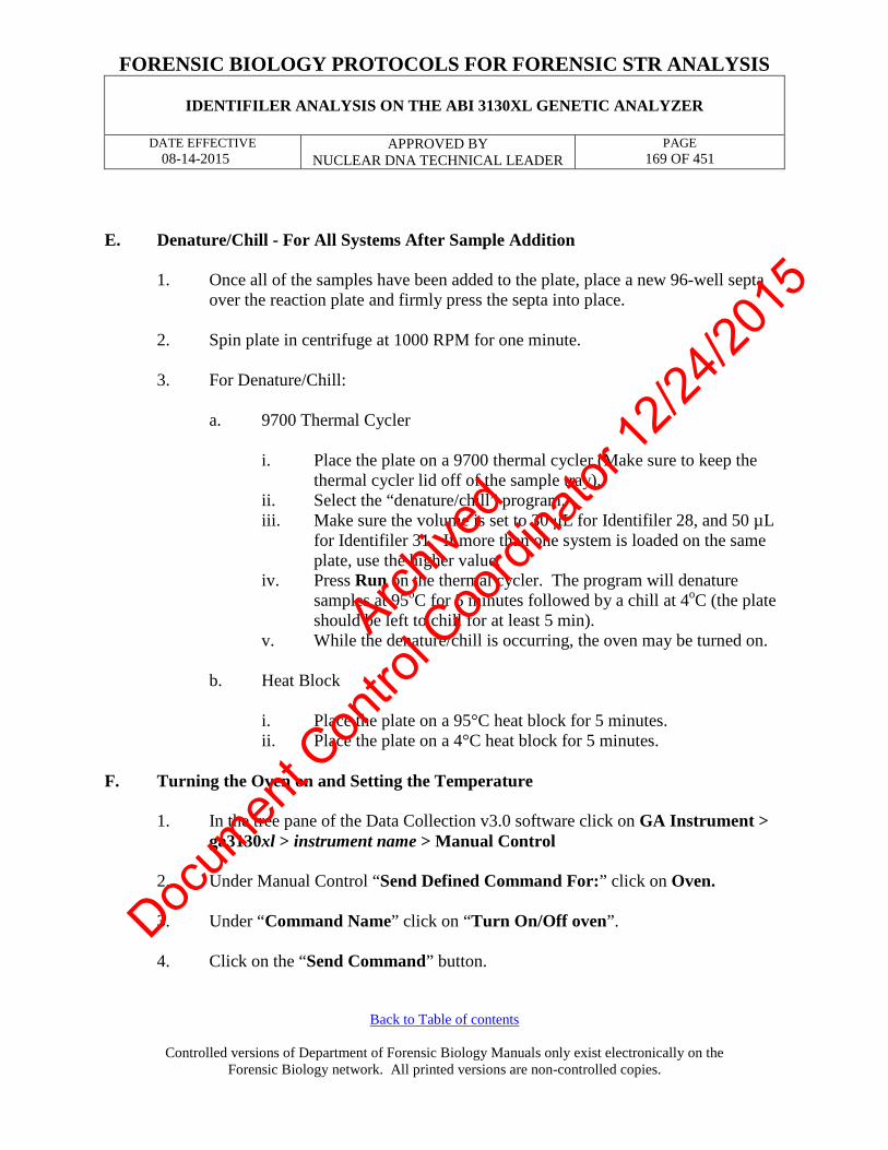
FORENSIC BIOLOGY PROTOCOLS FOR FORENSIC STR ANALYSIS
IDENTIFILER ANALYSIS ON THE ABI 3130XL GENETIC ANALYZER
DATE EFFECTIVE 08-14-2015
APPROVED BY NUCLEAR DNA TECHNICAL LEADER
PAGE 169 OF 451
Back to Table of contents
Controlled versions of Department of Forensic Biology Manuals only exist electronically on the Forensic Biology network. All printed versions are non-controlled copies.
E. Denature/Chill - For All Systems After Sample Addition
1. Once all of the samples have been added to the plate, place a new 96-well septa
over the reaction plate and firmly press the septa into place. 2. Spin plate in centrifuge at 1000 RPM for one minute.
3. For Denature/Chill:
a. 9700 Thermal Cycler
i. Place the plate on a 9700 thermal cycler (Make sure to keep the thermal cycler lid off of the sample tray).
ii. Select the “denature/chill” program. iii. Make sure the volume is set to 30 µL for Identifiler 28, and 50 µL
for Identifiler 31. If more than one system is loaded on the same plate, use the higher value.
iv. Press Run on the thermal cycler. The program will denature samples at 95oC for 5 minutes followed by a chill at 4oC (the plate should be left to chill for at least 5 min).
v. While the denature/chill is occurring, the oven may be turned on.
b. Heat Block
i. Place the plate on a 95°C heat block for 5 minutes. ii. Place the plate on a 4°C heat block for 5 minutes.
F. Turning the Oven on and Setting the Temperature
1. In the tree pane of the Data Collection v3.0 software click on GA Instrument > ga3130xl > instrument name > Manual Control
2. Under Manual Control “Send Defined Command For:” click on Oven. 3. Under “Command Name” click on “Turn On/Off oven”. 4. Click on the “Send Command” button.
Archive
d
Docum
ent C
ontro
l Coo
rdina
tor 12
/24/20
15

FORENSIC BIOLOGY PROTOCOLS FOR FORENSIC STR ANALYSIS
IDENTIFILER ANALYSIS ON THE ABI 3130XL GENETIC ANALYZER
DATE EFFECTIVE 08-14-2015
APPROVED BY NUCLEAR DNA TECHNICAL LEADER
PAGE 170 OF 451
Back to Table of contents
Controlled versions of Department of Forensic Biology Manuals only exist electronically on the Forensic Biology network. All printed versions are non-controlled copies.
5. Under “Command Name” click on “Set oven temperature” and Under “Value” set it to 60.
6. Click on the “Send Command” button. 7. Once denatured, spin the plate in centrifuge at 1000 RPM for one minute before
placing the reaction plate into the plate base. Secure the plate base and reaction plate with the plate retainer.
Archive
d
Docum
ent C
ontro
l Coo
rdina
tor 12
/24/20
15

FORENSIC BIOLOGY PROTOCOLS FOR FORENSIC STR ANALYSIS
IDENTIFILER ANALYSIS ON THE ABI 3130XL GENETIC ANALYZER
DATE EFFECTIVE 08-14-2015
APPROVED BY NUCLEAR DNA TECHNICAL LEADER
PAGE 171 OF 451
Back to Table of contents
Controlled versions of Department of Forensic Biology Manuals only exist electronically on the Forensic Biology network. All printed versions are non-controlled copies.
G. Placing the Plate onto the Autosampler (Linking and Unlinking Plate)
1. In the tree pane of the Foundation Data Collection v3.0 software click on GA Instrument > ga3130xl > instrument name > Run Scheduler > Plate View
2. Push the tray button on the bottom left of the machine and wait for the autosampler to move forward and stop at the forward position.
3. Open the doors and place the tray onto the autosampler in the correct tray position, A or B. There is only one orientation for the plate. (The notched end faces away from the user.)
4. Ensure the plate assembly fits flat in the autosampler.
When the plate is correctly positioned, the plate position indicator on the Plate View window changes from gray to yellow. Close the instrument doors and allow the autosampler to move back to the home position.
Archive
d
Docum
ent C
ontro
l Coo
rdina
tor 12
/24/20
15

FORENSIC BIOLOGY PROTOCOLS FOR FORENSIC STR ANALYSIS
IDENTIFILER ANALYSIS ON THE ABI 3130XL GENETIC ANALYZER
DATE EFFECTIVE 08-14-2015
APPROVED BY NUCLEAR DNA TECHNICAL LEADER
PAGE 172 OF 451
Back to Table of contents
Controlled versions of Department of Forensic Biology Manuals only exist electronically on the Forensic Biology network. All printed versions are non-controlled copies.
Linking/Unlinking the Plate Record to Plate
5. Type the exact plate name in the Plate ID window and click “Search.” Or, click the “Find All ” button and select the desired plate record.
NOTE: If the plate name is not typed in correctly, your plate will not be found.
Instead, a prompt to create a new plate will appear. Click “No” and retype the plate name correctly.
Click the plate position indicator corresponding to the plate position in the instrument. The plate position (A or B) displays in the link column.
If two plates are being run, the order in which they are run is based on the order in which the plates were linked.
6. The plate position indicator changes from yellow to green when linked correctly
and the green run button becomes active.
Archive
d
Docum
ent C
ontro
l Coo
rdina
tor 12
/24/20
15

FORENSIC BIOLOGY PROTOCOLS FOR FORENSIC STR ANALYSIS
IDENTIFILER ANALYSIS ON THE ABI 3130XL GENETIC ANALYZER
DATE EFFECTIVE 08-14-2015
APPROVED BY NUCLEAR DNA TECHNICAL LEADER
PAGE 173 OF 451
Back to Table of contents
Controlled versions of Department of Forensic Biology Manuals only exist electronically on the Forensic Biology network. All printed versions are non-controlled copies.
7. To unlink a plate record just click the plate record to be unlinked and click
“Unlink ”. H. Viewing the Run Schedule
1. In the tree pane of the Foundation Data Collection software, click GA Instruments > ga3130xl > instrument name > Run Scheduler > Run View.
2. The RunID column indicates the folder number(s) associated with each injection
(e.g. Run_Einstein_2011-03-10-0018 or Run_ Venus_2006-07-13_0018-0019). Note: This RunID may not be indicative of the Run Collection folder depending on results group used.
3. Click on the run file to see the Plate Map or grid diagram of the plate on the right. Check if the blue highlighted boxes correspond to the correct placement of the samples in the injections. NOTE: Before starting a run, check for air bubbles in the polymer blocks. If
present, click on the Wizards tool box on the top and select “Bubble
Archive
d
Docum
ent C
ontro
l Coo
rdina
tor 12
/24/20
15

FORENSIC BIOLOGY PROTOCOLS FOR FORENSIC STR ANALYSIS
IDENTIFILER ANALYSIS ON THE ABI 3130XL GENETIC ANALYZER
DATE EFFECTIVE 08-14-2015
APPROVED BY NUCLEAR DNA TECHNICAL LEADER
PAGE 174 OF 451
Back to Table of contents
Controlled versions of Department of Forensic Biology Manuals only exist electronically on the Forensic Biology network. All printed versions are non-controlled copies.
Remove Wizard”. Follow the wizard until all bubbles are removed.
4. Click on green Run button in the tool bar when you are ready to start the run. When the Processing Plate dialog box opens (You are about to start processing plates…), click OK.
5. To check the progress of a run, click on the Capillary Viewer or
Cap/ArrayViewer in the tree pane of the Foundation Data Collection software. The Capillary Viewer will show you the raw data of the capillaries you select to view whereas the Cap/Array Viewer will show the raw data of all 16 capillaries at once.
IMPORTANT: Always exit from the Capillary Viewer and Cap/Array
Viewer windows. During a run, do not leave these pages open for extended periods. Leave the Instrument Status window open.
Archive
d
Docum
ent C
ontro
l Coo
rdina
tor 12
/24/20
15

FORENSIC BIOLOGY PROTOCOLS FOR FORENSIC STR ANALYSIS
IDENTIFILER ANALYSIS ON THE ABI 3130XL GENETIC ANALYZER
DATE EFFECTIVE 08-14-2015
APPROVED BY NUCLEAR DNA TECHNICAL LEADER
PAGE 175 OF 451
Back to Table of contents
Controlled versions of Department of Forensic Biology Manuals only exist electronically on the Forensic Biology network. All printed versions are non-controlled copies.
The visible settings should be: EP voltage 15kV EP current (no set value) Laser Power Prerun 15 mW Laser Power During run 15mW Laser Current (no set value) Oven temperature 60°C Expected values are: EP current constant around 120 to 160µA Laser current: 5.0A ± 1.0
It is good practice to monitor the initial injections in order to detect problems. Table 11
I/L IR N H Oven Temp 60°C 60°C 60°C 60°C Pre-Run Voltage 15.0 kV 15.0 kV 15.0 kV 15.0 kV Pre-Run Time 180 sec 180 sec 180 sec 180 sec Injection Voltage 1 kV 5 kV 3 kV 6 kV Injection Time 22 sec 20 sec 20 sec 30 sec Run Voltage 15 kV 15 kV 15 kV 15 kV Run Time 1500 sec 1500 sec 1500 sec 1500 sec
Archive
d
Docum
ent C
ontro
l Coo
rdina
tor 12
/24/20
15

FORENSIC BIOLOGY PROTOCOLS FOR FORENSIC STR ANALYSIS
IDENTIFILER ANALYSIS ON THE ABI 3130XL GENETIC ANALYZER
DATE EFFECTIVE 08-14-2015
APPROVED BY NUCLEAR DNA TECHNICAL LEADER
PAGE 176 OF 451
Back to Table of contents
Controlled versions of Department of Forensic Biology Manuals only exist electronically on the Forensic Biology network. All printed versions are non-controlled copies.
Table 12
M MR Oven Temp 60°C 60°C Pre-Run Voltage 15.0 kV 15.0 kV Pre-Run Time 180 sec 180 sec Injection Voltage 3 kV 3 kV Injection Time 10 sec 20 sec Run Voltage 15 kV 15 kV Run Time 1500 sec 1500 sec
I. Collecting Data
When a run is complete, it will automatically be placed in D:/AppliedBio/Current Runs folder, labeled with either the plate name-date (e.g. Einstein11-025ID-015PPY-2011-03-11) or instrument name, date and runID (e.g. Run_Venus_2006-07-13_0018). Proceed to Analysis section of this manual.
J. Re-injecting Plates
1. Plates should be re-injected as soon as possible, preferably the same day. 2. Create a new test batch and plate record using the original documentation as a
guide. Select only those samples that need to be rerun by re-assigning “Sys”. For example, assign “IR” for an ID28 sample that needs to be re-run high.
NOTE: See Section 7 for information on which controls need to be run.
3. Follow the instructions for creating a test batch. Re-import the plate record. 4. Re-denature/chill the plate (if needed) as described in Part E. If a plate is being re-
injected the same day on which it was originally run, it does not require an additional denature/chill step before being rerun.
Archive
d
Docum
ent C
ontro
l Coo
rdina
tor 12
/24/20
15

FORENSIC BIOLOGY PROTOCOLS FOR FORENSIC STR ANALYSIS
IDENTIFILER ANALYSIS ON THE ABI 3130XL GENETIC ANALYZER
DATE EFFECTIVE 08-14-2015
APPROVED BY NUCLEAR DNA TECHNICAL LEADER
PAGE 177 OF 451
Back to Table of contents
Controlled versions of Department of Forensic Biology Manuals only exist electronically on the Forensic Biology network. All printed versions are non-controlled copies.
K. Water Wash and POP Change
Refer to Section A for schematic of 3130xl while proceeding with the water wash and POP change procedure.
1. Remove a new bottle of POP4 from the refrigerator.
2. Select Wizards > Water Wash Wizard and follow the wizard.
3. When the “Fill Array” step has completed, remove the anode buffer jar, empty,
and fill with 1x TBE Buffer (~15 mL).
4. Close instrument doors and wait for the steady green light.
5. Click “Finish.”
Archive
d
Docum
ent C
ontro
l Coo
rdina
tor 12
/24/20
15

FORENSIC BIOLOGY PROTOCOLS FOR FORENSIC STR ANALYSIS
IDENTIFILER ANALYSIS ON THE ABI 3130XL GENETIC ANALYZER
DATE EFFECTIVE 08-14-2015
APPROVED BY NUCLEAR DNA TECHNICAL LEADER
PAGE 178 OF 451
Back to Table of contents
Controlled versions of Department of Forensic Biology Manuals only exist electronically on the Forensic Biology network. All printed versions are non-controlled copies.
TROUBLESHOOTING GUIDE This section is provided as a guide. The decision on which of the recommended actions is the most promising should be made after consultation with a supervisor. PROBLEM: Many artifacts in sample.
Possible Cause Recommended Action Secondary structure present. Sample not denatured properly.
Clean pump block and change polymer to refresh the urea environment. Denature/chill samples.
PROBLEM: Decreasing peak heights in all samples.
Possible Cause Recommended Action Poor quality formamide or sample environment very ionic.
Realiquot samples with fresh HIDI.
PROBLEM: Individual injections run at varying speeds. For example, the scan number where the 100 bp size standard appears differs significantly from one injection to another, usually appearing earlier.
Possible Cause Recommended Action Warm laboratory temperatures. Redefine size standard.
If this fails, reinject.
Archive
d
Docum
ent C
ontro
l Coo
rdina
tor 12
/24/20
15

FORENSIC BIOLOGY PROTOCOLS FOR FORENSIC STR ANALYSIS
IDENTIFILER ANALYSIS ON THE ABI 3130XL GENETIC ANALYZER
DATE EFFECTIVE 08-14-2015
APPROVED BY NUCLEAR DNA TECHNICAL LEADER
PAGE 179 OF 451
Back to Table of contents
Controlled versions of Department of Forensic Biology Manuals only exist electronically on the Forensic Biology network. All printed versions are non-controlled copies.
PROBLEM : Loss of resolution of peaks.
Possible Cause Recommended Action Loss of resolution of peaks.
Clean pump block and change polymer to refresh the urea environment. Denature chill samples.
PROBLEM : An off ladder peak appears to be a pull up, but it is not exactly the same basepair as the true peak.
Possible Cause Recommended Action Matrix over-subtraction. Usually in the green channel, the true peak is overblown and is split. Pull up peaks appear in the blue and the red channels. In the yellow channel, there is a negative peak at the base pairs of the true peak, however immediately to the right and to the left are off ladder peaks.
Remove off ladder peaks as matrix over-subtraction.
PROBLEM : Peaks overblown and running as off ladder alleles.
Possible Cause Recommended Action More than the optimum amount of sample amplified.
Rerun samples at lower injection parameters. Or rerun samples with less DNA.
Archive
d
Docum
ent C
ontro
l Coo
rdina
tor 12
/24/20
15

FORENSIC BIOLOGY PROTOCOLS FOR FORENSIC STR ANALYSIS
IDENTIFILER ANALYSIS ON THE ABI 3130XL GENETIC ANALYZER
DATE EFFECTIVE 08-14-2015
APPROVED BY NUCLEAR DNA TECHNICAL LEADER
PAGE 180 OF 451
Back to Table of contents
Controlled versions of Department of Forensic Biology Manuals only exist electronically on the Forensic Biology network. All printed versions are non-controlled copies.
PROBLEM : Pull up peaks.
Possible Cause Recommended Action Colors bleeding into other colors. Run a spectral.
PROBLEM : Spikes in the electropherogram.
Possible Cause Recommended Action Crystals in the polymer solution due to the polymer warming and congealing from fluctuations in the room temperature.
Change the polymer.
PROBLEM : Spikes in electropherogram and artifacts.
Possible Cause Recommended Action Arcing: water around the buffer chambers.
Clean chambers; beware of drops accumulating around the septa.
PROBLEM : Split peaks.
Possible Cause Recommended Action Lower pump block is in the process of burning out due to the formation of a bubble.
Clean the block.
PROBLEM : Increasing number of spurious alleles.
Possible Cause Recommended Action Extraneous DNA in reagents, consumables, or instrument.
Stop laboratory work under advisement of technical leader. Implement a major laboratory clean-up.
Archive
d
Docum
ent C
ontro
l Coo
rdina
tor 12
/24/20
15

FORENSIC BIOLOGY PROTOCOLS FOR FORENSIC STR ANALYSIS
IDENTIFILER ANALYSIS ON THE ABI 3130XL GENETIC ANALYZER
DATE EFFECTIVE 08-14-2015
APPROVED BY NUCLEAR DNA TECHNICAL LEADER
PAGE 181 OF 451
Back to Table of contents
Controlled versions of Department of Forensic Biology Manuals only exist electronically on the Forensic Biology network. All printed versions are non-controlled copies.
GENERAL PROBLEMS
Problems Recommended Action Fatal Errors. 3130xl not cooperating. Shutter problems.
Close collection software. Restart collection software. Restart Computer and Instrument. Call Service.
Revision History: March 24, 2010 – Initial version of procedure. March 29, 2011 – Revised Step H.2 and I due to a change in the Results Group. July 16, 2012 – Revised procedure to accommodate LIMS. February 2, 2015 – updated witnessing procedures, removed the use of Teams, and added Identifiler High aliquoting
parameters for High Copy Number testing. August 14, 2015 – Removed references to High Sensitivity Team, corrected the volume of POP in the piston of the 3130xl. Removed references to GeneScan and Cleanup Database Utility.
Archive
d
Docum
ent C
ontro
l Coo
rdina
tor 12
/24/20
15

FORENSIC BIOLOGY PROTOCOLS FOR FORENSIC STR ANALYSIS
AMPLIFICATION USING THE YFILER SYSTEM
DATE EFFECTIVE 08-14-2015
APPROVED BY NUCLEAR DNA TECHNICAL LEADER
PAGE 182 OF 451
Back to Table of contents
Controlled versions of Department of Forensic Biology Manuals only exist electronically on the Forensic Biology network. All printed versions are non-controlled copies.
YFiler Kit TM
Amplification using the Yfiler TM System I. General Information for Amplification
The Yfiler™ Amplification System from Life Technologies targets sixteen (16) locations on the Y chromosome. The system includes loci with tri-, tetra-, penta- and hexa-nucleotide repeats and utilizes five dyes (6-FAM™, VIC®, NED™ and PET® for samples and LIZ® for the GeneScan™ 500 size standard).
LOCUS REPEAT Dye Label DYS456 tetra-nucleotide 6-FAM™ (blue) DYS389I tetra-nucleotide DYS390 tetra-nucleotide
DYS389II tetra-nucleotide DYS458 tetra-nucleotide VIC® (green) DYS19 tetra-nucleotide
DYS385a/b tetra-nucleotide DYS393 tetra-nucleotide NED™ (yellow) DYS391 tetra-nucleotide DYS439 tetra-nucleotide DYS635 tetra-nucleotide DYS392 tri-nucleotide
Y GATA H4 tetra-nucleotide PET® (red) DYS437 tetra-nucleotide DYS438 penta-nucleotide DYS448 hexa-nucleotide
The target DNA concentration for amplification using the Yfiler™ system is 500 pg male DNA. The minimum DNA concentration required for amplification in this system is 100 pg male DNA (minimum quantitiation value of 10 pg/ul male DNA). If a sample is found to contain less than 10.0 pg/µL male DNA, then the sample should not be amplified in Yfiler™. It can be re-extracted, reported as containing insufficient male DNA, concentrated using a Micro-concentrator or evaluated for High Sensitivity testing. (see Table 1)
Archive
d
Docum
ent C
ontro
l Coo
rdina
tor 12
/24/20
15

FORENSIC BIOLOGY PROTOCOLS FOR FORENSIC STR ANALYSIS
AMPLIFICATION USING THE YFILER SYSTEM
DATE EFFECTIVE 08-14-2015
APPROVED BY NUCLEAR DNA TECHNICAL LEADER
PAGE 183 OF 451
Back to Table of contents
Controlled versions of Department of Forensic Biology Manuals only exist electronically on the Forensic Biology network. All printed versions are non-controlled copies.
TABLE 1: For Yfiler™
Minimum Desired Template of male DNA 100.00 pg
Template volume for amp 10 µL
Minimum Sample Concentration of male DNA in 200 µL
10.0 pg/µL
Minimum Sample Concentration of male DNA in 200 µL prior to Microconning* to 50 µL
2.5 pg/µL
Minimum Sample Concentration of male DNA in 200 µL prior to Microconning** to 20 µL
1.0 pg/ µL
* Sample concentration prior to processing with a Microcon DNA Fast Flow and elution to 50 µL ** Sample concentration prior to processing with a Microcon DNA Fast Flow and elution to 20 µL
Since Yfiler™ samples often require further testing in Identifiler, the extraction negative must have a quantitation value of < 0.2 pg/ µL. II. Generation of Amplification Test Batches
Refer to the LIMS manual for Forensic Biology for specific procedures within the LIMS system. Any casefile documentation developed outside of the LIMS system should be scanned to a PDF document and attached to the appropriate electronic case record
Amplification test batches are generated following review of quantification results. Furthermore, samples may be submitted for amplification via the “add test” function in LIMS.
III. PCR Amplification – Sample Preparation
A. Samples amplified with Yfiler™ reagents should be prepared with ULTRAPURE water.
Prepare dilutions for each sample, if necessary, according to Table 2.
Archive
d
Docum
ent C
ontro
l Coo
rdina
tor 12
/24/20
15

FORENSIC BIOLOGY PROTOCOLS FOR FORENSIC STR ANALYSIS
AMPLIFICATION USING THE YFILER SYSTEM
DATE EFFECTIVE 08-14-2015
APPROVED BY NUCLEAR DNA TECHNICAL LEADER
PAGE 184 OF 451
Back to Table of contents
Controlled versions of Department of Forensic Biology Manuals only exist electronically on the Forensic Biology network. All printed versions are non-controlled copies.
TABLE 2: Dilutions Dilution Amount of DNA
Template (uL) Amount of ULTRAPURE
Water (uL) 0.25 3 or (2) 9 or (6) 0.2 2 8 0.1 2 18 0.05 2.5 47.5 0.04 4 or (2) 96 or (48) 0.02 2 or (1) 98 or (49) 0.01 2 198 0.008 4 or (2) 496 or (248)
The target DNA template amount for Yfiler™ is 500 pg male DNA. To calculate the amount of template DNA and diluant to add, the following formulas are used:
Target Amount (pg)
Amt of DNA (µL) = -------------------------------------------------------- (Male DNA concentration, pg/µL)(Dilution factor)
The amount of diluant to add to the reaction = 10 µL – amt of DNA (µL)
B. Create the male positive control by making a 0.5 dilution of Control DNA 007: • Label tube MPC • Aliquot 5µL of ULTRAPURE water into tube MPC • Aliquot 5µL of Control DNA 007 into tube MPC
C. Create the female negative control by making a 0.01 dilution of Control DNA
9947A: • Label tube FNC • Aliquot 198µL of ULTRAPURE water into tube FNC • Aliquot 2µL of Control DNA 9947A into tube FNC
D. Amplification Negative Control ULTRAPURE water will serve as an amplification negative control.
Archive
d
Docum
ent C
ontro
l Coo
rdina
tor 12
/24/20
15

FORENSIC BIOLOGY PROTOCOLS FOR FORENSIC STR ANALYSIS
AMPLIFICATION USING THE YFILER SYSTEM
DATE EFFECTIVE 08-14-2015
APPROVED BY NUCLEAR DNA TECHNICAL LEADER
PAGE 185 OF 451
Back to Table of contents
Controlled versions of Department of Forensic Biology Manuals only exist electronically on the Forensic Biology network. All printed versions are non-controlled copies.
E. Master Mix Preparation
1. Retrieve Yfiler™ primers and Yfiler™ reaction mix from the refrigerator. Retrieve ABI Taq Gold from the freezer. Store reagents in a Nalgene cooler on bench. Record the lot numbers of the reagents.
2. Vortex or pipette the reagents up and down several times to thoroughly mix the reagents. Do not vortex Taq Gold as it may degrade the enzyme. After vortexing, centrifuge reagents briefly at full speed to ensure that no sample is trapped in the cap.
3. Consult the amplification documentation for the exact amount of Yfiler™ primers, reaction mix and ABI Taq Gold to add. The amount of reagents for one amplification reaction is listed in Table 3.
Table 3 - Yfiler™ PCR amplification reagents for one sample
Reagent Per reaction Yfiler™ PCR Reaction Mix 9.2 µL Yfiler™ Primer Set 5.0 µL AmpliTaq Gold DNA Polymerase (5U/µL) 0.8 uL
Mastermix total in each sample: 15 µL DNA 10 µL
F. Reagent Aliquot
1. Vortex master mix to thoroughly mix. After vortexing, briefly tap or
centrifuge the master mix tube to ensure that no reagent is trapped in the cap.
2. Add 15 µL of the Yfiler™ master mix to each tube that will be utilized,
changing pipette tips and remixing master mix as needed. G. Witnessing Step
1. Arrange samples in a rack in precisely the positions they appear on the sheet.
2. Have a witness confirm the order of input and output samples:
Archive
d
Docum
ent C
ontro
l Coo
rdina
tor 12
/24/20
15

FORENSIC BIOLOGY PROTOCOLS FOR FORENSIC STR ANALYSIS
AMPLIFICATION USING THE YFILER SYSTEM
DATE EFFECTIVE 08-14-2015
APPROVED BY NUCLEAR DNA TECHNICAL LEADER
PAGE 186 OF 451
Back to Table of contents
Controlled versions of Department of Forensic Biology Manuals only exist electronically on the Forensic Biology network. All printed versions are non-controlled copies.
Input samples – From the main test batch screen, ensure that the extract tube label and entire LIMS input sample ID match for each sample.
Output samples – Go to the “Load Plate” screen in LIMS and ensure that the amp tube labels correspond to the order on the plate.
H. Sample and Control Aliquot
NOTE: Use a new sterile filter pipette tip for each DNA sample or control
addition. Open only one tube at a time for sample addition.
1. Prior to adding each sample or control to the master mix, pipette each up and down several times to thoroughly mix. Add the appropriate amount of DNA extract and diluant to each amp tube. The final aqueous volume in the PCR reaction mix tubes will be 25µL. After addition of the DNA and diluant (as needed), cap each sample before proceeding to the next tube.
2. After all samples have been added, take the rack to the amplified DNA area for Thermal Cycling.
IV. Thermal Cycling
A. Turn on the ABI 9700 Thermal Cycler. (See manufacturer's instructions).
PCR Conditions for the Perkin Elmer GeneAmp PCR System 9700
Archive
d
Docum
ent C
ontro
l Coo
rdina
tor 12
/24/20
15

FORENSIC BIOLOGY PROTOCOLS FOR FORENSIC STR ANALYSIS
AMPLIFICATION USING THE YFILER SYSTEM
DATE EFFECTIVE 08-14-2015
APPROVED BY NUCLEAR DNA TECHNICAL LEADER
PAGE 187 OF 451
Back to Table of contents
Controlled versions of Department of Forensic Biology Manuals only exist electronically on the Forensic Biology network. All printed versions are non-controlled copies.
9700 Yfiler™
user: casewk file: yfiler
The Yfiler™ file is as follows: Initial Incubation Step: Hold 95°C for 11 minutes Cycle (30 cycles) Denature at 94°C for 1 minute Anneal at 61°C for 1 minute Extend at 72°C for 1 minute Final Extension: Hold 60°C for 80 minutes Final Hold: Hold 4°C ∞.
B. 9700 Instructions
1. Place the tubes in the tray in the heat block (do not add mineral oil), slide the heated lid over the tubes, and fasten the lid by pulling the handle forward. Make sure you use a tray that has a 9700 label.
2. Start the run by performing the following steps: 3. The main menu options are RUN CREATE EDIT UTIL USER. To select
an option, press the F key (F1…F5) directly under that menu option. 4. Verify that user is set to “casewk.” If it is not, select the USER option
(F5) to display the “Select User Name” screen. 5. Use the circular arrow pad to highlight “casewk.” Select the ACCEPT
option (F1). 6. Select the RUN option (F1). 7. Use the circular arrow pad to highlight the desired STR system - yfiler .
Select the START option (F1). The “Select Method Options” screen will appear.
Archive
d
Docum
ent C
ontro
l Coo
rdina
tor 12
/24/20
15

FORENSIC BIOLOGY PROTOCOLS FOR FORENSIC STR ANALYSIS
AMPLIFICATION USING THE YFILER SYSTEM
DATE EFFECTIVE 08-14-2015
APPROVED BY NUCLEAR DNA TECHNICAL LEADER
PAGE 188 OF 451
Back to Table of contents
Controlled versions of Department of Forensic Biology Manuals only exist electronically on the Forensic Biology network. All printed versions are non-controlled copies.
8. Verify that the reaction volume is set to 25µL for Yfiler™. 9. If all is correct, select the START option (F1). 10. Update usage log. 11. The run will start when the heated cover reaches 103°C. The screen will
then display a flow chart of the run conditions. A flashing line indicates the step being performed, hold time is counted down. Cycle number is indicated at the top of the screen, counting up.
12. Upon completion of the amplification, remove samples and press the
STOP button repeatedly until the “End of Run” screen is displayed. Select the EXIT option (F5). Wipe any condensation from the heat block with a Kimwipe and pull the lid closed to prevent dust from collecting on the heat block. Turn the instrument off.
Note: Place the microtube rack used to set-up the samples for PCR in the container of 10% bleach container in the Post-Amp area.
Archive
d
Docum
ent C
ontro
l Coo
rdina
tor 12
/24/20
15

FORENSIC BIOLOGY PROTOCOLS FOR FORENSIC STR ANALYSIS
AMPLIFICATION USING THE YFILER SYSTEM
DATE EFFECTIVE 08-14-2015
APPROVED BY NUCLEAR DNA TECHNICAL LEADER
PAGE 189 OF 451
Back to Table of contents
Controlled versions of Department of Forensic Biology Manuals only exist electronically on the Forensic Biology network. All printed versions are non-controlled copies.
THIS PAGE INTENTIONALLY LEFT BLANK Revision History: April 1, 2014 – Initial version of procedure. June 16, 2014 – Corrected tables to reflect use of UV water and not TE-4 September 1, 2014 – modified section II.A.1.a due to LIMS is in use as opposed to macros. Modified Section II.A.1.a to
read “vulvar swab samples” instead of “vaginal samples”. Updated Table 4 to show new work flow. November 24, 2014 – Changed all instances of “irradiated” or “sterile” water to UltraPure water. February 2, 2015 - Clarified Witnessing step and fixed numbering nomenclature of procedure.
August 14, 2015 – Updated section to reflect changes in sample processing due to new quantitation assay that has recently come on-line.
Archive
d
Docum
ent C
ontro
l Coo
rdina
tor 12
/24/20
15

FORENSIC BIOLOGY PROTOCOLS FOR FORENSIC STR ANALYSIS
YFILER™ – CAPILLARY ELECTROPHORESIS
DATE EFFECTIVE 08/14/2015
APPROVED BY NUCLEAR DNA TECHNICAL LEADER
PAGE 190 OF 451
Controlled versions of Department of Forensic Biology Manuals only exist electronically on the Forensic Biology network. All printed versions are non-controlled copies.
Yfiler TM – Capillary Electrophoresis Refer to the “Identifiler Analysis on the ABI 3130xl Genetic Analyzer” procedures for instructions on how to:
1. set up the 3130xl instrument 2. create, import, and link the plate record 3. troubleshoot
A. Preparation of 3130xl Batch Ensure that the appropriate System is filled into the “Sys” column. Table 1
Amplification (System/Cycle)
Specification Run Module Code Parameters
Yfiler™ Normal M 3 kV for 10 sec High MR 5 kV for 20 sec
1. Arrange amplified samples in a 96-well rack according to how they will be loaded
into the 96-well reaction plate. Sample order is as follows: A1, B1, C1…G1, H1, A2, B2, C2…G2, H2, A3, B3, etc. Thus the plate is loaded in a columnar manner where the first injection corresponds to wells A1-H2, the second A3-H4 and so on.
2. Have another analyst witness the tube setup by comparing the tube labels and positions indicated on the Load Plate Screen in the LIMS system with the tube labels and positions of the tubes themselves.
Archive
d
Docum
ent C
ontro
l Coo
rdina
tor 12
/24/20
15

FORENSIC BIOLOGY PROTOCOLS FOR FORENSIC STR ANALYSIS
YFILER™ – CAPILLARY ELECTROPHORESIS
DATE EFFECTIVE 08/14/2015
APPROVED BY NUCLEAR DNA TECHNICAL LEADER
PAGE 191 OF 451
Controlled versions of Department of Forensic Biology Manuals only exist electronically on the Forensic Biology network. All printed versions are non-controlled copies.
B. Mastermix and Sample Addition for Yfiler™
1. Prepare one mastermix for all samples, negative and positive controls, allelic ladders as specified in the table below (mastermix calculation, add 8.7 µL HiDi + 0.3µL GS 500 LIZ standard per sample).
# Samples + 2 HiDi Form (8.7 µL per sample)
GS 500 LIZ Std (0.3 µL per sample)
16 156.6 5.4
32 295.8 10.2
48 435.0 15.0
64 574.2 19.8
80 713.4 24.6
96 852.6 29.4
112 991.8 34.2
128 1131.0 39.0
NOTE: HiDi Formamide cannot be re-frozen.
2. Obtain a reaction plate and label the side with the name used for the 3130xl Run ID and place the plate in an amplification tray or the plate base. Aliquot 9 µL of mastermix to each well.
3. For samples being run at normal parameters: Aliquot the following:
Allelic Ladder: 1 µL Positive/Negative Controls: 1 µL Samples: 1 µL
4. For samples being run at high parameters: Aliquot the following: Allelic Ladder: 1 µL Positive/Negative Control: 1 µL Samples: 1 µL
Archive
d
Docum
ent C
ontro
l Coo
rdina
tor 12
/24/20
15

FORENSIC BIOLOGY PROTOCOLS FOR FORENSIC STR ANALYSIS
YFILER™ – CAPILLARY ELECTROPHORESIS
DATE EFFECTIVE 08/14/2015
APPROVED BY NUCLEAR DNA TECHNICAL LEADER
PAGE 192 OF 451
Controlled versions of Department of Forensic Biology Manuals only exist electronically on the Forensic Biology network. All printed versions are non-controlled copies.
5. When adding PCR product, make sure to pipette the solution directly into the formamide and gently flush the pipette tip up and down a few times to mix it.
6. If an injection has less than 16 samples, add at least 9 µL of either dH2O,
formamide, HiDi, buffer or mastermix to all unused wells within that injection. C. Denature/Chill - For Yfiler™ After Sample Addition:
1. Once all of the samples have been added to the plate, place a new 96-well Septa over
the reaction plate and firmly press the septa into place.
2. Spin plate in centrifuge at 1000 RPM for one minute.
3. For Denature/Chill:
a. Place the plate on a 9700 thermal Cycler (Make sure to keep the Thermal Cycler lid off of the sample tray to prevent the septa from heating up.)
b. Select the “dechillYF” program for Yfiler (95°C for 3 minutes followed by 4°C for 3 minutes). Make sure the volume is set to 10 µL.
c. Press Run on the Thermal Cycler. d. Update usage log. e. While the denature/chill is occurring, you can turn on the oven on the ABI 3130xl.
NOTE: If Identifiler and Yfiler samples are on the same plate, the Dechill procedure for Identifiler should be used.
D. 3130xl Settings
3130xl visible settings: EP voltage 15kV EP current (no set value) Laser Power Prerun 15 mW Laser Power During run 15mW Laser Current (no set value) Oven temperature 60°C
Expected values are: EP current constant around 120 to 160µA Laser current: 5.0A ± 1.0
It is good practice to monitor the initial injections in order to detect problems.
Archive
d
Docum
ent C
ontro
l Coo
rdina
tor 12
/24/20
15

FORENSIC BIOLOGY PROTOCOLS FOR FORENSIC STR ANALYSIS
YFILER™ – CAPILLARY ELECTROPHORESIS
DATE EFFECTIVE 08/14/2015
APPROVED BY NUCLEAR DNA TECHNICAL LEADER
PAGE 193 OF 451
Controlled versions of Department of Forensic Biology Manuals only exist electronically on the Forensic Biology network. All printed versions are non-controlled copies.
Table 2
Y10 YR20 Oven Temp 60°C 60°C Pre-Run Voltage 15.0 kV 15.0 kV Pre-Run Time 180 sec 180 sec Injection Voltage 3 kV 5 kV Injection Time 10 sec 20 sec Run Voltage 15 kV 15 kV Run Time 1500 sec 1500 sec
Revision History: April 1, 2014 – Initial version of procedure. February 2, 2015 – Updated witnessing procedure. August 14, 2015 – Removed specific use of “sharpie” marker and clarified which dechill program to use if Yfiler is plated
on the same STR plate as Identifiler.
Archive
d
Docum
ent C
ontro
l Coo
rdina
tor 12
/24/20
15

FORENSIC BIOLOGY PROTOCOLS FOR FORENSIC STR ANALYSIS
AMPLIFICATION USING THE MINIFILER SYSTEM
DATE EFFECTIVE 05-12-2015
APPROVED BY NUCLEAR DNA TECHNICAL LEADER
PAGE 194 OF 451
Back to Table of contents
Controlled versions of Department of Forensic Biology Manuals only exist electronically on the Forensic Biology network. All printed versions are non-controlled copies.
Minifiler Kit
Amplification using the Minifiler System I. General Information for AmpF ℓSTR® MiniFiler™ PCR Amplification
The MiniFiler™ PCR Amplification Kit from Applied Biosystems is a miniature STR (miniSTR) test that utilizes reduced size primers to target Amelogenin and eight of the larger STR loci amplified with Identifiler® (D13S317, D7S820, D2S1338, D21S11, D16S539, D18S51, CSF1PO and FGA). The MiniFiler™ amplification results in amplicons that are significantly shorter in length than those produced with Identifiler® (see Figure 1). MiniFiler™ can be used in conjunction with Identifiler® to recover the larger loci that typically drop-out due to sample degradation. It can also be used for samples that may be inhibited and show no amplification with Identifiler®.
Figure 1. Amplicon size reduction of MiniFiler™ compared to the same STR loci in Identifiler®. Image from Applied Biosystems’s “MiniFiler™ Kit Multiplex Configuration,” 2006. http://marketing.appliedbiosystems.com/images/Product_Microsites/Minifiler1106/pdf/MplexConfig.pdf
Archive
d
Docum
ent C
ontro
l Coo
rdina
tor 12
/24/20
15

FORENSIC BIOLOGY PROTOCOLS FOR FORENSIC STR ANALYSIS
AMPLIFICATION USING THE MINIFILER SYSTEM
DATE EFFECTIVE 05-12-2015
APPROVED BY NUCLEAR DNA TECHNICAL LEADER
PAGE 195 OF 451
Back to Table of contents
Controlled versions of Department of Forensic Biology Manuals only exist electronically on the Forensic Biology network. All printed versions are non-controlled copies.
The target DNA concentration for amplification using the MiniFiler™ system is 500 pg. The minimum DNA concentration required for amplification in this system is 100 pg (minimum quantitiation value of 10 pg/µL). If a sample is found to contain less than 10 pg/µL of DNA, then the sample should not be amplified in MiniFiler™. It can be re-extracted, reported as containing insufficient DNA, concentrated using a Microcon DNA Fast Flow or possibly submitted for High Sensitivity testing (see Table 1).
TABLE 1: For MiniFiler™
Minimum Desired Template 100 pg
Template Volume for Amp 10 µL
Minimum Sample Concentration in 200 µL
10.0 pg/µL
Minimum Sample Concentration in 200 µL prior to Microconning* to 50 µL
2.5 pg/µL
Minimum Sample Concentration in 200 µL prior to Microconning** to 20 µL
1.0 pg/µL
* Sample concentration prior to processing with a Microcon DNA Fast Flow and elution to 50 µL
** Sample concentration prior to processing with a Microcon DNA Fast Flow and elution to 20 µL
Since MiniFiler™ has a template amplification volume of 10 µL, the extraction negative must have a quantitation value of < 0.2 pg/µL. Thus, if the extraction negative is > 0.2 pg/µL, it should be re-quantitated. If it fails again, the sample set must be re-extracted prior to amplification (see Table 2).
TABLE 2:
Amplification System Sensitivity of Amplification
Extraction Negative Control Threshold
MiniFiler™ 10 pg 0.20 pg/µL in 10 µL II. Generation of Amplification Sets
Archive
d
Docum
ent C
ontro
l Coo
rdina
tor 12
/24/20
15

FORENSIC BIOLOGY PROTOCOLS FOR FORENSIC STR ANALYSIS
AMPLIFICATION USING THE MINIFILER SYSTEM
DATE EFFECTIVE 05-12-2015
APPROVED BY NUCLEAR DNA TECHNICAL LEADER
PAGE 196 OF 451
Back to Table of contents
Controlled versions of Department of Forensic Biology Manuals only exist electronically on the Forensic Biology network. All printed versions are non-controlled copies.
Amp sets are generated by supervisors following review of quantification results. Furthermore, samples may be submitted for amplification through sample request documentation.
III. PCR Amplification – Sample Preparation
1. Samples amplified with MiniFiler reagents should be prepared with irradiated TE-4.
Prepare dilutions for each sample, if necessary, according to Table 3.
TABLE 3: Dilutions Dilution Amount of DNA
Template (µL) Amount of UltraPure
TE-4 (µL) 0.25 3 or (2) 9 or (6) 0.2 2 8 0.1 2 18 0.05 2.5 47.5 0.04 4 or (2) 96 or (48) 0.02 2 or (1) 98 or (49) 0.01 2 198 0.008 4 or (2) 496 or (248)
The target DNA template amount for MiniFiler is 500 pg. To calculate the amount of template DNA and diluent to add, the following formulas are used:
Target Amount (pg)
Amt of DNA (µL) = -------------------------------------------------------- (Sample concentration, pg/µL)(Dilution factor)
The amount of diluent to add to the reaction = 10 µL – amt of DNA (µL) For samples with quantitation values <50 pg/µL but >10 pg/µL, aliquot 10 µL extract.
Archive
d
Docum
ent C
ontro
l Coo
rdina
tor 12
/24/20
15

FORENSIC BIOLOGY PROTOCOLS FOR FORENSIC STR ANALYSIS
AMPLIFICATION USING THE MINIFILER SYSTEM
DATE EFFECTIVE 05-12-2015
APPROVED BY NUCLEAR DNA TECHNICAL LEADER
PAGE 197 OF 451
Back to Table of contents
Controlled versions of Department of Forensic Biology Manuals only exist electronically on the Forensic Biology network. All printed versions are non-controlled copies.
B. Positive Control
For MiniFiler, DO NOT make a dilution of the 100 pg/µL AmpFlSTR Control DNA 007. Instead, combine 5 µL of the Control DNA with 5 µL of irradiated TE-4. This yields a total volume of 10 µL with 500 pg in the amplification.
C. Amplification Negative Control
10 µL of irradiated TE-4 will serve as an Amplification Negative Control.
D. Master Mix Preparation
4. Retrieve the MiniFiler Primer Set and MiniFiler Master Mix from the refrigerator and store in a Nalgene cooler on the bench. Record the lot numbers of the reagents.
5. Vortex or pipette the reagents up and down several times to thoroughly mix the reagents. After vortexing, centrifuge reagents at full speed briefly to ensure that no sample is trapped in the cap.
6. Consult the amplification documentation for the exact amount of MiniFiler Primer Set and Master Mix to add. The amount of reagents for one amplification reaction is listed in Table 4.
TABLE 4: MiniFiler PCR amplification reagents for one sample
Reagent Per reaction MiniFiler Primer Set 5.0 µL MiniFiler Master Mix 10.0 µL Reaction Mix Total: 15.0 µL DNA 10.0 µL
Archive
d
Docum
ent C
ontro
l Coo
rdina
tor 12
/24/20
15

FORENSIC BIOLOGY PROTOCOLS FOR FORENSIC STR ANALYSIS
AMPLIFICATION USING THE MINIFILER SYSTEM
DATE EFFECTIVE 05-12-2015
APPROVED BY NUCLEAR DNA TECHNICAL LEADER
PAGE 198 OF 451
Back to Table of contents
Controlled versions of Department of Forensic Biology Manuals only exist electronically on the Forensic Biology network. All printed versions are non-controlled copies.
E. Reagent and Sample Aliquot
1. Vortex master mix to thoroughly mix. After vortexing, briefly tap or centrifuge the master mix tube to ensure that no reagent is trapped in the cap.
2. Add 15 µL of the MiniFiler reaction mix to each of the stratalinked PCR
tubes that will be utilized, changing pipette tips and remixing reaction mix as needed.
NOTE: Use a new sterile filter pipette tip for each sample addition. Open only one tube at a time for sample addition.
3. Arrange samples in a rack in precisely the positions they appear on the sheet.
4. Witness step. Ensure that your samples are properly positioned. 5. Prior to adding sample or control, pipette each sample or control up and
down several times to thoroughly mix. The final aqueous volume in the PCR reaction mix tubes will be 25 µL. After addition of the DNA, cap each sample before proceeding to the next tube.
6. After all samples have been added, take the rack to the amplified DNA
area for Thermal Cycling.
IV. Thermal Cycling
1. Turn on the ABI 9700 Thermal Cycler. (See manufacturer's instructions).
2. Choose the following files in order to amplify in MiniFiler:
MiniFiler
User: casewk File: mini
Archive
d
Docum
ent C
ontro
l Coo
rdina
tor 12
/24/20
15

FORENSIC BIOLOGY PROTOCOLS FOR FORENSIC STR ANALYSIS
AMPLIFICATION USING THE MINIFILER SYSTEM
DATE EFFECTIVE 05-12-2015
APPROVED BY NUCLEAR DNA TECHNICAL LEADER
PAGE 199 OF 451
Back to Table of contents
Controlled versions of Department of Forensic Biology Manuals only exist electronically on the Forensic Biology network. All printed versions are non-controlled copies.
PCR Conditions for the Perkin Elmer GeneAmp PCR System 9700
9700
MiniFiler User: casewk File: mini
The mini file is as follows: Soak at 95°C for 11 minutes : Denature at 94°C for 20 seconds 30 Cycles: : Anneal at 59°C for 2 minutes : Extend at 72°C for 1 minute
45 minute incubation at 60°C. Storage soak indefinitely at 4°C
3. 9700 Instructions
a. Place the tubes in the tray in the heat block (do not add mineral oil), slide the heated lid over the tubes, and fasten the lid by pulling the handle forward. Make sure you use a tray that has a 9700 label.
b. Start the run by performing the following steps: c. The main menu options are RUN CREATE EDIT UTIL USER.
To select an option, press the F key (F1…F5) directly under that menu option.
d. Verify that user is set to “casewk.” If it is not, select the USER
option (F5) to display the “Select User Name” screen. e. Use the circular arrow pad to highlight “casewk.” Select the
ACCEPT option (F1). f. Select the RUN option (F1). g. Use the circular arrow pad to highlight the desired STR system.
Select the START option (F1). The “Select Method Options” screen will appear.
Archive
d
Docum
ent C
ontro
l Coo
rdina
tor 12
/24/20
15

FORENSIC BIOLOGY PROTOCOLS FOR FORENSIC STR ANALYSIS
AMPLIFICATION USING THE MINIFILER SYSTEM
DATE EFFECTIVE 05-12-2015
APPROVED BY NUCLEAR DNA TECHNICAL LEADER
PAGE 200 OF 451
Back to Table of contents
Controlled versions of Department of Forensic Biology Manuals only exist electronically on the Forensic Biology network. All printed versions are non-controlled copies.
h. Verify that the reaction volume is set to 25µL for MiniFiler and
the ramp speed is set to 9600 (very important). i. If all is correct, select the START option (F1).
j. The run will start when the heated cover reaches 103°C. The
screen will then display a flow chart of the run conditions. A flashing line indicates the step being performed, hold time is counted down. Cycle number is indicated at the top of the screen, counting up.
k. Upon completion of the amplification, remove samples and press
the STOP button repeatedly until the “End of Run” screen is displayed. Select the EXIT option (F5). Wipe any condensation from the heat block with a Lint free wipe and pull the lid closed to prevent dust from collecting on the heat block. Turn the instrument off.
NOTE: Place the microtube rack used to set-up the samples for PCR
in the container of 10% bleach in the Post-Amp area. Revision History: March 24, 2010 – Initial version of procedure. July 16, 2012 – Revised procedure to accommodate LIMS. December 28, 2012 – YM100 microcons were discontinued by the manufacturer. The manufacturer is now producing the
DNA Fast Flow Microcons. All references to the YM100’s have been revised to the “DNA Fast Flow.” November 24, 2014 – Changed all instances of “irradiated” or “sterile” water to UltraPure water. May 12, 2015 – Updated acceptable E-Neg Values to reflect Quant Trio parameters.
Archive
d
Docum
ent C
ontro
l Coo
rdina
tor 12
/24/20
15

FORENSIC BIOLOGY PROTOCOLS FOR FORENSIC STR ANALYSIS
MINIFILER – CAPILLARY ELECTROPHORESIS
DATE EFFECTIVE 07-16-2012
APPROVED BY NUCLEAR DNA TECHNICAL LEADER
PAGE 201 OF 451
Controlled versions of Department of Forensic Biology Manuals only exist electronically on the Forensic Biology network. All printed versions are non-controlled copies.
Minifiler – Capillary Electrophoresis Refer to the “Identifiler Analysis on the ABI 3130xl Genetic Analyzer” manual for instructions on how to:
4. set up the 3130xl instrument 5. create, import, and link the plate record 6. troubleshoot
A. Preparation of 3130xl batch
Ensure that the appropriate System is filled into the “Sys” column. Table 1
Amplification System/Cycle)
Specification Run Module Code Parameters
MiniFiler™ Normal F 3 kV for 10 sec B. Master Mix and Sample Addition for MiniFiler™
1. Prepare one master mix for all samples, negative and positive controls, and allelic ladders as specified in the table below (master mix calculation: add 8.7 µL HiDi + 0.3 µL LIZ500 standard per sample).
# Samples + 2 HiDi Form (8.7 µL per sample)
LIZ500 Std (0.3 µL per sample)
16 157 µL 6 µL
32 296 µL 11 µL
48 436 µL 16 µL
64 575 µL 20 µL
80 714 µL 25 µL
96 853 µL 30 µL
112 992 µL 35 µL
128 1132 µL 40 µL
NOTE: HiDi Formamide cannot be re-frozen.
Archive
d
Docum
ent C
ontro
l Coo
rdina
tor 12
/24/20
15

FORENSIC BIOLOGY PROTOCOLS FOR FORENSIC STR ANALYSIS
MINIFILER – CAPILLARY ELECTROPHORESIS
DATE EFFECTIVE 07-16-2012
APPROVED BY NUCLEAR DNA TECHNICAL LEADER
PAGE 202 OF 451
Controlled versions of Department of Forensic Biology Manuals only exist electronically on the Forensic Biology network. All printed versions are non-controlled copies.
2. Obtain a reaction plate and label the side with the name used for the 3130xl Run ID and place the plate in an amplification tray or the plate base. Aliquot 9 µL of mastermix to each well.
C. Adding Samples:
f. Arrange amplified samples in a 96-well rack according to how they will be loaded
into the 96- well reaction plate. Sample order is as follows: A1, B1, C1, D1... G1, H1, A2, B2, C2...G2, H2, A3, B3, C3, etc. Thus the plate is loaded in a columnar manner where the first injection corresponds to wells A1-H2, the second A3-H4 and so on.
g. Have someone witness the tube setup by comparing the tube labels and positions
indicated on the sample sheet with the tube labels and positions of the tubes themselves.
h. Aliquot the following:
Allelic Ladder: 1 µL Positive/Negative Controls: 1 µL Samples: 1 µL
i. When adding PCR product, make sure to pipette the solution directly into the
formamide and gently flush the pipette tip up and down a few times to mix it.
j. If an injection has less than 16 samples, add 10µL of either dH2O, HiDi formamide, or master mix to all unused wells within that injection.
D. Denature/Chill – For MiniFiler™ After Sample Addition:
1. Once all of the samples have been added to the plate, place a new
96-well Septa over the reaction plate and firmly press the septa into place.
2. Spin plate in centrifuge at 1000 RPM for one minute.
Archive
d
Docum
ent C
ontro
l Coo
rdina
tor 12
/24/20
15

FORENSIC BIOLOGY PROTOCOLS FOR FORENSIC STR ANALYSIS
MINIFILER – CAPILLARY ELECTROPHORESIS
DATE EFFECTIVE 07-16-2012
APPROVED BY NUCLEAR DNA TECHNICAL LEADER
PAGE 203 OF 451
Controlled versions of Department of Forensic Biology Manuals only exist electronically on the Forensic Biology network. All printed versions are non-controlled copies.
3. For Denature/Chill:
a. Place the plate on a 9700 Thermal Cycler (Make sure to keep the Thermal Cycler lid off of the sample tray to prevent the septa from heating up).
ii. Select the “denature/chill” program. Make sure the volume is set to 10
µL. (or highest volume amount if multiple systems are being run on the same plate)
iii. Press Run on the Thermal Cycler. The program will heat denature
samples at 95oC for 5 minutes followed by a quick chill at 4oC (this will run indefinitely, but the plate should be left on the block for at least 5 min).
iv. Update usage log.
v. While the denature/chill is occurring, you can turn on the oven on the ABI 3130xl.
E. 3130xl Settings
3130xl visible settings: EP voltage 15kV EP current (no set value) Laser Power Prerun 15 mW Laser Power During run 15mW Laser Current (no set value) Oven temperature 60°C
Expected values are: EP current constant around 120 to 160µA Laser current: 5.0A ± 1.0
It is good practice to monitor the initial injections in order to detect problems.
Table 2 F Oven Temp 60°C Pre-Run Voltage 15.0 kV Pre-Run Time 180 sec Injection Voltage 3 kV Injection Time 10 sec Run Voltage 15 kV Run Time 1500 sec
Archive
d
Docum
ent C
ontro
l Coo
rdina
tor 12
/24/20
15

FORENSIC BIOLOGY PROTOCOLS FOR FORENSIC STR ANALYSIS
MINIFILER – CAPILLARY ELECTROPHORESIS
DATE EFFECTIVE 07-16-2012
APPROVED BY NUCLEAR DNA TECHNICAL LEADER
PAGE 204 OF 451
Controlled versions of Department of Forensic Biology Manuals only exist electronically on the Forensic Biology network. All printed versions are non-controlled copies.
THIS PAGE INTENTIONALLY LEFT BLANK Revision History: March 24, 2010 – Initial version of procedure. July 16, 2012 – Revised procedure to accommodate LIMS.
Archive
d
Docum
ent C
ontro
l Coo
rdina
tor 12
/24/20
15

FORENSIC BIOLOGY PROTOCOLS FOR FORENSIC STR TYPING
GENEMAPPER ID ANALYSIS
DATE EFFECTIVE 09-01-2014
APPROVED BY NUCLEAR DNA TECHNICAL LEADER
PAGE 205 OF 451
Back to Table of contents
Controlled versions of Department of Forensic Biology Manuals only exist electronically on the Forensic Biology network. All printed versions are non-controlled copies.
Genemapper ID Analysis A. CREATING A NEW PROJECT
1. Double click on the GeneMapper ID v3.2.1 icon on the analysis station desktop. 2. When prompted, enter your username and password. 3. The program will automatically open a new (blank) project. This main window is
called the “Project Window”. 4. Click on File�Add Samples to Project…or Ctrl+K . A new window will open,
listing the drives or folders from which to add the samples on the left. 5. Navigate to the proper drive, and choose the folder that contains the run folders or
samples that need to be analyzed. Select the run folder(s) or samples and click on Add to List .
6. On the bottom right Click Add. The chosen samples will now populate the project.
Adding by Sample File (.fsa file):
Archive
d
Docum
ent C
ontro
l Coo
rdina
tor 12
/24/20
15

FORENSIC BIOLOGY PROTOCOLS FOR FORENSIC STR TYPING
GENEMAPPER ID ANALYSIS
DATE EFFECTIVE 09-01-2014
APPROVED BY NUCLEAR DNA TECHNICAL LEADER
PAGE 206 OF 451
Back to Table of contents
Controlled versions of Department of Forensic Biology Manuals only exist electronically on the Forensic Biology network. All printed versions are non-controlled copies.
Adding by Run Folder:
Archive
d
Docum
ent C
ontro
l Coo
rdina
tor 12
/24/20
15

FORENSIC BIOLOGY PROTOCOLS FOR FORENSIC STR TYPING
GENEMAPPER ID ANALYSIS
DATE EFFECTIVE 09-01-2014
APPROVED BY NUCLEAR DNA TECHNICAL LEADER
PAGE 207 OF 451
Back to Table of contents
Controlled versions of Department of Forensic Biology Manuals only exist electronically on the Forensic Biology network. All printed versions are non-controlled copies.
B. ANALYSIS SETTINGS 1. All defined settings must be used and can be referenced in Appendix D. Analysis
Method Editor and Appendix G. Default Table and Plot Settings. 2. From the “Table Setting” drop-down menu in the toolbar, select “Analysis
View”. Project Window:
3. If the ladders, positive control, and negative control have not yet been designated,
do so now under “Sample Type”. 4. When there is more than one ladder in a project, designate one of the ladders as
“Allelic Ladder” in the Sample Type column. Additional allelic ladders within the project should be designated as “Sample”. If the allelic ladder analyzes correctly the additional ladders should be deleted from the project. If the allelic ladder does not analyze correctly, another allelic ladder in the project or folder may be designated as “Allelic Ladder” and the failed ladder deleted.
Project Window:
Archive
d
Docum
ent C
ontro
l Coo
rdina
tor 12
/24/20
15

FORENSIC BIOLOGY PROTOCOLS FOR FORENSIC STR TYPING
GENEMAPPER ID ANALYSIS
DATE EFFECTIVE 09-01-2014
APPROVED BY NUCLEAR DNA TECHNICAL LEADER
PAGE 208 OF 451
Back to Table of contents
Controlled versions of Department of Forensic Biology Manuals only exist electronically on the Forensic Biology network. All printed versions are non-controlled copies.
5. Fill in the correct analysis method, panel, and size standard following the table
below. Once the analysis method, panel, and size standard have been chosen for the first sample, you can fill down the same information by selecting all three columns. Do this by selecting the title row of the columns and then while holding down the left mouse button drag across the three columns, the selected columns will be highlighted blue. Next, click on Edit � Fill Down or Ctrl+D .
System Analysis Method Panel Size Standard
Identifiler 28 Cycles ID Analysis ID28 LIZ-250-340 Identifiler 31 Cycles ID Analysis ID31 LIZ-250-340 MiniFiler MiniFiler Analysis MiniFiler_GS500_v1 LIZ-250-340 YFiler YFiler YFiler_v2 LIZ-YFiler
6. A green arrow in the Status column of each sample means that the data is ready to be analyzed. Click on the green arrow in the toolbar. A “save project” prompt will pop-up asking for the run to be named.
Run
7. Name the project with the same name of the run followed by the analysis
parameter and the analysis set (i.e., “Newton062514 32-33IR A or Serena06141451-53M B” ). Click OK to start analysis.
8. The progress of the analysis can be seen at the bottom of the project window in
the progress status bar. Once analysis is finished the blue progress bar will stop, and the bottom left corner of the screen will read “Analysis Completed.”
Archive
d
Docum
ent C
ontro
l Coo
rdina
tor 12
/24/20
15

FORENSIC BIOLOGY PROTOCOLS FOR FORENSIC STR TYPING
GENEMAPPER ID ANALYSIS
DATE EFFECTIVE 09-01-2014
APPROVED BY NUCLEAR DNA TECHNICAL LEADER
PAGE 209 OF 451
Back to Table of contents
Controlled versions of Department of Forensic Biology Manuals only exist electronically on the Forensic Biology network. All printed versions are non-controlled copies.
C. VIEWING ANALYZED DATA Samples View – Overall Sample Quality Flags
1. In the Project Window under the Samples tab, the columns to the right side with colored shapes are Process Quality Value (PQV) flags. These flags do not replace our method for editing samples. Each sample must still be viewed and edited. The flags are simply a tool to draw your attention to samples that have analysis problems therefore assisting you with initial analysis, and editing.
2. The Pass (green square) symbol indicates that no problem exists. If a yellow
“check” flag, or a red “low quality” flag result in any of the columns, refer to the appendix A – “Quality Flags” for a description of the flags and the problems they identify. Whether a problem is flagged or not, proceed to the sizing section of the manual to individually check each size standard.
Samples tab Quality Flags Project Window:
Archive
d
Docum
ent C
ontro
l Coo
rdina
tor 12
/24/20
15

FORENSIC BIOLOGY PROTOCOLS FOR FORENSIC STR TYPING
GENEMAPPER ID ANALYSIS
DATE EFFECTIVE 09-01-2014
APPROVED BY NUCLEAR DNA TECHNICAL LEADER
PAGE 210 OF 451
Back to Table of contents
Controlled versions of Department of Forensic Biology Manuals only exist electronically on the Forensic Biology network. All printed versions are non-controlled copies.
D. SIZING 1. Select all of the samples in the Samples tab by clicking on Edit� Select All. 2. Next, click on the Sizing icon and the Size Match Editor window will open.
Sizing icon
Size Matches tab Sizing Quality value
Size Match Editor window:
3. Using the arrow keys, scroll through the samples on the left column and check the sizing for each sample in the Size Matches tab. The sizing is displayed as a plot with the base pairs displayed above each peak. See Appendix F for a reference of size standards.
Archive
d
Docum
ent C
ontro
l Coo
rdina
tor 12
/24/20
15

FORENSIC BIOLOGY PROTOCOLS FOR FORENSIC STR TYPING
GENEMAPPER ID ANALYSIS
DATE EFFECTIVE 09-01-2014
APPROVED BY NUCLEAR DNA TECHNICAL LEADER
PAGE 211 OF 451
Back to Table of contents
Controlled versions of Department of Forensic Biology Manuals only exist electronically on the Forensic Biology network. All printed versions are non-controlled copies.
a. Identifiler samples are run with LIZ 500 and should not have the 250 bp or 340 bp size standard labeled. At least the 100bp to 450bp peaks must be present for proper sizing.
b. MiniFiler samples are run with LIZ 500 and should not have the 250 bp or 340 bp size standard labeled. At least the 75bp to 400bp peaks must be present for proper sizing.
c. Yfiler™ samples are run with LIZ 500 (LIZ-YFiler) and should not have
the 250 bp size standard labeled. At least the 75 – 400 bp peaks must be present for proper sizing.
4. Red octagon symbol in the SQ column of the project window:
In some cases you may still be able to use this data by redefining the size standard for that sample. For instructions on how to re-label peaks which have been incorrectly labeled, see the Appendix E – Troubleshooting section of this manual.
5. While still in the Size Match Editor window document that each sample size standard has been inspected by selecting Edit � “Override All SQ ” or Ctrl+Shift+O ; Click Apply and then OK. The Size Match Editor window will then automatically close. A blue “X” will appear in the sizing quality check box (SQO) for each sample, signaling that the size standard for each sample has been reviewed.
Project Window:
6. If a green triangle appears in the status column for any of the samples after you
applied the SQO, press the green analyze button in the toolbar to finish the sizing quality override.
Archive
d
Docum
ent C
ontro
l Coo
rdina
tor 12
/24/20
15

FORENSIC BIOLOGY PROTOCOLS FOR FORENSIC STR TYPING
GENEMAPPER ID ANALYSIS
DATE EFFECTIVE 09-01-2014
APPROVED BY NUCLEAR DNA TECHNICAL LEADER
PAGE 212 OF 451
Back to Table of contents
Controlled versions of Department of Forensic Biology Manuals only exist electronically on the Forensic Biology network. All printed versions are non-controlled copies.
E. PLOT VIEWS
Samples Plot – Reviewing Ladders, Controls, and Samples
1. First, check the ladders and controls in the project using the following steps. If a project contains more than one allelic ladder, each ladder must be reviewed and pass analysis. Then repeat the steps for the samples. See Appendix F for a reference of allelic ladders and positive controls.
2. If there are two positive controls of the same date and time (i.e. high and normal),
you can remove one by selecting it in the Samples tab of the Project Window, then from the pull down menu select Edit � Delete from Project � OK.
3. In the Samples tab of the Project Window, select the sample rows you want to
view (i.e. ladders, controls, or samples) then click the plot button to display the plots (Analysis � Display Plots or Ctrl+L). Use the shift key or the ctrl key to select multiple samples.
Plot button Samples tab
Project Window:
4. In the “Samples Plot” window toolbar there is a Plot Setting dropdown list. For Identifiler and YFiler, select “Analysis View.” For Minifiler, select “Mini Analysis.” This will label the peaks with base pairs, RFUs and allele name.
Archive
d
Docum
ent C
ontro
l Coo
rdina
tor 12
/24/20
15

FORENSIC BIOLOGY PROTOCOLS FOR FORENSIC STR TYPING
GENEMAPPER ID ANALYSIS
DATE EFFECTIVE 09-01-2014
APPROVED BY NUCLEAR DNA TECHNICAL LEADER
PAGE 213 OF 451
Back to Table of contents
Controlled versions of Department of Forensic Biology Manuals only exist electronically on the Forensic Biology network. All printed versions are non-controlled copies.
“Plot Setting” dropdown list Samples Plot window:
5. Adjust the window zoom by right clicking above the plot pane and using the X
Axis Zooming dialog box to zoom into a specific range. Alternatively, hover the mouse above the panel; it will change into a magnifying glass that can be used to draw a box around a selected area to zoom in.
6. If you still have “no room for labels”, for example when you have many alleles
per locus such as the Allelic Ladder, it may be easier to review the sample in the “Genotypes Plot” as described in Appendix E – Troubleshooting Guide, 3. Genotypes Plot – Locus Specific Quality Flags. The Genotypes Plot is an alternate view option showing each locus in a separate pane. The locus specific quality flags can only be viewed in the Genotypes Plot window.
NOTE: Refer to the Appendix A – “Quality Flags” for a description of the flags
and the problems they identify.
Right click in this area for x-axis
zooming
Archive
d
Docum
ent C
ontro
l Coo
rdina
tor 12
/24/20
15

FORENSIC BIOLOGY PROTOCOLS FOR FORENSIC STR TYPING
GENEMAPPER ID ANALYSIS
DATE EFFECTIVE 09-01-2014
APPROVED BY NUCLEAR DNA TECHNICAL LEADER
PAGE 214 OF 451
Back to Table of contents
Controlled versions of Department of Forensic Biology Manuals only exist electronically on the Forensic Biology network. All printed versions are non-controlled copies.
F. EDITING Electronic Editing – First Analysis
1. You can view the sample in the Samples Plot window or the Genotypes Plot window or minimize back and forth between these views to facilitate analysis. Just ensure that you are using the correct view settings (“Analysis View” or “Mini Analysis.”)
2. Left click on the allele in question to select it.
3. To edit the allele you must right click on it while it is highlighted and you will see
a list of three choices – Delete Allele(s); Rename Allele; History.
4. Select Rename Allele; another drop down menu will appear listing all of the possible choices for alleles at that locus including “ ?” and Custom.
Left click
to select
Right click
to edit
Archive
d
Docum
ent C
ontro
l Coo
rdina
tor 12
/24/20
15

FORENSIC BIOLOGY PROTOCOLS FOR FORENSIC STR TYPING
GENEMAPPER ID ANALYSIS
DATE EFFECTIVE 09-01-2014
APPROVED BY NUCLEAR DNA TECHNICAL LEADER
PAGE 215 OF 451
Back to Table of contents
Controlled versions of Department of Forensic Biology Manuals only exist electronically on the Forensic Biology network. All printed versions are non-controlled copies.
5. If the sample has been labeled an Off Ladder (OL), choose “?”. If the peak has been given an allele call, chose that same allele call from the drop-down list.
For example, if a pull-up peak has been labeled a 7, highlight the 7 then right click and rename the allele 7 from the drop-down menu. This is done so that the reviewer can see what the allele was originally called.
6. A dialog box will then prompt you for an Edit Allele Comment. In the box enter
the code for the allele edit (see Appendix B for a list of editing codes).
7. Click OK.
8. You will notice on the electropherogram that the peak has been labeled as
follows: “changed”, the allele call, base pair, and RFU, followed by the corresponding edit code.
Archive
d
Docum
ent C
ontro
l Coo
rdina
tor 12
/24/20
15

FORENSIC BIOLOGY PROTOCOLS FOR FORENSIC STR TYPING
GENEMAPPER ID ANALYSIS
DATE EFFECTIVE 09-01-2014
APPROVED BY NUCLEAR DNA TECHNICAL LEADER
PAGE 216 OF 451
Back to Table of contents
Controlled versions of Department of Forensic Biology Manuals only exist electronically on the Forensic Biology network. All printed versions are non-controlled copies.
9. If you are removing all the peaks in the entire sample because it needs to be rerun, for example, when a sample is completely overblown, then you can delete all the peaks together without renaming each peak. The rerun is documented in column UD1. a. To delete a range of peaks, select the first peak of the range, and while the
first peak is still highlighted, drag a box across the range of peaks to select everything. Right click on the selection and click Delete Allele(s). When doing so, a box may pop-up with a message that more than one allele will be deleted. Click OK then enter the edit type in the allele comment box.
b. If the removed peaks need to be put back in, highlight the necessary samples from the Samples tab in the project window. From the Analysis drop down menu, select “Analyze Selected Samples.” A pop up window will ask for confirmation and state the action cannot be undone. Click OK. Edit the sample(s) appropriately. If this action is done as a change to the original project, there is no need to change the project name. Create new tables and re-export the project.
10. If you mistakenly delete a peak instead of renaming it first try to undo by
selecting edit from the drop down menu then select undo. You can undo as many changes as you made while that plot window was open, but if you close and re-open the plot window you will not be able to undo.
11. To revert a deleted peak back to the original allele call, select the peak, right click,
then choose add allele call when prompted for an add allele comment leave it blank. a. The original allele call will be added to the peak but the word “changed”
will still appear in the label. b. The word “changed” will not appear in the printed electropherogram, but
it will appear in the electronic editing sheet as a sample entry with no edit comment.
c. When the editing sheet is generated, scan through the sheet for any sample entries without edit comments these are the peaks that were added back in. Manually remove them from the worksheet before you print.
Archive
d
Docum
ent C
ontro
l Coo
rdina
tor 12
/24/20
15

FORENSIC BIOLOGY PROTOCOLS FOR FORENSIC STR TYPING
GENEMAPPER ID ANALYSIS
DATE EFFECTIVE 09-01-2014
APPROVED BY NUCLEAR DNA TECHNICAL LEADER
PAGE 217 OF 451
Back to Table of contents
Controlled versions of Department of Forensic Biology Manuals only exist electronically on the Forensic Biology network. All printed versions are non-controlled copies.
12. Once editing has been completed you can view the edits in the Genotypes table. This table contains all of the alleles, sizes, and edits for all of the samples. Up to 15 edits can be captured per locus.
Genotypes Table
Electronic Rerun Sheet 1. If a sample needs to be rerun, this too is electronically noted. Close the Sample
Plots window and return to the Samples tab in the Project Window. enter rerun code in UD1
Project Window:
Archive
d
Docum
ent C
ontro
l Coo
rdina
tor 12
/24/20
15

FORENSIC BIOLOGY PROTOCOLS FOR FORENSIC STR TYPING
GENEMAPPER ID ANALYSIS
DATE EFFECTIVE 09-01-2014
APPROVED BY NUCLEAR DNA TECHNICAL LEADER
PAGE 218 OF 451
Back to Table of contents
Controlled versions of Department of Forensic Biology Manuals only exist electronically on the Forensic Biology network. All printed versions are non-controlled copies.
2. Each sample scheduled for rerun must contain a code in column UD1. The first figure of the code stands for the sample status, the second figure stands for the multiplex system of the sample, and the third figure stands for the rerun parameter. The following are a few examples: a. A sample was overblown and all peaks were removed. It should be rerun
at a 1/10 dilution in Identifiler. Rerun Code: **ID b. An ID28 sample contained an off-ladder allele and needs to be rerun
normal in Identifiler. Rerun Code: ^I. c. An ID31 sample has a poor size standard and needs to be rerun at the
normal parameter. Rerun Code: #IN d. A sample has already been rerun once and the second time still produces
an off ladder allele, therefore it will not be rerun. Rerun code: ^N/A e. A ID31 sample needs to be rerun at two separate parameters: one rerun at
normal parameter for a range of peaks removed and another to confirm an off-ladder using rerun high. List both parameters separated by a comma. Rerun code: *IN, ^IH
3. After entering a code, click outside of the cell for the data to export properly. 4. See the Appendixes B and C for a complete list of edit, system, and rerun codes.
Exporting Data for LIMS
Any case documentation developed outside of the LIMS should be scanned to a PDF document and attached to the appropriate electronic case record
1. To export this information for use in the LIMS:
a. First, in the Project Window, make sure the table setting drop down menu
is set to “Casework”. In this view you will notice an additional category column “Specimen Category” this column should be set to “no export” for all the samples.
b. Then, Go to File � Export Combined Table. This table combines the rerun information from the Samples table and the editing information from the Genotypes table.
2. Select the appropriate run folder and check the run name contains the initials of the person analyzing the run.
Archive
d
Docum
ent C
ontro
l Coo
rdina
tor 12
/24/20
15

FORENSIC BIOLOGY PROTOCOLS FOR FORENSIC STR TYPING
GENEMAPPER ID ANALYSIS
DATE EFFECTIVE 09-01-2014
APPROVED BY NUCLEAR DNA TECHNICAL LEADER
PAGE 219 OF 451
Back to Table of contents
Controlled versions of Department of Forensic Biology Manuals only exist electronically on the Forensic Biology network. All printed versions are non-controlled copies.
3. The file must be exported as Text-tab delimited (.txt). Ensure this is selected and click “Export Combined Table.”
Casework table setting
Project Window:
To make the data available for review, the project needs to be exported from the Oracle database and placed on the network. Once on the network, the reviewer will have to re-import the project into a local Genemapper station before being able to review.
Exporting a Project
1. Click on Tools � GeneMapper Manager (Ctrl+M) or click on the GeneMapper Manager icon.
Select the project to export and click the “Export” button. A new window will open. Navigate to the 3130xl run folder through the “Save in” drop down box. In the “File name” box type in the name of the run. The “Files of type” box should be defaulted to Java serialized file (*.ser).
Archive
d
Docum
ent C
ontro
l Coo
rdina
tor 12
/24/20
15

FORENSIC BIOLOGY PROTOCOLS FOR FORENSIC STR TYPING
GENEMAPPER ID ANALYSIS
DATE EFFECTIVE 09-01-2014
APPROVED BY NUCLEAR DNA TECHNICAL LEADER
PAGE 220 OF 451
Back to Table of contents
Controlled versions of Department of Forensic Biology Manuals only exist electronically on the Forensic Biology network. All printed versions are non-controlled copies.
GeneMapper Manager icon Save in your 3130xl run folder Project Window:
Export
Type in the name of your run
G. EDITING - REVIEWER
Importing a Project
1. To import the project, open the GeneMapper Manager and click Import.
2. A new window will open asking for the file name. Navigate to the appropriate run folder, select the project and click Import. The project will be imported into GeneMapper.
Archive
d
Docum
ent C
ontro
l Coo
rdina
tor 12
/24/20
15

FORENSIC BIOLOGY PROTOCOLS FOR FORENSIC STR TYPING
GENEMAPPER ID ANALYSIS
DATE EFFECTIVE 09-01-2014
APPROVED BY NUCLEAR DNA TECHNICAL LEADER
PAGE 221 OF 451
Back to Table of contents
Controlled versions of Department of Forensic Biology Manuals only exist electronically on the Forensic Biology network. All printed versions are non-controlled copies.
3. To open the project you just imported, click File � Open Project (Ctrl + O). Select your project and click Open.
Electronic Editing - Reviewer
1. The reviewer should check the edits on the editing documentation against the
electronic data. 2. To display the sample plots, highlight all samples and click the “Plot View”
button or click “Analysis à Display Plots”. For more detailed information, refer to Section E “Plot Views”.
3. The software always keeps the original allele assignments and a list of all the
changes made. If desired, the allele history can be viewed. See “Appendix E – Troubleshooting Guide, 6. Allele History” for instructions.
4. To change, revert, or add an edit into the documentation, the reviewer should
make the correction in the edit table.
5. In the GMID project, to revert an edited peak back to the original allele call, left click on the allele to select it, then right click to Rename Allele; another drop down menu will appear listing all of the possible choices for alleles at that locus. Select the correct allele assignment to re-label the peak. This change will still be added to the history of that allele.
NOTE: Peaks can be selected and deleted together. For example when a sample
is overblown, and you need to remove many peaks in a range, simply select the first peak of the range, and while the first peak is still highlighted, drag a box across the range of peaks to select all. Press the delete key.
If the reviewing analyst disagrees with the removal of all peaks made during the
first analysis, the reviewer should not complete the review. Have the analyzing analyst go back to the project and reanalyze the affected sample(s), re-export the data and create new allele, edit and rerun tables and re-submit for review. The reviewer should then review the entire project again.
6. Once the reviewer approves all the edits, the peaks that are slated to be removed
should be deleted by selecting the peaks individually and using the Delete key.
Archive
d
Docum
ent C
ontro
l Coo
rdina
tor 12
/24/20
15

FORENSIC BIOLOGY PROTOCOLS FOR FORENSIC STR TYPING
GENEMAPPER ID ANALYSIS
DATE EFFECTIVE 09-01-2014
APPROVED BY NUCLEAR DNA TECHNICAL LEADER
PAGE 222 OF 451
Back to Table of contents
Controlled versions of Department of Forensic Biology Manuals only exist electronically on the Forensic Biology network. All printed versions are non-controlled copies.
7. A “Delete Allele Comment” box will pop-up. This can be left blank if you agree with the edit. If you made a change to the edit on the editing table, enter the new edit code. Click OK.
8. Once the changed alleles are deleted, the electronic editing sheet cannot be recreated. Therefore, Re-Save the project as the run name with “Reviewed” so the original edited project is not lost.
9. Generate the electropherograms using the instructions in the next section, Section
H Printing and Electropherogram Generation .
9. Export the new project to the run folder on the network as described in the previous section.
10. Once the project is exported, delete it from the project window in the
GeneMapper Manager.
11. Changes to any reviewed project can be saved under the same “reviewed” name. However, the affected pages must be hand initialed by the analyst making the changes.
H. PRINTING AND ELECTROPHEROGRAM GENERATION
The following are the page settings for the printer that can be checked by selecting File from the drop down menu, then Page Setup while in the Samples Plot view.
Table Tab Plot Tab
Archive
d
Docum
ent C
ontro
l Coo
rdina
tor 12
/24/20
15

FORENSIC BIOLOGY PROTOCOLS FOR FORENSIC STR TYPING
GENEMAPPER ID ANALYSIS
DATE EFFECTIVE 09-01-2014
APPROVED BY NUCLEAR DNA TECHNICAL LEADER
PAGE 223 OF 451
Back to Table of contents
Controlled versions of Department of Forensic Biology Manuals only exist electronically on the Forensic Biology network. All printed versions are non-controlled copies.
Printing: ID28, YFiler, and MiniFiler
1. Printing is done separately for the allelic ladders, controls, and samples. All allelic ladders in a project must be printed.
2. In the Project Window under the Samples tab, select only the rows you want to
print.
3. Click the plots button.
4. In the Samples Plot window, select the plot setting from the drop down list according to the system and sample type you need:
Print - ID Allelic Ladder Print - ID Controls Print - ID 28 Samples
Print - YFiler Allelic Ladder Print - YFiler Controls Print - ID 31 PE and Samples
Print - Mini Allelic Ladder Print - Mini Controls Print – YFiler Samples
Print – ID31 Negative Controls
Print - Mini Samples
5. Notice that the font size is reduced to accommodate the print setting. This setting
will add the appropriate labels to each peak for printing.
Archive
d
Docum
ent C
ontro
l Coo
rdina
tor 12
/24/20
15

FORENSIC BIOLOGY PROTOCOLS FOR FORENSIC STR TYPING
GENEMAPPER ID ANALYSIS
DATE EFFECTIVE 09-01-2014
APPROVED BY NUCLEAR DNA TECHNICAL LEADER
PAGE 224 OF 451
Back to Table of contents
Controlled versions of Department of Forensic Biology Manuals only exist electronically on the Forensic Biology network. All printed versions are non-controlled copies.
6. Zoom to the appropriate range by using the X-Axis Zooming dialog box to set the plot to the correct range listed in the table below: X-Axis Zooming:
Identifiler Zoom from 90 to 370 YFiler Zoom from 90 to 340 MiniFiler Zoom from 68 to 300
7. Select File from the drop down menu, and then print (ctrl+P). Print to PDF
format for LIMS. Save the PDF into the same directory as the analysis project. For the ladder, save the file as “Ladders”. For the controls, save the file as “Controls”. For the samples, save the file as the “[sample number]” on the plate. For example, if the sample was run as sample #23 on the plate, then the PDF will be saved as “23.pdf”.
8. If the peaks appear unusually small against the baseline in the printed
electropherogram, follow the additional instructions in Appendix E - Troubleshooting, 4. Printing, and re-print the affected pages.
Printing: ID31Positive Control (PE) and Samples
1. For ID31 Allelic Ladders and Negative Controls, use the associated ID print views. Continue below for printing the Positive Control and Samples.
2. In the Project Window under the Samples tab, select the replicates of one sample
and its corresponding pooled sample (i.e. “trigger_swab_a”, “trigger_swab_b”, “trigger_swab_c”, and “trigger_swab_abc”).
3. Click the plots button.
4. In the Samples Plot window, select the plot setting from the drop down list titled “Print – ID31 PE and Samples”.
5. Notice that in the Samples Plot tool bar only the blue dye is selected. This is
because one color will be printed at a time for these sample replicates.
6. Using the X-Axis Zooming dialog box, set the plot to zoom from 90 to 370.
7. Select File from the drop down menu, and then print (ctrl+P). Print to PDF format for LIMS. Save the PDF into the same directory as the analysis project.
Archive
d
Docum
ent C
ontro
l Coo
rdina
tor 12
/24/20
15

FORENSIC BIOLOGY PROTOCOLS FOR FORENSIC STR TYPING
GENEMAPPER ID ANALYSIS
DATE EFFECTIVE 09-01-2014
APPROVED BY NUCLEAR DNA TECHNICAL LEADER
PAGE 225 OF 451
Back to Table of contents
Controlled versions of Department of Forensic Biology Manuals only exist electronically on the Forensic Biology network. All printed versions are non-controlled copies.
8. If the peaks appear unusually small against the baseline in the printed
electropherogram, follow the additional instructions in Appendix E. Troubleshooting Guide, 4. Printing, and re-print the affected pages.
9. In the Samples Plot tool bar, unselect the blue dye by clicking it, and select the
green dye. With only the green dye selected repeat steps 6 and 7 for the green dye. Then repeat steps 6 and 7 for the yellow dye and red dyes individually.
10. After all colors have been printed for one triplicate sample, repeat steps 1 through
7 for the next sample in the injection until all samples in that run have been printed.
Revision History: March 24, 2010 – Initial version of procedure. September 27, 2010 – Updated information on analyzing allelic ladders, naming runs, edit codes, and print parameters. March 29, 2011 – Revised Step A.6 and B.4 for a change in the Results Group. April 1, 2014 – Procedure revised to include information for YFiler. September 1, 2014 – STR project naming was standardized so that analyst’s initials are no longer required in the naming of
the project.
Archive
d
Docum
ent C
ontro
l Coo
rdina
tor 12
/24/20
15

FORENSIC BIOLOGY PROTOCOLS FOR FORENSIC STR TYPING
GENEMAPPER ID – QUALITY FLAGS
DATE EFFECTIVE 03-24-2010
APPROVED BY NUCLEAR DNA TECHNICAL LEADER
PAGE 226 OF 451
Controlled versions of Department of Forensic Biology Manuals only exist electronically on the Forensic Biology network. All printed versions are non-controlled copies.
Quality Flags The Pass (green square) symbol indicates that no problem exists. The Check (yellow triangle) symbol appears when there are problematic components such as missing size standards, or off-scale data. The Low Quality (red octagon) symbol appears when the result falls below the defined threshold.
Whether you identify a size standard problem or not, proceed to the sizing section of the manual to individually check each size standard.
The following flags are visible in the Project Window with the “Samples” tab selected:
Quality Flag in “Samples” tab Code Sizing Quality Override – This check box marks the samples that have had the size standard quality score overridden. This box can also be used to indicate if the size standard has been reviewed.
SQO
Sample File Not Found – if the software cannot locate the .fsa files that correspond to a project, a yellow “check” flag is displayed. Re-import the run into the GeneMapper® ID software.
SFNF
Size Standard Not Found – A yellow “check” flag is displayed when no size standard is found in the sample. If a size standard has failed, it will be assigned an SQ value of 0.0 and “no sizing data” will be displayed in the “samples plot” window.
SNF
Off scale – This flag directs your attention to overblown peaks whose height [RFU] exceeds the range of the collection instrument.
OS
Sizing Quality – Values closest to 1.0 are denoted by a green “pass” flag. Questionable data is within the range of 0.25 and 0.75, and indicated with a yellow “check” flag. Low quality data is within the range of 0.0 – 0.25 and denoted by a red flag. If the RFU of the size standard falls below our detection threshold, it will be assigned an SQ value of 0.0, and the corresponding sample will display “no sizing data” in the “samples plot” window.
SQ
Archive
d
Docum
ent C
ontro
l Coo
rdina
tor 12
/24/20
15

FORENSIC BIOLOGY PROTOCOLS FOR FORENSIC STR TYPING
GENEMAPPER ID – QUALITY FLAGS
DATE EFFECTIVE 03-24-2010
APPROVED BY NUCLEAR DNA TECHNICAL LEADER
PAGE 227 OF 451
Controlled versions of Department of Forensic Biology Manuals only exist electronically on the Forensic Biology network. All printed versions are non-controlled copies.
These flags are intended to draw your attention to samples that have analysis problems. These flags do not replace our method for editing samples. Each sample must still be viewed and edited. If you identify a problem in a sample that can be edited, proceed to the editing section of this manual. The following flags are visible in the Plot View with the “Genotypes” tab selected:
Quality Flag in “Genotypes” tab Code
Allele Display Overflow – This check box indicates that there are more alleles at this locus than are displayed in the current window view.
ADO
Allele Edit – This box is checked when the allelic calls have been edited by the analyst in the plot view page.
AE
Off scale – This flag directs your attention to overblown peaks whose height [RFU] exceeds the range of the collection instrument for each locus.
OS
Out of bin allele – Displays a yellow “check” flag when peaks are outside of the bin boundary. These peaks are called OL.
BIN
Peak Height Ratio – Displays a yellow “check” flag if the ratio between the lower allele height and the higher allele height are below 70%. This value can be set in the Analysis Methods Peak Quality window.
PHR
Allele Number – This flag is a useful indicator of mixture samples, locus dropout, and extraneous alleles in the positive and negative controls. A yellow “check” flag is displayed when the number of alleles exceeds the number of expected alleles at a locus for the individual, or if no alleles are found. This number can be set in the Analysis Methods Peak Quality window.
AN
Archive
d
Docum
ent C
ontro
l Coo
rdina
tor 12
/24/20
15

FORENSIC BIOLOGY PROTOCOLS FOR FORENSIC STR TYPING
GENEMAPPER ID – QUALITY FLAGS
DATE EFFECTIVE 03-24-2010
APPROVED BY NUCLEAR DNA TECHNICAL LEADER
PAGE 228 OF 451
Controlled versions of Department of Forensic Biology Manuals only exist electronically on the Forensic Biology network. All printed versions are non-controlled copies.
Quality Flag in “Genotypes” tab Code Control Concordance – Serves as quality assurance during STR analysis. A yellow “check” flag appears when the designated control sample (positive or negative) does not exactly match the defined alleles at each locus.
CC
Overlap – It is possible to have two allele size ranges that overlap, therefore a yellow “check” flag is displayed when a peak in the overlapped region is called twice.
OVL
Revision History: March 24, 2010 – Initial version of procedure.
Archive
d
Docum
ent C
ontro
l Coo
rdina
tor 12
/24/20
15

FORENSIC BIOLOGY PROTOCOLS FOR FORENSIC STR TYPING
GENEMAPPER ID – EDITING CODES
DATE EFFECTIVE 08-14-2015
APPROVED BY NUCLEAR DNA TECHNICAL LEADER
PAGE 229 OF 451
Controlled versions of Department of Forensic Biology Manuals only exist electronically on the Forensic Biology network. All printed versions are non-controlled copies.
Editing Codes
Reason for Edit Edit Code Reason for Edit Edit Code Pull-ups of peaks in any color caused by a very high peak of another color in the same basepair range of a sample
1
Non specific artifacts+++ 5
Shoulder peaks approx. 1-4 bp bigger or smaller than main peak
2
Labels placed on elevated baselines
6
Split peak due to "N" bands
3a Spikes or peaks present in all
colors in one sample
7
Split peak due to matrix over-subtraction
3b
Dye artifact occurring at a constant scan position
8
stutter in non-mixtures+
4a
Peak outside of printed scan range 9
stutter preceding shoulder in a mixture++
4b
Initial peak of range removed ->
>20% stutter w/main peak plateau in non-mixtures
4c
Peak(s) within basepair range affected by overblown peak(s) removed
*
+ This edit is applicable for stutter peaks in non-mixtures in +/-4 bp positions for both
Identifiler®, MiniFiler®, Yfiler®, and in +/-3 bp positions at DYS392, +/-5 bp positions at DYS438, and +/-6 bp positions at DYS448 for Y STR systems.
++ This edit is applicable for stutter peaks preceding a shoulder in a mixture in the -4 bp
position for Identifiler and the -3, -4, -5, and -6 bp positions for Y STR Systems as referenced above.
+++ For Yfiler™, this edit is applicable for artifacts in the +/-2 bp position at DYS19. Revision History: March 24, 2010 – Initial version of procedure. September 27, 2010 – Updated edit codes and added MiniFiler. April 1, 2014 – Revised to include information for YFiler. September 1, 2014 – Added additional information pertaining to YFiler. August 14, 2015 – Removed references to PowerPlex Y.
Archive
d
Docum
ent C
ontro
l Coo
rdina
tor 12
/24/20
15

FORENSIC BIOLOGY PROTOCOLS FOR FORENSIC STR TYPING
GENEMAPPER ID – RERUN CODES
DATE EFFECTIVE 08-14-2015
APPROVED BY NUCLEAR DNA TECHNICAL LEADER
PAGE 230 OF 451
Controlled versions of Department of Forensic Biology Manuals only exist electronically on the Forensic Biology network. All printed versions are non-controlled copies.
ReRun Codes Sample Status Code
All peaks removed. ** Peak(s) within basepair range affected by overblown peak(s) removed
*
Sample shows presence of OL allele ^
No or poor size standard #
System for Rerun Code
Identifiler I MiniFiler F Yfiler M Do not rerun N/A
Parameter for Rerun Code Normal (HCN) no code High (HCN) R 1/5 dilution D.2 1/10 dilution D.1 1/20 dilution D.05 1/100 dilution D.01 Re-aliqout 1 ul 1ul Re-aliqout 2 ul 2ul 1 kV 22 s (LCN) L 3 kV 20 s (LCN) N 6 kV 30 s (LCN) H
Revision History: March 24, 2010 – Initial version of procedure. September 27, 2010 – Updated Sample-Status Codes. April 1, 2014 – Revised to include information for YFiler. August 14, 2015 – Removed references to PowerPlex Y.
Archive
d
Docum
ent C
ontro
l Coo
rdina
tor 12
/24/20
15

FORENSIC BIOLOGY PROTOCOLS FOR FORENSIC STR TYPING
GENEMAPPER ID – ANALYSIS METHOD EDITOR SETTINGS
DATE EFFECTIVE 05-01-2015
APPROVED BY NUCLEAR DNA TECHNICAL LEADER
PAGE 231 OF 451
Controlled versions of Department of Forensic Biology Manuals only exist electronically on the Forensic Biology network. All printed versions are non-controlled copies.
Genemapper ID Analysis Method Editor Settings Identifiler Analysis Settings:
Archive
d
Docum
ent C
ontro
l Coo
rdina
tor 12
/24/20
15

FORENSIC BIOLOGY PROTOCOLS FOR FORENSIC STR TYPING
GENEMAPPER ID – ANALYSIS METHOD EDITOR SETTINGS
DATE EFFECTIVE 05-01-2015
APPROVED BY NUCLEAR DNA TECHNICAL LEADER
PAGE 232 OF 451
Controlled versions of Department of Forensic Biology Manuals only exist electronically on the Forensic Biology network. All printed versions are non-controlled copies.
MiniFiler Analysis Settings:
Archive
d
Docum
ent C
ontro
l Coo
rdina
tor 12
/24/20
15

FORENSIC BIOLOGY PROTOCOLS FOR FORENSIC STR TYPING
GENEMAPPER ID – ANALYSIS METHOD EDITOR SETTINGS
DATE EFFECTIVE 05-01-2015
APPROVED BY NUCLEAR DNA TECHNICAL LEADER
PAGE 233 OF 451
Controlled versions of Department of Forensic Biology Manuals only exist electronically on the Forensic Biology network. All printed versions are non-controlled copies.
YFiler Analysis Settings:
Revision History: March 24, 2010 – Initial version of procedure. April 1, 2014 – Procedure revised to include information for YFiler. May 1, 2015 – Removed references to Power Plex Y
Archive
d
Docum
ent C
ontro
l Coo
rdina
tor 12
/24/20
15

FORENSIC BIOLOGY PROTOCOLS FOR FORENSIC STR TYPING
GENEMAPPER ID – TROUBLESHOOTING GUIDE
DATE EFFECTIVE 08-14-2015
APPROVED BY NUCLEAR DNA TECHNICAL LEADER
PAGE 234 OF 451
Controlled versions of Department of Forensic Biology Manuals only exist electronically on the Forensic Biology network. All printed versions are non-controlled copies.
Genemapper ID-Troubleshooting Guide
1. REDEFINING THE SIZE STANDARD
1.1. PROBLEM: “No Sizing Data” message; red octagon in SQ column
a. Select the flagged sample in the Samples tab of the Project Window as shown in the picture below.
b. From the View drop down menu, select Raw Data - this will show what the sample looks like. If raw data is visible, and after analysis there is “No Sizing Data”, most likely the size standard is mislabeled. If no raw data is visible, the injection for that capillary failed or no sample was loaded in to the well.
Archive
d
Docum
ent C
ontro
l Coo
rdina
tor 12
/24/20
15

FORENSIC BIOLOGY PROTOCOLS FOR FORENSIC STR TYPING
GENEMAPPER ID – TROUBLESHOOTING GUIDE
DATE EFFECTIVE 08-14-2015
APPROVED BY NUCLEAR DNA TECHNICAL LEADER
PAGE 235 OF 451
Controlled versions of Department of Forensic Biology Manuals only exist electronically on the Forensic Biology network. All printed versions are non-controlled copies.
Raw data view shows usable data:
Raw data shows poor quality injection, this injection fails:
Archive
d
Docum
ent C
ontro
l Coo
rdina
tor 12
/24/20
15

FORENSIC BIOLOGY PROTOCOLS FOR FORENSIC STR TYPING
GENEMAPPER ID – TROUBLESHOOTING GUIDE
DATE EFFECTIVE 08-14-2015
APPROVED BY NUCLEAR DNA TECHNICAL LEADER
PAGE 236 OF 451
Controlled versions of Department of Forensic Biology Manuals only exist electronically on the Forensic Biology network. All printed versions are non-controlled copies.
c. Click on the Size Match Editor icon in the toolbar to open the sizing window. Here you can see the labels that the macro assigned to each peak in the size standard for that sample.
d. Using the magnifying tool, zoom in on the area that appears to be
mislabeled.
e. Left click to select the peak that needs to be changed. The peak will be highlighted in blue.
f. Right click on the peak which is mislabeled, a menu pops up, with add,
delete or change.
Archive
d
Docum
ent C
ontro
l Coo
rdina
tor 12
/24/20
15

FORENSIC BIOLOGY PROTOCOLS FOR FORENSIC STR TYPING
GENEMAPPER ID – TROUBLESHOOTING GUIDE
DATE EFFECTIVE 08-14-2015
APPROVED BY NUCLEAR DNA TECHNICAL LEADER
PAGE 237 OF 451
Controlled versions of Department of Forensic Biology Manuals only exist electronically on the Forensic Biology network. All printed versions are non-controlled copies.
g. If a peak is labeled which is not supposed to be (the 250 or 340 peaks), select delete and the peak is unlabeled.
h. To re-label a peak correctly, select change, a dropdown list appears with
the choices for that size standard. Choose the correct one. The peak will be re-labeled.
i. Once all the changes are made, click on Apply to apply the changes. And then Ok to close the window.
j. From the View drop down menu, select Samples to return to the Samples
tab. In the Analysis View table setting, notice that the SQO box for that sample has a blue “X”, the SQ box has turned to a green square, and the status box for that sample has a green arrow. The green arrow indicates that a setting (in this case it’s the size standard) has been modified and it needs to be re-analyzed.
Archive
d
Docum
ent C
ontro
l Coo
rdina
tor 12
/24/20
15

FORENSIC BIOLOGY PROTOCOLS FOR FORENSIC STR TYPING
GENEMAPPER ID – TROUBLESHOOTING GUIDE
DATE EFFECTIVE 08-14-2015
APPROVED BY NUCLEAR DNA TECHNICAL LEADER
PAGE 238 OF 451
Controlled versions of Department of Forensic Biology Manuals only exist electronically on the Forensic Biology network. All printed versions are non-controlled copies.
k. Click on the green analyze button in the toolbar to re-analyze that sample with the redefined size standard.
2. ADJUSTING THE ANALYSIS DATA START POINT AND STOP POINT RANGE
2.1. PROBLEM: The data is too far to the left or right of the injection scan
range, or the size standard is cut out of the analysis range and therefore labeled incorrectly.
a. From the View drop down menu, select Raw Data. b. In the raw data view, choose a start point between the dye blob region that
appears at the beginning of every injection, and the first required peak of the size standard by hovering the mouse pointer over that peak on the x-axis. At the bottom of the screen you will see that the data point and RFU is displayed for the area you are hovering with the mouse. Try not to include any of the blobs in the beginning of the run as they tend to be very high RFUs and the software uses the highest signal in each color to determine the Y axis cut-off in the plot view.
c. Choose a stop point anywhere after the last peak in the size standard.
Archive
d
Docum
ent C
ontro
l Coo
rdina
tor 12
/24/20
15

FORENSIC BIOLOGY PROTOCOLS FOR FORENSIC STR TYPING
GENEMAPPER ID – TROUBLESHOOTING GUIDE
DATE EFFECTIVE 08-14-2015
APPROVED BY NUCLEAR DNA TECHNICAL LEADER
PAGE 239 OF 451
Controlled versions of Department of Forensic Biology Manuals only exist electronically on the Forensic Biology network. All printed versions are non-controlled copies.
d. At a minimum the following size standard peaks must be present for proper analysis: � For Identifiler, 100bp to 450bp minus the 250bp and 340bp peaks. � For Minifiler, 75bp to 400bp minus the 250bp and 340bp peaks. (The
Analysis Methods peak detector tab must start at 65bp and not 75bp in order to properly size peaks. This is because the 3rd Order Least Squares is the size calling method used.)
� For Yfiler, 75bp to 400bp minus the 250bp
NOTE: If the data in an Identifiler run is too far to the right and the last two peaks of the size standard (490 bp and 500 bp) are cut out of the visible range (as seen in the raw data view), the run can still be analyzed by selecting the size standard named “LIZ-250-340-490-500”. In this case your stop point for the analysis range should be set to 10,000. Additionally, QC should be notified to inspect the instrument as this occurrence is usually indicative of a polymer leak.
e. From the View drop down menu, select Samples to return to the samples
tab.
f. Select the analysis method in the project window to highlight it blue, and then double click to open it.
Archive
d
Docum
ent C
ontro
l Coo
rdina
tor 12
/24/20
15

FORENSIC BIOLOGY PROTOCOLS FOR FORENSIC STR TYPING
GENEMAPPER ID – TROUBLESHOOTING GUIDE
DATE EFFECTIVE 08-14-2015
APPROVED BY NUCLEAR DNA TECHNICAL LEADER
PAGE 240 OF 451
Controlled versions of Department of Forensic Biology Manuals only exist electronically on the Forensic Biology network. All printed versions are non-controlled copies.
g. The Analysis Method Editor window will automatically open to the Peak Detector tab.
h. In the Ranges section, change the start point and stop point as necessary. The only other setting that can be changed in this window is the Peak Amplitude Thresholds for the color of the size standard. If the size standard produced a low RFU signal this setting can be lowered to 25 RFU only in orange for Identifiler, MiniFiler and Yfiler.
i. Click OK.
j. When you return to the samples tab, you will see that the samples have a
green arrow in the status column signaling that a setting has been modified and it needs to be re-analyzed.
k. Click on the green analyze button in the toolbar to re-analyze with the modified setting.
3. Genotypes Plot – Locus Specific Quality Flags
3.1. PROBLEM: You see “no room for labels” in the panes of the Samples Plot window.
a. In the Project Window select the Genotypes tab, and then click the plot
button (Analysis � Display Plots or Ctrl+L). This plot window displays each locus in a separate pane; this is called the “Genotypes Plot”. Here you can clearly view each locus with its relevant quality flags. Once you are in the plot view you can toggle between the Samples Plot and the Genotypes Plot by going to the Project Window and selecting the Samples tab or Genotypes tab.
Archive
d
Docum
ent C
ontro
l Coo
rdina
tor 12
/24/20
15

FORENSIC BIOLOGY PROTOCOLS FOR FORENSIC STR TYPING
GENEMAPPER ID – TROUBLESHOOTING GUIDE
DATE EFFECTIVE 08-14-2015
APPROVED BY NUCLEAR DNA TECHNICAL LEADER
PAGE 241 OF 451
Controlled versions of Department of Forensic Biology Manuals only exist electronically on the Forensic Biology network. All printed versions are non-controlled copies.
b. If a locus contains a peak that exceeds the saturation threshold of the
3130xl a pink line will indicate the affected basepair range in every color, and draw attention to areas where the off-scale peaks have created pull-up.
c. These pink lines can be turned on or off from the plot window by selecting
View � “Off-scale peak indicator” from the pull down menu. Ensure that the off scale peak indication is checked on.
Samples tab Genotypes tab Plot button
Project Window:
Archive
d
Docum
ent C
ontro
l Coo
rdina
tor 12
/24/20
15

FORENSIC BIOLOGY PROTOCOLS FOR FORENSIC STR TYPING
GENEMAPPER ID – TROUBLESHOOTING GUIDE
DATE EFFECTIVE 08-14-2015
APPROVED BY NUCLEAR DNA TECHNICAL LEADER
PAGE 242 OF 451
Controlled versions of Department of Forensic Biology Manuals only exist electronically on the Forensic Biology network. All printed versions are non-controlled copies.
Locus Specific Quality Flags
d. Regardless of peak height, if the pink off scale indicator is not triggered,
the sample does not need to be rerun. e. If the pink off-scale indicator is triggered, do one of the following (may be
team specific):
i. Remove all peaks in the sample and run at a dilution (oversaturated single source samples with plateau shaped or misshaped peaks or mixtures)
Pull-up from a 7858 RFU peak in the blue CSF
locus
Pull-up from a 7672 RFU peak in the green D3
locus
Pull-up from a 8559 RFU peak in the blue D8 locus
Archive
d
Docum
ent C
ontro
l Coo
rdina
tor 12
/24/20
15

FORENSIC BIOLOGY PROTOCOLS FOR FORENSIC STR TYPING
GENEMAPPER ID – TROUBLESHOOTING GUIDE
DATE EFFECTIVE 08-14-2015
APPROVED BY NUCLEAR DNA TECHNICAL LEADER
PAGE 243 OF 451
Controlled versions of Department of Forensic Biology Manuals only exist electronically on the Forensic Biology network. All printed versions are non-controlled copies.
ii. Remove all peaks in loci containing pink saturation lines and in all other loci within that base pair range. These other loci will also be easily identifiable because they have the pink line indicating where the overblown peak from the other color has interrupted that entire base pair range. Rerun at a lower parameter (if applicable) or with a dilution.
f. The quality flags in the Genotypes window indicate locus specific
problems. If a yellow “check” flag, or a red “low quality” flag result in any of the columns, refer to the appendix A – “Quality Flags” for a description of the flags and the problems they identify.
NOTE: The locus specific quality flags can only be viewed in the Genotypes
Plot window. 4. PRINTING
4.1. PROBLEM: The peaks in the printed electropherogram appear unusually small.
a. The maximum RFU signal in each color is used to calculate the Y axis
cut-off value for the plot display. b. When the analysis range includes too much of the dye blob region that
appears at the beginning of each run, the Y axis cut-off will be very high because the blobs in the beginning of the run generally have high RFUs. As a result, the true peaks will appear really small in the plot display.
c. To adjust the Y axis cut-off, move the mouse pointer over the numbers on
the Y axis. Notice that the pointer will turn into a magnifying glass. While holding the left mouse button down you can move the magnifying glass up and down the Y axis and a box will form outlining the area to be zoomed in. Choose a level directly above the tallest peak. When you release the left mouse button, the area will automatically zoom in.
d. If you need to zoom back out to the full range, double click on the Y axis
while the mouse pointer is in the magnifying glass form.
Archive
d
Docum
ent C
ontro
l Coo
rdina
tor 12
/24/20
15

FORENSIC BIOLOGY PROTOCOLS FOR FORENSIC STR TYPING
GENEMAPPER ID – TROUBLESHOOTING GUIDE
DATE EFFECTIVE 08-14-2015
APPROVED BY NUCLEAR DNA TECHNICAL LEADER
PAGE 244 OF 451
Controlled versions of Department of Forensic Biology Manuals only exist electronically on the Forensic Biology network. All printed versions are non-controlled copies.
e. Do this individually for each color where the peak display is affected by the high RFU blob region.
f. Print the electropherogram as described in section H. Printing.
5. ALLELIC LADDER
5.1. PROBLEM: All of the peaks in the ladders and my samples are labeled “OL”. Make sure that only the allelic ladders are designated as “Allelic Ladder” in the Sample Type column in the project window and rerun the analysis.
Box outlining the area to zoom in
High RFU dye blobs exceed the detection
threshold
Archive
d
Docum
ent C
ontro
l Coo
rdina
tor 12
/24/20
15

FORENSIC BIOLOGY PROTOCOLS FOR FORENSIC STR TYPING
GENEMAPPER ID – TROUBLESHOOTING GUIDE
DATE EFFECTIVE 08-14-2015
APPROVED BY NUCLEAR DNA TECHNICAL LEADER
PAGE 245 OF 451
Controlled versions of Department of Forensic Biology Manuals only exist electronically on the Forensic Biology network. All printed versions are non-controlled copies.
5.2. PROBLEM: There is a confirmed off-ladder in my sample, how do I determine the closest allele call?
a. Select the ladder with your sample and view the plot by clicking on the
Display Plots button in the toolbar.
b. Turn off all colors except the color in which the OL appears using the
quick select color buttons in the toolbar. c. Turn the bins on by clicking on the Show Bins button in the toolbar.
d. Zoom in to the locus where the OL appears. The bins for that locus will be shaded in grey and you can determine what the true allele would be.
6. ALLELE HISTORY
6.1. PROBLEM: How do I know the history of an allele that was edited?
a. Double click on the allele and a window opens with the allele history of that peak. When an allele is created by the macro, it will read “GeneMapper HID Allele Calling Algorithm” in the comments section. The rest of the table describes the action taken on that peak. In this example allele 15.2 was edited as pull-up. The action column describes what was done to the peak and the comments column contains the editing code.
Archive
d
Docum
ent C
ontro
l Coo
rdina
tor 12
/24/20
15

FORENSIC BIOLOGY PROTOCOLS FOR FORENSIC STR TYPING
GENEMAPPER ID – TROUBLESHOOTING GUIDE
DATE EFFECTIVE 08-14-2015
APPROVED BY NUCLEAR DNA TECHNICAL LEADER
PAGE 246 OF 451
Controlled versions of Department of Forensic Biology Manuals only exist electronically on the Forensic Biology network. All printed versions are non-controlled copies.
b. If when you double click on a peak, a button pops up that reads “add allele call”, it means that the peak was not labeled by the GeneMapper macro.
6.2. PROBLEM: How do I view all deleted peak calls in a project?
Select all the samples in the samples tab of the project window. Click the Samples Plot button to view the electropherogram. In the View dropdown menu, select Allele Changes. Any peak that was called and subsequently deleted will appear with a strike out as depicted below.
7. SAMPLE HISTORY
7.1. PROBLEM: How can I see the run log for a sample to determine how the run was injected and analyzed?
a. In the project window under the samples tab, select the sample(s) of
interest. b. From the View drop down menu, select Sample Info c. This view contains all of the information pertaining to the sample
including error messages, current settings, run information, data collection settings, and capillary information.
Archive
d
Docum
ent C
ontro
l Coo
rdina
tor 12
/24/20
15

FORENSIC BIOLOGY PROTOCOLS FOR FORENSIC STR TYPING
GENEMAPPER ID – TROUBLESHOOTING GUIDE
DATE EFFECTIVE 08-14-2015
APPROVED BY NUCLEAR DNA TECHNICAL LEADER
PAGE 247 OF 451
Controlled versions of Department of Forensic Biology Manuals only exist electronically on the Forensic Biology network. All printed versions are non-controlled copies.
8. TYPOGRAPHICAL ERROR IN SAMPLE
8.1. PROBLEM: There is a typo in the sample name.
In the project window under the Samples tab, click on the sample name in the Sample Name column and correct the error.
9. TABLE ERRORS
9.1. PROBLEM: An error message occurs when making the allele table.
If you get an error message, this means that you have exported the combined table while still in “Analysis View”.
Click “End” or “OK” to close the error window, and close the excel worksheet without saving. Go back to your project in GeneMapper® ID. In the Project Window change the table setting drop down menu to “Casework”. Re-export the combined tables, then re-import into a new excel worksheet.
Revision History: March 24, 2010 – Initial version of procedure. September 27, 2010 – Updated procedure in Problem 3.1 to indicate what to do when off-scale indicator is triggered. April 1, 2014 – Procedure revised to include information for YFiler. August 14, 2015 – Removed References to PowerPlex Y.
Archive
d
Docum
ent C
ontro
l Coo
rdina
tor 12
/24/20
15

FORENSIC BIOLOGY PROTOCOLS FOR FORENSIC STR TYPING
GENEMAPPER ID – ALLELIC LADDERS, CONTROLS, AND SIZE STANDARDS
DATE EFFECTIVE 05-01-2015
APPROVED BY NUCLEAR DNA TECHNICAL LEADER
PAGE 248 OF 451
Controlled versions of Department of Forensic Biology Manuals only exist electronically on the Forensic Biology network. All printed versions are non-controlled copies.
References –Allelic Ladders, Controls, and Size Standards Identifiler Allelic Ladder
Archive
d
Docum
ent C
ontro
l Coo
rdina
tor 12
/24/20
15

FORENSIC BIOLOGY PROTOCOLS FOR FORENSIC STR TYPING
GENEMAPPER ID – ALLELIC LADDERS, CONTROLS, AND SIZE STANDARDS
DATE EFFECTIVE 05-01-2015
APPROVED BY NUCLEAR DNA TECHNICAL LEADER
PAGE 249 OF 451
Controlled versions of Department of Forensic Biology Manuals only exist electronically on the Forensic Biology network. All printed versions are non-controlled copies.
Identifiler Positive Control
Blue (6-FAM) D8S1179 D21S11 D7S820 CSF1PO
13 30 10, 11 10, 12
Green (VIC) D3S1358 TH01 D13S317 D16S539 D2S1338
14, 15 8, 9.3 11 11, 12 19, 23
Yellow (NED) D19S433 VWA TPOX D18S51
14, 15 17, 18 8 15, 19
Red (PET) AMEL D5S818 FGA
X 11 23, 24
Archive
d
Docum
ent C
ontro
l Coo
rdina
tor 12
/24/20
15

FORENSIC BIOLOGY PROTOCOLS FOR FORENSIC STR TYPING
GENEMAPPER ID – ALLELIC LADDERS, CONTROLS, AND SIZE STANDARDS
DATE EFFECTIVE 05-01-2015
APPROVED BY NUCLEAR DNA TECHNICAL LEADER
PAGE 250 OF 451
Controlled versions of Department of Forensic Biology Manuals only exist electronically on the Forensic Biology network. All printed versions are non-controlled copies.
LIZ-250-340
Archive
d
Docum
ent C
ontro
l Coo
rdina
tor 12
/24/20
15

FORENSIC BIOLOGY PROTOCOLS FOR FORENSIC STR TYPING
GENEMAPPER ID – ALLELIC LADDERS, CONTROLS, AND SIZE STANDARDS
DATE EFFECTIVE 05-01-2015
APPROVED BY NUCLEAR DNA TECHNICAL LEADER
PAGE 251 OF 451
Controlled versions of Department of Forensic Biology Manuals only exist electronically on the Forensic Biology network. All printed versions are non-controlled copies.
MiniFiler Allelic Ladder
Archive
d
Docum
ent C
ontro
l Coo
rdina
tor 12
/24/20
15

FORENSIC BIOLOGY PROTOCOLS FOR FORENSIC STR TYPING
GENEMAPPER ID – ALLELIC LADDERS, CONTROLS, AND SIZE STANDARDS
DATE EFFECTIVE 05-01-2015
APPROVED BY NUCLEAR DNA TECHNICAL LEADER
PAGE 252 OF 451
Controlled versions of Department of Forensic Biology Manuals only exist electronically on the Forensic Biology network. All printed versions are non-controlled copies.
MiniFiler Positive Control
Blue (6-FAM) D13S317 D7S820
11 7, 12
Green (VIC) AMEL D2S1338 D21S11
X, Y 20, 23 28, 31
Yellow (NED) D16S539 D18S51
9, 10 12, 15
Red (PET) CSF1PO FGA
11, 12 24, 26
Archive
d
Docum
ent C
ontro
l Coo
rdina
tor 12
/24/20
15

FORENSIC BIOLOGY PROTOCOLS FOR FORENSIC STR TYPING
GENEMAPPER ID – ALLELIC LADDERS, CONTROLS, AND SIZE STANDARDS
DATE EFFECTIVE 05-01-2015
APPROVED BY NUCLEAR DNA TECHNICAL LEADER
PAGE 253 OF 451
Controlled versions of Department of Forensic Biology Manuals only exist electronically on the Forensic Biology network. All printed versions are non-controlled copies.
YFiler Allelic Ladder
Archive
d
Docum
ent C
ontro
l Coo
rdina
tor 12
/24/20
15

FORENSIC BIOLOGY PROTOCOLS FOR FORENSIC STR TYPING
GENEMAPPER ID – ALLELIC LADDERS, CONTROLS, AND SIZE STANDARDS
DATE EFFECTIVE 05-01-2015
APPROVED BY NUCLEAR DNA TECHNICAL LEADER
PAGE 254 OF 451
Controlled versions of Department of Forensic Biology Manuals only exist electronically on the Forensic Biology network. All printed versions are non-controlled copies.
YFiler Positive Control
Blue (6-FAM) DYS456 DYS389I DYS390 DYS389II
15 13 24 29
Green (VIC) DYS458 DYS19 DYS385a/b
17 15 11, 14
Yellow (NED) DYS393 DYS391 DYS439 DYS635 DYS392
13 11 12 24 13
Red (PET) Y GATA H4 DYS437 DYS438 DYS448
13 15 12 19
Archive
d
Docum
ent C
ontro
l Coo
rdina
tor 12
/24/20
15

FORENSIC BIOLOGY PROTOCOLS FOR FORENSIC STR TYPING
GENEMAPPER ID – ALLELIC LADDERS, CONTROLS, AND SIZE STANDARDS
DATE EFFECTIVE 05-01-2015
APPROVED BY NUCLEAR DNA TECHNICAL LEADER
PAGE 255 OF 451
Controlled versions of Department of Forensic Biology Manuals only exist electronically on the Forensic Biology network. All printed versions are non-controlled copies.
YFiler Size Standard (LIZ GS500)
Revision History: March 24, 2010 – Initial version of procedure. August 2, 2010 – The profile of the in-house Male Positive Control was changed April 1, 2014 – Procedure revised to include information for YFiler. May 1, 2015 – Removed references to Power Plex Y
Archive
d
Docum
ent C
ontro
l Coo
rdina
tor 12
/24/20
15

FORENSIC BIOLOGY PROTOCOLS FOR FORENSIC STR TYPING
GENEMAPPER ID – DEFAULT TABLE AND PLOT SETTINGS
DATE EFFECTIVE 05-01-2015
APPROVED BY NUCLEAR DNA TECHNICAL LEADER
PAGE 256 OF 451
Controlled versions of Department of Forensic Biology Manuals only exist electronically on the Forensic Biology network. All printed versions are non-controlled copies.
Default Table and Plot Settings
TABLE SETTINGS – ANALYSIS VIEW: SAMPLES SETTINGS
Archive
d
Docum
ent C
ontro
l Coo
rdina
tor 12
/24/20
15

FORENSIC BIOLOGY PROTOCOLS FOR FORENSIC STR TYPING
GENEMAPPER ID – DEFAULT TABLE AND PLOT SETTINGS
DATE EFFECTIVE 05-01-2015
APPROVED BY NUCLEAR DNA TECHNICAL LEADER
PAGE 257 OF 451
Controlled versions of Department of Forensic Biology Manuals only exist electronically on the Forensic Biology network. All printed versions are non-controlled copies.
TABLE SETTINGS – ANALYSIS VIEW: GENOTYPES SETTINGS
Archive
d
Docum
ent C
ontro
l Coo
rdina
tor 12
/24/20
15

FORENSIC BIOLOGY PROTOCOLS FOR FORENSIC STR TYPING
GENEMAPPER ID – DEFAULT TABLE AND PLOT SETTINGS
DATE EFFECTIVE 05-01-2015
APPROVED BY NUCLEAR DNA TECHNICAL LEADER
PAGE 258 OF 451
Controlled versions of Department of Forensic Biology Manuals only exist electronically on the Forensic Biology network. All printed versions are non-controlled copies.
TABLE SETTINGS – ANALYSIS VIEW: GENOTYPES SETTINGS (continued)
Archive
d
Docum
ent C
ontro
l Coo
rdina
tor 12
/24/20
15

FORENSIC BIOLOGY PROTOCOLS FOR FORENSIC STR TYPING
GENEMAPPER ID – DEFAULT TABLE AND PLOT SETTINGS
DATE EFFECTIVE 05-01-2015
APPROVED BY NUCLEAR DNA TECHNICAL LEADER
PAGE 259 OF 451
Controlled versions of Department of Forensic Biology Manuals only exist electronically on the Forensic Biology network. All printed versions are non-controlled copies.
TABLE SETTINGS – CASEWORK VIEW: SAMPLES SETTINGS
Archive
d
Docum
ent C
ontro
l Coo
rdina
tor 12
/24/20
15

FORENSIC BIOLOGY PROTOCOLS FOR FORENSIC STR TYPING
GENEMAPPER ID – DEFAULT TABLE AND PLOT SETTINGS
DATE EFFECTIVE 05-01-2015
APPROVED BY NUCLEAR DNA TECHNICAL LEADER
PAGE 260 OF 451
Controlled versions of Department of Forensic Biology Manuals only exist electronically on the Forensic Biology network. All printed versions are non-controlled copies.
TABLE SETTINGS – CASEWORK VIEW: GENOTYPES SETTINGS
Archive
d
Docum
ent C
ontro
l Coo
rdina
tor 12
/24/20
15

FORENSIC BIOLOGY PROTOCOLS FOR FORENSIC STR TYPING
GENEMAPPER ID – DEFAULT TABLE AND PLOT SETTINGS
DATE EFFECTIVE 05-01-2015
APPROVED BY NUCLEAR DNA TECHNICAL LEADER
PAGE 261 OF 451
Controlled versions of Department of Forensic Biology Manuals only exist electronically on the Forensic Biology network. All printed versions are non-controlled copies.
TABLE SETTINGS – CASEWORK VIEW: GENOTYPES SETTINGS (continued)
Archive
d
Docum
ent C
ontro
l Coo
rdina
tor 12
/24/20
15

FORENSIC BIOLOGY PROTOCOLS FOR FORENSIC STR TYPING
GENEMAPPER ID – DEFAULT TABLE AND PLOT SETTINGS
DATE EFFECTIVE 05-01-2015
APPROVED BY NUCLEAR DNA TECHNICAL LEADER
PAGE 262 OF 451
Controlled versions of Department of Forensic Biology Manuals only exist electronically on the Forensic Biology network. All printed versions are non-controlled copies.
PLOT SETTINGS: ANALYSIS VIEW
Analysis View: Sample Header
Archive
d
Docum
ent C
ontro
l Coo
rdina
tor 12
/24/20
15

FORENSIC BIOLOGY PROTOCOLS FOR FORENSIC STR TYPING
GENEMAPPER ID – DEFAULT TABLE AND PLOT SETTINGS
DATE EFFECTIVE 05-01-2015
APPROVED BY NUCLEAR DNA TECHNICAL LEADER
PAGE 263 OF 451
Controlled versions of Department of Forensic Biology Manuals only exist electronically on the Forensic Biology network. All printed versions are non-controlled copies.
Analysis View: Genotype Header
Archive
d
Docum
ent C
ontro
l Coo
rdina
tor 12
/24/20
15

FORENSIC BIOLOGY PROTOCOLS FOR FORENSIC STR TYPING
GENEMAPPER ID – DEFAULT TABLE AND PLOT SETTINGS
DATE EFFECTIVE 05-01-2015
APPROVED BY NUCLEAR DNA TECHNICAL LEADER
PAGE 264 OF 451
Controlled versions of Department of Forensic Biology Manuals only exist electronically on the Forensic Biology network. All printed versions are non-controlled copies.
Analysis View: Sizing Table
Analysis View: Labels
Archive
d
Docum
ent C
ontro
l Coo
rdina
tor 12
/24/20
15

FORENSIC BIOLOGY PROTOCOLS FOR FORENSIC STR TYPING
GENEMAPPER ID – DEFAULT TABLE AND PLOT SETTINGS
DATE EFFECTIVE 05-01-2015
APPROVED BY NUCLEAR DNA TECHNICAL LEADER
PAGE 265 OF 451
Controlled versions of Department of Forensic Biology Manuals only exist electronically on the Forensic Biology network. All printed versions are non-controlled copies.
Analysis View: Display Settings
Archive
d
Docum
ent C
ontro
l Coo
rdina
tor 12
/24/20
15

FORENSIC BIOLOGY PROTOCOLS FOR FORENSIC STR TYPING
GENEMAPPER ID – DEFAULT TABLE AND PLOT SETTINGS
DATE EFFECTIVE 05-01-2015
APPROVED BY NUCLEAR DNA TECHNICAL LEADER
PAGE 266 OF 451
Controlled versions of Department of Forensic Biology Manuals only exist electronically on the Forensic Biology network. All printed versions are non-controlled copies.
PLOT SETTINGS: PRINT – IDENTIFILER ALLELIC LADDER
Print – Identifiler Allelic Ladder: Sample Header
Print – Identifiler Allelic Ladder: Genotype Header
Boxes 3 – 20 are unchecked
Archive
d
Docum
ent C
ontro
l Coo
rdina
tor 12
/24/20
15

FORENSIC BIOLOGY PROTOCOLS FOR FORENSIC STR TYPING
GENEMAPPER ID – DEFAULT TABLE AND PLOT SETTINGS
DATE EFFECTIVE 05-01-2015
APPROVED BY NUCLEAR DNA TECHNICAL LEADER
PAGE 267 OF 451
Controlled versions of Department of Forensic Biology Manuals only exist electronically on the Forensic Biology network. All printed versions are non-controlled copies.
Print – Identifiler Allelic Ladder: Sizing Table
Print – Identifiler Allelic Ladder: Labels
Archive
d
Docum
ent C
ontro
l Coo
rdina
tor 12
/24/20
15

FORENSIC BIOLOGY PROTOCOLS FOR FORENSIC STR TYPING
GENEMAPPER ID – DEFAULT TABLE AND PLOT SETTINGS
DATE EFFECTIVE 05-01-2015
APPROVED BY NUCLEAR DNA TECHNICAL LEADER
PAGE 268 OF 451
Controlled versions of Department of Forensic Biology Manuals only exist electronically on the Forensic Biology network. All printed versions are non-controlled copies.
Print – Identifiler Allelic Ladder: Display Settings
Archive
d
Docum
ent C
ontro
l Coo
rdina
tor 12
/24/20
15

FORENSIC BIOLOGY PROTOCOLS FOR FORENSIC STR TYPING
GENEMAPPER ID – DEFAULT TABLE AND PLOT SETTINGS
DATE EFFECTIVE 05-01-2015
APPROVED BY NUCLEAR DNA TECHNICAL LEADER
PAGE 269 OF 451
Controlled versions of Department of Forensic Biology Manuals only exist electronically on the Forensic Biology network. All printed versions are non-controlled copies.
PLOT SETTINGS: PRINT – IDENTIFILER 28 CONTROLS
Print – Identifiler 28 Controls: Sample Header
Print – Identifiler 28 Controls: Genotype Header
Boxes 3 – 20 are unchecked
Archive
d
Docum
ent C
ontro
l Coo
rdina
tor 12
/24/20
15

FORENSIC BIOLOGY PROTOCOLS FOR FORENSIC STR TYPING
GENEMAPPER ID – DEFAULT TABLE AND PLOT SETTINGS
DATE EFFECTIVE 05-01-2015
APPROVED BY NUCLEAR DNA TECHNICAL LEADER
PAGE 270 OF 451
Controlled versions of Department of Forensic Biology Manuals only exist electronically on the Forensic Biology network. All printed versions are non-controlled copies.
Print – Identifiler 28 Controls: Sizing Table
Print – Identifiler 28 Controls: Labels
Archive
d
Docum
ent C
ontro
l Coo
rdina
tor 12
/24/20
15

FORENSIC BIOLOGY PROTOCOLS FOR FORENSIC STR TYPING
GENEMAPPER ID – DEFAULT TABLE AND PLOT SETTINGS
DATE EFFECTIVE 05-01-2015
APPROVED BY NUCLEAR DNA TECHNICAL LEADER
PAGE 271 OF 451
Controlled versions of Department of Forensic Biology Manuals only exist electronically on the Forensic Biology network. All printed versions are non-controlled copies.
Print – Identifiler 28 Controls: Display Settings
Archive
d
Docum
ent C
ontro
l Coo
rdina
tor 12
/24/20
15

FORENSIC BIOLOGY PROTOCOLS FOR FORENSIC STR TYPING
GENEMAPPER ID – DEFAULT TABLE AND PLOT SETTINGS
DATE EFFECTIVE 05-01-2015
APPROVED BY NUCLEAR DNA TECHNICAL LEADER
PAGE 272 OF 451
Controlled versions of Department of Forensic Biology Manuals only exist electronically on the Forensic Biology network. All printed versions are non-controlled copies.
PLOT SETTINGS: PRINT – IDENTIFILER 28 SAMPLES
Print – Identifiler28 Samples: Sample Header
Print – Identifiler28 Samples: Genotype Header
Boxes 3 – 20 are unchecked
Archive
d
Docum
ent C
ontro
l Coo
rdina
tor 12
/24/20
15

FORENSIC BIOLOGY PROTOCOLS FOR FORENSIC STR TYPING
GENEMAPPER ID – DEFAULT TABLE AND PLOT SETTINGS
DATE EFFECTIVE 05-01-2015
APPROVED BY NUCLEAR DNA TECHNICAL LEADER
PAGE 273 OF 451
Controlled versions of Department of Forensic Biology Manuals only exist electronically on the Forensic Biology network. All printed versions are non-controlled copies.
Print – Identifiler28 Samples: Sizing Table
Print – Identifiler28 Samples: Labels
Archive
d
Docum
ent C
ontro
l Coo
rdina
tor 12
/24/20
15

FORENSIC BIOLOGY PROTOCOLS FOR FORENSIC STR TYPING
GENEMAPPER ID – DEFAULT TABLE AND PLOT SETTINGS
DATE EFFECTIVE 05-01-2015
APPROVED BY NUCLEAR DNA TECHNICAL LEADER
PAGE 274 OF 451
Controlled versions of Department of Forensic Biology Manuals only exist electronically on the Forensic Biology network. All printed versions are non-controlled copies.
Print – Identifiler28 Samples: Display Settings
Archive
d
Docum
ent C
ontro
l Coo
rdina
tor 12
/24/20
15

FORENSIC BIOLOGY PROTOCOLS FOR FORENSIC STR TYPING
GENEMAPPER ID – DEFAULT TABLE AND PLOT SETTINGS
DATE EFFECTIVE 05-01-2015
APPROVED BY NUCLEAR DNA TECHNICAL LEADER
PAGE 275 OF 451
Controlled versions of Department of Forensic Biology Manuals only exist electronically on the Forensic Biology network. All printed versions are non-controlled copies.
PLOT SETTINGS: PRINT – IDENTIFILER 31 POSITIVE CONTROL (PE) AND SAMPLES
Print – ID 31 PE and Samples: Sample Header
Print – ID 31 PE and Samples: Genotype Header
Boxes 3 – 20 are unchecked
Archive
d
Docum
ent C
ontro
l Coo
rdina
tor 12
/24/20
15

FORENSIC BIOLOGY PROTOCOLS FOR FORENSIC STR TYPING
GENEMAPPER ID – DEFAULT TABLE AND PLOT SETTINGS
DATE EFFECTIVE 05-01-2015
APPROVED BY NUCLEAR DNA TECHNICAL LEADER
PAGE 276 OF 451
Controlled versions of Department of Forensic Biology Manuals only exist electronically on the Forensic Biology network. All printed versions are non-controlled copies.
Print – ID 31 PE and Samples: Sizing Table
Print – ID 31 PE and Samples: Labels
Archive
d
Docum
ent C
ontro
l Coo
rdina
tor 12
/24/20
15

FORENSIC BIOLOGY PROTOCOLS FOR FORENSIC STR TYPING
GENEMAPPER ID – DEFAULT TABLE AND PLOT SETTINGS
DATE EFFECTIVE 05-01-2015
APPROVED BY NUCLEAR DNA TECHNICAL LEADER
PAGE 277 OF 451
Controlled versions of Department of Forensic Biology Manuals only exist electronically on the Forensic Biology network. All printed versions are non-controlled copies.
Print – ID 31 PE and Samples: Display Settings
Archive
d
Docum
ent C
ontro
l Coo
rdina
tor 12
/24/20
15

FORENSIC BIOLOGY PROTOCOLS FOR FORENSIC STR TYPING
GENEMAPPER ID – DEFAULT TABLE AND PLOT SETTINGS
DATE EFFECTIVE 05-01-2015
APPROVED BY NUCLEAR DNA TECHNICAL LEADER
PAGE 278 OF 451
Controlled versions of Department of Forensic Biology Manuals only exist electronically on the Forensic Biology network. All printed versions are non-controlled copies.
PLOT SETTINGS: PRINT – IDENTIFILER 31 NEGATIVE CONTROLS
Print – ID 31 Negative Controls: Sample Header
Print – ID 31 Negative Controls: Genotype Header
Boxes 3 – 20 are unchecked
Archive
d
Docum
ent C
ontro
l Coo
rdina
tor 12
/24/20
15

FORENSIC BIOLOGY PROTOCOLS FOR FORENSIC STR TYPING
GENEMAPPER ID – DEFAULT TABLE AND PLOT SETTINGS
DATE EFFECTIVE 05-01-2015
APPROVED BY NUCLEAR DNA TECHNICAL LEADER
PAGE 279 OF 451
Controlled versions of Department of Forensic Biology Manuals only exist electronically on the Forensic Biology network. All printed versions are non-controlled copies.
Print – ID 31 Negative Controls: Sizing Table
Print – ID 31 Negative Controls: Labels
Archive
d
Docum
ent C
ontro
l Coo
rdina
tor 12
/24/20
15

FORENSIC BIOLOGY PROTOCOLS FOR FORENSIC STR TYPING
GENEMAPPER ID – DEFAULT TABLE AND PLOT SETTINGS
DATE EFFECTIVE 05-01-2015
APPROVED BY NUCLEAR DNA TECHNICAL LEADER
PAGE 280 OF 451
Controlled versions of Department of Forensic Biology Manuals only exist electronically on the Forensic Biology network. All printed versions are non-controlled copies.
Print – ID 31 Negative Controls: Display Settings
Archive
d
Docum
ent C
ontro
l Coo
rdina
tor 12
/24/20
15

FORENSIC BIOLOGY PROTOCOLS FOR FORENSIC STR TYPING
GENEMAPPER ID – DEFAULT TABLE AND PLOT SETTINGS
DATE EFFECTIVE 05-01-2015
APPROVED BY NUCLEAR DNA TECHNICAL LEADER
PAGE 281 OF 451
Controlled versions of Department of Forensic Biology Manuals only exist electronically on the Forensic Biology network. All printed versions are non-controlled copies.
PLOT SETTINGS: PRINT – YFILER ALLELIC LADDER
Print – YFiler Allelic Ladder: Sample Header
Print – YFiler Allelic Ladder: Genotypes Header
Boxes 3 – 20 are unchecked
Archive
d
Docum
ent C
ontro
l Coo
rdina
tor 12
/24/20
15

FORENSIC BIOLOGY PROTOCOLS FOR FORENSIC STR TYPING
GENEMAPPER ID – DEFAULT TABLE AND PLOT SETTINGS
DATE EFFECTIVE 05-01-2015
APPROVED BY NUCLEAR DNA TECHNICAL LEADER
PAGE 282 OF 451
Controlled versions of Department of Forensic Biology Manuals only exist electronically on the Forensic Biology network. All printed versions are non-controlled copies.
Print – YFiler Y Allelic Ladder: Sizing Table
Print – YFiler Allelic Ladder: Labels
Archive
d
Docum
ent C
ontro
l Coo
rdina
tor 12
/24/20
15
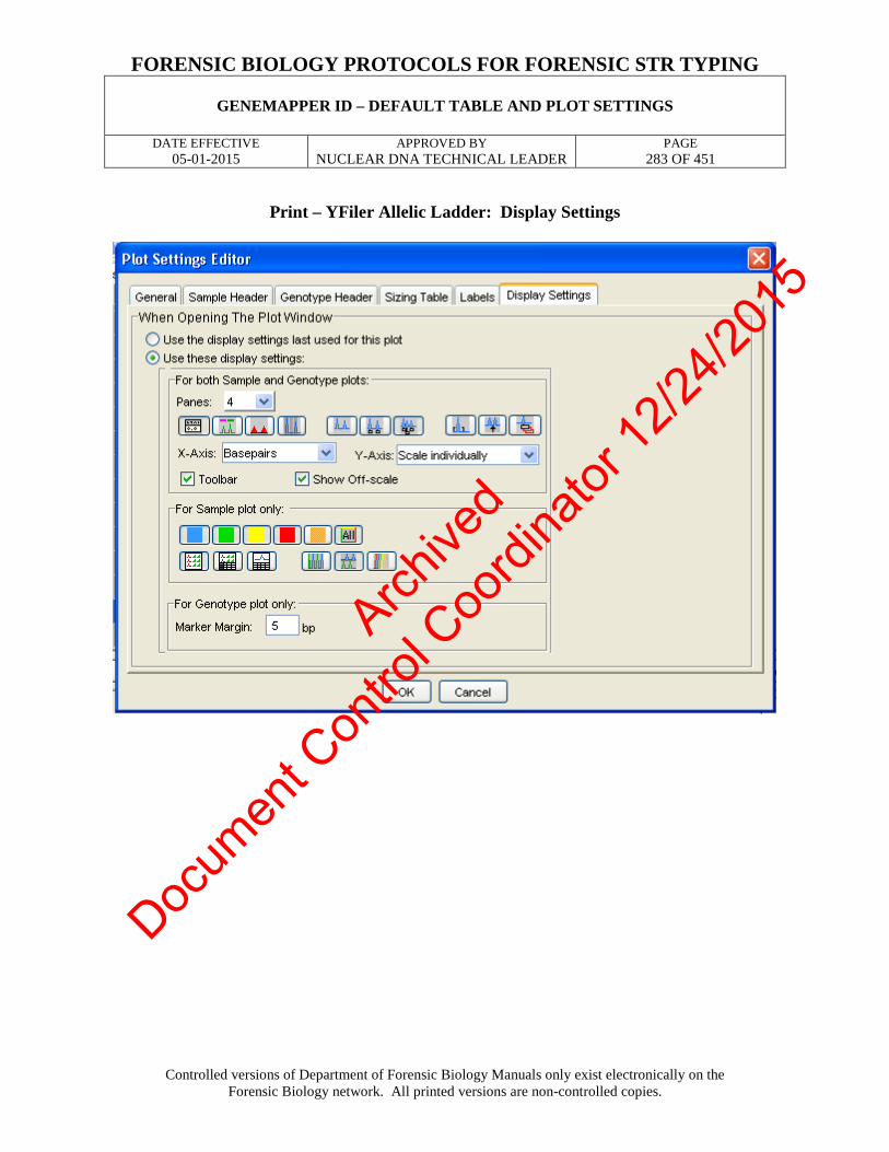
FORENSIC BIOLOGY PROTOCOLS FOR FORENSIC STR TYPING
GENEMAPPER ID – DEFAULT TABLE AND PLOT SETTINGS
DATE EFFECTIVE 05-01-2015
APPROVED BY NUCLEAR DNA TECHNICAL LEADER
PAGE 283 OF 451
Controlled versions of Department of Forensic Biology Manuals only exist electronically on the Forensic Biology network. All printed versions are non-controlled copies.
Print – YFiler Allelic Ladder: Display Settings
Archive
d
Docum
ent C
ontro
l Coo
rdina
tor 12
/24/20
15

FORENSIC BIOLOGY PROTOCOLS FOR FORENSIC STR TYPING
GENEMAPPER ID – DEFAULT TABLE AND PLOT SETTINGS
DATE EFFECTIVE 05-01-2015
APPROVED BY NUCLEAR DNA TECHNICAL LEADER
PAGE 284 OF 451
Controlled versions of Department of Forensic Biology Manuals only exist electronically on the Forensic Biology network. All printed versions are non-controlled copies.
PLOT SETTINGS: PRINT – YFILER CONTROLS
Print – YFiler Controls: Sample Header
Print – YFiler Controls: Genotypes Header
Boxes 3 – 20 are unchecked
Archive
d
Docum
ent C
ontro
l Coo
rdina
tor 12
/24/20
15

FORENSIC BIOLOGY PROTOCOLS FOR FORENSIC STR TYPING
GENEMAPPER ID – DEFAULT TABLE AND PLOT SETTINGS
DATE EFFECTIVE 05-01-2015
APPROVED BY NUCLEAR DNA TECHNICAL LEADER
PAGE 285 OF 451
Controlled versions of Department of Forensic Biology Manuals only exist electronically on the Forensic Biology network. All printed versions are non-controlled copies.
Print – YFiler Controls: Sizing Table
Print – YFiler Controls: Labels
Archive
d
Docum
ent C
ontro
l Coo
rdina
tor 12
/24/20
15

FORENSIC BIOLOGY PROTOCOLS FOR FORENSIC STR TYPING
GENEMAPPER ID – DEFAULT TABLE AND PLOT SETTINGS
DATE EFFECTIVE 05-01-2015
APPROVED BY NUCLEAR DNA TECHNICAL LEADER
PAGE 286 OF 451
Controlled versions of Department of Forensic Biology Manuals only exist electronically on the Forensic Biology network. All printed versions are non-controlled copies.
Print – YFiler Controls: Display Settings
Archive
d
Docum
ent C
ontro
l Coo
rdina
tor 12
/24/20
15

FORENSIC BIOLOGY PROTOCOLS FOR FORENSIC STR TYPING
GENEMAPPER ID – DEFAULT TABLE AND PLOT SETTINGS
DATE EFFECTIVE 05-01-2015
APPROVED BY NUCLEAR DNA TECHNICAL LEADER
PAGE 287 OF 451
Controlled versions of Department of Forensic Biology Manuals only exist electronically on the Forensic Biology network. All printed versions are non-controlled copies.
PLOT SETTINGS: PRINT – YFiler SAMPLES
Print – YFiler Samples: Sample Header
Print – YFiler Samples: Genotypes Header
Boxes 3 – 20 are unchecked
Archive
d
Docum
ent C
ontro
l Coo
rdina
tor 12
/24/20
15

FORENSIC BIOLOGY PROTOCOLS FOR FORENSIC STR TYPING
GENEMAPPER ID – DEFAULT TABLE AND PLOT SETTINGS
DATE EFFECTIVE 05-01-2015
APPROVED BY NUCLEAR DNA TECHNICAL LEADER
PAGE 288 OF 451
Controlled versions of Department of Forensic Biology Manuals only exist electronically on the Forensic Biology network. All printed versions are non-controlled copies.
Print – YFiler Samples: Sizing Table
Print – YFiler Samples: Labels
Archive
d
Docum
ent C
ontro
l Coo
rdina
tor 12
/24/20
15

FORENSIC BIOLOGY PROTOCOLS FOR FORENSIC STR TYPING
GENEMAPPER ID – DEFAULT TABLE AND PLOT SETTINGS
DATE EFFECTIVE 05-01-2015
APPROVED BY NUCLEAR DNA TECHNICAL LEADER
PAGE 289 OF 451
Controlled versions of Department of Forensic Biology Manuals only exist electronically on the Forensic Biology network. All printed versions are non-controlled copies.
Print – YFiler Samples: Display Settings
Archive
d
Docum
ent C
ontro
l Coo
rdina
tor 12
/24/20
15

FORENSIC BIOLOGY PROTOCOLS FOR FORENSIC STR TYPING
GENEMAPPER ID – DEFAULT TABLE AND PLOT SETTINGS
DATE EFFECTIVE 05-01-2015
APPROVED BY NUCLEAR DNA TECHNICAL LEADER
PAGE 290 OF 451
Controlled versions of Department of Forensic Biology Manuals only exist electronically on the Forensic Biology network. All printed versions are non-controlled copies.
PLOT SETTINGS: MINIFILER ANALYSIS VIEW
MiniFiler Analysis View: Sample Header
Archive
d
Docum
ent C
ontro
l Coo
rdina
tor 12
/24/20
15

FORENSIC BIOLOGY PROTOCOLS FOR FORENSIC STR TYPING
GENEMAPPER ID – DEFAULT TABLE AND PLOT SETTINGS
DATE EFFECTIVE 05-01-2015
APPROVED BY NUCLEAR DNA TECHNICAL LEADER
PAGE 291 OF 451
Controlled versions of Department of Forensic Biology Manuals only exist electronically on the Forensic Biology network. All printed versions are non-controlled copies.
MiniFiler Analysis View: Genotype Header
5-20 are blank
MiniFiler Analysis View: Sizing Table
Archive
d
Docum
ent C
ontro
l Coo
rdina
tor 12
/24/20
15

FORENSIC BIOLOGY PROTOCOLS FOR FORENSIC STR TYPING
GENEMAPPER ID – DEFAULT TABLE AND PLOT SETTINGS
DATE EFFECTIVE 05-01-2015
APPROVED BY NUCLEAR DNA TECHNICAL LEADER
PAGE 292 OF 451
Controlled versions of Department of Forensic Biology Manuals only exist electronically on the Forensic Biology network. All printed versions are non-controlled copies.
MiniFiler Analysis View: Labels
MiniFiler Analysis View: Display Settings
Archive
d
Docum
ent C
ontro
l Coo
rdina
tor 12
/24/20
15

FORENSIC BIOLOGY PROTOCOLS FOR FORENSIC STR TYPING
GENEMAPPER ID – DEFAULT TABLE AND PLOT SETTINGS
DATE EFFECTIVE 05-01-2015
APPROVED BY NUCLEAR DNA TECHNICAL LEADER
PAGE 293 OF 451
Controlled versions of Department of Forensic Biology Manuals only exist electronically on the Forensic Biology network. All printed versions are non-controlled copies.
PLOT SETTINGS: PRINT – MINIFILER ALLELIC LADDER
Print – MiniFiler Allelic Ladder: Sample Header
Print – MiniFiler Allelic Ladder: Genotype Header
5-20 are blank
Archive
d
Docum
ent C
ontro
l Coo
rdina
tor 12
/24/20
15

FORENSIC BIOLOGY PROTOCOLS FOR FORENSIC STR TYPING
GENEMAPPER ID – DEFAULT TABLE AND PLOT SETTINGS
DATE EFFECTIVE 05-01-2015
APPROVED BY NUCLEAR DNA TECHNICAL LEADER
PAGE 294 OF 451
Controlled versions of Department of Forensic Biology Manuals only exist electronically on the Forensic Biology network. All printed versions are non-controlled copies.
Print – MiniFiler Allelic Ladder: Sizing Table
Print – MiniFiler Allelic Ladder: Labels
Archive
d
Docum
ent C
ontro
l Coo
rdina
tor 12
/24/20
15

FORENSIC BIOLOGY PROTOCOLS FOR FORENSIC STR TYPING
GENEMAPPER ID – DEFAULT TABLE AND PLOT SETTINGS
DATE EFFECTIVE 05-01-2015
APPROVED BY NUCLEAR DNA TECHNICAL LEADER
PAGE 295 OF 451
Controlled versions of Department of Forensic Biology Manuals only exist electronically on the Forensic Biology network. All printed versions are non-controlled copies.
Print – MiniFiler Allelic Ladder: Display Settings
Archive
d
Docum
ent C
ontro
l Coo
rdina
tor 12
/24/20
15

FORENSIC BIOLOGY PROTOCOLS FOR FORENSIC STR TYPING
GENEMAPPER ID – DEFAULT TABLE AND PLOT SETTINGS
DATE EFFECTIVE 05-01-2015
APPROVED BY NUCLEAR DNA TECHNICAL LEADER
PAGE 296 OF 451
Controlled versions of Department of Forensic Biology Manuals only exist electronically on the Forensic Biology network. All printed versions are non-controlled copies.
PLOT SETTINGS: PRINT – MINIFILER CONTROLS
Print – MiniFiler Controls: Sample Header
Print – MiniFiler Controls: Genotype Header
5-20 are blank
Archive
d
Docum
ent C
ontro
l Coo
rdina
tor 12
/24/20
15

FORENSIC BIOLOGY PROTOCOLS FOR FORENSIC STR TYPING
GENEMAPPER ID – DEFAULT TABLE AND PLOT SETTINGS
DATE EFFECTIVE 05-01-2015
APPROVED BY NUCLEAR DNA TECHNICAL LEADER
PAGE 297 OF 451
Controlled versions of Department of Forensic Biology Manuals only exist electronically on the Forensic Biology network. All printed versions are non-controlled copies.
Print – MiniFiler Controls: Sizing Table
Print – MiniFiler Controls: Labels
Archive
d
Docum
ent C
ontro
l Coo
rdina
tor 12
/24/20
15

FORENSIC BIOLOGY PROTOCOLS FOR FORENSIC STR TYPING
GENEMAPPER ID – DEFAULT TABLE AND PLOT SETTINGS
DATE EFFECTIVE 05-01-2015
APPROVED BY NUCLEAR DNA TECHNICAL LEADER
PAGE 298 OF 451
Controlled versions of Department of Forensic Biology Manuals only exist electronically on the Forensic Biology network. All printed versions are non-controlled copies.
Print – MiniFiler Controls: Display Settings
Archive
d
Docum
ent C
ontro
l Coo
rdina
tor 12
/24/20
15

FORENSIC BIOLOGY PROTOCOLS FOR FORENSIC STR TYPING
GENEMAPPER ID – DEFAULT TABLE AND PLOT SETTINGS
DATE EFFECTIVE 05-01-2015
APPROVED BY NUCLEAR DNA TECHNICAL LEADER
PAGE 299 OF 451
Controlled versions of Department of Forensic Biology Manuals only exist electronically on the Forensic Biology network. All printed versions are non-controlled copies.
PLOT SETTINGS: PRINT – MINIFILER SAMPLES
Print – MiniFiler Samples: Sample Header
Print – MiniFiler Samples: Genotype Header
5-20 are blank
Archive
d
Docum
ent C
ontro
l Coo
rdina
tor 12
/24/20
15

FORENSIC BIOLOGY PROTOCOLS FOR FORENSIC STR TYPING
GENEMAPPER ID – DEFAULT TABLE AND PLOT SETTINGS
DATE EFFECTIVE 05-01-2015
APPROVED BY NUCLEAR DNA TECHNICAL LEADER
PAGE 300 OF 451
Controlled versions of Department of Forensic Biology Manuals only exist electronically on the Forensic Biology network. All printed versions are non-controlled copies.
Print – MiniFiler Samples: Sizing Table
Print – MiniFiler Samples: Labels
Archive
d
Docum
ent C
ontro
l Coo
rdina
tor 12
/24/20
15

FORENSIC BIOLOGY PROTOCOLS FOR FORENSIC STR TYPING
GENEMAPPER ID – DEFAULT TABLE AND PLOT SETTINGS
DATE EFFECTIVE 05-01-2015
APPROVED BY NUCLEAR DNA TECHNICAL LEADER
PAGE 301 OF 451
Controlled versions of Department of Forensic Biology Manuals only exist electronically on the Forensic Biology network. All printed versions are non-controlled copies.
Print – MiniFiler Samples: Display Settings
Revision History: March 24, 2010 – Initial version of procedure. September 27, 2010 – Updated default print settings. April 1, 2014 – Revised to include information for YFiler. May 1, 2015 – Removed references to Power Plex Y
Archive
d
Docum
ent C
ontro
l Coo
rdina
tor 12
/24/20
15

FORENSIC BIOLOGY PROTOCOLS FOR FORENSIC STR ANALYSIS
STR RESULTS INTERPRETATION
DATE EFFECTIVE 08-14-2015
APPROVED BY NUCLEAR DNA TECHNICAL LEADER
PAGE 302 OF 451
Back to Table of contents
Controlled versions of Department of Forensic Biology Manuals only exist electronically on the Forensic Biology network. All printed versions are non-controlled copies.
STR Results Interpretation I. Allele Calling Criteria
Results are interpreted by observing the occurrence of electropherogram peaks for the loci that are amplified simultaneously. The identification of a peak as an allele is determined through comparison to the allelic ladder. An allele is characterized by the labeling color of the locus specific primers and the length of the amplified fragment. See the Appendix for a listing of each locus in each multiplex. For each locus an individual can be either homozygous and show one allele, or heterozygous and show two alleles. In order to eliminate possible background and stutter peaks, only peaks that display intensity above the minimum threshold based on validation data – 75 Relative Fluorescent Units (RFU’s) – are labeled as alleles.
A. Computer program processing steps for raw data:
1. Recalculating fluorescence peaks using the instrument-specific spectral
file in order to correct for the overlapping spectra of the fluorescent dyes. 2. Calculating the fragment length for the detected peaks using the known in-
lane standard fragments. 3. For Identifiler 28, Identifiler 31, Minifiler, and YFiler (systems with an
allelic ladder) – comparing and adjusting the allele categories to the sizing of the co-electrophoresed allelic ladder by calculating the off sets (the difference between the first allele in a category and the first allele in the allelic ladder at each locus).
4. For Identifiler 28, Identifiler 31, Minifiler, and YFiler – labeling of all sized fragments that are above threshold and fall within the locus specific size range (see Appendix). Removing the labels from minor peaks (background and stutter) according to the filter functions detailed in the appendix of this manual.
Archive
d
Docum
ent C
ontro
l Coo
rdina
tor 12
/24/20
15

FORENSIC BIOLOGY PROTOCOLS FOR FORENSIC STR ANALYSIS
STR RESULTS INTERPRETATION
DATE EFFECTIVE 08-14-2015
APPROVED BY NUCLEAR DNA TECHNICAL LEADER
PAGE 303 OF 451
Back to Table of contents
Controlled versions of Department of Forensic Biology Manuals only exist electronically on the Forensic Biology network. All printed versions are non-controlled copies.
II. Manual Removal of Non Allelic Peaks
Additional non-allelic peaks may occur under the following instances (Clark 1988, Walsh et al. 1996, Clayton et al. 1998), which may be manually edited. Make sure not to remove any labels for potential DNA alleles. All edits must have a reference point on the editing sheet. When in doubt leave the peak labeled for review. Mixture samples must be edited conservatively and only electrophoresis artifacts can be eliminated. Peaks in stutter positions cannot be edited for mixtures, except when masked, (see D4).
A. Pull-up
1. Pull-up of peaks in one color may be due to very high peaks in another color. Pull-up is a spectral artifact that is caused by the inability of the software to compensate for the spectral overlap between the different colors if the peak height is too high.
2. The label in the other color will have a basepair size very close to the real
allele in the other color. The peak that is considered an artifact or “pull up” will always be shorter than the original, true peak. It is possible for a particularly high stutter peak in for example blue or green, to create pull up in red or orange.
3. Spectral artifacts could also be manifested as a raised baseline between
two high peaks or an indentation of a large peak over another large peak. Labels placed on such artifacts can be removed and is known as “spectral over-subtraction”.
B. Shoulder
Shoulder Peaks are peaks approximately 1-4 bp smaller or larger than main alleles. Shoulder Peaks can be recognized by their shape; they do not have the shape of an actual peak, rather they are continuous with the main peak.
Archive
d
Docum
ent C
ontro
l Coo
rdina
tor 12
/24/20
15

FORENSIC BIOLOGY PROTOCOLS FOR FORENSIC STR ANALYSIS
STR RESULTS INTERPRETATION
DATE EFFECTIVE 08-14-2015
APPROVED BY NUCLEAR DNA TECHNICAL LEADER
PAGE 304 OF 451
Back to Table of contents
Controlled versions of Department of Forensic Biology Manuals only exist electronically on the Forensic Biology network. All printed versions are non-controlled copies.
C. Split peaks (“N” Bands)
Split peaks are due to the main peak being split into two peaks caused by the Taq polymerase activity that causes the addition of a single “A” to the terminus of the amplified product (“N+1” band). Since allele calling is based on N+1 bands, a complete extra “A” addition is desired.
1. Split peaks due to incomplete non nucleotide template A addition should
not occur for samples with low amounts of DNA 2. Split peaks can also be an electrophoresis artifact and attributed to an
overblown allele. Additional labels can be edited out. 3. Split peaks may occur in overblown samples or amplicons due to matrix
over-subtraction. For example, an overblown green peak may dip at the top where a pull up peak is present in blue and in red. The yellow peak will also display over-subtraction with a dip at the peak’s crest. In this instance, the allele call on the left hand peak is usually edited.
D. Stutter – 4bp smaller than the main allele for most systems, 3, 4, 5 and 6bp
smaller that the main allele for Yfiler (Peaks one repeat unit longer or multiple units shorter than the main allele may be stutter, but is rare.)
1. The macro for each system has an automated stutter filter for each locus
(see appendix for stutter values) 2. In addition, for single source samples, potential stutter peaks may be
removed if they are within 20% of the larger peak for Identifiler and Yfiler.
3. Identifiler 31 samples have been shown to occasionally display peaks 4 bp
longer than the main allele.
Archive
d
Docum
ent C
ontro
l Coo
rdina
tor 12
/24/20
15

FORENSIC BIOLOGY PROTOCOLS FOR FORENSIC STR ANALYSIS
STR RESULTS INTERPRETATION
DATE EFFECTIVE 08-14-2015
APPROVED BY NUCLEAR DNA TECHNICAL LEADER
PAGE 305 OF 451
Back to Table of contents
Controlled versions of Department of Forensic Biology Manuals only exist electronically on the Forensic Biology network. All printed versions are non-controlled copies.
4. If the main allele has an additional label prior to the main allele label (e.g. a shoulder peak, 1bp less in size) this peak will be used for stutter percentage calculation and the stutter might not have been automatically removed. In this case, the stutter peak can also be removed for mixtures.
5. Peaks that are overblown with RFUs above 7000 (and thus their peak
height has plateaued), will often have a stutter peak that will be more than 20% of the main peak. If the sample is not a mixture, the stutter peaks for the alleles above 7000 RFUs may be removed.
E. Non specific artifacts
This category should be used if a labeled peak is caused by a not-previously categorized technical problem or caused by non-specific priming in a multiplex reaction. These artifacts are usually easily recognized due to their low peak height and their position outside of the allele range. For YFiler™, this edit is applicable for artifacts at the +/- 2bp position for DYS19.
F. Elevated baseline
Elevated or noisy baseline may be labeled. They do not resemble distinct peaks. Sometimes, an elevated baseline may occur adjacent to a shoulder peak.
G. Spikes
1. Generally, a spike is an electrophoresis artifact that is usually present in all colors.
Archive
d
Docum
ent C
ontro
l Coo
rdina
tor 12
/24/20
15

FORENSIC BIOLOGY PROTOCOLS FOR FORENSIC STR ANALYSIS
STR RESULTS INTERPRETATION
DATE EFFECTIVE 08-14-2015
APPROVED BY NUCLEAR DNA TECHNICAL LEADER
PAGE 306 OF 451
Back to Table of contents
Controlled versions of Department of Forensic Biology Manuals only exist electronically on the Forensic Biology network. All printed versions are non-controlled copies.
2. Spikes might look like a single vertical line or a peak. They can easily be distinguished from DNA peaks by looking at the other fluorescent colors, including red or orange. For Identifiler, a spike may appear in the red or green, but not be readily apparent in the other colors. However, you can zoom in and confirm the spike.
3. Spikes may be caused by power surges, crystals, or air bubbles traveling
past the laser detector window during electrophoresis.
H. Dye Artifacts
1. Constant peaks caused by fluorescent dye that is not attached to the primers or is unincorporated dye-labeled primers. These “color blips” can occur in any color. Dye artifacts commonly occur in the beginning of the green, blue, and the yellow loci right after the primer peaks (Applied Biosystems 2004 a and b).
2. These artifacts may or may not appear in all samples, but are particularly
apparent in samples with little or no DNA such as the negative controls.
I. Removal of a range of alleles
Mixed samples which contain overblown peaks must be rerun. Refer to the GeneMapper ID Analysis Section for more information.
All manual removals of peak labels must be documented. This also serves as documentation for the technical review. Check the appendix for the correct peak assignments to each allelic ladder and the expected genotype of the positive control.
Archive
d
Docum
ent C
ontro
l Coo
rdina
tor 12
/24/20
15

FORENSIC BIOLOGY PROTOCOLS FOR FORENSIC STR ANALYSIS
STR RESULTS INTERPRETATION
DATE EFFECTIVE 08-14-2015
APPROVED BY NUCLEAR DNA TECHNICAL LEADER
PAGE 307 OF 451
Back to Table of contents
Controlled versions of Department of Forensic Biology Manuals only exist electronically on the Forensic Biology network. All printed versions are non-controlled copies.
III. Detection of Rare Alleles
A. Off-ladder (OL) Alleles
1. A peak labeled as an OL allele may be a true allele not represented in the allelic ladder or may be a migration artifact. To ensure that it is not a migration artifact, an OL allele must be confirmed by another instance of the OL allele from any sample that was run separately.
2. Examine the OL allele closely in comparison to the ladder. If it is not at
least one full basepair from a true allele, it is likely not a real off-ladder allele.
3. If an OL allele does not appear to be a true off-ladder allele (ex., if it is
0.55 bp away from the closest allelic ladder allele call), the sample should be rerun or re-injected in order to determine the correct allele call.
4. If an OL allele appears to be a true off-ladder allele based on its sizing in comparison to the ladder, determine whether the sample needs to be rerun:
a. A rerun or re-injection is required if:
• The OL allele is not seen in any other sample in the case. • Other samples from the same case have the same OL allele,
however all samples were run within the same injection. At least one sample must be rerun or re-injected to confirm the OL allele.
b. A rerun or re-injection is not required if:
• The sample with the OL allele is deemed inconclusive or will not be used for comparison purposes.
• Another sample in the case has the same OL allele present and the other sample was run in a different injection. This confirms that the OL allele is not due to a migration artifact.
• The OL allele is seen only in the minor component and there are too few alleles for comparison
5. Alleles that are within the range of the ladder, or are either one repeat
larger or one repeat smaller than the ladder, and are called by the software need not be rerun (e.g., a “19.2” at FGA or a “20” at D3S1358).
Archive
d
Docum
ent C
ontro
l Coo
rdina
tor 12
/24/20
15

FORENSIC BIOLOGY PROTOCOLS FOR FORENSIC STR ANALYSIS
STR RESULTS INTERPRETATION
DATE EFFECTIVE 08-14-2015
APPROVED BY NUCLEAR DNA TECHNICAL LEADER
PAGE 308 OF 451
Back to Table of contents
Controlled versions of Department of Forensic Biology Manuals only exist electronically on the Forensic Biology network. All printed versions are non-controlled copies.
6. If an OL allele is labeled by the software as “OL” and is more than one repeat larger or smaller than the ladder for that locus, or if there is an unlabeled peak apparent outside the bin for a locus, then follow the guidelines in steps 2 and 3 above to determine whether the sample needs to be rerun.
7. Once an OL allele has been confirmed by another sample, rerun, or re-
injection, this allele may be assigned the appropriate allele call based on its measurement in comparison to the allelic ladder if it is between alleles, or by using “<” or “>” if above or below the range of the ladder for that locus.
IV. Interpretation of STR Data
A. Allele Table
1. After the assigning of allele names to the remaining labeled peaks, the software prepares a result table where all peaks that meet the above listed criteria are listed as alleles. The allele nomenclature follows the recommendations of the International Society for Forensic Haemogenetics (ISFH), (DNA recommendations, 1994) and reflects the number of 4bp core repeat units for the different alleles.
2. Subtypes displaying incomplete repeat units are labeled with the number
of complete repeats and a period followed by the number of additional bases.
3. The Y chromosome allele nomenclature is also based on the number of
core repeats and follows the nomenclature suggested in Evaluation of Y Chromosomal STRs (Kayser et al 1997) and the one used in the European Caucasian Y-STR Haplotype database (Roewer et al 2001).
B. Electropherograms
1. Capillary electrophoresis plot data containing case specific samples are
part of each case record.
Archive
d
Docum
ent C
ontro
l Coo
rdina
tor 12
/24/20
15

FORENSIC BIOLOGY PROTOCOLS FOR FORENSIC STR ANALYSIS
STR RESULTS INTERPRETATION
DATE EFFECTIVE 08-14-2015
APPROVED BY NUCLEAR DNA TECHNICAL LEADER
PAGE 309 OF 451
Back to Table of contents
Controlled versions of Department of Forensic Biology Manuals only exist electronically on the Forensic Biology network. All printed versions are non-controlled copies.
2. The table reflects the number and allele assignments of the labeled peaks visible on the electrophoresis plot. The electrophoresis plots are the basis for results interpretation.
3. The electrophoresis plot will display peak height information, unlabeled
peaks, intensity differences that may indicate the presence of a mixture, and will show all peaks at each locus.
4. Looking at the electrophoresis plots also serves as a control for the editing
process.
5. In certain instances it may be necessary to view the electropherogram electronically:
a. No peak is above the minimum threshold but unlabeled peaks are visible. Refer to GeneMapper ID Analysis Procedure.
b. High peaks and very minor peaks present in the same color lane
i. Since the RFU scale of the electropherogram is based on the highest peak in each color, alleles at weak loci will not be clearly visible if the loci are imbalanced.
ii. Access the file for mixture interpretation or allelic dropout
detection.
iii. Go to View menu enter a fixed y-scale for Plot Options, Main Window Lower Panel. Generate the new electropherogram plot documentation. Do not save changes.
c. Plot states “no size data available”
i. None of the peaks were above threshold ii. The original data which may be visible in the raw data file
of GeneMapper ID displays visible peaks below the sizing threshold.
d. Distinct unlabeled peak in locus with similar height as
“homozygous” allele. Refer to Section III – Detection of Rare Alleles.
Archive
d
Docum
ent C
ontro
l Coo
rdina
tor 12
/24/20
15

FORENSIC BIOLOGY PROTOCOLS FOR FORENSIC STR ANALYSIS
STR RESULTS INTERPRETATION
DATE EFFECTIVE 08-14-2015
APPROVED BY NUCLEAR DNA TECHNICAL LEADER
PAGE 310 OF 451
Back to Table of contents
Controlled versions of Department of Forensic Biology Manuals only exist electronically on the Forensic Biology network. All printed versions are non-controlled copies.
V. Interpretation of controls A. Electrophoresis Controls 1. Allelic Ladder
Evaluate the allelic ladder for expected results – Refer to GeneMapper ID “References – Allelic Ladders, Controls, and Size Standards” Section.
2. Amplification Positive Control
a. Evaluate the positive control for the expected type using the
GeneMapper ID “References – Allelic Ladders, Controls, and Size Standards” Section.
b. If the positive control has been shown to give the correct type, this confirms the integrity of the electrophoresis run and amplification set.
c. The amplification positive control may be run at a different (lower or higher) injection parameter or dilution than the corresponding samples and the amplification set can pass.
d. Positive controls amplified in Identifiler 31 can be amplified in
triplicate within one amplification set (e.g. replicates a, b and c). See section 4 for additional information regarding these controls.
3. Electrophoresis Run with Failed Positive Control
a. Electrophoresis Run containing one Positive Control
i. Fill out an Electrophoresis Failure Report or a Resolution Documentation and indicate the Positive Control will be rerun
Archive
d
Docum
ent C
ontro
l Coo
rdina
tor 12
/24/20
15

FORENSIC BIOLOGY PROTOCOLS FOR FORENSIC STR ANALYSIS
STR RESULTS INTERPRETATION
DATE EFFECTIVE 08-14-2015
APPROVED BY NUCLEAR DNA TECHNICAL LEADER
PAGE 311 OF 451
Back to Table of contents
Controlled versions of Department of Forensic Biology Manuals only exist electronically on the Forensic Biology network. All printed versions are non-controlled copies.
ii. Retest the Positive Control
a) If the Positive Control passes, then rerun the complete Amplification Set with the retested Positive Control. (The entire amplification set, including the positive control, may be rerun together as determined by the analyst.)
b) If the Positive Control fails; the Amplification Set
fails. Fill out an Electrophoresis Failure Report or a Resolution Documentation and indicate the Amplification Set will be re-amplified.
b. Electrophoresis Run containing more than one Positive Controls i. use another Positive Control to analyze the run
ii. Complete the STR Control Review documentation indicating the failed Positive Control “will be rerun”
iii. Add the sample number corresponding to the (failed) Positive Control to the Editing documentation
iv. Retest the (failed) Positive Control
a) If the Positive Control passes; the Amplification Set passes
b) If the Positive Control fails; the Amplification Set
fails. Complete the STR Control Review documentation indicating the “sample set will be re-amplified”
c. Reruns / Re-injections
An injection set consisting of reruns or re-injections must have at least one Positive Control
Archive
d
Docum
ent C
ontro
l Coo
rdina
tor 12
/24/20
15

FORENSIC BIOLOGY PROTOCOLS FOR FORENSIC STR ANALYSIS
STR RESULTS INTERPRETATION
DATE EFFECTIVE 08-14-2015
APPROVED BY NUCLEAR DNA TECHNICAL LEADER
PAGE 312 OF 451
Back to Table of contents
Controlled versions of Department of Forensic Biology Manuals only exist electronically on the Forensic Biology network. All printed versions are non-controlled copies.
Table 2 Interpretation of Electrophoresis Runs
Controls / Status
Resolution
Allelic Ladder – Pass
Positive Control – Pass
Run passes
Allelic Ladder – Pass
Positive Control – Fail
Refer to Section 3
Allelic Ladder(s) – Fail Positive Control – Fail
Run fails Fill out Electrophoresis Failure Report/ Resolution Documentation
Table 3 Retesting Strategies for Positive Control Positive Control Result Course of action No Data Available - No orange size standard in lane
Rerun
No amplification product but orange size standard correct Rerun with same result
Rerun Re-amplify amplification set
Incorrect genotype - Could be caused by ill-defined size standard, other Genotyper problems or sample mix-up Rerun fails to give correct type
Reanalyze sample, if not able to resolve, rerun amplification product Re-amplify amplification set
OL alleles
- possibly Genotyper problem
Rerun amplification product
Archive
d
Docum
ent C
ontro
l Coo
rdina
tor 12
/24/20
15

FORENSIC BIOLOGY PROTOCOLS FOR FORENSIC STR ANALYSIS
STR RESULTS INTERPRETATION
DATE EFFECTIVE 08-14-2015
APPROVED BY NUCLEAR DNA TECHNICAL LEADER
PAGE 313 OF 451
Back to Table of contents
Controlled versions of Department of Forensic Biology Manuals only exist electronically on the Forensic Biology network. All printed versions are non-controlled copies.
4. Electrophoresis Run containing triplicate Positive Controls amplified in Identifiler 31
a. The alleles which repeat in at least two of three amplifications are
considered part of the composite. The composite for the Positive Control must pass in order for the amplification to pass, meaning that alleles of the Positive Control must repeat in at least two of three amplifications for the amplification set to pass. See section VIII, Guidelines for reporting samples amplified with Identifiler for 31 cycles for additional information regarding the composite.
b. If any replicates of the positive control do not give the correct type, follow the table below as a guideline.
TABLE 4 Retesting Strategies for Positive Controls amplified with Identifiler 31.
Treatment of ID31 Triplicate PE Controls
Replicate(s) pass?
Composite Passes, thus amplification passes?
Course of action
Replicates a, b and c Yes Yes None
Replicates a, b and c; First run
At least one fails due to extra peak(s) or missing peak(s)
Yes Failed replicate(s) should be re-aliquoted and injected at same
parameters Failed replicate(s); Second run
At least one fails due to extra peak(s) or missing peak(s)
Previously passed The failed replicate(s) cannot be
used as an electrophoretic control for future injections
Replicates a, b and c; First run
One replicate has poor size standard (not overblown)
Yes
Failed replicate should be re-injected at same parameters
Failed replicate; Second run
Replicate has poor size standard (not
overblown) Previously passed
Failed replicate should be re-aliquoted and injected at same
parameters Replicates a, b and c; First run
One replicate has overblown size
standard Yes
Failed replicate should be re-injected at a lower parameter
and/or re-aliquotted as necessary
Replicates a, b and c; First run
At least one fails due to overblown peaks resulting in
OL allele(s)
Yes
Failed replicate(s) should be re-injected at lower parameters
and/or re-aliquotted as necessary
Archive
d
Docum
ent C
ontro
l Coo
rdina
tor 12
/24/20
15

FORENSIC BIOLOGY PROTOCOLS FOR FORENSIC STR ANALYSIS
STR RESULTS INTERPRETATION
DATE EFFECTIVE 08-14-2015
APPROVED BY NUCLEAR DNA TECHNICAL LEADER
PAGE 314 OF 451
Back to Table of contents
Controlled versions of Department of Forensic Biology Manuals only exist electronically on the Forensic Biology network. All printed versions are non-controlled copies.
Follow this table as a guideline, however more situations may arise. If the composite does not pass after the first run, re-aliquot and/or re-inject affected replicates as needed. If a failed replicate does not resolve itself, it should not be used as an electrophoretic control for future injections. NOTE: Samples may not be amplified/run in Identifiler 31 if the composite does not pass. All peaks should be removed from electropherograms for samples associated with a failed Identifiler 31 triplicate positive control.
B. Extraction Negative and Amplification Negative Controls
1. Minifiler negative controls, and Identifiler 28 and Yfiler negative controls injected under normal parameters:
a. Evaluate the extraction negative and/or amplification negative
control for expected results b. If peaks attributed to DNA are detected in an extraction negative and/or amplification negative control
i. Retest the extraction negative control and/or amplification negative control
ii. Refer to Table 4 and/or 5 for Retesting Strategies
Archive
d
Docum
ent C
ontro
l Coo
rdina
tor 12
/24/20
15

FORENSIC BIOLOGY PROTOCOLS FOR FORENSIC STR ANALYSIS
STR RESULTS INTERPRETATION
DATE EFFECTIVE 08-14-2015
APPROVED BY NUCLEAR DNA TECHNICAL LEADER
PAGE 315 OF 451
Back to Table of contents
Controlled versions of Department of Forensic Biology Manuals only exist electronically on the Forensic Biology network. All printed versions are non-controlled copies.
Table 5 Retesting Strategies for Extraction Negative Control Extraction Negative Result Course of action No data available - No orange size standard in lane
Rerun
Misshaped orange size standard peaks
Control passes if no peaks are present
Run artifacts such as color blips or spikes
Edit Rerun only if the artifacts are so abundant that amplified DNA might be masked
Alleles detected – Initial Run Rerun Alleles detected – Rerun Re-amplify control
Alleles detected – Re-amplification Extraction set fails
All samples must be re-extracted
Table 6 Retesting Strategies for Amplification Negative Controls
Amplification Negative Result Course of action No data available - No orange size standard in lane
Rerun
Misshapen orange size standard peaks
Control passes if no peaks are present
Run artifacts such as color blips or spikes
Edit Rerun only if artifacts are so abundant that amplified DNA might be masked.
Peaks detected – Initial Run Re-run Peaks detected – Rerun Amplification set fails
Re-amplify amplification set
Archive
d
Docum
ent C
ontro
l Coo
rdina
tor 12
/24/20
15

FORENSIC BIOLOGY PROTOCOLS FOR FORENSIC STR ANALYSIS
STR RESULTS INTERPRETATION
DATE EFFECTIVE 08-14-2015
APPROVED BY NUCLEAR DNA TECHNICAL LEADER
PAGE 316 OF 451
Back to Table of contents
Controlled versions of Department of Forensic Biology Manuals only exist electronically on the Forensic Biology network. All printed versions are non-controlled copies.
2. Identifiler 28 and Yfiler negative controls injected under “high” parameters a. Evaluate the extraction negative, amplification negative, and/or
microcon negative control for expected results b. If peaks attributed to DNA are detected in a negative control, refer
to Table 7 for retesting strategies. i. Re-aliquot and rerun the control at the same injection
conditions to confirm failure. If the realiquot still fails, the control (either the original aliquot so one can re-inject the sample plate) or the second aliquot must be re-injected with a lower injection parameter.
ii. If a negative control fails following injection with “high” parameters but passes with injections under “normal” parameters, data from samples in the amplification set injected with “high” parameters fails accordingly, whereas data from samples injected with “normal” parameters passes.
3. Identifiler 31 Controls
Negative controls can display spurious allele peaks and still pass, unless:
a. The allele occurs in two of the two or three amplifications, which
indicates potential contamination instead of drop-in. If this happens for only one or two loci, the affected loci must be evaluated for all samples. The locus is inconclusive for samples that display the same allele, which is present in the negative control, at this locus.
b. If more than two repeating peaks are present in a negative control,
the amplification or extraction fails. c. Even if none of the spurious allele peaks repeat in two
amplifications, a control fails if too many spurious alleles are present. The cut off is > 9 drop-in peaks distributed over at least two of the three amplification aliquots for three amplifications.
Archive
d
Docum
ent C
ontro
l Coo
rdina
tor 12
/24/20
15

FORENSIC BIOLOGY PROTOCOLS FOR FORENSIC STR ANALYSIS
STR RESULTS INTERPRETATION
DATE EFFECTIVE 08-14-2015
APPROVED BY NUCLEAR DNA TECHNICAL LEADER
PAGE 317 OF 451
Back to Table of contents
Controlled versions of Department of Forensic Biology Manuals only exist electronically on the Forensic Biology network. All printed versions are non-controlled copies.
d. If a negative control fails, it must be realiquotted and rerun at the same injection conditions to confirm failure. If the realiquot still fails, the control (either the original aliquot so one can re-inject the sample plate) or the second aliquot must be re-injected with a lower injection parameter.
e. If a negative control fails following injection with “high”
parameters but passes with injections at “optimal” or “low” parameters, data from samples in the amplification set injected with “high” parameters fails accordingly, whereas data from samples injected with “optimal” or “low” parameters passes.
f. Refer to the Table 6 to determine whether data for ID28 and ID31
samples may be used with respect to the pass/fail status of the associated controls at ID28 and ID31 injection parameters.
Archive
d
Docum
ent C
ontro
l Coo
rdina
tor 12
/24/20
15

FORENSIC BIOLOGY PROTOCOLS FOR FORENSIC STR ANALYSIS
STR RESULTS INTERPRETATION
DATE EFFECTIVE 08-14-2015
APPROVED BY NUCLEAR DNA TECHNICAL LEADER
PAGE 318 OF 451
Back to Table of contents
Controlled versions of Department of Forensic Biology Manuals only exist electronically on the Forensic Biology network. All printed versions are non-controlled copies.
TABLE 7 Interpretation of samples and Retesting Strategies for Negative Controls amplified with Identifiler 31.
Treatment of E-Neg/M’con Negative Controls
Result Course of action
Interpretation
Samples may be amped/run in:
Samples may NOT be amped/run in: (All peaks should be removed from electropherograms)
Amplified in Identifiler 31; Run on H parameters
PASS None
Identifiler 31, Identifiler 28 (any parameter).
N/A
Amplified in Identifiler 31; First run on H parameters
FAIL
Controls should be re-aliquoted and injected at H parameters again
N/A N/A
Amplified in Identifiler 31; Second run on H parameters
FAIL
Controls should be re-injected at N parameters
N/A N/A
Amplified in Identifiler 31; Run on N parameters
PASS None
Identifiler 31 injected at N or L, Identifiler 28 injected at I or IR
Identifiler 31 injected at H
Amplified in Identifiler 31; Run on N parameters
FAIL
Controls should be re-injected at L parameters
N/A N/A
Amplified in Identifiler 31; Run on L parameters
PASS None
Identifiler 31 injected at L, Identifiler 28 injected at I
Identifiler 31 injected at H and N Identifiler 28 injected at IR
Amplified in Identifiler 31, Run on L parameters
FAIL Controls may be amped in Identifiler 28
N/A
Identifiler 31, Identifiler 28 (any parameter).
H = High injection for Identifiler 31 samples at 6 kV 30 sec N = Normal injection for Identifiler 31 samples at 3 kV 20 sec L = Normal injection for Identifiler 31 samples at 1 kV 22sec
Archive
d
Docum
ent C
ontro
l Coo
rdina
tor 12
/24/20
15

FORENSIC BIOLOGY PROTOCOLS FOR FORENSIC STR ANALYSIS
STR RESULTS INTERPRETATION
DATE EFFECTIVE 08-14-2015
APPROVED BY NUCLEAR DNA TECHNICAL LEADER
PAGE 319 OF 451
Back to Table of contents
Controlled versions of Department of Forensic Biology Manuals only exist electronically on the Forensic Biology network. All printed versions are non-controlled copies.
TABLE 8 Interpretation of samples and Retesting Strategies for Extraction/Microcon Negative Controls amplified with Identifiler 28.*
Treatment of E-Neg/M’con Negative Controls
Result Course of action
Interpretation
Samples may be amped/run in:
Samples may NOT be amped/run in: (All peaks should be removed from electropherograms)
Amplified in Identifiler 28; Run on IR Parameters
PASS None Identifiler 28 injected at I or IR and YFiler
Identifiler 31
Amplified in Identifiler 28; First run on IR Parameters
FAIL
Controls should be re-aliquoted and injected at IR again
N/A N/A
Amplified in Identifiler 28; Second run on IR Parameters
FAIL
Controls should be re-injected at I
N/A N/A
Amplified in Identifiler 28; Run on I Parameters
PASS None Identifiler 28 injected at I and YFiler
Identifiler 31 and Identifiler 28 injected at IR
Amplified in Identifiler 28; Run on I Parameters
FAIL
Controls may be amped in Y-STR’s as needed
N/A Identifiler 31 and Identifiler 28 (all injection parameters)
IR = High injection for Identifiler 28 samples at 5 kV 20 sec I = Normal injection for Identifiler 28 samples at 1 kV 22 sec * If a negative control is amplified in Identifiler 28 initially, there may not be enough volume for Identifiler
31 amplification
Archive
d
Docum
ent C
ontro
l Coo
rdina
tor 12
/24/20
15

FORENSIC BIOLOGY PROTOCOLS FOR FORENSIC STR ANALYSIS
STR RESULTS INTERPRETATION
DATE EFFECTIVE 08-14-2015
APPROVED BY NUCLEAR DNA TECHNICAL LEADER
PAGE 320 OF 451
Back to Table of contents
Controlled versions of Department of Forensic Biology Manuals only exist electronically on the Forensic Biology network. All printed versions are non-controlled copies.
VI. Reporting Procedures
Evidence samples must meet the concordant analyses and “duplicate rule.” To improve workflow, evidence samples may automatically be duplicated regardless of DNA concentration.
A. Guidelines for Reporting Allelic Results
1. Items listed in results tables should be limited to samples that are used to
draw important conclusions of the case, including all deconvolutions. Genotypes are not reported and should not be inferred, i.e., if only a “7" allele is found; it should be reported as 7. Alleles and/or peaks are listed in the results tables regardless of intensity differences, based on the reporting criteria below.
2. If an allele meets the above reporting thresholds and fulfills the
concordant analyses and the duplicate rule as stated in the General PCR Guidelines, then the allele will be evaluated for the results table in the file.
3. For samples amplified in Identifiler 31 or Identifiler 28, small loci may be
overblown in order to visualize larger loci. In these instances, use the data from an injection with lower parameters (or run at a dilution) for the overblown loci whereas data from injections with higher parameters may be used for allelic assignments for larger loci. In this manner, a complete or near complete profile may be determined. Regarding the small loci at high injection parameters, remove the peaks if they are overblown and consider the locus inconclusive at the high injection parameters.
4. If no alleles are detected in a locus, then the locus may be reported as
“NEG” (no alleles detected).
Archive
d
Docum
ent C
ontro
l Coo
rdina
tor 12
/24/20
15

FORENSIC BIOLOGY PROTOCOLS FOR FORENSIC STR ANALYSIS
STR RESULTS INTERPRETATION
DATE EFFECTIVE 08-14-2015
APPROVED BY NUCLEAR DNA TECHNICAL LEADER
PAGE 321 OF 451
Back to Table of contents
Controlled versions of Department of Forensic Biology Manuals only exist electronically on the Forensic Biology network. All printed versions are non-controlled copies.
B. Previously unreported rare alleles
1. A distinct peak of the same labeling color outside the allelic range could be a rare new allele for this locus. This possibility should be considered if:
a. The overall amplification for the other loci displays distinct peaks
>75 (or 100 if applicable) and does not show artifacts b. The same color locus closest to the new size peak does not have
more than one allele peak, and
c. The new size peak is also detected in the duplicate run.
2. All alleles that are not present in the allelic ladder should be identified by their relative position to the alleles in the allelic ladder. The peak label should show the length in base pairs and this value can be used to determine the proper allele nomenclature. A D7S820 allele of the length 274 bp in Identifiler, is located between alleles 10 (271 bp) and 11 (275) and has to be designated 10.3. The off-ladder allele should be reported using this nomenclature.
3. Off-ladder alleles which fall outside the range of the allelic ladder at that
locus should be reported as < or > the smallest or largest allele in the ladder.
C. Discrepancies for overlapping loci in different multiplex systems
1. The primer-binding site of an allele may contain a mutation. a. This mutation may make the annealing phase of amplification less
efficient. b. Alternatively, if the mutation is near the 3' end, this may
completely block extension (Clayton et al. 1998).
2. This mutation may result in a pseudo-homozygote type. a. For a specific set of primers, this is reproducible. b. However, these mutations are extremely rare, estimated between
0.01 and 0.001 per locus (Clayton et al. 1998).
Archive
d
Docum
ent C
ontro
l Coo
rdina
tor 12
/24/20
15

FORENSIC BIOLOGY PROTOCOLS FOR FORENSIC STR ANALYSIS
STR RESULTS INTERPRETATION
DATE EFFECTIVE 08-14-2015
APPROVED BY NUCLEAR DNA TECHNICAL LEADER
PAGE 322 OF 451
Back to Table of contents
Controlled versions of Department of Forensic Biology Manuals only exist electronically on the Forensic Biology network. All printed versions are non-controlled copies.
3. If a pseudo-homozygote type for a locus was generated, evidence and exemplar samples amplified with the same primer sequence can be used for comparison. a. Identifiler has the same primer sequences as Cofiler and Profiler
Plus; however, these sequences differ in Minifiler. b. Therefore, the results from amplification with Identifiler may not
be reproducible when compared with those of Minifiler.
4. If the same locus is amplified using a multiplex system with primer sequences that differ, it is possible to obtain a heterozygote type in one multiplex and the pseudo-homozygote in the second. The heterozygote type is the correct type and should be reported.
VII. Guidelines for Interpretation of Results
The purpose of these guidelines is to provide a framework which can be applied to the interpretation of STR results in casework. The guidelines are based on validation studies, literature references, some standard rules and experience. However, not every situation can be covered by a pre-set rule. Equipped with these guidelines, analysts should rely on professional judgment and expertise.
A. First evaluate the profile in its entirety to determine whether the sample is
composed of one or more contributors.
1. For Low Template (LT-DNA) samples, refer to the interpretation section of the manual for samples amplified with 31 cycles.
2. A High Template DNA (HT-DNA) sample profile can be considered to
have originated from a single source if: a. Excluding stutter and other explainable artifacts, the sample does
not demonstrate more than two labeled peaks at each locus. b. The peak height ratio (PHR) at each heterozygous locus is above
60.5% for samples amplified with the AmpFlSTR Identifiler® kit for 28 cycles. Note the PHR of a heterozygous pair is determined by dividing the height of the shorter peak (in RFUs) by the height of the taller peak (in RFUs) and expressing the result as a percentage.
Archive
d
Docum
ent C
ontro
l Coo
rdina
tor 12
/24/20
15

FORENSIC BIOLOGY PROTOCOLS FOR FORENSIC STR ANALYSIS
STR RESULTS INTERPRETATION
DATE EFFECTIVE 08-14-2015
APPROVED BY NUCLEAR DNA TECHNICAL LEADER
PAGE 323 OF 451
Back to Table of contents
Controlled versions of Department of Forensic Biology Manuals only exist electronically on the Forensic Biology network. All printed versions are non-controlled copies.
c. If the PHR falls below 60.5% at a locus, consider whether this may be due to a primer binding site mutation, degradation, the amount of template DNA, or extreme allele size differences. Under these circumstances a sample may be considered single source and heterozygote pairs may be assigned even if greater imbalance is observed.
d. If the sample profile complies with the conditions above but three labeled peaks are present at a single locus, the DNA contributor may be tri-allelic at that locus.
3. If an additional allele is present at only one or two loci, these alleles may be the result of a low level mixture detected only at those loci. The source of these allele(s) cannot be determined. The sample may be interpreted according to the guidelines for single source samples.
a. No conclusions can be drawn regarding the source of these alleles that cannot be attributed to Male or Female Donor X.
b. Moreover, no comparisons can be made to this allele(s). 4. Samples that do not meet the single source criteria listed above should
be considered mixed samples.
B. DNA results may be described in one of three categories, designated as “A”,
“B”, or “C”.
1. Samples and/or components of samples with data at all targeted loci should be categorized as “A”. This category includes the following: a. Single source samples with labeled peaks at all loci and no peaks
seen below the detection threshold. b. The major and the minor contributors of mixtures where DNA
profiles are determined at all targeted loci including those loci assigned a “Z” if the “Z” designation was due to potential allelic sharing.
c. The major contributors of mixtures where the DNA profile of the major contributors were determined including those loci assigned a “Z” if the “Z” designation was due to potential allelic sharing, but the DNA profile of the minor contributors were not determined.
Archive
d
Docum
ent C
ontro
l Coo
rdina
tor 12
/24/20
15

FORENSIC BIOLOGY PROTOCOLS FOR FORENSIC STR ANALYSIS
STR RESULTS INTERPRETATION
DATE EFFECTIVE 08-14-2015
APPROVED BY NUCLEAR DNA TECHNICAL LEADER
PAGE 324 OF 451
Back to Table of contents
Controlled versions of Department of Forensic Biology Manuals only exist electronically on the Forensic Biology network. All printed versions are non-controlled copies.
d. Mixtures where the DNA profiles of the contributors were not or could not be determined and no peaks were seen below the detection threshold.
2. All samples or components of samples that are not categorized as “A”
described above or “C” described below may be considered “B”. This encompasses a wide continuum of samples including the following: a. Single source samples with labeled peaks at fewer than all targeted
loci and/or peaks below the detection threshold. b. The major and/or the minor contributors to mixtures where DNA
profiles were determined at less than the targeted number of loci. At least 4 complete loci or at least 5 loci including those assigned a “Z” if the “Z” designation was due to potential allelic sharing or dropout, should have been determined.
c. Mixtures where the DNA profiles of the major and the minor contributors could not be determined and peaks were noted below threshold, or allelic dropout is suspected.
3. Samples and/or components of samples categorized as “C” should not
be interpreted or used for comparison. This category includes the following: a. Too few peaks labeled
i. Single source HT-DNA samples with fewer than eight labeled peaks over four STR loci
ii. HT-DNA single source profiles with fewer than eight alleles over four loci
iii. Single source LT-DNA samples with fewer than eight labeled peaks over six STR loci in the composite
iv. LT-DNA single source profiles with fewer than eight assigned alleles over six loci
v. Single source YSTR data samples with fewer than four alleles over four YSTR loci
vi. Mixed HT-DNA samples with fewer than 12 labeled peaks over six STR loci
vii. Mixed LT-DNA samples with fewer than 12 labeled peaks over eight STR loci in the composite
Archive
d
Docum
ent C
ontro
l Coo
rdina
tor 12
/24/20
15

FORENSIC BIOLOGY PROTOCOLS FOR FORENSIC STR ANALYSIS
STR RESULTS INTERPRETATION
DATE EFFECTIVE 08-14-2015
APPROVED BY NUCLEAR DNA TECHNICAL LEADER
PAGE 325 OF 451
Back to Table of contents
Controlled versions of Department of Forensic Biology Manuals only exist electronically on the Forensic Biology network. All printed versions are non-controlled copies.
viii. Mixed samples where after deconvolution of the major contributor, there remain fewer than eight labeled peaks that cannot be attributed to the major component. In this situation, the remaining alleles should not be used for comparison.
*Note: If after deconvolution, the deduced profile of the major contributor has fewer than eight assigned alleles over four STR loci for HT-DNA samples or eight assigned alleles over six STR loci for LT-DNA samples, the sample should be interpreted as a mixture for comparison only.
b. Too many peaks labeled
i. Mixed HT-DNA samples that show seven or more labeled peaks (repeating or non-repeating) at two or more STR loci
ii. Mixed LT-DNA samples that show seven or more labeled peaks at two or more STR loci in the composite
c. Other sample characteristics i. Mixed HT-DNA samples that show excessive number of
peaks below the detection threshold seen over many loci ii. Mixed LT-DNA samples that show excessive number of
non-repeating peaks above or below the detection threshold seen over many loci
iii. Mixed HT-DNA samples with template amounts less than 150 pg and mixed LT-DNA samples with template amounts less than 20 pg that show drastic inconsistencies between replicates.
d. Use the Not Suitable for Comparison/Inconclusive documentation to record the reason for categorizing a sample as category “C”. For mixtures which can be deconvoluted for the major contributor, but are not suitable for comparison to the minor contributor, as described above in 3a IV, document the reason.
NOTE: The interpretation protocols detailed below and in the ID31 interpretation section accommodate samples from categories A and B.
Archive
d
Docum
ent C
ontro
l Coo
rdina
tor 12
/24/20
15

FORENSIC BIOLOGY PROTOCOLS FOR FORENSIC STR ANALYSIS
STR RESULTS INTERPRETATION
DATE EFFECTIVE 08-14-2015
APPROVED BY NUCLEAR DNA TECHNICAL LEADER
PAGE 326 OF 451
Back to Table of contents
Controlled versions of Department of Forensic Biology Manuals only exist electronically on the Forensic Biology network. All printed versions are non-controlled copies.
C. Interpretation of single source samples.
1. For LT-DNA samples refer to the interpretation section of the manual for samples amplified with 31 cycles.
2. HT-DNA samples may be used if they fulfill the concordant analysis and
duplicate rule. Refer to the “General Guidelines for DNA Casework”. 3. If multiple injections are generated for a given PCR product, and/or if
multiple amplifications were performed, for each locus select the injection and/or amplification that shows the greatest number of labeled peaks.
4. For replicate results check for consistency and assign the allele(s). If
results are not consistent between the replicates, a locus may be inconclusive or assigned a “Z”.
5. Peak height imbalance is a feature of heterozygotes. Refer to tables 10a
and 10b for OCME Identifiler® validation results. For single source samples, heterozygote pairs may be assigned even if greater than average imbalance is observed. Consider the potential contribution of stutter if one labeled peak is in the stutter position of the other.
6. When a single labeled peak is present, consider the potential for a false
homozygote. It is possible that allelic dropout occurred.
a. Apply caution when interpreting samples with labeled peaks below 250 RFU or samples that show a pattern of degradation. Regardless of the height of labeled peaks at other loci, if the peak in question is less than 250 RFU, this could be a false homozygote and a “Z” should be assigned to the locus to indicate the possibility of a heterozygote.
b. Consider whether the single labeled peak is at a large and/or less efficient locus. In Identifiler, these loci are: CSF1PO, D2S1338, D18S51, FGA, TH01 and D16S539. Consider also whether the single labeled peak is in the last labeled locus of each color. For example, in Identifiler, if CSF has no labeled peaks and a single labeled peak is seen at D7S820, this could be a false homozygote.
Archive
d
Docum
ent C
ontro
l Coo
rdina
tor 12
/24/20
15

FORENSIC BIOLOGY PROTOCOLS FOR FORENSIC STR ANALYSIS
STR RESULTS INTERPRETATION
DATE EFFECTIVE 08-14-2015
APPROVED BY NUCLEAR DNA TECHNICAL LEADER
PAGE 327 OF 451
Back to Table of contents
Controlled versions of Department of Forensic Biology Manuals only exist electronically on the Forensic Biology network. All printed versions are non-controlled copies.
D. Mixture Deconvolution
1. For LT-DNA samples refer to the interpretation section of the manual for samples amplified with 31 cycles.
2. There are several categories of mixtures that may be deconvoluted.
a. The major contributor is unambiguous. b. The major contributor and the minor contributor can be
deconvoluted using the specific guidelines described in the following sections.
c. The major contributor can be deconvoluted using the specific guidelines described in the following sections, but the minor contributor cannot.
d. The major contributor or the minor contributor can be deconvoluted using an assumed contributor and the specific guidelines described in the following sections.
3. Take the following general guidelines into consideration when
evaluating a mixed sample. a. For a deduced profile, a locus may be deemed inconclusive for the
deduction; however, this data might still be useful for comparison.
b. Caution should be used when deconvoluting the following types of samples: i. Mixtures with DNA template amounts between 100 pg and
250 pg. ii. Three person mixtures. These mixtures should only be
deconvoluted if one or more contributors are very minor. iii. If multiple amplifications are performed, and at a locus,
one allele is seen in just a single amplification.
c. The major contributor may be determined using the specific guidelines in the following sections without using an assumed contributor. i. Mixture ratios and potential allele sharing can be used to
evaluate genotype combinations; however, the PHRs of the allelic pairs should meet the specific guidelines described in the following sections.
Archive
d
Docum
ent C
ontro
l Coo
rdina
tor 12
/24/20
15

FORENSIC BIOLOGY PROTOCOLS FOR FORENSIC STR ANALYSIS
STR RESULTS INTERPRETATION
DATE EFFECTIVE 08-14-2015
APPROVED BY NUCLEAR DNA TECHNICAL LEADER
PAGE 328 OF 451
Back to Table of contents
Controlled versions of Department of Forensic Biology Manuals only exist electronically on the Forensic Biology network. All printed versions are non-controlled copies.
ii. For potential allele sharing, consider all possible genotype combinations at each locus and chose the one fulfilling the mixture ratio expectation. If there are two or more genotype combinations fulfilling the mixture ratio expectation, the DNA profile at that locus will either include a “Z” or be deemed inconclusive.
d. For some samples, the DNA profile of the minor contributor may
also be deconvoluted. The DNA profile of the major contributor and the mixture ratio expectation should be used, as well as the specific guidelines described in the following sections. In order to facilitate this process, it may be useful to amplify the sample with more DNA, if sufficient DNA is available.
e. The DNA profile of an assumed contributor may be used to determine the most likely profile of another contributor. In this situation, the PHRs of the assigned contributors should meet the specific guidelines described in the following sections, taking potential allele sharing into account. Examples of assumed contributors include the following: i. Examples of assumed contributors include the following:
1) A victim that is expected to have contributed biological material to the sample, and those DNA alleles are seen in the mixed sample.
2) An elimination sample such as a boyfriend, family member, or witness, and those DNA alleles are seen in the mixed sample.
3) A previously determined profile present in another sample within the case, and those DNA alleles are seen in the mixed sample.
ii. The report must state this assumption as follows: “Assuming that (insert name A here) is a contributor to this mixture,…” refer to the “STR Comparisons” procedure for further details.
Archive
d
Docum
ent C
ontro
l Coo
rdina
tor 12
/24/20
15

FORENSIC BIOLOGY PROTOCOLS FOR FORENSIC STR ANALYSIS
STR RESULTS INTERPRETATION
DATE EFFECTIVE 08-14-2015
APPROVED BY NUCLEAR DNA TECHNICAL LEADER
PAGE 329 OF 451
Back to Table of contents
Controlled versions of Department of Forensic Biology Manuals only exist electronically on the Forensic Biology network. All printed versions are non-controlled copies.
4. The first step in mixture deconvolution is to determine whether the sample meets the concordance policy. a. A single amplification that fulfills the concordance policy and is
suitable for deconvolution may be used. However, in order to deconvolute samples amplified with less than 250 pg of DNA template, duplication should be attempted with the following exceptions. i. If a known donor is assumed to be one of the contributors
to a concordant mixture and this known profile is utilized in the deconvolution (refer to section VII D for details), duplication is not required.
ii. Moreover, concordant mixtures used for comparison only do not need to be duplicated.
b. In order to fully resolve components of mixtures at loci which are saturated according to the Genemapper software, samples should be re-injected at a dilution or a lower parameter.
c. If multiple injections of a given PCR product and/or amplifications with varying amounts of DNA are generated for a sample, for each locus select the injection or amplification that shows the greatest number of labeled peaks that are not off scale or oversaturated. i. For example, if a small locus is off scale in the first
injection but is within range in the second injection, data from the second injection may be used for that locus.
ii. Similarly, if a large locus generates more data from the first injection than another, the data from the first injection may be used for that locus.
d. If duplicate amplifications are performed with the same DNA template amount follow the specific guidelines below for deconvolution.
5. The second step in analysis is to estimate the number of contributors
to the sample. a. A minimum number of contributors to a mixed profile can be
estimated using the locus or loci demonstrating the largest number of labeled peaks.
b. At least two contributors: i. If there are three or more labeled peaks at a locus, the
sample may be considered to have at least two contributors. 1) Consider whether one of the peaks could be
attributed to stutter.
Archive
d
Docum
ent C
ontro
l Coo
rdina
tor 12
/24/20
15

FORENSIC BIOLOGY PROTOCOLS FOR FORENSIC STR ANALYSIS
STR RESULTS INTERPRETATION
DATE EFFECTIVE 08-14-2015
APPROVED BY NUCLEAR DNA TECHNICAL LEADER
PAGE 330 OF 451
Back to Table of contents
Controlled versions of Department of Forensic Biology Manuals only exist electronically on the Forensic Biology network. All printed versions are non-controlled copies.
2) A third labeled peak at only one locus may be an indication of a tri-allelic pattern.
3) If an additional allele is present at only one or two loci, these alleles may be the result of a low level mixture detected only at those loci. The source of these allele(s) cannot be determined. The sample may be interpreted according to the guidelines for single source samples.
ii. Other indications of a two person mixture include observed peak height ratios between a single pair of labeled peaks at several loci below 60.5%. Tables 10a and 10b illustrate the empirically determined heterozygous PHR for single source samples.
c. At least three contributors:
Five alleles (repeating or non-repeating) are present at at least two loci. Stutter and other explainable artifacts should be considered when counting the number of alleles at a locus If the analyst cannot decide between two and three contributors after applying the above guidelines, the table below can be considered. However, the analyst’s discretion should be used when doing this determination. The entire sample should be taken into account when determining the number of contributors, which may include possible stochastic effects (e.g. peak height imbalance, drop in, etc).
HT-DNA Mixtures ≥ 2 loci with ≥ 5 different alleles
≥ 8 loci with ≥ 4 different alleles
Table 9. Characteristics of HT DNA mixtures with at least three contributors from Forensic Biology study (Perez et al CMJ 2011:393-405). * Note that these characteristics were not seen for all three person mixtures in the study.
Archive
d
Docum
ent C
ontro
l Coo
rdina
tor 12
/24/20
15

FORENSIC BIOLOGY PROTOCOLS FOR FORENSIC STR ANALYSIS
STR RESULTS INTERPRETATION
DATE EFFECTIVE 08-14-2015
APPROVED BY NUCLEAR DNA TECHNICAL LEADER
PAGE 331 OF 451
Back to Table of contents
Controlled versions of Department of Forensic Biology Manuals only exist electronically on the Forensic Biology network. All printed versions are non-controlled copies.
6. The third step in analysis is to estimate the mixture ratios of the contributors. a. For a two-person mixture, identify loci with four labeled peaks. If
there are none, evaluate loci with three alleles. For a three-person mixture where there are two major contributors and one very small contributor, select loci with four major labeled peaks to determine the ratio between the two major contributors.
b. If applicable, from those loci, select ones that have amplicons of short, medium and long length.
c. Calculate the ratio of the sum of the heights of the larger peaks to the sum of the heights of the smaller peaks for each selected locus. For a locus with three alleles (one peak significantly larger than two other peaks), divide the height of the larger peak by the sum of the heights of the smaller peaks.
d. A locus with three peaks of approximately equal heights may indicate a 2:1 mixture.
e. The resultant mixture ratio may be a range across loci. For example, the mixture ratio may range from 3:1 to 5:1.
f. Mixtures, where the tallest peaks in one amplification are not the tallest peaks in another amplification, may be approaching a 1:1 ratio.
g. For high mixture ratios such as 10:1, the estimate may be less extreme than the true ratio since some minor alleles may be below the detection threshold.
7. Mixed samples whose ratios approach 1:1 should not be deconvoluted
unless there is an assumed contributor. However, these mixtures may be used for comparison.
8. For all mixtures, a homozygote may be assigned if the following conditions are met: a. Major component
i. If two amplifications were performed, the same major peak should be labeled in both amplifications. All other peaks labeled at the locus should be less than 30% of the major peak.
Archive
d
Docum
ent C
ontro
l Coo
rdina
tor 12
/24/20
15

FORENSIC BIOLOGY PROTOCOLS FOR FORENSIC STR ANALYSIS
STR RESULTS INTERPRETATION
DATE EFFECTIVE 08-14-2015
APPROVED BY NUCLEAR DNA TECHNICAL LEADER
PAGE 332 OF 451
Back to Table of contents
Controlled versions of Department of Forensic Biology Manuals only exist electronically on the Forensic Biology network. All printed versions are non-controlled copies.
ii. The peak height of the potential homozygote should be above 250 RFU. This suggests that this peak is not a heterozygote, as the other peak in this pair would be above the detection threshold.
iii. Caution should be used when assigning a homozygote to a large and/or less efficient locus. In Identifiler® mixed samples, these loci are CSF1PO, D2S1338, D18S51, FGA, TH01, D16S539, and TPOX. TPOX is a locus prone to primer binding mutations, which is relevant for mixtures that contain a homozygote and a heterozygote that share the same allele. Consider also whether the potential homozygote peak is in the last labeled locus of each color. For example, in Identifiler®, if CSF has no labeled peaks and the potential homozygote peak is seen at D7S820, this could be a false homozygote.
iv. If two or more labeled alleles are present at FGA, and the tallest peak is ≤ 33.2 repeats and another peak is ≥ 42.2 repeats, do not assign a homozygote even if all minor peaks are < 30% of the tallest peak. Rather, assign the tallest labeled peak and a “Z”.
v. If a homozygote cannot be assigned at a locus, continue to the next step for a two-person mixture or to the step specific for three person mixtures to determine whether to assign a heterozygote or a “Z”.
b. Minor component (for two person mixtures only) i. Assign alleles to the major component first. Then, consider
the mixture ratio. ii. If there is a single labeled peak or a single labeled peak
that cannot be attributed to a major contributor at a locus, consider potential allelic sharing and allelic dropout. Criteria to assign a homozygote include the following: 1) The peak height of the potential homozygote should
be above 250 RFU. 2) Caution should also be used when assigning
homozygotes to the last apparent locus in each color and the less efficient loci as described for major contributors.
Archive
d
Docum
ent C
ontro
l Coo
rdina
tor 12
/24/20
15

FORENSIC BIOLOGY PROTOCOLS FOR FORENSIC STR ANALYSIS
STR RESULTS INTERPRETATION
DATE EFFECTIVE 08-14-2015
APPROVED BY NUCLEAR DNA TECHNICAL LEADER
PAGE 333 OF 451
Back to Table of contents
Controlled versions of Department of Forensic Biology Manuals only exist electronically on the Forensic Biology network. All printed versions are non-controlled copies.
3) The presence of peaks below the detection threshold could suggest dropout.
4) The template amount should be considered. iii. If there is a single labeled peak at a locus and if dropout is
not suspected, the minor component could share the allele with the major component. If dropout of one allele is suspected, assign the major allele and a “Z”. Alternatively, the locus may be inconclusive.
iv. If there are two or more labeled peaks at a locus, but only one labeled peak cannot be attributed to the major contributor, if dropout is not suspected, assign the labeled peak as a homozygote. If dropout of one allele is suspected, assign the labeled peak and a “Z”.
9. For two person mixtures, follow the steps below to determine whether
a heterozygote may be assigned.
NOTE: For two person mixtures, allele sharing may be unambiguous. If that is the case, subtract the contribution of the shared allele prior to the peak height ratio calculations.
a. Loci with two labeled peaks in an amplification:
i. Major Component 1) If the mixture is approximately 2:1, and has one
labeled peak in the stutter position, assign the largest peak and a “Z”. If two amplifications are performed, the peak should be the largest peak in both amplifications.
2) In all cases, consider the PHR for the two highest peaks at each locus for each amplification. To assign a heterozygote: a) If two amplifications were performed, one
amplification should have a ratio of at least 67% and the average of the ratios from each of the two amplifications should be at least 50%. If only one amplification was performed, the ratio should be at least 67%.
Archive
d
Docum
ent C
ontro
l Coo
rdina
tor 12
/24/20
15

FORENSIC BIOLOGY PROTOCOLS FOR FORENSIC STR ANALYSIS
STR RESULTS INTERPRETATION
DATE EFFECTIVE 08-14-2015
APPROVED BY NUCLEAR DNA TECHNICAL LEADER
PAGE 334 OF 451
Back to Table of contents
Controlled versions of Department of Forensic Biology Manuals only exist electronically on the Forensic Biology network. All printed versions are non-controlled copies.
b) If two amplifications were performed, if the peaks “flip”, meaning that peak A is taller in amp 1 and peak B is taller in amp 2, both peaks may be assigned if the PHR is ≥ 50% in each amplification and the mixture ratio is 3:1 or more extreme. If the peaks flip and these conditions are not met, the locus should be deemed inconclusive since the tallest peak cannot be identified.
c) Otherwise, assign the tallest peak in both amplifications and a “Z” to indicate the possible presence of another allele.
ii. Minor component 1) Assign alleles to the major component first, then,
consider the mixture ratio and potential allelic sharing. Subtract the height of the smaller allele from the larger allele and consider whether the resulting genotype combinations fulfill the mixture ratio expectation.
2) If the minor peak is in the stutter position, consider the possible contribution of stutter.
3) If the major component is heterozygous, determine whether part of one or both of the major peaks could also be attributed to the minor component. a) Evaluate whether dropout could have
occurred based on the presence of peaks below the detection threshold, the overall characteristics of the sample, and the efficiency of the loci amplified.
b) If dropout is suspected, the locus may be inconclusive, or if this fulfills the mixture ratio expectation, the larger labeled peak and a “Z” may be assigned.
c) If dropout is not suspected, consider potential allelic sharing, the mixture ratio and stutter in order to assign a homoygote or a heterozygote.
Archive
d
Docum
ent C
ontro
l Coo
rdina
tor 12
/24/20
15

FORENSIC BIOLOGY PROTOCOLS FOR FORENSIC STR ANALYSIS
STR RESULTS INTERPRETATION
DATE EFFECTIVE 08-14-2015
APPROVED BY NUCLEAR DNA TECHNICAL LEADER
PAGE 335 OF 451
Back to Table of contents
Controlled versions of Department of Forensic Biology Manuals only exist electronically on the Forensic Biology network. All printed versions are non-controlled copies.
4) If the major component is homozygous, refer to section 8b to determine whether the minor component is homozygous. If not, or if it cannot be determined, assign the minor labeled peak and a “Z”, or if there is no evidence of dropout, assign a heterozygote if this fulfills the mixture ratio expectation.
a. Loci with three labeled peaks in each amplification
i. Major Component 1) If the mixture is approximately 2:1, and has one
labeled peak in the stutter position of another peak, consider the potential contribution of stutter. a) At loci with high stutter, if peak imbalance
is maximal, one may not be able to deconvolute the locus. However, this situation does not usually repeat in two amplifications.
b) Therefore, if the allelic sharing is unambiguous in at least one amplification, an allele(s) may be assigned. Refer to the steps below.
2) Identify the two tallest peaks a) If the PHR for the height of the shortest
peak to the tallest peak is 67% or more, the locus may be deemed inconclusive.
b) If not, calculate the PHR of the shortest peak to the second tallest peak. If this PHR is less than 67%, proceed. Otherwise, the tallest peak in both amplifications and a “Z” may be assigned to indicate the presence of another allele.
c) If two amplifications are evaluated, and if, in at least one amplification, the criteria in step b are met and in the other amplification, the same two peaks are at least the tallest peaks, proceed below.
Archive
d
Docum
ent C
ontro
l Coo
rdina
tor 12
/24/20
15

FORENSIC BIOLOGY PROTOCOLS FOR FORENSIC STR ANALYSIS
STR RESULTS INTERPRETATION
DATE EFFECTIVE 08-14-2015
APPROVED BY NUCLEAR DNA TECHNICAL LEADER
PAGE 336 OF 451
Back to Table of contents
Controlled versions of Department of Forensic Biology Manuals only exist electronically on the Forensic Biology network. All printed versions are non-controlled copies.
3) In all cases, to assign a heterozygote to the major component, if it is not readily apparent that the two tallest labeled peaks could be a heterozygous pair, calculate the PHR for the two tallest labeled peaks. a) If two amplifications were performed, one
amplification should have a ratio of at least 67%, and the average of the two ratios should be at least 50%. If a single amplification was performed, the ratio should be at least 67%.
b) If two amplifications were performed, if the two tallest peaks (A and B) “flip”, meaning that peak A is taller in amp 1 and peak B is taller in amp 2, both peaks may be assigned if the PHR is ≥ 50% in each amplification, and the mixture ratio is 3:1 or more extreme. If the peaks flip and these conditions are not met, the locus should be deemed inconclusive since the tallest peak cannot be identified.
c) Otherwise, assign the tallest labeled peak in both amplifications and a “Z” to indicate the possible presence of another allele.
d) Note: to evaluate potential allelic sharing, subtract the contribution of the minor allele(s) from the major allele prior to calculating the PHR.
ii. Minor component 1) If the major component was determined to be
heterozygous, consider the peak that cannot be attributed to the major component and evaluate whether dropout could have occurred or whether the minor contributor is homozygous, refer to section 8b.
Archive
d
Docum
ent C
ontro
l Coo
rdina
tor 12
/24/20
15

FORENSIC BIOLOGY PROTOCOLS FOR FORENSIC STR ANALYSIS
STR RESULTS INTERPRETATION
DATE EFFECTIVE 08-14-2015
APPROVED BY NUCLEAR DNA TECHNICAL LEADER
PAGE 337 OF 451
Back to Table of contents
Controlled versions of Department of Forensic Biology Manuals only exist electronically on the Forensic Biology network. All printed versions are non-controlled copies.
2) Consider also the mixture ratio and potential allelic sharing to determine whether one of the major peaks could also be part of the minor component. For example, subtract the height of the smallest allele from the largest allele and consider whether the remaining peak heights fulfill the mixture ratio expectation.
3) If the major component was determined to be homozygous at a locus, evaluate the PHR for the other two labeled peaks as described above to determine whether they can be considered a heterozygous pair.
4) If a minor peak is in the stutter position, consider the possible contribution of stutter.
c. Loci with four labeled peaks in each amplification:
i. Major Component 1) If the mixture is approximately 2:1, and has one
labeled peak in the stutter position of another peak, stutter should be considered. In some cases, assign the largest peak in both amplifications and a “Z”. a) These situations may occur at loci with high
stutter and when peak imbalance is maximal, however this usually will not repeat in two amplifications.
b) Therefore, if the alleles are unambiguous in at least one amplification, both alleles may be assigned. Refer to the steps below.
Archive
d
Docum
ent C
ontro
l Coo
rdina
tor 12
/24/20
15

FORENSIC BIOLOGY PROTOCOLS FOR FORENSIC STR ANALYSIS
STR RESULTS INTERPRETATION
DATE EFFECTIVE 08-14-2015
APPROVED BY NUCLEAR DNA TECHNICAL LEADER
PAGE 338 OF 451
Back to Table of contents
Controlled versions of Department of Forensic Biology Manuals only exist electronically on the Forensic Biology network. All printed versions are non-controlled copies.
2) In all cases, to assign a heterozygote for the major component, if the PHR for the height of the shortest peak to the tallest peak is 67% or more, the locus may be deemed inconclusive. Otherwise, determine the peak height ratio for the two highest peaks at each locus for each amplification. a) If two amplifications were performed, the
ratio should be at least in one amplification, the ratio should be at least 67% and the average of the ratios from each of the two amplifications should be at least 50%. If a single amplification was performed, the ratio should be at least 67%.
b) If two amplifications were performed, and the two tallest peaks (A and B) “flip”, meaning that peak A is taller in amp 1 and peak B is taller in amp 2, both peaks may be assigned if the PHR is ≥ 50% in each amplification, and the mixture ratio is 3:1 or more extreme. If the peaks flip and these conditions are not met, the locus should be deemed inconclusive since the tallest peak cannot be identified.
c) Otherwise, assign the tallest peak in both amplifications and a “Z” to indicate the possible presence of another allele.
ii. Minor Component
1) After a heterozygote is assigned to the major component, consider the mixture ratio to determine whether the remaining two labeled peaks may be attributed to the minor component.
2) Consider also whether peaks are present below the detection threshold.
Archive
d
Docum
ent C
ontro
l Coo
rdina
tor 12
/24/20
15

FORENSIC BIOLOGY PROTOCOLS FOR FORENSIC STR ANALYSIS
STR RESULTS INTERPRETATION
DATE EFFECTIVE 08-14-2015
APPROVED BY NUCLEAR DNA TECHNICAL LEADER
PAGE 339 OF 451
Back to Table of contents
Controlled versions of Department of Forensic Biology Manuals only exist electronically on the Forensic Biology network. All printed versions are non-controlled copies.
3) If a minor peak is in the stutter position, consider the possible contribution of stutter.
4) Evaluate the PHR for the two minor peaks as described above to determine whether they can be considered a heterozygous pair.
5) The two minor peaks do not have to meet PHR thresholds if there are clearly only two contributors, the two heterozygous pairs are unambiguous in one amplification and any imbalance in the second amplification can be explained by the contributions of stutter and the length of the STR repeat alleles.
10. Assignment of a heterozygote for a three person mixture with one
clear major contributor and two very minor contributors.
a. Identify the two tallest peaks in both amplifications. i. If the PHR for the height of the shortest peak to the tallest
peak is 67% or more, the locus may be deemed inconclusive.
ii. If not, calculate the PHR of the shortest peak to the second tallest peak. If it is less than 67% proceed. Otherwise, the tallest peak in both amplifications and a “Z” may be assigned to indicate the possible presence of another allele.
iii. If two amplifications are evaluated, and if in at least one amplification the above criteria are met and in the other amplification the same two peaks are the tallest peaks, proceed below.
b. Determine the PHR for the two highest peaks at each locus for
each amplification. To assign a heterozygote at any locus: i. If two amplifications were performed, the ratio should be at
least 67% and the average of the ratios from each of the two amplifications should be at least 50%. If a single amplification was performed, the ratio should be at least 67%.
Archive
d
Docum
ent C
ontro
l Coo
rdina
tor 12
/24/20
15

FORENSIC BIOLOGY PROTOCOLS FOR FORENSIC STR ANALYSIS
STR RESULTS INTERPRETATION
DATE EFFECTIVE 08-14-2015
APPROVED BY NUCLEAR DNA TECHNICAL LEADER
PAGE 340 OF 451
Back to Table of contents
Controlled versions of Department of Forensic Biology Manuals only exist electronically on the Forensic Biology network. All printed versions are non-controlled copies.
ii. Alternatively, if the two tallest peaks “flip”, meaning that peak A is taller in amp 1 and peak B is taller in amp 2, a heterozygote may be assigned if both PHR are ≥ 50%. If the peaks flip and these conditions are not met, the locus should be deemed inconclusive, since the tallest peak cannot be identified.
iii. Otherwise, assign the tallest peak in both amplifications and a “Z” to indicate the possible presence of another allele.
iv. Due to potential allelic sharing, for a locus with all peak heights below 250 RFU, the locus may be inconclusive and even the tallest allele should not be assigned.
c. For three person mixtures with one major contributor and two
minor contributors where the ratio is less extreme, approaching 3:1:1 for example, follow the guidelines in step b with the following additional precaution:
At loci with only two labeled peaks and no indication of other peaks, although the PHRs may comply with the guidelines in step 10b, the locus may still be inconclusive due to allelic sharing. However, if one peak is significantly the tallest peak in both amplifications, one may assign that peak and a Z.
11. For three person mixtures with two major contributors and one very
minor contributor, follow the two-person rules for deconvoluting loci with two, three or four major labeled peaks at a locus. a. If only two or three labeled peaks are seen at a locus, potential
allelic sharing should be taken into account. This may especially be the situation for peaks in the stutter position. In some situations, only the largest labeled peak and a “Z” may be assigned.
b. Due to potential allele sharing, for a locus with all peak heights below 250 RFU, the locus may be inconclusive and even the tallest labeled peak should not be assigned.
Archive
d
Docum
ent C
ontro
l Coo
rdina
tor 12
/24/20
15

FORENSIC BIOLOGY PROTOCOLS FOR FORENSIC STR ANALYSIS
STR RESULTS INTERPRETATION
DATE EFFECTIVE 08-14-2015
APPROVED BY NUCLEAR DNA TECHNICAL LEADER
PAGE 341 OF 451
Back to Table of contents
Controlled versions of Department of Forensic Biology Manuals only exist electronically on the Forensic Biology network. All printed versions are non-controlled copies.
12. In some situations, not all loci will be able to be deconvoluted within a sample profile. These loci may contain multiple allele combinations that fall within the expected peak height ratio. In this case, the major and/or the minor component(s) at those loci will be inconclusive and not used for random match probability calculations.
13. Refer to the CODIS manual for instructions regarding the ability to
enter mixed or inconclusive loci into CODIS and the preparation of the DB Profile documentation.
E. Mixtures for comparison only
1. The mixture must fulfill the concordance policy and duplicate rule. Refer
to the “General Guidelines for DNA Casework”. 2. Consider all results according to the specific guidelines for sample
comparisons described in the STR manual. a. If multiple injections of a given PCR product and/or amplifications
with varying amounts of DNA are generated for a sample, for each locus select the injection or amplification that shows the greatest number of labeled peaks that are not off scale or oversaturated
b. If duplicate amplifications are performed with the same DNA template amount, evaluate all data. However, if for one or both amplifications, multiple injections of the same PCR product were generated, follow the guideline above (D2a).
F. Discrepancies for overlapping loci in different multiplex systems
1. The primer-binding site of an allele may contain a mutation.
a. This mutation may make the annealing phase of amplification less efficient.
b. Alternatively, if the mutation is near the 3' end, this may completely block extension (Clayton et al. 1998).
2. This mutation may result in a pseudo-homozygote type. a. For a specific set of primers, this is reproducible. b. However, these mutations are extremely rare, estimated between
0.01 and 0.001 per locus (Clayton et al. 1998).
Archive
d
Docum
ent C
ontro
l Coo
rdina
tor 12
/24/20
15

FORENSIC BIOLOGY PROTOCOLS FOR FORENSIC STR ANALYSIS
STR RESULTS INTERPRETATION
DATE EFFECTIVE 08-14-2015
APPROVED BY NUCLEAR DNA TECHNICAL LEADER
PAGE 342 OF 451
Back to Table of contents
Controlled versions of Department of Forensic Biology Manuals only exist electronically on the Forensic Biology network. All printed versions are non-controlled copies.
3. If a pseudo-homozygote type for a locus was generated, evidence and exemplar samples amplified with the same primer sequence can be used for comparison. a. Identifiler has the same primer sequences as Cofiler and Profiler
Plus; however, these sequences differ in Minifiler. b. Therefore, the results from amplification with Identifiler may not
be reproducible when compared with those of Minifiler. 4. If the same locus is amplified using a multiplex system with primer
sequences that differ, it is possible to obtain a heterozygote type in one multiplex and the pseudo-homozygote in the second. The heterozygote type is the correct type and should be reported.
TABLE 10A (below). Peak Height Ratios per locus: Peak height ratios were calculated for each locus for 500 pg, 250 pg, 150 pg and 100 pg of DNA amplified with Identifiler® for 28 cycles. The table depicts the average, the minimum and the maximum ratios observed.
500 pg 250 pg
AVE MIN MAX AVE MIN MAX
D8 89.61 83.42 99.8 81.22 59.22 95.04
D21 87.18 72.39 99.86 85.95 68.69 99.64
D7 79.57 59.67 95.17 73.92 56.27 90.84
CSF 77.59 49.02 99.06 71.47 57.48 82.8
D3 92.88 85.23 100 82.13 61.86 99.82
TH01 83.12 71.59 99.28 73.63 62.45 88.86
D13 91.1 60.59 100 87.38 70.96 98.92
D16 74.56 53.88 93.84 86.49 74.39 98.77
D2 79.2 50.89 99.86 73.93 60.67 88.37
D19 86.14 76.59 98.14 80.85 47.29 97.64
vWA 84.1 74.74 89.43 84.69 69.17 99.38
TPOX 75.95 54.85 93.29 79.85 42.41 96.69
D18 87.12 57.71 99.92 84.02 63.17 99.42
XY 84.28 78.01 87.52 91.64 82.4 96.99
D5 90.17 84.07 98.62 81.11 68.12 89.2
FGA 89.71 74.62 97.13 84.22 71.11 96.82
Archive
d
Docum
ent C
ontro
l Coo
rdina
tor 12
/24/20
15

FORENSIC BIOLOGY PROTOCOLS FOR FORENSIC STR ANALYSIS
STR RESULTS INTERPRETATION
DATE EFFECTIVE 08-14-2015
APPROVED BY NUCLEAR DNA TECHNICAL LEADER
PAGE 343 OF 451
Back to Table of contents
Controlled versions of Department of Forensic Biology Manuals only exist electronically on the Forensic Biology network. All printed versions are non-controlled copies.
TABLE 10A (below - continued). Peak Height Ratios per locus: Peak height ratios were calculated for each locus for 500 pg, 250 pg, 150 pg and 100 pg of DNA amplified with Identifiler® for 28 cycles. The table depicts the average, the minimum and the maximum ratios observed.
150 pg 100 pg
AVE MIN MAX AVE MIN MAX
D8 68.50 44.98 89.49 78.18 49.44 99.57
D21 76.60 45.39 96.45 85.55 55.17 98.47
D7 90.25 76.05 97.21 80.29 54.24 97.20
CSF 77.70 56.40 95.99 74.37 61.68 92.82
D3 84.74 68.18 98.51 75.48 45.18 87.40
TH01 76.20 33.14 99.69 70.26 54.94 86.89
D13 74.92 45.09 97.37 78.52 46.57 98.65
D16 76.73 54.58 100.00 80.15 56.72 99.40
D2 69.25 38.10 95.65 54.59 32.61 72.53
D19 82.93 52.06 96.59 75.58 46.80 96.88
vWA 80.74 53.27 99.43 80.58 54.24 100.00
TPOX 82.56 75.14 92.54 72.75 69.85 75.65
D18 80.65 53.33 99.66 80.25 69.41 96.02
XY 86.82 72.88 96.65 82.37 68.22 94.89
D5 73.71 68.27 81.60 84.66 60.31 100.00
FGA 85.34 72.97 93.75 83.46 60.44 96.84
Archive
d
Docum
ent C
ontro
l Coo
rdina
tor 12
/24/20
15

FORENSIC BIOLOGY PROTOCOLS FOR FORENSIC STR ANALYSIS
STR RESULTS INTERPRETATION
DATE EFFECTIVE 08-14-2015
APPROVED BY NUCLEAR DNA TECHNICAL LEADER
PAGE 344 OF 451
Back to Table of contents
Controlled versions of Department of Forensic Biology Manuals only exist electronically on the Forensic Biology network. All printed versions are non-controlled copies.
TABLE 10B. Peak Height Ratios over all loci: Peak height ratios were calculated for each locus for 1000pg, 500 pg, 250 pg, 150 pg and 100 pg of DNA amplified with Identifiler® for 28 cycles. The table depicts the average, the minimum and the maximum ratios observed over all loci. The average ratio plus two standard deviations of the mean is also shown.
Min Max Average
Standard Deviation (StDev)
Average minus 2 StDev
1000pg 74 99 90 3 84
500pg 49 100 85 6 73
250pg 42 100 81 5 71
150pg 33 100 79 6 67
100pg 33 100 77 8 61
Note that the average minus two standard deviations of the average PHR is a least 67% for 150 pg of DNA and above. The value is 61% for 100 pg. The minimum PHR was seen to be 33% at 100 pg and 150 pg and 42% for 250 pg. Therefore, if a heterozygous pair at a locus in one amplification has at PHR of 33%, then for the PHR to average 50% in both amplifications, the second amplification should have a PHR of at least 67%. Using this guideline, no assignments were incorrect. VIII. Guidelines for reporting samples amplified with Identifiler for 31 cycles
After samples are amplified in triplicate, the alleles which repeat in at least two of three amplifications are considered part of the composite. When data is included in the results table; the pooled injection does not need to be included; however, the composite is displayed in a row below the three rows of the replicate amplifications. These are termed “repeating or confirmed alleles”. Only confirmed alleles may be assigned to the most likely DNA profile of a sample interpreted as a single source, whereas only alleles that are detected in all three amplifications may be assigned to the most likely major DNA profile of a mixed DNA sample. However, in order to be assigned to a profile (termed “Assigned Alleles” for single source samples or the “Assigned Major” for mixed samples), the confirmed alleles must meet the criteria described below. Non-repeating alleles may be an allele from a minor contributor or may be a PCR artifact. If a sample was injected with multiple run parameters, combine the information for all of the runs into the results table.
Archive
d
Docum
ent C
ontro
l Coo
rdina
tor 12
/24/20
15

FORENSIC BIOLOGY PROTOCOLS FOR FORENSIC STR ANALYSIS
STR RESULTS INTERPRETATION
DATE EFFECTIVE 08-14-2015
APPROVED BY NUCLEAR DNA TECHNICAL LEADER
PAGE 345 OF 451
Back to Table of contents
Controlled versions of Department of Forensic Biology Manuals only exist electronically on the Forensic Biology network. All printed versions are non-controlled copies.
1. Sample Interpretation
a. Samples with too few or too many alleles should not be interpreted or used for comparison: 1. Single source LT-DNA samples with fewer than eight labeled
peaks over six STR loci in the composite 2. Single source LT-DNA samples where the interpretation has fewer
than eight assigned alleles over six loci 3. Mixed LT-DNA samples with fewer than 12 labeled peaks over
eight STR loci in the composite. 4. Mixed samples where after deconvolution of the major contributor,
there remain fewer than eight labeled peaks that cannot be attributed to the major component. In this situation, the remaining alleles should not be used for comparison. *Note: If after deconvolution, the deduced profile of the major
contributor has fewer than eight assigned alleles over four STR loci for HT-DNA samples or eight assigned alleles over six STR loci for LT-DNA samples, the sample should be interpreted as a mixture for comparison only
5. Mixed LT-DNA samples that show seven or more labeled peaks at
two or more STR loci in the composite. 6. Other sample characteristics
a. Mixed LT-DNA samples that show excessive number of non-repeating peaks above or below the detection threshold seen over many loci
b. Mixed LT-DNA samples with template amounts less than 20 pg that show drastic inconsistencies between replicates
b. When examining a triplicate amplification result, one must decide if the sample will be treated as a mixture of DNA or can be treated as a single source DNA profile.
Samples with 3 repeating alleles in at least three loci must be interpreted as mixtures.
Archive
d
Docum
ent C
ontro
l Coo
rdina
tor 12
/24/20
15

FORENSIC BIOLOGY PROTOCOLS FOR FORENSIC STR ANALYSIS
STR RESULTS INTERPRETATION
DATE EFFECTIVE 08-14-2015
APPROVED BY NUCLEAR DNA TECHNICAL LEADER
PAGE 346 OF 451
Back to Table of contents
Controlled versions of Department of Forensic Biology Manuals only exist electronically on the Forensic Biology network. All printed versions are non-controlled copies.
1. Samples with 3 repeating alleles at less than 3 loci may be interpreted according to the guidelines for single source samples. Additional allele(s) may be the result of a low level mixture. The source of these allele(s) cannot be determined. Refer to the interpretation section below for allelic assignment.
2. In some cases, a sample should be interpreted as a mixture even if
there are not 3 repeating alleles at at least 3 loci. For example, this may be evident when results at multiple loci are inconsistent among replicate amplifications or there are many additional non-repeating alleles.
c. A locus in the assigned profiles may be assigned a “Z” to indicate that
another allele may be present. d. ID 31 samples treated as single source DNA profiles are interpreted as
follows:
i. The heterozygote type for a locus is determined based on the two tallest repeating alleles in two amplifications. The heterozygote peaks do not have to show a specific peak balance with the following exceptions:
ii. If two repeating alleles are clearly major alleles, any additional
repeating alleles, which are consistently minor, are not assigned to the single source profile.
iii. When the same repeating allele is in the plus or minus 4 bp stutter
position, and is less than 30% of the major peak in two out of three amplifications, and is less than 50% of the major peak in the third amplification, the allele in the stutter position may not be part of the heterozygote pair. Therefore, a Z is assigned.
iv. If repeating alleles are present, and one allele is consistently major such that all alleles are less than 30% of this allele in all amplifications, the major allele may be assigned a homozygote if the criteria described below are met.
v. Homozygotes must be interpreted carefully.
Archive
d
Docum
ent C
ontro
l Coo
rdina
tor 12
/24/20
15

FORENSIC BIOLOGY PROTOCOLS FOR FORENSIC STR ANALYSIS
STR RESULTS INTERPRETATION
DATE EFFECTIVE 08-14-2015
APPROVED BY NUCLEAR DNA TECHNICAL LEADER
PAGE 347 OF 451
Back to Table of contents
Controlled versions of Department of Forensic Biology Manuals only exist electronically on the Forensic Biology network. All printed versions are non-controlled copies.
1) An allele must appear in all three amplifications to be considered a homozygote.
2) The presence of an additional allele in one of the three
amplifications can be indicative of allelic dropout.
• But if one allele is clearly the major allele and the minor allele(s) (even if they repeat) are less than 30% of the major allele in all three amplifications, the major allele can be assigned as a homozygote.
• Alternatively, if the non-repeating minor allele(s) are >30%
of the repeating major allele, allelic drop out should be suspected and the locus is marked with a Z, to indicate the possibility of a heterozygote.
• For following scenarios, loci should always be assigned a
Z:
� High molecular weight or less efficient loci: CSF1PO, THO1, D16S539, D2S1338, D18S51, and FGA if only one allele could be called
� All loci in samples amplified with less than 20
picograms in each replicate
� The largest locus with repeating alleles in each color. For example,
D7S820 CSF1PO Replicate a 9 8 Replicate b 9 NEG Replicate c 9 10 Composite 9 INC Assigned Alleles 9, Z INC
Archive
d
Docum
ent C
ontro
l Coo
rdina
tor 12
/24/20
15

FORENSIC BIOLOGY PROTOCOLS FOR FORENSIC STR ANALYSIS
STR RESULTS INTERPRETATION
DATE EFFECTIVE 08-14-2015
APPROVED BY NUCLEAR DNA TECHNICAL LEADER
PAGE 348 OF 451
Back to Table of contents
Controlled versions of Department of Forensic Biology Manuals only exist electronically on the Forensic Biology network. All printed versions are non-controlled copies.
3) If alleles in one of three amplifications are completely different from the other two amplifications, the assigned allele call for that locus is inconclusive. For example,
Example 1 Example 2 Replicate a 8, 11 8 Replicate b 8, 11 8 Replicate c 12, 13 11 Composite 8, 11 8 Assigned Alleles INC 8, Z
e. ID 31 Mixture Sample Interpretation
i. Determine the number of contributors to the mixture. LT-DNA
samples are considered three-person mixtures as follows: a. Five alleles are present in at least two loci in the composite.
1. Stutter and other explainable artifacts should be considered when counting the number of alleles at a locus.
b. Inconsistencies among the replicates may indicate the presence of a third contributor.
If the analyst cannot decide between two and three contributors after applying the above guidelines, the table below can be considered. However, the analyst’s discretion should be used when doing this determination. The entire sample should be taken into account when determining the number of contributors, which may include possible stochastic effects (e.g. peak height imbalance, drop in, etc).
Archive
d
Docum
ent C
ontro
l Coo
rdina
tor 12
/24/20
15

FORENSIC BIOLOGY PROTOCOLS FOR FORENSIC STR ANALYSIS
STR RESULTS INTERPRETATION
DATE EFFECTIVE 08-14-2015
APPROVED BY NUCLEAR DNA TECHNICAL LEADER
PAGE 349 OF 451
Back to Table of contents
Controlled versions of Department of Forensic Biology Manuals only exist electronically on the Forensic Biology network. All printed versions are non-controlled copies.
LT-DNA Mixtures
≥ 2 loci with ≥ 5 repeating alleles 1 locus with ≥ 5 repeating alleles and 2 other loci with ≥ 5 different alleles ≥ 6 loci with ≥ 4 repeating alleles
≥ 1 locus with 7 different alleles
≥ 2 loci with 6 different alleles
1 locus with 6 different alleles and ≥ 3 loci with 5 different alleles
≥ 5 loci with five different alleles
≥ 8 loci with ≥ 4 different alleles* Table 11. Characteristics of LT-DNA mixtures with at least three contributors from Forensic Biology study (Perez et al CMJ 2011:393-405). * Note that one LT-DNA two-person mixture had 8 loci with 4 or 5 different alleles. The additional alleles could be attributed to stutter. In addition, these characteristics were not seen for all three person mixtures in the study.
ii. Determine the mixture ratio. Examination of the profile from the injection of the pooled amplification products is often indicative of the mixture ratio.
iii. Mixture samples with apparently equal contribution from donors can only be used for comparison. Data generated for all replicates may be used for comparison.
iv. Mixtures may be deduced or deconvoluted as follows:
a) Major alleles can be assigned to a major component if they appear in all three amplifications and if they are the major alleles in two out of the three. A heterozygote pair can be called if two out of the three amplifications show allelic balance ≥ 50%.
b) Homozygote types must be deduced carefully. If one allele
is clearly the major allele and the minor allele(s) (even if they repeat) are less than 30% of the major allele in all three amplifications, the major allele can be assigned as a homozygote.
Archive
d
Docum
ent C
ontro
l Coo
rdina
tor 12
/24/20
15

FORENSIC BIOLOGY PROTOCOLS FOR FORENSIC STR ANALYSIS
STR RESULTS INTERPRETATION
DATE EFFECTIVE 08-14-2015
APPROVED BY NUCLEAR DNA TECHNICAL LEADER
PAGE 350 OF 451
Back to Table of contents
Controlled versions of Department of Forensic Biology Manuals only exist electronically on the Forensic Biology network. All printed versions are non-controlled copies.
c) When the shorter allele is within 30 to 50% of the taller allele, in at least two amplifications, it cannot be concluded if the major component is heterozygote or homozygote. In this case, a major peak can be assigned to the major component with a Z.
d) If only one allele could be confirmed, loci should always be
assigned a Z in the following scenarios:
• High molecular weight or less efficient loci such as CSF1PO, THO1, D16S539, D2S1338, D18S51 and FGA
• The largest locus with repeating alleles in each color. • TPOX, a locus prone to primer binding mutations- This
is relevant for mixtures that contain a homozygote and a heterozygote which share the same allele.
• All loci in samples amplified with less than 20
picograms in each replicate
v. Note that mixture ratios may vary between the smaller and the larger loci and in some cases larger loci may not be resolvable particularly if only two alleles are apparent.
vi. When deducing a mixture, if none of the alleles can be assigned to
the major component at one particular locus, that locus is not deduced and is called inconclusive in the Assigned Major profile.
vii. The DNA profile of an assumed contributor may be used to determine the most likely profile of another contributor. Alleles that are confirmed but do not belong to the known component may be assigned.
viii. Minor components should not be deduced without an assumed contributor. In these cases, alleles that may be attributed to the minor component(s) should only be used for comparison.
Archive
d
Docum
ent C
ontro
l Coo
rdina
tor 12
/24/20
15

FORENSIC BIOLOGY PROTOCOLS FOR FORENSIC STR ANALYSIS
STR RESULTS INTERPRETATION
DATE EFFECTIVE 08-14-2015
APPROVED BY NUCLEAR DNA TECHNICAL LEADER
PAGE 351 OF 451
Back to Table of contents
Controlled versions of Department of Forensic Biology Manuals only exist electronically on the Forensic Biology network. All printed versions are non-controlled copies.
f. In addition to applying the above protocols to the replicates, the pooled sample (which is a combined sample of amplification products from replicates a, b, and c) should be considered. Although the pooled sample is not evaluated independently, if it does not confirm the allelic assignments from the replicates, caution should be exercised.
Revision History: March 24, 2010 – Initial version of procedure. September 27, 2010 – Updated procedure to include information for PowerPlex Y; deleted Cofiler and Profiler Plus
information. April 5, 2011 – Updated procedure with detailed mixture interpretation guidelines. Predominant change is in Section VII.
Minor revisions to wording made to Section VIII.2.e.vii. Section VI.C revised to detail the handling of discrepancies for overlapping loci.
July 16, 2012 – Specific worksheets were removed and replaced with generic terminology to accommodate LIMS. April 1, 2014 – Procedure revised to include information for YFiler. May 21, 2014 – STR interpretation procedures were consolidated with the FST procedure concerning the number of
contributors assigned to mixture samples. Minor wording changes also made to this section of the manual. September 1, 2014– All references to a “profile generation sheet”, “allele typing table” or “table of profiles” has been
changed to “Results Table” for consistency between manuals. November 24, 2014- Clarification to section III – Detection of Rare Alleles policy and reduce the number of unnecessary
reruns/re-injections needed for OL allele confirmation. February 2, 2015 – Fixed table numbers for tables 8a and 8b, should be referred to as 10a and 10b. August 14, 2015 – Removed references to PowerPlex Y and YM1. Added verbiage to clarify which peak is removed when
Matrix over-subtraction occurs (Section C).
Archive
d
Docum
ent C
ontro
l Coo
rdina
tor 12
/24/20
15

FORENSIC BIOLOGY PROTOCOLS FOR FORENSIC STR ANALYSIS
ADDITIONAL INTERPRETATIONS OF Y-STR RESULTS AND COMPLEX Y-STR RESULTS
DATE EFFECTIVE
03-24-2010 APPROVED BY
NUCLEAR DNA TECHNICAL LEADER PAGE
352 OF 451
Controlled versions of Department of Forensic Biology Manuals only exist electronically on the Forensic Biology network. All printed versions are non-controlled copies.
Additional Interpretations of Y-STR Results and Complex Y-STR Results
I. Y-STR Mixtures of Male DNA Other than at the DYS385 locus, the occurrence of more than one allele peak at one or
more Y-STR loci indicates the presence of a mixture of male DNA.
A. In General
If the additional allele peaks are of similar height at one or more loci, the different components are present in similar levels. If only either DYS19 or DYS390 displays two alleles, and the other three loci show single peaks, the presence of an allele duplication event should be considered.
Mixtures of male DNA with different levels of starting DNA will lead to unequal peak heights for the different alleles for one system. If the ratio of the lower peak to the higher peak is consistent for all loci with two allele peaks, the haplotypes of the major and minor component can be inferred. If this is not the case, the possible presence of three contributors must be considered.
It is unreliable to solely use the alleles present at the DYS385 locus to determine whether or not a mixture is present or estimating the ratios of a determined mixture.
C. Possible mixture component masked by -4bp stutter
Peaks within a -4bp position from a main peak and less than 20% of the peak heights are not reported as true alleles. In a mixture the -4bp stutter could mask a real mixture component. Therefore individuals cannot be excluded from being a minor contributor to a mixture if their alleles are in the -4bp position of an allele from another individual.
D. Refer to the “STR Results Interpretation” section. Follow the procedures outlined in the appropriate section.
1. Partial Profiles 2. Detection of Previously Unreported Rare Alleles 3. Samples with High Background Levels
Archive
d
Docum
ent C
ontro
l Coo
rdina
tor 12
/24/20
15

FORENSIC BIOLOGY PROTOCOLS FOR FORENSIC STR ANALYSIS
ADDITIONAL INTERPRETATIONS OF Y-STR RESULTS AND COMPLEX Y-STR RESULTS
DATE EFFECTIVE
03-24-2010 APPROVED BY
NUCLEAR DNA TECHNICAL LEADER PAGE
353 OF 451
Controlled versions of Department of Forensic Biology Manuals only exist electronically on the Forensic Biology network. All printed versions are non-controlled copies.
THIS PAGE INTENTIONALLY LEFT BLANK Revision History: March 24, 2010 – Initial version of procedure.
Archive
d
Docum
ent C
ontro
l Coo
rdina
tor 12
/24/20
15

FORENSIC BIOLOGY PROTOCOLS FOR FORENSIC STR ANALYSIS
POPULATION FREQUENCIES FOR STR’s
DATE EFFECTIVE 08-14-2015
APPROVED BY NUCLEAR DNA TECHNICAL LEADER
PAGE 354 OF 451
Back to Table of contents
Controlled versions of Department of Forensic Biology Manuals only exist electronically on the Forensic Biology network. All printed versions are non-controlled copies.
Population Frequencies for STR’s To interpret the significance of a match between genetically typed samples, it is necessary to know the population distribution of alleles at the loci that were typed. If the STR alleles of the relevant evidence sample are different from the alleles of a subject’s reference sample, then the subject is “excluded,” and cannot be the donor of the biological evidence being tested. An exclusion is independent of the frequency of the alleles in the population.
If the subject and evidence samples have the same alleles, then the subject is “included”, or is a “match”, and could be the source of the evidence sample. The random match probability, or the probability that another, unrelated, individual would also match the evidence sample, is equal to the frequency of the evidence profile genotypes in the relevant population. Population frequencies are estimated separately for the Asian, Black, Caucasian and Hispanic populations. Additional population frequencies may be used for other population groups. If a source contains more than one frequency for a single population group, then the highest frequency is used for calculations. Allele frequencies are used for all calculations. Profile frequency estimates are calculated according to the National Research Council report entitled The Evaluation of Forensic DNA Evidence (National Academy Press 1996, pp. 4-36 to 4-37). Spreadsheets are used to automate the calculation of the population specific genotype and profile frequency estimates. The spreadsheets are located in the “POPSTATS” subdirectory on the network and explanations for their use are included with the spreadsheets. STR population frequency estimates are based on the OCME STR database, and the Population Data in the AmpFlSTR® IdentifilerTM PCR Amplification Kit User's Manual (2001) Population Data, Applied Biosystems, Foster City, California. I. Random Match Probability for Autosomal STRs
A. Enter the evidence profile alleles in the Identifiler worksheet of the POPSTATS spreadsheet. Off-ladder alleles can be entered as decimals (for example, “12.2”) or as “>” or “<” for values above or below the ladder, respectively.
B. For loci assigned a “Z” to indicate the possible presence of another allele, only
one allele is entered in the calculation spreadsheet. In this manner, the locus is not treated as a true homozygote whose statistical values are determined by squaring the allele frequency (p2). Rather “Z” loci utilize the probability only of the one assigned allele (2p), which allows the second allele to be anything.
C. The overall profile frequency estimate for each group is calculated by multiplying
Archive
d
Docum
ent C
ontro
l Coo
rdina
tor 12
/24/20
15

FORENSIC BIOLOGY PROTOCOLS FOR FORENSIC STR ANALYSIS
POPULATION FREQUENCIES FOR STR’s
DATE EFFECTIVE 08-14-2015
APPROVED BY NUCLEAR DNA TECHNICAL LEADER
PAGE 355 OF 451
Back to Table of contents
Controlled versions of Department of Forensic Biology Manuals only exist electronically on the Forensic Biology network. All printed versions are non-controlled copies.
the individual locus genotype frequency estimates together. D. In the standard scenario, homozygote genotype frequencies are estimated for each
population using the formula p2+p(1-p)θ for θ = 0.03 and heterozygote genotype frequencies are estimated using the formula 2pipj.
E. Genotype and profile frequencies are also estimated for isolated populations (i.e., “evidence and subject from the same subgroup (isolated village)”) and for relatives using the formulas in the National Research Council Report.
F. For each population, the overall profile frequency estimate under the standard
scenario of θ =0.03 unless there is reason to suspect that the “evidence DNA and subject are from the same subgroup” or a relative of the subject left the biological sample.
G. Calculations and allele frequencies are retained in the case file for referral at a
later date if necessary. II. Frequency for Y STRs
A. The frequency for a Y STR haplotype is estimated by counting the number of times the haplotype occurs in each of the population databases and dividing by the total number of individuals in the database.
1. A haplotype that has not been previously observed in the Asian database,
which includes 196 individuals, would be reported as “less than 1 in 196 Asians”.
2. A haplotype that has been observed once in the Asian database would be
reported as “1 in 196 Asians”. 3. A haplotype that has been observed 5 times in the Asian database is
reported as “1 in 39 Asians" (5 in 196 is equal to 1 in 39).
Archive
d
Docum
ent C
ontro
l Coo
rdina
tor 12
/24/20
15

FORENSIC BIOLOGY PROTOCOLS FOR FORENSIC STR ANALYSIS
POPULATION FREQUENCIES FOR STR’s
DATE EFFECTIVE 08-14-2015
APPROVED BY NUCLEAR DNA TECHNICAL LEADER
PAGE 356 OF 451
Back to Table of contents
Controlled versions of Department of Forensic Biology Manuals only exist electronically on the Forensic Biology network. All printed versions are non-controlled copies.
B. For Y-STR haplotypes, use the US Y-STR database to estimate haplotype frequencies.
1. Using Internet Explorer, navigate to www.usystrdatabase.org
2. Enter the Y-STR alleles from the profile into the drop-down boxes on the screen.
3. To specify a value not listed in the drop-down box, enter the value in the
text box next to the drop-down box. 4. The following value types are allowed:
a) Standard ladder allele such as “12” b) Off-ladder allele value such as “12.2” c) Off-ladder low- or high-value such as “<15” or “>21” d) Null allele: enter “0” if the sample is believed to contain a
legitimate null allele, for example, due to a primer binding site mutation.
e) No data: “*” is the default value. Loci with * are treated as wild cards.
5. In the “Search By Ancestry” box, select “All”. 6. Click “Search”
7. Scroll down for the results. The website reports the number of times the
haplotype was observed in the database, the observed frequency of the haplotype, and the upper bound of the 95% confidence interval. These values are reported for each of the populations in the database (African American, Asian, Caucasian, Hispanic, and Native American) and for all of the populations combined.
8. Adjust the margins of the page by selecting “Page Setup” from the printer
menu at the top of the page and changing the top and bottom margins to 0.5, then choosing “OK”.
9. Print the screen by selecting “Print” from the printer menu at the top of the
page and selecting a printer.
Archive
d
Docum
ent C
ontro
l Coo
rdina
tor 12
/24/20
15

FORENSIC BIOLOGY PROTOCOLS FOR FORENSIC STR ANALYSIS
POPULATION FREQUENCIES FOR STR’s
DATE EFFECTIVE 08-14-2015
APPROVED BY NUCLEAR DNA TECHNICAL LEADER
PAGE 357 OF 451
Back to Table of contents
Controlled versions of Department of Forensic Biology Manuals only exist electronically on the Forensic Biology network. All printed versions are non-controlled copies.
10. Verify on the printout that the Y-haplotype alleles were correctly entered into the website.
11. Report the 95% upper-bound confidence statistic from all ethnic groups,
and round down to three significant figures. 12. If both autosomal and Y-STRs are typed, the results are reported
separately.
III. Combined Probability of Inclusion (CPI) for Mixtures
The combined probability of inclusion (CPI) is defined as the probability that a randomly selected individual would be a contributor to a mixture of labeled DNA alleles. In other words, it is the expected frequency of individuals who could be included as potential contributors to the mixture because all of their alleles are labeled in the evidence profile. CPI can only be used if all of the following circumstances are met: • When the evidence sample contains a non-deducible mixture. • When the alleles of the associated known sample are labeled at all of the conclusive
loci in the evidence sample. A conclusive locus is a locus with concordant or repeating alleles. If an evidentiary sample is amplified more than once, loci with concordant alleles (HT-DNA samples) or repeating alleles (LT-DNA samples) are determined. Loci that are designated as “NEG” (for negative) or “INC” (for inconclusive) are not used in the CPI calculation. To avoid the possibility of bias, the determination to deem a locus inconclusive in the evidence profile must be made prior to viewing the comparison sample profile. Although CPI can be calculated at any point, for efficiency and workflow, CPI is calculated (if necessary) after the DNA profile of the comparison sample(s) is determined to be included in the evidence sample. The CPI is calculated for informative samples. If RMP values have been generated, the CPI may not need to be calculated. The CPI is reported in the evidence report. The comparison is based on the previously determined allele calls. If any of the alleles of a comparison sample are missing from the evidence profile at conclusive loci, CPI is not appropriate.
Archive
d
Docum
ent C
ontro
l Coo
rdina
tor 12
/24/20
15

FORENSIC BIOLOGY PROTOCOLS FOR FORENSIC STR ANALYSIS
POPULATION FREQUENCIES FOR STR’s
DATE EFFECTIVE 08-14-2015
APPROVED BY NUCLEAR DNA TECHNICAL LEADER
PAGE 358 OF 451
Back to Table of contents
Controlled versions of Department of Forensic Biology Manuals only exist electronically on the Forensic Biology network. All printed versions are non-controlled copies.
A. Computing CPI
1. Open CPI worksheet named “CPI.xls” 2. In cells A9 through P9 of the Data Entry worksheet, enter each allele that
is labeled in the evidence profile at conclusive loci, up to 10 alleles per locus. Alleles should be separated by commas and/or spaces. A profile from a PG sheet may be pasted into cells A9 through P9. All alleles that are labeled at conclusive loci in all amplifications must be entered.
3. Press the blue “Run CPI macro” button. The CPI for the Black,
Caucasian, Hispanic, and Asian populations appears at the bottom of the Results worksheet.
4. Print the results by selecting File > Print while in the Results worksheet.
The printout will include the alleles entered and the results.
Note: Off-ladder alleles may be entered in either 15.x format or as “<” or “>”. 5/2N will be used as the frequency for an off-ladder allele.
B. Interpretation
Results are presented for each of the four populations: Black, Caucasian, Hispanic, and Asian. The probability of inclusion is stated in the report. Combined Probability of Inclusion is the expected frequency of individuals who are carrying only alleles that are labeled in the mixture in question, and if tested could potentially be included as contributors to this mixture. It is the expected frequency of individuals who could be included as potential contributors to the mixture because they do not carry any alleles that are not labeled in the evidence profile.
Revision History: March 24, 2010 – Initial version of procedure. April 1, 2014 – Removed references to specific Y-STR amplification kits. August 14, 2015 – Updated document to correctly identify the databases that are used to calculate allele frequencies, as well
as other minor formatting revisions. Section II was updated to include how to report statistics when using the US Y STR Database.
.
Archive
d
Docum
ent C
ontro
l Coo
rdina
tor 12
/24/20
15

FORENSIC BIOLOGY PROTOCOLS FOR FORENSIC STR ANALYSIS
FORENSIC STATISTICAL TOOL (FST)
DATE EFFECTIVE 08-14-2015
APPROVING AUTHORITY NUCLEAR DNA TECHNICAL LEADER
PAGE 359 OF 451
Back to Table of contents
©2014 City of New York Office of Chief Medical Examiner. All rights reserved. Controlled versions of Department of Forensic Biology Manuals only exist electronically on the
Forensic Biology network. All printed versions are non-controlled copies.
Forensic Statistical Tool (FST) The Forensic Statistical Tool (FST) computes a statistical value known as a likelihood ratio (LR). The LR value provides a statistical measurement of the strength of support for one scenario over another, i.e., one scenario being that a known person contributed to a mixture versus the scenario that an unknown, unrelated person contributed instead. I. A comparison profile must be available in order to use FST
Whether or not the source of the comparison profile contributed to a mixture is the relevant question. Depending upon the context of the case, a comparison profile may be from a suspect or a victim or may be a single source or deconvoluted profile within a case. Profiles of known contributors to the evidence sample may be used, if available. For the majority of circumstances, a suspect should never be treated as a known contributor. Every attempt must be made to generate a full profile for a known or a comparison sample.
II. Sample Criteria for using the FST
A. The random match probability (RMP), not FST, will be used for the
following samples:
1. Single source profile 2. Deconvoluted major and/or minor profiles
B. FST should be used for the following mixed samples:
1. The DNA profiles of the major and the minor contributors cannot be
determined; however, the sample is informative and suitable for comparison.
2. The DNA profile(s) of the minor contributor(s) cannot be determined but
the sample is informative and suitable for comparison. In this situation, the random match probability should be used to calculate the statistical
Archive
d
Docum
ent C
ontro
l Coo
rdina
tor 12
/24/20
15

FORENSIC BIOLOGY PROTOCOLS FOR FORENSIC STR ANALYSIS
FORENSIC STATISTICAL TOOL (FST)
DATE EFFECTIVE 08-14-2015
APPROVING AUTHORITY NUCLEAR DNA TECHNICAL LEADER
PAGE 360 OF 451
Back to Table of contents
©2014 City of New York Office of Chief Medical Examiner. All rights reserved. Controlled versions of Department of Forensic Biology Manuals only exist electronically on the
Forensic Biology network. All printed versions are non-controlled copies.
value for the deconvoluted DNA profile of the major contributor and FST should be used for comparisons to the minor contributor(s). If the minor component to a mixture is not suitable for comparison, this sample should not be evaluated with FST.
Informative mixtures
a. Informative mixtures with which a comparison sample can be
positively associated (qualitatively “could be a contributor” or “cannot be excluded as a contributor”) should be tested using FST. If multiple items within a case are positively associated to a suspect, FST should be applied to each mixture, as it may not be feasible to determine in advance which items will be most informative to the case. Not all mixtures generate informative results. For example, the DNA profile of a homeowner found on an item within their home is most likely not informative.
b. It may not be necessary to use FST for all informative mixtures
within a case.
1. If multiple samples are taken from a single item, it may not be necessary to use FST for each one. For example, if Sample A generates a deducible mixture and Sample B from the same item generates a non-deducible mixture, statistics may not be necessary for Sample B if the comparison sample’s profile is consistent with the deconvoluted profile from Sample A, for which RMP can be calculated.
2. If related samples are taken from different items, such as sexual assault kit items or multiple stains from a crime scene, it may not be necessary to use FST for each one.
d. FST should be applied to mixtures to which a comparison sample can be positively associated. If multiple items within a case are positively associated to a suspect, FST should be applied to each mixture, as it may not be feasible to determine in advance which items will be most informative to the case.
Archive
d
Docum
ent C
ontro
l Coo
rdina
tor 12
/24/20
15

FORENSIC BIOLOGY PROTOCOLS FOR FORENSIC STR ANALYSIS
FORENSIC STATISTICAL TOOL (FST)
DATE EFFECTIVE 08-14-2015
APPROVING AUTHORITY NUCLEAR DNA TECHNICAL LEADER
PAGE 361 OF 451
Back to Table of contents
©2014 City of New York Office of Chief Medical Examiner. All rights reserved. Controlled versions of Department of Forensic Biology Manuals only exist electronically on the
Forensic Biology network. All printed versions are non-controlled copies.
C. Effect of relationships among the comparison sample, the known, and the unknowns.
1. There is no restriction on the relationship between the known(s) and the
comparison sample.
2. FST models the unknown persons as unrelated to one another and to the known(s) and the comparison sample.
a. In the event that it is asserted, for example, that the suspect’s
brother is the source of the DNA, FST cannot account for this relationship.
b. However, as stated in C1, FST can still be used if the comparison sample (the suspect for example) and the known contributor(s) are related because both profiles are available to be used in the calculation.
c. If the unknown contributors are thought to be related to the comparison sample, request elimination samples from those individuals. i. If an elimination sample was submitted, and he/she can be
positively associated (qualitatively “could be a contributor” or “cannot be excluded as a contributor”) with the evidence, that elimination sample may be used as a known. An alternative scenario should also be calculated with no known contributors.
ii. If the elimination sample can be excluded as a contributor or the results do not support a positive association or an exclusion (qualitatively “no conclusions can be drawn”), that sample should not be used as a known.
iii. If no elimination samples were submitted, calculate the LR with no known contributors in the model. The assumption that the unknown person(s) are unrelated must be stated.
D. Partial Profiles
1. Evidence samples may have loci with no information, which will result in blank data fields for these samples.
Archive
d
Docum
ent C
ontro
l Coo
rdina
tor 12
/24/20
15

FORENSIC BIOLOGY PROTOCOLS FOR FORENSIC STR ANALYSIS
FORENSIC STATISTICAL TOOL (FST)
DATE EFFECTIVE 08-14-2015
APPROVING AUTHORITY NUCLEAR DNA TECHNICAL LEADER
PAGE 362 OF 451
Back to Table of contents
©2014 City of New York Office of Chief Medical Examiner. All rights reserved. Controlled versions of Department of Forensic Biology Manuals only exist electronically on the
Forensic Biology network. All printed versions are non-controlled copies.
2. However, if a comparison or a known sample is partial, loci that are not complete or blank will be not used in the calculation. In other words, the program will only utilize loci that display allele calls for a comparison or a known sample. a. Samples used as a known (e.g. victim, Male Donor A, etc.) should
be a full profile. Any missing loci will be omitted from the calculation, even if the evidence and the comparison sample display results.
b. In most situations, comparison profiles should be full. Certain circumstances may dictate the use of a partial comparison profile. For example, a degraded exemplar may be used as a comparison if every attempt has been made to produce a full profile.
III. Hypothesis building
Hypotheses are built based on the data and the relevant question. For the majority of mixture comparisons no more than one, or at most two different LRs should be calculated.
A. Assuming one or more known contributors
1. If a profile is consistent with the profile of the major contributor to a mixture, the profile may be assumed as a known. a. If the profile reaches source attribution (refer to “Sample Comparisons” manual), only one scenario may be calculated. The full profile of the known contributor should be used for the calculation, even if only a partial profile was deconvoluted. b. If the profile does not reach source attribution, two scenarios should be calculated. In other words, a second scenario should be calculated that does not include the major contributor as a known. The full profile of the known contributor should be used for the calculation, even if only a partial profile was deconvoluted.
Archive
d
Docum
ent C
ontro
l Coo
rdina
tor 12
/24/20
15

FORENSIC BIOLOGY PROTOCOLS FOR FORENSIC STR ANALYSIS
FORENSIC STATISTICAL TOOL (FST)
DATE EFFECTIVE 08-14-2015
APPROVING AUTHORITY NUCLEAR DNA TECHNICAL LEADER
PAGE 363 OF 451
Back to Table of contents
©2014 City of New York Office of Chief Medical Examiner. All rights reserved. Controlled versions of Department of Forensic Biology Manuals only exist electronically on the
Forensic Biology network. All printed versions are non-controlled copies.
2. Other exemplar DNA profiles which are positively associated (qualitatively “could be a contributor” or “cannot be excluded as a contributor”) with the mixture may be used as a known in the calculation. An alternative scenario should also be calculated with no known contributors.
3. Under certain case scenarios, the hypothesis may assume a second suspect as a known contributor. This circumstance is generally very rare. If a second suspect is used as a known, a second scenario should be calculated that does not include the known. a. Suspects are related and both are positively associated
(qualitatively “could be a contributor” or “cannot be excluded as a contributor”) to the mixture. Suspects do not need to be used as a known if they are only positively associated but are not related.
b. One suspect is the deconvoluted major contributor to the mixture and another suspect is positively associated and therefore will be used as a comparison sample. The known profile should be the deconvoluted unknown (e.g. the deconvoluted profile of Male Donor A) and should be a full profile.
B. Effect of the choice of number of contributors
1. The number of contributors invoked to explain the data will have an effect
on the likelihood ratio. For a given hypothesis, using the minimum possible number of contributors will usually result in the lowest possible LR.
2. Use all available information, including assumed known contributors, to
determine which pair of hypotheses (with how many contributors) to use. Only in the rare instance where the data support more than one scenario, additional calculations may be performed.
Archive
d
Docum
ent C
ontro
l Coo
rdina
tor 12
/24/20
15

FORENSIC BIOLOGY PROTOCOLS FOR FORENSIC STR ANALYSIS
FORENSIC STATISTICAL TOOL (FST)
DATE EFFECTIVE 08-14-2015
APPROVING AUTHORITY NUCLEAR DNA TECHNICAL LEADER
PAGE 364 OF 451
Back to Table of contents
©2014 City of New York Office of Chief Medical Examiner. All rights reserved. Controlled versions of Department of Forensic Biology Manuals only exist electronically on the
Forensic Biology network. All printed versions are non-controlled copies.
IV. User defined factors that affect the drop-out and drop-in rates
A. Drop-out rates vary depending upon the amount of template DNA in a sample. The template amount is entered by the user and the program interpolates the dropout rate based on validation data. Drop-in rates depend on the number of PCR cycles used.
1. If different template amounts were amplified in different replicates, select
the replicate with the most information. Alternatively, if different information is seen among the replicates, use all replicates (up to three), but select the highest template amount amplified. In this manner, the most conservative drop-out rates are used by FST.
2. If different template amounts were amplified using different cycling parameters, select the run with the most information. Do not combine results across cycle number settings. The program uses different drop-out and drop-in rates for 28 and 31 cycle samples.
3. Drop-out rates are programmed for samples amplified with 28 cycles with
template DNA amounts ranging from 101pg to 500pg per amplification. Samples amplified with more than 500pg should be entered as 500pg. Samples amplified for 28 cycles with 100pg should be entered as 101pg.
4. Drop-out rates are programmed for samples amplified with 31 cycles with
template DNA amounts of 100pg per amplification and below. Therefore, for example, a sample amplified with 105pg for 31 cycles should be entered as 100pg.
B. Drop-out rates also vary depending upon the number of contributors to a mixture. Generally for a given locus and template amount, the drop-out rate is higher for a three-person mixture than a two-person mixture. 1. To determine the number of contributors to a sample, follow the
OCME mixture interpretation guidelines found in the STR Results Interpretation section of the manual.
Archive
d
Docum
ent C
ontro
l Coo
rdina
tor 12
/24/20
15

FORENSIC BIOLOGY PROTOCOLS FOR FORENSIC STR ANALYSIS
FORENSIC STATISTICAL TOOL (FST)
DATE EFFECTIVE 08-14-2015
APPROVING AUTHORITY NUCLEAR DNA TECHNICAL LEADER
PAGE 365 OF 451
Back to Table of contents
©2014 City of New York Office of Chief Medical Examiner. All rights reserved. Controlled versions of Department of Forensic Biology Manuals only exist electronically on the
Forensic Biology network. All printed versions are non-controlled copies.
2. In some circumstances it may be useful to do more than one scenario with varying numbers of contributors. For example, if a victim/elimination sample(s) is received and upon evaluation, it is determined that more contributors are present than what was determined at initial evaluation, two scenarios should be calculated: one with two contributors and no knowns and one with three contributors using the victim/elimination sample as a known.
C. Drop-out rates vary depending upon the approximate mixture ratio of the
contributors.
1. If a mixture has no major contributor, the user specifies that the mixture is “non-deducible” and the program will use drop-out rates for 1:1 (or 1:1:1) mixtures.
2. If a mixture has a major contributor whose profile can be deconvoluted
according to the OCME mixture interpretation guidelines, the user specifies that the mixture is “deducible” and the program will use drop-out rates for 4:1 (or 5:1:1) mixtures. a. The deconvoluted profile should have no fewer than 8 alleles over
4 loci (HT-DNA) or 6 loci (LT-DNA), otherwise consider the sample non-deducible.
b. In this situation, FST should only be used if the comparison sample is not consistent with the major contributor’s profile.
Archive
d
Docum
ent C
ontro
l Coo
rdina
tor 12
/24/20
15

FORENSIC BIOLOGY PROTOCOLS FOR FORENSIC STR ANALYSIS
FORENSIC STATISTICAL TOOL (FST)
DATE EFFECTIVE 08-14-2015
APPROVING AUTHORITY NUCLEAR DNA TECHNICAL LEADER
PAGE 366 OF 451
Back to Table of contents
©2014 City of New York Office of Chief Medical Examiner. All rights reserved. Controlled versions of Department of Forensic Biology Manuals only exist electronically on the
Forensic Biology network. All printed versions are non-controlled copies.
V. Instructions
In the sections that follow, the user is guided through instructions for setting up files, running the FST program, and interpreting the results.
A. Creating Evidence, Comparison, and Known Contributor Files for FST
Evidence, comparison, and known contributor profiles can be uploaded into FST instead of being entered manually. In order to be uploaded, files must be formatted as tab delimited text files, as shown in Tables 1 and 2 below. For comparison and known contributor profiles, homozygous alleles must appear twice. Tri-allelic loci may not be entered, as the program assumes that there will be a maximum of two alleles per locus. Incomplete or negative loci should be left blank for comparison and known profiles as well. To create a text file for a comparison or known contributor profile from an allele table in Excel:
1. Open “Make Suspect or Victim Profile for Upload.xlt” 2. From the allele table, copy one donor’s name and profile. Alleles can be
separated by commas and/or spaces. 3. Put the cursor on cell A4 in Sheet1 of “Make Suspect or Victim Profile for
Upload.xlt”. 4. Right click, choose “Paste Special”, then “values”, then “OK” to paste
profile data into the row. 5. Click anywhere else in the sheet. Then press Ctrl-m to run the macro. 6. Sorted results will appear in Sheet3. Verify that the values in Sheet3 are
correct. 7. Save Sheet3 as a tab-delimited text file using the donor’s name or some
other identifying information as the file name. Click “OK” and “Yes” when prompted.
8. Close “Make Suspect or Victim Profile for Upload.xlt” (no need to save this time) and re-open it in order to create the next text file. If the file is not closed and re-opened, the next profile will not be sorted properly.
Archive
d
Docum
ent C
ontro
l Coo
rdina
tor 12
/24/20
15

FORENSIC BIOLOGY PROTOCOLS FOR FORENSIC STR ANALYSIS
FORENSIC STATISTICAL TOOL (FST)
DATE EFFECTIVE 08-14-2015
APPROVING AUTHORITY NUCLEAR DNA TECHNICAL LEADER
PAGE 367 OF 451
Back to Table of contents
©2014 City of New York Office of Chief Medical Examiner. All rights reserved. Controlled versions of Department of Forensic Biology Manuals only exist electronically on the
Forensic Biology network. All printed versions are non-controlled copies.
LOCUS ALLELE 1 ALLELE 2 D8S1179 12 14 D21S11 28 32.2 D7S820 10 11 CSF1PO 10 10 D3S1358 14 15 TH01 9.3 9.3 D13S317 11 11 D16S539 11 13 D2S1338 20 25 D19S433 14 14 VWA 18 18 TPOX 8 8 D18S51 12 15 D5S818 11 13 FGA 22 22
Table 1. Format for uploadable comparison or known contributor profiles.
To create a text file from an evidence table in Excel:
1. Open “Make Evidence File for Upload.xlt” 2. Enter up to three amplifications for an ID28 sample. Alleles can be
separated by commas and/or spaces. 3. Enter all three replicates for an ID31 sample for one item. Since FST
takes into account drop-in/drop-out rates, data from all loci (whether they have repeating alleles or not) should be used in the calculation. Alleles can be separated by commas and/or spaces. Do not copy the pooled sample or the composite profile.
4. Put the cursor on cell A4 in Sheet1 of “Make Evidence File for Upload.xlt”.
5. Right click, choose “Paste Special”, then “values”, then “OK” to paste evidence profile data into rows 4 and 5 for duplicate amplifications or 4, 5, and 6 for triplicate amplifications.
6. Click anywhere else in the sheet. Click on the green button to run the macro.
7. Sorted results will appear in Sheet3. Verify that the values in Sheet3 are correct.
8. Save Sheet3 as a tab-delimited text file with an appropriate file name. Click “OK” and “Yes” when prompted.
Archive
d
Docum
ent C
ontro
l Coo
rdina
tor 12
/24/20
15

FORENSIC BIOLOGY PROTOCOLS FOR FORENSIC STR ANALYSIS
FORENSIC STATISTICAL TOOL (FST)
DATE EFFECTIVE 08-14-2015
APPROVING AUTHORITY NUCLEAR DNA TECHNICAL LEADER
PAGE 368 OF 451
Back to Table of contents
©2014 City of New York Office of Chief Medical Examiner. All rights reserved. Controlled versions of Department of Forensic Biology Manuals only exist electronically on the
Forensic Biology network. All printed versions are non-controlled copies.
9. Close “Make Evidence File for Upload.xlt” (no need to save this time) and re-open it in order to create the next text file. If the .xlt file is not closed and re-opened, it will not sort the next profile properly.
LOCUS REPLICATE ALLELE 1 ALLELE 2 ALLELE 3 ALLELE 4 ALLELE 5 D8S1179 1 10 14 D8S1179 2 10 14 D8S1179 3 D21S11 1 28 29 30 30.2 D21S11 2 28 30 D21S11 3 D7S820 1 10 D7S820 2 10 11 D7S820 3 CSF1PO 1 10 11 CSF1PO 2 10 11 CSF1PO 3 D3S1358 1 14 15 16 D3S1358 2 14 15 16 D3S1358 3 Etc… Table 2. Format for uploadable evidence amplifications with duplicate runs. If triplicate runs were performed, data from the third amplification would appear in rows associated with REPLICATE 3, indicated by a “3” in the second column. . Off-ladder alleles are acceptable as a whole number, decimal, or “<” or “>”. The macro limits the number of alleles per locus to 8. Additional alleles must be entered manually.
Archive
d
Docum
ent C
ontro
l Coo
rdina
tor 12
/24/20
15

FORENSIC BIOLOGY PROTOCOLS FOR FORENSIC STR ANALYSIS
FORENSIC STATISTICAL TOOL (FST)
DATE EFFECTIVE 08-14-2015
APPROVING AUTHORITY NUCLEAR DNA TECHNICAL LEADER
PAGE 369 OF 451
Back to Table of contents
©2014 City of New York Office of Chief Medical Examiner. All rights reserved. Controlled versions of Department of Forensic Biology Manuals only exist electronically on the
Forensic Biology network. All printed versions are non-controlled copies.
B. FST Home Screen
Figure 1. Home Screen of Forensic Statistical Tool (FST). After deciding which model to use, as outlined in Part II, parameters are specified and files are uploaded (or profiles are manually entered) through the FST web interface.
Archive
d
Docum
ent C
ontro
l Coo
rdina
tor 12
/24/20
15

FORENSIC BIOLOGY PROTOCOLS FOR FORENSIC STR ANALYSIS
FORENSIC STATISTICAL TOOL (FST)
DATE EFFECTIVE 08-14-2015
APPROVING AUTHORITY NUCLEAR DNA TECHNICAL LEADER
PAGE 370 OF 451
Back to Table of contents
©2014 City of New York Office of Chief Medical Examiner. All rights reserved. Controlled versions of Department of Forensic Biology Manuals only exist electronically on the
Forensic Biology network. All printed versions are non-controlled copies.
Figure 2. Select the appropriate test scenario from the “Select Scenario” drop-down box. Options are listed in Table 3 below. The option selected here is Comparison + Unknown / 2 Unknowns, which is used for a two-person mixture with a comparison profile, but no known contributor profile.
Archive
d
Docum
ent C
ontro
l Coo
rdina
tor 12
/24/20
15

FORENSIC BIOLOGY PROTOCOLS FOR FORENSIC STR ANALYSIS
FORENSIC STATISTICAL TOOL (FST)
DATE EFFECTIVE 08-14-2015
APPROVING AUTHORITY NUCLEAR DNA TECHNICAL LEADER
PAGE 371 OF 451
Back to Table of contents
©2014 City of New York Office of Chief Medical Examiner. All rights reserved. Controlled versions of Department of Forensic Biology Manuals only exist electronically on the
Forensic Biology network. All printed versions are non-controlled copies.
Numerator (Prosecutor’s Hypothesis)
Denominator (Defense Hypothesis)
Comparison Unknown Comparison + Unknown 2 Unknowns Comparison + Known Known + Unknown Comparison + 2 Unknowns 3 Unknowns Comparison + Known + Unknown Known + 2 Unknowns Comparison + 2 Knowns 2 Knowns + Unknown
Table 3. Numerator and denominator options available in FST. “Comparison” refers to the test profile of interest. This profile is often from a suspect, but could belong to a victim or an elimination sample. “Known” refers to an assumed known contributor. “Unknown” refers to a randomly selected individual from a population of individuals that are unrelated to the Known, Comparison or one another. Note: The random match probability should be routinely used for single source and deconvoluted profiles.
Archive
d
Docum
ent C
ontro
l Coo
rdina
tor 12
/24/20
15

FORENSIC BIOLOGY PROTOCOLS FOR FORENSIC STR ANALYSIS
FORENSIC STATISTICAL TOOL (FST)
DATE EFFECTIVE 08-14-2015
APPROVING AUTHORITY NUCLEAR DNA TECHNICAL LEADER
PAGE 372 OF 451
Back to Table of contents
©2014 City of New York Office of Chief Medical Examiner. All rights reserved. Controlled versions of Department of Forensic Biology Manuals only exist electronically on the
Forensic Biology network. All printed versions are non-controlled copies.
Figure 3. Ensure Identifiler is selected on the “Lab Kit” drop-down box.
Archive
d
Docum
ent C
ontro
l Coo
rdina
tor 12
/24/20
15

FORENSIC BIOLOGY PROTOCOLS FOR FORENSIC STR ANALYSIS
FORENSIC STATISTICAL TOOL (FST)
DATE EFFECTIVE 08-14-2015
APPROVING AUTHORITY NUCLEAR DNA TECHNICAL LEADER
PAGE 373 OF 451
Back to Table of contents
©2014 City of New York Office of Chief Medical Examiner. All rights reserved. Controlled versions of Department of Forensic Biology Manuals only exist electronically on the
Forensic Biology network. All printed versions are non-controlled copies.
Figure 4. Ensure 0.03 is selected on the “θ” drop-down box. For all routine testing performed at OCME, the default value of θ = 0.03 is to be used.
Archive
d
Docum
ent C
ontro
l Coo
rdina
tor 12
/24/20
15

FORENSIC BIOLOGY PROTOCOLS FOR FORENSIC STR ANALYSIS
FORENSIC STATISTICAL TOOL (FST)
DATE EFFECTIVE 08-14-2015
APPROVING AUTHORITY NUCLEAR DNA TECHNICAL LEADER
PAGE 374 OF 451
Back to Table of contents
©2014 City of New York Office of Chief Medical Examiner. All rights reserved. Controlled versions of Department of Forensic Biology Manuals only exist electronically on the
Forensic Biology network. All printed versions are non-controlled copies.
C. Uploading Files and Running FST
Figure 5. Enter the Comparison Profile name in the appropriate space on the Home Screen, then click “GO” on the bottom of the Home Screen to advance to the Data Entry Screen. Ignore the “BULK” option as this is reserved for quality control purposes.
Click GO to advance to the Data Entry Screen
Archive
d
Docum
ent C
ontro
l Coo
rdina
tor 12
/24/20
15

FORENSIC BIOLOGY PROTOCOLS FOR FORENSIC STR ANALYSIS
FORENSIC STATISTICAL TOOL (FST)
DATE EFFECTIVE 08-14-2015
APPROVING AUTHORITY NUCLEAR DNA TECHNICAL LEADER
PAGE 375 OF 451
Back to Table of contents
©2014 City of New York Office of Chief Medical Examiner. All rights reserved. Controlled versions of Department of Forensic Biology Manuals only exist electronically on the
Forensic Biology network. All printed versions are non-controlled copies.
Figure 6. Evidence, Comparison, and Known File Upload. Enter case information (FB number(s), comparison name, and item description) in the appropriate boxes on the top row. Enter the total amount of template DNA amplified in each replicate on the bottom row rounded up or down as appropriate to three digits. For example, enter 253 pg for sample with a concentration of 50.5 pg/µL (5 µL x 50.5 pg/µL = 252.5 pg). Important: If a 100 pg sample is amplified for 28 cycles, enter 101 pg, and if it is amplified for 31 cycles enter 100 pg. Samples amplified with more than 500pg should be entered as 500pg. If a sample was amplified with two different template amounts, enter the higher template amount.
Click “Browse” to upload files
Archive
d
Docum
ent C
ontro
l Coo
rdina
tor 12
/24/20
15

FORENSIC BIOLOGY PROTOCOLS FOR FORENSIC STR ANALYSIS
FORENSIC STATISTICAL TOOL (FST)
DATE EFFECTIVE 08-14-2015
APPROVING AUTHORITY NUCLEAR DNA TECHNICAL LEADER
PAGE 376 OF 451
Back to Table of contents
©2014 City of New York Office of Chief Medical Examiner. All rights reserved. Controlled versions of Department of Forensic Biology Manuals only exist electronically on the
Forensic Biology network. All printed versions are non-controlled copies.
For mixtures, select “Yes” or “No” in the Deducible drop-down box. For single source samples, the Deducible option is set to “Yes” and cannot be changed. Browse to select Comparison, Known and Evidence files.
Figure 7. If a model including a known contributor was selected, there will be space to upload a known profile.
Archive
d
Docum
ent C
ontro
l Coo
rdina
tor 12
/24/20
15

FORENSIC BIOLOGY PROTOCOLS FOR FORENSIC STR ANALYSIS
FORENSIC STATISTICAL TOOL (FST)
DATE EFFECTIVE 08-14-2015
APPROVING AUTHORITY NUCLEAR DNA TECHNICAL LEADER
PAGE 377 OF 451
Back to Table of contents
©2014 City of New York Office of Chief Medical Examiner. All rights reserved. Controlled versions of Department of Forensic Biology Manuals only exist electronically on the
Forensic Biology network. All printed versions are non-controlled copies.
Figure 8. After browsing to select Comparison, Known, and Evidence files, click “Preview” view uploaded data.
view uploaded
Archive
d
Docum
ent C
ontro
l Coo
rdina
tor 12
/24/20
15

FORENSIC BIOLOGY PROTOCOLS FOR FORENSIC STR ANALYSIS
FORENSIC STATISTICAL TOOL (FST)
DATE EFFECTIVE 08-14-2015
APPROVING AUTHORITY NUCLEAR DNA TECHNICAL LEADER
PAGE 378 OF 451
Back to Table of contents
©2014 City of New York Office of Chief Medical Examiner. All rights reserved. Controlled versions of Department of Forensic Biology Manuals only exist electronically on the
Forensic Biology network. All printed versions are non-controlled copies.
Figure 9. Profile Preview Screen. Uploaded data will be shown here. If a file was selected in error, click on “Edit” and then “Back” to re-upload the profile. Verify that the comparison and/or known(s) name(s) entered on the Home screen appear on this screen below the evidence profile entry area. Case and sample information may be entered or corrected on this screen, if necessary. If all information is correct, click “Compare” to run the analysis and generate results in a PDF file.
Archive
d
Docum
ent C
ontro
l Coo
rdina
tor 12
/24/20
15

FORENSIC BIOLOGY PROTOCOLS FOR FORENSIC STR ANALYSIS
FORENSIC STATISTICAL TOOL (FST)
DATE EFFECTIVE 08-14-2015
APPROVING AUTHORITY NUCLEAR DNA TECHNICAL LEADER
PAGE 379 OF 451
Back to Table of contents
©2014 City of New York Office of Chief Medical Examiner. All rights reserved. Controlled versions of Department of Forensic Biology Manuals only exist electronically on the
Forensic Biology network. All printed versions are non-controlled copies.
Figure 10. Results Screen. After clicking “Compare”, a pop-up window will provide the options to save or open the results file. Save the file as xx-xxxxx_sample name_FST in the appropriate folder and place a printout in the case file. Two person mixture results will be instantaneous. Three-person mixture results may require 10-15 minutes. Report the lowest of the four likelihood ratios shown on the bottom of the screen.
Archive
d
Docum
ent C
ontro
l Coo
rdina
tor 12
/24/20
15

FORENSIC BIOLOGY PROTOCOLS FOR FORENSIC STR ANALYSIS
FORENSIC STATISTICAL TOOL (FST)
DATE EFFECTIVE 08-14-2015
APPROVING AUTHORITY NUCLEAR DNA TECHNICAL LEADER
PAGE 380 OF 451
Back to Table of contents
©2014 City of New York Office of Chief Medical Examiner. All rights reserved. Controlled versions of Department of Forensic Biology Manuals only exist electronically on the
Forensic Biology network. All printed versions are non-controlled copies.
D. Interpretation of Results
It is very important that likelihood ratios are reported using the exact wording given below. Even minor deviation from this wording can lead to incorrect interpretation of results. Interpretation is always of the form “The DNA mixture found on [item] is X times more probable if the sample originated from A than if it originated from B. Therefore, there is [limited / moderate / strong / very strong] support that A contributed to this mixture, rather than B.” Please note that the result is a “ratio” between two likelihoods and cannot be reported for just one hypothesis. Reporting of the likelihood ratio (LR) depends on the comparison type selected and the value of the LR. Select the lowest value of the four likelihood ratios that appear at the bottom of the results page. This value will determine whether the result supports the prosecutor or the defense hypothesis. This value will also determine which descriptor (limited, moderate, strong, or very strong) to select in the second sentence. Use Table 4 to determine which descriptor to use in the second sentence. Note, only values that are equal to 1.00 should given the qualitative descriptor of “no conclusions”. If the lowest LR is greater than one, the results are interpreted as shown below, using the example shown in Figure 10, in which the lowest value is 4.54e+08, or 4.54 x 10⁸. If the lowest LR is between 106 and 1014, report the result as “million”, “billion” or “trillion”. For example, report 4.54 x 10⁸ as 454 million. In the first report sentence, because the lowest LR in this example is greater than one, the DNA mixture is more probable if the prosecution hypothesis is true than if the defense hypothesis is true. In the second sentence, because 4.54 x 10⁸ is greater than 1000, there is very strong support for the prosecutor’s hypothesis over the defense hypothesis.
Archive
d
Docum
ent C
ontro
l Coo
rdina
tor 12
/24/20
15

FORENSIC BIOLOGY PROTOCOLS FOR FORENSIC STR ANALYSIS
FORENSIC STATISTICAL TOOL (FST)
DATE EFFECTIVE 08-14-2015
APPROVING AUTHORITY NUCLEAR DNA TECHNICAL LEADER
PAGE 381 OF 451
Back to Table of contents
©2014 City of New York Office of Chief Medical Examiner. All rights reserved. Controlled versions of Department of Forensic Biology Manuals only exist electronically on the
Forensic Biology network. All printed versions are non-controlled copies.
If the comparison performed was Mr. Smith (comparison) + Unknown versus Two Unknowns (i.e., a two-person mixture with no known contributors), interpretation of the value above is:
The evidence profile is 454 million times more probable if the sample originated from Mr. Smith and one unknown, unrelated person than if it originated from two unknown, unrelated persons. Therefore, there is very strong support that Mr. Smith and an unknown, unrelated person contributed to the mixture, rather than two unknown, unrelated persons.
If the comparison performed was Mr. Smith (comparison) + Mr. Green (known) versus Mr. Green + Unknown (i.e., a two-person mixture with one known contributor), interpretation of the value above is:
The evidence profile is 454 million times more probable if the sample originated from Mr. Smith and Mr. Green than if it originated from Mr. Green and an unknown, unrelated person. Therefore, there is very strong support that Mr. Smith and Mr. Green contributed to the mixture, rather than Mr. Green and an unknown, unrelated person.
If the lowest likelihood ratio is less than one, the DNA mixture found on the item is more probable if the defense hypothesis is true than if the prosecution hypothesis is true. In this situation, the reciprocal of the lowest LR is reported and the positions of the two hypotheses in the interpretation sentences are reversed. For example, if the four values at the bottom of the results page are:
0.421 8.88e-02 1.49e-02 0.492 the lowest value is 1.49e-02, or 0.0149. The reciprocal of this value is 1 / 0.0149 = 67.114. Report the results rounded down to three significant figures as below. If the comparison performed was Mr. Smith (comparison) + Unknown versus Two Unknowns (i.e., a two-person mixture with no known contributors), interpretation of the value above is:
The evidence profile is 67.1 times more probable if the sample originated from two unknown, unrelated persons rather than from Mr. Smith and one unknown, unrelated person. Therefore, there is moderate support that two unknown,
Archive
d
Docum
ent C
ontro
l Coo
rdina
tor 12
/24/20
15

FORENSIC BIOLOGY PROTOCOLS FOR FORENSIC STR ANALYSIS
FORENSIC STATISTICAL TOOL (FST)
DATE EFFECTIVE 08-14-2015
APPROVING AUTHORITY NUCLEAR DNA TECHNICAL LEADER
PAGE 382 OF 451
Back to Table of contents
©2014 City of New York Office of Chief Medical Examiner. All rights reserved. Controlled versions of Department of Forensic Biology Manuals only exist electronically on the
Forensic Biology network. All printed versions are non-controlled copies.
unrelated persons contributed to the mixture, rather than Mr. Smith and an unknown, unrelated person.
If the comparison performed was Mr. Smith (comparison) + Mr. Green (known) versus Mr. Green + Unknown (i.e., a two-person mixture with one known contributor), interpretation of the value above is:
The evidence profile is 67.1 times more probable if the sample originated from Mr. Green and one unknown, unrelated person rather than from Mr. Smith and Mr. Green. Therefore, there is moderate support that Mr. Green and an unknown, unrelated person contributed to the mixture, rather than Mr. Smith and Mr. Green.
If the LR is between 10-3 and 105, the result will not appear in scientific notation. For example, if the results are
435.82 2993.88 23336.55 184.43
report a value of 184 (lowest value, rounded down to 3 significant figures), stating for example for a two-person mixture with no known contributor, “The evidence profile is 184 times more probable if the sample originated from Mr. X and one unknown, unrelated person than if it originated from two unknown, unrelated persons. Therefore, there is strong support that Mr. X and one unknown person contributed to the mixture, rather than two unknown, unrelated persons.”
If the likelihood ratio is… Then the evidence provides… Less than 0.001 Very strong support for Hd over Hp 0.001 to 0.01 Strong support for Hd over Hp 0.01 to 0.1 Moderate support for Hd over Hp 0.1 to 1.0 Limited support for Hd over Hp 1 to 10 Limited support for Hp over Hd 10 to 100 Moderate support for Hp over Hd 100 to 1000 Strong support for Hp over Hd Greater than 1000 Very strong support for Hp over Hd
Table 4. Qualitative interpretation of likelihood ratios. Likelihood ratios provide a measure of the strength of support in favor of one hypothesis over the other. Let Hp represent the prosecution hypothesis, or the hypothesis that the comparison sample did contribute to the sample. Let Hd represent the defense hypothesis, or the hypothesis that the comparison sample did not contribute to the sample. Use the values suggested by Butler (2005, Forensic DNA Typing. Burlington, MA: Elsevier Academic Press, pp 513), as shown here, to describe the strength of support for either Hp or Hd.
Archive
d
Docum
ent C
ontro
l Coo
rdina
tor 12
/24/20
15

FORENSIC BIOLOGY PROTOCOLS FOR FORENSIC STR ANALYSIS
FORENSIC STATISTICAL TOOL (FST)
DATE EFFECTIVE 08-14-2015
APPROVING AUTHORITY NUCLEAR DNA TECHNICAL LEADER
PAGE 383 OF 451
Back to Table of contents
©2014 City of New York Office of Chief Medical Examiner. All rights reserved. Controlled versions of Department of Forensic Biology Manuals only exist electronically on the
Forensic Biology network. All printed versions are non-controlled copies.
(THIS PAGE INTENTIONALLY LEFT BLANK) Revision History: April 5, 2011 – Initial version of procedure. January 12, 2012 – Added new section on hypothesis building and clarified several minor points throughout the document.
Removed section on database comparisons. April 15, 2014- “©2014 City of New York Office of Chief Medical Examiner. All rights reserved.” added to footer of
document. May 21, 2014 – Removed sections concerning the determination of the number of contributors; minor wording changes. August 14, 2015- Section V.C. updated to reflect that samples amplified with more than 500pg of DNA should be entered
into the FST program with 500pg of DNA.
Archive
d
Docum
ent C
ontro
l Coo
rdina
tor 12
/24/20
15

FORENSIC BIOLOGY PROTOCOLS FOR FORENSIC STR ANALYSIS
SAMPLE COMPARISONS
DATE EFFECTIVE 10-21-2014
APPROVED BY NUCLEAR DNA TECHNICAL LEADER
PAGE 384 OF 451
Back to Table of contents
Controlled versions of Department of Forensic Biology Manuals only exist electronically on the Forensic Biology network. All printed versions are non-controlled copies.
Sample Comparisons Autosomal STR Results The purpose of these guidelines is to provide a framework for sample comparisons in STR casework. (Refer to the Evidence and Case Management Manual for further details on reporting.) These guidelines are based on validation studies, literature references, some standard rules and experience. However, not every situation can be covered by a pre-set rule or proposed report wording. Equipped with these guidelines, analysts should rely on professional judgment and expertise. Report templates are available and should be used. These report templates have many pre-written statements which are applicable to most cases and save valuable time by eliminating the need to write the same sentences repeatedly. There are different report templates depending on case type and testing performed (Serology, DNA, suspect, missing persons, etc.); make sure the correct template is used for the type of case analyzed. Pre-written statements cannot cover every possible case scenario and should be modified as necessary for accuracy. Any documentation developed outside of the LIMS (e.g., statistical calculations) must be scanned to a PDF document and attached to the appropriate electronic case record. Statistics In general:
A. Statistical calculations for the results of each test in which a positive association is made must be clearly and properly qualified in the test report. This does not apply to associations made between the profile derived from an intimate sample and the individual from whom that sample was collected. Intimate samples are those that originate directly from an individual’s body or those where the individual’s profile could reasonably have been expected to be on that sample. For example:
• Body cavity swabs • Swabbing from any skin surface • Samples from fingernails • Underwear
Archive
d
Docum
ent C
ontro
l Coo
rdina
tor 12
/24/20
15

FORENSIC BIOLOGY PROTOCOLS FOR FORENSIC STR ANALYSIS
SAMPLE COMPARISONS
DATE EFFECTIVE 10-21-2014
APPROVED BY NUCLEAR DNA TECHNICAL LEADER
PAGE 385 OF 451
Back to Table of contents
Controlled versions of Department of Forensic Biology Manuals only exist electronically on the Forensic Biology network. All printed versions are non-controlled copies.
B. Statistical calculations for more than one test can be reported together if the results of those calculations are identical or, where applicable, are above the source attribution threshold.
C. Statistical information can be reported in the evidence report if appropriate. For example,
where a probative sample matches a relevant victim or elimination sample, the statistic is reported in the evidence report.
D. When using Random Match Probability, report the lowest statistic amongst the ethnic groups.
E. When using the US Y-STR Database (http://www.usystrdatabase.org), report the 95% upper-bound confidence statistic from all ethnic groups.
F. When using the Forensic Statistical Tool (FST), perform the calculation using the appropriate scenario(s) and report the lowest likelihood ratio amongst the ethnic groups for each scenario.
Comparison of samples based on Autosomal STR results, Statistical Treatment, and Reporting A. State the type of testing that was performed and, when needed, include the minimum
number of contributors to the sample. B. For each available comparison sample, the following conclusions can be made.
1. Comparison to a single source profile or to a deconvoluted profile from a mixed sample. a. The comparison sample is a match. b. The comparison sample is not a match.
2. Comparison to a mixed sample that was not deconvoluted.
a. The comparison sample is included as a possible contributor to the mixture.
b. No conclusions can be drawn regarding whether the comparison sample could be a possible contributor to the mixture.
c. The comparison sample is excluded as a possible contributor to the mixture.
Archive
d
Docum
ent C
ontro
l Coo
rdina
tor 12
/24/20
15

FORENSIC BIOLOGY PROTOCOLS FOR FORENSIC STR ANALYSIS
SAMPLE COMPARISONS
DATE EFFECTIVE 10-21-2014
APPROVED BY NUCLEAR DNA TECHNICAL LEADER
PAGE 386 OF 451
Back to Table of contents
Controlled versions of Department of Forensic Biology Manuals only exist electronically on the Forensic Biology network. All printed versions are non-controlled copies.
3. Statistics
a. For single source profiles, or profiles deconvoluted from a mixed sample, the Random Match Probability (RMP) will be used. Refer to the “Population Frequencies for STR’s” procedure.
b. For mixed samples not deconvoluted in their entirety, a likelihood ratio can be calculated; refer to the “Forensic Statistical Tool (FST)” procedure.
C. Single source profiles or deconvoluted profiles from mixed samples where a positive
association is stated.
1. The random match probability (RMP) will be used for statistical analysis of these profiles. Refer to the “Population Frequencies for STR’s” procedure for details on calculating this value.
2. Source Attribution Threshold:
a. If the RMP of an evidentiary profile is at least as rare as the source attribution threshold, 1 in greater than 6.80 trillion for all ethnic groups, then the profile may be attributed to the donor of a comparison sample. This threshold was calculated by applying a 99% confidence interval on the probability of not observing that profile in the world population as estimated by The US Census Bureau World Population Clock as of July 2010.
b. If the RMP does not meet the threshold, source attribution may not be used.
D. Mixed samples that are not deconvoluted in their entirety
1. These samples may include the following: a. The DNA profiles of the individual contributors could not be
deconvoluted, but the sample may be used for comparison. For example, a two-person mixture where the peak height ratio of the contributors are approximately 1:1 and the individual contributors could not be determined.
b. The DNA profiles of the individual contributors were not deconvoluted, but the sample may be used for comparison. For example, a two-person mixture where the major and minor contributors could be deconvoluted, but was not done so at the time of report writing.
Archive
d
Docum
ent C
ontro
l Coo
rdina
tor 12
/24/20
15

FORENSIC BIOLOGY PROTOCOLS FOR FORENSIC STR ANALYSIS
SAMPLE COMPARISONS
DATE EFFECTIVE 10-21-2014
APPROVED BY NUCLEAR DNA TECHNICAL LEADER
PAGE 387 OF 451
Back to Table of contents
Controlled versions of Department of Forensic Biology Manuals only exist electronically on the Forensic Biology network. All printed versions are non-controlled copies.
c. The DNA profile of the major contributor was determined, and there are sufficient labeled peaks that cannot be attributed to the major contributor that may be used for comparison.
2. Comparisons to these samples within a case are done as appropriate. This
decision is made on a case by case basis.
3. Comparisons are based on previously determined allele calls at conclusive loci. Loci that are designated as “NEG” for negative or “INC” for inconclusive cannot be used. For LT-DNA samples, conclusive loci must have repeating alleles.
4. All results for the same sample are evaluated and may be used for comparison.
5. The source of a comparison sample is included as a possible contributor to
the mixture if:
a. For samples amplified with 28 or 31 cycles, all of the alleles seen in the comparison sample are also labeled in the evidence sample.
b. If most of the labeled peaks seen in the comparison sample were also seen in the mixture, and the absent (or unlabeled) peak(s) can be explained. Explanations for absent or unlabeled peaks may include any of the following:
i. Amount of DNA amplified ii. Artifacts such as stutter iii. Degradation iv. Empirically defined locus characteristics – (In-house validation
studies of Identifier® demonstrated that the large and/or less efficient loci are: CSF1PO, D2S1338, D18S51, FGA, TH01, D16S539, and in mixed samples also TPOX.)
v. Length of the STR repeat vi. Minimum number of contributors to the sample
vii. For mixed HT-DNA samples, no more than two alleles can be completely absent or not visible that cannot be explained as above.
viii. For mixed LT-DNA samples, no more than two alleles can be unlabeled or absent.
ix. For all samples, if less than 10 loci are detected and two alleles are absent, the comparison may be inconclusive depending upon the
Archive
d
Docum
ent C
ontro
l Coo
rdina
tor 12
/24/20
15

FORENSIC BIOLOGY PROTOCOLS FOR FORENSIC STR ANALYSIS
SAMPLE COMPARISONS
DATE EFFECTIVE 10-21-2014
APPROVED BY NUCLEAR DNA TECHNICAL LEADER
PAGE 388 OF 451
Back to Table of contents
Controlled versions of Department of Forensic Biology Manuals only exist electronically on the Forensic Biology network. All printed versions are non-controlled copies.
characteristics of the sample and the loci from which the alleles are absent (refer to section D7).
c. The likelihood ratio (LR) can be calculated (if appropriate) using the
Forensic Statistical tool (FST) if there is a positive association (is included) between the comparison sample(s) and the evidence sample. For further details on performing this calculation, refer to the “Forensic Statistical Tool (FST)” procedures of the manual.
6. The source of a comparison sample is excluded as a possible contributor to
the mixture if:
a. One or more alleles seen in the DNA profile of the comparison sample are not seen in the mixture, and the absence cannot be explained. Explanations for absent or unlabeled alleles may include any of the following: i. Amount of DNA amplified
ii. Artifacts such as stutter iii. Degradation iv. Empirically defined locus characteristics – (In-house validation
studies of Identifier® demonstrated that the large and/or less efficient loci are: CSF1PO, D2S1338, D18S51, FGA, TH01, D16S539, and in mixed samples also TPOX.)
v. Length of the STR repeat vi. Minimum number of contributors to the sample
b. The phrase is excluded is used when:
i. For HT-DNA samples, 1) If a sample shows no unlabeled peaks, the unexplained absence
of one peak may be indicative of an exclusion.
2) If a sample shows an unlabeled peak(s) and/or dropout is suspected, do the following: • Evaluate the results at the efficient loci. The absence of
even a single peak may be indicative of an exclusion. • Evaluate the results at the less efficient or large loci. If the
absence of peaks cannot be explained, this may be indicative of an exclusion.
• Regardless of the locus, for a mixture with only two contributors, if an allele seen in the comparison sample is
Archive
d
Docum
ent C
ontro
l Coo
rdina
tor 12
/24/20
15

FORENSIC BIOLOGY PROTOCOLS FOR FORENSIC STR ANALYSIS
SAMPLE COMPARISONS
DATE EFFECTIVE 10-21-2014
APPROVED BY NUCLEAR DNA TECHNICAL LEADER
PAGE 389 OF 451
Back to Table of contents
Controlled versions of Department of Forensic Biology Manuals only exist electronically on the Forensic Biology network. All printed versions are non-controlled copies.
not present at a locus with four peaks, this could be indicative of an exclusion.
ii. For LT-DNA samples,
1) Three or more alleles seen in the DNA profile of the comparison sample are absent at the efficient loci.
2) Many alleles seen in the DNA profile of the comparison sample are absent at any locus.
7. No conclusions can be drawn regarding whether the source of a comparison sample is included or excluded as a possible contributor to the mixture.
a. When making a comparison, take into account the following:
i. Amount of DNA amplified ii. Artifacts such as stutter iii. Degradation iv. Empirically defined locus characteristics – (In-house validation
studies of Identifiler® demonstrated that the large and/or less efficient loci are: CSF1PO, D2S1338, D18S51, FGA, and TH01, D16S539, and in mixed samples TPOX.)
v. Length of the STR repeat vi. Minimum number of contributors to the sample
b. The phrase no conclusions can be drawn is used if the criteria for
“included” or “excluded” are not met. The factor(s) supporting this statement must be documented in the case file using the Not Suitable for Comparison/Inconclusive Form.
E. Samples which are not suitable for comparison
1. Refer to the Guidelines for interpretation of results in the “STR Results Interpretation” procedure for details on this category of samples.
2. Documentation in the case record
Factor(s) supporting this conclusion must be documented in the case record file using the Not Suitable for Comparison/Inconclusive Form. This includes mixtures which can be deconvoluted for the major contributor, but are not suitable for comparison to the minor contributor.
Archive
d
Docum
ent C
ontro
l Coo
rdina
tor 12
/24/20
15

FORENSIC BIOLOGY PROTOCOLS FOR FORENSIC STR ANALYSIS
SAMPLE COMPARISONS
DATE EFFECTIVE 10-21-2014
APPROVED BY NUCLEAR DNA TECHNICAL LEADER
PAGE 390 OF 451
Back to Table of contents
Controlled versions of Department of Forensic Biology Manuals only exist electronically on the Forensic Biology network. All printed versions are non-controlled copies.
Y-STR Results Comparison of samples based on Y STR results, Statistical Treatment, and Reporting These guidelines address sample comparisons and reporting specific for Y STR analysis. Refer to the Autosomal STR Comparison section and the Evidence and Case Management Manual for further details on categorizing samples and reporting in general.
A. State the type of testing that was performed and, when appropriate, include the
minimum number of contributors to the sample.
B. Mixed samples with non-deconvoluted loci
1. To the extent possible, mixed samples must be deconvoluted for comparisons within a case, to other cases, or to known samples as needed.
2. Comparisons are based on deconvoluted allele calls only. Loci that cannot be
deconvoluted are designated as “INC” for inconclusive and cannot be used for comparison.
C. For each Y STR based comparison, the following conclusions can be made.
1. Comparison to a single source profile or to a deconvoluted profile from a mixed sample. a. The comparison sample could be the source. b. The comparison sample is not the source.
2. Statistics
The haplotype frequency is determined using the US Y-STR Database website at http://www.usystrdatabase.org.
3. Exclusions The donor of a comparison sample is excluded if one or more alleles seen in the DNA profile of the comparison sample are not seen in the single-source or deconvoluted profile, and the absence cannot be explained.
Archive
d
Docum
ent C
ontro
l Coo
rdina
tor 12
/24/20
15

FORENSIC BIOLOGY PROTOCOLS FOR FORENSIC STR ANALYSIS
SAMPLE COMPARISONS
DATE EFFECTIVE 10-21-2014
APPROVED BY NUCLEAR DNA TECHNICAL LEADER
PAGE 391 OF 451
Back to Table of contents
Controlled versions of Department of Forensic Biology Manuals only exist electronically on the Forensic Biology network. All printed versions are non-controlled copies.
4. No conclusions can be drawn:
The phrase no conclusions can be drawn is used if the criteria for “included” or “excluded” are not met. The factor(s) supporting this statement should be documented in the case file using the Not Suitable for Comparison/Inconclusive Form.
D. Samples not suitable for comparison
1. Refer to the “STR Results Interpretation” procedure for details on
categorizing samples as not suitable or comparison. 2. Documentation in file
Factor(s) supporting this conclusion must be documented in the case record file using the Not Suitable for Comparison/Inconclusive Form. This includes mixtures which can be deconvoluted for the major contributor, but are not suitable for comparison to the minor contributor.
Revision History: March 24, 2010 – Initial version of procedure. August 30, 2010 – Extensively enhanced (from a five-page document to a 22-page document) to provide guidance on
comparisons made using Autosomal and Y STR results. September 27, 2010 – Added documentation requirements for samples that are not suitable for comparison. July 16, 2012 – Specific worksheets were removed and replaced with generic terminology to accommodate LIMS. April 1, 2014 – Procedure revised to include information for YFiler. May 21, 2014 – Minor wording changes within the CPI section.
September 1, 2014 – All references to a “profile generation sheet”, “allele typing table” or “table of profiles” has been changed to “Results Table” for consistency between manuals.
October 21, 2014- Manual section completely revised. September 1, 2014 – All references to a “profile generation sheet”, “allele typing table” or “table of profiles” has been
changed to “Results Table” for consistency between manuals.
Archive
d
Docum
ent C
ontro
l Coo
rdina
tor 12
/24/20
15

FORENSIC BIOLOGY PROTOCOLS FOR FORENSIC STR ANALYSIS
PATERNITY ANALYSIS
DATE EFFECTIVE 03-24-2010
APPROVED BY NUCLEAR DNA TECHNICAL LEADER
PAGE 392 OF 451
Controlled versions of Department of Forensic Biology Manuals only exist electronically on the Forensic Biology network. All printed versions are non-controlled copies.
Paternity Analysis Kinship Analysis tests alternate or competing hypotheses of kinship. In the forensic context, it is useful for determining familial relationships, the identification of unknown bodies, and the identification of the donor of bloodstains when the donor/body is missing or unavailable, and the identification of the biological father or mother of products of conception/babies, which result from a sexual assault or are abandoned. All calculations are performed according to the Parentage Testing Standards of the American Association of Blood Banks. The DNA from the subject/stain in question is compared to the DNA of close biological relatives. For parent(s)/child comparisons, the loci are first evaluated to determine whether the individual in question can be excluded as a biological relative of the other individual(s) (see below). If the individual cannot be excluded, or for comparisons not involving a parent(s)/child relationship, a PI (traditionally called a paternity index, but this could be a maternity or kinship index), is calculated for each locus using the DNAVIEW program of Dr. Charles Brenner. The formulas for parent/child comparisons are listed in Appendices 6 and 11 of Parentage Testing Accreditation Requirements Manual, 3
rd edition, AABB.
If there is an exclusion at a single locus in a parent/child comparison, The PI is calculated according to the formula in Appendix 11 (PI=µ/PE) where
µ (locus specific mutation rate) is obtained from Appendix 14 of Parentage Testing Accreditation Requirements Manual, Fourth Edition, AABB and
PE = h2 (1-2hH2) where H is the frequency of homozygosity and h is the frequency of heterozygosity. PE is calculated by the DNAVIEW program.
An overall CPI (combined paternity index) is calculated by multiplying all of the individual PIs. A probability of paternity (maternity/kinship) is then calculated using Bayes’ theorem and assuming a prior probability of 50%. The individual loci PI, the CPI, and probability of paternity (W) are calculated by the DNAVIEW program. The report printed out from DNAVIEW should be included in the case file as the statistics sheet. The DNAVIEW calculations should be performed for each race. The Forensic Biology case report should report the results for ONE race, preferably the race of the individual in question (e.g., the race of the tested man in a paternity case). The case report must list the PI for each locus, the race used for the calculations, the CPI, the probability of paternity, and the assumed prior probability. It must also state the final conclusion. The three possible final conclusions are exclusion, inconclusive, or inclusion, of the tested hypothesis of kinship.
Archive
d
Docum
ent C
ontro
l Coo
rdina
tor 12
/24/20
15

FORENSIC BIOLOGY PROTOCOLS FOR FORENSIC STR ANALYSIS
PATERNITY ANALYSIS
DATE EFFECTIVE 03-24-2010
APPROVED BY NUCLEAR DNA TECHNICAL LEADER
PAGE 393 OF 451
Controlled versions of Department of Forensic Biology Manuals only exist electronically on the Forensic Biology network. All printed versions are non-controlled copies.
Exclusions occur when either 2 or more loci exclude in a parent/child comparison, or when the CPI < 0.1. Inconclusive occurs when the CPI is between 0.1 and 10, and for individual loci in mixtures of parent/child combinations when there are other peaks visible which could potentially exclude or include but can not be genotyped by the software. Inclusions occur when either 0 or 1 loci exclude in parent/child combinations, and when for all cases the CPI > 10. The analyst should bear in mind and report the strength of the inclusion based on the CPI. When the CPI is greater than 2000 (probability of paternity > 99.95%, 50% prior probability), the hypothesis of kinship should be accepted (considered proven). When the CPI is between 100 and 2000, the hypothesis is supported by the data. When the CPI is between 10 and 100, the hypothesis should not be rejected, and should be considered a weak inclusion. Revision History: March 24, 2010 – Initial version of procedure.
Archive
d
Docum
ent C
ontro
l Coo
rdina
tor 12
/24/20
15

FORENSIC BIOLOGY PROTOCOLS FOR FORENSIC STR ANALYSIS
REFERENCES
DATE EFFECTIVE 03-24-2010
APPROVED BY NUCLEAR DNA TECHNICAL LEADER
PAGE 394 OF 451
Back to Table of contents
Controlled versions of Department of Forensic Biology Manuals only exist electronically on the Forensic Biology network. All printed versions are non-controlled copies.
References Extraction and Quantitation Arcturus (2001) PixCell IIe Laser Capture Microdissection (LCM) System Manual. Arcturus Systems for Microgenomix, Mountain View, CA. Budimlija ZM, Prinz M, Zelson-Mundorff A, Wiersema J, Bartelink E, Mackinnon G, Nazzaruolo B, Estacio SM, Hennessey MJ, Shaler RC (2003) World Trade Center Human Identification Project: Experiences with individual body identification cases. Croatian Medical Journal 44:259-263. Nicklas, J. A., Buel, E. Development of an Alu-based, Real-Time PCR Method for Quantitation of Human DNA in Forensic Samples
Nicklas, J. A., Buel, E. Development of an Alu-based, QSY 7-Labeled Primer PCR Method for Quantitation of Human DNA in Forensic Samples Office of Chief Medical Examiner, Histology Procedure Manual. Theisen Comey C, Koons, BW, Presley KW, Smerick JB, Sobieralski CA, Stanley DM, Baechtel FS (1994) DNA extraction strategies for amplified fragment length analysis. J Forensic Sci 39:1254-1269. Walsh, P.S., Metzger, D.A., Higuchi, R. (1991) Chelex 100 as a medium for simple extraction of DNA for PCR based typing from forensic material. Biotechniques 10(4):506-513. Walsh, P.S., Valaro, J., and Reynolds, R., (1992) A rapid chemiluminescent method for quantitation of human DNA. Nucleic Acids Research 20: 5061-5065. Wayne, J.S. and Willard, H.F., (1986) Structure, organization, and sequence of alpha satellite DNA from human chromosome 17: evidence for evolution by unequal Crossing-Over and an ancestral pentamer repeat shared with the human X chromosome. Molecular and Cellular Biology 6: 3156-3165. Whitehead, T.P., Thorpe, G.H.G., Carter, T.J.N., Groucutt, C., and Kricka, L.J., (1983) Enhanced luminescence procedure for sensitive determination of peroxidase-labeled conjugates in immunoassay. Nature 305: 158-159.
Archive
d
Docum
ent C
ontro
l Coo
rdina
tor 12
/24/20
15

FORENSIC BIOLOGY PROTOCOLS FOR FORENSIC STR ANALYSIS
REFERENCES
DATE EFFECTIVE 03-24-2010
APPROVED BY NUCLEAR DNA TECHNICAL LEADER
PAGE 395 OF 451
Back to Table of contents
Controlled versions of Department of Forensic Biology Manuals only exist electronically on the Forensic Biology network. All printed versions are non-controlled copies.
Fluorescent STR technology: methods and validations Applied Biosystems (1997) AmpFlSTR Profiler Plus User’s Manual, The Perkin Elmer Corporation, Foster City. Applied Biosystems, (1998) AmpFlSTR Cofiler User’s Manual, The Perkin Elmer Corporation , Foster City. Applied Biosystems (1998) ABI PRISMTM GeneScan Analysis Software 3.1 User’s manual. The Perkin Elmer Corporation, Foster City. Applied Biosystems (2001) AmpFlSTR Identifiler PCR Amplification Kit User’s Manual. Foster City, CA. Applied Biosystems (2004a) AmpFlSTR Identifiler PCR Amplification kit. Product Bulletin. Human Identification Group, Foster City, CA. Applied Biosystems (2004b) AmpFlSTR Identifiler PCR Amplification kit. Application Note. Human Identification Group, Foster City, CA. Buel, E.; Schwartz, M.B.; LaFountain, M.J.; (1998) Capillary electrophoresis STR analysis: Comparison to gel based systems. J. Forensic Sci. 43:164-170. Clark, J.M. (1988) Novel non-templated nucleotide addition reactions catalyzed by prokaryotic and eukaryotic DNA polymerases. Nucleic Acids Res. 16:9677-9686. Clayton, T.M., Whitaker, J..P, Sparkes, R., Gill, P. (1998) Analysis and interpretation of mixed forensic stains using DNA STR profiling. Forensic Sci. Int. 91:55-70. Collins, P.J., Hennessy, L.K., Leibelt, C.S., Roby, R.K., Reeder, D.J., Foxall, P.A. (2004) Developmental validation of a single-tube amplification of the 13 CODIS STR loci, D2S1338, D19S433, and Amelogenin: The AmpFlSTR Identifiler PCR amplification kit. J. Forensic Sci. 49: 1 – 13. Gill ,P.; Kimpton, C.P.; Urquhart, A.; Oldroyd, N.; Millican, E.S.; Watson, S.K.; Downes, T.J. (1995) Automated short tandem repeats (STR) analysis in forensic casework - a strategy for the future. Electrophoresis 16: 1543-1552.
Archive
d
Docum
ent C
ontro
l Coo
rdina
tor 12
/24/20
15

FORENSIC BIOLOGY PROTOCOLS FOR FORENSIC STR ANALYSIS
REFERENCES
DATE EFFECTIVE 03-24-2010
APPROVED BY NUCLEAR DNA TECHNICAL LEADER
PAGE 396 OF 451
Back to Table of contents
Controlled versions of Department of Forensic Biology Manuals only exist electronically on the Forensic Biology network. All printed versions are non-controlled copies.
Holt, C.L.; Bouncristiani,, M.; Wallin, J.M.; Nguyen, T.; Lazaruk, K.D.; Walsh, P.S.W. (2002) TWGDAM Validation of AmpFlSTR PCR Amplification Kits for Forensic DNA Casework. J Forensic Sci, Volume 47 : 66-96. Kayser M, Prinz M, et al (1997) Evaluation of Y chromosomal STRs: a multicenter study. Int. J. Leg. Med. 110:125-133. Krenke B, Tereba A, Anderson SJ, Buel E, Culhane S, Finis CJ, Tomsey CS, et al ....(2002) Validation of a 16-locus fluorescent multiplex system. J Forensic Sci 47:773-785. Mannucci, A.; Sullivan, K.M.; Ivanov PI; Gill, P. (1993) Forensic Application of a rapid and quantitative DNA sex test by amplification of the X-Y homologous gene Amelogenin. Int J Leg Med 106:190-193. Moretti T, Koons B, Budowle B (1998) Enhancement of PCR amplification yield and specificity using AmpliTaq Gold DNA Polymerase. Biotechniques 25:716-722. Prinz M (2003) Advantages and Disadvantages of Y-Short tandem repeat testing in forensic casework. Forensic Science Review 15: 189-195. Prinz M, Ishii A, Coleman A, Baum HJ, Shaler RC (2001) Validation and casework application of a Y chromosome specific STR multiplex. Forensic Science Int. 120:177-188. Promega (2002) Powerplex 16 System, Technical Manual D012, Promega Corporation, Madison. Roffey PE, Eckhoff CI, Kuhl JL (2000) A rare mutation in the Amelogenin gene and its potential investigative ramifications. J Forensic Sci 45:1016-1019. Sparkes, R., Kimpton, C., Watson, S., Oldroyd, N., Clayton, T., Barnett, L., Arnold, J., Thompson, C., Hale, R., Chapman, J., Urquhart, A., Gill, P. (1996) The validation of a 7-locus multiplex STR test for use in forensic casework (I) Mixtures, ageing, degardation and species studies. Int J. Leg. Med. 109:186-194. Sparkes, R., Kimpton, C., Gilbard, S., Carne, P., Andersen, J., Oldroyd, N., Thomas, D., Urquhart, A., Gill, P. (1996) The validation of a 7-locus multiplex STR test for use in forensic casework (I) Artefacts, casework studies and success rates. Int J. Leg. Med. 109:195-204.
Archive
d
Docum
ent C
ontro
l Coo
rdina
tor 12
/24/20
15

FORENSIC BIOLOGY PROTOCOLS FOR FORENSIC STR ANALYSIS
REFERENCES
DATE EFFECTIVE 03-24-2010
APPROVED BY NUCLEAR DNA TECHNICAL LEADER
PAGE 397 OF 451
Back to Table of contents
Controlled versions of Department of Forensic Biology Manuals only exist electronically on the Forensic Biology network. All printed versions are non-controlled copies.
Walsh, P.S., Fildes, N.J., Reynolds, R. (1996) Sequence analysis and characterization of stutter products at the tetranucleotide repeat locus VWA. Nucleic Acids Res. 24:2807-2812. Wallin JM, Holt CL, Lazaruk KD, Ngyuen TH, Walsh PS (2002) Constructing universal multiplex PCR systems for comparative Genotyping. J Forensic Sci, Volume 47 : 52-65. Whitaker, J.P.; Clayton, T.M.; Urquhart, A.J.; Millican, E.S.; Downes, T.J.; Kimpton, C.P.; Gill, P. (1995) Short Tandem Repeat Typing of Bodies from a Mass Disaster: High Success Rate and Characteristic Amplification Patterns in Highly Degraded Samples. Biotechniques, 18:671-677. Genetic markers and theoretical background Baer W, Brinkmann B, et al (1997) DNA recommendations: Further report of DNA commission of the International Society of Forensic Genetics regarding the use of Short tandem repeat systems. Int J Leg Med 110:175-176. Budowle B, Masibay A et al (2001) STR primer concordance study. Forensic Sci Int 124:47-54. Clayton TM, Hill SM, Denton LA, Watson SK, Urquhart AJ (2004) Primer binding site mutations affecting the typing of STR loci contained within the AMPFlSTR SGM kit. Forensic Sci Int 139:255-259. De Knijff P, Kayser M, Prinz M, et al (1997) Chromosome Y microsatellites: population genetic and evolutionary aspects. Int. J. Leg. Med. 110: 134-140. DNA recommendations-1994 report concerning further recommendations of the DNA (1994) Commission of the ISFH regarding PCR-based polymorphisms in STR (short tandem repeat) systems. Int. J. Leg. Med. 107: 159-160. Gill P, Brenner C, et al (2001) DNA commission of the International Society of Forensic genetics: recommendations on forensic analysis using Y-chromosome STRs. Int J Leg Med 114:305-309. Jobling MA, Tyler-Smith C (1995) Fathers and sons: the Y chromosome and human evolution. TIG 11: 449-456 Lazaruk K, Wallin J, Holt C, Ngyuen T, Walsh PS (2001) Sequence variation in humans and other primates at six short tandem repeat loci used in forensic identity testing. Forensic Sci Int 119:1-10.
Archive
d
Docum
ent C
ontro
l Coo
rdina
tor 12
/24/20
15

FORENSIC BIOLOGY PROTOCOLS FOR FORENSIC STR ANALYSIS
REFERENCES
DATE EFFECTIVE 03-24-2010
APPROVED BY NUCLEAR DNA TECHNICAL LEADER
PAGE 398 OF 451
Back to Table of contents
Controlled versions of Department of Forensic Biology Manuals only exist electronically on the Forensic Biology network. All printed versions are non-controlled copies.
Kayser M, Bauer S, Schaedlich H, Prinz M, Batzer M, Zimmermann PA, Boatin BA, Stoneking M (2003) Y chromosome STR haplotypes and the genetic structure of U.S. populations of African, European, and Hispanic Ancestry. Genome Research 13:624-634 National Research Council (1996) The evaluation of forensic DNA evidence. National Academy Press, Washington DC. Roewer L et al (2000) Caucasian Y-STR Haplotype Reference Database for Forensic Applications. Progress in Forensic Haemogenetics 8. GF Sensabaugh, PJ Lincoln, B Olaisen eds. Elsevier Science Press, Amsterdam, pp. 613-614 Urquhart, A, Kimpton CP, Downes TJ, Gill P (1994) Variation in short tandem repeat sequences - a survey of twelve microsatellite loci for use a forensic identification markers. Int J Leg Med 107:13-20. High Sensitivity Testing Gill P, Whitaker JP, Flaxman C, Brown N, Buckleton J (2000) An investigation of the rigor of interpretation rules for STRs derived from less than 100pg of DNA. Forensic Sci Int 112:17-40 Whitaker JP, Cotton EA, Gill P. (2001) A comparison of the characteristics of profiles produced with the AmpflSTR SGM Plus multiplex system for both standard and low copy number (LCN) STR DNA analysis. Forensic Sci Int 123:215-223. Kinship and Paternity testing American Association of Blood Banks, Standards for Parentage Testing Laboratories. AABB 3rd edition, 1998. American Association of Blood Banks, Parentage Testing; Accreditation Requirements Manual. AABB, 3rd edition, 1998. DNA View User’s Manual. Brenner, C.H., Berkeley, 2000 Morling N, Allen R et al (2003) Paternity testing commission of the International Society of Forensic Genetics: recommendations on genetic investigations in paternity cases. Int J Leg Med 117:51-61. Revision History: March 24, 2010 – Initial version of procedure.
Archive
d
Docum
ent C
ontro
l Coo
rdina
tor 12
/24/20
15

FORENSIC BIOLOGY PROTOCOLS FOR FORENSIC STR ANALYSIS
DNA-VIEW FOR PATERNITY AND KINSHIP ANALYSIS
DATE EFFECTIVE 03-24-2010
APPROVED BY NUCLEAR DNA TECHNICAL LEADER
PAGE 399 OF 451
Back to Table of contents
Controlled versions of Department of Forensic Biology Manuals only exist electronically on the Forensic Biology network. All printed versions are non-controlled copies.
DNA-View for Paternity and Kinship Analysis DNA-View is software created by Dr. Charles Brenner and is used for the performing paternity and kinship analysis. The following instructions are guidelines as to the use of DNA-View and interpretation of the results. I. Creating a DNA-View Worksheet and Import Record
1. Open up the DNA-View Form
2. On the DNAView Worksheet, fill in a 5-digit Case ID (i.e., if your case is FB04-1345, then the case ID will be 41345). Note the Case ID cannot start with zero.
3. Select the Case Type from the drop down menu: Paternity or Kinship . 4. Fill in Name section with sample names. Don’t use quotes because DNA-VIEW
will place double quotes around those sample names at the import step.
2
3
Archive
d
Docum
ent C
ontro
l Coo
rdina
tor 12
/24/20
15

FORENSIC BIOLOGY PROTOCOLS FOR FORENSIC STR ANALYSIS
DNA-VIEW FOR PATERNITY AND KINSHIP ANALYSIS
DATE EFFECTIVE 03-24-2010
APPROVED BY NUCLEAR DNA TECHNICAL LEADER
PAGE 400 OF 451
Back to Table of contents
Controlled versions of Department of Forensic Biology Manuals only exist electronically on the Forensic Biology network. All printed versions are non-controlled copies.
5. Assign a Relation to each sample using the designation codes from the Paternity or Kinship table below the spreadsheet (i.e., if the person is a mother, enter M for relation. If the person is a sibling, enter U for relation, if there are additional siblings, enter A, then B. There are only a standard number of designation codes for each relationship. If additional sibling relationships are required, for example, use the designations for Other: X, Y, Z, as needed. This convention also holds true for other relationships in the table).
6. Enter the DNA profiles for each sample. This can be done by typing them in by hand or by copy and pasting directly from an STR profile table.
For both homozygote and heterozygote profiles, enter both alleles at each locus,
separated by a space, not a comma. If there is allelic dropout at a locus, leave the entire locus blank.
7. Once the sheet is completely filled out, save it in the DNAVIEW \ WRKST
folder. Use the case ID as the file name and “save as” type Microsoft Office Excel Workbook. See below:
Archive
d
Docum
ent C
ontro
l Coo
rdina
tor 12
/24/20
15

FORENSIC BIOLOGY PROTOCOLS FOR FORENSIC STR ANALYSIS
DNA-VIEW FOR PATERNITY AND KINSHIP ANALYSIS
DATE EFFECTIVE 03-24-2010
APPROVED BY NUCLEAR DNA TECHNICAL LEADER
PAGE 401 OF 451
Back to Table of contents
Controlled versions of Department of Forensic Biology Manuals only exist electronically on the Forensic Biology network. All printed versions are non-controlled copies.
8. Click on the Save Import Sheet button on the top left corner of the worksheet. This will save the sheet in a format that DNA-View can import. The filename will be the five-digit case ID and the file will be saved in the DNAVIEW \ IMPORT folder.
9. Exit from Microsoft Excel. Another Microsoft Excel alert will pop-up asking if
you want to save the changes. Click No. II. Importing profiles into DNA-View
YOU CAN ALWAYS RETURN TO THE MAIN MENU FROM ANY STAGE OF THE PROGRAM (AND WITHOUT LOSING MUCH INFORMATION) BY HITTING THE Ctrl+C KEYS SIMULTANEOUSLY. THIS MAY COME IN HANDY IF YOU MISTYPE ANY ENTRY. YOU CAN ALSO USE THE MOUSE, SCROLL USING KEYBOARD ARROWS OR TYPE IN COMMANDS TO SELECT FROM THE MENU.
1. Open DNA-View, select Import/Export ( by either typing it in the Command
field or clicking it with a mouse), hit Enter.
Archive
d
Docum
ent C
ontro
l Coo
rdina
tor 12
/24/20
15

FORENSIC BIOLOGY PROTOCOLS FOR FORENSIC STR ANALYSIS
DNA-VIEW FOR PATERNITY AND KINSHIP ANALYSIS
DATE EFFECTIVE 03-24-2010
APPROVED BY NUCLEAR DNA TECHNICAL LEADER
PAGE 402 OF 451
Back to Table of contents
Controlled versions of Department of Forensic Biology Manuals only exist electronically on the Forensic Biology network. All printed versions are non-controlled copies.
2. At next screen, there is field that says Which Import/Export option? select Genotyper import, hit Enter.
3. In the field that says “What subdirectory?”, a path (\FBIOLO~3\MPERSONS\DNAVIEW\IMPORT\) will already be specified. Hit Enter.
If the field is blank, see the Troubleshooting section for specifying the
subdirectory.
4. Select your Case ID from the list. Hit Enter.
Archive
d
Docum
ent C
ontro
l Coo
rdina
tor 12
/24/20
15

FORENSIC BIOLOGY PROTOCOLS FOR FORENSIC STR ANALYSIS
DNA-VIEW FOR PATERNITY AND KINSHIP ANALYSIS
DATE EFFECTIVE 03-24-2010
APPROVED BY NUCLEAR DNA TECHNICAL LEADER
PAGE 403 OF 451
Back to Table of contents
Controlled versions of Department of Forensic Biology Manuals only exist electronically on the Forensic Biology network. All printed versions are non-controlled copies.
5. At the following window, path with selected Case ID will appear, hit Enter.
Archive
d
Docum
ent C
ontro
l Coo
rdina
tor 12
/24/20
15

FORENSIC BIOLOGY PROTOCOLS FOR FORENSIC STR ANALYSIS
DNA-VIEW FOR PATERNITY AND KINSHIP ANALYSIS
DATE EFFECTIVE 03-24-2010
APPROVED BY NUCLEAR DNA TECHNICAL LEADER
PAGE 404 OF 451
Back to Table of contents
Controlled versions of Department of Forensic Biology Manuals only exist electronically on the Forensic Biology network. All printed versions are non-controlled copies.
6. Now that Case ID has been selected, screen will say Initializing a new membrane. Date of run will default to the current date, hit Enter.
7. Membrane # or brief id will list the selected Case ID in the format of #####.txt. Hit Enter.
Archive
d
Docum
ent C
ontro
l Coo
rdina
tor 12
/24/20
15

FORENSIC BIOLOGY PROTOCOLS FOR FORENSIC STR ANALYSIS
DNA-VIEW FOR PATERNITY AND KINSHIP ANALYSIS
DATE EFFECTIVE 03-24-2010
APPROVED BY NUCLEAR DNA TECHNICAL LEADER
PAGE 405 OF 451
Back to Table of contents
Controlled versions of Department of Forensic Biology Manuals only exist electronically on the Forensic Biology network. All printed versions are non-controlled copies.
8. You will be asked, Is the above information correct? Verify the Date of run
and the Case ID and hit Enter.
9. You will be asked Who are you? The program defaults to 099 Genotyper (and unless you want to be someone else, such as secret agent, James Bond, or father of inductive reasoning, Francis Bacon) hit Enter.
Archive
d
Docum
ent C
ontro
l Coo
rdina
tor 12
/24/20
15

FORENSIC BIOLOGY PROTOCOLS FOR FORENSIC STR ANALYSIS
DNA-VIEW FOR PATERNITY AND KINSHIP ANALYSIS
DATE EFFECTIVE 03-24-2010
APPROVED BY NUCLEAR DNA TECHNICAL LEADER
PAGE 406 OF 451
Back to Table of contents
Controlled versions of Department of Forensic Biology Manuals only exist electronically on the Forensic Biology network. All printed versions are non-controlled copies.
10. The following window displays the entered loci, hit End or Esc, not Enter.
11. Wait for a few seconds for the DNA profiles to import.
Archive
d
Docum
ent C
ontro
l Coo
rdina
tor 12
/24/20
15

FORENSIC BIOLOGY PROTOCOLS FOR FORENSIC STR ANALYSIS
DNA-VIEW FOR PATERNITY AND KINSHIP ANALYSIS
DATE EFFECTIVE 03-24-2010
APPROVED BY NUCLEAR DNA TECHNICAL LEADER
PAGE 407 OF 451
Back to Table of contents
Controlled versions of Department of Forensic Biology Manuals only exist electronically on the Forensic Biology network. All printed versions are non-controlled copies.
12. Note: A screen may appear that says “There are some samples id’s…”. At the bottom of this screen, the program asks Proceed with generation? (N=modify parameters, Y=proceed). Y will appear, hit Enter. If this screen does not appear, do not be alarmed, the import will still work.
If you are using paternity instead of kinship, answer “N” to modify the parameters and type in “paternity.” If the order of races are incorrect or if you only want to test one race, you can change the order here or type in one letter for the race.
Archive
d
Docum
ent C
ontro
l Coo
rdina
tor 12
/24/20
15

FORENSIC BIOLOGY PROTOCOLS FOR FORENSIC STR ANALYSIS
DNA-VIEW FOR PATERNITY AND KINSHIP ANALYSIS
DATE EFFECTIVE 03-24-2010
APPROVED BY NUCLEAR DNA TECHNICAL LEADER
PAGE 408 OF 451
Back to Table of contents
Controlled versions of Department of Forensic Biology Manuals only exist electronically on the Forensic Biology network. All printed versions are non-controlled copies.
13. A green screen will appear, indicating a successful import. At this step, unique identifiers (circled below) are also added to each profile. Hit Esc to quit viewing this screen, and Esc again to get back to main menu.
III. Performing Paternity or Kinship Analysis
1. Select Casework, hit Enter.
Archive
d
Docum
ent C
ontro
l Coo
rdina
tor 12
/24/20
15

FORENSIC BIOLOGY PROTOCOLS FOR FORENSIC STR ANALYSIS
DNA-VIEW FOR PATERNITY AND KINSHIP ANALYSIS
DATE EFFECTIVE 03-24-2010
APPROVED BY NUCLEAR DNA TECHNICAL LEADER
PAGE 409 OF 451
Back to Table of contents
Controlled versions of Department of Forensic Biology Manuals only exist electronically on the Forensic Biology network. All printed versions are non-controlled copies.
2. Select Paternity case, hit Enter. (This will be used whether a paternity or a kinship case is being done).
3. Select case should be highlighted. Hit Enter.
Archive
d
Docum
ent C
ontro
l Coo
rdina
tor 12
/24/20
15

FORENSIC BIOLOGY PROTOCOLS FOR FORENSIC STR ANALYSIS
DNA-VIEW FOR PATERNITY AND KINSHIP ANALYSIS
DATE EFFECTIVE 03-24-2010
APPROVED BY NUCLEAR DNA TECHNICAL LEADER
PAGE 410 OF 451
Back to Table of contents
Controlled versions of Department of Forensic Biology Manuals only exist electronically on the Forensic Biology network. All printed versions are non-controlled copies.
4. At the next screen, at the field Case # (0 to exit) look for the 5 digit Case ID that was imported. If it is there, Hit Enter. If it is not there, the import step may need to be repeated (Refer to II. Importing profiles into DNA-VIEW).
5. Select immigration/kinship , hit Enter. Verify that the imported case information is correct such as the Case ID and all sample information, including relationships (if not, see section IV.2. for changing case language), and that, in the race(s): field, bcha is indicated. Go to step 8. If bcha is not indicated, the race list needs to be edited. See steps 6-8 for editing race list.
bcha: Abbreviation for Blacks, Caucasians, Hispanics, Asians
Archive
d
Docum
ent C
ontro
l Coo
rdina
tor 12
/24/20
15

FORENSIC BIOLOGY PROTOCOLS FOR FORENSIC STR ANALYSIS
DNA-VIEW FOR PATERNITY AND KINSHIP ANALYSIS
DATE EFFECTIVE 03-24-2010
APPROVED BY NUCLEAR DNA TECHNICAL LEADER
PAGE 411 OF 451
Back to Table of contents
Controlled versions of Department of Forensic Biology Manuals only exist electronically on the Forensic Biology network. All printed versions are non-controlled copies.
6. Use arrow keys to select edit race list in green menu on lower right corner of
screen. Hit Enter.
Archive
d
Docum
ent C
ontro
l Coo
rdina
tor 12
/24/20
15

FORENSIC BIOLOGY PROTOCOLS FOR FORENSIC STR ANALYSIS
DNA-VIEW FOR PATERNITY AND KINSHIP ANALYSIS
DATE EFFECTIVE 03-24-2010
APPROVED BY NUCLEAR DNA TECHNICAL LEADER
PAGE 412 OF 451
Back to Table of contents
Controlled versions of Department of Forensic Biology Manuals only exist electronically on the Forensic Biology network. All printed versions are non-controlled copies.
7. Type bcha in the race(s): field. Hit Enter. The changes will be saved.
8. After editing race list, select immigration/kinship, hit Enter.
Archive
d
Docum
ent C
ontro
l Coo
rdina
tor 12
/24/20
15

FORENSIC BIOLOGY PROTOCOLS FOR FORENSIC STR ANALYSIS
DNA-VIEW FOR PATERNITY AND KINSHIP ANALYSIS
DATE EFFECTIVE 03-24-2010
APPROVED BY NUCLEAR DNA TECHNICAL LEADER
PAGE 413 OF 451
Back to Table of contents
Controlled versions of Department of Forensic Biology Manuals only exist electronically on the Forensic Biology network. All printed versions are non-controlled copies.
9. Estimate likely relationships should be highlighted already. If not, select it and then hit Enter.
10. Wait for program to obtain allele frequencies for the four races.
Archive
d
Docum
ent C
ontro
l Coo
rdina
tor 12
/24/20
15

FORENSIC BIOLOGY PROTOCOLS FOR FORENSIC STR ANALYSIS
DNA-VIEW FOR PATERNITY AND KINSHIP ANALYSIS
DATE EFFECTIVE 03-24-2010
APPROVED BY NUCLEAR DNA TECHNICAL LEADER
PAGE 414 OF 451
Back to Table of contents
Controlled versions of Department of Forensic Biology Manuals only exist electronically on the Forensic Biology network. All printed versions are non-controlled copies.
11. The Estimate likely relationships screen will display the following information:
a. DNA profiles for each sample with a corresponding legend (alleles are expressed in letters)
b. A green likely relationships table (circled below) that lists PI (paternity indices) and SI (sibship indices) generated from calculations comparing every pair of individuals in the case. The numbers in each cell evaluate the corresponding pair of people as potential parent-children (PI), and as potential siblings (SI). Numbers are omitted if very small. (As per Dr. Charles Brenner’s DNA-VIEW Newsletter #17, http://dna-view.com/news17.htm)
c. After viewing this information, Hit Enter.
Archive
d
Docum
ent C
ontro
l Coo
rdina
tor 12
/24/20
15

FORENSIC BIOLOGY PROTOCOLS FOR FORENSIC STR ANALYSIS
DNA-VIEW FOR PATERNITY AND KINSHIP ANALYSIS
DATE EFFECTIVE 03-24-2010
APPROVED BY NUCLEAR DNA TECHNICAL LEADER
PAGE 415 OF 451
Back to Table of contents
Controlled versions of Department of Forensic Biology Manuals only exist electronically on the Forensic Biology network. All printed versions are non-controlled copies.
12. Select Add relationship est to report, hit Enter to add the likely relationships table to the final report that will be placed in the casefile.
13. Select Type in (or edit) scenario 1, hit Enter.
Archive
d
Docum
ent C
ontro
l Coo
rdina
tor 12
/24/20
15

FORENSIC BIOLOGY PROTOCOLS FOR FORENSIC STR ANALYSIS
DNA-VIEW FOR PATERNITY AND KINSHIP ANALYSIS
DATE EFFECTIVE 03-24-2010
APPROVED BY NUCLEAR DNA TECHNICAL LEADER
PAGE 416 OF 451
Back to Table of contents
Controlled versions of Department of Forensic Biology Manuals only exist electronically on the Forensic Biology network. All printed versions are non-controlled copies.
14. In the blue field, enter a kinship or maternity/paternity statement that expresses two hypotheses (or ways people are related), then hit Esc, not Enter. See below for examples of Kinship and Paternity scenarios.
a. In the case example featured in the screen captures, there is a typed femur,
V, that may or may not be from the mother of the typed daughter, D, son S, and son T
The format for this KINSHIP case is as follows:
1) D,S,T:V/Other+Pa (as seen in screen capture below) 2) This means daughter, D, son, S, and son, T are a product of the
typed femur donor, V, or another unknown individual, Other, and some untested man, Pa.
b. Another option is a case of with a trio of typed individuals, a child, C, a mother, M, and a tested man that may or may not be the father, F
The format for this PATERNITY case is as follows:
1) C:M+F/Other 2) This means that the child, C, is a product of the typed mother, M,
and the tested man, F, or another unknown man, Other.
Pa V
D S T
Archive
d
Docum
ent C
ontro
l Coo
rdina
tor 12
/24/20
15

FORENSIC BIOLOGY PROTOCOLS FOR FORENSIC STR ANALYSIS
DNA-VIEW FOR PATERNITY AND KINSHIP ANALYSIS
DATE EFFECTIVE 03-24-2010
APPROVED BY NUCLEAR DNA TECHNICAL LEADER
PAGE 417 OF 451
Back to Table of contents
Controlled versions of Department of Forensic Biology Manuals only exist electronically on the Forensic Biology network. All printed versions are non-controlled copies.
F M
C
Archive
d
Docum
ent C
ontro
l Coo
rdina
tor 12
/24/20
15

FORENSIC BIOLOGY PROTOCOLS FOR FORENSIC STR ANALYSIS
DNA-VIEW FOR PATERNITY AND KINSHIP ANALYSIS
DATE EFFECTIVE 03-24-2010
APPROVED BY NUCLEAR DNA TECHNICAL LEADER
PAGE 418 OF 451
Back to Table of contents
Controlled versions of Department of Forensic Biology Manuals only exist electronically on the Forensic Biology network. All printed versions are non-controlled copies.
15. Select Calculate & report LRs, 4 races, hit Enter.
16. Wait for the program to collect allele frequencies and calculate kinship equations. A series of screens will appear, see examples below.
Archive
d
Docum
ent C
ontro
l Coo
rdina
tor 12
/24/20
15

FORENSIC BIOLOGY PROTOCOLS FOR FORENSIC STR ANALYSIS
DNA-VIEW FOR PATERNITY AND KINSHIP ANALYSIS
DATE EFFECTIVE 03-24-2010
APPROVED BY NUCLEAR DNA TECHNICAL LEADER
PAGE 419 OF 451
Back to Table of contents
Controlled versions of Department of Forensic Biology Manuals only exist electronically on the Forensic Biology network. All printed versions are non-controlled copies.
Wait…
17. A table with cumulative LRs for each race will appear. These are the statistics that will be presented in the Forensic Biology report. In the field that says Ascii file name for posting (blank if none)?, enter the filename: first letter is a P or K (Paternity or Kinship) followed by the five digit ID number, and ending with .txt (e.g. P91125.txt, K80144.txt). Hit Enter to save the file.
Archive
d
Docum
ent C
ontro
l Coo
rdina
tor 12
/24/20
15

FORENSIC BIOLOGY PROTOCOLS FOR FORENSIC STR ANALYSIS
DNA-VIEW FOR PATERNITY AND KINSHIP ANALYSIS
DATE EFFECTIVE 03-24-2010
APPROVED BY NUCLEAR DNA TECHNICAL LEADER
PAGE 420 OF 451
Back to Table of contents
Controlled versions of Department of Forensic Biology Manuals only exist electronically on the Forensic Biology network. All printed versions are non-controlled copies.
a. Displayed in this screen capture is the following:
Cumulative LR This is a likelihood ratio, also known as the combined kinship index (CKI) or combined paternity index (CPI) which evaluates the assumptions spelled out in the proposed kinship or paternity scenarios from step 14 and determines which is more genetically likely. Posterior probability Posterior probability is also the relative chance of paternity (mentioned in Forensic Biology paternity report) Prior probability Prior probability is always 50% (both hypotheses equally plausible) for paternity and kinship cases (mentioned in Forensic Biology paternity report)
18. Select Quit from Immigration (should already be highlighted) and hit Enter.
Archive
d
Docum
ent C
ontro
l Coo
rdina
tor 12
/24/20
15

FORENSIC BIOLOGY PROTOCOLS FOR FORENSIC STR ANALYSIS
DNA-VIEW FOR PATERNITY AND KINSHIP ANALYSIS
DATE EFFECTIVE 03-24-2010
APPROVED BY NUCLEAR DNA TECHNICAL LEADER
PAGE 421 OF 451
Back to Table of contents
Controlled versions of Department of Forensic Biology Manuals only exist electronically on the Forensic Biology network. All printed versions are non-controlled copies.
19. Select print report, hit Enter.
20. Select Laserjet and hit Enter.
Archive
d
Docum
ent C
ontro
l Coo
rdina
tor 12
/24/20
15

FORENSIC BIOLOGY PROTOCOLS FOR FORENSIC STR ANALYSIS
DNA-VIEW FOR PATERNITY AND KINSHIP ANALYSIS
DATE EFFECTIVE 03-24-2010
APPROVED BY NUCLEAR DNA TECHNICAL LEADER
PAGE 422 OF 451
Back to Table of contents
Controlled versions of Department of Forensic Biology Manuals only exist electronically on the Forensic Biology network. All printed versions are non-controlled copies.
21. The following screens will appear. Just wait for the file to print.
Keep waiting…A second screen will appear.
Archive
d
Docum
ent C
ontro
l Coo
rdina
tor 12
/24/20
15

FORENSIC BIOLOGY PROTOCOLS FOR FORENSIC STR ANALYSIS
DNA-VIEW FOR PATERNITY AND KINSHIP ANALYSIS
DATE EFFECTIVE 03-24-2010
APPROVED BY NUCLEAR DNA TECHNICAL LEADER
PAGE 423 OF 451
Back to Table of contents
Controlled versions of Department of Forensic Biology Manuals only exist electronically on the Forensic Biology network. All printed versions are non-controlled copies.
22. After you obtain printed report, hit Ctrl+C to get back to the main menu. Select Quit DNA-VIEW and hit Enter. If report is not printing, see Section IV for troubleshooting.
IV. Importing Raw Data
The next step is to convert the raw data to a format that is easier to read and can be pasted into a report. You also have the option to type in the raw data into your report tables by hand.
1. Open the workbook you saved earlier. It can be found in the DNAVIEW \ WRKST folder.
2. Click on the Paste Report tab at the bottom of the worksheet
3. Select cell A1. Failure to select this cell may lead to improper results.
Archive
d
Docum
ent C
ontro
l Coo
rdina
tor 12
/24/20
15

FORENSIC BIOLOGY PROTOCOLS FOR FORENSIC STR ANALYSIS
DNA-VIEW FOR PATERNITY AND KINSHIP ANALYSIS
DATE EFFECTIVE 03-24-2010
APPROVED BY NUCLEAR DNA TECHNICAL LEADER
PAGE 424 OF 451
Back to Table of contents
Controlled versions of Department of Forensic Biology Manuals only exist electronically on the Forensic Biology network. All printed versions are non-controlled copies.
4. From the top menu, select Data → Import External Data → Import Data
5. Select the FBIOLOGY_1 / DnaView Casework / reports folder from the Look
in: menu
Archive
d
Docum
ent C
ontro
l Coo
rdina
tor 12
/24/20
15

FORENSIC BIOLOGY PROTOCOLS FOR FORENSIC STR ANALYSIS
DNA-VIEW FOR PATERNITY AND KINSHIP ANALYSIS
DATE EFFECTIVE 03-24-2010
APPROVED BY NUCLEAR DNA TECHNICAL LEADER
PAGE 425 OF 451
Back to Table of contents
Controlled versions of Department of Forensic Biology Manuals only exist electronically on the Forensic Biology network. All printed versions are non-controlled copies.
6. This folder contains the ASCII file you saved in Section III Step 17. Change the Files of type select All Files. Select the file and click Open.
7. The Text Import Wizard window will appear. The default settings should be as
seen above, correct them if they are not, and click Finish.
8. The Import Data window will appear. Select Properties…
Archive
d
Docum
ent C
ontro
l Coo
rdina
tor 12
/24/20
15

FORENSIC BIOLOGY PROTOCOLS FOR FORENSIC STR ANALYSIS
DNA-VIEW FOR PATERNITY AND KINSHIP ANALYSIS
DATE EFFECTIVE 03-24-2010
APPROVED BY NUCLEAR DNA TECHNICAL LEADER
PAGE 426 OF 451
Back to Table of contents
Controlled versions of Department of Forensic Biology Manuals only exist electronically on the Forensic Biology network. All printed versions are non-controlled copies.
9. The default settings in the External Data Range Properties window are correct but you need to select Overwrite existing cells with new data, clear unused cells. When the window has the settings shown above click OK.
10. You will be taken back to the Import Data window. Make sure Existing worksheet is selected and the window below it has =$A$1. Click OK.
Archive
d
Docum
ent C
ontro
l Coo
rdina
tor 12
/24/20
15

FORENSIC BIOLOGY PROTOCOLS FOR FORENSIC STR ANALYSIS
DNA-VIEW FOR PATERNITY AND KINSHIP ANALYSIS
DATE EFFECTIVE 03-24-2010
APPROVED BY NUCLEAR DNA TECHNICAL LEADER
PAGE 427 OF 451
Back to Table of contents
Controlled versions of Department of Forensic Biology Manuals only exist electronically on the Forensic Biology network. All printed versions are non-controlled copies.
11. The raw data has now been imported and your worksheet should look something like this:
Archive
d
Docum
ent C
ontro
l Coo
rdina
tor 12
/24/20
15

FORENSIC BIOLOGY PROTOCOLS FOR FORENSIC STR ANALYSIS
DNA-VIEW FOR PATERNITY AND KINSHIP ANALYSIS
DATE EFFECTIVE 03-24-2010
APPROVED BY NUCLEAR DNA TECHNICAL LEADER
PAGE 428 OF 451
Back to Table of contents
Controlled versions of Department of Forensic Biology Manuals only exist electronically on the Forensic Biology network. All printed versions are non-controlled copies.
12. Click on the Table tab at the bottom, and you will see a cleaned up version of the data you just imported:
This table has sorted the data you provided in the Allele Entry tab, as well as the raw data from DNA-View, into a format that is easy to read.
13. The top of the sheet has two indicators which let you know the status of the
import and the data. a. No data imported – Data has not been imported b. Import OK – The import was successful c. Data OK – The order of the loci in the imported data is usable
Archive
d
Docum
ent C
ontro
l Coo
rdina
tor 12
/24/20
15

FORENSIC BIOLOGY PROTOCOLS FOR FORENSIC STR ANALYSIS
DNA-VIEW FOR PATERNITY AND KINSHIP ANALYSIS
DATE EFFECTIVE 03-24-2010
APPROVED BY NUCLEAR DNA TECHNICAL LEADER
PAGE 429 OF 451
Back to Table of contents
Controlled versions of Department of Forensic Biology Manuals only exist electronically on the Forensic Biology network. All printed versions are non-controlled copies.
d. The following two errors are common when older files are imported: • Imported data not in correct order – Data has been imported but the
order of the loci in the report is not in the correct order to use this table.
• Imported data is in Co Pro order - Data has been imported but the order of the loci in the report is in Co Pro order.
Create a new report in DNA-View to fix this problem.
14. The rest of the table contains all of the information from the DNA-View report.
a b
d
c
Archive
d
Docum
ent C
ontro
l Coo
rdina
tor 12
/24/20
15

FORENSIC BIOLOGY PROTOCOLS FOR FORENSIC STR ANALYSIS
DNA-VIEW FOR PATERNITY AND KINSHIP ANALYSIS
DATE EFFECTIVE 03-24-2010
APPROVED BY NUCLEAR DNA TECHNICAL LEADER
PAGE 430 OF 451
Back to Table of contents
Controlled versions of Department of Forensic Biology Manuals only exist electronically on the Forensic Biology network. All printed versions are non-controlled copies.
a. Cumulative Likelihood Ratios – listed numerically and with words. The most conservative (lowest) value is indicated. Values are truncated at two significant figures.
b. Posterior Probability – listed to two decimal places c. Allele table – names, loci and alleles listed in FBio report format d. Paternity/Kinship Index Table – the paternity/kinship indices of each
locus’ genotype is listed below the locus for four major races
15. The allele table and paternity/kinship index table can be copied and pasted directly into the table of the report template. Blank rows should be omitted from the copy. Adjust wording from paternity to kinship as necessary.
V. Troubleshooting DNA-View
1. Printing problems a. Re-establish communication between DNA-View and the printer
1) Go to My Computer from the Start menu or the desktop icon. 2) Double click on M: drive. 3) Double click on FBiology_1 folder. 4) Double click on the DnaView Casework folder. 5) Double click on the Printers folder. 6) A list of MS-DOS batch files appears similar to those depicted
below:
Archive
d
Docum
ent C
ontro
l Coo
rdina
tor 12
/24/20
15

FORENSIC BIOLOGY PROTOCOLS FOR FORENSIC STR ANALYSIS
DNA-VIEW FOR PATERNITY AND KINSHIP ANALYSIS
DATE EFFECTIVE 03-24-2010
APPROVED BY NUCLEAR DNA TECHNICAL LEADER
PAGE 431 OF 451
Back to Table of contents
Controlled versions of Department of Forensic Biology Manuals only exist electronically on the Forensic Biology network. All printed versions are non-controlled copies.
7) Double click on the file that corresponds with your printer. (i.e., If you are trying to print to the printer on the 12th flr, click on Print DNABldg_dna_12fl_1204_hp4350_LPT2)
8) A black screen will appear and disappear quickly, this is normal. See below:
b. Communication has now been established successfully and printing should
work. c. Go back to DNA-View. In the main menu, select Reprint the last report
and hit Enter. Wait for the report to print.
Archive
d
Docum
ent C
ontro
l Coo
rdina
tor 12
/24/20
15

FORENSIC BIOLOGY PROTOCOLS FOR FORENSIC STR ANALYSIS
DNA-VIEW FOR PATERNITY AND KINSHIP ANALYSIS
DATE EFFECTIVE 03-24-2010
APPROVED BY NUCLEAR DNA TECHNICAL LEADER
PAGE 432 OF 451
Back to Table of contents
Controlled versions of Department of Forensic Biology Manuals only exist electronically on the Forensic Biology network. All printed versions are non-controlled copies.
2. Changing Language from Kinship to Paternity a. This is useful for paternity cases where C is indicated as Sibling #4,
instead of Child and F is indicated as Father instead of Tested Man b. Change case language from kinship to paternity
• After selecting case in step III.3., a menu will appear. Use arrows to select language is: kinship. Hit Enter.
Archive
d
Docum
ent C
ontro
l Coo
rdina
tor 12
/24/20
15

FORENSIC BIOLOGY PROTOCOLS FOR FORENSIC STR ANALYSIS
DNA-VIEW FOR PATERNITY AND KINSHIP ANALYSIS
DATE EFFECTIVE 03-24-2010
APPROVED BY NUCLEAR DNA TECHNICAL LEADER
PAGE 433 OF 451
Back to Table of contents
Controlled versions of Department of Forensic Biology Manuals only exist electronically on the Forensic Biology network. All printed versions are non-controlled copies.
• A field will appear that says Use the language of? and four options will appear. Use arrows to select Paternity, then hit Enter.
• Relationships have now been changed from Sibling #4 to Child and Father to Tested Man.
Archive
d
Docum
ent C
ontro
l Coo
rdina
tor 12
/24/20
15

FORENSIC BIOLOGY PROTOCOLS FOR FORENSIC STR ANALYSIS
DNA-VIEW FOR PATERNITY AND KINSHIP ANALYSIS
DATE EFFECTIVE 03-24-2010
APPROVED BY NUCLEAR DNA TECHNICAL LEADER
PAGE 434 OF 451
Back to Table of contents
Controlled versions of Department of Forensic Biology Manuals only exist electronically on the Forensic Biology network. All printed versions are non-controlled copies.
• Language will now be changed to paternity until the next user changes it to kinship.
3. Deleting records from DNA-View (in case of import problems, etc.)
a. Hit Ctrl+C to get to the main menu, select Casework, hit Enter.
b. Select Membrane, hit Enter.
Archive
d
Docum
ent C
ontro
l Coo
rdina
tor 12
/24/20
15

FORENSIC BIOLOGY PROTOCOLS FOR FORENSIC STR ANALYSIS
DNA-VIEW FOR PATERNITY AND KINSHIP ANALYSIS
DATE EFFECTIVE 03-24-2010
APPROVED BY NUCLEAR DNA TECHNICAL LEADER
PAGE 435 OF 451
Back to Table of contents
Controlled versions of Department of Forensic Biology Manuals only exist electronically on the Forensic Biology network. All printed versions are non-controlled copies.
c. Use arrows to highlight case that you want to delete, hit Delete. Screen will say Trying to delete membranes. A list will appear with a blank field that says Delete, select altogether-- D +R+ definition, hit Enter.
d. Wait for data to be deleted. When successful, a screen that says Trying to delete membranes (highlighted in blue) and expunged (in green) will appear, then disappear quickly.
e. The import list will then display (not pictured). The case that was deleted will no longer be in the import list. Hit Esc or Ctrl-C to get back to the main menu.
Archive
d
Docum
ent C
ontro
l Coo
rdina
tor 12
/24/20
15

FORENSIC BIOLOGY PROTOCOLS FOR FORENSIC STR ANALYSIS
DNA-VIEW FOR PATERNITY AND KINSHIP ANALYSIS
DATE EFFECTIVE 03-24-2010
APPROVED BY NUCLEAR DNA TECHNICAL LEADER
PAGE 436 OF 451
Back to Table of contents
Controlled versions of Department of Forensic Biology Manuals only exist electronically on the Forensic Biology network. All printed versions are non-controlled copies.
4. Designating a subdirectory if the subdirectory field is blank
a. Normally, the subdirectory field contains the following pathway:
b. In order to specify a subdirectory for the screen below, hit Enter.
Archive
d
Docum
ent C
ontro
l Coo
rdina
tor 12
/24/20
15

FORENSIC BIOLOGY PROTOCOLS FOR FORENSIC STR ANALYSIS
DNA-VIEW FOR PATERNITY AND KINSHIP ANALYSIS
DATE EFFECTIVE 03-24-2010
APPROVED BY NUCLEAR DNA TECHNICAL LEADER
PAGE 437 OF 451
Back to Table of contents
Controlled versions of Department of Forensic Biology Manuals only exist electronically on the Forensic Biology network. All printed versions are non-controlled copies.
c. On the next screen, a list of folders will appear. You will be asked Which file? (Esc if done) Select FBIOLO~3 from the list. Then hit Enter.
d. At this screen, hit Esc.
Archive
d
Docum
ent C
ontro
l Coo
rdina
tor 12
/24/20
15

FORENSIC BIOLOGY PROTOCOLS FOR FORENSIC STR ANALYSIS
DNA-VIEW FOR PATERNITY AND KINSHIP ANALYSIS
DATE EFFECTIVE 03-24-2010
APPROVED BY NUCLEAR DNA TECHNICAL LEADER
PAGE 438 OF 451
Back to Table of contents
Controlled versions of Department of Forensic Biology Manuals only exist electronically on the Forensic Biology network. All printed versions are non-controlled copies.
e. A list of folders contained in the main Forensic Biology folder will appear. Select MPERSONS\ and then hit Enter.
f. This folder has now been added to the path. Hit Esc.
Archive
d
Docum
ent C
ontro
l Coo
rdina
tor 12
/24/20
15

FORENSIC BIOLOGY PROTOCOLS FOR FORENSIC STR ANALYSIS
DNA-VIEW FOR PATERNITY AND KINSHIP ANALYSIS
DATE EFFECTIVE 03-24-2010
APPROVED BY NUCLEAR DNA TECHNICAL LEADER
PAGE 439 OF 451
Back to Table of contents
Controlled versions of Department of Forensic Biology Manuals only exist electronically on the Forensic Biology network. All printed versions are non-controlled copies.
g. A list of folders in the MPersons folder will appear. Select DNAVIEW\ then hit Enter.
h. This folder has now been added to the path. Hit Esc.
Archive
d
Docum
ent C
ontro
l Coo
rdina
tor 12
/24/20
15

FORENSIC BIOLOGY PROTOCOLS FOR FORENSIC STR ANALYSIS
DNA-VIEW FOR PATERNITY AND KINSHIP ANALYSIS
DATE EFFECTIVE 03-24-2010
APPROVED BY NUCLEAR DNA TECHNICAL LEADER
PAGE 440 OF 451
Back to Table of contents
Controlled versions of Department of Forensic Biology Manuals only exist electronically on the Forensic Biology network. All printed versions are non-controlled copies.
i. A list of folders in the DNAVIEW folder appears. Select IMPORT\ and
hit Enter.
j. This folder has now been added to the path. Hit Esc.
Archive
d
Docum
ent C
ontro
l Coo
rdina
tor 12
/24/20
15

FORENSIC BIOLOGY PROTOCOLS FOR FORENSIC STR ANALYSIS
DNA-VIEW FOR PATERNITY AND KINSHIP ANALYSIS
DATE EFFECTIVE 03-24-2010
APPROVED BY NUCLEAR DNA TECHNICAL LEADER
PAGE 441 OF 451
Back to Table of contents
Controlled versions of Department of Forensic Biology Manuals only exist electronically on the Forensic Biology network. All printed versions are non-controlled copies.
k. The folder has now been added and the subdirectory path is complete. It
will be automatically saved by the program. Hit Esc. Hit Esc again to return to the main menu.
5. Interpretation of DNA-View Report Page 1 features (see sample next page):
a. Case # b. Sample names with one letter relation code (i.e., M), relationship (i.e.,
mother), unique identifier, typed subject’s name c. DNA profiles. Alleles are displayed in letter format. The letters are
decoded in succeeding legend. d. Likely relationships table displays paternity and sibling indices (PI and SI)
to numerically evaluate plausible relationships between each tested subject e. Kinship/Paternity scenario contains the tested assumption and an alternate
hypothesis f. LR/CPI/CKI is cumulative likelihood ratio (also known as combined
paternity index or combined kinship index) or the genetic odds in favor of paternity or kinship. This number will be indicated in Forensic Biology paternity and kinship reports for all 4 races (Blacks, Caucasians, Hispanics, and Asians).
g. Posterior and prior probabilities. Posterior probability is also known as the relative chance of paternity. Prior probability is always 50% (meaning that both hypotheses are equally plausible). Both relative chance of paternity and prior probability are indicated in Forensic Biology paternity reports.
Archive
d
Docum
ent C
ontro
l Coo
rdina
tor 12
/24/20
15

FORENSIC BIOLOGY PROTOCOLS FOR FORENSIC STR ANALYSIS
DNA-VIEW FOR PATERNITY AND KINSHIP ANALYSIS
DATE EFFECTIVE 03-24-2010
APPROVED BY NUCLEAR DNA TECHNICAL LEADER
PAGE 442 OF 451
Back to Table of contents
Controlled versions of Department of Forensic Biology Manuals only exist electronically on the Forensic Biology network. All printed versions are non-controlled copies.
b. sample names
c. Profiles in letter format with legend below
d. Likely Relationships Table, also known as Plausible Relationship Chart
e. Kinship/Paternity scenario
f. LR/CPI/CKI g. Posterior and prior probabilities
a. case #
Archive
d
Docum
ent C
ontro
l Coo
rdina
tor 12
/24/20
15

FORENSIC BIOLOGY PROTOCOLS FOR FORENSIC STR ANALYSIS
DNA-VIEW FOR PATERNITY AND KINSHIP ANALYSIS
DATE EFFECTIVE 03-24-2010
APPROVED BY NUCLEAR DNA TECHNICAL LEADER
PAGE 443 OF 451
Back to Table of contents
Controlled versions of Department of Forensic Biology Manuals only exist electronically on the Forensic Biology network. All printed versions are non-controlled copies.
Page 2 (see sample below):
Allele frequencies as per OCME STR database (Hispanics, Asians), FBI database (Blacks, Caucasians) JFS 1999; 44(6): 1277-1286
Kinship equations
Individual LRs for each locus, all multiplied together to give cumulative LR (CPI/CKI) which goes into FBIO report
Archive
d
Docum
ent C
ontro
l Coo
rdina
tor 12
/24/20
15

FORENSIC BIOLOGY PROTOCOLS FOR FORENSIC STR ANALYSIS
DNA-VIEW FOR PATERNITY AND KINSHIP ANALYSIS
DATE EFFECTIVE 03-24-2010
APPROVED BY NUCLEAR DNA TECHNICAL LEADER
PAGE 444 OF 451
Back to Table of contents
Controlled versions of Department of Forensic Biology Manuals only exist electronically on the Forensic Biology network. All printed versions are non-controlled copies.
Page 3 (see sample below):
Revision History: March 24, 2010 – Initial version of procedure.
Imported DNA profiles
Archive
d
Docum
ent C
ontro
l Coo
rdina
tor 12
/24/20
15

FORENSIC BIOLOGY PROTOCOLS FOR FORENSIC STR ANALYSIS
APPENDIX
DATE EFFECTIVE 08-14-2015
APPROVED BY NUCLEAR DNA TECHNICAL LEADER
PAGE 445 OF 451
Back to Table of contents
Controlled versions of Department of Forensic Biology Manuals only exist electronically on the Forensic Biology network. All printed versions are non-controlled copies.
Appendix
Identifiler loci and approximate size range
Identifiler locus Color
Size Range 3130xl GS500 Std. Allele range in Ladder
D8S1179 Blue 123.0bp + 0.5bp To 169.0 + 0.5bp
8 to 19
D21S11 Blue 185.0bp + 0.5bp To 216.0 + 0.5bp
24 to 38
D7S820 Blue 255.0bp + 0.5bp To 291.0 + 0.5bp
6 to 15
CSF1PO Blue 305.0bp + 0.5bp To 342.0 + 0.5bp
6 to 15
D3S1358 Green 112.0bp + 0.5bp To 140.0 + 0.5bp
12 to 19
THO1 Green 163.0bp + 0.5bp To 202.0 + 0.5bp
4 to 13.3
D13S317 Green 217.0bp + 0.5bp To 244.0 + 0.5bp
8 to 15
D16S539 Green 252.0bp + 0.5bp To 292.0 + 0.5bp
5 to 15
D2S1338 Green 307.0bp + 0.5bp To 359.0 + 0.5bp
15 to 28
D19S433 Yellow 102.0bp + 0.5bp To 135.0 + 0.5bp
9 to 17.2
vWA Yellow 154.0bp + 0.5bp To 206.0 + 0.5bp
11 to 24
TPOX Yellow 222.0bp + 0.5bp To 250.0 + 0.5bp
6 to 13
D18S51 Yellow 262.0bp + 0.5bp To 345.0 + 0.5bp
7 to 27
Amelogenin Red 106.0bp + 0.5bp To 112.0 + 0.5bp
X and Y
D5S818 Red 134.0bp + 0.5bp To 172.0 + 0.5bp
7 to 16
FGA Red 214.0bp + 0.5bp To 355.0 + 0.5bp
17 to 51.2
Archive
d
Docum
ent C
ontro
l Coo
rdina
tor 12
/24/20
15

FORENSIC BIOLOGY PROTOCOLS FOR FORENSIC STR ANALYSIS
APPENDIX
DATE EFFECTIVE 08-14-2015
APPROVED BY NUCLEAR DNA TECHNICAL LEADER
PAGE 446 OF 451
Back to Table of contents
Controlled versions of Department of Forensic Biology Manuals only exist electronically on the Forensic Biology network. All printed versions are non-controlled copies.
MiniFiler loci and approximate size range
MiniFiler locus
Color Size Range 3130xl GS500 Std.
Allele range in Ladder
D13S317 Blue 90.0bp + 0.5bp To 139.0 + 0.5bp
8 to 15
D7S820 Blue 141.5bp+ 0.5bp To 193.5 + 0.5bp
6 to 15
Amelogenin Green 99.3bp + 0.5bp To 109.3 + 0.5bp
X and Y
D2S1338 Green 110.9bp + 0.5bp To 179.9 + 0.5bp
15 to 28
D21S11 Green 180.6bp + 0.5bp To 250.6 + 0.5bp
24 to 38
D16S539 Yellow 70.0bp + 0.5bp To 122.0 + 0.5bp
5 to 15
D18S51 Yellow 122.4bp + 0.5bp To 210.4 + 0.5bp
7 to 27
CSF1PO Red 84.6bp + 0.5bp To 132.6 + 0.5bp
6 to 15
FGA Red 136.4bp + 0.5bp To 296.4 + 0.5bp
17 to 51.2
Archive
d
Docum
ent C
ontro
l Coo
rdina
tor 12
/24/20
15

FORENSIC BIOLOGY PROTOCOLS FOR FORENSIC STR ANALYSIS
APPENDIX
DATE EFFECTIVE 08-14-2015
APPROVED BY NUCLEAR DNA TECHNICAL LEADER
PAGE 447 OF 451
Back to Table of contents
Controlled versions of Department of Forensic Biology Manuals only exist electronically on the Forensic Biology network. All printed versions are non-controlled copies.
YFiler loci and approximate size range
YFiler locus
Color Size Range 3130xl GS500 Std.
Allele range in Ladder
DYS456 Blue 103.0bp + 0.5bp To 123.0 + 0.5bp
13 to 18
DYS389I Blue 142.0bp + 0.5bp To 170.0 + 0.5bp
10 to 15
DYS390 Blue 193.0bp + 0.5bp To 237.0 + 0.5bp
18 to 27
DYS389II Blue 254.0bp + 0.5bp To 294.0 + 0.5bp
24 to 34
DYS458 Green 137.0bp + 0.5bp To 161.0 + 0.5bp
14 to 20
DYS19 Green 175.0bp + 0.5bp To 211.0 + 0.5bp
10 to 19
DYS385a/b Green 243.0bp + 0.5bp To 315.0 + 0.5bp
7 to 25
DYS393 Yellow 107.0bp + 0.5bp To 143.0 + 0.5bp
8 to 16
DYS391 Yellow 148.0bp + 0.5bp To 180.0 + 0.5bp
7 to 13
DYS439 Yellow 200.0bp + 0.5bp To 228.0 + 0.5bp
8 to 15
DYS635 Yellow 242.0bp + 0.5bp To 270.0 + 0.5bp
20 to 26
DYS392 Yellow 291.0bp + 0.5bp To 327.0 + 0.5bp
7 to 18
Y GATA H4 Red 122.0bp + 0.5bp To 142.0 + 0.5bp
8 to 13
DYS437 Red 182.0bp + 0.5bp To 202.0 + 0.5bp
13 to 17
DYS438 Red 223.5bp + 0.5bp To 248.5 + 0.5bp
8 to 13
DYS448 Red 276.0bp + 0.5bp To 324.0 + 0.5bp
17 to 24
Archive
d
Docum
ent C
ontro
l Coo
rdina
tor 12
/24/20
15

FORENSIC BIOLOGY PROTOCOLS FOR FORENSIC STR ANALYSIS
APPENDIX
DATE EFFECTIVE 08-14-2015
APPROVED BY NUCLEAR DNA TECHNICAL LEADER
PAGE 448 OF 451
Back to Table of contents
Controlled versions of Department of Forensic Biology Manuals only exist electronically on the Forensic Biology network. All printed versions are non-controlled copies.
Macro Filter functions - Allele Filters
Identifiler 28 cycles Allele Filters
Locus Stutter Filter 3130xl (OCME validation @ 500pg)
D8S1179 11.2%
D21S11 14.7%
D7S820 11.0%
CSF1PO 10.4%
D3S1358 10.8%
THO1 7.7%
D13S317 9.3%
D16S539 9.7%
D2S1338 10.5%
D19S433 19.1%
vWA 18.1%
TPOX 3.0%
D18S51 13.6%
Amelogenin none
D5S818 13.3%
FGA 24.6%
For Identifiler, a general 10% filter is also applied to all loci.
Archive
d
Docum
ent C
ontro
l Coo
rdina
tor 12
/24/20
15

FORENSIC BIOLOGY PROTOCOLS FOR FORENSIC STR ANALYSIS
APPENDIX
DATE EFFECTIVE 08-14-2015
APPROVED BY NUCLEAR DNA TECHNICAL LEADER
PAGE 449 OF 451
Back to Table of contents
Controlled versions of Department of Forensic Biology Manuals only exist electronically on the Forensic Biology network. All printed versions are non-controlled copies.
Identifiler 31 cycles Allele Filters Locus Stutter Filter 3130xl
(ABI default)
D8S1179 12%
D21S11 13%
D7S820 9%
CSF1PO 9%
D3S1358 11%
THO1 6%
D13S317 10%
D16S539 13%
D2S1338 15%
D19S433 17%
vWA 11%
TPOX 6%
D18S51 16%
Amelogenin none
D5S818 10%
FGA 11%
For Identifiler, a general 10% filter is also applied to all loci.
Archive
d
Docum
ent C
ontro
l Coo
rdina
tor 12
/24/20
15

FORENSIC BIOLOGY PROTOCOLS FOR FORENSIC STR ANALYSIS
APPENDIX
DATE EFFECTIVE 08-14-2015
APPROVED BY NUCLEAR DNA TECHNICAL LEADER
PAGE 450 OF 451
Back to Table of contents
Controlled versions of Department of Forensic Biology Manuals only exist electronically on the Forensic Biology network. All printed versions are non-controlled copies.
MiniFiler Allele Filters
Locus Stutter Filter 3130xl (ABI default)
D13S317 14 %
D7S820 11 %
Amelogenin None
D2S1338 18 %
D21S11 16 %
D16S539 15 %
D18S51 18 %
CSF1PO 14 %
FGA 15 %
For Minifiler, a general 10% filter is also applied to all loci.Arch
ived
Docum
ent C
ontro
l Coo
rdina
tor 12
/24/20
15

FORENSIC BIOLOGY PROTOCOLS FOR FORENSIC STR ANALYSIS
APPENDIX
DATE EFFECTIVE 08-14-2015
APPROVED BY NUCLEAR DNA TECHNICAL LEADER
PAGE 451 OF 451
Back to Table of contents
Controlled versions of Department of Forensic Biology Manuals only exist electronically on the Forensic Biology network. All printed versions are non-controlled copies.
YFiler Allele Filters
Locus Stutter Filter 3130xl (OCME validation @ 500pg)
DYS456 15.77%
DYS389I 13.65%
DYS390 13.01%
DYS389II 20.77%
DYS458 14.94%
DYS19 14.28%
DYS385a/b 14.75%
DYS393 15.71%
DYS391 9.32%
DYS439 11.14%
DYS635 18.93%
DYS392 24.30%
Y GATA H4 14.36%
DYS437 9.27%
DYS438 7.66%
DYS448 7.38%
For YFiler, an 8 % general filter is also applied to all loci. Revision History: March 24, 2010 – Initial version of procedure. April 1, 2014 – Procedure revised to include information for YFiler. August 14, 2015 – Added reference to the overall filters used under the Identifiler 28, Identifiler 31 and Minifiler charts, to
be consistent with filter already listed for YFiler chart.
Archive
d
Docum
ent C
ontro
l Coo
rdina
tor 12
/24/20
15
Related Documents