K>- -1 FOREIGN TRAVEL REPORT CONTRIBUTORS: LEO P. DUFFY, DONALD H. ALEXANDER, ELLEN LIVINGSTON-BEHAN, SATYENRA (JOHN) MATHUR, DONALD T. OAKLEY W. MELINDA DOWNING, WILLIAM C. SCHUTTE i

Welcome message from author
This document is posted to help you gain knowledge. Please leave a comment to let me know what you think about it! Share it to your friends and learn new things together.
Transcript

K>- -1 FOREIGN TRAVEL REPORT
CONTRIBUTORS: LEO P. DUFFY,DONALD H. ALEXANDER,ELLEN LIVINGSTON-BEHAN,SATYENRA (JOHN) MATHUR,DONALD T. OAKLEYW. MELINDA DOWNING,WILLIAM C. SCHUTTE
i

CONTENTS
TRIP REPORT SUMMARY
Travelers Names
Itinerary
Tip Cost
Abstract
Purpose of Trip
Objective I: Identify specific technologies of mutualinterest
Objective H: Determine if an annex to the current DOE-PNCAgreement is required
Objective III: Identify technical areas or specific technologiesthat should be incorporated in DOE-EM/PNCRecord of Meeting'
Objective IV: Initiate mechanism for collaboration with oierJapanese organizations
PAGE
1
2
2
2
3
DETAILED TRIP REPORT
Introduction
General Observations
MONDAY, NOVEMBER 5, 1990
Abstract of Activities for November 5
Meeting at U.S. Enbassy
Meeting with US/DOE Japan Staff, Tokyo
Meeting with Science and Technology Agency, Tokyo
Meeting with Japan Atomic Energy Research Institute, Tokyo
Meeting with Power and Nuclear Fuel Development Corporation, Tokyo
6
6
7
9
9
10
12
15
TUESDAY, NOVEIBER 6PAGE
Abstract of Activities for November 6 17
Meeting with National Research Institute for Pollution and Resources,Tsukuba Science City 17
o New Water Treatment Systemo CFC Decomposition by Thermal Plasma Reactoro Remote Sensing Techniques forAir Pollution Analysiso Measurement of Pollutants in Groundwater
Meeting with JGC Corporation, Oarai 23
o Cold Test Facility, Radioisotope Buildings and Pilot PlantTest Building
o High Temperature Demonstration Planto Roboticso Soil Stabilizationo Uranium-Selective Chelate Resin Processo Advanced Cement Solidification Processo Automated Waste Container Management Systemo Incinerators
WEDNESDAY, NOVEMBER 7
Abstract of Activities for November 7 27
Meeting with Power Reactor and Nuclear Fuel DevelopmentCorporation, Tokai Works 27
o Uranium Enrichmento Reprocessing Technologyo Plutonium Fuel Productiono Waste Managemento HLLW and TRUo Vtrificationo LL Liquid Waste Treatmento Waste Treatment Facilities (PWTF and LUfF)o Pu Monitoring in Suiface Waters
Meeting with Power Reactor and Nuclear Fuel DevelopmentCorporation, Oarai Engineering Center 32
o Waste Dismantling Facility0 Decontamination and Decommissioning
THURSDAY, NOVEMBER 8PAGE
Abstract of Activities for November 8 34
Meeting with Japan Atomic Energy Research Institute, Tokai-Mura 34
o Decommissioning of JPDRo Concrete Disposalo Dismantlingo Studies of Activated Metals
FRDAY, NOVEMBER 9
Abstract of Activities for November 9 37
Meeting with JAERI Takasalh Radiation Chemistry ResearchEstablishment 38
o Industrial Applicationso Environmental Applicationso Nuclear/Space Applicationso Scientific Exchange
Meeting with PNC, Tokyo 40
o Record of Meeting
SATURDAY, NOVEMBER 10
Abstract of Activities for November 10 44
Meeting at Kyoto University 44
o Site Characterization and Remediationo Neptunium Chemistry
MONDAY, NOVEMBER 12
Ascension Day 45
TUESDAY, NOVEMBER 13PAGE
Abstract of Activities for November 13 46
Meeting with PNC, Chubu Works 46
o Engineered Barrier Etperimento Nuclide Migration Testso Excavation Response Testso Eploratory Shaft Construction
WEDNESDAY, NOVEMBER 14
Abstract of Activities for November 14 49
Meeting with MI/AIST, Osaka 49
Glass and Ceramic Materials Department 52
o Glass and Ceramic Development, Optical Glasseso Nuclear Waste Form Glasso Ion Conducting Glass for Sensorso Porous Glass for Biochemical Catalysis and Bioreactiono New Water Treatment System
Material Chemistry Department 53
o Chemical and Biosensor Technologyo Catalysts for Gas Detectiono Inorganic Shell Microcapsuleso Glass Composite Membranes
Meeting with Kobe Steel 54
o Waste Management, Incineration, Ash Melting and Crud-SlurrySolidification
LIST OF ATTACHMENTS
Leo P. Duffy's Presentation
Technologies discussed at NRIPR, Tsukuba Science City and Bibliography
Technologies discussed at JGC Corporation, Oarai and Bibliography
Technologies discussed at PNC, Taka and Bibliography
Technologies discussed at PNC, Oarai and Bibliography
Technologies discussed at JAERI, Taka! and Bibliography
Technologies discussed at JAER, Takasaki and Bibliography
Technologies discussed at PNC, Chubu Works and Bibliography
Technologies discussed at Government Industrial Research Institute, Osakaand Bibliography
Technologies discussed with Kobe Steel and Bibliography
TRIP REPORT SUMMARY
1. TRAVELER'S NAMES:
Leo P. DuffyDirectorOffice of Environmental Restorationand Waste ManagementU.S. Department of Energy
Donald H. AlexanderProgram ManagerInternational Technology ExchangeU.S. Department of Energy
Ellen A. Livingston-BehanEnvironmental Regulatory SpecialistOffice of Environmental Restorationand Waste ManagementU.S. Department of Energy
Satyendra P. (John) MathurProgram ManagerTRU Waste and WIPP R&D Programs, U.S.U.S. Department of Energy
Donald T. OakleySenior Advisor to the Department of Energy's Office ofEnvironmental Restoration and Waste ManagementLos Alamos National Laboratory
W. Melinda DowningProgram Review CoordinatorOffice of Environmental Restoration andWaste ManagementU.S. Department of Energy
William C. SchutteGroup ManagerTechnical IntegrationIdaho National Engineering Laboratory
1
2. ITINERARY:
November 3 -Travel to MinneapolisNovember 4 -Leave USA for Tokyo, JapanNovember 5 -Tokyo, DOE Tokyo Staff, Atomic Energy Bureau/Science and Technology
Agency, Embassy, JAERI and JGC Corporation.November 6 -Mito, National Research Institute for Pollution andNovember 7- Mito, Power Reactor and Nuclear Fuel Development Corporation, Tokai
Works and Oarai Works.November 8 -Mito, Japan Atomic Energy Research InstituteNovember 9 -Takasaki, Takasaki Radiation Chemistry Research Establishment Tokyo, Power
Reactor and Nuclear Fuel Development CorporationNovember 10-Kyoto, Kyoto UniversityNovember 13-Tajimi, Power Reactor and Nuclear Fuel Development
Corporation, Chubu Works.November 14-Osaka, Ministry of International Trade and Industry/Agency for Industrial
Science and Technology.November 15-Depart Osaka, Japan for U.S.
3. TRIP COST: Estimated cost per traveler of $4,378.00
4. ABSTRACT: The Department of Energy Office of Environmental Restoration and WasteManagement (DOE/EM) participated in a series of fact finding meetings and facility tours inJapan. Meetings with Power Reactor and Nuclear Fuel Development Corporation (PNC)were conducted in accordance with the bilateral agreement between the United StatesDepartment of Energy and Power Reactor and Nuclear Fuel Development Corporation (PNC)In the opening session with Japan's Science and Technology Agency the EM delegation, ledby Mr. Leo P. Duffy, jointly underscored the continuing U.S. commitment that thetechnologies to be discussed would be limited to peaceful uses in the areas of environmentalrestoration and waste management. The delegation visited government, quasi-govemmentand private organizations during the November 3-14, 1990, fact finding mission including theScience and Technology Agency (Tokyo), the Ministry of Trade and Industry (Tokyo, Mito,Osaka), the Power reactor and Nuclear Fuel Development Corporation (Tokyo, Tokai, Oarai,Chubu), the Japan Atomic Energy Research Institute (Tokai, Tokyo), Kyoto University, JGCCorporation (Oarai), and Kobe Steel. The delegation concludes that expanded collaborationin several technical areas described in this report appear to be of potential mutual benefit.Several areas of potential technical collaboration appear to have considerable merit inaddition to successful on-going interactions related to vitrification, decommissioning, andTRU. This report provides meeting summaries and selected information on a wide range oftechnologies by organization.
2
5. PURPOSE OF TRIP: This trip was one in a series of fact-finding visits to Japan onenvironmental restoration and waste management. The following four pre-trip objectiveswere successfully met.
OBJECTTVE : IDENTIFY SPECIFIC TECHNOLOGIES OF MUTUAL INTEREST
The facility and site visits were designed to encourage useful dialogue for identifying:
1) transferrable technologies,
2) technologies under development, and
3) areas for cooperative technology development.
The delegation identified key technologies that have potential for the highest payoff for use inEM site characterization and restoration efforts. The delegation was provided with asubstantial amount of technical information through presentations and published materialswith broad applicability to the EM mission. A number of technology breakthroughs withpotential for significant impact for EM site characterization and environmental restorationwere presented to the delegation.
OBJECTIVE : DETERMINE IF AN ANNEX TO THE CURRENT DOE-PNCAGREEMENT IS REQUIRED
The current agreement appears to broadly cover DOE-EM/PNC exchanges. However, theagreement may need to be modified if new initiatives are pursued with PNC. The agreementwill be revisited after joint workshops are conducted in early 1991 to determine if jointtechnical collaboration with organizations other than PNC will be pursued. Collaborationand possible agreements with JAERI, MT and Kyoto University needs to be pursued sincethey are developing technologies or conducting research in areas relevant to DOE-EM.
OBJECT1YE m: IDENTIFY TECHNICAL AREAS OR SPECIFIC TECHNOLOGIESTHAT SHOULD BE INCORPORATED IN DOE-EMJPNC RECORDOF MEETING"
DOE and PNC agreed that several workshops would be arranged over the coming months tofocus on areas of joint technical interest in preparation for the Bilateral Coordination Meetingin the spring of 1991. DOE appointed Dr. Donald Alexander as the DOE-EM coordinator.PNC appointed Mr. Takao Yagi as PNC-EM coordinator.
3
The workshops will provide reports recommending areas of technical collaboration to theDOE-EM/PNC Coordinating Committee in the Spring of 1991. The U.S. delegationidentified several technical areas for continued collaboration in the November 9th meetingwith PNC including decontamination and decommissioning, vitrification and TRU handling,treatment and disposal.
Areas of particular interest to the delegation which will be considered for future collaborationwith PNC include:
1. the use of the plasma-arc saw for dismantling reactor vessels and relatedcontaminated structures;
2. smelting of slightly contaminated ferrous metals for recycling;
3. methods for removal of contaminated concrete;
4. methods for reusing slightly contaminated concrete;
5. methods of waste reduction and minimization;
6. partitioning and transmutation;
7. robotics;
Areas of particular interest to the delegation which will be considered for future collaborationwith MTI, JAERI and Kyoto University include:
1. methods for the removal of uranium from seawater;
2. applications of fiber-optics and lasers for in situ analysis ofgroundwater;
3. methods for the removal of organics such as trichloroethylene;
4. simulation modeling of groundwater contaminant migration;
5. research on actinide chemistry;
6. methods of underground characterization;
7. inorganic microencapsulated adsorbents;
8. optical microsensors for gases; and,
4
9. gold-metal oxide catalysts for sensor applications.
OBJECTfVE V: INITIATE MECHANISM FOR COLLABORATION Wrll! OTHERJAPANESE ORGANIZATIONS
Based on the findings of the delegation, as outlined in Objective III, mechanisms forcollaborating with MTI, JAERI, and Kyoto University should be pursued. A bilateralagreement between the USNRC and JAERI for exchanges in waste management currentlyexists and could serve as a model for DOE/EM-JAERI and DOE/EM-NMTI. Amending theexisting USNRCIJAERI agreement does not appear to be a viable option. Agreements withMITI and JAERI would be initiated by developing a broad scope of work, seeking StateDepartment concurrence and then arranging meetings with M and JAERI representativesin Washington to discuss the U.S. proposal. Upon general agreement between parties tocollaborate, formal agreements would be written, approval and signing of which would becoordinated through the DOE Office of International Affairs, IE-12.
Collaboration with Japanese Universities should be pursued through the Ministry ofEducation, Science and Culture or through laboratory to laboratory agreements.
One option being explored is to expand the existing DOE/JAERI Agreement onDecommissioning Nuclear Facilities (term 7-2-87 to 7-2-92) to include environmentalrestoration and waste management activities.
5

DETAILED TRIP REPORT
INTRODUCTION:
As the next step in the development of a cooperative initiative between the U.S. and Japanfor technology development in the area of environmental restoration and waste management,Leo P. Duffy led a U.S. delegation to Japan on November 3-14, 1990.
The trip was closely coordinated with and supported by the Power Reactor and Nuclear FuelDevelopment Corporation (PNC). The PNC is a Japanese quasi-governmental agencyresponsible for developing fuel cycle technologies (including technologies related to reactordesign, uranium mining and enrichment, spent fuel reprocessing, and radioactive wastedisposal).
The Department of Energy (DOE) currently has an agreement (finalized in 1986) with thePNC for the cooperative development of technology and techniques for radioactive wastemanagement. Objectives of the delegations trip to Japan focused on (1) identifying with thePNC specific technologies either in existence or under development that are applicable to EMefforts and that should be considered for exchange; (2) determining whether an annex to theexisting DOE-PNC Agreement is required to support technology exchange and cooperativedevelopment efforts; and (3) identifying (in cooperation with PNC) appropriate futureinitiatives with other Japanese organizations having technologies that appear applicable toDOE's clean-up and waste-management activities.
Meetings and on site visits during the trip focused on specific Japanese research anddevelopment (R&D) initiatives of particular interest to the Office of EnvironmentalRestoration and Waste Management (EM), including robotics, plasma-arc saw, recycling ofslightly contaminated metals and concrete, methods of waste reduction and minimization,partitioning and transmutation, fiber optics, filtration, sensors, research on actinidechemistry, inorganic micro-encapsulated adsorbents, gold-metal oxide catalysts,trichloroethylene extraction and uranium extraction from groundwater.
GENERAL OBSERVATIONS:
The delegations general impressions of the activities and facilities reviewed during the tripare as follows:
o technology development initiatives were generally at the same level of developmentfor similar DOE initiatives:
o as is the case in many U.S. research facilities, many Japanese research facilities egreatly under-utilized. Collaboration will reduce underutilization for both countriesand eliminate costs of erecting new redundant facilities:
6

o the facilities were clean and well managed:
o As is the case in the U.S.. the number of scientists that have specialized inEnvironmental Restoration and Waste Management research is insufficient to supportfuture government needs for technology development. Collaboration will helpreduce the manpower shortage for both nations.
o The Japanese are developing foreign-scientist enclaves at major research centers toattract foreign post doctoral candidates. This approach is being discussed withFrank Parker. National Academy of Sciences. for possible implementation in U.S.Universities and at U.S. National Laboratories.
o Collaborative efforts with PNC in decomissioning. TRU. waste reduction andminimization, and vitrification continue to be mutally beneficial.
o New initiatives with Mm, JAERL. and MESC should be pursued.
o U.s. mixed waste management capabilities should be shared with responsibleJapanese organizations.
MONDAY, November S
Abstract of Activities for November 5, 1990:
The first day of the trip was devoted to meetings with the directors of Japan's Science andTechnology Agency (STA), the Japan Atomic Energy Research Institute (JAERI), and thePower Reactor and Nuclear Fuel Development Corporation (PNC).
The organizations have the following responsibilities:
o The STA formulates policies for nuclear research and development, and establishes.and enforces technical and safety standards applicable to nuclear materialmanagement and disposal.
o The JAERI is a quasi-governmental research organization responsible forimplementing national nuclear energy programs.
o The PNC is a quasi-governmental research organization responsible for developingfuel cycle technologies (including technologies related to reactor design, uraniumining and enrichment, spent fuel reprocessing, and radioactive waste disposal). TheDepartment of Energy (DOE) currently has an agreement (finalized in 1986) with
7

the PNC for the cooperation of technology development for radioactive wastemanagement.
Principal spokesmen for each organization during meetings with the U.S. delegation wereMr. Hiroto Ishida, Deputy Director-General for the STA's Atomic Energy Bureau; Mr.Toyojira Fuketa, Vice President of JAERI; and Mr. Takao Ishiwatari, President of PNC.
During the meetings with these and other representatives of each organization, Mr. Duffydiscussed the following topics:
o Actions being taken by the DOE under the "Ten Point Plan" established bySecretary of Energy James Watkins to improve the DOE's performance andaccountability in protecting the environment and public health and safety.
o The development and implementation of DOE's program for environmentalrestoration, waste management, and related research and development initiativesunder the "Environmental Restoration and Waste Management Five-Year Plan."
o Objectives of the U.S. delegation's trip to Japan, with emphasis on:
1) identifying with the PNC specific technologies either in existence or underdevelopment that are applicable to efforts of the Office of Environmental Restorationand Waste Management and that should be considered for exchange (specificJapanese research and development initiatives of preliminary interest to the Office ofEnvironmental Restoration and Waste Management were noted to include robotics,fiber optics, partitioning and transmutation, filtration and sensors);
2) determining whether an annex to the existing DOE-PNC Agreement is required tosupport technology exchange and cooperative development efforts; and
3) identifying (in cooperation with the PNC) appropriate future initiatives with otherJapanese organizations having technologies that appear applicable to DOE's cleanupand waste-management activities.
The spokesmen for each organization expressed interest in working to identify areas ofcooperative effort. However, they emphasized the need (under existing laws and treaties) tolimit such cooperation to activities that are not directly related to U.S. nuclear defenseactivities.
Later that day, the STA responded to press inquiries on the DOE-EM visit. The STAreviewed the mission of the U.S. fact finding team, reviewed technologies of particularinterest to the DOE, noted its intent to cooperate positively in the DOE's fact-finding missionand the identification of cooperative technology initiatives, described the potential
8
development of a government-to-government agreement by 1992, and emphasized the need tofocus any such initiatives on the peaceful uses of nuclear energy.
Meeting at U.S. Embassy, Tokyo
Address:EMBASSY OF THE UNITED STATES OF AMERICA
1-10-5 AKASAKAMINATO-KU TOKYO 107
FROM THE U.S.A.APO SAN FRANCISCO, CA 96503
PHONE: (03) 224-5066
(ADDRESS FOR MAIL FROM U.S.)U.S. DEPARTMENT OF ENERGYU.S. EMBASSY - TOKYO
APO SAN FRANSISCO, CA 96503
Participants:William T. Breer
Minister
Richard S. KanterAssistant Commercial Attache
Detailed Meeting Notes:
The Minister and his staff provided the delegation with an overview of local protocols,information on the Ascension of the Emperor, and background information on the role of theU.S. Embassy in international technology exchanges.
Meeting with US/DOE Japan Staff, Tokyo
Address:
9
UNITED STATES DEPARTMENT OF ENERGYAMERICAN EMBASSY
10-5 AKASAKA 1-CHOMEMINATO-KU, TOKYO 107PHONE (03) 224-5475
Participants:
Milton EatonSenior DOE Representative
Toshiaki OkuboSenior Energy Affairs Specialist
Mayumi KainumaEnergy Affairs Specialist
Detailed Meeting Notes:
The DOE Representative and Staff are responsible for all in country coordination of DOErelated activities. The staff can provide on-site secretarial and other support services. Thelogistics for the delegation including the arrangement of lodging, travel accomodations andcoordination of the itinerary and coordinating agenda topics with Japanese organizations priorto the trip were all arranged by the DOE Embassy Staff. The delegation highly recommendsthat all future EM exchanges with Japan be coordinated with the Senior DOE Representative.
Meeting with Science and Technology Agency, Tokyo
Address:SCIENCE AND TECHNOLOGY AGENCY
ATOMIC ENERGY BUREAU2-2-1 KASUMIGASEKICHIYODA-KU, TOKYOPHONE (03) 581-5271
Role of STA in Nuclear Energy Development:
10
- The AEB formulates policies for nuclear energy R&D and supervises activities atJAERI, PNC, the National Institute of Radiological Sciences, and the Institute ofPhysical and Chemical Research (RIKEN). AEB also provides administrative support tothe Atomic Energy Commission (AEC).
- The Nuclear Safety Bureau (NSB) determines technological standards and enforcessafety regulations concerning new types of nuclear reactors, research reactors, nuclearfuel processing and reprocessing facilities, radioactive waste and transportation ofnuclear fuel substances. NSB also provides administrative support to the Nuclear SafetyCommission (NSC).
STA is also conducting the OMEGA Project, exchanging information of advanced wastetreatment technology. The project involves two technological fields - partitioning andtransmutation of TRU elements. A meeting of the OMEGA Project was convened in Tokyoduring the first week of this visit.
Participants:Hiroto Ishida
Deputy Director-GeneralAtomic Energy Bureau
Yukio SatoDirector, Power Reactor Development Division
Atomic Energy Bureau
Tomoyuki MurakamiResearch and International Affairs Division
Atomic Energy Bureau
Yukihide HayashiDirector, Research & International Affairs Division
Atomic Energy Bureau
Shizuo HoshibaDirector, Nuclear Fuel Cycle Back-End Office
Agenda:
*Meeting with Mr. Ishisda, Deputy-Director General, Atomic Energy Bureau.
11

Detailed Meeting Notes:
Mr. Ishida chaired the meeting with STA. The DOE delegation provided STA with a copyof the presentation by Mr. Duffy entitled The Program of the United States Department ofEnergy on Environmental Restoration and Waste Management' (See References). Mr. Duffyunderscored the Department's commitment to involve all affected parties in the restoration ofcontaminated sites. He noted by way of example that Indian Nations, with lands affected byenvironmental contamination resulting from DOE activities, are participants in the restorationprocess.
Environmental restoration is being undertaken by many technologically advanced nations.However, the resource requirements are staggering and the demands on scientific andengineering personnel will increase substantially. Therefore, the U.S. delegation suggestedthat the joint international sharing of technologies should be pursued to reduce the overallresource requirements and accelerate clean-up.
Mr. Duffy assured STA that EM's role is limited to environmental restoration and wastemanagement. Once a facility is turned over to EM, EM has the responsibility for themanagement of site clean-up. Mr. Duffy also stated that Secretary Watkins created the EMorganization as an entity with clear separation from military activities.
STA responded very positively to continued technology exchanges with DOE-EM. STAunderscored that joint activities must be restricted to peaceful uses and that the wastegenerated by military activities which are recovered with jointly developed technologies mustnot be used for military activities again.
**Mr. Duffy underscored the U.S. commitment to peaceful uses. He stated that many of theenvironmental problems being dealt with by EM were derived from non-nuclear wastes suchas solvents, PCBs, and heavy metals.
Meeting with Japan Atomic Energy Research Institute, Tokyo
Address:JAPAN ATOMIC ENERGY RESEARCH INSTITUTE
FUKOKU SEIMEI BLDG.2-2-2 UCHISAIWAI-CHO
CHIYODA-KU, TOKYO 100, JAPANPHONE 03-592-2101
12
Role of JAERI:
JAERI is a quasi-governmental research organization which implements national long-termprograms in nuclear energy, including joint projects and international cooperative efforts.
Research Activities:
- R&D of nuclear energy, nuclear safety, high temperature gas-cooled reactors, nuclearfusion, radiation applications, nuclear powered ships, basic research, decommissioningof nuclear reactors;
- Design, construction and operation of reactors;
- Education and training of researchers and engineers in the field of nuclear energy; and
- Dissemination of information obtained through R&D activities.
Participants:Kazuo Sato
Executive Director
T. TsujinoDeputy Director
Office of Planning
Masashi izumiDirector, Office of Planning
Keisuke KaiedaSenior Staff, Office of Int'l Affairs
Hideki OmichiSenior Staff, Office of Planning
Bibliography of Literature Received:
'Development of Technologies on Decommissioning of Nuclear Fuel CycleTechnologies', Japan Atomic Energy Research Institute. 5 pages.
'JPDR Decommissioning Program", written by T. Hoshi from the 9th TAG Meeting onOctober 8-12, 1990 at the Japan Atomic Energy Institute. 10 pages.
13
'New JRR-3, Compiled by the Research Reactor Operation at the Tokai ResearchEstablishment", Japan Atomic Energy Research Institute. 6 pages.
'Progress Report on Safety Research of High-Level Waste Management for thePeriod April 1988 to March 1989", Edited by Haruto Nakamura and Susumu Muraoka,Department of Environmental Safety Research, Tokai Research Establishment, JapanAtomic Energy Research Institute, 2 pages.
"Reactor Decommissioning Technology Development and Actual Dismantling of JPDR,"compiled by the Tokai Research Establishment, Japan Atomic Energy Research Institute.9 pages.
'Safety Studies on Glass Waste Form', written by S. Muraoka at Japan Atomic EnergyResearch Institute. 10 pages.
'Summary of WASTEF Facility", from Japan Atomic Energy Research Institute.10 pages.
'Volatilization of Cesium from Nuclear Waste in a Canister", Hiroshi Kamizono,Shizuo Kikkawa, Shingo Tashiro and Haruto Nakamura. at Japan AtomicEnergy Research Institute. Department of Environmental Safety Research, 6 pages.
Agenda:
*Meeting with Executive Vice President and Directors of JAERI.
Detailed Meeting Notes:
The DOE delegation provided JAERI with a copy of the presentation by Mr. Duffy entitled"The Program of the United States Department of Energy on Environmental Restoration andWaste Management" (See References). Mr. Duffy stated that there are an enormous numberof sites in the United States that need to be restored. He emphasized the delegation's interestin any technologies which may expedite the clean-up of these sites including sensors, fiber-optics, remote measuring techniques for groundwater, robotics, biotechnology, filtertechnology and waste forms.
Mr. Kazuo Sato stated that the JAERI representatives were favorably impressed with Mr.Duffy's presentation and looked forward to future collaboration with DOE-EM with thecaveat that all technology exchanged be used exclusively for peaceful uses. He stated thatJAERI would be very interested in reviewing any DOE-EM proposals for collaboration.
14
Meeting with Power Reactor & Nuclear Fuel Development Corporation, Tokyo
Address:POWER REACTOR & NUCLEAR FUEL DEVELOPMENT CORPORATION
9-13, -CHOME, AKASAKAMINATO-KU, TOKYO, 107 JAPAN
Role of PNC:
Plays a central role in developing fuel cycle technologies, and fast breeder reactors. PNChas developed technologies for prospecting for uranium deposits, refinement and conversion,centrifugal uranium enrichment, spent fuel reprocessing and radioactive waste disposal and ispreparing to cooperate with industry for demonstration and utilization of these technologies.
PNC operates the following facilities:
Tokai Works, Oarai Engineering Center, Fugen Nuclear Power Station (ATI prototypereactor), Monju Construction Office (FBR prototype reactor), Tsuruga Office, Chubu Works,and Ningyo Toge Works.
PNC has a plan to establish Storage Engineering Center' in Horonobe, Hokkaido, to storevitrified HLW and to study technology for geological disposal in deep undergroundformations.
Participants:Takao Ishiwatari
President
Yoshikazu HashimotoExecutive Director
Masao YamamotoDeputy Senior Director
Saburo KikuchiSecretary to the President
Kiyoshi KikuchiIng. Geologue, Department des Ressources Nucleaires
Tadashi ManoGeneral Manager, Conditioning Research Program
Radioactive Waste Management Project
is
Takashi YoshikawaManager, Int'l Cooperation Office, Int'l Division
Reiko NunomeInt'l Cooperation Office, Int'l Division
Akira WadamotoEngineer, Conditioning Research Prog.Radioactive Waste Management Project
Bibliography of Literature Received:
'FBR Development in PNC for Commercialization', PNC, 8 pages.
'Technical Draft for Comments RD&D Program on Low-Level TRU Bearing WasteManagement Technologies', PNC, 43 pages.
Agenda:
*Meeting with PNC President.
Detailed Meeting Notes:
Dr. Takao Ishiwatari welcomed the delegation and stated that PNC was pleased with the longstanding exchange program with the Department of Energy. He stated that future technologyexchanges should be preceded by a statement of clear objectives, should be open to interestedparties; and he underscored the need to limit collaboration to areas of peaceful uses ofnuclear technology.
Mr. Duffy stated that the U.S. delegation appreciated the sensitivities. He stated that DOE-EM has nothing to do with weapons technologies. The technologies being developed byDOE-EM will have applications for the clean-up of contamination from industry, agriculture,as well as nuclear activities.
The two delegations agreed to meet on Friday November 9, 1990, to discuss the tours by theU.S. delegation and to prepare the Record of Meeting.
16
TUESDAY, November 6
Abstract of Activities for November 6, 1990:
A tour of STA's National Research Institute for Pollution (MII, Tsukuba Science City)focused on the review of research on a water treatment system to promote biologicaltreatment of hazardous chemicals; decomposition of CFC's through use of a thermal plasmareaction; measurements of organic pollutants in groundwater through fiber optics and the useof laser enhanced ionization methods for detecting trace amounts of inorganic pollutants; andremote sensing techniques using satellites for air pollution analysis. The laboratory appearedto be greatly under-utilized.
The delegation then traveled to Mito and visited the JGC Corporation's Oarai Center, wherethe following technology developments were reviewed: uranium removal from waste liquids;advanced cement solidification of hazardous wastes; on-site stabilization processes usingfixing agents and cement or bentonite; automated waste-container inspection system; andincineration technologies for hazardous and radioactive waste.
Meeting with National Research Institute for Pollution & Resources (NRIPR):
Address:NATIONAL RESEARCH INSTITUTE FOR POLLUTION & RESOURCES
ONOGAWA 16-3TSUKUBA SCIENCE CITYEBARAKI 305, JAPAN
Role of NRIPR:
NRIPR is 1 of 16 research institutes of the Ministry of International Trade and Industry(Mm); 9 are located within Ibaraki Prefecture and 7 are located elsewhere. The NRIPR has9 departments conducting research in 4 overall areas: Resources, Industrial Safety, Energy,and Environmental Protection. The R&D budget for FY 1990 was 1,899 Million Yens(Approximately $32.1 Million.) The total staff consists of 319 people, out of which 243 aretechnical officials.
The departments and the research activities are described on P.5 of the NRIPR brochure.(See Attachments) Major R&D activities of the NRIPR are:
- Energy: Development of new fuels as alternatives to oil, including oil shale andgeothermal resources development.
- Coal: Gasification and liquefaction, and clean energy production.- Fuel: Production of high quality natural gas, gas generation from biomass in sludges,
and extraction of useful material from sea.
17
Combustion: Project on control of oxides of Sulfur and Nitrogen emissions,development of a system for high combustion efficiency, and heat pipes for cleanenergy.Resources: Materials processing, mining and geotechnology development.Materials: Extraction of rare earths, development of fine silicone particles, and de-ashing and desulfurization of coal.Mining: Recovery of manganese and cobalt from sea bottom, and research ongeothermal technologyIndustrial Safety: Safety in coal mines and other industries (prevention of fires andexplosions)Environmental Protection: environmental assessments, atmospheric environmentalprotection, and water pollution control. Examples of environmental assessments are:impacts of housing projects, land reclamation, discharges of pollutants to land and sea,including remote sensing of pollutants in land and sea. Examples of atmospheric R&Dare: Decrease/eliminate atmospheric discharges of pollutants from industries,measurement and control of exhausts from automobiles, and prediction of pollutantmovements. Examples of water pollution control are: control of pollutants fromagriculture and industries, and wastewater treatment (biophysical and biological).
Participants:Akira TakataDirector '
Osayuki YokoyamaDeputy Director
Akira MiyazakiChief of Water Analysis Laboratory
Water Pollution Control Department
Seiji MatsumotoResearch Planning Office
Yasumasa YamashitaDirector, International Cooperation Office
Masanao HiraiDirector, Water Pollution Control Department
18
Shooichi TaguchiInterspheric Environments Lab.
Bibliography of Literature Received from NRIPR:
"Summary of National Research Institute for Pollution and Resources", NRIPR, 44 pages.
Agenda:
*Tour National Research Institute for Pollution and Resources (NRIPR)
*Attended Presentations at NRIPR on following topics:
1) New Water Treatment System 'Aqua Renaissance '90":-Nitrogen Removal by an Activated Sludge Process with Cross-FlowFiltration
-Evaluation Technique for Organic Membrane Materials
2) Treatment of Industrial Types of Waste Containing Halogenated Organic Compounds
3) Prediction of Groundwater Pollution-Measurement of Pollutants-Measurements of Pollutants in Groundwater
4) Treatment and recovery of Biological Refractory Chemicals inWastewater with Supercritical Fluid.
5) Biological Treatment of Hazardous Chemicals
6) Remote Sensing Technologies
7) Mechanisms of Environmental Pollution
8) Biomass Energy
9) Waste Forms (Research on Solidification and Storage Techniquesof High-Level Nuclear Wastes)
10) Research on High Performance Chemical Sensors
11) Anti-Pollution Technology-Research on Automation Techniques for Monitoring Pollution inLakes
19
-Research on High-Performance Materials for Treatment of HazardousWaste
-Research on Optical Micro-Sensors for Gases
Detailed Meeting Notes:
Following the formal presentations, the DOE delegation went through a tour of the R&Dfacilities. The following is a brief description of the projects.
NEW WATER TREATMENT SYSTEM Aqua Renaissance '90"By: Dr. Y. Urushigawa, Chief, Ecological Chemistry and Microbiology Laboratory, WaterPollution Control Department.
The goals of the project are: energy recovery, and increasing treatment efficiency to allowreuse of treated waste water. This project was initiated in 1985, as 6-year project, formeeting energy and water needs of Japan. The project is co-sponsored by 4 governmentorganizations and about 20 industrial companies. The total budget of the project is about 12Billion Yen (about $1 Billion 1990 dollars). The project elements are: selection ofmicroorganisms for activated waste treatment; development of efficient filter membranewhich is resistant to deterioration by sewage and microorganisms; bioreactor fordenitrification, and R&D for on production of oil from sewage sludge; development of amembrane module for efficient separation of microorganisms and organic material; R&D onhigh efficiency bioreactor for methane productio:; development of monitoring system; anddesign and pilot plant operation by the end of 1990.
The DOE group saw the pilot plant which consists of a 20 cubic meter reactor for treating 7different types of simulated wastes. The filter membrane had microorganisms which survivedon the nutrients in the sewage. The pilot plant has an H2S control system, but did not haveany need for CO2 controls. The pilot plant consists of a vertical tank into which wastewateris fed from the bottom. Fermentation of the solids occurs in the tank and methane gas iscollected from the top of the tank. Supernatant liquid is pumped off from the top of the tank;the liquid goes through membrane filtration and settling. The effluent from this system isready for reuse.
CFC Decomposition By Thermal Plasma Reactor:By: Dr. T. Wakabayashi, Senior Researcher, Organic Chemicals Laboratory, FuelDepartment
Management of organic chemical, CFC in particular, is a part of a Global EnvironmentalProgram. The major effort of this program is to reduce environment emissions that causeacid rain and global warming. CFCs are attributed to ozone layer depletion and thegreenhouse effects.
20
The sources of CFC in Japan are: Production of CFCs which are used as solvents,propellants, refrigerants, and in semiconductor industries. The types of solutions are beingworked: Development of degradable CFC, restrict emissions of CFC to the atmosphere,where possible reuse it, and break up" CFC. CFCs used in the semiconductor industriescannot be reused because of the impurities in it.
The tour focused on thermal degradation of CFC. The NRIPR has built a pilot plant ThermalPlasma Reactor to treat 30 liters per hour of CFC. The reactor is heated by inductionheating, developing maximum temperature of 10,000° C and up to 7,000° C in the reactionzone. Briefly, the process is: CFC is evaporated and mixed with water vapor. The mixture isthermally treated in the plasma reactor in the presence of Argon gas. Off-gases, consisting ofHCl, HF, and water vapor, are treated in beds of KOH and CaO. Problems with the currentsystem are: deposition of Carbon in the nozzles and efficiency of 70%. R&D is in progressto solve the carbon deposition problem and to improve the efficiency. Estimated cost of theprocess is 500 Yens (about $4) per kg of CFC treated.
Remote Sensing Techniques for Air Pollution AnalysisBy: Dr. S. Taguchi, Senior Researcher, Interspheric Environments Laboratory,Environmental Assessment Department
NRIPR is currently working on the Interspherometric Monitoring for Greenhouse Gases.(IMG) project to remotely measure concentrations of gases in the atmosphere, that areassociated with greenhouse effect. The gases under consideration are: water vapor, CO2,oxygen, and chlorinated hydrocarbons. This project is sponsored by MJTI, with participationof many other organizations, such as STA. Sensors will be attached to a satellite ADEOS,which will be in synchronous orbit; the satellite is scheduled to be launched in February,1996. Sensors are being developed by TOSHIBA. Gas concentrations will be measured as afunction of the difference between transmitted and reflected lights.
Measurement of Pollutants in GroundwaterBy: Dr. A. Miyazaki, Chief, Water Analysis Laboratory, Water Pollution ControlDepartment
The NRIPR is developing remote sensors for characterization of contaminated groundwater.Rapid analytical methods will be used to monitor groundwater quality. The R&D consists oftwo parts: development of remote optical fibers for measuring organic chemicalcontaminants; and development of a laser ionization method for determining concentrationsof inorganic pollutants. Sensors have been developed for measuring TCE in ppb range andchloroform in 200ppm range.
During the lunch with NRIPR, Dr. Akira Takata, Director-General, said that Mr. YasumasaYamashita, Director, International Office will be the contact point.
21
Leo Duffy gave his presentation on EM's programs. Some of the points he discussed arebriefly stated below:
- In the U.S., public hearings are held on power plant applications.- In the environmental clean-up and restoration of ecology programs, DOE has problems
with heavy metals, contamination of groundwater from buried wastes.- We do not want to pass the problems to future generations.- We are looking for cheaper and efficient extraction technologies to remove the
contaminants.- Dr. Donald Alexander is developing a 3-D model for contaminant transport in
groundwater.- We need to get more analytical capabilities to measure environmental releases in low
concentrations. These measurements are to be made for demonstrating regulatorycompliance and are expensive.
- The technologies DOE develops would be passed to industry. DOE would like totransfer some of these cleanup technologies to Eastern Europe.
- DOE has problems with chlorinated compounds. Dr. Donald Oakley said thatgroundwater contamination by TCE is at all DOE sites. The pump and treat method isnot suitable. DOE is drilling horizontal wells and is vaporizing the volatile organiccontaminants. Some U.S. sites are using stripping columns packed with activatedcarbon; this method is very expensive, including the cost of treating carbon. The firsttreatment system, utilizing horizontal drilling and vapor extraction, is being done atSavannah River Site. This system was able to reduce concentrations to below detectablelimits (less than 2000ppb) in 90 days. We are looking into screenings systems (biologicalor otherwise) also.
- We have looked into the use of ultra-violet light and catalysts (Hydrogen peroxide) tobreak down hazardous chemicals, but the system is not very efficient and is costly.
- The cheapest solution is in situ microorganisms with the appropriate nutrients.- Briefly described RDDTE Plan.
Q. Mr. Duffy asked a question regarding materials extraction technology development, theresponse was that no research on materials extraction was being carried out because OakRidge has 500,000# of mercury in soil.
Q. Mr. Duffy asked if there were any problems with heavy metals in sewage.A. Except Tokyo, there are no problems.
22

Meeting with JGC Corporation:
Address:JGC CORPORATION
ENGINEERS & CONSTRUCTORSOARAI RESEARCH & DEVELOPMENT CENTERNUCLEAR & ADVANCED TECHNOLOGY DIVISION
2205, NARITACHO OARAIMACHI, HIGASHIIBARAKI-GUNIBARAKI PREFECTURE, 311-13 JAPAN
PHONE: 03-279-5441
Participants:Takao Nakajima
Executive Vice PresidentGeneral Manager
Hiroshi KuribayashiDirector, Senior Deputy General Manager
Yasuhiro MoriyaManager, Oarai Research & Development Center
Norimitsu KoshibaSection Manager, Sales, No. 1 Sales Department
Hiroshi YamashitaManager, U.S. Marketing Dept.U.S. Project Operations
Mamoru ShibuyaOarai Research & Development Center
Takuro YagiManager, No. 1 Team
Technology Development Department
Stephen D. GoetschMarket Development Coordinator
No. 1 Team, Technology Development Dept.
23
Bibliography of Literature Received:
'Advanced Waste Management Technologies", JGC Corporation, 100 pages.
Agenda:
1) Overview of Technologies to be Discussed.- RASEP/Uranium Chelate Resin- Soil Stabilization- Drum Inspection- Advanced Cement Solidification- Others, Included
- H Separation by Column and Laser- Incineration- Induction Melting- Wet Oxidization- Radioactive Gas Monitoring Research
2) View Drum Inspection System in Operation.
3) View Induction Melting System.
4) View 3H Separation Column.
5) Transit to Cold Pilot Plant Building.
6) View Wet Oxidization Pilot Plant.
7) View High Temperature Incinerator.
8) Pass Through Cold Building Pointing Out Other Pilot Plant Installations.
Detailed Meeting Notes:
Dr. Kuribyashi opened the meeting and made the following remarks:
-JGC is modifying or developing technologies for treatment of mixed waste, with specificemphasis on mixed waste monitoring.-JGC has developed some technologies that could be applied to US through US companies.-During the visit of the US delegation, there will be some discussion of the technologies anda visit of the plant.
24
Mr. Moriya briefly described the facilities included on the tour:
Cold Test Facility. Radioisotope Test Buildings & Pilot Plant Test Building:
Initial waste management R&D, using non-radioactive material, is conducted in the Cold Testfacility. This facility is equipped with chemical and physical analytical capabilities, as well aselectron microscope, plasma emission spectrochemical analyzers, etc.The radioisotope test facility is used for radioactive waste treatment R&D, as well as for useof radioisotopes for liquid wastes generated at the Center, and demonstration of compliancewith environmental regulations. The Center is not permitted to discharge any liquid wastescontaining radioisotopes (allowable radioactivity is less than 1 7mC/liter. JGC reuses allwaste water.
High Temperature Demonstration Plant:
High Temperature Demonstration Plant. This plant directly converts mixtures of combustibleand non-combustible radioactive wastes, including sludges, into stable granular form. Thissystem could be used for mixed waste processing also. Waste material is shredded and fedinto a cyclone furnace sludge incinerator/melter. High temperature, between 14000C and1500"C, is obtained by induction heating. The bottom ash and slag is removed in a moltenstate and cooled to form granular material. Off-gases are cooled and passed through ceramicand HEPA filters, and then discharged to the atmosphere.
Robotics:
Robot that moves on the floors as well as climbs over obstacles on walls was viewed anddiscussed.
Steve Goetsch made the following comments:
Soil Stabilization:
JGC submitted a proposal to INEL (August 1990) in response to PRDA for On-SiteStabilization Process (OSSP). The concept of the process is to stabilize by chemical andphysical methods soils contaminated with heavy metals, mercury, uranium and TRUisotopes. The process uses a proprietary fixing agent (non-silicate compound + cementitiousagent) to render the contaminates insoluble. The insoluble reaction products will be adsorbedinto the soil. The advantages of this process are: low leach rates, and minor volumeincreases. This process has application to Oak Ridge and Rocky Flats Plant.
Uranium-Selective Chelate Resin Process:
This process utilizes a uranium selective chelate resin (UR-3100) for removing uranium fromliquid wastes. This resin is highly selective for uranium, and the ion can be easily eluted
25

from the resin by using NaHCO% to give a concentrated solution of uranium. UR-3100 hasbeen tested with a solution containing zinc, copper, and iron. The resin did not absorb zincor copper, and absorbed very small quantities of iron. Solutions containing uranium up to71.1 ppm could be processed through this system. JGC proposed this system for WeldonSprings (did not receive any response; HydroPure got the contract); and has proposed thesystem for the Portsmouth Plant. Jerry Westerbeck from Fernald will be going to Japan tolook at this system.
Advanced Cement Solidification Process:
The process consists of pretreatment and mixing with cement. This process has been used forimmobilization of spent resins, boric acid wastes and incinerator fly ash and bottom ash. Inthe case of spent resins and boric acid waste, an additional step is introduced in the system -solid liquid separation or waste concentration. For Incinerator wastes, pretreatment consistsof treatment with Ca(OH)2 and NaOH, while for spent resins, cement and water are used. Incase of boric acid wastes, pretreatment is provided by using calcium borate. The leachabilityof the immobilized waste form is very low. Tests with wastes containing cadmium ormercury showed that bentonite, instead of cement works better as an immobilization agent.This system has potential application to the mercury problems at Oak Ridge.
Automated Waste Container Management System:
The system consists of the following steps: Visual inspection unit - top, sides and bottom ofwaste drums are inspected by three TV cameras; Surface Contamination and Dose RateMeasurement Unit - Smear samples are taken from four locations of the drums to determinesurface contamination density. At the same time surface dose rates are measured by sensorsbuilt into the smear sampling unit; Radioactivity/Weight Measurement Unit - Nondestructivedetermination of radioactivity concentrations of each radionuclide in the drum are made byspiral scanning Ge semi-conductor sensor, a plastic scintillator ( radioactivity concentration isdetermined from total dose - plastic scintillator , g scaling factors, and nuclides), andweights are determined by a simple machine; and Labeling Unit - Identification labels with aserial number and surface dose rates are automatically printed on the drums. TRU radioassayand free liquid detection systems are available, but have not been incorporated in the system.JGC submitted a proposal in response to INEL PRDA. This system could be potentially usedfor analysis gas in head space of drums to be disposed of at WIPP,
Incinerators:
Different types of incinerators at JGC were very briefly described: rotary kiln for hazardouswaste, radwaste, irradiated carcasses, and medical waste.
26
WEDNESDAY, November 7
Abstract of Activities for November 7, 1990:
A visit to the PNC's Tokai Works focused on R&D activities related to the (1) glassvitrification of high-level waste; (2) processing of transuranic waste through a process ofincineration, and acid digestion, with the production of metal ingots, ceramics and liquidresidues that are discharged into the sea; and (3) treatment of solid and liquid low-level wastethrough incineration, compaction and filtration processes. Presentations were also providedon environmental monitoring programs at the Tokai Works, and, upon request, the facility'sbuilding that houses a high-level waste tank was toured.
Meeting with Power Reactor and Nuclear Fuel Development Corporation, Tokai Works:
Address:TOKAI WORKS, PNC
MURAMATSU, TOKAI-MURA319-11 IBARAKI-KEN, JAPAN
Role of PNC:
Plays a central role in developing fuel cycle technologies and fast breeder reactor and ATR.PNC has developed technologies for prospecting for uranium deposits, refinement andconversion, centrifugal uranium enrichment, spent fuel reprocessing and radioactive wastedisposal and is preparing to cooperate with industry for demonstration and utilization of thesetechnologies.
Participants:
Tanehiko YamanouchiDirector
Y. KishimotoDirector
Technology Development, Coordination Division
Yoshiro AsakuraDirector
Waste Plants Operation Division
27
Takao TsuboyaDirector
Waste Technology Development Division
Ken-Ichi MatsumotoDeputy Director
Shin-Ichiro TorataAssistant Senior Engineer
Waste Tech. Devel. Division
Hiroyuki UmekiManager, Geological Isolation Technology Section
Waste Technology Development Division
Bibliography of Literature Received:
Budget Information from PNC, Tokai. PNC, Tokai, 1 page.
'Nuclear Fuel Cycle, Tokai Reprocessing Plant", PNC- Tokai Works, 15 pages.
"Present Status of R&D Activities on HLLW and TRU Conditioning in Tokai Works", PNCTokai Works, 26 pages.
'Some Aspects of Natural Analogue Studies for Assessment of Long TermDurability of Engineered Barrier Materials, CEC 4th Natural AnalogueWorking Group Meeting", Prepared by Y. Yusa, G. Kamei and T. Arai, PNC, 19pages.
"Tokai Vitrification Facility", PNC, Tokai Works, 3 pages.
"Pu-Contaminated Waste Treatment Facility", PNC, Tokai Works. 3 pages.
Agenda:
1) Attended Presentations at PNC Tokai Works on following topics:- Present status of R&D Activities on HLLW and TRU Waste Conditioning in Tokai
Works. (T. TsuboyalPNC)- Present Status of Waste Treatment Facilities in Tokai Works (Y. Asakura/PNC)- Present Status of other activities on Nuclear Fuel cycle in Tokai Works
(Y. KishimotolPNC)
28 -

2) Tour of Tokai Vitrification Facility (TVF).
3) Tour of Engineering Demonstration Facility III (EDF-M).
4) Tour of Engineering Testing Facility (EIF).
5) Tour of Chemical Processing Facility (CPF).
6) Tour of Plutonium Contaminated Waste Treatment Facility (PWTF) and PlutoniumContaminated Waste Storage Facility (PWSF).
Detailed Meeting Notes:
Director Tanehiko Yamanouchi gave a general introduction and overview of Tokaioperations.
Mr. Duffy thanked the Tokai Directors for inviting the DOE-EM delegation to the Tokaiplant.
T. Tsuboya presented information describing the status of the R&D activities on HLLW andTRU waste. Information relating to the Organization of PNC including staff and budget isgiven on page 2 and 3 of the booklet for the Power Reactor and Nuclear Fuel DevelopmentCLrporation, PNC. The 1989 PNC budget is 2,3x101 yen or 1.8x10⁹ dollars with a 1989staff of 2800. Activities discussed were uranium enrichment, reprocessing, plutonium fuel,and waste management.
Uranium Enrichment:
Uranium Enrichment method consisted of gas centrifuge enrichment where UF6 gascontaining U-234 and U-238 is centrifuged. The gas centrifuge has shown to be moreefficient. Presently the Japan Nuclear Fuel Industries is constructing a plant that will have acapacity of 1,500 tons SWU per year. For more information see page 9 of the PNC booklet.
Reprocessing Technology:
Reprocessing technology to recover uranium and plutonium from spent fuel are beinginvestigated at its Tokai Reprocessing Plant. This plant opened in 1977 and has reprocessed392 tons of spent fuel, this includes 5.2 tons of MOX fuel from ATR Fugen. Note they hadinitial problems with the acid recovery evaporator and dissolvers. The short-term goal is tooperate the plant on a 90-ton per year basis to recover plutonium for FBR Monju, which isscheduled to reach criticality in 1992. The flow diagram of the LWR Spent FuelReprocessing is given on page 11.
29
Plutnium Fuel Production:
The production of plutonium fuel for new reactors such as the ATR and FBR is produced bycombining the plutonium with uranium to form a mixed oxide (MOX) fuel. The MOX fuelis produced by mixing the nitrates of plutonium and uranium and converting to the oxide byusing microwave-heating to decompose the mixed uranium and plutonium nitrate to a mixeduranium and plutonium oxide. This system is automated and went into operation at theTokai Plutonium Conversion Development Facility with a daily co-conversion capacity of10kg MOX. PNC has fabricated more than 100 tons of MOX fuel and more than 40,000fuel rods have been successfully irradiated as of March 1989. At the Tokai Plutonium FuelProduction Facility they have the capacity of 5 tons of MOX fuel per year and another line isnow under construction that will supply 40 tons of MOX fuel per year. Flow diagram of theprocess is on page 13.
Waste Management:
Waste Management activities are described on page 14 of the PNC booklet. Briefly, theyconsist of research and development in vitrification using the liquid-fed ceramic melter;processing of TRU waste by incineration, melting the ash with microwave, and melt metalwaste by electro slag remelting; and conducting extensive research and development relatedto long-term management of high-level radioactive waste.
HLLW and TRU:
T. Tsuboya indicated that he gave an extensive presentation to Larry Harmon and thus gavea brief presentation of the R&D activities on HLLW and TRU. Title of the presentation isPresent Status of R&D activities on HLLW and TRU Waste conditioning in Tokai Works.Material presented was: R&D in the areas of Vitrification by LFCM and HLLW; Nuclideseparation from low level liquid waste and decomposition and nuclide separation from spentsolvent for TRU waste; Demonstration phases of Pu-Contaminated Waste Treatment Facility,Bituminization Demonstration Facility and Solvent Waste Treatment Facility.
Vitrification:
In the area of Vitrification a flow diagram was included in the presentation; it is important tonote that this process includes glass fiber addition. The delegation noted during the tour ofthe vitrification facility that the facility was nearly identical in design to the Savannah RverDefense Waste Processing Facility (WPF) but approximately 20-30% larger. The Tokaivitrification facility is 1 to 2 years behind the DWPF plant. Interior stainless steel wallswere not finished in the same manner as the DWPF plant.
30
LL Liouid Waste Treatment:
In the area of Low Level Liquid Waste Treatment silver nitrate and sodium sulfite are addedto the low level liquid waste. The silver precipitates the iodide ions present, the silver iodideis removed via ultra filtration. Sodium hydroxide and ferric nitrate are then added to thesupernatant and plutonium, uranium and the fission products are precipitated and removedvia ultra filtration. Ion exchange is used to remove the cesium and strontium ions. Sodiumis removed by evaporation and the liquid is released to the sea. The Spent SolventOxidative Decompositlon Process consists of oxidizing the solvent with hydrogen peroxidein the presence of a copper ad oxide catalyst producing carbon dioxide, water, and calciumhydrogenphosphate. Lanthanum (I is then added to precipitate the plutonium phosphate.
Waste Treatment Facilities (PWTF and LWF):
Y. Asakura, presented "Present Status of Waste Treatment Facilities in Tokai Works". Thispresentation basically covered the Pu-Contaminated Waste Treatment Facility (PWTF) andthe Low Level Waste Treatment Facility (LWTF). The PWTF uses conventionalincineration for metals, HEPA filters and cellulose. The ash is melted and converted toceramics and the metals are melted and converted to an ingot. The PVC chloroprene isshredded, followed by cyclone incineration or acid digestion; the ash is melted and convertedto ceramics. A flow diagram is included in the presentation. In the WTF for solids thecombustibles are incinerated by open incineration, the C1 containing materials are incineratedby closed incineration, HCL is collected, the ash is melted and converted to ceramics. Thenon-combustibles are cut, decontaminated and melted into ingots or pressure compacted.The low level liquid waste undergoes ultrafiltration, absorption, and is solidified. The flowdiagram for these processes is also included in Asakura's presentation.
Pu Monitoring in Surface Waters:
Y. Kishimoto reviewed the Present Status of Other Activities on Nuclear Fuel Cycle in TokaiWorks. He identified the sampling and monitoring points off site, the sampling points forsurface water and sediment, and the analysis and measurement methods they are using.Included in his presentation was the concentration of Pu-239 and 240 in sea sediments offshore of Tokai-mura.
The Plant Tour from 10:00 to 12:00 consisted of the Tokai Vitrification Facility, theEngineering Demonstration Facility-Ill, the Engineering Test Facility and the ChemicalProcessing Facility. From 1:30 to 2:30 pm the delegation was given a plant tour of thePWTF (Pu-contaminated Waste Treatment Facility) by Y. Asakura.
31
Meeting with PNC, Oaral Engineering Center:
Address:POWER REACTOR & NUCLEAR FUEL DEVELOPMENT CORPORATION
OARAI ENGINEERING CENTER4002, NARITA
OARAI, BARAKI, JAPANPHONE: (0292)674141
Role of PNC:
Plays a central role in developing fuel cycle technologies and fast breeder reactor and ATR.PNC has developed technologies for prospecting for uranium deposits, refinement andconversion, centrifugal uranium enrichment, spent fuel reprocessing and radioactive wastedisposal and is preparing to cooperate with industry for demonstration and utilization of thesetechnologies.
Basically, the mission of OARAI is to conduct research and development of key technologiesassociated with FBR and ATR power plants. This includes design studies for framing plantsystems with safety and economic competitiveness, research and development on basetechnologies and innovative technologies, research and development using experiencesobtained through construction and operation of Joyo, Monju, and Fugen, and research anddevelopment on fuel recycling (this iludes research in the area of transmutation.)
Participants:Mitsuru Kamei
Deputy DirectorTechnology Development Division
Kyoichiro SuzukiDeputy Director
Oarai Engineering Center
Hidehiko MiyaoGeneral Manager
Waste Management Section
Hirold KanemaruManager, Administration Div.PNC Oarai Engineering Center
32
Masao ShiotsukiSenior Research Engr., Waste Mgmt. Sec.
Oarai Engineering Center
Shigeyoshi KawamuraWaste Management SectionOarai Engineering Center
Masahiko ItohResearch & Devel. Coordination Section
Technology Development Division
Bibliography of Literature Received:
"Development of a Heat Resistant and Angle Beam Type Electro-Magnetic AcousticTransducer", Compiled by K. Ara, H. Rindo, K. Nakamoto, T. Doi, K.
Morimoto, and T. Sakamoto, Oarai Engineering Center, PNC, 5 pages.
'Development of Decommissioning Technologies for Nuclear Fuel Cycle Facility in WasteDismantling Facility", Oarai Engineering Center, PNC, 18 pages.
'Research and Development in Oarai Engineering Center", Oarai EngineeringCenter, PNC, 16 pages.
Agenda:
1) Arrive Oarai Engineering Center
2) Tour Waste Dismantling Facility (WDF).
Detailed Meeting Notes:
Waste Dismantling Facility:
H. Miyao at OARAI presented the activities of the Waste Dismantling Facility. The effortsin decontamination included dry ice blasting (ice-blasting), electo-polishing, and redoxprocesses. In the area of dismantling they were using plasma cutting, robotics, and lasercutting. In the area of monitoring they were using radiation image display through remotemeasurement.
33
Decontamination and Decommissioning:
S. Kawamura, discussed the technologies that were needed to decontaminate anddecommission a facility. These needed technologies are in the areas of monitoring, radiationcontrol, decontamination, dismantling, remote handling, waste treatment, and systemengineering.
For the tour of the facility they distributed ear phones to the DOE contingency. This wasextremely helpful for the people standing at the back of the group. Technologies viewed onthe tour consisted of ice-blasting, electropolishing, the alpha facility, laser cutting,monitoring, Hot Isostatic Pressure (HIP), robotics, fiber optics, and electromagnetic acousticsensors.
THURSDAY, November 8
Abstract of Activities for November 8,1990:
A tour of JAERI Tokai Research Institute facilities included review of safety evaluations oflong-term storage and disposal of high-level wastes (with research focusing on confinementability and durability of materials), reactor decommissioning and actual dismantling activities,the use of robotics, and heat/radiation resistant fiberscopes.
Meeting with JAERI, Tokai-Mura
Address:JAPAN ATOMIC ENERGY RESEARCH INSTITUTE
TOKAI RESEARCH ESTABLISHMENTTOKAI-MURA, BARAKI-KEN
JAPANPHONE: 0292-82-5410
Role of JAERI:
JAERI is a semi-governmental research organization which implements national long-termprograms in nuclear energy, including joint projects and international cooperative efforts.
34
Research Activities:
- R&D of nuclear energy, nuclear safety, high temperature gas-cooled reactors, nuclearfusion, radiation applications, nuclear powered ships, basic research, decommissioning ofnuclear reactors;
- Design construction and operation of reactors;
- Education and training of researchers and engineers in the field of nuclear energy; and
- Dissemination of information obtained through R&D activities.
Participants:Kakuzo TomiiDirector
Department of JPDR
Satoshi YanagiharaSenior Engineer
Decommissioning Tech. Lab.
Tsutao HoshiGeneral Manager
Reactor Decommissioning Op. Div.
Eiji ShiraiDeputy Director, Department of Research
Reactor Operation
Yoshiki WadachiDeputy Director
Department of Env. Safety Research
Susumu MuraokaHead, Engineered Barrier Materials Laboratory
Bibliography of Literature Received:
'Development of Technologies on Decommissioning of Nuclear Fuel CycleTechnologies,' Japan Atomic Energy Research Institute. 5 pages.
35
'JPDR Decommissioning Program", written by T. Hoshi from the 9th TAG Meeting onOctober 8-12, 1990 at the Japan Atomic Energy Institute. 10 pages.
'New JRR-3, Compiled by the Research Reactor Operation at the Tokai ResearchEstablishment", Japan Atomic Energy Research Institute. 6 pages.
"Progress Report on Safety Research of High-Level Waste Management for the Period April1988 to March 1989", Edited by Haruto Nakamura and Susumu Muraoka, Departmentof Environmental Safety Research, Tokai Research Establishment, Japan AtomicEnergy Research Institute, 74 pages.
"Reactor Decommissioning Technology Development and Actual Dismantling of JPDR,"compiled by the Tokai Research Establishment, Japan Atomic Energy ResearchInstitute. 9 pages.
"Safety Studies on Glass Waste Form", written by S. Muraoka at Japan Atomic EnergyResearch Institute. 10 pages.
"Summary of WASTEF Facility", from Japan Atomic Energy Research Institute.10 pages.
Volatilization of Cesium from Nuclear Waste in a Canister', Hiroshi Kamizono,Shizuo Kikkawa, Shingo Tashiro and Haruto Nakamura. at Japan AtomicEnergy Research Institute. Department of Environmental Safety Research, 6 pages.
Agenda:
1) Visit JAERI Tokai Research Facility.
2) Tour of JRR-3 (Japan Research Reactor No. 3).
3) Tour of Japan Power Demonstration Reactor-BWR TYPE (JPDR).-R&D for decommissioning technology.
4) Tour of Waste Safety Testing Facility (WASTEF).-Glass solidification technology for high-level radioactive wastesmanagement.
Detailed Meeting Notes:
Decommissioning of JPDR:
The delegation was given a short overview of the JPDR decommissioning program which iscontinuing through Jim Fiore and Bill Murphie (EM40). Mr. Hoshi is responsible for
36

decommissioning of the JPDR. The program started in 1981. The first phase completed in1986 involved technology development for cutting and disassembly and waste management.Phase II involving actual decommissioning started in 1986. Equipment surrounding thereactor vessel was removed by 1989. Reactor internals were removed by 1989 and thepressure vessel was projected for removal in 1990. Removal of the biological shieldconcrete is projected by 1992 and site restoration should be completed in 1993. Mr. Duffyasked where the materials were being stored. All materials are being stored on site at Tokai.
Concrete Disposal:
Two thousand tons of concrete are proposed to be stored in shallow land burial sites. TheJapanese are exploring ways to reuse minimally contaminated concrete.
Dismantling:
All dismantling of the biological shield is remote. Dose levels for workers in the U.S. andJapan is 5Rem in special cases. Plasma arc cutting is conducted underwater to preventrelease of fumes. Shaped explosives are used to minimize air contamination. A centralvacuum system is used to remove dust from cutting and blasting operations. The arc cuttersystem has been adopted from the U.S. The U.S. typically uses a vacuum system at thecutter head in addition to the central vacuum system with appropriate in line filters.
Studies of Activated Metals:
Studies of steel are being conducted to determine the extent of corrosion and to evaluateMcracking' and embrittlement, particularly in weldment materials.
FRIDAY, November 9
Abstract of Activities for November 9,1990:
The delegation visited the JAERI Radiation Chemistry Research Establishment in Takasakiwhere presentations focused on research initiatives related to the practical application ofnuclear energy (e.g., irradiation of food products to prevent spoilage). Of particular interestwere studies on uranium extraction from seawater. The development of a new acceleratorlab will depend heavily on the ability to attract foreign scientists committed to live with theirfamilies at the site in a foreign-scientist community development.
The delegation then traveled to Tokyo for a final meeting with PNC. A record of meetingwas signed, and the delegation agreed that Dr. Donald H. Alexander would be assigned thelead for working with the Japanese to formalize cooperative R&D initiatives. The PNC close-out discussion focused on R&D initiatives of particular interest to the U.S. including:
37

- Application of Japanese decontamination and decommissioning techniques.- Waste vitrification.- Fiber-optics.- Extension of studies of uranium extraction from seawater to contaminated groundwater.- Robotics.- Development of a wprofile system for tracking developments in international waste-
management R&D initiatives.- Exchange of scientists and students.
Meeting with JAERI Takasaki Radiation Chemistry Research Establishment:
Address:TAKASAKI RADIATION CHEMISTRY RESEARCH ESTABLISHMENT
JAPAN ATOMIC ENERGY RESEARCH INSTITUTE1233 WATANUKI-MACHI, TAKASAKI
GUNMA, 370-12, JAPANPHONE: 0273-46-1211
Role of JAERI:
JAERI is a quasi-governmental research organization which implements national long-termprograms in nuclear energy, including joint projects and international cooperative efforts.
Research Activities:
- R&D of nuclear energy, nuclear safety, high temperature gas-cooled reactors, nuclearfusion, radiation applications, nuclear powered ships, basic research, decommissioning ofnuclear reactors;
- Design construction and operation of reactors;
- Education and training of researchers and engineers in the field of nuclear energy; and
- Dissemination of information obtained through R&D activities.
Participants:Sueo Machi
Director General
Waichiro KawakamiDeputy Director
Department of Development
38
Shoichi SatoDirector, Department of Research
Isao IshigakiGeneral Manager
Radiation Processing Devel. LaboratoryDepartment of Development
Bibliography of Literature Received:
nAmidoxime-Group-Containing Adsorbents for Metal Ions Synthesized by Radiation-InducedGrafting", Written by J. Okamoto, T. Sugo, A. Katakai and H. Omichi. JAERI,Takasaki Radiation Chemistry Research Establishment, 11 pages.
'A New Type of Amidoxime-Group-Containing Adsorbent for the Recovery of Uraniumfrom Seawater", Written by H. Omichi, A. Katakai, T. Sugo and 1. Okamoto. JAERI,Takasaki Radiation Chemistry Research Establishment. 6 pages.
Agenda:
1) Tour Takasaki Radiation Chemistry Research Establishment.
Detailed Meeting Notes:
Activities at RCRE are centered upon the use of Co-Go and electron beam irradiationfacilities; principal activities are the 1) synthesis and modification of polymers for industrialand medical applications, 2) environmental protection, and 3) development of materials fornuclear/space applications.
Industrial Applications:
The most interesting recent development is the irradiation of a chelating membrane (5 micronthickness), which has been used to absorb uranium from sea water (2 gr U/Kg in 20 days).Uranium is desorbed from the membranes at -pH 2. Dr. Alexander suggested that the useof polyethylene beads may be more efficient for certain applications. He noted thatpolyethylene beads have been used as tracers and have been pumped through groundwatersystems. We discussed the potential use of micron-sized U-adsorbent beads to remediateuranium-and heavy element-contaminated ground water through vertical/horizontal wells.Adsorbant micro-spheres are being developed at MITI, Osaka. Other industrial applicationsincluded the development of new slow-release drugs, vulcanization of latex (which leads toless incineration residue and SO2 emissions), and curing of various coating materials.
39
Environmental Applications:
RCRE has developed technologies for the treatment of flue gases, municipal wastewater andsewage sludge. The latter two applications, although effective, have also met resistance inJapan. RCRE is evaluating electron beam irradiation of flue gases (SO2 and NO") in thepresence of ammonia. The resulting ammonium nitrate/sulfate solids can then be removedby an electrostatic precipitator.
Nuclear/Space Applications:
Irradiation of materials that are used for nuclear and space applications is performed atRCRE. This includes wire, cable, and insulating materials.
Scientific Exchange:
EM programs should consider scientific exchange with JAERI-Takasai. STA offersscholarships for studies at these facilities. Irradiation of chelating membranes for adsorptionof actinides, such as uranium or adsorption of organics such as trichloroethylene could becritical to meeting EM objectives.
Meeting with PNC, Tokyo
Address:POWER REACTOR & NUCLEAR FUEL DEVELOPMENT CORPORATION (PNC)
9-13, -CHOME, AKASAKAMINATO-KU, TOKYO, 107 JAPAN
Participants:Takao Ishiwatari
President
Yoshikazu HashimotoExecutive Director
Masao YamamotoDeputy Senior Director
Saburo KikuchiSecretary to the President
Kiyoshi KikuchiIng. Geologue, Department des Ressources Nucleaires
40
Tadashi ManoGeneral Manager
Conditioning Research ProgramRadioactive Waste Management Project
Takashi YoshikawaManager, International Cooperation Office
International Division
Reiko NunomeInternational Cooperation Office
International Division
Akira WadamotoEngineer, Conditioning Research ProgramRadioactive Waste Management Project
Bibliography of Literature Received:
'FBR Development in PNC for Commercialization", PNC, 8 pages.
'Technical Draft for Comments RD&D Program on Low-Level TRU Bearing WasteManagement Technologies", PNC, 43 pages.
Agenda:
*Meeting with PNC President.
Detailed Meeting Notes:
DOE and PNC agreed that several workshops would be arranged over the coming months tofocus on areas of joint technical interest in preparation for the Bilateral Coordination Meetingin the spring of 1991. DOE appointed Dr. Donald Alexander as the DOE-EM coordinator.PNC appointed Mr. Takao Yagi as PNC-EM coordinator.
The workshops will provide reports recommending areas of technical collaboration to theDOE-EM/PNC Coordinating Committee in the Spring of 1991. The U.S. delegationidentified several technical areas for continued collaboration in the November 9th meetingwith PNC including decontamination and decommissioning, vitrification and TRU handling,treatment and disposal.
Areas of particular interest to the delegation which will be considered for future collaborationwith PNC include:
41

1. the use of the plasma-arc saw for dismantling reactor vessels and relatedcontaminated structures;
2. smelting of slightly contaminated ferrous metals for recycling;
3. methods for removal of contaminated concrete;
4. methods for reusing slightly contaminated concrete;
5. methods of waste reduction and minimization;
6. partitioning and transmutation;
7. robotics;
Areas of particular interest to the delegation which will be considered for future collaborationwith MIT, JAERI and Kyoto University include:
1. methods for the removal of uranium from seawater;
2. applications of fiber-optics and lasers for in situ analysis of groundwater;
3. methods for the removal of organics such as trichloroethylene;
4. simulation modeling of groundwater contaminant migration;
5. research on actinide chemistry;
6. methods of underground characterization;
7. inorganic microencapsulated adsorbents;
8. optical microsensors for gases; and,
9. gold-metal oxide catalysts for sensor applications.
42

RECORD OF MEETINGBETWEEN
THE UNITED STATES DEPARTMENT OF ENERGYAND
THE POWER REACTOR AND NUCLEAR FUEL DEVELOPMENT CORPORATIONOF JAPAN
IN THE RADIOACTIVE WASTE MANAGEMENTNOVEMBER 9, 1990
TOKYO
In accordance with the terms of the Agreement between the UnitedStates (U.S.) Department of Energy (DOE) and the Power Reactorand Nuclear Fuel Development Corporation of Japan(PNC) in theArea of Radioactive Waste Management, representatives of the twoorganizations met in Tokyo on November 9, 1990.
A technical delegation led by Mr. Leo Duffy, Director, Office ofEnvironmental Restoration and Waste Management (EM), Departmentof Energy (DOE), met with officers and staff of the Power Reactorand Nuclear Fuel Development Corporation of Japan(PNC), todiscuss potential areas of possible technology exchange during1991. The wrap-up meeting was convened after participantscompleted tours of PNC sites and facilities.
Mr. Ishiwatari, President, PNC welcomed Mr. Duffy and the U.S.delegation provided a brief overview of the status of PNC wastemanagement activities. He encouraged continued technologyexchanges.
Mr. Duffy thanked PNC for their hospitality and efforts in makingthe arrangements to visit PNC sites and facilities. He provideda brief overview of the status of the DOE-EM program andunderscored his continued desire to pursue exchanges oftechnology.
DOE and PNC agreed that several workshops would be arranged overthe coming months to focus on areas of joint technical interestin preparation for the Bilateral Coordination Meeting in thespring of 1991. DOE appointed Dr. Donald Alexander as the DOE-EMcoordinator. PNC appointed Mr. Takao Yagi as PC-EM coordinator.
Dr. Alexander and Mr. Yagi will meet in Washington, D.C. inDecember 1990, to define workshops in common areas of interest.
' 9 ears /,5a ,f, g~t, A/Or
'aim AdDr. Donald Alexander, DOE Mr. Kiyoshi IKUCHI, NC
SATURDAY, November 10
Abstract of Activities for November 10, 1990:
A meeting was held with Professor Higashi of the Kyoto University, where the delegationdiscussed actions taken by the DOE under the "Ten-Point Plan" and the development andimplementation of the DOE's program for environmental restoration, waste management andrelated R&D under the Five-Year Plan". Professor Higashi expressed great interest in thestatus of the U.S. high level waste repository program and in the concept of a studentexchange. The University Staff expressed interest in pursuing opportunities for joint R&Dprojects related to neptunium chemistry.
Meeting at Kyoto University:
Address:KYOTO UNIVERSITY
DEPARTMENT OF NUCLEAR ENGINEERINGYOSHIDA, SAKYO-KUKYOTO 606, JAPANTEL 075-753-5831
Participants:Kunio HigashiProfessor
Hirotake MoriyamaAssociate Professor
Kazukuni ShimouraAssociate Professor
Tetsuji YamaguchiFaculty of Engineering
M. I. PratopoFaculty of Engineering
Ichizou KokajiChief of Reprocessing Section
44
Agenda:
1) Meeting with Professor Higashi, Kyoto University.
2) Discussed following topics:- Yucca Mountain Project Overview- High Level Repository Siting- Treatment of Slightly Contaminated Soils
Detailed Meeting Notes:
Site Characterization and Remediation
Professor Higashi introduced faculty members and students. Mr. Duffy gave an overallpresentation on the EM program and emphasized technology needs. Mr. Duffy invited Dr.Alexander to give a brief overview of performance assessment and site characterizationactivities at Yucca Mountain. Following the Yucca Mountain presentation, the participantsdiscussed the three issues raised by Dr. Higashi:
1) A brief explanation on the present status of Yucca Mountain Project (ConceptualDesign of the repository, and related matters).
2) Permanent disposal of HLW.
3) Treatment of soils which are slightly contaminated with metal oxides.
Neptunium Chemistry:
Dr. Alexander opened discussion on the Kyoto University research in neptunium chemistry.Several new compounds which raise the solubility limit of neptunium in groundwater werementioned. This information could have a significant impact on transport calculations forneptunium in groundwaters. Copies of recent publications are being acquired.
MONDAY, November 12,1990Ascension Day
45
TUESDAY, November 13,1990
Abstract of Activities for November 13, 1990:
The delegation visited the PNC Chubu Works where presentations were provided on R&Dactivities conducted at the Tono Uranium Mine to support the development of geologicdisposal technologies. Activities reviewed included the performance of engineered barriersand corrosion testing; geochemical investigations of groundwater; and the development andvalidation of migration models of radionuclides. PNC representatives noted strong publicopposition to the development of a geologic repository in the area.
Meeting with PNC, Chubu Works:
Address:CHUBU WORKS
POWER REACTOR AND NUCLEAR FUELDEVELOPMENT CORPORATION
OFFICE 959-31, SONODO, JYORINJITOKISHI, GIFUKEN, JAPAN
PHONE: 0572-54-1271
Role of PNC, Chubu Works:
PNC Chubu Works is developing technical capability to characterize sites for the permanentdisposal of CHLW.
Participants:Yozo Sugitsue
Director
Toshio TomishigeDeputy Director
Toshihiro SeoGeologist, Waste Isolation Research Section
46

Kozo SugiharaResearch Engineer
Waste Isolation Research Section
Shougo FujitaManager, General Affairs Section
Bibliography of Literature Received:
Field Tour Guide for Tono Mine Gallery (Tsukiyoshi Deposit),' PNC Chubu Works, 28pages.
"Natural Analogue Study of Tono Sandstone Type Uranium Deposit in Japan,"Written by C. Sato, Y. Ochiai and S. Takeda. Waste Management and RawMaterials Division, PNC-Chubu Works, 11 pages.
*Natural Analogue Study of Tono Sandstone Type Uranium Deposit in Japan,"Written by T. Seo, Y. Ochiai, S. Takeda and N. Nakatsuka. PNC-Chubu6 pages.
Agenda:
1) Tour PNC Chubu Works.
2) Tono Mine GalleryStop 1- Engineered Barrier Materials Field Tests.Stop 2,3- Hydrogeochemistry of Groundwater.Stop 4- Geochemistry of Natural U-Th Series Nuclides UraniumMineralization.Stop 5- Mine-by Experiments of Excavation Responses.Stop 6- Shaft Excavation Effect Project Site.
3) General Discussions re: Chubu Works Activities.
Detailed Meeting Notes:
The delegation was welcomed by Chubu Works Director Yozo Sugitsue and Deputy DirectorToshio Tomishige. We were told that Tono is a well known area for ceramics. The PNCoffice at Tono (Chubu Works) was established about 25 years ago with the discovery ofuranium. The deposits represent approximately 2/3 of the known Japanese reserves.
47
Exploration has since shifted overseas and has proven to be more economic, especially inCanada, Australia, Africa and China. Since 1986 Chubu Works has been devoted to R&D.
Chubu Works has 5 sections: 1) administrative; 2) overseas exploration; 3) geologicresearch; 4) Uranium deposit evaluation; and 5) physics and chemistry technology.
The ore at Tono is 135 meters deep with 7500 meters of developed underground galleries.The stratigraphy consists of sandstone, mudstone, and conglomerates over a granitebasement. The ore is covered by marine mudstones and clays.
PNC is conducting a variety of site characterization studies at Tono:
o natural analogue studies;
o isotopic disequilibria;
o excavation response/disturbance studies;
o corrosion tests (glass and stainless steel)
o development of a hydrogeologic model; and
o fault studies.
The fault at Tono is a reverse fault with a displacement of approximately 30 meters and withan age of about 10 million years.
PNC has been conducting regional hydrogeologic studies at Shomasama where they maintainan extensive core library with several 1000 meters of core.Other important HLW site characterization studies are ongoing in Horonobe tuff.
Engineered Barrier Experiment:
Two stations in the underground facility are devoted to engineered barrier experments. Thefirst involves the long term evaluation of bentonite backfill in a weathered granite block.The principal approach is similar to the U.S. approach of vertical emplacement of the wastepackages in the floors of the drifts. However, since the Japanese site is expected to besaturated, bentonite blocks would be emplaced around the container. The objective of thefirst station is to examine the durability and behavior of the barriers under field conditionsand develop methods for monitoring and performance evaluation. The second station isdesigned to examine a range of barrier materials including glass, copper, bentonite, stainlesssteel and bentonite blocks. Experiments include waste glass leaching (heating test), overpack
48
materials corrosion test (heating test), and monitoring the migration of groundwatercontaminants.
Nuclide Migration Tests:
The nuclide migration test is designed to examine uranium migration (and uranium seriesnuclides) along the Tsukiyoshi fault which has displaced the ore body by 30 meters.Geologic, mineralogic, geochemical, migration and retardation studies are being pursued.Groundwater chemistry tests indicate mixing of surface and deep waters through tritiumstudies. Uranium phases include andersonite (Na2Ca(UO2)(C0 3)3*10H 20 and zippeite(K4 (U0 2) 6(SO 4)3(OH)1 0 *H 2 O0
Excavation Response Tests:
Several drifts have been set aside for excavation response testing. Extensive cross holetesting and radial in-wall monitors are used to monitor excavation response. Measurementsto date indicate minimal response.
Exploratory Shaft Construction:
An exploratory shaft is being excavated to the testing horizon. A radial set of instrumentedboreholes are being used to monitor groundwater drawn down. Performance evaluations,similar to those at the Canadian URL and planned at Yucca Mountain are underway.
WEDNESDAY, November 14
Abstract of Activities for November 14, 1990:
The delegation visited the Government Industrial Research Institute in Osaka. The visitincluded a review of research on solidification and storage techniques (the research focusedon glass vitrification and appeared to have been discontinued); water treatment systems forindustrial waste using membrane materials and microorganisms; and pollution detectiontechnologies using high-performance chemical sensors and optical microsensors for gases.
Meeting with MITIAIST:
Address:MIT/AIST
GOVERNMENT INDUSTRIAL RESEARCH INSTITUTE, OSAKAMIDORIGAOKA 1, IKEDA, OSAKA
PHONE: (0727) 51-8351
49

Participants:T. Komiyama
Director General
Takako Takahashi
Masatake HarutaHead of Catalysis Section
Teruo KodamaDirector, Research Planning Office
Makoto KinoshitaGlass and Ceramic Materials Department
Steven N. CrichtonVisiting U.S. Scientist, Glass Science Section
Glass and Ceramic Materials Department
Kunishige HigashiSenior Researcher
Tetsuhiko KobayashiResearch Chemist
Yoshiko NakaharaDirector, Material Chemistry Department
Bibliography of Literature Received:
"AIST Summary', AIST, 35 pages.
'Aqua Renaissance '90 Project", National Research and Development Program, MiTI, 6pages.
"Budget, Staff and Scale Information", MITI, 7 pages.
"Fine Structure of Nobel Gold Catalysts Prepared by Coprecipitation", Written byM. Haruta, H. Kageyama, N. Kamijo, T. Kobayashi, and F. Delannay. GIRI-Osaka,10 pages.
50
'40th ISE Meeting -Extended Abstracts', Volume 1, International Society ofElectrochemistry, 3 pages.
'Glass and Ceramics for the Future', Glass and Ceramic Material Department, GIRl-Osaka.27 pages.
'Gold Catalysts Prepared by Coprecipitation for Low-Temperature Oxidation ofHydrogen and of Carbon Monoxide', Written by M. Haruta, N. Yamada,T. Kobayashi, and S. ijima. GIRI-Osaka, 9 pages.
'Gold Supporting Tin Oxide for Selective Co-Sensing", Written by T. Kobayashi, M. Harutaand H. Sano. GIRI-Osaka, 4 pages.
'Methodology for Making R&D Programs of Chemical Sensors', Written byM. Haruta, K. Hiiro, H. Tanigawa, H. Takenaka, S. Yoshilawa and H. Sano.GIRI-Osaka, 28 pages.
*New Technology Japan', Vol. 17, No. 2, May 1989, 2 pages.
'Outline of Researches', Government Industrial Research Institute, AIST, MITl,9 pages.
'Preparation and Catalytic Properties of Gold Finely Dispersed on Beryllium Oxide",Written by M. Haruta, K. Saika, T. Kobatashi, S. Tsubota and Y. Nakahara. GIRI-Osaka, 4 pages.
'Preparation of Highly Dispersed Gold on Titanium and Magnesium Oxide', Written by S.Tsubota, M. Haruta, T. Kobayashi, A. Ueda, Y. Nakahara. GIRI-Osaka, 9 pages.
'Proceedings- 9th International Congress on Catalysis', M. Haruta, T. Kobayashi and F.Delannay, GIRI-Osaka, 6 pages.
'Proceedings of the 3rd International Meeting on Chemical Sensors', Cosponsored by theEdison Sensor Technology Center, Resource for Biomedical Sensor Technology,Electronics Design Center and Case Western Reserve University. 5 pages.
'Research on HLW Management in GIRI-Osaka", GIRI-Osaka, 2 pages.
'Selective Co Sensor Using Ti-DOPED Fe203 with Coprecipitated Ultrafine Particles ofGold'. Written by T. Kobayashi, M. Haruta, H. Sano and M. Nakane. GIRI-Osaka,1 1 pages.
51
Agenda:
1) Visit AIST/MITI's Government Industrial Research Institute in Osaka.
2) Dr. T. Komiyama outlined the research activities of the institute.
3) Dr. M. Kinoshita discussed solidification and storage techniques of high-level nuclearwastes. He also presented the first part of a presentation on the New Water TreatmentSystem (Aqua-Renaissance '90 project).
4) Dr. Y. Nakahara gave the second portion of the new water treatment system (Aqua-Renaissance '90 project) detailing micro-organisms. Dr. Nakahara alsodiscussed anti-pollution technology.
5) Dr. Masatake Haruta made presentations on the development of new catalysis forsensor technology and micro-encapsulated spheres for the adsorption of contaminants.
Detailed Meeting Notes:
The MM Government Industrial Institute in Osaka was establishes in 1918. The Institue iswell known for its work on batteries, metal alloys for storage of hydrogen, and developmentand adaptation of new compounds for optical applications. They have manufactured somelarge optical lenses (the delegation saw some display) and are conducting optical fiberresearch.
Perhaps one of the most promising efforts for collaboration with EM involves the efforts ofthe Glass and Ceramics Materials Department and Materials Chemistry Department todevelop a wide range of sensors, adsorbants, and HLW glass waste forms.
GLASS AND CERAMIC MATERIALS DEPARTMENT
Glass and Ceramic Materials Development. Optical Glasses
The institute is developing glasses with high refractive index and low dispersion such as LaKand LaF utilized for lenses in the camera industry. They have succeeded in casting highquality discs 2m in diameter for telescopes with low thermal expansion.
Nuclear Waste Form Glass
Glass is being evaluated as a waste form for high level wastes. Chemical and physicalproperties, including ionic diffusion, electrical conductivity of the melt, thermal conductivity,volatilization, crystallization and phase separation of waste form glasses have been evaluatedfor over a decade. They have established glass compositions and melting technologynecessary for solidification of waste glass. Basic research continues on phase separation,
52

nucleation and crystallization, volatilization, diffusion, electrical conductivity, and mixedalkali effect. They have also compared synthetic glass leachability with natural glasses.
Ion Conducting Glass for Sensors
The Institute has been investigating Lithium-ion-conducting glasses for sensor applications.Li enhances conductivity at 0.3 Li2O*0.3B203*0.4Li2SO4.
Porous Glass for Biochemical Catalysis and Bioreaction
Porous glasses have been successfully developed for biochemical catalysis as carriers ofenzyymes. Enzymes thus immobolized by adsorption on the porous glasses maintain highactivity for a long period and may be used repeatedly.The EM application may be the delivery of porous enzyme bearing glass beads (inorganicmicrocapsules) to the underground bioreactor zone. (Alexander)
New Water Treatment System (Aqua-Renaissance '90 Project)
The Institute is developing a series of membranes for water purification. The project iscoordinated with MITI-Mito. For details see materials from Tuesday November 6, 1990.
MATERIAL CHEMISTRY DEPARTMENT
Chemical and Bio Sensor Technology
The Institute sponsors state-of-the-art research in sensor technology as the references attest.Emphasis is placed on the development of catalysts with an emphasis on gold plated metaloxides. The Institute is developing sensors for chemical detection in gas and liquids andenzyme immuno sensors. They have worked on multiple layer sensors. They are alsoworking jointly with Belgium to develop sensors to detect gases such as CO.
Catalysts for Gas Detection
Preparation of well defined metal compound catalysts is attempted by using homodispersefine particles as a building block and by applying modern in film techniques. Catalysts arecharacterized using EXAFS, XPS, and IR. The work is focused on the catalytic behavior ofultrafine gold particle and their interaction with the support oxides. These materials havewidespread application as catalysts for low temperature oxidation of CO and as sensors forflammable gases. This technology is applicable to Hanford tank characterization.
Inorganic Shell Microcapsules
The Institute is developing inorganic porous spheres and inorganic-shell microcapsules foradsorption of contaminants. The chemical and physical properties governing adsorption can
53

be selectively controlled by preparation conditions. These microcapsules could have wideapplication for restoration activities.
Glass Composite Membranes
Containment of microbes in the reactor and reuse of the filtered water by separatingmicrobes and pollutants from waste water is being researched. Glass and glass-ceramicmembranes are being evaluated. A range of membranes are being selected for each reactortype.
Meeting with Kobe Steel:
Address:KOBE STEEL, LTD.
TEKKO BLDG.8.2, MARUNOUCHI 1-CHOME
CHIYODA-KU, TOKYO, 100 JAPANPHONE: TOKYO (03) 218-6733
Participants:Yoshimasa Yamamoto
Chief Manager, Sales & MarketingNuclear Engineering and Equipment Department
Detailed Meeting Notes:
Waste Management. Incineration, Ash Melting. and Crud-Slury Solidification
Kobe Steel provides technological support to PNC. Although we did not have a formalmeeting scheduled, we met with Mr. Yamamot who provided the delegation withinformation on their capabilities. They are involved in the management of alphacontaminated wastes, incineration and ash melting for plutonium-contaminated combustiblewastes, and crud-slurry solidification systems. They have a U.S. Patent (4330698 My 18,1982) on their Microwave Melter.
54

LEO P. DUFFY'S PRESENTATIONVI
THE PROGRAM OF THE UNITED STATES DEPARTMENT OF ENERGY
ON ENVIRONMENTAL RESTORATION AND WASTE MANAGEMENT
DIRECTOR, OFFICE OF
LEO P. DUFFY
ENVIRONMENTAL RESTORATION AND WASTE MANAGEMENT
U.S. DEPARTMENT OF ENERGY
VISIT TO JAPAN
NOVEMBER 1990
PNL/I PSO-11/SO
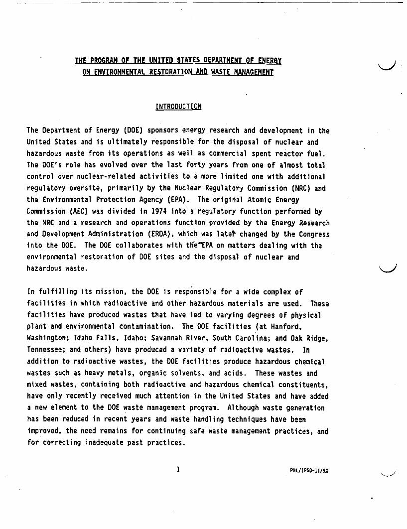
THE PROGRAM OF THE UNITED STATES DEPARTMENT OF ENERGY
ON ENVIRONMENTAL RESTORATION AND WASTE MANAGEMENT
INTRODUCTION
The Department of Energy (DOE) sponsors energy research and development in the
United States and is ultimately responsible for the disposal of nuclear and
hazardous waste from its operations as well as commercial spent reactor fuel.
The DOE's role has evolved over the last forty years from one of almost total
control over nuclear-related activities to a more limited one with additional
regulatory oversite, primarily by the Nuclear Regulatory Commission (NRC) and
the Environmental Protection Agency (EPA). The original Atomic Energy
Commission (AEC) was divided in 1974 into a regulatory function performed by
the NRC and a research and operations function provided by the Energy Research
and Development Administration (ERDA), which was late? changed by the Congress
into the DOE. The DOE collaborates with te"EPA on matters dealing with the
environmental restoration of DOE sites and the disposal of nuclear and
hazardous waste.
In fulfilling its mission, the DOE is responsible for a wide complex of
facilities in which radioactive and other hazardous materials are used. These
facilities have produced wastes that have led to varying degrees of physical
plant and environmental contamination. The DOE facilities (at Hanford,
Washington; Idaho Falls, Idaho; Savannah River, South Carolina; and Oak Ridge,
Tennessee; and others) have produced a variety of radioactive wastes. In
addition to radioactive wastes, the DOE facilities produce hazardous chemical
wastes such as heavy metals, organic solvents, and acids. These wastes and
mixed wastes, containing both radioactive and hazardous chemical constituents,
have only recently received much attention in the United States and have added
a new element to the DOE waste management program. Although waste generation
has been reduced in recent years and waste handling techniques have been
improved, the need remains for continuing safe waste management practices, and
for correcting inadequate past practices.
I PNL/IPSO-11/90
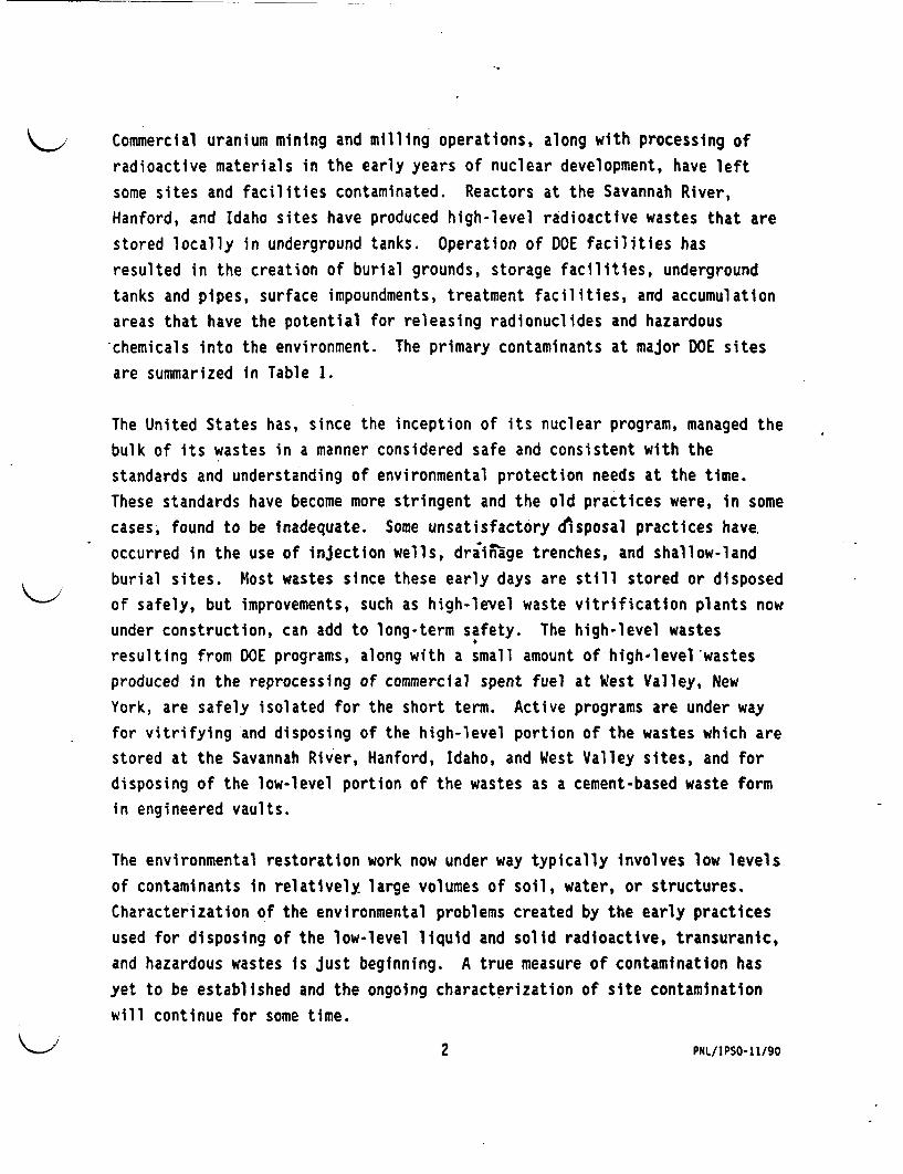
Commercial uranium mining and milling operations, along with processing of
radioactive materials in the early years of nuclear development, have left
some sites and facilities contaminated. Reactors at the Savannah River,
Hanford, and Idaho sites have produced high-level radioactive wastes that are
stored locally in underground tanks. Operation of DOE facilities has
resulted in the creation of burial grounds, storage facilities, underground
tanks and pipes, surface impoundments, treatment facilities, and accumulation
areas that have the potential for releasing radionuclides and hazardous
chemicals into the environment. The primary contaminants at major DOE sites
are summarized in Table 1.
The United States has, since the inception of its nuclear program, managed the
bulk of its wastes in a manner considered safe and consistent with the
standards and understanding of environmental protection needs at the time.
These standards have become more stringent and the old practices were, in some
cases, found to be inadequate. Some unsatisfactory disposal practices have.
occurred in the use of injection wells, driinage trenches, and shallow-land
burial sites. Most wastes since these early days are still stored or disposed
of safely, but improvements, such as high-level waste vitrification plants now
under construction, can add to long-term safety. The high-level wastes
resulting from DOE programs, along with a small amount of high-level wastes
produced in the reprocessing of commercial spent fuel at West Valley, New
York, are safely isolated for the short term. Active programs are under way
for vitrifying and disposing of the high-level portion of the wastes which are
stored at the Savannah River, Hanford, Idaho, and West Valley sites, and for
disposing of the low-level portion of the wastes as a cement-based waste form
in engineered vaults.
The environmental restoration work now under way typically involves low levels
of contaminants in relatively large volumes of soil, water, or structures.
Characterization of the environmental problems created by the early practices
used for disposing of the low-level liquid and solid radioactive, transuranic,
and hazardous wastes is Just beginning. A true measure of contamination has
yet to be established and the ongoing characterization of site contamination
will continue for some time.
2 PNL/IPSO-11/90
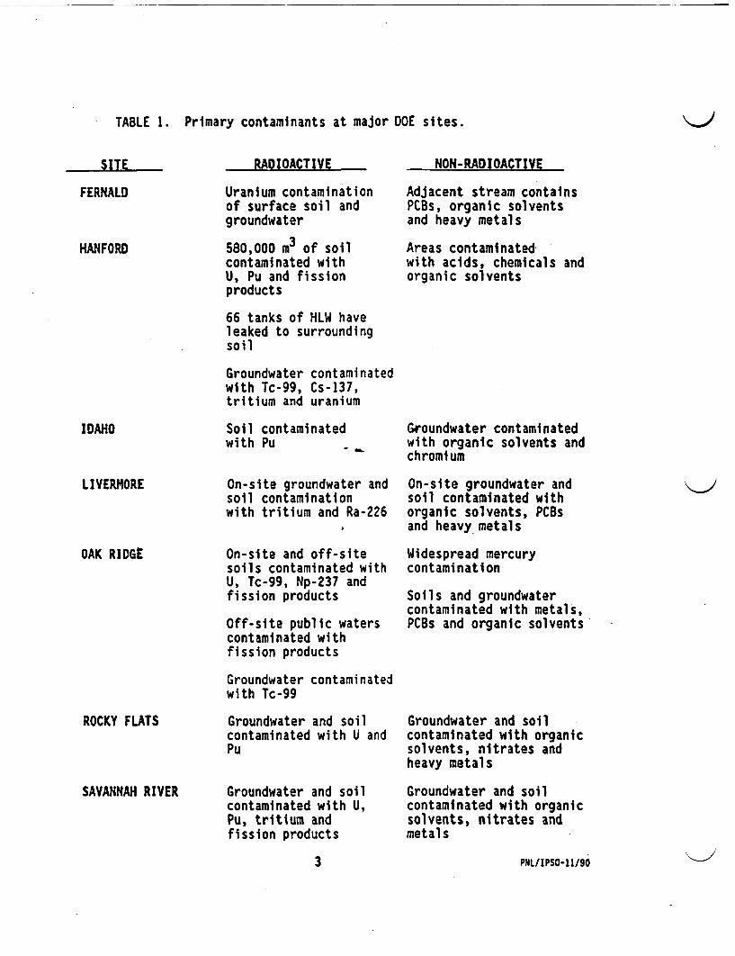
TABLE 1. Primary contaminants at major DOE sites.
RADIOACTIVE NON-RADIOACTIVE
FERNALD Uranium contaminationof surface soil andgroundwater
580,000 m3 of soilcontaminated withU, Pu and fissionproducts
Adjacent stream containsPCBs, organic solventsand heavy metals
Areas contaminatedwith acids, chemicals andorganic solvents
HANFORD
66 tanks of HLW haveleaked to surroundingsoil
Groundwater contaminatedwith Tc-99, Cs-137,tritium and uranium
IDAHO Soil contaminatedwith Pu
Groundwater contaminatedwith organic solvents andchromium
LIVERMORE
OAK RIDGE
On-site groundwater andsoil contaminationwith tritium and Ra-226
On-site and off-sitesoils contaminated withU, Tc-99, Np-237 andfission products
Off-site public waterscontaminated withfission products
On-site groundwater andsoil contaminated withorganic solvents, PCBsand heavy metals
Widespread mercurycontamination
Soils and groundwatercontaminated with metals,PCBs and organic solvents
Groundwater contaminatedwith Tc-99
ROCKY FLATS
SAVANNAH RIVER
Groundwater and soilcontaminated with U andPu
Groundwater and soilcontaminated with U,Pu, tritium andfission products
Groundwater and soilcontaminated with organicsolvents, nitrates andheavy metals
Groundwater and soilcontaminated with organicsolvents, nitrates andmetals
3 PNL/IPSO-11/90
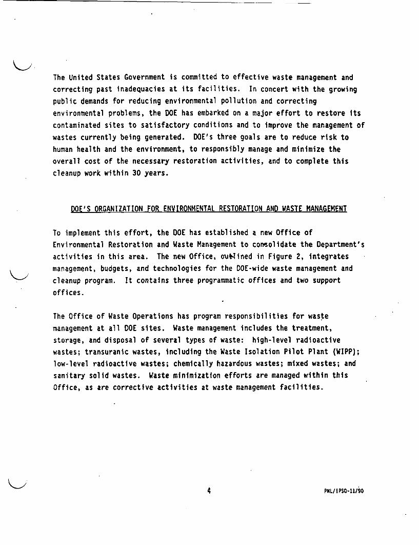
The United States Government is committed to effective waste management and
correcting past inadequacies at its facilities. In concert with the growing
public demands for reducing environmental pollution and correcting
environmental problems, the DOE has embarked on a major effort to restore its
contaminated sites to satisfactory conditions and to improve the management of
wastes currently being generated. DOE's three goals are to reduce risk to
human health and the environment, to responsibly manage and minimize the
overall cost of the necessary restoration activities, and to complete this
cleanup work within 30 years.
DOE'S ORGANIZATION FOR ENVIRONMENTAL RESTORATION AND WASTE MANAGEMENT
To implement this effort, the DOE has established a new Office of
Environmental Restoration and Waste Management to consolidate the Department's
activities in this area. The new Office, ou~lsined in Figure 2, integrates
management, budgets, and technologies for the DOE-wide waste management and
cleanup program. It contains three programmatic offices and two support
offices.
The Office of Waste Operations has program responsibilities for waste
management at all DOE sites. Waste management includes the treatment,
storage, and disposal of several types of waste: high-level radioactive
wastes; transuranic wastes, including the Waste Isolation Pilot Plant (WIPP);
low-level radioactive wastes; chemically hazardous wastes; mixed wastes; and
sanitary solid wastes. Waste minimization efforts are managed within this
Office, as are corrective activities at waste management facilities.
4 PHL/IPSO-l190
FIGURE 2. Office of Environmental Restoration and
Waste Management organization chart.
A
5 PNL/IPSO-11/90
The Office of Environmental Restoration has program responsibilities for
cleanup of inactive hazardous and radioactive waste sites at all DOE
facilities and some non-DOE sites for which DOE has responsibility (e.g.,
uranium mill tailings sites). Included are remedial actions and
decontamination and decommissioning (D&D) along with two ongoing programs, the
Uranium Mill Tailings Remedial Action Program (UMTRAP) and the Formerly
Utilized Sites Remedial Action Program (FUSRAP). Remedial actions are
concerned with all aspects of the assessment and cleanup of inactive but
potential release sites. DD is primarily concerned with the safe caretaking
of surplus nuclear facilities until either they are decontaminated for reuse
or are completely removed. Excluded from DOE responsibility are sites under
the authority of the electric power marketing administrations, the Office of
Naval Reactors, and the Office of Fossil Energy.
The Office of Technology Development has program responsibilities for
providing new and more effective technologiesto meet DOE's goal of regulatory
compliance and cleanup. Activities included are research and development of
new technologies; demonstration, testing, and evaluation of technologies
developed elsewhere; transportation; and educational programs to provide
trained staff to maintain the momentum of technology development.
The Office of Planning and Resource Management supports the program offices in
budget preparation and accounting and has the responsibility for coordinating
the annual update of the DOE Environmental Restoration and Waste Management
Plan. The Office of Environmental Quality Assurance and Quality Control
performs independent internal oversight to ensure compliance with
environmental and safety laws and regulations and to enhance the technical
validity and cost effectiveness of programs and projects.
The regulatory oversight of hazardous and radioactive waste management is
shared by several organizations. Establishment of overall standards for
environmental protection is performed by the EPA, which reports directly to
the U.S. President. The EPA's area of responsibility covers non-nuclear as
well as nuclear areas. The NRC regulates commercial nuclear activities, long-
6 PNL/IPSO-11/90

term storage and disposal of spent fuel and high-level waste, and (together
with the Department of Transportation) transportation of radioactive materials
and wastes.
SCOPE OF THE ENVIRONMENTAL RESTORATION AND WASTE MANAGEMENT PROGRAM
The activities of the DOE in the areas of environmental restoration and waste
management have been divided into four technical areas for management
purposes: (1) Corrective Activities, (2) Environmental Restoration, (3) Waste
Operations, and (4) Technology Development. Categories (1) and (3), being
similar in nature, are both managed by the DOE Office of Waste Operations.
CORRECTIVE ACTIVITIES
Corrective Activities are those activities necessary to bring active and
standby DOE facilities into compliance with local, state, and federal
regulations. Because corrective activities must be completed in a timely and
effective manner to protect the public health and safety and the environment,
these activities will generally be accomplished by the application of existing
technologies rather than new technologies that would require significant time
for development. Examples of corrective activities are the installation of
modern equipment to monitor air and liquid waste streams and replacement of
obsolete waste handling and storage equipment.
ENVIRONMENTAL RESTORATION
Past operations connected with DOE nuclear programs have resulted in
contamination of a large number of sites and facilities with quantities of
radioactive, hazardous, and mixed wastes. Environmental restoration is
concerned with assessment and cleanup of such sites and facilities to meet
prescribed standards derived from federal and state laws. A listing of
typical environmental restoration activities is presented in Table 2.
7 PNL/IPSO-11/90
TABLE 2. Typical environmental restoration activities.
Uranium Mill Tailings Remedial Action Program (UMTRAP)
Formerly Utilized Sites Remedial Action Program (FUSRAP)
Remediate contaminated surface waters
Remediate contaminated underground waters
Remediate contaminated soils
Remediate improper burial grounds
D&D contaminated inactive facilities
Note: Contaminants may include:
- Organics (polychlorinated biphenyls
(PCBs), trichloroethylene (TCE),
volatile organic compounds (VOCs),
pesticides, petroleum productsf
- Heavy metals (mercuri,^barium,
beryllium, lead, etc.)
- Radionuclides (including plutonium,
thorium, and uranium)
- Chemicals (nitrates, asbestos,
acids)
The DOE has two major restoration programs underway. Since 1974, the FUSRAP
has been working to restore 30 inactive federal facilities contaminated with
radioactive and/or hazardous materials. Nine sites have been completed. The
UMTRAP activity has been underway since 1978. The program was established by
a federal law to remediate uranium mill tailings resulting from uranium
production conducted between the early 1950s and the early 1970s. The program
is stabilizing 24 sites. Stabilization has been completed at 5 of these
sites.
Contaminated soil cleanup represents a major problem. The soil columns at
several of the sites are contaminated with radioactive and hazardous
substances resulting from the use of ponds and drainage fields for disposal of
8 PNL/IPS0-11/90
process effluents. Characterization and cleanup of these sites is difficult
because of the low concentrations of the contaminants, their variability, and
the large volumes of soil involved. The Hanford site, for example, covers an
area of 1,450 square kilometers. The near-surface disposal sites on the
Hanford Reservation contain 1.1 million cubic meters of solid waste which were
buried before segregation of alpha-contaminated waste was required. There are
also 32,000 cubic meters of soil contaminated with transuranic radionuclides.
Soils are often excavated and disposed of in secure landfills or processed at
the surface to separate the contaminants. A technique (in situ vitrification)
to convert soils in place to a vitreous and crystalline mass using electrical
current is being developed. The resulting mass significantly lowers the
solubility of inorganic contaminants. Such a treatment will also destroy
organic hazardous chemicals. Other prospective treatments for organic
contaminants include vacuum extraction, chemical oxidation, temporary removal
and soil treatment, and bioremediation.-
Groundwater contamination arises from leaking tanks, buried waste, and from
lagoons previously used for the disposal of liquid wastes. For example, at
the Portsmouth uranium enrichment facility, the groundwater has been found to
be contaminated with trichloroethylene and polychlorinated biphenyls. If the
level of contamination is high and the available technical means are not
adequate, interdiction wells can be used to temporarily retard migration. New
interdiction techniques under consideration are soil freezing, vitrified
barriers underneath the contamination zone, and various forms of grouting and
chemical injections to retard migration. It must be recognized, however, that
in the case of complex aquifers contaminated with dense, non-aqueous phase
liquids, current restoration technologies are probably inadequate.
Decontamination and decommissioning (D&D) of obsolete facilities produces
significant amounts of additional radioactive and hazardous waste. D&D needs
to rely on techniques to minimize the generation of waste by means of better
characterization and selective decontamination using materials that can be
recycled. Certain metals such as stainless steel, aluminum, nickel, and lead
might be recycled and used for containment and shielding materials in future
9 PNL/IPSO-11/90
construction. The use of robotic manipulators can improve safety by reducing
the radiation dose to workers.
WASTE OPERATIONS
Waste Operations include the treatment, storage, and disposal of wastes
generated as a result of ongoing operations at active facilities. This
includes the programs to build vitrification facilities for high-level wastes
at the Savannah River, Hanford, Idaho, and West Valley sites, and the WIPP
repository for transuranic wastes. One of the major waste operations
objectives is to effectively manage its processes and facilities in a safe and
environmentally responsible manner. Current efforts in this area also include
such tasks as establishing management controls over nonradioactive wastes,
including segregation of waste types and minimizing waste produced in DOE
facilities.
Mixed wastes, which contain both hazardous c micals and radioactive
materials, can be reduced by minimizing the use of hazardous materials and
identifying non-hazardous substitutes. The mixed wastes that already exist
can be treated to separate or destroy the hazardous components. A number of
physical and chemical processes are available to treat the waste:
electrochemical recovery of metals, leaching, washing, chromatographic
separation, evaporation and distillation, and smelting. Reactive metals can
be deactivated by controlled chemical reactions, and organic compounds can be
destroyed by heat provided by sources such as plasma arc furnaces, glass
melters, and even solar energy.
High-level radioactive waste treatment, although well-advanced, can be
tailored to address specific problems. Chemical compositions can be adjusted
to reduce the volume and the associated disposal cost. Stored calcined high-
level waste can be processed into a ceramic or glass to provide more stable
forms for geologic disposal.
10 PHL/IPSO-11/90

TECHNOLOGY DEVELOPMENT
Many waste management methods used in the past are no longer adequate. DOE is
striving to transcend current environmental restoration and waste management
practices and tools, replacing them with more effective and efficient
techniques. Where needed capability is not presently available, the Office of
Technology Development will seek to develop it. This can occur through
applied research and development by its laboratories, through adaptation of
technology from other fields, or through development in concert with industry,
academic institutions, and the international scientific community. Current
environmental restoration must be performed effectively the first time and
preclude the need for additional restoration in the future. Waste management
must prepare and treat residual materials to produce a minimum volume of
physically and chemically stable waste forms. Facility operations must
minimize waste generation by eliminating or recycling'hazardous materials.
To achieve these improvements, the attention of the scientific and engineering
communities is required. The long-term protection of human health and the
environment must be assured, and public confidence and respect for the
technical community are at stake. The aims of the environmental restoration
and waste management programs are to ensure that unacceptable risk of exposure
to contamination is eliminated and that there is no lasting adverse impact on
the environment resulting from radioactive and hazardous wastes.
11 P1PNL/IPSO-11/90
ENVIRONMENTAL RESTORATION AND WASTE MANAGEMENT PLAN
The 1992-96 update of the DOE Environmental Restoration and Waste Management
Five Year plan has been completed. The plan describes the current state of
technology and identifies improvements needed to fulfill DOE's three goals of
reducing risk to human health and the environment, decreasing the overall
cost of its restoration activities, and completing its cleanup work within 30
years. The technology development part of the plan provides for:
o development of new technologies and techniques for waste
minimization;
o development of technologies for improved waste treatment and storage;
o site characterization for environmental restoration using in-situ
monitoring, modeling to predict and prevent migration of contaminants,
and improved methods for assessing environmental and human health
risks;
o development of large promising, but underdeveloped, new technologies
such as robotics, biotechnology, and remote sensing to add new
capability and reduce the cost and/or risks of remediation;
o establishment of an outreach program through schools and universities
for educating students in science and waste management; and
o international technology exchanges to reduce or eliminate duplication
of efforts and to assist the international waste management community
in solving similar types of problems.
The technology development plan will continue to evolve over time because the
field of waste management is dynamic. Technology development will focus on
near-term research, development, and application, and it will not constitute
basic research. OOE intends to support development of innovative concepts
12 PNL/IPSO-1I/90
that are mature enough to begin demonstration within the present 5-year
planning horizon. Emphasis will be placed on creativity and the program will
have a strong international component.
INTEGRATED DEMONSTRATIONS AND PROGRAMS
Integrated demonstrations and programs will be used as a means to rapidly
develop, demonstrate, and transfer needed technology to the environmental
restoration and waste operations efforts. The integrated demonstration is the
cost-effective mechanism that evaluates the performance of related
technologies as part of a complete system in correcting waste management and
environmental problems from "cradle-to-grave". An integrated program is
similar, but is focused to solve a specific aspect of a problem.
The integrated demonstration involves three major facets: 1) the various
steps to solving the problem (e.g., planning, site characterization, waste
treatment, waste disposal, site monitoring), 2) development and application of
innovative technology solutions, and 3) evaluations relative to performance
goals and/or applicable regulatory requirements. Selecting and moving
promising technologies from research and development through final evaluation
is a continuous process. The transition of technologies into more advanced
phases of development requires the establishment of technical and regulatory
criteria for ascertaining if and when a developmental project should be
advanced. Because development costs increase dramatically as a project
progresses to more advanced phases, funds will not be available to support
full development of all concepts. Therefore, for technical, regulatory, and
cost-related reasons, the number of projects moving forward will be
selectively decreased by a filtering process. Technology development will be
conducted with programmatic integration at all stages.
The DOE sites themselves are important resources for technology development
and will be used for the demonstration and evaluation of new technologies.
The three main areas of focus and planned integrated demonstrations in these
areas are:
13 PLIPSO-11/90

1) groundwater and soils cleanup
* cleanup of organics in saturated soils and groundwater
* cleanup of organics in unsaturated soils and groundwater
* cleanup of plutonium/uranium from contaminated soils
2) waste retrieval and waste processing
* remediation of underground storage tanks
* remediation of buried wastes
* decontamination and decommissioning
3) waste minimization
* uranium manufacturing waste minimization
* non-nuclear waste minimization
WASTE MINIMIZATION
Throughout the DOE environmental restoration and waste management programs,
waste minimization will be a key objective. Waste minimization includes
volume reduction technology, such as supercompaction, and concentration.
However, true waste minimization is the avoidance of the generation of
radioactive, hazardous, and mixed wastes before treatment, storage, or
disposal. Waste minimization can be attained by various measures, including
administrative action, material substitution, recycling, and process changes.
Development and demonstration of new processes to avoid the generation of
wastes containing radioactive and hazardous constituents will be conducted.
Equipment used in waste processing will be designed to clean with nonhazardous
substances and/or to yield a nonhazardous product.
While waste minimization will significantly reduce the amount of waste that
must be managed, waste generation cannot be altogether eliminated. Generated
wastes must be managed more effectively than what was done in the past, which
will require new and better ways to treat, store, and dispose of wastes. The
14 PNL/IPSO-11/90
Technology Development Program will seek to develop and demonstrate
technologies to provide permanent solutions for generated wastes.
CONCLUSION
In the past, the highest-quality technological efforts have been directed
toward other missions than waste management. The Technology Development
Program will serve as a catalyst for applying today's technology to unresolved
cleanup and waste management problems in ways never before considered, as well
as the means for development and demonstration of new and innovative
environmental protection technologies. DOE will be providing hundreds of
millions of dollars to develop technical expertise through a series of new
partnerships between DOE's national laboratories, industry, and universities.
Integrated demonstrations will use experts from all sources in a systems
approach, including collaboration with other agencies and countries.
International technology exchange will be a major activity to help provide a
global approach to solving waste management problems.
1 5 PNL/IPSO-I1/90
C ~~~~~(
The Program ofthe United States Department of Energy
on Environmental Restoration andWaste Management
(
Leo P. DuffyDirector, Office of Environmqntal Restoration and
Waste ManagementU.S. Department of.Energy
Visit to JapanNovember 1990
S9010075.1
Presentation Outline
* DOE Waste Management Legacy
* DOE ER & WM Orgapization
* ER & WM Program Scope
* Technology Development Program
S9010075.2
( (
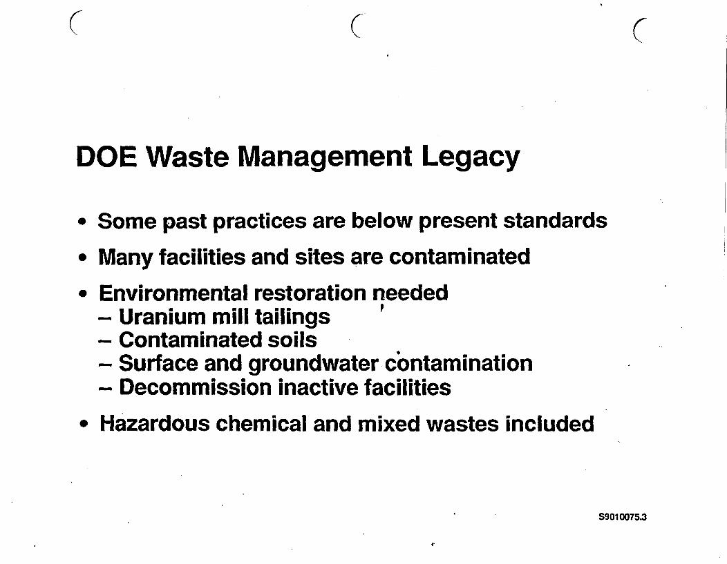
DOE Waste Management Legacy
* Some past practices are below present standards* Many facilities and sites are contaminated* Environmental restoration needed
- Uranium mill tailings- Contaminated soils- Surface and groundwater contamination- Decommission inactive facilities
* Hazardous chemical and mixed wastes included
S9010075.3
.9

DOE ER & WM Goals
* Reduce risk to human health and environment
* Decrease cost of restoration
* Complete cleanup in 30 years
S9010075.4
( (
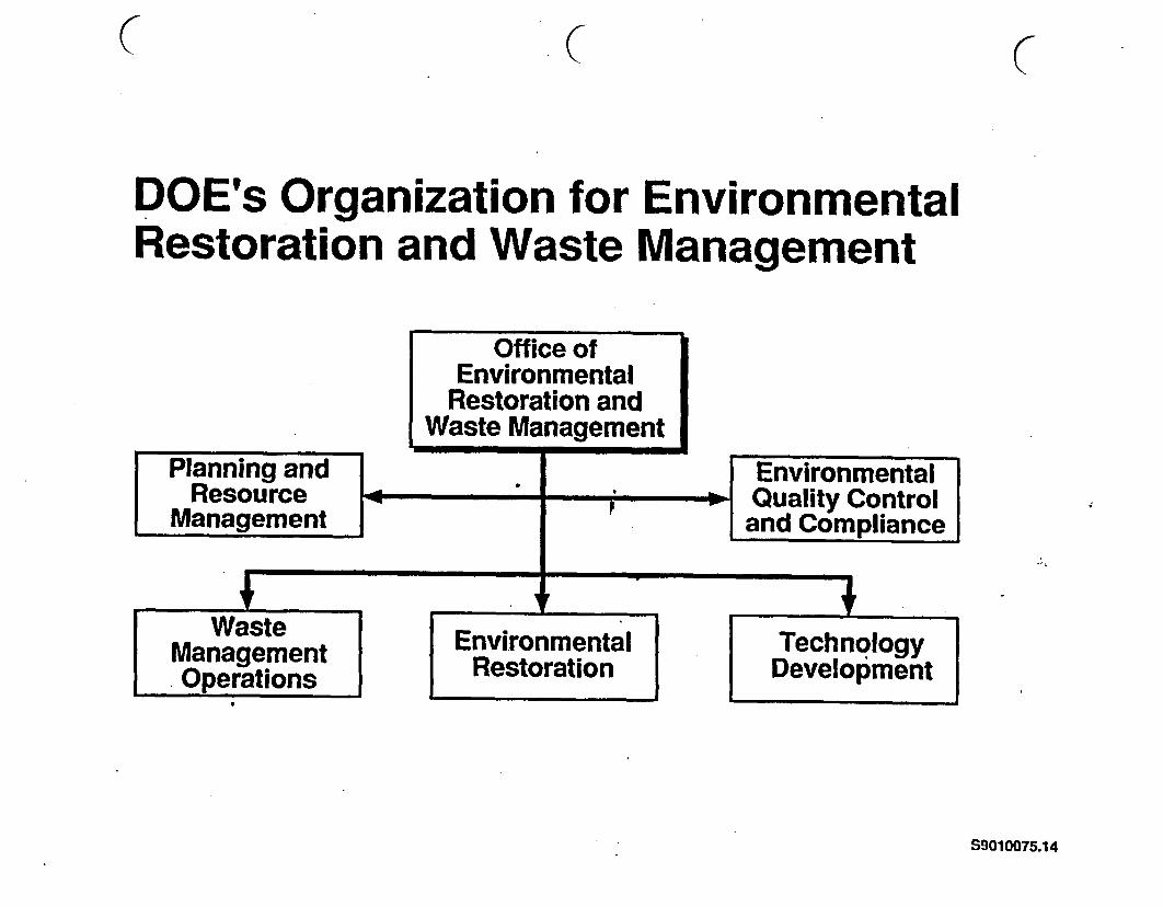
DOE's Organization for EnvironmentalRestoration and Waste Management
Office ofEnvironmental
Restoration andWaste Management
Planning and EnvironmentalResource 1 * Quality Control
Management and Compliance
Management Environmental TechnologyMpainmn Restoration Development
S9010075.14

ER & WM Program Scope
* Corrective activities
* Environmental restorationF
* Waste operations9
* Technology development
S9O10075.5
{( (
Technology Development Program
* Goal is to develop new technologies that are:
- safer, faster, cheaper; better
- while achieving and maintaining compliance
S9010075.6
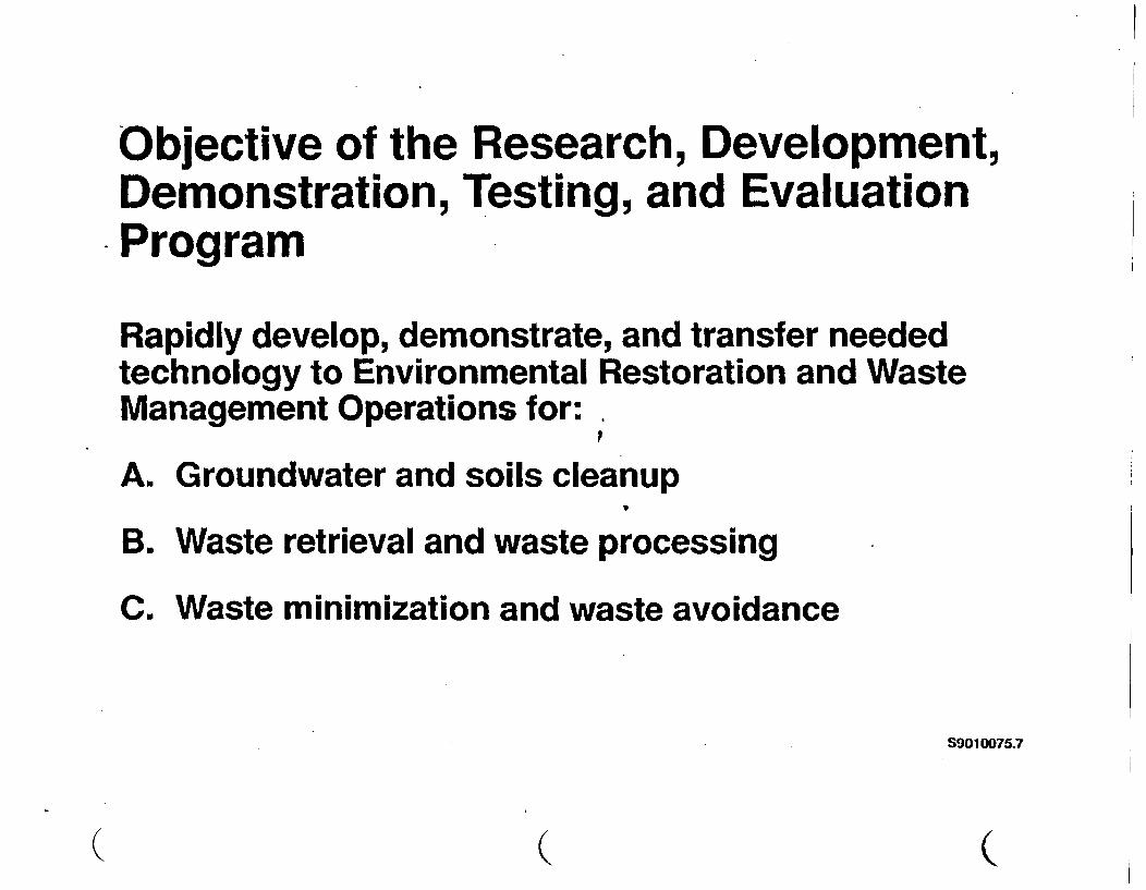
Objective of the Research, Development,Demonstration, Testing, and EvaluationProgram
Rapidly develop, demonstrate, and transfer neededtechnology to Environmental Restoration and WasteManagement Operations for:
A, Groundwater and soils cleanup
B. Waste retrieval and waste processing
C. Waste minimization and waste avoidance
S9010075.7
(. (C

Environmental Restoration Technologies
Site CharacterizationD ~~~~~~~Sensors
Fiber OpticsRemote Measuring Technologies
..... ... /for GroundwaterRobotics
Tank CharacterizationRoboticsSensorsRFiber Optics
CleanupBiotechnologyFitter TechnologyWaste Forms
S9010075.20
4.
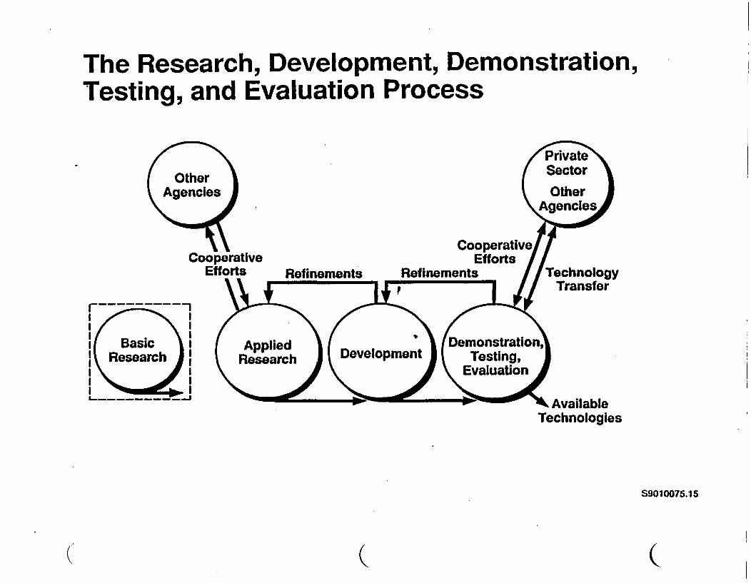
The Research, Development, Demonstration,Testing, and Evaluation Process
I II II II{ Basic II Research |I II II II - - -I
x AvailableTechnologies
S9010075.1 5
( (
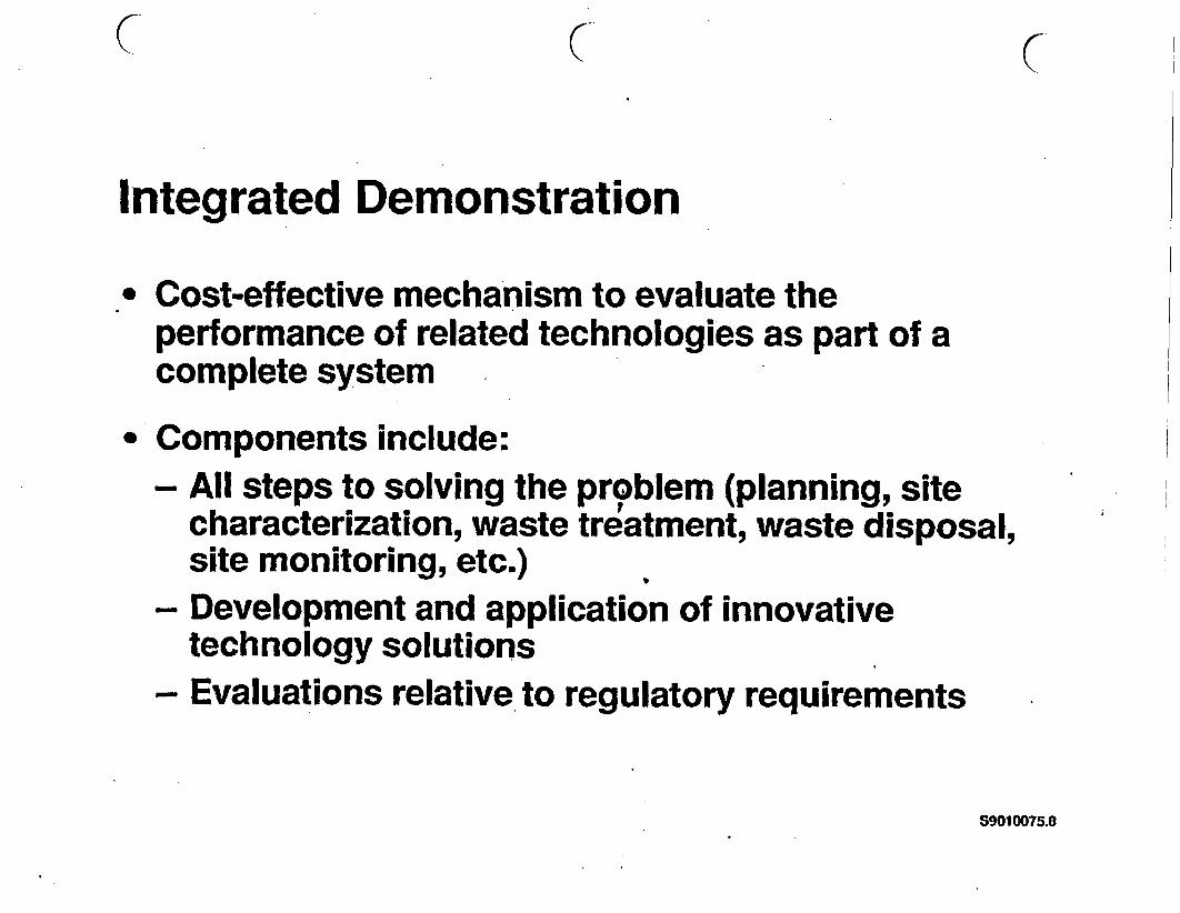
( ( C
Integrated Demonstration
- Cost-effective mechanism to evaluate theperformance of related technologies as part of acomplete system
* Components include:- All steps to solving the problem (planning, site
characterization, waste treatment, waste disposal,site monitoring, etc.)
- Development and application of innovativetechnology solutions
- Evaluations relative to regulatory requirements
S9010075.8

The Three Dimensions of the Integrated Demo
C
awI-$
0
C~~~Pormai tp oSlto
*Including regulatory linkage
S9010075.16
( ( (
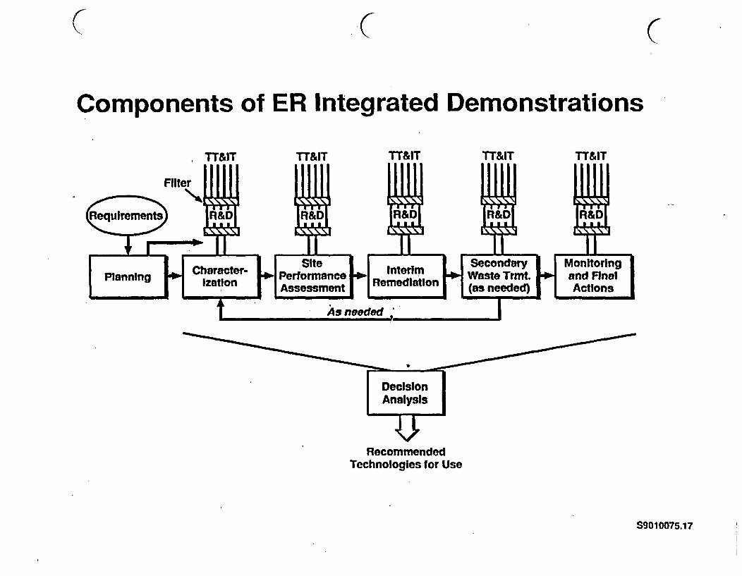
( ( C
Components of ER Integrated Demonstrations
RecommendedTechnologies for Use
S9010075.17

Components of WO Integrated Demonstrations*
*Like ER, WO Integrated demonstrations will have inputs on requirements,include assessment of multiple options, and make recommendations
S9010075.18
( (
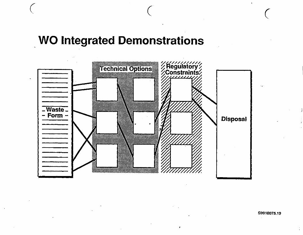
C ( (
W O Integrated De monstrations
S9010075.1 9
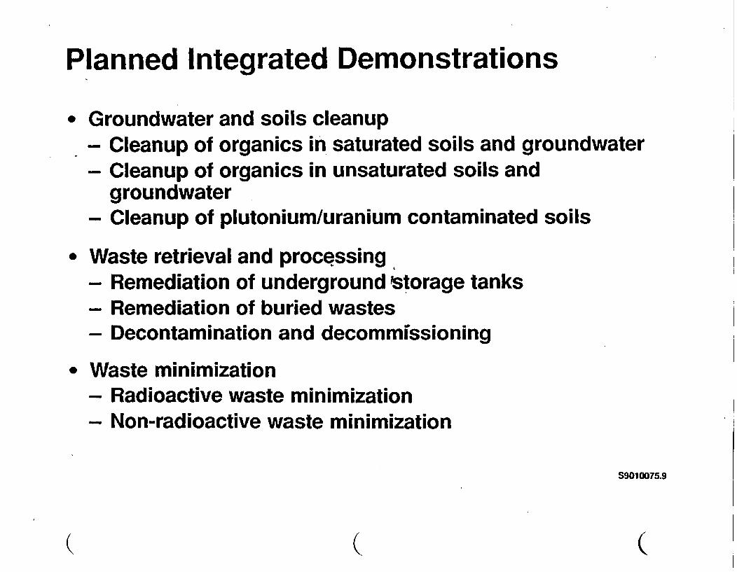
Planned Integrated Demonstrations
* Groundwater and soils cleanup- Cleanup of organics in saturated soils and groundwater- Cleanup of organics in unsaturated soils and
groundwater- Cleanup of plutonium/uranium contaminated soils
* Waste retrieval and processing- Remediation of underground Storage tanks- Remediation of buried wastes- Decontamination and decommissioning
* Waste minimization- Radioactive waste minimization
Non-radioactive waste minimization
S9010075.9
( (~~~ (

Waste Minimization
* Avoidance of waste generation- Administrative actions
Material substitutions- Recycling- Process changes
* Volume reduction- Supercompaction- Waste concentration- Waste processing
S9010075.10
DOE Will Utilize Expertise from AllSources to Solve ER & WM Problems
* National laboratories
* Industry
* Universities
* International cooperation
S9010075.11
(, (~~~~~~

International Technology Exchange
* Provides global approach to waste management
* Transfers innovative technologies
* Reduces cost and remediation time
* ITE mechanisms include: '
- Joint projects- Exchange of staff- Exchange of students- Workshops- Exchange of documents
S9010075.12

Summary
* DOE is committed to 30-year goal to clean up sites
* DOE established Environmental Restoration and WasteManagement Organization
* Technologies that are safer, fster, better, and cheaperwill be developed
* DOE will utilize expertise from al1 sources- International technology exchange will be a major
activity
S9010075.13
( (

. -
TECHNOLOGIES DISCUSSED AT JAPAN ATOMIC ENERGY RESEARCHINSTITUTE (7AERI)
- High Level Radioactive Waste- Mineralogical Research- Leaching and Volatilization of Radionuclides from Glass Waste- Spectroscopic Method- Fixation- Long-Term Reaction Path Modelling- Plutonium- Adsorption of Neptunium- Irradiation of Materials- Cold Neutron Source- Reactor Decommissioning Technology Development- Dismantling- Decommissioning- Safety Studies on Glass Waste Form- Waste Safety Testing Facility- Volatilization of Cesium from Nuclear Waste Glass in a Canister
BIBLIOGRAPHY OF LITERATURE REEV:
"Development of Technologies on Decommissioning of Nuclear Fuel CycleTechnologies, Japan Atomic Energy Research Institute. 5 pages.
*JPDR Decommissioning Program, written by T. Hoshi from the 9th TAG Meeting onOctober 8-12, 1990 at the Japan Atomic Energy Institute. 10 pages.
*New JRR-3, Compiled by the Research Reactor Operation at the Tokai ResearchEstablishment, Japan Atomic Energy Research Institutc. 6 pages.
'Progress Report on Safety Research of High-Level Waste agement for the Period April1988 to March 1989', Edited by Haruto Nakamura and Ssmu Muraola, Dqtmentof Environmental safety Research, Tokai Research E lishment, Japan AtomicEnergy Research Institute, 74 pages.
*Reactor Decommissioning Technology Development and Actual Dismantling of JPDR,compiled by the Tokali Research Establishment, Japan Atomic Energy ResearchInstitute 9 pages.
'Safety Studies on Glass Waste Form, written by S. Muraoka at Japan Atomic EnergyResearch Institute. 10 pages.

aSummary of WASTEF Facility', from Japan Atomic Energy Research Institute.10 pages.
*Volatilization of Cesium from Nuclear Waste In a Canister', Hiroshl Kamizono,Shizuo Kikkawa, Shingo Tashiro and Haruto Nakamura. at Japan AtomicEnergy Research Institute. Deprtment of Environmental Safety Research, 6 pages.

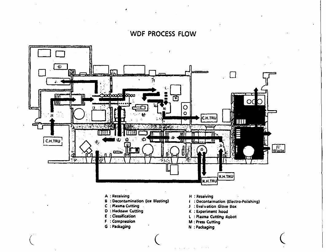
WDF PROCESS FLOW
A: ReceivingB: Decontamination (ce Blasting)C : Plasma CuttingD: Hacksaw CuttingE: ClassificationF : CompressionG: Packaging
( C~~~~
H : ReseivingI Decontaimation (Electro-Polishing)J Evaluation Glove BoxK Experiment hoodL: Plasma Cutting RobotM : Press CuttingN Packaging
(

(REDCf DEOMMISIOING ECHNQUE
R&D of DECOMMISSIONING TECHNIQUES
C
P ....
I I- High Decontainston Factor (OF)- Reduction of Arising Secondary Wastes- Aplicable to Complicated Form- Cost Effectiveness
ICE-BLAsTING
ELECTRO.POUSHING
RWOX PROCESS
- , -I - - -.
- ApplicabIe to Miscellaneous Items- Remote Handlfng Superior to Contact
Handling in Economics and Safety
PLASMA CUTTING
ROBOTICS
LASER CUTTING
. .M , , -
- Remote Meament- High Reability- High Efficiency
RADIATIONIMAGE
DISPLAY
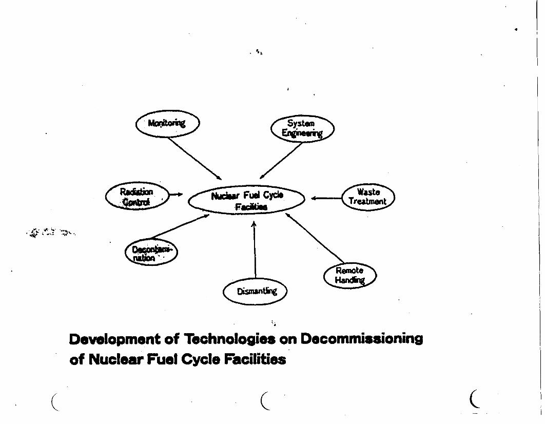
It
. all
r* t . ,
Development of Technologies on Decommissioningof Nuclear Fuel Cycle Facilities
Q C C

H P ME THOD
_. _~~HI
_C~yl inder
--- soileate r
|~~ I T t~ a l
l ~ ~~~ I
HIP equipment
is
.1
( Z<
aHIP treatment : Temperature : 1000 CPressure : 10 ~100 PaTime : 13 Hrs

The th TAG MeetingJPDR DECOMMISSIONING PROGRAM October 8 -12, 1990
T. Hoshl, JAERI
1) Dismantling of the RPV
Actual cutting of the RPV was started In the end of April and wascompleted successfully in the beginning of october, 1990. Theunderwater arc-saw cutting technique was applied to cut the bodyportion of the RPV where t was highly activated. The lowerspherical portion was cut by the conventional technique, a gascutting technique. Chronologies on the removal operations ofthe RPV are as follows;
Oct. 1989 - Apr. 1990 : Installation of the water tank,water treatment system, andarc-saw system
Apr. - Jul. 1990 : RPV cutting by arc-saw cutting systemJul. - Sep. 1990 : Removal of arc-saw cutting systemSep. - Oct. 1990 : RPV cutting by gas cutting method.
Arc-saw cutting system and cutting plan of the RPV are shown inFigs 1 and 2, respectively.
Cutting Characteristics of Arc-saw System
The body portion of the RPV was segmented into 65 pieces' lessthan 900 X 900 mm in size underwater. Cut pieces were, then,hanged up onto the service floor in the reactor containmentbuilding and were put nto the containers.- Shielded. containerswere used for the pieces around the reactor core region (Sections of 4 to 8 shown In Fig.2 ) but the pieces of the upperportions ( Sections of 1 to 3 ) were put into the standard 1 -containers.
Cutting speeds iwreir 0 m.5 /msec at'the flange portion ofwhich thickness was .250uan and 1 - 5 mm/sec at the body of about80 mm In thickness. These results are within the results obtainedboth in the developing tests and in the mock-up tests as shown inFig. 3 ; However, a difficulty was experienced at the beginningof this work. .e.. frequently over current trip In the system.This over current trip was observed In the vertical cuttingoperation of the flange potion , especially, at the firstcutting . This was due to nappropriate setting of an arc currentand a cutting speed as well as the most thick portion of theRPV. It took about 3 days to cut one vertical line of 700 mm atthe beginning, but it decreased soon to 5 - 8 lines 4,000 -7,000 mm ) per day. Planned and actual schedule Is shown inTable 1 and scenes of operations are shown In Photos 1 - 4.
1

Working Days and Manpower
Total number of days required to cutting by the arc-saw was 50days and it Is considerably less than the planned ones ( 6odays). It was concluded that this was due to ncreasing theskill of workers by progressing the cutting operations. On theother hand, about 8 months were required for such preparatoryworks as Installations of cutting system, water tank and watertreatment system as well as removals of these systems.
Manpower expenditures were of 1,700 man-days for arc-saw cuttingand of about 6,200 man-days for the preparatory works.
Radiation Exposure
Total radiation exposure of workers n the work was about 9 man-rem. Radiation exposure for cutting with the remote operated arc-saw cutting system was only 0.2 man-rem, but the rest was come.from the preparatory works as shown in Table 2. This largerradiation exposure during the preparatory works was resultedfrom the Installation of the water tank since the workers wereobliged to access to the RPV during this work, where theradiation dose rate was of 20 - 80 mR/hr ( Maximum dose rate atthe surface of the RPV was about 7 R/hr at the core centerlevel).
Radioactive Contamination
Insignificant contamlnation-ln the air was observed . A littlecontamination ( 3 X lor jCi/cc ) was measured in water, but itis easily reduced by the water treatment system with filters.Almost all of dross generated by cutting was also removed by thedross collecting pan which was installed in the lower portion ofthe RPV without difficulty.
Cutting of the Lower Spherical Portion of the RPV
The lower spherical portion of the RPV was hang up onto theservice floor and was cut by using a conventional gas cuttingtechnique. Radiation-dose rate was about 10 mR/hr at the surfaceof the RPV. -
2) Removal of Components In Turbine Building
Dismantling work of the components In the turbine building hasbeen started In April, 1990. Components of the condensate andfeed water system, the auxiliary system, the sea watercirculation :'system, etc., were removed. Turbine and generatorwill be removed in coming quarter.
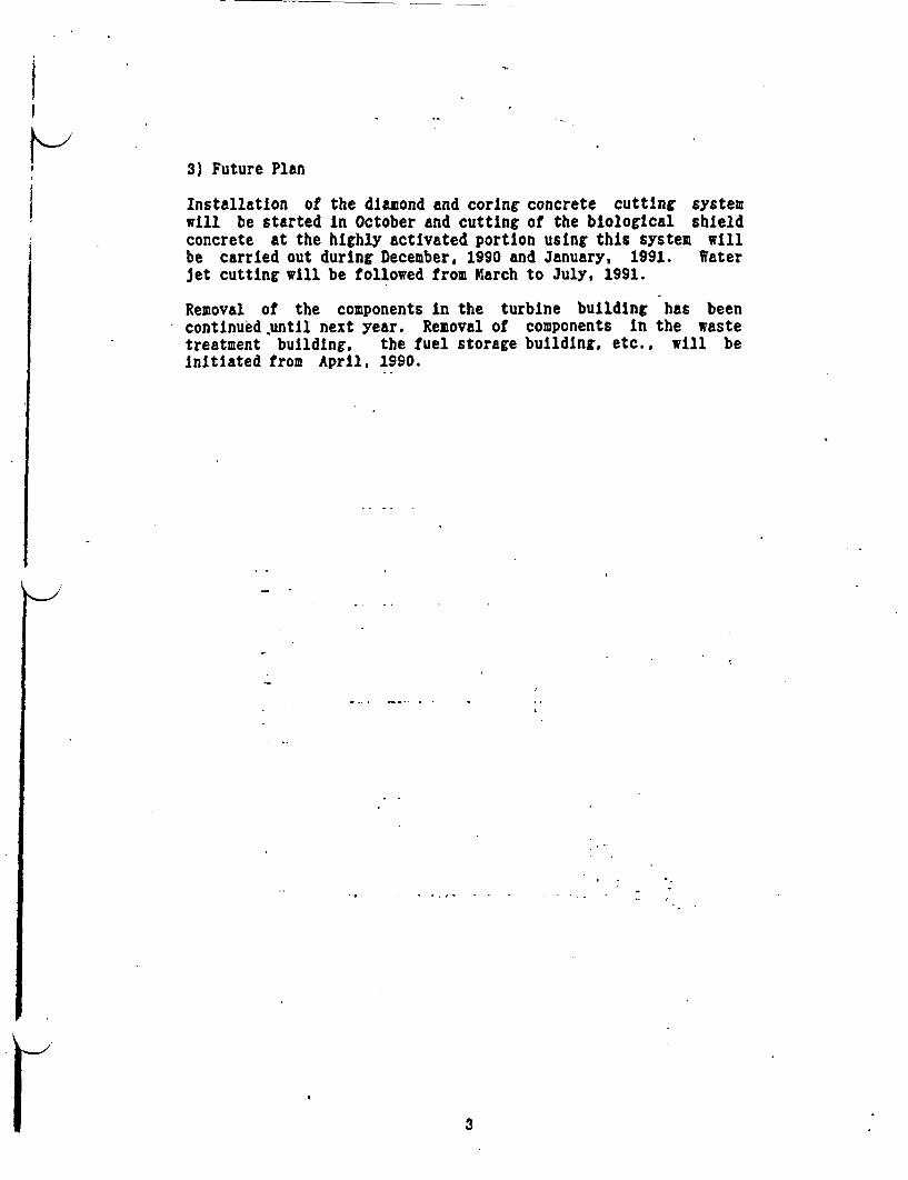
II
3) Future Plan
Installation of the diamond and coring concrete cutting systemwill be started in October and cutting of the biological shieldconcrete at the highly activated portion using this system willbe carried out during December, 1990 and January, 1991. WaterJet cutting will be followed from March to July, 1991.
Removalcontinuedtreatmentinitiated
of the components n the turbine buildingL.until next year. Removal of components Int building, the fuel storage building. etc..i from April. 1990.
has beenthe wastewill be
3
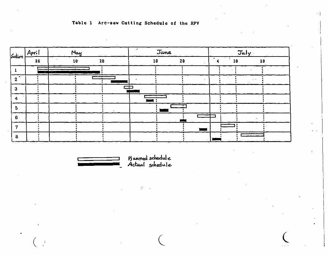
Table I Arc-saw Cutting Schedule of the RPV
Xn Apr I . . , r .dy26 10 20 10 20 4 10 19
4~~ ~ ~~~ ~ ~~~~~ ~~~~~~~~~~~~~ . i i a a '.
S = ' 1 ~~~~~~~~~~~~~~~~~~~~* . S' '' '.
1 - iS ., i i _ -' i
B ~ ~~ ~~ . -. _ ' S -
S
2* S S S S S S S~~~OW
6 M6~~~~~~~~~~~~~~~~~~~~~~*n*-
U _ I~~~Pi aota scheAulcAct"( Jiod"IeL
( C C

ITable 2 Man-power and Radiation Exposure
In Cutting the RPV by Arc-saw
Item Man-days Man-rem
Preparatory Works
Installation of arc-saw 2,470 0.24Installation of water tank 1,710 8.39Installation of
water treatment system 460 0.17
Removal of systems 1,600 0.36
Sus-total. 6,240 9.16
Cutting operation 1,700 0.21K.
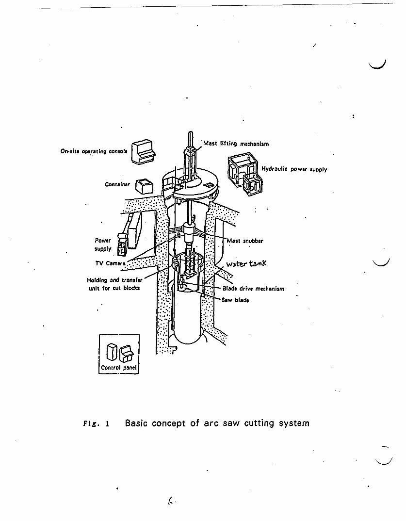
On-site operating console
Hydraulic power supply
Container
Power -Mast snubber
TV Came ate. n
Holding and transferunit for cut blocks Slade drive mechanism
a: ~~~~Saw blade
Control panel
Fig. 1 Basic concept of arc saw cutting system
(

�c7 - ~ ~~~ Mf-t @--w C
II
Fig. 2 Cutting Plan of The RPV by Arc-saw System
4.
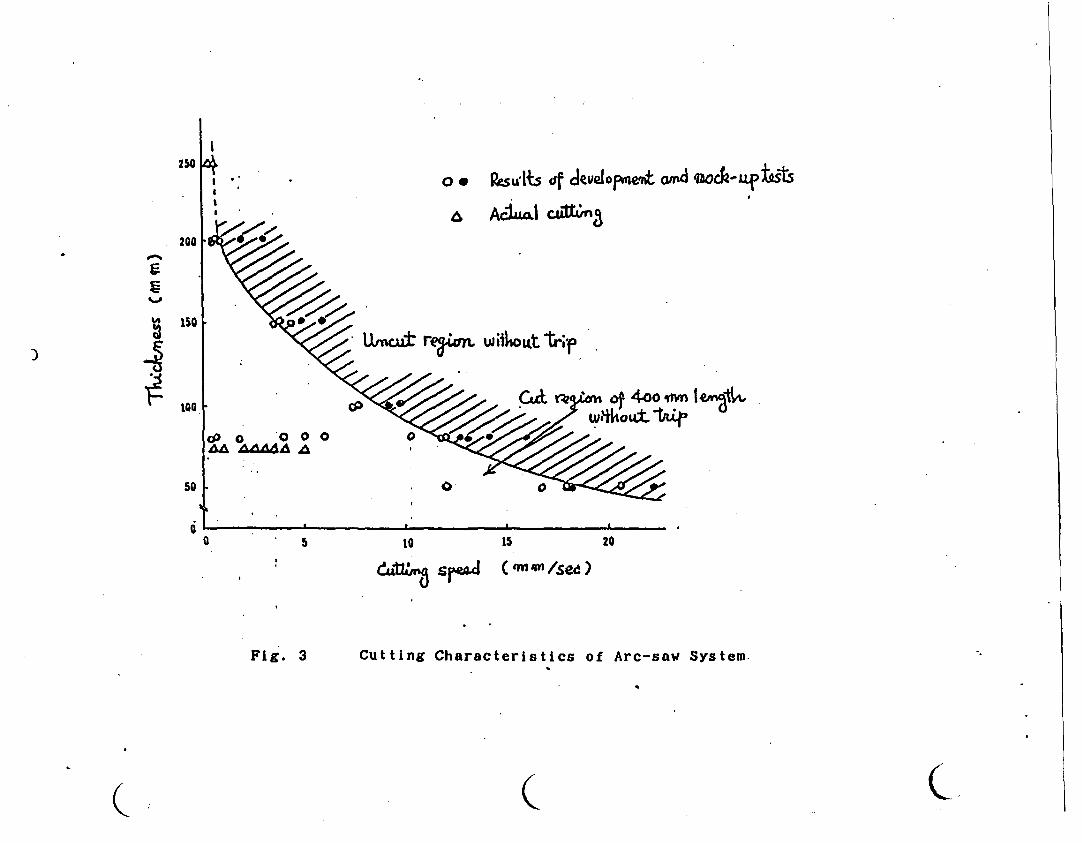
250
. 200
oa Rsuts df Jevelopewton d eoo-attt
& AcIUal cattrfl
U/neut remun W tOLat Ve;) 4ISO
too 4.o qWn I6 I. + ..
o .0 0 A A
0
50
0a 5 10 15 20
, ac~~dt[L spaM ( on 4/se )U) '
Fig. 3 Cutting Characteristics of Arc-saw System.
K C( C
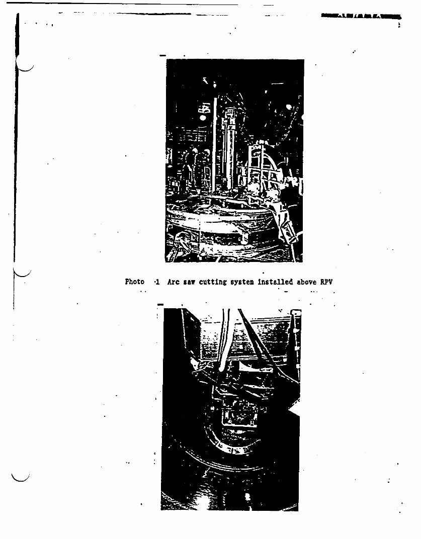
.................... I., ........ ..... "I'll ......
. II
Photo *1 Arc saw cutting systen Installed above RPV
I
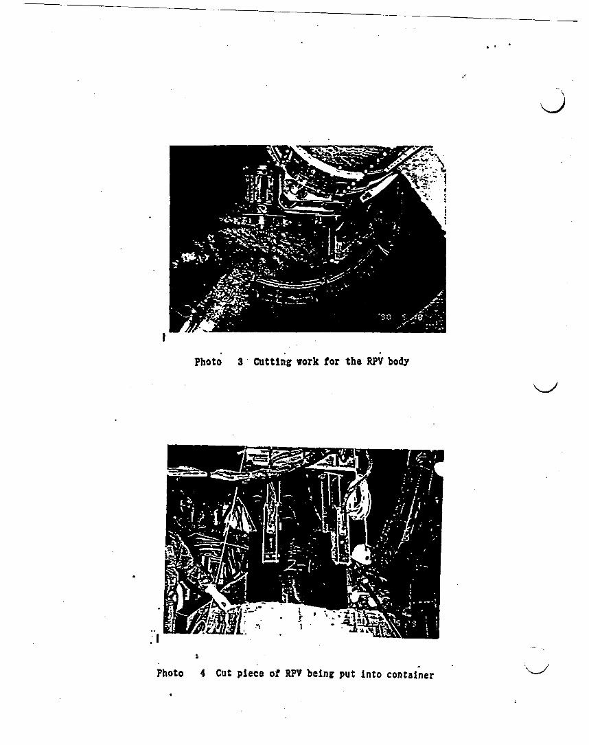
, I K
I
Photo 3 Cutting work for the RPV body
<2
Photo 4 Cut piece of RPY being put into container'sJ
'C (
;JPDR DECOMMISSIONING PROGRAM.
C
I
,.7
Japan Atomic Energy Reseach Institute
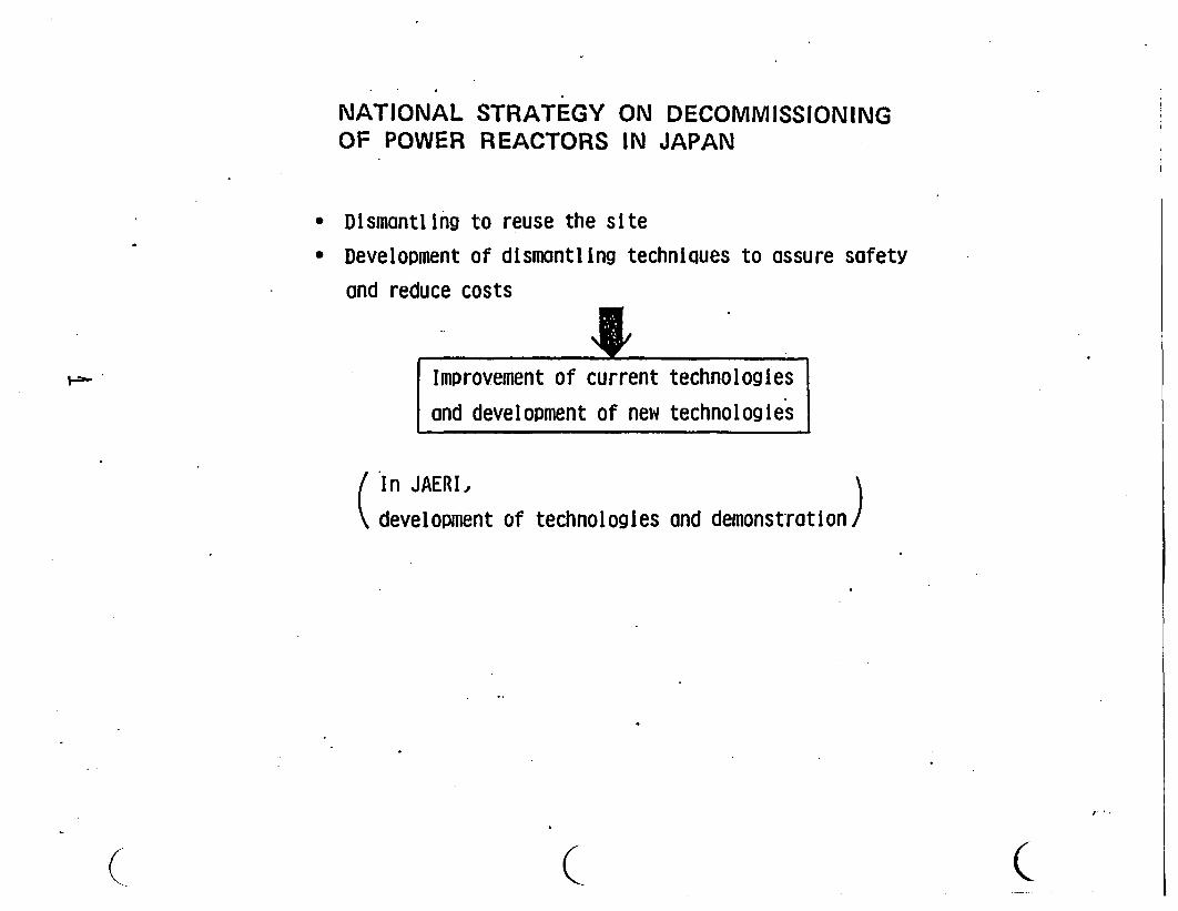
NATIONAL STRATEGY ON DECOMMISSIONINGOF POWER REACTORS IN JAPAN
* Dismantling to reuse the site* Development of dismantling techniques to assure safety
and reduce costs
improvement of current technologies|
|and development of new technologies
In JAERI, \
development of technologies and demonstration /
( C C~~~
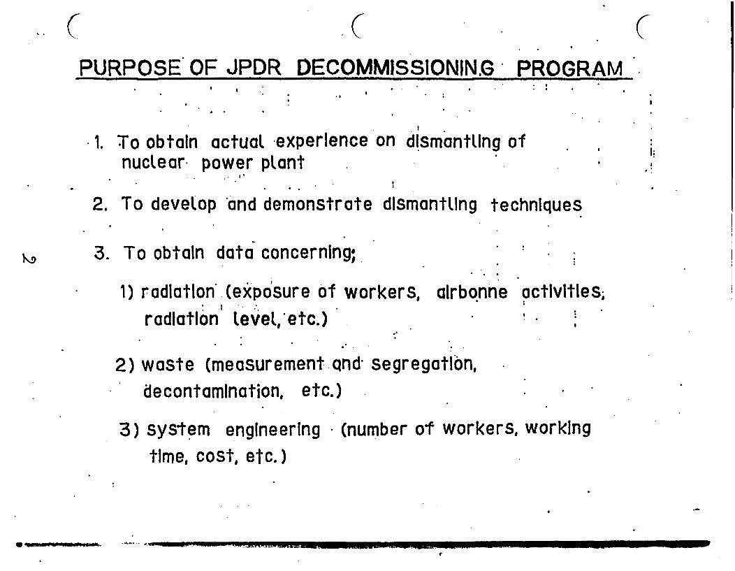
.6 (PURPOSE OF JPDR DECOMMISSIONINZG PROGRAM
.I I
;
1. To obtain actual experience on dismantling ofnuclear power plant
2. To develop and demonstrate dsmantLing
I;
techniques
3. To obtain data concerning;
1) radiation (exposure of workers, aIrbonne activities,I :I
radiation Level etc.)
2) waste (measurement qnd segregation,decontamination, etc.)
3) system engineering (number of workers, workingtime, cost, etc.)
0t - - .
f.
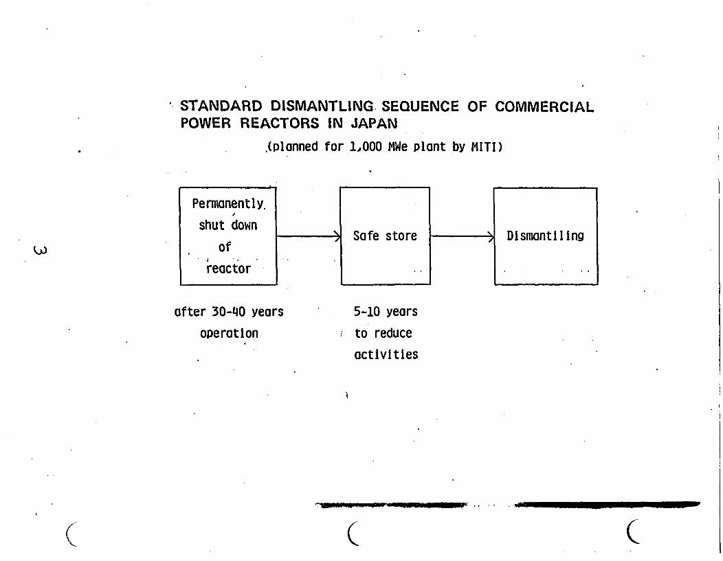
* STANDARD DISMANTLING SEQUENCE OF COMMERCIALPOWER REACTORS IN JAPAN
(planned for 1,000 MWe Plant by MITI)
after 30-40 years
operation
5-10 years
to reduce
activities
C ( c
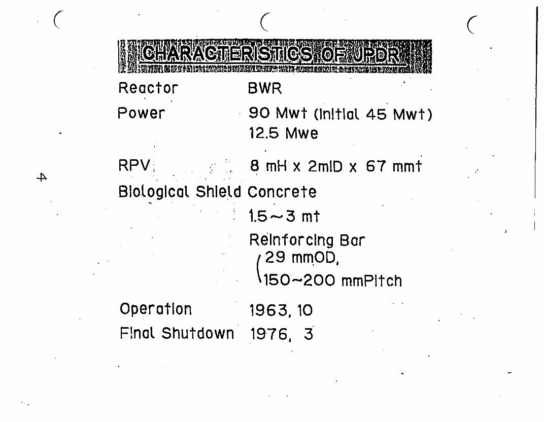
C C C
Reactor BWR
Power * 90 Mwt (Initlat 45 Mwt)12.5 Mwe
RPV,
Shield
8 mH x 2mlD x 67 mmt
Blologicat Concrete: 1.5'3 mt
Reinforcing Bar29 mm.OD,150'~200 mmPtch
Operation 1963, 10
Fnal Shutdown 1976, 3
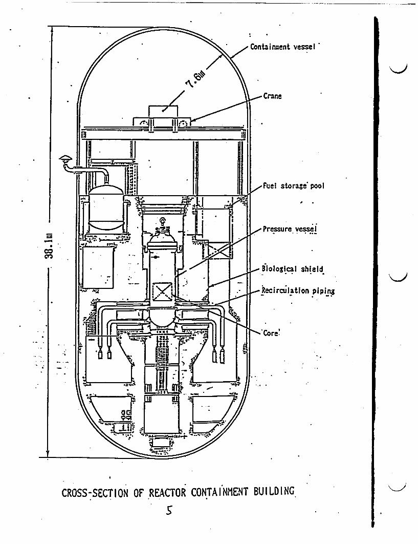
Containment vessel
Crane
11 1~~~~~~~~~~~~~~~~~~~~~~~~~~li
t 13: '1 l l | / Fuel storag& pool
IIJI t * <Pre Pressure vessel
jf B) a! | .^ ~iological shield
Fe. .. 1 tSERecirculation piping
'-Core'
CROSS-TIO - ' IT M
CROSS-SECTION OF REACTOR CONTAI NMENT BUI LD INGS.. .
.I.
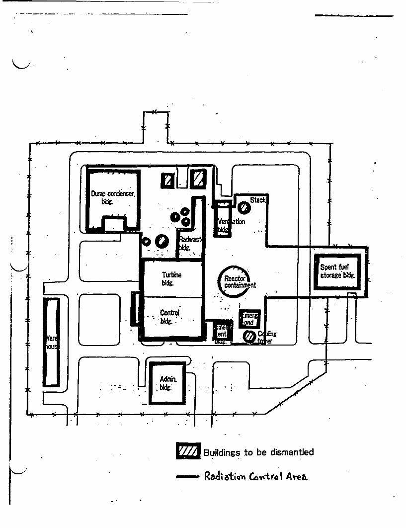
- - :
_ aoent fuel
Buidings to be dismantled
ReA;atiou CovtroI Are&

OPERATIONAL HISTORIES OF JPDR
TJPDRI
1963.8
1963.10
I. 1969.9
1969.10
- 1971.12[ii~JPD 1972.2R
II |1972.51|
1976.3
1982.12
Critical
Electrical power generation
45 WMt operation in natural
convection of coolant 9Shutdown reactor to ncrease power
Modifications of reactor core and
Plant to 90 MWt
Critical in new core -
Electrical power generation
power increase-to approx. 60 MWt )
Final shutdown
,-Apply the decommissioning permit
AppLy the revised decommissioningreport
Start physicat dismantlement
1986,7
1988,12
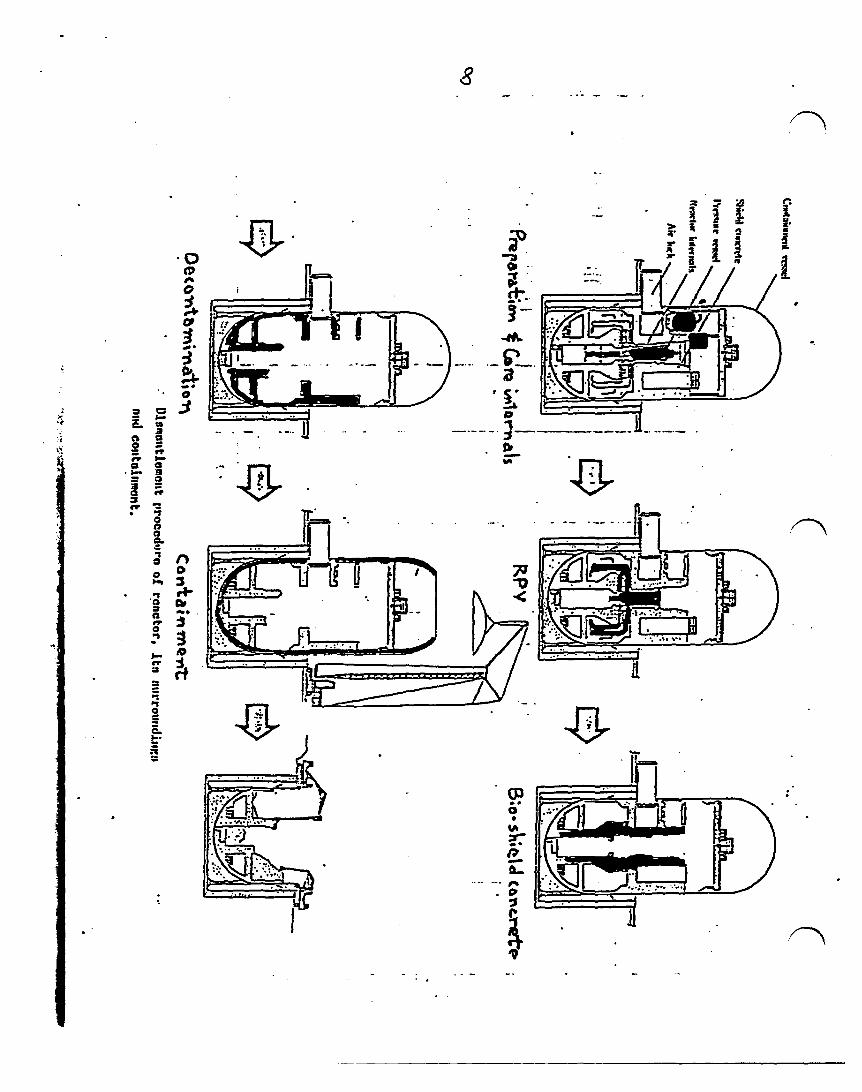
8
I,
i:
3 =
aC aa X= e
a a
a a
* *1aaaa.a
0
a-1
rp-I
I-
'V
EL
t,A
0
0
P.
.
ri
A9
3.
Cb
3
- -,oX
9?0
-
..
-
IV..

JPDR DECOMMISSIONING SCHEDULE.,_ 186 87 .88 89 90 91 92 9.3
Preparation, :
RPV Internals
RPV
Blo. Shield -Concrete
Containment
Other Buildings 1 - -
Landscaping |
g1,qSI,046 0 W j D
(
4,* ..W.44,ft. mwmmm���- - 04101ow
(. ( C
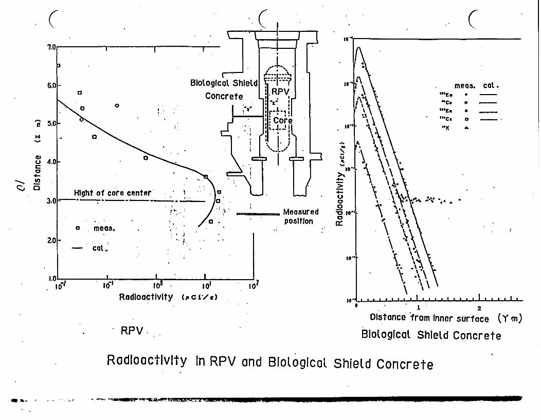
(
i'.O
a)0C
4-c~je-~ O
lG a
meas. cat."Eu 0 -
"Ce 0 --
"'Cs a -
"K "
N . * -
% I
I'\j '1
IVRadioactivity (p C i/ ) I0' . . 2 aa 2 I I I I a I I * . I . . I I
1 2
Distance from Inner surface (Y in)
BMoLogica ShleLd Concrete* RPV .
RadloactIvity In RPV and BioLogicaL Shield Concrete
| _. r --- up 7-

_.RPV (4oCi )
. CORE
,00Q Ci)
-tin,I.000
0.1 1 10 100 1000
Radiation(R/Hr )
RADIATION DOSERATE IN:JPDR FACILITY
.-. .4F.Z-. .4.-.a
(. ( C
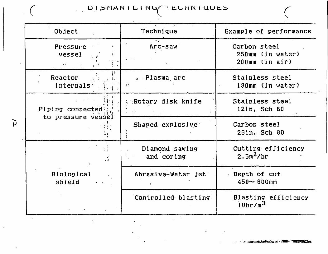
( L) I :> i AN I L l II I AA1- IN I t4U L CObJect Technique Example of performance
Pressure Arc-saw Carbon steelvessel 250mm (In water)
200mm (n air)
Reactor ; Plasma. arc Stainless steelinternals ,j 130mm (in water)
: . Rotary disk knife Stainless steelPiping connected.; 12in, Sch 80to pressure vessel
. .Shaped -explosive Carbon steel26in, Sch 80
, Diamond sawing Cutting efficiencyand coring 2.5m2/hr
Biological Abrasive-Water Jet' Depth of cutshield . 450- 600mm
Controlled blasting Blasting efficiency10 hr/m3
_ * j_4~~1.1 ' -iF t

Plasma arc torchdriving mechanism
Airborne particulatea collector
ventilation system Wing device
...... . ................. ..
_ -_ _
_ I II
. -I--Q%3�
ISuspended particulatecollector
A I I I
1. I 'Dross collector Container
Monitor (TV)Secondarycutting
lan
Lm
I I AL<Shroud.
Fuel storage poolPlasma arc
vessel
Fig. 4 PLASHA AC CUTTING SYSTEM- APPLIED TO IlEACTOWr INThEIINAIS
F� --I ** * - ... # -
c c
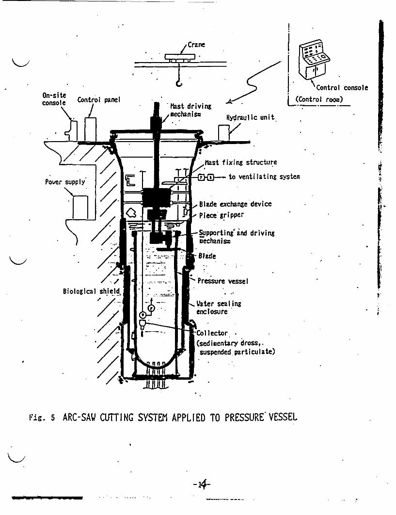
Crane
I W < -
On-site Control panelconsole i
'Control console
L(Control room)
Hydraulic unit
7K / Mast fixing structure
0-9--- to ventilating system
Blade exchange device
Piece gripper
Supporting ind drivingmechanism
FI
I
j
' Pressure vessel
,ater sealingenclosure
-'e 1 I-t- >- I~lrCollector / X u | | (sedimentary dross,.
.suspended particulate)
Fig. 5 ARC-SAW CUTTING SYSTEM APPLIED TO PRESSURE VESSEL
-4-
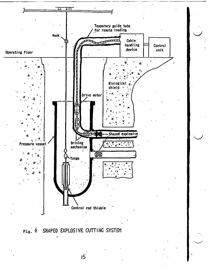
Temporary guide tubeI for remote loading
Hook
Operating floor
a 0
a . a
.
. . _ &a ., * * 'e &
. ;: .: : * /
Biological shield /... . a ..
.
.4a
Q P a '
.3
IA
0 l
% .. .
P * b I
. qIa aa
4a
I a ; *
0
0
0 .
, 0
j Control rod thimble
P
Fig. 4 SHAPEO EXPLOSIVE CUTTING SYSTEM
15
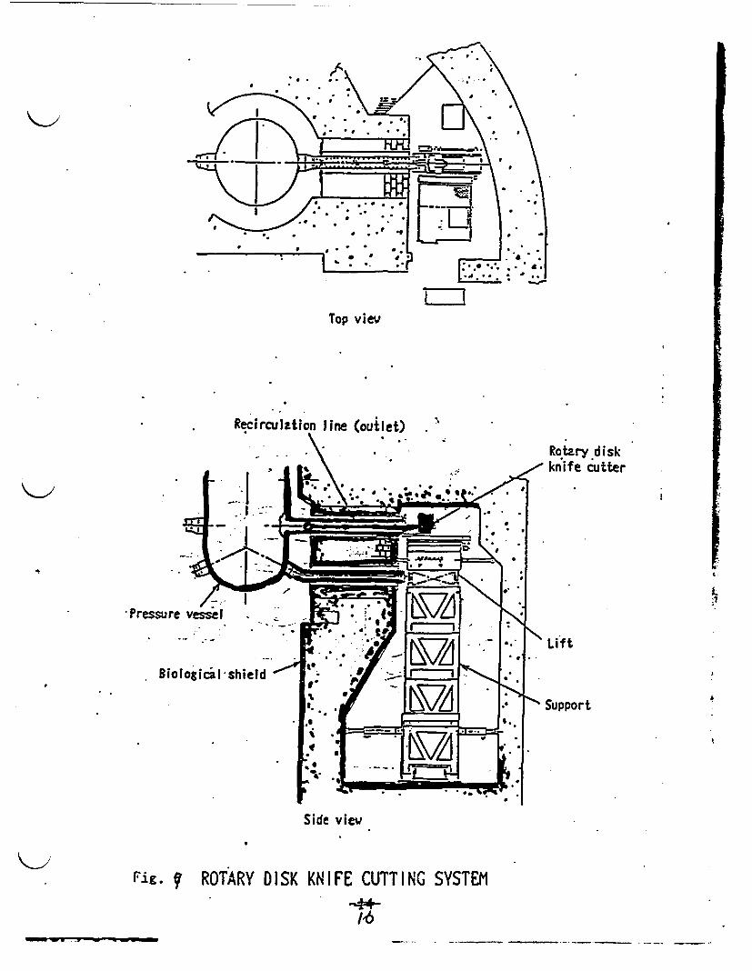
Top view
Recirculation line (outlet) ;I
Rotary diskknife cutter
I:1
Lifft
Support .
Side view
Fig. f ROTARY DISK KNIFE CUTTING SYSTEM
446
____

Conta I r Block gripper.
- rxDst collector(local)
Cutter
Dust collector (whole)
Control Consolej uni t * Activi nym
Fig. 8 D I AMOND SAW I NG AND COR I NG CUTT I NG SYSTEM
17
K>
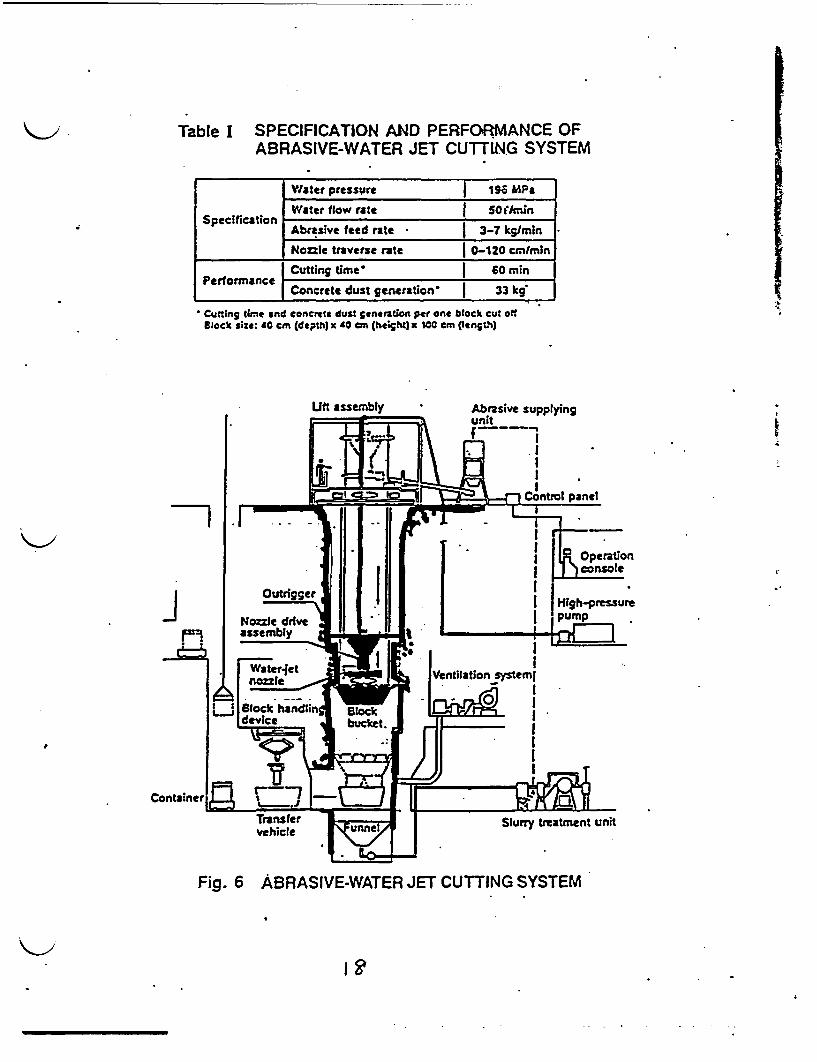
Table I SPECIFICATION AND PERFORMANCE OFABRASIVE-WATER JET CUTT1NjG SYSTEM
d1
Water pressure 196 mPg
Water flow rate SO ArL'nAbrasive feed rate 3-7 kg/in .
Nozzle traverse rate | 0-120 cmlmin
Cutting time. 60 mi
joConcrete dust generation- 33 kg
Cutting time and concrete dust ftneraton per one block cut offlock size: 40 cm (depth) x &0 cm (hetight) 1001 cm (length)
k
Fig. 6 ABRASIVE-WATER JET CUTTING SYSTEM

t 4
A Kinds and Activity of Radioactive astegenerated from the JPDR DecoMissioning
-Q
Kinds of Radioactive aste Activity (Ci) Weight (Ton)
Cor.e- InternalsControl rods, 4,050 2Q
Activated Core shroud, etc.Components Pressure Vessel 40 ]10
Biological Shield 10 1,350Concrete
Components 4.2 1.640Contaainated Concrete 0.2 830CoMponents _ _ _ _ _ _ _ _ _ _ _ _ _ _ _ _ _
.Resin, etc. 0.5 130
.Total 4,100 4,100
Eu I U I

Radioactive
ASI_ Waste
sIs.. S
-_ _ _ _ _A
I
H . I ;I
IIII
SIte Sea Irage Dumping
I.
Management SystemRadioactive Solid Waste
in Japan 20
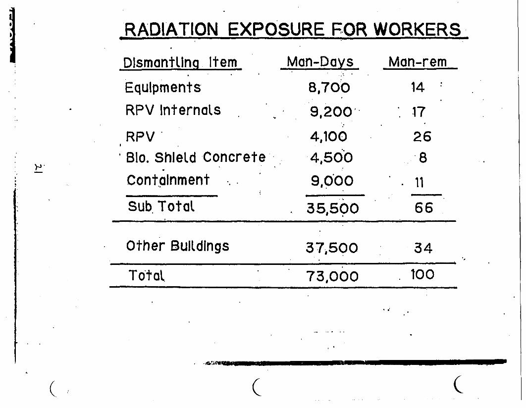
RADIATION EXPOSURE FOR WORKERS
DlsmantlIng Item Man-Days Man-rem
Equipments
RPV InternaLs
RPVBlo. Shield Concrete
Containment
8,700
9,200
4,100
4,500
9,000
14
.17
268
* 11
Sub. Total . 35.500 66
Other BuIldings 37.500 34
TotaL 73.000 100
. .
.W
( ( c
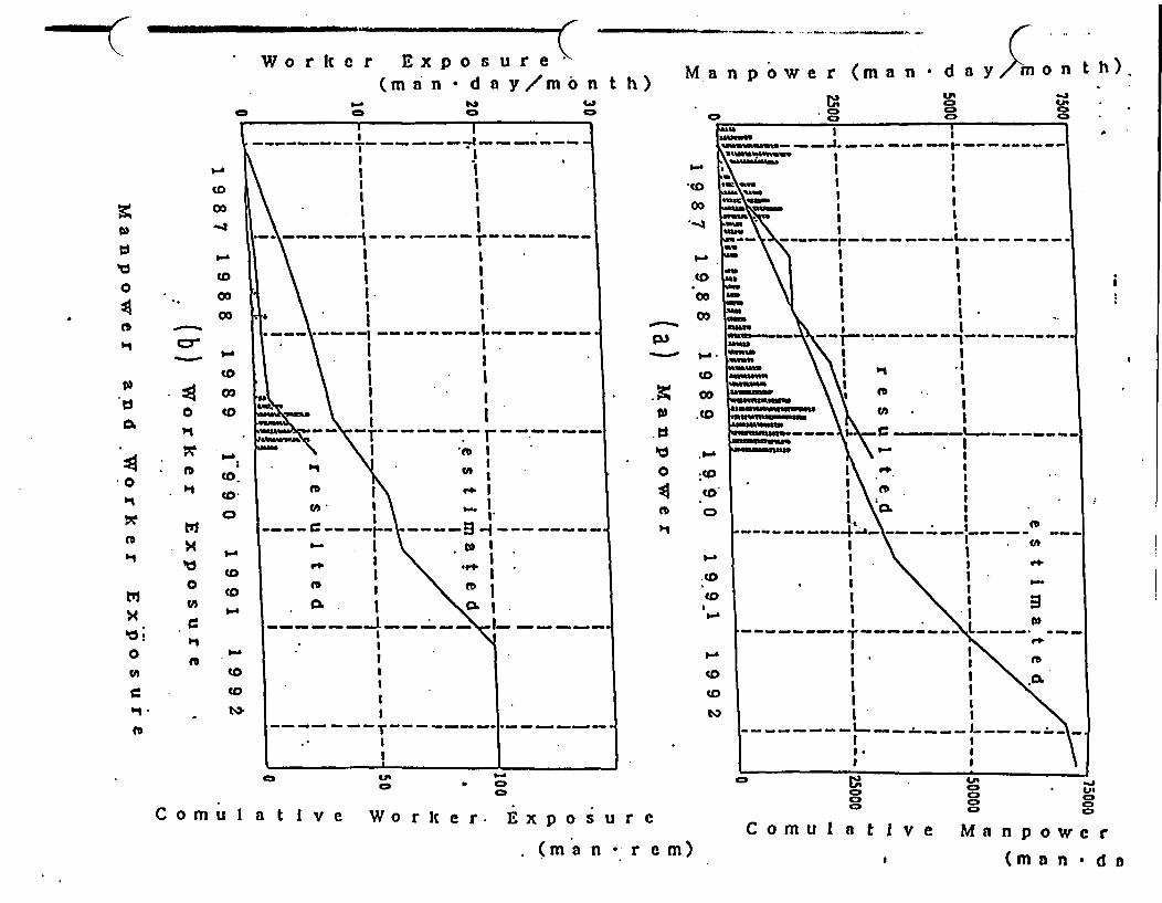
- -- So--
W o r It e r Ex p o s u r e(ma n * d a y/mo n t
La
we r (man d a onth) Ma n p o
I-
_,
03
-40
M
0
C,
rb 0r
0 . 4
0
* "t0
CDo~~~C03
00'a
to
toCD
toCo
CD
to
I I
I I
I II I
.1 I
I II II I
* I. I1 I.
*…I…I. - - - -- - -
I II II I
Sb I
I I- - - r - - - - -. - r - - -
r�I
CA 1ft IC". I
- - -- - - - - - � I.*-* .1'I.
ft II �I.
- - - -- - - - - - Is.. - - - - -
a
3 I
'CD
00
00&
oo
0K
0
ft
~1
'-.
.to
co
.D
CD
to
CDPt
M,
'1
MFo !
0
(A'
bi.
ft-
x
M
U0
CB
ft
-ao
CD
CD
CDto
_ S 1 *
I . II
a ' " ft .. I
C A . I
- ~ ~~~~~~~ . .\ l
I Is
. ' 0 . 8
I ! '
,. ,
. .0
, ~ ~ ~ I I
C~~ ~ ~ omI eM w
- tm n * d
C'ICL
'S
3.
-- ~ -- -- r- ---
I!
I._ _
I-U'
* O
C o m u I a t I v e Wo r I e r E x p o u r e
. (m a n * r e m)
I I
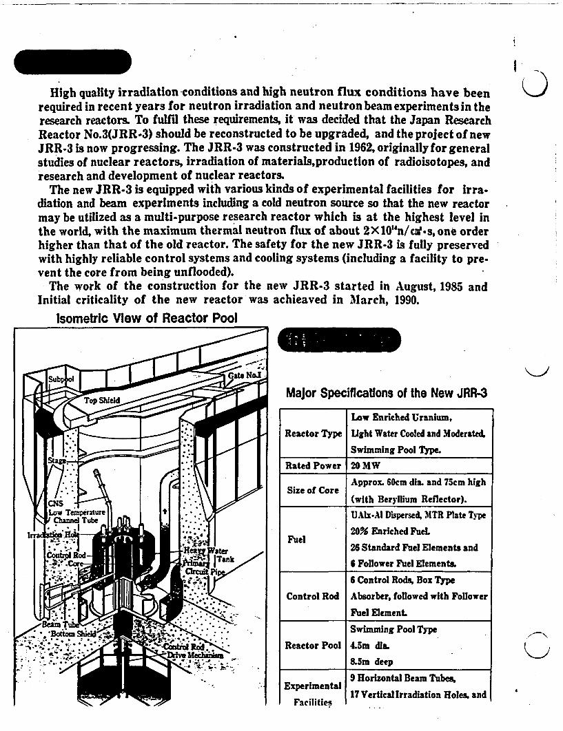
I
0High quality irradiation conditions and high neutron flux conditions have beenrequired in recent years for neutron irradiation and neutron beam experiments in theresearch reactors. To fulfil these requirements, it was decided that the Japan ResearchReactor No.3(JRR-3) should be reconstructed to be upgraded, and the project of newJRR-3 is now progressing. The JRR-3 was constructed in 1962, originally for generalstudies of nuclear reactors, irradiation of materials,production of radioisotopes, andresearch and development of nuclear reactors.
The new JRR-3 is equipped with various kinds of experimental facilities for irra-diation and beam experiments including a cold neutron source so that the new reactormay be utilized as a multi-purpose research reactor which is at the highest level inthe world, with the maximum thermal neutron flux of about 2X10"n/cue.s, one orderhigher than that of the old reactor. The safety for the new JRR-3 is fully preservedwith highly reliable control systems and cooling systems (including a facility to pre-vent the core from being unflooded).
The work of the construction for the new JRR-3 started in August, 1985 andInitial criticality of the new reactor was achieaved in March, 1990.
Isometric View of Reactor Pool
Major Specifications of the New JRR-3
Low Enriched Uranium,
Reactor Type Ught Water Cooled and Moderated,
Swimming Pool Type.
Rated Power 20 MW
Size of Core Approx. 60cm dia. and 75cm high
(with Beryllium Reflector).
UAIx-Al Dispersed, MTR Plate Ty pe
20% Enriched Fuel.Fuel
26 Standard Fuel Elements and
6 Follower Fuel Elements.
6 Control Rods, Box Type
Control Rod Absorber, followed with Follower
Fuel Element.
Swimming Pool Type
Reactor Pool 4.5m dia.
&5m deepK>
Experimental
Facilities
9 Horizontal Beam Tubes.
17 Vertical Irradiation Holes, and
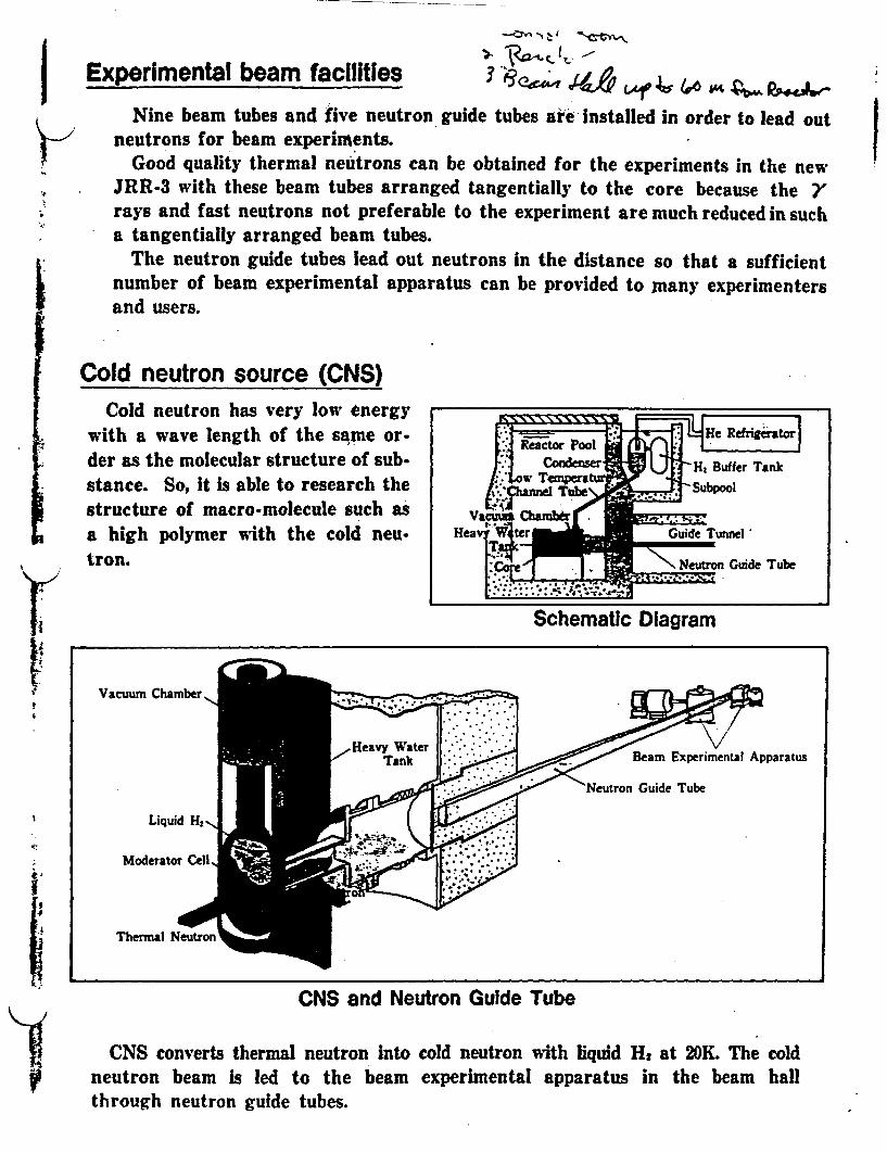
Experimental beam facilities a
Nine beam tubes and five neutron guide tubes are installed in order to lead outneutrons for beam experiments.
Good quality thermal neutrons can be obtained for the experiments in the newJRR-3 with these beam tubes arranged tangentially to the core because the rays and fast neutrons not preferable to the experiment are much reduced in sucha tangentially arranged beam tubes.
The neutron guide tubes lead out neutrons in the distance so that a sufficientnumber of beam experimental apparatus can be provided to mnany experimentersand users.
Cold neutron source (CNS)Cold neutron has very low energy
with a wave length of the same or-der as the molecular structure of sub-stance. So, it is able to research thestructure of macro-molecule such asa high polymer with the cold neu-tron.
I Reactor Pool11 CondomeItow Teniperatut
anel Tube
Vat Oicbamb.rrHeav4rJ
-' 1
3 F Hi Buffer Tank
> Subpool
Guide Tunnel'
\ Neutrn Guide Tube
r1Schematic Diagram
Vacuum Chamber
Liquid H2
Guide Tube
Il
Moderator Cell,
Thermal Neutron
CNS and Neutron Guide Tube
CNS converts thermal neutron into cold neutron with liquid H at 20K. The coldneutron beam is led to the beam experimental apparatus in the beam hallthrough neutron guide tubes.
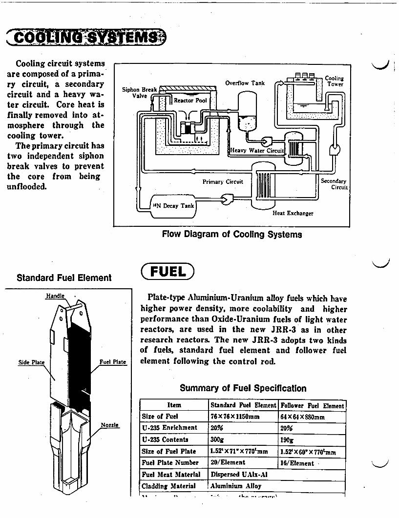
Cooling circuit systemsare composed of a prima- R Coolingry circuit, a secondary Overflow Tank Tower
Siphon Breakcircuit and a heavy wa- Valve
ter circuit. Core heat is AReactor Pool
finally removed into at-mosphere through thecooling tower.
The primary circuit hastwo independent siphon -terbreak valves to prevent Lthe core from being ' nnr n
Primary Circuit Secondaryunflooded. Circuit
_ ~~~~~~~~~Heat Exchanger
Flow Diagram of Cooling Systems
Standard Fuel Element C FUEL)Handle Plate-type Aluminium-Uranium alloy fuels which have
higher power density, more coolability and higher/ ° l L \ I performance than Oxide-Uranium fuels of light water
reactors, are used in the new JRR-3 as in otherresearch reactors. The new JRR-3 adopts two kindsof fuels, standard fuel element and follower fuel
Side Plate Fuel Plate element following the control rod.
Summary of Fuel Specification
Item Standard Fuel Element Follower Fuel Element
Size of Fuel 76X76Xll150mm 64 X64X88mm
U-235 Enrichment 20% 20%
U-235 Contents 300g| 190gl
Size of Fuel Plate 1.52' X 71' * 770mm 1.5? X 60 X 770'mm
Fuel Plate Number 20/Element 16/Element
Fuel Meat Material Dispersed UAlx-AI
Cladding Material Aluminium Alloy. ,,,,. ,, , o ,.%

For irradiation, vertical irradiation holes are arrangedboth in the core and in theheavy water tank.
For beam experiment, hor-izontal beam tubes arearranged in the heavy watertank.
Irradiation utilization facilitiesFor the purposes of reactor
K> fuels and materials exposuretests, radioisotope productionand activation analysis, thesefacilities are used to irradiateby neutron the samples in-serted into the vertical irra-diation holes.
(Vertical Irradiation Holes:HR, PN, PN3, S, DR, RG, VT-I, BR, SH
Horizontal Beam Tubes1G-6G, JR, T. 9C
Arrangement of Experimental Holes
Summary
Name No Application FeatureHydraulic rabbit General irradiation The rabbit is conveyed and cooled by water. This facilityirradiation facility 2 is used to irradiate the relatively heavy and high heat
(H R) Radioisotope production generating samples.Pneumatic rabbit General Irradiation The rabbit is conveyed and cooled by N gas. Thisirradiation facility 2 facility is used to irradiate the light and low heat
(PN) Radioisotope production generating samples.Activation analysis Activation analysis of The radiation measurement Is started immediately afterirradiation facility 1 the short life radio the Irradiation. This facility is used to analyze the short
(PN3) nuclides life radio nuclides.Uniform irradiation Material Irradiation The sample is rotated and moved up and down duringfacility I the irradiation. This facility is used to irradiate the
(SI) Silicon irradation sample uniformly.Rotating rradiation The sample is rotated during the irradiation. Thisfacility 1 Large material Irradiation facility is used to Irradiate the sample uniformly in the
(DR) radial direction.Capsule irradiationfacilitv
Exposure test This facility is used to irradiate for long period orcnntrnl the cample temperature in reopnn e to thein
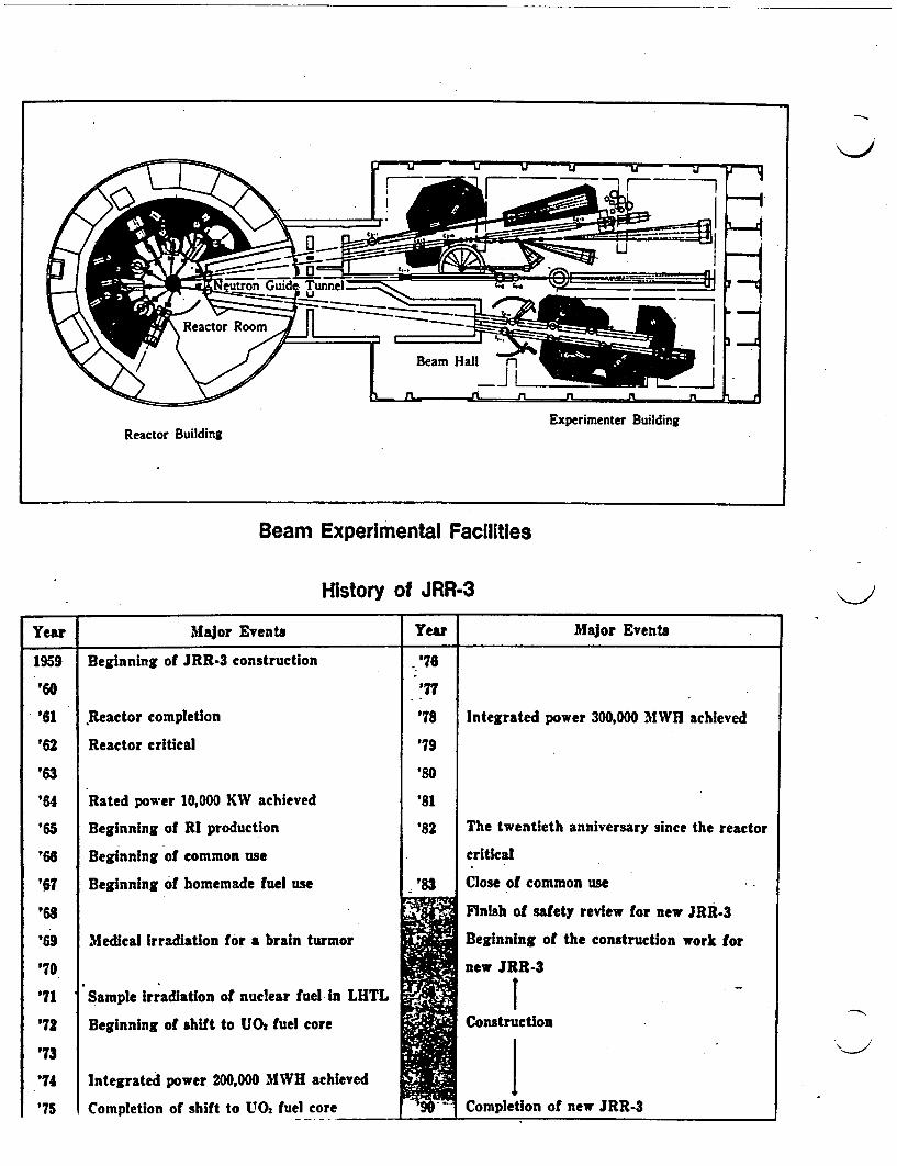
Experimenter BuildingReactor Building
Beam Experimental Facilities
History of JRR-3
Year Major Events Year Major Events
1959
'60
'61
'62
'63
'64
'65
'66
'67
'68
'69
'70
'71
'72
'73
'74
'75
Beginning of JRR-3 construction
Reactor completion
Reactor critical
Rated power 10,000 KW achieved
Beginning of RI production
Beginning of common use
Beginning of homemade fuel use
Medical rradiation for a brain turmor
Sample irradiation of nuclear fuel in LHTL
Beginning of shift to UO* fuel core
Integrated power 200,000 MWH achieved
Completion of shift to U02 fuel core
'76
'77
'78
'79
'80
'81
'82
Integrated power 300,000 MWH achieved
The twentieth anniversary since the reactor
critical
Close of common use
Finish of safety review for new JRR-3
Beginning of the construction work for
new JRR-3
tConstruction
Completion of newr JRR-3
'-I

JAERI-M 89-192
Progress Report on Safety Research of High-Level Waste
Management for the Period April 1988 to March 1989
(Eds.) Haruto NAKAMURA and Susumu MURAOKA
Department of Environmental Safety Research
Tokai Research Establishment
Japan Atomic Energy Research Institute
Tokai-mura, Naka-gun, Ibaraki-ken
(Received October 23, 1989)
Researches on high-level waste management at the High Level Waste
Management Laboratory and the Waste Safety Testing Facility Operation
Division of the Japan Atomic Energy Research Institute in the fiscal
year of 1988 are reviewed.
The topics are following studies on the long-term chemical
behaviors of long-lived nuclides in geosphere.
1) Mineralogical researches on the alteration layer of glass exposed
to water were carried out by laboratory experiments and investiga-
tion of natural glass. Leaching experiments of Pu and Np were also
conducted.
2) The spectroscopic methods are applied to study the long-term
reaction path modeling of radionuclide fixation using natural
materials.
Keywords: High-level Radioactive Waste, Glass, Mineralogical Research,
Leaching, Plutonium, Neptunium, Spectroscopic Method,
Long-term Reaction Path, Fixation
11

JAERI-M 89-192
Contents
Introduction ....... ... * * * * * * * * * * * * * * * * * * * *............. I
1. Studies on waste forms ****************s**................ 2
1.1 Studies on leaching and volatilization of radionuclides
from glass waste form *******e*********o***g******* 3
- (1) Continuous-flow leach tests of simulated high-level
waste glass in synthetic basalt groundwater 3
(2) Formation and evolution of alteration layers of
borosilicate and basaltic glasses I: Initial stage 6
(3) Growth rate of alteration layer and elemental mass
losses during leaching of borosilicate waste glass ...... 9
1.2 Leaching of Pu and Np *************************...*.*...... 12
(1) Temperature effect on Pu leach rate of the nuclear
waste glass ......................... 12
(2) Release of Np from Np-doped borosilicate waste glass 20
1.3 Volatilization of radionuclides from actual high-level
waste ....... ** ************. 28
(1) Volatilization of 37Cs and .06Ru from borosilicate
glass containing actual high-level waste 28
(2) Elemental analysis of the supernatant of actual
high-level radioactive liquid waste ...... 0.4 ...... 31
1.4 Change in density of curium-doped Synroc due to self-
irradiation ........ * ********.**. ...... * 33
2. Safety evaluation for geological disposal ....... 40
2.1 Studies on migration of radionuclides ... 00.0.00000 ...... 41
(1) An experimental study on nuclide migration in simulated
single fractures in granite .......... . ........... .. 41
(2) Porosities and diffusion coefficients of iodine anion
in rock ..... ................... * 45
(3) Adsorption of neptunium on naturally occurring iron-
containing minerals in aqueous solutions ..-.......... 48
2.2 Long-term reaction path modelling of radionuclide fixation
in geosphere by spectroscopic methods ... ... oo ...... 51
2.3 Safety assessment methods for geological disposal * 66
(1) Scenario and data base .................. .. 66
(2) Rough estimation of 237Np concentrations ..... 66
3. Hot operation at WASTEF .......................... .. 71
Reactor Decommissioning Technology Developmentand
Actual Dismantling of JPDR
Tokai Research EstablishmentJapan Atomic Energy Research Institute
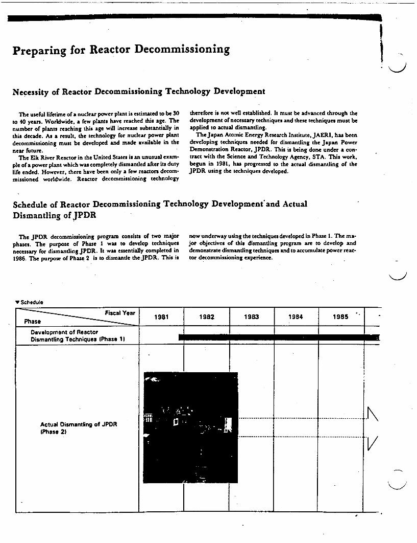
IPreparing for Reactor Decommissioning
Necessity of Reactor Decommissioning Technology Development
N
The useful lifetime of a nuclear power plant is estimated to be 30to 40 years. Worldwide, a few plants have reached this age. Thenumber of plants reaching this age will increase substantially inthis decade. As a result, the technology for nuclear power plantdecommissioning must be developed and made available in thenear future.
The Elk River Reactor in the United States is an unusual exam-ple of a power plant which was completely dismantled after its dutylife ended. However, there have been only a few reactors decom-missioned worldwide. Reactor decommissioning technology
therefore is not well established. It must be advanced through thedevelopment of necessary techniques and these techniques must beapplied to actual dismantling.
The Japan Atomic Energy Research Institute, JAERI, has beendeveloping techniques needed for dismantling the Japan PowerDemonstration Reactor, JPDR. This is being done under a con-tract with the Science and Technology Agency, STA. This work,begun in 1981, has progressed to the actual dismantling of theJPDR using the techniques developed.
Schedule of Reactor Decommissioning Technology Development'and ActualDismantling of JPDR
The JPDR decommissioning program consists of two majorphases. The purpose of Phase I was to develop techniquesnecessary for dismantling JPDR. It was essentially completed in1986. The purpose of Phase 2 is to dismantle theJPDR. This is
now underway using the techniques developed in Phase 1. The ma-jor objectives of this dismantling program are to develop anddemonstrate dismantling techniques and to accumulate power reac-tor decommissioning experience.
K-'
V Schedule
Fiscal Year 1981 1982 1983 1984 1985
Development of ReactorDismantling Techniques (Phase 11
Actual Dismantling of JPDR _1 ~~~~~~~~~~~~............................. .................... .......... .................. ..... Actual Dismantling of JPDR(Phase 2)
I .

Reactor Decommissioning Alternatives
Decommissioning a power reactor can be accomplished by any of the three following methods. Dismantlement is considered to be themost suitable decommissioning option in Japan because it effectively uses scarce land.
I Final Reactor Shutdown
C Mothballing ( MDsmantlement ) I Entombment
When this option is exercised, areactor facility is sealed afterdischarge of nuclear fuels, controlrods, reactor coolant, etc.
Surveillance and maintenance aenecessary inside and around the facili-ty for an extended time after that. Thereusable space available in the facilityis the smaUest among three methods.
When a nuclear facility is disman-ded, all components and structures arecompletely removed. The site can bereused for oher nuclear purposesafter confirming public safety by in-spection for radioactivity.
Decommissioning of the JPDR isbeing carried out in this manner.
When the entombment option is ex-ercised, extensive decontaminationand partial removal of the com-ponents are done after dischargingnuclear fuels, control rods, coolant,etc. Highly activated materials arecontained in an isolating barrier.Reusable space in the facility is slight-ly larger than that for mothballing.
.
i 1987 1988 1989 1990 199) 1992
Preparatory Work
Removal of Equipment from around R actor
Removal of Reacto Internals
Removal of iping Connecte to Reactor Pre sure Vessel\SW I
Removal of Reactor Pre ssure Vessel | > !."
Removal of Biological Shield Concr
Removal of Reactor Enclosure
Removal of Dump Co denser Building (Equipmentl (Building_
Removal of Spent Fuel Storage Building. Turbine uilding, etc. IE upment _A- -
IBuilding)
Site Restoration
________-IE_2
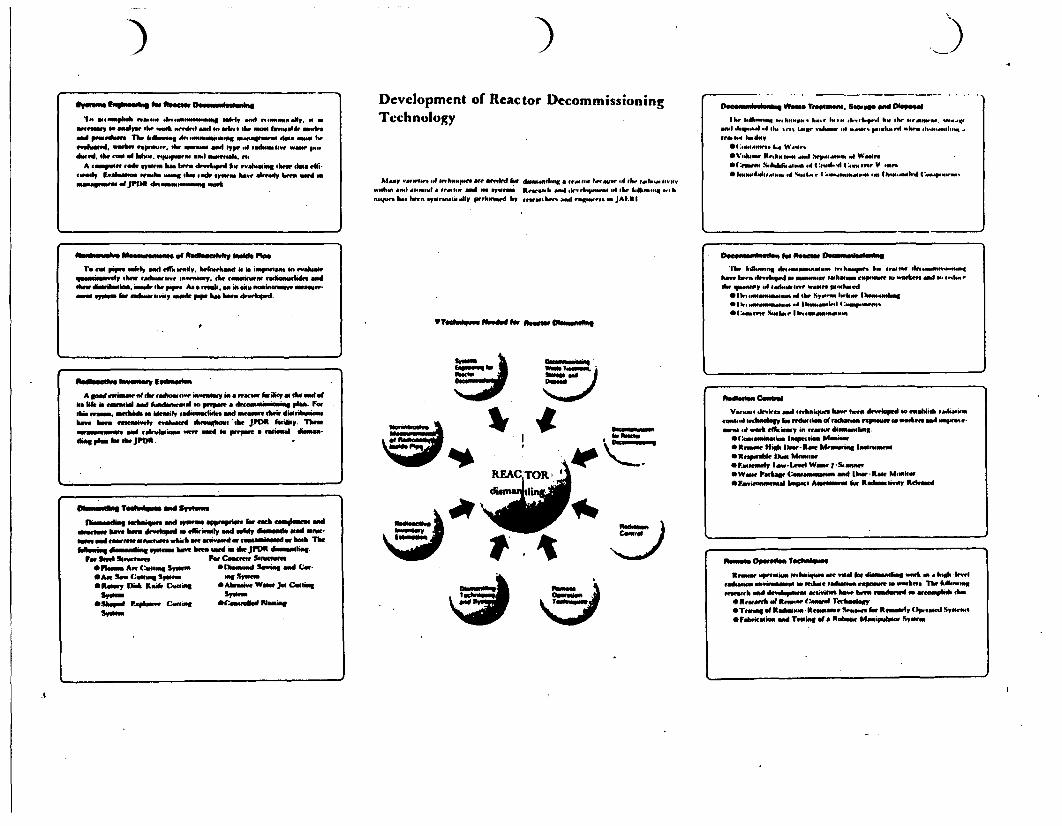
7: )- hghMP"" INI. "IMsOw OmotW~d$§.hIg
a Ota0. oAlp o."..hon4a4. s4 .a - a.w . -..w.wery sads May l.o.k.ow sooa4 s.o. I bOWN fi- gao. o ..1rovivelad, amaker rpoao.o. h. wuo.om asol yp. .4 ola Sw aw p.o..
A oainptheoCast o wla". hW ba .. hipo4h. ..oaitohdaa.tuoady .. aooss waooho Wo.g o.. .54. opm. ha., .Iaady hl.. ooad s
mngo.1ajrt)m doaooool..tg at
Devclopment of Reactor DecommissioningTechnology
Moonr ye....atOnhoa we MMMfr kw domoelooog a re ta Ia.. -I h. a..oo
VT*OA54*U MP""ds Isr bos"m O6011os1100g
Daalaol"oooo *arn Ifsevameo. Slog"s VWo plsposalBow.kh~o
0 .o..n h-. .......... h h .eao. ..oeyraa4 1 ooI.o .s tsa, no.0 .Oe o... n d...ooo..o. -
"lo .n dayi0A ..tObh Wear.
OV.os R..h. to*' ea. ht
p~o"-mo..4 Wawoa.St.... bo4.Ih. .. ,4(,C.oWd....o V on..eSmoAoooo~s..o 0%ot.OM .. o ioootn. . C~~.Sf~...,-o*..
btsaatlv Alssstlotam o .4 dkasaa itv b"de PipeTa two pes ddIy aold .01. wadi, bhailwtllod 00 .mptaam o .sahonO
qmaaimgod ta .haoow i..ormaY. oh. a."oiaa radiuomarcdre and4ohmo ditholis. isoid oh. pop. As a ..sd. am o ao fle onolm asamoon o,.owv 4.. am&...o.ioy oukol p op. has ha . 4.d.
Datomtebaitif #W M . 0m Dest. . .inIhe hA.oq .. oa0..t.-.a. t~hao ho. .. ". .bsd - -o...og
ha-. h-. dIaehop.. oo ina..a wnafioll .slplaw om st nd ".w #lo ,4t.doh. ooaaoy W4 ooiaoes aws~ pooahad
* I1 ,oa.tW o.ol 4th %VW-~ "ao. Ibo%-.aONoSib1 3. ..olo-a.a .4 Ih..o.o'O0 o.aowa54.. w ot. I hk-M,&eppwapoo
Reamedsp bamt" esivabaaa
A goad awosset. .4th. .admaoti. in-vallay ina Macmv failtY. ofheaod ofmonb tae..amnial sod holdsao..o s posata datsoiakal PI". Fatdlioaelasm ahsidam itul tadioawdindw. Ad mat hi.dioorihwimshae bet awuoislo ahIaawd hraolows oth. JPDR Istil. Tmmt "OyO sNW ah'Alaosooo wt 0.Pt-FM a omsad diosoan-dmag pk for dw JPOA.I
normoumbn
A
-~~~~~0-fn- ~~ on ~~~Wa o "
bat
'7"
REAL '1 .
VIN-ruft TOOWAW nd siSyisoo
bosssdkq oahdq . m ---so 1pasal. 0rsah so~s advroun hae hats di oopd vo vlfily lm4 osloy ismsosds OW5 Mow-small I"d awtot mlelo.. bhir ate at a~od lar .asmowd orbo hh f
Flat So Si For.t~s a Cowa... StoeetwemOPvallas An. Cammes SYuooo Oflsoud i s d CatOA.. S.. Cwtul.g Syllals olug ¶taOSeAMY P"s Km.4 Claotm SAhrely Wow Jet Caoliog
Olhpo R~apk.aa dston E~save Mting
onbodaso
c)
Vs-.. dkr ad I-Shiqo1n ha." host do..ddonaaobtehss
.0AtM~ .4 at&iaay i -Itow diftsawoobhg.
*ReAwoo High Dow- Raw M~nwio oaorwoa
OFaiy Il..LWr Waao, -!oanwwtowa. ipahag (ooataiaiuso ad [kwt-Ra Moit*F-ai~Ooosatal Ifapa Aaoat An Redmhattotso Rraowd
3.0sseu
~~UWS3U boot~~~~~~~~~~~~ow~~O1pa100111
ftmus. OPatsl. TdoiqooAwRrnao.paions oM hIsg.. at ead at dieaolswoo - W. htah host
tadoaos .sM~saa on tedotle tadoaao* aus .o athay Tlo &fitl.o-orewtolsh ad d dawu aw Wa ha ha ml asaoto atomoplb oh.-
eSxaMath of laws. cmaat Tarhunoag*Ttwwof Rallmono -sk~soa0 ha..... t Raessoa Op.....d Svvm.otfaawasl ad Timlaof aa Rabeew Illatuaitlat %Yu..
L
:A
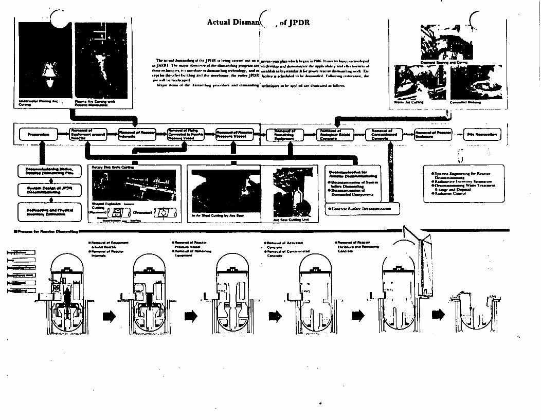
. r, Actual Disman( of JPDR
Thwea.al dinssngto4te JPI)R4 ii hin .t-d SI -a -yJ-eapn mhb hl t an Snlfl6 a luIm develiinJAFRINT n a idoriwe, id She dsnntpintW dv idd u dKe and iteei dik. ,ftnliae. g i.anrnue sod.ashnt seikii. d ua| ,.ibabsafmadh I.. pie. an- .hn.nsiS idntt ha.eiI. h~lsibrailihudng asdheu neehaae he enSeJPOR. Iacih.y;is aebdijd i~bediiiindld Folkoin ,e oaii dKe
il will I imdUIeapi
Ma.. i- d he . nan-ilig p.. e nd d.inading lwnkpe o applwd dhmtd *a li-._s
I-
I
i A. Stai C.At"i bw Am. SawAs SwCifi kwLo
_
*Syoen. Enitminug In RearweDlnn_.n- wiagM adi i. lnen y iniainm n
*l samnnni We lmasnwest.Siora and Dispsal
*Rolm- Qantnd
_ _ _
,u_
I _' I
[.~
e Offamad of £Oin0nWAsa s a u s od te c a
*W . as d sh uta Oo a C
* 1hisd a1d ofna-toPAoaln Vassal
* a at _a s u nEiso _~i~
O anl of Aciaad *F4in as IwcoConcfis Iichiina 1mi osi s
* .paj as Cas ntad CoaencConots
IL
* b¶ =rJ r, LV *1*
.,
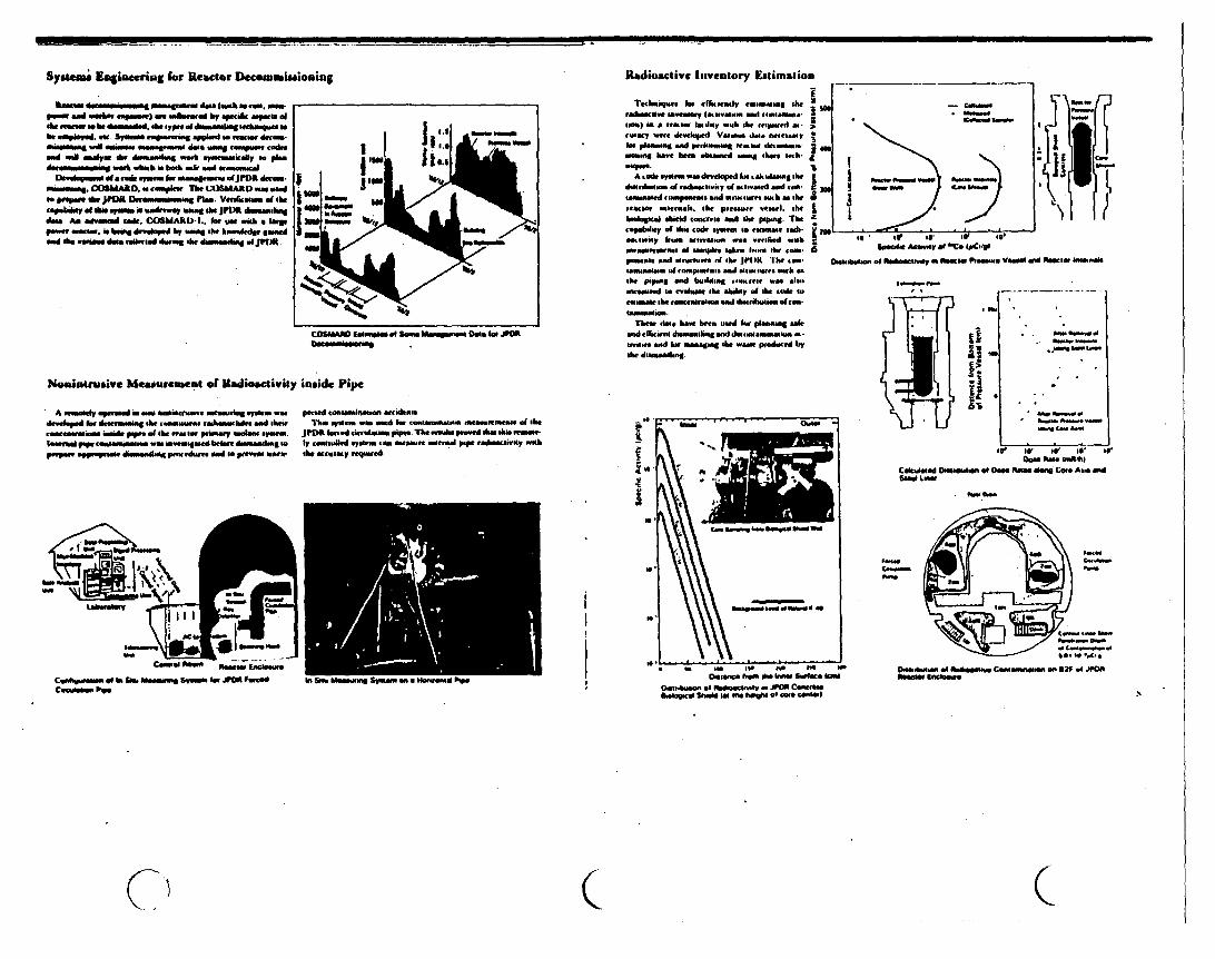
111111M -1 - . ..
Sysma Engineering for Reactor Decoulm itiloning
pln enid iswar osprnol am ,.asmar by speak mipis ofAte asaw a. he simsaalld. sb. arpe if dalnsmalag sarbalsashar lomhe.ea .Nis mn awmaang epgaka a. geer dicn- VWObsms" - aggmw m deeatds Wittg nanpssse codeasad WeA aellpe s dshngwish .5auisessrey t p"
*(ahis. cab Uind sy Im r mmeleasteu iFJf draM- lowsamosan. COMA&D. us csnssplese UhP LSMAKID -m wse
capldgp l 1 a s vu is sumirrimy mass she JPDA dumenshng ;due A ssmd caek. COSMdAAD- . for wait lim a eap
Noimarusive Ueearement of Radioactivity inside Pipe
A ymsl par ars osm gasa asesmann systess usa pacted meisesserdnsddoid rdsaada hersuaesrsssssisedSe Tha syuo Mr Slad hag rssgMMneU-s saseMsassni aIM l&
rsnesiguosi dit ~psoif aa as....peimeeyA ees post. )PDR h ird c sss kmsi The sw Aa pee-e shea ibis Frs-Issuel VWp rlanewanuweow sa anvesaeed bi otr dalweasilg a. ly "Insrslled aias -am amsae Noreml pip sidananscity washprepa. effimprss dmiss pesoedutsaed so passia asse- the acuracy eairedi.
Radiodetive Inventory Estimation
Ttesaqi"e kr irf..ally efusseae shefrelOsss iMo eaaOMMs and 0ssniOMs 5-too) i lnas aily wh he ressfsel alssivery wre destkpe. Veasw dimo naasyhfi en Nd prisa reaasa dasssa5 asouissg leae se ssed asang e ash-
A side yses wo devloped kwake esaeag shedaunb1asau if resaswsy of s maeed and .s. :"Naoussrs ssnse d W as ases w usm I ae hr5reacsa asesnas,. Ike presassae essel. e bvlogrl siedd ancerse ea" A papsog. The I-'sehay df Mbs gode sput a epasse r.etevaiy i arsavis"as we riaed meil ;"assanensa Go "oo. I" sh rss 6pa _ads enW aam ad she IpIoIl h11e su
IsaUne ad .easpieol.d g es -ath -ehe pp.g vod blsing . ree eim._nurld a " aise d abili of he ksse *soegnss she recesne soi lisrilsass siren
The dN haw betn used ir plenang s,sad efficw dseslinsg l dasoaesaes sitivise end IL aowisg the w produged tryshe diensmnf.
us CNI AMns
j~~~~~~. .aw _O
IIs INO W 5
-
I1
Dusab* ~so ol Rasersssas di AUse Plsesase. Vismall gad F.ae, lasseask
I ._
if.beINss. -
5. am 55
it 0 0 irb . a s a v s s
Siess SmogL as W 1h
rmade'an
*aNNCasa.
iI
II
~~%~IL~J~ %ws~~aa.. P5
lasers. Essntoesao Ilf W s ANN a iOsoesaft hema Os. Inrsm Surface semi
DolssaAssisoofp P44daoocgaVa -JIMIU CanoeS..Obaaisgsr l Shm5 We sP . Ieagli .5 lase CO- Wu
( C

C C Toosis bir DI)stinotimg T'lrhnitlec .yslenis
*""Mel of Reactor lateersish Using Pisimai Arc Cuttiag System
Reales. maen - s rtoses pste arse se, isiusYamoks . asesd ming se isawsrsiod -Nopaea o beshamassle I nketwsi. dh. .. es lsssed horksssg W., sorsad. std o do-wiet she staset A plans art oortsts eya-- LtfM go retotp fehs porg
Plas.a. (mg~q Iede ts... hl hess,_N..e byseelkrs.. "Wi Itc I~. Gos lsssigh she Oms hetssee she phton s.e eel-estead she weteil hesasso Thse 1 roetl itetl ets.. shssals.he metald sed se assit.. asinal -slies e-.Y.
TWOsMai mneak sto W Sns"s. psentet No he maesim
pro u easlq sagse rpeimef plasm *se cososig do.i Tleep ee as r-pered ssodeevaes I.. e spessi te oe pl.her shery e ss es mller pes., stabl .e thking i *uteieen Cses i she po d dreb h .-aedaey plwa serssnig deIe.
Ts ypers ot pla " nr ciss syswiessea h e., haed i-dr.ssssis she h te tefm stiesil. rh f. She rabawsmosapulao sype oed she s typt. *-- *- ted hase of the ditFe - sippmsos _d putssssiis. she pas... nbh. . sh.bdh -
Remsovl of Piping Connected to Reactor Preesure Vessel UsingShsped Explosive and Rotary Disk Knife Cutting Techniques
psisg ssnId e res ure werl i sh l. o sr s dsn, ieesd gaflra *h sise us.1e *- a pslbsolkvpi h s e a.wI Ir- . shetwe isO se pp by h u.s piessr. tisshe pse I ssosg "e d.es- p.. ll,'l IMWpe esi has misle a. ts io ly linhisdwM I- aod diu sis se.ss p..Issu. ag iasssg lp lbh shaIpd is Isibetw|e a the maso presiuse -wue nd el hiAigssl shrld ..m- dlruysphse h.-*es IelV qee isaashesiiirerse Shoprd eapkae WWi sndiy d.s 1sst *sssg syouses oe -d u 6e us. she pits a. a sueos iii 1dr isa5 list' *i
seheetee d d hi shew piues bantpopgs Itb 2mnm 11sJls (I) sy nslea oippe p shs-d hv stsinoss n sher tssat
or t. C .0t wsh iSleil tftieri at she s Wh V lairs his..i r s.ssi sbhe r mrcy disk hosl,
_>Coasts PstS WTestish * l
3 ar Cui
[tNaa isadEwin S~
I
4
[ftoses ote om ene Caseag SysemssI
sAss Cahioot Pants
losesse sheaias Tyopenasion Asc CeeM"s Sysi. Mms TV"s Photoss Arc Cme.ss System, Shaped tspteahs Cuness Syss esad Moeye O1 Kenie CosisiSyises
III
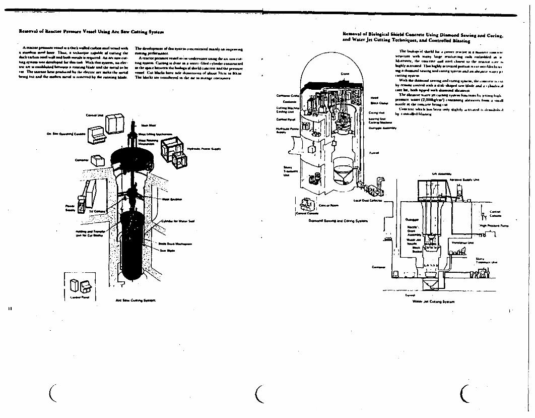
I I- - mommo�
Removal of fleactac Pressure Vessel WS Arc saw Cold.8g SYstem R.'.vl 01 Biological Slield CaMrete Using Diand Saviag and Coring.and Water Jet Cutting Tecaniques. and Controlled Wasting
A rame pwains enl i a eHawk walied calsact seatl alwashX Masalas eal h,_ 1 . a sadsw e sapahe a .Wsg Wshah caas lad wail sad bashdeal. se ersass wed Am a ea. cw-#wa laows ar I I fid ar de waab Wsea sysn ) . an ee.
sem aneor ersuAhlashed as ,a easasag Mlark, and se mesal s helaw5 The inrse be. prod-sada bV she, eireew sre webkS abe, wisbna s i a ma*lse ns a-a s anseed by she eaawa blader
The devalopsest a she s syesntasas~c-seuaad masly saa ksseseagasassag; perfinuae.
A sessse p-ense lel we Is adee e wa e _r w . aswau y.en Ceaa u shea as a wases (sbd yl.sde ss.s..din she spa. hetwoes he hadskgsel s. tawal eta* asd the peealaeemese (:s. Mass howse d salesla,s. .. u A so Eb..The blacks ae arawadeeeed m she auss smorsage asaees
_a_-. Scade
Ea'lsoe OhhI-gs0a 15461' "MalWd1 W 1w ods mwabla orIN
aghly. o aesap l heaksh aweld pwasaw ilav111 A.is
Webah a she alade bsawnsg-s51
11m ytm selcII i1
by esaesaei aahadshssdswbwl at lIm~s5
O. a ofasasd cow"
LAI Lafwewy
saomlwa Saeer, talfTh" ' I"sralC*Abss Wa us.. wa_
.,
: 1-s-
F-''' -�]09.I "'w" P 10 I AeC Saw _eg Sasea WONs Jsse CAMBOsai ystas.
( C C

iIk� j� - he!
� I - � �tk�t
5hl�I'SE
I iJ .3 1CC:r z-fl1�
gjl ji 1 JIlk!.: :1 Iiji!- 4t � E11 ;4�
.5.U * a - -� �
3 lId 111'�3 iiIiIiIIj
.:1 -3 * �- r
I!i�Iij �iIi�I a I
iii 11111I jillItlit� a111.iI I
I
00aC
0ta
W.
II
I
'Ii H9l
U,.
* -u
*3 '1
' liiilX .. s 'i]
a. u1 t 11
a'I
_.1 t
1a
I ;E4iI*II
I L
IIsi! I1 1
1 -I
tj a
j l l r l
I Ji',j11 1i
ii' I11111'I F
a
I c
itA
Ii. 1
'I I'1 '1
li II
I
I iI

preparing or Decommimioning of Commet'cial power Reactors in the Near Future
Deramm paumm~g Jtl musm ew 1... km Imnmm a mmis f ehe Pib sh ymem t-m.m . edmed mahuequts m e-waA M.. e ema.Rn~~ n eeymm e ns.. pero eFlemm.muis.e mnIuam.meeiiJpu
am ffbminis em ctwey bein pum...e mummY i-ma~ew. have mned dhe ta~mrmev.. pIgmome NW d ex m arg Ofmnmela II*$. ibmCompwam prwvmme he he E-sehmnge ml. mmuhmhmpe ee eoamyJE.t m hyda aoln
.. r and TeshmWe Iniarmam mm mernS Nuelem I.Mahlmm ml .me e i ml he pP4Cramii madie hmmsemimD)-ammammmemg Pvmjfeme m.a enem by 4)ilXD:INFA mm. uunsig geehew~ky d.k,ge.e * JAF.RI bMwee kehgilyg.Oe a xh. impmweuin. m, h dmmawwomiaq iehkugy emsermead by maity-min ft.e
BilauwaJ Couoperation in Decommissioning
la oh. mmmpetUw pespyuw. omk dlater bilateral and denommmnmnaflPawkelgeamemm tanlmwtem eagemmgtne frmb.h umde, m*mcid me. JALKI a m mo uptMiog mih dhe Umued %me mside ademmajinrmat JA~l ma m bhuel ertmnatmn ees she fikifmiMa excherege Of huin3 enh-MMOta 'ideed ,udafemen-Inae~ Kweaw. Cammda mA Frme. and i piuedmg w"t em- vemingebangem ofib emtnumimm. achleegy mmd etne~e neeim
Cmmghueld in De. IS" Can ed .n De. IS" Cachded in Nm.. I 26
t ~~~~~~~~~~t
I~~s - ONO r" P4WASiva ONO - 1gag
117 13 1973- I*114
/ ~~~1906- 2000 1373 1310
I
S.Uaibmdey. Assa*dand Key A0m#0061e11
S0 me D ommkm
*AelieniA0 -a"mr C-"so~ee Aam"t
0*0cemnimmvlsltaclmeseen
*Oncllmeamg W tlO~
JI
qCulteg Tool ToChrempe"4,Tlmemmoumto~n VW
eOmCantmetnf
62
ATt__
-n Frcmy
1132 - 102
Narmm of FSacimeyCmuntsy
I Typniul Cdty II 00cmmmaw"mu MmD"I no. o,,mm ,
Ocwwqmmmmm~m Psmgmct Pasitc~mammg a Men 0CONCA Camm,,smo Pfmgewavime do I cbheeG# SCemnm.4; VW ?aChwacm Ikfammm Ca;ma-g tu0mw OmMAgMmeOn Oft o MCh IM
afteml £eaeM Atemsgmexmnte . OECODMA COO&Amem"i. Ps"WOMmwm
I'.
C C

4 # /X
Safety Studies on Glass Waste Form
S.Muraoka
In order to achieve the safe disposal of radioactive waste,it is necessary to promote the development of waste managementtechnology as well as the safety assessment study. In JAERI,safety studies for contribution to establishment national safetycriteria and safety assessment are being conducted as well asbasic research to support development of waste managementtechnology which is adaptable to environmental conditions inJapan.
Characterization of radioactive waste has been carried out.for some items to evaluate the safety, according to process oftransportation, storage and disposal.
In this document, some of our recent activities aredescribed briefly of the JAERI's studies on the glass waste formfor high. level waste disposal.
(1) Volatilization of '37Cs and 106Ru from Borosilicate GlassContaining Actual High Level Waste l]
As the safety evaluation test in relation to operation ofstorage facility, the volatilization of Cs and Ru fromborosilicate glass containing actual HLW was examined in analmost closed canister.
The HLW glass used for the present study was borosilicateglass. The reagents for the glass additives and the simulated HLWwhich should be converted into 1300g of oxide glass were mixedsimultaneously and placed-in a vitrification apparatus with aboutone liter of a denitrated actual HLW solution. About 50g ofvarious oxides were assumed to come from the actual HLW solution.This mixture was calcined at about 7500C. melted at 12000 C for 2hours in the vitrification apparatus. Half the molten glass waspoured into an 8. cm-i. d. 24. 4cm-high stainless steel canister,kept at 6000C for 2 hours, and then cooled to room temperature ata cooling rate of less than 400C/h. The furnace temperaturewas raised in steps from 250C to 1000*C (Fig. ).The temperaturerise by the decay heat of the HLW was so small in the presentstudy that it did not affect the temperature control of theglass. During the course of heating, part of the air in the upperspace of the canister was collected in an evacuated samplingbottle with a volume of about 7 cm .
Radioactivity from volatile elements trapped by both thesampling bottle and the sampling needle was measured by anintrinsic Ge solid state deteo r. Figmy6 2 shows the temperaturedependence of volatility of Cs and Ru at a fixed time of 24hours when both nuclides are at apparent saturationconcentrations. The solid line in the fgure represents the dataobtained in our previous work 2J in which the activation energyof about 140 kJ/mol was obtained on simulated HLW glass
1

containing about 1.6 x 10¹⁰ B of 134Cs. The present data showsfairly good agreement w k previous one.
The volatilit 93 v Ru measured at 600°C and 8000C is aboutone fifth that of Cs. Since Gray 3] has pointed out that theactivation energy for various element ogre almost the same -aseach other, the air contamination of ° Ru at a usual storagej 5 perature of 4000C s also expected to ba 8e fifth that of
Cs; 1hus, the normalized concentration of 1URu would be about5 x 10 at 4000C. This extrapolated value may be conservative,since 4000C s below the softening point of the present glass anddiffusion may not be a significant mechanism at this temy8 gature.It should be also mentioned that the, volatility of 0Ru at1000 0Cco ld n be measured; It was under the detection limit of5 x 10 Bq/cm . This s probably an example that the backwardstep plays an Important role; the stainless steel Iunister ismarkedly oxidized at around 10000C and reacted with luORu in theair inside the canister. It Is also probable that RuO4 is notMble at high temperatures, and this Is one of the causes that
Ru disappeared at around 100 0°C..~~~~~27
(2) Release of Neptunium from a 237Np doped Borosilicate WasteGlass 4]
The MCC 1 static leach tests were performed for a 237Npdoped borosilicate waste glass at 90.°C with dionized water andsilicate water leachants to speculate the release mechanism of Npfrom waste glasses. The composition of the Np doped glass Isshown in Table 1. Teflon vessels were used as leach containersand SA/V ratio was 0. lcm
Deionized water and silicate water were used as leachants.At the desired leach durations, the Np concentrations in theleachates were measured by gamma counting with a high puritygermanium detector.
The amounts of Np released from the glass are plotted as afunction of time as shown In Fig. 3 in terms of the normalizedelemental mass loss NL)Np. Although the release behaviors as afunction of time are appreciably different between the delanizedwater and silicate water, the (NL)N values of about 5g/m aresimilar for the two leachates after 1 day leaching. The releasebehavior of Np In this study are compared with those of otherelements (Fig.4). A linear relation between log(NL) and log(time)is observed for Na, B and Cs within the studied leachingduration. As time proceeds, NL's for Np and Sr approach toconstant values.
According to our previous study, Na, B and Cs were found inthe leachates but not found in the surface layer; they arereleased from the bulk glass by decomposition of the glass anddiffuse through the surface layer without being trapped. Sr wasdetected both In the surface layer and in the lachates. ProbablyNp, representing a similar time dependent release behavior tothat for Sr. is also present in the surface layers.
It is reasonable to assume that Np concentrations Inleachates are controlled by the solubilities of Np solid phasesformed in the surface layer. This assumption leads to that thesolid phases formed In the surface layers must be primarily
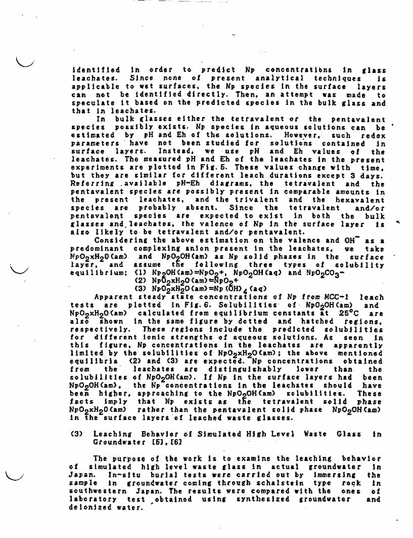
identified in order to predict Np concentrations In glassleachates. Since none of present analytical techniques isapplicable to wet surfaces, the p species In the surface layerscan not be identified directly. Then, an attempt was made tospeculate it based on the predicted species In the bulk glass andthat In leachates.
In bulk lasses either the tetravalent or the pentavalentspecies possibly exists. Nip species in aqueous solutions can beestimated by pH and Eh of the solutions. However, such redoxparameters have not been studied for solutions contained insurface layers. Instead, we use pH and Eh values of theleachates. The measured pH and Eh of the leachates In the presentexperiments are plotted in Fg.5. These values change with time,but they are similar for different leach durations except 3 days.Referring available pH-Eh diagrams, the tetravalent and thepentavalent species are possibly present In comparable amounts inthe present leachates, and the trivalent and the hexavalentspecies are probably absent. Since the tetravalent and/orpentavalent species are expected to exist in both the bulkglasses and. leachates, the valence of Np In the surface layer isalso likely to be tetravalent and/or pentavalent.
Considering the above estimation on the valence and OH as apredominant complexing anion present in the leachates, we takeYP02xH2 0(am) and NpO OH(am) as Np solid phases in the surfacelayer, and assume te following three types of solubilityequilibrium; (1) Np 0H(am)-NpOf, NpO20H(aq) and fMpO2CO3-
(2) NpO2 xH20(am)-NpO +(3) NpO2 xH2 0(am)=Np(8H) 4 (aq)
Apparent steady state concentrations of Np from MCC-1 leachtests are plotted in Fg.6. Solubilities of NpO2OH(am) andNpO2xH2 0(am) calculated from equilibrium constants at 250C arealso shown in the same figure by dotted and hatched regions.respectively. These regions Include the predicted solubilitiesfor different ionic strengths of aqueous solutions. As seen inthis figure, Np concentrations in the leachates are apparentlylimited by the solubilities of NpO2xH20(am); the above mentionedequilibria (2) and (3) are expected. Np concentrations obtainedfrom the leachates are distinguishably lower than thesolubilities of NpO20H(am). If Np in the surface layers had beenNpO2 0H(am), the Np concentrations in the leachates should havebeen higher, approaching to the NpOCOH(am) solubilities. Thesefacts imply that Np exists as tie tetravalent solid phaseNpO2xH2 0(am) rather than the pentavalent solid phase NpO20H(am)in the surface layers of leached waste glasses.
(3) Leaching Behavior of Simulated High Level Waste Glass inGroundwater 5), 62
The purpose of the work is to examine the leaching behaviorof simulated high level waste glass in actual groundwater inJapan. In-sltu burial tests were carried out by immersing thesample in groundwater coming through schalstein type rock insouthwestern Japan. The results were compared with the ones oflaboratory test obtained using synthesized groundwater anddeionized water.
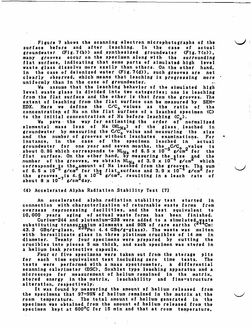
Figure 7 shows the scanning electron microphotographs of thesurface before and after leaching. In the case of actualgroundwater (Fig.7(b)) and synthesized groundwater (Fig.7(c)),many grooves occur on the specimen along with the surroundingflat surface. indicating that some parts of simulated high levelwaste glass dissolve more easily than others. On the other hand,in the case of deionized water Fig.7(d)), such grooves are notclearly observed, which means that leaching s progressing moreuniformly than in the case of groundwater.
We assume that the leaching behavior of the simulated highlevel waste glass is divided into two categories; one is leachingfrom the fla-t surface and the other is that from the grooves. Theextent of leaching from the flat surface can be measured by SEM-EDX. Here we define the C/C0 values as the ratio of theconcentration of Na on the flat surface of a leached specimen (C)to the Initial concentration of Na before leaching (CO).
We pave the way for estimating the order of normalizedelemental mass loss of Na (NLNa) of the glass. leached ingroundwater by measuring the C/CO value and measuring the sizeand the number of grooves without leachates examinations. Forinstance, in the case of the specimen leached in actualgroundwater for one year and seven months, the C/C value isabout 0.86 which corresponds to NL a of 6.5 x 10 5 gm 2 for theflat surface. On the other hand, y measuring the ize and thenumber of the grooves, we obtain NLga of 3.9 x 10 g/cm whichcorresponds o the 2 amount of Na leached from the groov s. Tha sumof 6.5 x 10a gcm for thI flat2 surface and 3.9 x 10⁴ g/cm forthe grooves is 4.2 x 10 g/cm resulting in a leach rate ofabout 8 x 10⁷ g/cm day.
(4) Accelerated Alpha Radiation Stability Test 7]
An accelerated alpha radiation stability test started inconnection with characterization of returnable waste forms fromoverseas reprocessing facilities, and the test equivalent to10,000 years aging of actual waste forms has been finished.
CurIum-244 and plutonium-238 were added to a simulated 213stesubstituting transu ium elements and 90X of rare earths ( Cm:43.3 GBq/g-glass. J Pu: 4.4 GBq/g-glass). The waste was moltenwith borosilicate glass in three platinum crucibles of 14 mm indiameter. Twenty four specimens were prepared by cutting thecrucibles into pieces 5 mm thick, and each specimen was stored ina helium leak protective capsule.
Four or five specimens were taken out from the storage pitsfor each time equivalent test including zero time tests. Thetests were performed with a mass spectrometer, a differentialscanning calorimeter (DSC), Soxhlet type leaching apparatus and amicroscope for measurement of helium remained in the matrix,stored energy in the matrix. leachability and fine-structurealteration, respectively.
It was found by measuring the amount of helium released fromthe specimens that 97-99X of helium remained in the matrix at theroom temperature. The total amount of helium generated in thespecimen was obtained from the amount of helium released from thespecimen kept at 6000C for 15 mn and that at room temperature,

because at 6000C the helium was completely depleted from theglass specimen.
The test results are shown in FIg.8. Density of thespecimens decreased slightly with the Increase of time and thedecrement of 1. X was observed at 10,000 years equivalentRegarding leachability based on the total weight losses, somefluctuating results were obtained in the initial stages of thetest but subsequently the curve is flat to the 10,000 yearsequivalent. Microscopic observation also did not show any changein the microstructure. Those results seem to suggest that alpharadiation has no significant influence on the performance ofglass forms to confine high level wastes.
References
C1] Kamizono, H., Kikkawa, S., Togashf, Y. and Tashiro. S.,'Volatilization of 137Cs and 106Ru from borosilicate glasscontaining actual high-level waste," J. Am. Ceram. Soc.. 72,1438 (1989)
C2J Kamizono, H., Kikkawa, S.. Tashiro, S. and Nakamura, H.,'Volatilization of cesium from nuclear waste glass in acanister," Nucl. Technol., 72. 84-88 (1986)
C3) Gray, W.J., "Volatility, of some potential high-levelradioactive waste forms," Radioact. Waste Manage., 1, 147-149(1980)
C43 Nakayama, S. and Banba, T. , Release of neptunium from aneptunium-doped borosilicate waste glass," J. Nucl. Scl.Technol. (in press)
(5] Kamizono, H., Leaching behavior of simulated high-levelwaste glass in groundwater," J. Nucl. Mater., 127, 242-246(1985)
[6] Kamizono, H. and Nakamura, H. , Simulated high-level nuclearwaste glass leached in one type of Japanese groundwater"J.Nucl.Mater., 152. 339-342 (1988)
[7) Tashiro, S., Banba. T., Mitamura, H., Kamlzono, H. Kikkawa,S., Matsumoto, S., Muraoka. S. and Nakamura H., "Safetyexamination of HLW solidified products at WASTEF,"Proceedings of The 1989 Joint International Waste Manage.Conf., Kyoto, Japan (1989)
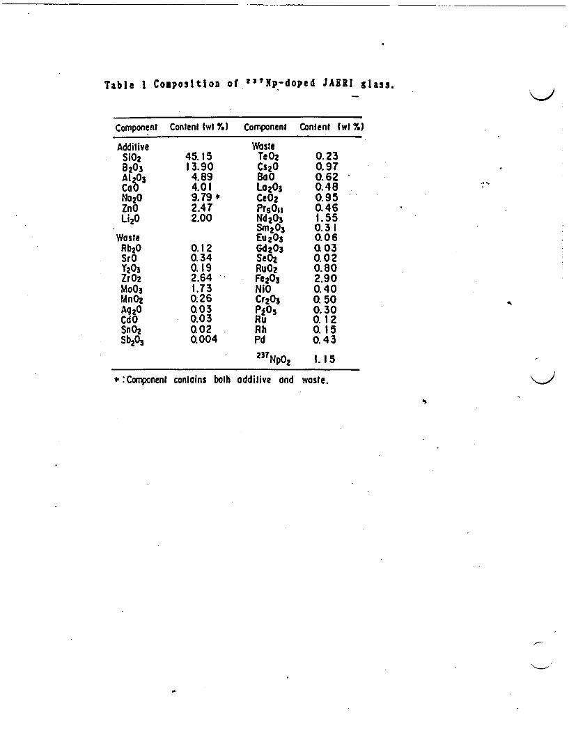
Table 1 Cposltion of 2aNp-doped JAERI glass.
Component Content (wI %) Component Content (wI %1
Additive WasteSiOz 45.15 TeO2 0.238203 13.90 Cs20 0.97Al 03 4.89 BoO 0.62CoO 4.01 La023 0.48No20 9.79 CeO2 0.95ZnO 2.47 Pr60S, 0.46Li20 2.00 Nd2O3 1.55
Sm 2 03 0.3 IWaste Eu 23 .06Rb2O 0.12 Gd2O3 Q03SrO 0.34 SeO2 0.02Y203 0.19 RuO2 0.80ZrO2 2.64 Fe203 2.90MoO3 1.73 NiO 0.40MnO2 0.26 Cr203 . 50Ag20 Q03 Pj05 0.30CdO 0.03 Ru 0.1 2SnO2 Q02 Rh 0.15Sb203 Q004 Pd 0.43
23TNp02 1. 1 5
# :Component contains bolh oddilive and waste.

( ( CTemperature (t)
1000 800 600 400-65 X _00 I 0w
This work (l0 I"Ru
100
-
0
-
.4-
a.
I-
80
60
0 r i*I
0 -1
0 I
o .. . !n~~~~~~~~~~~~~~~~0 o III
o 4. , , , , £~~~
M0
4-0
4.-C
0)W
C
_0
0
0
40
20 1(0
0 7 M4 21
Time (day )28 35
Previous work Rel .2)
7~~~~
_ \~~~
'_ I\-.. _I 2 , , Fig. I Schematic heating conditionsArrows show the sampling positions. 1059
O.5 1.0 2.0
103/T (K 1)rla 2 Temperature-dependence of the olatil Ity of 137Cs and
f.
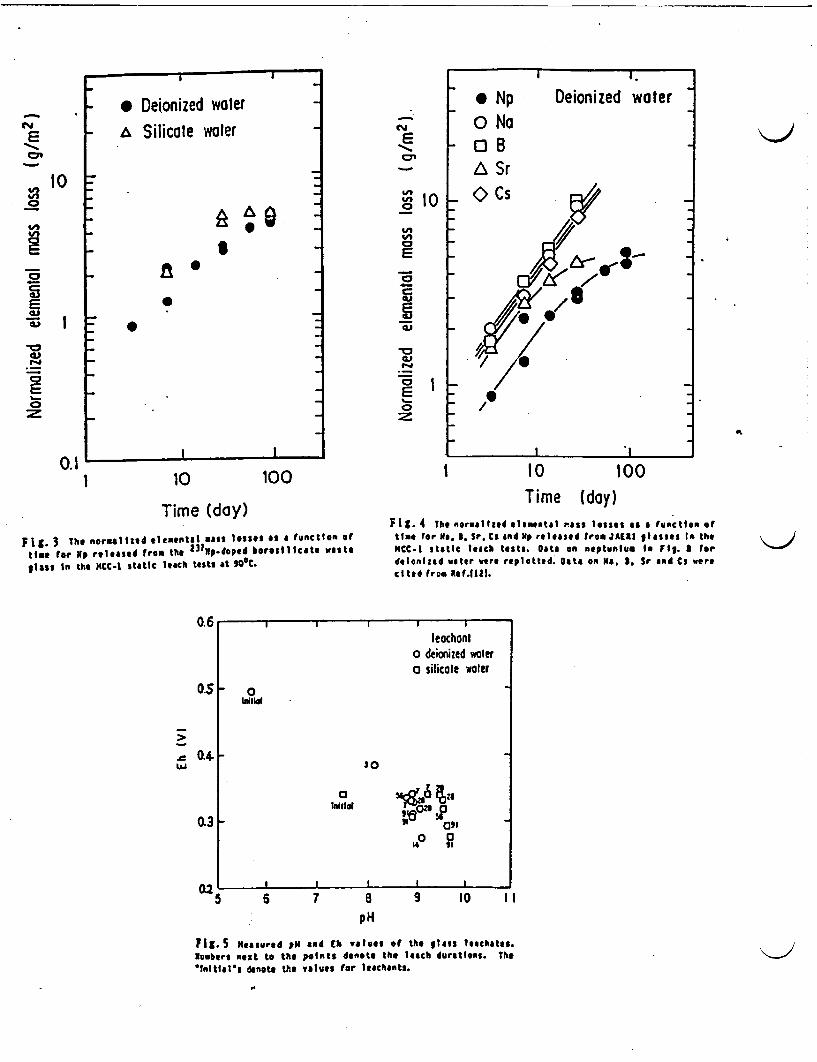
a a~~~~~~ I i.
Deionized water
10
* Deionized waterSilicate water
'A .@
n 0
- 0
E~~~
V-
U'V0 0
0
~0
-
ci
. 1E=0
* NpO Na
- OBA Sr
_ Cs
I .I
0.11 10 100 i 10 100
Time (day)
Fig. 3 The normaltied ,leentsl mass ltosses s a function oftime for p released from the
2 1ip-doped borosllcato aesteglass In the CC-I static leach tests at 900C.
Time (day)Flt. 4 The normalited elemental nsa lose as & functon oftIme for N1 l Sr. CS and Up relesed from JAEI glassas In theMCC-I static teach tests. ato on neptualnu In Fly. fordelnized water wre replotted. Data on N. . Sr and Cs werecited from Ref.1l21.
0.1
O.',
0.4
I I I I I
leochonio deionized walero silicole waler
inil Oi
. °I0
3 tniltd z a3, 0
I I I I I I
0Q
0:5 6 7 8 9 10 IIpH
Fig. 5 Measured PR and Eh values of the glass lechatoes.Numbers next to the points denote the leach durations. The'Initelts denote the values for leschants.
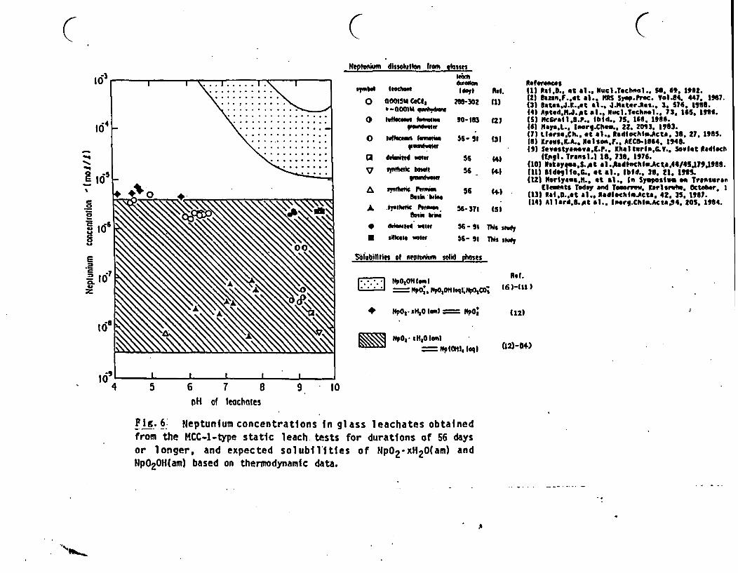
( C CNeptunlm dhsohile Ir hlasm
10"bw ld
O OOOtSM G(Cd,t-000 qwA,*w
O lr 1_.
O wh"A wwwo
A'
aa
a
,S
52.
a
¶7
dawd w
"k toll_ ._del
dwaule, Refren.cesIly) M~ 11) .. le 1,., t., Wvcl.Technel.. 5 6 182.
11) 3a1MtF..t a1.. IS Syp.Prec. 91..64. 447, 1967.M8-302 (1) (3) 1t4ts.J.l..t a1. Jjtate rRes., 3, S76, 1936.
14) Apted.N.J.pt at.. NocI.Techool., 73. 165. 186.90-163 12) (S) Mcgrall.U.P. Iid.. 75. 168. 1986.
(61 MayaL. 1wrg.C1o... 22. 2093. 1983.(7) LIrse.C,. at 41.. INdlechIt.Acts. 3 27, 1985.
56 91 131 (6 Kravs.LA., N.lson.., ACC0O,464, 1946.1') wevstyaa*va.E-P.. KXhltlrlP.V.. viet Radlech
56 (4) (Ejg). Trans).) 18. 738. 1976.(101 1okay &S..ot a1.RAdtechI.Aca.44/45l79.l9I8.
56 (44 (11) UldogI0.L. at a].. Ibid.. 3. 21 15.(12 I1yen911., t .. In Symposium a Transuran
06 . | Elmnts Today and To-.win'. Kaisr,4 Octabr. I*4 { (13)1 Rai.L..t aI.. tadtochfM.Act&, 42. 35. 1997.
(143 Allard.e..et a1.. Irg.ChI.Acta94. 205. 14.56-371 (SI
56- u TM$d
56- 9 T ,
,& ar etoc Two-'L tropic rwi"
So.l. b1ila
dsigNt welr
N 1H41e4 vowf
solubitllfis 1 Meohn solid es
NpO,0H 1l"-- - 6 p0, Hp0tOH q t0p~COj
+ 1PO,. .H4O 10Ie - 11 O
1 1 , . : 1 4 , 0 ( mqE~~ ~~ NpIHl * He 1
Rot.
(6)-Ul )
(12)
(10-4)
4 5 6 7 8 9 10pH of leochoes
P1g.6 Neptunium concentrations in glass leachates obtainedfrom the MCC-l-type static leach tests for durations of 56 daysor longer, and expected solubilities of Np02-xH20(am) andNpO2OH(am) based on thermodynamic data.

2.JI. I I I I I I I I. I.0 I . I I I I I I I I .
2
a -o -2 1rn^
)~~~~~~~ 1111111,-
II I I I - I -
I I I I I I I - I I I jI oo-. n IU
U- .
- o
c -
x
0
5
4
a
2
1
0 CI I I I I I I , I I
I 5000 10000
F 1 %,caan9ns e$bcjron mgph trua of the surlace of the unkached s e (a) andthe surIte of the specina ehd in actual poundwater (b). in synsheaiaad yountwacet (c)and t deod w AjW (d) lot I yea'. -
Aged le equivaleut 10 actuIl waste form (Year)
- FIg Results of accelerated alpha radiation stability test forthe waste glass.
C(, (

VOLATILIZATION OF CESIUMFROM NUCLEAR WASTE GLASSIN A CANISTERHIROSHI KAMIZONO, SHIZUO KIKKAWA, SHINGO TASHIRO, andHARUTO NAKAMURA Japan Atomic Energy Research Insti tuteDepartment of Environtnental Safety ResearchTokainwra, baroki-ken, 319-11 Japan
Rcccived February 21, 1985Accepted for Publicniion July 23, 1985
V'olatilization of '3 Cs front simulated high-levelwaste glass in a canister during several reheatings upto a m1aximunn of 1000 C was examined. The resultsshio wed that the temperature dependence of theamount1 of 3CS suspended in the air inside the can-ister could be divided into two categories. As the tem-perature was increased above 500C, the amount of134Cs suspended in the air inside the canister alsoincreased O tile other hand, for temperatures<3000C, the amount Of '3 4Cs suspended in the airinside the canister had an almost constant value afterseveral reheatings up to a maximum of 1000°C. In thiscase, the air contamination by cesium-bearing materialinside the canister is considered to be significant evenat waste storage temperatures <500 C.
. .%...Sg.V.St4
fl... ... ..
t
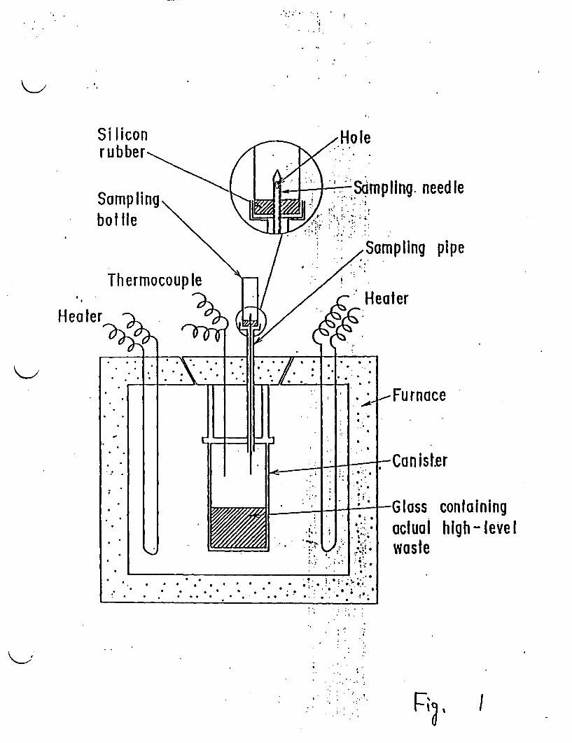
Si licon Holerubber
Sampling- Sdmpling, needleSampling \A .bottle
* / / Sampling pipe
Thermocouple
Heter~a] , By Heater
t :-. I I Still i | l-Furnac
.. . 1> _ _ .. . ~Canister
G* Glass containing::actual high-leVelI
_ _a *_ waste. ...
' . . . .* ' * .I* , * ? * .
I I*..,**I.
'* ' ,..

I .
Kamnizonlo l l. VOLATILIZATION OF CESIUM
Temperature (eC)1000 600 400 200 .1C
IIi
E
U
C0
C0C0
.
1 0
. 3.5103/T IK-')
0 Tcinpcralitre dcpcndency of te 34Cs concentra-tiOt thal rcprcscnts ilhe amount of "'Cs suspendedin tie air inside the canister (AHc,).at a fixed timeor I day. The data were collecied during the firstcycle of releating up to 1000sC (), the secondcycle up lo 900'C (u), the third cycle up to 900'C(x). the fourth cycle up to 700'C (c), and the fifthcycle up to 400-C (&), which correspond to Fig.. 2.The error bars show the standard deviation of eachplot. Note: Thus tar, we have not yet examined theexact cesium speciation. We speculate, however,that cesium may exist as a vapor phase for emper-nures or more tian 500SC and airn particles con-mining cesiumi play an mportant role In air
conlamination for emperaiures of <500C. There-rore, i is not appropriate to plot In partial pressuresor single chemical specie in the present paper.Instead, we preeer lo plot In Ao34c., which does notncd time cesium speciation. :
. .
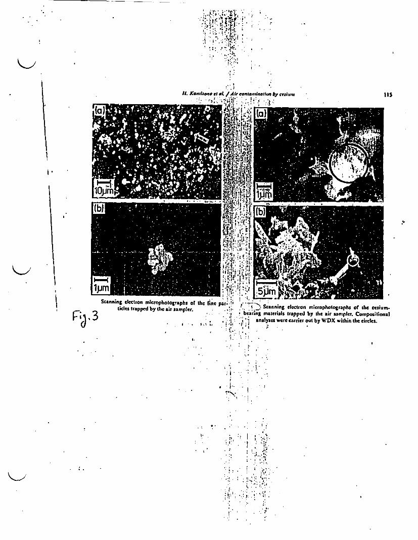
**' i' *!| .. - ;
-
II. Kantiaaie el a / Ir contaminn li by ceihnt ItS
fi ,. ,it;_
Sca ing electron b r hotogrphothe at pa . Scanning electron mirophot raps of the cesiumF;~ ~ ~ et tapdb h si saplr i ,. bearing matterials trapped by the air samper. Compositional
d . , . g~~~~~- nalIyses were carrier out by WDX w ithin she dreles.
4.~~~~~~~~~~~~~~~~~~~
* * ,.N !* .. ' . !~~~~~~I
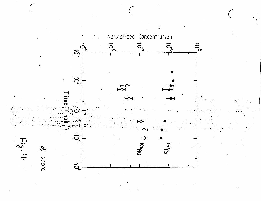
C
Normalized Concentration
C
Cf.-. (0
--
o, C,a)
o,Cn
I I ' I I I
0
-p
D
-p
0
* . r�..* . *
* �* *t..
6
. ....
...... I
. 7 -. . I
.. . . .. . ..' -t.i0
a)
cC-C,,
I I07
0O
-A. II I I l Ia I I I
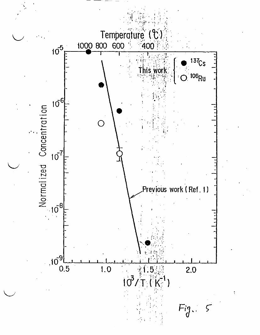
Temperature (C),15 0^ 1000 800 600 ' 400
1 01 lowI I . .
I ; 1 t ? .
0)
4-C
4-Iw ,CC
v '!; ;:-: 1-~I,
\ . This work
.
\~~~~ :
\ * '''
le ;137c s
,rt.106R
work (Ref. 1)
'70
E0
.10 -
.591005l I I I1 I -I I II I I
. o g 1 . 5;; .
103/T ( K-t). .
. .
. * ..
. . .
. .. ..
.. - :..
.. .. . .
i . .,
.. ..
*
..
2.0
F ,

-
WASTEF
I Japan Atomic Energy Research Institute
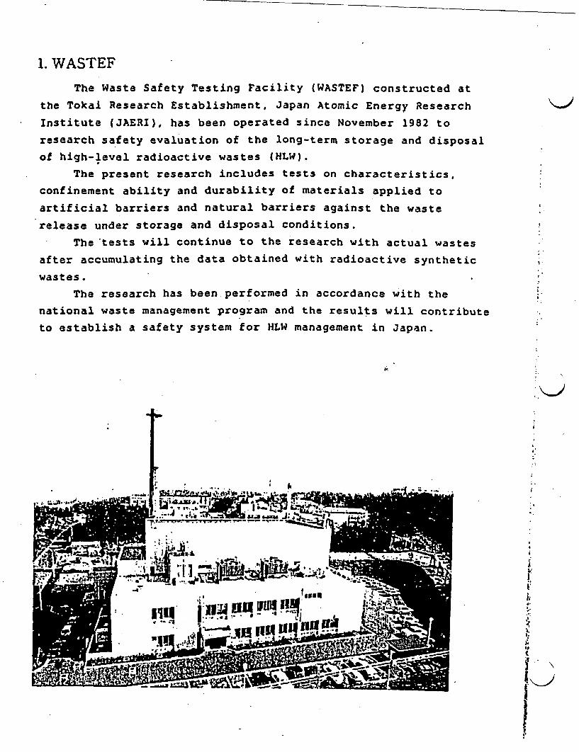
1. WASTEF
The Waste Safety Testing Facility (WASTEF) constructed at
the Tokai Research Establishment, Japan Atomic Energy Research
Institute (JAERI), has been operated since November 1982 to
research safety evaluation of the long-term storage and disposal
of high-level radioactive wastes (HLW).
The present research includes tests on characteristics,
confinement ability and durability of materials applied to
artificial barriers and natural barriers against the waste
release under storage and disposal conditions.
The-tests will continue to the research with actual wastes
after accumulating the data obtained with radioactive synthetic
wastes.
The research has been.performed in accordance with the
national waste management program and the results will contribute
to establish a safety system for HLW management in Japan.
J. .64
... 0.. -. 6
.3 It
-S *.~~~~~~~~~~~~~~~~~~~~~~~~~~~~~~~~~~~~~~~~~~~~~~~~~~~~~~~~~~~~~~~~~~~~~~~~~~~.
Ir A" !
71ESW~fi la OmF ......... 2*...uJ-N--_
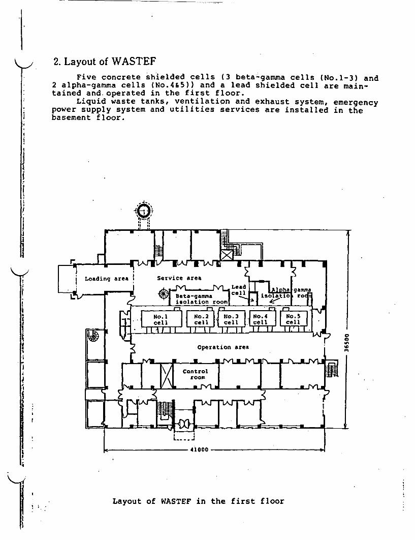
2. Layout of WASTEFFive concrete shielded cells (3 beta-gamma cells (No.1-3) and
2 alpha-gamma cells (No.4&5)) and a lead shielded cell are main-: tained and.operated in the first floor.
Liquid waste tanks, ventilation and exhaust system, emergencypower supply system and utilities services are installed in thebasement floor.
I
I. Layot ofLoading area Service area f f
i~~~ Betia - ergamma rj L . E ' m ~~~~~isolation rom isto _
! E f No~l : | No.2 |1 No.3 |. o4;|No. 5 m . c~~~~~~~ell lcl 1cl ellcl
! g ~~~~~~~~~~Operation area
.~~~~~~~~~~~~2 A AV aIr'_
. e ~~~~~~~~~~4000-
g ~~~Layout of WASTEF in the first floor
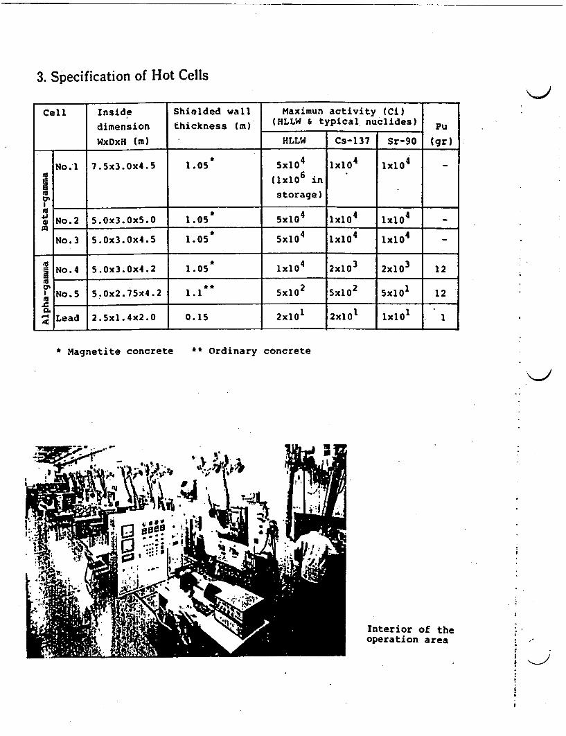
3. Specification of Hot Cells
Cell Inside Shielded wall Maximun activity (Ci)
dimension thickness (m) (HLLW typical nuclides) Pu
WxDxH (m) HLLW Cs-137 Sr-90 (gr)
* ~~4 44No.l 7.5x3.Ox4.5 1.05 5xlo lxl1 1x10⁴
'5 ~~~~~~~~~~~~~6(lxlO instorage)
Lu- * ~~~~~~~~4 44* No.2 5.Ox3.0x5.O 1.05 5X10 lxlO 1x10⁴
* ~~444No.3 5.0x3.0x4.5 1.05 5x10 Ix104 X10 -
No.4 5.0x3.0x4.2 1.05 lx104 2x10³ 2x10³ 12
No.5 5.0x2.75x4.2 1.1 5x10² 50 5X10² 12
Lead 2.5x1.4x2.0 0.15 2x10 2X101 1xO 1
* Magnetite concrete ** Ordinary concrete
r
I
Interior of theoperation area

4. Tests in WASTEF
Flow chart of tests in WASTEF
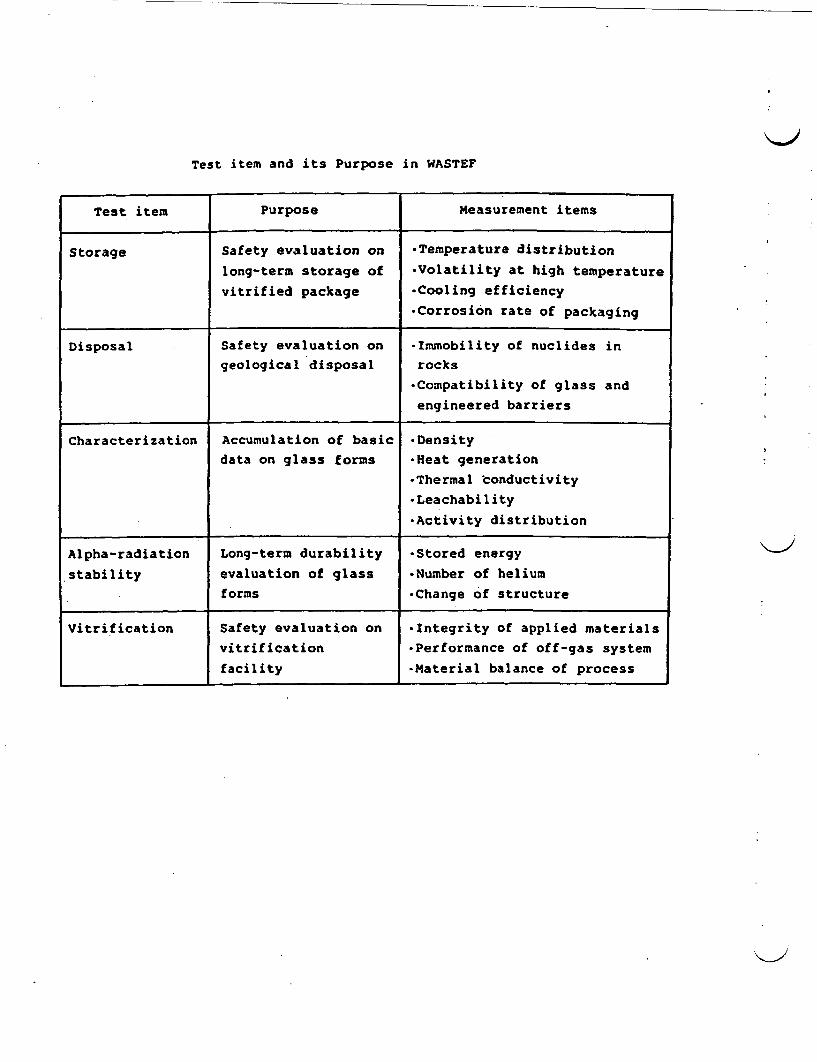
Test item and its Purpose in WASTEF
Test item Purpose Measurement items
Storage Safety evaluation on -Temperature distributionlong-term storage of -Volatility at high temperature
vitrified package *Cooling efficiency
*Corrosion rate of packaging
Disposal Safety evaluation on *Immobility of nuclides in
geological disposal rocks
-Compatibility of glass and
engineered barriers
Characterization Accumulation of basic *Densitydata on glass forms *Heat generation
*Thermal conductivity
*Leachability
*Activity distribution
Alpha-radiation Long-term durability *Stored energy
stability evaluation of glass *Number of helium
forms *Change of structure
Vitrification Safety evaluation on *Integrity of applied materials
vitrification *Performance of off-gas system
facility -Material balance of process
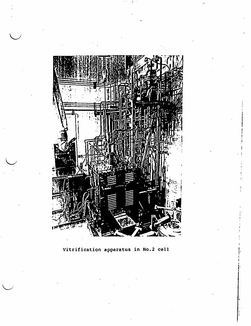
Vitrification apparatus in No.2 cell
I-
I.

G,
I.
IIii
I
S
Gamma-scanning and storage test apparatus in No.1 cell 6
.,'I
v.: '.
:..
- .Test specimens preparation apparatus in No.3 cell
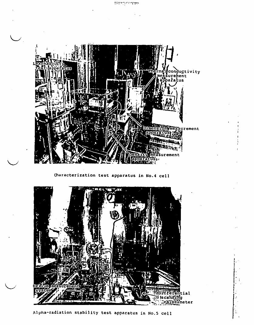
Characterization test apparatus in No.4 cel:
conductivityurementar us
Xesurement
oment
erential
Lr_ meter
Alpha-radiation stability test apparatus in No.5 cell

5. WASTEF Operation Schedule
Fiscal year
Item 19 1982 1983 1984 1985 1986 1987
Construction
Test run
Simulated waste tests onvitrification,storage, _ -
disposal,alpha-radiationstability and character- . _ --
istics using Cs-137,Sr-90 etc.
Actual waste tests onvitrification, storageand disposal__= 7
Organization Chart of Environmental Safety Rasearch at JAERI
Hea JAERI T
Headquarters(Tokyo)|
Tokai Research -.Establishment
Reactor SafetyResearch Center
Department of Environ-mental Safety Research
.
_WASTEF Operation Division
5 Environmental Research Laboratory
Environmental Research Laboratory 2
H Low Level Waste Management Laboratory
High Level Waste Management Laboratory]
_Radioactive Waste Partitioning Research Laboratory

TECHNOLOGIES DISCUSSED AT THE NATIONAL RESEARCH INSTITUTE FORPOLLUTION AND RESOURCES (NR1PR)
- Environmental Assessment Activities- Water Pollution Control Activities- Remote Sensing Techniques for Marine Pollution Analysis- Study of C02 Behavior in the Environment- Treatment of Individual Types of Waste Containing Halogenated Organic Compounds- Measurement of Pollutants in Groundwater- Bio Treatment of Hazardous Chemicals in Waste Water
BIBLIOGRAPHY OF IUTERATURE RECEIVED FROM NREPR
'Summary of National Research Institute for Pollution and Resources, NRIPR, 44 pages.
A RU'ffwriNATIONAL RESEARCH INSTITUTE FOR POLLUTION AND RESOURCES
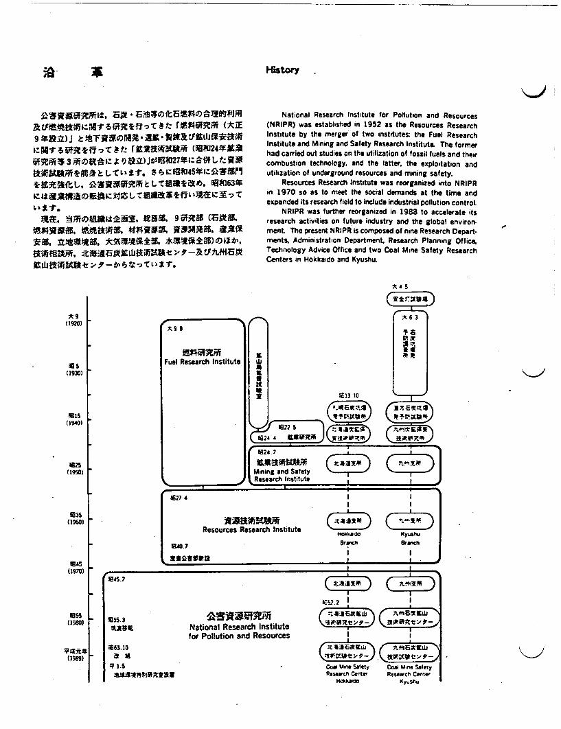
History
c:NiRuf~i-7-cv rasw W0S2419ifftifi*3 WrOVIN-I Jt1 0 Vt) Jt;9627*I--=N#Lt 9
Ma;. gurrunlikDi. V195 95:5MAEh
VKRff Ataltsfi )kM4%+Mg s
XtitANA. tttQX -Rflb
National Research Institute or Pollution and Resources(NRIPR) was established in 1952 as the Resources ResearchInstitute by the merger of two institutes: the Fuel ResearchInstitute and Mining and Safety Research Institute. The formerhad carried out studies on the utilization of fossil fuels and theircombustion technology, and the latter the exploitation andutilization of underground resources and mining safety.
Resources Research Institute was reorganized into NRIPRin 1970 so as to meet the social demands at the time andexpanded its research field to include industrial pollution control.
NRIPR was further reorganized in 1988 to accelerate itsresearch activities on future industry and the global environ-ment. The present NRIPR is composed of nine Research Departments, Administration Department. Research Planning Office,Technology Advice Office and two Coal Mine Safety ResearchCenters in Hokkaido and Kyushu.
Lg _(1920)
Fuel Research Institute
x s
* 3
.5(1930)
1B15(1940)
1125(1950)
1135(1960)
045(1970)
KjjaK
11??
91?" 4
SE13 10
Ix;;
WE (;;f
0 24 7 i I
Mining and Safety ' D Research Institute
,
1127 4 ; ;I I
Resources Research InstituteHotaado Kyushlu
47 3Branch Branch
I IEi~i. U I
I I
.45.7
1155 _(19S0) 1155.3
V3t; IE National Research Institutefor Pollution and Resources
G~D
Coal Mine SafetyResearch Center
iHakailo
Coal Mmne SafetyReeach Center
Kyi.Shu
(1989)
1163. 10
a i
5I S*4121"MR~TYM
+-~
irk!I IT~t*:. 7-.. _
Director-General Akira Takata, Dr. Eng.
For all the industrial activities in the world, natural resources and energy are of essential importance, and a more
affluent human life greatly depends on a sufficient supply of these resources. National Research Institute for Pollution
and Resources (NRJPR) is responsible for the development of technology on how to secure the natural resources and
energy, and how to utilize them effectively while preserving our environment of the beautiful planet, the earth.
Research and development in the field of science and technology have advanced at an amazing speed, and the
developments of these progressive industries have brought about a great deal of benefit to mankind. During the
development of technology it has been also recognized that the natural resources and energy are not infinite, and that the
environment can be destroyed even to a global scale by industrial pollution. Therefore, future research and development
should be carried out to harmonize human activities with the surrounding environment. Highly advanced technology and
wide-ranging knowledge based on various fields of science are necessary for achievement of this desired harmony.
Agency of Industrial Science and Technology (AIST) dedicates itself to the welfare of people through the develop-
ment of technology. NRIPR, as one of the members belonging to AIST, makes supreme efforts in carrying out studies
on the safety of various industrial processes, on environmental protection of a global scale and on the exploitation and
effective utilization of the natural resources and energy.
Role of the Institute
National Research Institute for Pollution and Resources isconcerned with a wide range of research fields related to exploi.tation. processing and utilization of mineral resources andenergy. mine and industrial safety and environmental protec.tion The Institute is affiliated with the Agency of IndustrialScience and Technology under the Ministry of InternationalTrade and Industry.
A great effort is being focussed on the following researchsubjects in each field at the Institute.1. Mineral Resources Development and Utilization
• Exploitation and development of marine mineral resourcesat offshore or at deep seabeds, such as manganese nodules,hydrothermal deposits and cobalt-rich manganese dusts.
X Advanced construction technology for underground spaceutilization
* Production of new materials such as functional siliconematerials and ultrafine powder.
• Processing and refining technology for low quality ore andunexploited resources. especially rare metals
2. Energy Development and Utilization* Comprehensive utilization technology of oiWaltemative
fuel resources such as coal, natural gas, oil sand, oil shale
and biomass. including organic materials technology.Advanced combustion technology utilizing various lowgrade fuels and energy-saving technology.
• Geothermal energy exploitation and heat extraction tech.nology.
3. Environmental Protection• Comprehensive industrial pollution control technology for
emission abatement, pollutants measurement and environ-mental assessment
• Pollution control and measurement technology of newchemical substances
*Advanced assessment technology for regional scales.Global scale environmental studies on climatic change,acidic rain formation and transformation of chemicals inthe troposphere
4. Mine and Industrial Safety* Coal mine safety technology, such as gas and coaldust
explosions, mine fires and gas outbursts in support of thedomestic coal mining industry.
* Safety assessment for utilization of underground space.• Safe demolition of old facilities using explosives..

I Resourn
.,c, *t�ft
k -�
#wtivr�i-. � *
�tl±, � *
For Japa. as poorly endowed with mineral resources as itis. the sufficient supply of resources and the development ofadvanced technologies for utilization are of particular impor-tance to support its vital economic activities and to provide fora more amiable life.
The Institute has conducted R & D on the techniques formining and processing of deep-sea mineral resources (manga-nese nodules. cobalt-rich crusts. polymetallic sulfides....). theadvanced utilization of granite and serpentinite for industrialmaterials, the purification and preparation of rare metals intohigh-grade materials. the production of carbon materials fromorganic carbon resources, the reclamation of water resourceswith igh-density bioreactor and organic membrane filter, andthe underground space development and utilization.
1t«ez to 5 9JLA J013 to°eX7Ma n Countries with Rare Metal Resources and these Shares
Mc..
o~~~~~o.
14MIMEW9 V7Y 9)L-EE
(R. t 1;.Ho W.Ep : t A;.
't-7X IF 59 79EME
Cas XfE:
~ANZE~ UP) Lut:m/JLt' 9 7-7twixt; isS o apF' (Mn: 12.0, Fe:29.4,Ni:0.82.Co: 1.08,
Cu 05 XgS09

A 9
�W�$JE5U)H�
� U �Pt�O)�L�t, ±
-�. ±LtI�L
Lt�'�Ad 9to
Development of Deep-Sea Mineral Resources
Several mineral deposits deep at the bottom of ocean floors.Manganese nodules on the pelagic sea floor, polymetallic sulfide(PMS) around oceanic spreading centers, and cobalt rich man-ganese crusts of seamounts have been identified as potentialeconomic resources.
Some groups around the world have been developingmining technology for manganese nodules. In Japan, AIST ispromoting it as a national R & D program. The NRIPR isconducting fundamental research on nodules under this pro-gram and fundamental studies for PMS and Co-rich manganesecrusts as well
XIJE 2IS
l~li~tiO~ilT~l< Distribution of Deep-Sea Mineral Deposits
j3r'JL4 'Jy) 59 k Aur ;A M n(O A*qxMKN- - __ . - I-

,- - - . . -- ------ -__- __ ___ _111
5 Resources
.v ^f>R^~
ttff, ~t~ffL$T4 lta{Z
Manganese Nodule Mining TechnologyThe test mining system of manganese nodules consists of
collecting, lifting and machinery handling systems, and a miningshipu The NRIPR is conducting fundamental research on thecollecting and lifting systems. An environmental impact studyis also being carried out.
1MR409P. Research on Collecting System:a*,Xtatwt"Met;;T 1r, 16MI t :.
M~ Towing Test of Model Collector
J4$0It0 Research on Lifting Systema>Bt, tr~tterst. at""*a6£t;K~oU-i;
|¢$".t~ ~ ~~~ Reerc nLit Sse
:/f*z6a¢riteL+
Ore Lifting Test Using Inclined and Swaying PipeManganese Nodule Mining System
t~ff:4E&:t¢. 2. Jf30)rVffrft% LTtg~tr;^FsM~t~fv=/<E ' ,f9a. L
Ests* tFl$ Lk ; PREPHI& eoITbito
Research on PMS and Co-Rich Manganese CrustsAn accurate assessment of the topographical characteris-
tics and engineering properties of PMS and Co rich manganesecrusts are required For their development. An evaluation methodof micro tcoograDhy is being developed. Physical and engineer-
% . lvwhlbl��:1 / I)L, � � -N tfAXXV
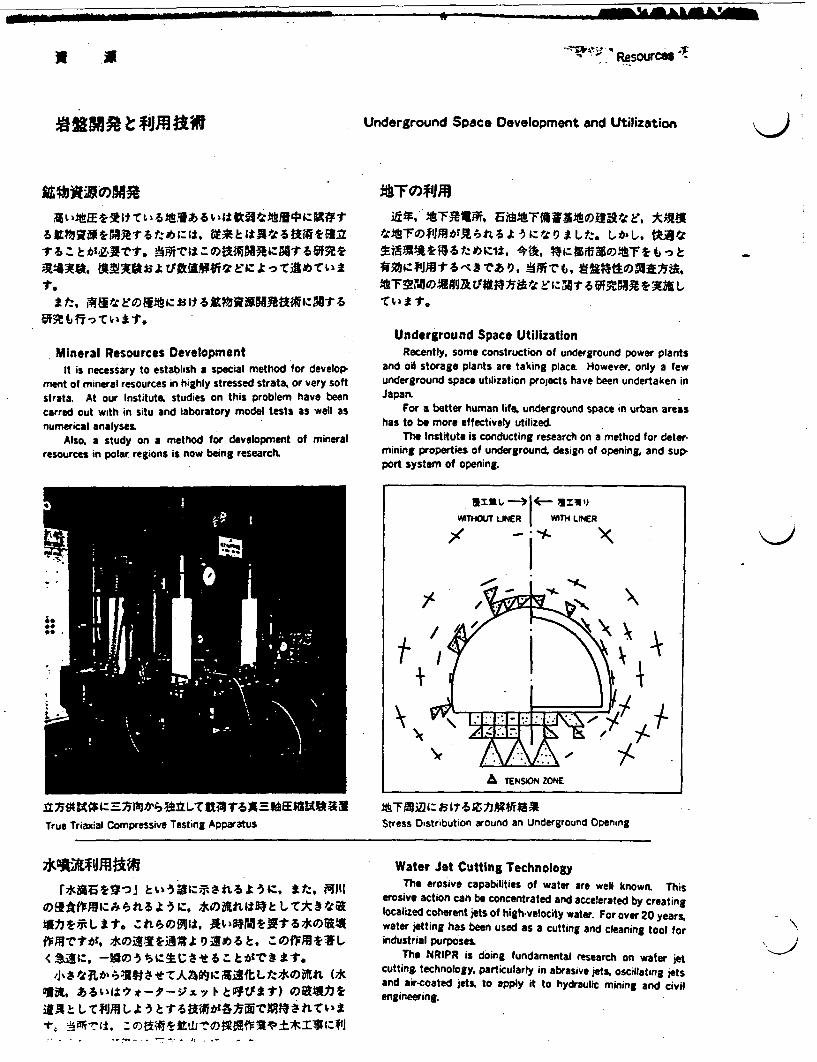
- mmoffililL Am
I- . Resources
02M~e"Ang Underground Space Development and Utilization
3t~dl±4 ZYt:s:, MX s~ttALfx" LaE*1text1 64,14 a sab
1.t t:, Ala E k i3$ It W ttRM IZX¢: t
Mineral Resources DevelopmentIt is necessary to establish a special method for develop.
ment of mineral resources in highly stressed strata, or very softstrata. At our Institute. studies on this problem have beencarred out with in situ and laboratory model tests as well asnumerical analyses.
Also, a study on a method for development of mineralresources in polar regions is now being research
kFO)*IJq
Et. Fniam. 6ahtFvai t E Al@8FF~;Xot a 5s~tz s Lt . t,;D, OAPT
Underground Space UtilizationRecently, some construction of underground power plants
and oil storage plants are taking place However only a fewunderground space utilization projects have been undertaken inJapan,
For a better human life, underground space in urban areashas to be more effectively utilized
The Institute is conducting research on a method for deter-mining properties of underground, design of opening, and support system of opening.
i1NU LtINE I W.4 2INER
~~~~WITHO LINER WI LR
-' *
A.
t+ 4
A TENSION ZONE
.Z51=4t>T UMZSLu ETrue Triaxial Compressive Testing Apparatus Stress Distribution around an Underground Opening
XS AS 1 -3 *0 X11 ISP t LT t$ 4CFA4113VTILUIT.
f1PMTtbf'<sat:,
!#A!: LTNALI -3
Water Jet Cutting TechnologyThe erosive capabilities of water are well known. This
erosive action can be concentrated and accelerated by creatinglocalized coherent jets of high-velocity water. For over 20 years,water jetting has been used as a cutting and cleaning tool forindustrial purposes.
The NRIPR is doing fundamental research on water jetcutting technology particularly in abrasive jets oscillating jetsand air-coated jets. to apply it to hydraulic mining and civilengineering.
K>
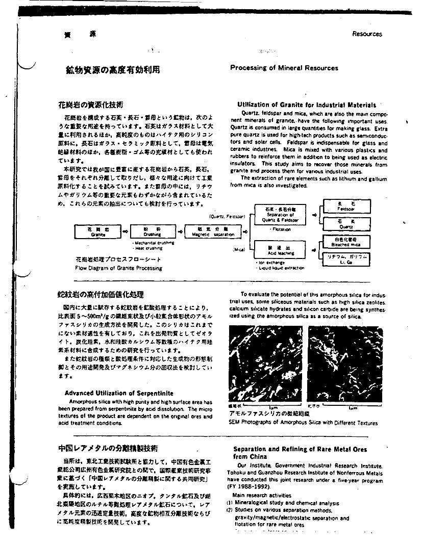
Resources
Processing of Mineral Resources
9 T
- J Afl.~v~&Ltj . it &..&4. 4 ~ t, 9f
Utilization of Granite for Industrial MaterialsQuartz. feldspar and mica. which are also the main compo.
nent minerals of granite. have the following important uses.Quartz is consumed in large quantities for making glass. Extrapure quartz is used for high-tech products such as sernconduc-tors and solar cells. Feldspar is indispensable for glass andceramic industries. Mica is mixed with various plastics andrubbers to reinforce them in addition to being used as electricinsulators. This study aims to recover those minerals fromgranite and process them for various industrial uses.
The extraction of rare elements such as lithium and galliumfrom mica is also investigated.
XV ,
(Quarz Fcsw) Separaton
f~uatz. e~s~r) ~ &Quartz ar XE a a Fl1e e 1* EteZ 1tpoaicr
GrCanit n sg M agnetic separain
MechanCal crush gMeat Crushing ;M c)
Acid leacing
ion exchange
Flow Diagram of Granite Processing LQuV-iQuC extracton
epr1:11Blecd ma
l3n4: si:IAV T 8 er~ : e k t9
ItJA 5 -5OOm'/g tWt 'J'4g 7/
Advanced Utilization of SerpentiniteAmorphous silica with high purity and high srface area has
been prepared from serpentinite by acid dissolution The microtextures of the product are dependent on the original ores andacid treatment conditions,
To evaluate the potential of this amorphous silica for industrial uses. some siliceous materials such as high silica eolites.calcium silicate hydrates and silicon carbide are being synthes-ized using the amorphous silica as a source of silica
Itt Xe It m r:*7 Ipin
SEM Photographs of Amorphous Silica with Different Textures
4319 ., Y Separation and Refining of Rare Metal Oresfrom China
Our Institute, Government Industrial Research Institute.Tohoku and Guanzhou Research Institute of Nonferrous Metalshave conducted this joint research under a five-year program(FY 1988-1992)
Main research activitiesq) Mineralogical study and chemical analysisi2) Studies on various separation methods.
gravity/magnetic/electrostatc separation andflotation for rare metal ores

WU . * . d Resources
Processing of Mineral Resources
i.-'7.)(,4 JIV)tA;VX#f L414
tF~oT;^2to ; Alt r baiz~tt s
Purification and Preparation of Rare Metals IntoHigh Grade Materials
Rare metals are indispensable to high-tech industry and theneed of rare metal materials of higher quality is increasing moreand more. Therefore, the innovation of purification and prepara-tion process becomes very important The important featuresof rare metals powders into high grade materials are highpurity, uniform particle size, homogeneity and high dispersibilityin addition to having small particle size The controlled prepara-tion process through organo-metallic compound formation mayrealize those effectively instead of conventional physicalmethods. At this institute, the interaction characteristics andselectivity in chemical reaction between the organic reagentsand the rare metals are utilized for high purification and powdersynthesis, and the above-mentioned highly controlled powdersare prepared due to the merits of process simplification with agreat reduction in COStoa
9~~~~F
< *-1:ITf r. as plataIs X1R 1 ti lttop
R**flffLTPA* PSk to-ol,/ > e~
Ultrafine Grinding ProcessAt the Institute, a nw ultrafine grinding machine to pro-
duce submicron material with higher efficiency than other millsis under development One example is called multi-disc millconsisting of a cylindrical vessel charged with several center-perforated discs and arod as thegrinding bodies. The breakageof material is carried out mainly by the abrasive stresses causedthrough the rotation of the vessel, In this mill each discbehaves independently, then the mill contents are distributedalmost homogeniously and the number of contact points notonly between grinding bodies but also between grinding bodiesand the wall of the vessel increases so that desirable grindingefficiency is brought about. The operating condition of this millfor ultra fine grinding is characterized by an etremely higherrotating speed compared with the ball or rod mill case.
&
LI 7.0 II,I Rare -elal. I
f
AVIXiraraeM
l'N
:'; - --1 7~~' a-e \,eas V t DSC V.11
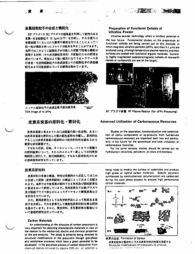
5 % . - _ .
I
RFf 1~ X-11 DC -f IX44ftlL-ZEV)Jb
U)~~~~~~fMu fttif
*~~~]V1119SSEC4.0 t to,17-
Preparation of Functional Colloids ofUltrafine Powder
Ultrafine powder technology offers a limitless potential inthe near future Fundamental studies on the preparation offunctional colloids are being carried out at this institute inwhich magnetic ultrafine particles (UFPs less than 0.1 m) areproduced using ultrahigh temperature plasma reactors and theirsurfaces are coated with functional organic materials. Current-ly, highly magnetized superparamagnetic colloids of rare-earthmetals or compounds are one of the target.
= -y Isownfl
TEM Image of Ni-UFPs RF 175 X7 R RF Plasma Reactor (for UFPs Processing)
Advanced Utilization of Carbonaceous Resources
-too,,
xr#04ftT6Z 1-b�s
1-42b SEX, ;E6. * -f IL, �, =-'v. ,ff * -7 7,484
W1MRk*fTL-C, 4ft-haffiffift.OfkWMRRfR1-ff
Studies on the separation. functionalization and carboniza-tion of useful components or by-products from fuel-derivedcarbonaceouce resources are important both now and particu-larly in the future for the ecoomical and total utilization ofcarbonaceous resources.
For the same reasons. studies should be carried out onhydrocarbon resources, petroleum, oil shale and biomass.
IZ Ifilt L flffi (AXIM10%) 041 :t ISTUN < ZE Lk
very important for obtaining characteristic materials in view ofthe relation to the mechanicaL electric and chemical propertiesof the nd products, The study is primarily being directed tostructural modifications of the precursors though gas-phaseand solid-phase processes which have a great potential to bedeveloped. In the gas-phase process of carbon deposition fromchemical secies activated by lasma CVD e a attemo! is
being made to modity the surface of substrates and producehigh grade or hybrid carbon materials. Specific polymerssynthesized by electrochemical polymerization are carbonizedduring the solid phase process to prepare high performancecarbon materials.
OlF 4 AK. arc.. ¢ 4 62 A
J.'~~~~~'
2-3vvn I n
Em -~~~~~~~~-Atjid M Formation of Carbon
Ofj* Fortion f ar bon 869 400~
Structural modifications of precursors to produce
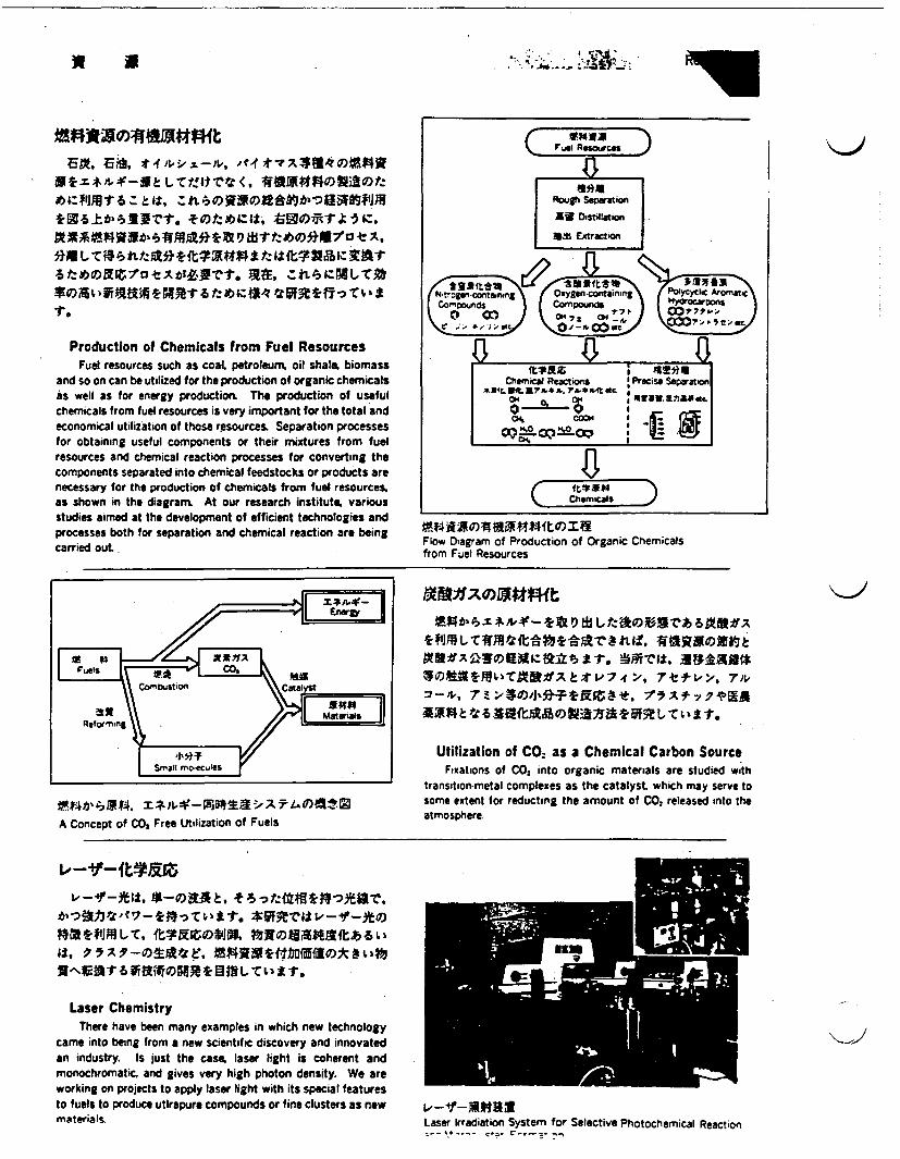
A a
We~ui esouir-sJ;Ea 6,1 -tdki-go -, Prf ;t A 3 f l a 4i
Ati1l1M1t W tit. a 9 t~u"X31 t:
Production of Chemicals from Fuel ResourcesFuel resources such as coat petroleum, oil shale. biomass
and so on can be utilized for the production of organic chemicalsas well as f or energy production The production of usefulchemicals from fuel resources is very important for the total andeconomical utilization of those resources Separation processesfor obtaining useful components or their mixtures from fuelresources and chemical reaction processes for converting thecomponents separated into chemical feedstocks or products arenecessary for the production of chemicals from fuel resourcesas shown in the diagram At our research institute variousstudies aimed at the development of efficient technologies andprocesses both for separation and chemical reaction are beingcarried out..
Rough sepatonAN Disillaman
ass Etraction
r4,geIcn7\rq Oxye-otinn yy ic Ar'omiCo-~ound I Compoundis Hyoearbons
1-'7z 79W~0 Co (".7Z _& ?~, - It
e U; alU- I aIVVIEZ I OI
Chemikai Reactsons I Precise separationx34t~~E4LE~b$&.7b*A.4t~ 6ON al{ at0 rrar~~~~~~~~~~~I
Ohio) i1404%1tomIaFlow Diagram of Production of Organic Chemicalsfrom Fuel Resources
l Ablt X */ atf-Q Lk batolr 6MIX
3gX82SX~aRS~t>74 7tfve+>, 7>iER * 'teV Q 9 3ttitoil~9Q Ls X ist
Utilization of CO. as a Chemical Carbon SourceFixations of C 2 into organic materials are studied with
transition-metal complexes as the catalyst. which may serve tosome extent for reducting the amount of CO: released into theatmosphereA Concept of CO, Free Utilization of Fuels
E,__* t, LtRs +6t.tL~t
Laser ChemistryThere have been many examples in which new technology
came into being from a new scientific discovery and innovatedan industry. Is just the case laser light is coherent andmonochromatic and gives very high photon density. We areworking on projects to apply laser light with its special featuresto fuels to produce utirapure compounds or fine clusters as newmaterials Laser irradiation System for Selective Photochemical Reaction
.- -- ?.r

M __ AUL~~m~~L~ 3
Resources
*�*IJ� -� �JJ�
~, f~t'~~t~lt. ~*W~fl, ±* I
* t~~ .' a ~;- ~M~tbttt
New Water Treatment System "Aqua Renaissance '90"
As a means of solving the problems concerning the largerdemand for water in future and the pollution of the source ofwater supply for the city and industrial water, a six-year planentitled New Water Treatment System (Aqua Renaissance '90)was set up by MITI and research on this project was started asof 1985. The new system consists of a bioreactor having a highconcentration of microorganisms and a membrane as the separator of microorganisms from the bioreactor.
What is attractive about the new system is that it will beable to recover marsh gas from the organic material containedin the sewerage and industrial wastewater and will be able toreuse the treated water as industrial water.
Nitrogen Removal by an Activated Sludge Processwith Cass-Flow Filtration.
The capability of ammonium oxidation of an activatedsludge process with cross-flow filtration while retaining a higherconcentration of activated sludge, and operating with very longsludge retention time is investigated. By this process, highernitrogenous and organic loadings were attained and someamount of oxidized nitrogen were denitrified. Thus, organiccarbon removal, itrification, and also denitrification may pos-sibly all occur at the same time when using this process with asingle reactor.
W*0111. 9J7as3-N0§Lftezf 9*NF
S~fetz~tEZ. St1Ar1YC§<. atl
Evaluation Technique for Organic MembraneMaterials
To develop a means by which the microbes within thebioreactor can be maintained and the wastewater recycled forreuse, we have been conducting research related to high perfor-mance organic type membranes which exhibit excellentcontaminant load capabilities are resistant to microbial deterio-ration, and which can be used over long period of time due totheir favorable durability characteristics.
Permeability test has been carried out on already existingorganic membrane materials using wastewater containinganaerobic microorganisms.
Those materials, exhibiting superior performance, havebeen selected and the optimal operating conditions have beeninvestigated
WVRE 1) 7 9- VFVV9ZII
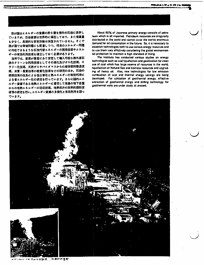
AKNAA . A6~ -AM& -A MM- --- IL
M
~Ei*,i,-O)SVSO) 6 Mt94:AML '\J niAbout 60% of Japanese primary energy consists of petroleum which is all imported Petroleum resources are irregularlydistributed in the world and cannot cover the worlds enormousdemand for oil consumption in the future So, it is necessary toestablish technologies both to use various energy resources andto use them very effictively considering the global environmen-tat protection to maintain a high standard of living.
The Institute has conducted various studies on energytechnologies such as coal liguefaction and gasification for cleanuse of coal which has large reserve of resources in the world.liquefaction of Natural Gas and biomass resources and upgrad.ing of heavy oil Also, new technologies for low emissioncombustion of coal and thermal energy savings are beingdeveloped For utilization of geothermal energy, effectiveextraction of geothermal energy and drilling technology forgeothermal wells are under study at present
- r- -- Ir+ -.!- - �- L. z:v 'T'Tjt 12 ' . =!;,M !-! IF, R!4 I
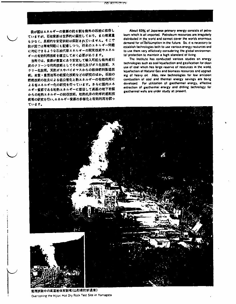
-
gb¢S$: t $ &f-O2wt 6 S t"ffieEz§# bt;^ttht. bS2sst^e&.&tUSD, gt:sRX,ytw<, pm"2*E"e&$^Etxt'tF&. +_r
t!tt¢s;:ttMEs; t E U oo, #Xe1 + wp $-N1E4:tt i 8 4 a TtwESeW f +,>fXMav t $,>
s-X#Xt1lSKtt bYS' < t^t¢$ g t t.S§t$$, 2st¢ffitz ̂ 9 t b tZA4>t;F"sE
^XA J->ttJKKs LI+eS{kRSf AtX, AX IJ-f'c.a R.t**AJPofd ;t ;tDx {> #)#£t;$K. tR*tffSSeR{kgtEsERelt', ESe
^ffiaXtZ; 66AEtt Msss>$-08m"Sza lit +*$�<COJESEtfiT;Stte S fvl;@SJ0it $>z-2erw6ttY snzz-z;SB t 1rRis<uJtewe
t'tetttttY s&8_oWaS tteX*e#Fa
sCttt6;^, t$&$-2SO++{k>#mtJS0.
About 60% of Japanese primary energy consists of petro-leum which is all wmported. Petroleum resources are irregulartlydistributed in the world and cannot cover the worlds enormousdemand for oil consumption in the future So. t is necessary toestablish technologies both to use various energy resources andto use them very effictively considering the global environmen.tal protection to maintain a high standard of living
The Institute has conducted various studies on energytechnologies such as coal liquefaction and gasification for cleanuse of coal which has large reserve of resources in the worldliquefaction of Natural Gas and biomass resources and upgrad-ing of heavy oil Also, new technologies for low emissioncombustion of coal and thermal energy savings are beingdeveloped For utilization of geothermal energy, effectiveextraction of geothermal energy and drilling technology forgeothermal wells are under study at present
Overicoking the Hijiun Hot Dry Rock Test Site in Yamagata

- A
- - - - __
¢a*E1LW S^;, Ua)">
The Sunshine Project has developed Brown Coal Liquefac-tion and Bituminous Coal Liquefaction.
The method which has been carried out at this Institute isone of the coal liquefaction processes conducted by solventextraction and is essentially a two-stage process. The purposeof this research is to provide fundamental data for the selectionof optimum reaction conditions for the liquefaction of variouscoals and the upgrading of coal liquid Product Utrtization isalso being investigated Coal Liquefaction Test Plant
W11caft"
, I
Hight pessUr *1
-
C4CM
-.
.01,_ A_
I12:10k.
High
Recycle Wvrt 10 ternperatiffe
0 0
0 0 00 0 0
Ft . aM
I
A
T7 r -- diL-%UesseAJ - AEETT
YA IT 6 z e I: I 9RAStur- I 14 It .5. 111*111
Coal can be converted into liquid fuel using a catalystat high temperature under high hydrogen pressure.
F*Ad)* 11,- - ;MA~tJ(NEDO). I)
- __ �'. -. . 4 �_ . -. - - - - -
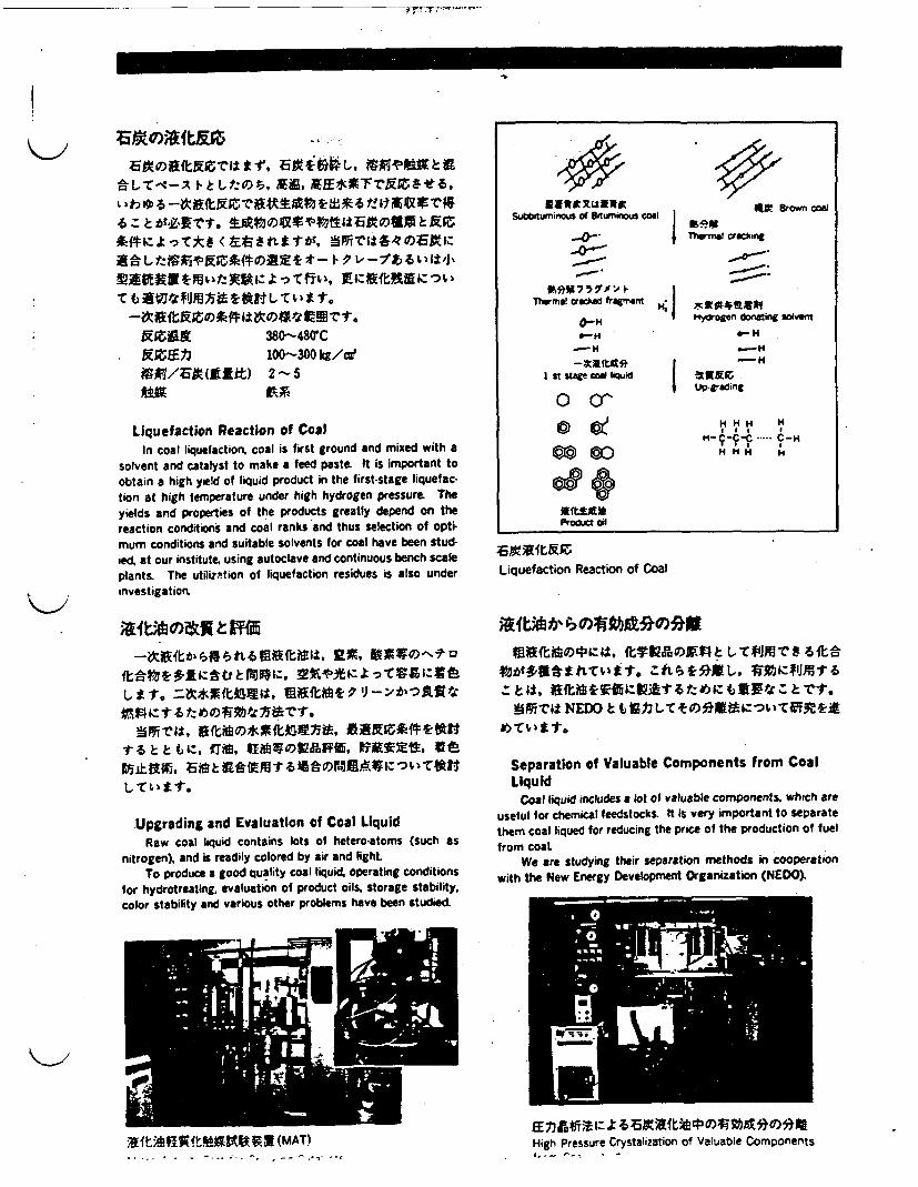
cE'0)ftrx-C1tr
-C L T - " A 1 k -tt, . E*XTr tZLl* t - tit £S t 6 t: 1MlVZr
xZA~~t 380-480CBEZE03 100-300 kg/aie
Liquefaction Reaction of CoalIn coat liquefaction, coal is first ground and mixed with a
solvent and catalyst to make a feed paste It is important toobtain a high yield of liquid product in the first-stage liquefac-tion at high temperature under high hydrogen pressure. Theyields and properties of the products greatly depend on thereaction conditions and coal ranks and thus selection of optimum conditions and suitable solvents for coal have been stud-ed, at our institute, using autoclave and continuous bench scaleplants. The utilition of liquefaction residues is also underinvestigation
Subbiturmous of S'turnnous coal
. i 4t Brown coa
Therml king
I
-0-*
__
%I~9Mi7i 5aI >Thrma crked framnt
_H
I t stage =oW liquid
O cr
HI
I1H;
i4odroenr donating solvent
- H_H
H H HH-r -CC -CH
H Hco co
08OJ91"AProdut ad
Liquefaction Reaction of Coal
-7tiS~fst>¢TM1 8ittlt atf Sl#-l A : t 6 .: * t E .E ~ S t J . X
Upgrading and Evaluation of Coal LiquidRaw coal liquid contains lots of hetero-atoms (such as
nitrogen), and is readily colored by air and lightTo produce a good quality coal liquid operating conditions
for hydrotreating, evaluation of product oils storage stability.color stability and various other problems have been studied
09fUMOD0¢4;11. tTVAUM : G-r#09JS St 0
S ril, NEDO t k TF
Separation of Valuable Components from CoalLiquid
Coal liquid includes a lot of valuable components which areuseful for chemical feedstocks. It is very important to separatethem coal liqued for reducing the price of the production of fuelfrom coaL
We are studying their separation methods in cooperationwith the New Energy Development Organization (NEDO)
Aft&F.=jRjtVKbtVX(MAT) High Pressure Crystalization of Valuable Components;,__ r- I

M
--i 141 M,
Al,," , , - , . 0. � -
a e-11 � : ., A Wts_ . - _- 4' .4T. F 116.
(2) H,. CO WldDWt gt IZ < (3* *' *P-t'Io)
t Ctg i f i C 1 M J ; X * Y ~ t 4 O A 1 U
X~lt`Skbf-.V-AtMAtLS T1,11 N. Rtk
Although the gasification of coal has been carried out formore than a century ago. the development of an advancedgasification process in which the problems of efficiency. reliabil-ity and environment have been solved. is still being anticipatedThe R & activities associated with coal gasification are beingstudied by government and private enterprises in cooperationwith each other as a part of the Sunshine Project
At this Institute, a fundamental study for coal gasificationat a high temperature has been carried out. One of the objectsof this investigation was the accumulation of basic data toimprove the gasification efficiency of coat Fundamental studiesare in progress on gasification phenomena and the influence ofmolten slag on gasification reaction above the melting tempera-ture of the ash using a bench-scale moving gasifier. plas.tometer, and other apparatus.
Coal I-Quefaction plant
S r:$ZI Liuefactton residue
lat Fuel CIll
Y"
coal
H.
Gas PutAwiAgion'4,4CO+ C+C, "Corn
*AM-Steam
*RK Nydrogen
~IFuel
Cobnild cycle vowel olarit
LUquid Iuel
It**&Chemical products
;E/X*Ffi*4*XXIZJt I)A2(1.60M)rM;k1tT.St. ;5MMM RX
-M10MVIAft'r. AMAPIMIJULIM7217-41A4ftsll.

os t V X '6 WMOOMf'<- * ±EN*-R)'$j, tI*( 'J a -7 ,> i O -or A*0m~r-c- *9-fO
1"T111Ii, 7'l IL v - i I 'm Y"tg ^ * #$
i--t R t tttil b ME .
Production of Liqued Fuels from BiomassBiomass resources are unique because they are renewable
and carbonaceous among non-fossil energy sources. The pur-pose of this study is to produce liquid fuels resembling heavyfuel oil by thermochemical conversion.
In this process, woody material is mixed with an aqueoussolution of alkali salt and treated at high temperature and underhigh pressure to achieve liquefaction. At the present timeresearch is being done for sewage sludge liquefaction using apilot plant
i7s;r7;MtREBiomass Liquefaction Test Plant
3. ..
~t3~$±, * O)*Vt-1 *M)3.OOOONgb~ gT s. tt lS O §i fdttz T * Z^¢1 t3,6 I1*
5.000)5nffl * n.
In Japan, roughly 30 million cubic meters of waste woodand 50 million cubic meters of sewage sludge are being gonerat.ed anually. However, the difficulty of finding the available spacefor disposition and other environmental reasons are making thematter of waste disposal a serious social problem
Since this type of liquefaction is carried out in the presenceof water, it can be applied to many kinds of organic materialcontaining water. For example, sewage sludge, pulping sludge,and peat are desirable potential candidates
eeitocksforLi)qeact(* in (y dh)Feedstocks for Liquefaction (Wood Chips)
This process has the following advantages: (1) No hydro-gen or carbon monoxide is needed (2) No drying or dewateringof starting material is needed since liquefaction proceeds in anaqueous phase; and (3) Clean fuel is obtained since woodymaterial hardly contains any pollutants such as sulfur, chlorineand heavy metals. According to a series of experiments, liqued

M M
M - - --
A."'. k�i �pi WI -�
Almost all crude oils consumed in Japan6 are imported fromforeign countries. Recently, the yield of light fractions in crudeoils imported is going down. On the other hand, the demand folight oils (such as kerosene and diesel fue is increasing.
To compensate for the lack of light oils, it is necessary toproduce light oils from heavy oils.
A homogeneous catalyst is useful for the hydrocracking ofheavy oils which contain a great deal of vanadium, nickel andasphaltenes. Homogeneous catalysts have very high efficiencyfor contact between a catalyst and heavy oil molecules. Even asmall amount of a homogeneous catalyst is capable of reducingasphaltenes in heavy oils.
020%bUXVTR~jSL(LNG) U [t 11-A0t, A-t
Jt -PT W fA 1ZJ 11 has IMI ST OOi T. &Z A* u U.
BOS* R*§flvt SX I4 rcem
1AA M9W *43L,1 Lt keR-*i~ff it, T I t
Although natural gas reserves in the world are next to thoseof oil so far about 20% of the world production has beenburned off at production sites because of difficulty in storing orhanding gaseous fuels. Liguefied Natural Gas (LNG). cooledat- 160C. is imported to Japan for limited uses such as electricpower fuel and town gas.
The chemical conversion of natural gas to liquid fuels isdesirable (1) to expand its utilization to automotive fuels.heating fuels, and chemical feedstocks; (2) to easily transportthe fuels at ambient temperature; and (3) to supply clean fuelscontaining no sulfur or nitrogen compounds. Aiming at chemi-cal conversion of natural gas into hydrocarbons and alcohols,research has been carried out on; (1) catalysts for the conver-sion; (2) reaction processes; and (3) evaluation of product fuels.
F* a "U a t mu Liquid Fuel Converted from Natral Gas
AS oMxve fe
4U5213~tiwX Tanker r.-,- eqConvertor to hicc 0 fuel t'c
E e-,~c bone,
a'!Ri~tW? LNG; 2:4Liqu!led Natural Gas (LNG. C-em cal Feedstockf.Product Oil and Homogeneous Catalysts
1I £!crIOW0*8
Refrigeratng LNG tanker (-16(C)~ V I!I
Natural Gas
J I

K>
Zt L £1.
]VE, f T, O."~~~19019M fr1
f-tT2t
High Efficiency Low Emission Coal CombustionCoal utilization must be expanded for stable primary energy
supply. However, coal has many problems, such as handlingand pollutant emissions. Gasification and liquefaction are thecountermeasures for them, and direct combustion is more effi-cient in energy utilization Circulating fluidized-bed combustionis one of the newest combustion methods It can burn manykinds of coal and various soled fuels with low pollutant emis-sions. Basic research on combustion procedures is carried on byusing bench-scale equipment High temperature slagging com-bustion method is also under development by using a testingequipment. Conventional pulverlized coal combustion method isbeing studied to know combustibility and NOx emission charac-teristics of various coals.
4-
CiruainM eCirculating Fluidized Bed Combustion Equipment
iAZIAMAKitRHigh Temperature Slagging Combustion Equipment

aT;Xs*-eS, £tl±ta.X~Pe~s*:Xfl t -),rCILB
*etht., CARS '. ek--Itmitm. Mpt v-I-r-7 r,-Mztnil_ 9fl&tt¶Ml&*M X, *e
@xEftt rtgffX~J~ta~S4*316440J.
M St - h/-f *WRI1421: t- M I (EZ&f!Vt350-1200'C) ;;
Si-.~~~~~~~~~~~~6L -Me X;j - t 1 i. f"PIM$tc t 4 34MOMM&R (*I.* ') A, - 9 )A, Vflyl-) A,1 98#9"t ISAA
:>V, X -f t;~~t FOIMIAZlA28OC~t~ft~f 'I h:f - >¢XV>-rL-C0s
Advanced Combustion TechnologyIn this research program, basic research on reaction
kinetics and flame structure is conducted to develop optimumcombustion control techniques for stabilizing gobal climate
CARS (Coherent Anti Stokes Raman Spectroscopy) methodfacilities, laser pyrolysis/laser fluorescence equipment, andshock tubes are used for reaction kinetics research in hightemperature Furthermore, the laser doppler anemometer isused for flame structure analysis.
This basic research is also being conducted to developcombustion simulation modeling.
High Temperature Heat PipesThis study consists of analyzing the maximum heat trans-
port capability etc.. for the high temperature heat pipes which isavailable for vapor temperature range from 350 to 1200'C andtesting the container material compatibility. In the heat pipes,mercury, potassium, sodium, and lithium are used as workingflued, and stainless steel tubing. inconel steel tubing, etc.. areused as the container materials. The following photographshows the condenser section part of the sodium heat pipe at thevapor temperature of SOOC
I2
1- 9 {J A t - 1- Pf-f Sodium Heat Pipe
Electrically Calibrated CalorimeterFrom the industrial point of view, in the field where the heat
is utilized f or heating or producing power in particular, howmuch heat the material for an energy source generates inburning is an important measure. So the method of determiningthe quantity of combustion heat of some standard samplespresisely with electrical energy is under investigation
burnng sipantmau Othmeododerin
Laser Pyrolysis / Laser Fluorescence Equipment
----
Isolaod vesaMo
F~ 0 .Uc')
assHeat CrOWcity
91---- peatt
C J/K (1CC)
y of heat.
I
uIhIt>Tempuature rise
AT K(C)_w
_ A i
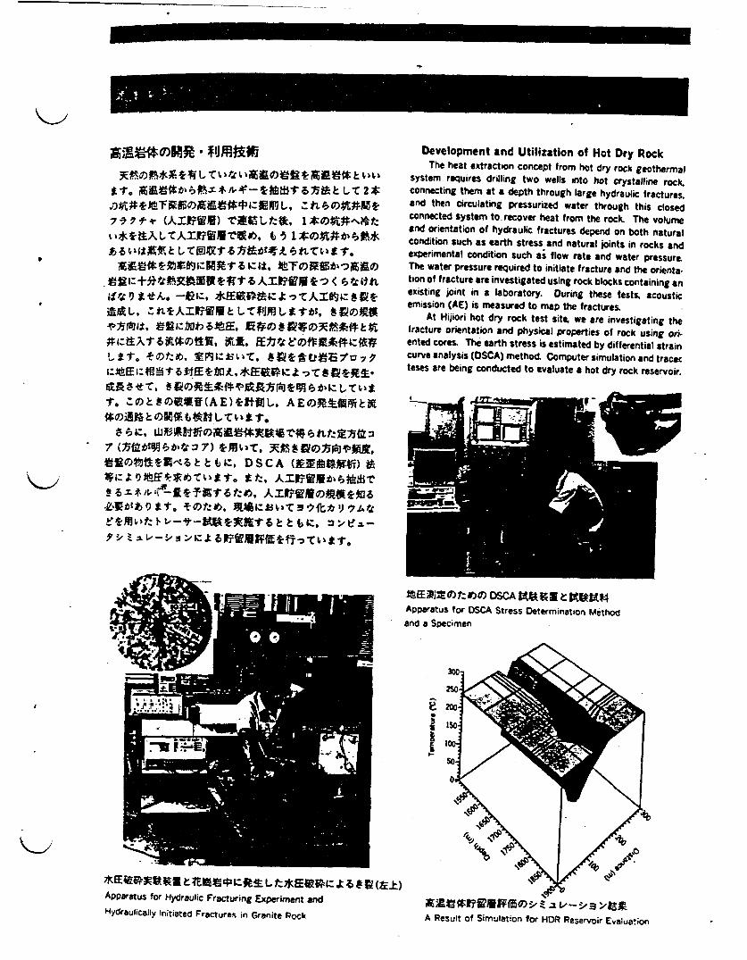
I
K>
%~~ fl L C "~K t. J e~1r q:0
4,
7 05bbtWt1Z7-1 W. JS~D~rpX
Development and Utilization of Hot Dry RockThe heat extraction concept from hot dry rock geothermal
system requires drilling two wells into hot crystalline rock.connecting thern at a depth through large hydraulic fractures,and then circulating pressurized water through this closedconnected system to. recover heat from the rock. The volumeand orientation of hydraulic fractures depend on both naturalcondition such as earth stress and natural joints in rocks andexperimental condition such as flow rate and water pressureThe water pressure required to initiate fracture and the orienta-tion of fracture are investigated using rock blocks containing anexisting joint in a laboratory. During these tests. acousticemission (AE) is measured to map the fractures
At Hijiori hot dry rock test site, we are investigating thefracture orientation and physical properties of rock using oriented cores. The earth stress is estimated by differential straincurve analysis (SCA) method Computer simulation and tracerteses are being conducted to evaluate a hot dry rock reservoir.
X Etz1O) DSCA KtgeKVApparatus for OSCA Stress Determination Methodand a Specimen
e300
Apparatus for Hydraulic Fracturing Experiment andHydraulically Initiated Fractures in Granite Rock A Result of Simulation for HDR Reservoir Evaluation

I M��
1\1�
j�MZRU)1� �
*-"X*>$-8J 6 ClstI43ctt 6 M*Abx
** I I F41tbiz, V:Fm O# *M9Utw*tU$ c9 A
Diamond Compact) t.
Drilling Technology for Geothermal WellsIn order to drill geothermal wells economically and eff icient-
ly, improvements in the drilling techniques have been conducted..Aerated mud drilling methods have been introduced to improvethe drilling efficiency of rock.
New bits with polycrystalline diamond compact cutters arealso being developed for the drilling of hot and hard formations.The photos below are of a drilling test facility and drill bits for*the tests.
Diaon Cmpct t vX s^ 1F
Drl in behooyfrGohra el
Downhole Coaxial Heat Exchanger SystemThe geothermal resources such as hot wet rocks which
contains insuficient amounts of steam o hot water for powergeneration. very high temperature formations adjacent tomagma bodies and magma itself are considerd difficult todevelop by ordinary heat extraction tecniques. In order torealize the development of those geothermal resource researchon the nw heat extraction system the downhole coaxial heatexchanger system has been carried out
AIqJXI^9R Drilling Test Facility
' (Vacuum Layer)
11a * IFM 1 (it :CouplIng nsuitv,
UP--I--

.. I . .. - I.. .- - . , -- -*0
fVtoL jjl1*41-t1.*:1V1t&k-
Air and water pollution problems were serious in the late1960 s in Japan. The National Research Institute for Pollutionand Resources. operating under the Agency of Industrial Scienceand Technology, has conducted research and development onindustrial pollution control technology.
As a result air and water conditions in Japan have beengreatly improved over the last 10 years, However, there are stillmany pollution problems to be solved, and recently globalenvironmental prot'lems such as climate changes due to greenhouse gases such as CO2. ozone holes caused by chlorofluo-rocarbons have become world problems. To solve these prob-lems, the institute is carrying out research on the measurementand control of pollutants, their behavior and environmentalassessment technology.
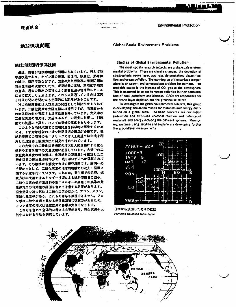
I -1- --
EnvironmetW Protection
Global Scale Environment Problems
Studies of Global Environmental Pollution
gatv*U.it*I±,10 s-o4~fl 044 Mg
till',7 ',) :
Lill'.C~t
The most update research subjects are global-scale environ-mental problems. These are climate changes, the depletion ofstratospheric ozone layer, acid rain, deforestation. desertification and ocean pollution The warming-up of the surface temperature is an urgent and commonplace problem for humans. Theprobable cause is the increase of CO, gas in the atmosphereThis is assumed to be due to human activities in their consump-tion of coat petroleum and biomass. CFCs are responsible forthe ozone layer depletion and the greenhouse effect
To investigate the global environmental subjects, this groupis developing simulation models for materials and energy distrmbution on a global scal. The basic concepts are circulation(advection and diffusion), chemical reaction and balance. ofmaterials and energy including the different spheres. Monitoring systems using satellite and airplane are developing furtherthe groundlevel measurements
Particles Released from Japan

M= E- - ___
1.s.t'rI± _ : offiz .a -, rF af ~ a' 00 a74
Remote Sensing Techniques for MarinePollution Analysis
Remote sensing data like multi-band spectra of radiationare quite useful for environmental assessment of marine andatmospheric environmental studies.
Measurements of seawater temperature and chlorophyll incoastal area have been already developed For utilization ofremote sensing to marine environmental problems, we have tostudy the relationship between physical factors and biologicalactivities in the sea through statistical and image analyzingtechniques.
It is also quite effective for atmospheric environmentalproblems, like diffusion of forest fire smoke, volcanic eruption.etc. We will continue the study of remote senst data analysisfor further utilization of it to environmental studies.
,m
, .
0 i
Water at DX f)istiu tii (rface )
Water Temperature Distribution of Surface in
=W1:.gIS * 75.y*sAO)
at XrWE~tbI:J f3 Rb G ~ tR
ts t. tV_*A% AM 9VZN Xt8trT*M
t. 4&5O£Mz 1-2CO)S FRtift v^q
Study of CO2 Behavior In the Environmentby the Field Observations
Trace gases such as CO. and CFC (Chlorofluorocarbons)absorb the infrared radiation from the earth surface and havepossibility of changing the climate.
If the tendency of CO. and CFC concentration continues toincrease, the air temperature at the surface will be increase by1-2C irk t' following 50 years.
The assessment of the CO, concentration in future is stillnot cear due to the uncertain behavior of CO. in the environ-ment and the uncertainty of the fossil-fuel comsumpution infuture
Field observations using airplanes and towers are beingcarried out over land and sea inside and around Japarn Thebehaviors of C, and CFC under the various surface conditionsand latitudes are being investigated as a result of these obser.vations.
r *?J~YRFVW:k1.02Vnpt*-

'A~~~~~~~~~~~~~~~~~~~~~~~~~~~~~~~~~~
I.
Varou kind> s o ;primry olltans emtted int teniromt from many 9 sorcs fid their wito the7 X tmo s tor3ates adsonaetansformeddecompos
Mechanisms of Environmental PollutionVarious kinds of primary pollutants emitted into the envi*
ronment from many sources, find their way into the atmospherewaters and soil and are transformed.'decomposed by complexchemical reactions The products and primary pollutants bothhave serious adverse effects in the environment
ml R 1IMAX AR i A '
l_1 ersb1b9 IRS. *Ve AAtf1;X 8 *4*VtStfir -5tLIT NitffbNE e4Dt-r3IfCA1Z.b11F
Forest Damage Due to Acid Precipitation
Mechanisms of Acid Precipitation and Develop-ment of Monitoring Technology
Acidification of environment is considered to arise fromsulfuric and nitric acids formed from SO: and NOx in the atmosphere Many kinds of oxidants (oxygen, ozone, hydrogenperoxide) and chemical species (ammonia, metal ions, aidehydes) are concerned with the atmospheric oxidation reactionstaking place in the gas phase, in the liquid phase (clouds, fogsand rain) and in the solid phase (particles). In order to knowwhy and how the acidification of environment occurs, the rateand mechanisms of atmospheric chemistry and development ofthe instruments and methods measuring the various kinds ofchemical species are being investigated
) it 7t C7 :4ttt XV*X0 o l. 6t ( it
-t OfRik T t .Io a ; rt>ih Xt -t
Transformation and 'or Decomposition ofChemicals in the Troposphere
Stable chemicals such as freons and their alternativeswhich cannot be decomposed by tropospheric gas-phase photochemical reactions are considered to have a reaction to thegreenhouse effect and the destruction of the ozone layer. Theymay possibly be decomposed by the photocatalytic action of thesolids in the troposphere The rate and mechanisms of thistIrs1t.%-'2'- and deorriosition are unde i~atir3t-
.1. ..1A "�k , -
flsNt(SOz. NOx, *l A,, ftajtj,
Environmental Pollution Problems Resulting from VariousKinds of Primary Pollutants (SO,, NOx, Particles, Chemicalsand Others) and Secondary Ones Formed by Complex Chemi-cal Rea!ctv-'
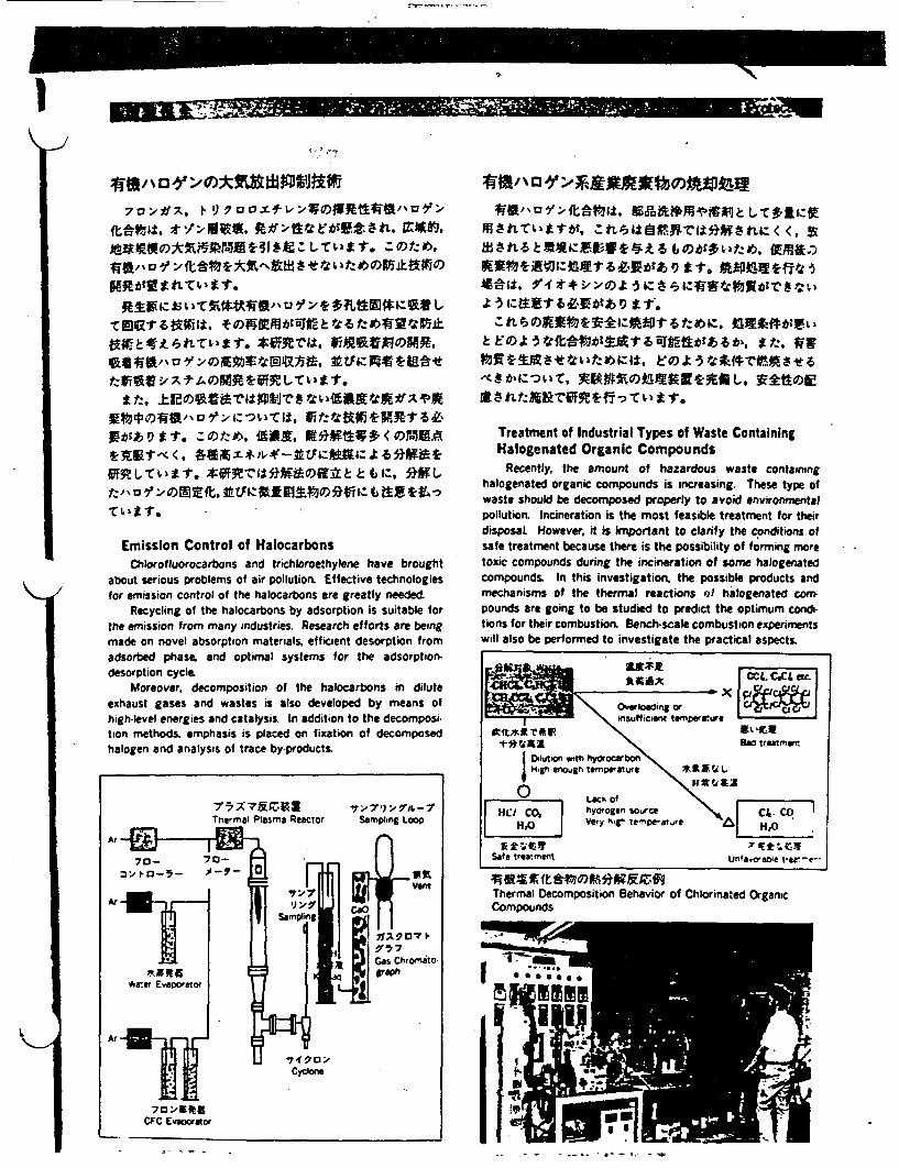
N
I _N__ 111 I ER-MI,,, .,
ft-oti tA:,RIA.t RO;'tweviett. Mitri.
tM -r~s ~ t.
Emission Control of HalocarbonsChlorofluorocarbons and trichloroethylene have brought
about serious problems of air pollution Effective technologiesfor emission control of the halocartbons are greatly needed
Recycling of the halocarbons by adsorption is suitable orthe emission from many industries. Research efforts are beingmade on novel absorption materials, efficient desorption fromadsorbed phase, and optimal systems or the adsorption-desorption cycle.
Moreover, decomposition of the halocarbons in diluteexhaust gases and wastes is also developed by means ofhigh-level energies and catalysi In addition to the decomposi-tion methods, emphasis is placed on fixation of decomposedhalogen and analysis of trace by-products.
Jt~ ~ ~~~1
Halogenated Organic CompoundsRecently, the amount of hazardous waste containing
halogenated organic compounds is increasing. These type ofwaste should be decomposed properly to avoid environmentalpollution. Incineration is the most feasible treatment for theirdisposal However, it is iporant to clarify the c onditions ofsafe treatment because there is the possibility of forming moretoxic compounds during the incineration of some halogenatedcompounds. In this investigation, the possible products andmechanisms of the thermal reactions of haogenated cornpounds are going to be studied to predict the optimum contions for their combustion Bench-scale combustion experimentswill also be performed to investigate the practical aspects.
pollution Incinerat ufioni ifl ot fail ramn o hisat tearnntbeaue hee i te osibliy t oring ornore
tdinfcimt ermnerstureAlt*2 Ter~~~~~~~~~~~i~'e.
compounds In this investigation, the posba trutsmwan
mechanisson the hrrarecin afhlgatdo
Hp s enough temperature to U'i t im
XW~~~~~~
Lac ofvegn enoggn e'mr e'attre \ *1,t
(l hyorogen source \cHOt | ver - temprat, reH;C
Safe treatment unfaira:e t'ea¢-e
Thermal Decomposition Behavior of Chlorinated OrganicCompounds
145X7&L9IThermal Plasma Reactor
.7 �-7') :" 9I)L, - I
SamPling LOOP
Ar
7 D RtICFC Evaporator

'
FrW-Macn_-� I
aSiAMATN Environmental Assessment
IW40. NO* ' 2YN 3 tL M-9CLM si. x -* Ax-tv;r.X9&t,-eew~~
MIlt, A11 MRA92iS 4i text Aft*34N
Simulation Model of Diffusion for the ParticulatesParticulates flowing tough the air are composed of pri-
mary particles released from sources as particle phase andsecondary particles changed from gas phase to particle Diffu-sion of these particlates icluding the formation and removalprocess is investigated by particle counter, NOx analyzer andother equipment on an airplane or helicopter, with the measure.ment of wind, temperature and humidity. Near the groundsurface. beyond several tens kilometers in horizontal the con.centrations of contaminants and weather are observed Thedata are utilized to develop simulation model of dif fusion for theparticulates
*Diffusion experiments with SF as a tracer and wind tunnelexperiments over complex terrain are being made to clarify theeffects of configuration on the diffusion since some factoriesconcerning advanced technological industry are located withinvery complex terrains.
dtR~bylttlt~t&;#g 162000mn 1212rCo
Mechanisms of Atmospheric Diffusion ProcessPollutants released near the ground surface are mainly
advected and diffused in an atmospheric boundary layer lowerthan 2000m or so. Under this circumstance. sea/land breezecirculation and heat island near urban areas affect the diffusionof the pollutants. Measurements of turbulence and temperaturewith an airplane and low atitude sonde are carried out to investi-gate the mechanisms of airflow in the boundary layer. Concen-trations of pollutants often become very high at night in theinversion layer near the ground surface Turbulence in theinversion layer is also measured by equipment on short masts.Using these results, computer simulation of airflow can becarried out
:--
I
. ' - - ---…*t . - . - .- - -
R XL F w o v ) anto P n Su m EsWind Flow over te Kanto Plains in Summer Estimated
. - . . e _ .v-

- ~~ImOIMAN
r t^,'~~ ;,:t-a-..
<~~~~~~~~~~~~
O)~I~L, tt-AI±$MOMt9, it-JS~~~f *t. iE3V/t)1A5A'C PTODtSA taJtW
Oft Oiffxt km r I jf * a.
Prediction Methods for Marine EnvironmentalPollution
In general, the water pollution in coastal areas is caused bymixed wastewater from industries. agriculture, stockbreedingand sewerage We easily recoginize sea phenomena with physi.cal factors such as tidal currents and wind wav. chemicalfactors such as water quality and salinity, and biological factorssuch as the abundant growth of phytoplankton and marineorganisms. Nowadays, we found to realize the problems ofwater pollution in open ocean caused in oil spillt heavy metalsand chemical organic compounds. These problems are closelyrelated to the economical and industrial activities of mankind, sowe must protect the marine ecosystem and more adequatelymanage the social behavior of activities of humans in futureOur laboratory is investigating predictive methods for pollutioneffects on natural coastal waters.. For instance, an attempt isbeing made to develop an ecological and hydraulical numericalsimulation model by a computer. For this purpose, we aredeveloping instruments for field serveys and studying a metho-dology for field observation to obtain accurate data from thesea.
1 _- 7-7 7'~~.. IF,,in_
iteof. Atf. 90.~*X$r win
1-. t~~~,b m. W
ve<lpentofMane nvirmentt. tfaManageent Tehniquetanvro, A)
oatal mrin envir oet suha wate ,qualty prAo.
eris off mA s t d life f orgai as tffec ied y pyica
and cemicl fatosas discre f wtetr Waeut
dvelo an obsrtio istuhet n systems DV'4Z:fork* mitaining
a vclea oasalenvionMaen to irotmntranims
e oa sta ing nvnte ret sh bsewate nvion mentpenofmea and ie organisms ih enfocused on bacterit a tn an curent, g a ti etorological coasetal
an heia fatr as. distpr£1 e of te water e must
aMlan astalenvironentiquoectmnrgnssWeoarstaldmainge rltosi ewe environmentasclswae uliy fp
penoena and sdmearne o organisms ih enocused basce-
areas. Moreover, we have developed a numerical model foreutrophication and using it to simulate the environmentalchanges in the coastal waters
-v~~~~-
TM ff;U -_*~~~ Q_~L. ~
- le - I" -Iff11 . .1
.-tVVb"A.91 d6
Tramh Se6memF '- A*Ae
fteel- -we" Of Lmnu I .
;' -er- � -f : ;t- -1.� - - M*A~~eAA19* "
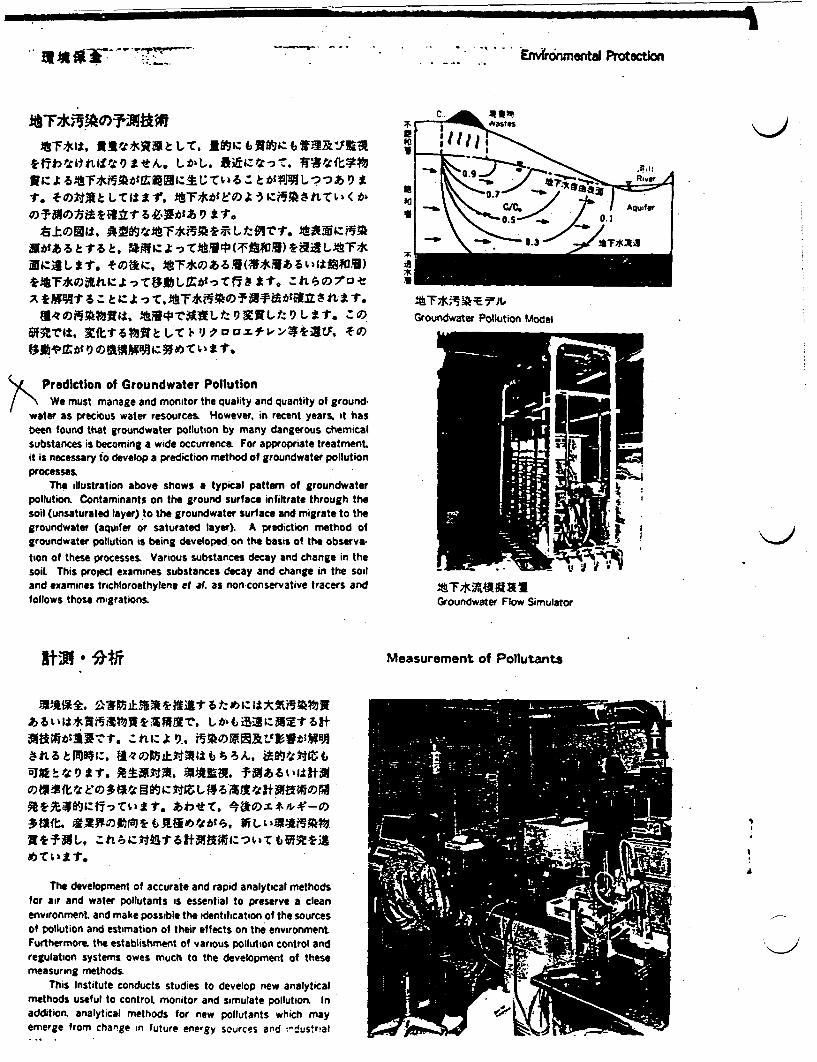
A�
I
.. a a 0 V. - -- 77. 7'�'-I-..
Em*6nmental Protixtion
ai0II
*6*11 MC~~tktr,"L i MI 6TMC7-
II ttfI t?)tAlR Z).c - Z.V trti I
~~AWW~~&-b15 It.
III
,57 pi:
--I. :�.=0.7--S. c/eft ifor
0 1
-0- --111- - 0. AA
U
I
is?X
Groundwater Pollution Model
>Ni Prediction of Groundwater PollutionWe must manage and monitor the quality and quantity of ground.
water as precious water resources. However, in recent years, it hasbeen found that groundwater pollution by many dangerous chemicalsubstances is becoming a wide occurrence. For appropriate treatmentit is necessary to develop a prediction method of groundwater pollutionprocesses.
The illustration above shows a typical pattern of groundwaterpollution. Contaminants on the ground surface infiltrate through thesoil (unsaturated layer) to the groundwater surface and migrate to thegroundwater (aquifer or saturated layer). A prediction method ofgroundwater pollution is being developed on the basis of the observa-
bon of these processes. Various substances decay and change in thesoil This project examines substances decay and change in the soiland examines trichloroethylene et a. as non-conservative tracers andfollows those migrations.
';) * ii-.
The development of accurate and rapid analytical methodsfor air and water pollutants is essential to preserve a cleanenvironment, and make possible the identification of the sourcesof pollution and estimation of their effects on the environmentFurthermore. the establishment of various pollution control andregulation systems owes much to the development of thesemeasuring methods.
This Institute conducts studies to develop new analyticalmethods useful to control monitor and simulate pollution. Inaddition, analytical methods for new pollutants which mayemerge from change in future energy sources and "'dustrial
Groundwater Flow Simulator
Measurement of Pollutants
I
-

- * v ] A m a A A -
- I - - ..- ___ L- -
I Mill - � N
��Ot,
Mbf WSM) OW19VI, 101MnCX-:11 b C1Z"V
J2 X ;.sI t. axle 1 L . SPM OR*Ef ~WN AO
New Measuring Method of Source DustSince an environmental quality standard for suspended
particulate matter (SPM) was enacted in 1972. the compliancerate with the standard has remained at low level in Japan, andit is a very serious administractive problem to improve thecompliance rate. The identification of emission source is impor-tant for this purpose, but it is difficult to determine the origin ofSPM because the data about particle, which is priAjced fromexhaust gas after it is emitted from stack to the air, is insuffi-cient in the source model based on current official measuringmethod
At our Institute, research is being carried out to develop anew evaluation and measuring method for source dust in consid-eration of the relation with SPM by improving the currentofficial method The new method can take the contribution ofsecondary particle into consideration, which is produced throughcondensation and oxidation from exhaust gas in the air.
T**WKIRIP'.
Y6 r8 h t * X t t to d ;'C + a TIC bits t I., fta za
Measurements of Pollutants In GroundwaterGroundwater is regarded as one of the precious water
resources. However. in recent years it has been found thatgroundwater is widely polluted by toxic organo chloro compounds, etc. Since groundwater is difficult to clean if it is oncepolluted. prevention of the pollution is of extreme importance .Rapid analytical methods for pollutants. therefore, are essentialto sufficiently monitor the quality of groundwater. The object ofthis investigation is to establish rapid and remote measuringmethods for pollutants in groundwater. This investigationconsists of two parts 1) the development of remote optical fiberfluorimetry for the determination of organic pollutants; and 2)the development of laser enhanced ionization methods for thedetermination of trace inorganic pollutants,
Block Diagram of Measuring System for GroundwaterContaminants
11 4~~~~
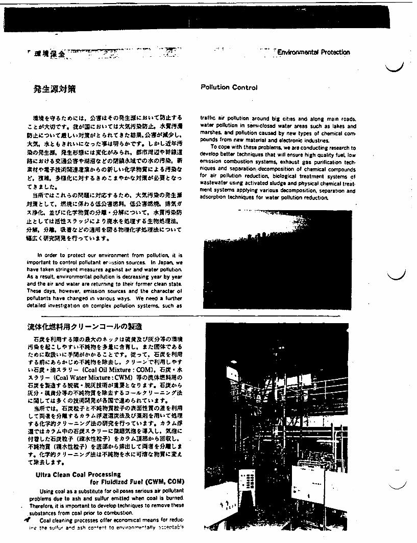
r is It I �Wtrlwmo_. -;,� .. _;Tr__ -"04 .. . .71_ . ; . - Environmenta Protection
Pollution Control
*Z, t6t:e *s waf tt 1 L)£3X;A t~t t
imoat t nro plutn aD s 'errisnsoucs. InJpawe
a the ai an wae r rtigto ~s therfore lea Lstte
Ztbt ESb~tkV£bt. 1-a,$
pollutatsafv hngdin aiu se nee In A w a turth
dtiledivetatio o 6 Ol poltonyteJ Su Mas
ASr t aM:tt ,oa,*dk) * M
G < MWRfiFTvxs
In order to protect our environment from pollution, it isimportant to control pollutant er Csisicin sources In Japan wehave taken stringent measures against air and water pollutionAs a result. environmental pollution is decreasing year by yearand the air and water are returning to their former clean stateThese days, however. emission sources and the character ofpollutants have changed n various ways. We need a furtherdetailed investigation on complex pollution systems. such as
traffic air pollution around big cities and along main roadswater pollution in semiclosed water areas such as lakes andmarshes, and pollution caused by new types of chemical com-pounds from new material and electronic industries
To cope with these problems, we are conducting research todevelop better techniques that will ensure high quality fuel lowemission combustion systems, exhaust gas purification tech-niques and separation. decomposition of chemical compoundsfor air pollution reduction, biological treatment systems ofwastewater using activated sludge and physical chemical treat-ment systems applying various decomposition, separation andadsorption techniques for water pollution reduction
LBiJAA .. (Coal Oil Mixture:COM). t**
x 9- (Coal Water Mixture: CWM) 4i$4 RO)
tEK* i4.Xft *Wtt 6 3 9 -
Ultra Clean Coal Processingfor Flu idized Fuel (CWM, COM)
Using coal as a substitute for oil poses serious air pollutantproblems due to ash and sulfur emitted when coal is burnedTherefoe 1 it is important to develop techniques to remove thesesubstances from coal prior to combustion.
4 Coal cleaning processes offer economical means for reduc-pro the suef ad ash co+e to evirontdwenaly b::ertae

: r..'
2411"IM".41M
-1T -. Kwu -
- . - - . .. .. .:�I.. . I - . 9"�W
*Combustion Control Techniques for LowVolatile Coal
Coal has been utilized positively in commercial steamboilers and furnaces as one of the main alternative energysources since the 1970 oil crisis Therefore, it is forecasted thatthe demand for imported coal will increase in Japart Especially.the percentage of low volatile coal among the imported coal ison the increase.
Low volatile coal has poor combustibility and high NOxemission level in comparison with high volatile coal. Therefore,combustion techniques for low volatile coaL such as a pulverizedcoal combustion with a gasification process or a circulatingfluidized bed combustion have been studied to control theemission of pollutants and obtain high combustion efficiency.
Development of the Control Techniques forDiesel Exhaust Emissions
There is no indication that compliance rate with environ-mental quality standard for NO2 and suspended particulatematter (SPM) has been improved It is, therefore desired tostrengthen the emission standard for diesel-powered vehicleswhich are one of the primary emission sources of N 2 and PM.For the contrary tendency between NOx and particulate emis-sion that the control techniques for NOx increases particulateemission and vice versa it is necessary to develop otherapproaches for the control techniques rather than engine modifi-cat ions.
At our Institute, the control techniques for diesel exhaustemissions are under tudy, especially in the survey of thecatalyst for NO reduction development of trap systems forparticulate reduction and improvement of diesel fuels for simul-taneous reduction of NOx and particulates.
l.
Mth&NKKJP Pulverized Coal Combustion Furnace
NO. %X10)tO t0h°PMt A
Sale Staar Sx$tA~
§s~^;*i~t;fNO,,. sfi~rel0t*A-iC 9 t
tot NO NM *GCA_ -Zk : > i a. t r-.
Catalytic Combustion Techniques for the SmallScale Stationary Sources
Since the low combustion temperature on a catalyticallyactive surface, the use of catalytic combustion has showns5gm Scant advantages in the control of emissions The purpose
.1 - .-. . -. . .. _. . .. .I
91, HI, VI", R "t 1k a at 6 t N�OXVR't I

a -
1F1I W ~ - - , 1Z :"- -t1 . - .. - I -- -"-~ 6.. E�mentd �
m*fll 40Jff_ . LT . SUA
Treatment and Recovery of Biological RefractoryChemicals In Wastewater with Supercritical Fluid
According to the production of various chemical sub-stances, the dispersion and accumulation in environment ofthese chemicals have become a serious problem. The purpose ofthis research is to develop supercritical fluid technology for.removing chemniCal pollutants that are not amenable to biologi-cal treatment from wastewater.
A subtance that has been brought beyond a critical point.has the great solubility change with relatively small changes inoperating conditions. This substance is referred to supercriticalfluid (SCF). SCF can beused to separate and recover pollutantsfrom wastewater by two processes. One is SCF regeneration ofadsorbents that have become saturated with pollutants. allow-ing the adsorbents to bp recycled This method is advantageousin the concentration of dilute pollutants. The other is directcounter current contact Of SCF with wastewater for recovery ofpollutants. This one-step process is applicable when the concen-tration of a pollutant is relatively high. The data on phaseequilibrium for many SCFs is also collected. This data offers thekey to Useful aPPlications of SCF technology.
4* ; a Xi: .t h;1. i BOD ( , -r 1.X-) COD (LIVAMAt) t * i -: ts
Ch el i W stew tr L 4 I- < L4
s T h e ; M r e u a t r e m p a s t h W a e o lto n C o n tr o l L a w
n e e d o n v t e w a s t w a e tr e a m e n t e c h n o l o gyo _ to m na g h a z a r d o u s c e a w a t e w t Y h a b e e s r t d
h iological T reat ment pHazrces a
C cals in Wastewater h sbe n etgtd b s d o h d pa
b T e u to e h mi encee aclimattiton ol L f
atiad s chemicals saolationt of mncr
needP for inoaivewatewate treatmenit tchnoXogy t man
Inti k iological reatment pro s azardous ceichmals in astewater sbe netgtdbsdo h dpablThe robesator eheicas Hte aer limiztion o
ai ate sude from specifi chmias otonetoa micollu-
degrading the chemicals. kinetics of degradation, physiology ofthe microbes, and the behaviour of the microbes in activatedsludge process. are under study.
Acara!-.s f E':-!!br -- esr e ? �t- - $-- - '-.- =-- -9 - - -- - -
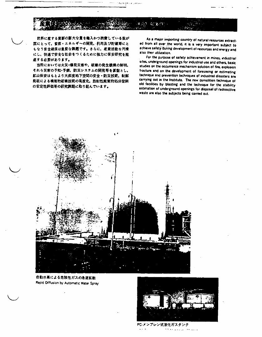
6 � ± �, * wu�w�, �
�' �
As a major importing country of natural resources extracted from all over the world, it is a very important subject toachieve safety uring development of resources and energy andalso their utilization.
For the purpose of safety achievement in minmes industrialsites. underground openings for industrial use and others, basicstudies on the occurrence mechanism solution of fire, explosionfracture and on the development of foreseeing or estimatingtechnique and prevention techniques of industrial disasters arecarrying out in the Institute. The new demolition technique ofold facilities by blasting and the technique for the stabilityestimation of underground openings for disposal of radioactivewaste are also the subjects being carried out.
I
Rapid Diffusion by Automatic Water Spray
Pc-i:~ '7 Ilftf ':1
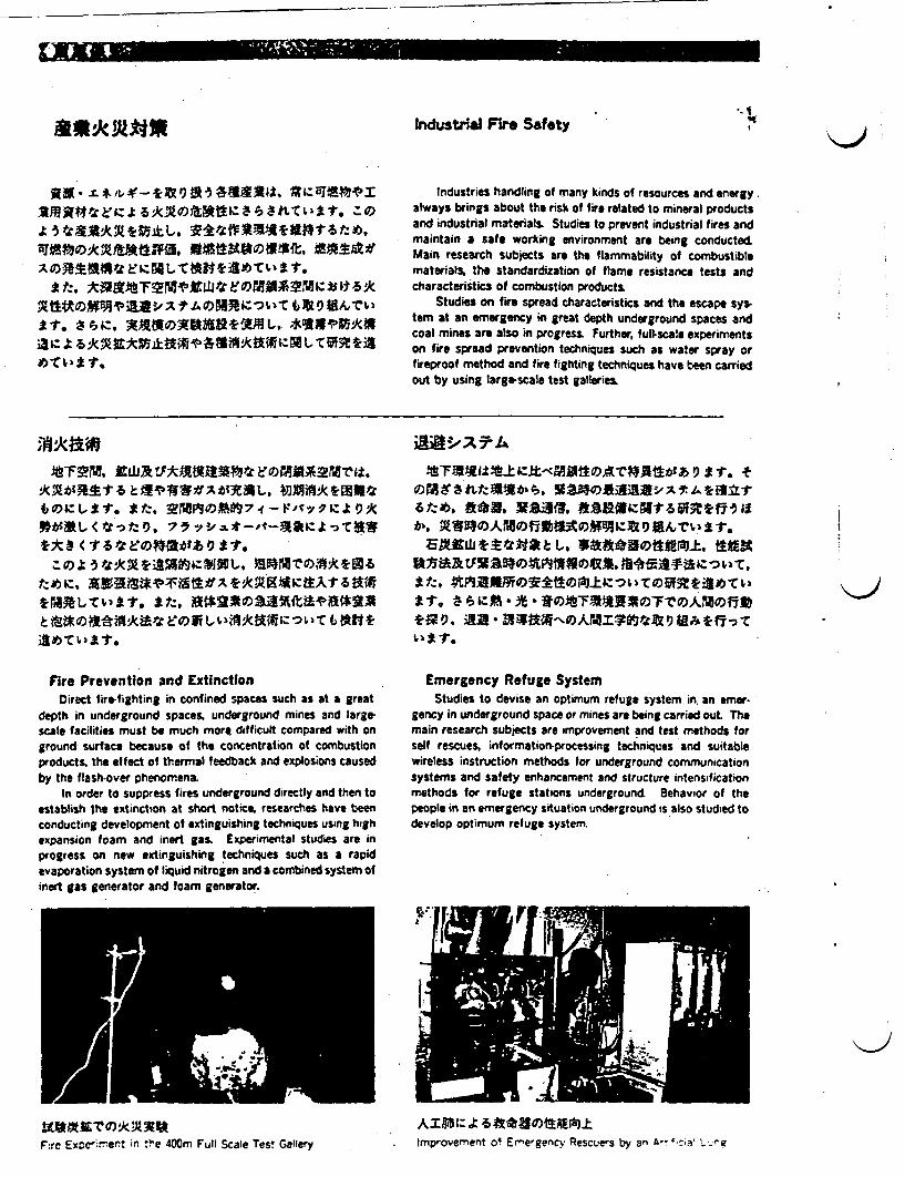
Z.-- ub� IM11111111
iustri Fire Safety,o1.
I'
* t, M~~~*ZW~~t I!t b
ia~~~A~~r L CA1
Industries handling of many kinds of resources and energyalways brings about the risk of fire related to mineral productsand industrial materials. Studies to prevent industrial fires andmaintain a safe working environment are being conductedMain research subjects are the flammability of ombustiblematerials, the standardization of flame resistance tests andcharacteristics of combustion products
Studies on fire spread characteristics and the escape sys.tern at an emergency in great depth underground spaces andcoal mines are also in progress, Further, fullscale experimentson fire spread prevention techniques such as water spray orfireproof method and fire fighting techniques have been carriedout by using large-scale test galleries
scl ftis ut e mchmoe ifiu cmared witho
grondsurf ae because of te coctrat ;on bus
*bJE < 2 X£gs
prod uts th f ,tm al eedacka exlsoscedzoDe, 3*;kX,*Affi9JXL.Eg~tg
Fire Prevention and ExtinctonDirect fire-fighting in confined spaces such as at a great
depth in underground spaces underground mines and largescale facilities must be much morel difticutt compared with nground surface because of the concentration of combustionproducts. the offlect of thermal feedback and explosions causedby the flash-over phenomena
In order to suppress fires underground directly and then toestablish the extinction at short notice researches have beenconducting development of extinguishing techniques using highexpansion foam and inert gas Experimental studies are inprogress on new extinguishing techniques such as a rapidevaporation system of liquid nitrogen and a combined system ofinert gas generator and foam generator.
bie, U~, a)Jf, if~~ti~~~
at ai, ae at b.F
*1. b§ * * XFTA MOXX~0 iljtg9,9A iI §Ra~AMdI*te 9athzs
1-t.
Emergency Refuge SystemStudies to devise an optimum refuge system in. an emer-
gency in underground space or mines are being carried out Themain research subjects are improvement and test methods forself rescues. informationprocessing techniques and suitablewireless instruction methods for underground communicationsystems and safety enhancement and structure intensificationmethods for refuge stations underground Behavior of thepeople in an emergency situation underground is also studied todevelop optimum refuge system.
i
5c i;M1ltOAX AMe- Ale rI t 6ftaA e ciF rC ExDCe mert in 'vie 40Om Full Scale Test Gallery . Improvement of ErnergenvRecuer by an a- sia L veq
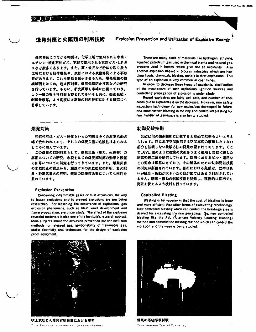
- & - f_ _-
-06�0
O L C I tr.
ion Prevention end Utilization of Expllsve Energy
There are many kinds of materials like hydrogen, ethylene,liquefied petroleum gas used in chemical plants and natural gas.propane used in homes, which give rise to accidents Alsoanother explosion hazard in process industries which are han.dling foods, chemicals. plastics metals is dust explosions. Thistype of an explosion is very common in coal mines.
In order to decrease these types of accidents clarificationof the mechanism of such explosions, ignition sources andcontrolling propagation of explosion is under study.
Recent explosives are fairly well safe, and number of accidents due to explosives is on the decrease. However, new safetyinspection technology for new explosives developed in futurenew construction blasting in the city and controlled blasting fornew frontier of geo-space is also being studied
Explosion PreventionConcerning inflammable gases or dust explosions. the way
to lessen explosions and to prevent explosions are are beingresearched For lessening the occurrance of explosions, gasexplosion phenomena, such as blast wave development andflame propagation. are under study. The effect of the explosionrestraint materials is also one of the Institutes research subject.Main subjects about the explosion prevention are the diffusionmethods for released gas. ignitionability of flammable gasstatic electricity and techniques for the design of explosionproof equipment.
Controlled BlastingBlasting is far superior n that the cost of blasting is lower
and more efficient than other forms of excavating tecchnology.New controlled blasting which can control the breakage area isdesired for excavating the new geospac- So. new controlledblasting like the AVL (lternate Velocity oading Blasting)method and construction blasting method which can control thevibration and the noise is being studied.
-
'-C - -- ~ -,- - "I-- - Li -i- - - -a -- -4 = , - --, -
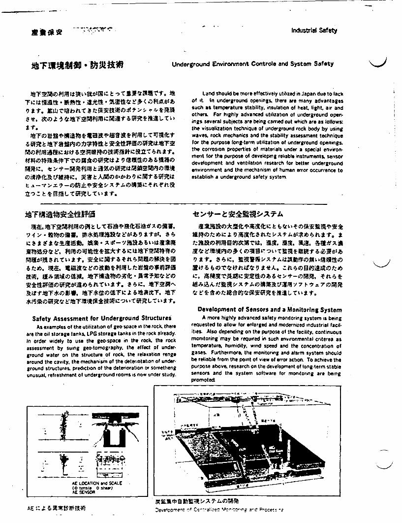
Industrial Sat eti
Underground Environment Controle and System Safety
�. �,zGx� ��1-.
�
-e �-�'J� e±�M2MP�o�� � 9
Land should be more effectively utilized in Japan due to lackof it. In underground openings, there are many advantagessuch as temperature stability, insulation of heat, light. air andothers. For highly advanced utilization of underground open-ings several subjects are being carried out which are as ollowsthe visualization technique of underground rock body by usingwaves, rock mechanics and the stability assessment techniquefor the purpose long-term utilization of underground openings,the corrosion properties of materials under a special environ-ment for the purpose of developing reliable instruments, sensordevelopment and ventilation research for better undergroundenvironment and the mechanism of human error occurrence toestablish a underground safety system.
W:!si2UV2:9d ffi ~ yR^tla
Safety Assessment for Underground StructuresAs examples of the utilization of geo-space in the rock, there
are the oil storage tanks. LPG storage tanks in the rock already.In order widely to use the geo-space in the rock. the rockassessment by suing geo-tomography. the effect of under-ground water on the structure of rock. the relaxation rengearound the cavity, the mechanism of the deteriotation of under-ground structures. prediction of the deterioration or somethengunusual, refreshment of underground rooms is now under study.
$"Ot:^|:aD7|attt, w2f.t3,blt ;&syk
IZ,
Development of Sensors and a Monitoring SystemA more highly advanced safety monitoring system is being
requested to allow for enlarged and modernized industrial facil-ities. Also depending on the purpose of the facility, continuousmonitoring may be required in such environmental criterea astemperature, humidity, wind speed and the concentration ofgases. Furthermore, the monitoring and alarm system shouldbe reliable from the point of view of error action. To achieve thepurpose above, research on the development of long-term stablesensors and the system software for monitoring are beingpromoted
-~~~~~~ q~~~~~~~d ' 3 - - 'I -~~~ .....................
. ~ ~ ~ ~~-I _ , .
_ A__ ~0 _M-
AE LOCATION and SCALE(O tensile 0 shear)AE SENSOR
AE ~~~~~~~~~ ~~~~~eveloorrent n e afe Vcn-;to.-ing a-c! P ce~s -;.A E t:: �` 6 X19 rl, V tA W3

ne a - . - a .. -
w Se :,-&s, tul.Jztet ~ o 43-ril,
1.askF2etrtit edri
*7r
The Coal Mine Safety Research Center (Hokkaido) hasfocussed its research efforts on developing safety technologyfor coal mines. Major research activities are being carried outas a special project in cooperation with the Industrial SafetyDept. and the Coal Mine Safety Research Center (Kyushu).
The project involves a study on the electrostatic charge inthe dry weather of H~okkaido to prevent gas explosions causedby electrostatic discharges. Typical research work at the Centerinclude:1. Locomotive Mechanism for Underground Development2. Advanced Monitoring Sensor Development3. Extension of the Intrinsic Safety Concept
Lt-,-f, AU WZVWf ENl6fltAf . *]E4 £5 L < * Zrt1, WiLN US R, M R)
#51PUMMODWL. ;V5£0Rt e+< Aiffk,6i3-1ar
nKAX a**;kWI R14, > 1,ArA A)$ R Pi
e-tt, t#L _ets" stt
moxi~seesto* ebm; w t et .f
The Coal Mine Safety Research Center (Kyushu) was established by the Japanese Government and Civilian Organization inMay 1915. For over 70 years, the Center has provided technol-ogy and technical services to the coal mining industry for coalmine safety. The experimental coal mine of the Center. which isa unique facility in Japan, has been used for full-scale tests anduseful results have been obtained
Over the past decades, the working environment of coalmines in the Kyushu coal-mining area ha s been getting worse.The Centers research focuses on developing advanced technol.ogy for coal mines, such as underground communication sys-tems, data transfer techniques in mines. monitoring the fire-damp movement and fire-extinguishing method for coal mines.The Center also encourages technology transfer to apply thesetechnologies to the mining industry
Tf;0A7-f-UExperiment of Optical Fiber Sensor
Explosion Flame ofExplosive in Motar
51fIVX 9' I L11M4~A"Test Gaiiery of Explosives
International Cooperation of Scde and Technology
UMISM~ke gVAJIOECD 4Eeh
2.~~~~~-
4. MA ~%J*f IA
4. tMOMMO 4,,.
The Signing Ceremony of ITIT Program with India
Science and Technology have greatly contributed to ourhealth and welfare, but they also have brought about someproblems of a global scale regarding natural resources, energyand the environment. Future science and technology should notbe indifferent to such problems, and their research and develop.mont should be carried out so as to harmonize industrial activ-ities with the global environment International cooperation isindispensable to cope with such problems.
On the other hand as recent science and technology havebecome and complicated it is difficult for a country to maketheir further progress only by itself. International cooperation isnecessary from this point of view.
The International Research Cooperation Office was set upto promote research cooperation with foreign countries throughthe offer of the latest information about countries overseas andtheir research activities
The following programs are in progress at the NationalResearch Institute for Pollution and Resources:1. Joint research with the organizations of advanced countries.2. Institute for the Transfer of Industrial Technology (ITIT)
projects3. Cooperation with JICA (Japan International Cooperation
Agency) in its projects by dispatching specialists and accept-ing foreign trainees.
4. The interchange of research personnel and guidance forforeign visitors
A rup T Crs
JICA JuicyEFJICA Group Training Course
I T ~~~~~~I
JICA Eted )'LtH4ttxFRMY �'!I- L0113...- _-
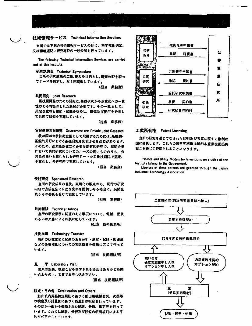
jAfl"1 -. Z Technical Information Servies
The following Technical Information Services are carriedout at this Institute.
FIM* Technical Symposium
~~2 A~~~I& LNARK
ANVIR Joint Research
(IS tR)
Ml~tlUSNIF Government and Private Joint Research
teiWR Sponsored Research
JAME1h1 Technical Advice
Technology Transfer
*:si,}T0Xet&;s~t#--ti~* t0t# S
li t Laboratory Visit
2§b4tU± SThlP2: i gETet}L 3 i.d3
MD t)
- (E NlA8 i)
4f~.*Ujf ertifctony Tandters
s§EtIlSe$fe^E
a 'D~:;i~g~lst£f*C :tfo
I*A~j?4j Patent Licensing
Patents and Utility Models for Inventions on studies at theInstitute belong to the Government.
Licenses of these patents are granted through the JapanIndustrial Technology Association.
(
C& 71- W71i -W D9
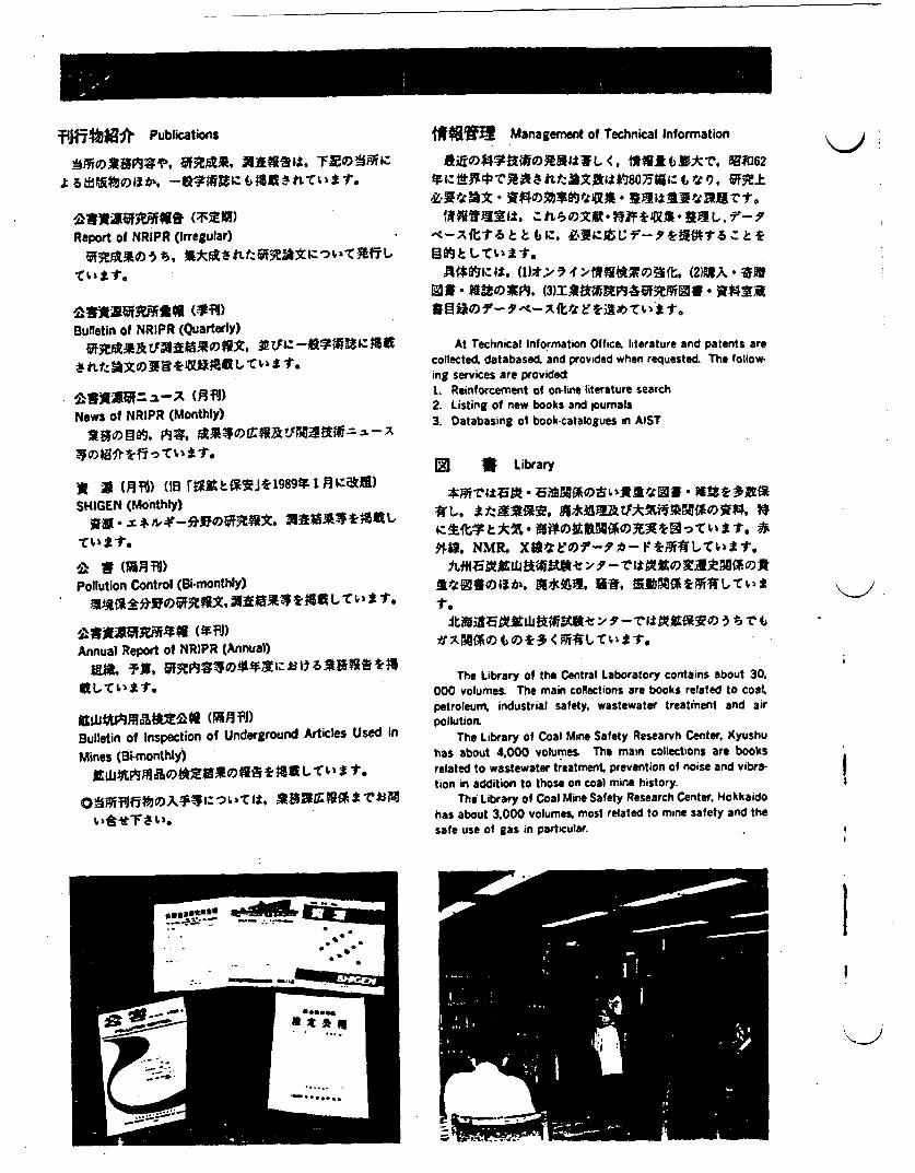
fJlf W Publications
§tAlfti# (l;i)SReport of NRIPR (Irregular)
Bulletin of NRIPR (Quarterly)
News of NRIPR (Monthly)
a mv ( us r1 aitzPJ~l989*i1n;:atn)SHIGEN (Monthly)
b w (z))
Pollution Control (Bi-monthly)JR-aieAW11MOVIVAeX 31E 372 1, le t vc I I"
0 311* 9IRM441 0"DJAnnual Report of NR1PR (Annual)
Bulletin of Inspection of Underground Articles Used inMines (Si-monthly)
tllJAP411 00531MONS~ *AI S *} ks -r.
j#!MW:; Management of Technical Information
SiEX~t*l~~tl< k"Z#?*4V*r. aB-D62
Af*niz t, ()I4; ¶t f WNX . s4
At Technical Information Office. literature and patents arecollected databased. and provided when requested. The follow-ing services are provided1. Reinforcement of on-line literature search2. Listing of new books and joumals3. Databasing of book-catalogues in AIST
(X * Library
tU. as*. S sIA)fld'c~Ew *
MA, NMR . EfBF*tT>t
The Library of the Central Laboratory contains about 30.000 volumes. The main collections are books related to coatpetroleum, industrial safety, wastewater treatment and airpollution.
The Library of Coal Mine Safety Researvh Center. Kyushuhas about 4000 volumes The main collections are booksrelated to wastewater treatment, prevention of noise and vibra-tion in addition to those on coal mine history.
The Library of Coal Mine Safety Research Center. Hokkaidohas about 3,000 volumes. most related to mine safety and thesafe use of gas in particular
I)
i
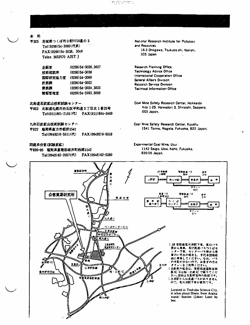
'Y 305 XiWt < SJffP1169e 3Tel(029)54-3000(ftA) -FAX (0298)54-3038, 3049Telex 3652570 AIST J
National Research Institute for Pollutionand Resources
16-3 Onogawa, Tsukuba shi, barakli.305 Japan
:NfrRM480AMWORWirfiF.ff JR
Walt
INN1619tr
(0298) 54-3026.3027(0298)54-3036(0298)54-3060(0298)54-3022(0298)54-3024.3025(0298)54-3163.3050
Research Planning OfficeTechnology Advice OfficeInternational Cooperation OfficeGeneral Affairs DivisionResaarch Service DivisionTechnical Information Office
t003 t $LttlF5f3 E JAK 3 JT]4t l 25gTel (011)861-2191(fK) FAX(011)864-3469
1822 16 II Mffi l1541Tel(09492)6-5511 (ft) FAX (09492)6-5518
1820-05 189091 #319PRI91142Tel (0948) 62-2057(ft) FAX (0948) 62-5280
Coal Mine Safety Research Center. HokkaidoKita 1-25. Heiwadori 3, Shiroishi, Sapporo,003 Japan.
Coal Mine Safety Research Center, Kyushu1541 Tonno, Nogata, Fukuoka, 822 Japan.
Experimental Coal Mine. Usui1142 Saigo. Usui. Kaho, Fukuoka,820-05 Japan.
A
AJ
JRtUU WON u i r11 lwvI 30* 3*
1 P Y~~~ 0 * ~2 0*3
it
di JR iL S,- . 7,
X IX ±4AC -, -a f!
I gwlo* R0e 3-
Located in Tsukuba Science City..it takes about 20mi. from Arakawaoki Station (joban Line) bybus.

ITINOLDGIES DISCUSSED AT JGC CORPORATION
- Radioactive Waste Management Technologies
1. Treatment of High Conductivity Liquid Waste2. Treatment of Liquid Waste Containing Ammonia3. Microwave Dryer for Spent Resins4. New Vacuum Conveying System for Radioactive iquid Waste
- Incinerator Technologies
1. SIAS2. Gasification Furnace Incinerator3. Hazardous Waste Incineraor4. Energy- Recovery of Uquid Injection5. Radioisotope Carcass Incinerator6. Radwaste Incinerator7. Medical Waste Incinerator8. High Temperature Waste Incinerator9. CyForMelt
10. Induction Heating Melting System
- Tritium Separation/Concentration- Wet Oxidization- Reprocsing Facility Real-Time Gas Monitoring System- Mixed Waste and Reprocessing Management Technologies
1. Advanced Cement Solidification2. Induction Heating Melting System3. incineration of Spent TBP Contaminated U and Pu4. iUquid Waste Treatment
- Hazardous Waste Management Technologies
1. Recovery of Solvent from Off-Gas by Activated Carbon Fiber Filter2. In-situ Stabilization of Cd and Pb Contaminated Soil3. Hazardous Waste Incinerator4. PCB and VCM Waste IncineratorS. Energy Recoring Type Liquid Injection Incinerator6. Gasification Furnace Type Incinerator7. Treatment of Heavy Metal and Organisms Contained In Iquid Waste8. Regeneration of Spent Activated Carbon
BIBLIOGRAPHY OF LTRATURE RECVED FROM JGC CORPORATION"Advanced Waste Management Technologies", JOC Corporation, 100 pages.
ADVANCED WASTE MANAGEMENT
TECHNOLOGIES
NOVEMBER, 1990
JGC CORPORATION
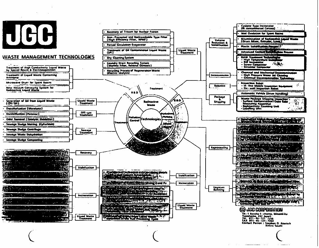
WASTE MANAGEMENT TECHNOLOGiES
Tieatieunt of High Conducity y liquid Wasteby SpeciM Rein$ & Ikcio"Ipiitiont
lreaunet of Liquid Waste Containm -
" mIt nilv D______for______Mans
Uew Vauwn Convewien Sys lotBdaoackav. biquwd i
. w-
iJ
AI-I"
L.. ff,1- - a, 'BIit
IlIUMMkmnilka
C C an 0. Goesch
.Saudis
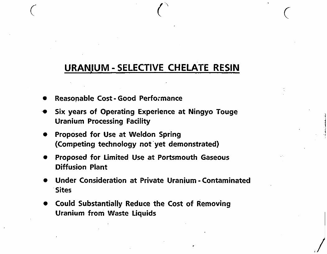
URANIUM - SELECTIVE CHELATE RESIN
* Reasonable Cost- Good Performance
0 Six years of Operating Experience at Ningyo TougeUranium Processing Facility
* Proposed for Use at Weldon Spring .
(Competing technology not yet demonstrated)
* Proposed for Limited Use at Portsmouth GaseousDiffusion Plant
* Under Consideration at Private Uranium-ContaminatedSites
* Could Substantially Reduce the Cost of RemovingUranium from Waste Liquids
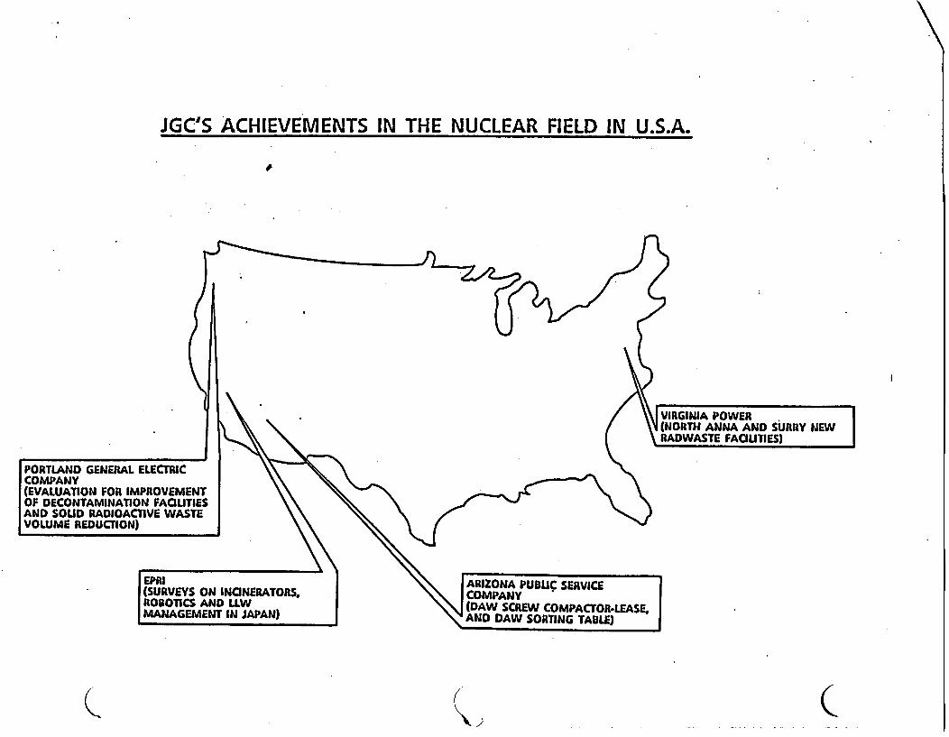
JGC'S ACHIEVEMENTS IN THE NUCLEAR FIELD IN U.S.A.
VIRGINIA POWER(NORTH ANNA AND SURRY NEW
9\ \ \ ~~~~~~~~~~~~~~RADWASTE FACIUTIES)
GENERAL ELECTRIC
ON FOR IMPROVEMENTlAMINATION FACIUTIES) RADIOACTIVE WASTE,EDUCnON)
EPRI ~~~~~~~~~~~RIZONA PUBLIC SERVICE(SURVEYS ON INCINERATORS, COMPANYROBOTICS AN D LLW \\| (DAW SCREW COMPACTOR-LEASE,MANAGEMENT IN JAPAN) \ AND DAW SORTING TABLE)
Q C~~~~~~~~~~~~~~~~~~~~~~~~~~~~~~~~~~~~~~~~~~~~~~~~~~~~~~~~~~~~~~~~~~~~~~~~~~~~~~~~~~~~~~~~~~~~~~~~~~~~~~~~~~~V~~~~~~~~...
PORTLANDCOMPANY(EVALUATIOF DECONAND SOULVOLUME A
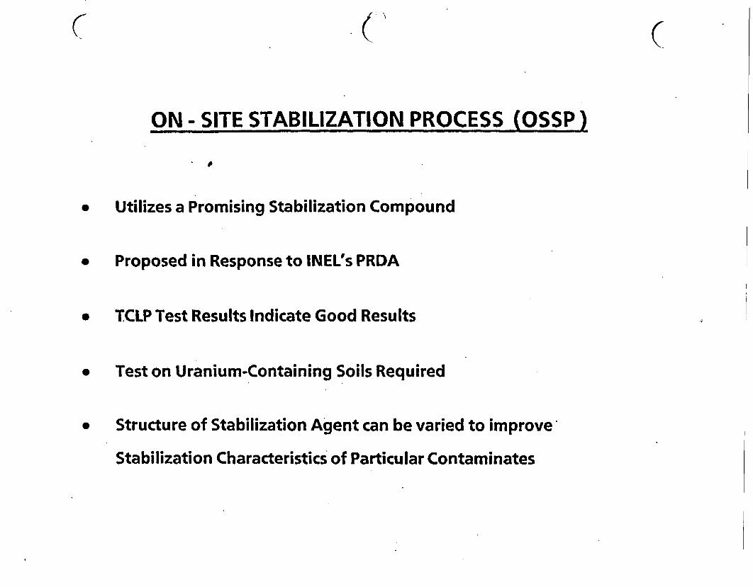
ON - SITE STABILIZATION PROCESS OSSP)
* Utilizes a Promising Stabilization Compound
(
* Proposed in Response to INEL's PRDA
* TCLP Test Results Indicate Good Results
* Test on Uranium-Containing Soils Required
* Structure of Stabilization Agent can be varied to improve
Stabilization Characteristics of Particular Contaminates
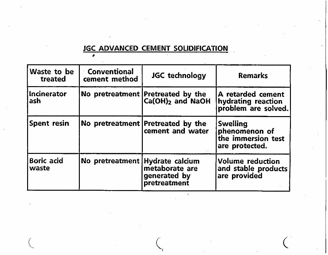
JGC ADVANCED CEMENT SOLIDIFICATIONJG DACDCMNTSLDFCTO
Waste to be Conventionaltreated cement method JGC technology Remarks
Incinerator No pretreatment Pretreated by the A retarded cementash Ca(OH) 2 and NaOH hydrating reaction
problem are solved.
Spent resin No pretreatment Pretreated by the Swellingcement and water phenomenon of
the immersion testare protected.
Boric acid No pretreatment Hydrate calcium Volume reductionwaste metaborate are and stable products
generated by are providedpretreatment
Q (
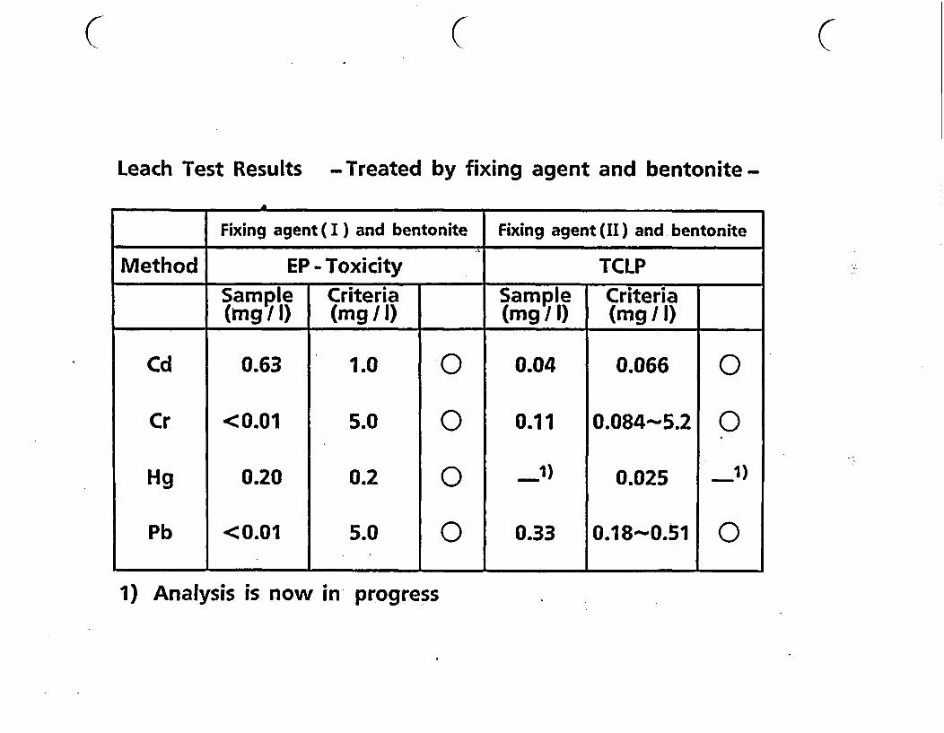
C ( C
Leach Test Results -Treated by fixing agent and bentonite -
A
Fixing agent( I ) and bentonite Fixing agent (II) and bentonite
Method EP - Toxicity TCLPSample Criteria Sample Criteria(mg/) (mg/) (mgI) (mg/
Cd 0.63 1.0 0 0.04 0.066 0
Cr <0.01 5.0 0 0.11 0.084-5.2 0
Hg 0.20 0.2 0 1) 0.025 1)
Pb <0.01 5.0 0 0.33 0.18s0.51 0
1) Analysis is now in progress
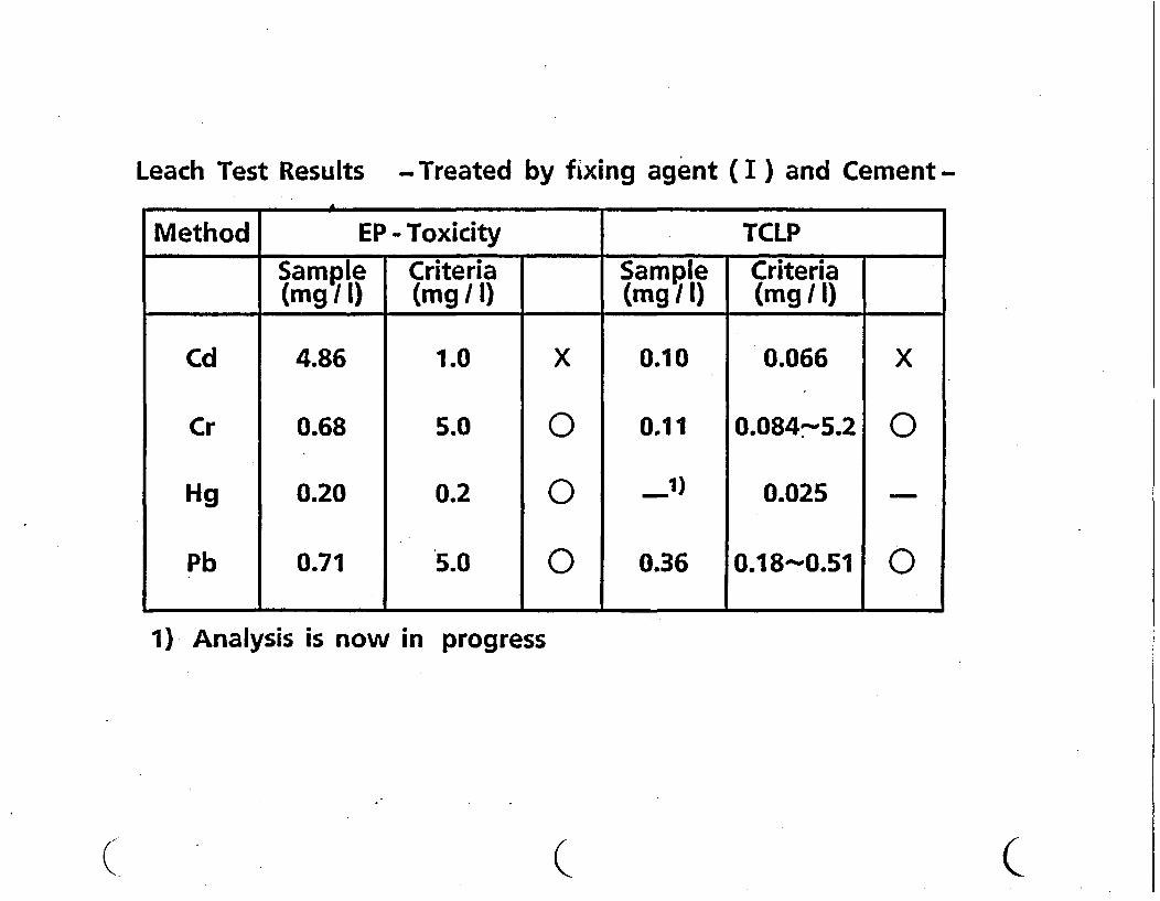
Leach Test Results -Treated by fixing agent (I ) and Cement-
Method EP - Toxicity TCLPmple a Sample Criteria
(mg /I) (mg /I) (mg /I) (mg/I)
Cd 4.86 1.0 X 0.10 0.066 X
Cr 0.68 5.0 0 0.11 0.084-5.2 0
Hg 0.20 0.2 0 1) 0.025
Pb 0.71 5.0 0 0.36 0.18-0.51 0
1) Analysis is now in progress
Q ( C
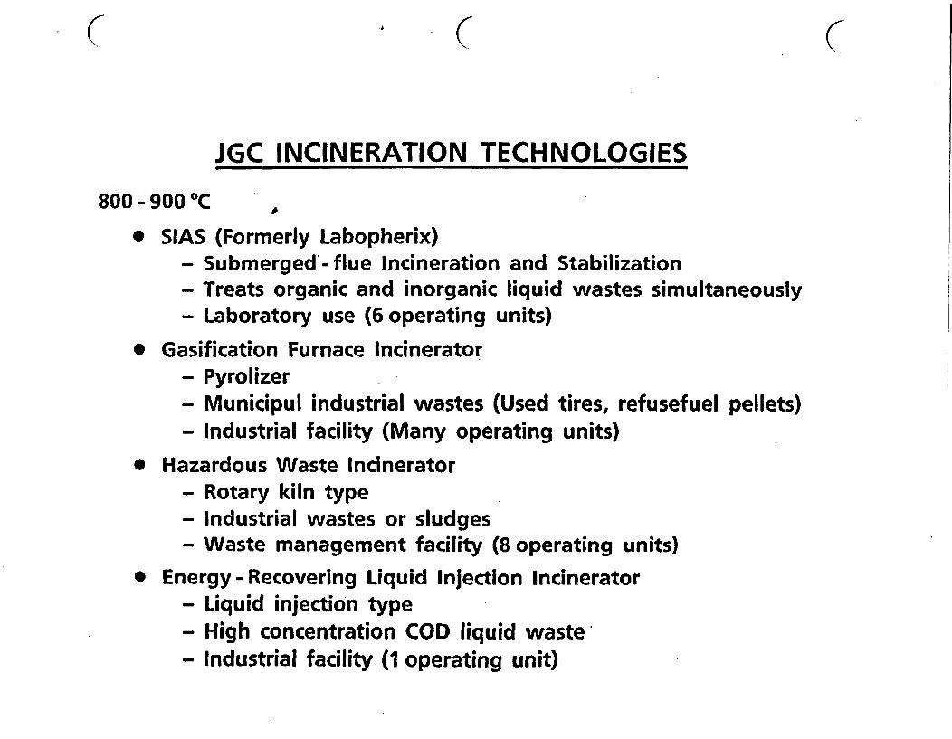
JGC INCINERATION TECHNOLOGIES
800 - 900 C
* SIAS (Formerly Labopherix)- Submerged-flue Incineration and Stabilization- Treats organic and inorganic liquid wastes simultaneously- Laboratory use (6 operating units)
* Gasification Furnace Incinerator- Pyrolizer- Municipul industrial wastes (Used tires, refusefuel pellets)- Industrial facility (Many operating units)
* Hazardous Waste Incinerator- Rotary kiln type- Industrial wastes or sludges- Waste management facility (8 operating units)
* Energy - Recovering Liquid Injection Incinerator- Liquid injection type- High concentration COD liquid waste,- Industrial facility (1 operating unit)
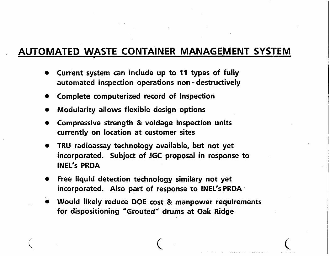
AUTOMATED WASTE CONTAINER MANAGEMENT SYSTEM
* Current system can include up to 11 types of fullyautomated inspection operations non-destructively
* Complete computerized record of Inspection
* Modularity allows flexible design options
* Compressive strength & voidage inspection unitscurrently on location at customer sites
* TRU radioassay technology available, but not yetincorporated. Subject of JGC proposal in response toINEL's PRDA
* Free liquid detection technology similary not yetincorporated. Also part of response to INEL's PRDA
* Would likely reduce DOE cost & manpower requirementsfor dispositioning "Grouted" drums at Oak Ridge
( ( (
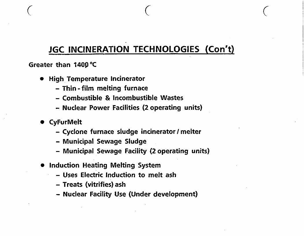
JGC INCINERATION TECHNOLOGIES (Con't)
Greater than 140p 0C
* High Temperature Incinerator- Thin - film melting furnace- Combustible & Incombustible Wastes- Nuclear Power Facilities (2 operating units)
* CyFurMelt- Cyclone furnace sludge incinerator / melter- Municipal Sewage Sludge- Municipal Sewage Facility (2 operating units)
* Induction Heating Melting System- Uses Electric Induction to melt ash- Treats (vitrifies) ash- Nuclear Facility Use (Under development)
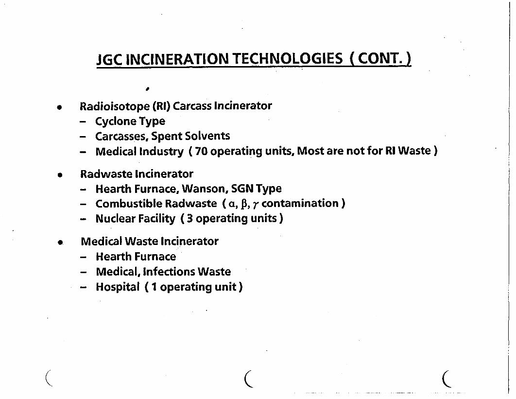
JGC INCINERATION TECHNOLOGIES (CONT.-)
* Radioisotope (RI) Carcass Incinerator- Cyclone Type- Carcasses, Spent Solvents- Medical Industry ( 70 operating units, Most are not for RI Waste)
* Radwaste Incinerator- Hearth Furnace, Wanson, SGN Type- Combustible Radwaste (a, , ;r contamination)- Nuclear Facility ( 3 operating units)
* Medical Waste Incinerator- Hearth Furnace- Medical, Infections Waste- Hospital (I operating unit)
( (
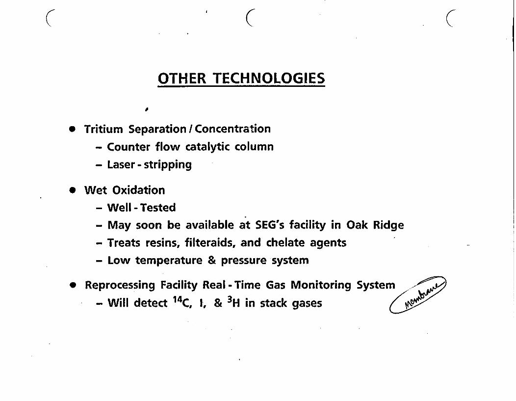
OTHER TECHNOLOGIES
* Tritium Separation / Concentration
- Counter flow catalytic column
- Laser - stripping
* Wet Oxidation
- Well-Tested
- May soon be available at SEG's facility in Oak Ridge
- Treats resins, filteraids, and chelate agents
- Low temperature & pressure system
* Reprocessing Facility Real -Time Gas Monitoring System
- Will detect 14C, 1, & 3H in stack gases
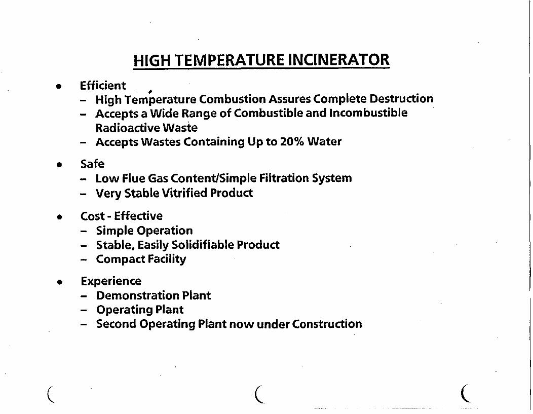
HIGH TEMPERATURE INCINERATOR* Efficient
- High Temperature Combustion Assures Complete Destruction- Accepts a Wide Range of Combustible and Incombustible
Radioactive Waste- Accepts Wastes Containing Up to 20% Water
* Safe- Low Flue Gas Content/Simple Filtration System- Very Stable Vitrified Product
* Cost - Effective- Simple Operation- Stable, Easily Solidifiable Product- Compact Facility
* Experience- Demonstration Plant- Operating Plant- Second Operating Plant now under Construction
C~~~~~~~~~~~~~~~~~~~~~~~~~~~~~~~~~~~~~~~~~~~~~~~~~~~~ . . . . . C.. .

JOGPART 1
INTRODUCTION
TO
JGC COPRORATION
1-1
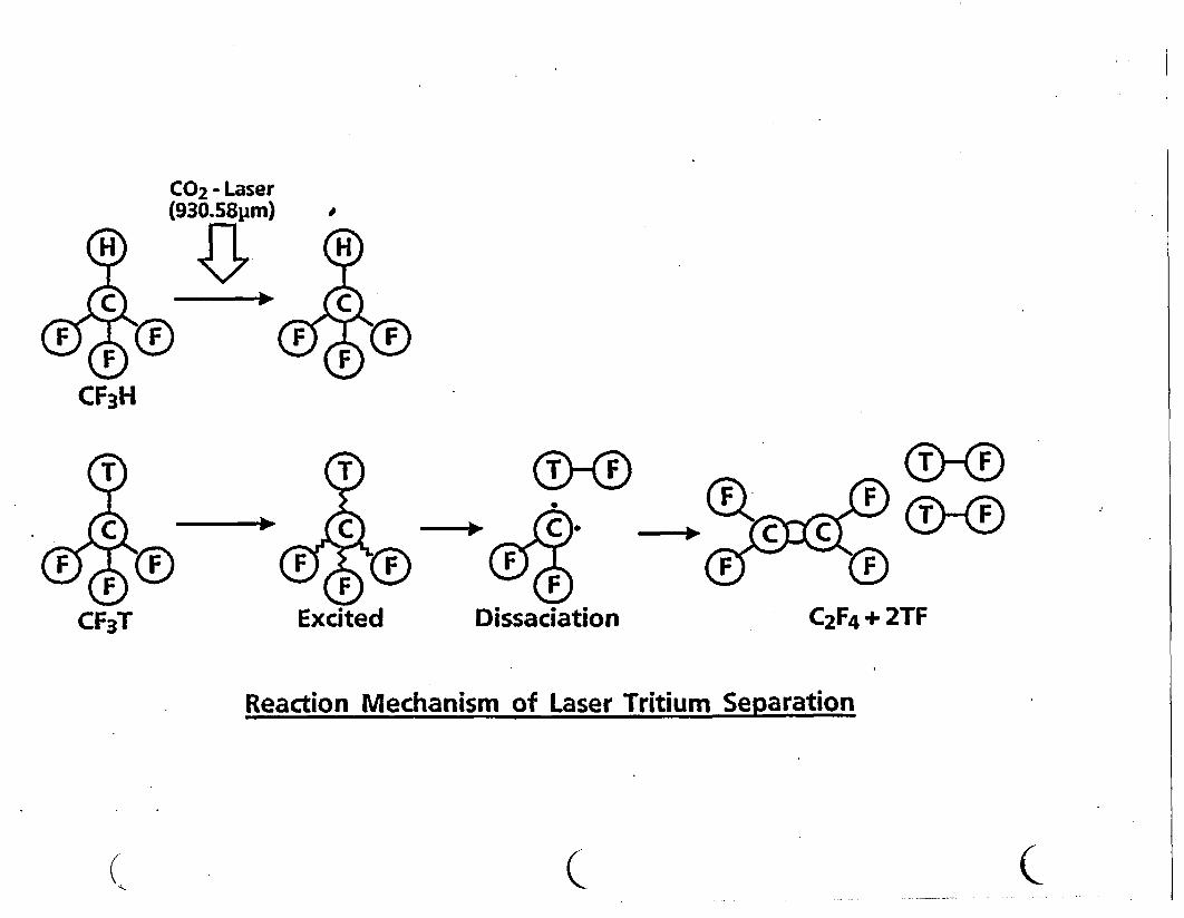
CO2 - Laser(930.58pjm) M
CF3H
0-0 0-0
C 0 +
C 2F 4 + 2TFCF3T Dissaciation
Reaction Mechanism of Laser Tritium Separation
(Q C
JOGJGC'S BACKGROUND
o Established :
o Employees :
October 25, 1928
2,800(Including)
18 in the U.S.A120 in other foreign countries
0 Contracts completed :$ 1,180 Million (fiscal year 1989)
0 Contracts awarded : $ 3,800 Million (fiscal year 1989)
Memo ;
1-2
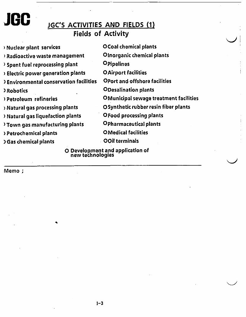
JaG JGC'S ACTIVITIES AND FIELDS (1)Fields of Activity
) Nuclear plant services OCoal chemical plants
Radioactive waste management Olnorganic chemical plants
) Spent fuel reprocessing plant OPipelines
) Electric power generation plants OAirport facilities
) Environmental conservation facilities OPort and offshore facilities
) Robotics ODesalination plants) Petroleum refineries 0 Municipal sewage treatment facilities
) Natural gas processing plants OSynthetic rubber resin fiber plants
) Natural gas liquefaction plants OFood processing plants
)Town gas manufacturing plants OPharmaceutical plants) Petrochemical plants OMedical facilities) Gas chemical plants OOil terminals
O Development and application ofnew technologies
Memo;
1-3
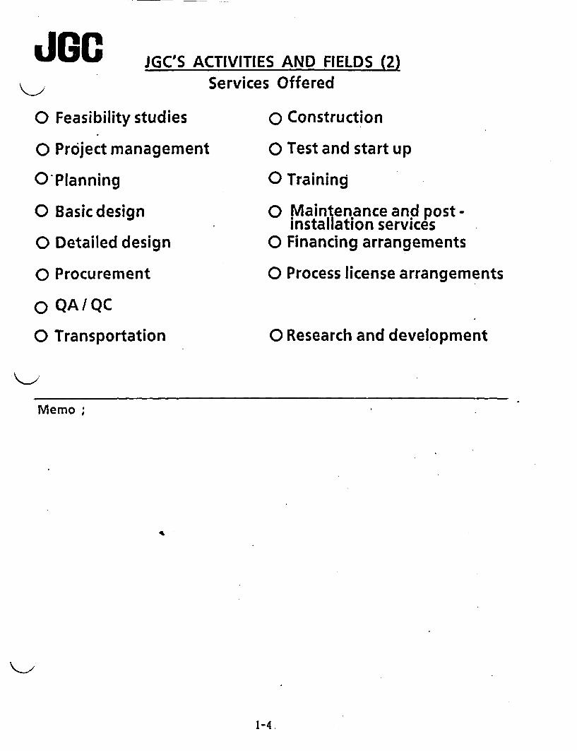
IJGCo Feasibility s-
o Project man
O Planning
o Basic design
o Detailed de!
o Procuremen
o QAIQC
o Transportat
JGC'S ACTIVITIES AND FIELDS (2)Services Offered
tudies 0 Construction
agement 0 Test and start up
0 Training
0 Mlaintenanceand post-installation services
sign 0 Financing arrangements
it 0 Process license arrangements
ion 0 Research and development
Memo ;
1-4

WORLDWIDE OFFICE NETWORK I(Excluding the U.S.A.) n3
~~~~~~~LONDON OFFICE
\ \~~~~~~U LT. \ rTHE HAGUE 4 °~~~~~~~TKYO OFC|A
\ A LIAISON OFFIE *YAOKO ./J
.~~~~~IION 0 ,ENGINEERING HQS -7> / 5 | PARIS OFFIE/_eg
<2 C70 /;- | 8~~~~~~~BJING OFIE a
X~~RE OFFImCE FD h I ALGIERS OFFICE7 1 /// E at
|SANTO DOMINGO RERWTV OFFICE
SAO ~ ~ ~ ~ ~~ / PAUL JAKARTA OFFICE|
|JGC ARABIA LTD. / |P.T.PERTAFNIK|
|BAHRAIN OFFICE
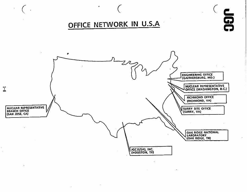
( & ( ( C
OFFICE NETWORK IN U.S.A 8
I
ENGINEERING OFFICE(GAITHERSBURG, MD.)
N REPRESENTATIVEOF (WASHINGTON, D.C.)
|RICHMOND OFFICE lW {RICMONDVA)l
JSURRY SITE OFFICE(SURRY. VA)
NUCLEAR REPRESENTATIVEBRANCH OFFICE(SAN JOSE, CA)
OAK RIDGE NATIONALLABORATORY(OAK RIDGE. TN)
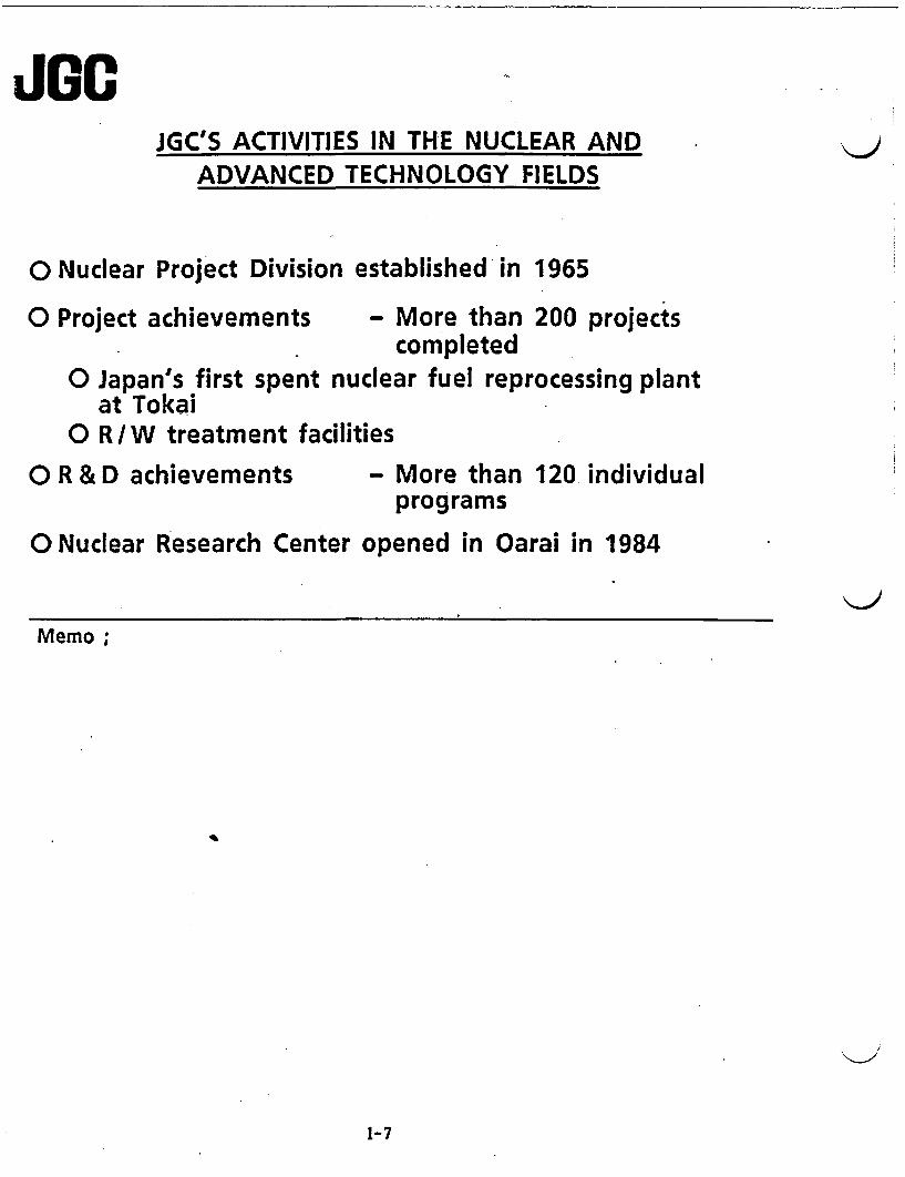
JGO sJGC'S ACTIVITIES IN THE NUCLEAR AND
ADVANCED TECHNOLOGY FIELDS
o Nuclear Project Division established in 1965
o Project achievements - More than 200 projectscompleted
o Japan's first spent nuclear fuel reprocessing plantat Tokai
o R/W treatment facilities
O R & D achievements - More than 120 individualprograms
0 Nuclear Research Center opened in Oarai in 1984
Memo;
1-7
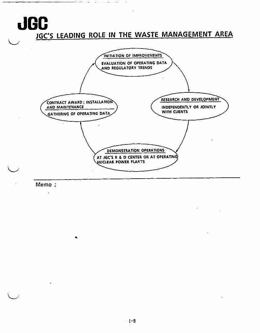
JGC'S LEADING ROLE IN THE WASTE MANAGEMENT AREA
T E RALUATION ER OER ATGATN )
(AND MAINTENANCE ) INDEPENDENTLY OR JOINTLY )
\/ DEMONSTRATION PkTOS-
(AT GC'S R & D CENTER OR AT OPERANGCLEAR POWER PLANTS
Memo;
1-8
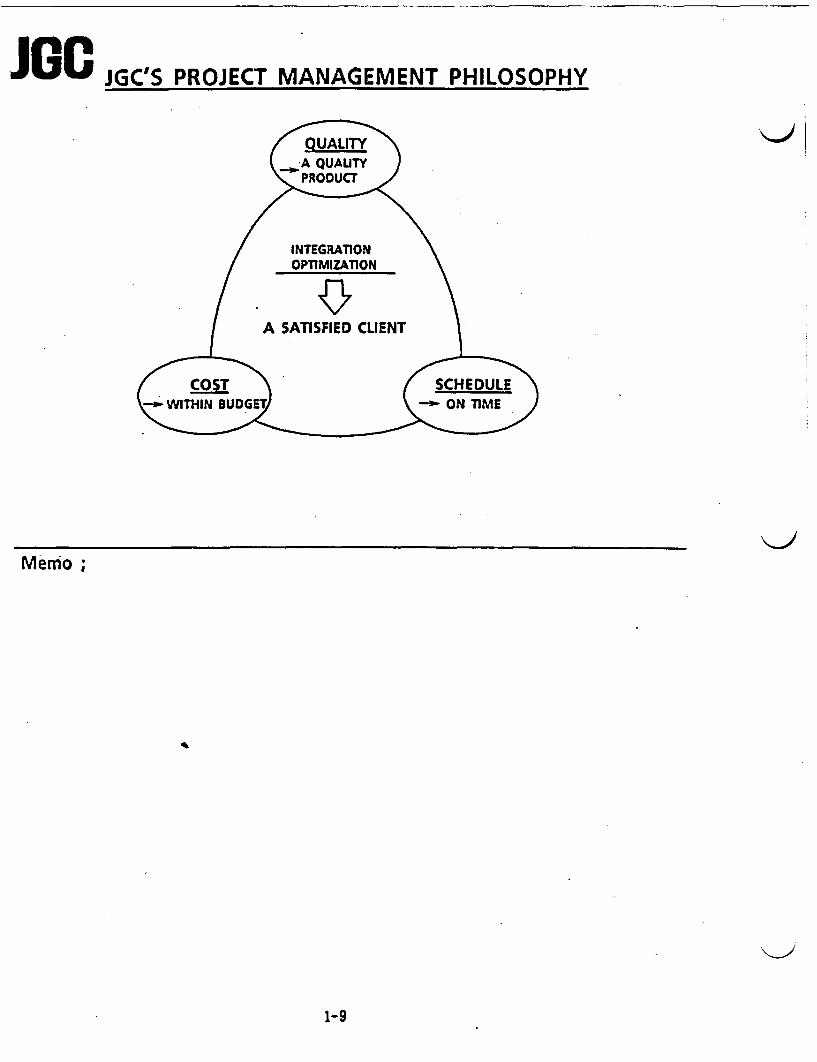
J Gc JGC'S PROJECT MANAGEMENT PHILOSOPHY
A QUALITY
INTEGRATIONOPTIMIZATION
A SATISFIED CLIENT
MeCOSTmo;K SCHE\iTH N BUDGE ON M J
Memo ;
1-9

C C C
JGC'S ACHIEVEMENTS IN THE NUCLEAR FIELD IN JAPANi
Tomeri I;A
a
Advanced Cement SolidificationSystem
Bituminization System
Plastic Solidification System
Nuclepore Membrane Filter
HE Filter
Dry-Wet Cleaning System
Concentrator
Incinerator
Compactor
- National LLW Disposal-. Facility
---- National Spent FuelReprocessing Plant
I3~ 4 tLiu9
Genkai
a
0'F
ISendaiI
- Fukushima Daiichi No.6Total Radwaste Treatment Facility
,/ _ Fukushima Daini No.3&4- ~ Independent Radwaste Treatment Facility
-Toka,Total Radwaste Treatment Facility/ Expansion Facility
-~-JAERI(Tokai) .
\\ -- Pt4C(Tokai) A 9Spent Fuel Reprocessing Plant
"' JAER(Oarai) 'A 9iPNC(Oarai) 9'
NOTE; JAERI: JAPAN ATOMIC ENFRGY RESEARCII INSTITIITE
PNC : POWER REACTOR AND NUCLEAR FUEL DEVELOPMENT CORP.

JGCOS ACHIEVEMENTS IN THE NUCLEAR FIELD IN U.S.A. 0
) \ A~~~~~~~~~~~~~~r~~VRGNIA POWER\ \ \8 ~~~~~~~~~~~~(NORTH ANNA AND SURRY NEW
<\ \ * \ ~~~~~~~~~~~~~~RADWASTE FACILITIES)
CTRIC
DVEMENTFACILITIESE WASTE
.RI ARIZONA PUBUC SERVICE,URVEYS ON INaNERATORS, COMPANYDBOTICS AND LLW (DAW SCREW COMPACTOR-LEASE.IANAGEMENT IN JAPAN) AND DAW SORTING TABLE)
C (
PORTLAND GENERAL ELECOMPANY(EVALUATION FOR IMPRtOF DECONTAMINATION IAND SOUD RADIOACTIVIVOLUME REDUCTION)
EP(SiRCMl
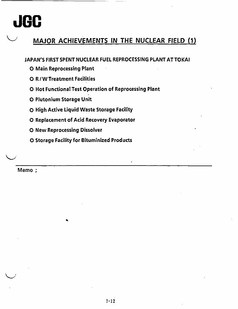
JGMAJOR ACHIEVEMENTS IN THE NUCLEAR FIELD (1)
JAPAN'S FIRST SPENT NUCLEAR FUEL REPROCESSING PLANT AT TOKAI
O Main Reprocessing Plant
o R /W Treatment Facilities
o Hot Functional Test Operation of Reprocessing Plant
O Plutonium Storage Unit
o High Active Liquid Waste Storage Facility
o Replacement of Acid Recovery Evaporator
O New Reprocessing Dissolver
O Storage Facility for Bituminized Products
Memo;
1-12
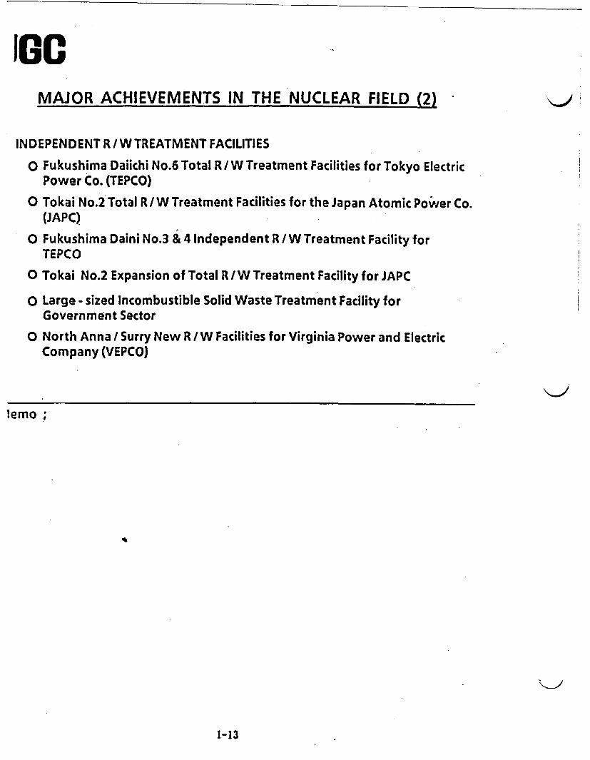
IGOMAJOR ACHIEVEMENTS IN THE NUCLEAR FIELD (2)
INDEPENDENT R/W TREATMENT FACILITIES
o Fukushima Daiichi No.6 Total R/ W Treatment Facilities for Tokyo ElectricPower Co. TEPCO)
o Tokai No.2 Total R/W Treatment Facilities for the Japan Atomic Power Co.(JAPC)
o Fukushima Daini No.3 & 4 Independent R / W Treatment Facility forTEPCO
O Tokai No.2 Expansion of Total R /W Treatment Facility for JAPC
o Large - sized Incombustible Solid Waste Treatment Facility forGovernment Sector
o North Anna / Surry New R / W Facilities for Virginia Power and ElectricCompany (VEPCO)
lemo
1-13

JGMAJOR ACHIEVEMENTS IN THE NUCLEAR FIELD (3)
COMPLETION CONSTRUCTION
PACKAGED SYSTEMS
(1) Bitumen solidification 13
(2) Plastic solidification 2 1
(3) Cement solidification 2
(4) Advanced cement solidification 2
(5) Incineration 4 2
(6) Filtration 16
(7) Compaction 7
(8) Laundry(dry and wet systems) 11 3
(9) Wet oxidation of resins I
(10) Robotics 2 1
Memo
1-14
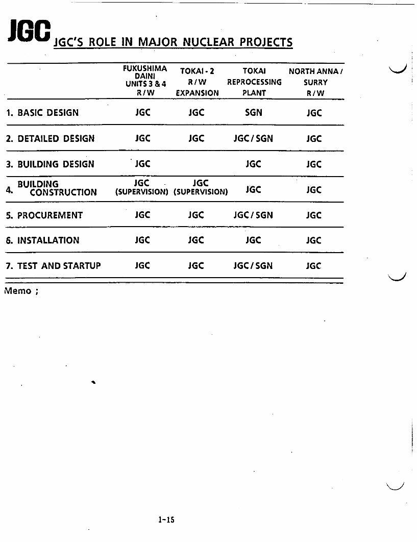
J 8 JGC'S ROLE IN MAJOR NUCLEAR PROJECTS
FUKUSHIMA TOMAI.2 TOKAI NORTH ANNA/DAINI
UNITS 3 & 4 R/W REPROCESSING SURRYR/W EXPANSION PLANT R/W
1. BASIC DESIGN JGC JGC SGN JGC
2. DETAILED DESIGN JGC JGC JGC/SGN JGC
3. BUILDING DESIGN JGC JGC JGC
BUILDING JGC JGC4. CONSTRUCTION (SUPERVISION) (SUPERVISION) JGC JGC
5.PROCUREMENT JGC JGC JGC/SGN JGC
6. INSTALLATION JGC JGC JGC JGC
7. TEST AND STARTUP JGC JGC JGC/SGN JGC
Memo;
1-15
JOGPART 2
OVERVIEW OF
JGC WASTE MANAGEMENT
TECHNOLOGIES
2-1
0C,
I
INTRODUCTION
JGC Can Provide Total Engineering/Construction & TestOperation Services in the Environmental ConservationField & Various Other Fields Based on its 60 Years ofExperience
( ( I 1 . .. _1 , .. . .

C ( (
C,
IRELEVANT JGC TECHNOLOGIES
* Radioactive Waste Management
* Mixed Wastes & Reprocessing Management
* Hazardous Waste Management
* Pollution Control

List of Radioactive Waste Management Technologies
Treatment of High Conductivity Liquid Wasteby Special Resins & Electrodeposition
Treatment of Liquid WasteContaining Ammonia
Microwave Dryer or Spent Resins
| Recovery of Irititm ur Nuclear Fusion -
. . .. . _ - .. . _ -1-I
Non Precoated and Backwashable Type Filter(High ftfitiency Filter. NPMF) I
Liquid WasteI ___ _ _ __ I
_ . -
[ forced Circulation Evaporator
Treatment of Oil Contaminated liquid(SPI)
Dry leaning ystem
I Laundry Drain Recycling System(Marimo Filter, R/O)
waste
. , I
New Vacuum Conveying Systemfor Radioactive Liquid Waste
Recycling Process of Reyeiei dtiuii Waste(Electro dialysis)
" R.W. : Radioactive Waste
L RP/UR.: Reprocessing/ Uranium Refining
M.W. : Mixed Waste
H.W. : Hazardous Waste
P. C. : Pollution Control
I
Volumekvductior &.Solidiigatiun
Wet Oxidation for Spe.l. *.ns ii
Bituminiatirn of RddiL .t. e I iqtiid Waste
DI Lrn I'Ai .er E ti uJ.Ži I. IJ.A A
P..stic S'hdIt4tjio Pl..e.
Ad. .:i.:di Cein:.ntt S ith, tito.i Pi k
AW it~ tmesit _ r_. I .
Ihuegh leumpeii.iutu ll. t .-- I. nd unlillelatol
Chemical and Mechanical Decontamination-Dion- High Pressure Water Jet Cleaning
- Chemical Decontamination Technology
Packaging. Shippiny i
-- rAutumiiit Vehilde (Diurn Haoidli)
,~~~~~~~ . . ,
Waste Package Shipping m.peitionSil#/fpe- Continr.ftiun Do-it,1Rate,Klu.taiiing ApparatusRadiuautivity CouLnting Unit; ll .|1.Ilig Unit
Decon:tamin-al-E ::_Robotics I I II II. III, imitilt- Iltpettu I I.Iupuw..11
gammuuipawIjMi
( ( (

( (List of Mixed Waste & Reprocessing Management Technologies
R.W. : Radioactive Waste
(
RP/UR.: Reprocessing/Uranium Refining
M.W.
H.W.
P.C.
TBP
: Mixed Waste
: Hazardous Waste
: Pollution Control
: Tributylphosphate
Removal of Iodine from Contaminated LiquidL Waste (Reverse Osmosis)
Extraction ol U .d Pu by 30 wul% TBP iiHNO3 Mediti did %tbseqtivitt FdtitExtraction by Mixet %wttlefs
Removal of Li and Pu frum Uigarii Wastes |by Carbondle .Wasiing iasiaiq Mixei %ettcis
Acid R(cover' of IINO3 fromn R ffmate (if
RepioteD'iiq Extraction P(etts. by Ateiio'.phuiic indResdutecl Pe!,,lm Evapoi.ite .rid Di'tIlitvi
/ *O pli( pl idlt le~l. iiI Ps tI .:11 1 PIl 'I t11107 I iq.,id Wast.s
.InEinelAtiron of Spent iq.r..4 Wa.1wsContdining LI and P|
a - /
Ii .. a < .;i..'..a ., I I~ cifle i dl.) A s h C o Ot IliiIOJ ?v. 1 . l.l j- Ad.j t-d Cememt Solidif.itiomm
hd- ldii..iun lidfirg Melter System
Inineiiziiuit of pent TRPPContainingUa d Pu.
I' Decomposition of Chelating Agents Used inDecontamination and DecommssioningProcesses(Wet Oxidation/UV-H 202 Oxidation)
Removal of Cr6 and Other Salts with UF HO FD Systems
."', I
III
1 Stabili.-m ion I II
I. , -I Incineigation I Uranium
Refining
* Adsorption of U by Ion -exchange Resins 1. ~ ~ ~ I- _ _ _ -
_* Extraction of U by Solvent (Amine)
* Recovery ot Fine UF4 Slurry Membrane Filter 1*Co - precipitation of U by CaF2 Flocculation
from H0 4 - HCI - HF Waste
Removal of U from Spent Organic Wastes byCarbonate Washing
Recovery of Sulfuric Acid from Waste AcidContaining HCI and HF
Pruievang uf Liquid Wdste Contaminatedwith Urdnium. Ileavy Metals and OlherPotentidlly Toxic substontes
- : :: _ .. ... - - .
Retmoval of U Pu fivni Liquid Watstebotwiited in the Fuel Processing Cyflc
I..I Liquid Waste
Treatment
0lC JOGRRIIO

List of Hazardous Waste Management Technologies
I
F Recovery of Solvent from OH - gas byActivated Carbon Fiber Filter
lot sites ;Stibiliziwn' t (d -nd PI I
Y Hazardous Waste Incinerator(Rotary Kiln Type)
arrd VCM Wastee nninner aorr
Energy Recovering Type Liquid InjectionIinerbtor
Gasification Furnace Type Incinerator -
Treatment of Heavy Metals and OrganicsContained in Liquid Waste (LABOPHlIUX)
Regenerdtion of Spent Activated Carbon
I Stdbili~dli(ill e
- -i incinerationj
,/Liquid Waste
TreatmentI..
R.W. : Radioactive Waste
RP/UR. : Reprocessing/Uranium Refining
M.W. : Mixed Waste
H.W. ; Hazardous Waste
P. C. : Pollution Control
VCM : Vinyl Chloride Monomer
JCC CUUpWI1WU
( ( (

C
' st of Pollution Control Technologies
I
C (
Sepawdtiolr of oil fion liquid Waste |,(CPI/SPI) _I
I)rt'slfuruation (Moretana) .
Denifiration ( Paranox)
C;do Rmo-val ( Catdlytic Oxidation
V.?rtal S uirl Sudge Melter System --. ,
I iquid Wdte |Treatnent
Off - asreatment
SewageTreatment
I
1
S.v.3ge Sitidge entifutwe
S *9v -jr- V . te r'ehydr.ation
_ A.(v . pomi
I
R.W. : Radioactive Waste
RPUR. : Reprocessing/Uranium Refining
M.W.: Mixed Waste
H.W. : Hazardous Waste
P. C. : Pollution Control
0 ice conronnitoN
PART 4
MIXED / HAZARDOUS
WASTE MANAGEMENT
TECHNOLOGIES

TABLE OF CONTENTS
No. Title
1. Automated Waste Container Management System
2. RASEP / Uranium - Selective Resin
3. On - Site Stabilization Process (OSSP)
4. Advanced Cement Solidification
5. Wet Oxidation
6. High Temperature Incineration
7. Other Technologies

JGJGC's Automated Waste Container Management System (AWCMS)
Proposed in response to NEL's PRDA
The JC Automated Waste Container Management System (AWCMS) builds on JGC's druminspection system already tested and currently being commercially installed in Japan to inspect,classify and label drums of solidified power reactor waste The current system conducts a series ofautomated checks to determine compliance to packaging requirements, including the presence ofsurface contamination, and then scans the package for gamma radiation to perform a fully automatedradioassay of the contents. The system then classifies the waste according to Japanese requitmentsand applies appropriate color-coded labels. Finally, the system records the results of all theinspections, and a video image of the drum on a micro floppy disk The research and developmentwork proposed in response to the PRDA at INEL would extend the technology to include checks forinternal free liquids ad perform a radioassay for alpha-emitting isotopes, as well as to determinewhich technologies would be economically appropriate to include in a system to process the tens ofthousands of DOE waste drums awaiting inspection, classification, and disposition.
The demonstration facility at the JGC Nuclear Research Center in Oaral includes four stations, oneeach for:
o Recording a video image of all surfaces of the package
o Performing a surface co smear test
o Performing a gama radioassay of the drum
o Classifying and labeling the inspected drum
I The entire process is automated and computcrized to reduce etror, limit operator exposure, and tominimize manpower requirements.
In addition to the systems in the demonstration facility, JGC has developed and implementedadditional systems to not-destructively check the compressive strength of the waste form, and tocheck for voids in the drum. These systems are being incorporated into systems being implementedin Japan, and prototypes demonstrating their operation have been built These prototypes arecurrently on location at customer sites to verify their performance on actual waste drums scheduledfor future shipping.
The technology to perform non-destructive radioassays of alpha-emitting waste containes is stillemerging. While basic research to perform this kind of inspection has been completed, it has not yetbeen adapted to an automated system, nor has it been used for large inspection campaigns like thoserequired by DOE Non-destuctive/non-invasive methods for detecting free liquids within the drumsalso have not yet been automated, and some basic research remains to determine whic combinationof technologies might most reliably detect significant fre liquids.
However, the ability to eliably and efficiently inspect the undocumented, often poorly stabilizedcontainers of TRU and suspected TRU in the DOE inventory could provide significant cost savingsin the final disposition of these wastes. In addition, successful implementation of the AWCMSwould provide a very high level of confidence in the actual condition and classification of thesewastes.
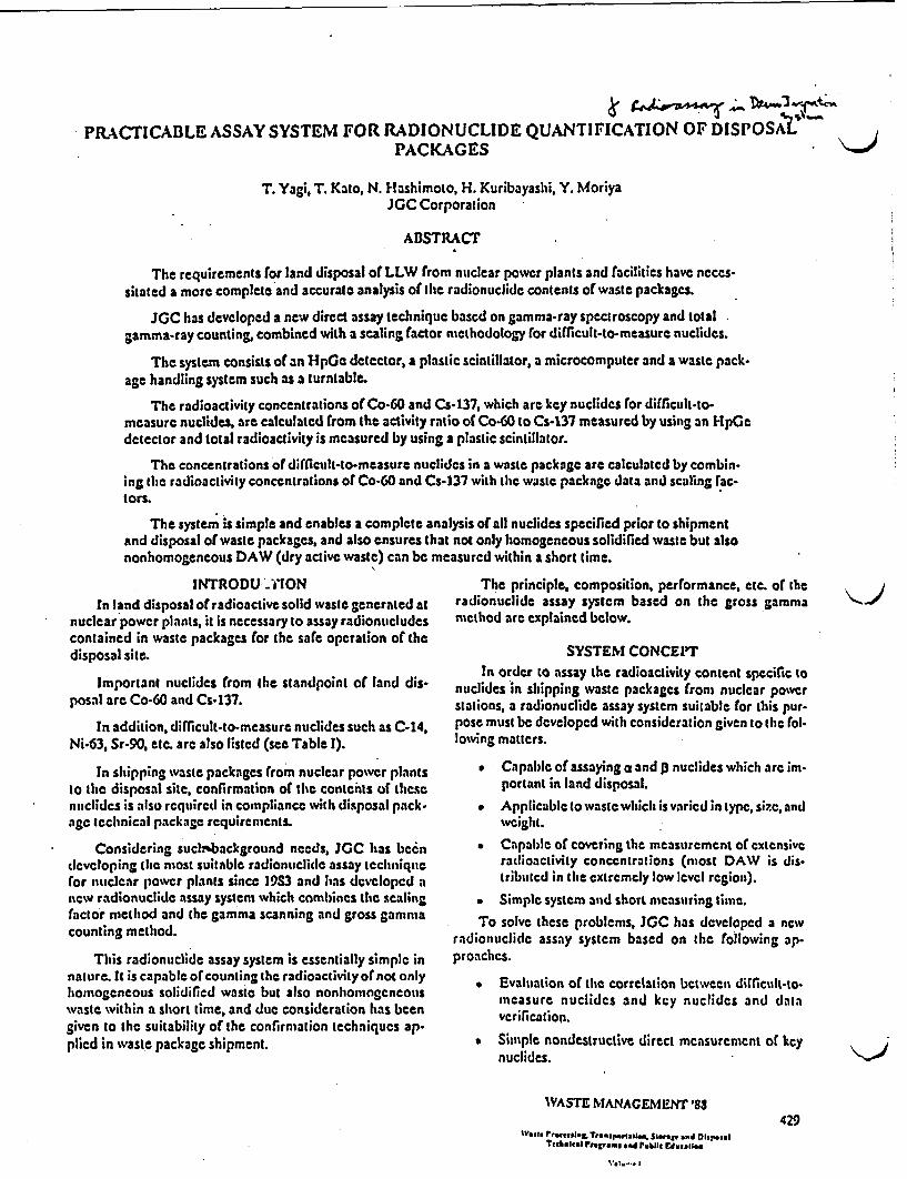
PRACTICABLE ASSAY SYSTEM FOR RADIONUCLIDE QUANTIFICATION OF DISPOSAPACKAGES
T. Yagi, T. Kato, N. Hashimoto, H. Kuribayashi, Y. MoriyaJGC Corporation
ABSTRACT
The requirements for land disposal of LLW from nuclear power plants and facilities have ncccs-sitated a more complete and accurate analysis of th radionuclide contents of waste packages.
IGC has developed a ncw dirccl assay lechnique bascd on gamma-ray spectroscopy and totalgamma-ray counting, combined with a scaling factor methodology for difficult-to-measure nuclides.
The system consists of an HpGc detector, a plastic scintillatori a microcomputer and a waste pack.age handling system such as a turntable.
The radioactivity concentrations of Co-60 and Cs-137, which art key nuclides for difficult-to-measure nuclides, are calculated from the activity ratio of Co-60 to Cs-137 measured by using an HpGedetector and total radioactivity is measured by using a plastic scintillator.
The concentrations of dilccult-to-measure nuclides in a waste package are calculatcd by combin-ing the radioactivity concentrations of Co-60 and Cs-137 with the waste package data and scaling fac-tors.
The system is simple and enables a complete analysis of all nuclides specified prior to shipmentand disposal of waste packages, and also ensures that not only homogeneous solidified waste but alsononhomogencous DAW (dry active waste) can be measured within a short time.
INTRODU .CIONIn land disposal of radioactive solid waste generated at
nuclear power plants, it is necessary to assay radionucludescontained in waste packages for the safe operation of thedisposal site.
Important nuclides from the standpoint of land dis-posal are Co-60 and Cs-137.
In addition, difficult-to-measure nuclides such as C-14,Ni-63, Sr-90, etc. arc also listed (see Table I).
In shipping waste packages from nuclear power plantsto the disposal site, confirmation of the conteinis of thesenuclides is also required in compliance with disposal pack.age tchnical package requirements.
Considering uch'background needs, JC has becndeveloping lie most suitable radionuclide assay techniquefor nuclear powcr plants since 19S3 and has dcvelopcd anew radionuclide assay system which combines the scalingfactor method and the gamma scanning and gross gammacounting method.
This radionuclide assay system is essentially simple innature. It is capable of counting the radioactivity of not onlyhomogeneous solidified waste but also nonhomognecouswastc within a short time, and due consideration has beengiven to the suitability of the confirmation techniques ap-plied in waste package shipment.
The principle, composition, performance, etc. o theradionuclide assay system based on the gross gammamethod are explained below.
SYSTEM CONCEPTIn order to assay the radioactivity content specific to
nuclides in shipping waste packages from nuclear powerstations, a radionuclide assay system suitable for tis pur-pose must be developed with consideration given to thc fol-lowing matters.
* Capable of assaying a and p nuclides which are im-portant in land disposal.Applicable to wastewhich is varied in type, sizc, andwveiglt.
Capable of covering the measurement of extensiveradioactivity concentrations (most DAW is dis-tributed in the extremely low level region).
Simple system and short measuring time.
To solve these problems. JGC has developed a nvradionuclide assay system based on the following ap-proaches.
. Evaluation Of the correlation bctween difficult-to-measure nuclidcs and ky nuclides and dataverification.
* Simple nondestructive direct measurement of kcynuclides.
WASTE NIANAGEMENT'88
rIehmIC& Pogram s-d N1,1. Edstalls
V?..I
429

Yagi RADIONUCLIDE QUANTIFICATION OF DISPOSAL PACKAGES
TABLE I
Activity Concentration Limits of LLW Burial in Japan
(rCi/g)
C- 14 1x100
Co -60 3x10²
Ni-63 3x10"
Sr-90 2x100
Cs-137 3x101
TRU 3x10 2
Sampling Analysis of Reactor Coolant .|
and Wastes|
I ~ Scaling Factor Estimation Program
I Direct Assay of Key Nuclides
Determination of Radionuclide Contents. in Waste Packeges
Fig. 1. Conccpt of Assaying Radionuclidcs in Waste Packagc.
430
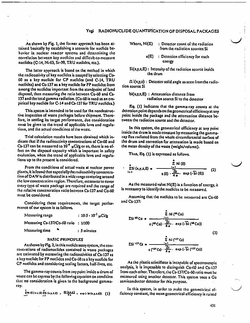
Yagi RADIONUCLIDE QUANTIFICATION OF DISPOSAL PACKAGES
As shown by Fig. 1, the former approach has been at-tained basically by establishing a scenario for nuclide be-havior in nuclear reactor systems and dctermining hecorrelation between ky nuclides and difficult-to-mcasurenuclides (C.14, Ni-63, Sr-90, TRU nuclides, etc.).
The latter approach is based on the method in whichthe radioactivity of key nuclidcs is assayed by selecting Co-60 as a key nuelide for CP nuclides (and C-14, TRUnuclides) and Cs-137 as a key nuclide for FP nuclides fromamong the nuclides important from the standpoint of landdisposal, then measuring the ratio between Co-60 and Cs-137 and the total gamma radiation. (Co-60 is used as an em-pirical key nuclide for C-14 and Cs-137 for TRU nuclides.)
This system is intended to be used for the nondcstruc-live inspection of waste packages before shipment. There-fore, in settling its target prformance, due considerationmust be given to the trend of applicablc laws and rgula-tions, and the actual conditions of the waste.
Trial calculation results have been obtained which in-dicate that if the radioactivity concentrations of Co-60 andCs-137 can be measured to 104 tLCi/g or so, there is no ef-fcct on the disposal capacity which is important in safetyevaluation, when the trend of applicable laws and rcgula-tions up to the present is considered.
From the conditions of actual waste at nuclear powerplants, it is found that especially the radioactivity concentra-lion ofDAW is distributed in a wide rangc centering aroundthe low concentration rgion. Therefore, measures to coverevery type of waste package are required and the range oftlic relative concentration ratio betwccn Cs-137 and Co-60must be considered.
Considering these requirements, the target perfor-mance of our system is as follows.
Where, Ni(E) : Dtetor count of the radiationfrom the radiation sources Si
e(E) : Detection efficiency for eachenergy
Si(x,y,z,E): Intensity of the radiation source insidethe drum
n i(xyz): Detector solid angle as seen fromthe radia-tion source Si
bi(x,y,z,E): Attenuation distance fromradiation source Si to the detector
Eq. (1) indicates that the gamma-ray counts at thedetection point depends on thec geomcrical efficiency at anypoint inside the package and the attenuation distance be-tween the radiation source and the detector.
In this system, the geometrical efficiency at any pointinside the drum is made constant by measuring the gamma-ray flux radiated from the whole circumferential surface ofthe drum and correction for attenuation is made based onthe mean density of the waste (weight/volumc).
Thus, Eq. (1) is expressed as follows.
E Li (x,y,,E) let
i N (E)I.1
(2)
M~easuring range ial- - 0~ )jISC/
As the measured value Ni(E) is a function of energy, itis necessary to identify the nuclides to be measured.
Assuming that the nuclides to be measured are Co-G0and Cs-137:
2 Ni ("Co)£Si Co*
c('oCo) * exp (-bi (6Co))
(3)
2 Ni 3 Cs)
t (1"Cs) n * exp(i("'Cs))4j,
Measuring Cs-137/Co-60 ratio : 1/100
Measuring time ' : S minutes
BASIC PlRINCII'LESAs shown by Fig. 2, in this nuelide assay system, the con-
ccntrations of radionuclides contained in waste packagesarc estimated by measuring the radioactivities of Cs-137 asa key nuclide for F nuclides and Co-60 as a key nuclide forCP nuclides and considering scaling factors, half-lives, etc.
The gamma-ray counts from any point inside a drum ofwaste can be express by the following equation on conditionthat no consideration is given to the background gamma-ray.
ENi CE a) ES, ('v..!) .L *i,-t . p(.bdC.y.zg)) (I)
As the plastic scintillator is incapable of spectroscopicanalysis, it is impossible to distinguish Co-G0 and Cs-137from each othcr.Therctore, the Cs-137/Co-60 ratio must bcmeasurcd using another detector. This system uses a Gesemiconductor detector for this purpose.
In this system, in order to make the geometrical ef-ficiency constant, the mean geometrical efficiency is raised
431
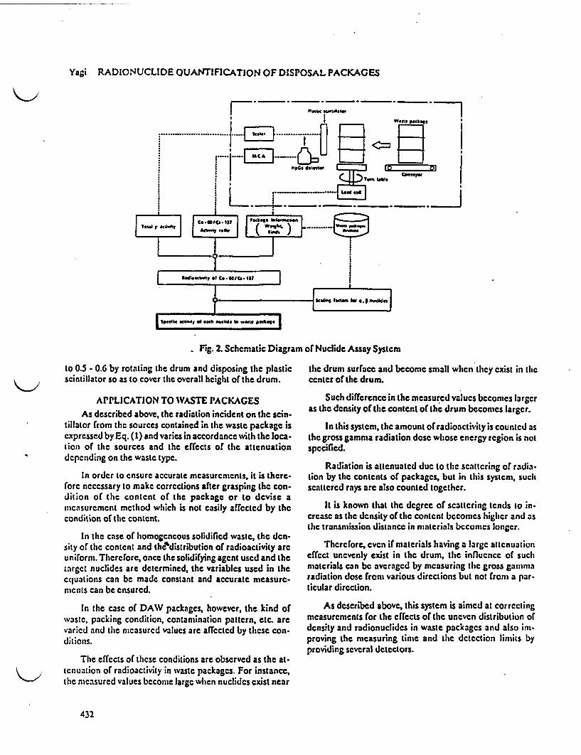
Yagi RADIONUCLIDE QUANTIFICATION OF DISPOSAL PACKAGES
Fig. 2. Schematic Diagram of Nuclide Assay System
to 0.5 - 0.6 by rotating the drum and disposing the plasticscintillator so as to cover the overall height of the drum.
APPLICATION TO WASTE PACKAGESAs described above, the radiation incident on the scin-
tillator from the sources contained in the waste package isexpressed by Eq. (1) and varies in accordance with the loca-tion of the sources and the effects of the attenuationdepending on the waste type.
In order to ensure accurate measurements, it is there.forc necessary to make corrections after grasping the con-dition of the content of the package or to devise ameasurement method which is not easily affected by thecondition of the content.
In the case of homogeneous solidified waste, the dcn.sity of the content and the'distribution of radioactivity areuniform. Therefore, once the solidifying agent used and thetarget nuclides are determined, the variables used in theequations can be made constant and accurate measure-mcnts can be ensured.
In the case of DAW packages, however, the kind ofwaste, packing condition, contamination pattern, etc. arevaried and the mcasured values are affected by these con-ditions.
The effects of these conditions are observed as the at-tcnuation of radioactivity in waste packages. For instance,the measured values become large when nuclides exist near
the drum surface and become small when they exist in thecenter of the drum.
Such difference in the measured values becomes largeras the density of the content of the drum becomes larger.
In this system, the amount of radioactivity is counted asthe gross gamma radiation dose whose energy region is notspecified.
Radiation is attenuated due to the scattering of radia-lion by the contents of packages, but in this system, suchscattered rays arc also counted together.
It is known that the degree of scattering tends to in-crease as the density of the content becomes higher and asthe transmission distance in materials becomcs longer.
Thercrore, even if materials having a large attenuationeffect unevenly exist in the drum, the influence of suchmaterials can be averaged by measuring the gross gammaradiation dose front various directions but not froni a par-ticular direction.
As described above, this system is aimed at correctingmeasurements for the effects of the uneven distribution ofdensity and radionuclides in waste packages and also imi-proving the measuring time and the detection limits byproviding several detectors.
432
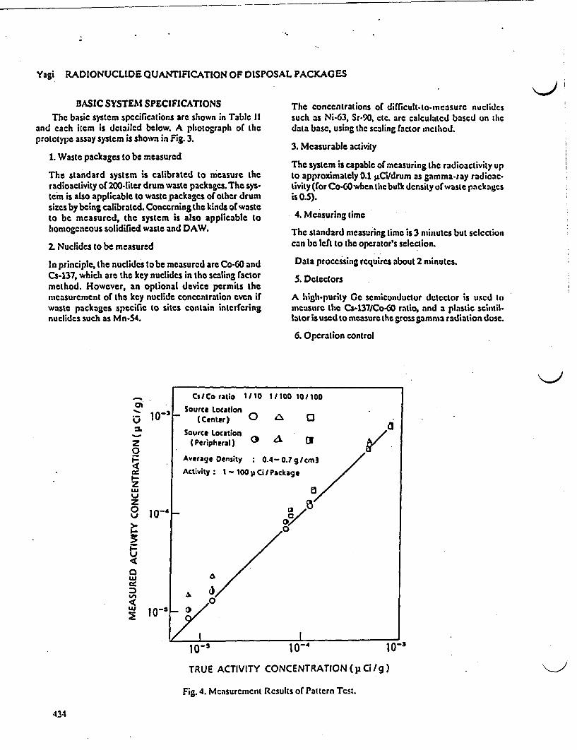
Yagi RADIONUCLIDE QUANTIFICATION OF DISPOSAL PACKAGES
BASIC SYSTEM SPECIFICATIONSThe basic system specifications are shown in Tabie 11
and each item is detailed below. A photograph of Lhcprototype assay system is shown in Fig. 3.
1. Waste packages to be measured
The standard system is calibrated to measure theradioactivity of 200-liter drum waste packages. The sys-tern is also applicable to waste packages of other drumsizes by being calibrated. Concerning the kinds of wasteto be measured, the system is also applicable tohtomogeneous solidified waste and DAW.
2. Nuclides to be measured
In principle, the nuclides to be measured are Co-60 andCs-137, which are the key nuclides in the scaling factormethod. However, an optional device permits themeasurement of the key nuclide concentration evcn irwaste packages specific to sites contain interferingnucliics such as Mn-54.
The concentrations of difficult-to-measurc nuclidecssuch as Ni-63, Sr-90, ctc. are calculated based on thedata base, using the scaling factor method.
3. Measurable activity
The system is capable of measuring the radioactivity upto approximately 0.1 $.Ci/drum as gamma-ray radioac-tivity (for Co-60when the bulk density of waste pack agcsis 0.5).
4. Measuring time
The standard measuring time is 3 minutes but selectioncan be left to the operator's selection.
Data processing requires about 2 minutes.
S. Detectors
A high-purity Cc semiconductor detector is used tomeasure the Cs-137JCo-60 ratio, and a plastic sintil-lator is used to measure the gross gamma radiation dose.
6. Operation control
I-
LU
0
UI-
0LU
LU_
1 0-'
10-4
Cs/Co ratio 1/10 I1100 10100
Source Location(Center) 0 A O
Source Location(Peripheral) ° a
Average Oensity 0.4-0.7 g/cm3
Activity: I-100 y Ci/Package
0Y
10-'
_
10-, 10-4 10-3
TRUE ACTIVITY CONCENTRATION (p Cig)
Fig. 4. Measurement Rcsults of Pattcrn Tcst.
434
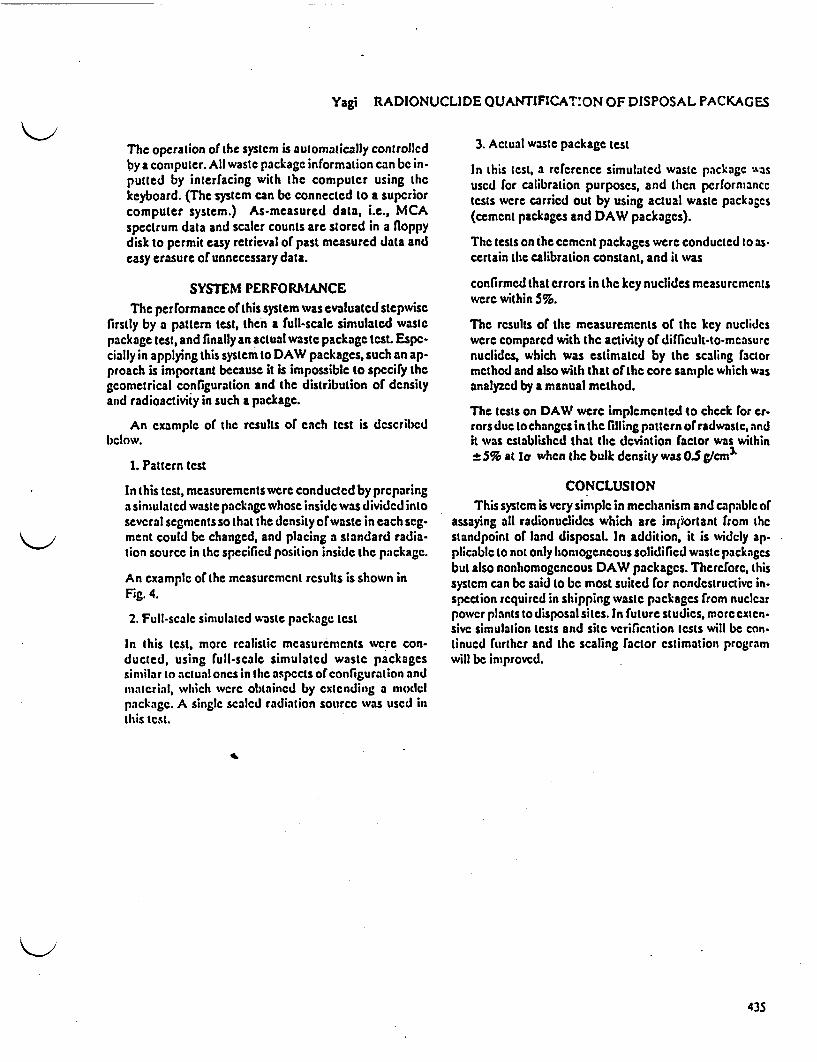
Yagi RADIONUCLIDE QUANTIFICAT:ON OF DISPOSAL PACKAGES
The operation of the systcm is automatically controllcdby a computer. All waste packagc information can be in-putted by interfacing with thc computer using thckeyboard. (The system can be connected to a superiorcomputer system.) As-measured data, i.e., MCAspectrum data and scaler counts arc stored in a floppydisk to permit easy retrieval of past measured data andeasy erasure of unnecessary data.
SYSTEM PERFORMANCEThe performance otthis system was evaluated stepwise
firstly by a pattern test, hen a full-scale simulated wastepackage test, and finally an actual waste package test. Espc-cially in applying this system to DAW packages, such an ap-proach is important because it is impossible to specify thegcometrical configuration and the distribution of densityand radioactivity in such a package.
An example of the rsults of each test is describedlclow.
1. Pattern test
In this test, measurements werc conducted by preparinga simulated waste package whose inside was divided intoseveral segments so that the density of waste in each scg-ment could be changed, and placing a standard radia-tion source in the specified position inside the package.
An example of the measuremcnt rsults is shown inFig. 4.
2. Full-scale simulated waste package test
In his test, more realistic measurements were con-ducted, using full-scale simulated waste packagessimilar to actual ones in the aspects of configuration andmatcrial, which wrc obtained by extending a modelpackagc. A single scaled radiation source was uscd inthis test.
3. Actual waste package test
In this test, a reference simulated waste package .asused for calibration purposes, and then performancctests were carried out by using actual waste packages(cement packages and DAW packages).
The tests on the cement packages were conducted to as-certain the calibration constant, and it was
confirmed that errors in the key nuclides measurementswere within 5%.
The results of the measurements of the key nuclideswere compared with the activity of difficult-to-mcasurcnuclides, which was estimated by the scaling factormethod and also with that of the core sample which wasanalyzed by a manual method.
The tests on DAW were implemented to check or cr-rors due to changes in the filling pattern orradwastc, andit was established that the deviation factor was within
5% at Ur when the bulk density was 0.5 g/cmi
CONCLUSIONThis system is very simple in mechanism and capable of
assaying all radionuclides which are imjiortant from thestandpoint of land disposal. In addition, it is widcly ap-plicablc to not only homogeneous solidified waste packagesbut also nonhomogcneous DAW packages. Therefore, thissystem can be said to be most suited or nondestructive in-spection required in shipping waste packages from nuclearpower plants to disposal sites. In futurc studies, more exten-sivC simulation tests and site verification tests will be con-tinued further and the scaling actor estimation programwill be improved.
435

FULL-SCALE TESTING OF WASTE PACKAGE INSPECTION SYSTEMT. Yagi H. Xuribayashi, Y. Moriya, H. Fujisawa,
N.TkebayashiJGC Corporation, Japan
ABSTRACT
In land disposal of low-level radioactive waste (LLW) in Japan, it is legally required that the wastepackages to be disposed of be inspected for conformance to applicable technical regulations prior toshipment from each edsrtg power station.
JGC has constructed a fully automatic waste package inspection system for the purpose of obtainingthe required design data and proving the performance of the systcaL
This system consists of three inspection units (for visual inspcton, surface contamination/dose ratemeasurement and radioactivitylweight measurement), a labelling unit, a centralized control unit and adrum handling unit.
The outstandin; features of the system are as follows: The equipment and components aremodularized and designed to be of the most compact size and the quality control functions are performedby an advanced centralized cQntrol system.
As a result of the full-scale testing it has been confirmed that this system satisies all the performancerequirements for the inspection of disposal packages.
The treatment capacity, operability and data control nins of this system were also checked andconfirmed in the full-scale testing of the system.
The results of the perform ance tests show that JGC can establish the most rational and economicalwaste package inspection system applicable to any nuclear power station.
VC17RODUCTION Therefore, in the cast of the inspection of waste pack-At prescnt, approximately 440,000 drums filled with ages at the power station, it is important to not only inspect
LLW are storus at nuclear pOWer stations in Japan: of them, the external appearance of packages but also the quality ofsome drums contai solidied aste hating barrirabty their contents and the history after the generation of theand some contain untreated miscellaneous solid waste. waste. Phrthermore, it is essential to evaluate and confirm
In accordance with the Nuclear Installation Regulation the results accurately and rationally.Law revised in 1986, and the Waste Burial Regulation and It is necessary to ensure the quality of waste packagesrelated notifications establIshed in 1988, various items of byobtaining evaluation data forthe technical criteriabasedwork concerning the transportation to and the burial di- on a combination of information from (See Table I.):posal of wastes at the Radioactive Waste Storage Center (1) Waste and process control programwhich will be constructed in Rokkasho Village, Aomori Operationcontrolandqualitycontroldata,suchasthePrefecture, are being conducted by national and private waste content code, operation records of the waste treatorganizations for the commencement ofthe operation ofthe mont facilities and the certifications of solidificationCenter in 1991. materials and containers
Waste package shipping inspection facilities are being (2) Nondestructive inspectionplanned at each nuclear power station in Japan for shipping Data obtained by conducting nondestructive ispecseveral thousand to dozen thousand waste packages per tions of waste packages (surface contamination density,year. - radioactivity concentration, etc.).
Waste package shipping inspection facilities arc bei (3) Sampling programplanned at each nuclear power station in Japan for shipping Sampling analysis data such as radioactivity concentra-several thousand to dozen thousand waste packages per don data for each type of nuclide and product propertyyear. evaluation test data (compressive strength, eachability,
Ths report will discuss the concept of LLW shipping etc.)inspection and introdfte one example of the structuring of WASTE PACKAGE INSPECTION DEMONSTRATIONa nondestructive inspection systemi. PLANT
BASIC CONCEPT OF INSPECTION OF WASTE The commercial-scale demonstration plant con-PACKAGES structed at JGC's Nuclear Research Center is an eample
If thz plan for burial disposal ss put into practice, the of waste package inspection facilities based on the abovewaste stored at each nue car power station will be basic concept of waste package inspection. (See Fig. 2.)transported to the storage center where it will be buried in This demonstration plant is designed to conduct fivea concrete pit and controlled therein for several hundred t"pu of inspection (visual inspection, surface contamina-years. (See FBig L) ton densitymeasurement, dose rate measurement, radioac
Thus, the entirely different circumstances of the waste tivity measurement and weight measurement).packages, including other barriers such as the concrete pits It is a fully automatic module system whose inspectionand earth strata, will enable their long-term safe disposal equipment, labelling unit, andling unit and centralized
control system have been developed and designed to beAccordingly the shipping inspection, the preparation of rational and practical.
base data is required to ensure the control of the safety of The major components of the system are as outlinedpackages as mmum units. below.
801
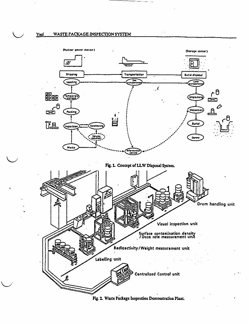
Yai * WASTE PACKAGE INSPECTON SYSTEM
(NucSlear power station) (Storage ernr)
. .J-E3 I LI~hm
:v-
Fi L Concept o LLW Disposal System
Drum handling unh
Surface contamination density/Dose rate measurement unit
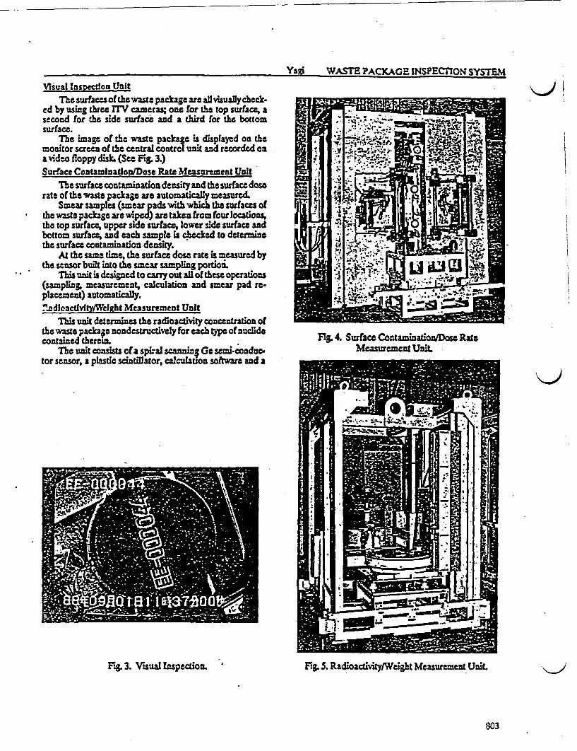
Yagt WASTE PACKAGE INSPECTION SYSTEM
Vlsual Inspection UnitThe surfaces of the waste package are all visually check-
ed by using three ITV cameras; one for the top surface, asecond for the side surface and a third for the bottomsurface.
The image of the waste package is displayed on themonitor screen of the central control unit and recorded ona video floppy diski (Sec Fg 3.)Surface Contamluatlon/Dose Rate Measurement Unit
The surface contamination density and the surface doserate of the waste package are automatically measured.
Smear samples (smear pads with which the surfaces ofthe waste package arc wiped) are taken from four location,the top surface, upper side surface, lower side surface andbottom surface, and each samplc is checked to determinethe surface contamiation density.
At the same time, the surface dosc rate is measured bythe sensor built into the smear sampling portioi
This unit is designed to carry out al of these operations(ampling, measurement, calculation and smear pad rt-placement) automatically.7ndlcactlyfty/WeIght Measurement Unit
This unit determines the radioactivity concentration ofthe waste package nondestructively for each type of nuclidecontained therein.
The unit consists of a spiral sann; Ge semi-conduc-tor sensor, a plastic scintillator, calculation software and a
\Jj
Fg 4. Surface Contaminationl90se RateMcasuremcnt Unit
Fg. 3. Visual Inspection. Fig. S. Radloactivity/Weight Measurement Unit.
803

Yaei WASTE PACKAGE NSPECTION SYSTEM
TABLE IQualification of Waste Package for Disposal
Regulation
NOt
Quslification Method
PCP
0
* Basic methodO Option
21. Solidification Binder2. Waste Container3. Compressive Strength (Cement)4. Hardness (Plastic)S. Mixing Ratio (Bitumen. Plastic)6. Homogeneous Mixing7. Void6. Activity Concentration9. Surface Contamination Density
10. Chemicals11. Stackability12. Package Damage13. Weight14. Surface Dose ate
15. abelling
(T)O (Ultrasonic Speed)
o (Durometer)
O (Ultrasonic Speed)* r Scanning)* (Smear Method)
00 o
O (PropertyO Test)0
0 (FNucideAnalysis)
* (ITV) 0) ( UTlThermography)
turntable with a load cell. (See Fig. S.)Ile radioactivity concentration is determined for each
Mi type of nuclide fom the tot dose (plastic scintillator), yscaling factors for difficult-to-measure uclides and yl tnucldes, which i available from the data base.Labellafu Unit
Tis unit labels the waste package with a color band todasiltysurface dose rates. It also ffixes stickers indicatingidentification numbers for shipping and disposal manage.ment after the completion of the abovementioned five types
1 of inspebtion. (See Fig. 6.)Color bands (white, orange and red) are automatically
selected based on the surface dose rate measurementresults and attached to the waste package. The identifica-tion numbers are automatically marked on the yellow baseI labels by heat transfer printing.
. This labelling is conducted automatically by recogni-] tion of the radiation warning symbol marked on the waste. | . ! package, using an optical sensor.. - Ceattalized Control Unit
This unt automatically controls each inspection unitand the drum handling unitEl t1ata on each waste package are received into thissystem and inspection data from each inspection unit areprocessed. Daily reports, inspection reports and shippingmanagement data are then prepared.
TEST RESULT1Performance tests of each inspection unit were con-
ducted and the capacity, workability and measurement ac-curacy of each unit were evaluated. As a result, it has beenascertained that each unit is capable of achieving the
Fig. 6. Labelling Unit.
Z1.1
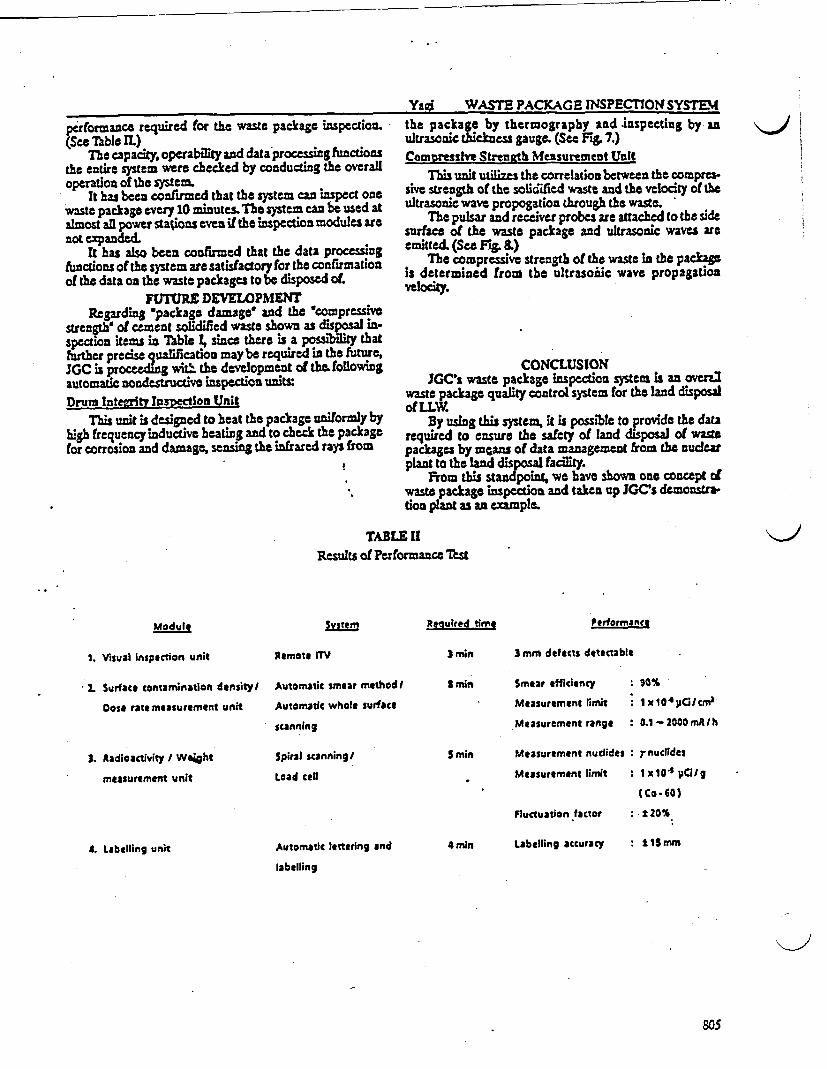
Yai WASTE PACKAGE INSPECrION SYSTEMperformance required for the waste package inspection.(See Table IL)
The capacity, operability and data processing functionsthe entire system were checked by conducting the overalloperation of the cystcmo
It has been confirmed that the syst cis naspect onewaste package every 10 minutes. The system can be used atalmost all power stations even if the inspection modules arenot expanded.
It has also been confirmed that the data processingfunctions of the system are satisfactory for the confirmationof the data on the waste packages to be disposed of.
FUTURE DEVELOPMENTRegardiq package damage' and the 'compressive
strenga of cement solidified waste shown as disposal in-spection itemws in Thle t, since there is a possibility thatfurther precise qualification maybe required in the future,JGC is proceding w the development of thefollowingautomatic nondestructive inspction unitxDrums Intezrtl Tnspection Unit
This unit is designed to beat the package uniformly byhigh frequency inductive beating and to check the packagefor corrosion and damage, sensing the infrared rays from
the package by thernography and inspecting by nultrasonic thickness gauge. (See Fig. 7.)Compresslye Streneth Measurement UnIt
Tis unit utilizes the correlation between the compres-sive strength of the solikified waste and the velocity of theultrasonic wave propogation through the waste.
The pulsar and receiver probes are attached to the sidesurface of the waste package and ultrasonic waves reemitted. (Sec F'& 8.)
The compressive strength of the waste in the packagis determined from the ultrasoiic wave propagationVelocity.
t111� IIii
t
I
i
CONCLUSIONJGC's waste package inspection system is an overZ
waste package quality control system for the land disposalo(LLW.
By using this system, it is possible to provide the datarequired to ensure the safety of land disposal of wastepackages by mcans of data managemeat from the nuclearplant to the land disposal facility.
From this standpoint, we have shown one concept ofwaste package inspection and taken up JGC's dcmonstrtion plant as an example
TABLE 11Results of Performance Test
Modult Systeni Required time Performance
1. Visual inspection unit Remote ITV 3 min
3min
3 mm defects detectable
2. Surface contamination density/ Automatic smear methodl Smear efficiency : 90%
Dos rate measurement unit Automatic whole surface
scanning
Measurement limit i lxj04YCi/cm
Measurement range : 0.1 - 2000 mA I h
3. adioactivity / Weiht
measurement unit
Spiral scanning/
Load cell
S min Measurement nudides: r nuclides
Measurement lirnit 1x I104 C9
(Co-co)
Fluctuation factor * ± 20%
* ±15mm4. Labelling unit Automatic lettering and
labelling
4 min Labelling accuracy
805
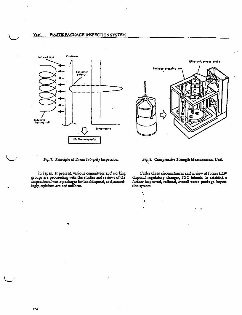
Yagi 'WA PACKAGE WJSPECMION SYSTEM
infrared toys
4-
Container
./1 Ultrasonk sensor probe
Containerdefects7.ec
J.............._ .. ,,,,___
(4-
4-
4-
4-
..... .
Temperature
L UlThetmogrophy I
-Fg 7. Principle of Drum Ir gity Inspection.
In Japan, at present, various committees and workinggroups are proceeding with the studies and reviews of theinpecton of waste packages for land disposal, and, accord-Zigly, opiions are not uniform.
Fg & Compressive Strength Measurement Unit.
Under these circumstances and in view of future LLWdisposal regulatory changes, JGC intends to stablish afrter improved, rational, overall ste package inspec-tion sytem.
I~~~~~~~~~~~~~~~~~~~~~~~~~~~~~~~~
cArA
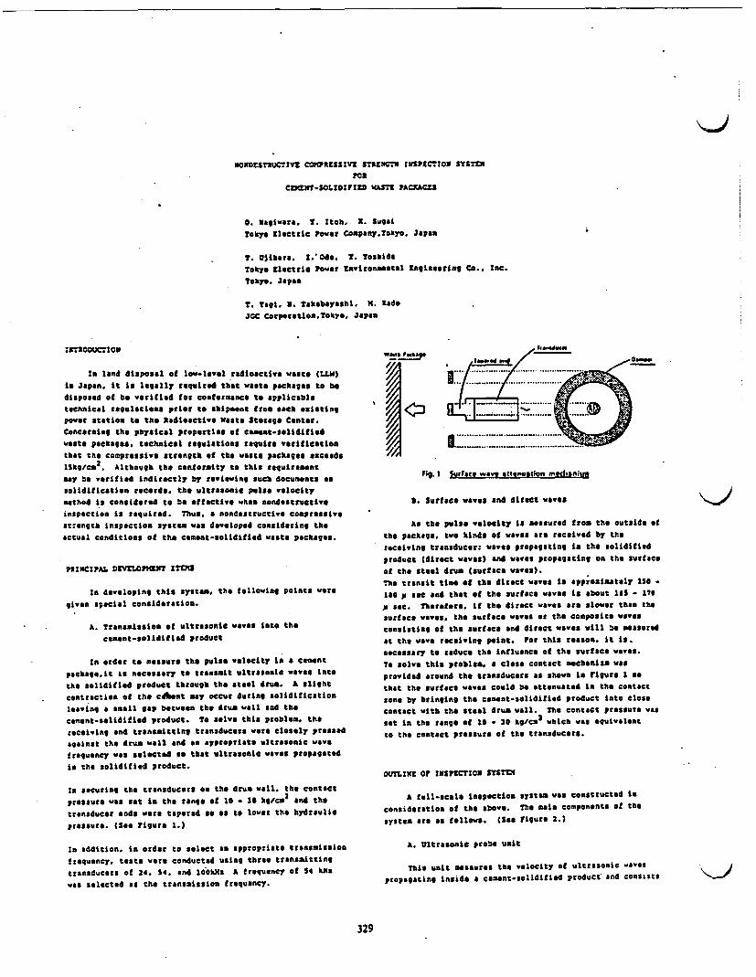
ONrDESnuCS1vt COHIRZSSZv ST5XNCh rNSpECTcso SYSTE
roaCDMXt-SOLDIFIZD WASTC PACXACZS
0. Ragiwart. . toh. It. SugatToky ZSoctric Pwer Compsny.Tokre. Japan
T. Uvihers. Ode. 1. ToshidsTokyo ZleCtfic Power mantronmtsetl tZaineertn Co. lnC.Tokyo. Japan
T. Tagi. . akeb*Yashi. . eadoJGC Corporatioa.Takyo, Japan
SIR20DOCSSON
ISn land disposal of low-level radioactive waste (jiW)is Japan. it is legallr equired that waste packages to bedisposed of e verified for cofermanca to epplicabletechnical regulaciona prior to shipsent from each eistingpower station to the Radioactive Waste Storage Canter.
Concerning the physical properties of ameme-Selidif edWeste packages, technical regultionm rquire verificatioathat t coaprassive strength of the waste packages escedslSkgme
2. Although the conformity t this rquirement
may b verified indirectly by reviewing such document asSolidification recoerd, the ultrasonic pulse velocity*ethod is considered to be effective when nondestructiveinspction is requirad. Thus, a nondestructive compressivestrength inspection system was developed considaeing the
actual Conditions at the cement-Solidilied waste packages.
PSINCIPAL ZraWPMNT ITEMS
la developing this system, the following points weregiven special consideration.
A. Transmission of ultrasonti wvee into thecement-Selidified roduct
In order to measure the pulse velocity t a ementpeckage.it is necessary to transmit ultrasoSic wSeve intothe solidified roduct through the teel drum. A slightcontraction ot the cOfnt may occur during lidificationleaving a small gap etweem the drum wall and te
cement-selidified product. To solve this roblem. thereceiving and transmitting transducers were lOelr pressedagainst the drum wil end an appropriate ltrasonic wavefrequency was selected so that ultrasonic waves propagatedis the solidified roduct.
in securing the transducers e the drum wall, the contactpressure was Set i the range of 10 - 0 kcm
2and the
transducer cnds were tapered so as to lower the hdraulicpressure. (See Figure 1.)
in addition, in order to select an appropriate transmission
frequency, teste were conducted using three transmitting
transducers of 24. 4. and lOOkils A frequency of 54 kMewas selected as the tansmissioa frequency.
I
Wet@ Pswt.geweed &-d .0
.. ..* 2 i t / 0 _.........
a / f ~~~~. .. . .. .
_ - g 9 X~~........
I .. ... ._ .. . ..... . . ...... . . ....
Fig. Iurfact wave sttnuatlon moclannn
t. Surface waves and direct waves
As the ulse velocity IS measured from the outside ofthe package, two kinds of weves are received by thereceiving transducer: weves propagating ia the solidifiedproduct (direct wavesl end waves propagating on the surfaceof the steel drum (surface Yvees).The transit time Of tha direct weves Is pprosiately 150 .180 p sec and thet ot the surface waves is about 14 - 17p sec. Therefore, it the direct waves are slower than thesurface waves, the surface weves or the composite wavesconsisting of the surface and direct waves will be measuredat the wave receiving point. For this reason. it is.necessary to reduce the influence oI the surface waves.To solve this problem, a close contact mechanism wasprovided around the transducers as shown in niure 2 eothat the surface Waves could be attenuated In the contacttons by bringing the cement-solidified product Into closecontact with the stnel drum wall. The contact pressure wasset in the range of 16 - 20 kg/cm which was equivalentto the Contact prOssure of the transducers.
OUTLINZ of INSFCTION SsTss
A full-scale npctCiOS system was construted Isconsideration of the sbove. The main components Of thesystem are as follows. (See Figure 2.)
A. Ultrasonic probe unit
This unit measures the velocity of ultrasonic g&aespropagating inside a cement-solidified product' and consists
329
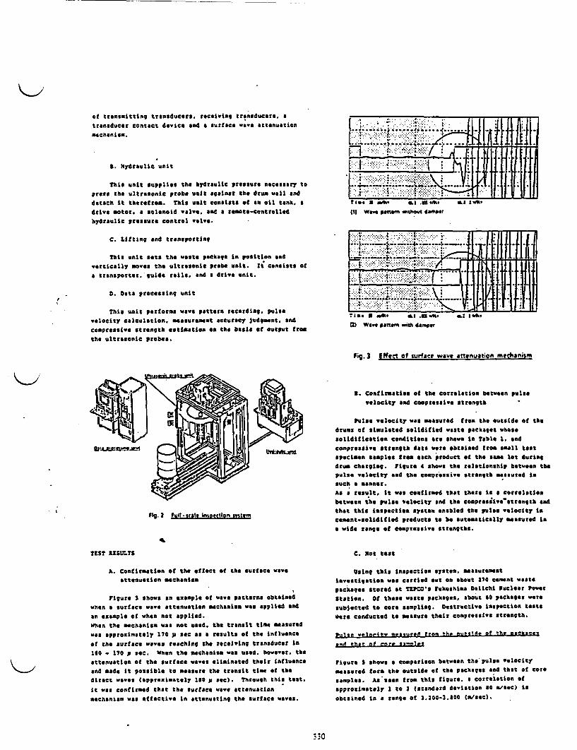
of transmitting transducers. receiving transducers a
transducer contact device and a surface wave attenuatien
mechanism.
S. Hydraulic unit
This unit supplies the hydraulic pressure necessary tePress the ultrasonic probe unit agarnst the drum wail and
detach t therefrom. This unit consists t tm oil tank. a
drive otor. a solenoid valve. and a remate-contrlled
hydraulic pressure control walve.
C. Lifting nd transporting
This unit ets the waste package in position and
vertically moves the ultrasonic probe unit. Xt consists of
a transporter, guide railr. and a drive unit.
p. ats processing unit
This unit performs wave pttern recording, pulse
velocity calculation. measurement accuracy judgment. and
compressive strength estiasties on tgh basis ot output from
the ultrasonic probes.
i;6~I11Wave patn" wishow domp
t -. ....:........ .- . . 1i . 1 1
_*w**-* ..... .......... 4
t. .t -. . .. . t1 2.. . .. . ...l
_. _ol 4. _ . - . 4Lf : I..... _ ...k .1
; s War Wit d.. ,. a , . . * ., r_. L
II
Fig. 3 Effect of surface wave attenuation mnecIhaniinm
3. Contirmatien of the correlation between pulae
velocity and compressive srength
Pulse velocity was masured Iron the outside of the
drums of simulated olidified wste packages whose
solidification conditions are hown in Table 1. and
compressive strength data wre obtained from sall test
specimen emples irem each product ot the ame lot during
drum charging. Figure 4 shows the relationship between the
pulse velocity and the compressive strength measured nsuch a *annetr.
AS a result, t ws confirmed that there is a correlartion
between the puise velocity nd the compresiivetrengt ad
that this imspection system enabled the pulse elocity n
cement-soliditfied products t be automatically measured in
a wide range of compressive strengths.
C. Not test
Using this inspection system. easuresent
investigation was carried out on about 70 cement waste
packages stored at Tgpc=s Fukushima Datichi nuclear Power
Station. Of these waste packages, about 0 packages were
Subjected to Core spling. DeStructive inspection teatsoere conducted to *asure their compressive trength.
Pig.) IPull .scals insotclion mtiem
TSST MLTS
A Confirmation of the effect of the urfaee wweattenuation mechanitt
Figure shows an example of wave patterns obteined
when a surface wave ttenuation mechanias was applied and
an example of when not applied.when the mbchanism was not used, the transit tie measured
was approximately 170 p sec as a results oi the influenceof the surface waves reaching the receiving transducer in
1l0 - 170 p see. When the mechanism was used, however, the
attenuation of the surface waves eliminated their influenceand made it posible to measure the transit tine of the
direct waves (approzimately 150 p sec). Through this teat.
it was confirmed that the surface wave attenuation
mechanism was effective in attenuating the surface waves.
P,10C, vpetelty .wp'sgsue trail Oh. p,,,,'5. of the sakafe
s.ft he aP nure e
Figure S how a omparison between the pulse velocity
measured forn the outside of the packages and that of core
samples. Asseen from this figuro. a correlation Of
PproXimately I to I (Standard deviation 40 ./ae) is
obtained in a range of 3.1200-3100 (nseec).
30

Table I Solidification conditions of simulated cement roducts
*'~ ~ ~~ow"po I MSM. OaWas n nu .. Os 1.c... .
A " t_ I W as-sWu i
4 * _1" W. 1 I Cao, W1 2.1
* Sla . 11 CiCOg i01 5
Ia
ID ~~~~~U 't a
23 0~~~~~
.I
I
Iii
t
i
l.a 1.5
PUSM VILOCITY (km^sr
I.s
Fig. £ Pulse velocity vs Compressive trenoth
a
II w
55~~~~.
' IL - .55( I a
am eoorru
ielfmatlifat e01 rayiv* gt?.0e0
The compressive strengths t 76 actual wste packages vereestimated sing the above quetion and its fraquencydistributios Ws. Shown n igure 7. The mesa ecopressiwsstrsegth nd standard devistios were 441 kg/Ca2 and 1kg/cma3 respeotively.
Fig. 4 Relationship between pulse vlocityand comresivo strenath
_
2iIs
f
I
4.
3.
2-
1 -
/~~~~~~~/~~~~~~~~~1
I
co lsW SURssNCti.
Fig. 7 Freavency distributionU-
0I . . I
I 2 3 4 S
FULIS vMOCT -CPU (hista
Fig. S Comparison between puls velocity measured from theoutside oL. the packa nd tat of core samoles.
fr5o this fact. t was confirmed tat the pulse velocity incament ete pekages could be esisured nondestructivelyfrom the otside of the drn using this compressivestrength inspactios system.
Cnrrls rLs >!P.S 0U1tO v~stnel5Yv *d n olele eW ?FfpOet
co"C5a1SM
te etablish a highly reliSle nondestructivecompressive strength inspection system. tis paperreported the design ad the fabricatie, of a full-scaladonstration unit. results oe the basic tste nd theactual tests. and the prectical applicability Of thiJsystem.agulatlons enA standards relating to nondestruc:ve
testing Such as AX. S. and . show a problem of
accuracy ot nondestructtiv inspectios techaiques as a meansOf estimating the compressive strength of concrete.lowevor. A described above. satisfactory accuracy wasobtained la t case ot cent-solidifldi waste packagesgenerated at nuclear powev plants whore very stringentquality control was achieved.
o tahe future. a are reliable nondestructive compressive
strength inspection system will be established through thestudy of the correlatieo btween the pulse velocity and the
compressive strength on the basis of the data obtained fromthe measurements using actual cment-solidified peod.cts.
Figure shows the correlatioa between the pulse velocity
agasured by this inspectios system and the compressivestrength obtained trod COre samples. The followingequation was obtained as a egtegto line t the plots.
C a 30e4.9 I P - 2.4
wheredc * Compressive strength (XVac3
2)
VP * Ultrasonic pulse velocity 434/sec)
331
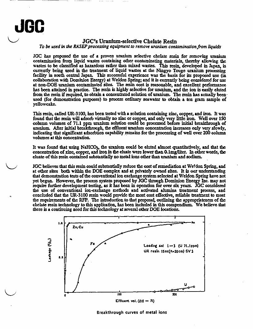
JGC's Uranium-selective Chelate ResinTo be used in the RASEP processing equipment to remove uranium contaminadonfrom liquids
JGC has proposed the use of a proven uranium selective chelate resin for removing uraniumcontamination from liquid wastes containing other contaminating materials, thereby allowing thewastes to be classied as hazardous rather than mixed wastes. This resin, developed in Japan, iscurrently being used in the treatment of liquid wastes at the Ningyo Touge uranium processingfacility in south central Japan. This successful experience was the basis for its proposed use (incollaboration with Dominion Energy) at Weldon Spring; and it is currently being considered for useat non-DOE uranium contaminated sites. The resin cost is reasonable, and excellent performancehas been attained in practice. The resin is highly selective for uranium, and the ion is easily elutedfrom the resin if required, to obtain a concentrated solution of uranium. The resin has actually beenused (for demonstration purposes) to process ordinary seawater to obtain a ten gram sample ofyellowcake.
This resin, called UR-3100, has been tested with a solution containing zinc, copper, and iron. It wasfound that the resin will adsorb virtually no zinc or copper, and only very little iron. Well over 150column volumes of 71.1 ppm uranium solution could be processed before initial breakthrough ofuranium. After initial breakthrough, the effluent uranium concenration increases only very slowly,indicating that significant adsorbtion capability remains for the processing of well over 200 columnvolumes at this concentration.
It was found that using NaHCO, the uranium could be eluted almost quantitatively, and that theconcentration of zinc, copper, and iron in the eluate were lower than 0.1mg/liter. In other words, thecluate of this resin contained substantially no metal ions other than uranium and sodium.
JGC believes that this resin could substantially reduce the cost of remediation at Weldon Spring, andat other sites both within the DOE complex and at privately owned sites. It is our understandingthat demonstration tests of the conventional ion exchange system selected at Weldon Spring have notyet begun. However, the process system proposed by JGC through Dominion Energy Inc. may notrequire further development testing, as it has been in operation for over six years. JC consideredthe use of conventional ion-exchange methods and activated alumina treatment process, andconcluded that the UR-3 100 resin would provide the most cost effective, reliable treatment to meetthe requirements of the RFP. The introduction to that proposal, outlining the appropriateness of thechelate resin technology to this application, has been included in this compendium. We believe thatthere is a continuing need for this technology at several other DOE locations
Zn. CU
F / Loading sol 1-3 (U I.ppm)'C$ Vr UR resin Scc(hs2Ocm) SV3
I.S-J
Effluent vol. (I - R)
Breakthrough curves of metal ions
1 .INTRODUCTION
This Proposal is offered in response to the Request For Proposal No.RFP-3589-VP 140 issued by Contractor, HK-Ferguson Company,- Inc.(hereinafter referred to as XK-Ferguson).
Dominion Energy, Inc. (DEI) is a subsidiary of Dominion Resources, Inc.,located in Richmond, Virginia. Dominion Resources, Inc. is the holdingcompany for Virginia Power, the major utility company serving the state ofVirginia. It is the intention of DEI to commercialize varioustechnologies and services as a result of Its in depth technical andoperating experience related to nuclear power plant and fossil pover plantwaste treatment. Furthermore, a major strategy of DEI is, to enter intopartnerships with other companies which possess the technology whichcompliments the operating experience of DEI.
DEI has selected JGC Corporation (JGC), Tokyo, Japan as a lover-tierSubcontractor for the design of the water treatment facility based onJGC's significant experience in the design of facilities for treatingradioactivei-astes and hazardous materials.
Vith respect to the treatment of uranium that currently exists in theVeldon Spring quarry, it is DEI's technical position based on extensivetesting and operating experience that conventional vater treatmenttechniques vill not, because of known nefficiencies, be successful inremoving uranium from the quarry water in accordance with the requirementsof the technical specifications of the RFP. Therefore, the use ofconventional techniques will be highly inefficient and will not meet theenvironmental objectives of MK-Ferguson vith respect to the discharge ofthe effluent to an uncontrolled environment. In this proposal, DEIrecommends the use of a chelating resin that has been demonstrated to beeffective in the removal of uranium impurities from aste water in Japan.
The following specific technical information is provided to support thesestatements:
1. Use ofveonventional ion exchange ethods - Based on testing andoperating experience in Japan, the use of Ion exchange resin In thisapplication will be highly inefficient. The ion exchange resin usedin this system should be a non-regeneration system. The reasons areas follows. In the caseof a regeneration system of ion exchangeresin, the regeneration solution (a 2S04 solution) shoyld be treatedby an additional solidification process. For the S - ion, it isappropriate to add Ca + in order to cause CaSO 4 precipitation.However, in that case, the quantity of Ca(03)2 to be.added willincrease and Na which is not removed by precipitation willaccumulate. Therefore, the regeneration interval will besignificantly decreased.
- 1 -
For the volume of ater and the concentration of uranium contained inthe quarry, t is estimated, n the case of a non-regenerationsystem, that It vill require approximately 20,000 ft3 of on exchangeresin to treat the vaste stream. Operating vith such a largequantity of resin vill be very inefficient and vill result insignificant maintenance and operating expenditures n order tooperate the treatment system.
The following discussion provides the technical basis for the abovestatements. In i conventional system, the ion exchange resin lladsorb all ons present n solution. In addition to the uraniumcontamination, the quarry also contains relatively largeconcentrations of calcium, manganese and sodium. Since the ionexchange resin will not have a preference for uranium versus othercontaminated material, conventional non-regenerative resins willquickly saturate and a very large quantity of resin ould berequired.
On the other hand, a regenerative on exchange system vill not befeasible since the large quantity of regenerated effluent as well asthe resin chemicals ill accumulate n the equalization basin. Thissituation vould eriously interfere ith the discharge of effluent toan uncontrolled environment.
A chelating resin vill selectively remove uranium ons from the vastestream and therefore require significantly less resin and vill beeasily regenerated. DEI estimates that the volume of chelating resinvill be 1/240th the volume of the ion exchange resin that ould berequired. Table 1 demonstrates the efficiency of uranium separationunder various conditions.
2. Uranium removal using activated alumina - DEI predicts that theactivated alumina vll not provide the reduction n concentrationrequired by the RFP technical specifications. Based on extensivelaboratory testing, t s known that a removal efficiency ofapproximately ninety percent for uranium using activated aluminaadsorption.
Based on an influent concentration of 1750pci/l stated in table11300-1 of the specification, t s predicted that an effluentconcentration of 30pcl/l would not be achieved.
Furthermore, for the use of a non-regenerative system, the volume ofactivated alumina that ould be required s very large. According tothe information from the manufacturer, it is estimated thatapproximately 6500 cubic feet vould be required. On the.other hand,in a regenerative system, the frequency of regeneration vill be onceper eighty hours and a large amount of chemical could be required.Bence, the chelate resin has distinct advantages over activatedalumina.
- 2 -

3. Uranium recoval using coprecipitation and chelate resin -- Based onJGC's testing and operating experience, DEI/JGC propose to use asystem that s based on the use of coprecipitation and chelatingresins. The details of- this system are described in section 7 ofthis proposal. In addition to having conducted significant R&D tosubstantiate the design described In this proposal, JGC hasexperience In the operation of the Yaste Treatment plant at NngyoTouge, Japan. This facility hlch is operated by the Pover Reactorand Nuclear Fuel Development Corporation routinely processes vastevater contaminated vith uranium. The nominal flow rate of this plantIs 23 gpo. Figure 1 provides a summary of the demonstrated removalefficiencies for uranium. Please note that although some samplesexceed 30pc/l1, the average value of the effluent vould meet the30pci/l limit.
The Ningyo Touge plant was commissioned n January 1984 and the watertreatment plant has operated in a consistently reliable manner overthe last five years. The commercial purpose of the plant s toprovide water treatment for liquid waste generated from the refiningof uranium one nto UP4. Therefore, the operation of this plant hasprovided JGC vith extensive operating history and operationsexperience vith'respect to uranium removal. This type of operatingexperience does not exist in the U.S. Therefore, JGC has a uniquebase of experience that has been factored into the design describedIn this proposal. As a result of the experience gained at thisJapanese plant, DEI can state, vith a high degree of onfidence, thatthe other competitors who are bidding on this RPP do not have thisextensive experience base.
In summary, DEl has developed sufficient test and operating data todemonstrate that the chelating resins and coprecipitation techniquesdescribed n this proposal ill provide an effective eans ofremoving uranium from the Veldon Spring quarry n accordance vith theeffluent discharge limits specified in this RFP.
JGC has extensive experience in ntegrating the various technologiesrequired to treat the Veldon Spring quarry aste ater nto an integratedturnkey syste that operates in a highly reliable manner.
Additionally, DI has selected NUS Corporation located n Gaithersburg,Maryland, to be responsible, as a lover-tier Subcontractor, for the detaildesign ork to ensure compliance ith the laws, regulations and standardsin the U.S.A. and also for the engineering coordination between the U.S.fabricators from whom all of the equipment and materials vill be ordered,except the new chelating resin which s only anufactured in Japan.
DEI has selected Corrigan Company as the local construction contractor forsite work. Figure 1.1 provides a summary of the. vork scope of thecompanies In this team. Figure 1.2 provides a summary of proposedequipment suppliers.
- 3 -
Concerning the remainder of this Proposal, Chapter 2 provides theadministrative text of this Proposal in accordance ith K-Ferguson'sformat, and Chapter 3 provides clarifications and modifications to thecommercial conditions proposed in the RFP.
The submittals required in the Technical Instructions to Proposers in the"Request for Proposal" are provided in Chapters 4 though 7.
Chapters 8 through 11 provide the Proposer's technical description of itsprocesses.
Chapter 12 indicates the extent of items hich vill be imported and whichvill be limited to one consumable essential for the above-mentionedinnovative processing.
- 4 -

Table 1
Adsorption parameters of UR-3100 for Mn+ at 25 C
Q KC /n Q mg M/1-Res.C = mg M/l-Sol.
HC6 1.0 N 0. 1 N
M n+ K 1 /n K |1 /n
U6+ 2800 0.53 8400 0.39
Fe 3+ 380 0.60 700 0.592+ rCu <1 <__ 220 0.56
Zn+ < 1 - 780 0.632+Zn < 1 < 1
Ni2+ < 1 <1 -
Mn 2 + < 1 - <1 -
Definition of terms: M - applicable metal, for example Fe. U. etc.a - amount (mg) of adsorbed metal per liter of resinC - amount of Influent metal per liter of solutionK - constant
I C C
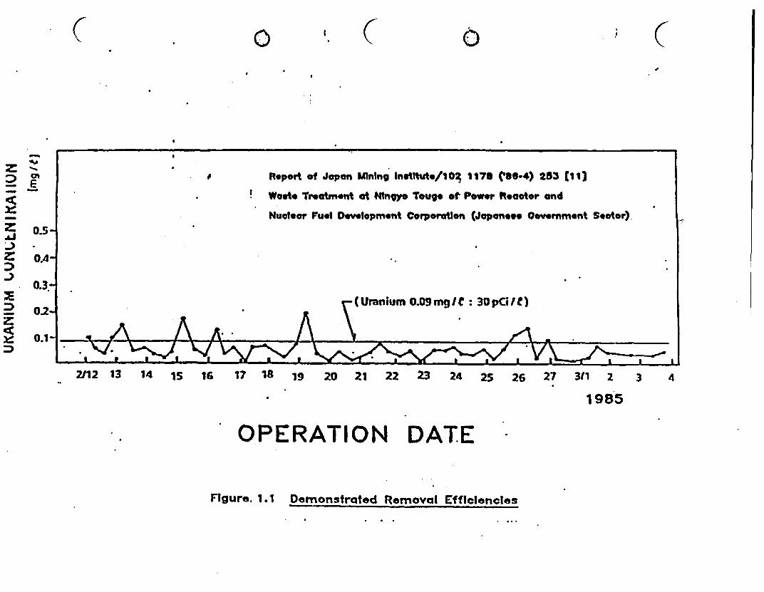
( 0 Ie 0 i I y
II Report of Japan Mining Inelttute/10 1176 ('86-4) 253 13
Woet Treatment at Nlngoy Toug. et Power Reaotor and
Nueatr Fuel Development Corporaton (Japanv. Covermment Stotor)
0.5
(1Uranium 0.o9mgIC : 30pC I )AA
A..0.1
2112 13 14 15 I6 17 18 19 20 21 22 23 24 25 26 27 3f1 2 3 4
1985
OPERATION DATE
Figure. 1.1 Demonstrated Removal Efficiencies
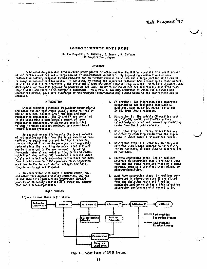
RADIONUCLIDE SEPARATION PROCESS (RASEP)
H. uribayashi, Y. Koshiba, K. Suzuki, . ShibuyaJGC Corporation, Japan
ABSTRACT
Liquid radwaste generated from nuclear power plants or other nuclear facilities consists of a small amountof radioactive nuclides and a large amount of non-radioactive matter. y separating radioactive and non-radioactive matter, original liquid radwaste can be further reduced in volume and a large portion of it can bereleased as non-radioactive waste. In addition, by fixing the separated radionuclides according to their viature,it will be possible to effectively and efficiently meet the waste disposal requirements. With this approach. JCdeveloped a radionuclide searation process called RASEP in which radionuclides are selectively separated fromliquid waste nd fixed in n inorganic adsorbent. As a result, maximum reduction of waste via a simple andeconomical method, plus safe discharge of the treated (decontamination) liquid waste to the environment can beachieved.
INTRODUCTION
Liquid radwaste generated at nuclear power plantsand other nuclear facilities usually contains insolu-ble CP nuclides, soluble CP/FP nuclides and non-radioactive substances. The CP and FP are containedin the waste with a considerable amount of non-radioactive substances, which occupy substantialvolumes in waste packages produced by conventionalimmbilization processes.
By separating and fixing only the trace amountsof radioactive nuclides from the large amount of non-radioactive substances present in liquid radwaste,the quantity of final waste packages can be greatlyreduced since the resulting decontaminated effluentmay be discharged to the environment. y usIngInorganic material and metal as long term and radio-activity-fixing media, JGC developed a process whichsolely and selectively separates radioactive nuclidesfrom liquid radwaste. This process fixes separatednuclides in the form of stable packages for safe,long-term storage and disposal.
In cooperation with Tokyo Electric Power Inc.,and other five Japanese utility companies, JGC hasestablished this radionuclid se aration (ASEP)process which mainTy consists 4ffiltration, adsorp-tion and electro-deposition.
RA&EP PROCESS
Figure I shows these major steps.
t lost* - aAdwpd-4 ;)
1. Filtration: The filtration step separatessuspended solids including insoluble CPnuclides, such as Co-60, n-S4, Fe-59 andZn-6S, from liquid radwaste.
2. Adsorption 1: The soluble CP nuclides suchas of Co-tO, Mn54, and n-65 are thenselectively adsorbed and removed by cheltingresin from the liquid radwaste.
3. Adsorption step II: iiere, Sr nuclides areadsorbed by chelating resin from the liquidwaste in which soluble FP nuclides remain.
4. Adsorption step III: Zeolite, an inorganicmaterial with a high adsorption selectivityfor Cs nuclides. is next used to separate theCs nuclides.
S. Electro-deposition step: The CP nuclidesadsorbed in adsorption step I are now elutedfrom the chlating resin and fixed on a metalcathode, such as a stainless steel plate, byelectro-deposition.
6. Auxiliary adsorption step: Sr nuclides con-centrated in adsorption step 11 are elutedfrom the chelating resin and fixed bysynthetic zeolite which has a high selectiveadsorption performance with regard to Sr. '
Fig. 1. Major Steps of RASEP System.
89
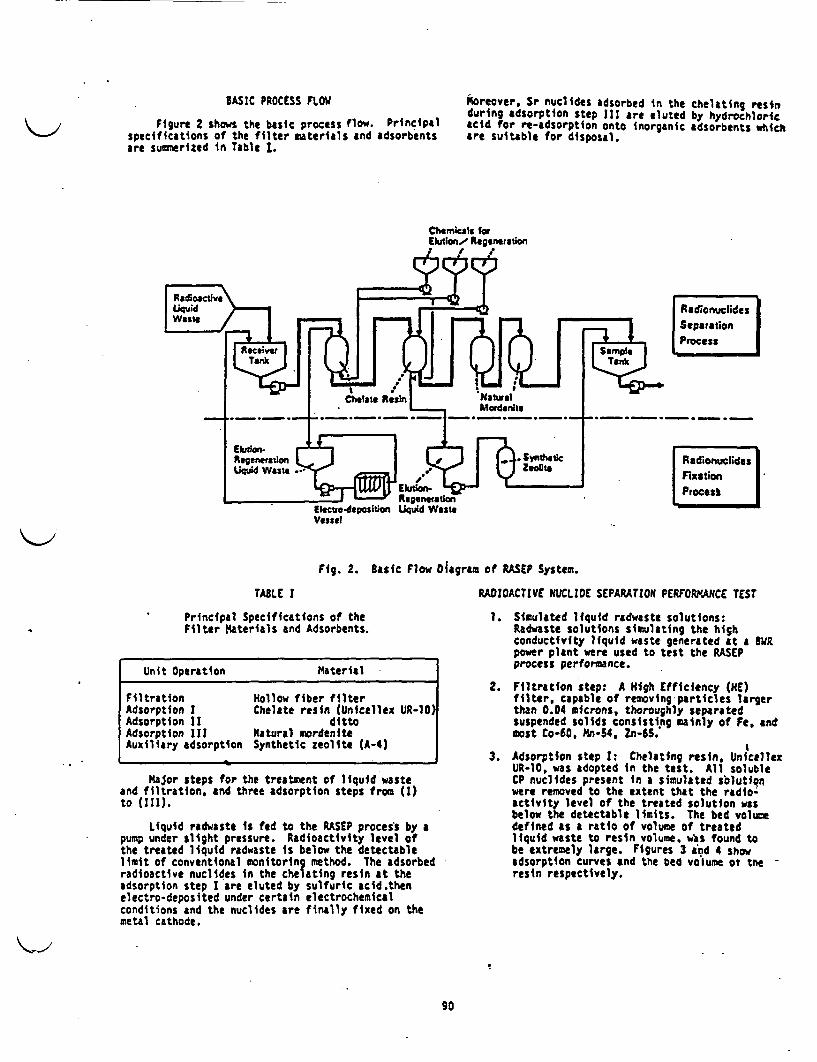
BASIC PROCESS FLOW
Figure 2 shows the basic process flow. Principalspecifications of the filter materials and adsorbentsare sunrmerized in Table 1.
Moreover, Sr nuclides adsorbed in the chelating restaduring adsorption step III are eluted by hydrochloricacid for re-adsorption onto inorganic adsorbents whichare suitable for disposal.
Vessel
Fig. 2. Basic Flow Diagram of RASEP System.
RADIOACTIVE NUCLIDE SEPARATION PERFORMANCE TESTTABLE I
Principal Specifications of theFilter Materials and Adsorbents.
Unit Operation Material
Filtration Hollow fiber filterAdsorption I Chelate resin (Unicellex UR-10)Adsorption II dittoAdsorption III Natural mordeniteAuxiliary adsorption Synthetic zeolite A-4)
Major steps for the treatment of liquid wasteand filtration, and three adsorption steps from ()to (111).
Liquid radwaste is fed to the RASEP process by apump under slight pressure. Radioactivity level ofthe treated liquid radwaste is below the detectablelimit of conventional monitoring method. The adsorbedradioactive nuclides in the chelating resin at theadsorption step I are eluted by sulfuric acid .thenelectro-deposited under certain electrochemicalconditions and the nuclides are finally fixed on themetal cathode.
1. Simulated liquid radwaste solutions:Radwaste solutions simulating the highconductivity liquid waste generated at a tipower plant were used to test the RASEPprocess performance.
2. Filtration step: A High Efficiency (HE)filter, capable of removing-particles largerthan 0.04 microns, thoroughly separatedsuspended solids consisting mainly of Fe, andmost Co-60, Mn-54, Zn-65.
t3. Adsorption step I: Chelating resin, Unicellex
UR-10, was adopted in the test. All solubleCP nuclides present in a simulated solutionwere removed to the extent that the radio'activity level of the treated solution wAsbelow the detectable limits. The bed voluedefined as a ratio of volume of treatedliquid waste to resin volume. wbs found tobe extremely large. Figures 3 ind 4 showadsorption curves and the eC volume ot tne -resin respectively.
90

_r!, L eM_
* AlOOa&tivy
Z n . % 18-4 p ci/
"z7-X18-4Pci/m
S
3a
_t
10 - WCo,Mn.z Not detectabl t5~SSr Dtected ~
10' 6rri-ss
to I t chaets ralsncolumn outlet Detectable limit
0-1 A0.. .. -
i
I
iI
I
i
i
c lU8 to-
.,
.3
i "Co. 1Mn. OZ5 Not doeteabtbe
I2nd chulate resn %5column outlet
I I I I I
-Sr Detected
Detectable Umit
la.,.,
.. :
0 2 000. 4.000 6,000 8 000
Bad Volume (1/1 resin)10000 12.000
10. C
I
I
CO
0
Fig. 3. Radionuclide Adsorption Performance of UR-10 Chelating Resin.
4. Adsorption step 11: As shown in Fig. 3.Sr nuclides passing through adsorption stepI were efficiently removed by this additional
* con UR-tO column.
* S .~. §O' _S. Adsorption step III: Natural mordenitc- VIfZA selected fran various inorganic adsorbents
was used to selectively remove Cs nuclidefrom the waste. Radioactivity level of the
*1 treated effluent was below the detcctablea ||limit.
* Adsorption steps I and III are auxiliarysteps when soluble FP nuclides coexist in
I the liquid radwaste.
6. Electrodeposition step: The eluted solutionS " was obtained by treating spent UR-lO by
.@ ~~~~~~~~sulfuric acid. C-60 nd Mn-54 a major CP_ nuclides were tested n the pressnc of
small amount of Ni ion with the applicationa of DC voltage. The N deposition on a metal
cathode was observed with simultaneous incor-poration of these nuclides.
. . . Figure 5shows the removal ratio of CP nuclides* a vs time under N1 deposition conditions.
m I Figure 5 indicates that more than 90$ of thenot adsorbed CP nuclides was removed and the metal \athode
7. A0 ir Ccould be repeatedly used.
S. 0
- Co.Mn,. .
Radionuclides
Fig. 4. 8ed Volume of UR-10 ChelatingResin for Radionuclides.
91

COST-EFFECTIVENESS OF THE RASEP SYSTEM
I~ -~ ~L±J
So ~ ~ I
*0 ~ ~ ~ ~ ~ 4
o 0 0 0 50rme (h)
Fig. S. Metallic ton and Radionuclide Removalcharacteristics by Electro-deposition Unit.
7. Auxiliary adsorption step: For the purposeof concentrating Sr nuclide from originalliquid waste, chelating resin is superior tozeolite because of higher bed volume evenfor high conductivity liquid waste. However.zeolite is a more stable long termjlatrixmaterial for fixing Sr nuclides.
The RASEP consumes minimal energy since it canbe operated at normal temperatures and pressures.Cost can also be reduced since its simple constructioneliminates the need for any special, expensive compc-nents or equipment.
Compared with an evaporation concentration system(without a solidification process), the RASEP facilityand utility costs are below one-sixth of those of theevaporation system, as shown in Fig. 7. Since acostly solidification unit is usually installed forconventional evaporation systems, the RASEP processcan be expected to be far more economically advanta-geous than conventional processes.
so .
40 -
I~30
laVOL114E REDUCTION
High conductivity liquid waste is conventionallyconcentrated by evaporation, then solidified usingcement, asphalt or plastic.
In the RASEP. however, liquid radwaste can betreated to obtain almost non-radioactlve liquideffluent which renders the solidification of suchliquid unnecessary as a rule. As a result, a veryhigh volume reduction is achieved. Figure 6 comparesvolume reductions achievable with the RASEP processand with conventional processes at BWR plants.
IIIIIIIIIIIIII
to
fillL.Au_
I
Equipment Operation andMaintenanceCostif Cost
.
I
I
Fig. 7. Cost-Benefit Comparison betweenthe RASEP and Evaporation Systems.
ACKNOWLEDGEMENTS
This study was partly sponsored by Tokyo ElectricPower Co., Inc., Tohoku Electric Power Co.. Inc.,Chubu Electric Power Co., Inc.. Hokuriku ElectricPower Co.. Inc., Chugoku Electric Power Co.., Inc., andJapan Atomic Power Co., Inc.
Fig. 6. Comparison of Amounts of WastePackages between Three Systems.
92
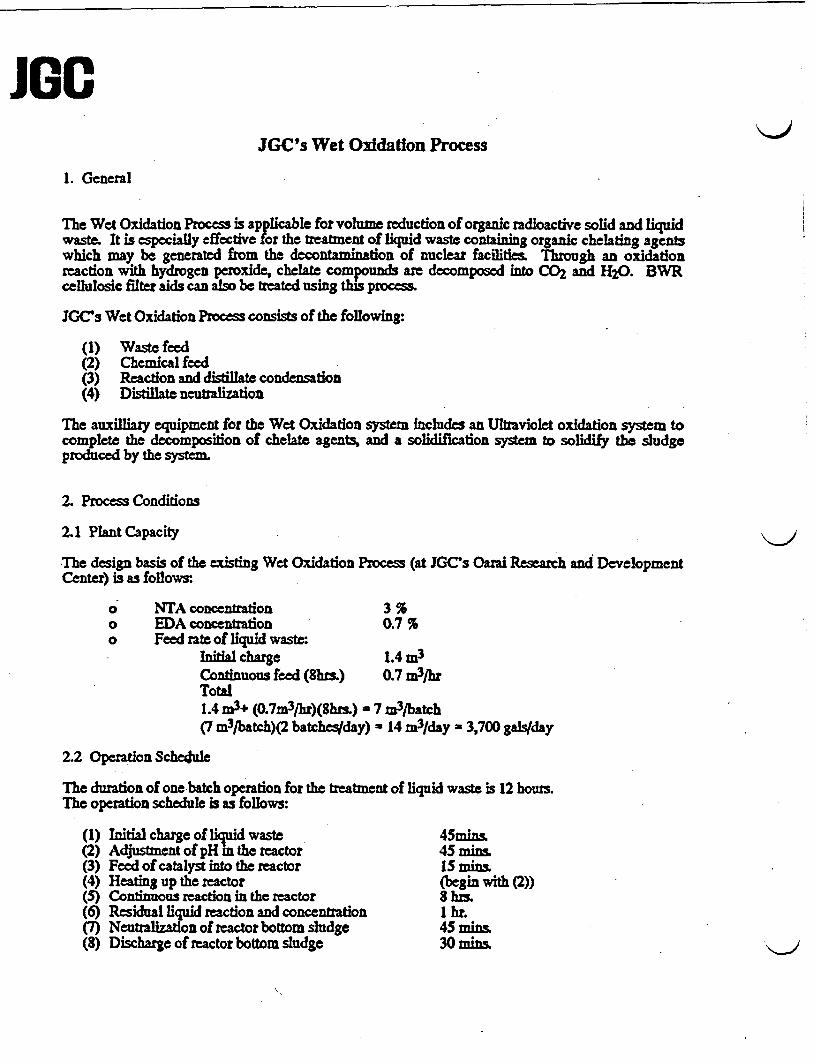
JGOJGC's Wet Oxidation Process
1. General
The Wet Oxidation Process is applicable for volume reduction of organic radioactive solid and liquidwaste. It is especially effective for the treatment of liquid waste containing organic chelating agentswhich may be generated from the dco ition of nuclear facilitie Through an oxidationreaction with hydrogen peroxide, chelate compounds are decomposed into C0 2 and H20. BWRcellulosic filter aids can also be treated using this process.
JGCs Wet Oxidation Process consists of the following:
(1) Waste feed(2) Chemical feed(3) Reaction and distillate condensation(4) Distillat neutalizaon
The auxilliaty equipment for the Wet Oxidation system includes an Ultraviolet oxidation system tocomplete the decomposition of chelate agents, and a solidification system to solidify the sludgeproduced by the system.
2. Process Conditions
2.1 Plant Capacity
The design basis of the existing Wet Oxidation Process (at JGC's Oarai Research and DevelopmentCenter) is as follows:
o NTA concentration 3 %o EDA concentration 0.7 %o Feed rate of liquid waste
Initial charge 1.4 m3
Continuous feed (8hzs.) 0.7 m3/hrTotal1.4 m3+ (0.7m3/hr)(8hs.) - 7 m3/batch(7 m3/batch)(2 batches/day) - 14 m3/day 3,700 gals/day
2.2 Operation Schedule
The duration of one batch operation for the treatment of liquid waste is 12 hous.The operation schedule is as follows:
(1) Initial charge of lid waste 45mins.(2) Adjustment of pH n the reactor 45 mins.(3) Feed of catalyst into the reactor IS mins.(4) Heating up the reactor (begin with (2))(5) Continuous recdon in the reactor 8 hts.(6) Residual liquid reaction and concentration 1 hr.(7) Neutralization of reactor bottom sludge 45 mins.(8) Discharge of reactor bottom sludge 30 mins.

JG2.3 Chemicals
(1) A 50% H2 0 2 solution is used as an oxidizing agent during the reaction.(2) A 98% H 2 S04 solution is used to maintain an acidic pH-value.(3) A mixture of 10% FeSO4 solution and 10% CuSO4 solution is used as a catalyst(4) A silicone-emulsion type anti-foaming agent is used under the additive condition of
1,000 - 5,000ppm aqueous solution.(5) 25% NaOH solution is used to neutralized reactor bottom sludge after the residual
liquid reaction and concentration.
3. Description of Each Process Unit
3.1 Waste Feed
Decontamination liquid waste is directly charge into the reactor from the receiving tank by a pump.
3.2 Chemical Feed
The chemical feed unit consists of the following storage tanks and pumps:
o One storage Ank for the 50% H202 solution and one pump.o One storage tank for the 98% H2 S04 solution and one pump.o One storage tank for the 10% FeSO4 and 10% CuSO4 solutions and one pump.o One silicone-emulsion type anti-foaming agent tank and one pump.o One storage tank for the 25% NaOH solution and two pumps.
3.3 Reactor
The reactor unit consists of one reactor, one demister and one condenser.
(1) Initial charge
The effective reactor volume is 11 .4m3 . After the initial charge of liquid waste intothe reactor from the receiving tank, the pH-value shall be adjusted to between 3 and 4by adding sulphurc acid.A 10% eSO4 and 10% CuSO4 mixture solution is fed to the reactor, where theconcentrations of FeSQ4 and CuSO4 are 0.0Imolter.
(2) Heating up the reactor
A stemn heating coil and an agitator are installed inside the reactor. Chemicallyadjusted liquid waste is steam heated up to 950C.
(3) Continuous reaction in the reactor
The oxidation reaction proceeds under an evaporative condition by the continuousfeeding of liquid waste and 50% H202 oxidizing agent solution accompanied by steamheating.The silicone-emulsion type anti-foaming agent is constantly added.Vapor and produced gas, mainly consisting of C0 2, are evacuated into the condenserthrough the demister. The vapor is condensed and introduced into the distillate tank.
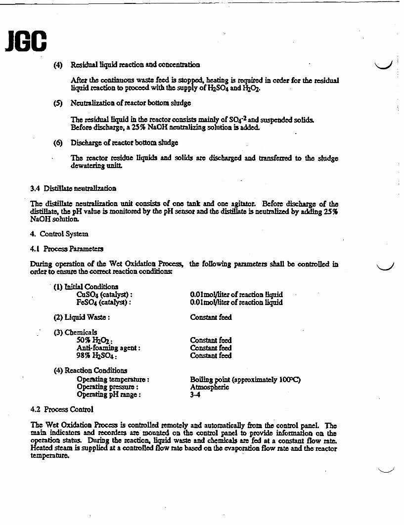
Jan(4) Residual liquid reaction and concentration
After the continuous waste feed is stopped, heating is required in order for the residualliqLid reaction to proceed with the supply of hSO4 and H202.
(5) Neutralization of reactor bottom sludge
The residual liquid in the reactor consists mainly of S04-2 and suspended solids.Before discharge, a 25% NaOH neutraizing solution is added-
(6) Discharge of reactor bottom sludge
The reactor residue liquids and solids ate discharged and transferred to the sludgedewateuing unitt.
3.4 Distillate neutralization
The distillate neutralization unit consists of one t and one agitator. Before discharge of thedistillate, the pH value is monitored by the pH sensor and the distillate is neutralized by adding 25%NaOH solution.
4. Control System
4.1 Process Parameters
During operation of the Wet Oxidation Process,order to ensure the correct reaction conditions:
(1) Initial ConditionsCuSO4 (catalyst):FeSO4 (catalyst):
(2) Liquid Waste:
(3) Chemicals50% 0 2:And-foaming agent:98% H2SO4:
(4) Reaction ConditionsOpefating temperature:Operating pressure:Operaig pH range:
the following parameters shall be controlled in
0.01molyliter of reaction liquid0.0Imo/llter of reaction liquid
Constant feed
Constat feedConistant feedConstant feed
Boiling point (approximtly 1tPC)Atmospheric34
J
4.2 Process Control
The Wet Oxidation Process is controlled remotely and automatically from the control paneL Themain indicators and recorders are mounted on the control panel to provide information on theoperation status During the reaction, liquid waste and chemicals are fed at a constant flow rate.Heated steam is supplied at a controlled flow rate based on the evaporation flow rate and the reactortemperature.
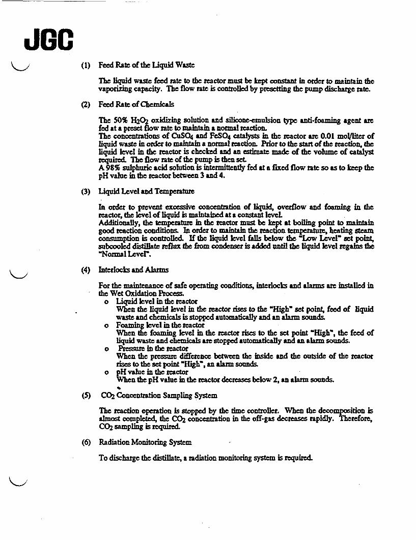
JG(1) Feed Rate of the Liquid Waste
le liquid waste feed rate to the reactor must be kept constant in order to maintain thevaporizng capacity. The flow rate is controlled by presetting the pump discharge rate.
(2) Feed Rate of Chemicals
The 50% H 2 2 oxidizing solution and silicone-emulsion type anti-foaming agent arefed at a preset flow rate to maintain a normal reaction.The concentrations of CuSO4 and FeSO4 catalysts in the reactor are 0.01 mo/iter ofliquid waste in order to maintain a normal reaction. Prior to the start of the reaction, theliquid level in the reactor is checked and an estimate made of the volume of catalystrequire. The flow rate of the pump is then set.A 98% sulphuric acid soutionis intermittently fed at a fied flow rate so as to keep thepH value in the reactor between 3 and 4.
(3) Liquid Level and Temperature
In order to prevent excessive concentration of liquid, overflow and foaming in thereactor, the level of liquid is maintained at a constant level.Additionally, the temperature in the reactor must be kept at boiling point to maintaingood reaction conditions. In order to maintain the reaction temperature, heating steamconsumption is controlled. If the liquid level falls below the 'Low Level' set pont,subcooled distillate rfhx the from condenser is added until the liquid level regains the"Normal Lever.
(4) Interlocks and Alarms
For the maintenance of safe operating conditions, interlocks and alarm ae installed inthe Wet Oxidation Process.
o Liquid level in the reactorWhen the liquid level in the reactor rises to the 'High' set point, feed of liquidwaste and chemicals is stopped automatically and an alarm sounds.
o Foaming level in the reactorWhen the foaming level in the reactor rises to the set point "High", the feed ofliquid waste and chemicals are stopped automatically and an alarm sounds.
o Pressure in the reactorWhen the pressure difference between the inside and the outside of the reactorrises to the set point THigh", an alarm sounds.
o pH value in the reactorWhen the pH value in the reactor decreases below 2, an alarm sounds.
(5) C02 Concentration Sampling System
The reaction operation is stopped by the time controller. When the decomposition isalmost completed, the CO2 concentration in the off-gas decreases rapidly. Therefore,C 2 sampling is required.
(6) Radiation Monitoring System
To discharge the distillate, a radiation monitoring system is required
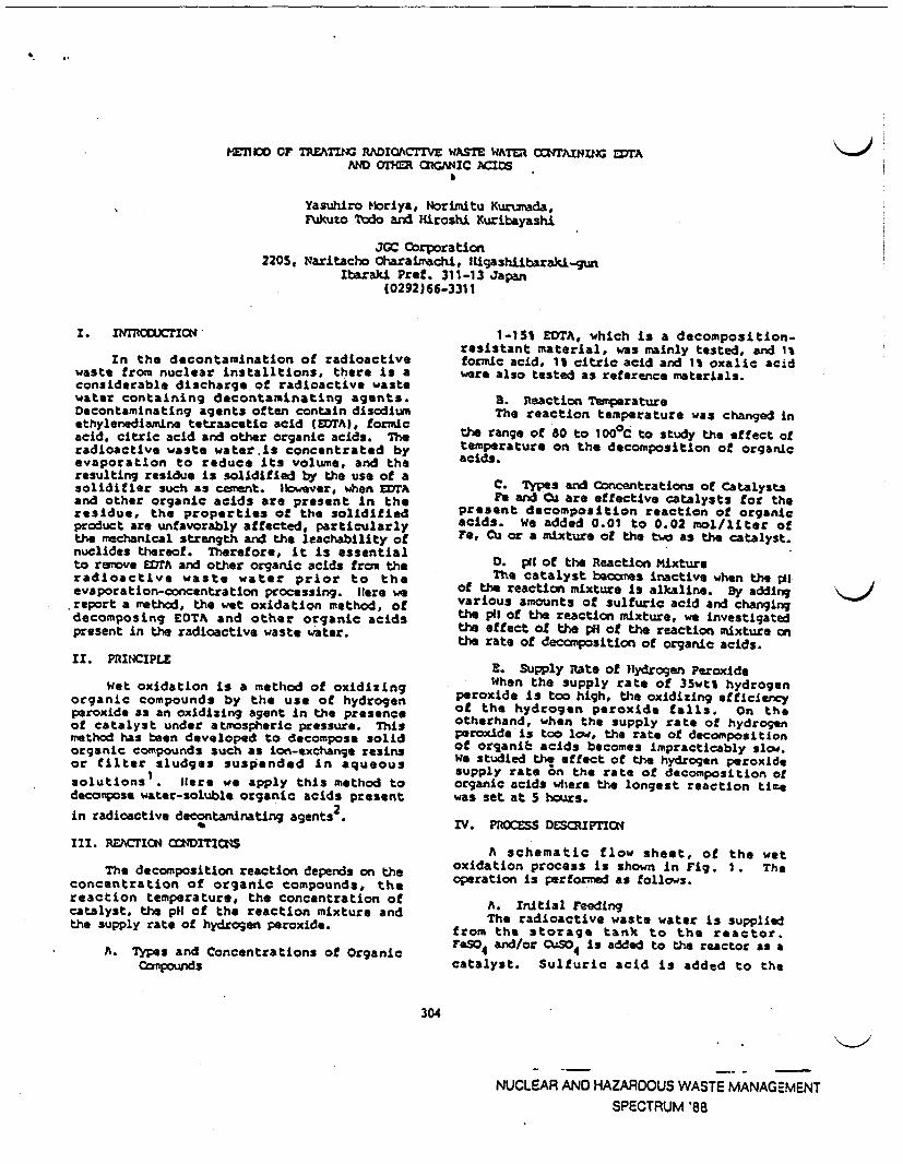
ME70 OF T 4REATIG RADIOACTIVE WASTE WATER CafTAINDN EDTAANDoaxm RCGmNIC ACIDS
Yasuhiro Morlya, Norimitu Kurumada,FUkuzo Todo and Hiroshi Kuribayashi
JGC Corporation2205, Naritacho Oharaimachi, IHigashiibaraki-gwn
Ibaraki Pref. 311-13 Japan(0292)66-3311
�11�t
I
ii4II
Ii
z. ItnMODUCT.c N
In the decontamination of radioactivewaste from nuclear nstalltions, there is aconsiderable discharge of radioactive wastewater containing decontaminating agents.Decontaminating agents often contain disodiumethylenediamine tetraacetic acid (EDrA), formicacid. citric acid and other organic acids. Theradioactive waste water is concentrated byevaporation to reduce its volume, and theresulting residue is solidified by the use of asolidifier such as cement. 1owever, when EDTAand other organic acids are present in theresidue, the properties of t solidifiedproduct are unfavorably affected, particularlythe mechanical strength and the leachability ofnuclides thereof. Therefore, it is essentialto remove EDTA and other organic acids from theradioactive waste water prior to theevaporation-concentration processing. lere wereport a method, the wet oxidation method, ofdecomposing EOTA and other organic acidspresent in the radioactive waste water.
II. PRINCIPLE
Wet oxidation s a method of oxidizingorganic compounds by the use of hydrogenperoxide as an oxidizing agent in the presenceof catalyst under atmospheric pressure. Thismethod has been developed to decompose solidorganic compounds such as ion-exchange resinsor filter sludges suspended in aqueous
solutions. Itere we apply this method todeconpose water-soluble organic acids present
2in radioactive decontaminating agents
III RCTION CNDITICOS
The decomposition reaction depends on theconcentration of organic compounds, thereaction temperature, the concentration ofcatalyst, the pH of the reaction mixture andthe supply rate of hydrogen peroxide.
A. Types and Concentrations of OrganicComtpounds
1-151 EDTA, which is a decomposition-resistant material, was mainly tested, and 1%formic acid, 1 citric acid and oxalic acidwere also tested as reference materials.
S. Reaction TemperatureThe reaction temperature was changed in
the range of 80 to 100°C to study the effect oftemperature on the decomposition of organicacids.
C. Types and Cncentrations of CatalystsFe and Cu are effective catalysts for the
present decomposition reaction of organicacids. We added 0.01 to 0.02 mol/liter ofFe, Cu or a mixture of the two as the catalyst.
0. pit of the Reaction MixtureThe catalyst becmnes inactive when the pi
of the reaction mixture is alkaline. Dy addingvarious amounts of sulfuric acid and changingthe pI of the reaction mixture, we investigatedthe effect ot the pH of the reaction mixture nthe rate of decomposition of organic acids.
E. Supply Rate of Hydrogen PeroxideWhen the supply rate of 3wtl hydrogen
peroxide is too high, the oxidizing efficiencyof the hydrogen peroxide falls. On theotharhand, when the supply rate of hydrogenperoxide is too low, the rate of decompositionof organil acids becomes impracticably slow.we studied the effect of the hydrogen peroxidesupply rate 6 n the rate of decomposition oforganic acids where the longest reaction tirewas set at S huss.
IV. PROCESS DESCRIPTIcN
A schematic flow sheet, of the wetoxidation process is shown in Fig. 1 . Theoperation is performed as follows.
A. Initial FeedingThe radioactive waste water is supplied
from the storage tank to the reactor.FOSO 4 and/or CuSO4 is added to the reactor as a
catalyst. Sulfuric acid is added to the
304
NUCLEAR AND HAZARDOUS WASTE MANAGEMENTSPECTRUM '88
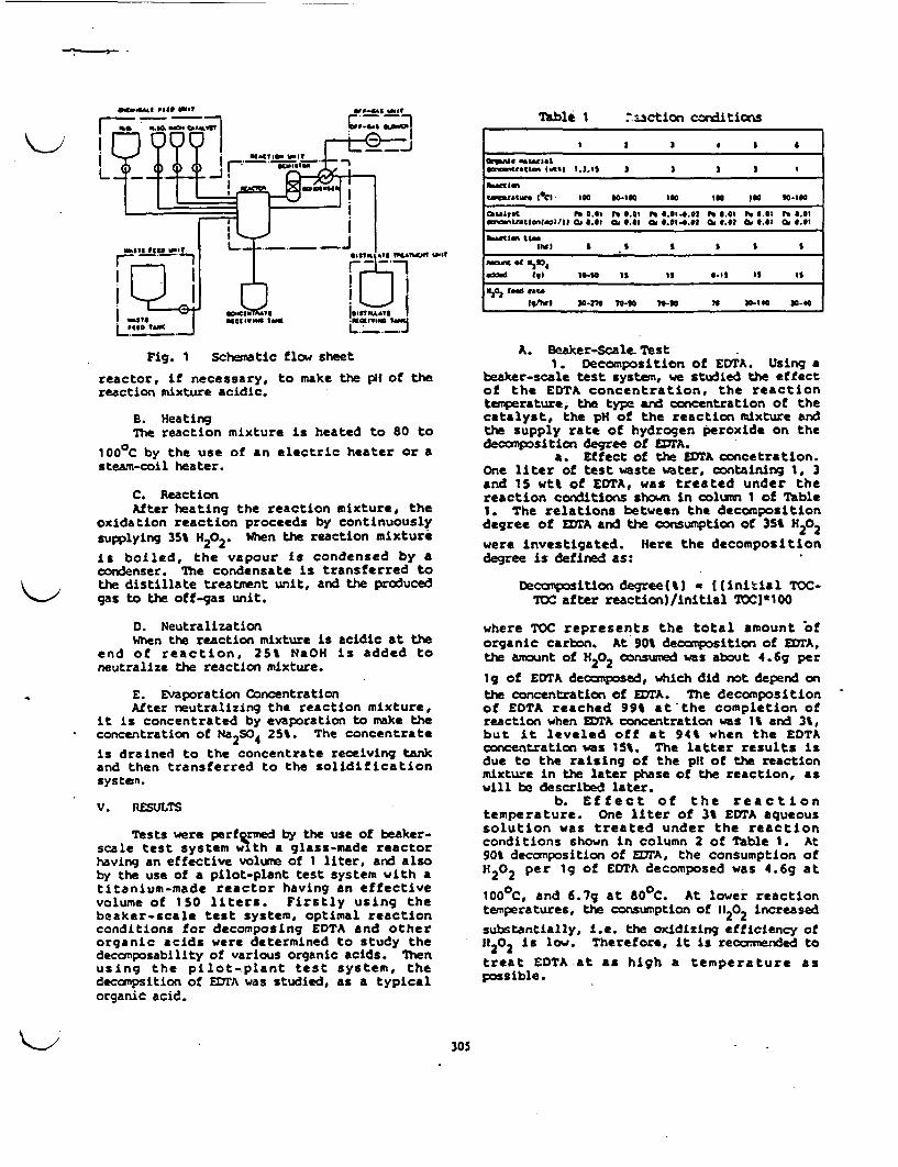
Table I .3ction conditions
I ~ .2 0
arlo antrta n 0 1 2 2
M.tl-
tona~tw IC1 100 00-100 too 100 In0 90.100
MU t17 t t 0 .1 X 6.01 ft 0.1402 X .0 t .01 X .01mtrufttatl¶into/IIC .0, .0 Ci004.0 Ca 0 Ca001C 0
A.gt tn
d tol 0i-so 1 is 0.1% is Is
0202 t to fat.ton~r 20-370 ted0 70-0 36 2-10 204
I ,I
Fig. 1 Schematic flow sheet
reactor, if necessary, to make the p of thereaction mixture acidic.
S. HeatingThe reaction mixture is heated to 80 to
1000C by the use of an electric heater or asteam-coil heater.
C. ReactionAfter heating the reaction mixture, the
oxidation reaction proceeds by continuouslysupplying 35% H202. When the reaction mixture
Is boiled, the vapour is condensed by acondenser. The condensate is transferred to
t the distillate treatment unit, and the producedgas to the off-gas unit.
D. NeutralizationWhen the reaction mixture is acidic at the
end of reaction, 25% NOH is added toneutralize the reaction mixture.
E. Evaporation ConcentrationAfter neutralizing the reaction mixture,
it is concentrated by evaporation to make theconcentration of Na2 S04 25%. The concentrate
is drained to the concentrate receiving tankand then transferred to the solidificationsysten.
V. RESULTS
Tests were performed by the use of beaker-scale test system oi th a glass-made reactorhaving an effective volume of 1 liter, and alsoby the use of a pilot-plant test system with atitanium-made reactor having an effectivevolume of 150 liters. Firstly using thebeaker-scale test system, optimal reactionconditions for decomposing EDTA and otherorganic acids were determined to study thedecomposability of various organic acids. Thenusing the pilot-plant test system, thedecampsition of EDTA was studied, as a typicalorganic acid.
A. Beaker-Scale- Test1. Decomposition of EDTA. Using a
beaker-scale test system, we studied the effectof the EDTA concentration, the reactiontemperature, the type and concentration of thecatalyst, the pH of the reaction mixture andthe supply rate of hydrogen peroxide on thedeccmposition degree of EDrA.
a. Effect of the ETA concetration.One liter of test waste water, containing 1, 3and 1S wt% of ETA, was treated under thereaction conditions shown in column 1 of Table1. The relations between the decompositiondegree of EDTA and the consumption of 35% H202
were investigated. Here the decompositiondegree is defined as:
Decomposition degree(%) * ((initial TOC-SOC after reaction)/initial TC)*100
where TOC represents the total amount oforganic carbon. At 90% decomposition of ErA,the amount of H202 consumed was about 46g per
19 of EDTA decomposed, which did not depend onthe concentration of EDTA. The decompositionof EDTA reached 99% at the completion ofreaction when ETA concentration was t and 3,but it leveled off at 94% when the EDTAconcentration was 15%. The latter results isdue to the raising of the p of the reactionmixture in the later phase of the reaction, aswill be described later.
b. Effect of the reactiontemperature. One liter of 3 EDTA aqueoussolution was treated under the reactionconditions shown in column 2 of Table 1. At901 decomposition of EA, the consumption ofIt202 per g of EDTA decomposed was 46g at
1000C, and 67g at 800C. At lower reactiontemperatures, the consumption of 11202 increased
substantially, i.e. the oxidizing efficiency ofIf202 is low. Therefore, it is recommended to
treat EDTA at as high a temperature aspossible.
305
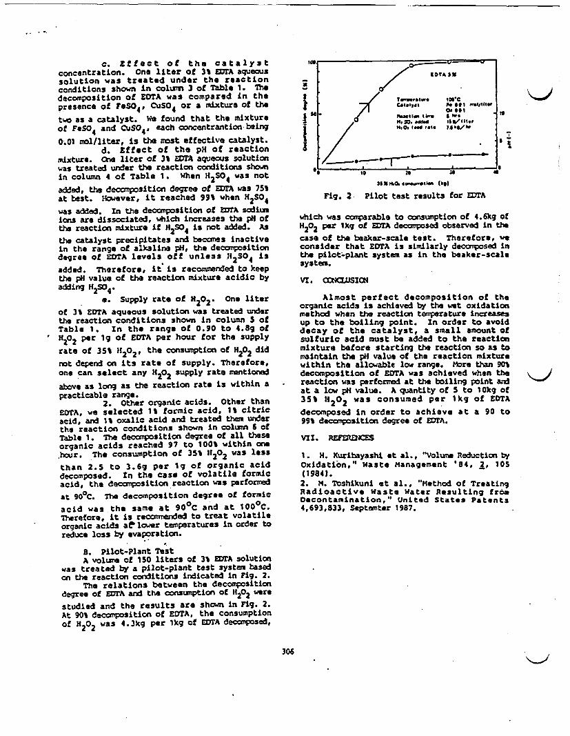
c. Effect of the catalystconcentration. One liter of 3 ETA aqueoussolution was treated under the reactionconditions shown in column 3 of Table 1. Thedecomposition of EDTA was compared in thepresence of FeSO 4, CuS0 4 or a mixture of the
two as a catalyst. We found that the mixtureof Fo 4 and CuSO4, each concentrantion being
0.01 mol/liter, is the most effective catalyst.d. Effect of the pH of reaction
mixture. ne liter of 3 EM aqueous solutionwas treated under the reaction conditions shownin column 4 of Table 1 When H2504 was not
added, the decomposition degree of EDTA was 75%at best. However, it reached 99% when H2S04
was added. In the decomposition of EDTA sodiumions are dissociated, which increases the pH ofthe reaction mixture if H2S04 is ot added. As
the catalyst precipitates and becomes inactivein the range of alkaline pH, the decompositiondegree of EDTA levels off unless 112 S04 is
added. Therefore, it is recommended to keepthe pH value of the reaction mixture acidic byadding H2S04.
a. Supply rate of H 202. One liter
of 3 EoTA aqueous solution was treated underthe reaction conditions shown in column S ofTable 1. In the range of 0.90 to 48g of1202 per ig of EDTA per hour for the supply
rate of 35% It202# the consumption of H 202 did
not depend on its rate of supply. Therefore,one can select any H202 supply rate mentioned
above as long as the reaction rate is within apracticable range.
2. Other organic acids. Other thanEOTA, we selected formic acid, 1 citricacid, and 1 oxalic acid and treated them underthe reaction conditions shown in column 6 ofTable 1. The decomposition degree of all theseorganic acids reached 97 to 100% within onhour. The consumption of 35% 11202 was less
than 2.5 to 3.69 per 1g of organic aciddecomposed. In the case of volatile formicacid, the decomposition reaction was performed
at 900C. The decomposition degree of formic
acid was the same at 900 C and at 100 0 C.Therefore, it is recommended to treat volatileorganic acids ae lower temperatures in order toreduce loss by evaporation.
S. Pilot-Plant TestA volume of 150 liters of 3% EDTA solution
was treated by a pilot-plant test system basedon the reaction conditions indicated in Fig. 2.
The relations between the decompositiondegree of EDTA and the consumption of HP202 were
studied and the results are shown in Fig. 2.At 90% decomposition of EDRTA, the consumptionof H 202 was 4.3kg per 1kg of LOTA decomposed,
a;
I'I
I
ITA S
Catalyst .@1 .lj e
h$
14$0. aded cat1s te
2 0 o a Ibl
I
I
I le 20 am
305XK 4W4Wt6M (be)
Fig. 2 Pilot test results for EDrA
which was comparable to consumption of 4.6kg ofH202 per 1kg of EDrA decomposed observed in thecase of the beaker-scale test. Therefore, -econsider that EDTA is similarly decomposed inthe pilot-plant system as in the beaker-scalesystem.
VI. COMSIO
Almost perfect decomposition of theorganic acids is achieved by the wet oxidationmethod when the reaction temperature increasup to the boiling point. In order to avoiddecay of the catalyst, a small amount ofsulfuric acid must be added to the reactionmixture before starting the reaction so as tomaintain the pH value of the reaction mixturewithin the allowable low range. More than 90%decomposition of EDTA was achieved when thereaction was performed at the boiling point andat a low pH value. A quantity of to 10kg of35% H202 was consumed per 1kg of EDTA
decomposed in order to achieve at a 90 to99% decomposition degree of ETA.
VII * R2ERNCES
1 H. Xuribayashi et al., "Volme Reduction byOxidation," Waste Management '84, 2, 105(1984).2. M. Toshikuni et al., "Method of TreatingRadioactive Waste Water Resulting fromDecontamination," United States Patents4.693,833, Septemter 1987.
306
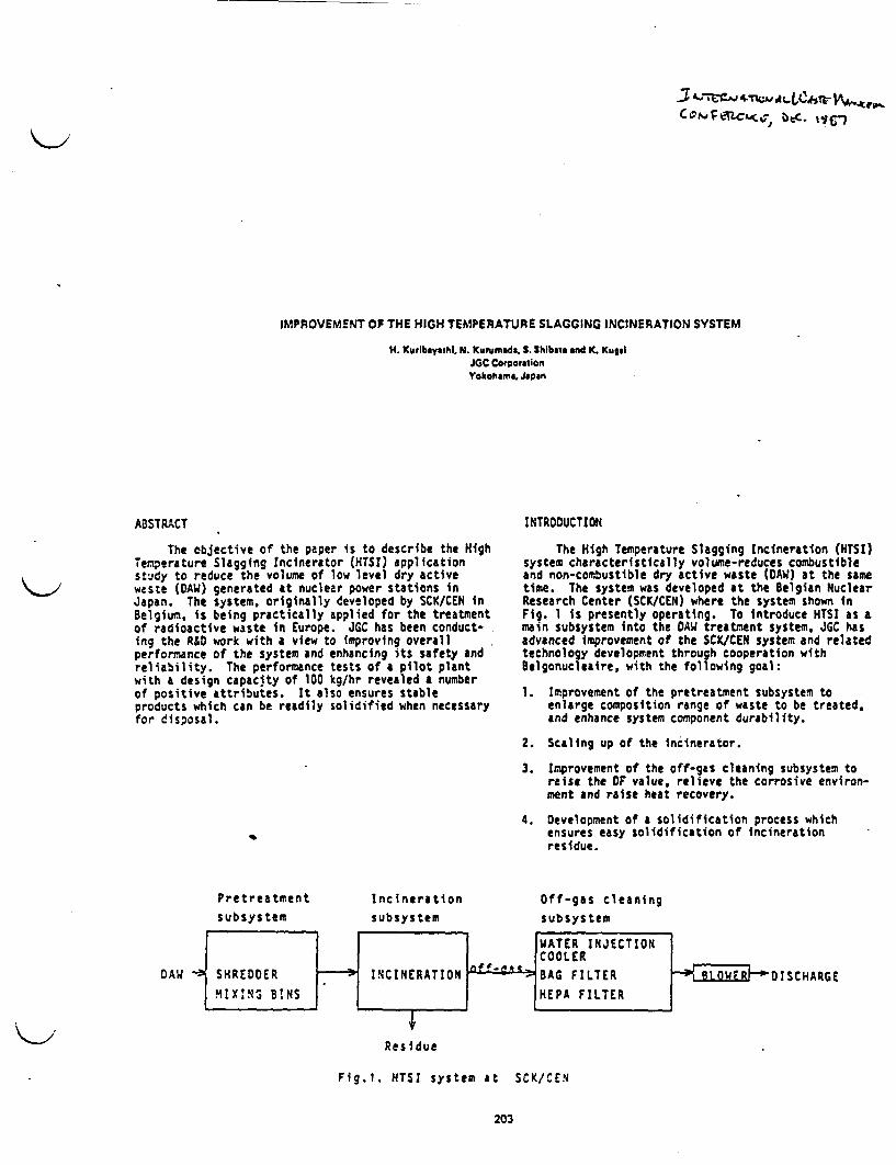
C ¢-~_-_,FT;, AdC. g )
IMPROVEMENT OF THE HIGH TEMPERATURE SLAGGING INCINERATION SYSTEM
H. urlbayashl, N. Kunumada. S. Shibata and K. KuradJGC caoorationYokohama. J0an
ABSTRACT
The objective of the paper is to describe the HighTemperature Slagging Incinerator (HTSI) applicationstudy to reduce the volume of low level dry activewaste (OAW) generated at nuclear power stations inJapan. The system, originally developed by SCK/CEN inBelgium, is being practically applied for the treatmentof radioactive waste in Europe. JGC has been conduct-ing the R&D work with a view to improving overallperformance of the system and enhancing its safety andreliability. The performance tests of a pilot plantwith a design capacity of 100 kg/hr revealed a numberof positive attributes. It also ensures stableproducts which can be readily solidified when necessaryfor disposal.
INTRODUCTION
The High Temperature Slagging Incineration (TSI)system characteristically volume-reduces combustibleand non-combustible dry active waste DAW) at the sametime. The system was developed at the Belgian NuclearResearch Center (SCK/CEN) where the system shown inFig. is presently operating. To introduce HTSt as amain subsystem into the DAW treatment system, JGC hasadvanced Improvement of the SCK/CEN system and relatedtechnology development through cooperation withBelgonucleaire, with the following goal:
1. Improvement of the pretreatment subsystem toenlarge composition range of waste to be treated.and enhance system component durability.
2. Scaling up of the ncinerator.
3. Improvement of the off-gas cleaning subsystem toraise the OF value, relieve the corrosive environ-ment and raise heat recovery.
4. Development of a solidification process whichensures easy solidification of ncinerationresidue.
Pretreatment
subsystem
Incinerationsubsystem
Off-gas cleaningsubsystem
DAW SCHARGE
Residue
Fig.l. HTSI system at SCK/CEN
203

.1.
In order to ach'eve these goals, JGC constructed a100 kg/hr pilot plant at the JGC Nuclear ResearchCenter in harai in July 1985 by making principalimprovements of the pilot plant in Belgium. Operationrecords after those improvement are described below.
3ACtQOUN0 OF MPROVEMENTS
The following AW Is generated at nuclear powerstations mainly through periodical inspection andfacility improvement:
1. Hard materials such as concrete, thermal insulationmaterial, wood blocks, etc.
2. Soft materials such as waste cloth, plastic sheets,etc.
3. Comparatively easily shreddable small metals suchas wire, thin iron plates, small diameter pipes,etc.
4. Unshreddable large metals such as large diameter-thick pipes, valves, etc.
To ensure stable incinerator operation, DAW shouldbe shredded into 5 cm or smaller size pieces, while thewaste listed in Item 4 above should be excluded fortreatment by the HTSI system. The A1 (hard and soft)listed in Items to 3 differ In properties from eachother; when they are treated by a shear shredder only,the abrasion of shredder edges lowers the throughputof the pretreatment subsystem.
In order to solve this problem, the pretreatmentsubsystem was modified as shown in Fig. 3 so that Wesubsystem could perform its anticipated function;shredding waste into small pieces for prolonged per4:dof time.
The modified pretreatment subsystem characteris-tically treats hard and soft materials by a crusherand shredder, respectively.
After waste sorting, acceptable hard and softDAW is directly fed to the crushe and shredder,respectively, through Line 2. When perfect wastesorting is not expected, mixed AW is fed to a shortingunit through Line . Hard AU is then crushed intosmall pieces by the crusher and separated from themixed DAW by a trommel screen before remaining softDM is fed to the shredder. As a result, abrasion ofthe shredder edges is avoided and durablity of theshredder is improved. In order to allow the HTSIsystem to function satisfactorily, hard AW must becompletely crushed nto small pieces by the crusher.Thus, a rotary hammer type machine was selected forthe crusher.
In the SCK/CEM off-gas cleaning subsystem, off-;asis released after being cooled by a water injectioncooler (WIC) and then treated by a bag and HEPA filter.The following were considered in modifying the off-gascleaning subsystem:
S. Replacement of the bag filter with another highefficiency filter system aiming at a prolongedlife of HEPA filter elements.
6. Elimination the IC since some measures must betaken to prevent dew condensation due to highwater content when the WIC is used.
7. High temperature off-gas treatment to preventcondensation of HC1 and S03-
Fig. 4 shows a modified off-gas cleaning subsystemin which these improvements were incorporated:
\'~2l
Fig.2. Plan for DA treatment. Li N IHed AW
Sot . AW
LINE a u14 0at,, GAW000*t Sell OAW
OAW
Fig. 3. Modifled retreatnent SUD$ystem.
204

Off-gas
from Incinerator
iOOC
Ai A ITER
4500§C
Air HEAT EXCHANGER Heated Air
300C
CERAMIC FILTER
2001C
I AIR DILUTER
[ fHIGH AEMP HEAP FILTERI G TE
The HEPA filter load is reduced by adopting ahigh-efficiency ceramic filter, and the entire systemcan be operated at high temperature by adopting a hightemperature HEPA filter. Water content in the off-gasis reduced by adopting a heat exchanger and fuel savingis ensured by using heated air for combustion air.
PILOT PLANT DESCRIPTION
The main process flow diagram of the HTSI Is shownin Fig. S. The simulated non-radioactive waste con-sists mainly of wood, paper cloth, sheet, rubber, smallmetals, concrete and thermal insulation material.The waste is crushed or shredded, then fed to a mixingbin. The mixed waste is then fed to the incineratorat a normal feeding rate of 100 kg/hr. with intermit-tent operation of a conveyer at 20 minutes per hour.The incinerator residue, falling from FLK in the formof droplets into a water bath, is cooled in water.dried by heated air, then packed into 200 liter drums.
The incinerator off-gas is cooled to about 5000Cin a shell-and-tube countercurrent air heat exchangerand further cooled to 3000C by an air diluter, thenfiltered by the ceramic filter. To prevent the off-gasfrom leaking, the entire facility is kept below atmos-pheric pressure by an off-gas blower.
Pretreatment unit
The crusher is a heavy duty industrial machineequipped with a vertical rotating shaft with hammerscapable of crushing hard materials into 1 to 3 mpieces, having a crushing rate of 2 ton/hr for averagecomposition waste.
The shredder consists of a single low-speedrotating shaft equipped with disk-shaped blades,stationary edges fixed on the outer wall, and a cmperforated screen below them. Its shredding rate isS ton/hr.
IBLOWER]
Exhaust
Fig.4. Off-gas cleaning system
WASTE
7ROALWL SCREN
KESET
r-GAs LOACR
LAG ritr
Fig. 5. Flow scerne of thf MTSI Pilot Plant
205
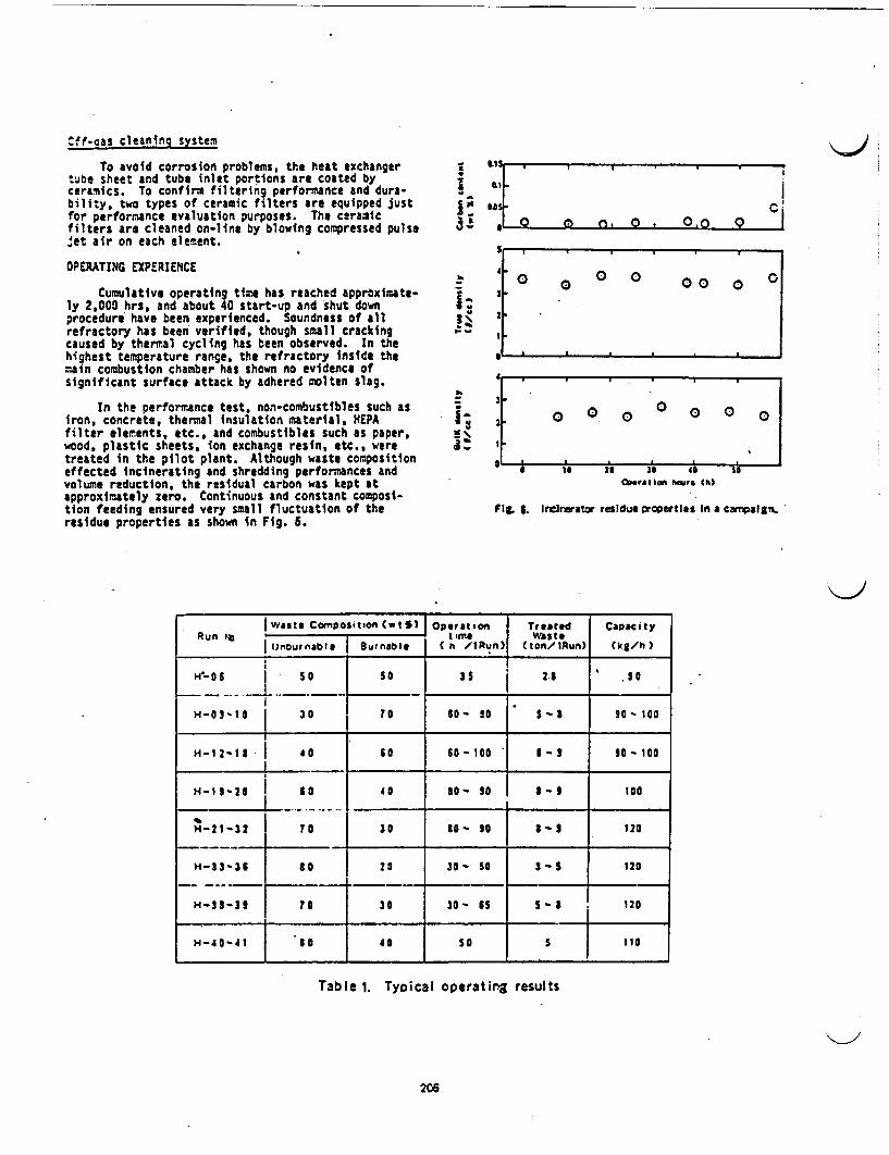
Cff-aas cleaning system
To avoid corrosion problems, the heat exchangertube sheet and tube inlet portions are coated byceramics. To confirm filtering performance and dura-bility, two types of ceramic filters are equipped justfor performance evaluation purposes. The ceramicfilters are cleaned on-line by blowing compressed pulse,et air on each element.
OPERATING EXPERIENCE
Cumulative operating time has reached approximate-ly 2,000 hrs, and about 40 start-up and shut downprocedure have been experienced. Soundness of allrefractory has been verified, though small crackingcaused by thermal cycling has been observed. In thehighest temperature range, the refractory inside themain combustion chamber has shown no evidence ofsignificant surface attack by adhered molten slag.
In the performance test, non-combustibles such asiron, concrete, thermal insulation material, EPAfilter elements, etc., and combustibles such as paper,wood, plastic sheets, ion exchange resin, etc., weretreated in the pilot plant. Although waste compositioneffected incinerating and shredding performances andvolume reduction, the residual carbon was kept atapproximately zero. Continuous and constant composi-tion feeding ensured very small fluctuation of theresidue properties as shown in Fig. 6.
C
I:
a-
I-
'e ;
i-
0 0 0.0
0 f 0 000
0 0 0 0 00
;. a. nhat h
Fig. 5. Irlnerator residue properties n a cmpalgn.
waste CompositiCt) Operation | Treated Capacity
Unburnable |urnable h /lRun) 1 (ton/iRun) (k/h)
I~~~~~~~~~~~~~~~~~i'... 1J 50 so s5 2.5 .901~~~~~~~~~~~~ 5
N-03-I 30 7 0 60- 90 s- 90- 100
H-i2- 1S 40 60 60-O I1-3 90 -i o
H-1 9 ' i0 so S- 90 -9 l e
H-21-32 To | 30 go- 50 1 - 9 120
H-33-36 o 0 30- 50 3 -5 120
H-9I-31 0o 30 30- S -I 120
H-40-41 I0 0 S0 5 10___________ __________ I _________ ___________ __________ 110~~~~~~~~~~~~~~~~~~~~~~
Table 1. Typical operating results
206
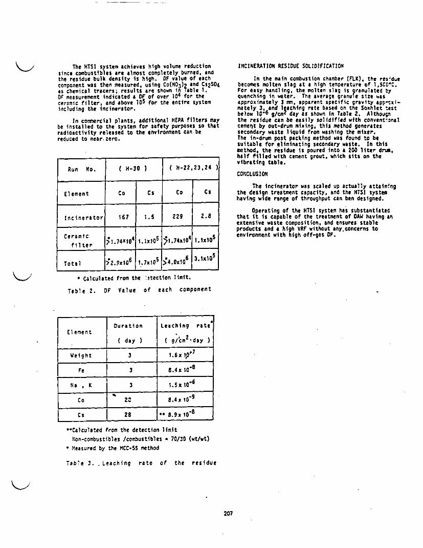
The HTSI system achieves high volume reductionsince combustibles are almost completely burned, andthe residue bulk density Is high. OF value of eachcomponent was then measured, using Co(NO3)2 and Cs2SO4as chemical tracers; results are shown in Table 1.OF measurement indicated a OF of over 104 for theceramic filter, and above 105 for the entire systemincluding the incinerator.
In commercial plants, additional HEPA filters maybe installed to the system for safety purposes so thatradioactivity released to the environment can bereduced to near zero.
INCINERATION RESIDUE SOLIDIFICATION
In the main combustion chamber (FLK). the residuebecomes molten slag at a high temperature of lSCCC.For easy handling, the molten slag is granulated yquenching in water. The average granule size wasapproximately 3 mm. apparent specific gravity app-xi-mately 3, and aching rate based on the Soxhlet testbelow 10-6 g/cml day as shown in Table 2. Althournthe residue can be easily solidified with conventionalcement by out-drum mixing, this method generatessecondary waste liquid from washing the mixer.The in-drum post packing method was found to besuitable for eliminating secondary waste. In thismethod, the residue is poured into a 200 liter druhalf filled with cement grout, which sits on thevibrating table.
CONCLUSION
The incinerator was scaled up actually attainingthe design treatment capacity, and the TSI systemhaving wide range of throughput can ben designed.
Operating of the HTSI system has substantiatedthat it is capable of the treatment of AW having atextensive waste composition, and ensures stableproducts and a high VRF without any.concerns toenvironment with high off-gas OF.
Run No. ( H-30 ) ( H-22,23,24
Element Co Cs Co s
Incinerator 167 1.5 229 2.8
Ceramic >1.740104 l.1x10S i'.74x10 4I.1x1S0
Total ;2.oxt6 1 .7x10$ 6 31X105
* Calculated from the itection limit.
Table 2. OF Value of each component
Duration Leaching rateElement
( day ) a g/cm2day )
Weicht 3 1.6x ip' 7
Fe 3 8. 4x I0-8
Na K | 3 1.5x 10⁶
Co .2 8.4x 10'9
Cs 28 *8.9x 0D8
**Calculated from the detection limit
Non-combustibles /combustibles a 70/30 (wt/wt)
* Measured by the MCC-SS method
Tab'e 3. Leaching rate of the residue
207
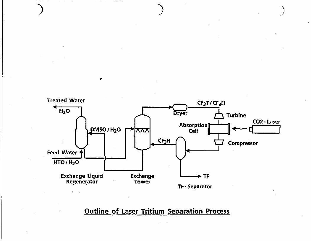
7) )
I
Treated Water CF3T/ CF3H
TurbineC02- Laser
Compressor
Exchange LiquidRegenerator
ExchangeTower
TF * Separator
Outline of Laser Tritium Separation Process

C C C
C0 2 - Laser(930.58pim) I
CF3H
0-00-0
C 2F 4+2TFCF3T Disassociation
Reaction Mechanism of Laser Tritium Separation

K>2 o After teatment, soils exhibit very low leach rates for mercury and heavy metals, aswell as for other contmies
o Uranium Ad TRU contamination can be effectively stabilized.
o Excessive volume increases are eliminated.
In addition, the system can easily be adapted to a mobile system, providing economical treatment atdiverse locations without excessive set-up casts.
Successful Implementation of the concept will:
o Allow more effective stabilization and leach resistance for heavy metals.
o Provide the first effective method of on-site stabilization of low levels of mercurycontaination.
o Reduce the cost of temediating sites cominated with mercury.
o Allow the stabilization of soils contaminated with a combination of hazardous metals,uranium, and TRU.
o Allow efficient remediation of smaller contaminated sites
o Reduce volume of low concentration TRU required to be sent to WIPP
o Provide a method for stabilization of soils containing heavy nmeals and TRU fixed tochelate agents such as EDTA and DTPA.
JOC is optimistic that this process could substantially improve the effectiveness and cost ofremediation of these DOE sites. In addition, it is likely that many EPA-designated Superfund sitescould benefit from the successful implementation of the concept.
soi
I Excavate I
Q. I Crushing I
Chemical Reaaent Solution
I Mixing IBentonite or Portland Cement
I MixingI BackfillI

Leach Test Resultsa
- Treated by fixing agent (I ) and Cement-
Method EP - Toxicity _TCLP
Sample Criteria Sample Criteria(mg/I) (mg/I) (mg /I) (mg/I)
Cd 4.86 1.0 X 0.10 0.066 X
Cr 0.68 5.0 0 0.11 0.084-5.2 0
Hg 0.20 0.2 0 1) 0.025
Pb 0.71 5.0 0 0.36 0.18-0.51 0
1) Analysis is now in progress
( ( C

( ( (
Leach Test Results - Treated by fixing agent and bentonite -
__________________ I ___________________________________________________________Fixing agent ( I ) and bentonite Fixing agent (II) and bentonite
Method EP - Toxicity TCLPSample Criteria Sample Criteria(mg/) (mg/1) (mg/) (mg/1)
Cd 0.63 1.0 0 0.04 0.066 0
Cr < 0.01 5.0 0 0.11 0.084'-5.2 0
Hg 0.20 0.2 0 | 0.025 | )
Pb <0.01 5.0 0 0.33 0.18-0.51 0
1) Analysis is now in progress

Comparison between the Conventional Cement Svstem and JGC's AC-ProcessI 0
W aste to be Conventionaltreated cement method JGC technology Remarks
Incinerator No pretreatment Pretreated by the A retarded cementash Ca(OH)2 and NaOH hydrating reaction
problem are solved.
Spent resin No pretreatment Pretreated by the Swellingcement and water phenomenon of
the immersion testare protected.
Boric acid No pretreatment Hydrate calcium Volume reductionwaste metaborate are and stable products
generated by are providedpretreatment
Q ( C
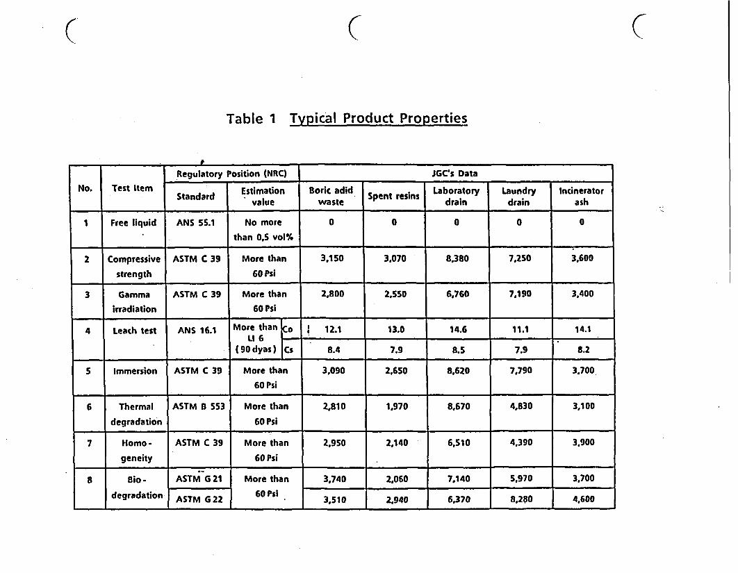
C
Table 1 Typical Product Properties
C
Regulatory Position (NRC) JGCs DataNo. Test Item Standard Estimation Boric adid Laboratory Laundry Incinerator
value waste Spn eis drain drain ash
I Free liquid ANS 5.1 No more 0 0 0 0 0than 0,S vol%
2 Compressive ASTM C 39 More than 3.150 3.070 8,380 7.250 3,600strength 60 Psi
3 Gamma ASTM C 39 More than 2,800 2.550 6,760 7,190 3.400irradiation 60 Psi
4 Leach test ANS 16.1 More than o 12.1 13.0 14.6 11.1 14.1LIG
(90 dyas) Cs 8.4 7.9 8.5 7.9 8.2
S Immersion ASTM C 39 More than 3.090 2.650 8.620 7.790 3,70060 Psi
6 Thermal ASTM B 553 More than 2,810 1,970 8,670 4,830 3,100degradation 60 Psi
7 Homo- ASTM C 39 More than 2.950 2,140 6,510 4.390 3,900geneity 60 Psi __.
8 io - ASTM G 21 More than 3,740 2,060 7.140 5.970 3.700degradation ASTM G 22 60 Psi 3,510 2.940 6,370 8.280 4.600

WASTE MANAGEMENT '85Waste Isolation in the U.S.
Technical Programs and Public EducationI - 6&.2,c.'A
Volume 2
WA.STE POICIES ANO PROGRAMS.LOW-LEVEL. WASTE
Procted~ngsofI i.Symposium an waslte Ma,'.onzn
at Tucson. ArizonaM.'dh 24-25. tM8 ADVANCED CEMENT SOLIDIFICATION PROCESS
Teruo 1Wi Hideo KodamaKyushu Electric Power Co., Inc.
1-82. Watanabe-Cori. 2-Chome, Chuo-ku.Fukuoka. 810 Japan.
Rend Perlas, Claude JaouenSocliti GenErala pour ls Techniques Nouvelles I SGN)
78184. Saint Quentin Yvelines Cedex.France.
Hirosht Kuribayashi. Norinmitsu KurumadaJGC CORPORATION
2205, Naritacho, Ohara-mnachi, Higashi-Ibaraki-gun. Ibaraki Pref.. 311-13 Japan.
ABSTRACT
The Advanced Cement Solidification Process. which features mproved volume reductivity and properties ofsolidified wastes. has been developed-to establish a better radioactive waste management system. Cement hasbeen widely used as an norganic solidification agent for the treatment of radioactive wastes generated atnuclear facilities. With current technology. borate waste solutions generated at PR plant are neutralized withcaustic soda and solidified directly with cement. This causes a increase in the volume of waste. iloreover.since borates retard the hydration of cement, the properties of solidified waste are not always such that meetthe final disposal requirements. In order to eliminate these defects and to improve conventional cement solidi-fication processes, SGN and JGC have conducted co-operative research. especially basic research on the pretreat-ment of borate. As a result of numerous experiments. a new process has been developed, by which solidifiedproducts with high volume reductivity and excellent physical properties can be produced. On the other hand.research and development work on a pilot plant have been carried out in co-operation with Kyushu Electric PowerCo., Inc.. including small scale hot tests of actual wastes at its Genkal Nuclear Power Station. A commercial-scale cold pilot plant was constructed and several proving tests have been conducted successfully.
INTRODUCTION
An increase In the amount of radioactive wastesgenerated at nuclear power plants along with an in-crease in their construction and operation, has cre-ated significant problems of radioactive waste manage-rent. Under such circumstances. the development ofpractical treatment processes for such wastes is anurgent task facing the world's nuclear power Industry.
In order to store and transport medium- and low-level radioactive wastes generated at nuclear powerplants easily and economically. it is essential notonly to reduce their volume to the maximum extent butalso to transform tem Into a solidified product sothat it is suitable for final disposal and will main-tain its chemical and physical soundness over a verylong period of time.
For this purpose, the Advanced Cement Solidifi-cation Process with high volume reducibility has beendeveloped. Cement has been most commonly used as anInorganic solidification agent for radioactive wastesat nuclear facilities, since it has many advantages asfollows:
- It is standard. low cost embedding material.
- It is compatible with wet waste.
- Its hardened product is stable, and has highdensity and high mechanical resistance.
However, it has been generally observed that thevolume of solidified products produced by conventional
cement solidification rocesses becomes larger thanthe original volume of radioactive wastes. Ioreover,the high quality solidified products are not alwaysproduced in cases where borate wastes generated at PvAplant are treated by such processes, because bratespresent in the wastes retard the hydration of cementand impede the progression of the hardening of cementpaste.
In order to eliminate these defects of most ofthe conventional cement solidification processes.mainly related to borate wastes, SGN had been develop-ing a new volume reduction and cement solidificationsystem, in which a borate waste solution is pretreatedand then overconcentrated. Independently of SGN, JGCwas conducting basic research on the pretreatment ofborates and on the hydration of cement.
In 1982. SGN and JGC agreed to begin co-operativework on the research and development of a volume-reducing cement solidification process, based on theirpast experience. After a series of basic experiments.particularly on the pretreatment of brates. SGN andJGC developed the Advanced Cement SolidificationProcess, by which the volume of wastes can be highlyreduced and solidified products with good physicalproperties can be produced.
Small scale hot tests of actual wastes based onthis process. with the co-operation of yushu ElectricPower Co. Inc.. were carried out at its Genkai uclearPower Station. In this hot test, the results of basicresearch were reconfirmed and the practicability ofthe process was proved. Based on preliminary perform-ance test data on selected equipment. comrercial-scale
211
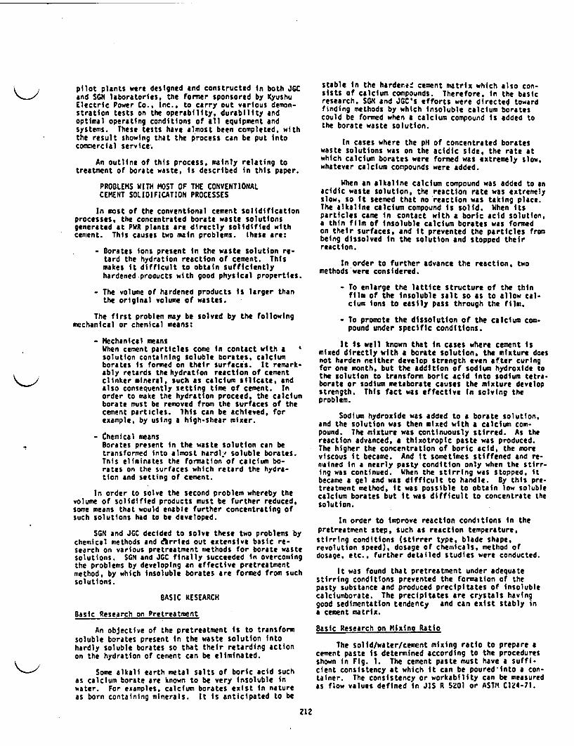
pilot plants were designed and constructed in both JGCand SGX laboratories, the former sponsored by KyushuElectric Power Co., Inc.. to carry out various demon-stration tests on the operability, durability andoptimal operating conditions of all equipment andsystems. These tests have almost been completed, withthe result showing that the process can be put intocommercial service.
An outline of this process, mainly relating totreatment of borate waste, is described in this paper.
PROBLEMS WITH MOST OF THE CONVENTIONALCEMENT SOLIDIFICATION PROCESSES
In most of the conventional cement solidificationprocesses, the concentrated borate waste solutionsgenerated at PWR plants are directly solidified withcement. This causes two main problems. these are:
- Gorates ions present In the waste solution re-tard the hydration reaction of cement. Thismakes it difficult to obtain sufficientlyhardened products with good physical properties.
- The volume of hardened products is larger thanthe original volume of wastes.
The first problem may be solved by the followingmechanical or chemical means:
- Mechanical meansWhen cement particles come in contact with asolution containing soluble borates, calciumborates is formed on their surfaces. It remark-ably retards the hydration reaction of cementclinker mineral, such as calcium silicate, andalso consequently setting time of cement. Inorder to make the hydration proceed, the calciumborate must be removed from the surfaces of thecement particles. ihis can be achieved, forexample, by using a high-shear mixer.
- Chemical meansBorates present in the waste solution can betransformed into almost hardly' soluble borates.This eliminates the formation of calcium bo-rates on the surfaces which retard the hydra-tion and setting of cement.
In order to solve the second problem whereby thevolume of solidified products must be further reduced,some means that would enable further concentrating ofsuch solutions had to be developed.
SGN and JGC decided to solve these two problems bychemical methods and drried out extensive basic re-search on various pretreatment methods for borate wastesolutions. SGN and GC finally succeeded in overcomingthe problems by developing an effective pretreatmentmethod, by which insoluble borates are formed from suchsolutions.
BASIC RESEARCH
Basic Research on Pretreatment
An objective of the pretreatment is to transformsoluble borates present in the waste solution intohardly soluble borates so that their retarding actionon the hydration of cement can be eliminated.
Some alkali earth metal salts of boric acid suchas calcium borate are known to be very insoluble inwater. For examples, calcium borates exist n natureas born containing minerals. It is anticipated to be
212
stable in the harderee cement matrix which also con-sists of calcium compounds. Therefore, in the basicresearch. SGN and JGC's efforts were directed towardfinding methods by which insoluble calcium boratescould be formed when a calcium compound is added tothe borate waste solution.
In cases where the pH of concentrated borateswaste solutions was on the acidic side. the rate atwhich calcium borates were formed was extremely slow.whatever calcium compounds were added.
When an alkaline calcium compound was added to anacidic waste solution, the reaction rate was extremelyslow, so it seemed that no reaction was taking place.The alkaline calcium compound is solid. When itsparticles came in contact with a boric acid solution.a thin film of insoluble calcium borates was formedon their surfaces, and it prevented the particles frombeing dissolved in the solution and stopped theirreaction.
In order to further advance the reaction. twomethods were considered.
- To enlarge the lattice structure of the thinfilm of the insoluble salt so as to allow cal-cium ions to easily pass through the film.
- To promote the dissolution of the calcium com-pound under specific conditions.
It is well known that in cases where cement Ismixed directly with a borate solution. the mixture doesnot harden neither develop strength even after curingfor one month, but the addition of sodium hydroxide tothe solution to transform boric acid into sodium tetra-borate or sodium metaborate causes the mixture developstrength. This fact was effective in solving theproblem.
Sodium hydroxide was added to a borate solution.and the solution was then mixed with a calcium com-pound. The mixture was continuously stirred. As thereaction advanced, a thixotropic paste was produced.The higher the concentration of boric acid, the moreviscous it became. And it sometimes stiffened and re-mained in a nearly pasty condition only when the stirr-ing was continued. When the stirring was stopped itbecame a gel and was difficult to handle. By this pre-treatment method, it was possible to obtain low solublecalcium borates but it was difficult to concentrate thesolution.
In order to improve reaction conditions In thepretreatment step, such as reaction temperature,stirring conditions (stirrer type, blade shape,revolution speed). dosage of chemicals, method ofdosage, etc.. further detailed studies were conducted.
It was found that pretreatment under adequatestirring conditions prevented the formation of thepasty substance and produced precipitates of insolublecalciumborate. The precipitates are crystals havinggood sedimentation tendency and can exist stably ina cement matrix.
Basic Research on Mixing Ratio
The solid/water/cement mixing ratio to prepare acement paste is determined according to the proceduresshown in Fig. 1. The cement paste must have a suffi-cient consistency at which it can be poured into a con-tainer. The consistency or workability can be measuredas flow values defined in JIS R 5201 or ASTM C124-71.

Fig. 2. Basic Flow Diagram of Advanced CementSolidification Process.
Fig. 1. Procedure of Design of Mixing Ratio.
Experiments showed that the consistency or work-ability of cement paste increased proportionally as thevolume fraction of liquid n a mixture ncreased. Thevolume of liquid in a mixture can be determined If thetarget flow value is set.
Meanwhile, the strength of solidified products de-pends upon cement/water ratio in a mixture. The cement/water ratio can be determined if the target strengthof solidified product s set. Since liquid volumedetermines the quantity of water, the mixing ratio canbe determined f the consistency of a mixture and thestrength of solidified products are set.
Experiments on consistency and strength showedthat a mixing ratio of 50/30/20 (solid/cement/water)by weight was adequate in eases where the target flowvalue was set at 200 mm or larger, while the target oneznth compressive strength of solidified product wasset at 20 MPa or larger.
HOT TEST
A series of small-scale hot tests of this processwere carried out at the Genkal Nuclear Power Station ofKyushu Electric Power Co.. Inc. The experimentalresults are summarized below.
- Calcium borate precipitates were successfullyobtained in a pretreatment step.
- Pretreated waste solutions were concentrated.The concentrates were solidified with cement.Sufficiently hardened products were produced.
- In cases where the concentration of boric acidIn the waste solutions was 12 wt S. the volumeof solidified product became approximately 1/4of that of their original waste solution.
- Solidified products showed good water resist-ance.
The hot tests confirmed the results of the basicresearch and proved that the process is effective insolidifying actual borate waste solutions.
BASIC PROCESS FLOW
The basic flow of the Advanced Cement Solidifi-cation Process is shown 1n Fig. 2. This process con-sists of the following three main steps.
Pretreatment Step
The pretreatment step. the key to the successfuloperation of the process. is ndispensable for ensuring
213
the hardening of cement to produce sufficiently soI-fied products, with good physical properties in a re-producible way.
In the pretreatment step, calcium borate is fonedand precipitated: The precipitates are stable crysulsand have good sedimentation properties.
Since dissolved borate, deterimental to thehydration of cement, can be converted into nsolublecalcium borate precipitates, it has become possible toobtain sufficiently hardened products with good physi-cal properties, which are suitable for waste storage.transportation and final disposal.
Concentration Step (Volume Reduction Step)
In this step, a borate waste solution is concent-rated to such an extent that only a minimum quantity ofwater necessary for mixing with cement is left. Thisoperation has become feasible by removing dissolvedborate in the form of insoluble calcium borate showinggood sedimentation.
From the viewpoint of reducing the volume of aborate waste solution, the most common method that ena-bles the greatest volume reduction is to evaporate sjch-solution to complete dryness. In the process, theborate waste solution is not evaporated to dryness butis concentrated to an optimum volume, because cementmust be mixed with water so as to harden t.
The concentration step avoids techaically diffi-cult dry powder handling operations.
Mixing Step
An out-drum mixing method is employed in the mix-ing step. In order to produce solidified productshaving high strength and highly reduced volume, it isimportant to prepare a cement paste of good consistencywith a minimum quantity of water. It Is also importantto increase the packing efficiency of such paste in acontainer. for these reasons, It s preferable toadopt the out-drum method, which can provide high mix-ing and filling.
Different kinds of cement can be used dependingon requirements of the final product qualities. Theresults presented hereinafter are based on the ordinaryportland cement (corresponding to ASTM Type 1).
Advantages
The advantages of the Advanced Cement Solidifica-tion Process are:
- Based on 12 wt of boric acid, the volume ofsolidifind products produced by the process is1/7 - 1/8 of that produced by conventionalcement solidification processes.
- Solidified products having good physical prop-erties are produced.
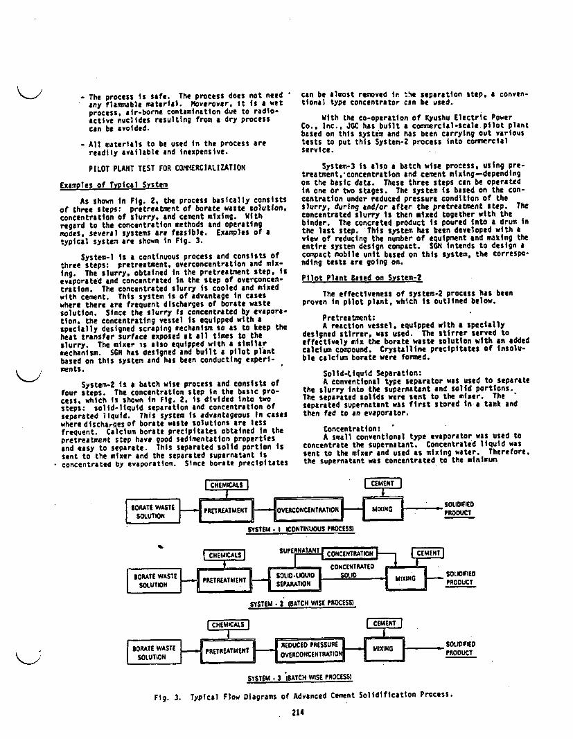
- The process is safe. The process does not needany flammable material. Moverover, it is a wetprocess, air-borne contamination due to radio-active nuclides resulting from a dry processcan be avoided.
- All materials to be used in the process arereadily available and inexpensive.
PILOT PLANT TEST FOR COEiRCIALIZATION
ExamPles of Typical System
As shown n Fig. 2, the process basically consistsof three steps: pretreatment of borate waste solution,concentration of slurry, and cement mixing. Withregard to the concentration methods and operatingmodes, several systems are feasible. Examples of atypical system are shown in Fig. 3.
System-I s a continuous process and consists ofthree steps: pretreatment, overconcentration and mix-Ing. The slurry, obtained n the pretreatment step, sevaporated and concentrated in the step of overconcen-tration. The concentrated slurry is cooled and mixedwith cement. This system is of advantage in caseswhere there are frequent discharges of borate wastesolution. Since the slurry is concentrated by evapora-tion, the concentrating vessel s equipped with aspecially designed scraping mechanism so as to keep thebeat transfer surface exposed at all times to theslurry. The mixer is also equipped with a similarmechanism. SGN has designed and built a pilot plantbased on this system and has been conducting experi-ments.
System-2 Is a batch wise process and consists offour steps. The concentration step in the basic pro-cess, which Is shown in Fig. 2, is divided into twosteps: solid-liquid separation and concentration ofseparated liquid. This system is advantageous in caseswhere discharqes of borate waste solutions are lessfrequent. Calcium borate precipitates obtained in thepretreatment step have good sedimentation propertiesand easy to separate. This separated solid portion Issent to the mixer and the separated supernatant isconcentrated by evaporation. Since borate precipitates
can be almost removed ir he separation step, a conven-tional type concentrator can be used.
With the co-operation of yushu Electric PowerCo., Inc., JGC has built a comnercial-scale p1lot plantbased on this system and has been carrying out varioustests to put this System-2 process into comercialservice.
System-3 is also a batch wise process, using pre-treatment, concentration and cement mixing-dependingon the basic data. These three steps can be operatedin one or two stages. The system is based on the con-centration under reduced pressure condition of theslurry, during and/or after the pretreatment step. Theconcentrated slurry s then mixed together with thebinder. The concreted product Is poured nto a drum inthe last step. This system has been developed with aview of reducing the number of equipment and making theentire system design compact. SGN ntends to design acompact mobile unit based on this system, the correspo-nding tests are going on.
Pilot Plant Based on System-?
The effectiveness of system-2 process has beenproven in pilot plant, which s outlined below.
Pretreatment:A reaction vessel, equipped with a specially
designed stirrer, was used. The stirrer served toeffectively mix the borate waste solution with an addedcalcium compound. Crystalline precipitates of Insolu-ble calcium borate were formed.
Solid-Liquid Separation:A conventional type separator was used to separate
the slurry into the supernatant and solid portions.The separated solids were sent to the mixer. Theseparated supernatant was first stored 1na tank andthen fed to an evaporator.
Concentration:A small conventional type evaporator was used to
concentrate the supernatant. Concentrated liquid wassent to the mixer and used as mixing water. Therefore.the supernatant was concentrated to the minimum
SYSTEM. I COhTINUOUS PROCESS)
SYSTEM 2 ATCH WISE PROCESS)
SOLIDIFIEDPRODUCT
SOLIDIFIED.PRODUCT
SYSTEM 3 BATCH WSE PROCESSI
Fig. 3 Typical Flow Diagrams of Advanced Cement Solidification Process.
214
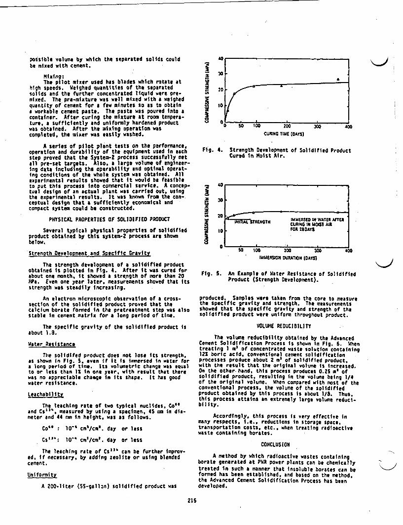
possible volume by whichbe mixed with cement.
the separated solids could
Mixing:The pilot mixer used has blades which rotate at
high speeds. Weighed quantities of the separatedsolids and the further concentrated liquid were pre-mixed. The pro-mixture was well mixed with a weighedquantity of cement for a few minutes so as to obtaina workable cement paste. The paste was poured into acontainer. After curing the mixture at room tempera-ture, a sufficiently and uniformly hardened product
was obtained. After the mixing operation wascompleted, the mixer was easily washed.
A series of pilot plant tests on the performance,operation and durability of the equipment used in eachstep proved that the System-2 process successfully metall pre-set targets. Also, a large volume of engineer-ing data including the operability and optimal operat-ing conditions of the whole system was obtained. Allexperimental results showed that it would be feasibleto put this process nto commercial service. A concep-tual design of an actual plant was carried out, usingthe experimental results. It was known from the con-.ceptual design that a sufficiently economical andcompact system could be constructed.
PHYSICAL PROPERTIES OF SOLIDIFIED PRODUCT
Several typical physical properties of solidifiedproduct obtained by this system-2 process are shownbelow.
Strength Development and Specific Gravity
The strength development of a solidified productobtained is plotted in Fig. 4. After it was cured forabout one month, it showed a strength of more than 20APa. Even one year later, measurements showed that itsstrength was steadily increasing.
An electron microscopic observation of a cross-section of the solidified product proved that thecalcium borate formed in the pretreatment step was alsostable in cement matrix for a long period of time.
The specific gravity of the solidified product isabout 1.8.
Water Resistance
The solidifed product does not lose its strength.as shown in Fig. S. even if It Is immersed in water fora long period of time. Its volumetric change was equalto or less than 1S in one year, with result that therewas no appreciable chaige in its shape. It has goodwater resistance.
LeachabilitZ
The leaching rate of two typical nuclides, Co"and Cs ', measured by using a specimen. 45 mm in dia-meter and 44 mm n height, was as follows.
Co" : 10' cm'/cm'. day or less
Cs': 10" cm'Icm'. day or less
The leaching rate of Cs"' can be further improv-ed, if necessary, by adding zeolite or using blendedcement.
Uniformity
A 200-11ter (5S-gsllzn) solidified product was
9WW
I
I
CURING TIME (DAYS
Fig. 4. Strength Development of Solidified ProductCured in Moist Air.
a
I40
30
20
10
0
I
INITIAL STRENGTH IMMERSED IN WATER AFTERCURING IN MM AIRFOR 24DAYS
- ---Wu I; RI zUo
IMMERSION DUAT~ION (DAYS)a0 400
Fig. 5. An Example of Water Resistance of SolidifiedProduct (Strength Development).
produced. Samples were taken from the core to measurethe specific gravity and strength. The measurementsshowed that the specific gravity and strength of thesolidified product were uniform throughout product.
VOLUME REDUCIBILITY
The volune reducibility obtained by the AdvancedCement Solidification Process is shown in Fig. 6. Whentreating I m of concentrated waste solution containing121 boric acid, conventional cement solidificationprocesses produce about 2 m of solidified product,with the result that the original volume is increased.On the other. hand, this process produces 0.2S a ofsolidified product, resulting in the volume being 1/4of the original volume. When compared with most of theconventional process, the volume of the solidifiedproduct obtained by this process is about 1/8. Thus.this process attains an extremely large volume reduci-bility.
Accordingly, this process Is very effective inmany respects. i.e., reductions in storage space,transportation costs. etc.. when treating radioactivewaste containing borates.
CONCLUSION
A method by which radioactive wastes containingborate generated at PR power plants can be chemicallytreated in such a manner that insoluble borates can beformed has been established, and based on the method,the Advanced Cement Solidification Process has beendeveloped.
215
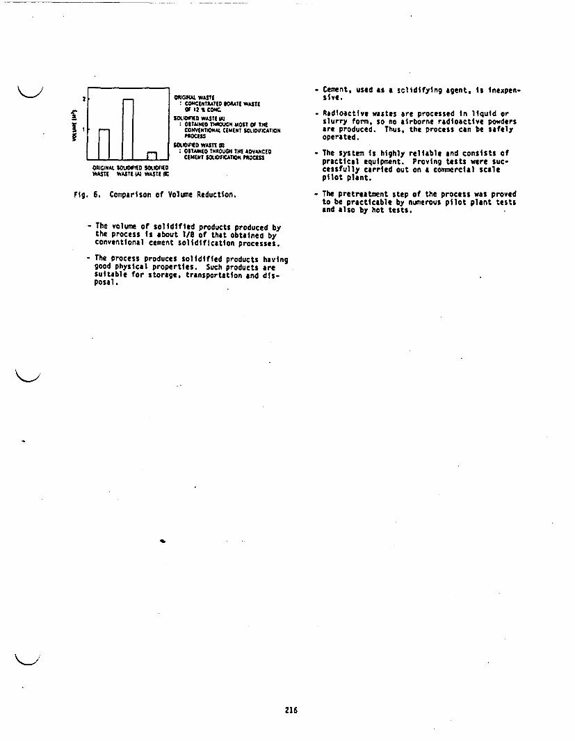
-- -
II
I I n_OPIGY4At SMIDIFID STOUIDWASTE WASTE A WASTE ST
OPKGNAL WASTECONCENTRATED BOR WASTIor 12 CONC.
5IDOfLED WASTE iOBTAINED TROUGH MOST OF THECONVENTIONAL CEMENT OUOWICATIONPOCESS
SGIWE0 WASTE MSOBTAINtD THROUGH THE AVANCEDCEMENT 5OOCATON PROCESS
- Cement, used as a slidifying agent. is nexpen-sive.
- Radioactive wastes are processed in liquid orslurry form, so no airborne radioactive powdersare produced. Thus, the process can be safelyoperated.
- The system is highly reliable and consists ofpractical equipment. Proving tests were suc-cessfully carried out on a commercial scalepilot plant.
Fig. 6. Comparison of Volume Reduction. - The pretreatment step of the process was provedto be practicablt by numerous pilot plant testsand also by hot tests.
- The volume of solidified products produced bythe process is about 1/8 of that obtained byconventional cement solidification processes.
- The process produces solidified products havinggood physical properties. Such products aresuitable for storage, transportation and dis-posal.
216
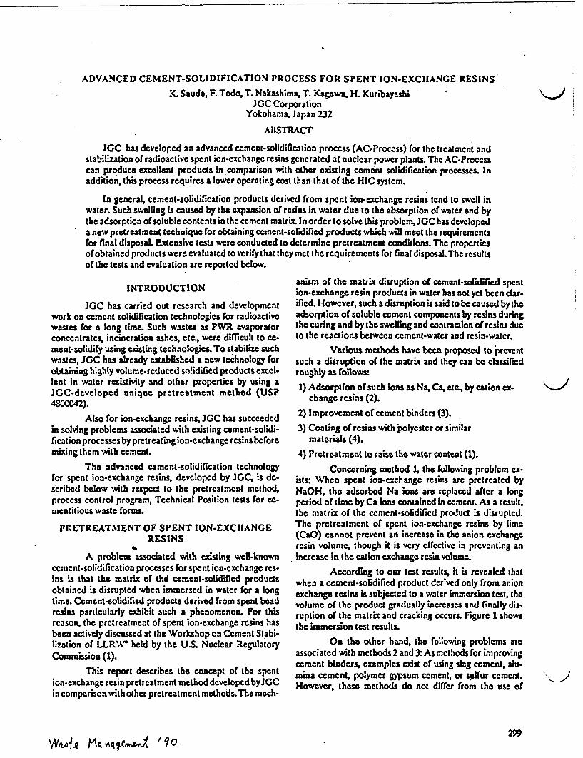
ADVANCED CEMENT-SOLIDIFICATION PROCESS FOR SPENT ON-EXCIANGE RESINS
X. Sauda, F. Todo, T. Nakashima, T. Kagawa, H. KuribayashiJGC Corporation
Yokohama, Japan 232
ABSTRACT
IGC has developed an advanced cemcnt-solidification proccss (AC-Process) for the trcatment andstabilization otradioactive spent ion-cxchangc resins generated at nuclcar power plants. The AC-Proccsscan produce excellent products in comparison with other existing cement solidification processcs. Inaddition, this process requires a lower operating cost than that of the HIC systcm.
In general, cement-solidification products derived from spent ion-exchange rcsins tend to swell inwater. Such swelling is caused by the expansion of resins in watcr due to the absorption of water and bythe adsorption of soluble contents in the cement matrix. In order to solve this problem, *GC has developeda new pretreatment technique for obtaining cemcnt-solidified products which will meet the requirementsfor final disposal. Extensive tests were conducted to detcrmine pretreatment conditions. The propertiesofobtained products were evaluated to verify that they mct the requirements for final disposal. The resultsof the tests and evaluation are reported below.
INTRODUCTION
JGC has carried out research and developmentwork on cement solidification technologies tor radioactivewastes for a long time. Such wastes as PWR evaporatorconcentrates, incineration ashes, etc, were difficult to ce-ment-solidify using existing technologies. To stabilize suchwastes, IGC has already established a new technology forobtaining highly volume-reduced so!idified products excel-lent in water resistivity and othtr properties by using aJCC-developed unique pretreatment method (US?4S00042).
Also for ion-exchangc resins, JGC has succeededin solving problems associated with existing cement-solidi-fication processes by pretreating ion-exchange resins beforemixing them with cement.
The advanced cement-solidification technologyfor spent ion-exchange resins, developed by JGC, is de-scribcd below with respect to the pretreatment method,process control program, Technical Position tests for cc-mcntitious waste forms.
PRETREATMENT OF SPENT ION-EXCIIANGERESINS
A problem associated with existing well-knowncement-solidification processes for spent ion-cxchange rcs-ins is that the matrix of the cement-solidificd productsobtained is disrupted when immersed in water for a longtime. Ccment-solidified products derived from spent beadresins particularly exhibit such a phenomenon. For thisreason, the pretreatment of spent ion-exchange resins hasbeen actively discussed at the Workshop on Cement Stabi-lization of LLRN' held by the U.S. Nuclear RegulatoryCommission (1).
This report describes the concept of the spention-exchange resin pretreatment method developed byJGCin comparison with other pretreatment methods. The mcch-
anism of the matrix disruption of cement-solidified spention-exchange resin products in water has not yet been clar-ified. However, such a disruption is said to be caused by theadsorption of soluble cement components by resins duringthe curing and by the swelling and contraction of resins ducto the reactions between cement-water and rcsin-water.
Various methods have been proposed to preventsuch a disruption of the matrix and they can be classifiedroughly as follows:
1) Adsorption of such ions as Na, Ca, etc, by cation ex-change resins (2).
2) Improvement or cement binders (3).
3) Coating of rcsins with polyestcr or similarmaterials (4).
4) Prctreatmcnt to raisc the water content (1).
Concerning method 1, the following problem ex-ists: When spent ion-exchangc resins are prtrcated byNaOH, the adsorbed Na ions arc replaced after a longperiod of time by Ca ions contained in ccment. As a result,the matrix of the cemcnt-solidified product is disrupted.The pretreatment of spent ion-cxchange resins by lime(CaO) cannot prcvent an increase in the anion exchangeresin volume, though it is very cfrcctive in preventing anincrease in the cation exchange resin volume.
According to our test results, it is revealed thatwhen a cemcnt-solidified product derived only from anionexchange resins is subjected to a water immersion test, thevolume of the product gradually increases and finally dis-ruption of the matrix and cracking occurs. Figure 1 showsthe immersion test results.
On the other hand, the following problems areassociated with methods 2 and 3: As mchods for improvingcement binders, examples exist of using slag cement, alu-mina cement, polymer gypsum cement, or sulfur cement.However, these methods do not differ from the use of
299W6A-ole A~qtC-4--v 'o
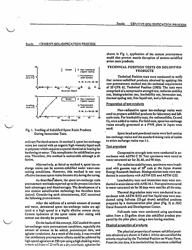
Sauda CENMENT-SOUDIFICATION PROCESS
Sauda CEMENT-SOLIDIFICATION PROCESS
Caion i-) Non treatment
tate (%j * '- Pteereatnmcnt
R.W C 1030 0
0 '~~~~Mis i0 is sDuration Edaya)
,~~ ~ ~ ~~ Non treatment
_E I (Spent frlian)
Swelling lb Pretreatmentfate j with ement
mR.. . 0so06so
0 I0 i 0 2S 30Ouration (days)
Fig. 1. Selling of Solidified Spent Resin ProductsDuring Immersion Tests.
ordinary Portland cement. In method 3, spent ion-exchangeresins ire coated with an organic high-viscosity liquid suchas polyester which requires a special chemical or hcating forhardening to occur. This complicates the solidification pro-ccss. Therefore, this method is undcsirable although is ef-fectivC.
Alternativcly, as listcd as method 4, spent ion-cx-changc rsins can be cmcnt-solidiflcd under water-con-taining conditions. However, this method is not vcrycffcctivc becausc spent rcsins become dry during the curing.
As describccrabovc the spent ion-exchange resinpretrcatmcnt methods reported up to the present time haveboth advantages and disadvantages. The development of anew ccment solidification technology has therefore beendcsircd. Considering such circumstances JC conceivedthe following pretreatment.
After the addition of a certain amount of cementand water, dewatered spent ion-exchange resins arc agi-latcd at a high speed in a highly alkaline cement slurry.Ccmcn hydration of the spent resins after mixing withcement can thereby be prevented.
On the basis of this concept, JGCstudied the spention-exchange resin pretreatment conditions, especially theamount of cement to be added, prctremmtcnt time, andagitator revolutions. As a result of the study, it was revealedthat satisfactory pretreatment cfccis could be achieved byhigh-specd agitation at 350 rpm using a high shciring mixer,ccmcnt addition of2o wt% on a dry rcsin basis, agitation for
shown in Fig. 1, application of the cement pretreatmentcould also prevent matrix disruption of cemcnt-solidificdanion resin products.
TECHNICAL POSITION TESTS ON SOLIDIFIEDPRODUCTS
Technical Position tests were conducted to vcritVthat cement-solidified products obtained by applying thisnew pretreatment method met the technical requirementsof 10 CFR 61, Technical Position (1983). The tests werecomprised ota compressive strength test, radiation stabilitytest, biodegradation test, leachability test, immersion test.thermal cycling test, free liquid test, and a full-scale test.
Preparation or test products I
Non-radioactive spent ion-exchange resins wereused to prepare solidified products for laboratory and ull-scale tests. For eachability tests, the radionuclides, Co andCs, were added to resins. For field tests, spent ion-cxchangeresins actually generated at a PWR plant in Japan wereused.
Spent bcad and powdered resins were both used asion-exchange resins and the standard mixing ratio of cationto anion exchange resins was 1:1.
Test procedure
Compressive strength tests were conducted in ac-cordance with ASTM C 39. Tcst specimens were cured inwater-saturated air for 30, 60, and 90 days.
For radiation stability tests, specimens were irradi-ated with gamma rays of IO rads at the Japan AtomicEnergy Research Institute. Biodegradation tests were con-ducted in accordance with ASTM G21 and ASTNI G22.
Leachability tests and immersion tests were con-ducted in accordance with ANSI 16.1.Test specimens curedin watcr-saturatcd air for 30 days were used for all the tests.
Thermal degradation tests were conducted in ac-cordance with ASTM BSS3 and free liquid tests were con-ducted using full-size (55-gal drum) solidified productsprepared by a demonstration pilot plant (ig. 2) t JGCOarai Research and Development Center.
Full-scale tests were conducted using specimenstaken from a 55-gallon drum size solidified product prc-pared by the pilot plant, using a core boring machine.
Physical properlics or products
The physical properties of cemcnt-solidiflcd prod.ucts obtained arc shown in Table I. All the data satisfied thecritcria required by the Technical Position on Wastc Form.From the test data, it is concluded that the ccmcnt-solidificd

Sauda CEMENT-SOLIDIFICATION PROCESS
products obtained by this process meet the requirementsfor Class B and Class C waste forms.
System DescRtlon
JGC's advanced cement-solidilication process, forthe effective pretreatment of spent ion-exchange resins, isshown in Fig. 3. Spent ion-exchange resins are received in aspent resin receiving tank, then sent to a dehydrator orcentrifugal separator for dehydration purposes. The super.natant is returned to a spent resin storage tank and thedewatered resins are received in a mixer, where the resinsare mixed with the specified amount of cement and.water.After the specified amount of cement is added, the pre-treated resins are sufficiently mixed, then filled into drums.
Control parameters
The following parameters are controlled to obtainsatisfactory cement-solidiied products. The amount of ce-ment to be added for pretreatment is more than 20 wt% ona dry resin basis. Resins are mixed for more than 10 minutesat an agitation speed of 350 rpm and cured for more than 3hours. In addition, when the pretreated resin is mixed in themixer, the weights are controlled so as to enable the follow-
cementIt
Flow se2j
) ~~~Comnpresive srn...7.m..:* ~~ma slid content
9-.W---. 0 S40 l~~~~~~~~~~~a esins
Spn rs I
I; i]Solid / Liquidseparation
.
. I
Cement -
Cement-
Pretreatment
and
mixing
2- Supernatant
Water
Admixture
Fig. 4. Relation Between Mixig Ratios (R/W/C) andBounding Limits.
ing mixing ratio:
Resin/Water/Cement = 1346
Resin: Dry resin (lb)
Water: Water contained in resin + Free water (lb)
Cement: Portland cement (lb)When the amount of water increases beyond the
No. 1 line in Fig 4, bleeding occurs, and when the amountof water decreases below the No. 2 line, the dischargeabilityfrom the mixer is lowered. An increase in the amount ofresin lowers the compressive strength of cement-solidificdproducts and causes disruption of the matrix in imersiontests. The No. 3 line indicates the condition under whichcement-solidified products cured in water-saturated air for30 days show a compressive strength of 700 psi. When theamount of resin is increased above the No. 4 line, cracksdevelop on the surface of cement-solidified products in90-day immersion tests.
ECONOMICAL EVALUATION
This advanced cement solidification process clim-inates the need for using expensive HIC liners because spention-exchange resins are stabilized by cement. A large redue
tion of direct expenses such as container cost, disposal cost,etc, can therefore be achieved.
'I i
IProducts
Fig. 3. Basic Flow Diagram of AC - Process.
302
Sauda1 rCkEvME,:T_.zr lnl~rATS^M 1nnfCcee~2~IA3 NT~AT tr.ImrATWr1ha D%%f'l
CONCLUSION
In the advanced cement solidification process de-vclopcd by *GC, solidified products obtained are cxccllentin physical properties because spent ion-exchange resinsare suflicicntly pretreated before being cement-solidified.Thercfore, the products can satisfactorily meet the wasteform criteria required by 10 CFR 61 and Technical Position.In addition, direct expenses can be largely reduced becausethere the use of expensive HIC liners is not required.
REFERENCES
1. U.S. NRC, *Workshop on Cement Stabilization ofLow-Levcl Radioactive Waste," NUREG/CP-0103,NISTIR 89-4178.
2. T. TSUTSUI and K NISHIMAJU, 'EvaluationMcthod for Ccment-Solidified Products of Radioac-
tive Waste,' Vol. 9, P87 94, Health Physics, (1974).
3. Brookhaven National Laboratory'Waste Form Dcvcl-opment Program Annual Report,' BNL 51614, (1982).
4. Brookhaven National Laboratory, 'Waste Form Devel.opmenl Program Annual Report,' BNL 51756, (1983).
303

INCIiERATION \ % Ac 560k CONFERENCE 1990 sfSL'. L
MAY 1411 * 337r rAlHN UR Jl 11IIITtL r ~.-^w AstSAN D9CO. CALFORU SA
Technology of Stabilization for Incinerator Ash Wastes
K. Yokoyama, K. Suzukr, F. Todo and Y. MoriyaJGC CORPORATION, (Tokyo, Japan)
ABSTRACT
This report concerns the stabilization of ncinerator ashess advanced cementsolidification and high frequency induction malting.
(1) AC SolidificationMost important points in this process are pretreatment of ashas by.Ca(OH)2 addition and use of high shearing mixer to give efficienthomogeneity. The products contain 35vt% ashes, and have highcompressive strength (200kg/cm2) and low leachability.
(2) HFIMAshes are melted at 1.200 - ,6006C by the induced heating using a 2XHzhigh frequency, in a mlter made of carbon material. The vitrifiedproducts have good chemical-physical properties. Furthermore, theprocess is capable of treating concrete, heat-insulator materials andother noncombustible DAW.
INTRODUCTIO1U
The stabilization of incinerator ash wastes is classified into two mainprocesses one is embeddinj in a binder matrix(2)(2), and the other ismalting into hard blocks( ). Cement-, bitumen, plastic-solidificationbelong to the former process. These are easily operated by simple equipment,though both volume and weight of solidified products are increased. Thelatter is the melting treatment by method such as Joule-heat, high frequencyinduction, microwave and so on. These processes have higher volume reductionbut involve considerably more complicated systems.The application of these techniques to actual wastes should be reasonablyselected with consideration given to several parameters ; waste-volume,-weight, -form, contamination lvels of radioactive or/and hazardous wastes,required capacity and foreign materials in ashes.In this paper, advanced cement (AC) solidification and high frequencyinduction mlting (HFIM), developed by JGC, for radioactive ash wastes arereported.
ADVANCED CEMENT SOLIDIFICATION
S. Concept of AC solidificationAC solidification process for incinerator ashes consisted of two mainprocedures s pretreatment and homogeneously mixing by high shearingmixer. Figure 1 shows the basic flow diagram. Pretreatment is requiredto effectively prevent a cement-hydration reaction due to Zn, Pb metalcompounds. Also, this can avoid the deterioration of product-blockstrength due to H2 gas generation reacting with Al metal. The abovementioned metal compounds are generally contained in incinerator ashes.The process proceeds with the direct addition of Ca(OH)2 and NaOH intoash-wastes in the presence of appropriate amount of water.
1 1.5. 1

II. Properties of cement productTo obtain the fairly homogeneous mixture of cement the pretreated ashwaste, a high shearing mixer, as shown in Figure 2, has been used at themixing condition of 35wt% ash-waste content and weight ratio of water tocement-l:1. The pretreatment requires about one day.The physical-chemical properties of products are summarized in Table 1.The density and compressive strength are range from 1.7 - 1.9 and 200 -
400 kg/cm2, respectively. The Incinerator ashes are effectivelyembedded in cement matrix by C process.Leaching index(LI) values, defined by ANS16.1 are obtained forradioactive Co and Cs, based on the leaching tests results over 90day.These LI values satisfy the requirement that L>6.
III. Features of the process system- The pretreatment of additive Ca(OH)2 to incinerator ashes is
sufficiently effective to obtain stabilized cement products.- This process system has very simple equipment and a easy to operate,
although the weight and volume of wastes finally increase.- The homogeneous mixture of cement and ash waste (35wt% content) Isgiven by high shearing mixer.
HIGH FREQUENCY INDUCTION MELTING
1. Concept of HFIMFigure 3 illustrates main system-components In the FIM test pilot.The noncombustible wastes, which are shredded or crushed, if necessary.are fed to the melting pot made of carbon material. The outside of thispot is surrounded with high frequency induction coils. The wastes aredirectly melted in the pot without any additives, and blown down intothe canister to storage vitrified products. The off-gas is cleanedthrough the combination system of cyclone, elecrostatic precipitator andREPA filter. The main wastes to be treated are the following:The main wastes to be treated are the following;- Incinerator ash- Heat-insulation material (containing asbestos)- HEPA filter material- Concrete debris
The melting temperature of these waste are ranges from 1200 to 16009C,so that the wastes can be melted by FIM method in either respective ormixed forms.
II Feature of pilot plantThe main features of the pilot plant to be used in experiments are shownbelow;
capacity t 15 kg/h (based on incinerator ash)melting pot : 5 literelectric power : 42 KMcooling water : 3m3 /hoff-gas : 12 - 13 Nm3
canister : 50 liter
5 2
Figur 4 to Figure 6 correspond to the photographs of induction heatingmolter main part. caniter/holder, and off-gas treatment, respectively.The mlted astes are blown from the bottom of the carbon material pot.by controlling the carbon rod stopper setting in the pot. A sample ofvitrified product is shown in Figure 7.
III. Characteristics of the process(1) Melting pot material
In this experiment, tsts were conducted on the applicability of carbonand silicon-coramic materials to a malting pot in the H1F7 process. Asa results, the ceramic had severe damage due to the complicate reactionvith a little amount of ron metal n mlted wastes. On the other hand,although carbon material has easily reacted with oxygen and decreasedthe weight in high temperatures, the long operation time, 60 - 100 hourscould be done under the nitrogen atmosphere. Then, carbon material wasselected. The effective procedure will be expected by completedeoxygon-pretreatment of astes and shielding the Inside of wholeprocesses by nitrogen.
(2) Off-gas treatmentIn order to confirm the performance of off-gas treatment system, thewastes doped radioactive materials 60Co. l34Cs were melted In themelter. Table 2 shows results of DF in the off-gas system. More than104 is obtained as the total DF values.
(3) Physical-chemical properties of vitrified productsTable 3 indicates the volume reduction factors of noncombustible wastestreated by the pilot plant. High Volume reduction was achieved. Table4 summarisis the density, compressive strength etc.. of the vtrifiedproducts. The leachability of F and a tested by the MCC-SS method(100C, 7days) ranges from 10-3 to 10-6 g/cm2 day, being almostsame as that of general vitrified glass mlted products.
IV. Features of the process system
- Various noncombustible wastes can be treated simultaneously- Final products are vitrified form with excellent physical-chemical
properties.- High volume reduction can be obtained, for example. S - 9 for
incimrator ashes.- The mlter is heated from outside using high frequency induction coils.- The inventory volume of mlted wastes in mlter is small, thus
allowing the maintenance of the molter to be readily carried out.
CONCLUSION
As a result of the experiments, it was confirmed that both processes of ACsolidification and HFIM can be applied to treating Incinerator ash wastes.The AC solidification process is suitable for treating large amounts of ashwaste which is lss contaminated by radioactive and/or hazardous materials.The HFIM process can be applied to treating small amounts of ash waste whichis highly contaminated, in order to obtain stable vitrified products.
I 5 3

REFERERCES
(1) D. L. Charlesworth et al., The International Conference on Incineratorof Hazardous radioactive Mixed Wastes, May 3 - 6, 1988, pB*-2
(2) N. urumada et al., Waste Management 85, Vol. 2, 1985, p211(3) . Kato et al., J. t. Energy Soc. Japan, Vol. 31, No. 9, plOS3 (1989)
. .
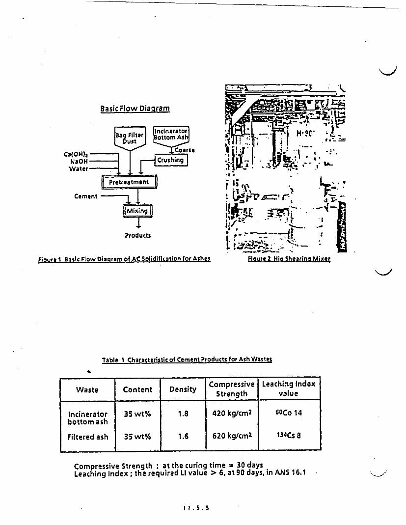
Basic Flow DiaQram
Ca(OH)2N3OH
Cement
Products Products -ii~~~~~P -
O - *
Figure 1 Basic Flow Diagram of AC Solidifii3tion for Ashes Figure 2
Table I Characteristic of Cement Products for Ash Wastes
Hig Shearing Mixer
Waste Content Density Compressive Leaching IndexStrength value
Incinerator 35 wt% 1.8 420 kg/cm2 6OCo 14bottom ash
Filtered ash 35 wt% 1.6 620 kg/cm2 134Cs 8
Coressive Strength ; at the curing time = 30 daysLeaching Index; the required LI value > 6, at 90 days, in ANS 16.1
1 1.5.5

a"--
Figure 4 HF Induction Heating MelterFigure 3 Basic Flow of Pilot Plant of HFIM
Figure 5 Canister Holder p . .- -.. .*a*- -!..-~..
I
. .
Figure 6 Off gas Treatment System
.. ,U
Figure 7 Vitrified Product Block
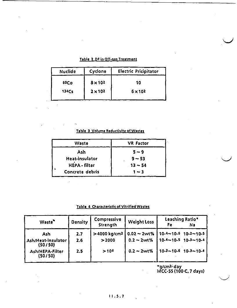
Table 2 OF in Off-gas Treatment
Nuclide I Cyclone I Electric Pricipitator
6OCo
134Cs
8x10²
2x 10²
10
6x10²
Table 3 Volume Reductivity of Wastes
Waste VR Factor
Ash 5 9
Heat-insulator 9 53HEA filter 13 54
Concrete debris 1 - 3
Table 4 Characteristic of Vitrified Wastes
Waste Density Compressive Weight Loss Leaching Ratio*.nsay Strength Fe Na
Ash 2.7 >4000kg/cm2 0.02-2wt% 10-4-10-6 10-2-10.SAsh/Heat-insulator 2.6 >2000 0.2- 2wt% 10-4-10-5 10-3-10-4
(50 /50)Ash/HEPA-Filter 2.5 > 104 0.2-2wt% 10-3-10-6 10-3-10-4
(50/ 50)
%lg/cm2 - dayMCC-5S (1 00*C. 7 days)
II .. 7

JGPART 5
DESIGN AND CONSTRUCTION
OF VIRGINIA POWER
LOW LEVEL RADWASTE
FACILITIES PROJECT
5-1

PROJECT OVERALL SCHEDULE
ACTIVITY 1987 198X '989 1990 1991
BASIC DESIGN * U UI Nunn
:.w,
DE-AILED DESIGN Ems **EE**U
LICENSE * *
CONSTRUCTION(NORTH ANNA#
CONSTRUCTION (SURRY) .,
START -UP TEST &TRAINING
PROCUREMENT.,, * EIM,"4
. ores sot
PROJECT OFIFCELOCATION I
. , .wa__ _ __ _ __ _ :_ _ s 4~ _ __ _ _ _ _ _ _ _ _ _
'~Memo ;
5-2

OUTLINE OF NRF BUILDING
Memo
5-3
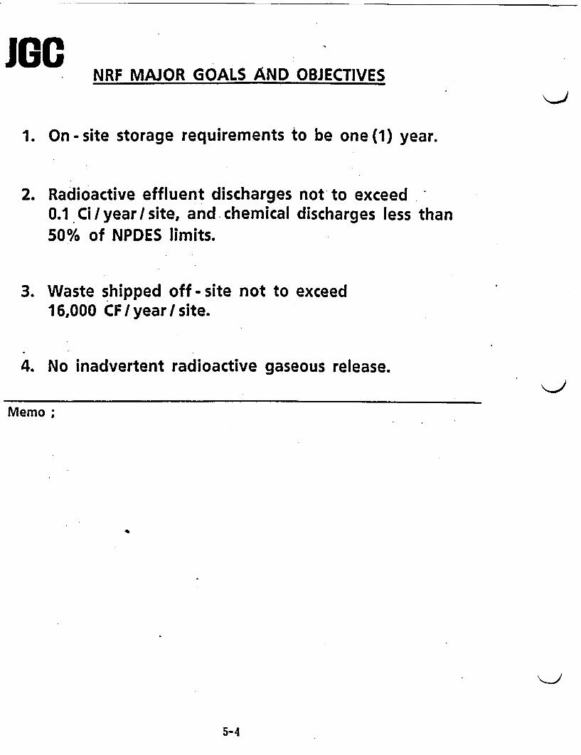
NRF MAJOR GOALS AND OBJECTIVES
1. On -site storage requirements to be one(1) year.
2. Radioactive effluent discharges not to exceed0.1 Ci,/year/site, and chemical discharges less than50% of NPDES limits.
3. Waste shipped off -site not to exceed16,000 CF / year / site.
4. No inadvertent radioactive gaseous release.
Memo;
5-4

JOGBLOCK FLOW FOR SURRY'S NEW RW FACILITY ACTIVITY SHIPPING
RELEASE VOLUME(Ci / YR]j IFT3 / YRI
I LIQ RADWASTE EAORATOR DEIERLIZE I-
I~J-IP DEMINERALIZER Lt ITUMENIZATION
0.042
-a..
| LAUNDRY WASTE
LA RESI
-��lLTER . , >
0.037
0.013
3,852
679I- IA U cUrM . ,-bI n I
I _ .... - -- -
- HIC -
I OILY WASTE 1 TA1Ig17ATI'n II ' I - ,
DAW
i ; -, II. I
HIGH PRESSURE I} ------ i ------- ------- L--- .0 COMPACTOR 70_ 8,430
TOTAL 0.092 12.961
GOAL 0.1 16,000
Memo ;
5-5
PROJECT FEATURES- SCOPE OF WORK
Memo ;
5-6
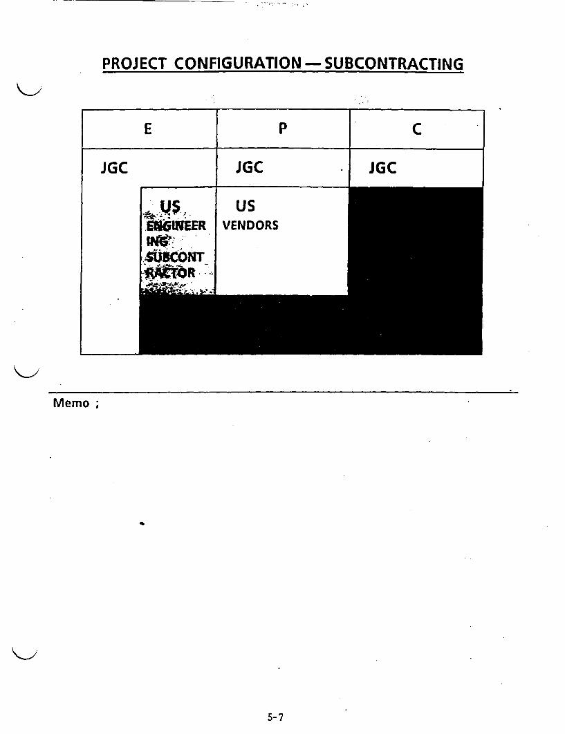
PROJECT CONFIGURATION -SUBCONTRACTING
E_ P C
JGC JGC JGC
Memo;
5-7
PLASTIC MODEL
Memo;-
5-8
~~~~~~~~~~~~~~~~~~~~~~~~~~~~~~~~~~-1
- ~~~~~~~~~~~~~~~~~~~~~~~~~~~~~~~~~~~' K. l.!~~ ~ ~~~~~~~~~~~~~~~~~~~~~~~~~~ a_ I
=!8 E _x r~~~~~~~~~~~t
~~~~~~~~~~~b L , A. i
3 - D CAD MODEL
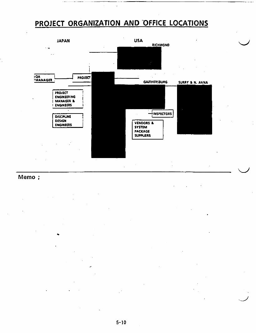
PROJECT ORGANIZATION AND OFFICE LOCATIONS
JAPAN
I QA
MANAGER _PRJEC
IPROJECTIIENGINEERINGIMANAGER &
ENGINEERS |
ISI NIENEERS _
USAOND
SURRV L AlA
Memo ;
5-10
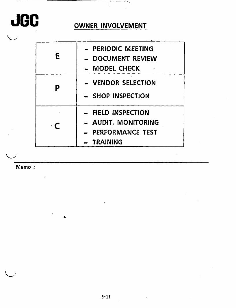
JGC OWNER INVOLVEMENT
- PERIODIC MEETING
E _ DOCUMENT REVIEW
MODEL CHECK
p - VENDOR SELECTION
- SHOP INSPECTION
- FIELD INSPECTION
c - AUDIT, MONITORING- PERFORMANCE TEST
- TRAINING
Memo ;
5-11
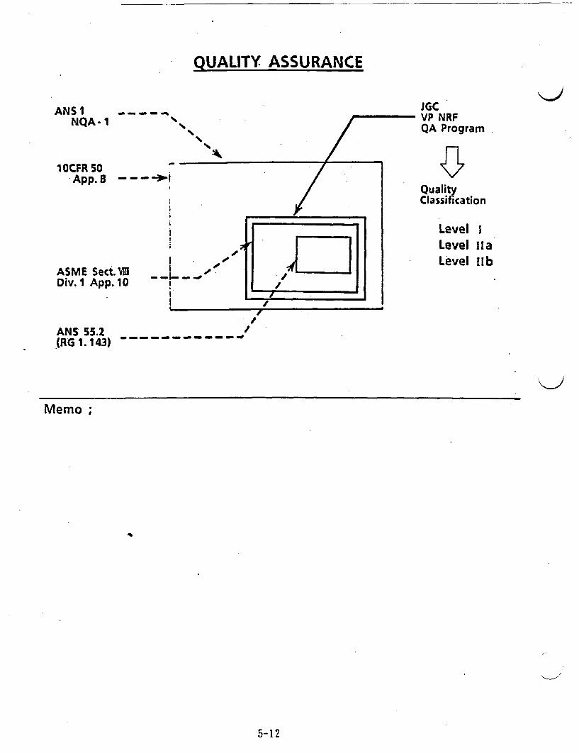
QUALITY ASSURANCE
ANS NQA-
- --- -~1JGCVP NRFQA Program
1 OCFR O-App.B -- -1
ASME Sect.V3 _I- -I.Div.1I App. 10
QualityClassification
Level ILevel laLevel ub
ANS 55.2(RG 1. 143) - - -
Memo ;
5-12
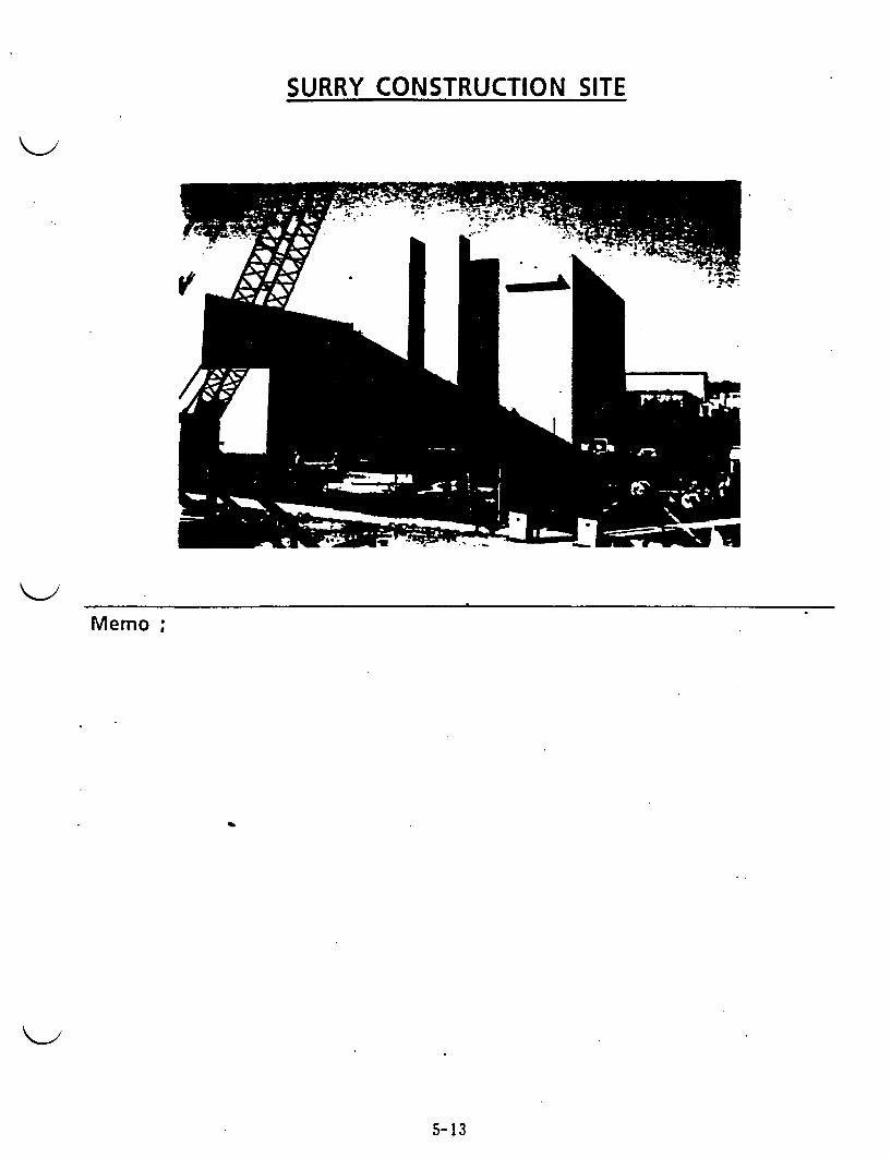
SURRY CONSTRUCTION SITE
Memo;
5-13
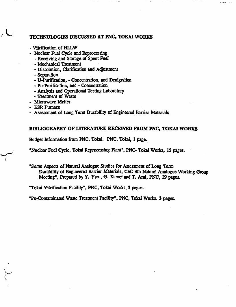
TECHNOLOGIES DISCUSSED AT PNC, TOKAI WORKS
- Vitrification of HLLW- Nuclear Fuel Cycle and Reprocessing
- Receiving and Storage of Spent Fuel- Mechanical Treatment- Dissolution, Clarification and Adjusunent- Separation- U-Purification, - Concentration, and Denigration- Pu-Purification, and - Concentration- Analysis and Operational Testing Laboratory- Treatment of Waste
- Microwave Melter- ESR Furnace- Assessment of Long Term Durability of Engineered Barrier Matas
BIBLIOGRAPHY OF LITERATURE RECED FROM PNC, TOKAI WORKS
Budget Information from PNC, Tolmi. PNC, Tolai, 1 page.
*Nuclear Fuel Cycle, Tokai Reprocessing Plant', PNC- Tokai Work3, 15 pages.
'Some Aspects of Natural Analogue Studies for Assessment of Long TermDurability of Engineered Barrier Materials, CEC 4th Natural Analogue Working GroupMeeting', Prepared by Y. Yusa, G. Kamei and T. Arai, PNC, 19 pages.
*Tokai Vitrification Facility', PNC, Tokai Works, 3 pages.
*Pu-Contaminated Waste Treatment Facility', PNC, Tokai Works. 3 pages.
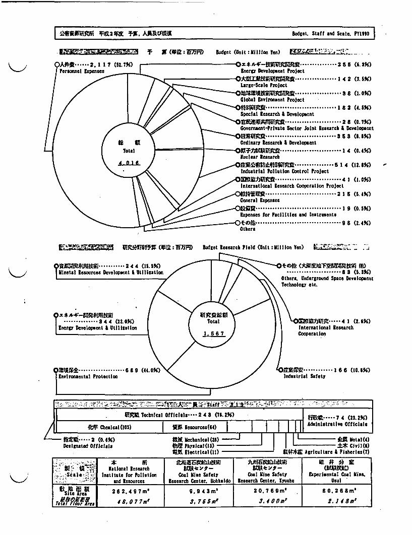
I iMIRAMM *Xt22M TX. AAREINIR Budget. Staff and Scale. PY199 II W. ~ 2 t~ R.5~IBugt tf n cl.PI3
w c~-- T- E(AtM: WF Budget (Unit :UliIlon en) M : 1-12V- -_
_ . h
Dl 4 �-�IiH�1Il1IU.Energy Development roject
wOdl21,Yw"I.....
.. ... 2 5 5 (6.3%)
......... 14 2 (3.5%)Large-Scale Project
)14MIMR .... S ( .0%)Global Environment Project)S ......................... 1 8 2 (4.5%)Special esearch & DevelopmentMU MO YM ........... 2 8 (7X)Government-Private Sector Joint Research & Development
M'RVtr& ............... 9 5 3 (8.1%)Ordinary Research & Development
)XI .................. 1 4 (0.4%)Nuclear Researeb)VA04MLOW.5 ................ 1 54 (12.8%)Industrial Pollution Control Project
OWtY fi ........................... 4 1 .0%)International Research Cooperation Project). .2 1 5 (5. 4%)General Expenses
2 9 %.............. 1 05Expenses for Facilities and Instruments
)5sft .......... 9 8 (2.4%6)Others
IUMMIMF (OM: 9MID Budget Research Fleld (Unit :illilon Yn) t _ ;
...... 8 3 (5.3%)Others. Underground Space DevelopmentTechnology etc.
~ . - - -*> - - .7 . - I
/iR Technical Offclals**.. 24 3 (76.2%) i . .. 7 4 (23.2%)
ii {t CbeRleAl0lO) ' Ri Resources(64) | I I I A £dinistrative Officials
- 2 ( O. %) #1MK 1 iech an l a l(2 8 L.6...................J IeI -ca -) i R m etal(4 )Designated Officials 1 PlysICal(i,) i* Cvil(S)
X% Electrical (I) 2 Agriculture I Eisheries(7)
ffi r g~fl~rt! National Research Em4ed3 _E# g_ ( z)I -Sale !-' Institute or Pollution C0al ine Satety Coal Kirke Safety Experibental Coal lline.
________ _ ¢ and Resources Research Center. blkaido Research Center. Iyushu Usul
iSte Cae 262.497m' 9.943m' 20.769m' 80. 26 m'
Te700piges 4 8. 0 7 7m9 3. 7 6 5ml 3. 4 0 Om' 2.1 8m'

I
I

I2
I
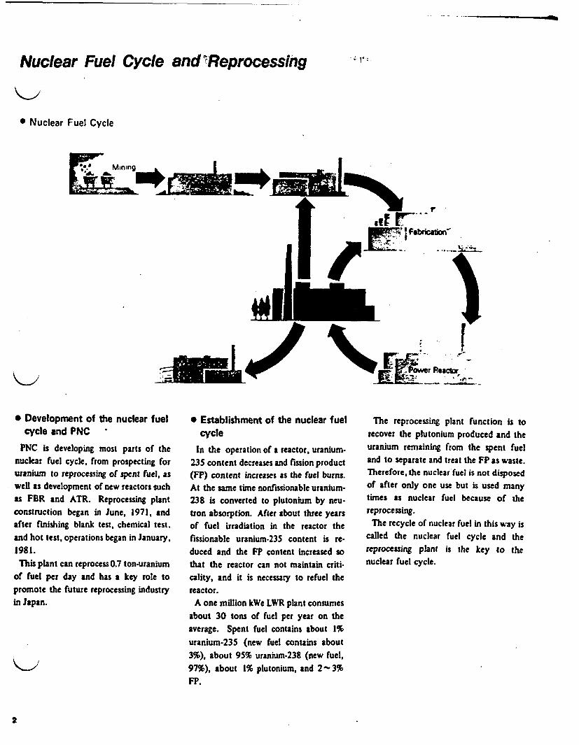
-
Nuclear Fuel Cycle and'Reprocessng
* Nuclear Fuel Cycle
Mining
~zMJ
I.
F
...- _ 14., "i'l
.1j M. ' "
* Development of the nuclear fuelcycle and PNC
PNC is developing most parts of thenuclear fuel cycle, fom prospecting foruranium to reprocessing of spent fuel, aswell as development of new reactors suchas FBR and ATR. Reprocessing plantconstruction began in June, 1971, andafter finishing blank test, chemical test.and hot test, operations began in January,1981.
This plant can reprocess 0.7 ton-uraniumof fuel per day and has a key role topromote the future reprocessing industryin Japan.
* Establishment of the nuclear fuelcycle
In the operation of a reactor, uranium-235 content decreases and fission product(FP) content increases as the fuel burns.At the same time nonfissionable uranium-238 is converted to plutonium by neu-tron absorption. After about three yearsof fuel irradiation in the reactor thefissionable uranium-235 content is re-duced and the FP content increased sothat the reactor can not maintain criti-cality, and it is necessary to refuel thereactor.
A one million kWe LWR plant consumesabout 30 tons of fuel per year on theaverage. Spent fuel contains about 1%uranium-235 (new fuel contains about3%), about 95% uranium-238 (new fuel,97%), about 1% plutonium, and 2 3%FP.
The reprocessing plant function is torecover the plutonium produced and theuranium remaining from the spent fueland to separate and treat the FP as waste.Therefore, the nuclear fuel is not disposedof after only one use but is used manytimes as nuclear fuel because of thereprocessing.
The recycle of nuclear fuel in this way iscalled the nuclear fuel cycle and thereprocessing plant is the key to thenuclear fuel cycle.

J View of Main Plant
ie of main plant-t capacity About 0.7 Metric ton of uranium per daynt fuel to be processed Enriched uranium fuelCladding material Zircaloy or stainless steelBurn-L o About 28,000MWD/t (Average)Specific power About 35 MW/t Average)Cooling time 180 days (Minimum)Enrichment 4% (Maximum)
)e of process Purex process with chop and leachductUranium trioxide (U03Plutonium nitrate Pu(N0 3 )4)
1 Truck airlock2 Cask decontamination room3 Fuel unloading pool4 Fuel Storage pool5 Mechanical treatment cell6 Dissolver loading cell7 Feed adjustment cell8 Separation cells9 U-purification cell10 Pu-purification cell11 Utility room12 Control room
3

II ~~I
III
PI
To 5[1111:Si~I
a
I
I
f
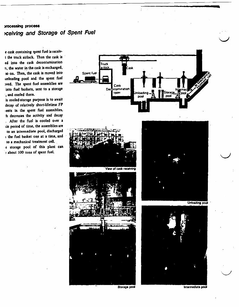
- -
I proces
ceiving and Storage of Spent Fuel
e cask containing spent fuel is receiv-t the truck airlock. Then the cask ised into the cask decontaminationn, the water in the cask is exchanged,so on. Then, the cask is moved into Spent fuelunloading pool and the spent fuelwed. The spent fuel assemblies areinto fuel baskets, sent to a storage
and cooled there.is cooled-storage purpose Is to awaitdecay of relatively short-lifetime FPtents in the spent fuel assemblies,h decreases the activity and decay. After the fuel is cooled over aiin period of time, the assemblies areto an intermediate pool, discharged
i the fuel basket one at a time, andto a mechanical treatment cell.
e storage pool of this plant canabout 100 tons of spent fuel.
I
Soage* pod

Reprocessing process
M-^hanical Treatment
The spent fuel assemblies sent to themechanical treatment cell from the stor-age pool have the end parts of the fuelassemblies removed, and then the remain-der is chopped into pieces about Scm(3 inches) long. These fuel pieces aresent to a dissolver in the dissolver cell.Solid wastes, such as the end parts of thefuel assemblies which have been off first,and the hulls (fuel element clad) whichdon't dissolve in the dissolver, are put intoa waste container and stored in a highactive solid waste storage facility.
The mechanical treatment cell is sur-rounded by a concrete wali.about 150cmthick. Viewing windows and manipu-lators are set up for remote operation ofthe chopping work. A decontaminationcell and airlock cell are also set up for
and maintenance of the machinery.
7
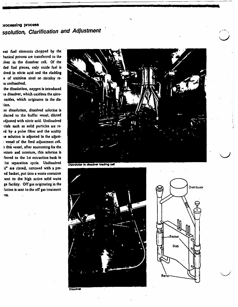
oceslng procei
ssolutlon, Clarification and Adjustment
ent fuel elements chopped by thehanical process are transferred to theAlver in the dissolver cell.- Of theded fuel pieces, oniy oxide fuel isAved in nitric acid and the claddinge of stainless steel or.zircaloy re.is undissolved.the dissolution, oxygen is introducedie dissolver, which oxidizes the nitro-oxides, which originates in the dis-tion.:er dissolution, dissolved solution isferred to the buffer vessel, diluted
adjusted with nitric acid. Undissolvedrals such as solid particles are re-d by a pulse filter and the acidity
ie solution is adjusted in the adjust-vessel of the feed adjustment cell.
i this vessel, after accounting for themnium and uranium, this solution isferred to the Ist extraction bank in1st separation cycle. ndissolved M , issoIoin g cs" are rinsed, removed with a per.ed basket, put into a waste containersent to the high active solid wastege facility. Off gas originating in the . k )lution is sent to the off gas treatment D!SL ' ' '
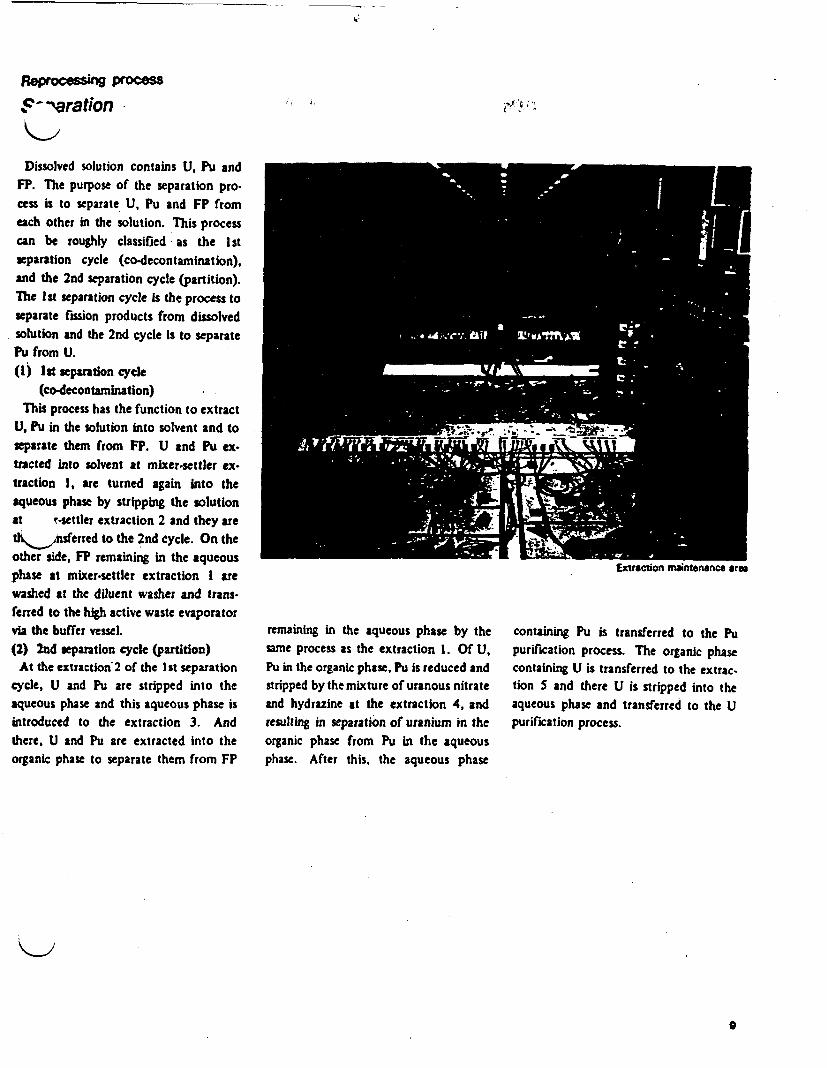
Reprocessing process
$ 'aration .. - i. -N, i
Dissolved solution contains U, Pu andFP. The purpose of the separation pro.cess is to separate U, Pu and FP fromeach other in the solution. This processcan be roughly classified as the I stseparation cycle (co-decontamination),and the 2nd separation cycle (partition).The st separation cycle Is the process toseparate fission products from dissolvedsolution and the 2nd cycle is to separatePu from U.(I) Ist separation cycle
(co-decontamination)This process has the function to extract
U, Pu in the solution into solvent and toseparate them from FP. U and Pu ex-tracted Into solvent at mixer-settler ex-traction I, are turned again into theaqueous phase by stripping the solutionat T-settler extraction 2 and they ared,,Aisferfed to the 2nd cycle. On theother side, F remaining in the aqueousphase at mixer-settler extraction I arewashed at the dfluent washer and trans-ferred to the high active waste evaporatorvia the buffer vessel.(2) 2nd separation cycle (partition)
At the extraction2 of the 1 st separationcycle, U and Pu are stripped into theaqueous phase and this aqueous phase isintroduced to the extraction 3. Andthere, U and Pu are extracted into theorganic phase to separate them from FP
tracon mantenance area
remaining in the aqueous phase by thesame process as the extraction 1. Of U,Pu in the organic phase, Pu is reduced andstripped by the mixture of uranous nitrateand hydrazine at the extraction 4, andresulting in eparation of uranium in theorganic phase from Pu in the aqueousphase. After this, the aqueous phase
containing Pu is transferred to the Pupurification process. The organic phasecontaining U is transferred to the extrac-tion and there U is stripped into theaqueous phase and transferred to the Upurification process.
0

xocessing process
purification, -concentration and Denitratlon
he solution containing U that is stripp-uito the aqueous phase at the extrac-1 5 of the 2nd separation cycle isisferred to the extraction 6 of the Uification cycle. There, U is separated-n the trace of FP by the solvent as inextraction I and they are purified.
!parated U is transferred to the extrac-7, stripped again into the aqueous
se by dilute acid and then transferredthe U concentration-denitration pro-
-containing solution (uranyl nitrate)isferred to the U concentration-deation is concentrated in the I st evapo-ir. This concentrate, keeping a con-it concentration, is removed from the3orator and after cooling it is trans.ed to the dilute vessel via the con-trate receiver. At this-vessel, inspec-, is done and if within specification itansferred to the feed vessel.ic concentrate transferred to tis feedel is re-concentrated at the 2nd evapo-r, transferred to the denitrator viabuffer vessel and there it is decom-
!d into U03 powder.33 powder is continuously removedn the bottom of the denitrator, pack.nto the container as final product andto U03 storage.
I
Uraniun nitrae and ursium tnoxide
inciple of Solvent Extraction MethodJ Mixer-settlerthe eprocess plant, the main techniquecovering U and Pu from spent fuel is thent extraction method.a method has the function of extractingA elements from the nitric acid solutionting from disolving spent tuels, conversionorganic solvent or stripping elemats fromrunk phasc into ShC aqueous phase and
example, at the I t separation cycle that-he function of spra"ting U. Pu rom FP.d P Is extracted into the organic phaseie the higher acidity makes it them casy to
In n the organic phase. Under this con-. F? remain in the aqueous phase becausesolubility.
is FP are separated from U and Pu. And U.the organic phase ae able to be stripped
into the aqueous phase because the loweracidity makes it easier to dissolve In the aqueousphase than in the organic phase.
Furthermore, tetravalent P In the organicphase is reduced to trivalent Pu by a reductionreagent. Trivalent Pu is so insoluble in theorganic phase and Is stripped into the aqueousphase. So Pu is separated from U remaining inthe orgnic phase. Thus, repeating the extrac-tion, stripping and Pu stripping make it posibbeto separt U.Pu and F? firom each osha.* The mixer-settler consists of the mixing partand the settling part.
mixing part contacting the organic solventwith acid solution
settling part: dividing the aqueous phaseFor example, at she extnaction 1 * the extrac-
tion operation proceeds as in the figure.Rea mixer-ettlers differ in size from each
other, but a model is shown in the photo.
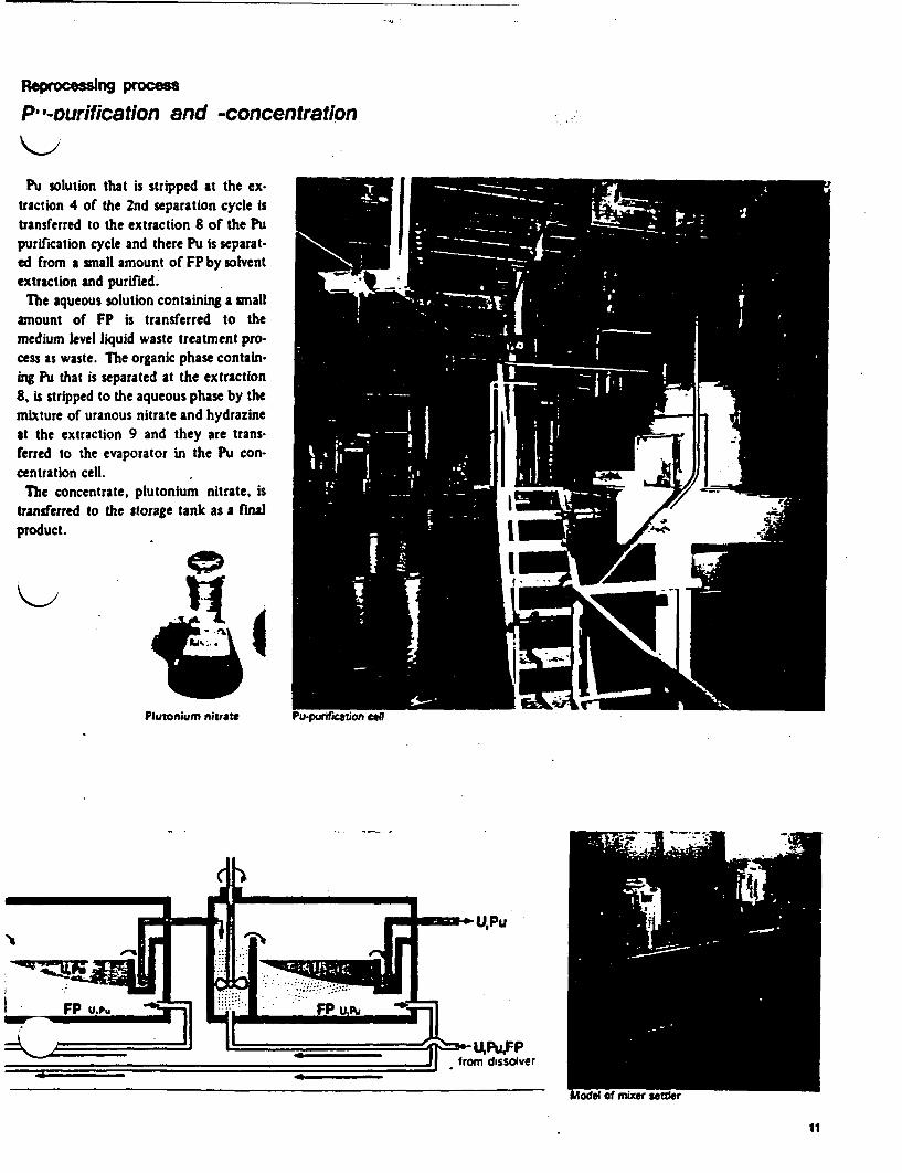
Reprocesing pcs
Pa-ourification and -concentration
Pu solution that is stripped at the ex-traction 4 of the 2nd separation cycle istransferred to the extraction 8 of the Pupurification cycle and there Pu is separat-ed from a small amount of FP by solventextraction and purified.
The aqueous solution containing a smallamount of FP is transferred to themedium level liquid waste treatment pro-cess as waste. The organic phase contain-ing Pu that is separated at the extraction8, is stripped to the aqueous phase by themixture of uranous nitrate and hydrazineat the extraction 9 and they are trans-ferred to the evaporator in the Pu con-centration cell.
The concentrate, plutonium nitrate, istransferred to the storage tank as a finalproduct.
Plutonium nitrate Pu-ourificatios
11
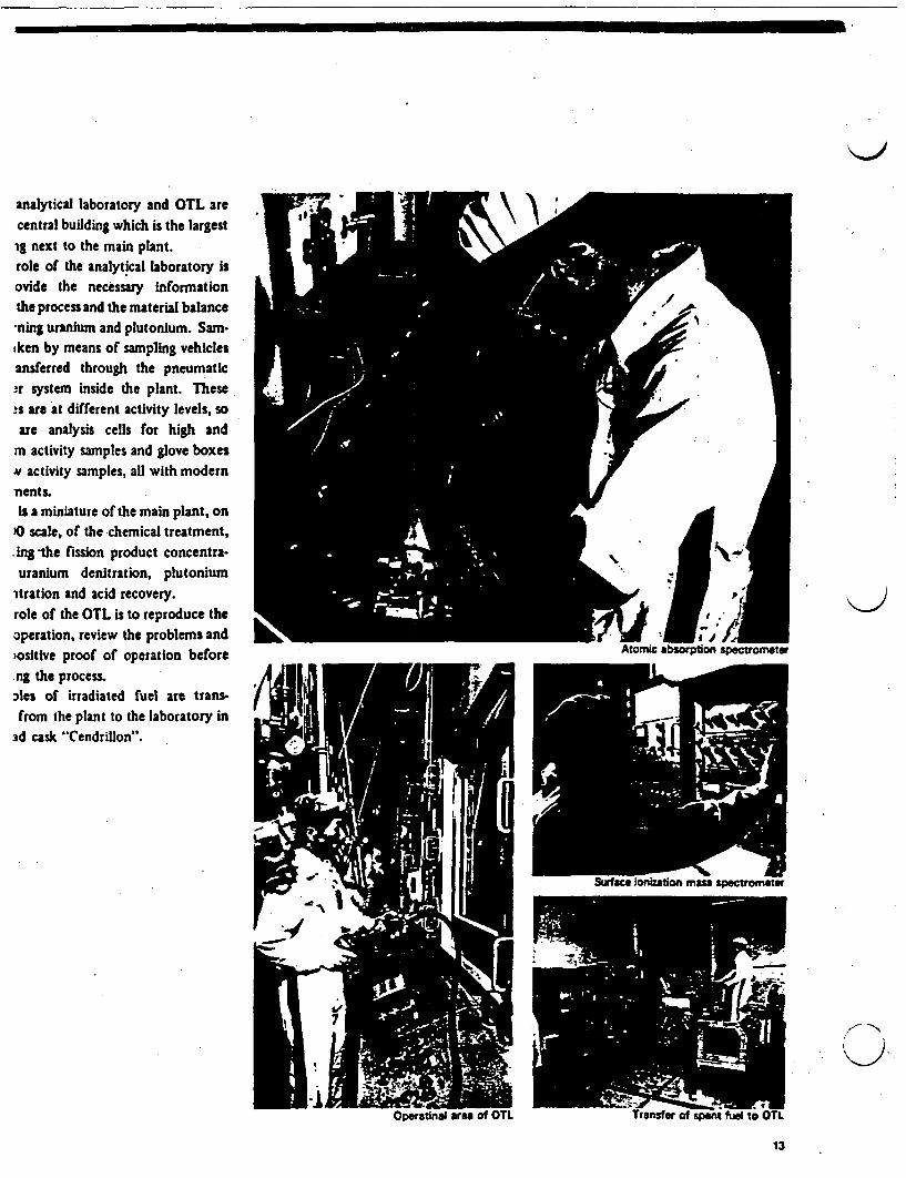
analytical laboratory and OTL arecentral building which is the largestig next to the main plant.role of the analytical laboratory isovide the necessary informationthe process and the material balance _'-ning uranium and plutonium. Sam-iken by means of sampling vehiclesansferred through the pneumatic-r system inside the plant. These!s are at different activity levels, soare analysis cells for high and
m activity samples and glove boxeswN activity samples, all with modernnents.is a miniature of the main plant, on
O scale, of the chemical treatment,*ing the fission product concentra-uranium denitration, plutonium
itration and acid recovery.role of the OTL is to reproduce theoperation, review the problems andiositive proof of operation before Atomic absorpion spectomete
.ng the process.Ales of irradiated fuel are trans- /_from the plant to the laboratory in
ad cask "Cendrillon". !_
Surfae ionizatio mass sectometer
N~~~~~~~~~
13
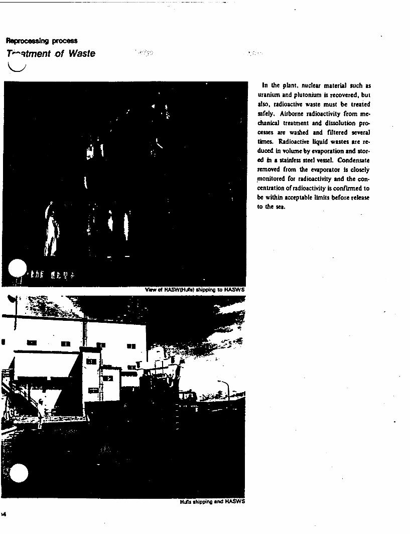
Reproesing Proce
TPtment -of Waste --
In the plant, nuclear material such asuranium and plutonium is recovered. butalso, radioactive waste must be treatedsafely. Airborne radioactivity from me-chanical treatment and dissolution pro-cesses are washed and filtered severaltimes. Radioactive liquid wastes are re-duced in volume by evaporation and stor-ed a stainless steel vessel. Condensateremoved from the evaporator is closelymonitored for radioactivity and the con-centration of radioactivity is confirmed tobe within acceptable limits before releaseto the sea.

Gsous Witst of the radioactive gaseous waste; from the dissolution process andnechanicai treatment process. with ai amount from various cell andI ventilation systems These gaseouses are assayed and filtered severals according to their activity level and
released to the atmosphere afterul activity monitoring.Liquid wasteh active level liquid waste (HALW) isly the aqueous raffinate from the I stration cycle, which contains nearlythe nonvolatile fission products.W is reduced in volume by evapora.and stored in underground tanktdium active level liquid wasteLW) is the raffiate from the 2ndration cycle, uranium purification: and plutonium purification cyclethe nitric acid solution recovered
i absorber of the uranium denitrationess and HALW concentration process..W is treated by the acid recoveryess. The distillate is reused in theess as recovered nitric acid and the
:entrate in the evaporator bottom issferred to the HALW evaporator.I active level liquid waste (ALW)1 other processes and facilities issferred to the auxiliary active facility.F) and stored temporarily accordingactivity level. The comparative highA{e liquid waste such as the raffinate K )n the solvent regeneration cycle isiced in volume by evaporation and itsdensate is transferred to the buffer Controonf AAFcs and the other concentrate is storedessels#ie other liquid waste such as laundryte is treated by flocculation, andled other water is transferred to bufferks and the sludge is stored in vessels.
reduce the sea-discharge activities,itionally two evaporator stations forLW (E and Z facility) were constructeder start of hot operation. For therained TBP, the de-oiling station (Cility) was installed before sea-dischargenitoring vessels.he water is carefully monitored andimined, and the concentration df radio-ivity is determined to be within accept.e limits before release to the sea.
Solid wastefigh active level solid waste (HASW)isists of the end plugs of spent fuelemblies sheared in the mechanicalatment process and insoluble hullsm the dissolving process. HASW isntained in stainless steel drums and)red in HASW storage .ow active level solid waste is sorted as
mbustible waste or non-compressibleiste, which is either incinerated, com- 0cted or placed in drumLThese treated wastes are stored in thevSW storage area. r J AL rrcs t n a dIu
.. -1 -~~~~~~~~~~~~~1
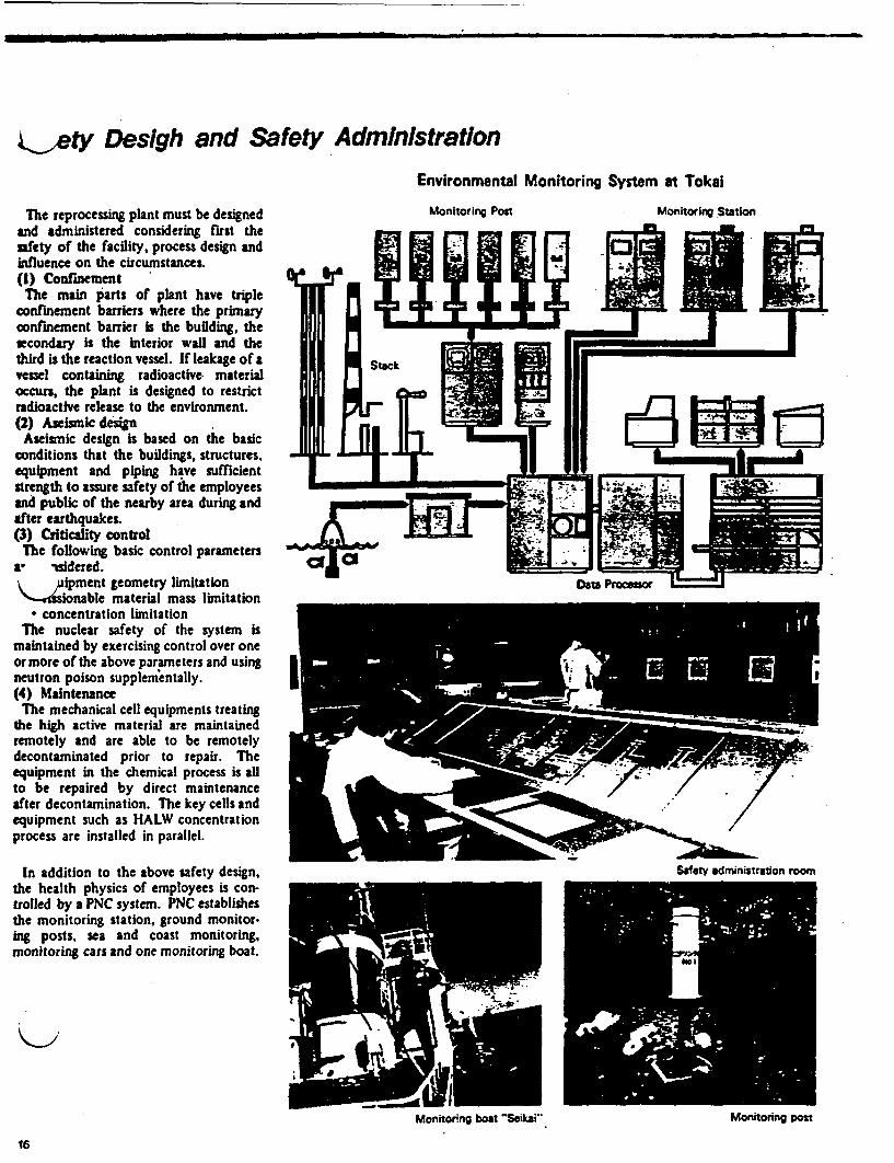
Sety Desigh and Safety AdministrationEnvironmental Monitoring System at Tokal
The reprocessing plant must be designedand administered considering first thesafety of the facility, process design andinfluence on the circumstances.(1) Confinement
The main arts of plant have tripleconfinement barriers where the primaryconfinement barrier Is the building, thesecondary is the interior wall and thethird is the reaction vessel. If leakage of avessel containing radioactive materialoccurs, the plant is designed to restrictradioactive release to the environment.(2) Aseismic design
Aseismic design is based on the basicconditions that the buildings, structures.equipment and piping have sufficientstrength to assure safety of the employeesand public of the nearby area during andafter earthquakes.(3) Criticality control
The following basic control parametersaL -sidered.V Sipment geometry limitation
sonable material mass limitationa concentration limitation
The nuclear safety of the system ismaintained by exercising control over oneor more of the above parameters and usingneutron poison supplementally.(4) Maintenance
The mechanical cell equipments treatingthe high active material are maintainedremotely and are able to be remotelydecontaminated prior to repair. Theequipment in the chemical process is allto be repaired by direct maintenanceafter decontamination. The key cells andequipment such as HALW concentrationprocess are installed in parallel.
In addition to the above safety design,the health physics of employees is con-trolled by a PNC system. PNC establishesthe monitoring station, ground monitor-ing posts, sea and coast monitoring,monitoring cars and one monitoring boat.
Monitoring Post Monitoring Station
Monitorng boat Seikaio Monitoring post

(C ( C
Present Status of R & D Activitieson HLLW and TRU Waste Conditi oning
in Tokai Works
November 1990
POWER REACTOR AND NUCLEAR FUELDEVELOPMENT CORPORATION(PNC) Pr---%NC

Major RD and D Activitieson HLLW and TRU Waste Conditioning
in Tokai Works.
R & D phase- HLLW : Vitrification by LFCM Process
- TRU Wastes: Nuclide Separation from Low Level Liquid Waste
Decomposition and Nuclide Separation from Spent Solvent
Demonstration phasePWTF : Pu - Contaminated Waste Treatment Facility
AspF : Bituminization Demonstration Facility
STF : Solvent Waste Treatment Facility
Q C (
HLLW Conditioning Technology

Vitrification TechnologY Development
Process Development
-kStorage
-V -Y -Y
- Cold Test (ETF, MTF, EDF-IlI)
_~ Hot Labo. Test (CPF)
: C C

(
Development of Vitrification Processand
Related Technology in PNC
c
ess!velopment(ETF, MTF)
LOD =E
I Off -Gas Treatment I~~~~~~~~~~I
I tFood L.,
r , -.
Glas ing.Off_"Lth )e I
I
Non -adioactie Leaching studylab, test
Glass properties
Pretreatment | M*
Feed Systemr.Evaporationkconcentrationf,* Air - lift i&
NM [Waste Glass Package _4 Package Handling
II ~ .
g . ..A9..09Y
-Canister material
* Heat & Cooling analysis-Lid Welding* Decontamination
* Joule - heat melter ."system IV LI
Radioactivelab. test
In CPF(CPF)* Dismantling / Z fV
ngineering(in EDF)
* Leaching test
Remote Operation/ Maintenance Technology- Rack system * Two -armed manipulator
Ventilation System, ISI, Instrumentations

ChemicalReagent
ScrubbingSolution
IodineAdsorber
HEPAFilter
ancentrateom secondaryiuid waste treatment'ocess
fromessing
FeedTank(1)
FeedTank(2) HEPA
Filter
WaterScrubber
AdditiveVenturiScrubber
Demister(HEME)
RuAdsorber
ReceivingTank
Canister
Vitrification Process Flow
( C

J
h.~6I :

TRU Waste Conditioning Technology
A
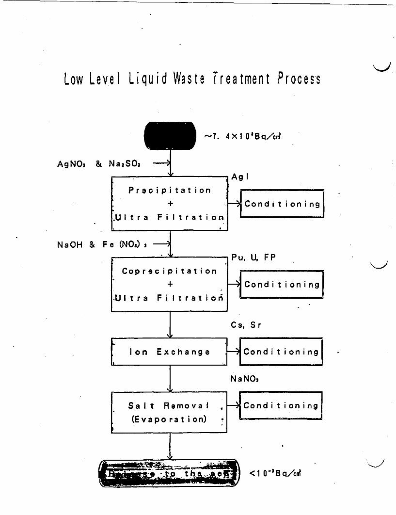
Low Level Liquid Waste Treatment Proce.s
Ag_~a & Na:S-7. 4I0'Bq/cr
AgNO3 & Na:SO,
NaOH &
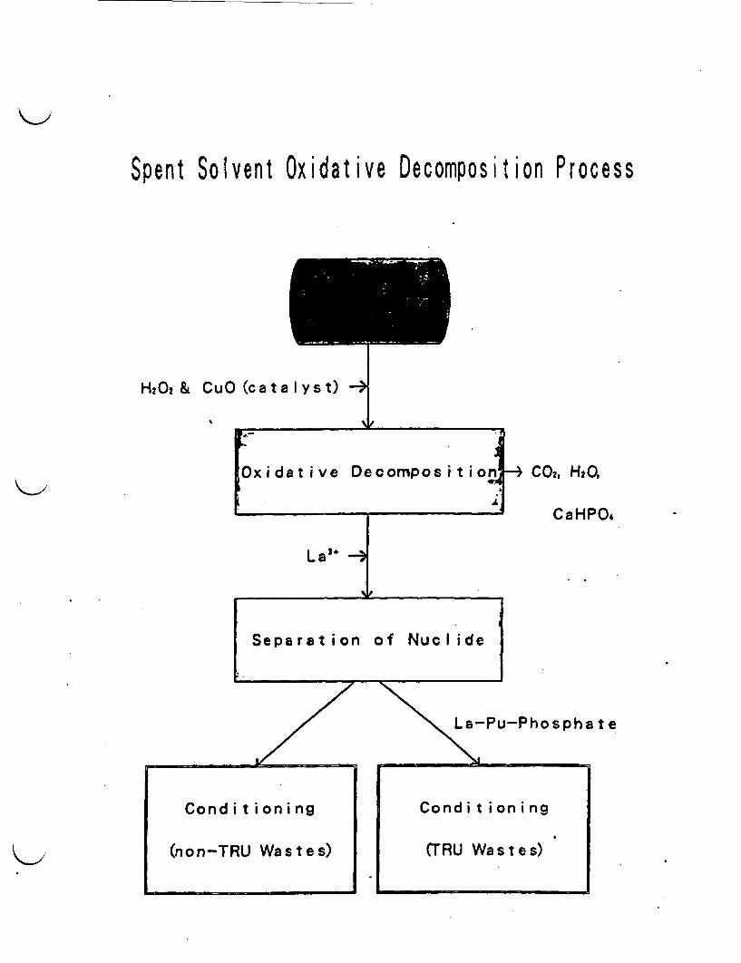
Spent Solvent Oxidative Decomposition P rocess
H 20 2 & CO (cata Iyst) -
p
Oxidative Decomposition
La` -i of N__I id
Separation of Nuclide
-- C02 , H2Q
CaHP0.
La-Pu-Phosphate
I
Present Status of
WVaste Treatment Facilitiesin Tokai Works
November 1990
POWER REACTOR AND NUCLEAR FUEL11 P� N (ODEVELOPMENT CORPORATION(PNC)
C c (
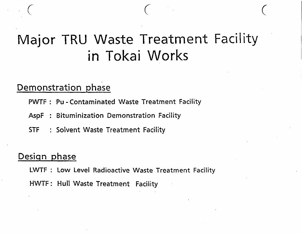
(C ( C
Major TRU Waste Treatment Facilityin Tokai Works
Demonstration phasePWTF
AspF
STF
Desiqn
: Pu - Contami nated Waste Treatment Facility
: Bituminization Demonstration Facility
: Solvent Waste Treatment Facility
phase_-LWTF: Low Level Radioactive Waste Treatment Facility
Hull Waste Treatment FacilityHWTF:
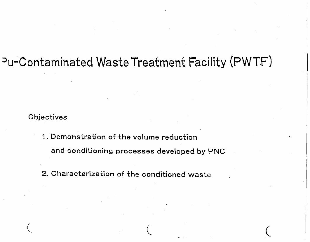
Du-Contaminated Waste Treatment Facility (PWTF)
Objectives
1. Demonstration of the volume reduction
and conditioning processes developed by PNC
2. Characterization of the conditioned waste
( ( c
(
3 9 9
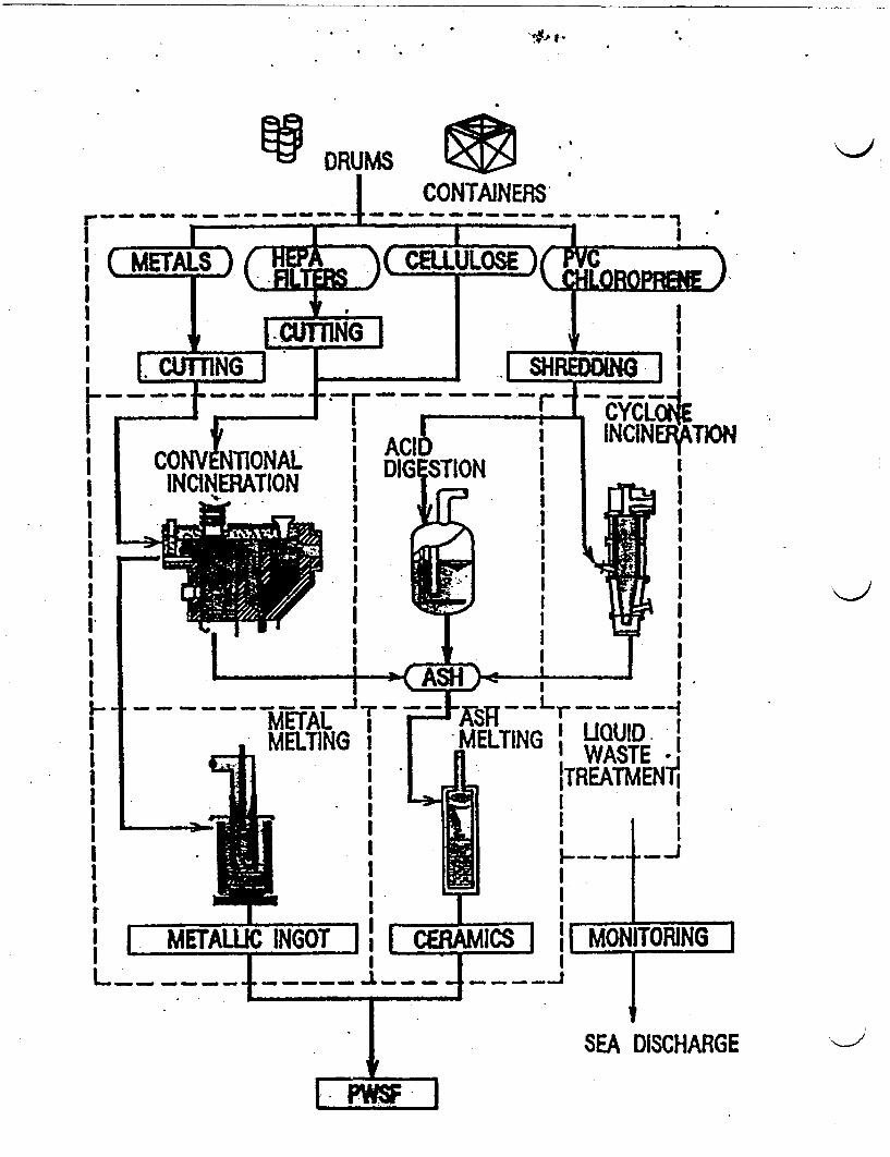
.PI-
io DRUMSCONTAINERS
I I - '
I ~~~~~~II I.1 II I
I. ~~~~II* I I
I II II I
ASHI I-- L~~~~~-
MELTING I UIQUID II WASTE' 1ITREATMENlI I
I~~~~~~~~~~~
II---III t
IIIIIIIII,t_II1| METAWLL__ __Z__9
IIIIII
I ~~~~~~~~~~-1
C INGOT k - - - - -
I -~ II CERAMICS II 1
MONITORING
.. .
ISEA DISCHARGE
-I-
LES Fw I
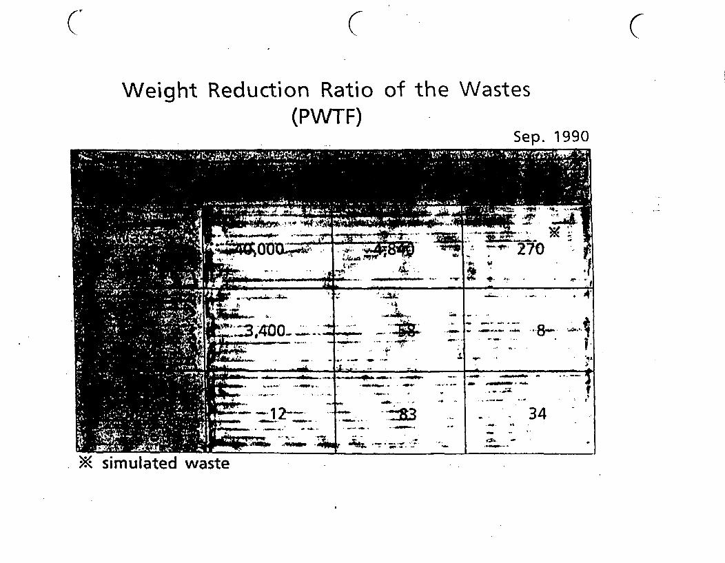
C~~~~~~~~~~~
Weight Reduction Ratio of the Wastes(PWTF)
Sep. 1990
>X simulated waste
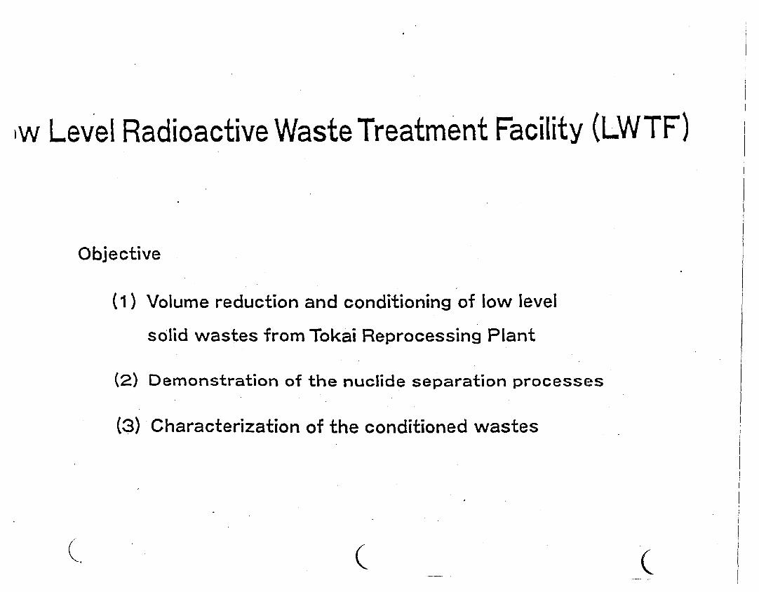
iw Level Radioactive Waste Treatment Facility (LWTF)
Objective
(1) Volume reduction and conditioning of low level
solid wastes from Tokai Reprocessing Plant
(2) Demonstration of the nuclide separation processes
(3) Characterization of the conditioned wastes
(Q ( C

[SOLID WASTE] [LIQUID WASTE)
DRUMS CONTAINERS
I [ CUTTINs .--------- T----------- t--------------- ----- -------- 4
-- - - - - - -I - - -- - - -
INCINER(ATION INCINERATIONIDECO&MI- ,HIGH P SSURED ULTRAFI RATION,ffi | ~~~NATION COMPACTON jg
' , 0 ~~ADSI TION.
,'~ ~. D-, , j SASH MELTING ,METAL MELTING FILMCTN
| ' @ ~~~~~1 SOLIDI0ICATION
a .a . ,
LASWS | ASP.-S
fACTt E r)D Dnf:4cINI I\1 I \A/T:
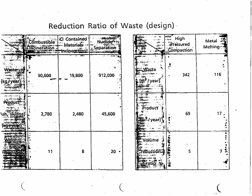
Reduction Ratio of Waste (design)
I
I
( C
( ( (
Present Status of Other Activiti eson Nuclear Fuel Cycle
in Tokai Works
November 1990
POWER REACTOR AND NUCLEAR FUEL fc-:))IF . (0DEVELOPMENT CORPORATION(PNC)
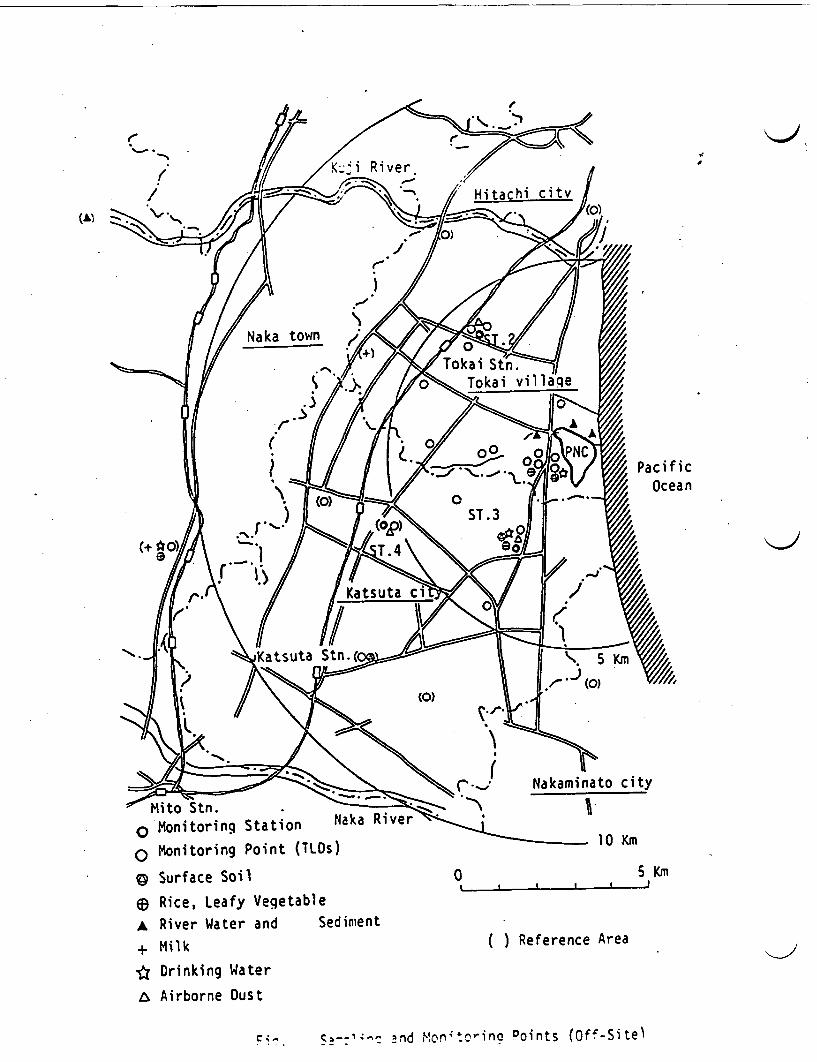
c
Mito Stn.o Monitoring Station Naka River
o Monitoring Point (TLOs)
C Surface Soil
63 Rice, Leafy Vegetable
A River Water and Sediment
+ Milk
* Drinking Water
A Airborne Oust
0 5 Km. . .
. . . . . .~~~~~~~
( ) Reference Area
c , , ,--1;'- nd Pont-oflC Points (Off-Site)
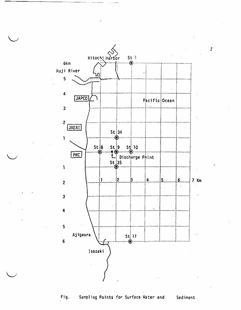
/ f
r St 1.......... .... . . .6km
Kuji River
5 >N
4
3
2
ES1 -
.,
.............
.............
..............
.............
i OceanI.............
............
I.............
...........
I ...........
St J (~~~~~~~~~~~~~~~~~~~~~~~~~~~
PNC
;..............St
i 4
i8 St
LSt.
...............
1
2
3
4
5
6
..........................
i34 .1 .
1~ 0
:9 st~~~~~~~~~
iDischarge Pint .::35 : :::
_...... ....... ......... ................. --------- *6-*5--o ---- :- - - --
: t: : 7 :. .. . . .. . . .. . . . . . . . .. . . . . .:.. . . .
7 Km
.I
.......................
................
Ajigaura
I sozaki
Fig. Sampling Points for Surface Water and Sed iment
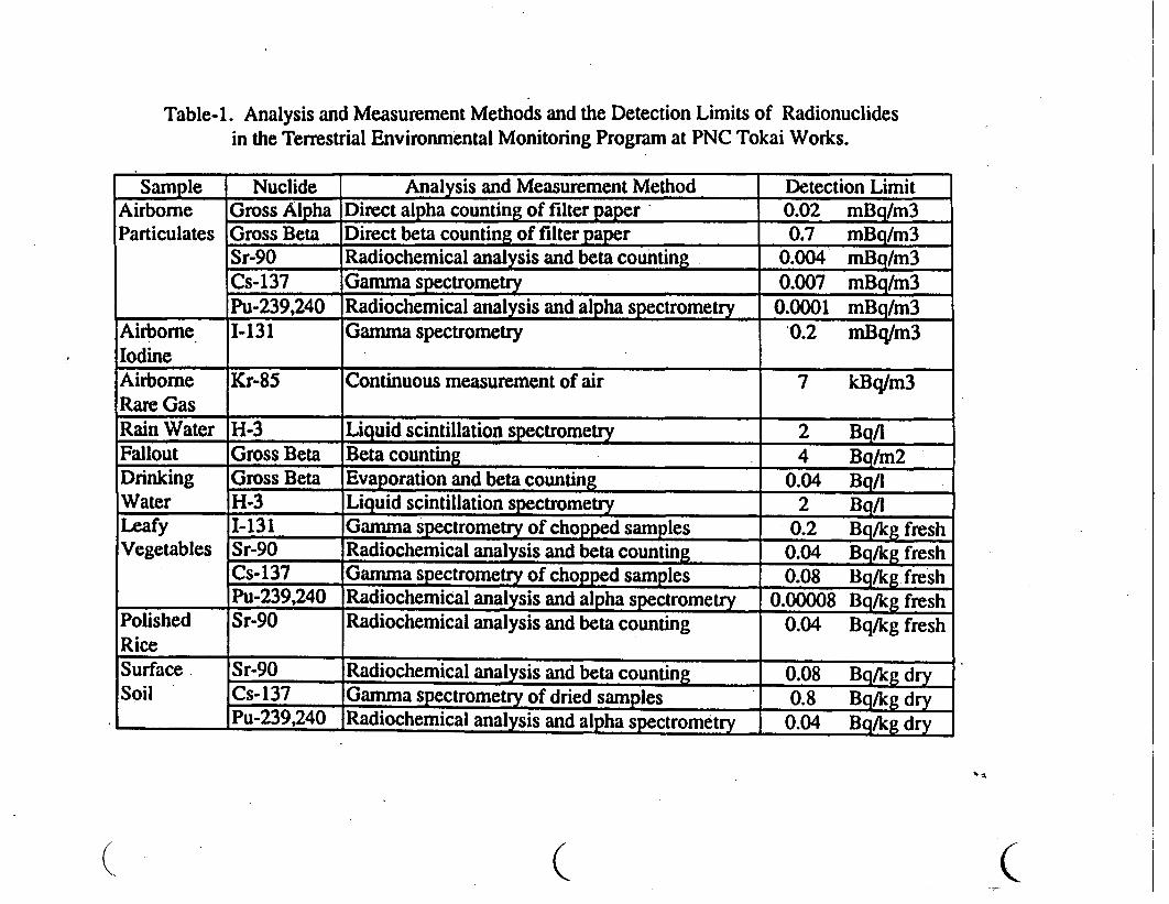
Table-1. Analysis and Measurement Methods and the Detection Limits of Radionuclidesin the Terrestrial Environmental Monitoring Program at PNC Tokai Works.
Sample Nuclide Analysis and Measurement Method Detection LimitAirborne G Alpha Direct alpha counting of filter paper 0.02 mBq/m3Particulates Gross Beta Direct beta counting of filter paper 0.7 mBq/m3
Sr-90 Radiochemical analysis and beta counting 0.004 mBq/m3Cs-137 Gamma spectrometry 0.007 mBq/m3Pu-239,240 Radiochemical analysis and alpha s ectromet 0.0001 mBq/m3
Airborne 1-131 Gamma spectrometry 0.2 mBq/m3IodineAirborne Kr-85 Continuous measurement of air 7 kBq/m3Rare GasRain Water H-3 Liquid scintillation spectrometry 2 Bq/lFallout Gross Beta Beta counting 4 Bq/m2Drinking Gross Beta Evaporation and beta counting 0.04 Bq/IWater H-3 Liquid scintillation spectrometry 2 Bq/lLeafy I-131 Gamma spectrometry of chopped samples 0.2 Bq/kg freshVegetables Sr-90 Radiochemical analysis and beta counting 0.04 Bq/kg fresh
Cs-137 Gamma spectrometry of chopped samples 0.08 Hg/kg freshPu-239,240 Radiochemical analysis and alpha spectrometry 0.00008 Bq/kg fresh
Polished Sr-90 Radiochemical analysis and beta counting 0.04 Bq/kg freshRiceSurface. Sr-90 Radiochemical analysis and beta counting 0.08 Bg/kg drySoil Cs-137 Gamma spectrometry of dried samples 0.8 Bq/kg dry
Pu-239,240 Radiochemical analysis and alpha spectrometry 0.04 Bq/kg dry
. ( C
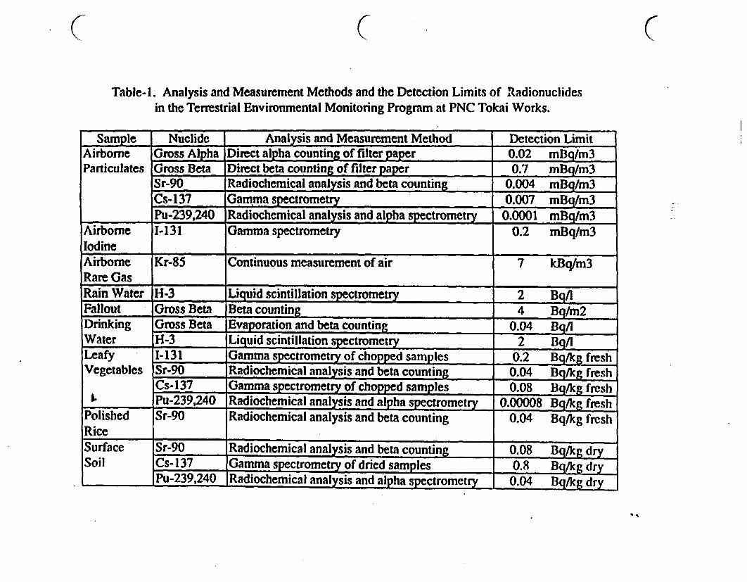
Table-i. Analysis and Measurement Methods and the Detection Limits of Radionuclidesin the Terrestrial Environmental Monitoring Program at PNC Tokai Works.
C
Sample| Nuclide Analysis and Measurement Method Detection LimitAirborne Gross Alpha Direct alpha counting of filter paper 0.02 mBq/m3Particulates Gross Beta Direct beta counting of filter paper 0.7 mBg/m3
Sr-90 Radiochemical analysis and beta counting 0.004 mBq/m3Cs-137 Gamma spectrometry 0.007 mBq/m3Pu-239,240 Radiochemical analysis and alpha spectrometry 0.0001 mBq/m3
Airborne 1-131 Gamma spectrometry 0.2 mBq/m3IodineAirborne Kr-85 Continuous measurement of air 7 kBq/m3Rare GasRain Water H-3 Liquid scintillation spectrometry 2 Bg/lFallout Gross Beta Beta counting 4 Bq/m2Drinking Gross Beta Evaporation and beta counting 0.04 Bq/lWater H-3 Liquid scintillation spectrometry 2 Bg/lLeafy 1-131 Gamma spectrometry of chopped samples 0.2 Bg/kg freshVegetables Sr-90 Radiochemical analysis and beta counting 0.04 Bq/kg fresh
Cs-137 Gamma spectrometry of chopped samples 0.08 Bq/kg fresh.s Pu-239,240 Radiochemical analysis and alpha spectrometry 0.00008 Bq/kg fresh
Polished Sr-90 Radiochemical analysis and beta counting 0.04 Bq/kg freshRiceSurface Sr-90 Radiochemical analysis and beta counting 0.08 Bq/kg drySoil Cs- 137 Gamma spectrometry of dried samples 0.8 Bq/kg dry
Pu-239,240 Radiochemical analysis and alpha spectrometry 0.04 Bq/kg dry

I
Hi6km
Kuji River
5 \
4JAP
3
2JAERI
1
lor St
..
,... .......................
St
A.............. .........................
* . ~P
St:34
.~~~~~~~~~p
8 St,9 S. 1
LDischarge PiSt 35 .@..~~~~~......
2 :3............. 2 .......... ;.
.............. ....... .........
5.............
..... i..
..............
3cif ice
..............
.............
ninti
............
, ...........
..... j..
............
.............!Ocean.............
.......................
1
2
3
4
5
6
PNC ......
.......
.....
Aj igaura.
..............
........
........
7 Km
I..... ..........
.... ; .............
S t: 1 7,A ........... :,,..........i
-A
1-1�
Fig. Sampling Points for Surface Water and Sed iment
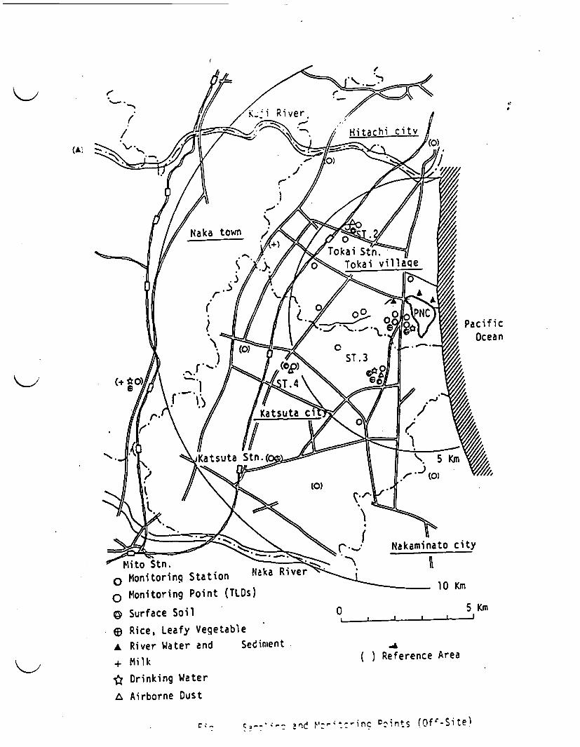
(At
"m it o S tn .
o Monitoring Station Naka River
o Monitoring Point (TLDs)
C Surface Soil
E6 Rice, Leafy VegetableA River Water and Sediment
+ Milk
* Drinking Water
A Airborne Dust
0 5 KmI . , I
( ) Reference Area
C z <, -; 3n ;n FI---Cin Dnts (Ofr-Si te}
Present Status of Other Activitieson Nuclear Fuel Cycle
in Tokai Works
"I November 1990
POWER REACTOR AND NUCLEAR FUEL'PWDEVELOPMENT CORPORATION(PNC)
( c C
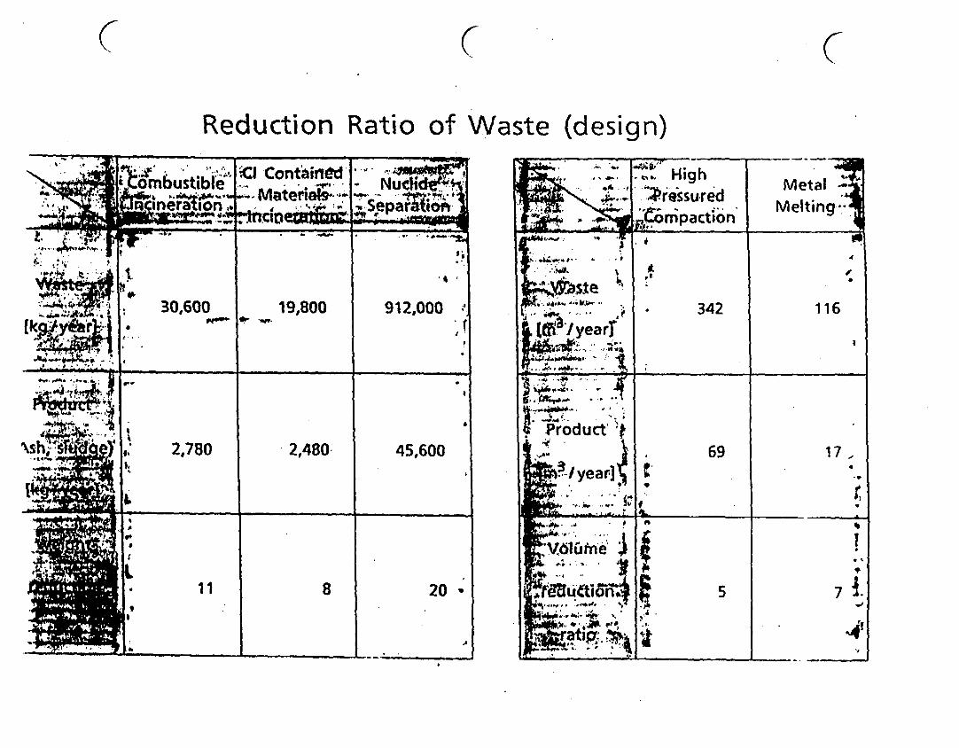
C C (7Reduction Rati o of Waste (design)
I I
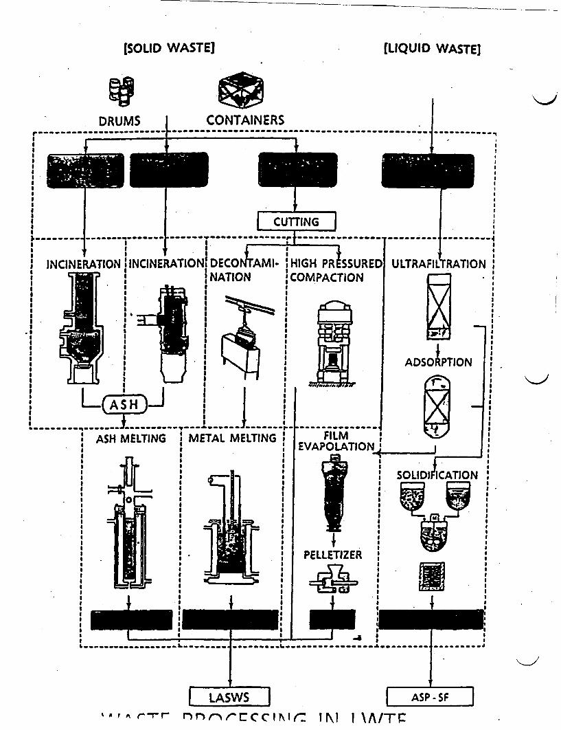
(SOLID WASTE) LIQUID WASTE]
CONTAINERS
I. . * .. ... .. ..*- I e
DRUMSe .. ... ..r
Jr
III
IIIIII
CUTTING
INCINERATION 1lNCINERATIONjtDECO l1- jHIGH PR SSUREDINCINERATIONATION : COMPACTION
ULTRAFI RATION*, 1 II
I iI
i. u I IsI
I ~~~~~~~~II I II II I
I II I~~~~~~~~ |ASH MELTING * METAL MELTINGI II iI II S:IIl
FILMEVAPOLATION
ELLETiZER i
I i
PtLLEtIZfER I*IEIII
II | I I -a S
I I~~~~~~~~~~
LASWS7 ASP -SF
'A, A rrr nnorfECIr IN I A/T:
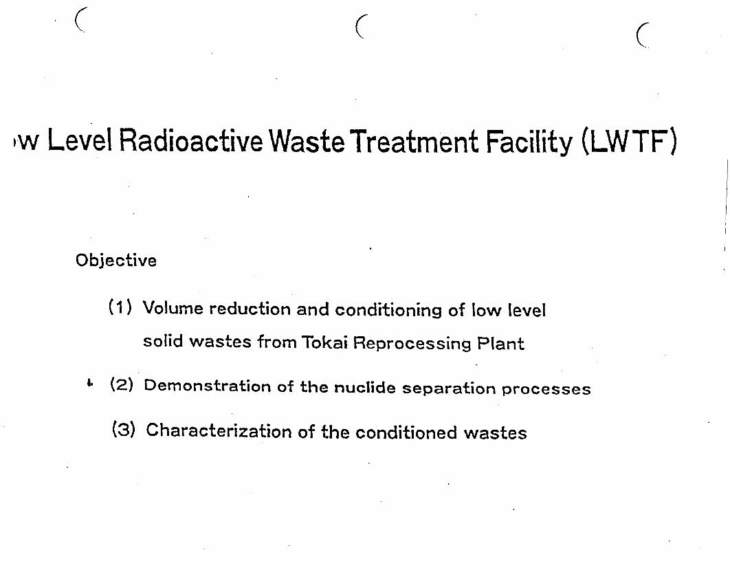
C C C
iw Level Radioactive Waste Treatment Facility (LWTF)
Objective
(1) Volume reduction and conditioning of low level
solid wastes from Tokai Reprocessing Plant
6 (2) Demonstration of the nuclide separation processes
(3) Characterization of the conditioned wastes
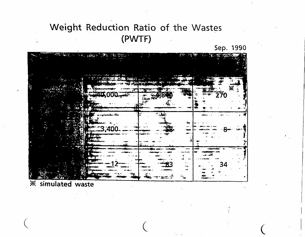
Weight Reduction Ratio of the Wastes(PWTF)
Sep. 1990
Ve~~t
- -~~
4--'- -.
2_ - 34.a 0 __. 's . ON"............ . a
| I....v_ ...... ; _.-- ............ i.~~~~~~Ask
< simulated waste
Q(C C
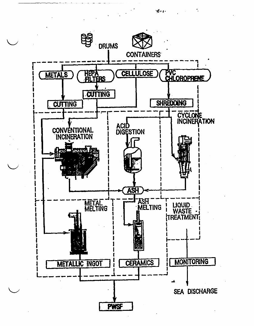
DRUMSCONTAINERS
- -a - - - IIr - I - e -
I LUQUID. ITINGI WASTE I|TREATMENTI II I II I
C / C C
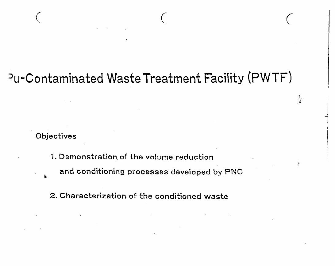
( C C
u-Contaminated Waste Treatment Facility (PWTF).Z
Objectives
1. Demonstration. of the volume reduction
and conditioning processes developed by PNCk.
2. Characterization of the conditioned waste
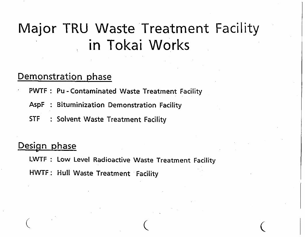
Major TRU Waste Treatment Facilityin Tokai Works
Demonstration phasePWTF
AspF
STF
Design
: Pu - Contaminated Waste Treatment Facility
: Bituminization Demonstration Facility
: Solvent Waste Treatment Facility
phaseLWTF:
HWTF:
Low Level Radioactive Waste Treatment Facility
Hull Waste Treatment Facility
( ( c

(
Present Status ofWaste Treatment Facilities
in Tokai Works
November 1990
C
POWER REACTOR AND NUCLEAR FUEL . lC) .DEVELOPMENT CORPORATION(PNI r P- " N 0
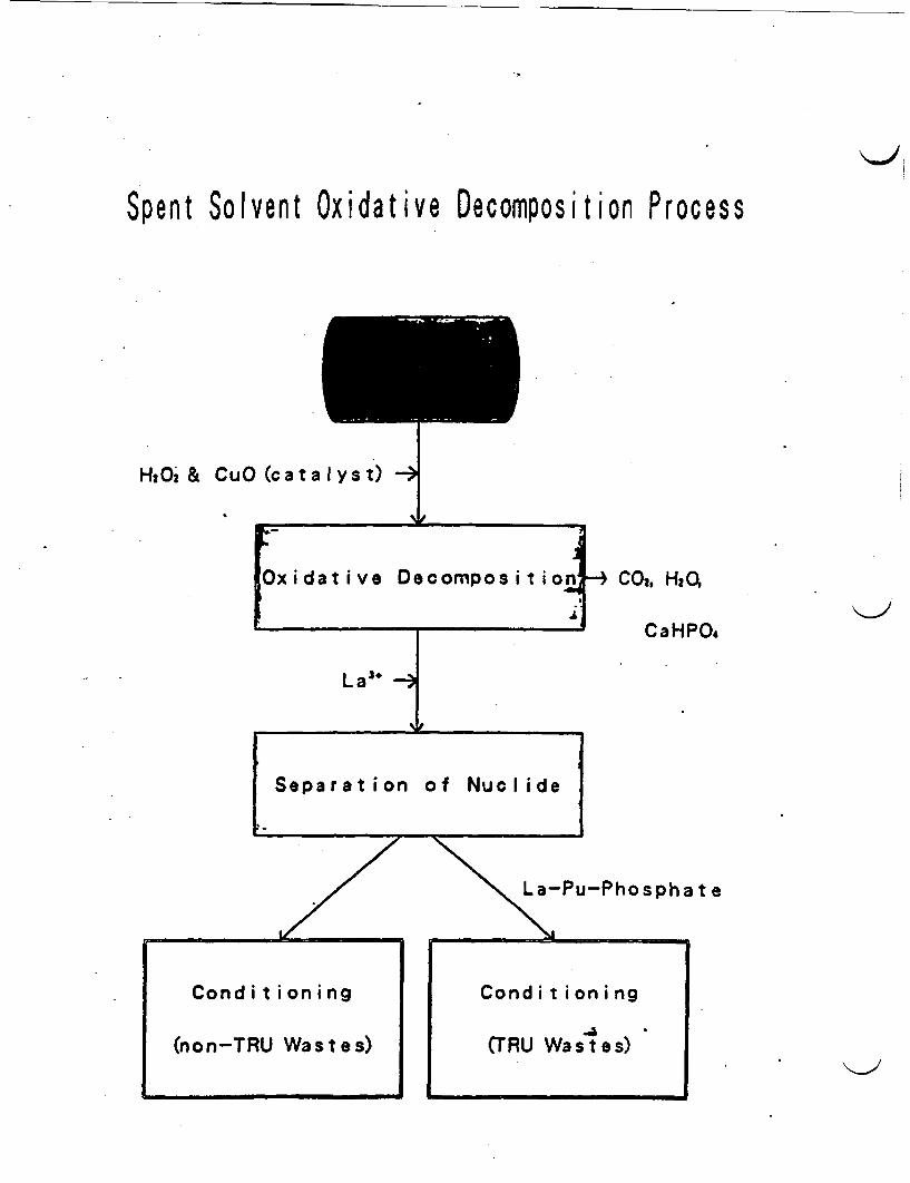
Spent Solvent Oxidative Decomposition Process
H20 & CuO (catalyst) e
I0
xidative Decompositio
La3+ - __
Separation of Nuclide
.~~~~~~~~~~~~~~~~~~~
e CO, HQ
CaH P0.
La-Pu-Phosphate
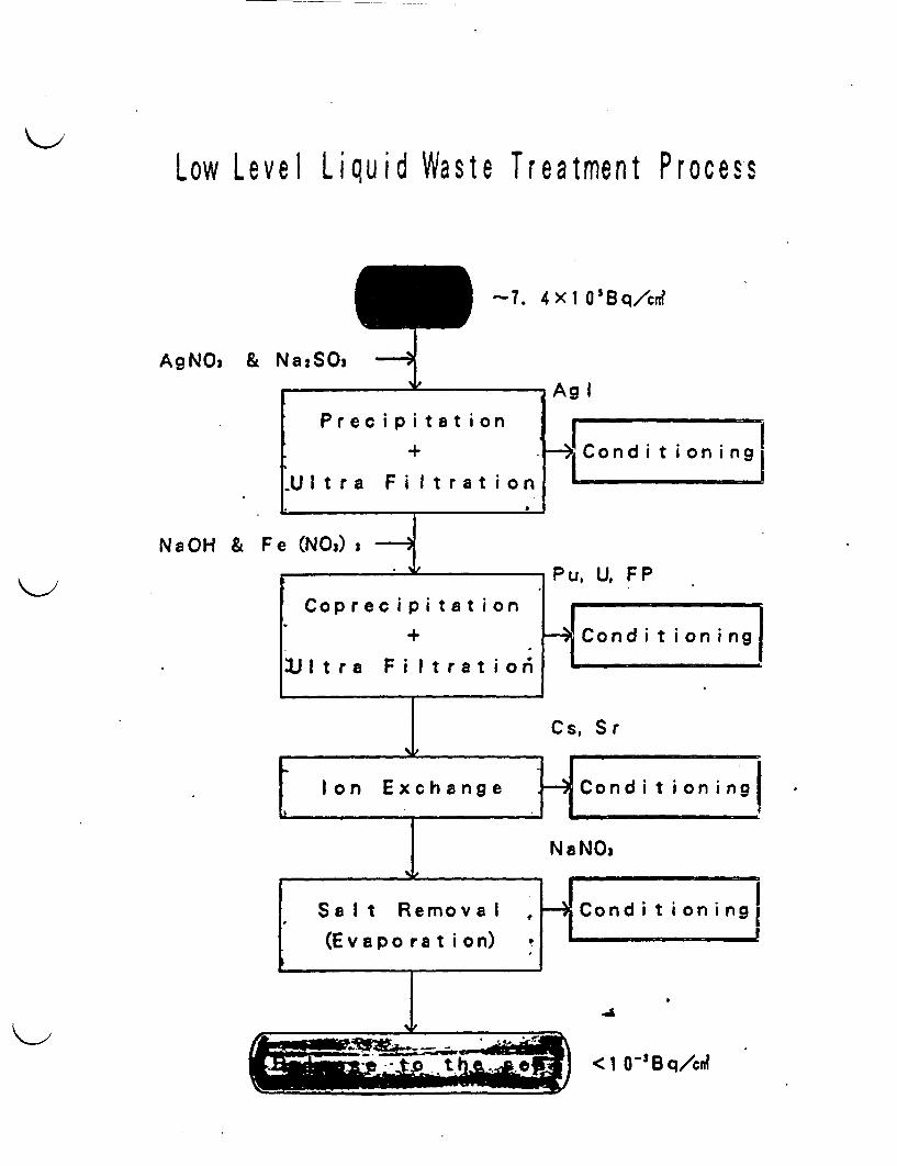
Low Level Liquid Waste Treatment Process
-7. 4 1 0'Bq/cn?
AgNO3
NaOH &
TRU Waste Conditioning Technology
Q ( C
vm a .
* . � @
-
IIiII
C-) C-
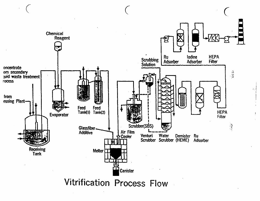
( CChemical
Reagent
ScrubbingSolution
IodineAdsorber
HEPAFilteroncentrate
om secondaryluid waste treatmentrocess
fromessing Pant- -
-Xs
4;e
FeedTank(l)
FeedTank(2) HEPA
Filter
Glassfiber.Additive L_.
VenturiScrubber
WaterScrubber
Demister(HEME)
RuAdsorber
ReceivingTank
Vitrification Process Flow
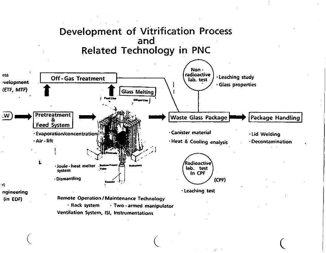
Development of Vitrification Processand
Related Technology in PNC
esswvelopment(ETF, MTF)
I .
I Off -Gas Treatment II
t t rGlass Melting, . ;On" j
,- l
I
I
Non -radioactive Leaching study
lab, test * Glass properties
-) _ Pretreatment -m_Feed Str
* Evaporation/concentration
* Air- lift
, . . .
_M* IWae 61a ss Package _ [Package Handling
I F IImv,1m* Canister material
* Heat & Cooling analysis-Lid Welding* Decontamination
IA* joule - heat melter *M.- I"
system Iva..
* Dismantling / 'iiiRadioactivelab. test
In CPF(CPF)
* Leaching test
'mm
ngineering(in EDF) Remote Operation/ Maintenance Technology
- Rack system - Two -armed manipulatorVentilation System, ISI, Instrumentations
I ( (
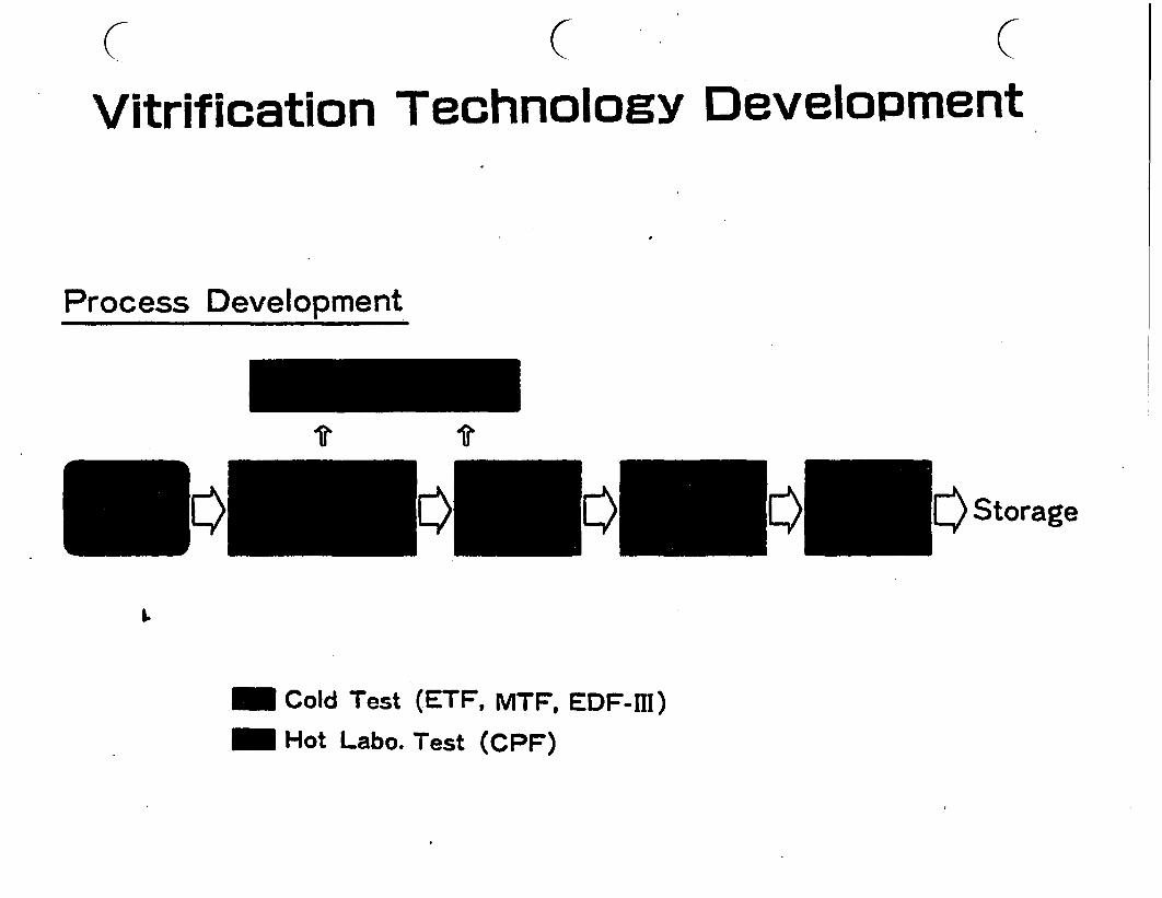
C C (Vitrification TechnologY Development
Process Development
ir�Storage
-Y
I.
- Cold Test (ETF, MTF, EDF-m)
_IM Hot Labo. Test (CPF)

HLLW Conditioning Technology
i.
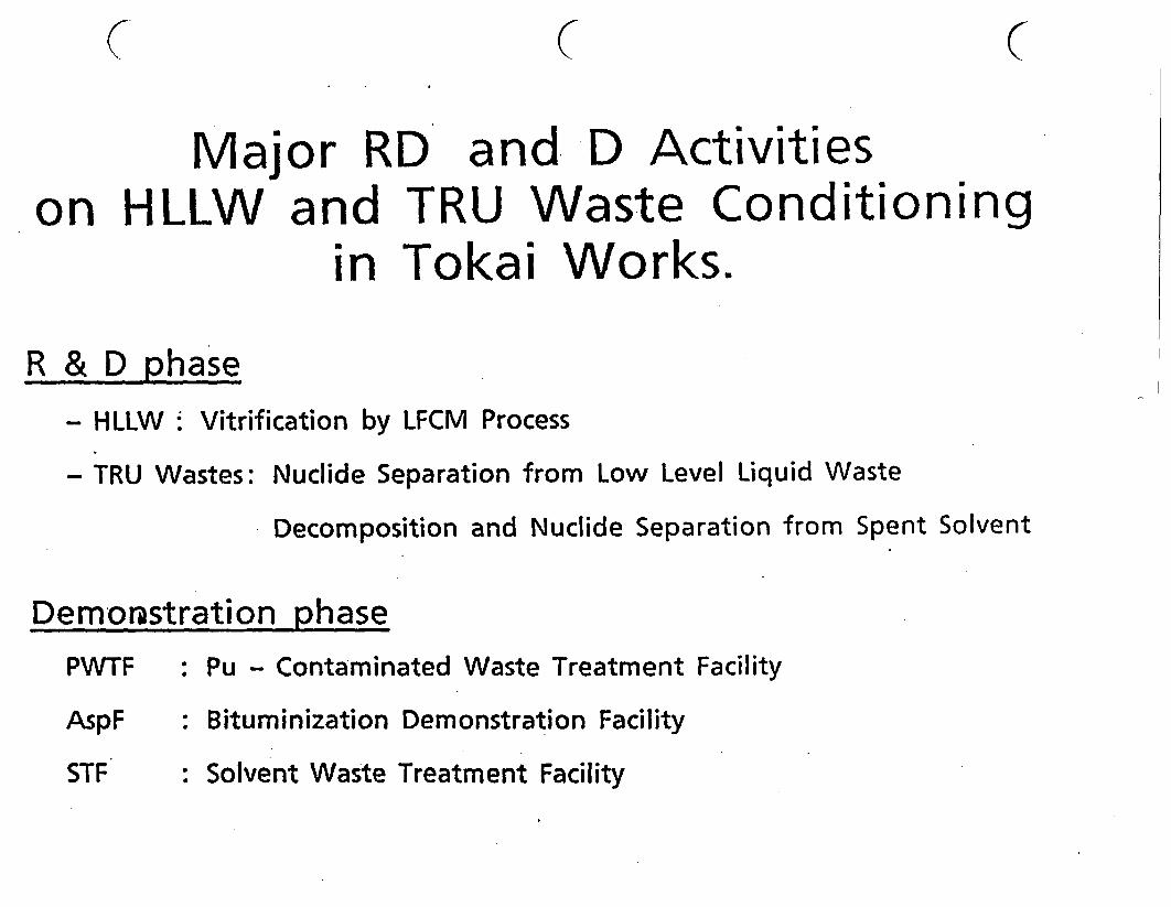
C ( C
Major RD and D Activitieson HLLW and TRU Waste Conditioning
in Tokai Works.
R & D phase- HLLW Vitrification by LFCM Process
- TRU Wastes: Nuclide Separation from Low Level Liquid Waste
Decomposition and Nuclide Separation from Spent Solvent
Demonstration phasePWTF
AspF
: Pu - Contaminated Waste Treatment Facility
: Bituminization Demonstration Facility
: Solvent Waste Treatment FacilitySTF

Present Status of R & D Activitieson HLLW and TRU Waste Co nditi on' ng
in Tokai Works
November 1990
POWER REACTOR AND NUCLEAR FUELDEVELOPMENT CORPORATION(PNC) [F""'NO
( ( (

CEC 4th Natural Analogue working Group Meeting
Pitlochry, Scotland, 17-22 June 1990
(CEC EUR REPORT)
SOME ASPECTS OF NATURAL ANALOGUE STUDIES FOR ASSESSMENT
OF LONG-TERM DURABILITY OF ENGINEERED BARRIER MATERIALS
- RECENT ACTIVITIES AT PNC, JAPAN -
(YUSA, Y., KAMEI, G. and ARAI, T.)

-I115. Framework of our analogue studies: Our natural analogue programme has threecomponents: 1) nvestgation of alteration phenomena, 2) examination ofenvironmental conditions, 3) support experiments. The support experiments arean essential part of our study in order to enhance the wider applicability ofthe natural analogue.
1. INTRODUCTION
1.1 COMPONENTS OF ENGINEERED BARRIERS
The Components, candidate materials, and functions of various types ofengineered barriers are as follows:
Component Candidate materials Function expected
* Vitrified waste * Borosilicate glass * Restricts release"..................................................................................................................... ...........................................................
* Overpack * Carbon steel or * Retards water penetration Cast iron * Provides favourable chemistry
..................................................................... ..........................................................................................
Buffer * Restricts water penetration materials * Bentonite * Delays commencement of release
* Restricts radionuclides release.......................................................................................................................................................* Backfill * Concrete * Minimizes water access to packaget
materials (Cement) * Alters groundwater chemistry t* Retards solute transport
............................................................................... ;............................................................................(* :NAGRA 1985), t :Chapman et al 19871)
As a part of the study on engineered barrier materials and systems forgeological disposal of radioactive waste in Japan, analogue studies for theassessment of long-term durability of engineered barrier materials areconducted at PNC Tokai Works. This paper describes the state-of-the-art on thestudies, specifying their main purposes and framework, and demonstrating ouremphasis on natural materials. The results obtained to date will be summarized.Some parts of studies on natural glass and bentonite were already presented atthe MRS Symposium (Arai et al., 1988; and Kamei et al., 1989), although revisedand expanded data are shown here.
1.2 DEFINITION OF "NATURAL ANALOGUE"
One of the most critical aspects in the evaluation of the durability ofcandidate materials for engineered barriers is the extrapolation of the resultsof short-term experiments over a long time scale. Natural analogues currentlyprovide the only means by which such. extrapolated long-term behaviour can beconfirmed.

I
SOME ASPECTS OF NATURAL ANALOGUE STUDIES FOR ASSESSMENTOF LONG-TERM DURABILITY OF ENGINEERED BARRIER MATERIALS
- RECENT ACTIVITIES AT PNC TOKAI, JAPAN -
YUSA,Y., KAMEIG. and ARAIT.Geological-Isolation Technology Section, Tokai WorksPower Reactor and Nuclear Fuel Development Corporation
319-11 Tokai Ibaraki JAPAN
SUMMARY
This paper contains an overview of analogue studies for the assessment of long-term durability of engineered barrier materials at PNC Tokai.
Materials of young age and with simple history are the most suitable for studyas: 1) properties of the materials tend to deteriorate over longer historicaltime Intervals; and 2) detailed quantitative data on time intervals andenvironmental conditions are more likely to be available. The followingmaterials and their alteration phenomena were selected: 1) weatheringalteration of basaltic glass (as vitrified waste form), 2) corrosion of iron insoil (as overpack), 3) illitization of smectite associated with contactmetamorphism (as buffer material), 4) alteration of cement (as buffer orbackfill material). X
1. Weathering alteration of basaltic glass: Basaltic glasses, from the Fujiand the Izu-Ohshima pyroclastic fall deposits were studied. The observationswere made: 1) Climatological conditions have not varied significantly duringthe last three thousand years. Therefore, values for temperature, amount, andchemistry of ground water are quantified. 2) The cases studied could beregarded as leaching experiments in groundwater, using mass balances in water-glass interaction. 3) Although the groundwater is of Ca(Mg)-HCO3 type in theFuji area and of Na-Cl type in the Izu-Ohshima, similar alteration ratios (2 -3U mlOOOyr) were obtained.
2. Corrosion of iron in soil: Industrial materials, such as gas/water servicepipes of carbon steel or cast Iron embedded in soil for 20 110 years, wereselected for an analogue study of corrosion of iron in bentonite. The maximumcorrosion rates obtained so far fall in the range of 0.04 - 0.09 mm/yr.
3. Illitization of smectite associated with contact metamorphism: In theMurakami bentonite deposit n central Japan, lateral variation of smectite tosmectite/illite mixed-layer minerals are found in the aureole of the rhyoliteintrusion body. Conversion of smectite to the mixed-layer mineral -composed of40% illite was found to have occurred n a period of 2.4 Ma over a temperaturerange of above 240 ( 50) C to 105 lC.
4. Alteration of cement: Concrete components of fabrications, such as estuarywalls, with a known age were studied. Chemical alteration of the cement weredetected to a depth of few centimeters by EPMA, SEM, TEM and XRD.
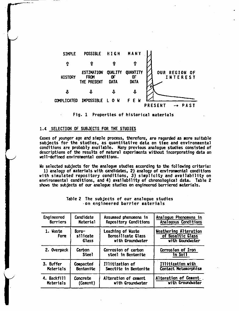
FSIMPLE POSSIBLE H I G H M A N Y
ESTIMATIONHISTORY FROM
THE PRESENT
QUALITYOF
DATA
QUANTITYOF
DATA
OUR REGION OFINTEREST
4 48COMPLICATED IMPOSSIBLE L 0 W F E W
PRESENT - PAST
Fig. 1 Properties of historical materials
1.4 SELECTION OF SUBJECTS FOR THE STUDIES
Cases of younger age and simple process, therefore, are regarded as more suitablesubjects for the studies, as quantitative data on time and environmentalconditions are probably available. Many previous analogue studies consisted ofdescriptions of the results of natural experiments without incorporating data onwell-defined environmental conditions.
We selected subjects for the analogue studies according to the following criteria:1) analogy of materials with candidates, 2) analogy of environmental conditions
with simulated repository conditions, 3) simplicity and availability onenvironmental conditions, and 4) availability of chronological data. Table 2shows the subjects of our analogue studies on engineered barriered materials.
Table 2 The subjects of our analogue studies*on engineered barrier materials
Engineered Candidate Assummed phenomena in Analogue Phenomena inBarriers Material Repository Conditions Analogous Conditions
1. Waste Boro- Leaching of Waste Weathering AlterationForm silicate Borosilicate Glass of Basaltic Glass
Glass with Groundwater with Goundwater
2. Overpack Carbon Corrosion of carbon Corrosion of IronSteel steel in Bentonite in Soil
3. Buffer Compacted Illitization of Illitization withMaterials Bentonite Smectite in Bentonite Contact Metamorphism
4. Backfill Concrete Alteration of cement Alteration of Cement.Materials (Cement) with Groundwater with Groundwater

The term "natural analogue' can be defined as "natural phenomena which resemblethose assumed in geological disposal scenarios". The selection of an appropriatenatural analogue is the key issue which will determine whether the naturalanalogue study will be successful.
1.3 PROPERTIES OF NATURAL ANALOGUE
First, consideration is given to the properties of the natural analogues. Inorder to extrapolate the results of short-term experiments to the long-term, it isdesirable that the natural phenomena can be individually and quantitativelydescribed in terms of three constituents: 1) starting materials, 2)environmental conditions (including time scale), and 3) results. These are thethree normal constituents of all "experiments".
However, there are some Intrinsic difficulties in regarding such phenomena asexperiments. Most naturally occurring aterials, from which an relevant analoguemust be selected, have complicated histories resulting the overprint of differentprocesses, as shown in Table 1.
Table 1 Comparison between laboratory experiments and natural phenomena
Laboratory Experiments Natural Phenomena
(1) Materials Candidates Analogue................................... .................. ..................
([)Number M a n y Solitary, few
Simple, Uniform Complicated(2) Environmental Constant, Controlled V a ri a bl e
(Experimental) Common IndividualCondition Small Scale Large Scale
(3) Period Short-term Long-term
(4) Results Independent variables OverprintingDiscrimination among of factorsconditions is possible Restoration
is difficult
Secondly, geological and historical records are often incomplete, and errors inthe determination of time scale and environmental conditions are not small.Although such disadvantages differ case to case and sample to sample, asmaterials age, their histories generally become more complicated; the factors withwhich alteration phenomena were related become overlapped, and quality andquantity of available data decreases. Thus, estimation from present observationsbecomes virtually impossible with very old samples (Figure 1).
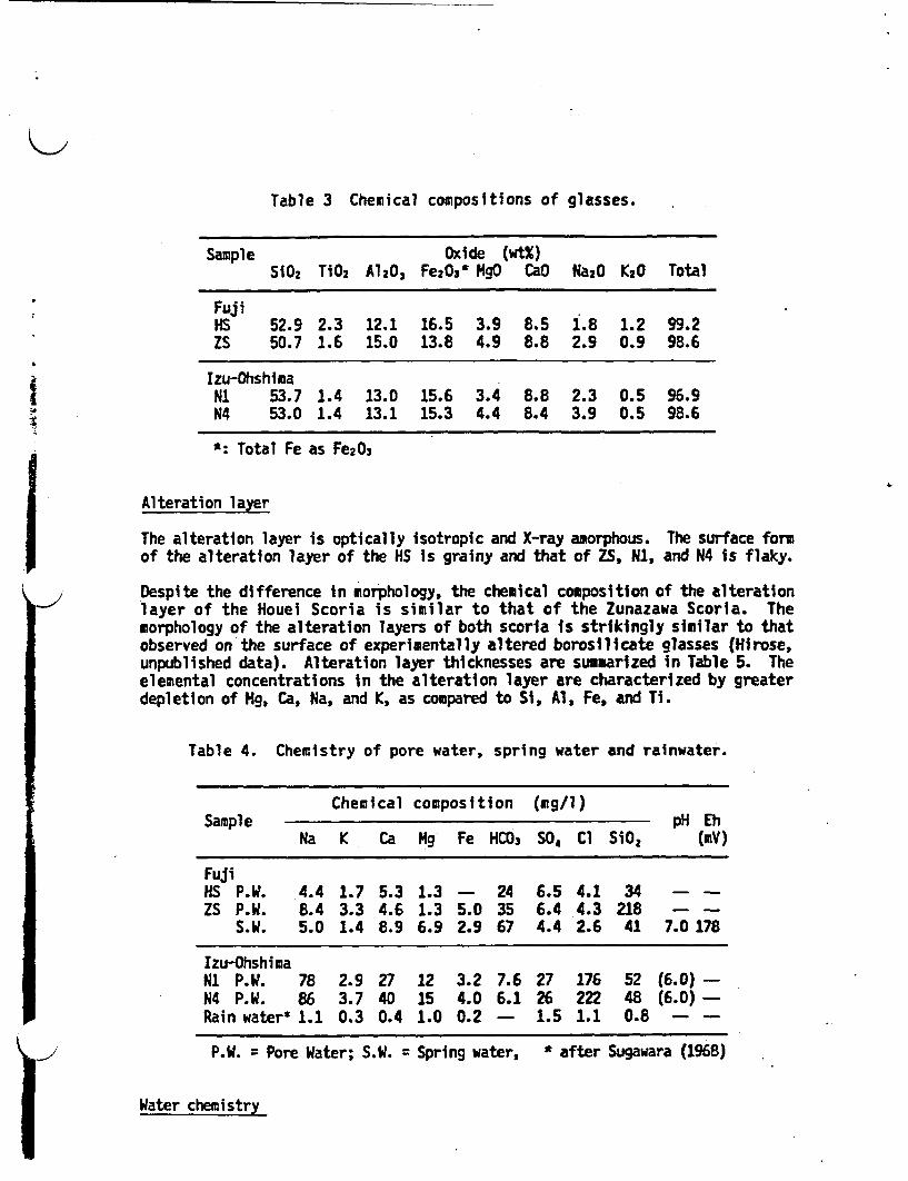
Table 3 Chemical compositions of glasses.
Sample Oxide (wtX)SiO2 TiO2 A1203 Fe20,3 MgO CaO Ka2O K20 Total
FujiHS 52.9 2.3 12.1 16.5 3.9 8.5 1.8 1.2 99.2ZS 50.7 1.6 15.0 13.8 4.9 8.8 2.9 0.9 98.6
Izu-OhshimaNi 53.7 1.4 13.0 15.6 3.4 8.8 2.3 0.5 96.9N4 53.0 1.4 13.1 15.3 4.4 8.4 3.9 0.5 98.6
*: Total Fe as Fe203
Alteration layer.1 The alteration layer is optically isotropic and X-ray amorphous.of the alteration layer of the HS is grainy and that of ZS, N1,
The surface formand N4 is flaky.
-. 'IDespite the difference in morphology, the chemical composition of the alterationlayer of the Houei Scoria is similar to that of the Zunazawa Scoria. Themorphology of the alteration layers of both scorla is strikingly similar to thatobserved on the surface of experimentally altered borosilicate glasses (Hirose,unpublished data). Alteration layer thicknesses are summarized in Table 5. Theelemental concentrations in the alteration layer are characterized by greaterdepletion of Mg, Ca, Na, and K, as compared to Si, Al, Fe, and Ti.
Table 4. Chemistry of pore water, spring water and rainwater.
Chemical composition (g/l)Sample pH Eh
Na K Ca Mg Fe HCO3 SO, Cl SiO2 (mv)
FujiHS P.W. 4.4 1.7 5.3 1.3 - 24 6.5 4.1 34 - -
ZS P.W. 8.4 3.3 4.6 1.3 5.0 35 6.4 4.3 218 - -
S.W. 5.0 1.4 8.9 6.9 2.9 67 4.4 2.6 41 7.0 178
Izu-OhshimaN1 P.W. 78 2.9 27 12 3.2 7.6 27 176 52 (6.0) -N4 P.W. 86 3.7 40 15 4.0 6.1 26 222 48 (6.0) -Rain water* 1.1 0.3 0.4 1.0 0.2 - 1.5 1.1 0.8 - -
P.W. = Pore Water; S.W. = Spring water, * after Sugawara (1968)
Water chemistry

2. Weathering alteration of basaltic glass
2.1 SCOPE OF STUDIES
Many analogue studies of the alteration of natural glasses indicate that thealteration rates at low temperatures of natural glasses vary from 0.001#om/1000yr to 30 U' 11OO yr (Hekinian et al. 1975; Bryan et al. 1977; Allen 1982; Lutzeet al. 1985 & 1987; Grambow et al. 1986; Ewing et al. 1987; Jercinovic et al.1988). This variation is interpreted as the result of variations in environmentalconditions. However, few detailed studies on environmental conditions have beenreported.
Described below are the effects of alteration by weathering of basaltic glasseswith well established environmental conditions and ages. The alteration is along-term leach test carried out by nature with rainwater as the leachant andgroundwater as the leachate. The young-aged (280 - 2800 years ) samples wereselected to investigate environmental conditions during alteration based onpresent meteorological data.
Samples
Volcanic glasses constituting scoria of pyroclastic fall deposits were studied.Scoria samples were collected at the foot of the Fuji and Izu-Ohshima volcanoes,on both of which the stratigraphy and chronology of pyroclastic fall deposits havebeen studied in detail.
The samples collected were Houei Scoria (HS, 280 years ago) and Zunazawa Scoria(ZS, 2800 years) from the Fuji, and N (880 years) and N4 Scoria (1240 years) fromthe Izu-Ohshima volcano.
All of the scoria samples contained pore water, and spring water was found about2.5 below the Zunazawa Scoria bed.
Methods
Glass compositions were determined by Electron Probe icroanalyser (EPMA).Alteration layers were studied by optical microscope, EPHA and Scanning ElectronHicroprobe (SEM). The thickness of alteration layers was measured from SEMphotos of the sections oriented nearly perpendicular to the layers.
In the field, the pH and Eh of the spring water were measured by portable meters.The spring water was filtrated through a 0.45 1im filter and the filtrate wasanalyzed by absorption spectrophotometry, flame spectrometry and atomic absorptionspectrometry.
2.2 RESULTS
The chemical compositions of the glasses are shown in Table 3. These are withinthe range of basalts. )
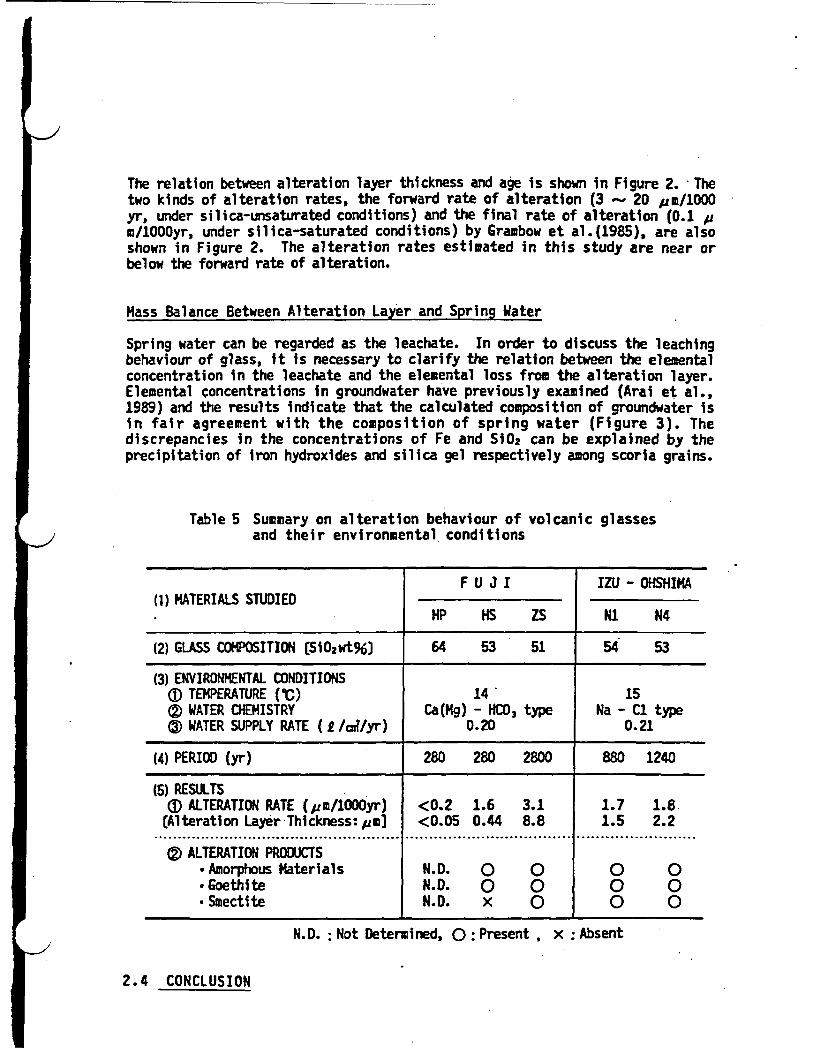
The relation between alteration layer thickness and age is shown in Figure 2. Thetwo kinds of alteration rates, the forward rate of alteration (3 20 gm/100yr, under silica-unsaturated conditions) and the final rate of alteration (0.1 m/1000yr, under silica-saturated conditions) by Grambow et al.(1985), are alsoshown in Figure 2. The alteration rates estimated in this study are near orbelow the forward rate of alteration.
Mass Balance Between Alteration Layer and Spring Water
Spring water can be regarded as the leachate. In order to discuss the leachingbehaviour of glass, it is necessary to clarify the relation between the elementalconcentration in the leachate and the elemental loss from the alteration layer.Elemental concentrations in groundwater have previously examined (Arai et al.,1989) and the results indicate that the calculated composition of groundwater isin fair agreement with the composition of spring water (Figure 3). Thediscrepancies in the concentrations of Fe and SO2 can be explained by theprecipitation of iron hydroxides and silica gel respectively among scoria grains.
Table 5 Summary on alteration behaviour of volcanic glassesand their environmental conditions
F U J I IZU - OHSHIKA(l) MATERIALS STUDIED
HP HS ZS N1 N4
(2) GLASS COMPOSITION SiO2wt6) 64 53 51 54 53
(3) ENVIRONMENTAL CONDITIONSa) TEMPERATURE (C) 14 15(D WATER CHEMISTRY Ca(Mg) - HCO3 type Na - C1 type® WATER SUPPLY RATE ( /od/yr) 0.20 0.21
(4) PERIOD (yr) 280 280 2800 880 1240
(5) RESULTS(]) ALTERATION RATE (m/lOOOyr) <0.2 1.6 3.1 1.7 1.8.(Alteration Layer Thickness:pm] <0.05 0.44 8.8 1.5 2.2
................................................... ............... ................................... .................... ...............
(2) ALTERATION PRODUCTS.Amnorphous Materials N.D. 0 0 0 0.Goethite N.D. 0 0 0 0.Smectite N.D. x 0 0 0
N.D. Not Determined, 0 Present , x Absent
2.4 CONCLUSION

j)The chemistry of the pore and spring water is listed in Table 4, together with theaverage of rainwater in Japan (Sugawara, 1968). The elemental concentrations inZS pore water are higher than those in HS pore water. This implies that elementalconcentration in groundwater increases with depth.
2.3 DISCUSSION
Environmental Conditions
Analyses of paleo-sea level variations (Sugimura, 1977) and paleo-climatologicaldata (Yamamoto, 1980; and Haejima, 1984), indicate that the climatic conditionsin Japan have not varied significantly for the last 2800 years. Therefore, thetemperature and the water supply rate are estimated from meteorological data suchas mean annual temperature, annual rainfall, and evapotranspiration. The sampleswere situated in the unsaturated zone; accordingly, percolating meteoric water isthe only source of pore water. The pore water flows downward in the deposits anddissolves the components of scoria. This natural phenomenon can be regarded as aleach test being constantly renewed fresh rainwater.
Alteration Rate
In natural alteration systems, it is generally difficult to know the exposure ageof a sample, that is, the time that the glass has actually been in contact withwater (Jercinovic et al., 1988). The exposure ages of the samples in this studyare equivalent to the samples ages as their surfaces were always in wetconditions and were always in contact with renewed pore water.
1 o4
1 3
Z102
U,
'1w
1 1t
(Grambow et al 15)
EC0
aC.
1 UV I Rain water(average value in Japan)
OSpring waterI Calculated
groundwater
10
I - l pH .
NI
HS X
.HPj Ito..INa K Ca Mg Fe SiO,
1n-Zt Ilu -'
1 A02 lo, I (yIOAge (yr)
Fig. 2 The relation between ageof samples and thicknessof alteration layer
Fig. 3 The comparison between elementalconcentrations of spring waterand calculated groundwater
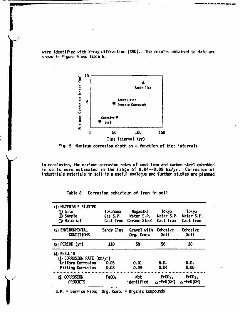
MN�A& W-.M.1MLAmw.,m,.
were identified with X-ray diffraction (XRD).shown in Figure 5 and Table 6.
The results obtained to date are
A
C
CS.
C
IE
U,
S1
10
5
ASandy Cty
Gravel itbO Organic CoaPoUnds
Cobesivc* SiI
0 50 100 150
-1/
Time Interval (yr)
Fig. 5 Maximum corrosion depth as a function of time intervals
In conclusion, the maximum corrosion rates of cast iron and carbon steel embeddedin soils were estimated in the range of 0.04- 0.09 mm/yr. Corrosion ofindustrials materials in soil is a useful analogue and further studies are planned.
Table 6 Corrosion behaviour of iron in soil
(1) MATERIALS SDIED®D Site Yokohama Nagasaki Tokyo Tokyo®2 Sample Gas S.P. Water S.P. Water S.P. Water S.P.
(3) Material Cast Iron Carbon Steel Cast Iron Cast Iron
(2) ENVIRONMENTAL Sandy Clay Gravel with Cohesive CohesiveCONDITIONS Org. Conp. Soil Soil
(3) PERIOD (yr) 110 50 56 20
(4) RESULTSAI) CORROSION RATE (mm/yr)Uniform Corrosion 0.03 0.01 N.D. N.D.Pitting Corrosion 0.08 0.09 0.04 0.06
...... .................. ....................... ...................................................................................
(2 CORROSION FeCO3 Not FeCDW, FeCO3,PRODUCTS identified a-FeO(OH) a-FeO(OH)
S.P. = Service Pipe; Org. Comp. = Organic Compounds

1) It was possible-to determine the alteration behaviour of volcanic glasses fromthree experimental constituents: 1) starting materials, 2) environmentalconditions and time scale, and 3) results (Table 5).
2) Calculation of the mass balance between the elements depleted from the glassesand the chemical composition of groundwater permitted us to regard the casesstudied as experiments in the leaching of glasses by groundwater.
3) The natural alteration products of the volcanic glasses were very similar tothose of laboratory experiments with simulated waste glasses.
4) Although the ground water is Ca(Mg)-HCOs type in the Fuji area, and of Na-Cltype in the Izu-Ohshima area, similar alteration rates ( 2 3 pm/iOOO yr)were obtained.
3. CORROSION OF IRON IN SOIL
Industrial materials such as water service pipes, were studied for the followingreasons: 1) iron or steel is one of the candidate materials for waste package,2) soil environment is probably similar to the bentonite fill environment, 3)samplavailability, and 4) chronology and environmental data are fairlyassessable in ccomparison to those of archeological artifacts. One of thepurposes of this analogue study is to validate whether the results of corrosionrates and models derived from the results of laboratory experiments can beextrapolated to a few tens of years (Figure 4).
I dustri- IArcheologicalArtifacts LamIi zed
Corrosion
o CorrosioLaborat
CD
0 102 I
Time Interavals (yr)
Fig. 4 The relation between the subjects for studieson corrosion of iron and their time interval
The samples studied were gas or water service pipes, composed of cast iron orcarbon steel. The soil or clay adjacent to the pipe was examined in order toavoid the influence of the macro-cell effect. The corrosivities of the soilenvironment at each site were estimated as not being very severe from theviewpoint of both electrochemical and chemical characteristics of the soil.Corrosion rates were derived from the measurements of the thickness of the pipe,and chemical composition of the material were determined. The corrosion products
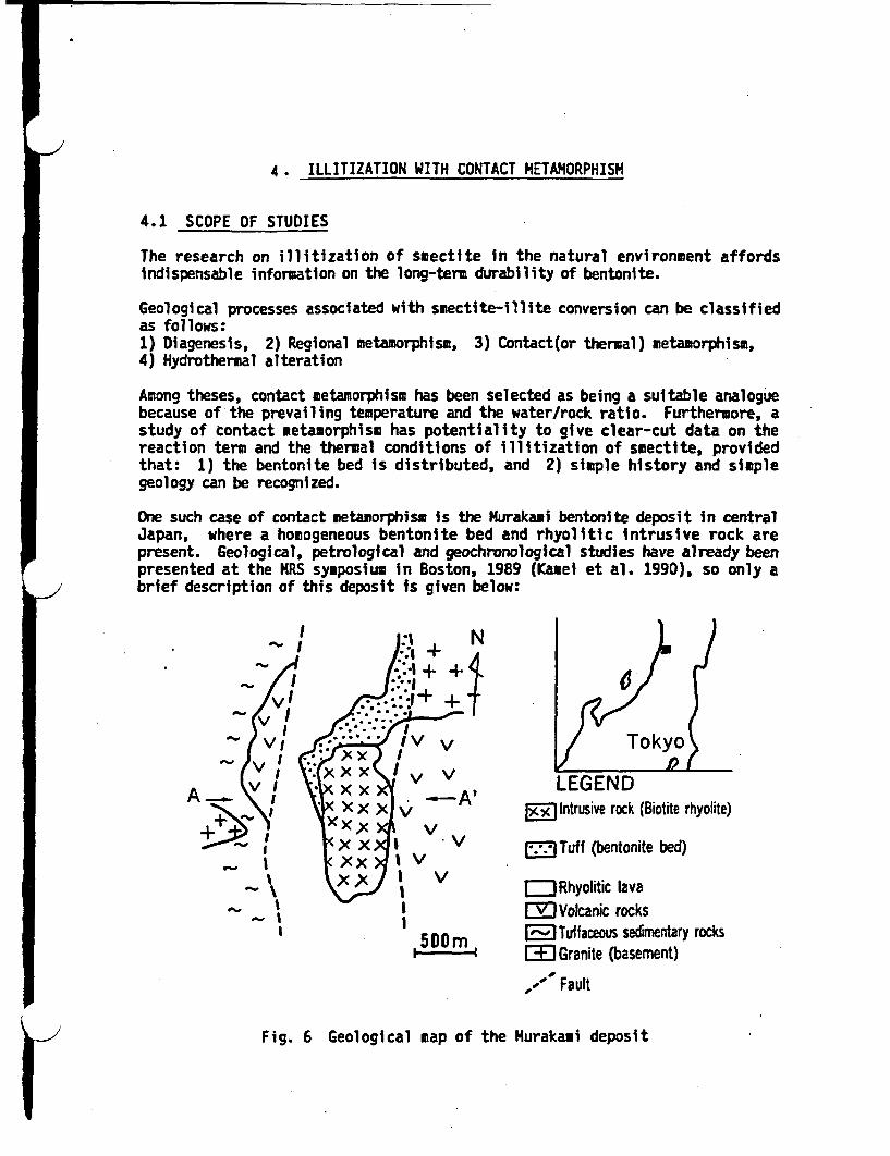
-
Ir_-I4. ILLITIZATION WITH CONTACT METAMORPHISM
4.1 SCOPE OF STUDIES
The research on illitization of smectite in the natural environment affordsindispensable information on the long-term durability of bentonite.
Geological processes associated with smectite-illite conversion can be classifiedas follows:1) Diagenesis, 2) Regional metamorphism, 3) Contact(or thermal) metamorphism,4) Hydrothermal alteration
Among theses, contact metamorphism has been selected as being a suitable analoguebecause of the prevailing temperature and the water/rock ratio. Furthermore, astudy of contact metamorphism has potentiality to give clear-cut data on thereaction term and the thermal conditions of illitization of sectite, providedthat: 1) the bentonite bed is distributed, and 2) simple history and simplegeology can be recognized.
One such case of contact metamorphism is the urakami bentonite deposit in centralJapan, where a homogeneous bentonite bed and rhyolitic Intrusive rock arepresent. Geological, etrological and geochronological studies have already beenpresented at the MRS symposium in Boston, 1989 (Kanei et al. 1990), so only abrief description of this deposit is given below:
4 ~~~~+N
VS A+ +I
IXV V I
A~ V I 5 X X x -- A' LEGENDI, + )( I X A 3 Intrusive rock (Biotite rhyolite)
X x I V E5ITuff (bentonite bed)
X\)( 1 V rRhyoitic lavaVolcanic rocks
500M DO mTuffaceus sedimentary rocksI Granite (basement)
,,' Fault
Fig. 6 Geological map of the Murakami deposit

(Smectite) ISample Al
'::'.~i~S iiedi9Pi x x~ pi x x -X ;KX ~ V V. V
Rhyolitic Lava X A ) X v Volcanic
I.
150m
Fig. 7 An idealized geological section of the urakami deposit
Geology
A geological map and an idealized section of the urakami deposit area are shownin Figure 6 and 7, respectively. Rhyolitic lava and tuff are distributed in agraven with a width of approximately one kilometer. The reported age ofdeposition of this unit ranges from 18 to 14 Ma (Huramatsu, 1988). The tuff isregarded as being deposited in a marine environment, and was converted intobentonite probably due to diagenetic reaction. Subsequent intrusions of botiterhyolite are found in the bentonite bed. The contact between the intrusive rockand the tuff dips about 30 near the surface of the ground, and the intrusive rockbody is assumed to form a funnel with a diameter of less than 200 meters (Figure7).
Samples
Sample A was collected from a point 30 meters distant from the contact between theintrusive body and the bentonite bed. X-ray diffraction showed that sample Acontained illite-smectite mixed layers with an illite ratio of about 40 96.
4.2 RESULTS
Thermal HistoryTh-cooing rate of the intrusive rock was determined from combining radiometricmineral ages and each closure temperature. The cooling rate of sample A wasestimated by the "TRUMP' thermal analysis code. The results are shown in Figure 8.
The cooling rates of the intrusive rock and of sample A were 70 C/Ma, and 60 C/Ma, respectively. (Figure 8 and the values for cooling rates are newly revised,therefore those reported in the MRS Proceedings (Kamei et al. 1990), should beignored.)
The Illitization Period
In the Murakami deposit area, a minimum temperature of illitization is regarded as
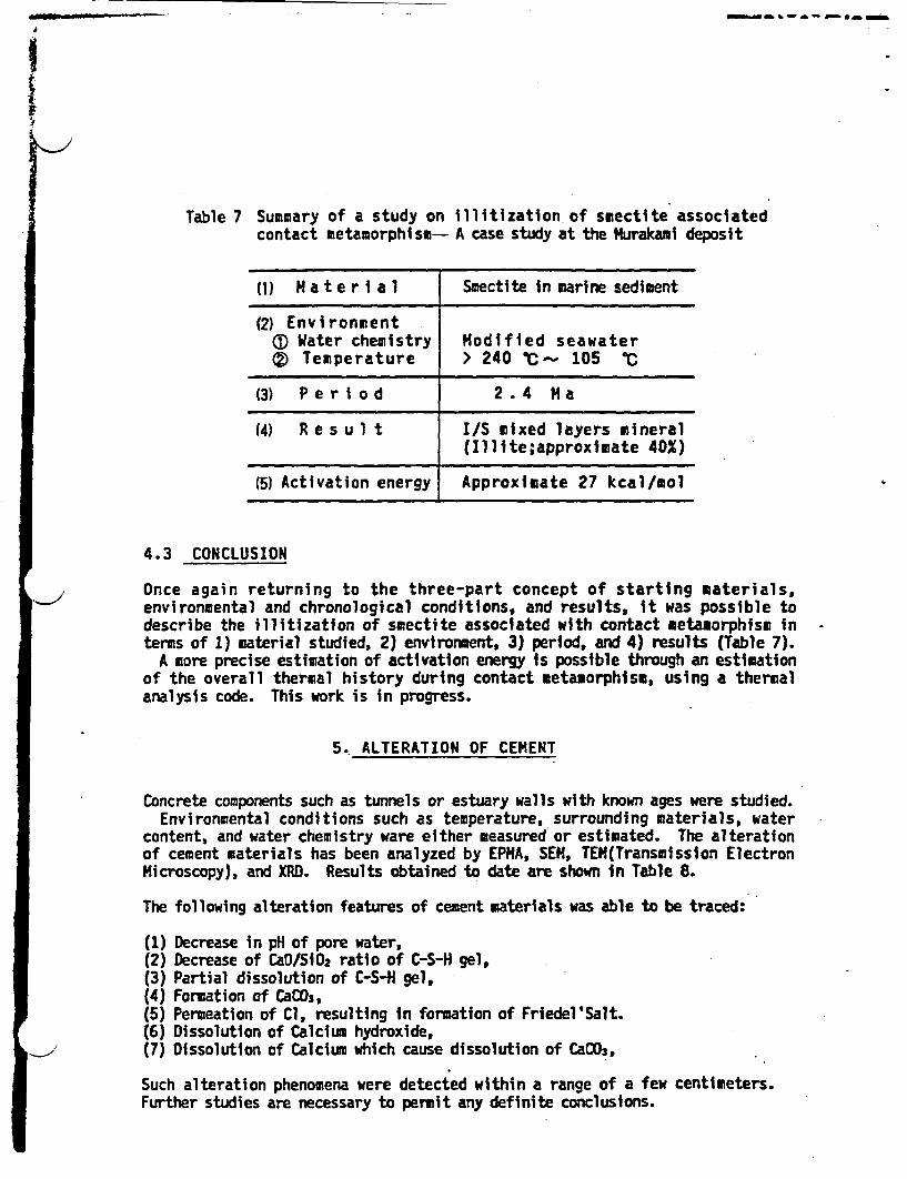
I
- db % W- A - a -
Table 7 Summary of a study on illitization of sectite associatedcontact metamorphism- A case study at the urakami deposit
(1) M a t e r i a l Smectite in marine sediment
(2) EnvironmentcD Water chemistry Modified seawater(® Temperature > 240 C ~ 105 IC
(3) P e r i o d 2 .4 Ma
(4) R e s u 1 t I/S mixed layers mineral(Illite;approxiuate 40X)
(5) Activation energy Approximate 27 kcal/mol
4.3 CONCLUSION
Once again returning to the three-part concept of starting materials,environmental and chronological conditions, and results, it was possible todescribe the illitization of sectite associated with contact metamorphism interms of 1) material studied, 2) environment, 3) period, and 4) results (Table 7).
A more precise estimation of activation energy is possible through an estimationof the overall thermal history during contact metamorphism, using a thermalanalysis code. This work is in progress.
5. ALTERATION OF CEMENT
Concrete components such as tunnels or estuary walls with known ages were studied.Environmental conditions such as temperature, surrounding materials, water
content, and water chemistry ware either measured or estimated. The alterationof cement materials has been analyzed by EPHA, SEN, TEN(Transmission ElectronMicroscopy), and XRD. Results obtained to date are shown in Table 8.
The following alteration features of cement materials was able to be traced:
(1)(2)(3)(4)(5)(6)(7)
Decrease in pH of pore water,Decrease of CaO/SiO2 ratio of C-S-H gel,Partial dissolution of C-S-H gel,Formation of CaCO3,Permeation of Cl, resulting in formation of Friedel'Salt.Dissolution of Calcium hydroxide,Dissolution of Calcium which cause dissolution of CaCO3,
Such alteration phenomena were detected within a range of a few centimeters.Further studies are necessary to permit any definite conclusions.

105C, because this was the temperature estimate made by Oda et al. (1985) forthe appearance of illite-smectite mixed layers in Japanese oil fields, of whichthe Murakami deposit for. a part. In the vicinity where sample A was collected,the temperature at 6.4 Ma was presumed to be 240 ±50C. Therefore, a period ofabout 2.4 Ma was required to cool these rocks from 240 to 1050C.
In short, smectite was converted into illite-smectite mixed layers, in which theillite ratio is approximately 40 96, in the period of more than 2.4 Ma.
500-Intrusive
Rock Biotite (Rb-Sr)
p ; A_ . | Biotite (K-Ar)
Sample A Plagioclase (K-Ar)Lu 300 (Estimated)
< 200-
CL Zircon (Fission-track)E 100 I -- 2.4Ma -l 5'::Appearence of S/I mixed-W layer mineral in Japanese
oilfield (Oda et aL 15)
8 7 6 5 4 3 2 1PresentTIME (x I 08yrs)
Fig. 8 Thermal history of intrusive body and sample A
Water Chemistry
The chemical composition of the rocks distributed In the Murakami area is mostlyrhyolitic, and the tuff, now converted into bentonite bed, is of marine origin.The geological evidence leads to the idea that the chemistry of the water relatedto illitization was very similar to that of seawater after it was modified byinteraction with rocks of rhyolitic composition.
The hydrogen isotopic composition (D/H) of water, in the form of hydroxyl groups,in the Illite and the smectite-illite mixed layers, were measured, and from thisan assessment of the water involved in illitization was made. The resultssupported the idea noted above.
Provisional Calculation of Activation Energy
The activation energy for illitization at the urakaui deposit was provisionallycalculated on the basis of the estimated thermal history. The calculationprocedure was already described in Kamei et al. (1990). Using the revised coolingrate of.60 C/a. and a period of 2.4 Ma. the activation energy is approximately27 kcal/mol. This value is close to that obtained by Roberson Lahann(1981) ofapproximately 30 kcal/mol. The water used for their experiments contained 400 pp.K and 9400 pp. Na ' , the chemistry of seawater. A similar water chemistry canbe inferred at Murakami.
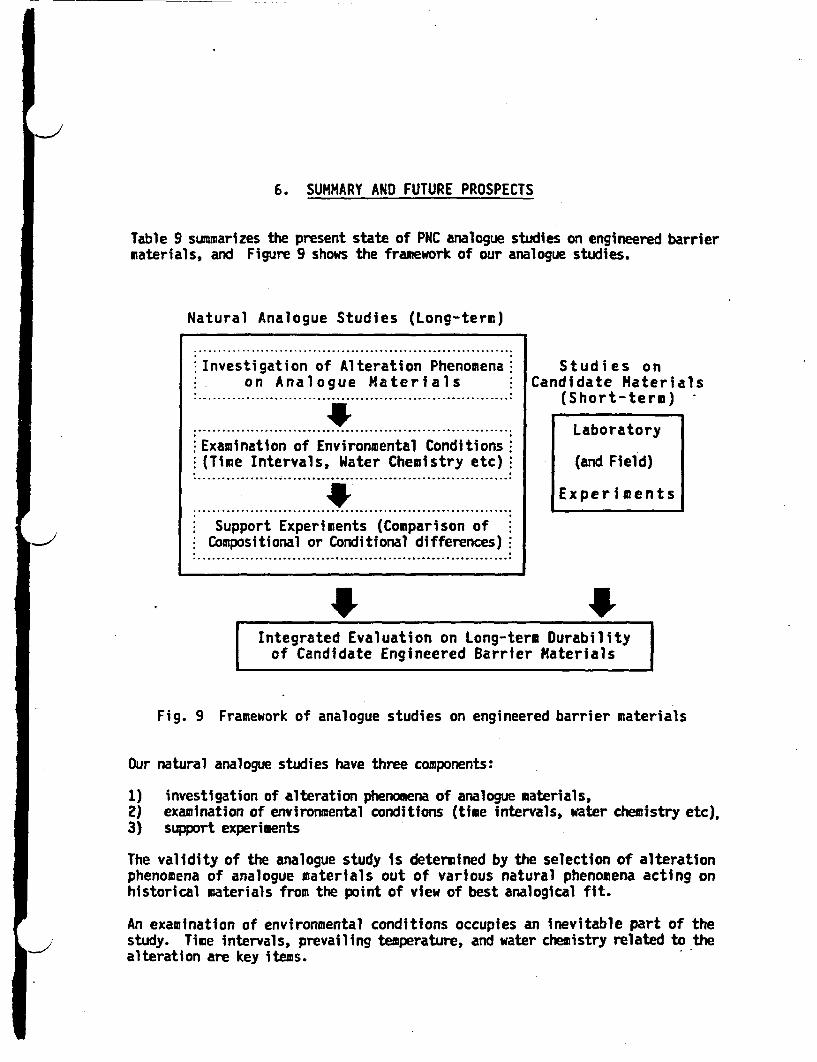
I6. SUMMARY AND FUTURE PROSPECTS
Table 9 summarizes the present state of PNC analogue studies on engineered barriermaterials, and Figure 9 shows the framework of our analogue studies.
Natural Analogue Studies (Long-term)
:.................................................................:Investigation of Alteration Phenomena: Studies on
on Analogue Materials Candidate Materials................ .. ... :(Short-term)
............I........ . .............. LaboratoryExamination of Environmental Conditions(Time Intervals, Water Chemistry etc) (and Field)
1* Experiments.................................................................
Support Experiments (Comparison ofCompositional or Conditional differences)
.................................................................
Integrated Evaluation on Long-term Durability |of Candidate Engineered Barrier Materials
Fig. 9 Framework of analogue studies on engineered barrier materials
Our natural analogue studies have three components:
1) investigation of alteration phenomena of analogue materials,2) examination of environmental conditions (time intervals, water chemistry etc),3) support experiments
The validity of the analogue study is determined by the selection of alterationphenomena of analogue materials out of various natural phenomena acting onhistorical materials from the point of view of best analogical fit.
An examination of environmental conditions occupies an inevitable part of thestudy. Time intervals, prevailing temperature, and water chemistry related to thealteration are key items.

0Table 8. Alteration behaviour of cement fabrics
(1) MATERIALS STUDIED(j) SITE Kanagawa-Manazuru Yokohama-katabira(2 SAMPLE Concrete of Railway Concrete of
MATERIALS Tunnel Wall Estuary Wall
(2) ENVIRONMENT(D Temperature 1 3 IC 1 5 C(D Surrounding Lapilli tuff S o i
Materials(3 Water Content 40 96 3 3 96
@Water Chemistry Ca - NOa(HCOs) Na - Cl
(3) PERIOD (yr) 6 7 6 1
(4) RESULTS OF Ca depletion Cl permeation >10 cmALTERATION <fe w x CaCO3 formation >8 cm
CaCD0dissolution >5 cm
&Table 9 The present state of PNC analogue studies
on engineered barrier materials
Barrier Materials Estimation ofComponents and Mode of Period Estimation of - Environental
(Candidate Occurrence (yr) Period ConditionsMaterials)
Waste Form Scoria Tephro- From Recent(Borosilicate (Pyroclastic 102 _104 chronology Climatological
glass) Fall Deposit) Conditions
Buffer Contact Radiometric Closure Temperature(Compacted Metamorphosed 106-101 Age of Radiometric Ages
Bentonite) (Natural) Determination Geological andBentonite Geochemical Data
Overpack Industrial From Present(Carbon Materials 10' -10' Documents Embedded
Steel) (Pipe) Conditions
Industrial From PresentBackfill Materials 10' r-102 Documents Embedded(Concrete) (Components Conditions
of Fabrics)
3. Chapman,N.A., and McKinley, I.G. (1987) The Geological Disposal of NuclearWaste, John Wiley & Sons,
4. Ewing, R.C., and Jercinovic, M.J., (1987) Mat. Res. Soc. Proc., 84, 67-83.5. Bryan, W., and Moore, J.G. (1977) Geol. Soc. Amer. Bull., E8, 556-570.6. Grambow, B., Jercinovic, M.J., Ewing, R.C. and Byers, C.D. (1986) Mat. Res.
Soc. Proc., 9 263-272.7. Hekinian,H., and Hoffert, M., (1975) Marine Geology, 19, 91-109.8. Jercinovic M.J. and Ewing, R.C.(198B) JSS Project Technical Report, 6-01,
21.9. Kamel, G., Aral, T., Yusa, Y., Sasaki, N., and Sakuramoto Y., (1990) Mat.
Res. Soc. Symp. Proc.,176. 657-663.10. Lutze, W. Malow, G., Ewing, R.C., Jercinovic, M.J. and Keil,K., (1985)
Nature, 314, 252-255.11. Lutze, W., Grambow, B., Ewing, R.C. and Jercinovic, M.J. (1987) Natural
Analogues in Radioactive Waste Disposal, 142-152.12. Maejima, I., (1984) Jour. of Geol., 93, 413-419 (n Japanene).13. Muramatsu, T., (1988) Regional Geology of Japan IV. CHUBU-I , p.62.14. NAGRA (1985) Project Report NGB 85-09.15. Oda, y., Suzuki, S., and Ohyama, Y., (1985) Jour. Petrol. Mineral. Econ.
Geol. 80, 526-536 (in Japanene).16. Roberson, H.E. and Lahann, R.W., (1981) Clays and Clay Mnerals, 29, 1-29.17. Sugawara, K., (1967) Tkyu Kagaku (Geochemistry) 2, 501 (in Japanene).18. Sugimura, S., (1977) Kagaku (Science) 47, 749-755 (n Japanene).19. Yamamoto, T., (1980) Tenki (Weather), 27, 76-855 (in Japanene).

-- ~ ~ ~ ~ ~ ~ ~ ~ ~ ~ ~ ~~n.EL~n
Support experiments are indispensable to the study in order to enhance the widerapplicability of the natural analogue. Comparison of differences ncomposition or condition Is the key ssue for laboratory support experiments.Such experiments for the comparison of compositional differences betweenbasaltic glasses and candidate waste glass have already started, and the resultsto date indicate that there is no significant recognizable difference in theleaching rates.
From a combination of the natural analogue studies outlined above and laboratoryexperiments on the candidate materials, an Integrated evaluation of the long-tem durability of candidate engineered barrier materials can be conducted.
ACKNOWLEDGMENTS
We are sincerely grateful to Prof. H. Machida, Dr. K. Hakamada, Dr. K. Marumoand Mr. M. Sato for their useful suggestions for obtaining samples, to Prof. K.Suzuki for provision of standard samples for analysis by EPMA, to Mr. Y.Sakuramoto for valuable discussions, to Mr. T. Teshima and Mr. J. Yamagata fortheir preparation of Tables and Figures, to Prof. Y. Kuroda and Mr. Y. Suzukifor hydrogen isotope determinations, to Mr. H. Takano for field survey, andDr. M. Apted and Dr. G. Davidson for their helpful editing.
The organizations which collaborated with PNC on ts analogue programme onengineered barriers were:1) Department of Glass Industry, Ohsaka Industry Laboratory, n the laboratoryleaching experiments of both borosilicate and basaltic glassess;2) Dr. K. Tamada, Corrosion Protection Laboratory, NKK Corporation, in charge ofcorrosion studies on carbon steel pipe n soil environments;3) Laboratory of Clay Mineralogy, Jyoetsu University of Education, especiallyProfessor T. Watanabe as technical and scientific advisor concerning theillitizatlon study;4) A cooperative group of companies consisting of Kajima Corporation, ShimizuConstruction Co. Ltd, Taisei Corporation, and Ohbayashl Corporation, in thesampling of concrete materials and In acquisition of data on environmentalconditions;5) Laboratory of Cement Mineralogy, Nagoya Institute of Technology, especiallyProfessor K. Suzuki as technical advisor concerning hydration of cementmaterials;
to all of these organizations and people we are much ndebted.
REFERENCES
1. Allen, C.C. (1982) Mat. Res. Soc. Proc., 5, 37-44.2. Arai, T., Yusa, Y., Sasaki, N., Tsunoda, N., and Takano, H., (1989) Mat.
Res. Soc. Symp. Proc., 127, 73-80.

1..Tokai Vitrification Facility (TVF)
Power Reactor and Nuclear Fuel Development Corporation
Tokal Works

Tokal rmcotton Facility Basec Flow Sheet and Key Components
FLIWW-Z The mission o the TVF is to immobilize the high levelradioactive liquid waste (HLLW) stored is the Tokai Repro-cessing Iaat into the stable gs ore.
Reived HUM W is continuously led into the glass erter withglass additive to he melted after conditioning of it The moltenglass is discharged ito the canister periodically. ad filledcanister is tored i the stoer cell after the lid welding, - ---deconteminstioe. and ispection The off-gases rom the an onmelter, and vessels are treated by cleaing equipment.
0n
CW ~ Cu
mow. i~~~~~fl1omeo__~~~~~~~~~aew pep" Fe" T t Com,
F_... ._. .. ._ . .. . ._. I. ._. .. . _ . .. . ._ . ... . .. . . ........... ,_____.. _F.
jm F__M _ ~~ ~ ~ _ E 4..... _ ;;�I iChrscdaqdlft C HLLW(alt owln I B-srs)0.0mm of ILW OWMm~~g~uss aev I Sx W. 9jUl6unces NMd S AWItdTU
W"~~~N.ONd.a Co.be
Mqu~~AMO
fJ. Ne.P. A m. One
Gls Ma looIl""nMg
Dunnes ja 25m10v 94010
Caes IiWi ass io
COMPOelo I DNIt, Co Wt Glass Product VWteld Product
..4 vm lbamanaus _
esc a 1- ' I1.10 3coo I ~ Caniser
AO 3-I5`-
0mg. s-3r°sen t
011 goO"M a
�I�1
SWAP Pus
Evapwrator PAodel- AMM
.�A _ - - ....... - ._ .. . _ _ .flerlX riaataaas ipwU-ia~n~ u s . 4
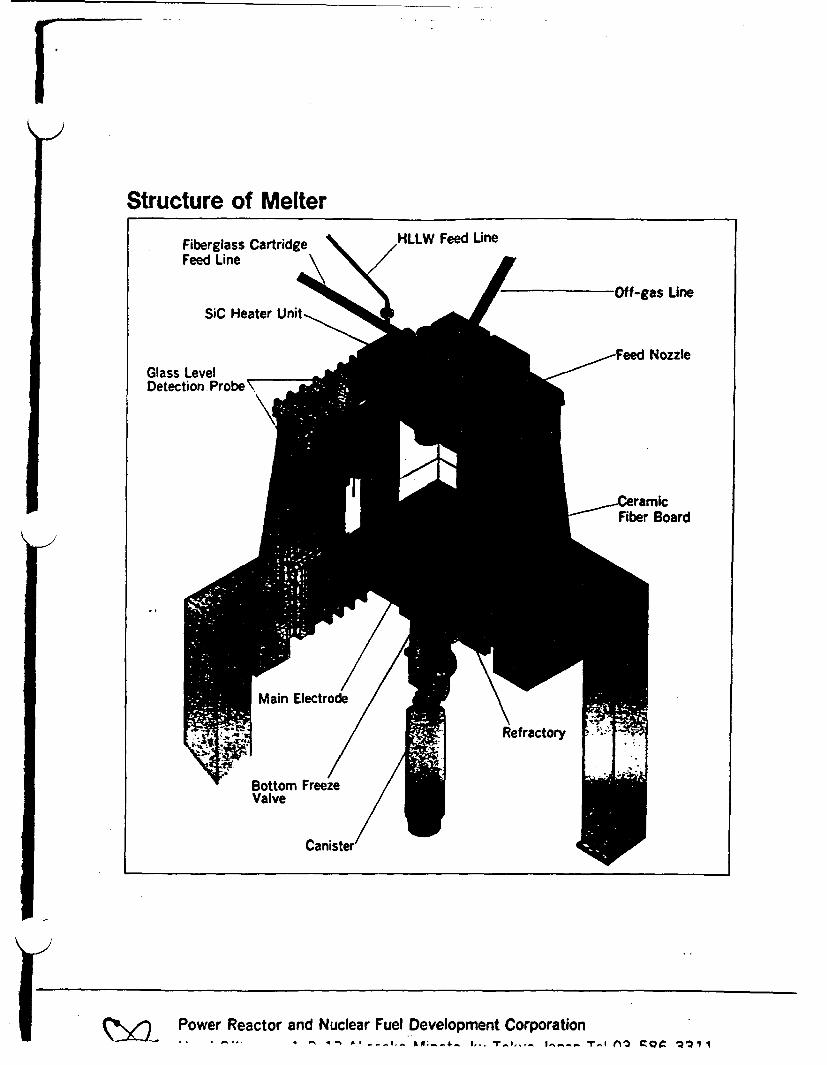
Structure of Melter
-Off-gas Line
Glass LevelDetection Probe \ ad
Rerctr
Power Reactor and Nuclear Fuel Development Corporation' ' ' ^ ' ' ' ^ - '% - - a. tR 1 . To ilI-- - .. . . . . - .r M13 Tac %Q; 1 1

Pu-contaminated WasteTreatment Facility (PWTF)
Power Reactor and Nuclear Fuel Development Corporation

Flow Dg. ) of Waste Processin at the PWTF 7) "'D
6L Ioluavu redection of he wastes wwratedL2L ftoftt~_ of rwJ fro MOX laid abricatio.
.C4eeostration of the processes developedby I'NC.
Saf ft" tc
D F#
IeeCowa _
0 l 0 nmFRItt C_
1 I,I
I
I I
;;,
leAM : -7 Sg xM
Cemhds ciI W0et
Optmng Data km kbvtn Prce
VI f"_ \OMM We" rI-
Ceevea.eed A M ee. pcel(<5X3a4
1dM OgeO 35.om we"s.. _ . We...
tivemeb-
-V -~ Ou
-... , 0.. . 3C
1" . I *i01
- Del,Metal Mt _ P _O _
MI~w~~e~meWOWcofCopper I
_. daw _ __e
_ tkeeiaa _ IOkIS_Pesia d lg.fwM_ ,._ . .
Opa" Dtaon Microwave me"n Procen
5405 hi mm- 'eam9
MJm OAIPk Igftow
Mn-ADeetruclive Aeeey INDA)*Peasove -toy lchnequr ctve nAic, tcnc o
Specifi tio d Wahs Fcofoxilifte block
t : :b' I
Maai $01 304 a.tONIeaags: *tmewax
ll0100MD__io : tA_
Uu.
Pasive nelton apparatust '.
Storage tn Slor."Pt inC,a iShe cotaumc -fiku blacks 4t hcon na.ti. mn.4
i
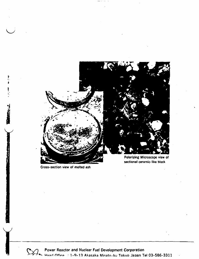
-I
Polarizing Microscope view ofsectional ceramic-like block
Cross-section view of melted ash
Power Reactor and Nuclear Fuel Development CorporationCArffig-A 1-9-13 Akasaka Minatn-ku Tokvo Janan Tel 03-586-3311
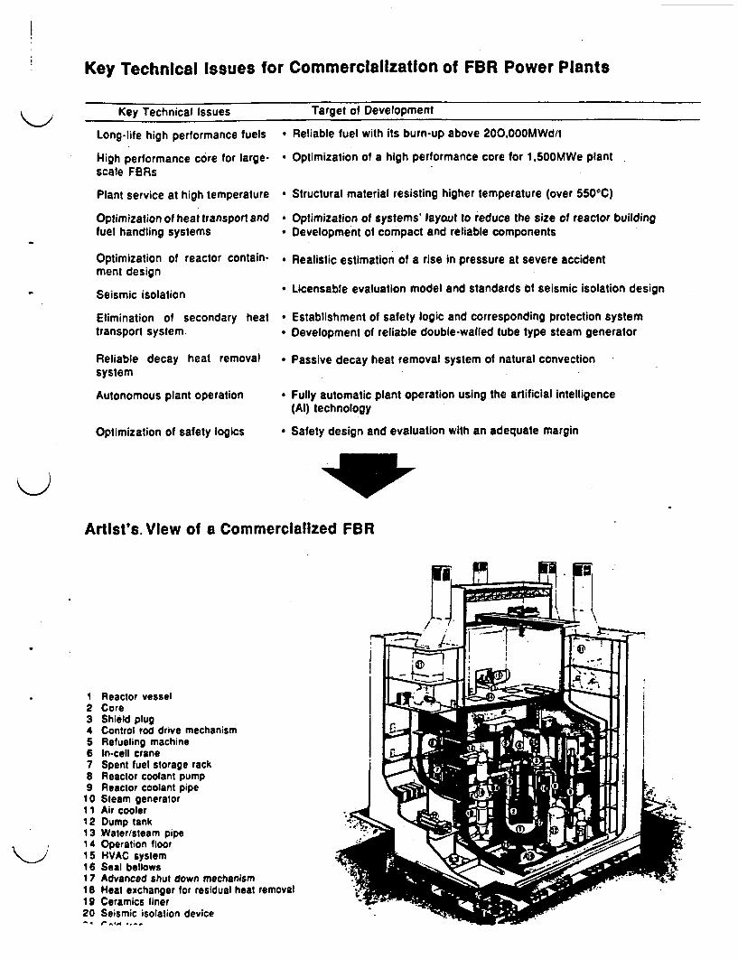
Key Technical Issues for Commercialization of FBR Power Plants
-
Key Technical Issues
Long-life high performance fuels
High performance core for large-scale FRs
Plant service at high temperature
Optimization of heat transport andfuel handling systems
Optimization of reactor contain-ment design
Seismic isolation
Elimination of secondary healtransport system.
Reliable decay heat removalsystem
Autonomous plant operation
Optimization of safety logics
.
Target of Development
* Reliable fuel with its burn-up above 200000MWd/l
* Optimization of a high performance core for 1 ,500MWe plant
* Structural material resisting higher temperature (over 5506C)
* Optimization of systems' layout to reduce the size of reactor building* Development of compact and reliable components
* Realistic estimation of a rise in pressure at severe accident
* Licensable evaluation model and standards of seismic isolation design
* Establishment of safety logic and corresponding protection system* Development of reliable double-walled tube type steam generator
* Passive decay heat removal system of natural convection
* Fully automatic plant operation using the artificial intelligence(Al) technology
* Safety design and evaluation with an adequate margin
Artist's. View of a Commercialized FBR
1 Reactor vessel2 Core3 Shield plug4 Control rod drive mechanism5 Refueling machine6 In-cell crane7 Spent fuel storage rack8 Reactor coolant pump9 Reactor coolant pipe10 Steam generator
1 Air cooler12 Dump tank13 Water/steam pipe14 Operation floor15 HVAC system16 Seal bellows17 Advanced shut down mechanism18 Heat exchanger for residual heat removal19 Ceramics liner20 Seismic isolation device
4 t.e.W. .
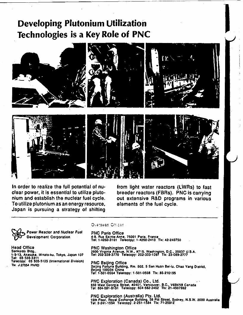
IDeveloping Plutonium UtilizationTechnologies is a Key Role of PNC
I
IIn order to realize the full potential of nu-clear power, it is essential to utilize pluto-nium and establish the nuclear fuel cycle.To utilize plutonium as an energy resource,Japan is pursuing a strategy of shifting
from light water reactors (LWRs) to fastbreeder reactors (FBRs). PNC is carryingout extensive R&D programs in variouselements of the fuel cycle.
2_/0 .-~ :s ea .s C4 .- --
(*')a- Power Reactor and Nuclear Fuellop Development Corporation
Head OfficeSankaido Bldg..1-9-13, Akasaka. Minato-ku. Tokyo, Japan 107Tel: 03 586-3311Telecopy: 03 505-5125 (International Division)TIx: J 27654 PNRD
PNC Paris Office4-8. Rue Sainte-Anne, 75001 Paris, FranceTel: 1-4260-3101 Telecopy: 1-4260-2413 Tlx: 42-240750
PNC Washington Office2600 Virginia Avenue, N.W.. #715. Washington, D.C.. 20037 U.S.A.Tel: 202-338-3770 Telecopy: 202-333-1097 Tlx: 23-089-2777
PNC Beijing OfficeBeijing Fortune Building, Rm. 602, 5 San Huan Bei-lu. Chao Yang District,Beijing 100004 ChinaTel: 1-501-0564 Telecopy: 1-501;0566 Tx: 85-210195
PNC Exploration (Canada) Co., Ltd.650 West Georgia Street. #2401. Vancouver, B.C., V6B4N8 CanadaTel: 604-681-6151 Telecopy: 604-682-3452 Tx: 21-4507862
PNC Exploration (Australia) Pty. Ltd.16th Floor, Royal Exchange Building. 56 Pitt Street, Sydney, N.S.W. 2000 AustraliaTel: 2-241-1594 Telecopy: 2-251-1584 Tx: 71-25912

TECHNOLOGEES DISCUSSED AT PNCOARAI
- Decommissioning Technology for Nuclear Fuel Cycle Facility in WDF- Separation and Removal
- Decontamination with Melting- Electopolishing I- Electropolishing H- Ice Blasting Decontamination- REDOX
- Radiation Control- System Engineering- Waste Treatment- Remote Handling- Dismantling- Plasma Arc Cutting- Monitoring- Radiation Image Display- R&D of Fast Breeder Reactors (BR)- R&D of Advanced Thermal Reactors (ATR)- R&D on Fuel Recycling- Development of a Heat re nt and Angle Beam Type Eectro-Magnetic Acoustic
Transducer- R&D on Plutonium Fuel- Low Level TRU Bearing Waste Management Technologies
- Incineration- Acid Digestion- U-Contaminated Waste Incineration- TRU- Contaminated Waste Incineration- Cyclone Icineration- Waste Incineration
- Decomposition- Dismantling
- Plasma Arc Cutting- Ima Arc Cutting
- Immobilization- Microwave Melting- Eectro-Slag Remelting- Hip Solidification- Dehydration and Solidification with Microwave- Hypothermal Solidification- Cementation- Plastic Solidification- BitminIzaion- Krypton Immobilization
BIBLIOGRAPHY OF L IRATURE RECEIVD FROM PNC.OARAI
*Development of a Heat Resistant and Angle Beam Type Elect-Magnetic AcousticTransducer', Compiled by K. Am, H. Rindo, K. Nakamoto, T. Doi, K.Morimoto, and T. Sakamoto, Oarai Engineering Center, PNC, S pages.
uDevelopment of Decommissioning Technologies for Nuclear Fuel Cycle Facility in WasteDismantling Facility', Oarai Engineering Center, PNC, 18 pages.
§FBR Development in PNC for Commercialization, PNC, 8 pages.
aResearch and Development in Oarai Engineering Center', Oarai Engineering Center, PNC,16 pages.
*Techrdcal Draft for Comments RD&D Program on Low-Level TRU Bearing WasteManagement Technologies', PNC, 43 pages.
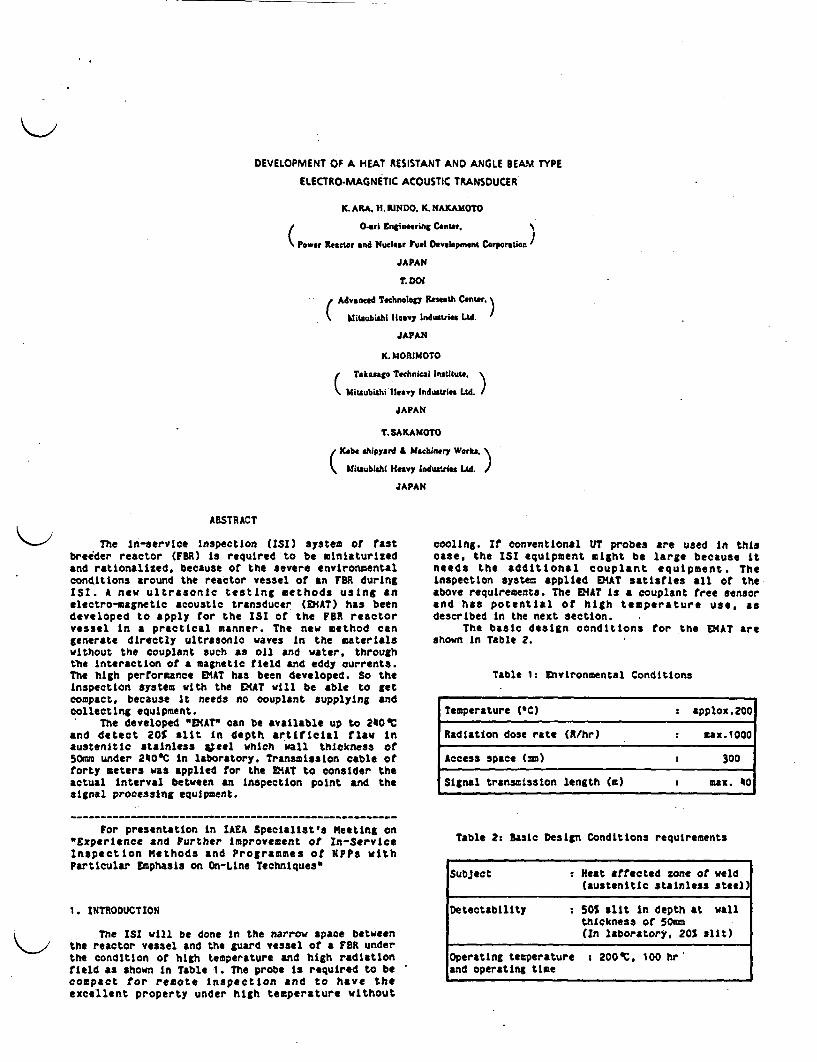
DEVELOPMENT OF A HEAT RESISTANT AND ANGLE BEAM TYPE
ELECTRO-MAGNETIC ACOUSTIC TRANSDUCER
K. ARA. H. RINDO. K. NAKAMOTO
t 0 ~~O-ri nginering Cnte.
(Power Reactor nd Nucear ul Development Corption
JAPAN
T. DO
( Advanced Technology Restomh Cenwr.
Mitsubishi leavy Industrie M.
JAPAN
K. MJORIMOTO
Tkasago Technial Instituto,
Mitsubishi Ileavy Industries Ltd.
JAPAN
T. SAKAMOTO
Xob shipyard & Machinery Works.( Miuubiahi Heavy Induelries LAd.'
JAPAN
ABSTRACT
The ln-service Inspection (ISI) system or tastbreeder reactor (FBR) is required to be miniaturizedand rationalized, because of the severe environmentalconditions around the reactor vessel f an FR duringISI. A new ultrasonic testing methods using anelectromagnetic acoustic transducer (EMAT) has beendeveloped to apply for the ISI of the FBR reactorvessel In a practical manner. The new method cangenerate directly ultrasonic waves n the materialswithout the couplant such as oil and water, throughthe interaction of a magnetic field and eddy urrents.The high performance MT has been developed. So theInspection system with the MlT will be able to getcompact, because it needs no ouplant supplying andcollecting equipment.
The developed EMAT" can be available up to 240Tand detect 20S slit n depth artificial law Inaustenitie stainless #;eel hich wall thickness f50mm under 2400C in laboratory. Transmission cable offorty meters was applied for the MAT to consider theactual Interval between an Inspection point and thesignal processing equipment.
cooling. If conventional UT probes are used n thiscase, the ISI equipment eight be large because tneeds the additional couplant equipment. TheInspection system applied MT satisfies all of theabove requirements. The VIAT Is a ouplant tree sensorand has potential of high temperature use, asdescribed In the next section.
The basic design conditions for the EMAT areshown n Table 2.
Table 1 Environmental Conditions
For presentation in AEA Specialist's Meeting on"Experience and Further Improvement of In-ServiceInspection Methods and Programmes of NPPs withParticular Emphasis on On-Line Techniques"
1. INTRODUCTION
The IS will be done in the narrow pace betweenthe reactor vessel and the guard vessel of a FR underthe condition of high temperature and high radiationfield as shown n Table 1. The probe s required to becompact for remote Inspection and to have theexcellent property under high temperature without
Temperature (C) applox.200
Radiation dose rate (R/hr) max.1000
Access space (=i) 300
Signal transission length () z max.
Table 2 Basic Design Conditions requirements
Subject M Neat affected zone of weld(austenItIc stalnless teel)
Detectability 50S slit in depth at wallthickness 50me
tIn laboratory, 20S slit)
operating temperature 200'. 100 hrand operating time
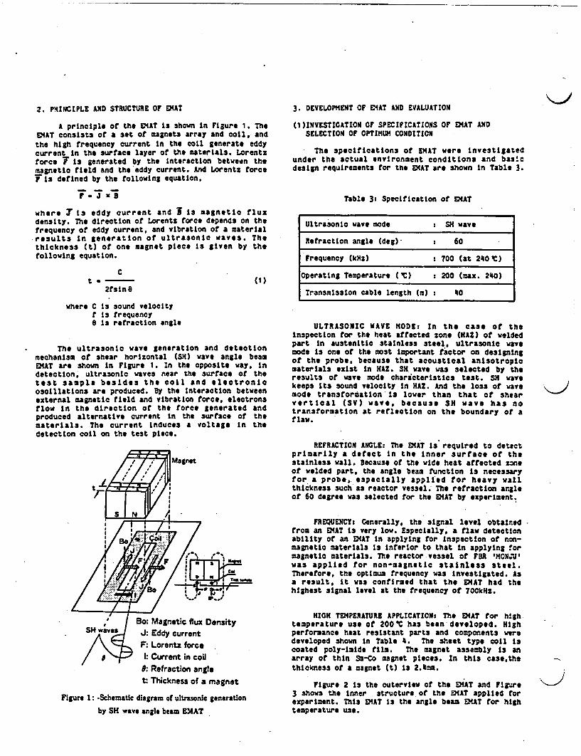
2. PRINCIPLE AND STRUCTURE OF DtAT
A principle of the ENAT is shown In Figure 1 TheE14AT consists of a set of magnets array and coil. andthe high frequency current In the coil generate eddycurrent In the urface layer of the aterlals. Lorentzforce T Is generated by the Interaction between themagnetic feld and the eddy current. And Lorentz forceT13 defined by the following equation,
r.J X3N
where T s eddy current and i 1s magnetic fluxdensity. The direction of Lorentz force depends on thefrequency of eddy current, and vibration of a materialreaults n generation of ultrasonic waves. Thethickness t) of one magnet piece is given by thefollowing equation.
C
3. DEVELOPMENT OF 4AT AND EVALUATION
(1 )INVESTIGATION OF SPECIFCATIONS OF E1AT ANDSELECTION OF OPTIMUM CONDITION
The specifications of EAT were nvestigatedunder the actual environment conditions and bas'cdesign requirements for the EMAT are shown In Table 3.
Table 3: Specification of EAT
t . ~2fsinG
(1)
where C is sound velocityf is frequency0 Is retraction angle
The ultrasonic wave generation and detectionmechanism of shear horizontal (SH) wave angle beamEMAT are shown n Figure 1. In the opposite way Indetectiont ultrasonic waves near the urface of thetest sample besides the coll and electronicoscillations are produced. y the Interaction betweenexternal magnetic field and vibration force, electronsflow in the direction of the force generated andproduced alternative current In the surface of thematerials. The current Induces a voltage n thedetection coil on the test piece.
I Mgnt
Ultrasonic wave mode SN wave
Retraction angle (deg) 60
Frequency kHz) 700 (at 240 C)
Operating Temperature (C) 200 (max. 240)
Transmission cable length (m) 0
ULTRASONIC AVE MODEt In the case of theInspection for the heat affected zone (HAZ) of weldedpart n austenitic stainless steel, ultrasonic wayemode is one of the most Important factor on designingof the probe, because that acoustical anisotropicmaterials exist n HAZ. SH wave was selected by theresults of wave mode characteristics test. SH wayekeeps Its sound velocity In HA. And the loss of wavemode transformation is lower than that of shearvertical (SV) wave, because SN wave has notransformation at reflection on the boundary of aflaw.
REFRACTION ANGLE: The EMAT is required to detectprimarily a defect In the nner surface of thestainless wall. ecause or the wide heat affected zneof welded part, the angle beam function is necessaryfor a probe,. especially applied for heavy wallthickness such as reactor vessel. The refraction angleof 60 degree was selected for the EMAT by experiment.
FREQUENCY: Generally, the signal level obtainedfrom an EMAT is very low. Especially, a flaw detectionability of an E4AT In applying for nspection of non-magnetic materials is Inferior to that n applying formagnetic materials. The reactor vessel of FR 'HON.J'was applied for non-magnetic tainless steel.Therefore, the optimum frequency was nvestigated. Asa result, it was confirmed that the EIAT had thehighest signal level at the frequency of 700kHz.
HIGH TPERATURE APPLICATION: Th EMAT for h!ghtemperature use of 2000C has been developed. Highperformance heat resistant parts and components weredeveloped shown In Table 4. The heet type coil scoated poly-imide film. The magnet assembly s anarray of thin S-Co magnet pieces. In this casethethickness of a magnet t) is 211.
Figure 2 s the outervIew of the EiAT and Firgure3 shows the Inner tructure of the EMAT applied forexperiment. This EMAT Is the angle beam EAT for hightemperature use.
Bo: Magnetic flux Density
J: Eddy currentF: Lorentz force1: Current in coil
9: Refraction angle
t Thickness of a magnet
Figure 1: -Schematic diagram of ultrasonic generation
by SH wave angle beam EMAT
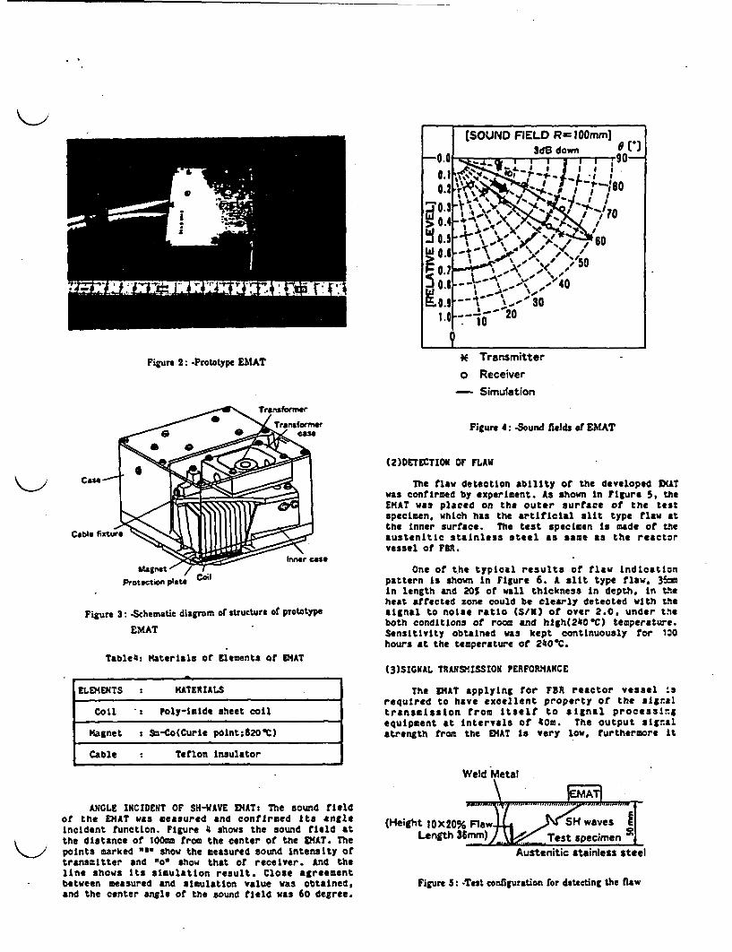
Figure 2: -Prototype EMAT * Transmittero Receiver
- Simulation
Cable fixtu s
Protectifo plate
Figure 3 -Schematic diagrum or structure or prototype
EMAT
Table4i Materials of Elements of EMAT
Figure 4: -Sound fiolds of EMAT
(2)DETECTION OF FLAW
The flaw detection ability of the developed ATwas confirmed by experiment. s shown In Figure 5, theEMAT was placed on the outer surface of the testspecimen, which has the artificial alit type flaw atthe nner surface. The test specimen Is made of theaustenitic stainless steel as same as the reactorvessel of FBR.
One of the typical results of flaw indicationpattern s shown in Figure 6. A slit type flaw, 3 In length and 20% of wall thickness n depth, In theheat afrected zone could be clearly detected with thesignal to noise ratio S/N) of over 2.0. under theboth conditions of room and hgh(240IC) temperature.Sensitivity obtained was kept continuously for 10hours at the temperature of 240C.
ELEYENTS MATERIALS
Coil P Poly-mlide sheet coil
Magnet s Sm-Co(Curie point;820C)
Cable Teflon Insulator
ANGLE INCIDENT OF SH-WAVE EATs The sound fieldof the EMAT was measured and confirmed ts angleincident function. Figure 4 shows the sound feld atthe distance of 1OOmm from the center of the EMAT. Thepoints marked "" show the measured sound ntensity oftransmitter and "o show that of receiver. And theline shows Its simulation result. Close agreementbetween measured and simulation value was obtained,and the center angle of the sound field was 60 degree.
t3)SIGNAL TRANSMISSION PERFORMANCE
The DIAT applying for FR reactor vessel srequired to have excellent property of the signaltransmission from Itself to signal processingequipment at Intervals of 40m. The output signalstrength from the EAT Is very low, urthermore It
Weld Metal
|EMAT|
(Height l0X20% Flaw4 )<SH waves ILength 36mm) __ Test specimen _
Austenitic stainless steel
Figure 5: Test configuration for detecting the nw

Figure : -CRT traces for detecting the slit type flaw in laboratory
High temp.(240Ct - I Room temp.
Figure 7: -Test configuration for signal transmission
attenuate through the long transmission Cable.Therefore, signal Impedance matching between the EMATand the signal processing equipment is needed. Testcontiguration for signal transmission is shown inFigure 7. The attenuation ratio In transmission lineunder high temperature of 2400C was higher than thatIn room temperature as shown in Figure 8
( 4 )EVALUATION
HIGH TEMPERATURE OPERATION: Minimum Requirementor operating temperature Is 200C for 100 hours. Itwas confirmed by the experiment that the EIAT could beoperated up to 240 TC for 100 hours over. The element
with the low heat resistance ae oll and cable.especially electrical nsulator. The maximum operatingtemperature of the E!MAT depends on that of theelectrical insulation aterials. It is necessary toimprove these materials for realizing highertemperature use.
DESIGN PARAMETERS: The specitications the VIATfor FBR reactor vessel were decided through soMoexperiments. It was confirmed that design value agreedwith measured value well. Design parameters depend onthe conditions an ispected material. For example,In the case of applyirg for the thin wall nspectionsuch as piping. retraction angle and frequency ofultrasound should be selected optimum value.
DETECTABILITY: The requirements flaw detectlonability is 20 slit In depth in austenitlo stainlesssteel under high temperature of 20 C. The results Othe research satisfied with the target. We could getthe result that the flaw signal level n hightemperature of 240C as about 3dB lower than that inroom temperature.
APPLICATIONt In remote operation. the flawsignal level 1sattenuated through the longtransmission cable.. but impedance matching isetfective, It could transmit the flaw signal without aampltier.

(Time 20us/div, Amp, 5OmV/div)
Room temp. High temp.(240C)
Flaw signal Flaw signal
@ vf e F 1 ' B |-Tt-rf 1:
03: A
C.)
I- i;Ixo i
Figure 8: -CRT traces for transmitting signal at intervals or 40m in laboratory
4. CONCLUSION
SH wave angle beam E4AT with high temperature usewa3 developed which is applicable to the reactorvessel inspection Or FBR. It was confirmed Inlaboratory that the EMAT could be operated up to 240OCfor over 100 hours, the flaw detection ability was 20%slit In depth artificial flaw in austenitic stainlesssteel wall thickness of 50mm, and forty meters ofsignal transmission cable could be applied.
REFERENCEtl NakamuraT. and H.Rindo, K.Ara, T.Kamimura.
S.Tsuzuki, XK.Morioto, E.Nagaoka, N.Ikeda,"Conceptional Desgn of ISI System for 'MONJU'9,
Mitsubishi 'eavy Industries, Ltd. TechnitalRev.24,2,100-106(1987)
t2] Dol,T. and KMorimoto, TSakamoto, K.Ara.H.Rindo, Kakamoto, "Development of HighTemperature DiAT". Proc. Autumn Convention ZSJapan,(1986)(tn Japanese)
E3] Dol,. and XMorlmoto, T.Sakamoto, X.ara.H.Rindo, K.Nakamoto, DEVELQPMENT OF HIGHTEMPERATURE EMAT" ASM 9th InternationalConference on NDE n Nuclear Industry, (1988)
t4] K.ARA, N.Oyama, "Overview of Examination andInspection Technology n FBR", Vol.28, No.12pp1133-1134 (1986) AES (n Japanese)
:r I
.. -
- -U , t -.
..- Q .
- ::S
m A
. .
. ,.
LCIII%I .. .- f
,.. ., --.
.:- . *l
.. i. ,
- . ..
;.: . .I
-f:
-p, --
- n2J
P -�
4W- :-�- -
*U. st2�$�. 44
4 t,
.i
Ai
Jb177 � �.a'rrz-�- - -. .�-.-pa - *� �*-� * r
LI 4�4-- 4' - - - - .tt#A. -at
*r 4 4J-t t�r At *'r
r t.&'�9�
-Cv E�U�rt
., .0, . .,I . .__ - , .
.
'-~~~~~~ 24* '; '.*r *4 ''-
-
OARAI ENGINEERING CENTER
POWER REACTOR AND NUCLEAR FUELDEVELOPMENT CORPORATION
1. ,. Z
i 1: .-
* *
* an.
- *
C 943°89303
CONTENTS
1. INTRODUCT ION ................................................................................... 1.
2. OUTLINE OF WDF ---------------..-... 2
3. R&D STRATEGY OF D/D TECHNOLOGIES -.---------.. . 7
4. DEVELOPMENT OF DECONTAMINATION TECHNIQUES .---------- 7
4- 1 Ice Blast Decontamination ....................................................- 8
4- 2 Electropolishing Decontamination .*-.-------- .
4-3 REDOX Decontamination -........................ 10
5. DEVELOPMENT OF DISMANTLING TECHNIQUES .... I I
5-I Plasma Cutting Robot .---- 1i
6. DEVELOPMENT OF MONITORING TECHNIQUES--------------------------.... 1 3
6-I Radiation Image Display (RID) ............................................ 13
7. CONCLUSION ......................................................................................... 16
8. REFERENCES . . .1 6
Kt)
<a

p C N94 3 0 89-003
DEVEurW4 OF DECOMISSIONING TEGINOLOGIES FR Nll£AR RFEL CYaE FACILITYIN WASIE DISANING FCILIY
MASAO SHIOTSUXI. SATOSHI IKEDA. and HIDEHIKO IYAOPower Reactor and Nuctear Fuel Development Corporation (PNC)
1. INTRODUCTIONNuclear facilities such as power reactors, reprocessing plants and fuel fabrication
plants are generally said to have a limited life of up to 30 or 40 years. When they are
superannuated, these acilities have to be dismantled and removed safely, and wastes from
such dismantling ust be treated under appropriate control. These operations arecomprehensively termed as decommissioning3.
Power eactor and Nuclear Fuel Development Corporation (PNC) has so far dedicated
itself to the technical development of fast breeder reactors, reprocessing techniques andMOX fabrication techniques. Prograzs are based on national policy of plutonium fuelrecycle. PNC is now developing fuel cycle facility decomilasioning techniques.
At the Waste Dismantling Facility (WDF) located n 0-arai Engineering Center (OEC),PNC is eager to validate its technical developuent efforts aimed at the treatment of
surface-contaminated large size wastes from post irradiated FBR fuel and material
examination (PIE) facilities.
Photo.1 View of Waste Di mantling Facilitr tWF)
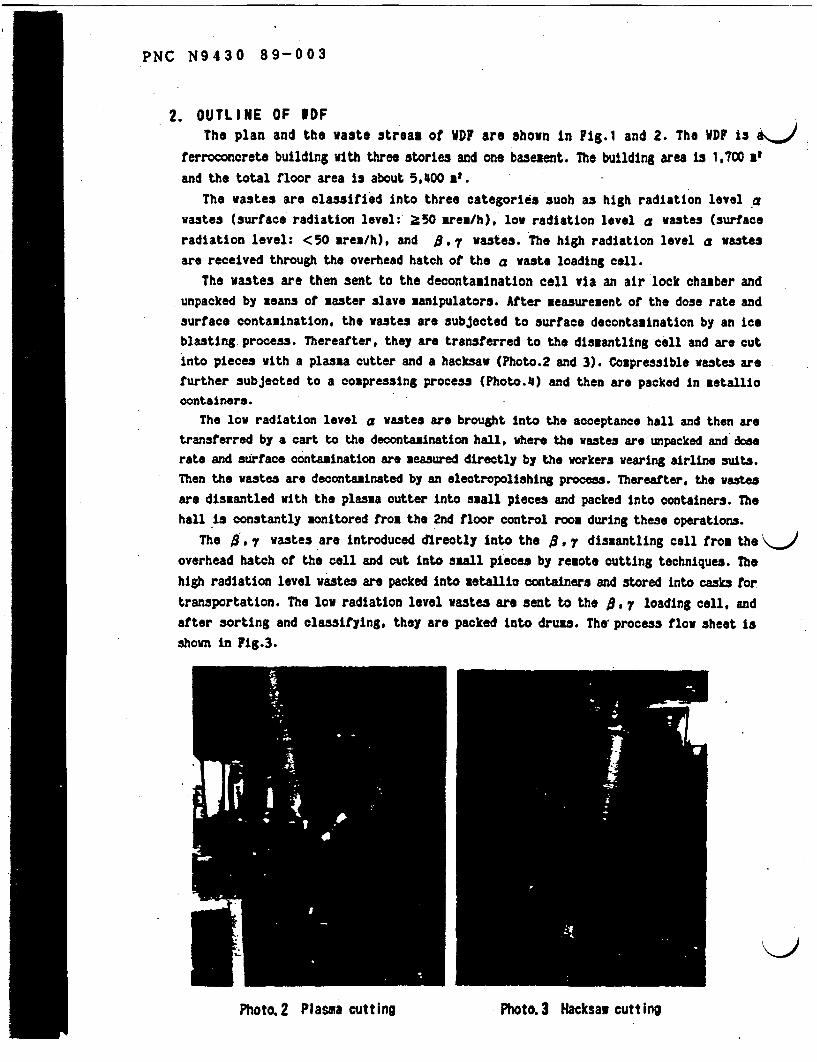
PNC N9430 89-003
2. OUTLINE OF WDFThe plan and the wast. streas of WDF are hown in Fig.1 and 2. The WDF is
ferroconcrete building with three stories and one basesent. The building area is 1,700 atand the total floor area is about 5,400 at.
The wastes are classified into three ategories such as high radiation level a
wastes (surface radiation level: 50 rea/h), low radiation level a astes (urface
radiation level: < 50 area/h), and 9. 7 wastes. The high radiation level a wastes
are received through the overhead hatch of the a waste loading cell.
The wastes are then sent to the decontamination cell via an air lock chamber andunpacked by eans of aster slave anipulators. After measureaent of the dose rate and
surface contamination, the wastes are subjected to surface decontamination by an ice
blasting process. Thereafter, they are transferred to the dismantling cell and are cut
into pieces with a plasaa cutter and a hacksaw (Photo.2 and 3). Compressible wastes are
further subjected to a compressing process (Photo.4) and then are packed in etallic
containers.The low radiation level a wastes are brought into the acceptance hall and then are
transferred by a cart to the decontamination hall, where the wastes are unpacked and does
rate and surface contamination are measured directly by the workers wearing airline suits.
Then the wastes are decontaminated by an electropollshing process. Thereafter, the wastes
are dismantled with the plasma cutter into sall pieces and packed into containers. The
hall is constantly onitored from the 2nd floor control room during these operations.
The 8 , 7 wastes are introduced directly into the , 7 dismantling cell from the
overhead hatch of the cell and out into sall pieces by remote cutting techniques. The
high radiation level wastes are packed into aetallio containers and stored into casks for
transportation. The low radiation level wastes are sent to the , 7 loading cell, and
after sorting and classifying, they are packed into drums. ThW process flow sheet is
shown in Fig.3.
_~~~~K
Photo.2 Plasma cutting PtPhoto.3 Hacksaw cutting

IC 9430 89-003
'InI
Photo. 4 Com nressing Machine Photo.5 Operator wearing Frog-man suit
in!
zi
l;
I. I-1Fig. I WDF Plan
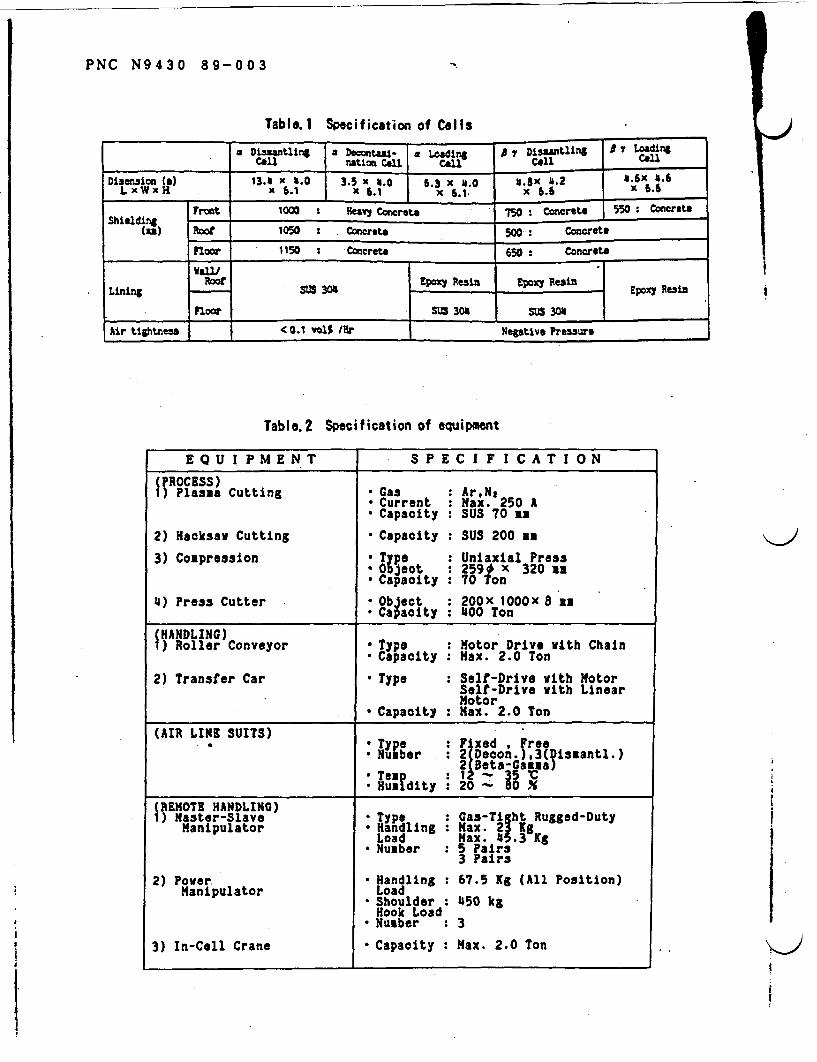
PNC N9430 89-003
Table. 1 Specification of Clls
a Da ling a Dontau- a Loading 7 Dislantlilng A LdingCell nlation Call Conl Collca
Diaensboo (c) 13.4 x .0 3. x |6 6.t3 x 6..0 _2 1.6x 4.6LxWxH x .1 X .1 X 6 . x 6.6
Front 1000 : ea17 Concrete 750 Concrete 550 ConcreteShielding_________
(u) Roof 1050 Concrete 500 Concrete
Floor 1150 - Coneret 650 Concrete
Lining Rf SU5 304|R Epoxy Resin EpOxY Resin
Floor ttghtzess cO~t voSUS 30 SUS 30
Wi tightness -C 0.1 V% IAr Neg,*tive Pressure
I
I
J
Table. 2 Specification of equipment
EQUIPMENT SPECIFICATION
(PROCESS)1) Plassa Cutting * Gas : Ar,N,
* Current : Max. 250 A* Capacity : SUS 70 as
2) Hacksaw Cutting Capacity : SUS 200 an
3) Compression * Type : Uniaxial Press* Object : 259t x 320 zm* Capacity : 70 Ton
4) Press Cutter Object : 200X lOOx 8 m* Capacity : 400 Ton
IHANDLING)Roller Conveyor * Type : Motor Drive with Chain
* capacity : Max. 2.0 Ton
2) Transfer Car * Type : Self-Drive with MotorSelf-Drive with LinearMotor
* Capacity : Max. 2.0 Ton
(AIR LINE SUITS)Type : Fixed , ree
* Nu ber : 2 DecorAi )3(Dismantl.)
*Tea : 1 35 'C*Hualdlty I 20 - 0 X
REMOTE HANDLING)1) a~ster-Slave * Type : Gas-Ti ht Rugged-Duty
Manipulator Handling Max 21*KgLoad Max. 453gKg
* Number : 5 Pairs3 Pairs
2) Powr. * Handling : 67.5 Xg (All Position)Manipulator Load
*Shoulder : 450 kgHook Load
* Number : 3
3) In-Cell Crane Capacity : Max. 2.0 Ton
i

~~~~~~~~~~~~~~~~~~~~~~~~~~~~~o -
~~~~~~~~~~~~~a *- .1- 4-
) )0
IN'~~~~I
LIP~~~~~~~~~~~~~~~~~~~~~~~~~~~~~~~~~~~~~~~~I
0
a) .,

0z
CA)0
0)
01CD
c;)
llaste
A ReceivingB Decontamination (Ice Blasting)C Plasma CuttingD Hacksaw CuttingE ClassificationF CompressionG Packaging
Fig.3 VDF Procoss Flow
H ReceivingI Decontaimation (Electro-Polishing)J Evaluation Glove BoxK Experiment hoodL Plasma Cutting RobotM Press CuttingN Packaging
c -C
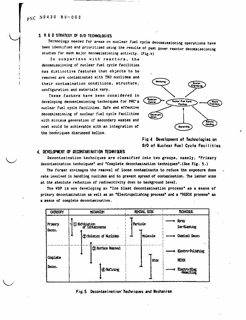
pC N9430 89-003
3. R & 0 STRATEGY OF D/D TECHNOLOGIES
Technology needed for areas on nuclear fuel cycle decommissioning operations have
been identified and prioritized using the results of past power reactor decommissioning
studies for each major decommissioning activity. (Fig.4)
In comparison with reactors, the
decommissioning of nuclear fuel cycle facilities
has distinctive features that objects to be
removed are contaminated with TRU nuclides and
their contamination conditions, structure, "
configuration and materials vary.
These factors have been considered indeveloping decommissioning techniques for PNC's k C
nuclear fuel cycle facilities. Safe and effective
decommissioning of nuclear fuel cycle facilities c \
with minimum generation of secondary wastes and
cost would be achievable with an integration of
the techniques discussed bellow.
Fig.4 Developmnt of Technologies on
D/D of Nuclear Fuel Cycle Facilities
4. DEEOPENT OF DECONTAMINATION TECHNiIUES
Decontamination techniques are classified into two groups, namely, Primary
decontamination techniques" and 'Complete decontamination techniques'.(See Fig. 5.)
The former envisages the removal of loose contaminants to reduce the exposure dose
rate involved in handling nuclides and to prevent spread of contamination. The latter aims
at the absolute reduction of radioactivity down to background level.
The WDF is now developing an Ice blast decontamination process' as a means of
primary decontamination as well as an Electropolishing process' and a REDOX process as
a means of complete decontamination.
Run~~ Woliaticn. ' ' lof Crtnmnts ' , Io ingn
eSoltion cf Nrlides ' W.Mbale ' _ hsal D=n
Szrfae sl
*t,. 19' .,
Fig.5 Decontamination Techniques and Mechanism
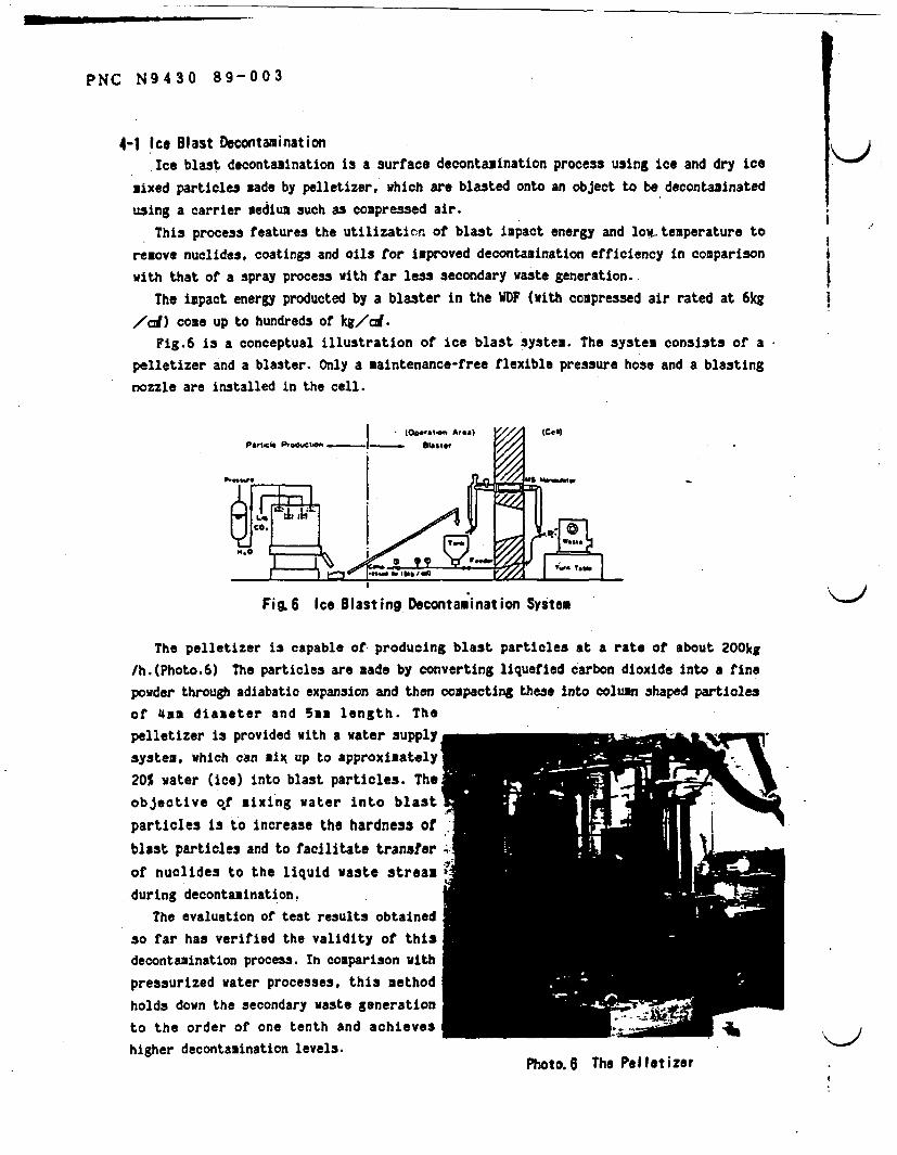
PNC N9430 89-003
4-1 Ice Blast DecontaminationIce blast decontamination is a surface decontamination process using ice and dry ice
Nixed particles ade by pelletizer, which are blasted onto an object to be decontaminatedw ing a carrier edium such ss coupressed air.
This process features the utilizaticn of blast impact energy and low temperature to
remove nuclides, coatings and oils for improved decontamination efficiency in comparisonwith that of a spray process with far less secondary waste generation. I
The ipact energy producted by a blaster in the WDF (with compressed air rated at 6kg/cd) come up to hundreds of kg/cm(.
Fig.6 is a conceptual illustration of ice blast system. The systen consists Of a
pelletizer and a blaster. Only a maintenance-free flexible pressure hose and a blastingnozzle are installed in the cell.
OwtI A,@a (2 cog)
P.S..,. Ml M S Mw
$4.0~~~~~~~~~~~~~~-4
.6.0 *50 u s , _>20i.
Fig. 6 Ice B1asting Decontamination System
The plletizer is capable of producing blast particles at a rate of about 200kg
/h.(Photo.6) The particles are made by converting liquefied carbon dioxide into a finepowder through adiabatic expansion and then compacting these into column shaped particlesof 4m diameter and 5aa length. Thepelletizer is provided with a water supplysystem, which can ix up to approximately
20% water (ice) into blast particles. Theobjective of mixing water into blast
particles is to increase the hardness of
blast particles and to facilitate transfer
of nuclides to the liquid Waste stream
during decontamination.
The evaluation of test results obtainedso far has verified the validity of thisdecontamination process. In comparison with
pressurized water processes, this methodholds down the secondary waste generation
to the order of one tenth and achieves
higher decontamination levels.Photo.5 e relletizer
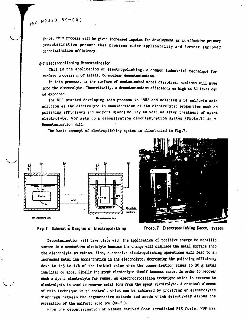
FSC w 9 0 3p .c 943 0 89-0
Hence, this process will be given increased ipetus for development as an effective primary
decontamination process that promises wider applicability and further improved
decontamination efficiency.
4-2 Eectropolishing DecontaminationThis is the application of electropolishing, a common industrial technique for
surface processing of etals. to nuclear decontamination.
In this process, as the surface of contaminated metal dissolves, nuclides will move
into the electrolyte. Theoretically. a decontamination efficiency as high as G level can
be expected.
The DF started developing this process in 1982 and selected a 5% sulfuric acid
solution as the electrolyte in consideration of its electrolytic properties such as
polishing efficiency and uniform dissolubility as well as after treatment of spent
electrolyte. WDF sets up a demonstration decontamination system (Photo.7) in a
Decontamination Hall.
The basic concept of electroplishing system is illustrated in Fig.7.
FizzT Schematic Diagram of Electropolishing Photo.? Electropolishing Decon. syste
Decontamination viii take place vith the application of positive charge to metallic
wastes in a conductive electolyte because the charge viii displace the metal surface into
the electrolyte as cation. Also, successive electropolishing operations wiii lead to an
increased metal ion concentration in the electrolyte, decreasing the polishing efficiencydown to 1/3 to 1/4l of the initial value when the concentration rises to 30 g metal
ion/liter or more. Finally the spent electrolyte itself becomes waste. In order to recoversuch a spent electrolyte for reuse, an electrodeposition technique which is reverse toelectrolysis is used to recover metal ions from the spent electrolyte. A critical element
Of this technique is pH control, which can be achieved by providing an electrolyticdiaphragm between the regenerative cathode and anode which selectively allows the
permeation of the sulfuric acid ion (SO.21).
From the decontamination Of wastes derived from irradiated FBR fuels, WDF has
M
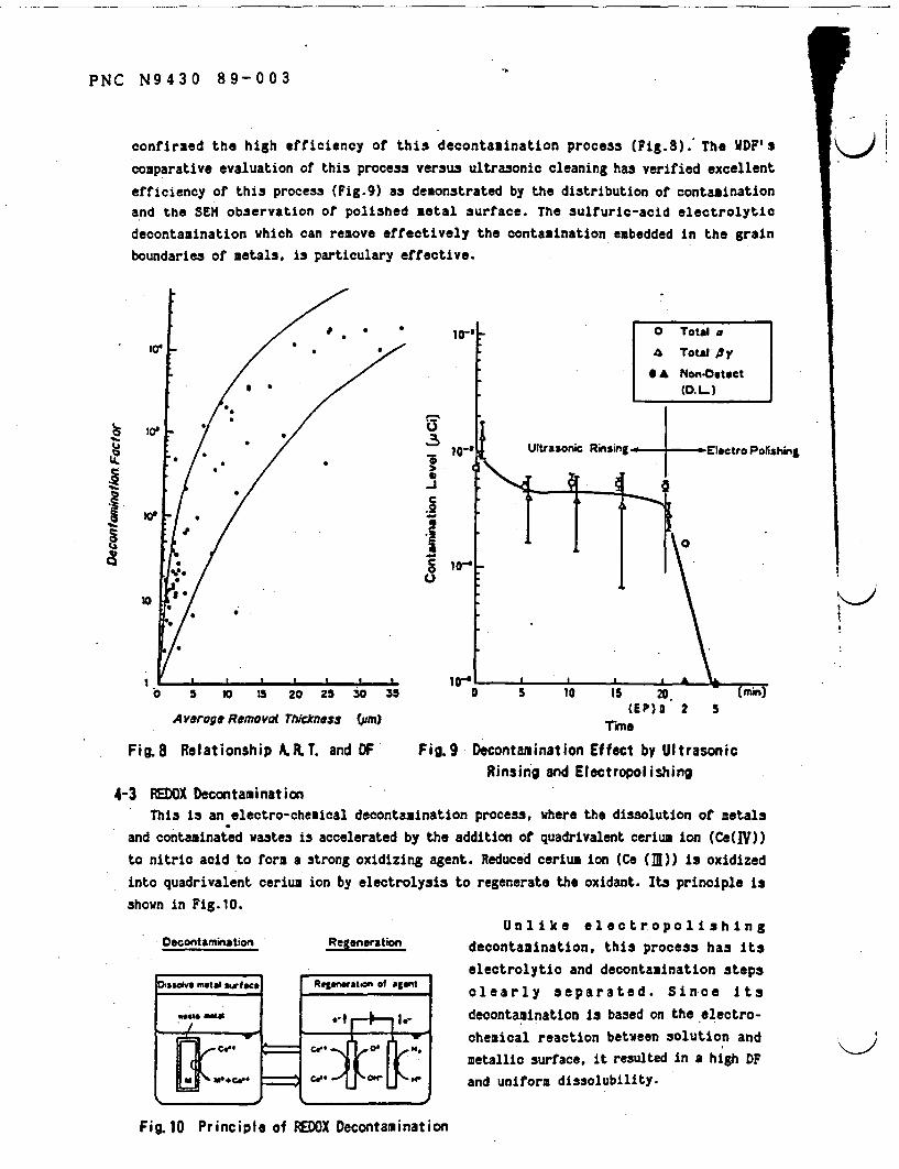
PNC N9430 89-003
confirmed the high efficiency of this decontamination process (Fig.8). The WDF's
comparative evaluation of this process versus ultrasonic cleaning has verified excellent
efficiency of this process (Fig.9) as demonstrated by the distribution of contaminationand the SEM observation of polished metal surface. The ulfuric-acid electrolytic
decontamination which can remove effectively the contamination ebedded in the grainboundaries Of etals, is particulary effective.
* S
10'
100
U
§ e~~~~s
1 ,o. ,.
Cs~~~~~~.
a
10i 0
I I L I I
0 5 10 1 20 25 S0
Averoge Removol Thckness (gm)
Fig.8 Relationship A.R.. and DF
3
.1
S1-J
_t..ft
35 20,(EP) O 2 5
rhne
Fig.9 Decontamination Effect by UltrasonicRinsing and Electropolishing
4-3 EDOX DecontaminationThis is an electro-chemical decontamination process, where the dissolution of etals
and contaminated wastes is accelerated by the addition of quadrivalent cerium ion (Ce(W))
to nitric acid to form a strong oxidizing agent. Reduced cerium ion (Ce ()) is oxidizedinto quadrivalent cerium ion by electrolysis to regenerate the oxidant. Its principle isshown in Fig.10.
Docontamination Regeneration
otsOve metal wfac
S..
N am
Rtswati of awd
Unlike electropolishingdecontamination, this process has itselectrolytic and decontamination stepsclearly separated. Since its
decontamination is based on the electro-chemical reaction between solution andetallic surface, it resulted in a high DF
and unifora dissolubility.
* C l
CAe M.
C" : l 011 ,
Fig.10 Principle of REDOX Decontamination

p NC N9430 89-003
The DF has been opelated a a cold decontamination experiment system (with a 100-
liter decontamination bath) since 1985 and has verified the validity of its highly
uniform dissolubility in polishing tests on Plates and valves with different surface
roughnesses.
This process, however, is not free from problems due to the strong acidity of
quadrivalent cerium ion. Such problems include the selection and evaluation of the
equipment component materials and the treatment of spent decontagination solutions. These
will be solved through subsequent studies plus hot tests to be conducted on actual wates.
5. DEVOELWNT OF DIS1MATLING EC*IlOESFacilities. machines and equipment used n the nuclear fuel cycle are diverse in
construction, configuration and material. Thus, it is essential to evaluate the
applicability, safety and efficiency of dismantling techniques under development.
In its efforts to develop dismantling operations, the WDF places greater emphasis on
plasma cutting technique which has wide applicability to many components. In the WDF,
large-size wastes generated in OEC have been cut by a plasma arc or a hacksaw, and
operation of the plasma torch with a aster slave manipulator and preliminary plasma
cutting robot have been demonstrated. In the same way, various methods, peripheral
techniques and remote control techniques for dismantling are being developed.
5-1 Plasma Cutting RobotIn order to dismantle large-size equipment and machines of complex configuration
installed in high-radiation and high-contamination areas, it is essential to use remote
control techniques for automatic, efficient and safe dismantling and removal operations.
In 1984 a plasma cutting robot (Photo.8)
was installed in WDF, as a modified version of
industrial robots, as a link in the development
of remote control technology to verify its
usefulness in the dismantling of wastes from
operating plants. This robot as based on a
teaching playback method, in which a cutting
path on an object is preliminarily taught to the
robot and cutting is made to the given cutting
path. If the object to be cut has a complex
configuration. its teaching procedure takes much
time. To solve this problem, some notable
improvements have been madei.e. the addition
of a voltage arc sensor which will feedback
voltage fluctuations to the robot during
-cutting for automatic operation. In addition a
non-contact type laser distance sensor, a joy
stick and a master arm (Photo.9 and 10) have
been added.
Photo. 8 Plasma Cutting Robot
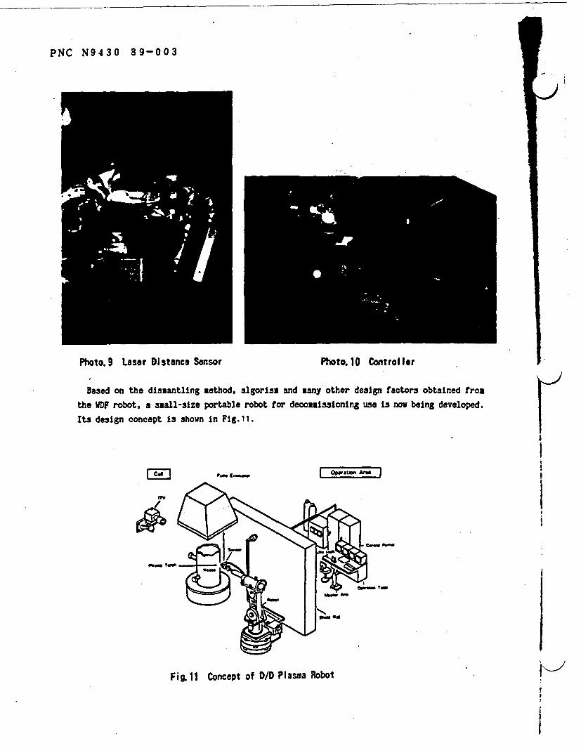
PNC N9430 89-003
Photo.9 Laser Distance Sensor Photo.10 Controller
Based on the dismantling ethod, algorist and any other design factors obtained rot
the DF robot, a sall-size portable robot for decootissioning use is now being developed.
Its design concept is shown in Fig.11.
i Opwi At INM g.0~
7V
Fig. 11 Concept of D/D Plasma Robot V-'
I

11r p NC N9430 89-003
6. DEVELOPMENT OF MONITORING TECHIUOLESEfficient and safe decommissioning operation addresses importance to monitoring
techniques by which to determine the quantity and distribution pattern of contaninated
nuclides.
PNC is developing a radiation image display (RID) which could be replaceable the
conventional smear method and direct survey method and provide a reliable and quick meansof evaluating the distribution of nuclide contamination by remote control.
6-1 Radiation Image Display (RID)To improve measurement and evaluation efficiency for decommissioning, to decrease
radiation exposure during the work and also to improve the reliability of measurement
data, PNC has been developing a radiation image display capable of remote and automatic
measurement and image display of the distribution of radioactive substances.
Its operating principle is to run a colimated7 ray detector and distance meter to
scan across a contaminated object to be measured and obtain radiation information and
distance information, from which a computer will create a picture of the distribution of
radioactive substances (evaluation picture) composed of 1,500 to 9,000 plots divided into
ten color levels and then will display the picture on a TV monitor as a synthetic image.
The measurement principle is illustrated in Fig. 12. Photo.11 shows the prototype
equipment No. 1 manufactured in 1986.
Table. 3 Specification of RID No. I
I
ITEM RID(l)
CsI(T )-PD' Detector
¢ 28 x50 (W
Shielding Material Tungsten
Shielding Thickness 5022
Shielding Power 1/100(- EnergylMeV)
Detector Weight -50kg
Detector Dimension 300(w) x350(D)x 900(H)
Cable Numbers 5
Measurement Time 10,15,30,60 min
Calculation Time 3min
Fio.12 Composition of Radiation Image isplay
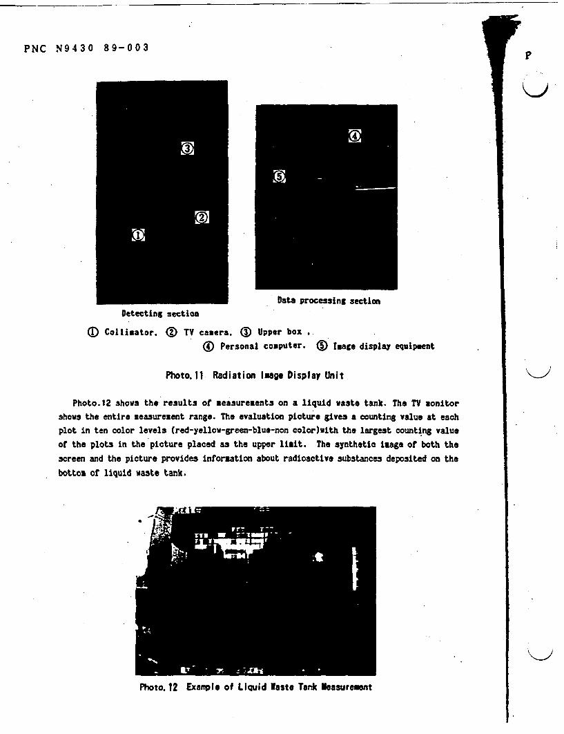
PNC N9430 89-003P
Data processing sectionDetecting section
D Collimator. (D TV camera. Upper box
® Personal computer. D Image display equipment
Photo.11 Radiation Image Display Unit
Photo.12 shows the results of easurements on a liquid waste tank. The TV monitor
shows the entire measurement range. The evaluation picture gives a counting value at eachplot in ten color levels (red-yellow-green-blue-non color)with the largest counting value
of the plots in the picture placed as the upper liait. The synthetic image of both the
screen and the picture provides information about radioactive ubstances deposited on the
bottoz of liquid waste tank.
Photo. 12 Example of Liquid aste Tank easurement
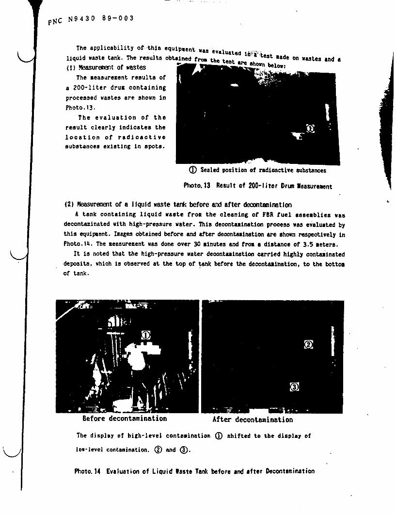
p14C N43 0 89-003
The applicability of -this equipment as evaluated if i t a
liquid waste tank. The results obtained b w the teteast and (1) Measuremnt of wastes
The measurement results of
a 200-liter drum containingprocessed wastes are shown in
Photo. 13.The evaluation of the
result clearly indicates the
location of radioactivesubstances existing in pots.
0 Sealed position of radioactive substances
Photo.13 Result of 200-liter Drum Yeasurement
(2) Measurement of a liquid waste tank before and after decontaminationA tank containing liquid waste from the cleaning of FR fuel ssemblies was
decontaminated with high-pressure water. This decontamination process as evaluated bythis equipment. Images obtained before and after decontamination are shown respectively inPhoto.14. The measurement was done over 30 inutes and from a distance of 3.5 meters.
It is noted that the high-pressure water decontamination carried highly contaminateddeposits, which is observed at the top of tank before the decontamination, to the bottomof tank.
Before decontamination After decontamination
The display of high-level contamination a) shifted to the display of
low-level contamination. X and (3.
Photo. 14 Evaluation of Liquid Waste Tank before and after Decontamination
PNC N9430 89-003
1.CONCLUS I ONWe will continue the development of decontamination and dismantling technologies
undertaken by WDF to establish techniques that can validate the safety and econony of
various nuclear fuel cycle facilities.
&REFERENCES
E.INADA, et al: 'Development of lectropolishing Decontamination Technique for Surface
Contaminated TRU Wastes' (text in Japanese) Annual Meeting of the Atomic Energy Society of
Japan, 1986.
T.MANO, et al: 'Development of Ice Blasting Decontamination Technique for Surface
Contaminated TRU Wastes' (text in Japanese), Fall Meeting of the Atomic Energy Society of
Japan, 1987.
H.MIYAO, et al: 'Development of Radiation Image Display', Annual Meeting of the Atotio
Energy Society of Japan, 1988.
M.SHIOTSUKI, et al Decommissioning of Nuclear Fuel Facilities Technological
Experiences and R&D', SPECTRUN'88, 1988.
-I1
1, -O M S -~~~ -0 -
lmor- - -IV .. 11;Israeli
..=- ' ^

Construction of "Monju' A PrototypeFast Breeder Reactor
Kv
ial view of Monju. May 1990
-vation completed In May 1t86 Reector contelnment vessel completed In April 18?
CONSTRUCTION SCHEDULE OF IAONJU
i______ 1 s5 w {u j'e7 (u { ~I" { 93 A 2 13EXCAVATION BASEAT REACTOR vESSEL INITIAL
START I CONCRETE O SET CRITICALITYKEY OCTART START OCT 8 OCT 92
MILESTONdE F-.I

Research and Development onPlutonium Fuel ;.
An essential element of fuel for new reactors such as theATR and FBR is plutonium - a byproduct of nuclear reactoroperation that can be recovered from spent fuel. The plu-tonium is combined with uranium to form mixed oxide(MOX) fuel.
Since MOX fuel consists of both uranium and pluto-nium. an effective non-proliferation measure is to mix thetwo and convert them to oxide immediately after extract-ing the plutonium.
PNC developed its own process. called the "microwave-heating direct denitration process." to carry out this co-conversion. It has been used since 1979 at the TokaiPlutonium Fuel Fabrication Facility (PFFF). The TokaiPlutonium Conversion Development Facility, with a dailyco-conversion capacity of 10kg MOX. went into operationin 1983. using plutonium nitrate and uranium nitrate fromthe reprocessing plant to produce MOX powder for ATRFugen, FBR Joyo, and FBR Monju.
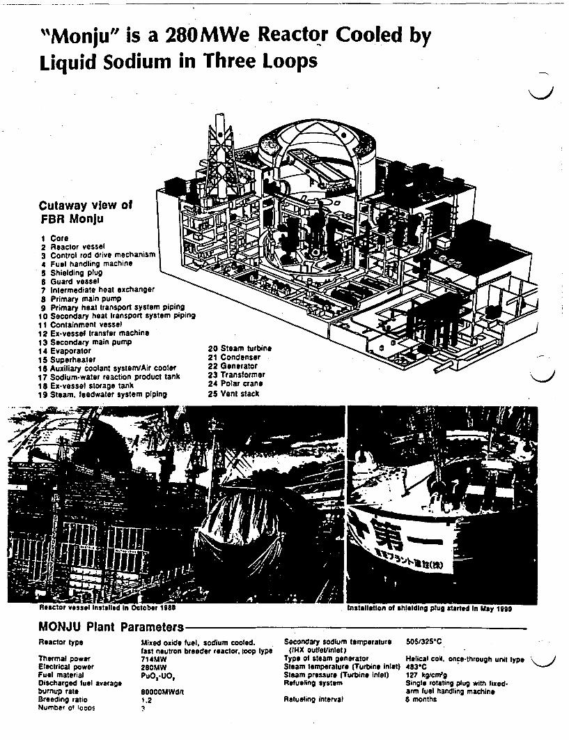
"Monju" is a 280MWe Reactor Cooled byLiquid Sodium in Three Loops
n
Cutaway view ofFBR Monju1 Core2 Reactor vessel3 Control rod drive mechanism4 Fuel handling machine5 Shielding plug6 Guard vessel7 Intermediate heat exchanger8 Primary main pump9 Primary heat transport system piping
10 Secondary heat transport system piping11 Containment vessel12 Ex-vessel transfer machine13 Secondary main pump14 Evaporator15 Superheater16 Auxiliary coolant systemlAir cooler17 Sodium-water reaction product tank18 Ex-vessel storage tank19 Steam feedwater system piping
20 Steam turbine21 Condenser22 Generator23 Transformer24 Polar crane25 Vent stack
MONJU Plant ParametersReactor type
Thermal powerElectrical powerFuel materialDischarged fuel averageburnup rateBreeding ratioNumber of oot
Mixed oxide fuel, sodium cooled.fast neutron breeder reactor. loop type714MW280MWPuO, .UO,
80000MWd/t1.2
Secondary sodium temperature 5051325*C(IHX outeVlinlet
Type of steam generator Helical coil.Steam temperature (Turbine inlet) 4830CSteam pressure (Turbine inlet) 127 kg/cm'sRefueling system Single rotat
arm fuel haRefueling interval 6 months
once-through unit type
Iing plug with ixed-andling machine
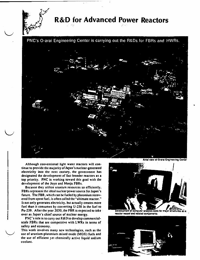
R&D for Advanced Power Reactors
ir
I
Although conventional light water reactors will con-tinue to provide the majority of Japan's nuclear-generatedelectricity into the next century. the government hasdesignated the development of fast breeder reactors as atop priority. PNC is working toward this goal with thedevelopment of the Joyo and Monju FBRs.
Because they utilize uranium resources so efficiently.FBRs represent the ideal nuclear power source for Japan'sfuture. The FBR, which can be fueled by plutonium recov-ered from spent fuel. is often called the "ultimate reactor."It not only generates electricity. but actually creates morefuel than it consumes by converting U-238 in the fuel toPu-239. After the year 2030, the FBR is expected to takeover as Japan's chief source of nuclear energy.
PNC's role is to carry out R&D to develop commercial-scale FBRs that are competitive with LWRs in terms ofsafety and economy.
i , ! This work involves many new technologies, such as theuse of uranium-plutonium mixed oxide (MOX) fuels andthe use of efficient yet chemically active liquid sodiumcoolant.
reactor "ssel end related Comoonents
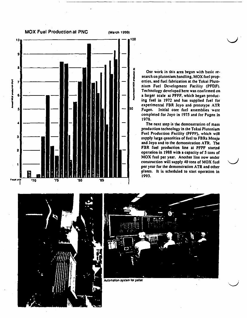
MOX Fuel Production at PNC (March} 1990)
100
Our work in this area began with basic re-search on plutonium handling, MOX fuel prop-erties, and fuel fabrication at the Tokai Pluto-nium Fuel Development Facility (PFDF).Technology developed here was confirmed ona larger scale at PFFF, which began produc-ing fuel in 1972 and has supplied fuel forexperimental FBR oyo and prototype ATRFugen. Initial core fuel assemblies werecompleted for Joyo in 1975 and for Fugen in1978.
The next step is the demonstration of massproduction technology in the Tokai PlutoniumFuel Production Facility (PFPF), which willsupply large quantities of fuel to FBRs Monjuand oyo and to the demonstration ATR. TheFBR fuel production line at PFPF startedoperation in 1988 with a capacity of S tons ofMOX fuel per year. Another line now underconstruction will supply 40 tons of MOX fuelper year for the demonstration ATR and otherplants. It is scheduled to start operation in1993.
AUiomaUOn sys57m Myw p1n1
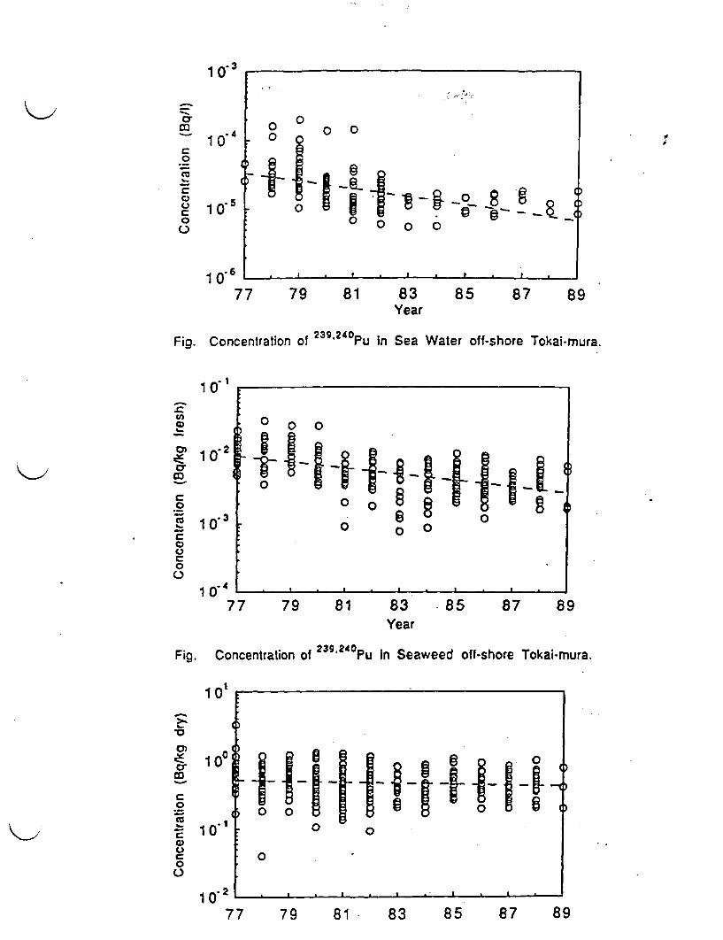
1 O3
r 10 4 0*~~
7 080~~~~~
o*4 '
o
Co
0 10 8
1677 79 81 83 85 87 89
Year
Fig. Concentration of 239,240Pu in Sea Water off-shore Tokai-mura.
1 0-
0
00 0 0 E
0 ~ ~ ~ 00
00
77 79 81 83 85 87 89Year
Fig. Concentration of 239.240 P in Seaweed off-shore Tokai-mura.
101
1. 10 0
0 0
0
0~~~~~~~~~
77 79 81 83 85 87 89
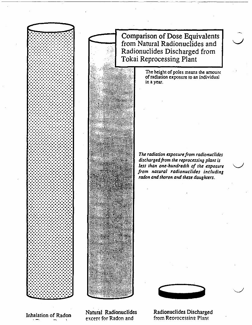
... .. ...
* ~ - a
*
. . . . . . . . . . . .. . . . . . . . . . . . . .
. .
. . . . . . . . . . .. . . . . . . . . . . . . .
. . . . . . . . . . . . .
. . . . . . . . . . . . .
*~~~~~~~
.. .. . . . . . . . .. . . . . . . . .
* . . . . . . . . . . . . .
. . . . . . . . . .
. . . . . . . . . . . . .
. . . . . .
. . . . . . . . . . . . . ............... ^ ^ ^ * * ^ ^. . . . . . . . . . . . . .
. . . . . . . . . . . . . .
. . . . . . . . . . . . . .. . . . . . . . . . . . . .. . . . . . . . . . . . . ^
. . . .. .. . .
. . . . . . . . . . . . . .. . . . . . . . . . . . . .. . . . . . . . . . . . . .
............ * ^ ^ ^ ^ ^ * ̂
*~~~~~~~
. . . . . . .
. . . . . . . . . . . . . .
. . . . . . . . . . . . . .* ^ . . . . . . . . . . . .
. . . . . . . . . . .
. . . . . . . . . . . . . .
. . . . . . . . . . .* ^ ^. . . . . . . . . . . . . a
.............. * ^ ^ * ^ ^ ^
. . . . . . . . . . . . . .
. . . . . . . . . . . . . .
. . . . . . . . . . ^ ^ ^ ^. . . . . . . . . .̂ ^ ^ ^
. . . . . . . . . . . . . .. . . . . . . . . . . . . .
. . . . . . . . . . . . . .. . . . . . . . .
. . . . . . . . . . . . . .
.O . . . . . . . . . . ^ ^
a .
*^ . . . . . . . .: ... : .
* a
a... .. . . . a
. . . . . . . . . . . .. . . . . . . . . . . . .a
. . . . . . . . . .
. . . . . . . . . . . . .
. . . . . . . . . . .
. . . . . . . . . . . .* . . . . . . . . . . .. . . . . . . . . . . . .
* . . . . . . . .
. . . . . . . . . .
. . . . . . . . . .
. . . . . . . . . . . .
. . . . . . . . . .
a a a a a * a a a a....^ ^^^
^ ^ ^ ^ ^ ^^ ^ ^ ^ * * * ^ ^ ^^ ^^ ^ ^
^ ^ * ^ ^^ ^* ^ ^ ^ * ̂ ^ ^ ^^ ^ * ^ ^a^ ^ * ^ ^^ ^^ ^ ^
^ ^ ^^ ^ ^ ^ ^ ^^ ^ ^ ^ * ^ *^ ^^ ^ ^ ^ * ̂ ^ ^ ^^ ^ ^ ^ ^ ^ *^ ^ ^^ ^ aa ^ * ̂ ^ ^ ^^ ^ ^ ^ ^ *~~~~~~ a
^*^^^^^^^^^^^^a* ̂ ^^ ^ ^ ^ ^ ^^ ^
^ ^ ^ ^ ^^ ^^ ^ ^ ^ ^ ^ ^ ^^ ^^ ^ ^
^~ ~~~ a *a ^^^^
a * a a a a a a aa ... aa^^
a. * a a a a * a. a a aaa *^ ^^
^~~ ~~~ *a a ^^^^^^^^^a a a
.. a a a a .a a a a a
.a a a a a a a a .a......^ ^* *^
.a. a ... ^^^ * . . a . a a a a a . a a a * a . a a a . a
.a a a a a a a
* . a a * a ̂
.^ ^ ^ ^ . aaa aaa
. a..
Comparison of Dose Equivalentsfrom Natural Radionuclides andRadionuclides Discharged fromTokai Reprocessing Plant
-U
The height of poles means the amountof radiation exposure to an individualin a year.
The radiation exposurefrom radionuclidesdischargedfrom the reprocessing plant isless than one-hundredth of the exposurefrom natural radionuclides includingradon and thoron and these daughters.
'-I
Inhalation of Radon Natural Radionuclidesexcert for Radon and
Radionuclides Dischargedfrom Retrocessins Plant
RESEARCH AND DEVELOPMENTIN OARAI ENGINEERING CENTER
November 7
OARAI ENGINEERING CENTER,
POWER REACTOR AND NUCLEAR FUEL DEVELOPMENT
CORPORATION

RESEARCH AND DEVELOPMENTIN OARAI ENGINEERING CENTER
1. Mission of Oarai Engineering Center
2. Outline of Oarai Engineering Center
0 P. 1
*** P. 2
3. Research and Development on Fast BreederReactors(FBRs) 0 .0 006a 00a6aa0a e **a a * a . 6
4. Research and Development on AdvancedThermal Reactors(ATRs) 0 00 0 0 0 00 6 0 P. 9
5. Research and Development on Fuel Recycl-ing ** a 0 ...SO * O 6. . . P.10
6. 'Frontier' Research a 60 0 0 00 0 0 06 a P.11
7. Facilities for Research and Development inOarai Engineering Center u . . m* . . .mm P. 13
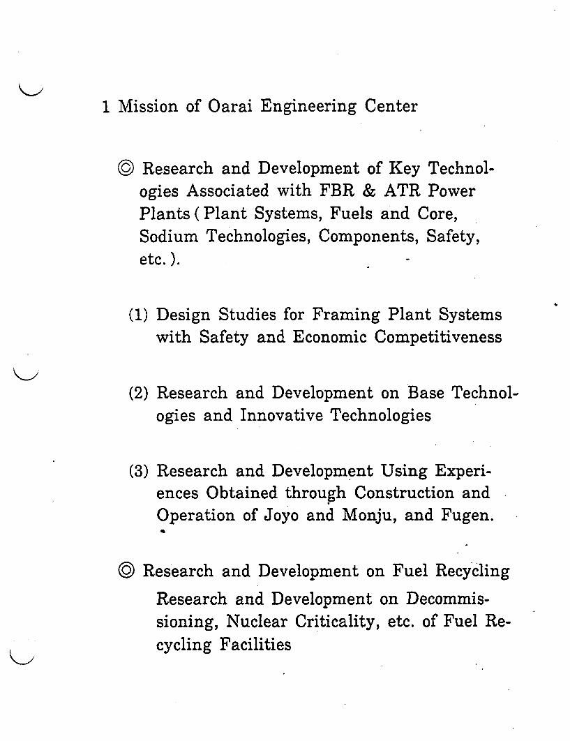
1 Mission of Oarai Engineering Center
© Research and Development of Key Technol-ogies Associated with FBR & ATR PowerPlants ( Plant Systems, Fuels and Core,Sodium Technologies, Components, Safety,etc.).
(1) Design Studies for Framing Plant Systemswith Safety and Economic Competitiveness
(2) Research and Development on Base Technol-ogies and Innovative Technologies
(3) Research and Development Using Experi-ences Obtained through Construction andOperation of Joyo and Monju, and Fugen.
© Research and Development on Fuel Recycling
Research and Development on Decommis-sioning, Nuclear Criticality, etc. of Fuel Re-cycling Facilities
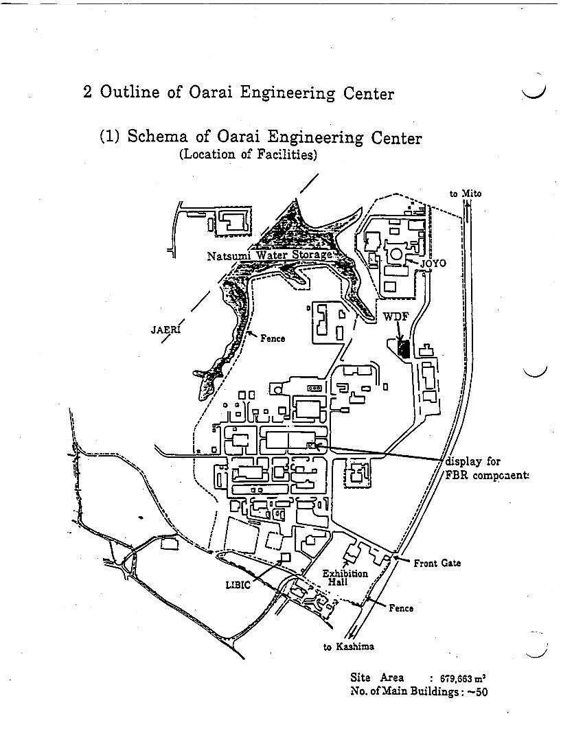
2 Outline of Oarai Engineering Center
(1) Schema of Oarai Engineering Center(Location of Facilities)
/ to Mito
ay forcomponents
Site Area : 679,663 m2
No. of Main Buildings: -50
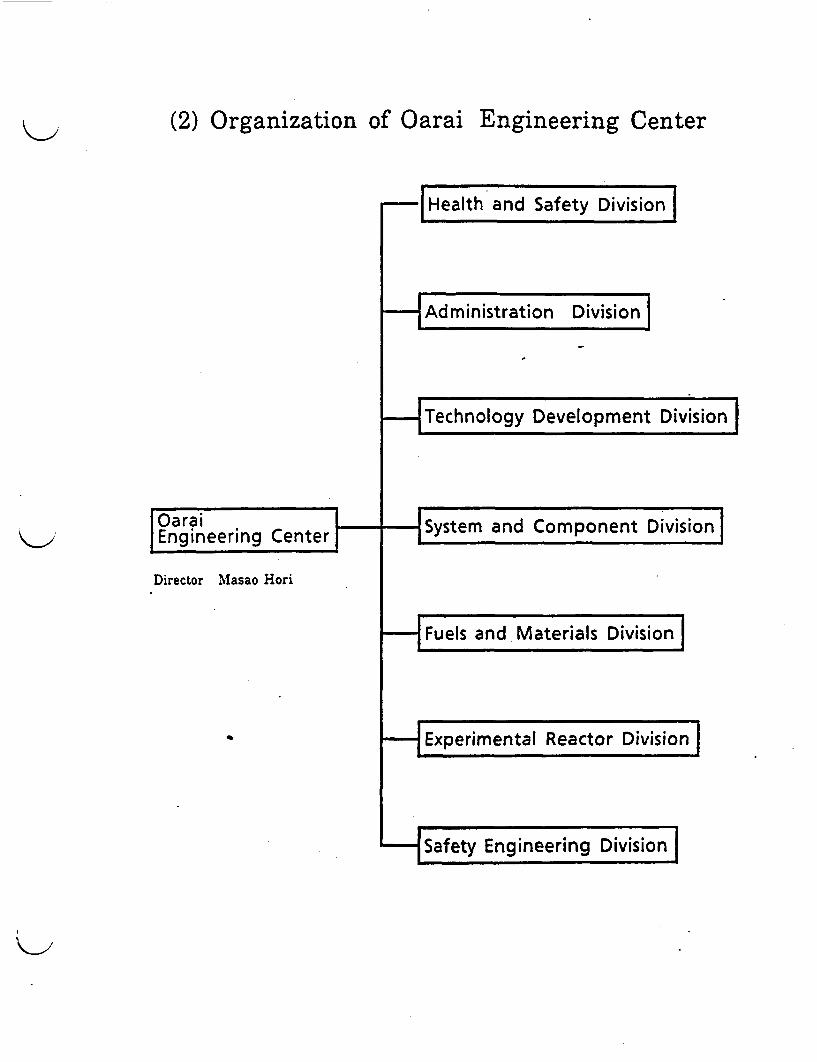
(2) Organization of Oarai Engineering Center
-~ Health and Safety Division
-H Administration Division . _ .
OaraiIEngineering Centerr
Director Masao Hori
Technology Development Division
�System and Component Division
and M ate na Is D ivislo n
-�yEn�i�eerinj�ivision

(3) Chronology of Oarai Engineering Center
o Oct.1967 Foundation of Power Reactor andNuclear Fuel Development Corp-oration
o Dec.1969 Initial Nuclear Criticality in theDeutorium Criticality Assembly(DCA)
o Mar.1970 Establishment of Oarai Engi-neering Center
o May.1970 Start of the Fast ExperimentalReactor "Joyo" Construction
0 July 1974 Start of 50MW Steam GeneratorTest Facility Operation
o Apr.1977 Initial Nuclear Criticality of"Joyo"
o Nov.1982 First Nuclear Criticality of"Joyo" Irradiation Core(MK-IICore)
o Sep.1984 Completion of the Fuel Cycle'Loop' Using "Joyo"

o Feb.1987
o Mar.1989
o DEC.1989
Agreement between "Joyo" and"Phenix" on Exchange Irradi-ation of Fuel Assembly
Contract of Technical Coopera-tion Agreement between PNCand JAPC for Research andDevelopment of the Demonstra-tion Fast Breeder Reactor.
Achievement of 40,000 accumu-lating hours' Operation for"Joyo"
la
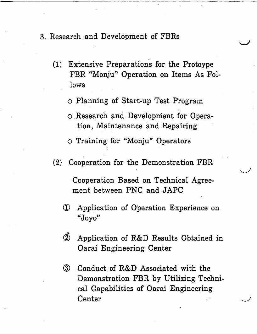
3. Research and Development of FBRs
(1) Extensive Preparations for the ProtoypeFBR "Monju" Operation on Items As Fol-lows
o Planning of Start-up Test Program
o Research and Developrment for Opera-tion, Maintenance and Repairing
o Training for "Monju" Operators
(2) Cooperation for the Demonstration FBR
Cooperation Based on Technical Agree-ment between PNC and JAPC
(; Application of Operation Experience on"Joyo,
-Z Application of R&D Results Obtained inOarai Engineering Center
(I Conduct of R&D Associated with theDemonstration FBR by Utilizing Techni-cal Capabilities of Oarai EngineeringCenter
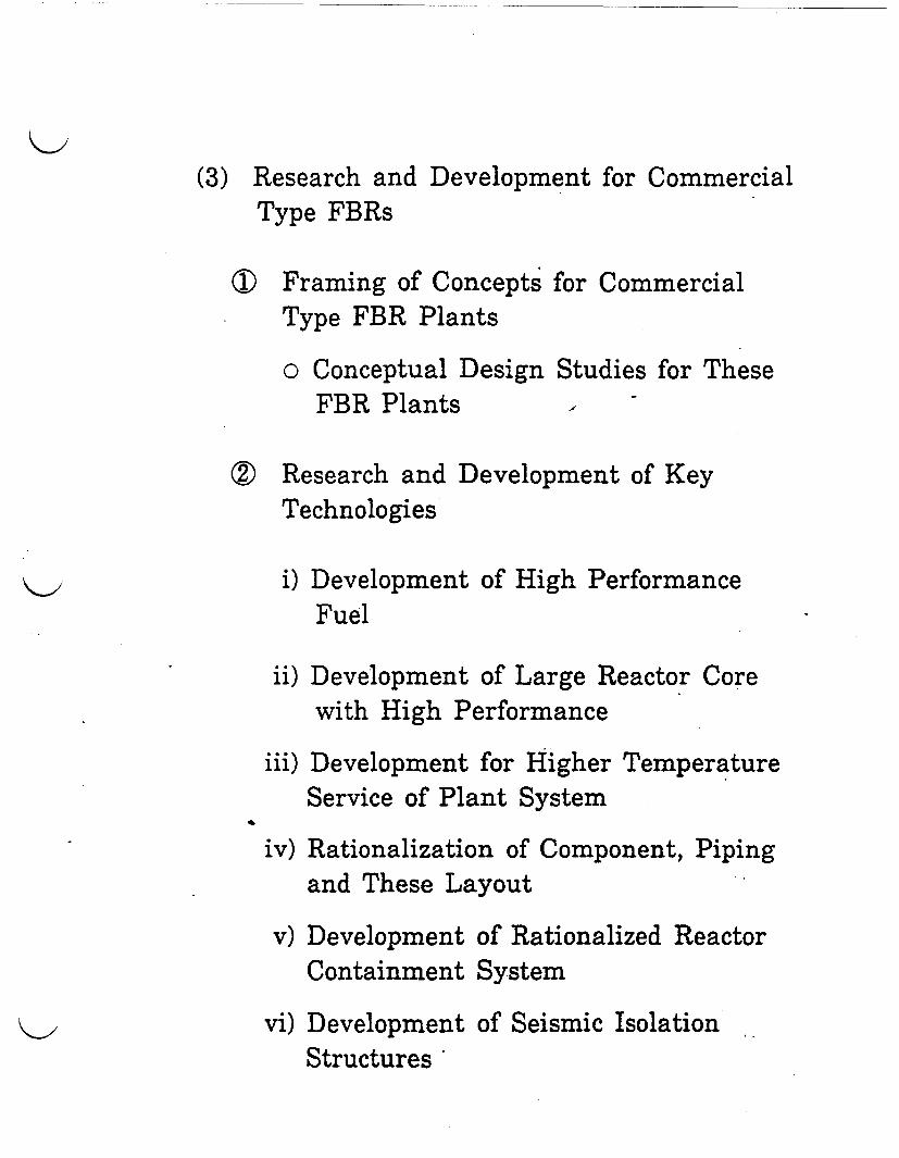
(3) Research and Development for CommercialType FBRs
T Framing of Concepts for CommercialType FBR Plants
o Conceptual Design Studies for TheseFBR Plants -
Z Research and Development of KeyTechnologies
i) Development of High PerformanceFuel
ii) Development of Large Reactor Corewith High Performance
iii) Development for Higher TemperatureService of Plant System
iv) Rationalization of Component, Pipingand These Layout
v) Development of Rationalized ReactorContainment System
vi) Development of Seismic IsolationStructures
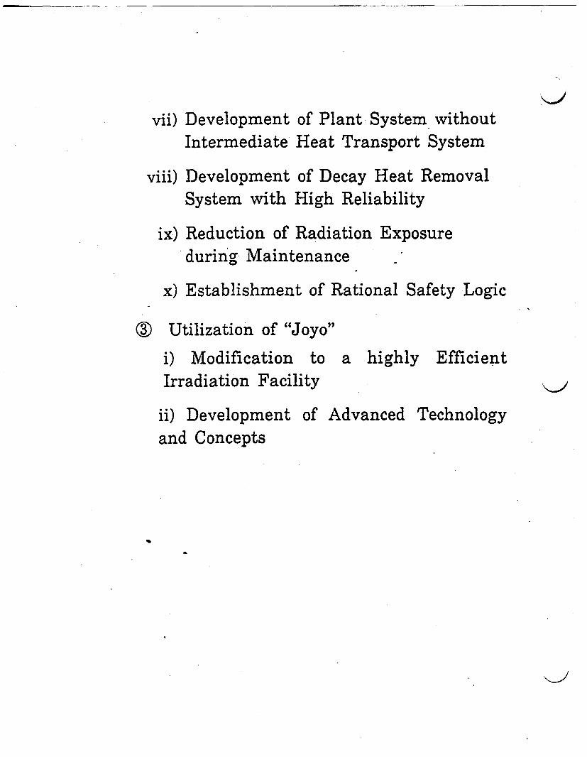
vii) Development of Plant System withoutIntermediate Heat Transport System
viii) Development of Decay Heat RemovalSystem with High Reliability
ix) Reduction of Radiation Exposureduring Maintenance
x) Establishment of Rational Safety Logic
() Utilization of "Joyo"
i) Modification to a highly EfficientIrradiation Facility
ii) Development of Advanced Technologyand Concepts

4 Research and Development of Advanced Thermal
Reactors(ATRs)
(1) Cooperation to the Demonstration ATR(Oma Nuclear Power Station in AomoriPref.)
c Conduct of Tests to Ensure Designing ofthe Demonstration ATR under Contractwith Electric Power Development Corpo-ration
(2) Research and Development of Base Techno-logies
o Conduct of High Performance Fuel De-velopment, and of Safety Research As-sociated with Severe Accidents
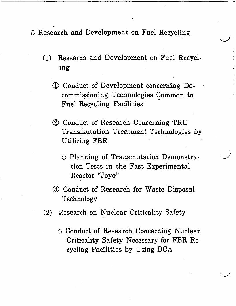
5 Research and Development on Fuel Recycling
(1) Research and Development on Fuel Recycl-ing
(I) Conduct of Development concerning De-commissioning Technologies Common toFuel Recycling Facilities
( Conduct of Research Concerning TRUTransmutation Treatment Technologies byUtilizing FBR
o Planning of Transmutation Demonstra-tion Tests in the Fast ExperimentalReactor "Joyo"
( Conduct of Research for Waste DisposalTechnology
(2) Research on Nuclear Criticality Safety
o Conduct of Research Concerning NuclearCriticality Safety Necessary for FBR Re-cycling Facilities by Using DCA
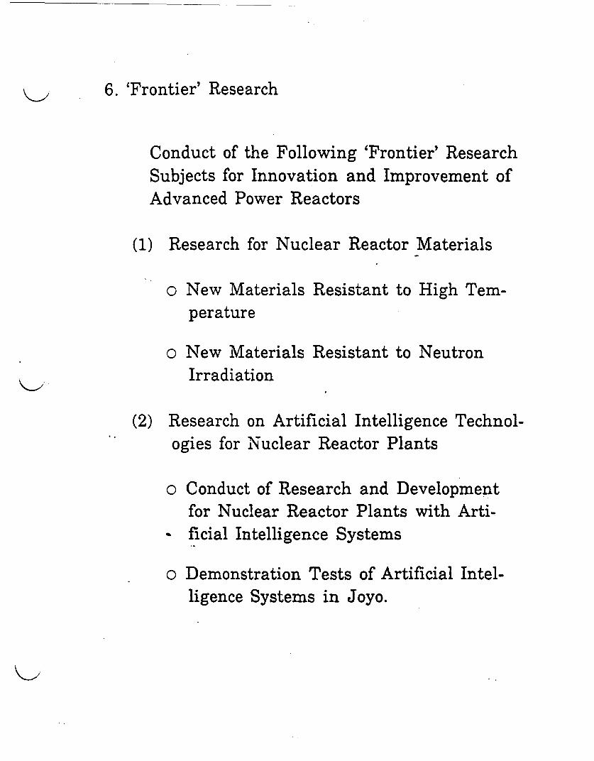
6. 'Frontier' Research
Conduct of the Following 'Frontier' ResearchSubjects for Innovation and Improvement ofAdvanced Power Reactors
(1) Research for Nuclear Reactor Materials
o New Materials Resistant to High Tem-perature
o New Materials Resistant to NeutronIrradiation
(2) Research on Artificial Intelligence Technol-ogies for Nuclear Reactor Plants
o Conduct of Research and Developmentfor Nuclear Reactor Plants with Arti-ficial Intelligence Systems
o Demonstration Tests of Artificial Intel-ligence Systems in Joyo.

(3) Diversification of Plutonium Utilization
o Conduct of Research on FBRs UsingAdvanced Fuels, Small- and Medium-Sized FBRs, Inherent Safe FBRs, etc.
"-I
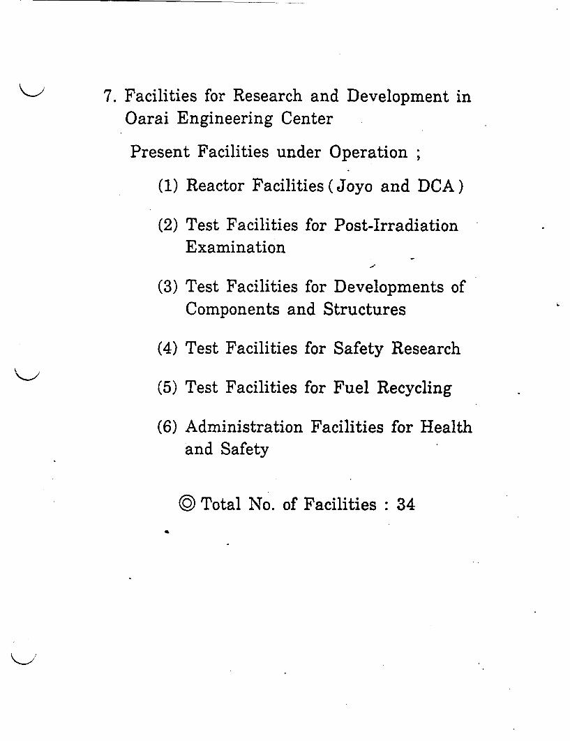
7. Facilities for Research and Development inOarai Engineering Center
Present Facilities under Operation;
(1) Reactor Facilities (Joyo and DCA)
(2) Test Facilities for Post-IrradiationExamination
(3) Test Facilities for Developments ofComponents and Structures
(4) Test Facilities for Safety Research
(5) Test Facilities for Fuel Recycling
(6) Administration Facilities for Healthand Safety
© Total No. of Facilities : 34
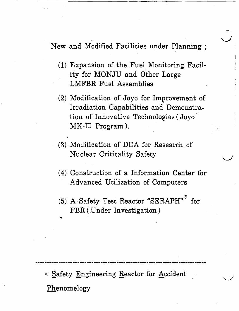
New and Modified Facilities under Planning ;
(1) Expansion of the Fuel Monitoring Facil-ity for MONJU and Other LargeLMFBR Fuel Assemblies
(2) Modification of Joyo for Improvement ofIrradiation Capabilities and Demonstra-tion of Innovative Technologies (JoyoMK-III Program).
(3) Modification of DCA for Research ofNuclear Criticality Safety
(4) Construction of a Information Center forAdvanced Utilization of Computers
(5) A-Safety Test Reactor "SERAPH" forFBR ( Under Investigation)
…-------------------------------------------------------- -…---------------
X Safety Engineering Reactor for Accident
Phenomelogy
I
I
I
IIII
Technical Draft for Comments
R D & D Program
on
Low-Level TRU Bearing Waste
Management Technologies
March 1, 1 9 9 0
I1III
II
Power Reactor and Nuclear Fuel Development Corporation
(PNC)
Translated into English and Preparedby
Radioactive Waste Mkgement Project, PNCIn
February 1990for
the U.S. Departmet of Energy
\JI
Technical Draft for Comments
R D & D Program
on
Low-Level T R U Bearing Waste
Management Technologies
March 1, 1 9 90
Radioactive Waste Management Project
Power Reactor and Nuclear Fuel Development Corporation
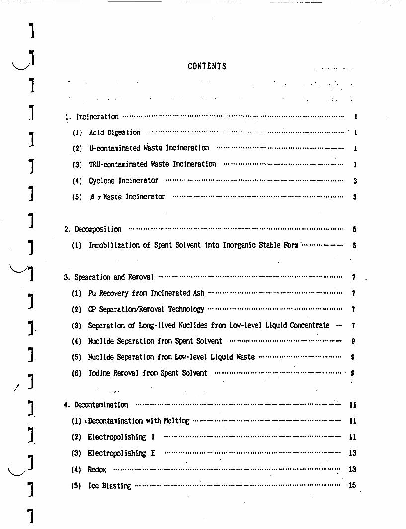
K....i CONTENTS
~ ~~~ . I c rt o .. ... .. .. .. .. .. ...... ... ... ... ... ... ... ... ... ... ... ..-. . . . . . .. .........(1 Ac i Di e t o .. .. .......... .. .. .. .. .. .... .. ...... .. .. . . . . .. . . . . .1 1. Incineration*----------------------------.
7 (I) Acid Digestion*--------------------------.
(2) U-contaminated Waste Incineration .*-----------------------------------------------------.
'3 (3) TRU-contaminated Waste Incineration .1.-..-..-..-..-..-..-..-..-..-... .... I
(4) Cyclone Incinerator ... ... .3
'3 (5) A 7 Waste Incinerator ...---------------.--..--..--..--..--.. 3........................................ . , 3
I 2. Decomposition *---------------------------------------------------------..5
(1) Imobilization of Spent Solvent into Inorganic Stable Form ---------------- S.5
1 3. Spearation and Removal.*---------------------------------------------..7
(1) Pu Recovery from Incinerated Ash ... .. 7
(2) CP Separation/Removal Technology ... ...................................... 7
'3 (3) Separation of Long-lived Nuclides from Low-level Liquid Concentrate ... 7
(4) Nuclide Separation from Spent Solvent ... ... .. ... .. ... .. .. ... .. .. ... ... ... .. 9
'3. (5) Nuclide Separation from Low-level Liquid Waste ............................
(6) Iodine Removal from Spent Solvent9
] ~~4. Decontamination ........................................................ ...
(1) Decontamination with Melting ....................... . . . . . . . ... 11
'3 ~~~(2) Electropolishin I ................................................... 11
(3) Electropolishing I . . . . . . . . .................. . . . . . . ... 13
(4) Redox........................................................... ... 13
'3 (5) Icee ls inB......l...... ......astir......g............. .15.... ...... ....... 1

5. Dismantling ... -.----------------------------------------- 17
(1) Plasma-arc Cutting ... -- ... ... -- 17
(2) Laser Cutting .. ... ... 17
6. Immobilization (Stabilization) .*----------------------------------------------------------------- 19
(1) Micro-wave Melting .19-------------------------... ................................... 19
(2). Electro-slag Remelting .*-----------------------------------------------------------------------19
(3) HIP Solidification ... ... ... ... ... 21
(4) Dehydrating and Solidification with Micro-Wave ... ... 21
(5) Solidification of Separated Nuclide Residue .*------------------------------------- 21
(6) Hydrothermal Solidification ... -... .23
(7) Cementation ... -... -... ... ... ... 23
(8) Krypton Immobilization .. ... -... ... 23
(9) Plastic Solidification ... ... -------------------- 23
(10) Flame Retardation of Bitumen ... .. .. .. .. .. ............ .. .. .. .. .. .. ..-........... 25
(11) Bituminization ... .. .. .. .. .. .. .. .. .................. .. .. .. .. .. .. .. ................ 25
7. Solidified aste Characterization ... ... 27
(1) Evaluation of Synthetic Minerals produced at PWF ... -... ... 27
(2) Evaluation of Metal Ingots produced at PWIF .*--------------------------------------27
(3) Compressive Strength Measuring Test of Plastic-solidified Waste .*--------27
(4) Evaluation of Bitumen .*------------------------------------------------ -- ... ... 29
(5) Surface Contamination Measurement Test ... -- - 29
(6) Verification Test of Solidified Waste Homgeneity .*-------------------------------- 29
8. Source Term .*-------------------------------------------------------------------------------.----.-.31
(1) NDA. ... ... -... ... -- ... - 31
(2) Scanner for Solidified aste ..-------------------------------------------------------------- 31

9. Facility Management ... ... ......................................................... . 33
(1) PWTF Operation Supporting System ......................................................... 33
(2) Automation and Remotization of a Hall ... .......................................... ... 33
(3) Hull Retrieval Technology ... ....................................... ... -. ... 33
(4) Radiation Image Display (RID) ... ... . ...................................... ... ... - ---. ... 35
10. Miscellaneous ... ... ... - 37
(1) Treatment of Alcoholate Liquid Waste ... ... .................. ... 37
(2) Purification of Recovered Xenon ... .. 37
(3) De Minlmis Level Measurement Technique *-- ............................. ... 37
(4) Entrusted Research of
| - "ot Treatment Test of Concentrated Liquid Waste. -.----------------------------.37
1
I
-II
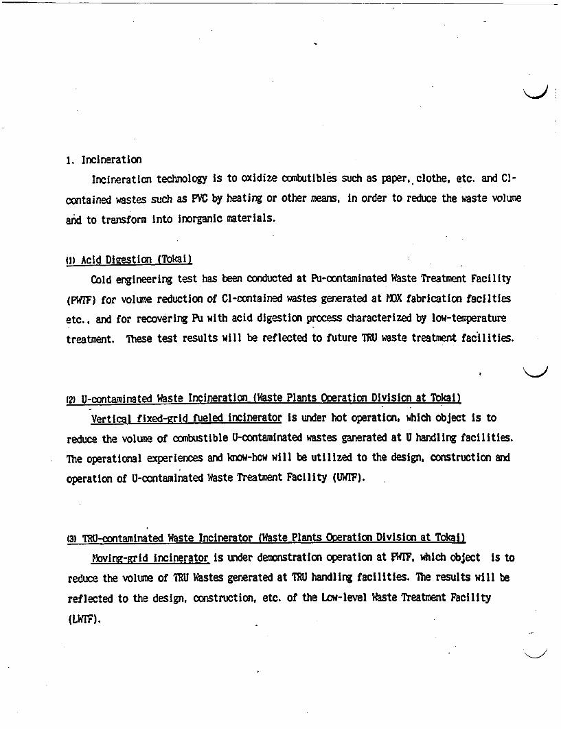
1. Incineration
Incineration technology is to oxidize combutibles such as paper, clothe, etc. and Cl-
contained wastes such as PVC by heating or other means, in order to reduce the waste volume
and to transform into inorganic materials.
I1 Acid Digestion (Tokail)
Cold engineering test has been conducted at Pu-contaminated Waste Treatment Facility
(PWTF) for volume reduction of Cl-contained wastes generated at MOX fabrication facilties
etc., and for recovering Pu with acid digestion process characterized by low-temperature
treatment. These test results will be reflected to future TRU waste treatment facilities.
(2) U-contaminated Waste Incineration (Waste Plants Operation Division at Tokai)
Vertical fixed-rid fueled incinerator is under hot operation, which object is to
reduce the volume of combustible U-contaminated wastes ganerated at U handling facilities.
The operational experiences and know-how will be utilized to the design, construction and
operation of U-contaminated Waste Treatment Facility (UWIF).
(3) TU-contaminated Waste Incinerator (Waste Plants Oeration Division at Tokanl
kovin-grid incinerator is under demonstration operation at PWIF, which object is to
reduce the volume of TRU Wastes generated at TRU handling facilities. The results will be
reflected to the design, construction, etc. of the Low-level Waste Treatment Facility
(LW).
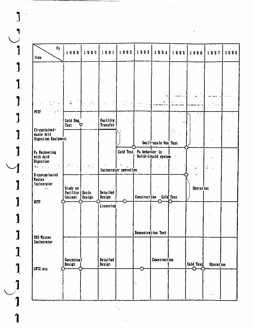
I
I m 9 89 19 9 0 1 9 I 9 9 2 1 9 9 3 1 9 4 1 9 9 l 9 9 6 1 9 7 9 9 I~ ternI
I
I
IIi
RITF
Cl-contained-waste AcidDigestion Equipzx
Pu Recoveringwith AcidDigestionC...,
U-contazinatedtastesIncinerator
1 I. I I I I .I
Cold E.Test N7
FacilityTransfer
4 . ._ - I -
nt
Cold Test1..Small-scale ot Test
I If- Y - I. ..
Pu behav ior In ISolid-liquid systen
I I
Incinerat*.
operation4 I 4. 4 .LII
IIII1II1I1
Study onFacilityConcept
BasicDesign|3De' C
DetailedDesign Construction
Operation
Col TestC 7-C :- ; ,
Licensins
DemonstratiIon TestTRU WastesIncinerator
4. - 4 ________ 1. 4-4
ConceptualIDes inI
0---
DetailedDesign
Construction
LUTF. etc. CCold Ts Operation
z ; : 3-I ;1 4.,
..
I1
'I
\J i
(4) Cyclone Incinerator (Tokai)
Self-burning cclone incineration technology which is characterized by using good-
corrosion-resistant electro-melted Alumina for refractories, and non-moving parts, is
under demonstration test at PWrF, in order to establish the technology of the volume
reduction with incineration for Cl-contained wastes generated from MOX fuel fabrication
facilities, etc.
(5) 0 7 Waste Incinerator (Tokai)
Moving-grid incinerator is under construction to reduce the volume of 7 wastes from
Tokal Reprocessing Plant. - -
I
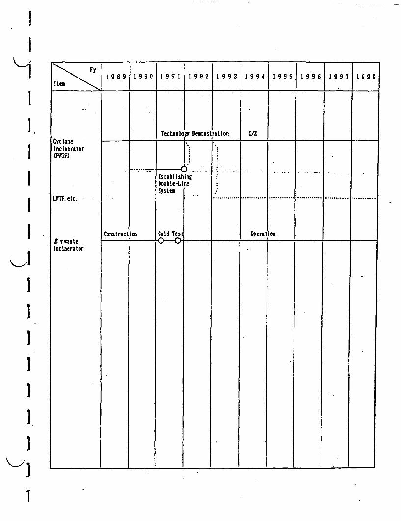
II
Fyle 1 98 9I____0 i99 1J1 9 92 1 9 93 1 99 4 1 99 5j19 9 61 9 9119 9 8
Technolouy DemonstrationI *
C/ACycloneIncinerator(P"TF)
L1TF.etc.
B wasteIncinerator
I Y - I� I I
EstablishingDouble-LineSystel
Cold test
...... . _
.,:
:.............
Construction Operation
I
II
1III
1

2 . Decomposition
Deconmposiontion is to transform organic materials into stable inorganic form except
oxide by heating, etc.
1) Immobolization of Spent Solvent into Inorganic Stable Form (Tokal)
RI tracer tests of the advanced technology characterized by incorporation-of synthetic
mica or hydrated lime and pyrolysis are being carried out to inorganize spent solvent.
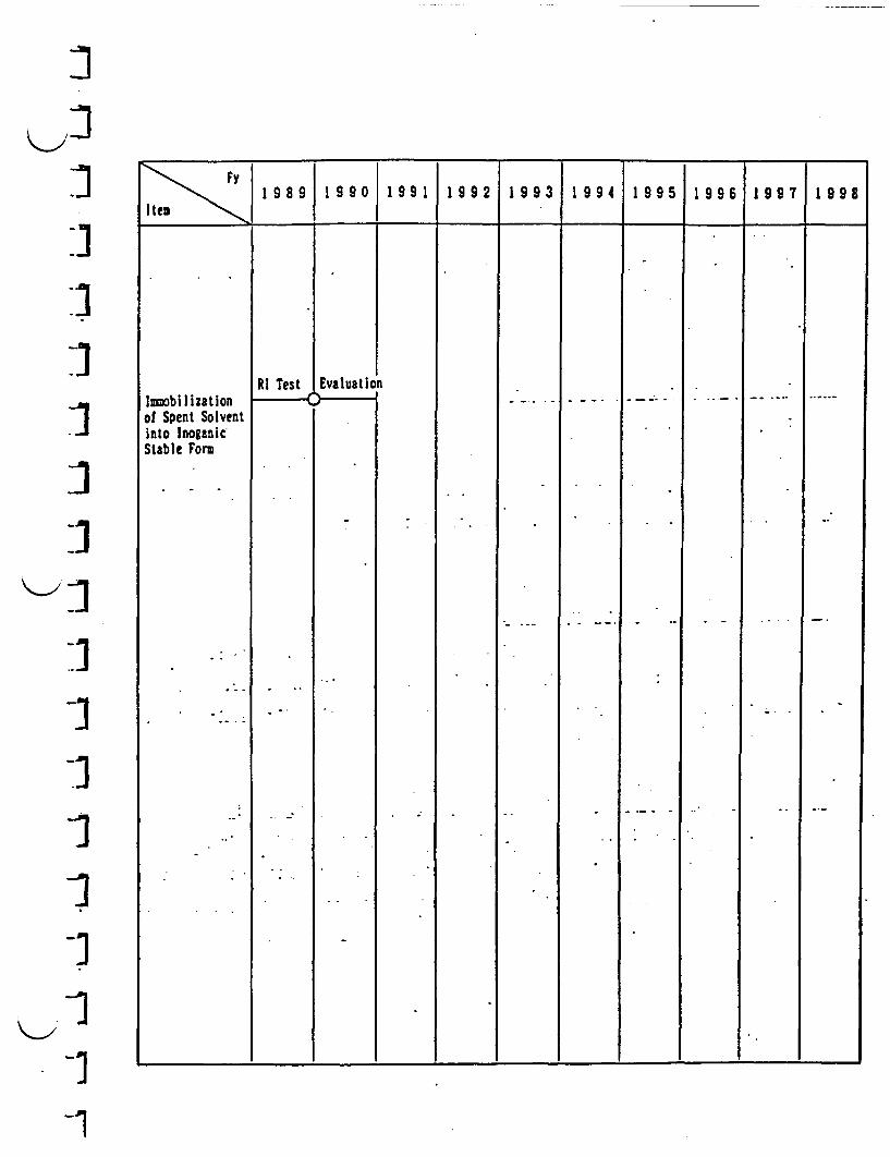
I
I
-3
:1- III-1
-1
\ y____________ 90 19 1}1 99 21 9 9 3 199 4 1 99 5 19 96 1 9 97 1 998a
lsobi I izationof Spent Solventinto InoganicStable Form
RI Test EvaluationvI
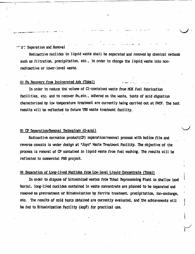
3 Separation and Removal
Redloactive nuclides in liquid waste shall be separated and removed by chemical methods
such as filtration, precipitation. etc., in order to change the liquid waste into non-
radioactive or lower-level waste.
(1) Pu Recovery from Incinerated Ash (Tokal) _
In order to reduce the volume of Cl-contained waste from MOX fuel fabrication
facilities, etc. and to recover Puetc., adhered on the waste, tests of acid digestion
characterized by low temperature treatment are currently being carried out at PWFF. The test
results will be reflected to future TRU waste treatment facility.
(2) CP Separation/Removal Technology (0-arai)
Radioactive corrosion product(CP) separation/removal process with hollow film and
reverse osmosis is under design at "Joyo" Waste Treatment Facility. The objective of the
process is removal of CP contained in liquid waste from fuel washing. The results will be
reflected to commercial FR project.
(3) Separation of Loe-lived Nuclides from Low-level Liquid Concentrate (Tokail)
In order to dispose of bituminized wastes from Tokai Reprocessing Plant in shallow land
burial, long-liked nuclides contained in waste concentrate are planned to be separated and
removed as pretreatment of Bituminization by ferrite treatment, precipitation. on-exchange,
etc. The results of cold tests obtained are currently evaluated, and the achievements will
be fed to Bituminization Facility (AspF) for practical use.
-iI
19 9{1999 1991 1992 1993 1994 1995 1996 1997 1 99
item ~~~~~~~~~~~~~~~~~.T I.
I
ILII
Demonstra Lion Test
11
-1
-1
-1-1-J
K-/
PIITF
Pu Pecoveryby Acid Digestion
CP Separation/RemovalTechnology(including re-construction of'Joyo WfasteTreatitent Facilit
Separation ofLong-lived Nuclidfrom Low-levelLiquid Concentrat
ColdTest
Small-scaleNot Test
r ----- I--r
Pu BehaviorSystem I
in Solid-liquid
I i I :
Design/LicensingI~~~- )
Fabrication. :
Demonstration Test) ~ ~~~ IJ I
CommercialIFBR
BasicTest
.......
es
Cold Engineering Test........................
I fstF
(4) Nuclide Separation from Spent Solvent (Tokal)
ibis technology is to reduce the radioactive concentration in the liquid waste below
the regulatory level of sea discharge, by separation and removing the radionuclides in
phosphoric-acid liquid waste with oprecipitation-ultrafiltration, etc., after
inorganization of spent solvent into phosphoric-acid waste using hydro peroxide. The results
will be reflected to the design of LWrF.
(5) Nuclide Separation from Low-level Liquid Waste (Tokal)
The objective of the technology Is the volume reduction of low-level concentrated J
liquid waste, etc., generated in Tokal Reprocessing Plant. The technology will enable to
reduce the concentration of the radioactive nuclides in liquid waste below the regulatory
level of sea discharge, by adsorption, coprecipitation-ultrafiltration and ion-exchange.
Cold basic test using simulated waste is currently implemented, and the results will be
reflected to the design of LWFF.
(6) Iodine Removal from Sent Solvent (Tokal)
In order to reduce iodine concentration discharged to the environment, hot test of
removal(adsorption, etc.) of iodine contained in spent solvent, TBP and dodecane is
currently being conducted. The results will be reflected to Solvent Waste Treatment
Demonstaration Facility STF) for practical use.
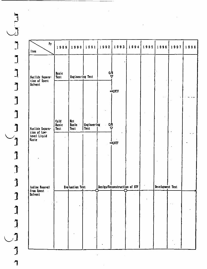
r1
-1I3.II
I1
IKA

4. Decontamination
Decontamination technology enables to remove radioactive nuclides adhered on solid
wastes by chemical or mechanical methods. The objective is to change the radioactive solid
wastes into non-radioactive or lower-level wastes.
(1) Melt Decontamination (Tokai)
Melt decontamination can achieve the volume reduction and decontamination of metal
wastes, simultaneously. The electro-slag melting is currently under cold and hot testing at
PWFF for volume reduction and stabilization of U-contained metal wastes. The test
results will be reflected to the future TRU waste treatment facility projects such as LWF,
Hull Waste Treatment Facility (HWTF), etc. - --
(2) Electropolishin I (kai)
Electropolishing will be utilized to decontaminate the surface of metal wastes for
volume reduction of TU contaminated metal wastes generated at reprocessing plants and MX
fuel fabrication facilities. Hot test is currently being carried out using active metal
wastes, and the results will be reflected to the practical use for TRU waste volume
reduction hereafter.
;>

Ky]
]1.4
Fy198 9J 9 9 1 9 9 1J19 9 2j9 93 1 99 4 1 9 9 1 9 9 6}S9S9 1 998a
'I'I'I'I
'I'I7121Ij
<I
tielItDecontaninal ion
PA1TF (NOt1)
Cold Test
LIMT
HW17F
Llectropol ishingDecontamination
Practical Testt t I 4 +~~~~~~~~~~~~~~~~~~~~~~~~~~~~~~~~~~~~~~~~~~~~~~~~
IEvaluati!on.............................................
(Muclide Removal metOff-gas Bahavior)
*1 Iconceptual Design Deli
p0~
conceptualDesig
Not Test oElectrodeposi tionRegeneration
hod C)
led Desli
II.I ..Z. ..ii
i
i
I:
CConstruction
I
Cold I
[.Ipe rat ion
).- 4 -�e
Basic Design Detailed Design Construct ion. -. �- -. , I -
Pu Recovery est
ar*respectivewaste treatment
I1
(3) Electropolishing E (arai)
Electropolishing is removing the surface layer of metal wastes electrochemically as the
wastes for anion in electrolyte. Cold plant-scale test and hot basic test of
electropolishing is currently being implemented so as to develop the reuse technology of
depleted electrolyte and the electrodeposition technology separating eluted metal on from
acid, as increasing the concentration of eluted metal ion in electrolyte, The aim of the
tests is to make life of electrolyte longer.
(4) Redox (0-arai)
Redox decontamination is expected to be advantageous technology for miscellaneous waste
decontamination, because of its applicability for complex shaped metal wastes and high
decontamination effect. Utilizing Ce(IV) in nitric acid as strong oxidizing agent, it is
currently under development through cold engineering tests, etc.
\1

:2
I:1
II
- -
-Iq
K>]
II11
I
KY'
-1I1
Fy
- 1~9 8 9 1 9 90 19 9I 19 92 1 9 93 1 99 419 9.5 1 99 6 19 97 19 98
Hot testElectropolishing
Cold Test
LITF
Redox
_____ 4. 4
' _ I'jTest on Expansion
Detailed Design/Safety ReviewI I-
cif Applicability. ,
System Englneering-4. 4 - I
Construct ion -04_ I ptrVI.9 -
ionI
Evaluationon conpositionmaterials
-0--Mot' Basic test
I
CSecondary Waste Treatment Test
I System En ineeringI 4
. . .~~~~~~~~~~~~-
(5) Ice Blasting (0-arai)
Ice Blasting has been developed as the decontamination technology in which water and
dry ice are sprayed on to waste surface using air as the transfer media. It is regarded as
good primary decontamination technology because of generating small quantity of secondary
waste, and hot test has been conducted using actual waste, at the Waste Dismantling
Facility (WDF) since Fy1984. Ice blasting will be applied more extensively for
decontamination use of in-situ equipment surface and concrete, etc. aiming establishment of
decommissioning purpose, hereafter.

I
I
-I
I>
II
I
:1
I-11
. 11
989 1 99 0 1 9 91 92 993 19 411te~ 1 19 61 99 7 199 8
Hot lest (WDF)Ice Blasting
Expansion ofappl icat ion
Nuclide Recovery
; ;* 7s ; ; H : -
0-~
'I
* DecomDiss ion imSystem EngineeringI I--
_ . . , . , . . * .~~~~~~~
I1

.~~~~~~~~~~~~~~~~~
5. Dismantling
Dismantling is the cutting or sectioning technology for large solid wastes by the use
of thermal and or mechanical techniques, in order to facilitate the handling of solid wastes.
E1) Plasma-arc Cuttinz (0-arai) jPlasma-are cutting method, and related recovering methods of aerosol and dross, etc.
are under development as remotely dismantling technology for large TRU-contaminated solid iwaste to obtain good effiecincy of work, execellent dismantling capability and extended
applicability.
In particular, automatic arc-cutting robot has been designed and fabricated for
dismantling in-cell equipments. The achievements will be reflected to &Ds of TRU waste
treatment and decommissioning technologies. X
(2) Laser Cuttinz (-arai) l
Laser cutting technology, which is suitable for remote operation, because of generating
less amount of aerosol or dross and being applicable to broad materials for cutting, is
under development as the advanced, promising dismantling technology for large equipments, etc.
Especially, the basic research has been implemented on the cutting performance of CO-
laser, power transmission characteristics, etc. and application for the decomxissioning of
fuel cycle facilities is planned, ncreasing laser power step-by-step, hereafter.
IX
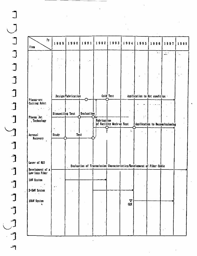
IJ
:1.n
.3
I'I
I
.1
I
III
-,.
19 89 1 99 0 191199 2 99 1 99 99 119 6 1997 9 9
Design cond itFabrication Cold Test Application to ot ionPlasta-arcCutting Robot
Plasma Jet, Technology
AerosolRecovery
Laser of R&D
Development of aLo-loss Fiber
lkiM System
3-5kW System
10.t System
r4 4.- I- ! .1. .4
Dismantl g Test Evaluation .
Fabricationbf Facility liock-l
I=.t. I
Test-I (
p Test APol feat I
Study
on to Decommissioniut iI
I
I--------
I I IEvaluation of Transmission Character ist ics/Development 0 Fiber Cabe
4. 4 7 t 4. -
.........VCLIR
.. ~~~ I ---- . ,
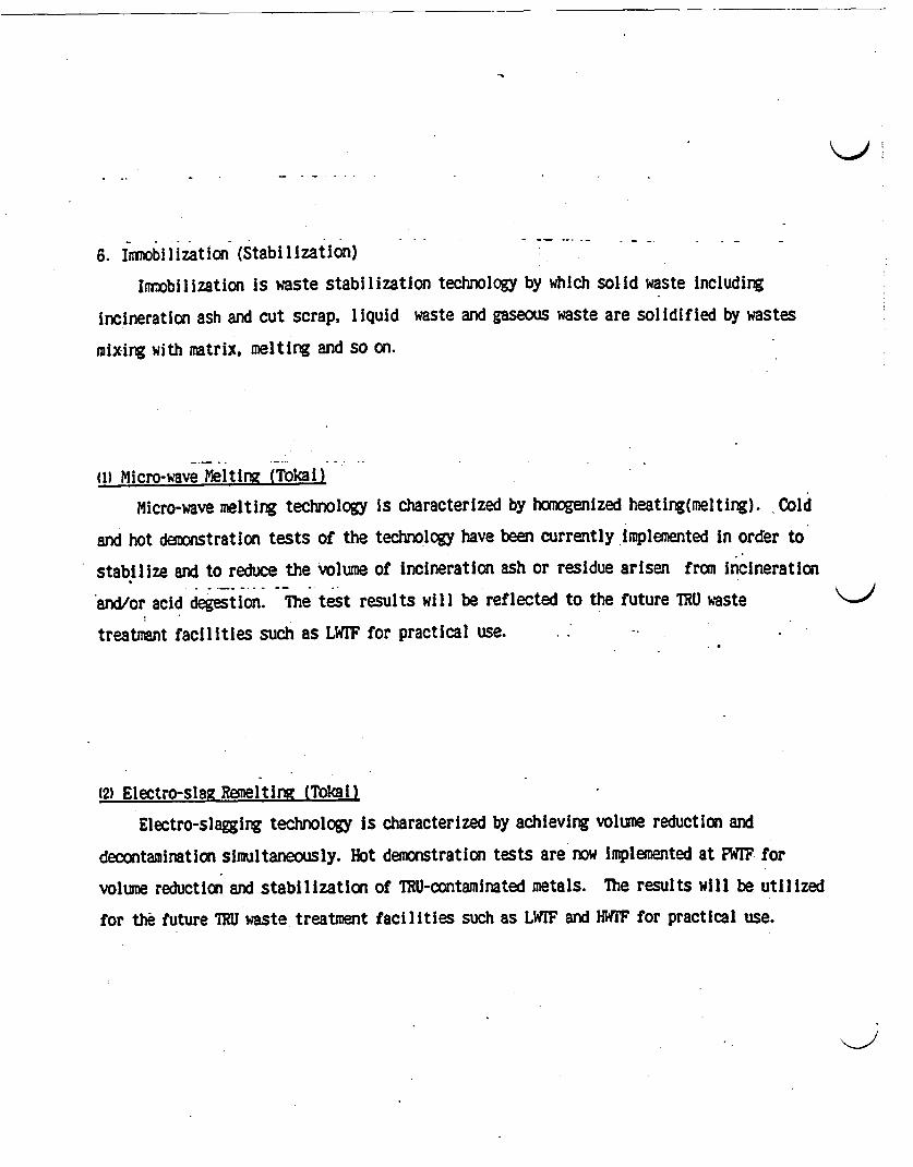
K)l
6. Immobilization (Stabilization)
Imobilization is waste stabilization technology by which solid waste including
incineration ash and cut scrap, liquid waste and gaseous waste are solidified by wastes
mixing with matrix, melting and so on.
(1) Micro-wave Meltinz (Tokal)
Micro-wave melting technology is characterized by homogenized heating(meltlng). Cold
and hot dmonstration tests of the technology have been currently implemented in order to
stabilize and to reduce the volume of incineration ash or residue arisen from incineration
and/or acid degestion. The test results will be reflected to the future TRU waste
treatmient facilities such as LWrF for practical use. -
12) Electro-slau Remeltinz (Tokai)
Electro-slagging technology is characterized by achieving volume reduction and
decontamination simultaneously. Hot demonstration tests are now implemented at PWF for
volume reduction and stabilization of TRU-contaminated metals. The results will be utilized
for the future ThU waste treatment facilities such as LW!F and HWF for practical use.

-1
cli
~1
jII
III
I
:1
*1
:1K;
Fy I1 8 I990 1 9 I I 2 1 9 93 1 994 199 19 96 119 97 1 995I
ite ______ _ JI I
Micro-waveMe I ing
N\TF(hot)
Cold Test
L111F
Electro-slagRemelting
Demonstration test_____ 1 �- 4 + - 4
Evaluation TestII C/R, -.-. . I .
Melting Hoogeneity
Conceptual IDesign - Doetailed Design Construction
ColdTest Operation
;.. . . . C - : I. :
_ .Demo istration test4 4 .� I. -
. I
Feed resultsat any time
Detal ed DesignLSIF
: .I. Conceptual
Desi g
ConceptualDesign I
ConstructionI-'
. . . .
ColdT Cst C
DonStructic
)erat ion_ _
a
ahasiC Design Detailed Delign I
3 - . 1 - _

(3) HIP Solidification (O-arai)
Cold test of solidification by. Hot Isostatic Press (HIP) method is under progress. The
HIP technology is planned to be applied for volume reduction and stabilization of hulls and
other metal wastes arising at Tokai Reprocessing Plant, and the achievements obtained from
the development activities will be utilized for the facility design of HWIF.
v; .~~~~~~~~~~~~.
(4) Dehydratinz and Solidification with Micro-wave (Stabilization) (0-aral)
Dehydrating and solidification technology which converts the fuel washing liquid waste
of "Joyo"(high-alkali property including corrosion products), into glass-like block safely
with simple facility, is under development. The results will be utilized to reconstruct 3the existent waste treatment facility.
(5) Solidification of Separated Nuclide Residue (Tokai) JIn order to stabilize the separated nuclide residue removed fran low-level liqued waste
and spent solvent, an advanced solidification process is to be developed. In the present,
solidification technologies is under investigation, and the results will be reflected to the I
design of LWIF.
I
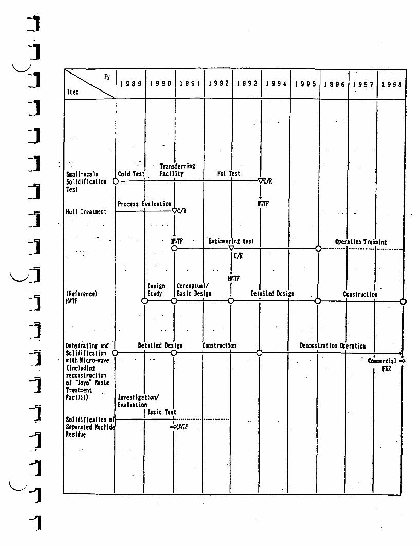
I
I1 9 9 1 9 9 0 1 9 1 9 9 2 9 9 3 9 9 4 9 95 1 9 6 1 9 9 7 1 9 9 8
Item
Small-scaleSolidificationTest
TestTransferringFacility 'estCold Hot
C ! ' ' I V'lZI1
I_]
_I
Li
_I.1II1
V-
1I>
Process EvaluationI __ t
gmT
Hull Treatment
(Reference)ID;TF
Dehydrating andSolidification (with Micro-wave(includingreconstructionof Joyo* WasteTreatmentFacilit)
Solidification oSeparated NuclideResidue
,t. i,.,
I* I. ~~~~~~~~~~~I
-lTF - I Engineering I
--I - -- * . j~~~C/R
Design Conceptual/Study Basic Design I
tilled Design Construction
Lest Oper............
ition Training-
Detailed Design ConstructionI )- 4. )I
I Df
I.
Demonstratlion OperationI I
. I T -
omercial C.
fR I
Invest ihatioa/Evaluation
TestBasicI l ; ,. I............ ...
-'LUT
. . . , .I I.I
I1
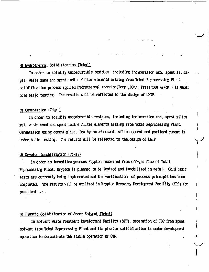
(6) Hdrothermal Solidification (Tokai)
In order to solidify uncombustible residues, including incineration ash, spent silica-
gel, waste sand and spent iodine filter elements arising from Toka Reprocessing Planti
solidification process applied hydrothermal reactIon(Temp:100c, Press:300 k/cmu) is unde?
cold basic testing. The results will be reflected to the design of LWrF.
(7) Cementation (Tokai)
In order to solidify uncombustible residues, including incineration ash, spent silica-
gel, waste sand and spent iodine filter elements arising from Tokai Reprocessing Plant,
Cementation using cement-glass, low-hydrated cement, silica cement and portland cement is
under basic testing. The results will be reflected to the design of LWIF
(8) Krypton Immobilization (Tokal)
In order to Imobilize gaseous Krypton recovered from off-gas flow of Tokai
Peprocessing Plant. Krypton is planned to be ionized and immobilized in metal. Cold basic
tests are currently being implemented and the verification of process principle has been
completed. The results will be utilized in Krypton Recovery Development Facility (KRF) for
practical use.
(9) Plastic Solidification of Scent Solvent (Tokai)
In Solvent Waste Treatment Development Facility (STF), separation of TP from spent
solvent from Tokai Reprocessing Plant and its plastic solidification is under development
operation to demonstrate the stable operation of-STF.
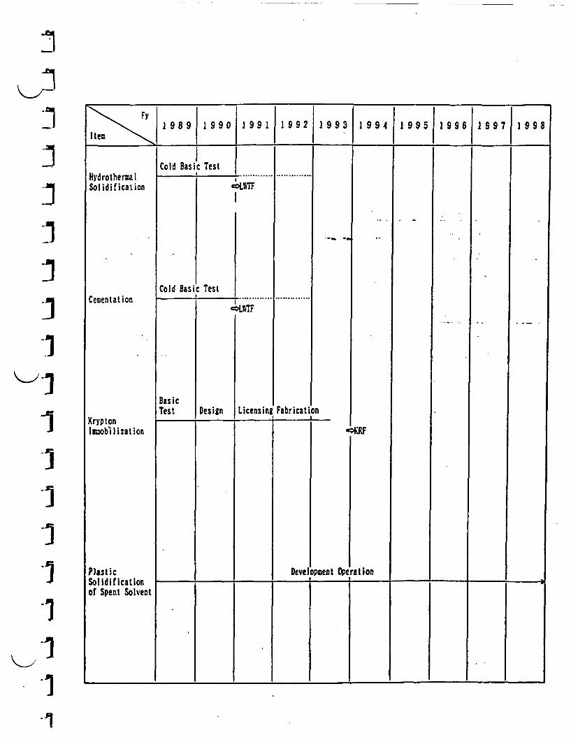
-
1II
III
<>1rI
I-1
I-I.1-1
*1-1

to Flame Retardation of Bitumen (Tokai)
The technology of flame retardation of bitumen by adding reagent before bituminization,
is being tested (cold, laboratory-scale). The results will be utilized for the operation
Improvement of Bituminization Facility (AspF).
{D Bituminization (Tokat)
In order to demonstrate the bituminization process for liquid waste arising from Tokal
Reprocessing Plant and the storage of bituninized wastes, developmental operation hs been
continued at AspF.

I
II.II>
IIIIII
¶1
I
Fy1 9 89 1 99 0 1 99 1 1 9 92 1 99 3 1 99419951996199719 98
Item~~~~~~~~~~~~~~~~~~~~~~~~~~~~~~~~~~~~~~~
Flame Retardatiorof Bitumen
Bituminihzation
Experimental ReseaC / R . ......ClR
rch (V)AAspF
rationI I-
for Developrentopf. . ;
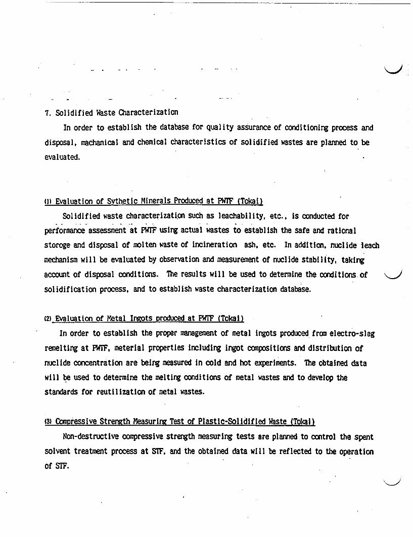
7. Solidified Waste Characterization
In order to establish the database for quality assurance of conditioning process and
disposal, machanical and chemical characteristics of solidified wastes are planned to be
evaluated.
11) Evaluation of Svthetic Minerals Produced at PWTF (Tokal)
Solidified waste characterization such as leachability, etc., s conducted for
performance assessment at PWTF using actual wastes to establish the safe and rational
storoge and disposal of molten waste of incineration ash, etc. In addition, nuclide leach
mechanism will be evaluated by observation and measurement of nuclide stability, taking
account of disposal conditions. The results will be used to determine the conditions of
solidification process, and to establish waste characterization database.
12) Evaluation of Metal Ingots produced at PWF (Tokal)
In order to establish the proper management of metal ingots produced from electro-slag
remelting at PWTF, meterial properties Including ingot compositions and distribution of
nuclide concentration are being measured in cold and hot experiments. The obtained data
will be used to determine the melting conditions of metal wastes and to develop the
standards for reutilization of metal wastes.
13) Compressive Strength Measuri n Test of Plastic-Solidified Waste (Tokal)
Non-destructive compressive strength measuring tests are planned to control the spent
solvent treatment process at STF, and the obtained data will be reflected to the operation
of STF.

I
lII
-II
IIIII
*1.I
.1
FY I 9 9 2 I 9 9 3 1 9 9 4 | 9 9 6 1 9 9 7 1 91989 1990 19917 9 9 9 . ;I tem
reance Ass Solidified asItsEvaluation ofSolidified WasteSoundness(POTF)
Cold Test
Evaluation ofMetal Ingots(P9lTF)
Cold Test
CompressiveStrengthMeasuring Test oPlastic-So4ldifiedwaste I
Perfo !sseent of Active
Leachability. lineral Compositions
I I_______ Leaching Test
Leaching Mechanism
Fundamental Properties of Solidified Waste(Density. Nuclide Stability)
. . . | | ' 1 .1 . . .Evaluation of Properties of Active
Solidified Wastes
Compositions -
Distribution of Nuclide Concentration .
Evaluation of Properties of Metal Ingos
Melting F
:Al.
4PSTF i
ropertles '(Slag Bahavior. Kucl'lde Deconi aminabillty)
PrototypiTest
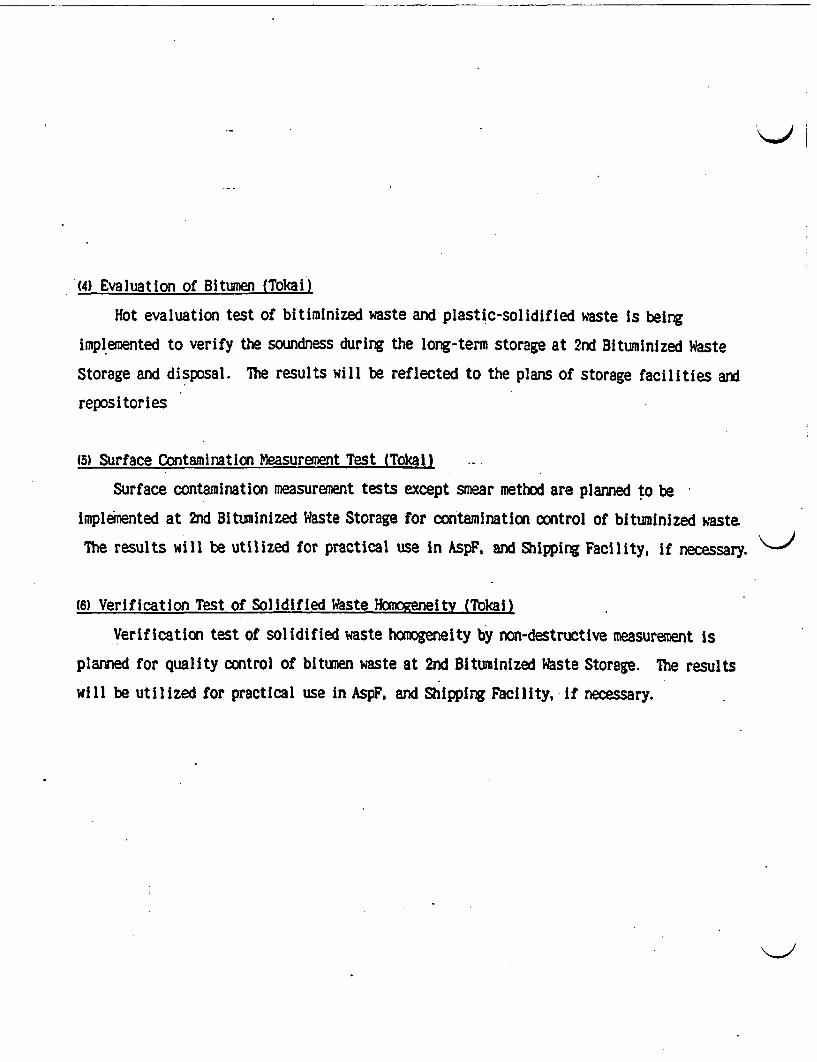
(4) Evaluation of Bitumen (Tokai)
Hot evaluation test of bitiminized waste and plastic-solidified waste is being
implemented to verify the soundness during the long-term storage at 2nd Bituminized Waste
Storage and disposal. The results will be reflected to the plans of storage facilities and
repositories
(5) Surface Contamination Measurement Test (Tokal)
Surface contamination measurement tests except smear method are planned to be
implemented at 2nd Bituminized Waste Storage for contamination control of bituminized waste.
The results will be utilized for practical use in AspF, and Shipping Facility, if necessary. K
(6) Verification Test of Solidified Waste Homogeneity (Tbkai)
Verification test of solidified waste homogeneity by non-destructive measurement is
planned for quality control of bitumen waste at 2nd Bituminized Waste Storage. The results
will be utilized for practical use in AspF, and Shipping Facility. if necessary.
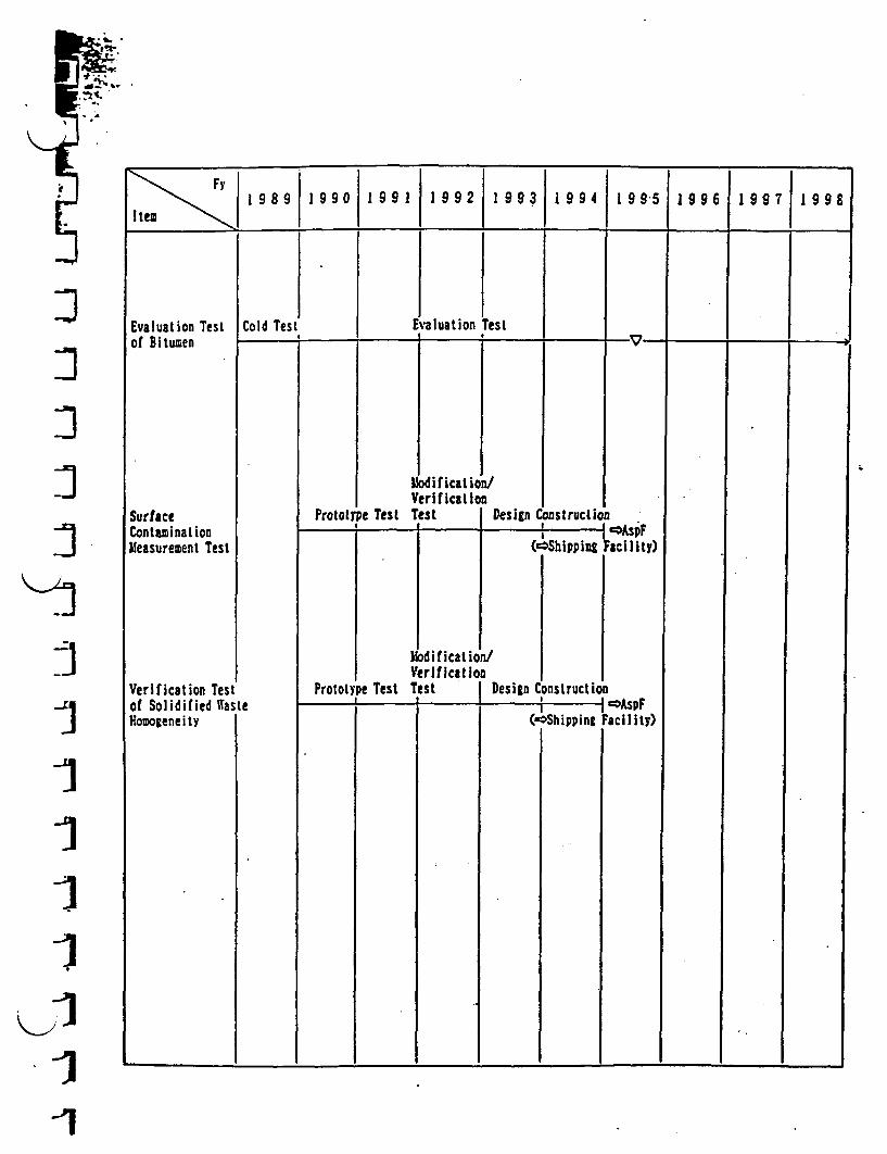
F~y19 9 9 9 1 1 I 9 9 1 9 9 1 9 9 3 1 9 9 4 1 9 5 1 9 9 6 1 9 9 7 1 9 9 8
Item . , . I_
I
:3
:1
-1I11
-1
Evaluation Testof Bitumen
SurfaceContaminationMeasurement Test
Verification Testof Solidified WasHomogeneity
Cold Test Evaluation Test________ .4 .4 .4
MV
Pe Test
Edification/cerificationest. I IPro to[ )esign Construction
I . i -
- I^.^
(OShiPPinl
Constructioi
Facility)
I >AspFFacility)
I IModification!Verification
Pe Test Test I IPrototy )esignte I 1 .4
(Shipping
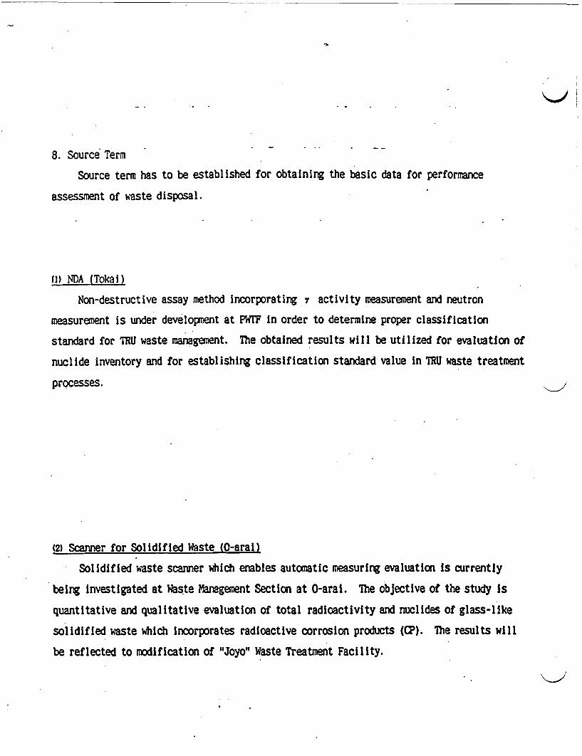
8. Source Term -
Source term has to be established for obtaining the basic data for performance
assessment of aste disposal.
(1) NDA (Tokai)
Non-destructive assay method incorporating activity measurement and neutron
measurement is under development at PWIF in order to determine proper classification
standard for TRU waste management. The obtained results will be utilized for evaluation of
nuclide inventory and for establishing classification standard value in 7RU waste treatment
processes.
(2) Scanner for Solidified Waste (0-aral)
Solidified waste scanner which enables automatic measuring evaluation is currently
being investigated at Waste Management Section at O-aral. The objective of the study is
quantitative and qualitative evaluation of total radioactivity and nuclides of glass-like
solidified waste which incorporates radioactive corrosion products (CP). The results will
be reflected to modification of "Joyo" Waste Treatment Facility.

:
1 989 1990 1991 1992 1993 1994 1995 1996 1997 1 99I teo~~~~~~~~~~~~~~~~~~~~~~~~~~~~~~~~~~~~~~~~~~~~~~~~~~~~~~~~~~~~~~~~~~~~~~~~
]1:7I]I7
Measurement Test._,ceptua
1
PKTF
7-activityMeasurement
NeutronMeasurement
LTF .
Design andFabrication ofSolidified WasteScanner
I IConcentration Distribution.Measurement/Evaluation
Detection Sensitivity/Accuracy Improvement Test
Prograzintg andModification
Software IImprovement and Verification
I ActiveI_ I
_. * I. ;
Denstration Test
4 :
I IDetailed
Waste Measurement Test4 4. :
ConceptuaDeign C
Inv
ict ionlesign ConstruTrial IOperatiol-0-C
a Operation_________ 4� 1- 4. 4.
I 4.Ir
-_
_1Idcst igation
I Design/Fa brication)
'Joyo Wast Treatent Fcilety
-I_ . _ . . .
-1
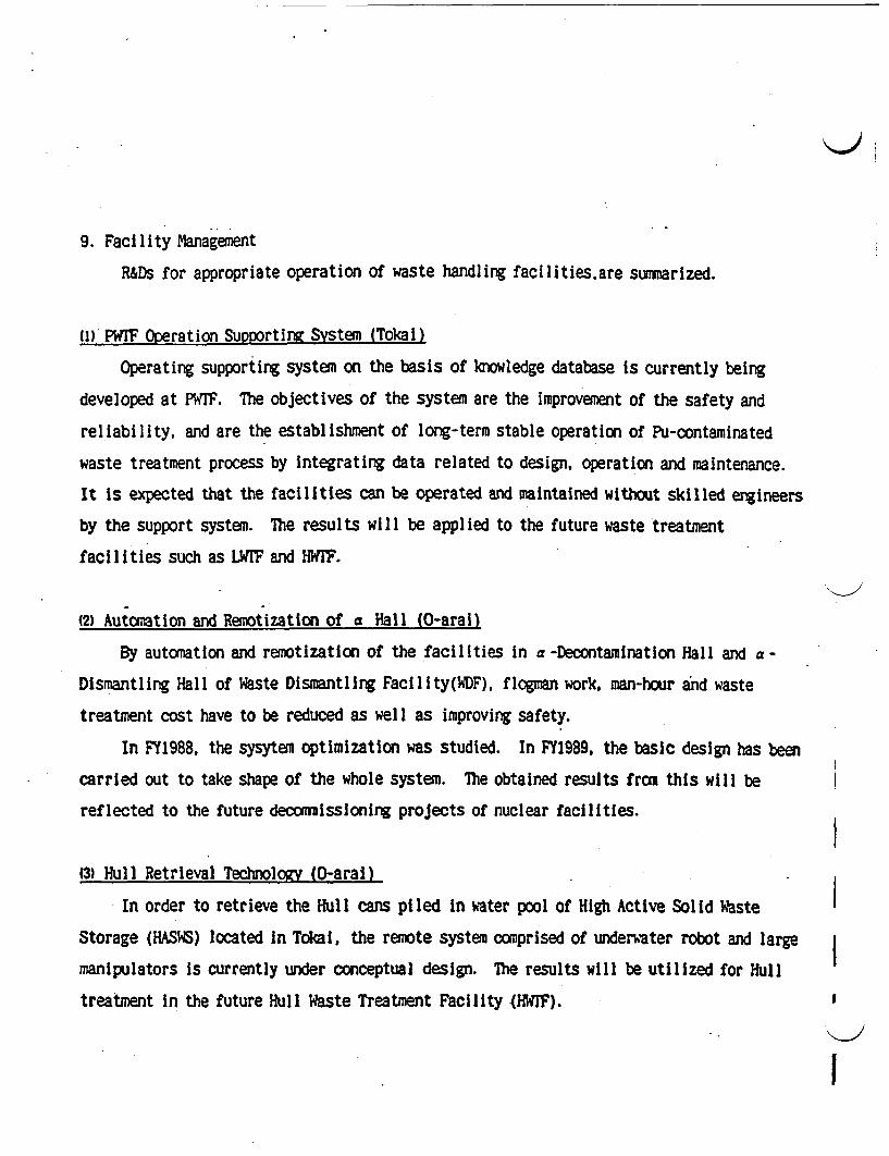
9. Facility Management
R&Ds for appropriate operation of waste handling facilities.are summarized.
() PWrF Operation Supporting System Tokai)
Operating supporting system on the basis of knowledge database is currently being
developed at PWrF. The objectives of the system are the improvement of the safety and
reliability, and are the establishment of long-term stable operation of Pu-contaminated
waste treatment process by integrating data related to design, operation and maintenance.
It is expected that the facilities can be operated and maintained without skilled engineers
by the support system. The results will be applied to the future waste treatment
facilities such as LWIF and HWTF.
(2) Automation and Remotization of a Hall (0-arai)
By automation and remotization of the facilities in a -Decontamination Hall and a -
Dismantling Hall of Waste Dismantling Facility(WDF), flogman work, man-hour and waste
treatment cost have to be reduced as well as improving safety.
In FY1988, the sysytem optimization was studied. In FY1989, the basic design has been
carried out to take shape of the whole system. The obtained results from this will be
reflected to the future decommissioning projects of nuclear facilities.
(3) Hull Retrieval Technology (0-aral)
In order to retrieve the Hull cans piled in water pool of High Active Solid Waste
Storage (HASWS) located in Tokai, the remote system comprised of underater robot and large
manipulators is currently under conceptual design. The results will be utilized for Hull
treatment in the future Hull Waste Treatment Facility (HWJF).
I
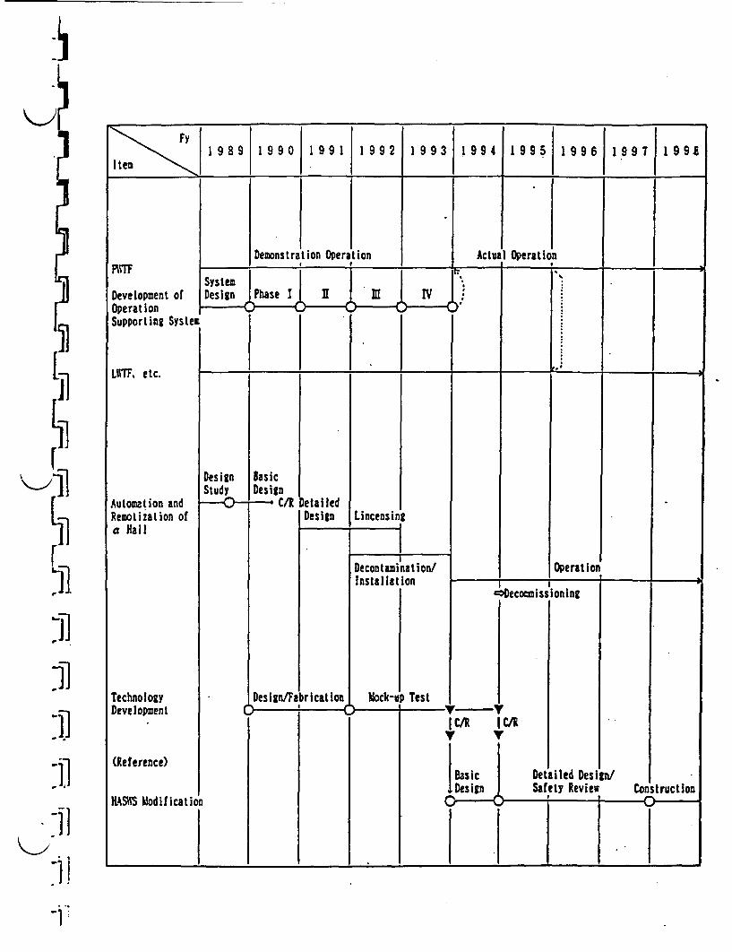
51[Ji
rK.j1
1)1)
Fy1 9 89 1 9 90 1 9 91 1 9 92 993 9 995 1 6 19 7 199S
Demonstralion Operation Actual OperationPWFF
Development ofOperationSupporting System
LIITF. etc.
Automation andRemotization ofa Hall
TechnologyDevelopment
(Refe rence)
HSS Modificati
r 7
SystemDesign Phase I
I >-��,V � I. I
DesignStudy
BasicDesign
--- C/R )etai ledDesign Lincens i
*1*
Decontamination/Installation
Operationp - I J -
C>Decosissioning
DesignFabrication Mck-t
I I
p Test I !
I C/R I
IBasicDesign
C/K
'1')
-Il
Detailed DesiSafety Review
i/Construction-0--~* :4 -
14) Radiation Imaze Display (RID) (O-arai)
Radiation Image Display (RID) which visualizes the distribution, quantity etc. of
radioactive substances is currently being developed, as a part of development of radiation
measurement technologies which aim efficient and economical operation of decontamination and
dismantling (D&D), measuring contaminants and dose prior to determining DD method.
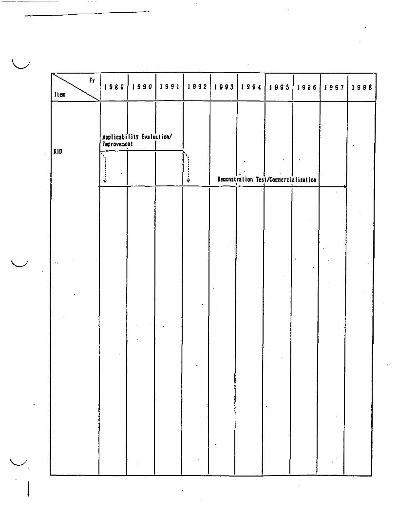
1989 1990 1991 1992 1993 1994 1995 1996 1997 1998
Applicability Evaluation/mprovemenat I
RID .
ration Test/ComerciDemonsi Iiat ion
a - - - _______ a.
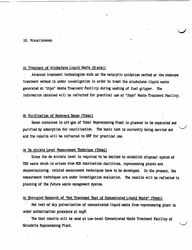
10. Miscellaneous
u) Treatment of Alcoholate Liquid Waste (0-arai)
Advanced treatment technologies such as the catalytic oxidation method or the membrane
treatment method is under investigation in order to treat the alcoholate liquid waste
generated at Joyo" Waste Treatment Facility during washing of fuel gripper. The
information obtained will be reflected for practical use at Joyo" Waste Treatment Facility.
(2) Purification of Recoverd Xenon (Tokal)
Xenon contained in off-gas of Tokal Reprocessing Plant is planned to be separated and
purified by adsorption for reutilization. The basic test is currently being carried out
and the results will be reflected to KRF for practical use.
(3) De minimis Level Measurement Technique (Tokal)
Since the de minimis level is required to be decided to establish disposal system of
TRU waste which is arisen from MVX fabrication facilities, reprocessing plants and
decommissioning, related measurement techniques have to be developed. In the present, the
measurement techniques are under investigation evaluation. The results will be reflected to
planning of the future waste management system.
(4) Entrusted Research of "Hot Treatment Test of Concentrated Liquid Waste" (Tokai)
Hot test of dry pulverization of concentrated liquid waste from reprocessing plant is
under authorization procedure at AspF.
The test results will be used at Low-level. Condentrated Waste Treatment Facilicy of
Shimokita Reprocessing Plant.
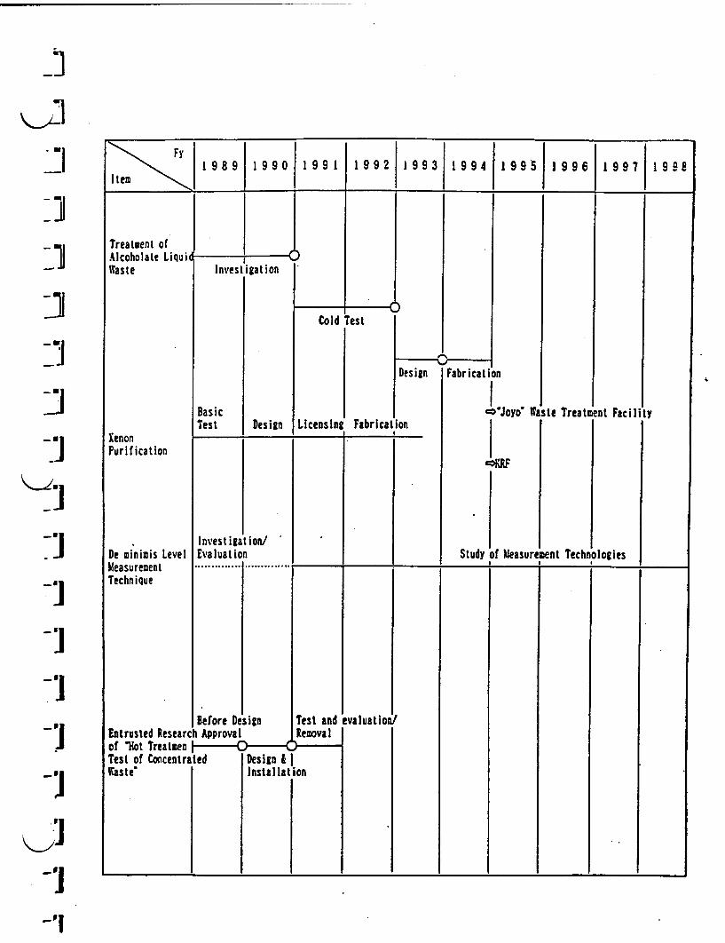
-1
I
-JI
1 9891 99 0 1991 1992 19931 994 1995 1996 1997 199I
Treatment ofAlcoholate LiquiWaste
XenonPurification
De minimis LevelMeasurementTechnique
--I
?Investigation
0Cold Test
Design
BasicTest Design Licensing Fabrication
I. :
Fabrication
WJoyo W
Study of easuri
tsle Treatslent Facility
J]Investigation/Evaluation Dent Technologies I
............. r .... .;.;.;.:I;I ;
-'I
-i.1
Before Design Test andEntrusted Research Approval Recovalof 'ot Trealmen Test of Concentrated Design & IWaste' Installation
evaluation!
-i-'
TECHNOLOGIES DISCUSSED AT JAERI- Takasaki Radiation Chemistry ResearchEstablishment
- Amidoxime Group Containing Adsorbents for Metal Ions Synthesed by Radiation-Induced Grafting
- New Type of Amnidoxime Group Containing Adsorbent for the Recovery of Uranium fromSeawater
BIBLIOGRAPHY OF ITERATURE RECEIVED FROM TAKASAK RADIATIONCHEMISTRY RESEARCH ESTABLISEMENT
-Amidoxime-Group-Containing Adsorbents for Metal Ions Synthesized by Radiation-InducedGraftings, Written by J. Okamoto, T. Sugo, A. Katakal and H. Omichi. JAERI, TakasaERadiation Chemistry Research Establishment, 11 pages.
'A New Type of Amidoxime-Group-Containing Adsorbent for the Recovery of Uraniumfrom Seawater, Written by H. Omichi, A. Katakal, T. Sugo and . Okamoto. JAEPU,Takasaki Radiation Chemistry Research Establishment. 16 pages.
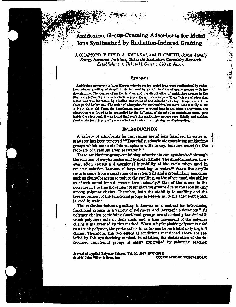
- -
I
4
Amidoxime-Group-Containg Adsorbents for MetalIons Synthesized by Radiation-Induced Grafting
J. OKAMCIO, T. SUGO, A. KATAKAI, and H. OMICHI, JApan AtoncEnero Research Institute, Takaaki Radiation Chemisty ReSarch
Establishm M Takasak, Gunma 3701Z Japan
Synopsis
Amidouimeoup contalnng fibrous edforbent fAr eme ion we. mynthebsed by radioation-Induced grafting of acrylonitrile followed by azldozlmatin of cydno groups with 1W-drmlanIB. The degros of amidoximation and the diarbutlon of mioxime groupy in thefibere follwed by mea of electrprobe X-ray microwaysioTheodeny ofadsorbingmetal ions was increased by alkaline treatment of the adsorbent at high temperature fr ashort period before us Ile order of adsorption for warious balent metal ions was Fg > Ou> Ni > Co > Cd. From the ditribution pattern of metal lonein the fibrous adsorbent, theadsorption was found to be controlled by the diffusion of the solution containing metal Ionsinside the adsorbent. It was found that confining anidoxime groups superficIally and maiingshort chain length of grafts wer effective to obtain a igh dere of adsorption.
INTRODUCFION
A variety of adsorbents for recovering metal ions dissolved in water orseawater has been reported. Especially, adsorbents containing amidozimegroups which make chelate complexes with uranyl ons are noted for therecovery of uranium from seawater.6-U
These amidoimegroupcontalnig adisorbents are syntesized throughthe reaction of acrylic resins and hydroxylamine. The amidoximatlon, how-ever, often causes a dimensional instability of the resin when used inaqueous solution because of large swelling in water." When the acrylicresin is made from a copolymer of acrylonitrile and a croeulinking monomersuch as divinylbenzene to reduce the swelling, on the other hand, the abilityto adsorb metal ions decreases tremendously." One of the causes is thedecrease in the free movement of amidoxime groups due to the crosslinkingamong polymer chains. Therefore, both the Stability to welling and thefree movement of the functional groups are essential to the adsorbent hichis used in water.
The radiation-induced grafting is known as a method for introducingfunctional groups in a variety of polymers and inorganic substances." Aspolymer chains containing functional groups are chemically bonded withtrunk polymers only at their chain end, a free movement of the polymerchains is maintained by this method. When a hydrophobic polymer is usdas a trunk polymer, the part swollen in water can be restricted only to graftchains. Therefore, the two essential conditions mentioned above are sat-isfied by this synthesizing method. In addition, the distribution of the in-troduced functional groups is easily controlled by selecting reaction
Journa of Applied Polymer Science, Vol. 30, 2967-2977 (19)e 1955 John Wiley & Sons, Inc. CCC 0021-8995/85/07296711U00
w41 ..A U '

298 OKAMOTO Er AL
conditions such as irradiatio n dos, dose rate, temperature, and reactiontime. H~owever, the studies of snsthesizing adsorets for metal ion byradiation-induced grafting have been little reported.
In the present study, fibrous adsorbents containing amidoxime groupswere synthesized by the radiation-induced grafting of acrylonitrile ontofibers and adsorption of heavy metal Ions such as copper ions were at-tempted.
EXPERIMTAL
Fibers used for synthesizing adsorbents are listed in Table L The fiber(ca. 40 )Am in diameter, and 15mm lo0g) rinsed with acetone and dried ina vacuum oven for 16 h was packed in a polyethylene bag under nitrogenatmosphere and was irradiated wtih an electron accelerator (Dynamitron,Model IEA 3000-25-2, Radiation Dynamics) operating at beam energy of 1.5MeV and a current of 1 mA at room temperature In order to reduce theheat accumulation on the sample along with the irradiation, the polyeth-ylene bag was conveyed back and forth under the window of the acceleratorat a rate 2.3 m/min. The dose rate was 1 Mrad/pasa
The irradiated fiber was installed in a glass ampoule and was evacuatedfor 5 min followed by the introduction of purified acrylonitrile under anitrogen atmosphere. The graft polymerization was carried out at 25CWhen acrylonitrile was grafted in vapor phase, the fiber was separatedfrom liquid acrylonitrile with a perforated plate After the grafting, ho-mopolymer and unreacted monomer were extracted with NN-dimethylformamide. The grafting yield was obtained from the weight increase basedon the initial weight.
The amidoxime group-containing fiber (AO fiber) was obtained by heatinggrafted fiber with 3% hydroxylamine solution (methanol/water - 1/1) atpH 7 then rinsed with methanol and dried at 40'C under a reduced pressure.The amount of amidoxime groups was measured by elemental analysis.
The distribution of amidoxime groups combined with metals in the crosssection of AG fiber was measured by means of a JEOL electron probe X-ray microanalyzer (EPMA), Model JXA 733.
About 0.5 g of AG fiber was immersed in 1 L of metal ion (0.1-0.2 mm)-containing Clark-Lubs buffer solution in the pH 2-7 region at 30'C for theprescribed periods. Then the fiber was rinsed with water and was dried ina vacuum oven. A concentrated sulfuic acid was added to a platinum
TABLB IFhbers Used tor Syntieizing Adsorbezt
No. Materials Producers
I Tetraluoroethylene-ethylenecopolymer (poly(FE)l Asahi GUM
2 Polypropylene eP Ube Industries3 Polyamide Teijin4 Polyethylene (PE) Misui Petrachem5 Polyester Teijin6 Carbon iber Toray
0
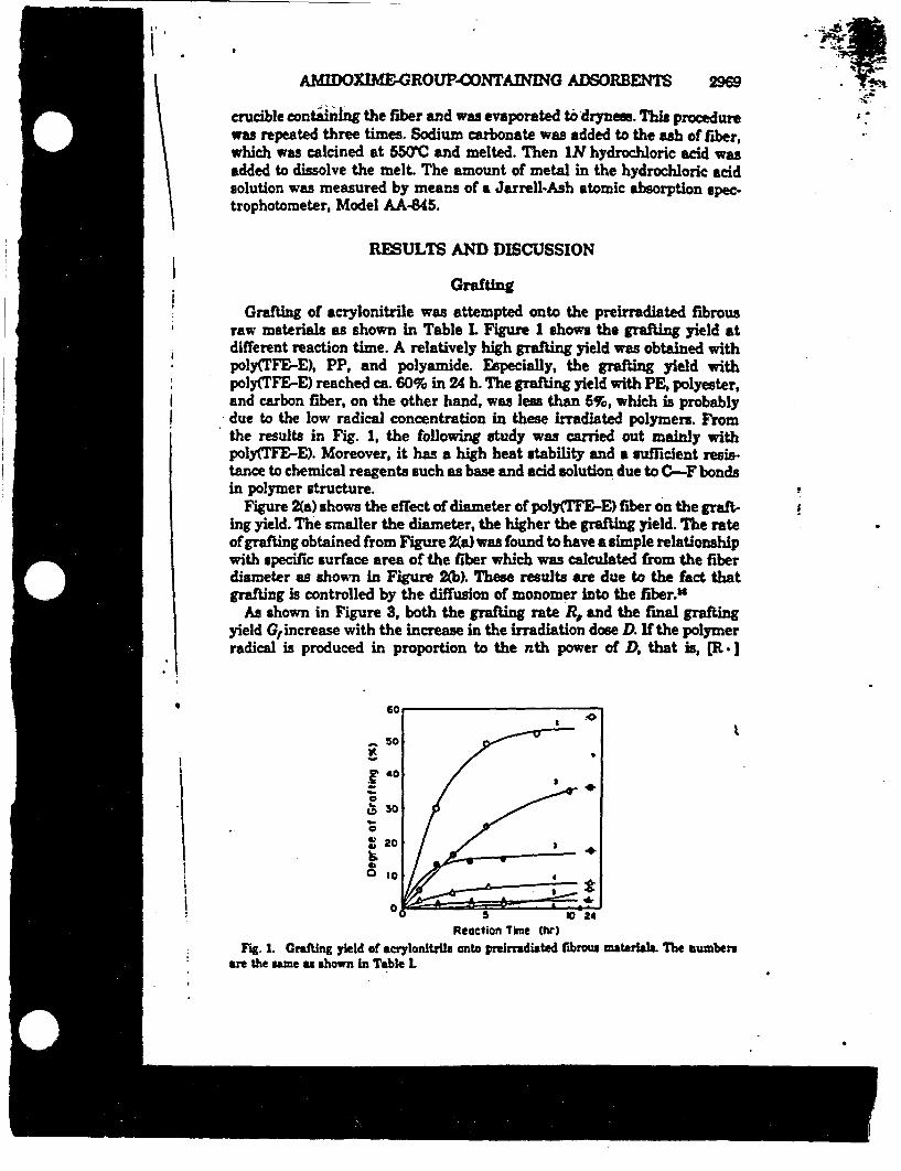
.i,
AMIDOXIME-GROUP-CONTAINING ADSORBENTS 2969
. .~crucible containing the fiber and was evaporated to drynes. This procedurewas repeated three times. Sodium carbonate was added to the ash of fiber,which was calcined at 550'C and melted. Then IN hydrochloric acid wasadded to dissolve the melt. The amount of metal in the hydrochloric acidsolution was measured by means of a Jarrell-Ash atomic absorption spec.trophotometer, Model AA-845.
RESULTS AND DISCUSSION
I Grafting
Grafting of acrylonitrile was attempted onto the preirradiated fibrousraw materials as shown in Table L Figure shows the grafting yield atdifferent reaction time. A relatively high grafting yield was obtained withpoly(TFE-E), PP, and polyamide. Especially, the grafting yield withpoly(TFE-E) reached ca. 60% in 24 h. The grafting yield with PE, polyester,and carbon fiber, on the other hand, was less than 6%, which is probablydue to the low radical concentration in these irradiated polymers. Fromthe results in Fig. 1, the following study was carried out mainly withpoly(TFE-E). Moreover, it has a high heat stability and a sufficient resis-tance to chemical reagents such as base and acid solution due to C-F bondsin polymer structure.
Figure 2(a) shows the effect of diameter of poly(TFE-E) fiber on the graft-ing yield. The smaller the diameter, the higher the grafting yield. The rateof grafting obtained from Figure 2(a) was found to have a simple relationshipwith specific surface area of the fiber which was calculated from the fiberdiameter as shown in Figure 2(b). These results are due to the fact thatgrafting is controlled by the diffusion of monomer into the fiber."
As shown in Figure 3, both the grafting rate R and the final graftingyield G increase with the increase in the irradiation dose D. If the polymerradical is produced in proportion to the nth power of D, that is, R I
;
0
I\S -
x o
a% o0
0
0 2020
4)o 1
Reaction Tine (hr)Fig. 1. Grafting yield of acrylonitrile onto preiridisted fibrous materials. The lumbers
are the same as shown in Table 1.
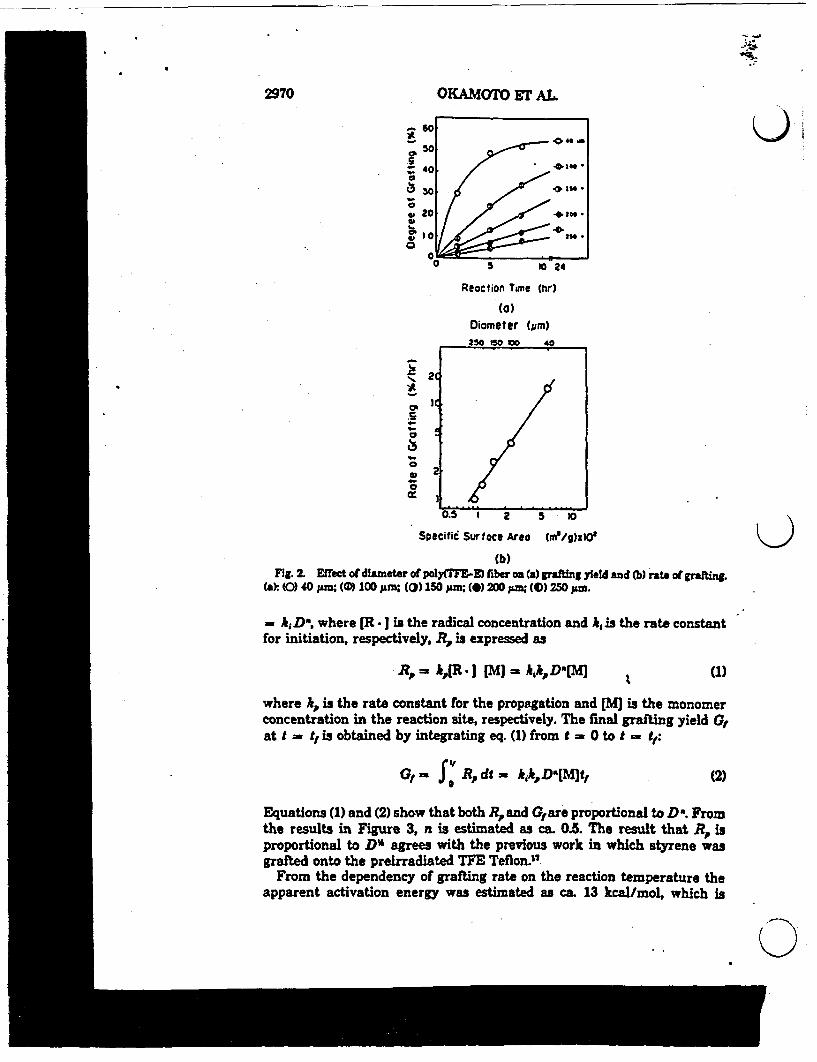
--
2970 OKAMOTO ET AL
0S
0Va
Reaction Time (hr)
(a)Diameter (pm)250 50 MD 40
-4-
4-
0
'S
a
2C
lC
2
I
U.* 1 2 5 20
Specific Surlace Area a/9g)xIO1
0
(b)Fig. 2. Effect of diameter of pGu(sFE-E) fiber on (a) grafting yield and A) rat of grafting.
(a): (0) 40 jim; (ll 100 ;&m; () 150 jm; () 200 pm; () 250 zA.
= hiD%, where [R ] is the radical concentration and kis the rate constantfor initiation, respectively. R,. is expressed as
R,,=-i,(R *I [M) = jkjDD[W (1)
where k,. is the rate constant for the propagation and [M is the monomerconcentration in the reaction site, respectively. The final grafting yield G,at t = t is obtained by integrating eq. (1) from t = Oto t =t
G, Rdt = kD[M]ft (2)
Equations (1) and (2) show that both R, and Gare proportional to D . Fromthe results in Figure 3, n is estimated as ca. 0.S. The result that R isproportional to Do6 agrees with the previous work in which styrene wasgrafted onto the preirradiated TFE Teflon."
From the dependency of grafting rate on the reaction temperature theapparent activation energy was estimated as ca. 13 kcal/mol, which is
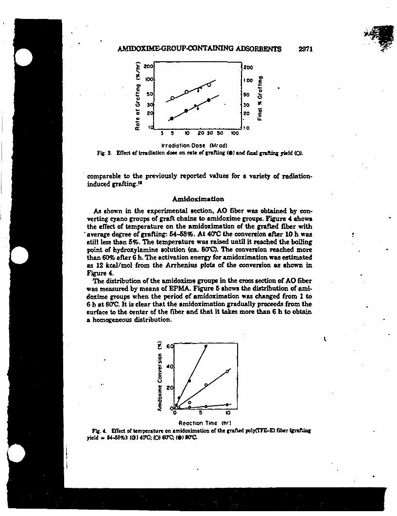
AMMOXIdE-GROUPCONTANING ADSORBENTS 2971
E 2C
- IC
.SI-
o 2
a
*I
100
10.
200
too 5100
50 L-
030 t'
20 E..
Io3 5 10 20 30 50 100
Irradiation Dose (Mrad)Fig. . Effect of irradiation dose on rate of grafting (0) and final grafting yield (0).
comparable to the previously reported values for a variety of radiation-induced grafting."
Amidodmation
As shown in the experimental section, AO fiber was obtained by con-verting cyano groups of graft chains to amidoxime groups. Figure 4 showsthe effect of temperature on the amidoximation of the grafted fiber withaverage degree of grafting- 54-68%. At 40'C the conversion after 10 h wasstill less than 5%. The temperature was raised until it reached the boilingpoint of hydroxylamine solution (ca. WO. The conversion reached morethan 60% after 6 h. The activation energy for amidoximation was estimatedas 12 kcal/mol from the Arrhenius plots of the conversion as shown inFigure 4.
The distribution of the anidoxime groups in the cross section of AO fiberwas measured by means of EPMA. Figure 6 shows the distribution of ami-doxime groups when the period of anidoximation was changed from 1 to6 h at 8C. It is clear that the amidoximation gradually proceeds from thesurface to the center of the fiber and that it takes more than 6 h to obtaina homogeneous distribution.
q
C262
CaU
0E
E
Reaction Time (hr)Fig. 4. Effect of temperature on amidoxiantion or the grafted plyfITE-E) fiber (prfting
yield - 5489%k (0) 4M-; (0) WOC; (0) SOM

2972 OKAMOrO LT AL
_ ..(a) (b) (c)ftg 6. Dstribution of amidime, groups n the o section of AO fiber m~easured by
means of EPMA reaction tim 0* 1; (b) 3; (c) 6.
Figure 6 shows the temperature effect on the width of distribution ofamidoxime groups in AO fiber obtained from EPMA measurement. Whenthe temperature is high and the reaction time of amidoximation is long, °the distribution becomes widespread. The almost linear relationship of thewidth with reaction time indicates that amidoximaton in the center of thefiber proceeds at a similar rate as on the surface region. The activationenergy for spreading amidoxime groups in the fiber was estimated as ca.10 kcal/mol. This value is in fair agreement with the above-mentioned oactivation energy for converting cyano groups to anidoxime groups. t
Such thermodynamic similarity between the conversion of amidoximation .aand the spread of distribution of amidoxime groups inside the fiber I more 4clearly indicated when these values are plotted against each other as shownin Figure 7. Clearly, the conversion increases in proportion to the increase o.in the width under all the present experimental conditions. Therefore, it fris reasonable to say that the amidoximation occurs homogeneously at leastwithin 20 ;im from the surface of the fiber. Probably, cyano groups of graftchains exist homogeneously in the fiber and as soon as the hydroxylamine trsolution reaches the cyano groups the amidoximation occurs. In other words, Inthe reaction is controlled by the diffusion of hydroxylamine solution in the thfiber.
02
0
l O 5 ~ ~ 10
Reaction 1e (r)Fig.I. Effect of temperature on the width of distribution of amidoulme groups In AO fiber. Fi
The rymbols are the same s shown In Figure f I
'' (Li~

I-1
AMIDOXIME&GROUP-ONTAINMG ADSORBENTS 2973
i
0
0 tO 20
Width of Amdozeme Leyer from Surfocglpm)
Fig. 7. Relationship between the conversion of amidoximation and the spread of distributionof anidoxime groups. The symbols are the same as shown in Figure 4.
Adsorption of Metal Ions
The dried AO fiber did not adsorb metal ions at room temperature. Oneof the causes is the insufficient swelling of the fiber in metal ion-containingsolution. The hydrophilicity of poly(TE-E) fiber itself is virtually negligibleand amidoxime groups are not so hydrophilic.'0
Heating of AO fiber in alkaline solutin was found to increase the swellingof AO fiber in aqueous solution. For example, the contact of AO fiber with0.5N potassium hydroxide solution at 20C for 8 h elicited S0% augmentationin the water uptake.
The increase in hydrophilicity of the fiber is expected to increase theadsorption of metal ions. Figure 8 shows the effect of temperature of alkalinetreatment on adsorption efficiency expressed as the percentage of amidox-ime groups used for complexation with copper ions. It is clear that raisingthe temperature increases the efficiency. Although the efficiency abruptly
S
I
:V0
aw2
Reoction Time hr)Fig. S. Effect of temperature of alkaline treatement of AO fiber on adsorption *fflciency
for copper Ion: (0) 2DC ((0) 50C (0) ARC.
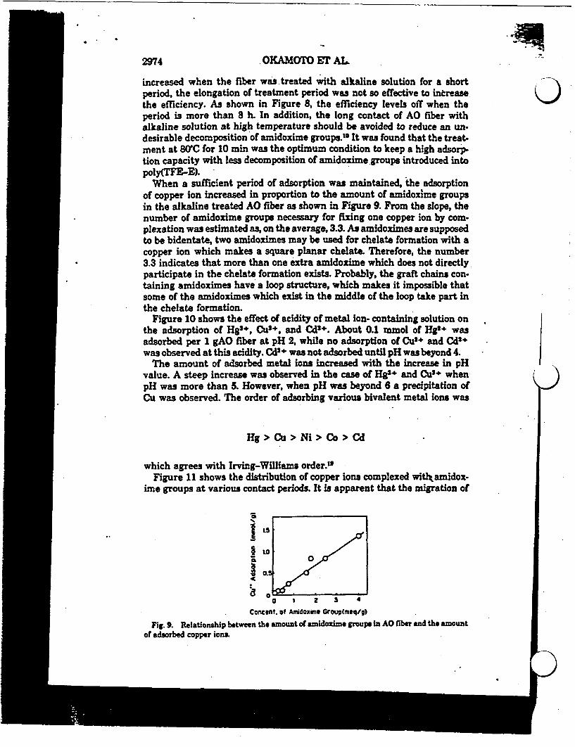
2974 OKAMOTO Er AL
increased when the fiber was treated with alkaline solution for a shortperiod, the elongation of treatment period was not so effective to increase 0the efficiency. As shown in Figure 8, the efficiency levels off when theperiod is more than 8 h. In addition, the long contact of AO fiber withalkaline solution at high temperature should be avoided to reduce an un-desirable decomposition of amidoxime groups.W It was found that the treat,ment at 80'C for 10 min was the optimum condition to keep a high adsorp-tion capacity with less decomposition of amidoxime groups introduced intopoly(TFE-E).
When a sufficient period of adsorption was maintained, the adsorptionof copper ion increased in proportion to the amount of amidoxime groupsin the alkaline treated AO fiber as shown in Figure 9. From the slope, thenumber of amidoxime groups necessary for fixing one copper ion by com-plexation was estimated as, on the average, 3.3. As amidoximes are supposedto be bidentate, two amidoximes may be used for chelate formation with acopper ion which makes a square planar chelate. Therefore, the number3.3 indicates that more than one extra amidoxime which does not directlyparticipate in the chelate formation exists. Probably, the graft chains con-taining amidoximes have a loop structure, which makes it impossible thatsome of the amidoximes which exist in the middle of the loop take part inthe chelate formation.
Figure 10 shows the effect of acidity of metal ion- containing solution onthe adsorption of Hg'*, Cut+, and Cd2+. About 0.1 mmol of Hg' wasadsorbed per 1 gAO fiber at pH 2, while no adsorption of Cut+ and Cd2+was observed at this acidity. Cd'+ was not adsorbed until pH was beyond 4.
The amount of adsorbed metal ions increased with the increase in pHvalue. A steep increase was observed in the case of Hg and Cu2+ whenpH was more than 5. However, when pH was beyond 6 a precipitation ofCu was observed. The order of adsorbing various bivalent metal ions was
Hg > Cu > Ni > Co > Cd
which agrees with Irving-Willias order."Figure 11 shows the distribution of copper ions complexed witlkamidox-
ime groups at various contact periods. It is apparent that the migration of
ILS0
O 1 2 3 4
Concent. of Aidoxime Group(meq/')
Fig. 9. Relationship between the amount ofamidoxime groups in AO fiber and the amountof adsorbed copper ions.

AMIDOXIME-GROUPCONTAINING ADSORBENTS 2976
la0EE
C0
4-L-o
V)
pHFig. 10. Effect of acidity of metal ion-containing solution on the adsorption of various
bivalent metal ions.
copper ion through the amidoxime group layer is glow. It took about 1 dayto obtain an almost homogeneous distribution of copper ions in AO fiber.The rapid increase in the population of copper ions on the surface region,on the other hand, suggests that confining amidoxiine groups superficiallyon the adsorbent fiber is effective to obtain a high adsorption ability. Thisassumption was confirmed by the result shown in Figure 12 where thedistribution of amidoxime groups in AO fiber and the adsorption amount
r (a) (b) (C)
t
(d) (e)Fig. 11. Distribution of copper ions complezed with amidoxime groups at vauious contact
periods: (a) 1 min; (b) 6 iin; (c) 10 min; (d) 20 miin; (e) 24 h
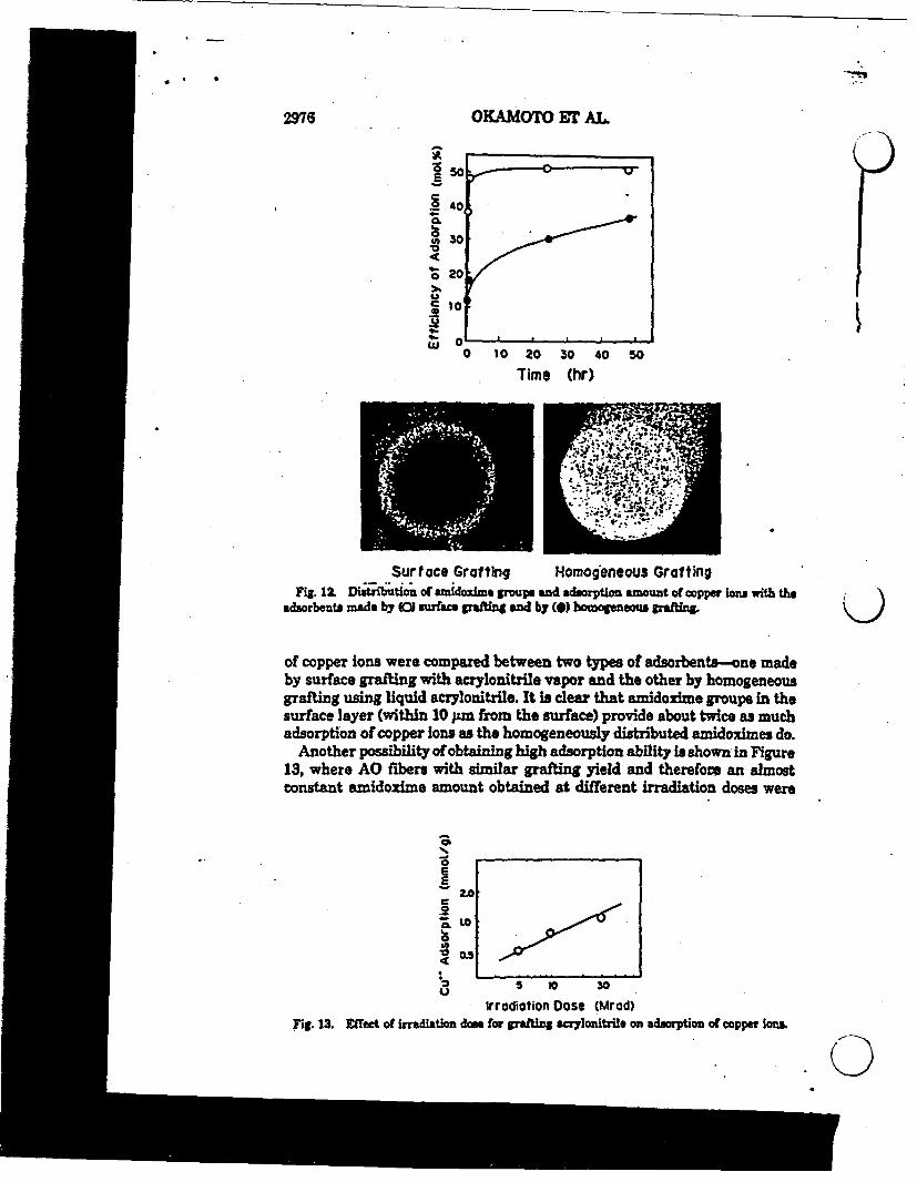
* . 9
2976 OKAMOTO Er AL
a 50
°9 4040
Ub 30
C 20
, 10
..
i~~~~~
I
I) . . . . .
0 10 20 30 40 50
Time (hr)
Surface Grafting Homogeneous GraftingFig. 12. Di t~tioi of amdouitm groups and adsorption amount of copper ions witM the
adsorbents made by (0) Surface gaftin and by (0) hooogeneous graffln
of copper iona were compared between two types of adsorbents-one madeby surface grafting with acrylonitrile vapor and the other by homogeneousgrafting using liquid acrylonitrile. It is clear that amidoxime groups in thesurface layer (within 10 pm from the surface) provide about twice as muchadsorption of copper ions as the homogeneously distributed amidoximes do.
Another possibility of obtaining high adsorption ability in shown in Figure13, where AO fibers with similar grafting yield and therefore an almostconstant amidosime amount obtained at different irradiation doses were
obS1..
A2.0
C.
<s °LOla0.5
C.5 V 30
Irrodition Dose (Mrod)Fig. 13. E et irraLiation dose for grafting acrylonitrile on adsorption of copper ioa
* . SAMIDOXIME-GROUP-CONTAINING ADSOREENTS 2977
used. By increasing the irradiation dose, the number of trunk polymerradicals which can initiate graft polymerization increases. As the graftingyield is the product of the number of initiation rdicals and the length ofthe graft chains, the result that these AO fibers have similar grafting yieldindicates that the graft chain lengths are different according to the differ-ence in the number of initiation radicals. It is clear that the AO fiber ofshorter chain length (or irradiated with higher dose) provides a higheradsorption capacity for copper ions. Probably, the shorter chains have moreflexibility of the movement of amidoxime groups for the complex formationwith copper ions.
AO fiber has high stability to various kinds of treatment. For example,when dry AO fiber was treated with 2.5% potassium hydroxide solution atWOC for 10 min, the diameter increased only 4%, which proves that AOfiber swells little in alkaline solution. No further increase in diameter wasobserved when the alkaline treated AO fiber was contacted with water at30'C for 24 h, while a considerable amount of water uptake (ca. 30%) wasobserved as mentioned above.
Thus, this new adsorbent produced by radiation-induced grafting provesvery effective for the use in water because of high adsorption ability forheavy metal ions and sufficient stability under various conditions.
References1. A. D. Kelmern, Separation Sci TeoL, 16, 1019 (1981).2. H. J. Schenk. L. Astheimer. E: G. Witte, and K. Schwochau. Separation &i TechnoL.
17, 1293 11982).3. T. Miyake. K. Takeda, and A. Ikeda nEyunen (Japanec 20, 21 (1982).4. H.J. Fischer and K. H. Lieser, Angew lMakromoL Chen, 112, 1 (1983).6. T. Miyamatsu. N. Oguchi, Y. Kanchiku, and T. Aoyagi, J Sc. fiber &i TechnoL Jpr.
38, T537. T. 546 (1982; 39. T-25, T42 (1983).6. 1. Tabushi, Y. Kobuke, and T. Nishiya Natwu 280, 665 (1979)7. D. Heitkamp and K. Wagener,&d. Eq. Chen, Process. Da Deu, 21, 781 (1982).S. Z Suleek and V. Sixta, CoIL Czeck Chen Commun., 40, 2295 (1975).I 9. H. Egawa and H. Harada, J Mmain. Soc. Jpn., 1979. 958; 1980. 1767, 1773.
10. S. Katoh, K. Sugasaka. K. Sakmne N. Takai, H. TakahashL Y. Unezawa, end K. Itagaki,J. Chken. Soc. Jpn., 1982, 1449, 1455.
11. K. Sugasaka, S. Katoh, N. Takai, H. Takahashi, andY. Unezawe Seporatio.&SL TechnoL,16, 971 (1981).
12. L. Astheimer, H. J. Schenk, E. 0. Witte, and K. Schwochau, Separation &. ecuntoL.18. 307 (1983).
13. K. Sakane, T. Hirotau, N. Takagi. S. Katoh, K. Sugasaka, Y. Umezawa, N. Taklui, andH. Takahashi, ButL Soc. Sea Water Sci Jpn., 56, 101 (1982).
14. S. Katoh, K. Sugasaka, T. Hirotsu, N. Takai, T. Itagaki. and H. Ouchi, Proc. IMRUP.Tokyo, 1983 p. 138.
15. A. Chapiro, Radiation Chemist of Polymeric Systems. High Polymer Set. Vol. 15, In-terscience, New York, 1962.
16. 1. Sakurada, T. Okada, and N. Hatakeyama, Bonded Mater 1, 11(1962).17. X. Zhi-li, W. Gen-hua, W. Han4ng, . Gyn, and N. Min hua, RadiaL Ph C, 22,
939 (1983).18. S. N. hattacharyya and D. Mattas. J. Pbly. Sei., Plym Chem. Ed, 21, 3291(1983).19. H. Irving and R. J. P. Williams, Natw, 162, 746 (1948)
Received September 18, 1984Accepted November 27, 1984

SEPARATION SCIENCE AND TECHNOLOGY, 20(2 & 3). pp. 163-178, 1985
A New Type of Amidoxime-Group-Containing Adsorbentfor the Recovery of Uranium from Seawater
H. OMICHI, A. KATAKAI, T. SUGO, and J. OKAMOTOTAKASAKI RADIATION CHEMISTRY RESEARCH ESTABUSHMENTJAPAN ATOMIC ENERGY RESEARCH INSTITUTETAKASAKI, GUNMA 370-12, JAPAN
Abstract
A new type of adsorbent containing amidoximne groups for the recovery ofuranium from seawater was synthesized by the radiation-induced graft polymeriza-tion of acrylonitrile onto polymeric fiber followed by amidoximation with hydroxyl-amine. When arnidoxime groups were introduced superficially on the fiber, theamount of uranium adsorbed by the amidoxime groups was higher than that withthe amidoximne groups introduced homogeneously in the fiber. The introduction ofthe poly(acrylic acid) chain and the increase in temperature and flow rate in theadsorption process were effective in increasing the amount of adsorbed uranium.Although alkali metals and alkaline earth metals were found in the adsorbent, theconcentration factors for these metals were less than l/103 of that for uranium. Thepresent adsorbent had a high stability to various treatments such as contact withalkali and seawater.
INTRODUCTION
Separation of uranium from seawater has been studied with variouskinds of inorganic (1-5) and organic adsorbents (6-IS). Among them,amidoxime-group-containing polymeric adsorbents are noted because ofthe high loading of uranium and the rapid adsorption, rate. Recently, afibrous adsorbent containing amidoxime groups synthesized through theamidoximation of a commercially available acrylic synthetic fiber withhydroxylamine has been used. It has been reported that the fibrousadsorbent has much higher adsorption ability for uranium when comparedwith a corresponding bead-type adsorbent (16).
163
Copyright 0 1985 by Marcel Dekker, Inc. 0149-6395/85/2002-0163$3.50/0
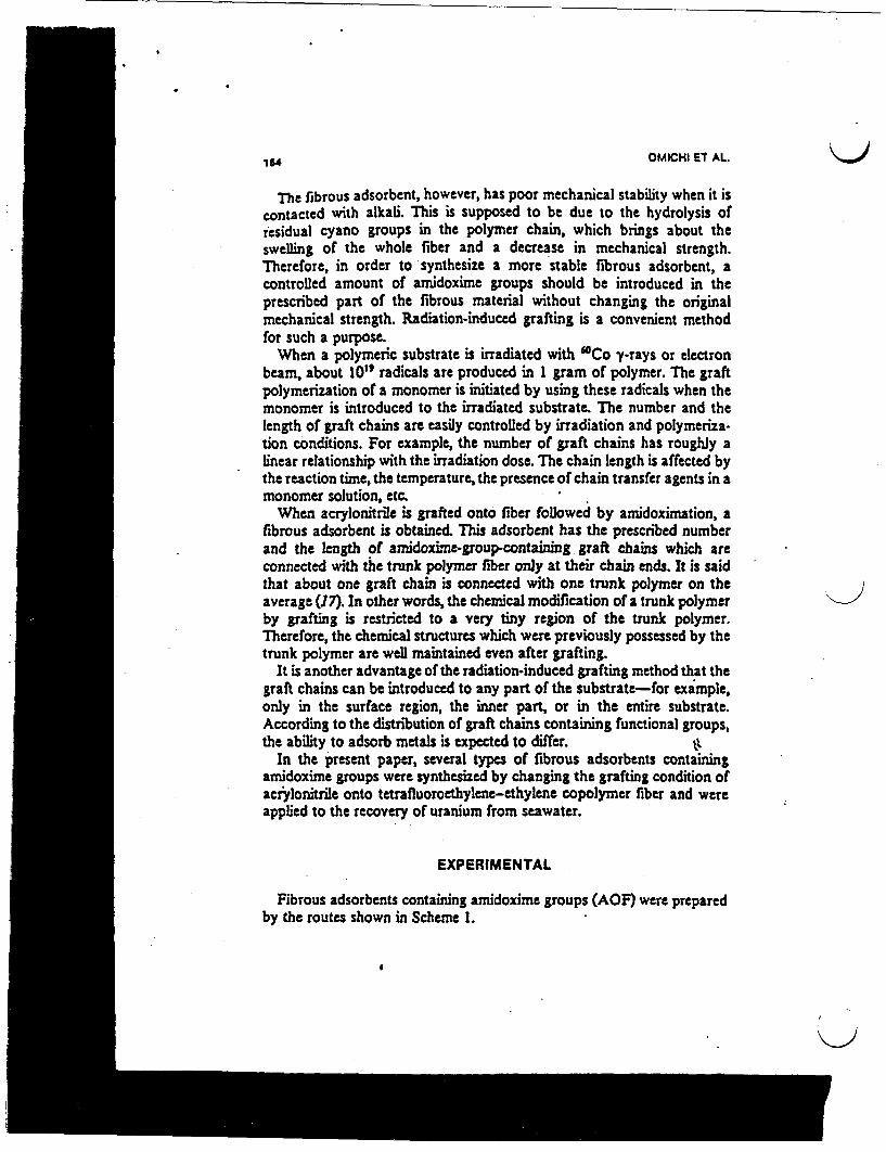
164 OMICHI ET AL.
The fibrous adsorbent, however, has poor mechanical stability when it iscontacted with alkali. This is supposed to be due to the hydrolysis ofresidual cyano groups in the polymer chain, which brings about theswelling of the whole fiber and a decrease in mechanical strength.Therefore, in order to synthesize a more stable fibrous adsorbent, acontrolled amount of amidoxime groups should be introduced in theprescribed part of the fibrous material without changing the originalmechanical strength. Radiation-induced grafting is a convenient methodfor such a purpose.
When a polymeric substrate is irradiated with ' 0Co yrays or electronbeam, about 10" radicals are produced in 1 gram of polymer. The graftpolymerization of a monomer is initiated by using these radicals when themonomer is introduced to the irradiated substrate. The number and thelength of graft chains are easily controlled by irradiation and polymeriza-tion conditions. For example, the number of graft chains has roughly alinear relationship with the irradiation dose. The chain length is affected bythe reaction time, the temperature, the presence of chain transfer agents in amonomer solution, etc.
When acrylonitrile is grafted onto fiber followed by aidoximation, afibrous adsorbent is obtained. This adsorbent has the prescribed numberand the length of amidoxime-group-containing graft chains which areconnected with the trunk polymer fiber only at their chain ends. It is saidthat about one graft chain is connected with one trunk polymer on theaverage (17). In other words, the chemical modification of a trunk polymerby grafting is restricted to a very tiny region of the trunk polymer.Therefore, the chemical structures which were previously possessed by thetrunk polymer are well maintained even after grafting.
It is another advantage of the radiation-induced grafting method that thegraft chains can be introduced to any part of the substrate-for example,only in the surface region, the inner part, or in the entire substrate.According to the distribution of graft chains containing functional groups,the ability to adsorb metals is expected to differ. it
In the present paper, several types of fibrous adsorbents containingarnidoxime groups were synthesized by changing the grafting condition ofacrylonitrile onto tetrafluoroethylene-ethylene copolymer fiber and wereapplied to the recovery of uranium from seawater.
EXPERIMENTAL
Fibrous adsorbents containing amidoxime groups (AOF) were preparedby the routes shown in Scheme 1.
4 ~~~'.'
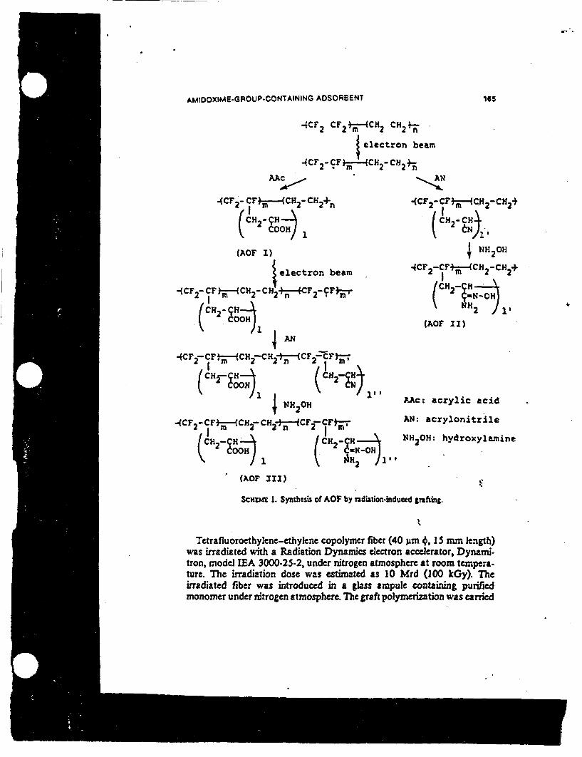
1.
AMIDOXIME.GROUP CONTAINING ADSORBENT
QCF2 CF2 CH2 CH 2 *.
Ielectron beam
-4CF 2 -CF-M CH2 - CH2 +-n
AAc *
US
(CF 2 - CFm --- (CH 2 -CH 2+n
I~~~(H 2°° 1
(AOF I)
electron beam
-(CF -CF t-(Cm2 -CH24F +CF 2 CF -
2 CH2- C )
~AN_
4CFr -c - CH - CH2n-CF2 7 tF
(CH C21CN2 (CH CF
NH2H
-(CF2_CF*j--(CH2- CH 2I-J-CF -CFt)7
/H 2-CH-, CH2-CN
t 2 COOH 1 NN~~92- let
4CF 2 - CF*-(CH 2 CH2+
CH 2- C H)3
; NH 2OH
4CF2 -CF+-4CH 2 -CH2 +
CH2-JH
NH2 1
(AOF 11)
AAc: acrylic acid
AN: acrylonitrile
NH2 OH: hydroxylamine
4
(AOF 11)
ScHtU 1. Synthesis of AOF by Tadition-induced tgrfing.
Tetrafluoroethylene-ethylene copolymer fiber (40 gm 4, IS mm length)was irradiated with a Radiation Dynamics electron accelerator, Dynami-tron, model EA 3000-25-2, under nitrogen atmosphere at room tempera-ture. The irradiation dose was estimated as 10 Mrd (100 kGy). Theirradiated fiber was introduced in a glass ampule containing purifiedmonomer under nitrogen atmosphere. Tbe graft polymerization was carried
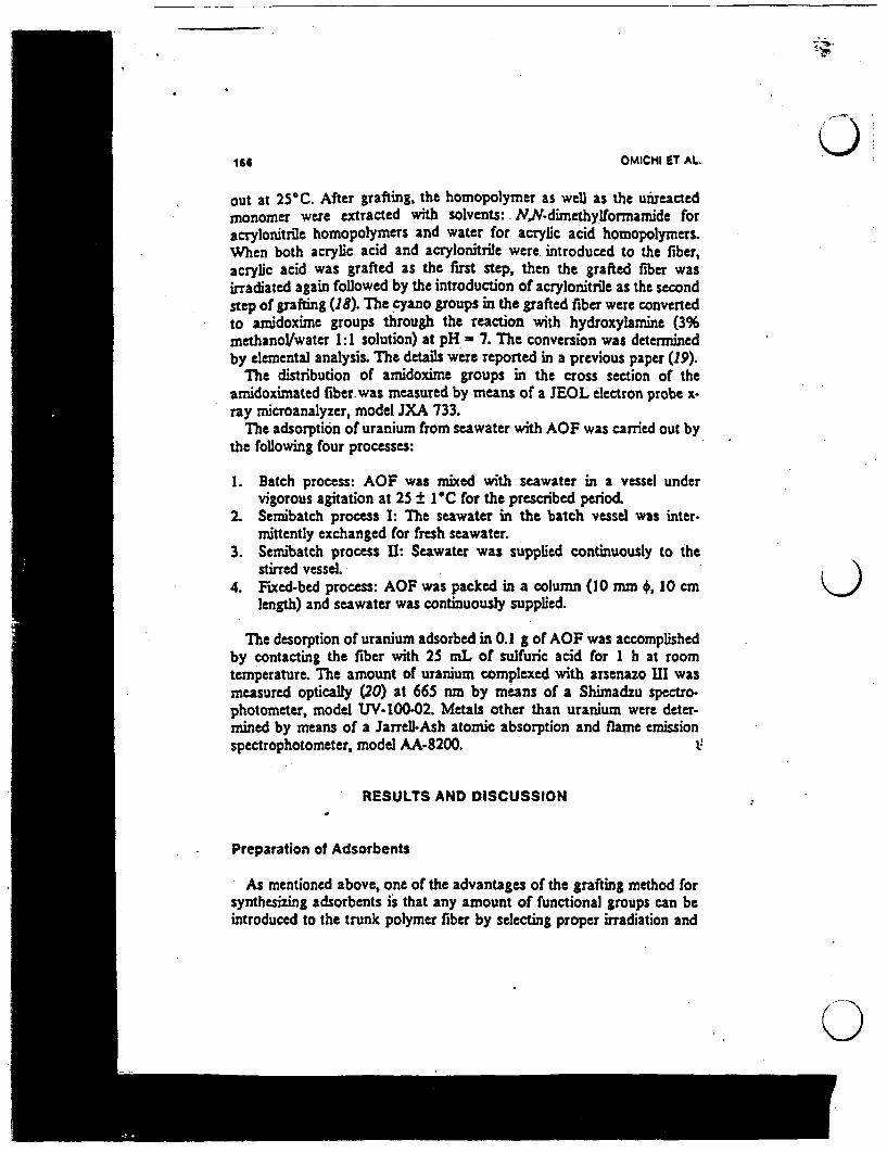
166 OMICHI ST AL.
out at 25 C. After grafting, the homopolymer as well as the u reactedmonomer were extracted with solvents: NN-dimethylformamide foracrylonitrile homopolymers and water for acrylic acid homopolymers.When both acrylic acid and acrylonitrile were introduced to the fiber,acrylic acid was grafted as the first step, then the grafted fiber wasirradiated again followed by the introduction of acrylonitrile as the secondstep of grafting (18). The cyano groups un the grafted fiber were convertedto amidoxime groups through the reaction with hydroxylamine (3%methanol/water 1:I solution) at pH 7. The conversion was determinedby elemental analysis. The details were reported in a previous paper (19).
The distribution of amidoxime groups in the cross section of theamidoximated fiber. was measured by means of a JEOL electron probe x-ray microanalyzer, model JXA 733.
The adsorption of uranium from seawater with AOF was carried out bythe following four processes:
1. Batch process: AOF was mixed with seawater in a vessel undervigorous agitation at 25 ± 1@C for the prescribed period.
2. Sernibatch process : The seawater in the batch vessel was inter-mittently exchanged for fresh seawater.
3. Semibatch process II: Seawater was supplied continuously to thestirred vessel.
4. Fixed-bed process: AOF was packed in a column (10 mm +, 10 cm K )length) and seawater was continuously supplied.
The desorption of uranium adsorbed in 0.1 g of AOF was accomplishedby contacting the fiber with 25 mL of sulfuric acid for I h at roomtemperature. The amount of uranium complexed with arsenazo HII wasmeasured optically (20) at 665 nm by means of a Shimadzu spectro-photometer, model UV-100-02. Metals other than uranium were deter-mined by means of a Jarrell-Ash atomic absorption and flame emissionspectrophotometer, model AA-8200.
RESULTS AND DISCUSSION
Preparation of Adsorbents
As mentioned above, one of the advantages of the grafting method forsynthesizing adsorbents is that any amount of functional groups can beintroduced to the trunk polymer fiber by selecting proper irradiation and
0
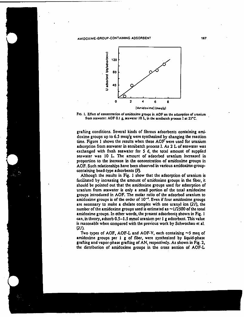
AMIDOXIME-GROUP-CONTAINING ADSORBENT 167
120
so ~ oo
40
0 2 4 6 8
(Amidoxime) (meqg)
FiG. 1. Effect of concentraion of amidoxime groups in AOF on the adsorption of uraniumfrom seawater: AOF 0.1 A, seawater 10 L, in the senubatch process I at 25C.
grafting conditions. Several kinds of fibrous adsorbents containing ami-doxime groups up to 6.5 meq/g were synthesized by changing the reactiontime. Figure 1 shows the results when these AOI? were used for uraniumadsorption from seawater in semibatch process 1. As 2 L of seawater wasexchanged with fresh seawater for 5 d, the total amount of suppliedseawater was 10 L The amount of adsorbed uranium increased inproportion to the increase in the concentration of amidoxime groups inAOF. Such relationships have been observed in various amidoxime-group-containing bead-type adsorbents (9).
Although the results in Fig. 1 show that the adsorption of uranium isfacilitated by increasing the amount of amidoxime groups in the fiber, itshould be pointed out that the amidoxime groups used for adsorption ofuranium from seawater is only a small portion of the total amidoximegroups introduced in AOF. The molar ratio of the adsorbed uranium toamidoxime groups is of the order of 10'. Even if four amidoxime groupsare necessary to make a chelate complex with one uranyl ion (21), thenumber of the amidoxime groups used is estimated as -1/2500 of the totalamidoxime groups. In other words, the present adsorbentt shown in Fig. Ican, in theory, adsorb 0.5-1.5 mmol uranium per I g adsorbent. This valueis reasonable when compared with the previous work by Schwochau et al.(21).
Two types of AOF, AOF-L and AOF-V, each containing -5 meq ofamidoxime groups per I g of fiber, were synthesized by liquid-phasegrafting and vapor-phase grafting of AN, respectively. As shown in Fig. 2,the distribution of amidoxime groups in the cross section of AOF-L

(9 OMICHI ET AL.161
(a)
-~~ ~ ~ 00 b
FXL 2. Distribution patterns of avidoxzne groups in the cross sweon of (a) AOF-V and (b)AOF.L Do and DI an the outer and inner dlamenter respeae y.
K)observed by means of EPMA is homogeneous. On the other hand, in AOF-V the distribution is heterogeneous-mostly restricted to the layer within10 Am from the surface. Because uranium in seawater is adsorbed in thethin surface layer of the adsorbent (21), only the amidoxime groups existingin the surface layer are supposed to be effective for adsorbing uranium
The concentration of amidoxime groups in the thin surface layer ofAOF-L was compared with that of AOF-V. TIe ratio between the twoamounts is given as
F. /sF2 - (F,/F2) DS) (I)
where F. and F2 are the concentrations of amidoxime groups for AOF-L(5.1 meqJg) and AOF-V (.0 meq/g), respectively, and Do and D, are theouter and inner diameters of cross section, respectively, as shown in Fig. 2.S0 and S are the corresponding areas. By introducing Do = 80 gim,D, - 60 m,F, - 5.1 meq/g, and F2 5.0 mq/g, the ratio was obtained as0.45. This result indicates that the concentration of amidoxime groups in aunit surface layer of AOF-V is twice as large as that of AOF-L According
K)

-
AMIDOXIME-GFOUP-CONTAINING ADSORBENT 169
_ 100C
so,g 60 /
400
0 1 2 3 A
Adsorpiion te Id)
FIc. 3. Adsorption of uranium from usawater with (0) AOF.V and (6) AOF-L i theseirbatch proc 1.
to the results in Fig. 1, therefore, the adsorption of uranium with AOF isexpected to be twice as much as that with AOF-L However, Fig. 3 showsthat the adsorption of uranium with AOF-V is slightly higher than that ihAOF-L This is a rather unexpected result because we observed that theadsorption of copper ions from a buffer solution at pH - 6 with AOF-Vwas about twice as much as that with AOF-L (22). In the case of adsorbinguranium from seawater, the functional groups existing on the surface layerare occupied by various kinds of metal ions other than uranium and arequickly covered with organic substances such as seaweeds. Therefore, thereare fewer residual functional groups which work for adsorbing uraniumcompared with those functional groups existing inside an adsorbent likeAOF-L In the latter case, the surface layer may work as a filter for theseobstacle substances. The result in Fig. 3 indicates that an adsorbent whichis effective in a pure solution is not always effective in seawater. Tertfbfi,the following experiments were carried out with the homogeneous adsor-bent AOF-L
Figure 4(a) shows the amount of uranium adsorbed from 2 L of seawaterwith 0.1 of three types of adsorbents, AOF-I, II, and III, *hich were madeby liquid-phase grafting. The compositions of the adsorbents are shown inTable 1. AOF-I, containing only carboxyl groups, did not adsorb uraniumat all. Referring to the report that poly(acrylic acid) can make a chelatecomplex with uranyl ions under acidic condition (23), the present resultmay be partly due to the insufficient pH value of seawater for chelateformation between carboxyl groups and uranyl ions. At pH - 8,
. 4

C)170 OMICHI ET AL
(a) (bi
.150
1 40
3 30
a 20
M 10
0 2 4
Time (dl
I
6 a l
U
SC40
*2
K)0 5 10 15 20 2S
Timr d)
F:. 4. Amounts of uranium adsorbed in (a) the batch process with (*) AOFI, (0) AOF-II,and (0) AOF.III, and in (b) the semnbatch process I with (0) AOF-.I and (0) AOFI.I.
TABLE IComposition of Adsorbents AOF
Concentration of functional groups (mmoV/)
Adsorbent Carboxyl Aidoxime
AOF-I 5.2 0AOF11 0 5.1AOF-UI 1.9 3.4
0
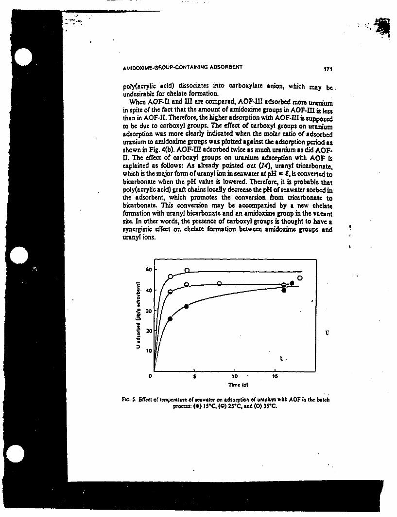
AMIDOXIME-GROUP-CONTAINING ADSORSENT 171
poly(acrylic acid) dissociates into carboxylate anion, which may beundesirable for chelate formation.
When AOF-U and III are compared, AOF-UI adsorbed more uraniumin spite of the fact that the amount of amidoxime groups in AOF-JII is lessthan in AOF-I. T herefore, the higher adsorption with AOF-ll is supposedto be due to carboxyl groups. The effect of carboxyl groups on uraniumadsorption was more clearly indicated when the molar ratio of adsorbeduranium to amidoxime groups was plotted against the adsorption period asshown in Fig. 4(b). AOF-IU adsorbed twice as much uranium as did AOF.I. The effect of carboxyl groups on uranium adsorption with AOF isexplained as follows: As already pointed out (14), uranyl ticarbonate,which is the major form of uranyl ion in seawater at pH = 8, is converted tobicarbonate when the pH value is lowered. Therefore, it is probable thatpoly(acrylic acid) graft chains locally decrease the pH of seawater sorbed inthe adsorbent, which promotes the conversion from tricarbonate tobicarbonate. This conversion may be accompanied by a new chelateformation with uranyl bicarbonate and an amidoxime group in the vacantsite. In other words, the presence of carboxyl groups is thought to have asynergistic effect on chelate formation between aidoxime groups anduranyl ions.
50~ ~ ~ ~ ~ ~ ~:
.~30
10
0 5 10 15
Time (dl
FIo. S. Effect of temperature of seawaer on adsorption of uranium with AOF in the batchprocss: () 15*C, (0) 2SC, and (0) 35C.
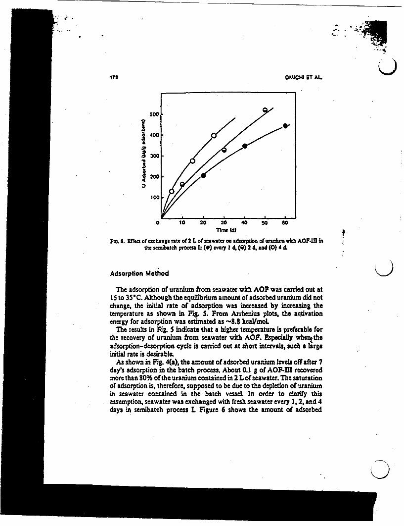
172 OM)CHI ET AL
Soo400
3 00-
1 00
10t 20 30 4 50 60TVn Cd)
FIo. 6. Effect of exchangs rat* of 2 Lof eawateron adsm prtiof oturanhumwih AOF-J inthe senhtch process 1: (0) every 1 4, () 2 d, a (0) 4 d.
Adsorption Method )The adsorption of uranium from seawater with AOF was carried out at
15 to 35C. Although the equilibrium amount of adsorbed uranium did notchange, the initial rate of adsorption was increased by increasing thetemperature as shown in Fig. 5. From Arrhenius plots, the activationenergy for adsorption was estimated as -8.8 kcal/moL
The results in Fig. indicate that a higher temperature is preferable forthe recovery of uranium from seawater with AOF. Especially whcnthesdsorption-desorption cycle is carried out at short intervals, such a largeinitial rate is desirable.
As shown in Fig. 4(a), the amount of adsorbed uranium levels off after 7day's adsorption in the batch process. About 0.1 g of AOF-III recoveredmore than 80% of the uranium contained in 2 L of seawater. The saturationor adsorption is, therefore, supposed to be due to the depletion of uraniumin seawater contained in the batch vessel. In order to clarify thisassumption, seawater was exchanged with fresh seawater every 1, 2, and 4days in semibatch process L Figure 6 shows the amount of adsorbed
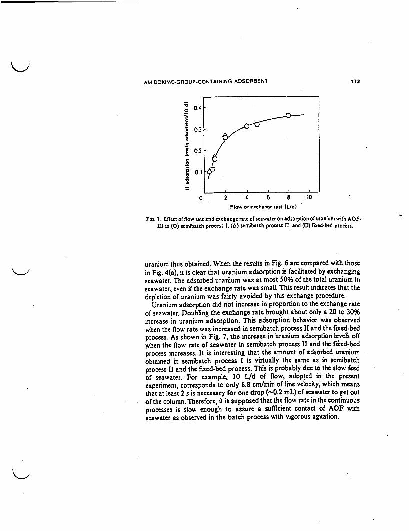
AMIDOXIME-GROUP.CONTAINING ADSORBENT 17t3
0.4 0
.0o 0.3
02 /. .
e0.1
0 2 L 6 8 10Flow or exchange rate (Lid)
FIG. 7. Effect of flow rate and exchange ate of seawater on adsorption of uranium with AOF.III in (0) seinbatch process 1, (a) semibatch process 11, and (0) rixed-bed process.
uranium thus obtained. When the results in Fig. 6 are compared with thosein Fig. 4(a), it is clear that uranium adsorption is facilitated by exchangingseawater. The adsorbed urarfium was at most 50% of the total uranium inseawater, even if the exchange rate was small. This result indicates that thedepletion of uranium was fairly avoided by this exchange procedure.
Uranium adsorption did not increase in proportion to the exchange rateof seawater. Doubling the exchange rate brought about only a 20 to 30%increase in uranium adsorption. This adsorption behavior was observedwhen the flow rate was increased in semibatch process II and the fixed-bedprocess. As shown in Fig. 7, the increase in uranium adsorption leves offwhen the flow rate of seawater in semibatch process II and the fiiced-bedprocess increases. It is interesting that the amount of adsorbed uraniumobtained in sernibatch process I is virtually the same as in semibatchprocess II and the fixed-bed process. This is probably due to the slow feedof seawater. For example, 10 L/d of flow, adopted in the presentexperiment, corresponds to only 8.8 cm/min of line velocity, which meansthat at least 2 s is necessary for one drop (-0.2 mL) of seawater to get outof the column. Therefore, it is supposed that the flow rate in the continuousprocesses is slow enough to assure a sufficient contact of AOF withseawater as observed in the batch process with vigorous agitation.

174 OMICHI ET AL.
As)
a-UU
R'
1C
0
I.a'
0 10 20 30 40 50Amount of seawater IL)
Ib)
i
0-e
E.5t
I
i
0'a
U
U
*0
.5U
0
oU
10 20 30 4O
Amount of seawater IL)
FIG. S. Amounts of (a) alkali metals ((a) Na and (d) K) and (b) alkaline earth metals ((0) Mgand () Ca) adsorbed in AOF-II1 at different periods.
Characteristics of AOF
It has been reported that alkaline earth metals disturb the recovery ofuranium from seawater (24). The smaller uptake of these metals is desirableas adsorbents for uranium. Although alkali metal ions and alkaline earthmetal ions were reported to have small affinity for amidoxime groups (10),
'K
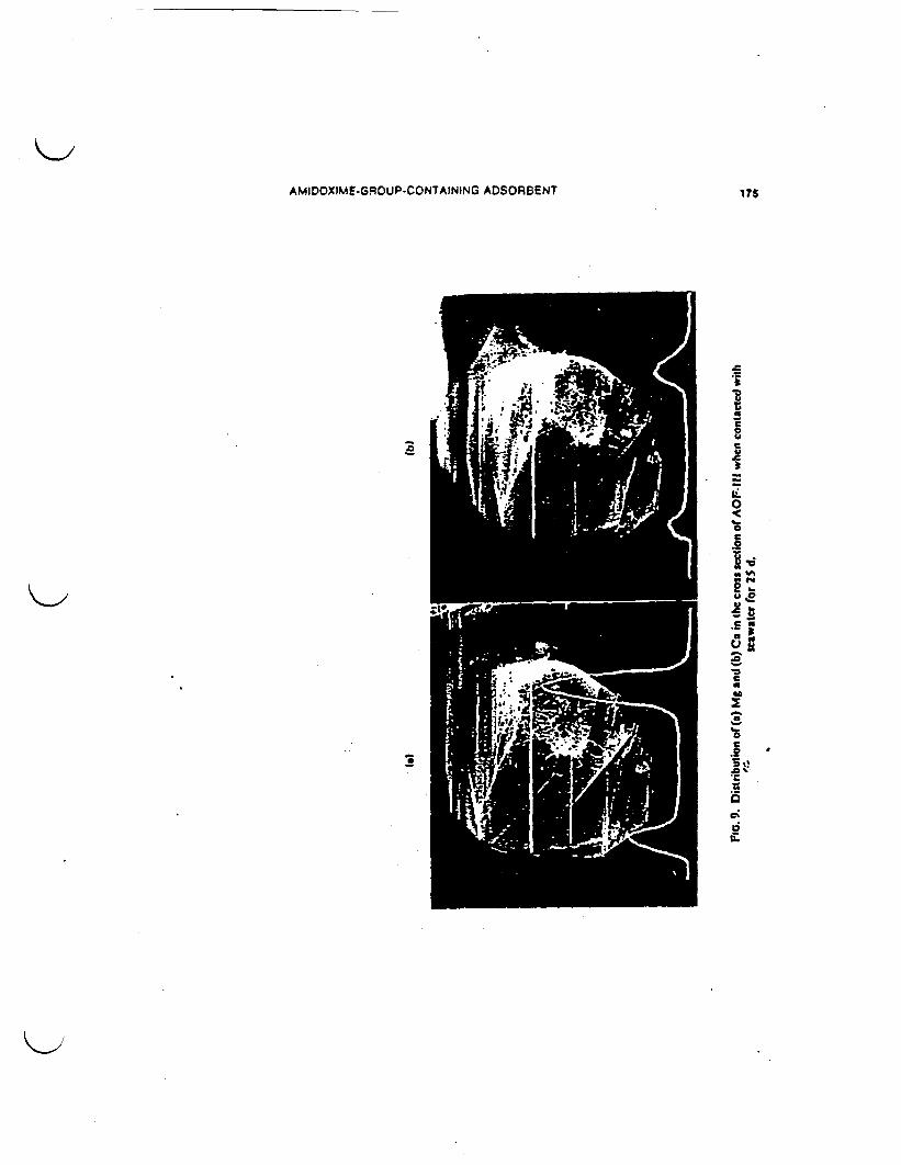
AMIDOXIME.GROUP.CONTAINING ADSORBENT 175
IE
0
L6
am i~~~~~~~~~~D
Y w~~~~-
, WREN~~~~~C
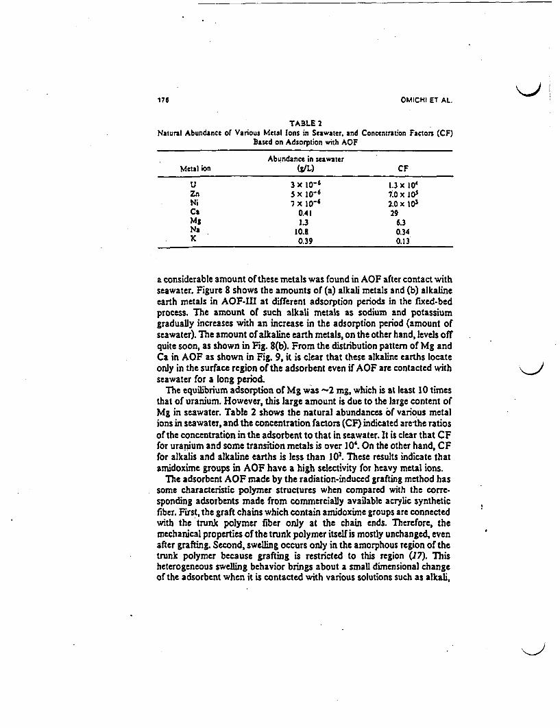
1?6 OMICHI ET AL.
TABLE 2Natural Abundance of Various Metal Ions in Seawater, and Concentration Factors (CF)
Based on Adsorption with AOF
Abundance in seawaterMetal ion WL) CF
U 3x 10⁻⁶ 1.3x 10'Zn sx1o6 7'Ox1SNi 7X 10⁻⁶ 2.0x 10³
Ca 0.41 29Mg 1.3 6.3Na 10.8 0.34K 0.39 0.13
a considerable amount of these metals was found in AOF after contact withseawater. Figure 8 shows the amounts of (a) alkali metals and (b) alkalineearth metals in AOF-III at different adsorption periods in the fixed-bedprocess. The amount of such alkali metals as sodium and potassiumgradually increases with an increase in the adsorption period (amount ofseawater). The amount of alkaline earth metals, on the other hand, levels offquite soon, as shown in Fig. 8(b). From the distribution pattern of Mg andCa in AOF as shown in Fig. 9, it is clear that these alkaline earths locateonly in the surface region of the adsorbent even if AOF are contacted withseawater for a long period.
The equilibrium adsorption of Mg was -2 mg, which is at least 10 timesthat of uranium. However, this large amount is due to the large content ofMg in seawater. Table 2 shows the natural abundances of various metalions in seawater, and the concentration factors (CF) indicated are-the ratiosof the concentration in the adsorbent to that in seawater. It is clear that CFfor uranium and some transition metals is over 10'. On the other hand, CFfor alkalis and alkaline earths is less than 102. These results indicate thatamidoxime groups in AOF have a high selectivity for heavy metal ions.
The adsorbent AOF made by the radiation-induced grafting method hassome characteristic polymer structures when compared with the coffe-sponding adsorbents made from commercially available acrylic syntheticfiber. First, the graft chains which contain amidoxime groups are connectedwith the trunk polymer fiber only at the chain ends. Therefore, themechanical properties of the trunk polymer itself is mostly unchanged, evenafter grafting. Second, swelling occurs only in the amorphous region of thetrunk polymer because grafting is restricted to this region (17). Thisheterogeneous swelling behavior brings about a small dimensional changeof the adsorbent when it is contacted with various solutions such as alkali,
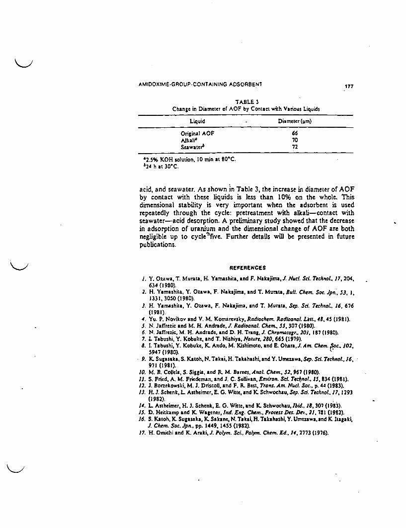
AMIDOXIMEGROUP-CONTAINING ADSORBENT 177
TABLE 3Change in Diameter of AOF by Contact vith Various Liquids
Liquid Diameter (m)
Original AOF 66AIkali' 70Seawatet6 72
'2.S% KOH solution, 10 min at 80'Cb24 h at 30C.
acid, and seawater. As shown in Table 3, the increase in diameter of AOFby contact with these liquids is less than 10% on the whole. Thisdimensional stability is very important when the adsorbent is usedrepeatedly through the cycle: pretreatment with alkali-contact withseawater-acid desorption. A preliminary study showed that the decreasein adsorption of uranium and the dimensional change of AOF are bothnegligible up to cyclec"five. Further details will be presented in futurepublications.
REFERENCES
J. Y. Ozawa, T. Murata, H. Yamashita, and F. Nakajima, . Nuel. Sci Technol. 17, 204.634 (1980).
2. H. Yamashita, Y. Ozawa, F. Nakajima, and T. Murata, Bull. Chem. Soc. Jpn., 53, 1,1331, 3050 (1980).
3. H. Yamashita, Y. Ozawa, F. Nakajima, and T. Murata, Sep. Sc. Technol. 16, 676(1981).
4. Yu. P. Novikov and V. M. Komarevsky, Radiochem. Radioanal. aIl., 48,45 (1981)5. N. Jaffrezic and M. H. Andrade, I. Radioonal. Chem., 55, 307 (1980).6. N. Jafrezic, M. H. Andrade, and D. H. Trang,J. Chromatogr 201, 187 (1980).7. 1 Tabushi, Y. Kobuke, and T. Nishiya, Notur, 280, 665 (1979).8. 1. Tabushi, Y. Kobuke, K. Ando, M. Kishimoto, and E Ohara,J. Am. Chem. isoc.. 102,
5947 (1980).9. K. Sugasaka, S. Katoh, N. Takai, H. Takahashi, and Y. Umezawa, Sep. Sd. Tchnol., 16,
971 (1981).10. M. B. CoUela, S. Sigtia, and R. M. Barnes. Anal Chem.. 52, 967 (1980).11. S. Fried, A. M. Fiedeman, and J. C. Sullivan, Environ. Sd. Technol.. J5. 834 (1981).12. J. Borzekowski, M. J. Driscol, and F. R. Best, Trans. Am. Nuud Soc., p. 44 (1983).13. H. . SchenkL Asthcimer,E. G. Witte, and K Schwochau, Sep. Sci. echnol.. 17, 1293
(1982).1. L Astheimer, H. J. Schenk, E. 0. Wittc, and K Schwochau, Ibid.. 18, 307 (1983).J5. D. Heitkamp and K. Wagener, Ind. Eng. Chem.. Process Des. Dev.. 21, 781 (1982).16. S. Katoh. K. Sugasaka, K. Sakane, N. Takai, H. Takahashi, Y. Umezawa, and K Itagaki,
J. Chem. Soc. Jpn., pp. 1449, 1455 (1982).17. H. Omichi and K. Araki,J. Polym. Sci., Polym. Chem. Ed., 14. 2773 (1976).
178 OMICHI ET AL.
I. H. Omichi and J. Okamoto, Ibid.. 20, 521 (1982).19.. J. Okamoto, T. Sugo, A. Katakai, and H. Onichi, J. ppl. Polym. Sc;., To Be
Published.20. H. Ohnishi and Y. Toyota, Bunseki Kagaku. 14, 1141 (1965) (in Japanese).21. K. Schwochau, L Astheimer, J. YK Schenk, and E G. Witte, Proceedings of the
International Meeting for the Recovery of Uranium from Seawater, Tokyo, 983, p.178.
22. T. Sugo, A. Katakai, H. Ornichi, and J. Okamoto, Unpublished Data.23. H. Nishide, N. Oki, and E. Tsuchida, Eur. Polym. J., 18, 799 (1932).24. YK Sugasaka and A. Katoh, Bull. Soc. Seawater Sd. Jpn., 35, 317 (1982).
Received by editor September 24. 1984
I

TECHNOLOGIES DISCUSSED AT PNC-CHUBU WORKS
- National Analogue Study on TONO Sandstone- Type Uranium Deposit in Japan
BIBLIOGRAPHY OF LITERATURE RECEIVED FROM PNC4CUBU WORKS
-Field Tour Guide for Tono Mine Gallery (Tsukiyoshi Deposit), PNC Chubu Works, 28pages.
'Natural Analogue Study of Tono Sandstone Type Uranium Deposit In Japan,"Written by C. Sato, Y. Ochial and S. Takeda. Waste Management and RawMaterials Division, PNC-Chubu Works, 11 pages.
wNatural Analogue Study of Tono Sandstone Type Uranium Deposit in Japan,"Written by T. Seo, Y. Ochial, S. Takeda and N. Nakatska. PNC-Chubu6 pages.
November 13. 1990
Field Tour Guide
for
Tono Mine GalI ery(Tsukiyoshi Deposit)
S
Chubu Works
Power Reactor and Nuclear Fuel
Development Corporat ion(PNC)
JAPAN

Field Tour
Meeting Room ;
- Brief Overview of R&D Activities of PNC at Chubu Works
- Introduction of Field Tour
Tono mine gallery ; (see next three pages)
- STOP 1 Engineered Barrier Materials Field Tests
- STOP 2.3 Hydrogeochemistry of grounwater
- STOP 4 Geochemistry of Natural U-Th Series tclides
Uranium Mineralization
- STOP 5 Mine-by Experiments on Excavation Responses
- STOP 6 Shaft Excavation Effect Project Site

C ( C
0
*Tsuldyoshl
PNC Facilities
| U-ranium Deposit 1. Tokol Works2. 0 oral Engineering Cent'3. PNC Head Office4. Fugen Nuclear Power SNt5. Tsurugo Office6. Monju Construction Office'7. Chbu Works8. Nlngyo Tone Works 0/
0 2km
Location Map of Test Area in Tono Mine and Adjacent Area

X x x a a a a x x u
Sx~~~t x x K x x b . .3 * . *3 * * x x x
Ri . s., 33X333333X
S.>:@:, 4u. x 3x33 x x
It~~i'l it 33I - 9 a ~33
X- -
. X a
3 a
a X 1
X X I
X X a
X 31X X X
X 1
x X
X X X
Nox
I
V'.a.X_..' .,
N."X X x
R X X~x
'333+4
13X X X
:3*3X3X3-
:3X3X X X3X
:3XX33XX3
:333X 333* X X X
:333X X X X X X
3 3 X3X3X * X X * 13
:333X3X3X X X X333+
sXXX* X X X X X
33 +
- +4
'PA XX XX-_X X XRXTXC
*4 X X* , X. X * +4XX
'I F + * + D+4+_
+ F F+
+ -+ * * +4FwF@+ -
+++++
+ + +
+j +. + z
P*LEOG.NE-C1A EOUS5080M
0
,Ws
ILx >0 ' 0
MIOCENE15-22 Ma
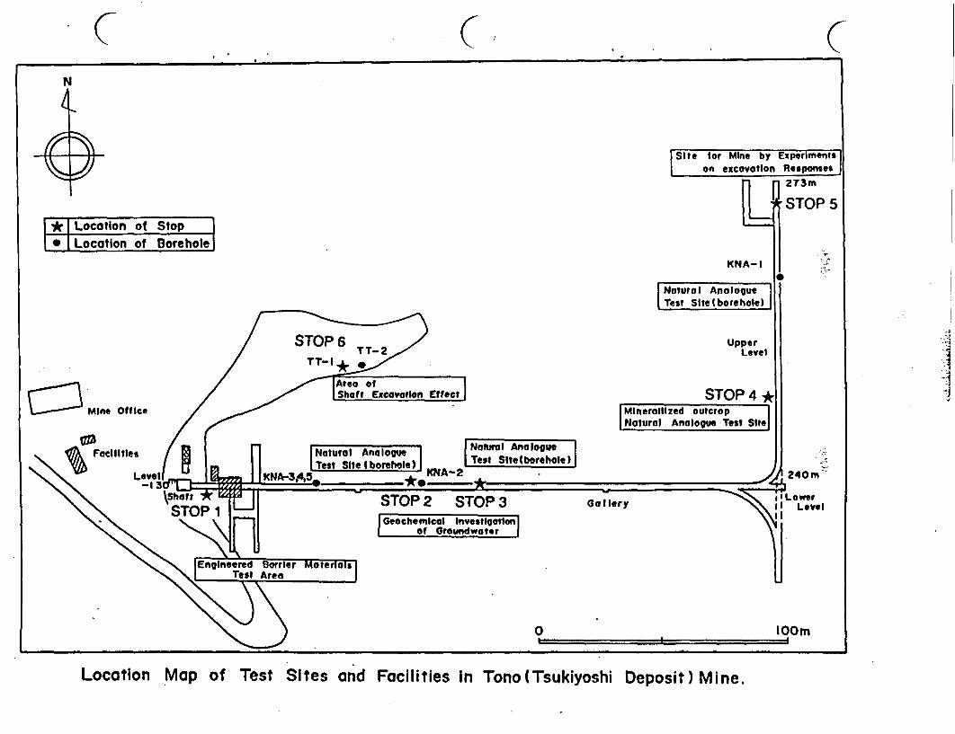
C C (N
Site for Mine by Experimentson excovotion Responses
273m
STOP 5* I Location of Stop* Location of Borehole
.
UpperLevel
STOP 4 j.
! - .
Notural Ana logueTTie Ieehoie
240m
STOP 3 Go I lery
Geochemleal InvestflotlonI of Groundwater I
0 lOOm
Location Map of Test Sites and Facilities in Tono(Tsukiyoshi Deposit) Mine.
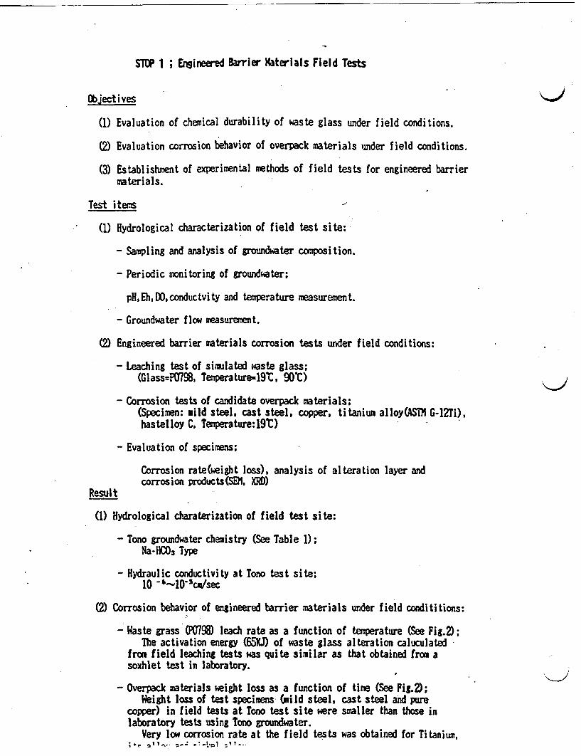
SlUP 1; Engineered Barrier Materials Field Tests
Objectives
(1) Evaluation of chemical durability of waste glass under field conditions.
(2) Evaluation corrosion behavior of overpack materials under field conditions.
(3) Establishment of experimental methods of field tests for engineered barriermaterials.
Test items
(1) Hydrological characterization of field test site:
- Sampling and analysis of groundwater composition.
- Periodic monitoring of groundwater;
pH,Eh,DO,conductvity and temperature measurement.
- Groundwater flow measurement.
(2) Engineered barrier materials corrosion tests under field conditions:
- Leaching test of simulated waste glass;(Glass=P0798, emperature=19t, 90'C)
- Corrosion tests of candidate overpack materials;(Specimen: mild steel, cast steel, copper, titanium alloyCAS G-l2Ti),hastelloy C, Teperature:19t)
- Evaluation of specimens;
Corrosion rate(weight loss), analysis of alteration layer andcorrosion products(SEN, XRD)
Result
(1) Hydrological charaterization of field test site:
- Tono groundwater chemistry (See Table 1);Na-HCO3 Type
- Hydraulic conductivity at Tono test site;10 &1-10-Scnusec
(2) Corrosion behavior of engineered barrier materials under field condititions:
- Waste grass (P0798) leach rate as a function of temperature (See Fig.2);The activation energy (65KJ) of waste glass alteration caluculated
from field leaching tests was quite similar as that obtained from asoxhlet test in laboratory.
- Overpack materials eight loss as a function of time (See Fig.2);Weight loss of test specimens (mild steel, cast steel and pure
copper) in field tests at Tono test site were smaller than those inlaboratory tests using Tono groundwater.
Very low corrosion rate at the field tests was obtained for Ti tanium,
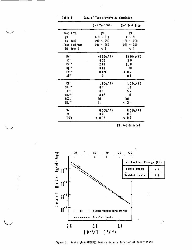
Table I Data of Tono groundwater chemistry
1st Test Site 2nd Test Site
Temp ( C) 19 19pH 8.9-9.1 8-9El (CY) 242 - 296 160 - 260
Cond. (p S/c) 244 - 260 200 - 300DO (pP) < 1 < 1
Pa' 46.8 (g/ ) 65. 0(Stu/ )K- '0.32 3.0Ca'' 2.04 11.0mg 0.04 NDFe'' 20.024 < 0.3All 1.2 0.6
C. 1. 0(mg/) 1.5(/ ISO4. 0.7 1.2F - 8.7 5.4
PO4 - 0.07 NDKC03- 90 140C0,' 11 < 3
Si 6.5(0/1) 6.5(Mg/ )B 0.3 0.3T-Fe < 0.12 < 0.3
ND: Not Detected
-5
N.
.*
4v
100 50 40 20 (C )
I I I I I
11-4
iOl-5S
l0-IC-6
1-7
Act,
. % ~~~~~~~F it'
Soxh'
-O-------- Field tests(Tcno Mine)
-------- Soxhiet tests
Ivatleto Energy KJ)
bId tts 6 5
llet tests 6 3
2.6 3.01 0-/ T ( 'K ')
3.4
Figur ! Waste glass(PQ79). leach rate as a frction of te-.oe-eture

1O
Ar'-a
a'
-aI o --
tCn
4, 1 0 '
1 0 .
Field test Lab.test
SW OMCW SW B/SW
mild steel 0 0 0 U
cast steel 6j A +
102 12 3"T i m e (days)
1218 13SW: GroundwaterB:Brnton te
1 0 -'-
co
-
.A
0'
-
A1
1 0 - -
Field test Lab. tet
W GW B/GW1 0 -aI
pure copperI 0 1 0 1.
.~ - . .
102 11 361T i m e (days)
1218J GW:lroundwaterI a I 11B:8ntoniteW.'
Figure 2 Overpack aterials weight loss as a ranction of time
STIP 2; General Prorase and Work Scope an Katural Analogue Studies
Objectives
(1) Contribution to validation of migration models in natural barrier for
long-term safety assessment.
-To understand geochemical basis related to migration and fixation of
U-series nuclides for long-tern prediction models.
(2) Contribution to the site investigation process.
-To develop the methodology and equipments for the characterization of
suitable geological environment for isolation of radioactive wastes.
(3) Contribution to establishment of public acceptance.
-To support the feasibility of geological isolation of radioactive
wastes in Japanese geological environment.
Work So
The following studies are in progress to investigate fixation-migration
of U-series nuclides.and its relevant geological and geochemical environment.
(1) Migration and retardation studies uranium of series nuclides.
-Uranium series disequilibria in ore zone and around the Tsukiyosi fault.-In-situ distribution coefficients-Matrix diffusion into granite boulders in ore zone.-Transportation to biosphere.
(2) Geochemical study of groundwater.
-Geochemical parameters.-Characterization of natural colloids.-Geochemical modelling of groundwater.
(3) Hydrogeological study at Tono area.
-Hydrogeological parameters.-Modelling of groundwater flow system.
(4) Geological and geochronological study.
-Occurrence of uranium deposits.-Geological history of Tono area.-Mineralogy of host rock.
(5) Migration modelling.
-Data base of above studies._, I :J 12_ _ _t_,v,

Rearks
(1) General and economic geology have been studied i.e. stratigraphy,
geological structure, geological history, ore distribution, ore grade
ore charcteristic, mineralogy of host rock, etc.
(2) There is no evidence of migration of uranium series nucides such as
238U, 23 U and 2" 0Th for a period of at least 1 million years.
(3) 2'Ra has been migrated over a distance of several meters for recent
thousand years.
(4) The chemical and isotopic composition is charcterized in correspondence
with the stratigraphy.
(5) The tritium concentration in groundwater show that shallow groundwater
is directry recharged by rainfall and discharge very quickly and the
deep groundwater is stagnant.
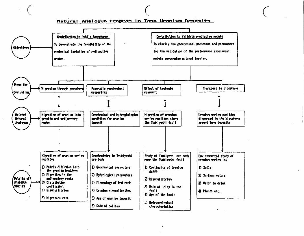
CNatur-al Analgue P-og,-ar In Tono Uraniumur Depemits
CI I
Contribution to Pu l Aeceptance
To dmons trate the fessibi I i ty of the
geological isolation of radioactive
Mstes.
Contribution to Validate predictive models
To clarify the eochemical processes and parameters
for the validation of the performance assessrent
models concerning natural barrier.
I
Ite for\igration tlwougu
EvaluationFavrabe geodelapre a les
I
I
Effect of tectonicmovem!"t
Transport to biosphere
| Trannort to blosphare I
I L IM1igratlon of ranium Into GeodeMI al d hydroglologlalgranite and sedimentary condition for raniumrocks de t
___A , . I_ _
Migration of traniumseries nucil Ides alongthe TsuIyoshl fault
11ranium series nulidesdispersed In the blospherearound Tono deposits
__I__Dtals _
Aniou
Migration of uraIum seriesnuclides
1) Matrix diffusion intothe ranite boulders
2) Migration in theaedimenttary rods
3) Distributioncoefficient
4) Disequilibrium
5) Migration rate
Ceadmiwstry In Tsuklyoshlore body
1) Geochlemical parareters
2) wRdrolosical parameters
3) Mineralogy of bed rock
4) Uranium mineralization
5) Ae of uranium deposit
6) Role of colloid
Study of Tsilyoshil ore bodynear the TsukIyoshi fault
1) Continuity of Uraniumgrade
2) Disequilibrium
3) Role of clay in thefault
4) Age of the fault
5) ilydrogeologicalcharacteristics
E" wiroruintaI study ofuranium series In;
1) Soils
2) Surface waters
3) Water to drink
4) Plants etc.

S S ~~~~NSL. m.
300
5 7 9Aepm pH -1 0.1 1 5 5ppbL--. U I. 1 . I- ,1!0.000 100.000Sp.res. ' I *A .... i ohm cm
5.6166i 0 1.05 21301~ .I I58*300~o
6.61 01<$ ~ \' \ "7/ 14.20<~s~ 8.0o 4.SIOA 015
<~~~~' /6.00" -,
< 4 7.2 9.6 / 0.14
F 2~.380 5.750o
0
6.24 + + +4
Tsukiyoshi Faulthexadiaqtrn asaslei I:Surface atersoJ
SO(hCXsd1A$raus -- rou Kroku-b'ota)21 groundwater, Sto C. (sublevel A condu~t) I o C.-gI3: Jo.. Hizuoaml. C. (sublevel. C.conduit) CO F, q" la do., Toki, C. (ain Itvel Ila. 11 brs hole)col. in Dec. 916-
abbr.1 S:Set* roup H:hLxuna C. (:uppcC Lilovg~r) T:TokL C. (cticoeigloweratessisandstone aid shale caicsaaLy aandstonc) C:Cranlte U:uc~anium deqoaLtFig. Cherisrty of groundwater around TSukiyosi deposit.
C C
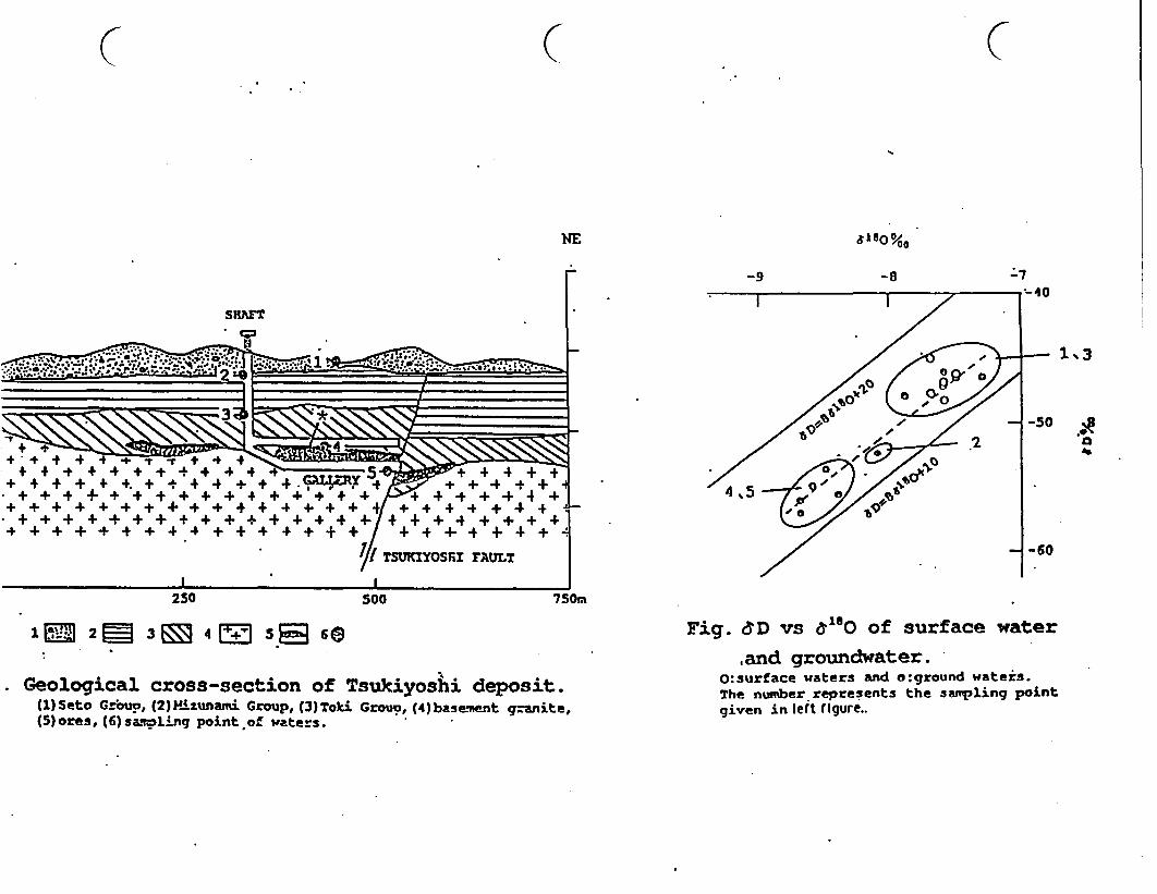
C ( (
NE £180 0/00
-9 -8 *7
.a*41+
+ 4+ + + . + + _ + 4 + +.++ +++++ + + + + + + ++ + + T K4YO4R+A + 4
+++++ +++ +++ + + + + +-/+ + + +++ + +4
71TSUKXYOSfiI FEAUT
250 500 750m
I1M 20 3 4 5 6G
Geological cross-section of Tsukiyoshi deposit.(1)Seto Group, (2) 14izunami Group, (3)Toki Grouo, (4)basement granite,(5)ores, (6) sapl ling point of waters.
Fig. ED vs 180 of surface water
.and groundwater.O:surface waters and o:ground waters.The number represents the sampling pointgiven in left figure..
SlP 4; Geochemistry of Natural U-Th seies uclides
(Disequilibrium of Uranlium series M clides)
Objectives
(1) To estimate the time scale and spacial sacle of migration of U-series
nuclides in sedimentary ore zone and fault zone.
(2) To identify the minerals on which U-series nuclides are fixed.
(3) To understand the geochemical mechanism related to migration and
fixation of U-series nucides for long-term prediction model.
.Works
The measurement of U-series disequilibrium and analysis of associated
minerals are in progress concerninig the following samples.
(1) Three dimensional grid samples in fresh ore zone of gallery.
(2) Two dimensional grid samples in fault zone of gallery.
(3) Drilled core samples in ore body along the direction of groundwater flow.(4) Drilled core samples in the vicinity of fault zone.
Results
(1) Uranium has not been migrated over distances of 1 for at least
recent I million years.(2) 22'Ra has been leached over distances of 1 m for recent thousands
years.(3) Radioactive disequilibrium is observed within a few meters along
fault zone.(4) Uranium is associated with various materials such as zeolite, clay
titanium compound and organic carbon.
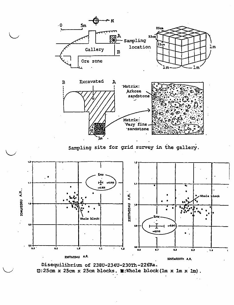
K* 0 SM -r
0MA ~~~25_ /- Sampling
,/ Gallery | location
Ore zone
B Excavated A
Sampling site for grid survey in the gallery.
.C
n
.
4I
c
"S
Ili
23OTh/234U R.226RaJ3OTh AR.
Disequilibrium of 238U-234U-23OTh-226Ra.D:25cm x 25cm x 25cm blocks. 3:Whole block (lm x lm x m).
STnP 5 ; Hine-by Experiments on Excavation Responses
Objectives
(1) Preliminary study on the monitoring system of excavation responses.
(2) Test and evaluation of the instruments and methods which are currently
available for the measurements of rock mass behavior.
(3) Aquisition of the geomechanical and hydraulic data on excavation responses
for the preparation of the further experiments in the actual deep
underground research laboratory.
Works
(1) Pilot boring for the initial investigations.
(2) Laboratory tests on the boring cores.
(3) Geological mapping.
(4) Measurements of the pourwater pressures.
(5) Permeability measurements.
(6) Measurements of the rock mass displacements.
(7) Measurements of the axial stress of rockbolts.
(8) Borehole loading tests.
(9) Seismic tomography.
40 In-situ stress measurements
0) Groundwater level monitoring.
CO Comparison of the actual rock mass displacements with the predicted ones by
the F.E.M.model.
Results
(1) Rock ass displacement was almost terminated when the excavation face
procceeded about 2times of the drift diameter from the measuring point.
(2) In-situ stress was not isotropic.
(3) Permeability measurement was impossible at the zone of 0.5-1.Om from the drift
face after the drift excavation.
(4) Seismic survey suggested the low velocity zone of .8m thickness around the
drift.
(5) F.E.M. simulation result was consistent with the actual measurements assuming
the excavation influeuced zone of 1.Cm thickness around the drift.
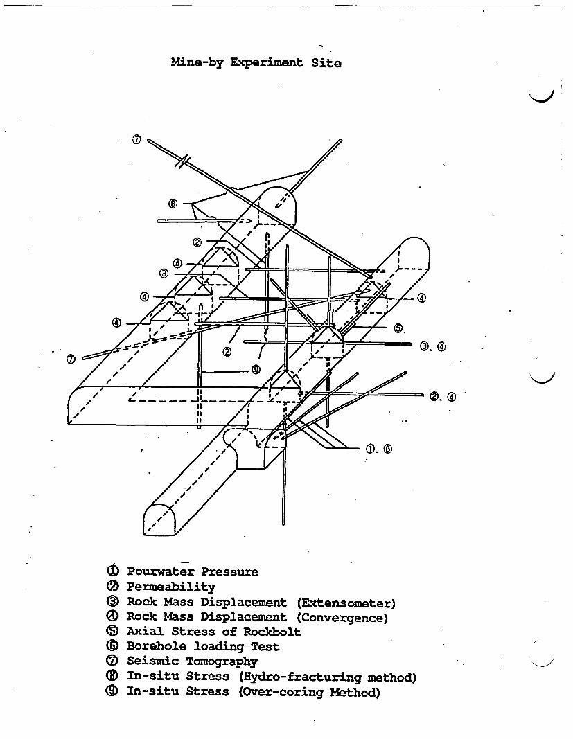
Mine-by Experiment Site
Pourwater PressurePermeabilityRock Mass Displacement (Extensometer)Rock Mass Displacement (Convergence)Axial Stress of RockboltBorehole loading TestSeismic TomographyIn-situ Stress (ydro-fracturing method)In-situ Stress (Over-coring Method)
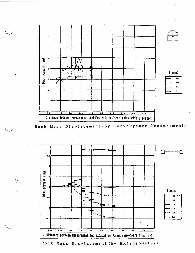
S --- I----
I � t -
-~ I! v F r I_
-in-o.. - -_ . -
Distance Between Keasure~ent andl Excavation Faces (XD:-Drif C Diameter)
* Legend
...- 0t- S i
-. F,
Rock Mass Displacement (by Convergence Measurement)
legend_. ,,,
...- ..- g.e_. ,.
-. Is
I.-0 1.3
- 3
- Distance Between easuresent.and Excavation Faces (xD:=Drift Diameter)
Rock Mass Displacement (by Etensometer)

< ~~~Distamce rom the o i t al ( )
Shiulat(, Value OD
easured Vale 0 °°
(I ) -a FIla I
Of to ck Mai.s LIs pI cei
( ( ( I
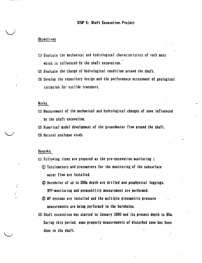
STOP 6; Shaft Excavation Project
Objectives
(1) Evaluate the mechanical and hydrological characteristics of rock mass
which is influenced by the shaft excavation.
(2) Evaluate the change of hydrological condition around the shaft.
(3) Develop the repository design and the performance accessment of geological
isolation for nuclide transport.
Works
(1) Measurement of the mechanical and hydrological changes of zone influenced
by the shaft excavation.
(2) Numerical model development of the groundwater flow around the shaft.
(3) Natural analogue study.
Remarks
(1) Following items are prepared as the pre-excavation monitoring .
0D Tensiometers and piezometers for the monitoring of the subsurface
water flow are installed.
®S Boreholes of up to 200m depth are drilled and geophysical loggings.
BTV-monitoring and permeability measurement are performed.
®O MP systems are installed and the multiple piezometric pressure
measurements are being performed in the boreholes.
(2) Shaft excavation was started in January 1990 and its present depth is 96m.
During this period, some property measurements of disturbed zone has been
done in the shaft.
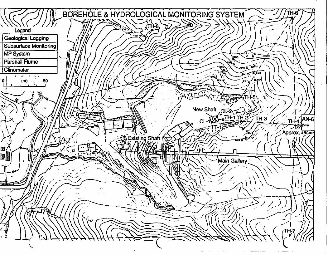
* Jj,~~~~. BOREHOLE & HYDROLOGICAL MNITORING SSE
LegendGeological LoggingSubsurface MonitoringMP System
PasalFlume//7,i-;>4.c-Clinometer ,*7
01 Cm) 50 /ii4&
'.k.:*-.... -(1< (/1 ~~~~~~~~~New Shaft CL2~~~~-.A
I. ,-1 * . ~~~~~~~~~~~~~~~~~~~~ %~~~Approx. 450M-
~~~' / ~~~~~~~~~~Existing Shaft.I
* ~ ~ ~ ~Main Gallery
.... .... ...... ... Kr. . ........... 7t
TH 7/(
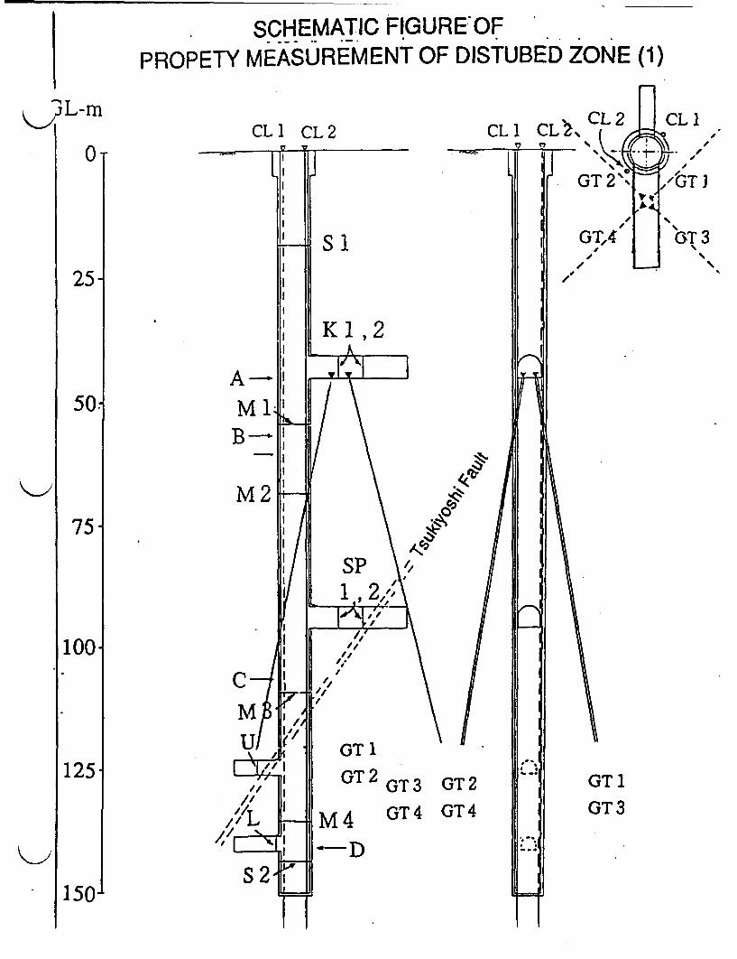
SCHEMATIC FIGUREOFMEASUREMENT OF DISTUBED ZONE (1)PROPETY
CL1 CL2 CL 1 CL~\CL
I.
SI
K 1, 2
A-
B-
M2
C
GT1 .
GT2 GT3 GT2
A GT4 GT4
GT 1
GT3KAlVl
DS2
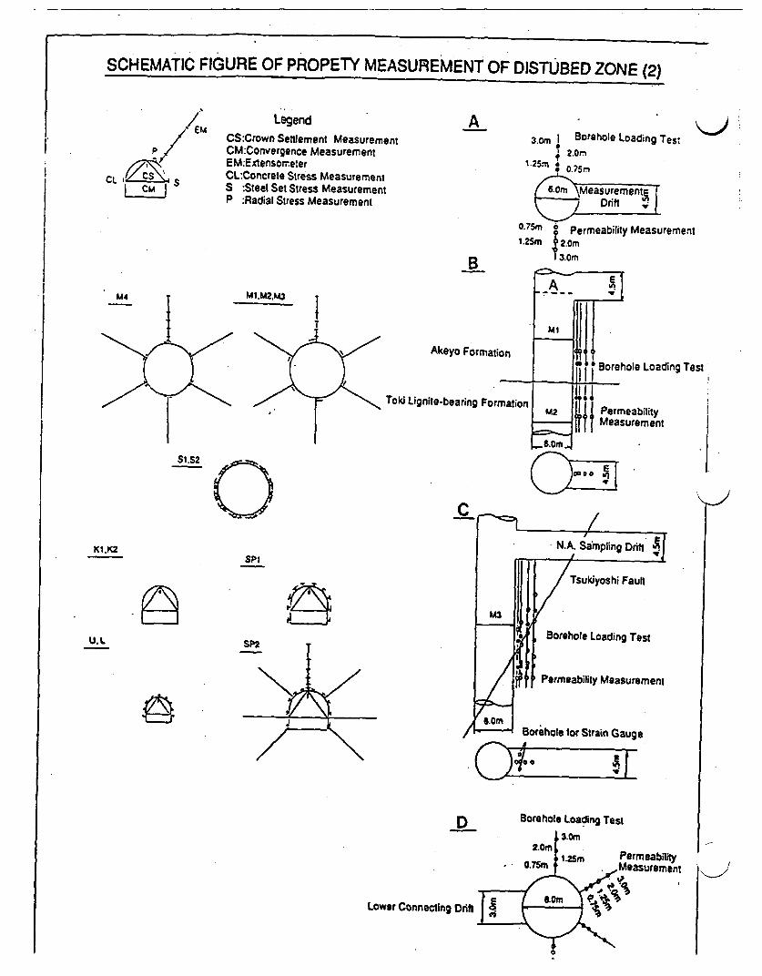
SCHEMATIC FIGURE OF PROPETY MEASUREMENT OF DISTUBED ZONE (2)
/ ' EM
Pg
CL S
LegendCS:Crown Settlement MeasurementCM:Convergence MeasurementEM:ExensonreterCL:Concrete Stress MeasurementS :Steel Set Stress MeasurementP :Radial Stress Measurement
A * )3.0m Borehole Loading Test
2rn
I .O.75m Permeability Measurementt.25m ; 2.Om
13.0mB
A4
SI S2
KI-CKK1 ,K2
M1.M2,M3
Akeyo Formation
Toki Lignite-bearing FormalPermeabMeasurei
Loading Test
lility,ment
SPI
Tsukiyoshi Faun
U.LBorehole Loading Test
SP2
I Permeability Measurement
Borehole or Strain Gauge
o�3D Borehole Loading Test
IJ
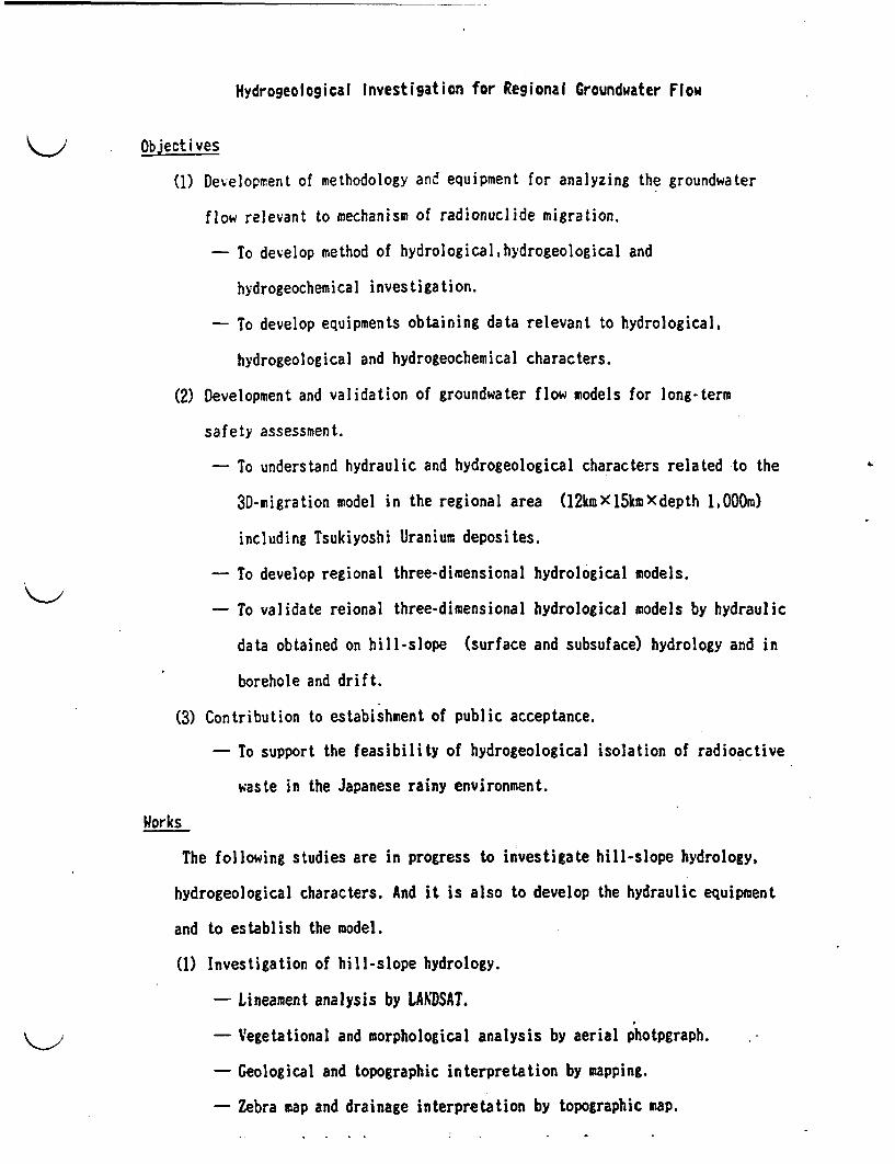
Hydrogeological Investigation for Regional Groundwater Flow
Objectives
(1) Development of methodology and equipment for analyzing the groundwater
flow relevant to mechanism of radionuclide migration.
- To develop method of hydrological,hydrogeological and
hydrogeochemical investigation.
- To develop equipments obtaining data relevant to hydrological,
hydrogeological and hydrogeochemical characters.
(2) Development and validation of groundwater flow models for long-term
safety assessment.
- To understand hydraulic and hydrogeological characters related to the
3D-migration model in the regional area (12kmxx5kmXdepth lOOOm)
including Tsukiyoshi Uranium deposites.
- To develop regional three-dimensional hydrological models.
- To validate reional three-dimensional hydrological models by hydraulic
data obtained on hill-slope (surface and subsuface) hydrology and in
borehole and drift.
(3) Contribution to estabishment of public acceptance.
- To support the feasibility of hydrogeological isolation of radioactive
waste in the Japanese rainy environment.
Works
The following studies are in progress to investigate hill-slope hydrology,
hydrogeological characters. And it is also to develop the hydraulic equipment
and to establish the model.
(1) Investigation of hill-slope hydrology.
- Lineament analysis by LANDSAT.
- Vegetational and morphological analysis by aerial photpgraph.
- Geological and topographic interpretation by mapping.
- Zebra map and drainage interpretation by topographic map.

- Investigation of surface hydraulic characterization of
evapotranspiration, river flow and precipitation.
- easurement of specific discaharge and electric conductivity.
(2) Hydrogeological characters.
2-1 Core logging
- Investigation of fracture characterization(fracture pattern,filling
materials,ROD etc.)
- Measurement of physical properties(effective porosity, density and
hydraulic conductivity etc.)
2-2 borehole hydraulic investigation
- Measurement of hydraulic parameters(hydraulic conductivity, pore
pressure and groundwater flow velocity by tracer test).
- Geophysical logs(sonic log, neutron log, BHTV and RADER etc.).
- Measurement of groundwater physico-chemical parameters(Eh, pH,
electric conductivity and groundwater composition etc.) and ground-
water sampling.
2-3 Hydraulic investigation in drift
- Geological analysis of fracture system.
- Measurement of hydraulic parameters(hydraulic conductivity,pore
pressure and groundwater discharge etc.).
- Evaporation analysis on tunnel wall.
- Geochemical analysis of groundwater composition and filling materials
in fracture.
(3) Development and validation of 3D regional hydrogeological models. It(TAGSAC CORD developed by Dr. WATANABE, SAITAIA UNIVERCITY) V
- Data base of above studies.
- Validation of regional three-dimensional hydrogeological model from
hydraulic data obtaining on hill-slope hydrology, and in borehole and
drift.
- PNC Tracer Test System.
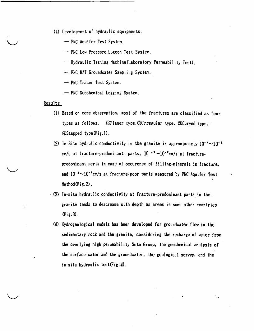
(4) Development of hydraulic equipments.
- PC Aquifer Test System.
- PNC Low Pressure Lugeon Test System.
- Hydraulic Testing achine(Laboratory Permeability Test).
- PNC BAT Groundwater Sampling System.
- PNC Tracer Test System.
- PNC Geochemical Logging System.
Results
(1) Based on core observation, most of the fractures are classified as four
types as follows. ®Planer type,QIrregular type, Curved type,
C4Stepped type(Fig.1).
(2) In-Situ hydrulic conductivity in the granite is approximately 10-4---10-5
cm/s at fracture-predominants parts, 10 7-'10 3'cm/s at fracture-
predominant parts in case of occurence of filling-minerals in fracture,
and 10'8-'10-'cm/s at fracture-poor parts measured by PNC Aquifer Test
Method (Fig. 2).
(3) In-situ hydraulic conductivity at fracture-predominant parts in the
granite tends to descrease with depth as areas in some other countries
(Fig.3).
(4) Hydrogeological models has been developed for groundwater flow in the
sedimentary rock and the granite, considering the recharge of water from
the overlying high permeability Seto Group, the geochemical analysis of
the surface-water and the groundwater, the geological survey, and the
in-situ hydraulic test(Fig.4).
natural Aaloue Study f on Sndstone Typc Uranimu Depoit In Japan
C. Sato, 1. Ochii nd S. TakadaUast. Xsnagement nd Sel aterial Devilion
twat? tsactor and uclar 161 Developent Corporation ( C )
Sandstone type uranium deposit, located In Tono area, central part ofJapan, has been recegnsed potentially useful nalope of geolog-ical isolation of radioactive vstes In Japan. The uranlu depositoccurs as the stratifora which I leo than SO a n depth nd belowthe Vater tble. T studied area Le not far from ihabitant.teliimnary etudy bas been undertaken en migration of atural uraniumseries muclides and a hydrogeochedistry In TSauklyosi era body. Theradioactive doquilibrium study of drill core sbows that the quillb-ri. has been almost kept within the ore body. The bydrogeocbeoicalstudy has revealed that tere are three types of groundvater cleselfi-ad in correspondence with the tratigrtphy ea d laline fluorn-richad groundvter Is confined Intepaletoveathered basement grenteand prmable beds In the ore horln.The. am of this study i to reveal the geological, gochemical and by-drogical conditions which Is favorable to keep uranium series uclidesundisturbed for a crtain period of time an to prove the feasibilityof underground disposal of radioactive vastes i Japan where gologic-al environment Is cowlated and untable.
1. Introduction
Japanese Island arch Is a part of the circem-cific mobile belt andat considered to have geological stability as the area such as recablienshield. Bowever, geological solation of high level radioactive waste basbean recognsed to be bsically feasible In Japan by mas of a cobinstionof engineered end natural barriers. Occurrence of uranium deposit as matur-*1 analogue s thought to support the verification of geological solationsyst.
Vranim deposits Including small bodies lin Japan. east f whch aresandstone-type bosted in Tertiary ystem overlying cretaceous granites.have bn revIewed fre the point of matural analogue. As a result. Toeodeposit wes chosen as the moot favorable one for the following reasons, (1)
It the only wnmemd deposit with minable re grads. 2) t has a lsewhich is roughly equivalent to that of the repository, (3) t is possibleto Snvestigste the Influence of fault and groundwater on uclid migrationend (4) many Information s already availablaz,(),O),I).(4S).
A boundary betveen ozidised and reduced sons which Is comon In roll
462
front type deposit S not observed Is thlu deposit. A reducing eaviromatmay hve bees dominant during and after the deposition. t is particdelrlyimportant In natural analogue study to nvottiato the geological, .goe-Ica1 and hydrogical conditions which to fvorable to keep uranium otsnucildes undisturbed. roduct of this study also make contribution to S-to characterisation as well as to validation of odel for performance asso-snomet.
Preliminary study was carried out on mainly ontlide* distribution andhydropochbaSstry i Tuklyoshi Or bdy of one deposit In order to discu-ss the vaia111ty of natural ana0lou study IS this deposit.
. Ceoloteate Outline
Tano are I located in 350 k southwest of Tokyo. l this area. sedi-entary rocks of iocene age overlie uncomfortably cretaceous granitces(FIS.
1). The remrable structual feature of uranium occurrce Is paleochannelcontrol on the plane of uncoonority. The most favorable sons in the chana-el for uranium mineraliaation So In the lower prt of trtiary fluvial #ad-Simt of TokI Croup which Is composed of arkolsi sandstone, taffaceous san-dston, carbonacous udstone and congloserate. T depth of uraum occur-roce I less than 130 a (1g.2,3).
Sb deposit Is classified nto sandstone type. aoat of uaium is cs-tacteristical1y accompanied with telite, clay minerals, catboaaceout matt-er t l (2). Try small munt of uraninte and coffilto are observed.
Tono uranium deposit consists of four ore bodis naely Isuikyushi,isaneo, tozaka ad JorWi. Tauklyoeti ore body Is roughly 3400 * by 500
is is with thicknes of 1 to 3 . There So a reverse fault i-T- ye-shi ultl-W, 60-700S. with a throw of 35 mVahich cute the re body. Shaftand gallery for exploration have been constructed in the middle part of theore body. Present natural nalogue study is undertaken within Tsuklyothlorc body.
3. Dtrtbution of Ntural Vranium Woelidoa
he preliminary studies was made for ore samples whith were taken fromthe gallery end drill core within the ore body.
3.1 samle and locatioa(i) pes In the gallery
The eamples were collected a the eloration gallery, and their loca-tions are hova in r.3,4. The redistribution of radionuclides after cons-truction of the gllery assumed f samplso(No.i-10) taks from the sur-face of the gallsry. Sample No.1, n the outside of the ore body. Is aradioactive anomaly accompanied with a fragment of carbonized wood.(ii) Drill core samples
Dril core samples were taken from the uranium mineralized one andits nghbours at upstream and midstream Is channel structures of the orebody. The locations of the drill boles. S-2 and i-12. are hos n 1 .3.
3.2 NinralorvThe minaerado of samples n the gallery are shows in tble-I. to
*amples within ote zone mainly consist of quarts, plagioclase. kasliate.amorIlloalto, calcite and heulandite. Low *meunt of Iron odes as ie-
alte are also present. Is a few *samles(No.5,1 7) secondary uranium miner-al as andoreaolte and silpte ro observed which ay have mineralized dueto oxidation aftar onstructlos of the gallery. Sample No.11 contains a
463

large quantity Of sulfate minerals as jarolte and gpeum in addition toMtaorillnits, Uoliaita and carbonized wood. Luterediography and radiol-uWgrapY Glo Urads does eat exist n carbonized wood but n clay minera-1. In this particular sample.
tIcapt for amaU aount of pyrite, the mineral composition of the dri-11 core samples is aiilar to that of the gallery samples No.1-4.
3.3 Eatural Vrdan Serige Docuilibrius(1) Samples fre the gallery
Assay of V-238, 1-234 and Th-230 were carried out by alpha spectromet-ry. Ra-226 and b-20 were mondstructively analysed by hig pure germaniumdetector. n the ama-ray measurement se was kept in seted containerfor three weeks and U-238 was calculated from the 3 hT gems ray of theshort lived daughter h-234.
th results of assay are presented in Table-I together with the urani-ua contents. the relative activities of LF238. U-234 nd h-230 art plottedIn ternary diagram 113.5 (6). According to their radioactive disequilbrivestates, the fllowing geocheical processes which cause redistribution ofuranium series uclides can be ILfered.No.1 1-238. 1-234 and Tb-230 are almost in rdloactive equilibrium. Thismeans that the le Is eldar than at least a million years. o t therhand radium is slightly eached out by reduced groundwater fairly recently.No.2,4,10 U: Uranium, preferentially U-234, ad radiuS Is prtially leach-*d out probably by oxidized roundvttr. lhile lg lived daughter Th-230which is almost imobil s present a excess stte.No.lS,6,7,S,7: Acculotion of uranium occurred fairly reently by ecomda-ry inflow of uranium, La which excess of -234 was contained by alpha reco-1 process.(11) Drill core samples
the -234/1-238 end Th-230/U-234 activity ratios ar shown in ?ig.6.together with ur au content and geologic colum. There are so significantfractionation. between these uclides In the two drill coes frou upstreamand midstream of the chanl structure of Tukiyoshi ore body. ovever, theresults of SN-2 coens suggest partial raniu leaching had occurred justabove unconforolty.
3.4 SIlective Thase SearattonSequential extraction techniques were applied to dentify the phases
of uranu series uclides are. lbs following five fractions were separ-ated a ieanticable pasesi exchangeable, bond to carbonates, bond to rnoxides, bond to organic matter and rsudLal (7). Leschla procedures andreagents are _ mmarlsd n Tabl-Il, and the rsults obtained on samplesfre the gallery are boew n Ig.7. A large portion of uranum so associa-ted with carbonates and ran oxides, even though total of ran and carbona-te s less than 6 percent la weight fr all of the samples.
Complementary measurenents as alpha spectru and X-ray diffraction arenot yet performed on the individual leachates and on the residuals followi-ng each extraction.
4. yrogeocbeuitr
traniua In Toe deposit could be originated from the basement granitesand transported by circulated groundwater through permeable host rock. Theuranium deposit Is assued to be nriched by repetitions of leaching- andfixing cycle between host rock nd groundwater (3). he present ore horizonlles below water table and mostly In aquiclude.
464
The general stratttaphy of Tono area s composed of Toki Crcup, 3USr-maus C., and Ste . I ascending order. Croundvater samplas were eollectedfrom each geological group for hemical analysIs (Tablo-ltl Pg.).)
There is a igniftoast Increase to p, bicarbonate, sodium and fluori-na a correspondence with the tratigraphical dpth. The groundwater inSok5 Croup where uranium a deposited is cliss"Ifi4chet"aelly as -BCO3type. Th bh level of thene ons'seems to be caused by long tore Intaerac-tion between vater and the minerals I bot rock (). Th rults of tritt-u* analysts suggest that the groundwater Is stagnate for oro thae 30 years.Bovevr. the groundwater In To Croup doos't contain hIgher level of ura-nia s contrast t higher bicarbonate content. The uranium Concentratiosis almost as Sam s that of surface wter.
These results suggest that the groundwater In ore borizos t stagnatefor a l time and the bydrogeocheical nvironment Is reducing.
5. Conclusions and Future Studie
The results of preliminary study r sumarized as follow,:
(1) A quite minor dsequilibrus of uranium series ouclde Is obserd inthe or body.
(2) A large portion of uranium exist in the three fractions of carbonate,Iroan oides and eshangeablos.
(3) Three types of groundwater is Identifted IS correspondence with the at-ratlgrapyb of Tona ar".
M) She groundwater of rt zoO is characterized by hIgh content of bcarb-
onats sodium and fluorine on against the low content of uranium and
tritium oo.These results ruggest that this natural analogue tudy available to
reveal the favorable anironot for the repository and to demonstrate thefasibility of the pologtal Isolation as well as to understand the ocU-des migratio by groundwater.
Therefore, the future studies should nclude the following subjects tocontribut t assessment of radioSctive waste repository sites:
(t) Dtaled study on suclides distributioe within and around the re body.(2) Dtailed geological and mineralogical study ith ehsis o uraum
occurre=e.(3) InVestigation on colloid formation and transport.
(4) ftrtber study oa hdrogeology ad hydrogeocheeistry including develope-.oat of is-situ measurement technique.
(5) Validatios of developed model for uclide migration.
Te authers vis% to thank Prof. Dr. . kanishi of Kanazava UDearsi-ty and Dr. . arace and Dr. . Tanaka" of Pvez Reactor and Wclear Fuel
Development Corporation for valuable sugpstioS.
References
(1) Sakamue,. a t aI. Ceochem. Jour. 2 (196) 1-8(2) IstayawU., irono,!. and lironeS., LUA-SH-183111, (1974) 437-452(3) Dti., BironeS. and Saksaaki,., tcon. aol. 70.(), (1975) 628446(4) Sakazki,?. IAL-TUDOC-328. (1985) 135-154(5) Talgiewla,., S. Papers Cll.aculty of Sciencejanazava Uv.(1923)(6) RosohltJ.l., Uranium Series Disequilibrlum plications to. Environ-
utah Problem, Claredon Press, Oxford. (1987) 167-180(7) TlssiarA. t a, Anal. Cem. 51,(7),(W79844-350
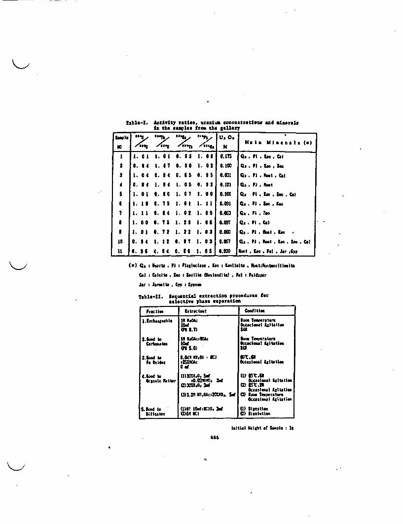
Tabla-I. Activity ratto., uaranium coucatratiow and inat.In the .. ml.. from the gaflery____________
X S l~eS fGOt 341
110 <||g =,g /qaW o<"b N Ug a I I a I a ()
1 1.01 1.1 6l0.15 1.03 OS 0.5 Qa..E oCal
2 .14 1. 67IO. 30 1. 02 0.1O Q.pi.to.Zee
2 1. 0 . 0 . 0 e. .031 Qa.F pi. t.Cal
4 0. 1 . 34 1. Os 0. 32 0.121 Q.pnF t
5 1. 01 0. 3 1. 0 7 I. 00 0.166 Q, tl.IoZ.Cal
6 1.1I 0. 1.1 1. 11 0.091 Qs .p.i 2. o
7 1. I1 0 . 4 1. 2 I. 05 0.063 Qs .p .0o
I 1. 0 0 ..5 1. 23 1. 03 0.097 QS. Fi ea
I 1. 0 Q. 72 1.22 1. 0 o.eo0 Qs.PI.NMIZs o
10 0. 4 1. 52 . *7 1.03 0.067 Q. n.hIat . o. Ze.C a
11 0. 4 6 4. 4 . 3 6 1. 0 0.200 Fst . .IF .ar .C
(s) Qs : hrts . F : Flealcla, I ao: ollelte h.tz otaorilloeitt
Cal Calcite . Z: bolit leladil) . el Feldspar
Jar Jrolle g Cyp Cypsw
Tble-I. equential extraction Procedures foraelectivs phase separatift
ffecil" Eztractast coilos,
.8chaaesable IN Oc oom Tesperatere.d 0cealest £sl ta|la1f I.7 2U
1ikad to Il ItAktilc loo tperster£arbouto wS0 2Uc le"sI l141tlea
c S) 24
.kw o 6.80 ilDOU * ilCI s ItWaFe his .2ZLlU Occauienal Iglistes.
S d
4.Bow to (1)302lRt SW (11I} t.1Organic at tr 40.02Il, 3d tD oul lles
0=3110 3d I00 21Occasional 4i1tatlec
03.2 l.oWc2MXn ,. Sd 3) Iooc TeperaureOccaslmosl 41t tiae
Sond to (I)IF IlOC10. 3d () igestleaSilIcates (2)6" lI C Disoltlen
laitisl veigbt of Smple It
466
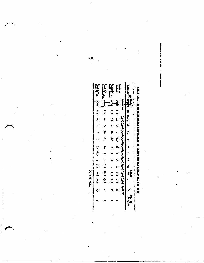
£91~~~5
w d *
p . -1Po so o i
%a P4 p. I
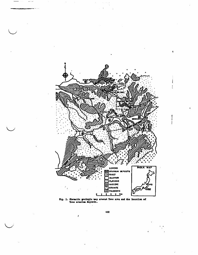
K>
* *
*
* I
* * * * * 1
. I q I . s6 I {-
fig. 1. theatlc ologic rap aruand toi an& and the location ofTana uraiuo deposit.
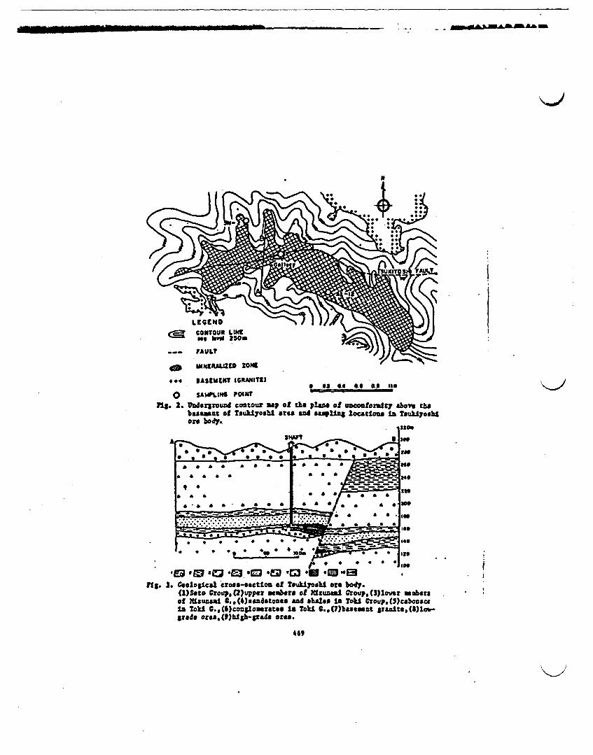
- - -
MINXIMAzE ZONK#* BASIUCUT IGRAM4ITI
II 0~~~~~ II OS £$ G. Iatso SAWLING POINTPS. 2. loderground contou say Of the plane of uncootoralty aov thebament of Tsuhiyashi at"s and sampling locatlaoa In Twuklyoshlore body.
lassoAl
a 'a 4 0 a aw L - - - |
* & A a a a a & a a a
a a
a aa * = & a a a a
a la a
* a a a a a a a
* * * a a 0 *& 0
we
too
lee
240
In.we
I"z
†.* -= m : .* .* ..
.w-- W: ,-
tlSeo SO M -0otoo -E Z o .J1. . Geological irs-oto fTOUklYOUb orebo.U)eo rovp,W2uppev ammbre of idu"AUS Oroup.(M)over nbersof Nlsuneal C.M(4andstones and *WOs I TOll Crotip.M3cabonscela Tokl .,C6)conglouera~ea a Tokl G.,(7)baseamut Srszltm,(8)loh-
grade ora, (1)Uhi-prade ores.
I
i
II
459

_______________________________________________________ _____ - m~ u
a
V lTrr
P.
* : wem": a fw w teae
U:
C:0 s ae " l
ad fm all wy *f ukiyosblrig. . locatiou of the a1ls cliector body.
I
Inu fOe
JoS. S. Terary dram of relatie activites of V-23S.9-234 andTh-230 for the aples fre the lry.
"0
i
iIiIIi7i
I

SN - 2 (UPs&onm of ChOiW)tob top-"
A 1-12 (Midsm of Chonl)uso(3
S.,
£.4
8.
E
. .0 0
. .0*
..
.._..I.0.0
.0.. .::::
_,;
:* **
Catu
-
a
l
i ~. <,saLd~
I I__°^e~~s act ..
F-_ . . . . . .
CatW I _
oIS *-_- mqB _-~ V a_
ts. . VeaLatl um At deph of esI ty eaos Ia "&aal W-8eggtsmfor el11 eam e 1m" t sm vsa &M ""m of Ut *U yILere body.
C
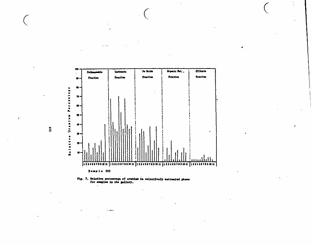
btWIt | Fe Came Oge.IClt.. Sloe
* XFmcI* ;m1_ea Focal_ F11_
Sample NO
Fla. . Reative Peento wrtu In lecetly ewtatead rhofor som1a is the sbarn.
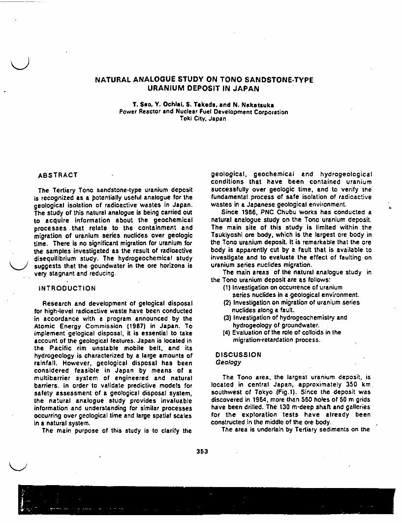
NATURAL ANALOGUE STUDY ON TONO SANDSTONE-TYPEURANIUM DEPOSIT IN JAPAN
T. Seao. Y. Ochial, S. Takeda, and N. NakatsukaPower Reactor and Nuclear Fuel Development Corporation
Toki City, Japan
ABSTRACT
The Tertiary Tono sandstone-type uranium depositis recognized as a potentially useful analogue for thegeological isolation of radioactive wastes in Japan.The study of this natural analogue is being carried outto acquire information about the geochemicalprocesses that relate to the containment andmigration of uranium series nuclides over geologictime. There is no significant migration for uranium forthe samples investigated as the result of radioactivedisequilibrium study. The hydrogeochemical studysuggests that the goundwater in the ore horizons isvery stagnant and reducing.
INTRODUCTION
Research and development of gelogical disposalfor high-level radioactive waste have been conductedin accordance with a program announced by theAtomic Energy Commission (1987) in Japan. Toimplement gelogical disposal, it is essential to takeaccount of the geological features. Japan is located inthe Pacific rim unstable mobile belt, and itshydrogeology is characterized by a large amounts ofrainfall. However, geological disposal has beenconsidered feasible in Japan by means of amultibarrier system of engineered and naturalbarriers. In order to validate predictive models forsafety assessment of a geological disposal system,the natural analogue study provides invaluableinformation and understanding for similar processesoccurring over geological time and large spatial scalesin a natural system.
The main purpose of this study is to clarify the
geological, geochemical and hydrogeologicalconditions that have been contained uraniumsuccessfully over geologic time, and to verify triefundamental process of safe isolation of radioactivewastes in a Japanese geological environment.
Since 1986, PNC Chubu works has conducted anatural analogue study on the Tono uranium deposit.The main site of this study is limited within theTsukiyoshi ore body, which is the largest ore body inthe Tono uranium deposit. It is remarkable that the orebody is apparently cut by a fault that is available toinvestigate and to evaluate the effect of faulting onuranium series nuclides migration.
The main areas of the natural analogue study inthe Tono uranium deposit are as follows:
(1) Investigation on occurrence of uraniumseries nuclides in a geological environment.
(2) Investigation on migration of uranium series-nuclides along a fault.
(3) Investigation of hydrogeochemistry andhydrogeology of groundwater.
(4) Evaluation of the role of colloids in themigration-retardation process.
D ISCUSSIONGeology
The Tono area, the largest uranium deposit, islocated in central Japan, approximately 350 kmsouthwest of Tokyo Fig.1). Since the deposit wasdiscovered in 1964, more than 560 holes of 50 m gridshave been drilled. The 130 m-deep shaft and galleriesfor the exploration tests have already beenconstructed in the middle of the ore body.
The area is underlain by Tertiary sediments on the
353
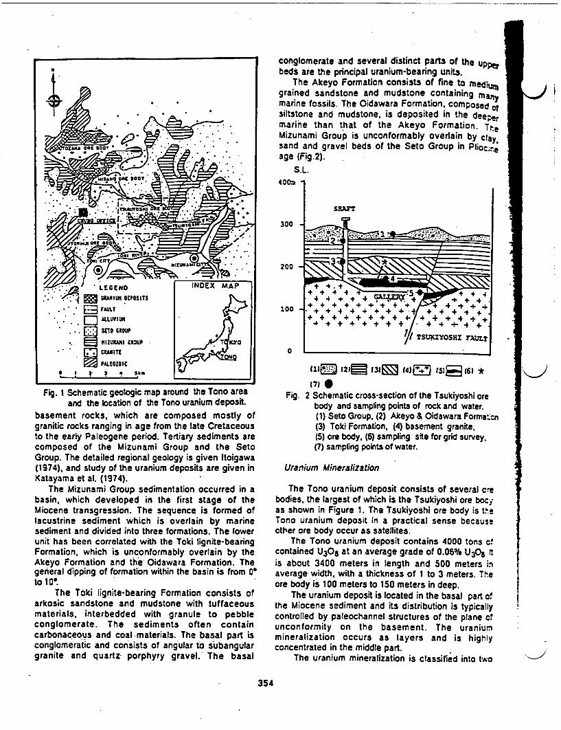
conglomerate and several distinct parts of the upperbeds are the principal uranium-bearing units.
The Akeyo Formation consists of fine to medigrained sandstone and mudstone containing manymarine fossils. The Oidawara Formation, composed ofsiltstone and mudstone, is deposited in the deepermarine than that of the Akeyo Formation. TteMizunami Group is unconformably overlain by ca.sand and gravel beds of the Seto Group in Pliocteeage (Fig.2).
S.L.400rn
Sor"
300
200
44 +4+ 4 4 F+I a 100 - '++ +_P++++ + + + at +4+| ++
+4+ ++ + + + + + + + 4+ + 4 ++
TSUYOSHI FAuLT
0
(1E3 12Ql 131l0 4JLz 153 63 *
(71 0Fig. 2 Schematic cross-section of the Tsukiyoshi ore
body and sampling points of rock and water.(1) Seto Group, (2) Akeyo & Oidawara Format=,(3) Toki Formation, (4) basement granite,(5) ore body. (6) sampling site for grid survey.(7) sampling points of water.
Uranium Mineralization
The Tono uranium deposit consists of several crebodies, the largest of which is the Tsukiyoshi ore bocyas shown in Figure 1. The Tsukiyoshi ore body is teTono uranium deposit in a practical sense becauseother ore body occur as satellites.
The Tono uranium deposit contains 4000 tons c!contained U30 8 at an average grade of 0.06% U308 ftis about 3400 meters in length and 500 meters inaverage width, with a thickness of 1 to 3 meters. Theore body is 100 meters to 150 meters in deep.
The uranium deposit is located in the basal part cthe Miocene sediment and its distribution is typicallycontrolled by paleochannel structures of the plane c,unconformity on the basement. The uraniummineralization occurs as layers and is highlyconcentrated in the middle part.
The uranium mineralization is classified into two
Fig. I Schematic geologic map around the Tono areaand the location of the Tono uranium deposit.
basement rocks, which are composed mostly ofgranitic rocks ranging in age from the late Cretaceousto the early Paleogene period. Tertiary sediments arecomposed of the Mizunami Group and the SetoGroup. The detailed regional geology is given Itoigawa(1974), and study of the uranium deposits are given inKatayama et al. (1974).
The Mizunami Group sedimentation occurred in abasin, which developed in the first stage of theMiocene transgression. The sequence is formed oflacustrine sediment which is overlain by marinesediment and divided into three formations. The lowerunit has been correlated with the Toki lignite-bearingFormation, which is unconformably overlain by theAkeyo Formation and the Oidawara Formation. Thegeneral dipping of formation within the basin is from 0to 1 o
The Toki lignite-bearing Formation consists ofarkosic sandstone and mudstone with tuffaceousmaterials, interbedded with granule to pebbleconglomerate. The sediments often containcarbonaceous and coal materials. The basal part isconglomeratic and consists of angular to subangulargranite and quartz porphyry gravel. The basal
354
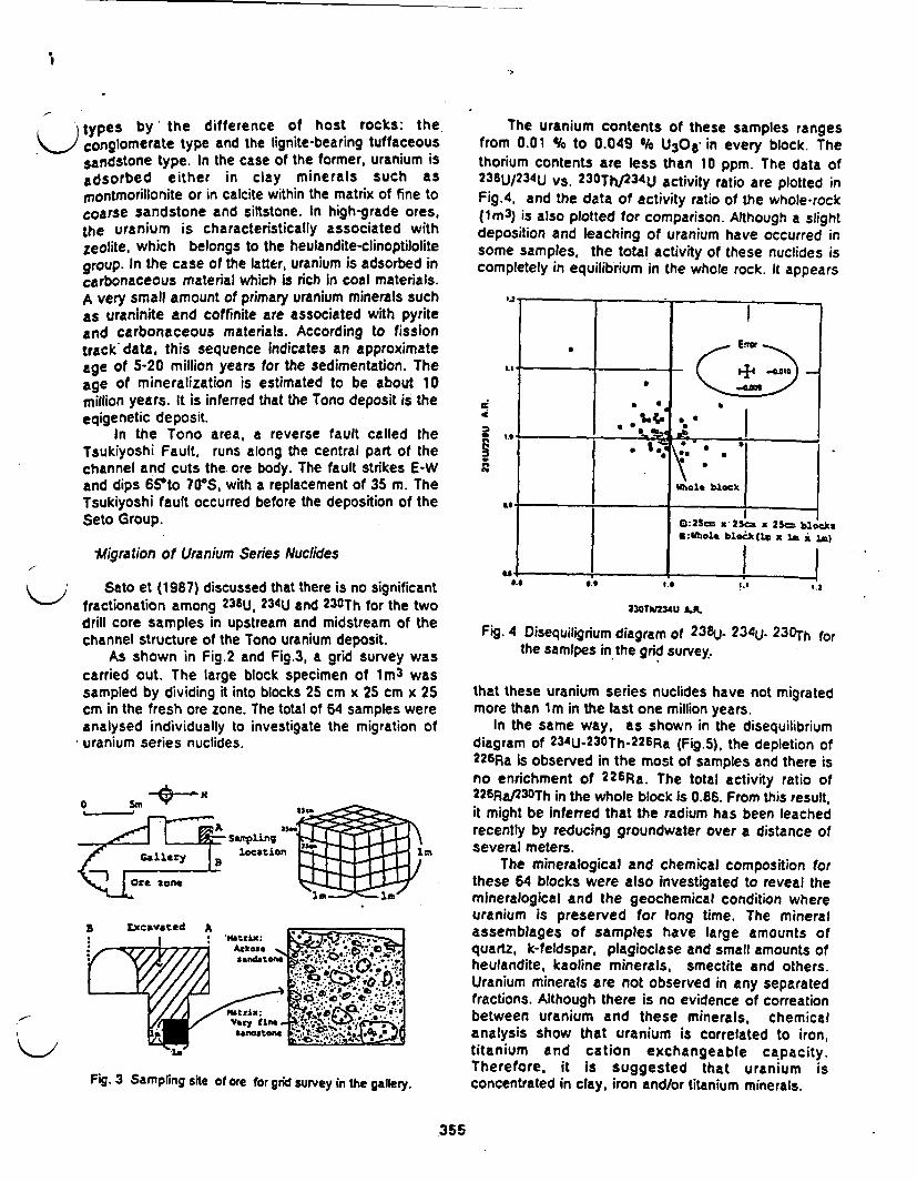
0
types by' the difference of host rocks: the\.,) conglomerate type and the lignite-bearing tuffaceous
sandstone type. In the case of the former, uranium isadsorbed either in clay minerals such asmnontmorillonite or in calcite within the matrix of fine tocoarse sandstone and iltstone. In high-grade ores,the uranium is characteristically associated withzeolite, which belongs to the heulandite-clinoptilolitegroup. In the case of the latter, uranium is adsorbed incarbonaceous material which is rich in coal materials.A very small amount of primary uranium minerals suchas uraninite and coffinite are associated with pyriteand carbonaceous materials. According to fissiontrack data, this sequence indicates an approximateage of 5-20 million years for the sedimentation. Theage of mineralization is estimated to be about 10million years. It is inferred that the Tono deposit is theeqigenetic deposit.
In the Tono area, a reverse fault called theTsukiyoshi Fault, runs along the central part of thechannel and cuts the. ore body. The fault strikes E-Wand dips 65*to 70"S, with a replacement of 35 m. TheTsukiyoshi fault occurred before the deposition of theSeto Group.
Migration of Uranium Series Nuclides
Sato et (1987) discussed that there is no significantfractionation among 238U. 234U and 230Th for the twodrill core samples in upstream and midstream of thechannel structure of the Tono uranium deposit.
As shown in Fig.2 and Fig.3, a grid survey wascarried out. The large block specimen of 1m3 wassampled by dividing it into blocks 25 cm x 25 cm x 25cm in the fresh ore zone. The total of 64 samples wereanalysed individually to investigate the migration ofuranium series nuclides.
The uranium contents of these samples rangesfrom 0.01 % to 0.049 % U30 6 in every block. Thethorium contents are less than 10 ppm. The data of238U/234U Vs. 230Th/23 4U activity ratio are plotted inFig.4, and the data of activity ratio of the whole-rock(1m3) is also plotted for comparison. Although a slightdeposition and leaching of uranium have occurred insome samples, the total activity of these nuclides iscompletely in equilibrium in the whole rock. It appears
S(3-
.. !.f G l
It _____- S *~~ __itblock
0:23m x2S 2 blocksG:IWholt blockQ. I I)
230TS234U A.
Fig. 4 Disequiligrium diagram of 238U. 2 34u- 2 30 Th forthe samipes in the grid survey.
that these uranium series nuclides have not migratedmore than 1m in the last one million years.
In the same way, as shown in the disequilibriumdiagram of 234U- 23OTh-22GRa (Fig.5), the depletion of226Ra is observed in the most of samples and there isno enrichment of 22 6Ra. The total activity ratio of226Ra/23OTh in the whole block is 0.86. From this result,it might be inferred that the radium has been leachedrecently by reducing groundwater over a distance ofseveral meters.
The mineralogical and chemical composition forthese 64 blocks were also investigated to reveal themineralogical and the geochemical condition whereuranium is preserved for long time. The mineralassemblages of samples have large amounts ofquartz, k-feldspar, plagioclase and small amounts ofheulandite, kaoline minerals, smectite and others.Uranium minerals are not observed in any separatedfractions. Although there is no evidence of correationbetween uranium and these minerals, chemicalanalysis show that uranium is correlated to iron,titanium and cation exchangeable capacity.Therefore, it is suggested that uranium isconcentrated in clay, iron and/or titanium minerals.
a Sm 0' -i
Fig. 3 Sampling site of ore for grid survey in the gallery.
355

002i2
0O :25m a 2 x 25 blocks.VIWhole block (.a le 'in
I.' I___ < .I ____,h 1JO, block
...~ * -(o a:a.yI'.. -.
ase
:..l
Ero U_ _
and 180 and higher values in pH. bicarbonatesodium, and fluoride.
As shown in Fig.5, D andalSbO values fgroundwater and surface water samples, which areimportant parameters of a groundwater rechargingsystems, tall on the line of 6 - 130 + 13. Thisrelation is in the range of the meteoric origin in thesouthern part of Chubu district of Japan. The a0and 180 values of the groundwaters in the Tokilignite-bearing Formation are lower than those forsurface water and groundwater in the Seto Groupover scale of 10 and 1 per mil respectively.Consequently, although the origin of these naturalwaters is rainfall, the source of groundwater in theToki lignite-bearing Formation is clearly different fromthe present rainfall, which is represented by surfacewaters and groundwaters in the Seto Group.
... ... ... 1.. M.
226R230Th R.
Fig. 5 Disequilibrium diagram of 23 4U- 230Th- 2 26Rafor the samples in the grid survey.
This sampling method seems to be effective forinvestigating three-dimensional radionuclidemigration.
Hydrogeochemistry and Groundwater System
The isotopic and chemical characteristics ofgroundwater and surface water in the area of theTono uranium deposit were investigated. The resultsare summarized in Tablel. In correspondence withthe stratigraphy, there are significant differences inthe hydrogeochemical compositions.
Groundwater in the aquifers of the Toki lignite-bearing Formation, where uranium is deposited, weresampled from boreholes in the gallery. Some of theboreholes are intersectted across the TsukiyoshiFault. These groundwater samples have similarcharacteristics, that is, lower values in 3H, dD
Table 1. Chemical and isotopic composition of watersaround the Tsukiyoshi ore body.
Simple we PI Its ft V 2C0 r th 3t to SIlo
C MS 1 0.3 0.1 10 0.2 - 35 -46 -7.6
2 1,2 I 0.1 0.1 20 0.1 - 35 -46 -1.5
3 7.2 1 0.1I 0.1 0 0.1 - - -52 -6.I
8.6 35 0. a 0.1-1 so -*e00 ( -15 -0.5
* 5.6 26 (0. 0.1-1 64 4 - a -SS -8.6
-9 -8 -7
1 2
J
0ea
Fig. 6 a D vs.a180 of surface and ground watersaround the Tsukiyoshi ore bore body . Thenumber represents the sampling point given inFig. 2.
The groundwater in the Seto Group is directlyrecharged by rainfall and discharged within a veryshort residence time through the loose sand gravelbeds. The groundwater in the aquifer of the MizunamiGroup, except for the Toki lignite-bearing Formation,which is overlain by the Seto Group, is more stagnantand has characteristics intermediate between those ofthe Seto Group and the Toki lignite-bearingFormation.
On the other hand, the groundwater in the Tokilignite-bearing Formation is stagnant for a long time inthe deepest aquifer, and very little recharge of verticalflow occurs along the Tsukiyoshi Fult. Thegroundwater is reducing due to the presence of
\J
356
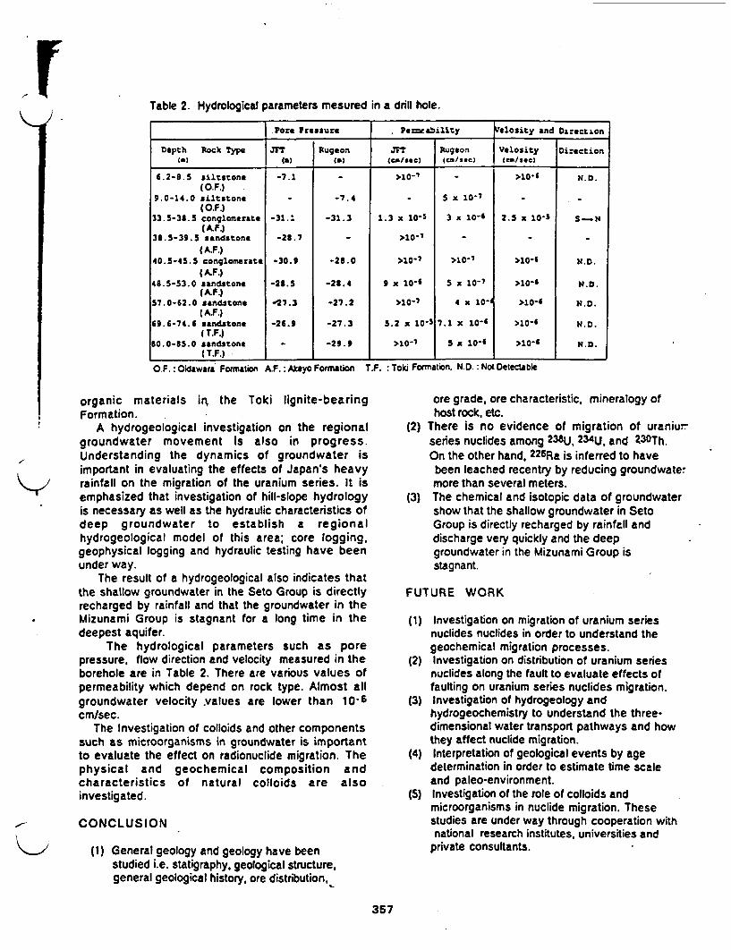
Table 2. Hydrological parameters mesured in a drill hole.
.Pore Pessure PereablXity Velosity and Direction
Depth Rock Type J7 Rugeon JFT Rugeon V*lsity DirectionCm) (a) C() (Ca-/sec) (ca/see) (CM/SeC)
6.2-8.5 siltstone -7.1 - 107 >10-6 N.D(O.F.)
9.0-14.0 siltstone - -7.4 - 5 x 1o (O.F.)
33.5-38.5 conglomerate -31.: -31.3 1.3 x 10-S 3 x 10⁻⁴ 2.5 x 10⁻⁵ 5 N(A.kF.)
38.5-39.5 sandstone -28.7 - >10-7 _- -
(A.F.)40.5-45.5 conglomerate -30.9 -21.0 >107 >1- >10- N.D.
(A.F.)4a.5-53.0 sandstone -28.5 -28.4 9 x 10- 5 x 10⁻⁷ >10- N.D
(A.F)57.0-62.0 sandstone -27.3 -27.2 >10- 4 x 10- >10-6 N.D.
(A.F.)69.6-74.6 sandstone -26.9 -27.3 5.2 x 10⁻⁵ 7.1 X 10 >10- N.D.
( T.F.)80.0-85.0 sandstone - -29.9 >107 5 10-$ >10-6 N.D.
( T.F.) ___ __ S o _ormation __ _ _ _ _Fr i__o__
O.F, Oidawara Formation A.F. Akyo Formation T.F. Toki Formation. N.D.: Not Detectable
organic materials i the Toki lignite-bearingFormation.
A hydrogeological investigation on the regionalgroundwater movement is also in progress.Understanding the dynamics of groundwater isimportant in evaluating the effects of Japan's heavyrainfall on the migration of the uranium series. It isemphasized that investigation of hill-slope hydrologyis necessary as well as the hydraulic characteristics ofdeep groundwater to establish a regionalhydrogeological model of this area; core logging,geophysical logging and hydraulic testing have beenunder way.
The result of a hydrogeological also indicates thatthe shallow groundwater in the Seto Group is directlyrecharged by rainfall and that the groundwater in theMizunami Group is stagnant for a long time in thedeepest aquifer.
The hydrological parameters such as porepressure, flow direction and velocity measured in theborehole are in Table 2. There are various values ofpermeability which depend on rock type. Almost allgroundwater velocity values are lower than 10-6cm/sec.
The Investigation of colloids and other componentssuch as microorganisms in groundwater is importantto evaluate the effect on radionuclide migration. Thephysical and geochemical composition andcharacteristics of natural colloids are alsoinvestigated.
CONCLUSION
(1) General geology and geology have beenstudied i.e. statigraphy, geological structure.general geological history, ore distribution,
ore grade, ore characteristic, mineralogy ofhost rock, etc.
(2) There is no evidence of migration of urani-series nuclides among 238U, 234U, and 30Th.On the other hand, 226Ra is inferred to havebeen leached recentry by reducing groundwatemore than several meters.
(3) The chemical and isotopic data of groundwatershow that the shallow groundwater in SetoGroup is directly recharged by rainfall anddischarge very quickly and the deepgroundwater in the Mizunami Group isstagnant.
FUTURE WORK
(1) Investigation on migration of uranium seriesnuclides nuclides in order to understand thegeochemical migration processes.
(2) Investigation on distribution of uranium seriesnuclides along the fault to evaluate effects offaulting on uranium series nuclides migration.
(3) Investigation of hydrogeology andhydrogeochemistry to understand the three-dimensional water transport pathways and howthey affect nuclide migration.
(4) Interpretation of geological events by agedetermination in order to estimate time scaleand paleo-environment.
(5) Investigation of the role of colloids andmicroorganisms in nuclide migration. Thesestudies are under way through cooperation withnational research institutes, universities and
private consultants.
357

REFERENCES
Atomic Energy Comission, 1987, Long-TermProgram for Development and Utilization of NuclearEnergy, Atomic Energy Ccrnisiion, Japan. p.1-87.
Itoigawa, J. , 1974, Geology and Paleontology ofMizunami City, Bulletins of the Mizunami FosilMuseum, No. 1, p. 3-42, p. 353-386.
Katayama, N., Kubo, K. and Hirono, S., 1974, Genesisof Uranium Deposits of Tono Mine, Japan,Symposium of the Formation of Uranium OreDeposits, Athens. May, 1974, Proc, IAEA-SM-183/11,p.437-452.
Sato, C., Ochiai, Y. and Takeda, S., 1987, NaturalAnalogue Study of Tono Sandstone-Type UraniumDeposit in Japan, Natural Analogue in RadioactiveWaste Disposal, CEC, p.462-4 72.
358
TECHNOLGIES DISCUSSED AT GOVERNMEN INDUSTRIAL RESEARCHINSTITUTE-OSAKA
- Natural Analogues for Leaching Behavior of Nuclear Waste Glass Forms- Vitrification- Improvement of Melter Elements- Characterization of Solidified Products- Alternative Solidification Processes
1. Alcoholated Gelatin of HLW and Melting by Microwave Furnace2. Pressure Sintering Process3. Normal Sintering of HLW Powders
- And-Pollution Technologies1. inorganic Mcroencapsulated Adsorbents
- Research on Optical Micro-Sensors for Gases- Gold Catalysts Prepared by Copreciitation for Low Temperature Oxidation of Hydrogen
and of Carbon Monoxide- X-ray Photoelectron Spectroscopy- Transmission Electron Microscopy- Gold Immobilization- Chemical Sensos (Overall, Humidity, Ion, Bio, Gas)- Selective Co-Sensoring- Inorganic Microcapsule- Glass and Ceramics
BIBLIOGRAPHY OF ITLATURE RECEIVED AT GOVERNMN NDUSTRIALRESEARCH INSTITUTE-OSAKA
'A Selective Co Sensor Using I-DOPED Fe2 3 with Coprecipitated Ultrafine Particles ofGold-. Written by T. Kobayashi, M. Haruta, H. Sano and M. Nakane. GW-Osah,11 pages.
*Fine Structure of Noved Gold Catalysts Prepared by Coprecipitation', Written by M.Haruta, H. Kageyama, N. Kamijo, T. Kobayashi, and F. Ddannay. G-l-Osaka, 10pages.
'40th ISE Meeting -Extended Abstracts, Volume 1-, Iterationa Society ofElectrochemistry, 3 pages.
wGlass and Ceramics for the Future'J Glass and Ceramic Material Department, GM-Osaka.27 pages.
"Gold Catalysts Prepared by Coprecipitation for Low-Temperatue Oxidation ofHydrogen and of Carbon Monoxide, Written by M. HarutaN. Yamada, T.Kobayashi, and S. Iijima GIR-Osaka, 9 pages.
*Gold Supporting Tn Oxide for Selective Co-Sensing", Written by T. Kobayashi, M. Harutaand H. Sano. GIRI-Osaka, 4 pages.
*Methodology for Making R&D Programs of Chemical Sensors', Written by M.Haruta, K. Hiiro, H. Tanigawa, H. Takenaka, S. Yoshikawa and H. Sano.GIRI-Osaka, 28 pages.
*New Technology Japan, Vol. 17, No. 2, May 1989, 2 pages.
wOutline of Researches', Government Industrial Research Institute, AIST, MM,9 pages.
sPreparation and Catalytic Properties of Gold Finely Dispersed on Beryllium Oxide',Written by M. Haruta, K. Saika, T. Kobatashi, S. Tsubota and Y. Nakalaa. GIRI-Osaka, 4 pages.
'Preparation of Highly Dispersed Gold on Titanium and Magnesium Oxide, Written by S.Tsubota, M. Haruta, T. Kobayashi, A. Ueda, Y. Nakaha. GIRI-Osaka, 9 pages.
Proceedings- 9th International Congress on Catalysis", M. H~aruta, T. Kobayashi and F.Delannay, GIRI-Osaka, 6 pages.
'Proceedings of the 3rd Inte onal Meeting on Chemical Sensors', Cosponsored by theEdison Sensor Technology Center, Resource for Biomedical Sensor Technology,Electronics Design Center and Case Western Reserve University. 5 pages.
'Research on HLW Management in GIRI-Osaka", GIRI-Osaka, 2 pages.

Sensors and Actuators, 13 (1988) 339 349 339
A SELECTIVE CO SENSOR USING Ti-DOPED ca-Fe 2 O, WITH* COPRECIPITATED ULTRAFINE PARTICLES OF GOLD*
TETSUHIKO KOBAYASHI, MASATAKE HARUTA, HIROSHI SANO andMASANORI NAKANE
Government Industrial Research Institute of Osaka, Midorigaoka 1, Ikeda 563 (Japan)(Received January 15, 1987; in revised form June 30, 1987;accepted October 15, 1987)
Abstract
Titanium-doped a-Fe2O3 with ultrafine deposits of Au was prepared bythe coprecipitation method. A thick-film sensor fabricated from the abovesemiconductor had high sensitivity and excellent selectivity to CO againstethanol and H2 in the temperature range 30 C to 100 C. This unique sensingproperty was found to originate from a high catalytic activity of the mate-rial, which could catalyse CO oxidation even at a temperature as low as-70 C. High-resolution electron microscopic observation has revealed thatgold ultrafine particles with a mean diameter of 36 A are homogeneouslydispersed and that they are not merely supported on but strongly held bythe host oxide a-Fe2O3-Ti4+. The sensing mechanism and the origin of thehigh selectivity to CO are discussed.
1. Introduction
There are growing needs for selective detection of CO in both domesticand industrial sectors of society, because it is toxic even at a concentrationas low as 100 ppm. Selective CO gas sensors are indispensable for the detec-tion of incomplete combustion, the prevention of poisoning in mines, andthe detection of early stages of a fire.
Gas sensors based on a conductivity change of n-type semiconductiveoxides, such as ZnO [1] and SnO2 [21, have been widely used in gas-leakalarms. Several oxidation catalysts have been used as sensitizing additives tothe above semiconductive oxides in order to control the sensitivity and theselectivity to reducing gases 3, 41. In the case of CO detection, the addition
A of Pt 15], Pd [6-8], CuO [7, 9, or Pd, MgO and ThO2 [10] can increasethe sensitivity. However, since these sensitizers also tend to increase thesensitivity to ethanol and/or H2 [11 - 131, it has been difficult to obtainsufficiently high selectivity for CO.
*Paper presented at the 2nd International Meeting on Chemical Sensors, Bordeaux,France, July 7 -10, 1986.
0250-6874/88/S3.50 C) Elsevier Sequoia/Printed in The Netherlands

-
g~~~fs~ - . -. _._, ., ........................ , -_ ,A ..t'A, - , ......... . - '~ .--- ;. .;_
340
We have recently reported that a novel catalyst composed of a.Fe2O3and ultrafine particles of gold (UFP-Au) with an optimum atomic ratioof Au:Fe - 5:95 can catalyse the oxidation of CO even at a temperature aslow as -70 0C 141. This catalyst exhibits remarkably enhanced activity incomparison with those of Au powder and a-Fe2O3; when these single com-pounds were used, the CO oxidation needed much.higher temperatures, -
200 0C for a-Fe 2O3 and 300 C for Au powder. Furthermore, the UFP-Au/-.a-Fe2O3 catalyst is so stable that it does not lose its high catalytic activityduring continuous oxidation of CO for one week in a moistened atmosphereat room temperature.
It is reasonable to expect that the high catalytic activity of the UFP-Au/a-Fe2O3 catalyst may lead to a high sensitivity to and high selectivityof CO at low temperatures, if suitable modification of the catalyst can bemade. The present study has been undertaken in an attempt to make n-typesemiconductors from UFP-Au/a-Fe2O3 and to utilize them as a CO gas sensor.
2. Experimental
2.1. Preparation of semiconductive materialsHaematites (a-Fe203) doped with tetravalent metal ions were prepared
by coprecipitation from a mixed aqueous solution of Fe(NO3)3 and eachof SiCI4, Ti(OH)3 (OOH), SnC14 and ZrOCl2 with an aqueous solution ofNa2CO3. The precipitates were washed with distilled water then vacuum driedand calcined in air at 400 *C for 3 h. Titanium-doped a-Fe2O3 with ultrafinegold particles (UFP-Au/oa-Fe 2O3-Ti 4+) was prepared by a similar coprecipita-tion method using a mixed solution of HAuCI4 , Fe(NO3)3 , and Ti(OH)r(OOH). For comparison, the following four kinds of materials were also pre-pared; (1) PhotodepoAuca-Fe 2 03 -Ti4 was obtained by the photodepositionmethod [151 from a mixed aqueous solution of HAuCI4, ethanol and a dis-persion of -Fe20 3-Ti4 powder under the illumination by a mercury arclamp (100 W) for 10 h. (2) Au-sol/a-Fe 2O3-Ti 4+ was prepared by coprecipita-tion from a mixed solution of Fe(NO3)3 and Ti(OH) 3(OOH) with a Na2CO3solution containing Au-sol. The gold sol was previously prepared by thereduction of HAuCI4 with formaldehyde [161. (3) lmpreg-Au/jc-Fe 2O3-Ti 4+was obtained by impregnation of a HAuC14 solution into a-Fe2O3-Ti4' par-ticles. (4) Au/SnO 2 was prepared by coprecipitation from a mixed solutionof HAuC14 and SnC14. These materials were calcined at 400 C for 3 h andwere further calcined at 600 C for I h.
2.2. CharacterizationX-ray diffraction (XRD) analysis was made by using the Rad-B system
(Rigaku Denki Co. Ltd.). The mean particle diameter of a-Fe2O3 and Au wasestimated from half-widths of the (104) peak of c!-Fe2O3 at 28 - 33.150and the (111) peak of Au at 2 - 38.180 using Scherrer's equation [171.

341
r) : * To observe the fine structure of the material, a high resolution transmissionelectron microscope (TEM) (H-800, Hitachi Co. Ltd.) operated at 200 kVwas used.
2.3. Fabrication of thick-film sensors and gas sensitivity measurementsA,*, *- j *t ' 'a An aqueous paste of the gas-sensing material calcined at 400 C was
Adz;;; deposited on an alumina plate on which a pair of comb-like Au electrodeswas previously printed. Both the width of the Au electrodes and that of the
_~ gap between the electrodes are 0.2 mm, and the total length of the electro-des is 77 mm. The amount of gas-sensing material used for one sensor devicewas about 10 mg per cm2 of the alumina plate. The thick film was finallyheat treated at 600 C for 1 h in air before measurements. The sensor devicethus obtained was set on a temperature-controlled hot plate in a test cham-ber (7000 cm3) that was filled with clean air humidified to 65% r.h. Thechange in resistance of the device was measured when a reducing gas, suchas CO, ethanol or H2 was introduced by a gas syringe into the test chamber.The sensitivity is expressed by the ratio of the resistance measured in airalone, R-air, to that measured in the presence of reducing gases, R-gas.
2.4. Catalytic activity measurementsCatalytic activities of the materials for CO oxidation and H2 oxidation
were measured by using a small fixed-bed reactor with 0.2 g of the materials,which had passed through 70 and 120 mesh sieves. A standard gas consistingof 1.0 vol.% CO or H2 balanced with dry air to 1.0 atm was passed throughthe catalyst bed at a flow rate of 66 ml min-. Conversion efficiencies fromCO to CO2 or from H2 to H20 were determined by the gas chromatographicanalysis (G-1880, Yanagimoto Co.) of the effluent from the reactor. Thecatalytic activities were expressed by the specific temperatures, denoted asTI/2, at which 50% conversion efficiency was attained, and therefore lowerT 12 implies higher catalytic activity for the oxidation.
3. Results
3.1. Doping of metal ions into ar-Fe2O3The resistance of a thick-film device fabricated from UFP-Au/ac-Fe 2O3
catalyst (Au:Fe - 5:95 in atomic ratio) was over 10 M12 at 250 C in air.This resistance value is so high that a precise measurement of the resistancechange caused by reducing gases is difficult without sufficient amplification.Therefore, several tetravalent metal cations like Si4, Ti4+, Sn4+ and Zr4+were used to dope -Fe2O3 by a coprecipitation method in order to increaseits n-type semiconductivity. The resistances of the thick-film devices pre-pared from the doped a-Fe2O3 were measured at 250 TC in air and the resultsare shown in Fig. 1 as a function of the radius of the dopant ions. Titaniumion, Ti'+, which has a nearly identical ionic radius to that of Fe3 +, was foundto decrease the resistance of a-Fe2O3 most effectively. Figure 2 shows that
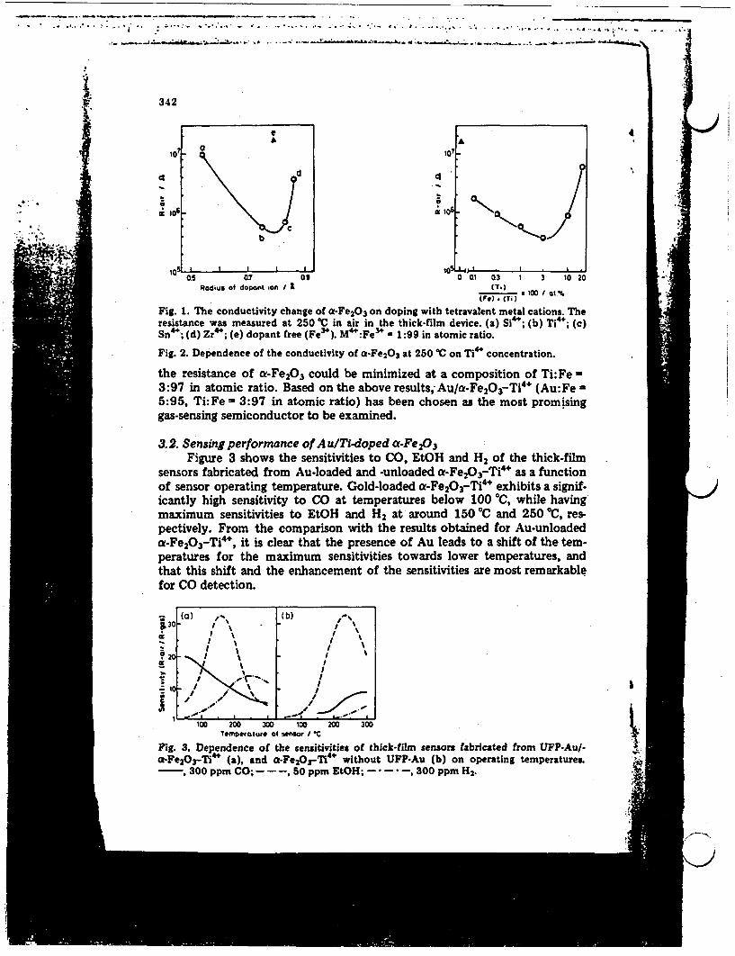
---- __ - -_ - 71 - - __ - .- - . ..- . . ... . .
: : .. , -..' . ..- I . ... -... .. . .... - . .. ; , ,.. 1, � #. . .., '. . . . ....... . - . .. . -.4 ... . " ;. .. . �.. .. .,. ;I
. - .. - .- ,, I__ ._.. - -;� i
I 342
aa
eA
d
b
-n I
4
CI
£t
I
0 .5 07 09 0 01 03 1 3 10 20Radius of dopant ion I (T.)
(TWO -T) * 00 I al.%
Fig. 1. The conductivity change of a-Fe 2O3 on doping with tetravalent metal cations. Theresistance was measured at 250 TC in air in the thick-film device. (a) Si4+; (b) Ti4+; (c)Sn4+; (d) Zr4+; (e) dopant free (Fe3+). M4+:Fe3* a 1:99 in atomic ratio.
Fig. 2. Dependence of the conductivity of a-Fe2O3 at 250 C on Ti4+ concentration.
the resistance of t-Fe2O3 could be minimized at a composition of Ti:Fe -3:97 in atomic ratio. Based on the above results, Au/a-Fe2O3-Ti4' (Au:Fe -5:95, Ti:Fe - 3:97 in atomic ratio) has been chosen as the most promisinggas-sensing semiconductor to be examined.
3.2. Sensing performance of Au/Ti-doped a-FeA 3Figure 3 shows the sensitivities to CO, EtOH and H2 of the thick-film
sensors fabricated from Au-loaded and -unloaded ot-Fe20 3-Ti4 as a functionof sensor operating temperature. Gold-loaded a-Fe2O3-Ti4 exhibits a signif-icantly high sensitivity to CO at temperatures below 100 TC, while havingmaximum sensitivities to EtOH and H2 at around 150 0C and 250 0C, res-pectively. From the comparison with the results obtained for Au-unloadeda-Fe2 O3 -Ti4 , it is clear that the presence of Au leads to a shift of the tem-peratures for the maximum sensitivities towards lower temperatures, andthat this shift and the enhancement of the sensitivities are most remarkablefor CO detection.
J
3
* 213>i
_ 1
(a) I,-. (b) -%
I iI ~~~~~~~~~ ~~I
II
Ia. I
.-.~~~~~~*I . I~ ~~~~.
W
100 200 300 100 200 300temperature of sesex / C
Fig. 3. Dependence of the sensitivities of thick-film sensors fabricated from UFP-Au/-a-Fe2 037-Ti 4 * (a), and -Fe2OrTi 4 * without UFP-Au (b) on operating temperatures.- 300 ppm CO;---, 50 ppm EtOH; - --- , 300 ppm H2.
U1
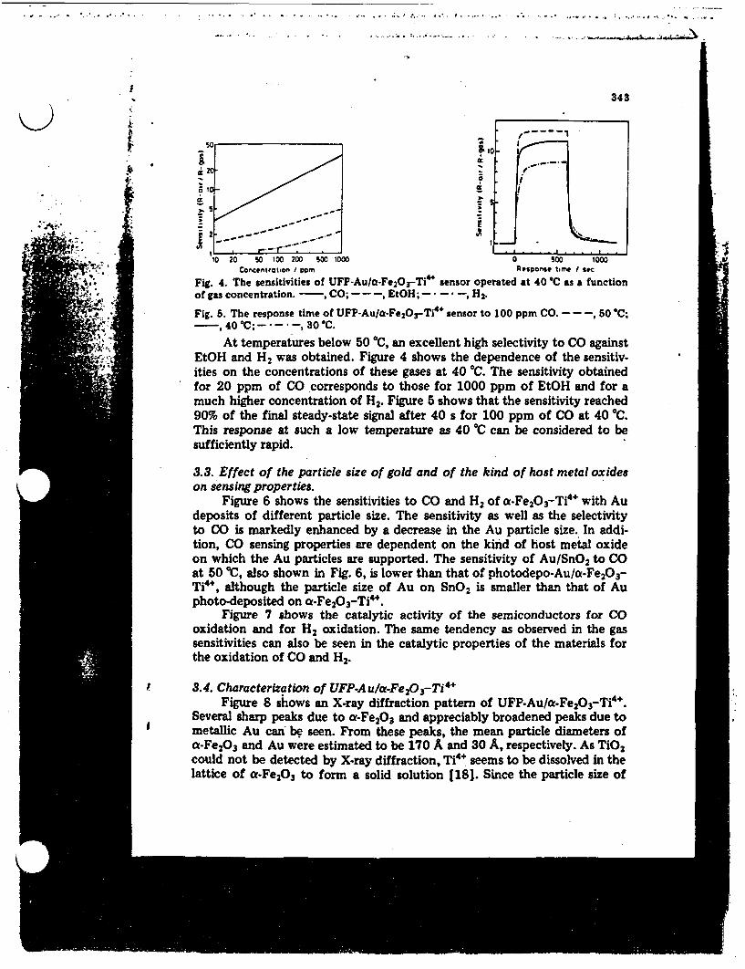
- .-...J.~...
343
lo~ -
V~~~~~~~~~~- I-- 5X i,_
10 20 0 t0 200 500 1000 0 So 1000Concentration I om Response time s ec
Fig. 4. The sensitivities of UFP-AuIO-Fe2OrTi'" sensor operated at 40 C as a functionof gas concentration. - , CO; - - -, EtOH; - - -, H2
Fig. 5. The response time of UFP-Au/a-Fe2OrTi4 ' sensor to 100 ppm CO. - - -, 50 C;-t', 40 C--- 30 C.
At temperatures below 50 0C, an excellent high selectivity to CO againstEtOH and H2 was obtained. Figure 4 shows the dependence of the sensitiv-ities on the concentrations of these gases at 40 C. The sensitivity obtainedfor 20 ppm of CO corresponds to those for 1000 ppm of EtOH and for amuch higher concentration of H2. Figure 5 shows that the sensitivity reached90% of the final steady-state signal after 40 s for 100 ppm of CO at 40 'C.This response at such a low temperature as 40 C can be considered to besufficiently rapid.
3.3. Effect of the particle size of gold and of the kind of host metal oxideson sensing properties.
Figure 6 shows the sensitivities to CO and H2 of a-Fe2O3-Ti4+ with Audeposits of different particle size. The sensitivity as well as the selectivityto CO is markedly enhanced by a decrease in the Au particle size. In addi-tion, CO sensing properties are dependent on the kind of host metal oxideon which the Au particles are supported. The sensitivity of Au/SnO2 to COat 50 C, also shown in Fig. 6, is lower than that of photodepo-Aua-Fe 2O3-Ti"', although the particle size of Au on SnO2 is smaller than that of Auphoto-deposited on ct-Fe 2 O-Ti'.
Figure 7 shows the catalytic activity of the semiconductors for COoxidation and for H2 oxidation. The same tendency as observed in the gassensitivities can also be seen in the catalytic properties of the materials forthe oxidation of CO and H2.
3.4. Characterization of UFP-Au/<c-Fe2 03 -Ti4 1Figure 8 shows an X-ray diffraction pattern of UFP-Au/a-Fe2O3-Ti4+.
Several sharp peaks due to a-Fe2O3 and appreciably broadened peaks due tometallic Au can be seen. From these peaks, the mean particle diameters ofa-Fe2O3 and Au were estimated to be 170 A and 30 A, respectively. As TiO2could not be detected by X-ray diffraction, Ti4+ seems to be dissolved in thelattice of a-Fe2O, to form a solid solution [181. Since the particle size of
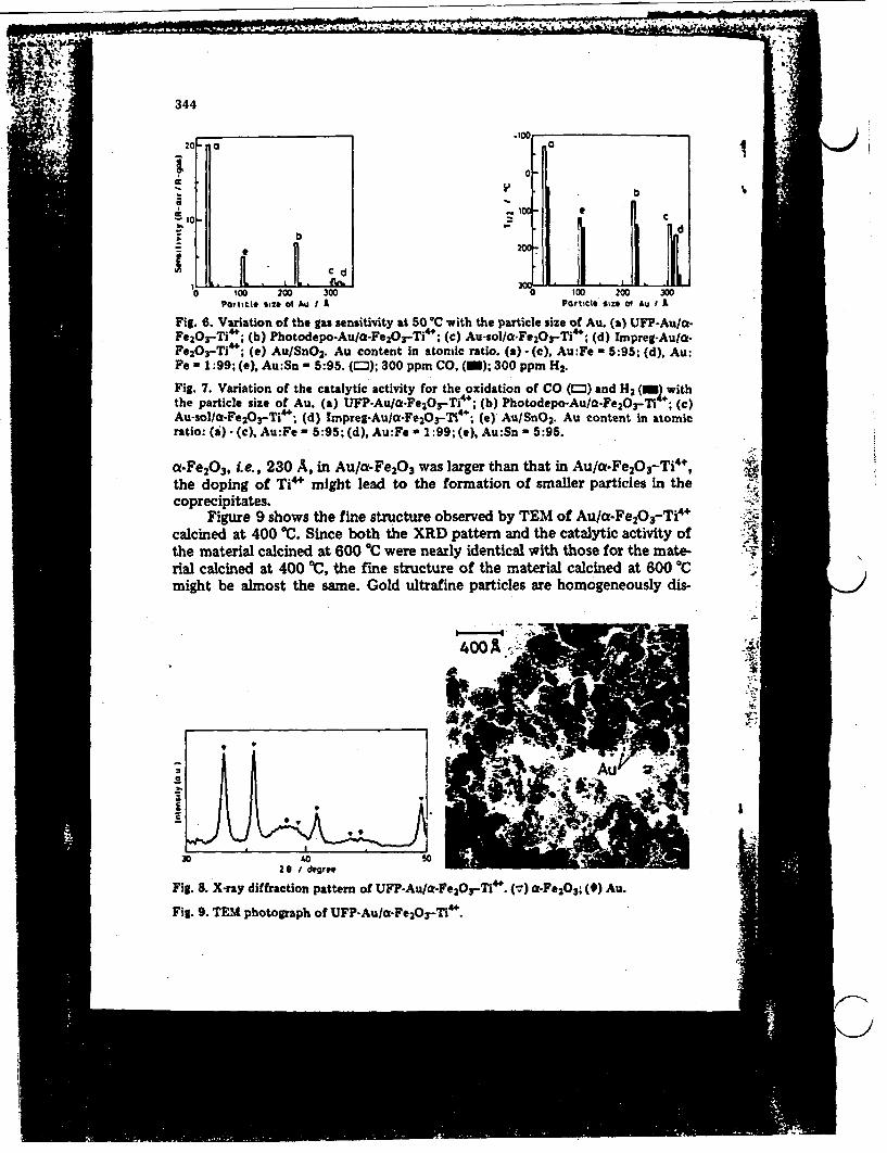
,% �6 - - - ---- '; .' I I 11A. 'Al",- I-- -C ' � ! ? n r �--'
1'344
2I
-i
.a
b
I
V
0 100 200 300Porticle size 0 Au I A
100 200 30Pvrticle size Au I A
Fig. 6. Variation of the gas sensitivity at 50 C with the particle size of Au. (a) UFP.AuIa-Fe20 3 -Ti'*; (b) Photodepo-AuIO-Fe2Os-Ti4+; (c) Au-sol/-FelOrTi&; (d) Impreg-Auta.Fe2O3-Ti4*; (e) Au/SnO2 . Au content in atomic ratio. (a) - (c), Au:Fe - 5:95; (d), Au:Fe - 1:99; (e), Au:Sn - 5:95. (0); 300 ppm CO, (i); 300 ppm H2.
Fig. 7. Variation of the catalytic activity for the oxidation of CO (l) and H2 (TI withthe particle size of Au. (a) UFP-Au/a-Fe 2 Or-Ti4+; (b) Photodepo-Au/a-Fe 2OY-Tl ; ()Au-sol/aC-Fe 2 O3-Ti4+; (d) Impreg-AuIa-Fe 2OrTi4+; (e) AuISnO2 . Au content in atomicratio: (i} (c), Au:Fe - 5:95; (d), Au:Fe a 1:99; (e), Au:Sn - 5:95.
a-Fe2O3 , i.e., 230 A, in Au/a-Fe2O3 was larger than that in Au/a.Fe 2O3-Ti 4*,the doping of Ti4+ might lead to the formation of smaller particles in thecoprecipitates.
Figure 9 shows the fine structure observed by TEM of Au/a-Fe20 3-Ti'calcined at 400 'C. Since both the XRD pattern and the catalytic activity ofthe material calcined at 600 'C were nearly identical with those for the mate-rial calcined at 400 C, the fine structure of the material calcined at 600 Cmight be almost the same. Gold ultrafine particles are homogeneously dis- J
t.
1'
Ii
2 / degree
Fig. 8. X-ray diffraction pattern of UFP-Au/cf-Fe20OrM4. (1) e-Fe 2O3 ; () Au.
Fig. 9. TEM photograph of UFP-AuIa-Fe 2Or-M4+.

.4 ~~~~~~~~~~~~~~~~~~~~345
persed on the surface of a-FeAO particles of about 200 A in diameter. Thediameter of 2663 particles of Au in the enlarged TEM photographs wasmeasured by using a slide caliper and their distribution is plotted in Fig. 10.The mean particle diameter of Au and the standard deviation were calculatedto be 36 A and 13 A, respectively. The particle diameters of oi-FeAO and ofAu determined from TEM coincided well with those estimated by XRDand indicate the validity of the XRD method.
Figure 11 shows that, typically, at the junction between Au particlesand a-FeAO, the basal planes of hemispherical Au particles are in contact
A_) - pe onwith the surface of aFe 2O 3particles. From the interplanar spacing of theicrystallites, it can be seen that the (111) plane of a Au crystallite is grown
on a -FeOb (110) plane. Such a crystal orientation is often but not alwaysobserved at Au/ct-Fe2O3 junctions. Furthermore, ultrafine Au particles arestable on t-Fec-Ti and did not coagulate under the electron beam radia-tion in a TEM, while ultrafine Au particles vacuum-deposited on SiO2 changetheir crystal structure in less than 0.1 s and occasionally move on the SiO2surface to coagulate with each other [191.
Neither the strongly bound interface nor the crystal orientation couldbe observed by TEM for ipreg-Au/-FeO-Ti 4 , where spherical particlesof Au were grown to a size larger than 200 A in diameter and were present asa simple mixture with Au-FeO-T particles.
600
40
.20C
0 20 4 0 SO so W 20 .w..
Fig. 10. Size distribution of UFP-Au on 0.1Fe 2Oy-Ti*. Total number of measured Au par-ticles: 2663. Mean particle size: 36 A. Standard deviation: 13 A.Fig. i. The fine structure of the interface between Au and a-Fel03. Note that the inter-planer spacings of Au(I1) and cc-FeIO 3 (110) are 2.355 A and 2.519 A, respectively.
4: Discussion4. 1. Sensig mechanism
It has been shown that the gas-sensing semiconductor, UFPAuia-Fe2O3-Ti 4 , can selectively detect CO with a high sensitivity at temperatures

-~ ~ ~~ '***'** : ~ * 4 ;' % ~ *'~
346
below 100 0C (Figs. 3 and 4). Some Pd-added SnO2 sensors 16, 8] have alsobeen reported to detect CO at temperatures below 100 C. Gold-loadedof-FelO3 -Ti4+ has a sensitivity and selectivity comparable to those of thePd/SnO2 sensor of best performance reported so far [20]. However, there isa marked difference in the response time between the two materials. Theresponse time with UFPAu/oc.Fe2O3 -Ti4 is less than 1 min (Fig. 5), while itis over 10 min with Pd/SnO2 61.
Another big difference is the catalytic activity for CO oxidation; i.e.,over UFP-Au/ci-Fe2O3-Ti4", CO oxidation takes place even at -70 0C (Fig.7), while it commences only at around 100 0C on Pd/SnO2 catalysts [21].Hence, at the temperatures for which both of the materials have high COsensitivity, CO oxidation takes place vigorously on UFP-Au/a-Fe2 03-Ti4 *but not on Pd/SnO2 . This difference strongly suggests that there should bea substantial difference in the CO sensing mechanism between these twomaterials.
The activation mechanisms of the gas-sensing semiconductors sensitizedby Pd, Pt and Ag have been classified into two types [221. In the first mech-anism, the reducing gases are adsorbed and activated on the sensitizers, andthen the activated gases react with the oxygen adsorbed anionically on thesemiconductor surfaces. The resultant removal of the surface oxygen causesan increase in the conductivity of the n-type semiconductors. In this case, ahigh sensitivity is expected to appear as a reflection of a high catalytic activ-ity for the oxidation of reducing gases at the same temperature range.
The second mechanism is an electronic one in which the sensitizerscreate such surface states as to directly exchange electrons with the semicon-ductors. The reducing gases are adsorbed on the sensitizers and then donateelectrons to the semiconductors via the surface states originated from thesensitizers, which also results in an increase in the conductivity of the n-typesemiconductors. In this case, catalytic activity for the oxidation is notnecessarily needed for sensing reducing gases.- From the relation between the sensitivity and the catalytic activity at
temperatures below 100 C, the first mechanism would be valid for UFP-Au/-a-Fe2O3-Ti44 , and the second for Pd/SnO2. In the latter case, it is likely thatCO molecules will be adsorbed too strongly on the Pd surfaces 231 to reactwith the surface oxygen on SnO2 at such low temperatures. This may beresponsible for the very slow response time of Pd/SnO2.
4.2. Origin of high CO sensitivityCarbon monoxide oxidation takes place at temperatures above 200 TC
on -Fe2O3 141, where the rate-determining step is the adsorption of COonto the oi-Fe203 surface 241. Such a catalytic nature of a-Fe2O3 is r-flected in the CO-sensing property of a-Fe2 0 3-Ti4 without UFP-Au (Fig. 3).If UFP-Au provides sites for the activation of CO and then facilitates itstransfer to the -Fe2O3 surface, the fast CO oxidation at low temperaturesand hence the high sensitivity to CO of UFP-Au/a-Fe2 0 3-Ti4 ' will beexplainable.

347
Since the surface of pure gold is known to be essentially inactive tomost chemicals, including CO [25], it can be suggested that -the surface pro-perty of Au is significantly changed in UFP-Au held on the a-Fe2O3 surface.
The first experimental evidence is the size effect of Au particles shownin Figs. 6 and 7. The UFP-Au particles on a-Fe20 3-Ti4 are so small that alarge part of the constituent Au atoms is exposed to the surface. The numberof constituent Au atoms in an Au sphere with a diameter of 36 A is calcul-ated to be about 103, and about 40% of the Au atoms exist on the outermostsurface of the particle. The catalytic properties of such ultrafine metal par-ticles are expected to differ significantly from those of bulk metals 26],due to an increase in the surface dangling bonds [27] and/or a change in theelectronic structure due to quantum size effects [281 with a decrease in theparticle size. In fact, it has been reported that atomic Au can react with bothCO and 02 even at 10 K and that the resultant Au(CO) 202 complex decom-poses to produce CO2 at 40 K 291.
Secondly, it can be pointed out that 'metal-support interaction' [30]may govern the chemical properties of UFP-Au. Electron microscopic obser-vation showed that UFP-Au particles were not spherical but hemisphericaland were strongly held on the host oxide of a-Fe2O3-Ti 4 '. The activity toCO at low temperatures was appreciably dependent on the kinds of hostmetal oxides; on SnO2, instead of a-Fe2O3, UFP-Au catalysts did not exhibithigh catalytic activity (Fig. 7). Bond et al. [31] have proposed that ultrafineAu particles supported on A1203 or SiO2 become electron deficient by donat-ing electrons to the supports and the catalytic properties of the electron-deficient Au particles then resemble somewhat those of Pt, which is theelement to the left of Au in the Periodic Table.
It is well known that CO is adsorbed strongly on Pt in contrast to theweak adsorption on 'inherent' Au and that CO adsorbed on the Pt surface istoo stabilized to be oxidized by 02 at temperatures below 150 TC [231. The )adsorption energy of CO on Pt is 110 - 140 kJ/mole [23], while that on'inherent' Au is about 40 kJ/mole 321. If UFP-Au becomes electron def-icient by donating electrons to the host oxide of a-Fe20 3-Ti4 and then hasintermediate CO adsorption between that of Pt and 'inherent' Au, UFP-Aucan provide suitable sites for the CO adsorption, which would facilitate reac-tion with 02 adsorbed on the a-Fe203 surface.
Acknowledgement
We are greatly indebted to Dr. S. ijima of Research Development Cor-poration of Japan for his helpful discussions.
References
1 T. Seiyama, A. Kato, K. Fujiishi and M. Nagatani, A new detector for gaseouscomponents uing semiconductive thin films, Anal. Chem., 34 (1962) 1502 - 1503.
It
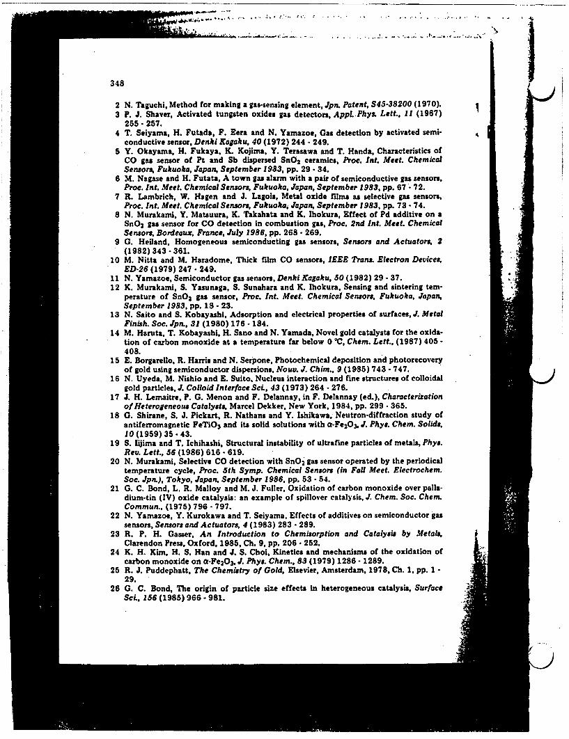
- .-.- -. -. ..
348
2 N. Taguchi, Method for making a gas-sensing element, Jpn. Patent, S45-38200 (1970).3 P. J. Shaver, Activated tungsten oxides gas detectors, Appl. Phys. Lett., 11 (1967)
255- 257.4 T. Seiyama, H. Futada, F. Eera and N. Yamazoe, Gas detection by activated semi-
conductive sensor, Denki Kagaku, 40 (1972) 244 - 249.5 Y. Okayama, H. Fukaya, K. Kojima, Y. Terasawa and T. Handa, Characteristics of
CO gas sensor of Pt and Sb dispersed SnO2 ceramics, Proc. nt. Meet. ChemicalSensors, Fukuoka, Japan, September 1983, pp. 29 - 34.
6 M. Nagase and H. Futata, A town gas alarm with a pair of semiconductive gas sensors.Proc. Int. Meet. Chemical Sensors, Fukuoka, Japan, September 1983, pp. 67 72 2.
7 R. Lambrich, W. Hagen and J. Lagois, Metal oxide flms as selective gas sensors,Proc. Int. Meet. Chemical Sensors, Fukuoka, Japan, September 1983, pp. 73 - 74.
8 N. Murakami, Y. Matsuura, K. Takahata and K. Ihokura, Effect of Pd additive on aSnO2 gas sensor for CO detection in combustion gas, Proc. 2nd Int. Meet. ChemicalSensors, Bordeaux, France, July 1986, pp. 268 269.
9 G. Heiland, Homogeneous semiconducting gas sensors, Sensors and Actuators, 2(1982) 343 -361.
10 M. Nitta and M. Haradome, Thick film CO sensors, IEEE Trans. Electron Devices, *
ED-26 (1979) 247. 249.11 N. Yamazoe, Semiconductor gas sensors, Denki Kagaku, 50 (1982) 29- 37. 3 -
12 K. Murakami, S Yasunaga, S. Sunahara and K. Ihokura, Sensing and sintering tem-perature of SnO2 gas sensor, Proc. Int. Meet. Chemical Sensors Fukuoka, Japan,September 1983, pp. 18- 23.
13 N. Saito and S. Kobayashi, Adsorption and electrical properties of surfaces, J. MetalFinish. Soc. Jpn., 31 (1980) 176- 184.
14 M. Haruta, T. Kobayashi, H. Sano and N. Yamada, Novel gold catalysts for the oxida-tioh of carbon monoxide at a temperature far below 0 C, Chem. Lett., (1987) 405-408.
15 E. Borgarello, R. Harris and N. Serpone, Photochemical deposition and photorecoveryof gold using semiconductor dispersions, Nouu. J. Chim., 9 (1985) 743 - 747.
16 N. Uyeda, M. Nishio and E. Suito, Nucleus interaction and fine structures of colloidalgold particles, J. Colloid Interface Sci., 43 (1973) 264 - 276.
17 J. H. Lemaitre, P. G. Menon and F. Delannay, in F. Delannay (ed.), Characterizationof Heterogeneous Catalysts, Marcel Dekker, New York, 1984, pp. 299- 365.
18 G. Shirane, S. J. Pickart, R. Nathans and Y. Ishikawa, Neutron-diffraction study ofantiferromagnetic FeTiO3 and its solid solutions with o-Fe2 03, J. Phys. Chem. Solids,10 (1959) 35 43.
19 S. Iijima and T. Ichihashi, Structural instability of ultrafine particles of metals, Phy.Rev. Lett., 56 (1986) 616 - 619.
20 N. Murakami, Selective CO detection with SnO 2 gas sensor operated by the periodicaltemperature cycle, Proc. 5th Symp. Chemical Sensors (in Fall Meet. Electrochem.Soc. Jpn.), Tokyo, Japan, September 1986, pp. 53 - 54.
21 G. C. Bond, L. R. Malloy and M. J. Fuller, Oxidation of carbon monoxide over palla-dium-tin (IV) oxide catalysis: an example of spillover catalysis, J. Chem. Soc. Chem.Commun, (1975) 796 - 797.
22 N. Yamazoe, Y. Kurokawa and T. Seiyama, Effects of additives on semiconductor gassensors, Sensors and Actuators, 4 (1983) 283 - 289.
23 R. P. H. Gasser, An Introduction to Chemisorption and Catalysis by Metals,Clarendon Press, Oxford, 1985, Ch. 9, pp. 206 252.
24 K. H. Kim, H. S. Han and J. S. Choi, Kinetics and mechanisms of the oxidation ofcarbon monoxide on a-Fe2A3 , J- Phys. Chem., 83 (1979) 1286 - 1289.
25 R. J. Puddephatt, The Chemistry of Gold, Elsevier, Amsterdam, 1978, Ch. 1, pp. 1 -29.
26 G. C. Bond, The origin of particle size effects in heterogeneous catalysis, Surface ;SeL, 156 (1985) 966 . 981.

349
A.
.,.
27 R. Van Hardeveld and F. Hartog, The statistics of surface atoms and surface siteson metal crystals, Surface Sci., 15 (1969) 189 - 230.
28 R. Kubo, Electronic properties of metallic fine particles. I, J., Phys. Soc. Jpn., 17(1962) 976 - 986.
29 H. Huber, D. McIntosh and G. A. Ozin, A metal atom model for the oxidation ofcarbon monoxide to carbon dioxide. The gold atom-carbon monoxide-dioxygenreaction and the gold atom-carbon dioxide reaction, lnorg. Chem., 16 (1977) 975 -979.
30 G. C. Bond, in B. Imelik, C. Naccache, G. Coudurier, H. Praliaud, P. Meriaudeau,P. Gallezot, G. A. Martin and J. C. Vedrine (eds.), Metal-Support and Metal-Additive Effects in Catalysis, Elsevier, Amsterdam, 1982, pp. 1 10.
31 G. C. Bond and P. A. Sermon, Gold catalysts for olefin hydrogenation. Trans-mutation of catalytic propertes, Gold Bull., 6 (1973) 102 - 105.
32 R. R. Ford, in D. D. Eley, H. Pines and P. B. Weisz (eds.), Advances in Catalysis,Vol. 21, Academic Press, New York, 1970, pp. 51 150.
Biographies
Tetsuhiko Kobayashi received B. E. and Doctor of Engineeringdegrees from Osaka University, in 1978 and 1983, respectively. From 1983to 1984 he remained at Osaka University as a postdoctral fellow of theJapan Society for the Promotion of Science to continue his work ohelectrochemistry. Since joining GIRIO in 1984, his research has focusedon the development of new gas sensors.
Masatake Haruta received a B. E. from Nagoya Institute of Technologyin 1970 and a Doctor of Engineering from Kyoto University in 1976. Sincejoining GIRIO in 1976, he has worked on the preparation of combustioncatalysts and gas-sensing oxide materials.
Hiroshi Sano received a B. Sc. from Niigata University in 1955 and aDoctor of Engineering from Kyoto University in 1976. He has been thedirector of the Material Chemistry Department in GIRIO since 1986,and his current fields of interest are catalysts and their application to newenergy technology and pollution control.
Masanori Nakane received a B. E. from Kumamoto Institute ofTechnology in 1948 and a Doctor of Engineering from Osaka University in1971. He was the director of the Material Chemistry Department in GIRIOuntil 1986. His major activities are concerned with the development of newmaterials.
P

Ij9
* I - N .-~~: t ..Dj** ..... '. ' .. * A.A...~... ; .r.~. . ~ .%....t................................4
~~~~~~~~- *. S L.A *- .... *.........
T. Inui (Editor), Sucesfu Design Of Catalysts 33O 1988 Elsevier Science Publishers B-V-., Amsterdam - Printed in The Netherlands
FINE STRUCTURE OF NOVEL GOLD CATALYSTS PREPARED BY COPRECIPITATION
; # .14. HARUTA1, H. KAGEYAMA1, N. KAMIJO1, T. KOBAYASHI1, and F. DELANNAY2
S v-. lGovernment Industrial Research Institute of Osaka, Midorigaoka 1, Ikeda. 563
2Universiti Catholique de Louvain, Department of Material Science andProcesses, Place Sainte Barbe 2, 8-1348 Louvain-la-Neuve(Belgium)
ABSTRACTHighly dispersed gold catalysts have been prepared by calcining the
coprecipitates obtained from an aqueous solution of HAuCl4 and the nitrate ofFe, Co, Ni, or Be. They are active for the oxidation of CO even at such a lowtemperature as -70'C and become more active in the presence of moisture. Thegold particles are hemispherical in shape and are nearly homodispersed with amean diameter smaller than lOnm. Most of them are strongly attached at theirflat planes to the metal oxide support exhibiting a specific crystalorientation. The chemical shifts in XPS showed that the ultrafine goldparticles were electron deficient. The results of EXAFS studies suggested thepossibility of the existence of gold atoms coordinated with iron atoms.
INTRODUCTION
Gold has attracted little attention as a catalyst because of its inert
character and the difficulties in preparing highly dispersed small particles.
Schwank noticed unusual activities and selectivities of monometallic gold
catalysyts in his reviewl). However, gold catalysts have been considered in
many cases not to be competitive with other noble metal catalysts in terms of
activity. This remains to be true even in the small supported gold particles2).
An interesting discovery made recently is that gold supported on
borosilicate catalyzes the oxidation of many organic compounds by nitrogen
dioxides3'4). The reactions are efficient and highly selective and are being
applied to the detection of butylated hydroxytoluene(BHT). On the other hand,
we have also found recently that coprecipitation enables us to prepare highly
dispersed gold catalysts and that the combination with the oxides of group VIII
3d transition metals5-7) and alkaline earth metals8) makes gold so active that
it can catalyze the oxidation of CO, even at -70'C. The above gold catalysts
are now under way for the application to the removal of CO from air, the
oxidation of CO in sealed C02 laser, and selective CO gas sensors9).
The present paper deals with the characterization of the novel gold
catalysts, specifically Au/a-Fe2O3 and Au/BeO, through XPS, EXAFS, and TEM. The

* '�A�-"S
Is
*. .. 7
mechanism is also discussed of the oxidation of CO on these gold catalysts inmoistened air at a room temperature.
EXPERIMENTALThe gold catalysts were prepared by coprecipitation with sodium carbonate
from an aqueous solution of AuCl 4 and the nitrates of various metals. Thecoprecipitates were washed, vacuum dried, and calcined n air at temperaturesfrom 80C to 500-C. Catalytic activity measurements were carried out in a smallfixed bed reactor, with 0.209 of catalysts that had passed through 70 and 120mesh sieves. A standard gas consisting of 1.0 voll H2 or CO balanced with airto 1 atm. was passed through the catalyst bed at a flow rate of 66 l/min.
The structures of the gold catalysts were observed using a Hitachi H-9000electron microscope operated at 300 kY. X-ray photoelectron spectroscopicanalyses were made using a Shimadzu ESCA 750 under a vacuum below 5x10⁻⁶ torr.The binding energies were calculated by reference to that of Cls carboncontamination peak assumed at 285.0 eV. Measurements of EXAFS and XANES werecarried out at the beam line 103 of the 2.5 GeY storage ring of Photon Factoryin the National Laboratory for High Energy Physics(XCEKTsukuba). Data analysiswas made following the method of Maeda et al.l1).
RESULTSCatalyt1c properties of gold catalysts repared b coprecipitation
Table 1 shows the catalyticactivities of the gold catalysts with differentmetal oxide supports for the oxidation of H2 and CO. The activity is expressedin terms of the temperature corresponding to 50X conversion(Tl/2). The particlesizes of gold were calculated from peak half-widths of XRD and in some casesfrom TEN photograghs.
There are two groups of metal oxide supports that can generate remarkablyhigh catalytic activities for the oxidation of CO at -70C. They are theoxides of group VIII 3d transition metals like Fe, Co, and Ni and the oxides ofalkaline earth metals like Be and Mg. In contrast to the catalytic nature ofpure gold that the oxidation of 2 occurs at lower temperatures than that ofCO, the above gold catalysts can catalyze the oxidation of CO at much lowertemperatures. On the contrary to the metal oxide supports alone which areseriously deactivated by moisture, the coprecipitated gold catalysts becomemore active in the presence of moisture. In the experiments carried out at 30Cusing the large grain of Au/a-Fe203(7-9 meshes) calcined at 400C under a spacevelocity of 4x10⁴ h0, the oxidation efficiency of CO was raised to 1001 from951 by the addition of water in a range from 0.6 to 4.0 vol. Thesecharacteristic properties may permit us to distinguish the coprecipitated goldcatalysts from the conventional ones which are prepared by impregnation on MgO.
A_~~~~~~~~~~~~~~~~~~~~~~~~
M _~~~~~~~~~~~~~~~~~~
I
P
J
U
j
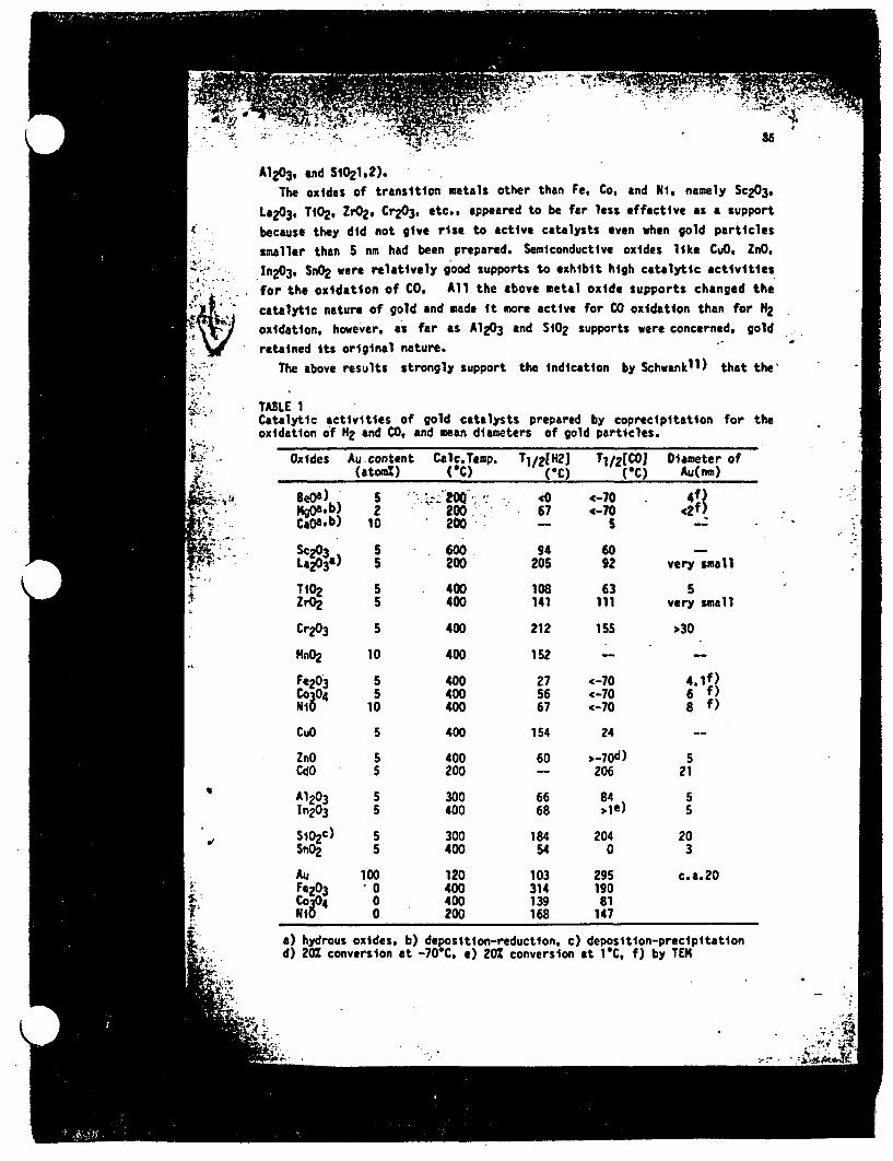
E9
85 I
A1203, and SiO2l.2). :The oxides of transition metals other than Fe. Co, and Ni, namely Sc203-
La203, T 2 , rO2, Cr203. etc.. appeared to be far less effective as a supportbecause they did not give rise to active catalysts even when gold particlessmaller than 5 nm had been prepared. Semiconductive oxides like CuO. ZnO,In203- SnO2 were relatively good supports to exhibit high catalytic activitiesfor the oxidation of CO. All the above metal oxide supports changed thecatalytic nature of gold and made it more active for CO oxidation than for 2oxidation, however, as far as A1203 and SiO2 supports were concerned, goldretained its original nature.
The above results strongly support the indication by Schwankll) that the'
TABLE 1Catalytic activities of gold catalysts prepared by coprecipitation for theoxidation of H2 and CO. and mean diameters of gold particles.
' T
":. '-
.. . I
t^'':
61 - -
� W, "4'.-'C, "�T � - 7
-.
Oxides Au content Calc.Temp. T1/2[N21 Tl/21COJ Diameter of(atom%) (C) (C) (C) Au(nm)
BeOa) 5 C 20 -- 70 4f4O.b) 2 200 67 (-70 42f,C&0a.b) 10 20D - 5
Sc23 5 600 94 60La2O3a) 5 200 205 92 very small
Tb°2 5 400 108 63 5ZrO2 5 400 141 ill very small
Cr203 5 400 212 155 ;30
MnO2 10 400 152 -
Fe203 5 400 27 <-70 4.1f)Co304 5 400 56 (-70 6 f)N10 10 400 67 <-70 8 f)
CuO 5 400 154 24 --
ZnO 5 400 60 , 70d) 5CdO 5 200 -- 206 21
A1203 5 300 66 84 5In203 5 400 68 e) 5
Si02c) 5 300 184 204 20SnO2 5 400 54 0 3
Au 100 120 103 295 c.a.20Fe203 0 400 314 190Co304 0 400 139 81N10 0 200 168 147
B,
a) hydrous oxides, b) deposition-reduction, c) deposition-precipitationd) 20% conversion at -70'C, e) 20% conversion at 1C. f) by TEM
.. -t.~ -,

-5----* -.v*.
* .�f.I
5 9type of support might play criicial role in determining the catalytic actiyof gold in reactions of oxygen-bearing molecules. Especially, in the cases o-gold catalysts prepared by coprecipitation the metal-support interactions couij1strinkingly change the nature of gold due to the small sizes of particles. ;Among a variety of supported gold catalysts, Au/i-Fe2O3 and AuBMO, that wer# the most active, have been chosen as samples for the further investigation.
Effect of calcination temerature on atalvt1r aotxvttv
Figure 1 shows the dependence of the conversion in H2 oxidation at 3C andCO oxidation at -70C on the calcination temperature for the Au-Fe4Wcoprecipitate. Figure 2 shows the dependence of T 2 values for the oxidation 4of H2 and CO on the calcination temperature for the Au-Be coprecipitate. Thecontents of Au in these catalysts were 5 atoml, which had been proved to b %ithe optimum content.
In the Au-Fe coprecipitate, a maximum catalytic activity was obtained bycalcination at 200C for H2 oxidation, but for C oxidation it was obtained by s
calcination at 300-C, X-ray diffraction confirmed the sample calcined at 200C as poorly crystalline hematite(a-Fe 203) with no other apparent crystalline-compounds. In the samples calcined at 300C only hematite became more Acrystallized. At 400-C, broad diffraction peaks due to metallic gold appeared.
IrD .-
0
4I
0
CA1
.'II
0I 3!'50
0
1S
I
ICO
I :, '
J
aI?'-
-o 200 400 600Calcination temperature. T(C)
Fig. 1. Effect of calcination temperatureon the catalytic activities of Au-Fecoprecipitate for the oxidation of H2 andCO. , H2 At 30OT; 0%, CO at -70'.
0 100 200 0oo 400 500
Calciation temapraturwetC)
Fig. 2. Effect of calcinatlontemperature on the catalyticactivities of Au-Be coprecipitatefor the oxidation of H2 and C0and on specific surface area.A, H2; , CO; 0, specificsurface area. The arrows denotethat Tl/2 values are lower thanindicated.
I-
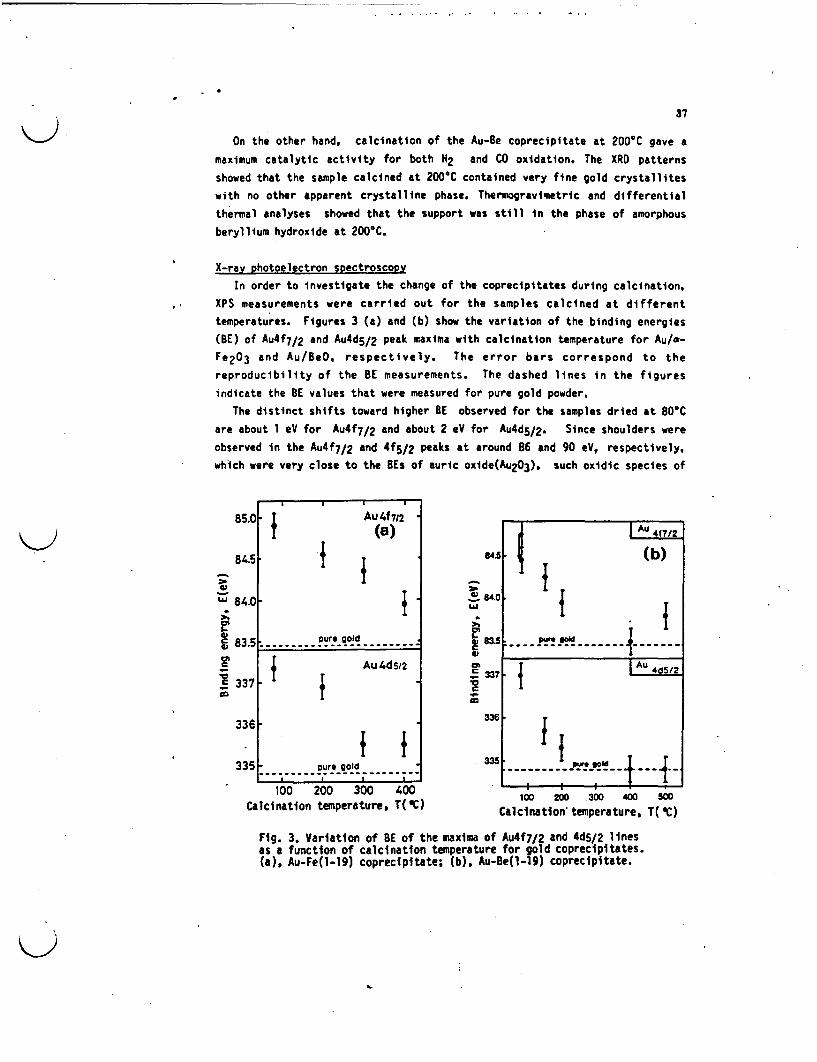
-
37
On the other hand, calcination of the Au-Be coprecipitate at 200C gave amaximum catalytic activity for both H2 and CO oxidation. The XRD patternsshowed that the sample calcined at 200C contained very fine gold crystalliteswith no other apparent crystalline phase. Thermogravimetric and differentialthermal analyses showed that the support was still in the phase of amorphousberyllium hydroxide at 200C.
X-ray photoelectron spectroscopyIn order to nvestigate the change of the coprecipitates during calcination,
XPS measurements were carried out for the samples calcined at differenttemperatures. Figures 3 (a) and (b) show the variation of the binding energies(BE) of Au4f 7/2 and Au4d5/2 peak maxima with calcination temperature for Au/a-Fe2O3 and Au/BeO. respectively. The error bars correspond to thereproducibility of the BE measurements. The dashed lines in the figuresindicate the BE values that were measured for pure gold powder.
The distinct shifts toward higher BE observed for the samples dried at 80Care about 1 eV for Au4f7/ 2 and about 2 eV for Au4d5 /2. Since shoulders wereobserved in the Au4f7/2 and 4f 5/ 2 peaks at around 86 and 90 eV, respectively,which were very close to the BEs of auric oxide(Au2O3), such oxidic species of
85.0
845i
W
1
c
L.
.
I-G
840
83.5
, T Auf712
i (a)
1 {
} Au {~d52
______........ __ I:... ure gold
-Ei
C
.
CO337
336
335
100 200 300 400Calcination temperature, T(2)
100 200 .300 400 500
Calcination temperature, T( C)
Fig. 3. Variation of BE of the maxima of Au4f7/2 and 4d5/2 linesas a function of calcination temperature for gold coprecipitates.(a), Au-Fe(l-19) coprecipitate; (b), Au-Be(l-19) coprecipitate.
I
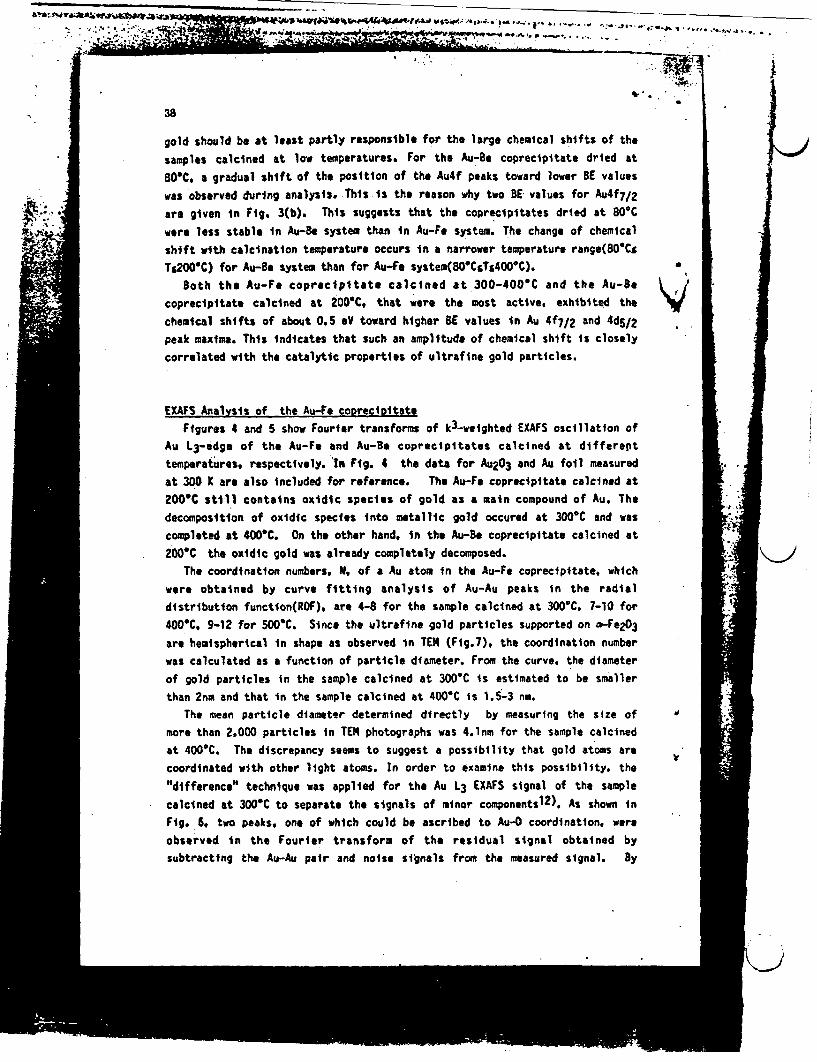
* - -
.. t , . PA
'I
b*
F.
- , t ~-O "*
~~~~~~~~~~~~~~~~~~~~~-=
38
gold should be at least partly responsible for the large chemical shifts of the
samples calcined at low temperatures. For the Au-Be coprecipitate dried at
80%C a gradual shift of the position of the Au4f peaks toward lower BE values
was observed during analysis. This is the reason why two BE values for Au4f7/2
are given in Fig. 3(b). This suggests that the coprecipitates dried at 80C
were less stable in Au-Be system than in Au-Fe system. The change of chemical
shift with calcination temperature occurs n a narrower temperature range(80'CS
Ts200C) for Au-Be system than for Au-Fe system(8OCsTs400C).
Both the Au-Fe coprecipitate calcined at 300-400'C and the Au-Be /coprecipitate calcined at 200C, that were the most active, exhibited the
chemical shifts of about 0.5 eV toward higher BE values in Au 4f7/2 and 4ds/2
peak maxima. This indicates that such an amplitude of chemical shift is closely
correlated with the catalytic properties of ultrafine gold particles.
EXAFS Analysis of the Au-Fe coprecipitate
Figures 4 and 5 show Fourier transforms of k3-weighted EXAFS oscillation of
Au 13 -edge of the Au-Fe and Au-Be coprecipitates calcined at different
temperatures, respectively. in Fig. 4 the data for Au2 03 and Au foail measured
at 300 X are also included for reference. The Au-Fe coprecipitate calcined at
200iC still contains oxidic species of gold as a main compound of Au. The
decomposition of oxidic species nto metallic gold occured at 300'C and was
completed at 400C. On the other hand, in the Au-Be coprecipitate calcined at
200C the oxidic gold was already completely decomposed.
The coordination numbers, N. of a Au atom in the Au-Fe coprecipitate, which
were obtained by curve fitting analysis of Au-Au peaks in the radial
distribution function(ROF), are 4-8 for the sample calcined at 300C. 7-10 for
400C, 9-12 for 500C. Since the ultrafine gold particles supported on -Fe203
are hemispherical in shape as observed in TE4 (Fig.7). the coordination number
was calculated as a function of particle diameter. From the curve. the diameter
of gold particles in the sample calcined at 300C is estimated to be smaller
than 2nm and that in the sample calcined at 400C is 1.5-3 nm.
The mean particle diameter determined directly by measuring the size of
more than 2,000 particles in TEN photographs was 4.1nm for the sample calcined
at 400C. The discrepancy seems to suggest a possibility that gold atoms are
coordinated with other light atoms. In order to examine this possibility. the
"difference" technique was applied for the Au 3 EXAFS signal of the sample
calcined at 3000C to separate the signals of minor componentsl2). As shown in
Fig. 6, two peaks, one of which could be ascribed to Au-0 coordination, were
observed in the Fourier transform of the residual signal obtained by
subtracting the Au-Au pair and noise signals from the measured signal. By
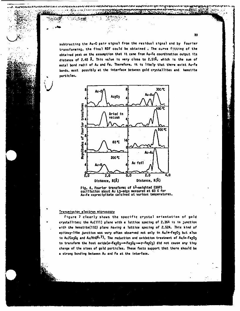
*.J. g@ ws, gt. tw-~:^s^.w#44 >-fi~4' t * f w &V¢- ^
adgihf~
\~~~~~~~~~~~~~~it A<'
subtracting the Au-0 pair signal from the residual signal and by Fo
transforming, the final RF could be obtained . The curve fitting ol
obtained peak on the assumption that it came from Au-Fe coordination outpu
distane of 2.48 A. This value is very close to 2.slA. which is the si
_:*@*- "
.; !!- .-
4eV
9
urier
f theit ts
Jm of
metal bond radii of Au and Fe. Therefore, it is likely that there exist Au-Fe
bonds, most possibly at the nterface between gold crystallites and hematite
particles.
.
I
Distance, R) Distance, RA)
Fig. 4. Fourier transforms of k3-weighted EXAFSoscillation about Au L3-edge measured at 60 K forAu-Fe coprecipitate calcined at various temperatures.
Transmission electron microscopy
Figure 7 clearly shows the specific crystal orientation of gold
crystallites; the Au(ll) plane with a lattice spacing of 2.36A is in junction
with the hematite(110) plane having a lattice spacing of 2.52A. This kind of
epitaxy-like junction was very often observed not only in Au/a-Fe203 but also
in Au/Co304 and Au/NiO6 .7 ). The reduction and oxidation treatment of Au/a-Fe2Q3to transform the host oxide(a-Fe2 03 -... Fe304--._y-Fe2Q3) did not cause any tiny
change of the sizes of gold particles. These facts support that there should be
a strong bonding between Au and Fe at the interface.

-
! p _
~ - 'I
:: -:D$ -, Im;
40
.,... .
I-
A
0
L
I6
t
i,
A
IA-
J.)
I2.0
Distance, R(A)1.6 3.2
Distance, R(A)Fig. 5. Fourier transforms ofk3-weighted EXAFS oscillationabout Au 3-edge measured at300 K. for Au-Be coprecipitatecalcined at arious atures.
.~~~~~"v MI,
Fig. 6. The frst differenceFourier transform of the Au13 difference signal obtainedby subtracting the Au-Au pairsignal from the measured signal.
a,
Fig. 7. TEN photogragh of Ti doped Au-Fe(1-19) coprecipitate calcined at 400 C.
J_'
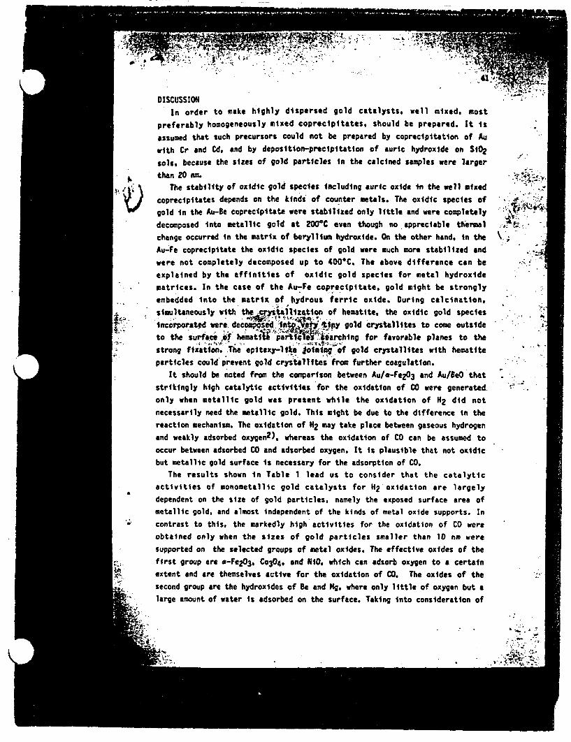
4 ~ ~7in= ; - 3 .- 4 . -, , - *,,
DISCUSSION;In order to make highly dispersed gold catalysts, well mixed, most
preferably homogeneously mixed coprecipitates, should be prepared. It is
assumed that such precursors could not be prepared by coprecipitation of Au
with Cr and Cd. and by deposition-preclpitation of auric hydroxide on S102
sols, because the sizes of gold particles in the calcined samples were largerthan 20 nm. g
6. It \ The stability of oxidic gold species including auric oxide n the well mixedcoprecipitates depends on the kinds of counter metals. The oxidic species of $ elgold in the Au-Be coprecipitate were stabilized only little and were completely a_
decomposed into metallic gold at 200-C even though no appreciable thermal ; -
change occurred in the matrix of beryllium hydroxide. On the other hand, in the \ >
Au-Fe coprecipitate the oxidic species of gold were much more stabilized and
were not completely decomposed up to 400'C. The above difference can be
explained by the affinities of oxidic gold species for metal hydroxide
matrices. In the case of the Au-Fe coprecipitate, gold might be strongly
embedded into the matrix of hydrous ferric oxide. During calcination,
simultaneously with the crystallizntion of hematite, the oxidic gold speciesi ncorporated were. dec w @ d >^fe" lip gold crystallites to come outside
to the surface uf heaati1 i arch for favorable planes to theno. A * 6I - . ! -,.r-^;tS "
strong fixation. The pitaxy-liki oimnin of gold crystallites with hematite
particles could prevent gold crystallftes from further coagulation.It should be noted from the comparison between Au/a-Fe203 and Au/BeO that
strikingly high catalytic activities for the oxidation of CO were generated
only when metallic gold was present while the oxidation of 2 did not
necessarily need the metallic gold. This might be due to the difference in the
reaction mechanism. The oxidation of H2 may take place between gaseous hydrogen
and weakly adsorbed oxygen2), whereas the oxidation of CO can be assumed to
occur between adsorbed CO and adsorbed oxygen. It is plausible that not oxidic
but metallic gold surface is necessary for the adsorption of CO.The results shown in Table 1 lead us to consider that the catalytic
activities of monometallic gold catalysts for H oxidation are largely
dependent on the size of gold particles, namely the exposed surface area ofmetallic gold, and almost independent of the kinds of metal oxide supports. In
* contrast to this, the markedly high activities for the oxidation of CO were
obtained only when the sizes of gold particles smaller than 10 nm were
supported on the selected groups of metal oxides. The effective oxides of the
first group are -Fe203, Co3O4, and N10, which can adsorb oxygen to a certain
extent and are themselves active for the oxidation of 00. The oxides of the
second group are the hydroxides of Be and g. where only little of oxygen but a* large amount of water is adsorbed an the surface. Taking into consideration of
the enhancing effeict water A/-Fe2O3 as well as the surface pr
of hydroxides of Be nd 9g, t could be concluded that adsorbed water as e
as adsorbed oxygen on the surface of support oxides is involved in the
oxidation of CD.The XPS studies showed that n the active gold catalysts ultrafine gold
particles were electron deficient. Hence, they become electronically similar to-
the metal to the lft in the Periodic Table, namely Ptl3), on which COmolecules are strongly chemiSorbed. Therefore, the nature of ultraffne gold tbparticles imobilized on the selected metal oxides might possibly be altered so
that the sufficient chemtsorPtion of CO occurs at low temperatures although
bulk gold surface- does not hemisorb Col). _ i4 a- Based on the above considerations the following mechanism can be speculated w
for the oxidation of CO in moistened air at a room temperature. Owing to Asi
transmutation of catalytic properties of ultrafine gold partlcles mobilized
on Fe 203, carbon monoxide and oxygen can be chemisorbed on the surface ofgold. The adsorbed CO molecules react with H20 molecules and OH groups on the
surface of metal oxides to form formic acid or formate ions. The adsor NOd
oxygen then reacts with the formate intermediates to produce carbon dioxide. --Without ultrafine gol4 particles, metal oxide catalysts like Fe2O3,aCoft.
are seriously teaftvted by i~sture because iwtir' prevents CO molecules fh*adsorption 'a the metal sites. Even with hydrous BeOd4 XgO where 1ttle
oxygen species are adsorb . high activities wer obtatw' ibis. ffacti
indtcite that oxygei1s qatAid on the gold surface and ls spilled over ta.
the metal oxide surface;5 . ' -,
REFERENCES
1 J. Schwank, Gold Bull.. 76 (1983) 103-110.2 G. Zhang, Ph. D. Dissertation, Stanford University, 1985. UI 8608245.3 S. A. Nyarady and R. E. Sievers, J. Amer. Chem. Soc., 107 (1985) 3726-3727.4 Chem. Engng. News. June 24, 1985, pp. 42-43. .5 M. Haruta, T. Kobayashi, H. Sano and N. Yamada. Chem. Lett. (1987) 405-408.6 M. Haruta, Hyomenkagaku(Surface Science), 8 (1987) 407-414. -7 M. Haruta. T. Kobayashi, S. ijima and F. elannay. Proc. 9th Intern. Congr.
Catal.. Calgary, June 26-July 1 1988, pp. 1206-1213.8 M. Haruta. K. Saika, T. Xobayashi. S. Tsubota and Y. Nakahara, Chem.
Express. 3 (1988) 159-162.9 T. Kobayashi. M. Haruta, H. Sano and M. akane, Sensors and Actuators, 13
(1988) 339-349.10 H. Maeda, H. Terauchi, K. Tanabe, N. Kamijo, M. Hida and H. Kawamura, Jpn.
J. Appl. Phys., 21 (1982) 1342-1346.11 J. Schwank, S. Galvano and 6. Parravano. J. Catal., 63 (1980) 415-423.12 B. K. To, EXAFS: Basic Principles and Data Analysis, Inorganic Chemistry
Concepts. Vol. 9, Springer Verlag, 1986. pp. 139-142.13 6. C. Bond and P. A. Sermon, Gold Bull., 6 (1973) 102-105.
IN
l IN.C.~~~~~~~
- ;:. j-: - - �:7- , , . -
.. -.- : - -. - s . . ;, . .- ,.., . .. . . -"- -;. - -
I , .1 - -:,� , . - , .T -1. .. . . - I . - .. . . - .
;�IZIWAArMiliMAr 14 - 1, 44' -,
il"tt ;W '. - 47,?, k- 6, --, -.� - - -& -t- V-1, . =p
P-
EN ~ 4
-a
.*: �a..
*�6
a�a*j��* *�t 6 .NW/A- � ak.. . .. -� I �Zt*S *�
NO�N��N** N� i�. � �.
-. .�.,.. -.a. -
I
X X X 06w w [ X b V :; w-~~~~~~-.wL-
_ .-_ ,. ho *%*,,, -a ^ {ts ;t .* *;; *^ A, Or > * ... N.'
40th ISE MEETING :-:
(TENDED ABSTRACTS...- 1......
. .. . . ~ ~ ~~~~~~~~~. %
_, : ;. , . -. -...... .. , -. _. * -................
-v -VOLUME l: .-- -I
. .1
¶1 . . . N ..
,~%. L . .. KYOTbY*JAPA
t"SEPTEMBER17-22~~~~~f~~j~~~ic.198
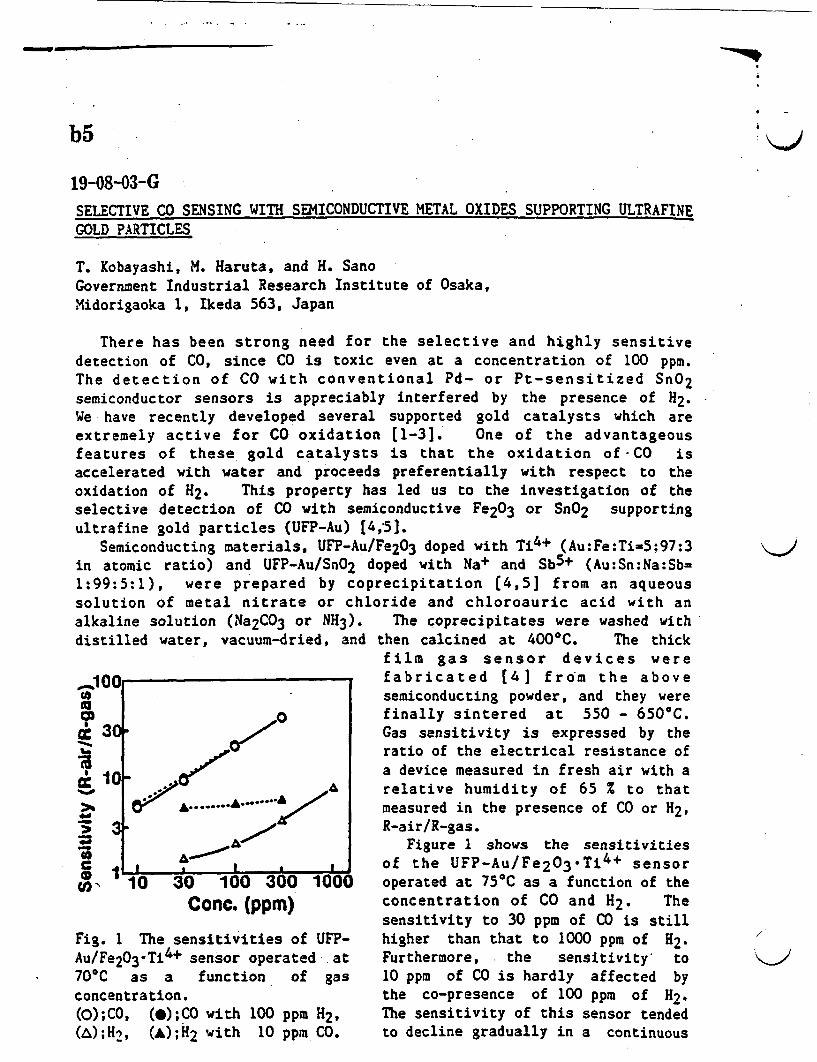
-MMM
b5
19-8-03-GSELECTIVE CO SENSING WITH SEMICONDUCTIVE METAL OXIDES SUPPORTING ULTRAFINEGOLD PARTICLES
T. Kobayashi, M. Haruta, and H. SanoGovernment Industrial Research Institute of Osaka,Midorigaoka 1, Ikeda 563, Japan
There has been strong need for the selective and highly sensitivedetection of CO, since CO is toxic even at a concentration of 100 ppm.The detection of CO with conventional Pd- or Pt-sensitized SnO2semiconductor sensors is appreciably interfered by the presence of H2.We have recently developed several supported gold catalysts which areextremely active for CO oxidation [1-3]. One of the advantageousfeatures of these gold catalysts is that the oxidation of CO isaccelerated with water and proceeds preferentially with respect to theoxidation of H2. This property has led us to the investigation of theselective detection of CO with semiconductive Fe2O3 or SnO2 supportingultrafine gold particles (UFP-Au) [4,5].
Semiconducting materials, UFP-Au/Fe2O3 doped with Ti4+ (Au:Fe:Ti-5:97:3in atomic ratio) and UFP-Au/SnO2 doped with Na+ and Sb5+ (Au:Sn:Na:Sb-1:99:5:1), were prepared by coprecipitation 4,5] from an aqueoussolution of metal nitrate or chloride and chloroauric acid with analkaline solution (Na2CO3 or NH3).distilled water, vacuum-dried, and
_--100
COc 3
i1
cc 1W-0
-
CO I
-
F.
F..
I.
AA........ /
2,U * I
The coprecipitates were washed withthen calcined at 400°C. The thickfilm gas sensor devices werefabricated [4] from the abovesemiconducting powder, and they werefinally sintered at 550 - 650°C.Gas sensitivity is expressed by theratio of the electrical resistance ofa device measured in fresh air with arelative humidity of 65 to thatmeasured in the presence of CO or H2,R-air/R-gas.
Figure 1 shows the sensitivitiesof the UFP-Au/Fe2 03Ti4 + sensoroperated at 75C as a function of theconcentration of CO and H2. Thesensitivity to 30 ppm of CO is stillhigher than that to 1000 ppm of H2.Furthermore, the sensitivity to10 ppm of CO is hardly affected bythe co-presence of 100 ppm of H2.The sensitivity of this sensor tendedto decline gradually in a continuous
_ __ _ -10 30 100 300 1000
Conc. (ppm)
Fig. 1 The sensitivities of UFP-Au/Fe2O3-Ti4+ sensor operated at70°C as a function of gasconcentration.(O);CO, ();CO with 100 ppm H2,(A);H2, (&);H2 with 10 ppm CO.
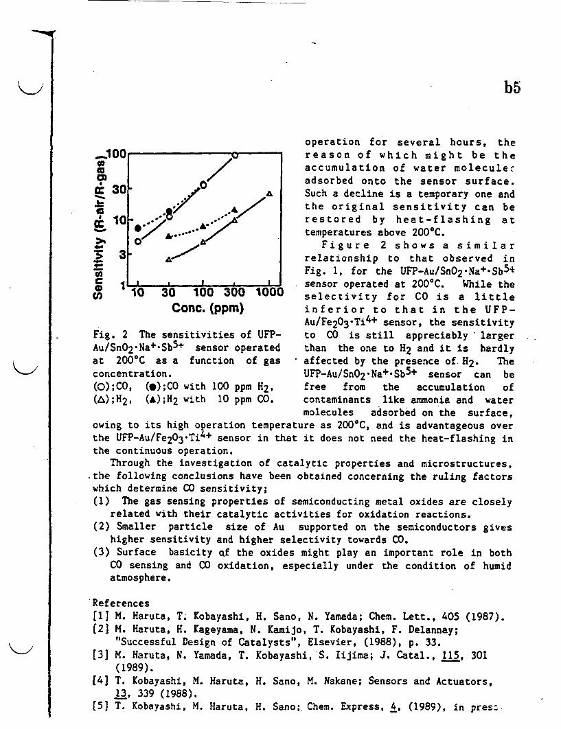
b5
operation for several hours, the100 reason of which might be theto /accumulation of water moleculesCn _ / adsorbed onto the sensor surface.tC 30 . £ ^ Such a decline is a temporary one and
the original sensitivity can beC 10 _...j restored by heat-flashing at_ *;,' . A temperatures above 2000C.a4 AFigure 2 shows a similar
> 3 relationship to that observed inFig. 1, for the UFP-Au/SnO2 Na+-Sb5+
0 1 sensor operated at 200 0C. While the10 30 100 300 1000 selectivity for CO is a littleConc. (ppm) inferior to that in the UFP-
Au/Fe2O3.Ti4+ sensor, the sensitivityFig. 2 The sensitivities of UFP- to CO is still appreciably largerAu/SnO2.Na+.Sb5+ sensor operated than the one to H2 and it is hardlyat 200'C as a function of gas affected by the presence of H2. Theconcentration. UFP-Au/SnO2.Na+.Sb5+ sensor can be(O);CO, (*);CO with 100 ppm H2, free from the accumulation of(A);H2, (A);H2 with 10 ppm CO. contaminants like ammonia and water
molecules adsorbed on the surface,owing to its high operation temperature as 200'C, and is advantageous overthe UFP-Au/Fe203Ti4+ sensor in that it does not need the heat-flashing inthe continuous operation.
Through the investigation of catalytic properties and microstructures,the following conclusions have been obtained concerning the ruling factorswhich determine CO sensitivity;(1) The gas sensing properties of semiconducting metal oxides are closely
related with their catalytic activities for oxidation reactions.(2) Smaller particle size of Au supported on the semiconductors gives
higher sensitivity and higher selectivity towards CO.(3) Surface basicity f the oxides might play an important role in both
CO sensing and CO oxidation, especially under the condition of humidatmosphere.
*References[1] M. Haruta, T. Kobayashi, H. Sano, N. Yamada; Chem. Lett., 405 (1987).(21 M. Haruta, H. Kageyama, N. Kamijo, T. Kobayashi, F. Delannay;
"Successful Design of Catalysts", Elsevier, (1988), p. 33.(3] M. Haruta, N. Yamada, T. Kobayashi, S. Iijima; J. Catal., 115, 301
(1989).[4] T. Kobayashi, M. Haruta, H. Sano, M. Nakane; Sensors and Actuators,
13, 339 (1988).[51 T. Kobayashi, M. Haruta, H. Sano;. Chem. Express, 4, (1989), in pres:-

g
vGLASS AND CERAMICS
FOR THE FUTURE
(Growth of Superconducting Whisker, Bi-System, xllOO)
GLAS AND CERAMIC MATERIAL DEPARTMENT
GOVERNMENT INDUSTRIAL RESEARCHINSTITUTE, OSAKA
BRIEF HISTORY AND BACKGROUND
Government Industrial Research Institute, Osaka, (GIRIO) was founded in
1918 as a national research laboratory to develop and promote the chemical
industry in the western area of Japan. It now belongs to the Ministry ofInternational Trade and Industry. Glass and Ceramic Material department
is one of five research departments. There is also a general adminis-
trative department within GIRIO.
Since the foundation we have pursued a wide range of studies on glass.Much of the work has borne fruits and has found application within the
Japanese glass industry. For example,. great advances in the camera
industry have been made using the result of our research on optical glass.The department began ceramic research after the second world war.
Through comprehensive studies on the effects of constituents on the
optical- properties of glass, we succeeded in developing glasses with highrefractive index and low dispersion, such as LaK and LaF. The Japanese
camera ndustry has benefited greatly from this development. Our interest
In optical glass led us to produce a large telescope mirror disc with a low
thermal expansion coefficient. We succeeded in casting high quality discs >2m In diameter. A bobbin for a precise electrical inductance coil has
made from glass with an extremely low expansion coefficient.
Borosilicate glass is well known for its durability. In the course of
research on this glass system, we have developed the technique of preparingporous glass with high silica content by phase separation and subsequent
leaching. Comprehensive developmental research is continuing on porous
glasses.Glass has the capacity to incorporate many elements. For this reason,
it may be used for the disposal of high level radioactive waste from
nuclear processes. We have conducted research and development in thisfield for more than a decade and have established the glass compositions
and melting technology necessary for solidification of nuclear waste. Thechemical and technical properties of the solidified wastes were Investigated.
We have performed excellent basic researches on, for example, phaseseparation; nucleation and crystallization; volatilization; diffusion; electrical
conductivity; mixed alkali ,effect. As will be explained after, We are nowexploring so-called new glasses.
New ceramic materials have great potential and are currently finding
1
industrial applications. We developed cutting tools made of alumina which
sh(W cxccllent performance compared with carbide tools. In the course of
our research on MHD materials, we have succeeded in developing a new
ype or heating element, made of lanthanum chromite, which is commercial-
ly produced by a private company.
We have taken part in an R/D project on high efficiency gas turbines
and are currently participating in fine ceramic project (one of the ISEDAI
projects). In these projects, our attention has been mainly focused on
composite ceramics, composed of a non-oxide ceramic matrix reinforced
with ceramic fibers or whiskers to improve the reliability.
Ceramic joining is an Important industrial problem. We have developed
many joining methods, most of which could easily applied to large scale
production.Our research interests also include functional ceramics. We have
worked on gas sensor materials and conductive perovskite-type oxides. We
are currently working on superconducting oxides which are synthesized by
melting process. So far the results look very promising.
i. 1.
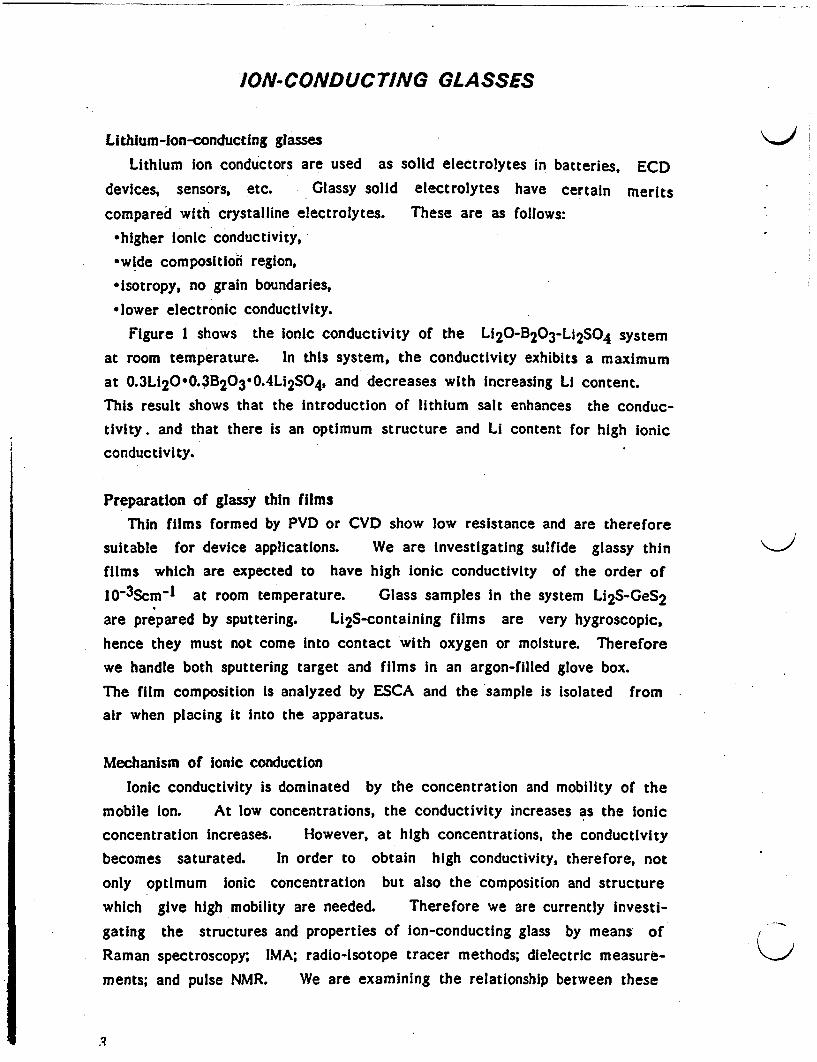
ION-CONDUCTING GLASSES
Lithium-ion-conducting glasses
Lithium ion conductors are used as solid electrolytes in batteries, ECD
devices, sensors, etc. Glassy solid electrolytes have certain merits
compared with crystalline electrolytes. These are as follows:
*higher Ionic conductivity,*wide composition region,*Isotropy, no grain boundaries,
-lower electronic conductivity.
Figure I shows the Ionic conductivity of the L120-B20 3-Li 2SO4 systemat room temperature. In this system, the conductivity exhibits a maximum
at 0.3L 20e0.3B20 3 -0.4Li 2S04, and decreases with Increasing Li content.This result shows that the introduction of lithium salt enhances the conduc-tivity. and that there is an optimum structure and Li content for high ionicconductivity.
Preparation of glassy thin filmsThin films formed by PVD or CVD show low resistance and are therefore
suitable for device applications. We are Investigating sulfide glassy thin X
films which are expected to have high ionic conductivity of the order of
10-3Scm-1 at room temperature. Glass samples in the system Li2S-GeS2
are prepared by sputtering. Li2S-containing films are very hygroscopic,
hence they must not come into contact with oxygen or moisture. Thereforewe handle both sputtering target and films in an argon-filled glove box.
The film composition is analyzed by ESCA and the sample is Isolated fromair when placing it into the apparatus.
Mechanism of ionic conduction
Ionic conductivity is dominated by the concentration and mobility of themobile ion. At low concentrations, the conductivity increases as the ionicconcentration increases. However, at high concentrations, the conductivitybecomes saturated. In order to obtain high conductivity, therefore, not
only optimum Ionic concentration but also the composition and structure
which give high mobility are needed. Therefore we are currently Investi-
gating the structures and properties of ion-conducting glass by means ofRaman spectroscopy; IMA; radio-isotope tracer methods; dielectric measure- Qments; and pulse NMR. We are examining the relationship between these
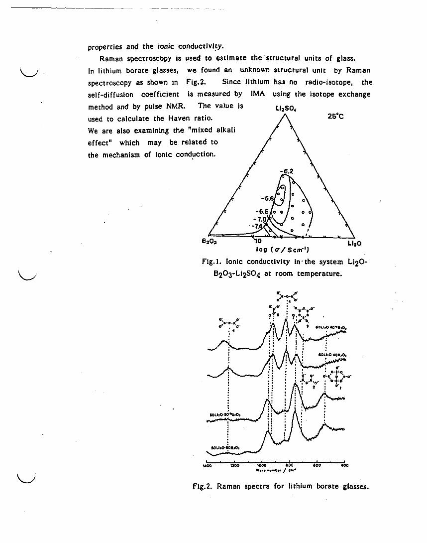
properties and the ionic conductivity.Raman spectroscopy is used to estimate the structural units of glass.
In lithium borate glasses, we found an unknown structural unit by Raman
spectroscopy as shown in Fig.2. Since lithium has no radio-isotope, the
self-diffusion coefficient is measured by IMA using the isotope exchange
method and by pulse NMR. The value is L12S04
used to calculate the Haven ratio. 250C
We are also examining the "mixed alkali
effect" which may be related to
the mechanism of ionic conduction.
-6.2
0
B203~~~~~~
log (ao/ Scml L)2
Fig. I. Ionic conductivity in -the system Li20-
< , Ei~~~~~~~~~~203-Li2S04 at room temperature.
rS-6.Soo 00'I
603 '1200 %000 * 0 o 400
5203-Li2SOWarombe empeatre
Fig.2. Raman spectra for lithium borate glasses.

HIGH LEVEL RADIOACTIVEWASTE GLASS
High-level liquid radioactive wastes generated from the reprocessing ofspent nuclear fuel must be converted to a durable solid form in order toimmobilize the radio-nuclides before they can be permanently stored. Aspart of a government directive we have for the past two decades been
carrying out a research program on the fundamental problems of thevitrification of spent nuclear fuel. The work is also in cooperation withPNC (the Power Reactor and Nuclear Fuel Development Corporation). Thefollowing topics have been studied by our group:1) We have searched for the optimum glass composition for nuclear wastecontainment. Phase separations such as crystallization and 'yellow phase'separation must be avoided in the glass formation. Screening of theglasses was done by a Soxhlet leach test.2) Other solidification processes have been Investigated. These includehot pressing and batch preparation of glass by the sol-gel method. Thewet gels were first dried and then melted by microwave heating.3) We have performed corrosion tests on refractory and electrode materialsand have developed new corrosion resistant materials for use in ceramicmelters. PNC have applied our results to the vitrification of nuclearwaste program.
Atomic transport and surface analysis in waste glass
In order to assess the long term stability of the glass, we have investi-gated the material transport properties such as Ionic diffusion, electricalconductivity of the melt, thermal conductivity, volatilization, crystallization,phase separation and corrosion in aqueous solutions.
An understanding of ionic diffusion in glasses is essential to elucidatethe leaching mechanism. The self-diffusion coefficients of alkali ions andprotons have been measured using radio isotope tracer techniques. Theself-diffusion coefficients decrease in the order Na'+proton'Cs+. Protonsplay a key role in the corrosion of nuclear waste glass.
Corroded surface layers caused by water attack have been analyzed byESCA and FTIR, which provide information about deposits in the layers andtheir dissolution in water. Figure 1 shows the ESCA depth profile of eacht
element in a hydrated surface layer of nuclear waste glass which has beencorroded by a Soxhlet leaching treatment. Alkali metals, alkaline earthelements, silicon and aluminum are depleted in the surface layer, whilst

the concentrations of rare earth elements, zirconium and iron are increased.
Ice behavior is governed by thermodynamics, whether an element leaches
(jut or deposits depends on the solubility product of its hydrate.
Comparison of the leachability of nuclear waste glasses with natural
glassesThis project, 'Research on natural analogues for leaching behavior of
nuclear waste glass forms', seeks to compare the long-term stability of
nuclear waste glasses with that of natural glasses which have undergone
weathering. However, the corrosion rate may be different owing to
differences in composition. Basaltic glasses found in nature have a similar
composition to nuclear waste glasses, although they contain no borate and
comparatively few alkali oxide ions. We have therefore compared proper-
tics such as the Soxhlet leaching ability and the diffusion coefficients of
Nu+ and protons. Figure 2 shows an example of a Soxhlet leaching test.
The corrosion rate increased when alumina was substituted by borate.
$~~~~~~~~~~~~ ,
Glass:S-1491t * Weight loss6 - SiO2
Soxhlet, 94*C, 5h
~B203
l 2 Oil \ <~~~E Na20
0)
y.; 0?O) o0 iz 5 CaOiK K20
1-- 21.5Mg I N7a~O0.8KN2 -10~~~~~~~~
-J
0~~~~
so go 120 01
Sputtering Tie (min.)B23MI
.~~th profile of leached Fig.2. The change of weight loss and leach
mured by ESCA. rate in Basalt-type glasses containing
B 20 3. The composition is as follows;
52.3 mol%S1022 (lO.3-x)AI 20 3 oxB 20 3e
2 1.5MgO I l.7CeO-O.8K 2 0*3.3Na 2 O.
6
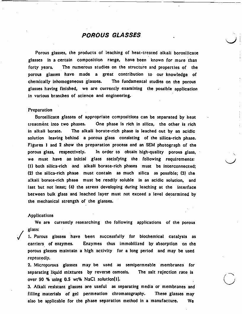
POROUS GLASSES
Porous glasses, the products of leaching of heat-treated alkali borosilicate
glasses in a certain composition range, have been known for more than
forty years. The numerous studies on the structure and properties of the
porous glasses have made a great contribution to our knowledge of
chemically nhomogeneous glasses. The fundamental studies on the porous
glasses having finished, we are currently examining the possible applicationin various branches of science and engineering.
PreparationBorosilicate glasses of appropriate compositions can be separated by heat
treatment into two phases. One phase is rich in silica, the other is richin alkali borate. The alkali borate-rich phase is leached out by an acidicsolution leaving behind a porous glass consisting of the silica-rich phase.
Figures I and 2 show the preparation process and an SEM photograph of theporous glass, respectively. In order to obtain high-quality porous glass,we must have an initial glass satisfying the following requirements:(1) both silica-rich and alkali borate-rich phases must be Interconnected;(2) the silica-rich phase must contain as much silica as possible; (3) thealkali borate-rich phase must be readily soluble In an acidic solution, andlast but not least; (4) the stress developing during leaching at the interfacebetween bulk glass and leached layer must not exceed a level determined by
the mechanical strength of the glasses.
ApplicationsWe are currently researching the following applications of the porous
glass:1. Porous glasses have been successfully for biochemical catalysis as
carriers of enzymes. Enzymes thus immobilized by absorption on theporous glasses maintain a high activity for a long period and may be used
repeatedly.2. Microporous glasses may be used as semipermeable membranes for
separating liquid mixtures by reverse osmosis. The salt rejection rate isover 90 % using 0.5 wt% NaCI solutionili.
3. Alkali resistant glasses are useful as separating media or membranes andfilling materials of gel permeation chromatography. These glasses may
also be applicable for the phase separation method in a manufacture. We
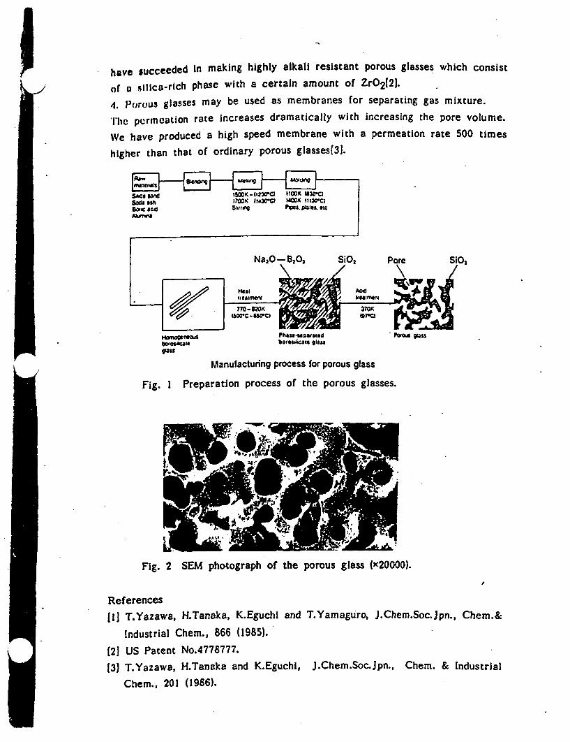
have succeeded In making highly alkali resistant porous glasses which consist
of a silica-rich phase with a certain amount of ZrO2 12).
4. Porous glasses may be used as membranes for separating gas mixture.
'Ilc permeation rate increases dramatically with increasing the pore volume.
We have produced a high speed membrane with a permeation rate 500 times
higher than that of ordinary porous glasses[3J.
Ncmo~e1WOA Phase-aparstedW~osftsIU bfOtsaicaCSm glassfas
Manufacturing process for porous glass
Fig. I Preparation process of the porous glasses.
t
the porous glass (OOOO).Fig. 2 SEM photograph of
References
[II T.Yazawa, H.Tanaka, K.Eguchi and T.Yamaguro, J.Chem.Soc.jpn., Chem.&
Industrial Chem., 866 (1985).
(21 US Patent No.4778777.
(3) T.Yazawa, H.Tanaka and K.Eguchi, JChem.Soc pn., Chem. & Industrial
Chem., 201 (1986).
i I
HALIDE GLASSES
Our halide glass team is currently working on glasses based on chlorides,
bromides and iodides, but not fluorides. The present research project of
non-fluoride halide glasses started in 1986 following a two-year preliminary
study.Much attention on ZrF 4-based glasses in glass science and technology in
the past decade has stimulated research activities on the non-fluoride halide
glasses. This is because the use of halides other than fluorides theoreti-
cally enable us to obtain glasses with ultralow optical loss, which is
superior to fluoride glasses. Another more important possibility is the
application as a glass fiber transmitting CO2 laser energy. However,
several problems arise which must be overcome before halide glasses can be
successfully used e.g. they are highly hygroscopic and have low thermal
stability. Every new glass forming system is being explored in order to
solve these problems.The final goal of our research is to establish the technology of glass
preparation, purification, and fabrication for the halide glasses. We are
also interested in the structure and fundamental properties of halide glasses
as they are intermediate between oxide glasses with more covalent bonds
and fluoride glasses with more Ionic bonds.
The hygroscopic nature of halide glasses prevents them from being
prepared by the usual method of melting in air. They are therefore
prepared in a glove box containing dry N2. Figure 1 shows the glass
forming region of the ZnBr2-BaBr2-KBr ternary systemlil. Glasses withglass transition temperatures higher than 901C have been obtained in this
system. The infrared transmission of several different types of glass is
shown in Fig. 2. This indicates that the ZnBr2-based glass Is transparent
over a wider band of wavelengths than the other glass systems.
The crystallization behavior of the ZnBr2-based glasses has been examined
by DSC. We are carrying out structural analyses of ZnX2-based and
CdX2-based glasses using vibrational spectroscopy21 and XAFS. -
The practical application of halide glasses in the near future seems to
be difficult. However, we believe that these materials will eventuallyplay an important role in the region of far-infrared optics.
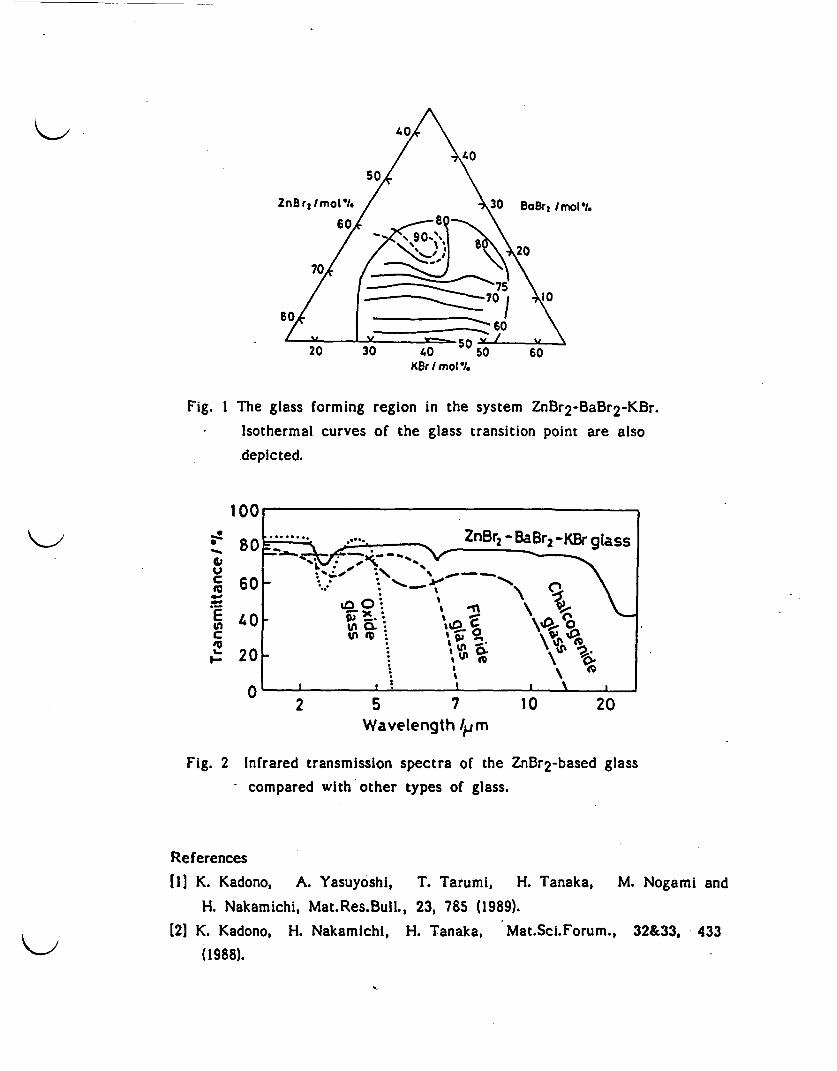
ZnBr I mo V% Z r I30 BaBr Imol'I
60
20 30 5 0KBr / mol %
0
Fig. I The glass forming region in the system ZnBr2-BaBr 2 -KBr.
Isothermal curves of the glass transition point are also
depicted.
16
0
C
(nC'UI-I--
to 0O It< I I
X I
M, 9,5 I
5 7 0
2 0 20Wavelength /Im
Fig. 2 Infrared transmission spectra of the ZnBr2 -based glass
- compared with other types of glass.
References
II K. Kadono, A. Ysuyoshi, T. Tarumi, H. Tanaka, M. Nogami and
H. Nakamichi, Mat.Res.Bull., 23, 785 (1989).
[21 K. Kadono, H. Nakamichi, H. Tanaka, Mat.Sci.Forum., 32&33, 433
(1988).
GLASS SCIENCEUNDER MICROGRAVITY CONDITION
New and pure glassy materials are required for highly functionalelements in opto-electronics technology. It is, however, difficult toprepare such glasses on the earth, since glass cannot be produced without acrucible, which contaminates the glass. Nucleation of crystals alsooccurs at the container wall and the container material restricts the upperlimit of the glass melting temperature. These difficulties can be solvedif the melting process is carried out without the crucible. In outer spaceonly very weak force is needed to control the movements of objectsexperiencing microgravity. Glasses may therefore be produced by thecontainerless melting process. The objective of this study is to developthe technology of glass production under microgravity and to prepare newglasses with superior transmittance in the non-visible region, particularlyin the infrared region.
Development of Containerless Melting ProcessThe first stage of the research was to develop a suitable furnace for
containerless melting. In cooperation with NASDA (National SpaceDevelopment Agency of Japan) and Ishikawajima-Harlma Heavy Industry(Fig.1)we developed an image furnace equipped with acoustic levitation apparatuswhich floats and holds the specimen at the center of the furnace undermicrogravity. Glass melting tests have been conducted using this furnaceat gravitational forces of 1/10-1/100 G for 20-22 seconds produced by theballistic flight of an aircraft. We succeeded in containing the materialin the center of the furnace. On melting the floating materials a sphereof molten glass was obtained(Fig.2)[1,21.
Properties of Glasses Prepared under Microgravity Conditions
In 1991, we shall conduct a glass melting experiment in the NASA spaceshuttle. We plan to prepare glasses in the system CaO-Ga 2O3-GeO 2, whichhave good near-infrared transmittance(3,41. The glass-forming region,crystallization rate and glass transition temperature have all been investi-gated at a force of IG, In order to select the most suitable glass composi-tion and operating conditions of the furnace[41. Having developedthe furnace and its operating conditions we then went on to examine theproblems of hot working of glass production under microgravity.
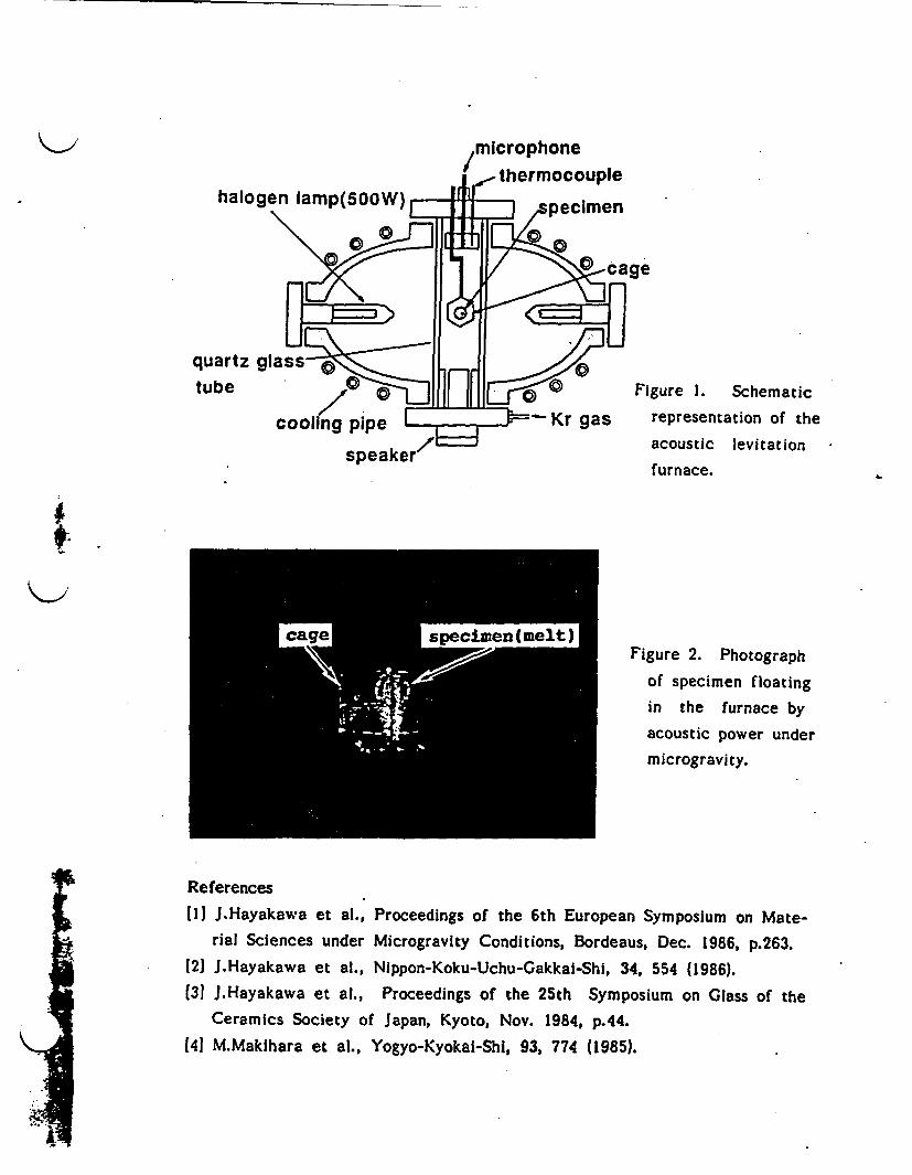
quartz glass tube /19 ] "Al9 Figure 1. Schematic
Cooling pipe Ad Kr gas representation of thespeaker /L= acoustic levitation
furnace.
i~~~~~~~~~~~~~~~~~~~~~~~~~~~~~~~~~~~~~~~~~~~~~~~~~~~~~~~~~~~~~~~~~~~~~~~~~~~~~~~~~~~~~~~~~~~~~~~~~~~~~~~~~~~~~~~~~~~~~~~~~~~~~~~~~~~~~~~~~~~~~
Figure 2. Photographof specimen floatingin the furnace byacoustic power undermicrogravity.
References
11 J.Hayakawa et al., Proceedings of the 6th European Symposium on Mate-rial Sciences under Microgravity Conditions, Bordeaus, Dec. 1986, p.263.
[2] J.Hayakawa et al., Nippon-Koku-Uchu-Gakkai-Shi, 34, 554 (1986).(31 J.Hayakawa et al., Proceedings of the 25th Symposium on Glass of the
Ceramics Society of Japan, Kyoto, Nov. 1984, p.44.[41 M.Maklhara et al., Yogyo-Kyokal-Shi, 93, 774 (1985).
I

XPS and UPS measurement
Measurement of electconductivity of ionic-conductive glass
Preparation of halide glassin dry atmosphere
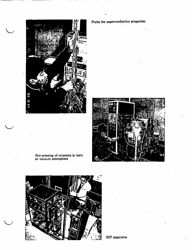
Probe for superconductive properties
Hot-pressing of ceramics in inertor vacuum atmosphere
31 HIP apparatus

GLASSES FOR NON-LINEAR OPTICAL DEVICES
Materials which have non-linear optical properties have attracted much
attention in the fields of information processing and optical communications.Switching devices, optical bistable devices, amplifiers and modulators allmakes use of non-linear optical effects. Glass dispersed with semi-
conductors is one candidate material, since various optical properties ofsemiconductors are more easily controlled in a glass matrix. In this
department, we are developing the basic technology for producing glassesdispersed with a semiconductor which have well controlled characteristics.Control of the composition and of the dispersion conditions is importantas are the particle size and shape of the dispersed semiconductor. Newprocesses for producing glasses with a dispersed semiconductor are alsobeing investigated.
ACCURATE DETERMINATION OF REFRACTIVE INDEXOF SILICA GLASSES
Refractive index (n) and Its temperature coefficient (dn/dT) have been
determined accurately for various silica glasses. In the ultra-violet(UV) region, photo-lithography is of great importance, for fabrication -of
semiconductor LSI circuits. Silica glass is an ideal material for trans-mitting UV light since it does not degrade on irradiation. It is commonlyused as a lens material in UV light projectors. Lenses to be used at248nm require n to be known to an accuracy of ±1x10⁻⁵ or better. The
temperature coefficient of n is about IXlO-5/1C for most silica glasses atroom temperature so the ambient temperature of the lens must becontrolled to within 1°C. The value of n is found to depend on the
�11� i�
fabrication method and thermal historystudying the way in which n Is relatedreflects the thermal history of the glass
refractive index.
of the glass. We are currentlyto specific gravity, which directlyand is easier to measure than the
<9
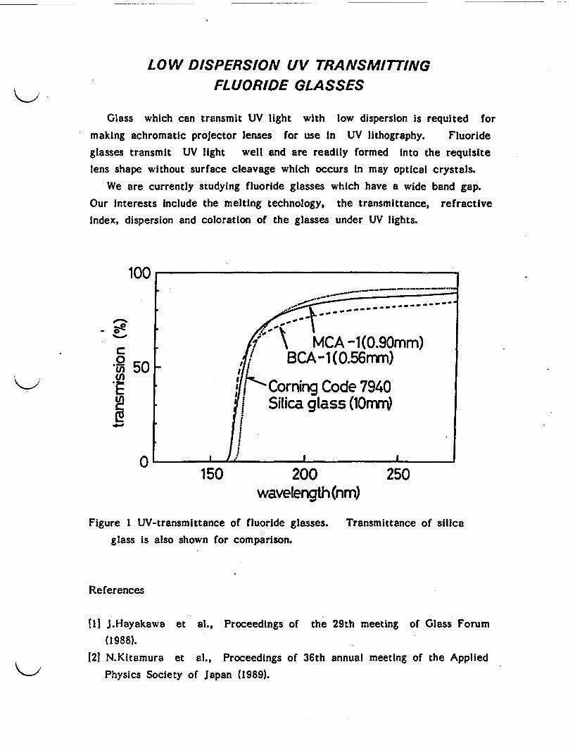
LOW DISPERSION UV TRANSMITTINGFLUORIDE GLASSES
Glass which can transmit UV light with low dispersion is requited formaking achromatic projector lenses for use In UV lithography. Fluoride
glasses transmit UV light well and are readily formed Into the requisitelens shape without surface cleavage which occurs In may optical crystals.
We are currently studying fluoride glasses which have a wide band gap.
Our Interests Include the melting technology, the transmittance, refractiveindex, dispersion and coloration of the glasses under UV lights.
100
0
C0cnI.e
50 F
-e - -- --
r0 A MCA -1(0.90mm)BCA-1 t0.56mm)
4"' Corning Code 7940Silica glass (OU
I I0 I /
150 200wavelength (nmr
250
Figure I UV-transmittance of fluoride glasses.glass is also shown for comparison.
Transmittance of silica
References
[1n J.Hayakawa et al., Proceedings of the 29th meeting of Glass Forum(1988).
121 N.Kitamura et al., Proceedings of 36th annual meeting of the AppliedPhysics Society of Japan (1989).
CERAMIC COMPOSITE
Brittleness is the weakest point of ceramics when they are used as
structural components for example In a diesel engine or a gas turbine.
One of the ways to overcome this problems is- "toughening" of the ceramic
through reinforcement with fibers or particles. In such CMC (Ceramic
Matrix Composite), fibers or particles improve toughness by dissipating or
absorbing fracture energy at the top of crack front. Research on CMC's
with various combinations of matrix and fibers/particles is one of the main
themes of ceramic research in our department. Current efforts in this
area are as follows:
Whisker reinforced composite
As whiskers of SIC or Si3 N 4 have very high strength and refractivity,
they are suitable for use as the reinforcing fiber in CMC's. CMC's with
various matrices such as S 3 N 4, SC, and A1203 are being investigated.
The SiC(whisker)/Si3 N4 composite( 11, which was first successfully
fabricated in our department, exhibits an strength increase at temperatures
over 11000C. This is attributed to the fact that the whisker which
prevent grains from sliding at high temperatures. Both fracture toughness
and wear-resistivity are also enhanced[2J. Whisker incorporation has a
remarkable effect on the electric resistivity, which decreased markedly from
that of Si3 N4 which is an insulator to about 10 ohm cm or less. Such a
low, resistivity means the composite can be subjected to electric discharging
machining (see Fig.1).
One of current topics of interest is to tailor the texture of whisker-
reinforced CMC's. SiC or Si3 N4 whisker are mixed with organosilicon
polymer, which forms a matrix of SC or S 3N4 upon pyrolysis. The
interface between the whisker and matrix is also being investigated.
Other research is aimed at clarifying the fundamental phenomena in the
composite forming process, In order to develop highly reliable ceramics for
gas turbine components. The effects of fibers or sintering aids on toughness
and on densification behavior of CMC are being studied.
Long fiber-reinforced composite
CMC's reinforced with a continuous fiber such as SC fiber or carbon
fiber attracts much attention as they have extraordinary toughness similar
to that of bamboo or other wooden material. Such composites are expect-

ed to be the next generation material of choice for structural application eg.
in the aerospace industry. We are currently looking at ways of improving
fabrication of the composite without damaging the fiber in the process.
Particle reinforced composite
Ceramics have medical applications as they can be used to make
artificial bone or tooth. The texture of apatite is similar to that of
human bone, but It suffers from low strength. The strength and toughness
may be improved by dispersing ZrO2 particles in it.
Several combinations of different matrices and particles are currently
being studied. ZrC particle / B 4C matrix composite exhibits Improved
strength and toughness. A roller bearing made of Si3N4 dispersed with TiC
particles had a longer lifetime than one made from Si3N4 alone.
Fig.1 I C(whlsker)/S13N4 composite pieces machined
by means of electric discharging. I~1 cm
(11 R.Hayami, K.Ueno, .Kondo, N.Tamari and Y.Toibana, Tailoring Multiphase
and Composite Ceramics, ed. by R.Tressler, G.L.Messing, C.G.Pantano and
R.E.Newnham, pp. 663-674, Plenum Pub. Co., 1986.
[2J H.Jshigakl, R.Nagata, M.Jwasa, N.Tamarl and I.Kondo, Tran. ASME J.
Tribology, 110, 434-438 (1988).
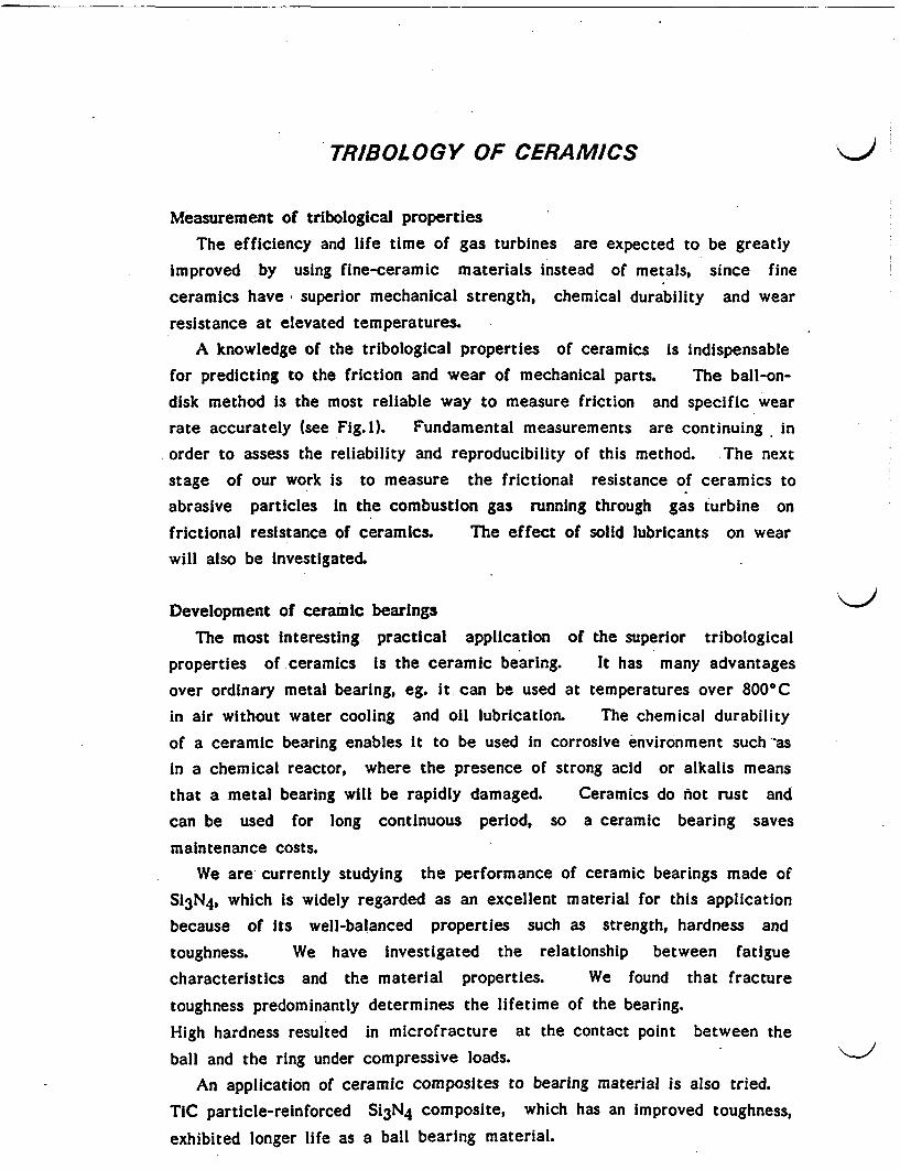
TRIBOLOGY OF CERAMICS
Measurement of tribological propertiesThe efficiency and life time of gas turbines are expected to be greatly
improved by using fine-ceramic materials instead of metals, since fine
ceramics have superior mechanical strength, chemical durability and wearresistance at elevated temperatures.
A knowledge of the tribological properties of ceramics is indispensablefor predicting to the friction and wear of mechanical parts. The ball-on-
disk method is the most reliable way to measure friction and specific wearrate accurately (see Fig.1). Fundamental measurements are continuing in
order to assess the reliability and reproducibility of this method. The nextstage of our work is to measure the frictional resistance of ceramics toabrasive particles in the combustion gas running through gas turbine on
frictional resistance of ceramics. The effect of solid lubricants on wearwill also be investigated.
Development of ceramic bearings
The most interesting practical application of the superior tribologicalproperties of ceramics is the ceramic bearing. It has many advantages
over ordinary metal bearing, eg. it can be used at temperatures over 8000Cin air without water cooling and oil lubrication. The chemical durability
of a ceramic bearing enables it to be used in corrosive environment such asin a chemical reactor, where the presence of strong acid or alkalis means
that a metal bearing will be rapidly damaged. Ceramics do hot rust and
can be used for long continuous period, so a ceramic bearing saves
maintenance costs.We are currently studying the performance of ceramic bearings made of
S13N4, which is widely regarded as an excellent material for this applicationbecause of ts well-balanced properties such as strength, hardness andtoughness. We have investigated the relationship between fatiguecharacteristics and the material properties. We found that fracture
toughness predominantly determines the lifetime of the bearing.
High hardness resulted in microfracture at the contact point between theball and the ring under compressive loads.
An application of ceramic composites to bearing material is also tried.
TIC particle-reinforced Si3N4 composite, which has an improved toughness,
exhibited longer life as a ball bearing material.
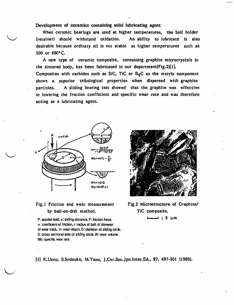
Development of ceramics containing solid lubricating agent
When ceramic bearings are used at higher temperatures, the ball holder
(retainer) should withstand oxidation. An ability to lubricate is also
desirable because ordinary oil is not stable at higher temperatures such as
500 or 600§C.A new type of ceramic composite, containing graphite microcrystals in
the sintered body, has been fabricated in our department(Fig.2)11].Composites with carbides such as SiC, TiC or 4C as the matrix component
shows a superior tribological properties when dispersed with graphite
particles. A sliding bearing test showed that the graphite was effectivein lowering the friction coefficient and specific wear rate and was therefore
acting as a lubricating agent.
P PF/P _
F r4; h d21
Fig. Friction and wear measurement
by ball-on-disk method.
P: applied bad. x: sliding distance. F: friction force.p : coefficient of friction. r: radius of ball. d: diameterof wear track. h wear depth. D: diarrgter of sliding circle.S: cross sectional area of sliding circle. W: wear volneWs: specific wear rate
Fig.2 Microstructure of Graphite/TIC composite.
L '; 5 prm
111 KUeno, S.Sodeoka, M.Yano, J.Cer.Soc.Jpn.lnter.Ed., 97, 497-501 1989).

SUPERCONDUCTING CERAMICS
A Superconducting cuprate (La-Ba-Cu-O) was first reported by Bednorz
and Muller in 1986, and a number of studies on this material have beenundertaken all over the world. Our institute started to investigate thesuperconducting ceramics at the Glass and Ceramic Material departmentin 1987.
The effects of sulfur additionThe effects of sulfur addition on the superconductivity of Y-Ba-Cu-O
system were studiedil). We examined whether the substitution of oxygenwith sulfur took place or not, and expected to improve the superconductivityby adding sulfur to the Y-Ba-Cu-O system. Sulfur-containing compoundswith nominal compositions YBa2Cu 3OxSy were prepared by the solid statereaction method using CuS or Cu2S instead of CuO. By this method, sulfuratoms were not Incorporated into the crystal lattice of the 1:2:3 phase andmade It multiphasic. Although Tc(critical temperature) was lowered withincreasing sulfur content, Jc(critical current density) for y=0.03 was abouttwice as high as that for y=0.00, this is due to the Increasing the bulk.density by adding sulfur.
Superconducting glass ceramicsThe new type superconducting oxide, B-Sr-Ca-Cu-O system, was found
by Maeda et. al. In 1988. The characteristic nature upon processing is thatthe Bi-Sr-Ca-Cu-O compounds form a glassy state when it is rapidlyquenched from a molten state. We have been researching into the crystal-lization of superconducting phases from a glassy melt-quenched solid. Wefound that the addition of Ga or Ge to the B-Sr-Ca-Cu-O system waseffective for manufacturing when the glass was formed. The wide glassforming region is obtained by adding Ga or Ge. We made fibers andribbons (10cm length) by the melt-quench method using a single roller withGa or Ge additives. After heating at 8200C, the ribbons showed Tc(end)at 77-80K. We determined the composition region where the super-conductivity was maintained in spite of the improvement in manufacturing.
Superconducting whiskersThe superconducting whiskers of Bi(Pb)-Sr-Ca-Cu-O were prepared by
heating a glassy melt-quenched plate in a stream of oxygen gas (Fig.l).

* The dimensions of the whiskers are 2-10im x 10-300um x -15mm. The
whiskers have the 2212 structure (low-Tc phase) and show a zero-resistance
state at 70K. Each whisker exhibits the structure where several platelike
single crystals are stacked. The orientation of the longest c axis is
perpendicular to the platelike crystal plane and the ab plane is parallel to
the crystal plane. The whiskers are able to be bent to a radius of
curvature(R) of 0.4mm without a decrease in the Tc value. The highest
Jc is 67000A/cm 2 (63K, zero magnetic field) in a nonbending state. It
surpasses 35000A/cm2 even in a bending state of R mm and finally
decreases down to 3200A/cm2 for R=0.4mm (Fig.2). Our further subjects
for study related to the whiskers are the elucidation of the growth
mechanism, preparation of high-Tc whiskers, lengthening the whiskers and
evaluation of the mechanical properties[2,31.
lending Sirela %to1 LI 12 e*.
7g~~~~~~~~~~~~~~~1
- llearwalre 1|d11.|gso- 4
i0 0 0 0 Ica
30
50010~~~~~~~~~~~~~~~~4
I 0
cla I I-. r rdi. m
Fig.1 The whiskers of B(Pb)-Sr-Ca- Fig.2 The Tc and Jc (63K, zero
Cu-O grown by heating a glassy melt- magnetic field) of the whiskers
quenched plate in a stream of oxygen as a function of the radius of
curvature.
References
[11 I.Matsubara, H.Tanigawa, T.Ogura and S.Kose, Jpn.J.Appl.Phys., 27, 1080
(1988).
[21 I.Matsubara, H.Kageyama, H.Tanigawa, T.Ogura, H.Yamashita and
T.Kawai, Jpn.J.Appl.Phys., 28, 1121 (1989).
[31 I.Matsubara, H.Tanigawa, T.Ogura, H.Yamashita, M.Kinoshita and T.Kawai,
Jpn.J.Appl.Phys., 28, 1358 (1989).

CERAMIC COATING
Ceramic coating by the plasma spraying technique is being studied.
METCO 9MB Low-Pressure-Plasma-Spraying (LPPS) system and TAFA 90HVAtmospheric-Plasma-Spraying (APS) system are used in this section. Plasma
spraying is one of the coating processes in which molten raw material
powders are accelerated and shot onto the substrate in the plasma flame.In principle, anything that can be melted is applicable as the sprayedmaterial. Any material may be coated when it is adequately cooled.
Ceramic-ceramic composite coating and non-oxide ceramic coating are
studied as part of the ordinary research and development "A study on theceramic coating by low pressure plasma spraying". Coatings made of
non-oxide ceramics, such as SC, S 3N 4, etc., are expected to resist wearat high temperature. However, non-oxide ceramic coatings can not be
made by plasma spraying in air because of thermal decomposition. Thesecoatings are achieved when the appropriate spraying aid is added and thespraying Is carried out in a closed chamber with the a controlled
atmosphere.
Vacuum chamberPowder ~~~~~~~~mechanical
feeder gun f 1 ilter star pump
nbsdust collector rotary pump
Fig.1 Low-Pressure-Plasma-Spraying Fig.2 Plasma flame at 300 torr,system. 40kW.
FLUORINE RESISTIVE ENAMELS
This research aims at development of fluorine resistive coatings on
metals to be used in the fluorine chemical and semiconductor industries.

In these fields, corrosion of tanks and pipes by fluoride gasses or fluoric
acids causes severe safety problems. Traditional enamels composed of oxides
are easily attacked by these fluorides leading to failure in a closed system.Fluoride enamels, on the other hand, composed of metal fluorides such
as MgF2, CaF2, SrF2, BaF2, NF 2, YF3, etc. are highly resistive to theseatmospheres, even at moderately high temperatures. They are therefore
promising materials for use in this field. We are surveying glass
compositions which are durable to these gasses and acids, and are highlyadhesive to metals without fracture at elevated temperatures under bending
stress.
THEORETICAL STUDYOF CERAMIC INTERFACES
Various properties of ceramics depend on grain boundaries, mechanical
and electrical properties and sintering ability. The joining between ceramicsand metals is an essential technique in order to realize the practical use ofceramics. It is essential to understand the fundamental properties of grainboundaries and interfaces in ceramics and of metal/ceramic Interfaces froma macroscopic viewpoints. We are Investigating theoretically the atomic
structure and properties of grain boundaries in covalent ceramics such as
SiC and of metal/ceramic interfaces such as alumina/transition metalinterfaces. In these systems, it is necessary to calculate the electronicstructure of the interface. With powerful modern computers, interfacial
electronic structures, stable atomic configurations and interfacial energies
can be calculated using the electronic theory of solids. The effects ofimpurities and the dependence on the kinds of ceramics and metals arealso being examined. By comparing the calculated results with observationsand experiments, such as HREM images and photoelectron spectroscopy, itis possible to understand the fundamental properties of grain boundaries
and interfaces from a microscopic viewpoint.
References
[I1 M.Koyama et al., J.Phys. C 21, 3205 (1988).
[21 M.Koyama et al., J.Phys. C 21, 695 (1988).[31 M.Koyama et al., Trans. ISIJ 28, 836 (1988).
14] M.Koyama et al., Phys.Status Solidi b 152, 533 (1989).151 M.Koyama et al., to be published in J.Phys.:Condens.Matter (1988).
ORGANIZATION AND OTHER ACTIVITY
This department consists of 5 sections. Three of them deal with glass
research and two with ceramics. The total research staff number 33.
We have-now more than 20 research projects both large and small. Some
of them are inter-sectional and inter-departmental. We participate in
national R&D projects, most of which are in cooperation with other national
laboratories and private companies.
Organization and main research fields
Director: Dr. M. Kinoshita
Glass technology section: Mr. J. Hayakawa
Glass melting under microgravity, optical properties of glasses.
Glass science section: Dr. H. Wakabayashl
Ion conducting glasses, technology of waste management.
Advanced glass section: Dr. H. Tanaka
Halide glasses, porous glass, non-linear photonic materials.
Engineering ceramics section: Mr. S. Kose
Composite ceramics, ceramic coating, tribology, ceramic interfaces.
Functional ceramics section: Dr. H. Yamashita
Superconducting oxides, fluorine resistive materials.
Other Activities
Most of the researchers in this department are members of the Ceramic
Society of Japan. We also have close contact with other societies such as
those of optical glass, applied physics, power metallurgy, and fine ceramics.
Ours is the only national laboratory dealing widely with glass.
We have therefore run a glass technology course for foreign researchers for
many years.
There are several invitation schemes applicable to foreign researchers,
whose numbers in our institute have been increasing in recent years.

The main building of the glass and ceramic materialdepartment
The annex of the department
GLASS AND CERAMIC MATERIAL DEPARTMENT
GOVERNMENT INDUSTRIALRESEARCH INSTITUTE, OSAKA
8-31 MIDORIGAOKA-1, IKEDA,OSAKA 563
PHONE: (0727) 51-8351TELEFAX: (0727) 51-2156
OMAL OF CATALYSIS 115, 301-309 (1989)
Gold Catalysts Prepared by Coprecipitation for Low-TemperatureOxidation of Hydrogen and of Carbon Monoxide
M. HARUTA,* N. YAMADAJ T. KOBAYASHI, AND S. IUIMA*'
t "Government Industrial Research Institute of Osaka, Midorigaoka 1, Ikeda 563. Japan; tashida ChemicalsCompany, Ltd., Joshoji-machi, Kadoma 571. Japan; and tResearch Development Corporation of Japan,
Science Bulding. 5-2 Nagata-cho 2-chome. Tokyo 1(. Japan
* Received October 7, 1987; revised June 6. 1988
Novel gold catalysts were prepared by coprecipitation from an aqueous solution of HAuCL andthe nitrates of various transition metals. Calcination of the coprecipitates in air at 400C producedultrafine gold particles smaller than 10 um which were uniformly dispersed on the transition metaloxides. Among them. Au/a-Fe2O,. Au/Co3O4, and Au/NiO were highly active for H. and COoxidation, showing markedly enhanced catalytic activities due to the combined effect of gold andthe transition metal oxides. For the oxidation of CO they were active even at a temperature as lowas -7(TC. o iJ9 Acadmic Prs. Inc.
INTRODUCTION
During the course of an investigation intonew oxide catalysts useful for the low-tem-perature catalytic combustion of hydrogen(1-4), it became evident that the catalyticactivities of transition metal oxides for hy-drogen oxidation had a volcano-like rela-tion with the heat of fornation of oxides pergram-atom of oxygen (5). The volcano rela-tion indicates that the formation of metal-oxygen (M-O) bonds is rate determiningfor the oxides of Ag and Au, which are lo-cated on the left side, while the breaking ofM-O bonds is the slow step for the othermetal oxides located on the right side.Therefore, an attempt was made to developcomposite oxides of Ag with the 3d transi-tion metals, for which an enhancement inboth catalytic activity and thermal stabilitywas expected.
Our earlier paper (5) reported that an ap-preciable enhancement in catalytic activitywas, in fact, achieved in some compositeoxides of silver with 3d transition metalswhich were prepared by coprecipitation.Specifically, a mixed oxide composed of
'Present address: NEC Corp., Miyazaki 4. Mi-yamae, Kawasaki 213, Japan.
Co. Mn, and Ag (20:4: 1 in atom ratio) wasboth thermally stable and highly active forthe oxidation of H2 and CO. The successfulresults obtained for these composite oxidesof silver led us to expect that a significantenhancement in catalytic activity mightalso be exhibited by composites of gold andthe other metal oxides. The present investi-gation into gold-based oxide catalysts wasundertaken to test this hypothesis.
Previous work on gold catalysts has beenreviewed by several authors (6-10). All thegold catalysts investigated so far are goldsupported on inactive ceramic oxides, suchas SiO2 (11-17), A1203 (14-16, 18), MgO(15-17, 19), and TiO2 (20), or unsupportedgold filaments (21). powder (22, 23),sponges (24), filings (25), and gauze (26).
The chemical reactivity of gold catalystshas been studied for the oxidation by-oxy-gen or nitrogen oxides of CO (11, 22,24,26)and H2 (12, 15, 17, 21-23), selective oxida-tion of organic compounds by nitrogen di-oxide (13), hydrogenation of alkenes (7),and so on. However, the conventional goldcatalysts prepared by impregnation havebeen reported to be usually far less activethan platinum-group metal catalysts, al-though they are superior in selectivity foronly a few reactions such as the oxidation
3010021-9517189 3.00
Copyright C 19K9 y Acadeic Prc%%. Iac.AM right o rmproductioa i any hrm ws ed.
EMWWWWP__�WkikAws"i
302 HARUTA lI AL. I p
.
of -pentanol to -pentaldehyde by N02(13) and the hydrogenation of I-penten ton-pentane (7). The present paper deals witha new type of gold catalyst prepared by co-precipitation instead of impregnation. In aprevious short communication (27), we re-ported that combination with the oxides ofGroup V111 3d transition metals makes goldso active that it catalyzes the oxidation ofCO. even at -70C.
EXPERIMENTAL
The gold catalysts were prepared by co-precipitation. An aqueous solution of chlo-roauric acid and a transition metal nitratewas poured into an aqueous solution of so-dium carbonate under stirring. The precipi-tate was washed, vacuum dried, andcalcined in air at 400'C for 4 h. Gold pow-der and the simple oxides of Fe, Co, and Niwere also prepared in this manner. Conven-tional gold catalysts were prepared by im-mersing support oxides in an aqueous solu-tion of HAuCI4 with a small excess volume.After drying, the impregnated sampleswere reduced with hydrogen at 200 or3000C. They were then washed in hot waterseveral times and dried in air at 200TC. Thesupport oxides used were a-Fe 2O3 calcinedat 4000C (SA - 42 m21g) and I-A120% (anhy-drous extra pure, Merck, SA - 97 m2/g).Another type of gold catalyst was preparedby the reduction of HAuCI with diammo-nium citrate in an aqueous dispersion ofcolloidal SiO2. (STO, Nissan ChemicalsInd., Ltd.). This catalyst was finallycalcined in air at 3000C after washing anddrying.
All the starting materials used were re-agent grade (Kishida Chemicals Co., Ltd.).Elemental analysis of chloroauric acid tet-rahydrate (HAuCL4 4H20) was conductedby means of atomic emission spectroscopyusing an inductively coupled argon plasmasource (Hitachi, Ltd., ICP Emission Analy-sis System 306) to determine the impuritylevels of Pd, Pt, and r, because traceamounts of these Pt-group metals maysometimes account for part or almost all the
catalytic activity of the gold sample understudy (10). The impurity levels were ap-proximately 11, 2, and 7 ppm, for Pd, Pt,and Ir, respectively.
Catalytic activity measurements werecarried out in a small fixed-bed reactor,with 0.20 g of catalyst that had passedthrough 70- and 120-mesh sieves. After thepretreatment of catalysts in a dried airstream at 2000C for 30 mn, a standard gasconsisting of 1.0 vol% H2 or CO balancedwith air to I atn was passed through thecatalyst bed at a flow rate of 66 ml/min.This reaction gas was dried by passingthrough columns of silica gel and P20S gran-ules. In the experiments at temperaturesbelow WAC, the reaction gas was furtherpassed through a silica gel column cooled to-77C to prevent the accumulation of mois-ture in the catalyst bed. In order to investi-gate the influence of moisture on the cata-lytic activity, the reaction gas was passedinto a constant moisture device (28) whichcontained saturated NH4CI aqueous solu-tion. The relative humidity of the reactiongas was kept constant at 76%, as confirmedby humidity measurements using a Humi-dector (Shinyei Co., Ltd.).
Activated carbon and molecular sieve13X were used as column packing agents toanalyze CO2 and CO, respectively, in theeffluent gas by a gas chromatograph. Theconversion efficiencies, determined fromthe changes in concentrations of CO2 andCO, were in good agreement with eachother under all the conditions tested.
The activity of a given catalyst is usuallyexpressed in terms of the temperature cor-responding to 50% conversion (T1,2), whichcan be obtained from the conversion vstemperature curves. A lower temperaturefor T indicates correspondingly greatercatalytic activity.
Specific surface areas were determinedby the single-point method using a Quanta-sorb surface area analyzer. A mixture of 30vol% N2 in He gas was used, with N2 asadsorbate at a temperature of -195.8°C.The reproducibility of the data was within
9h
Ku
V
I&1
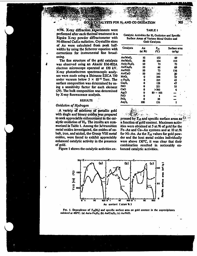
� y., :
M�'''F�' - I..' H AND CO 0XIDAnION; , . . ISIS FOR
US%. Xray diffiracdo .. eriments wereperformed after each thermal treatment in aRigaku X-ray powder diffractometer withNi-filtered CuKa radiation. Crystallite sizesof Au were calculated from peak half-widths by using the Scherrer equation withcorrections for instrumental ine broad-ening.
The fine structure of the gold catalystsA was observed using an Akashi EM002A
electron microscope operated at 120 k.X-ray photoelectron spectroscopic analy-ses were made using a Shimazu ESCA 750under vacuum below x 10-6 Torr. Thesurface composition was determined by us-ing a sensitivity factor for each element(29). The bulk composition was determinedby X-ray fluorescence analysis.
TABLE I
Catalytic Activities for H2 Oxidation and SpecificSurface Areas of Various Metal Oxides and
Gold Catalysts
Catalysts Au TM Surface a(at.%) (C) (MIg)
Au/MaO, 10 152 69AutMaO, SD 134 115Auka-Fc32 to 73 73Au/Co 3O, 10 66 69Au/NiO 10 73 116AuxuO 10 143 PMnO 0 24; 32a-FeA0 0 225 43Co3 4 0 128 47NiO 0 221 55CuO a >300 6AgIO 0 89-103 -PdO 0 I -
PtOZ 0 38 _AuzO3 100 131 1
RESULTS
Oxidation of HydrogenA variety bnaxtie f metaic gold
with single and binary oxidepvas preparedto seek appreciable enhancement in the cat-alytic oxidation of H2. The results are sum-marized in Table 1. Among the 3d transitionmetal oxides investigated, the oxides of co-balt, iron, and nickel, the Group VIII metaloxides, were found to exhibit appreciablyenhanced catalytic activity in the presenceof gold.
Figure 1 shows the catalytic activities ex-
. ' -.. - - -
pressed by TL* and specific surface areas asa function of gold content. Maximum activ-ities were obtained at at.% of gold for theFe-Au and Co-Au systems and at 10 at.%for Ni-Au. As the T 2 values for gold pow-der and the host metal oxides individuallywere above 1300C, it was clear that theircombination resulted in noticeably en-hanced catalytic activities.
Cd
II.I
Au content (atom )
FIG. 1. Dependence of TJ1HJ and specific surface area on gold content in the coprecipitatescalcined at 40C. (a) Aufa-Fe1Oh; (b) AuJCo3O.; (c) AutNiO.
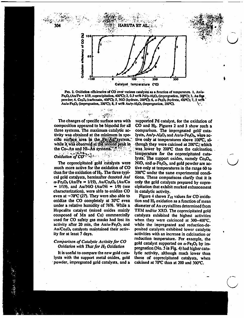
. -�'- .. ---
-.7 .. , Aa_ I. -..,. ,,ti�; , - - -',*- -, -, -
. " , -, 4-3�;7 -.1 .X- --. 1� . 1:. - . .. �w
I &
0 100 .s 200
Catalyst temperature (OC)
Fo. 2. Oxidation efciecndces of CO over various catal yatsas a function of temperature. 1. Au/a-Fe2O, (Au/Fe - 1/19, coprecipitation, 4WC); 2, 0.3 wt% Pd/-AlA (impregnation. 30 3. Au fpowder; 4, Co3O. (carbonate, 400'); 5, NiO (hydrate. 200C); 6, a-Fe2h (hydrate, 400C; 7, 'bl%Au/a-FeA (impregnation 200; S. 5 wt9% Au/rA1O0 (Impregnation, 20(tC). V.
- r ~
The changes of specific surface area withcomposition appeared to be bipodal for allthree systems. The maximum catalytic ac-tivity was obtained at the minimum in spe-cifc suarefia hIi theMCR em,while it, ase e v.NX inthe Co-Au and Ni-Aa system e?-
Oxidation Iof C - i : -
The coprecipitated goid.catalysts weremuch more active for the oxidation of COthan for the oxidation of H2. The three typi-cal gold catalysts, hereinafter denoted Au/a-Fe2O3 (Au/Fe - 1/19), Au/Co304 (Au/Co= 1/19), and AuiNiO (Au/Ni - 119) (seecharacterization), were able to oxidize COeven at -7OC (27). They were also able tooxidize the CO completely at 3C evenunder a relative humidity of 76%. While aHopcalite catalyst (mixed oxides mainlycomposed of Mn and Cu) commerciallyused for CO safety gas masks had lost itsactivity after 20 min, the Au/a-Fe 203 andAuICo304 catalysts maintained their activ-ity for at least 7 days.
supported Pd catalyst, for the oxidation ofCO and H2. Figures 2 and 3 show such acomparison. The impregnated gold' cata-lysts, Au/rA1203 and Au/a-Fe 2O3 , were ac-tive only at temperatures above lOC..al-
* though they were calcined at 200aC: whichwas lower by 200PC than the calcinatioix.temperature for the coprecipitated cata-lysts. The support oxides, namely Co30.,NiO, and a-Fe203 , and gold powder are ac-tive only at temperatures in the range 60 to300TC under the same experimental condi-tions. These comparisons clarify that it isonly the gold catalysts prepared by copre-cipitation that exhibit marked enhancementin catalytic activity.
Figure 4 shows T,2 values for CO oxida-tion and H2 oxidation as a function of meandiameter of Au crystallites determined fromTEM and/or XRD. The coprecipitated goldcatalysts exhibited the highest activitieswhen they were calcinced at 300-4000 C,while the impregnated and reduction-de-posited catalysts exhibited lower catalyticactivities with an increase in calcination orreduction temperature. For example, thegold catalyst supported on a-Fe2O, by im-pregnation (No. in Fig. 4) had higher cata-lytic activity, although much lower thanthose of coprecipitated catalysts, whencalcined at 7CC than at 200 and 300C.
K-)
Comparison of Catalytic Activity for COOxidation with Thatfor Hz OxidationIt is useful to compare the new gold cata-
lysts with the support metal oxides, gold-powder, impregnated gold catalysts, and a
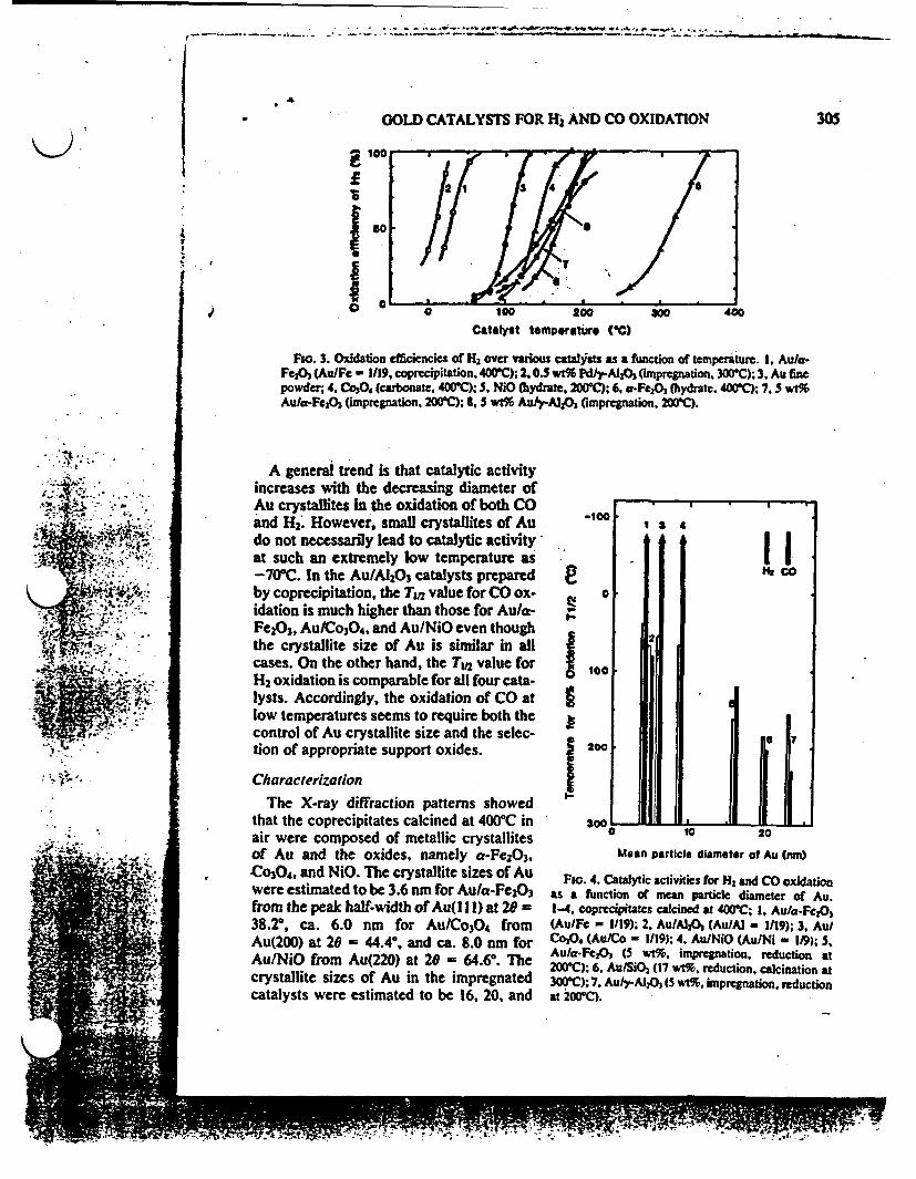
r - v .. *s~w- - .. - .-.; P - e....0 p -- .
at
0 GOLD CATALYSTS FOR H2 AND CO OXIDATION 305
I
I0
Catalyst temperature ARC)
Fm. 3. Oxidation efficiencies of H2 over various catalsts as a function of temperature. 1, Au/a-FeO 1 (Au/Fe - 119, coprecipitation. 400"C); 2, 0.5 wt% Pdti-AIA (impregnation, 300&C); 3, Au finepowder; 4, Co3O, (carbonate. 40C); S. NiO (hydrate, 200C); 6, a-Fe203 (hydrate. 41C; 7,5 wt%Aula-FeO3 (impregnation, 200; 8, 5 wt% AuJ-Al2 (impregnation. 200C).
A general trend is that catalytic activityincreases with the decreasing diameter ofAu crystallites in the oxidation of both COand H2. However, small crystallites of Audo not necessarily lead to catalytic activityat such an extremely low temperature as-708 C. In the AuIA20 3 catalysts preparedby coprecipitation, the Tw value for CO ox-idation is much higher than those for Au/a-Fe2O3, Au/Co3O4, and Au/NiO even thoughthe crystallite size of Au is similar in allcases. On the other hand, the T1,2 value forH2 oxidation is comparable for all four cata-lysts. Accordingly, the oxidation of CO atlow temperatures seems to require both thecontrol of Au crystallite size and the selec-tion of appropriate support oxides.
CharacterizationThe X-ray diffraction patterns showed
that the coprecipitates calcined at 4000C inair were composed of metallic crystallitesof Au and the oxides, namely a-Fe 203 ,Co30 4, and NiO. The crystallite sizes of Auwere estimated to be 3.6 nm for Au/e-Fe 203from the peak half-width of Au(l I1) at 29 -38.2, ca. 6.0 nm for Au/Co3O4 fromAu(200) at 20 = 44.4, and ca. 8.0 nm forAu/NiO from Au(220) at 20 = 64.68. Thecrystallite sizes of Au in the impregnatedcatalysts were estimated to be 16, 20, and
-100
I
I
0
ILI2 4
I Ir.~ ~ ~l a .
100
200
'U-
3UU - -*- ha - I * *- J.aI to 20
Mean particle diameter of Au (mnoI Flo. 4. Catalytic activities for H and CO oxidation
as a function of mean particle diameter of Au.1-4, coprecipitates calcined at 400C; 1, Au/a-Fej2O(Au/Fe - 1/19); 2, Au/Al2% (Au/Al - 1/19); 3, Au/Co30, (Au/Co - 1/19); 4. Au/NiO (AufNi - 119); 5,Au/*-Fc2% (5 wt%. impregnation, reduction at200C); 6. Au/SiO% (17 wt%, reduction, calcination at300C); 7, Au/rA120 ( wt%. impregnation. reductionat 200Co.
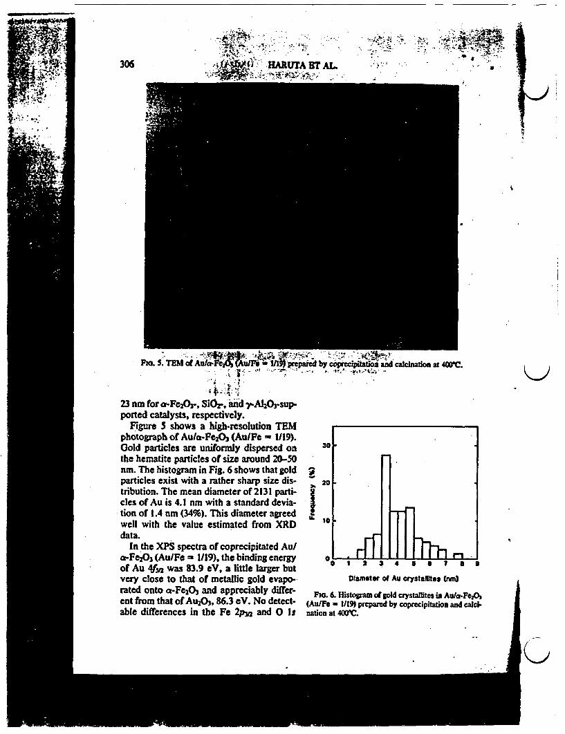
-S~ ~~~~~~~~~~~~~~{ -, J i
PMa. S. TEM of Au/a-Fec calcination at i
i1~ ~ 4 i -. i
23 urn for cf-Fe2O3 , SiOr-, aw yAlOrsup-ported catalysts, respectively.
Fgure shows a high-resolution TEMphotograph of Au/af-Fe203 (Au/Fe - 1119).Gold particles are uniformly dispersed on 3 the hematite particles of size around 20-50nrn. The histogram in Fig. 6 shows that gold particles exist with a rather sharp size dis- 20-tribution. The mean diameter of 2131 parti-cles of Au is 4.1 nm with a standard devia-tion of 1.4 n (34%). This diameter agreed well with the value estimated from XRD 1data.
In the XPS spectra of coprecipitated Au/o.-Fe2O3(Au/Fe - 119), the binding energy 0 ' - * , 7 -
.- , ~~~~~~~ ~ 2, 4 ...... I.... .
of Au 4for was 83.9 eV, a little larger butvery close to that of metallic gold evapo-. Dlamei of Au crystates (nm)rated onto at-F2 and appreciably diffier- . 6. r of gold crystallites in Aufa-Fe2Ocut from that of Au 3, 86.3 eV. No detect- (Au/Fe - 1/19) prepared by cop.cipitation and cal-able differences in the Fe 2p 2 and 0 Is nation at C.
GOLD CATALYSTS FOR H2 AND CO OXIDATIONm . I . � Ia
S I... TABLE 2
Composition of Au/a-FeA CatalystsPrepared by Coprecipitation
Oxides Fe Au
Prepared (at.%) 9S 5Elem. anal. (at.%) 94.6 5.4XPS (at.%) 93.4 6.6XRD Au particles and a-Fe2,
'I
spectra between Au/a-Fe2O3 (Au/Fe =
1/19) and a-Fe2O3 were observed.Table 2 summarizes the results of analy-
ses for the surface composition calculatedfrom the peak area of Au f5 and Fe 2p3 inXPS and the bulk composition obtainedfrom X-ray uorescence measurements.The compositions of the starting solution,surface layer, and bulk were nearly identi-cal. This result shows that gold particlesare deposited mainly on the surface of he-matite particles with little, if any, being in-corporated into the bulk of the hematite.'
DISCUSSION
It has been demonstrated in the presentstudy that gold becomes a very active cata-lyst for the oxidation of CO when smallgold particles are prepared in the presenceof 3d transition metal oxides. In the impreg-nation and reduction methods, which wereused for the preparation of almost all theconventional gold catalysts, gold was ob-tained only as large particles, usually above10 nm in diameter. This is because gold hasa very low melting temperature, low subli-mation energy, and very low Tammanntemperature (10). These properties, in addi-tion to the intrinsically poor reactivity ofgold metal, make gold markedly differentfrom Pt-group metals in catalytic behavior.
An attempt has recently been made byZhang (10) to prepare small gold particlessupported on MgQ and Y-zeolite by incipi-ent wetness impregnation of chloroauricacid and by ion exchange with gold dieth-ylenediamine trichloride, respectively. Al-though gold particles smaller than 2 nm
were obtained by calcining at temperaturesbelow 200M, the reported catalytic activity'for H2 oxidation was not appreciably high.It could be assumed that chloride ions re-mained in the MgO carrier because the cat-alysts were not washed by hot water afterreduction. In fact, the catalytic activity ofAu/A120 prepared in our laboratory by im-pregnation was appreciably improved bywashing with hot water. In the coprecipi-tated gold catalysts, the coprecipitateswere thoroughly washed before calcinationand therefore were considered to be almostfree from chloride ions. It could also be ex-pected that Pt-gup metal impurities con-tained in HAuCI4 might be mostly excludedduring the coprecipitation of gold and 3dtransition metals because of the extremelylow concentrations of those impurities inthe starting solution. The small gold parti-cles held inside the supercages of zeolite Ycontaining Na+ grew at temperatures above10M0 C, indicating that they were not ther-mally stable when used as an oxidation cat-alyst.
From a comparison with Zhang's work, itis evident that coprecipitation is an effec-tive method to prepare small gold particleswith good thermal stability and possibly toavoid contamination from chloride ions andPt group metals which are usually con-tained in the starting materials. During cal-cination, gold components were decom-posed to form metallic gold crystalliteswhich move out from the inner part of thecoprecipitate particles toward the surface.This process might cause the gold particlesto be strongly held by the support oxidesthereby preventing their coagulation.
The parabolic changes in catalytic activ-ity for H2 oxidation shown in Fig. I may beclosely related to the dispersion and ex-posed surface area of Au metal. The totalsurface area of exposed Au metal increaseswith an initial increase in Au content andmay then decline with a further increase inAu content due to the coagulation of Auparticles. This compensating effect of Aucontent gives rise to the maximum in the
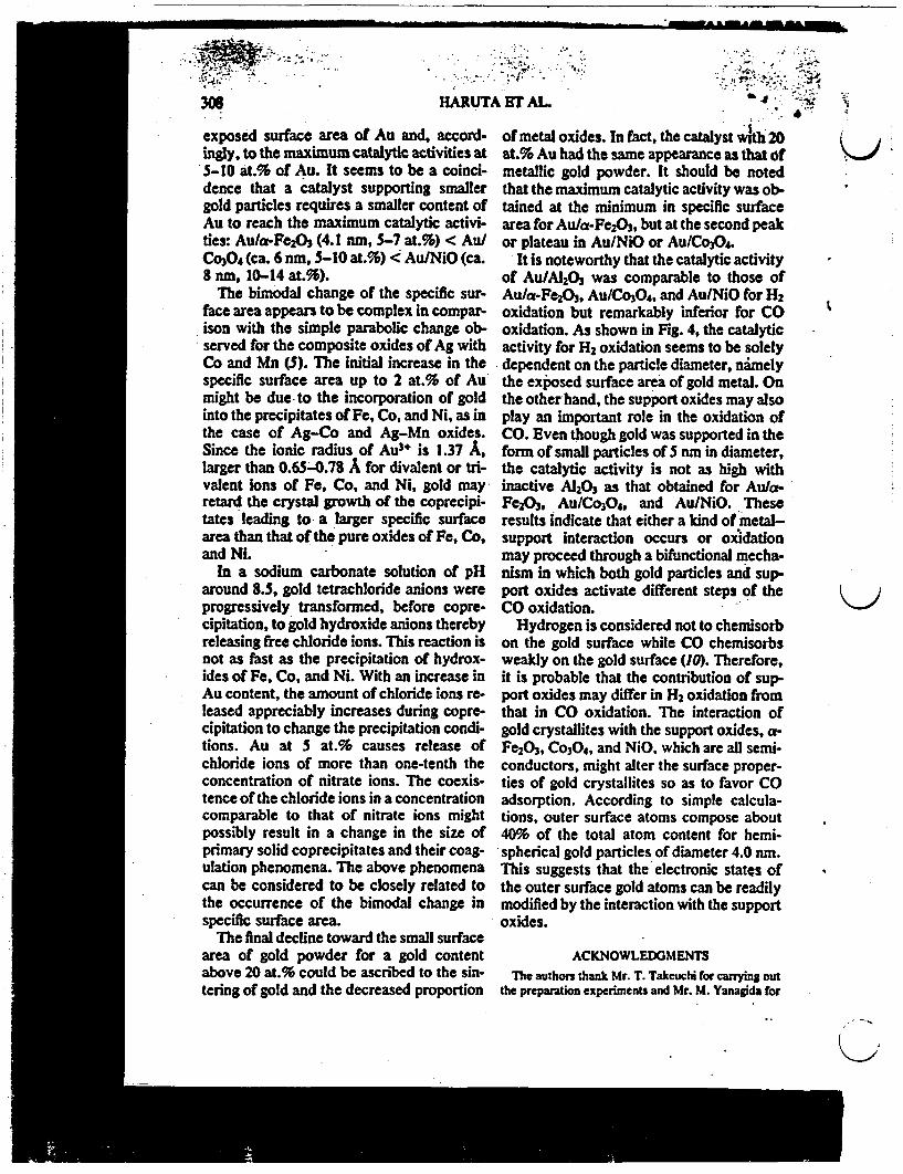
--- mamamook.
306 HARUTj
exposed surface area of Au and, accord-ingly, to the maximum catalytic activities at5-10 at.% of Au. It seems to be a coinci-dence that a catalyst supporting smallergold particles requires a smaller content ofAu to reach the maximum catalytic activi-ties: Au/a-Fe2 O, (4.1 nun, 5-7 at.%) < Au/Co3O4 (ca. 6 nm, 5-10 at.%) < Au/NiO (ca.8 nm, 10-14 at.%).
The bimodal change of the specific sur-face area appears to be complex in compar-ison with the simple parabolic change ob-served for the composite oxides of Ag withCo and Mn (5). The initial increase in thespecific surface area up to 2 at.% of Aumight be due to the incorporation of goldinto the precipitates of Fe, Co, and Ni, as inthe case of Ag-Co and Ag-Mn oxides.Since the ionic radius of Au3* is 1.37 A,larger than 0.65-0.78 A for divalent or tri-valent ions of Fe, Co, and Ni, gold mayretard the crystal growth of the coprecipi-tates leading to a larger specific surfacearea than that of the pure oxides of Fe, Co,and Ni.
In a sodium carbonate solution of pHaround 8.5, gold tetrachloride anions wereprogressively transformed, before copre-capitation, to gold hydroxide anions therebyreleasing free chloride ions. This reaction isnot as fast as the precipitation of hydrox-ides of Fe, Co. and Ni. With an increase inAu content, the amount of chloride ions re-leased appreciably increases during copre-cipitation to change the precipitation condi-tions. Au at 5 at.% causes release ofchloride ions of more than one-tenth theconcentration of nitrate ions. The coexis-tence of the chloride ions in a concentrationcomparable to that of nitrate ions mightpossibly result in a change in the size ofprimary solid coprecipitates and their coag-ulation phenomena. The above phenomenacan be considered to be closely related tothe occurrence of the bimodal change inspecific surface area.
The final decline toward the small surfacearea of gold powder for a gold contentabove 20 at.% could be ascribed to the sin-tering of gold and the decreased proportion
ErT AL
of metal oxides. In fact, the catalyst with 20at.% Au had the same appearance as that ofmetallic gold powder. It should be notedthat the maximum catalytic activity was ob-tained at the minimum in specific surfacearea for Au/a-Fe 2 03, but at the second peakor plateau in Au/NiO or Au/Co304.
It is noteworthy that the catalytic activityof Au/A120 was comparable to those ofAu/a-Fe 2O3 , Au/Co304, and Au/NiO for H2oxidation but remarkably inferior for COoxidation. As shown in Fig. 4, the catalyticactivity for H2 oxidation seems to be solelydependent on the particle diameter, namelythe exposed surface area of gold metal. Onthe other hand, the support oxides may alsoplay an important role in the oxidation ofCO. Even though gold was supported in theform of small particles of 5 nm in diameter,the catalytic activity is not as high withinactive A1203 as that obtained for Au/a-Fe2Od, Au/Co304, and Au/NiO. Theseresults indicate that either a kind of metal-support interaction occurs or oxidationmay proceed through a bifunctional mecha-nism in which both gold particles and sup-port oxides activate different steps of theCO oxidation.
Hydrogen is considered not to chemisorbon the gold surface while CO chemisorbsweakly on the gold surface (10). Therefore,it is probable that the contribution of sup-port oxides may differ in H2 oxidation fromthat in CO oxidation. The interaction ofgold crystallites with the support oxides, a-Fe20 3 , Co3O4, and NiO. which are all semi-conductors, might alter the surface proper-ties of gold crystallites so as to favor COadsorption. According to simple calcula-tions, outer surface atoms compose about40% of the total atom content for hemi-spherical gold particles of diameter 4.0 nrn.This suggests that the electronic states ofthe outer surface gold atoms can be readilymodified by the interaction with the supportoxides.
ACKNOWLEDGMENTS
The authors thank Mr. T. Takeuchi for carrying outthe preparation experiments and Mr. M. Yanagida for
'j

GOLD CATALYSTS FOR H2 AND CO OXIDATION 309
the elemental analyses by atomic emission spectros-copy. Thanks are also due to Dr. A. R. West. Univer-sity of Aberdeen, for his valuable comments and criti-cal reading of the manuscript.
REFERENCES1. Haruta. M.. and Sano, H., Int. J. Hydrogen En-
ergy 6, 601 (1981).2. Haruta, M.. Suoma, Y., and Sano. H., Int. J. Hy-
drogen Energy 7, 729 1982).3. Haruta, M., and Sano. H.. Int. J. Hydrogen En-
ergy 7, 737 (1982).4. Haruta, M., and Sano, H.. Int. J. Hydrogen En-
ergy 7, 801 (1982).5. Haruta. M., and Sano, H.. in "Preparation of Cat-
alysts 111" (G. Poncelet. P. Grange. and P. A.Jacobs, Eds.), p. 225. Elsevier. Amsterdam, 1983.
6. Bond. G. C.. Gold Bull. 5, 11 (1972).7. Bond. G. C., and Sermon. P. A.. Gold Bull. 6, 102
(1973).8. Wachs, 1. E., Gold Bull. 16, 98 (1983).9. Schwank. J., Gold Bull. 16, 103 (1983).
10. Zhang. G., Ph.D. thesis. Stanford University. UM8608245, 1985.
II. Yates, D. J., J. Colloid Interface Sci. 29, 194(1969).
12. Lam, Y. L., and Boudart, M., J. Catal. 50, 530(1977).
13. Nyarady. S. A., and Sievers. R. E., J. Amer.Chem. Soc. 107, 3726 (1985).
14. Sermon. P. A., Bond, G. C., and Wells. P. B.. J.Chem. Soc. Faraday Trans. 1 74, 385 (1978).
15. Galvagno, S.. and Parravano. G.. J. Catal. 55. 178(1978).
16. Fukushima, T.. Galvagno, S.. and Parravano. G..J. Catal. 57, 177 (1979).
17. Lea. I. Y., and Schwank. J.. I. Catal. 102, 207(1986).
18. Buchanan. D. A., and Webb, G., J. Chem. Sox.Faraday Trans. 1 70, 134 (1974).
19. Schwank. J., Parravano. G.. and Gruber. H. L.. J.Catal. 61, 19 (1980).
20. Shastri. A. G,, Datye, A. K.. and Schwank. J.. J.Catal. 87, 265 1984).
21. Chapman, D. L.. Ramsbottom. J. E., and Trot-man, C. G.. Proc. Soc. London A 107, 29 (1925).
22. Benton. A. F., and Elgin. J. C.. J. Amer. Chem.Soc. 49, 2426 (1927).
23. Chambers, R. P., and Boudart. M.. J. Catal. 5,517 (1966).
24. Cant. N. W.. and Fredrickson. P. W., J. Catal. 37,531 (1975).
25. Bollinger, M. J., Sievers. R. E.. Fahey. D. W..and Fehsenfeld, F. C., Anal. Chem. 55, 1980(1983).
26. Hodges. C. N.. and Roselaar. L. C.. J. Appl.Chem. Biotecnol. 25, 609 (1975).
27. Hartua, M., Kobayashi, T.. Sano. H.. andYamada, N.. Chem. Lett. 405 (1987).
28. Nakamura. O., Ogino. . and Kodama. T.. Rev.Sci. nstrum. 50, 1313 (1979).
29. Wagner, C. D., Davis. L. E., Zeller, M. V.. Tay-lor, J. A.. Raymond, R. H., and Gale. L. H.. Surf.Interface Anal. 3, 211 1981).
A
Chemistry Express. Vol.4, No.4pp.217 - 220(19891 KINKI CHEMICAL SOCIETY. JAPAN C
GOLD-SUPPORTING TIN OXIDE FOR SELECTIVE CO SENSING
Tetsuhiko KOBAYASHI,* Masatake HARUTA, and Hiroshi SANO
Government Industrial Research Institute of Osaka,1-8-31 Midorigaoka, Ikeda, Osaka 563
The sensitivity and selectivity of semiconducting SnO2
towards CO at 150 - 250'C was appreciably enhanced bysupporting highly dispersed gold and by doping with Mg2+ions. The addition of M2+ prevented the Au/SnO2 solid
from sintering and maintained it catalytically active forCO oxidation, even in a moist atmosphere.
In a recent paper we reported that Ti4+-doped Fe2O3 supportingultrafine gold particles with a diameter of about 4nm (hereafterdenoted as UFP-Au) exhibits excellent CO selectivity against H2 and
ethanol at an operating temperature below 100C (1). This sensingproperty originates from the high catalytic activity of UFP-Au/Fe2O3 for CO oxidation at low temperatures [2). The gas
sensors operating below 100'C, however, seem to have thedisadvantage that they usually need periodic heat-flashing in long-time operation to avoid the accumulation of water and contaminants
on the surface 13]. A commercVal semiconductor CO sensor, whichis fabricated from Pd-supporting SnO2, also uses periodic heat-flashing to remove CO molecules which are adsorbed at around90*C [4].
In order to obtain a CO sensor operated at a constanttemperature without the need for heat-flashing, a new gas-sensingsemiconductor must be developed that exhibits sufficient CO
sensitivity and selectivity at temperatures above 150-C. Since COoxidation over UFP-Au/SnO2 needs a temperature at least 100 degreeshigher than UFP-Au/Fe2O3 151. a relatively high sensing temperatureof CO would be required for the former material. Therefore, we
have made an attempt to prepare new CO selective semiconductors
composed of SnO2 and Au.Semiconducting SnO2 incorporating Au, M2+, and Sb5 +
217
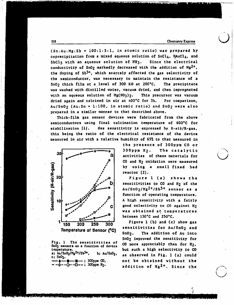
218 Chemistry Express )(Sn:Au:Mg:Sb - 100:1:5:1. in atomic ratio) was prepared bycoprecipitation from a mixed aqueous solution of SnC14, HAuC14, and
SbCl with an aqueous solution of N3. Since the electricalconductivity of SnO2 markedly decreased with the addition of Mg2 +,the doping of Sb5+. which scarcely affected the gas selectivity ofthe semiconductor, was necessary to maintain the resistance of aSnO2 thick film at a level of 300 K at 2001C. The precipitatewas washed with distilled water, vacuum dried, and then impregnated
with an aqueous solution of M(N03)2. This precursor was vacuumdried again and calcined in air at 400C for 3h. For comparison,
Au/SnO2 (Au:Sn 1:100, in atomic ratio) and SnO2 were alsoprepared in a similar manner to that described above.
Thick-film gas sensor devices were fabricated from the abovesemiconductors using final calcination temperature of 6001C forstabilization 11]. Gas sensitivity is expressed by R-air/R-gas.
this being the ratio of the electrical resistance of the devicemeasured in air with a relative humidity of 65% to that measured in
the presence of 300ppm CO or------ 300ppm H2. The catalytic
30 a activities of these materials for
by using a small fixed bed
* .' reactor 2].f 20- as Figure 1 (a) shows the
3 opt b sensitivities to CO and H of the
Au/SnO2/Mg2 +/Sb5 +. sensor as a10 ,*function of operating temperature.
" 10 .- 0w' :P A high sensitivity with a fairlyc* O / o' , C good selectivity to CO against 2
was obtained at temperatures* Ibetween 150C and 250C.
150 200 250 300 Figure 1 (b) and (c) show gassensitivities for Au/SnO2 and
Temperature of Sensor OC) Sn02. The addition of Au into
SnO2 improved the sensitivity forFig. 1 The sensitivities of CO more appreciably than for H2 ,SnO2 sensors as a function of devicetemperature. but such a high selectivity to COa; Au/SnO2/Mg2+/Sb5 + b; Au/SnO2, as observed in Fig. 1 (a) couldc; Sn02.- * - * -| - ; 300ppu CO, not be obtained without the- -- O--O--; 300PPm H2 addition of Hg2+. Since the
,-

Chemistry Express 219(�h.�nistrY Express 219
addition of M2+ into SnO2 without Au did not improve the original
sensitivities of SnO2. selective CO detection obtained with
Au/SnO2/Kg2+/Sb5 + might be due to a synergism between the Au
particles and Mg2+.
0S.
35 4026 (degree)
fig. 2 The XRD patterns of sensormaterials.a; AuSri /g 2+/Sb5+ (color; black),
i b; Au/SnO2 (color; deep purple).V; SnO2. ; Au.
;- P%
01 I
ff 0
I0
I. I so0 I50 150 250
Figure 2 shows the XR6 patterns
of AuISnO2IMg2+ISb5+ and Au/SnO2.
The XRD p aks of
Au/SnO2/Mg2+/Sb 5 +. which are
broader than those of AuISnO2.clearly indicate that M&24
suppresses the sintering of
AuISnO2 to give smaller goldparticles. The Mg2+ doped sample
show no appreciable XRD peaks
due to metallic Au even after
heat-treatment at 600C. The
black color of this material may
indicate the presence of highly
dispersed Au particles, which are
smaller than those in Au/SnO2.
Direct information concerning
the difference in the
sensitivities of Au/SnO2 with andwithout Mg2+ was obtained by
measuring the catalytic activities
of the materials for CO oxidation.Figure 3 shows that CO oxidationtakes place in preference to H2oxidation over the above twomaterials in the dried reactiongas. In the humidified reactiongas. water vapor does not affectthe catalytic activities of M82+
doped Au/SnO2 but inhibits CO
oxidation over Au/SnO2 withoutMS2+ decreasing the preference to
CO oxidation.The difference in the size of
Au particles may account for the
difference in the sensing
1
'50 150 250Reaction Temperature (C)
Fig. 3 The efficiency of CO and 2oxidation over sensor materials as afunction of temperature;a; u/SnO2 /Mg2 /Sb 5+, b; Au/SnO2 .-0 ... Da-; 1 CO + air (dried by
P205 column),-*-U -; 11 CO + air (saturatedvith l 20 at OIC),- -- A--; I 2 + air.L.FF Space velocity; 20000h' 1 ml g1.
§ Zn~22 ChemistyExpress
* properties of the Au/SnO2IMg2+/Sb5+ and the Au/SnO2 sensor. It
has been found in the case of UFP-Au/Fe2 O3 -Ti4 + that the
sensitivity as well as the selectivity towards CO increases with
smaller Au particles [il. The measurements of gas sensitivitieswere conducted under humid conditions, despite this
Au/SnO2/Mg2+/Sb5+ remains selective to CO due to the fact that it
is unaffected by water in the catalytic oxidation of CO.Recently, UFP-Au supported on hydrous oxides of alkaline earthmetals have been found to catalyze CO oxidation even at 70`C
[5,6). An increase in the basicity of SnO2 by doping with Mg2+might play an important role in the water-resistant oxidation of
CO.
References1. T. Kobayashi, M. Haruta, H. Sano, and M. Nakane, Sensors and
Actuators, 13, 339 (1988).2. M. Haruta, T. Kobayashi, H. Sanos and N. Yamada, Chem. Lett.,
405 (1987).
3. M. Nagase and H. Futata, Proc. Int. Meet. Chem. Sens., Fukuoka
(1983). p.65.
4. T. Amamoto and N. Murakami, Sensor Gijutsu (Sensor Technology).7(13). 45 (1987).
5. . Haruta, H. Kageyama. N. Kamijo, T. Kobayashi, andF. Delannay, in T. Inui (ed.), "Successful Design of Catalysts",Elsevier, Amsterdam, 1988, pp. 33-42.
6. M. Haruta, K. Saika, T. Kobayashi, S. Tsubota, and Y. Nakahara,Chem. Express, 3, 159 (1988).
C OAIROZMT 4i" A114AXX
7563 A-MVVIA-8-31
t> item lU t~k@i:BaXM g '4 C S>0§ZIIk; at ± 3l, C i . Mg'-04NMA't Au/SnOtOMOV011ftt
I .
J
.--.--.------- (Rceived: February 28, 1989 * Accepted for publication: March 11. 1989)

A ev / t7 -. C -c( c*._ / £'-f9
METHODOLOGY FOR M'AKING R&D PROGRAMS OF CHEMICAL SENSORS
Masatake HARLTA, Kazuo HIIRO, Hideo TAYIGAWA, Hiroyasu TAKENAKA,
Susumu YOSHIKAWA, and Hiroshi SANO
Government Industrial Research Institute of Osaka
Midorigaoka 1, Ikeda 563, Japan
ABSTRACT
The R&D programs of chemical sensors should particularly be focused onthe practical needs. Sensing materials and signal transducers shouldbe exploited efficiently and should be combi.ed synergetically bytaking into consideration of the sensitivities, selectivities, andstabilities required. The methodology for program making is presentedby showing the examples of Government Industrial Research Institute ofOsaka. The practical needs, technological bottle necks, prospects ofdevelopment, and fields of application were disclosed through thesurvey by distributing questionnaires to the people engaged inchemical sensors. The results of needs analyses together with seedsexploration substantially helped the establishment of the needs-orientated and motivation-enforced R&D programs. The activities andachievements of research carried out in the framework of the programsat GRIO are also described.
1. INTRODUCTION
Chemical sensors are a sort of artificial eyes to recognize
chemical species. They measure the presence or concentration of
gases, ions in solutions, and organic compounds. They are widely used
in microwave ovens, gas safety alarms, air-fuel ratio control systems
for automobiles, monitoring of water pollution, medical drug delivery
devices for diabetes, process control of fermentation and so forth.
They are really becoming indispensable for many ndustries and for our
daily lives as well.
There are various kinds of chemical sensors; multifarious sensors
are existing and will be needed even for a single chemical compound
depending on the conditions of operation, sensing materials,
transducers, and detecting principles. Especia1.y, sensing materials
used are diverse from organic metal complexes, conductive polymers,

biological materials, metals, and metal oxides. This situation makes
it difficult for users to choose suitable chemical sensors without a
vast amount of knowledge and for engineers a makers to find the
efficient approach to the development of a sensor specifically
desired.
From the above points of view, it is very :mpor:ant to establish
the methodology for making R&D programs of chemical sensors. The R&D
programs of Government Industrial Research Ins::tute of Osaka(GIRIO)
were made based on the results of questionnaire survey of social needs
to chemical sensors and on the results of literature and patent survey
of the past ten years. Several distinguished results were obtained in
the framework of the R&D programs. These activ:ties at GIRIO for the
past five years are presented to show one of the examples of the
methodology for program making and its validity.
2. THE STRUCTJRES AND PERFORMANCES OF CHEMICAL SENSORS
Chemical sensors can be classified into four groups; humidity,
gas, ion, and bio-sensors. Structually, they are divided into two
typesfl] as shown in Fig. 1. The first type is called "unstructured
sensors". where sensing of chemical species and transducing the
resulting physico-chemical changes to an electrical signal is
performed in a single phase. Humidity and gas sensors using sintered
ceramics are typical examples of this type. The adsorption and
reaction of water or flammable gases on the surface results in a
change of the electrical conductivity of the sintered body ceramics,
thus leading to an increase in electrical current under a constant
applied voltage.
The second type is "structured sensors", because the part of
receptor for chemical species and the part of transducer are clearly
separated into two phases. Conventional ion se ective electrodes are
a typical example of this type. They are combined with reference
electrodes to measure the potential difference between the two
electrodes. Almost all biosensors are also included in this category.
For example, glucose oxidase recognizes glucose and then catalyzes the
reaction to produce H202 , the concentration of. which is transduced
with an oxygen electrode to an electrical signal.
J

1. UNSTRUCTURED SSORS
/ Mvs. \ i~~~~~~~Eecrel
Ocanges Signa
Sensing Transducing
I Single nose
Recetor Transducer Sigral
Sensing _ 1 Electrocfeiccl _Flns lf2 elecrode)j
cel l se5lzm ,_ _ Semconductor|-lt cl
eccece _ _ IS~Lcond r (F 1 Electrical
ofl st IO fer rsI
tal . (SAWI o ez'o.
vellfI -
uRs glass
%preseglucose I __ Fluorescence, .Ot
ozidase Fiber otics
It. STRIUR SENSORS
Fig. 1. Structure of chemical sensors.
Many advanced sensors have been developed in the structured type
by using FET(Field Effect Transistor)(21, SAW(Surface Acoustic Wave)
devices[3,4], piezoelectric crystals[5,6,7], fluorescence(8,93, and
fiber optics(O] as a transducer. One of the advantageous features of
this type is that it allows us to choose and prepare sensing materials
without taking into consideration of their transducing properties..
The typical examples of sensing membranes are cellulose acetate
butyrate[(11 for humidity, Pd(12] and SnO2 113] for gases, Si3N4 1l4],
NAS glass(15J, valinomycin[16] for ions, and urease and glucose
oxidase[17] for bio-related compounds.
The R&D work of chemical sensors consists of exploiting sensing
materials and transducing devices, fabricating them into sensing

devices, and testing ensor performances. There are three "S"s in the
performances of chemical sensors. The first is sensitivity which
includes range of detectable concentration, resolution with respect to
a certain concentration change, and response time, namely, three "r"s.
The second S is selectivity. The interference by other coexisting
species is one of the serioius problems of the present chemical
sensors. It should be examined beforehand which kinds of species
coexist in the atmosphere where the target sensors are used. The
third S is stability which includes reproducibility of signal output
during the repetition of measurements and durability in the long term
use.
3. SURVEY AND ANALYSES OF NEEDS TO CHEMICAL SENSORS
In order to establish a self-consistent and effective strategy
for the R&D programs of chemical sensors, a comprehensive survey of
social needs was made by GIRIO in 1983[18]. Questionnaire sheets were
sent to 341 people who were engaged in chemical sensors at
industries(236), universities(65), national and public research
laboratories(14), and technical consultants(6). Forty eight per cent
of them sent us back their answers, from which the needs to chemical
sensors were analyzed as described below.
3.1 Overall Chemical Sensors
Figure 2 shows the number of answers to the question "Please
choose three chemical sensors which you think will grow remarkably in
the future.". The area of each circle is proportional to the number
of answers. In the category of gas sensors, oxygen sensors gained the
largest number. It seemed to be reasonable because oxygen sensors
were being commercially used for the control of air-fuel ratio in
automobiles. The second is CO sensors. This s probably because
there were no reliable CO sensors to monitor whether combustion of
fuel in household appliances is safely taking place. The third is
H2 0, namely, humidity sensors. This might be due to the very humid
climate in Japan. Humidity sensors are in a wide-spread use for air
conditioners, video tape recorders, automatic cooking oven ranges and
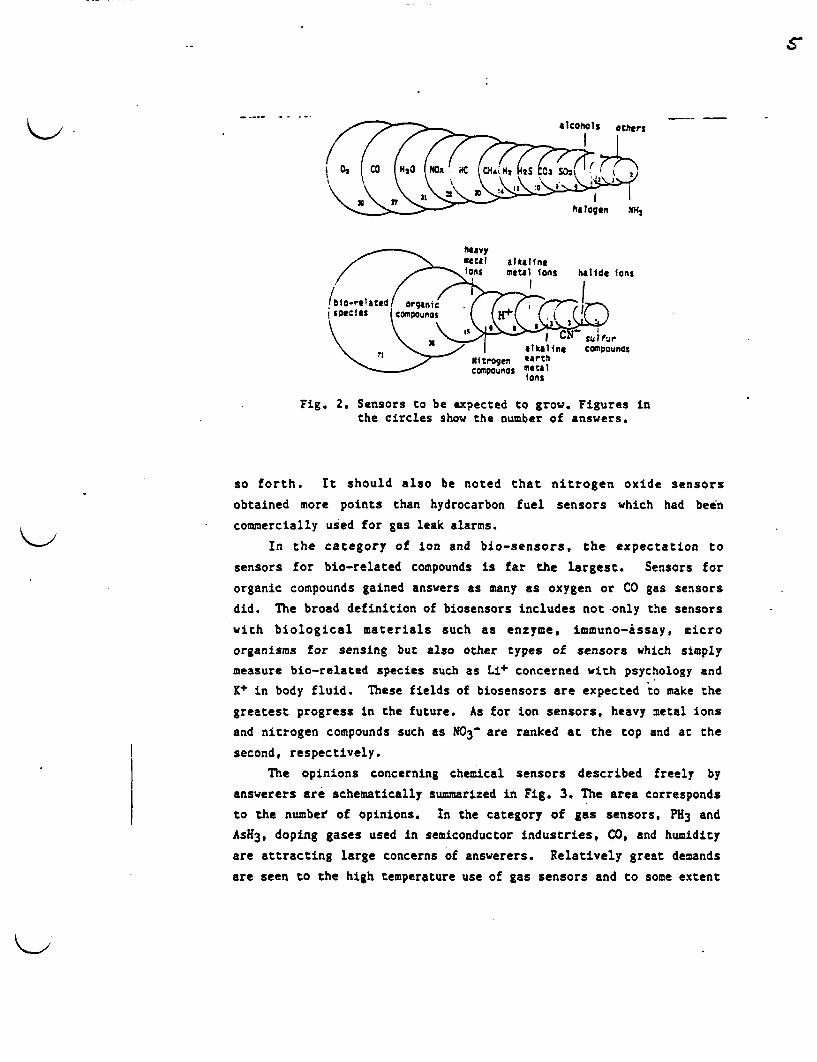
Fig. 2. Sensors to be expected to grow. Figures inthe circles show the number of answers.
so forth. It should also be noted that nitrogen oxide sensors
obtained more points than hydrocarbon fuel sensors which had been
commercially used for gas leak alarms.
In the category of ion and bio-sensors, the expectation to
sensors for bio-related compounds is far the largest. Sensors for
organic compounds gained answers as many as oxygen or CO gas sensors
did. The broad definition of biosensors includes not only the sensors
with biological materials such as enzyme, immuno-issay, micro
organisms for sensing but also other types of sensors which simply
measure bio-related species such as Li+ concerned with psychology and
K+ in body fluid. These fields of biosensors are expected to make the
greatest progress in the future. As for ion sensors, heavy metal ions
and nitrogen compounds such as IN03 - are ranked at the top and at the
second, respectively.
The opinions concerning chemical sensors described freely by
answerers are schematically summarized in Fig. 3. The area corresponds
to the number of opinions. In the category of gas sensors, PH3 and
AsH3, doping gases used in semiconductor industries, CO, and humidity
are attracting large concerns of answerers. Relatively great demands
are seen to the high temperature use of gas sensors and to some extent

6
(GAS (DEVICE o (REQUIRE- (ION & 31-' -(SENSORS) TECHMOLOYCJ (HTS ) SENSORS
Doping ___-...So eci.! smell
pHi I - ty
l S3 Tastetgr tr n
A! qaiot. B y
Lo / duabily url t
aunction St !iolty lscstwoo. /Reoroejelii
-bililty I r -dc
Hum"'idity 4.'ent5
Fig. 3. Schematic surmary of the opinionswritten freely by correspondents.
to the low temperature use. In the category of ion and biosensors,
smell and taste sensors are pointed out as a future target of
research. Ion sensors for rare earth metal ions, N03-, organic acids
are also a big concern. Among the requirements for the performances
of chemical sensors, selectivity and stability are of the greatest.
It is important for making R&D programs to grasp properly the
technological problems. Figure 4 shows that the most serious problems
are degradation, reproducibility, stability of signal output, and
contamination by oil and dust. These all concerns the stability of
sensors in a wider sense of meanings.
Reproducibility
range - /
10, .w Oegradation.
Response \/ w , Ourability
Sonsi1tie1 ty 5sta bilirty Fig. 4. Problems of chemical sensors.

/7
iOO; 100 articles
1 Papers
Patents
Humldity Seors M.oisture Seftiors
Zon Senorsloft sensit< & a n 0senluve Electro
Gas Sensorn
1z n3.4? ns: S SI 12
Fig. 5. Annual growth in thenumber of papers and patentsconcerning chemical sensors.
papers indicating that R&D w
industries.
A literature and patent survey
was done for the past ten years to
know the state of the art of
chemical sensors mostly from the
point of seeds. Figure 5 shows
that there is a big contrast in the
number of scientific papers and
patents between ion sensors and
the other chemical sensors. In the
field of ion sensors, scientific
papers are much more than patents,
probably because R&D work is mainly
done in university laboratories,
especially as the subjects of
analytical chemistry. On the other
hand, in the fields of humidity and
gas sensors the number of patents
largely exceeds that of scientific
ork has been carried out mainly in
3.2 Humidity Sensors
As shown in Fig. 6, few people think that the present humidity
sensors have no serious problems and that their ost are too high.
The biggest problems are reproducibility and precision, secondly,
stability of signal output, thirdly, durability and life and then the
range and conditions of measurements. The former three constraints
are more or less concerned with the stability properties of sensors in
a short and long term use. Therefore, an improvement in stability is
considered to be the most important task of R&D on humidity sensors.
Figure 7 shows the fields of application of humidity sensors. They are
expected to be the most frequently used for air conditioning in
residences and offices, probably because the humid hot summer and dry
cold winter in Japan. The second largest field of application is
drying processes, where high temperature performance and durability is
particularly required for humidity sensors.

t?
Ito seriousoroolees
.,
_. -*/ LifeSelectivity
Masurable range ndconditions
0 20 40 50 80 !0059
::noor ant
Air concitioning
~~j j j j j ~~~rying ProctsSes
///W ....... i ;lreen .custs
M////S',',.,,,i I ousenoIoz/iiiZx ! Ielectrics40 22 a
Factory I off Iceenv ronment
38 22 :0____________- ____| _____ |___ Prevention of
"Alg: -' ew drops
S.-- . - e48
Weatherforecasting
L ss 1mortant
Fig. 6. Problems ofhumidity sensors.
Fig. 7. Felds of application ofhumidity sensors.
K-,
3.3 Gas Sensors
Figure 8 shows several problems of
probl ems
Selectivity
Cost
Precision
Stab IIty\
gas sensors with their
respective percent
fractions in the
number of answers.
Selectivity occupies
the largest fraction.
Then, limitation to
the applicable condit-
ions, life, and stabi-
lity occupy almost
equal fractions to
each other.
/ Limitation ofussole conditions
Life
Fig. 8. Problems of gas sensors.
I- ,'

Table I shows more detailed data how differently producers,
sellers, users, and researchers recognized the problems of each gas
sensor. Concerning CO gas sensors, although producers and sellers do
not think there are any serious problems, users and researchers
complain of selectivity, stability, and applicable conditions. As for
fuel gas sensors which had been already commercialized in Japan,
selectivity and stability are considered similarly by the four groups
to be very serious problems. Therefore, it may be suggested that the
types of CO gas sensors under consideration are different between the
group of producers and sellers and the group of users and researchers;
the former is actually dealing with electrochemical sensors and the
latter is developing oxide semiconductor or other types of compact
sensors.
In the case of oxygen sensors, durability is the largest
constraint and the second largest ones are convenience and conditions
for use. There also observed a big discrepancy in answers between the
group of producers and sellers and the group of users and researchers.
This may again suggest that users and researchers were seeking for
stabilized-zironia based oxygen sensors or other ones of the new type
which were different from conventional electrochemical sensors.
Concerning hydrogen sulfide and sulfur dioxide gas sensors, for which
electrochemical cells have long been used, no serious problems are
pointed out for the present.
Table I. Constraints of producers, sellers, users, andresearchers on the respective gas sensors.
[ S4ensors CO IFuel ases 02 HiS SOil Pro PS IUI R I P S i UIp s U R P S U R T
Usability; -I -I - I- -- - I * - '-- I - I iCost - - - -I- --- IDurability1 -i-! -l ; -- -s -- A-I -I -j -.- 7
5electivitv - 1- - - -- - | - | . } - 3jConditiafon --! - I -¢ -I -¢ -l I I i - - I -I- I 73 Stablity! - | t ---
TOTAI ItOIw 529 i37124143 6i39916 2134 40111i5sI21 12' X
PROBLEMS - ; no + : a little ++ serious
+++ : very serious * Total

So
nR qw "coe
alcohols S' 1 i -- ng
Production
L |_ V%' tI A7r halogens
so co3 C~o HC o: cu. N~z HzS SOz ° Others
Fig. 9. The number of people engaged in gas sensors.
Figure 9 shows the number of answerers who were engaged in
respective gas sensors at the time of questionnaire survey. The
number was by far the largest for those who were engaged in 02
sensors. Sensors for H2, CO, CR4, and hydrocarbons had almost the
same number of people engaged, however, the fraction of R&D was
relatively large in the case of CO gas sensors.
The comparison of the present situation shown in Fig. 9 with the
future situation estimated from the number of answers to the question
"In the future which gas sensors do you wish to develop, use, sell, or
produce?" can tell us the growth potentials of respective gas
sensors. The ratios of the numbers of the future involvement to those
of present one, namely, "future indices", are shown in Table II. The
production and selling of CO sensors will appreciably grow. Nitrogen
oxide sensors are exceptional that they will grow appreciably in every
sector. Users will increase in the sensors for alcohols, NO1,
halogens, and SO2. Research & development activities will be
strengthened in the sensors for SO1, halogens, H2S, NO1, and H2.
Strong interest in MOSFET sensors night be responsible for the large
index of H2 .
Among the fields of application of gas sensors, prevention of gas
explosion and of accidental death by oxygen shortage is considered to
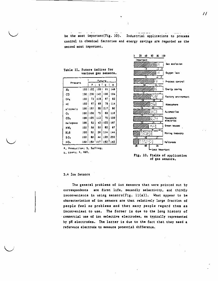
/
be the most important(Fig. 10). Industrial applications to process
control in chemical factories and energy savings are regarded as the
second most important.
2 20 40 so so :c0
:rnoortant
Table II. Future indices forvarious gas sensors.
I P0 Se U1:8H., 100! 12 108: 1 91 1146co -00 2 30 :42 10S,104
CH4 100 | 3 1181 6- | 82
Mtc 1001 6, 69 81 114
alconols 100 I !S7 88 217 80
0: 1001 106 75 63 116
CO, 1O0 1 25 1131 70 100
halogens 1001 5 43 122 167
NIs 100 | 56 50 82 67
HS 1001 50 36 114 144
SO, 120 80 44 120 200
NO, 100 160 1117 162 142
P. Producion; S. Selling;
U. Users; R. R&D.
~~iI~~~i Gas xlso75 . .
/ / Oxygen iacx
Process control
E////// I// I Energy saving
Ad// v - j FJctory nvfIrotlent
Ab:tosphere
i ' - -.-
I Au: mai es
|ree hosed_ alectrics
| Green house5M-1V10."A .S.t.
I-
tqning ndustry
42 .4
La 48 34
LLess 4cortant
Fig. 10. Fields of applicationof gas sensors.
3.4 Ion Sensors
The general problems of ion sensors that were pointed out by
correspondents are first life, secondly selectivity, and thirdly
inconvenience in using sensors(Fig. 11(a)). What appear to be
characteristics of ion sensors are that relatively large fraction of
people feel no problems and that many people regard them as
inconvenient to use. The former is due to the long history of
commercial use of ion selective electrodes, as typically represented
by pH electrodes. The latter is due to the fact that they need a
reference electrode to measure potential difference.

4
Cost Stabil1tya~~~~~~nq ~~~~~~Reproduci billityndl~~~~~n ** ~~~~L ife
Selec:ivitytns*ftctlS.I \ 1\' LmVitation of
28 \\ ! X Usable concitionseen~outittiflity '. - ' 's 1 No problem,
Inconvenience \ Life
Sleteti ty -_ -____,
(a) overall ion sensors (b) proton sensors(307 answers) (29 answers)
Others
Handling I..
leproduclbilit. ........,Ef...........nC// 'i
<y, * Limitation f...:,5usable conditions (e) heavy metal ions
(d) organic compounds (8 answers)(18 answers)
(c) bio-related compounds(29 answers) Fig. 11. Problems of ion sensors.
The problems of several respective ion sensors are also shown in
Fig.l. Concerning proton ion sensors, more than 70% of correspondents
answered "there is no problem". In the following three ion sensors
which were expected to grow markedly in the future, no one answered
"no problem". The heavy metal ion sensors need more improvements in
fundamental properties such as life, selectivity, nd applicable
conditions than in stability of operation, reproducibility, and
precision of measurements. Similarly, for organic compounds, life,
selectivity, and applicable conditions are the major constraints. In
the case of bio-related compounds, the problems concerning stability
and reproducibility are as serious as the problems of life, selectivi-

IX L (b) future
H+~~~~~~~~~~~~~~~~~~~~~~~~~~~~~~~~~~~~~~~~~~'a ~ ~ ~ - U
z im Hi (4) r R D
c m: i a, c 6 * 'Fig 12. Th -ubro epeeggdi
MOHi(a present Sln
ion sensors. ~ ~ ~ ser
andappicale ondtios. ismit bebecaus livingProducton
0 - '..~~~~U
Figure ig 12(a sosthe number of anseperwh en arenred ins
respective ion sensors. Those who are concerned with proton occupv
the largest number, halide ions the second, and alkaline and cyanide
ions the third and then bio-related compounds. It should be noted that
the fractions of R&D on organic compounds and on bio-related compounds
are very large while that of users is more than half in proton
sensors.
When the future involvement shown in Fig. 12(b) are compared
with the present one, a marked increase is observed in organic and
bio-related compounds whereas an appreciable decrease i s observed in
proton. It is worthy of noting that the fractions of R&D are
relatively large in both present and future involvement in heavy metal
ions and nitrogen compounds.
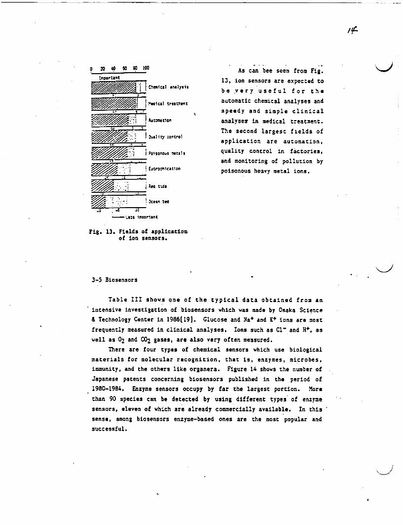
'4
o 20 40 50 80 100
Imoortant
g///j//,/gm j I Coilcal analysis
i//CI treatment
///, Pa Autcatlon
Quality :crftrol
Add' X | Poisonous etals
I d ~~~~Eitrochication
hcan te
Ss imoortant
As can bee seen from Fig.
13, ion sensors are expected to
be very useful for the
automatic chemical analyses and
speedy and simple clinical
analyses in medical treatment.
The second largest fields of
application are automation,
quality control in factories,
and monitoring of pollution by
poisonous heavy metal ions.
Fig. 13. Fields of applicationof ion sensors. -
3-5 Biosensors
Table III shows one of the typical data obtained from an
intensive investigation of biosensors which was made by Osaka Science
& Technology Center in 1986[19]. Glucose and a+ and K ions are most
frequently measured in clinical analyses. Ions such as Cl- and H+, as
well as 02 and C 2 gases, are also very often measured.
There are four types of chemical sensors which use biological
materials for molecular recognition, that is, enzymes, microbes,
immunity, and the others like organera. Figure 14 shows the number of
Japanese patents concerning biosensors published in the period of
1980-1984. Enzyme sensors occupy by far the largest portion. More
than 90 species can be detected by using different types of enzyme
sensors, eleven of wh.ch are already commercially available. In this
sense, among biosensors enzyme-based ones are the most popular and
successful.
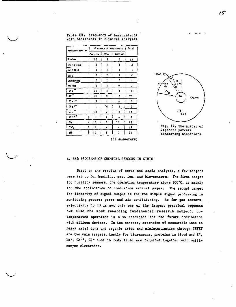
Table m. Frequency of measurementswith biosensors in clinical analyses.
ftesure | SW Frimelcv of sulrats TotaliNeasura SCEs~L ..... 2. Oa!Everwecs t Hr Sonetimei
| iucsn 13 I} 3 | I i
IL3C':C CRE@ I I I 5 1 1 I
Crearif t 2 i 3 I 0 I
! 8.- ! 14 1 3 2 I ;sI.4
} C,:- 5 4 T 0
C M{:- i 2 3 ;
Cl- ! I 2 _2_ 1
0, 1 I S I ! 1
COt :0 I 4 I 4 I 1 II to p H I 21 1
(32 answerers)
Fig. 14. The number ofJapanese patentsconcerning biosensors.
4. R&D PROGRAMS OF CHEMICAL SENSORS IN GIRIO
Based on the results of needs and seeds analyses, a few targets
were set up for humidity, gas, ion, ant bio-sensors. The first target
for humidity sensors, the operating temperature above 200'C, is mainly
for the application to combustion exhaust gases. The second target
for linearity of signal output is for the simple signal processing in
monitoring process gases and air conditioning. As for gas sensors,
selectivity to CO is not only one of the largest practical requests
but also the most rewarding fundamental research subject. Low
temperature operation is also attempted for the future combination
with silicon devices. In ion sensors, extension of measurable ions to
heavy metal ions and organic acids and miniaturization through ISFET
are two main targets. Lastly for biosensors, proteins in blood and +,
Na+, Ca2 +, C ions in body fluid are targeted together with multi-
enzyme electrodes.

/6
4.1 Humidity Sensors
A glassy material composed f V205-7eO2-Li2O + Ao-KO2orn] was
exploited for a humidity sensor which could be operated at above
200*C. The main component V2057TeO2 is one of electrically conductive
glasses, to which LiO was added to provide moisture sensitivity. The
addition of A820 was to reduce the electrical resistivity. The role
of K20 was to enhance the sensitivity to trace amount of moisture.
The above compounds are mixed and ground well. To the fine powder
urea was added and then t was pressed and calcined at 300-350C. The
addition of urea made the sintered elements macro-porous to facilitate
the diffusion of water molecules into the inside of the elements.
The material without 120 can be used as a dew point sensor for
VTR heads and the rear indows of automobiles. Figure 15 shows that
the electrical resistance decreases only slightly until it sharply
drops at a relative humidity around 90%. This sharp drop can be
operated as an on-off switch which works at around a dew point.
On the other hand, if K20 is added, the material turns to be
sensitive to the whole range of humidity as shown in Fig. 16. The
resistance change of two order of magnitude can be obtained for a
;t ;- lot 525V1 Os 2. -.O.5 ; O;
5Y04.- e Ofwi.O12~ -tzrreI~oC
-92 q0 r e t t 6t o0
lc* ~ ~ ~~~~ ~22
0 20 40 so; 30 *0 I¢90Riarivtt uritv %:
Pig. 1S. Response curves of Re~otiv* umidity IINglassy sintered elements fordew point sensors. Fig. 16. Response curves of
A: clton aL glassy sintered elements for:naedded cienwcod the whole range humidity sensors.
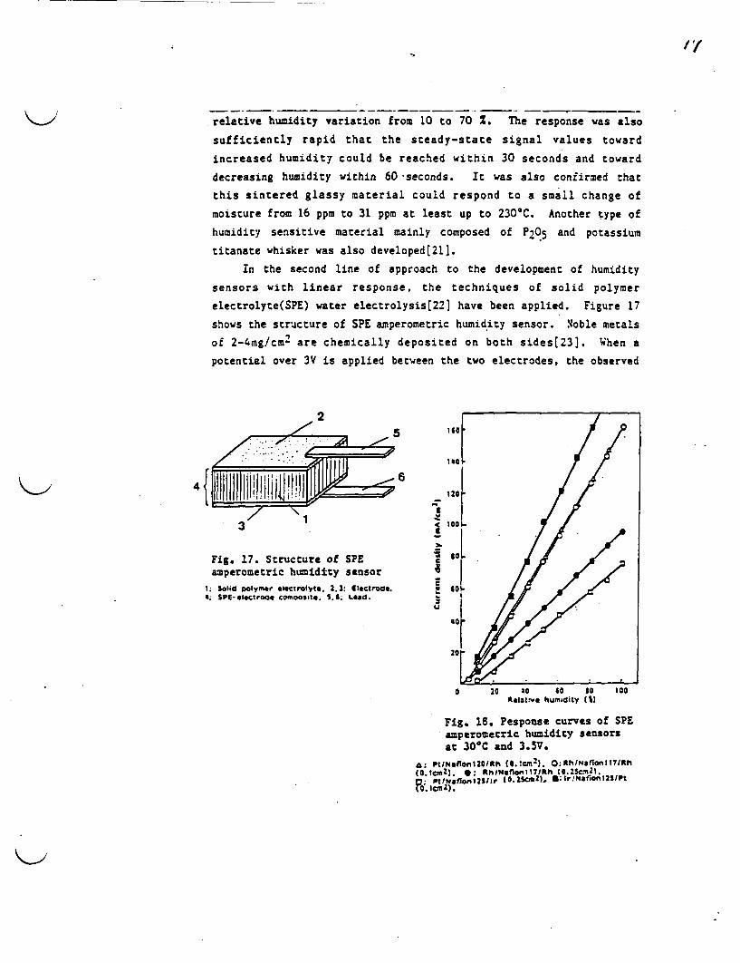
'/
relative humidity variation from 10 to 70 Z. The response was also
sufficiently rapid that the steady-state signal values toward
increased humidity could be reached within 30 seconds and toward
decreasing humidity within 60 seconds. It was also confirmed that
this sintered glassy material could respond to a small change of
moisture from 16 ppm to 31 ppm at least up to 230*C. Another type of
humidity sensitive material mainly composed of P0 5 and potassium
titanate whisker was also developedt21].
In the second line of approach to the development of humidity
sensors with linear response, the techniques of solid polymer
electrolyte(SPE) water electrolysis[221 have been applied. Figure 17
shows the structure of SPE amperometric humidity sensor. Noble metals
of 2-4mg/cm2 are chemically deposited on both sides[23]. When a
potential over 3V is applied between the two electrodes, the observed
/ In 1e7 1 t -J{,Sf I~~U
Fig. 17. Structure of SPE c SoL .amperometric humidity sensor3/
1; salid polymer .l CtrOIlyo. 2.3: Ietrod.. U 601- /E
*.SPeIettroo. cooosa.1.4. *Lead. ' [ 0 20 aC 40 30 100
ROlatNC humidity CUa
FIg. 18. Pesponse curves of SPEahperoeetric humidity sensorsat 30@C and 3.5V.
AS PtoNaidalZOmrtlie0le.trmly. O;AhINaton l7clrh
FFi.g.t/m O. 2ecsLn *; urNi onfSPE

A?
current is proportional to the amount of water decomposed, which is
again in proportion to the concentration of water in a gas stream.
This amperometric sensors exhibited. perfectly linear responses in the
whole range of relative humidity as shown in Fig. 18. As monometallic
electrode catalysts Rh, Ir, and Pt, were found to be preferable owing
to their corrosion resistivity.
4.2 Gas Sensors
There are two types of CO sensors commercially available.
Semiconductive SnO2 catalyzed by Pd needs periodical heat flashing to
sweep out CO adsorbed at a low temperature(24]. Electrochemical CO
sensors are not compact and are troublesome in maintenance[25].
Therefore, new sensing materials were exploited for the development of
highly selective CO gas sensors which could hopefully be operated at
low temperatures for the future combination with silicon devices.
The material newly developed was a novel gold catalyst which
exhibited an extremely high activity for the oxidation of CO at low
temperatures(26-30J. Figure 19 shows T photographs of the old
catalyst prepared by calcination of Au-Fe coprecipitate in air at
400C. The gold loading is about 13wt%, which corresponds to an
atomic ratio of Au/Fe - 1/19. Very fine gold particles are
homogeneously dispersed with a mean diameter of 4.lnm and a standard
deviation of 36%. These gold particles are not spherical but hemi-
spherical in shape and are contacted at their flat planes with -Fe203
(hematite) exhibiting a specific crystal orientation of Au (111) plane
toward the 110) plane of hematite. This epitaxial-like growth of gold
particles makes them very stable against heating and reduction-
oxidation treatments.
The catalytic properties of the Au/a-Fe2O3 are very unique
compared with those of single oxides and gold powder itself (Fig. 20).
Over gold powder, CO oxidation takes place at much higher temperature
than hydrogen oxidation. The same nature can be seen for Pd supported
on A1203. On the other hand, on almost all the metal oxides, the
oxidation of CO occurs at lower temperatures as typically shown by a-
Fe2O3. The coprecipitated gold catalyst is so active that it can
catalyze the oxidation of CO even at -70'C and has similar nature to
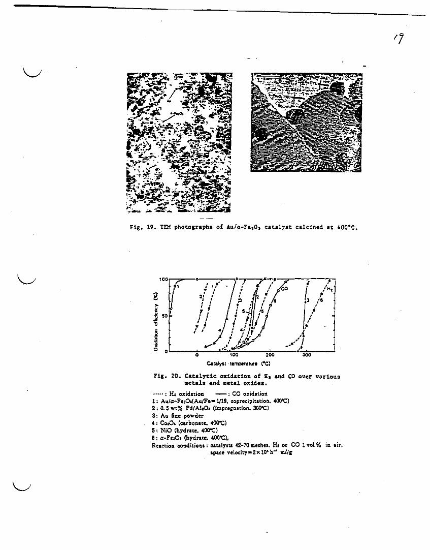
/7
I pp ..- w'. s--.-
.', .. ~~~&s3
Fi. 9 TE htgah fA/-eO aaytclie t40C
0
Catafyst temperature (IC)
Fig. 20. Catalytic oxidation of Es
metals and metal oxides.and CO over various
.-----: Ha oxidation -: CO oxidation
1: Au/a-Fe:O3(Au/Fe-1119 cprecipitation. 400C)
2: 0.5 wt% PdIAIzOs (imipregnation. 300C)
3: Au fine powder4: CosO (carbonate. 400C)5: NiO (hydrate. 400C)6: :-Fe.Os (hydrate. 400'C),Reaction conditions: catalysts 42-70 meshes Hs or CO 1 vol % in air.
space velocityu2x 104 h-' mllg
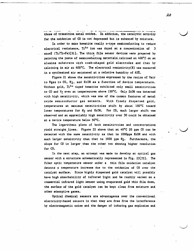
20
those of transition metal oxides. In addition, the catalytic activity
for the oxidation of CO is not depressed but is enhanced by moisture.
In order to make hematite really n-type semiconducting to reduce
electrical resistance, Ti4+ ion was doped at a concentration of 3
atomZ (Ti/Ti+Fe)(311. The thick film sensor devices were prepared by
painting the paste of semiconducting materials. calcined at 400°C on an
alumina substrate with comb-shaped gold electrodes and then by
calcining in air at 600C. The electrical resistivity(R) was measured
in a synthesized air moistened at a relative humidity of 6L
Figure 21 shows the sensitivities expressed by the ratios of Rair
to Rgas to CO, H2, and EtOH as a function of device temperature.
Without gold, Ti4+ doped hematite exhibited only small sensitivities
to CO and H even at temperatures above 1500C. Only EtOH was detected
with high sensitivity, which was one of the common features of metal
oxide semiconductor gas sensors. With finely dispersed gold,
temperatures at maximum sensitivities shift by about 100C toward
lower temperatures for H2 and EtOH. For CO, much larger shift was
observed and an appreciably high sensitivity over 30 could be obtained
at a device temperature below 50C.
The logarithmic plots of both sensitivities and concentrations
yield straight lines. Figure 22 shows that at 40C 20 ppm CO can be
detected with the same sensitivity as that to 1000ppm EtOH and with
much larger sensitivity than that to 1000 ppm H2. Furthermore, the
slope for CO is larger than the other two showing higher resolution
for CO.
In the next step, an attempt was made to develop an optical gas
sensor with a structure schematically represented in Fig. 23[32J. The
fiber optic temperature sensor under a thin film oxidation catalyst
detects a temperature increase due to the oxidation of CO over the
catalyst surface. Since highly dispersed gold catalyst will possibly
have high absorbability of infrared light and be readily warmed as a
commercial infrared light sensor using evaporated gold thin film does,
the surface of the gold catalyst can be kept clean from moisture and
other adsorptive gases.
Optical hemical sensors are advantageous over the conventional
electricity-based sensors in that they are free from the interference
by electromagnetic noise and the danger of inducing gas explosion and
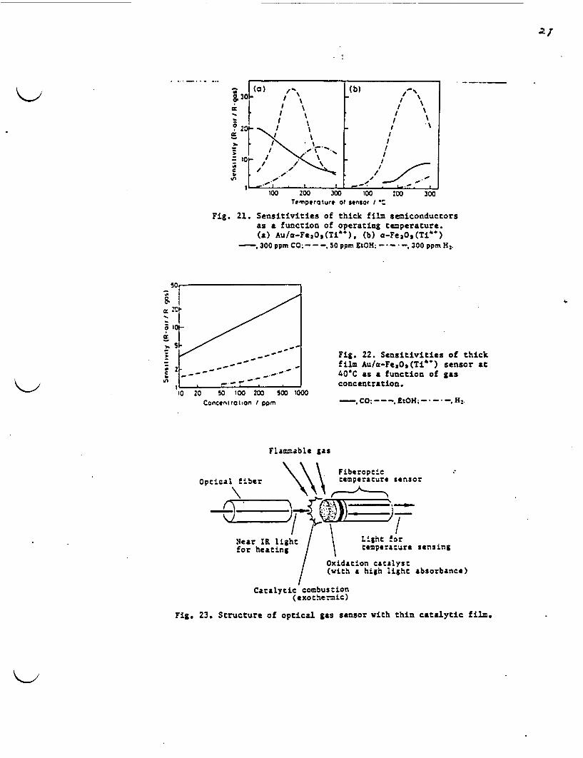
2),
g
30[
° 201
I %
I I
* I~ ~ IC,I/1
(b) -
I \
III
I
C
10
l _ . . . . _ _. ,. 100 z00 - 300 100
Temperature at sensor _ 1200 300
Fig. 21. Sensitivities of thick film semiconductorsas a function of operating temperature.(a) Au/a-FeaO 3(Ti"), (b) a-Fe 2O2(Ti')
- , 300 ppm CO: - - -. 50 ppm EtOH; - - - 300 ppm H.
50
S I
o 10%
t/ _, S Fig. 22. Sensitivities of thickfilm Au/a-Feas(Ti") sensor at40C as a function of gasconcentration.
-. CO -- - EtOH;- - - H:.10 20 50 100 200 500
Concentration pm1000
Flammable gas
Fiberopc'ctemperacure sensor
FLight fortemperacure sensing
Oxidation cactalyst(with a high light absorbance)
Catalytic combustion(exothermic)
Fig. 23. Structure of optical gas sensor with thin catalytic film.

that they are capable of the control at remote location and of the
direct linkage with an optical information system.
A film of 0.5=u thick composed of -Fe203 with highly dispersed
Au was prepared by simultaneous sputtering. The pillar-structured thin
film obtained was still less active than the thick film prepared from
the paste of coprecipitated powder, however, it was sufficiently
active at temperatures around 150C. The preparation of thin film
gold catalysts in connection with their optical properties is under
study.
4.3 Ion Sensors
The first ine of approach to the development of new ion sensors
was the utilization of a natural lacquer, Urushi as a matrix material
of ion sensitive membranes. Urushi is an oriental natural lacquer
used extensively for Japanese lacquer-wares(33] and has excellent
durability and mechanical strength. Many ion-selective electrodes for
iodide(34], perchlorate(351, nitrate[36] and thiocyanate(37] ions have
already been developed using Urushi at GIRIO. The second line of
approach was the application of FET to the fabrication of miniaturized
ion sensors.
Selenocyanate ion selective electrodes were prepared from tri-n-
octylmethylammonium selenocyanate ion-exchanger and Urushi[38].
Figure 24 shows that linear potential-concentration curves with a
slope of 6mV per decade were obtained within the concentration range
of 10-1-10-mol/l selenocyanate for the membranes composed of ion-
exchanger at 5-5Owt%. The static response time was less than 30
seconds. The electrode exhibited constant potential within the pH
range 2-10 and good selectivity except for a few cases. Figure 25
shows selectivity coefficients, ij in the Nernstian equation E-E@*
[(2.303RT)/zF]log(ai+Kija4).
As the first step for the miniaturization, a coated wire
electrode was linked to the gate lead-wire of a conventional field
effect transistor[39]. This coated lead-wire ion sensitive
FET(CLISFET) was prepared by using even weight of selenocyanate ion-
exchanger and Urushi. A linear response was obtained in the range of
10-2 to 10-5mol/l selenocyanate.

;;0CIM:;C;
3lo - (- o 1- 4 1-
rn ton tO" ton 'O'e ?O"Concentration of SU.N (mc0/lt
Fig.24. Potenlai-concentnuion curie o seienocyanate-selectveetc:roces: wt% of ion-excnanger: (J) SO. b.y) 45: (3) 40; 4) 35
Reference glrodo A se
FET (ISFE
Is IJ'uifl. meffiermfa a mixturSolution / exchange
Souv C gS O, directly Source C 0 Drain with a si
The FET d
/ owing to
shows the
Fig 26. Mcasunng awirtw of Urubhi ISFET. Aobtained
mol/l. nand other characteristics of the above two
10.'
-No;
- :;
Ic' -L. !- ;5- C;,-lcl
.'.Fig. 25. iecivtycefficts.
lenocyanate ion sensitive
L) was fabricated by coating
e of selenocyanate ion-
r(45%) and Urushi(55%)
on the gate of a FET device
Lze of 0.5mm x 6.5mm(401.
evice was water resistive
Si3N4 coating. Figure 26
measuring circuit of Urushi
linear response was also
in the range of 0-1-i0-5
he selectivity coefficients
FET sensors were almost the
same as those of the ion selective electrode.
A chemically modified CLISFET for silver ion was prepared using
silver-7,7,8,8-tetracyanoquinodimethane anion radical(Ag-TCNQ-) film
formed by dipping the wire in the TCNQ dry acetonitrile solution[4l].
A CLISFET for copper(II)ion was also developed by using Cu-TCNQT
film(42]. These sensors showed linear responses to the concentration
of their respective ions in the range of 10-1 to 10-5 mol/l with
Nernstian slopes.
New ISFET sensors using silica on sapphire(SOS) wafer are under
development for the detection of copper(II) ion and gluconic acid.
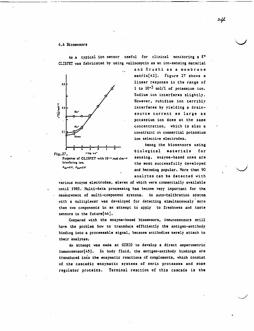
4.4 iosensors
As a typical ion sensor useful for clinical monitoring a K+
CUSFET was fabricated by using valinomycin as an ion-sensing material
and Urushi as a membrane
matrix[43]. Figure 27 shows a
as5 - linear response in the range of1 to 10-5 mol/l of potassium ion.
Sodium ion interferes slightly.
However, rubidium ion terribly
2.3 / interferes by yielding a drain-
source current as large as
- potassium ion does at the same
Nzi concentration, which is also a
2.1 constraint on commercial potassium
ion selective electrodes.
,__,__,__,__,__I Among the biosensors using
Fig 27. 4t 2^ biological materials forResponse of CLISFET with 10-' my dm-8 sensing, enzyme-based ones areinterfering ion. the most successfully developed
0 0.ov, vD.3v and becoming popular. More than 90
analytes can be detected with
various enzyme electrodes, eleven of which were commercially available
until 1985. Multi-data processing has become very important for the
measurement of multi-component systems. An auto-talibration system
with a multiplexer was developed for detecting simultaneously more
than two components in an attempt to apply to freshness and taste
sensors in the future[44].
Compared with the enzyme-based biosensors, immunosensors still
have the problem how to transduce efficiently the antigen-antibody
binding into a processable signal, because antibodies merely attach to
their analytes.
An attempt was made at GIRIO to develop a direct amperometric
immunosensor(45]. In body fluid, the antigen-antibody bindings are
transduced into the enzymatic reactions of complements, which consist
of the cascadic enzymatic systems of serin proteases and some
regulator proteins. Terminal reaction of this cascade is the
formation of membrane attack complex, which is a channel of 11 m
in diameter, in the cell membranes or artificial lipid bilayers.
Lipid membranes containing some hapten ligand, which were complete
insulators, were formed in the filter and attached to the end of
electrode. The membranes become conductive in proportion to the
degree of the immunological reactions induced by the addition of anti-
serum sample. The conductivity change is measured by an usual
amplification apparatus.
This detecting system, an unlabeled method named by us
"Complement-mediated Amperometric Imnunosensor(CAIS)", is highly
sensitive up to sub-nanomolar concentration, easy-handled, and free
from background noise caused by non-specific protein adsorption. This
is applicable to the detection of both immuno-assay and complement
assay.
5. CONCLUSION
Research on chemical sensors at GIRIO has been initiated as a.
practical subject of surface science and at the same time as one of
the attempts to explore new functional surface materials. The social
needs to chemical sensors were gathered through the questionnaire
survey. The analyses of the answers led to the establishment of self-
consistent and efficient strategy for the R&D of humidity, gas, ion,
and bio-sensors. Through the exploitation of new sensing materials
and the application of material technology already accumulated in
different lines of research, several new chemical sensors were
successfully developed.
The above experiences concerning the methodology for making R&D
programs of chemical sensors led us to the following conclusions.
1) Needs-orientated programs are particularly important for the R&D of
chemical sensors. It has been often the case that necessity is the
mother of invention of chemical sensors.
2) Needs to chemical sensors should be properly translated into the
required properties represented by the three Ss, namely,
sensitivities, selectivities, and stabilities.
3) Seeds of chemical sensors, namely, sensing materials and
transducing devices should be synergetically combined so as to
126
fulfill the requirements to chemical sensors.
4) Liaison between universities, national laboratories, and industries
will be the key for the efficient program making and successful
accomplishment. Scientists in university laboratories and
engineers in industries are, expected to be good sensors to needs
and seeds, respectively. Those who work for national laboratories
like GRI0 will have to be good transducers for seeds to needs, and
vice versa.
Ackowledgment. We thank Dr. Nakane, former director of material
chemistry department, GIRIO for his guidance and support throughout
the research. We also thank Mr. S. Wakida and Dr. T. obavashi for
their significant contribution to the R&D work on ion sensors and gas
sensors, respectively.
REFERENCES
1. Clifford P. K., Proc. 1st Intern. Meet. Chem. Sensors, Fukuoka,
1983, pp. 135-146.
2. Janata J., Proc. 2nd Intern. Meet. Chem. Sensors, Bordeaux, 1986,
pp. 2-31.
3. Vetelino J. F., Lade R., Falconer R. S., ibid, pp.688-691.
4. Jarvis M. L., Lint J., Snow A. W., and Wohltjen H., "Fundamentals
and Applications of Chemical Sensors" ACS Sym. Series 309,
Schuetzle D. and Hammerle R. eds., Washington DC, 1986, pp.309-319.
5. Ross J. F. and Roberts G. G., Proc 2nd Intern. Meet. Chem.
Sensors, Bordeaux, 1986, pp.704-707.
6. Beitnes H. and Schroder K., Anal. Chim. Acta 158, 57-65(1984).
7. Guilbault G. G., Proc. 1st Intern. Meet. Chem. Sensors, Fukuoka,
1983, pp. 637-643.
8. Carpenter .M. K., Van Ryswyk H., and Ellis A. B., Langmuir 1, 605-
607(1985).
9. Chem. Engng. News, April 27, 1987, p. 48.
10. Narayanaswamy R. and Sevilla III F., J. Phys. E: Sci. Instrum. 21,
10-17(1988).
11. Hijikikawa M., Proc. 2nd. Intern. Meet. Chem. Sensors, Bordeaux,
1986, pp. 101-108.
12. Lundstr8m I., Armgarth M., Spetz A., and Winquist F., ibid,
31. Kobayashi T., Haruta M., Sano ., and Nakane M., Sensors and
Actuators 13, 339-349(1988).
32. Kobayashi T. and Haruta M., Koatsu Gasu(J. High.. Pressure Gas
Safety Inst. of Jpn.) 24, 684-686(1987).
33. "Encyclopaedia Cimica", Vol.l Kyoritsu Pub. Co., Tokyo, p.807
(1960).
34. Hiiro K., Tanaka T., and Kawahara A., Bunseki Kagaku 2, 653-6S4(1976).
35. Hiiro K., Kawahara A., and Tanaka T., Anal. Chim. Acta 110, 321-
324(1979).
36. Hiiro K., Kawahara A., and Tanaka T., Bull. Chem. Soc. Jpn. 6,
1447-1452(1980).
37. Hiiro K., Kawahara A., and Tanaka T., Bunseki Kagaku 31, E33-E39
(1982).
38. H iro K., Wakida S., Tanaka T., Kawahara A., and Yamane M.,
Fresenius Z. Anal. Chen. 326, 362-364(1987).
39. Wakida S., Tanaka T., awahara A., and iiro K., Bull. GIRIO
37, 36-39(1986).
40. Wakida S., Tanaka T., Kawahara A., Yamane M, and Hiiro K.,
Analyst 1ir, 795-797(1986).
41. Wakida S. and Ujihira Y., Anal. Sci. 2, 231-233(1986).
42. Wakida S. and Ujihira Y., Jpn. J. Appl. Phys. 27, 68-70(1988).
43. Wakida S., Tanaka T., awahara A., and Hiiro K., Bunseki Kagaku
33, 56-560(1984).
44. Ishikawa T., Jpn. Pae.(claimed) 62-002674(1987).
45. Yoshikawa S., Fukumura H., and Hayashi K., Proc. 56th Annual Meet.
Chem. Soc. Jpn., I, p559(1988).
2.7
pp.387-390.
13. Dobos ., Krey D., and Zimmer. G., Proc. 1st Intern. Meet. Chem.
Sensors, Fukuoka, 1983, pp. 464-467.
14. Lefevre C., Lacombe ?., Bayre J., and Chauvet F., Proc. 2nd
Intern. Meet. Chem. Sensors, Bordeaux, 1986, pp. 427-430.
15. Shoji S., Esashi M., Matsuo T., Denki Tsusnin Gakkai Ronbunshi
(Bull. Electro-communication Society of Jpn.) 1, J68-C, 473(1985).
16. Sohn B., Lee D., and Lee J., Proc. 2nd Intern. Meet. Chem.
Sensors, Bordeaux, 1986, pp. 411-414.
17. Kuriyama T., Nakamoto S., Kawana Y., and Kimura J., ibid, pp. 568-
571.
18. "A Report of the Survey of Chemical Sensors"(Japanese), Ikeda,
1983, Government Industrial Research Institute of Osaka.
19. "A Report of the Survey of Development and Application of
Biosensors", Osaka, 1986, Osaka Science and Technology Center.
20. Tanigawa H., Sano H., and atsumoto.Y., Bull. GRIO 38, 148-154
(1987).
21. Tanisawa H., Nakane M., and Onishi S., Bull. GIRIO 37, 17-23
(1986).
22. Takenaka H., Torikai E., Kawami Y., Wakabayashi N., and Sakai T.,
Denki agaku(J. Electrochem. Soc. Jpn.) 3, 261-265(1985).
23. Takenaka H., Torikai E., and Kawami Y., Sensor Technology
(Japanese) 4(5), 56-59(1984).
24. Murakami N., Proc. 5th Meet. Chem. Sensors Jpn., Tokyo, 1986,
pp.53-54.
25. Yoneyama H. and Tamura H., Sensor Technology(Japanese) 2(13), 81-
90(1982).
26. Haruta M., Kobayashi T., Sano H., and Yamada N., Chem. Lett., 405-
408(1987).
27. Haruta M., Hyoumen agaku(Surface Science) 8, 407-414(1987).
28. Haruta M., Yamada N., Kobayashi T., and Iijima S., J. Catal., in
press.
29. Haruta ., Kobayashi T., Iijima S., and Delannay F., Proc. 9th
Intern. Cong. Catal., Calgary. 1988, pp. 1206-1213.
30. Haruta M., Kageyama H., Kamijo ., Kobayashi T., and Delannay F.,
"Studies in Surface Science and Catalysis : Successful Design of
Catalysts", Inui T. eds., Elsevier, Amsterdam, in press.
K> N EW Vol.17 No.2 Nlay, 1989
TECHNOLOGY- JAPAN
INNOVATIVE PRODUCTION NOW.4 : tho0ie Lighfing maindacruring
TOPICSSlhi'ane Preict:ire's ExchangeGroujs bereen Dfere,:t Trades
Derelopnient of DOep-Seoz Sw'tersible Shinkai 60
HIGH-TECH INFORMATIONS.:em tor EJricent Treatment of
E; :ulusiA iny' Oil W 'aste oater J ! ft ITecIiologq Thr Coating Cramic
1ll,:e -Alcohol Sporatuio;, itl$Haolloiv Fiber .elembrane MIodule _I |f
Fa-vicatO o PoPer Transisror iniC Formi
.0 ::dlot'nia Saplings Ctured b3S. echnological' t!ehod
NA1IONAL R&D PROJECTS.\t c ii aer Treatwmen Ssten)
* 'Aqua-Renaissance 90 Prolect _t-From MITI s Large-ScaleP-.,ject -
FLASHSpecial-Purpose Calculator'forDietetic Treatment
Automatic FingerS'phygmomanolneter
IETRO
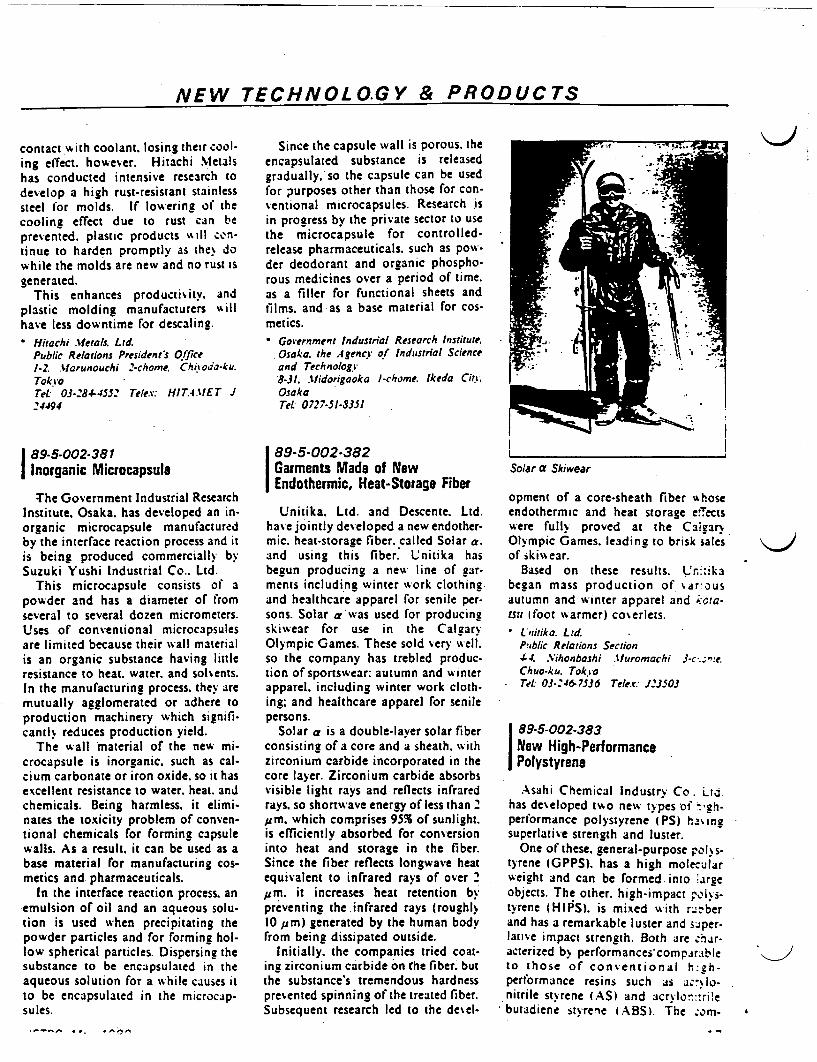
NEW TECHNOL O.GY & PRODUCTS
contact Aith coolant, losing their cool-ing elTect. however. Hitachi Metalshas conducted intensive research todevelop a high rust-resistant stainlesssteel for molds. If lowering of thecooling effect due to rust can beprevented. plastic products %ill cn-tinue to harden promptly as the dowhile the molds are new and no rust Isgenerated.
This enhances productixitv. andplastic molding manufacturers %t illhave less downtime for descaling.
Hitachi ferals. Ltd.Public Relations President's Office1-2 .arunouchi -chome. Chioda-ku.Tok roTet 03-.84-4552 Telex: HITAMEr J24494
89-5-002-381Inorganic Microcapsule
The Government Industrial ResearchInstitute. Osaka. has developed an in-organic microcapsule manufacturedby the interface reaction process and itis being produced commercially bySuzuki Yushi Industrial Co.. Ltd.
This microcapsule consists of apowder and has a diameter of fromseveral to several dozen micrometers.Uses of conventional microcapsulesare limited because their wall materialis an organic substance having littleresistance to heat. water. and solvents.In the manufacturing process. they aremutually agglomerated or adhere toproduction machinery which signifi-cantlK reduces production yield.
The wall material of the new mi-crocapsule is inorganic, such as cal-cium carbonate or iron oxide. so it hasexcellent resistance to water. heat. andchemicals. Being harmless. it elimi-nates the toxicity problem of conven-tional chemicals for forming capsulewalls. As a result. it can be used as abase material for manufacturing cos-metics and pharmaceuticals.
In the interface reaction process. anemulsion of oil and an aqueous solu-tion is used when precipitating thepowder particles and for forming hol-low spherical particles. Dispersing thesubstance to be encapsulated in theaqueous solution for a while causes itto be encapsulated in the microcap-sules.
_*.-.. Ore
Since the capsule wall is porous. theencapsulated substance is releasedgradually, so the capsule can be usedfor purposes other than those for con-ventional microcapsules. Research sin progress by the private sector to usethe microcapsule for controlled-release pharmaceuticals. such as pow-der deodorant and organic phospho-rous medicines over a period of time.as a filler for functional sheets andfilms. and as a base material for cos-metics.
Government Industrial Research InstituteOsaka. the .4gency of Industrial Scienceand Technology8-31. .tlidorigaoka -chome. Ikeda Ci.OsakaTeL 0727-51-8351
89-5-002-382Garments Made of NewEndothermic, Heat-Storage Fiber
Unitika. Ltd. and Descente. Ltd.ha% e jointly developed a new endother-mic. heat-storage fiber. called Solar a.and using this fiber Unitika hasbegun producing a new line of gar-ments including winter work clothingand healthcare apparel for senile per-sons. Solar a'was used for producingskiwear for use in the CalgaryOlympic Games. These sold very well.so the company has trebled produc-tion of sportswear: autumn and winterapparel. including winter work cloth-ing; and healthcare apparel for senilepersons.
Solar a is a double-laver solar fiberconsisting of a core and a sheath. withzirconium carbide incorporated in thecore layer. Zirconium carbide absorbsvisible light rays and reflects infraredrays. so shortwave energy of less than 2pm, which comprises 95% of sunlight.is efficiently absorbed for conversioninto heat and storage in the fiber.Since the fiber reflects longwave heatequivalent to infrared rays of over 'pm. it increases heat retention bypreventing the infrared rays (roughl%10 um) generated by the human bodyfrom being dissipated outside.
Initially. the companies tried coat-ing zirconium carbide on the fiber. butthe substance's tremendous hardnesspresented spinning of the treated fiber.Subsequent research led to the deel-
Solar a Skiwear
opment of a core-sheath fiber hoseendothermic and heat storage eectswere fully proved at the Calg3r%Olympic Games. leading to brisk salesof skivwear.
Based on these results. 'n;.ikabegan mass production of ar usautumn and winter apparel and ;.Cra-isit foot warmer) coverlets.
Lritika. Ltd.Puiblic Relations Section4-4. .Vihonbashi .turomachi 3-.V~"eChuo-ku. Toki oTel: 03-'46-7536 Telex: J3503
89-5-002-383New High-PerformancePolystyrene
Asahi Chemical Industry Co. Ltdhas developed two new types of ~-'h-performance polystyrene (PS) ha,6ingsuperlative strength and luster.
One of these. general-purpose polys-tyrene GPPS). has a high molecularweight and can be formed into rgeobjects. The other. high-impact olys-tyrene HIPS). is mixed ith berand has a remarkable luster and sper-lati'e impact strength. Both are har-acterized b performances'compsrableto those of conventional h:zh-performance resins such as ac-lo-nitrile stvrene (AS) and crlo-:rilebutadient stvrenie z ABS) he zorr- 4

1990
/I,,,-igte Tt"R
voe. AI ttI NF3 IR fiGOVERNMENT INDUSTRIAL RESEARCH INSTITUTE. OSAKA
AGENCY OF INDUSTRIAL SCIENCE AND TECHNOLOGYMINISTRY OF INTERNATIONAL TRADE AND INDUSTRY
IIII
t
i
I
7 WT 5 z 0 PC Outline of Researches
j'~~~Mig~~~F~~ ~
Atfl~- a tZT
~~~ x*~~~r
L 2 AL -c t642ifti-*1;
Ordinary Research and Development
Spec
and Development
i
I
iI
ial Research
R & D Program .
National
Research and Develop-ment on New Energy Technolcg e
. . ~~~~~Researchand Development on Energy Conservation Tech-nology
Research and Development Project of BasicTechnologies for Future Industries
National R & D Programsfor Medical and Welfare Apparatus .
Specific Regional Technology Develop-
ment System G. . -- GlobalEnvironment Project
II

i : .
- I . :
. z . 4 . .
. . t-. -- I - .
2 .7I
I t I I 3 3 -
fi fi I XX. -
tA7,: =
i '
i & i -I - i x, 1
= z 2 _ = = ' x 2 s2 _ >
¾..>
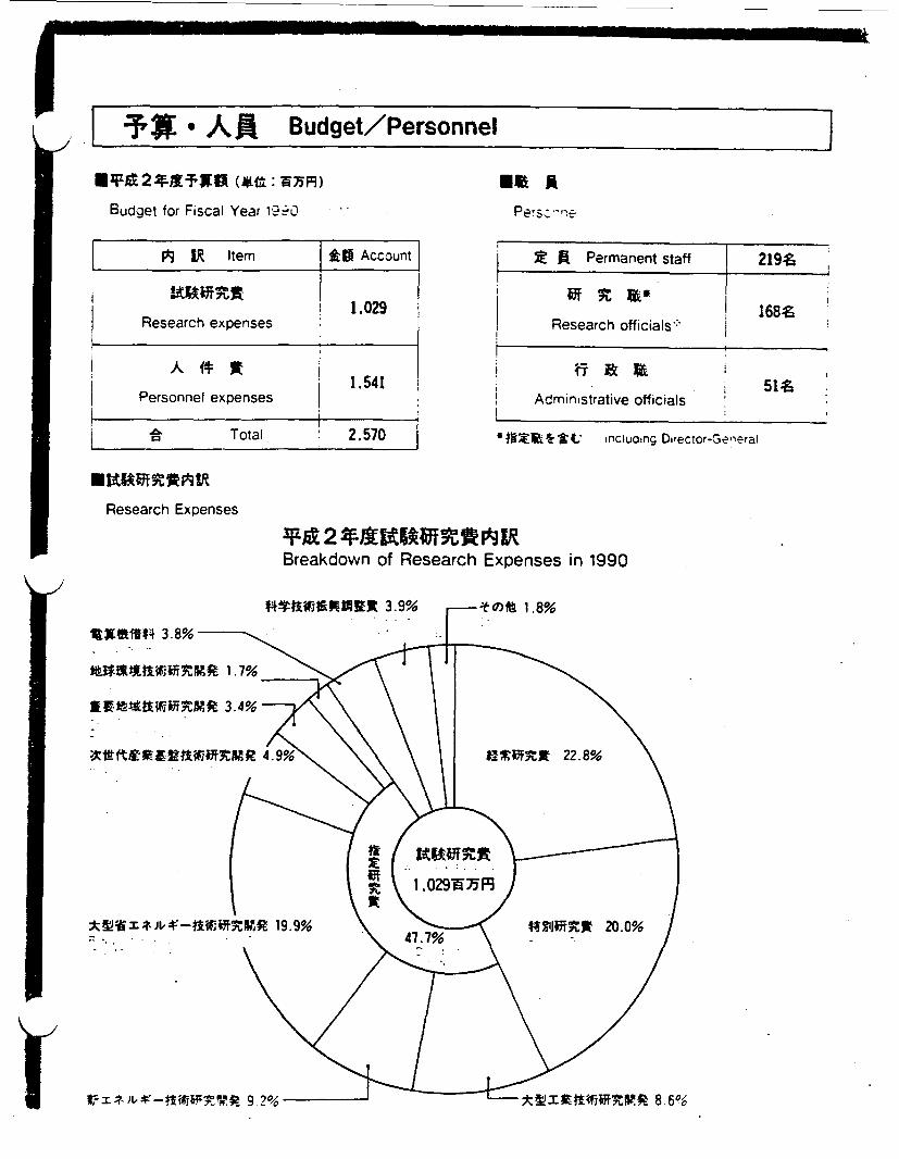
I i AR Budget/Personnel I.
*IN 2 4-fTW (*t: W7YF9)
Budget for Fiscal Year 19-Q
Elm APers; 1>
r A Z Item Ig Account
i 1.029I Research expenses
1.541| Personnel expenses _
Total 2.570
Permanent staff 219i
I 168?Research officials:
51 Administrative officials
*0 Xk*V ,ncluding DIfector-General
Research Expenses
*A12 *AKUWtVABreakdown of Research Expenses in 1990
11OIM4 3.8%
*-%}IKIWMRMR 1.7°%
XX~ti6S~tSXZ 3.4% 7
:i f~X RMR 4.9%
;*z4t I * Jv -,if~lt 19.9%, .~~~~~~~
r, I- ): t-t WkW V 9 26 *% t ifRR 8.6%
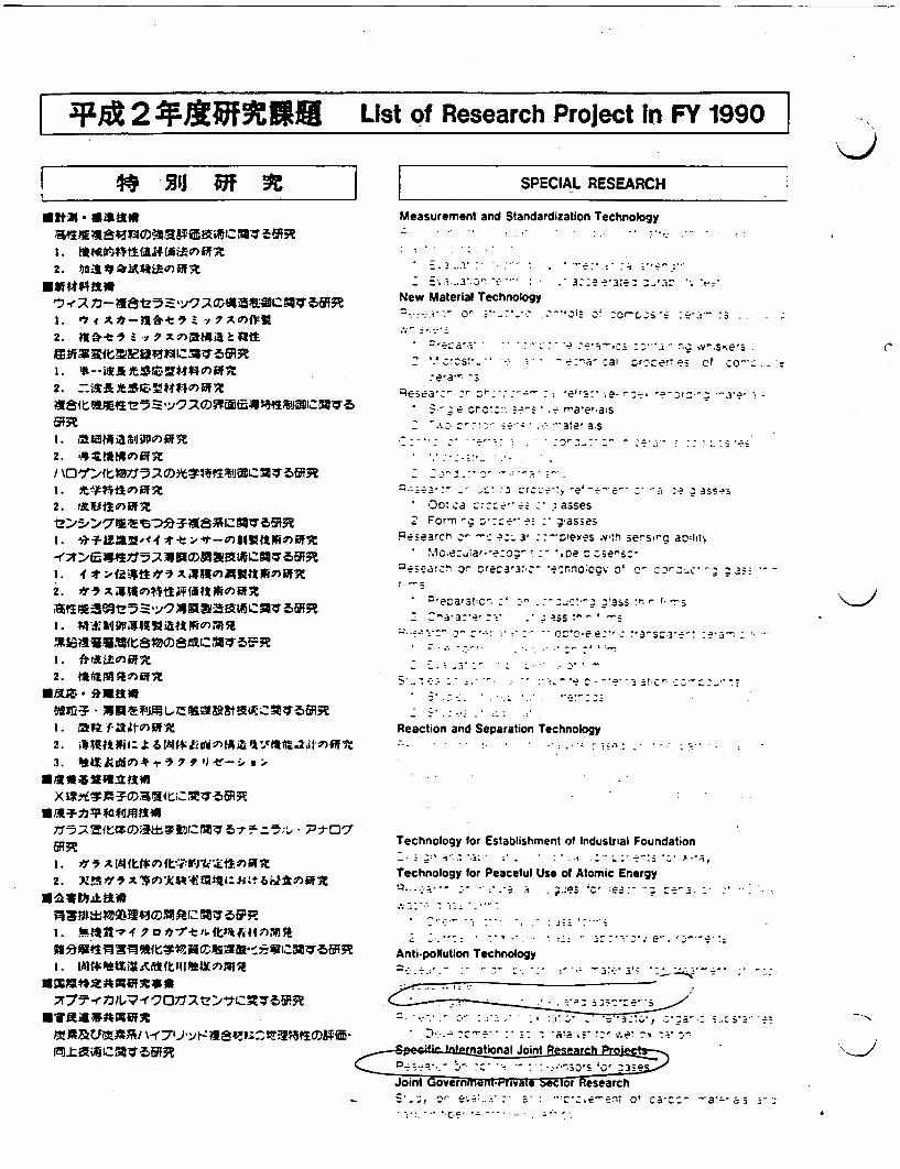
I|lp 2 * iff3tiU List of Research Project In FY 1990QJ
2. itQU ~i ) o*111M3
2. is ? PIA.) a &:W
I. I1Ui
2. 44)if 5
2. fl1dV)R
2. *AtP~IumI'
1.
2. 44M7x
| ~SPECIAL RESEARCH
Measurement and Standardization Technology
.. .. *.. . . .: .1.... .. -. .
- -.Ze'ae :
New Material Technology
=>~ ~~ *;--r :e sj-*: ::"j C-OC_' :¾~i :;:. --'.: -~ ~~~.-,o
- ..- a --. --- ;- e- .- : -- a i~st ' ,.^. cs- -- a- a or.er,,ez cf co-- z-era" -3
Peseac - ei';- ;e--.e r_ *3.e;
* o,.-: z r -?- ' fe ra etia:s- .~~~c ~~ .- ale, .S
- .- -- - - .-:; :--
-- . ... . .3 Zr
* )o:.ca r - asses2 For-n . : : asses
Researcr o -c _ 3- :- exes .v-h sesr ahl;* bilc.e¶. ~ar.--e~ .. *.pe ocsersz
°es---a 3c r etia @-nnoccv o ** ^-'r_';'.3 '
* ;ecara!:c_ ... j3SS f -S
-: '3:- r - ,-' *^~ A2' J-
Reaction and Separation Technology
Technology for Establishment of Industrial Foundation
_ ; . - -. . , .- ,. . . , *
Technology for Peaceful Use of Atomic Energy-A . T. .
... ..
--.. . . e..
Rationndeurtion Technology
.~~~~. .2
C,
b. ^~~~~~~ : . .' c- 2 <
Joit Gvenmfnr rwle ecor esearch
N
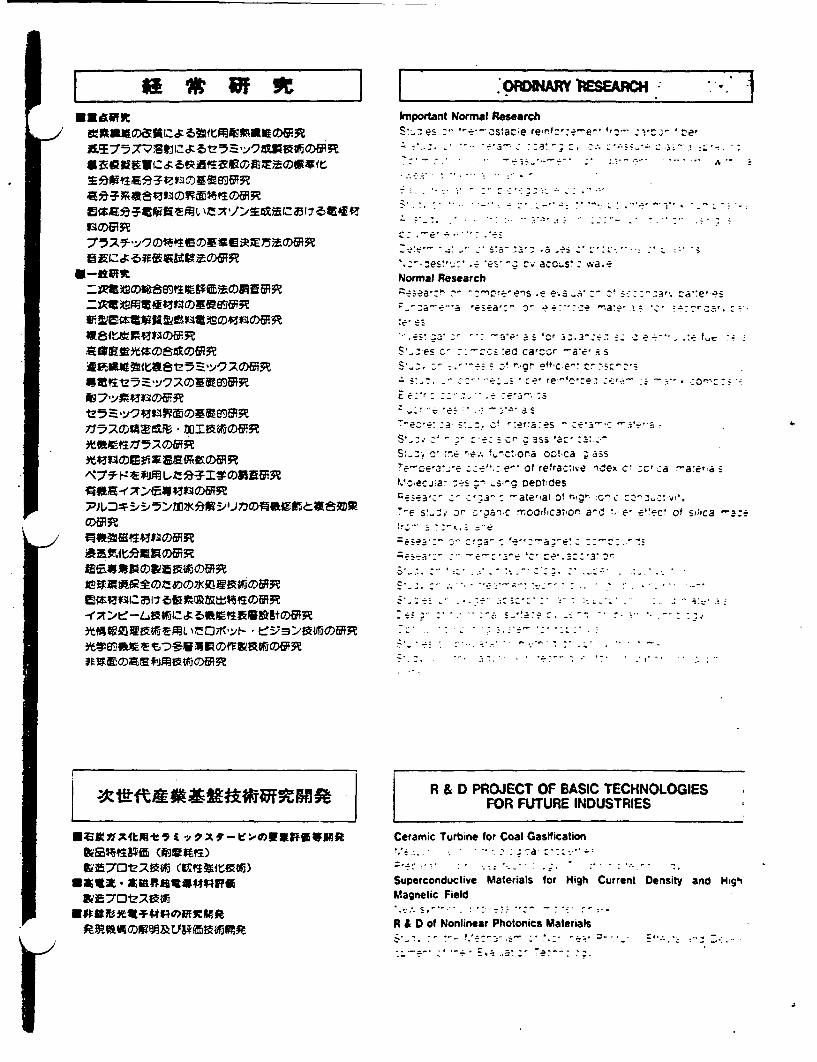
I ff*fIi
R96�I�
a�R
�WML7)�f�
� t�i0�
*O1011m airY)sAcImportant Normal ResearchS-: es ~--astac;e rerf..ze- ',-elc
Normal Research
S C-we - .- z,5 :ed catr.-o -ae' a~s
- r ~~~~~r
S---,C .E ' vora obca ; ass~~ * ~~ 'e- of refrac-Nve ,Cex c' -a a~e~
V; ecja- --s s, ceotdes- ate'!a, of "o- c
T- s ,. r m cclrofca',or a-d e, e-"c! ot silica -az-
I
POOR �
0ZAZX4tffl-t IIVVxf -e:e0w*ff*wKft6WRI44SAT115 MUMS)&r-70V;Uz4rj (Gq3K1ta1rj)
E Aux -WE701Z170bri
Enaft *Q-TVIROW Stan
R & D PROJECT OF BASIC TECHNOLOGIESFOR FUTURE INDUSTRIES
Ceramic Turbine for Coal Gasification.. . . -:: ~
Superconductive Materials for High Current Density and HghMagnetic Field
R & D of Nonlinear Photonics Materials
… ...................................... ,
A

*sx #-o ~0irfIts
N*oa*
R & D ON NEW ENEMGY TECHNOLOGYf(THE SUNSHINE PROJECT)
Hydrogen EnergyHydrogen Production Technology
Transportation and Storage of Hydrogen
Utilization of Hydrogen
Advanced Battery Electric Power Storage SystemNew Types of Batteries
*3!-'..r':e -.... - : _ :e, 4 , . j
_~~~~~~o a-. z-ec t .... ...s 3
Fuel Cell Power Generation TechnologyMolten Carbonate Fuel Cells
;'se,_ e-. cacnn mater a3 3.a~- a es'a -emrod's for c.-oonenis.
Leading and Basic Technology for Energy ConservationResearch on High Lithium Ion Conductive Solid ElectrolyteResearch on Energy Saving Organic Synthesis Using CopperCatalyst
&
N1
\K>
;AA7~ftWW ib)
Ut ~Ot:P
XNAIN0Mt4M1. VF t* 'Ii t14
2. WtAam X a4n1Tf4is
R'X% 190411lU A Q09AfM P19 PA R
NATIONAL R & D PROGRAM(LARGE-SCALE PROJECT)
New Water Treatment System (Aqua-rena ssance 90 project)Micro-organisms
Membrane Materials
: _ , .. .: .: : : ,:
Advanced Material Processing and Machining SystemIon Beam Processing Technology.
Evaluation of Essential Technology in Advanced MaterialProcessing System for Power Plants
Characterization of Micro-areaed Surface Layer.Fine Chemicals from Marine Organism
Fundamental Technology for Utilization of Marine Organisms
Jes.e- - . ; a "v
Basic Technology for Research and Utilization of Useful Bio-logical Functions
.ie - a-- <-- --Super/Hyper Sonic Transport Propulsion System
7 -a - e tecl!-

- WftIAI1IV-NW*IMUCAL At.
Laser Device for Arteriosurgery, - - - -. - * . s; *- . - - .
* UkZ**IMIL-J 6=W1tIE30EMt4tt1ItO)KR
JWXA1?)O'r-JflZ~
GLOBAL ENVIRONMENTPROJECT
Study on the C02 Fixation by Artificial Photo-synthesis.- _G esze- _esourcei -
SPECIFIC REGION TECHNOLOGY|DEVELOPMENT SYSTEM
Technology Development for Advanced Surface Modification imMaterial Processing.
- - .a --. : ~ rove"er r z--aze- - e ~zc 'or ua'e-§l- i -
1�11
*E4~z-*st V~iff 5 A
2.gloz 1E*09L tr1Ak x -!::r t 1i0
DATA BASE MANAGEMEtNTISYSTEMS
Information Supporting System for Material Development in EnergyConservation Technologies.
LEADING TECHNOLOGY DEVELOPMENT FOR ORDINARY LOCAL AREAS
Research and Development of Highly Tough Plastic Composites
SPECIAL COORDINATION FUNDS FORPROMOTING SCIENCE AND TECHNOLOGY
ENCOURAGEMENT OF BASIC RESEARCH ATNATIONAL RESEARCH INSTITUTE
a, 2
. = -. e
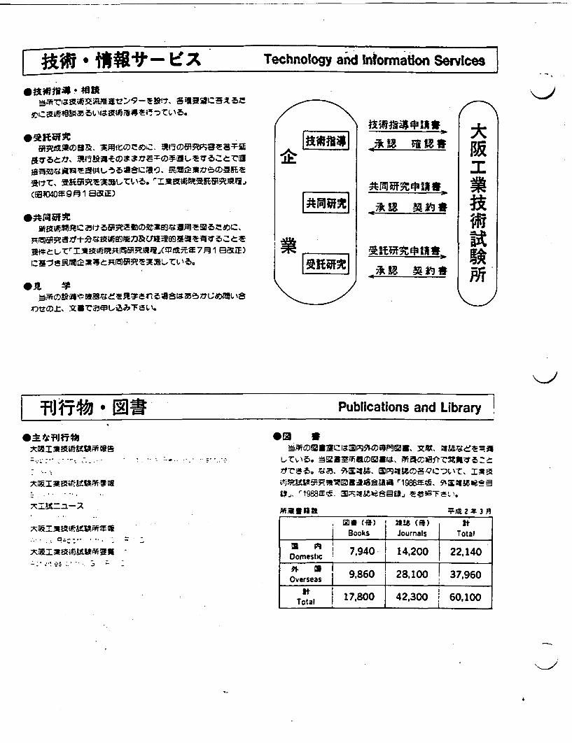
Technology and Intormatlon Services
(ET001 8R B)E
F" ~m-
a ,
#M-UNFPI#O
IE
af
| IJii .- j J* Publications and Library w
0* *H noXMIAMMKoffiva
00 a�zw, narwerAm
�:�Gznm*dmmnll,
17ca-5. Ua. 91,34M, TIVArlwo, 9kx;9&CIeS=3
",, r1988a:t, 3XCW*a8�[I., �E-0-967L".�.
Magian 1F 2 3
XMBmmmffi"m^- Re , -
, l () | UZ I) atBooks I Journals Total
Dom sti4i 7,940 14,200 22,140Domestic1
esea 9,860 | 28,100 1 37,960versasI __ I,0 |4230!610
It 17800 142,300 6010Total 17I _ _ _ _ _
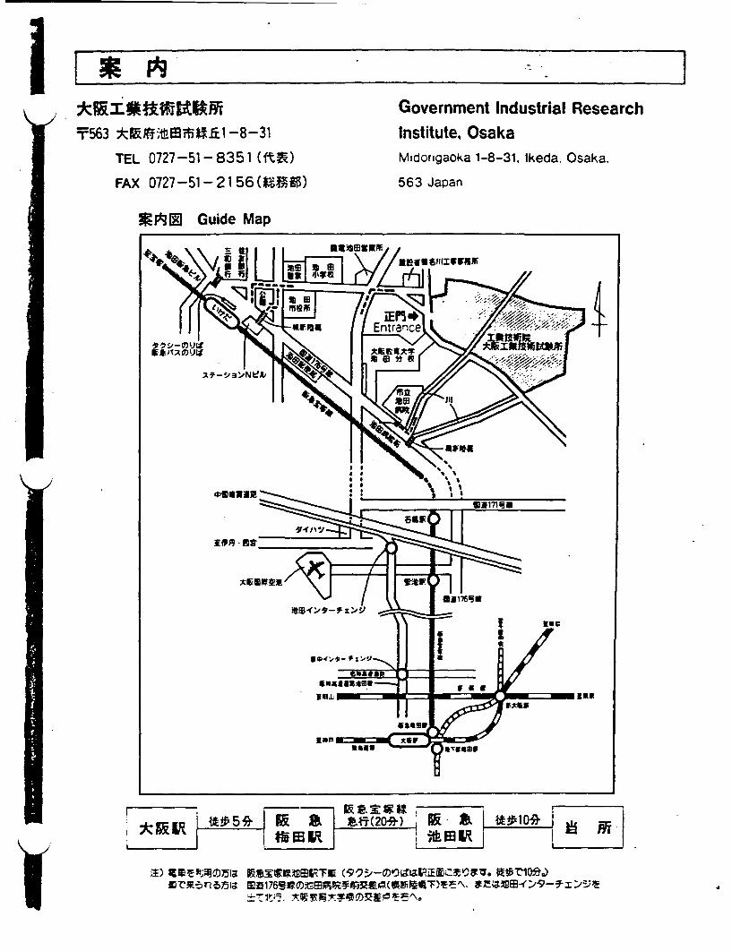
I I
T563 tW9,tE1BiW xl-8-31
TEL 0727-51-8351 (ftV)
FAX 0727-51-2156(U-S)
Government Industrial ResearchInstitute, OsakaMidorigaoka 1-8-31, Ikeda. Osaka.
563 Japan
WiNM Guide Map
4
I wz S V w KIt 5 qF -A -i~ A-F(20R itk tPI4
i1) CERUMV51a FaSX09EATI RseO~a7;u4 ffilre.S-CA5n-B)5ia 6fSERFtgl45$-t;S+9E>J
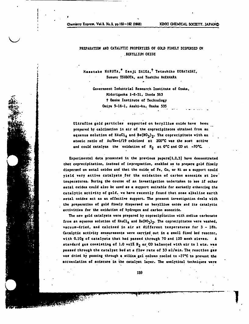
I
!~~~~~~~
Chevistry Expms. VeoL. No.3. pp 59-lU 158) 1CMtl CHEMICAL SOCIETY. APANC)
PREPARATION AND CATALYTIC PROPERTIES OF GOLD FINELY DISPERSED ON
.BERYLLIUM OXIDE
Hasatake HARUTA, Kenji SAIKAt Ttsuhiko KOBAYASHI,* Susumu SUBOTA, and oshiko NAEAHARA
Government Industrial Research Institute of Osaka,
Midorigaoka 1-8-31, Ikeda 563
t Osaka Institute of Technology
Omiya -16-1, Asahi-ku, Osaka 535
Ultrafine gold particles supported on beryllium oxide have been
prepared by calcination in air of the coprecipitates obtained from an
aqueous solution of AuCl and Be(N03)2. The coprecipitate with an
atomic ratio of Au/Ee-1/19 calcined at 200C was the most active
and could catalyte the oxidation of H at OC and CO at 70C.
Experimental data presented n the previous papers(1,2,3J have demonstrated
that coprecipitation, instead of impregnation, enabled us to prepare gold finely
dispersed on metal oxides and that the oxide of Fe, Co, or Ni as a support could
yield very active catalysts for the oxidation of carbon monoxide at low
temperatures. During the course of an investigation undertaken to see if other
metal oxides could also be used as a support uitable for markedly enhancing the
catalytic activity of gold, we have recently found that some alkaline earthmetal oxides act as an effective support. The present investigation deals with
the preparation of gold finely dispersed on beryllium oxide and ts atalyticactivities for the oxidation of hydrogen and carbon monoxide.
The new gold catalysts were prepared by coprecipitation with sodium carbonate
from an aqueous solution of HAuCl 4 and e(N0 3 )2. The coprecipitates were washed,
vacuum-dried, and calcined in air at different temperatures for 3 - 18h.
Catalytic activity measurements were carried out n a small fixed bed reactor,
with O.1Og of catalysts that had passed through 70 and 120 mesh sieves. A
standard gas consisting of 1.0 olZ 2 or CO balanced with air to I atm. was
passed through the catalyst bed at a flow rate of 33 1/ain. The reaction gas
was dried by passing through a silica gel column cooled to -77'C to prevent the
accumulation of moisture n the catalyst layer. The analytical techniques were
159
. - . . P
.1
I
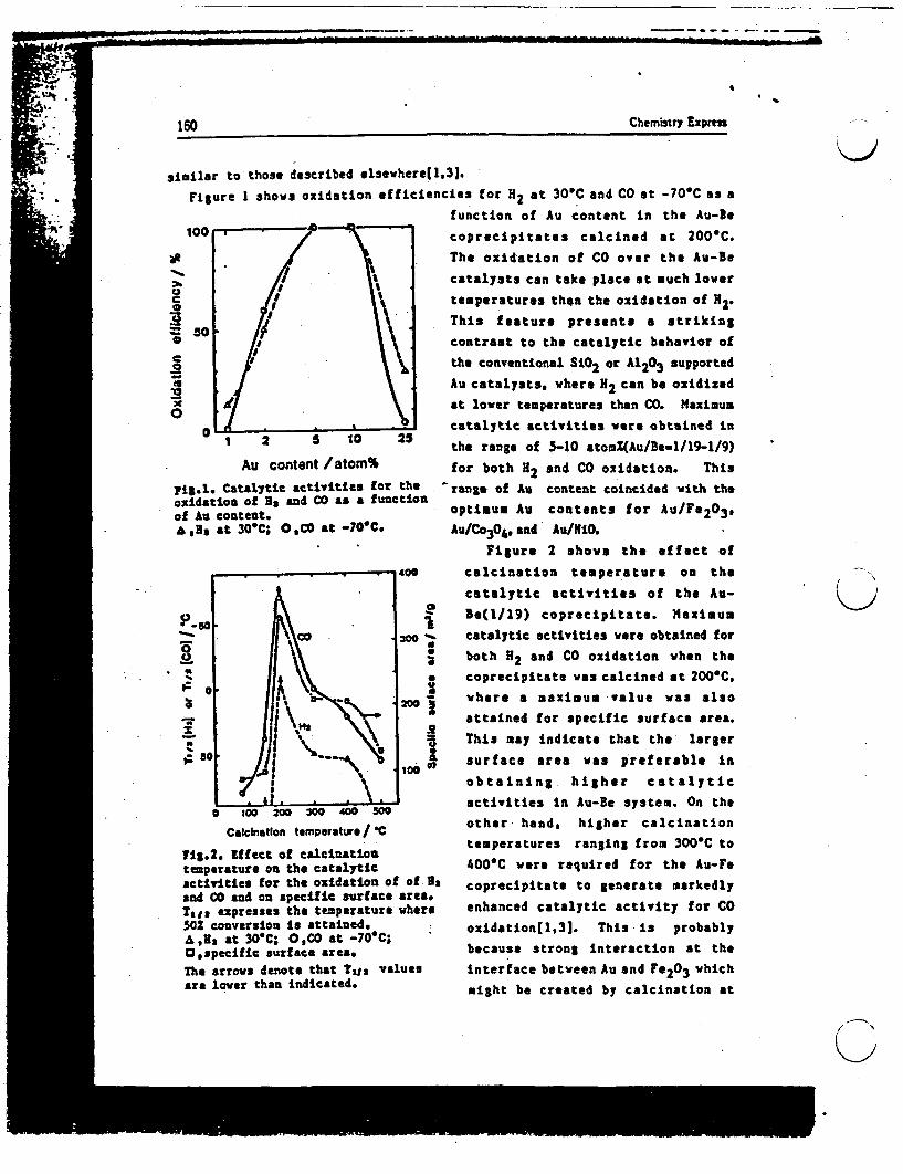
160 Chemistry Express
similar to those described lsewherel l31.
Figure shows oxidation efficiencies for 2 at 30'C and CO at -70'C as afunction of Au content in the Au-Be
100 *7 coprecipitates calcined at 200'C.
The oxidation of CO over the Au-Be
S / \; catalysts can take place at much lowero gt \: temperatures than the oxidation of H2.
_ 50 // \\ This festure presents a strikingo / contrast to the catalytic behavior of
o | \ \ the conventional SiO2 or A1203 supportedAu catalysts, where 2 can b oxidized
O a *t lover temperatures than CO. Maximum0
catalytic activities were obtained in1 2 0 10 25 the range of 5-10 atom%(Au/Be-1/19-1/9)
Au content /atom% for both 2 and CO oxidation. This
pig.l. Catalytic activities for the ran&e of Au content coincided with theoxidation of s and CO s a functiontents for Au/F&203of Au content. piu ucnet o uF 2 3&,la at 30C; OCO at -70'C. Au/Co3 4 ,and Au/iO.
Figure 2 shows the effect of
0so calcination temperature on the
. % .scatalytic activities of the Au-
p-o I Be(l/19) coprecipitate. MaximuU
_ catalytic activities were obtained for
0 1l \ both H2 and CO oxidation when the
* coprecipitate was calcined at 200'C- - __ \ . where a maximum value was 1so
attained for specific surface area.
- _ i \ s This may indicate that the larger0 so so* surface area was preferable in
obtaining higher catalytic
activities n Au-Be system. On the00 200 300 400 500
Calcin200 300 400pera5ure/other hand, higher calcinationCalination temperatre/ -
temperatures ranging from 300-C toTIZ.2. ffect of calclation temperature on the catalytic 400*C were required for the Au-Feactivities for the oxidation of of a coprecipitate to generate markedlyand CO and on specific surface reaoTale expresses the temperature where enhanced catalytic activity for CO502 conversion is attained. oxidation[1,31. This ls probablyA,12 t 30"C; ,CO t -70OC;OUa at 30C;le Oe *ra -0Cbecause strong interaction at theO,specific surface area.The arrows denote that Tgr values interface between Au and F0 3 whichare lower than indicated* might be created by calcination at
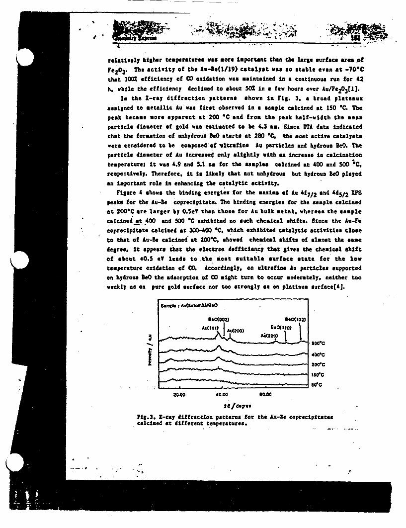
-
, .~- .~~~t# .. .. _
relatively higher temperatures as more Important than the large surface are of
Fe 2 03 . The activity of the Au-le(1/19) catalyst was so stable even at -0Cthat 1002 efficiency of CO oxidation was maintained in a continuous run for 42
h. while the efficiency declined to about 502 n a few hours over Au/Fe203 (13.In the I-ray diffraction patterns shown n Fig. 3, a broad plateaux
assigned to metallic Au was first observed in a *saple calcined at 150 C. Te
peak became more apparent at 200 C and from the peak half-width the mean
particle diameter of gold was estimated to be 4.3 an. Since TA data indicatedthat the formation of unhydrous eO starts at 280 C, the moat active catalysts
were considered to be composed of ultrafine Au particles and hydrous e0. The
particle diameter of Au increased only slightly with an Increase ln calcination
temperature; t was 4.9 and 1 an for the samples calcined at 400 and 500 C.respectively. Therefore, t to likely that not unhjdrous but hydrous eO played
an Important role n enhancing the catalytic ctivity.
Figure 4 shows the binding energies for the maxlms of Au 47/2 and d5/2 Mpeaks for the Au-Be coprecipitate. The binding energies for the sample calcinedat 200C are larger by .eV than those for Au bulk metal, whereas the sample
calcinei at 400 and 500 *C exhibited no such chemical shifts. Since the Au-Fe
coprecipitata calcined at 300-400 C, which exhibited catalytic activities close
to that of u-Be calcined at 200C showed chemical shifts of almost the same
degree, t appears that the electron dofficelancy that lives the chemical shift
of about 0.3 eT leads to the oat suitable surface state for the low
temperature oxidation of C. Accordingly. on ultrafine Au particles supported
on hydrous eO the adsorption of CO ight turn to occur moderately, neither too
weakly as on pure gold surface nor too strongly as on platinum surface41.
-Aittt) 8*0(103~tt )|
4009C
__. = - ~~~~1565CW50C
20.00 40.00 60.00
20/deres
7lg.3. -ray dffraction patterns for the Au-Be coprecipitatescalcined at different temperatures.
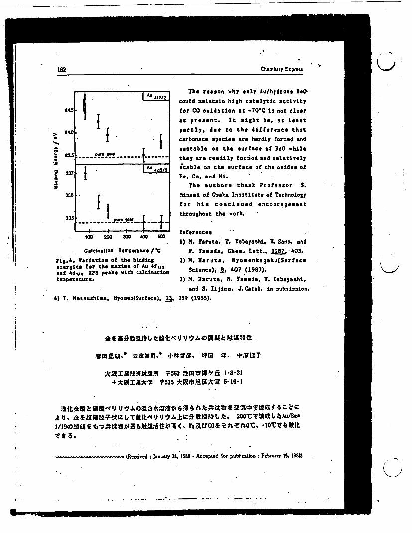
162 Ctemury Epfess162 Chemistry Expreu
r _ _
841.
21
0C
co
8M
8a
337
I I.
I~~~~~I [A dS/
-------------. n1_4 -- .
The reason why only Au/hydrous 3eO
could maintain hgh catalytic activity
for CO oxidation at -70C ia not clear
at present. It might be, at least
partly, due to the difference that
carbonate species are hardly formed and
unstable on the surface of BeO while
they are readily forued and relatively
stable on the surface of the oxides of
Fe, Co, and Ni.
The authors thank Professor S.
Hinsoi of Osaka Insititute of Tchnology
for his continued encouragement
throughout the work.335
Fig.4. VIenergiesand d,,temperatu
00 ZI In I sa References1) . aruta, T. obayashi, . San., and
Calelnatlon Temperature /C N. auads, Chain. Lett., 1987, 405.rtation of the binding 2) M. aruta, Hyosenkagku(Surfacafor the maxima of Au f,1 .XPS peaks with calcination Science). 8. 407 (1987).
Ire. 3) M. aruta, N. Tamada, T. obayashi,
and S. Iliji.a, JCatal. in submission.sushima, Hyomen(Surface), 23, 259 (1985).
K)
4) T. Mat
4 IEU.* 11A2 NIJt 'J492 'J 19 c#'{11UT
ARSUMUMNt~ 563 diiBE1-8 31@ *k I* 535 AMMUILX 5-16-1
ID E lb . tlb tt r I b i < NaZi t ICO't 200 : tOC . 1tlb fAu/ eI/19DX0tt :}gtthtttlilS t ISA X~LFCO 1 tTho'1 70' 4Tlbt1t
- ww -*(Receied : Janusy 31. 1983 -Accepted (or publication: Febnr 1S. lS88)
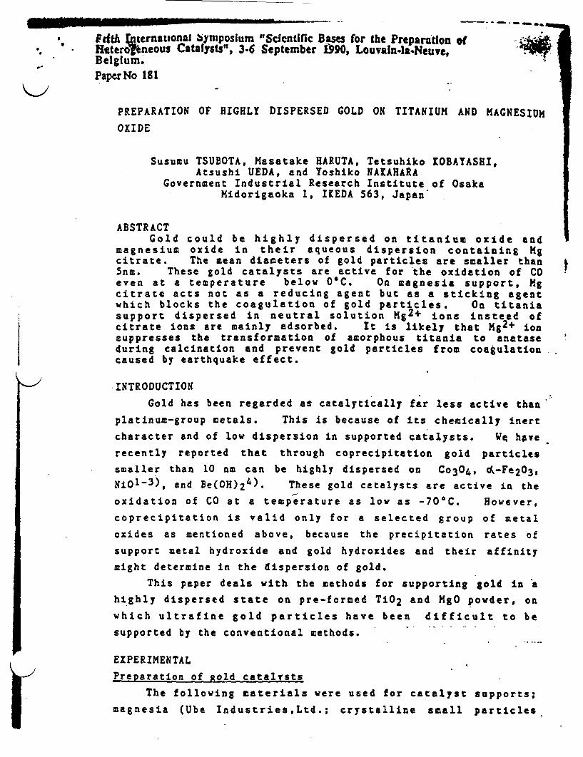
F ifthazernautonl bymposium "Scientific Bas for the Preparation ofHtteroneous Catalysts", 36 September 990, Louvalnla.Neuye,Belgium.PaperNo 181
PREPARATION OF HIGHLY DISPERSED GOLD ON TITANIUM AND MAGNESIUM
OXIDE
Susumu TSUBOTA, Masatake HARUTA, Tetsuhiko OBAYASHI,Atsushi UEDA, and Yoshiko NAKAHARA
Government Industrial Research Institute of OsakaMidorigaoka 1, IKEDA 563, Japan
ABSTRACTGold could be highly dispersed on titanium oxide and
magnesium oxide in their aqueous dispersion containing Mgcitrate. The mean diameters of gold particles are smaller than5nm. These gold catalysts are active for the oxidation of COeven at a temperature below 0C. On magnesia support, Mgcitrate acts not as a reducing agent but as a sticking agentwhich blocks the coagulation of gold particles. On titaniasupport dispersed in neutral solution Mg2 + ions instead ofcitrate ions are mainly adsorbed. It is likely that Mg2+ ionsuppresses the transformation of amorphous titania to anataseduring calcination and prevent gold particles from coagulationcaused by earthquake effect.
INTRODUCTION
Gold has been regarded as catalytically far less active than
platinum-group metals. This is because of its chemically inert
character and of low dispersion in supported catalysts. Wq hve
recently reported that through coprecipitation gold particles
smaller than 10 nm can be highly dispersed on Co3 0 4 , -Fe2 O3 ,Niol-3), and Be(OH)24). These gold catalysts are active in the
oxidation of CO at a temperature as low as -70'C. However,
coprecipitation is valid only for a selected group of metal
oxides as mentioned above, because the precipitation rates of
support metal hydroxide and gold hydroxides and their affinitymight determine in the dispersion of gold.
This paper deals with the methods for supporting gold in ahighly dispersed state on pre-formed TiO2 and MgO powder, onwhich ultrafine gold particles have been difficult to be
supported by the conventional methods.
EXPERIMENTAL
Preparation of old catalysts
The following materials were used for catalyst supports;magnesia (Ube IndustriesLtd.; crystalline small particles
t.
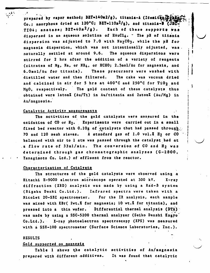
.I ~~. A
prepared by vapor ethod; BZTu140E2/g)* titania-A (IdeitA4k @
Co.; amorphous dried at 120'C; BETa110a2/g), ad ttania3- (JR10
T104; anatase; BET*40a2 /g). Each of these supports as
dispersed in an aqueous solution of HAuC14. - The pH of titania
dispersion was adjusted to 7.0 with Na2CO3 , while the pH for
magnesia dispersion, which was not intentionally adjusted, was
naturally settled at around 9.6. The aqueous dispersions were
stirred for 2 hrs after the addition of a variety of reagents
(citrates of Mg Na, or NH4, or HCHO; 2.5mol/Au for magnesia, and
6.Omol/Au for titania). These precursors were washed with
distilled water nd then filtered. The cake was vacuum dried
and calcined in air for 5 hrs at 400C and 250'C for TiO2 and
MgO, respectively. The gold content of these catalysts thus
obtained were latom% (Au/Ti) in Au/titania and 2atom% (Au/Mg) in
Au/magnesia.
Catalytic Activity measurementsThe activities of the gold catalysts were measured in the
oxidation of CO or 2. Experiments were carried out in a small
fixed bed reactor with 0.10g of catalysts that had passed throughi.
70 and 120 mesh sieves. A standard gas of 1.0 vol.1 H2 or CO
balanced with air to 1 atm was passed through the catalyst bd at
.a flow rate of 33m1/min. The conversion of CO and 2 was
determined through gas chromatographic analyses (G-2800,
Yanagimoto Co. Ltd.) of effluent from the reactor.
Characterization of Catalysts
The structures of the gold catalysts were observed using a
Hitachi H-9000 electron microscope operated at 300 kV. X-ray
diffraction (XRD) analysis was made by using a Rad-B system
(Rigaku Denki Co.Ltd.). Infrared spectra were taken with a
Nicolet 20-SIC spectrometer. For the IR analysis, each sample
was mixed- with Br( 2wt.% for magnesia; 10 wt.% for ttania), and
pressed Into a thin wafer. Differential thermal analysis (DTA)
was made by using a SSC-5200 thermal analyzer (Seiko Denshi Kogyo
Co.Ltd.). I-ray photoelectron spectroscopy (PS) was measured
with a SSX-100 spectrometer (Surface Science Laboratories, Inc.).
RESULTS
Gold supported on magnesia
Table 1 shows the catalytic activities of Au/magnesia
prepared with different additives. It was found that catalytic
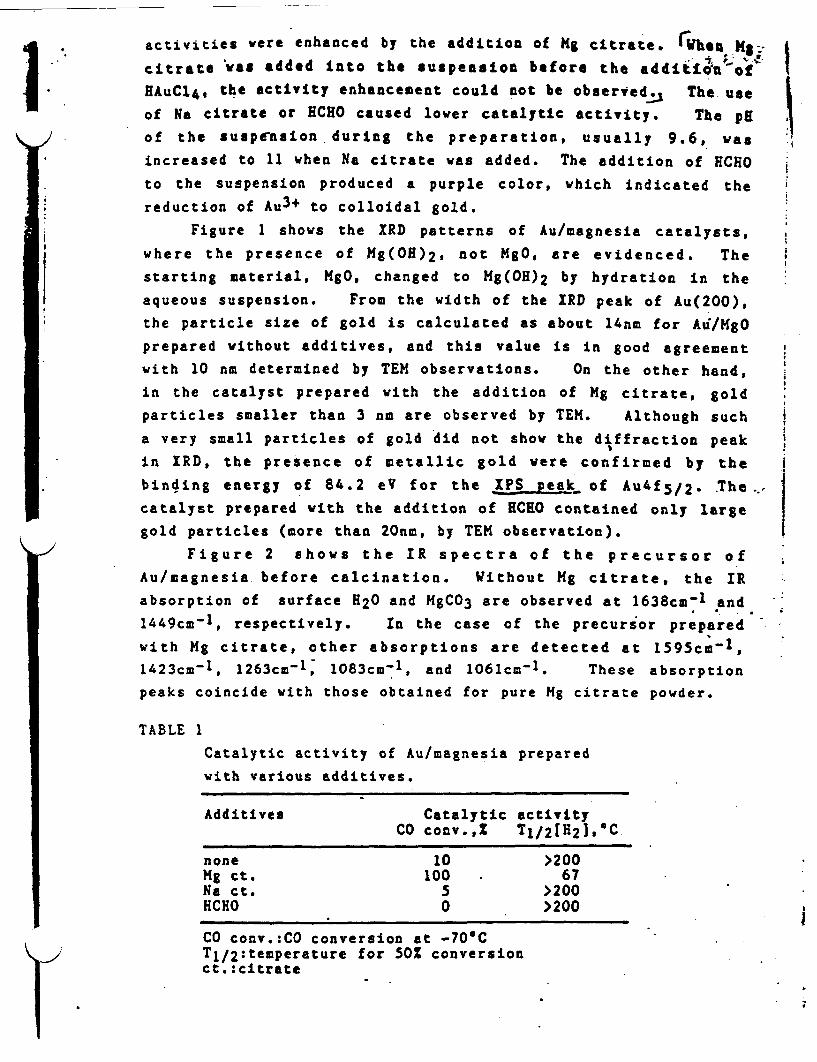
activities were enhanced by the addition of g citrate. re.f Mgcitrate was added Into the suspension before the addi t of
*EAuCl, the activity enhancement could not be observed The use
of Na ctrate or ECHO caused lover catalytic activity. The pH
/1 of the suspension during the preparation, usually 9.6, was
increased to 11 when Na citrate was added. The addition of ECHO
to the suspension produced a purple color, which indicated the
reduction of Au3+ to colloidal gold.
Figure 1 shows the RD patterns of Au/magnesia catalysts,
where the presence of g(OH)2, not MgO, are evidenced. The
starting material, MgO, changed to Hg(OH)2 by hydration in the
aqueous suspension. From the width of the RD peak of Au(200),
the particle size of gold is calculated as about 4nm for Au/HgO
prepared without additives, and this value is in good agreement
with 10 nm determined by TEM observations. On the other hand,
in the catalyst prepared with the addition of Mg citrate, gold
particles smaller than 3 n are observed by TEM. Although such
a very small particles of gold did not show the diffraction peak
in RD, the presence of metallic gold were confirmed by the
binding energy of 84.2 eV for the PS peak, of A4f5 /2- The
catalyst prepared with the addition of ECHO contained only large
gold particles (more than 20nm, by TEM observation).
Figure 2 shows the IR spectra of the precursor of
Au/magnesia before calcination. Without Mg citrate, the IR
absorption of surface H20 and MgCO3 are observed at 1638cm- and
1449cm-1, respectively. In the case of the precursor prepared
with Mg citrate, other absorptions are detected at 1595cm 1,
1423cm-1, 1263cm-l, 1083cm-1, and 1061cm-1. These absorption
peaks coincide with those obtained for pure Mg citrate powder.
TABLE 1
Catalytic activity of Au/magnesia prepared
with various additives.
Additives Catalytic activityCO conv.,X T1/2 [H2 ],C
none 10 >200Mg ct. 100 67Na ct. 5 >200HCHO 0 >200
CO conv.:CO conversion at -70'CTI/2:temperature for 50% conversionct.:citrate
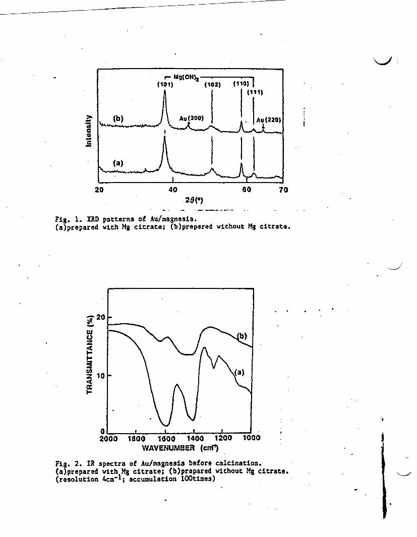
11)Mg(014) 2 7 1)j101) 110) {o
>~~~~~~~u20 Au (220~~~~~~~Ih~~~~~~~~~~
0 (
20 40 60 7020(0)
Fig. 1. XRD patterns of Au/magnesia.(a)prtpared with Mg citrate; (b)prepared without Mg citrate.
_ 20
z 10 r4
z0
2000 1800 1600 1400 1200 1000WAVENUMBER (cnm1 )
Fig. 2. IR spectra of Au/magnesia before calcination.(a)prepared with Mg citrate; (b)prepared without Mg citrate.(resolution 4cm-1; accumulation l00times)
.4

vul, supDorc.U on L.Lanid
In Table 2 the effect of the addition of g ctrate .on
catalytic activity is compared on the two different types of T-2.
supports. While the catalytic activity of Au/titania-A
(amorphous) is enhanced by use of Mg citrate, Au/titania-E
(anatase) shows a high catalytic activity regardless of the
addition of Mg citrate.
Figure 3 shows TEM photographs of Au/titania catalysts.
When Mg citrate is added in the dispersion, the gold particles
are highly dispersed on titania-A (the average particle size of
gold is about 4nm), and gold particles become larger without g
citrate. In the case of titania-B, however, the small gold
particles are highly dispersed even when Mg citrate was not used.
The IR absorption spectra of the precursor of Au/titania
prepared with Mg citrate were shown in Fig.. 4. The adsorption i
peak at 1400cm-1 on titania-A might correspond to the adsorbed
citrate species. Compared with the case of Au/Mg(OH)2 . however, A
the amount of citrate species is much less on the titania
support.
TABLE 2 A
Catalytic activity of Au/titania prepared with and without
Mg citrate, (Comparison of two different titania supports).
Catalytic activityTitania Support Addition of g citrate none
Titania-A(amorphous)Titania-B(anatase)
Tl/2LCOJ.T 1/2[H2 J. *T1 / 2[CO T 2 [H 2 J, C , C ,*cI eC
<0 25. 35 139<0 35 <0 .34
-
Tl/2:temperature for 50% conversion
TABLE 3Catalytic activity of Au/titania-A preparedwith additives.
Additives Catalytic activityT1 / 2 CO],C TI/2lH2 ],C
none 35 139HCH0 83 165Na ct. 23 93NH4 ct. 5 85Mg ct. <0 25Mg(N03)2 <0 35
ct. :citrateT1/2: temperature for 501 conversion
~F

- '4:-I.." - � - ....40,-,; , 'y #�� r K i
t~~~~~~~~~~~~~~~~~~~~~~~~~~~~~~~~~~~.
' I
Al 3.* as (s rc .
I
Fig. 3. TEM photograph of Au/titania prepared with or without Mg citrate.(a)with*Mg citrate; (b)without Mg citrate, on titania-A (amorphous):(c)with Mg citrate; (d)without Mg citrate, on titania-B (anatase).
,.
'
.
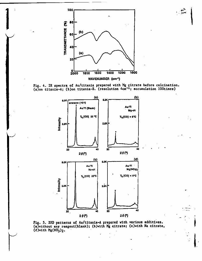
F'
100 '
s o
60 _(
C20 § |J
200 1800 1600 1400 1200 *000
WAVEN4UMBER (an-')
Fig. 4. IR spectra of Au/titania prepared ith Mg citrate before calcination.(aon titania-A; (b)on titania-B. (resolution 4cm-1; accumulation 100times)
(a). ^e, . .
Ur
.-
2
aiatas (101)
Au/T1 (Blwuc)
vtCO 35 C
a 40
20(') 28(')
(C) Id)nK. -
0
* 2-K
AWTwaW
T., COI 23-C
i~~
5.SK . -
z.KI
AuITIUg(NO*2
' (CO] < O0C
,-
40 20 40
2 G () 26 eFig. 5. XRD patterns of Au/titania-A prepared with various additives.(e)without any reagent(blank); (b)with Mg citrate; (c)with Na citrate,(d)with Mg(NO 3)2.
'" iIII
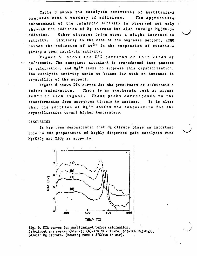
Table 3 shows the catalytic activities of Au/titania-&
prepared with a variety of additives. The appreciable
enhancement of the catalytic activity is observed not only
through the addition of M citrate but also through M(N03 )2
addition. Other citrates bring about a slight increase in
activity. Similarly to the case of the magnesia support, HCHO
causes the reduction of Au3+ in the suspension of titania-A
giving a poor catalytic activity.
Figure 5 shows the XRD patterns of four kinds of
Au/titania. The amorphous titania-A is transformed into anatase
by calcination, and M2+ seems to suppress this crystallization.
The catalytic activity tends to become low with an increase in
crystallity of the support.
Figure 6 shows DTA curves for the precursors of Au/titania-A
before calcination. There is an exothermic peak at around
460*C in each signal. These peaks corresponds to the
transformation from amorphous titania to anatase. It is clear
that the addition of M 2+ shifts the temperature for the
crystallization toward higher temperature.
DISCUSSION
It has been demonstrated that Mg citrate plays an important
role in the preparation of highly dispersed gold catalysts with
Mg(OH)2 and TiO2 as supports.
7 . (a
4
3300 400 500 600
TEMP (C)
Fig. 6. DTA curves for Au/titania-A before calcination.(a)without any reagent(blank); (b)with Na citrate; (c)with Mg(N03)2,(d)with Mg citrate. (heating rate : 5C/min in air).

However, it has appeared that the role of g citrate is different
between TiO2 and NS(OE)2.
Gold supported on magnesia
The pH of the suspension of magnesia is 9.6 during the
preparation. At such a pH region, AuC14- should be
sufficiently hydrolyzed into Au(OH)3 Judging from the stabilityof gold species in aqueous solutions5). Then the hydroxide ofAu might be deposited on the surface of Mg(OH)2 before theadditives are introduced into the suspension. Since the pointof zero charge (PZC) of Mg(OH)2 appears at pH . 126), the
positively charged surface is suitable for the adsorption ofanions such as citrate ion, as observed in the IR spectrum.
The reduction of Au3+ by HCHO in the suspension made the Au
particles large and lowered the catalytic activity (Tables 1 and3), and therefore, the reducing power of citrate ion seems not tobe related to the high activity. The adsorbed citrate ion isconsidered to act as a sticking reagent which can block thecoagulation of gold species in the suspension and/or during
calcination. A speculated behavior of citrate ion sillustrated in Fig. 7.
The pH of the suspension containing Na citrate was 11 and
close to the PZC of Mg(OH)2. Since the effective adsorption ofcitrate ion is not expected at such a pH region, the enhancement
of the catalytic activity might not be observed in Au/Mg(OH)2prepared with Na citrate.
C(OH)COO ~ Mg citrateCHC00
CH)COO
g' + CO)SCOO citrate i
CW 4trte/
Mg(OH o
Fig. 7. Speculated behavior of Mg citrate in aqueous dispersion.
Gold supported on titanla
Sine the p of the suspension of ttania is adjusted to
7.0, Au species to be deposited on the support might be Au(OH)3as in the case of A/Hg(OH)2. However, since the surface of
titania in the suspension was proved to be negatively charged, as
was reasonable from the PZC of TiO2 at pH * 4 -66), cations
such as M2+ should be more easily adsorbed on titania than
citrate anion.
Figures 4 and 5 show that the addi tion of Mg citrate or
Mg(N03 )2 enhances the catalytic activity of Au/titania-A and
suppress the crystal growth of anatase. On the other hand, when
anatase support, titania-B, was used as a starting support, therewas observed no appreciable effect of Mg citrate addition.
The liability of the surface of the carrier will accelerate the
coagulation of supported species due to the so called "earthquake
effect". The presence of Mg2+ prevents amorphous titania-A from
crystallization and therefore from the "earthquake effect".
On the other hand, since anatase support has already crystallized
structure, there is no appreciable effect of Mg citrate
addition on the dispersion of gold.
A small amount of citrate species are detectable on titania-
A in Fig. 6. The citrates other than Mg salt might have also a
certain effect on an increase in catalytic activity of
Au/titania-A. It is probable that citrate ions in Au/titania-A
play similar role to that in Au/Mg(OH)2.
Acknowledgment
We would like to thank Mr. M. Genet (UCL, Belgium) for
the analyses of X-ray photoelectron spectroscopy.
REFERENCES
1) . Haruta, N. Yamada, T. obayashi, and S.Iijima, J.Catal.,115, 301-309 (1989).
2) M. aruta, H.Kageyama, N. amijo, T. lobayashi, andF. Delannay, Stud. Surf. Sci. Catal. 44, 33-42 (1988). -
3) M.Haruta, T. obayashi, S. Iijima, and F. Dellannay,Proc. 9th Intern. Congr. Catal., 3, 1206-1213 (1988).(
4) M. Haruta, .Saika, T. obayashi, S. Tsubota, and Y. Nakahara,Chem. Express, 3, 159-162 (1988).
5) R. J. Puddephatt, The Chemistry of Gold, Elsevier.,Amsterdam, 1978, p.91.'
6) G. A. Parks, Chem. Rev. 65, 177-198 (1965).

* b. �* 4
1..
J�4
I.
p

1206
ULTRAFINE COLD PARTICLES IMOBILIZED WITH OXIDES OF Fe. Co, or NiFOR THE CATALYTIC OXIDATION OF CARBON MONOXIDE AT -70*C
H. HARUTA . T. KOBAYASHI*. S. IIJIHA**. and F. DELANMY**
* Government Industrial Research Institute of OsakaHidorigaoka 1, Ikeda, 563 Japan
** Research Development Corporation of Japan.c/o Department of Physics. Yagoto-urayaaa. Tenpaku.Nagoya 468. Japan.
*' Department of Material Science,Universite Catholique de Louvain.Place Sainte Barba, B-1348. LLN. Belgium
ABSTRACTGold particles smaller than 10 no in diameter. Immobilized with e-
Fe203. Co304, or NiO. were prepared by coprecipitation from an aqueoussolution of AuCl4 and the nitrate of Fe. Co. or Ni and by calcination ofthe coprecipitates in air at 300-400C. The ultrafino gold prticles werehemispherical in shape and strongly hld by the host oxides. In most ces,hemispherical gold crystallites were deposited directing their flat (111)planes toward -Fez03 (110). Co304 (111). nd NiO (111) planes. X-rayphotoelectron spectra showed that the gold particles with a mean diameter of4.1 n immobilized on a-Fe203 were more electron deficient than evaporatedgold prticles of the same size. The ultrafine gold particles imuobilizedwith 3d transition metal oxides were ctive for the oxidation of CO *evn atsuch a low temperature as -70 C.
I NTRODUCTIONIt has generally been understood that gold is catalytically fr less
active in most of the reactions than platinum metal catalysts. Since goldparticles were supported with a size larger than 10 n and ostly rangingfrom 50 to 100 na in the conventional gold catalystsl*2), the difficulty toobtain highly dispersed gold particles might be another additional reasonfor the poor catalytic activities of gold catalysts. Although an attempt hasrecently been made to prepare highly dispersed gold catalysts byimpregnation. . they are thermally unstable at temperatures above 200-C andat. poorly active for the oxidation of 2 and C3).
On the other hand, our previous letter has reported that gold catalystsprepared by coprecipitation with group VIII 3d transition metal oxidesexhibit extremely high activities for the oxidation of 00 even at -70C4).The present paper will deal with the characterization of the coprecipitatedgold catalysts by TEN and XPS nd will discuss the origin of th, catalyticactivities.
FTPrRTMFUTAI
C;.C

(31207 U ;
CU~TRAPINE COL D PARTILES Oro co OXIDATIONULTRAFINE COLD PARTICLES FOR CO OXIDATION 1208
carbonate from an aqueous solution of AuC14 and the nitrat.. a varioustransition metals. The coprecipitates were washed, vacuum dried. andcalcined in air at temperatures from 80C to 5OOC. Catalytic activitymeasurements were carried out in a small fixed-bed reactor. with 0.20 ofcatalysts that had passed through 70 and 120 mesh sieves. A standard gasconsisting of 1.0 vol of CO or M2 balanced with air to I atm. was passedthrough the catalyst bed at a flow rate of 66 ml/min.
The fine structures of the gold catalysts were observed using an AkashiEM-002A electron microscope operated at 120 kV and a Hitachi H-9000 electronmicroscope operated at 300 kY X-ray photoelectron spectroscopic analyseswere made using a Shimazu ESCA 750 under vacuum below 5xio-6 torr.
RESULTSCold Immobilized with 3-FeZ3
Figure 1 shows the dependence of the oxidation efficiencies of 2 andCO on calcination temperature of Au-Fe coprecipitate containing 5 atoml Au.As is clearly understood from the reaction temperature. the gold catalystsprepared by coprecipitation are highly active for the oxidation of both HZand CO. In addition, they are much more active in the oxidation of CO thanin the oxidation of H2. This is one of the characteristic features ofcoprecipitated gold catalysts because the gold powder and the conventionalgold catalysts supported on innert metal oxides such as HgO, A1203. SiOz areless active in the oxidation of CO than in the oxidation of H2. There wasalso observed a pronounced contrast between H2 oxidation and CO oxidation inthe effect of calcination temperature on the catalytic activity. Whilecalcination at 200C gave a maximum catalytic activity for H2 oxidation, itdid not create the catalytic activity for CO oxidation. The catalyticactivity for the oxidation of CO appreciably increased only when thecoprecipitate was calcined at temperatures above 300C.
coprecipitate calcined at temperatures below 200'C. No signaiicantdifference of the BE value or of the shape of Fe 2P3/2 and FeL3VV lines wererecorded for samples calcined at 200-C end 300'C. and for pyre Fe2O3
i calcined at 400'C.
I
I
2!
C
ZZ
*1~~4 -- 3*~S.e aBin- ding Energy ( V
Pig. 2. Change of PS spectra of Au-FG(l/19)with calcination temperature.
coprecipitate
In order to clarify the100 ' change of the coprecipitate
occurring during calcination.0 XPS measurements were carriedA. 4out. Figure 2 shows comparison
of the Au 4f5/2+7/2. Au dS/2.and 0 Is lines for the foursamples calcined at different
I I temperatures. The most conspi--50 I "I cuous result is the shift of the
soc binding energy (BE) of Au 4f and4d lines toward lower energyvalues with increasing calcina-
o l tion temperature. The magnitude/-7osof the shift between BO'C and
X400/C is about .OeV for Au4f7/2 and about 2 eV for Au
o 4dS/2. The width of the peaks0 200 400 a00 also decreases with increasing
Calcination temperature (C} calcination temperature. For Au4f lines, this manifests itself
Fit. 1. Efficiencies for CO snd H by a decrease of the depth ofoxidation a. a function of calcination the "valley" between the twotemperature of Au-Pe(l/19) coprecipitate. lines For the smples calcined
at 80'C and 200C. the Au 4f5/2line exhibits a shoulder on the
high BE side. As the BEs for Au2O3 were 86.4eV and 90.1eV for Au 4f7/2 and; .,~~~~~ * * . ,- - .:a *- . *,,
The presence of metallic gold could be detected by IRD as a broad peakof Aull1) at 29-38.2' only for samples calcined at 40C. It wag also onlyfor samples calcined at 400-C that sharp and intensified diffraction peakscorresponding to a-Fe203 were observed. However, the diffraction patternfor the samples calcined at 300C showed the onset of crystallization towarda-Fe203. The above results obtained by XPS and XRD indicate thatcoprecipitates calcined at temperatures above 300-C consist of metallic goldparticles and e-Fe203 while coprecipitates calcined at lower temperaturesconsist of metallic and oxidized gold, and amorphous precursor of a-Fe3.
Figures 3 and 4 shows TEM photographs for Au-Fe coprecipitate(Au/Fe-l/19) calcined at 400C. Very small gold particles are honogoeouslydispersed on the surface of e-Fe2O3 particles. The mean diameter of thegold particles measured for 2131 particles was 4.nm with a standarddeviation of 14. The TEM observation both in the bright and dark fieldsincidated that the gold particles were not twinned or poly-crystals butsingle crystals. The enlarged view of the interface between ultra-fine soldparticles and hematite shows that the gold particles are not spherical buthemispherical in shape and are strongly bound at their flat planes with thehost oxide. It was most commonly observed that the crystal of goldparticles grew with a specific crystal direction: Au(ll1) plans with alattice spacing of 236R was in junction with a-Fe203(1I0) plane having alattice spacing of 252R. The difference of the lattice spacings was within71.
The strength of interaction operating between ultrafine gold prticle.and hematite appeared to be very high because the reduction and oxidationtreatment of Au/o-Fe2O3 to transform the host oxide (a-Fe2O3 F304 I,-Fe2O3) did not cause any tiny change of the mean particle diameter of
I
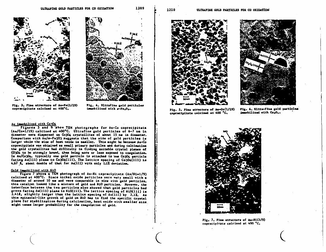
ULTRAYIN A COLD PARTICLES FOR CO OXIDATION1209II
1210 ULTRAFINE COLD PARtICLES OR CO OXIDASIO61
. '. 2
ig. 3. ine structure of Au-Fe(l/19) Fig. . Ultrafin gold prticles L :coprecipitate calcined at 00C. imobilized with -r*ao. Fig. 5. iae structure of Au-CoO./19) rig. 6. Ultro-fin. gold particle.
coprecipitate calcined at 400 *C. Lmobilired ith CO*.O#
Au imobilized with Co3O4Figures and show TEN photographs for Au-Co coprecipitate
(Au/Co-1/19) calcined at 400C. Ultrafine gold particles of 6-7 an indiameter ware dispersed on Co304 crystallites of about 15 nm in diameter.Comparison with Au/s-Fe2O3.suggests that the size of gold particles i -larger while the size of host oxide is amaller. This might be because Au-Cocoprecipitate was obtained a mall primary particles and during calcinationthe gold crystallite. had difficulty in finding suitable crystal planes ofC0304 to be strongly bound. thus being more or less exposed to coagulation.In Au/Co304. typically one gold particle is attached to one C304 particlefacing Au(lll) plane to Co304(111). The lattice spacing of Co304(111) is I4.67 A. about double of that for Au(lll) with only 1.12 deviation.
Cold immobilized with NiOFigure 7 shows a TEN photograph of Au-Ni coprecipitate (Au/Iiwl/9)
cslcined at 400C. Since nickel oxide particles were very small with adiameter of around 10 as nd were comparable in size with gold particles. Ithis catalyst looked like a mixture of gold and NiO particles. However, theinterface between the two particles also showed that gold particles hadgrown facing Au(111) ploa. to NiO(111. The lattice spacing of NiO(lll) is2.41*, lightly larger than the lattice spacing of Au(l1l) by 2.1S. Asthis epitaxial-like growth of gold on NiO has to find the specific crystalplane for sabilization during calcination, host oxide with smaller izemight cause larger probability for the coagulation of gold. .
rig. 7. Fine tructure of Au-Ni(l/9)coprectpitate calcined at 400 C.
CI C

ULTRAFlNE COLD PFAT1CES FOR CO OXIDATION 1213
I I REFERENCES
I) Bond, C. C. and Sermon, P. A.. Cold Bull. 6, 102(1973).2) Galvano, S. and Parravano. C., J. Ctal. 5, 178(1978).3) Zang, C, Ph. D. Thesis, Stanford University, U 8608245 (1985).4) Hrut-, M8 ,) obayashi T Sno, H nd d- .. Chem. Ltt 1987,4 405(1987) 15) Haruta, ., Delannay, F., lijima, S., and obayashi, T.,
Shokubai (Catalysts) 29, 162(1987).4 ~6) Oberli L onat, R Htieu H J.. Landolt D nd utter J. Surf.4
4 ~ScL. 106, 301(1981).! ~7) Raub, . nd Walter P Z Hetalkunde 41, 23401979).
8) Wangner C D Riggs, W M., Dis, L E oulder, J F., nd I Huilenberg, G. E. "Handbook of X-ray Photoelection Spectroscopy'.
Perkin-Elmer Co.. Eden Prairie, U. S. A., (1979).
.I
;I
l~~~~~~~~~~~~~~~~~~~~~~~~~~~~~~~~~
al~~~~~~~~~~~~~~~~~~~~~~~~~
3 3
J
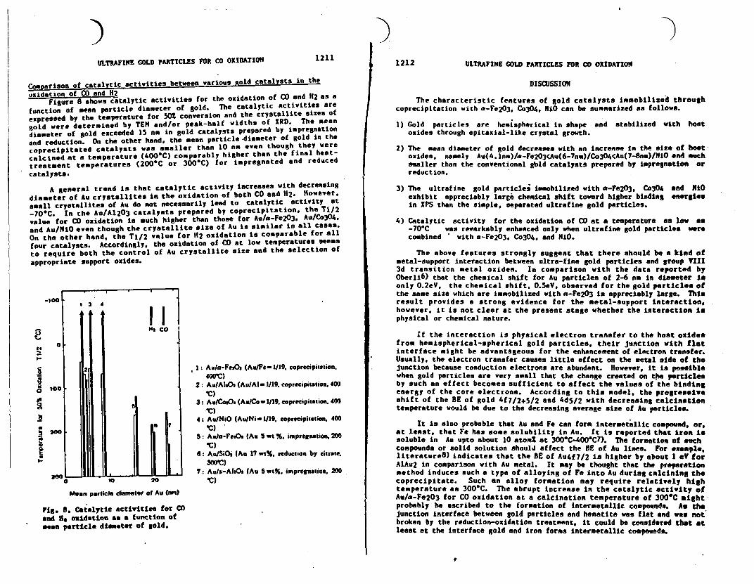
ULTRAFINE COLD PARTICLES FOR CO OXIDATION 12111212 ULTRAFINE COLD PARTICLES FOR CO OXIDATION
Comparison of catalytic activities between various old catalysts in theoxidation of CO and 112
Figure 8 shows catalytic activities for the oxidation of CO and 2 as afunction of mean particle diameter of gold. The catalytic activities areexpressed by the temperature for 502 conversion and the crystallite sizes ofgold were determined by TEN and/or peak-half widths of RD. The meandiameter of gold exceeded 15 no in gold catalysts prepared by impregnationand reduction. On the other hand, the mean particle diameter of gold in thecoprecipitated catalysts was smaller than 10 an even though they werecalcined at a temperature (400-C) comparably higher than the final heat-treatment temperatures (200C or 300-C) for impregnated and reducedcatalysts.
A general trend is that catalytic activity increases with decreasingdiameter of Au crystallites in the oxidation of both CO and H2. However,small crystallites of Au do not necessarily lead to catalytic activity at-70-C. In the Au/A1203 catalysts prepared by coprecipitation, the Tl/2value for CO oxidation is much higher than those for Aulo-Fe2O3. Au/Co3O4.and Au/NiO even though the crystallite size of Au is similar in all cases.On the other hand, the TI/2 value for H2 oxidation is comparable for allfour catalysts. Accordingly, the oxidation of CO at low temperatures seemsto require both the control of Au crystallite size and the selection ofappropriate support oxides.
. , S _ .
.-
ICb
2C
a:
.100
too .
124~~~1
Hi1: Au/a-FeO (Au/Fe-1/19. coprecipittion.400)
2: Au/AI*Os (Au/Al- 1/19. coprecipiatioa. 400IC)
3: Au/Co9O. (Au/Co- 1/19. coprecipitation. 400'C)
4: Au/NiO (Au/Ni - 1/19. eoprecipitution. 400IC)
5: Aula-PnOm (Au S wt %. imprenation. 200IC)
6: Au/SiOs (Au 17 w1%. reductioa by citrate.300'C)
7: Au/u-AltO, (Au Sw%. impregnaion, 200IC)
DISCUSSION
The characteristic features of gold catalysts immobilized throughcoprecipitation with a-Fe2O3. Co304. NiO can be summarized as follows.
1) Gold particles are hemispherical in shape and stabilized with hostoxides through epitaxial-like crystal growth.
2) The mean diameter of gold decreases with an increase in the size of hostoxides. namely Au(4. lnm)/a-Fe23<Au(67nm)/Co34<Au( -8nm)/NiO and muchsmaller than the conventional gbld catalysts prepared by impregnation orreduction.
3) The ultrafine gold particles immobilized with a-Fe203, Co3O4 and RiOexhibit appreciably large chemical shift toward higher binding energiesin PS than the simple, separated ultrafine gold particles.
4) Catalytic activity for the oxidation of CO at a temperature as low as-70*C was remarkably enhanced only when ultrafine gold particles werecombined with -Fe2O3. Co3O4, and NiO.
The above features strongly suggest that there should be a kind ofmetal-support interaction between ultra-fine gold particles and group III3d transition metal oxides. In comparison with the data reported byOberli 6 ) that the chemical shift for Au particles of 2-6 no in diameter isonly 0.2eV, the chemical shift. OSeV, observed for the gold particles ofthe same size which are immobilized with a-Fe203 is appreciably large. Thisresult provides a strong evidence for the metal-support interaction.however, it is not clear at the present stage whether the interaction isphysical or chemical nature.
If the interaction is physical electron transfer to the host oxidesfrom hemispherical-spherical gold particles, their junction with flatinterface might be advantageous for the enhancement of electron transfer.Usually, the electron transfer causes little effect on the metal side of thejunction because conduction electrons are abundant. However, it is possiblewhen gold particles are very small that the change created on the particlesby such an effect becomes sufficient to affect the values of the bindingenergy of the core electrons. According to this model, the progressiveshift of the BE of gold 4f7/2+5/2 and 4d5/2 with decreasing calcinetiontemperature would be due to the decreasing average size of Au particle.
It is also probable that Au and Fe can form intermetallic compound, or,at least, that Fe has some solubility in Au. It is reported that iron issoluble in Au upto about 10 atom% at 300'C-400'C7). The formation of suchcompounds or solid solution should affect the BE of Au lines. For example.literature8) indicates that the BE of Au4f7/2 is higher by about eV forAlAu2 in comparison with Au metal. It may be thought that the preparationmethod induces such a type of alloying of Fe into Au during calcining thecoprecipitate. Such an alloy formation may require relatively hightemperature as 300-C. The abrupt increase in the catalytic activity ofAu/a-Fe2O3 for CO oxidation at a calcination temperature of 300-C mightprobably be ascribed to the formation of intermetallic compounds. As thejunction interface between gold particles and hematite was flat nd was notbroken by the reduction-oxidation treatment, it could be considered that atleast at the interface gold and iron forms intermetallic compounds.
200 l
a"0o0 . _ . .. ..-
tO 70
Mean particle diamter of Au (nn)
Fig. . Catalytic activities for COand U8 oxidation as a function ofse prticle diameter of gold.
f.

PROCEEDINGS OF THE
THIRD INTERNATIONAL MEETING ONCHEMICAL SENSORS
September 24-26, 1990Cleveland, Ohio, USA
Cosponsored by:The Edison Sensor Technology CenterResource for Biomedical Sensor TechnologyElectronics Design CenterCase Western Reserve University
l
I
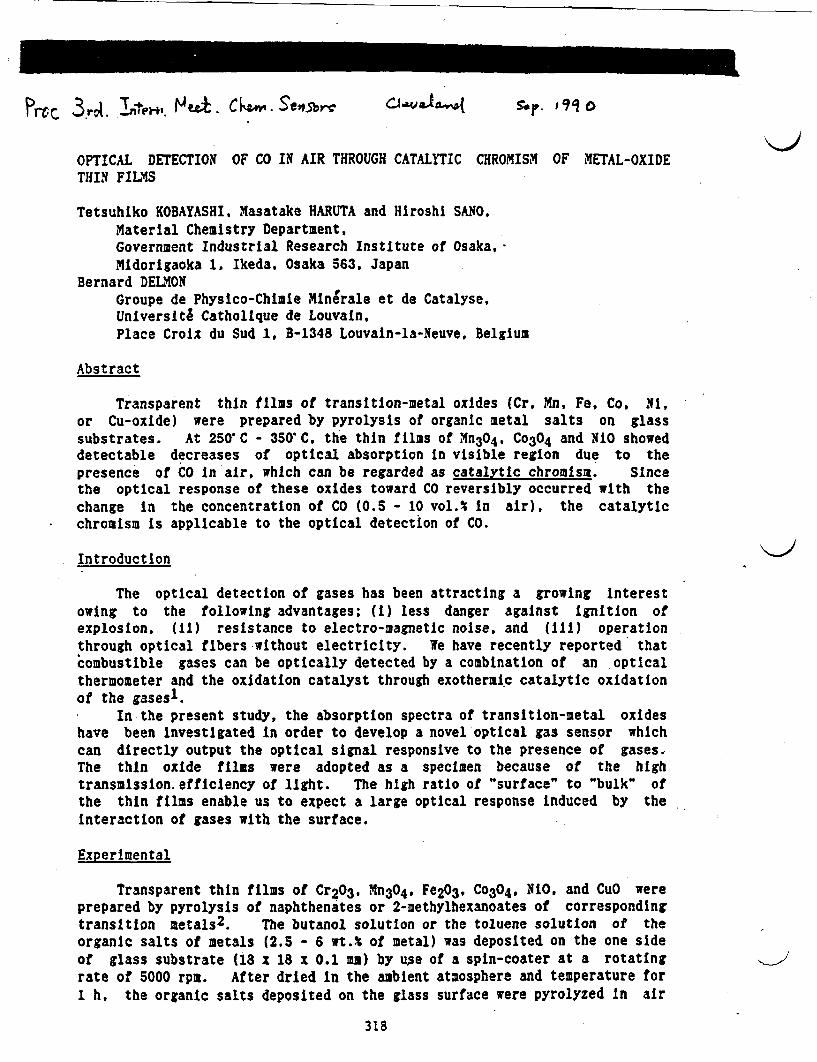
P.t% 3r1. tnet4' HfA. Ckz. Serv Sro. 19i0
OPTICAL DETECTION OF CO IN AIR THROUGH CATALYTIC CHROMISM OF ETAL-OXIDETHIN FILMS
Tetsuhiko KOBAYASHI, Masatake HARUTA and Hiroshi SNO,Material Chemistry Department,Government Industrial Research Institute of Osaka,Midorigaoka 1 Ikeda, Osaka 563, Japan
Bernard DELMONGroupe de Physico-Chimle Minerale et de Catalyse,Universite CatholIque de Louvain,Place Croix du Sud 1. B-1348 Louvain-la-Meuve, Belgium
Abstract
Transparent thin films of transition-metal oxides (Cr, Mn, Fe, Co. Ni,or Cu-oxide) were prepared by pyrolysis of organic metal salts on glasssubstrates. At 250 C - 350 C, the thin fils of Mn3O4. Co304 and NiO showeddetectable decreases of optical absorption n visible region due to thepresence of CO n air. which can be regarded as catalytic chromisa. Sincethe optical response of these oxides toward CO reversibly occurred with thechange in the concentration of CO (0.5 - 10 vol.% n air), the catalyticchromism s applicable to the optical detection of CO.
Introduction
The optical detection of gases has been attracting a growing interestowing to the following advantages; (i) less danger against gnition ofexplosion. (i) resistance to electro-magnetic noise, and (ii) operationthrough optical fibers without electricity. We have recently reported thatcombustible gases can be optically detected by a combination of an opticalthermometer and the oxidation catalyst through exotheraic catalytic oxidationof the gasesl.
In the present study, the absorption spectra of transition-metal oxideshave been nvestigated n order to develop a novel optical gas sensor whichcan directly output the optical signal responsive to the presence of gases.The thin oxide films were adopted as a specimen because of the hightransaission.efficlency of light. The high ratio of "surface" to "bulk" ofthe thin films enable us to expect a large optical response nduced by theInteraction of gases with the surface.
Experimental
Transparent thin films of Cr2O3, Mn304, Fe2O3, Co304, N. and CuO wereprepared by pyrolysis of naphthenates or 2-methylhexanoates of correspondingtransition metals2. The butanol solution or the toluene solutlon of theorganic salts of metals (2.5 - 6 wt.% of metal) was deposited on the one sideof glass substrate (8 x 18 x 0.1 m) by use of a spin-coater at a rotatingrate of 5000 rpm. After dried n the ambient atmosphere and temperature for1 h, the organic salts deposited on the glass surface were pyrolyzed n air
318
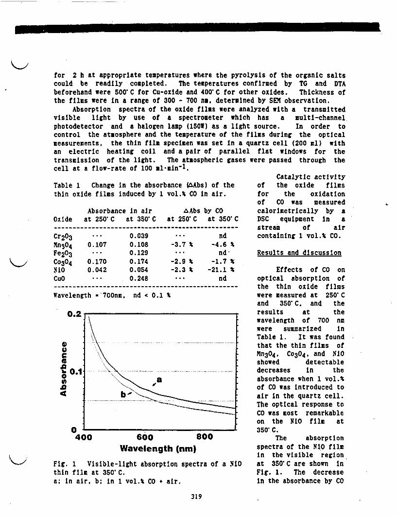
�1
for 2 h at appropriate temperatures where the pyrolysis of the organic saltscould be readily completed. The temperatures confirmed by TG and DTAbeforehand were 500'C for Cu-oxide and 400'C for other oxides. Thickness ofthe films were n a range of 300 - 700 na, determined by SEM observation.
Absorption spectra of the oxide films were analyzed with a transmittedvisible light by use of a spectrometer which has a multi-channelphotodetector and a halogen lamp (150W) as a light source. In order tocontrol the atmosphere and the temperature of the films during the opticalmeasurements, the thin film specimen was set in a quartz cell (200 ml) withan electric heating coil and a pair of parallel flat windows for thetransmission of the light. The atmospheric gasescell at a flow-rate of 100 l min-1.
Table 1 Change n the absorbance (AAbs) of thethin oxide films nduced by 1 vol.% CO n air.
Absorbance n air AAbs by COOxide at 250 C at 350'C at 250 C at 350'C
Cr203 ... 0.039 ... ndMnSO4 0.107 0.108 -3.7 % -4.6 %Fe2O3 .*. 0.129 ... ndCo3O4 0.170 0.174 -2.9 % -1.7 %Nio 0.042 0.054 -2.3 % -21.1 CuO ... 0.248 nd
Wavelength 700nm, nd < 0.1
0.2
4) ...~~~~~~~~~~~~~~~~~~~. ................ ...
U
o0.1
0400 600 800
Wavelength (nm)
Fig. 1 Visible-light absorption spectra of a iOthin film at 350'C.a; n air, b; n 1 vol.% CO air.
were passed through the
Catalytic activityof the oxide filmsfor the oxidationof CO was measuredcalorimetrically by aDSC equipment In astream of aircontaining 1 vol.% CO.
Results and discussion
Effects of CO onoptical absorption ofthe thin oxide filmswere measured at 250'Cand 350'C, and theresults at thewavelength of 700 nmwere summarized inTable 1. It was foundthat the thin films ofMn304, C 304, and NOshowed detectabledecreases in theabsorbance when 1 vol.%of CO was ntroduced toair n the quartz cell.The optical response toCO was most remarkableon the RIO film at350'C.
The absorptionspectra of the N10 filmin the visible regionat 350'C are shown inFig. 1. The decreasein the absorbance by CO
319
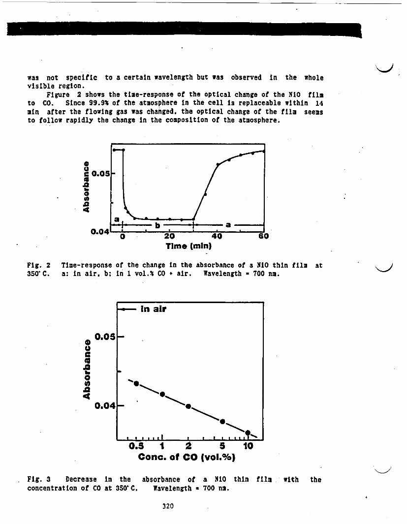
was not specific to a certain wavelength but was observed n the wholevisible region.
Figure 2 shows the time-response of the optical change of the NO filmto CO. Since 99.9% of the atmosphere n the cell is replaceable within 14mn after the flowing gas was changed, the optical change of the film seemsto follow rapidly the change in the composition of the atmosphere.
U
0'a4
Time (min)
Fig. 2 Time-response of the change n the absorbance of a iO thin film350'C. a: in air, b; n 1 vol.% CO + air. Wavelength 700 n.
at
- in air
0.0S_0
.00
40.041-
. a 1
0.5 1Cone.
2of CO
5(vol.%)
10
Fig. 3 Decrease in theconcentration of CO at 350'C.
absorbance of a NO thinWavelength = 700 na.
f11m with the
320
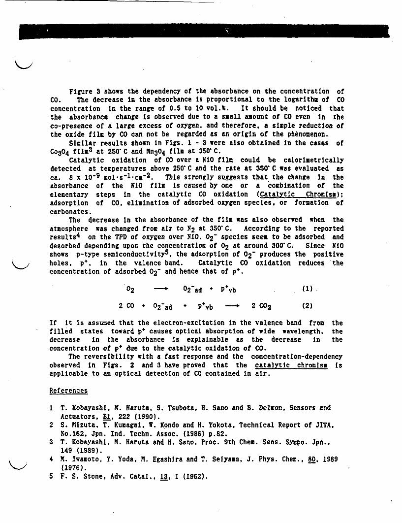
Figure 3 shows the dependency of the absorbance on the concentration ofCO. The decrease in the absorbance is proportional to the logarithm of Coconcentration in the range of 0.5 to 10 vol.%. It should be noticed thatthe absorbance change Is observed due to a small amount of CO even In theco-presence of a large excess of oxygen. and therefore, a simple reduction ofthe oxide film by C can not be regarded as an origin of the phenomenon.
Similar results shown in Figs. 1 - 3 were also obtained In the cases ofCo304 film at 250 C and Mn3O4 film at 350 C.
Catalytic oxidation of CO over a LO film could be calorimetricallydetected at temperatures above 250 C and the rate at 350 C was evaluated asca. 8 x 10⁻⁹ mol s-l cm-2. This strongly suggests that the change In theabsorbance of the 10 fila Is caused by one or a combination of theelementary steps in the catalytic CO oxidation (Catalytic Chromiss);adsorption of CO, elimination of adsorbed oxygen species, or formation ofcarbonates.
The decrease n the absorbance of the film was also observed when theatmosphere was changed from air to 2 at 350 C. According to the reportedresults4 on the TPD of oxygen over NIO, 02- species seen to be adsorbed anddesorbed depending upon the concentration of 02 at around 300 C. Since NiOshows p-type semiconductivity5, the adsorption of 02- produces the positiveholes, p, in the valence band. Catalytic CO oxidation reduces theconcentration of adsorbed 02- and hence that of p.
02 ---- 02 ad * P vb (1)
2 C0 + 02-ad + P vb 2 C02 (2)
If it is assumed that the electron-excitation In the valence band from thefilled states toward p+ causes optical absorption of wide wavelength, thedecrease In the absorbance Is explainable as the decrease In theconcentration of p due to the catalytic oxidation of CO.
The reversibility with a fast response and the concentration-dependencyobserved in Figs. 2 and 3 have proved that the catalytic chromism isapplicable to an optical detection of CO contained in air.
References
1 T. Kobayashi, M. Haruta, S. Tsubota, H. Sano and B. Delmon, Sensors andActuators, B1, 222 (1990).
2 S. Mizuta, T. Kumagai, . Kondo and H. Yokota, Technical Report of JITA,No.162, Jpn. Ind. Techn. Assoc. (1986) p.82.
3 T. Kobayashi, M. Haruta and H. Sano, Proc. 9th Chem. Sens. Sympo. Jpn.,149 (1989).
4 M. Iwamoto, Y. Yoda, M. Egashlra and T. Selyama, J. Phys. Chem., 80, 1989(1976).
5 F. S. Stone, Adv. Catal., 13, 1 (1962).
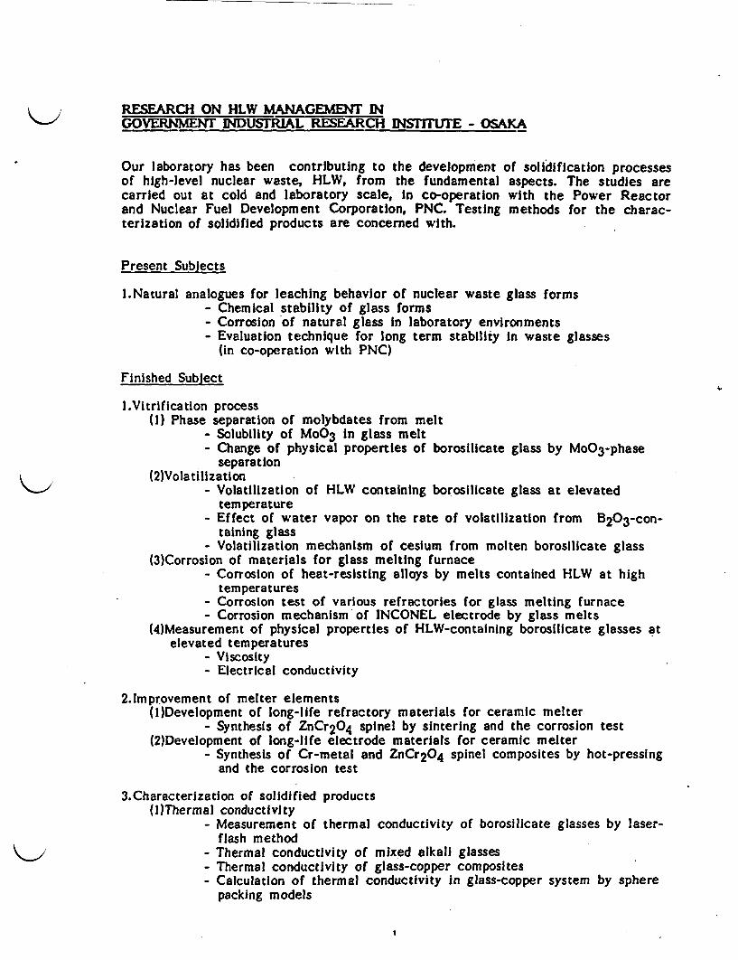
RESEARCH ON HLW MANAGEMENT INGOVERNMENT INDUSTRIAL RESEARCH INSTITUTE - OSAKA
Our laboratory has been contributing to the development of solidification processesof high-level nuclear waste, HLW, from the fundamental aspects. The studies arecarried out at cold and laboratory scale, In co-operation with the Power Reactorand Nuclear Fuel Development Corporation, PNC. Testing methods for the charac-terization of solidified products are concerned with.
Present Subjects
l.Natural analogues for leaching behavior of nuclear waste glass forms- Chemical stability of glass forms- Corrosion of natural glass in laboratory environments- Evaluation technique for long term stability in waste glasses
(in co-operation with PNC)
Finished Sublect
l.Vitrification process(1) Phase separation of molybdates from melt
- Solubility of MoO 3 in glass melt- Change of physical properties of borosilicate glass by MoO3 -phase
separation(2)Volatilization
- Volatilization of HLW containing borosilicate glass at elevatedtemperature
- Effect of water vapor on the rate of volatilization from B203 -con-taining glass
- Volatilization mechanism of cesium from molten borosilicate glass(3)Corrosion of materials for glass melting furnace
- Corrosion of heat-resisting alloys by melts contained HLW at hightemperatures
- Corrosion test of various refractories for glass melting furnace- Corrosion mechanism of INCONEL electrode by glass melts
(4)Measurement of physical properties of HLW-containing borosilicate glasses atelevated temperatures
- Viscosity- Electrical conductivity
2.1mprovement of melter elements(I)Development of long-life refractory materials for ceramic melter
- Synthesis of ZnCr2O4 spinel by sintering and the corrosion test(2)Development of long-life electrode materials for ceramic melter
- Synthesis of Cr-metal and ZnCr 2O4 spinel composites by hot-pressingand the corrosion test
3.Characterization of solidified products(I)Thermal conductivity
- Measurement of thermal conductivity of borosilicate glasses by laser-flash method
- Thermal conductivity of mixed alkali glasses- Thermal conductivity of glass-copper composites- Calculation of thermal conductivity in glass-copper system by sphere
packing models
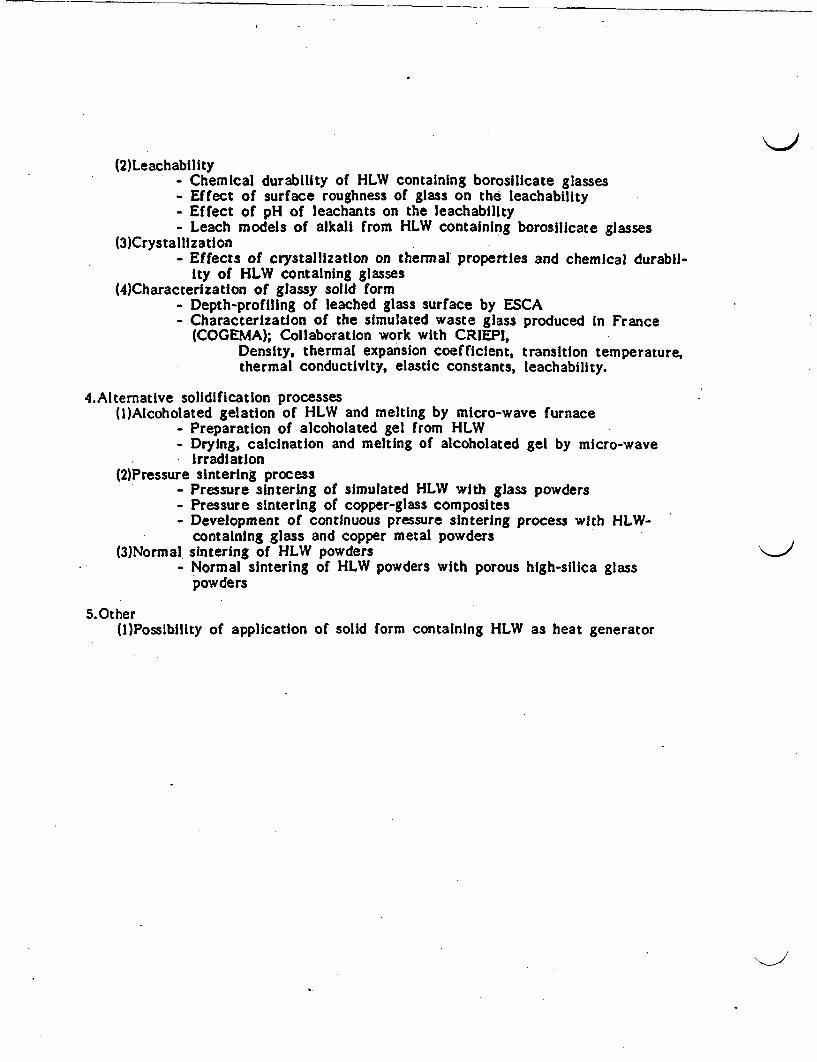
(2)Leachability- Chemical durability of HLW containing borosilicate glasses- Effect of surface roughness of glass on the leachability- Effect of pH of leachants on the leachability- Leach models of alkali from HLW containing borosilicate glasses
(3)Crystallization- Effects of crystallization on thermal properties and chemical durabil-
ity of HLW containing glasses(4)Characterization of glassy solid form
- Depth-profiling of leached glass surface by ESCA- Characterization of the simulated waste glass produced in France
(COGEMA); Collaboration work with CRIEPI,Density, thermal expansion coefficient, transition temperature,thermal conductivity, elastic constants, leachability.
4.AIternative solidification processes(l)Alcoholated gelation of HLW and melting by micro-wave furnace
- Preparation of alcoholated gel from HLW- Drying, calcination and melting of alcoholated gel by micro-wave
irradiation(2)Pressure sintering process
- Pressure sintering of simulated HLW with glass powders- Pressure sintering of copper-glass composites- Development of continuous pressure sintering process with HLW-
containing glass and copper metal powders(3)Normal sintering of HLW powders
- Normal sintering of HLW powders with porous high-silica glasspowders
5.Other(I)Possibility of application of solid form containing HLW as heat generator

TEHNOLOGIES DISCUSSED WITH MIT
- Rapid Measurement Technique of Pollutants In Groundwater- Treatment of Wastewater Chemicals by Super Critical Fluid- Enhancement of Mirobial Activity In Membrane Bioreactor- Evaluation of Organic Membrane Materials for Bioreactor- Microhabitat of Microbes Degrading Hazardous Compounds in Activated Sludge Floc- Decomposition of Organic Compounds by Oxidation Methods- Oxidation of Organic Compounds with Biomimetic Catalysts- Trace Metal Species in Inland Sea Bottom Water- Interferometer Type Sensors Using Optical Fibers- New Waste Water Treatment System Using High-Concentrated Bioreactor and Separation
membrane, for Water Reuse and Energy Recovery- Remote Fiber Sensing of Some Organic Contaminants in Waler by Las Spectrometry
BIBLIOGRAPHY OF LITERATURE RECEIVED EROM MIT!
'Aqua Renaissance '90 Project", National Research and Development Program, MI, 6pages.
'Budget, Staff and Scale Information', GMII, 7 pages.
National Research and Development Program
AQUA RENAISSANCE '90 PROJECTR&D on new wastewater treatment system,
using high-concentrated bioreactorand separation membrane,
for water reuse and energy recovery
* Aqua Renaissance '90 Project.To cope with short supply of water in the
near future and water pollution, industrialwastewater, sewage, and other aqueous ef-fluents must be orocessed to get new water re-source. But the prevailing water treatmentprocess require large treatment facility sitesor large land as sludge-disposal dumps andmuch energy consumption.
Japan depends heavily on imported pet-roluem for its energy supply and its energysupply structure is fragile compared withother advanced countries. For this reason, itis necessary to establish novel ways of ob-
taining new, inexpensive energy in order tomake the nation less dependent on petroleum.
The Ministry of International Trade and In-dustry (MITI) has been conducting researchand development on new wastewater treat-ment systems permitting water reuse andenergy recovery under the name of "theAqua Renaissance '90 Project" This under-taking is part of the National Research andDevelopment Program "large-scale project".The total budget of the project is about 12billion yen during six years (1985-1990).
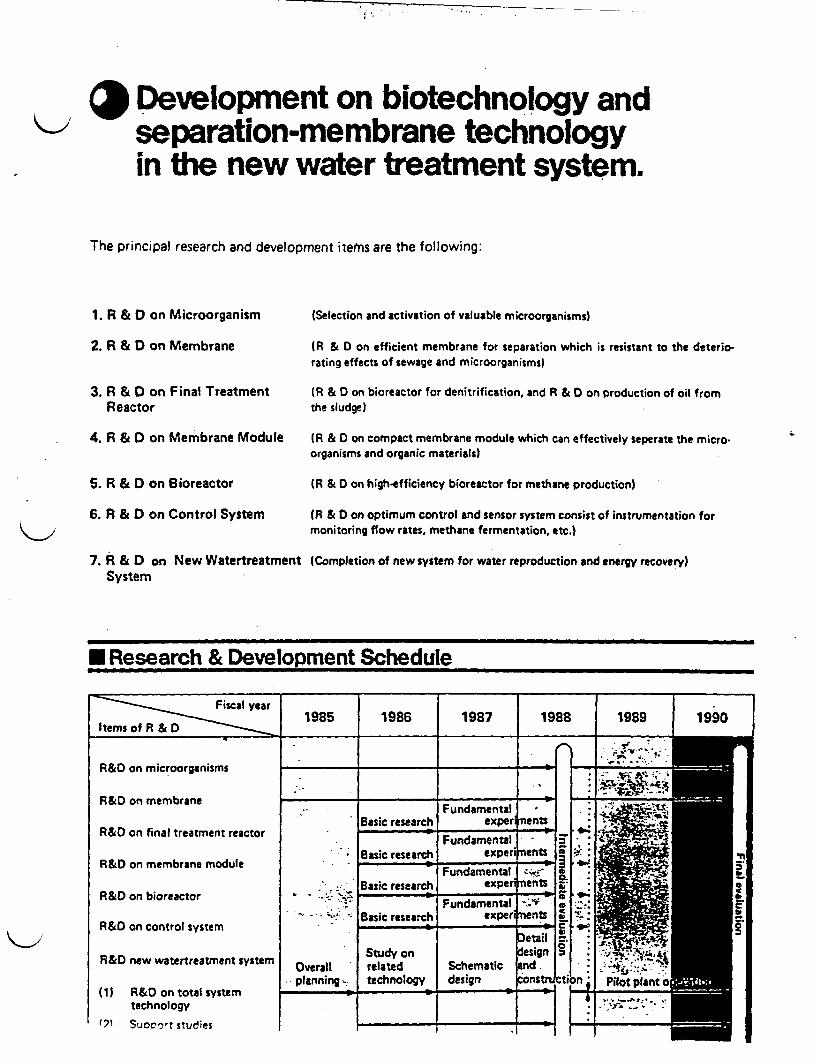
* Development on biotechnology andseparation-membrane technologyin the new water treatment system.
The principal research and development itetrs are the following:
1. R & D on Microorganism
2. R & D on Membrane
3. R & D on Final TreatmentReactor
4. R & D on Membrane Module
5. R & D on Bioreactor
6. R & D on Control System
7. & D on New WatertreatmentSystem
(Selection and activation of valuable microorganisms)
(R & D on efficient membrane for separation which is resistant to the deterio-rating effects of sewage and microorganisms)
(R & D on bioreactor for denitrification, and R & D on production of oil fromthe sludge)
(R & D on compact membrane module which can effectively seperate the micro-organisms and organic materials)
(R & D on high-efficiency bioreactor for methane production)
(R & D on optimum control and sensor system consist of instrumentation formonitoring flow rates, methane fermentation, etc.)
lCompletion of new system for water reproduction and energy recovery)
S Research & Development Schedule
R&D on microorganisms
R&D on membrane
R&D on final treatment reactor
R&D on membrane module
R&D on bioreactor
R&D on control system
R&D new watertreatment system
(1) R&D on total systemtechnology
(9 Suoot studies
I I
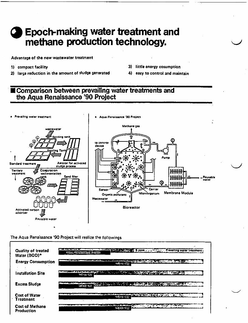
* Epoch-making water treatment andmethane production technology,
Advantage of the new wastewater treatment
1) compact facility2) large reduction in the amount of sludge generated
3) little energy cosumption
4) easy to control and maintain
U Comparison between prevailing water treatments andthe Aqua Renaissance '90 Project
a Prevailing water treatment a Aqua Renaissance '90 Project
SStandard
Tertiarytreatment
I 4e - Reusablewater
BioreactorActivated carbonadsorber J
Reusable water
The Aqua Renaissance '90 Project will realize the followings
Quality of treatedWater BOD)lEnergy Consumption
, . u yu u ii san UIrJ pp1J1
-- - -~ ~ ~ ~ ~ ~ ~ -ea...-. *. -
Installation Site .-- ~~~~ F.-R-0-SPRIM .~~~~~~~ C.. .. * *I
Excess Sludge
Cost of Water- Treatment
Cost of MethaneProduction
i===l~~~~~~~~~~~~~~~~~~~~~~~~..
- a) | E' ' Ad ; r ; . ' ?11111111M101

* Extensive Spin-off ofAqua Renaissance '90 Project
Purification of rivers & lakes
Building the commuity immuneto water shortage
Promotion of construction of seweragePI _ __ - - - *ANN"
Streamlined treatment ofindustrial waste water
'OADOMEO-
r
O.__MP.4
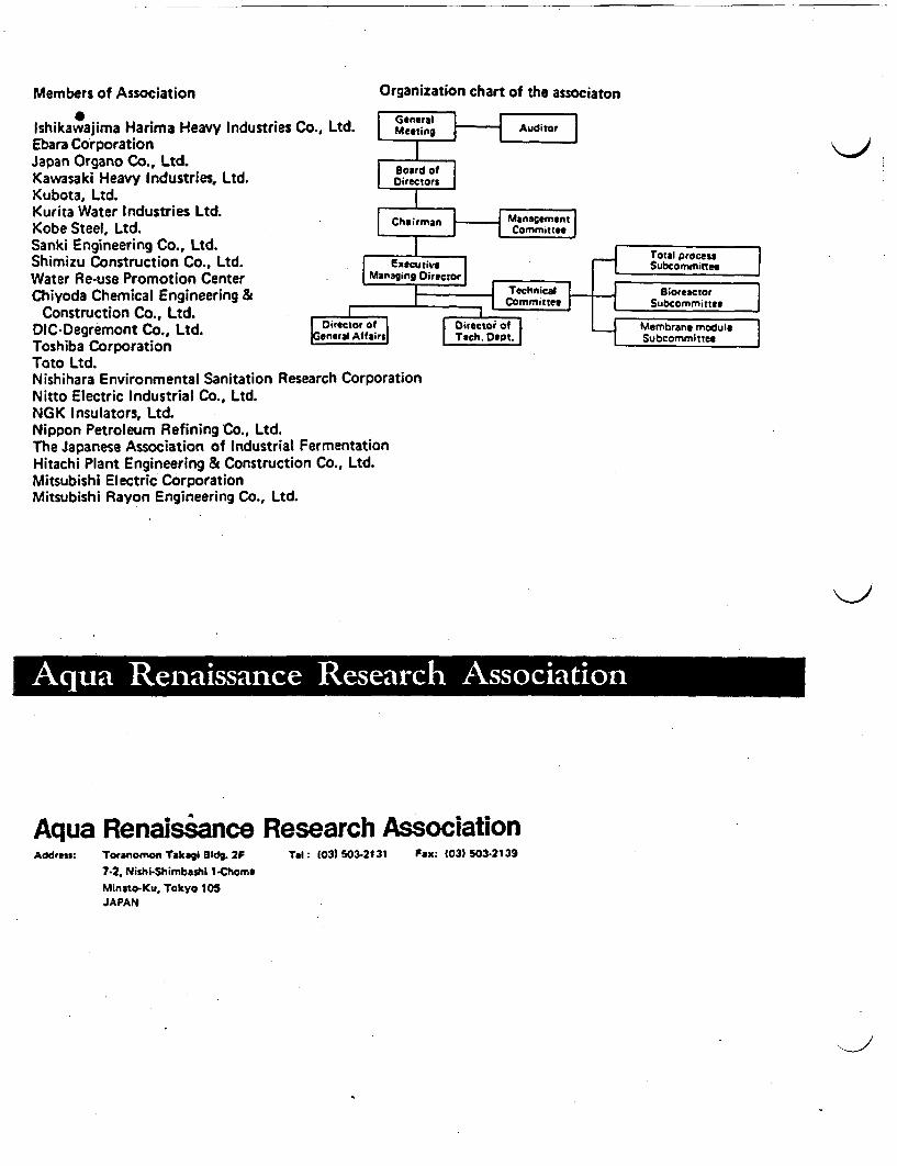
Members of Association Organization chart of the associaton* Goner
Ishikawajima Harima Heavy Industries Co., Ltd. MeeitiEbara CorporationJapan Organo Co., Ltd. BoardKawasaki Heavy Industries, Ltd. Dir~etiKubota, Ltd.Kurita Water Industries Ltd.Kobe Steel, Ltd. ChaSanki Engineering Co., Ltd.Shimizu Construction Co., Ltd. ExwctWater Re-use Promotion Center Managing CChiyoda Chemical Engineering &
Construction Co., Ltd.DIC-Degremont Co., Ltd. ;° rsToshiba CorporationToto Ltd.Nishihara Environmental Sanitation Research CorporationNitto Electric Industrial Co., Ltd.NGK Insulators, Ltd.Nippon Petroleum Refining Co., Ltd.The Japanese Association of Industrial FermentationHitachi Plant Engineering & Construction Co., Ltd.Mitsubishi Electric CorporationMitsubishi Rayon Engineering Co., Ltd.
£ I. I . I
Aqua Renaissance Research AssociationAddress: Toranomon Takagi 1d. 2F Tel: 103) 503-2131 Fax: 03) 503-2139
7-2. Nishi-Shimbashi I-ChomeMinato-Ku. Tokyo 105JAPAN

. 'isaxffiRfi TW & -. R A CA I Budget, Staff and Scale, FY1S8S
fT (fm) Budget( Unit: Million Yen I
I
I Personnel Expenses2.147 (55.3%)
II
OX*-W$l" Mft*.. 177 4 5%;Energy Development Project
-O*12.IN...Ef.t*- 100 (2. 6)Large-Scale Proect
- 1O 1HF .. ..t3... - 30 (0.8%)Global Environment Protect
O ..4. .lW. - 169 4. 3%)Special Research A Development
I W. ....... .... - -8 (0.2%)Government & Private Organization Joint Research
... . . . .349 (9.0%)Ordinary Research
rw N tt. . . . . . .12 0. 3%1Nuclear Research
(3 }gtiM|5$ ..i~iR.. 55 14.2X)tndustrias pcilution Control Protect
Imrt 4 11= 0 ...................................... 10 (0 3%;Inention al - - -rinlernational esearch Cooperatiron Projec
-: A f12 t ...... 212 (5.5%)General Expenses
-. . .. 26 (0.7%)Expenses for Facilities and Instruments
f -.89 (2.3%)IO~Q
Others
INEftff 311T X (*2197iTE Budget Researcl
- ................... - 10 (0.6% )Internationa: Research Cooperation
MI Field
A staff
4 1 Designated Officials 2
SqR* Technical Officials 2 4 6
INUFA Administrative Officials 7 6
t It Total 324
1Z 40 Scale
PR UAMtE9914Aivi J6tt lL ft * # *National Research t X 5i ) KFlt > 9 -Institute for Pollution Coal Mine Safety Coal Mine Safety Experimental Coal Mine.
and Resources Research Center.Hokkaido Research Center.Kyushu Usui
Area
Bulding
262. 497m
5 4 8 2 6m
I C. 1 9 7m
3. 7 6 m
20. 769 W
3. 4 0 Om
8 0. 2 6 8m
2. 1 1 3m

Orger.eiallon end AcdvilefbI22FIR JAH19" I
- .W.Malo
*90V j .011Ac.W .ada, 0a. CoEe 0
POSSWOIm~kli to FW -a I tow.i-own~~~dt -1~A.AgbW
OmIe,. fho
511101 -0 Ill*auuo.LU..Ib. WEb10-
Ll.8'WP~d il 0610411 PICillWew 0.0km- .
UTOW E 1011.Ml.U.@Ii U
r41 I I 111110911 0L k I I t A-l
Id~~dK~~e tab.06w0
--i Ift v ________ JAlT.A w A S a19Md Kaa1..100K .l '".1.K4AWa R f. p ttaaaW fRl
IAab 101.. 0 1 1.-
F~k.#a .- l -k. lall'..eV. Cad a-Oiiiiirmaaea1q
I -__ - .- _.. .. -I
-4. IC KC.0 god co Difill- ~ ~ 'If~
to II gak e(v a.u I MglIl a%
-avolba.. 400 -- --- PlW
at ..I ql
11M Alli
told .01.Ae.00 - -- - -I kAIMiml 111Kb---Kll11~t
.1 livW9
fillt 0 01Jsldli W~ ,jll'1 1
Ala ... $"-*CSOO F. Wi
-.061gM~~~~~~~~~~~~~~~~~I 642
a v a" 4 ad.
W&W Pilmi".C.O.4 lpl -- la.AI M''
IN d4 o. M~,ao.. 4n il
l.
. . . m %0- -
Iti,, ..al k1P Pil. ONAlS. 'ali ooAa.0._ .pol a.1 A mi Sa 9.b111U 1i .il,01111. D" 'PllAre Y01di K* VU.NNW
0.m .a In' . %.P-WI SlV g~ b D. Io: a. A. b I osbwboo
l,.jda~~~~~~~~~~~~~~ll ~~~~~coo t..OcAaU.I aIM TA, 011V6.60
I ~~ ~~~CU..W~. Ill, 0011100
Pill II -d.0 %MM Cu....1. lla19. kS.09
paqi gK~~~.Ilal'~~VqUI~~lS II jill C. .0~~o_ bld.ILda fie jul D MUCKIS
Pill if ~ ~ ~ 11. aC"pdNL 4. pgF&.HK.01.1.1141 aa0..l'.Wl. 9C0~~~~A TWl %V~ l0W1Lo l 1l 0,W U11 W
II 4, I, A 11 ,ill R.U.1111tU Lo gag MA o.11Va.110
if IF .1 OU.aldAwill f-1j 11 JIt1 S^`loca.MIWO Lo Pi" II 1.AIW4Ah
I -aF.1 141511 pw01400 .%Lob jgal ofl 0. H %"
Gwi .. "U W atmmcl tL 4-Il All1 Oft 04 Keluge-
AMM 'I.. AW U.~~~~~~~~~~~5,WE~~~~eip.SwetL Xal hA IKAWVESA.9mit air. M " Sv~fa -It - L., ,Ill - ko K L4
~~..i. aeu."~~~~~~~~.' talC ov,_ fIW dEEIofPW- tab 111 K I-
a .* ,5 ~~~~~~~~~l~~~lIA t~~~~q~sd Ii tab d A.
Z ~g,. i0 .,Af.lU oh Amad.. EmatmmLob It" ISA
,~4 ,,Al~u., AftMiiiAWIS i4 1 LobKW~M III IAm
I 4 ,,.,RA'fINU~l A. ait Wrqll? -. V' Iaw..o lls Lab114
111*1 i~~1 a~.a..~..CPAft lS 611 P1 hoagaaKtle.101PIaOWLob *I? 4.
*..4..114l If aIMIIA A4Ck0 l M ~.W~ft t
*ui..1fi.. UNlqi11iiiU.h 41"l
O n~..1 A l dA g. W . S tab 1111~ O 1.l
VI It II .Otl
M Kooict
Dea K K&"woU.R K*10010
I. K
U. K 0111111
lIll UK VM
0. 0 vakuolim
.1' 011
F
Mitt A1 K Tea...aiw
- d l U NC l I A l . - .a.a w. g . lu - a d EU."
EKE %l.l, so .a, .,- ,*a C ,.O. a.* ..I
C ab M -K Idea', Rt. 4..d C ob.. K pa.. . - --
.. M ) R'P.qA
---

IiW49*&ffiRRE.I* 1: LUst of Research Project In FY1989
l
SpeciaI Research & Development,I f~ pcllRsac & Development,i V RSeilRsac
CL- 7- wa
Rs3~~
CA 603
MUM1u1
AssmantsW~
z1I: 1*II A _VVlNkWfP
IA4#1401
Mine and Indusbial Safety
^Mine Salety Technology (Fire prevention and emergency escape
system)
OSafety technology on the Liquefied Petroleum Gas
CSafety n Discontinuous Rocks
Resources and Energy Technology
CProduction of Liquid Fuel from Natural Gas
"'Production of Silicon Materials from Low-grade SiO2 Oros by
Chlorination
ORetining of Rare Metals
Utillzation of Granit for Indusial Use
CHigh Temperature Heat Pipes
New Materials
CFormation of Carbon Materials by CVO
C Formation of Functional Suspension Colloids of Ultratine Powder
Containing Rare-Earth Compounds
Basic Technology for Future Indusy
CUltra-fine Grinding Process
C Production of carbon Clusters and Carbon Metal Complexes Us-
ing Laset
Coal Mine Safety
CMine Fire Extinguish Techniques
OCountermeasures against Electrostatic Charges
Gavemment & P"ivate OrganIzation Joint Research
C Precise Measurement of AE. Earth Pressure and Deformation of
Rockmass around the Cavern
Nuclear ResearchCRock Mechanics about Storage Caverns for Radioactive Wastes
Pollutlon Control_ Transformation and Decomposition of Less Active Chemical Sub-
stances in the Troposphere
C Physicol Chemical Wastewater Treatment for Nitrogen and Phos-
phorus Removal
CComplex Propagation Model for Factory Noise
C Ecological Control of Activated Sludge Process for Hazardous
CompoundsO Simulation Models of Suspended Particulate Concentration from
Industrial Emission
2Eehavior of Synthetic Organic Compounds in Coastal Environment
% CRpid Measurement Technique of Pollutants in Groundwater
C"reparation Technology of Ultra Clean and Combustion Control
Technique for Low Volatile Coal
CReduction of NO. emitted from Heavy-Duty Diesel-Powered Vehi-
clesMeasurements of Various Reactive Species Related to Environ-mental Acidification by Developing Sensitive Analytical Methods
Anoxic Water Mass Formed in the Stagnant Waters of Inland Sea
I
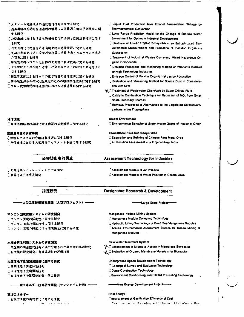
-4 .r. - M ' f iM) A A0. It Iii:Ki hRI
1kX Zl 6J#11 IIL1- M. r7S0)fl Itr i?
* ? it ?" )ftA5~ i~aif6
Liquid Fuel Production from Ethanol Fermentation Stillage byThermchemical Conversion
Long Range Prediction Model for the Change of Shallow Water
Environment for Optimum Industrial Development
Structure of Lower Trophic Ecosystem in an Eutrophicated Bay-
Automated Measurement and Prediction of Plankton Organisus
Succession
Treatment of Industrial Wastes Containing Mixed Hazardous Or.
ganic Compounds
Diffusion Processes and Monitoring Method of Pollutants Related
to High Technology Industries
Emission Control of Volatile Organic Halides by Adsorption
Evaluation and Measuring Method for Source Dust in Considera-
tion with SPM
--Treatment of Wastewater Chemicals by Super Critical Fluid
Catalytic Combustion Technique for Reduction of NO. from Small
Scale Stationary Sources
Removal Processes of Altematives to the Legislated Chlordftuoro.
carbons in the Troposphere
Global Environment
Environmental Behavior of Green House Gases of Industrial Origin
Intemattonal Research Cooperation
Separation and Refining of Chinese Rare Metal Ores
Air Pollution Assessment in a Tropical Area, India
ewn*i8Dfaff Assessment Technology for Industries
7 k MA~, 21A t- -: V ;, .. -'&
Ct~i 0fA7 Assessment Models of Air Pollution
_ Assessment Models of Water Pollution in Coastal Area
OZER ' Designated Research & Development
-UkxVJE2-IAifflR ('YO tU) -
1"A-AX W.- aR
-LargeScale Project
Manganese Nodule Mining System
-Manganese Nodule Collecting Technology
Hydraulic Lifting Technology of Deep Sea Manganese Nodules
:Marie Environmental Assessment Studies for Ocean Mining of
Manganese Nodules
New Water Treatment System
Enhancement of Microbial Activity in Membrane Bioreactor
_ Evaluation of Organic Membrane Materials for Bioreactor
Underground Space Development Technology
--Geological Survey and Evaluation Technology
_ Dorm Construction Technology
Environment Conditioning and Hazard Preventing Technology
-Nw Energy Development Projec-
Coal Energyimprovement of Gasification Efficiency of Coal
-, .,.~ * I.., *- IF It+il 7 t., ,f *f* _o ..I
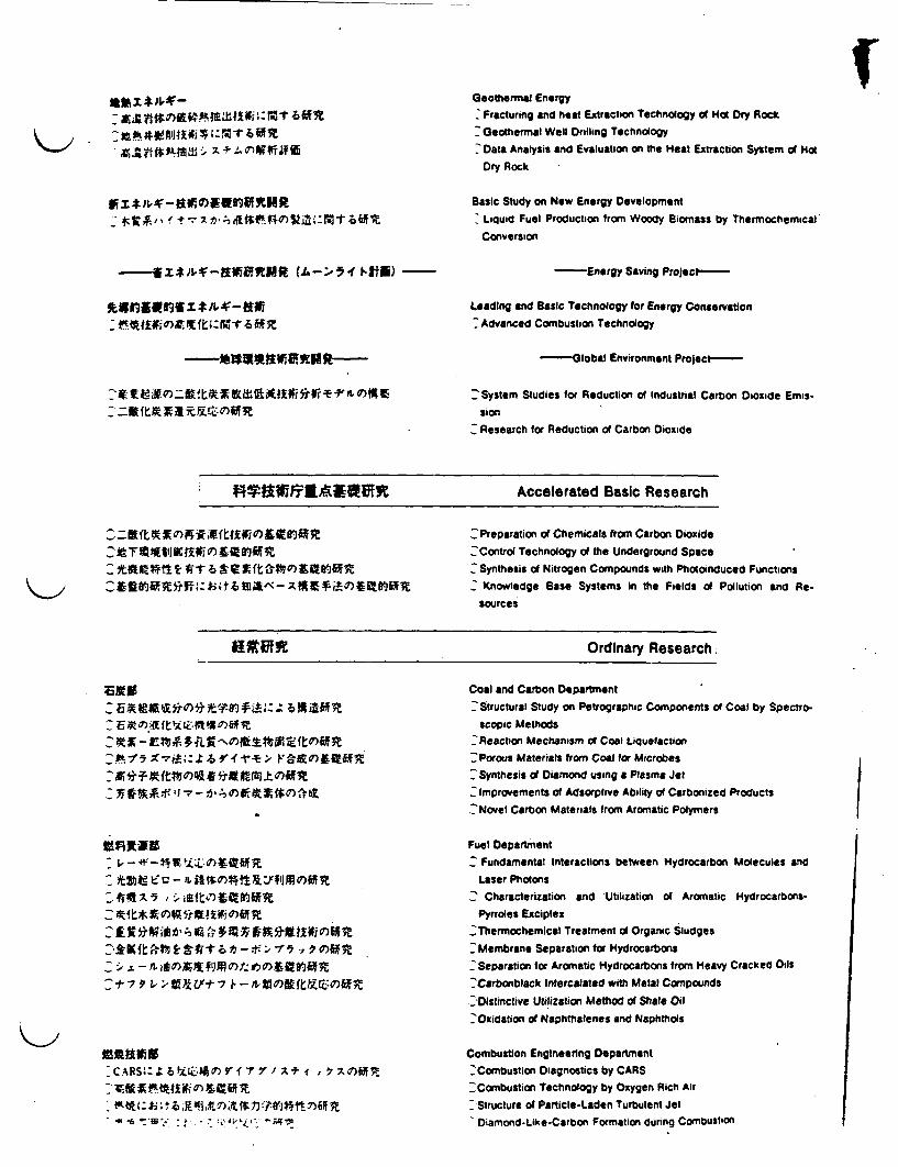
f
-- X*J~-~V~NR (JA->14 ~1tff)-
Geothermal EnergyFracturing and heat Extraction Technology of Hot Dry Rock
Geothermal Well Drilling Technology
Data Analysis and Evaluation on the Heat Extraction System of Hot
Dry Rock
Basic Study on New Energy Development
Liquid Fuel Production from Woody Bionass by Thermochemical
Conversion
Energy Saving Project-
Leading and Basic Technology for Energy Conservation
Advanced Combustion Technology
-G lobal Environment Proect
zmktefl tPFLOs-System Studies for Reduction of Industrial Carbon Dioxide Emis-
sion_ Research for Reduction of Carbon Dioxide
"*9lfi6tt^ NlO~tE Accelerated Basic Research
2 YtT l1V~IK tO tf 1107WM6FC&"9~ff: #1 A1< fi
_ Preparation of Chemicals from Carbon Dioxide
_ Contrl Technology of the Underground Space
^ Synthesis of Nitrogen Compounds with Photoinduced Functions
C Knowledge Base Systems in the Fields of Pollution and Re-
sources
Ordinary Research.
2 ~~~ 'a~~~no) i A n,1 i
2 17 t .V
I2 Z5 wi b 4 IQ 1 ~ C x 3M u a i
-, . tIa 4t1 , ' , 0
:cA 0s) ALi 1ap - 11` y/arXfdf R
*'ItJtfj*1t6
Coal and Carbon Department
Structural Study on Petrographic Components of Coal by Spectro-
scopic Methods-Reaction Mechanism of Coat Liquefaction
_Porous Materials from Coat for Microbes
:'Synthesis of Diamond using a Plasma Jet
-Improvements of Adsorptive Ability of Carbonized Products
- Novel Carbon Materials from Aromatic Polymers
Fuel Department
F fundamental Interactions between Hydrocarbon Molecules and
Laser Photons_ Characterization and Utilization of Aromatic Hydrocarbons-
Pyrroles Exciplex
_Thermochemical Treatment of Organic Sludges
_ Membrane Separation for Hydrocarbons
-Separation for Aromatic Hydrocarbons from Heavy Cracked Oils
Carbonblack Intercalated with Metal Compounds
.:Distinctive Utilization Method of Shale Oil
'Oxidation of Naphthalenes and Naphthols
Combustion Engineeing Department'-Combustion Diagnostics by CARS2 Combustion Technology by Oxygen Rich Air
_Structure of Particle-Laden Turbulent JetDiamond-Like-Carbon Formation during Combustion
I
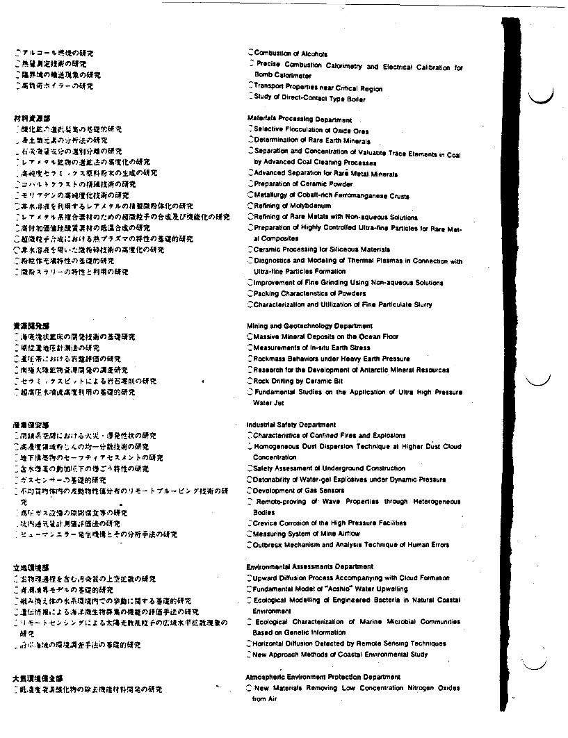
J- T)L2 U t)tof# CCombustion of Alcohols_ Precise Combustion Calorimetry and Electrical Calibration for
Bomb Calorimeter
^2Transport Properties near Cntical Region^ Study di Direct-Comtt Type Boiler
4$*9
F-A X9 a i t J)f J.W1
NATt21.t.f V.. - V290)6*
AN25~vsru
r%.A;- T1!> .*-fr 5WXAIM
14t $fi~O 11
AralIMM- ~ a
1"MA Ik~t
i aAAT a lC-
Materials Processing Department
2Selective Flocculation of Oxide Ores
,Determination of Rare Earth Minerals, Separation and Concentration of Valuable Trace Elements in Coal
by Advanced Coal Cleaning Processes
_Advanced Separation for Rare metal Minerals
_Preparation of Ceramic PowderOMetallurgy of Cobalt-rich Ferromanganese CrustsCRefining d1 Molybdenum-Refining of Rare Metals with Non-aqueous Solutions^Preparation df Highly Controlled Ultra-line Particles for Rare Met-
al Composites
_ Ceramic Processing for Siliceous Materials^ Diagnostics and Modeling of Thermal Plasmas in Connection with
Ultra-line Particles Formation
.:Improvement of Fine Grinding Using Non-aqueous Solutions_ Packing Characteristics of Powders
_Characterization and Utilization of Fine Particulate Slurry
Mining and Gootechnology Department
C Massive Mineral Deposits on the Ocean Floor:Measurements of In-situ Earth Stress:Rockmass Behaviors under Heavy Earth Pressure
-Research for the Development of Antarctic Mineral Resources--Rock Drilling by Ceramic Bit
2 Fundamental Studies on the Application of Ultra High PressureWater Jet
Industrial Safety Department
-Characteristics of Confined Fires and ExplosionsHomogeneous Dust Dispersion Technique at Higher Dust Cloud
ConcentrationOSafety Assessment of Underground Construction
ODetonability of Water-gel Explosives under Dynamic PressureDevelopment of Gas Sensors
' Remoto-proving of Wave Properties through Heterogeneous
Bodies' Crevice Corrosion of the High Pressure Facilities
C Measuring System of Mine Airflow_Outbreak Mechanism and Analysis Technique of Human Errors
Environmental Assessments Department
Upward Diffusion Process Accompanying with Cloud Formation
::Fundamental Model of Aoshior Water UpwellingEcological Modelling of Engineered Bacteria in Natural CoastalEnvironment
_ Ecological Characterization of Marine Microbial CommunitiesBased on Genetic Information
_ Horizontal Diffusion Detected by Remote Sensing Techniques-New Approach Methods of Coastal Environmental Study
Atmospheric Environment Protection Department
- New Materials Removing Low Concentration Nitrogen Oxidesfrom Air
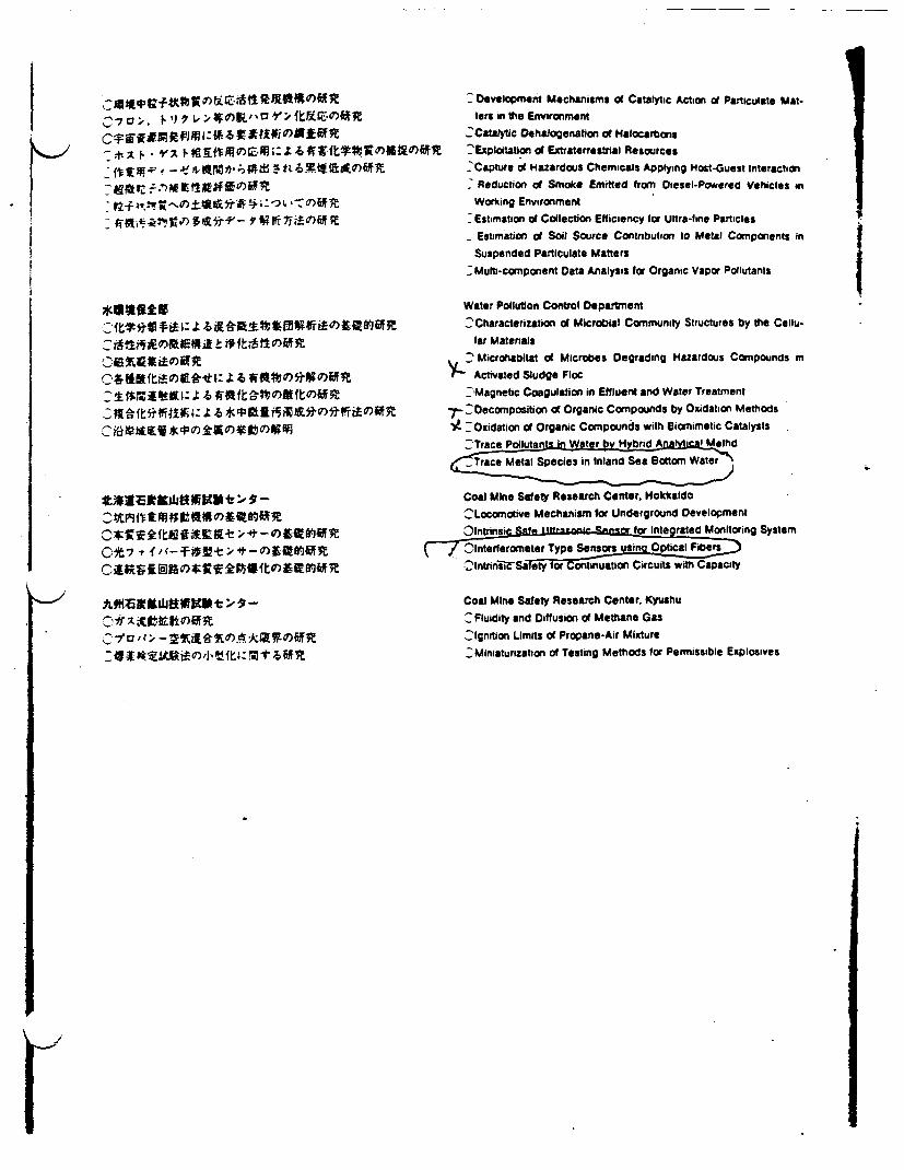
I0 Y1fg0>.K1)jj1
-ei WI l
~~*z 1- ','~ 1x73#gft~~#j~o,~U)
7~~0'Z ~~~~~o)_6* f
t~~,1jT*!Ut 4t -)j"E
Development Mechanisms O Catalytic Action o Particulate Mat-ters in the Environment
C:Catac Dehalogenation of Halocarbons--Explitation of Extraterrestrial Resources'Capture of Hazardous Chemicals Applying Host-Guest Interaction
Reduction of Smoke Emitted from Diesel-Powered Vehicles inWorking Environment
Estimation of Collection Efficiency for Ultra-fine ParticlesEstimation d Soil Source Contribution to Metal Components inSuspended Particulate Matters
7Mult-component Data Analysis for Organic Vapor Pollutants
i
Water Pollution Control Depaitment
_ Characterization of Microbial Community Structures by the Cellu-lar Matenals
Microhabitat of Microbes Degrading Hazardous Compounds in_ Activated Sludge Floc_ Magnetic Coagulation in Effluent and Water Treatment
D Oecomposition of Organic Compounds by Oxidation Methods- - Oxidation of Organic Compounds with Sionimetic Catalysts
--Trace Plutanftsin Water by-Hybrid ~~ feAD MthdMetal Species in Inland Sea Bottom Water
Coal Mine Safety Research Center. HokkaldoCLocomotive Mechanism for Underground Development
r for Integrated Monitoring SystemTypeerlSensoesin Optical Fibers
2lntrini;FSaacq tor Continuation Circuits with Capacity
Coal Mine Safety Research Center. KyushuC Fluidity and Diffusion of Methane Gas
lIgnition Limits of Propane-Air Mixture--Miniaturization of Testing Methods for Permissible Explosives
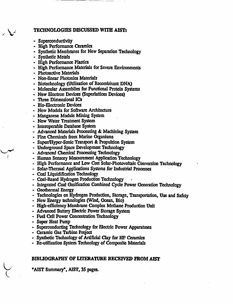
TLCHOLOGIES DISCUSSED WITM AIST
- Superconductivity- High Performance Ceramics- Synthetic Membranes for New Separation Technology- Synthetic Metals- High Performance Plastics- High Performance Materials for Severe Environments- Photoactive Materials- Non-linear Photonics Materials- Biotechnology (Utilization of Recombinant DNA)- Molecular Assemblies for Functional Protein Systems- New Electron Devices (Superlaitices Devices)- Three Dimensional ICs- Bio-Electronic Devices- New Models for Software Architecture- Manganese Module Mning System- New Water Treatment System- Interoperable Database System- Advanced Materials Processing & Machining System- Fine Chemicals from Marine Organisms- Super/Hyper-Sonic Transport & Propulsion System- Underground Space Development Technology- Advanced Chemical Processing Technology- Human Sensory Measurement Application Technology- High Perfonnance and Low Cost Solar-Photovoltaic Conversion Technology- Solar-Thermal Applications Systems for Industrial Processes- Coal iquidification Technology- Coal-Based Hydrogen Production Technology- integrated Coal Gasification Combined Cycle Power Generation Technology- Geothermal Energy- Technologies on Hydrogen Production, Storage, Transportation, Use and Safety- New Energy technologies (Wind, Ocean, Bio)- High-efficiency Membrane Complex Metne Production Unit- Advanced Battery Electric Power Storage System- Fuel Cell Power Concentraion Technology- Super Heat Pump- Superconducting Technology for Electric Power Apparatuses- Ceramic Gas Turbine Prqect- Synthetic Technology of Artificial Clay for HP Ceramics- Re-utilization System Technology of Composite Materials
BIBLIOGRAM OF L1TEURE CIVED FROMAYST
6AIST Summary, AIST, 35 pages.
rLABORATORIES AND INSTITUTES
Technology is a repository of great hope in today's world. At theresarch laboratories of AIST work is carried on in developing theleading and basic technologies that will form the groundwork forfutre technological innovations.
New R&D projects aim at finding soludons to energy shortages.the depletion of the world's natural resources. environmentalpollution nd other pressing problems.
R&DIi
II
II
Research carried out at AIST laboratories and institutes includesthe following characteristics.
Research and development of leading technologies to form abase for future technological innovationAs national institutes, AIST facilities conduct reserch neededfor the propagation of technical standards required forgovernment administration. the establishment maintenance andsupply of standards, and the creation of sophisticatedexperimental methods.
* Research addressing Social needs in earthquake prediction andenvirorunental protection.Government support makes possible fundamental andcomprehensive experimental research which would be beyondthe resources of the private sector.
Research projects are classified into two broadcategories:ordinary fundamental research and special research.Research institutes under AIST have over 600 ordinary researchthemes and more than 150 special ones. These re further classifiedinto 17 fields, such as electronics, earthquake prediction andbiotechnology.
Besides these the designated research is executed. This projectresearch is aimed at industrialization and includes the nationalR&D lgC-scale project. R&D project on basic technology forfuture industries. R&D on new energy technology called the"Sunshine Project' and R&D on energy conservation technologycalled the "Moonlight Project". AIST institutes are taking chargesof fundamental fields represented by the above-mentioned project.
THE TSUKUBA RESEARCH CENTER
In fiscal year 1979. nine research laboratories under AISTmoved to Tsukuba Academic City to form the Research Center ofthe Agency of Industrial Science and Technology. Havingpreviously been scattered over the Tokyo metropolitan area,consolidation of these nine institutions - National ResearchLaboratory of Mesrology, Mechanical Engineering Laboratory.National Chemical Laboratory for Industry (formerly the IndustrialLaboratory of Tokyo). Fermentation Research Institute. ResearchInstitute for Polymers and Textiles, Geological Survey of Japan.Electrotechnical Laboratory. Industrial Products Research Institute.and National Research Institute for Pollution and Resources, helpedthe Center forge closer relations among AIST institutions andsupported the eflicient development of advanced research activities.
1. Project for Expanding Infrastructure for Research andInformationTo support research and development and permit more effectiveuse of research and technological information and moreadvanced computerization and processing. AIST is developingsystem for promoting laboratory automation constructing andexpanding data bases on research and technology, andexpanding networks, aided by the Research InformationProcessing System (RIPS), installed for joint use by AISTinstitutions at the time of their move to Tsukuba.
2. Project for Promoting Research CooperationAIST is taking a variety of steps to promote interaction betweenAIST institutes in Tsukuba. while stepping up private/publicinternational technical exchanges and more effective use ofresearch and technical information. This includes holdingcomprehensive symposiums and other forums at Tsukuba.accepting researchers from foreign countries and receivingtechnical trainees from local public entities and otherorganizations. These arrangements are aimed at strengtheningresearch projects and encouraging studies in Japan.
3. Activities of RIPS (Research Information Processing System)At the end of fiscal 1987 a large-scale, general-purposecomputer system (FACOM M-780/20) and a super computersystem (CRAY supercomputer XMPJ216 and its IBM front-endprocessor 3090/18E) were installed as the third stage to meetincreasing demands for high-speed calculations and large-scalememory capability. Furthermore, software for structuralanalysis, image processing. models of simulation and scientificcalculations wereinstalled in this system. In addition to thepresent one a high-speed channel (EATHERNME) enhanced thenetwork among the laboratories. Now. RIPS is aimed atsupporting the advanced, efficient research activities demandedby the AIST laboratories.

INTRODUCTION TO INDIVIDUAL LABORATORIES ANDNSTITUTES
The National Research Laboratory of Metrlogy (N.RLM) isic natonal representative institute for standards of length. time.sass. temperature ad related quantities i Japan. and takes the leadI unifying units of various physical and egiziecting quantities amnproving standards for science and technology. The researchorks cover broad fields for the development and the improvementf standards. The NRLM is responsible for establishing of working:andards and calibraticn of measuring instruments in compliance4ith the Measurement Law. The technical conultancies are alsoeinr carried out Another important responsibility is to promote'iteationa cooperation for metrological unificazion, in pxirsu e4th the Metric Convention. The NRLM keeps close contact withe Intenational Bureau of Weights and Measures, the international
lureau of Legal Metrology and the research institute$ for Standardsa many countries. The major research projects of the institute ae asoliows:
Standards and Metrology (1) Basic standards of length time.temperature ad mass (2) Industial standards of density, force,pressure, flow rate, vibration, shock acceleration, surfaceroughness. microparticles an viscosity.Applied Precision Metology (1) Precision measurement of lawsrfrequency (2) Precision nonlinear spectroscopy (3) Precision
long distance'measurement (4) Nanometrology (5) Hightemperature thermophysical properties (6) Thermal andmechanical properties of solids (7) Thcrmophysical properes offluids (8) Precision dimensional metrology (9) Measurementsystem and evaluation (10) Reliability of measurementapparatus (11) Measurement for high temperaturesuperconductivity.
New Cesium Time and Frequent StwidudAdoptsthe "OpdciPumpig Technique"
National Research Laboratory of Metrology Tsukube Gakuen 0298 (4) 4118 Total personnel 2181-4, Umemono 1-chome. Tsukuba-shi, Ibarai 305 Senior Officer for Research Planning Total budget 2243 (million yen)
The Mechanical Engineering Laboratory (MEL) was:stablished in 1937 with the objective of promoting advancement of,he Japan's machine industry. Today, still maintaining its traditional-ole, MEL has changed and expanded its role for the developmentaf new engineering technologies through association of mechanicalzngineering with other technical fields, development of traditional.echnologies in mechanical engineering towards their limits, andLntellectualizaion of machines and systems The major R&D fields -
are shown below-1. Basic Researches in Mechanical Engineering () Optics, ^ -
Instrumentation and control. (2) Micro machines. (3) Tribology.(4) Control of noise and vibration. _;
2. Materials and Manufacturing Engineering (I) Synthesis andevaluation of novel materials for machines. (2) Advanced metalforming and high-precision machining/grinding. (3) Energyprocessing and binding. (4) Intelligent manufacturing system.
3. Energy Saving and New Energies (1) Wind power conversionsystem. (2) Advanced combustion engines. (3) High-performane heat transfer/exchange. (4) Environment control.
4. Robotics and Intellectualization (I) Locomotion andmanipulation. (2) Motion controL (3) Computer-aided analysisand design for manufacturing. :
S. Bioengineering (1) Engineering for medical diagnosis. (2) Mio Gr4iper Protorype-IBiocompatible materials. (3) Elucidation of biological functiots. for Miniature Operadton
Mechanical Engineering Laboatory Tel. 81-298-54-2521 Fax. 81-298-54-2513 Total personnel 2761-2 Namki Tsukuba-shiL Ibardki. 305 (Research Planning Office) Total budget 3.320 (million yen)
K>1
I
tIi
I
I
iI
r
DIFFUSION OF TECHNOLOGICAL ACCOMPLISHMENTS
The Agency of Industrial Science and Technology registers asindusial properties both at home and abroad the technologicaldevelopments of its 16 research laboratories and several projectsunder outside contract. and works to ensure their effectiveutilization and diffusion.
Patents and other industrial properties (collectively refered to as.patents") within the jurisdiction of AIST can be licensed to bothdomestic and ferign companies under certain conditions They sue(1) a license fee is paid. (2) the licensee is capable of using thepatents and (3) the licenses is non-exclusive.
Since October. 1985. NEDO conducts management andpropagation of accomplishment of development contacted toNEDO.
Industrial properties under AIST'sJurlsdctlon(registered or pending as of March 31. 1990)
1. Patents under AIST's Jurisdiction and Their LicensingThe present status of patents under the jurisdiction of AIST as ofMarch 31. 1990 is shown in the table below. The Agency is incharge of about 15.900 patents in Japan and about 2.100 abroad.Of the total. 762 patents are licensed to private and semiprivateenterprises. The revenue from licensed patents totaled V330million in fiscal 1989
2. System of Disseminating Technological AccomplishmentsPermission to use patents under the jurisdiction of AIST withexception of some patents. is granted to abroad segment ofJapanese and foreign businesses by the Japan IndustrialTechnology Association (JITA).JITA is a nonprofit foundation intended primarily to diffuse thetechnological achievements of AIST. The Association offers (I)mediation by specialized consultant engineer. (2) conclusionand mediation of state-owned patents for conclusion of licenseagreement and agreement management. and (3) briefings andpublishings of information on state-owned patents likely to beexercised in the near future, in order to ensure effectivedissemination of state-owned patents.In a tie-up arrangement with the Research DevelopmentCorporation of Japan. JITA calls on it to promote application ofunused state-owned patents while presenting mutualcharacteristics.
Note Toutl number ofpatents, utilitymodels, designs.and tademarks for'Domestic" andwoal number ofcases for Forcign"
Domestic Foreign
Laboatories 7.702 1.700
Commissioned 6.236 4'3research anddeveloprnen
Total 15.938 2.123
INDUSTRIAL TECHNOLOGY COUNCIL
1. OverviewThe Industrial Technology Council was established on July
25. 1973. as an affiliated institution of the Ministry ofInternational Trade and Industry. ITC officials investigate anddeliberate on important matters related to scientific technologyin the mining and manufacturing industries in response toinquiries from the Minister of International Trade and Industry.
Conditions affecting Japanese technological developmenthave changed in recent years. The time has come for Japan todevelop original technologies in a way that can give full play tonational ingenuity and creativity. Moreover. Japan is pinninghigh hopes on technological development as a means ofenhancing the quality of national life, upgrading the domesticindustrial structure and contributing to international society.
Under this situation. ITC is working on a broad range ofissues related to technological development from a standpoint ofM as a whole.
2. Activities (Recommendations and Reports Since FY 1982)Industrial technology development policies(Report of the Planning Subcommittee. CoordinateCommittee. November 27 1984)
* Future system of the Second Round(Report of the Planning Subcommittee. Future TechnologyDevelopment Committee. June 24, 1988)Industrial Science and Technology Policies for 1 990s(Report of the Technology Innovation Subcommittee for1990s. Coordination Committee. May 11. 1990)New Evolution of the Sunshine Project(Interim Report of the New Energy Technology DevelopmentCommittee. June 15. 1990)
Organization Chart of the Industrial Technology Council(as of August 30. 1990)
-I-wU.
-I Coordinate committee
-I Research and Development Committee I
-I Global environmental Technology Committee I
-4 Intenattonal R&D cooneraion committee I
National Development Program Committee I
Local research organization committee
- New enenty technology development committee I
-- Energy conservation technology development conmmuee|--I Fuure technology development committee I, ... . . .
RECENT TRENDS INVOLVING AIST
The situation surrounding the science and technology ischanging substantially. Fr example. the so-called approaching/resonance phenomenon of the science and technology is going onand the necessity of harmny between the science/technology andnature/society is increasing. Japan is now expected to contributepositively to the international society in terms of science andtechnology. In this background, it is essential to promote techno.gloabilism fron the global point view as well as to proceed with R& D with balance established between the science and technology.In particular. the global environmental problems are commonsubjects of human being. and their solution requires technologicalbreak-through. The 'Vision for 1990" recently publicized by theIndustrial Structure Council and Japan Industrial TechnologyAssociation as well as the Recommendation No.17 of the Scienceand Technology Conference stress this concept
In the field of standardization administration. active discussionsare under way concerning the future industrial technology, such asproposition made on the basic concept of long-term plan for thefuture .1s policy.
Vision for 1990sThe Technological Policy for 1990s Subcommittee was erected
under the Coordination Committee of the Industrial TechnologyCouncil in the course of review on 'Trade and Industry Policies for1990s' of Mm. The industrial technology policies in 1990s werestudied in its joint meeting with the Industrial Technology PolicySubbommittee of the 1990. Policy Committee of the IndustrialStructure Conference, and the report publicized in May 16. 1990.
The science and technology is. one of developmentinfrastructures of a country and the world and at the same time apowerful means to solve subjects common to all human beings. Inthis recosuiton, the importance or expectation on the science andtechnology is growing rapidly In this situation. Japan is requestedto make international contribution worthy of its power in the field ofscience and technology. On the other hand, the present state ofscience and technology of Japan iicates relative lagging in thefield of fundamental researches and heavy shortage of talents forresearch and development. Moreover. this report sets forthfollowing four vital columns of industrial technology policies for1990 in view of changes in tides surrounding of the science andtechnology, such as progress of approach and resonancephenomenon between science and technology harmony betweenscience/echnology and natUrelsociety or necessity of achieving thecomfortable and affluent national living. These columns arepromotion of techno-globalism from a global point of view,promotion of R & D with balance established between science andtechnology promotion of R & D to realize the comfortable andaffluent national life, and improvement and expansion ofinfrastructures for development of the science and technology.
Recommendation and report of the Science and TechnologyConference(1) Report for Inquiry No.7
'R and D basic plan on environmental protection technology,Concerning global environmental protection technology, theguideline of science and technology policies determined by thecabinet in March, 1986 set forth planning of the research anddevelopment basic plan as a priority field of promotion. With aaim placed on deepening of comprehensive understanding on theearth and full exploitation of the result to contribute toprosperity of humankind, with due consideration oninternational contribution the prime minister made inqury onthe R & D basic plan of global science and technology in Mach1989 to the 42nd Science and Technology Conference. Inresponse the dissions were made in the global environmental.protection technology committee and its subcommittees and thereport made in JurA 1990.
(2) No.18 inquiry. Comprehensive basic policies for future"In compliance with the guideline for science and technologypolicies determined in the cabinet in Mach, 1986. the science'and technology promotion policies have been pushed forwardtoward creation of more affluent society and national life whilecentering around the creative and affluent science andtechnology. However. the environment surrounding the scienceand technology has undergone substantial change In order forJapan to play the role as a member of the international societyand to make effort for enhancement of the national life andcontinuous prosperity the prime minister made inquiry onplanning of comprehensive science and technology policies forcoming 10 years with insight into the coming new century.
I
f
6
t
i
4
r INDUSTRLAL STANDARDIZATION
r
.1
fC
1. Outlinepromoting industrial standardization is one of AIST's mostimportant tasks. By law. deliberations on nlS (JapaneseIndustrial Standards) ar the responsibility of an AIST subsidiaryorganization. SC (the Japanese Industrial StandardsCommittec)Industrial standardization has contributed to the building ofJapan's industrial infrastructure and helped rationalize productionin its industries. nS operates through delibrations by some 9.OOexperts from industry and academia, as well as consumers. Asal IS are voluntary standards. it is essential that they reflect theopinions of all concerned.
2. nS and IS Marking SystemLike many other countries, the purpose of AS in to promote (i)improved quality and rationalized production. (ii) smooth andfair trade, and (iii) rational consumption through appropriate andrational standards." Some 8.400 ITS are established at the endof FY 1990.The IS marking system is used to encourage standardization (seefigures below). Under the IS Marking System, followinggovernment inspection regarding quality control and otherfactors, authorized manufacturers ar permitted to atach the ASmark to products which belong to categories designated by therelavant Minister(s) as worthy of the mark, thus helping usersand consumers to judge the quality and performance of theproduct. So far some 1100 items bear the nS mark, and some16.300 permits, including about 150 approvals for overseasfactories, have been granted.There are two possible ways of obtaining llS marking approvalfor foreign factories: procedures A and B. as explained in thenote below.
sub-committees and has been active in romotinwiternational cooperation and exchanges of tebogy arinformationAt the 13th General Assembly of ISO was held a Tokyo i1985. Mr. samu Yamashitsa vice-president of Kciwren, waelected the 14th ISO president The first Japanese presiderof ISO. he served until 1988.
(2) Technical Cooperation with Developing CountriesThe Standards Deparnent carries out technical operatioin the field of Industrial standardization and Qu&oy ControThese cooperation are designed to help developing countrprogress in industrial standardization and Qualit Controlicollaboration with the Japan International CvperatioAgency (JICA) and the Japanese Standards Associatior(ISA)Threce group training courses are conducted cd year: a month course on implementation of TQC and sun~adizaticactivity a 2-month course on certification and tspectiosystem and a I-month course on a senior seminer oindustrial standardization and quality control. Pcipans ithese courses are Governmental officials i charge cstandardization in government agencies or natiorXa standarcbodies in developing countries.Aside from holding training courses, the StandardDepartment sends experts and survey teams o Industri.Standardization and quality control to developizg countricupon official request. A nd in order to transfer echnoloEfrom Japan to a developing countries by means of trainirengineers and the governmental officials in charge standardization and quality control in developing eountries.center for standardization is scheduled to be built, wheJapanese experts will work for technicaf cooprtion. Tcenter will be a base to establish and promote stadardizaticin the country. In 1989. five year cooperation pla startedthe Industrial Standardizaion and Certification Test CenterThailand.
(Note) JIS Marking System for Foreign ProductsA foreign factory seeking IS marking approval may procet
(A) .,)
Fig. A t. B
If
e'y-e
y
FigA: The mark to be affited bythe manufacturcr of thedesignaied commoditiesprovided in Article 19,ofthe IndustrialStandardization Lw, to thedesignated rommodities.their packaes, rontainersor invoices when themanufacturer has obtainedpermission or approval.
3. International Standardization
Fit. B: The mark to he afixed bythe manufacturer using thedesignated processingtechniques provided inArticles 25. of theIndustrial StndardizationLAw, so the processedcommodities, theirpackages. containers orinvoices when themanufacturer has obtainedpermission or approval.
(1) Participation in ISO and IECA large number of international standards have beenestablished by the International Organization forStandardization (ISO) and the International ElectrotechnicalCommission (IEC). Both organizations are involved in awide range of activities. There were about 7400 ISOstandards and about 2,100 IEC standards at the end of 1989.The Japanese Industrial Standards Committee (JISC) is amember of ISO and IEC and has participated actively inISO's work since 1952 and in EC's since 1953. Wheneverpossible. JISC has taken on important duties in thesecretariats of the organizations' technical committees and
according to scheme A or B.
TECHNOLOGY RESEARCH AND INFORMATION
1 Technological SuveysIn order for Japan to make sound economic progress and
contribute to global welfare, it must deal successfully with awide variety of issues including trade friction, resources andenergy supply, ad employment The creative and independentdevelopment of technology in a comprehensive and efficientmanner will be indispensable to achieve these goals. In theplannihg and preparation of a reasonable and effective industrialtechnology policy there is a need to come to grips with researchand development both at home and abroad and to analyzeindustry and its problems while checking these findings againstactual research and development in JapL
To this end. AIST surveys trends in research anddevelopment, technology trade, and patents in Japan andoverseas; the technology policies and development status ofother countries, and more comprehensively the important andurgent questions involved in the pursuit of creative andindependent technological development
2. Propagation ActivitiesTo enhance awareness of mining and manufacturingtechnologies and the industrial technology policies of AIST teAgency publicizes its policies and the technologicalachievements made at its 16 research lboatcries, in its bulletin*ISAT (Industrial Science and Technology)". In aclidon, AISTissues "An Introduction to AIST, distributed domestically aoverseas in both Japanese and English. in which on-goingprojects we described. AIST also publishes detals of its workin the AIST Annual Reporr. Newspapers. television ndradio are also used to report on the progress of AIST projectsunder way.
Domestic surveysAIST conducts surveys in Japan to understand trends in
technological development, research and development activities ofenterprises, problems surrounding technology, and technologicalpolicies.
rhemes for 19891* Survey on technology transfer* Survey on reorganization and location trends of research
agency of enterprses in Japan* Survey on the present state of industrial technology level of
NIEs in Asia and the research and development strategy of ourenterprises for NlEs of Asia
Overseas surveysThe office conducts collection and analyses of various overseas
technological publications. reports, and literature as well as surveysand analyses of technological development and technologicalpolicies in advanced countries such as the USA and Europe incooperation if JETRO and other organization while utilizing thefund for scientific technological promotion adjustment.
[Themes for 1989, related to the fund for scientific technologicalpromotion adjustment)
Survey on the method of advanced scientific technologicalpromotion adjustnent fund
The Committee for Science and Technology Policy (CSTP) ofthe OECD conducts various programmes including the exchange ofexperiences and information on science and technology policies ofmember countries in order to promote the international cooperationin the field of science and technology. AIST makes positivecontribution to the activities of CSTP, participating in variousconferences.
In May. 1988. OECD started the 3-year programme named TEP(Technology/Economy Programme) for the purpose of analyzing theinter-relationship between science. technology, economy andsociety and also developing useful indices for the governments ofmember countries to plan, execute, and evaluate the technology-related policy.
In this regard, the Government of Japan hosted an internationalconference for TEP in Tokyo in March. 1990.
l
I
I

II
7i-J, J i:... - liu %Jnr Advaced Cou'.es
Japanese Research Counterpart Research Counsezpez Insuc~a DrclName of Research Proect Insttute in Developed Country in DoN ing Chmuy (Fcal yer)
~ ~PlO~~i~n Ieclviiq fore Gznerlogical Survey of Japan United States Geological Bur of Mincs and 1987.1991ram mineral atsources Survey. USA ow-Sciences.(Rarm mncl resource) Philippines
2. Cemicl suessmnt in ile River National Research Institute United States Environmental ManSora University, 1990 1992Cenical assessment) for Pollution and Resources Protection Agency. USA Egypt
5) Joint Researches for GlobalEnvironmental Technology
Name of Research Project AITRsac onepr eerhCuty DuraionAIST Research Counterpart Research Dur~ rFa yearNarne Of Rescatrch Project Institutc Istitute (onr Fiscal year)
1. Studies on afforestaion with functional National Chemical Laboratory Central Arid Zone Research India 1990-.993soil improving materials for Industry Government Institute Phili es(Functional soil) Industrial Development Industial Technology
Laboratory, Hokkaid o Development Institute
2. Prevention of expanded pollution in rhe National Research Institute for National Departnment of Mineral Brazil 1990-1992tropical aone with the metal mining Pollution and Resources Productiondevelopmnent(Polluton with metal mining)
(2) Promotion Program of Research and Development Cooperation
Name of Research Project Japanese Research Institute Counterpsrt Country D( noiReseatrch Institute (Fsca year)
Research and Development Project Electrotechnical Laboratory China Software Technique China 1987.1992of Machine Translation System with CorporationJapan's Neighboring Countries Center of the International National Electronics and Computer Thailand
cooperation for Computer- Technology Centerrelation Language Research Division Malaysia
Mgency for the Assessment and IndonesiaApplication of Technology
International Research Cooperation Governmental Industrial Comision de Fomento Minero Mexico 1989-1994on Recovery of Valuable Resources Research Institute, Shikokuin Brine The Institute of Salinc.Academia China
Sinica
(3) Bilateral and Multilateral CooperationAIST Promotes bilateral cooperation with China. Korea, etc.through science and technology agreements and multilateralcooperation with ASEAN countries.
3. NEDO International Research Exchange CenterNEDO has established the International Research ExchangeCenter in 1989 to conduct the following four programs:
(1) International joint research program(2) International research exchange program to invite foreig%
researchers in the long-tenn and help them do resea.ch a.4line in Japan smoothly.
(3) On the Research Training Program to re-educate researchersin and out of Japan.
(4) International Joint Research Grant Program to conLte theadvancement of international exchange.
THE JAPAN KEY TECHNOLOGY CENTER
The Japan Key Technology Center. established in response to aproposal by the private sector, conducts activities directed at theoverall improvement of the enviromnent for private research anddevelopment in fundamental technologies.(a) Capital Investment
The Center provides capital investment for researches carriedout by companies established for joint research purposes.(C9OFY V21.7 billion)
(b) Loan ServiceThe Center provides conditional interest-free loans to aid inreducing R&D related risks and costs. ('90FY V6.3 billion)
(c) Mediation in Arranging Joint ResearchMediation is performed for private companies wishing toconduct joint research with national research institutions.
(d) Execution of Consigned ResearchThe Center brings together experts from government. industr.and academia to conduct research consigned to The Center b1private companies.
(e) Japan Trust International Research Cooperation ServiceThe Center has established a charitable trust called the JaparTrust Fund. The operating profits from this fund will be used tcinvite foreign researchers in key technologies to Japan
(f) Research Information ServiceThe Center collects and sorts a wide variety of iporta-:research literature which is kept on file at national researchinstitutes and other organizations.
(g) Surveys ServiceThe Center conducts various kinds of surveys to aid private.sector research in key technologies.
J;
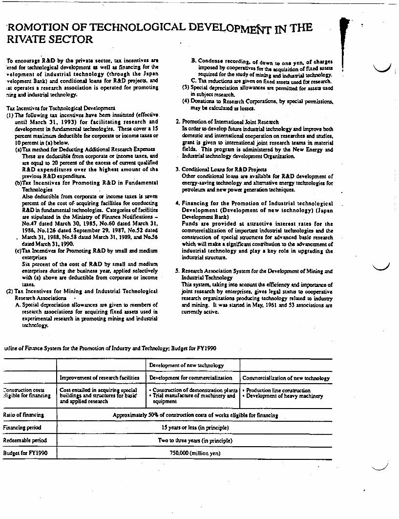
ROMOTION OF TECHNOLOGICAL DEVELOpUf IN THERIVATE SECTOR I VTo encourage R&D by the private sector, tax incentives arsered for technological development as well as financing for thevelopment of industrial technology (through the Japanvelopment Bank) and conditional loans for R&D projects. andiat operates a research association is operated for promotingning and industrial technology.
Tax Incentives for Technological Development(I) The following tax incentives have been instituted (effective
until March 31. 1993) for facilitating research anddevelopment in fundamental technologies. These cover a 15percent maximum deductible for corporate or income taxes or10 percent in (a) below.(a)Tax method for Deducting Additional Research Expenses
These are dedu ctible from corporate or income taxes, andare equal to 20 percent of the excess of current qualifiedR&D expenditures over the highest amount of theprevious R&D expenditure.
(b)Tax Incentives for Promoting R&D in FundamentalTechnologiesAlso deductible from corporate or income taxes is sevenpercent of the cost of- acquiring facilities for conductingR&D in fundamental technologies. Categories of facilitiesare stipulated in the Ministry of Finance Notifications -No.47 dated March 30. 1985. No.60 dated March 31.1986. No.126 dated September 29, 1987. No.52 datedMarch 31. 1988. No.58 dated March 31. 1989. and No.56dated March 31. 1990.
(c)Tax Incentives for Promoting R&D by small and mediumenterprisesSix percent of the cost of R&D by small and mediumenterprises during the business year applied selectivelywith (a) above are deductible from corporate or income
Mxes.(2) Tax Incentives for Mining and Industrial Technological
Research AssociationsA. Special depreciation allowances are given to members of
research associations for acquiring fixed assets used inexperimental research in promoting mining and industrialtechnology.
B. Condense recording, of down to one yen. of chargesimposed by cooperatives for the acquisiton of fixed assetsrequired for the study of mining and indust technology.
C. Tax reductions are given on fixed assets used for research.(3) Special depreciation allowances am permitted for assets used
in subject research.(4) Donations to Research Corporations, by special permissions,
may be calculated as losses.
2. Promotion of International Joint ResearchIn order to develop future industrial technology and improve bothdomestic and international cooperation on researches and studies,grant is given to international joint research teams in materialfields. This program is administered by the New Energy andIndustrial technology development Organization.
3. Conditional Loans for R&D ProjectsOther conditional loans are available for R&D development ofenergy-saving technology and alternative energy technologies forpetroleum and new power generation techniques
4. Financing for the Promotion of Industrial technologicalDevelopment (Development of new technology) (JapanDevelopment Bank)Funds are provided at attractive interest rates for thecommercialization of important industrial technologies and theconstruction of special structures for advanced basic researchwhich will make a significant contribution to the advancement ofindustrial technology and play a key role in upgrading theindustrial structure.
5. Research Association System for the Development of Mining andIndustrial TechnologyThis system, taking into account the efficiency and importance ofjoint research by enterprises, gives legal status to cooperativeresearch organizations producing technology related to industryand mining. It was started in May. 1961 and 53 associations arecurrently active.
utline of Finance System for the Promotion of Industry and Techno1ogy; Budget for FYI 990
F Y F
Development of new technology
Improvement of research facilities Development for commercialization Commercialization of new technology
7onstruction costs Cost entailed in acquiring special * Construction of demonstration plants Production line constructionzligible ror financing buildings and structures for basic * Trial manufacture of machinery and * Development of heavy machinery
and applied research equipment
Ratio of financing Approximately 50% of construction costs of works eligible for financing
Financing period IS years or less (in principle)
Redeemable period Two to three years (in principle)
Budget for FY1990 750.000 (million yen)
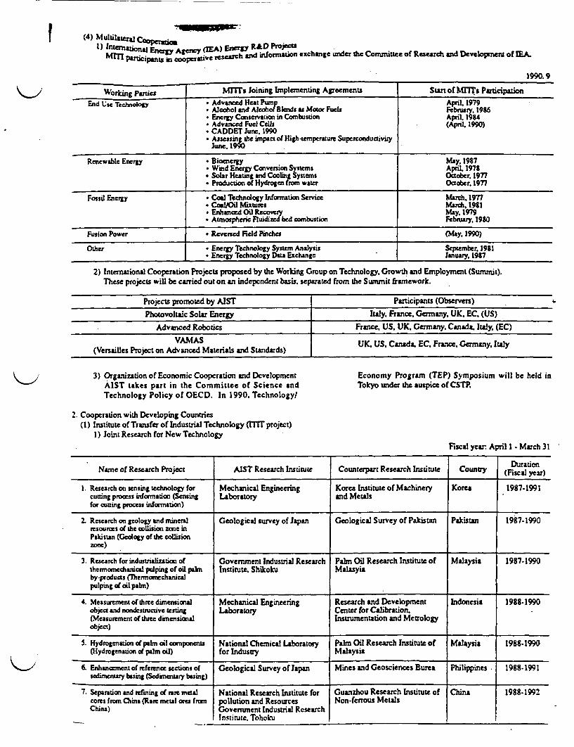
------
4) Multilate CooPerat R&D Projects
1)ueaearrntnE airi gcyd inform tion exchange unde the Committee of Research and Development of EA.
1990.9
Workine Plaies MlTls Joining Implementing Agreements Start of MrTT& ParticipationEnd Cse Technolo . Advanced Heat Pump April. 1979
* Alcohol and Alcohol Blends as Motor Fuels February. 1986* Energy Conservation in Combustion April. 194* Advanced Fuel Cells (April 1990)* CADDET June. 1990* Assess' he impact of High-tempature Superconductiviy
lune, 199
Renewable Energy * Bioenesgy May. 1987. Wind Energy Conversion Systems April, 1978* Solar Heating and Cooing Systems October, 1977* Production of Hydrogen tran water October 1977
Fossil Energy * Coal Techndogy Wormation Service March. 1977* CoaQil Mixtures March. 1981
Enhanced Oil Recovery May. 1979* Atnopheric Fluidiwd bed cornbustion February. 1980
Fusion Power * Reversed Field Pinches (May 1990)
Other Energy Technology System Analysis September, 19S1Energy Technology Da Exchange January 1987
2) International Cooperation Projects proposed by the Working Group on Technology. Growth and Employment (Sumrit).These projects will be carried out on an independent basis. separated from the Summit framework.
Projects promoted by AIST Participants (Observers)
Photovoltaic Solar Energy Italy. France. Germany UK. EC. (US)
Advanced Robotics France US. UK. Germany. Canada. Italy, (EC)
VAMAS UK US Canada EC Frusie Germany I1y(Versailles Project on Advanced Materials and Standards) U.U.Cnd.E.Fac.Gray tl
3) Organization of Economic Cooperation and DevelopmentAIST takes part in the Committee of Science andTechnology Policy of OECD. In 1990. Technology/
Economy Program (TEP) Symposium will be held inTokyo under the auspice of CSTP
2. Cooperation with Developing Countries(1) Institute of Transfer of Industrial Technology (ITIT project)
I) Joint Research for New Technology
Fiscal year April 1 -March 31
Name of Research Project AIST Research Institute Counterpart Research Institute Country Duration
1. Research on sensing technology for Mechanical Engineering Korea Institute of Machinery Korea 1987-1991cutting process information (Sensing Laboratory and Metalsfor cutting process information)
2. Research on geology and mineral Geological survey of Japan Geological Survey of Pakistan Pakistan 1987-1990resources of the DIlision zone inPakistan (Geology of the collisionzone)
3. Research for industrialization of Government Industrial Research Palm Oil Research Institute of Malaysia 1987.1990themornedianical pulping of oil palm Institute. Shikoku Malasyiaby-products (flermonechanicalpulping of oil palm)
4. Measurementof three dimensional Mechanical Engineering Research and Development Indonesia 1988-1990object and nondescnucuve testing Laboratory Center for Calibration.(Measurement of three dimensional Instrumentation and Metrologyobject)
S. Hydrogenation of palm oil components National Chemical Laboratory Palm Oil Research Institute of Malaysia 1988-1990(Hydrogenation of palm oil) for Industry Malaysia
6. Enhancement of reference sections of Geological Survey of Japan Mines and Geosciences Burea Philippines 1988.1991sedimentary baing (Sedimentary basing)
7. Separation and efining of rare metacores from China (Rare metal ores fromChina)
National Research Institute forpollution and ResourcesGovernment Industrial ResearchInstitute. Tohoku
Guanzhou Research Institute ofNon-ferrous Metals
China 1988-199!
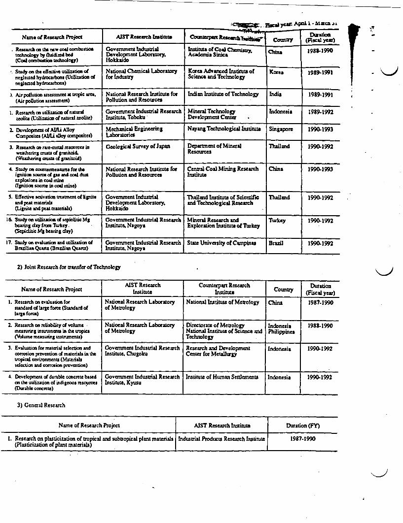
f I
Nuns of Research Pnpject AIST Research Intiut
________ 10gr..O ~ayew. ApaL I -hMca i s
Counterpa DuratioCotry (Fiscal ye)
Instiute of Co A 1981990Academia So
4 I
I Research an m nw coal combstiontdnogy by fluid bed
(Coal constdo eluioogy)
Government IndustrialDevelopnent Laboratory.Hokkaido
Study on the effaCt tuliZA60n Of National Chemical Laboratory Korea Advaced Institute of Korea 1991991negleced hydroarbons (Utilization of for Industry Science andTechnologyneglected hydroeaxbons)
) Air pollution assessment a t ope ara. National Research Institute for Indian Institute of Technology India 199-1991(Air poliution assessment) Pollution and Resources
I. Research an utilization of natural Government Industrial Research Mineral Technology Indonesia 1989-1992zeolite tlizaion of natural zealile) Institute, Tohoku Development Center
2. Develoapnt f AUl Alloy Mechanical Engineering Nay=& Technological Institute Singapore 1990.1993Cornposites (AlU alloy composites) Laboratories
3. Reseac c ramatl r cs in Geological Survey of Japan Departnent of Mineral Thuailand 1990-1992weathering cruts of tranitoW. Resources(Weathering ausu d panitoid) _
4. Study on comntaminasnea for sh National Research Institute for Central Coal Mining Research China 1990-1993ignition source of gas aId cool dut Pollution and Resources Instintaexplosions in coal mine(Ignition soaroe in cod mine)
S. Effective activation uAtment of lignite Government Industrial Thailand Institute of Scientific Thailand 1990-1992and peat materials Development Laboratry, and Technological Research(Lignite and peas materials) Hokkaido
16. Study on utiizos of sepiolitic Mg Government Industrial Research Mineral Research and Turkey 1990-1992bearing day from Turkey. Institute. Nagoya Exploration Institute of brWky(Sepiciic Mg bearing day)
17. Study on evaluation and utiaon of Government Industrial Research State University of Carpinuz Brand 1990-1992Brazilian Quartz (Brazilian Quartz) Institute. Nagoya
2) Joint Research for transfer of Technology
AIST Research Counterpart Research Cou DurationNamc of Research Pro~~~cst Inslitute Lnstituu CoFic al yenr)
I Research on evaluation for National Research Laboratory National Institute of Metrology China 1987-1990standard of large force (Standard of of Metrologylarge force)
2. Research on reliability of volume National Research Laboratory Directorate of Metrology Indonesia 1988-1990measuring stsrumens in the uopics of Metrology National Institute of Science and PhilippinesVlume measuring rsswnumenu) Technology
3. Evaluation for material selection and Government Industrial Research Research and Development Indonesia 1990-1992corrosion prevention of materials i th Institute. Chugokt Center for Metallurgytropical environments (Materialsselection and corrosion prevention)
4. Developmnt of durable concrete based Government Industrial Research Institute of Human Settlements Indonesia 1990-1992on the utilization of indigeous resources Institute. Kyusu(Durable concrete)
3) General Research
Name of Research Project AIST Research Institute Duration (Y)
1. Research on plasticization of tropical and subtropical plant materials Industrial Products Research Institute 1987-1990(Plasticization of plant materials)
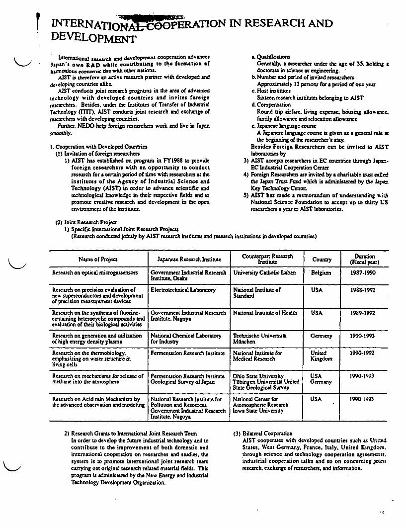
INTERNAO NIN RESEARCH AND. DEVELOPMENT
ntenation research and devel0pmnet cooperation advancesJapan s own R&D whilc contributing to the formation ofharmonious economic des with other nations.
AIST i therefore an active research parner with developed andde% eloping countries alike.
AIST conducts joint research programs in the area of advancedtechnology with developed countries and invites foreignresearchers. Besides, under the Institutes of Transfer of [ndusuialTechnology (ITIT. AIST conducts joint research and exchange ofresearchers with developing countries.
Further. NEDO help foreign researchers work and live in Japansmoothly.
t. Cooperation with Developed Countries(1) Invitation of foreign researchers
1) AIST has established on program in FY1988 to provideforeign researchers with an opportunity to conductresearch for a certain period of tirne with researchers at theinstitutes of the Agency of Industrial Science andTechnology (AIST) in order to advance scientific andtechnological knowledge in their respective fields and topromote creative research and development in the openenvironment of the institutes.
a. QualificationsGenerally, a researcher under the age of 35. holding adoctorate in science or engineeng.
b.Numnber and period of invited researchersApproximately 13 persons for a period of one year
c. Host institutesSixteen research institutes belonging to AIST
d.CompensaionRound trip airfare living expense, housing allowance.family allowance and relocation allow ce
e. Japanese language courseA panese language course is given as a general rule sthe beginning of the researcher's stay.
Besides Foreign Researchers can be invited to AISTlaboratories by
3) AIST acceps researchers in EC counties through Japan.EC Industrial Cooperation Center
4) Foreign Researchers are invited by a charitable tmist calledthe Japan Trust Fund which is administered by the JpanKey Technology Center.
5) AIST has made a memorandum of understanding withNational Science Foundation to accept up to thirty uSresearchers a year to AIST laboratories.
(2) Joint Research Project1) Specific International Joinst Research Projects
(Research conducted jointly by AIST research institutes and research institutions in developed countries)
Name of Project Japanese Research Institute |nt tRes Country (Dirsya
Research on optical microgassensors Government Industrial Research University Catholic Laban Belgium 1987-1990Institute Osaka
Research on precision evaluation of Electrotechnical Laboratory National Institute of USA 1988-1992new superconductors and development Standardof precision measurement devices
Research on the synthesis of fluorine. Government Industrial Research National Institute of Health USA 1989-1992contauning heterocyclic compounds and Institute. Nagoyaevaluation of their biological activities
Research on generation and utilization National Chemical Laboratory Technische Universitat Germany 1990-1993of high energy density plasma for Industry Malnchen
Research on the thermobiology. Fermentation Research Institute National Institute for United 1990-1992emphasizing on water structure in Medical Research Kingdomliving cells
Research on mechanisms for release of Fermentation Research Institute Ohio State University USA 19901993methane into the atmosphere Geological Survey of Japan Tdbingen Universitit United Germany
State Geological Survey
Research on Acid rain Mechanism by National Research Institute for National Center for USA 1990-1993the advanced observation and modeling Pollution and Resources Atomospheric Research
Government Industrial Research Iowa State UniversityInstitute, Nagoya
2) Research Grants to International Joint Research TeamIn order to develop the future industrial technology and tocontribute to the improvement of both domestic andinternational cooperation on researches and studies, thesystem is to promote international joint research teamcarrying out original research related material fields. Thisprogram is administered by the New Energy and IndustrialTechnology Development Organization.
(3) Bilateral CooperationAIST cooperates with developed countries such as UnitedStates. West Germany, France. Italy. United Kingdom.through science and technology cooperation agreements.industrial cooperation talks and so on concerning jointresearch. exchange of researchers, and information.
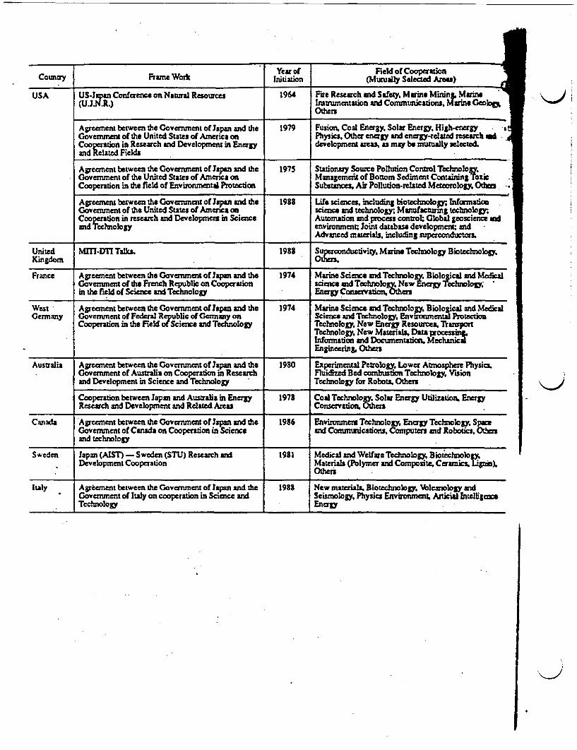
Coimiry Frame Wosi IsYeaor Feld of CooperationCountry Frame Work [~~~~~initiation (Mutually Selectad Areas)
USA US-Jpn Conference on Natural Resources 1964 Fite Research cd Safety, Marne MinL Marn(U.J.N.R.) Instrumentation and Communiicaions. Martne Geolo
Others
Agreement between the Government of Japan and the 1979 Fusion. Coal Energy. Solar Energy. High-energy Government of the United States of America on Physics, Other energy and energy-related research dCooerion Research and Development in Energy development areas, as may be mutually selectedand Related Fields
Agreement between the Government of Japan and the 1975 Stationaiy Source Pollution Control Technology.Government of the United States of America on Managemnft of Bottom Sediment Containing ToxvCooperation in the field of Environmental Protection Substances, Air Pollution-relted Meteorology OtDz
Agreement between the Government of Japan and the 1988 Life sciences. including biotechnolop; tnformalicGovernment of the United States of America on science and technology; Manufactunrng teclnologyCooperation in research and Development in Science Automation and process control: Global geoscience wdand Technology environment; Joint database developmenit; and
Advanced materials, including superconductorm
United MlIl-D7I Talks 1982 Su tiducdvity. Maine Technology Biotechnoloa.Kingdom -
France Agreement between the Government of Japan and the 1974 Marine Science and Technologyr Bioloical and Me&alGovernment of the French Republic on Cooperation science and Technolo. New Energy 'echnology,in the field of Science and Technology Energy Conservation, Oters
West Agreement between the Government of Ja and the 1974 Maine Science and Technolopy. Biological and MedicalGermany Government of Federal Republic of Germany on Science and Technolo Env ental Proteci
Cooperation in the Field of Science and Technology Technology. ew Energy Rso , TrortTechnology. New Maserials Dara processIfomation d Docun nt MechaniEngineering, Others
Australia Agreement between the Government of Japan and the 1980 Experimental Petrology. Lower Atmosphere Physics.Government of Australia on Cooperation in Research Fluidized Bed combustion Technology. Visionand Development in Science and Technology Technology for Robots Others
Cooperation between Japan and Australia in Energy 1978 Coal Technology, Solar Energy Utilization. EnergyResearch and Development and Reled Aru Conservation. Others
Canada Agreement between the Government of Japan ad the 1986 Environment Technology. Energy Technology. Sp#Government of Canada on Cooperation in Science and Commuiicatons, Computers and Robotics. 0crsand technology
Sweden Japan (AIST) - Sweden (STU) Research nd 1981 Medical and Welfare Technology. Biotechnolog)Development Cooperation Materials (Polymer and Composite, Ceramics. I 1).
Others
Italy Agreement between the Government of Japan and the 1988 New materials, Biotechnology. Vlcanogy andGovernment of Italy on cooperation in Science and Seismology. Physics Environmt, Anicial IntelligaesTechnology Energy
i11�1� II
ijiIIiIi
r
i
i
4
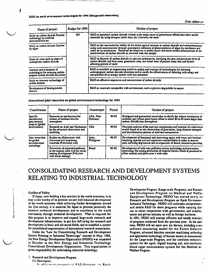
IR&D on eath environment tecsnooks ror it" (Designatd rmarches
_______________ ~~~~~~~~~~~~~~~~~~~~~(Unit: ftukr yet
Nun o project Budget for 1990 Outline of project
Study on carbon dioxide fixataon 165 R&D to trasfont carbon dioxide (which is the major cause of greenhouse effe) io other usfltechnology by artificial materials by using energies (solar rays, tc.) currently not used.photosynthesis etc.
Study on carbon dioxide fixation R&D on Ox counteaction ability of the nature against incrse in carbon dioxide and counermeauresby algae using such counteraction through uantitative definition of photosynthesis of algae by condition andstudy on its mechnism Technical development to enable easier and moe correct measurement of the
concentrtion of carbon dioxide in seawater with less sample
Study on conal reefs as sinks of R&D on fixation of carbon dioxide to calcium tarbonate by clarifn the past concentration level ofaunospheric carbon dioxide carbon dioxide and lime stone generation state, and actual sute of present coral ed and factors
affecting growth of coral
Anlysis end evaluation o R&D to establish an engineering model to analize and evaluate of technologies for reducingtechnologies for reuaing antho anthro-ic c rbon dioxide emissions and to clafy the effectiveness of reducing technology and
pogenic carbon dioxide enissions compoiton of an energy system with less emissions
Study on recovery technology of R&D n effective separation and concentration of carbon dioxidecarbon dioxide
Development of biodegradable R&D on mateis cornpatible with environment such as plastics degradable in natureplastics
International Joit researches on global environmental technology for 1990
Classification Name of project Counterpart Period Outline of project
Specific Research on mechanisms for USA. West 90-93 Biological and eoetrical researches to clarify the release mecharnism ofinterntionl release of methane into the Germany methane g (whose green house effect is about 20 to 40 times lger than
joint research atmosphere carbon dioxide) into atmosphereprojects (globalenvironment) Research on Acid rain Mechanism USA 90-93 Precision analysis of the acid ain cteponents and reation of a simulation
by the advanced observation and model based on in-sit observation of generaton. long-distance tnsponmodeling and transforation process of acid rain components.
Joint researches Studies on fforestauon with India. 90-93 Development of functional soil recovering agent with water and fertlizerfor ;robal functional soi iproving Philippine retaining apacity and soi-organisms compatibility in order to recoverenvironmental materials (Functional sod) soils sufering degrdation due to expansion of desen excessive pasturingtechnology
Prevention of expanded pollution Brazil 90-92 Development of wide-aa pollution survey technology nd peviin the tropical zone with the metal technology for mining production of tropical forests which is presumed tomining development (Pollution affect animals and plants over a wide-rea.with metal mining)
CONSOLIDATING RESEARCH AND DEVELOPMENT SYSTEMSRELATING TO INDUSTRIAL TECHNOLOGY
Outline of PolicyIf Japan. now holding a key position in the world economy is to
play a role worthy of its position toward well-balanced developmentof the world economy while achieving further development towardthe 21st century. it is essential for Japan to promote positively thecreative technical development and to contribute to the worldcommunity through technical development. What is required forthis purpose is to improve and expand large-scale research anddevelopment infrastructures, to put into full swing the research anddevelopment in basic and advanced fields, and to establish a systemfor consolidated augmentation of international research cooperation.
Under the Law for Consolidating Research and DevelopmentSystem Relating to Industrial Techology" enacted in May, 198.the New Energy Development Organization (NEDO) was expandedin October to the New Energy and Industrial TechnologyConsolidated Development Organization. This organization isgiven responsibility for undertaking industrial technology.
I. Research and Development Progrm(1) Description
I- i.1l! t~nn tn en-vertr--i' RPD Pnerr- -n Baic
Development Program (Large-scale Program). and Researc-and Development Program on Medical and WeIfar,Equipment Technology. NEDO hs started newly th-Research and Development Program on Earth EnvironmerIndustnial Technology. NEDO will undertake comprehensiand mobile R&D for these programs while carrying the-out in closer cooperation with government, and academ.sector and private industry as well as foreign institutes.In 1991, NEDO will attempt efficient and steady executic-of programs continued from the previous year. At the sam.time. NEDO will set upon new six themes including a ne-software structuring model for the Future IndustrieProgram. advanced function creation machining echnolojgand application technology of human sns to measuremer-for the Large-scale Program, and the condition moniorir.system for the aged, digital hearing aid, and continuotblood sugar measurement system for the Medical arWelfare Program.
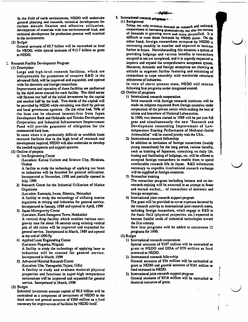
In the field of earth environment, NEDO win us dertakegeneral planning and research. technical development forcarbon dioxide fixation and effective utilization.development of materials with less environmental load andtechnical development for production process well matchedto the envirmerL
(2) BudgetCeneral accounts of V5.7 billion will be earmarked as fundfor NEDO. while special accounts of V13.7 billion as grantto NEDO.
2. Research Facility Development Program(I) Description
Large and high-level research facilities. which areindispensable for promotion of creative R&D in theadvanced field, will be improved and expanded, and openedwide for domestic and foreign researchers.Improvement and operation of these facilities are performedby the third sector erected for each facility. The third sectorwill finance one half of the initial investment by the capitaland another half by the load. Two-thirds of the capital willbe provided by NEDO while remaining one-third by privateand local government agencies. On the other had. 709T ofthe loan can be obtained interest-free from JapanDevelopment Bank and Hokkaido and Tohoku DevelopmentCorporation. and Industrial Infrastructure ImprovementFund will provide guarantee of obligation for thecommercial bank loan.In cases where it is particularly difficult to establish basicresearch facilities due to the high level of research anddevelopment required, NEDO will also undertake to developthe needed equipment and support systems.
(2) Outline of projects1) Ion Engineering Center
(Location: Kansai Culture and Science City. HirakataOsaka)A facility to study the technology of applying ion beamto industries will be founded for general utilization.Incorporated in November. 1988 and partially opened inJuly. 1990
2) Research Center for the Industrial Utilization of MarineOrganisms(Location: Kamaishi. Iwate; Shimizu. Shizuoka)A facility to study the technology of utilizing marineorganisms in mining and industries for general service.Incorporated in January. 1989 and opened in April 1990
3) Japan Microgravity Center(Location: Kami Sunagawa Town Hokkaido)A vertical drop facility which enables various non-gravity tests for about 10 seconds using existing verticalpits of old mines will be improved and expanded forgeneral service. Incorporated in March. 1989 and openedat the end of 1990 Fy
4) Applied Laser Engineering Center(Location: Nagacka Niigata)A facility to study the technology of applying laser toindustries will be erected for general service.Incorporated in March. 1990
5) Advanced Material Research Center(Location: Ube. Yamaguchi; Tajimi. Gifu)A facility to study and evaluate material physicalproperties and functions in super-high temperatureenvironment will be improved and expanded for generalservice. Incorpotated in March. 1990
(3) BudgetIndustrial investment account capital of IM2 billion will beearmarked as a component of investment of NEDO to thethird sector and general accounts of V200 million as afundnecessary for improvement of facilities by NEDO itself.
3. International reach (1) Background
Today. not only overseas denims , ,tseagch and technicalco lurabn ai creasng quagtitatively, but also the contentof demands is growing more and more diversified. It isdifficult to meet these demands by NEDO alone. On theother hand, foreign researchers accepted by NEDO isincreasing steadily in number and expected to increasefurther in future. Notwithstanding this situation, a system ofproviding lodgings and various benefits to researchersaccepted is not yet completed. and it is urgently requested oimprove and expand the comprehensive acceptance systemMoreover, domestic and foreign enterprises are showing attitude to augment further fostering and retraining ofresearchers to cope smoothly with worldwide structuraladjustment of industriesIn view of above present state, NEDO will executefollowing four programs under integrated controL
(2) Oudine of programsI) International research cooperation
Joint research with foreign research institutes will bemade on subjects requested from foreign countries undercooperation of the private sector while making the best oftalents and knowhow of National Laboratories.In 199, two themes started in 1989 will be put into fullgear and simultaneously the new Research andDevelopment concerning Improvement of Low-temperature Starting Performance of Methanol-fueledAutomobiles' will be started jointly with the USA.
2) International research fellowshipIn addition to invitation of foreign researchers (mainlyyoung researchers) for the long period, various benefits.such as training of Japanese, consulting on daily life.leasing and facilitating of lodgings, etc. will be offered toaccepted foreign researchers to enable them to spendcomfortable research life in Japan. R&D informationnecessary to expedite international research exchangewill be supplied to foreign countries.
3) Researcher trainingThe researcher program including lectures and on-the-research-training will be executed in an attempt to fosterand mutual exchan,- of researchers of domestic andforeign enterprises.
4) International joint research support programThe grant will be provided to cover expenses incurred bythe research activity to international joint research teams,including foreign researchers, which engage in R&D inthe basic field (physical properties. etc.) expected tobecome fruitful seeds of industrial technologies towardthe 21st century.New four programs will be added to continuous 12programs for 1990.
(3) Budget1) International research cooperation
Special accounts of V197 million will be earmarked asgrant to NEDO and ODA of V59 million as fundentrusted to NEDO.
2) International research fellowshipGeneral accounts of V54 million will be earmarked asgrant to NEDO and general accounts of V161 million asfund entrusted to NEDO.
3) International joint research support programGeneral accounts of V516 million will be earmarked asfinancial rsourcs of grant
III
i
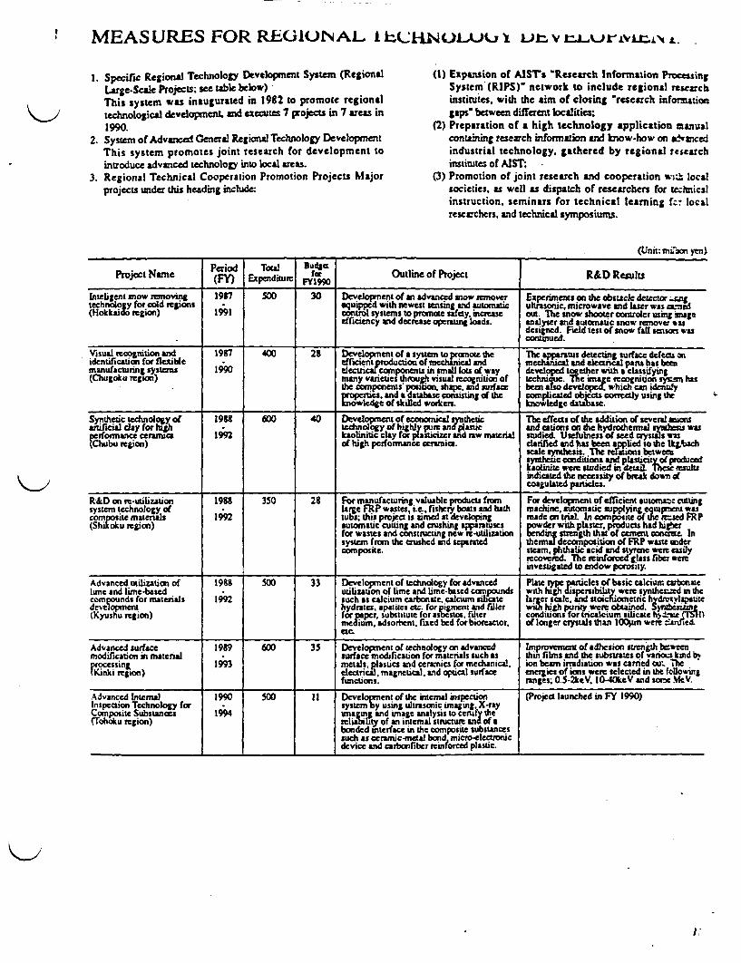
II MEASURESFORREGilONALI EkCUwL, 9 urLL
. Specific Regions Technology Development System (RegionalLarge-Scale Projects; see table below)This system was inaugurated in 1982 to promote regionaltechnological development. and executes 7 projects in 7 areas in1990.
2. System of Advanced General Regional Technology DevelopmentThis system promotes joint research for development tointroduce advanced technology into local areas.
3. Regional Technical Cooperation Promotion Projects Majorprojects under this heading include:
(1) Expansion of AISTs Research Information ProcessingSystem (RIPS)' network to include regional researchinstitutes, with the aim of closing 'research inforwuiongaps' between different localities;
(2) Preparation of a high technology application manualcontaining research information and know-how on &aNsncedindustrial technology, gathered by regional researchinstitutes of AIST;
(3) Promotion of joint research and cooperation wi - localsocieties, as well as dispatch of researchers for ecmicalinstruction, seminars for technical earning fc! localresearchers, and technical symposiums.
(Unit: mron yen)
Period Total 3agProject Nametc (R) ToS F Outline of Project R&D ResultsProject Name (FY Expenditure FYIM___________
Inteligeni now removing 1957 500 30 Development of an advanced snow remover Experiments on the obstacle detector eitgtechnoogy for cold tevjoni equipped with newest ensing nd automatic ultrasouc, microwave and lser was aed(Hokkaido region) 1991 contirol systems to promote safety, increase out. The snow shooter controler using mage
efficiency and decrease operating loads, analyser and automatic snow remover *asdesigned. Field test of now fail sensori wascontinued.
Visual recognition and 197 400 28 Development of a system to promote the Tc apparatus detecting surface defects onidentification for flexible .fficient producion of menical nd mechnical and lenca prts has benmanufacturing systems 1990 elecica components in small lot of way developed together with a cassifying(Chugoku region) srough visua recognition of The ma e rcognition sysn hs
the capnnsposition, shape, and urface been dev which can identifyprierties. and a database consisting df the complicaed objects correctly snth
______ ~~~knowledge of skilled wodten. kntowledge database, sn h
Synthetic technoloy 1918 600 40 Develxnat of economical sflditeic The effects of the addition of several aionsaftificial day for iht tedinology of highl pretanJplastic and ains on the hydrothermal rytihesis wasperformance cerrruac 1992 kolinitic clay for pasticizer and raw material studied. Usefulness of eed crystals ussrChubu region) of high perfortance cerucs. clarified and hu a bed to the ,%ach
scale yrthesis. The ru lions btwemsynthetic conditions and plasticityof roducdkaolinitE were studied in detil hesesultsindicated the necessity of break down ofcoagulated particles.
R&D on re-utilization 198I 350 28 For manufacturing valuable products from For development of efTicient utom; cuttingsystem technology of U lrge FRP wastes, i.e.. ishery boats and bath machine, automnatic suppying equprient wascomposite matials 199 tubs; this project is aimed a developing made on trial. In com posite f theic.We FR P(Shikoku region) automatic cutting and crushing apparatuses powder with plaster, products had hither
for wastes and constructing new re-utilization bending strength that or cement octe Insystem from the crushed and separated thermal deconposition of FRP waste undercomposite. steam, phthalic acid and styrtne were asily
recovered. 7he reinoredgss fiber wereinvestigated to endow porosity.
Advanced uttlization of 1988 500 33 Development of technology for advanced Plt yeprilso ai acu bonatelime and line-based utilization of lime and lime-based compounds wthh dispesibili tywere synthecompounds for materials 1992 such as calcium carbonate, calcium slicate her scle, and stoioetre hydovlapatedevelopmnern hydrates. apatites etc. for piment and filler ihigpnswreoand.5diuzn(Kyushu region) for pper substitue forasbeitos, fiter conditos fo1rtricalc)ium ilae ta±- Sl
medium, adsorbent, fixed bed for bioreactor, of longer ewysal s thn l00zm were nnrie4etc.
Advanced surface 1989 600 35 Development of tecihnology on advanced Improvemnent of adhesion stmenth eweenmodification in material 1 surface modification for materials such *s thin films and the substrates of varinas kind b%firoessing 1993 metals, plastics and ceramics for mechanical, ion bearm irradiation was carried ow. TheOkregion) electrical, mageical. and optical surface energies of ions were selected in the folo 'ing
functions, ranges; 0S5-2keV. 10-40keVs and some MeV.
Advanced Internal 90 50 1 Develoent of the internal inspection (Project launched in FY 1990)Inspection Technology for system Dy using ultrasonic imaging. X-rayComposite Substances 1994 imagug and inage nalysis to certaf the(Tohoku region) reliability of an iteal stmiture nof a
bonded interface in the composite substanCessuch as ceramic-metal bond, mzcro-electroracdevice and carbonfiber reinforced plastic
l .

THE HUMAN FRONTIER SCIENCE PROGRAM
Since the Industrial Revolution, technology has long beenrecognized as a method of conquering, managing. and controllingnature. Technological developments have helped us to move intoscientific domains of higher temperature. higher pressure, higherspeed, and greater magnitude. As a result. our knowledge base, aswell as the range of human activities, has greatly expanded. In themeantime, a variety of serious problems have emerged whichinclude increases in resource and energy consumption and theheavier load imposed on the environment as weli as more intenseman-machine conflicts. In order to ensure more humanity andgreater prosperity in the 21 st century. it is necessary to create a newsystem of scientific technology which will foster harmoniousrelationships with society and nature.
Based on these observations, it is believed that basic research onthe precise mechanisms of organisms has the potential to become adriving force in developing various research areas and couldbecome a treasure chest of scientific and technological seeds as it isexpected to exploit the frontier of scientific technology for the 21stcentury.
Living organisms possess superior functional characteristicswhich have become extremely sophisticated and precise over abillion years of biological evolution. In contrast, only severalhundred years have passed since the Industrial Revolution.
Today's most advanced scientific technology is no match for thesuperior mechanisms of living organisms. If these superiorbiological functions were to be clearly elucidated and properlyutilized, it would help develop a new system of scientifictechnology characterized by anti-pollution' and energy saving'.thus bringing humans as unlimited number of benefits.
1. Human Frontier Science ProgramThe Human Frontier Science Program is an international jointproject in which basic research to elucidate superior functia ofliving organisms will be conducted in an anempt to utilize itsresults for the benefit of all human beings.Voices which call for Japan to contribute more in the field ofbasic research are growing stronger. In response in theinternational area to this. the Japanese goverment proposed theProgram at the Venice Summit in 1987 in an effort to exploit thescientific frontier of the 21st century. After the proposal wasadopted at the Venice Summit. an international feasibility studywas conducted by scientists in 1987 and the successful resultswere reported at the Toronto Summit in June, 1988.The organization for the implementation of the HFSP wasestablished in Strasbourg, France in October, 1989, starting theundertakings of research grants to international joint researchteams, fellowships for travel and accommodation charges forresearch outside the country, and holding and sponsoring ofworkshops for information exchange and discussions, The firstawarded have bees designated in March, 1990.
2. Research and Development Program for the Elucidation ofBiological Functions,While promoting the Human Frontier Science Program, theResearch and Development Program for the Elucidation ofBiological Functions was newly established in 1988 and researchis currently in progress at research facilities of the Agency ofIndustrial Science and Technology in an attempt to elucidatebiological functions under investigation.
RESEARCH AND DEVELOPMENT OF TECHNOLOGIESRELATED TO GLOBAL ENVIRONMENT
Global environmental problems such as global warming(greenhouse effect) by carbon dioxide. depletion of the ozone layermay exert substantial effects on the industrial society and humanlife. The solution of such problems is urgently demanded as asubject to be overcome commonly by human beings. In thisrespect. the designated research frame in the global environmentfield was created in 1989 to start promotion of advanced R&D in anattempt to promote researches on fixation of carbon dioxide byartificial photosynthesis etc.. while exploiting technical lrnowhowand resources of laboratories and institutes of the Agency ofIndustrial Science and Technology.
In 1990. the international joint researches on global environmenttechnologies by the AIST and foreign research institutes werestarted. The R&D program of global environment industrialtechnology was added to research and development activities ofNEDO to proceed with improvement and expansion of theintegrated R&D organization participated by the industry,government. and college.
R&D projects of global environment Industrial technologies foi1990
r
Name of project
(I) Developmcm of environmentally benign produaion prcessesI) R&D on advmned biomactor systermn
(2) Develcpmaw of envuonmenally benign substancesI) Developmens of CFC substinaes withot global warming or ozone
layer depleting characteristics2) Developmntu of biodegradable plastics
(3) Developmemt of full carbon cycle technologyI) R&D on fixation and reutilization of carbon dioxide by
photosynthetic microorgans and algae2) R&D on fixation nd reutilization of carbon dioxide by catalytic
hydrogenation3) Study of carbon cycle mechanism in he ocan
I
ii
I
III
i
Ii
i
II
I
4

'R&D ON ENERGY CONSERVATION TECHNOLOGY
-THE MOONLIGHT PROJECT-
\~ Lched1 in 1978, the Moonlight Project is comprChensivePogaro t of R&D for energy conservation under which work is
carried out cooperatively by national lboratories. industries anduniversities.
(Unit: million yen)-- U Y
ProjeCt Narne
AdvSse BaucryjEkculc PoVe StorageSyitent
Period(FY)
siattr
FY I990Outline of Projeci R&D Results
I�- I- I *1*
1980-1991
2,273[26]
247J
Developmrent of an lectric energy-sworage systemincluding high-efficiency. large scale advancedbatteeies.The system is expected o have a load levelinfaeution allowing electric cnergy to be srduring of hours and dishaged during peakhours.
Developed 4 r Advanced Batteries with capacity of6OkWandwi ffierincies of 77%.Developed 00CkW classpower stoage system usaimprnncd leatd-acid battncries, and with eictercy of 7U
Fuel CeU1 Power 1981. 3,180 Develo nent of design concepts for I stems Posphoric acid fuel cell)Genertuon 1995 r 361 azptacC to both dispersed nd eentritd poWer Dcveloped two OOkW plants and two on-site 200kWTechnobgy L 31441 Jstatons. using fuel ceUl power generating devices I stem which were nstaed n Tot shtti Island nd
whose potenUal efficiency can reach as much as40 to 6D%. Natural gas methanol and coal- ( hen atrbonate fuel cell)derived gas are used as uels. Deld 1kW IW and 25kW class cell stacks.
class cell stacks.
eloped IkW clas cell stacks and tested moem than2000 hours continuously.
Super Heat Pump 19S4 - 1,784 Development of several new systems, each of Applied for St patents as result of studies on workingEnergy Acumulation 1992 r 371 which consists of a high-performace electric fluids, materials, elemental apparatuses, systematization,
1.746- driven heat pump system and a chemical he etc. Developed bench plant.storage system.These are expected to be used for air conditioningfor Large buidings, for district heating andcooling, or as process hut sources.The systems are to be eperated so as to storeenergy at night and to disdharge the stored energyin the daytime in order to eontribute to a levelingof electnc power demand.
Supercounducting 1988 2,610 Development of a mmrn efficient and stable Develoed high stability and high current density typeTechnology for 1995 r 121 electrc power system using supereounducttng IOKA class NbTt conductors for Field windings.Electnc rower L 2,521 J power apparatuses, among which generators are Designed 70M4W class model machine.Apparatuses the closest tart. Descgned ompressor unit of refrigeration system.
The system wilasist in overcoming probbimssuch as power loss and lack of suitable sites fortransmission lines which occur as power stationsbecone bigger and more remotely situated.
Ceramic Gas Turbine 19S88 1.132 Development of ceramic gas turbines applicable (Project launched in FY 1988)Project 1996 r 651 to co-generation and elctric power generation
'l1067 fstemsThese turbines, which use nonperoleum. fuelssuch as natural as and methanol, offer thermalefficiency which may be increased to 42 byrising the turbine inlet temperature to 1350uC
Other 644 Leading and Basic Technology for Energy2911 Conservation Intenutional Coopntion n R&D.353 J Technlogy Assessment on Enery Consrvation;
Conditiona lans for Ener y Conservaon£ ~s1.' onal~5I~e gy ConservationPromot, P; romotio Encrgy Conservationthrough Standardization, etc.
NOTE: Upper coluns in parentheses rpresent general accounts and lower ones special accounts. Those not in parentheses represent general accounts only
Completed R&D Projects on Energy Conservation Technology (Unit: billion yen)I Waste Heat Utilization Technology System (1976-19S1.4)2. Magneto-Hydro Dynamic (IHD) Power Generation Technology (1966-1983 11.4)3. Advanced Gas Turbine (1978-198726)4. Stirluig Engine for Wide Use (1982-197.1 )

R&D ON MEDICAL AND WPeTECHNOLOGY
lapan is putting much effort into raising the standard of itsmedical and welfare services. and there is an urgent need for mreadvanced equipment in this field. Often however. the developnentof technology for medical and welfare apparatus is hampered bylarge risks. Since 1976 fiscal year. AIST has addressed thisproblem by carrying out R&D aimed at the rapid development andmarketing of reasonably priced, high-performance apparatus in this'high-risk" category. Research work is conducted at AIST'snational research laboratories or on a consignment basis at theTechnology Research Association of Medical and WelfareApparatus (administered jointly by MM and the Ministry of Healthand Welfare).
~11AQxfl[ L - ~o ci0
BY the Cd af fical 199. R&D had bee. coPid do twelvetypes of equipment for medical cre and tbirtees for Nuhazdic eleven these are aly in use,
Development of non-invasive continuous blood lucosmonitoring system. digital hearings-ids and health monitoeingsystem for the elderly started this yew by the New Energy >!Industial Technology Developnent Organdado.
Development of four type of equipment for medical car adthre for nursing handicap contimed into 1990 (fisal yen) hfoamthe previous yemr
(Unit: mlion an)
1\11-� iI
i
I
I
I
I
iProject Name Period (FY) Bdges f9r Outline of Project
L Medal equipmernt technology
1. Autmaic HIA typing system 1957.1990 40 Device to auotarically classify leukocya fomis in teen t of lukemia
2. Laser angkcplmu sysum 1911-1991 223 Device to remove thrombus into au with aIer beam
3. dimesional imagingsysem for 193"1991 114medical diagnoss Syte providing the-rdirensoal imnagg for medical dignc s
4. Laer osteolaoy system 19S9-1992 74 System to perform ostecotoy accurately wii eimsua laser bem
5. Non-Invasive Continuous blood 1990-1993 3 System to measure th valve of blood glucose nor-invasively and c nuouslygluoseMcnsitruing system with blo-ssor
11. Nursing Handicap equiprnent tochmlogy
I Ani-decubius mechanical mawess 1987-1990 24 A bed to provide prolonged preventias of decubitus cen for thob who amthe bed ridden an am uable to umn
2. Evacuastion ca system 19S9-1993 63 System to crush and rove he solidifed feces standing in the rectum withsupeisoe vil a
3. lbree-dimensional tactile dispay 1989-1992 54 System to foam tactile solid body au of pi display of high density for visallyterminal for visually handicapped hadicapped
4. Digitalhearing-aids 1990-1994 t Hearing idstobeabletodjsaicorre- ndenttoeachhearingsaractisticand to change the sound speed
m. Support Equipnrert for pasticipaton of theelderly in society
1. Health mosutorung system for the elderly 1990-1992 57 Stem to be able to participate and detect early in cam of eergeency of the
Completed R&D on Medical and Welfare Equipment (nit: million yen)
1. Medical equipment technology(1) Multichannel automated biochemical analyzer
(1976.1978.251),(2) Automated differentil blood cell analyzer
(1976-197S.269)(3) Artificial heirt for clinical use (1976-1979 480)(4) Portable artificial kidney (1976-1980.617)(5) Laser scalpel (197t-1981.533)(6) Positron computer technology (1979-1982, 470)(7) Liver function support device (1979.1984. 653)(3) Diagnosis and therapy support system for neural disorders
(19S1-1986.600)(9) Blood treatment system for nmuno-related disease
(1953-1987.362)(10) Photochemical reaction systen for diagnosis and therapy of cancer
(19841987.306)(11) Immunological cancer diagnosis system (1985-198t.306)(12) Hyperthermia system for cancer therapy (1986-1989,3S8)
2. Welfare equipment technology(1) Modular-type noorized wheelchair(1976-1973,226)(2) Brasle duplicating system (1976-1978. 143)(3) Goh pattem analyzer forthe handicpped (1976197.161)(4) Mulifunctonsal bed for the severely handicapped
(1976-1978. 101)(5) Middle ear implant (197J-1932, 429)(6) Guidance device for the blind (1979-1953,366)(7) Vcal and speech tining device (1979-1983.346)(8) Powerdsiveranilcial whed leg (1980-1915.427)(9) Chair capable of 3-dimensional movement (19S119S5.297)
(10) Book readerforthe blind (1982.198. 55)(I1) Transfer supporting system for he handicapped
(19S3-198S.522)(12) Autnated body temperture adjuster (I 984-198S. 272)(13) System forprocessng prosthetic sockets (1986-1989209)
A
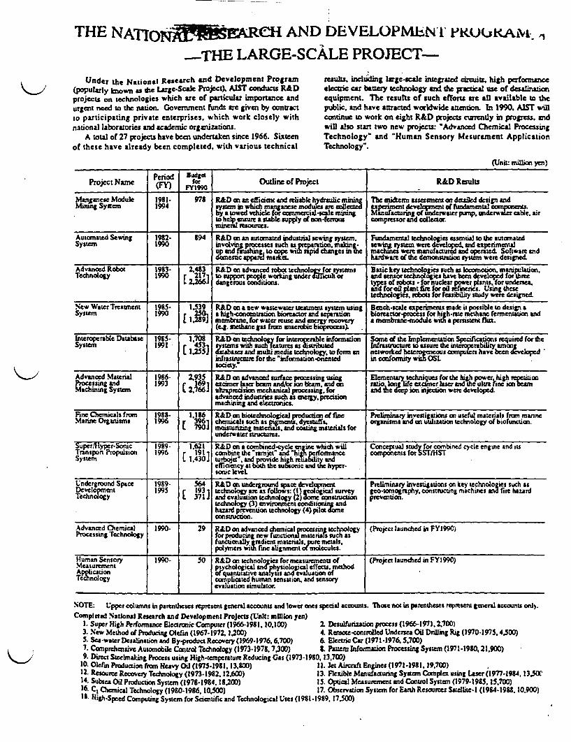
THE NATnQ14AE~ReH AND DEVELOPMELNI iKUU.& 1
THE LARGE-SCALE PROJECT-Under the National Research and Development Program
(popularly known as he LArge-Scae Project). AIST conducts R&Dprojects on echnologies which are of particular iportance andurgent need to the nation. Government funds are given by contractto participating private enterprises, which work closely withnational laboratories and academic organizations.
A total of 27 projects have been undertaken since 1966. Sixteenof these have already been completed, with various technical
results, includI lage-scale integrated ctrceuts. high performanceelectric car battery echrlogy and the pr ai- use of desalinationequipment. The results of such efforts are all avalble to thepublic. and have atracted worldwide atenton. In 1990. AIST willcontinue to work on eight R&D projects currently in progress, andwill also start two new projects: "Advanced Chemical ProcessingTechnology" and Human Sensory Mesurement ApplicationTechnology'.
(Unit: MilLion yen)
Period DodgeProject Name fo) r Outline of Project R&D Results
Manpanese Module 19I8 978 RD an efficient and reliable ydraulic min Te ierm assessmen deta3ed design andbdinung Syscem 1994 qn n nhich muaganese mod ue r leted expesimcnt developn ' afundamensal componA7A
by a towed vehicle for commercialdc niuig Manufactring of underwater pump. underwter cable, airto help ensure a stable supply of onfrrous compressor and collector.rninc resources.
Automated Sewing 1982- 394 R&D on an automated industrial ng sy Fundamental echnologes essential o the automatedSystem 1990 involving processes such as petiaorationdai- sein system were deveoped. and experimental
up and ririshing to cope witb ipid chanes tn he machines were manufactured and operted Software anddomestic apparel market hardware of the demonstrsation system were designed.
Advanced Robot 1983- 2.4t3 R&D on advanced robat tchnology for systems Basic key techrologie such ts bocootion. manspulation.Technology 1990 r 27 o support people working under dficult or and senior technologies have been developed for three
L 2a266J dangerous conditions types of rol~s -for nuclear power plants, for undersea.and for oil plant fire for oil finecEs. Using thesetechnologies. rnbots for feasibility study were designe
New Water Treatment 1935- 1.539 R&D an a new wastewater tuasment system using Bench-scale experiments made i possible to design aSystem 1990 250 a high nntration bioreactor and separation bioreacor-process for high-rase methane fermentation and
l.239J mnbrane, for ruse and energy recovery a menbrane-module wth a peristent flux.(eg. methane gas from anaerobic bioprocess)
Interopcrable Database 19E5- 1.70S R&D n echnology for intperable infortnaion Some of the Implenentation Specifications required for theSyStem 1991 r ed r ssnbused In structure to assure th interoperatility anong
L 1.255 uad rnultechnolgy, to form an networked heterogeneas computers have been e lopedinfrassnzcstr re for the "infonsticn-onentei in conformity with OSLsociety.-
Advanced Maserial 196- 2.935 R&D on advanced surface processing uSing Elementary techniques for e high power high reP=anProcessing and 1993 r 169i excimer lsr beam andfor son bearn, and o tio on life excner laser and the ultu2 bne ion beaMachining System L 2,766 ultrapreisior mechanical processing. for and hc p ion injetion were developed.
advanced industries such as enevrly, prcisionmachining and electronics.
Fine Chemicals from 1938. 1.1S6 R&D on biotechnologic l production of fine Preliminary investigations an useful materials from manrneMarine Organisms 1996 r 39l cemicals ish as pigments. dyestuffs. organisms and on uilizstion technology of biofunction.
L 790.5 moisturing matenals. and coating materials forunderwater structures.
Super/lHyper-Sonic 1989- 1.621 R&D on a combined-cycle en inc which will Concepsual stud for combined cycle engine and itsTransport Propulsion 1996 r 1911 combine the nrajes and 'hiath perfom ane coanponerns forST/HSTSysten L 1.430.J turbojea. and provide high riability nd
efficiency at both the subsonic and the hyper-sonic level
Underground Space 1989- 564 R&D on underground space devdepment Preliminary investigations an key technologies such asDevelopment 1995 r 193 l10o gyareas foUows: (I )aeoogical survey geo-tomography constructing machines and fire haurdTechnology L 371.5 and evaluaion technology () dome constuctlon prevention.
technology (3) environment conditining andhazard prevention technology (4) po decmstrucion.
Advanced Chemical 1990- 29 R&D on advanced chemical prOcssing technology (Project launched in FY1990)Processing Technology for producing new functional materials such as
functionally gradient materials, pIre metalspolymers with iuse alignment of mlecules.
Human Sensory 1990- 50 R&D on technologies for measure nenzs of (Project launched in FY1 990)Mc urenen psychological anlphysioloeica effects, methodAppliction of quantitative analysis and evaluation ofTicnology complicated human sensation, and sensory
evaluation simulator.
NOTE: Upper columns in parentheses represent general accounts and lower ones special acconts. Those not in parentheses represent general accounts only.Completed National Resarch and Development Projects (Unit: mgion yen)
I1 Super High Performance Eleannic Comnputer(1966-1981. 10. 100) 2. Desulfurizatiin process (1966-1971. 2.700)3. New Method of Producing Olefin (1967-1972.1 200) 4. Ranso-controlled Undersea Oil Drilling Rig (1970-1975.4.500)S. Sea-water Desalination and By-product Recovery (19691976.6.700) 6 Electric Car (1971-1976.5.700)7. Comprehensive Automobile Control Technology (1973-1978 7300) 1 Patter Information Processing System (1971-1930.21.900)9. Direct Steelmaking Process using High-temperature Reducing Gas (1973-1980,13,700)
30. Olerin Production fron Heavy Oil (1975-191. 13tO00) 11. et Aircraft Engines (1971-191. 19,700)12. Resource Recovery Technology (193.1932.12.60D) 13. Flexible Manufacturing System Complex using Laser (197-1984. 13SO14. Subses Oil Production System (197-19t4 I33200) 15. Optical Measurement and Control System (1979-1985. 5.700)16- Ci Chemical Technology (190-1936 0.500) 17. Observation System for Earth Resources Satellite 1 (1984-19t8 10.900)15. High-Speed Computing System for Scientific and Technological Uses (1981-1989. 17.500)

R&D ON NEW ENERGY TECENOLO*XRA-THE SUNSHNE PROJECT, -
IThe Sunshine Project was started in July 1974 to secure a stab
energy supply for Japaz which has a vulnerable energy stucture.High priorities are given to he development of the following rveprojects.(1) Solar Energy(2) Geothermal Energy(3) Coal Energy(4) Hydrogen Energy(5) Comprehensive Research
'The Agency PsOftg the Sunshine PToject is lso active antmerational coopeaa1i, through lEA and other itetiitioi �i
fIitI
iI(Unit: million yen)
Budge,Project Name for Outline of Project R&D Results
1. Solar Energy 7324 (1) Research snd development of high- * The price of solar cell has been reduced fromperformance and low-cost sola-photovoltaic- 20.000-30,000 yenlWpeak to 720 yen/Wpeak.
7 134 conversion technology which we hope will be * he cost of sol3r-photovoltaic-conversion systenwidely used by early 21st century. has been reduced om 2.000 yen /kWh to 200
(2) Development of the application of solar- yenkWhthermal-application systems for industrial * Technology of fied-temperature-stock-roomprocesses which require sophisticated thermal systemn (-C) driven by solar-thermal energy hascontrols. been achieved.
2. Geothermal 5378 (1) Nation-wide geothermal exploration survey * Completion of geothermal potential map in Japan.Energy 5 i33] assessing geothermal potential in apan. * Geothermal potential assessment and development
5.245 (2) Research to confirm the effectiveness of of optimumn exploration mehods for high potentialexploration techniques for deep geothenal areas.resources * Development of high-precision magneto-telluric
(3) Development of binary cycle generation plant method.and hot dry rock generation system. * Design and test operation studies of Downbole
Pump for binary cycle power generation.Producion of geothermal researvoirs by fracturingtechniques developed for hot dry rock powergeneration system.
3. Coal Energy 24.901 (1) Coal Liquefaction Technology (1) Design of 150 d pilot plant for liquefaction of266 ] Development of original liquefaction processes bituMinous coal.
24635 for both bituminous and brown coal. * Opertion of 50 t/d pilot plant for liquefaction of(2) Coal-based Hydrogen Production Technology brown coal.
Development of mass-production technology (2) Construction of 20 tId pilot plant for coal-basedfor low-cost clean hydrogen energy. hydrogen production.
(3) Integrated Coal Gasification Combined Cycle (3) Construetion of 200 t/d IGCC pilot plant withPower Generation Technology (IGCC entrained bed reactor.Sponsored by ANRE)Development of the technology of 1GCC whichis more efficient and have less environmentalimpact thin conventional coal-fired powergeneration.
4. Hydrogen 108 Development of technologies an hydrogen Th pilot plant of alkaline-wacr electrolyzer with aEnergy production, storage and transportation use and 2N m3/h capacity was successfully operated for a
safety long period at the highest efficiency in the world.Development of technologies on producing highlyefficiently, and on transportation and storage usingmetal hydridesDevelopment of hydrogen batteries and hydrogen-fueled engines
S. Comprehensive 1.84 (1) Basic studies of other new energy technoloi Th pilot plant of 100kW-class wind turbinResearch 145 such as wind energy, ocean e ry, bio enery, generator systeM was successhly operated for a long
1.639 but excluding four areas (solar. geothermal period.coal and hydrogen) are proceeding.
(2) Development of a high-efficiency membranecomplex methane production unit.
6. International 61 (1) International cooperation through IEA.Cooperation (2) Bilateral cooperation with Australia, etc.
NOTE: Upper columna in parehes pset genral acoum s and lower n spea ac hose in parmtsearepc genal Uot *.
I
I
I 4
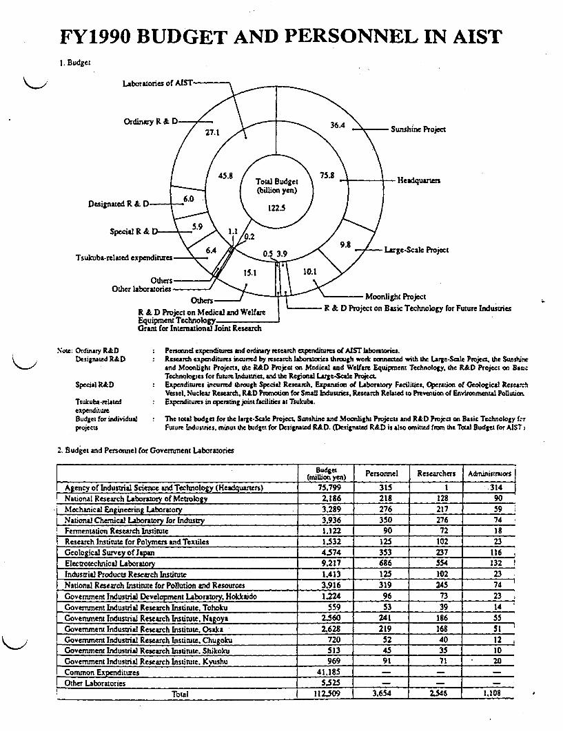
FY1990 BUDGET AND PERSONNEL IN AIST1. Budget
Sunshine Project
- Headquarters
Designated R & D- .
Special R & D-
Tsukuba-related expcnditures'- arge-Scale Project
R &; D Project on Basic Technology for Future Industries
Xote: Ordinary R&DDesignated R&D
Special R&D
Tsukuba-rlatedexpenditureBudget for individualptojects
Persnnel expenditures nd ordinary research xpenditures of AIST labotores.Research expecnditures incurred by research laboratories throngh work cm ected with the Large-Scale Project, the Sunshineand Moonlight Projects, the R&D Project an Medical and Welfare Equipment Technology the R&D Project on BasicTechnologies for future Industries, and the Regional LArge-Scale Project.Expenditures incurred through Special Research, Expansion of LAboratory Facilities, Operatio of Geological ResearchVessel. Nuclear Research. R&D Psunotion for Small Industries, Research Related to Prevention of Environmental PoUution.Expenditures in operating joint facilities a: Tsukubr.
: Tbe loul budge: for the large-Scale Project. Sunshine and Moonlight Projects and R&D Project on Basic Technology f1rFuture Industries, minus the budget for Designated R&D. (Designated R&D is also omitted fron the Toal Budget for AIST j
2. Budget and Personnel for Goverment Laboratories
Budget Personnel Researchers Adrninistratorsi_ _ _ _ _ _ _ _ _ _ _ _ _ _ _ _ _ _ _ _ _ _ _ _ _ _ _ _ _ _ _ _ ~~ ~~(m illion Yens)
Agency of Industrial Science and Technology (Headquarters) 75.799 315 1 314National Research Laboratory of Metrology 2,186 218 128 90Mchanical Engineering Laboratory 3,289 276 217 59National Chemical Laboratory for Industry 3.936 350 276 74Fermentation Research Institute 1.122 90 72 18Research Institute for Polymers ndTextiles 1532 125 102 23Geological Survey of Japan 4.574 353 237 116Electrotechnical Laboratory 9.217 686 554 132Industrial Products Research Institute 1.413 125 102 23National Research Institute for Pollution and Resources 3.916 319 245 74 _
Government Industrial Development Laboratory, Hokkaido 1.224 96 73 23Government Industrial Research Institute. Tohoku 559 53 39 14Govenunent Industrial Research Institute, Nagoya 2.560 241 186 55Govervnent Industrial Research Institute. Osaka 2628 219 168 51Government Industrial Research Institute. Chugoku 720 52 40 12Government Industrial Research Instinte. Shikoku 513 45 35 10Government Industrial Research Institute. Kyushu 969 91 71 20Common Expenditures 41.185 - - -
Other Laboratories 5,525 _ _Total 112.509 3.654 2.546 1.108

- .- �P-- - -- I''- - I -L-19M - I ff (W(I'YIFj'
RESEARCH AND DEVELOP S PROORASIC-TECHNOLOGIES FOR FUTURE INDUSTR& _ -,
K>This project is aimed as the developmenat of innovaive basictechnologies essential for establisinS new industies.
The five fields covered are supercenductivity. new materials.-biotechnology. new eleconics devices and software. The followingfourteen special categories, all of which have theoretically
of 2Pl et shaw potentida for applicanca 0 new ctistrialtehINolgieOS have ben selectedL Research and developmat m
u &a e a ud ui the materials involved are readyfor practical noicaio,
evLas:- nillioc Ycn)PeidBudge
Project Name Prod ft Outline of Project R&D Reilts___________ (FY) nFY _ _ __ _ _ _ __ _ _ _ _ _ _ _ __ _ _ _ __ _ _ _ _
Superconductivity(1 24 o new u d aterica Effiv' e merswabadw~ jaxizdeI1918. pioceasm formethod to 9Ncsly ob was
Muscr 1997 L1.4371 cd ea pm d h d in oxide _ ,ecnaco aDevices 55. said Wi dIcU
wcfmologie Yi9 faficaizidevices eupercorductor devic, was
(21 New Materials 19S1- 1,313 Developat Ohisegth ceraic a Sis N and SiC ceramics with hisI reliability wic cmI)J igh-Paf es 1992 1 exrun1 c bigl tewnus to be used aatum (-l2C were develed a
C_______" 11304 mu or un gs w a ~a x
2) Syzfl~mic 19SI- 192 Delopmn d utiisthetlc membranes for new Sy icmmbnes which can effidly rMembwanes for 1990 a a ia t o ad wermUxod sdmias.COIIaedzases.
aewoS atreely micd pse wmixturesby udln optical scness of msid r dev oNew tion diffeca in pysa p e
3) Snhetic Metals h19S * D c of ie als a polmr Layered ynthtic with ighest__°90_ - mU~lS~i~y4Wpr cSf d 9z10O Ya5wsu hefi
h bd~~~~~~~~~~o~aod ringsyl
4)Hii Paforma 1981- 126 De e d hih fomc pstics md P oWa with bitl= modui and moldPlagica 1990 pdmcc materials with mechanici] propaties of tectmiq.0CSforotm ia) perfforaclii.d-aYFaml
hmetL polymes aid olcdccnoates have bees deelped.
5) lilnPfmia 1989- 10 Developeann cro/abo epsls SiC fil:&md by doe elecuo bea mdMaWias fo See 1996 r 6j3 intenpad.ic c an fiber ifaced was udedto sid hi tmperure (-150Envirnet 3l' inretic _o~ms whih c b so
Sevoa spce%'p1a'rSSTM *
6)P otativs 1985- 47t Developmen of photoactVe maeials wich hxou3wie Lm fisfor multiple cg andMaterials 1993 7 ] icaW exhibi a reversible Zia he bing mat*rials which work at quW
L9" 3961 dhc guulm qTarlngeene of molecules El u5 qxp= have bea developed.response o a light smulus.
7).Nonainear 1919- s4 Deqpmera of Ornics mafti als whichexhi dd spe g bangPhotonics Materials 1998 high nnlinear ical sceib and &bort the ighs epbility reported so far hve bca
wpons enies orfspplicaion of opcal developedom~losses(3) Biotedmoloty 191- 152 Invest i us of recanbinant DNA Nobe ot-vector systems of yeass wen deC wdinholo99- r0 fo us e on
rItizaionw 1990 t o fr the deqnm of new VaYous uymes and biosciWe substances have Recombian DNA inicsoinncs for practl use ia dlsuy. cElyducol by e iepvanew of bo-vctor
__ . synt d I ms~~~~~~~~~~~~~~ucrrzn'mssystms ,ust*- 'ees wer titueed re2)Molecula 1919. 321 Developn d molecular Ofamblies g u fJx
Anemblies for 1998 fadncsiaol pr s for acon wh K d pbos aFunctiona Protein fucons .- etian and cec emb wl oean o h moecsystem bu with eiv w so r
_. Atanpo d recogm fthfit ine Id aa
(4) New Electron 1ence Multifunctialhiseed devices which Sis resonaitDevices 1981- ih etemely fne sacun ailoed so uatoic t g hi r, aid bi rce in
1)Suprsnies 1990 cats for utiling new elclsnic effects. superanie wet faricbe by olclrbea iLnyDevices CMBE) and m oie c il vaor depoei
methods
2)T'les.Dimensional 19S1- 301 Dvelopment i IC characterized b a thc- Proye MO3D e tocal detaor AD logeICs 1990 dimcnstonal auanmn of active emns made and memyCrcIS wen f&bnaW by SO fot A
of seiductor lyn. teags eered by 5 oranolgies3) Dio-lectronic 1956 280 Development o biodacusie devices for fure A new optical method for deting nurl ctivitiel is he
Devices 1995 ccmpute ticro sig bher was developed. A powoeleEtro dvce which hadinformices" fzucsss s( very high qsas cfficy was also pd by png-ptanicky X molcl - and s up ,lememI
(S software 1990- 53 Developmen f innovative models for exible (Pmo-a launhdi FY1990)I)New Models for 1997 eoftwa architectue so th stwaue cM functill
Software .og to the uundirl i .Archic . _ . _
4
NOTE Upper coumns m parentheses repesengeneral accounts a lower ones special acoonts The not i prentheses represent general accohnu only.Completed Research and Development Projects on Bade Technologtes for Future Industres (Unut: millio yea)
FonifIeld Cs for Extreme Conditias (1911-1915.1.31 S)' Advanced Alloys with Controlled Crystalline (1 91-198 3903)
Advanced compoesit Maeria (1911-191J,4.649)Biortactor (1981-1911. 2,971)
Large-Scale Cel Cultivation (1931-1989. 3.362)

ii .111ii I I Iii .1 *IJ
U
131 3 111111. ii I .r ii
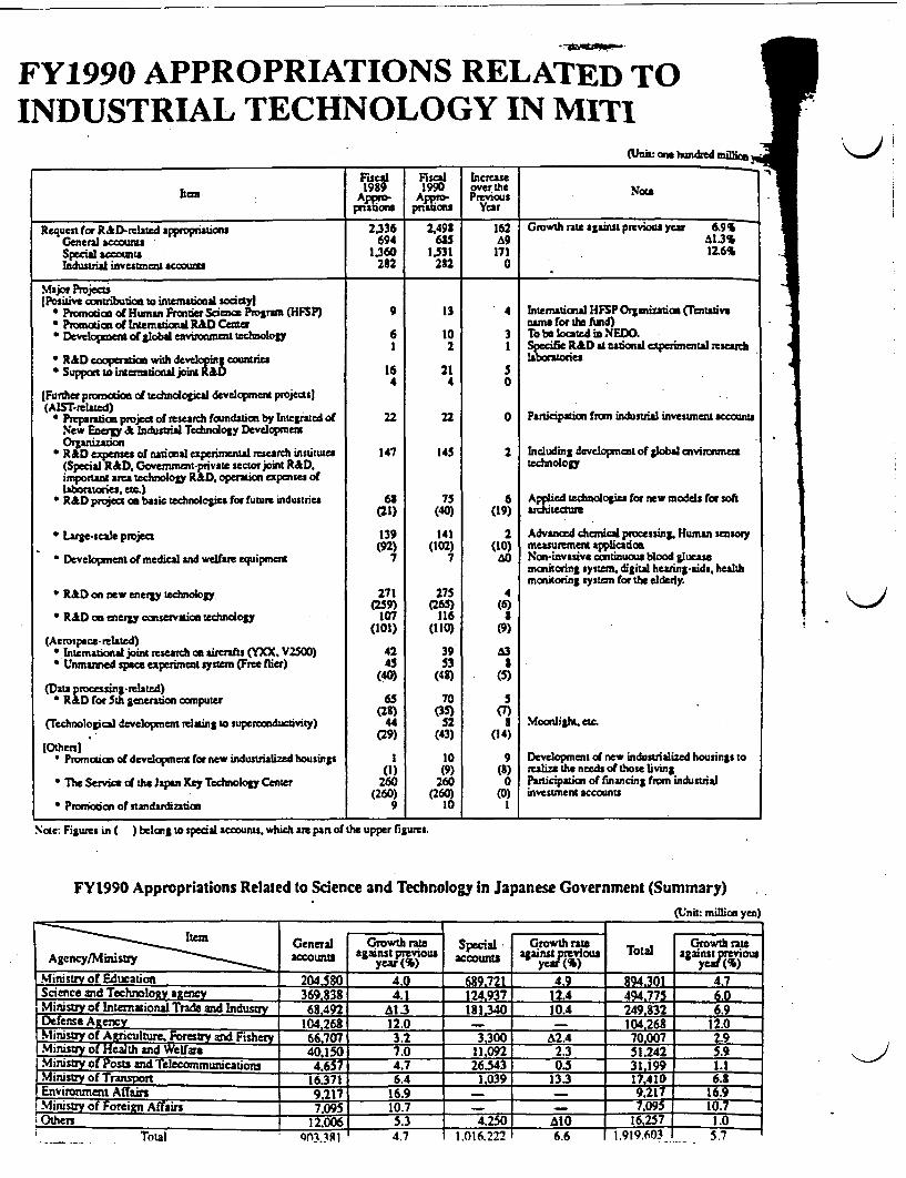
FY1990 APPROPRIATIONS RELATED TOINDUSTRIAL TECHNOLOGY IN MITI
(Unis: onehunmred million V
Fiscal Fiscal Increase1939 1990 overthe gtlunm Appro- Ajppmo- Previous
prisDons pritcts Year
Request for R&D-relsted appropriations 2,336 2,493 162 Growth rate against previous year 69General accoutms 694 695 9 13%Special aoants 1.360 1.531 171 12.6Sindustrial investmCnt c 282 232 0
MaJor Nrojects(Positive ountribuon to internatonal socityj
* Pnotia of Human FrontScience Progrrn (HFSP) 9 13 4 International HFSPOrganization Tentative* Promoia of International R&D Center name for t fd)* Dcvdopm of lol enuunmnatechnoloy 6 10 3 To be located in NEDO.
1 2 1 Specifc R&D at national eperinental researhR&D cooperatn with deveoping ountuies laboratoriesSuppt to intermaionaljoint R&D 16 21 5
4 4 0[Further pronctics of tehndogical development projecasi(AIST-related)
* Preparatx. project of research foundation by Integrated of 22 22 0 Participation from industrial investment accountsNew Enery & Industrial Techndogy Development
* RhDexpn of nat aleperimental rescarh institutes 147 145 2 Induding developmentofglobalenvirrnment(Special R&D. Govemmat -pnvate sector Jint R&D. tectnoloDtimporant area technology RhD. opration eapaoses of
1aotre. ac)* R&D prvect co basic technologies for fuure industries 6S 75 6 Applied tednlogies for new models for soft
(21) (40) (19) aritctee
* Large-scale project 139 141 2 Advanced chemical processing. Human sensory(92) (102) (10) measurement applicaoit
* Developmernt of medical and welfare equipment 7 7 ao Non-invasive continuous blood glueasemronitoring sysm. digiud hearing-aids. healthmonitoring system for the elderly
R&D o new energy ecology 271 275 4(259) (265) (6)
* R&D on energy conservation tedunology 107 116 8(101) (110) (9)
(Arospacem rlated)* Intemational joint research on arerafts (YXX. V2500) 42 39 A3* Unmanned sp e experiment system (Free flier) 45 53 3
(40) (48) (5)(Data processing-related)
R&D for Sth gaenation czputer 65 70 5(28) (35) (7)
(Technological development relating to supercunductivity) 44 52 8 Moonlight. etc.(29) (43) (14)
1Others]* Promotin of developenet for new industrialized housings I 10 9 Development of new industrialized housings to
(1) (9) (J) realize the needs of those living* The Service of the Ispen Key Technology Center 260 260 0 Paricipatia of financing from industrial
(260) (260) (0) investment accounts* Pronidon of standardization 9 10 I
Noe: Figures in ) belong to special accounts. which am pan of the upper figurs.
FY1990 Appropriations Related to Science and Technology in Japanese Government (Summary)(Unit: million yen)
IIZIIte General Growth rats Special Growth re Growth lateAgency/Mistry accounU against previous at;ins preious Total against prvioutS
______ ~year (%) ____ year (1) __ yen M~
-Ministry of Education 204580 4.0 689721 4. 9 894.301 4.7Science and Technoloy atency 369 834.1 124937 12.4 49 775 . ..Ministry International Trade and Industry 492 A1.3 181.340 10.4 24932 6.9Defense Atencv 104268 12.0 - 104268 12.0Ministry of Arnculture. Forestry and Fishery 66707 3.2 3,300 A2A 70007 2.9Ministry of Health and Welfar 40.150 7.0 11,092 2.3 51,242 5.9tMinisry of Posts and Telecommunications 4.657 4.7 26.343 0.5 31,199 1.1Ministry of Transpom 16.371 6.4 1,039 13.3 17.410 6.8Environment Affairs 9.217 16.9 - 9,217 16.9Minstry of Foreign Affairs 709S 10.7 - - 10.7
th 12.006 5.3 4.2 0 mo 162 7 1.0Total QA331 4.7 1.016.222 6.6 1.919.603 S7
II
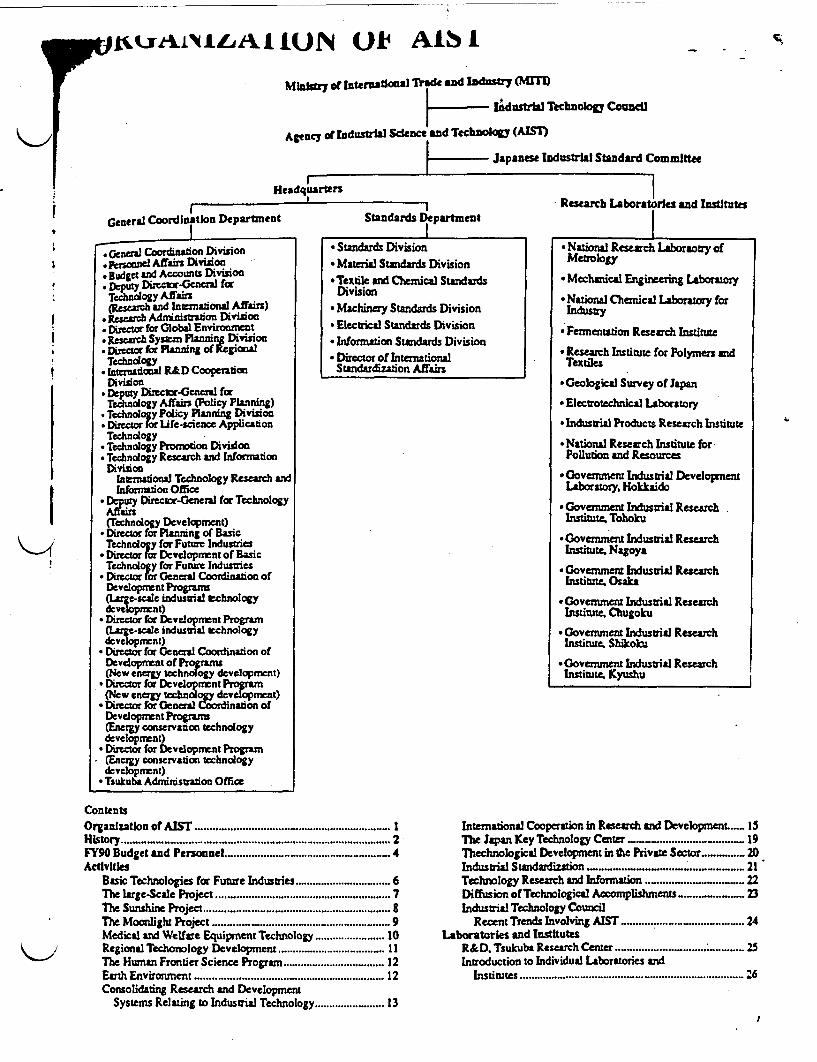
i^uU ION O AIS I Sc
M ity of International T de and Industry (NUTI)
KAdustral Technolop Council
Agency of IndusWa Science and TtchnokSy (AIM
Japanese Industrial Stundard Committee
HeadquartersI
General Coordination DepartmentI
.Gncral Coordinalion Division. psonnel Affirs Division* Budget and Accounts Division* DEputy Diretr-Gcneral for
Technology Affairs(Researc la onal Affairs)
* Researeh Ad strion Division* Director for Global Environment
Research System Planning DivisionDircr for Planning of RegioalTechnology
* Intaonal R&D CooperadonDivision
* Deputy Direcb-General forTechnodogy Affairs (Policy Planning)
* Technooy Poiey Planuung Divuion* irecor for life-science ApplicafonTechnology
* Technology Promotion Division* Technology Research and WormationDivision
Intnaional Technology Research andinforridon Office
* giuty Director-General for TechnologyAn&=S(Technology Development)
* Director for Planning of BasicTechndogy for Fune Industries
* Director for Development of BasicTechnology for Future Industries
* Director for General Coordinaton ofDevelopment Programs(Irge-cac indusuia technologydevelopmnt)
* Director for Development Programafgec-scale indusmal technologydev~elmt)
* Director for General Coordination ofDcvdopmcntof Projrams
(Nw cng lechndg dedpct)*Dirctor for Decvclopment Program(New energy techndogy deeopment)*Dircor for General Coordination ofDevdopment Programs(Energy conservation technologydevelopment)Director for Development Program(Energy conservation technologydevelopment)Tsukuba Adminstration Office
Standards Department
* Standards Division* Material Standards Division*Textile and Chemical Standards
Division• Machinery Standards Division
* Electrical Standards Division* Information Standards Division
* Director of InternationalStandardization Affairs
Research Laboratories and Institutes
r National Research Laboraoay ofNrtional Rrch Lboraotr ofMetrology
* Mechanical Engineering Laboratory
* National Chemical Laboratory forIndustry
* Fermentation Research Institute
* Research Istitute for Polymers andTextiles
* Geological Survey of Japan
* Electrotechnical Laboratory
* Industrial Products Research Institute
* National Research Institute forPollution and Resources
*oovernment Industrial DevelopnentLaboratory, Hokkaido
* Governnent Industrial ResearchInstitute, Tohoku
* Government Industrial ResearchInstitute, Nagoya
* Government Industrial ResearchInstitute. Osaka
* Government Industrial ResearchInstitute, Chugoku
* Government Industrial ResearchInstitute, Shikoku
* Government Industrial ResearchInstitute, Kyushu
ContentsOrganization of AIST . . ..................... IHistory .......... .. .2FY90 Budget and Personnel ... ........................... _ 4Activities
Basic Technologies for Future Industries ............................. 6The large-Scale Project ............................. 7Tle Sunshine Project ............................. 8The Moonlight Project ........... .9Medical and Welfare Equipment Technology .10Regional Techonology Development .11The Human Frontier Science Progra .12Earth Environment .12Consolidating Research and Development
Systems Relating to Industrial Technology .13
International Cooperation in Research and DevelopmenL ..... ISThe Japan Key Technology Center ....... ..... 19Thehnological Development in the Private Sector .... ........ 20Industrial Standardization . .... ....... .. ... 21Technology Research and Information ... ...... .... ... 22Diffusion of Technological Accomplishments...-... 23Industrial Technology Council
Recent Trends Involving AIST ............................... 24Laboratories and Institutes
R&D. Tsukuba Research Center ...- . . .. : .25Introduction to Individual Laboratories and
Institutes ............................... '6
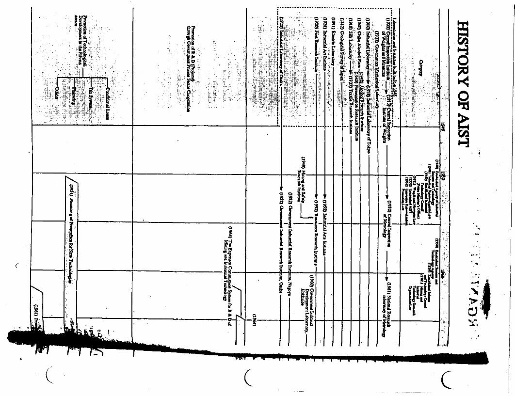
�I1I .1'
Ma 0I;
-' �jjq � - n
� 111<.'.�...* 0I f I I
1 "21S hi
___________ * *'i't1F-4 a -�
A
_______________ ___________________ II
SUIF 0 ['E'II[P!a.a�n EI
Ii I IWN
ij' It I_______ cit
- --- 1-3 'Ti ii liii'
3. -
aa.
Q C C

-- l". -
Agency of Industrial Science and Technology
1990
MINISTRY OF INTERNATIONAL TRADE AND INDUSTRV

OVERVIEW OF THE AGENCY OFINDUSTRIAL SCIENCE ANDTECHNOLOGY
R&D in advanced fields of electronics. new materials. biotechnology, and so forth is remarkable at the present time. In view ofcontributing to the international society through technical development while taking into account domestic and international changessurrounding science and technology. Japan will promote Techno-Globalism to stimulate scientific and technological creativity aswell as distribution and transfer of the results of such activities. Domestically. Japan which is now one of top ranking economic andtechnological powers in the world, will maintain and enhance the bases for building up a= affluent economic society in the future.This will enable us to establish a long-and medium-term basis for the economic development of Japan. Also in contributingpositively to the international society through R&D it is essential for Japan to play a role in promoting increased R&D in inovativeareas which will benefit all humankind.
For 1991. the Agency of Industrial Science and Technology will promote R&D in such areas as new energy, energy conservation,and pollution control to tackle environmental problems while making efforts to expand and argument R&D activities of designatedresearch organizations in developing global environmental technologies, promoting international joint studies on globalenvironmental technologies, and establishing R&D organizations to study industrial technology related to the global environmentWe also intend to develop overall industrial technology policies, in particular the following.
Frst of alL for this year, international research cooperation will promote the Human Frontier Science Programs designed toexplain the superior functions of the living body and to search for possible applications. Specifically, we will make effects to furtherimprove and expand international research exchange by;(1) R&D in specific areas through task sharing among the Agency of Industrial Science and Technology and research institutes of
advanced countrie,(2) assistance to R&D development by international joint study teams in explaining physical properties and functions.(3) invitation of foreign researchers to the research institutes of the Agency of Industrial Science and Technology, and(4) incorporation of the International Exchange Center established in NEDO in 1990 into the International Industrial Technology
Research Exchange Center.Secondly. regarding R&D in basic and advanced fields, she following projects will be further expanded:Basic Technologies for Future Industry to promote advanced technology development (new materials. superconductivity). Large.
Scale Project of Industrial Technologies vital in terms of the national economy (effective utilization of marine micro organism) andR&D for of Medical and Welfare Equipment Technology to contribute to the welfare of society through technological development.
Continued promotion is also planned for the Sunshine Project aimed at developing clean new energies (solar and geothermaleneries. etc.) and the Moon-light Project for generating energy conservation technology to achieve high energy efficiency in viewof Japan's energy security.
Technological R&D for Vital Regions will be actively promoted to stimulate economic growth of regional areas.In in with these R&D focusing on basic areas will continue in 16 research laboratories under the Agency of Industrial Science
and Technology, while furthering mutual exchanges through joint research among industries, government, and universities.Thirdly. in order to encourage R&D in the private sector, R&D founding will be provided by the Infrastructure Technology
Promotion Center. utilizing various tax incentives (Added R&D Expenditure tax deductions and tax incentives for promotinginfrastructure technology for RAD). The latter refers to improving the research infrastructure necessary for promotg high-levelR&D.
Finally, regarding the industrial standardization system (11S) which has supported our development in industries, we will advanceinternational cooperation through making positive contributions to international standardization activities and standardizationtechnical cooperation. promotion of standardization in advanced technology fields (information technology, new materials, andbiotechnology).We hope this pamphlet will help in understanding the policies of the Agency of Industrial Science and Technology.
Dr. Masaru SugiuraDirector-General,Agency of Industrial .Science and Technology
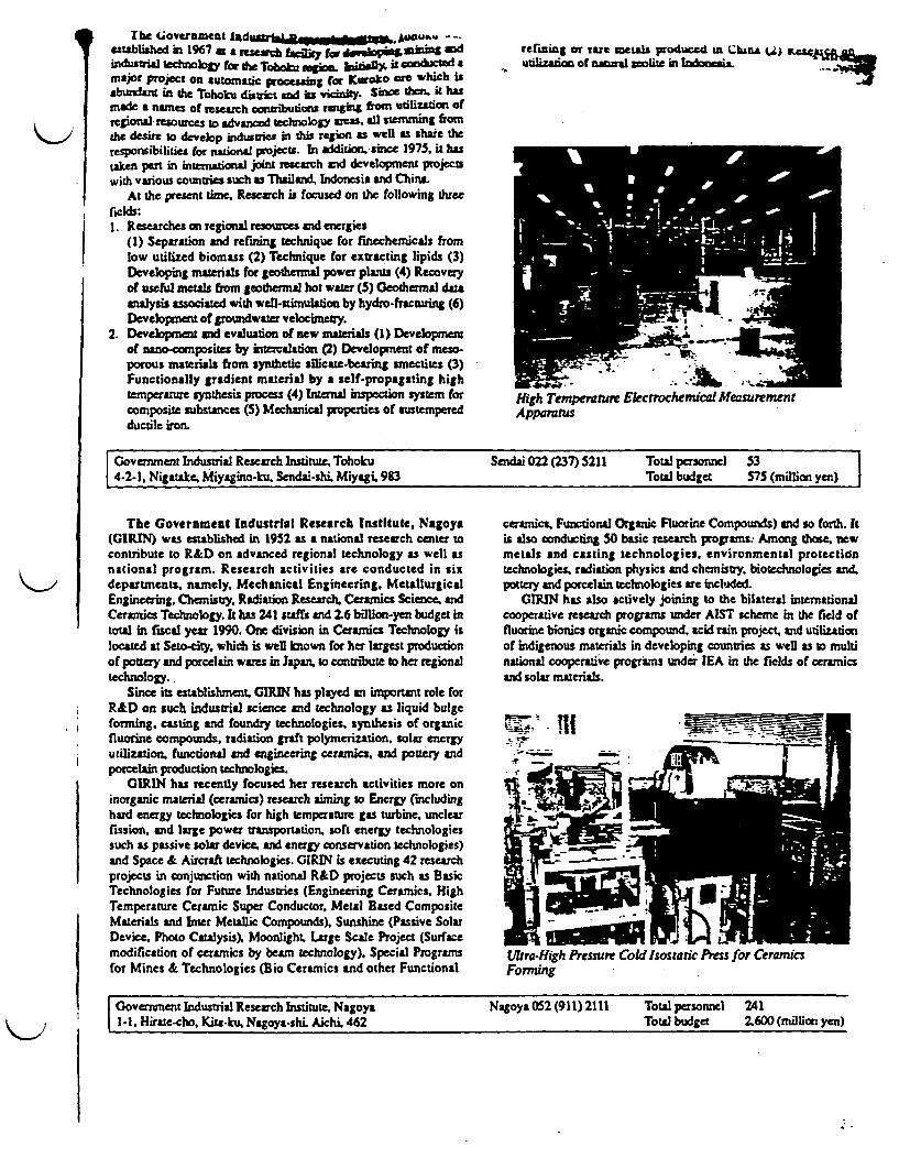
The Giovernment 1ntdusrma&.3u S.. AUDubw --.established in 1967 a research finity f i Windustial tedtnokY for the Toboka go bitiaDY. 3 condcted aMajor proiect on utomatic procesing for r h*bundant in the Tohoku district and its vky. Since thn it hasmade a names of h clbutan rggU fotm utiliztion ofrtSOnalIrsources o dvancd techology areas, anl stemming fromthe desire to develop industries in his region as well as shae theresponsibilities for national projects. In addition. sine 1975S it hastaken part in intenional joint research and development projectswith various countries such as Thailand, Indonesia and China.
At the present time. Research is focused on the following threeficids:1 Researches on regional resoursces and energies
(1) Separation and refining technique for finechemicals fromlow utilized biomass (2) Technique for extracting lipids (3)Developing materials for geothenal power plants (4) Recoveryof useful metals from geothermal hot water (5) Geothermal datanalysis associated with wel-stimulation by hydro-fracturing (6)Development of groundrwater velocimety.
2. Development and evaluation of new materials (1) Developmentof nano-composites by intercalation (2) Development of meso-porous materials from synthetic silicare-bearing smectites (3)Functionally gradient material by a self-propagating hightemperature synthesis process (4) Internal inspection system forcomposite substances (5) Mechanical properties of austemperedductile iron.
refining or rae metals produced an Chuna s aaffutilization of nual zeolite in Ieaz'
High Temperanure Electrochemical MeasurementApparatus
Government Industrial Research Institute, Tohoku Sendai 022 (237) 5211 Total personnel 534-2-1, Nigatake, Miyagino-ku. Sendai-shi Miyagi 983 Total budget 375 (million yen)
The Government Industrial Research Institute, Nagoya ceramics, Funtional Organic Fluorine Compounds) and so forth. it(GIRIN) was established in 1952 as a national research cener to is also conducting 50 basic research programs. Among ace. newcontribute to R&D on advanced regional technology as well as metals and casting technologies, environmental protectidnnational program. Research activities are conducted in six technologies, radiation physics and chenistry. biotechnologies anddepartments, namely. Mechanical Engineering. Metallurgical pottery and porcelain technologies are included.Engineering. Chemistry. Radiation Research. Cerarnics Sciene, and GIRIN has also actively joining to the bilateral internationalCeramics Technology. It has 241 staffs and 2.6 billion-yen budget in cooperative research programs under AIST scheme in the field oftotal in fscal year 1990. One division in Ceramics Technology is fluorine bionics organic compound, acid rain projet and utilizationlocated at Seto-city, which is well known for her largest production of indigenous materials in developing countries as well as to multiof pottery and porcelain waes in Japan to contribute to her regional national cooperative programs under IEA in the fields of ceramicstechnology. and solar materials.
Since its establishment. GIRIN has played an important role forR&D on such inustrial science and technology as liquid bulgeforming, casting and foundry technologies, synthesis of organic ; -fluorine compounds. radiation graft polymerization, solar energy - - -
utilization, functional and engineering ceramics, and pottery and -- -:
porcelain production technologies.GIRIN has recently focused her research activities more on -
inorganic material (ceramics) research aiming to Energy (includinghard energy technologies for high temperature gas turbine, unclear -
fission, and large power transportation soft energy technologies -
such as passive solar device, and energy conservation technologies)and Space & Aircraft technologies. GIRIN is executing 42 research - -' -
projects in conjunction with national R&D projects such as Basic ;Technologies for Future Industries (Engineering Ceramics. High -Temperantre Ceramic Super Conductor. Metal Based CompositeMaterials and Inter Metallic Compounds), Sunshine (Passive SolarDevice. Photo Catilysis) Moonlight, Large Scale Project (Surface |
modification of ceramics by beam echnology). Special Programs fWira-High Pressure Cold Isosrsic Press for Ceramicsfor Mines & Technologies (Bio Ceramics and other Functional Forming
Government Industrial Research Istitute, Nagoya Nagoya 052 (911)211I Total personnel 2411-1. Hirce-cho, Kita-ku, Nagoya-shi Aichi 462 Total budget 2.600 (million yen)"I_

FThe Government Industrial Researcb Institute, Osaka was
established in 1918. Since then it has produced a number ofoutstanding research achievements in the exploration anddevelopment of new materials including carbon fibers andelectrically conductive transparent thin films. Our research instituteconsists of five research departments and is giving priority to thefollowing research fields:1) Energy-related Materials:matcrials for energy conversion such
as for batteries- fuel cells. electrolysis processes, hydrogenenergy, and high-tenperature ceramics for gas turbines, etc.
2) Optical Materials glasses and thin films for optics, nonlinearoptical materials, optical chemical senso, etc..
3) Functional Surface Materials:heterogeneous catalysts.biocompatible materials. atomic-scale designing of graphiteintercaladon compounds, new functions and theoretical analysesof the interconnection in composite materials, surfacemodification with ion implantation. etc.In addition to the above fields of materials research, the
following lines of approach are also being put forward:I) Intensification of innovative, fundamental studies to create
highly advanced functions of materials.2) Initiation of unexplored approaches to materials through human
sensation and feelings3) Fermentation of basic science concerning the creation and
analyses of novel materials through atomic-scale techniques andcompuuer calculation and graphics.
4) Promotion of R&D programs for global environmetItechnologyThrough the above research activities. our institute encourag" I
contacts and cooperation between industrial and university reward uon a regional. national. and international leveL
Goverrunet ndustrial Research Institute, Osaka Ikeda 0727 (1) 8351 Total persomnel 2193-31. Midouigocka I-chome, Ikeda-shi Osaka. 563 Total budget 2560 (mflion yen)
The Government Industrial Research Institute, Chugokuwas established in 1971 to conduct pollution control studies in theSeto Iand Sea and engineering studies to develop new industrialtechnology in the Chugoku district. Since then there have beenmany noteworthy achievements by the Institute results, includingrcsearch on dissolution of pollutant out of the bottom sediment inthe Seto Inland Sea, development of a fresh surface characterizingmicroscope using exo-electron. and materials evaluation in severeenvironments.
Two research department the Marine Science and TechnologyDepartment and the Industrial System Department, are affiliatedwith the Institute. The first has four research divisions, and studiesocean engineering using the largest hydraulic model of the SetoInland Sea in the world, shown in the picture, as well as physical.chemical and biological oceanographies. The second has threeresearch divisions, and studies machining technology the surfacescience of new materials and computer science in factory - 5 ;automation.
The institute also conducts marine biology studies under a majornational R&D progrm amaterial study of hydrogen energy and . - -
ocean thermal energy conversion (OTEC) under national R&D --projects focusing on new energy, computer image processing studies *for developing specific regional technology and international joint Large-scale Hydrauic Model of the Seto InZd Searesearch with Indonesia in the area of corrosion.
Government Industrial Research Institute, Chugcka Kure 0823 (72) 1111 Total personnel 522-2, Hirosutehiro 2-chome, Kure-si Hiroshima, 737-01 Total budget 726 (million yen)
''I

The Government Industrial Research Institute, Shikoku wasestablished in 1967 as a R&D center for developing muting andindustries in the Shikoku region. taking advantage of its mildclimate and location near the sea and rich forest resources. Its R&Dcenters upon pulp and paper techn6logy and in developing marineresources, it is primarily concerned with extraction and uses ofminor elements dissolved in sea water. and underwater welding andcutting.
Balancing its regional and national interests. the institute hasemphasized research in marine resources, functional resources andmechatronics. Furthermore, our institute is the leader in theShikoku region for research and technologies.The major research area of the Institute are as follows:1. Marine resources
(1) Manufacturing process of high-functional chemicals fromsealife. (2) Developing excellent absorbents for uranium andlithium. (3) Developing functional sheets from acidicpolysaccharides. the main constituents of seaweeds. (4)Manufacturing degradation-controlled sheet. (5) Developmentof magnesium pyroborate whisker.
2. Local technologies(1) R&D on re-utilization system technology of compositematerials. (2) Control of a flexible long arm and development ofa small active mass damper. (3) Swing and vibration control ofa crane. (4) Sophisticated surface processing with laser beamand ion beam.
3. International R&D cooperation projects and fundamentalresearch
(1) Research on industrization of thermoriechanical pulping ofoil palm by-products. (2) International research coopation anrecovery of valuable brine resources. (3) Molecular mechanismof interactive recognization between cell surface andpolysaccharides.
Bio-degradablk Polymer Film
Government Industrial Research Institute, Shikoku Takamatsu 0878 (67) 3511 Total personnel 453-3. Hananomiya-cho 2-chome, Takarnatsu-shi Kagawa. 761 Total budget 513 (milion yen)
The Government Industrial Research Institute, Kyusyu was 3. Energy and pollution control technologies; (1) Study of thestablished in 1964 to contribute to developing mining and behaviorof coal and solvent mixtures in the initial stages of coaindustries in Kyusyu. liquefaction. (2) Hot-gas corrosion of ceramics for gas turbin
The institute has conducted 17 special research and 35 general blades, (3) Development of new muffler adaptable witdresearch projects in the following major fields: controlled resonators. (4) Research on the advanced biologicaI. Production and processing technologies for new materials; (1) treatment of organic waste water. (5) Liquefaction of coal an
Study of ductile ceramics at high temperatures. (2) Development extraction of liquefied products under the condition oof intelligent ceramic composite materials, (3) Research on supercritical state.fabrication and thermal characterization of heat resistant carbonceramic composite materials. (4) Machining technology inceramics and cutting tool application. () Development ofceramic cutting tools for steel. (6) Development of high-performance engineering carbons, (7) Development of advancedcarbon/carbon composites with oxidation resistance. (8) aTechnology for improving properties of materials by the powder forming method. (9) Development of particle dispersed icomposite metals by high pressure solidification method. (10)Research on metallic materials using quantitative stereology. -- -
(11) Study of production of multifunctional microspheres. (12) -
Study of spectroscopic characterization of ceramics.2. Advanced technology for utilizing natural resources; (1) R&D -
utilizing lime and lime-based compounds in advanced materials.(2) Processing and evaluation of inorganic polymer having layerstructure. (3) Production of porous ceranic materials from ricehusks. (4) Advanced utilization of volcanic glass, (5) Production Fand utilization of molecular sieves from coal. (6) Research on Friction and Wear Tesdag Apparausconcentrating a trace amount of gallium. (7) Refining process offine parts of weathered granite
Government Industrial Research Institute, Kyusyu Tosu 0942 (82) 5161 Total personnel 91Syuku-machi. Tosu-shL Sags 841 Total budget 946 (million yen)

ITb National Chemicn lbor*ay r a (NCLI) was
established in 1900 for prnmoitg the chemica in1trly in Japn.be lasoratoy conducts nmeous rsearch pjects in four Ara 1.
developnent of new substances and highly fncional miteials: 2.bio and biontimetic chemistry 3. conversion and conscrvationtechnologies for energy and a curves. And 4. sandardization andsafety technologies. Many strategies aiming the first rea are,rtroduced in chemical reactions and processes. for examples. ultra-high temperature plasma. ultra-high pressure. laser beams.,computer-aided molecular design systems. For the elucidation and;pplication of biological functions, the laboratory has developedtcchnologics for geneic ngineerg cell membranes. Artificial andsuper enzymes. and artificial photosynthesis. In effective utilizanionof energy and natural resources. extensive studies are being made oncatalysis technology, coal liquefaction, heat storage using chemicalreactions, fuel cells. superconductors, membrane technology, andbiomass utilization. Regarding the final Area, intensive studies areAlso made on standardization of chemicals, as well as a means ofcontrolling environmental pollutiton. eliminating industria hazards.and preventing explosions of gases and explosives. The mainresearch projects of the laboratory atr as follows:(I) Ultra-high ternperature: geration, measurement and utilization(2) Solid state polymerization under ultra-high pressure (3) Laserregulated chemical reactions (4) Development of organo-siliconcompounds (3) Research and development of superconductingmaterials and devices (6) Research on the analytical andevaluational technology for high-quality functional materials by
beam technology (7) Advanced maial procesmr and mahfizassystemS (8) Synthetic membranes for new separacio ftcbnolO UResearch for morphogenesis and expression of genetic information(10) Development of proteins with new function (tl) Liquefactionof coal (12) Super heat pump energy accumulation system (13)Reference materials for calibration of analytical instruments (14)Esrimation and prevention of explosion hazards of special materialgasses.
Applcation of Excimer Lasen to Chemical Syntheses
[National Chemical Laboratory for Industry Tsukuba Gakuen 0298 (54) 4431 Total personnel 3491, Higashi l-chome. Tsukuba-shi Ibaraki 305 Research Planning Office Total budget 4,300 (million yen)
The Fermentation Researeh Institute (FRI) was established in Function, Regulatory Mechanisms of Cell Proliferation on1940 with the objective of contributing to the development of Eukaryotic Microorganisms, Studies on the Thermobiology.industries involved with microorganisms. The Institute conducts a Mechanisms for Release of Methane into the Atmosphere bybroad range of activities including the development of a variety of Microorganisms, Treatment of Offensive Odors Usingenzymes, techniques for biologically trating industrial waste water. Microorganisms, Flocculant Produced by Microorganisms, andand improved industrial processes related to microorganisms. Studies on the Role of Calcium ton in Signal Transduction inRecent years have brought advances in such reas as recombinant Animal Cells.DNA technology, bioreactors using immobilized enzymes and Special Coordination Funds for Promoting Science and Technology:coenzymes, cell growth and gene expression control in cultured Basic Study on Safety of Genetical Engineering Techniques in Openanimal and plant cells, hydrogen producing microorganisms, the System. Structure-Function Relationship of RNA Molecules andproduction of substances egulating cell function, the development Application of Synthetic Ribozymes, Development of Experimentalof new enzymes and the utilization of thus far unused resources. As System for the Analysis of the Response Mechanism of Plant Cells.the authorized depository for patent microorganisms in Japan, the and Studies on Angiogenic Factors.Institute also handles the deposition and distribution of domesticand foreign strains of microorg nisms.
Major research performed at the Institute centers on the areasbelow.Designated Research: Protein Molecular Assembly Technology. _
R&D on a New Waer Treatment System. Fundaenetal Technologyfor Utilization of Marine Organisms, Basic Technology for _Utilization of Useful Biological Function. Research on Energy ' *
Conversion by Photosynthetic Microorganisms. Algal Potential forCarbon Dioxide Fixation, Molecular and Cellular Biological Studyof Morphogenesis in vitro. Regulation of Plant Gene Expression.Molecular Mechanisms for Regulatory Protein Functions, Research _ -
on Photosynthetic Molecular Assembly. Molecular Recognition and _Response of Smooth Muscle Cells. Expression Regulation of anIntestine Contractor Peptide Gene, and Theoretical andExperimental Investigation on Ribozymes.Special Research: New Transferring Enzymes and their Functions,Construction of Bioreactor. Biocatalyst for Oxidation in Microaqueous System. Application of Recombinant DNA Technology toHydrocarbon Utilizing Soil Pseudomonads. Development of Plant Various Kinds of Biodegradable PlasticsGenetic Engineering, Development of Substances Regulating Cell
f
I
I
I
Fermcnt3aion Research Institute Tsukuba Gakuen 0298 (54) 6023 Total personnel 89^ *2 -. - i ._ - '; I .k -qh~ 1rki. 365 Tecnicai Service Offive Total budget 1. 105 (million ven

vveEs ib-Yt rE rw t sn and Tete.wb-itliiambf'nia"I 913 s to Sl tshrary d ce the Texti Regearch Wbht covering the entire ar of.til tectnology. Ate Wu. polymer ciene and tcioblgyts integrated into this research field. ad the present name wasopted in 1969. The present organization was founded in 1988rnprised of 4 research departmenu Polymer Chemistry Dept.a-crgineering DeptL Material Physics Dcpt and Material DesignI Engineering Dept. In rtee= yea. research activity has been:used on upgrading polymer materials. the synthesis of newnctional polymers. bio-function utilizing technology andiovative technology for textile indusuies. And. fture emphasisLo be placed on the development of functional materials based onlecular-level science. Main research items are as follows:Synthesis and stucuring of polymeric materials (1) Synthesis ofordered polymers (2) Organization of polymer surfaces (3)Synthesis of biologically functional polymersFunctional Molecules (I) Photo-reactive polymers (2) Energytransforming polymers (3) Conductive polymers (4) Polymericmaterials for specific separationBio-functional materials (1) Structure analysis and moleculardesign of biopolymers (2) Biocompatible materials andpharmacologically active polymers (3) Biosensor and biodevice(4) Biomimetic materialsComposite and high performance materials (1) Highly durablematerials under extreme conditions (2) Light-weight strongpolymeric materials (3) Polymer alloys
q _ 10-Ilf'I "_ " n 1 _ ,. - -WWN %. -U-.Y
for "Wiw~ g ocesta wlSI OW Olrkem .- ,-i. -
6. Meauurtnie wAr arialysla of materials (1) Characterizaion 8ev9112601 Of Polymer (2) Nondestrui cv valustionl Wchiquq%for polymeric maials (3) Weairg of polymc mariaqt
oh
on,
.
Plasma Reactor
ceseareh Insttux for Polymers and Textiles Tsukuba Gakuen 0298 (4) 6229 Toal personne 124-4. Higasi 1-chong. Tsukuba-sli Ibaraid. 305 Senicr Offcer for Research Plaming Total budget 1.607 (million yen)
Established in 1882. the Geological Survey of Japan is the 4. Field of geological study for atomic energy utilization (1)-ly national research institute in the country concerned with the Geological study of deep underground disposal of high-level"stematic investigation of geology And mineral resources. It is radioactive waste (2) Geohdronological study on fault activity.sponsible for geological sheet mapping and for research on etc.-ology and various kinds of resources (metallic and non-metallic 5. Field of international cooperation (1) Mechanism of methaneinerals. fuel. geothermal energy and ground water) in the Japanese disdiarge into atmospehe etcchipelago and adjoining offshore areas. Its work has contributedibstantially to nvironmental conservation and to mitigatingimage from geological hazards such as earthquakes, volcanicuptions and landslides. The Survey also takes an active part inforts. Experts on geology and mineral resources are sent overseas Aid foreign trainees are admitted to training coue in the Survey.
addition, the Survey provides technical guidance to other;encies, local governments and the general public. The results of
work are published in the form of various scales of geological-d thematic maps, bulletins and special publications. Majorsearch programs in each field are as follows:
Field of geothermal resources (1) Confirmation study of theeffectiveness of prospecting techniques for deep geothermalresources (2) Basic study on nationwide and regional geothermalassessmenLField of utilization and development of resources (1) Study onmetal concentration mechanism in the hydrothermal system. (2)Three-dimentional modeling for fuel resources assessment, etc.Field of disaster prediction and enviroinmental research (1) Thgeological study of earthquakes. (2) Geological, geochemical Taking Sampks of Sea Bottom Sediment byand geophysical study of active volcanoes (3) Long range the Geological Sumvey Vessel "Hakurei-,van"prediction model for changes in the shallow water environmentto enable optimum industrial development use.
Geological Survey of Japan Research Planning Office 0298 (54) 3572 Total personnel 3491-3. Higashi -chome, Tsykuba-shi. Ibaraki 305 Total budget 4.300 (million yen)
i
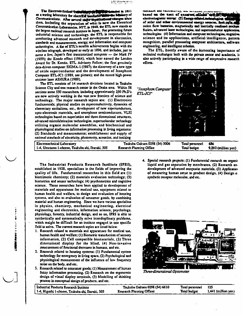
Tha W 'lk 1891as aaig laboraoryx for lem-. myof
CoMCt 0n1. Aa~ s'er vathen. ncluding the e on of wist is w thc EleicalCo"rrmiCatio abmor . NT i t94in , w& EL no stwAs asth largest national reech instiute in japen. lor promoting futureindustrial science and technology. the ETL is responsible forconducting advnc research and development in electronics.standards and measurements. energ.and information and computertechnologies. A Hs of ET s notable shieve nts begins with thewireless telegraph. developed as early as 1896, and includes just toname a few. Japan's fast transistorized computer - the Mark IV(1959): the Kondo effect (1964). which later earned the LondonAward for Dr. Kondo, ETL Advisory Fellow, the first genuinelydata-driven computer SIGMA-I (1987); the discovery of a new typeof oxide superconductor and the development of JosephsonComputer ETL-JCI (1989, see picture), and the record high-powerexcimer laser ASHURA (1989).
The ETL consists of 14 research divisions located in TsukubaScience City and one research center in the OsakA area. Within 58sections some 550 reseatrchs including approximately 250 PhD'sare now actively working in the vast new frontiers of science andtechnology. The major research topics are: (1) Electronicsfundamentals; physical studies on superconductivity, dynamics ofelementary excitations etc., development of new superconductors.opto-electronic materials, and amorphous semiconductors. VLSItechnologies based on superlattice and three dimensional structures.advanced microfabrication technologies, supermolecular technologyutilizing organic molecular assemblies, and biochemical andphysiological studies on information processing in living orgauism:(2) Standards and measurements; establishment and supply ofnational standards of electricity photometry acoustics, and ionizing
rlauaLn amo r4,,, ._ ., ,based thl %as of iuawuaa_eketramnqztic Ww (3) Emu' doof solar ad okw nvrumW easegy .wsredox flow benries. magneticafly md inmirlly cfus. advanced lar techologies. an mupvooauca Witechnologies: (4) Informaion and cnmpuc tchnologi c gni, sscience and its applications. artificial intelligence pattrecognition. parallel processing compuner architecttm softwaeengineering. and intelligent roboti
The ETL. keenly aware of the incresing importanec oftechnical exchanges both wth the private sctor a cademi isalso ctively participating in a wide range of cooperative searchefforts.
'Josephson CompuerETLJCr1
a.aI
Electrotechnical Laboratory Tsukuba Gakuen 0298 (54) 5006 Total personnel 6861-4, Umezono I-chome, TsukubashLi. Ibaraki 305 Research Planning Office Total budget 9,280 (million yen)
4. Special research projects; (1) Fundantal research on orgmiThe Industrial Products Research Institute (IPRI), liquid and gas separation by membranes. (2) Research an,
established in 1928. specializes in the fields of improving the development of advanced composite materials, (3) Applicatioquality of life. Fundamental researches in this field are (1) of measuring human sense to product design. (4) Design obiomimetic chemistry; (2) materials evaluation technology; (3) synthetic receptor molecules, and etc.biometrics nd sensor technology; (4) psychometrics aid cognitivescience. Those researches have been applied to development ofmaterials and apparatuses for medical use. equipment related tohuman health and welfare, to design and evaluation of housingsystems. and also to evaluation of consuner goods, by combiningmaterial and human engineering. Since we have various specialistsin physics, chemistry, mechanical engineering. electricalengineering and electronics, information science, psychology,physiology, forestry, industrial design, and so on. IPRI is able tosynthetically and systematically solve interdisplinary problems.which maight be difficult for an institute engaged in one specificfield to solve. The curent research topics re listed below.1 Research related to maerials and pparatuses for medical use, _
human health and welfare; (1) Biometric transduction of sensoryinformation. (2) Cell compatible biomaterials, (3) Threedimensional display for the blind, (4) Non-invasivemeasurement of functional decreases in humans, and etc.
2. Research related to housing systems; (1) Fundamental systemtechnology for emergency in living space. (2) Psychological and -_|physiological measurement of the influence of low frequency -.
noise on the body, and etc.3. Research related to constner goods; (1) Measurenent of human W OM
fuzzy information processing. (2) Research on the ergonomic Threemensional Optometerdesign of visual display terminals. (3) Modelling of thinkingprocess in conceptual design of products, and etc.
Industrial Products Research Institute Taukuba Gakuen 0298 (54) 6610 Total personnel 1251.4. Higashi -chome Tsukuba-shi. Ibaraki, 305 Research Planning Oficer Total budget 1,441 (million yen)
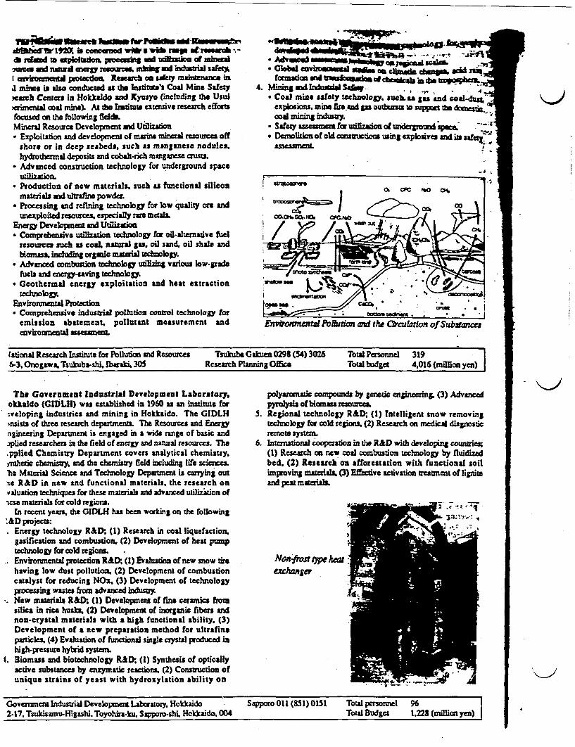
abm d1 is coad w at pal dit relad tr aploitsdon, udo~m Adtiou of mtxc3 a dnd eng ratx8 I-wS Wid kUtia SaMtI emkfonmnell paotacdomL Research an sAfety mainnce in,a mines is aso wntd as te hurstai's Coal Mine Safetyearch Centers n Hokkaldo and Kys (Including the Usuawrieal coad mine). At do trisutit extensive research efforsfocused on the folowing fdda.Mineral Resource Development and Ulization• Exploitation aid development of mmne mineral resourcs off
shore or in deep seabeds, such as manganese nodules.hydrothermal deposits and cobat-rich mangsses crusts.
* Advanced construction technology for underground spaceutilization.
* Production of new materials, such as functional siliconmaterials and ultrafins powder.
* Processing and refining tehnology for low quality ore andunexploited reource especially rar meals.
Energy Developnt aN Utilizatio* Comprehesive utilization technology for oil-alternative fuel
resources such as coaL natural gS, oil sand, oil shale andbions, including orgaic material technology.
* Advanced combustion technology utiling various low-gradeuela and energy-sving techology.
* Geothermal energy exploitation and heat extractiontechnology.
Environmental Protection* Comprehensive industria pollution oorol technology for
emission abatement. pollutant measurement andenviroanental asesame
* M 5 ~ o W ;u l. _
* GloWal aiviz~tal ~ T n w d rn,formation ad _ etranao of cd r in ro-
4. Mining and TuSdd Sa 4
* Coal mina safety technology, such. as gas an coad-s;explosions. mine fir and gas outhurso to sppon the 1nu&ti.coa mning n"' y.
* Safety assesmet for utilization of u'dergrouxI space,.* Demolition of old cstrctions using explosives ai ite e
asaa '
EnvfrofmzntaPo &dmod n the 0Oculadon of Subsw:=e
fational Research Institute for Pollution and Resources TsukubsGakumn 0298 (54) 3026 Total Personnel 3196-3. Onosawa. Tsukuba-shi. Ibaraki, 305 Research Planning Office Total budget 4,016 (millimn yen)
The Government IndustrIal Development Laboratory, polyarventic compounds by genetic engineering (3) Advancedokkaldo (GIDLH) was established in 1960 as an institute for pyrolysisofbimnass resources..veloping industries and mining in Hokkaido. The GIDLH S. Regional technology R&D; (1) Intelligent snow removing*nsists of three research departments. The Resources and Energy technology for cold regions (2) Research on medica diagnosticngineering Department is engaged in a wide range of basic and remote system.plied researchers in the field of energy and natural resources. The 6. International cooperation in the R&D with developing countries.ppliel Chemistry Department covers analytical chemistry, (1) Research an new coal combustion technology by fluidized'nshetic chemistry. and the chemistry field including life sciences. bed. (2) Research on *fforestation with functional soilhe Material Science and Technology Department is carrying out improving mterials, (3) Effective activation treatment of ligniteae R&D in new and functional materials, the research on and peatmatrialvaluation techniques for these materias and vanced utilization oftcse materials for cold regions.
In recent yeas. the GIDLH has been working on the folbwingt&Dprojects:
Energy technology R&D- (1) Research in coal liquefaction.gasification and combustion. (2) Development of heat pmptechnology for cold regions. Environmental protection R&D () Evaluation of new snow tire NOnfistX C typ Awhaving low dust pollution. (2) Development of combustion exmhmgercatalyst for reducing NOx. (3) Development of technologyprocessing wastes from advanced induny,New materials R&D; (1) Development of fe ceramics fm.silica in rice husks (2) Development of inorganic fibers andnon-crystal materials with a high functional ability, (3)Development of a new preparation method for ultrafineparticles. (4) Evaluation of functional single crystal produced inhigh-pressure hybrid system
t. Biomass and biotechnology R&D; (I) Synthesis of opticallyactive substances by enzymatic reactions. (2) Construction ofunique strains of yeast with hydroxylation ability on
Government ndustial Development LAboratory Hokkaido Sapporo 011 (851) 0151 Total personnel 962-17. Tsukisamu-Higashi. Toyohi-ku. Sappo.o-shi Hcklaido. 004 Total Budget 1,228 (million yen) A

TECENOLOGIES DISCUSSED WITE KOBE STEEL
- KSL Technology of Microwave Melter- Management of Alpha-Contaminated Wastes- Incineration and Ash Melting for Plutonium-Contaminated Combustible Wastes- Microwave Solidification Treatment of Incinerated Ash Contaminated by Radioactive
Materials- Crud Slurry Solidification System- Copper Alloy for High-Cycle Plastic Molding- Cryopump for Producing a Good Quality Vacuum- Twin-Head Arc Welding Robot- GT-5000
BIBLIOGRAPHY OF LITERATURE RECEIVED FROM KOBE STEEL
-KSL Technology of Microwave Melter', Kobe Steel, 49 pages.

- - -
o .1 W~1%
o
0~~~~~~~~~~~~~~~~~~~~~~~~~~~~~~~~~~~~~0
0 -
0 co a z -. 1-
xi X4 X - X
0 0 > -4 X
w jl
)~~~~~~~~~~~~~~a
0 UJ
a
l
Reprint from
"MANAGEMENT OFALPHA.CONTAIMNATED WASTES"
.
INTERNATIONAL ATOMIC ENERGY AGENCYVIENNA, 1981
K>
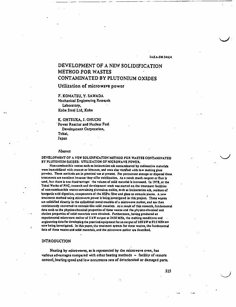
JAEA S.M-246/4
DEVELOPMENT OF A NEW SOLIDIFICATIONMETHOD FOR WASTESCONTAMINATED BY PLUTONIUM OXIDESUtilization of microwave power
F. KOMATSU, Y. SAWADAMechanical Engineering Research
Laboratory,Kobe Steel Ltd. Kobe
K. OHTSUKA, J. OHUCHIPower Reactor and Nuclear Fuel
Development Corporation,Tokai,Japan
Abstnact
DEVELOPMENT OF A NEW SOLIDIFICATION METHOD FOR WASTES CONTAMINATEDBY PLUTONIUM OXIDES: UTILIZATION OF MICROWAVE POWER.
Non-combustible wastes such as incineration ash contaminated by radioactive materialswere imobilized with cement or biumen, and were also vitrified with low melting glasspowder. These methods are in practical use at present. For permanent storage or disposal thesetreatments are excellent because they offer stabilization. As a result much reagent or flux isused, but there is one disadvantage: the volume of solid material is increased. In 1978, at theTokai Works of NC, research and development work was started on the treatment facilitiesof non-combustible wastes containing plutonium oxides, such as incineration ash, residues ofinorganic acid digestion, components of the HEPA ilter and glass or ceramic pieces. A newtreatment method using microwave power is beint investigated in this project These wastesare solidified directly in the cylindrical metal crucible of a microwave melter, and are thencontinuously convened to ceramic-like solid materals. As a result of this research, fundamentaldata such as the physico chemical properties of tese wastes and the physico-chemical andelution properties of solid materials were obtained. Furthermore, having produced anexperimental microwave melter of S kW output as 24S0 MHt, the melting conditions andengineering data for developing th. practical equipment for an output of 100 kW at 91 S MHz arenow being investigated. In this paper, the treatment system for these wastes, the fundamentaldtsa of these wastes and solid materials, and the microwave melter are described.
INTRODUCTION
Heating by microwaves, as is represented by the microwave oven, hasvarious advantages compared with other heating methods - facility of remotecontrol, heating speed and low occurrence rate of deteriorated or damaged parts.
325

326 KOMATSU et a.
_ _
,
r -Ii .i.
I -i I .
I~~~~~~~~~~~~~~~~~1
I !Li .2*. d 2
-9, Iz I it :
'I .- -'ft c
I
i
i 1 .1-: I

IAEA-SM.246/4 3'17
The principle of microwave heating is the dielectric heating methodintended to oscillate directly by electric waves the molecules which composethe substance. Hence, it could be one of the most excellent methods formelting non-combustible wastes composed of inorganic oxide substances suchas Al2 03 S103 and CaO.
The Power Reactor and Nuclear Fuel Development Corporation (PNC) iscurrently investigating the solidification treatment method by microwaves fornon-combustible wastes, other than metals, of the plutonium fuel facilitiesat Tokai Works. This PNC plan has set a timetable, with completion in 1985,of treatment facilities including the secondary treatment process for reduction.
1. PROPERTIES AND OUTPUT OF WASTES
At present plutonium-contaminated HEPA filters, neoprene gloves andcombustible wastes are stored temporarily in the storage yard. When the treatingfacilities are completed they will be removed from the storage yard and treated.
The kinds of waste to be treated, the secondary treatment method forreduction and the output of secondary wastes, are shown in Fig. 1. The majorwaste outputs are HEPA filter elements, residues of acid digestion and incineratedash, which occur at the rate of 1:0.28:0.19.
The physico-chemical properties of the wastes for solidification treatmentare presented in Table 1.
Samples possessing the same analytical values as given in this Table were alsoused in the microwave solidification experiment. Since the actual wastescontaining plutoniuni'cannot be used for the experiment, HfO2 , whose physicalproperties with respect to density, vapour pressure and free energy of oxidesare similar to those of PuO,, was added by 0.1 wte in the solidification experiment,as the dummy substance for PuO.
1.1. Incinerated ash
In the plan, combustible matter such as tissue paper, cardboard boxes,swabs, latex gloves and plywood frames of the HEPA filter, after dismantling,are burnt in the incinerator installed at the facility. The ash output is assumedto be about 7 kgld.
The chemical composition of incinerated ash varies with the kind andquantity of the materials incinerated. The ash of the chemical compositionpresented in Table I is the result of incineration in an ordinary incinerator oftissue paper, 85%; cardboard boxes, 5%; latex gloves + gummed tape, 1.5%;and LPDE sheets, 1.5%.
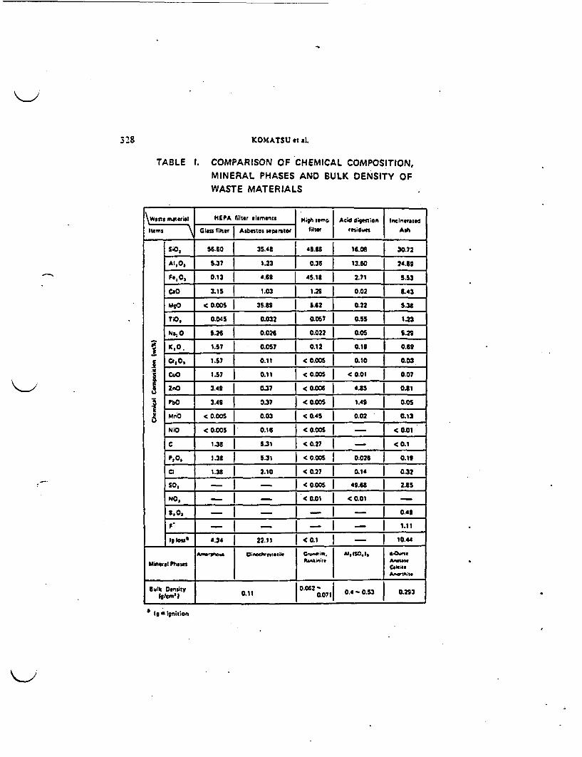
328 KOMATSU et aL
TABLE 1. COMPARISON OF CHEMICAL COMPOSITION,MINERAL PHASES AND BULK DENSITY OFWASTE MATERIALS
no Inst rial HE_ A fter lements |1ighi i |m Acid dpewion Ininrated
Itms m la # i Mler Asbmtos ,apznor | filtr residua Ash
siO, 56-.0 | 35.48 4.38 16.06 3 30.72
AI,0, 5.37 1.23 0.36 j 13.o0 24.53
Fe,0, 0.13 4.69 45.11 2.71 5.S3
CO 115 3 1.03 1.2S 0.02 L43
M9p MS.005 1 3S.82 _ 5._ 2 0.22 5.36TO, 0.045 0.032 0.057 | 0.55 | 1.23
NatO 5.26 0.026 0.022 0.05 1 5.2
iCO. 1.57 1 0.0S7 1 0.12 0.13 0.69
_ r Cta, 1.57 0.11 1 0.005 | 10 0.03
CUO 1.57 0.11 0.005 (0.01 0.07
ZrO 3.42 | 037 |(.0.6 | * S 0o.1
PbO 3.49 1 0.37 < (0.005 1.42 J 0.05
MmO <0.005 0.03 _ OAS_ 0.02 _ _0.13
NiO < 0.005 | 0.16 |< 0.005 | _ |< 0.01
_ 1.38 5.31 < 0.27 - < <0.1
° l _.3 _ _ 5.31 <0005_ _ 0.026 0.13
al 1.38 | 2.10 |C(0.27 0.14 | 0.32
SO, - IC 0.006 -S.6 2.85
NO, | - < 0.01 | 0.01
3,0 _ - 1 r - 0.43
F |_ - _....r.. | _ |. 1.11Iglos" 4.34 22.11 (0.1 - I 10.4
_~~~~~ _AR- so-we vi "dwvnol~ib cwi"'t. A,10. 1, .
Mineral Phasts C&ICI
IMIt I 0.11 0Q062 - 0.53 0.23
I s ilnitioft
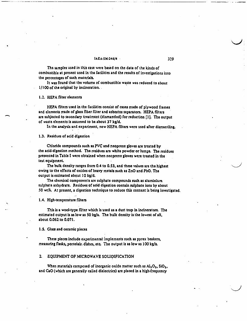
IAEA-SM-246/4 329
The samples used in this case were based on the data of the kinds ofcombustible at present used in the facilities and the results of investigations intothe percentages of such materials.
It was found that the volume of combustible waste was reduced to about1/100 of the original by incineration.
1.2. HEPA ilter elements
HEPA filters used in the facilities consist of cases made of plywood framesand elements made of glass fiber filter and asbestos separators. HEPA filtersare subjected t secondary treatment (dismantled) for reduction [I 1. The outputof waste elements is assumed to be about 37 kgld.
In the analysis and experiment, new HEPA filters were used after dismantling.
1.3. Residues of acid digestion
Chloride compounds such as PVC and neoprene gloves are treated bythe acid-digestion method. The residues are white powder or lumps. The residuespresented in Table were obtained when neoprene gloves were treated in thetest equipment
The bulk density ranges from 0.4 to 0.S3, and these values are the highestowing to the effects of oxides of heavy metals such as ZnO and PbO. Theoutput is estimated about 10 kld.
The chemical components are sulphate compounds such as aluminiumsulphate anhydrate. Residues of acid digestion contain sulphate ions by about50 wt% A present, a digestion technique to reduce this content is being investigated.
1.4. High-temperature filters
This is a wool-type filter which is used as a dust trap in incinerators. Theestimated output is as low as 50 kg/a. The bulk density is the lowest of all,about 0.062 to 0.071.
1.S. Glass and ceramic pieces
These pieces include experimental implements such as pyrex beakers,measuring flasks, porcelain dishes, etc. The output is as low as 100 kg/a.
2. EQUIPMENT OF MICROWAVE SOLIDIFICATION
When materials composed of inorganic oxide matter such as Al203, SiO2,and CaO (which are generally called dielectrics) are placed in a high-frequency
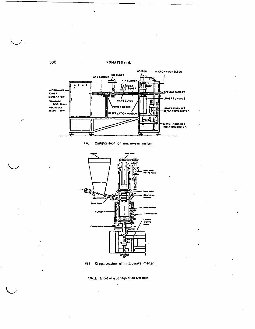
330 KOMATSU et i.
I .
(A) Composition of microwave melter
. AtW
.Wdw
habMM"~a
(B) Cross.ection of microwave melter
FIG.2 Microw e solidiflcaflo'i tet unit.

IAEA-SH214i24 331
FIG.3. Photorrph of the microwvve solldificatlon rets unit.
electric field (microwave), the molecules. which are in an electrically neutralstate, are turned into molecules with electric dipoles by the strong electric field.
Molecules violently change polarity owing to the frequencies and theygenerate frictional heat. As a result, the substance reaches the molten state.
By using microwave energy the solidifiable temperature is determined bythe material of the crucible and its melting point. When a metal cruciblemanufactured from low carbon steel is used, the maximum applicable temperatureis I SOOC The microwave melter shown in Figs 2 and 3 was newly developedfor the purpose of treating waste containing radioactive substances.
Microwaves from a microwave power generator are radiated into themicrowave melter through a wave guide. The melter is the so-called cavitytype, which can concentrate the microwave energy on to the sample byvertically adjusting the head tuner.
The sample is continuously fed into the metal crucible - which is alsoused as a canister - from the hopper by means of a screw feeder and iscontinuously solidified. During solidification the metal crucible is rotated ata speed of 2 to 5 rpm to radiate the microwaves uniformly.
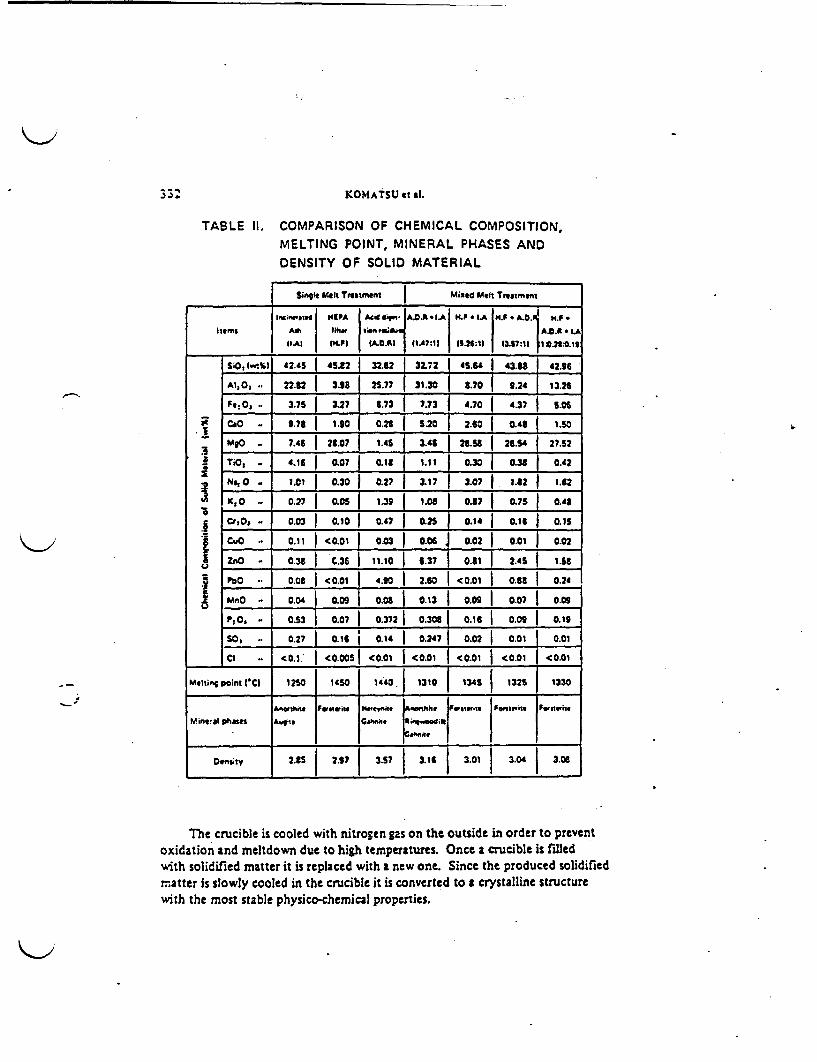
KOMATSU * a.
TABLE 11. COMPARISON OF CHEMICAL COMPOSITION,MELTING POINT, MINERAL PHASES ANDDENSITY OF SOLID MATERIAL
Single Mltk Treatment Mixed Met Treatment
IftiMraled IPA A cid# . ADA. I 1t4f * tA H.P * A t HF. -
Items At. ~lher iioi J-, A.OA * LA
_Al MtPI MCA (1.47:11 11.24:11 3.117:111 t:.28:0.t8
SiO, l___) 42545 4S.82 32.32 32.72 15.64 43.U 42.96
Al, .. 22.32 3.98 25.77 31.30 3.70 f 9.24 I 13.26
Fe .. | 3.75 3.27 | 6.73 7.73 4.70 4.37 | 5.0
at o 9.78 1.90 0.2t ! 20 2.60 0.48 1.50
MO - 7.46 28.07 1.45 3.41 2E-StU 2E354 L 27.52
I TiO, - 416 07 0.1 1.11 0.30 0.38 0.42
N t.Ct Q30 0.27 3_17 3.07 1.82 1.62
KO .. 0.27 0Q05 | 1-39 | 1.08 | .87 0.75 0.43
Cr'O,. 0.03 0.10 0.47 j 0.25 | 0.14 t0e 0.15
- CuO .. 0.11 <.01 0.03 I 0.06 4 0.02 0.01 j 0.02
ZnO 038 C.36 11.10 1 3.7 0.31 2.4 I IiS
Po - 0.03 < O.O1 4.90 2.60 <0.01 0.38 0.24- o o J 0.ooI o.os 1 0.13 1 o.og I 0.07 1 009
Po, - 0.53 I 0.07 0.372 | 0.308 0.16 | 0.09 0.19
SO, - 0.271 0.16 j 0.14 0.2471 0.021 0.01 0-01
CI .. I0. I.' <0005 <0.01 <001 <0.01 <001 <001
Melting Point Cl 150 1450 1440 1310 1345 1325 1330
A-arlhio f re "i e Ao he fS wsli* f etwito Fewntoio
M.inqal pha .Ghm. .que j;
Density 2.35 2-S7 1 3 57 31 | 3.01 | 3.04 | 3-0t
4.
The crucible is cooled with nitrogen gas on the outside in order to preventoxidation and meltdown due to high temperatures. Once a crucible is filledwith solidified matter it is replaced with a new one. Since the produced solidifiednatter is slowly cooled in the crucible it is converted to a crystalline structurewith the most stable physico-chemical properties.
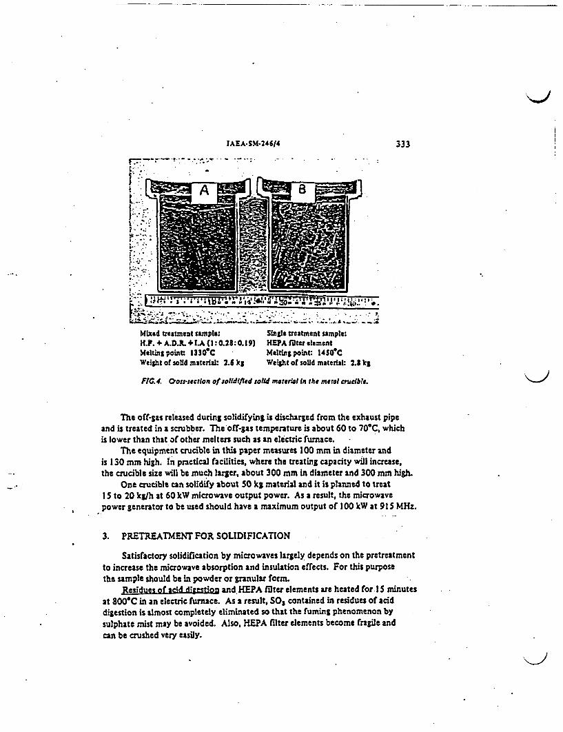
IAEA.SM-246/4 ;333
r -rea me - S .- sample:
.e:~~ ~ ~ ~ ~~~~~~~~~~~~~ .t - ,. S
t:-.~~~~~. -. .<
Mixed tscatmeat sample: Singls treatment sample:H.F. + A.D.R. + 1A (1: 0.28:0.19) HEPA filter elementMelting point 1330 C Melting point: 14S0CWeight of solid material: 2.6 kg Weight of solid material: 2.8 kg
FIC.4. 'ou-section of olidiJted solid materiatl in the metl crncible.
The off-gas released during solidifying is discharged from the exhaust pipeand is treated in a scrubber. The off-gas temperature is about 60 to 70'C whichis lower than that of other melters such as an electric furnace.
The equipment crucible in this paper measures 100 mm in diameter andis 130 mm high. In practical facilities, where the treating capacity will increase,the crucible size will be much larger, about 300 mm in diameter and 300 mm high.
One crucible can solidify about 50 kg material and it is planned to treat15 to 20 kg/h at 60 kW microwave output power. As a result, the microwavepower generator to be used should have a maximum output of 100 kW at 915 MHz.
3. PRETREATMENT FOR SOLIDIFICATION
Satisfactory solidification by microwaves largely depends on the pretreatmentto increase the microwave absorption and insulation effects. For this purposethe sample should be in powder or granular form.
Residues of acid digestion and HEPA filter elements are heated for 15 minutesat 800C in an electric furnace. As a result, S0 contained in residues of aciddigestion is almost completely eliminated so that the fuming phenomenon bysulphate mist may be avoided. Also, HEPA filter elements become fragile andcan be crushed very easily.
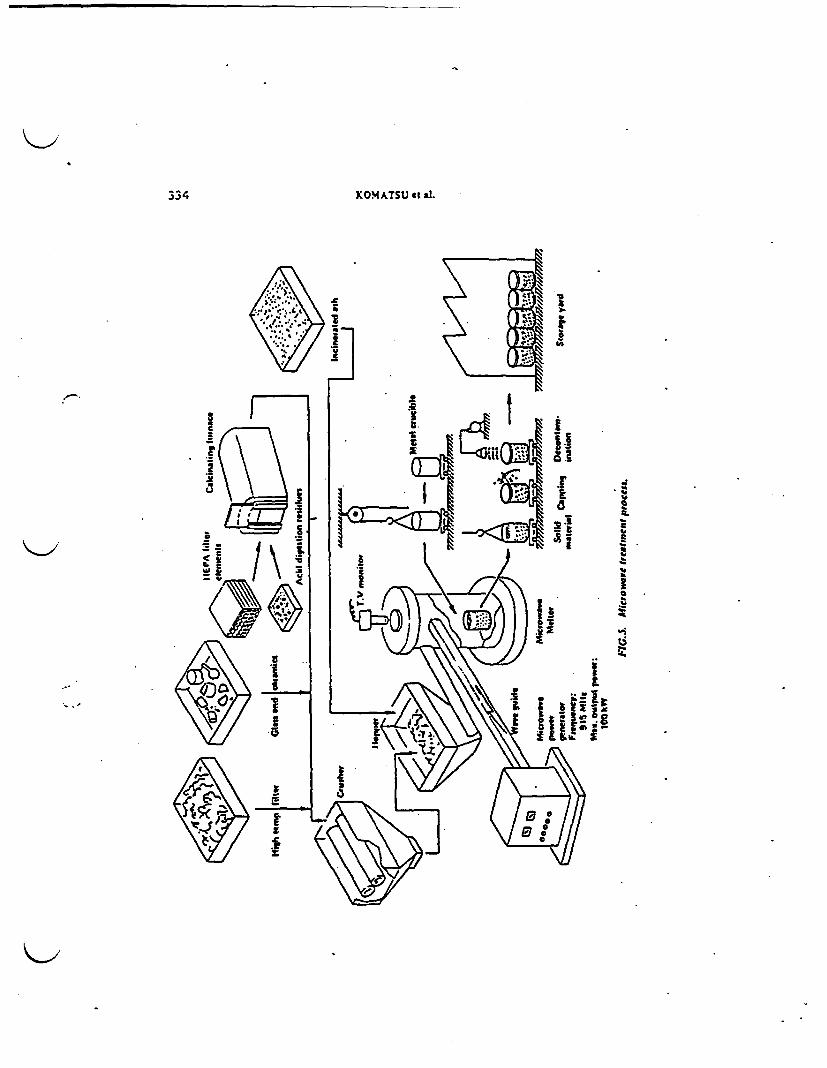
334 KOMATSU et al.
iid C
ix..
I 1"It
I I
iI~~i~~~
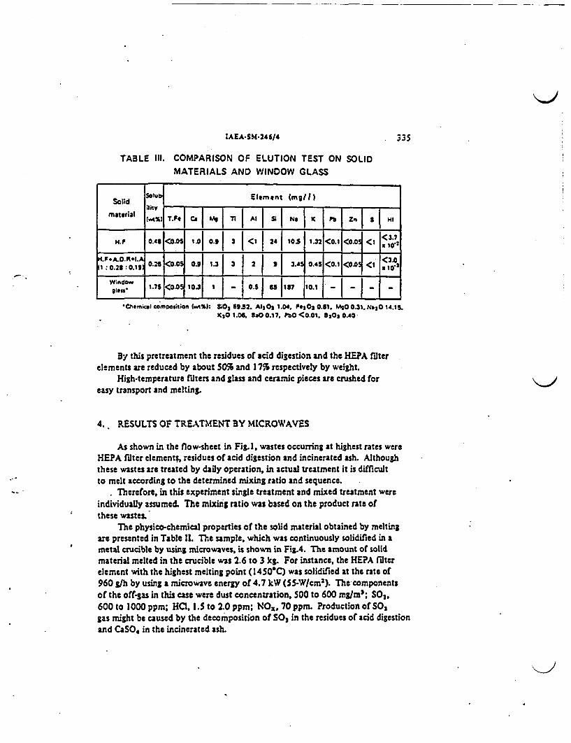
IAEA.SM-24614 . 335
TABLE III. COMPARISON OF ELUTION TEST ON SOLIDMATERIALS AND WINDOW GLASS
Solid qSolu Element mg/ I)
material (VA%) T.F C t n 1 l| Si N, K P | Zn S I Hf
.~~~~~~~~~~~~~~<.H.F 0.43 <0.05 . 0.9 3I<1 24 105 1.32 <0.1 0.0 < <370,
H.F#A.D.R~l.A <3.0
WindowIgIts"' 1.75 <00 1 0.5 137 10.1 _
*Chermikal comiestion lWVl: S02 69.52. A130 3 1.04. FeOs 0.61. MgO .31 N3014.15.KCO 1.06. SaOO.17. PbO <0.01. 903 A.4O
By this pretreatment the residues of acid digestion and the HEPA filterelements are reduced by about 50% and 17% respectively by weight.
High-temperature filters and glass and crarmic pieces are crushed foreasy transport and melting.
4. RESULTS OF TREATMENT BY MICROWAVES
As shown in the flow-sheet in Fig. 1 wastes occurring at highest rates wereHEPA filter elements, residues of acid digestion and incinerated ash. Althoughthese wastes are treated by daily operation, in actual treatment it is difficultto melt according to the determined mixing ratio and sequence.
Therefore, in this experiment single treatment and mixed treatment wereindividually assumed. The mixing ratio was based on the product rate ofthese wastes.
The physico-chemical properties of the solid material obtained by meltingare presented in Table 11. The sample, which was continuously solidified in ametal crucible by using microwaves, is shown in Fi8A. The amount of solidmaterial melted in the crucible was 2.6 to 3 kg. For instance, the HEPA filterelement with the highest melting point (1450C) was solidified at the rate of960 glh by using a microwave energy of 4.7 kW (S5W/cm3). Te componentsof the off-gas in this case were dust concentration. 500 to 600 mg/m3; SO2,600 to 1000 ppm; HQ, 1.5 to 2. 0 ppm; NOz, 70 ppm. Production of SO,gas might be caused by the decomposition of SO in the residues of acid digestionand CaSO4 in the incinerated ash.
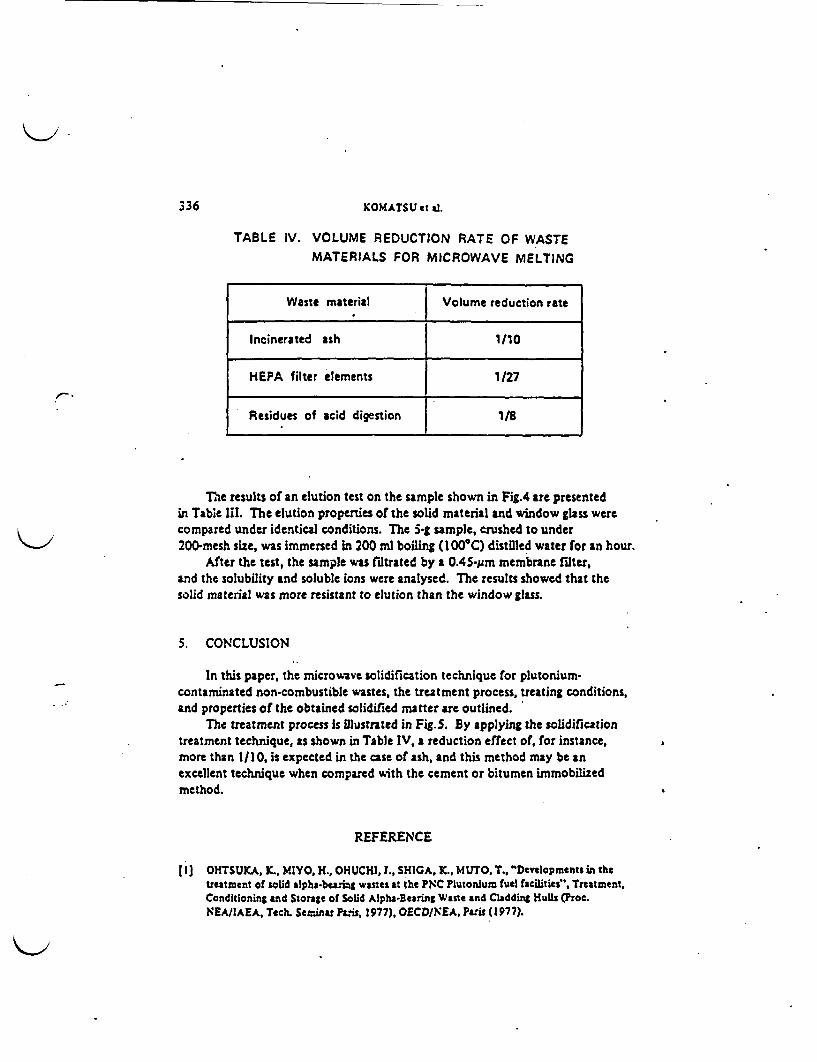
336 KOMATSU et dL
TABLE IV. VOLUME REDUCTION RATE OF WASTE
MATERIALS FOR MICROWAVE MELTING
Waste material I Volume reduction rate
Incinerated ash 1/10
HEPA filter elements 1/27
Residues of acid digestion 18
The results of an elution test on the sample shown in Fig4 are presentedin Table liI. The elution properties of the solid material and window glass werecompared under identical conditions. The 5*S sample, crushed to under200 mesh size, was immersed in 200 ml boiling (I OOC) distilled water for an hour.
After the test, the sample was filtrated by a 0.45-ym membrane filter.and the solubility and soluble ions were analysed. The results showed that thesolid material was more resistant to elution than the window glass.
5. CONCLUSION
In this paper, the microwave solidification technique for plutonium-contaminated non-combustible wastes, the treatment process, treating conditions,and properties of the obtained solidified matter are outlined.
The treatment process is iMlustrated in Fig.S. By applying the solidificationtreatment technique, as shown in Table IV, a reduction effect of, for instance,more than 1/10, is expected in the case of ash, and this method may be anexcellent technique when compared with the cement or bitumen immobilizedmethod.
REFERENCE
I] OHTSUKA, K., MIYO. H., OHUCHI, I., SHIGA, K., MUTO. T., "Developments in thetreatment of solid alphs-bearing wastes at the PN'C Plutonium fuel facilities". Treatment,Conditioning and Storage of Solid Alpha-Bearing Waste and Cladding Hulls (Proc.NEA/lAEA, Tech. Seminar Pais, 1977), OECD/NEA, Paris (1977).

IAEA.SM.24614 3;
DISCUSSION
C. SOMBRET: The experimental furnace which you described has a lowoutput (S kW). The corresponding throughput which you quoted is less than1 kg per hour, which is understandable. Work on the processing of other typesof waste in microwave furnaces has been carried out in France and also, I believe,in Harwell. Mr. Grover could, Im sure, provide a few details on this point. InFrance, the studies were discontinued owing to the difficulty of finding a high-output industrial generator, which is essential in order to process any form ofwaste from an industrial installation. Do you know of any manufacturer inJapan or elsewhere in the world who could supply a suitable generator, let us say,with an output 100 kW?
F. KOMATSU: Themagnetron tube of 100kW output (915 MHz) iscommercially available in Japan.
J.R. GROVER: Microwave heating is being studied in the United Kingdomfor both the evaporation stage and melting stage of a possible vitrification processfor high-level wastes to produce a borosilicate glass product.
C. BAUER: Mr. Komatsu, did you investigate the structure and compositionof the phase or phases present in the crucible after the melting? And did youconsider the possibilitity of accumulation of Pu in one of the phases?
F. KOMATSU: For the experiment we used HfO2 whose physical propertiesare similar to those of PuO2; it was added up to 0.1 wt%. We investigated thestructure and composition of the solidified matter using the electron ptobemicroanalyser. The Hf element was found to be distributed uniformly over thematrix. We have performed no experiments with plutonium so far.
'~
Printed by the IAEA in Austria

INCIN\RATION AND ASH IMLTING FOR PLUTONUqtCON-rAHNAT:DCOMUSTIBLE WASTES
K.MIYATA*, JOHUCHI, E.INADA and N.TSUNODAPower Reactor and Nuclear Fuel Development Corporation (PNC)
Tokai-mura, Ibaraki, Japan 319-11
1. IntroductionPlutonium-conta...inated solid wastes have been enerated
during OX fuel fabrication in PNC. These wastes are classified intocombustibles, non-combustibles and chlorine-containing organicmaterials such as PVC and chloroprene, and packed in 200Q drums or1.7mzcubic containers at the OX fuel facilities.
These wastes have been treated for the olume. reduction andconditioned in the Plutonium-contaminated Waste Treatment Facility(PWTF) since late 1987. The combustible wastes have been treated inthe conventional incinerator. The incinerated ashes are meltedwithout any additives to be a 20-.30kg ceramics-like block in the
* stainless steel made canister by powering microwave. The productsare packed in the 200drums and stored temporarily in thePlutonium-contaminated Waste Storage Facility (PWSF).
2. Process Description2.1 Waste Feed
The combustible wastes are introduced into the glove box fromdrums after being assayed Pu-contents. The wastes of paper and ragsare sealed in a paper bag by 2kg automatically and wood-framed EPAfilters are cut into several pieces using circular saw. These wastesare sent to the incinerator by the belt conveying system.
*2.2 IncinerationThe conventional incineration unit consists of feeder,
incinerator, ash transfer unit and off-gas treatment unit and hasthe throughput of 50kg/h in one-shift operation. The incinerator iscomposed of primary and secondary combustion chamber, and coveredwith stainless steel casing to keep lpha-tightnesi and prevent theleakage of radionuclides. The pressure and temperature in theincinerator are regulated automatically by controlling the flowrates of exhaust gas and kerosene.
Paper bagged combustible wastes and cut pieces of EPA filtersare fed to the primary combustion chamber from the top of theincinerator through the airlock room with adiabatic shutter. Thesewastes are incinerated on the inconel made fire grades by twokerosene burners. The combustion off-gas with coarse dusts fromprimary combustion chamber is transferred to the secondary chamberand high-temperature filter (TF) for post combustion and filtration.Secondary chamber is filled with silicon carbide lumps. HTF ismainly composed of many vertical cylindrical tubes that are coatedwith asbestos fiber.
Figure 1 and 2 show the artistic view of the conventionalincineration unit and the cross section of the incinerator.
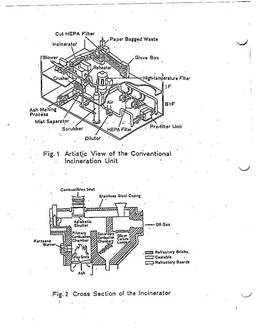
Cut HEPA Filter
FIlter
Ash MellProcess
Fig. 1 Artistic View of the Conventional* Incineration Unit
Combustibles Inlet
Stainless Steel Casing
ba , Shut gk - - Off GasShutttr f - fGa
.* Refractory Bricks.*Castable
= Refractory Boards
Fig. 2 Cross Section of the -Incinerator

2.3 Off-gas TreatmentThe off-gas treatment unit consists of dilutor, pre-filter,
IESPA filter, scrubber, mist separator and blowers. The off-gas fromhigh-temperature filter is mixed with air and cooled below 80C bythe dilutor. Radionuclides are removed from the off-gas by the n_?Afilters, and environmental pollutants such as SOx and NOx gas areremoved by the scrubber prior to discharge to the atomosphere.
2.4 Ash HandlingThe ash handling unit consists of hopper, cusher, vibrating
sieve, and belt conveyers. The ash is crushed and separated fromnails after being removed from the bottom of the primary chamber.The ash is sent to the microwave melting process by flight conveyer.
2.5 Microwave MeltingThe microwave melting unit consists of a microwave generator,
wave guide and melter. The melter is equipped with tuner, powermonitor, isolator, discharge detector and ITV monitor, installed ina glove box. Microwave from microwave generator is radiated to theash in the cavity-type melter through.a wave guide. Microwave energyis focused on the ash in the canister by adjusting the tunervertically. The microwave generator has the output of lOkW with2450>fllz requency. The melter has the throughput of 5kg/h.
The ash is melted in the cnister (130mm'X 770mmX) at1200 - 14000C, and converted into ceramics-like blocks, which arebagged out' for packing in 2001 drum. The drum %iith eight ceramics-like blocks is stored in PWSF. The major mineral phases of theproducts are forsterite, anorthite and augite.'The off-gas releasedduring melting is sent to the off-gks treatment unit of theconventional incinerator.
Figure 3 and Table . show the microwave melting process flowand the operating data of incineration and melting, respectively.
Glove Box---- r-------------------------_-__-_____incnerated As Tunr
Hoppe Cooling Wave Gudt I Caram cs.like Lfro".,,- t @@IIBlo ._ck ~ele.Pocs
I i~S Coolng crowave Generatori | [ }3 Cow , Water
L . > ) ~~~Cooln-0 ~e kislk Water CuamtcsIkeI
Adabaor anster
2001iug. I '-WNitroenGas
Fig. 3 Microwave Melting Process Flow
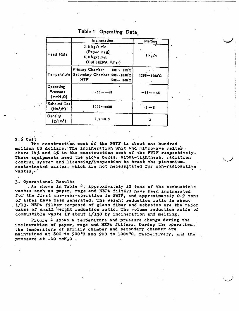
Table 1 Operating Data.
I_________ Incineration Melting2.0 kg/3 min.
(Paper Bag).Feed Rate 5.0 kg/S mi. .4 kg/h
(Cut HEPA Filter)
Primary Chamber 1o- 00*CTemperature Secondary Chamber 300-1 0a C 1200-1400'C
HTF 500- 600 C
OperatngPressure -30--40 _45__55
(mmH 2O) ______________ _ 1Exhaust Gas
(Nm3/h) 000-3000
Density(Z/cm1)- .- 3
2.6 CoitThe construction cost f the PVTF is about one hundred
million US dollars.The incineration unit and microwave melter.share 14% and 4% in the construction cost o the PWTF respectively.These equipments need the glove boxes, alpha-tightness, radiationcontrol system and licensing/inspection to treat the plutonium-contaminated wastes, which are not necessitated fr non-radioactivewastes3 -
3. Operational ResultsAs shown in Table 2, approximately 12 tons of the combustible
wastes such as paper,..rags and REPA filters have been incineratedfor the first one-year-operation in PTS, and approximately 0.9 tonsof ashes have been generated. The weight reduction ratio is about1/13. HEPA filter composed of glass fiber and asbestos are the majorcause of small weight reduction ratio. The volume reduction ratio ofcombustible waste iabout 1/130 by incineration and melting.
Figure 4 shows a temperature and pressure change during theincineration of paper, rags and HPA filters. During the operation,the temperature of primary chamber and secondary chamber aremaintained at 800 to 900'C and 900 to 1000 'C, respectively, and thepressure at -40 mrpO

.Table 2 Weight and Volume Reduction Ratioof the Incineration and Melting
Treatment Method
Items \ ~~~~Incineration Melting
Treated Waste Weight 12 ton | 70k
Product 900 kg 34 blocks(Ash) (800 )
Weight Reduction Ratio . l/13 [ 1
Volume Reduction Ratio 1/13D
Incineration
-
. .
0Ea,
-20 I
I
E-4 0 E
-60 Dkm0
-an XL- v
Time (h)
Fig. 4 Temperature and Pressure Change ofthe Incinerator

4. Conclusions* (1) Incineration and microwave melting for plutonium-* contaminated combustible waste has been demonstrated
successfully for the volume reduction and immobilization.(2) The alpha-tightness of the conventional incinerator have
been maintained during the incineration up to date.(3) The volume reduction ratio o 1/130 for the combustible
wastes have been attained by the combinated process ofconventional incineration and microwave melting.
(4) The incinerated ash have been conditioned stably without anyadditives by powering microwave.
(5) Treatment for plutonium-contaminated waste from MOXfacilities will be continued to reduce the stored wastevolume and the characterization o the conditioned waste willbe also progressed.
Reference
(x)F.KOXATSU, Y.SAW'ADA, .OHTSUXA, J.OHUCHI, "Development of a new--. solidification method for wastes contaminated by plutonium oxides",
Radioactive waste management (IAEA in Seattle, 16-20 Mray .1985)
(2)Y.OGATA, J.OHUCHI, E.INADA and N.TSUNODA, "Processing ofPlutonium-contaminated waste at PWT?" (IAEA in Stockholm, May 1988).
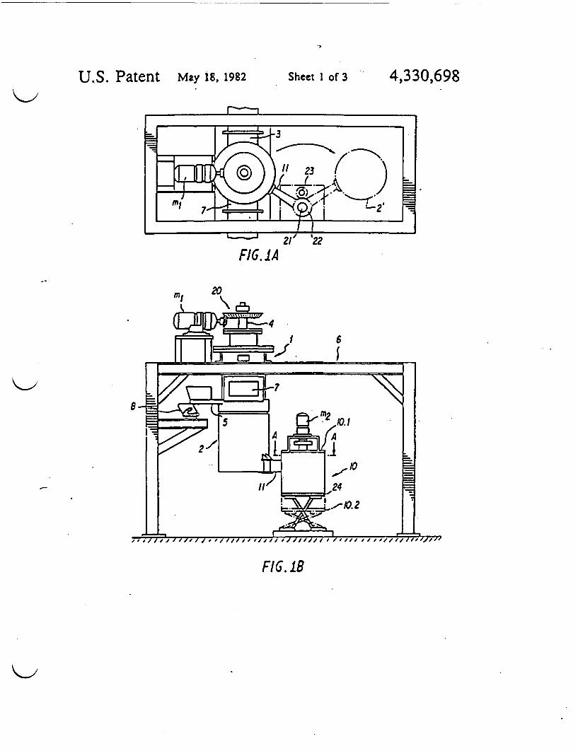
U.S. Patent May 19, 1982 Sheet I of 3 4,330,698
FIG. IA
FIG.IB

U.S. Patent May 18, 1982 Sheet 2 of 3 4,330,698
F16.3
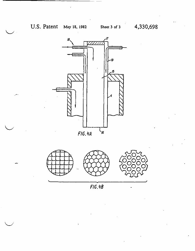
U.S. Patent May 18, 1982 Sheet 3 of 3 4,3302698
.17
FiG. 4A
0
FI. 8

@ BUNDESREPUBLIK
DEUTSCH-LAND
.DEUTSCHES
PATENTAMT
@ PatentschriftODE 3015300 C2
4) Int. CI. 3:
H 05 B 6/80
(j) Aktenzeichen:@> Anmeldetlg:@ Oenlegungstag:
@ Ver tfentlichungstag:
P30 1S 300.534
21. 4. 8030. 10. 805. 1. 83
0C-
0c-
Innerhalb von 3 Monaten nach Ver6ffentlichung der Eneilung kann Einspruch erhoben werden
(0 Unionsprioritit: Q (2 (2
21.04.79 JP P54-49599
1 Patentinhaber:Kobe Steel, Ltd., Kobe. Hyogo. JP
® Vertreter:Tiedtke. H.. Dipl.-Ing.; 80hlinq. G.. Dipl.-Chem. Knnc, R..Dipl.-Ing.; Grupe. P.. Dipl.Ing. PeIlmann. H., Dipl-Ing..Pat.-Anw., 8000 M~nchen
Mikrowellenofen
0
tC .
( Erfinder:
Sawada. Yoshihisa: Komatsu. Fumiaki. Nishinomiya, JP;Sanada. Kazuo. Kobe. JP; Sakaki,. Yorihisa. Akashi, JP
@ Entgegenhaltungen:
US 40 39 97US 25 85 754

JO 15 300
Paenanspruche:
I. Mikrowellenoren zum ErwSrmen eines Gutes.der aus einem das Gut aufnehmenden undabnehmbaren Unterteil und einem Oberteil besieht.das ber einen Mikrowellenleiter mit cinemMikrowellenoszillator verbunden ist. dad u r c hg e k e n n z e i c h n e . daO zum Verflassigen inesschmelbaren Gutes (Af) im Unterteil (2) cinSchmelztiegel (8) vorgesehen ist. dcr aber eine imOberteil (1) vorgesehene Fulloffnung (5) beschickbarist. wobei die Leistung des Mikrowellenofens (I. 2)uber eine aut dem Oberteil (1) angeordneteAbstimmvorrichtung (4) steuerbar ist. die von einemhohlen. zylindrischen Metallkorper gebildet ist. derverschiebbar im Oberteil (1) gerhrt ist. und daB dieMikrowellenzuleitung (3) gegen im Ofenraumentstehende Gase abgedichtet iSt.
2. Mikrowellenofen nach Anspruch 1. dadurchgekennzeichnet daB der Schmelzviegel (8) in einemBehalter (12) aurgenommen ist. der drehbarinnerhalb des Unterteils (2) montier ist.
3. Mikrowellenofen nach Anspruch I oder dadurch gekennzeichnet. daO cas Unterteil (2) miteinem InergasanschluO (1l4) versehen ist. durch denin einen Spalt (C) zwischen der Innenwand desUnterteils (2) und der AuBenwand des Behilters (12)ein Inertgas einleitbar ist. welches einen Druckbcsitzt. der Ober dem nnendruck des Mikrowelleno-fens iegt.
4. Mikrowellenofen nach Anspruch 2 oder 3.dadurch gekennzeichnet. daB der Behilter (12) eineAntriebswelle (13) trigt. die aus dem Unterteil (2)herausfohrt und ber eine Antriebsvorrichtungangetrieben ist.
5. Mikrowellenofen nach Anspruch I bis 4.dadurch gekennzeichnet. daD die Mikrowellenzulei.tung (3) ein Hohlileiter ist. in dem zueinander imAbstand siehend mehrere luftdichte Zwischenwinde(SI: S2) eingesetzt sind und somi zischen sich undder Innenwand des HohIleiters (3) einen Innenraumbegrenzen. dessen Druck hoher gehahen ist als derInnendruck des Mikrowellenofens.
6. Mikrowellenofen nach Anspruch I bis 5.dadurch gekennzeichnct daB der Hohizylinder eindoppelwandiger Zylinder ist, dessen Zeniralhohl-raum (15) auf der dem Schmelztiegel (8) zugewand-ten Seite durch ein Netz (16) aus leitflhigemMaterial und auf der anderen Seite durch cinSichttenster (17) abgeschlossen und mit einemlnertgas-AnschluB (18) versehen ist und dessenWandungs-Hohlraum (19) einen AnschluS fur eineMantelkuhlung besitzL
Die Erfindung bezieht sich auf einen MikrowellenofengemaO dem Oberbegriff des Patentanspruchs 1.
Das Verfahren zum Erwarmen und Schmelzenverschiedener Materialien durch Einwirkung vonMikrowellenstrahlen hat im Vergleich zu anderenAnwirm-und SchmeIzverfahren eine Reihe von Vortei-len. zu denen die VergleichmiBigung des Ecwarm- undSchmelzprozesses und die Maglichkeit der genauerenSteuerung der Geschwindigkeit des Schmelzvorgangsdurch Einstellen der aufgebrachten Mikrowellenei-stung gehoren.
2Das Prinzip der klikrowetlen-Erwirmung kann auf
zahlireichen verschiedenen Gebieten und zu verschie-densten Zwecken angewendet werden. Beispielsweisekann das Volumen von Abfallschlimmen. die bei
s diversen industriellen Prozessen anfallen. durch Trock.nen oder Schmelzen (mit nachfolgender Erstarring) mitHilfe von Mikrowellen verringert werden. um dieweitere Behandlung zu erleichiern. Die Schelz.. undErstarrungsbehandlung zur Volumenverringerung
io durch Mikrowellenbestrahlung kann auch bei radioakti-ven Abfallen angewendet werden. die in kerniechni-schen Anlagen anfallen. gesammelt werden undwhrend langer Zeit an abgeschirmten Orten gelagertwerden. um Beh3lter und Raum ftr die Lagerung
iS einzusparen und dadurch die Lagerkapazitit zuerhohen. wobei au~erdem der Arbeiisaufiuand zurHandhabung derAb(IIte verringert wird.
Aus der US-PS 25 86 754 ist in Mikrowellenofengema3 dem Oberbegrifr des Patentanspruchs 1 bekannt,
20 bei dem die Energieubetragung vom Mikrowellenoszil-lator in den Mikrowellenofen durch eine Koaxialkabel-Einrichtung erfolgt, deren Autbau auf eine vorbestimm-te Mikrowellenlinge hin so optimiert ist. daB dieMikrowellen.Obertragungsverluste vom Mikrowelle-
25 nosZillator zum Mikrowellenofen moglichst kleingehalten werden. Die Mikrowellenteistung bzw. die aufdas zu schmelzende Gut zu bertragende Mikrowellen-leistung ist bei diesem bekannten Mikrowellenoenallein ber den Mikrowellenoszillator beeinfnuBbar.
30 Der Wirkungsgrad eines Mikrowellenolens hngtallerdings im wesentlichen davon Ab wie exak dieMikrowellenfrequenz auf den Mikrowellen-Resonanz-korper abgestimmt ist. Wenn das zu erwirmende utwlhrend des Erwarmungsvorgangs sein Volumen
3s andert. wird der Mikrowellen-Resonanzkorper dadurchebenfalls beeinflu~t. so daB diese Abstimrnmung nichtmehr exakt vorliegt. Der aus der US-PS 25 86 754bekannte Mikrowellenofen eignel sich deshalb nur frdie witschatliche Erwarmung eines Gutes. das im
4o Verhiltnis zur Ofenkonstruktion bzw. zun ErwIr-mungsbehilter oder Schmelzbehilter so klein .st. da2 esden sich aus Mikrowellenofengehiuse. Mkrowellenlei-ter und zu erwirmendem Gut zusammensetzenden
>MIikrowellen-Resonanzkdrpert nur unA esentti:h*s prigt. Das Resonanzverhalten des aus den oben
angegebenen Komponenten bestehenden Mikrowellen-Resonanzsystems ist dabei weitestgehend unabhingigvon dem zu erwirmenden Gut; mit einem Mikrowelle-nofen. wie er aus der US-PS 25 86 754 bekanrnt ist, und
so der ein derartiges Resonanzsysterni besitzt. konnensomit nur Oter erwlrmt werden, deren Ge undForm beim Erwirmungsvorgang gleich bleibt. Fr diewirtschaftliche Aufschmelzung von anderen Gtern. wiesie im industriellen Anwendungsgebiet beispielsweise in
5S sich stetig ndernden Mengen anfallen. kann dieserbekannte Mikrowellenofen nicht mehr wirschattlicheingesetzt werden.
Der Erfindung liegt die Aufgabe zugrunde einenMikrowellenoten emiB dem Oberbegriff des Patentan-
60 spruchs I zu schaffen, mit dem selbst gr6Bere Mengeneines im Rahmen eines industriellen erfahrensanfallenden Gutes in einem Schmelztiegel wirtschartlichaufgeschmolzen werden knnen.
Diese Aufgabe wird durch die im kennzeichnenden65 Tel des Patentanspruchs I angegebenen erkmale
gelosLDie sich beim Aufschmelzen und durch die kontinuier-
liche Zufuhr des zu schmelzenden Gutes stetig
' J
30 15 3003
verindernden V'olumina des aurzuschmelzenden Gutesim Mikrowellenofen bestimmen wesendich das Reson.anzverhaliten des oben bcschriebenen Mikrowcllen-u-Resonanzkorpersysttmsts aus Miikrowellenleiter.Ofenwandung und Gut. so daO sich bei herkommlicherKonstruktion der Wirkungsgrad des Mikrowellenofensmit dem momentanen Zustand des Gutes Andert. Durchdic ertindungsgemiGe NMaBnahme. die Abstimmvorrich.Wng justierbar im Oberteil des Ofens zu fhren. kannder Wirkungsgrad des Ofens den jeweifigen Betriebsbe-dingungen des Aufschmelzvorgangs optimal angepa~twerden. Diese zur Wirkungsgrad-Optimierung fhrendeAbstimmung erfolgi zudem mit geringstem Aufwand.indem durch einraches Verschieben des Abstimmkor-pers die Resonanzflache und damit die Resonanzfahig-keit bzw. die Resonanzbedingungen des Mikrowelleno-fen-Resonanzsystems exakt justiert und abgestimmtwerden. Unter Loslosung von der herkommlichenLehre. die Mikrowellenfrequenz auf den Mikrowellen.Resonanzk6rper im Hinblick aur tine wirtschaftlicheErwarmung starr abzustimmen. eraffnen die erfindungs-gemaBen Mafnahmen ersimals die M6glichkeit. auchvariable Volumina bzw. sperrige Goter wirtschaftlich zuerwirmen. deren Ausdehnung sich im Schmelzraumbeim Erwirmen stark ndert. Dadurch kann uchkontinuierlich aufzuschnelzendes Gut zugerahrt wer.den. ohne Wirkungsgradverluste in Kauf nehmen zumOssen.
Vorteilhafte Weiterbildungen hinsichilich der zusitz-lichen Anhebung des Wirkunlsgrades des Mikrowelle.nofens sind Gegenstand der UnteransprOche.
Nachstchend werden anhand schematischer Zeich-nungen mehrere Ausfahrungsbeispiele der Erfindungniher erlautert. Es zeigt
F i g. (!) eine Draufsicht auf einen Mikrowellenofen.der als Schmelzvorrichtung dient.
F i g. 1(11) eine Seitenansicht des MikrowellenofensF i g. 2 cinen senkrechten Schnitt, der einen Schmelz-
tiegel zeigt. der sich in einem Unterteil des Mikrowelle.nofens befindet.
F i g. 3 eine Schnitidarstellung der Mikrowellenzulei.tung des Mikrowellenofens.
Fig.4(l) cine Schnittdarstellung einer einstellbarenAbstimmvorrichtung des Mikrowellenofens. und
Fig.4(11) Ansichten von Ausfuhrungsbeispielen derim Mikrowellenofen benutzten Netze.
Im folgenden wird zunichst auf Fig. I eingegangen.Die darin dargestellte Mikrowellen-Schmelzvorrich.tung umfaBt cinen Mikrowellen-Schmelzofen. der auseinem Oberteil I und cinem Unterteil 2 besteht. Um denSchmetzofen herum ist eine nicht dargestellte Kfhicin-richtung ngordnet. die normalerweise us Rohrenbestehi, durch die in Kohimittel umgewilzt wird. DasOberteil bzw. die obere Oenhilfte I ist mit einemHohileiter bzw. Wellenleiter 3 fur Mikrowellen, einercinstellbaren Abstimmvorrichtung 4 und einer Zufuhr-leitung S ur Schmelzgut. d. h. for zu chmelzendesMaterial. versehen. Die obere Ofenhilfic 1 ist an einerTragkonstruktion 6 unabhangig vom Unteneil bzw. vonder unteren Ofenhalfte 2 befestigt und wird von dieserTragkonstruktion abgestOtzt. Zum Antrieb des cinstell-baren Tuners bzw. der Abstimmvorrichtung 4 dient inMotor mi, der mit dem Tuner 4 Ober tin Kegelradgetrie.be 20 verbunden ist. damit die H15he der Abstimmvor-richtung 4 im Mikrowellenofen eingesteilt werden kann.Die obere Ofenhailfte I ist ferner mit ciner Abgasleitung7 versehen, durch die Schwebstoffe. d. h. Staub undRauch, die im Schmelzofen entstehen und die Wirksam-
4
keit der Mikrowellenbestrahlung senken. aus demSchmelzofen abgeleitet werden. In der unteren Oren-
it 2 ist in Schmelzvicyel (siche Fi. 2)angeordnet. Die untere Ofenhilft 2 wird von ciner
s Trageinrichtung 10 getragen. die die untere Orenhilfte 2von der oberen Ofcnhblfte wegbewegen und zu dieserhinbewegen knn. Die Trageinrichtung 10 besteht auseinern Drehmechanismus 10. 1 mit cinem Motor n undeinem Hubmechanismus 10.2. Zum Drehmechanismus
0 10.1 ehort ein Tragarm 1 1. dessen eines Ende mit derunteren Ofenhilft 2 verbunden ist. An seinem anderenEnde ist der Tragarm 1 mit einem Zahnrad 22versehen. das auf einer Welle 21 befestigt ist. witF i g. l(l) erkennen 11Bt. in der die Trageinrichiung 10 im
is Schnitt em13 AA in Fig. il() dargestellt is:. DasZahnrad 22 kmmt mit cinem Zahnrad 23. das zumMotor m gehort und von diesem angetrieber. wird sodal der Tragarm I in einer horizontalen Ebene um dieAchse der WeIle 21 gedrehi bzw. eschwenkt wird und
° dabei die untere Ofenhilfte 2 von der oberen OfenhAlfteI wegbewegen und in eine urOckgezogene Stellungbringen kann. in der die untere Ofenhalfte mit 2'bezeichnet ist Der Drehmechanismus 10.1 wird voneinem Hubtisch 24 des Hubmechanismus 10.2 getragen.-
25 Der Hubtisch 24 wird von einer hydraulischen oderanderen Antriebseinrichtung aufwirts- und abwirtsbe-wegt, um die untere Ofenhilfte 2 in senk;rechterRichtung zur oberen Ofenhilfte I und von dieserwegzubewegen.
30 Wthrend des Betricbs der vorstehend beschriebenenSchmelzvorrichtung in Gestalt eines Mikrowellenofenswird die untere Ofenhilfte 2 die den Schmelztiegel 8trigt. mit der oberen Ofenhilmte verbunden. indem dieTrageinrichtung 10 die untere Ofenhilfte in ihre
'S Arbeitsstellung schwenkt und hebt. bevor der Mikrowel-len-Schmelzofen mit dem Material bzw. Schmelzgut MgefOllt wird. das aus einer Aufgabevorrichnung B durchdie Zufahrleitung zugefrhrt wird. V.Ihrend desSchmelzens werden Schwebstoffe. d. h. Staub und
0 Rauch. die im Schmelzofen whrend des Schmelzensauftreten und die Bestrahlung mit Mikrowellenbehindern. durch die Abgasleitung 7 abgeleitet. whrenddas Material M im Schmelztiegel mit Mikrowellenbestrahit wird. die von einem nicht dargestellten
' Mikrowellengenerator erzeugt werden und durch dieMikrowellenzuleitung 3 zum Schmelzofen eleitetwerden.
Es versteht sich, daB die obere Ofenh5lfte I und dieuntere Ofenhilhte 2 dicht miteinander verbunden sind.
50 damit weder die in den Schmelzofen geleitetenMikrowellen noch der Staub austrcten knnen. der imSchmelzofen whrend des Schmelzens entsteht.
Damit der Erwirmungs- und Schmelzvorgang gleich-miAig und wirkungsvoll durchgef~hrt werden kann. ist
55 es erforderlich. das eingefollte Schmelzgut gleichmiSigmit den Mikrowellen zu bestrahlen. Es hat sichallerdings oftmals als schwierig erwiesen. eine gleichrma-Bige Mikrowellenbestrahlung durchzutahren, wenn dasSchmelzgut in den Schmelzoren derart eingelahrt
60 werden muBte, daB sich an bestimmten Sellen desSchmelzofens ine grdOere Schmelzgutmenge ansam-melte oder daB das Schmelzgut eine unebene Oberfl-chenkontur annahm, die eine unregelmlBige Wirkungder auftreffenden Mikrowellen verursachten. so daB
65 unterschiedliche Bereiche des Schmelzgutes unter-schiedlich stark erwirmt wurden. Dies konnte dadurchvermieden werden. daB am Mikrowellen-Schmelzofenmehrere Mikrowellen-Bestrahlungsquellen vorgesehen
au Io auu �_ I-
werden: allerdings hitte das den Nachtcil. dall dieSchmeizvorrichtung groG und kompliziert wurde. eider vorliegenden hitikro ellen.Schmelzvorrichtungwird dieses Problem durch eine drehbare Ofenkonstruklion. d. h. durch einen drehbaren Behilter gelost. der denSchmelzviegel aufnimmt und im Unterteil des Ofensgelagert ist.
Wvit in F i g. 2 erkennbar ist. ist der Schmelztiegel 8 anund in einem drehbaren Behzher 12 ausgehingt. der aufeiner drehbaren NWelle 13 im unteren Abschnitt derunteren Ofenhilfte 2 angebracht ist. so daB der drehbareBehalter 12 und der Schmelvziegel in ciner horizontalenEbene gedreht werden knnen. Die Welle 13 ist miteinem getigneten. nicht dargestellten Drehantriebverbunden. beispielsweise einem Anriebsmotor. der ander unteren Ofenhillte 2 befestig ist. Der im drehbarenBehilter 12 aufgehingte Schmelztiegel 8 wird somitwhrend der Mikrowellenbestrahlung mit geeigneterGeschwindigkeit gedreht. so dal alle ereiche desMaterials M gleichmi0ig mit Mikrowellen bestrahlwerden d. h. geichmiGig erwirmt und geschmolzenwerden, unabhIngig von ungleichm5Biger Verteilungdes Materials M4 im Schmelzofen und unabhlngig von
< gegebenenfalls unebenen Oberflichen des Schmelzgu.Cs.
Der drehbare Behilter 12 ist vorzugsweise losbar ander unteren OfenhAlfte 2 angebracht. um die WartungJes Schmelzoiens in dem Fall zu erleichtern, daBlgeschmolzenes Material aurgrund einer Undichtheit desSchmelztiegels 8 in den drehbaren Behilher 12 nieBL
Wahrend der Schmetlzbehandlung des SchmeIzgutesdehnt sich der Schmnelztiegel in LUngsrichtungthermisch aus Durch diese thermische Ausdehnung desSchmeielicgels treten bei der Erfindung keine Schwie-rigkeiten auf. da der Schmelztiegel im bzw. amdrehbaren Behilter 12 aL:!gehlngt iL
Wlhrend des Erwirmeas und Schmelzens desSchmelzgutes ist s bisweilen notwendig. Reaktionenzwischen dem Schmelzgut und der Atmosphare imMikrowellen-Schmefzofen zu verhindern. um nach derSchmelzbehandlung erstarries Material mit bestimmtenchemischen und physikalischen Eigenschaften zu erhal-ten. In diesem Fall kann der Schmeizoren mit Mittelnzum Enilen eines ner:gases versehen sein. um aufdiese Weise im Schmelzo!en ine Inertgasatmosphare
- u erzeugen. Das Einleiten eins Inetases hat dieusitzlichen Wirkungen. da3 der durch Oxidation
nervorgerufene Verschlei8 des Schmelztiegels geringerbleibt und daB ein Kuhleffekt erziel wird. der Schidenam Schmelzviegel durch Oberhitzen verhindert.
Bei der Ausfuhrungsform gemiB F i 82 ist am Bodender unteren Orenhilfte 2 ein Inerigasanschlu 14vorgesehen. durch den ein Inergas in einen Spalt Gzwischen der AuBenseite bzw. -wand des drehbarenBehilters 12 und der Innenseite der Wand der unterenOfenhilfte geleitet wird Der Druck der Inerigasatmo-sphare im Spalt G wird auf einen Wert eingestellt. deretwas hher als der Druck der Atmosphire imSchmelzolen ist, so daB das Inengas im Spalt G in denSchmelzofen str8mt und darin tine Inerigasatmosphireerzeugt. wobei es gleichzeitil das Austreten von Rauchoder anderen Ablasen durch einen Spalt Cverhindert.
Rauchgase. die in die Mikrowelienzuleitung 3gelangen. werden mit Mikrowellen bestrahIt undverringern die nutzbaren Mikrowelleneneigic erheblich.
6da sie zu Entladungen oder anderen Phinomenenfuhren. Um dies zu verhindern ist in der Mikrowellenzu-leitung 3 eine Zwischenwand S bzw S vorgesehen.wobei Luft oder ein Inerigas in den Raum auf der dem
; Mikrowellen.Schmelzofen zugewandten Seite der Zwi.schenwand geleitet wird. damit Gasstrome enistehen.die die Rauchgase und den Staub stindig in Richtungzum Schmelzofen spulen. Insbesondere bei inerSchmelzvorrichtung zur Behandlung radioaktiven Ma.
t terials sind vorzugsweise zwei Zwischenwinde S, und S2aus Teflon4 oder Quarzglas am inneren tzw. uXerenEnde der Mikrowellenzuleitung 3 angeordnet. wit diesin F i g. 3 gezeigt ist Fr den Fall. da3 die Luftdichtheitdurch Ermudung der inneren Zwischenwand S,
is nachlalt. ist der Innenraum S zwischen den zweiZwischenwanden S, und S vorzugsweise mit einemInertgas gelul.t das einen Druck hat. der etwas hoher alsder Druck der Ofenatmosphire ist. wodurch verhindertwird. daB Gas aus dem Schmelzofen in die Mikrowellen-
u zuleitung3 str6MLDer bei der Mikrowellenofen.Schmeizvorrichtung
verwendete und als Abstimmvorrichtung dienendeTuner 4 hat vorzugsweise die in F ig. 4(1) dargestellteAusbildung; er weist einen Hohlkorper aus Metall mit
?3 einer Lngsbohrung 1S auf. Der Tuner ist an seinemunteren Ende mit einem Gilter bzw. Netz 16 ausleitfhligem Material, das das Austreten von Mikrowel.len unterbindet. sowie an seinem oberen Ende mit einemSichtfenster. 17 aus einen plattenfrmigen. lichtdurch.
30 lissigen Material wie Quanglas versehen. das eineBeobachtung des Inneren des Mikrowellen-Schmelzo.lens ermaglicht und das Austreten von Gasen undStaub. die im Schmelzofen entstehen. verhindert.Beispiele fr die Ausbildung des Netzes 16 sind in
35 Fig. 411)dargstelltDas Eindringen von Staub in die Lingsbohrung IS des
Tuners bzw. der Abstimmvorrichtung 4 kann durchEinleiten eines Inertgases durch einen InertgasanschluB18 in die LUngsbohrung verhinden werden. Das
co eingeleitete Inertgas hat einen Druck. der etwas hherals der Innendruck des Mikrowellen-Schmelzofens ist.Gegen Strahlungswirme knn der Tuner geschutztwerden. indem durch einen Wandungshohlraum 19 aufseiner Au3enseite Kuhlwasser umgewilzi wird.
45 Der Schmeiziegel kann aus einern metallischenMaterial beispielsweise rostfrciem Stahl. oder einemkohlenstorfhaltigen MateriaL beispielsweise Graphitbestehen. Vorzugsweise wird allerdings ein Schmelztie-gel aus Metall benutZL Wenn das Schmelzgut einen
50 hohen Schmelzpunkt hat. kann tin Schmelztiegelbenutzt werden. dessen Innenseite mit einer Lagc auswirmeisolierendem Material mit hohem Schmelzpunktwie beispielsweise Aluminiumoxidzement beschichtetist.
55 WIhrend des Schmelzens mittels der beschriebenenMikrowellen-Schmelzvorrichtung kann das zu behan-delnde Material kontinuierlich dem Schmelztiegelzugefahrt werden wobei dann die Erwirmungs. undSchmelzbehandlung durch Mikrowellenbestrahlung
t-0 kontinuierlich erfolgt. Alternativ kann, nachdem eineMaterialcharge geschmolzen worden ist und dadurchihr Volumen verringert worden ist. immer wiederunbehandeltes Material in die Schmelze zugegebenwerden. bis die Fllung des Schmelztegels auf tin
*" bestimmtes MaB angewachsen ist.
Hierzu 4 Blatt Zeichnungen

ZEICHNUNGEN Ltrr I Nummer: 3015300Int. ClO: HOS a6/Ver6tfentlichungstag: S. Januar 19B3
3
i g. 1 ( II )
230 261/589
ZEICHNUNGEN BLAT 2 Nummer: 3015300Int. Cl.3: H as 3 6180Ver6ffentlichungstag: 5. Januar 1983
-C
G
8
M
2
-12
14
J<,'
C--)
Fig.2
230 261529
ZEICHNUNGEN BLAr 3 Nummer: 3015 300tnt. Cl.3: HNOS B 6/S0Ver6ffentlichungstag: 5. Januar 1983
f
1� K
S2 7 3 Si
Fig. 3
230 261/589

ZEICHNUNGEN BLATT 4
I'
Nummer: 3015300Int. CO?: H 05 3 6/80Ver6ffenilichungstag: 5. Januar 19B3
7
1119
15
It,,{
16
F i g. 4 ( I )
Fig. 4 ( II )
230 281/589
(12)UK Patent t19 GB 11)2.067 823 B
N4�� -
(54) Title of invention
System for treating radioactive waste
(5 11 INT CL2: G21 F 900
_.
(21) Application No8041"I
(22) Date of filing29 Dee 19380
130) Priority data
131) 54/18430355/060291
(321 28 Dee 1979a May 1980
(33) Japan (JP)
(43) Application published30 Jul 1 981
(453 Patent published11 May1983
(733 ProprietorKobe Steel Limited.3-18 -chome. Wakinohama-cho. Fukiai-ku. Kobe-City.Japan
(72) InventorsAtushi Tagusagawa.Yorihisa Sakaki.Yoshihisa Saweda,Fumiaki Komatsu.Masaru Hayashi
(741 AgentElkington and Fife.High Holborn House. 52/54High Holborn. LondonWCIVSSH
(52) Domestic classificationG6R 1A10
(561 Documents citedG3 1 510494
(58) Field of searchG6R Go
N)0
.00NW
LONOON THE PATENT OFFICE
118- 122
,126 12
3b --- 23a
117_32, -
30a 0~~~~~~~~~~~~0
37~~~~~~~~~~~~~~~~~~~~~~,
_____ ___ Fi~~~~~~R g.1
.
2067823
2/6
.I
Fig.2
20678233/6
8c 2
a 0~InI
Fig.3
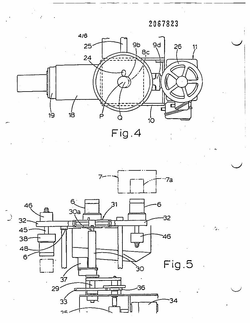
20678234/6
Fig.4
K>l.F .. ... 77--- -l.r-7
46
.5
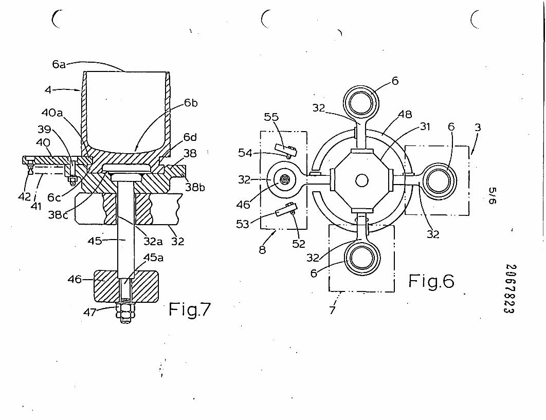
(7 ( (
6
3
/U'
Na
CDO
7
.
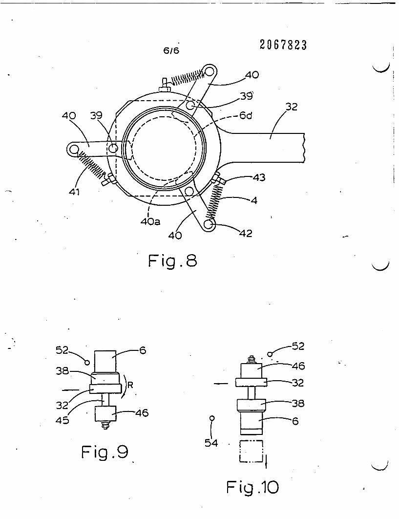
6/6 2067823
Fig.8
o ,,52
54Fig.9 7-l
L..
Fig .10

I GS 2 067 923 9 II GB2O67�23� i -
SPECIFICATIONSystem for treating radioactive waste
Background of the InventionThis invention relates to comprehensive system
5 for treating the radioactive waste which isdischarged as a slurry in large quantities from anaromatic plant and is subsequently thickened,dried and prepared for melting.
There have already been proposed a number of10 methods for treating radioactive waste in slurry
form, which contains radioactive componentssuch as the primary cooling water of an atomicpile. These proposals include that of JapaneseLaid-Open Patent Specification No. 17572/75 in
1 5 which it has been cnsidered advantageous fromthe viewpoint of the economic disposal ofradioactive waste to store the latter aftersedimental collection, drying, melting andsolidification of the radioactive component.O 20 However, up to the present, apparatus forputting such proposals into practical operation hasnot yet been developed.
Sunmary of the InventionUnder these circumstances, the present
25 invention has as its object the provision of acomprehensive system which can treat a slurrywith radioactive components efficiently in oneplace by successively thickening and drying theradioactive waste nto a form ready for charging to
30 the hopper of a melter.According to the present invention, there is
provided an apparatus for the treatment ofradioactive waste, comprising:
a storage tank holding a slurry of the35 radioactive waste;
a sedimentation tank for thickening the slurry ofradioactive waste received from said storage tank;
a drier for drying the thickened radioactive waste:a hopper for receiving the dried radioactive
40 waste; anda rotary mechanism for transferring the
radioactive waste to and from the sedimentationtank, drier and hopper, said mechanism having anumber of containers for holding the radioactive
45 waste, rotary arms for supporting said containers;a rotational drive mechanism for said rotary arms.and a lift mechanism for vertically lifting saidcontainers up and down.
In one embodiment of the apparatus of the50 invention the sedimenta:ion tank and drier are
located successively above the rotational path oftravel of said containers, and said hopper islocated beneath said rotational path of travel in aposition spaced from said drier by a
55 predetermined angle about the axis of rotation ofsaid rotary mechanism. The apparatus may alsocomprise means for inverting and upturning saidcontainers, provided respectively before and aftersaid hopper in the rotational path of travel of said
60 containers.In a particular embodiment of the invention,
said sedimentation tank is provided with a rotary
venical bore forming inlet and outlet openings on65 the upper and lower sides thereof in alignment
with an opening at the bonom of saidsedimentation tank and a tapered bore formedperpendicularly to. and across, said vertical bore arotary shaft having a tapered body portion fitted ir
70 said tapered bore and provided with a cavity insaid tapered body portion in alignment with saidinlet opening for collecting radioactive sediment aspring urging one end of said rotary shaft in thetapered direction thereof, and a rotational drive
75 mechanism connected to the other end of saidrotary shaft for rotating the latter through apredetermined angle, the radioactive sedimentcollected in said cavity being dropped through saidoutlet opening upon rotation of said rotary shaft.
80 In one embodiment of the apparatus of theinvention the lift mechanism is so designed as tolift said rotary arms up and down.
In another embodiment, said lift mechanism isinstalled beneath said drier or said rotary collector
85 whereby said container is lifted up and downwhen said container comes beneath said drier orsaid rotary collector.
Brief Description of the DrawingsReference is now made to the accompanying
SO drawings in which:Fig. 1 is a schematic illustration of one
embodiment according to the present invention c'apparatus for treating radioactive waste:
Fig. 2 is a schematic vertical section of a rotary95 collector:
Fig. 3 is a sectional view across a rotarycollector shaft:
Fig. 4 is a plan view of the rotary collector:Fig. S is a schematic view of a rotary transfer
100 mechanism;Fig. 6 is a plan view of the rotary transfer
mechanism:Fig. 7 is a schematic section of pot supporting
structures;105 Fig. 8 is a plan view of the pot supporting
structures:Fig. 9 is a view explanatory of the inversion c a
pot: andFig. 10 is a view showing an inverted pot to be
110 upturned into initial upright position.
Description of Preferred EmbodimentsReferring to the accompanying drawings and
first to Fig. 1. indicated at 1 is a tank which isprovided in the lower half of a fixed frame 2 to
115 hold a slurry of radioactive waste therein, and a: 3a vessel which is supported on top of the frame 2for thickening the slurry and which is. in theparticular example shown, a sedimentation tank.Provided beside the frame 2 is a side frame 5 of a
120 smaller height supporting thereon a rotarymechanism which turns a number of pots 6 alon;a predetermined rotational path of travel.Designated at 7 is a dryer such as a microwavedryer for drying the condensate which is
125 accommodated in the pot 6, and at 108 is a_6-ar wehich ece:ves *ke dried material and
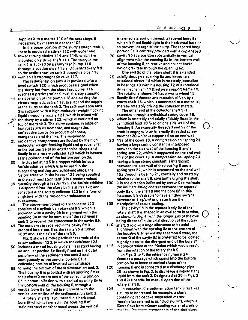
2 GE 2 067 823 8 27 G620675238 2
supplies it to a melter 11 O of the next stage. ifnecessary. by means of a feeder 109.
In the upper portion of the slurry storage tank 1.there is provided a stirrer 112 with upper and
5 lower stirring blades 1 14 and 1 14b which aremounted on a drive shaft 1 13. The slurry in thetank is sucked by a slurry feed pump 1 16through a suction pipe 11 5 and quantitatively fedto the sedimentation tank 3 through a pipe 1 18
10 with an electromagnetic valve 117.The sedimentation tank 3 is provided with a
level switch 120 which produces a signal whenthe slurry fed from the slurry feed pump 116reaches a predetermined level, thereby stopping
1 5 the operation of the pump 1 16 and closing theelectromagnetic valve 117. to suspend the supplyof the slurry to the tank 3. The sedimentation tank3 is supplied with a high molecular weight flockingliquid through a nozzle 121. which is mixed with
20 the slurry by a stirrer 122, which is mounted ontop of the tank 3. The slurry contains in additioniron rust such as hematite, and magnetite,radioactive corrosion products of cobalt.manganese and the like. The suspended
25 radioactive components are flocked by the highmolecular weight flocking liquid and gradually fallto the bottom 3a of inverted conical shape andfinally in to a rotary collector 123 which is locatedat the pointed end of the bottom portion 3a.
30 Indicated at 125 is s hopper which holds afusible additive which is to be used in thesucceeding melting and solidifying stage, thefusible additive in the hopper 125 being suppliedto the sedimentaion tank 3 in a predetermined
35 quantity through a feeder 126. The fusible additiveis dispersed into the slurry by the stirrer 122 andcollected in the rotary collector 123 in the form ofa mixture with the radioactive substance orsubstances.
40 The 3bove-mentioned rotary collector 123consists of a cylindrical rotary shaft 9 which isprovided with a cavity 9b in alignment with theopening 3b at the bottom end of the sedimentaltank 3 to receive the condensate in the cavity 9b.
45 The condensate received in the cavity 9b isdropped into a pot 6 as the cavity Sbo is turned180' about the axis of the shaft 9.
Fig. 2 shows a more particular example of therotary collector 123, in which the collector 123
50 includes a metal housing of stainless steel havingan annular portion Ss fixedly fitted on the outerperiphery of the sedimentation tank 3 and,contiguously to the annular portion Sa acollecting portion of inverted conical shape
55 forming the bottom of the sedimentation tank 3.The housing 8 is provided with an opening Sd atthe pointed bottom end of the collecting portionSb in communication with a conical opening 8dinthe bottom wall of the housing S. through a
60 vertical bore 8e formed in alignment with thevertical center line of the sedimentation tank 3.
A rotary shaft 9 is journalled in a horizontalbore 8f which is formed in the housing 8 ofstainless steel or other meal across the vertical
intermediate portion thereof a tapered body Sawhich is fitted liquid-tight in the horizontal bore fto prevent leakage of the slurry. The tapered bodyportion Se is centrally provided with a cup-shaped
70 cavity Sb at a position substantially in verticalalignment with the opening Sc in the bottom wallof the housing S, to receive and collect flockswhich gravitate through the opening Sc.
One end Sc of the rotary shaft 9 is extended75 axially through a cup ring 9d and keyed to a
rotational sleeve 14 which is rotatably journalledin bearings 13 within a housing 12 of a rotationaldrive mechanism 1 1 fixed on a support frame 10.The rotational sleeve 14 has a worm wheel 15
S0 fixedly fitted thereon and rotatably driven by aworm shaft 16, which is connected to a motor 10,thereby rotatably driving the collector shaft 9.
The other end of the collector shaft 9 isextended through a cylindrical spring cover 1S
85 which is rotatably and axially slidably fitted in thecylindrical hool 18 fixed on one side wall of thehousing S. An externally threaded end Se of the Jshaft is engaged in an internally threaded screwmember 20 which is supported on an end wall
90 1 Sa of the cover 1 . A compression coil spring 23having a large spring constant is interposedbetween the side wall of the housing 8 and aspring seat 22, which is supported on the end wall1 9saof the cover 19. A compression coil spring 23
95 having a large spring constant is interposedbetween the side wall of the housing 8 and aspring seat 22. which is supported on the end wall19a through a bearing 21, coaxially and rotatablyrelative to the shaft 9, constantly urging the shaft
100 9 in the direction indicated by arrow X to maintainthe intimate fitting contact between the taperedbody 9 of the shaft 9 and the bore t. In thisinstance, it is desirable to have a fitting surfacepressure of 1 kg/cm2 or greater from the
105 standpoint of secure sealing.The cavity Sb in the tapered body Se of the
rotary shaft 9 is shaped in an oval form in section. Bas shown in Fig. 4, with the longer axis of the oval Jbeing disposed in the axial direction of the rotary
110 shaft, 9 to give a large allowance to its axial.alignment with the opening ac at the bottom ofthe housing 8. In an initially assembled state, thecenter 0 of the cavity Sb is preferred to be locatedslightly closer to the divergent end of the bore Sf
115 in consideration of the friction which would resultfrom the rotation of the rotary shaft S.
In Figs. 2 to 4. the reference numeral 24denotes a passage which opens into the bottomportion Sb of inverted conical shape of the
120 housing and is connected to a discharge pipe25, as shown in Fig. 3, to discharge a supematantliquid from the tank 3. Designated at 26 in Figs. 2and 4 is a handle for manual operation of therotary shaft S.
125 In operation, the sedimentation tank 3 receivesa slurry to be treated, for example, a slurrycontaining radioactive suspended matter(hereinafter referred to as clud slurry"). which isfiltered out from pr mary cooling water of a pile or
4 .1.0 ae two -2- ''nnonents of the dud slurry
1<-

3 G 2 067 823 3.3 G820678238 3
,_.
are iron oxides which are suspended in aconcentration of 500-50,000 ppM.
When feeding the dud slurry to thesedimentation tank 3, the rotary collector shaft 9
5 is retained in the collecting position shown in Figs.i and 3. After feeding a predetermined quantity ofthe dud slurry to the tank 3, the stirrer is started tomix the dud slurry. For this purpose, the stirrer ispreferred to be driven at a speed of 100-200
10 r.p.m. Next, a predetermined amount of flockingagent of high molecular weight is added to theslurry in a concentration of about 2-10 pprn, toflock the suspended substances.
After continuing the stirring at that spped for a1 5 predetermined time period, the stirring speed is
dropped to allow small flocks to grow into largerones, to facilitate the sedimentation of the flocks.Upon lapse of a predetermined time, the stirrer isstopped and the suspension is left to stand for a
20 while for sedimentation of the flocks. Theprecipitated flocks go down the tank, guided bythe bottom wall Sb of inverted conical shape, andfinally settle in the cavity 9b in the tapered bodyportion 98aof the rotary collector shaft 9.
25 After sedimentation of a predetermined timeperiod, the supernatant liquid Is drawn out andcollected by opening a valve (not shown) of thedischarge pipe 25. Thereafter, the motor of therotational drive mechanism I 1 is actuated to
30 rotate the rotary collecting shaft 9 by 180through the worm shaft 16 and worm wheel 15,turning the cavity 9b upside down, to drop thesediment into a pot of the rotary transfermechanism 4, which is located beneath the
35. col ector shaft 9.As shown in Fig S. the rotary transfer
mechanism 4 basically includes a center shaft 29which is rotatably supported on the side frame 5by a bearing 28 for rotation about a vertical axis, a
40 hydraulic cylinder 30 which is coaxially fixed tothe upper portion of the center shaft 29, and arotary head 31, which is attached to the upper endof a plunger 30a of the hydraulic cylinder 30. Therotary head 31 supports thereon four rotary arms
45 32 which have their respective base endssupported in bearings for rotation about ahorizontal axis, each rotary arm 32 supportingreversibly' at its outer or front end, a pot 6 forreceiving the collected sediment.
50 A driven gear 33, which is fixedly mounted atan intermediate position on the center shaft 29, ismeshed with a drive gear 36 which is driven froma motor 34 through a reducer 35, so that thecenter shaft 29 is rotated upon actuating the
55 motor 34. If necessary, the hydraulic cylinder 30 isoperated by a hydraulic control device 37 to lift orto lower the rotary head 31 through the plunger30a.
Instead of a mechanism such as power cylinder.-0 e.g. the hydraulic cylinder 30, the lifting and
lowering means may be installed beneath the drier7 or the rotary collector 123, respectively.
The pot fI is lifted and lowered when, throughthe rotation, the pot 6 reaches positions where the
-_ ot 5 receives :he collected sediment a.d where
the collected sediment in the pot 6 is subjected todrying treatment in the drier 7.
As shown in fig. 7. each pot 6 is in a taperedform with an inside diameter increasing towards
70 the upper open end and a round bottom, so thatits content is easily released when the pot isturned upside down. Contiguously beneath anannular groove 6d. the pot 6 is provided with aflanged bottom wall 6c to be fitted with a recess
75 38a of a seat plate 38, which is mounted on therotary arm 32. The seat plate 38 is provided with aflanged portion 38b around its outer periphery, onwhich a locking lever 40 is hinged by a hinge pin39, rockably in a horizontal plane. As shown in Fig.
80 8, a pawl portion 4 at the front end of thelocking lever 40 is fitted into the annular groove6d on the outer periphery of the pot 6. In thismanner, the pot 6 and the seat plate 38 areintegrally connected with each other by hinge
85 pins, which are located at three positions on theouter periphery of the pot 6 As shown in Figs 7and 8, a spring 41 tensioned between a springstop pin 42 fixed at the rear end of the lockinglever 40 and a spring stop pin 43 fixed on the
90 circumference of the seat plate 3, urges thelocking lever 40 in the locking direction.
Fixedly secured to the center portion of the seatrplate 38 of the pot 6 is the upper end of areversing rod 45 which is extended vertically
95 through a bore 32a in the front end-portion of therotary arm 32, and provided with an externallythreaded portion 45a at its lower end, inengagement with a weight 46 and a stop nut 47.The pot 6 is thus stably supported on the rotary
100 arm 32 by the weight 46. and, when the pot isturned upside down, the contents of the pot aresecurely released by the falling impact of theweight 46.
In Figs. 1, 5 and 6, designated at 48 is a circular105 guide rail which guides the turning movements of
the rotary arms 32 on the underside thereof. andwhich is liftable up and down and normally urgedupward by guide rods 49 and guide cylinders 50.
As shown in Fig. 1, the sedimentation tank 3110 and drier 7 are located above the locus of rotation
of the pots 6 on the rotary arms 32. and'in ' positions spaced from each other by 90 aboutthe axis of rotation, as particularly shown in Fig. 6.In this instance, the lower opening of the rotary
115 collector shaft 9 at the bottom of thesedimentation tank 3 is positioned so that it isbrought into alignment with the center axis of apot 6 which latter pot is turned into a receivingposition, ensuring that the dropped sediment is
120 securely received in the pot 6.On the other hand, the hopper 108 is located
beneath the locus of rotation of the pots 6 at aposition 90 shifted from the drier 7, so that thedried material in the pot 6 is dropped into the
125 hopper 108 when the pot 6 is turned upsidedown, as will be described hereinafter.
As shown in Fig. 6. in order to invert the pots 6.a pot-invening mechanism is provided above thehopper 108, including a knock pin 52 which is
* a .- ___ffS - n^ ,_- V2 ^- ^ ._ ol..
4 GO 2 067 823 3 4
the pOts 6 which are successively tiirned towardsthe hopper S. The inverted pot 6 is upturned againby an upturning knock pin 54' similar to the pot-upsetting knock pin 52, which is supported on an
5 arm 55 at a position rotationally forward of thehopper 108.
Referring to Fig. 9 the pot-upsetting pin 52 hitsthe outer wall surface of the, pot 6 when the latteris rotated by the rotary arm 32 to a point above
1 0 the hopper 105. and. upon further rotation, the pot6 is turned upside down together with the rotaryarm 32. about the axis thereof, as indicated by thearrow R in Fig. 9. Upori inversion of the pot 6. theweight 46 is allowedto drop freely by a play of the
S rod 45 relative to the rotary arm 32 and hitsagainst the arm, the impact transmitted to the pot6 encouraging dumping of its contents.
The inverted pot 6 then abuts against a potupturning pin 54 which, as shown in fig. 10 is
^ located in a position beneath, and spaced by acertain angle from, the pot-inverting pin 52.causing the vacant pot 8 and arm 32 to turnclockwise to assume again their original uprightposition.
25 In the operation of the above-describedtreatment system, with stirring by the stirrer 1 12,a slurry in the slurry tank 1 is fed to thesedimentation tank 3 through conduits 115 and118 by operation of the slurry feed pump 118 . As
30 soon as the slurry in the sedimentation tank 3reaches a predeternined level, the level switch120 is actuated to stop the slurry feed pump I1 6so as to suspend the feed of the slurry. Apredetermined amount of a high molecular weight
35 flocking liquid is added to the slurry in thesedimentation tank 3 through the nozz!e 121 andmixed therewith by actuating the stirrer 122.Simultaneously, a fusible additive stored in thehopper 125, which is quantitatively fed by the
40 feeder 126, is also mixed into the slurry in the tank3.
In this stirring and mixing stage, the radioactivesubstances in the slurry are flocked by the highmolecular weight flocking liquid and, upon
45 stopping the stirrer 122. allowed to fall bygravitation onto the bottom portion 3a of the tank,finally settling in the cavity 9b of the rotarycollector 123. In this flocking and settling stage.the fusible additive is also collected together with
50 the condensate in the form of a mixture with theradioactive substances.
At the time point when the sedimentation hasproceeded to a sufficient degree, the supernatantliquid is drawn out of the tank 3 by opening the
55 electromagnetic valve in the discharge pipe 60which communicates with the bottom portion 3aof the tank 3. sending the liquid to a waste watertreatment process.
After the extraction of the supernatant liquid,60 the rotary shaft 9 of the rotary collector 123 is
rotated by 180@ to drop the condensate in thecavity 9b into a pot 6, which has been lifted to aposition close to the outlet opening Se of therotary collector 123 by the operation of the lift
During the above-described flocking andcollecting operation a condensate collected bythe preceding flocking and collecting operation isdried in the drier 7 until the succeeding mass of
70 condensate is received in a vacant pot ,whereupon the cylinder 30 is lowered once andthe motor 34 is actuated to rotate the rotary arm32 through 900 to bring the received condensateto a position beneath the drier 7. The water vapour
75 which is generated by heating is passed throughan exhaust gas treatment device like a condenser.
As a result of the rotation of the arm 32, the pot6 which holds the dried condensate is turnedupside down above the hopper 8 by the pin 52 of
80 the pot-inverting mechanism of Fig. 6 to releasethe dried condensate into the hopper 8 in themanner explained hereinbefore in connection withFig. 9. At this time, the dried material which isdeposited on the inner wall surface of the pot 6 is
85 caused to fall off more forcibly by the impact ofthe dropping weight 46 than when resort is madeto natural or spontaneous fall of the material.
After the 90 rotation, the rotary head 31 islifted by the operation of the lift cylinder 30 to.
90 position a vacant pot 6 immediately beneath therotary collector 123 of the sedimentation tank 3,while passing a pot 6 filled with a condensate tothe dryer 7 from beneath for heating and dryingthe condensate.
95 During the above-described revolution of theiotary head 31, a pot 6 which passes over thehopper 108 in an inverted state is upturned intoan upright position and is stopped in a stand-byposition.
100 The dried condensate released into the hopper8, which is a mixture of the radioactive substancesand fusible additive, is fed into the melting furnace110 by the feeder 9. The mixture which is meltedin the furnace 1 0 is solidified and put in a storage
105 container which is then capped, sealed andcleaned of contaminants for storage over a longtime period.
The condensate in the pots, which is heatedand dried by a single dryer in the foregoing
1 10 embodiment may be adapted to be preheated andthen fully heated by driers which are located ;ntwo separate positions in the rotational path oftravel.
Further, although the fusible additive is11 5 admixed to the slurry in the sedimentation tank it
may be fed to. and mixed with, the condensate inthe hopper 108 prior to charging to the meltingfurnace 10.
As appears from the foregoing description, the120 present inven:ion employs a rotary mechanism
which includes in its rotational path of travel anumber of stages required for treating a slurry ofradioactive substances. i.e.. a stage ofcondensation of the slurry, a stage of heating and
125 drying the condensate and a stage of transfer to amelting furnace, prior to the final melting andsolidifying stages, thereby allowing treatment ofradio-active waste continuously in one place.
According to the invention, the waste is; ,. ,.- ...̂ *
I
S G 2 067 All E 55 �R 2 O�7 �
respective stages of treatment by the operation-ofa single rotary mechanism, so that it becomespossible to enhance the capacity of treatment andto reduce the floor space required for the
5 treatment operation. In addition, the rotarymechanism with liftable pots simplifies thetreatment operation and permits of remote controlor complete automation of the treatmentoperation.
1 0 CLAIMS1. Apparatus for the treatment of radioactive
waste, comprising:a storage tank holding a slurry of the
radioactive waste;I5 a sedimentation tank for thickening the slurry of
radioactive waste received from said storage tank.a drier for drying the thickened radioactive
waste:a hopper for receiving the dried radioactive
-' 20 waste; anda rotary mechanism for transferring the
radioactive waste to and from the sedimentationtank, drier and hopper, said mechanism having anumber of containers for holding the radioactive
25 waste, rotary arms for supporting said containers;a rotational drive mechanism for said rotary arms,and a lift mechanism for vertically lifting saidcontainers up and down.
2. Apparatus as sat forth in claim 1, wherein30 said sedimentation tank and drier are located
successively above the rotational path of travel ofsaid containers, and said hopper is located.beneath said rotational path of travel n a positionspaced from said drier by a predetermined angle
35 about the axis of rotation of said rotation
mechanism.3. Apparatus as set forth in claim 1 or 2 further
comprising means for inverting and upturning saidcontainers. provided respectively before and after
40 said hopper in the rotational path of travel of saidcontainers.
4. Apparatus as set forth in claim 1, 2 or 3.wherein said sedimentation tank is provided witha rotary collector including a housing block having
45 a vertical bore forming inlet and outlet openingson the upper and lower side thereof in alignmentwith an opening at the boitom of saidsedimentation tank and a tapered bore formedperpendicularly to, and across, said verticaf bore.'a
50 rotary shaft having a tapered body portion fitted insaid tapered bore and provided with a cavity insaid tapered body portion in alignment with saidinlet opening for collecting radioactive sediment, aspring urging one end of said rotary shaft in the
55 tapered direction thereof, and a rotational drivemechanism connected to the other end of saidrotary shaft for rotating the latter through apredetermined angle, the radioactive sedimentcollected in said cavity beingdropped through said
60 outlet opening upon rotation of said rotary shaft.5. Apparatus as set forth in claim 1. 2, 3 or 4.
wherein said lift mechanism is so designed as tolift said rotary arms up and down.
6. Apparatus as set forth in claim 1, 2. 3 or 4,65 wherein said lift mechanism is installed beneath
said drier or said rotary collector whereby saidcontainer is lifted up and down when saidcontainer comes beneath said drier or said rotarycollector.
70 7. Apparatus as set forth in claim Isubstantially as hereinbefore described withreference to the accompanying drawings.
Prnted or er Majesty's Stationery Office by uthe Ccuier Press. Leemington So&. 1953. Pubishted by the Patent otticm.25 outhtampiton uildings. London. WCZA AY. rom~ which copies may be obtsined.
Related Documents