Foreign Gas Carrier Examiner (FGCE) Tactics, Techniques, and Procedures CGTTP 3-72.6 April 2016

Welcome message from author
This document is posted to help you gain knowledge. Please leave a comment to let me know what you think about it! Share it to your friends and learn new things together.
Transcript
Foreign Gas Carrier Examiner (FGCE)Tactics, Techniques, and Procedures
CGTTP 3-72.6April 2016

This page intentionally left blank.
CommanderUnited States Coast GuardForce Readiness Command
300 E. Main Street, Suite 1100Norfolk, VA 23510Staff Symbol: FC-P Phone: (757) 628-4463
CGTTP 3-72.6 April 2016
COAST GUARD TACTICS, TECHNIQUES, AND PROCEDURES 3-72.6
Subj: FOREIGN GAS CARRIER EXAMINER (FGCE) TTP
Ref: a. Carriage of Liquid Bulk Dangerous Cargoes, 46 U.S.C. § 3711b. Safety Standards for Self Propelled Vessels Carrying Bulk Liquefied Gases,
46 C.F.R. Part 154c. SOLAS: Consolidated Text of the International Convention for the Safety of
Life at Sea, 1974, and its Protocol of 1988: Articles, Annexes and Certificates(Incorporating all amendments in effect from 1 July 2009), InternationalMaritime Organization (IMO)
d. Clarification of Requirements for Confined Space Entry for Ma ineInspectors, Especially for New Construction, ALCOAST 221/15
e. Cargo Compressor Room Entries During Port State Control Exams and LawEnforcement Boardings of Liquefied Petroleum Gas (LPG) Carriers, CG-543Safety Alert, COMDT COGA D WASHINGTON DC//CG-543// 191819ZMAR 10
f. Code for the Construction and Equipment of Ships Carrying Liquefied Gases inBulk (GC Code), 1983 edition, IMO Resolution A.328(IX)
g. International Code for the Construction and Equipment of Ships CarryingLiquefied Gases in Bulk (IGC Code), 1993 edition, IMO Resolution MSC.5(48)
h. Code for Existing Ships Carrying Liquefied Gases in Bulk (EGC Code), IMOresolution A.329(IX)
i. Preparing for Inspections and Examinations, MPS-PR-SEC-04j. Alternate Pressure Relief Valve Settings on Vessels Carrying Liquefied Gases in
Bulk in Independent Type B & Type C Tanks, CG-ENG Policy Letter 04-12,k. USCG Marine Safety Manual, Vol. I: Administration and Management,
COMDTINST M16000.6 (series)l. International Chamber of Shipping Tanker Safety Guide Liquefied, Second
Edition, 1995m. Amendments to the International Code for the Construction and Equipment of
Ships Carrying Liquefied Gases in Bulk (IGC Code), MSC.370(93), 22 May2014
n. Control of Pollution of Noxious Liquid Substances in Bulk, MARPOL Annex II
CGTTP 3-72.6Foreign Gas Carrier Examiner (FGCE)
o. Amendments to the International Code for the Construction and Equipment ofShips Carrying Liquefied Gases in Bulk (IGC Code) (Harmonized system ofsurvey and certification), MSC.17(58)
p. Survey Guidelines Under the Harmonized System of Survey and Certification(HSSC), 2011, IMO Resolution A.1053(27)
q. USCG Marine Safety Manual, Vol. II: Materiel Inspection, COMDTINSTM16000.7 (series)
r. International Convention on Standards of Training, Certification andWatchkeeping for Seafarers (STCW), Including 2010 Manila Amendments,STCW Convention and STCW Code, 2011 Edition
s. World Health Organization, International Medical Guide for Ships, 3rd Editiont. Medical First Aid Guide for use in Accidents Involving Dangerous Goods
(MFAG), 1994 Editionu. Port State Control Information for Nov – Dec 2015, Commandant (CG-5P)
Command Email of 18 Dec 15v. Port State Control Information, for February 2016, Commandant (CG-5P)
Command Email of 26 Feb 16w. An Introduction to the Design and Maintenance of Cargo System Pressure Relief
Valves on Board Gas Carriers, SIGTTO 1998x. ESD Arrangements & Linked Ship/Shore Systems for Liquefied Gas Carriers,
SIGTTO 2009y. CG-CVC-2 Port State Control Information for October 2015z. Definitions, 33 C.F.R. § 156.105aa. Definitions, 33 C.F.R. § 154.105 bb. Liquefied Gas Handling Principles On Ships and In Terminals, SIGTTO, Third
Edition cc. National Fire Protection Association (NFPA) 77: Recommended Practice on
Static Electricity, 2014 Edition dd. Life-Saving Appliances (LSA) Code, International Maritime Organization
(IMO), 2010 ee. Electrical Installations in Ships, International Standard, IEC 60092-502, Fifth
Edition 1999 ff. Foreign Flag Vessel: Certificate of Compliance Endorsement Application, 46
C.F.R. § 154.22(a)(9)(i)(B)gg. International Fire Safety Systems (FSS Code), 2007 hh. Guidelines for the Maintenance and Inspection of Fixed Carbon Dioxide Fire-
Extinguishing Systems, International Maritime Organization (IMO), MSC.1/Circ. 1318
ii. Guidelines for the Maintenance and Inspection of Fire Protection Systems &Appliances, International Maritime Organization (IMO), MSC.1/Circ. 1432
CGTTP 3-72.6Foreign Gas Carrier Examiner (FGCE)
jj. Guidelines for Foreign Liquefied Gas Carrier COC Endorsement, Marine Safety Center (MSC), Plan Review Guideline, C1-43
kk. Vapor Control Systems, 46 C.F.R. Part 39 ll. Special Equipment, Machinery, and Hull Requirements, 46 C.F.R. Part 32
1. PURPOSE. To provide port state control officers (PSCOs) and apprentice marineinspectors (AMIs) with Coast Guard tactics, techniques, and procedures (CGTTP) onCertificate of Compliance (COC) examinations of foreign-flagged liquefied gas carriers.
2. ACTION. This publication applies to PSCOs and AMIs. Internet release authorized.
3. DIRECTIVES/TTP AFFECTED. None.
4. DISCUSSION. To support the Assistant Commandant for Prevention Policy (CG-5P’s)mission objective, this publication details the tasks and steps required to effectively,efficiently, and safely conduct examinations of liquefied gas carriers.
5. DISTRIBUTION. FORCECOM TTP Division posts an electronic version of this TTPpublication to the CGTTP Library on CGPortal. In CGPortal, navigate to the CGTTPLibrary by selecting References > Tactics, Techniques, and Procedures (TTP).FORCECOM TTP Division does not provide paper distribution of this publication.
6. FORMS/REPORTS. The forms called for in this publication are available in USCGelectronic forms on the standard workstation or on the Internet:http://www.uscg.mil/forms/; CGPortal: Select References from the home page; andIntranet at http://cgweb.comdt.uscg.mil/CGForms
7. REQUEST FOR CHANGES. Submit recommendations for TTP improvements orcorrections via email to [email protected] or through the TTP Request form onCGPortal. In CGPortal, navigate to the TTP Request form by selecting References >Tactics, Techniques, and Procedures (TTP) > TTP Request.
Send lessons learned applicable to this TTP publication via command email toFORCECOM TTP Division at CMD-SMB-CG-FORCECOM.
PATRICK J. SHAWCommander, U. S. Coast Guard Acting Chief, FORCECOM TTP Division (FC-P)By Direction of Commander, Force Readiness Command
SHAW.PATRICK.J.1179100912
Digitally signed by SHAW.PATRICK.J.1179100912 DN: c=US, o=U.S. Government, ou=DoD, ou=PKI, ou=USCG, cn=SHAW.PATRICK.J.1179100912 Date: 2016.04.08 15:04:23 -04'00'

CGTTP 3-72.6Foreign Gas Carrier Examiner (FGCE)
This page intentionally left blank.
CGTTP 3-72.6Foreign Gas Carrier Examiner (FGCE)
i
Table of Contents
Table of Figures .........................................................................................................................iv
Table of Tables..........................................................................................................................vii
Chapter 1: Introduction ........................................................................................................... 1-1
Section A: Introduction ............................................................................................................................. 1-2
Section B: Notes, Cautions, and Warnings ................................................................................................. 1-5
Chapter 2: Pre-Exam (PE) Preparation .................................................................................. 2-1
Section A: Certificate of Compliance (COC) CG-3585 .................................................................................. 2-2
Section B: Safety Meeting ......................................................................................................................... 2-4
Section C: Gas Code Applicability .............................................................................................................. 2-7
Section D: Gas Carrier (Ship) Types/Containment Systems ........................................................................ 2-8
Chapter 3: Certificates and Documents (CD) Examination.................................................. 3-1
Section A: International Pollution Prevention Certificate for the Carriage of Noxious Liquid Substances in Bulk (IPP NLS) ........................................................................................................................................... 3-2
Section B: COF - International Code for the Construction and Equipment of Ships Carrying Liquefied Gases in Bulk (IGC Code) ........................................................................................................................................ 3-3
Section C: COF – International Code for the Construction and Equipment of Ships Carrying Liquefied Gases in Bulk (GC Code) ......................................................................................................................................... 3-5
Section D: COF – Code for Existing Ships Carrying Liquefied Gases in Bulk (EGC Code) ................................ 3-7
Section E: Allowable Loading Limits and Temperatures for Each Product .................................................. 3-9
Section F: Changing/Setting Cargo Tank Pressure Relief Valves Documentation ....................................... 3-10
Section G: Crew Training Documentation ................................................................................................. 3-11
Section H: Subchapter “O” Endorsement (SOE) ........................................................................................ 3-12
Section I: Certificate of Inhibition ............................................................................................................ 3-14
Chapter 4: Logs and Manuals (LM) Examination.................................................................. 4-1
Section A: Cargo Record Book ................................................................................................................... 4-2
Section B: Procedures and Arrangements (P&A) Manual ........................................................................... 4-3
Section C: Shipboard Marine Pollution Emergency Plan (SMPEP) for Noxious Liquid Substances (NLS) ....... 4-4
CGTTP 3-72.6Foreign Gas Carrier Examiner (FGCE)
ii
Section D: Cargo Operations Manual ........................................................................................................ 4-5
Section E: Loading and Stability Information Booklet ................................................................................ 4-6
Chapter 5: Instrumentation (IE) Examination........................................................................ 5-1
Section A: Fixed Gas Detection System ..................................................................................................... 5-2
Section B: Portable Gas Detection Equipment .......................................................................................... 5-13
Section C: Temperature Indicating Devices .............................................................................................. 5-17
Section D: Pressure Monitoring Devices ................................................................................................... 5-19
Section E: Overflow Control System ......................................................................................................... 5-22
Chapter 6: General Health (GH) and Safety Examination .................................................... 6-1
Section A: Decontamination Showers and Eye Wash Stations ................................................................... 6-2
Section B: Respiratory and Eye Protection for Emergency Escape Purposes ............................................... 6-3
Section C: Personnel Safety Equipment ..................................................................................................... 6-4
Section D: First Aid Equipment ................................................................................................................. 6-6
Chapter 7: Air Lock (AL) Examination ................................................................................... 7-1
Section A: Air Locks .................................................................................................................................. 7-2
Chapter 8: Cargo Systems (CS) Examination ....................................................................... 8-1
Section A: Emergency Shutdown (ESD) System ......................................................................................... 8-2
Section B: Cargo Tank Pressure Relief Valves ............................................................................................ 8-8
Section C: Cargo Piping ............................................................................................................................ 8-17
Section D: Cargo System Shutoff Valves ................................................................................................... 8-20
Section E: Cargo Machinery Room (Cargo Compressor Room) Equipment Exam ....................................... 8-22
Chapter 9: Cargo Environmental Control (CE) Examination ............................................... 9-1
Section A: Inert Gas Systems (IGS) ............................................................................................................ 9-2
Section B: Nitrogen (N2) Gas Generating System ....................................................................................... 9-4
Section C: Inert Gas/Nitrogen (N2) Storage Tanks ...................................................................................... 9-7
Chapter 10: Lifesaving Equipment (LS) Examination ........................................................10-1
Section A: Lifeboats ................................................................................................................................. 10-2
CGTTP 3-72.6Foreign Gas Carrier Examiner (FGCE)
iii
Chapter 11: Electrical Systems (ES) Examination..............................................................11-1
Section A: Electrical Installations in the Cargo Machinery (Cargo Compressor) Room Exam ..................... 11-2
Section B: Electrical Installations in Gas Dangerous Zones (Open Decks and Other Spaces Other than Cargo Machinery Rooms) .................................................................................................................................. 11-5
Chapter 12: Cargo Area Ventilation (CV) Systems Examination.......................................12-1
Section A: Cargo Machinery Motor (Electric Motor) Room Ventilation System Exam ............................... 12-2
Section B: Cargo Machinery Room Ventilation System ............................................................................. 12-5
Chapter 13: Gas Fuel (GF) Supply System Examination ...................................................13-1
Section A: Master Gas Valve .................................................................................................................... 13-2
Section B: Ventilation within the Ventilation/Boiler Hood or Casing Exam ............................................. 13-11
Section C: Gas Detection System Used for the Protection of the Cargo Fuel System ............................... 13-12
Section D: Gas Utilization Unit(s) (GUU) ................................................................................................. 13-13
Section E: Gas Fuel Piping (Double Wall Piping System) .......................................................................... 13-16
Section F: Gas Fuel Piping (Ventilated Pipe or Duct System) ................................................................... 13-18
Section G: Gas Combustion Unit (GCU) .................................................................................................. 13-19
Chapter 14: Firefighting Systems (FF) Examination ..........................................................14-1
Section A: Fire Water Main Equipment .................................................................................................... 14-2
Section B: Deck Water Spray System ........................................................................................................ 14-3
Section C: Dry Chemical Powder Fire-Extinguishing System ...................................................................... 14-5
Section D: Cargo Machinery (Compressor) Motor Room Fixed Fire-Extinguishing System ......................... 14-6
Section E: Cargo Machinery Motor Room Fixed Fire-Extinguishing System ............................................... 14-7
Section F: Fire-fighter Outfits ................................................................................................................... 14-8
Chapter 15: Follow Up (FU) Actions.....................................................................................15-1
Section A: Issue COC (CG-3585) ................................................................................................................ 15-2
Section B: COC (CG-3585) Common Mistakes ........................................................................................... 15-3
Section C: Complete MISLE Activity .......................................................................................................... 15-4
Appendix A: Glossary and Acronyms .................................................................................. A-1
CGTTP 3-72.6Foreign Gas Carrier Examiner (FGCE)
iv
Appendix B: Confined Space Safety Alert 2010................................................................... B-1
Appendix C: Sample Certificate of Compliance (COC) ....................................................... C-1
Appendix D: Example COF (GC Code).................................................................................. D-1
Appendix E: Example International COF (IGC Code) .......................................................... E-1
Appendix F: Example SOE..................................................................................................... F-1
Appendix G: SOE Checklist ................................................................................................... G-1
Appendix H: Ammonia Mishap .............................................................................................. H-1
Appendix I: PSC Information for Nov-Dec 2015, Commandant (CG-5P) Command Email of 18 Dec 15 ............................................................................................................................... I-1
Appendix J: Electrical Charts ................................................................................................. J-1
Appendix K: Sample Deficiencies ......................................................................................... K-1
Index........................................................................................................................................... I-1
Table of FiguresFigure 2-1 More common cargo containments systems for LNG gas carriers .................................................... 2-11
Figure 2-2 Relationship between tank types(s), cargo temperature(s), and secondary barrier(s) requirements 2-11
Figure 5-1 Gas detection system ...................................................................................................................... 5-3
Figure 5-2 LNG gas carrier cycled gas detection cabinet interior ....................................................................... 5-4
Figure 5-3 LNG gas carrier cycled gas detection span gas analysis certificate .................................................... 5-5
Figure 5-4 LNG gas carrier continuous gas detection cabinet interior ............................................................... 5-6
Figure 5-5 Combined suction (holds/un-manned spaces)/electronic (accommodations/manned spaces) fixed gas detection system ............................................................................................................................................ 5-6
Figure 5-6 LEL/LFL display ................................................................................................................................ 5-7
Figure 5-7 Electronic sensor sample point ........................................................................................................ 5-7
Figure 5-8 Suction type detection system ........................................................................................................ 5-8
Figure 5-9 Example span gas: 4 gas; 8% butane, balance nitrogen (N2); and 50% LEL ........................................ 5-11
Figure 5-10 0.75% by volume propane (34% LEL) balance air ........................................................................... 5-12
Figure 5-11 Portable gas meters ..................................................................................................................... 5-14
CGTTP 3-72.6Foreign Gas Carrier Examiner (FGCE)
v
Figure 5-12 Hydrocarbon meter ...................................................................................................................... 5-14
Figure 5-13 Portable gas meter ....................................................................................................................... 5-15
Figure 5-14 Temperature indicating device readings on an LPG gas carrier ...................................................... 5-17
Figure 5-15 Example of temperature sensors location on a membrane containment system ........................... 5-18
Figure 5-16 Testing of the high/low pressure alarm using a special handle ...................................................... 5-19
Figure 5-17 Testing of the high/low pressure alarm using a hand pump .......................................................... 5-20
Figure 5-18 High level alarm and overfill protection float system .................................................................... 5-23
Figure 6-1 Suitably marked decontamination shower and eye wash station ..................................................... 6-2
Figure 6-2 Gas suit orange ............................................................................................................................... 6-4
Figure 6-3 Stretcher ......................................................................................................................................... 6-6
Figure 7-1 Air lock (note the two steel doors) .................................................................................................. 7-3
Figure 7-2 Self closing mechanism, door open, and door closed indicator ........................................................ 7-3
Figure 8-1 Typical ESD activation point ............................................................................................................ 8-2
Figure 8-2 Typical ESD valve ............................................................................................................................ 8-3
Figure 8-3 Fusible plug .................................................................................................................................... 8-4
Figure 8-4 Fusible link ..................................................................................................................................... 8-4
Figure 8-5 Valves position perpendicular to the pipe ....................................................................................... 8-6
Figure 8-6 LPG cargo containment example of operation and relief pressure for tank hold and tank levels ....... 8-9
Figure 8-7 LNG tank pressure parameters ....................................................................................................... 8-10
Figure 8-8 Cargo relief valves .......................................................................................................................... 8-12
Figure 8-9 Sealed pilots 1 ............................................................................................................................... 8-12
Figure 8-10 Incorrect pilot operated relief ...................................................................................................... 8-13
Figure 8-11 MARVS stacked correctly, typical LPG set-up ................................................................................ 8-14
Figure 8-12 Two pilot-operated relief valves at vapor dome of LNG gas carrier ............................................... 8-15
Figure 8-13 Permanent relief valve seals on LNG gas carrier ............................................................................ 8-15
Figure 8-14 Overpressure relief operation of cargo tank relief valve ............................................................... 8-16
Figure 8-15 Vacuum relief operation of cargo tank relief valve ........................................................................ 8-16
CGTTP 3-72.6Foreign Gas Carrier Examiner (FGCE)
vi
Figure 8-16 Electrically bonded relief valve ..................................................................................................... 8-19
Figure 8-17 Hydraulically actuated fill line shutoff valve on an LPG gas carrier ................................................ 8-20
Figure 8-18 Three-stage cargo compressor on an LPG gas carrier..................................................................... 8-24
Figure 8-19 LNG vaporizer on an LNG gas carrier ............................................................................................. 8-25
Figure 8-20 Lubricated bulkhead shaft seal passing through the gas tight bulkhead on an LNG gas carrier ....... 8-26
Figure 8-21 Single-stage direct reliquefaction system...................................................................................... 8-27
Figure 8-22 Two-stage direct reliquefaction system ........................................................................................ 8-27
Figure 8-23 Cascade-direct reliquefaction system ........................................................................................... 8-28
Figure 9-1 IGS on a gas carrier ......................................................................................................................... 9-3
Figure 9-2 Gas separation membrane .............................................................................................................. 9-5
Figure 9-3 Pressure swing adsorption .............................................................................................................. 9-5
Figure 9-4 Liquid N2 storage ............................................................................................................................. 9-7
Figure 10-1 Self-contained air support system ................................................................................................ 10-3
Figure 11-1 Division and zone comparison chart ............................................................................................. 11-3
Figure 11-2 Division and zone scheme markings ............................................................................................. 11-3
Figure 11-3 IEC marking chart ......................................................................................................................... 11-4
Figure 11-4 Gas dangerous zones .................................................................................................................... 11-5
Figure 12-1 Machinery motor room supply ..................................................................................................... 12-3
Figure 12-2 Ventilation ................................................................................................................................... 12-4
Figure 13-1 LNG gas carrier BOG fuel system ventilated duct or pipe arrangement .......................................... 13-3
Figure 13-2 LNG gas carrier BOG fuel gas system inerted double-wall pipe arrangement ................................. 13-3
Figure 13-3 Typical LNG gas carrier BOG fuel system gas utilization unit ventilation and valve arrangements .. 13-4
Figure 13-4 Red “flag” atop the valve stem aligned with the pipe indicates that the MGV is open ................... 13-7
Figure 13-5 Example of second fail-closed shutoff valve installed in series with the MGV in the boiler hood or gas room .............................................................................................................................................................. 13-7
Figure 13-6 Multiple valve arrangements ....................................................................................................... 13-8
Figure 13-7 Fail-open vent valves ................................................................................................................... 13-9

CGTTP 3-72.6Foreign Gas Carrier Examiner (FGCE)
vii
Figure 13-8 Twin MGVs ................................................................................................................................ 13-10
Figure 13-9 Gas utilization room on LNG gas carrier ...................................................................................... 13-14
Figure 13-10 GVU is an integral part of the GUU on DFDE propulsion system ................................................ 13-15
Figure 13-11 GCU site glass ........................................................................................................................... 13-19
Figure 13-12 Typical GCU fitted on LNG gas carrier ....................................................................................... 13-21
Figure 14-1 Activated deck water spray system (manifold) ............................................................................. 14-3
Figure 14-2 Deck water spray system (tank domes) ........................................................................................ 14-4
Figure 14-3 Dry chemical powder fire extinguishing system ............................................................................ 14-5
Figure 14-4 Fire-fighter outfit ......................................................................................................................... 14-8
Table of Tables
Table 2-1 Gas Code Chart ................................................................................................................................ 2-7
Table 3-1 Time windows for surveys carried out under the gas codes .............................................................. 3-4
Table 3-2 Time windows for surveys carried out under the gas codes .............................................................. 3-6
Table 3-3 Time windows for surveys carried out under the gas codes .............................................................. 3-8
Table 5-1 Vapor densities ................................................................................................................................ 5-9
Table 14-1 Required number of fire-fighter outfits aboard .............................................................................. 14-9

CGTTP 3-72.6Foreign Gas Carrier Examiner (FGCE)
viii
This page intentionally left blank.
CGTTP 3-72.6Foreign Gas Carrier Examiner (FGCE)
1-1 Chapter 1: Introduction
Chapter 1: Introduction
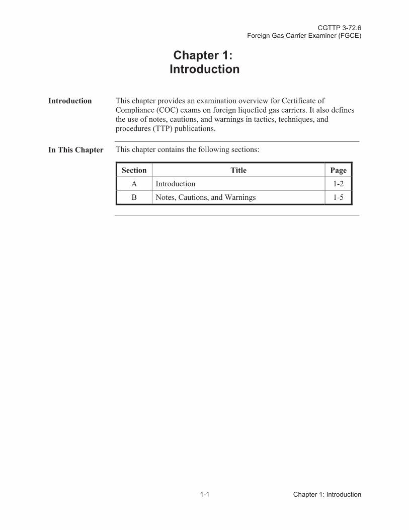
Introduction This chapter provides an examination overview for Certificate of Compliance (COC) exams on foreign liquefied gas carriers. It also defines the use of notes, cautions, and warnings in tactics, techniques, and procedures (TTP) publications.
In This Chapter This chapter contains the following sections:
Section Title Page
A Introduction 1-2
B Notes, Cautions, and Warnings 1-5
CGTTP 3-72.6Foreign Gas Carrier Examiner (FGCE)
Chapter 1: Introduction 1-2
Section A: Introduction
A.1.Background
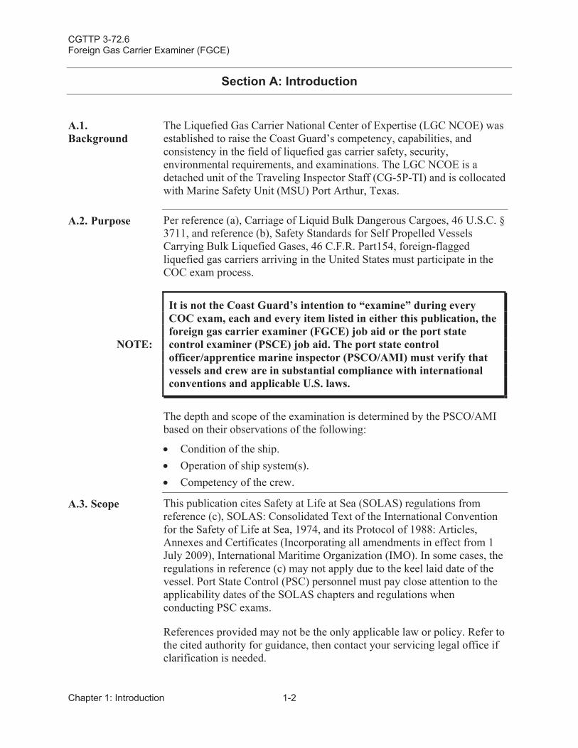
The Liquefied Gas Carrier National Center of Expertise (LGC NCOE) was established to raise the Coast Guard’s competency, capabilities, and consistency in the field of liquefied gas carrier safety, security,environmental requirements, and examinations. The LGC NCOE is a detached unit of the Traveling Inspector Staff (CG-5P-TI) and is collocated with Marine Safety Unit (MSU) Port Arthur, Texas.
A.2. Purpose Per reference (a), Carriage of Liquid Bulk Dangerous Cargoes, 46 U.S.C. § 3711, and reference (b), Safety Standards for Self Propelled Vessels Carrying Bulk Liquefied Gases, 46 C.F.R. Part154, foreign-flaggedliquefied gas carriers arriving in the United States must participate in the COC exam process.
NOTE:
It is not the Coast Guard’s intention to “examine” during every COC exam, each and every item listed in either this publication, the foreign gas carrier examiner (FGCE) job aid or the port state control examiner (PSCE) job aid. The port state control officer/apprentice marine inspector (PSCO/AMI) must verify that vessels and crew are in substantial compliance with international conventions and applicable U.S. laws.
The depth and scope of the examination is determined by the PSCO/AMI based on their observations of the following:
Condition of the ship.Operation of ship system(s).Competency of the crew.
A.3. Scope This publication cites Safety at Life at Sea (SOLAS) regulations from reference (c), SOLAS: Consolidated Text of the International Convention for the Safety of Life at Sea, 1974, and its Protocol of 1988: Articles, Annexes and Certificates (Incorporating all amendments in effect from 1 July 2009), International Maritime Organization (IMO). In some cases, the regulations in reference (c) may not apply due to the keel laid date of the vessel. Port State Control (PSC) personnel must pay close attention to the applicability dates of the SOLAS chapters and regulations when conducting PSC exams.
References provided may not be the only applicable law or policy. Refer to the cited authority for guidance, then contact your servicing legal office if clarification is needed.
CGTTP 3-72.6Foreign Gas Carrier Examiner (FGCE)
1-3 Chapter 1: Introduction
NOTE:
Reference (d), Clarification of Requirements for Confined SpaceEntry for Ma ine Inspectors, Especially for New Construction,ALCOAST 221/15, DOES NOT SUPERSEDE reference (e), Cargo Compressor Room Entries During Port State Control Exams andLaw Enforcement Boardings of Liquefied Petroleum Gas (LPG) Carriers, CG-543 Safety Alert, COMDT COGATD WASHINGTON DC//CG-543// 191819Z MAR 10, (Appendix B:Confined Space Safety Alert 2010) for entry into gas carrier compressor rooms.
A.4.Audience
This publication is intended for use by Coast Guard port state control officers (PSCOs) and apprentice marine inspectors (AMIs) during COCexams on foreign-flagged liquefied gas carriers. It is only meant to enhance the U.S. Coast Guard Foreign Gas Carrier Examiner (FGCE) job aid and is focused on the cargo specific tasks/steps performed by a PSCO who holds the FGCE certification. The additional COC tasks/steps performed by the port state control examiner (PSCE) are found in the PSCE job aid. Use in conjunction with the following:
U.S. Coast Guard Foreign Gas Carrier Examiner (FGCE) Port StateControl Officer Performance and Qualification Standard, 04 November2015.
U.S. Coast Guard Gas Carrier Inspector Course (MS-513) StudentGuide, March 2016 (course code: 351263).
U.S. Coast Guard Foreign Gas Carrier Examiner Job Aid,04 November 2015.
U.S. Coast Guard Foreign Gas Carrier Examiner Competency Code(FGCE) Training Aid, 04 November 2015.
CGTTP 3-72.6Foreign Gas Carrier Examiner (FGCE)
Chapter 1: Introduction 1-4
A.5. Governing References
The following references are considered “governing references” within this publication. As such, they will be called “the gas codes” when referred to collectively. Individual instances will be either GC Code, IGC Code, or EGC Code respectively.
Reference (f), Code for the Construction and Equipment of Ships Carrying Liquefied Gases in Bulk (GC Code), 1993 edition, IMO Resolution A.328(IX).
Reference (g), International Code for the Construction and Equipment of Ships Carrying Liquefied Gases in Bulk (IGC Code), 1993 edition,IMO Resolution MSC.5(48).
Reference (h), Code for Existing Ships Carrying Liquefied Gases in Bulk (EGC Code), Resolution A.329(IX).
A.6. Registered Trademark Disclaimer
The use of registered trademarks in this publication is not an endorsement of these products or companies by the United States Coast Guard, the Department of Homeland Security (DHS), or the Federal government.
CGTTP 3-72.6Foreign Gas Carrier Examiner (FGCE)
1-5 Chapter 1: Introduction
Section B: Notes, Cautions, and Warnings
B.1. Overview The following definitions apply to notes, cautions, and warnings found in TTP publications.
NOTE: An emphasized statement, procedure, or technique.
CAUTION: A procedure, technique, or action that, if not followed, carries therisk of equipment damage.
WARNING: A procedure, technique, or action that, if not followed, carries the risk of personal injury or death.
CGTTP 3-72.6Foreign Gas Carrier Examiner (FGCE)
Chapter 1: Introduction 1-6
This page intentionally left blank.
CGTTP 3-72.6Foreign Gas Carrier Examiner (FGCE)
2-1 Chapter 2: PE Preparation
Chapter 2:Pre-Exam (PE) Preparation
Introduction This chapter discusses pre-exam (PE) preparations. Refer to reference (i),Preparing for Inspections and Examinations, MPS-PR-SEC-04.
In This Chapter This chapter contains the following sections:
Section Title Page
A Certificate of Compliance (COC) CG-3585 2-2
B Safety Meeting 2-4
C Gas Code Applicability 2-7
D Gas Carrier (Ship) Types/Containment Systems 2-8
CGTTP 3-72.6Foreign Gas Carrier Examiner (FGCE)
Chapter 2: PE Preparation 2-2
Section A: Certificate of Compliance (COC) CG-3585
A.1. Certificate of Compliance (COC)CG-3585
Prepare the Certificate of Compliance (CG-3585) form for issuance to the vessel:
Obtain this information from the vessel’s arrival information, “including” the Continuous Synopsis Record (CSR).
NOTE: Do not rely on Marine Information for Safety and Law Enforcement (MISLE) for completed COC information.
NOTE:
If the vessel also has an International Pollution Prevention Certificate for the Carriage of Noxious Liquid Substances in Bulk (IPP NLS) certificate, only check the second block in the COCs“Particulars of Ship” section to designate the vessel to carry the listed products. Refer to Appendix C: Sample Certificate of Compliance (COC) for more information.
NOTE: If necessary, contact the vessel’s agent to request additional information or documentation.
Print a copy of the most recent Subchapter “O” Endorsement (SOE) located in the documents section of the vessel’s MISLE file. The USCG Marine Safety Center’s (MSC) current template listed status is “in process.”
NOTE:
Reference (j), Alternate Pressure Relief Valve Settings on Vessels Carrying Liquefied Gases in Bulk in Independent Type B & Type C Tanks, CG-ENG Policy Letter 04-12, may cause the SOE to change. Ensure most recent SOE is issued. Refer to Chapter 15: Follow Up (FU) Actions for further guidance.
CGTTP 3-72.6Foreign Gas Carrier Examiner (FGCE)
2-3 Chapter 2: PE Preparation
Review and compare the SOE to the vessel’s Certificate of Fitness (COF) for any changes or errors (pay particular attention to the maximum allowable relief valve setting (MARVS) section).
Ensure the cargo listed on the advanced notice of arrival (ANOA) is an authorized cargo on the SOE.
Ensure the SOE references the appropriate IMO COF resolution.
Forward the COC and SOE to the officer-in-charge (OIC), marine inspections (OCMI), or designated representative for signature.
CGTTP 3-72.6Foreign Gas Carrier Examiner (FGCE)
Chapter 2: PE Preparation 2-4
Section B: Safety Meeting
B.1. Safety Meeting
The lead FGCE meets with the examination team to discuss the scope of the exams. This helps ensure the exams are conducted efficiently and safely. Discuss and review the following:
Per reference (k), USCG Marine Safety Manual, Vol. I: Administration and Management, COMDTINST M16000.6 (series), verifyexamination team is outfitted with appropriate personal protective equipment (PPE) to include:
Hard hat.
Eye Protection.
Coveralls (best practice is to wear long sleeves while examining liquefied gas carriers due to the low temperature and flammability characteristics of the cargoes carried).
Gloves.
Safety toed boots.
Hearing protection.
Flashlight.
Foul weather gear appropriate for current or anticipated conditions.
If boarding the vessel at sea, personal flotation device (PFD) or anti exposure coveralls (i.e., mustang or dry suit).
Reference (k) requires personnel working near liquefied cargoes to wear atmospheric monitors and alarms (i.e., multi-gas meters).
Verify each team member has a multi-gas meter that is fully charged and calibrated before leaving the office.
Per reference (k), verify examination team has Emergency Escape Breathing Devices (EEBD).
CGTTP 3-72.6Foreign Gas Carrier Examiner (FGCE)
2-5 Chapter 2: PE Preparation
WARNING:
Do not don the EEBD to enter a hazardous area. The EEBD is for emergency ESCAPE only. If a known hazard exists in any space, do not enter until the hazard is corrected and the space is declared safe for entry.
Be familiar with EEBD procedures in the event an emergency escape situation arises.
o Read and fully understand the operating instructions on the EEBD.
o At least annually, conduct training and familiarization using the EEBD training aid.
o Verify EEBD pressure gauge is within the green sector and not past its expiration date.
Determine if a marine chemist is required.
WARNING:
Coast Guard policy does not require a marine chemist to certify a liquefied gas carrier’s cargo compressor room as safe, before Coast Guard personnel entry. In addition to unit policy, reference (e), Cargo Compressor Room Entries During Port State Control Exams and Law Enforcement Boardings of Liquefied Petroleum Gas (LPG) Carriers, CG-543 Safety Alert, COMDT COGATD WASHINGTON DC//CG-543// 191819Z MAR 10 (Appendix B: Confined Space Safety Alert 2010) and reference (k), USCG Marine Safety Manual, Vol. I: Administration and Management, COMDTINST M16000.6 (series), provide guidance to personnel on assessing the risks associated with cargo compressor room entry. Use all references to assess risks and determine if a marine chemist must clear a cargo compressor room before entry.
Before boarding a vessel, the PSCO ensures each team member is aware of the applicable safety hazards associated with the vessel’s cargo. Review list of cargoes and evaluate with the cargo data sheets, safety data sheet (SDS), and Emergency Response Guide for applicable hazards such as:
Cryogenic (frostbite).
Flammability.
Toxicity.
Asphyxia (suffocation).
Chemical burns.
CGTTP 3-72.6Foreign Gas Carrier Examiner (FGCE)
Chapter 2: PE Preparation 2-6
NOTE:
Reference (l), International Chamber of Shipping Tanker Safety Guide Liquefied Gas, Second Edition, 1995, is an excellent reference for hazards and characteristics of cargo(s). Recommend this as an office reference for units with gas carrier expectations.
NOTE: Identify unit policy for exposures.
Review risk for any special operations such as nighttime exams andoffshore boarding.
Evaluate exam team’s fitness and rest period.
Advise team members to be aware of how current and evolving on-site environmental conditions (such as wind speed/direction) may affectrisks, and to reevaluate those risks as conditions change.
CGTTP 3-72.6Foreign Gas Carrier Examiner (FGCE)
2-7 Chapter 2: PE Preparation
Section C: Gas Code Applicability
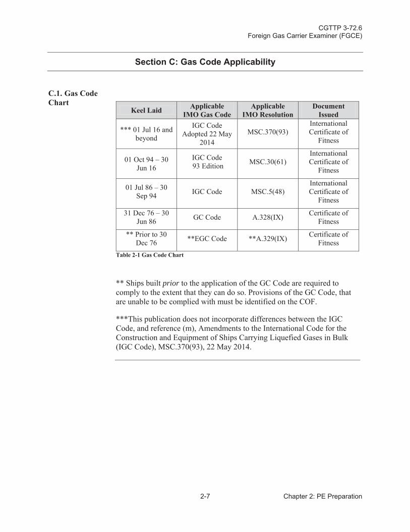
C.1. Gas Code Chart
Keel Laid ApplicableIMO Gas Code
ApplicableIMO Resolution
Document Issued
*** 01 Jul 16 and beyond
IGC CodeAdopted 22 May
2014MSC.370(93)
International Certificate of
Fitness
01 Oct 94 – 30 Jun 16
IGC Code 93 Edition MSC.30(61)
International Certificate of
Fitness
01 Jul 86 – 30 Sep 94 IGC Code MSC.5(48)
International Certificate of
Fitness
31 Dec 76 – 30Jun 86 GC Code A.328(IX) Certificate of
Fitness
** Prior to 30Dec 76 **EGC Code **A.329(IX) Certificate of
FitnessTable 2-1 Gas Code Chart
** Ships built prior to the application of the GC Code are required to comply to the extent that they can do so. Provisions of the GC Code, that are unable to be complied with must be identified on the COF.
***This publication does not incorporate differences between the IGC Code, and reference (m), Amendments to the International Code for the Construction and Equipment of Ships Carrying Liquefied Gases in Bulk (IGC Code), MSC.370(93), 22 May 2014.
CGTTP 3-72.6Foreign Gas Carrier Examiner (FGCE)
Chapter 2: PE Preparation 2-8
Section D: Gas Carrier (Ship) Types/Containment Systems
D.1. Gas CarrierTypes
Liquefied gas carriers are typically divided into two main groups; liquefied petroleum gas (LPG) and liquefied natural gas (LNG). LPG gas carriers are designed to mainly carry the following cargoes:
Butane (C4H10).
Propane (C3H8).
Butadiene (C4H6).
Propylene (C3H6).
Vinyl chloride monomer (VCM) (C2H3Cl).
Anhydrous ammonia (NH3).
LNG gas carriers are designed to carry liquefied natural gas which is comprised mostly of methane (CH4).
All gas carriers are classified into three types based on the hazard potential of the cargoes carried. These classes are:
1G: Requires the maximum preventative measures to prevent the escape of the cargoes carried. Such cargoes are:
Chlorine (Cl).
Ethylene oxide (C2H4O).
Methyl bromide (CH3Br).
Sulfur dioxide (SO2).
2G: Requires significant preventative measures to prevent the escape of the cargoes carried. Such cargoes are:
Ethane (C2H6).
Methane (CH4).
Ethylene (C2H4).
CGTTP 3-72.6Foreign Gas Carrier Examiner (FGCE)
2-9 Chapter 2: PE Preparation
2PG: A gas carrier less than 150 meters in length, requires significant preventative measures to prevent escape of cargoes carried and wherethose cargoes are carried in independent Type C tanks designed for a MARVS of at least 0.7 bar gauge (BARG) and a cargo containment system design temperature of -55 degrees Celsius or above. Such cargoes are:
Ammonia (NH3).
Butadiene (C4H6).
Butane (C4H10).
Propane (C3H8), etc.
NOTE: Consider all gas carriers of this description that are over 150 meters in length as a type 2G gas carrier.
3G: Requires moderate preventative measures to preclude the escape of the cargoes carried. Such cargoes are:
Nitrogen (N2).
Refrigerant gases, etc.
Since all gas cargoes are transported as liquids and because of their chemical and physical properties, they are carried in one of the three conditions:
A pressure greater than atmospheric.
At a temperature below ambient.
A combination of both.
Generally, LPG gas carriers are fully pressurized, semi-pressurized and refrigerated, or fully refrigerated.
Fully pressurized.
Tanks are horizontal, cylindrical, or spherical pressure vessels.
Semi-pressurized and refrigerated.
Tanks are either cylindrical, spherical or bi-lobe.
CGTTP 3-72.6Foreign Gas Carrier Examiner (FGCE)
Chapter 2: PE Preparation 2-10
Fully refrigerated.
Tanks are prismatic.
LNG is a cryogenic cargo that is transported near atmospheric pressure. Although a few LNG gas carriers are fitted with refrigeration (reliquefaction) systems, most rely on other means to control pressure and temperature of the cargo. Most LNG gas carriers rely on containment systems that use highly efficient insulation around the tanks and consumption of boil-off gas (BOG), whether in propulsion boilers, diesel engines and/or gas combustion units (GCUs).
D.2.Containment Systems
The IGC Code identifies four different types of cargo containment systems (tank types):
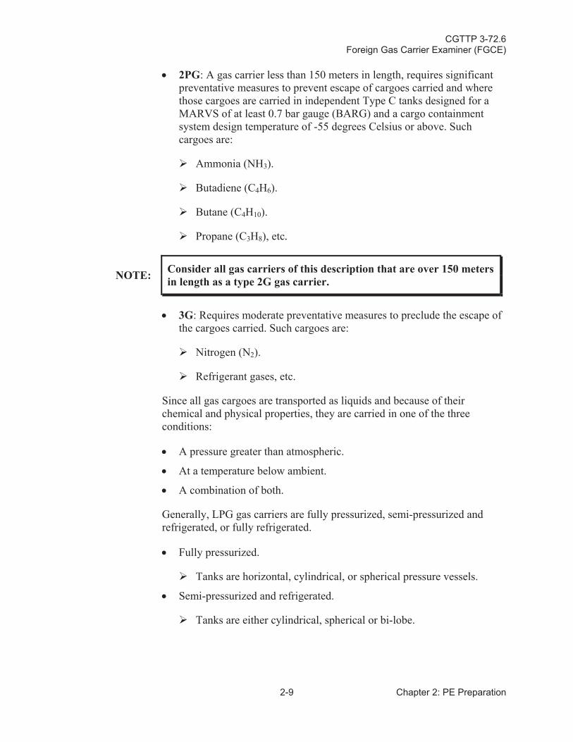
1. Independent or self-supporting (A, B or C).
a. Type A: Normally a self-supporting prismatic tank with cargoes carried in a fully refrigerated condition near atmospheric pressure.
b. Type B: Normally a sphere but the IGC Code allows for constructing containment systems from plane surfaces. This type was originally designed for LNG carriage but is frequently used for ethylene carriage.
c. Type C: Normally a horizontal cylindrical pressure vessel. This type is used in fully pressurized and semi-pressurized gas carriers and also used as deck tanks on LPG gas carriers.
2. Membrane.
a. This type of system is based on a very thin primary barrier (membrane) and a full secondary barrier, both supported by layers of insulation.
3. Semi-membrane.
4. Integral (part of the hull, like a conventional tank vessel).
CGTTP 3-72.6Foreign Gas Carrier Examiner (FGCE)
2-11 Chapter 2: PE Preparation
Figure 2-1 More common cargo containments systems for LNG gas carriers
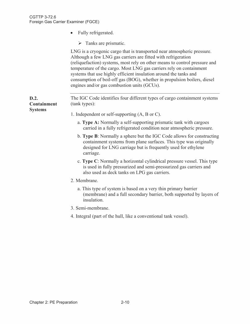
Figure 2-2 Relationship between tank types(s), cargo temperature(s), and secondary barrier(s) requirements
CGTTP 3-72.6Foreign Gas Carrier Examiner (FGCE)
Chapter 2: PE Preparation 2-12
This page intentionally left blank.
CGTTP 3-72.6Foreign Gas Carrier Examiner (FGCE)
3-1 Chapter 3: CD Examination
Chapter 3:Certificates and Documents (CD) Examination
Introduction This chapter discusses collection and review of all pertinent vessel certificates and documents (CD) for validity, certification, and endorsements.
In This Chapter This chapter contains the following sections:
Section Title Page
A International Pollution Prevention Certificate for the Carriage of Noxious Liquid Substances in Bulk (IPP NLS)
3-2
B COF - International Code for the Construction and Equipment of Ships Carrying Liquefied Gases in Bulk (IGC Code)
3-3
C COF – International Code for the Construction and Equipment of Ships Carrying Liquefied Gases in Bulk (GC Code)
3-5
D COF – Code for Existing Ships Carrying Liquefied Gases in Bulk (EGC Code)
3-7
E Allowable Loading Limits and Temperatures for Each Product
3-9
F Changing/Setting Cargo Tank Pressure Relief Valves Documentation
3-10
G Crew Training Documentation 3-11
H Subchapter “O” Endorsement (SOE) 3-12
I Certificate of Inhibition 3-14
CGTTP 3-72.6Foreign Gas Carrier Examiner (FGCE)
Chapter 3: CD Examination 3-2
Section A: International Pollution Prevention Certificate for the Carriage of Noxious Liquid Substances in Bulk (IPP NLS)
A.1. Overview Liquefied petroleum gas (LPG) gas carriers might also have authorization to carry noxious liquid substances (NLS) cargoes. In the IGC Code and the GC Code, an asterisk (*) identifies these NLS cargoes.
Per reference (n), Control of Pollution of Noxious Liquid Substances in Bulk, MARPOL Annex II, NLS cargoes are authorized when the vessel isissued an International Pollution Prevention Certificate for the Carriage of Noxious Liquid Substances in Bulk (IPP NLS).
NLS products are dual regulated. In addition to complying with the IGC Code or GC Code, they also must comply with reference (n). Certification and documentation are still required which includes the NLS certificate, the Procedures and Arrangements Manual (P&A Manual), Shipboard Marine Pollution Emergency Plan (SMPEP), and the cargo record book.
A.2. Conducting Exam
Verify the following:
Certificate is valid. The IPP NLS is never issued for longer than five years.
Vessel’s Administration or any person or organization duly authorizedissued the certificate.
Certificate authorizes carriage of the NLS cargo(es).
Completion of the required intermediate survey, if applicable.
NOTE:Per reference (n), the intermediate survey must be complete within three months before or three months after the second or third anniversary date of when the certificate was issued.
Status of the required annual surveys, if applicable.
NOTE:Per reference (n), the annual surveys must be complete within three months before or three months after the anniversary date of when the certificate was issued.
CGTTP 3-72.6Foreign Gas Carrier Examiner (FGCE)
3-3 Chapter 3: CD Examination
Section B: COF - International Code for the Construction and Equipment of Ships Carrying Liquefied Gases in Bulk (IGC Code)
B.1. Overview Gas carriers in compliance with the IGC Code receive an international COF. The certificate is issued under the authority of reference (o), Amendments to the International Code for the Construction and Equipment of Ships Carrying Liquefied Gases in Bulk (IGC Code) (Harmonized system of survey and certification), MSC.17(58), for vessels with a keel laid date of 01 July 1986 and later.
B.2. Conducting Examination
Verify the following:
Certificate references the appropriate IMO resolution based on the vessel’s keel laid date.Certificate is valid. COFs are never valid for longer than five years from the date of the initial or periodical (renewal) survey.Vessel’s Administration or any person or organization duly authorized issued the certificate. Certificate authorizes carriage of the cargo(es). Certificate identifies any alternative arrangements or equivalencies. Completion of the required intermediate survey, if applicable. Status of the annual surveys, if applicable.
CGTTP 3-72.6Foreign Gas Carrier Examiner (FGCE)
Chapter 3: CD Examination 3-4
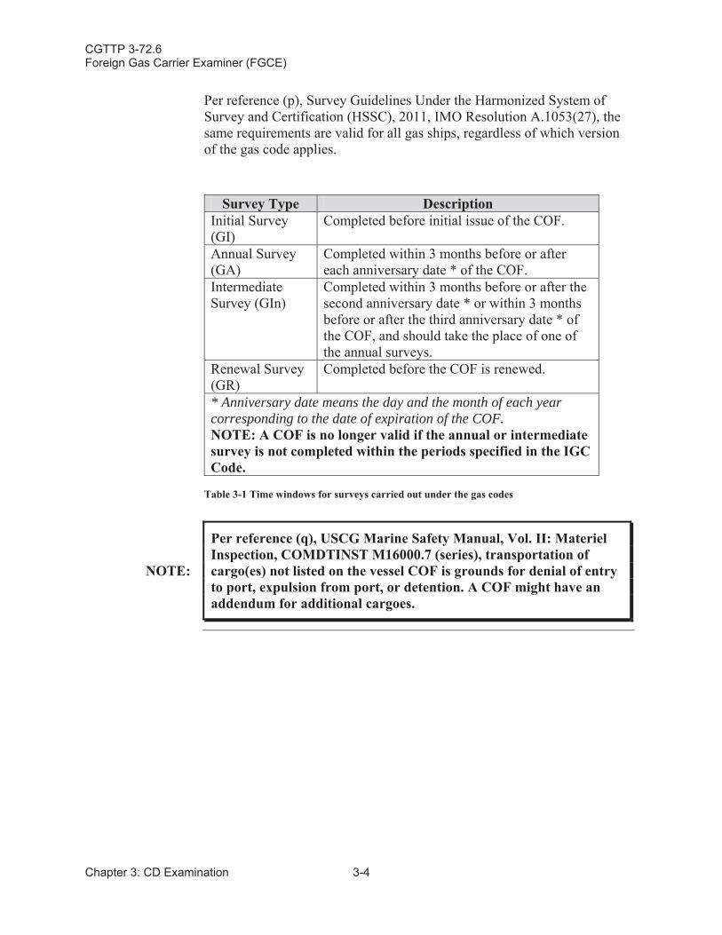
Per reference (p), Survey Guidelines Under the Harmonized System of Survey and Certification (HSSC), 2011, IMO Resolution A.1053(27), the same requirements are valid for all gas ships, regardless of which version of the gas code applies.
Survey Type DescriptionInitial Survey (GI)
Completed before initial issue of the COF.
Annual Survey (GA)
Completed within 3 months before or after each anniversary date * of the COF.
Intermediate Survey (GIn)
Completed within 3 months before or after the second anniversary date * or within 3 months before or after the third anniversary date * of the COF, and should take the place of one of the annual surveys.
Renewal Survey (GR)
Completed before the COF is renewed.
* Anniversary date means the day and the month of each year corresponding to the date of expiration of the COF.NOTE: A COF is no longer valid if the annual or intermediate survey is not completed within the periods specified in the IGC Code.
Table 3-1 Time windows for surveys carried out under the gas codes
NOTE:
Per reference (q), USCG Marine Safety Manual, Vol. II: Materiel Inspection, COMDTINST M16000.7 (series), transportation of cargo(es) not listed on the vessel COF is grounds for denial of entry to port, expulsion from port, or detention. A COF might have an addendum for additional cargoes.
CGTTP 3-72.6Foreign Gas Carrier Examiner (FGCE)
3-5 Chapter 3: CD Examination
Section C: COF – International Code for the Construction and Equipment of Ships Carrying Liquefied Gases in Bulk (GC Code)
C.1. Overview Gas carriers in compliance with the GC Code receive an international COF. The certificate is issued under the authority of the GC Code, for vessels with a keel laid date of 31 December 1976 to 30 June 1986.
C.2. Conducting Examination
Verify the following:
Certificate references the appropriate IMO resolution based on the vessel’s keel laid date.
Certificate is valid. COFs are never valid for longer than five years from the date of the initial or periodical (renewal) survey.
Vessel’s Administration or any person or organization duly authorized issued the certificate.
Certificate authorizes carriage of the cargo(es).
Certificate identifies any alternative arrangements or equivalencies.
Completion of the required intermediate survey, if applicable.
Status of the annual surveys, if applicable.
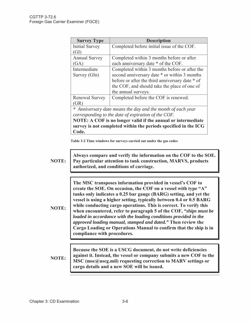
Per reference (p), Survey Guidelines Under the Harmonized System of Survey and Certification (HSSC), 2011, IMO Resolution A.1053(27), the same requirements are valid for all gas ships, regardless of which version of the gas code applies.
CGTTP 3-72.6Foreign Gas Carrier Examiner (FGCE)
Chapter 3: CD Examination 3-6
Survey Type DescriptionInitial Survey (GI)
Completed before initial issue of the COF.
Annual Survey (GA)
Completed within 3 months before or after each anniversary date * of the COF.
Intermediate Survey (GIn)
Completed within 3 months before or after the second anniversary date * or within 3 months before or after the third anniversary date * of the COF, and should take the place of one of the annual surveys.
Renewal Survey (GR)
Completed before the COF is renewed.
* Anniversary date means the day and the month of each year corresponding to the date of expiration of the COF.NOTE: A COF is no longer valid if the annual or intermediate survey is not completed within the periods specified in the ICG Code.
Table 3-2 Time windows for surveys carried out under the gas codes
NOTE:Always compare and verify the information on the COF to the SOE. Pay particular attention to tank construction, MARVS, products authorized, and conditions of carriage.
NOTE:
The MSC transposes information provided in vessel’s COF to create the SOE. On occasion, the COF on a vessel with type “A”tanks only indicates a 0.25 bar gauge (BARG) setting, and yet the vessel is using a higher setting, typically between 0.4 or 0.5 BARG while conducting cargo operations. This is correct. To verify this when encountered, refer to paragraph 5 of the COF, “ships must be loaded in accordance with the loading conditions provided in the approved loading manual, stamped and dated.” Then review the Cargo Loading or Operations Manual to confirm that the ship is in compliance with procedures.
NOTE:
Because the SOE is a USCG document, do not write deficiencies against it. Instead, the vessel or company submits a new COF to the MSC ([email protected]) requesting correction to MARV settings or cargo details and a new SOE will be issued.
CGTTP 3-72.6Foreign Gas Carrier Examiner (FGCE)
3-7 Chapter 3: CD Examination
Section D: COF – Code for Existing Ships Carrying Liquefied Gases in Bulk (EGC Code)
D.1. Overview Ships built before 31 December 1976 must comply with the GC Code to the extent that they are able to do so. Ships able to fully comply with the GC Code receive a COF per the GC Code.
Ships unable to comply with the GC Code can still receive a COF, under authority of the EGC Code.
COFs shall identify the aspects of the GC Code, with which the ship cannot comply.
NOTE:Ships unable to comply with the GC Code but still receiving a COF are authorized but not common. If this situation occurs contact theLGC NCOE.
D.2. Conducting Examination
Verify the following:
Certificate references the appropriate IMO resolution based on the vessel’s keel laid date.
Certificate is valid. COFs are never valid for longer than five years from the date of the initial or periodical (renewal) survey.
Vessel’s Administration or any person or organization authorized issued the certificate.
Certificate authorizes carriage of the cargo(es).
Certificate identifies any alternative arrangements or equivalencies.
Completion of the required intermediate survey, if applicable.
Status of the annual surveys, if applicable.
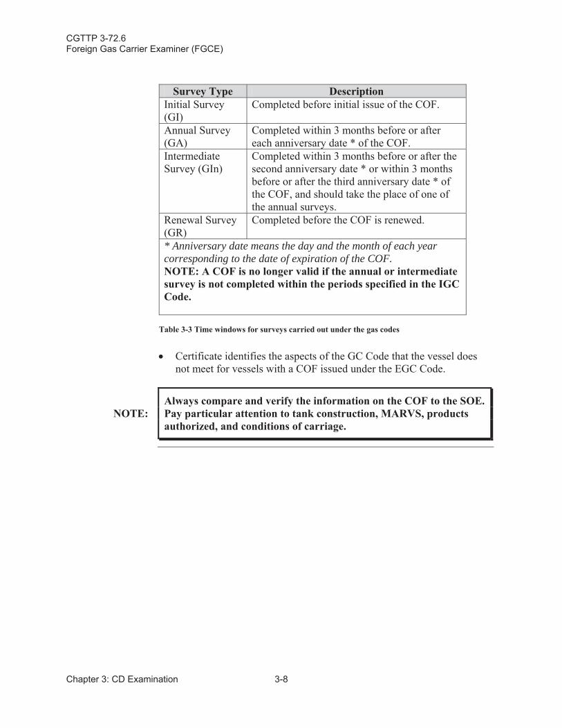
Per reference (p), Survey Guidelines Under the Harmonized System of Survey and Certification (HSSC), 2011, IMO Resolution A.1053(27), the same requirements are valid for all gas ship, regardless of which version of the gas code applies.
CGTTP 3-72.6Foreign Gas Carrier Examiner (FGCE)
Chapter 3: CD Examination 3-8
Survey Type DescriptionInitial Survey (GI)
Completed before initial issue of the COF.
Annual Survey (GA)
Completed within 3 months before or after each anniversary date * of the COF.
Intermediate Survey (GIn)
Completed within 3 months before or after the second anniversary date * or within 3 months before or after the third anniversary date * of the COF, and should take the place of one of the annual surveys.
Renewal Survey (GR)
Completed before the COF is renewed.
* Anniversary date means the day and the month of each year corresponding to the date of expiration of the COF.NOTE: A COF is no longer valid if the annual or intermediate survey is not completed within the periods specified in the IGC Code.
Table 3-3 Time windows for surveys carried out under the gas codes
Certificate identifies the aspects of the GC Code that the vessel does not meet for vessels with a COF issued under the EGC Code.
NOTE:Always compare and verify the information on the COF to the SOE. Pay particular attention to tank construction, MARVS, products authorized, and conditions of carriage.
CGTTP 3-72.6Foreign Gas Carrier Examiner (FGCE)
3-9 Chapter 3: CD Examination
Section E: Allowable Loading Limits and Temperatures for Each Product
E.1. Overview Per the ICG Code, masters of liquefied gas carriers shall receive and permanently keep information on the maximum allowable loading limits for each cargo tank. Tanks should not be more than 98 percent liquid full at the reference temperature, unless a higher fill limit is allowed by the Administration. For example, LNG gas carriers are commonly authorized to load to 98.5 percent because they use BOG as fuel resulting in lower levels as the loaded voyage progresses.
Information for each product aboard includes:
Applicable loading temperature.
Applicable maximum reference temperature. Gas carriers fitted with membrane tanks may have limits for partial fill levels, as specified on the COF. Loading limits may be expressed as a percentage of tank height, tank length, tank width or tank volume, or as a combination. For example, a gas carrier may be required to maintain liquid level lower than a level corresponding to 10 percent of the height of the tank, or higher than a level corresponding to 70 percent of the height of the tank.
CAUTION: Tank levels outside of specified ranges can result in tank damage from excessive sloshing.
E.2. Conducting Examination
Do the following:
Examine the COF to determine authorized tank levels and authorized minimum temperatures for cargoes aboard.
Verify that cargo information available to the master includes reference temperatures and cargo tank relief valve set pressures. Find cargo information on SDSs.
Verify that tank liquid levels shown on the gauging system do not exceed authorized levels.
CGTTP 3-72.6Foreign Gas Carrier Examiner (FGCE)
Chapter 3: CD Examination 3-10
Section F: Changing/Setting Cargo Tank Pressure Relief ValvesDocumentation
F.1. Overview The IGC Code and the GC Code identify requirements when a liquefied gas carrier changes the cargo tank pressure relief valve settings and when verifying and setting cargo tank pressure relief valve settings. MARVS are set and sealed typically during the gas carrier’s special survey (dry dock)every 5 years.
F.2. Conducting Examination
Verify the following:
Documentation is from an “administration accepted” competent authority (Recognized Organization [RO]) attesting to the proper setting of the cargo tank pressure relief valves.
Flag State Administration approval of procedures for changing cargo tank pressure relief valves (only applies to LPG gas carriers). Refer to Chapter 8: Cargo Systems (CS) Examination for full examination.
Ship’s log records all changes to cargo tank pressure relief valves (only applies to LPG gas carriers).
CGTTP 3-72.6Foreign Gas Carrier Examiner (FGCE)
3-11 Chapter 3: CD Examination
Section G: Crew Training Documentation
G.1. Overview Reference (r), International Convention on Standards of Training, Certification and Watchkeeping for Seafarers (STCW), Including 2010 Manila Amendments, STCW Convention and STCW Code, 2011 Edition,specifies additional requirements for mariners serving on liquefied gas carriers.
G.2. Conducting Examination
Verify the following:
Each officer and rated individual with specific duties and responsibilities related to cargo operations or cargo equipment holds a certificate in basic training for liquefied gas tanker operations.
The master, chief engineer, chief mate, second engineer, and anyone responsible for cargo-related operations holds a certificate in advanced training for liquefied gas tanker cargo operations.
All officers with specific cargo duties hold a certificate of proficiency from the Flag Administration demonstrating compliance with reference (r). The certificate shall not be issued for a period longer than 5 years.
NOTE:
At a minimum, certificate must reference Chapter V: Standards Regarding Special Training Requirements for Personnel on Certain Ship Types, Section A-V/1-2: Mandatory Minimum Requirements for the Training and Qualifications of Masters, Officers and Ratings on Liquefied Gas Tankers of reference (r).
CGTTP 3-72.6Foreign Gas Carrier Examiner (FGCE)
Chapter 3: CD Examination 3-12
Section H: Subchapter “O” Endorsement (SOE)
H.1. Overview The MSC generates a Subchapter “O” Endorsement (SOE) at the completion of the Subchapter “O” Plan Review process. The SOE is part of the COC for gas carriers and is required by reference (b), Safety Standards for Self Propelled Vessels Carrying Bulk Liquefied Gases, 46C.F.R. Part154. Refer to reference (q), USCG Marine Safety Manual, Vol. II: Materiel Inspection, COMDTINST M16000.7 (series) for COC and SOE guidance.
Refer to Appendix D: Example COF (GC Code), Appendix E: Example International COF (IGC Code), and Appendix F: Example SOE for samples.
H.2. Conducting Examination
Verify the following:
IMO International Gas Code COF referenced on the SOE matches the actual COF issued to the vessel.
Cargo containment system(s) aboard the vessel is/are accurately identified on the SOE.
MARVS are set no higher than the values indicated on the SOE.
Cargo(es) authorized for carriage are also authorized on the IMO gas code COF.
Any special restrictions noted are complied with.
The most current SOE from the vessel’s MISLE documents is present.Review and compare SOE to COF for any changes or errors (Pay particular attention to the MARVS section).
Ensure the cargo listed on the ANOA is an authorized cargo on the SOE.
NOTE:
If a vessel is NOT authorized for carriage of cargoes in Alaskan waters because of requirements per reference (b), the following statement is included on the SOE in Paragraph 12: Special Restrictions: “Based on the ambient design temperatures listed in the vessel’s IMO Certificate of Fitness, the cargoes authorized for carriage in Paragraph 4 may not be carried in Alaskan waters.”
CGTTP 3-72.6Foreign Gas Carrier Examiner (FGCE)
3-13 Chapter 3: CD Examination
NOTE:
For more guidance (i.e., plan review guidance (PRG) or SOE Checklist (Appendix G: SOE Checklist). A complete list of PRGs can be found by going to the MSC Workspace on CGPortal, clicking on the CG Marine Safety Center Homeport Page link, and navigating to the Plan Review Guidelines link under the References section.
CGTTP 3-72.6Foreign Gas Carrier Examiner (FGCE)
Chapter 3: CD Examination 3-14
Section I: Certificate of Inhibition
I.1. Overview Polymerization is the process of monomer molecules reacting together in a chemical reaction to form polymer chains or three-dimensional networks. Certain chemical cargoes require the addition of an inhibitor to prevent or slow down polymerization. When an inhibitor is added to a cargo, the manufacturer is required to issue the vessel a Certificate of Inhibition per the IGC Code, the GC Code, and reference (b), Safety Standards for Self Propelled Vessels Carrying Bulk Liquefied Gases, 46 C.F.R. Part 154.
I.2. Conducting Examination
Verify the following is indicated:
CAUTION:
It is very important that the gas carrier use the proper types and amounts, maintain effective temperature control of, and monitor the lifespan of any inhibitors. This is extremely critical for the safe storage and carriage of certain cargoes primarily to reduce the detrimental effects of polymerization and any detrimental impacts to the gas carrier and/or the port.
Name of inhibitor.
Amount of inhibitor added to the cargo(es).
Date inhibitor was added.
Normal expectation of the inhibitor's effective lifetime.
Inhibitor temperature limitations that may affect its effectiveness.
Any actions the crew is required to take when the length of the voyage exceeds the effective lifetime of the inhibitor.
NOTE:
Transporting cargo(es) with an inhibitor without the required/validCertificate of Inhibition is grounds for detention. For ports where cargo is loaded, the certificate may not be available until after the loading is completed.
CGTTP 3-72.6Foreign Gas Carrier Examiner (FGCE)
4-1 Chapter 4: Logs and Manuals Examination
Chapter 4:Logs and Manuals (LM) Examination
Introduction This chapter discusses collection and review of all vessel documents for validity, proper certification, and endorsement.
In This Chapter This chapter contains the following sections:
Section Title Page
A Cargo Record Book 4-2
B Procedures and Arrangements (P&A) Manual 4-3
C Shipboard Marine Pollution Emergency Plan (SMPEP) for Noxious Liquid Substances
4-4
D Cargo Operations Manual 4-5
E Loading and Stability Information 4-6
CGTTP 3-72.6Foreign Gas Carrier Examiner (FGCE)
Chapter 4: Logs and Manuals Examination 4-2
Section A: Cargo Record Book
A.1. Overview When an LPG gas carrier is authorized to carry NLS it must comply with requirements outlined in reference (n), Control of Pollution of Noxious Liquid Substances in Bulk, MARPOL Annex II. This includes having areadily available for inspection Cargo Record Book aboard.
A.2. Conducting Examination
Verify the following:
Cargo Record Book is properly formatted in accordance with reference (n).
NOTE:
When a vessel with a COF for liquefied gas is authorized to carry any of the products also regulated by reference (n), the vessel must also have a NLS certificate and meet the requirements of reference (n). Specifically, the vessel must have a P&A Manual, a Cargo Record Book, and a SMPEP.
NOTE:
Per reference (n), every applicable ship shall be provided a Cargo Record Book, whether as part of the ship’s official log-book or otherwise, in the form specified in reference (n). Vessel is not deficient unless determined per reference (n), cargo is aboard and not logged.
Each entry is signed by the OIC of the operation.
Each page is signed by the master.
NOTE:The applicable cargoes are identified by a “*”after their name in the table located within Chapter 19: Summary of Minimum Requirements of the IGC Code and GC Code.
CGTTP 3-72.6Foreign Gas Carrier Examiner (FGCE)
4-3 Chapter 4: Logs and Manuals Examination
Section B: Procedures and Arrangements (P&A) Manual
B.1. Overview Per reference (n), Control of Pollution of Noxious Liquid Substances in Bulk, MARPOL Annex II, every ship certified to carry a category X, Y or Z NLS shall have aboard a Procedures and Arrangements (P&A) Manual.The purpose of this manual is to identify the physical arrangements and operational procedures for the handling of these cargoes.
B.2. Conducting Examination
Verify the following:
P&A Manual is approved by the Flag Administration.
P&A Manual is in the standard format per reference (n).
CGTTP 3-72.6Foreign Gas Carrier Examiner (FGCE)
Chapter 4: Logs and Manuals Examination 4-4
Section C: Shipboard Marine Pollution Emergency Plan (SMPEP) for Noxious Liquid Substances (NLS)
C.1. Overview Per reference (n), Control of Pollution of Noxious Liquid Substances in Bulk, MARPOL Annex II, every ship of 150 gross tons and above certified to carry NLS shall have aboard a Shipboard Marine Pollution Emergency Plan (SMPEP) for NLS. The plan outlines procedures for personnel aboardto reduce or control the discharge of NLS following an incident.
C.2. Conducting Examination
Verify the following:
Flag Administration approved the plan.
Authorities or people to contact in the event of an incident are identified.
CGTTP 3-72.6Foreign Gas Carrier Examiner (FGCE)
4-5 Chapter 4: Logs and Manuals Examination
Section D: Cargo Operations Manual
D.1. Overview Liquefied gas carriers are required to have aboard information that assists individuals responsible for the safe carriage of the cargo(es) being carried per the IGC Code, the GC Code, and reference (b), Safety Standards for Self Propelled Vessels Carrying Bulk Liquefied Gases, 46 C.F.R. Part154.
Typically the information is contained in a manual; however newer vessels may keep this information in a computer database.
D.2. Conducting Examination
NOTE:
Be familiar with the general content of the Cargo Operations Manual before conducting the cargo portion of the exam. Approval of the Cargo Operations Manual is not required and might be split into several sections.
Verify the following is in the manual:
A description of the physical and chemical properties necessary for the safe containment of cargo.
Actions to take in the event of spills or leaks.
Counter measures against accidental personal contact.
Firefighting procedures and firefighting media to use.
Procedures for cargo transfer, gas freeing, ballasting, tank cleaning and changing cargoes.
Any special equipment needed for the safe handling of a particular cargo.
Minimum allowable inner hull steel temperatures.
Emergency procedures.
CGTTP 3-72.6Foreign Gas Carrier Examiner (FGCE)
Chapter 4: Logs and Manuals Examination 4-6
Section E: Loading and Stability Information Booklet
E.1. Overview The master of a liquefied gas carrier is supplied with a Loading and Stability Information Booklet per the IGC Code, the GC Code, reference (b), Safety Standards for Self Propelled Vessels Carrying Bulk Liquefied Gases, 46 C.F.R. Part154, and reference (c), SOLAS: Consolidated Text of the International Convention for the Safety of Life at Sea, 1974, and its Protocol of 1988: Articles, Annexes and Certificates (Incorporating all amendments in effect from 1 July 2014), International Maritime Organization (IMO).
E.2. Conducting Examination
Verify the following:
Satisfactory to the Administration (RO).
Booklet contains details of typical service conditions, to include loading, unloading, and ballast conditions.
Booklet contains a summary of the gas carrier's survival capabilities.
CGTTP 3-72.6Foreign Gas Carrier Examiner (FGCE)
5-1 Chapter 5: IE Examination
Chapter 5:Instrumentation (IE) Examination
Introduction This chapter discusses requirements and procedures for conducting the instrumentation (IE) examination.
In This Chapter This chapter contains the following sections:
Section Title Page
A Fixed Gas Detection System 5-2
B Portable Gas Detection Equipment 5-13
C Temperature Indicating Devices 5-17
D Pressure Monitoring Devices 5-19
E Overflow Control System 5-22
CGTTP 3-72.6Foreign Gas Carrier Examiner (FGCE)
Chapter 5: IE Examination 5-2
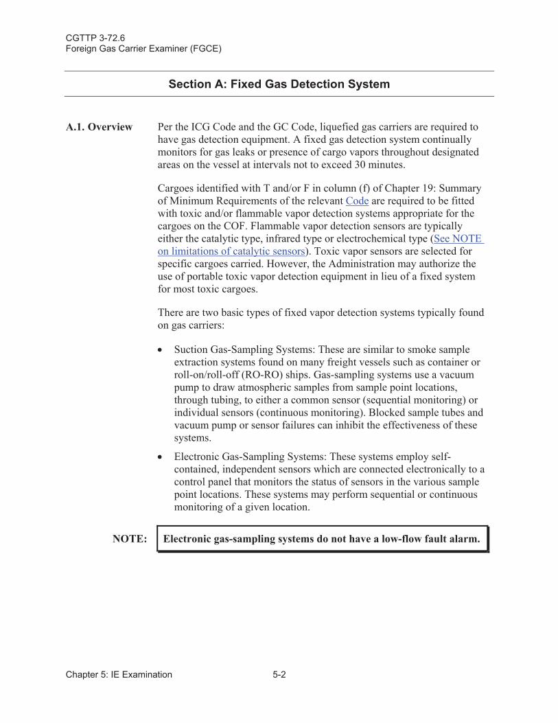
Section A: Fixed Gas Detection System
A.1. Overview Per the ICG Code and the GC Code, liquefied gas carriers are required to have gas detection equipment. A fixed gas detection system continually monitors for gas leaks or presence of cargo vapors throughout designated areas on the vessel at intervals not to exceed 30 minutes.
Cargoes identified with T and/or F in column (f) of Chapter 19: Summary of Minimum Requirements of the relevant Code are required to be fitted with toxic and/or flammable vapor detection systems appropriate for the cargoes on the COF. Flammable vapor detection sensors are typically either the catalytic type, infrared type or electrochemical type (See NOTEon limitations of catalytic sensors). Toxic vapor sensors are selected for specific cargoes carried. However, the Administration may authorize the use of portable toxic vapor detection equipment in lieu of a fixed system for most toxic cargoes.
There are two basic types of fixed vapor detection systems typically found on gas carriers:
Suction Gas-Sampling Systems: These are similar to smoke sample extraction systems found on many freight vessels such as container or roll-on/roll-off (RO-RO) ships. Gas-sampling systems use a vacuum pump to draw atmospheric samples from sample point locations, through tubing, to either a common sensor (sequential monitoring) or individual sensors (continuous monitoring). Blocked sample tubes and vacuum pump or sensor failures can inhibit the effectiveness of these systems.
Electronic Gas-Sampling Systems: These systems employ self-contained, independent sensors which are connected electronically to a control panel that monitors the status of sensors in the various sample point locations. These systems may perform sequential or continuous monitoring of a given location.
NOTE: Electronic gas-sampling systems do not have a low-flow fault alarm.
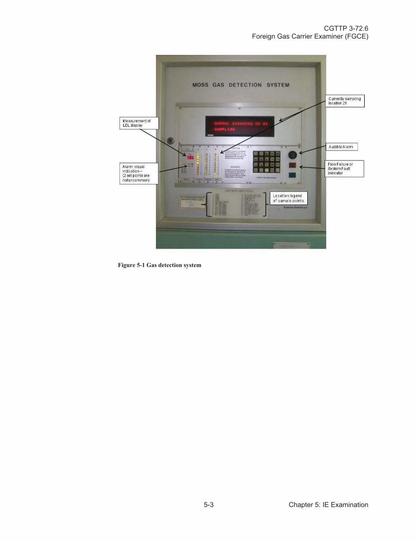
CGTTP 3-72.6Foreign Gas Carrier Examiner (FGCE)
5-3 Chapter 5: IE Examination
Figure 5-1 Gas detection system
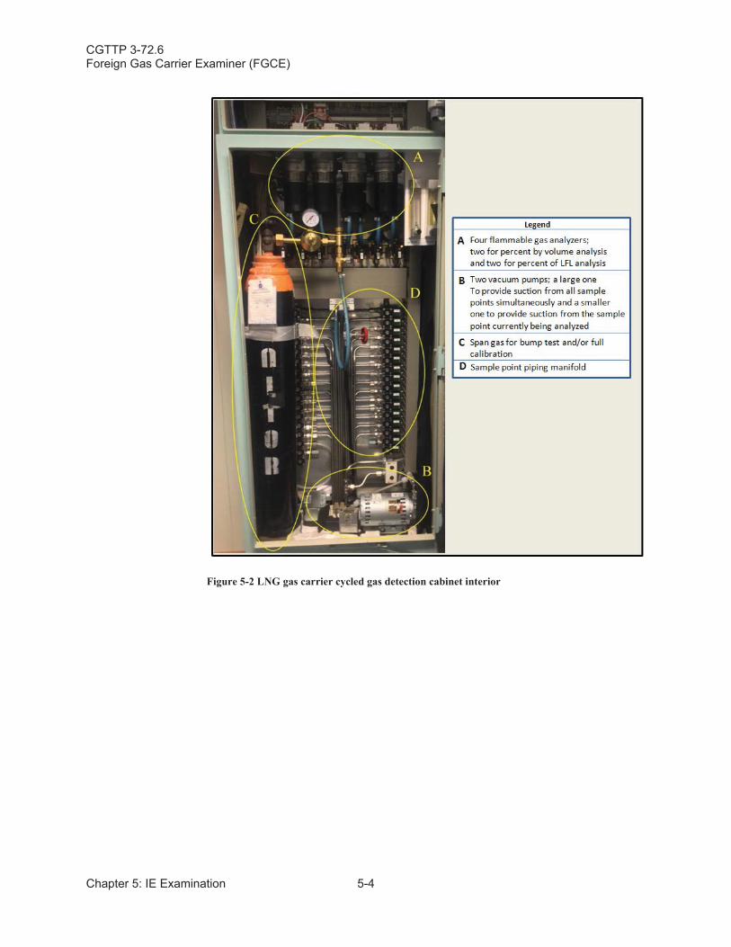
CGTTP 3-72.6Foreign Gas Carrier Examiner (FGCE)
Chapter 5: IE Examination 5-4
Figure 5-2 LNG gas carrier cycled gas detection cabinet interior
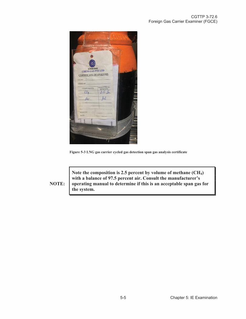
CGTTP 3-72.6Foreign Gas Carrier Examiner (FGCE)
5-5 Chapter 5: IE Examination
Figure 5-3 LNG gas carrier cycled gas detection span gas analysis certificate
NOTE:
Note the composition is 2.5 percent by volume of methane (CH4)with a balance of 97.5 percent air. Consult the manufacturer’s operating manual to determine if this is an acceptable span gas for the system.
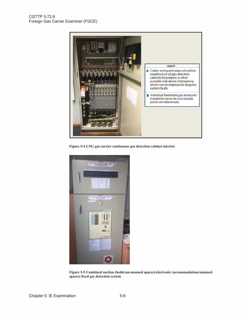
CGTTP 3-72.6Foreign Gas Carrier Examiner (FGCE)
Chapter 5: IE Examination 5-6
Figure 5-4 LNG gas carrier continuous gas detection cabinet interior
Figure 5-5 Combined suction (holds/un-manned spaces)/electronic (accommodations/manned spaces) fixed gas detection system
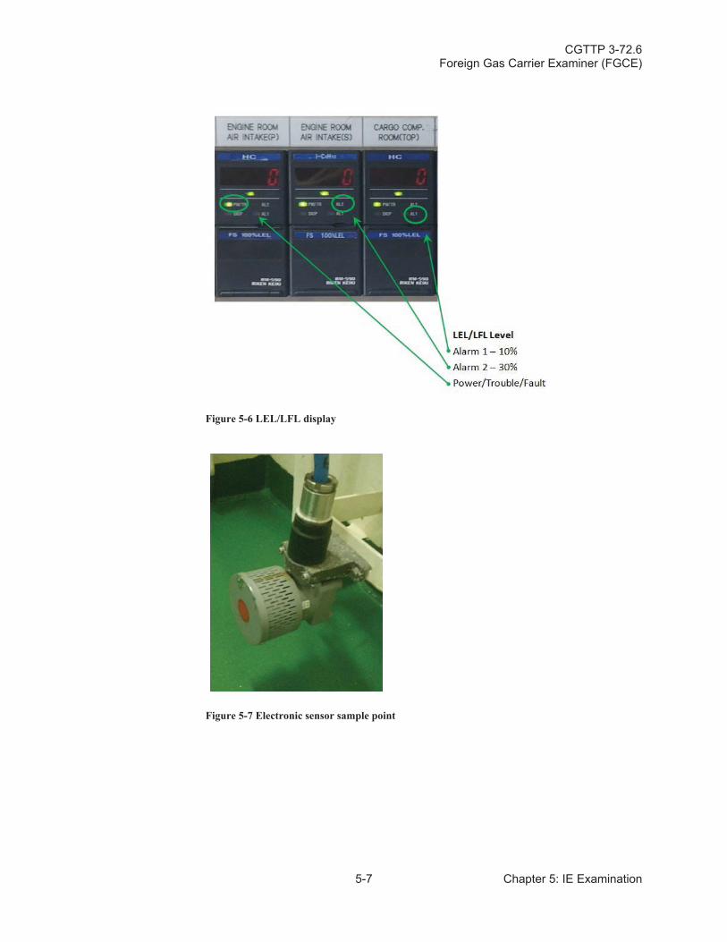
CGTTP 3-72.6Foreign Gas Carrier Examiner (FGCE)
5-7 Chapter 5: IE Examination
Figure 5-6 LEL/LFL display
Figure 5-7 Electronic sensor sample point
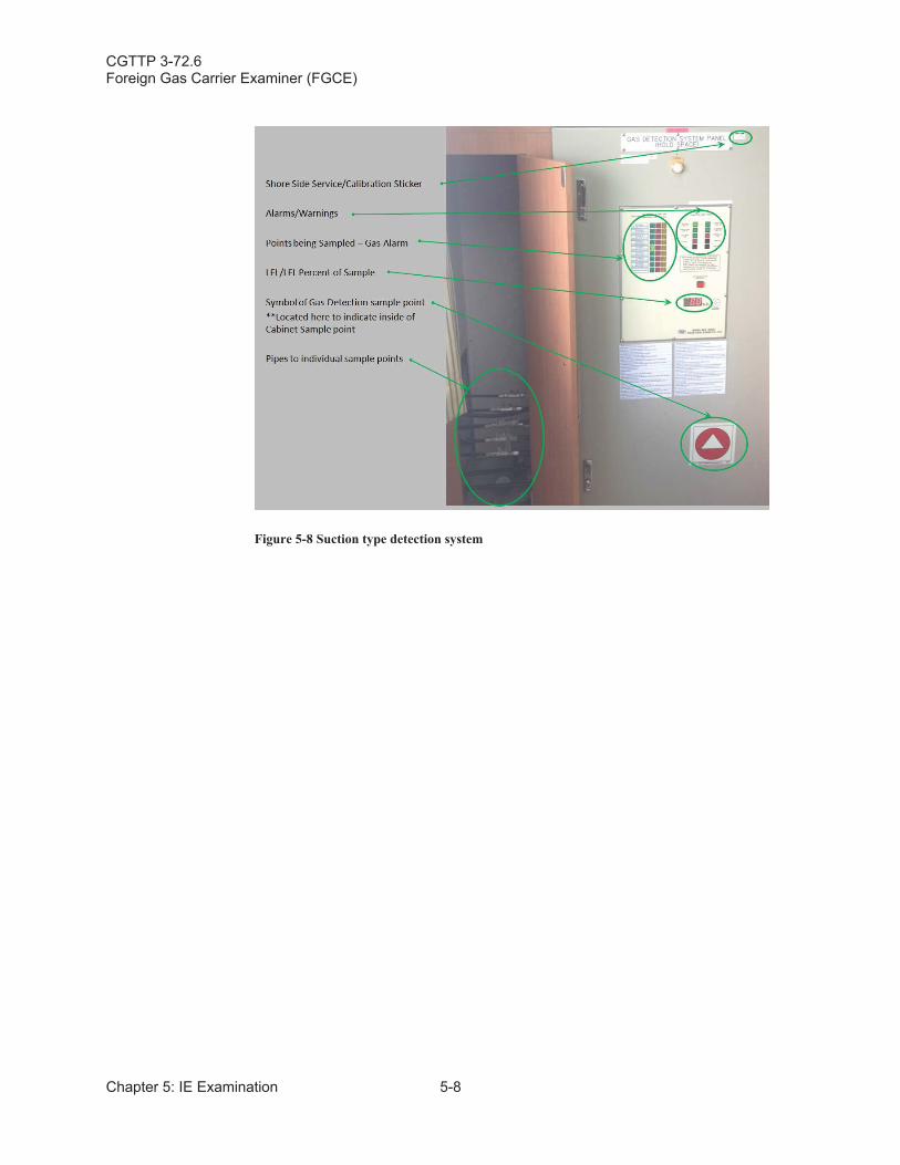
CGTTP 3-72.6Foreign Gas Carrier Examiner (FGCE)
Chapter 5: IE Examination 5-8
Figure 5-8 Suction type detection system
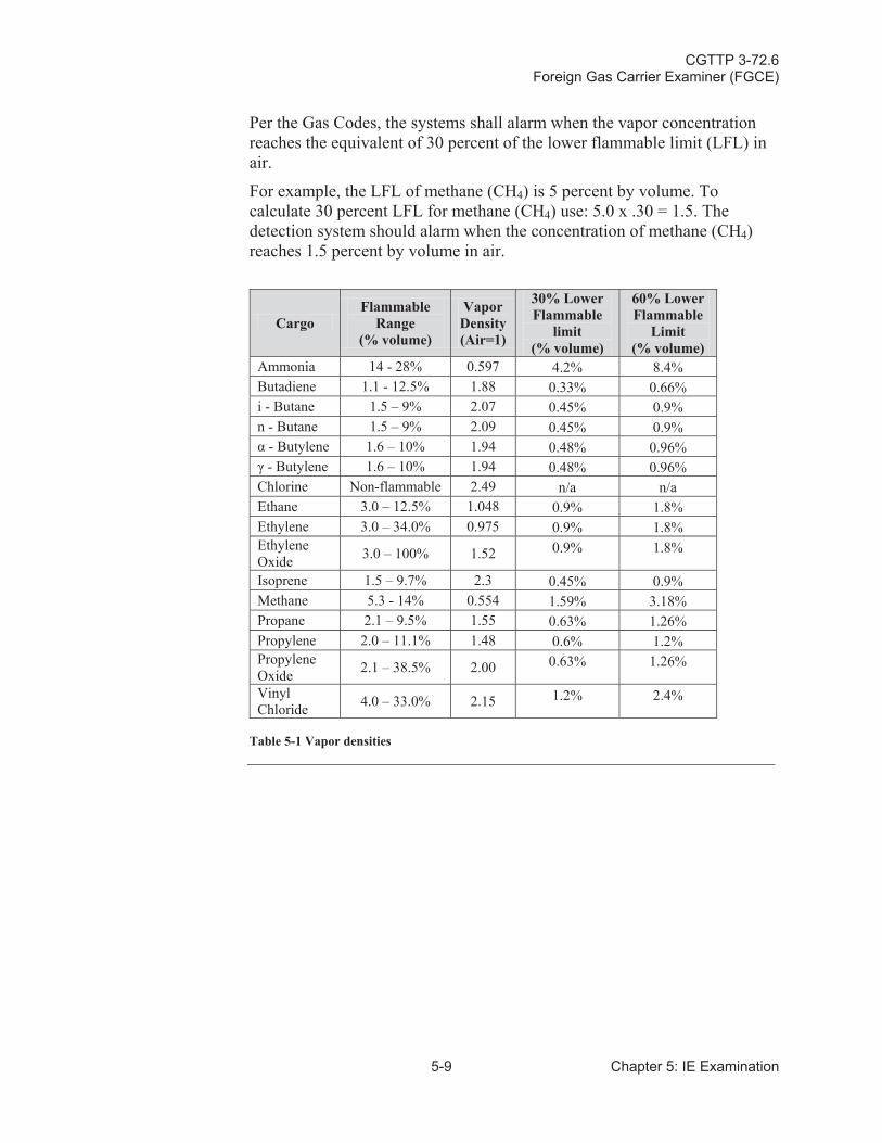
CGTTP 3-72.6Foreign Gas Carrier Examiner (FGCE)
5-9 Chapter 5: IE Examination
Per the Gas Codes, the systems shall alarm when the vapor concentration reaches the equivalent of 30 percent of the lower flammable limit (LFL) in air.
For example, the LFL of methane (CH4) is 5 percent by volume. To calculate 30 percent LFL for methane (CH4) use: 5.0 x .30 = 1.5. The detection system should alarm when the concentration of methane (CH4)reaches 1.5 percent by volume in air.
CargoFlammable
Range (% volume)
Vapor Density(Air=1)
30% Lower Flammable
limit(% volume)
60% Lower Flammable
Limit(% volume)
Ammonia 14 - 28% 0.597 4.2% 8.4%Butadiene 1.1 - 12.5% 1.88 0.33% 0.66%i - Butane 1.5 – 9% 2.07 0.45% 0.9%n - Butane 1.5 – 9% 2.09 0.45% 0.9%
- Butylene 1.6 – 10% 1.94 0.48% 0.96%- Butylene 1.6 – 10% 1.94 0.48% 0.96%
Chlorine Non-flammable 2.49 n/a n/aEthane 3.0 – 12.5% 1.048 0.9% 1.8%Ethylene 3.0 – 34.0% 0.975 0.9% 1.8%Ethylene Oxide 3.0 – 100% 1.52 0.9% 1.8%
Isoprene 1.5 – 9.7% 2.3 0.45% 0.9%Methane 5.3 - 14% 0.554 1.59% 3.18%Propane 2.1 – 9.5% 1.55 0.63% 1.26%Propylene 2.0 – 11.1% 1.48 0.6% 1.2%Propylene Oxide 2.1 – 38.5% 2.00 0.63% 1.26%
Vinyl Chloride 4.0 – 33.0% 2.15 1.2% 2.4%
Table 5-1 Vapor densities
CGTTP 3-72.6Foreign Gas Carrier Examiner (FGCE)
Chapter 5: IE Examination 5-10
A.2. Required Monitoring
Alarms are located on the navigation bridge, the cargo control room, and at the gas detector readout location. Some of the newer gas detection systems are electrochemical sensors. The sensor’s measuring performance is increased by means of a bias voltage being measured and kept constant by means of the reference-electrode and an electronic control circuit (so-called potentiostat circuit). These systems are normally only calibrated annually by a third party.
NOTE:Gas detection employing catalytic sensors which rely on oxygen [O2]cannot be used in atmospheres that are inert (deficient in O2) to check for percent LFL or percent by volume.
A.3. Conducting Exam
When conducting an examination of the fixed gas detection system, do the following:
Witness a satisfactory calibration of the fixed gas detection system.
NOTE: Request to see a certificate of calibration if gas carrier’s system was calibrated by a third party.
NOTE: Per the IGC Code, span gas for this purpose is required aboard the ship.
Verify gas detection alarms at 30 percent LFL.
Verify installation of sampling points or sensors (if using electrochemical sensors) in required spaces.
NOTE:
The IGC Code and the GC Code, identify the required gas detection sampling point’s spaces. Use the gas detection system section of the vessel’s Cargo Operations Manual to compare actual locations with required locations.
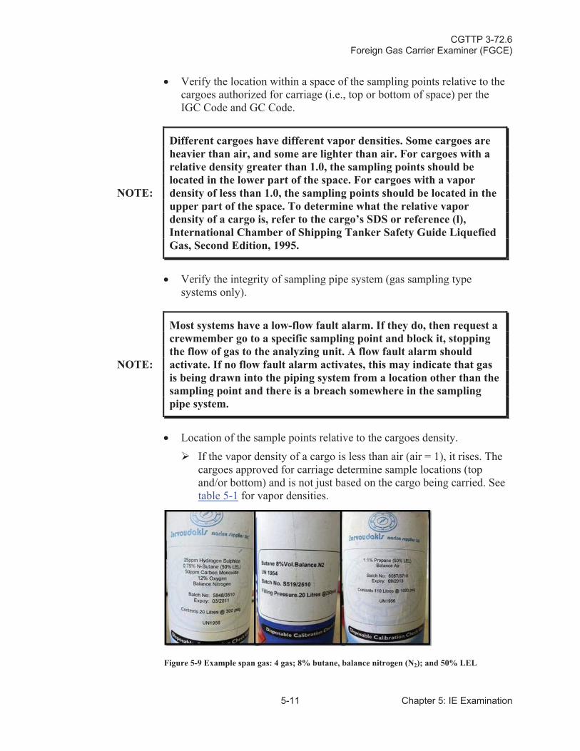
CGTTP 3-72.6Foreign Gas Carrier Examiner (FGCE)
5-11 Chapter 5: IE Examination
Verify the location within a space of the sampling points relative to the cargoes authorized for carriage (i.e., top or bottom of space) per the IGC Code and GC Code.
NOTE:
Different cargoes have different vapor densities. Some cargoes are heavier than air, and some are lighter than air. For cargoes with a relative density greater than 1.0, the sampling points should be located in the lower part of the space. For cargoes with a vapor density of less than 1.0, the sampling points should be located in the upper part of the space. To determine what the relative vapor density of a cargo is, refer to the cargo’s SDS or reference (l), International Chamber of Shipping Tanker Safety Guide Liquefied Gas, Second Edition, 1995.
Verify the integrity of sampling pipe system (gas sampling type systems only).
NOTE:
Most systems have a low-flow fault alarm. If they do, then request acrewmember go to a specific sampling point and block it, stopping the flow of gas to the analyzing unit. A flow fault alarm should activate. If no flow fault alarm activates, this may indicate that gas is being drawn into the piping system from a location other than the sampling point and there is a breach somewhere in the sampling pipe system.
Location of the sample points relative to the cargoes density.
If the vapor density of a cargo is less than air (air = 1), it rises. The cargoes approved for carriage determine sample locations (top and/or bottom) and is not just based on the cargo being carried. See table 5-1 for vapor densities.
Figure 5-9 Example span gas: 4 gas; 8% butane, balance nitrogen (N2); and 50% LEL
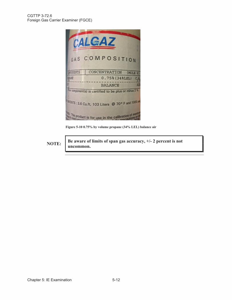
CGTTP 3-72.6Foreign Gas Carrier Examiner (FGCE)
Chapter 5: IE Examination 5-12
Figure 5-10 0.75% by volume propane (34% LEL) balance air
NOTE: Be aware of limits of span gas accuracy, +/- 2 percent is not uncommon.
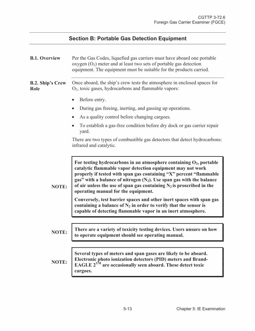
CGTTP 3-72.6Foreign Gas Carrier Examiner (FGCE)
5-13 Chapter 5: IE Examination
Section B: Portable Gas Detection Equipment
B.1. Overview Per the Gas Codes, liquefied gas carriers must have aboard one portable oxygen (O2) meter and at least two sets of portable gas detection equipment. The equipment must be suitable for the products carried.
B.2. Ship’s Crew Role
Once aboard, the ship’s crew tests the atmosphere in enclosed spaces for O2, toxic gases, hydrocarbons and flammable vapors:
Before entry.
During gas freeing, inerting, and gassing up operations.
As a quality control before changing cargoes.
To establish a gas-free condition before dry dock or gas carrier repair yard.
There are two types of combustible gas detectors that detect hydrocarbons: infrared and catalytic.
NOTE:
For testing hydrocarbons in an atmosphere containing O2, portable catalytic flammable vapor detection equipment may not work properly if tested with span gas containing “X” percent “flammable gas” with a balance of nitrogen (N2). Use span gas with the balance of air unless the use of span gas containing N2 is proscribed in the operating manual for the equipment.
Conversely, test barrier spaces and other inert spaces with span gas containing a balance of N2 in order to verify that the sensor is capable of detecting flammable vapor in an inert atmosphere.
NOTE: There are a variety of toxicity testing devices. Users unsure on how to operate equipment should see operating manual.
NOTE:
Several types of meters and span gases are likely to be aboard.Electronic photo ionization detectors (PID) meters and Brand-EAGLE 2TM are occasionally seen aboard. These detect toxic cargoes.
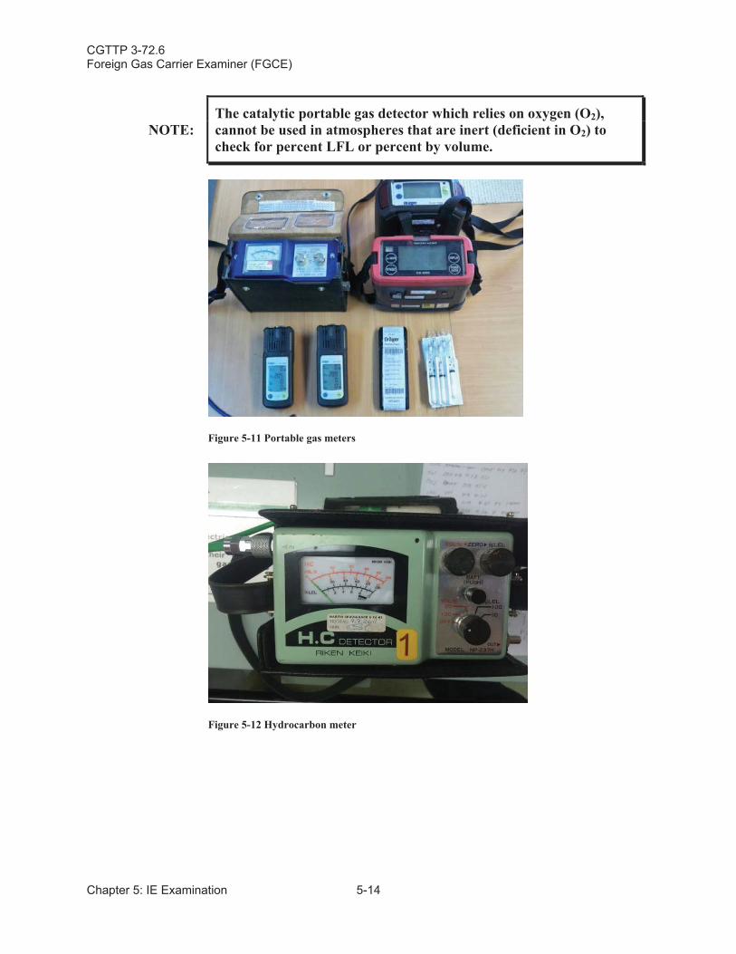
CGTTP 3-72.6Foreign Gas Carrier Examiner (FGCE)
Chapter 5: IE Examination 5-14
NOTE:The catalytic portable gas detector which relies on oxygen (O2),cannot be used in atmospheres that are inert (deficient in O2) to check for percent LFL or percent by volume.
Figure 5-11 Portable gas meters
Figure 5-12 Hydrocarbon meter
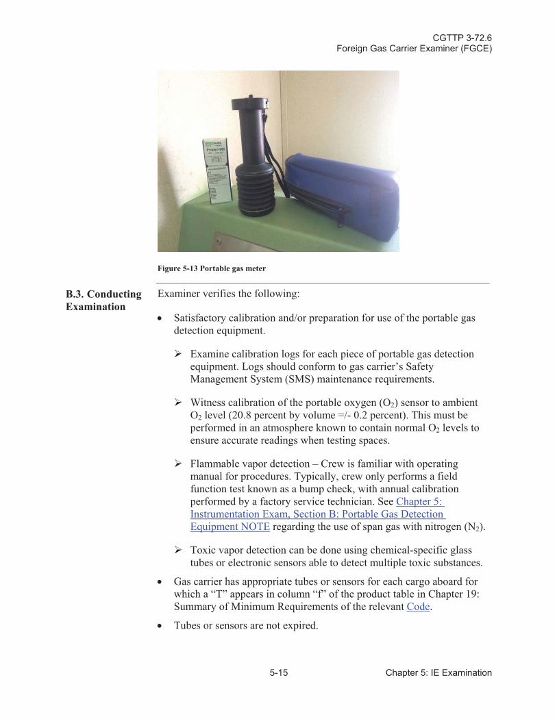
CGTTP 3-72.6Foreign Gas Carrier Examiner (FGCE)
5-15 Chapter 5: IE Examination
Figure 5-13 Portable gas meter
B.3. Conducting Examination
Examiner verifies the following:
Satisfactory calibration and/or preparation for use of the portable gas detection equipment.
Examine calibration logs for each piece of portable gas detection equipment. Logs should conform to gas carrier’s Safety Management System (SMS) maintenance requirements.
Witness calibration of the portable oxygen (O2) sensor to ambient O2 level (20.8 percent by volume =/- 0.2 percent). This must be performed in an atmosphere known to contain normal O2 levels to ensure accurate readings when testing spaces.
Flammable vapor detection – Crew is familiar with operating manual for procedures. Typically, crew only performs a field function test known as a bump check, with annual calibration performed by a factory service technician. See Chapter 5: Instrumentation Exam, Section B: Portable Gas Detection Equipment NOTE regarding the use of span gas with nitrogen (N2).
Toxic vapor detection can be done using chemical-specific glass tubes or electronic sensors able to detect multiple toxic substances.
Gas carrier has appropriate tubes or sensors for each cargo aboard for which a “T” appears in column “f” of the product table in Chapter 19:Summary of Minimum Requirements of the relevant Code.
Tubes or sensors are not expired.
CGTTP 3-72.6Foreign Gas Carrier Examiner (FGCE)
Chapter 5: IE Examination 5-16
Air-tight seal for vacuum pump, bellows or suction syringe. When the suction tip is sealed, the instrument should hold a vacuum.
NOTE:
DraegerTM and Gas TechTM are two common brands of testing “tubes” for toxics. They both operate similarly, but have different suction pumps; Gas TechTM has a suction syringe type pump and DraegerTM has a “squeeze bellows” pump. Both types require the operator to purge air out of the equipment and hose using an exact number of “pumps”, as indicated in the operating manual, in order to get an accurate reading.
NOTE: Toxic vapor tubes and changeable sensors can have errors of +/-25percent.
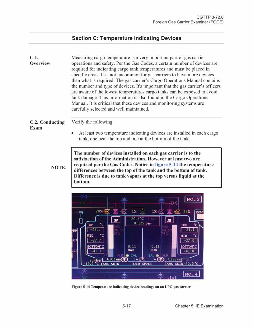
CGTTP 3-72.6Foreign Gas Carrier Examiner (FGCE)
5-17 Chapter 5: IE Examination
Section C: Temperature Indicating Devices
C.1.Overview
Measuring cargo temperature is a very important part of gas carrier operations and safety. Per the Gas Codes, a certain number of devices are required for indicating cargo tank temperatures and must be placed in specific areas. It is not uncommon for gas carriers to have more devices than what is required. The gas carrier’s Cargo Operations Manual contains the number and type of devices. It's important that the gas carrier’s officersare aware of the lowest temperatures cargo tanks can be exposed to avoid tank damage. This information is also found in the Cargo Operations Manual. It is critical that these devices and monitoring systems are carefully selected and well maintained.
C.2. Conducting Exam
Verify the following:
At least two temperature indicating devices are installed in each cargo tank, one near the top and one at the bottom of the tank.
NOTE:
The number of devices installed on each gas carrier is to the satisfaction of the Administration. However at least two are required per the Gas Codes. Notice in figure 5-14 the temperature differences between the top of the tank and the bottom of tank. Difference is due to tank vapors at the top versus liquid at the bottom.
Figure 5-14 Temperature indicating device readings on an LPG gas carrier
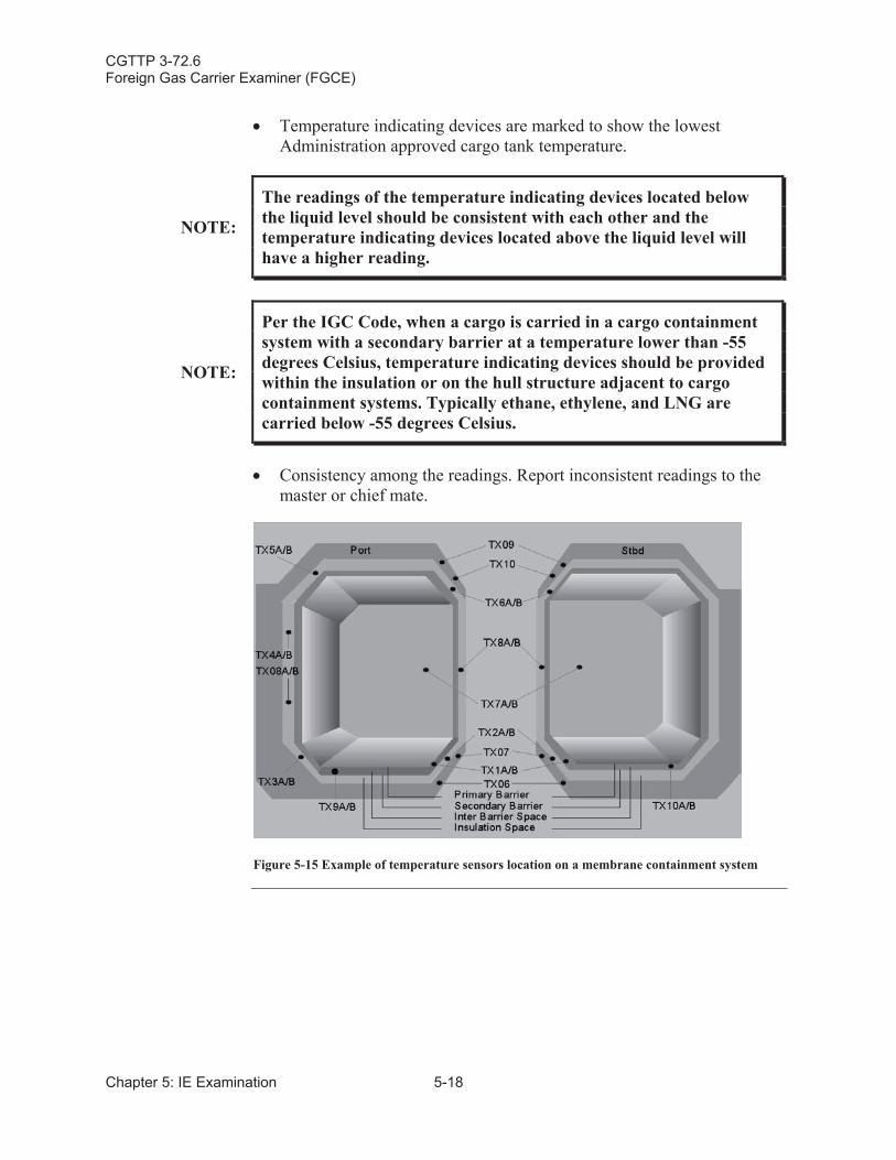
CGTTP 3-72.6Foreign Gas Carrier Examiner (FGCE)
Chapter 5: IE Examination 5-18
Temperature indicating devices are marked to show the lowest Administration approved cargo tank temperature.
NOTE:
The readings of the temperature indicating devices located below the liquid level should be consistent with each other and the temperature indicating devices located above the liquid level will have a higher reading.
NOTE:
Per the IGC Code, when a cargo is carried in a cargo containment system with a secondary barrier at a temperature lower than -55degrees Celsius, temperature indicating devices should be provided within the insulation or on the hull structure adjacent to cargo containment systems. Typically ethane, ethylene, and LNG are carried below -55 degrees Celsius.
Consistency among the readings. Report inconsistent readings to the master or chief mate.
Figure 5-15 Example of temperature sensors location on a membrane containment system
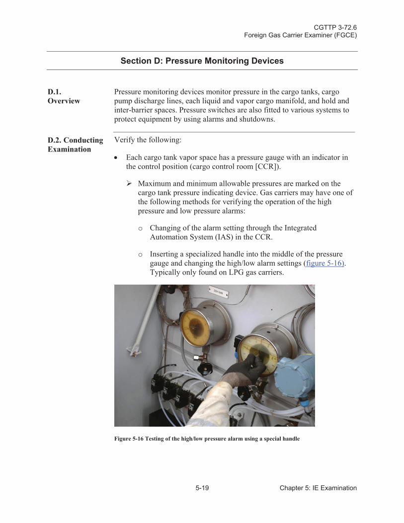
CGTTP 3-72.6Foreign Gas Carrier Examiner (FGCE)
5-19 Chapter 5: IE Examination
Section D: Pressure Monitoring Devices
D.1.Overview
Pressure monitoring devices monitor pressure in the cargo tanks, cargo pump discharge lines, each liquid and vapor cargo manifold, and hold and inter-barrier spaces. Pressure switches are also fitted to various systems to protect equipment by using alarms and shutdowns.
D.2. Conducting Examination
Verify the following:
Each cargo tank vapor space has a pressure gauge with an indicator in the control position (cargo control room [CCR]).
Maximum and minimum allowable pressures are marked on the cargo tank pressure indicating device. Gas carriers may have one of the following methods for verifying the operation of the high pressure and low pressure alarms:
o Changing of the alarm setting through the Integrated Automation System (IAS) in the CCR.
o Inserting a specialized handle into the middle of the pressure gauge and changing the high/low alarm settings (figure 5-16).Typically only found on LPG gas carriers.
Figure 5-16 Testing of the high/low pressure alarm using a special handle
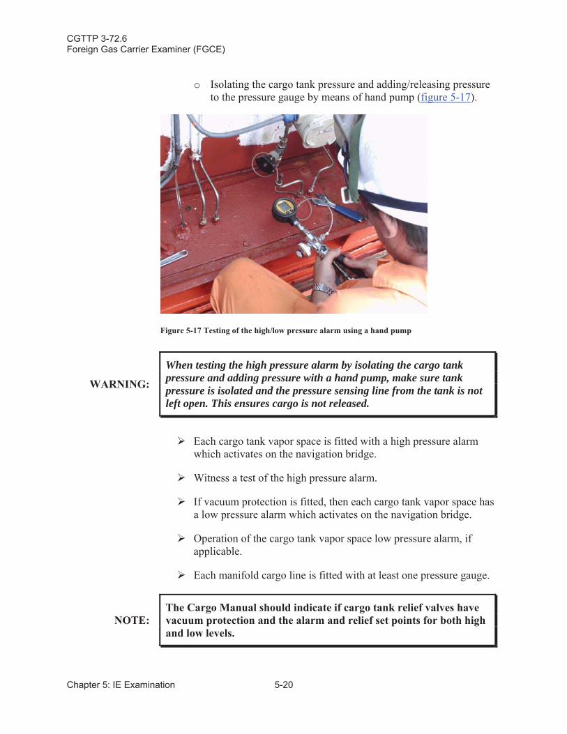
CGTTP 3-72.6Foreign Gas Carrier Examiner (FGCE)
Chapter 5: IE Examination 5-20
o Isolating the cargo tank pressure and adding/releasing pressure to the pressure gauge by means of hand pump (figure 5-17).
Figure 5-17 Testing of the high/low pressure alarm using a hand pump
WARNING:
When testing the high pressure alarm by isolating the cargo tank pressure and adding pressure with a hand pump, make sure tank pressure is isolated and the pressure sensing line from the tank is not left open. This ensures cargo is not released.
Each cargo tank vapor space is fitted with a high pressure alarmwhich activates on the navigation bridge.
Witness a test of the high pressure alarm.
If vacuum protection is fitted, then each cargo tank vapor space has a low pressure alarm which activates on the navigation bridge.
Operation of the cargo tank vapor space low pressure alarm, if applicable.
Each manifold cargo line is fitted with at least one pressure gauge.
NOTE:The Cargo Manual should indicate if cargo tank relief valves have vacuum protection and the alarm and relief set points for both high and low levels.
CGTTP 3-72.6Foreign Gas Carrier Examiner (FGCE)
5-21 Chapter 5: IE Examination
WARNING:
The manifold local pressure gauge required by the IGC Code is used by ship’s personnel when connecting/disconnecting the cargo manifold to ensure their safety. If pressure is in the line, steps to relieve the pressure must be taken before loosening flange bolts.
Hold/inter-barrier spaces without open communication to the atmosphere are provided with operational pressure gauges.
CGTTP 3-72.6Foreign Gas Carrier Examiner (FGCE)
Chapter 5: IE Examination 5-22
Section E: Overflow Control System
E.1.Overview
The overflow control system provides a warning to shipboard personnel before the cargo tanks become full. It also initiates isolation of those cargo tanks by closing the liquid fill line valves.
Each cargo tank is fitted with a high liquid level alarm operating independently of other liquid level indicators and gives an audible/visual alarm. Another sensor operating independently of the high level alarm automatically closes a shutoff valve in the cargo tank filling line to prevent the cargo tank from overflowing. Consult the Cargo Manual for further guidance.
The authorized loading limits are provided by the Administration to the master and are located on the COF. Per the IGC Code and the GC Code,ship’s crew shall not load liquefied gas carriers more than 98 percent,unless authorized by the Administration.
E.2. Conducting Examination
Verify the following:
High level alarm provides both an audible and visual warning.
NOTE:
On most gas carriers, you can witness system testing by a crewmember lifting up the test actuator, located underneath the screw cap (see figure 5-18). Before testing, the crewmember should open the liquid filling valves to that particular cargo tank, so that during testing the filling valves automatically close.
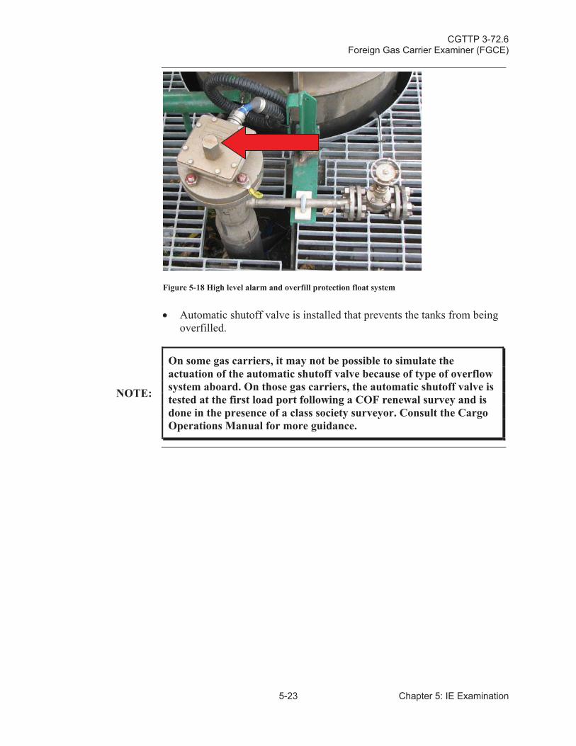
CGTTP 3-72.6Foreign Gas Carrier Examiner (FGCE)
5-23 Chapter 5: IE Examination
Figure 5-18 High level alarm and overfill protection float system
Automatic shutoff valve is installed that prevents the tanks from being overfilled.
NOTE:
On some gas carriers, it may not be possible to simulate the actuation of the automatic shutoff valve because of type of overflow system aboard. On those gas carriers, the automatic shutoff valve is tested at the first load port following a COF renewal survey and is done in the presence of a class society surveyor. Consult the Cargo Operations Manual for more guidance.

CGTTP 3-72.6Foreign Gas Carrier Examiner (FGCE)
Chapter 5: IE Examination 5-24
This page intentionally left blank.
CGTTP 3-72.6Foreign Gas Carrier Examiner (FGCE)
6-1 Chapter 6: GH and Safety Examination
Chapter 6:General Health (GH) and Safety Examination
Introduction This chapter discusses the various requirements and procedures for conducting a general health (GH) and safety examination.
In This Chapter This chapter contains the following sections:
Section Title Page
A Decontamination Showers and Eye Wash Stations 6-2
B Respiratory and Eye Protection for Emergency Escape Purposes
6-3
C Personnel Safety Equipment 6-4
D First Aid Equipment 6-6
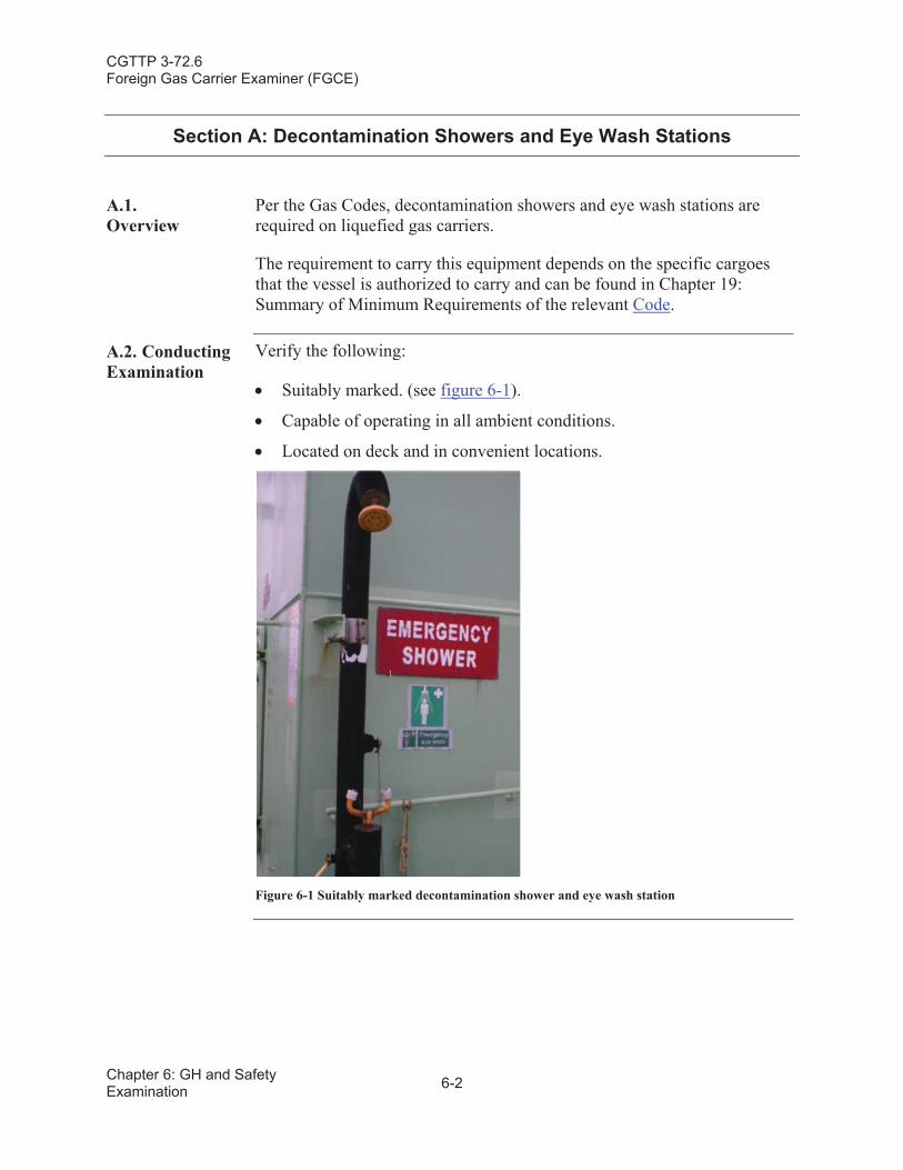
CGTTP 3-72.6Foreign Gas Carrier Examiner (FGCE)
Chapter 6: GH and Safety Examination 6-2
Section A: Decontamination Showers and Eye Wash Stations
A.1.Overview
Per the Gas Codes, decontamination showers and eye wash stations are required on liquefied gas carriers.
The requirement to carry this equipment depends on the specific cargoes that the vessel is authorized to carry and can be found in Chapter 19:Summary of Minimum Requirements of the relevant Code.
A.2. Conducting Examination
Verify the following:
Suitably marked. (see figure 6-1).
Capable of operating in all ambient conditions.
Located on deck and in convenient locations.
Figure 6-1 Suitably marked decontamination shower and eye wash station
CGTTP 3-72.6Foreign Gas Carrier Examiner (FGCE)
6-3 Chapter 6: GH and Safety Examination
Section B: Respiratory and Eye Protection for Emergency Escape Purposes
B.1.Overview
Per the IGC Code, respiratory and eye protection for emergency escape purposes are required on liquefied gas carriers. The requirement to carry this equipment depends on the specific cargoes that the vessel is authorized to carry and can be found in Chapter 19: Summary of Minimum Requirements of the relevant Code.
B.2. Conducting Exam
Verify the following:
Provided for each person aboard and two additional sets of respiratory and eye protection are permanently located on the bridge for navigation watch personnel.
Respirator is not a filter type.
Self-Contained Breathing Apparatus (SCBA) with 15 minutes of oxygen (O2) supply.
Identified for escape purposes only and is not used for cargo handling or firefighting purposes.
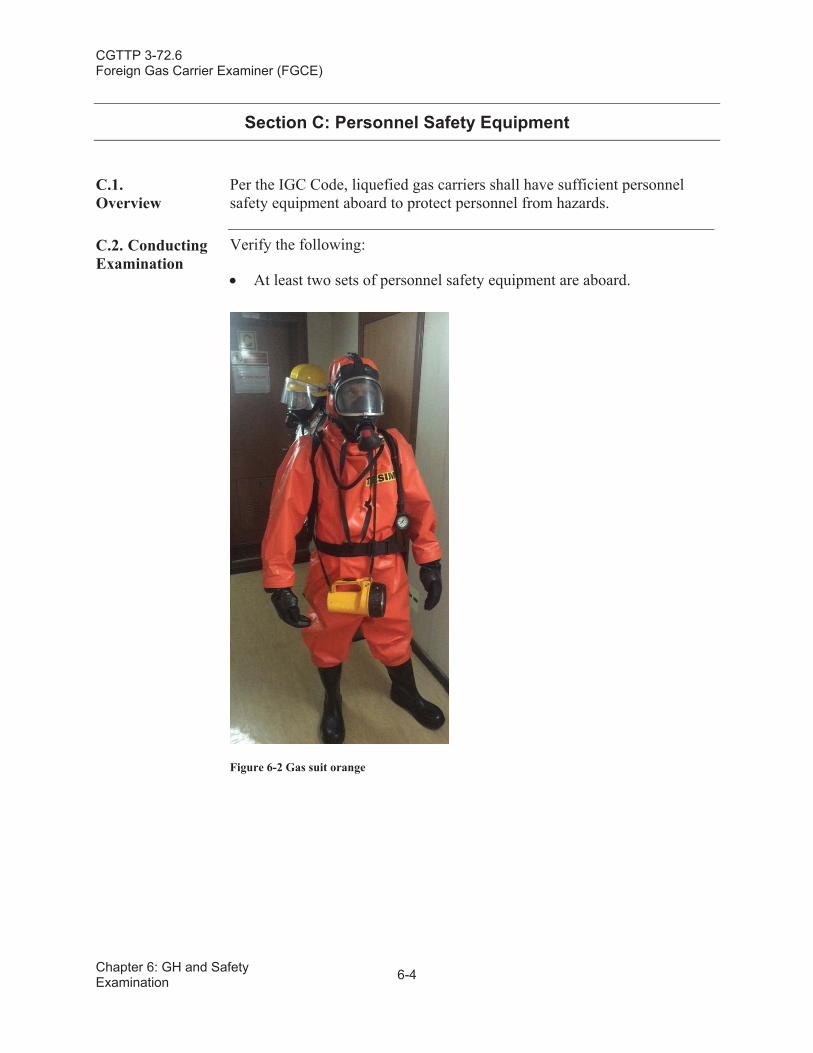
CGTTP 3-72.6Foreign Gas Carrier Examiner (FGCE)
Chapter 6: GH and Safety Examination 6-4
Section C: Personnel Safety Equipment
C.1.Overview
Per the IGC Code, liquefied gas carriers shall have sufficient personnelsafety equipment aboard to protect personnel from hazards.
C.2. Conducting Examination
Verify the following:
At least two sets of personnel safety equipment are aboard.
Figure 6-2 Gas suit orange
CGTTP 3-72.6Foreign Gas Carrier Examiner (FGCE)
6-5 Chapter 6: GH and Safety Examination
Each set of personnel safety equipment contains the requiredequipment as follows:
One SCBA with at least 1,200 liters of free air.
Protective clothing, boots, gloves and tight fitting goggles.
Steel-cored rescue line.
Explosion proof lamp.
An adequate supply of compressed air is available as required by relevant Code.
Compressed air used for safety equipment is inspected once a month by a gas carrier’s officer.
Compressed air used for safety equipment is inspected once a year by an expert.
NOTE:
An expert typically is an individual, not part of the vessel's crew, who works ashore at a facility that conducts servicing and inspections on compressed air equipment used for breathing purposes.
Per the IGC Code, when 14.4.4 is listed in column (i) (Special Requirements) of Chapter 19 for the cargo being carried, and the vessel has a cargo capacity of more than 2,000 cubic meters (m3), two additional sets of safety equipment are provided with at least three spare charged air bottles for each additional set.
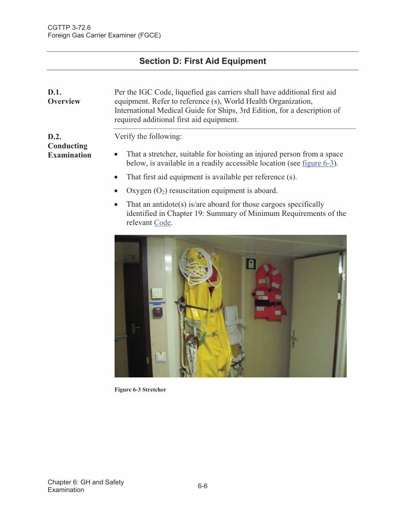
CGTTP 3-72.6Foreign Gas Carrier Examiner (FGCE)
Chapter 6: GH and Safety Examination 6-6
Section D: First Aid Equipment
D.1.Overview
Per the IGC Code, liquefied gas carriers shall have additional first aid equipment. Refer to reference (s), World Health Organization, International Medical Guide for Ships, 3rd Edition, for a description of required additional first aid equipment.
D.2.Conducting Examination
Verify the following:
That a stretcher, suitable for hoisting an injured person from a space below, is available in a readily accessible location (see figure 6-3).
That first aid equipment is available per reference (s).
Oxygen (O2) resuscitation equipment is aboard.
That an antidote(s) is/are aboard for those cargoes specifically identified in Chapter 19: Summary of Minimum Requirements of the relevant Code.
Figure 6-3 Stretcher
CGTTP 3-72.6Foreign Gas Carrier Examiner (FGCE)
6-7 Chapter 6: GH and Safety Examination
NOTE:
Reference (t), Medical First Aid Guide for use in Accidents Involving Dangerous Goods (MFAG), 1994 Edition, includes the numbers of products covered by the Code(s) and the emergency procedures to apply in the event of an incident. Reference (t)numbers related to products covered by the Code(s) are given in the Code’s Table of Minimum Requirements.
Currently, reference (t) does not state the specific antidotes required by name. If there is concern the gas carrier may not have the appropriate antidote(s) aboard, request proper documentation from either the gas carrier’s Classification Society or Flag State.
CGTTP 3-72.6Foreign Gas Carrier Examiner (FGCE)
Chapter 6: GH and Safety Examination 6-8
This page intentionally left blank.
CGTTP 3-72.6Foreign Gas Carrier Examiner (FGCE)
7-1 Chapter 7: AL Examination
Chapter 7:Air Lock (AL) Examination
Introduction This chapter discusses the various requirements and procedures for conducting air lock (AL) examinations.
In This Chapter This chapter contains the following sections:
Section Title Page
A Air Locks 7-2
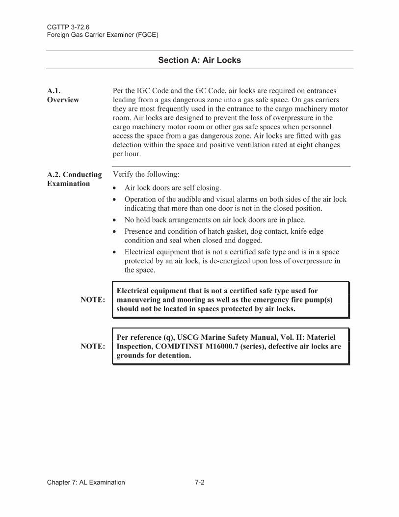
CGTTP 3-72.6Foreign Gas Carrier Examiner (FGCE)
Chapter 7: AL Examination 7-2
Section A: Air Locks
A.1.Overview
Per the IGC Code and the GC Code, air locks are required on entrances leading from a gas dangerous zone into a gas safe space. On gas carriers they are most frequently used in the entrance to the cargo machinery motor room. Air locks are designed to prevent the loss of overpressure in the cargo machinery motor room or other gas safe spaces when personnel access the space from a gas dangerous zone. Air locks are fitted with gas detection within the space and positive ventilation rated at eight changes per hour.
A.2. Conducting Examination
Verify the following:
Air lock doors are self closing.Operation of the audible and visual alarms on both sides of the air lock indicating that more than one door is not in the closed position. No hold back arrangements on air lock doors are in place.Presence and condition of hatch gasket, dog contact, knife edgecondition and seal when closed and dogged.Electrical equipment that is not a certified safe type and is in a space protected by an air lock, is de-energized upon loss of overpressure in the space.
NOTE:Electrical equipment that is not a certified safe type used for maneuvering and mooring as well as the emergency fire pump(s) should not be located in spaces protected by air locks.
NOTE:Per reference (q), USCG Marine Safety Manual, Vol. II: MaterielInspection, COMDTINST M16000.7 (series), defective air locks are grounds for detention.
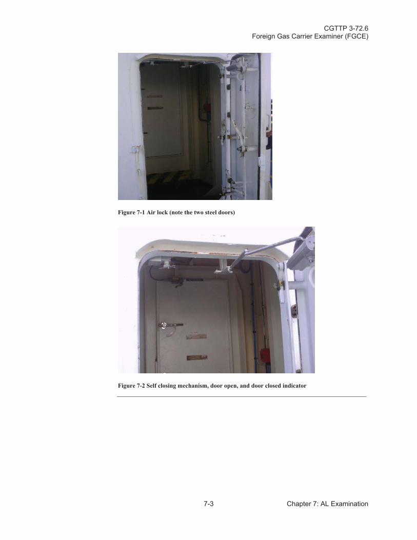
CGTTP 3-72.6Foreign Gas Carrier Examiner (FGCE)
7-3 Chapter 7: AL Examination
Figure 7-1 Air lock (note the two steel doors)
Figure 7-2 Self closing mechanism, door open, and door closed indicator

CGTTP 3-72.6Foreign Gas Carrier Examiner (FGCE)
Chapter 7: AL Examination 7-4
This page intentionally left blank.
CGTTP 3-72.6Foreign Gas Carrier Examiner (FGCE)
8-1 Chapter 8: CS Examination
Chapter 8:Cargo Systems (CS) Examination
Introduction This chapter discusses the various requirements and procedures for conducting a cargo systems (CS) examination.
In This Chapter This chapter contains the following sections:
Section Title Page
A Emergency Shutdown (ESD) System 8-2
B Cargo Tank Pressure Relief Valves 8-8
C Cargo Piping 8-17
D Cargo System Shutoff Valves 8-20
E Cargo Machinery Room (Cargo Compressor Room) Equipment Exam
8-22
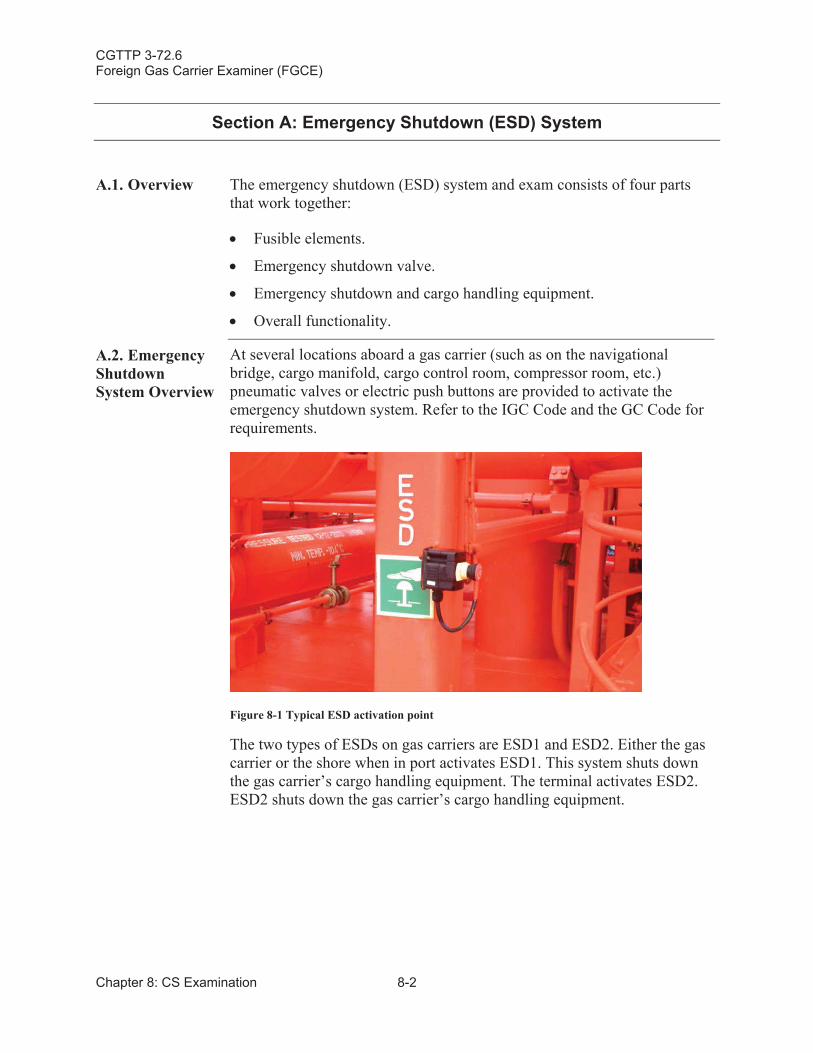
CGTTP 3-72.6Foreign Gas Carrier Examiner (FGCE)
Chapter 8: CS Examination 8-2
Section A: Emergency Shutdown (ESD) System
A.1. Overview The emergency shutdown (ESD) system and exam consists of four parts that work together:
Fusible elements.
Emergency shutdown valve.
Emergency shutdown and cargo handling equipment.
Overall functionality.
A.2. Emergency Shutdown System Overview
At several locations aboard a gas carrier (such as on the navigational bridge, cargo manifold, cargo control room, compressor room, etc.) pneumatic valves or electric push buttons are provided to activate the emergency shutdown system. Refer to the IGC Code and the GC Code for requirements.
Figure 8-1 Typical ESD activation point
The two types of ESDs on gas carriers are ESD1 and ESD2. Either the gas carrier or the shore when in port activates ESD1. This system shuts down the gas carrier’s cargo handling equipment. The terminal activates ESD2.ESD2 shuts down the gas carrier’s cargo handling equipment.
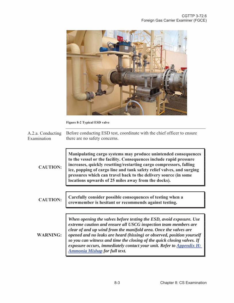
CGTTP 3-72.6Foreign Gas Carrier Examiner (FGCE)
8-3 Chapter 8: CS Examination
Figure 8-2 Typical ESD valve
A.2.a. Conducting Examination
Before conducting ESD test, coordinate with the chief officer to ensure there are no safety concerns.
CAUTION:
Manipulating cargo systems may produce unintended consequences to the vessel or the facility. Consequences include rapid pressureincreases, quickly resetting/restarting cargo compressors, falling ice, popping of cargo line and tank safety relief valves, and surging pressures which can travel back to the delivery source (in some locations upwards of 25 miles away from the docks).
CAUTION: Carefully consider possible consequences of testing when acrewmember is hesitant or recommends against testing.
WARNING:
When opening the valves before testing the ESD, avoid exposure. Useextreme caution and ensure all USCG inspection team members are clear of and up wind from the manifold area. Once the valves are opened and no leaks are heard (hissing) or observed, position yourself so you can witness and time the closing of the quick closing valves. If exposure occurs, immediately contact your unit. Refer to Appendix H:Ammonia Mishap for full text.
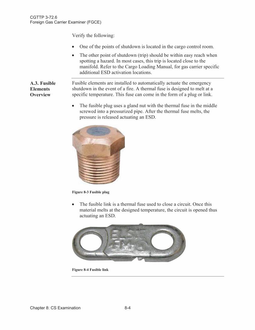
CGTTP 3-72.6Foreign Gas Carrier Examiner (FGCE)
Chapter 8: CS Examination 8-4
Verify the following:
One of the points of shutdown is located in the cargo control room.
The other point of shutdown (trip) should be within easy reach whenspotting a hazard. In most cases, this trip is located close to the manifold. Refer to the Cargo Loading Manual, for gas carrier specific additional ESD activation locations.
A.3. Fusible ElementsOverview
Fusible elements are installed to automatically actuate the emergency shutdown in the event of a fire. A thermal fuse is designed to melt at a specific temperature. This fuse can come in the form of a plug or link.
The fusible plug uses a gland nut with the thermal fuse in the middle screwed into a pressurized pipe. After the thermal fuse melts, the pressure is released actuating an ESD.
Figure 8-3 Fusible plug
The fusible link is a thermal fuse used to close a circuit. Once this material melts at the designed temperature, the circuit is opened thus actuating an ESD.
Figure 8-4 Fusible link
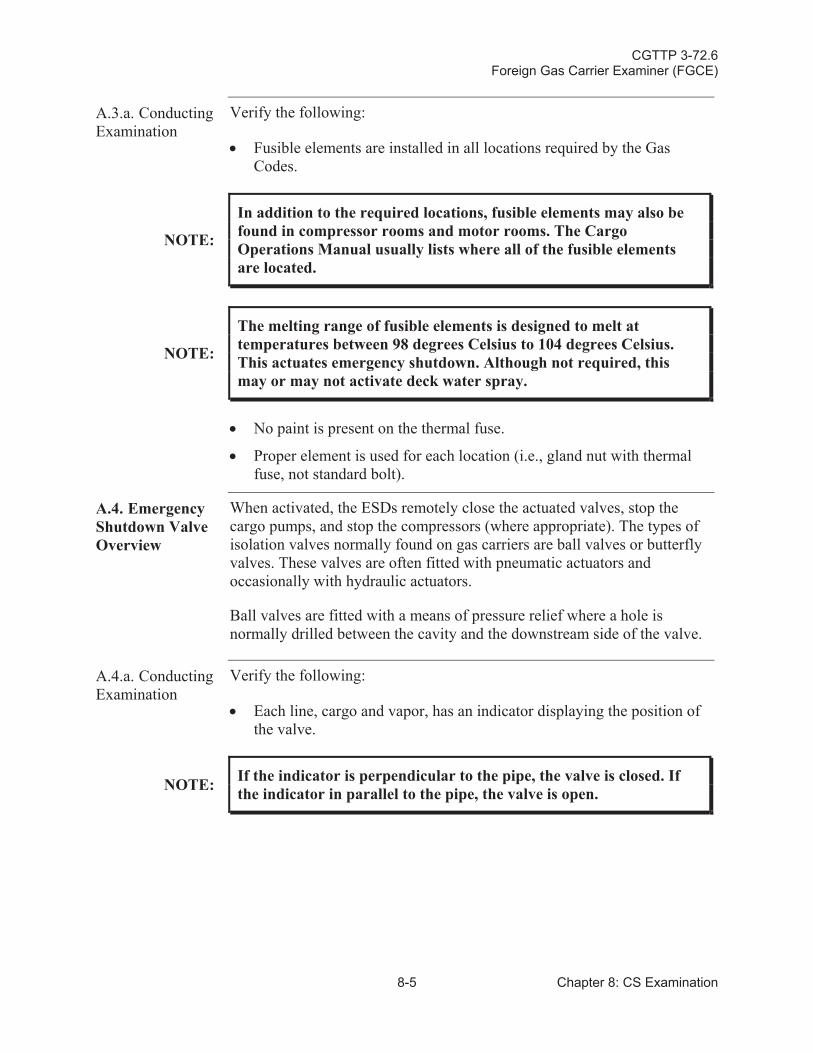
CGTTP 3-72.6Foreign Gas Carrier Examiner (FGCE)
8-5 Chapter 8: CS Examination
A.3.a. Conducting Examination
Verify the following:
Fusible elements are installed in all locations required by the Gas Codes.
NOTE:
In addition to the required locations, fusible elements may also be found in compressor rooms and motor rooms. The Cargo Operations Manual usually lists where all of the fusible elements are located.
NOTE:
The melting range of fusible elements is designed to melt at temperatures between 98 degrees Celsius to 104 degrees Celsius. This actuates emergency shutdown. Although not required, this may or may not activate deck water spray.
No paint is present on the thermal fuse.
Proper element is used for each location (i.e., gland nut with thermal fuse, not standard bolt).
A.4. Emergency Shutdown ValveOverview
When activated, the ESDs remotely close the actuated valves, stop the cargo pumps, and stop the compressors (where appropriate). The types of isolation valves normally found on gas carriers are ball valves or butterfly valves. These valves are often fitted with pneumatic actuators and occasionally with hydraulic actuators.
Ball valves are fitted with a means of pressure relief where a hole is normally drilled between the cavity and the downstream side of the valve.
A.4.a. Conducting Examination
Verify the following:
Each line, cargo and vapor, has an indicator displaying the position of the valve.
NOTE: If the indicator is perpendicular to the pipe, the valve is closed. If the indicator in parallel to the pipe, the valve is open.
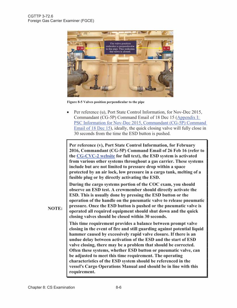
CGTTP 3-72.6Foreign Gas Carrier Examiner (FGCE)
Chapter 8: CS Examination 8-6
Figure 8-5 Valves position perpendicular to the pipe
Per reference (u), Port State Control Information, for Nov-Dec 2015, Commandant (CG-5P) Command Email of 18 Dec 15 (Appendix I:PSC Information for Nov-Dec 2015, Commandant (CG-5P) Command Email of 18 Dec 15), ideally, the quick closing valve will fully close in 30 seconds from the time the ESD button is pushed.
NOTE:
Per reference (v), Port State Control Information, for February 2016, Commandant (CG-5P) Command Email of 26 Feb 16 (refer to the CG-CVC-2 website for full text), the ESD system is activated from various other systems throughout a gas carrier. These systems include but are not limited to pressure drop within a space protected by an air lock, low pressure in a cargo tank, melting of a fusible plug or by directly activating the ESD.During the cargo systems portion of the COC exam, you should observe an ESD test. A crewmember should directly activate the ESD. This is usually done by pressing the ESD button or the operation of the handle on the pneumatic valve to release pneumatic pressure. Once the ESD button is pushed or the pneumatic valve is operated all required equipment should shut down and the quick closing valves should be closed within 30 seconds.This time requirement provides a balance between prompt valve closing in the event of fire and still guarding against potential liquid hammer caused by excessively rapid valve closure. If there is anundue delay between activation of the ESD and the start of ESD valve closing, there may be a problem that should be corrected. Often these systems, whether ESD button or pneumatic valve, can be adjusted to meet this time requirement. The operating characteristics of the ESD system should be referenced in the vessel's Cargo Operations Manual and should be in line with this requirement.
CGTTP 3-72.6Foreign Gas Carrier Examiner (FGCE)
8-7 Chapter 8: CS Examination
CAUTION: Variables in response time include ambient temperature and product flow rate.
CAUTION:
Reference (w), An Introduction to the Design and Maintenance of Cargo System Pressure Relief Valves on Board Gas Carriers,SIGTTO, 1998, recommends that these valves close between 25-30seconds. By closing too fast a build-up of pressure could cause damage to the piping system with the possibility of leakage.
The actual closing time is referenced in the Cargo Operations Manual and is reproducible.
A.5. Emergency Shutdown and Cargo Handling Equipment Overview
When activated, the ESDs remotely close the actuated valves, stop the cargo pumps, and stop the compressors (where appropriate).
A.5.a. Conducting Examination
Verify that cargo pumps and compressors shutdown after ESD is initiated.
NOTE:
An operational test to demonstrate this step may not always bepossible. Factors precluding you from witnessing a shutdown of cargo pumps and compressors include; loading/discharging operations that are underway, pressure of cargo tanks, and the amount of time required to put the equipment back on line. Coordinate with the chief mate/master before witnessing the shutdown of pumps and compressors.
NOTE:More information about ESD arrangements can be found in reference (x), ESD Arrangements & Linked Ship/Shore Systems for Liquefied Gas Carriers, SIGTTO 2009.
CGTTP 3-72.6Foreign Gas Carrier Examiner (FGCE)
Chapter 8: CS Examination 8-8
Section B: Cargo Tank Pressure Relief Valves
B.1. Overview LPG gas carriers have cargo tank relief valves which can be changed by the crew (i.e. Harbor and At Sea settings). These settings are changed by insertion or removal of spacer pieces or alternative springs, or by other similar means (figure 8-11). When cargo tank relief valve settings are changed in this manner, it must be done under the supervision of the master, and a notation must be made in the ship’s log. The active setting must be displayed in the cargo control room and at each relief valve. Some Classification Societies also require the active setting be displayed on the bridge, but this is not mandated in the Gas Codes.
Cargo tank relief valves on both LNG and LPG gas carriers have provisions to make fine adjustments to the permanent settings to achieve accurate pressure or vacuum settings. For example, some relief valves have an adjusting screw that alters spring tension to make small changes in the settings. The adjusting screw is typically found under a cap located on top of the valve stem. These adjustments are made when the valve is installed or serviced. The Class Surveyor then seals the cap with a lead and wire seal or other similar means to prevent tampering.
There are two types of pressure relief valves on liquefied gas carriers:
Pilot operated valve: Consists of a main valve and a pilot valve. The main valve has an unbalanced piston or diaphragm. Tank pressure is applied to the top of the piston via the pilot. As the area at the top of the piston is larger than the bottom, the valve remains closed. When the set pressure is reached, the pilot valve opens venting the space above the piston to the atmosphere, or the vent stack. (figure 8-14 and figure 8-15)
Spring operated valve: A coil spring exerts pressure onto the top of the piston or valve. As the tank pressure increases, the valve-seating contact is reduced, making the setting of an exact set pressure more difficult.
NOTE:More information can be found in reference (w), An Introduction to the Design and Maintenance of Cargo System Pressure Relief Valves on Board Gas Carriers, SIGTTO 1998.
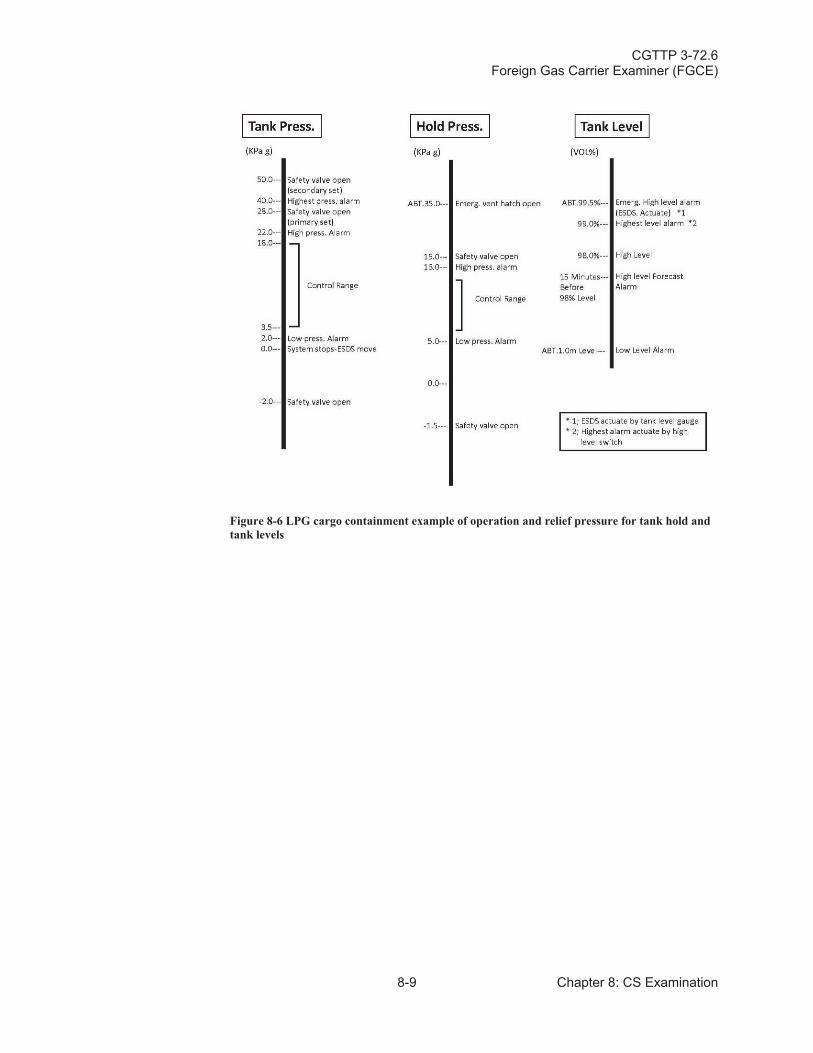
CGTTP 3-72.6Foreign Gas Carrier Examiner (FGCE)
8-9 Chapter 8: CS Examination
Figure 8-6 LPG cargo containment example of operation and relief pressure for tank hold and tank levels
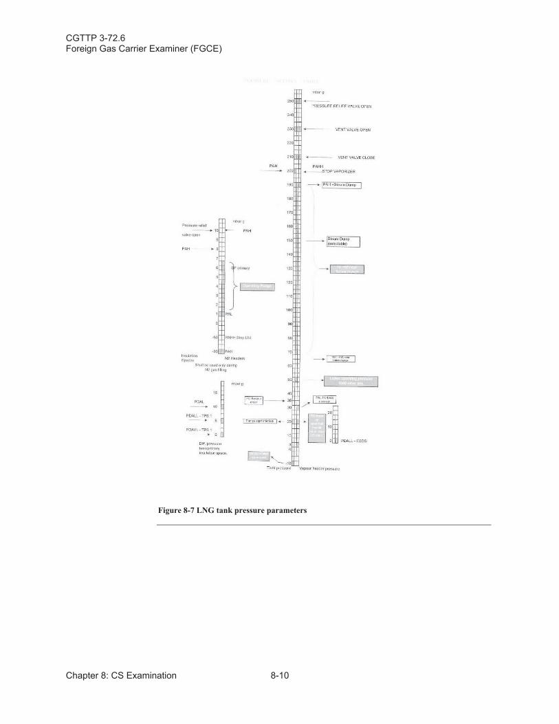
CGTTP 3-72.6Foreign Gas Carrier Examiner (FGCE)
Chapter 8: CS Examination 8-10
Figure 8-7 LNG tank pressure parameters
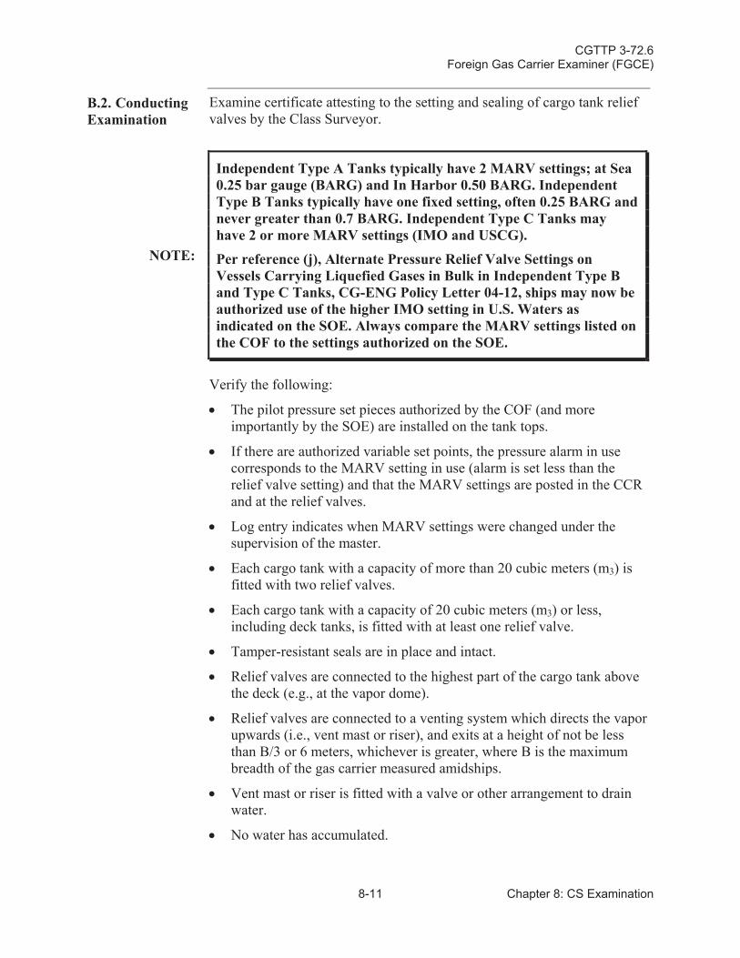
CGTTP 3-72.6Foreign Gas Carrier Examiner (FGCE)
8-11 Chapter 8: CS Examination
B.2. Conducting Examination
Examine certificate attesting to the setting and sealing of cargo tank relief valves by the Class Surveyor.
NOTE:
Independent Type A Tanks typically have 2 MARV settings; at Sea 0.25 bar gauge (BARG) and In Harbor 0.50 BARG. Independent Type B Tanks typically have one fixed setting, often 0.25 BARG and never greater than 0.7 BARG. Independent Type C Tanks may have 2 or more MARV settings (IMO and USCG).
Per reference (j), Alternate Pressure Relief Valve Settings on Vessels Carrying Liquefied Gases in Bulk in Independent Type B and Type C Tanks, CG-ENG Policy Letter 04-12, ships may now be authorized use of the higher IMO setting in U.S. Waters as indicated on the SOE. Always compare the MARV settings listed on the COF to the settings authorized on the SOE.
Verify the following:
The pilot pressure set pieces authorized by the COF (and more importantly by the SOE) are installed on the tank tops.
If there are authorized variable set points, the pressure alarm in use corresponds to the MARV setting in use (alarm is set less than the relief valve setting) and that the MARV settings are posted in the CCR and at the relief valves.
Log entry indicates when MARV settings were changed under the supervision of the master.
Each cargo tank with a capacity of more than 20 cubic meters (m3) is fitted with two relief valves.
Each cargo tank with a capacity of 20 cubic meters (m3) or less, including deck tanks, is fitted with at least one relief valve.
Tamper-resistant seals are in place and intact.
Relief valves are connected to the highest part of the cargo tank above the deck (e.g., at the vapor dome).
Relief valves are connected to a venting system which directs the vapor upwards (i.e., vent mast or riser), and exits at a height of not be less than B/3 or 6 meters, whichever is greater, where B is the maximum breadth of the gas carrier measured amidships.
Vent mast or riser is fitted with a valve or other arrangement to drain water.
No water has accumulated.
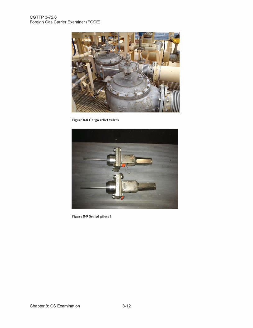
CGTTP 3-72.6Foreign Gas Carrier Examiner (FGCE)
Chapter 8: CS Examination 8-12
Figure 8-8 Cargo relief valves
Figure 8-9 Sealed pilots 1
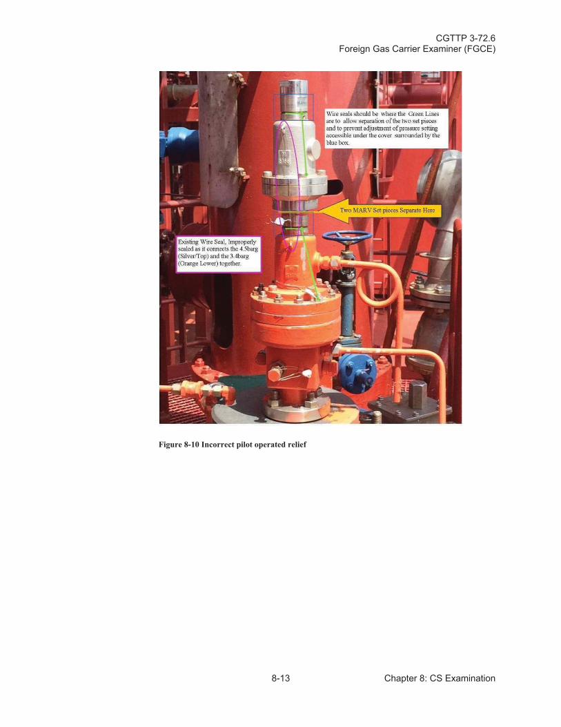
CGTTP 3-72.6Foreign Gas Carrier Examiner (FGCE)
8-13 Chapter 8: CS Examination
Figure 8-10 Incorrect pilot operated relief
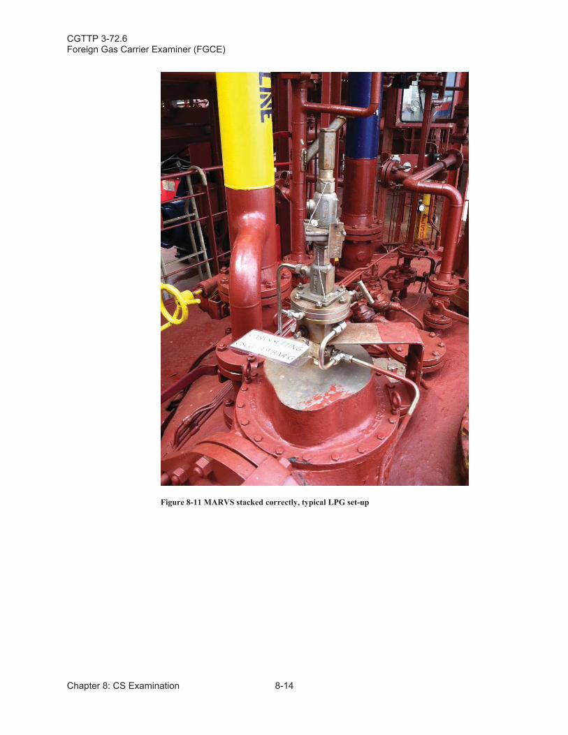
CGTTP 3-72.6Foreign Gas Carrier Examiner (FGCE)
Chapter 8: CS Examination 8-14
Figure 8-11 MARVS stacked correctly, typical LPG set-up
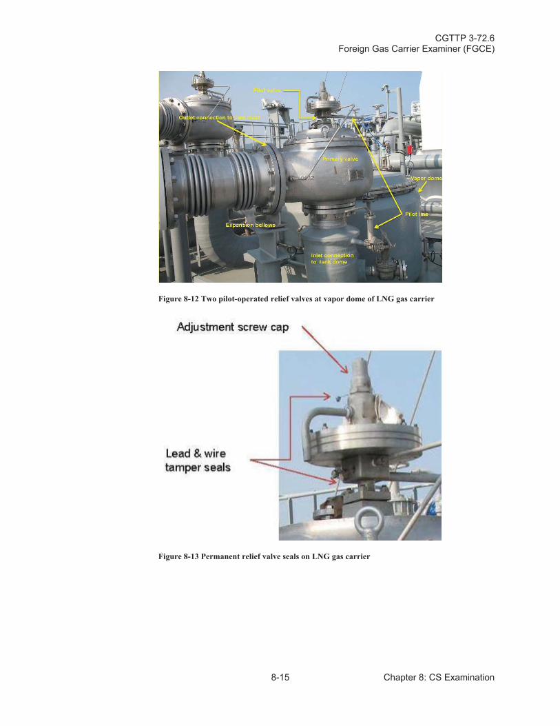
CGTTP 3-72.6Foreign Gas Carrier Examiner (FGCE)
8-15 Chapter 8: CS Examination
Figure 8-12 Two pilot-operated relief valves at vapor dome of LNG gas carrier
Figure 8-13 Permanent relief valve seals on LNG gas carrier
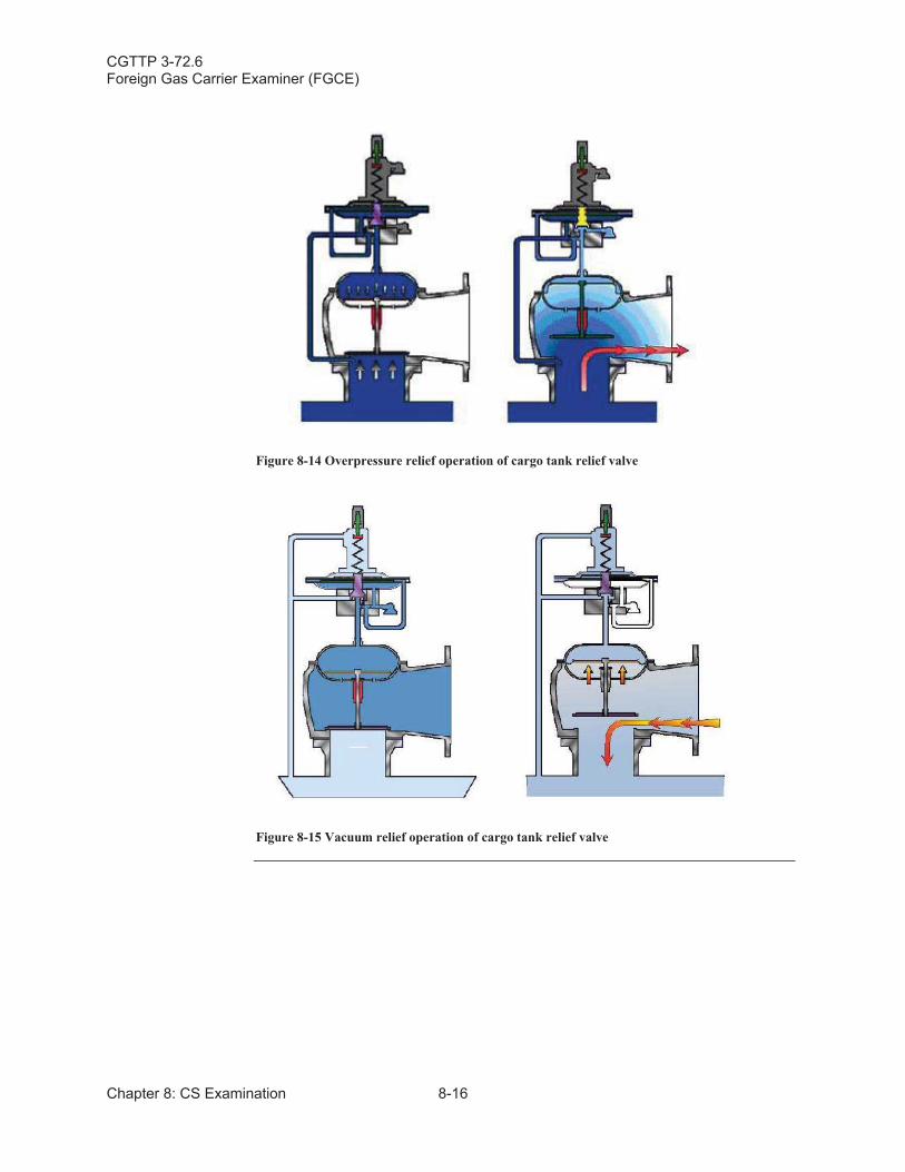
CGTTP 3-72.6Foreign Gas Carrier Examiner (FGCE)
Chapter 8: CS Examination 8-16
Figure 8-14 Overpressure relief operation of cargo tank relief valve
Figure 8-15 Vacuum relief operation of cargo tank relief valve
CGTTP 3-72.6Foreign Gas Carrier Examiner (FGCE)
8-17 Chapter 8: CS Examination
Section C: Cargo Piping
C.1. Overview Per the Gas Codes, there shall be no cargo piping below the main deck. All cargo piping must enter the tank through the tank dome. This design prevents the hull from filling with liquid or vapor in the event of a grounding or collision. Also, cargo piping must allow for thermal expansion and contraction. This is achieved by using loops, bends, and mechanical expansion joints (bellows).
NOTE:
As outlined in reference (y), CG-CVC-2 Port State Control Information for October 2015, there is no requirement for annual pressure testing of cargo lines on liquefied gas carriers. The requirement for testing of cargo lines found in reference (z), Definitions, 33 C.F.R. § 156.105, applies to oil and hazardous materials. However, the definition of hazardous materials in reference (aa), 33 C.F.R. § 154.105 specifically excludes liquefied gases.
CAUTION:
Ensure cargo piping supports on a bellows is not restricted because it is an integral part of the installation. The supports are adjusted to allow for a certain amount of expansion and contraction, otherwise it would damage the piping.
C.2. Conducting Examination
Verify the following:
Low temperature piping is thermally isolated from the adjacent hull structure.
NOTE:
Piping isolation prevents the temperature of the hull from falling below the design temperature of the hull material. This can be achieved by adding insulation around the pipe and/or raising the piping above the cargo deck.
Hull protection is present in areas where low temperature piping can be regularly dismantled or where leakage is anticipated.
NOTE:On LNG vessels, the water curtain is a wall of water that runs down the side of the gas carrier below the manifold. The marine loading arm (MLA) is the facility’s loading arm.
CGTTP 3-72.6Foreign Gas Carrier Examiner (FGCE)
Chapter 8: CS Examination 8-18
NOTE:
Per the ICG Code, where liquid piping is dismantled regularly (cargo manifold), or where liquid leakage may be anticipated, such as at shore connections and at pump seals, protection for the hull beneath should be provided. Examples of this protection are water curtains and/or drip trays.
If the MLAs are connected and the water curtain is not activated, determine if a valid reason exists for that condition. Activation period may be stated in the Cargo Operations Manual or on the Declaration of Inspection (DOI).
CAUTION:
Per reference (bb), Liquefied Gas Handing Principles on Ships and in Terminals, SIGTTO, Third Edition, manifold drip trays for LNG transfers should be as dry as reasonably practical. Crew should not deliberately introduce water or allow water to accumulate in the rain.
Gasketed pipe joints are electronically bonded. Ensure bonding arrangements have metal to metal contact and are intact (no breaks, loose connections, or excessive corrosion).
WARNING:
Per the ICG Code, when liquid is being moved through conducting material, static electricity may build up depending on how much friction the liquid is causing. If two pipes are connected with a gasket there is a small space in between the pipes. If the pipes are not electrically bonded and the charge is great enough, a spark may occurwhich can cause an explosion/fire. To prevent this spark, the pipes are joined by conducting material. This may be in the form of wire or thin plate. For additional information about static electricity and electrical continuity , see Chapter 5: Fundamentals of Static Electricity of reference (cc), National Fire Protection Association (NFPA) 77: Recommended Practice on Static Electricity, 2014 Edition.
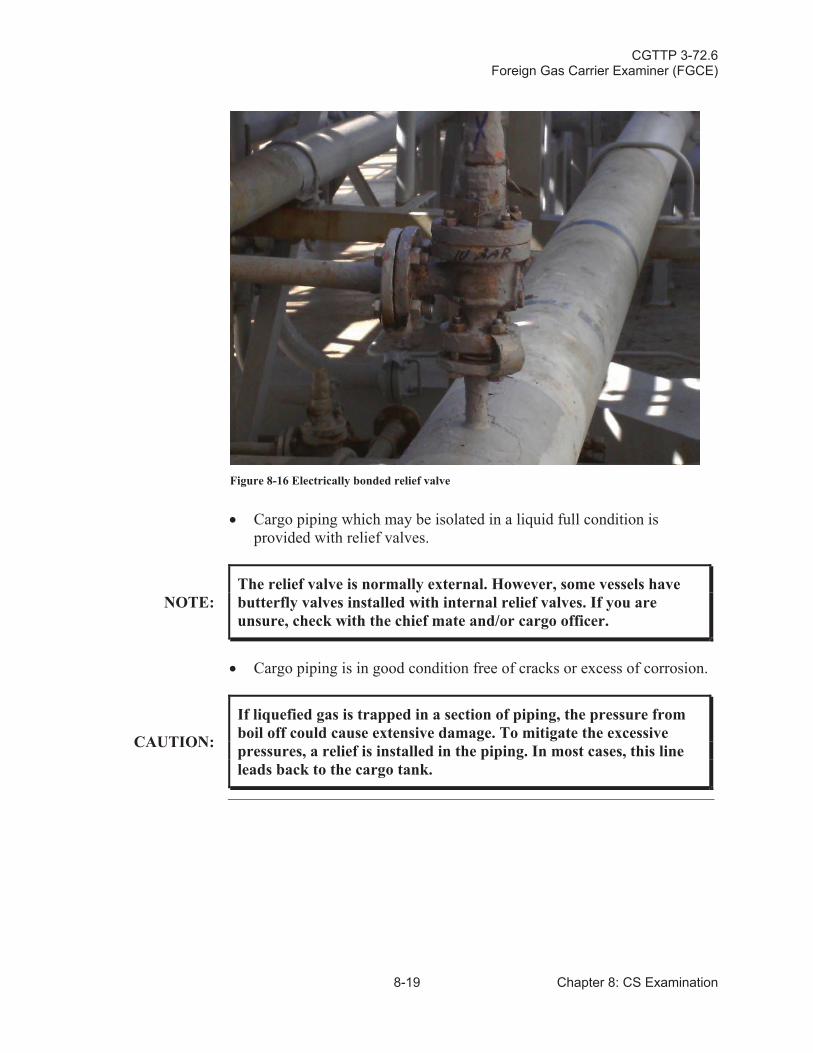
CGTTP 3-72.6Foreign Gas Carrier Examiner (FGCE)
8-19 Chapter 8: CS Examination
Figure 8-16 Electrically bonded relief valve
Cargo piping which may be isolated in a liquid full condition isprovided with relief valves.
NOTE:The relief valve is normally external. However, some vessels have butterfly valves installed with internal relief valves. If you are unsure, check with the chief mate and/or cargo officer.
Cargo piping is in good condition free of cracks or excess of corrosion.
CAUTION:
If liquefied gas is trapped in a section of piping, the pressure from boil off could cause extensive damage. To mitigate the excessive pressures, a relief is installed in the piping. In most cases, this line leads back to the cargo tank.
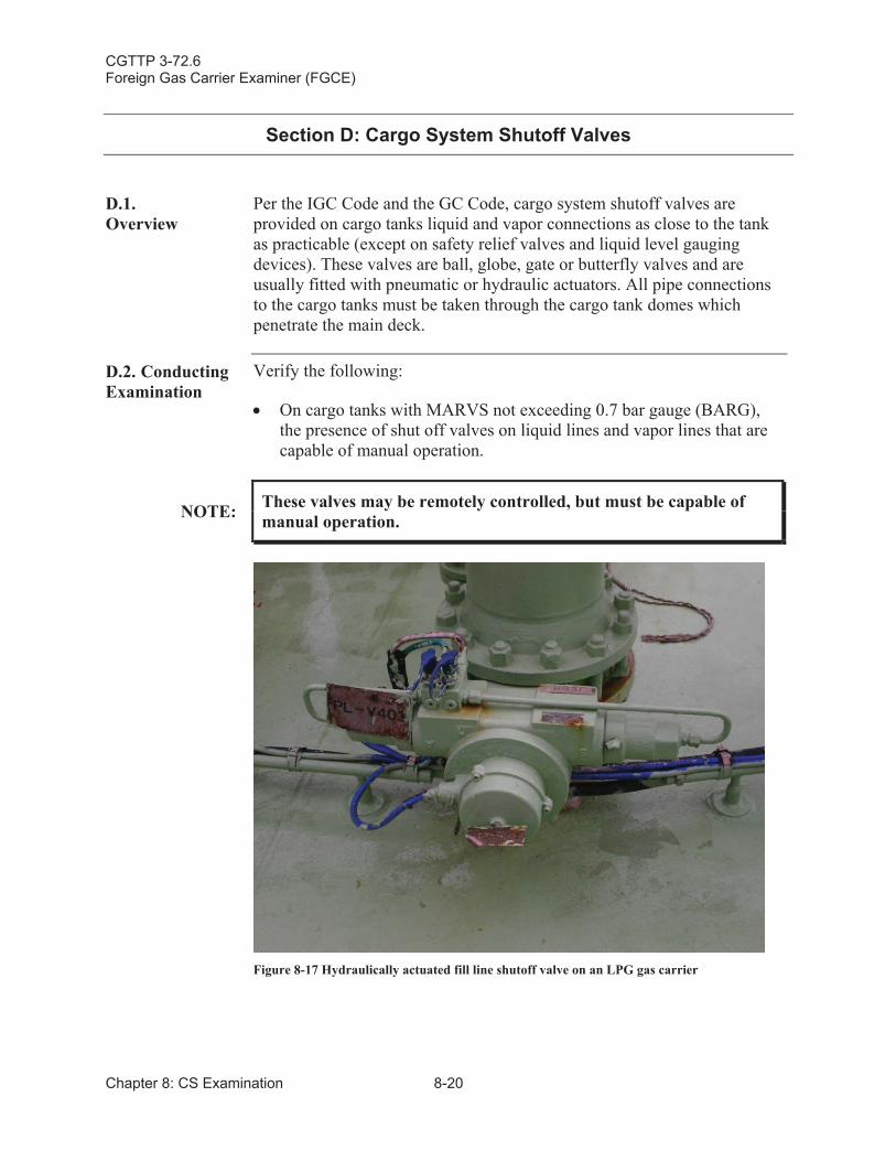
CGTTP 3-72.6Foreign Gas Carrier Examiner (FGCE)
Chapter 8: CS Examination 8-20
Section D: Cargo System Shutoff Valves
D.1.Overview
Per the IGC Code and the GC Code, cargo system shutoff valves are provided on cargo tanks liquid and vapor connections as close to the tank as practicable (except on safety relief valves and liquid level gauging devices). These valves are ball, globe, gate or butterfly valves and are usually fitted with pneumatic or hydraulic actuators. All pipe connections to the cargo tanks must be taken through the cargo tank domes which penetrate the main deck.
D.2. Conducting Examination
Verify the following:
On cargo tanks with MARVS not exceeding 0.7 bar gauge (BARG),the presence of shut off valves on liquid lines and vapor lines that are capable of manual operation.
NOTE: These valves may be remotely controlled, but must be capable of manual operation.
Figure 8-17 Hydraulically actuated fill line shutoff valve on an LPG gas carrier
CGTTP 3-72.6Foreign Gas Carrier Examiner (FGCE)
8-21 Chapter 8: CS Examination
On cargo tanks with MARVS exceeding 0.7 bar gauge (BARG), the presence of a manually operated stop valve and a remotely controlled emergency shutdown valve on liquid and vapor lines.
NOTE: MARVS are indicated on the COF and SOE.
NOTE:
A single valve may be substituted for the two separate valves provided; the valve complies with the IGC Code, the GC Code, is capable of local manual operation, and provides full closure of the line.
NOTE:
Per the IGC Code, the GC Code, and reference (b), Safety Standards for Self Propelled Vessels Carrying Bulk Liquefied Gases, 46 C.F.R. Part 154, MARVS for tank types “A” and “B”,may not exceed 0.7 bar gauge (BARG).
Per reference (b), MARVS for “membrane” may not exceed 0.25 BARG without Commandant approval.
NOTE:Per reference (q), USCG Marine Safety Manual, Vol. II: MaterielInspection, COMDTINST M16000.7 (series), missing or defective quick closing valves is grounds for detention.
CGTTP 3-72.6Foreign Gas Carrier Examiner (FGCE)
Chapter 8: CS Examination 8-22
Section E: Cargo Machinery Room (Cargo Compressor Room) EquipmentExam
E.1. Overview When conducting the cargo machinery room exam, equipment may or may not be in operation depending on if it’s an LNG or LPG vessel. The primary purpose of examining the cargo machinery room equipment is not to test equipment, but to view its overall condition.
Determine that the cargo machinery room equipment is in good order. Determine by obtaining a general impression through visual observation that a good standard of maintenance exists and that the equipment appears to be functional.
NOTE:
The term “good standard of maintenance” is very subjective, and depends on your background and experience. If the equipment is fully functional, and not leaking, etc, it might be hard to articulate clear grounds for expanding the exam. But if you can, the SMS maintenance schedule is a good place to start the expansion.
WARNING:
USCG issued safety gear is not designed to protect you from exposure to cargo liquids or vapors. Be familiar with reference (e), Cargo Compressor Room Entries During Port State Control Exams and Law Enforcement Boardings of Liquefied Petroleum Gas (LPG) Carriers,CG-543 Safety Alert, COMDT COGA D WASHINGTON DC//CG-543// 191819Z MAR 10 (Appendix B: Confined Space Safety Alert 2010), and conduct the required risk assessment before entering thecargo compressor room.
The cargo machinery room aboard a liquefied gas carrier is a gas dangerous space located in the cargo area. It houses equipment such as:
Cargo compressors.
NOTE:The cargo compressors are usually powered by a motor located in an adjacent gas safe space with a shaft passing through the bulkhead by way of a gas or oil tight seal.
Cargo condensers.
Cargo vaporizers.
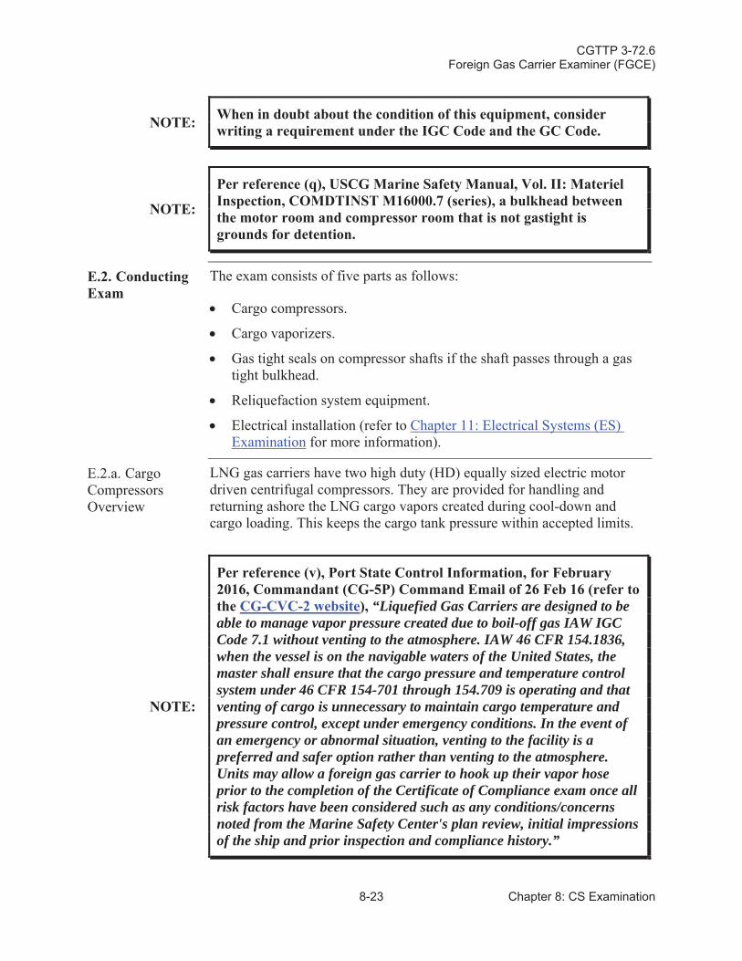
CGTTP 3-72.6Foreign Gas Carrier Examiner (FGCE)
8-23 Chapter 8: CS Examination
NOTE: When in doubt about the condition of this equipment, consider writing a requirement under the IGC Code and the GC Code.
NOTE:
Per reference (q), USCG Marine Safety Manual, Vol. II: MaterielInspection, COMDTINST M16000.7 (series), a bulkhead between the motor room and compressor room that is not gastight is grounds for detention.
E.2. Conducting Exam
The exam consists of five parts as follows:
Cargo compressors.
Cargo vaporizers.
Gas tight seals on compressor shafts if the shaft passes through a gas tight bulkhead.
Reliquefaction system equipment.
Electrical installation (refer to Chapter 11: Electrical Systems (ES) Examination for more information).
E.2.a. Cargo Compressors Overview
LNG gas carriers have two high duty (HD) equally sized electric motor driven centrifugal compressors. They are provided for handling and returning ashore the LNG cargo vapors created during cool-down and cargo loading. This keeps the cargo tank pressure within accepted limits.
NOTE:
Per reference (v), Port State Control Information, for February 2016, Commandant (CG-5P) Command Email of 26 Feb 16 (refer to the CG-CVC-2 website), “Liquefied Gas Carriers are designed to be able to manage vapor pressure created due to boil-off gas IAW IGC Code 7.1 without venting to the atmosphere. IAW 46 CFR 154.1836, when the vessel is on the navigable waters of the United States, the master shall ensure that the cargo pressure and temperature control system under 46 CFR 154-701 through 154.709 is operating and that venting of cargo is unnecessary to maintain cargo temperature and pressure control, except under emergency conditions. In the event of an emergency or abnormal situation, venting to the facility is a preferred and safer option rather than venting to the atmosphere. Units may allow a foreign gas carrier to hook up their vapor hose prior to the completion of the Certificate of Compliance exam once allrisk factors have been considered such as any conditions/concerns noted from the Marine Safety Center's plan review, initial impressions of the ship and prior inspection and compliance history.”
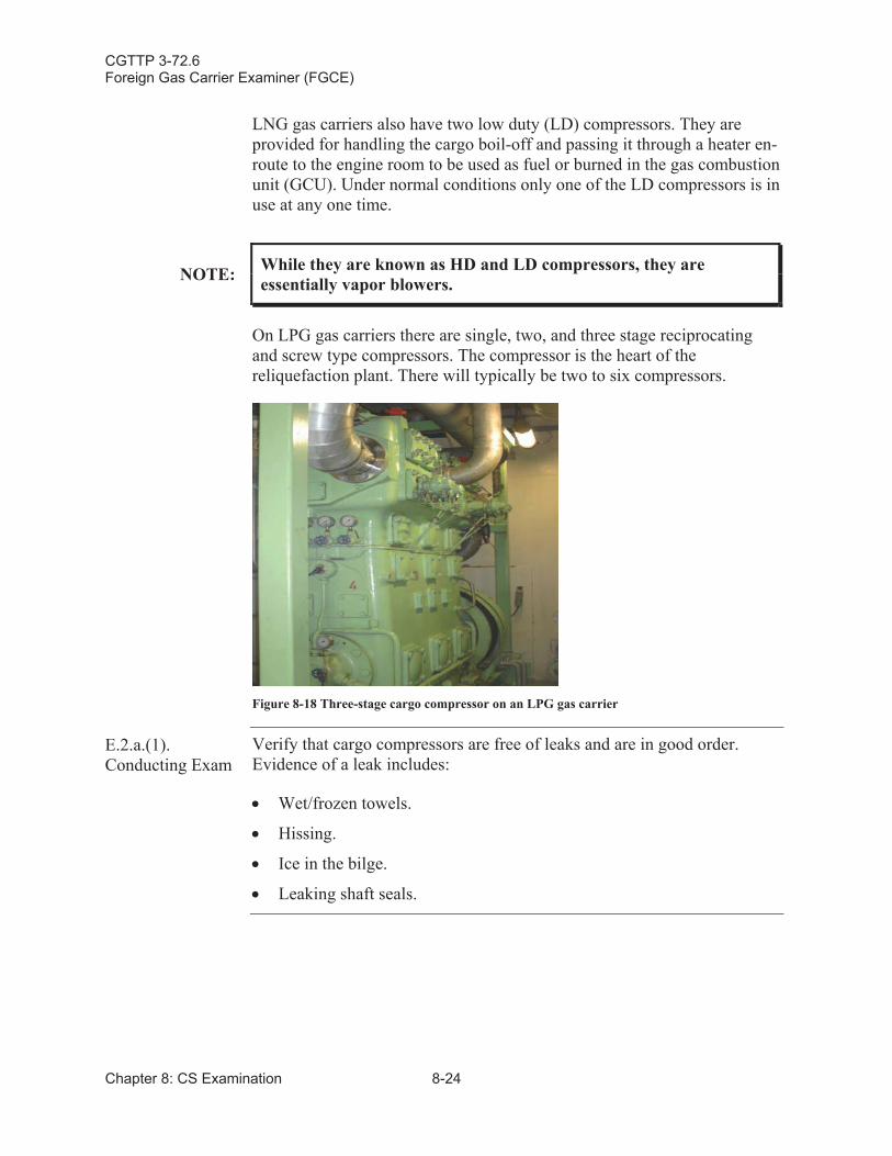
CGTTP 3-72.6Foreign Gas Carrier Examiner (FGCE)
Chapter 8: CS Examination 8-24
LNG gas carriers also have two low duty (LD) compressors. They are provided for handling the cargo boil-off and passing it through a heater en-route to the engine room to be used as fuel or burned in the gas combustion unit (GCU). Under normal conditions only one of the LD compressors is in use at any one time.
NOTE: While they are known as HD and LD compressors, they are essentially vapor blowers.
On LPG gas carriers there are single, two, and three stage reciprocating and screw type compressors. The compressor is the heart of the reliquefaction plant. There will typically be two to six compressors.
Figure 8-18 Three-stage cargo compressor on an LPG gas carrier
E.2.a.(1).Conducting Exam
Verify that cargo compressors are free of leaks and are in good order.Evidence of a leak includes:
Wet/frozen towels.
Hissing.
Ice in the bilge.
Leaking shaft seals.
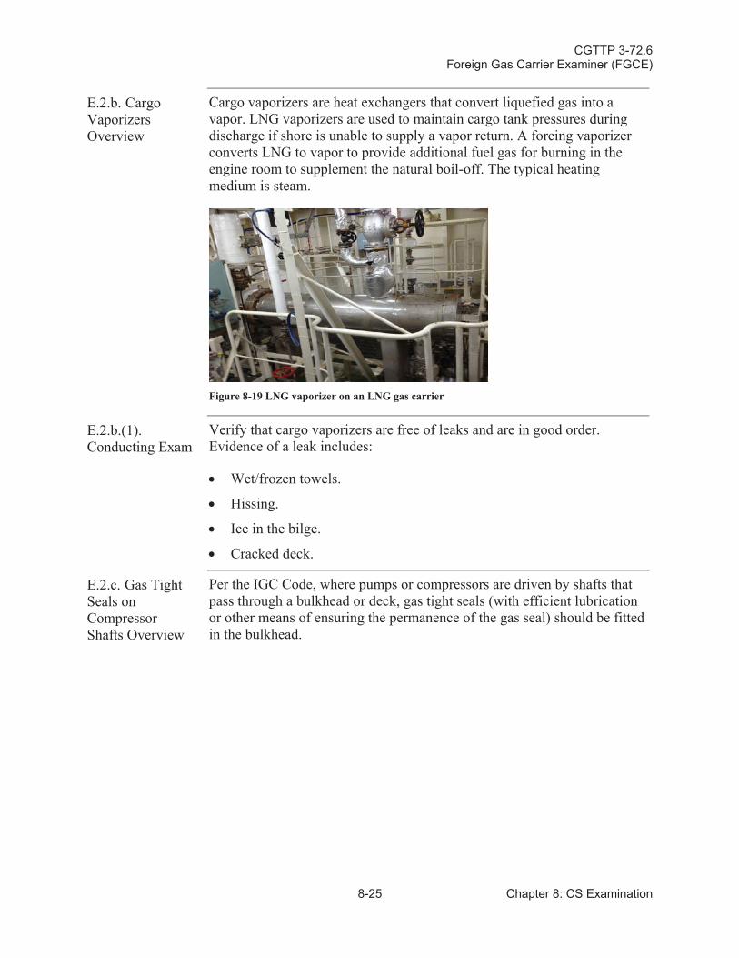
CGTTP 3-72.6Foreign Gas Carrier Examiner (FGCE)
8-25 Chapter 8: CS Examination
E.2.b. Cargo Vaporizers Overview
Cargo vaporizers are heat exchangers that convert liquefied gas into a vapor. LNG vaporizers are used to maintain cargo tank pressures during discharge if shore is unable to supply a vapor return. A forcing vaporizer converts LNG to vapor to provide additional fuel gas for burning in the engine room to supplement the natural boil-off. The typical heating medium is steam.
Figure 8-19 LNG vaporizer on an LNG gas carrier
E.2.b.(1).Conducting Exam
Verify that cargo vaporizers are free of leaks and are in good order. Evidence of a leak includes:
Wet/frozen towels.
Hissing.
Ice in the bilge.
Cracked deck.
E.2.c. Gas Tight Seals on Compressor Shafts Overview
Per the IGC Code, where pumps or compressors are driven by shafts that pass through a bulkhead or deck, gas tight seals (with efficient lubrication or other means of ensuring the permanence of the gas seal) should be fitted in the bulkhead.
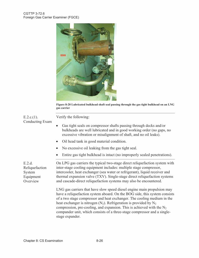
CGTTP 3-72.6Foreign Gas Carrier Examiner (FGCE)
Chapter 8: CS Examination 8-26
Figure 8-20 Lubricated bulkhead shaft seal passing through the gas tight bulkhead on an LNG gas carrier
E.2.c.(1).Conducting Exam
Verify the following:
Gas tight seals on compressor shafts passing through decks and/or bulkheads are well lubricated and in good working order (no gaps, no excessive vibration or misalignment of shaft, and no oil leaks).
Oil head tank in good material condition.
No excessive oil leaking from the gas tight seal.
Entire gas tight bulkhead is intact (no improperly sealed penetrations).
E.2.d.Reliquefaction System Equipment Overview
On LPG gas carriers the typical two-stage direct reliquefaction system with inter-stage cooling equipment includes: multiple stage compressor, intercooler, heat exchanger (sea water or refrigerant), liquid receiver andthermal expansion valve (TXV). Single-stage direct reliquefaction systems and cascade-direct reliquefaction systems may also be encountered.
LNG gas carriers that have slow speed diesel engine main propulsion may have a reliquefaction system aboard. On the BOG side, this system consists of a two stage compressor and heat exchanger. The cooling medium in the heat exchanger is nitrogen (N2). Refrigeration is provided by N2compression, pre-cooling, and expansion. This is achieved with the N2compander unit, which consists of a three-stage compressor and a single-stage expander.
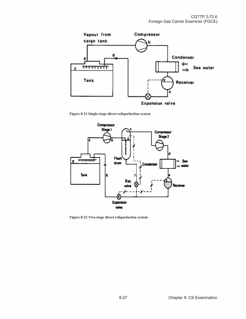
CGTTP 3-72.6Foreign Gas Carrier Examiner (FGCE)
8-27 Chapter 8: CS Examination
Figure 8-21 Single-stage direct reliquefaction system
Figure 8-22 Two-stage direct reliquefaction system
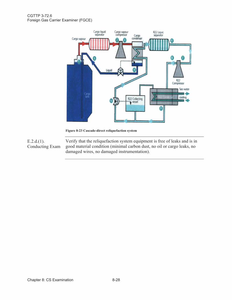
CGTTP 3-72.6Foreign Gas Carrier Examiner (FGCE)
Chapter 8: CS Examination 8-28
Figure 8-23 Cascade-direct reliquefaction system
E.2.d.(1).Conducting Exam
Verify that the reliquefaction system equipment is free of leaks and is in good material condition (minimal carbon dust, no oil or cargo leaks, no damaged wires, no damaged instrumentation).
CGTTP 3-72.6Foreign Gas Carrier Examiner (FGCE)
9-1 Chapter 9: CE Examination
Chapter 9:Cargo Environmental Control (CE) Examination
Introduction This chapter discusses requirements and procedures for conducting a cargo environmental control (CE) examination.
In This Chapter This chapter contains the following sections:
Section Title Page
A Inert Gas System 9-2
B Nitrogen (N2) Gas Generating System 9-4
C Inert Gas/Nitrogen (N2) Storage Tanks 9-7
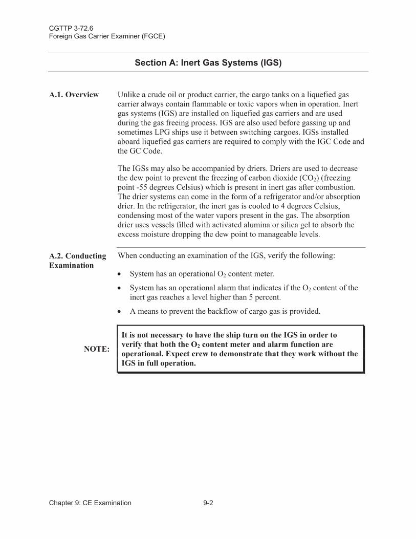
CGTTP 3-72.6Foreign Gas Carrier Examiner (FGCE)
Chapter 9: CE Examination 9-2
Section A: Inert Gas Systems (IGS)
A.1. Overview Unlike a crude oil or product carrier, the cargo tanks on a liquefied gas carrier always contain flammable or toxic vapors when in operation. Inert gas systems (IGS) are installed on liquefied gas carriers and are used during the gas freeing process. IGS are also used before gassing up and sometimes LPG ships use it between switching cargoes. IGSs installed aboard liquefied gas carriers are required to comply with the IGC Code and the GC Code.
The IGSs may also be accompanied by driers. Driers are used to decrease the dew point to prevent the freezing of carbon dioxide (CO2) (freezing point -55 degrees Celsius) which is present in inert gas after combustion. The drier systems can come in the form of a refrigerator and/or absorptiondrier. In the refrigerator, the inert gas is cooled to 4 degrees Celsius,condensing most of the water vapors present in the gas. The absorption drier uses vessels filled with activated alumina or silica gel to absorb the excess moisture dropping the dew point to manageable levels.
A.2. Conducting Examination
When conducting an examination of the IGS, verify the following:
System has an operational O2 content meter.
System has an operational alarm that indicates if the O2 content of the inert gas reaches a level higher than 5 percent.
A means to prevent the backflow of cargo gas is provided.
NOTE:
It is not necessary to have the ship turn on the IGS in order to verify that both the O2 content meter and alarm function are operational. Expect crew to demonstrate that they work without the IGS in full operation.
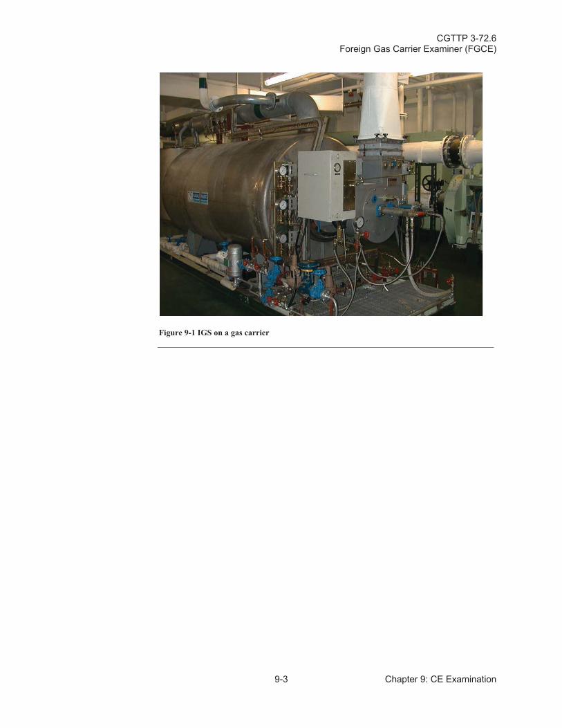
CGTTP 3-72.6Foreign Gas Carrier Examiner (FGCE)
9-3 Chapter 9: CE Examination
Figure 9-1 IGS on a gas carrier
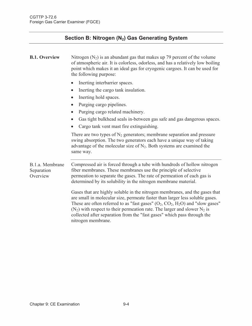
CGTTP 3-72.6Foreign Gas Carrier Examiner (FGCE)
Chapter 9: CE Examination 9-4
Section B: Nitrogen (N2) Gas Generating System
B.1. Overview Nitrogen (N2) is an abundant gas that makes up 79 percent of the volume of atmospheric air. It is colorless, odorless, and has a relatively low boiling point which makes it an ideal gas for cryogenic cargoes. It can be used for the following purpose:
Inerting interbarrier spaces.Inerting the cargo tank insulation.Inerting hold spaces.Purging cargo pipelines.Purging cargo related machinery.Gas tight bulkhead seals in-between gas safe and gas dangerous spaces.Cargo tank vent mast fire extinguishing.
There are two types of N2 generators; membrane separation and pressure swing absorption. The two generators each have a unique way of taking advantage of the molecular size of N2. Both systems are examined the same way.
B.1.a. Membrane SeparationOverview
Compressed air is forced through a tube with hundreds of hollow nitrogen fiber membranes. These membranes use the principle of selective permeation to separate the gases. The rate of permeation of each gas is determined by its solubility in the nitrogen membrane material.
Gases that are highly soluble in the nitrogen membranes, and the gases that are small in molecular size, permeate faster than larger less soluble gases. These are often referred to as "fast gases" (O2, CO2, H2O) and "slow gases" (N2) with respect to their permeation rate. The larger and slower N2 is collected after separation from the "fast gases" which pass through the nitrogen membrane.
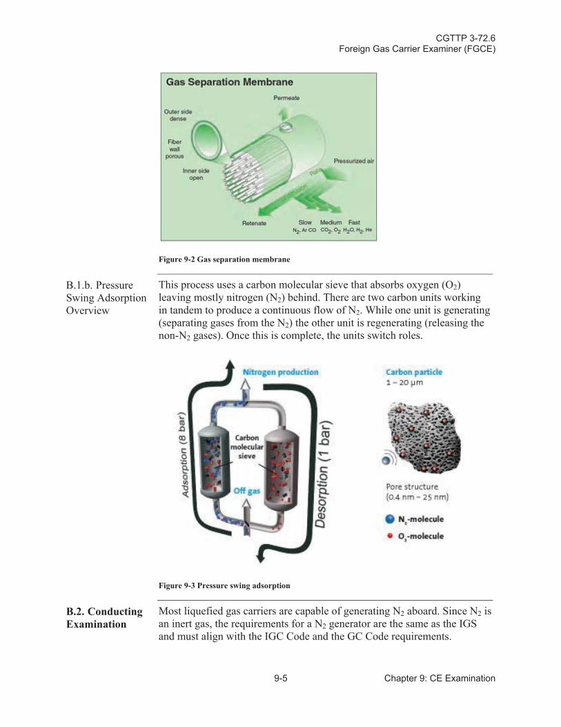
CGTTP 3-72.6Foreign Gas Carrier Examiner (FGCE)
9-5 Chapter 9: CE Examination
Figure 9-2 Gas separation membrane
B.1.b. Pressure Swing AdsorptionOverview
This process uses a carbon molecular sieve that absorbs oxygen (O2)leaving mostly nitrogen (N2) behind. There are two carbon units working in tandem to produce a continuous flow of N2. While one unit is generating (separating gases from the N2) the other unit is regenerating (releasing the non-N2 gases). Once this is complete, the units switch roles.
Figure 9-3 Pressure swing adsorption
B.2. Conducting Examination
Most liquefied gas carriers are capable of generating N2 aboard. Since N2 is an inert gas, the requirements for a N2 generator are the same as the IGS and must align with the IGC Code and the GC Code requirements.
CGTTP 3-72.6Foreign Gas Carrier Examiner (FGCE)
Chapter 9: CE Examination 9-6
When conducting an examination of the N2 plant, verify the following:
System has an operational O2 content meter.
System has an operational alarm that indicates if the O2 content of the inert gas reaches a level higher than 5 percent.
A means to prevent the backflow of cargo gas is provided.
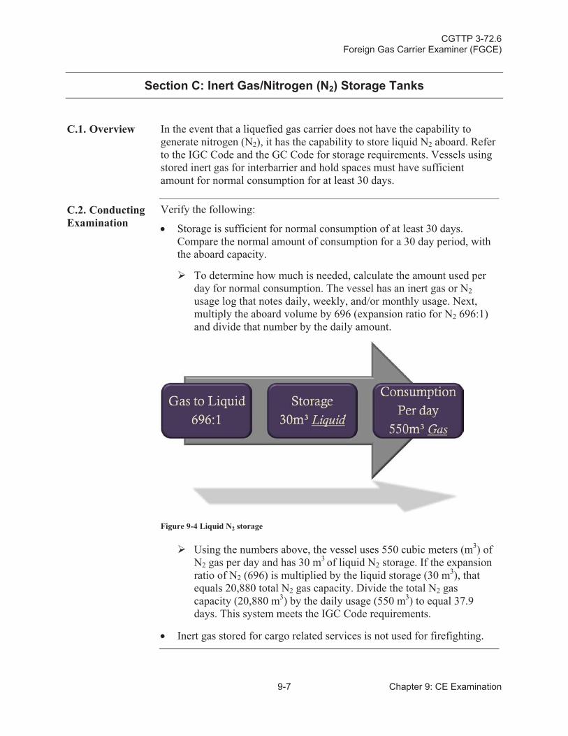
CGTTP 3-72.6Foreign Gas Carrier Examiner (FGCE)
9-7 Chapter 9: CE Examination
Section C: Inert Gas/Nitrogen (N2) Storage Tanks
C.1. Overview In the event that a liquefied gas carrier does not have the capability to generate nitrogen (N2), it has the capability to store liquid N2 aboard. Refer to the IGC Code and the GC Code for storage requirements. Vessels using stored inert gas for interbarrier and hold spaces must have sufficient amount for normal consumption for at least 30 days.
C.2. Conducting Examination
Verify the following:
Storage is sufficient for normal consumption of at least 30 days. Compare the normal amount of consumption for a 30 day period, with the aboard capacity.
To determine how much is needed, calculate the amount used per day for normal consumption. The vessel has an inert gas or N2usage log that notes daily, weekly, and/or monthly usage. Next, multiply the aboard volume by 696 (expansion ratio for N2 696:1) and divide that number by the daily amount.
Figure 9-4 Liquid N2 storage
Using the numbers above, the vessel uses 550 cubic meters (m3) of N2 gas per day and has 30 m3 of liquid N2 storage. If the expansion ratio of N2 (696) is multiplied by the liquid storage (30 m3), that equals 20,880 total N2 gas capacity. Divide the total N2 gas capacity (20,880 m3) by the daily usage (550 m3) to equal 37.9 days. This system meets the IGC Code requirements.
Inert gas stored for cargo related services is not used for firefighting.
CGTTP 3-72.6Foreign Gas Carrier Examiner (FGCE)
Chapter 9: CE Examination 9-8
This page intentionally left blank.
CGTTP 3-72.6Foreign Gas Carrier Examiner (FGCE)
10-1 Chapter 10: LS Examination
Chapter 10:Lifesaving Equipment (LS) Examination
Introduction This chapter provides an examination overview for the lifeboats on liquefied gas carriers. Refer to reference (dd), Life-Saving Appliances (LSA) Code, International Maritime Organization (IMO), 2010.
In This Chapter This chapter contains the following sections:
Section Title Page
A Lifeboats 10-2
CGTTP 3-72.6Foreign Gas Carrier Examiner (FGCE)
Chapter 10: LS Examination 10-2
Section A: Lifeboats
A.1. Overview Lifeboats on tankers and liquefied gas carriers must have additionalequipment beyond what lifeboats on other ships carry. For a complete list of required equipment, see reference (c), SOLAS: Consolidated Text of theInternational Convention for the Safety of Life at Sea, 1974, and itsProtocol of 1988: Articles, Annexes and Certificates (Incorporating allamendments in effect from 1 July 2009), International MaritimeOrganization (IMO), which references reference (dd), Life-Saving Appliances (LSA) Code, International Maritime Organization (IMO), 2010 Sections 4.8 and 4.9 respectively.
CAUTION:
Cargoes carried on liquefied gas carriers are either flammableand/or toxic. Depending on the hazard of the cargo carried, lifeboats must have a self contained air support system and some kind of fire protection (e.g., a water spray system).
A.2. Conducting Examination
The lifeboat exam consists of three parts:
Self contained air support system.
Air supply system pressure.
Lifeboat water spray system.
A.2.a. Self Contained Air Support SystemOverview
A self contained air support system is required by reference (dd), to provide breathable air for the maximum capacity authorized and engine combustion so the lifeboat can safely maneuver away from the vessel andany fire. It also prevents the ingress of toxic fumes or gas. Supplied air is intended to provide safe breathable environment for a minimum of 10 minutes.
A.2.a.(1).Conducting Examination
In addition to the other lifeboat equipment, verify the following:
The satisfactory condition of the self-contained air support system. Look for signs of corrosion, breaches in piping, indications of poor maintenance, and failure of the system to operate properly.
Bottles are securely fastened within the lifeboat and in good condition (no deformation or excessive pitting to bottles).
Hoses are in good condition without deformities (kinks, sharp bends, etc.) that would hinder air flow.
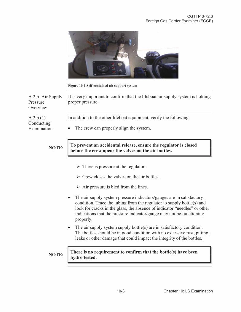
CGTTP 3-72.6Foreign Gas Carrier Examiner (FGCE)
10-3 Chapter 10: LS Examination
Figure 10-1 Self-contained air support system
A.2.b. Air Supply PressureOverview
It is very important to confirm that the lifeboat air supply system is holding proper pressure.
A.2.b.(1).Conducting Examination
In addition to the other lifeboat equipment, verify the following:
The crew can properly align the system.
NOTE: To prevent an accidental release, ensure the regulator is closed before the crew opens the valves on the air bottles.
There is pressure at the regulator.
Crew closes the valves on the air bottles.
Air pressure is bled from the lines.
The air supply system pressure indicators/gauges are in satisfactory condition. Trace the tubing from the regulator to supply bottle(s) and look for cracks in the glass, the absence of indicator “needles” or other indications that the pressure indicator/gauge may not be functioning properly.
The air supply system supply bottle(s) are in satisfactory condition.The bottles should be in good condition with no excessive rust, pitting, leaks or other damage that could impact the integrity of the bottles.
NOTE: There is no requirement to confirm that the bottle(s) have been hydro tested.
CGTTP 3-72.6Foreign Gas Carrier Examiner (FGCE)
Chapter 10: LS Examination 10-4
A.2.c. Lifeboat Water Spray System Overview
Per reference (dd), Life-Saving Appliances (LSA) Code, International Maritime Organization (IMO), 2010 and reference (c), SOLAS: Consolidated Text of the International Convention for the Safety of Life at Sea, 1974, and its Protocol of 1988: Articles, Annexes and Certificates (Incorporating all amendments in effect from 1 July 2009), International Maritime Organization (IMO), a fire protection system is required. It may be a water spray system. Usually, the water spray system is an engine driven pump that suctions sea water from under the lifeboat. This ensuresthat no flammable liquid is drawn into the system. Water will spray over the entire surface of the boat. Just like the self contained air support system, the water spray system ensures the lifeboat can safely maneuver away from the vessel and any fire.
A.2.c.(1).Conducting Examination
Verify the following:Sea water intake for the system is below the water line.The water flows continuously over the lifeboat for at least 8 minuteswhen system is operational. Look for continuous water coverage over the housing. The stainless piping housing the water spray system is in good working condition. No excessive rust, pitting or clogs to piping restricting the flow of water.For liquefied gas carriers authorized to carry flammable cargoes, ship’screw routinely maintains and tests the lifeboat water spray system.Ensure maintenance and tests are properly documented (logged).
NOTE:
The ship’s crew normally tests a water spray system when boat(s) are lowered during routine drills. Per reference (q), USCG Marine Safety Manual, Vol. II: Materiel Inspection, COMDTINST M16000.7 (series), lowering, releasing, and exercising lifeboats is not required during a routine COC exam. Rely on a visual examination and ship documentation.
NOTE:LPG gas carriers authorized to carry only toxic cargoes (i.e., anhydrous ammonia) are not required to have a water spray system.
NOTE:
It is rare to see the launching and operation of a lifeboat. However, read the vessel Classification Report on the proper operation of this equipment. It is common to see digital images of lifeboat launch and water spray during the last test.
CGTTP 3-72.6Foreign Gas Carrier Examiner (FGCE)
11-1 Chapter 11: ES Examination
Chapter 11:Electrical Systems (ES) Examination
Introduction This chapter discusses requirements and procedures for conducting the electrical systems (ES) examination.
In This Chapter This chapter contains the following sections:
Section Title Page
A Electrical Installations in the Cargo Machinery (Cargo Compressor) Room
11-2
B Electrical Installations in Gas Dangerous Zones (Open Decks and Other Spaces Other than Cargo Machinery Rooms)
11-5
CGTTP 3-72.6Foreign Gas Carrier Examiner (FGCE)
Chapter 11: ES Examination 11-2
Section A: Electrical Installations in the Cargo Machinery (Cargo Compressor) Room Exam
A.1. Overview The cargo machinery room is a gas dangerous space. Per the IGC Code, electrical equipment within this space shall be approved for this environment.
Pressurized fixtures: Per reference (bb), Liquefied Gas Handling Principles On Ships and In Terminals, SIGTTO, Third Edition,maintain an over-pressure of about 0.5 bar gauge (BARG) (7.3 pounds per square inch [psi]), relative to the surrounding atmosphere.
Purged fixtures: Per reference (bb), a continuous supply of purging gas (air or inert gas) must be provided to the enclosure.
Flameproof enclosure: Enclosure can withstand the pressure from an internal ignition of a flammable mixture. The gap through which the hot gases are allowed to escape is critical. Understand how each type of fixture is designed to function.
Designed so that any flames inside the enclosure are cooled to below ignition temperatures before reaching the surrounding atmosphere.
A.2. Conducting Exam
Examiner visually verifies the following:
Lighting fixtures must be pressurized, purged, or flameproof.
If there is no visible data plate or approval, or there is a concern about the data plate, refer to Type Approval Certificates.
Fixtures are intact and in good material condition.
These may include no:
o Broken or exposed wires.
o Broken bonding cables/straps.
o Cracked lenses.
o Loose or missing bolts.
o Paint or other foreign matter on flameproof fixtures that interferes with venting arrangements or fixtures not fully enclosed/sealed, as appropriate.
Ensure cables are enclosed in an explosion protected device bymeans of an approved gland or equivalent device capable of maintaining the integrity of the enclosure.
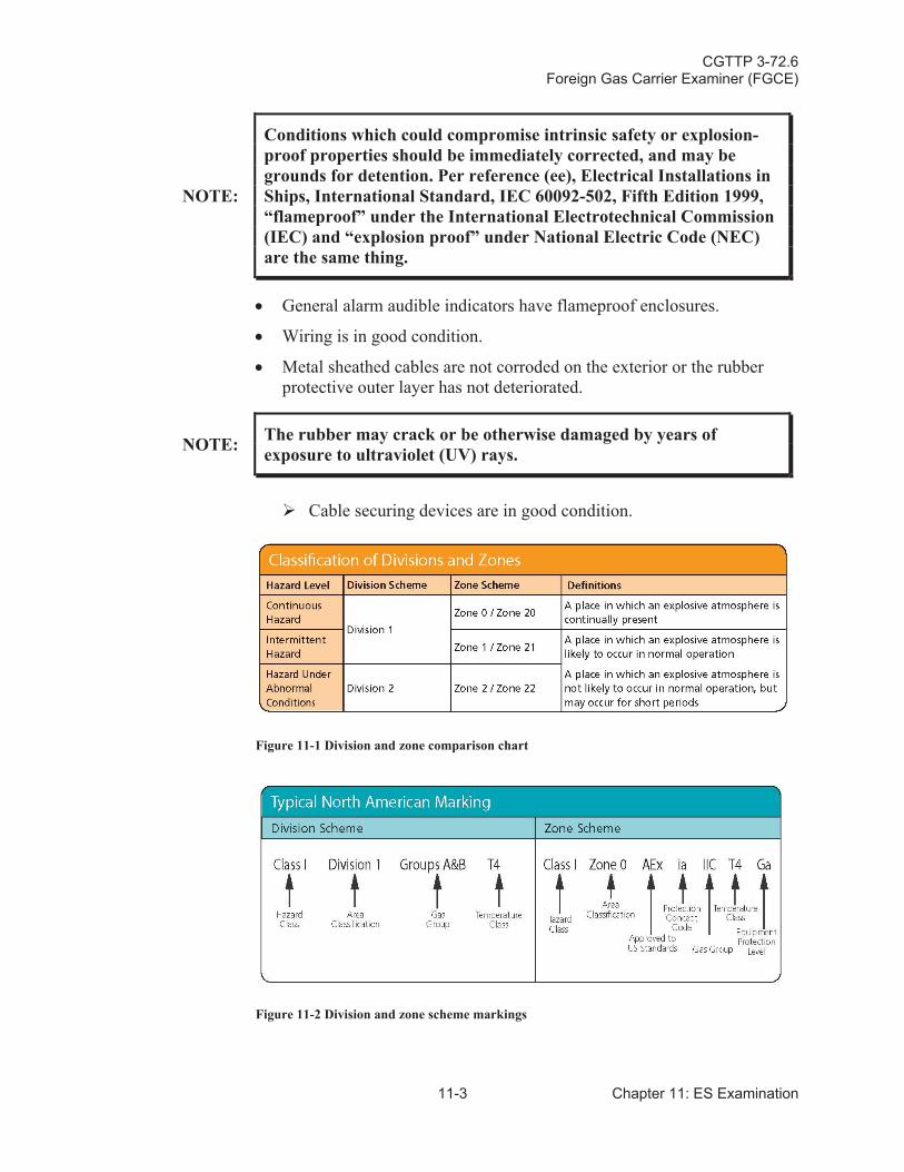
CGTTP 3-72.6Foreign Gas Carrier Examiner (FGCE)
11-3 Chapter 11: ES Examination
NOTE:
Conditions which could compromise intrinsic safety or explosion-proof properties should be immediately corrected, and may be grounds for detention. Per reference (ee), Electrical Installations in Ships, International Standard, IEC 60092-502, Fifth Edition 1999,“flameproof” under the International Electrotechnical Commission (IEC) and “explosion proof” under National Electric Code (NEC)are the same thing.
General alarm audible indicators have flameproof enclosures.
Wiring is in good condition.
Metal sheathed cables are not corroded on the exterior or the rubber protective outer layer has not deteriorated.
NOTE: The rubber may crack or be otherwise damaged by years of exposure to ultraviolet (UV) rays.
Cable securing devices are in good condition.
Figure 11-1 Division and zone comparison chart
Figure 11-2 Division and zone scheme markings
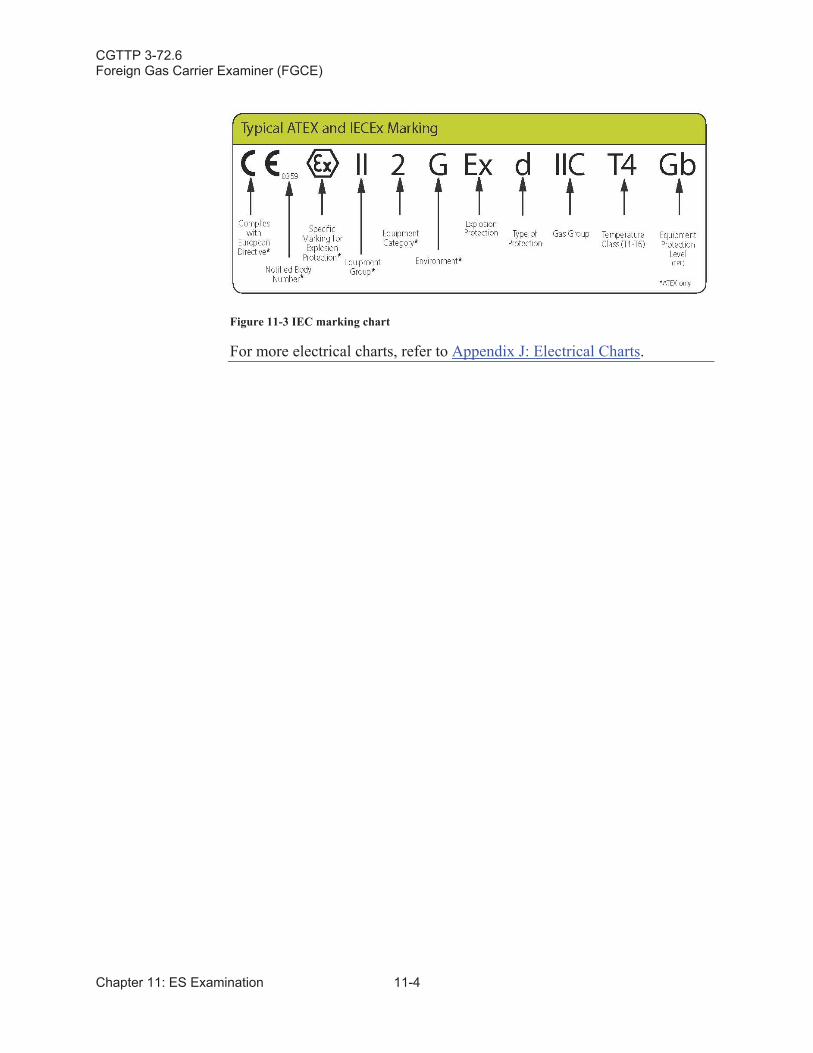
CGTTP 3-72.6Foreign Gas Carrier Examiner (FGCE)
Chapter 11: ES Examination 11-4
Figure 11-3 IEC marking chart
For more electrical charts, refer to Appendix J: Electrical Charts.
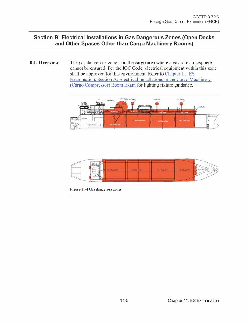
CGTTP 3-72.6Foreign Gas Carrier Examiner (FGCE)
11-5 Chapter 11: ES Examination
Section B: Electrical Installations in Gas Dangerous Zones (Open Decks and Other Spaces Other than Cargo Machinery Rooms)
B.1. Overview The gas dangerous zone is in the cargo area where a gas safe atmosphere cannot be ensured. Per the IGC Code, electrical equipment within this zone shall be approved for this environment. Refer to Chapter 11: ES Examination, Section A: Electrical Installations in the Cargo Machinery (Cargo Compressor) Room Exam for lighting fixture guidance.
Figure 11-4 Gas dangerous zones
CGTTP 3-72.6Foreign Gas Carrier Examiner (FGCE)
Chapter 11: ES Examination 11-6
B.2. Conducting Exam
Verify the following:
Certified safe type equipment is used. If there is no visible data plate or approval, or there is a concern about the data plate, refer to Type Approval Certificates.
NOTE:
Per reference (bb), Liquefied Gas Handling Principles On Ships & In Terminals, SIGTTO, Third Edition, “certified safe type equipment is electrical equipment of a type for which a national or other appropriate authority has carried out the type verifications and tests necessary to certify the safety of the equipment with regard to explosion hazard when used in an explosive gas atmosphere.”
Through runs of cables are used.
Check to make sure that there are no junction boxes in these areas.
Lighting fixtures are pressurized/purged or flameproof.
CGTTP 3-72.6Foreign Gas Carrier Examiner (FGCE)
12-1 Chapter 12: CV Systems Examination
Chapter 12:Cargo Area Ventilation (CV) Systems Examination
Introduction This chapter discusses requirements and procedures for conducting the cargo area ventilation (CV) systems examination.
In This Chapter This chapter contains the following sections:
Section Title Page
A Cargo Machinery 12-2
B Cargo Machinery Room Ventilation System 12-5
CGTTP 3-72.6Foreign Gas Carrier Examiner (FGCE)
Chapter 12: CV Systems Examination 12-2
Section A: Cargo Machinery Motor (Electric Motor) Room Ventilation System Exam
A.1.Introduction
The cargo machinery motor (electric motor) room is a gas safe space and, per the IGC Code, must have positive ventilation. This helps the space maintain a pressure differential between it and the adjacent gas dangerous space. In the event of a leak in the cargo machinery room or on deck, the positive pressure prevents ingress of vapors.
A.2. Conducting Exam
Verify the following:
The ventilation system is controlled from outside the space.
NOTE: The control location is typically just outside the space or in the cargo control room.
Positive ventilation is operational.
Positive pressure is 30 air changes per hour.
NOTE:Ventilation systems are designed to meet this requirement. It is very difficult on operating vessels to easily confirm that the system(s) is/are actually meeting the 30 changes per hour requirement.
Indications that the system is not functioning properly and an expanded exam is warranted include:
o It is obvious when entering the space that the pressure in the space is weak. It should take a considerable effort to close a door against positive ventilation pressure.
o One or more of the ventilation fans is damaged or is inoperable.
o The fan(s) are blocked or inhibited from properly spinning.
o The fan(s) cannot operated due to electrical or motor problems.
o There is a component of the system that is “out of service” or not operating such that the system is no longer “as designed.”
Adjacent air locks have mechanical ventilation and are maintained atan overpressure compared to the on deck gas dangerous zone. Refer to Chapter 7: Air Lock (AL) Examination for more information.
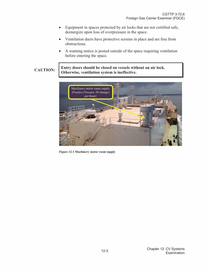
CGTTP 3-72.6Foreign Gas Carrier Examiner (FGCE)
12-3 Chapter 12: CV Systems Examination
Equipment in spaces protected by air locks that are not certified safe,deenergize upon loss of overpressure in the space.
Ventilation ducts have protective screens in place and are free from obstructions.
A warning notice is posted outside of the space requiring ventilation before entering the space.
CAUTION: Entry doors should be closed on vessels without an air lock. Otherwise, ventilation system is ineffective.
Figure 12-1 Machinery motor room supply
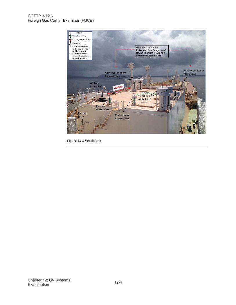
CGTTP 3-72.6Foreign Gas Carrier Examiner (FGCE)
Chapter 12: CV Systems Examination 12-4
Figure 12-2 Ventilation
CGTTP 3-72.6Foreign Gas Carrier Examiner (FGCE)
12-5 Chapter 12: CV Systems Examination
Section B: Cargo Machinery Room Ventilation System
B.1.Overview
The cargo machinery room is a gas dangerous space and per the IGC Codeis required to have negative ventilation. This helps the space maintain a pressure differential between it and the adjacent gas safe space.
Air is pulled from different sections of the machinery room to ensure gas pockets do not accumulate. Another factor that determines inlet location is the density of cargoes authorized for carriage. If the cargoes have a vapor density lighter than air, ventilation inlets should be placed near the top of the space.
B.2. Conducting Exam
Verify the following:
The ventilation can be controlled from outside the space.
NOTE: The control location is typically just outside the space or in the cargo control room.
Negative ventilation is operational when going through the entrance of this space (you should feel a slight pulling affect).
NOTE: If checking the outlet, you should feel air escaping from the space.
Ventilation extraction points are relative to the cargoes density.Duct openings have protective screens in place and are free from obstructions.A warning notice is posted outside of the space requiring the use of ventilation prior to entering the space.
CGTTP 3-72.6Foreign Gas Carrier Examiner (FGCE)
Chapter 12: CV Systems Examination 12-6
This page intentionally left blank.
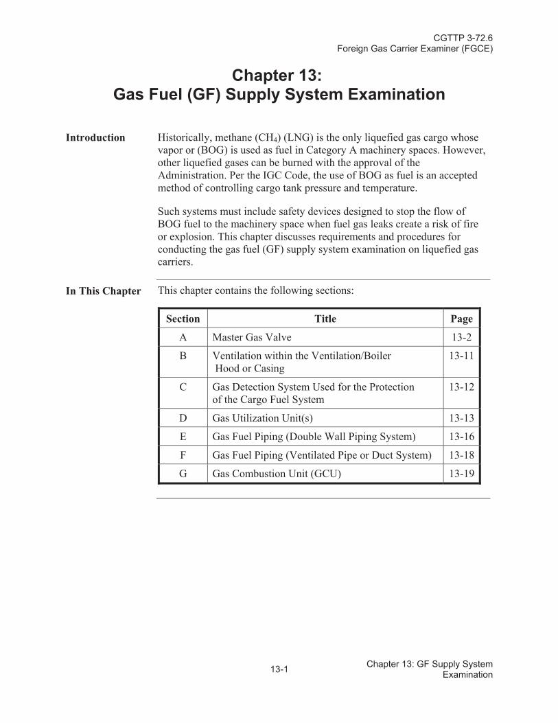
CGTTP 3-72.6Foreign Gas Carrier Examiner (FGCE)
13-1 Chapter 13: GF Supply System Examination
Chapter 13:Gas Fuel (GF) Supply System Examination
Introduction Historically, methane (CH4) (LNG) is the only liquefied gas cargo whose vapor or (BOG) is used as fuel in Category A machinery spaces. However, other liquefied gases can be burned with the approval of the Administration. Per the IGC Code, the use of BOG as fuel is an accepted method of controlling cargo tank pressure and temperature.
Such systems must include safety devices designed to stop the flow of BOG fuel to the machinery space when fuel gas leaks create a risk of fire or explosion. This chapter discusses requirements and procedures for conducting the gas fuel (GF) supply system examination on liquefied gas carriers.
In This Chapter This chapter contains the following sections:
Section Title Page
A Master Gas Valve 13-2
B Ventilation within the Ventilation/BoilerHood or Casing
13-11
C Gas Detection System Used for the Protection of the Cargo Fuel System
13-12
D Gas Utilization Unit(s) 13-13
E Gas Fuel Piping (Double Wall Piping System) 13-16
F Gas Fuel Piping (Ventilated Pipe or Duct System) 13-18
G Gas Combustion Unit (GCU) 13-19
CGTTP 3-72.6Foreign Gas Carrier Examiner (FGCE)
Chapter 13: GF Supply System Examination 13-2
Section A: Master Gas Valve
A.1. Overview Per the IGC Code, the gas fuel system has a master gas valve (MGV) located in the cargo area. There must be a means to close the MGV within the machinery space. When the fuel gas supply needs to be shut off because of hazardous circumstances (e.g., fuel gas leak), the MGV must close automatically.
WARNING:
Before testing that the MGV can close automatically, discuss the fuel supply status, cargo tank vapor pressures, and possible consequences of MGV shutdown with the vessel master or chief officer.
In heavy seas, the agitation of the cargo can increase tank pressures to unusually high levels during and immediately after voyages. If MGV closure could potentially elevate pressures to cause cargo tank safety relief vales to lift, carefully consider the need to perform test(s).Gas carrier specific fuel gas configurations are outlined in the vessel’s Cargo Operations or Machinery Manual.
WARNING:
Failure of the MGV or other components of the fuel gas system, could result in loss of propulsion during maneuvering, or render the vessel unfit for service. Such failures represent clear grounds to expand the exam, such as reviewing relevant SMS maintenance and crew training records. Consider control actions if the safety of the vessel, crew, or the port is in doubt.
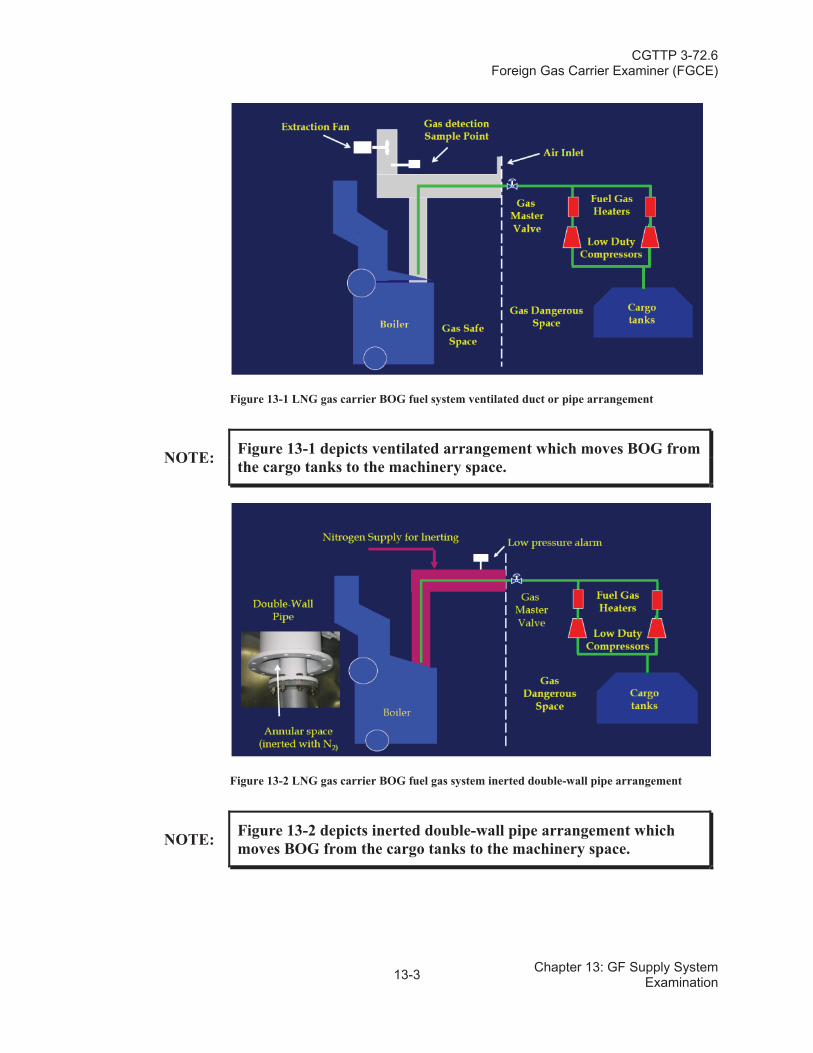
CGTTP 3-72.6Foreign Gas Carrier Examiner (FGCE)
13-3 Chapter 13: GF Supply System Examination
Figure 13-1 LNG gas carrier BOG fuel system ventilated duct or pipe arrangement
NOTE: Figure 13-1 depicts ventilated arrangement which moves BOG from the cargo tanks to the machinery space.
Figure 13-2 LNG gas carrier BOG fuel gas system inerted double-wall pipe arrangement
NOTE: Figure 13-2 depicts inerted double-wall pipe arrangement whichmoves BOG from the cargo tanks to the machinery space.
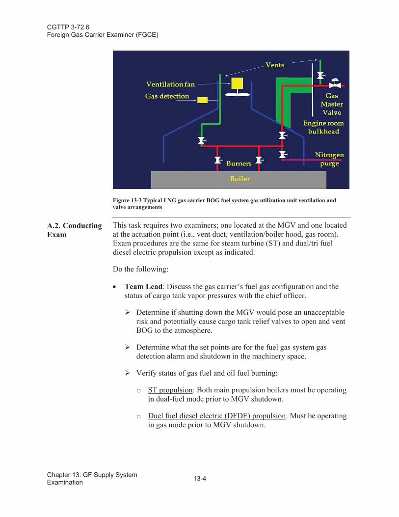
CGTTP 3-72.6Foreign Gas Carrier Examiner (FGCE)
Chapter 13: GF Supply System Examination 13-4
Figure 13-3 Typical LNG gas carrier BOG fuel system gas utilization unit ventilation and valve arrangements
A.2. Conducting Exam
This task requires two examiners; one located at the MGV and one located at the actuation point (i.e., vent duct, ventilation/boiler hood, gas room).Exam procedures are the same for steam turbine (ST) and dual/tri fuel diesel electric propulsion except as indicated.
Do the following:
Team Lead: Discuss the gas carrier’s fuel gas configuration and the status of cargo tank vapor pressures with the chief officer.
Determine if shutting down the MGV would pose an unacceptable risk and potentially cause cargo tank relief valves to open and vent BOG to the atmosphere.
Determine what the set points are for the fuel gas system gas detection alarm and shutdown in the machinery space.
Verify status of gas fuel and oil fuel burning:
o ST propulsion: Both main propulsion boilers must be operating in dual-fuel mode prior to MGV shutdown.
o Duel fuel diesel electric (DFDE) propulsion: Must be operating in gas mode prior to MGV shutdown.
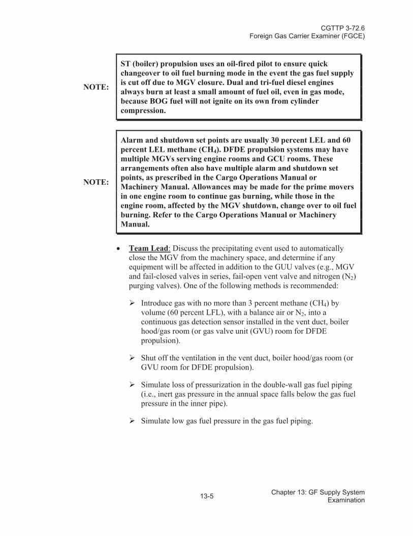
CGTTP 3-72.6Foreign Gas Carrier Examiner (FGCE)
13-5 Chapter 13: GF Supply System Examination
NOTE:
ST (boiler) propulsion uses an oil-fired pilot to ensure quick changeover to oil fuel burning mode in the event the gas fuel supply is cut off due to MGV closure. Dual and tri-fuel diesel engines always burn at least a small amount of fuel oil, even in gas mode, because BOG fuel will not ignite on its own from cylinder compression.
NOTE:
Alarm and shutdown set points are usually 30 percent LEL and 60 percent LEL methane (CH4). DFDE propulsion systems may have multiple MGVs serving engine rooms and GCU rooms. These arrangements often also have multiple alarm and shutdown set points, as prescribed in the Cargo Operations Manual or Machinery Manual. Allowances may be made for the prime movers in one engine room to continue gas burning, while those in the engine room, affected by the MGV shutdown, change over to oil fuel burning. Refer to the Cargo Operations Manual or Machinery Manual.
Team Lead: Discuss the precipitating event used to automatically close the MGV from the machinery space, and determine if any equipment will be affected in addition to the GUU valves (e.g., MGV and fail-closed valves in series, fail-open vent valve and nitrogen (N2)purging valves). One of the following methods is recommended:
Introduce gas with no more than 3 percent methane (CH4) by volume (60 percent LFL), with a balance air or N2, into a continuous gas detection sensor installed in the vent duct, boiler hood/gas room (or gas valve unit (GVU) room for DFDE propulsion).
Shut off the ventilation in the vent duct, boiler hood/gas room (or GVU room for DFDE propulsion).
Simulate loss of pressurization in the double-wall gas fuel piping (i.e., inert gas pressure in the annual space falls below the gas fuel pressure in the inner pipe).
Simulate low gas fuel pressure in the gas fuel piping.
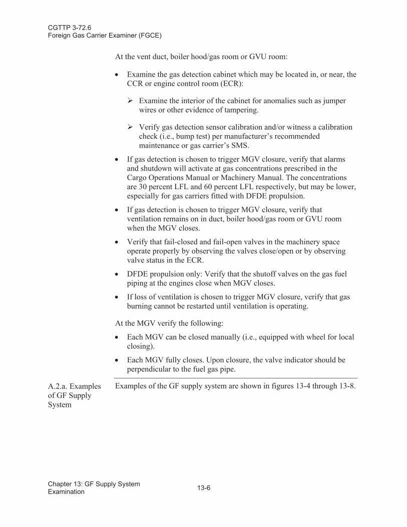
CGTTP 3-72.6Foreign Gas Carrier Examiner (FGCE)
Chapter 13: GF Supply System Examination 13-6
At the vent duct, boiler hood/gas room or GVU room:
Examine the gas detection cabinet which may be located in, or near, the CCR or engine control room (ECR):
Examine the interior of the cabinet for anomalies such as jumper wires or other evidence of tampering.
Verify gas detection sensor calibration and/or witness a calibration check (i.e., bump test) per manufacturer’s recommended maintenance or gas carrier’s SMS.
If gas detection is chosen to trigger MGV closure, verify that alarms and shutdown will activate at gas concentrations prescribed in the Cargo Operations Manual or Machinery Manual. The concentrations are 30 percent LFL and 60 percent LFL respectively, but may be lower, especially for gas carriers fitted with DFDE propulsion.
If gas detection is chosen to trigger MGV closure, verify that ventilation remains on in duct, boiler hood/gas room or GVU room when the MGV closes.
Verify that fail-closed and fail-open valves in the machinery space operate properly by observing the valves close/open or by observing valve status in the ECR.
DFDE propulsion only: Verify that the shutoff valves on the gas fuel piping at the engines close when MGV closes.
If loss of ventilation is chosen to trigger MGV closure, verify that gas burning cannot be restarted until ventilation is operating.
At the MGV verify the following:
Each MGV can be closed manually (i.e., equipped with wheel for local closing).
Each MGV fully closes. Upon closure, the valve indicator should be perpendicular to the fuel gas pipe.
A.2.a. Examples of GF Supply System
Examples of the GF supply system are shown in figures 13-4 through 13-8.
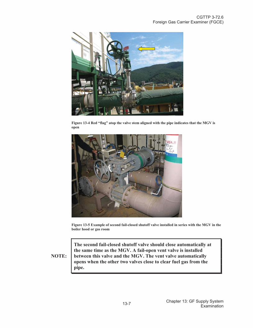
CGTTP 3-72.6Foreign Gas Carrier Examiner (FGCE)
13-7 Chapter 13: GF Supply System Examination
Figure 13-4 Red “flag” atop the valve stem aligned with the pipe indicates that the MGV is open
Figure 13-5 Example of second fail-closed shutoff valve installed in series with the MGV in the boiler hood or gas room
NOTE:
The second fail-closed shutoff valve should close automatically at the same time as the MGV. A fail-open vent valve is installed between this valve and the MGV. The vent valve automaticallyopens when the other two valves close to clear fuel gas from the pipe.
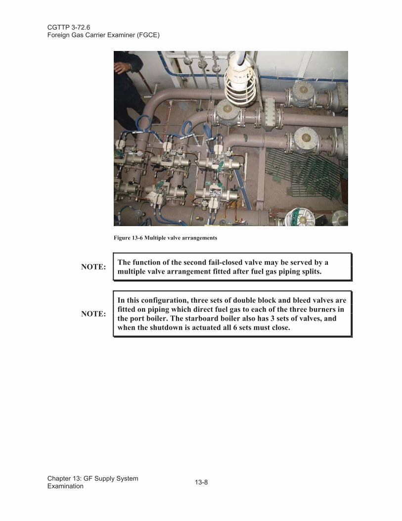
CGTTP 3-72.6Foreign Gas Carrier Examiner (FGCE)
Chapter 13: GF Supply System Examination 13-8
Figure 13-6 Multiple valve arrangements
NOTE: The function of the second fail-closed valve may be served by a multiple valve arrangement fitted after fuel gas piping splits.
NOTE:
In this configuration, three sets of double block and bleed valves are fitted on piping which direct fuel gas to each of the three burners in the port boiler. The starboard boiler also has 3 sets of valves, and when the shutdown is actuated all 6 sets must close.
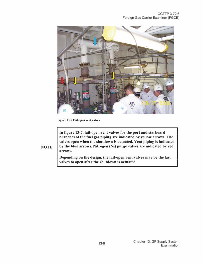
CGTTP 3-72.6Foreign Gas Carrier Examiner (FGCE)
13-9 Chapter 13: GF Supply System Examination
Figure 13-7 Fail-open vent valves
NOTE:
In figure 13-7, fail-open vent valves for the port and starboard branches of the fuel gas piping are indicated by yellow arrows. The valves open when the shutdown is actuated. Vent piping is indicated by the blue arrows. Nitrogen (N2) purge valves are indicated by redarrows.
Depending on the design, the fail-open vent valves may be the last valves to open after the shutdown is actuated.
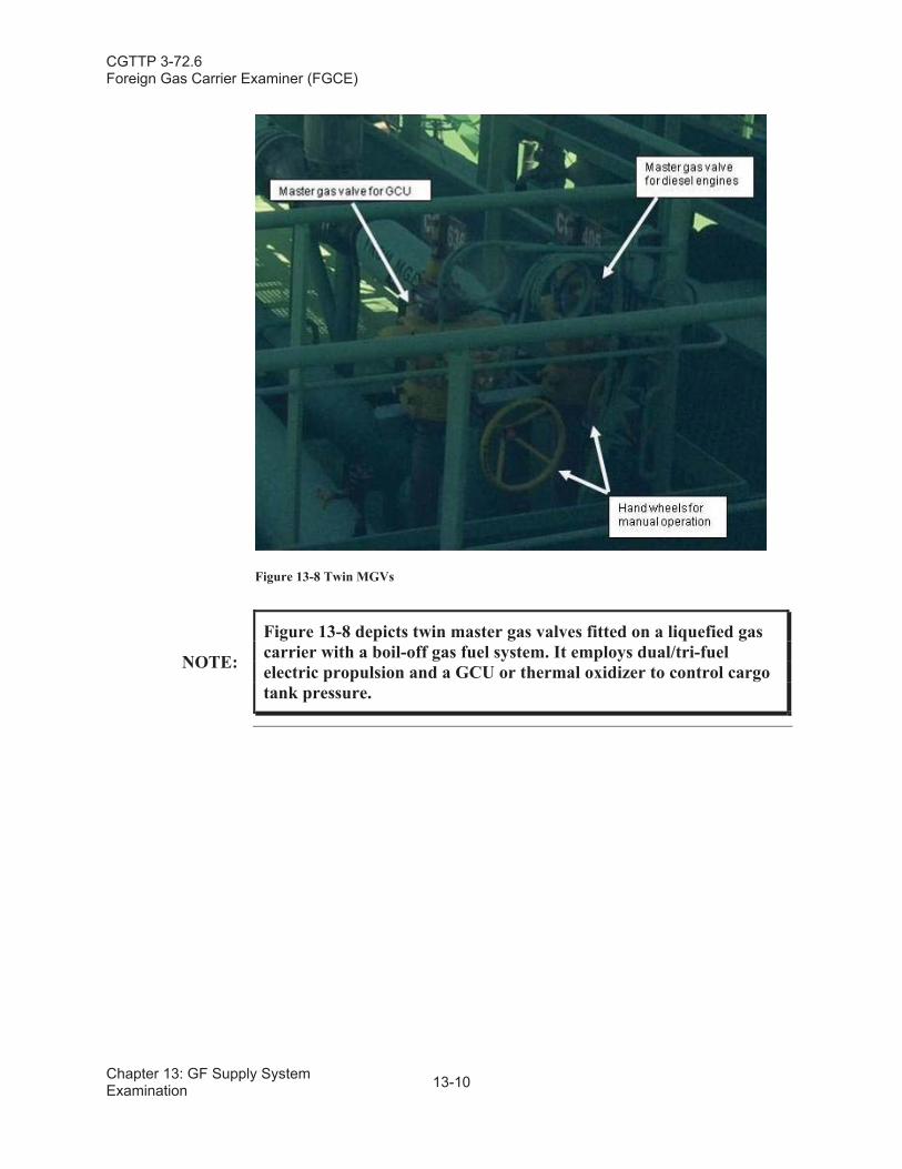
CGTTP 3-72.6Foreign Gas Carrier Examiner (FGCE)
Chapter 13: GF Supply System Examination 13-10
Figure 13-8 Twin MGVs
NOTE:
Figure 13-8 depicts twin master gas valves fitted on a liquefied gas carrier with a boil-off gas fuel system. It employs dual/tri-fuel electric propulsion and a GCU or thermal oxidizer to control cargo tank pressure.
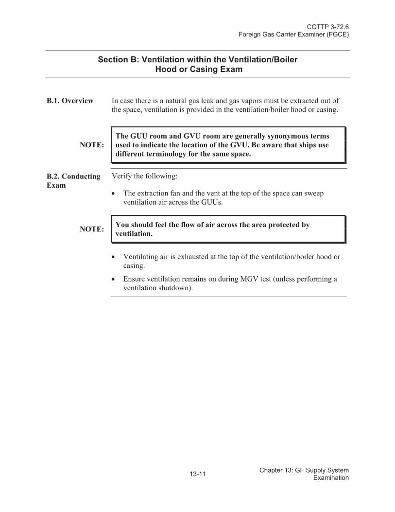
CGTTP 3-72.6Foreign Gas Carrier Examiner (FGCE)
13-11 Chapter 13: GF Supply System Examination
Section B: Ventilation within the Ventilation/BoilerHood or Casing Exam
B.1. Overview In case there is a natural gas leak and gas vapors must be extracted out of the space, ventilation is provided in the ventilation/boiler hood or casing.
NOTE:The GUU room and GVU room are generally synonymous terms used to indicate the location of the GVU. Be aware that ships use different terminology for the same space.
B.2. Conducting Exam
Verify the following:
The extraction fan and the vent at the top of the space can sweep ventilation air across the GUUs.
NOTE: You should feel the flow of air across the area protected by ventilation.
Ventilating air is exhausted at the top of the ventilation/boiler hood or casing.
Ensure ventilation remains on during MGV test (unless performing aventilation shutdown).
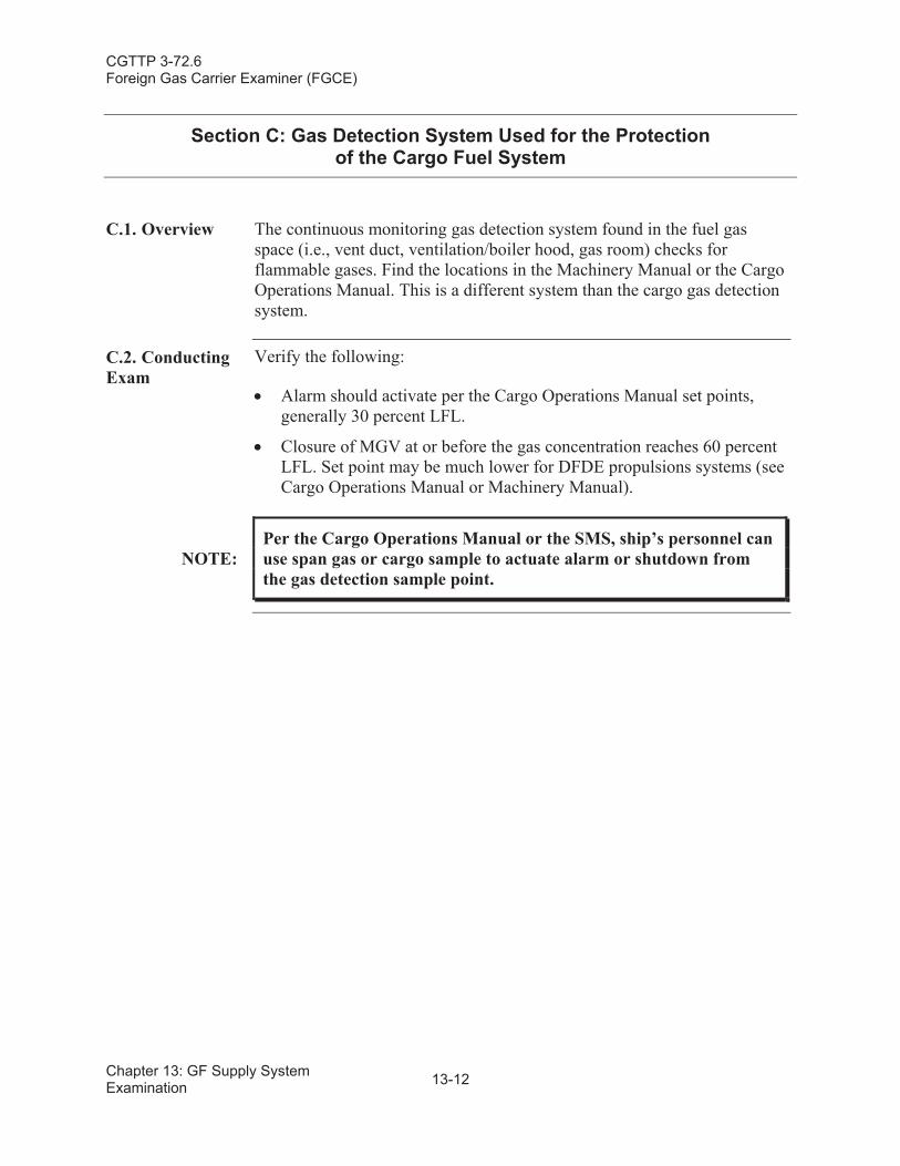
CGTTP 3-72.6Foreign Gas Carrier Examiner (FGCE)
Chapter 13: GF Supply System Examination 13-12
Section C: Gas Detection System Used for the Protection of the Cargo Fuel System
C.1. Overview The continuous monitoring gas detection system found in the fuel gas space (i.e., vent duct, ventilation/boiler hood, gas room) checks for flammable gases. Find the locations in the Machinery Manual or the Cargo Operations Manual. This is a different system than the cargo gas detection system.
C.2. Conducting Exam
Verify the following:
Alarm should activate per the Cargo Operations Manual set points, generally 30 percent LFL.
Closure of MGV at or before the gas concentration reaches 60 percent LFL. Set point may be much lower for DFDE propulsions systems (see Cargo Operations Manual or Machinery Manual).
NOTE:Per the Cargo Operations Manual or the SMS, ship’s personnel can use span gas or cargo sample to actuate alarm or shutdown from the gas detection sample point.
CGTTP 3-72.6Foreign Gas Carrier Examiner (FGCE)
13-13 Chapter 13: GF Supply System Examination
Section D: Gas Utilization Unit(s) (GUU)
D.1. Overview There are a number of automatic protective devices (valves) built into a system that uses LNG boil-off as fuel. As required by the IGC Code, each GF supply system shall be fitted with a Gas Utilization Unit (GUU). These protective devices (valves) are built into the system to ensure safe operation and they must be regularly inspected and maintained. Protective systems include automatic shut-down in the event of system malfunction or leak detection.
On ST (boiler) propulsion systems the GUU consists of a MGV located on the open deck, and fail-closed shutoff valve(s) and fail-open vent valves located in the machinery space. On DFDE propulsion systems, the GUU is comprised of the MGV, one or more GVU located in the GVU room(s),and fuel gas shutoff valves located at the engines.
The GVU typically has fail-closed shutoff valve(s), filters, flow meter, anda fuel gas control valve. The main functions of the GVU are pressure regulation, fuel shutoff in the event of a fuel gas leak or other anomalies,and inerting/venting fuel gas piping after shutdown. See Chapter 13: GasFuel Supply System Examination, Section A: Master Gas Valve for additional details.
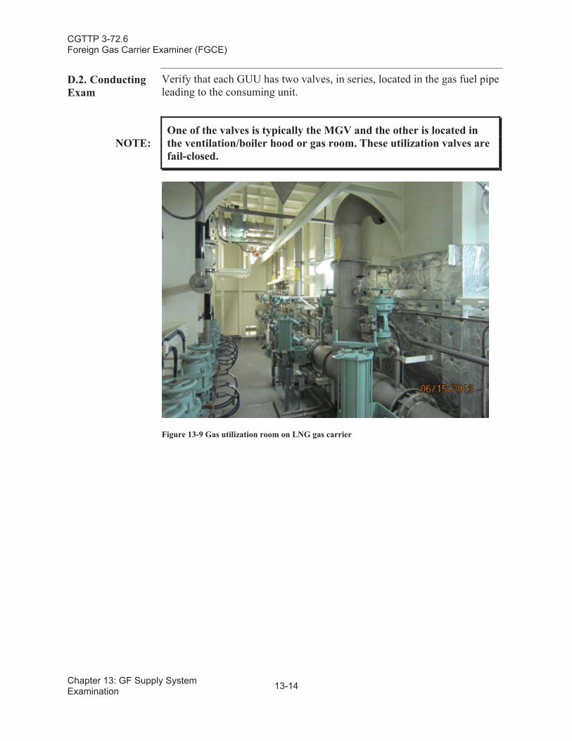
CGTTP 3-72.6Foreign Gas Carrier Examiner (FGCE)
Chapter 13: GF Supply System Examination 13-14
D.2. Conducting Exam
Verify that each GUU has two valves, in series, located in the gas fuel pipe leading to the consuming unit.
NOTE:One of the valves is typically the MGV and the other is located in the ventilation/boiler hood or gas room. These utilization valves are fail-closed.
Figure 13-9 Gas utilization room on LNG gas carrier
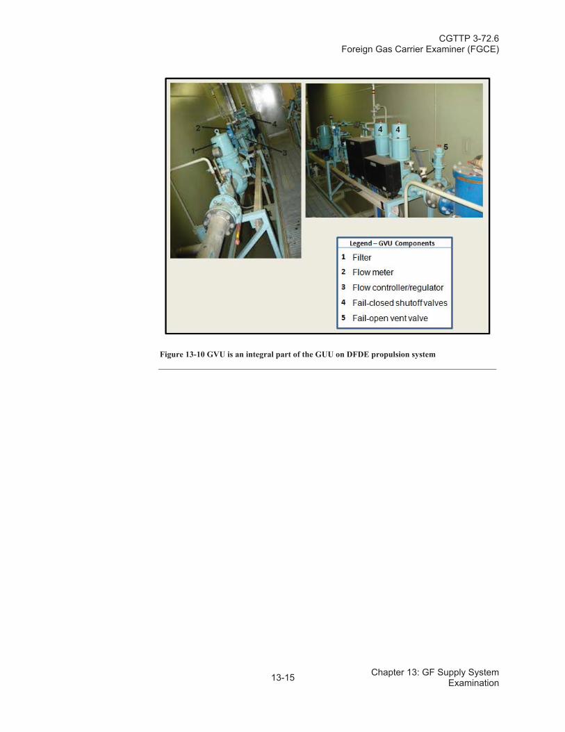
CGTTP 3-72.6Foreign Gas Carrier Examiner (FGCE)
13-15 Chapter 13: GF Supply System Examination
Figure 13-10 GVU is an integral part of the GUU on DFDE propulsion system
CGTTP 3-72.6Foreign Gas Carrier Examiner (FGCE)
Chapter 13: GF Supply System Examination 13-16
Section E: Gas Fuel Piping (Double Wall Piping System)
E.1. Overview Gas fuel (BOG) is provided to the engine room from the cargo machinery (compressor) room through either a double wall piping system or a ventilated pipe or duct system. This section discusses the double wall piping system.
The double wall piping system employs two concentric pipes. Fuel gas (vapor) flows through the inner pipe, while the annular space (see figure 13-2) between the two pipes contains inert gas (typically nitrogen [N2]) at a higher pressure than the fuel gas. See vessel’s Cargo Operations Manual or Machinery Manual for a detailed description and diagrams of the double wall pipe system.
E.2. Conducting Exam
Verify the following in the engine control room:
Inert gas is at a pressure in the annular space that is greater than the gas fuel pressure in the inner pipe.
Double wall piping system is fitted with an alarm that activates when inert gas pressure falls below the fuel gas pressure in the inner pipe.
NOTE:
Determine by comparing the fuel gas system piping and alarm details in the Cargo Operations Manual or Machinery Manual with the installation fitted on the vessel. The alarm can be tested in conjunction with the MGV test discussed in Chapter 13: Gas Fuel Supply System Examination, Section A.2.: Conducting Exam.
WARNING:
Before testing that the MGV can close automatically, discuss the fuel supply status, cargo tank vapor pressures, and possible consequences of MGV shutdown with the vessel master or chief officer.
In heavy seas, the agitation of the cargo can increase tank pressures to unusually high levels during and immediately after voyages. If MGV closure could potentially elevate pressures to cause cargo tank safety relief vales to lift, carefully consider the need to perform test(s). Gas carrier specific fuel gas configurations are outlined in the vessel’s Cargo Operations or Machinery Manual.
CGTTP 3-72.6Foreign Gas Carrier Examiner (FGCE)
13-17 Chapter 13: GF Supply System Examination
WARNING:
Failure of the MGV or other components of the fuel gas system, could result in loss of propulsion during maneuvering, or render the vessel unfit for service. Such failures represent clear grounds to expand the exam, such as reviewing relevant SMS maintenance and crew training records. Consider control actions if the safety of the vessel, crew, or the port is in doubt.
CGTTP 3-72.6Foreign Gas Carrier Examiner (FGCE)
Chapter 13: GF Supply System Examination 13-18
Section F: Gas Fuel Piping (Ventilated Pipe or Duct System)
F.1. Overview Gas fuel (BOG) is provided to the engine room from the cargo machinery (compressor) room through either a double wall piping system or a ventilated pipe or duct system. This section discusses the ventilated pipe or duct system.
Ventilated pipe or duct systems employ a duct or concentric pipe around the fuel gas pipe. When fuel gas is flowing, negative ventilation is maintained in the annular space by an extraction fan at a rate of at least 30 air changes per hour. The fan is fitted near the upper end of the duct, and exhausts to a safe location (outside the engine room). This arrangement is designed to prevent the accumulation of flammable vapor in the duct in the event of a gas leak. If a gas leak is detected, or if ventilation is cut off, the MGV closes automatically.
F.2. Conducting Exam
Verify the following:
Mechanical exhaust ventilation system is running while the vessel is operating in dual/tri-fuel mode.
When in the ECR, there is continuous gas detection at the gas detection panel.
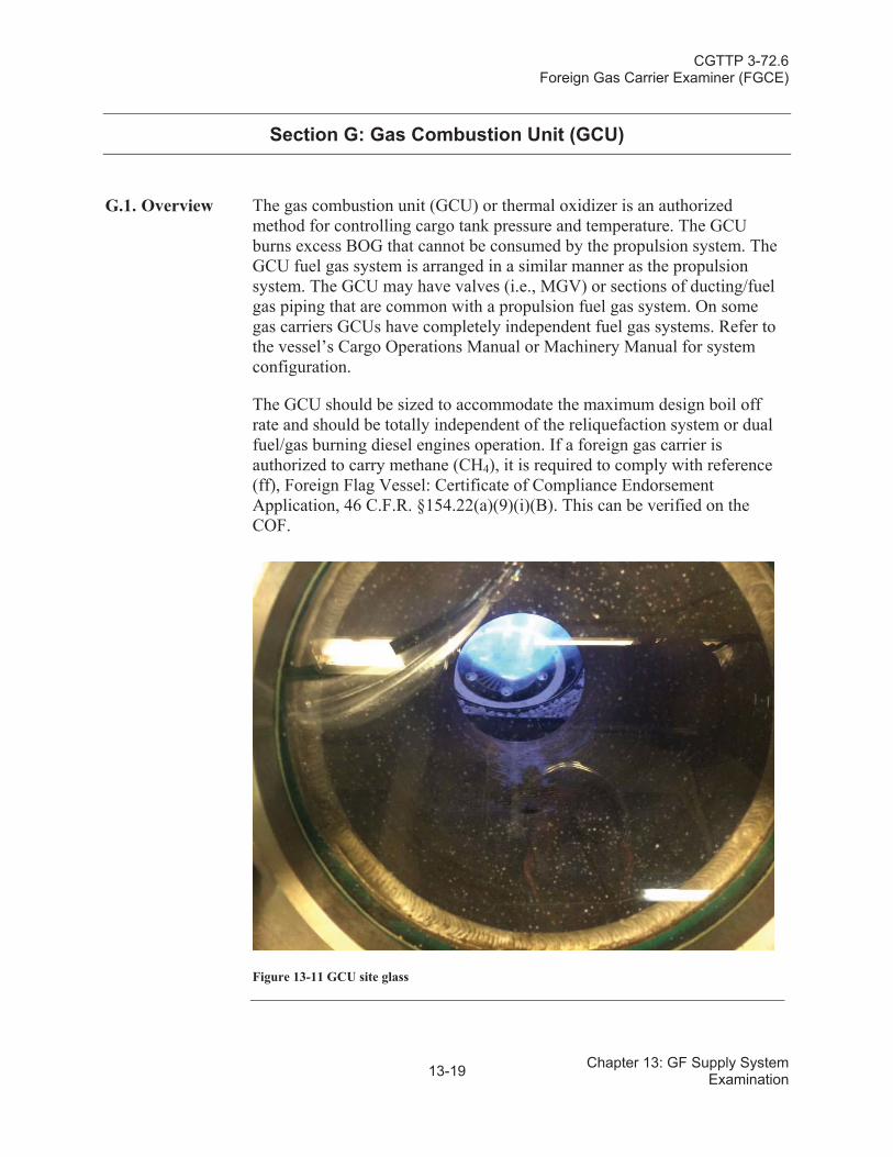
CGTTP 3-72.6Foreign Gas Carrier Examiner (FGCE)
13-19 Chapter 13: GF Supply System Examination
Section G: Gas Combustion Unit (GCU)
G.1. Overview The gas combustion unit (GCU) or thermal oxidizer is an authorized method for controlling cargo tank pressure and temperature. The GCU burns excess BOG that cannot be consumed by the propulsion system. TheGCU fuel gas system is arranged in a similar manner as the propulsion system. The GCU may have valves (i.e., MGV) or sections of ducting/fuel gas piping that are common with a propulsion fuel gas system. On some gas carriers GCUs have completely independent fuel gas systems. Refer to the vessel’s Cargo Operations Manual or Machinery Manual for system configuration.
The GCU should be sized to accommodate the maximum design boil off rate and should be totally independent of the reliquefaction system or dual fuel/gas burning diesel engines operation. If a foreign gas carrier is authorized to carry methane (CH4), it is required to comply with reference (ff), Foreign Flag Vessel: Certificate of Compliance Endorsement Application, 46 C.F.R. §154.22(a)(9)(i)(B). This can be verified on the COF.
Figure 13-11 GCU site glass
CGTTP 3-72.6Foreign Gas Carrier Examiner (FGCE)
Chapter 13: GF Supply System Examination 13-20
G.2. Conducting Exam
The GCU fuel system is similar to the BOG fuel gas system for propulsion. Do the following:
Verify the GCU is in operational condition.Determine if the MGV shutdown will be tested. If so, follow procedures in Chapter 13: Gas Fuel Supply System Examination, Section A.2.: Conducting Exam.
NOTE: Enclosed space needs 30 air changes per hour and gas detection,including the GCU room.
NOTE:
Per the IGC Code, double wall pipe must be inert to a pressure above the boil off gas pressure, or the annular space shall have ventilation with 30 air changes per hour and maintained at a pressure less than atmospheric.
Verify alarms are operational. Per the GCU operations manual, select two or three alarms to test. Typical alarms to choose from are:
Flame failure.
Flame scanner failure.
Combustion air fan failure.
Dilution air fan failure.
Main power supply failure.
Control power supply failure.
High flue gas outlet temperature.
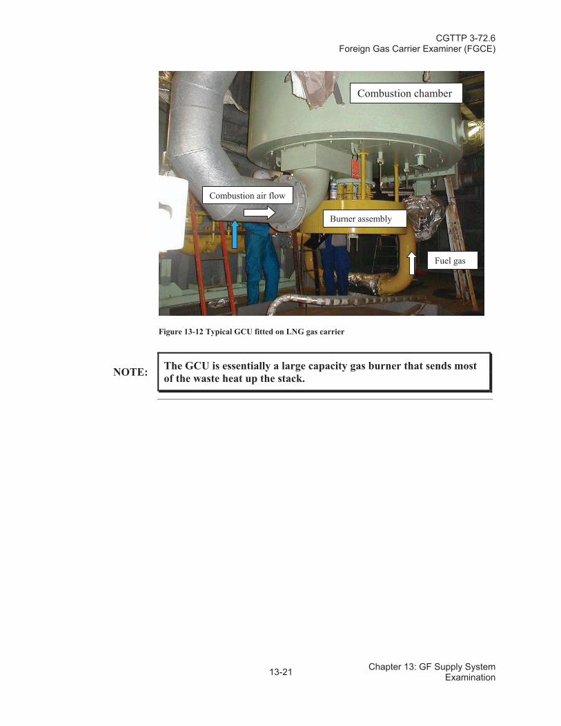
CGTTP 3-72.6Foreign Gas Carrier Examiner (FGCE)
13-21 Chapter 13: GF Supply System Examination
Figure 13-12 Typical GCU fitted on LNG gas carrier
NOTE: The GCU is essentially a large capacity gas burner that sends most of the waste heat up the stack.
Combustion chamber
Combustion air flow
Burner assembly
Fuel gas
CGTTP 3-72.6Foreign Gas Carrier Examiner (FGCE)
Chapter 13: GF Supply System Examination 13-22
This page intentionally left blank.
CGTTP 3-72.6Foreign Gas Carrier Examiner (FGCE)
14-1 Chapter 14: FF Examination
Chapter 14:Firefighting Systems (FF) Examination
Introduction This chapter provides an examination overview for a liquefied gas carrier’s firefighting equipment.
In This Chapter This chapter contains the following sections:
Section Title Page
A Fire Water Main Equipment 14-2
B Deck Water Spray System 14-3
C Dry Chemical Powder Fire-Extinguishing System 14-5
D Cargo Machinery (Compressor) Motor Room Fixed Fire-Extinguishing System
14-6
E Cargo Machinery Motor Room Fixed Fire-Extinguishing System
14-7
F Fire-fighter Outfits 14-8
CGTTP 3-72.6Foreign Gas Carrier Examiner (FGCE)
Chapter 14: FF Examination 14-2
Section A: Fire Water Main Equipment
A.1. Overview Fire prevention and firefighting is paramount for the safety of the crew and the vessel. Therefore it is critical that the system and all of its components are well maintained and ready for immediate use. All gas carriers are required to have a fire main system. Requirements vary based on keel laid date (refer to Chapter 2: PE Preparations, Section C: Gas Code Applicability for more guidance).
A.2. Conducting Exam
Verify the following:
The main piping, fittings, and nozzles are in good condition, free of excessive corrosion, pitting, and holes (unauthorized temporary repairs).
Per the IGC Code, there are at least two jets of water that can reach any part of the deck in the cargo area as well as those portions of the cargo containment system and tank covers above the deck.
Stop valves are fitted at intervals of not more than 40 meters and in any crossovers.
Two pumps are present.
There are no excessive leaks from mechanical seal, valves, and flanges.
Pumps must attain a pressure per reference (c), SOLAS: Consolidated Text of the International Convention for the Safety of Life at Sea,1974, and its Protocol of 1988: Articles, Annexes and Certificates (Incorporating all amendments in effect from 1 July 2009), International Maritime Organization (IMO). However, if fire main and fire pump is used as part of the water spray system, as permitted by the IGC Code, the pressure needs to be at least 5 bar gauge (BARG) (73.5pounds per square inch [psi]).
If the gas carrier's engine room is unattended, one of the vessel’s fire pumps can remotely start and connect to the fire main from the navigating bridge or other control station outside the cargo area.
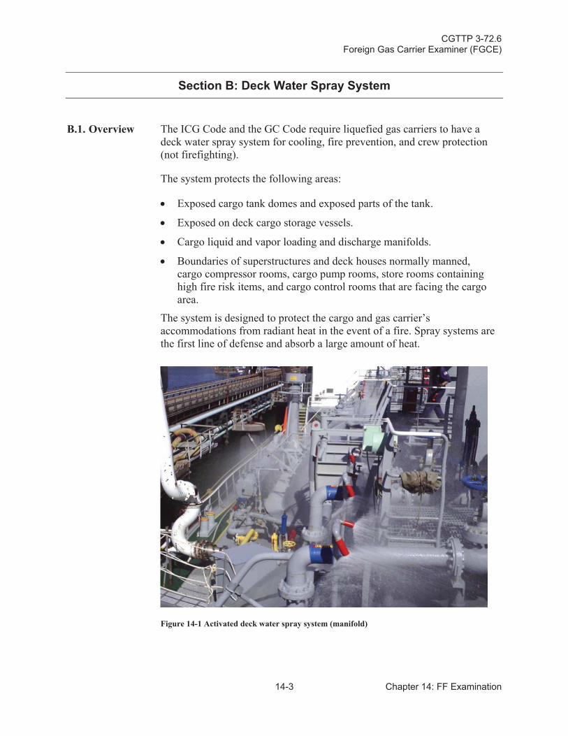
CGTTP 3-72.6Foreign Gas Carrier Examiner (FGCE)
14-3 Chapter 14: FF Examination
Section B: Deck Water Spray System
B.1. Overview The ICG Code and the GC Code require liquefied gas carriers to have a deck water spray system for cooling, fire prevention, and crew protection(not firefighting).
The system protects the following areas:
Exposed cargo tank domes and exposed parts of the tank.
Exposed on deck cargo storage vessels.
Cargo liquid and vapor loading and discharge manifolds.
Boundaries of superstructures and deck houses normally manned, cargo compressor rooms, cargo pump rooms, store rooms containing high fire risk items, and cargo control rooms that are facing the cargo area.
The system is designed to protect the cargo and gas carrier’s accommodations from radiant heat in the event of a fire. Spray systems are the first line of defense and absorb a large amount of heat.
Figure 14-1 Activated deck water spray system (manifold)
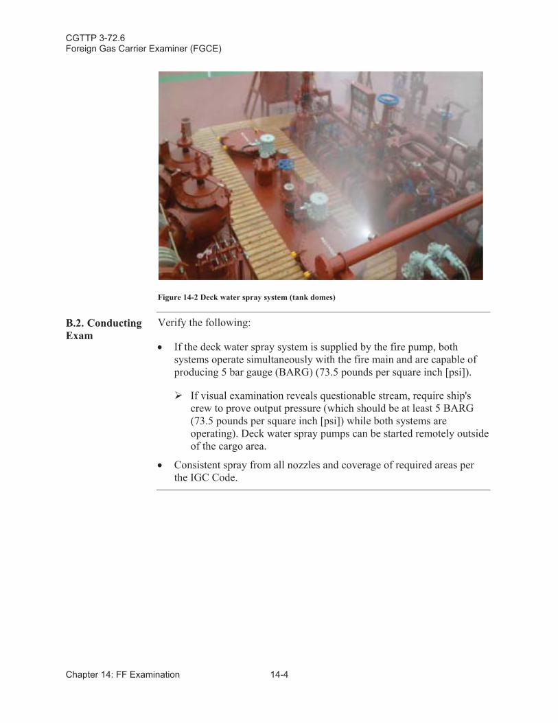
CGTTP 3-72.6Foreign Gas Carrier Examiner (FGCE)
Chapter 14: FF Examination 14-4
Figure 14-2 Deck water spray system (tank domes)
B.2. Conducting Exam
Verify the following:
If the deck water spray system is supplied by the fire pump, both systems operate simultaneously with the fire main and are capable of producing 5 bar gauge (BARG) (73.5 pounds per square inch [psi]).
If visual examination reveals questionable stream, require ship's crew to prove output pressure (which should be at least 5 BARG(73.5 pounds per square inch [psi]) while both systems are operating). Deck water spray pumps can be started remotely outside of the cargo area.
Consistent spray from all nozzles and coverage of required areas per the IGC Code.
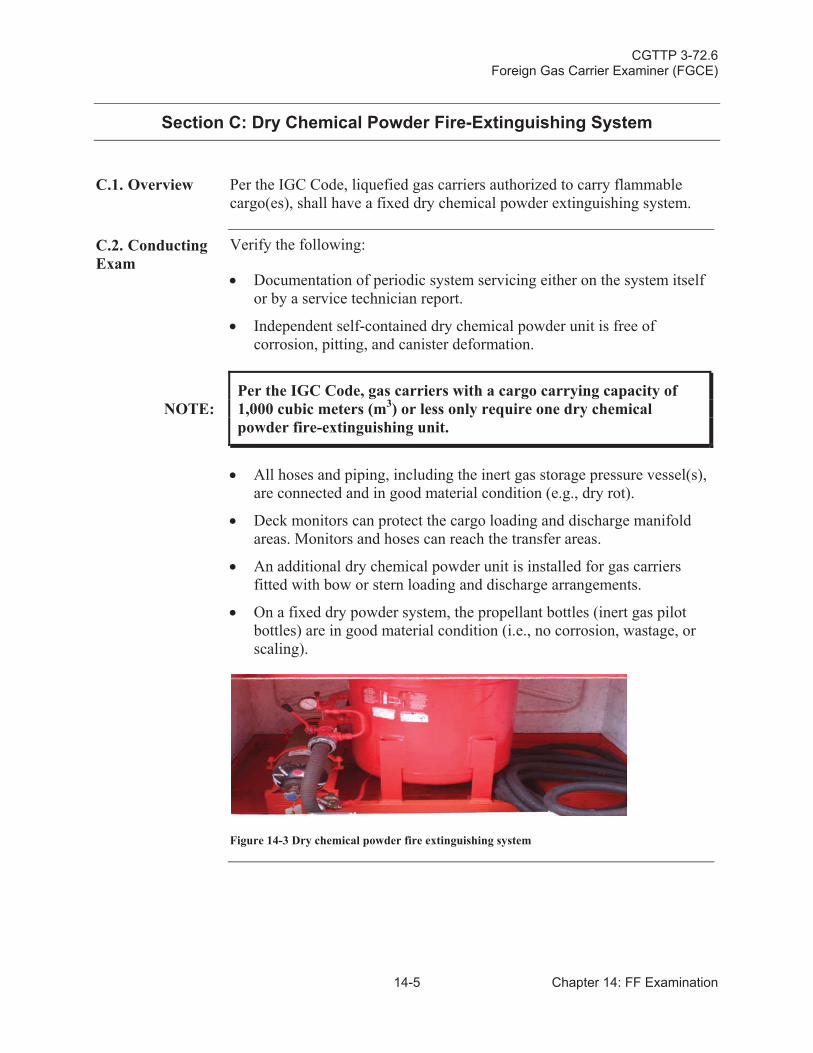
CGTTP 3-72.6Foreign Gas Carrier Examiner (FGCE)
14-5 Chapter 14: FF Examination
Section C: Dry Chemical Powder Fire-Extinguishing System
C.1. Overview Per the IGC Code, liquefied gas carriers authorized to carry flammable cargo(es), shall have a fixed dry chemical powder extinguishing system.
C.2. Conducting Exam
Verify the following:
Documentation of periodic system servicing either on the system itself or by a service technician report.
Independent self-contained dry chemical powder unit is free of corrosion, pitting, and canister deformation.
NOTE:Per the IGC Code, gas carriers with a cargo carrying capacity of 1,000 cubic meters (m3) or less only require one dry chemical powder fire-extinguishing unit.
All hoses and piping, including the inert gas storage pressure vessel(s), are connected and in good material condition (e.g., dry rot).
Deck monitors can protect the cargo loading and discharge manifold areas. Monitors and hoses can reach the transfer areas.
An additional dry chemical powder unit is installed for gas carriersfitted with bow or stern loading and discharge arrangements.
On a fixed dry powder system, the propellant bottles (inert gas pilot bottles) are in good material condition (i.e., no corrosion, wastage, or scaling).
Figure 14-3 Dry chemical powder fire extinguishing system
CGTTP 3-72.6Foreign Gas Carrier Examiner (FGCE)
Chapter 14: FF Examination 14-6
Section D: Cargo Machinery (Compressor) Motor Room Fixed Fire-Extinguishing System
D.1. Overview Cargo machinery (compressor) motor rooms shall have a fixed carbon dioxide (CO2) extinguishing system installed to the satisfaction of thevessel’s Flag Administration and per:
The IGC Code.
The GC Code.
Reference (c), SOLAS: Consolidated Text of the International Convention for the Safety of Life at Sea, 1974, and its Protocol of 1988: Articles, Annexes and Certificates (Incorporating all amendments in effect from 1 July 2009), International Maritime Organization (IMO).
Reference (gg), International Fire Safety Systems (FSS Code), 2007.
CAUTION:As with all fixed CO2 systems, it is critical that the system, including all of its components, are well maintained and ready for immediate use.
D.2. Conducting Exam
Examine the system the same as any PSC exam.
CGTTP 3-72.6Foreign Gas Carrier Examiner (FGCE)
14-7 Chapter 14: FF Examination
Section E: Cargo Machinery Motor Room Fixed Fire-Extinguishing System
E.1. Overview Although not required by the Gas Codes, cargo machinery motor rooms may have a fixed carbon dioxide (CO2) extinguishing system.
Refer to the reference (hh), Guidelines for the Maintenance and Inspection of Fixed Carbon Dioxide Fire-Extinguishing Systems, InternationalMaritime Organization (IMO), MSC.1/Circ.1318 and reference (ii), Guidelines for the Maintenance and Inspection of Fire Protection Systems & Appliances, International Maritime Organization (IMO), MSC.1/Circ. 1432, for more guidance.
E.2. Conducting Exam
Examine the system the same as any PSC exam.
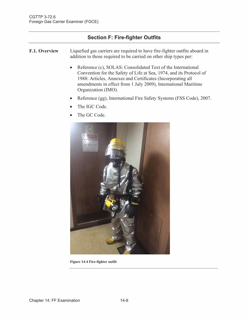
CGTTP 3-72.6Foreign Gas Carrier Examiner (FGCE)
Chapter 14: FF Examination 14-8
Section F: Fire-fighter Outfits
F.1. Overview Liquefied gas carriers are required to have fire-fighter outfits aboard in addition to those required to be carried on other ship types per:
Reference (c), SOLAS: Consolidated Text of the International Convention for the Safety of Life at Sea, 1974, and its Protocol of 1988: Articles, Annexes and Certificates (Incorporating all amendments in effect from 1 July 2009), International Maritime Organization (IMO).
Reference (gg), International Fire Safety Systems (FSS Code), 2007.
The IGC Code.
The GC Code.
Figure 14-4 Fire-fighter outfit
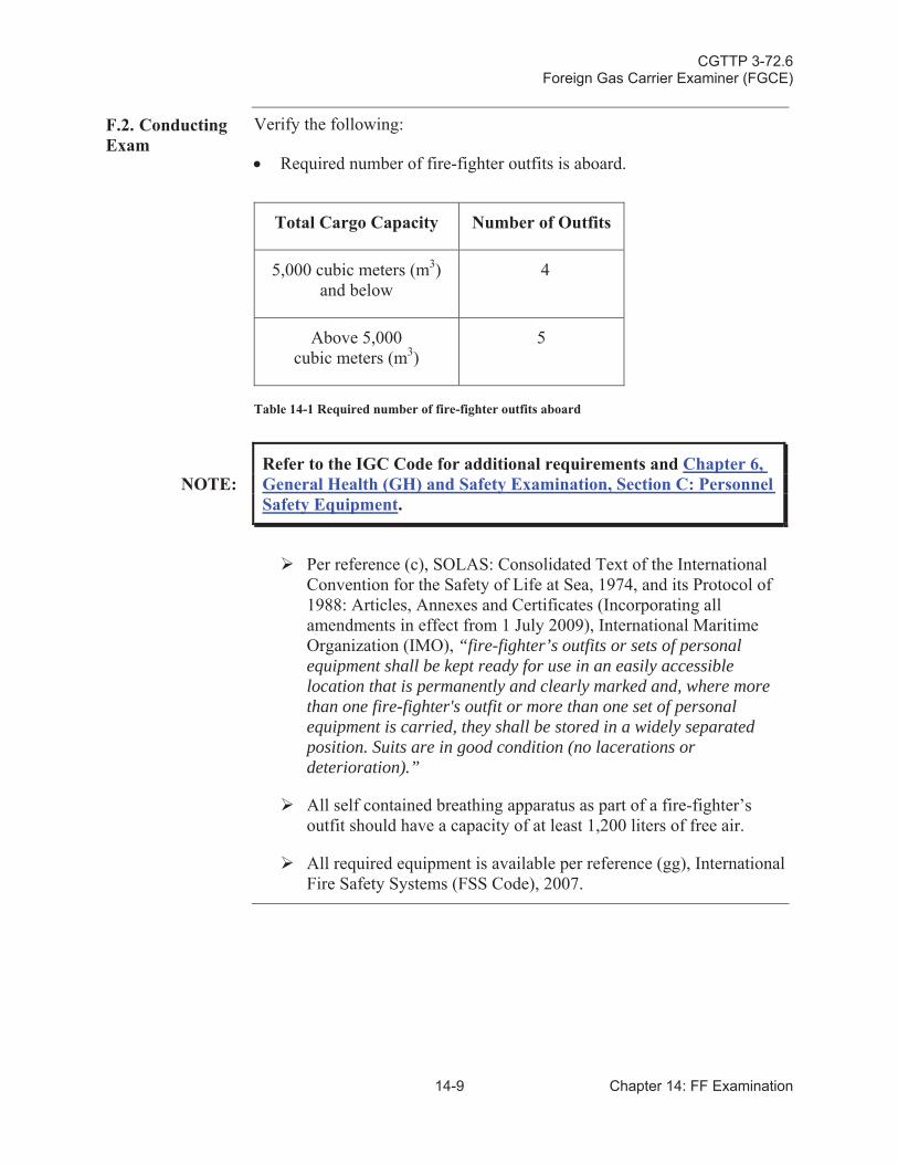
CGTTP 3-72.6Foreign Gas Carrier Examiner (FGCE)
14-9 Chapter 14: FF Examination
F.2. Conducting Exam
Verify the following:
Required number of fire-fighter outfits is aboard.
Total Cargo Capacity Number of Outfits
5,000 cubic meters (m3)and below
4
Above 5,000 cubic meters (m3)
5
Table 14-1 Required number of fire-fighter outfits aboard
NOTE:Refer to the IGC Code for additional requirements and Chapter 6, General Health (GH) and Safety Examination, Section C: PersonnelSafety Equipment.
Per reference (c), SOLAS: Consolidated Text of the International Convention for the Safety of Life at Sea, 1974, and its Protocol of 1988: Articles, Annexes and Certificates (Incorporating all amendments in effect from 1 July 2009), International Maritime Organization (IMO), “fire-fighter’s outfits or sets of personal equipment shall be kept ready for use in an easily accessiblelocation that is permanently and clearly marked and, where more than one fire-fighter's outfit or more than one set of personal equipment is carried, they shall be stored in a widely separated position. Suits are in good condition (no lacerations or deterioration).”
All self contained breathing apparatus as part of a fire-fighter’soutfit should have a capacity of at least 1,200 liters of free air.
All required equipment is available per reference (gg), International Fire Safety Systems (FSS Code), 2007.

CGTTP 3-72.6Foreign Gas Carrier Examiner (FGCE)
Chapter 14: FF Examination 14-10
This page intentionally left blank.
CGTTP 3-72.6Foreign Gas Carrier Examiner (FGCE)
15-1 Chapter 15: Follow Up Actions
Chapter 15:Follow Up (FU) Actions
Introduction This chapter discusses follow up (FU) actions after all exams are completed. Refer to reference (jj), Guidelines for Foreign Liquefied Gas Carrier COC Endorsement, Marine Safety Center (MSC), Plan Review Guideline, C1-43.
In This Chapter This chapter contains the following sections:
Section Title Page
A Issue COC (CG-3585) 15-2
B COC (CG-3585) Common Mistakes 15-3
C Complete MISLE Activity 15-4
CGTTP 3-72.6Foreign Gas Carrier Examiner (FGCE)
Chapter 15: Follow Up Actions 15-2
Section A: Issue COC (CG-3585)
A.1.Overview
Once examination is complete, fill out the remainder of the COC (using guidance below, reference (q), USCG Marine Safety Manual, Vol. II: Materiel Inspection, COMDTINST M16000.7 (series), and reference (jj), Guidelines for Foreign Liquefied Gas Carrier COC Endorsement, Marine Safety Center (MSC), Plan Review Guideline, C1-43, and issue it to the ship’s master.
A.2. Completing the COC CG-3585
Obtain Certificate of Compliance (CG-3585) form and do the following[refer to Appendix C: Sample Certificate of Compliance (COC)]:
Place an “X” in the following blocks under the “For Tank ships only” section:
The vessel is authorized to carry into or from United States ports.
The products listed on the COF for the carriage of liquefied gases in bulk subject to conditions noted on the attached USCG SOE.
The vessel is equipped with (check all that apply).
Segregated ballast tanks. (Place the vessel’s deadweight tonnage in this section).
Fill in the Date Issued section: Date of the exam.
Fill in the Date of Expiration section: Two years from the date of the exam.
Fill in the Annual Exam Due section: One year from the date of the exam.
Complete the Examination Record on pages 2 or 3. This section iscompleted after initial, renewal and annual exams as follows:
Type of Examination section: Write in “COC-Gas Ren”, “COC-Gas Ann” or “COC-Initial”, as appropriate.
Remarks section: When deficiencies are found, list them along with corrective actions required or accomplished. Include requirements as to the type of repairs and time permitted for completion.
CGTTP 3-72.6Foreign Gas Carrier Examiner (FGCE)
15-3 Chapter 15: Follow Up Actions
Section B: COC (CG-3585) Common Mistakes
B.1. Common Mistakes to Avoid
When preparing a COC, do not check the following blocks:
“Category Z Noxious Liquid Substances (NLS) as noted on the vessel’s International Pollution Prevention Certificate for the Carriage of Noxious Liquid Substances in Bulk (NLS Certificate).”
NOTE:
The governing document for issuing a COC to a liquefied gas carrier is the COF, not the IPP NLS certificate. The IPP NLS never authorizes cargo carriage on a liquefied gas carrier without COF authorization. The block on the COC regarding the carriage of category Z NLS cargoes will only be applicable to product carriersthat are issued an IPP NLS certificate authorizing the carriage of category Z NLS cargoes.
“This vessel meets the double-hull construction requirements as noted on the IOPP certificate and supplements.”
NOTE:
This information only applies to vessels carrying bulk oil, and is only found on the supplement to the International Oil Pollution Prevention (IOPP) certificate, Record of Construction, and Equipment for Oil Tankers.
“The vessel’s Vapor Collection System (VCS) meets the requirements of 46 CFR § 39.” (reference (kk), Vapor Control Systems, 46 C.F.R.Part 39).
NOTE:Even though liquefied gas carriers are designed to manage and transfer vapors, reference (kk) only applies to tank vessels that transfer vapors from crude oil, gasoline blends, and benzene.
“This vessel is equipped with an Inert Gas System that complies with the requirements of SOLAS 74 (amended) II-2/4.5.5 and 46 CFR § 32.”(reference (c), SOLAS: Consolidated Text of the InternationalConvention for the Safety of Life at Sea, 1974, and its Protocol of 1988: Articles, Annexes and Certificates (Incorporating all amendments in effect from 1 July 2009), International Maritime Organization (IMO), and reference (ll), Special Equipment, Machinery, and Hull Requirements, 46 C.F.R. Part 32).
For inspection result sample deficiencies, refer to Appendix K: Sample Deficiencies.
CGTTP 3-72.6Foreign Gas Carrier Examiner (FGCE)
Chapter 15: Follow Up Actions 15-4
Section C: Complete MISLE Activity
C.1. Complete MISLE Activity
Upon completion of the COC examination the lead FGCE ensures that a MISLE activity is created and completed (see The Marine Information for Safety and Law Enforcement (MISLE) - Vessel Inspection User Guide, Version 1.0, 30 June 2015, on CGPortal). In addition to the requirements identified in the work instruction, the FGCE ensures the following:
For initial and renewal exams, the status of the COC in MISLE ischanged from “In Process” to “Valid.”
The dates of the COC in MISLE are updated to accurately reflect the date of issuance, next annual exam, and expiration date.
For initial and renewal exams in which the SOE is initially issued, the status of the SOE in MISLE should remain “In Process” unless changed by MSC.
A copy of the COC and SOE, after issue, is scanned and uploaded into MISLE.
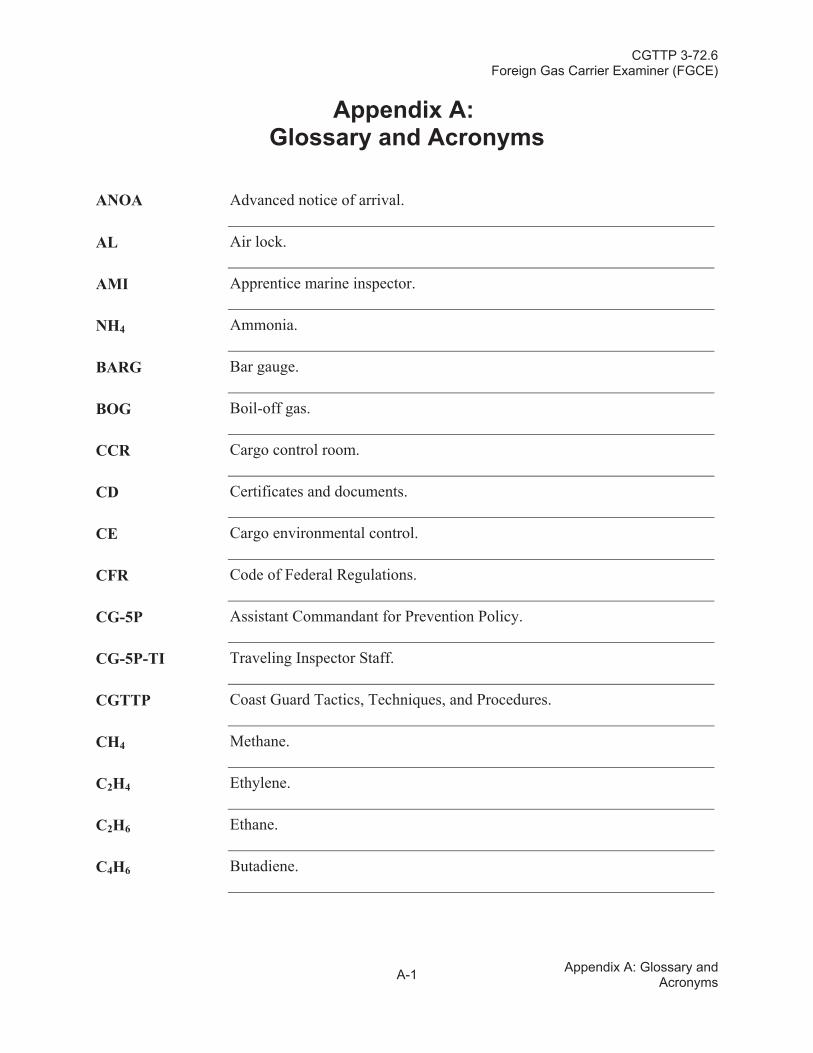
CGTTP 3-72.6Foreign Gas Carrier Examiner (FGCE)
A-1 Appendix A: Glossary and Acronyms
Appendix A:Glossary and Acronyms
ANOA Advanced notice of arrival.
AL Air lock.
AMI Apprentice marine inspector.
NH4 Ammonia.
BARG Bar gauge.
BOG Boil-off gas.
CCR Cargo control room.
CD Certificates and documents.
CE Cargo environmental control.
CFR Code of Federal Regulations.
CG-5P Assistant Commandant for Prevention Policy.
CG-5P-TI Traveling Inspector Staff.
CGTTP Coast Guard Tactics, Techniques, and Procedures.
CH4 Methane.
C2H4 Ethylene.
C2H6 Ethane.
C4H6 Butadiene.
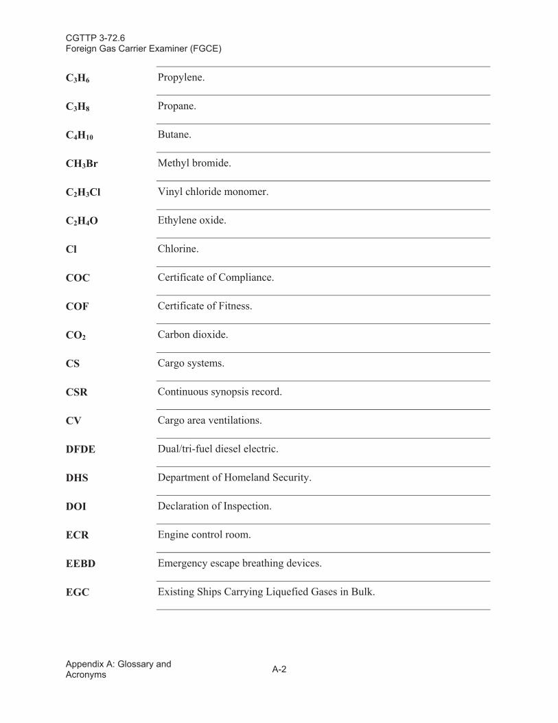
CGTTP 3-72.6Foreign Gas Carrier Examiner (FGCE)
Appendix A: Glossary and Acronyms A-2
C3H6 Propylene.
C3H8 Propane.
C4H10 Butane.
CH3Br Methyl bromide.
C2H3Cl Vinyl chloride monomer.
C2H4O Ethylene oxide.
Cl Chlorine.
COC Certificate of Compliance.
COF Certificate of Fitness.
CO2 Carbon dioxide.
CS Cargo systems.
CSR Continuous synopsis record.
CV Cargo area ventilations.
DFDE Dual/tri-fuel diesel electric.
DHS Department of Homeland Security.
DOI Declaration of Inspection.
ECR Engine control room.
EEBD Emergency escape breathing devices.
EGC Existing Ships Carrying Liquefied Gases in Bulk.
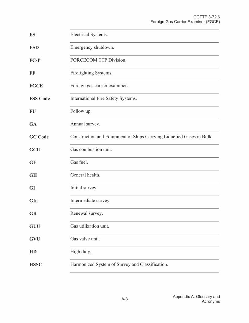
CGTTP 3-72.6Foreign Gas Carrier Examiner (FGCE)
A-3 Appendix A: Glossary and Acronyms
ES Electrical Systems.
ESD Emergency shutdown.
FC-P FORCECOM TTP Division.
FF Firefighting Systems.
FGCE Foreign gas carrier examiner.
FSS Code International Fire Safety Systems.
FU Follow up.
GA Annual survey.
GC Code Construction and Equipment of Ships Carrying Liquefied Gases in Bulk.
GCU Gas combustion unit.
GF Gas fuel.
GH General health.
GI Initial survey.
GIn Intermediate survey.
GR Renewal survey.
GUU Gas utilization unit.
GVU Gas valve unit.
HD High duty.
HSSC Harmonized System of Survey and Classification.
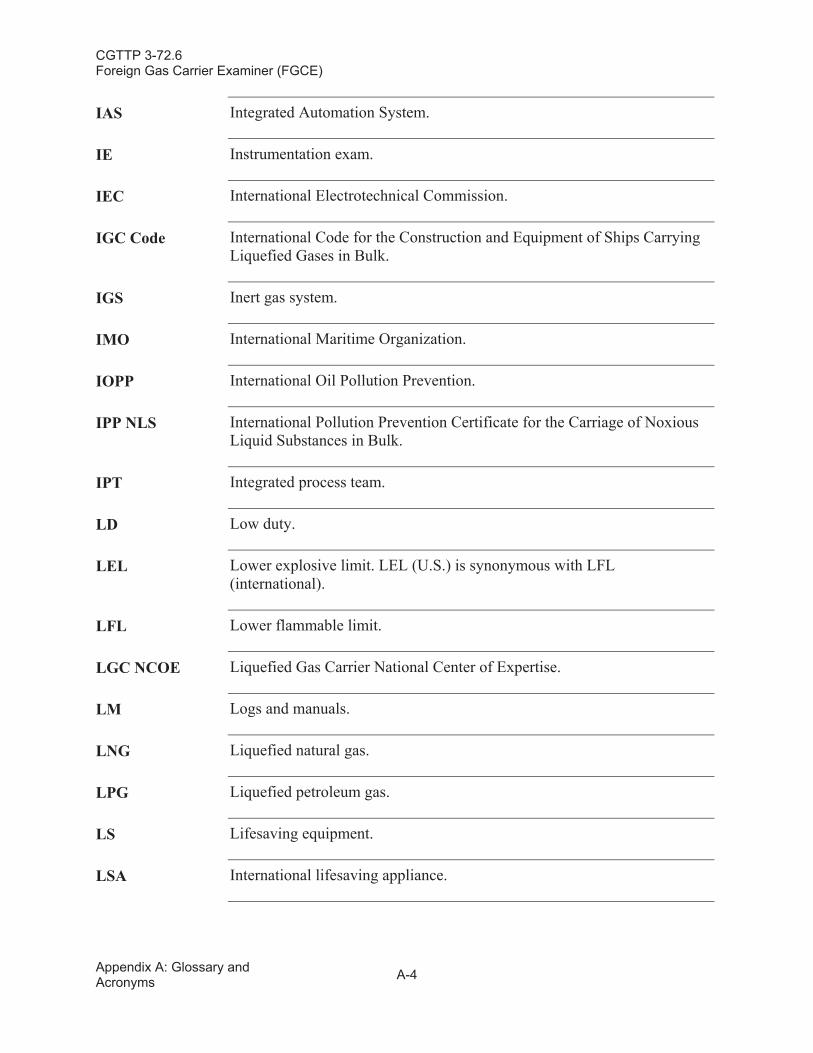
CGTTP 3-72.6Foreign Gas Carrier Examiner (FGCE)
Appendix A: Glossary and Acronyms A-4
IAS Integrated Automation System.
IE Instrumentation exam.
IEC International Electrotechnical Commission.
IGC Code International Code for the Construction and Equipment of Ships Carrying Liquefied Gases in Bulk.
IGS Inert gas system.
IMO International Maritime Organization.
IOPP International Oil Pollution Prevention.
IPP NLS International Pollution Prevention Certificate for the Carriage of Noxious Liquid Substances in Bulk.
IPT Integrated process team.
LD Low duty.
LEL Lower explosive limit. LEL (U.S.) is synonymous with LFL (international).
LFL Lower flammable limit.
LGC NCOE Liquefied Gas Carrier National Center of Expertise.
LM Logs and manuals.
LNG Liquefied natural gas.
LPG Liquefied petroleum gas.
LS Lifesaving equipment.
LSA International lifesaving appliance.
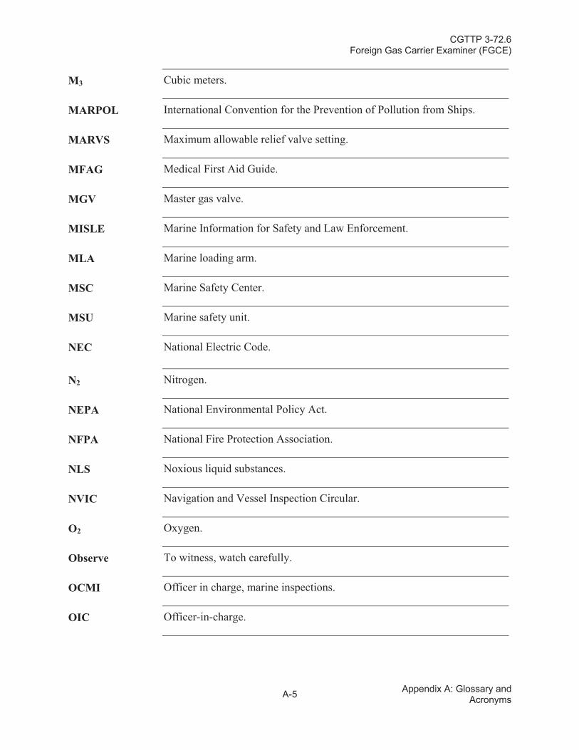
CGTTP 3-72.6Foreign Gas Carrier Examiner (FGCE)
A-5 Appendix A: Glossary and Acronyms
M3 Cubic meters.
MARPOL International Convention for the Prevention of Pollution from Ships.
MARVS Maximum allowable relief valve setting.
MFAG Medical First Aid Guide.
MGV Master gas valve.
MISLE Marine Information for Safety and Law Enforcement.
MLA Marine loading arm.
MSC Marine Safety Center.
MSU Marine safety unit.
NEC National Electric Code.
N2 Nitrogen.
NEPA National Environmental Policy Act.
NFPA National Fire Protection Association.
NLS Noxious liquid substances.
NVIC Navigation and Vessel Inspection Circular.
O2 Oxygen.
Observe To witness, watch carefully.
OCMI Officer in charge, marine inspections.
OIC Officer-in-charge.
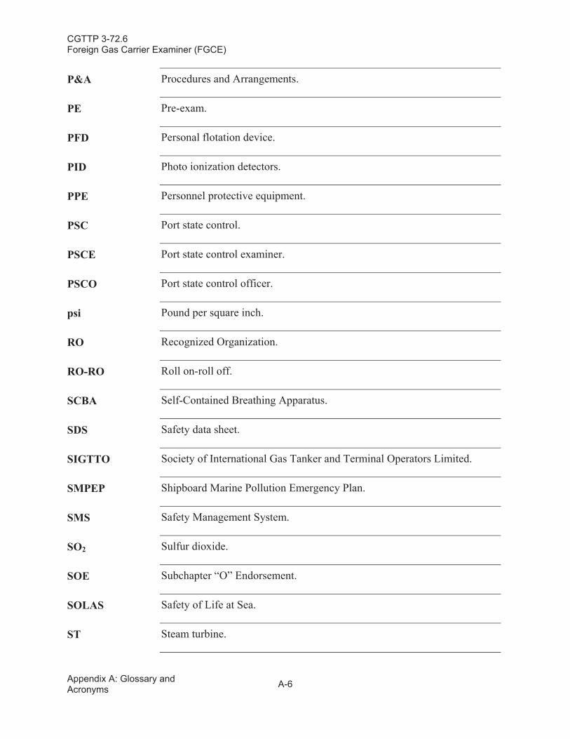
CGTTP 3-72.6Foreign Gas Carrier Examiner (FGCE)
Appendix A: Glossary and Acronyms A-6
P&A Procedures and Arrangements.
PE Pre-exam.
PFD Personal flotation device.
PID Photo ionization detectors.
PPE Personnel protective equipment.
PSC Port state control.
PSCE Port state control examiner.
PSCO Port state control officer.
psi Pound per square inch.
RO Recognized Organization.
RO-RO Roll on-roll off.
SCBA Self-Contained Breathing Apparatus.
SDS Safety data sheet.
SIGTTO Society of International Gas Tanker and Terminal Operators Limited.
SMPEP Shipboard Marine Pollution Emergency Plan.
SMS Safety Management System.
SO2 Sulfur dioxide.
SOE Subchapter “O” Endorsement.
SOLAS Safety of Life at Sea.
ST Steam turbine.
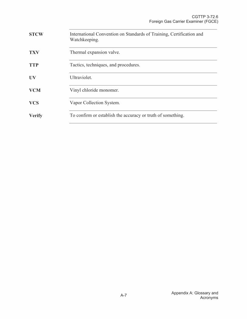
CGTTP 3-72.6Foreign Gas Carrier Examiner (FGCE)
A-7 Appendix A: Glossary and Acronyms
STCW International Convention on Standards of Training, Certification and Watchkeeping.
TXV Thermal expansion valve.
TTP Tactics, techniques, and procedures.
UV Ultraviolet.
VCM Vinyl chloride monomer.
VCS Vapor Collection System.
Verify To confirm or establish the accuracy or truth of something.

CGTTP 3-72.6Foreign Gas Carrier Examiner (FGCE)
Appendix A: Glossary and Acronyms A-8
This page intentionally left blank.
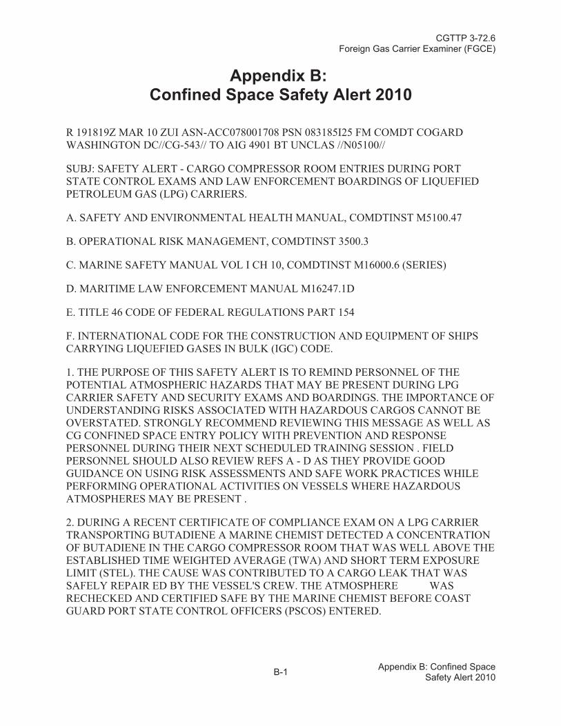
CGTTP 3-72.6Foreign Gas Carrier Examiner (FGCE)
B-1 Appendix B: Confined Space Safety Alert 2010
Appendix B:Confined Space Safety Alert 2010
R 191819Z MAR 10 ZUI ASN-ACC078001708 PSN 083185I25 FM COMDT COGARD WASHINGTON DC//CG-543// TO AIG 4901 BT UNCLAS //N05100//
SUBJ: SAFETY ALERT - CARGO COMPRESSOR ROOM ENTRIES DURING PORT STATE CONTROL EXAMS AND LAW ENFORCEMENT BOARDINGS OF LIQUEFIED PETROLEUM GAS (LPG) CARRIERS.
A. SAFETY AND ENVIRONMENTAL HEALTH MANUAL, COMDTINST M5100.47
B. OPERATIONAL RISK MANAGEMENT, COMDTINST 3500.3
C. MARINE SAFETY MANUAL VOL I CH 10, COMDTINST M16000.6 (SERIES)
D. MARITIME LAW ENFORCEMENT MANUAL M16247.1D
E. TITLE 46 CODE OF FEDERAL REGULATIONS PART 154
F. INTERNATIONAL CODE FOR THE CONSTRUCTION AND EQUIPMENT OF SHIPS CARRYING LIQUEFIED GASES IN BULK (IGC) CODE.
1. THE PURPOSE OF THIS SAFETY ALERT IS TO REMIND PERSONNEL OF THE POTENTIAL ATMOSPHERIC HAZARDS THAT MAY BE PRESENT DURING LPG CARRIER SAFETY AND SECURITY EXAMS AND BOARDINGS. THE IMPORTANCE OF UNDERSTANDING RISKS ASSOCIATED WITH HAZARDOUS CARGOS CANNOT BE OVERSTATED. STRONGLY RECOMMEND REVIEWING THIS MESSAGE AS WELL AS CG CONFINED SPACE ENTRY POLICY WITH PREVENTION AND RESPONSE PERSONNEL DURING THEIR NEXT SCHEDULED TRAINING SESSION . FIELD PERSONNEL SHOULD ALSO REVIEW REFS A - D AS THEY PROVIDE GOODGUIDANCE ON USING RISK ASSESSMENTS AND SAFE WORK PRACTICES WHILE PERFORMING OPERATIONAL ACTIVITIES ON VESSELS WHERE HAZARDOUS ATMOSPHERES MAY BE PRESENT .
2. DURING A RECENT CERTIFICATE OF COMPLIANCE EXAM ON A LPG CARRIER TRANSPORTING BUTADIENE A MARINE CHEMIST DETECTED A CONCENTRATION OF BUTADIENE IN THE CARGO COMPRESSOR ROOM THAT WAS WELL ABOVE THE ESTABLISHED TIME WEIGHTED AVERAGE (TWA) AND SHORT TERM EXPOSURE LIMIT (STEL). THE CAUSE WAS CONTRIBUTED TO A CARGO LEAK THAT WAS SAFELY REPAIR ED BY THE VESSEL'S CREW. THE ATMOSPHERE WAS RECHECKED AND CERTIFIED SAFE BY THE MARINE CHEMIST BEFORE COAST GUARD PORT STATE CONTROL OFFICERS (PSCOS) ENTERED.
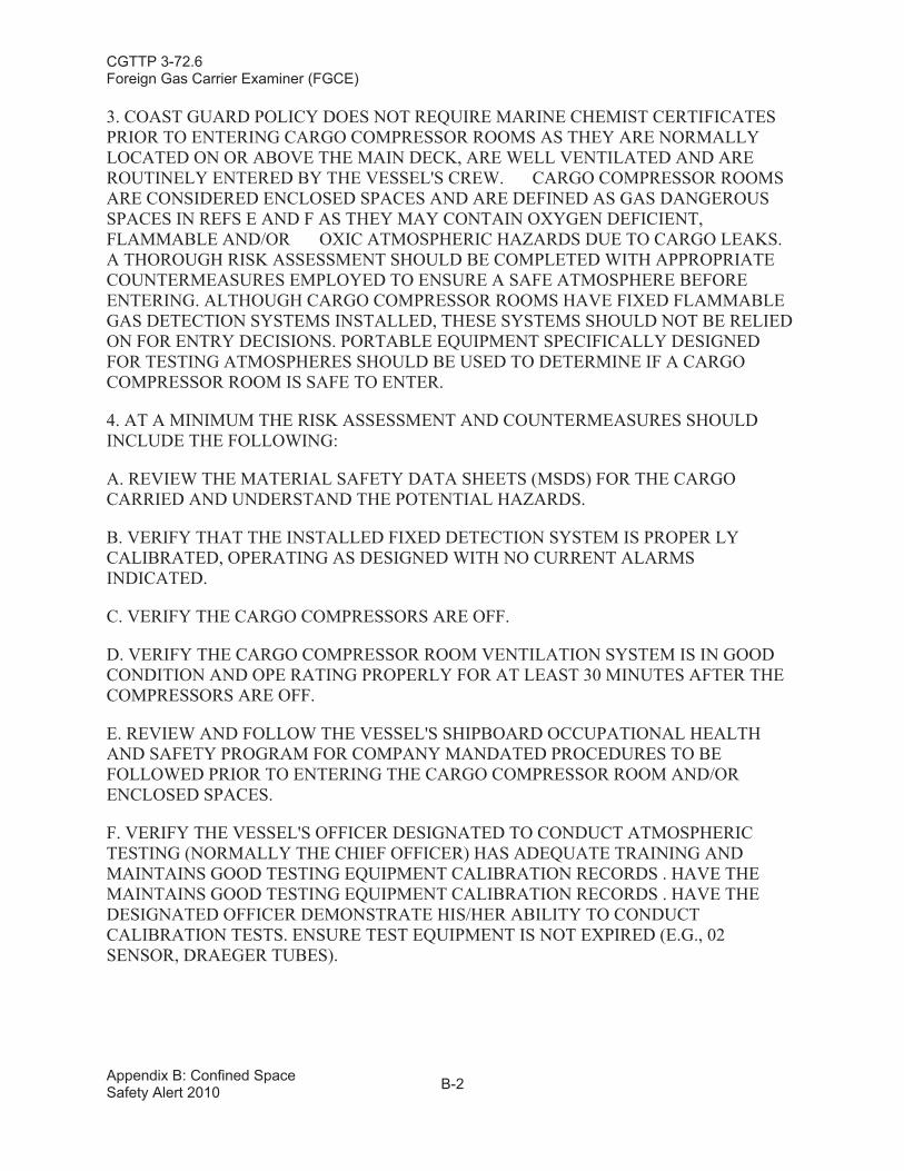
CGTTP 3-72.6Foreign Gas Carrier Examiner (FGCE)
Appendix B: Confined Space Safety Alert 2010 B-2
3. COAST GUARD POLICY DOES NOT REQUIRE MARINE CHEMIST CERTIFICATES PRIOR TO ENTERING CARGO COMPRESSOR ROOMS AS THEY ARE NORMALLY LOCATED ON OR ABOVE THE MAIN DECK, ARE WELL VENTILATED AND ARE ROUTINELY ENTERED BY THE VESSEL'S CREW. CARGO COMPRESSOR ROOMS ARE CONSIDERED ENCLOSED SPACES AND ARE DEFINED AS GAS DANGEROUS SPACES IN REFS E AND F AS THEY MAY CONTAIN OXYGEN DEFICIENT, FLAMMABLE AND/OR OXIC ATMOSPHERIC HAZARDS DUE TO CARGO LEAKS. A THOROUGH RISK ASSESSMENT SHOULD BE COMPLETED WITH APPROPRIATE COUNTERMEASURES EMPLOYED TO ENSURE A SAFE ATMOSPHERE BEFORE ENTERING. ALTHOUGH CARGO COMPRESSOR ROOMS HAVE FIXED FLAMMABLE GAS DETECTION SYSTEMS INSTALLED, THESE SYSTEMS SHOULD NOT BE RELIED ON FOR ENTRY DECISIONS. PORTABLE EQUIPMENT SPECIFICALLY DESIGNED FOR TESTING ATMOSPHERES SHOULD BE USED TO DETERMINE IF A CARGO COMPRESSOR ROOM IS SAFE TO ENTER.
4. AT A MINIMUM THE RISK ASSESSMENT AND COUNTERMEASURES SHOULD INCLUDE THE FOLLOWING:
A. REVIEW THE MATERIAL SAFETY DATA SHEETS (MSDS) FOR THE CARGO CARRIED AND UNDERSTAND THE POTENTIAL HAZARDS.
B. VERIFY THAT THE INSTALLED FIXED DETECTION SYSTEM IS PROPER LY CALIBRATED, OPERATING AS DESIGNED WITH NO CURRENT ALARMS INDICATED.
C. VERIFY THE CARGO COMPRESSORS ARE OFF.
D. VERIFY THE CARGO COMPRESSOR ROOM VENTILATION SYSTEM IS IN GOOD CONDITION AND OPE RATING PROPERLY FOR AT LEAST 30 MINUTES AFTER THE COMPRESSORS ARE OFF.
E. REVIEW AND FOLLOW THE VESSEL'S SHIPBOARD OCCUPATIONAL HEALTH AND SAFETY PROGRAM FOR COMPANY MANDATED PROCEDURES TO BE FOLLOWED PRIOR TO ENTERING THE CARGO COMPRESSOR ROOM AND/OR ENCLOSED SPACES.
F. VERIFY THE VESSEL'S OFFICER DESIGNATED TO CONDUCT ATMOSPHERIC TESTING (NORMALLY THE CHIEF OFFICER) HAS ADEQUATE TRAINING AND MAINTAINS GOOD TESTING EQUIPMENT CALIBRATION RECORDS . HAVE THE MAINTAINS GOOD TESTING EQUIPMENT CALIBRATION RECORDS . HAVE THE DESIGNATED OFFICER DEMONSTRATE HIS/HER ABILITY TO CONDUCT CALIBRATION TESTS. ENSURE TEST EQUIPMENT IS NOT EXPIRED (E.G., 02 SENSOR, DRAEGER TUBES).
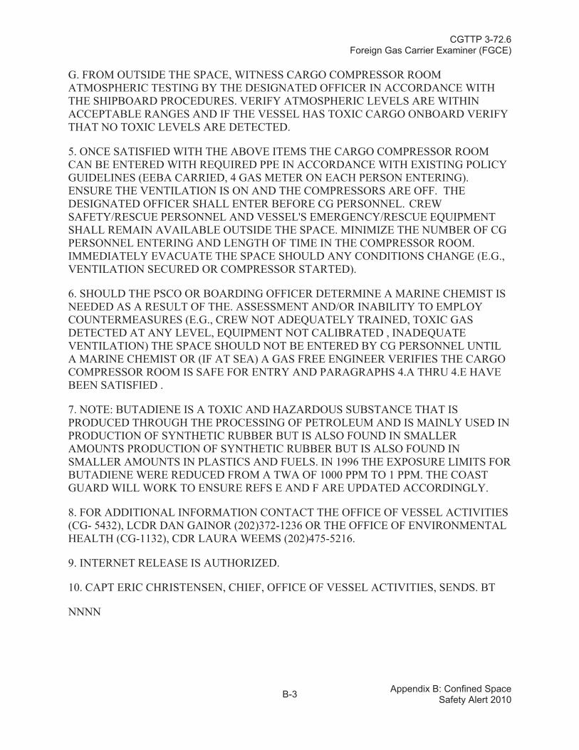
CGTTP 3-72.6Foreign Gas Carrier Examiner (FGCE)
B-3 Appendix B: Confined Space Safety Alert 2010
G. FROM OUTSIDE THE SPACE, WITNESS CARGO COMPRESSOR ROOM ATMOSPHERIC TESTING BY THE DESIGNATED OFFICER IN ACCORDANCE WITH THE SHIPBOARD PROCEDURES. VERIFY ATMOSPHERIC LEVELS ARE WITHIN ACCEPTABLE RANGES AND IF THE VESSEL HAS TOXIC CARGO ONBOARD VERIFY THAT NO TOXIC LEVELS ARE DETECTED.
5. ONCE SATISFIED WITH THE ABOVE ITEMS THE CARGO COMPRESSOR ROOM CAN BE ENTERED WITH REQUIRED PPE IN ACCORDANCE WITH EXISTING POLICY GUIDELINES (EEBA CARRIED, 4 GAS METER ON EACH PERSON ENTERING). ENSURE THE VENTILATION IS ON AND THE COMPRESSORS ARE OFF. THE DESIGNATED OFFICER SHALL ENTER BEFORE CG PERSONNEL. CREW SAFETY/RESCUE PERSONNEL AND VESSEL'S EMERGENCY/RESCUE EQUIPMENT SHALL REMAIN AVAILABLE OUTSIDE THE SPACE. MINIMIZE THE NUMBER OF CG PERSONNEL ENTERING AND LENGTH OF TIME IN THE COMPRESSOR ROOM. IMMEDIATELY EVACUATE THE SPACE SHOULD ANY CONDITIONS CHANGE (E.G., VENTILATION SECURED OR COMPRESSOR STARTED).
6. SHOULD THE PSCO OR BOARDING OFFICER DETERMINE A MARINE CHEMIST IS NEEDED AS A RESULT OF THE. ASSESSMENT AND/OR INABILITY TO EMPLOY COUNTERMEASURES (E.G., CREW NOT ADEQUATELY TRAINED, TOXIC GAS DETECTED AT ANY LEVEL, EQUIPMENT NOT CALIBRATED , INADEQUATE VENTILATION) THE SPACE SHOULD NOT BE ENTERED BY CG PERSONNEL UNTIL A MARINE CHEMIST OR (IF AT SEA) A GAS FREE ENGINEER VERIFIES THE CARGO COMPRESSOR ROOM IS SAFE FOR ENTRY AND PARAGRAPHS 4.A THRU 4.E HAVE BEEN SATISFIED .
7. NOTE: BUTADIENE IS A TOXIC AND HAZARDOUS SUBSTANCE THAT IS PRODUCED THROUGH THE PROCESSING OF PETROLEUM AND IS MAINLY USED IN PRODUCTION OF SYNTHETIC RUBBER BUT IS ALSO FOUND IN SMALLER AMOUNTS PRODUCTION OF SYNTHETIC RUBBER BUT IS ALSO FOUND IN SMALLER AMOUNTS IN PLASTICS AND FUELS. IN 1996 THE EXPOSURE LIMITS FOR BUTADIENE WERE REDUCED FROM A TWA OF 1000 PPM TO 1 PPM. THE COAST GUARD WILL WORK TO ENSURE REFS E AND F ARE UPDATED ACCORDINGLY.
8. FOR ADDITIONAL INFORMATION CONTACT THE OFFICE OF VESSEL ACTIVITIES (CG- 5432), LCDR DAN GAINOR (202)372-1236 OR THE OFFICE OF ENVIRONMENTAL HEALTH (CG-1132), CDR LAURA WEEMS (202)475-5216.
9. INTERNET RELEASE IS AUTHORIZED.
10. CAPT ERIC CHRISTENSEN, CHIEF, OFFICE OF VESSEL ACTIVITIES, SENDS. BT
NNNN
CGTTP 3-72.6Foreign Gas Carrier Examiner (FGCE)
Appendix B: Confined Space Safety Alert 2010 B-4
This page intentionally left blank.
Related Documents