Ford Mondeo Service and Repair Manual Jeremy Churchill and A K Legg LAE MIMI Models covered All Ford Mondeo models with four-cylinder petrol engines, including special/limited editions 1597 cc, 1796 cc and 1988 cc Does not cover Diesel or V6 engines, or four-wheel-drive models © Haynes Publishing 1996 A book in the Haynes Service and Repair Manual Series All rights reserved. No part of this book may be reproduced or transmitted in any form or by any means, electronic or mechanical, including photocopying, recording or by any information storage or retrieval system, without permission in writing from the copyright holder. ISBN 1 85960 167 7 British Library Cataloguing in Publication Data A catalogue record for this book is available from the British Library. Printed by J H Haynes & Co. Ltd, Sparkford, Nr Yeovil, Somerset BA22 7JJ Haynes Publishing Sparkford, Nr Yeovil, Somerset BA22 7JJ, England Haynes North America, Inc 861 Lawrence Drive, Newbury Park, California 91320, USA Editions Haynes S.A. 147/149, rue Saint Honoré, 75001 PARIS, France (1923-304-10X3)

Welcome message from author
This document is posted to help you gain knowledge. Please leave a comment to let me know what you think about it! Share it to your friends and learn new things together.
Transcript

Ford MondeoService and Repair ManualJeremy Churchill and A K Legg LAE MIMI
Models coveredAll Ford Mondeo models with four-cylinder petrol engines,including special/limited editions1597 cc, 1796 cc and 1988 cc Does not cover Diesel or V6 engines, or four-wheel-drive models
© Haynes Publishing 1996
A book in the Haynes Service and Repair Manual Series
All rights reserved. No part of this book may be reproduced or transmittedin any form or by any means, electronic or mechanical, includingphotocopying, recording or by any information storage or retrieval system,without permission in writing from the copyright holder.
ISBN 1 85960 167 7
British Library Cataloguing in Publication DataA catalogue record for this book is available from the British Library.
Printed by J H Haynes & Co. Ltd, Sparkford, Nr Yeovil,Somerset BA22 7JJ
Haynes PublishingSparkford, Nr Yeovil, Somerset BA22 7JJ, England
Haynes North America, Inc861 Lawrence Drive, Newbury Park, California 91320, USA
Editions Haynes S.A.147/149, rue Saint Honoré, 75001 PARIS, France
(1923-304-10X3)
LIVING WITH YOUR FORD MONDEOIntroduction Page 0•4
Safety First! Page 0•5
General dimensions and weights Page 0•6
MOT Test ChecksChecks carried out from the driver’s seat Page 0•7
Checks carried out with the vehicle on the ground Page 0•8
Checks carried out with the vehicle raised Page 0•9
Checks carried out on your vehicle’s exhaust emission system Page 0•10
Roadside RepairsJacking, towing and wheel changing Page 0•11
Booster battery (jump) starting Page 0•12
Identifying leaks Page 0•13
Conversion factors Page 0•14
Routine MaintenanceRoutine maintenance and servicing Page 1•1
Lubricants, fluids and capacities Page 1•2
Maintenance schedule Page 1•3
Weekly checks Page 1•6
Every 10 000 miles or 12 months Page 1•11
Every 20 000 miles or 2 years Page 1•20
Every 30 000 miles or 3 years Page 1•22
Every 60 000 miles Page 1•26
Every 3 years Page 1•26
Contents
REPAIRS & OVERHAULEngine and Associated SystemsIn-car engine repair procedures Page 2A•1
Engine removal and general engine overhaul procedures Page 2B•1
Cooling, heating and air conditioning systems Page 3•1
Fuel and exhaust systems Page 4•1
Engine electrical systems Page 5•1
Emissions control systems Page 6•1
TransmissionManual transmission Page 7A•1
Automatic transmission Page 7B•1
Clutch and driveshafts Page 8•1
Brakes Braking system Page 9•1
Suspension Suspension and steering systems Page 10•1
Body Equipment Bodywork and fittings Page 11•1
ElectricalBody electrical systems Page 12•1
Wiring Diagrams Page 12•24
REFERENCETools and Working Facilities Page REF• 1
General Repair Procedures Page REF• 4
Buying spare parts and vehicle identification numbers Page REF• 5
Fault Finding Page REF• 6
Glossary of Technical Terms Page REF•13
Index Page REF•17
Contents
0•4 Introduction
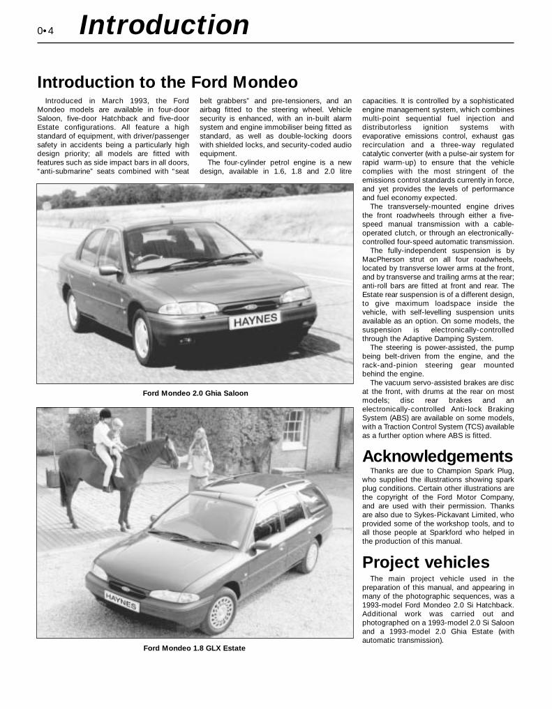
Introduced in March 1993, the FordMondeo models are available in four-doorSaloon, five-door Hatchback and five-doorEstate configurations. All feature a highstandard of equipment, with driver/passengersafety in accidents being a particularly highdesign priority; all models are fitted withfeatures such as side impact bars in all doors,“anti-submarine” seats combined with “seat
belt grabbers” and pre-tensioners, and anairbag fitted to the steering wheel. Vehiclesecurity is enhanced, with an in-built alarmsystem and engine immobiliser being fitted asstandard, as well as double-locking doorswith shielded locks, and security-coded audioequipment.
The four-cylinder petrol engine is a newdesign, available in 1.6, 1.8 and 2.0 litre
capacities. It is controlled by a sophisticatedengine management system, which combinesmulti-point sequential fuel injection anddistributorless ignition systems withevaporative emissions control, exhaust gasrecirculation and a three-way regulatedcatalytic converter (with a pulse-air system forrapid warm-up) to ensure that the vehiclecomplies with the most stringent of theemissions control standards currently in force,and yet provides the levels of performanceand fuel economy expected.
The transversely-mounted engine drivesthe front roadwheels through either a five-speed manual transmission with a cable-operated clutch, or through an electronically-controlled four-speed automatic transmission.
The fully-independent suspension is byMacPherson strut on all four roadwheels,located by transverse lower arms at the front,and by transverse and trailing arms at the rear;anti-roll bars are fitted at front and rear. TheEstate rear suspension is of a different design,to give maximum loadspace inside thevehicle, with self-levelling suspension unitsavailable as an option. On some models, thesuspension is electronically-controlledthrough the Adaptive Damping System.
The steering is power-assisted, the pumpbeing belt-driven from the engine, and therack-and-pinion steering gear mountedbehind the engine.
The vacuum servo-assisted brakes are discat the front, with drums at the rear on mostmodels; disc rear brakes and anelectronically-controlled Anti-lock BrakingSystem (ABS) are available on some models,with a Traction Control System (TCS) availableas a further option where ABS is fitted.
AcknowledgementsThanks are due to Champion Spark Plug,
who supplied the illustrations showing sparkplug conditions. Certain other illustrations arethe copyright of the Ford Motor Company,and are used with their permission. Thanksare also due to Sykes-Pickavant Limited, whoprovided some of the workshop tools, and toall those people at Sparkford who helped inthe production of this manual.
Project vehiclesThe main project vehicle used in the
preparation of this manual, and appearing inmany of the photographic sequences, was a1993-model Ford Mondeo 2.0 Si Hatchback.Additional work was carried out andphotographed on a 1993-model 2.0 Si Saloonand a 1993-model 2.0 Ghia Estate (withautomatic transmission).
Introduction to the Ford Mondeo
Ford Mondeo 2.0 Ghia Saloon
Ford Mondeo 1.8 GLX Estate

Working on your car can be dangerous.This page shows just some of the potentialrisks and hazards, with the aim of creating asafety-conscious attitude.
General hazardsScalding• Don’t remove the radiator or expansiontank cap while the engine is hot.• Engine oil, automatic transmission fluid orpower steering fluid may also be dangerouslyhot if the engine has recently been running.
Burning• Beware of burns from the exhaust systemand from any part of the engine. Brake discsand drums can also be extremely hotimmediately after use.
Crushing• When working under or neara raised vehicle, alwayssupplement thejack with axlestands, or usedrive-on ramps.Never ventureunder a carwhich is onlysupported bya jack.• Take care if loosening or tightening high-torque nuts when the vehicle is on stands.Initial loosening and final tightening shouldbe done with the wheels on the ground.
Fire• Fuel is highly flammable; fuel vapour isexplosive. • Don’t let fuel spill onto a hot engine. • Do not smoke or allow naked lights(including pilot lights) anywhere near avehicle being worked on. Also beware ofcreating sparks (electrically or by use of tools).• Fuel vapour is heavier than air, so don’twork on the fuel system with the vehicle overan inspection pit.• Another cause of fire is an electricaloverload or short-circuit. Take care whenrepairing or modifying the vehicle wiring.• Keep a fire extinguisher handy, of a typesuitable for use on fuel and electrical fires.
Electric shock • Ignition HTvoltage can bedangerous,especially topeople withheart problemsor a pacemaker.Don’t work on ornear the ignitionsystem with theengine running or theignition switched on.
• Mains voltage is also dangerous. Makesure that any mains-operated equipment iscorrectly earthed. Mains power points shouldbe protected by a residual current device(RCD) circuit breaker.
Fume or gas intoxication • Exhaust fumes arepoisonous; they oftencontain carbonmonoxide, which israpidly fatal if inhaled.Never run theengine in aconfined spacesuch as a garagewith the doors shut.• Fuel vapour is alsopoisonous, as are the vapours from somecleaning solvents and paint thinners.
Poisonous or irritant substances• Avoid skin contact with battery acid andwith any fuel, fluid or lubricant, especiallyantifreeze, brake hydraulic fluid and Dieselfuel. Don’t syphon them by mouth. If such asubstance is swallowed or gets into the eyes,seek medical advice.• Prolonged contact with used engine oil cancause skin cancer. Wear gloves or use abarrier cream if necessary. Change out of oil-soaked clothes and do not keep oily rags inyour pocket.• Air conditioning refrigerant forms apoisonous gas if exposed to a naked flame(including a cigarette). It can also cause skinburns on contact.
Asbestos• Asbestos dust can cause cancer if inhaledor swallowed. Asbestos may be found ingaskets and in brake and clutch linings.When dealing with such components it issafest to assume that they contain asbestos.
Special hazardsHydrofluoric acid• This extremely corrosive acid is formedwhen certain types of synthetic rubber, foundin some O-rings, oil seals, fuel hoses etc, areexposed to temperatures above 4000C. Therubber changes into a charred or stickysubstance containing the acid. Once formed,the acid remains dangerous for years. If itgets onto the skin, it may be necessary toamputate the limb concerned.• When dealing with a vehicle which hassuffered a fire, or with components salvagedfrom such a vehicle, wear protective glovesand discard them after use.
The battery• Batteries contain sulphuric acid, whichattacks clothing, eyes and skin. Take carewhen topping-up or carrying the battery.• The hydrogen gas given off by the batteryis highly explosive. Never cause a spark orallow a naked light nearby. Be careful whenconnecting and disconnecting batterychargers or jump leads.
Air bags• Air bags can cause injury if they go offaccidentally. Take care when removing thesteering wheel and/or facia. Special storageinstructions may apply.
Diesel injection equipment• Diesel injection pumps supply fuel at veryhigh pressure. Take care when working onthe fuel injectors and fuel pipes.
Warning: Never expose thehands, face or any other part ofthe body to injector spray; the
fuel can penetrate the skin withpotentially fatal results.
Remember...DO• Do use eye protection when using powertools, and when working under the vehicle.
• Do wear gloves or use barrier cream toprotect your hands when necessary.
• Do get someone to check periodicallythat all is well when working alone on thevehicle.
• Do keep loose clothing and long hair wellout of the way of moving mechanical parts.
• Do remove rings, wristwatch etc, beforeworking on the vehicle – especially theelectrical system.
• Do ensure that any lifting or jackingequipment has a safe working load ratingadequate for the job.
A few tipsDON’T• Don’t attempt to lift a heavy componentwhich may be beyond your capability – getassistance.
• Don’t rush to finish a job, or takeunverified short cuts.
• Don’t use ill-fitting tools which may slipand cause injury.
• Don’t leave tools or parts lying aroundwhere someone can trip over them. Mopup oil and fuel spills at once.
• Don’t allow children or pets to play in ornear a vehicle being worked on.
0•5Safety First!

0•6 General Dimensions & Weights
DimensionsOverall length:
Saloon, Hatchback . . . . . . . . . . . . . . . . . . . . . . . . . . . . . . . . . . . . . 4481 mmEstate . . . . . . . . . . . . . . . . . . . . . . . . . . . . . . . . . . . . . . . . . . . . . . . 4631 mm
Overall width - including mirrors . . . . . . . . . . . . . . . . . . . . . . . . . . . . . 1925 mmOverall height - at kerb weight:
Saloon, Hatchback . . . . . . . . . . . . . . . . . . . . . . . . . . . . . . . . . . . . . 1403 to 1435 mmEstate . . . . . . . . . . . . . . . . . . . . . . . . . . . . . . . . . . . . . . . . . . . . . . . 1416 to 1501 mm
Wheelbase . . . . . . . . . . . . . . . . . . . . . . . . . . . . . . . . . . . . . . . . . . . . . 2704 mmFront track - all models . . . . . . . . . . . . . . . . . . . . . . . . . . . . . . . . . . . . 1503 mmRear track:
Saloon, Hatchback . . . . . . . . . . . . . . . . . . . . . . . . . . . . . . . . . . . . . 1486 to 1487 mmEstate . . . . . . . . . . . . . . . . . . . . . . . . . . . . . . . . . . . . . . . . . . . . . . . 1504 mm
Turning circle . . . . . . . . . . . . . . . . . . . . . . . . . . . . . . . . . . . . . . . . . . . 10.9 m
WeightsKerb weight:
1.6 Saloon, Hatchback models . . . . . . . . . . . . . . . . . . . . . . . . . . . . 1215 to 1250 kg1.6 Estate models . . . . . . . . . . . . . . . . . . . . . . . . . . . . . . . . . . . . . . 1265 to 1275 kg1.8 Saloon, Hatchback models:
Manual transmission . . . . . . . . . . . . . . . . . . . . . . . . . . . . . . . . . . 1225 to 1260 kgAutomatic transmission . . . . . . . . . . . . . . . . . . . . . . . . . . . . . . . . 1260 to 1280 kg
1.8 Estate models:Manual transmission . . . . . . . . . . . . . . . . . . . . . . . . . . . . . . . . . . 1275 to 1285 kgAutomatic transmission . . . . . . . . . . . . . . . . . . . . . . . . . . . . . . . . 1305 kg
2.0 Saloon, Hatchback models:Manual transmission . . . . . . . . . . . . . . . . . . . . . . . . . . . . . . . . . . 1250 to 1310 kgAutomatic transmission . . . . . . . . . . . . . . . . . . . . . . . . . . . . . . . . 1285 to 1340 kg
2.0 Estate models:Manual transmission . . . . . . . . . . . . . . . . . . . . . . . . . . . . . . . . . . 1295 to 1335 kgAutomatic transmission . . . . . . . . . . . . . . . . . . . . . . . . . . . . . . . . 1330 to 1415 kg
Maximum gross vehicle weight:Saloon, Hatchback:
1.6 models . . . . . . . . . . . . . . . . . . . . . . . . . . . . . . . . . . . . . . . . . . 1725 kg1.8 Saloon models, automatic transmission . . . . . . . . . . . . . . . . . 1750 kg2.0 models, automatic transmission . . . . . . . . . . . . . . . . . . . . . . . 1800 kgAll others . . . . . . . . . . . . . . . . . . . . . . . . . . . . . . . . . . . . . . . . . . . 1775 kg
Estate:1.6 models, 2.0 models with manual transmission . . . . . . . . . . . . 1900 kgAll others . . . . . . . . . . . . . . . . . . . . . . . . . . . . . . . . . . . . . . . . . . . 1925 kg
Maximum roof rack load:Estate models with integral roof rack . . . . . . . . . . . . . . . . . . . . . . . . 100 kgAll others . . . . . . . . . . . . . . . . . . . . . . . . . . . . . . . . . . . . . . . . . . . . . 75 kg
Maximum towing weight . . . . . . . . . . . . . . . . . . . . . . . . . . . . . . . . . . . 1500 kgTrailer nose weight limit . . . . . . . . . . . . . . . . . . . . . . . . . . . . . . . . . . . . 75 kg
0•7
This is a guide to getting your vehicle through the MOT test.Obviously it will not be possible to examine the vehicle to the samestandard as the professional MOT tester. However, working throughthe following checks will enable you to identify any problem areasbefore submitting the vehicle for the test.
Where a testable component is in borderline condition, the testerhas discretion in deciding whether to pass or fail it. The basis of suchdiscretion is whether the tester would be happy for a close relative orfriend to use the vehicle with the component in that condition. If thevehicle presented is clean and evidently well cared for, the tester maybe more inclined to pass a borderline component than if the vehicle isscruffy and apparently neglected.
It has only been possible to summarise the test requirements here,based on the regulations in force at the time of printing. Test standardsare becoming increasingly stringent, although there are someexemptions for older vehicles. For full details obtain a copy of the Haynespublication Pass the MOT! (available from stockists of Haynes manuals).
An assistant will be needed to help carry out some of these checks.
The checks have been sub-divided into four categories, as follows:
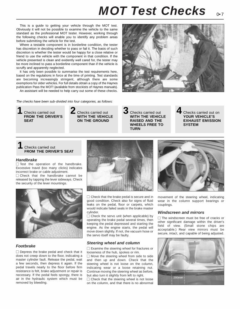
HandbrakeM Test the operation of the handbrake.Excessive travel (too many clicks) indicatesincorrect brake or cable adjustment.M Check that the handbrake cannot bereleased by tapping the lever sideways. Checkthe security of the lever mountings.
FootbrakeM Depress the brake pedal and check that itdoes not creep down to the floor, indicating amaster cylinder fault. Release the pedal, waita few seconds, then depress it again. If thepedal travels nearly to the floor before firmresistance is felt, brake adjustment or repair isnecessary. If the pedal feels spongy, there isair in the hydraulic system which must beremoved by bleeding.
M Check that the brake pedal is secure and ingood condition. Check also for signs of fluidleaks on the pedal, floor or carpets, whichwould indicate failed seals in the brake mastercylinder.M Check the servo unit (when applicable) byoperating the brake pedal several times, thenkeeping the pedal depressed and starting theengine. As the engine starts, the pedal willmove down slightly. If not, the vacuum hose orthe servo itself may be faulty.
Steering wheel and column M Examine the steering wheel for fractures orlooseness of the hub, spokes or rim. M Move the steering wheel from side to sideand then up and down. Check that the steering wheel is not loose on the column,indicating wear or a loose retaining nut.Continue moving the steering wheel as before,but also turn it slightly from left to right. M Check that the steering wheel is not looseon the column, and that there is no abnormal
movement of the steering wheel, indicatingwear in the column support bearings or couplings.
Windscreen and mirrors M The windscreen must be free of cracks orother significant damage within the driver’sfield of view. (Small stone chips areacceptable.) Rear view mirrors must besecure, intact, and capable of being adjusted.
1Checks carried outFROM THE DRIVER’S SEAT
MOT Test Checks
1Checks carried outFROM THE DRIVER’SSEAT
2Checks carried outWITH THE VEHICLEON THE GROUND
3Checks carried outWITH THE VEHICLERAISED AND THEWHEELS FREE TOTURN
4Checks carried out onYOUR VEHICLE’SEXHAUST EMISSIONSYSTEM
Seat belts and seats Note: The following checks are applicable toall seat belts, front and rear.
M Examine the webbing of all the belts(including rear belts if fitted) for cuts, seriousfraying or deterioration. Fasten and unfasteneach belt to check the buckles. If applicable,check the retracting mechanism. Check thesecurity of all seat belt mountings accessiblefrom inside the vehicle.M The front seats themselves must besecurely attached and the backrests mustlock in the upright position.
Doors M Both front doors must be able to be openedand closed from outside and inside, and mustlatch securely when closed.
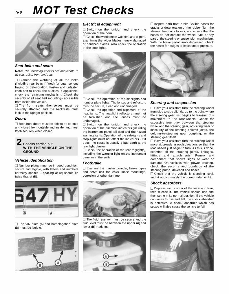
Vehicle identificationM Number plates must be in good condition,secure and legible, with letters and numberscorrectly spaced – spacing at (A) should betwice that at (B).
M The VIN plate (A) and homologation plate(B) must be legible.
Electrical equipmentM Switch on the ignition and check the operation of the horn.M Check the windscreen washers and wipers,examining the wiper blades; renew damagedor perished blades. Also check the operationof the stop-lights.
M Check the operation of the sidelights andnumber plate lights. The lenses and reflectorsmust be secure, clean and undamaged. M Check the operation and alignment of theheadlights. The headlight reflectors must notbe tarnished and the lenses must beundamaged.M Switch on the ignition and check the operation of the direction indicators (includingthe instrument panel tell-tale) and the hazardwarning lights. Operation of the sidelights andstop-lights must not affect the indicators - if itdoes, the cause is usually a bad earth at therear light cluster.M Check the operation of the rear foglight(s),including the warning light on the instrumentpanel or in the switch.
FootbrakeM Examine the master cylinder, brake pipesand servo unit for leaks, loose mountings, corrosion or other damage.
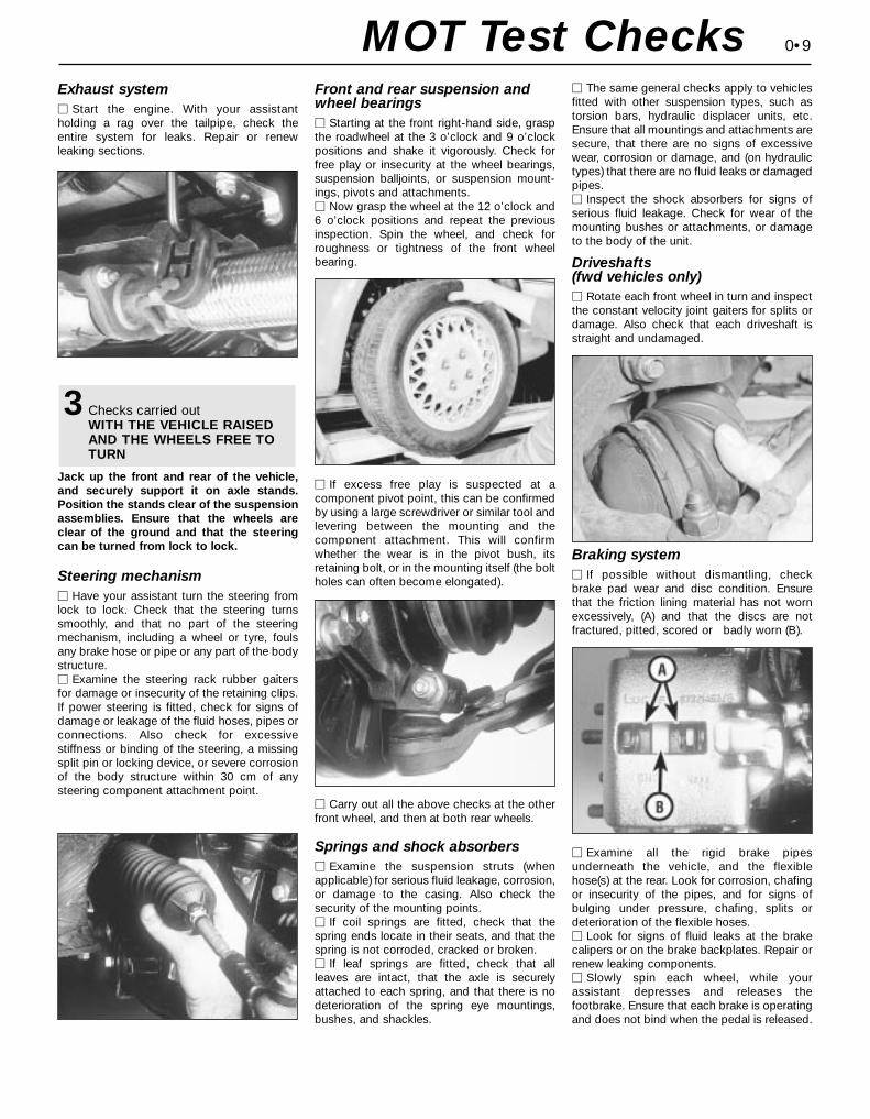
M The fluid reservoir must be secure and thefluid level must be between the upper (A) andlower (B) markings.
M Inspect both front brake flexible hoses forcracks or deterioration of the rubber. Turn thesteering from lock to lock, and ensure that thehoses do not contact the wheel, tyre, or anypart of the steering or suspension mechanism.With the brake pedal firmly depressed, checkthe hoses for bulges or leaks under pressure.
Steering and suspensionM Have your assistant turn the steering wheelfrom side to side slightly, up to the point wherethe steering gear just begins to transmit thismovement to the roadwheels. Check forexcessive free play between the steeringwheel and the steering gear, indicating wear orinsecurity of the steering column joints, thecolumn-to-steering gear coupling, or thesteering gear itself.M Have your assistant turn the steering wheelmore vigorously in each direction, so that theroadwheels just begin to turn. As this is done,examine all the steering joints, linkages,fittings and attachments. Renew anycomponent that shows signs of wear or damage. On vehicles with power steering,check the security and condition of the steering pump, drivebelt and hoses.M Check that the vehicle is standing level,and at approximately the correct ride height.
Shock absorbersM Depress each corner of the vehicle in turn,then release it. The vehicle should rise andthen settle in its normal position. If the vehiclecontinues to rise and fall, the shock absorberis defective. A shock absorber which hasseized will also cause the vehicle to fail.
2Checks carried outWITH THE VEHICLE ON THEGROUND
0•8 MOT Test Checks
Exhaust systemM Start the engine. With your assistant holding a rag over the tailpipe, check theentire system for leaks. Repair or renewleaking sections.
Jack up the front and rear of the vehicle,and securely support it on axle stands.Position the stands clear of the suspensionassemblies. Ensure that the wheels areclear of the ground and that the steeringcan be turned from lock to lock.
Steering mechanism M Have your assistant turn the steering fromlock to lock. Check that the steering turnssmoothly, and that no part of the steeringmechanism, including a wheel or tyre, foulsany brake hose or pipe or any part of the bodystructure.M Examine the steering rack rubber gaitersfor damage or insecurity of the retaining clips.If power steering is fitted, check for signs ofdamage or leakage of the fluid hoses, pipes orconnections. Also check for excessivestiffness or binding of the steering, a missingsplit pin or locking device, or severe corrosionof the body structure within 30 cm of anysteering component attachment point.
Front and rear suspension andwheel bearings M Starting at the front right-hand side, graspthe roadwheel at the 3 o’clock and 9 o’clockpositions and shake it vigorously. Check forfree play or insecurity at the wheel bearings,suspension balljoints, or suspension mount-ings, pivots and attachments.M Now grasp the wheel at the 12 o’clock and6 o’clock positions and repeat the previousinspection. Spin the wheel, and check forroughness or tightness of the front wheelbearing.
M If excess free play is suspected at acomponent pivot point, this can be confirmedby using a large screwdriver or similar tool andlevering between the mounting and thecomponent attachment. This will confirmwhether the wear is in the pivot bush, itsretaining bolt, or in the mounting itself (the boltholes can often become elongated).
M Carry out all the above checks at the otherfront wheel, and then at both rear wheels.
Springs and shock absorbers M Examine the suspension struts (whenapplicable) for serious fluid leakage, corrosion,or damage to the casing. Also check thesecurity of the mounting points.M If coil springs are fitted, check that thespring ends locate in their seats, and that thespring is not corroded, cracked or broken.M If leaf springs are fitted, check that allleaves are intact, that the axle is securelyattached to each spring, and that there is nodeterioration of the spring eye mountings,bushes, and shackles.
M The same general checks apply to vehiclesfitted with other suspension types, such astorsion bars, hydraulic displacer units, etc.Ensure that all mountings and attachments aresecure, that there are no signs of excessivewear, corrosion or damage, and (on hydraulictypes) that there are no fluid leaks or damagedpipes.M Inspect the shock absorbers for signs ofserious fluid leakage. Check for wear of themounting bushes or attachments, or damageto the body of the unit.
Driveshafts(fwd vehicles only)M Rotate each front wheel in turn and inspectthe constant velocity joint gaiters for splits ordamage. Also check that each driveshaft isstraight and undamaged.
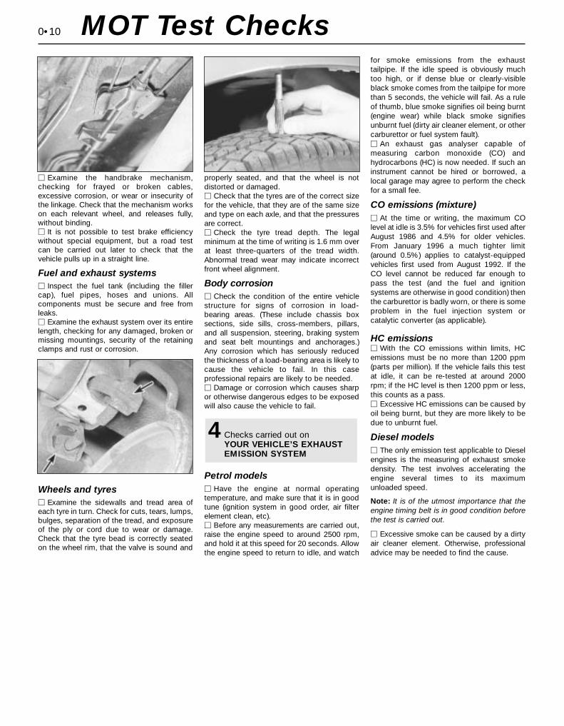
Braking system M If possible without dismantling, checkbrake pad wear and disc condition. Ensurethat the friction lining material has not wornexcessively, (A) and that the discs are notfractured, pitted, scored or badly worn (B).
M Examine all the rigid brake pipesunderneath the vehicle, and the flexiblehose(s) at the rear. Look for corrosion, chafingor insecurity of the pipes, and for signs ofbulging under pressure, chafing, splits ordeterioration of the flexible hoses.M Look for signs of fluid leaks at the brakecalipers or on the brake backplates. Repair orrenew leaking components.M Slowly spin each wheel, while yourassistant depresses and releases thefootbrake. Ensure that each brake is operatingand does not bind when the pedal is released.
3Checks carried outWITH THE VEHICLE RAISEDAND THE WHEELS FREE TOTURN
0•9MOT Test Checks
0•10
M Examine the handbrake mechanism,checking for frayed or broken cables,excessive corrosion, or wear or insecurity ofthe linkage. Check that the mechanism workson each relevant wheel, and releases fully,without binding.M It is not possible to test brake efficiencywithout special equipment, but a road testcan be carried out later to check that thevehicle pulls up in a straight line.
Fuel and exhaust systemsM Inspect the fuel tank (including the fillercap), fuel pipes, hoses and unions. Allcomponents must be secure and free fromleaks.M Examine the exhaust system over its entirelength, checking for any damaged, broken ormissing mountings, security of the retainingclamps and rust or corrosion.
Wheels and tyres M Examine the sidewalls and tread area ofeach tyre in turn. Check for cuts, tears, lumps,bulges, separation of the tread, and exposureof the ply or cord due to wear or damage.Check that the tyre bead is correctly seatedon the wheel rim, that the valve is sound and
properly seated, and that the wheel is notdistorted or damaged. M Check that the tyres are of the correct sizefor the vehicle, that they are of the same sizeand type on each axle, and that the pressuresare correct.M Check the tyre tread depth. The legalminimum at the time of writing is 1.6 mm overat least three-quarters of the tread width.Abnormal tread wear may indicate incorrectfront wheel alignment.
Body corrosionM Check the condition of the entire vehiclestructure for signs of corrosion in load-bearing areas. (These include chassis boxsections, side sills, cross-members, pillars,and all suspension, steering, braking systemand seat belt mountings and anchorages.)Any corrosion which has seriously reducedthe thickness of a load-bearing area is likely tocause the vehicle to fail. In this caseprofessional repairs are likely to be needed.M Damage or corrosion which causes sharpor otherwise dangerous edges to be exposedwill also cause the vehicle to fail.
Petrol modelsM Have the engine at normal operatingtemperature, and make sure that it is in goodtune (ignition system in good order, air filterelement clean, etc).M Before any measurements are carried out,raise the engine speed to around 2500 rpm,and hold it at this speed for 20 seconds. Allowthe engine speed to return to idle, and watch
for smoke emissions from the exhausttailpipe. If the idle speed is obviously muchtoo high, or if dense blue or clearly-visibleblack smoke comes from the tailpipe for morethan 5 seconds, the vehicle will fail. As a ruleof thumb, blue smoke signifies oil being burnt(engine wear) while black smoke signifiesunburnt fuel (dirty air cleaner element, or othercarburettor or fuel system fault).M An exhaust gas analyser capable ofmeasuring carbon monoxide (CO) andhydrocarbons (HC) is now needed. If such aninstrument cannot be hired or borrowed, alocal garage may agree to perform the checkfor a small fee.
CO emissions (mixture)M At the time or writing, the maximum COlevel at idle is 3.5% for vehicles first used afterAugust 1986 and 4.5% for older vehicles.From January 1996 a much tighter limit(around 0.5%) applies to catalyst-equippedvehicles first used from August 1992. If theCO level cannot be reduced far enough topass the test (and the fuel and ignitionsystems are otherwise in good condition) thenthe carburettor is badly worn, or there is someproblem in the fuel injection system orcatalytic converter (as applicable).
HC emissionsM With the CO emissions within limits, HCemissions must be no more than 1200 ppm(parts per million). If the vehicle fails this testat idle, it can be re-tested at around 2000rpm; if the HC level is then 1200 ppm or less,this counts as a pass.M Excessive HC emissions can be caused byoil being burnt, but they are more likely to bedue to unburnt fuel.
Diesel modelsM The only emission test applicable to Dieselengines is the measuring of exhaust smokedensity. The test involves accelerating theengine several times to its maximumunloaded speed.
Note: It is of the utmost importance that theengine timing belt is in good condition beforethe test is carried out.
M Excessive smoke can be caused by a dirtyair cleaner element. Otherwise, professionaladvice may be needed to find the cause.
4Checks carried out onYOUR VEHICLE’S EXHAUSTEMISSION SYSTEM
MOT Test Checks
0•11Roadside Repairs
To change a wheel, remove the sparewheel and jack, apply the handbrake, andchock the wheel diagonally opposite theone to be changed. On manual transmissionmodels, select first or reverse gear; onautomatic transmission models, place theselector lever in “P”. Make sure that thevehicle is located on firm level ground. Usethe flat end of the wheelbrace carefully toremove the trim covering the wheel nuts,then slightly loosen the wheel nuts with thebrace (see illustrations). Locate the jackhead in the jacking point nearest to thewheel to be changed, ensuring that thechannel in the jack head fits over the bodyflange (see illustrations) and turn itshandle to raise the jack. When the wheel isclear of the ground, remove the nuts and liftoff the wheel. Fit the spare wheel, andmoderately tighten the nuts. Lower thevehicle, then tighten the nuts fully and refitthe trim. With the spare wheel in position,remove the chock, and stow the jack andtools.
When jacking up the vehicle to carry outrepair or maintenance tasks, position the jackas follows.
If the front of the vehicle is to be raised,either place the jack head under the sump,with a block of wood to prevent damage, orplace a jacking beam across the two frontpoints “B” shown in the accompanyingillustration, and lift the vehicle evenly.
To raise the rear of the vehicle, place ajacking beam across the two rear points “B”shown in the accompanying illustration, andlift the vehicle evenly.
To raise the side of the vehicle, place thejack head under the appropriate pointindicated in the accompanying illustration - ifa trolley jack or similar is used on the points“A” provided for the vehicle’s jack, make up awooden spacer with a groove cut in it toaccept the underbody flange, so that there is
no risk of the jack slipping or buckling theflange. Never work under, around or near araised vehicle unless it is adequatelysupported in at least two places with axlestands or suitable sturdy blocks.
The vehicle may be towed, for breakdownrecovery purposes only, using the towing eyespositioned at the front and rear of the vehicle(see illustrations). These eyes are intendedfor towing loads only, and must not be usedfor lifting the vehicle, either directly orindirectly.
If the vehicle is equipped with automatictransmission, the following precautions mustbe observed if the vehicle is to be towed,particularly if any kind of transmission fault issuspected. Preferably, a front-end-suspendedtow should be used (ie with the front wheelsoff the ground). If this is not possible, placethe selector lever in “N” and tow the vehicle -forwards only, never backwards - for adistance of no more than 30 miles (50 km),and at speeds no greater than 30 mph (50 km/h).
Jacking, towing and wheel changing
Front towing eye Rear towing eye
Use flat end of wheelbrace to remove trimcovering roadwheel nuts
Slacken roadwheel nuts in diagonalsequence
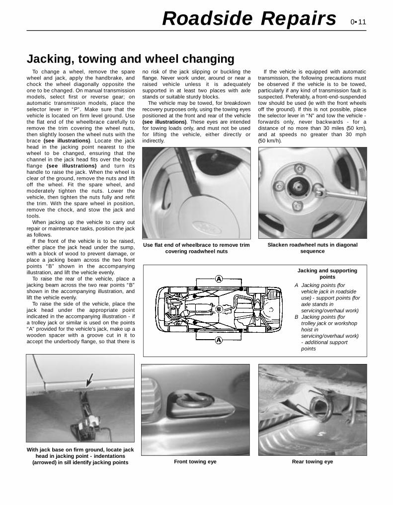
With jack base on firm ground, locate jackhead in jacking point - indentations
(arrowed) in sill identify jacking points
Jacking and supportingpoints
A Jacking points (forvehicle jack in roadsideuse) - support points (foraxle stands inservicing/overhaul work)
B Jacking points (fortrolley jack or workshophoist inservicing/overhaul work)- additional supportpoints
0•12
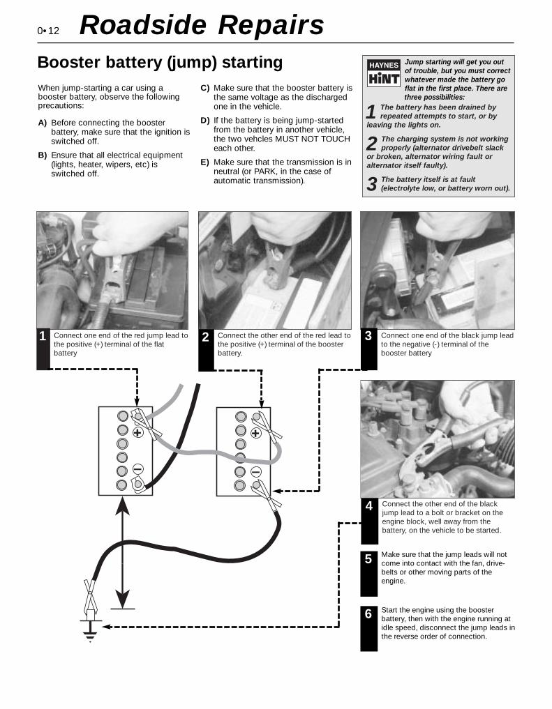
When jump-starting a car using abooster battery, observe the followingprecautions:
A) Before connecting the boosterbattery, make sure that the ignition isswitched off.
B) Ensure that all electrical equipment(lights, heater, wipers, etc) isswitched off.
C) Make sure that the booster battery isthe same voltage as the dischargedone in the vehicle.
D) If the battery is being jump-startedfrom the battery in another vehicle,the two vehcles MUST NOT TOUCHeach other.
E) Make sure that the transmission is inneutral (or PARK, in the case ofautomatic transmission).
Jump starting will get you outof trouble, but you must correctwhatever made the battery goflat in the first place. There are three possibilities:
1 The battery has been drained byrepeated attempts to start, or by
leaving the lights on.
2 The charging system is not workingproperly (alternator drivebelt slack
or broken, alternator wiring fault oralternator itself faulty).
3 The battery itself is at fault(electrolyte low, or battery worn out).
Connect one end of the red jump lead tothe positive (+) terminal of the flatbattery
Connect the other end of the red lead tothe positive (+) terminal of the boosterbattery.
Connect one end of the black jump leadto the negative (-) terminal of thebooster battery
Connect the other end of the blackjump lead to a bolt or bracket on theengine block, well away from thebattery, on the vehicle to be started.
1 2 3
4
Make sure that the jump leads will notcome into contact with the fan, drive-belts or other moving parts of theengine.
5
Start the engine using the boosterbattery, then with the engine running atidle speed, disconnect the jump leads inthe reverse order of connection.
6
Roadside RepairsBooster battery (jump) starting

0•13Roadside Repairs
Puddles on the garage floor or drive, orobvious wetness under the bonnet or underneath the car, suggest a leak that needsinvestigating. It can sometimes be difficult todecide where the leak is coming from,especially if the engine bay is very dirtyalready. Leaking oil or fluid can also be blownrearwards by the passage of air under the car,giving a false impression of where theproblem lies.
Warning: Most automotive oilsand fluids are poisonous. Washthem off skin, and change out ofcontaminated clothing, withoutdelay.
Identifying leaksThe smell of a fluid leakingfrom the car may provide aclue to what’s leaking. Somefluids are distictively coloured.
It may help to clean the car carefullyand to park it over some clean paperovernight as an aid to locating thesource of the leak.Remember that some leaks may onlyoccur while the engine is running.
Sump oil Gearbox oil
Brake fluid Power steering fluid
Oil from filter
Antifreeze
Engine oil may leak from the drain plug... ...or from the base of the oil filter.
Leaking antifreeze often leaves a crystallinedeposit like this.
Gearbox oil can leak from the seals at theinboard ends of the driveshafts.
A leak occurring at a wheel is almostcertainly brake fluid.
Power steering fluid may leak from the pipeconnectors on the steering rack.
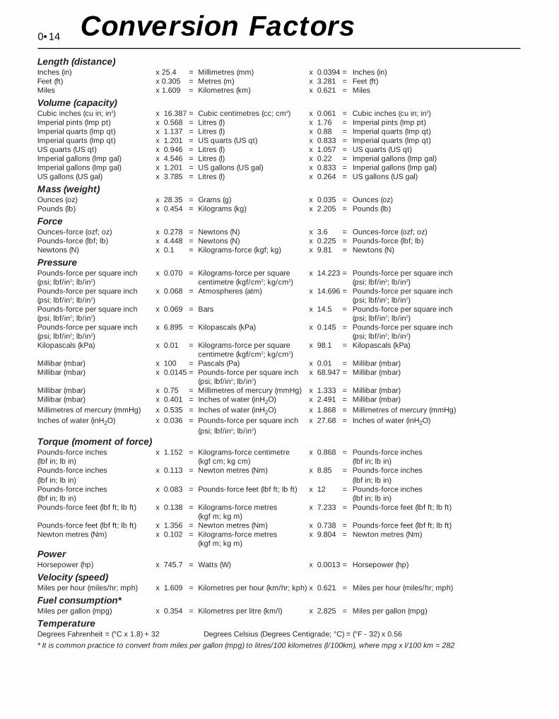
0•14 Conversion FactorsLength (distance)Inches (in) x 25.4 = Millimetres (mm) x 0.0394 = Inches (in)Feet (ft) x 0.305 = Metres (m) x 3.281 = Feet (ft)Miles x 1.609 = Kilometres (km) x 0.621 = Miles
Volume (capacity)Cubic inches (cu in; in3) x 16.387 = Cubic centimetres (cc; cm3) x 0.061 = Cubic inches (cu in; in3)Imperial pints (Imp pt) x 0.568 = Litres (l) x 1.76 = Imperial pints (Imp pt)Imperial quarts (Imp qt) x 1.137 = Litres (l) x 0.88 = Imperial quarts (Imp qt)Imperial quarts (Imp qt) x 1.201 = US quarts (US qt) x 0.833 = Imperial quarts (Imp qt)US quarts (US qt) x 0.946 = Litres (l) x 1.057 = US quarts (US qt)Imperial gallons (Imp gal) x 4.546 = Litres (l) x 0.22 = Imperial gallons (Imp gal)Imperial gallons (Imp gal) x 1.201 = US gallons (US gal) x 0.833 = Imperial gallons (Imp gal)US gallons (US gal) x 3.785 = Litres (l) x 0.264 = US gallons (US gal)
Mass (weight)Ounces (oz) x 28.35 = Grams (g) x 0.035 = Ounces (oz)Pounds (lb) x 0.454 = Kilograms (kg) x 2.205 = Pounds (lb)
ForceOunces-force (ozf; oz) x 0.278 = Newtons (N) x 3.6 = Ounces-force (ozf; oz)Pounds-force (lbf; lb) x 4.448 = Newtons (N) x 0.225 = Pounds-force (lbf; lb)Newtons (N) x 0.1 = Kilograms-force (kgf; kg) x 9.81 = Newtons (N)
PressurePounds-force per square inch x 0.070 = Kilograms-force per square x 14.223 = Pounds-force per square inch(psi; lbf/in2; lb/in2) centimetre (kgf/cm2; kg/cm2) (psi; lbf/in2; lb/in2)Pounds-force per square inch x 0.068 = Atmospheres (atm) x 14.696 = Pounds-force per square inch(psi; lbf/in2; lb/in2) (psi; lbf/in2; lb/in2)Pounds-force per square inch x 0.069 = Bars x 14.5 = Pounds-force per square inch(psi; lbf/in2; lb/in2) (psi; lbf/in2; lb/in2)Pounds-force per square inch x 6.895 = Kilopascals (kPa) x 0.145 = Pounds-force per square inch(psi; lbf/in2; lb/in2) (psi; lbf/in2; lb/in2)Kilopascals (kPa) x 0.01 = Kilograms-force per square x 98.1 = Kilopascals (kPa)
centimetre (kgf/cm2; kg/cm2)Millibar (mbar) x 100 = Pascals (Pa) x 0.01 = Millibar (mbar)Millibar (mbar) x 0.0145 = Pounds-force per square inch x 68.947 = Millibar (mbar)
(psi; lbf/in2; lb/in2)Millibar (mbar) x 0.75 = Millimetres of mercury (mmHg) x 1.333 = Millibar (mbar)Millibar (mbar) x 0.401 = Inches of water (inH2O) x 2.491 = Millibar (mbar)Millimetres of mercury (mmHg) x 0.535 = Inches of water (inH2O) x 1.868 = Millimetres of mercury (mmHg)Inches of water (inH2O) x 0.036 = Pounds-force per square inch x 27.68 = Inches of water (inH2O)
(psi; lbf/in2; lb/in2)
Torque (moment of force)Pounds-force inches x 1.152 = Kilograms-force centimetre x 0.868 = Pounds-force inches(lbf in; lb in) (kgf cm; kg cm) (lbf in; lb in)Pounds-force inches x 0.113 = Newton metres (Nm) x 8.85 = Pounds-force inches(lbf in; lb in) (lbf in; lb in)Pounds-force inches x 0.083 = Pounds-force feet (lbf ft; lb ft) x 12 = Pounds-force inches(lbf in; lb in) (lbf in; lb in)Pounds-force feet (lbf ft; lb ft) x 0.138 = Kilograms-force metres x 7.233 = Pounds-force feet (lbf ft; lb ft)
(kgf m; kg m)Pounds-force feet (lbf ft; lb ft) x 1.356 = Newton metres (Nm) x 0.738 = Pounds-force feet (lbf ft; lb ft)Newton metres (Nm) x 0.102 = Kilograms-force metres x 9.804 = Newton metres (Nm)
(kgf m; kg m)
PowerHorsepower (hp) x 745.7 = Watts (W) x 0.0013 = Horsepower (hp)
Velocity (speed)Miles per hour (miles/hr; mph) x 1.609 = Kilometres per hour (km/hr; kph) x 0.621 = Miles per hour (miles/hr; mph)
Fuel consumption*Miles per gallon (mpg) x 0.354 = Kilometres per litre (km/l) x 2.825 = Miles per gallon (mpg)
TemperatureDegrees Fahrenheit = (°C x 1.8) + 32 Degrees Celsius (Degrees Centigrade; °C) = (°F - 32) x 0.56
* It is common practice to convert from miles per gallon (mpg) to litres/100 kilometres (l/100km), where mpg x l/100 km = 282
Chapter 1 Routine maintenance and servicing
Air conditioning system check . . . . . . . . . . . . . . . . . . . . . . . . . . . . . 14Air filter element renewal . . . . . . . . . . . . . . . . . . . . . . . . . . . . . . . . . . 29Automatic transmission fluid level check . . . . . . . . . . . . . . . . . . . . . 7Automatic transmission linkage lubrication . . . . . . . . . . . . . . . . . . . 18Auxiliary drivebelt check and renewal . . . . . . . . . . . . . . . . . . . . . . . . 11Battery check, maintenance and charging . . . . . . . . . . . . . . . . . . . . 9Brake check . . . . . . . . . . . . . . . . . . . . . . . . . . . . . . . . . . . . . . . . . . . 23Brake fluid renewal . . . . . . . . . . . . . . . . . . . . . . . . . . . . . . . . . . . . . . 34Clutch pedal adjustment . . . . . . . . . . . . . . . . . . . . . . . . . . . . . . . . . . 17Coolant renewal . . . . . . . . . . . . . . . . . . . . . . . . . . . . . . . . . . . . . . 2, 28Door and bonnet check and lubrication . . . . . . . . . . . . . . . . . . . . . . 24Driveshaft rubber gaiter and CV joint check . . . . . . . . . . . . . . . . . . . 20Electrical system check . . . . . . . . . . . . . . . . . . . . . . . . . . . . . . . . . . . 8Engine compartment wiring check . . . . . . . . . . . . . . . . . . . . . . . . . . 13Engine oil and filter change . . . . . . . . . . . . . . . . . . . . . . . . . . . . . . . . 15Exhaust system check . . . . . . . . . . . . . . . . . . . . . . . . . . . . . . . . . . . 21Fluid level checks . . . . . . . . . . . . . . . . . . . . . . . . . . . . . . . . . . . . . . . 3Fuel filter renewal . . . . . . . . . . . . . . . . . . . . . . . . . . . . . . . . . . . . . . . 33Idle speed and mixture check and adjustment . . . . . . See Chapter 4
Ignition timing check . . . . . . . . . . . . . . . . . . . . . . . . . . See Chapter 5Introduction . . . . . . . . . . . . . . . . . . . . . . . . . . . . . . . . . . . . . . . . . . . . 1Manual transmission oil level check . . . . . . . . . . . . . . . . . . . . . . . . . 16Positive Crankcase Ventilation (PCV) system check
and filter cleaning . . . . . . . . . . . . . . . . . . . . . . . . . . . . . . . . . . . . . 30Power steering fluid level check . . . . . . . . . . . . . . . . . . . . . . . . . . . . 5Road test . . . . . . . . . . . . . . . . . . . . . . . . . . . . . . . . . . . . . . . . . . . . . . 26Roadwheel nut tightness check . . . . . . . . . . . . . . . . . . . . . . . . . . . . 25Seat belt check . . . . . . . . . . . . . . . . . . . . . . . . . . . . . . . . . . . . . . . . . 10Spark plug renewal . . . . . . . . . . . . . . . . . . . . . . . . . . . . . . . . . . . . . . 31Specifications . . . . . . . . . . . . . . . . . . . . . . . . . . . . See end of ChapterSteering, suspension and roadwheel check . . . . . . . . . . . . . . . . . . . 19Timing belt renewal . . . . . . . . . . . . . . . . . . . . . . . . . . . . . . . . . . . . . . 32Tyre and tyre pressure checks . . . . . . . . . . . . . . . . . . . . . . . . . . . . . 4Underbody and fuel/brake line check . . . . . . . . . . . . . . . . . . . . . . . . 22Underbonnet check for fluid leaks and hose condition . . . . . . . . . . 12Ventilation system pollen filter renewal . . . . . . . . . . . . . . . . . . . . . . . 27Windscreen/tailgate washer system and wiper blade check . . . . . . 6
1•1
Easy, suitable fornovice with littleexperience
Fairly easy, suitablefor beginner withsome experience
Fairly difficult, suitablefor competent DIYmechanic
Difficult, suitable forexperienced DIYmechanic
Very difficult,suitable for expert DIYor professional
Degrees of difficulty
Contents
1
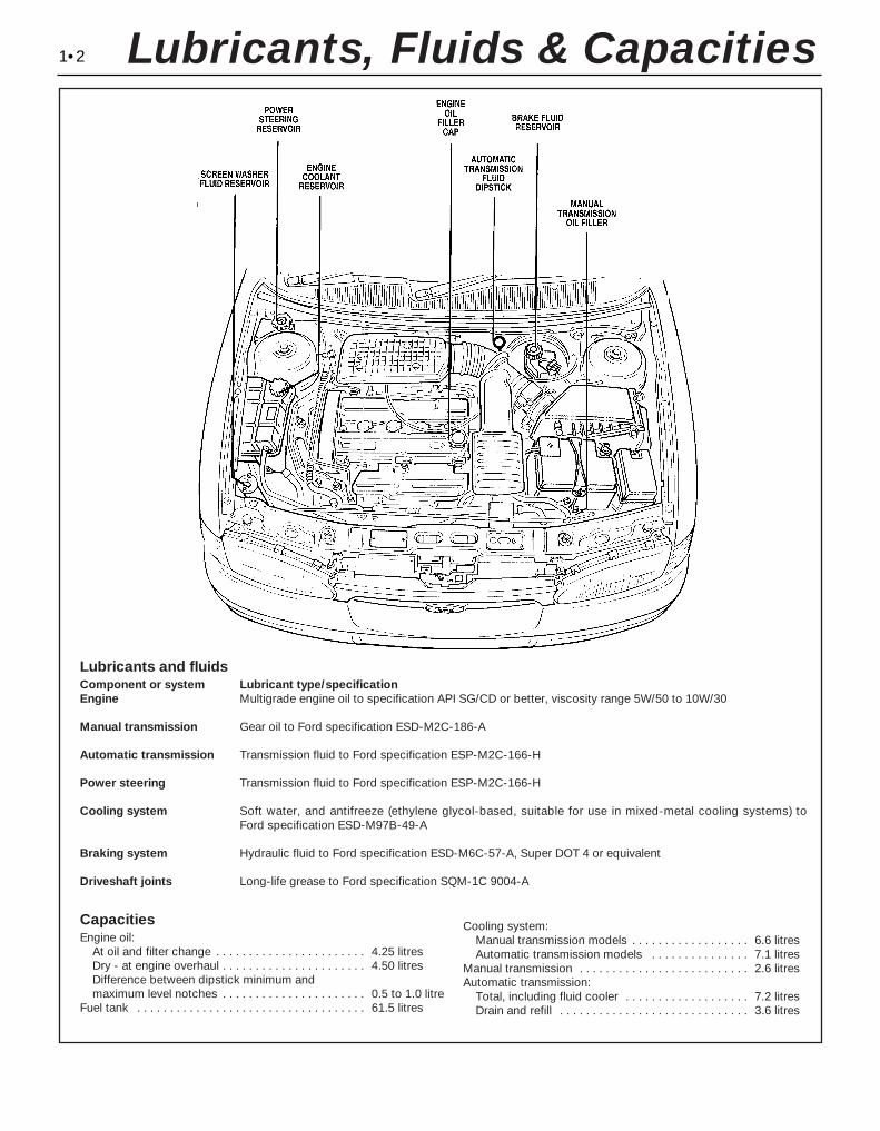
1•2 Lubricants, Fluids & Capacities
Lubricants and fluidsComponent or system Lubricant type/specificationEngine Multigrade engine oil to specification API SG/CD or better, viscosity range 5W/50 to 10W/30
Manual transmission Gear oil to Ford specification ESD-M2C-186-A
Automatic transmission Transmission fluid to Ford specification ESP-M2C-166-H
Power steering Transmission fluid to Ford specification ESP-M2C-166-H
Cooling system Soft water, and antifreeze (ethylene glycol-based, suitable for use in mixed-metal cooling systems) to Ford specification ESD-M97B-49-A
Braking system Hydraulic fluid to Ford specification ESD-M6C-57-A, Super DOT 4 or equivalent
Driveshaft joints Long-life grease to Ford specification SQM-1C 9004-A
CapacitiesEngine oil:
At oil and filter change . . . . . . . . . . . . . . . . . . . . . . . 4.25 litresDry - at engine overhaul . . . . . . . . . . . . . . . . . . . . . . 4.50 litresDifference between dipstick minimum and maximum level notches . . . . . . . . . . . . . . . . . . . . . . 0.5 to 1.0 litre
Fuel tank . . . . . . . . . . . . . . . . . . . . . . . . . . . . . . . . . . . 61.5 litres
Cooling system:Manual transmission models . . . . . . . . . . . . . . . . . . 6.6 litresAutomatic transmission models . . . . . . . . . . . . . . . 7.1 litres
Manual transmission . . . . . . . . . . . . . . . . . . . . . . . . . . 2.6 litresAutomatic transmission:
Total, including fluid cooler . . . . . . . . . . . . . . . . . . . 7.2 litresDrain and refill . . . . . . . . . . . . . . . . . . . . . . . . . . . . . 3.6 litres
Ford Mondeo maintenance schedule
1•3
1
Maintenance schedule
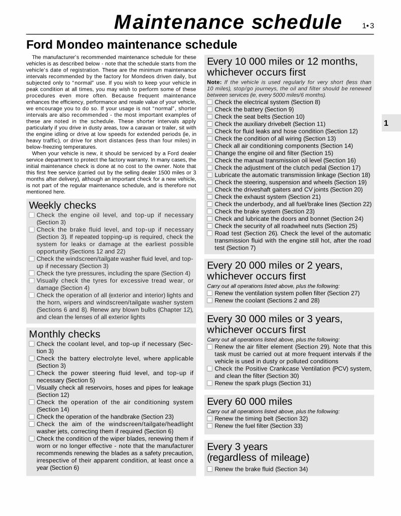
The manufacturer’s recommended maintenance schedule for thesevehicles is as described below - note that the schedule starts from thevehicle’s date of registration. These are the minimum maintenanceintervals recommended by the factory for Mondeos driven daily, butsubjected only to “normal” use. If you wish to keep your vehicle inpeak condition at all times, you may wish to perform some of theseprocedures even more often. Because frequent maintenanceenhances the efficiency, performance and resale value of your vehicle,we encourage you to do so. If your usage is not “normal”, shorterintervals are also recommended - the most important examples ofthese are noted in the schedule. These shorter intervals applyparticularly if you drive in dusty areas, tow a caravan or trailer, sit withthe engine idling or drive at low speeds for extended periods (ie, inheavy traffic), or drive for short distances (less than four miles) inbelow-freezing temperatures.
When your vehicle is new, it should be serviced by a Ford dealerservice department to protect the factory warranty. In many cases, theinitial maintenance check is done at no cost to the owner. Note thatthis first free service (carried out by the selling dealer 1500 miles or 3months after delivery), although an important check for a new vehicle,is not part of the regular maintenance schedule, and is therefore notmentioned here.
Weekly checksmm Check the engine oil level, and top-up if necessary
(Section 3)mm Check the brake fluid level, and top-up if necessary
(Section 3). If repeated topping-up is required, check thesystem for leaks or damage at the earliest possibleopportunity (Sections 12 and 22)
mm Check the windscreen/tailgate washer fluid level, and top-up if necessary (Section 3)
mm Check the tyre pressures, including the spare (Section 4)mm Visually check the tyres for excessive tread wear, or
damage (Section 4)mm Check the operation of all (exterior and interior) lights and
the horn, wipers and windscreen/tailgate washer system(Sections 6 and 8). Renew any blown bulbs (Chapter 12),and clean the lenses of all exterior lights
Monthly checksmm Check the coolant level, and top-up if necessary (Sec-
tion 3)mm Check the battery electrolyte level, where applicable
(Section 3)mm Check the power steering fluid level, and top-up if
necessary (Section 5)mm Visually check all reservoirs, hoses and pipes for leakage
(Section 12)mm Check the operation of the air conditioning system
(Section 14)mm Check the operation of the handbrake (Section 23)mm Check the aim of the windscreen/tailgate/headlight
washer jets, correcting them if required (Section 6)mm Check the condition of the wiper blades, renewing them if
worn or no longer effective - note that the manufacturerrecommends renewing the blades as a safety precaution,irrespective of their apparent condition, at least once ayear (Section 6)
Every 10 000 miles or 12 months,whichever occurs firstNote: If the vehicle is used regularly for very short (less than 10 miles), stop/go journeys, the oil and filter should be renewedbetween services (ie, every 5000 miles/6 months).mm Check the electrical system (Section 8)mm Check the battery (Section 9)mm Check the seat belts (Section 10)mm Check the auxiliary drivebelt (Section 11)mm Check for fluid leaks and hose condition (Section 12)mm Check the condition of all wiring (Section 13)mm Check all air conditioning components (Section 14)mm Change the engine oil and filter (Section 15)mm Check the manual transmission oil level (Section 16)mm Check the adjustment of the clutch pedal (Section 17)mm Lubricate the automatic transmission linkage (Section 18)mm Check the steering, suspension and wheels (Section 19)mm Check the driveshaft gaiters and CV joints (Section 20)mm Check the exhaust system (Section 21)mm Check the underbody, and all fuel/brake lines (Section 22)mm Check the brake system (Section 23)mm Check and lubricate the doors and bonnet (Section 24)mm Check the security of all roadwheel nuts (Section 25)mm Road test (Section 26). Check the level of the automatic
transmission fluid with the engine still hot, after the roadtest (Section 7)
Every 20 000 miles or 2 years,whichever occurs firstCarry out all operations listed above, plus the following:mm Renew the ventilation system pollen filter (Section 27)mm Renew the coolant (Sections 2 and 28)
Every 30 000 miles or 3 years,whichever occurs firstCarry out all operations listed above, plus the following:mm Renew the air filter element (Section 29). Note that this
task must be carried out at more frequent intervals if thevehicle is used in dusty or polluted conditions
mm Check the Positive Crankcase Ventilation (PCV) system,and clean the filter (Section 30)
mm Renew the spark plugs (Section 31)
Every 60 000 miles Carry out all operations listed above, plus the following:mm Renew the timing belt (Section 32)mm Renew the fuel filter (Section 33)
Every 3 years (regardless of mileage)mm Renew the brake fluid (Section 34)

1•4
Engine compartment components
1 Spark plugs (Section 31)2 Engine oil filler cap (Section 3)3 Brake fluid reservoir (Section 3)4 Auxiliary fusebox (Chapter 12)5 Air cleaner assembly (Section 29)6 Battery (Section 9)7 Cooling system expansion tank
(Section 28)8 Ventilation system pollen filter - under
cowl grille panel (Section 27)9 Air intake resonator (Chapter 4)
10 Radiator top hose (Section 12)11 Cooling system expansion tank filler cap
(Section 3)12 Air intake plenum chamber (Chapter 4)13 Engine oil dipstick (Section 3)14 Vehicle Identification Number (VIN) plate15 Windscreen/tailgate washer fluid reservoir
(Section 3)16 Auxiliary drivebelt (Section 11)17 Power steering fluid reservoir (Section 5)
Front underbody view
1 Radiator bottom hose (Section 12)2 Exhaust gas oxygen sensor (Chapter 6)3 Braking system, fuel and emission control
system lines (Section 22)4 Front disc brake (Section 23)5 Manual transmission drain plug
(Chapter 7, Part A)6 Front suspension subframe (Chapter 2,
Part B)7 Manual transmission filler/level plug
(Section 16)8 Radiator undershield (Section 28)9 Catalytic converter (Section 21)
10 Exhaust system rubber mountings (Section 21)
11 Engine oil drain plug (Section 15)12 Engine oil filter (Section 15)
Maintenance procedures
1•5
1
Maintenance procedures
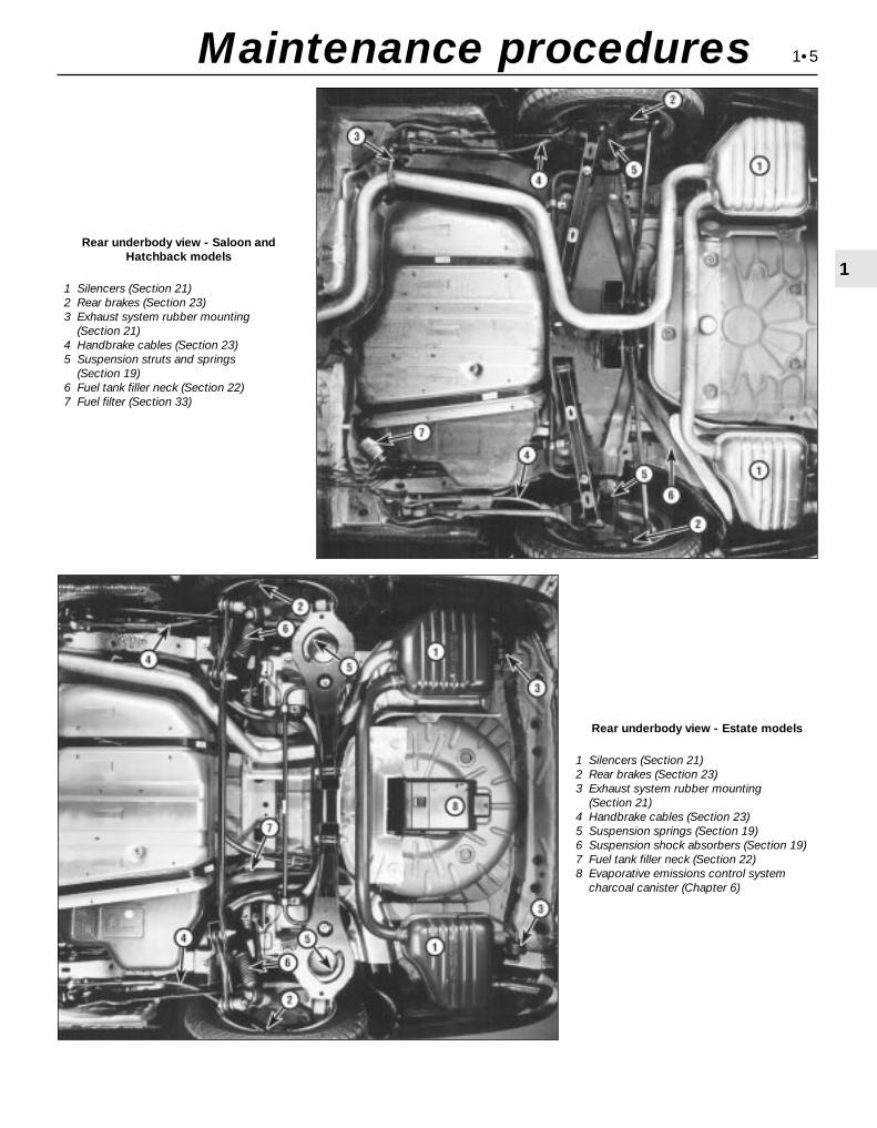
Rear underbody view - Saloon andHatchback models
1 Silencers (Section 21)2 Rear brakes (Section 23)3 Exhaust system rubber mounting
(Section 21)4 Handbrake cables (Section 23)5 Suspension struts and springs
(Section 19)6 Fuel tank filler neck (Section 22)7 Fuel filter (Section 33)
Rear underbody view - Estate models
1 Silencers (Section 21)2 Rear brakes (Section 23)3 Exhaust system rubber mounting
(Section 21)4 Handbrake cables (Section 23)5 Suspension springs (Section 19)6 Suspension shock absorbers (Section 19)7 Fuel tank filler neck (Section 22)8 Evaporative emissions control system
charcoal canister (Chapter 6)
This Chapter is designed to help the homemechanic maintain the Ford Mondeo modelsfor peak performance, economy, safety andlong life.
On the following pages are Sectionsdealing specifically with each item on themaintenance schedule. Visual checks,adjustments, component replacement andother helpful items are included. Refer to theaccompanying illustrations of the enginecompartment and the underside of the vehiclefor the location of various components.
Servicing your Mondeo in accordance withthe mileage/time maintenance schedule andthe following Sections will provide it with aplanned maintenance programme, whichshould result in a long and reliable service life.This is a comprehensive plan, so maintainingsome items but not others at the specifiedservice intervals will not produce the sameresults.
As you service your Mondeo, you willdiscover that many of the procedures can -and should - be grouped together, because ofthe nature of the particular procedure you’reperforming, or because of the close proximityto one another of two otherwise-unrelatedcomponents.
For example, if the vehicle is raised for any
reason, you should inspect the exhaust,suspension, steering and fuel systems whileyou’re under the vehicle. When you’rechecking the tyres, it makes good sense tocheck the brakes and wheel bearings,especially if the roadwheels have alreadybeen removed.
Finally, let’s suppose you have to borrow orhire a torque wrench. Even if you only need totighten the spark plugs, you might as wellcheck the torque of as many critical fastenersas time allows.
The first step of this maintenanceprogramme is to prepare yourself before theactual work begins. Read through all theSections which are relevant to the proceduresyou’re planning to carry out, then make a listof, and gather together, all the parts and toolsyou will need to do the job. If it looks as if youmight run into problems during a particularsegment of some procedure, seek advicefrom your local parts man or dealer servicedepartment.
Ford state that, where antifreeze tospecification ESD-M97B-49-A (the type withwhich the vehicle’s cooling system wouldhave been filled on production at the factory)is used, it will last the lifetime of the vehicle.
This is subject to it being used in therecommended concentration, unmixed withany other type of antifreeze or additive, andtopped-up when necessary using only thatantifreeze mixed 50/50 with clean water. If anyother type of antifreeze is added, the lifetimeguarantee no longer applies; to restore thelifetime protection, the system must bedrained and thoroughly reverse-flushedbefore fresh coolant mixture is poured in.
If the vehicle’s history (and therefore thequality of the antifreeze in it) is unknown,owners who wish to follow Ford’srecommendations are advised to drain andthoroughly reverse-flush the system, asoutlined in Section 28, before refilling withfresh coolant mixture. If the appropriatequality of antifreeze is used, the coolant canthen be left for the life of the vehicle.
If any antifreeze other than Ford’s is to beused, the coolant must be renewed at regularintervals to provide an equivalent degree ofprotection; the conventional recommendationis to renew the coolant every two years.
The above assumes the use of a mixture (inexactly the specified concentration) of clean,soft water and of antifreeze to Ford’sspecification or equivalent. It is also assumedthat the cooling system is maintained in ascrupulously-clean condition, by ensuring thatonly clean coolant is added on topping-up,and by thorough reverse-flushing wheneverthe coolant is drained (Section 28).
2 Coolant renewal
1 Introduction
1•6 Weekly checks
Weekly checks
General1 Fluids are an essential part of thelubrication, cooling, braking and othersystems. Because these fluids graduallybecome depleted and/or contaminated duringnormal operation of the vehicle, they must beperiodically replenished. See “Lubricants andfluids and capacities” at the beginning of thisChapter before adding fluid to any of thefollowing components. Note: The vehiclemust be on level ground before fluid levels canbe checked.
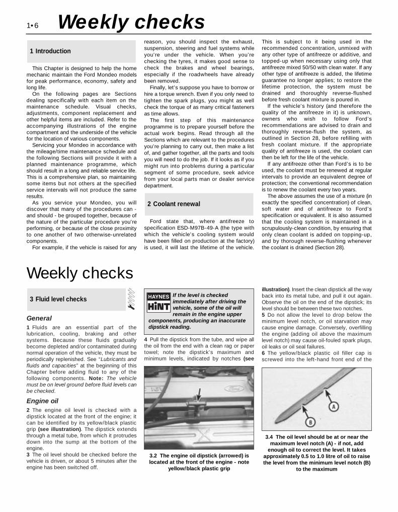
Engine oil2 The engine oil level is checked with adipstick located at the front of the engine; itcan be identified by its yellow/black plasticgrip (see illustration). The dipstick extendsthrough a metal tube, from which it protrudesdown into the sump at the bottom of theengine.3 The oil level should be checked before thevehicle is driven, or about 5 minutes after theengine has been switched off.
4 Pull the dipstick from the tube, and wipe allthe oil from the end with a clean rag or papertowel; note the dipstick’s maximum andminimum levels, indicated by notches (see
illustration). Insert the clean dipstick all the wayback into its metal tube, and pull it out again.Observe the oil on the end of the dipstick; itslevel should be between these two notches.5 Do not allow the level to drop below theminimum level notch, or oil starvation maycause engine damage. Conversely, overfillingthe engine (adding oil above the maximumlevel notch) may cause oil-fouled spark plugs,oil leaks or oil seal failures.6 The yellow/black plastic oil filler cap isscrewed into the left-hand front end of the
3 Fluid level checks
3.2 The engine oil dipstick (arrowed) islocated at the front of the engine - note
yellow/black plastic grip
3.4 The oil level should be at or near themaximum level notch (A) - if not, add
enough oil to correct the level. It takesapproximately 0.5 to 1.0 litre of oil to raisethe level from the minimum level notch (B)
to the maximum
If the level is checkedimmediately after driving thevehicle, some of the oil willremain in the engine upper
components, producing an inaccuratedipstick reading.
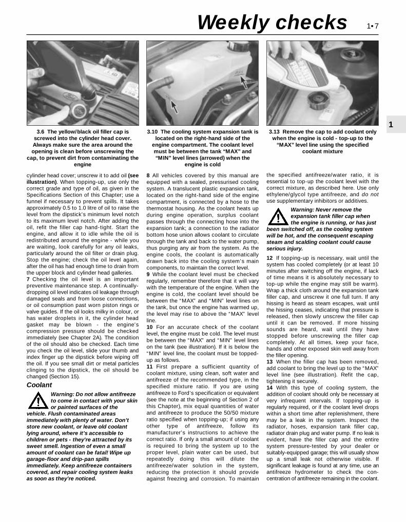
cylinder head cover; unscrew it to add oil (seeillustration). When topping-up, use only thecorrect grade and type of oil, as given in theSpecifications Section of this Chapter; use afunnel if necessary to prevent spills. It takesapproximately 0.5 to 1.0 litre of oil to raise thelevel from the dipstick’s minimum level notchto its maximum level notch. After adding theoil, refit the filler cap hand-tight. Start theengine, and allow it to idle while the oil isredistributed around the engine - while youare waiting, look carefully for any oil leaks,particularly around the oil filter or drain plug.Stop the engine; check the oil level again,after the oil has had enough time to drain fromthe upper block and cylinder head galleries.7 Checking the oil level is an importantpreventive maintenance step. A continually-dropping oil level indicates oil leakage throughdamaged seals and from loose connections,or oil consumption past worn piston rings orvalve guides. If the oil looks milky in colour, orhas water droplets in it, the cylinder headgasket may be blown - the engine’scompression pressure should be checkedimmediately (see Chapter 2A). The conditionof the oil should also be checked. Each timeyou check the oil level, slide your thumb andindex finger up the dipstick before wiping offthe oil. If you see small dirt or metal particlesclinging to the dipstick, the oil should bechanged (Section 15).
CoolantWarning: Do not allow antifreezeto come in contact with your skinor painted surfaces of the
vehicle. Flush contaminated areasimmediately with plenty of water. Don’tstore new coolant, or leave old coolantlying around, where it’s accessible tochildren or pets - they’re attracted by itssweet smell. Ingestion of even a smallamount of coolant can be fatal! Wipe upgarage-floor and drip-pan spillsimmediately. Keep antifreeze containerscovered, and repair cooling system leaksas soon as they’re noticed.
8 All vehicles covered by this manual areequipped with a sealed, pressurised coolingsystem. A translucent plastic expansion tank,located on the right-hand side of the enginecompartment, is connected by a hose to thethermostat housing. As the coolant heats upduring engine operation, surplus coolantpasses through the connecting hose into theexpansion tank; a connection to the radiatorbottom hose union allows coolant to circulatethrough the tank and back to the water pump,thus purging any air from the system. As theengine cools, the coolant is automaticallydrawn back into the cooling system’s maincomponents, to maintain the correct level.9 While the coolant level must be checkedregularly, remember therefore that it will varywith the temperature of the engine. When theengine is cold, the coolant level should bebetween the “MAX” and “MIN” level lines onthe tank, but once the engine has warmed up,the level may rise to above the “MAX” levelline.10 For an accurate check of the coolantlevel, the engine must be cold. The level mustbe between the “MAX” and “MIN” level lineson the tank (see illustration). If it is below the“MIN” level line, the coolant must be topped-up as follows.11 First prepare a sufficient quantity ofcoolant mixture, using clean, soft water andantifreeze of the recommended type, in thespecified mixture ratio. If you are usingantifreeze to Ford’s specification or equivalent(see the note at the beginning of Section 2 ofthis Chapter), mix equal quantities of waterand antifreeze to produce the 50/50 mixtureratio specified when topping-up; if using anyother type of antifreeze, follow itsmanufacturer’s instructions to achieve thecorrect ratio. If only a small amount of coolantis required to bring the system up to theproper level, plain water can be used, butrepeatedly doing this will dilute theantifreeze/water solution in the system,reducing the protection it should provideagainst freezing and corrosion. To maintain
the specified antifreeze/water ratio, it isessential to top-up the coolant level with thecorrect mixture, as described here. Use onlyethylene/glycol type antifreeze, and do notuse supplementary inhibitors or additives.
Warning: Never remove theexpansion tank filler cap whenthe engine is running, or has just
been switched off, as the cooling systemwill be hot, and the consequent escapingsteam and scalding coolant could causeserious injury.
12 If topping-up is necessary, wait until thesystem has cooled completely (or at least 10minutes after switching off the engine, if lackof time means it is absolutely necessary totop-up while the engine may still be warm).Wrap a thick cloth around the expansion tankfiller cap, and unscrew it one full turn. If anyhissing is heard as steam escapes, wait untilthe hissing ceases, indicating that pressure isreleased, then slowly unscrew the filler capuntil it can be removed. If more hissingsounds are heard, wait until they havestopped before unscrewing the filler capcompletely. At all times, keep your face,hands and other exposed skin well away fromthe filler opening.13 When the filler cap has been removed,add coolant to bring the level up to the “MAX”level line (see illustration). Refit the cap,tightening it securely.14 With this type of cooling system, theaddition of coolant should only be necessary atvery infrequent intervals. If topping-up isregularly required, or if the coolant level dropswithin a short time after replenishment, theremay be a leak in the system. Inspect theradiator, hoses, expansion tank filler cap,radiator drain plug and water pump. If no leak isevident, have the filler cap and the entiresystem pressure-tested by your dealer orsuitably-equipped garage; this will usually showup a small leak not otherwise visible. Ifsignificant leakage is found at any time, use anantifreeze hydrometer to check the con-centration of antifreeze remaining in the coolant.
1•7
13.13 Remove the cap to add coolant only
when the engine is cold - top-up to the“MAX” level line using the specified
coolant mixture
3.6 The yellow/black oil filler cap isscrewed into the cylinder head cover.Always make sure the area around theopening is clean before unscrewing the
cap, to prevent dirt from contaminating theengine
3.10 The cooling system expansion tank islocated on the right-hand side of the
engine compartment. The coolant levelmust be between the tank “MAX” and“MIN” level lines (arrowed) when the
engine is cold
Weekly checks
15 Coolant hydrometers are available atmost automotive accessory shops. If thespecific gravity of a sample taken from theexpansion tank (when the engine is switchedoff and fully cooled down) is less than thatspecified, the coolant mixture strength hasfallen below the minimum. If this is found,either the coolant strength must be restoredby adding neat antifreeze to Ford’sspecification (if that is what is in the system)or by draining and flushing the system, thenrefilling it with fresh coolant mixture of thecorrect ratio (if any other type of antifreeze isbeing used).16 When checking the coolant level, alwaysnote its condition; it should be relatively clear.If it is brown or rust-coloured, the systemshould be drained, flushed and refilled. Ifantifreeze has been used which does notmeet Ford’s specification, its corrosioninhibitors will lose their effectiveness withtime; such coolant must be renewed regularly,even if it appears to be in good condition,usually at the intervals suggested at thebeginning of Section 2 of this Chapter.
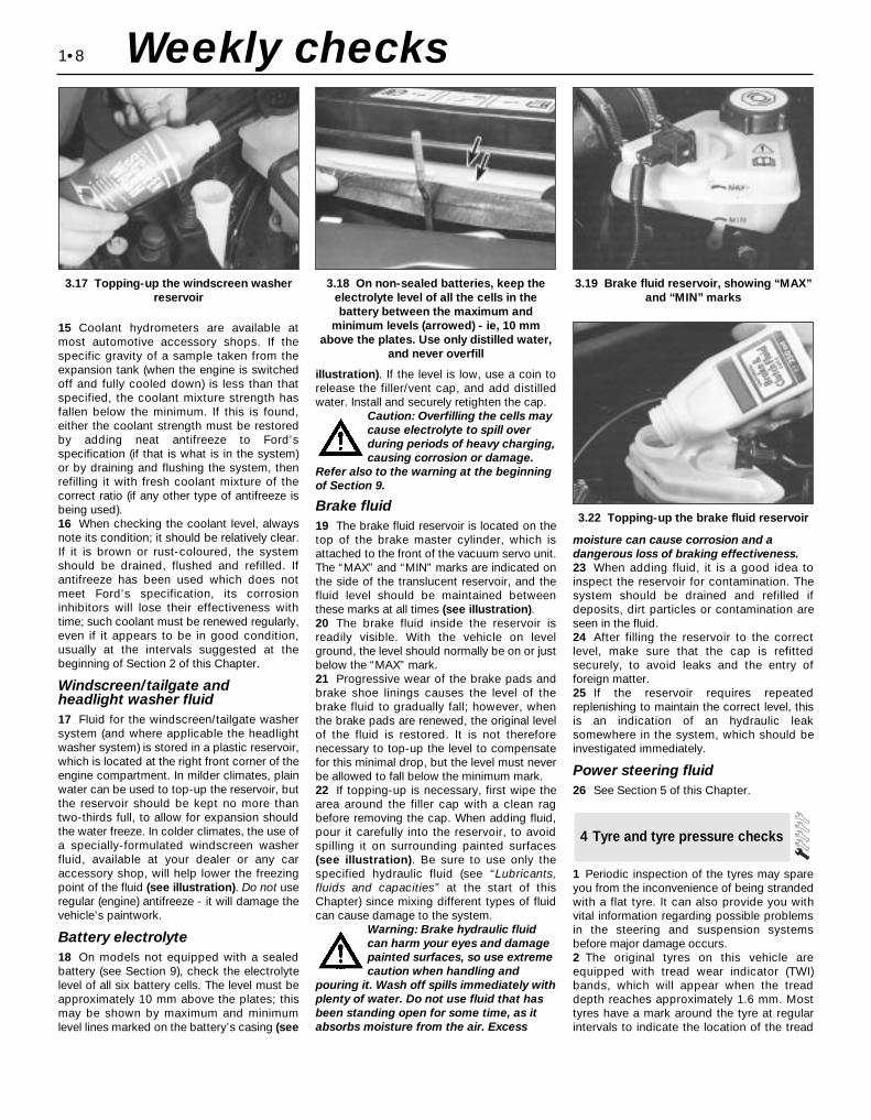
Windscreen/tailgate andheadlight washer fluid17 Fluid for the windscreen/tailgate washersystem (and where applicable the headlightwasher system) is stored in a plastic reservoir,which is located at the right front corner of theengine compartment. In milder climates, plainwater can be used to top-up the reservoir, butthe reservoir should be kept no more thantwo-thirds full, to allow for expansion shouldthe water freeze. In colder climates, the use ofa specially-formulated windscreen washerfluid, available at your dealer or any caraccessory shop, will help lower the freezingpoint of the fluid (see illustration). Do not useregular (engine) antifreeze - it will damage thevehicle’s paintwork.
Battery electrolyte18 On models not equipped with a sealedbattery (see Section 9), check the electrolytelevel of all six battery cells. The level must beapproximately 10 mm above the plates; thismay be shown by maximum and minimumlevel lines marked on the battery’s casing (see
illustration). If the level is low, use a coin torelease the filler/vent cap, and add distilledwater. Install and securely retighten the cap.
Caution: Overfilling the cells maycause electrolyte to spill overduring periods of heavy charging,causing corrosion or damage.
Refer also to the warning at the beginningof Section 9.
Brake fluid19 The brake fluid reservoir is located on thetop of the brake master cylinder, which isattached to the front of the vacuum servo unit.The “MAX” and “MIN” marks are indicated onthe side of the translucent reservoir, and thefluid level should be maintained betweenthese marks at all times (see illustration).20 The brake fluid inside the reservoir isreadily visible. With the vehicle on levelground, the level should normally be on or justbelow the “MAX” mark.21 Progressive wear of the brake pads andbrake shoe linings causes the level of thebrake fluid to gradually fall; however, whenthe brake pads are renewed, the original levelof the fluid is restored. It is not thereforenecessary to top-up the level to compensatefor this minimal drop, but the level must neverbe allowed to fall below the minimum mark.22 If topping-up is necessary, first wipe thearea around the filler cap with a clean ragbefore removing the cap. When adding fluid,pour it carefully into the reservoir, to avoidspilling it on surrounding painted surfaces(see illustration). Be sure to use only thespecified hydraulic fluid (see “Lubricants,fluids and capacities” at the start of thisChapter) since mixing different types of fluidcan cause damage to the system.
Warning: Brake hydraulic fluidcan harm your eyes and damagepainted surfaces, so use extremecaution when handling and
pouring it. Wash off spills immediately withplenty of water. Do not use fluid that hasbeen standing open for some time, as itabsorbs moisture from the air. Excess
moisture can cause corrosion and adangerous loss of braking effectiveness.23 When adding fluid, it is a good idea toinspect the reservoir for contamination. Thesystem should be drained and refilled ifdeposits, dirt particles or contamination areseen in the fluid.24 After filling the reservoir to the correctlevel, make sure that the cap is refittedsecurely, to avoid leaks and the entry offoreign matter.25 If the reservoir requires repeatedreplenishing to maintain the correct level, thisis an indication of an hydraulic leaksomewhere in the system, which should beinvestigated immediately.
Power steering fluid26 See Section 5 of this Chapter.
1 Periodic inspection of the tyres may spareyou from the inconvenience of being strandedwith a flat tyre. It can also provide you withvital information regarding possible problemsin the steering and suspension systemsbefore major damage occurs.2 The original tyres on this vehicle areequipped with tread wear indicator (TWI)bands, which will appear when the treaddepth reaches approximately 1.6 mm. Mosttyres have a mark around the tyre at regularintervals to indicate the location of the tread
4 Tyre and tyre pressure checks
1•8
3.17 Topping-up the windscreen washerreservoir
3.18 On non-sealed batteries, keep theelectrolyte level of all the cells in thebattery between the maximum and
minimum levels (arrowed) - ie, 10 mmabove the plates. Use only distilled water,
and never overfill
3.19 Brake fluid reservoir, showing “MAX”and “MIN” marks
3.22 Topping-up the brake fluid reservoir
Weekly checks

wear indicators, the mark being TWI, anarrow, or the tyre manufacturer’s symbol (seeillustration). Tread wear can also bemonitored with a simple inexpensive deviceknown as a tread depth indicator gauge (seeillustration).3 Ensure that tyre pressures are checkedregularly and maintained correctly (see theSpecifications at the beginning of this Chapter
for pressures). Checking should be carried outwith the tyres cold, and not immediately afterthe vehicle has been in use. If the pressuresare checked with the tyres hot, an apparently-high reading will be obtained, owing to heatexpansion. Under no circumstances should anattempt be made to reduce the pressures tothe quoted cold reading in this instance, oreffective under-inflation will result.
1•9
1
Tyre Tread Wear Patterns
Shoulder Wear
Underinflation (wear on both sides)Check and adjust pressures
Incorrect wheel camber(wear on one side)Repair or renew suspension parts
Hard corneringReduce speed!
Centre Wear
OverinflationCheck and adjust pressures
If you sometimes have to inflateyour car’s tyres to the higherpressures specified for maximumload or sustained high speed,don’t forget to reduce the pres-sures to normal afterwards.
Toe Wear
Incorrect toe settingAdjust front wheel alignment
Note: The feathered edge of the tread which characterises
toe wear is best checked by feel.
Uneven Wear
Incorrect camber or castorRepair or renew suspensionparts
Malfunctioning suspensionRepair or renew suspensionparts
Unbalanced wheelBalance tyres
Out-of-round brake disc/drumMachine or renew
4.2A The TWI mark on the side of the tyreshows the position of the tread wear
indicator bands
4.2B A tyre tread depth indicator shouldbe used to monitor tyre wear - they are
available at accessory shops and servicestations, and cost very little
Weekly checks
Most garage forecourts have apressure line which combines a gaugeto check and adjust the tyre pressures,but they may vary in accuracy, due togeneral misuse and abuse. It thereforepays to carry a good-quality tyrepressure gauge in the vehicle, to makethe regular checks required and ensurepressure accuracy.
4 Note any abnormal tread wear (seeillustration). Tread pattern irregularities suchas feathering, flat spots, and more wear onone side than the other, are indications offront wheel alignment and/or balanceproblems. If any of these conditions arenoted, they should be rectified as soon aspossible.
5 Under-inflation will cause overheating of thetyre, owing to excessive flexing of the casing,and the tread will not sit correctly on the roadsurface. This will cause a consequent loss ofadhesion and excessive wear, not to mentionthe danger of sudden tyre failure due to heatbuild-up.6 Over-inflation will cause rapid wear of the
centre part of the tyre tread, coupled withreduced adhesion, harder ride, and thedanger of damage occurring in the tyrecasing.7 Regularly check the tyres for damage in theform of cuts or bulges, especially in thesidewalls. Remove any nails or stonesembedded in the tread, before they penetrate

the tyre to cause deflation. If removal of a nailreveals that the tyre has been punctured, refitthe nail, so that its point of penetration ismarked. Then immediately change the wheel,and have the tyre repaired by a tyre dealer. Donot drive on a tyre in such a condition. If in anydoubt as to the possible consequences of anydamage found, consult your local tyre dealerfor advice.8 General tyre wear is influenced to a largedegree by driving style - harsh braking andacceleration, or fast cornering, will all producemore rapid tyre wear. Interchanging of tyresmay result in more even wear; however, it isworth bearing in mind that if this is completelyeffective, the added expense is incurred ofreplacing simultaneously a complete set oftyres, which may prove financially restrictivefor many owners.9 Front tyres may wear unevenly as a result ofwheel misalignment. The front wheels shouldalways be correctly aligned according to thesettings specified by the vehiclemanufacturer.
10 Don’t forget to check the spare tyre forcondition and pressure.11 Legal restrictions apply to many aspectsof tyre fitting and usage, and in the UK thisinformation is contained in the Motor VehicleConstruction and Use Regulations. It issuggested that a copy of these regulations isobtained from your local police, if in doubt asto current legal requirements with regard totyre type and condition, minimum tread depth,etc.
1 The power steering fluid reservoir is locatedon the right-hand rear corner of the enginecompartment.2 For the fluid level check, the power steeringsystem should be at its normal operatingtemperature, so it is best to carry out thecheck after a run.3 Position the vehicle on level ground, with
the front wheels pointing straight ahead, andswitch off the engine.4 Check that the fluid level is up to the “MAX”mark on the reservoir (see illustration).5 If topping-up is required, first use a cleanrag to wipe the filler cap and the surroundingarea, to prevent foreign matter from enteringthe system. Unscrew and remove the fillercap.6 Top-up the level to the “MAX” mark, usingthe grade of fluid specified at the beginning ofthis Chapter (see illustration). Be careful notto introduce dirt into the system, and do notoverfill. The need for frequent topping-upindicates a leak, which should beinvestigated.7 Refit the filler cap.
1 The windscreen wiper and blade assemblyshould be inspected at the specified intervalsfor damage, loose components, and crackedor worn blade elements.2 Road film can build up on the wiper bladesand affect their efficiency, so they should bewashed regularly with a mild detergentsolution.3 The action of the wiping mechanism canloosen bolts, nuts and fasteners, so theyshould be checked and tightened, asnecessary, at the same time as the wiperblades are checked.4 If the wiper blade elements are cracked,worn or warped, or no longer cleanadequately, they should be replaced with newones.5 Lift the wiper arm and blade away from theglass.6 To remove the windscreen wiper blade,release the catch on the arm, then turn theblade through 90° and withdraw the bladefrom the end of the arm (see illustration).7 To remove the tailgate wiper blade, pushthe wiper blade forward, and at the same timedepress it against the spring pressure, thenwithdraw it from the end of the arm (seeillustration).8 If the metal part of the wiper blade is ingood condition, it may be possible to renewthe rubber insert separately. The insert can beobtained from a car accessory shop and,according to type, it may need to be cut to thecorrect length before sliding into the clips.9 Refit the wiper blade assembly using areversal of the removal procedure, makingsure that it fully engages with the spring clip.10 Check that the washer jets direct the fluidonto the upper part of thewindscreen/tailgate/rear window/headlight,and if necessary adjust the small sphere onthe jet with a pin.
6 Windscreen/tailgate washersystem and wiper blade check
5 Power steering fluid levelcheck
1•10
5.4 Power steering fluid reservoir,showing “MAX” and “MIN” marks
5.6 Topping-up the power steering fluidreservoir
6.7 Tailgate wiper blade removal6.6 Releasing the catch to remove awindscreen wiper blade
Weekly checks

Every 10 000 miles or 12 months
1•11
17.4 Removing the automatic transmission
dipstick from its tube7.6A “MIN” and “MAX” marks on the
dipstick7.6B Adding automatic transmission fluid
through the dipstick tube
Every 10 000 miles
1 The level of the automatic transmission fluidshould be carefully maintained. Low fluid levelcan lead to slipping or loss of drive, whileoverfilling can cause foaming, loss of fluid andtransmission damage.2 The transmission fluid level should only bechecked when the transmission is hot (at itsnormal operating temperature). If the vehiclehas just been driven over 10 miles (15 miles ina cold climate), and the fluid temperature is160 to 175°F, the transmission is hot.
Caution: If the vehicle has justbeen driven for a long time athigh speed or in city traffic in hotweather, or if it has been pulling
a trailer, an accurate fluid level readingcannot be obtained. In thesecircumstances, allow the fluid to cooldown for about 30 minutes.
3 Park the vehicle on level ground, apply thehandbrake, and start the engine. While theengine is idling, depress the brake pedal andmove the selector lever through all the gearranges three times, beginning and ending in“P”.4 Allow the engine to idle for one minute, then(with the engine still idling) remove the dipstickfrom its tube (see illustration). Note thecondition and colour of the fluid on the dipstick.5 Wipe the fluid from the dipstick with a cleanrag, and re-insert it into the filler tube until thecap seats.6 Pull the dipstick out again, and note thefluid level. The level should be between the“MIN” and “MAX” marks. If the level is on the“MIN” mark, stop the engine, and add thespecified automatic transmission fluid throughthe dipstick tube, using a clean funnel ifnecessary (see illustrations). It is importantnot to introduce dirt into the transmissionwhen topping-up.7 Add the fluid a little at a time, and keepchecking the level as previously describeduntil it is correct.
8 The need for regular topping-up of thetransmission fluid indicates a leak, whichshould be found and rectified without delay.9 The condition of the fluid should also bechecked along with the level. If the fluid at theend of the dipstick is black or a dark reddish-brown colour, or if it has a burned smell, thefluid should be changed. If you are in doubtabout the condition of the fluid, purchasesome new fluid, and compare the two forcolour and smell.
1 Check the operation of all external lightsand indicators (front and rear).2 Check for satisfactory operation of theinstrument panel, its illumination and warninglights, the switches and their function lights.3 Check the horn(s) for satisfactory operation.4 Check all other electrical equipment forsatisfactory operation.5 Check all electrical wiring in the enginecompartment for correct routing, and for anysigns of physical or heat-damage or chafing.
Warning: Certain precautionsmust be followed when checkingand servicing the battery.Hydrogen gas, which is highly
flammable, is always present in the batterycells, so keep lighted tobacco and all otheropen flames and sparks away from thebattery. The electrolyte inside the batteryis actually dilute sulphuric acid, which willcause injury if splashed on your skin or inyour eyes. It will also ruin clothes andpainted surfaces. When disconnecting thebattery, always detach the negative (earth)lead first and connect it last!Note: Before disconnecting the battery, referto Section 1 of Chapter 5.
9 Battery check, maintenanceand charging
8 Electrical system check
7 Automatic transmission fluidlevel check
9.1 Tools and materials required forbattery maintenance
1 Face shield/safety goggles - Whenremoving corrosion with a brush, the acidicparticles can easily fly up into your eyes2 Baking soda - A solution of baking sodaand water can be used to neutralise corrosion3 Petroleum jelly - A layer of this on thebattery terminals will help prevent corrosion4 Battery terminal/lead cleaner - This wirebrush cleaning tool will remove all traces ofcorrosion from the battery terminals and leadclamps5 Treated felt washers - Placing one ofthese on each terminal, directly under thelead clamps, will help prevent corrosion6 Puller - Sometimes the lead clamps arevery difficult to pull off the terminals, evenafter the nut has been completely slackened.This tool pulls the clamp straight up and offthe terminal without damage7 Battery terminal/lead cleaner - Here isanother cleaning tool which is a slightlydifferent version of number 4 above, but doesthe same thing8 Rubber gloves - Another safety item toconsider when servicing the battery;remember, that’s acid inside the battery!

General
1 A routine preventive maintenanceprogramme for the battery in your vehicle isthe only way to ensure quick and reliablestarts. Before performing any batterymaintenance, make sure that you have theproper equipment necessary to work safelyaround the battery (see illustration).2 There are also several precautions thatshould be taken whenever batterymaintenance is performed. Before servicingthe battery, always turn the engine and allaccessories off, and disconnect the lead fromthe negative terminal of the battery - seeChapter 5, Section 1.3 The battery produces hydrogen gas, whichis both flammable and explosive. Never createa spark, smoke, or light a match around thebattery. Always charge the battery in a well-ventilated area.4 Electrolyte contains poisonous andcorrosive sulphuric acid. Do not allow it to getin your eyes, on your skin, or on your clothes.Never ingest it. Wear protective safety glasseswhen working near the battery. Keep childrenaway from the battery.5 Note the external condition of the battery. Ifthe positive terminal and lead clamp on yourvehicle’s battery is equipped with a plasticcover or rubber protector, make sure that it’snot torn or damaged. It should completely
cover the terminal. Look for any corroded orloose connections, cracks in the case orcover, or loose hold-down clamps. Also checkthe entire length of each lead for cracks andfrayed conductors.6 If corrosion, which looks like white, fluffydeposits (see illustration) is evident,particularly around the terminals, the batteryshould be removed for cleaning. Slacken thelead clamp nuts with a spanner, being carefulto remove the negative (earth) lead first, andslide them off the terminals (see illustration).Then unscrew the hold-down clamp nuts,remove the clamp, and lift the battery from theengine compartment.7 Clean the lead clamps thoroughly, using asoft wire brush or a terminal cleaner, with asolution of warm water and baking soda.Wash the terminals and the top of the batterycase with the same solution, but make surethat the solution doesn’t get into the battery.When cleaning the leads, terminals andbattery top, wear safety goggles and rubbergloves, to prevent any solution from coming incontact with your eyes or hands. Wear oldclothes too - even when diluted, sulphuricacid splashed onto clothes will burn holes inthem. If the terminals have been extensivelycorroded, clean them up with a terminalcleaner (see illustrations). Thoroughly washall cleaned areas with plain water.8 Make sure that the battery tray is in goodcondition and the hold-down clamp nuts aretight (see illustration). If the battery is
removed from the tray, make sure no partsremain in the bottom of the tray when thebattery is refitted. When refitting thehold-down clamp nuts, do not overtightenthem.9 Information on removing and installing thebattery can be found in Chapter 5. Informationon jump starting can be found at the front ofthis manual. For more detailed batterychecking procedures, refer to the HaynesAutomobile Electrical and Electronic SystemsManual.
Cleaning10 Corrosion on the hold-down components,battery case and surrounding areas can beremoved with a solution of water and bakingsoda. Thoroughly rinse all cleaned areas withplain water.11 Any metal parts of the vehicle damagedby corrosion should be covered with azinc-based primer, then painted.
ChargingWarning: When batteries arebeing charged, hydrogen gas,which is very explosive andflammable, is produced. Do not
smoke, or allow open flames, near acharging or a recently-charged battery.Wear eye protection when near the batteryduring charging. Also, make sure thecharger is unplugged before connecting ordisconnecting the battery from thecharger.12 Slow-rate charging is the best way torestore a battery that’s discharged to thepoint where it will not start the engine. It’s alsoa good way to maintain the battery charge in avehicle that’s only driven a few miles betweenstarts. Maintaining the battery charge isparticularly important in winter, when thebattery must work harder to start the engine,and electrical accessories that drain thebattery are in greater use.13 It’s best to use a one- or two-amp batterycharger (sometimes called a “trickle” charger).They are the safest, and put the least strain onthe battery. They are also the least expensive.For a faster charge, you can use a higher-
1•12
9.6A Battery terminal corrosion usuallyappears as light, fluffy powder
9.6B Removing a lead from the batteryterminal - always remove the earth lead
first, and connect it last!
9.7A When cleaning the lead clamps, allcorrosion must be removed - the inside ofthe clamp is tapered to match the terminal,
so don’t remove too much material
9.7B Regardless of the method used toclean the terminals, a clean, shiny surface
should result9.8 Make sure the battery hold-down nuts
(arrowed) are tight
Every 10 000 miles

amperage charger, but don’t use one ratedmore than 1/10th the amp/hour rating of thebattery (ie no more than 5 amps, typically).Rapid boost charges that claim to restore thepower of the battery in one to two hours arehardest on the battery, and can damagebatteries not in good condition. This type ofcharging should only be used in emergencysituations.14 The average time necessary to charge abattery should be listed in the instructions thatcome with the charger. As a general rule, atrickle charger will charge a battery in 12 to 16 hours.
1 Check the seat belts for satisfactoryoperation and condition. Inspect the webbingfor fraying and cuts. Check that they retractsmoothly and without binding into their reels.2 Check that the seat belt mounting bolts aretight, and if necessary tighten them to thespecified torque wrench setting.
General1 The auxiliary drivebelt is of the flat, multi-ribbed (or “polyvee”) type, and is located onthe right-hand end of the engine. It drives thealternator, water pump, power steering pumpand (when fitted) the air conditioningcompressor from the engine’s crankshaftpulley.2 The good condition and proper tension ofthe auxiliary drivebelt is critical to theoperation of the engine. Because of theircomposition and the high stresses to whichthey are subjected, drivebelts stretch and
deteriorate as they get older. They must,therefore, be regularly inspected.
Check3 With the engine switched off, open andsupport the bonnet, then locate the auxiliarydrivebelt on the right-hand end of the engine,under the engine right-hand mountingbracket. (Be very careful, and wear protectivegloves to minimise the risk of burning yourhands on hot components, if the engine hasrecently been running.) For improved access,jack up the front right-hand side of thevehicle, support it securely on an axle stand,remove the roadwheel, then remove theauxiliary drivebelt cover (two fasteners) frominside the wheel arch (see illustration).4 Using an inspection light or a small electrictorch, and rotating the engine when necessarywith a spanner applied to the crankshaftpulley bolt, check the whole length of thedrivebelt for cracks, separation of the rubber,and torn or worn ribs (see illustration). Alsocheck for fraying and glazing, which gives thedrivebelt a shiny appearance. Both sides ofthe drivebelt should be inspected, whichmeans you will have to twist the drivebelt tocheck the underside. Use your fingers to feelthe drivebelt where you can’t see it. If you arein any doubt as to the condition of thedrivebelt, renew it (go to paragraph 7).
Drivebelt tension5 The auxiliary drivebelt is tensioned by anautomatic tensioner; regular checks are notrequired, and manual “adjustment” is notpossible.6 If you suspect that the drivebelt is slippingand/or running slack, or that the tensioner isotherwise faulty, it must be renewed. To dothis, remove the drivebelt as described below,then unbolt the tensioner (two Torx-typescrews accessible from underneath, via thewheel arch) from the alternator mountingbracket (see illustration). On fitting the newtensioner, ensure it is aligned correctly on itsmountings, and tighten the screws to thespecified torque wrench setting.
Renewal7 Open the bonnet. Jack up the front right-hand side of the vehicle and support itsecurely on an axle stand, remove theroadwheel, then remove the auxiliary drivebeltcover (two fasteners) from inside the wheelarch.8 If the existing drivebelt is to be refitted,mark it, or note the maker’s markings on itsflat surface, so that it can be installed thesame way round.9 Reaching up between the body and theengine (above and to the rear of thecrankshaft pulley), apply a spanner to thehexagon in the centre of the automatictensioner’s pulley. Rotate the tensioner pulleyclockwise to release its pressure on thedrivebelt, then slip the drivebelt off thecrankshaft pulley, and release the tensioneragain (see illustration). Working from thewheel arch or engine compartment asnecessary, and noting its routing, slip thedrivebelt off the remaining pulleys andwithdraw it.10 Check all the pulleys, ensuring that theirgrooves are clean, and removing all traces ofoil and grease. Check that the tensionerworks properly, with strong spring pressure
11 Auxiliary drivebelt check andrenewal
10 Seat belt check
1•13
1
11.9 Rotate the tensioner pulley clockwiseto release its pressure on the drivebelt,then slip the drivebelt off the crankshaft
pulley
11.3 Removing the auxiliary drivebeltcover - it is secured by a fastener at eachend (arrowed) - from inside the right-hand
front wheel arch
11.4 Check the auxiliary drivebelt for signsof wear like these. Very small cracks across
the drivebelt ribs are acceptable. If thecracks are deep, or if the drivebelt looks
worn or damaged in any other way, renew it
11.6 The auxiliary drivebelt is tensioned byan automatic tensioner; Torx screws
(arrowed) secure it to alternator mountingbracket
Every 10 000 miles
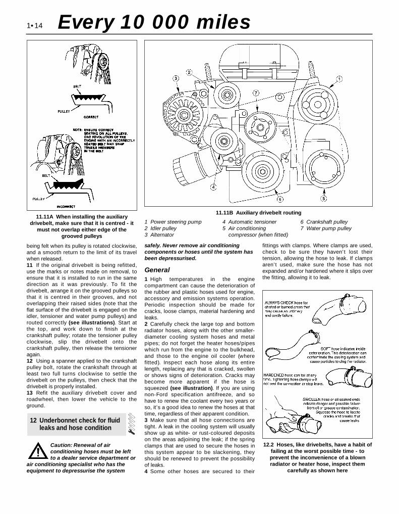
being felt when its pulley is rotated clockwise,and a smooth return to the limit of its travelwhen released.11 If the original drivebelt is being refitted,use the marks or notes made on removal, toensure that it is installed to run in the samedirection as it was previously. To fit thedrivebelt, arrange it on the grooved pulleys sothat it is centred in their grooves, and notoverlapping their raised sides (note that theflat surface of the drivebelt is engaged on theidler, tensioner and water pump pulleys) androuted correctly (see illustrations). Start atthe top, and work down to finish at thecrankshaft pulley; rotate the tensioner pulleyclockwise, slip the drivebelt onto thecrankshaft pulley, then release the tensioneragain.12 Using a spanner applied to the crankshaftpulley bolt, rotate the crankshaft through atleast two full turns clockwise to settle thedrivebelt on the pulleys, then check that thedrivebelt is properly installed.13 Refit the auxiliary drivebelt cover androadwheel, then lower the vehicle to theground.
Caution: Renewal of airconditioning hoses must be leftto a dealer service department or
air conditioning specialist who has theequipment to depressurise the system
safely. Never remove air conditioningcomponents or hoses until the system hasbeen depressurised.
General1 High temperatures in the enginecompartment can cause the deterioration ofthe rubber and plastic hoses used for engine,accessory and emission systems operation.Periodic inspection should be made forcracks, loose clamps, material hardening andleaks.2 Carefully check the large top and bottomradiator hoses, along with the other smaller-diameter cooling system hoses and metalpipes; do not forget the heater hoses/pipeswhich run from the engine to the bulkhead,and those to the engine oil cooler (wherefitted). Inspect each hose along its entirelength, replacing any that is cracked, swollenor shows signs of deterioration. Cracks maybecome more apparent if the hose issqueezed (see illustration). If you are usingnon-Ford specification antifreeze, and sohave to renew the coolant every two years orso, it’s a good idea to renew the hoses at thattime, regardless of their apparent condition.3 Make sure that all hose connections aretight. A leak in the cooling system will usuallyshow up as white- or rust-coloured depositson the areas adjoining the leak; if the springclamps that are used to secure the hoses inthis system appear to be slackening, theyshould be renewed to prevent the possibilityof leaks.4 Some other hoses are secured to their
fittings with clamps. Where clamps are used,check to be sure they haven’t lost theirtension, allowing the hose to leak. If clampsaren’t used, make sure the hose has notexpanded and/or hardened where it slips overthe fitting, allowing it to leak.
12 Underbonnet check for fluidleaks and hose condition
1•14
11.11A When installing the auxiliarydrivebelt, make sure that it is centred - it
must not overlap either edge of thegrooved pulleys
11.11B Auxiliary drivebelt routing
1 Power steering pump2 Idler pulley3 Alternator
4 Automatic tensioner5 Air conditioning
compressor (when fitted)
6 Crankshaft pulley7 Water pump pulley
12.2 Hoses, like drivebelts, have a habit offailing at the worst possible time - toprevent the inconvenience of a blownradiator or heater hose, inspect them
carefully as shown here
Every 10 000 miles
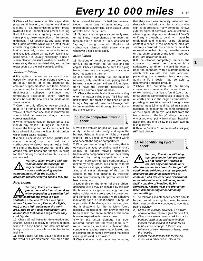
5 Check all fluid reservoirs, filler caps, drainplugs and fittings etc, looking for any signs ofleakage of oil, transmission and/or brakehydraulic fluid, coolant and power steeringfluid. If the vehicle is regularly parked in thesame place, close inspection of the groundunderneath it will soon show any leaks; ignorethe puddle of water which will be left if the airconditioning system is in use. As soon as aleak is detected, its source must be tracedand rectified. Where oil has been leaking forsome time, it is usually necessary to use asteam cleaner, pressure washer or similar, toclean away the accumulated dirt, so that theexact source of the leak can be identified.
Vacuum hoses6 It’s quite common for vacuum hoses,especially those in the emissions system, tobe colour-coded, or to be identified bycoloured stripes moulded into them. Varioussystems require hoses with different wallthicknesses, collapse resistance andtemperature resistance. When renewinghoses, be sure the new ones are made of thesame material.7 Often the only effective way to check ahose is to remove it completely from thevehicle. If more than one hose is removed, besure to label the hoses and fittings to ensurecorrect installation.8 When checking vacuum hoses, be sure toinclude any plastic T-fittings in the check.Inspect the fittings for cracks, and check thehose where it fits over the fitting for distortion,which could cause leakage.9 A small piece of vacuum hose (quarter-inchinside diameter) can be used as astethoscope to detect vacuum leaks. Holdone end of the hose to your ear, and probearound vacuum hoses and fittings, listeningfor the “hissing” sound characteristic of avacuum leak.
Warning: When probing with thevacuum hose stethoscope, bevery careful not to come intocontact with moving engine
components such as the auxiliarydrivebelt, radiator electric cooling fan, etc.
Fuel hosesWarning: There are certainprecautions which must be takenwhen inspecting or servicing fuel
system components. Work in a well-ventilated area, and do not allow openflames (cigarettes, appliance pilot lights,etc.) or bare light bulbs near the workarea. Mop up any spills immediately, anddo not store fuel-soaked rags where theycould ignite.10 Check all fuel hoses for deterioration andchafing. Check especially for cracks in areaswhere the hose bends, and also just beforefittings, such as where a hose attaches to thefuel filter.11 High-quality fuel line, usually identified bythe word “Fluoroelastomer” printed on the
hose, should be used for fuel line renewal.Never, under any circumstances, useunreinforced vacuum line, clear plastic tubingor water hose for fuel lines.12 Spring-type clamps are commonly usedon fuel lines. These clamps often lose theirtension over a period of time, and can be“sprung” during removal. Replace allspring-type clamps with screw clampswhenever a hose is replaced.
Metal lines13 Sections of metal piping are often usedfor fuel line between the fuel filter and theengine. Check carefully to be sure the pipinghas not been bent or crimped, and that crackshave not started in the line.14 If a section of metal fuel line must berenewed, only seamless steel piping shouldbe used, since copper and aluminium pipingdon’t have the strength necessary towithstand normal engine vibration.15 Check the metal brake lines where theyenter the master cylinder and ABS hydraulicunit (if used) for cracks in the lines or loosefittings. Any sign of brake fluid leakage callsfor an immediate and thorough inspection ofthe brake system.
1 With the vehicle parked on level ground,apply the handbrake firmly and open thebonnet. Using an inspection light or a smallelectric torch, check all visible wiring withinand beneath the engine compartment.2 What you are looking for is wiring that isobviously damaged by chafing against sharpedges, or against moving suspension/transmission components and/or the auxiliarydrivebelt, by being trapped or crushedbetween carelessly-refitted components, ormelted by being forced into contact with thehot engine castings, coolant pipes, etc. Inalmost all cases, damage of this sort iscaused in the first instance by incorrectrouting on reassembly after previous work hasbeen carried out.3 Depending on the extent of the problem,damaged wiring may be repaired by rejoiningthe break or splicing-in a new length of wire,using solder to ensure a good connection,and remaking the insulation with adhesiveinsulating tape or heat-shrink tubing, asappropriate. If the damage is extensive, giventhe implications for the vehicle’s futurereliability, the best long-term answer may wellbe to renew that entire section of the loom,however expensive this may appear.4 When the actual damage has beenrepaired, ensure that the wiring loom is re-routed correctly, so that it is clear of othercomponents, and not stretched or kinked, andis secured out of harm’s way using the plasticclips, guides and ties provided.5 Check all electrical connectors, ensuring
that they are clean, securely fastened, andthat each is locked by its plastic tabs or wireclip, as appropriate. If any connector showsexternal signs of corrosion (accumulations ofwhite or green deposits, or streaks of “rust”),or if any is thought to be dirty, it must beunplugged and cleaned using electricalcontact cleaner. If the connector pins areseverely corroded, the connector must berenewed; note that this may mean the renewalof that entire section of the loom - see yourlocal Ford dealer for details.6 If the cleaner completely removes thecorrosion to leave the connector in asatisfactory condition, it would be wise topack the connector with a suitable materialwhich will exclude dirt and moisture,preventing the corrosion from occurringagain; a Ford dealer may be able torecommend a suitable product.7 Check the condition of the batteryconnections - remake the connections orrenew the leads if a fault is found (see Chap-ter 5). Use the same techniques to ensure thatall earth points in the engine compartmentprovide good electrical contact through clean,metal-to-metal joints, and that all are securelyfastened. (In addition to the earth connectionat the engine lifting eye, and that from thetransmission to the body/battery, there areone or two earth points behind each headlightassembly, and one below the power steeringfluid reservoir.)8 Refer to Section 31 for details of spark plug(HT) lead checks.
Warning: The air conditioningsystem is under high pressure.Do not loosen any fittings orremove any components until
after the system has been discharged. Airconditioning refrigerant must be properlydischarged into an approved type ofcontainer, at a dealer service departmentor an automotive air conditioning repairfacility capable of handling R134arefrigerant. Always wear eye protectionwhen disconnecting air conditioningsystem fittings.1 The following maintenance checks shouldbe performed on a regular basis, to ensurethat the air conditioner continues to operate atpeak efficiency:(a) Check the auxiliary drivebelt. If it’s worn
or deteriorated, renew it (see Section 11).(b) Check the system hoses. Look for cracks,
bubbles, hard spots and deterioration.Inspect the hoses and all fittings for oilbubbles and seepage. If there’s anyevidence of wear, damage or leaks, renewthe hose(s).
(c) Inspect the condenser fins for leaves,insects and other debris. Use a “fin
14 Air conditioning systemcheck
13 Engine compartment wiringcheck
1•15
1
Every 10 000 miles

comb” or compressed air to clean thecondenser.
Warning: Wear eye protectionwhen using compressed air!
(d) Check that the drain tube from the frontof the evaporator is clear - note that it isnormal to have clear fluid (water) drippingfrom this while the system is in operation,to the extent that quite a large puddle canbe left under the vehicle when it is parked.
2 It’s a good idea to operate the system for
about 30 minutes at least once a month,particularly during the winter. Long termnon-use can cause hardening, andsubsequent failure, of the seals.3 Because of the complexity of the airconditioning system and the specialequipment necessary to service it, in-depthfault diagnosis and repairs are not included inthis manual. For more complete informationon the air conditioning system, refer to theHaynes Automotive Heating and AirConditioning Manual.4 The most common cause of poor cooling issimply a low system refrigerant charge. If anoticeable drop in cool air output occurs, thefollowing quick check will help you determineif the refrigerant level is low.5 Warm the engine up to normal operatingtemperature.6 Place the air conditioning temperatureselector at the coldest setting, and put theblower at the highest setting. Open the doors- to make sure the air conditioning systemdoesn’t cycle off as soon as it cools thepassenger compartment.7 With the compressor engaged - the clutchwill make an audible click, and the centre ofthe clutch will rotate - feel the inlet and outletpipes at the compressor. One side should becold, and one hot. If there’s no perceptibledifference between the two pipes, there’ssomething wrong with the compressor or thesystem. It might be a low charge - it might besomething else. Take the vehicle to a dealerservice department or an automotive airconditioning specialist.
1 Make sure that you have all the necessarytools before you begin this procedure (seeillustration). You should also have plenty ofrags or newspapers handy, for mopping upany spills.2 To avoid any possibility of scalding, and toprotect yourself from possible skin irritantsand other harmful contaminants in usedengine oils, it is advisable to wear gloveswhen carrying out this work.3 Access to the underside of the vehicle isgreatly improved if the vehicle can be lifted ona hoist, driven onto ramps, or supported byaxle stands.
Warning: Do not work under avehicle which is supported onlyby an hydraulic or scissors-typejack, or by bricks, blocks ofwood, etc.
4 If this is your first oil change, get under thevehicle and familiarise yourself with theposition of the engine oil drain plug, which islocated at the rear of the sump. The engineand exhaust components will be warm duringthe actual work, so try to anticipate anypotential problems while the engine andaccessories are cool.5 The oil should preferably be changed whenthe engine is still fully warmed-up to normaloperating temperature, just after a run (theneedle on the temperature gauge should be inthe “Normal” sector of the gauge); warm oiland sludge will flow out more easily. Park thevehicle on firm, level ground, apply thehandbrake firmly, then select 1st or reversegear (manual transmission) or the “P” position(automatic transmission). Open the bonnetand remove the engine oil filler cap from thecylinder head cover, then remove the oil leveldipstick from its tube (see Section 3).6 Raise the front of the vehicle, and support itsecurely on axle stands. Remove the frontright-hand roadwheel to provide access to theoil filter; if the additional working clearance isrequired, remove also the auxiliary drivebeltcover (two fasteners).
15 Engine oil and filter change
1•16
15.1 These tools are required whenchanging the engine oil and filter
1 Drain pan - It should be fairly shallow indepth, but wide to prevent spills2 Rubber gloves - When removing the drainplug and filter, it is inevitable that you will getoil on your hands (the gloves will preventburns from hot oil)3 Breaker bar - Sometimes the oil drain plugis pretty tight, and a long breaker bar isneeded to loosen it4 Socket - To be used with the breaker baror a ratchet (must be the correct size to fit thedrain plug)5 Filter wrench - This is a metal band-typewrench, which requires clearance around thefilter to be effective6 Filter wrench - This type fits on thebottom of the filter, and can be turned with aratchet or breaker bar (different size wrenchesare available for different types of filters)
15.7 Use the correct-size spanner orsocket to remove the oil drain plug and
avoid rounding it off
15.9 Since the oil filter is usually on verytight, you’ll need a special wrench forremoval. DO NOT use the wrench to
tighten the new filter. Pack rag under thefilter before removal to minimise the mess
Every 10 000 miles
Frequent oil changes are thebest preventive maintenancethe home mechanic can givethe engine, because ageing
oil becomes diluted and contaminated,which leads to premature engine wear.
Note: It isantisocial andillegal to dumpoil down thedrain. To findthe location ofyour local oilrecycling bank,call thisnumber free.
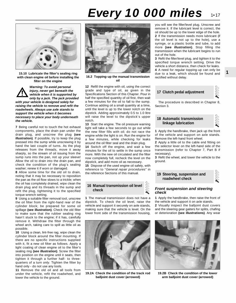
Warning: To avoid personalinjury, never get beneath thevehicle when it is supported byonly by a jack. The jack provided
with your vehicle is designed solely forraising the vehicle to remove and refit theroadwheels. Always use axle stands tosupport the vehicle when it becomesnecessary to place your body underneaththe vehicle.
7 Being careful not to touch the hot exhaustcomponents, place the drain pan under thedrain plug, and unscrew the plug (seeillustration). If possible, try to keep the plugpressed into the sump while unscrewing it byhand the last couple of turns. As the plugreleases from the threads, move it awaysharply, so the stream of oil issuing from thesump runs into the pan, not up your sleeve!Allow the oil to drain into the drain pan, andcheck the condition of the plug’s sealingwasher; renew it if worn or damaged.8 Allow some time for the old oil to drain,noting that it may be necessary to repositionthe pan as the oil flow slows to a trickle; whenthe oil has completely drained, wipe clean thedrain plug and its threads in the sump andrefit the plug, tightening it to the specifiedtorque wrench setting.9 Using a suitable filter removal tool, unscrewthe oil filter from the right-hand rear of thecylinder block; be prepared for some oilspillage (see illustration). Check the old filterto make sure that the rubber sealing ringhasn’t stuck to the engine; if it has, carefullyremove it. Withdraw the filter through thewheel arch, taking care to spill as little oil aspossible.10 Using a clean, lint-free rag, wipe clean thecylinder block around the filter mounting. Ifthere are no specific instructions suppliedwith it, fit a new oil filter as follows. Apply alight coating of clean engine oil to the filter’ssealing ring (see illustration). Screw the filterinto position on the engine until it seats, thentighten it through a further half- to three-quarters of a turn only. Tighten the filter byhand only - do not use any tools.11 Remove the old oil and all tools fromunder the vehicle, refit the roadwheel, andlower the vehicle to the ground.
12 Refill the engine with oil, using the correctgrade and type of oil, as given in theSpecifications Section of this Chapter. Pour inhalf the specified quantity of oil first, then waita few minutes for the oil to fall to the sump.Continue adding oil a small quantity at a time,until the level is up to the lower notch on thedipstick. Adding approximately 0.5 to 1.0 litrewill raise the level to the dipstick’s uppernotch.13 Start the engine. The oil pressure warninglight will take a few seconds to go out whilethe new filter fills with oil; do not race theengine while the light is on. Run the engine fora few minutes, while checking for leaksaround the oil filter seal and the drain plug.14 Switch off the engine, and wait a fewminutes for the oil to settle in the sump oncemore. With the new oil circulated and the filternow completely full, recheck the level on thedipstick, and add more oil as necessary.15 Dispose of the used engine oil safely, withreference to “General repair procedures” inthe reference Sections of this manual.
1 The manual transmission does not have adipstick. To check the oil level, raise thevehicle and support it securely on axle stands,making sure that the vehicle is level. On thelower front side of the transmission housing,
you will see the filler/level plug. Unscrew andremove it. If the lubricant level is correct, theoil should be up to the lower edge of the hole.2 If the transmission needs more lubricant (ifthe oil level is not up to the hole), use asyringe, or a plastic bottle and tube, to addmore (see illustration). Stop filling thetransmission when the lubricant begins to runout of the hole.3 Refit the filler/level plug, and tighten it to thespecified torque wrench setting. Drive thevehicle a short distance, then check for leaks.4 A need for regular topping-up can only bedue to a leak, which should be found andrectified without delay.
The procedure is described in Chapter 8,Section 3.
1 Apply the handbrake, then jack up the frontof the vehicle and support on axle stands.Remove the left-hand front wheel.2 Apply a little oil to the cable end fitting onthe selector lever on the left-hand side of thetransmission (refer to Chapter 7, Part B ifnecessary).3 Refit the wheel, and lower the vehicle to theground.
Front suspension and steeringcheck1 Apply the handbrake, then raise the front ofthe vehicle and support it on axle stands.2 Visually inspect the balljoint dust coversand the steering gear gaiters for splits, chafingor deterioration (see illustrations). Any wear
19 Steering, suspension androadwheel check
18 Automatic transmissionlinkage lubrication
17 Clutch pedal adjustment
16 Manual transmission oil levelcheck
1•17
1
19.2B Check the condition of the lowerarm balljoint dust cover (arrowed)
15.10 Lubricate the filter’s sealing ringwith clean engine oil before installing the
filter on the engine16.2 Topping-up the manual transmission
oil
19.2A Check the condition of the track rodballjoint dust cover (arrowed)
Every 10 000 miles
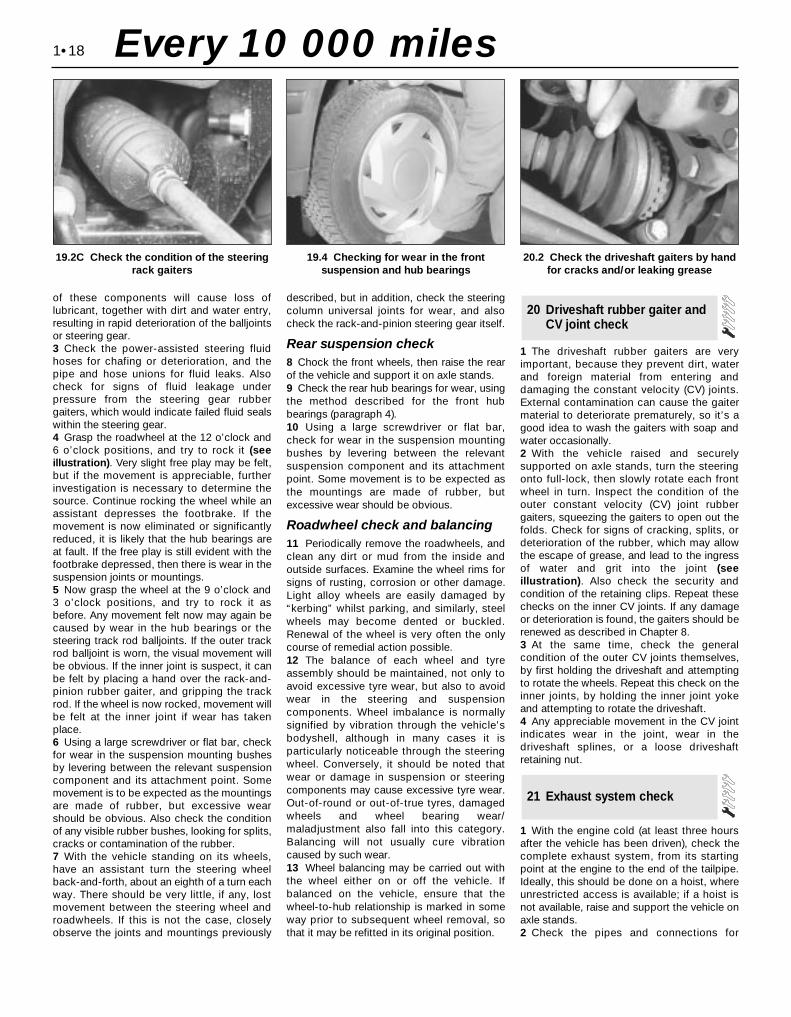
of these components will cause loss oflubricant, together with dirt and water entry,resulting in rapid deterioration of the balljointsor steering gear.3 Check the power-assisted steering fluidhoses for chafing or deterioration, and thepipe and hose unions for fluid leaks. Alsocheck for signs of fluid leakage underpressure from the steering gear rubbergaiters, which would indicate failed fluid sealswithin the steering gear.4 Grasp the roadwheel at the 12 o’clock and6 o’clock positions, and try to rock it (seeillustration). Very slight free play may be felt,but if the movement is appreciable, furtherinvestigation is necessary to determine thesource. Continue rocking the wheel while anassistant depresses the footbrake. If themovement is now eliminated or significantlyreduced, it is likely that the hub bearings areat fault. If the free play is still evident with thefootbrake depressed, then there is wear in thesuspension joints or mountings.5 Now grasp the wheel at the 9 o’clock and 3 o’clock positions, and try to rock it asbefore. Any movement felt now may again becaused by wear in the hub bearings or thesteering track rod balljoints. If the outer trackrod balljoint is worn, the visual movement willbe obvious. If the inner joint is suspect, it canbe felt by placing a hand over the rack-and-pinion rubber gaiter, and gripping the trackrod. If the wheel is now rocked, movement willbe felt at the inner joint if wear has takenplace.6 Using a large screwdriver or flat bar, checkfor wear in the suspension mounting bushesby levering between the relevant suspensioncomponent and its attachment point. Somemovement is to be expected as the mountingsare made of rubber, but excessive wearshould be obvious. Also check the conditionof any visible rubber bushes, looking for splits,cracks or contamination of the rubber.7 With the vehicle standing on its wheels,have an assistant turn the steering wheelback-and-forth, about an eighth of a turn eachway. There should be very little, if any, lostmovement between the steering wheel androadwheels. If this is not the case, closelyobserve the joints and mountings previously
described, but in addition, check the steeringcolumn universal joints for wear, and alsocheck the rack-and-pinion steering gear itself.
Rear suspension check8 Chock the front wheels, then raise the rearof the vehicle and support it on axle stands.9 Check the rear hub bearings for wear, usingthe method described for the front hubbearings (paragraph 4).10 Using a large screwdriver or flat bar,check for wear in the suspension mountingbushes by levering between the relevantsuspension component and its attachmentpoint. Some movement is to be expected asthe mountings are made of rubber, butexcessive wear should be obvious.
Roadwheel check and balancing11 Periodically remove the roadwheels, andclean any dirt or mud from the inside andoutside surfaces. Examine the wheel rims forsigns of rusting, corrosion or other damage.Light alloy wheels are easily damaged by“kerbing” whilst parking, and similarly, steelwheels may become dented or buckled.Renewal of the wheel is very often the onlycourse of remedial action possible.12 The balance of each wheel and tyreassembly should be maintained, not only toavoid excessive tyre wear, but also to avoidwear in the steering and suspensioncomponents. Wheel imbalance is normallysignified by vibration through the vehicle’sbodyshell, although in many cases it isparticularly noticeable through the steeringwheel. Conversely, it should be noted thatwear or damage in suspension or steeringcomponents may cause excessive tyre wear.Out-of-round or out-of-true tyres, damagedwheels and wheel bearing wear/maladjustment also fall into this category.Balancing will not usually cure vibrationcaused by such wear.13 Wheel balancing may be carried out withthe wheel either on or off the vehicle. Ifbalanced on the vehicle, ensure that thewheel-to-hub relationship is marked in someway prior to subsequent wheel removal, sothat it may be refitted in its original position.
1 The driveshaft rubber gaiters are veryimportant, because they prevent dirt, waterand foreign material from entering anddamaging the constant velocity (CV) joints.External contamination can cause the gaitermaterial to deteriorate prematurely, so it’s agood idea to wash the gaiters with soap andwater occasionally.2 With the vehicle raised and securelysupported on axle stands, turn the steeringonto full-lock, then slowly rotate each frontwheel in turn. Inspect the condition of theouter constant velocity (CV) joint rubbergaiters, squeezing the gaiters to open out thefolds. Check for signs of cracking, splits, ordeterioration of the rubber, which may allowthe escape of grease, and lead to the ingressof water and grit into the joint (seeillustration). Also check the security andcondition of the retaining clips. Repeat thesechecks on the inner CV joints. If any damageor deterioration is found, the gaiters should berenewed as described in Chapter 8.3 At the same time, check the generalcondition of the outer CV joints themselves,by first holding the driveshaft and attemptingto rotate the wheels. Repeat this check on theinner joints, by holding the inner joint yokeand attempting to rotate the driveshaft.4 Any appreciable movement in the CV jointindicates wear in the joint, wear in thedriveshaft splines, or a loose driveshaftretaining nut.
1 With the engine cold (at least three hoursafter the vehicle has been driven), check thecomplete exhaust system, from its startingpoint at the engine to the end of the tailpipe.Ideally, this should be done on a hoist, whereunrestricted access is available; if a hoist isnot available, raise and support the vehicle onaxle stands.2 Check the pipes and connections for
21 Exhaust system check
20 Driveshaft rubber gaiter andCV joint check
1•18
19.2C Check the condition of the steeringrack gaiters
19.4 Checking for wear in the frontsuspension and hub bearings
20.2 Check the driveshaft gaiters by handfor cracks and/or leaking grease
Every 10 000 miles

evidence of leaks, severe corrosion, ordamage. Make sure that all brackets andrubber mountings are in good condition, andtight; if any of the mountings are to berenewed, ensure that the replacements are ofthe correct type (see illustration). Leakage atany of the joints or in other parts of the systemwill usually show up as a black sooty stain inthe vicinity of the leak. Note: Exhaust sealantsshould not be used on any part of the exhaustsystem upstream of the catalytic converter -even if the sealant does not contain additivesharmful to the converter, pieces of it maybreak off and foul the element, causing localoverheating.3 At the same time, inspect the underside ofthe body for holes, corrosion, open seams,etc. which may allow exhaust gases to enterthe passenger compartment. Seal all bodyopenings with silicone or body putty.4 Rattles and other noises can often betraced to the exhaust system, especially therubber mountings. Try to move the system,silencer(s) and catalytic converter. If anycomponents can touch the body orsuspension parts, secure the exhaust systemwith new mountings.5 Check the running condition of the engineby inspecting inside the end of the tailpipe;the exhaust deposits here are an indication ofthe engine’s state of tune. The inside of thetailpipe should be dry, and should vary incolour from dark grey to light grey/brown; if itis black and sooty, or coated with whitedeposits, the engine is in need of a thoroughfuel system inspection.
1 With the vehicle raised and supported onaxle stands or over an inspection pit,thoroughly inspect the underbody and wheelarches for signs of damage and corrosion. Inparticular, examine the bottom of the sidesills, and any concealed areas where mud cancollect. Where corrosion and rust is evident,
press and tap firmly on the panel with ascrewdriver, and check for any seriouscorrosion which would necessitate repairs. Ifthe panel is not seriously corroded, cleanaway the rust, and apply a new coating ofunderseal. Refer to Chapter 11 for moredetails of body repairs.2 At the same time, inspect the PVC-coatedlower body panels for stone damage andgeneral condition.3 Inspect all of the fuel and brake lines on theunderbody for damage, rust, corrosion andleakage. Also make sure that they arecorrectly supported in their clips. Whereapplicable, check the PVC coating on thelines for damage.
Note: For detailed photographs of the brakesystem, refer to Chapter 9.1 The work described in this Section shouldbe carried out at the specified intervals, orwhenever a defect is suspected in the brakingsystem. Any of the following symptoms couldindicate a potential brake system defect:(a) The vehicle pulls to one side when the
brake pedal is depressed.(b) The brakes make scraping or dragging
noises when applied.(c) Brake pedal travel is excessive.(d) The brake fluid requires repeated topping-
up.2 A brake pad wear warning light is fitted, andit is illuminated when the thickness of the front(or rear) disc brake pad linings reach theminimum amount. However, a physical checkshould be made to confirm the thickness ofthe linings, as follows.
Disc brakes3 Jack up the front or rear of the vehicle, asapplicable, and support it on axle stands.Where rear brake pads are fitted, also jack upthe rear of the vehicle and support on axlestands.4 For better access to the brake calipers,remove the wheels.5 Look through the inspection window in the
caliper, and check that the thickness of thefriction lining material on each of the pads isnot less than the recommended minimumthickness given in the Specifications. Note:Bear in mind that the lining material is normallybonded to a metal backing plate.6 If it is difficult to determine the exactthickness of the pad linings, or if you are at allconcerned about the condition of the pads,then remove them from the calipers for furtherinspection (refer to Chapter 9).7 Check the remaining brake caliper(s) in thesame way.8 If any one of the brake pads has worn downto, or below, the specified limit, all four padsat that end of the car must be renewed as aset (ie all the front pads or all the rear pads).9 Measure the thickness of the discs with amicrometer, if available, to make sure thatthey still have service life remaining. If anydisc is thinner than the specified minimumthickness, renew it (refer to Chapter 9). In anycase, check the general condition of thediscs. Look for excessive scoring anddiscolouration caused by overheating. If theseconditions exist, remove the relevant disc andhave it resurfaced or renewed (refer toChapter 9).10 Before refitting the wheels, check allbrake lines and hoses (refer to Chapter 9). Inparticular, check the flexible hoses in thevicinity of the calipers, where they aresubjected to most movement. Bend thembetween the fingers (but do not actually bendthem double, or the casing may be damaged)and check that this does not revealpreviously-hidden cracks, cuts or splits (seeillustration).
Rear drum brakes11 Chock the front wheels, then jack up therear of the vehicle and support on axle stands.12 For better access, remove the rearwheels.13 To check the brake shoe lining thicknesswithout removing the brake drums, prise therubber plugs from the backplates, and use anelectric torch to inspect the linings of theleading brake shoes (see illustration). Checkthat the thickness of the lining material on the
23 Brake check
22 Underbody and fuel/brakeline check
1•19
121.2 If any of the exhaust system rubber
mountings are to be renewed, ensure thatthe replacements are of the correct type -their colour is a good guide. Those nearest
to the catalytic converter are more heat-resistant than the others
23.10 Checking the condition of a flexiblebrake hose
23.13 Prise the rubber plugs from thebackplates to inspect the leading brake
shoe linings
Every 000 miles
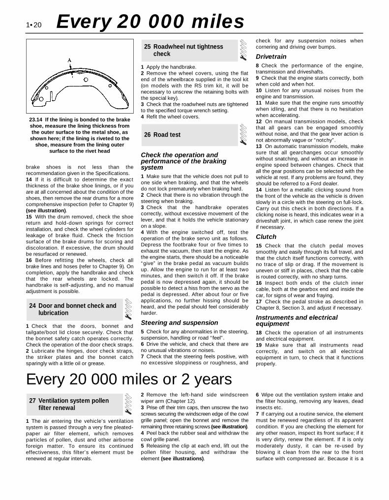
brake shoes is not less than therecommendation given in the Specifications.14 If it is difficult to determine the exactthickness of the brake shoe linings, or if youare at all concerned about the condition of theshoes, then remove the rear drums for a morecomprehensive inspection (refer to Chapter 9)(see illustration).15 With the drum removed, check the shoereturn and hold-down springs for correctinstallation, and check the wheel cylinders forleakage of brake fluid. Check the frictionsurface of the brake drums for scoring anddiscoloration. If excessive, the drum shouldbe resurfaced or renewed.16 Before refitting the wheels, check allbrake lines and hoses (refer to Chapter 9). Oncompletion, apply the handbrake and checkthat the rear wheels are locked. Thehandbrake is self-adjusting, and no manualadjustment is possible.
1 Check that the doors, bonnet andtailgate/boot lid close securely. Check thatthe bonnet safety catch operates correctly.Check the operation of the door check straps.2 Lubricate the hinges, door check straps,the striker plates and the bonnet catchsparingly with a little oil or grease.
1 Apply the handbrake.2 Remove the wheel covers, using the flatend of the wheelbrace supplied in the tool kit(on models with the RS trim kit, it will benecessary to unscrew the retaining bolts withthe special key).3 Check that the roadwheel nuts are tightenedto the specified torque wrench setting.4 Refit the wheel covers.
Check the operation andperformance of the brakingsystem1 Make sure that the vehicle does not pull toone side when braking, and that the wheelsdo not lock prematurely when braking hard.2 Check that there is no vibration through thesteering when braking.3 Check that the handbrake operatescorrectly, without excessive movement of thelever, and that it holds the vehicle stationaryon a slope.4 With the engine switched off, test theoperation of the brake servo unit as follows.Depress the footbrake four or five times toexhaust the vacuum, then start the engine. Asthe engine starts, there should be a noticeable“give” in the brake pedal as vacuum buildsup. Allow the engine to run for at least twominutes, and then switch it off. If the brakepedal is now depressed again, it should bepossible to detect a hiss from the servo as thepedal is depressed. After about four or fiveapplications, no further hissing should beheard, and the pedal should feel considerablyharder.
Steering and suspension5 Check for any abnormalities in the steering,suspension, handling or road “feel”.6 Drive the vehicle, and check that there areno unusual vibrations or noises.7 Check that the steering feels positive, withno excessive sloppiness or roughness, and
check for any suspension noises whencornering and driving over bumps.
Drivetrain8 Check the performance of the engine,transmission and driveshafts.9 Check that the engine starts correctly, bothwhen cold and when hot.10 Listen for any unusual noises from theengine and transmission.11 Make sure that the engine runs smoothlywhen idling, and that there is no hesitationwhen accelerating.12 On manual transmission models, checkthat all gears can be engaged smoothlywithout noise, and that the gear lever action isnot abnormally vague or “notchy”.13 On automatic transmission models, makesure that all gearchanges occur smoothlywithout snatching, and without an increase inengine speed between changes. Check thatall the gear positions can be selected with thevehicle at rest. If any problems are found, theyshould be referred to a Ford dealer.14 Listen for a metallic clicking sound fromthe front of the vehicle as the vehicle is drivenslowly in a circle with the steering on full-lock.Carry out this check in both directions. If aclicking noise is heard, this indicates wear in adriveshaft joint, in which case renew the jointif necessary.
Clutch15 Check that the clutch pedal movessmoothly and easily through its full travel, andthat the clutch itself functions correctly, withno trace of slip or drag. If the movement isuneven or stiff in places, check that the cableis routed correctly, with no sharp turns.16 Inspect both ends of the clutch innercable, both at the gearbox end and inside thecar, for signs of wear and fraying.17 Check the pedal stroke as described inChapter 8, Section 3, and adjust if necessary.
Instruments and electricalequipment18 Check the operation of all instrumentsand electrical equipment.19 Make sure that all instruments readcorrectly, and switch on all electricalequipment in turn, to check that it functionsproperly.
26 Road test
25 Roadwheel nut tightnesscheck
24 Door and bonnet check andlubrication
1•20
23.14 If the lining is bonded to the brakeshoe, measure the lining thickness fromthe outer surface to the metal shoe, as
shown here; if the lining is riveted to theshoe, measure from the lining outer
surface to the rivet head
Every 20 000 miles
Every 20 000 miles or 2 years
1 The air entering the vehicle’s ventilationsystem is passed through a very fine pleated-paper air filter element, which removesparticles of pollen, dust and other airborneforeign matter. To ensure its continuedeffectiveness, this filter’s element must berenewed at regular intervals.
2 Remove the left-hand side windscreenwiper arm (Chapter 12).3 Prise off their trim caps, then unscrew the twoscrews securing the windscreen edge of the cowlgrille panel; open the bonnet and remove theremaining three retaining screws (see illustration).4 Peel back the rubber seal and withdraw thecowl grille panel.5 Releasing the clip at each end, lift out thepollen filter housing, and withdraw theelement (see illustrations).
6 Wipe out the ventilation system intake andthe filter housing, removing any leaves, deadinsects etc.7 If carrying out a routine service, the elementmust be renewed regardless of its apparentcondition. If you are checking the element forany other reason, inspect its front surface; if itis very dirty, renew the element. If it is onlymoderately dusty, it can be re-used byblowing it clean from the rear to the frontsurface with compressed air. Because it is a
27 Ventilation system pollenfilter renewal

pleated-paper type filter, it cannot be washedor re-oiled. If it cannot be cleanedsatisfactorily with compressed air, discardand renew it.
Warning: Wear eye protectionwhen using compressed air!
8 Refitting is the reverse of the removalprocedure; ensure that the element andhousing are securely seated, so that unfilteredair cannot enter the passenger compartment.
Note: If the antifreeze used is Ford’s own, or ofsimilar quality, the coolant need not berenewed for the life of the vehicle. If thevehicle’s history is unknown, if antifreeze oflesser quality is known to be in the system, orsimply if you prefer to follow conventionalservicing intervals, the coolant should bechanged periodically (typically, every 2 years)as described here. Refer also to theinformation in Section 2 of this Chapter.
Warning: Do not allow antifreezeto come in contact with your skinor painted surfaces of the
vehicle. Flush contaminated areasimmediately with plenty of water. Don’tstore new coolant, or leave old coolantlying around, where it’s accessible tochildren or pets - they’re attracted by itssweet smell. Ingestion of even a smallamount of coolant can be fatal! Wipe upgarage-floor and drip-pan spillsimmediately. Keep antifreeze containerscovered, and repair cooling system leaksas soon as they’re noticed.
Warning: Never remove theexpansion tank filler cap whenthe engine is running, or has just
been switched off, as the cooling systemwill be hot, and the consequent escapingsteam and scalding coolant could causeserious injury.
Coolant drainingWarning: Wait until the engine iscold before starting thisprocedure.
1 To drain the system, first remove theexpansion tank filler cap (see Section 3).2 If the additional working clearance isrequired, raise the front of the vehicle andsupport it securely on axle stands.3 Remove the radiator undershield (eight ornine screws), then place a large drain trayunderneath, and unscrew the radiator drainplug; direct as much of the escaping coolantas possible into the tray (see illustrations).
System flushing4 With time, the cooling system maygradually lose its efficiency, as the radiatorcore becomes choked with rust, scaledeposits from the water, and other sediment(refer also to the information at the start ofSection 2). To minimise this, as well as usingonly good-quality antifreeze and clean softwater, the system should be flushed asfollows whenever any part of it is disturbed,and/or when the coolant is renewed.5 With the coolant drained, refit the drain plugand refill the system with fresh water. Refit theexpansion tank filler cap, start the engine andwarm it up to normal operating temperature,then stop it and (after allowing it to cool downcompletely) drain the system again. Repeat asnecessary until only clean water can be seento emerge, then refill finally with the specifiedcoolant mixture.6 If only clean, soft water and good-qualityantifreeze (even if not to Ford’s specification)has been used, and the coolant has beenrenewed at the suggested intervals, the aboveprocedure will be sufficient to keep clean thesystem for a considerable length of time. If,
however, the system has been neglected, amore thorough operation will be required, asfollows.7 First drain the coolant, then disconnect theradiator top and bottom hoses. Insert agarden hose into the top hose, and allowwater to circulate through the radiator until itruns clean from the bottom outlet.8 To flush the engine, insert the garden hoseinto the thermostat water outlet, and allowwater to circulate until it runs clear from thebottom hose. If, after a reasonable period, thewater still does not run clear, the radiatorshould be flushed with a good proprietarycleaning agent.9 In severe cases of contamination, reverse-flushing of the radiator may be necessary. Todo this, remove the radiator (Chapter 3), invertit, and insert the garden hose into the bottomoutlet. Continue flushing until clear water runsfrom the top hose outlet. A similar procedurecan be used to flush the heater matrix.10 The use of chemical cleaners should benecessary only as a last resort. Normally,regular renewal of the coolant will preventexcessive contamination of the system.
Coolant filling11 With the cooling system drained andflushed, ensure that all disturbed hose unions
28 Coolant renewal
1•21
1
28.3A Remove the screws (arrowed) andwithdraw the radiator undershield . . .
28.3B . . . to unscrew the radiator drainplug (arrowed) and empty the coolingsystem. Try to protect yourself from
coolant splashing into your eyes or ontoyour skin, catching as much of it as
possible in the drain tray
27.3 Remove screws (arrowed) to releasecowl grille panel . . . 27.5A . . . release clips to lift out pollen
filter housing . . .27.5B . . . then withdraw pollen filter
element
Every 20 000 miles
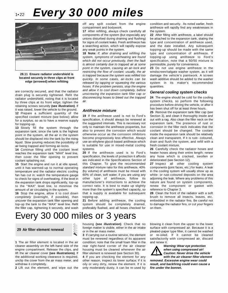
are correctly secured, and that the radiatordrain plug is securely tightened. Refit theradiator undershield, noting that it is locatedby three clips at its front edge; tighten theretaining screws securely (see illustration). Ifit was raised, lower the vehicle to the ground.12 Prepare a sufficient quantity of thespecified coolant mixture (see below); allowfor a surplus, so as to have a reserve supplyfor topping-up.13 Slowly fill the system through theexpansion tank; since the tank is the highestpoint in the system, all the air in the systemshould be displaced into the tank by the risingliquid. Slow pouring reduces the possibility ofair being trapped and forming air-locks.14 Continue filling until the coolant levelreaches the expansion tank “MAX” level line,then cover the filler opening to preventcoolant splashing out.15 Start the engine and run it at idle speed,until it has warmed-up to normal operatingtemperature and the radiator electric coolingfan has cut in; watch the temperature gaugeto check for signs of overheating. If the level inthe expansion tank drops significantly, top-upto the “MAX” level line, to minimise theamount of air circulating in the system.16 Stop the engine, allow it to cool downcompletely (overnight, if possible), thenuncover the expansion tank filler opening andtop-up the tank to the “MAX” level line. Refitthe filler cap, tightening it securely, and wash
off any spilt coolant from the enginecompartment and bodywork.17 After refilling, always check carefully allcomponents of the system (but especially anyunions disturbed during draining and flushing)for signs of coolant leaks. Fresh antifreeze hasa searching action, which will rapidly exposeany weak points in the system.18 Note: If, after draining and refilling thesystem, symptoms of overheating are foundwhich did not occur previously, then the faultis almost certainly due to trapped air at somepoint in the system, causing an air-lock andrestricting the flow of coolant; usually, the airis trapped because the system was refilled tooquickly. In some cases, air-locks can bereleased by tapping or squeezing the varioushoses. If the problem persists, stop the engineand allow it to cool down completely, beforeunscrewing the expansion tank filler cap ordisconnecting hoses to bleed out the trappedair.
Antifreeze mixture19 If the antifreeze used is not to Ford’sspecification, it should always be renewed atthe suggested intervals. This is necessary notonly to maintain the antifreeze properties, butalso to prevent the corrosion which wouldotherwise occur as the corrosion inhibitorsbecome progressively less effective. Alwaysuse an ethylene glycol-based antifreeze whichis suitable for use in mixed-metal coolingsystems.20 If the antifreeze used is to Ford’sspecification, the levels of protection it affordsare indicated in the Specifications Section ofthis Chapter. To give the recommendedstandard mixture ratio for this antifreeze, 40%(by volume) of antifreeze must be mixed with60% of clean, soft water; if you are using anyother type of antifreeze, follow itsmanufacturer’s instructions to achieve thecorrect ratio. It is best to make up slightlymore than the system’s specified capacity, sothat a supply is available for subsequenttopping-up.21 Before adding antifreeze, the coolingsystem should be completely drained,preferably flushed, and all hoses checked for
condition and security. As noted earlier, freshantifreeze will rapidly find any weaknesses inthe system.22 After filling with antifreeze, a label shouldbe attached to the expansion tank, stating thetype and concentration of antifreeze used,and the date installed. Any subsequenttopping-up should be made with the sametype and concentration of antifreeze. Iftopping-up using antifreeze to Ford’sspecification, note that a 50/50 mixture ispermissible, purely for convenience.23 Do not use engine antifreeze in thewindscreen/tailgate washer system, as it willdamage the vehicle’s paintwork. A screenwash additive should be added to the washersystem in its maker’s recommendedquantities.
General cooling system checks24 The engine should be cold for the coolingsystem checks, so perform the followingprocedure before driving the vehicle, or after ithas been shut off for at least three hours.25 Remove the expansion tank filler cap (seeSection 3), and clean it thoroughly inside andout with a rag. Also clean the filler neck on theexpansion tank. The presence of rust orcorrosion in the filler neck indicates that thecoolant should be changed. The coolantinside the expansion tank should be relativelyclean and transparent. If it is rust- coloured,drain and flush the system, and refill with afresh coolant mixture.26 Carefully check the radiator hoses andheater hoses along their entire length; renewany hose which is cracked, swollen ordeteriorated (see Section 12).27 Inspect all other cooling systemcomponents (joint faces, etc.) for leaks. A leakin the cooling system will usually show up aswhite- or rust-coloured deposits on the areaadjoining the leak. Where any problems of thisnature are found on system components,renew the component or gasket withreference to Chapter 3.28 Clean the front of the radiator with a softbrush to remove all insects, leaves, etc,embedded in the radiator fins. Be careful notto damage the radiator fins, or cut your fingerson them.
1•22
28.11 Ensure radiator undershield islocated securely in three clips at front
edge (arrowed) when refitting
Every 30 000 miles
Every 30 000 miles or 3 years
1 The air filter element is located in the aircleaner assembly on the left-hand side of theengine compartment. Release the clips, andlift the air cleaner cover (see illustrations). Ifthe additional working clearance is required,unclip the cover from the air mass meter, andwithdraw it completely.2 Lift out the element, and wipe out the
housing (see illustration). Check that noforeign matter is visible, either in the air intakeor in the air mass meter.3 If carrying out a routine service, the elementmust be renewed regardless of its apparentcondition; note that the small foam filter in therear right-hand corner of the air cleanerhousing must be cleaned whenever the airfilter element is renewed (see Section 30).4 If you are checking the element for anyother reason, inspect its lower surface; if it isoily or very dirty, renew the element. If it isonly moderately dusty, it can be re-used by
blowing it clean from the upper to the lowersurface with compressed air. Because it is apleated-paper type filter, it cannot be washedor re-oiled. If it cannot be cleanedsatisfactorily with compressed air, discardand renew it.
Warning: Wear eye protectionwhen using compressed air! Caution: Never drive the vehiclewith the air cleaner filter element
removed. Excessive engine wear couldresult, and backfiring could even cause afire under the bonnet.
29 Air filter element renewal
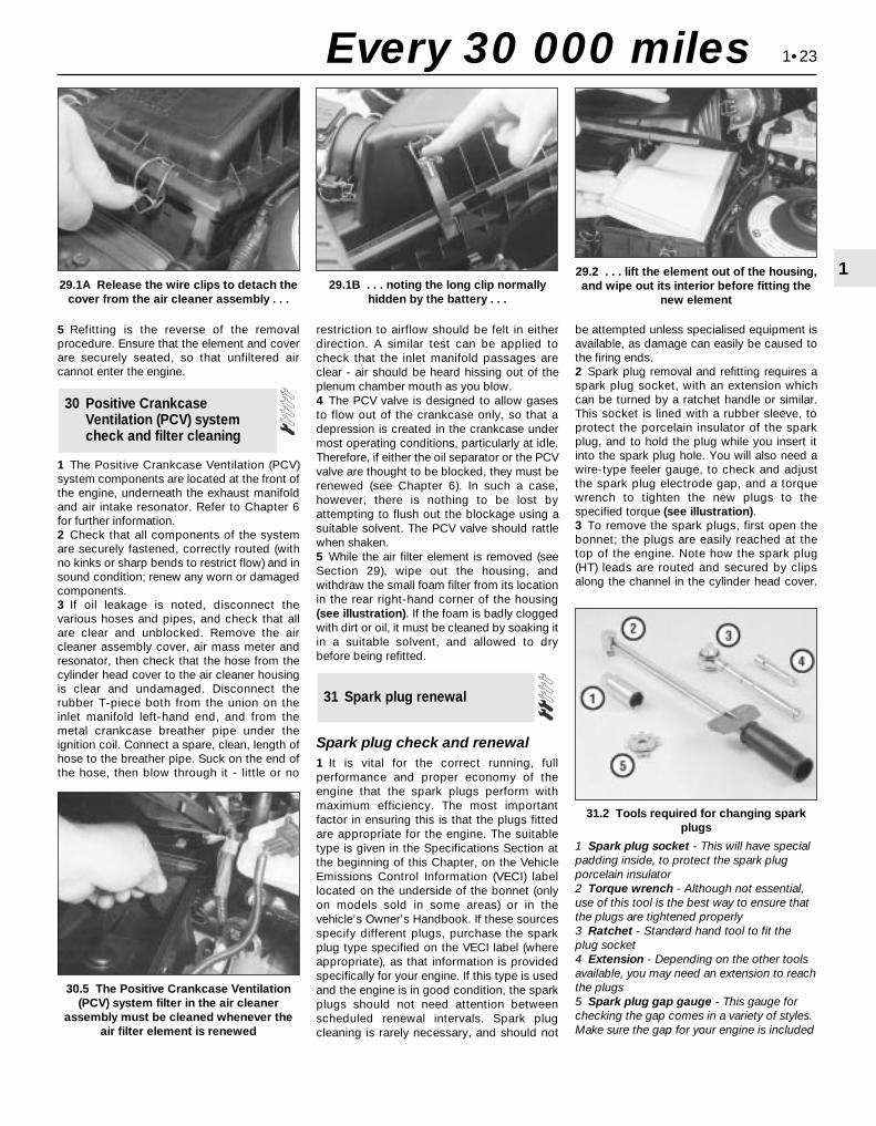
5 Refitting is the reverse of the removalprocedure. Ensure that the element and coverare securely seated, so that unfiltered aircannot enter the engine.
1 The Positive Crankcase Ventilation (PCV)system components are located at the front ofthe engine, underneath the exhaust manifoldand air intake resonator. Refer to Chapter 6for further information.2 Check that all components of the systemare securely fastened, correctly routed (withno kinks or sharp bends to restrict flow) and insound condition; renew any worn or damagedcomponents.3 If oil leakage is noted, disconnect thevarious hoses and pipes, and check that allare clear and unblocked. Remove the aircleaner assembly cover, air mass meter andresonator, then check that the hose from thecylinder head cover to the air cleaner housingis clear and undamaged. Disconnect therubber T-piece both from the union on theinlet manifold left-hand end, and from themetal crankcase breather pipe under theignition coil. Connect a spare, clean, length ofhose to the breather pipe. Suck on the end ofthe hose, then blow through it - little or no
restriction to airflow should be felt in eitherdirection. A similar test can be applied tocheck that the inlet manifold passages areclear - air should be heard hissing out of theplenum chamber mouth as you blow.4 The PCV valve is designed to allow gasesto flow out of the crankcase only, so that adepression is created in the crankcase undermost operating conditions, particularly at idle.Therefore, if either the oil separator or the PCVvalve are thought to be blocked, they must berenewed (see Chapter 6). In such a case,however, there is nothing to be lost byattempting to flush out the blockage using asuitable solvent. The PCV valve should rattlewhen shaken.5 While the air filter element is removed (seeSection 29), wipe out the housing, andwithdraw the small foam filter from its locationin the rear right-hand corner of the housing(see illustration). If the foam is badly cloggedwith dirt or oil, it must be cleaned by soaking itin a suitable solvent, and allowed to drybefore being refitted.
Spark plug check and renewal1 It is vital for the correct running, fullperformance and proper economy of theengine that the spark plugs perform withmaximum efficiency. The most importantfactor in ensuring this is that the plugs fittedare appropriate for the engine. The suitabletype is given in the Specifications Section atthe beginning of this Chapter, on the VehicleEmissions Control Information (VECI) labellocated on the underside of the bonnet (onlyon models sold in some areas) or in thevehicle’s Owner’s Handbook. If these sourcesspecify different plugs, purchase the sparkplug type specified on the VECI label (whereappropriate), as that information is providedspecifically for your engine. If this type is usedand the engine is in good condition, the sparkplugs should not need attention betweenscheduled renewal intervals. Spark plugcleaning is rarely necessary, and should not
be attempted unless specialised equipment isavailable, as damage can easily be caused tothe firing ends.2 Spark plug removal and refitting requires aspark plug socket, with an extension whichcan be turned by a ratchet handle or similar.This socket is lined with a rubber sleeve, toprotect the porcelain insulator of the sparkplug, and to hold the plug while you insert itinto the spark plug hole. You will also need awire-type feeler gauge, to check and adjustthe spark plug electrode gap, and a torquewrench to tighten the new plugs to thespecified torque (see illustration).3 To remove the spark plugs, first open thebonnet; the plugs are easily reached at thetop of the engine. Note how the spark plug(HT) leads are routed and secured by clipsalong the channel in the cylinder head cover.
31 Spark plug renewal
30 Positive CrankcaseVentilation (PCV) systemcheck and filter cleaning
1•23
1
30.5 The Positive Crankcase Ventilation(PCV) system filter in the air cleaner
assembly must be cleaned whenever theair filter element is renewed
31.2 Tools required for changing sparkplugs
1 Spark plug socket - This will have specialpadding inside, to protect the spark plugporcelain insulator2 Torque wrench - Although not essential,use of this tool is the best way to ensure thatthe plugs are tightened properly3 Ratchet - Standard hand tool to fit theplug socket4 Extension - Depending on the other toolsavailable, you may need an extension to reachthe plugs5 Spark plug gap gauge - This gauge forchecking the gap comes in a variety of styles.Make sure the gap for your engine is included
29.1A Release the wire clips to detach thecover from the air cleaner assembly . . .
29.1B . . . noting the long clip normallyhidden by the battery . . .
29.2 . . . lift the element out of the housing,and wipe out its interior before fitting the
new element
Every 30 000 miles
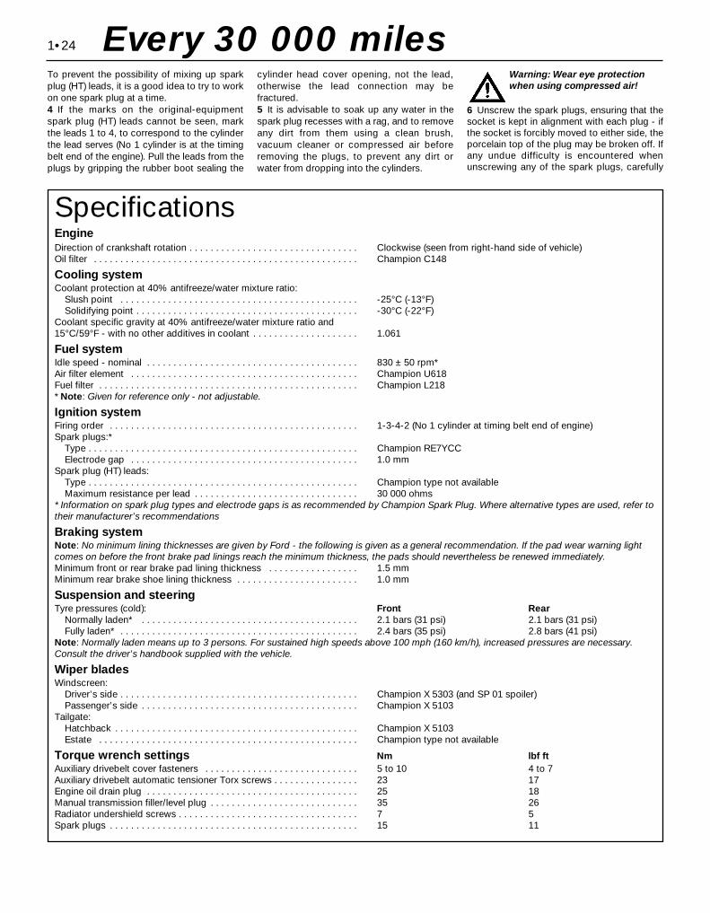
To prevent the possibility of mixing up sparkplug (HT) leads, it is a good idea to try to workon one spark plug at a time.4 If the marks on the original-equipmentspark plug (HT) leads cannot be seen, markthe leads 1 to 4, to correspond to the cylinderthe lead serves (No 1 cylinder is at the timingbelt end of the engine). Pull the leads from theplugs by gripping the rubber boot sealing the
cylinder head cover opening, not the lead,otherwise the lead connection may befractured.5 It is advisable to soak up any water in thespark plug recesses with a rag, and to removeany dirt from them using a clean brush,vacuum cleaner or compressed air beforeremoving the plugs, to prevent any dirt orwater from dropping into the cylinders.
Warning: Wear eye protectionwhen using compressed air!
6 Unscrew the spark plugs, ensuring that thesocket is kept in alignment with each plug - ifthe socket is forcibly moved to either side, theporcelain top of the plug may be broken off. Ifany undue difficulty is encountered whenunscrewing any of the spark plugs, carefully
1•24 Every 30 000 miles
SpecificationsEngineDirection of crankshaft rotation . . . . . . . . . . . . . . . . . . . . . . . . . . . . . . . . Clockwise (seen from right-hand side of vehicle)Oil filter . . . . . . . . . . . . . . . . . . . . . . . . . . . . . . . . . . . . . . . . . . . . . . . . . . Champion C148
Cooling systemCoolant protection at 40% antifreeze/water mixture ratio:
Slush point . . . . . . . . . . . . . . . . . . . . . . . . . . . . . . . . . . . . . . . . . . . . . -25°C (-13°F)Solidifying point . . . . . . . . . . . . . . . . . . . . . . . . . . . . . . . . . . . . . . . . . . -30°C (-22°F)
Coolant specific gravity at 40% antifreeze/water mixture ratio and 15°C/59°F - with no other additives in coolant . . . . . . . . . . . . . . . . . . . . 1.061
Fuel systemIdle speed - nominal . . . . . . . . . . . . . . . . . . . . . . . . . . . . . . . . . . . . . . . . 830 ± 50 rpm*Air filter element . . . . . . . . . . . . . . . . . . . . . . . . . . . . . . . . . . . . . . . . . . . Champion U618Fuel filter . . . . . . . . . . . . . . . . . . . . . . . . . . . . . . . . . . . . . . . . . . . . . . . . . Champion L218* Note: Given for reference only - not adjustable.
Ignition systemFiring order . . . . . . . . . . . . . . . . . . . . . . . . . . . . . . . . . . . . . . . . . . . . . . . 1-3-4-2 (No 1 cylinder at timing belt end of engine)Spark plugs:*
Type . . . . . . . . . . . . . . . . . . . . . . . . . . . . . . . . . . . . . . . . . . . . . . . . . . . Champion RE7YCCElectrode gap . . . . . . . . . . . . . . . . . . . . . . . . . . . . . . . . . . . . . . . . . . . 1.0 mm
Spark plug (HT) leads:Type . . . . . . . . . . . . . . . . . . . . . . . . . . . . . . . . . . . . . . . . . . . . . . . . . . . Champion type not availableMaximum resistance per lead . . . . . . . . . . . . . . . . . . . . . . . . . . . . . . . 30 000 ohms
* Information on spark plug types and electrode gaps is as recommended by Champion Spark Plug. Where alternative types are used, refer totheir manufacturer’s recommendations
Braking systemNote: No minimum lining thicknesses are given by Ford - the following is given as a general recommendation. If the pad wear warning lightcomes on before the front brake pad linings reach the minimum thickness, the pads should nevertheless be renewed immediately.Minimum front or rear brake pad lining thickness . . . . . . . . . . . . . . . . . 1.5 mmMinimum rear brake shoe lining thickness . . . . . . . . . . . . . . . . . . . . . . . 1.0 mm
Suspension and steeringTyre pressures (cold): Front Rear
Normally laden* . . . . . . . . . . . . . . . . . . . . . . . . . . . . . . . . . . . . . . . . . 2.1 bars (31 psi) 2.1 bars (31 psi)Fully laden* . . . . . . . . . . . . . . . . . . . . . . . . . . . . . . . . . . . . . . . . . . . . . 2.4 bars (35 psi) 2.8 bars (41 psi)
Note: Normally laden means up to 3 persons. For sustained high speeds above 100 mph (160 km/h), increased pressures are necessary.Consult the driver’s handbook supplied with the vehicle.
Wiper bladesWindscreen:
Driver’s side . . . . . . . . . . . . . . . . . . . . . . . . . . . . . . . . . . . . . . . . . . . . . Champion X 5303 (and SP 01 spoiler)Passenger’s side . . . . . . . . . . . . . . . . . . . . . . . . . . . . . . . . . . . . . . . . . Champion X 5103
Tailgate:Hatchback . . . . . . . . . . . . . . . . . . . . . . . . . . . . . . . . . . . . . . . . . . . . . . Champion X 5103Estate . . . . . . . . . . . . . . . . . . . . . . . . . . . . . . . . . . . . . . . . . . . . . . . . . Champion type not available
Torque wrench settings Nm lbf ftAuxiliary drivebelt cover fasteners . . . . . . . . . . . . . . . . . . . . . . . . . . . . . 5 to 10 4 to 7Auxiliary drivebelt automatic tensioner Torx screws . . . . . . . . . . . . . . . . 23 17Engine oil drain plug . . . . . . . . . . . . . . . . . . . . . . . . . . . . . . . . . . . . . . . . 25 18Manual transmission filler/level plug . . . . . . . . . . . . . . . . . . . . . . . . . . . . 35 26Radiator undershield screws . . . . . . . . . . . . . . . . . . . . . . . . . . . . . . . . . . 7 5Spark plugs . . . . . . . . . . . . . . . . . . . . . . . . . . . . . . . . . . . . . . . . . . . . . . . 15 11
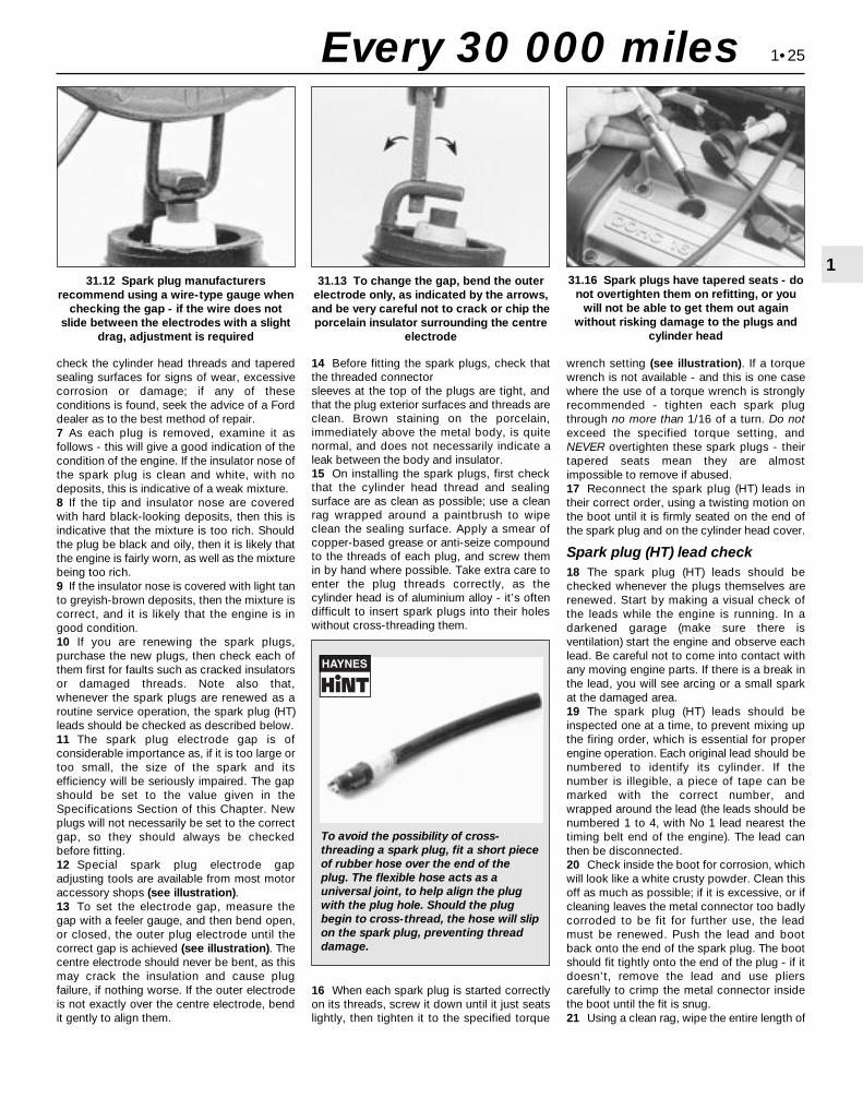
check the cylinder head threads and taperedsealing surfaces for signs of wear, excessivecorrosion or damage; if any of theseconditions is found, seek the advice of a Forddealer as to the best method of repair.7 As each plug is removed, examine it asfollows - this will give a good indication of thecondition of the engine. If the insulator nose ofthe spark plug is clean and white, with nodeposits, this is indicative of a weak mixture.8 If the tip and insulator nose are coveredwith hard black-looking deposits, then this isindicative that the mixture is too rich. Shouldthe plug be black and oily, then it is likely thatthe engine is fairly worn, as well as the mixturebeing too rich.9 If the insulator nose is covered with light tanto greyish-brown deposits, then the mixture iscorrect, and it is likely that the engine is ingood condition.10 If you are renewing the spark plugs,purchase the new plugs, then check each ofthem first for faults such as cracked insulatorsor damaged threads. Note also that,whenever the spark plugs are renewed as aroutine service operation, the spark plug (HT)leads should be checked as described below.11 The spark plug electrode gap is ofconsiderable importance as, if it is too large ortoo small, the size of the spark and itsefficiency will be seriously impaired. The gapshould be set to the value given in theSpecifications Section of this Chapter. Newplugs will not necessarily be set to the correctgap, so they should always be checkedbefore fitting.12 Special spark plug electrode gapadjusting tools are available from most motoraccessory shops (see illustration).13 To set the electrode gap, measure thegap with a feeler gauge, and then bend open,or closed, the outer plug electrode until thecorrect gap is achieved (see illustration). Thecentre electrode should never be bent, as thismay crack the insulation and cause plugfailure, if nothing worse. If the outer electrodeis not exactly over the centre electrode, bendit gently to align them.
14 Before fitting the spark plugs, check thatthe threaded connectorsleeves at the top of the plugs are tight, andthat the plug exterior surfaces and threads areclean. Brown staining on the porcelain,immediately above the metal body, is quitenormal, and does not necessarily indicate aleak between the body and insulator.15 On installing the spark plugs, first checkthat the cylinder head thread and sealingsurface are as clean as possible; use a cleanrag wrapped around a paintbrush to wipeclean the sealing surface. Apply a smear ofcopper-based grease or anti-seize compoundto the threads of each plug, and screw themin by hand where possible. Take extra care toenter the plug threads correctly, as thecylinder head is of aluminium alloy - it’s oftendifficult to insert spark plugs into their holeswithout cross-threading them.
16 When each spark plug is started correctlyon its threads, screw it down until it just seatslightly, then tighten it to the specified torque
wrench setting (see illustration). If a torquewrench is not available - and this is one casewhere the use of a torque wrench is stronglyrecommended - tighten each spark plugthrough no more than 1/16 of a turn. Do notexceed the specified torque setting, andNEVER overtighten these spark plugs - theirtapered seats mean they are almostimpossible to remove if abused.17 Reconnect the spark plug (HT) leads intheir correct order, using a twisting motion onthe boot until it is firmly seated on the end ofthe spark plug and on the cylinder head cover.
Spark plug (HT) lead check18 The spark plug (HT) leads should bechecked whenever the plugs themselves arerenewed. Start by making a visual check ofthe leads while the engine is running. In adarkened garage (make sure there isventilation) start the engine and observe eachlead. Be careful not to come into contact withany moving engine parts. If there is a break inthe lead, you will see arcing or a small sparkat the damaged area.19 The spark plug (HT) leads should beinspected one at a time, to prevent mixing upthe firing order, which is essential for properengine operation. Each original lead should benumbered to identify its cylinder. If thenumber is illegible, a piece of tape can bemarked with the correct number, andwrapped around the lead (the leads should benumbered 1 to 4, with No 1 lead nearest thetiming belt end of the engine). The lead canthen be disconnected.20 Check inside the boot for corrosion, whichwill look like a white crusty powder. Clean thisoff as much as possible; if it is excessive, or ifcleaning leaves the metal connector too badlycorroded to be fit for further use, the leadmust be renewed. Push the lead and bootback onto the end of the spark plug. The bootshould fit tightly onto the end of the plug - if itdoesn’t, remove the lead and use plierscarefully to crimp the metal connector insidethe boot until the fit is snug.21 Using a clean rag, wipe the entire length of
1•25
1
Every 30 000 miles
31.12 Spark plug manufacturersrecommend using a wire-type gauge when
checking the gap - if the wire does notslide between the electrodes with a slight
drag, adjustment is required
31.13 To change the gap, bend the outerelectrode only, as indicated by the arrows,and be very careful not to crack or chip theporcelain insulator surrounding the centre
electrode
31.16 Spark plugs have tapered seats - donot overtighten them on refitting, or you
will not be able to get them out againwithout risking damage to the plugs and
cylinder head
To avoid the possibility of cross-threading a spark plug, fit a short pieceof rubber hose over the end of theplug. The flexible hose acts as auniversal joint, to help align the plugwith the plug hole. Should the plugbegin to cross-thread, the hose will slipon the spark plug, preventing threaddamage.

1•26 Every 60 000 miles
Every 60 000 miles
Refer to Chapter 2, Part A.
Warning: Petrol is extremelyflammable, so extra precautionsmust be taken when working on
any part of the fuel system. Do not smoke,or allow open flames or bare light bulbs,near the work area. Also, do not work in agarage if a gas appliance with a pilot light ispresent. While performing any work on thefuel system, wear safety glasses, and havea suitable (Class B) fire extinguisher onhand. If you spill any fuel on your skin, rinseit off immediately with soap and water.1 The fuel filter is located at the front right-hand corner of the fuel tank, just forward ofthe vehicle’s right-hand rear jacking point. Thefilter performs a vital role in keeping dirt andother foreign matter out of the fuel system,and so must be renewed at regular intervals,
or whenever you have reason to suspect thatit may be clogged. It is always unpleasantworking under a vehicle - pressure-washing orhosing clean the underbody in the filter’svicinity will make working conditions moretolerable, and will reduce the risk of gettingdirt into the fuel system.2 Relieve any residual pressure in the systemby removing the fuel pump fuse (No 14) andstarting the engine; allow the engine to idle untilit dies. Turn the engine over once or twice onthe starter, to ensure that all pressure isreleased, then switch off the ignition.
Warning: This procedure willmerely relieve the pressurenecessary for the engine to run -
remember that fuel will still be present inthe system components, and takeprecautions before disconnecting them.3 Noting the comments made in Section 1 ofChapter 5, disconnect the battery earth terminal.4 Jack up the rear right-hand side of thevehicle, and support it securely on an axle stand.5 Using rag to soak up any spilt fuel, releasethe fuel feed and outlet pipe unions from thefilter, by squeezing together the protrudinglocking lugs on each union, and carefullypulling the union off the filter stub (see
illustration). Where the unions are colour-coded, the feed and outlet pipes cannot beconfused; where both unions are the samecolour, note carefully which pipe is connectedto which filter stub, and ensure that they arecorrectly reconnected on refitting.6 Noting the arrows and/or other markings onthe filter showing the direction of fuel flow(towards the engine), slacken the filter clampscrew and withdraw the filter. Note that thefilter will still contain fuel; care should betaken, to avoid spillage and to minimise therisk of fire.7 On installation, slide the filter into its clampso that the arrow marked on it faces thecorrect way, then slide each pipe union on toits (correct) respective filter stub, and press itdown until the locking lugs click into theirgroove (see illustrations). Tighten the clampscrew carefully, until the filter is just preventedfrom moving; do not overtighten the clampscrew, or the filter casing may be crushed.8 Refit the fuel pump fuse and reconnect thebattery earth terminal, then switch the ignitionon and off five times, to pressurise thesystem. Check for any sign of fuel leakagearound the filter unions before lowering thevehicle to the ground and starting the engine.
33 Fuel filter renewal
32 Timing belt renewal
33.5 Squeeze together fuel filter pipe unionlocking lugs, then pull pipes off filter stubs -
ensure pipes are correctly reconnected
33.7A When installing the new filter,ensure the arrow showing direction of fuel
flow points towards the engine . . .
Every 3 yearsThe procedure is similar to that for the
bleeding of the hydraulic system as describedin Chapter 9, except that the brake fluidreservoir should be emptied by syphoning,
and allowance should be made for the oldfluid to be removed from the circuit whenbleeding a section of the circuit.34 Brake fluid renewal
31.22 Measure the resistance of the sparkplug leads - if any exceeds the specified
maximum value, renew all the leads
the lead to remove built-up dirt and grease.Once the lead is clean, check for burns, cracksand other damage. Do not bend the leadsharply, because the conductor might break.22 Disconnect the lead from the ignition coilby pressing together the plastic retainingcatches and pulling the end fitting off the coilterminal. Check for corrosion and for a tightfit. If a meter with the correct measuring rangeis available, measure the resistance of thedisconnected lead from its coil connector toits spark plug connector (see illustration). Ifthe resistance recorded for any of the leadsexceeds the value specified, all the leads
should be renewed as a set. Refit the lead tothe coil, noting that each coil terminal ismarked with its respective cylinder number,so that there is no risk of mixing up the leadsand upsetting the firing order.23 Inspect the remaining plug leads, ensuringthat each is securely fastened both ends whenthe check is complete. If any sign of arcing,severe connector corrosion, burns, cracks orother damage is noticed, obtain new sparkplug (HT) leads, renewing them as a set. If newspark plug leads are to be fitted, remove andrefit them one at a time, to avoid mix-ups inthe firing order.
33.7B . . . secure pipe unions as described -do not overtighten clamp screw (arrowed)

Chapter 2 Part A: In-car engine repair procedures
Auxiliary drivebelt check and renewal . . . . . . . . . . . . . See Chapter 1Camshaft oil seals - renewal . . . . . . . . . . . . . . . . . . . . . . . . . . . . . . . 12Camshafts and hydraulic tappets - removal, inspection
and refitting . . . . . . . . . . . . . . . . . . . . . . . . . . . . . . . . . . . . . . . . . . 13Compression test - description and interpretation . . . . . . . . . . . . . . 3Crankshaft oil seals - renewal . . . . . . . . . . . . . . . . . . . . . . . . . . . . . . 20Crankshaft pulley - removal and refitting . . . . . . . . . . . . . . . . . . . . . 8Cylinder head - removal and refitting . . . . . . . . . . . . . . . . . . . . . . . . 14Cylinder head and valve components - cleaning and inspection . . . . . . . . . . . . . . . . . . . . . . . . . . . . . . . . . . . See Chapter 2BCylinder head cover - removal and refitting . . . . . . . . . . . . . . . . . . . 5Engine oil and filter change . . . . . . . . . . . . . . . . . . . . . See Chapter 1Engine oil level check . . . . . . . . . . . . . . . . . . . . . . . . . . See Chapter 1Engine overhaul - general information . . . . . . . . . . . . . See Chapter 2BEngine/transmission - removal and refitting . . . . . . . . See Chapter 2BEngine/transmission mountings - inspection and renewal . . . . . . . . 22Exhaust manifold - removal, inspection and refitting . . . . . . . . . . . . 7
Flywheel/driveplate - removal, inspection and refitting . . . . . . . . . . 21General information . . . . . . . . . . . . . . . . . . . . . . . . . . . . . . . . . . . . . . 1Inlet manifold - removal and refitting . . . . . . . . . . . . . . . . . . . . . . . . 6Oil cooler - removal and refitting . . . . . . . . . . . . . . . . . . . . . . . . . . . . 17Oil level sensor - removal and refitting . . . . . . . . . . . . . . . . . . . . . . . 18Oil pressure warning light switch - removal and refitting . . . . . . . . . 19Oil pump - removal, inspection and refitting . . . . . . . . . . . . . . . . . . . 16Repair operations possible with the engine in the vehicle . . . . . . . . 2Spark plug renewal . . . . . . . . . . . . . . . . . . . . . . . . . . . See Chapter 1Sump - removal and refitting . . . . . . . . . . . . . . . . . . . . . . . . . . . . . . . 15Timing belt - removal, refitting and adjustment . . . . . . . . . . . . . . . . 10Timing belt covers - removal and refitting . . . . . . . . . . . . . . . . . . . . . 9Timing belt tensioner and toothed pulleys - removal,
inspection and refitting . . . . . . . . . . . . . . . . . . . . . . . . . . . . . . . . . 11Top Dead Centre (TDC) for No 1 piston - locating . . . . . . . . . . . . . . 4Water pump - removal and refitting . . . . . . . . . . . . . . . See Chapter 3
GeneralEngine type . . . . . . . . . . . . . . . . . . . . . . . . . . . . . . . . . . . . . . . . . . . . . . . Four-cylinder, in-line, double overhead camshaftsEngine code:
1.6 litre models . . . . . . . . . . . . . . . . . . . . . . . . . . . . . . . . . . . . . . . . . . LIF1.8 litre models . . . . . . . . . . . . . . . . . . . . . . . . . . . . . . . . . . . . . . . . . . RKA2.0 litre models . . . . . . . . . . . . . . . . . . . . . . . . . . . . . . . . . . . . . . . . . . NGA
Capacity:1.6 litre models . . . . . . . . . . . . . . . . . . . . . . . . . . . . . . . . . . . . . . . . . . 1597 cc1.8 litre models . . . . . . . . . . . . . . . . . . . . . . . . . . . . . . . . . . . . . . . . . . 1796 cc2.0 litre models . . . . . . . . . . . . . . . . . . . . . . . . . . . . . . . . . . . . . . . . . . 1988 cc
Bore:1.6 litre models . . . . . . . . . . . . . . . . . . . . . . . . . . . . . . . . . . . . . . . . . . 76.0 mm1.8 litre models . . . . . . . . . . . . . . . . . . . . . . . . . . . . . . . . . . . . . . . . . . 80.6 mm2.0 litre models . . . . . . . . . . . . . . . . . . . . . . . . . . . . . . . . . . . . . . . . . . 84.8 mm
Stroke - all models . . . . . . . . . . . . . . . . . . . . . . . . . . . . . . . . . . . . . . . . . 88.0 mmCompression ratio:
1.6 litre models . . . . . . . . . . . . . . . . . . . . . . . . . . . . . . . . . . . . . . . . . . 10.3:11.8 and 2.0 litre models . . . . . . . . . . . . . . . . . . . . . . . . . . . . . . . . . . . . 10.0:1
Compression pressure - at starter motor speed, engine fully warmed-up . Not availableFiring order . . . . . . . . . . . . . . . . . . . . . . . . . . . . . . . . . . . . . . . . . . . . . . . 1-3-4-2 (No 1 cylinder at timing belt end)Direction of crankshaft rotation . . . . . . . . . . . . . . . . . . . . . . . . . . . . . . . . Clockwise (seen from right-hand side of vehicle)
Cylinder headHydraulic tappet bore inside diameter . . . . . . . . . . . . . . . . . . . . . . . . . . 28.395 to 28.425 mm
Camshafts and hydraulic tappetsCamshaft bearing journal diameter . . . . . . . . . . . . . . . . . . . . . . . . . . . . . 25.960 to 25.980 mmCamshaft bearing journal-to-cylinder head running clearance . . . . . . . . 0.020 to 0.070 mmCamshaft endfloat . . . . . . . . . . . . . . . . . . . . . . . . . . . . . . . . . . . . . . . . . . 0.080 to 0.220 mmHydraulic tappet diameter . . . . . . . . . . . . . . . . . . . . . . . . . . . . . . . . . . . . 28.400 mm
2A•1
Easy, suitable fornovice with littleexperience
Fairly easy, suitablefor beginner withsome experience
Fairly difficult, suitablefor competent DIYmechanic
Difficult, suitable forexperienced DIYmechanic
Very difficult,suitable for expert DIYor professional
Degrees of difficulty
Specifications
Contents
2A
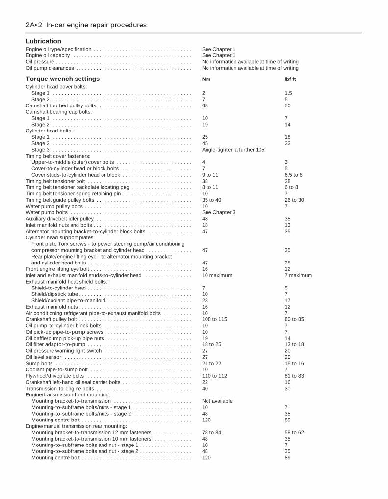
LubricationEngine oil type/specification . . . . . . . . . . . . . . . . . . . . . . . . . . . . . . . . . . See Chapter 1Engine oil capacity . . . . . . . . . . . . . . . . . . . . . . . . . . . . . . . . . . . . . . . . . See Chapter 1Oil pressure . . . . . . . . . . . . . . . . . . . . . . . . . . . . . . . . . . . . . . . . . . . . . . . No information available at time of writingOil pump clearances . . . . . . . . . . . . . . . . . . . . . . . . . . . . . . . . . . . . . . . . No information available at time of writing
Torque wrench settings Nm lbf ftCylinder head cover bolts:
Stage 1 . . . . . . . . . . . . . . . . . . . . . . . . . . . . . . . . . . . . . . . . . . . . . . . . 2 1.5Stage 2 . . . . . . . . . . . . . . . . . . . . . . . . . . . . . . . . . . . . . . . . . . . . . . . . 7 5
Camshaft toothed pulley bolts . . . . . . . . . . . . . . . . . . . . . . . . . . . . . . . . 68 50Camshaft bearing cap bolts:
Stage 1 . . . . . . . . . . . . . . . . . . . . . . . . . . . . . . . . . . . . . . . . . . . . . . . . 10 7Stage 2 . . . . . . . . . . . . . . . . . . . . . . . . . . . . . . . . . . . . . . . . . . . . . . . . 19 14
Cylinder head bolts:Stage 1 . . . . . . . . . . . . . . . . . . . . . . . . . . . . . . . . . . . . . . . . . . . . . . . . 25 18Stage 2 . . . . . . . . . . . . . . . . . . . . . . . . . . . . . . . . . . . . . . . . . . . . . . . . 45 33Stage 3 . . . . . . . . . . . . . . . . . . . . . . . . . . . . . . . . . . . . . . . . . . . . . . . . Angle-tighten a further 105°
Timing belt cover fasteners:Upper-to-middle (outer) cover bolts . . . . . . . . . . . . . . . . . . . . . . . . . . 4 3Cover-to-cylinder head or block bolts . . . . . . . . . . . . . . . . . . . . . . . . 7 5Cover studs-to-cylinder head or block . . . . . . . . . . . . . . . . . . . . . . . . 9 to 11 6.5 to 8
Timing belt tensioner bolt . . . . . . . . . . . . . . . . . . . . . . . . . . . . . . . . . . . . 38 28Timing belt tensioner backplate locating peg . . . . . . . . . . . . . . . . . . . . . 8 to 11 6 to 8Timing belt tensioner spring retaining pin . . . . . . . . . . . . . . . . . . . . . . . . 10 7Timing belt guide pulley bolts . . . . . . . . . . . . . . . . . . . . . . . . . . . . . . . . . 35 to 40 26 to 30Water pump pulley bolts . . . . . . . . . . . . . . . . . . . . . . . . . . . . . . . . . . . . . 10 7Water pump bolts . . . . . . . . . . . . . . . . . . . . . . . . . . . . . . . . . . . . . . . . . . See Chapter 3Auxiliary drivebelt idler pulley . . . . . . . . . . . . . . . . . . . . . . . . . . . . . . . . . 48 35Inlet manifold nuts and bolts . . . . . . . . . . . . . . . . . . . . . . . . . . . . . . . . . . 18 13Alternator mounting bracket-to-cylinder block bolts . . . . . . . . . . . . . . . 47 35Cylinder head support plates:
Front plate Torx screws - to power steering pump/air conditioning compressor mounting bracket and cylinder head . . . . . . . . . . . . . . . 47 35Rear plate/engine lifting eye - to alternator mounting bracket and cylinder head bolts . . . . . . . . . . . . . . . . . . . . . . . . . . . . . . . . . . . . 47 35
Front engine lifting eye bolt . . . . . . . . . . . . . . . . . . . . . . . . . . . . . . . . . . . 16 12Inlet and exhaust manifold studs-to-cylinder head . . . . . . . . . . . . . . . . 10 maximum 7 maximumExhaust manifold heat shield bolts:
Shield-to-cylinder head . . . . . . . . . . . . . . . . . . . . . . . . . . . . . . . . . . . . 7 5Shield/dipstick tube . . . . . . . . . . . . . . . . . . . . . . . . . . . . . . . . . . . . . . . 10 7Shield/coolant pipe-to-manifold . . . . . . . . . . . . . . . . . . . . . . . . . . . . . 23 17
Exhaust manifold nuts . . . . . . . . . . . . . . . . . . . . . . . . . . . . . . . . . . . . . . . 16 12Air conditioning refrigerant pipe-to-exhaust manifold bolts . . . . . . . . . . 10 7Crankshaft pulley bolt . . . . . . . . . . . . . . . . . . . . . . . . . . . . . . . . . . . . . . . 108 to 115 80 to 85Oil pump-to-cylinder block bolts . . . . . . . . . . . . . . . . . . . . . . . . . . . . . . 10 7Oil pick-up pipe-to-pump screws . . . . . . . . . . . . . . . . . . . . . . . . . . . . . . 10 7Oil baffle/pump pick-up pipe nuts . . . . . . . . . . . . . . . . . . . . . . . . . . . . . 19 14Oil filter adaptor-to-pump . . . . . . . . . . . . . . . . . . . . . . . . . . . . . . . . . . . . 18 to 25 13 to 18Oil pressure warning light switch . . . . . . . . . . . . . . . . . . . . . . . . . . . . . . 27 20Oil level sensor . . . . . . . . . . . . . . . . . . . . . . . . . . . . . . . . . . . . . . . . . . . . 27 20Sump bolts . . . . . . . . . . . . . . . . . . . . . . . . . . . . . . . . . . . . . . . . . . . . . . . 21 to 22 15 to 16Coolant pipe-to-sump bolt . . . . . . . . . . . . . . . . . . . . . . . . . . . . . . . . . . . 10 7Flywheel/driveplate bolts . . . . . . . . . . . . . . . . . . . . . . . . . . . . . . . . . . . . 110 to 112 81 to 83Crankshaft left-hand oil seal carrier bolts . . . . . . . . . . . . . . . . . . . . . . . . 22 16Transmission-to-engine bolts . . . . . . . . . . . . . . . . . . . . . . . . . . . . . . . . . 40 30Engine/transmission front mounting:
Mounting bracket-to-transmission . . . . . . . . . . . . . . . . . . . . . . . . . . . Not availableMounting-to-subframe bolts/nuts - stage 1 . . . . . . . . . . . . . . . . . . . . 10 7Mounting-to-subframe bolts/nuts - stage 2 . . . . . . . . . . . . . . . . . . . . 48 35Mounting centre bolt . . . . . . . . . . . . . . . . . . . . . . . . . . . . . . . . . . . . . . 120 89
Engine/manual transmission rear mounting:Mounting bracket-to-transmission 12 mm fasteners . . . . . . . . . . . . . 78 to 84 58 to 62Mounting bracket-to-transmission 10 mm fasteners . . . . . . . . . . . . . 48 35Mounting-to-subframe bolts and nut - stage 1 . . . . . . . . . . . . . . . . . . 10 7Mounting-to-subframe bolts and nut - stage 2 . . . . . . . . . . . . . . . . . . 48 35Mounting centre bolt . . . . . . . . . . . . . . . . . . . . . . . . . . . . . . . . . . . . . . 120 89
2A•2 In-car engine repair procedures
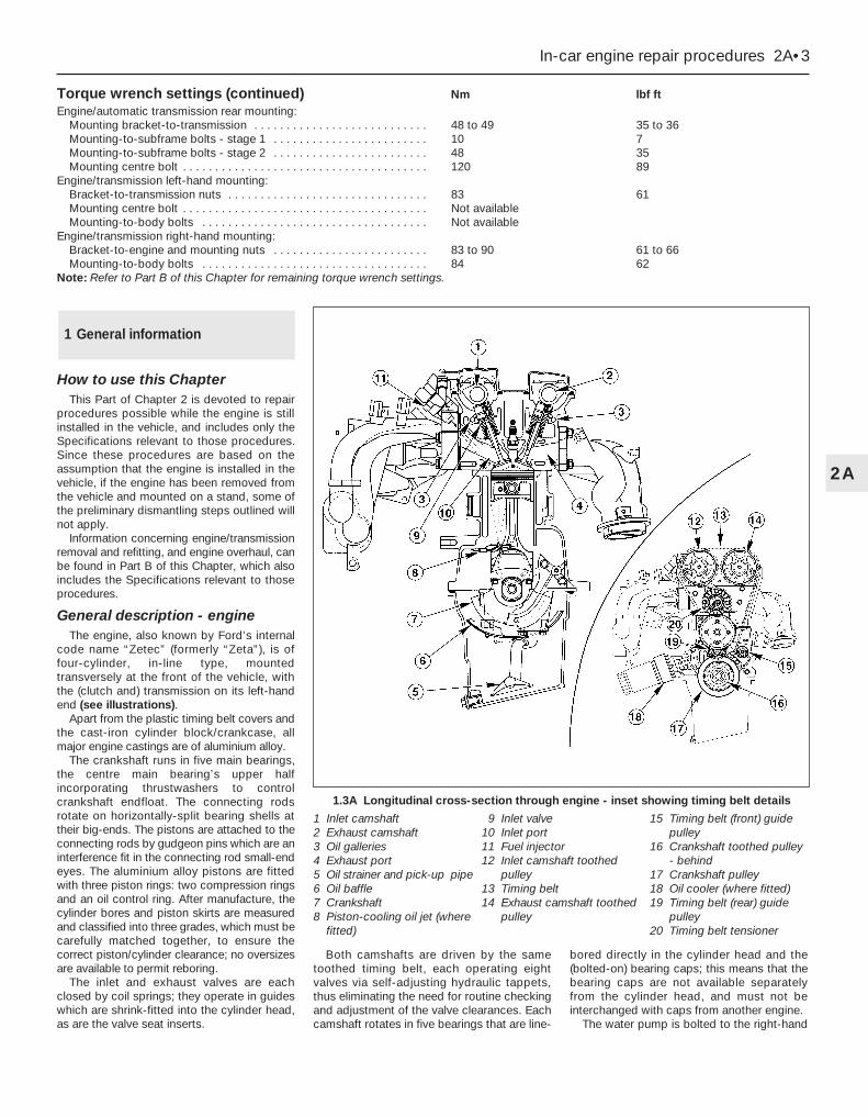
Torque wrench settings (continued) Nm lbf ftEngine/automatic transmission rear mounting:
Mounting bracket-to-transmission . . . . . . . . . . . . . . . . . . . . . . . . . . . 48 to 49 35 to 36Mounting-to-subframe bolts - stage 1 . . . . . . . . . . . . . . . . . . . . . . . . 10 7Mounting-to-subframe bolts - stage 2 . . . . . . . . . . . . . . . . . . . . . . . . 48 35Mounting centre bolt . . . . . . . . . . . . . . . . . . . . . . . . . . . . . . . . . . . . . . 120 89
Engine/transmission left-hand mounting:Bracket-to-transmission nuts . . . . . . . . . . . . . . . . . . . . . . . . . . . . . . . 83 61Mounting centre bolt . . . . . . . . . . . . . . . . . . . . . . . . . . . . . . . . . . . . . . Not availableMounting-to-body bolts . . . . . . . . . . . . . . . . . . . . . . . . . . . . . . . . . . . Not available
Engine/transmission right-hand mounting:Bracket-to-engine and mounting nuts . . . . . . . . . . . . . . . . . . . . . . . . 83 to 90 61 to 66Mounting-to-body bolts . . . . . . . . . . . . . . . . . . . . . . . . . . . . . . . . . . . 84 62
Note: Refer to Part B of this Chapter for remaining torque wrench settings.
In-car engine repair procedures 2A•3
2A
How to use this ChapterThis Part of Chapter 2 is devoted to repair
procedures possible while the engine is stillinstalled in the vehicle, and includes only theSpecifications relevant to those procedures.Since these procedures are based on theassumption that the engine is installed in thevehicle, if the engine has been removed fromthe vehicle and mounted on a stand, some ofthe preliminary dismantling steps outlined willnot apply.
Information concerning engine/transmissionremoval and refitting, and engine overhaul, canbe found in Part B of this Chapter, which alsoincludes the Specifications relevant to thoseprocedures.
General description - engineThe engine, also known by Ford’s internal
code name “Zetec” (formerly “Zeta”), is offour-cylinder, in-line type, mountedtransversely at the front of the vehicle, withthe (clutch and) transmission on its left-handend (see illustrations).
Apart from the plastic timing belt covers andthe cast-iron cylinder block/crankcase, allmajor engine castings are of aluminium alloy.
The crankshaft runs in five main bearings,the centre main bearing’s upper halfincorporating thrustwashers to controlcrankshaft endfloat. The connecting rodsrotate on horizontally-split bearing shells attheir big-ends. The pistons are attached to theconnecting rods by gudgeon pins which are aninterference fit in the connecting rod small-endeyes. The aluminium alloy pistons are fittedwith three piston rings: two compression ringsand an oil control ring. After manufacture, thecylinder bores and piston skirts are measuredand classified into three grades, which must becarefully matched together, to ensure thecorrect piston/cylinder clearance; no oversizesare available to permit reboring.
The inlet and exhaust valves are eachclosed by coil springs; they operate in guideswhich are shrink-fitted into the cylinder head,as are the valve seat inserts.
Both camshafts are driven by the sametoothed timing belt, each operating eightvalves via self-adjusting hydraulic tappets,thus eliminating the need for routine checkingand adjustment of the valve clearances. Eachcamshaft rotates in five bearings that are line-
bored directly in the cylinder head and the(bolted-on) bearing caps; this means that thebearing caps are not available separatelyfrom the cylinder head, and must not beinterchanged with caps from another engine.
The water pump is bolted to the right-hand
1 General information
1.3A Longitudinal cross-section through engine - inset showing timing belt details
1 Inlet camshaft2 Exhaust camshaft3 Oil galleries4 Exhaust port5 Oil strainer and pick-up pipe6 Oil baffle7 Crankshaft8 Piston-cooling oil jet (where
fitted)
9 Inlet valve10 Inlet port11 Fuel injector12 Inlet camshaft toothed
pulley13 Timing belt14 Exhaust camshaft toothed
pulley
15 Timing belt (front) guide pulley
16 Crankshaft toothed pulley - behind
17 Crankshaft pulley18 Oil cooler (where fitted)19 Timing belt (rear) guide
pulley20 Timing belt tensioner

end of the cylinder block, inboard of thetiming belt, and is driven with the powersteering pump and alternator by a flat“polyvee”-type auxiliary drivebelt from thecrankshaft pulley.
When working on this engine, note thatTorx-type (both male and female heads) andhexagon socket (Allen head) fasteners arewidely used; a good selection of bits, with thenecessary adaptors, will be required, so thatthese can be unscrewed without damageand, on reassembly, tightened to the torquewrench settings specified.
General description - lubricationsystem
Lubrication is by means of an eccentric-rotor trochoidal pump, which is mounted onthe crankshaft right-hand end, and draws oilthrough a strainer located in the sump. Thepump forces oil through an externally-mounted full-flow cartridge-type filter - onsome versions of the engine, an oil cooler isfitted to the oil filter mounting, so that cleanoil entering the engine’s galleries is cooled bythe main engine cooling system. From thefilter, the oil is pumped into a main gallery inthe cylinder block/crankcase, from where it isdistributed to the crankshaft (main bearings)and cylinder head (see illustration).
The big-end bearings are supplied with oilvia internal drillings in the crankshaft. Onsome versions of the engine, each pistoncrown is cooled by a spray of oil directed atits underside by a jet. These jets are fed bypassages off the crankshaft oil supplygalleries, with spring-loaded valves to ensurethat the jets open only when there is sufficientpressure to guarantee a good oil supply tothe rest of the engine components; where thejets are not fitted, separate blanking plugs areprovided, so that the passages are sealed,but can be cleaned at overhaul (seeillustration).
2A•4 In-car engine repair procedures
1.3B Lateral cross-section through engine
1 Exhaust valve2 Piston3 Oil baffle
4 Oil strainer and pick-up pipe
5 Spark plug
6 Fuel injector7 Piston-cooling oil jets
(where fitted)
1.10 Engine lubrication system - inset showing longitudinal cross-section
1 Main oil gallery2 From oil filter3 Oil pump4 Cylinder head oil-retaining valve5 Cylinder head oil gallery
6 Cylinder head oil supply7 Oil return8 Piston-cooling oil spray (where fitted)9 Oil filter - oil cooler not shown here
1.11 Piston-cooling oil jet details
1 Oil jets (when fitted)2 Oil flow - only when valve opens at set
pressure3 Oil spray4 Blanking plug (when fitted)
The cylinder head is provided with two oilgalleries, one on the inlet side and one on theexhaust, to ensure constant oil supply to thecamshaft bearings and hydraulic tappets. Aretaining valve (inserted into the cylinderhead’s top surface, in the middle, on the inletside) prevents these galleries from beingdrained when the engine is switched off. Thevalve incorporates a ventilation hole in itsupper end, to allow air bubbles to escapefrom the system when the engine is restarted.
While the crankshaft and camshaftbearings and the hydraulic tappets receive apressurised supply, the camshaft lobes andvalves are lubricated by splash, as are allother engine components.
Valve clearances - generalIt is necessary for a clearance to exist
between the tip of each valve stem and thevalve operating mechanism, to allow for theexpansion of the various components as theengine reaches normal operatingtemperature.
On most older engine designs, this meantthat the valve clearances (also known as“tappet” clearances) had to be checked andadjusted regularly. If the clearances wereallowed to be too slack, the engine would bevery noisy, its power output would suffer, andits fuel consumption would increase. If theclearances were allowed to be too tight, theengine’s power output would be reduced,and the valves and their seats could beseverely damaged.
The engines covered in this manual,however, employ hydraulic tappets which usethe lubricating system’s oil pressureautomatically to take up the clearancebetween each camshaft lobe and itsrespective valve stem. Therefore, there is noneed for regular checking and adjustment ofthe valve clearances, but it is essential thatonly good-quality oil of the recommendedviscosity and specification is used in theengine, and that this oil is always changed atthe recommended intervals. If this advice isnot followed, the oilways and tappets maybecome clogged with particles of dirt, ordeposits of burnt (inferior) engine oil, so thatthe system cannot work properly; ultimately,one or more of the tappets may fail, andexpensive repairs may be required.
On starting the engine from cold, there willbe a slight delay while full oil pressure buildsup in all parts of the engine, especially in thetappets; the valve components, therefore,may well “rattle” for about 10 seconds or so,and then quieten. This is a normal state ofaffairs, and is nothing to worry about,provided that all tappets quieten quickly andstay quiet.
After the vehicle has been standing forseveral days, the valve components may“rattle” for longer than usual, as nearly all theoil will have drained away from the engine’stop end components and bearing surfaces.While this is only to be expected, care must
be taken not to damage the engine underthese circumstances - avoid high speedrunning until all the tappets are refilled with oiland operating normally. With the vehiclestationary, hold the engine at no more than afast idle speed (maximum 2000 to 2500 rpm)for 10 to 15 seconds, or until the noiseceases. Do not run the engine at more than3000 rpm until the tappets are fully rechargedwith oil and the noise has ceased.
If the valve components are thought to benoisy, or if a light rattle persists from the topend after the engine has warmed up tonormal operating temperature, take thevehicle to a Ford dealer for expert advice.Depending on the mileage covered and theusage to which each vehicle has been put,some vehicles may be noisier than others;only a good mechanic experienced in theseengines can tell if the noise level is typical forthe vehicle’s mileage, or if a genuine faultexists. If any tappet’s operation is faulty, itmust be renewed (Section 13).
The following major repair operations canbe accomplished without removing theengine from the vehicle. However, ownersshould note that any operation involving theremoval of the sump requires carefulforethought, depending on the level of skilland the tools and facilities available; refer tothe relevant text for details.(a) Compression pressure - testing.(b) Cylinder head cover - removal and
refitting.(c) Timing belt covers - removal and refitting.(d) Timing belt - renewal.(e) Timing belt tensioner and toothed pulleys
- removal and refitting.(f) Camshaft oil seals - renewal.(g) Camshafts and hydraulic tappets -
removal and refitting.(h) Cylinder head - removal, overhaul and
refitting.(i) Cylinder head and pistons -
decarbonising.(j) Sump - removal and refitting.(k) Crankshaft oil seals - renewal.(l) Oil pump - removal and refitting.(m) Piston/connecting rod assemblies -
removal and refitting (but see note below).(n) Flywheel/driveplate - removal and
refitting.(o) Engine/transmission mountings - removal
and refitting.Clean the engine compartment and the
exterior of the engine with some type ofdegreaser before any work is done. It willmake the job easier, and will help to keep dirtout of the internal areas of the engine.
Depending on the components involved, itmay be helpful to remove the bonnet, toimprove access to the engine as repairs areperformed (refer to Chapter 11 if necessary).
Cover the wings to prevent damage to thepaint; special covers are available, but an oldbedspread or blanket will also work.
If vacuum, exhaust, oil or coolant leaksdevelop, indicating a need for component/gasket or seal replacement, the repairs cangenerally be made with the engine in thevehicle. The intake and exhaust manifoldgaskets, sump gasket, crankshaft oil sealsand cylinder head gasket are all accessiblewith the engine in place.
Exterior components such as the intakeand exhaust manifolds, the sump, the oilpump, the water pump, the starter motor, thealternator and the fuel system componentscan be removed for repair with the engine inplace.
Since the cylinder head can be removedwithout lifting out the engine, camshaft andvalve component servicing can also beaccomplished with the engine in the vehicle,as can renewal of the timing belt and toothedpulleys.
In extreme cases caused by a lack ofnecessary equipment, repair or renewal ofpiston rings, pistons, connecting rods andbig-end bearings is possible with the enginein the vehicle. However, this practice is notrecommended, because of the cleaning andpreparation work that must be done to thecomponents involved, and because of theamount of preliminary dismantling workrequired - these operations are thereforecovered in Part B of this Chapter.
1 When engine performance is down, or ifmisfiring occurs which cannot be attributed tothe ignition or fuel systems, a compressiontest can provide diagnostic clues as to theengine’s condition. If the test is performedregularly, it can give warning of trouble beforeany other symptoms become apparent.2 The engine must be fully warmed-up tonormal operating temperature, the oil levelmust be correct, the battery must be fullycharged, and the spark plugs must beremoved. The aid of an assistant will berequired also.3 Disable the ignition system by unpluggingthe ignition coil’s electrical connector, andremove fuse 14 to disconnect the fuel pump.4 Fit a compression tester to the No 1cylinder spark plug hole - the type of testerwhich screws into the plug thread is to bepreferred.5 Have the assistant hold the throttle wideopen and crank the engine on the startermotor; after one or two revolutions, thecompression pressure should build up to amaximum figure, and then stabilise. Recordthe highest reading obtained.6 Repeat the test on the remaining cylinders,recording the pressure developed in each.7 At the time of writing, no compression
3 Compression test - description and interpretation
2 Repair operations possible withthe engine in the vehicle
In-car engine repair procedures 2A•5
2A

specifications were available from Ford, but atypical reading would be in excess of 12 bars.All cylinders should produce very similarpressures; any difference greater than 10%indicates the existence of a fault. Note that thecompression should build up quickly in ahealthy engine; low compression on the firststroke, followed by gradually-increasingpressure on successive strokes, indicates wornpiston rings. A low compression reading on thefirst stroke, which does not build up duringsuccessive strokes, indicates leaking valves or ablown head gasket (a cracked head could alsobe the cause). Deposits on the undersides of thevalve heads can also cause low compression.8 If the pressure in any cylinder isconsiderably lower than the others, introducea teaspoonful of clean oil into that cylinderthrough its spark plug hole, and repeat thetest.9 If the addition of oil temporarily improvesthe compression pressure, this indicates thatbore or piston wear is responsible for thepressure loss. No improvement suggests thatleaking or burnt valves, or a blown headgasket, may be to blame.10 A low reading from two adjacent cylindersis almost certainly due to the head gaskethaving blown between them; the presence ofcoolant in the engine oil will confirm this.11 If one cylinder is about 20 percent lowerthan the others and the engine has a slightlyrough idle, a worn camshaft lobe or faultyhydraulic tappet could be the cause.12 If the compression is unusually high, thecombustion chambers are probably coatedwith carbon deposits. If this is the case, thecylinder head should be removed anddecarbonised.13 On completion of the test, refit the sparkplugs, then reconnect the ignition system andfuel pump.
General1 Top Dead Centre (TDC) is the highest pointin its travel up-and-down its cylinder borethat each piston reaches as the crankshaft
rotates. While each piston reaches TDC bothat the top of the compression stroke andagain at the top of the exhaust stroke, for thepurpose of timing the engine, TDC refers tothe piston position (usually No 1 piston) at thetop of its compression stroke.2 It is useful for several servicing proceduresto be able to position the engine at TDC.3 No 1 piston and cylinder are at the right-hand (timing belt) end of the engine (right-and left-hand are always quoted as seen fromthe driver’s seat). Note that the crankshaftrotates clockwise when viewed from theright-hand side of the vehicle.
Locating TDC4 Remove all the spark plugs (Chapter 1).5 Disconnect both battery leads - seeChapter 5, Section 1 - unless the startermotor is to be used to turn the engine.6 Apply the handbrake and ensure that thetransmission is in neutral, then jack up thefront right-hand side of the vehicle andsupport on an axle stand. Remove theroadwheel.7 Remove the auxiliary drivebelt cover (seeChapter 1) to expose the crankshaft pulleyand timing marks.8 It is best to rotate the crankshaft using aspanner applied to the crankshaft pulley bolt;however, it is possible also to use the startermotor (switched on either by an assistantusing the ignition key, or by using a remotestarter switch) to bring the engine close toTDC, then finish with a spanner. If the starteris used, be sure to disconnect the batteryleads immediately it is no longer required.9 Note the two pairs of notches in the innerand outer rims of the crankshaft pulley. In thenormal direction of crankshaft rotation(clockwise, seen from the right-hand side of thevehicle) the first pair of notches are irrelevant tothe vehicles covered in this manual, while thesecond pair indicate TDC when aligned withthe rear edge of the raised mark on the sump.Rotate the crankshaft clockwise until thesecond pair of notches align with the edge ofthe sump mark; use a straight edge extendedout from the sump if greater accuracy isrequired (see illustrations).
10 Nos 1 and 4 cylinders are now at TDC,one of them on the compression stroke.Remove the oil filler cap; if No 4 cylinderexhaust cam lobe is pointing to the rear of thevehicle and slightly downwards, it is No 1cylinder that is correctly positioned. If thelobe is pointing horizontally forwards, rotatethe crankshaft one full turn (360°) clockwiseuntil the pulley notches align again, and thelobe is pointing to the rear and slightly down.No 1 cylinder will then be at TDC on thecompression stroke.11 Once No 1 cylinder has been positionedat TDC on the compression stroke, TDC forany of the other cylinders can then be locatedby rotating the crankshaft clockwise 180° at atime and following the firing order (seeSpecifications).12 An alternative method of locating TDC isto remove the cylinder head cover (seeSection 5) and to rotate the crankshaft(clockwise, as described in paragraph 8above) until the inlet valves for the cylinderconcerned have opened and just closedagain. Insert a length of wooden dowel(approximately 150 mm/6 in long) or similarinto the spark plug hole until it rests on thepiston crown, and slowly further rotate thecrankshaft (taking care not to allow the dowelto be trapped in the cylinder) until the dowelstops rising - the piston is now at the top ofits compression stroke, and the dowel can beremoved.13 There is a “dead” area around TDC (asthe piston stops rising, pauses and thenbegins to descend) which makes difficult theexact location of TDC by this method; ifaccuracy is required, either establish carefullythe exact mid-point of the dead area, or referto the timing marks (paragraph 9 above).
1 Unplug the two electrical connectors anddisconnect the vacuum hose (where fitted),then remove the air cleaner assembly coverwith the air mass meter, the resonator and theplenum chamber (see Chapter 4).2 Disconnect the accelerator cable from the
5 Cylinder head cover -removal and refitting
4 Top Dead Centre (TDC) for No 1 piston - locating
2A•6 In-car engine repair procedures
4.9A Do not use crankshaft pulley’s firstpair of notches “A” - align second pair of
notches “B” with raised rib on sump “C” . . .
4.9B . . . using a straight edge extendedout from the sump (arrowed) if greater
accuracy is required
5.4 Disconnecting crankcase breatherhose from cylinder head cover union
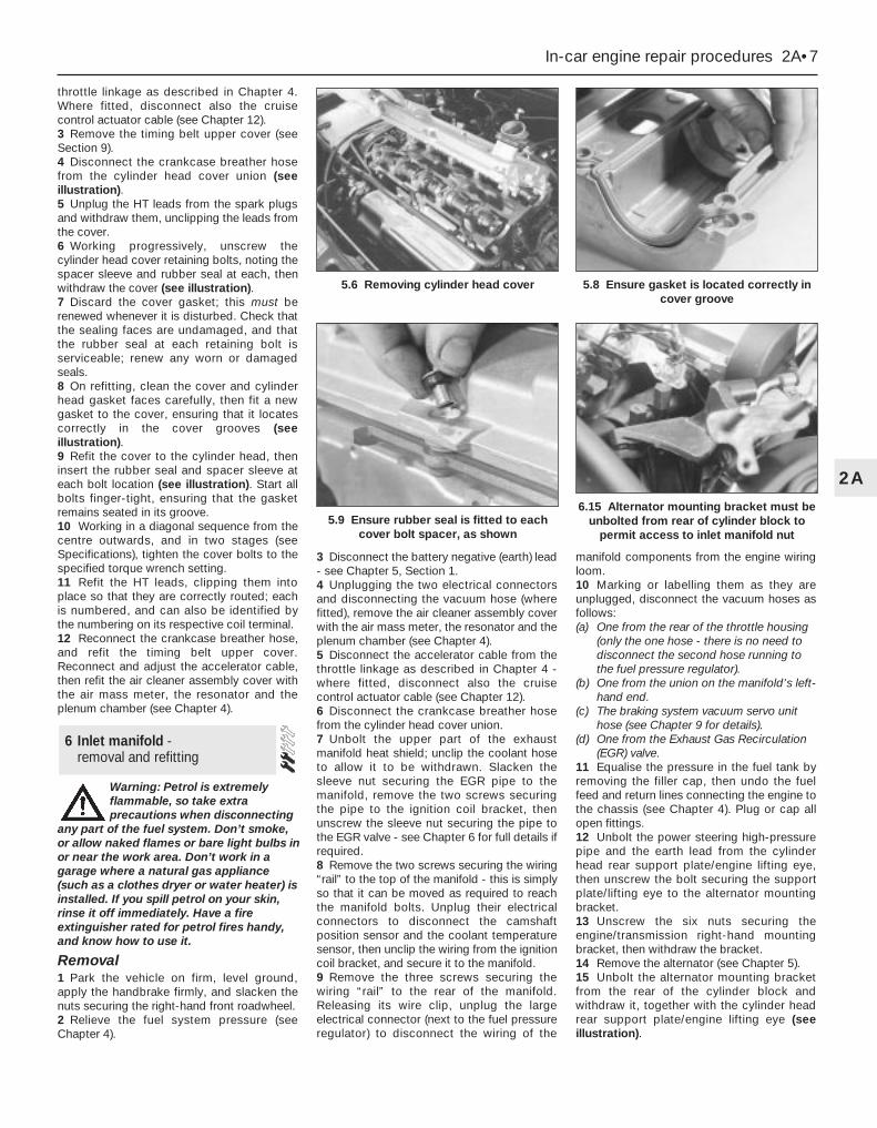
throttle linkage as described in Chapter 4.Where fitted, disconnect also the cruisecontrol actuator cable (see Chapter 12).3 Remove the timing belt upper cover (seeSection 9).4 Disconnect the crankcase breather hosefrom the cylinder head cover union (seeillustration).5 Unplug the HT leads from the spark plugsand withdraw them, unclipping the leads fromthe cover.6 Working progressively, unscrew thecylinder head cover retaining bolts, noting thespacer sleeve and rubber seal at each, thenwithdraw the cover (see illustration).7 Discard the cover gasket; this must berenewed whenever it is disturbed. Check thatthe sealing faces are undamaged, and thatthe rubber seal at each retaining bolt isserviceable; renew any worn or damagedseals.8 On refitting, clean the cover and cylinderhead gasket faces carefully, then fit a newgasket to the cover, ensuring that it locatescorrectly in the cover grooves (seeillustration).9 Refit the cover to the cylinder head, theninsert the rubber seal and spacer sleeve ateach bolt location (see illustration). Start allbolts finger-tight, ensuring that the gasketremains seated in its groove.10 Working in a diagonal sequence from thecentre outwards, and in two stages (seeSpecifications), tighten the cover bolts to thespecified torque wrench setting.11 Refit the HT leads, clipping them intoplace so that they are correctly routed; eachis numbered, and can also be identified bythe numbering on its respective coil terminal.12 Reconnect the crankcase breather hose,and refit the timing belt upper cover.Reconnect and adjust the accelerator cable,then refit the air cleaner assembly cover withthe air mass meter, the resonator and theplenum chamber (see Chapter 4).
Warning: Petrol is extremelyflammable, so take extraprecautions when disconnecting
any part of the fuel system. Don’t smoke,or allow naked flames or bare light bulbs inor near the work area. Don’t work in agarage where a natural gas appliance(such as a clothes dryer or water heater) isinstalled. If you spill petrol on your skin,rinse it off immediately. Have a fireextinguisher rated for petrol fires handy,and know how to use it.
Removal1 Park the vehicle on firm, level ground,apply the handbrake firmly, and slacken thenuts securing the right-hand front roadwheel.2 Relieve the fuel system pressure (seeChapter 4).
3 Disconnect the battery negative (earth) lead- see Chapter 5, Section 1.4 Unplugging the two electrical connectorsand disconnecting the vacuum hose (wherefitted), remove the air cleaner assembly coverwith the air mass meter, the resonator and theplenum chamber (see Chapter 4).5 Disconnect the accelerator cable from thethrottle linkage as described in Chapter 4 -where fitted, disconnect also the cruisecontrol actuator cable (see Chapter 12).6 Disconnect the crankcase breather hosefrom the cylinder head cover union.7 Unbolt the upper part of the exhaustmanifold heat shield; unclip the coolant hoseto allow it to be withdrawn. Slacken thesleeve nut securing the EGR pipe to themanifold, remove the two screws securingthe pipe to the ignition coil bracket, thenunscrew the sleeve nut securing the pipe tothe EGR valve - see Chapter 6 for full details ifrequired.8 Remove the two screws securing the wiring“rail” to the top of the manifold - this is simplyso that it can be moved as required to reachthe manifold bolts. Unplug their electricalconnectors to disconnect the camshaftposition sensor and the coolant temperaturesensor, then unclip the wiring from the ignitioncoil bracket, and secure it to the manifold.9 Remove the three screws securing thewiring “rail” to the rear of the manifold.Releasing its wire clip, unplug the largeelectrical connector (next to the fuel pressureregulator) to disconnect the wiring of the
manifold components from the engine wiringloom.10 Marking or labelling them as they areunplugged, disconnect the vacuum hoses asfollows:(a) One from the rear of the throttle housing
(only the one hose - there is no need todisconnect the second hose running tothe fuel pressure regulator).
(b) One from the union on the manifold’s left-hand end.
(c) The braking system vacuum servo unithose (see Chapter 9 for details).
(d) One from the Exhaust Gas Recirculation(EGR) valve.
11 Equalise the pressure in the fuel tank byremoving the filler cap, then undo the fuelfeed and return lines connecting the engine tothe chassis (see Chapter 4). Plug or cap allopen fittings.12 Unbolt the power steering high-pressurepipe and the earth lead from the cylinderhead rear support plate/engine lifting eye,then unscrew the bolt securing the supportplate/lifting eye to the alternator mountingbracket.13 Unscrew the six nuts securing theengine/transmission right-hand mountingbracket, then withdraw the bracket.14 Remove the alternator (see Chapter 5).15 Unbolt the alternator mounting bracketfrom the rear of the cylinder block andwithdraw it, together with the cylinder headrear support plate/engine lifting eye (seeillustration).
6 Inlet manifold - removal and refitting
In-car engine repair procedures 2A•7
2A
5.8 Ensure gasket is located correctly incover groove
5.6 Removing cylinder head cover
5.9 Ensure rubber seal is fitted to eachcover bolt spacer, as shown
6.15 Alternator mounting bracket must beunbolted from rear of cylinder block to
permit access to inlet manifold nut
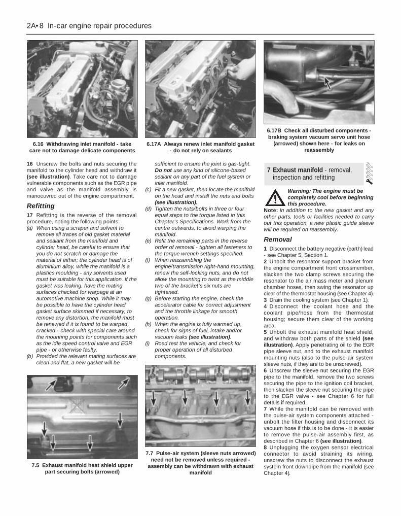
16 Unscrew the bolts and nuts securing themanifold to the cylinder head and withdraw it(see illustration). Take care not to damagevulnerable components such as the EGR pipeand valve as the manifold assembly ismanoeuvred out of the engine compartment.
Refitting17 Refitting is the reverse of the removalprocedure, noting the following points:(a) When using a scraper and solvent to
remove all traces of old gasket materialand sealant from the manifold andcylinder head, be careful to ensure thatyou do not scratch or damage thematerial of either; the cylinder head is ofaluminium alloy, while the manifold is aplastics moulding - any solvents usedmust be suitable for this application. If thegasket was leaking, have the matingsurfaces checked for warpage at anautomotive machine shop. While it maybe possible to have the cylinder headgasket surface skimmed if necessary, toremove any distortion, the manifold mustbe renewed if it is found to be warped,cracked - check with special care aroundthe mounting points for components suchas the idle speed control valve and EGRpipe - or otherwise faulty.
(b) Provided the relevant mating surfaces areclean and flat, a new gasket will be
sufficient to ensure the joint is gas-tight.Do not use any kind of silicone-basedsealant on any part of the fuel system orinlet manifold.
(c) Fit a new gasket, then locate the manifoldon the head and install the nuts and bolts(see illustration).
(d) Tighten the nuts/bolts in three or fourequal steps to the torque listed in thisChapter’s Specifications. Work from thecentre outwards, to avoid warping themanifold.
(e) Refit the remaining parts in the reverseorder of removal - tighten all fasteners tothe torque wrench settings specified.
(f) When reassembling theengine/transmission right-hand mounting,renew the self-locking nuts, and do notallow the mounting to twist as the middletwo of the bracket’s six nuts aretightened.
(g) Before starting the engine, check theaccelerator cable for correct adjustmentand the throttle linkage for smoothoperation.
(h) When the engine is fully warmed up,check for signs of fuel, intake and/orvacuum leaks (see illustration).
(i) Road test the vehicle, and check forproper operation of all disturbedcomponents.
Warning: The engine must becompletely cool before beginningthis procedure.
Note: In addition to the new gasket and anyother parts, tools or facilities needed to carryout this operation, a new plastic guide sleevewill be required on reassembly.
Removal1 Disconnect the battery negative (earth) lead- see Chapter 5, Section 1.2 Unbolt the resonator support bracket fromthe engine compartment front crossmember,slacken the two clamp screws securing theresonator to the air mass meter and plenumchamber hoses, then swing the resonator upclear of the thermostat housing (see Chapter 4).3 Drain the cooling system (see Chapter 1).4 Disconnect the coolant hose and thecoolant pipe/hose from the thermostathousing; secure them clear of the workingarea.5 Unbolt the exhaust manifold heat shield,and withdraw both parts of the shield (seeillustration). Apply penetrating oil to the EGRpipe sleeve nut, and to the exhaust manifoldmounting nuts (also to the pulse-air systemsleeve nuts, if they are to be unscrewed).6 Unscrew the sleeve nut securing the EGRpipe to the manifold, remove the two screwssecuring the pipe to the ignition coil bracket,then slacken the sleeve nut securing the pipeto the EGR valve - see Chapter 6 for fulldetails if required.7 While the manifold can be removed withthe pulse-air system components attached -unbolt the filter housing and disconnect itsvacuum hose if this is to be done - it is easierto remove the pulse-air assembly first, asdescribed in Chapter 6 (see illustration).8 Unplugging the oxygen sensor electricalconnector to avoid straining its wiring,unscrew the nuts to disconnect the exhaustsystem front downpipe from the manifold (seeChapter 4).
7 Exhaust manifold - removal,inspection and refitting
2A•8 In-car engine repair procedures
6.16 Withdrawing inlet manifold - takecare not to damage delicate components
6.17A Always renew inlet manifold gasket- do not rely on sealants
6.17B Check all disturbed components -braking system vacuum servo unit hose
(arrowed) shown here - for leaks onreassembly
7.5 Exhaust manifold heat shield upperpart securing bolts (arrowed)
7.7 Pulse-air system (sleeve nuts arrowed)need not be removed unless required -
assembly can be withdrawn with exhaustmanifold

9 Remove the nuts and detach the manifoldand gasket (see illustration). Take care notto damage vulnerable components such asthe EGR pipe as the manifold assembly ismanoeuvred out of the engine compartment.When removing the manifold with the enginein the vehicle, additional clearance can beobtained by unscrewing the studs from thecylinder head; a female Torx-type socket willbe required (see illustration).10 Always fit a new gasket on reassembly, tocarefully-cleaned components (see below).Do not attempt to re-use the original gasket.
Inspection11 Use a scraper to remove all traces of oldgasket material and carbon deposits from themanifold and cylinder head mating surfaces. Ifthe gasket was leaking, have the manifoldchecked for warpage at an automotivemachine shop, and have it resurfaced ifnecessary.
Caution: When scraping, be verycareful not to gouge or scratchthe delicate aluminium alloycylinder head.
12 Provided both mating surfaces are cleanand flat, a new gasket will be sufficient toensure the joint is gas-tight. Do not use anykind of exhaust sealant upstream of thecatalytic converter.13 Note that the downpipe is secured to themanifold by two bolts, with a coil spring,spring seat and self-locking nut on each. Onrefitting, tighten the nuts until they stop on the
bolt shoulders; the pressure of the springs willthen suffice to make a leakproof joint (seeillustrations).14 Do not overtighten the nuts to cure a leak- the bolts will shear; renew the gasket andthe springs if a leak is found. The boltsthemselves are secured by spring clips to themanifold, and can be renewed easily ifdamaged (see illustration).
Refitting15 Refitting is the reverse of the removalprocedure, noting the following points:(a) Position a new gasket over the cylinder
head studs, and fit a new plastic guidesleeve to the stud nearest to thethermostat housing, so that the manifoldwill be correctly located (see illustration).Do not refit the manifold without thissleeve.
(b) Refit the manifold, and finger-tighten themounting nuts.
(c) Working from the centre out, and in threeor four equal steps, tighten the nuts to thetorque wrench setting given in theSpecifications Section of this Chapter.
(d) Refit the remaining parts in the reverseorder of removal. Tighten all fasteners tothe specified torque wrench settings.
(e) Refill the cooling system (see Chapter 1).(f) Run the engine, and check for exhaust
leaks. Check the coolant level when fullywarmed-up to normal operatingtemperature.
1 Remove the auxiliary drivebelt - eitherremove the drivebelt completely, or justsecure it clear of the crankshaft pulley,depending on the work to be carried out (seeChapter 1).2 If necessary, rotate the crankshaft until thetiming marks align (see Section 4).3 The crankshaft must now be locked toprevent its rotation while the pulley bolt isunscrewed. Proceed as follows:(a) If the engine/transmission is still installed
in the vehicle:(1) If the vehicle is fitted with manual
transmission, select top gear, and have anassistant apply the brakes hard.
(2) If the vehicle is fitted with automatictransmission, unbolt the small metal coverplate from the sump, and use a largescrewdriver or similar to lock thedriveplate ring gear teeth while anassistant slackens the pulley bolt; takecare not to damage the teeth or thesurrounding castings when using thismethod.
(b) If the engine/transmission has beenremoved but not yet separated:
(1) If the vehicle is fitted with manualtransmission, remove the starter motor(see Chapter 5) and lock the flywheel
8 Crankshaft pulley - removal and refitting
In-car engine repair procedures 2A•9
2A
7.13B Renew exhaust system downpipe-to-manifold gasket to prevent leaks
7.14 Release spring clip to extractsecuring bolt from manifold, when required
7.15 Fit plastic guide sleeve to studarrowed when refitting exhaust manifold
7.9A Unscrew nuts (arrowed) to removeexhaust manifold . . .
7.9B . . . studs can be unscrewed also, ifrequired, to provide additional working
space
7.13A Showing exhaust downpipe-to-manifold securing bolts - note coil spring,
and shoulder on bolt

using the method outlined in (2) above.(2) If the vehicle is fitted with automatic
transmission, see (2) above.(c) If the engine/transmission has been
removed and separated, use the methodshown in illustration 21.11.
4 Unscrew the pulley bolt and remove thepulley (see illustrations).5 Refitting is the reverse of the removalprocedure; ensure that the pulley’s keyway isaligned with the crankshaft’s locating key,and tighten the pulley bolt to the specifiedtorque wrench setting.
Upper cover1 Unscrew the cover’s two mounting boltsand withdraw it (see illustration).2 Refitting is the reverse of the removalprocedure; ensure the cover edges engagecorrectly with each other, and note the torquewrench setting specified for the bolts.
Middle cover3 Unscrew the six nuts securing theengine/transmission right-hand mountingbracket, then withdraw the bracket.4 Slacken the water pump pulley bolts.5 Remove the timing belt upper cover (seeparagraph 1 above).6 Remove the auxiliary drivebelt (see Chap-ter 1).7 Unbolt and remove the water pump pulley(see illustration).8 Unscrew the middle cover fasteners (onebolt at the front, one at the lower rear, onestud at the top rear) and withdraw the cover(see illustration).9 Refitting is the reverse of the removalprocedure. Ensure the cover edges engagecorrectly with each other, and note the torquewrench settings specified for the variousfasteners. When reassembling the engine/transmission right-hand mounting, renew theself-locking nuts, and do not allow themounting to twist as the middle two of thebracket’s six nuts are tightened.
Lower cover10 Remove the crankshaft pulley (seeSection 8).11 Unscrew the cover’s three securing boltsand withdraw it (see illustration).12 Refitting is the reverse of the removalprocedure; ensure the cover edges engagecorrectly with each other, and note the torquewrench settings specified for the variousfasteners.
Inner shield13 Remove the timing belt, its tensionercomponents and the camshaft toothedpulleys (see Sections 10 and 11).14 The shield is secured to the cylinder headby two bolts at the top, and by two studs
lower down; unscrew these and withdraw theshield (see illustration).15 Refitting is the reverse of the removalprocedure; note the torque wrench settingsspecified for the various fasteners.
Note: To carry out this operation, a newtiming belt (where applicable), a new cylinderhead cover gasket, and some special tools(see text) will be required. If the timing belt isbeing removed for the first time since thevehicle left the factory, a tensioner spring andretaining pin must be obtained for fitting onreassembly.
10 Timing belt - removal, refitting and adjustment
9 Timing belt covers - removal and refitting
2A•10 In-car engine repair procedures
8.4A Unscrew pulley bolt to releasecrankshaft pulley
8.4B Ensure pulley is located oncrankshaft Woodruff key on reassembly
9.1 Remove bolts (arrowed) to releasetiming belt upper cover
9.8 Remove fasteners (arrowed) to releasetiming belt middle cover
9.7 Slacken water pump pulley bolts andremove pulley
9.11 Removing timing belt lower cover -bolt locations arrowed
9.14 Timing belt inner shield fasteners(arrowed)
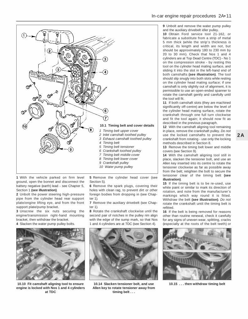
1 With the vehicle parked on firm levelground, open the bonnet and disconnect thebattery negative (earth) lead - see Chapter 5,Section 1 (see illustration).2 Unbolt the power steering high-pressurepipe from the cylinder head rear supportplate/engine lifting eye, and from the frontsupport plate/pump bracket.3 Unscrew the six nuts securing theengine/transmission right-hand mountingbracket, then withdraw the bracket.4 Slacken the water pump pulley bolts.
5 Remove the cylinder head cover (seeSection 5).6 Remove the spark plugs, covering theirholes with clean rag, to prevent dirt or otherforeign bodies from dropping in (see Chap-ter 1).7 Remove the auxiliary drivebelt (see Chap-ter 1).8 Rotate the crankshaft clockwise until thesecond pair of notches in the pulley rim alignwith the edge of the sump mark, so that Nos1 and 4 cylinders are at TDC (see Section 4).
9 Unbolt and remove the water pump pulleyand the auxiliary drivebelt idler pulley.10 Obtain Ford service tool 21-162, orfabricate a substitute from a strip of metal 5 mm thick (while the strip’s thickness iscritical, its length and width are not, butshould be approximately 180 to 230 mm by20 to 30 mm). Check that Nos 1 and 4cylinders are at Top Dead Centre (TDC) - No 1on the compression stroke - by resting thistool on the cylinder head mating surface, andsliding it into the slot in the left-hand end ofboth camshafts (see illustration). The toolshould slip snugly into both slots while restingon the cylinder head mating surface; if onecamshaft is only slightly out of alignment, it ispermissible to use an open-ended spanner torotate the camshaft gently and carefully untilthe tool will fit.11 If both camshaft slots (they are machinedsignificantly off-centre) are below the level ofthe cylinder head mating surface, rotate thecrankshaft through one full turn clockwiseand fit the tool again; it should now fit asdescribed in the previous paragraph.12 With the camshaft aligning tool remainingin place, remove the crankshaft pulley. Do notuse the locked camshafts to prevent thecrankshaft from rotating - use only the lockingmethods described in Section 8.13 Remove the timing belt lower and middlecovers (see Section 9).14 With the camshaft aligning tool still inplace, slacken the tensioner bolt, and use anAllen key inserted into its centre to rotate thetensioner clockwise as far as possible awayfrom the belt; retighten the bolt to secure thetensioner clear of the timing belt (seeillustration).15 If the timing belt is to be re-used, usewhite paint or similar to mark its direction ofrotation, and note from the manufacturer’smarkings which way round it is fitted.Withdraw the belt (see illustration). Do notrotate the crankshaft until the timing belt isrefitted.16 If the belt is being removed for reasonsother than routine renewal, check it carefullyfor any signs of uneven wear, splitting, cracks(especially at the roots of the belt teeth) or
In-car engine repair procedures 2A•11
2A
10.10 Fit camshaft aligning tool to ensureengine is locked with Nos 1 and 4 cylinders
at TDC
10.14 Slacken tensioner bolt, and useAllen key to rotate tensioner away from
timing belt . . .
10.15 . . . then withdraw timing belt
10.1 Timing belt and cover details
1 Timing belt upper cover2 Inlet camshaft toothed pulley3 Exhaust camshaft toothed pulley4 Timing belt5 Timing belt tensioner6 Crankshaft toothed pulley7 Timing belt middle cover8 Timing belt lower cover9 Crankshaft pulley10 Water pump pulley
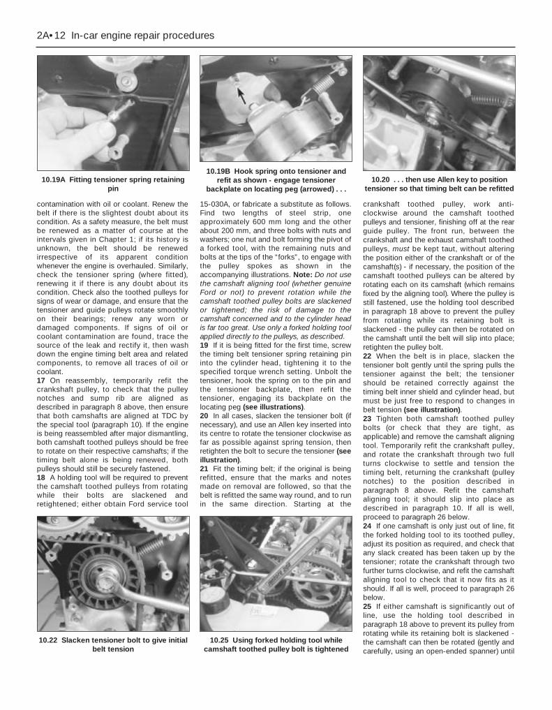
contamination with oil or coolant. Renew thebelt if there is the slightest doubt about itscondition. As a safety measure, the belt mustbe renewed as a matter of course at theintervals given in Chapter 1; if its history isunknown, the belt should be renewedirrespective of its apparent conditionwhenever the engine is overhauled. Similarly,check the tensioner spring (where fitted),renewing it if there is any doubt about itscondition. Check also the toothed pulleys forsigns of wear or damage, and ensure that thetensioner and guide pulleys rotate smoothlyon their bearings; renew any worn ordamaged components. If signs of oil orcoolant contamination are found, trace thesource of the leak and rectify it, then washdown the engine timing belt area and relatedcomponents, to remove all traces of oil orcoolant.17 On reassembly, temporarily refit thecrankshaft pulley, to check that the pulleynotches and sump rib are aligned asdescribed in paragraph 8 above, then ensurethat both camshafts are aligned at TDC bythe special tool (paragraph 10). If the engineis being reassembled after major dismantling,both camshaft toothed pulleys should be freeto rotate on their respective camshafts; if thetiming belt alone is being renewed, bothpulleys should still be securely fastened.18 A holding tool will be required to preventthe camshaft toothed pulleys from rotatingwhile their bolts are slackened andretightened; either obtain Ford service tool
15-030A, or fabricate a substitute as follows.Find two lengths of steel strip, oneapproximately 600 mm long and the otherabout 200 mm, and three bolts with nuts andwashers; one nut and bolt forming the pivot ofa forked tool, with the remaining nuts andbolts at the tips of the “forks”, to engage withthe pulley spokes as shown in theaccompanying illustrations. Note: Do not usethe camshaft aligning tool (whether genuineFord or not) to prevent rotation while thecamshaft toothed pulley bolts are slackenedor tightened; the risk of damage to thecamshaft concerned and to the cylinder headis far too great. Use only a forked holding toolapplied directly to the pulleys, as described.19 If it is being fitted for the first time, screwthe timing belt tensioner spring retaining pininto the cylinder head, tightening it to thespecified torque wrench setting. Unbolt thetensioner, hook the spring on to the pin andthe tensioner backplate, then refit thetensioner, engaging its backplate on thelocating peg (see illustrations).20 In all cases, slacken the tensioner bolt (ifnecessary), and use an Allen key inserted intoits centre to rotate the tensioner clockwise asfar as possible against spring tension, thenretighten the bolt to secure the tensioner (seeillustration).21 Fit the timing belt; if the original is beingrefitted, ensure that the marks and notesmade on removal are followed, so that thebelt is refitted the same way round, and to runin the same direction. Starting at the
crankshaft toothed pulley, work anti-clockwise around the camshaft toothedpulleys and tensioner, finishing off at the rearguide pulley. The front run, between thecrankshaft and the exhaust camshaft toothedpulleys, must be kept taut, without alteringthe position either of the crankshaft or of thecamshaft(s) - if necessary, the position of thecamshaft toothed pulleys can be altered byrotating each on its camshaft (which remainsfixed by the aligning tool). Where the pulley isstill fastened, use the holding tool describedin paragraph 18 above to prevent the pulleyfrom rotating while its retaining bolt isslackened - the pulley can then be rotated onthe camshaft until the belt will slip into place;retighten the pulley bolt.22 When the belt is in place, slacken thetensioner bolt gently until the spring pulls thetensioner against the belt; the tensionershould be retained correctly against thetiming belt inner shield and cylinder head, butmust be just free to respond to changes inbelt tension (see illustration).23 Tighten both camshaft toothed pulleybolts (or check that they are tight, asapplicable) and remove the camshaft aligningtool. Temporarily refit the crankshaft pulley,and rotate the crankshaft through two fullturns clockwise to settle and tension thetiming belt, returning the crankshaft (pulleynotches) to the position described inparagraph 8 above. Refit the camshaftaligning tool; it should slip into place asdescribed in paragraph 10. If all is well,proceed to paragraph 26 below.24 If one camshaft is only just out of line, fitthe forked holding tool to its toothed pulley,adjust its position as required, and check thatany slack created has been taken up by thetensioner; rotate the crankshaft through twofurther turns clockwise, and refit the camshaftaligning tool to check that it now fits as itshould. If all is well, proceed to paragraph 26below.25 If either camshaft is significantly out ofline, use the holding tool described inparagraph 18 above to prevent its pulley fromrotating while its retaining bolt is slackened -the camshaft can then be rotated (gently andcarefully, using an open-ended spanner) until
2A•12 In-car engine repair procedures
10.19A Fitting tensioner spring retainingpin
10.19B Hook spring onto tensioner andrefit as shown - engage tensioner
backplate on locating peg (arrowed) . . .10.20 . . . then use Allen key to position
tensioner so that timing belt can be refitted
10.22 Slacken tensioner bolt to give initialbelt tension
10.25 Using forked holding tool whilecamshaft toothed pulley bolt is tightened

the camshaft aligning tool will slip into place;take care not to disturb the relationship of thepulley to the timing belt. Without disturbingthe pulley’s new position on the camshaft,tighten the pulley bolt to its specified torquewrench setting (see illustration). Remove thecamshaft aligning tool, rotate the crankshaftthrough two further turns clockwise and refitthe tool to check that it now fits as it should.26 When the timing belt has been settled atits correct tension, and the camshaft aligningtool fits correctly when the crankshaft pulleynotches are exactly aligned, tighten thetensioner bolt to its specified torque wrenchsetting (see illustration). Fitting the forkedholding tool to the spokes of each pulley inturn, check that the pulley bolts are tightenedto their specified torque wrench setting.Remove the camshaft aligning tool, rotate thecrankshaft through two further turnsclockwise, and refit the tool to make a finalcheck that it fits as it should.27 The remainder of the reassemblyprocedure is the reverse of removal, notingthe following points:(a) Tighten all fasteners to the torque wrench
settings specified.(b) When reassembling the
engine/transmission right-hand mounting,renew the self-locking nuts, and do notallow the mounting to twist as the middletwo of the bracket’s six nuts aretightened.
TensionerNote: If the tensioner is being removed for thefirst time since the vehicle left the factory, atensioner spring and retaining pin must beobtained for fitting on reassembly.1 While it is possible to reach the tensioneronce the timing belt upper and middle coversonly have been removed (see Section 9), thewhole procedure outlined below must befollowed, to ensure that the valve timing iscorrectly reset once the belt’s tension hasbeen disturbed.2 Release the tension from the timing belt asdescribed in Section 10, paragraphs 1 to 14.3 Unscrew the tensioner bolt and withdrawthe tensioner, unhooking the spring, if fitted(see illustration). Check the tensioner andspring as described in paragraph 16 ofSection 10.4 On reassembly, if it is being fitted for thefirst time, screw the timing belt tensionerspring retaining pin into the cylinder head,tightening it to the specified torque wrenchsetting. Hook the spring onto the pin and thetensioner backplate, then refit the tensioner,engaging its backplate on the locating peg.5 Use an Allen key inserted into its centre torotate the tensioner clockwise as far aspossible against spring tension, then tightenthe bolt to secure the tensioner.6 Reassemble, checking the camshaftalignment (valve timing) and setting the timingbelt tension, as described in paragraphs 22 to27 of Section 10.
Camshaft and crankshaft toothedpulleys7 While it may be possible to remove any ofthese pulleys once their respective covershave been removed, the complete timing beltremoval/refitting procedure (see Section 10)must be followed, to ensure that the valvetiming is correctly reset once the belt’stension has been disturbed.
8 With the timing belt removed, the camshafttoothed pulleys can be detached once theirretaining bolts have been unscrewed asdescribed in paragraphs 18 and 21 of Section10. The crankshaft toothed pulley can bepulled off the end of the crankshaft once thecrankshaft (grooved) pulley and the timingbelt have been removed. Note the “FRONT”marking identifying the pulley’s outboardface, and the thrustwasher behind it; notewhich way round the thrustwasher is fitted(see illustration). Note the pulley-locatingWoodruff key; if this is loose, it should beremoved for safe storage with the pulley.9 Check the pulleys as described inparagraph 16 of Section 10.10 Refitting is the reverse of the removalprocedure.
Timing belt guide pulleys11 Remove the timing belt covers (seeSection 9).12 Unbolt and withdraw the pulley(s); checktheir condition as described in paragraph 16of Section 10.13 Refitting is the reverse of the removalprocedure; tighten the pulley bolts to thespecified torque wrench setting (seeillustration).
Note: While it is possible to reach either oilseal, once the respective toothed pulley hasbeen removed (see Section 11) to allow theseal to be prised out, this procedure is notrecommended. Not only are the seals verysoft, making this difficult to do without risk ofdamage to the seal housing, but it would bevery difficult to ensure that the valve timingand the timing belt’s tension, once disturbed,are correctly reset. Owners are advised tofollow the whole procedure outlined below.1 Release the tension from the timing belt asdescribed in Section 10, paragraphs 1 to 14.Note: If the timing belt is found to becontaminated by oil, remove it completely asdescribed, then renew the oil seal (see below).Wash down the engine timing belt area and all
12 Camshaft oil seals - renewal
11 Timing belt tensioner andtoothed pulleys - removal,inspection and refitting
In-car engine repair procedures 2A•13
2A
11.3 Removing timing belt tensioner11.8 Note “FRONT” marking on outsideface of crankshaft toothed pulley - notewhich way round thrustwasher behind is
fitted
11.13 Tighten timing belt guide pulleybolts to specified torque settings on
refitting
10.26 When setting is correct, tightentensioner bolt to specified torque wrench
setting

related components, to remove all traces ofoil. Fit a new belt on reassembly.2 If the timing belt is still clean, slip it off thetoothed pulley, taking care not to twist it toosharply; use the fingers only to handle thebelt. Do not rotate the crankshaft until thetiming belt is refitted. Cover the belt, andsecure it so that it is clear of the working areaand cannot slip off the remaining toothedpulley.3 Unfasten the pulley bolt and withdraw thepulley (see Section 11).4 Unbolt the camshaft right-hand bearingcap, and withdraw the defective oil seal.Clean the seal housing, and polish off anyburrs or raised edges, which may havecaused the seal to fail in the first place.5 To fit a new seal, Ford recommend the useof their service tool 21-009B, with a bolt (10 mm thread size, 70 mm long) and awasher, to draw the seal into place when thecamshaft bearing cap is bolted down; asubstitute can be made using a suitablesocket (see illustration). Grease the seal lipsand periphery to ease installation, and drawthe seal into place until it is flush with thehousing/bearing cap outer edge. Refit thebearing cap, using sealant and tightening thecap bolts as described in Section 13.6 For most owners, the simplest answer willbe to grease the seal lips, and to slide it on tothe camshaft (until it is flush with the
housing’s outer edge). Refit the bearing cap,using sealant and tightening the cap bolts asdescribed in Section 13 (see illustration).Take care to ensure that the seal remainsabsolutely square in its housing, and is notdistorted as the cap is tightened down.7 Refit the pulley to the camshaft, tighteningthe retaining bolt loosely, then slip the timingbelt back onto the pulley (refer to para-graphs 18 and 21 of Section 10) and tightenthe bolt securely.8 The remainder of the reassemblyprocedure, including checking the camshaftalignment (valve timing) and setting the timingbelt tension, is as described in paragraphs 22to 27 of Section 10.
Removal1 Release the tension from the timing belt asdescribed in Section 10, paragraphs 1 to 14.2 Either remove the timing belt completely(Section 10, paragraphs 15 and 16) or slip itoff the camshaft toothed pulleys, taking carenot to twist it too sharply; use the fingers onlyto handle the belt. Cover the belt, and secureit so that it is clear of the working area. Do notrotate the crankshaft until the timing belt isrefitted.
3 Unfasten the pulley bolts as described inSection 10, paragraphs 18 and 21, andwithdraw the pulleys; while both are the sameand could be interchanged, it is good workingpractice to mark them so that each is refittedonly to its original location (see illustration).4 Working in the sequence shown, slackenprogressively, by half a turn at a time, thecamshaft bearing cap bolts (see illustration).Work only as described, to release graduallyand evenly the pressure of the valve springson the caps.5 Withdraw the caps, noting their markingsand the presence of the locating dowels, thenremove the camshafts and withdraw their oilseals. The inlet camshaft can be identified bythe reference lobe for the camshaft positionsensor; therefore, there is no need to markthe camshafts (see illustrations).6 Obtain sixteen small, clean containers, andnumber them 1 to 16. Using a rubber sucker,withdraw each hydraulic tappet in turn, invertit to prevent oil loss, and place it in itsrespective container, which should then befilled with clean engine oil (see illustrations).Do not interchange the hydraulic tappets, orthe rate of wear will be much increased. Donot allow them to lose oil, or they will take along time to refill on restarting the engine,resulting in incorrect valve clearances.
Inspection7 With the camshafts and hydraulic tappetsremoved, check each for signs of obvious
13 Camshafts and hydraulictappets - removal, inspection and refitting
2A•14 In-car engine repair procedures
12.5 Using socket and toothed pulley boltto install camshaft oil seal
12.6 Alternatively, seal can be insertedwhen camshaft bearing cap is unbolted
13.3 Using forked holding tool whilecamshaft toothed pulley bolt is slackened
13.4 Camshaft bearing cap slackeningsequence
Note: View from front of vehicle, showingbearing cap numbers
13.5A Note locating dowels whenremoving camshaft bearing caps
13.5B Inlet camshaft has lobe forcamshaft position sensor
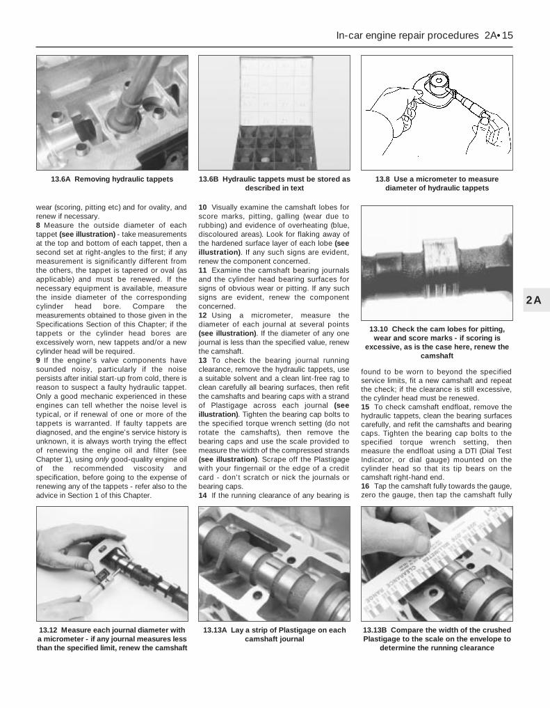
wear (scoring, pitting etc) and for ovality, andrenew if necessary.8 Measure the outside diameter of eachtappet (see illustration) - take measurementsat the top and bottom of each tappet, then asecond set at right-angles to the first; if anymeasurement is significantly different fromthe others, the tappet is tapered or oval (asapplicable) and must be renewed. If thenecessary equipment is available, measurethe inside diameter of the correspondingcylinder head bore. Compare themeasurements obtained to those given in theSpecifications Section of this Chapter; if thetappets or the cylinder head bores areexcessively worn, new tappets and/or a newcylinder head will be required.9 If the engine’s valve components havesounded noisy, particularly if the noisepersists after initial start-up from cold, there isreason to suspect a faulty hydraulic tappet.Only a good mechanic experienced in theseengines can tell whether the noise level istypical, or if renewal of one or more of thetappets is warranted. If faulty tappets arediagnosed, and the engine’s service history isunknown, it is always worth trying the effectof renewing the engine oil and filter (seeChapter 1), using only good-quality engine oilof the recommended viscosity andspecification, before going to the expense ofrenewing any of the tappets - refer also to theadvice in Section 1 of this Chapter.
10 Visually examine the camshaft lobes forscore marks, pitting, galling (wear due torubbing) and evidence of overheating (blue,discoloured areas). Look for flaking away ofthe hardened surface layer of each lobe (seeillustration). If any such signs are evident,renew the component concerned.11 Examine the camshaft bearing journalsand the cylinder head bearing surfaces forsigns of obvious wear or pitting. If any suchsigns are evident, renew the componentconcerned.12 Using a micrometer, measure thediameter of each journal at several points(see illustration). If the diameter of any onejournal is less than the specified value, renewthe camshaft.13 To check the bearing journal runningclearance, remove the hydraulic tappets, usea suitable solvent and a clean lint-free rag toclean carefully all bearing surfaces, then refitthe camshafts and bearing caps with a strandof Plastigage across each journal (seeillustration). Tighten the bearing cap bolts tothe specified torque wrench setting (do notrotate the camshafts), then remove thebearing caps and use the scale provided tomeasure the width of the compressed strands(see illustration). Scrape off the Plastigagewith your fingernail or the edge of a creditcard - don’t scratch or nick the journals orbearing caps.14 If the running clearance of any bearing is
found to be worn to beyond the specifiedservice limits, fit a new camshaft and repeatthe check; if the clearance is still excessive,the cylinder head must be renewed.15 To check camshaft endfloat, remove thehydraulic tappets, clean the bearing surfacescarefully, and refit the camshafts and bearingcaps. Tighten the bearing cap bolts to thespecified torque wrench setting, thenmeasure the endfloat using a DTI (Dial TestIndicator, or dial gauge) mounted on thecylinder head so that its tip bears on thecamshaft right-hand end.16 Tap the camshaft fully towards the gauge,zero the gauge, then tap the camshaft fully
In-car engine repair procedures 2A•15
2A
13.12 Measure each journal diameter witha micrometer - if any journal measures lessthan the specified limit, renew the camshaft
13.13A Lay a strip of Plastigage on eachcamshaft journal
13.13B Compare the width of the crushedPlastigage to the scale on the envelope to
determine the running clearance
13.6A Removing hydraulic tappets 13.6B Hydraulic tappets must be stored asdescribed in text
13.8 Use a micrometer to measurediameter of hydraulic tappets
13.10 Check the cam lobes for pitting,wear and score marks - if scoring is
excessive, as is the case here, renew thecamshaft

away from the gauge, and note the gaugereading. If the endfloat measured is found tobe at or beyond the specified service limit, fita new camshaft and repeat the check; if theclearance is still excessive, the cylinder headmust be renewed.
Refitting17 On reassembly, liberally oil the cylinderhead hydraulic tappet bores and the tappets(see illustration). Note that if new tappets arebeing fitted, they must be charged with cleanengine oil before installation. Carefully refit thetappets to the cylinder head, ensuring that eachtappet is refitted to its original bore, and is thecorrect way up. Some care will be required toenter the tappets squarely into their bores.18 Liberally oil the camshaft bearings andlobes (see illustration). Ensuring that eachcamshaft is in its original location, refit thecamshafts, locating each so that the slot in itsleft-hand end is approximately parallel to, andjust above, the cylinder head mating surface(see illustration).19 Ensure that the locating dowels arepressed firmly into their recesses, and checkthat all mating surfaces are completely clean,unmarked and free from oil. Apply a thin filmof suitable sealant (Ford recommend Loctite518) to the mating surfaces of each
camshaft’s right-hand bearing cap (seeillustration). Referring to paragraph 6 ofSection 12, some owners may wish to fit thenew camshaft oil seals at this stage.20 All camshaft bearing caps have a single-digit identifying number etched on them (seeillustration). The exhaust camshaft’s bearingcaps are numbered in sequence 0 (right-handcap) to 4 (left-hand cap), the inlet’s 5 (right-hand cap) to 9 (left-hand cap); see illustration13.21B for details. Each cap is to be fitted sothat its numbered side faces outwards, to thefront (exhaust) or to the rear (inlet).21 Ensuring that each cap is kept square tothe cylinder head as it is tightened down, andworking in the sequence shown, tighten thecamshaft bearing cap bolts slowly and by oneturn at a time, until each cap touches thecylinder head (see illustrations). Next, goround again in the same sequence, tighteningthe bolts to the first stage torque wrenchsetting specified, then once more, tighteningthem to the second stage setting. Work onlyas described, to impose gradually and evenlythe pressure of the valve springs on the caps.Fit the camshaft aligning tool; it should slipinto place as described in paragraph 10 ofSection 10 (see illustration).22 Wipe off all surplus sealant, so that noneis left to find its way into any oilways. Followthe sealant manufacturer’s instructions as tothe time needed for curing; usually, at least anhour must be allowed between application ofthe sealant and starting the engine.
2A•16 In-car engine repair procedures
13.17 Oil liberally when refitting hydraulictappets
13.18A Apply engine assembly lubricant ormolybdenum disulphide-based grease to
the cam lobes and journals before refittinga camshaft
13.19 Apply sealant to mating surface ofcamshaft right-hand bearing caps
13.20 Etched marks on camshaft bearingcaps must be arranged as shown, and face
outwards
13.18B Use camshaft position sensor lobeto identify inlet camshaft on refitting -locate camshafts as described in text
13.21A Keep caps square to cylinder headat all times when tightening down
13.21B Camshaft bearing cap tighteningsequence
Note: View from front of vehicle - locatebearing caps according to etched numbers,
aligned as described in text13.21C Fit camshaft aligning tool to set
TDC position . . .

23 If using Ford’s recommended procedure,fit new oil seals to the camshafts asdescribed in paragraph 5 of Section 12.24 Using the marks and notes made ondismantling to ensure that each is refitted toits original camshaft, refit the toothed pulleysto the camshafts, tightening the retainingbolts loosely (see illustration). Slip the timingbelt back onto the pulleys (refer to para-graph 21 of Section 10) and tighten the boltssecurely - use the forked holding tooldescribed in paragraph 18 of Section 10.25 The remainder of the reassemblyprocedure, including checking the camshaftalignment (valve timing) and setting the timingbelt tension, is as described in paragraphs 17to 27 of Section 10.
RemovalNote: The following text assumes that thecylinder head will be removed with both inletand exhaust manifolds attached; thissimplifies the procedure, but makes it a bulkyand heavy assembly to handle - an enginehoist will be required, to prevent the risk ofinjury, and to prevent damage to any delicatecomponents as the assembly is removed andrefitted. If it is wished first to remove themanifolds, proceed as described in Sections6 and 7 of this Chapter; amend the followingprocedure accordingly.
1 Relieve the fuel system pressure (seeChapter 4).2 With the vehicle parked on firm levelground, open the bonnet and disconnect thebattery negative (earth) lead - see Chapter 5,Section 1.3 Whenever you disconnect any vacuumlines, coolant and emissions hoses, wiringloom connectors, earth straps and fuel linesas part of the following procedure, alwayslabel them clearly, so that they can becorrectly reassembled.
4 Unplugging the two electrical connectors,disconnecting the vacuum hose (where fitted)and disconnecting the crankcase breatherhose from the cylinder head cover, removethe complete air cleaner assembly with the airmass meter, the resonator and the plenumchamber (see Chapter 4).5 Equalise the pressure in the fuel tank byremoving the filler cap, then undo the fuelfeed and return lines connecting the engine tothe chassis (see Chapter 4). Plug or cap allopen fittings.6 Disconnect the accelerator cable from thethrottle linkage as described in Chapter 4 -
where fitted, disconnect also the cruise controlactuator cable (see Chapter 12). Secure thecable(s) clear of the engine/transmission.7 Unbolt the power steering high-pressurepipe from the cylinder head rear supportplate/engine lifting eye, and from the frontsupport plate/pump bracket. Releasing itswire clip, unplug the power steering pressureswitch electrical connector, then unbolt theearth lead from the cylinder head rear supportplate/engine lifting eye.8 Remove the three screws securing thewiring “rail” to the rear of the manifold.Releasing its wire clip, unplug the largeelectrical connector (next to the fuel pressureregulator) to disconnect the engine wiring fromthe main loom (see illustration). Unplug theelectrical connectors on each side of theignition coil, and the single connector frombeneath the front of the thermostat housing, todisconnect the coil and coolant temperaturegauge sender wiring (see illustration).9 Marking or labelling them as they areunplugged, disconnect the vacuum hoses asfollows:(a) One from the rear of the throttle housing
(only the one hose - there is no need todisconnect the second hose running tothe fuel pressure regulator).
(b) One from the union on the inlet manifold’sleft-hand end (see illustration).
(c) The braking system vacuum servo unithose (see Chapter 9 for details).
(d) Disconnect all vacuum hoses from theExhaust Gas Recirculation systemcomponents - one from the EGR valveand two from the EGR pipe. (Note thatthese last two are of different sizes, as aretheir pipe stubs, so that they can only beconnected the correct way round.)
10 Unbolt both parts of the exhaust manifoldheat shield; unclip the coolant hose to allow theupper part to be withdrawn. Either remove thedipstick and tube, or swing them out of the way.11 Unscrew the single bolt securing thepulse-air filter housing to the engine/transmission front mounting bracket, thendisconnect its vacuum hose.12 Drain the cooling system (see Chapter 1).13 Disconnect all coolant hoses from thethermostat housing (see illustration).
14 Cylinder head - removal and refitting
In-car engine repair procedures 2A•17
2A
14.9 Disconnect vacuum hoses (arrowed)as described in text
14.13 Disconnect all coolant hoses(arrowed) from thermostat housing
13.24 . . . while camshaft toothed pulleysare refitted
14.8A Release wire clip to unplug enginewiring loom connector from inlet manifold
14.8B Unplug connectors (arrowed) todisconnect ignition coil wiring
Masking tape and/or a touch-up paint applicator work well for marking items. Take instant photos, or
sketch the locations of componentsand brackets.

14 Unscrew the two nuts to disconnect theexhaust system front downpipe from themanifold (Chapter 4); disconnect the oxygensensor wiring, so that it is not strained by theweight of the exhaust system.15 Remove the auxiliary drivebelt (seeChapter 1).16 Support the weight of theengine/transmission using a trolley jack, witha wooden spacer to prevent damage to thesump.17 Unscrew the six nuts securing theengine/transmission right-hand mountingbracket, then withdraw the bracket. Unboltthe auxiliary drivebelt’s idler pulley (seeillustration).18 Unbolt the cylinder head front and rearsupport plates (see illustrations).19 Remove the timing belt and bothcamshafts (see Sections 10 and 13); if thecylinder head is to be dismantled, withdrawthe hydraulic tappets.20 Remove the timing belt inner shield (seeSection 9).21 Working in the reverse of the sequenceshown in illustration 14.32C, slacken the tencylinder head bolts progressively and by oneturn at a time; a Torx key (TX 55 size) will berequired. Remove each bolt in turn, andensure that new replacements are obtainedfor reassembly; these bolts are subjected tosevere stresses and so must be renewed,regardless of their apparent condition,whenever they are disturbed.
22 Lift the cylinder head away; useassistance if possible, as it is a heavyassembly (see illustration). Remove thegasket, noting the two dowels, and discard it.
Refitting23 The mating faces of the cylinder head andcylinder block must be perfectly clean beforerefitting the head. Use a hard plastic or woodscraper to remove all traces of gasket andcarbon; also clean the piston crowns. Takeparticular care, as the soft aluminium alloy iseasily damaged. Also, make sure that thecarbon is not allowed to enter the oil andwater passages - this is particularly importantfor the lubrication system, as carbon couldblock the oil supply to any of the engine’scomponents. Using adhesive tape and paper,seal the water, oil and bolt holes in thecylinder block. Clean all the pistons in thesame way.
24 Check the mating surfaces of the cylinderblock and the cylinder head for nicks, deepscratches and other damage. If slight, theymay be removed carefully with a file, but ifexcessive, machining may be the onlyalternative to renewal.25 If warpage of the cylinder head gasketsurface is suspected, use a straight edge tocheck it for distortion. Refer to Part B of thisChapter, Section 7, if necessary.26 Wipe clean the mating surfaces of thecylinder head and cylinder block. Check thatthe two locating dowels are in position in thecylinder block, and that all cylinder head boltholes are free from oil.27 Position a new gasket over the dowels onthe cylinder block surface, so that the“TOP/OBEN” mark is uppermost, and thetooth (or teeth, according to engine size)protruding from one edge point to the front ofthe vehicle (see illustration).28 Temporarily refit the crankshaft pulley,and rotate the crankshaft anti-clockwise sothat No 1 cylinder’s piston is lowered toapproximately 20 mm before TDC, thusavoiding any risk of valve/piston contact anddamage during reassembly.29 As the cylinder head is such a heavy andawkward assembly to refit with manifolds, it ishelpful to make up a pair of guide studs fromtwo 10 mm (thread size) studs approximately90 mm long, with a screwdriver slot cut in oneend - two old cylinder head bolts with theirheads cut off would make a good startingpoint. Screw these guide studs, screwdriverslot upwards to permit removal, into the boltholes at diagonally-opposite corners of thecylinder block surface (or into those wherethe locating dowels are fitted, as shown);ensure that approximately 70 mm of studprotrudes above the gasket.30 Refit the cylinder head, sliding it down theguide studs (if used) and locating it on thedowels (see illustration). Unscrew the guidestuds (if used) when the head is in place.31 Fit the new cylinder head bolts dry (do notoil their threads); carefully enter each into itshole and screw it in, by hand only, until finger-tight.32 Working progressively and in thesequence shown, use first a torque wrench,
2A•18 In-car engine repair procedures
14.17 Unbolt auxiliary drivebelt idler pulley 14 18A Remove cylinder head front . . . 14.18B . . . and rear support plates
14.22 Using an engine hoist to lift off thecylinder head complete with manifolds
14.27 Ensuring protruding tooth (or teeth)“A” are at front and marking “B” is
upwards, locate new cylinder head gasketon dowels “C”
To prevent carbon enteringthe gap between the pistonsand bores, smear a littlegrease in the gap. After
cleaning each piston, use a small brushto remove all traces of grease andcarbon from the gap, then wipe awaythe remainder with a clean rag.

then an ordinary socket extension bar and anangle gauge, to tighten the cylinder headbolts in the stages given in the SpecificationsSection of this Chapter (see illustrations).Note: Once tightened correctly, following thisprocedure, the cylinder head bolts do notrequire check-tightening, and must not be re-torqued.33 Refit the hydraulic tappets (if removed),the camshafts, their oil seals and pulleys (seeSections 10, 11, 12 and 13, as appropriate).Temporarily refit the crankshaft pulley, androtate the crankshaft clockwise to return thepulley notches to the position described inparagraph 8 of Section 10.34 Refit the timing belt and covers, checkingthe camshaft alignment (valve timing) andsetting the timing belt tension, as described inSection 10.35 The remainder of reassembly is thereverse of the removal procedure, noting thefollowing points:(a) Tighten all fasteners to the torque wrench
settings specified.(b) When reassembling the
engine/transmission right-hand mounting,renew the self-locking nuts, and do notallow the mounting to twist as the middletwo of the bracket’s six nuts aretightened.
(c) Refill the cooling system, and top-up theengine oil.
(d) Check all disturbed joints for signs of oilor coolant leakage, once the engine hasbeen restarted and warmed-up to normaloperating temperature.
RemovalNote: To carry out this task with theengine/transmission installed in the vehiclerequires the assistance of at least one person,plus the equipment necessary to raise andsupport the front of the vehicle (high enoughthat the sump can be withdrawn fromunderneath), and to lift and support thecomplete engine/transmission unit 2 to
3 inches from its mountings while the vehicleis raised. Precise details of the procedure willdepend on the equipment available - thefollowing is typical.
The full procedure outlined below must befollowed, so that the mating surfaces can becleaned and prepared to achieve an oil-tightjoint on reassembly, and so that the sumpcan be aligned correctly; depending on yourskill and experience, and the tools andfacilities available, it may be that this task canbe carried out only with the engine removedfrom the vehicle.
Note that the sump gasket must berenewed whenever it is disturbed.1 With the vehicle parked on firm levelground, open the bonnet and disconnect thebattery negative (earth) lead - see Chapter 5,Section 1.2 Drain the engine oil, then clean and refit theengine oil drain plug, tightening it to thespecified torque wrench setting. Although notstrictly necessary as part of the dismantlingprocedure, owners are advised to removeand discard the oil filter, so that it can berenewed with the oil (see Chapter 1).3 Drain the cooling system (see Chapter 1).4 Disconnect the radiator bottom hose fromthe radiator union and from the (heater)coolant pipe. Unbolt the coolant pipe fromthe sump; if they will prevent sump removal,disconnect or release the coolant hoses fromthe oil cooler unions (where fitted).5 Unscrew the two bolts securing the power
steering system pipes to the right-hand sideof the subframe.6 Unplug the electrical connector(s) todisconnect the oxygen sensor and, wherefitted, the oil level sensor wiring - unclip theconnectors to release the wiring wherenecessary.7 Where the vehicle is fitted with automatictransmission, trace the fluid cooler lines fromthe transmission to the radiator, and releasethem from any clips etc, so that they have asmuch movement as possible.8 Remove the auxiliary drivebelt cover (seeChapter 1).9 Unscrew the nuts to disconnect theexhaust system front downpipe from themanifold, then either unhook all the system’srubber mountings and withdraw the completeexhaust system from under the vehicle, orremove only the downpipe/catalytic converter(see Chapter 4 for details).10 Unscrew the sump-to-transmission bolts,also any securing the engine/transmissionlower adaptor plate.11 Unplugging the two electrical connectors,disconnecting the vacuum hose (where fitted)and disconnecting the crankcase breatherhose from the cylinder head cover, removethe complete air cleaner assembly with the airmass meter, the resonator and the plenumchamber (see Chapter 4).12 Take the weight of the engine/transmission unit using the lifting eyesprovided on the cylinder head; bolt on
15 Sump - removal and refitting
In-car engine repair procedures 2A•19
2A
14.32B . . . and to third stage using anglegauge
14.32C Cylinder head bolt tighteningsequence
Note: View from rear of vehicle
15.12 Equipment must be available to raiseand support engine/transmission unit while
vehicle is raised, to allow sump removal
14.30 Refitting cylinder head - notefabricated guide studs (arrowed)
14.32A Tightening cylinder head bolts (tofirst and second stages) using torque
wrench . . .
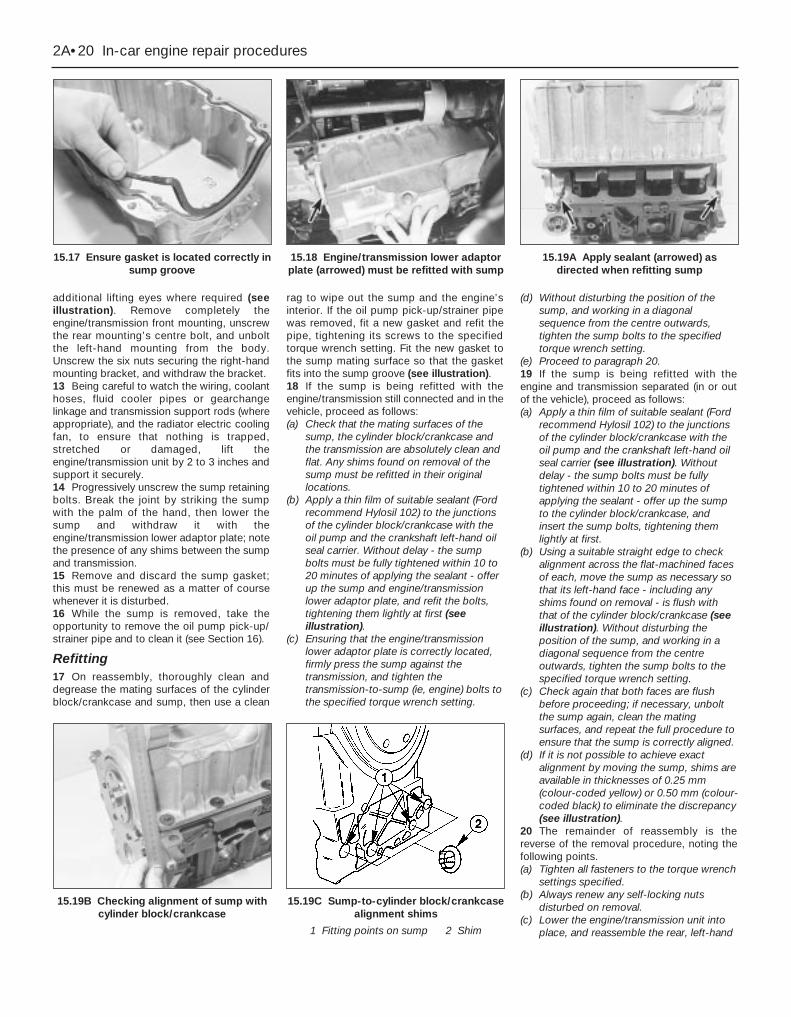
additional lifting eyes where required (seeillustration). Remove completely theengine/transmission front mounting, unscrewthe rear mounting’s centre bolt, and unboltthe left-hand mounting from the body.Unscrew the six nuts securing the right-handmounting bracket, and withdraw the bracket.13 Being careful to watch the wiring, coolanthoses, fluid cooler pipes or gearchangelinkage and transmission support rods (whereappropriate), and the radiator electric coolingfan, to ensure that nothing is trapped,stretched or damaged, lift theengine/transmission unit by 2 to 3 inches andsupport it securely.14 Progressively unscrew the sump retainingbolts. Break the joint by striking the sumpwith the palm of the hand, then lower thesump and withdraw it with theengine/transmission lower adaptor plate; notethe presence of any shims between the sumpand transmission.15 Remove and discard the sump gasket;this must be renewed as a matter of coursewhenever it is disturbed.16 While the sump is removed, take theopportunity to remove the oil pump pick-up/strainer pipe and to clean it (see Section 16).
Refitting17 On reassembly, thoroughly clean anddegrease the mating surfaces of the cylinderblock/crankcase and sump, then use a clean
rag to wipe out the sump and the engine’sinterior. If the oil pump pick-up/strainer pipewas removed, fit a new gasket and refit thepipe, tightening its screws to the specifiedtorque wrench setting. Fit the new gasket tothe sump mating surface so that the gasketfits into the sump groove (see illustration).18 If the sump is being refitted with theengine/transmission still connected and in thevehicle, proceed as follows:(a) Check that the mating surfaces of the
sump, the cylinder block/crankcase andthe transmission are absolutely clean andflat. Any shims found on removal of thesump must be refitted in their originallocations.
(b) Apply a thin film of suitable sealant (Fordrecommend Hylosil 102) to the junctionsof the cylinder block/crankcase with theoil pump and the crankshaft left-hand oilseal carrier. Without delay - the sumpbolts must be fully tightened within 10 to20 minutes of applying the sealant - offerup the sump and engine/transmissionlower adaptor plate, and refit the bolts,tightening them lightly at first (seeillustration).
(c) Ensuring that the engine/transmissionlower adaptor plate is correctly located,firmly press the sump against thetransmission, and tighten thetransmission-to-sump (ie, engine) bolts tothe specified torque wrench setting.
(d) Without disturbing the position of thesump, and working in a diagonalsequence from the centre outwards,tighten the sump bolts to the specifiedtorque wrench setting.
(e) Proceed to paragraph 20.19 If the sump is being refitted with theengine and transmission separated (in or outof the vehicle), proceed as follows:(a) Apply a thin film of suitable sealant (Ford
recommend Hylosil 102) to the junctionsof the cylinder block/crankcase with theoil pump and the crankshaft left-hand oilseal carrier (see illustration). Withoutdelay - the sump bolts must be fullytightened within 10 to 20 minutes ofapplying the sealant - offer up the sumpto the cylinder block/crankcase, andinsert the sump bolts, tightening themlightly at first.
(b) Using a suitable straight edge to checkalignment across the flat-machined facesof each, move the sump as necessary sothat its left-hand face - including anyshims found on removal - is flush withthat of the cylinder block/crankcase (seeillustration). Without disturbing theposition of the sump, and working in adiagonal sequence from the centreoutwards, tighten the sump bolts to thespecified torque wrench setting.
(c) Check again that both faces are flushbefore proceeding; if necessary, unboltthe sump again, clean the matingsurfaces, and repeat the full procedure toensure that the sump is correctly aligned.
(d) If it is not possible to achieve exactalignment by moving the sump, shims areavailable in thicknesses of 0.25 mm(colour-coded yellow) or 0.50 mm (colour-coded black) to eliminate the discrepancy(see illustration).
20 The remainder of reassembly is thereverse of the removal procedure, noting thefollowing points.(a) Tighten all fasteners to the torque wrench
settings specified.(b) Always renew any self-locking nuts
disturbed on removal.(c) Lower the engine/transmission unit into
place, and reassemble the rear, left-hand
2A•20 In-car engine repair procedures
15.17 Ensure gasket is located correctly insump groove
15.18 Engine/transmission lower adaptorplate (arrowed) must be refitted with sump
15.19A Apply sealant (arrowed) asdirected when refitting sump
15.19B Checking alignment of sump withcylinder block/crankcase
15.19C Sump-to-cylinder block/crankcasealignment shims
1 Fitting points on sump 2 Shim
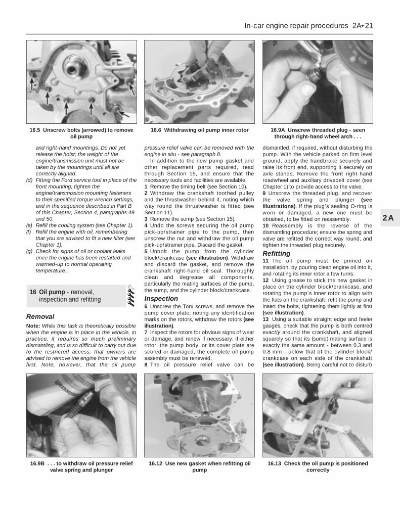
and right-hand mountings. Do not yetrelease the hoist; the weight of theengine/transmission unit must not betaken by the mountings until all arecorrectly aligned.
(d) Fitting the Ford service tool in place of thefront mounting, tighten theengine/transmission mounting fastenersto their specified torque wrench settings,and in the sequence described in Part Bof this Chapter, Section 4, paragraphs 49and 50.
(e) Refill the cooling system (see Chapter 1).(f) Refill the engine with oil, remembering
that you are advised to fit a new filter (seeChapter 1).
(g) Check for signs of oil or coolant leaksonce the engine has been restarted andwarmed-up to normal operatingtemperature.
RemovalNote: While this task is theoretically possiblewhen the engine is in place in the vehicle, inpractice, it requires so much preliminarydismantling, and is so difficult to carry out dueto the restricted access, that owners areadvised to remove the engine from the vehiclefirst. Note, however, that the oil pump
pressure relief valve can be removed with theengine in situ - see paragraph 8.
In addition to the new pump gasket andother replacement parts required, readthrough Section 15, and ensure that thenecessary tools and facilities are available.1 Remove the timing belt (see Section 10).2 Withdraw the crankshaft toothed pulleyand the thrustwasher behind it, noting whichway round the thrustwasher is fitted (seeSection 11).3 Remove the sump (see Section 15).4 Undo the screws securing the oil pumppick-up/strainer pipe to the pump, thenunscrew the nut and withdraw the oil pumppick-up/strainer pipe. Discard the gasket.5 Unbolt the pump from the cylinderblock/crankcase (see illustration). Withdrawand discard the gasket, and remove thecrankshaft right-hand oil seal. Thoroughlyclean and degrease all components,particularly the mating surfaces of the pump,the sump, and the cylinder block/crankcase.
Inspection6 Unscrew the Torx screws, and remove thepump cover plate; noting any identificationmarks on the rotors, withdraw the rotors (seeillustration).7 Inspect the rotors for obvious signs of wearor damage, and renew if necessary; if eitherrotor, the pump body, or its cover plate arescored or damaged, the complete oil pumpassembly must be renewed.8 The oil pressure relief valve can be
dismantled, if required, without disturbing thepump. With the vehicle parked on firm levelground, apply the handbrake securely andraise its front end, supporting it securely onaxle stands. Remove the front right-handroadwheel and auxiliary drivebelt cover (seeChapter 1) to provide access to the valve.9 Unscrew the threaded plug, and recoverthe valve spring and plunger (seeillustrations). If the plug’s sealing O-ring isworn or damaged, a new one must beobtained, to be fitted on reassembly.10 Reassembly is the reverse of thedismantling procedure; ensure the spring andvalve are refitted the correct way round, andtighten the threaded plug securely.
Refitting11 The oil pump must be primed oninstallation, by pouring clean engine oil into it,and rotating its inner rotor a few turns.12 Using grease to stick the new gasket inplace on the cylinder block/crankcase, androtating the pump’s inner rotor to align withthe flats on the crankshaft, refit the pump andinsert the bolts, tightening them lightly at first(see illustration).13 Using a suitable straight edge and feelergauges, check that the pump is both centredexactly around the crankshaft, and alignedsquarely so that its (sump) mating surface isexactly the same amount - between 0.3 and0.8 mm - below that of the cylinder block/crankcase on each side of the crankshaft(see illustration). Being careful not to disturb
16 Oil pump - removal,inspection and refitting
In-car engine repair procedures 2A•21
2A
16.9B . . . to withdraw oil pressure reliefvalve spring and plunger
16.12 Use new gasket when refitting oilpump
16.13 Check the oil pump is positionedcorrectly
16.5 Unscrew bolts (arrowed) to removeoil pump
16.6 Withdrawing oil pump inner rotor 16.9A Unscrew threaded plug - seenthrough right-hand wheel arch . . .
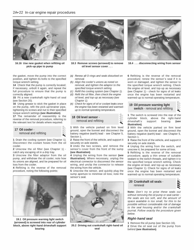
the gasket, move the pump into the correctposition, and tighten its bolts to the specifiedtorque wrench setting.14 Check that the pump is correctly located;if necessary, unbolt it again, and repeat thefull procedure to ensure that the pump iscorrectly aligned.15 Fit a new crankshaft right-hand oil seal(see Section 20).16 Using grease to stick the gasket in placeon the pump, refit the pick-up/strainer pipe,tightening its screws and nut to their specifiedtorque wrench settings (see illustration).17 The remainder of reassembly is thereverse of the removal procedure, referring tothe relevant text for details where required.
1 Drain the cooling system (see Chapter 1).Disconnect the coolant hoses from the oilcooler.2 Unscrew the oil filter (see Chapter 1) -catch any escaping oil in a drip tray.3 Unscrew the filter adaptor from the oilpump, and withdraw the oil cooler; note howits unions are aligned, and be prepared for oilloss from the cooler.4 Refitting is the reverse of the removalprocedure, noting the following points:
(a) Renew all O-rings and seals disturbed onremoval.
(b) Align the cooler’s unions as noted onremoval, and tighten the adaptor to thespecified torque wrench setting.
(c) Refill the cooling system (see Chapter 1).(d) Refit the oil filter, then check the engine
oil level, and top-up as necessary (seeChapter 1).
(e) Check for signs of oil or coolant leaks oncethe engine has been restarted and warmed-up to normal operating temperature.
1 With the vehicle parked on firm levelground, open the bonnet and disconnect thebattery negative (earth) lead - see Chapter 5,Section 1.2 Raise the front of the vehicle, and support itsecurely on axle stands.3 Undo the two screws, and remove thesensor’s cover from the front of the sump(see illustration).4 Unplug the wiring from the sensor (seeillustration). Where necessary, unplug theelectrical connector to disconnect the sensorwiring, and unclip the connector to releasethe wiring from the vehicle.5 Unscrew the sensor, and quickly plug thesump aperture to minimise oil loss; note thesensor’s seal.
6 Refitting is the reverse of the removalprocedure; renew the sensor’s seal if it isworn or damaged, and tighten the sensor tothe specified torque wrench setting. Checkthe engine oil level, and top-up as necessary(see Chapter 1) - check for signs of oil leaksonce the engine has been restarted andwarmed-up to normal operating temperature.
1 The switch is screwed into the rear of thecylinder block, above the right-handdriveshaft’s support bearing (seeillustration).2 With the vehicle parked on firm levelground, open the bonnet and disconnect thebattery negative (earth) lead - see Chapter 5,Section 1.3 Raise the front of the vehicle, and support itsecurely on axle stands.4 Unplug the wiring from the switch, andunscrew it; be prepared for some oil loss.5 Refitting is the reverse of the removalprocedure; apply a thin smear of suitablesealant to the switch threads, and tighten it tothe specified torque wrench setting. Checkthe engine oil level, and top-up as necessary(see Chapter 1). Check for signs of oil leaksonce the engine has been restarted andwarmed-up to normal operating temperature.
Note: Don’t try to prise these seals outwithout removing the oil pump or seal carrier -the seals are too soft, and the amount ofspace available is too small, for this to bepossible without considerable risk of damageto the seal housing and/or the crankshaftjournal. Follow exactly the procedure givenbelow.
Right-hand seal1 Remove the oil pump (see Section 16).2 Drive the oil seal out of the pump frombehind (see illustration).
20 Crankshaft oil seals -renewal
19 Oil pressure warning lightswitch - removal and refitting
18 Oil level sensor - removal and refitting
17 Oil cooler - removal and refitting
2A•22 In-car engine repair procedures
16.16 Use new gasket when refitting oilpick-up pipe to pump
18.3 Remove screws (arrowed) to removeoil level sensor cover . . .
18.4 . . . disconnecting wiring from sensor
19.1 Oil pressure warning light switch(arrowed) is screwed into rear of cylinder
block, above right-hand driveshaft supportbearing
20.2 Driving out crankshaft right-hand oilseal
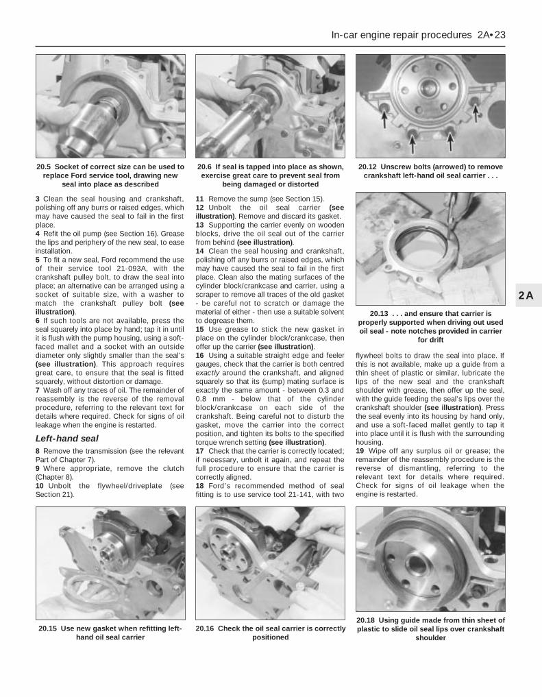
3 Clean the seal housing and crankshaft,polishing off any burrs or raised edges, whichmay have caused the seal to fail in the firstplace.4 Refit the oil pump (see Section 16). Greasethe lips and periphery of the new seal, to easeinstallation.5 To fit a new seal, Ford recommend the useof their service tool 21-093A, with thecrankshaft pulley bolt, to draw the seal intoplace; an alternative can be arranged using asocket of suitable size, with a washer tomatch the crankshaft pulley bolt (seeillustration).6 If such tools are not available, press theseal squarely into place by hand; tap it in untilit is flush with the pump housing, using a soft-faced mallet and a socket with an outsidediameter only slightly smaller than the seal’s(see illustration). This approach requiresgreat care, to ensure that the seal is fittedsquarely, without distortion or damage.7 Wash off any traces of oil. The remainder ofreassembly is the reverse of the removalprocedure, referring to the relevant text fordetails where required. Check for signs of oilleakage when the engine is restarted.
Left-hand seal8 Remove the transmission (see the relevantPart of Chapter 7).9 Where appropriate, remove the clutch(Chapter 8).10 Unbolt the flywheel/driveplate (seeSection 21).
11 Remove the sump (see Section 15).12 Unbolt the oil seal carrier (seeillustration). Remove and discard its gasket.13 Supporting the carrier evenly on woodenblocks, drive the oil seal out of the carrierfrom behind (see illustration).14 Clean the seal housing and crankshaft,polishing off any burrs or raised edges, whichmay have caused the seal to fail in the firstplace. Clean also the mating surfaces of thecylinder block/crankcase and carrier, using ascraper to remove all traces of the old gasket- be careful not to scratch or damage thematerial of either - then use a suitable solventto degrease them.15 Use grease to stick the new gasket inplace on the cylinder block/crankcase, thenoffer up the carrier (see illustration).16 Using a suitable straight edge and feelergauges, check that the carrier is both centredexactly around the crankshaft, and alignedsquarely so that its (sump) mating surface isexactly the same amount - between 0.3 and0.8 mm - below that of the cylinderblock/crankcase on each side of thecrankshaft. Being careful not to disturb thegasket, move the carrier into the correctposition, and tighten its bolts to the specifiedtorque wrench setting (see illustration).17 Check that the carrier is correctly located;if necessary, unbolt it again, and repeat thefull procedure to ensure that the carrier iscorrectly aligned.18 Ford’s recommended method of sealfitting is to use service tool 21-141, with two
flywheel bolts to draw the seal into place. Ifthis is not available, make up a guide from athin sheet of plastic or similar, lubricate thelips of the new seal and the crankshaftshoulder with grease, then offer up the seal,with the guide feeding the seal’s lips over thecrankshaft shoulder (see illustration). Pressthe seal evenly into its housing by hand only,and use a soft-faced mallet gently to tap itinto place until it is flush with the surroundinghousing.19 Wipe off any surplus oil or grease; theremainder of the reassembly procedure is thereverse of dismantling, referring to therelevant text for details where required.Check for signs of oil leakage when theengine is restarted.
In-car engine repair procedures 2A•23
2A
20.15 Use new gasket when refitting left-hand oil seal carrier
20.16 Check the oil seal carrier is correctlypositioned
20.18 Using guide made from thin sheet ofplastic to slide oil seal lips over crankshaft
shoulder
20.5 Socket of correct size can be used toreplace Ford service tool, drawing new
seal into place as described
20.6 If seal is tapped into place as shown,exercise great care to prevent seal from
being damaged or distorted
20.12 Unscrew bolts (arrowed) to removecrankshaft left-hand oil seal carrier . . .
20.13 . . . and ensure that carrier isproperly supported when driving out usedoil seal - note notches provided in carrier
for drift

Removal1 Remove the transmission (see the relevantPart of Chapter 7). Now is a good time tocheck components such as oil seals andrenew them if necessary.2 Where appropriate, remove the clutch(Chapter 8). Now is a good time to check orrenew the clutch components and pilotbearing.3 Use a centre-punch or paint to makealignment marks on the flywheel/driveplateand crankshaft, to ensure correct alignmentduring refitting.4 Prevent the flywheel/driveplate fromturning by locking the ring gear teeth, or bybolting a strap between the flywheel/driveplate and the cylinder block/crankcase. Slacken the bolts evenly until allare free.5 Remove each bolt in turn, and ensure thatnew replacements are obtained forreassembly; these bolts are subjected tosevere stresses, and so must be renewed,regardless of their apparent condition,whenever they are disturbed.6 Noting the reinforcing plate (automatictransmission-equipped models only),withdraw the flywheel/driveplate; do not dropit - it is very heavy.
Inspection7 Clean the flywheel/driveplate to removegrease and oil. Inspect the surface for cracks,rivet grooves, burned areas and score marks.Light scoring can be removed with emerycloth. Check for cracked and broken ring gearteeth. Lay the flywheel/driveplate on a flatsurface, and use a straight edge to check forwarpage.8 Clean and inspect the mating surfaces ofthe flywheel/driveplate and the crankshaft. Ifthe crankshaft left-hand seal is leaking, renewit (see Section 20) before refitting theflywheel/driveplate.9 While the flywheel/driveplate is removed,
clean carefully its inboard (right-hand) face,particularly the recesses which serve as thereference points for the crankshaftspeed/position sensor. Clean the sensor’s tip,and check that the sensor is securelyfastened.
Refitting10 On refitting, ensure that theengine/transmission adaptor plate is in place(where necessary), then fit theflywheel/driveplate to the crankshaft so thatall bolt holes align - it will fit only one way -check this using the marks made on removal.Do not forget the reinforcing plate (wherefitted).11 Lock the flywheel/driveplate by themethod used on dismantling. Working in adiagonal sequence to tighten them evenly,and increasing to the final amount in two orthree stages, tighten the new bolts to thespecified torque wrench setting (seeillustration).12 The remainder of reassembly is thereverse of the removal procedure, referring tothe relevant text for details where required.
General1 The engine/transmission mountingsseldom require attention, but broken ordeteriorated mountings should be renewedimmediately, or the added strain placed onthe driveline components may cause damageor wear.2 While separate mountings may be removedand refitted individually, if more than one isdisturbed at a time - such as if the
engine/transmission unit is removed from itsmountings - they must be reassembled andtheir fasteners tightened in a strict sequence.3 On reassembly, the weight of theengine/transmission unit must not be takenby the mountings until all are correctlyaligned. Fitting the Ford service tool in placeof the front mounting, tighten theengine/transmission mounting fasteners totheir specified torque wrench settings, and inthe sequence described in Part B of thisChapter, Section 4, paragraphs 49 and 50.
Inspection4 During the check, the engine/transmissionunit must be raised slightly, to remove itsweight from the mountings.5 Raise the front of the vehicle, and support itsecurely on axle stands. Position a jack underthe sump, with a large block of woodbetween the jack head and the sump, thencarefully raise the engine/transmission justenough to take the weight off the mountings.
Warning: DO NOT place any partof your body under the enginewhen it is supported only by ajack!
6 Check the mountings to see if the rubber iscracked, hardened or separated from themetal components. Sometimes the rubberwill split right down the centre.7 Check for relative movement between eachmounting’s brackets and the engine/transmission or body (use a large screwdriveror lever to attempt to move the mountings). Ifmovement is noted, lower the engine andcheck-tighten the mounting fasteners.
RenewalFront mounting8 Unbolt the resonator support bracket fromthe engine compartment front crossmember,slacken the two clamp screws securing the
22 Engine/transmissionmountings - inspection and renewal
21 Flywheel/driveplate - removal, inspection and refitting
2A•24 In-car engine repair procedures
21.11 Note method used to lockflywheel/driveplate while (new) bolts are
tightened
22.8 Engine/transmission front mounting - manual transmission shown, automaticequivalent similar
1 Transmission 3 Mounting 5 Mounting centre bolt2 Mounting bracket 4 Front suspension subframe
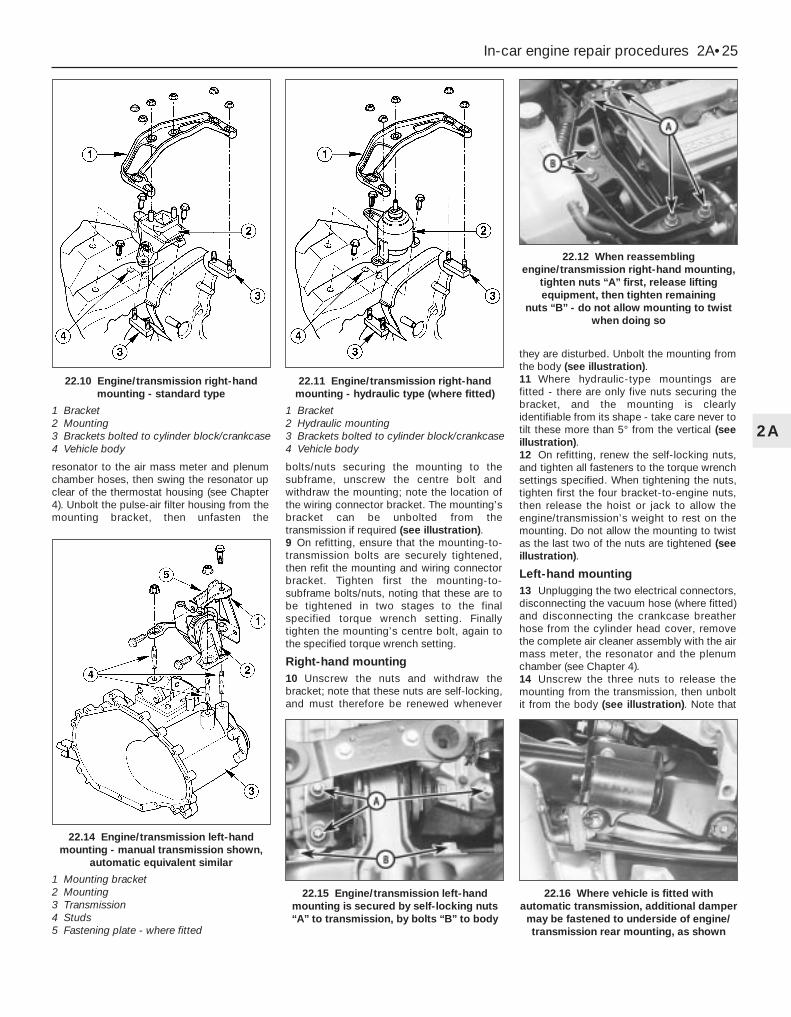
resonator to the air mass meter and plenumchamber hoses, then swing the resonator upclear of the thermostat housing (see Chapter4). Unbolt the pulse-air filter housing from themounting bracket, then unfasten the
bolts/nuts securing the mounting to thesubframe, unscrew the centre bolt andwithdraw the mounting; note the location ofthe wiring connector bracket. The mounting’sbracket can be unbolted from thetransmission if required (see illustration).9 On refitting, ensure that the mounting-to-transmission bolts are securely tightened,then refit the mounting and wiring connectorbracket. Tighten first the mounting-to-subframe bolts/nuts, noting that these are tobe tightened in two stages to the finalspecified torque wrench setting. Finallytighten the mounting’s centre bolt, again tothe specified torque wrench setting.
Right-hand mounting10 Unscrew the nuts and withdraw thebracket; note that these nuts are self-locking,and must therefore be renewed whenever
they are disturbed. Unbolt the mounting fromthe body (see illustration).11 Where hydraulic-type mountings arefitted - there are only five nuts securing thebracket, and the mounting is clearlyidentifiable from its shape - take care never totilt these more than 5° from the vertical (seeillustration).12 On refitting, renew the self-locking nuts,and tighten all fasteners to the torque wrenchsettings specified. When tightening the nuts,tighten first the four bracket-to-engine nuts,then release the hoist or jack to allow theengine/transmission’s weight to rest on themounting. Do not allow the mounting to twistas the last two of the nuts are tightened (seeillustration).
Left-hand mounting13 Unplugging the two electrical connectors,disconnecting the vacuum hose (where fitted)and disconnecting the crankcase breatherhose from the cylinder head cover, removethe complete air cleaner assembly with the airmass meter, the resonator and the plenumchamber (see Chapter 4).14 Unscrew the three nuts to release themounting from the transmission, then unboltit from the body (see illustration). Note that
In-car engine repair procedures 2A•25
2A
22.14 Engine/transmission left-handmounting - manual transmission shown,
automatic equivalent similar
1 Mounting bracket2 Mounting3 Transmission4 Studs5 Fastening plate - where fitted
22.12 When reassemblingengine/transmission right-hand mounting,
tighten nuts “A” first, release liftingequipment, then tighten remaining
nuts “B” - do not allow mounting to twistwhen doing so
22.15 Engine/transmission left-handmounting is secured by self-locking nuts“A” to transmission, by bolts “B” to body
22.16 Where vehicle is fitted withautomatic transmission, additional damper
may be fastened to underside of engine/transmission rear mounting, as shown
22.10 Engine/transmission right-handmounting - standard type
1 Bracket2 Mounting3 Brackets bolted to cylinder block/crankcase4 Vehicle body
22.11 Engine/transmission right-handmounting - hydraulic type (where fitted)
1 Bracket2 Hydraulic mounting3 Brackets bolted to cylinder block/crankcase4 Vehicle body

the nuts are self-locking, and must thereforebe renewed whenever they are disturbed.Unscrew the centre bolt to dismantle themounting, if necessary to renew components.15 On refitting, renew the self-locking nuts,and do not allow the mounting to twist as thenuts are tightened (see illustration). Tightenall fasteners to the specified torque wrenchsettings.
Rear mounting16 Where the vehicle is fitted with automatictransmission, a separate damper may befitted beneath the subframe, which must beunbolted to reach the mounting’s fasteners(see illustration).17 Unbolt the mounting from the subframe,then unscrew the mounting’s centre bolt. Ifrequired, unbolt the mounting’s bracket from
the transmission (see illustrations).18 On refitting, ensure that the mounting-to-transmission bolts are securely tightened,then refit the mounting. Tighten first themounting-to-subframe bolts, noting thatthese are to be tightened in two stages to thefinal specified torque wrench setting. Finallytighten the mounting’s centre bolt, again tothe specified torque wrench setting.
2A•26 In-car engine repair procedures
22.17A Engine/transmission rear mounting -manual transmission type
1 Transmission 4 Mounting2 Mounting bracket 5 Mounting centre bolt3 Front suspension subframe
22.17B Engine/transmission rear mounting - automatic transmission type
1 Transmission 3 Mounting 5 Mounting centre bolt2 Mounting bracket 4 Front suspension subframe

Chapter 2 Part B: Engine removal and general engine overhaul procedures
Compression test - description and interpretation . . . See Chapter 2ACrankshaft - inspection . . . . . . . . . . . . . . . . . . . . . . . . . . . . . . . . . . . 13Crankshaft - refitting and main bearing running
clearance check . . . . . . . . . . . . . . . . . . . . . . . . . . . . . . . . . . . . . . 17Crankshaft - removal . . . . . . . . . . . . . . . . . . . . . . . . . . . . . . . . . . . . . 10Cylinder block/crankcase - cleaning and inspection . . . . . . . . . . . . 11Cylinder head - dismantling . . . . . . . . . . . . . . . . . . . . . . . . . . . . . . . 6Cylinder head - reassembly . . . . . . . . . . . . . . . . . . . . . . . . . . . . . . . 8Cylinder head and valve components - cleaning and inspection . . . 7Engine - initial start-up after overhaul . . . . . . . . . . . . . . . . . . . . . . . . 19Engine overhaul - dismantling sequence . . . . . . . . . . . . . . . . . . . . . 5
Engine overhaul - general information . . . . . . . . . . . . . . . . . . . . . . . 2Engine overhaul - reassembly sequence . . . . . . . . . . . . . . . . . . . . . 15Engine/transmission - removal and refitting . . . . . . . . . . . . . . . . . . . 4Engine/transmission removal - methods and precautions . . . . . . . . 3General information . . . . . . . . . . . . . . . . . . . . . . . . . . . . . . . . . . . . . . 1Main and big-end bearings - inspection . . . . . . . . . . . . . . . . . . . . . . 14Piston/connecting rod assemblies - inspection . . . . . . . . . . . . . . . . 12Piston/connecting rod assemblies - refitting and
big-end bearing running clearance check . . . . . . . . . . . . . . . . . . . 18Piston/connecting rod assemblies - removal . . . . . . . . . . . . . . . . . . 9Piston rings - refitting . . . . . . . . . . . . . . . . . . . . . . . . . . . . . . . . . . . . 16
Cylinder headMaximum permissible gasket surface distortion . . . . . . . . . . . . . . . . . . 0.10 mmValve seat included angle . . . . . . . . . . . . . . . . . . . . . . . . . . . . . . . . . . . . 90°Valve guide bore . . . . . . . . . . . . . . . . . . . . . . . . . . . . . . . . . . . . . . . . . . . 6.060 to 6.091 mm
Valves - general Inlet ExhaustValve lift . . . . . . . . . . . . . . . . . . . . . . . . . . . . . . . . . . . . . . . . . . . . . . . . . . 7.500 to 7.685 mm 7.610 to 7.765 mmValve length . . . . . . . . . . . . . . . . . . . . . . . . . . . . . . . . . . . . . . . . . . . . . . . 96.870 to 97.330 mm 96.470 to 96.930 mmValve head diameter:
1.6 litre engine . . . . . . . . . . . . . . . . . . . . . . . . . . . . . . . . . . . . . . . . . . . 26.0 mm 24.5 mm1.8 and 2.0 litre engines . . . . . . . . . . . . . . . . . . . . . . . . . . . . . . . . . . . 32.0 mm 28.0 mm
Valve stem diameter . . . . . . . . . . . . . . . . . . . . . . . . . . . . . . . . . . . . . . . . 6.028 to 6.043 mm 6.010 to6.025 mmValve stem-to-guide clearance . . . . . . . . . . . . . . . . . . . . . . . . . . . . . . . . 0.017 to 0.064 mm 0.035 to 0.081 mm
Cylinder blockCylinder bore diameter - 1.6 litre engine:
Class 1 . . . . . . . . . . . . . . . . . . . . . . . . . . . . . . . . . . . . . . . . . . . . . . . . . 76.000 to 76.010 mmClass 2 . . . . . . . . . . . . . . . . . . . . . . . . . . . . . . . . . . . . . . . . . . . . . . . . . 76.010 to 76.020 mmClass 3 . . . . . . . . . . . . . . . . . . . . . . . . . . . . . . . . . . . . . . . . . . . . . . . . . 76.020 to 76.030 mm
Cylinder bore diameter - 1.8 litre engine:Class 1 . . . . . . . . . . . . . . . . . . . . . . . . . . . . . . . . . . . . . . . . . . . . . . . . . 80.600 to 80.610 mmClass 2 . . . . . . . . . . . . . . . . . . . . . . . . . . . . . . . . . . . . . . . . . . . . . . . . . 80.610 to 80.620 mmClass 3 . . . . . . . . . . . . . . . . . . . . . . . . . . . . . . . . . . . . . . . . . . . . . . . . . 80.620 to 80.630 mm
Cylinder bore diameter - 2.0 litre engine:Class 1 . . . . . . . . . . . . . . . . . . . . . . . . . . . . . . . . . . . . . . . . . . . . . . . . . 84.800 to 84.810 mmClass 2 . . . . . . . . . . . . . . . . . . . . . . . . . . . . . . . . . . . . . . . . . . . . . . . . . 84.810 to 84.820 mmClass 3 . . . . . . . . . . . . . . . . . . . . . . . . . . . . . . . . . . . . . . . . . . . . . . . . . 84.820 to 84.830 mm
2B•1
Easy, suitable fornovice with littleexperience
Fairly easy, suitablefor beginner withsome experience
Fairly difficult, suitablefor competent DIYmechanic
Difficult, suitable forexperienced DIYmechanic
Very difficult,suitable for expert DIYor professional
Degrees of difficulty
Specifications
Contents
2B

Pistons and piston ringsPiston diameter - 1.6 litre engine:
Class 1 . . . . . . . . . . . . . . . . . . . . . . . . . . . . . . . . . . . . . . . . . . . . . . . . . 75.975 to 75.985 mmClass 2 . . . . . . . . . . . . . . . . . . . . . . . . . . . . . . . . . . . . . . . . . . . . . . . . . 75.985 to 75.995 mmClass 3 . . . . . . . . . . . . . . . . . . . . . . . . . . . . . . . . . . . . . . . . . . . . . . . . . 75.995 to 76.005 mm
Piston diameter - 1.8 litre engine:Class 1 . . . . . . . . . . . . . . . . . . . . . . . . . . . . . . . . . . . . . . . . . . . . . . . . . 80.570 to 80.580 mmClass 2 . . . . . . . . . . . . . . . . . . . . . . . . . . . . . . . . . . . . . . . . . . . . . . . . . 80.580 to 80.590 mmClass 3 . . . . . . . . . . . . . . . . . . . . . . . . . . . . . . . . . . . . . . . . . . . . . . . . . 80.590 to 80.600 mm
Piston diameter - 2.0 litre engine:Class 1 . . . . . . . . . . . . . . . . . . . . . . . . . . . . . . . . . . . . . . . . . . . . . . . . . 84.770 to 84.780 mmClass 2 . . . . . . . . . . . . . . . . . . . . . . . . . . . . . . . . . . . . . . . . . . . . . . . . . 84.780 to 84.790 mmClass 3 . . . . . . . . . . . . . . . . . . . . . . . . . . . . . . . . . . . . . . . . . . . . . . . . . 84.790 to 84.800 mm
Oversizes - all engines . . . . . . . . . . . . . . . . . . . . . . . . . . . . . . . . . . . . . . None availablePiston-to-cylinder bore clearance . . . . . . . . . . . . . . . . . . . . . . . . . . . . . . No information available at time of writingPiston ring end gaps - installed:
Top compression ring - 1.6 and 1.8 litre engines . . . . . . . . . . . . . . . . 0.30 to 0.50 mmTop compression ring - 2.0 litre engine . . . . . . . . . . . . . . . . . . . . . . . 0.26 to 0.50 mmSecond compression ring . . . . . . . . . . . . . . . . . . . . . . . . . . . . . . . . . . 0.30 to 0.50 mmOil control ring - 1.6 litre engine . . . . . . . . . . . . . . . . . . . . . . . . . . . . . 0.25 to 1.00 mmOil control ring - 1.8 litre engine . . . . . . . . . . . . . . . . . . . . . . . . . . . . . 0.38 to 1.14 mmOil control ring - 2.0 litre engine . . . . . . . . . . . . . . . . . . . . . . . . . . . . . 0.40 to 1.40 mm
Gudgeon pinDiameter:
White colour code/piston crown marked “A” . . . . . . . . . . . . . . . . . . . 20.622 to 20.625 mmRed colour code/piston crown marked “B” . . . . . . . . . . . . . . . . . . . . 20.625 to 20.628 mmBlue colour code/piston crown marked “C” . . . . . . . . . . . . . . . . . . . . 20.628 to 20.631 mm
Clearance in piston . . . . . . . . . . . . . . . . . . . . . . . . . . . . . . . . . . . . . . . . . 0.010 to 0.016 mmConnecting rod small-end eye internal diameter . . . . . . . . . . . . . . . . . . 20.589 to 20.609 mmInterference fit in connecting rod . . . . . . . . . . . . . . . . . . . . . . . . . . . . . . 0.011 to 0.042 mm
Crankshaft and bearingsMain bearing shell standard inside diameter - installed . . . . . . . . . . . . 58.011 to 58.038 mmMain bearing journal standard diameter . . . . . . . . . . . . . . . . . . . . . . . . 57.980 to 58.000 mmMain bearing journal-to-shell running clearance . . . . . . . . . . . . . . . . . . 0.011 to 0.058 mmMain bearing shell undersizes available . . . . . . . . . . . . . . . . . . . . . . . . . 0.02 mm, 0.25 mmBig-end bearing shell standard inside diameter - installed . . . . . . . . . . . 46.926 to 46.960 mmCrankpin (big-end) bearing journal standard diameter . . . . . . . . . . . . . 46.890 to 46.910 mmCrankpin (big-end) bearing journal-to-shell running clearance . . . . . . . . 0.016 to 0.070 mmBig-end bearing shell undersizes available . . . . . . . . . . . . . . . . . . . . . . 0.02 mm, 0.25 mmCrankshaft endfloat . . . . . . . . . . . . . . . . . . . . . . . . . . . . . . . . . . . . . . . . . 0.090 to 0.310 mm
Torque wrench settings Nm lbf ftMain bearing cap bolts and nuts . . . . . . . . . . . . . . . . . . . . . . . . . . . . . . 80 59Big-end bearing cap bolts:
Stage 1 . . . . . . . . . . . . . . . . . . . . . . . . . . . . . . . . . . . . . . . . . . . . . . . . 18 13Stage 2 . . . . . . . . . . . . . . . . . . . . . . . . . . . . . . . . . . . . . . . . . . . . . . . . Angle-tighten a further 90°
Piston-cooling oil jet/blanking plug Torx screws . . . . . . . . . . . . . . . . . . 10 7Cylinder block and head oilway blanking plugs:
M6 x 10 . . . . . . . . . . . . . . . . . . . . . . . . . . . . . . . . . . . . . . . . . . . . . . . . 8 to 11 6 to 8M10 x 11.5 - in block . . . . . . . . . . . . . . . . . . . . . . . . . . . . . . . . . . . . . . 24 171/4 PTF plug - in block . . . . . . . . . . . . . . . . . . . . . . . . . . . . . . . . . . . . 25 18
Power steering pump/air conditioning compressor mounting bracket-to-cylinder block bolts . . . . . . . . . . . . . . . . . . . . . . . . . . . . . . . . 47 35Exhaust manifold heat shield mounting bracket-to-cylinder block bolts . . . . . . . . . . . . . . . . . . . . . . . . . . . . . . . . . . . . . . . . . . . . . . . . 32 24Crankcase breather system:
Oil separator-to-cylinder block bolts . . . . . . . . . . . . . . . . . . . . . . . . . 10 7Pipe-to-cylinder head bolt . . . . . . . . . . . . . . . . . . . . . . . . . . . . . . . . . . 23 17
Water pump bolts . . . . . . . . . . . . . . . . . . . . . . . . . . . . . . . . . . . . . . . . . . See Chapter 3Driveshaft support bearing bracket-to-cylinder block bolts . . . . . . . . . . 48 35Transmission-to-engine bolts . . . . . . . . . . . . . . . . . . . . . . . . . . . . . . . . . See Part A of this ChapterEngine/transmission mounting fasteners . . . . . . . . . . . . . . . . . . . . . . . . See Part A of this ChapterFront suspension subframe bolts . . . . . . . . . . . . . . . . . . . . . . . . . . . . . . 130 96Note: Refer to Part A of this Chapter for remaining torque wrench settings.
2B•2 Engine removal and general engine overhaul procedures
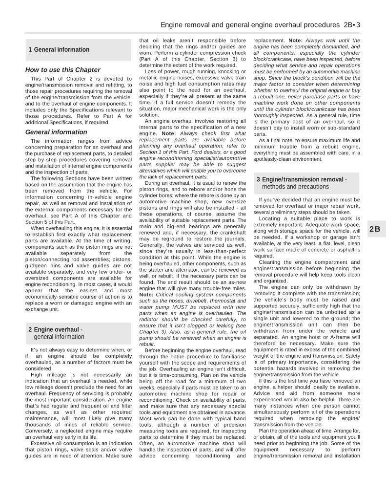
How to use this ChapterThis Part of Chapter 2 is devoted to
engine/transmission removal and refitting, tothose repair procedures requiring the removalof the engine/transmission from the vehicle,and to the overhaul of engine components. Itincludes only the Specifications relevant tothose procedures. Refer to Part A foradditional Specifications, if required.
General informationThe information ranges from advice
concerning preparation for an overhaul andthe purchase of replacement parts, to detailedstep-by-step procedures covering removaland installation of internal engine componentsand the inspection of parts.
The following Sections have been writtenbased on the assumption that the engine hasbeen removed from the vehicle. Forinformation concerning in-vehicle enginerepair, as well as removal and installation ofthe external components necessary for theoverhaul, see Part A of this Chapter andSection 5 of this Part.
When overhauling this engine, it is essentialto establish first exactly what replacementparts are available. At the time of writing,components such as the piston rings are notavailable separately from thepiston/connecting rod assemblies; pistons,gudgeon pins and valve guides are notavailable separately, and very few under- oroversized components are available forengine reconditioning. In most cases, it wouldappear that the easiest and mosteconomically-sensible course of action is toreplace a worn or damaged engine with anexchange unit.
It’s not always easy to determine when, orif, an engine should be completelyoverhauled, as a number of factors must beconsidered.
High mileage is not necessarily anindication that an overhaul is needed, whilelow mileage doesn’t preclude the need for anoverhaul. Frequency of servicing is probablythe most important consideration. An enginethat’s had regular and frequent oil and filterchanges, as well as other requiredmaintenance, will most likely give manythousands of miles of reliable service.Conversely, a neglected engine may requirean overhaul very early in its life.
Excessive oil consumption is an indicationthat piston rings, valve seals and/or valveguides are in need of attention. Make sure
that oil leaks aren’t responsible beforedeciding that the rings and/or guides areworn. Perform a cylinder compression check(Part A of this Chapter, Section 3) todetermine the extent of the work required.
Loss of power, rough running, knocking ormetallic engine noises, excessive valve trainnoise and high fuel consumption rates mayalso point to the need for an overhaul,especially if they’re all present at the sametime. If a full service doesn’t remedy thesituation, major mechanical work is the onlysolution.
An engine overhaul involves restoring allinternal parts to the specification of a newengine. Note: Always check first whatreplacement parts are available beforeplanning any overhaul operation; refer toSection 1 of this Part. Ford dealers, or a goodengine reconditioning specialist/automotiveparts supplier may be able to suggestalternatives which will enable you to overcomethe lack of replacement parts.
During an overhaul, it is usual to renew thepiston rings, and to rebore and/or hone thecylinder bores; where the rebore is done by anautomotive machine shop, new oversizepistons and rings will also be installed - allthese operations, of course, assume theavailability of suitable replacement parts. Themain and big-end bearings are generallyrenewed and, if necessary, the crankshaftmay be reground to restore the journals.Generally, the valves are serviced as well,since they’re usually in less-than-perfectcondition at this point. While the engine isbeing overhauled, other components, such asthe starter and alternator, can be renewed aswell, or rebuilt, if the necessary parts can befound. The end result should be an as-newengine that will give many trouble-free miles.Note: Critical cooling system componentssuch as the hoses, drivebelt, thermostat andwater pump MUST be replaced with newparts when an engine is overhauled. Theradiator should be checked carefully, toensure that it isn’t clogged or leaking (seeChapter 3). Also, as a general rule, the oilpump should be renewed when an engine isrebuilt.
Before beginning the engine overhaul, readthrough the entire procedure to familiariseyourself with the scope and requirements ofthe job. Overhauling an engine isn’t difficult,but it is time-consuming. Plan on the vehiclebeing off the road for a minimum of twoweeks, especially if parts must be taken to anautomotive machine shop for repair orreconditioning. Check on availability of parts,and make sure that any necessary specialtools and equipment are obtained in advance.Most work can be done with typical handtools, although a number of precisionmeasuring tools are required, for inspectingparts to determine if they must be replaced.Often, an automotive machine shop willhandle the inspection of parts, and will offeradvice concerning reconditioning and
replacement. Note: Always wait until theengine has been completely dismantled, andall components, especially the cylinderblock/crankcase, have been inspected, beforedeciding what service and repair operationsmust be performed by an automotive machineshop. Since the block’s condition will be themajor factor to consider when determiningwhether to overhaul the original engine or buya rebuilt one, never purchase parts or havemachine work done on other componentsuntil the cylinder block/crankcase has beenthoroughly inspected. As a general rule, timeis the primary cost of an overhaul, so itdoesn’t pay to install worn or sub-standardparts.
As a final note, to ensure maximum life andminimum trouble from a rebuilt engine,everything must be assembled with care, in aspotlessly-clean environment.
If you’ve decided that an engine must beremoved for overhaul or major repair work,several preliminary steps should be taken.
Locating a suitable place to work isextremely important. Adequate work space,along with storage space for the vehicle, willbe needed. If a workshop or garage isn’tavailable, at the very least, a flat, level, cleanwork surface made of concrete or asphalt isrequired.
Cleaning the engine compartment andengine/transmission before beginning theremoval procedure will help keep tools cleanand organized.
The engine can only be withdrawn byremoving it complete with the transmission;the vehicle’s body must be raised andsupported securely, sufficiently high that theengine/transmission can be unbolted as asingle unit and lowered to the ground; theengine/transmission unit can then bewithdrawn from under the vehicle andseparated. An engine hoist or A-frame willtherefore be necessary. Make sure theequipment is rated in excess of the combinedweight of the engine and transmission. Safetyis of primary importance, considering thepotential hazards involved in removing theengine/transmission from the vehicle.
If this is the first time you have removed anengine, a helper should ideally be available.Advice and aid from someone moreexperienced would also be helpful. There aremany instances when one person cannotsimultaneously perform all of the operationsrequired when removing the engine/transmission from the vehicle.
Plan the operation ahead of time. Arrange for,or obtain, all of the tools and equipment you’llneed prior to beginning the job. Some of theequipment necessary to performengine/transmission removal and installation
3 Engine/transmission removal -methods and precautions
2 Engine overhaul - general information
1 General information
Engine removal and general engine overhaul procedures 2B•3
2B

safely and with relative ease, and which mayhave to be hired or borrowed, includes (inaddition to the engine hoist) a heavy-duty trolleyjack, a strong pair of axle stands, some woodenblocks, and an engine dolly (a low, wheeledplatform capable of taking the weight of theengine/transmission, so that it can be movedeasily when on the ground). A complete set ofspanners and sockets (as described in the frontof this manual) will obviously be needed,together with plenty of rags and cleaningsolvent for mopping-up spilled oil, coolant andfuel. If the hoist is to be hired, make sure thatyou arrange for it in advance, and perform all ofthe operations possible without it beforehand.This will save you money and time.
Plan for the vehicle to be out of use forquite a while. A machine shop will be requiredto perform some of the work which the do-it-yourselfer can’t accomplish without specialequipment. These establishments often havea busy schedule, so it would be a good ideato consult them before removing the engine,to accurately estimate the amount of timerequired to rebuild or repair components thatmay need work.
Always be extremely careful when removingand installing the engine/transmission.Serious injury can result from carelessactions. By planning ahead and taking yourtime, the job (although a major task) can beaccomplished successfully.
Warning: Petrol is extremelyflammable, so take extraprecautions when disconnectingany part of the fuel system. Don’t
smoke, or allow naked flames or bare lightbulbs in or near the work area, and don’twork in a garage where a natural gasappliance (such as a clothes dryer or waterheater) is installed. If you spill petrol onyour skin, rinse it off immediately. Have afire extinguisher rated for petrol fireshandy, and know how to use it.
Note: Read through the entire Section, as wellas reading the advice in the preceding Section,before beginning this procedure. The engineand transmission are removed as a unit,lowered to the ground and removed fromunderneath, then separated outside the vehicle.
Removal1 Park the vehicle on firm, level ground, applythe handbrake firmly, and slacken the nutssecuring both front roadwheels.2 Relieve the fuel system pressure (seeChapter 4).3 Disconnect the battery negative (earth) lead- see Chapter 5, Section 1. For better accessthe battery may be removed completely (seeChapter 5).4 Place protective covers on the wings andengine compartment front crossmember, thenremove the bonnet (see Chapter 11).5 Whenever you disconnect any vacuumlines, coolant and emissions hoses, wiringloom connectors, earth straps and fuel linesas part of the following procedure, alwayslabel them clearly, so that they can becorrectly reassembled.6 Unplug the two electrical connectors,
disconnect the vacuum hose (where fitted)and disconnect the crankcase breather hosefrom the cylinder head cover, then remove thecomplete air cleaner assembly, with the airmass meter, the resonator and the plenumchamber (see Chapter 4).7 Equalise the pressure in the fuel tank byremoving the filler cap, then undo the fuelfeed and return lines connecting the engine tothe chassis (see Chapter 4). Plug or cap allopen fittings (see illustration).8 Disconnect the accelerator cable from thethrottle linkage as described in Chapter 4 -where fitted, also disconnect the cruisecontrol actuator cable (see Chapter 12).Secure the cable(s) clear of theengine/transmission.9 Releasing its wire clip, unplug the powersteering pressure switch electrical connector,then unbolt the power steering high-pressurepipe and the earth lead from the cylinder headrear support plate/engine lifting eye (seeillustrations).10 Marking or labelling all components asthey are disconnected (see paragraph 5above), disconnect the vacuum hoses asfollows:
4 Engine/transmission - removal and refitting
2B•4 Engine removal and general engine overhaul procedures
4.7 Note colour-coding of unions whendisconnecting fuel feed and return lines
4.9A Unplug the power steering pressureswitch electrical connector . . .
4.9B . . . unbolt the power steering high-pressure pipe . . .
Whenever any wiring is disconnected, . . . vacuum hoses and pipes should mark or label it as shown, to ensure be similarly marked
correct reconnection . . .
Masking tape and/or a touch-up paint applicator work well for marking items. Takeinstant photos, or sketch the locations of components and brackets.

(a) One from the rear of the throttle housing(only the one hose - there is no need todisconnect the second hose running tothe fuel pressure regulator) (seeillustration).
(b) One from the union on the inlet manifold’sleft-hand end (see illustration).
(c) The braking system vacuum servo unithose - from the inlet manifold (seeChapter 9 for details).
(d) Also disconnect the vacuum hoses fromthe Exhaust Gas Recirculation systemcomponents - one from the EGR valve,two from the EGR pipe (note that theselast two are of different sizes, as are theirpipe stubs, so that they can only beconnected the correct way round).
(e) While you are there, trace the vacuum linefrom the pulse-air filter housing over thetop of the transmission, and disconnect itby pulling the plastic pipe out of therubber hose just beneath the bulkhead-mounted pulse-air solenoid valve (seeillustration).
(f) Secure all these hoses so that they won’tget damaged as the engine/transmissionis removed.
11 Unbolt the engine/transmission-to-bodyearth lead from the transmission’s top surface(see illustration). Disconnect the speed-ometer drive cable (see Chapter 12) andsecure it clear of the engine/transmission.12 Where the vehicle is fitted with manualtransmission, disconnect the clutch cable (see
Chapter 8). Where automatic transmission isfitted, disconnect the selector cable (seeChapter 7, Part B). Secure the cable clear ofthe engine/transmission.13 Marking or labelling all components asthey are disconnected (see paragraph 5above), disconnect the engine wiring loomfrom the body as follows:(a) Starting at the left-hand side of the engine
compartment, release and unplug thethree large electrical connectors clippedto the suspension mounting - note thewire clips fitted to some connectors (seeillustration).
(b) Disconnect and/or release the battery-to-starter motor wiring, noting the singleconnector which must be unplugged.
(c) Unplug the electrical connector(s) todisconnect the vehicle speed sensor,oxygen sensor and, where fitted, the oillevel sensor wiring - unclip the connectorsto release the wiring where necessary.
(d) Work along the loom to the bulkhead,unclipping the loom and unplugging thevarious bulkhead-mounted componentsconnected into it, until you reach theright-hand side of the enginecompartment (see illustration).
(e) Carefully prise the power steering fluidreservoir upwards out of its clip on thesuspension mounting, then unscrew theECU connector’s retaining bolt andunplug the connector (see illustration).
(f) Unbolt the earth lead from the right-hand
Engine removal and general engine overhaul procedures 2B•5
2B
4.13A Unplug three large electricalconnectors (arrowed) . . .
4.13B . . . unplug engine wiring loom frombattery wiring and bulkhead components
(arrowed) . . .
4.13C . . . and disconnect ECU wiring andearth lead (arrowed) to release engine
wiring loom from vehicle body
4.9C . . . and the earth lead from thecylinder head rear support plate/engine
lifting eye
4.10A Disconnect vacuum hose shownfrom rear of throttle housing . . .
4.10B . . . vacuum hose (arrowed) fromunion on left-hand end on inlet manifold . . .
4.10C . . . also brake servo hose (A), EGRvalve hose (B), EGR pipe hoses (C) - noting
their different sizes - and pulse-air filtervacuum line (D)
4.11 Unbolt the engine/transmission-to-body earth lead - hidden behind wiring
loom guide - from location (arrowed) onthe transmission’s top surface

inner wing panel, release the enginewiring loom and refit the power steeringfluid reservoir.
(g) Secure the engine wiring loom neatly tothe engine/transmission so that it cannotbe damaged as the unit is removed fromthe vehicle.
14 Unbolt both parts of the exhaust manifoldheat shield; unclip the coolant hose to allowthe upper part to be withdrawn.15 Remove the auxiliary drivebelt (seeChapter 1).16 Unbolt the power steering pump (seeChapter 10); secure it as far as possible(without disconnecting the system’s hoses)clear of the engine/transmission.17 Raise the vehicle and support it securelyon axle stands, then remove the frontroadwheels. Drain the cooling system and (ifthe engine is to be dismantled) drain theengine oil and remove the oil filter (seeChapter 1). Also drain the transmission asdescribed in the relevant Part of Chapter 7.18 Withdraw the lower part of the exhaustmanifold heat shield.19 Unscrew the nuts to disconnect theexhaust system front downpipe from themanifold, then unhook all the system’s rubbermountings and withdraw the completeexhaust system from under the vehicle (seeChapter 4 for details).20 Where the vehicle is fitted with manualtransmission, mark their positions, thendisconnect the gearchange linkage andtransmission support rods from the rear of thetransmission. Unscrew the retaining nuts, andwithdraw the gear linkage heat shield from theunderbody. Unbolt the rear end of the linkagefrom the underbody, swivel the linkage aroundto the rear, and tie it to the underbody (seeChapter 7, Part A, for details).21 Disconnect both anti-roll bar links fromtheir respective suspension strut - note theflexible brake hose bracket attached to eachlink stud - and both track rod ends from theirsteering knuckles. Unfasten the clamp boltsecuring each front suspension lower armballjoint to its steering knuckle (see Chap-ter 10 for details). Check that both balljointscan be released from the knuckle assemblieswhen required, but leave them in place for the
time being, secured by the clamp bolts ifnecessary.22 Where the vehicle is fitted with airconditioning, unbolt the accumulator/dehydrator from the subframe; secure it as faras possible (without disconnecting thesystem’s hoses) clear of the engine/transmission.
Warning: Do not disconnect therefrigerant hoses.
23 Unbolt the steering gear from thesubframe; if the bolts are not accessible fromabove, a Ford service tool will be required toreach them from underneath the vehicle (seeChapter 10 for details).24 Unscrew the two bolts securing the powersteering system pipes to the right-hand sideof the subframe.25 Hold the radiator in its raised position, byinserting split pins through the holes in therear of the engine compartment frontcrossmember and into the radiator’s uppermounting extensions. Unbolt the radiatormounting brackets from the subframe; notethat they are handed, and are marked toensure correct refitting (see illustrations).Collect and store the bottom mountingrubbers for safekeeping, noting which way upthey are fitted.26 Unbolt the engine/transmission rearmounting from the subframe - where thevehicle is fitted with automatic transmission, aseparate damper may be fitted beneath thesubframe, which must be unbolted to reachthe mounting’s fasteners. Where the vehicle isfitted with manual transmission, also unscrewthe mounting centre bolt, and unbolt themounting bracket from the transmission.27 Unscrew the engine/transmission frontmounting centre bolt, and unbolt themounting from the subframe, noting thelocation of the wiring connector bracket.28 Use white paint or similar (do not use asharp-pointed scriber, which might break theunderbody protective coating and causerusting) to mark the exact relationship of thesubframe to the underbody. Unscrew the fourmounting bolts from the subframe (note theirdifferent-sized washers - see also illus-
tration 4.47A) and allow the subframe to hangdown on the suspension lower arm balljoints.Disconnect the balljoints one at a time fromthe steering knuckle assemblies (see Chap-ter 10) and lower the subframe to the ground;withdraw the subframe from under thevehicle.29 Marking or labelling all components asthey are disconnected (see paragraph 5above) and catching as much as possible ofthe escaping coolant in the drain tray,disconnect the cooling system hoses andpipes as follows - refer to Chapter 3 for furtherdetails, if required:(a) Remove the radiator top hose.(b) Remove the (heater) hose running from
the thermostat to the enginecompartment bulkhead union.
(c) Disconnect from the thermostat the hoserunning to the expansion tank - secure thehose clear of the working area.
(d) Disconnect from the thermostat thecoolant hose/pipe which runs to theradiator bottom hose.
(e) Disconnect the radiator bottom hose fromthe radiator union, from the (sump) heatercoolant pipe and from the water pumpunion - secure the hose clear of theworking area.
(f) Unbolt the (heater) coolant pipe from thesump, trace the pipe/hose round to theengine compartment bulkhead union,disconnecting (where fitted) the oil coolerhoses from the cooler unions, thenremove it.
(g) Unless the vehicle has air conditioningfitted, secure the radiator as far forwardsas possible while it is in its raised position;if air conditioning is fitted, remove theradiator completely (see Chapter 3).
30 Where the vehicle is fitted with airconditioning, unplug the compressor’selectrical connector, and unbolt thecompressor from the engine (seeillustration). Secure it as far as possible(without disconnecting the system’s hoses)clear of the engine/transmission.
Warning: Do not disconnect therefrigerant hoses.
2B•6 Engine removal and general engine overhaul procedures
4.25A Use split pins as shown to secureradiator in its raised position . . .
4.25B . . . while you unbolt the bottommountings (arrowed) - note that the
mountings are handed, and do not lose themounting rubbers
4.30 Unscrew bolts (arrowed) to releaseair conditioning compressor from engine

31 Where the vehicle is fitted with manualtransmission, disconnect the driveshafts fromthe transmission as follows, referring toChapter 8 for further details when required:(a) Unscrew the nuts securing the right-hand
driveshaft support bearing, and withdrawthe heat shield.
(b) Pull the right-hand driveshaft out of thetransmission; be prepared to catch anyspilt oil.
(c) Secure the driveshaft clear of theengine/transmission - remember that theunit is to be lowered out of the vehicle -and ensure that the inner joint is notturned through more than 18°.
(d) Prise the left-hand driveshaft out of thetransmission - again, be prepared for oilspillage. Secure the driveshaft clear of theengine/transmission, and ensure that itsinner joint is not turned through more than18°.
32 Where the vehicle is fitted with automatictransmission, proceed as follows, referring toChapter 7, Part B and to Chapter 8 for furtherdetails when required:(a) Unscrew its centre bolt, then unbolt the
engine/transmission rear mountingbracket from the transmission.
(b) Disconnect the fluid cooler pipe from therear of the transmission, and secure itclear of the unit.
(c) Prise the left-hand driveshaft out of thetransmission; be prepared to catch anyspilt oil.
(d) Secure the driveshaft clear of theengine/transmission - remember that theunit is to be lowered out of the vehicle -and ensure that the inner joint is notturned through more than 18°.
(e) Unscrew the nuts securing the right-handdriveshaft support bearing, and withdrawthe heat shield.
(f) Pull the right-hand driveshaft out of thetransmission - again, be prepared for oilspillage. Secure the driveshaft clear of theengine/transmission, and ensure that itsinner joint is not turned through more than18°.
(g) Disconnect the fluid cooler pipe from thefront of the transmission, and secure itclear of the unit.
33 The engine/transmission unit should nowbe hanging on the right- and left-handmountings only, with all components whichconnect it to the rest of the vehicledisconnected or removed and secured wellclear of the unit. Make a final check that this isthe case, then ensure that the body issecurely supported, high enough to permit thewithdrawal of the engine/transmission unitfrom underneath; allow for the height of theengine dolly, if used.34 Take the weight of the engine/transmission unit, using the lifting eyesprovided on the cylinder head. Unscrew thesix nuts securing the right-hand mountingbracket, then the three nuts securing the left-hand bracket.
Warning: Do not put any part ofyour body under the vehicle, orunder the engine/transmission
unit, when they are supported only by ahoist or other lifting equipment.35 Lower the engine/transmission to theground, and withdraw it from under thevehicle (see illustration).36 Referring to the relevant part of Chapter 7,separate the transmission from the engine.37 While the engine/transmission is removed,check the mountings; renew them if they areworn or damaged. Similarly, check thecondition of all coolant and vacuum hosesand pipes (see Chapter 1); components thatare normally hidden can now be checkedproperly, and should be renewed if there isany doubt at all about their condition. Wherethe vehicle is fitted with manual transmission,take the opportunity to overhaul the clutchcomponents (see Chapter 8). It is regarded bymany as good working practice to renew theclutch assembly as a matter of course,whenever major engine overhaul work iscarried out. Check also the condition of allcomponents (such as the transmission oilseals) disturbed on removal, and renew anythat are damaged or worn.
Refitting38 Refitting is the reverse of the removalprocedure, noting the following points.Tighten all fasteners to the torque wrenchsettings given; where settings are not quotedin the Specifications Sections of the two Partsof this Chapter, refer to the SpecificationsSection of the relevant Chapter of this manual.39 In addition to the points noted inparagraph 37 above, always renew anycirclips and self-locking nuts disturbed onremoval.40 Where wiring, etc, was secured by cableties which had to be cut on removal, ensurethat it is secured with new ties on refitting.41 With all overhaul operations completed,refit the transmission to the engine asdescribed in Chapter 7.42 Manoeuvre the engine/transmission unitunder the vehicle, attach the hoist, and lift theunit into position until the right- and left-handmountings can be reassembled; tighten the(new) nuts only lightly at this stage. Do not yetrelease the hoist; the weight of theengine/transmission unit must not be taken bythe mountings until all are correctly aligned.43 Using new circlips, and ensuring that theinner joints are not twisted through too greatan angle (see Chapter 8), refit the driveshafts.Where the vehicle is fitted with manualtransmission, the procedure is the reverse ofthat outlined in paragraph 31 above. Wherethe vehicle is fitted with automatictransmission, proceed as follows, referring toChapter 7, Part B and to Chapter 8 for furtherdetails when required:(a) Refit the left-hand driveshaft.(b) Using the clips provided to ensure that
they are correctly routed, and tightening
the couplings to the specified torquewrench setting where possible, reconnectthe fluid cooler pipes, first to the rear,then to the front, of the transmission.
(c) Refit the right-hand driveshaft to thetransmission, refit the heat shield, andtighten the support bearing nuts to thespecified torque wrench setting.
(d) Refit the engine/transmission rearmounting bracket to the transmission,tightening the bolts to the torque wrenchsetting specified, then refit the mounting,tightening the centre bolt only lightly atthis stage.
44 Where the vehicle is fitted with airconditioning, do not forget to refit thecompressor; tighten the bolts to the specifiedtorque wrench setting, and plug in itselectrical connector.45 Using the marks and notes made onremoval, refit the cooling system hoses.Where they are left disconnected or unclippedfor the time being, do not forget to securethem at the appropriate moment during thereassembly procedure. Refit the radiator (ifremoved), using split pins to secure it in theraised position.46 Offer up the subframe one side at a time,and hold it by securing the suspension lowerarm balljoints to the steering knuckleassemblies. Refit the subframe bolts, ensuringthat the washers are refitted correctly, andtightening the bolts only lightly at this stage.47 The subframe must now be aligned on theunderbody. Ford specify the use of servicetool 15-097, which is a pair of tapered guides,with attachments to hold them in thesubframe as it is refitted. However, since theworking diameter of these tools is 20.4 mm,and since the corresponding aligning holes inthe subframe and underbody are respectively21 mm and 22 mm in diameter, there is asignificant in-built tolerance possible in thesubframe’s alignment, even if the correct toolsare used. If these tools are not available, youcan align the subframe by eye, centring thesubframe aligning holes on those of theunderbody, and using the marks made onremoval for assistance. Alternatively, you canalign the subframe using a tapered drift (suchas a clutch-aligning tool), or even a deep
Engine removal and general engine overhaul procedures 2B•7
2B
4.35 Lowering the engine/transmissionunit out of the vehicle
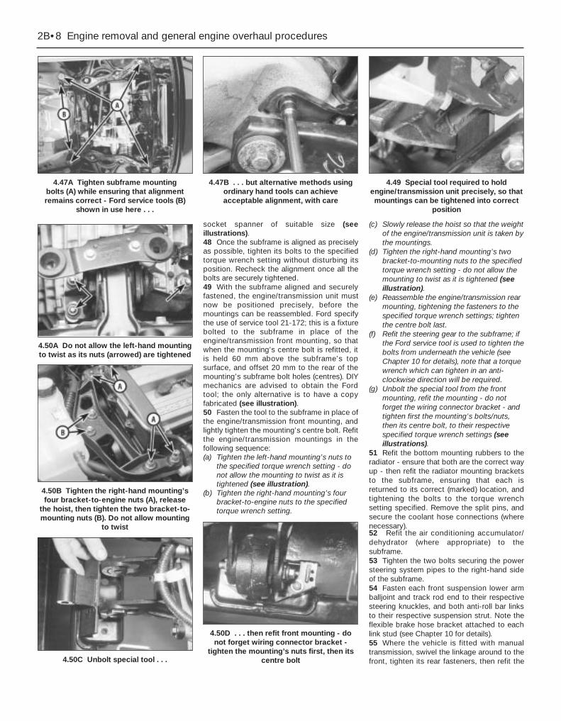
socket spanner of suitable size (seeillustrations).48 Once the subframe is aligned as preciselyas possible, tighten its bolts to the specifiedtorque wrench setting without disturbing itsposition. Recheck the alignment once all thebolts are securely tightened.49 With the subframe aligned and securelyfastened, the engine/transmission unit mustnow be positioned precisely, before themountings can be reassembled. Ford specifythe use of service tool 21-172; this is a fixturebolted to the subframe in place of theengine/transmission front mounting, so thatwhen the mounting’s centre bolt is refitted, itis held 60 mm above the subframe’s topsurface, and offset 20 mm to the rear of themounting’s subframe bolt holes (centres). DIYmechanics are advised to obtain the Fordtool; the only alternative is to have a copyfabricated (see illustration).50 Fasten the tool to the subframe in place ofthe engine/transmission front mounting, andlightly tighten the mounting’s centre bolt. Refitthe engine/transmission mountings in thefollowing sequence:(a) Tighten the left-hand mounting’s nuts to
the specified torque wrench setting - donot allow the mounting to twist as it istightened (see illustration).
(b) Tighten the right-hand mounting’s fourbracket-to-engine nuts to the specifiedtorque wrench setting.
(c) Slowly release the hoist so that the weightof the engine/transmission unit is taken bythe mountings.
(d) Tighten the right-hand mounting’s twobracket-to-mounting nuts to the specifiedtorque wrench setting - do not allow themounting to twist as it is tightened (seeillustration).
(e) Reassemble the engine/transmission rearmounting, tightening the fasteners to thespecified torque wrench settings; tightenthe centre bolt last.
(f) Refit the steering gear to the subframe; ifthe Ford service tool is used to tighten thebolts from underneath the vehicle (seeChapter 10 for details), note that a torquewrench which can tighten in an anti-clockwise direction will be required.
(g) Unbolt the special tool from the frontmounting, refit the mounting - do notforget the wiring connector bracket - andtighten first the mounting’s bolts/nuts,then its centre bolt, to their respectivespecified torque wrench settings (seeillustrations).
51 Refit the bottom mounting rubbers to theradiator - ensure that both are the correct wayup - then refit the radiator mounting bracketsto the subframe, ensuring that each isreturned to its correct (marked) location, andtightening the bolts to the torque wrenchsetting specified. Remove the split pins, andsecure the coolant hose connections (wherenecessary).52 Refit the air conditioning accumulator/dehydrator (where appropriate) to thesubframe.53 Tighten the two bolts securing the powersteering system pipes to the right-hand sideof the subframe.54 Fasten each front suspension lower armballjoint and track rod end to their respectivesteering knuckles, and both anti-roll bar linksto their respective suspension strut. Note theflexible brake hose bracket attached to eachlink stud (see Chapter 10 for details).55 Where the vehicle is fitted with manualtransmission, swivel the linkage around to thefront, tighten its rear fasteners, then refit the
2B•8 Engine removal and general engine overhaul procedures
4.47A Tighten subframe mounting bolts (A) while ensuring that alignmentremains correct - Ford service tools (B)
shown in use here . . .
4.47B . . . but alternative methods usingordinary hand tools can achieveacceptable alignment, with care
4.49 Special tool required to holdengine/transmission unit precisely, so thatmountings can be tightened into correct
position
4.50B Tighten the right-hand mounting’sfour bracket-to-engine nuts (A), release
the hoist, then tighten the two bracket-to-mounting nuts (B). Do not allow mounting
to twist
4.50A Do not allow the left-hand mountingto twist as its nuts (arrowed) are tightened
4.50C Unbolt special tool . . .
4.50D . . . then refit front mounting - donot forget wiring connector bracket -
tighten the mounting’s nuts first, then itscentre bolt

gear linkage heat shield. Reconnect thegearchange linkage and transmission supportrods to the transmission, adjusting the linkageusing the marks made on removal (seeChapter 7, Part A, for details).56 Re-install the remaining components andfasteners in the reverse order of removal.57 Add coolant, engine oil and transmissionfluids as needed (see Chapter 1).58 Run the engine, and check for properoperation and the absence of leaks. Shut offthe engine, and recheck the fluid levels.59 Remember that, since the front suspensionsubframe and steering gear have beendisturbed, the wheel alignment and steeringangles must be checked fully and carefully assoon as possible, with any necessaryadjustments being made. This operation is bestcarried out by an experienced mechanic, usingproper checking equipment; the vehicle shouldtherefore be taken to a Ford dealer or similarly-qualified person for attention.
1 It is much easier to dismantle and work onthe engine if it is mounted on a portable enginestand. These stands can often be hired from atool hire shop. Before the engine is mountedon a stand, the flywheel/driveplate should beremoved (Part A of this Chapter, Section 21)so that the stand bolts can be tightened intothe end of the cylinder block/crankcase.2 If a stand is not available, it is possible todismantle the engine with it mounted onblocks, on a sturdy workbench or on the floor.Be extra-careful not to tip or drop the enginewhen working without a stand.3 If you are going to obtain a reconditionedengine, all external components must beremoved first, to be transferred to thereplacement engine (just as they will if you aredoing a complete engine overhaul yourself).Note: When removing the externalcomponents from the engine, pay closeattention to details that may be helpful orimportant during refitting. Note the fittedposition of gaskets, seals, spacers, pins,washers, bolts and other small items. Theseexternal components include the following:(a) Alternator and brackets (Chapter 5).(b) HT leads and spark plugs (Chapter 1).(c) Thermostat and housing (Chapter 3).(d) Dipstick tube.(e) Fuel injection system components
(Chapter 4).(f) All electrical switches and sensors - refer
to the appropriate Chapter.(g) Inlet and exhaust manifolds (Part A of this
Chapter).(h) Oil filter (Chapter 1).(i) Engine/transmission mounting brackets
(Part A of this Chapter, Section 22).(j) Flywheel/driveplate (Part A of this
Chapter, Section 21).4 If you are obtaining a “short” engine (which
consists of the engine cylinderblock/crankcase, crankshaft, pistons andconnecting rods all assembled), then thecylinder head, sump, oil pump, and timing beltwill have to be removed also.5 If you are planning a complete overhaul, theengine can be dismantled and the internalcomponents removed in the following order.(a) Inlet and exhaust manifolds (Part A of this
Chapter).(b) Timing belt, toothed pulleys and
tensioner, and timing belt inner cover(Part A of this Chapter).
(c) Cylinder head (Part A of this Chapter,Section 14).
(d) Flywheel/driveplate (Part A of thisChapter, Section 21).
(e) Sump (Part A of this Chapter, Section 15).(f) Oil pump (Part A of this Chapter, Sec-
tion 16).(g) Piston/connecting rod assemblies
(Section 9).(h) Crankshaft (Section 10).6 Before beginning the dismantling and
overhaul procedures, make sure that you haveall of the correct tools necessary. Refer to theintroductory pages at the beginning of thismanual for further information.
Note: New and reconditioned cylinder headsare available from the manufacturers, andfrom engine overhaul specialists. Due to thefact that some specialist tools are required forthe dismantling and inspection procedures,and new components may not be readilyavailable (refer to Section 1 of this Part), it maybe more practical and economical for thehome mechanic to purchase a reconditionedhead, rather than to dismantle, inspect andrecondition the original head.1 Remove the camshafts and hydraulictappets (Part A of this Chapter, Section 13),being careful to store the hydraulic tappets asdescribed (see illustration).
6 Cylinder head - dismantling
5 Engine overhaul - dismantling sequence
Engine removal and general engine overhaul procedures 2B•9
2B
6.1 Cylinder head components
1 Hydraulic tappet2 Valve collets3 Valve spring upper seat4 Valve spring
5 Valve spring lower seat/stem oil seal
6 Oil-retaining valve7 Engine lifting eye8 Cylinder head gasket
9 Inlet valve10 Locating dowels11 Exhaust valve12 Cylinder head bolt
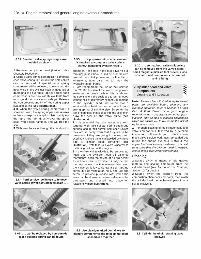
2 Remove the cylinder head (Part A of thisChapter, Section 14).3 Using a valve spring compressor, compresseach valve spring in turn until the split colletscan be removed. A special valve springcompressor will be required, to reach into thedeep wells in the cylinder head without risk ofdamaging the hydraulic tappet bores; suchcompressors are now widely available frommost good motor accessory shops. Releasethe compressor, and lift off the spring upperseat and spring (see illustrations).4 If, when the valve spring compressor isscrewed down, the spring upper seat refusesto free and expose the split collets, gently tapthe top of the tool, directly over the upperseat, with a light hammer. This will free theseat.5 Withdraw the valve through the combustion
chamber. If it binds in the guide (won’t pullthrough), push it back in, and de-burr the areaaround the collet groove with a fine file orwhetstone; take care not to mark thehydraulic tappet bores.6 Ford recommend the use of their servicetool 21-160 to extract the valve spring lowerseat/stem oil seals; while this is almostindispensable if the seals are to be removedwithout risk of (extremely expensive) damageto the cylinder head, we found that aserviceable substitute can be made from astrong spring of suitable size. Screw on thetool or spring so that it bites into the seal, thendraw the seal off the valve guide (seeillustrations).7 It is essential that the valves are kepttogether with their collets, spring seats andsprings, and in their correct sequence (unlessthey are so badly worn that they are to berenewed). If they are going to be kept andused again, place them in a labelled polythenebag or similar small container (seeillustration). Note that No 1 valve is nearest tothe timing belt end of the engine.8 If the oil-retaining valve is to be removed (toflush out the cylinder head oil galleriesthoroughly), seek the advice of a Ford dealeras to how it can be extracted; it may be thatthe only course of action involves destroyingthe valve as follows. Screw a self-tappingscrew into its ventilation hole, and use thescrew to provide purchase with which thevalve can be drawn out; a new valve must bepurchased and pressed into place onreassembly (see illustration).
Note: Always check first what replacementparts are available before planning anyoverhaul operation; refer to Section 1 of thisPart. A Ford dealer, or a good enginereconditioning specialist/automotive partssupplier, may be able to suggest alternativeswhich will enable you to overcome the lack ofreplacement parts.1 Thorough cleaning of the cylinder head andvalve components, followed by a detailedinspection, will enable you to decide howmuch valve service work must be carried outduring the engine overhaul. Note: If theengine has been severely overheated, it is bestto assume that the cylinder head is warped,and to check carefully for signs of this.
Cleaning2 Scrape away all traces of old gasketmaterial and sealing compound from thecylinder head (see Part A of this Chapter,Section 14 for details).3 Scrape away the carbon from thecombustion chambers and ports, then washthe cylinder head thoroughly with paraffin or asuitable solvent.
7 Cylinder head and valvecomponents - cleaning and inspection
2B•10 Engine removal and general engine overhaul procedures
6.3A Standard valve spring compressormodified as shown . . .
6.3B . . . or purpose-built special version,is required to compress valve springswithout damaging cylinder head . . . 6.3C . . . so that both valve split collets
can be removed from the valve’s stem -small magnetic pick-up tool prevents loss
of small metal components on removaland refitting
6.6B . . . can be replaced by home-madetool if suitable spring can be found
6.6A Ford service tool in use to removevalve spring lower seat/stem oil seals . . .
6.7 Use clearly-marked containers toidentify components and to keep matched
assemblies together6.8 Cylinder head oil-retaining valve
(arrowed)
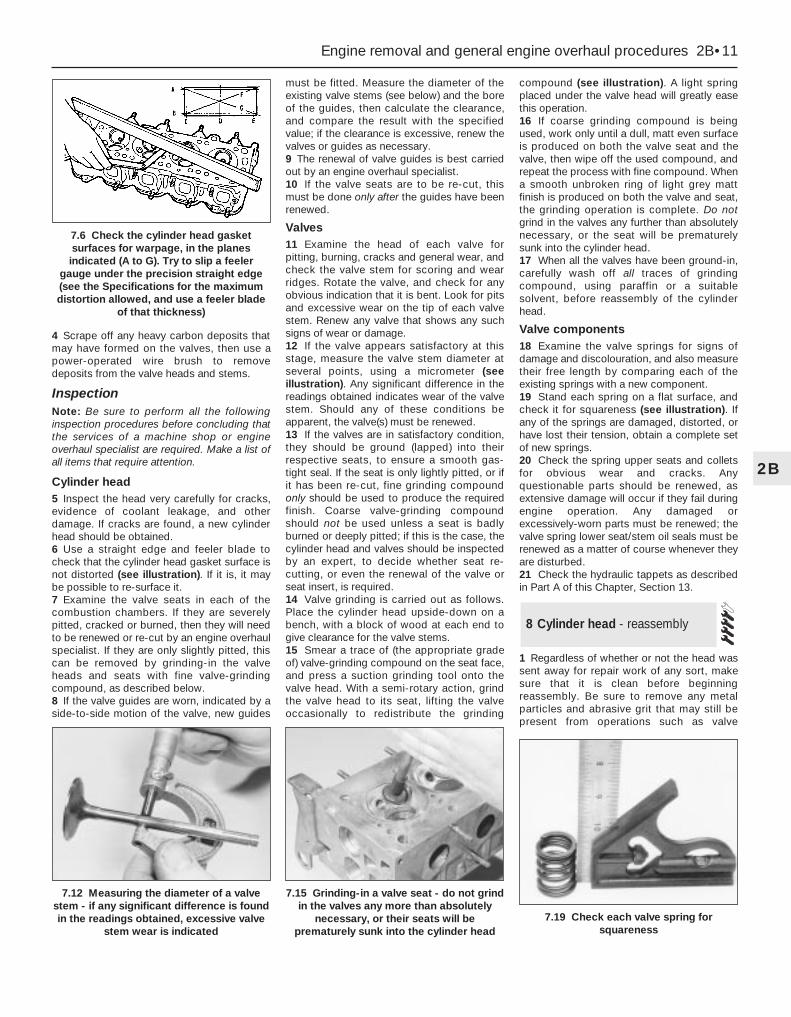
4 Scrape off any heavy carbon deposits thatmay have formed on the valves, then use apower-operated wire brush to removedeposits from the valve heads and stems.
InspectionNote: Be sure to perform all the followinginspection procedures before concluding thatthe services of a machine shop or engineoverhaul specialist are required. Make a list ofall items that require attention.
Cylinder head5 Inspect the head very carefully for cracks,evidence of coolant leakage, and otherdamage. If cracks are found, a new cylinderhead should be obtained.6 Use a straight edge and feeler blade tocheck that the cylinder head gasket surface isnot distorted (see illustration). If it is, it maybe possible to re-surface it.7 Examine the valve seats in each of thecombustion chambers. If they are severelypitted, cracked or burned, then they will needto be renewed or re-cut by an engine overhaulspecialist. If they are only slightly pitted, thiscan be removed by grinding-in the valveheads and seats with fine valve-grindingcompound, as described below.8 If the valve guides are worn, indicated by aside-to-side motion of the valve, new guides
must be fitted. Measure the diameter of theexisting valve stems (see below) and the boreof the guides, then calculate the clearance,and compare the result with the specifiedvalue; if the clearance is excessive, renew thevalves or guides as necessary.9 The renewal of valve guides is best carriedout by an engine overhaul specialist.10 If the valve seats are to be re-cut, thismust be done only after the guides have beenrenewed.
Valves11 Examine the head of each valve forpitting, burning, cracks and general wear, andcheck the valve stem for scoring and wearridges. Rotate the valve, and check for anyobvious indication that it is bent. Look for pitsand excessive wear on the tip of each valvestem. Renew any valve that shows any suchsigns of wear or damage.12 If the valve appears satisfactory at thisstage, measure the valve stem diameter atseveral points, using a micrometer (seeillustration). Any significant difference in thereadings obtained indicates wear of the valvestem. Should any of these conditions beapparent, the valve(s) must be renewed.13 If the valves are in satisfactory condition,they should be ground (lapped) into theirrespective seats, to ensure a smooth gas-tight seal. If the seat is only lightly pitted, or ifit has been re-cut, fine grinding compoundonly should be used to produce the requiredfinish. Coarse valve-grinding compoundshould not be used unless a seat is badlyburned or deeply pitted; if this is the case, thecylinder head and valves should be inspectedby an expert, to decide whether seat re-cutting, or even the renewal of the valve orseat insert, is required.14 Valve grinding is carried out as follows.Place the cylinder head upside-down on abench, with a block of wood at each end togive clearance for the valve stems.15 Smear a trace of (the appropriate gradeof) valve-grinding compound on the seat face,and press a suction grinding tool onto thevalve head. With a semi-rotary action, grindthe valve head to its seat, lifting the valveoccasionally to redistribute the grinding
compound (see illustration). A light springplaced under the valve head will greatly easethis operation.16 If coarse grinding compound is beingused, work only until a dull, matt even surfaceis produced on both the valve seat and thevalve, then wipe off the used compound, andrepeat the process with fine compound. Whena smooth unbroken ring of light grey mattfinish is produced on both the valve and seat,the grinding operation is complete. Do notgrind in the valves any further than absolutelynecessary, or the seat will be prematurelysunk into the cylinder head.17 When all the valves have been ground-in,carefully wash off all traces of grindingcompound, using paraffin or a suitablesolvent, before reassembly of the cylinderhead.
Valve components18 Examine the valve springs for signs ofdamage and discolouration, and also measuretheir free length by comparing each of theexisting springs with a new component.19 Stand each spring on a flat surface, andcheck it for squareness (see illustration). Ifany of the springs are damaged, distorted, orhave lost their tension, obtain a complete setof new springs.20 Check the spring upper seats and colletsfor obvious wear and cracks. Anyquestionable parts should be renewed, asextensive damage will occur if they fail duringengine operation. Any damaged orexcessively-worn parts must be renewed; thevalve spring lower seat/stem oil seals must berenewed as a matter of course whenever theyare disturbed.21 Check the hydraulic tappets as describedin Part A of this Chapter, Section 13.
1 Regardless of whether or not the head wassent away for repair work of any sort, makesure that it is clean before beginningreassembly. Be sure to remove any metalparticles and abrasive grit that may still bepresent from operations such as valve
8 Cylinder head - reassembly
Engine removal and general engine overhaul procedures 2B•11
2B
7.12 Measuring the diameter of a valvestem - if any significant difference is foundin the readings obtained, excessive valve
stem wear is indicated
7.15 Grinding-in a valve seat - do not grindin the valves any more than absolutely
necessary, or their seats will beprematurely sunk into the cylinder head
7.19 Check each valve spring forsquareness
7.6 Check the cylinder head gasketsurfaces for warpage, in the planesindicated (A to G). Try to slip a feeler
gauge under the precision straight edge(see the Specifications for the maximumdistortion allowed, and use a feeler blade
of that thickness)

grinding or head resurfacing. Usecompressed air, if available, to blow out all theoil holes and passages.2 Beginning at one end of the head, lubricateand install the first valve. Apply molybdenumdisulphide-based grease or clean engine oil tothe valve stem, and refit the valve. Where theoriginal valves are being re-used, ensure thateach is refitted in its original guide. If newvalves are being fitted, insert them into thelocations to which they have been ground.3 Fit the plastic protector supplied with newvalve spring lower seat/stem oil seals to theend of the valve stem, then put the new sealsquarely on top of the guide, and leave itthere; the action of refitting the valve springpresses the lower seat/stem oil seal into place(see illustration).4 Refit the valve spring and upper seat.5 Compress the spring with a valve springcompressor, and carefully install the collets inthe stem groove. Apply a small dab of greaseto each collet to hold it in place if necessary(see illustration). Slowly release thecompressor, and make sure the collets seatproperly.6 When the valve is installed, place thecylinder head flat on the bench and, using ahammer and interposed block of wood, tapthe end of the valve stem gently, to settle thecomponents.
7 Repeat the procedure for the remainingvalves. Be sure to return the components totheir original locations - don’t mix them up!8 Refit the hydraulic tappets (Part A of thisChapter, Section 13).
Note: Always check first what replacementparts are available before planning anyoverhaul operation; refer to Section 1 of thisPart. A Ford dealer, or a good enginereconditioning specialist/automotive partssupplier, may be able to suggest alternativeswhich will enable you to overcome the lack ofreplacement parts.Note: While this task is theoretically possiblewhen the engine is in place in the vehicle, inpractice, it requires so much preliminarydismantling, and is so difficult to carry out dueto the restricted access, that owners areadvised to remove the engine from the vehiclefirst. In addition to the new gaskets and otherreplacement parts required, a hoist will beneeded. Alternatively, an adjustable enginesupport bar, fitting into the water drain
channels on each side of the bonnet aperture,and having a hook which will engage theengine lifting eyes and allow the height of theengine to be adjusted, could be used. Liftingequipment such as this can be hired frommost tool hire shops - be sure that any suchequipment is rated well in excess of thecombined weight of the engine/transmissionunit.1 Remove the cylinder head (Part A of thisChapter, Section 14).2 Bolt lifting eyes to suitable points on theengine and transmission, then attach thelifting equipment so that the engine/transmission unit is supported securely.3 Remove the sump (Part A of this Chapter,Section 15).4 Undo the screws securing the oil pumppick-up/strainer pipe to the pump, thenunscrew the four nuts, and withdraw the oilpump pick-up/strainer pipe and oil baffle (seeillustration).5 Temporarily refit the crankshaft pulley, sothat the crankshaft can be rotated. Note thateach piston/connecting rod assembly can beidentified by its cylinder number (countingfrom the timing belt end of the engine) etchedinto the flat-machined surface of both theconnecting rod and its cap. The numbers arevisible from the front (exhaust side) of theengine. Furthermore, each piston has anarrow stamped into its crown, pointingtowards the timing belt end of the engine. Ifno marks can be seen, make your own beforedisturbing any of the components, so that youcan be certain of refitting eachpiston/connecting rod assembly the right wayround, to its correct (original) bore, with thecap also the right way round (seeillustrations).6 Use your fingernail to feel if a ridge hasformed at the upper limit of ring travel (about aquarter-inch down from the top of eachcylinder). If carbon deposits or cylinder wearhave produced ridges, they must becompletely removed with a special tool (seeillustration). Follow the manufacturer’sinstructions provided with the tool. Failure toremove the ridges before attempting to
9 Piston/connecting rodassemblies - removal
2B•12 Engine removal and general engine overhaul procedures
8.3 Valve spring pressure is sufficient toseat lower seat/stem oil seals on
reassembly
8.5 Apply a small dab of grease to eachcollet before installation - it will hold themin place on the valve stem until the spring
is released
9.4 Removing the oil baffle to provideaccess to crankshaft and bearings
9.5A Each connecting rod and big-endbearing cap will have a flat-machined
surface visible from the front (exhaust)side of the engine, with the cylinder
number etched in it
9.5B Piston crown markings
A 1.6 and 1.8 litre enginesB 2.0 litre engines1 Gudgeon pin diameter grade - when used2 Piston skirt diameter grade3 Arrow mark - pointing to timing belt end of
engine
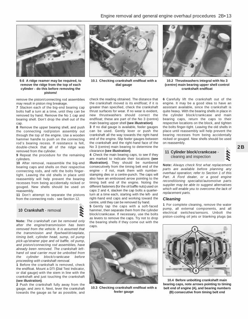
remove the piston/connecting rod assembliesmay result in piston ring breakage.7 Slacken each of the big-end bearing capbolts half a turn at a time, until they can beremoved by hand. Remove the No 1 cap andbearing shell. Don’t drop the shell out of thecap.8 Remove the upper bearing shell, and pushthe connecting rod/piston assembly outthrough the top of the engine. Use a woodenhammer handle to push on the connectingrod’s bearing recess. If resistance is felt,double-check that all of the ridge wasremoved from the cylinder.9 Repeat the procedure for the remainingcylinders.10 After removal, reassemble the big-endbearing caps and shells on their respectiveconnecting rods, and refit the bolts finger-tight. Leaving the old shells in place untilreassembly will help prevent the bearingrecesses from being accidentally nicked orgouged. New shells should be used onreassembly.11 Don’t attempt to separate the pistonsfrom the connecting rods - see Section 12.
Note: The crankshaft can be removed onlyafter the engine/transmission has beenremoved from the vehicle. It is assumed thatthe transmission and flywheel/driveplate,timing belt, cylinder head, sump, oil pumppick-up/strainer pipe and oil baffle, oil pump,and piston/connecting rod assemblies, havealready been removed. The crankshaft left-hand oil seal carrier must be unbolted fromthe cylinder block/crankcase beforeproceeding with crankshaft removal.1 Before the crankshaft is removed, checkthe endfloat. Mount a DTI (Dial Test Indicator,or dial gauge) with the stem in line with thecrankshaft and just touching the crankshaft(see illustration).2 Push the crankshaft fully away from thegauge, and zero it. Next, lever the crankshafttowards the gauge as far as possible, and
check the reading obtained. The distance thatthe crankshaft moved is its endfloat; if it isgreater than specified, check the crankshaftthrust surfaces for wear. If no wear is evident,new thrustwashers should correct theendfloat; these are part of the No 3 (centre)main bearing upper shell (see illustration).3 If no dial gauge is available, feeler gaugescan be used. Gently lever or push thecrankshaft all the way towards the right-handend of the engine. Slip feeler gauges betweenthe crankshaft and the right-hand face of theNo 3 (centre) main bearing to determine theclearance (see illustration).4 Check the main bearing caps, to see if theyare marked to indicate their locations (seeillustration). They should be numberedconsecutively from the timing belt end of theengine - if not, mark them with number-stamping dies or a centre-punch. The caps willalso have an embossed arrow pointing to thetiming belt end of the engine. Noting thedifferent fasteners (for the oil baffle nuts) used oncaps 2 and 4, slacken the cap bolts a quarter-turn at a time each, starting with the left- andright-hand end caps and working toward thecentre, until they can be removed by hand.5 Gently tap the caps with a soft-facedhammer, then separate them from the cylinderblock/crankcase. If necessary, use the boltsas levers to remove the caps. Try not to dropthe bearing shells if they come out with thecaps.
6 Carefully lift the crankshaft out of theengine. It may be a good idea to have anassistant available, since the crankshaft isquite heavy. With the bearing shells in place inthe cylinder block/crankcase and mainbearing caps, return the caps to theirrespective locations on the block, and tightenthe bolts finger-tight. Leaving the old shells inplace until reassembly will help prevent thebearing recesses from being accidentallynicked or gouged. New shells should be usedon reassembly.
Note: Always check first what replacementparts are available before planning anyoverhaul operation; refer to Section 1 of thisPart. A Ford dealer, or a good enginereconditioning specialist/automotive partssupplier may be able to suggest alternativeswhich will enable you to overcome the lack ofreplacement parts.
Cleaning1 For complete cleaning, remove the waterpump, all external components, and allelectrical switches/sensors. Unbolt thepiston-cooling oil jets or blanking plugs (as
11 Cylinder block/crankcase -cleaning and inspection
10 Crankshaft - removal
Engine removal and general engine overhaul procedures 2B•13
2B
10.3 Checking crankshaft endfloat with afeeler gauge
10.4 Before unbolting crankshaft mainbearing caps, note arrows pointing to timingbelt end of engine (A), and bearing numbers
(B) consecutive from timing belt end
9.6 A ridge reamer may be required, toremove the ridge from the top of eachcylinder - do this before removing the
pistons!
10.1 Checking crankshaft endfloat with adial gauge
10.2 Thrustwashers integral with No 3(centre) main bearing upper shell control
crankshaft endfloat
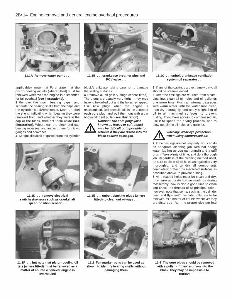
applicable); note that Ford state that thepiston-cooling oil jets (where fitted) must berenewed whenever the engine is dismantledfor full overhaul (see illustrations).2 Remove the main bearing caps, andseparate the bearing shells from the caps andthe cylinder block/crankcase. Mark or labelthe shells, indicating which bearing they wereremoved from, and whether they were in thecap or the block, then set them aside (seeillustration). Wipe clean the block and capbearing recesses, and inspect them for nicks,gouges and scratches.3 Scrape all traces of gasket from the cylinder
block/crankcase, taking care not to damagethe sealing surfaces.4 Remove all oil gallery plugs (where fitted).The plugs are usually very tight - they mayhave to be drilled out and the holes re-tapped.Use new plugs when the engine isreassembled. Drill a small hole in the centre ofeach core plug, and pull them out with a carbodywork dent puller (see illustration).
Caution: The core plugs (alsoknown as freeze or soft plugs)may be difficult or impossible toretrieve if they are driven into theblock coolant passages.
5 If any of the castings are extremely dirty, allshould be steam-cleaned.6 After the castings are returned from steam-cleaning, clean all oil holes and oil galleriesone more time. Flush all internal passageswith warm water until the water runs clear,then dry thoroughly, and apply a light film ofoil to all machined surfaces, to preventrusting. If you have access to compressed air,use it to speed the drying process, and toblow out all the oil holes and galleries.
Warning: Wear eye protectionwhen using compressed air!
7 If the castings are not very dirty, you can doan adequate cleaning job with hot soapywater (as hot as you can stand!) and a stiffbrush. Take plenty of time, and do a thoroughjob. Regardless of the cleaning method used,be sure to clean all oil holes and galleries verythoroughly, and to dry all componentscompletely; protect the machined surfaces asdescribed above, to prevent rusting.8 All threaded holes must be clean and dry,to ensure accurate torque readings duringreassembly; now is also a good time to cleanand check the threads of all principal bolts -however, note that some, such as the cylinderhead and flywheel/driveplate bolts, are to berenewed as a matter of course whenever theyare disturbed. Run the proper-size tap into
2B•14 Engine removal and general engine overhaul procedures
11.1A Remove water pump . . . 11.1B . . . crankcase breather pipe andPCV valve . . .
11.1C . . . unbolt crankcase ventilationsystem oil separator . . .
11.1F . . . but note that piston-cooling oiljets (where fitted) must be renewed as a
matter of course whenever engine isoverhauled
11.2 Felt marker pens can be used asshown to identify bearing shells without
damaging them
11.1D . . . remove electricalswitches/sensors such as crankshaft
speed/position sensor . . .
11.1E . . . unbolt blanking plugs (wherefitted) to clean out oilways . . .
11.4 The core plugs should be removedwith a puller - if they’re driven into the
block, they may be impossible to retrieve
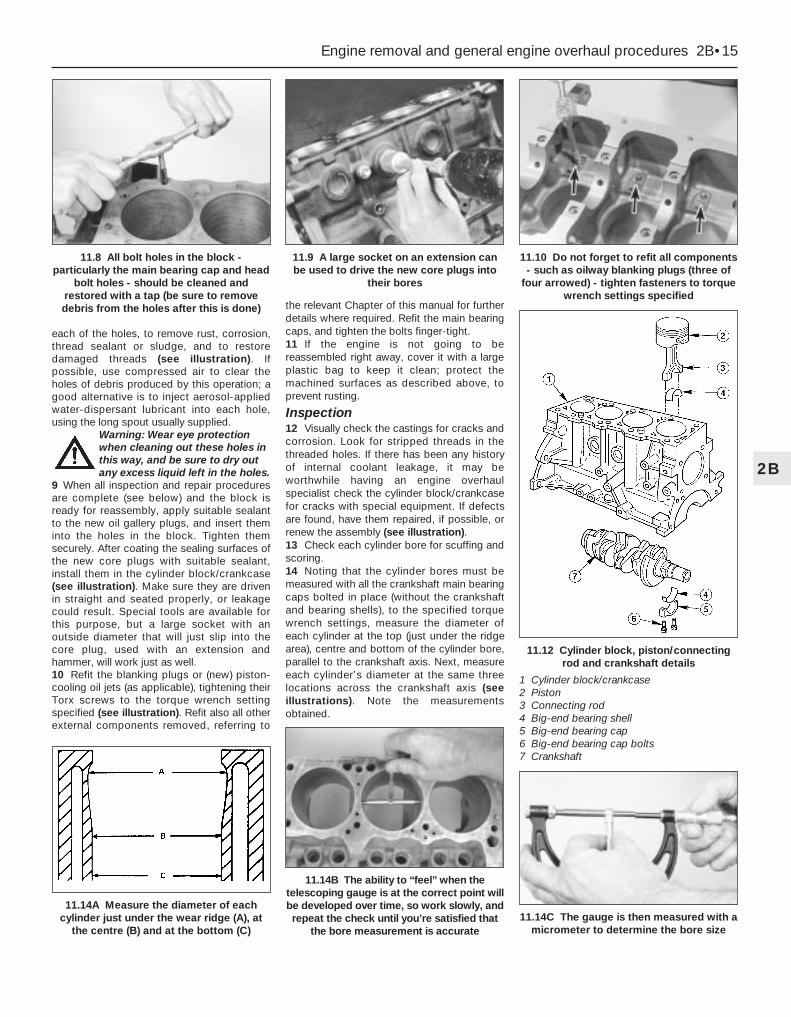
each of the holes, to remove rust, corrosion,thread sealant or sludge, and to restoredamaged threads (see illustration). Ifpossible, use compressed air to clear theholes of debris produced by this operation; agood alternative is to inject aerosol-appliedwater-dispersant lubricant into each hole,using the long spout usually supplied.
Warning: Wear eye protectionwhen cleaning out these holes inthis way, and be sure to dry outany excess liquid left in the holes.
9 When all inspection and repair proceduresare complete (see below) and the block isready for reassembly, apply suitable sealantto the new oil gallery plugs, and insert theminto the holes in the block. Tighten themsecurely. After coating the sealing surfaces ofthe new core plugs with suitable sealant,install them in the cylinder block/crankcase(see illustration). Make sure they are drivenin straight and seated properly, or leakagecould result. Special tools are available forthis purpose, but a large socket with anoutside diameter that will just slip into thecore plug, used with an extension andhammer, will work just as well.10 Refit the blanking plugs or (new) piston-cooling oil jets (as applicable), tightening theirTorx screws to the torque wrench settingspecified (see illustration). Refit also all otherexternal components removed, referring to
the relevant Chapter of this manual for furtherdetails where required. Refit the main bearingcaps, and tighten the bolts finger-tight.11 If the engine is not going to bereassembled right away, cover it with a largeplastic bag to keep it clean; protect themachined surfaces as described above, toprevent rusting.
Inspection12 Visually check the castings for cracks andcorrosion. Look for stripped threads in thethreaded holes. If there has been any historyof internal coolant leakage, it may beworthwhile having an engine overhaulspecialist check the cylinder block/crankcasefor cracks with special equipment. If defectsare found, have them repaired, if possible, orrenew the assembly (see illustration).13 Check each cylinder bore for scuffing andscoring.14 Noting that the cylinder bores must bemeasured with all the crankshaft main bearingcaps bolted in place (without the crankshaftand bearing shells), to the specified torquewrench settings, measure the diameter ofeach cylinder at the top (just under the ridgearea), centre and bottom of the cylinder bore,parallel to the crankshaft axis. Next, measureeach cylinder’s diameter at the same threelocations across the crankshaft axis (seeillustrations). Note the measurementsobtained.
Engine removal and general engine overhaul procedures 2B•15
2B
11.12 Cylinder block, piston/connectingrod and crankshaft details
1 Cylinder block/crankcase2 Piston3 Connecting rod4 Big-end bearing shell5 Big-end bearing cap6 Big-end bearing cap bolts7 Crankshaft
11.14A Measure the diameter of eachcylinder just under the wear ridge (A), at
the centre (B) and at the bottom (C)
11.14B The ability to “feel” when thetelescoping gauge is at the correct point willbe developed over time, so work slowly, andrepeat the check until you’re satisfied that
the bore measurement is accurate
11.8 All bolt holes in the block -particularly the main bearing cap and head
bolt holes - should be cleaned andrestored with a tap (be sure to removedebris from the holes after this is done)
11.9 A large socket on an extension canbe used to drive the new core plugs into
their bores
11.10 Do not forget to refit all components- such as oilway blanking plugs (three of
four arrowed) - tighten fasteners to torquewrench settings specified
11.14C The gauge is then measured with amicrometer to determine the bore size

15 Measure the piston diameter at right-angles to the gudgeon pin axis, just above thebottom of the skirt; again, note the results(see illustration).16 If it is wished to obtain the piston-to-boreclearance, measure the bore and piston skirtas described above, and subtract the skirtdiameter from the bore measurement. If theprecision measuring tools shown are notavailable, the condition of the pistons andbores can be assessed, though not quite asaccurately, by using feeler gauges as follows.Select a feeler gauge of thickness equal to thespecified piston-to-bore clearance, and slip itinto the cylinder along with the matchingpiston. The piston must be positioned exactlyas it normally would be. The feeler gaugemust be between the piston and cylinder onone of the thrust faces (at right-angles to thegudgeon pin bore). The piston should slipthrough the cylinder (with the feeler gauge inplace) with moderate pressure; if it fallsthrough or slides through easily, the clearanceis excessive, and a new piston will berequired. If the piston binds at the lower endof the cylinder, and is loose toward the top,the cylinder is tapered. If tight spots areencountered as the piston/feeler gauge isrotated in the cylinder, the cylinder is out-of-round (oval).17 Repeat these procedures for theremaining pistons and cylinder bores.18 Compare the results with theSpecifications at the beginning of thisChapter; if any measurement is beyond thedimensions specified for that class (check thepiston crown marking to establish the class ofpiston fitted), or if any bore measurement issignificantly different from the others(indicating that the bore is tapered or oval),the piston or bore is excessively-worn.19 Worn pistons must be renewed; at thetime of writing, pistons are available as Fordreplacement parts only as part of thecomplete piston/connecting rod assembly.See a Ford dealer or engine reconditioningspecialist for advice.20 If any of the cylinder bores are badly
scuffed or scored, or if they are excessively-worn, out-of-round or tapered, the usualcourse of action would be to have the cylinderblock/crankcase rebored, and to fit new,oversized, pistons on reassembly. See a Forddealer or engine reconditioning specialist foradvice.21 If the bores are in reasonably goodcondition and not excessively-worn, then itmay only be necessary to renew the pistonrings.22 If this is the case (and if new rings can befound), the bores should be honed, to allowthe new rings to bed in correctly and providethe best possible seal; before honing thebores, refit the main bearing caps (without thebearing shells), and tighten the bolts to thespecified torque wrench setting. Note: If youdon’t have the tools, or don’t want to tacklethe honing operation, most enginereconditioning specialists will do it for areasonable fee.23 Two types of cylinder hones arecommonly available - the flex hone or “bottle-brush” type, and the more traditionalsurfacing hone with spring-loaded stones.Both will do the job and are used with apower drill, but for the less-experiencedmechanic, the “bottle-brush” hone willprobably be easier to use. You will also needsome paraffin or honing oil, and rags.Proceed as follows:(a) Mount the hone in the drill, compress the
stones, and slip it into the first bore (seeillustration). Be sure to wear safetygoggles or a face shield!
(b) Lubricate the bore with plenty of honingoil, switch on the drill, and move the honeup and down the bore, at a pace that willproduce a fine cross-hatch pattern on thecylinder walls. Ideally, the cross-hatchlines should intersect at approximately a60° angle (see illustration). Be sure touse plenty of lubricant, and don’t take offany more material than is absolutelynecessary to produce the desired finish.Note: Piston ring manufacturers mayspecify a different crosshatch angle - read
and follow any instructions included withthe new rings.
(c) Don’t withdraw the hone from the borewhile it’s running. Instead, switch off thedrill, and continue moving the hone upand down the bore until it comes to acomplete stop, then compress the stonesand withdraw the hone. If you’re using a“bottle-brush” hone, switch off the drill,then turn the chuck in the normaldirection of rotation while withdrawing thehone from the bore.
(d) Wipe the oil out of the bore, and repeatthe procedure for the remaining cylinders.
(e) When all the cylinder bores are honed,chamfer the top edges of the bores with asmall file, so the rings won’t catch whenthe pistons are installed. Be very carefulnot to nick the cylinder walls with the endof the file.
(f) The entire cylinder block/crankcase mustbe washed very thoroughly with warm,soapy water, to remove all traces of theabrasive grit produced during the honingoperation. Note: The bores can beconsidered clean when a lint-free whitecloth - dampened with clean engine oil -used to wipe them out doesn’t pick upany more honing residue, which will showup as grey areas on the cloth. Be sure torun a brush through all oil holes andgalleries, and flush them with runningwater.
(g) When the cylinder block/crankcase iscompletely clean, rinse it thoroughly anddry it, then lightly oil all exposedmachined surfaces, to prevent rusting.
24 The cylinder block/crankcase should nowbe completely clean and dry, with allcomponents checked for wear or damage,and repaired or overhauled as necessary.Refit as many ancillary components aspossible, for safekeeping (see paragraphs 9and 10 above). If reassembly is not to startimmediately, cover the block with a largeplastic bag to keep it clean, and protect themachined surfaces as described above toprevent rusting.
2B•16 Engine removal and general engine overhaul procedures
11.15 Measure the piston skirt diameter atright-angles to the gudgeon pin axis, just
above the base of the skirt
11.23A A “bottle-brush” hone will producebetter results if you have never honed
cylinders before
11.23B The cylinder hone should leave asmooth, cross-hatch pattern with the linesintersecting at approximately a 60º angle
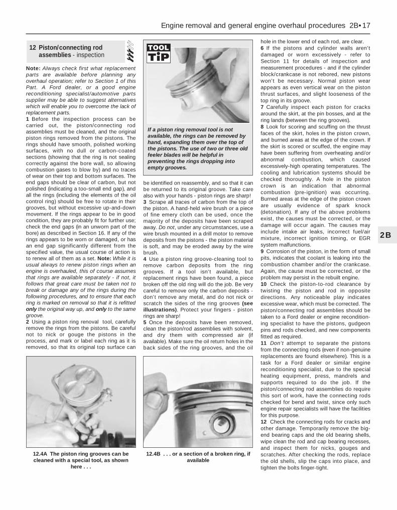
Note: Always check first what replacementparts are available before planning anyoverhaul operation; refer to Section 1 of thisPart. A Ford dealer, or a good enginereconditioning specialist/automotive partssupplier may be able to suggest alternativeswhich will enable you to overcome the lack ofreplacement parts.1 Before the inspection process can becarried out, the piston/connecting rodassemblies must be cleaned, and the originalpiston rings removed from the pistons. Therings should have smooth, polished workingsurfaces, with no dull or carbon-coatedsections (showing that the ring is not sealingcorrectly against the bore wall, so allowingcombustion gases to blow by) and no tracesof wear on their top and bottom surfaces. Theend gaps should be clear of carbon, but notpolished (indicating a too-small end gap), andall the rings (including the elements of the oilcontrol ring) should be free to rotate in theirgrooves, but without excessive up-and-downmovement. If the rings appear to be in goodcondition, they are probably fit for further use;check the end gaps (in an unworn part of thebore) as described in Section 16. If any of therings appears to be worn or damaged, or hasan end gap significantly different from thespecified value, the usual course of action isto renew all of them as a set. Note: While it isusual always to renew piston rings when anengine is overhauled, this of course assumesthat rings are available separately - if not, itfollows that great care must be taken not tobreak or damage any of the rings during thefollowing procedures, and to ensure that eachring is marked on removal so that it is refittedonly the original way up, and only to the samegroove.2 Using a piston ring renoval tool, carefullyremove the rings from the pistons. Be carefulnot to nick or gouge the pistons in theprocess, and mark or label each ring as it isremoved, so that its original top surface can
be identified on reassembly, and so that it canbe returned to its original groove. Take carealso with your hands - piston rings are sharp! 3 Scrape all traces of carbon from the top ofthe piston. A hand-held wire brush or a pieceof fine emery cloth can be used, once themajority of the deposits have been scrapedaway. Do not, under any circumstances, use awire brush mounted in a drill motor to removedeposits from the pistons - the piston materialis soft, and may be eroded away by the wirebrush.4 Use a piston ring groove-cleaning tool toremove carbon deposits from the ringgrooves. If a tool isn’t available, butreplacement rings have been found, a piecebroken off the old ring will do the job. Be verycareful to remove only the carbon deposits -don’t remove any metal, and do not nick orscratch the sides of the ring grooves (seeillustrations). Protect your fingers - pistonrings are sharp!5 Once the deposits have been removed,clean the piston/rod assemblies with solvent,and dry them with compressed air (ifavailable). Make sure the oil return holes in theback sides of the ring grooves, and the oil
hole in the lower end of each rod, are clear.6 If the pistons and cylinder walls aren’tdamaged or worn excessively - refer toSection 11 for details of inspection andmeasurement procedures - and if the cylinderblock/crankcase is not rebored, new pistonswon’t be necessary. Normal piston wearappears as even vertical wear on the pistonthrust surfaces, and slight looseness of thetop ring in its groove.7 Carefully inspect each piston for cracksaround the skirt, at the pin bosses, and at thering lands (between the ring grooves).8 Look for scoring and scuffing on the thrustfaces of the skirt, holes in the piston crown,and burned areas at the edge of the crown. Ifthe skirt is scored or scuffed, the engine mayhave been suffering from overheating and/orabnormal combustion, which causedexcessively-high operating temperatures. Thecooling and lubrication systems should bechecked thoroughly. A hole in the pistoncrown is an indication that abnormalcombustion (pre-ignition) was occurring.Burned areas at the edge of the piston crownare usually evidence of spark knock(detonation). If any of the above problemsexist, the causes must be corrected, or thedamage will occur again. The causes mayinclude intake air leaks, incorrect fuel/airmixture, incorrect ignition timing, or EGRsystem malfunctions.9 Corrosion of the piston, in the form of smallpits, indicates that coolant is leaking into thecombustion chamber and/or the crankcase.Again, the cause must be corrected, or theproblem may persist in the rebuilt engine.10 Check the piston-to-rod clearance bytwisting the piston and rod in oppositedirections. Any noticeable play indicatesexcessive wear, which must be corrected. Thepiston/connecting rod assemblies should betaken to a Ford dealer or engine recondition-ing specialist to have the pistons, gudgeonpins and rods checked, and new componentsfitted as required.11 Don’t attempt to separate the pistonsfrom the connecting rods (even if non-genuinereplacements are found elsewhere). This is atask for a Ford dealer or similar enginereconditioning specialist, due to the specialheating equipment, press, mandrels andsupports required to do the job. If thepiston/connecting rod assemblies do requirethis sort of work, have the connecting rodschecked for bend and twist, since only suchengine repair specialists will have the facilitiesfor this purpose.12 Check the connecting rods for cracks andother damage. Temporarily remove the big-end bearing caps and the old bearing shells,wipe clean the rod and cap bearing recesses,and inspect them for nicks, gouges andscratches. After checking the rods, replacethe old shells, slip the caps into place, andtighten the bolts finger-tight.
12 Piston/connecting rodassemblies - inspection
Engine removal and general engine overhaul procedures 2B•17
2B
12.4A The piston ring grooves can becleaned with a special tool, as shown
here . . .
12.4B . . . or a section of a broken ring, ifavailable
If a piston ring removal tool is notavailable, the rings can be removed byhand, expanding them over the top ofthe pistons. The use of two or three oldfeeler blades will be helpful inpreventing the rings dropping intoempty grooves.

Note: Always check first what replacementparts are available before planning anyoverhaul operation; refer to Section 1 of thisPart. A Ford dealer, or a good enginereconditioning specialist/automotive partssupplier, may be able to suggest alternativeswhich will enable you to overcome the lack ofreplacement parts.1 Clean the crankshaft, and dry it withcompressed air if available.
Warning: Wear eye protectionwhen using compressed air! Besure to clean the oil holes with apipe cleaner or similar probe.
2 Check the main and crankpin (big-end)bearing journals for uneven wear, scoring,pitting and cracking.3 Rub a penny across each journal severaltimes (see illustration). If a journal picks upcopper from the penny, it is too rough.4 Remove all burrs from the crankshaft oilholes with a stone, file or scraper.5 Using a micrometer, measure the diameterof the main bearing and crankpin (big-end)journals, and compare the results with theSpecifications at the beginning of this Chapter(see illustration).6 By measuring the diameter at a number ofpoints around each journal’s circumference,you will be able to determine whether or notthe journal is out-of-round. Take themeasurement at each end of the journal, nearthe webs, to determine if the journal istapered.7 If the crankshaft journals are damaged,tapered, out-of-round, or worn beyond thelimits specified in this Chapter, the crankshaftmust be taken to an engine overhaulspecialist, who will regrind it, and who cansupply the necessary undersize bearingshells.8 Check the oil seal journals at each end ofthe crankshaft for wear and damage. If eitherseal has worn an excessive groove in its
journal, consult an engine overhaul specialist,who will be able to advise whether a repair ispossible, or whether a new crankshaft isnecessary.
Note: Always check first what replacementparts are available before planning anyoverhaul operation; refer to Section 1 of thisPart. A Ford dealer, or a good enginereconditioning specialist/automotive partssupplier, may be able to suggest alternativeswhich will enable you to overcome the lack ofreplacement parts.1 Even though the main and big-end bearingshells should be renewed during the engineoverhaul, the old shells should be retained forclose examination, as they may revealvaluable information about the condition ofthe engine (see illustration).2 Bearing failure occurs because of lack oflubrication, the presence of dirt or otherforeign particles, overloading the engine, andcorrosion. Regardless of the cause of bearingfailure, it must be corrected before the engineis reassembled, to prevent it from happeningagain.3 When examining the bearing shells, removethem from the cylinder block/crankcase andmain bearing caps, and from the connectingrods and the big-end bearing caps, then laythem out on a clean surface in the samegeneral position as their location in theengine. This will enable you to match anybearing problems with the correspondingcrankshaft journal. Do not touch any shell’sbearing surface with your fingers whilechecking it, or the delicate surface may bescratched.4 Dirt or other foreign matter gets into theengine in a variety of ways. It may be left inthe engine during assembly, or it may passthrough filters or the crankcase ventilationsystem. It may get into the oil, and from thereinto the bearings. Metal chips from machiningoperations and normal engine wear are oftenpresent. Abrasives are sometimes left inengine components after reconditioning,
especially when parts are not thoroughlycleaned using the proper cleaning methods.Whatever the source, these foreign objectsoften end up embedded in the soft bearingmaterial, and are easily recognized. Largeparticles will not embed in the material, andwill score or gouge the shell and journal. Thebest prevention for this cause of bearingfailure is to clean all parts thoroughly, and tokeep everything spotlessly-clean duringengine assembly. Frequent and regular engineoil and filter changes are also recommended.5 Lack of lubrication (or lubricationbreakdown) has a number of inter-relatedcauses. Excessive heat (which thins the oil),overloading (which squeezes the oil from thebearing face) and oil leakage (from excessivebearing clearances, worn oil pump or highengine speeds) all contribute to lubricationbreakdown. Blocked oil passages, whichusually are the result of misaligned oil holes ina bearing shell, will also starve a bearing of oil,and destroy it. When lack of lubrication is thecause of bearing failure, the bearing materialis wiped or extruded from the shell’s steelbacking. Temperatures may increase to thepoint where the steel backing turns blue fromoverheating.6 Driving habits can have a definite effect onbearing life. Full-throttle, low-speed operation(labouring the engine) puts very high loads onbearings, which tends to squeeze out the oilfilm. These loads cause the shells to flex,which produces fine cracks in the bearingface (fatigue failure). Eventually, the bearingmaterial will loosen in pieces, and tear awayfrom the steel backing. Short-distance drivingleads to corrosion of bearings, becauseinsufficient engine heat is produced to driveoff condensed water and corrosive gases.These products collect in the engine oil,forming acid and sludge. As the oil is carried
14 Main and big-end bearings -inspection
13 Crankshaft - inspection
2B•18 Engine removal and general engine overhaul procedures
13.3 Rubbing a penny lengthwise alongeach journal will reveal its condition - ifcopper rubs off and is embedded in the
crankshaft, the journals should bereground
13.5 Measure the diameter of eachcrankshaft journal at several points, to
detect taper and out-of-round conditions
14.1 When inspecting the main and big-end bearings, look for these problems

to the engine bearings, the acid attacks andcorrodes the bearing material.7 Incorrect shell refitting during engineassembly will lead to bearing failure as well.Tight-fitting shells leave insufficient bearingrunning clearance, and will result in oilstarvation. Dirt or foreign particles trappedbehind a bearing shell result in high spots onthe bearing, which lead to failure. Do nottouch any shell’s bearing surface with yourfingers during reassembly; there is a risk ofscratching the delicate surface, or ofdepositing particles of dirt on it.
1 Before reassembly begins, ensure that allnew parts have been obtained, and that allnecessary tools are available. Read throughthe entire procedure, to familiarise yourselfwith the work involved, and to ensure that allitems necessary for reassembly of the engineare at hand. In addition to all normal tools andmaterials, suitable sealant will be required fortwo of the joint faces (Ford recommendHylosil 102 for the cylinder block/crankcase-to-sump/oil pump/oil seal carrier joints, andLoctite 518 for the camshaft right-handbearing caps). In all other cases, provided therelevant mating surfaces are clean and flat,new gaskets will be sufficient to ensure jointsare oil-tight. Do not use any kind of silicone-based sealant on any part of the fuel systemor inlet manifold, and never use exhaustsealants upstream of the catalytic converter.2 In order to save time and avoid problems,engine reassembly can be carried out in thefollowing order:(a) Crankshaft (Section 17).(b) Piston/connecting rod assemblies
(Section 18).(c) Oil pump (Part A of this Chapter, Section
16).(d) Sump (Part A of this Chapter, Section 15).(e) Flywheel/driveplate (Part A of this
Chapter, Section 21).(f) Cylinder head (Part A of this Chapter,
Section 14).
(g) Timing belt inner cover, tensioner andtoothed pulleys, and timing belt (Part A ofthis Chapter).
(h) Engine external components.3 At this stage, all engine components shouldbe absolutely clean and dry, with all faultsrepaired; they should be laid out (or inindividual containers) on a completely-cleanwork surface.
1 Before installing new piston rings, checkthe end gaps. Lay out each piston set with apiston/connecting rod assembly, and keepthem together as a matched set from now on.2 Insert the top compression ring into the firstcylinder, and square it up with the cylinderwalls by pushing it in with the top of the piston(see illustration). The ring should be near thebottom of the cylinder, at the lower limit ofring travel.3 To measure the end gap, slip feeler gaugesbetween the ends of the ring, until a gaugeequal to the gap width is found (seeillustration). The feeler gauge should slidebetween the ring ends with a slight amount ofdrag. Compare the measurement to the valuegiven in the Specifications Section of thisChapter; if the gap is larger or smaller thanspecified, double-check to make sure youhave the correct rings before proceeding. Ifyou are assessing the condition of used rings,have the cylinder bores checked andmeasured by a Ford dealer or similar enginereconditioning specialist, so that you can besure of exactly which component is worn, andseek advice as to the best course of action totake.4 If the end gap is still too small, it must beopened up by careful filing of the ring endsusing a fine file. If it is too large, this is not asserious, unless the specified limit is exceeded,in which case very careful checking isrequired of the dimensions of all components,as well as of the new parts.5 Repeat the procedure for each ring that willbe installed in the first cylinder, and for each
ring in the remaining cylinders. Remember tokeep rings, pistons and cylinders matched up.6 Refit the piston rings as follows. Where theoriginal rings are being refitted, use the marksor notes made on removal, to ensure thateach ring is refitted to its original groove andthe same way up. New rings generally havetheir top surfaces identified by markings(often an indication of size, such as “STD”, orthe word “TOP”) - the rings must be fitted withsuch markings uppermost (see illustration).Note: Always follow the instructions printedon the ring package or box - differentmanufacturers may require differentapproaches. Do not mix up the top andsecond compression rings, as they usuallyhave different cross-sections.7 The oil control ring (lowest one on thepiston) is usually installed first. It is composedof three separate elements. Slip thespacer/expander into the groove (seeillustration). If an anti-rotation tang is used,make sure it is inserted into the drilled hole inthe ring groove. Next, install the lower siderail. Don’t use a piston ring installation tool onthe oil ring side rails, as they may bedamaged. Instead, place one end of the siderail into the groove between thespacer/expander and the ring land, hold itfirmly in place, and slide a finger around thepiston while pushing the rail into the groove
16 Piston rings - refitting
15 Engine overhaul - reassembly sequence
Engine removal and general engine overhaul procedures 2B•19
2B
16.7A Installing the spacer/expander inthe oil control ring groove
16.2 When checking piston ring end gap,the ring must be square in the cylinder
bore (this is done by pushing the ring downwith the top of a piston, as shown)
16.3 With the ring square in the bore,measure the end gap with a feeler
gauge
16.6 Look for etched markings (“STD” -indicating a standard-sized ring - shownhere) identifying piston ring top surface

(see illustration). Next, install the upper siderail in the same manner.8 After the three oil ring components havebeen installed, check that both the upper andlower side rails can be turned smoothly in thering groove.9 The second compression (middle) ring isinstalled next, followed by the topcompression ring - ensure their marks areuppermost, and be careful not to confusethem. Don’t expand either ring any more thannecessary to slide it over the top of the piston.10 With all the rings in position, space thering gaps (including the elements of the oilcontrol ring) uniformly around the piston at120° intervals. Repeat the procedure for theremaining pistons and rings.
1 Crankshaft refitting is the first major step inengine reassembly. It is assumed at this pointthat the cylinder block/crankcase andcrankshaft have been cleaned, inspected andrepaired or reconditioned as necessary.Position the engine upside-down.2 Remove the main bearing cap bolts, and lift
out the caps. Lay the caps out in the properorder, to ensure correct installation.3 If they’re still in place, remove the oldbearing shells from the block and the mainbearing caps. Wipe the bearing recesses ofthe block and caps with a clean, lint-freecloth. They must be kept spotlessly-clean!
Main bearing running clearancecheck4 Clean the backs of the new main bearingshells. Fit the shells with an oil groove in eachmain bearing location in the block; note thethrustwashers integral with the No 3 (centre)main bearing upper shell. Fit the other shellfrom each bearing set in the correspondingmain bearing cap. Make sure the tab on eachbearing shell fits into the notch in the block orcap. Also, the oil holes in the block must lineup with the oil holes in the bearing shell (seeillustration).
Caution: Don’t hammer the shellsinto place, and don’t nick or gougethe bearing faces. No lubricationshould be used at this time.
5 Clean the bearing surfaces of the shells in
the block and the crankshaft main bearingjournals with a clean, lint-free cloth. Check orclean the oil holes in the crankshaft, as anydirt here can go only one way - straightthrough the new bearings.6 Once you’re certain the crankshaft is clean,carefully lay it in position in the main bearings.Trim several pieces of the appropriate-sizePlastigage (they must be slightly shorter thanthe width of the main bearings), and place onepiece on each crankshaft main bearingjournal, parallel with the crankshaft centre-line(see illustration).7 Clean the bearing surfaces of the capshells, and install the caps in their respectivepositions (don’t mix them up) with the arrowspointing to the timing belt end of the engine.Don’t disturb the Plastigage (see illustration).8 Working on one cap at a time, from thecentre main bearing outwards (and ensuringthat each cap is tightened down squarely andevenly onto the block), tighten the mainbearing cap bolts to the specified torquewrench setting. Don’t rotate the crankshaft atany time during this operation!9 Remove the bolts, and carefully lift off themain bearing caps. Keep them in order. Don’tdisturb the Plastigage or rotate thecrankshaft. If any of the main bearing caps aredifficult to remove, tap them gently from side-to-side with a soft-faced mallet to loosenthem.10 Compare the width of the crushedPlastigage on each journal with the scaleprinted on the Plastigage envelope to obtainthe main bearing running clearance (seeillustration). Check the Specifications tomake sure that the clearance is correct.11 If the clearance is not as specified, seekthe advice of a Ford dealer or similar enginereconditioning specialist - if the crankshaftjournals are in good condition (see Sec-tion 13), it may be possible simply to renewthe shells to achieve the correct clearance. Ifthis is not possible, the crankshaft must bereground by a specialist who can supply thenecessary undersized shells. First though,
17 Crankshaft - refitting and main bearingrunning clearance check
2B•20 Engine removal and general engine overhaul procedures
16.7B DO NOT use a piston ringinstallation tool when installing the oil ring
side rails
17.4 Tab on each bearing shell mustengage with notch in block or cap, and oilholes in upper shells must align with block
oilways
17.6 Lay the Plastigage strips (arrowed) onthe main bearing journals, parallel to the
crankshaft centre-line
17.7 Refit the main bearing caps andtighten the bolts as specified
17.10 Compare the width of the crushedPlastigage to the scale on the envelope todetermine the main bearing oil clearance
(always take the measurement at thewidest point of the Plastigage). Be sure touse the correct scale; Imperial and metric
scales are included
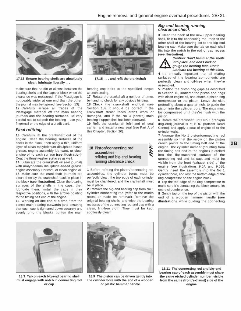
make sure that no dirt or oil was between thebearing shells and the caps or block when theclearance was measured. If the Plastigage isnoticeably wider at one end than the other,the journal may be tapered (see Section 13).12 Carefully scrape all traces of thePlastigage material off the main bearingjournals and the bearing surfaces. Be verycareful not to scratch the bearing - use yourfingernail or the edge of a credit card.
Final refitting13 Carefully lift the crankshaft out of theengine. Clean the bearing surfaces of theshells in the block, then apply a thin, uniformlayer of clean molybdenum disulphide-basedgrease, engine assembly lubricant, or cleanengine oil to each surface (see illustration).Coat the thrustwasher surfaces as well.14 Lubricate the crankshaft oil seal journalswith molybdenum disulphide-based grease,engine assembly lubricant, or clean engine oil.15 Make sure the crankshaft journals areclean, then lay the crankshaft back in place inthe block (see illustration). Clean the bearingsurfaces of the shells in the caps, thenlubricate them. Install the caps in theirrespective positions, with the arrows pointingto the timing belt end of the engine.16 Working on one cap at a time, from thecentre main bearing outwards (and ensuringthat each cap is tightened down squarely andevenly onto the block), tighten the main
bearing cap bolts to the specified torquewrench setting.17 Rotate the crankshaft a number of timesby hand, to check for any obvious binding.18 Check the crankshaft endfloat (seeSection 10). It should be correct if thecrankshaft thrust faces aren’t worn ordamaged, and if the No 3 (centre) mainbearing’s upper shell has been renewed.19 Refit the crankshaft left-hand oil sealcarrier, and install a new seal (see Part A ofthis Chapter, Section 20).
1 Before refitting the piston/connecting rodassemblies, the cylinder bores must beperfectly clean, the top edge of each cylindermust be chamfered, and the crankshaft mustbe in place.2 Remove the big-end bearing cap from No 1cylinder connecting rod (refer to the marksnoted or made on removal). Remove theoriginal bearing shells, and wipe the bearingrecesses of the connecting rod and cap with aclean, lint-free cloth. They must be keptspotlessly-clean!
Big-end bearing runningclearance check3 Clean the back of the new upper bearingshell, fit it to the connecting rod, then fit theother shell of the bearing set to the big-endbearing cap. Make sure the tab on each shellfits into the notch in the rod or cap recess(see illustration).
Caution: Don’t hammer the shellsinto place, and don’t nick orgouge the bearing face. Don’tlubricate the bearing at this time.
4 It’s critically important that all matingsurfaces of the bearing components areperfectly clean and oil-free when they’reassembled.5 Position the piston ring gaps as describedin Section 16, lubricate the piston and ringswith clean engine oil, and attach a piston ringcompressor to the piston. Leave the skirtprotruding about a quarter-inch, to guide thepiston into the cylinder bore. The rings mustbe compressed until they’re flush with thepiston.6 Rotate the crankshaft until No 1 crankpin(big-end) journal is at BDC (Bottom DeadCentre), and apply a coat of engine oil to thecylinder walls.7 Arrange the No 1 piston/connecting rodassembly so that the arrow on the pistoncrown points to the timing belt end of theengine. The cylinder number (counting fromthe timing belt end of the engine) is etchedinto the flat-machined surface of theconnecting rod and its cap, and must bevisible from the front (exhaust side) of theengine (see illustrations 9.5A and 9.5B).Gently insert the assembly into the No 1cylinder bore, and rest the bottom edge of thering compressor on the engine block.8 Tap the top edge of the ring compressor tomake sure it’s contacting the block around itsentire circumference.9 Gently tap on the top of the piston with theend of a wooden hammer handle (seeillustration), while guiding the connecting
18 Piston/connecting rodassemblies -refitting and big-end bearingrunning clearance check
Engine removal and general engine overhaul procedures 2B•21
2B
18.3 Tab on each big-end bearing shellmust engage with notch in connecting rod
or cap
18.9 The piston can be driven gently intothe cylinder bore with the end of a wooden
or plastic hammer handle
18.11 The connecting rod and big-endbearing cap of each assembly must sharethe same etched cylinder number, visiblefrom the same (front/exhaust) side of the
engine
17.13 Ensure bearing shells are absolutelyclean, lubricate liberally . . .
17.15 . . . and refit the crankshaft

rod’s big-end onto the crankpin. The pistonrings may try to pop out of the ringcompressor just before entering the cylinderbore, so keep some pressure on the ringcompressor. Work slowly, and if anyresistance is felt as the piston enters thecylinder, stop immediately. Find out what’sbinding, and fix it before proceeding. Do not,for any reason, force the piston into thecylinder - you might break a ring and/or thepiston.10 To check the big-end bearing runningclearance, cut a piece of the appropriate-sizePlastigage slightly shorter than the width ofthe connecting rod bearing, and lay it in placeon the No 1 crankpin (big-end) journal, parallelwith the crankshaft centre-line (see illus-tration 17.6).11 Clean the connecting rod-to-cap matingsurfaces, and refit the big-end bearing cap.Make sure the etched number on the cap ison the same side as that on the rod (seeillustration). Tighten the cap bolts evenly -first use a torque wrench to tighten the boltsto the specified (first stage) torque setting,then use an ordinary socket extension barand an angle gauge to tighten the boltsfurther through the specified (second stage)angle. Use a thin-wall socket, to avoiderroneous torque readings that can result ifthe socket is wedged between the cap andnut. If the socket tends to wedge itselfbetween the nut and the cap, lift up on itslightly until it no longer contacts the cap.Don’t rotate the crankshaft at any time duringthis operation!12 Unscrew the bolts and detach the cap,being very careful not to disturb thePlastigage.13 Compare the width of the crushedPlastigage to the scale printed on thePlastigage envelope, to obtain the runningclearance (see illustration 17.10). Compare itto the Specifications, to make sure theclearance is correct.14 If the clearance is not as specified, seekthe advice of a Ford dealer or similar enginereconditioning specialist - if the crankshaftjournals are in good condition (see Sec-tion 13), it may be possible simply to renewthe shells to achieve the correct clearance. Ifthis is not possible, the crankshaft must be
reground by a specialist, who can also supplythe necessary undersized shells. First though,make sure that no dirt or oil was trappedbetween the bearing shells and theconnecting rod or cap when the clearancewas measured. Also, recheck the crankpindiameter. If the Plastigage was wider at oneend than the other, the crankpin journal maybe tapered (see Section 13).15 Carefully scrape all traces of thePlastigage material off the journal and thebearing surface. Be very careful not to scratchthe bearing - use your fingernail or the edge ofa credit card.
Final piston/connecting rodrefitting16 Make sure the bearing surfaces areperfectly clean, then apply a uniform layer ofclean molybdenum disulphide-based grease,engine assembly lubricant, or clean engine oil,to both of them. You’ll have to push the pistoninto the cylinder to expose the bearing surfaceof the shell in the connecting rod.17 Slide the connecting rod back into placeon the crankpin (big-end) journal, refit the big-end bearing cap, and then tighten the bolts intwo stages, as described above.18 Repeat the entire procedure for theremaining piston/connecting rod assemblies.19 The important points to remember are:(a) Keep the backs of the bearing shells and
the recesses of the connecting rods andcaps perfectly clean when assemblingthem.
(b) Make sure you have the correctpiston/rod assembly for each cylinder -use the etched cylinder numbers toidentify the front-facing side of both therod and its cap.
(c) The arrow on the piston crown must facethe timing belt end of the engine.
(d) Lubricate the cylinder bores with cleanengine oil.
(e) Lubricate the bearing surfaces whenrefitting the big-end bearing caps after therunning clearance has been checked.
20 After all the piston/connecting rodassemblies have been properly installed,rotate the crankshaft a number of times byhand, to check for any obvious binding.
1 With the engine refitted in the vehicle,double-check the engine oil and coolantlevels. Make a final check that everything hasbeen reconnected, and that there are no toolsor rags left in the engine compartment.2 With the spark plugs removed and theignition system disabled by unplugging theignition coil’s electrical connector, removefuse 14 to disconnect the fuel pump. Turn theengine on the starter until the oil pressurewarning light goes out.3 Refit the spark plugs, and connect all thespark plug (HT) leads (Chapter 1). Reconnectthe ignition coil wiring, refit the fuel pump fuse,then switch on the ignition and listen for the fuelpump; it will run for a little longer than usual,due to the lack of pressure in the system.4 Start the engine, noting that this also maytake a little longer than usual, due to the fuelsystem components being empty.5 While the engine is idling, check for fuel,coolant and oil leaks. Don’t be alarmed ifthere are some odd smells and smoke fromparts getting hot and burning off oil deposits.If the hydraulic tappets have been disturbed,some valve gear noise may be heard at first;this should disappear as the oil circulates fullyaround the engine, and normal pressure isrestored in the tappets.6 Keep the engine idling until hot water is feltcirculating through the top hose, check that itidles reasonably smoothly and at the usualspeed, then switch it off.7 After a few minutes, recheck the oil andcoolant levels, and top-up as necessary(Chapter 1).8 If they were tightened as described, there isno need to re-tighten the cylinder head boltsonce the engine has first run after reassembly- in fact, Ford state that the bolts must not bere-tightened.9 If new components such as pistons, ringsor crankshaft bearings have been fitted, theengine must be run-in for the first 500 miles(800 km). Do not operate the engine at full-throttle, or allow it to labour in any gear duringthis period. It is recommended that the oil andfilter be changed at the end of this period.
19 Engine - initial start-up after overhaul
2B•22 Engine removal and general engine overhaul procedures
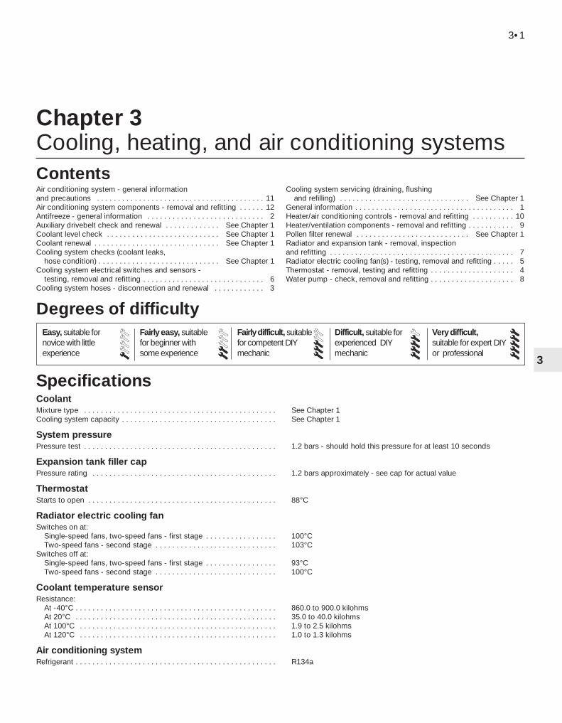
Chapter 3Cooling, heating, and air conditioning systems
Air conditioning system - general information and precautions . . . . . . . . . . . . . . . . . . . . . . . . . . . . . . . . . . . . . . . . 11Air conditioning system components - removal and refitting . . . . . . 12Antifreeze - general information . . . . . . . . . . . . . . . . . . . . . . . . . . . . 2Auxiliary drivebelt check and renewal . . . . . . . . . . . . . See Chapter 1Coolant level check . . . . . . . . . . . . . . . . . . . . . . . . . . . See Chapter 1Coolant renewal . . . . . . . . . . . . . . . . . . . . . . . . . . . . . . See Chapter 1Cooling system checks (coolant leaks,
hose condition) . . . . . . . . . . . . . . . . . . . . . . . . . . . . . See Chapter 1Cooling system electrical switches and sensors -
testing, removal and refitting . . . . . . . . . . . . . . . . . . . . . . . . . . . . . 6Cooling system hoses - disconnection and renewal . . . . . . . . . . . . 3
Cooling system servicing (draining, flushing and refilling) . . . . . . . . . . . . . . . . . . . . . . . . . . . . . . . See Chapter 1
General information . . . . . . . . . . . . . . . . . . . . . . . . . . . . . . . . . . . . . . 1Heater/air conditioning controls - removal and refitting . . . . . . . . . . 10Heater/ventilation components - removal and refitting . . . . . . . . . . . 9Pollen filter renewal . . . . . . . . . . . . . . . . . . . . . . . . . . . See Chapter 1Radiator and expansion tank - removal, inspection and refitting . . . . . . . . . . . . . . . . . . . . . . . . . . . . . . . . . . . . . . . . . . . . 7Radiator electric cooling fan(s) - testing, removal and refitting . . . . . 5Thermostat - removal, testing and refitting . . . . . . . . . . . . . . . . . . . . 4Water pump - check, removal and refitting . . . . . . . . . . . . . . . . . . . . 8
CoolantMixture type . . . . . . . . . . . . . . . . . . . . . . . . . . . . . . . . . . . . . . . . . . . . . . See Chapter 1Cooling system capacity . . . . . . . . . . . . . . . . . . . . . . . . . . . . . . . . . . . . . See Chapter 1
System pressurePressure test . . . . . . . . . . . . . . . . . . . . . . . . . . . . . . . . . . . . . . . . . . . . . . 1.2 bars - should hold this pressure for at least 10 seconds
Expansion tank filler capPressure rating . . . . . . . . . . . . . . . . . . . . . . . . . . . . . . . . . . . . . . . . . . . . 1.2 bars approximately - see cap for actual value
ThermostatStarts to open . . . . . . . . . . . . . . . . . . . . . . . . . . . . . . . . . . . . . . . . . . . . . 88°C
Radiator electric cooling fanSwitches on at:
Single-speed fans, two-speed fans - first stage . . . . . . . . . . . . . . . . . 100°CTwo-speed fans - second stage . . . . . . . . . . . . . . . . . . . . . . . . . . . . . 103°C
Switches off at:Single-speed fans, two-speed fans - first stage . . . . . . . . . . . . . . . . . 93°CTwo-speed fans - second stage . . . . . . . . . . . . . . . . . . . . . . . . . . . . . 100°C
Coolant temperature sensorResistance:
At -40°C . . . . . . . . . . . . . . . . . . . . . . . . . . . . . . . . . . . . . . . . . . . . . . . . 860.0 to 900.0 kilohmsAt 20°C . . . . . . . . . . . . . . . . . . . . . . . . . . . . . . . . . . . . . . . . . . . . . . . . 35.0 to 40.0 kilohmsAt 100°C . . . . . . . . . . . . . . . . . . . . . . . . . . . . . . . . . . . . . . . . . . . . . . . 1.9 to 2.5 kilohmsAt 120°C . . . . . . . . . . . . . . . . . . . . . . . . . . . . . . . . . . . . . . . . . . . . . . . 1.0 to 1.3 kilohms
Air conditioning systemRefrigerant . . . . . . . . . . . . . . . . . . . . . . . . . . . . . . . . . . . . . . . . . . . . . . . . R134a
3•1
Easy, suitable fornovice with littleexperience
Fairly easy, suitablefor beginner withsome experience
Fairly difficult, suitablefor competent DIYmechanic
Difficult, suitable forexperienced DIYmechanic
Very difficult,suitable for expert DIYor professional
Degrees of difficulty
Specifications
Contents
3
Torque wrench settings Nm lbf ftRadiator mounting bracket-to-subframe bolts . . . . . . . . . . . . . . . . . . . . 23 17Fluid cooler pipe unions - automatic transmission . . . . . . . . . . . . . . . . . 23 17Thermostat housing-to-cylinder head bolts . . . . . . . . . . . . . . . . . . . . . . 20 15Water outlet-to-thermostat housing bolts . . . . . . . . . . . . . . . . . . . . . . . 8 to 11 6 to 8Coolant temperature sensor . . . . . . . . . . . . . . . . . . . . . . . . . . . . . . . . . . 23 17Coolant temperature gauge sender . . . . . . . . . . . . . . . . . . . . . . . . . . . . 8 6Water pump bolts . . . . . . . . . . . . . . . . . . . . . . . . . . . . . . . . . . . . . . . . . . 18 13Water pump pulley bolts . . . . . . . . . . . . . . . . . . . . . . . . . . . . . . . . . . . . . See Chapter 2AAir conditioning compressor mounting bolts . . . . . . . . . . . . . . . . . . . . . 25 18
3•2 Cooling, heating and air conditioning systems
Engine cooling systemAll vehicles covered by this manual employ
a pressurised engine cooling system withthermostatically-controlled coolant circu-lation. A water pump mounted on the drivebeltend of the cylinder block/crankcase pumpscoolant through the engine. The coolant flowsaround each cylinder and toward thetransmission end of the engine. Cast-incoolant passages direct coolant around theinlet and exhaust ports, near the spark plug areas and close to the exhaust valveguides.
A wax pellet type thermostat is located in ahousing at the transmission end of the engine.During warm-up, the closed thermostatprevents coolant from circulating through theradiator. Instead, it returns through thecoolant metal pipe running across the front ofthe engine to the radiator bottom hose andthe water pump. The supply to the heater ismade from the rear of the thermostat housing.As the engine nears normal operatingtemperature, the thermostat opens and allowshot coolant to travel through the radiator,where it is cooled before returning to theengine.
The cooling system is sealed by a pressure-type filler cap in the expansion tank. Thepressure in the system raises the boiling pointof the coolant, and increases the coolingefficiency of the radiator. When the engine isat normal operating temperature, the coolantexpands, and the surplus is displaced into theexpansion tank. When the system cools, thesurplus coolant is automatically drawn backfrom the tank into the radiator.
Warning: DO NOT attempt toremove the expansion tank fillercap, or to disturb any part of thecooling system, while it or the
engine is hot, as there is a very great riskof scalding. If the expansion tank filler capmust be removed before the engine andradiator have fully cooled down (eventhough this is not recommended) thepressure in the cooling system must firstbe released. Cover the cap with a thicklayer of cloth, to avoid scalding, and slowlyunscrew the filler cap until a hissing soundcan be heard. When the hissing has
stopped, showing that pressure isreleased, slowly unscrew the filler capfurther until it can be removed; if morehissing sounds are heard, wait until theyhave stopped before unscrewing the capcompletely. At all times, keep well awayfrom the filler opening.
Warning: Do not allow antifreezeto come in contact with yourskin, or with the painted surfacesof the vehicle. Rinse off spills
immediately with plenty of water. Neverleave antifreeze lying around in an opencontainer, or in a puddle in the driveway oron the garage floor. Children and pets areattracted by its sweet smell, but antifreezeis fatal if ingested.
Warning: If the engine is hot, theelectric cooling fan may startrotating even if the engine is notrunning, so be careful to keep
hands, hair and loose clothing well clearwhen working in the engine compartment.
Heating systemThe heating system consists of a blower fan
and heater matrix (radiator) located in theheater unit, with hoses connecting the heatermatrix to the engine cooling system. Hotengine coolant is circulated through theheater matrix. When the heater temperaturecontrol on the facia is operated, a flap dooropens to expose the heater box to thepassenger compartment. When the blowercontrol is operated, the blower fan forces airthrough the unit according to the settingselected.
Air conditioning systemSee Section 11.
Warning: Do not allow antifreeze to come incontact with your skin, or with the paintedsurfaces of the vehicle. Rinse off spillsimmediately with plenty of water. Antifreeze ishighly toxic if ingested. Never leave antifreezelying around in an open container, or inpuddles on the floor; children and pets areattracted by its sweet smell, and may drink it.Check with local authorities about disposingof used antifreeze - many have collectioncentres which will see that antifreeze isdisposed of safely.
The cooling system should be filled with awater/ethylene glycol-based antifreezesolution, of a strength which will preventfreezing down to at least -25°C, or lower if thelocal climate requires it. Antifreeze alsoprovides protection against corrosion, andincreases the coolant boiling point.
The cooling system should be maintainedaccording to the schedule described inChapter 1. If antifreeze is used that is not toFord’s specification, old or contaminatedcoolant mixtures are likely to cause damage,and encourage the formation of corrosion andscale in the system. Use distilled water withthe antifreeze, if available - if not, be sure touse only soft water. Clean rainwater issuitable.
Before adding antifreeze, check all hosesand hose connections, because antifreezetends to leak through very small openings.Engines don’t normally consume coolant, so ifthe level goes down, find the cause andcorrect it.
The exact mixture of antifreeze-to-waterwhich you should use depends on therelative weather conditions. The mixtureshould contain at least 40% antifreeze, butnot more than 70%. Consult the mixtureratio chart on the antifreeze containerbefore adding coolant. Hydrometers areavailable at most automotive accessoryshops to test the coolant. Use antifreezewhich meets the vehicle manufacturer’sspecifications.
Note: Refer to the warnings given in Section 1of this Chapter before starting work.1 If the checks described in Chapter 1 reveala faulty hose, it must be renewed as follows(see illustration).2 First drain the cooling system (see Chap-ter 1); if the antifreeze is not due for renewal,the drained coolant may be re-used, if it iscollected in a clean container.3 To disconnect any hose, use a pair of pliersto release the spring clamps (or a screwdriverto slacken screw-type clamps), then movethem along the hose clear of the union.Carefully work the hose off its stubs. Thehoses can be removed with relative easewhen new - on an older car, they may havestuck.
3 Cooling system hoses -disconnection and renewal
2 Antifreeze - general information
1 General information

4 If a hose proves stubborn, try to release itby rotating it on its unions before attemptingto work it off. Gently prise the end of the hosewith a blunt instrument (such as a flat-bladedscrewdriver), but do not apply too much force,and take care not to damage the pipe stubs orhoses. Note in particular that the radiator hoseunions are fragile; do not use excessive forcewhen attempting to remove the hoses. If allelse fails, cut the hose with a sharp knife, thenslit it so that it can be peeled off in two pieces.While expensive, this is preferable to buying anew radiator. Check first, however, that a newhose is readily available.5 When refitting a hose, first slide the clamps
onto the hose, then work the hose onto itsunions. If the hose is stiff, use soap (orwashing-up liquid) as a lubricant, or soften itby soaking it in boiling water, but take care toprevent scalding.6 Work each hose end fully onto its union,then check that the hose is settled correctlyand is properly routed. Slide each clip alongthe hose until it is behind the union flared end,before tightening it securely.7 Refill the system with coolant (see Chap-ter 1).8 Check carefully for leaks as soon aspossible after disturbing any part of thecooling system.
Note: Refer to the warnings given in Section 1of this Chapter before starting work.
Removal1 Disconnect the battery negative (earth) lead(see Chapter 5, Section 1).2 Unbolt the resonator support bracket fromthe engine compartment front crossmember.Slacken the two clamp screws securing theresonator to the air mass meter and plenumchamber hoses, then swing the resonator upclear of the thermostat housing (see Chap-ter 4).3 Drain the cooling system (see Chapter 1). Ifthe coolant is relatively new or in goodcondition, drain it into a clean container andre-use it.4 Disconnect the expansion tank coolanthose and the radiator top hose from thethermostat housing’s water outlet.5 Unbolt the water outlet and withdraw thethermostat (see illustration). Note theposition of the air bleed valve, and how thethermostat is installed (which end is facingoutwards).
TestingGeneral check6 Before assuming the thermostat is to blamefor a cooling system problem, check thecoolant level, auxiliary drivebelt tension andcondition (see Chapter 1) and temperaturegauge operation.7 If the engine seems to be taking a long timeto warm up (based on heater output ortemperature gauge operation), the thermostatis probably stuck open. Renew thethermostat.8 If the engine runs hot, use your hand tocheck the temperature of the radiator tophose. If the hose isn’t hot, but the engine is,the thermostat is probably stuck closed,preventing the coolant inside the engine fromescaping to the radiator - renew thethermostat.
4 Thermostat - removal, testing and refitting
Cooling, heating and air conditioning systems 3•3
3
4.5 Unbolt water outlet to withdrawthermostat
3.1 Cooling system components
1 Radiator2 (Twin) electric cooling fan
and shroud3 Expansion tank4 Filler/pressure cap5 Bolt6 (Single) electric cooling fan
and shroud
7 Bolt8 Coolant pipe9 Nut
10 Top mounting rubber11 Bottom mounting rubber12 Bolt13 Radiator mounting
bracket
14 Coolant hose15 Bolt16 Radiator top hose17 Coolant pipe/hose18 Stud19 Thermostat housing20 Radiator bottom hose

Caution: Don’t drive the vehiclewithout a thermostat. The lack ofa thermostat will slow warm-up
time. The engine management system’sECU will then stay in warm-up mode forlonger than necessary, causing emissionsand fuel economy to suffer.
9 If the radiator top hose is hot, it means thatthe coolant is flowing and the thermostat isopen. Consult the “Fault diagnosis” section atthe front of this manual to assist in tracingpossible cooling system faults.
Thermostat test10 If the thermostat remains in the openposition at room temperature, it is faulty, andmust be renewed as a matter of course.11 To test it fully, suspend the (closed)thermostat on a length of string in a containerof cold water, with a thermometer beside it;ensure that neither touches the side of thecontainer.12 Heat the water, and check thetemperature at which the thermostat begins toopen; compare this value with that specified.Continue to heat the water until thethermostat is fully open; the temperature atwhich this should happen is stamped in theunit’s end. Remove the thermostat and allowit to cool down; check that it closes fully.13 If the thermostat does not open and closeas described, if it sticks in either position, or ifit does not open at the specified temperature,it must be renewed.
Refitting14 Refitting is the reverse of the removalprocedure. Clean the mating surfacescarefully, renew the thermostat’s sealing ringif it is worn or damaged, then refit thethermostat with its air bleed valve uppermost(see illustration). Tighten the water outletbolts to the specified torque wrench setting.15 Refill the cooling system (see Chapter 1).16 Start the engine and allow it to reachnormal operating temperature, then check forleaks and proper thermostat operation.
Note: Refer to the warnings given in Section 1of this Chapter before starting work.
Testing1 The radiator cooling fan is controlled by theengine management system’s ECU, acting onthe information received from the coolanttemperature sensor. Where twin fans or two-speed fans are fitted, control is through aresistor assembly, secured to the bottom left-hand corner of the fan shroud - this can berenewed separately if faulty.2 First, check the relevant fuses and relays(see Chapter 12).3 To test the fan motor, unplug the electricalconnector, and use fused jumper wires toconnect the fan directly to the battery. If thefan still does not work, renew the motor.4 If the motor proved sound, the fault lies inthe coolant temperature sensor (see Section 6for testing details), in the wiring loom (seeChapter 12 for testing details) or in the enginemanagement system (see Chapter 6).
Removal and refitting5 Disconnect the battery negative (earth) lead(see Chapter 5, Section 1).6 Unbolt the resonator support bracket fromthe engine compartment front crossmember.Slacken the two clamp screws securing theresonator to the air mass meter and plenumchamber hoses, then swing the resonator upclear of the thermostat housing (see Chapter 4).
7 Drain the cooling system (see Chapter 1).8 Remove the radiator top hose completely.Disconnect the metal coolant pipe/hose fromthe thermostat, and unbolt the coolant pipefrom the exhaust manifold heat shield.9 Unplug the cooling fan electricalconnector(s), then release all wiring and hosesfrom the fan shroud.10 Unscrew the two nuts securing the fanshroud, then lift the assembly to disengage itfrom its bottom mountings and from theradiator top edge (see illustrations).11 Withdraw the fan and shroud as anassembly (see illustration).12 At the time of writing, the fan, motor andshroud are available only as a completeassembly, and must be renewed together iffaulty.13 Refitting is the reverse of the removalprocedure. Ensure that the shroud is settledcorrectly at all four mounting points beforerefitting and tightening the nuts.
Note: Refer to the warnings given in Section 1of this Chapter before starting work.
Coolant temperature gaugesenderTesting1 If the coolant temperature gauge is inopera-tive, check the fuses first (see Chapter 12).2 If the gauge indicates Hot at any time,consult the “Fault finding” section at the endof this manual, to assist in tracing possiblecooling system faults.3 If the gauge indicates Hot shortly after theengine is started from cold, unplug thecoolant temperature sender’s electricalconnector. If the gauge reading now drops,renew the sender. If the reading remains high,the wire to the gauge may be shorted to earth,or the gauge is faulty.4 If the gauge fails to indicate after the enginehas been warmed up (approximately 10 minutes) and the fuses are known to besound, switch off the engine. Unplug the
6 Cooling system electricalswitches and sensors - testing, removal and refitting
5 Radiator electric cooling fan(s) - testing, removal and refitting
3•4 Cooling, heating and air conditioning systems
4.14 Ensure thermostat is refitted asshown
5.10A Fan shroud is secured at top bymounting nut (A), at bottom by clip (B) . . .
5.10B . . . and is hooked over radiator topedge (one point arrowed)
5.11 Removing radiator electric coolingfan and shroud assembly
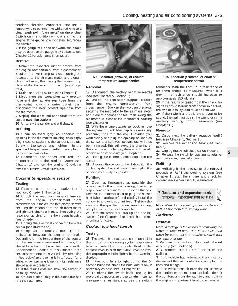
sender’s electrical connector, and use ajumper wire to connect the white/red wire to aclean earth point (bare metal) on the engine.Switch on the ignition without starting theengine. If the gauge now indicates Hot, renewthe sender.5 If the gauge still does not work, the circuitmay be open, or the gauge may be faulty. SeeChapter 12 for additional information.
Removal6 Unbolt the resonator support bracket fromthe engine compartment front crossmember.Slacken the two clamp screws securing theresonator to the air mass meter and plenumchamber hoses, then swing the resonator upclear of the thermostat housing (see Chap-ter 4).7 Drain the cooling system (see Chapter 1).8 Disconnect the expansion tank coolanthose and the radiator top hose from thethermostat housing’s water outlet, thendisconnect the metal coolant pipe/hose fromthe thermostat.9 Unplug the electrical connector from thesender (see illustration).10 Unscrew the sender and withdraw it.
Refitting11 Clean as thoroughly as possible theopening in the thermostat housing, then applya light coat of sealant to the sender’s threads.Screw in the sender and tighten it to thespecified torque wrench setting, and plug inits electrical connector.12 Reconnect the hoses and refit theresonator, top-up the cooling system (seeChapter 1) and run the engine. Check forleaks and proper gauge operation.
Coolant temperature sensorTesting13 Disconnect the battery negative (earth)lead (see Chapter 5, Section 1).14 Unbolt the resonator support bracketfrom the engine compartment frontcrossmember. Slacken the two clamp screwssecuring the resonator to the air mass meterand plenum chamber hoses, then swing theresonator up clear of the thermostat housing(see Chapter 4).15 Unplug the electrical connector from thesensor (see illustration).16 Using an ohmmeter, measure theresistance between the sensor terminals.Depending on the temperature of the sensortip, the resistance measured will vary, butshould be within the broad limits given in theSpecifications Section of this Chapter. If thesensor’s temperature is varied - by removingit (see below) and placing it in a freezer for awhile, or by warming it gently - its resistanceshould alter accordingly.17 If the results obtained show the sensor tobe faulty, renew it.18 On completion, plug in the connector andrefit the resonator.
Removal19 Disconnect the battery negative (earth)lead (see Chapter 5, Section 1).20 Unbolt the resonator support bracketfrom the engine compartment frontcrossmember. Slacken the two clamp screwssecuring the resonator to the air mass meterand plenum chamber hoses, then swing theresonator up clear of the thermostat housing(see Chapter 4).21 With the engine completely cool, removethe expansion tank filler cap to release anypressure, then refit the cap. Provided youwork swiftly and plug the opening as soon asthe sensor is unscrewed, coolant loss will thusbe minimised; this will avoid the draining ofthe complete cooling system which wouldotherwise be necessary (see Chapter 1).22 Unplug the electrical connector from thesensor.23 Unscrew the sensor and withdraw it. If thecooling system has not been drained, plug theopening as quickly as possible.
Refitting24 Clean as thoroughly as possible theopening in the thermostat housing, then applya light coat of sealant to the sensor’s threads.Remove the material used to plug the sensorhole (where applicable), and quickly install thesensor to prevent coolant loss. Tighten thesensor to the specified torque wrench setting,and plug in its electrical connector.25 Refit the resonator, top-up the coolingsystem (see Chapter 1) and run the engine,checking for leaks.
Coolant low level switch
Testing26 The switch is a reed-type unit mounted inthe bottom of the cooling system expansiontank, activated by a magnetic float. If thecoolant level falls to the “MIN” level or less,the appropriate bulb lights in the warningdisplay.27 If the bulb fails to light during the 5-second bulb test, check the bulb, and renew ifnecessary as described in Chapter 12.28 To check the switch itself, unplug itselectrical connector, and use an ohmmeter tomeasure the resistance across the switch
terminals. With the float up, a resistance of 90 ohms should be measured; when it isdown, the resistance should increase toapproximately 150 kilohms.29 If the results obtained from the check aresignificantly different from those expected,the switch is faulty, and must be renewed.30 If the switch and bulb are proven to besound, the fault must be in the wiring or in theauxiliary warning control assembly (seeChapter 12).
Removal31 Disconnect the battery negative (earth)lead (see Chapter 5, Section 1).32 Remove the expansion tank (see Sec-tion 7).33 Unplug the switch electrical connector.34 Release the switch by twisting its retaineranti-clockwise, then withdraw it.
Refitting35 Refitting is the reverse of the removalprocedure. Refill the cooling system (seeChapter 1). Start the engine, and check forcoolant leaks when it is fully warmed-up.
Note: Refer to the warnings given in Section 1of this Chapter before starting work.
Radiator
RemovalNote: If leakage is the reason for removing theradiator, bear in mind that minor leaks canoften be cured using a radiator sealant withthe radiator in situ.1 Remove the radiator fan and shroudassembly (see Section 5).2 Disconnect the bottom hose from theradiator.3 If the vehicle has automatic transmission,disconnect the fluid cooler lines, and plug thelines and fittings.4 If the vehicle has air conditioning, unscrewthe condenser mounting nuts or bolts, detachthe condenser from the radiator, and tie it tothe engine compartment front crossmember.
7 Radiator and expansion tank -removal, inspection and refitting
Cooling, heating and air conditioning systems 3•5
3
6.9 Location (arrowed) of coolanttemperature gauge sender
6.15 Location (arrowed) of coolanttemperature sensor

Warning: Do not disconnect anyof the refrigerant hoses.
5 Unbolt the radiator mounting brackets fromthe subframe; note that they are handed, andare marked to ensure correct refitting (seeillustration). Collect the bottom mountingrubbers, noting which way up they are fitted,and store them carefully.6 Carefully lower the radiator from thevehicle, and withdraw it.7 With the radiator removed, it can beinspected for leaks and damage. If it needsrepair, have a radiator specialist or dealerservice department perform the work, asspecial techniques are required.8 Insects and dirt can be removed from theradiator with a garden hose or a soft brush.Don’t bend the cooling fins as this is done.Refitting9 Refitting is the reverse of the removalprocedure. Be sure the mounting rubbers areseated properly at the base of the radiator.10 After refitting, refill the cooling systemwith the proper mixture of antifreeze andwater (see Chapter 1).11 Start the engine, and check for leaks.Allow the engine to reach normal operatingtemperature, indicated by the radiator tophose becoming hot. Recheck the coolantlevel, and add more if required.
12 If working on an vehicle with automatictransmission, check and add transmissionfluid as needed (see Chapter 1).
Expansion tank13 With the engine completely cool, removethe expansion tank filler cap to release anypressure, then refit the cap.14 Disconnect the hoses from the tank,upper hose first. As each hose isdisconnected, drain the tank’s contents into aclean container. If the antifreeze is not due forrenewal, the drained coolant may be re-used,if it is kept clean.15 Unscrew the tank’s two mounting boltsand withdraw it, unplugging the coolant lowlevel switch electrical connector (where fitted).16 Wash out the tank, and inspect it forcracks and chafing - renew it if damaged.17 Refitting is the reverse of the removalprocedure. Refill the cooling system with theproper mixture of antifreeze and water (seeChapter 1), then start the engine and allow itto reach normal operating temperature,indicated by the radiator top hose becominghot. Recheck the coolant level and add moreif required, then check for leaks.
Note: Refer to the warnings given in Section 1of this Chapter before starting work.
Check1 A failure in the water pump can causeserious engine damage due to overheating.2 There are three ways to check the operationof the water pump while it’s installed on theengine. If the pump is defective, it should bereplaced with a new or rebuilt unit.3 With the engine running at normal operatingtemperature, squeeze the radiator top hose. Ifthe water pump is working properly, apressure surge should be felt as the hose isreleased.
Warning: Keep your hands awayfrom the radiator electriccooling fan blades!
4 Remove the timing belt covers (see Chap-ter 2, Part A). Water pumps are equipped withweep or vent holes. If a failure occurs in thepump seal, coolant will leak from the hole. Inmost cases you’ll need an electric torch tofind the hole on the water pump fromunderneath to check for leaks.5 If the water pump shaft bearings fail, theremay be a howling sound at the drivebelt endof the engine while it’s running. Shaft wearcan be felt if the water pump pulley is rockedup and down. Don’t mistake drivebeltslippage, which causes a squealing sound, forwater pump bearing failure.
Removal and refitting6 Remove the timing belt and tensioner (seeChapter 2, Part A). As noted in Chapter 2, ifthe belt is fouled with coolant, it must berenewed as a matter of course.7 Drain the cooling system (see Chapter 1).8 Disconnect the radiator bottom hose fromthe pump union. It is easier to reach this unionif the power steering pump is unbolted andmoved aside as described in Chapter 10 (seeillustration). There is no need to disconnectany of the power steering system hoses.9 Unbolt and remove the water pump (seeillustration). If the pump is to be renewed,unbolt the timing belt guide pulleys, andtransfer them to the new pump.10 Clean the mating surfaces carefully; thegasket must be renewed whenever it isdisturbed (see illustration).11 On refitting, use grease to stick the newgasket in place, refit the pump, and tightenthe pump bolts to the specified torque wrenchsetting.12 The remainder of the reassemblyprocedure is the reverse of dismantling. Notethat a new tensioner spring and retaining pinmust be fitted if the timing belt has beenremoved for the first time. Tighten allfasteners to the specified torque wrenchsettings, and refill the system with coolant asdescribed in Chapter 1.
8 Water pump - check, removal and refitting
3•6 Cooling, heating and air conditioning systems
7.5 Radiator mounting bracket-to-subframe bolts (A), air conditioning system
condenser mounting bolt (B)
8.8 Power steering system pump shouldbe removed to reach water pump hose
union (arrowed)
8.9 Unscrew bolts (arrowed) . . . 8.10 . . . to remove water pump - alwaysrenew gasket and clean all mating
surfaces carefully

Heater blower motorRemoval1 Disconnect the battery negative (earth) lead(see Chapter 5, Section 1).2 Release the four clips (by pulling them out)securing the passenger side footwell uppertrim panel, then withdraw the panel.3 Unplug the motor’s electrical connector.4 Lift the motor’s retaining lug slightly, twistthe motor anti-clockwise (seen from beneath)through approximately 30°, then withdraw theassembly.5 The motor’s control resistor can beremoved by sliding a slim screwdriver into theslot provided in one end. Press thescrewdriver in approximately 5 mm againstspring pressure, and prise the resistor out(see illustration).
Refitting6 Refitting is the reverse of the removalprocedure. Refit the motor, and twist itclockwise until the retaining lug engagessecurely (see illustration).
Heater matrixRemoval7 Disconnect the battery negative (earth) lead(see Chapter 5, Section 1).
8 Drain the cooling system (see Chapter 1).9 Disconnect the coolant hoses from theheater matrix unions protruding through theengine compartment bulkhead (seeillustrations).10 Working inside the passengercompartment, remove the trim panels fromeach footwell, just in front of the centreconsole. Each panel is secured by twoscrews. If additional clearance is required, thecentre console can be removed as well (seeChapter 11), but this is not essential.11 Remove the single screw to release the airduct in the base of the heater unit (seeillustration).12 Remove the three Torx-type screws (sizeT20) securing the air distributor to the heaterunit bottom cover, then release the clips.
There is a single plastic clip on each side, andadditional metal clips may be found. Push theduct up to retract it, and withdraw the airdistributor (see illustration).13 Release the clips - there are two plasticclips on each side, and additional metal clipsmay be found - then withdraw the heaterunit’s bottom cover, complete with the matrix(see illustration).14 Undo the screw and withdraw the clampto separate the matrix from the bottom cover(see illustration).
Refitting15 Refitting is the reverse of the removalprocedure. Additional metal clips may berequired to secure the heater unit’s bottomcover and the air distributor. Ensure that the
9 Heater/ventilation components- removal and refitting
Cooling, heating and air conditioning systems 3•7
3
9.12 . . . release clips (A) to free airdistributor from base of heater unit - note
clips (B) securing . . .9.13 . . . heater unit’s bottom cover,
complete with matrix9.14 Remove clamp (one screw) to separate
matrix from heater unit’s bottom cover
9.5 Heater blower motor control resistorcan be prised out of heater unit
9.6 Ensure blower motor retaining lug(arrowed) engages securely in heater unit
on reassembly9.9A Coolant pipes to heater matrix must
be disconnected . . .
9.9B . . . but can be reached best frombeneath vehicle (arrowed)
9.11 Remove screw to allow air duct to beretracted into air distributor at base of
heater unit . . .
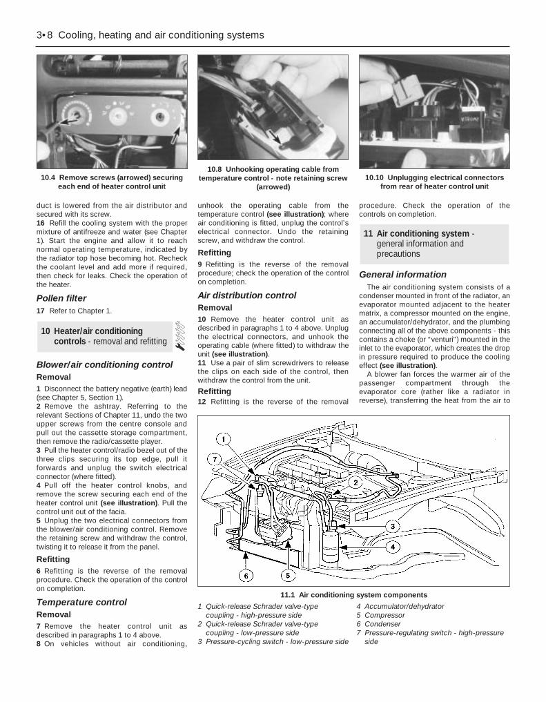
duct is lowered from the air distributor andsecured with its screw.16 Refill the cooling system with the propermixture of antifreeze and water (see Chapter1). Start the engine and allow it to reachnormal operating temperature, indicated bythe radiator top hose becoming hot. Recheckthe coolant level and add more if required,then check for leaks. Check the operation ofthe heater.
Pollen filter17 Refer to Chapter 1.
Blower/air conditioning controlRemoval1 Disconnect the battery negative (earth) lead(see Chapter 5, Section 1).2 Remove the ashtray. Referring to therelevant Sections of Chapter 11, undo the twoupper screws from the centre console andpull out the cassette storage compartment,then remove the radio/cassette player.3 Pull the heater control/radio bezel out of thethree clips securing its top edge, pull itforwards and unplug the switch electricalconnector (where fitted).4 Pull off the heater control knobs, andremove the screw securing each end of theheater control unit (see illustration). Pull thecontrol unit out of the facia.5 Unplug the two electrical connectors fromthe blower/air conditioning control. Removethe retaining screw and withdraw the control,twisting it to release it from the panel.
Refitting6 Refitting is the reverse of the removalprocedure. Check the operation of the controlon completion.
Temperature controlRemoval7 Remove the heater control unit asdescribed in paragraphs 1 to 4 above.8 On vehicles without air conditioning,
unhook the operating cable from thetemperature control (see illustration); whereair conditioning is fitted, unplug the control’selectrical connector. Undo the retainingscrew, and withdraw the control.
Refitting9 Refitting is the reverse of the removalprocedure; check the operation of the controlon completion.
Air distribution controlRemoval10 Remove the heater control unit asdescribed in paragraphs 1 to 4 above. Unplugthe electrical connectors, and unhook theoperating cable (where fitted) to withdraw theunit (see illustration).11 Use a pair of slim screwdrivers to releasethe clips on each side of the control, thenwithdraw the control from the unit.
Refitting12 Refitting is the reverse of the removal
procedure. Check the operation of thecontrols on completion.
General informationThe air conditioning system consists of a
condenser mounted in front of the radiator, anevaporator mounted adjacent to the heatermatrix, a compressor mounted on the engine,an accumulator/dehydrator, and the plumbingconnecting all of the above components - thiscontains a choke (or “venturi”) mounted in theinlet to the evaporator, which creates the dropin pressure required to produce the coolingeffect (see illustration).
A blower fan forces the warmer air of thepassenger compartment through theevaporator core (rather like a radiator inreverse), transferring the heat from the air to
11 Air conditioning system - general information andprecautions
10 Heater/air conditioningcontrols - removal and refitting
3•8 Cooling, heating and air conditioning systems
10.4 Remove screws (arrowed) securingeach end of heater control unit
10.8 Unhooking operating cable fromtemperature control - note retaining screw
(arrowed)10.10 Unplugging electrical connectors
from rear of heater control unit
11.1 Air conditioning system components
1 Quick-release Schrader valve-type coupling - high-pressure side
2 Quick-release Schrader valve-type coupling - low-pressure side
3 Pressure-cycling switch - low-pressure side
4 Accumulator/dehydrator5 Compressor6 Condenser7 Pressure-regulating switch - high-pressure
side
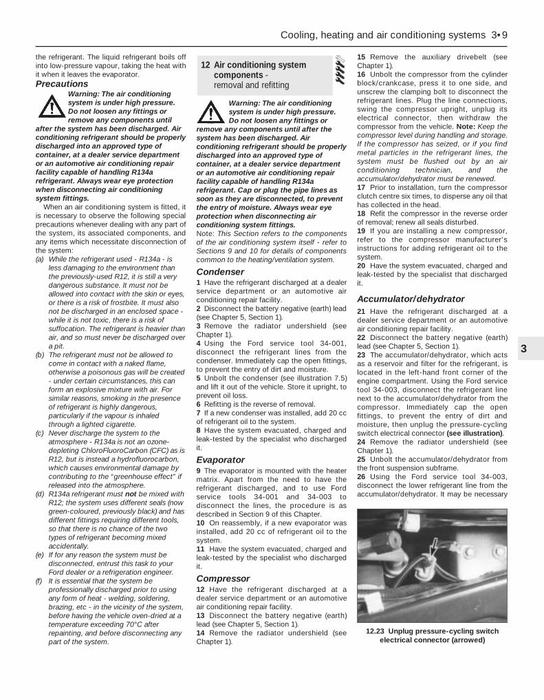
the refrigerant. The liquid refrigerant boils offinto low-pressure vapour, taking the heat withit when it leaves the evaporator.Precautions
Warning: The air conditioningsystem is under high pressure.Do not loosen any fittings orremove any components until
after the system has been discharged. Airconditioning refrigerant should be properlydischarged into an approved type ofcontainer, at a dealer service departmentor an automotive air conditioning repairfacility capable of handling R134arefrigerant. Always wear eye protectionwhen disconnecting air conditioningsystem fittings.
When an air conditioning system is fitted, itis necessary to observe the following specialprecautions whenever dealing with any part ofthe system, its associated components, andany items which necessitate disconnection ofthe system:(a) While the refrigerant used - R134a - is
less damaging to the environment thanthe previously-used R12, it is still a verydangerous substance. It must not beallowed into contact with the skin or eyes,or there is a risk of frostbite. It must alsonot be discharged in an enclosed space -while it is not toxic, there is a risk ofsuffocation. The refrigerant is heavier thanair, and so must never be discharged overa pit.
(b) The refrigerant must not be allowed tocome in contact with a naked flame,otherwise a poisonous gas will be created- under certain circumstances, this canform an explosive mixture with air. Forsimilar reasons, smoking in the presenceof refrigerant is highly dangerous,particularly if the vapour is inhaledthrough a lighted cigarette.
(c) Never discharge the system to theatmosphere - R134a is not an ozone-depleting ChloroFluoroCarbon (CFC) as isR12, but is instead a hydrofluorocarbon,which causes environmental damage bycontributing to the “greenhouse effect” ifreleased into the atmosphere.
(d) R134a refrigerant must not be mixed withR12; the system uses different seals (nowgreen-coloured, previously black) and hasdifferent fittings requiring different tools,so that there is no chance of the twotypes of refrigerant becoming mixedaccidentally.
(e) If for any reason the system must bedisconnected, entrust this task to yourFord dealer or a refrigeration engineer.
(f) It is essential that the system beprofessionally discharged prior to usingany form of heat - welding, soldering,brazing, etc - in the vicinity of the system,before having the vehicle oven-dried at atemperature exceeding 70°C afterrepainting, and before disconnecting anypart of the system.
Warning: The air conditioningsystem is under high pressure.Do not loosen any fittings or
remove any components until after thesystem has been discharged. Airconditioning refrigerant should be properlydischarged into an approved type ofcontainer, at a dealer service departmentor an automotive air conditioning repairfacility capable of handling R134arefrigerant. Cap or plug the pipe lines assoon as they are disconnected, to preventthe entry of moisture. Always wear eyeprotection when disconnecting airconditioning system fittings.Note: This Section refers to the componentsof the air conditioning system itself - refer toSections 9 and 10 for details of componentscommon to the heating/ventilation system.
Condenser1 Have the refrigerant discharged at a dealerservice department or an automotive airconditioning repair facility.2 Disconnect the battery negative (earth) lead(see Chapter 5, Section 1).3 Remove the radiator undershield (seeChapter 1).4 Using the Ford service tool 34-001,disconnect the refrigerant lines from thecondenser. Immediately cap the open fittings,to prevent the entry of dirt and moisture.5 Unbolt the condenser (see illustration 7.5)and lift it out of the vehicle. Store it upright, toprevent oil loss.6 Refitting is the reverse of removal.7 If a new condenser was installed, add 20 ccof refrigerant oil to the system.8 Have the system evacuated, charged andleak-tested by the specialist who dischargedit.
Evaporator9 The evaporator is mounted with the heatermatrix. Apart from the need to have therefrigerant discharged, and to use Fordservice tools 34-001 and 34-003 todisconnect the lines, the procedure is asdescribed in Section 9 of this Chapter.10 On reassembly, if a new evaporator wasinstalled, add 20 cc of refrigerant oil to thesystem.11 Have the system evacuated, charged andleak-tested by the specialist who dischargedit.
Compressor12 Have the refrigerant discharged at adealer service department or an automotiveair conditioning repair facility.13 Disconnect the battery negative (earth)lead (see Chapter 5, Section 1).14 Remove the radiator undershield (seeChapter 1).
15 Remove the auxiliary drivebelt (seeChapter 1).16 Unbolt the compressor from the cylinderblock/crankcase, press it to one side, andunscrew the clamping bolt to disconnect therefrigerant lines. Plug the line connections,swing the compressor upright, unplug itselectrical connector, then withdraw thecompressor from the vehicle. Note: Keep thecompressor level during handling and storage.If the compressor has seized, or if you findmetal particles in the refrigerant lines, thesystem must be flushed out by an airconditioning technician, and theaccumulator/dehydrator must be renewed.17 Prior to installation, turn the compressorclutch centre six times, to disperse any oil thathas collected in the head.18 Refit the compressor in the reverse orderof removal; renew all seals disturbed.19 If you are installing a new compressor,refer to the compressor manufacturer’sinstructions for adding refrigerant oil to thesystem.20 Have the system evacuated, charged andleak-tested by the specialist that dischargedit.
Accumulator/dehydrator21 Have the refrigerant discharged at adealer service department or an automotiveair conditioning repair facility.22 Disconnect the battery negative (earth)lead (see Chapter 5, Section 1).23 The accumulator/dehydrator, which actsas a reservoir and filter for the refrigerant, islocated in the left-hand front corner of theengine compartment. Using the Ford servicetool 34-003, disconnect the refrigerant linenext to the accumulator/dehydrator from thecompressor. Immediately cap the openfittings, to prevent the entry of dirt andmoisture, then unplug the pressure-cyclingswitch electrical connector (see illustration).24 Remove the radiator undershield (seeChapter 1).25 Unbolt the accumulator/dehydrator fromthe front suspension subframe.26 Using the Ford service tool 34-003,disconnect the lower refrigerant line from theaccumulator/dehydrator. It may be necessary
12 Air conditioning systemcomponents - removal and refitting
Cooling, heating and air conditioning systems 3•9
3
12.23 Unplug pressure-cycling switchelectrical connector (arrowed)
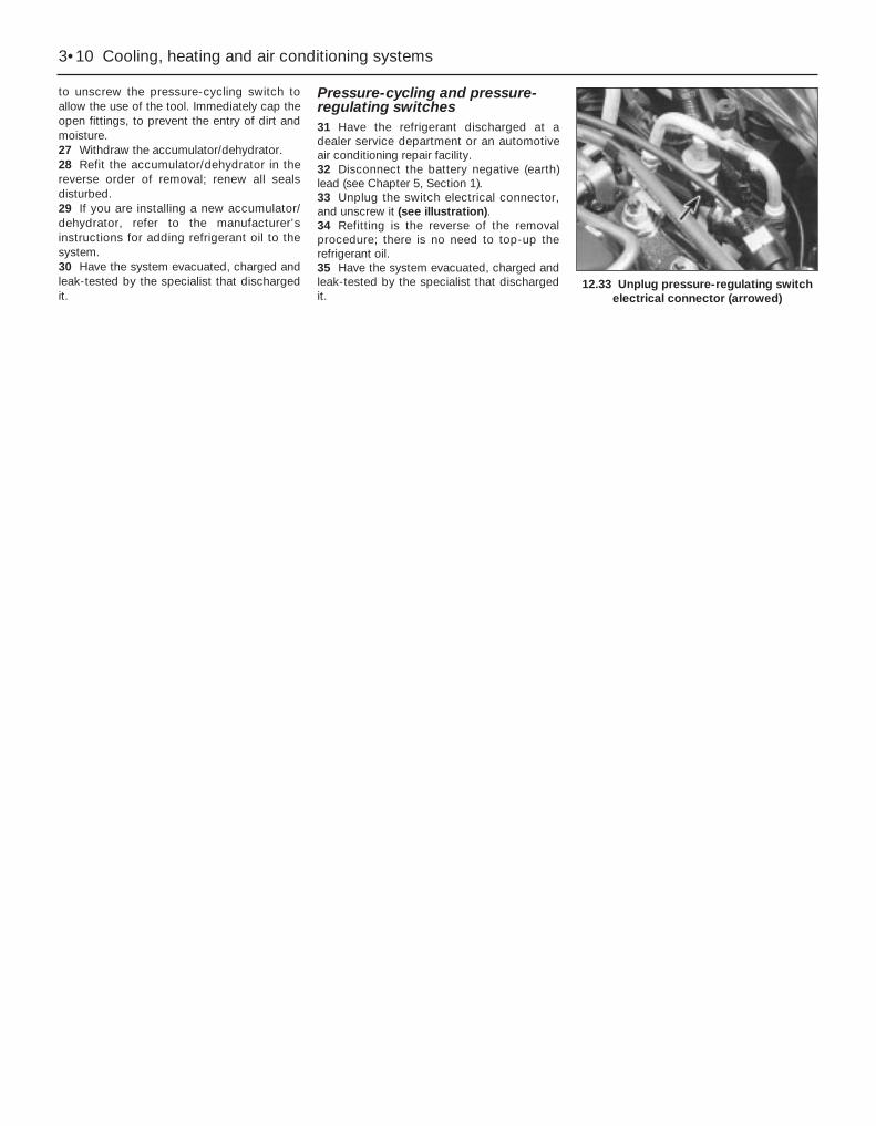
to unscrew the pressure-cycling switch toallow the use of the tool. Immediately cap theopen fittings, to prevent the entry of dirt andmoisture.27 Withdraw the accumulator/dehydrator.28 Refit the accumulator/dehydrator in thereverse order of removal; renew all sealsdisturbed.29 If you are installing a new accumulator/dehydrator, refer to the manufacturer’sinstructions for adding refrigerant oil to thesystem.30 Have the system evacuated, charged andleak-tested by the specialist that dischargedit.
Pressure-cycling and pressure-regulating switches31 Have the refrigerant discharged at adealer service department or an automotiveair conditioning repair facility.32 Disconnect the battery negative (earth)lead (see Chapter 5, Section 1).33 Unplug the switch electrical connector,and unscrew it (see illustration).34 Refitting is the reverse of the removalprocedure; there is no need to top-up therefrigerant oil.35 Have the system evacuated, charged andleak-tested by the specialist that dischargedit.
3•10 Cooling, heating and air conditioning systems
12.33 Unplug pressure-regulating switchelectrical connector (arrowed)
Chapter 4 Fuel and exhaust systems
Accelerator cable (models with traction control) - removal, refitting and adjustment . . . . . . . . . . . . . . . . . . . . . . . . . 6
Accelerator cable (models without traction control) - removal, refitting and adjustment . . . . . . . . . . . . . . . . . . . . . . . . . 5
Accelerator pedal - removal and refitting . . . . . . . . . . . . . . . . . . . . . 7Air cleaner assembly/air intake components - removal and refitting . 4Air filter element renewal . . . . . . . . . . . . . . . . . . . . . . . See Chapter 1Catalytic converter . . . . . . . . . . . . . . . . . . . . . . . . . . . . See Chapter 6Exhaust manifold - removal and refitting . . . . . . . . . . . See Chapter 2AExhaust system - general information and component renewal . . . . 17Exhaust system check . . . . . . . . . . . . . . . . . . . . . . . . . See Chapter 1Fuel cut-off switch - removal and refitting . . . . . . . . . . . . . . . . . . . . 13Fuel filter renewal . . . . . . . . . . . . . . . . . . . . . . . . . . . . . See Chapter 1Fuel injection system/engine management system - check . . . . . . . 15Fuel injection system/engine management system - general . . . . . 14
Fuel lines and fittings - general information . . . . . . . . . . . . . . . . . . . 3Fuel pump/fuel gauge sender unit - removal and refitting . . . . . . . . 9Fuel pump/fuel pressure - check . . . . . . . . . . . . . . . . . . . . . . . . . . . 8Fuel system - depressurisation . . . . . . . . . . . . . . . . . . . . . . . . . . . . . 2Fuel system components - check and renewal . . . . . . . . . . . . . . . . 16Fuel tank - removal and refitting . . . . . . . . . . . . . . . . . . . . . . . . . . . . 10Fuel tank cleaning and repair - general information . . . . . . . . . . . . . 11General information and precautions . . . . . . . . . . . . . . . . . . . . . . . . 1Idle speed and mixture check and adjustment . . . . . . See Section 14Inlet manifold - removal and refitting . . . . . . . . . . . . . . See Chapter 2AOxygen sensor . . . . . . . . . . . . . . . . . . . . . . . . . . . . . . . See Chapter 6Roll-over valves - removal and refitting . . . . . . . . . . . . . . . . . . . . . . . 12Underbody fuel/brake line check . . . . . . . . . . . . . . . . . See Chapter 1Underbonnet hose check . . . . . . . . . . . . . . . . . . . . . . . See Chapter 1
GeneralIdle speed:
Regulated - nominal (± 50 rpm) . . . . . . . . . . . . . . . . . . . . . . . . . . . . . . 830 to 880 rpm*Unregulated - base . . . . . . . . . . . . . . . . . . . . . . . . . . . . . . . . . . . . . . . 1500 rpm*
Idle mixture (CO level) . . . . . . . . . . . . . . . . . . . . . . . . . . . . . . . . . . . . . . . Not available* Given for reference only - not adjustable.
Rev limiter operationFuel injectors shut off at:
Automatic transmission, position “N” selected . . . . . . . . . . . . . . . . . . 4100 rpmAutomatic transmission, any other position selected . . . . . . . . . . . . . 6800 rpm (approximately)Manual transmission . . . . . . . . . . . . . . . . . . . . . . . . . . . . . . . . . . . . . . 6800 to 7100 rpm
Fuel pressureRegulated fuel pressure - engine running at idle speed:
Pressure regulator vacuum hose connected . . . . . . . . . . . . . . . . . . . 2.1 ± 0.2 barsPressure regulator vacuum hose disconnected . . . . . . . . . . . . . . . . . 2.7 ± 0.2 bars
Note: When the ignition is switched off, the system should hold 1.8 bars for 5 minutes. If the engine is hot, the pressure may rise to maximum of2.7 bars during this check. Pressure regulator (when reconnected) should prevent any higher pressure being reached.
Fuel injectorsResistance . . . . . . . . . . . . . . . . . . . . . . . . . . . . . . . . . . . . . . . . . . . . . . . . 13.7 to 15.2 ohms
Idle speed control valveResistance . . . . . . . . . . . . . . . . . . . . . . . . . . . . . . . . . . . . . . . . . . . . . . . . 6 to 14 ohms
Idle-increase solenoid valveResistance . . . . . . . . . . . . . . . . . . . . . . . . . . . . . . . . . . . . . . . . . . . . . . . . 50 to 120 ohms
Torque wrench settings Nm lbf ftPlenum chamber-to-inlet manifold fasteners . . . . . . . . . . . . . . . . . . . . . 4 3Throttle housing-to-inlet manifold screws . . . . . . . . . . . . . . . . . . . . . . . 10 7Idle speed control valve bolts . . . . . . . . . . . . . . . . . . . . . . . . . . . . . . . . . 6 4Fuel pressure regulator bolts . . . . . . . . . . . . . . . . . . . . . . . . . . . . . . . . . 6 4Fuel injector bolts . . . . . . . . . . . . . . . . . . . . . . . . . . . . . . . . . . . . . . . . . . 6 4Fuel rail-to-inlet manifold bolts . . . . . . . . . . . . . . . . . . . . . . . . . . . . . . . . 10 7Fuel feed and return line threaded couplings at fuel rail . . . . . . . . . . . . . 24 to 30 17 to 22All exhaust system nuts and bolts . . . . . . . . . . . . . . . . . . . . . . . . . . . . . 40 to 45 30 to 33
4•1
Easy, suitable fornovice with littleexperience
Fairly easy, suitablefor beginner withsome experience
Fairly difficult, suitablefor competent DIYmechanic
Difficult, suitable forexperienced DIYmechanic
Very difficult,suitable for expert DIYor professional
Degrees of difficulty
Specifications
Contents
4

This Chapter is concerned with thosefeatures of the engine management systemthat supply clean fuel and air to the engine,meter it in the required proportions, anddispose of the results. Since the emissioncontrol sub-systems modify the functions ofboth the fuel and exhaust sub-systems, all ofwhich are integral parts of the whole enginemanagement system, there are many cross-references to Chapters 5 and 6. Informationon the electronic control system, its faultdiagnosis, sensors and actuators, is given inChapter 6.
The air intake system consists of severalplastics components designed to eliminateinduction roar as much as possible. The airintake tube (opening behind the directionindicator/headlight assembly) is connected,via small and large resonators located underthe front left-hand wing, to the air cleanerassembly in the engine compartment. Once ithas passed through the filter element and theair mass meter, the air enters the plenumchamber mounted above the throttle housingand inlet manifold; the resonator mounted inthe engine compartment further reduces noiselevels.
The fuel system consists of a plastic tank(mounted under the body, beneath the rearseats), combined metal and plastic fuel hoses,an electric fuel pump mounted in the fuel tank,and an electronic fuel injection system.
The exhaust system consists of an exhaustmanifold, the front downpipe and catalyticconverter and, on production-fit systems, arear section incorporating two or threesilencers and the tailpipe assembly. Theservice replacement exhaust system consistsof three or four sections: the frontdownpipe/catalytic converter, theintermediate pipe and front silencer, and thetailpipe and rear silencer. On some versions,the tailpipe is in two pieces, with two rearsilencers. The system is suspendedthroughout its entire length by rubbermountings.
Extreme caution should be exercised whendealing with either the fuel or exhaustsystems. Fuel is a primary element forcombustion. Be very careful! The exhaustsystem is an area for exercising caution, as itoperates at very high temperatures. Seriousburns can result from even momentarycontact with any part of the exhaust system,and the fire risk is ever-present. The catalyticconverter in particular runs at very hightemperatures - refer to the information inChapter 6.
Warning: Many of the proceduresin this Chapter require theremoval of fuel lines andconnections, which may result in
some fuel spillage. Petrol is extremelyflammable, so take extra precautions
when you work on any part of the fuelsystem. Don’t smoke, or allow open flamesor bare light bulbs, near the work area.Don’t work in a garage where a naturalgas-type appliance (such as a waterheater or clothes dryer) with a pilot light ispresent. If you spill any fuel on your skin,rinse it off immediately with soap andwater. When you perform any kind of workon the fuel system, wear safety glasses,and have a Class B type fire extinguisheron hand. Before carrying out any operationon the fuel system, refer also to theprecautions given in “Safety first!” at thebeginning of this manual, and follow themimplicitly. Petrol is a highly-dangerous andvolatile liquid, and the precautionsnecessary when handling it cannot beoverstressed.
Warning: The fuel system willremain pressurised for longperiods of time after the engine isswitched off - this pressure must
be released before any part of the systemis disturbed. Petrol is extremelyflammable, so take extra precautionswhen you work on any part of the fuelsystem. Don’t smoke, or allow open flamesor bare light bulbs, near the work area.Don’t work in a garage where a naturalgas-type appliance (such as a waterheater or clothes dryer) with a pilot light ispresent. If you spill any fuel on your skin,rinse it off immediately with soap andwater. When you perform any kind of workon the fuel system, wear safety glasses,and have a Class B type fire extinguisheron hand.1 The fuel system referred to in this Chapteris defined as the fuel tank and tank-mountedfuel pump/fuel gauge sender unit, the fuelfilter, the fuel injectors and the pressureregulator in the injector rail, and the metalpipes and flexible hoses of the fuel linesbetween these components. All these containfuel, which will be under pressure while theengine is running and/or while the ignition isswitched on.2 The pressure will remain for some time afterthe ignition has been switched off, and mustbe relieved before any of these components isdisturbed for servicing work.3 The simplest method is simply todisconnect the fuel pump’s electrical supplywhile the engine is running - either byremoving the fuel pump fuse (number 14), orby lifting the red button on the fuel cut-offswitch (see Section 13) - and to allow theengine to idle until it dies through lack of fuelpressure. Turn the engine over once or twiceon the starter to ensure that all pressure isreleased, then switch off the ignition; do notforget to refit the fuse (or depress the red
button, as appropriate) when work iscomplete.4 The Ford method of depressurisation is touse service tool 29-033 fitted to the fuel railpressure test/release fitting - a Schrader-typevalve with a blue plastic cap, located on theunion of the fuel feed line and the fuel rail - torelease the pressure, using a suitablecontainer and wads of rag to catch the spiltfuel. Do not simply depress the valve core torelease fuel pressure - droplets of fuel willspray out, with a consequent risk of fire, andof personal injury through fuel getting intoyour eyes.
Warning: Either procedure willmerely relieve the increasedpressure necessary for theengine to run. Remember that
fuel will still be present in the systemcomponents, and take precautionsaccordingly before disconnecting any ofthem.5 Note that, once the fuel system has beendepressurised and drained (even partially), itwill take significantly longer to restart theengine - perhaps several seconds of cranking- before the system is refilled and pressurerestored.
Warning: The fuel systempressure must be released beforeany part of the system isdisturbed - see Section 2. Petrol
is extremely flammable, so take extraprecautions when you work on any part ofthe fuel system. Don’t smoke, or allowopen flames or bare light bulbs, near thework area. Don’t work in a garage where anatural gas-type appliance (such as awater heater or clothes dryer) with a pilotlight is present. If you spill any fuel on yourskin, rinse it off immediately with soap andwater. When you perform any kind of workon the fuel system, wear safety glasses,and have a Class B type fire extinguisheron hand.
Disconnecting and connectingquick-release couplings1 Quick-release couplings are employed at allunions in the fuel feed and return lines.2 Before disconnecting any fuel systemcomponent, relieve the residual pressure inthe system (see Section 2), and equalise tankpressure by removing the fuel filler cap.
Warning: This procedure willmerely relieve the increasedpressure necessary for theengine to run - remember that
fuel will still be present in the systemcomponents, and take precautionsaccordingly before disconnecting any ofthem.
3 Fuel lines and fittings - general information
2 Fuel system - depressurisation
1 General information andprecautions
4•2 Fuel and exhaust systems
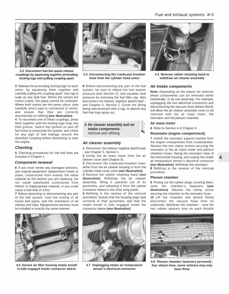
3 Release the protruding locking lugs on eachunion, by squeezing them together andcarefully pulling the coupling apart. Use rag tosoak up any spilt fuel. Where the unions arecolour-coded, the pipes cannot be confused.Where both unions are the same colour, notecarefully which pipe is connected to which,and ensure that they are correctlyreconnected on refitting (see illustration).4 To reconnect one of these couplings, pressthem together until the locking lugs snap intotheir groove. Switch the ignition on and offfive times to pressurise the system, and checkfor any sign of fuel leakage around thedisturbed coupling before attempting to startthe engine.
Checking5 Checking procedures for the fuel lines areincluded in Chapter 1.
Component renewal6 If you must renew any damaged sections,use original-equipment replacement hoses orpipes, constructed from exactly the samematerial as the section you are replacing. Donot install substitutes constructed frominferior or inappropriate material, or you couldcause a fuel leak or a fire.7 Before detaching or disconnecting any partof the fuel system, note the routing of allhoses and pipes, and the orientation of allclamps and clips. Replacement sections mustbe installed in exactly the same manner.
8 Before disconnecting any part of the fuelsystem, be sure to relieve the fuel systempressure (see Section 2), and equalise tankpressure by removing the fuel filler cap. Alsodisconnect the battery negative (earth) lead -see Chapter 5, Section 1. Cover the fittingbeing disconnected with a rag, to absorb anyfuel that may spray out.
Air cleaner assembly1 Disconnect the battery negative (earth) lead- see Chapter 5, Section 1.2 Unclip the air mass meter from the aircleaner cover (see Chapter 6).3 Disconnect the crankcase breather hose,either from the air cleaner housing or from thecylinder head cover union (see illustration).4 Remove the rubber retaining band (seeillustration). Withdraw the air cleanerassembly, lifting it upwards out of itsgrommets, and releasing it from the rubberconnector sleeve in the inner wing panel.5 Refitting is the reverse of the removalprocedure. Ensure that the housing pegs seatcorrectly in their grommets, and that theintake mouth is fully engaged inside theconnector sleeve (see illustration).
Air intake componentsNote: Depending on the reason for removal,these components can be removed eitherindividually, or as one assembly. For example,unplugging the two electrical connectors anddisconnecting the vacuum hose (where fitted),will allow the air cleaner assembly cover to beremoved with the air mass meter, theresonator and the plenum chamber.
Air mass meter6 Refer to Section 4 of Chapter 6.
Resonator (engine compartment)7 Unbolt the resonator support bracket fromthe engine compartment front crossmember.Slacken the two clamp screws securing theresonator to the air mass meter and plenumchamber hoses. Swing the resonator clear ofthe thermostat housing, and unplug the intakeair temperature sensor’s electrical connector(see illustration). Withdraw the resonator.8 Refitting is the reverse of the removalprocedure.
Plenum chamber9 Prising out the rubber plugs covering them,undo the chamber’s fasteners (seeillustration). Slacken the clamp screwsecuring the chamber to the resonator hose.10 Lift the chamber and (where fitted)disconnect the vacuum hose from itsunderside. Withdraw the chamber - note thetwo rubber spacers (one on each throttle
4 Air cleaner assembly and airintake components - removal and refitting
Fuel and exhaust systems 4•3
4
4.5 Ensure air filter housing intake mouthis fully engaged inside connector sleeve
4.7 Unplugging intake air temperaturesensor’s electrical connector
4.9 Plenum chamber fasteners (arrowed) -four shown here, some vehicles may only
have three
3.3 Disconnect fuel line quick-releasecouplings by squeezing together protruding
locking lugs and pulling coupling apart4.3 Disconnecting the crankcase breather
hose from the cylinder head union4.4 Remove rubber retaining band to
withdraw air cleaner assembly

housing stud) and the sealing O-ring in thechamber’s mouth (see illustrations).11 Refitting is the reverse of the removalprocedure. Ensure that the O-ring andspacers are correctly seated.
Underwing components12 Remove the left-hand wheel arch liner(see Chapter 11).13 Unbolt and withdraw the air intake tubeand both resonators as required.14 Refitting is the reverse of the removalprocedure.
Removal1 Disconnect the battery negative (earth) lead- see Chapter 5, Section 1.2 Remove the plenum chamber (see Sec-tion 4).3 Remove the clip securing the cable to thethrottle housing bracket (see illustration).Disconnect the cable end nipple from thethrottle linkage, and release the cable fromany securing clips or ties.4 Working in the passenger compartment,reach up to the top of the accelerator pedal.Pull the end fitting and collar out of the pedal,
then release the cable inner wire through theslot in the pedal (see illustration). Tie a lengthof string to the end of the cable.5 Returning to the engine compartment, pullthe cable through the bulkhead until the stringcan be untied and the cable removed.
Refitting6 Refitting is the reverse of the removalprocedure; use the string to draw the cablethrough the bulkhead.7 Adjust the cable as described below.
Adjustment8 Remove the plenum chamber (see Sec-tion 4).9 Find the cable adjuster - this is either at thethrottle housing bracket, or two-thirds alongthe length of the cable, clipped to the frontsuspension right-hand mounting (seeillustration). Remove the metal clip andlubricate the adjuster’s grommet with soapywater.10 Remove any slack by pulling the cableouter as far as possible out of the adjuster.Have an assistant depress the acceleratorpedal fully - the cable outer will move backinto the adjuster - and hold it there while theclip is refitted.11 Check that the throttle valve movessmoothly and easily from the fully-closed tothe fully-open position and back again, as theassistant depresses and releases the
accelerator pedal. Re-adjust the cable ifrequired.12 When the setting is correct, refit theplenum chamber (see Section 4).
RemovalNote: While the following procedure dealswith the complete cable, the pedal-to-actuator and actuator-to-throttle housingsections of the cable are available separately,and can be removed and refitted individually.If doing this, modify the procedure asrequired.1 Disconnect the battery negative (earth) lead- see Chapter 5, Section 1.2 Remove the plenum chamber (see Sec-tion 4).3 Remove the clip securing the cable to thethrottle housing bracket, then pull the cable’sgrommet out of the bracket. Disconnect thecable end nipple from the throttle linkage, andrelease the cable from any securing clips orties.4 Unplug the TCS throttle actuator’s electricalconnector, and prise off its cover (seeillustration).5 Noting which cable section is connected to
6 Accelerator cable (modelswith traction control) - removal, refitting and adjustment
5 Accelerator cable (modelswithout traction control) -removal, refitting and adjustment
4•4 Fuel and exhaust systems
4.10A Lift plenum chamber and (wherefitted) disconnect the vacuum hose - note
the two rubber spacers (arrowed) . . .4.10B . . . and the sealing O-ring (arrowed)
in the chamber’s mouth5.3 Removing clip securing accelerator
cable to throttle housing bracket
5.4 Pull the accelerator cable end fitting(arrowed) out of the pedal
5.9 Location of accelerator cable adjuster- remove metal clip (arrowed) to enable
adjustment to be made
6.4 Unplug TCS throttle actuator’selectrical connector (A), and prise off its
cover at two points (B)
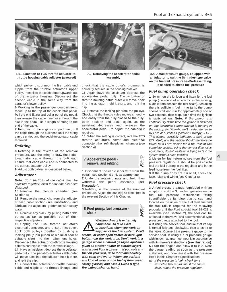
which pulley, disconnect the first cable endnipple from the throttle actuator’s upperpulley, then slide the cable outer upwards outof the actuator housing. Disconnect thesecond cable in the same way from theactuator’s lower pulley.6 Working in the passenger compartment,reach up to the top of the accelerator pedal.Pull the end fitting and collar out of the pedal,then release the cable inner wire through theslot in the pedal. Tie a length of string to theend of the cable.7 Returning to the engine compartment, pullthe cable through the bulkhead until the stringcan be untied and the pedal-to-actuator cableremoved.
Refitting8 Refitting is the reverse of the removalprocedure. Use the string to draw the pedal-to-actuator cable through the bulkhead.Ensure that each cable end is connected tothe correct actuator pulley.9 Adjust both cables as described below.
AdjustmentNote: Both sections of the cable must beadjusted together, even if only one has beendisturbed.10 Remove the plenum chamber (seeSection 4).11 Remove the metal clip from the adjusterof each cable section (see illustration), andlubricate the adjusters’ grommets with soapywater.12 Remove any slack by pulling both cableouters as far as possible out of theirrespective adjusters.13 Unplug the TCS throttle actuator’selectrical connector, and prise off its cover.Lock both pulleys together by pushing alocking pin (a pin punch or a similar tool ofsuitable size) into their alignment holes.Disconnect the actuator-to-throttle housingcable’s end nipple from the throttle linkage.14 Have an assistant depress the acceleratorpedal fully. The pedal-to-actuator cable outerwill move back into the adjuster; hold it there,and refit the clip.15 Connect the actuator-to-throttle housingcable end nipple to the throttle linkage, and
check that the cable outer’s grommet iscorrectly secured in the housing bracket.16 Again have the assistant depress theaccelerator pedal fully. The actuator-to-throttle housing cable outer will move backinto the adjuster; hold it there, and refit theclip.17 Remove the locking pin from the pulleys.Check that the throttle valve moves smoothlyand easily from the fully-closed to the fully-open position and back again, as theassistant depresses and releases theaccelerator pedal. Re-adjust the cable(s) ifrequired.18 When the setting is correct, refit the TCSthrottle actuator’s cover and electricalconnector, then refit the plenum chamber (seeSection 4).
1 Disconnect the cable inner wire from thepedal - see Section 5 or 6, as appropriate.2 Undo the retaining nuts and bolt, thenwithdraw the pedal assembly (seeillustration).3 Refitting is the reverse of the removalprocedure. Adjust the cable(s) as described inthe relevant Section of this Chapter.
Warning: Petrol is extremelyflammable, so take extraprecautions when you work onany part of the fuel system. Don’t
smoke, or allow open flames or bare lightbulbs, near the work area. Don’t work in agarage where a natural gas-type appliance(such as a water heater or clothes dryer)with a pilot light is present. If you spill anyfuel on your skin, rinse it off immediatelywith soap and water. When you performany kind of work on the fuel system, wearsafety glasses, and have a Class B typefire extinguisher on hand.
Fuel pump operation check1 Switch on the ignition and listen for the fuelpump (the sound of an electric motor running,audible from beneath the rear seats). Assumingthere is sufficient fuel in the tank, the pumpshould start and run for approximately one ortwo seconds, then stop, each time the ignitionis switched on. Note: If the pump runscontinuously all the time the ignition is switchedon, the electronic control system is running inthe backup (or “limp-home”) mode referred toby Ford as “Limited Operation Strategy” (LOS).This almost certainly indicates a fault in theECU itself, and the vehicle should therefore betaken to a Ford dealer for a full test of thecomplete system, using the correct diagnosticequipment; do not waste time trying to test thesystem without such facilities.2 Listen for fuel return noises from the fuelpressure regulator. It should be possible tofeel the fuel pulsing in the regulator and in thefeed hose from the fuel filter.3 If the pump does not run at all, check thefuse, relay and wiring (see Chapter 6).
Fuel pressure check3 A fuel pressure gauge, equipped with anadaptor to suit the Schrader-type valve on thefuel rail pressure test/release fitting(identifiable by its blue plastic cap, andlocated on the union of the fuel feed line andthe fuel rail) is required for the followingprocedure. If the Ford special tool 29-033 isavailable (see Section 2), the tool can beattached to the valve, and a conventional-typepressure gauge attached to the tool.4 If using the service tool, ensure that its tapis turned fully anti-clockwise, then attach it tothe valve. Connect the pressure gauge to theservice tool. If using a fuel pressure gaugewith its own adaptor, connect it in accordancewith its maker’s instructions (see illustration).5 Start the engine and allow it to idle. Notethe gauge reading as soon as the pressurestabilises, and compare it with the pressurelisted in this Chapter’s Specifications.(a) If the pressure is high, check for a
restricted fuel return line. If the line isclear, renew the pressure regulator.
8 Fuel pump/fuel pressure -check
7 Accelerator pedal - removal and refitting
Fuel and exhaust systems 4•5
4
6.11 Location of TCS throttle actuator-to-throttle housing cable adjuster (arrowed)
7.2 Removing the accelerator pedalassembly
8.4 A fuel pressure gauge, equipped withan adaptor to suit the Schrader-type valveon the fuel rail pressure test/release fitting,
is needed to check fuel pressure

(b) If the pressure is low, pinch the fuel returnline. If the pressure now goes up, renewthe fuel pressure regulator. If the pressuredoes not increase, check the fuel feedline, the fuel pump and the fuel filter.
6 Detach the vacuum hose from the fuelpressure regulator; the pressure shown on thegauge should increase. Note the increase inpressure, and compare it with that listed inthis Chapter’s Specifications. If the pressureincrease is not as specified, check thevacuum hose and pressure regulator.7 Reconnect the regulator vacuum hose, andswitch off the engine. Verify that the fuelpressure stays at the specified level for fiveminutes after the engine is turned off.8 Carefully disconnect the fuel pressuregauge. Be sure to cover the fitting with a ragbefore slackening it. Mop up any spilt petrol.9 Run the engine, and check that there are nofuel leaks.
Warning: Petrol is extremelyflammable, so take extraprecautions when you work on
any part of the fuel system. Don’t smoke,or allow open flames or bare light bulbs,near the work area. Don’t work in a garagewhere a natural gas-type appliance (suchas a water heater or clothes dryer) with apilot light is present. If you spill any fuel onyour skin, rinse it off immediately withsoap and water. When you perform anykind of work on the fuel system, wearsafety glasses, and have a Class B typefire extinguisher on hand.Note: Ford specify the use of their service tool23-038 (a large box spanner with projecting teethto engage the fuel pump/sender unit retainingring’s slots) for this task. While alternatives arepossible, as shown below, in view of the difficultyexperienced in removing and refitting thepump/sender unit, owners are strongly advisedto obtain this tool before starting work. The helpof an assistant will be required.1 Relieve the residual pressure in the fuelsystem (see Section 2), and equalise tankpressure by removing the fuel filler cap.
Warning: This procedure willmerely relieve the increasedpressure necessary for theengine to run - remember that
fuel will still be present in the systemcomponents, and take precautionsaccordingly before disconnecting any ofthem.
2 Disconnect the battery negative (earth) lead- see Chapter 5, Section 1.3 Unbolt or fold forwards (as appropriate) therear seat base cushion (see Chapter 11).Withdraw from the vehicle’s floor the grommetcovering the fuel pump/sender unit. Wash offany dirt from the tank’s top surface, and dry it;use a vacuum cleaner to clean the immediatesurroundings of the vehicle’s interior, toreduce the risk of introducing water, dirt anddust into the tank while it is open.4 Unplug the fuel pump/sender unit’selectrical connector (see illustration).5 To disconnect the fuel feed and returnpipes from the unit, release each pipe’scoupling, by squeezing together theprotruding locking lugs on each union andcarefully pulling the coupling apart. Use rag tosoak up any spilt fuel. Where the couplingsare difficult to separate, use a pair of pliersand a block of wood as shown, to lever thepipe out of the union. Considerable force may
be required, but be as careful as possible toavoid damaging any of the components (seeillustration).6 Release the fuel pump/sender unit’sretaining ring by turning it anti-clockwise. Asnoted above, Ford recommend the use ofservice tool 23-038. For those without accessto such equipment, a hammer and drift, or apair of slip-jointed pliers, will serve as anadequate substitute - at least for removal (seeillustration).7 Withdraw the fuel pump/fuel gauge senderunit, taking care not to bend the float arm. Thefloat arm is mounted on a spring-loadedextension, to hold it closely against thebottom of the tank. Note the sealing ring; thismust be renewed whenever it is disturbed(see illustrations).8 On refitting, use a new sealing ring, andensure that the gauze filter over the base ofthe pump pick-up is clean.9 Align the pump/sender unit with the tankopening, and refit it, ensuring that the floatarm is not bent. Insert the unit so that the floatarm slides correctly up the extension, until theunit’s top mounting plate can be aligned withthe tank opening and pressed onto the sealingring. This may require a considerable amountof pressure; if so, be careful to avoiddamaging any of the components. The Fordservice tool provides the best way of holding
9 Fuel pump/fuel gauge senderunit - removal and refitting
4•6 Fuel and exhaust systems
9.4 Unplugging the fuel pump/fuel gaugesender unit electrical connector (arrowed)
9.5 If fuel couplings are difficult to release,use pliers and a block of wood as shownto prise pipe end out of union - be careful
not to damage pipes or unions
9.6 Fuel pump/fuel gauge sender unit’sretaining ring can be released using
ordinary tools as shown. Correct servicetool will probably be required on refitting
9.7A Removing fuel pump/fuel gaugesender unit - take care not to bend floatarm, and note how it is fitted on spring-
loaded extension
9.7B Fuel pump/fuel gauge sender unit’ssealing ring must be renewed whenever it
is disturbed
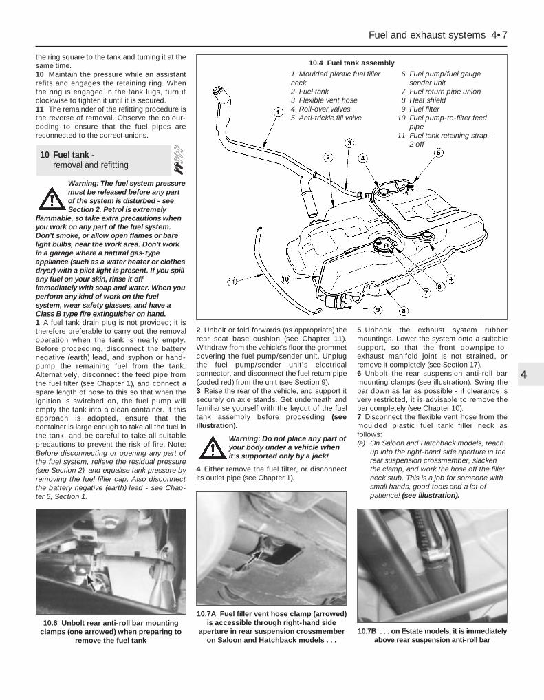
the ring square to the tank and turning it at thesame time.10 Maintain the pressure while an assistantrefits and engages the retaining ring. Whenthe ring is engaged in the tank lugs, turn itclockwise to tighten it until it is secured.11 The remainder of the refitting procedure isthe reverse of removal. Observe the colour-coding to ensure that the fuel pipes arereconnected to the correct unions.
Warning: The fuel system pressuremust be released before any partof the system is disturbed - seeSection 2. Petrol is extremely
flammable, so take extra precautions whenyou work on any part of the fuel system.Don’t smoke, or allow open flames or barelight bulbs, near the work area. Don’t workin a garage where a natural gas-typeappliance (such as a water heater or clothesdryer) with a pilot light is present. If you spillany fuel on your skin, rinse it offimmediately with soap and water. When youperform any kind of work on the fuelsystem, wear safety glasses, and have aClass B type fire extinguisher on hand.1 A fuel tank drain plug is not provided; it istherefore preferable to carry out the removaloperation when the tank is nearly empty.Before proceeding, disconnect the batterynegative (earth) lead, and syphon or hand-pump the remaining fuel from the tank.Alternatively, disconnect the feed pipe fromthe fuel filter (see Chapter 1), and connect aspare length of hose to this so that when theignition is switched on, the fuel pump willempty the tank into a clean container. If thisapproach is adopted, ensure that thecontainer is large enough to take all the fuel inthe tank, and be careful to take all suitableprecautions to prevent the risk of fire. Note:Before disconnecting or opening any part ofthe fuel system, relieve the residual pressure(see Section 2), and equalise tank pressure byremoving the fuel filler cap. Also disconnectthe battery negative (earth) lead - see Chap-ter 5, Section 1.
2 Unbolt or fold forwards (as appropriate) therear seat base cushion (see Chapter 11).Withdraw from the vehicle’s floor the grommetcovering the fuel pump/sender unit. Unplugthe fuel pump/sender unit’s electricalconnector, and disconnect the fuel return pipe(coded red) from the unit (see Section 9).3 Raise the rear of the vehicle, and support itsecurely on axle stands. Get underneath andfamiliarise yourself with the layout of the fueltank assembly before proceeding (seeillustration).
Warning: Do not place any part ofyour body under a vehicle whenit’s supported only by a jack!
4 Either remove the fuel filter, or disconnectits outlet pipe (see Chapter 1).
5 Unhook the exhaust system rubbermountings. Lower the system onto a suitablesupport, so that the front downpipe-to-exhaust manifold joint is not strained, orremove it completely (see Section 17).6 Unbolt the rear suspension anti-roll barmounting clamps (see illustration). Swing thebar down as far as possible - if clearance isvery restricted, it is advisable to remove thebar completely (see Chapter 10).7 Disconnect the flexible vent hose from themoulded plastic fuel tank filler neck asfollows:(a) On Saloon and Hatchback models, reach
up into the right-hand side aperture in therear suspension crossmember, slackenthe clamp, and work the hose off the fillerneck stub. This is a job for someone withsmall hands, good tools and a lot ofpatience! (see illustration).
10 Fuel tank - removal and refitting
Fuel and exhaust systems 4•7
4
10.6 Unbolt rear anti-roll bar mountingclamps (one arrowed) when preparing to
remove the fuel tank
10.7A Fuel filler vent hose clamp (arrowed)is accessible through right-hand side
aperture in rear suspension crossmemberon Saloon and Hatchback models . . .
10.7B . . . on Estate models, it is immediatelyabove rear suspension anti-roll bar
10.4 Fuel tank assembly
1 Moulded plastic fuel fillerneck2 Fuel tank3 Flexible vent hose4 Roll-over valves5 Anti-trickle fill valve
6 Fuel pump/fuel gauge sender unit
7 Fuel return pipe union8 Heat shield9 Fuel filter
10 Fuel pump-to-filter feedpipe
11 Fuel tank retaining strap - 2 off
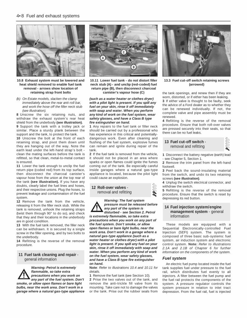
(b) On Estate models, slacken the clampimmediately above the rear anti-roll bar,and work the hose off the filler neck stub(see illustration).
8 Unscrew the six retaining nuts, andwithdraw the exhaust system’s rear heatshield from the underbody (see illustration).9 Support the tank with a trolley jack orsimilar. Place a sturdy plank between thesupport and the tank, to protect the tank.10 Unscrew the bolt at the front of eachretaining strap, and pivot them down untilthey are hanging out of the way. Note theearth lead under the left-hand strap’s bolt -clean the mating surfaces before the tank isrefitted, so that clean, metal-to-metal contactis ensured.11 Lower the tank enough to unclip the fuelreturn pipe (coded red) from its top surface,then disconnect the charcoal canister’svapour hose from the union at the top rear ofthe tank (see illustration). If you have anydoubts, clearly label the fuel lines and hoses,and their respective unions. Plug the hoses, toprevent leakage and contamination of the fuelsystem.12 Remove the tank from the vehicle,releasing it from the filler neck stub. While thetank is removed, unhook the retaining straps(twist them through 90° to do so), and checkthat they and their locations in the underbodyare in good condition.13 With the fuel tank removed, the filler neckcan be withdrawn. It is secured by a singlescrew in the filler opening, and by two bolts tothe underbody.14 Refitting is the reverse of the removalprocedure.
Warning: Petrol is extremelyflammable, so take extraprecautions when you work onany part of the fuel system. Don’t
smoke, or allow open flames or bare lightbulbs, near the work area. Don’t work in agarage where a natural gas-type appliance
(such as a water heater or clothes dryer)with a pilot light is present. If you spill anyfuel on your skin, rinse it off immediatelywith soap and water. When you performany kind of work on the fuel system, wearsafety glasses, and have a Class B typefire extinguisher on hand.1 Any repairs to the fuel tank or filler neckshould be carried out by a professional whohas experience in this critical and potentially-dangerous work. Even after cleaning andflushing of the fuel system, explosive fumescan remain and ignite during repair of thetank.2 If the fuel tank is removed from the vehicle,it should not be placed in an area wheresparks or open flames could ignite the fumescoming out of the tank. Be especially carefulinside garages where a natural gas-typeappliance is located, because the pilot lightcould cause an explosion.
Warning: The fuel systempressure must be released beforeany part of the system isdisturbed - see Section 2. Petrol
is extremely flammable, so take extraprecautions when you work on any part ofthe fuel system. Don’t smoke, or allowopen flames or bare light bulbs, near thework area. Don’t work in a garage where anatural gas-type appliance (such as awater heater or clothes dryer) with a pilotlight is present. If you spill any fuel on yourskin, rinse it off immediately with soap andwater. When you perform any kind of workon the fuel system, wear safety glasses,and have a Class B type fire extinguisheron hand.Note: Refer to illustrations 10.4 and 10.11 fordetails.1 Remove the fuel tank (see Section 10).2 Prise the two valves out of the tank, andremove the anti-trickle fill valve from itsmounting. Take care not to damage the valvesor the tank. Prise out the rubber seals from
the tank openings, and renew then if they areworn, distorted, or if either has been leaking.3 If either valve is thought to be faulty, seekthe advice of a Ford dealer as to whether theycan be renewed individually. If not, thecomplete valve and pipe assembly must berenewed.4 Refitting is the reverse of the removalprocedure. Ensure that both roll-over valvesare pressed securely into their seals, so thatthere can be no fuel leaks.
1 Disconnect the battery negative (earth) lead- see Chapter 5, Section 1.2 Remove the trim panel from the left-handfootwell.3 Peel back the sound-insulating materialfrom the switch, and undo its two retainingscrews (see illustration).4 Unplug the switch electrical connector, andwithdraw the switch.5 Refitting is the reverse of the removalprocedure. Ensure that the switch is reset bydepressing its red button.
These models are equipped with aSequential Electronically-controlled FuelInjection (SEFI) system. The system iscomposed of three basic sub-systems: fuelsystem, air induction system and electroniccontrol system. Note: Refer to illustrations2.1A and 2.1B of Chapter 6 for furtherinformation on the components of the system.
Fuel systemAn electric fuel pump located inside the fuel
tank supplies fuel under pressure to the fuelrail, which distributes fuel evenly to allinjectors. A filter between the fuel pump andthe fuel rail protects the components of thesystem. A pressure regulator controls thesystem pressure in relation to inlet tractdepression. From the fuel rail, fuel is injected
14 Fuel injection system/enginemanagement system - generalinformation
13 Fuel cut-off switch - removal and refitting
12 Roll-over valves - removal and refitting
11 Fuel tank cleaning and repair -general information
4•8 Fuel and exhaust systems
10.8 Exhaust system must be lowered andheat shield removed to enable fuel tank
removal - arrows show location ofretaining strap front bolts
10.11 Lower fuel tank - do not distort fillerneck stub (A) - and unclip (red-coded) fuelreturn pipe (B), then disconnect charcoal
canister’s vapour hose (C)
13.3 Fuel cut-off switch retaining screws(arrowed)

into the inlet ports, just above the inlet valves,by four fuel injectors. The system alsoincludes features such as the flushing of fresh(ie, cold) fuel around each injector on start-up,thus improving hot starts.
The amount of fuel supplied by the injectorsis precisely controlled by an ElectronicControl Unit (ECU). The ECU uses the signalsderived from the engine speed/crankshaftposition sensor and the camshaft positionsensor, to trigger each injector separately incylinder firing order (sequential injection), withbenefits in terms of better fuel economy andlower exhaust emissions.
Air induction systemThe air system consists of an air filter
housing, an air mass meter, an intakeresonator and plenum chamber, and a throttlehousing. The air mass meter is an information-gathering device for the ECU; it uses a “hot-wire” system to send the ECU a constantly-varying (analogue) voltage signalcorresponding to the volume of air passinginto the engine. Another sensor in the air massmeter measures intake air temperature. TheECU uses these signals to calculate the massof air entering the engine.
The throttle valve inside the throttle housingis controlled by the driver, through theaccelerator pedal. As the valve opens, theamount of air that can pass through thesystem increases. The throttle potentiometeropens further, the air mass meter’s signalalters, and the ECU opens each injector for alonger duration, to increase the amount of fueldelivered to the inlet ports.
Electronic control systemThe ECU controls the fuel injection system,
as well as the other sub-systems which makeup the entire engine management system. Itreceives signals from a number of informationsensors, which monitor such variables asintake air mass and temperature, coolanttemperature, engine speed and position,acceleration/deceleration, and exhaust gasoxygen content. These signals help the ECUdetermine the injection duration necessary forthe optimum air/fuel ratio. These sensors andassociated ECU-controlled relays are locatedthroughout the engine compartment. Forfurther information regarding the ECU and itscontrol of the engine management system,see Chapter 6.
Idle speed and mixtureadjustment - general
Both the idle speed and mixture are underthe control of the ECU, and cannot beadjusted. Not only can they not be adjusted,they cannot even be checked, except with theuse of special diagnostic equipment (seeChapter 6) - this makes it a task for a Forddealer service department. Do not attempt to“adjust” these settings in any way withoutsuch equipment.
If the idle speed and mixture are thought to
be incorrect, take the vehicle to a Ford dealerfor the complete system to be tested.
On models equipped with a heatedwindscreen, an idle-increase solenoid valve isfitted, which raises the idle speed tocompensate for the increased load on theengine when the heated windscreen isswitched on. When the valve is open, air fromthe plenum chamber bypasses the throttlehousing and idle speed control valve, passingdirectly into the inlet manifold through theunion on its left-hand end. The system isactive only for the four minutes that theheated windscreen circuit is live, and issupplementary to the main (ECU-controlled)idle speed regulation.
Warning: Petrol is extremelyflammable, so extra precautionsmust be taken when working onany part of the fuel system. Do
not smoke, or allow open flames or barelight bulbs, near the work area. Don’t workin a garage if a natural gas-type appliancewith a pilot light is present. Whileperforming any work on the fuel system,wear safety glasses, and have a drychemical (Class B) fire extinguisher onhand. If you spill any fuel on your skin,rinse it off immediately with soap andwater.Note: This is an initial check of the fuel deliveryand air induction sub-systems of the enginemanagement system, to be carried out inconjunction with the operational check of thefuel pump (see Section 8), and as part of thepreliminary checks of the complete enginemanagement system (see Section 3 ofChapter 6).1 Check the earth wire connections fortightness. Check all wiring and electricalconnectors that are related to the system.Loose electrical connectors and poor earthscan cause many problems that resemblemore serious malfunctions.2 Check to see that the battery is fully-charged. The ECU and sensors depend on anaccurate supply voltage to properly meter thefuel.3 Check the air filter element - a dirty orpartially-blocked filter will severely impedeperformance and economy (see Chapter 1).4 If a blown fuse is found, renew it and see ifit blows again. If it does, search for a short-circuited wire in the harness related to thesystem (see Chapter 6).5 Check the air intake duct from the intake tothe inlet manifold for leaks, which will result inan excessively-lean mixture. Also check thecondition of the vacuum hoses connected tothe inlet manifold.6 Remove the plenum chamber from thethrottle housing. Check the throttle valve fordirt, carbon or other residue build-up. If it’s
dirty, seek the advice of a Ford dealer - sincethe electronic control system is designed tocompensate for factors such as the build-upof dirt in the throttle housing, it may well bebest to leave it dirty, unless the deposits areextensive. Note: A warning label on thehousing states specifically that the housingbore and the throttle valve have a specialcoating, and must not be cleaned usingcarburettor cleaner, as this may damage it.7 With the engine running, place ascrewdriver or a stethoscope against eachinjector, one at a time. Listen through thescrewdriver handle or stethoscope for aclicking sound, indicating operation.8 If an injector isn’t operating (or soundsdifferent from the others), turn off the engine,and unplug the electrical connector from theinjector. Check the resistance across theterminals of the injector, and compare yourreading with the resistance value listed in thisChapter’s Specifications. If the resistanceisn’t as specified, renew the injector.9 A rough idle, diminished performanceand/or increased fuel consumption could alsobe caused by clogged or fouled fuel injectors.Fuel additives that can sometimes cleanfouled injectors are available at car accessoryshops.10 The remainder of the system checksshould be left to a dealer service departmentor other qualified repair specialist, as there isa chance that the ECU may be damaged iftests are not performed properly.
Warning: The fuel systempressure must be released beforeany part of the system isdisturbed - see Section 2. Petrol
is extremely flammable, so take extraprecautions when you work on any part ofthe fuel system. Don’t smoke, or allowopen flames or bare light bulbs, near thework area. Don’t work in a garage where anatural gas-type appliance (such as awater heater or clothes dryer) with a pilotlight is present. If you spill any fuel on yourskin, rinse it off immediately with soap andwater. When you perform any kind of workon the fuel system, wear safety glasses,and have a Class B type fire extinguisheron hand.
Throttle housing
Check1 Remove the plenum chamber (see Sec-tion 4), and verify that the throttle linkageoperates smoothly.2 If the housing bore and valve are dirtyenough for you to think that this might be thecause of a fault, seek the advice of a Forddealer. Do not clean the housing (see thenotes in the checking procedure given inSection 15).
16 Fuel system components -check and renewal
15 Fuel injection system/enginemanagement system - check
Fuel and exhaust systems 4•9
4

Renewal3 Disconnect the battery negative (earth) lead- see Chapter 5, Section 1.4 Remove the plenum chamber (see Sec-tion 4).5 Disconnect the accelerator cable from thethrottle linkage (see Section 5 or 6, asappropriate). Where fitted, also disconnectthe cruise control actuator cable (see Chap-ter 12).6 Releasing its wire clip, unplug the largeelectrical connector (next to the fuel pressureregulator). Similarly release and unplug thethrottle potentiometer’s electrical connector.7 Clearly label, then detach, all vacuum hosesfrom the throttle housing.8 Remove the throttle housing mountingscrews (see illustration), then detach thethrottle housing and gasket from the inletmanifold. Discard the gasket - this must berenewed whenever it is disturbed.9 Using a soft brush and carburettor cleaner,thoroughly clean the exterior of the throttlehousing, then blow out all passages withcompressed air.
Caution: Do not clean the throttlehousing’s bore, the throttle valve,or the potentiometer, either byscraping or with a solvent. Just
wipe them over carefully with a clean softcloth.10 Refitting is the reverse of the removalprocedure. Fit a new gasket, and tighten thehousing screws to the specified torque.
Fuel rail and injectorsCheck11 Refer to the procedure in the fuel systemcheck (see Section 15).
RenewalNote: For simplicity, and to ensure thenecessary absolute cleanliness onreassembly, the following proceduredescribes the removal of the fuel railassembly, complete with the injectors andpressure regulator, so that the injectors can beserviced individually on a clean work surface.
It is also possible to remove and refit anindividual injector once the fuel system hasbeen depressurised and the battery has beendisconnected. If this approach is followed,read through the complete procedure, andwork as described in the relevant paragraphs,depending on the amount of preliminarydismantling required. Be careful not to allowany dirt to enter the system (seeillustrations).12 Relieve the residual pressure in the fuelsystem (see Section 2), and equalise tankpressure by removing the fuel filler cap.
Warning: This procedure willmerely relieve the increasedpressure necessary for theengine to run - remember that
fuel will still be present in the systemcomponents, and take precautionsaccordingly before disconnecting any ofthem.13 Disconnect the battery negative (earth)lead - see Chapter 5, Section 1.14 Remove the plenum chamber (seeSection 4).15 If the additional clearance is required,disconnect the accelerator cable from thethrottle linkage (see Section 5 or 6, asappropriate). Where fitted, also disconnectthe cruise control actuator cable (see Chap-ter 12).16 Releasing the wire clips, unplug the fourfuel injector electrical connectors.17 Disconnect the fuel feed and return linesat the quick-release couplings next to thebraking system vacuum servo unit, thenunclip the fuel hoses from the inlet manifold;use rag to soak up any spilt fuel. Note: Do notdisturb the threaded couplings at the fuel railunions unless absolutely necessary; these are
sealed at the factory. The quick-releasecouplings will suffice for all normal serviceoperations.18 Disconnect the crankcase breather hosefrom the cylinder head cover union, and thevacuum hose from the fuel pressure regulator(see illustration).19 Unscrew the three bolts securing the fuelrail, and withdraw the rail, carefully prising itout of the inlet manifold, and draining anyremaining fuel into a suitable clean container(see illustrations). Note the seals betweenthe rail noses and the manifold; these must berenewed whenever the rail is removed.20 Clamping the rail carefully in a vice fittedwith soft jaws, unscrew the two bolts securingeach injector, and withdraw the injectors.Place each in a clean, clearly-labelled storagecontainer.21 If you are renewing the injector(s), discardthe old injector, the nose seal and the O-rings.If you are simply renewing leaking injector O-
4•10 Fuel and exhaust systems
16.8 Undo screws (arrowed) to removethrottle housing
16.12A Fuel injectors can be unbolted(arrowed) . . .
16.12B . . . and removed individually ifrequired, but it is better to remove them
with the fuel rail, if servicing is necessary.O-ring seals (arrowed) must be renewed
whenever injector is removed
16.18 Injector removal - disconnect fuellines at quick-release couplings (A), uncliphoses (B), disconnect vacuum hose from
regulator (C), unplug electrical connectors (D) - three of four shown - anddisconnect breather hose from union (E)
16.19A Unscrew bolts (arrowed) . . .
16.19B . . . and withdraw fuel rail withinjectors and pressure regulator - renew
nose seals (arrowed) whenever rail isdisturbed

rings, and intend to re-use the same injectors,remove the old nose seal and O-rings, anddiscard them.22 Further testing of the injector(s) is beyondthe scope of the home mechanic. If you are indoubt as to the status of any injector(s), it canbe tested at a dealer service department.23 Refitting is the reverse of the removalprocedure, noting the following points:(a) Lubricate each nose seal and O-ring with
clean engine oil on installation.(b) Locate each injector carefully in the fuel
rail recess, ensuring that the locating tabon the injector head fits into the slotprovided in the rail. Tighten the bolts tothe specified torque.
(c) Fit a new seal to each fuel rail nose, andensure the seals are not displaced as therail is refitted. Ensure that the fuel rail issettled fully in the manifold beforetightening the three bolts evenly and tothe torque wrench setting specified.
(d) Fasten the fuel feed and return quick-release couplings as described in Sec-tion 3.
(e) Ensure that the breather hose, vacuumhose and wiring are routed correctly, andsecured on reconnection by any clips orties provided.
(f) On completion, switch the ignition on andoff five times, to activate the fuel pump andpressurise the system, without crankingthe engine. Check for signs of fuel leaksaround all disturbed unions and jointsbefore attempting to start the engine.
Fuel pressure regulatorCheck24 Refer to the fuel pump/fuel pressurecheck procedure (see Section 8).
Renewal25 Relieve the residual pressure in the fuelsystem (see Section 2), and equalise tankpressure by removing the fuel filler cap.
Warning: This procedure willmerely relieve the increasedpressure necessary for the engineto run - remember that fuel will
still be present in the system components,and take precautions accordingly beforedisconnecting any of them.
26 Disconnect the battery negative (earth)lead - see Chapter 5, Section 1.27 Remove the plenum chamber (seeSection 4).28 Disconnect the vacuum hose from theregulator.29 Unscrew the two regulator retaining bolts,place a wad of clean rag to soak up any spiltfuel, and withdraw the regulator (seeillustration).30 Refitting is the reverse of the removalprocedure, noting the following points:(a) Renew the regulator sealing O-ring
whenever the regulator is disturbed.Lubricate the new O-ring with cleanengine oil on installation.
(b) Locate the regulator carefully in the fuelrail recess, and tighten the bolts to thespecified torque wrench setting.
(c) On completion, switch the ignition on andoff five times, to activate the fuel pump andpressurise the system, without crankingthe engine. Check for signs of fuel leaksaround all disturbed unions and jointsbefore attempting to start the engine.
Idle speed control valveCheck31 Disconnect the battery negative (earth)lead - see Chapter 5, Section 1.32 Raise the front of the vehicle, and supportit securely on axle stands.
Warning: Do not place any part ofyour body under a vehicle whenit’s supported only by a jack!
33 Unplug the valve’s electrical connector(see illustration).34 Connect a 12-volt battery across thevalve’s terminals - positive (+) to terminal 37(the green/yellow wire) and negative (-) toterminal 21 (the black/yellow).
Caution: It is essential that thecorrect polarity is observed, orthe diode incorporated in thevalve may be damaged.
35 A distinct click should be heard each timecontact is made and broken. If not, measurethe resistance between the terminals. If theresistance is as specified, the valve is okay(but there may be a problem with the wiring orthe ECU). If the resistance is not as specified,renew the valve (see below).
36 Plug in the valve’s electrical connector.
Renewal37 Disconnect the battery negative (earth)lead - see Chapter 5, Section 1.38 Raise the front of the vehicle, and supportit securely on axle stands.
Warning: Do not place any part ofyour body under a vehicle whenit’s supported only by a jack!
39 Unplug the valve’s electrical connector.40 Unscrew the two retaining bolts, andwithdraw the valve from the inlet manifold(see illustration).41 Since the valve’s individual componentsare not available separately, and the completeassembly must be renewed if it is thought tobe faulty, there is nothing to be lost byattempting to flush out the passages, usingcarburettor cleaner or similar solvent. Thiswon’t take much time or effort, and may wellcure the fault.42 Refitting is the reverse of the removalprocedure, noting the following points:(a) Clean the mating surfaces carefully, and
always fit a new gasket whenever thevalve is disturbed.
(b) Tighten the bolts evenly and to thespecified torque wrench setting.
(c) Once the wiring and battery arereconnected, start the engine and allow itto idle. When it has reached normaloperating temperature, check that the idlespeed is stable, and that no induction (air)leaks are evident. Switch on all electricalloads (headlights, heated rear window,etc), and check that the idle speed is stillcorrect.
Fuel and exhaust systems 4•11
4
16.43 Location of idle-increase solenoidvalve (A) and diode (B)
16.29 Disconnect vacuum hose, andunscrew bolts (arrowed) to withdraw fuel
pressure regulator
16.33 Access to idle speed control valve isfrom underneath vehicle - unplug electrical
connector (arrowed) to check valve
16.40 Unscrew bolts (arrowed) to removeidle speed control valve

Idle-increase solenoid valveCheck43 If this valve is thought to be faulty, unplugits electrical connector and disconnect itsvacuum hoses, then connect a battery directlyacross the valve’s terminals. Check that aircan flow through the valve’s passages whenthe solenoid is energised, and that nothingcan pass when the solenoid is not energised.Alternatively, connect an ohmmeter tomeasure the resistance between the valve’sterminals, and compare this reading to thatlisted in the Specifications Section at thebeginning of this Chapter. Renew the valve ifit is faulty (see illustration).44 The solenoid’s diode is fitted to controlany voltage “spikes” which might occur as thesolenoid is switched off. A faulty diode wouldnot, therefore, necessarily interfere with theoperation of the valve. If the diode is thoughtto be faulty, however, it can be checked byunplugging it and connecting an ohmmeteracross its terminals, to check that continuityexists in one direction only. If continuity isfound in both directions, or in neither, thediode is faulty, and must be renewed.
Renewal45 If better access is required, remove theplenum chamber (see Section 4).46 Disconnect the battery negative (earth)lead - see Section 1 of Chapter 5.46 Unplug the valve’s electrical connector.Unclip the valve from the bulkhead, thendisconnect its vacuum hoses and withdraw it.47 Refitting is the reverse of the removalprocedure.
Warning: Inspection and repair ofexhaust system componentsshould be done only after enough
time has elapsed after driving the vehicleto allow the system components to coolcompletely. This applies particularly to thecatalytic converter, which runs at veryhigh temperatures. Also, when workingunder the vehicle, make sure it is securelysupported on axle stands.1 The exhaust system is composed of anexhaust manifold, the front downpipe andcatalytic converter, and a rear sectionincorporating two silencers (three on someversions) and the tailpipe assembly. Theservice replacement exhaust system consistsof three or four sections: the frontdownpipe/catalytic converter, theintermediate pipe and front silencer, and thetailpipe and rear silencer. On some versions,the tailpipe is in two pieces, with two rearsilencers. The system is suspendedthroughout its entire length by rubbermountings.2 If any of these parts are damaged or
deteriorated, excessive noise and vibrationwill occur.3 Conduct regular inspections of the exhaustsystem, to keep it safe and quiet. Look for anydamaged or bent parts, open seams, holes,loose connections, excessive corrosion, orother defects which could allow exhaustfumes to enter the vehicle. Deterioratedexhaust system components should not berepaired - they should be replaced with newparts.4 If the exhaust system components areextremely corroded or rusted together, theywill probably have to be cut from the exhaustsystem. The most convenient way ofaccomplishing this is to have a quick-fitexhaust repair specialist remove the corrodedsections. If, however, you want to save moneyby doing it yourself (and you don’t have anoxy/acetylene welding outfit with a cuttingtorch), simply cut off the old components witha hacksaw. If you have compressed air,special pneumatic cutting chisels can also beused. If you do decide to tackle the job athome, be sure to wear eye protection, toprotect your eyes from metal chips, and workgloves, to protect your hands. If theproduction-fit system is still fitted, it must becut at the points shown (see illustrations) forthe service-replacement system sections to fit.5 Here are some simple guidelines to applywhen repairing the exhaust system:
Warning: The catalytic converteroperates at very hightemperatures, and takes a long
time to cool. Wait until it’s completely coolbefore attempting to remove theconverter. Failure to do so could result inserious burns.(a) Work from the back to the front when
removing exhaust system components.(b) Apply penetrating fluid to the exhaust
system component fasteners, to makethem easier to remove.
(c) Use new gaskets, rubber mountings andclamps when installing exhaust systemcomponents.
(d) Apply anti-seize compound to the threadsof all exhaust system fasteners duringreassembly.
(e) Note that the downpipe is secured to themanifold by two bolts, with a coil spring,spring seat and self-locking nut on each.On refitting, tighten the nuts until theystop on the bolt shoulders; the pressureof the springs will then suffice to make aleakproof joint (see illustration). Do notovertighten the nuts to cure a leak - thebolts will shear. Renew the gasket and thesprings if a leak is found (also see Chap-ter 2, Part A).
(f) Be sure to allow sufficient clearancebetween newly-installed parts and all pointson the underbody, to avoid overheating thefloorpan, and possibly damaging theinterior carpet and insulation. Payparticularly close attention to the catalyticconverter and its heat shield.
17 Exhaust system - general information andcomponent renewal
4•12 Fuel and exhaust systems
17.4A Cutting point for renewal of production-fit exhaust system - 1.6 and 1.8 models
17.4B Cutting points for renewal of production-fit exhaust system - 2.0 models
17.5 Tighten exhaust system frontdownpipe-to-manifold nuts as described -
do not overtighten them
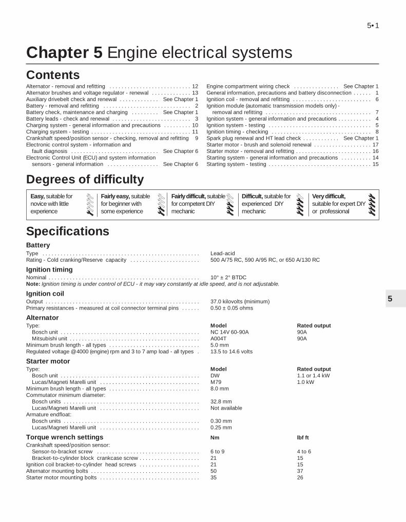
Chapter 5 Engine electrical systems
Alternator - removal and refitting . . . . . . . . . . . . . . . . . . . . . . . . . . . 12Alternator brushes and voltage regulator - renewal . . . . . . . . . . . . . 13Auxiliary drivebelt check and renewal . . . . . . . . . . . . . See Chapter 1Battery - removal and refitting . . . . . . . . . . . . . . . . . . . . . . . . . . . . . 2Battery check, maintenance and charging . . . . . . . . . See Chapter 1Battery leads - check and renewal . . . . . . . . . . . . . . . . . . . . . . . . . . 3Charging system - general information and precautions . . . . . . . . . 10Charging system - testing . . . . . . . . . . . . . . . . . . . . . . . . . . . . . . . . . 11Crankshaft speed/position sensor - checking, removal and refitting 9Electronic control system - information and
fault diagnosis . . . . . . . . . . . . . . . . . . . . . . . . . . . . . See Chapter 6Electronic Control Unit (ECU) and system information
sensors - general information . . . . . . . . . . . . . . . . . See Chapter 6
Engine compartment wiring check . . . . . . . . . . . . . . . See Chapter 1General information, precautions and battery disconnection . . . . . . 1Ignition coil - removal and refitting . . . . . . . . . . . . . . . . . . . . . . . . . . 6Ignition module (automatic transmission models only) -
removal and refitting . . . . . . . . . . . . . . . . . . . . . . . . . . . . . . . . . . . 7Ignition system - general information and precautions . . . . . . . . . . . 4Ignition system - testing . . . . . . . . . . . . . . . . . . . . . . . . . . . . . . . . . . 5Ignition timing - checking . . . . . . . . . . . . . . . . . . . . . . . . . . . . . . . . . 8Spark plug renewal and HT lead check . . . . . . . . . . . . See Chapter 1Starter motor - brush and solenoid renewal . . . . . . . . . . . . . . . . . . . 17Starter motor - removal and refitting . . . . . . . . . . . . . . . . . . . . . . . . . 16Starting system - general information and precautions . . . . . . . . . . 14Starting system - testing . . . . . . . . . . . . . . . . . . . . . . . . . . . . . . . . . . 15
BatteryType . . . . . . . . . . . . . . . . . . . . . . . . . . . . . . . . . . . . . . . . . . . . . . . . . . . . Lead-acidRating - Cold cranking/Reserve capacity . . . . . . . . . . . . . . . . . . . . . . . 500 A/75 RC, 590 A/95 RC, or 650 A/130 RC
Ignition timingNominal . . . . . . . . . . . . . . . . . . . . . . . . . . . . . . . . . . . . . . . . . . . . . . . . . . 10° ± 2° BTDCNote: Ignition timing is under control of ECU - it may vary constantly at idle speed, and is not adjustable.
Ignition coilOutput . . . . . . . . . . . . . . . . . . . . . . . . . . . . . . . . . . . . . . . . . . . . . . . . . . . 37.0 kilovolts (minimum)Primary resistances - measured at coil connector terminal pins . . . . . . 0.50 ± 0.05 ohms
AlternatorType: Model Rated output
Bosch unit . . . . . . . . . . . . . . . . . . . . . . . . . . . . . . . . . . . . . . . . . . . . . . NC 14V 60-90A 90AMitsubishi unit . . . . . . . . . . . . . . . . . . . . . . . . . . . . . . . . . . . . . . . . . . . A004T 90A
Minimum brush length - all types . . . . . . . . . . . . . . . . . . . . . . . . . . . . . . 5.0 mmRegulated voltage @ 4000 (engine) rpm and 3 to 7 amp load - all types . 13.5 to 14.6 volts
Starter motorType: Model Rated output
Bosch unit . . . . . . . . . . . . . . . . . . . . . . . . . . . . . . . . . . . . . . . . . . . . . . DW 1.1 or 1.4 kWLucas/Magneti Marelli unit . . . . . . . . . . . . . . . . . . . . . . . . . . . . . . . . . M79 1.0 kW
Minimum brush length - all types . . . . . . . . . . . . . . . . . . . . . . . . . . . . . . 8.0 mmCommutator minimum diameter:
Bosch units . . . . . . . . . . . . . . . . . . . . . . . . . . . . . . . . . . . . . . . . . . . . . 32.8 mmLucas/Magneti Marelli unit . . . . . . . . . . . . . . . . . . . . . . . . . . . . . . . . . Not available
Armature endfloat:Bosch units . . . . . . . . . . . . . . . . . . . . . . . . . . . . . . . . . . . . . . . . . . . . . 0.30 mmLucas/Magneti Marelli unit . . . . . . . . . . . . . . . . . . . . . . . . . . . . . . . . . 0.25 mm
Torque wrench settings Nm lbf ftCrankshaft speed/position sensor:
Sensor-to-bracket screw . . . . . . . . . . . . . . . . . . . . . . . . . . . . . . . . . . 6 to 9 4 to 6Bracket-to-cylinder block crankcase screw . . . . . . . . . . . . . . . . . . . . 21 15
Ignition coil bracket-to-cylinder head screws . . . . . . . . . . . . . . . . . . . . 21 15Alternator mounting bolts . . . . . . . . . . . . . . . . . . . . . . . . . . . . . . . . . . . . 50 37Starter motor mounting bolts . . . . . . . . . . . . . . . . . . . . . . . . . . . . . . . . . 35 26
5•1
Easy, suitable fornovice with littleexperience
Fairly easy, suitablefor beginner withsome experience
Fairly difficult, suitablefor competent DIYmechanic
Difficult, suitable forexperienced DIYmechanic
Very difficult,suitable for expert DIYor professional
Degrees of difficulty
Specifications
Contents
5
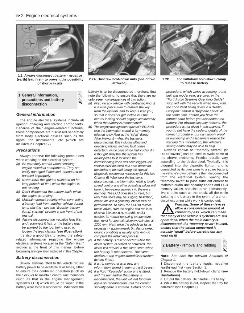
General informationThe engine electrical systems include all
ignition, charging and starting components.Because of their engine-related functions,these components are discussed separatelyfrom body electrical devices such as thelights, the instruments, etc (which areincluded in Chapter 12).
PrecautionsAlways observe the following precautions
when working on the electrical system:(a) Be extremely careful when servicing
engine electrical components. They areeasily damaged if checked, connected orhandled improperly.
(b) Never leave the ignition switched on forlong periods of time when the engine isnot running.
(c) Don’t disconnect the battery leads whilethe engine is running.
(d) Maintain correct polarity when connectinga battery lead from another vehicle duringjump starting - see the “Booster battery(jump) starting” section at the front of thismanual.
(e) Always disconnect the negative lead first,and reconnect it last, or the battery maybe shorted by the tool being used toloosen the lead clamps (see illustration).
It’s also a good idea to review the safety-related information regarding the engineelectrical systems located in the “Safety first!”section at the front of this manual, beforebeginning any operation included in this Chapter.
Battery disconnectionSeveral systems fitted to the vehicle require
battery power to be available at all times, eitherto ensure their continued operation (such asthe clock) or to maintain control unit memories(such as that in the engine managementsystem’s ECU) which would be wiped if thebattery were to be disconnected. Whenever the
battery is to be disconnected therefore, firstnote the following, to ensure that there are nounforeseen consequences of this action:(a) First, on any vehicle with central locking, it
is a wise precaution to remove the keyfrom the ignition, and to keep it with you,so that it does not get locked in if thecentral locking should engage accidentallywhen the battery is reconnected!
(b) The engine management system’s ECU willlose the information stored in its memory -referred to by Ford as the “KAM” (Keep-Alive Memory) - when the battery isdisconnected. This includes idling andoperating values, and any fault codesdetected - in the case of the fault codes, if itis thought likely that the system hasdeveloped a fault for which thecorresponding code has been logged, thevehicle must be taken to a Ford dealer forthe codes to be read, using the specialdiagnostic equipment necessary for this (seeChapter 6). Whenever the battery isdisconnected, the information relating to idlespeed control and other operating values willhave to be re-programmed into the unit’smemory. The ECU does this by itself, butuntil then, there may be surging, hesitation,erratic idle and a generally inferior level ofperformance. To allow the ECU to relearnthese values, start the engine and run it asclose to idle speed as possible until itreaches its normal operating temperature,then run it for approximately two minutes at1200 rpm. Next, drive the vehicle as far asnecessary - approximately 5 miles of varieddriving conditions is usually sufficient - tocomplete the relearning process.
(c) If the battery is disconnected while thealarm system is armed or activated, thealarm will remain in the same state whenthe battery is reconnected. The sameapplies to the engine immobiliser system(where fitted).
(d) If a trip computer is in use, anyinformation stored in memory will be lost.
(e) If a Ford “Keycode” audio unit is fitted,and the unit and/or the battery isdisconnected, the unit will not functionagain on reconnection until the correctsecurity code is entered. Details of this
procedure, which varies according to theunit and model year, are given in the“Ford Audio Systems Operating Guide”supplied with the vehicle when new, withthe code itself being given in a “RadioPassport” and/or a “Keycode Label” atthe same time. Ensure you have thecorrect code before you disconnect thebattery. For obvious security reasons, theprocedure is not given in this manual. Ifyou do not have the code or details of thecorrect procedure, but can supply proofof ownership and a legitimate reason forwanting this information, the vehicle’sselling dealer may be able to help.
Devices known as “memory-savers” (or“code-savers”) can be used to avoid some ofthe above problems. Precise details varyaccording to the device used. Typically, it isplugged into the cigarette lighter, and isconnected by its own wires to a spare battery;the vehicle’s own battery is then disconnectedfrom the electrical system, leaving the“memory-saver” to pass sufficient current tomaintain audio unit security codes and ECUmemory values, and also to run permanently-live circuits such as the clock, all the whileisolating the battery in the event of a short-circuit occurring while work is carried out.
Warning: Some of these devicesallow a considerable amount ofcurrent to pass, which can mean
that many of the vehicle’s systems are stilloperational when the main battery isdisconnected. If a “memory-saver” is used,ensure that the circuit concerned isactually “dead” before carrying out anywork on it!
Note: See also the relevant Sections ofChapter 1.1 Disconnect the battery leads, negative(earth) lead first - see Section 1.2 Remove the battery hold-down clamp (seeillustrations).3 Lift out the battery. Be careful - it’s heavy.4 While the battery is out, inspect the tray forcorrosion (see Chapter 1).
2 Battery - removal and refitting
1 General information,precautions and batterydisconnection
5•2 Engine electrical systems
1.2 Always disconnect battery - negative(earth) lead first - to prevent the possibility
of short-circuits2.2A Unscrew hold-down nuts (one of two
arrowed) . . .2.2B . . . and withdraw hold-down clamp
to release battery
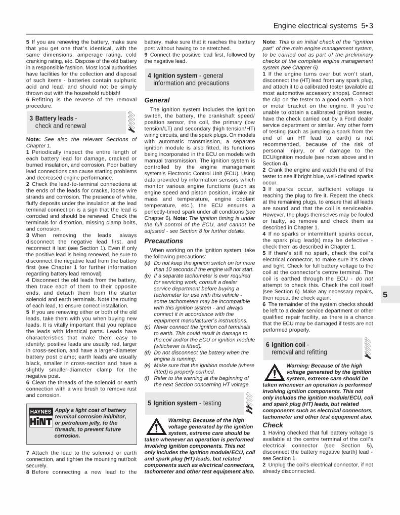
5 If you are renewing the battery, make surethat you get one that’s identical, with thesame dimensions, amperage rating, coldcranking rating, etc. Dispose of the old batteryin a responsible fashion. Most local authoritieshave facilities for the collection and disposalof such items - batteries contain sulphuricacid and lead, and should not be simplythrown out with the household rubbish!6 Refitting is the reverse of the removalprocedure.
Note: See also the relevant Sections ofChapter 1.1 Periodically inspect the entire length ofeach battery lead for damage, cracked orburned insulation, and corrosion. Poor batterylead connections can cause starting problemsand decreased engine performance.2 Check the lead-to-terminal connections atthe ends of the leads for cracks, loose wirestrands and corrosion. The presence of white,fluffy deposits under the insulation at the leadterminal connection is a sign that the lead iscorroded and should be renewed. Check theterminals for distortion, missing clamp bolts,and corrosion.3 When removing the leads, alwaysdisconnect the negative lead first, andreconnect it last (see Section 1). Even if onlythe positive lead is being renewed, be sure todisconnect the negative lead from the batteryfirst (see Chapter 1 for further informationregarding battery lead removal).4 Disconnect the old leads from the battery,then trace each of them to their oppositeends, and detach them from the startersolenoid and earth terminals. Note the routingof each lead, to ensure correct installation.5 If you are renewing either or both of the oldleads, take them with you when buying newleads. It is vitally important that you replacethe leads with identical parts. Leads havecharacteristics that make them easy toidentify: positive leads are usually red, largerin cross-section, and have a larger-diameterbattery post clamp; earth leads are usuallyblack, smaller in cross-section and have aslightly smaller-diameter clamp for thenegative post.6 Clean the threads of the solenoid or earthconnection with a wire brush to remove rustand corrosion.
7 Attach the lead to the solenoid or earthconnection, and tighten the mounting nut/boltsecurely.8 Before connecting a new lead to the
battery, make sure that it reaches the batterypost without having to be stretched.9 Connect the positive lead first, followed bythe negative lead.
GeneralThe ignition system includes the ignition
switch, the battery, the crankshaft speed/position sensor, the coil, the primary (lowtension/LT) and secondary (high tension/HT)wiring circuits, and the spark plugs. On modelswith automatic transmission, a separateignition module is also fitted, its functionsbeing incorporated in the ECU on models withmanual transmission. The ignition system iscontrolled by the engine managementsystem’s Electronic Control Unit (ECU). Usingdata provided by information sensors whichmonitor various engine functions (such asengine speed and piston position, intake airmass and temperature, engine coolanttemperature, etc.), the ECU ensures aperfectly-timed spark under all conditions (seeChapter 6). Note: The ignition timing is underthe full control of the ECU, and cannot beadjusted - see Section 8 for further details.
PrecautionsWhen working on the ignition system, take
the following precautions:(a) Do not keep the ignition switch on for more
than 10 seconds if the engine will not start.(b) If a separate tachometer is ever required
for servicing work, consult a dealerservice department before buying atachometer for use with this vehicle -some tachometers may be incompatiblewith this ignition system - and alwaysconnect it in accordance with theequipment manufacturer’s instructions.
(c) Never connect the ignition coil terminalsto earth. This could result in damage tothe coil and/or the ECU or ignition module(whichever is fitted).
(d) Do not disconnect the battery when theengine is running.
(e) Make sure that the ignition module (wherefitted) is properly earthed.
(f) Refer to the warning at the beginning ofthe next Section concerning HT voltage.
Warning: Because of the highvoltage generated by the ignitionsystem, extreme care should be
taken whenever an operation is performedinvolving ignition components. This notonly includes the ignition module/ECU, coiland spark plug (HT) leads, but relatedcomponents such as electrical connectors,tachometer and other test equipment also.
Note: This is an initial check of the “ignitionpart” of the main engine management system,to be carried out as part of the preliminarychecks of the complete engine managementsystem (see Chapter 6).1 If the engine turns over but won’t start,disconnect the (HT) lead from any spark plug,and attach it to a calibrated tester (available atmost automotive accessory shops). Connectthe clip on the tester to a good earth - a boltor metal bracket on the engine. If you’reunable to obtain a calibrated ignition tester,have the check carried out by a Ford dealerservice department or similar. Any other formof testing (such as jumping a spark from theend of an HT lead to earth) is notrecommended, because of the risk ofpersonal injury, or of damage to theECU/ignition module (see notes above and inSection 4).2 Crank the engine and watch the end of thetester to see if bright blue, well-defined sparksoccur.3 If sparks occur, sufficient voltage isreaching the plug to fire it. Repeat the checkat the remaining plugs, to ensure that all leadsare sound and that the coil is serviceable.However, the plugs themselves may be fouledor faulty, so remove and check them asdescribed in Chapter 1.4 If no sparks or intermittent sparks occur,the spark plug lead(s) may be defective -check them as described in Chapter 1.5 If there’s still no spark, check the coil’selectrical connector, to make sure it’s cleanand tight. Check for full battery voltage to thecoil at the connector’s centre terminal. Thecoil is earthed through the ECU - do notattempt to check this. Check the coil itself(see Section 6). Make any necessary repairs,then repeat the check again.6 The remainder of the system checks shouldbe left to a dealer service department or otherqualified repair facility, as there is a chancethat the ECU may be damaged if tests are notperformed properly.
Warning: Because of the highvoltage generated by the ignitionsystem, extreme care should be
taken whenever an operation is performedinvolving ignition components. This notonly includes the ignition module/ECU, coiland spark plug (HT) leads, but relatedcomponents such as electrical connectors,tachometer and other test equipment also.
Check1 Having checked that full battery voltage isavailable at the centre terminal of the coil’selectrical connector (see Section 5),disconnect the battery negative (earth) lead -see Section 1.2 Unplug the coil’s electrical connector, if notalready disconnected.
6 Ignition coil - removal and refitting
5 Ignition system - testing
4 Ignition system - generalinformation and precautions
3 Battery leads - check and renewal
Engine electrical systems 5•3
5
Apply a light coat of batteryterminal corrosion inhibitor,or petroleum jelly, to thethreads, to prevent futurecorrosion.

3 Using an ohmmeter, measure theresistance of the coil’s primary windings,connecting the meter between the coil’sterminal pins as follows. Measure first fromone outer pin to the centre pin, then from theother outer pin to the centre. Compare yourreadings with the coil primary resistance listedin the Specifications Section at the beginningof this Chapter.4 Disconnect the spark plug (HT) leads - notetheir connections or label them carefully, asdescribed in Chapter 1. Use the meter tocheck that there is continuity (ie, a resistancecorresponding to that of the coil secondarywinding) between each pair of (HT) leadterminals; Nos 1 and 4 terminals areconnected by their secondary winding, as areNos 2 and 3. Now switch to the highestresistance scale, and check that there is nocontinuity between either pair of terminals andthe other - ie, there should be infiniteresistance between terminals 1 and 2, or 4and 3 - and between any terminal and earth.5 If either of the above tests yield resistancevalues outside the specified amount, orresults other than those described, renew thecoil. Any further testing should be left to adealer service department or other qualifiedrepair facility.
Removal and refitting6 Disconnect the battery negative (earth) lead- see Section 1.7 Remove the air mass meter and resonator -refer to Chapter 4.8 Unplug the electrical connector from eachside of the coil, then disconnect the sparkplug (HT) leads - note their connections orlabel them carefully, as described in Chapter1.9 Undo the two screws securing the EGRpipe to the coil bracket, then remove the coilmounting (Torx-type) screws. Withdraw thecoil assembly from the cylinder head (seeillustration).10 The suppressor can be unbolted from themounting bracket, if required; note that thecoil and bracket are only available as a singleunit.11 Refitting is the reverse of the removal
procedure. Ensure that the spark plug (HT)leads are correctly reconnected, and tightenthe coil screws securely.
Note: See Chapter 6 for component locationillustrations.1 Disconnect the battery negative (earth) lead- see Section 1.2 If better access is required, remove theresonator (see Chapter 4).3 Unplug the electrical connector from themodule (see illustration).4 Remove the retaining screws, and detachthe module from the bulkhead mountingbracket.5 Refitting is the reverse of the removalprocedure.
As noted in Section 4, the ignition timing iscontrolled entirely by the ECU (acting with theignition module, on models with automatictransmission), and cannot be adjusted. Thevalue quoted in the Specifications Section ofthis Chapter is for reference only, and may
vary significantly if “checked” by simplyconnecting a timing light to the system andrunning the engine at idle speed.
Not only can the ignition timing not beadjusted, it cannot be checked either, exceptwith the use of special diagnostic equipment(see Chapter 6) - this makes it a task for aFord dealer service department.
Owners who are taking their vehiclesabroad should note that the ignition system isset for the engine to use petrol of 95 RONoctane rating by fitting a “plug-in bridge” tothe service connector on the enginecompartment bulkhead (see illustration).Removing the “plug-in bridge” retards theignition timing - by an unspecified value - toallow the engine to run on 91 RON fuel. Thisgrade of fuel is the “Regular” or “Normal”widely used abroad, but not at presentavailable in the UK. If you are taking thevehicle abroad, seek the advice of a Forddealer (or of one of the motoringorganisations). This will ensure that you arefamiliar with the grades of fuel you are likely tofind (and the sometimes confusing names forthose grades), and that the vehicle is setcorrectly at all times for the fuel used. Note:The octane ratings mentioned above are both,of course, for unleaded petrol. Do not useleaded petrol at any time in a vehicle equippedwith a catalytic converter.
Checking1 See Section 4 of Chapter 6.
Removal and refitting2 Disconnect the battery negative (earth) lead- see Section 1.3 Raise the front of the vehicle, and support itsecurely on axle stands.
Warning: Do not place any part ofyour body under a vehicle whenit’s supported only by a jack!
4 Unplug the sensor’s electrical connector(see illustration).
9 Crankshaft speed/positionsensor - checking, removal and refitting
8 Ignition timing - checking
7 Ignition module (automatictransmission models only) -removal and refitting
5•4 Engine electrical systems
6.9 Unplug coil electrical connector (A),suppressor connector (B), and spark
plug/HT leads (C), remove screws (D), thenundo Torx-type screws (E) to release
ignition coil assembly
7.3 Separate ignition module is fitted toautomatic transmission models only - note
electrical connector (A) and retainingscrews (B)
8.3 Service connector (A) mounted onengine compartment bulkhead is fitted with
“plug-in bridge” (B) to set engine to use(unleaded) petrol of 95 RON octane rating
9.4 Location of crankshaft speed/positionsensor - connector arrowed - in front of
cylinder block/crankcase
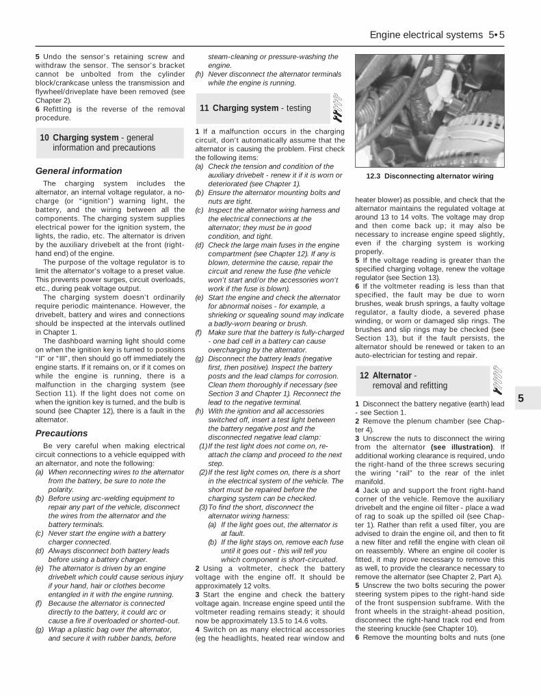
5 Undo the sensor’s retaining screw andwithdraw the sensor. The sensor’s bracketcannot be unbolted from the cylinderblock/crankcase unless the transmission andflywheel/driveplate have been removed (seeChapter 2).6 Refitting is the reverse of the removalprocedure.
General informationThe charging system includes the
alternator, an internal voltage regulator, a no-charge (or “ignition”) warning light, thebattery, and the wiring between all thecomponents. The charging system supplieselectrical power for the ignition system, thelights, the radio, etc. The alternator is drivenby the auxiliary drivebelt at the front (right-hand end) of the engine.
The purpose of the voltage regulator is tolimit the alternator’s voltage to a preset value.This prevents power surges, circuit overloads,etc., during peak voltage output.
The charging system doesn’t ordinarilyrequire periodic maintenance. However, thedrivebelt, battery and wires and connectionsshould be inspected at the intervals outlinedin Chapter 1.
The dashboard warning light should comeon when the ignition key is turned to positions“II” or “III”, then should go off immediately theengine starts. If it remains on, or if it comes onwhile the engine is running, there is amalfunction in the charging system (seeSection 11). If the light does not come onwhen the ignition key is turned, and the bulb issound (see Chapter 12), there is a fault in thealternator.
PrecautionsBe very careful when making electrical
circuit connections to a vehicle equipped withan alternator, and note the following:(a) When reconnecting wires to the alternator
from the battery, be sure to note thepolarity.
(b) Before using arc-welding equipment torepair any part of the vehicle, disconnectthe wires from the alternator and thebattery terminals.
(c) Never start the engine with a batterycharger connected.
(d) Always disconnect both battery leadsbefore using a battery charger.
(e) The alternator is driven by an enginedrivebelt which could cause serious injuryif your hand, hair or clothes becomeentangled in it with the engine running.
(f) Because the alternator is connecteddirectly to the battery, it could arc orcause a fire if overloaded or shorted-out.
(g) Wrap a plastic bag over the alternator,and secure it with rubber bands, before
steam-cleaning or pressure-washing theengine.
(h) Never disconnect the alternator terminalswhile the engine is running.
1 If a malfunction occurs in the chargingcircuit, don’t automatically assume that thealternator is causing the problem. First checkthe following items:(a) Check the tension and condition of the
auxiliary drivebelt - renew it if it is worn ordeteriorated (see Chapter 1).
(b) Ensure the alternator mounting bolts andnuts are tight.
(c) Inspect the alternator wiring harness andthe electrical connections at thealternator; they must be in goodcondition, and tight.
(d) Check the large main fuses in the enginecompartment (see Chapter 12). If any isblown, determine the cause, repair thecircuit and renew the fuse (the vehiclewon’t start and/or the accessories won’twork if the fuse is blown).
(e) Start the engine and check the alternatorfor abnormal noises - for example, ashrieking or squealing sound may indicatea badly-worn bearing or brush.
(f) Make sure that the battery is fully-charged- one bad cell in a battery can causeovercharging by the alternator.
(g) Disconnect the battery leads (negativefirst, then positive). Inspect the batteryposts and the lead clamps for corrosion.Clean them thoroughly if necessary (seeSection 3 and Chapter 1). Reconnect thelead to the negative terminal.
(h) With the ignition and all accessoriesswitched off, insert a test light betweenthe battery negative post and thedisconnected negative lead clamp:
(1) If the test light does not come on, re-attach the clamp and proceed to the nextstep.
(2) If the test light comes on, there is a shortin the electrical system of the vehicle. Theshort must be repaired before thecharging system can be checked.
(3) To find the short, disconnect thealternator wiring harness:(a) If the light goes out, the alternator is
at fault.(b) If the light stays on, remove each fuse
until it goes out - this will tell youwhich component is short-circuited.
2 Using a voltmeter, check the batteryvoltage with the engine off. It should beapproximately 12 volts.3 Start the engine and check the batteryvoltage again. Increase engine speed until thevoltmeter reading remains steady; it shouldnow be approximately 13.5 to 14.6 volts.4 Switch on as many electrical accessories(eg the headlights, heated rear window and
heater blower) as possible, and check that thealternator maintains the regulated voltage ataround 13 to 14 volts. The voltage may dropand then come back up; it may also benecessary to increase engine speed slightly,even if the charging system is workingproperly.5 If the voltage reading is greater than thespecified charging voltage, renew the voltageregulator (see Section 13).6 If the voltmeter reading is less than thatspecified, the fault may be due to wornbrushes, weak brush springs, a faulty voltageregulator, a faulty diode, a severed phasewinding, or worn or damaged slip rings. Thebrushes and slip rings may be checked (seeSection 13), but if the fault persists, thealternator should be renewed or taken to anauto-electrician for testing and repair.
1 Disconnect the battery negative (earth) lead- see Section 1.2 Remove the plenum chamber (see Chap-ter 4).3 Unscrew the nuts to disconnect the wiringfrom the alternator (see illustration). Ifadditional working clearance is required, undothe right-hand of the three screws securingthe wiring “rail” to the rear of the inletmanifold.4 Jack up and support the front right-handcorner of the vehicle. Remove the auxiliarydrivebelt and the engine oil filter - place a wadof rag to soak up the spilled oil (see Chap-ter 1). Rather than refit a used filter, you areadvised to drain the engine oil, and then to fita new filter and refill the engine with clean oilon reassembly. Where an engine oil cooler isfitted, it may prove necessary to remove thisas well, to provide the clearance necessary toremove the alternator (see Chapter 2, Part A).5 Unscrew the two bolts securing the powersteering system pipes to the right-hand sideof the front suspension subframe. With thefront wheels in the straight-ahead position,disconnect the right-hand track rod end fromthe steering knuckle (see Chapter 10).6 Remove the mounting bolts and nuts (one
12 Alternator - removal and refitting
11 Charging system - testing
10 Charging system - generalinformation and precautions
Engine electrical systems 5•5
5
12.3 Disconnecting alternator wiring

at the top, two at the bottom). Withdraw thealternator from the engine, and manoeuvre itout through the wheel arch (see illustration).Do not drop it, it is fragile.7 If you are renewing the alternator, take theold one with you when purchasing areplacement unit. Make sure that the new orrebuilt unit is identical to the old alternator.Look at the terminals - they should be thesame in number, size and location as theterminals on the old alternator. Finally, look atthe identification markings - they will bestamped in the housing, or printed on a tag orplaque affixed to the housing. Make sure thatthese numbers are the same on bothalternators.8 Many new/rebuilt alternators do not have apulley installed, so you may have to switch thepulley from the old unit to the new/rebuilt one.When buying an alternator, ask about theinstallation of pulleys - some auto-electricalspecialists will perform this service free ofcharge.9 Refitting is the reverse of the removalprocedure, referring where necessary to therelevant Chapters of this manual. Tighten allfasteners to the specified torque wrenchsettings.10 Check the charging voltage to verifyproper operation of the alternator (see Sec-tion 11).
Note: This procedure assumes thatreplacement parts of the correct type havebeen obtained. At the time of writing, noindividual alternator components wereavailable as separate replacement Ford parts.An auto electrical specialist should be able tosupply parts such as brushes.
The following procedure is for the Boschunit fitted to the project vehicle - details mayvary for other alternator types.1 Remove the alternator from the vehicle (seeSection 12) and place it on a cleanworkbench.2 Remove the three screws, and withdraw theplastic end cover (see illustration).
3 Remove the two voltage regulator/brushholder mounting screws.4 Remove the regulator/brush holder from theend frame (see illustration). If you arerenewing the assembly, proceed to para-graph 8, install the new unit, reassemble thealternator, and refit it to the engine (seeSection 12). If you are going to check thebrushes, proceed to the next paragraph.5 Measure the exposed length of each brush,and compare it to the minimum length listed inthis Chapter’s Specifications. If the length ofeither brush is less than the specifiedminimum, renew the assembly.6 Make sure that each brush moves smoothlyin the brush holder.7 Check that the slip rings - the ring ofcopper on which each brush bears - areclean. Wipe them with a solvent-moistenedcloth; if either appears scored or blackened,take the alternator to a repair specialist foradvice.8 Refit the voltage regulator/brush holder,ensuring that the brushes bear correctly onthe slip rings, and that they compress intotheir holders. Tighten the screws securely.9 Install the rear cover, and tighten thescrews securely.10 Refit the alternator (see Section 12).
General informationThe sole function of the starting system is
to turn over the engine quickly enough toallow it to start.
The starting system consists of the battery,the starter motor, the starter solenoid, and thewires connecting them. The solenoid ismounted directly on the starter motor.
The solenoid/starter motor assembly isinstalled on the rear upper part of the engine,next to the transmission bellhousing.
When the ignition key is turned to position“III”, the starter solenoid is actuated throughthe starter control circuit. The starter solenoidthen connects the battery to the starter. Thebattery supplies the electrical energy to the
starter motor, which does the actual work ofcranking the engine.
The starter motor on a vehicle equippedwith automatic transmission can be operatedonly when the selector lever is in Park orNeutral (“P” or “N”).
If the alarm system is armed or activated,the starter motor cannot be operated. Thesame applies with the engine immobilisersystem (where fitted).
PrecautionsAlways observe the following precautions
when working on the starting system:(a) Excessive cranking of the starter motor
can overheat it, and cause seriousdamage. Never operate the starter motorfor more than 15 seconds at a timewithout pausing to allow it to cool for atleast two minutes. Excessive starteroperation will also risk unburned fuelcollecting in the catalytic converter’selement, causing it to overheat when theengine does start (see Chapter 6).
(b) The starter is connected directly to thebattery, and could arc or cause a fire ifmishandled, overloaded or shorted-out.
(c) Always detach the lead from the negativeterminal of the battery before working onthe starting system (see Section 1).
Note: Before diagnosing starter problems,make sure that the battery is fully-charged,and ensure that the alarm/engine immobilisersystem is not activated.1 If the starter motor does not turn at all whenthe switch is operated, make sure that, onautomatic transmission models, the selectorlever is in Park or Neutral (“P” or “N”).2 Make sure that the battery is fully-charged,and that all leads, both at the battery andstarter solenoid terminals, are clean andsecure.3 If the starter motor spins but the engine isnot cranking, the overrunning clutch or (whenapplicable) the reduction gears in the startermotor may be slipping, in which case the
15 Starting system - testing
14 Starting system - generalinformation and precautions
13 Alternator brushes andvoltage regulator - renewal
5•6 Engine electrical systems
12.6 Alternator must be withdrawnthrough right-hand front wheel arch
13.2 Renewing voltage regulator/brushholder - Bosch alternator. Remove three
screws and withdraw end cover . . .13.4 . . . then remove regulator/brush
holder assembly (secured by two screws)

starter motor must be overhauled or renewed.(Other possibilities are that the starter motormounting bolts are very loose, or that teethare missing from the flywheel/driveplate ringgear.)4 If, when the switch is actuated, the startermotor does not operate at all but the solenoidclicks, then the problem lies with either thebattery, the main solenoid contacts, or thestarter motor itself (or the engine is seized).5 If the solenoid plunger cannot be heard toclick when the switch is actuated, the batteryis faulty, there is a fault in the circuit, or thesolenoid itself is defective.6 To check the solenoid, connect a fusedjumper lead between the battery (+) and theignition switch terminal (the small terminal) onthe solenoid. If the starter motor nowoperates, the solenoid is OK, and the problemis in the ignition switch, selector lever positionsensor (automatic transmission) or in thewiring.7 If the starter motor still does not operate,remove it (see Section 16). The brushes andcommutator may be checked (see Sec-tion 17), but if the fault persists, the motorshould be renewed, or taken to an auto-electrician for testing and repair.8 If the starter motor cranks the engine at an
abnormally-slow speed, first make sure thatthe battery is charged, and that all terminalconnections are tight. If the engine is partiallyseized, or has the wrong viscosity oil in it, itwill crank slowly.9 Run the engine until normal operatingtemperature is reached, then switch off anddisable the ignition system by unplugging theignition coil’s electrical connector; removefuse 14 to disconnect the fuel pump.10 Connect a voltmeter positive lead to thebattery positive terminal, and connect thenegative lead to the negative terminal.11 Crank the engine, and take the voltmeterreadings as soon as a steady figure isindicated. Do not allow the starter motor toturn for more than 15 seconds at a time. Areading of 10.5 volts or more, with the startermotor turning at normal cranking speed, isnormal. If the reading is 10.5 volts or more butthe cranking speed is slow, the solenoidcontacts are burned, the motor is faulty, orthere is a bad connection. If the reading is lessthan 10.5 volts and the cranking speed isslow, the starter motor is faulty or there is aproblem with the battery.
1 Disconnect the battery negative (earth) lead- see Section 1.2 Remove the air mass meter and resonator -refer to Chapter 4.3 Unscrew the upper two starter motormounting bolts, noting that one also securesan engine/transmission earth lead (seeillustration).4 Raise the front of the vehicle, and support itsecurely on axle stands.
Warning: Do not place any part ofyour body under a vehicle whenit’s supported only by a jack!
5 Unscrew the nuts to disconnect the wiringfrom the starter/solenoid terminals.6 Remove the remaining starter motormounting bolt (see illustration). Remove thestarter.7 Refitting is the reverse of the removalprocedure. Tighten the bolts to the specifiedtorque wrench settings.
Note: This procedure assumes thatreplacement brushes of the correct type havebeen obtained - at the time of writing, noindividual starter motor components wereavailable as separate replacement Ford parts.An auto electrical specialist should be able tosupply parts such as brushes.
The following procedures are for theLucas/Magneti Marelli unit fitted to the projectvehicle - the procedure is essentially the samefor the Bosch unit that may be found on othermodels.1 Remove the starter motor from the vehicle(Section 16) (see illustration).
17 Starter motor - brush andsolenoid renewal
16 Starter motor - removal and refitting
Engine electrical systems 5•7
5
16.3 Unscrew upper two starter motormounting bolts (arrowed) from above
16.6 Disconnect starter motor wiring (A),then unscrew remaining mounting bolt (B),
and remove starter motor from beneathvehicle
17.1 Exploded view of the Bosch DW startermotor
1 Solenoid2 Spring3 Plunger4 Engaging lever5 Drive end housing6 Drive pinion and
clutch7 Spacer8 Ring gear and carrier9 Output shaft and
planet gear unit10 Circlip
11 Screw12 End cap13 C-clip14 Shim15 Commutator end
housing16 Brushplate17 Yoke18 Rubber block19 Armature20 Retaining plate

Brush renewal2 Remove the brushes as shown (seeillustrations).3 In some cases, the brushes will have wearlimit marks, in the form of a groove etchedalong one face of each brush; when thebrushes are worn down to these marks, theymust be renewed. If no marks are provided,measure the length of each brush, andcompare it with the minimum length given inthe Specifications Section of this Chapter. Ifany brush is worn below this limit, renew thebrushes as a set. If the brushes are stillserviceable, clean them with a petrol-
moistened cloth. Check that the springpressure is equal for all brushes, and holdsthe brushes securely against the commutator.If in doubt about the condition of the brushesand springs, compare them with newcomponents.4 Clean the commutator with a petrol-moistened cloth, then check for signs ofscoring, burning, excessive wear or severepitting. If worn or damaged, the commutatorshould be attended to by an auto-electrician.5 Refitting is the reverse of the removalprocedure.
Solenoid renewal6 Unscrew the nut, noting the lockwasher(s),and disconnect the motor link from thesolenoid terminal.7 Unscrew the two bolts securing thesolenoid to the motor drive end housing.8 Release the solenoid plunger from thestarter engaging lever, then withdraw thesolenoid, noting the spring.9 Refitting is the reverse of the removalprocedure. Clean the solenoid, its plunger andthe motor/solenoid mating surfaces carefully,and lubricate the plunger/starter engaginglever surfaces with a smear of grease.
17.2G . . . lift off the plastic insulating plate . . .
17.2H . . . remove the brushbox andremove the positive brushes complete with
the bus bar . . .
17.2I . . . note how the bus bar is engagedon the brushbox before removing it
5•8 Engine electrical systems
17.2A Remove the two screws to releasethe end cap. Withdraw the gasket and
prise out the C-clip, noting any shims fittedto control armature endfloat . . .
17.2B . . . unscrew the two screws . . . 17.2C . . . and withdraw the end housing . . .
17.2D . . . then unclip the brush holdersand springs . . .
17.2E . . . unscrew the nut securing thesolenoid link . . .
17.2F . . . withdraw the negative brushes . . .
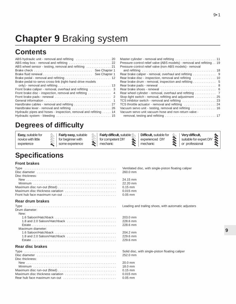
Chapter 9 Braking system
ABS hydraulic unit - removal and refitting . . . . . . . . . . . . . . . . . . . . 20ABS relay box - removal and refitting . . . . . . . . . . . . . . . . . . . . . . . . 22ABS wheel sensor - testing, removal and refitting . . . . . . . . . . . . . . 21Brake check . . . . . . . . . . . . . . . . . . . . . . . . . . . . . . . . . See Chapter 1Brake fluid renewal . . . . . . . . . . . . . . . . . . . . . . . . . . . . See Chapter 1Brake pedal - removal and refitting . . . . . . . . . . . . . . . . . . . . . . . . . . 12Brake pedal-to-servo cross-link (right-hand-drive models
only) - removal and refitting . . . . . . . . . . . . . . . . . . . . . . . . . . . . . . 13Front brake caliper - removal, overhaul and refitting . . . . . . . . . . . . 3Front brake disc - inspection, removal and refitting . . . . . . . . . . . . . 4Front brake pads - renewal . . . . . . . . . . . . . . . . . . . . . . . . . . . . . . . . 2General information . . . . . . . . . . . . . . . . . . . . . . . . . . . . . . . . . . . . . . 1Handbrake cables - removal and refitting . . . . . . . . . . . . . . . . . . . . . 27Handbrake lever - removal and refitting . . . . . . . . . . . . . . . . . . . . . . 26Hydraulic pipes and hoses - inspection, removal and refitting . . . . . 14Hydraulic system - bleeding . . . . . . . . . . . . . . . . . . . . . . . . . . . . . . . 15
Master cylinder - removal and refitting . . . . . . . . . . . . . . . . . . . . . . . 11Pressure-control relief valve (ABS models) - removal and refitting . . 19Pressure-control relief valve (non-ABS models) - removal
and refitting . . . . . . . . . . . . . . . . . . . . . . . . . . . . . . . . . . . . . . . . . . 18Rear brake caliper - removal, overhaul and refitting . . . . . . . . . . . . . 9Rear brake disc - inspection, removal and refitting . . . . . . . . . . . . . 10Rear brake drum - removal, inspection and refitting . . . . . . . . . . . . . 5Rear brake pads - renewal . . . . . . . . . . . . . . . . . . . . . . . . . . . . . . . . 8Rear brake shoes - renewal . . . . . . . . . . . . . . . . . . . . . . . . . . . . . . . 6Rear wheel cylinder - removal, overhaul and refitting . . . . . . . . . . . . 7Stop-light switch - removal, refitting and adjustment . . . . . . . . . . . . 25TCS inhibitor switch - removal and refitting . . . . . . . . . . . . . . . . . . . 23TCS throttle actuator - removal and refitting . . . . . . . . . . . . . . . . . . 24Vacuum servo unit - testing, removal and refitting . . . . . . . . . . . . . . 16Vacuum servo unit vacuum hose and non-return valve -
removal, testing and refitting . . . . . . . . . . . . . . . . . . . . . . . . . . . . . 17
Front brakesType . . . . . . . . . . . . . . . . . . . . . . . . . . . . . . . . . . . . . . . . . . . . . . . . . . . . Ventilated disc, with single-piston floating caliperDisc diameter . . . . . . . . . . . . . . . . . . . . . . . . . . . . . . . . . . . . . . . . . . . . . 260.0 mmDisc thickness:
New . . . . . . . . . . . . . . . . . . . . . . . . . . . . . . . . . . . . . . . . . . . . . . . . . . . 24.15 mmMinimum . . . . . . . . . . . . . . . . . . . . . . . . . . . . . . . . . . . . . . . . . . . . . . . 22.20 mm
Maximum disc run-out (fitted) . . . . . . . . . . . . . . . . . . . . . . . . . . . . . . . . . 0.15 mmMaximum disc thickness variation . . . . . . . . . . . . . . . . . . . . . . . . . . . . . 0.015 mmFront hub face maximum run-out . . . . . . . . . . . . . . . . . . . . . . . . . . . . . . 0.05 mm
Rear drum brakesType . . . . . . . . . . . . . . . . . . . . . . . . . . . . . . . . . . . . . . . . . . . . . . . . . . . . Leading and trailing shoes, with automatic adjustersDrum diameter:
New:1.6 Saloon/Hatchback . . . . . . . . . . . . . . . . . . . . . . . . . . . . . . . . . . . 203.0 mm1.8 and 2.0 Saloon/Hatchback . . . . . . . . . . . . . . . . . . . . . . . . . . . . 228.6 mmEstate . . . . . . . . . . . . . . . . . . . . . . . . . . . . . . . . . . . . . . . . . . . . . . . . 228.6 mm
Maximum diameter:1.6 Saloon/Hatchback . . . . . . . . . . . . . . . . . . . . . . . . . . . . . . . . . . . 204.2 mm1.8 and 2.0 Saloon/Hatchback . . . . . . . . . . . . . . . . . . . . . . . . . . . . 229.6 mmEstate . . . . . . . . . . . . . . . . . . . . . . . . . . . . . . . . . . . . . . . . . . . . . . . . 229.6 mm
Rear disc brakesType . . . . . . . . . . . . . . . . . . . . . . . . . . . . . . . . . . . . . . . . . . . . . . . . . . . . Solid disc, with single-piston floating caliperDisc diameter . . . . . . . . . . . . . . . . . . . . . . . . . . . . . . . . . . . . . . . . . . . . . 252.0 mmDisc thickness:
New . . . . . . . . . . . . . . . . . . . . . . . . . . . . . . . . . . . . . . . . . . . . . . . . . . . 20.0 mmMinimum . . . . . . . . . . . . . . . . . . . . . . . . . . . . . . . . . . . . . . . . . . . . . . . 18.0 mm
Maximum disc run-out (fitted) . . . . . . . . . . . . . . . . . . . . . . . . . . . . . . . . . 0.15 mmMaximum disc thickness variation . . . . . . . . . . . . . . . . . . . . . . . . . . . . . 0.015 mmRear hub face maximum run-out . . . . . . . . . . . . . . . . . . . . . . . . . . . . . . 0.05 mm
9•1
Easy, suitable fornovice with littleexperience
Fairly easy, suitablefor beginner withsome experience
Fairly difficult, suitablefor competent DIYmechanic
Difficult, suitable forexperienced DIYmechanic
Very difficult,suitable for expert DIYor professional
Degrees of difficulty
Specifications
Contents
9

Torque wrench settings Nm lbf ftFront caliper bracket . . . . . . . . . . . . . . . . . . . . . . . . . . . . . . . . . . . . . . . . 120 89Rear caliper bracket . . . . . . . . . . . . . . . . . . . . . . . . . . . . . . . . . . . . . . . . 59 44Front caliper guide bolts . . . . . . . . . . . . . . . . . . . . . . . . . . . . . . . . . . . . . 28 21Rear caliper guide bolts . . . . . . . . . . . . . . . . . . . . . . . . . . . . . . . . . . . . . 41 30Rear drum brake backplate . . . . . . . . . . . . . . . . . . . . . . . . . . . . . . . . . . . 50 37Vacuum servo unit . . . . . . . . . . . . . . . . . . . . . . . . . . . . . . . . . . . . . . . . . 40 30Master cylinder . . . . . . . . . . . . . . . . . . . . . . . . . . . . . . . . . . . . . . . . . . . . 23 17ABS hydraulic unit to bracket . . . . . . . . . . . . . . . . . . . . . . . . . . . . . . . . . 20 15Roadwheel nuts . . . . . . . . . . . . . . . . . . . . . . . . . . . . . . . . . . . . . . . . . . . 85 63
9•2 Braking system
1.2 Handbrake lever and associated components1 Handbrake lever2 Clock spring3 Handbrake cable4 Toothed segment and pawl to lock the
handbrake lever
5 Fine-toothed segment for the clock spring6 Pawl for the clock spring7 Underbody bracket
The braking system is of diagonally-split,dual-circuit design, with ventilated discs atthe front, and drum or disc brakes (accordingto model) at the rear. The front calipers are offloating single-piston design, using asbestos-free pads. The rear drum brakes are of theleading and trailing shoe type. They are self-adjusting during footbrake operation. The rearbrake shoe linings are of differentthicknesses, in order to allow for the differentproportional rates of wear.
Pressure-control relief (PCR) valves arefitted to the rear brakes, to prevent rear wheellock-up under hard braking. The valves aresometimes referred to as pressure-consciousreducing valves. On non-ABS models, they
are fitted in the master cylinder rear brakeoutlet ports; on ABS models, they are locatedon the ABS unit.
When rear disc brakes are fitted, the rearbrake caliper is located on the front of theknuckle on Saloon and Hatchback models,and on the rear of the knuckle on Estatemodels (see illustration).
The handbrake is cable-operated, and actson the rear brakes. On rear drum brakemodels, the cables operate on the rear trailingbrake shoe operating levers, and on rear discbrake models, they operate on levers on therear calipers. The handbrake leverincorporates an automatic adjuster, whichremoves any slack from the cables when thelever is disengaged (see illustration).Handbrake lever movement remainsconsistent at all times, and no adjustment isnecessary or possible.
Where fitted, the anti-lock braking system(ABS) is of the four-channel low-pressure type(see illustration). It uses the basicconventional brake system, together with a
Bendix ABS hydraulic unit fitted between themaster cylinder and the four wheel brakes.The hydraulic unit consists of a hydraulicactuator, an ABS brake pressure pump, anABS module with built-in relay box, and twopressure-control relief valves. Braking at eachof the four wheels is controlled by separatesolenoid valves in the hydraulic actuator. Ifwheel lock-up is detected on a wheel whenthe vehicle speed is above 3 mph, the valveopens, releasing pressure to the relevantbrake, until the wheel regains a rotationalspeed corresponding to the speed of thevehicle. The cycle can be repeated manytimes a second. In the event of a fault in theABS system, the conventional braking systemis not affected. Diagnosis of a fault in the ABSsystem requires the use of special equipment,and this work should therefore be left to aFord dealer. Diagnostic connectors arelocated on the side of the left-hand frontsuspension turret.
The traction control system (TCS) is fittedas an option to some models, and uses the
1 General information
1.1 Rear disc brake location onSaloon/Hatchback models (A) and Estate
models (B)
1 Handbrake cable lever facing away from caliper
2 Handbrake cable lever facing towards caliper
3 Brake hose banjo bolt4 Front of vehicle
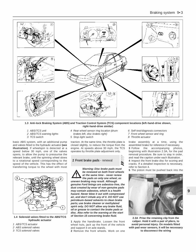
basic ABS system, with an additional pumpand valves fitted to the hydraulic actuator (seeillustration). If wheelspin is detected at aspeed below 30 mph, one of the valvesopens, to allow the pump to pressurise therelevant brake, until the spinning wheel slowsto a rotational speed corresponding to thespeed of the vehicle. This has the effect oftransferring torque to the wheel with most
traction. At the same time, the throttle plate isclosed slightly, to reduce the torque from theengine. At speeds above 30 mph, the TCSoperates by throttle plate adjustment only.
Warning: Disc brake pads mustbe renewed on both front wheelsat the same time - never renewthe pads on only one wheel, as
uneven braking may result. Althoughgenuine Ford linings are asbestos-free, thedust created by wear of non-genuine padsmay contain asbestos, which is a healthhazard. Never blow it out with compressedair, and don’t inhale any of it. DO NOT usepetroleum-based solvents to clean brakeparts; use brake cleaner or methylatedspirit only. DO NOT allow any brake fluid,oil or grease to contact the brake pads ordisc. Also refer to the warning at the startof Section 15 concerning brake fluid.
1 Apply the handbrake. Loosen the frontwheel nuts, jack up the front of the vehicleand support it on axle stands.2 Remove the front wheels. Work on one
brake assembly at a time, using theassembled brake for reference if necessary.3 Follow the accompanying photos,beginning with illustration 2.3A, for the padremoval procedure. Be sure to stay in order,and read the caption under each illustration.4 Inspect the front brake disc for scoring andcracks. If a detailed inspection is necessary,refer to Section 4.5 The piston must be pushed back into the
2 Front brake pads - renewal
Braking system 9•3
9
1.4 Solenoid valves fitted to the ABS/TCShydraulic actuator
1 ABS/TCS actuator2 ABS solenoid valves3 TCS solenoid valves
1.3 Anti-lock Braking System (ABS) and Traction Control System (TCS) component locations (left-hand-drive shown, right-hand-drive similar)
1 ABS/TCS unit2 ABS/TCS warning lights3 TCS switch
4 Rear wheel sensor ring location (drum brakes left, disc brakes right)
5 Stop-light switch
6 Self-test/diagnosis connectors7 Front wheel sensor and ring8 Throttle actuator
2.3A Prise the retaining clip from thecaliper. Hold it with a pair of pliers, to
avoid personal injury. On models fittedwith pad wear sensors, it will be necessary
to disconnect the wiring
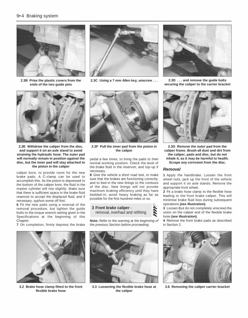
caliper bore, to provide room for the newbrake pads. A C-clamp can be used toaccomplish this. As the piston is depressed tothe bottom of the caliper bore, the fluid in themaster cylinder will rise slightly. Make surethat there is sufficient space in the brake fluidreservoir to accept the displaced fluid, and ifnecessary, syphon some off first.6 Fit the new pads using a reversal of theremoval procedure, but tighten the guidebolts to the torque wrench setting given in theSpecifications at the beginning of thisChapter.7 On completion, firmly depress the brake
pedal a few times, to bring the pads to theirnormal working position. Check the level ofthe brake fluid in the reservoir, and top-up ifnecessary.8 Give the vehicle a short road test, to makesure that the brakes are functioning correctly,and to bed-in the new linings to the contoursof the disc. New linings will not providemaximum braking efficiency until they havebedded-in; avoid heavy braking as far aspossible for the first hundred miles or so.
Note: Refer to the warning at the beginning ofthe previous Section before proceeding.
Removal1 Apply the handbrake. Loosen the frontwheel nuts, jack up the front of the vehicleand support it on axle stands. Remove theappropriate front wheel.2 Fit a brake hose clamp to the flexible hoseleading to the front brake caliper. This willminimise brake fluid loss during subsequentoperations (see illustration).3 Loosen (but do not completely unscrew) theunion on the caliper end of the flexible brakehose (see illustration).4 Remove the front brake pads as describedin Section 2.
3 Front brake caliper - removal, overhaul and refitting
9•4 Braking system
2.3B Prise the plastic covers from theends of the two guide pins
2.3C Using a 7 mm Allen key, unscrew . . . 2.3D . . . and remove the guide boltssecuring the caliper to the carrier bracket
2.3E Withdraw the caliper from the disc,and support it on an axle stand to avoid
straining the hydraulic hose. The outer padwill normally remain in position against thedisc, but the inner pad will stay attached to
the piston in the caliper
2.3F Pull the inner pad from the piston inthe caliper
3.2 Brake hose clamp fitted to the frontflexible brake hose
3.3 Loosening the flexible brake hose atthe caliper
3.6 Removing the caliper carrier bracket
2.3G Remove the outer pad from thecaliper frame. Brush all dust and dirt from
the caliper, pads and disc, but do notinhale it, as it may be harmful to health.
Scrape any corrosion from the disc.

5 Support the caliper in one hand, andprevent the hydraulic hose from turning withthe other hand. Unscrew the caliper from thehose, making sure that the hose is not twistedunduly or strained. Once the caliper isdetached, plug the open hydraulic unions inthe caliper and hose, to keep out dust anddirt.6 If required, the caliper carrier bracket canbe unbolted and removed from the steeringknuckle (see illustration).
Overhaul7 With the caliper on the bench, brush awayall traces of dust and dirt, but take care not toinhale any dust, as it may be injurious tohealth.8 Pull the dust-excluding rubber seal from theend of the piston.9 Apply low air pressure to the fluid inletunion, and eject the piston. Only low airpressure is required for this, such as isproduced by a foot-operated tyre pump.
Caution: The piston may beejected with some force.
10 Using a suitable blunt instrument (forinstance a knitting needle or a crochet hook),prise the piston seal from the groove in thecylinder bore. Take care not to scratch thesurface of the bore.11 Clean the piston and caliper body withmethylated spirit, and allow to dry. Examine thesurfaces of the piston and cylinder bore for wear,damage and corrosion. If the piston alone isunserviceable, a new piston must be obtained,along with seals. If the cylinder bore isunserviceable, the complete caliper must berenewed. The seals must be renewed, regardlessof the condition of the other components.12 Coat the piston and seals with cleanbrake fluid, then manipulate the piston sealinto the groove in the cylinder bore.
13 Push the piston squarely into its bore.14 Fit the dust-excluding rubber seal ontothe piston and caliper, then depress thepiston fully.
Refitting15 Refit the caliper, and where applicable thecarrier bracket, by reversing the removaloperations. Make sure that the flexible brakehose is not twisted. Tighten the mountingbolts and wheel nuts to the specified torque(see illustration).16 Bleed the brake circuit according to theprocedure given in Section 15, rememberingto remove the brake hose clamp from theflexible hose. Make sure there are no leaksfrom the hose connections. Test the brakescarefully before returning the vehicle tonormal service.
Note: To prevent uneven braking, BOTH frontbrake discs should be renewed or reground atthe same time.
Inspection1 Apply the handbrake. Loosen the relevantwheel nuts, jack up the front of the vehicleand support it on axle stands. Remove thewheel.2 Remove the front brake caliper and carrierbracket with reference to Section 3, but donot disconnect the flexible hose. Support thecaliper on an axle stand, or suspend it out ofthe way with a piece of wire, taking care toavoid straining the flexible hose.3 Temporarily refit two of the wheel nuts todiagonally-opposite studs, with the flat sidesof the nuts against the disc. Tighten the nutsprogressively, to hold the disc firmly.4 Scrape any corrosion from the disc. Rotatethe disc, and examine it for deep scoring,grooving or cracks. Using a micrometer,measure the thickness of the disc in severalplaces. The minimum thickness is stamped onthe disc hub (see illustrations). Light wearand scoring is normal, but if excessive, the
disc should be removed, and either regroundby a specialist, or renewed. If regrinding isundertaken, the minimum thickness must bemaintained. Obviously, if the disc is cracked,it must be renewed.5 Using a dial gauge or a flat metal block andfeeler gauges, check that the disc run-out 10 mm from the outer edge does not exceedthe limit given in the Specifications. To dothis, fix the measuring equipment, and rotatethe disc, noting the variation in measurementas the disc is rotated (see illustration). Thedifference between the minimum andmaximum measurements recorded is the discrun-out.6 If the run-out is greater than the specifiedamount, check for variations of the discthickness as follows. Mark the disc at eightpositions 45° apart, then using a micrometer,measure the disc thickness at the eightpositions, 15 mm in from the outer edge. If thevariation between the minimum and maximumreadings is greater than the specified amount,the disc should be renewed.7 The hub face run-out can also be checkedin a similar way. First remove the disc asdescribed later in this Section, fix themeasuring equipment, then slowly rotate thehub, and check that the run-out does notexceed the amount given in theSpecifications. If the hub face run-out isexcessive, this should be corrected (byrenewing the hub bearings - see Chapter 10)before rechecking the disc run-out.
4 Front brake disc - inspection,removal and refitting
Braking system 9•5
9
4.5 Measuring the disc run-out with a dialgauge
3.15 Tightening the carrier bracketmounting bolts
4.4A Using a micrometer to measure thethickness of the front brake disc
4.4B Disc minimum thickness marking
Position a thin piece of woodbetween the piston and thecaliper body, to preventdamage to the end face of the
piston, in the event of it being ejectedsuddenly.
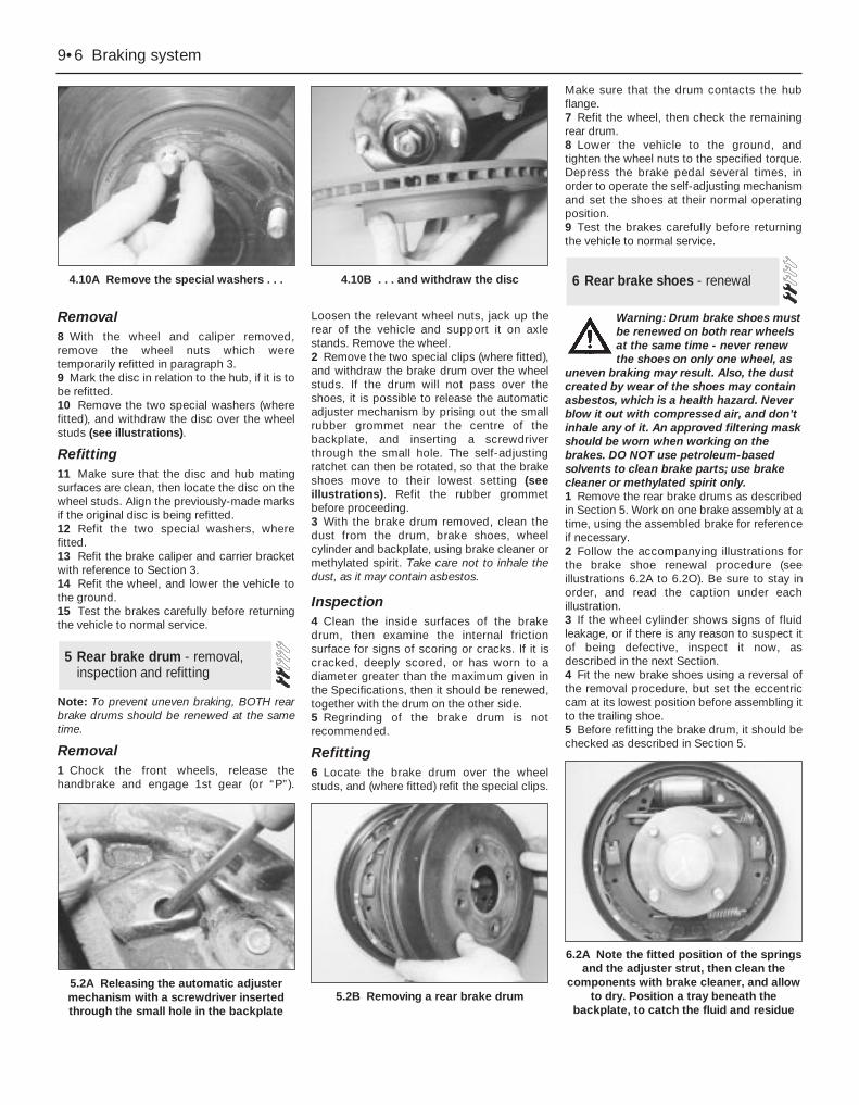
Removal8 With the wheel and caliper removed,remove the wheel nuts which weretemporarily refitted in paragraph 3.9 Mark the disc in relation to the hub, if it is tobe refitted.10 Remove the two special washers (wherefitted), and withdraw the disc over the wheelstuds (see illustrations).
Refitting11 Make sure that the disc and hub matingsurfaces are clean, then locate the disc on thewheel studs. Align the previously-made marksif the original disc is being refitted.12 Refit the two special washers, wherefitted.13 Refit the brake caliper and carrier bracketwith reference to Section 3.14 Refit the wheel, and lower the vehicle tothe ground.15 Test the brakes carefully before returningthe vehicle to normal service.
Note: To prevent uneven braking, BOTH rearbrake drums should be renewed at the sametime.
Removal1 Chock the front wheels, release thehandbrake and engage 1st gear (or “P”).
Loosen the relevant wheel nuts, jack up therear of the vehicle and support it on axlestands. Remove the wheel.2 Remove the two special clips (where fitted),and withdraw the brake drum over the wheelstuds. If the drum will not pass over theshoes, it is possible to release the automaticadjuster mechanism by prising out the smallrubber grommet near the centre of thebackplate, and inserting a screwdriverthrough the small hole. The self-adjustingratchet can then be rotated, so that the brakeshoes move to their lowest setting (seeillustrations). Refit the rubber grommetbefore proceeding.3 With the brake drum removed, clean thedust from the drum, brake shoes, wheelcylinder and backplate, using brake cleaner ormethylated spirit. Take care not to inhale thedust, as it may contain asbestos.
Inspection4 Clean the inside surfaces of the brakedrum, then examine the internal frictionsurface for signs of scoring or cracks. If it iscracked, deeply scored, or has worn to adiameter greater than the maximum given inthe Specifications, then it should be renewed,together with the drum on the other side.5 Regrinding of the brake drum is notrecommended.
Refitting6 Locate the brake drum over the wheelstuds, and (where fitted) refit the special clips.
Make sure that the drum contacts the hubflange.7 Refit the wheel, then check the remainingrear drum.8 Lower the vehicle to the ground, andtighten the wheel nuts to the specified torque.Depress the brake pedal several times, inorder to operate the self-adjusting mechanismand set the shoes at their normal operatingposition.9 Test the brakes carefully before returningthe vehicle to normal service.
Warning: Drum brake shoes mustbe renewed on both rear wheelsat the same time - never renewthe shoes on only one wheel, as
uneven braking may result. Also, the dustcreated by wear of the shoes may containasbestos, which is a health hazard. Neverblow it out with compressed air, and don’tinhale any of it. An approved filtering maskshould be worn when working on thebrakes. DO NOT use petroleum-basedsolvents to clean brake parts; use brakecleaner or methylated spirit only.1 Remove the rear brake drums as describedin Section 5. Work on one brake assembly at atime, using the assembled brake for referenceif necessary.2 Follow the accompanying illustrations forthe brake shoe renewal procedure (seeillustrations 6.2A to 6.2O). Be sure to stay inorder, and read the caption under eachillustration.3 If the wheel cylinder shows signs of fluidleakage, or if there is any reason to suspect itof being defective, inspect it now, asdescribed in the next Section.4 Fit the new brake shoes using a reversal ofthe removal procedure, but set the eccentriccam at its lowest position before assembling itto the trailing shoe.5 Before refitting the brake drum, it should bechecked as described in Section 5.
6 Rear brake shoes - renewal
5 Rear brake drum - removal,inspection and refitting
9•6 Braking system
4.10A Remove the special washers . . . 4.10B . . . and withdraw the disc
5.2A Releasing the automatic adjustermechanism with a screwdriver insertedthrough the small hole in the backplate
5.2B Removing a rear brake drum
6.2A Note the fitted position of the springsand the adjuster strut, then clean the
components with brake cleaner, and allowto dry. Position a tray beneath the
backplate, to catch the fluid and residue
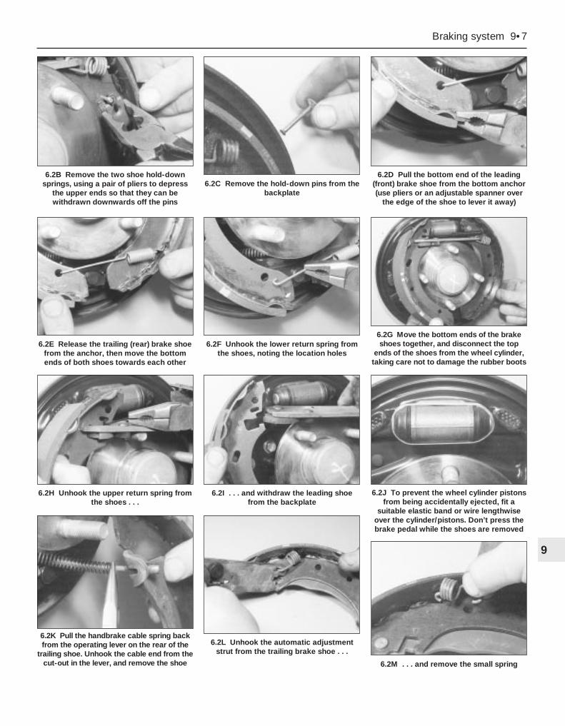
Braking system 9•7
9
6.2K Pull the handbrake cable spring backfrom the operating lever on the rear of the
trailing shoe. Unhook the cable end from thecut-out in the lever, and remove the shoe
6.2L Unhook the automatic adjustmentstrut from the trailing brake shoe . . .
6.2M . . . and remove the small spring
6.2B Remove the two shoe hold-downsprings, using a pair of pliers to depress
the upper ends so that they can bewithdrawn downwards off the pins
6.2C Remove the hold-down pins from thebackplate
6.2D Pull the bottom end of the leading(front) brake shoe from the bottom anchor(use pliers or an adjustable spanner over
the edge of the shoe to lever it away)
6.2E Release the trailing (rear) brake shoefrom the anchor, then move the bottomends of both shoes towards each other
6.2F Unhook the lower return spring fromthe shoes, noting the location holes
6.2G Move the bottom ends of the brakeshoes together, and disconnect the top
ends of the shoes from the wheel cylinder,taking care not to damage the rubber boots
6.2H Unhook the upper return spring fromthe shoes . . .
6.2I . . . and withdraw the leading shoefrom the backplate
6.2J To prevent the wheel cylinder pistonsfrom being accidentally ejected, fit a
suitable elastic band or wire lengthwiseover the cylinder/pistons. Don’t press thebrake pedal while the shoes are removed
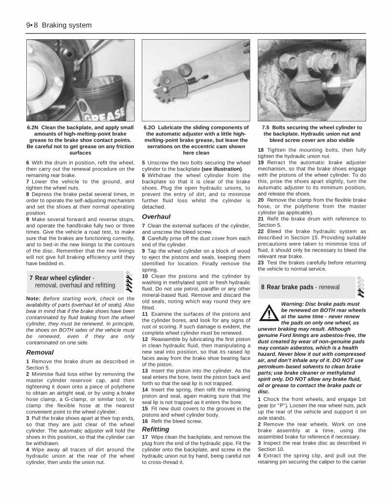
6 With the drum in position, refit the wheel,then carry out the renewal procedure on theremaining rear brake.7 Lower the vehicle to the ground, andtighten the wheel nuts.8 Depress the brake pedal several times, inorder to operate the self-adjusting mechanismand set the shoes at their normal operatingposition.9 Make several forward and reverse stops,and operate the handbrake fully two or threetimes. Give the vehicle a road test, to makesure that the brakes are functioning correctly,and to bed-in the new linings to the contoursof the disc. Remember that the new liningswill not give full braking efficiency until theyhave bedded-in.
Note: Before starting work, check on theavailability of parts (overhaul kit of seals). Alsobear in mind that if the brake shoes have beencontaminated by fluid leaking from the wheelcylinder, they must be renewed. In principle,the shoes on BOTH sides of the vehicle mustbe renewed, even if they are onlycontaminated on one side.
Removal1 Remove the brake drum as described inSection 5.2 Minimise fluid loss either by removing themaster cylinder reservoir cap, and thentightening it down onto a piece of polytheneto obtain an airtight seal, or by using a brakehose clamp, a G-clamp, or similar tool, toclamp the flexible hose at the nearestconvenient point to the wheel cylinder.3 Pull the brake shoes apart at their top ends,so that they are just clear of the wheelcylinder. The automatic adjuster will hold theshoes in this position, so that the cylinder canbe withdrawn.4 Wipe away all traces of dirt around thehydraulic union at the rear of the wheelcylinder, then undo the union nut.
5 Unscrew the two bolts securing the wheelcylinder to the backplate (see illustration).6 Withdraw the wheel cylinder from thebackplate so that it is clear of the brakeshoes. Plug the open hydraulic unions, toprevent the entry of dirt, and to minimisefurther fluid loss whilst the cylinder isdetached.
Overhaul7 Clean the external surfaces of the cylinder,and unscrew the bleed screw.8 Carefully prise off the dust cover from eachend of the cylinder.9 Tap the wheel cylinder on a block of woodto eject the pistons and seals, keeping themidentified for location. Finally remove thespring.10 Clean the pistons and the cylinder bywashing in methylated spirit or fresh hydraulicfluid. Do not use petrol, paraffin or any othermineral-based fluid. Remove and discard theold seals, noting which way round they arefitted.11 Examine the surfaces of the pistons andthe cylinder bores, and look for any signs ofrust or scoring. If such damage is evident, thecomplete wheel cylinder must be renewed.12 Reassemble by lubricating the first pistonin clean hydraulic fluid, then manipulating anew seal into position, so that its raised lipfaces away from the brake shoe bearing faceof the piston.13 Insert the piston into the cylinder. As theseal enters the bore, twist the piston back andforth so that the seal lip is not trapped.14 Insert the spring, then refit the remainingpiston and seal, again making sure that theseal lip is not trapped as it enters the bore.15 Fit new dust covers to the grooves in thepistons and wheel cylinder body.16 Refit the bleed screw.
Refitting17 Wipe clean the backplate, and remove theplug from the end of the hydraulic pipe. Fit thecylinder onto the backplate, and screw in thehydraulic union nut by hand, being careful notto cross-thread it.
18 Tighten the mounting bolts, then fullytighten the hydraulic union nut.19 Retract the automatic brake adjustermechanism, so that the brake shoes engagewith the pistons of the wheel cylinder. To dothis, prise the shoes apart slightly, turn theautomatic adjuster to its minimum position,and release the shoes.20 Remove the clamp from the flexible brakehose, or the polythene from the mastercylinder (as applicable).21 Refit the brake drum with reference toSection 5.22 Bleed the brake hydraulic system asdescribed in Section 15. Providing suitableprecautions were taken to minimise loss offluid, it should only be necessary to bleed therelevant rear brake.23 Test the brakes carefully before returningthe vehicle to normal service.
Warning: Disc brake pads mustbe renewed on BOTH rear wheelsat the same time - never renewthe pads on only one wheel, as
uneven braking may result. Althoughgenuine Ford linings are asbestos-free, thedust created by wear of non-genuine padsmay contain asbestos, which is a healthhazard. Never blow it out with compressedair, and don’t inhale any of it. DO NOT usepetroleum-based solvents to clean brakeparts; use brake cleaner or methylatedspirit only. DO NOT allow any brake fluid,oil or grease to contact the brake pads ordisc.1 Chock the front wheels, and engage 1stgear (or “P”). Loosen the rear wheel nuts, jackup the rear of the vehicle and support it onaxle stands.2 Remove the rear wheels. Work on onebrake assembly at a time, using theassembled brake for reference if necessary.3 Inspect the rear brake disc as described inSection 10.4 Extract the spring clip, and pull out theretaining pin securing the caliper to the carrier
8 Rear brake pads - renewal7 Rear wheel cylinder -
removal, overhaul and refitting
9•8 Braking system
6.2N Clean the backplate, and apply smallamounts of high-melting-point brake
grease to the brake shoe contact points.Be careful not to get grease on any friction
surfaces
6.2O Lubricate the sliding components ofthe automatic adjuster with a little high-
melting-point brake grease, but leave theserrations on the eccentric cam shown
here clean
7.5 Bolts securing the wheel cylinder tothe backplate. Hydraulic union nut and
bleed screw cover are also visible

bracket. Note that on Saloon and Hatchbackmodels, the pin is at the bottom of the caliper,whereas on Estate models, it is at the top.5 Swivel the caliper away from the carrierbracket, to expose the brake pads (seeillustrations).6 Disconnect the pad wear warning light wire(when fitted) at the connector. Also unbolt thebrake hose bracket from the rear suspensionstrut, to avoid straining the flexible hose.7 If necessary, the caliper may be completelyremoved by prising off the cap andunscrewing the pivot guide bolt. Support thecaliper on an axle stand, or tie it to one sidewith wire.8 Remove the pads from the carrier bracket.9 Brush all dust and dirt from the caliper,pads and disc, but do not inhale it, as it maybe harmful to health. Scrape any corrosionfrom the disc.10 Before fitting the new pads, screw thecaliper piston fully into its bore, at the sametime pressing the piston fully to the bottom ofthe bore. Proprietary tools are available forthis operation - at a pinch, it may be possibleto use long-nosed pliers engaged with thecut-outs in the piston. Brake fluid will bedisplaced into the master cylinder reservoir,so check first that there is enough space toaccept the fluid. If necessary, syphon offsome of the fluid.11 Fit the new pads using a reversal of theremoval procedure. On completion, firmlydepress the brake pedal a few times, to bringthe pads to their normal working position.Check the level of the brake fluid in thereservoir, and top-up if necessary.12 Give the vehicle a road test, to make surethat the brakes are functioning correctly, andto bed-in the new linings to the contours ofthe disc. Remember that full brakingefficiency will not be obtained until the newlinings have bedded-in.
Removal1 Chock the front wheels, and engage 1stgear (or “P”). Loosen the rear wheel nuts, jackup the rear of the vehicle and support it onaxle stands. Remove the appropriate rearwheel.2 Fit a brake hose clamp to the flexible hoseleading to the rear brake caliper. This willminimise brake fluid loss during subsequentoperations.3 Loosen (but do not completely unscrew) theunion on the caliper end of the flexible hose.4 Remove the rear brake pads, and free thecaliper as described in Section 8.5 Disconnect the handbrake cable from thecaliper. On Saloon and Hatchback models,the handbrake lever faces away from thecaliper, whereas on Estate models, it facestowards the caliper (see illustrations).
6 Support the caliper and disconnect thehydraulic hose, making sure that the hose isnot twisted or strained unduly. Once thecaliper is detached, place it to one side, andplug the open hydraulic unions to keep dustand dirt out.7 If necessary, unbolt the carrier bracket fromthe knuckle.
Overhaul8 No overhaul procedures were available atthe time of writing, so check availability ofspares before dismantling the caliper. Inprinciple, the overhaul information given forthe front brake caliper will apply, noting that itwill be necessary to unscrew the piston fromthe handbrake mechanism (see Section 8,paragraph 10) before being able to expel thepiston from the caliper. On reassembly, pushthe piston fully into the caliper, and screw itback onto the handbrake mechanism. Do notattempt to dismantle the handbrakemechanism; if the mechanism is faulty, thecomplete caliper assembly must be renewed.
Refitting9 Refit the caliper, and where applicable thecarrier bracket, by reversing the removaloperations. Tighten the mounting bolts andwheel nuts to the specified torque, and do notforget to remove the brake hose clamp fromthe flexible brake hose.
9 Rear brake caliper - removal,overhaul and refitting
Braking system 9•9
99.5A Rear brake caliper on
Saloon/Hatchback models (A) and Estatemodels (B)
1 Caliper body2 Frame3 Brake pad spring clip4 Handbrake cable lever facing away from
caliper5 Handbrake cable lever facing towards
caliper6 Bleed screw7 Guide pin protective cap8 Pad wear warning light connector9 Flexible hydraulic hose connection
9.5B Handbrake operation on the rearbrake caliper
1 Piston2 Automatic adjusting screw3 Spring washers4 Cam5 Handbrake cable lever
8.5A Rear brake pad removal on Saloonand Hatchback models
4 Brake caliper 5 Brake pads
8.5B Rear brake pad removal on Estatemodels
3 Brake caliper 5 Brake pads
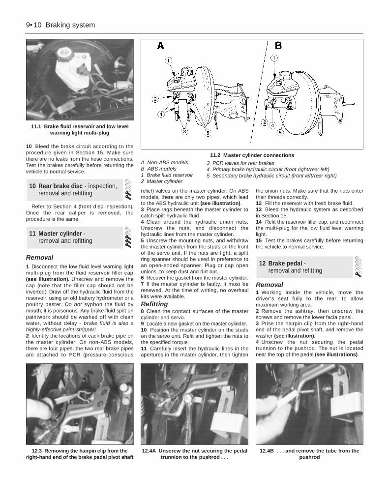
10 Bleed the brake circuit according to theprocedure given in Section 15. Make surethere are no leaks from the hose connections.Test the brakes carefully before returning thevehicle to normal service.
Refer to Section 4 (front disc inspection).Once the rear caliper is removed, theprocedure is the same.
Removal1 Disconnect the low fluid level warning lightmulti-plug from the fluid reservoir filler cap(see illustration). Unscrew and remove thecap (note that the filler cap should not beinverted). Draw off the hydraulic fluid from thereservoir, using an old battery hydrometer or apoultry baster. Do not syphon the fluid bymouth; it is poisonous. Any brake fluid spilt onpaintwork should be washed off with cleanwater, without delay - brake fluid is also ahighly-effective paint-stripper!2 Identify the locations of each brake pipe onthe master cylinder. On non-ABS models,there are four pipes; the two rear brake pipesare attached to PCR (pressure-conscious
relief) valves on the master cylinder. On ABSmodels, there are only two pipes, which leadto the ABS hydraulic unit (see illustration).3 Place rags beneath the master cylinder tocatch spilt hydraulic fluid.4 Clean around the hydraulic union nuts.Unscrew the nuts, and disconnect thehydraulic lines from the master cylinder.5 Unscrew the mounting nuts, and withdrawthe master cylinder from the studs on the frontof the servo unit. If the nuts are tight, a splitring spanner should be used in preference toan open-ended spanner. Plug or cap openunions, to keep dust and dirt out.6 Recover the gasket from the master cylinder.7 If the master cylinder is faulty, it must berenewed. At the time of writing, no overhaulkits were available.
Refitting8 Clean the contact surfaces of the mastercylinder and servo.9 Locate a new gasket on the master cylinder.10 Position the master cylinder on the studson the servo unit. Refit and tighten the nuts tothe specified torque.11 Carefully insert the hydraulic lines in theapertures in the master cylinder, then tighten
the union nuts. Make sure that the nuts entertheir threads correctly.12 Fill the reservoir with fresh brake fluid.13 Bleed the hydraulic system as describedin Section 15.14 Refit the reservoir filler cap, and reconnectthe multi-plug for the low fluid level warninglight.15 Test the brakes carefully before returningthe vehicle to normal service.
Removal1 Working inside the vehicle, move thedriver’s seat fully to the rear, to allowmaximum working area.2 Remove the ashtray, then unscrew thescrews and remove the lower facia panel.3 Prise the hairpin clip from the right-handend of the pedal pivot shaft, and remove thewasher (see illustration).4 Unscrew the nut securing the pedaltrunnion to the pushrod. The nut is locatednear the top of the pedal (see illustrations).
12 Brake pedal - removal and refitting
11 Master cylinder - removal and refitting
10 Rear brake disc - inspection,removal and refitting
9•10 Braking system
11.1 Brake fluid reservoir and low levelwarning light multi-plug
11.2 Master cylinder connectionsA Non-ABS modelsB ABS models1 Brake fluid reservoir2 Master cylinder
3 PCR valves for rear brakes4 Primary brake hydraulic circuit (front right/rear left)5 Secondary brake hydraulic circuit (front left/rear right)
12.3 Removing the hairpin clip from theright-hand end of the brake pedal pivot shaft
12.4A Unscrew the nut securing the pedaltrunnion to the pushrod . . .
12.4B . . . and remove the tube from thepushrod
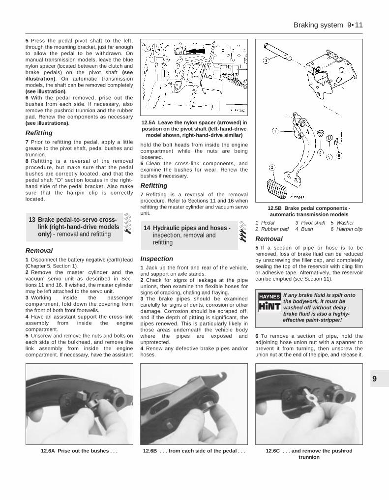
5 Press the pedal pivot shaft to the left,through the mounting bracket, just far enoughto allow the pedal to be withdrawn. Onmanual transmission models, leave the bluenylon spacer (located between the clutch andbrake pedals) on the pivot shaft (seeillustration). On automatic transmissionmodels, the shaft can be removed completely(see illustration).6 With the pedal removed, prise out thebushes from each side. If necessary, alsoremove the pushrod trunnion and the rubberpad. Renew the components as necessary(see illustrations).
Refitting7 Prior to refitting the pedal, apply a littlegrease to the pivot shaft, pedal bushes andtrunnion.8 Refitting is a reversal of the removalprocedure, but make sure that the pedalbushes are correctly located, and that thepedal shaft “D” section locates in the right-hand side of the pedal bracket. Also makesure that the hairpin clip is correctlylocated.
Removal1 Disconnect the battery negative (earth) lead(Chapter 5, Section 1).2 Remove the master cylinder and thevacuum servo unit as described in Sec-tions 11 and 16. If wished, the master cylindermay be left attached to the servo unit.3 Working inside the passengercompartment, fold down the covering fromthe front of both front footwells.4 Have an assistant support the cross-linkassembly from inside the enginecompartment.5 Unscrew and remove the nuts and bolts oneach side of the bulkhead, and remove thelink assembly from inside the enginecompartment. If necessary, have the assistant
hold the bolt heads from inside the enginecompartment while the nuts are beingloosened.6 Clean the cross-link components, andexamine the bushes for wear. Renew thebushes if necessary.
Refitting7 Refitting is a reversal of the removalprocedure. Refer to Sections 11 and 16 whenrefitting the master cylinder and vacuum servounit.
Inspection1 Jack up the front and rear of the vehicle,and support on axle stands.2 Check for signs of leakage at the pipeunions, then examine the flexible hoses forsigns of cracking, chafing and fraying.3 The brake pipes should be examinedcarefully for signs of dents, corrosion or otherdamage. Corrosion should be scraped off,and if the depth of pitting is significant, thepipes renewed. This is particularly likely inthose areas underneath the vehicle bodywhere the pipes are exposed andunprotected.4 Renew any defective brake pipes and/orhoses.
Removal5 If a section of pipe or hose is to beremoved, loss of brake fluid can be reducedby unscrewing the filler cap, and completelysealing the top of the reservoir with cling filmor adhesive tape. Alternatively, the reservoircan be emptied (see Section 11).
6 To remove a section of pipe, hold theadjoining hose union nut with a spanner toprevent it from turning, then unscrew theunion nut at the end of the pipe, and release it.
14 Hydraulic pipes and hoses -inspection, removal andrefitting
13 Brake pedal-to-servo cross-link (right-hand-drive modelsonly) - removal and refitting
Braking system 9•11
9
12.6A Prise out the bushes . . . 12.6B . . . from each side of the pedal . . . 12.6C . . . and remove the pushrodtrunnion
12.5A Leave the nylon spacer (arrowed) inposition on the pivot shaft (left-hand-drive
model shown, right-hand-drive similar)
12.5B Brake pedal components -automatic transmission models
1 Pedal 3 Pivot shaft 5 Washer2 Rubber pad 4 Bush 6 Hairpin clip
If any brake fluid is spilt ontothe bodywork, it must bewashed off without delay -brake fluid is also a highly-effective paint-stripper!
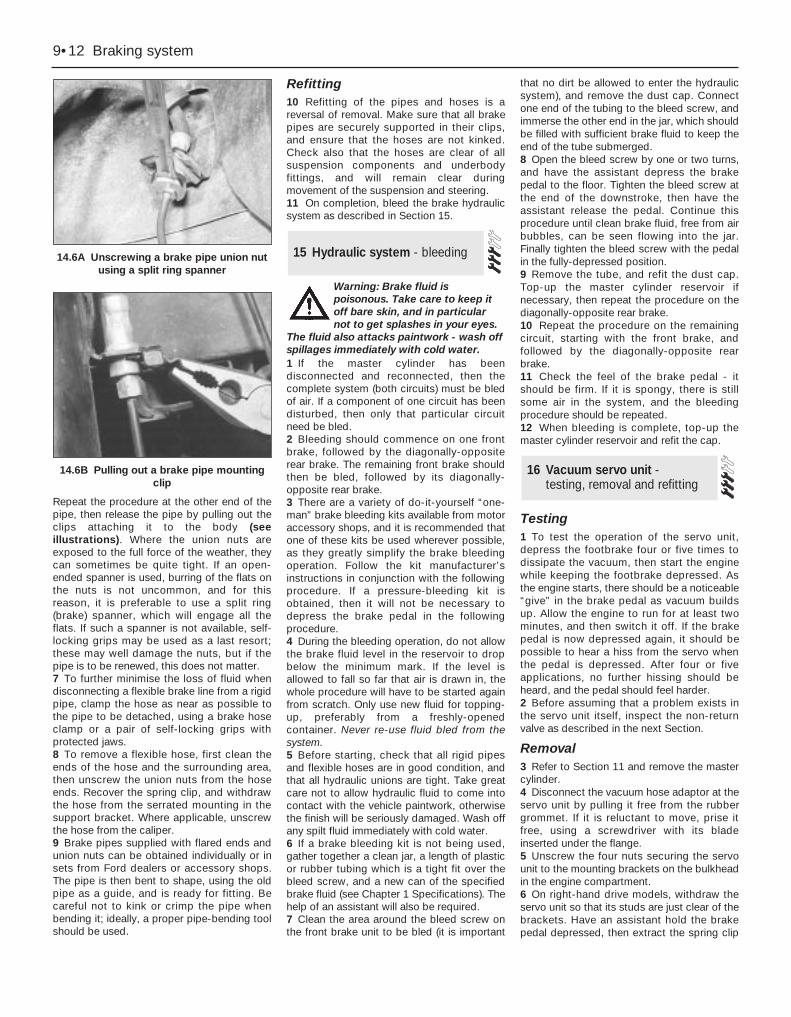
Repeat the procedure at the other end of thepipe, then release the pipe by pulling out theclips attaching it to the body (seeillustrations). Where the union nuts areexposed to the full force of the weather, theycan sometimes be quite tight. If an open-ended spanner is used, burring of the flats onthe nuts is not uncommon, and for thisreason, it is preferable to use a split ring(brake) spanner, which will engage all theflats. If such a spanner is not available, self-locking grips may be used as a last resort;these may well damage the nuts, but if thepipe is to be renewed, this does not matter.7 To further minimise the loss of fluid whendisconnecting a flexible brake line from a rigidpipe, clamp the hose as near as possible tothe pipe to be detached, using a brake hoseclamp or a pair of self-locking grips withprotected jaws.8 To remove a flexible hose, first clean theends of the hose and the surrounding area,then unscrew the union nuts from the hoseends. Recover the spring clip, and withdrawthe hose from the serrated mounting in thesupport bracket. Where applicable, unscrewthe hose from the caliper.9 Brake pipes supplied with flared ends andunion nuts can be obtained individually or insets from Ford dealers or accessory shops.The pipe is then bent to shape, using the oldpipe as a guide, and is ready for fitting. Becareful not to kink or crimp the pipe whenbending it; ideally, a proper pipe-bending toolshould be used.
Refitting10 Refitting of the pipes and hoses is areversal of removal. Make sure that all brakepipes are securely supported in their clips,and ensure that the hoses are not kinked.Check also that the hoses are clear of allsuspension components and underbodyfittings, and will remain clear duringmovement of the suspension and steering.11 On completion, bleed the brake hydraulicsystem as described in Section 15.
Warning: Brake fluid ispoisonous. Take care to keep itoff bare skin, and in particularnot to get splashes in your eyes.
The fluid also attacks paintwork - wash offspillages immediately with cold water.1 If the master cylinder has beendisconnected and reconnected, then thecomplete system (both circuits) must be bledof air. If a component of one circuit has beendisturbed, then only that particular circuitneed be bled.2 Bleeding should commence on one frontbrake, followed by the diagonally-oppositerear brake. The remaining front brake shouldthen be bled, followed by its diagonally-opposite rear brake.3 There are a variety of do-it-yourself “one-man” brake bleeding kits available from motoraccessory shops, and it is recommended thatone of these kits be used wherever possible,as they greatly simplify the brake bleedingoperation. Follow the kit manufacturer’sinstructions in conjunction with the followingprocedure. If a pressure-bleeding kit isobtained, then it will not be necessary todepress the brake pedal in the followingprocedure.4 During the bleeding operation, do not allowthe brake fluid level in the reservoir to dropbelow the minimum mark. If the level isallowed to fall so far that air is drawn in, thewhole procedure will have to be started againfrom scratch. Only use new fluid for topping-up, preferably from a freshly-openedcontainer. Never re-use fluid bled from thesystem.5 Before starting, check that all rigid pipesand flexible hoses are in good condition, andthat all hydraulic unions are tight. Take greatcare not to allow hydraulic fluid to come intocontact with the vehicle paintwork, otherwisethe finish will be seriously damaged. Wash offany spilt fluid immediately with cold water.6 If a brake bleeding kit is not being used,gather together a clean jar, a length of plasticor rubber tubing which is a tight fit over thebleed screw, and a new can of the specifiedbrake fluid (see Chapter 1 Specifications). Thehelp of an assistant will also be required.7 Clean the area around the bleed screw onthe front brake unit to be bled (it is important
that no dirt be allowed to enter the hydraulicsystem), and remove the dust cap. Connectone end of the tubing to the bleed screw, andimmerse the other end in the jar, which shouldbe filled with sufficient brake fluid to keep theend of the tube submerged.8 Open the bleed screw by one or two turns,and have the assistant depress the brakepedal to the floor. Tighten the bleed screw atthe end of the downstroke, then have theassistant release the pedal. Continue thisprocedure until clean brake fluid, free from airbubbles, can be seen flowing into the jar.Finally tighten the bleed screw with the pedalin the fully-depressed position.9 Remove the tube, and refit the dust cap.Top-up the master cylinder reservoir ifnecessary, then repeat the procedure on thediagonally-opposite rear brake.10 Repeat the procedure on the remainingcircuit, starting with the front brake, andfollowed by the diagonally-opposite rearbrake.11 Check the feel of the brake pedal - itshould be firm. If it is spongy, there is stillsome air in the system, and the bleedingprocedure should be repeated.12 When bleeding is complete, top-up themaster cylinder reservoir and refit the cap.
Testing1 To test the operation of the servo unit,depress the footbrake four or five times todissipate the vacuum, then start the enginewhile keeping the footbrake depressed. Asthe engine starts, there should be a noticeable“give” in the brake pedal as vacuum buildsup. Allow the engine to run for at least twominutes, and then switch it off. If the brakepedal is now depressed again, it should bepossible to hear a hiss from the servo whenthe pedal is depressed. After four or fiveapplications, no further hissing should beheard, and the pedal should feel harder.2 Before assuming that a problem exists inthe servo unit itself, inspect the non-returnvalve as described in the next Section.
Removal3 Refer to Section 11 and remove the mastercylinder.4 Disconnect the vacuum hose adaptor at theservo unit by pulling it free from the rubbergrommet. If it is reluctant to move, prise itfree, using a screwdriver with its bladeinserted under the flange.5 Unscrew the four nuts securing the servounit to the mounting brackets on the bulkheadin the engine compartment.6 On right-hand drive models, withdraw theservo unit so that its studs are just clear of thebrackets. Have an assistant hold the brakepedal depressed, then extract the spring clip
16 Vacuum servo unit - testing, removal and refitting
15 Hydraulic system - bleeding
9•12 Braking system
14.6A Unscrewing a brake pipe union nutusing a split ring spanner
14.6B Pulling out a brake pipe mountingclip
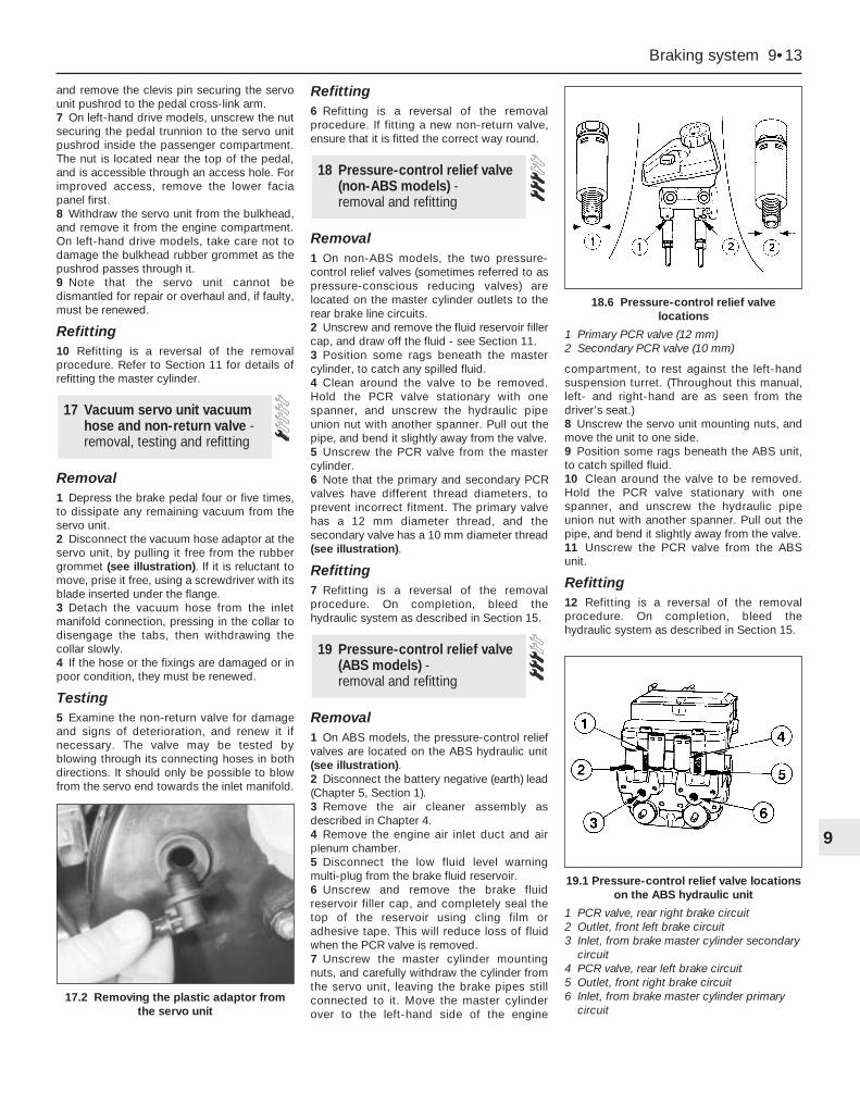
and remove the clevis pin securing the servounit pushrod to the pedal cross-link arm.7 On left-hand drive models, unscrew the nutsecuring the pedal trunnion to the servo unitpushrod inside the passenger compartment.The nut is located near the top of the pedal,and is accessible through an access hole. Forimproved access, remove the lower faciapanel first.8 Withdraw the servo unit from the bulkhead,and remove it from the engine compartment.On left-hand drive models, take care not todamage the bulkhead rubber grommet as thepushrod passes through it.9 Note that the servo unit cannot bedismantled for repair or overhaul and, if faulty,must be renewed.
Refitting10 Refitting is a reversal of the removalprocedure. Refer to Section 11 for details ofrefitting the master cylinder.
Removal1 Depress the brake pedal four or five times,to dissipate any remaining vacuum from theservo unit.2 Disconnect the vacuum hose adaptor at theservo unit, by pulling it free from the rubbergrommet (see illustration). If it is reluctant tomove, prise it free, using a screwdriver with itsblade inserted under the flange.3 Detach the vacuum hose from the inletmanifold connection, pressing in the collar todisengage the tabs, then withdrawing thecollar slowly.4 If the hose or the fixings are damaged or inpoor condition, they must be renewed.
Testing5 Examine the non-return valve for damageand signs of deterioration, and renew it ifnecessary. The valve may be tested byblowing through its connecting hoses in bothdirections. It should only be possible to blowfrom the servo end towards the inlet manifold.
Refitting6 Refitting is a reversal of the removalprocedure. If fitting a new non-return valve,ensure that it is fitted the correct way round.
Removal1 On non-ABS models, the two pressure-control relief valves (sometimes referred to aspressure-conscious reducing valves) arelocated on the master cylinder outlets to therear brake line circuits.2 Unscrew and remove the fluid reservoir fillercap, and draw off the fluid - see Section 11.3 Position some rags beneath the mastercylinder, to catch any spilled fluid.4 Clean around the valve to be removed.Hold the PCR valve stationary with onespanner, and unscrew the hydraulic pipeunion nut with another spanner. Pull out thepipe, and bend it slightly away from the valve.5 Unscrew the PCR valve from the mastercylinder.6 Note that the primary and secondary PCRvalves have different thread diameters, toprevent incorrect fitment. The primary valvehas a 12 mm diameter thread, and thesecondary valve has a 10 mm diameter thread(see illustration).
Refitting7 Refitting is a reversal of the removalprocedure. On completion, bleed thehydraulic system as described in Section 15.
Removal1 On ABS models, the pressure-control reliefvalves are located on the ABS hydraulic unit(see illustration).2 Disconnect the battery negative (earth) lead(Chapter 5, Section 1).3 Remove the air cleaner assembly asdescribed in Chapter 4.4 Remove the engine air inlet duct and airplenum chamber.5 Disconnect the low fluid level warningmulti-plug from the brake fluid reservoir.6 Unscrew and remove the brake fluidreservoir filler cap, and completely seal thetop of the reservoir using cling film oradhesive tape. This will reduce loss of fluidwhen the PCR valve is removed.7 Unscrew the master cylinder mountingnuts, and carefully withdraw the cylinder fromthe servo unit, leaving the brake pipes stillconnected to it. Move the master cylinderover to the left-hand side of the engine
compartment, to rest against the left-handsuspension turret. (Throughout this manual,left- and right-hand are as seen from thedriver’s seat.)8 Unscrew the servo unit mounting nuts, andmove the unit to one side.9 Position some rags beneath the ABS unit,to catch spilled fluid.10 Clean around the valve to be removed.Hold the PCR valve stationary with onespanner, and unscrew the hydraulic pipeunion nut with another spanner. Pull out thepipe, and bend it slightly away from the valve.11 Unscrew the PCR valve from the ABSunit.
Refitting12 Refitting is a reversal of the removalprocedure. On completion, bleed thehydraulic system as described in Section 15.
19 Pressure-control relief valve(ABS models) - removal and refitting
18 Pressure-control relief valve(non-ABS models) - removal and refitting
17 Vacuum servo unit vacuumhose and non-return valve -removal, testing and refitting
Braking system 9•13
9
17.2 Removing the plastic adaptor fromthe servo unit
18.6 Pressure-control relief valvelocations
1 Primary PCR valve (12 mm)2 Secondary PCR valve (10 mm)
19.1 Pressure-control relief valve locationson the ABS hydraulic unit
1 PCR valve, rear right brake circuit2 Outlet, front left brake circuit3 Inlet, from brake master cylinder secondary
circuit4 PCR valve, rear left brake circuit5 Outlet, front right brake circuit6 Inlet, from brake master cylinder primary
circuit

Note: If any part of the ABS hydraulic unit isdefective, it must be renewed as an assembly.Apart from the relay box (Section 22),individual spare parts are not available.
Removal1 Remove both pressure-control relief valvesas described in Section 19.2 Identify the location of the remaining brakehydraulic pipes on the ABS hydraulic unit,then unscrew the union nuts and pull out thepipes. Carefully bend the pipes away from thehydraulic unit, to allow the unit to be removed.3 Disconnect the multi-plugs from thehydraulic unit. To disconnect the main 22-pinmulti-plug, push the locktab, then swivel themulti-plug outwards and unhook it.
Right-hand drive models4 Have an assistant hold the brake pedaldepressed, then extract the spring clip andremove the clevis pin securing the servo unitpushrod to the pedal cross-link arm.5 Remove the vacuum servo unit from theengine compartment.
Left-hand drive models6 Unscrew the nut securing the pedaltrunnion to the servo unit pushrod inside thepassenger compartment. The nut is locatednear the top of the pedal, and is accessiblethrough an access hole. For improved access,remove the lower facia panel first.7 Remove the vacuum servo unit, togetherwith the pushrod, from the enginecompartment. Take care not to damage therubber grommet in the bulkhead.
All models8 Unscrew the pump mounting nut.9 Raise the left-hand side of the ABShydraulic unit, then swivel the unit out of theright-hand mounting. Take care not to lose thebracket studs and insulator ring.
Refitting10 Locate the insulator ring on the pumpend, and fit the stud cap to the insulator ring.11 Lower the ABS hydraulic unit intoposition, right-hand end first.12 Fit the right-hand bracket studs onto theinsulators.13 Lower the left-hand end of the ABShydraulic unit onto the bracket, then fit andtighten the pump mounting nut.
Left-hand drive models14 Locate the vacuum servo unit andpushrod on the bulkhead bracket, taking carenot to damage the rubber grommet.15 Insert the pushrod in the pedal trunnion,and tighten the nut.16 Refit the lower facia panel if it wasremoved.
Right-hand drive models17 Locate the vacuum servo unit andpushrod on the bulkhead bracket.18 Refit the clevis pin and spring clipsecuring the servo unit pushrod to the pedalcross-link arm.
All models19 Reconnect the multi-plugs to thehydraulic unit.20 Reconnect the brake pipes to thehydraulic unit, and tighten the union nuts.21 Refit both pressure-control relief valves,with reference to Section 20.
Testing1 Checking of the sensors is done beforeremoval, connecting a voltmeter to thedisconnected sensor multi-plug. Using ananalogue (moving coil) meter is not practical,since the meter does not respond quicklyenough. A digital meter having an AC facilitymay be used to check that the sensor isoperating correctly. To do this, raise therelevant wheel then disconnect the wiring tothe ABS sensor and connect the meter to it.Spin the wheel and check that the outputvoltage is between 1.5 and 2.0 volts,depending on how fast the wheel is spun.Alternatively, an oscilloscope may be used tocheck the output of the sensor - an alternatingcurrent will be traced on the screen, ofmagnitude depending on the speed of therotating wheel.2 If the sensor output is low or zero, renewthe sensor.
RemovalFront wheel sensor3 Apply the handbrake, jack up the front ofthe vehicle and support it on axle stands.Remove the relevant wheel.4 Unscrew the sensor mounting bolt locatedon the steering knuckle, and withdraw thesensor (see illustrations).5 Remove the sensor wiring loom from the
support brackets on the front suspensionstrut and wheel arch.6 Prise out the stud clips, and remove theTorx screws and screw clips holding the wheelarch liner in position. Withdraw the liner.7 Disconnect the multi-plug, and withdrawthe sensor and wiring loom.
Rear wheel sensor8 Chock the front wheels, and engage 1stgear (or “P”). Jack up the rear of the vehicleand support it on axle stands. Remove therelevant wheel.9 Unscrew the sensor mounting bolt, locatedon the brake backplate (drum brakes) or rearsuspension knuckle (disc brakes), andwithdraw the sensor.10 On disc brake models, prise out the studclips, and remove the Torx screws and screwclips holding the wheel arch liner in position.Withdraw the liner.11 Disconnect the sensor wiring loom fromthe supports on the rear suspension strut (orknuckle) and wheel arch.12 Working inside the vehicle, lift the rearseat cushion, then disconnect the multi-plugfor the sensor wiring loom (see illustration).13 Withdraw the sensor and wiring loomthrough the rubber grommet in the rear floor.
RefittingFront and rear wheel sensors14 Refitting is a reversal of the removalprocedure.
Removal1 Disconnect the battery negative (earth) lead(Chapter 5, Section 1).2 Detach the vacuum hose from the inletmanifold connection, pressing in the collar todisengage the tabs, then withdrawing thecollar slowly.3 To improve access, free the heater hosefrom its retaining clips, and position it clear ofthe relay box.4 Disconect the wiring connector(s) from therelay box and, where necessary, the speedsender unit.
22 ABS relay box - removal and refitting
21 ABS wheel sensor - testing, removal and refitting
20 ABS hydraulic unit - removal and refitting
9•14 Braking system
21.4 Unscrew the mounting bolt andremove the ABS sensor
21.12 Rear ABS sensor wiring multi-pluglocated beneath the rear seat
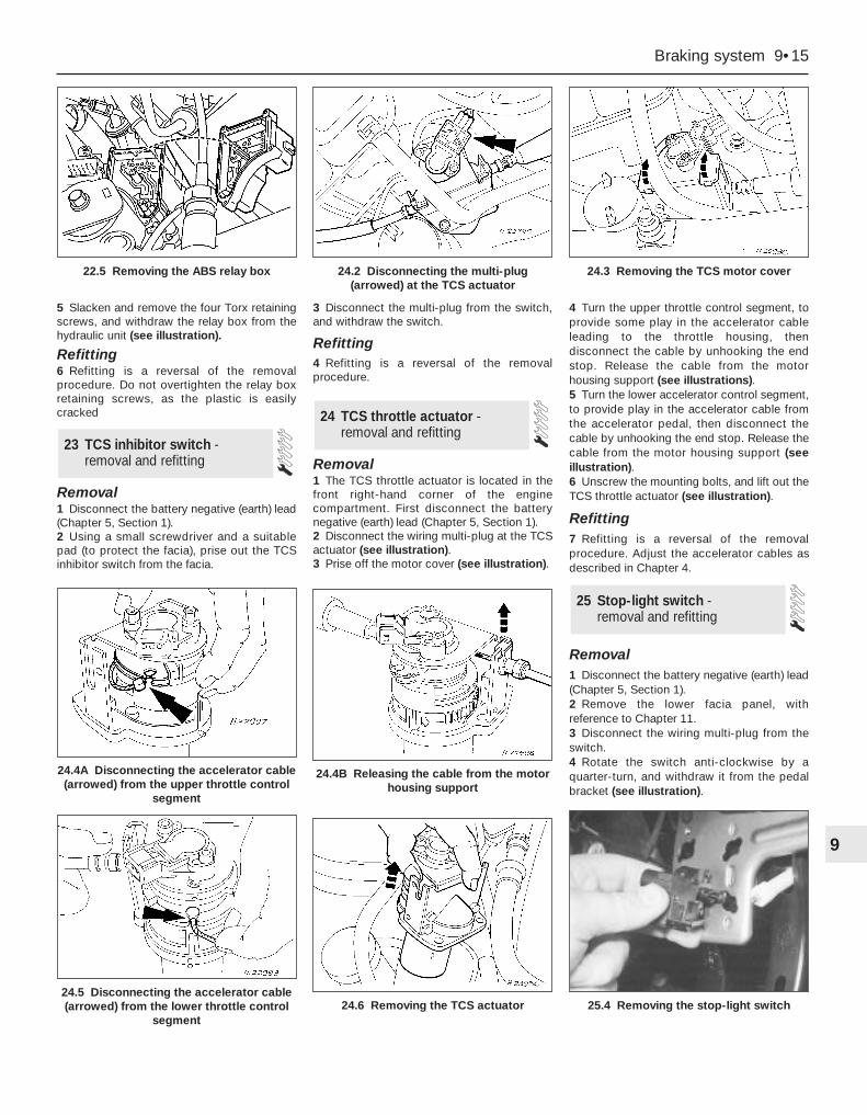
5 Slacken and remove the four Torx retainingscrews, and withdraw the relay box from thehydraulic unit (see illustration).
Refitting6 Refitting is a reversal of the removalprocedure. Do not overtighten the relay boxretaining screws, as the plastic is easilycracked
Removal1 Disconnect the battery negative (earth) lead(Chapter 5, Section 1).2 Using a small screwdriver and a suitablepad (to protect the facia), prise out the TCSinhibitor switch from the facia.
3 Disconnect the multi-plug from the switch,and withdraw the switch.
Refitting4 Refitting is a reversal of the removalprocedure.
Removal1 The TCS throttle actuator is located in thefront right-hand corner of the enginecompartment. First disconnect the batterynegative (earth) lead (Chapter 5, Section 1).2 Disconnect the wiring multi-plug at the TCSactuator (see illustration).3 Prise off the motor cover (see illustration).
4 Turn the upper throttle control segment, toprovide some play in the accelerator cableleading to the throttle housing, thendisconnect the cable by unhooking the endstop. Release the cable from the motorhousing support (see illustrations).5 Turn the lower accelerator control segment,to provide play in the accelerator cable fromthe accelerator pedal, then disconnect thecable by unhooking the end stop. Release thecable from the motor housing support (seeillustration).6 Unscrew the mounting bolts, and lift out theTCS throttle actuator (see illustration).
Refitting7 Refitting is a reversal of the removalprocedure. Adjust the accelerator cables asdescribed in Chapter 4.
Removal1 Disconnect the battery negative (earth) lead(Chapter 5, Section 1).2 Remove the lower facia panel, withreference to Chapter 11.3 Disconnect the wiring multi-plug from theswitch.4 Rotate the switch anti-clockwise by aquarter-turn, and withdraw it from the pedalbracket (see illustration).
25 Stop-light switch - removal and refitting
24 TCS throttle actuator -removal and refitting
23 TCS inhibitor switch -removal and refitting
Braking system 9•15
9
24.4B Releasing the cable from the motorhousing support
24.4A Disconnecting the accelerator cable(arrowed) from the upper throttle control
segment
24.5 Disconnecting the accelerator cable(arrowed) from the lower throttle control
segment24.6 Removing the TCS actuator
22.5 Removing the ABS relay box 24.2 Disconnecting the multi-plug(arrowed) at the TCS actuator
24.3 Removing the TCS motor cover
25.4 Removing the stop-light switch

Refitting and adjustment5 With the switch removed, reset it by fullyextending its plunger.6 Depress the brake pedal until the distancebetween the pedal and mounting bracket is asshown (see illustration).7 Hold the pedal in this position, and refit thestop-light switch to the mounting bracket .8 With the switch securely clipped in position,release the brake pedal, and gently pull it fullyback to the at-rest position. This willautomatically set the adjustment of the stop-light switch.9 reconnect the wiring connector and thebattery, and check the operation of the switchprior to refitting the lower facia panel (Chapter 11).
Removal1 Raise the front and rear of the vehicle, andsupport it on axle stands. Fully release thehandbrake lever.2 Remove the centre console as described inChapter 11.3 Working beneath the vehicle, release theexhaust system from the rubber mountings.Lower the exhaust system as far as possible,supporting it on blocks or more axle stands.4 Detach the exhaust heat shield from theunderbody.5 Unhook the secondary (rear) handbrakecables from the equaliser bar.6 Working inside the vehicle, unscrew andremove the two mounting bolts securing thehandbrake lever to the floor (see illustration).
7 Turn the handbrake lever upsidedown, thendisconnect the primary cable end from thesegment.8 Withdraw the handbrake from inside thevehicle.
Refitting9 Refitting is a reversal of the removalprocedure, making sure that the primary cableis correctly located in the segment. Check theoperation of the handbrake before returningthe vehicle to normal service.
RemovalPrimary (front)1 Remove the handbrake lever as describedin Section 26.2 Prise the grommet from the underbody,and withdraw the cable from beneath thevehicle.
Secondary (rear)3 Chock the front wheels, and engage 1stgear (or “P”). Jack up the rear of the vehicleand support it on axle stands. Fully releasethe handbrake lever.4 Remove the relevant rear wheel.
5 Working beneath the vehicle, release theexhaust system from the rubber mountings.Lower the exhaust system as far as possible,supporting it on blocks or more axle stands.6 Unbolt the exhaust heat shield from theunderbody.7 Unhook the relevant cable from theequaliser bar.8 On drum brake models, remove the rearbrake shoes on the relevant side as describedin Section 6, then remove the outer cable fromthe backplate by compressing the threeretaining lugs (use a suitable ring spanner)and pushing the cable through (seeillustration).9 On disc brake models, unhook the end ofthe cable from the handbrake operating armon the rear caliper.10 Release the lugs securing the outer cableto the underbody brackets, then release thecable from the clips, and withdraw it fromunder the vehicle (see illustrations).
Refitting
All cables11 Refitting is a reversal of the removalprocedure, but make sure that the cable endfittings are correctly located. Check theoperation of the handbrake before returningthe vehicle to normal service.
27 Handbrake cables -removal and refitting
26 Handbrake lever - removal and refitting
9•16 Braking system
25.6 To ensure correct adjustment,position the brake pedal as shown prior torefitting the switch to its mounting bracket
26.6 Handbrake lever mounting bolts 27.8 Using a ring spanner to compress theretaining lugs securing the outer cable to
the backplate
27.10A Release the lugs using a ringspanner . . .
27.10B . . . and remove the outer cablefrom the underbody brackets

Chapter 6 Emissions control systems
Catalytic converter - general information, checking and component renewal . . . . . . . . . . . . . . . . . . . . . . . . . . . . . . . . 9
Diagnosis system - general information . . . . . . . . . . . . . . . . . . . . . . 3Electronic control system - description and precautions . . . . . . . . . 2Engine compartment wiring check . . . . . . . . . . . . . . . See Chapter 1EVAPorative emissions control (EVAP) system - general
information, checking and component renewal . . . . . . . . . . . . . . 5Exhaust Gas Recirculation (EGR) system - general
information, checking and component renewal . . . . . . . . . . . . . . 6Exhaust system check . . . . . . . . . . . . . . . . . . . . . . . . . See Chapter 1
General information . . . . . . . . . . . . . . . . . . . . . . . . . . . . . . . . . . . . . . 1Information sensors - general information, testing,
removal and refitting . . . . . . . . . . . . . . . . . . . . . . . . . . . . . . . . . . . 4Positive Crankcase Ventilation (PCV) system - general
information, checking and component renewal . . . . . . . . . . . . . . 8Positive Crankcase Ventilation (PCV) system check and filter cleaning . . . . . . . . . . . . . . . . . . . . . . . . . . . . . See Chapter 1Pulse-air system - general information, checking
and component renewal . . . . . . . . . . . . . . . . . . . . . . . . . . . . . . . . 7Underbonnet hose check . . . . . . . . . . . . . . . . . . . . . . . See Chapter 1
Crankshaft speed/position sensorResistance . . . . . . . . . . . . . . . . . . . . . . . . . . . . . . . . . . . . . . . . . . . . . . . . 200 to 450 ohms
Camshaft position sensorResistance . . . . . . . . . . . . . . . . . . . . . . . . . . . . . . . . . . . . . . . . . . . . . . . . 200 to 900 ohms
Intake air temperature sensorResistance:
At -40°C . . . . . . . . . . . . . . . . . . . . . . . . . . . . . . . . . . . . . . . . . . . . . . . . 860 to 900 k ohmsAt 20°C . . . . . . . . . . . . . . . . . . . . . . . . . . . . . . . . . . . . . . . . . . . . . . . . 35 to 40 k ohmsAt 100°C . . . . . . . . . . . . . . . . . . . . . . . . . . . . . . . . . . . . . . . . . . . . . . . 1.9 to 2.5 k ohmsAt 120°C . . . . . . . . . . . . . . . . . . . . . . . . . . . . . . . . . . . . . . . . . . . . . . . 1.0 to 1.3 k ohms
Throttle potentiometerResistance - see text . . . . . . . . . . . . . . . . . . . . . . . . . . . . . . . . . . . . . . . 400 to 6000 ohms
Power steering pressure switchOperating pressure - green switch body:
Contacts open - infinite resistance . . . . . . . . . . . . . . . . . . . . . . . . . . 31.5 ± 3.5 barsContacts close - 0 to 2.5 ohms resistance . . . . . . . . . . . . . . . . . . . . Between 13.5 and 24.0 bars
Charcoal canister-purge solenoid valveResistance . . . . . . . . . . . . . . . . . . . . . . . . . . . . . . . . . . . . . . . . . . . . . . . . 50 to 120 ohms
Pulse-air solenoid valveResistance . . . . . . . . . . . . . . . . . . . . . . . . . . . . . . . . . . . . . . . . . . . . . . . . 50 to 120 ohms
Torque wrench settings Nm lbf ftCamshaft position sensor screw . . . . . . . . . . . . . . . . . . . . . . . . . . . . . . . 18 to 23 13 to 17Intake air temperature sensor . . . . . . . . . . . . . . . . . . . . . . . . . . . . . . . . . 23 17Oxygen sensor . . . . . . . . . . . . . . . . . . . . . . . . . . . . . . . . . . . . . . . . . . . . 60 44Exhaust Gas Recirculation (EGR) system components:
Valve-to-inlet manifold bolts . . . . . . . . . . . . . . . . . . . . . . . . . . . . . . . . 9 6Pipe-to-ignition coil screws . . . . . . . . . . . . . . . . . . . . . . . . . . . . . . . . . 10 7
Pulse-air system components:Filter housing mounting bolt . . . . . . . . . . . . . . . . . . . . . . . . . . . . . . . . 47 35Piping-to-exhaust manifold sleeve nuts . . . . . . . . . . . . . . . . . . . . . . . 32 24
6•1
Easy, suitable fornovice with littleexperience
Fairly easy, suitablefor beginner withsome experience
Fairly difficult, suitablefor competent DIYmechanic
Difficult, suitable forexperienced DIYmechanic
Very difficult,suitable for expert DIYor professional
Degrees of difficulty
Specifications
Contents
6
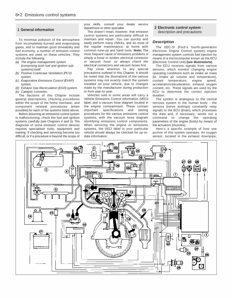
To minimise pollution of the atmospherefrom incompletely-burned and evaporatinggases, and to maintain good driveability andfuel economy, a number of emission controlsystems are used on these vehicles. Theyinclude the following:(a) The engine management system
(comprising both fuel and ignition sub-systems) itself.
(b) Positive Crankcase Ventilation (PCV)system.
(c) Evaporative Emissions Control (EVAP)system.
(d) Exhaust Gas Recirculation (EGR) system.(e) Catalytic converter.
The Sections of this Chapter includegeneral descriptions, checking procedureswithin the scope of the home mechanic, andcomponent renewal procedures (whenpossible) for each of the systems listed above.
Before assuming an emissions control systemis malfunctioning, check the fuel and ignitionsystems carefully (see Chapters 4 and 5). Thediagnosis of some emission control devicesrequires specialised tools, equipment andtraining. If checking and servicing become toodifficult, or if a procedure is beyond the scope of
your skills, consult your dealer servicedepartment or other specialist.
This doesn’t mean, however, that emissioncontrol systems are particularly difficult tomaintain and repair. You can quickly andeasily perform many checks, and do most ofthe regular maintenance, at home withcommon tune-up and hand tools. Note: Themost frequent cause of emissions problems issimply a loose or broken electrical connectoror vacuum hose, so always check theelectrical connectors and vacuum hoses first.
Pay close attention to any specialprecautions outlined in this Chapter. It shouldbe noted that the illustrations of the varioussystems may not exactly match the systeminstalled on your vehicle, due to changesmade by the manufacturer during productionor from year-to-year.
Vehicles sold in some areas will carry aVehicle Emissions Control Information (VECI)label, and a vacuum hose diagram located inthe engine compartment. These containimportant specifications and settingprocedures for the various emissions controlsystems, with the vacuum hose diagramidentifying emissions control components.When servicing the engine or emissionssystems, the VECI label in your particularvehicle should always be checked for up-to-date information.
DescriptionThe EEC-IV (Ford’s fourth-generation
Electronic Engine Control system) enginemanagement system controls fuel injection bymeans of a microcomputer known as the ECU(Electronic Control Unit) (see illustrations).
The ECU receives signals from varioussensors, which monitor changing engineoperating conditions such as intake air mass(ie, intake air volume and temperature),coolant temperature, engine speed,acceleration/deceleration, exhaust oxygencontent, etc. These signals are used by theECU to determine the correct injectionduration.
The system is analogous to the centralnervous system in the human body - thesensors (nerve endings) constantly relaysignals to the ECU (brain), which processesthe data and, if necessary, sends out acommand to change the operatingparameters of the engine (body) by means ofthe actuators (muscles).
Here’s a specific example of how oneportion of this system operates. An oxygensensor, located in the exhaust downpipe,
2 Electronic control system -description and precautions1 General information
6•2 Emissions control systems

Emissions control systems 6•3
6
2.1B Location of principal fuel injection, ignition andemissions control system components
2.1A Engine management system, showing fuel injection, ignition and emissions control sub-systems
1 ECU (Electronic Control Unit)2 Fuel pump/fuel gauge sender
unit3 Fuel pump relay4 Fuel filter5 Idle speed control valve6 Air mass meter7 Air cleaner assembly8 Fuel pressure regulator9 Fuel rail
10 Throttle potentiometer11 Intake air temperature sensor12 Fuel injector13 Camshaft position sensor14 Charcoal canister15 Charcoal canister-purge
solenoid valve16 Ignition coil17 Battery18 Ignition module - only
separate (from ECU) onvehicles with automatictransmission
19 Coolant temperature sensor20 Oxygen sensor21 Crankshaft speed/position
sensor22 Power supply relay23 Power steering pressure
switch
24 Air conditioning compressorclutch solenoid
25 Service connector - for octaneadjustment
26 Self-test connector - for FordSTAR tester diagnosticequipment
27 Diagnosis connector - for Forddiagnostic equipment FDS2000
28 Ignition switch29 Fuel cut-off switch30 Exhaust Gas Recirculation
(EGR) solenoid valve31 Exhaust Gas Recirculation
(EGR) valve32 Exhaust Gas Recirculation
(EGR) exhaust gas pressuredifferential sensor
33 Exhaust Gas Recirculation(EGR) pressure differentialmeasuring point
34 To inlet manifold35 Pulse-air filter housing36 Pulse-air solenoid valve37 Air conditioning/radiator
electric cooling fan control38 Automatic transmission
control system - whereapplicable
1 ECU (Electronic Control Unit)2 Self-test, diagnosis and service connectors
(left to right)3 Bulkhead component mounting bracket - manual
transmission - showing from left to right, (EGR) solenoidvalve, pulse-air solenoid valve and (EGR) exhaust gaspressure differential sensor
4 Bulkhead component mounting bracket - automatictransmission - showing from left to right, (EGR) solenoidvalve, pulse-air solenoid valve and (EGR) exhaust gaspressure differential sensor, with separate ignition moduleabove
5 Throttle housing, including potentiometer6 Idle speed control valve7 Intake air temperature sensor8 Air mass meter9 Exhaust Gas Recirculation (EGR) valve
10 Coolant temperature sensor11 Crankshaft speed/position sensor12 Pulse-air filter housing13 Oxygen sensor14 Ignition coil and spark plug (HT) leads15 Camshaft position sensor16 Fuel injector(s)17 Power steering pressure switch18 Air cleaner assembly19 Air intake tube and resonators - under left-hand front wing20 Resonator
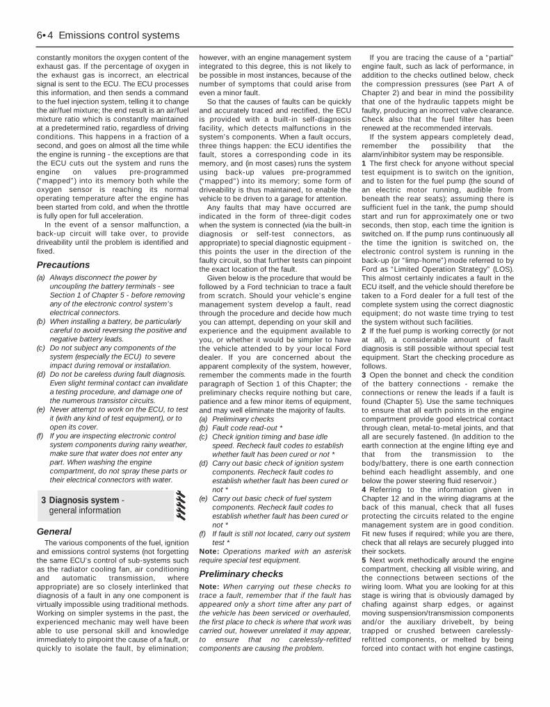
constantly monitors the oxygen content of theexhaust gas. If the percentage of oxygen inthe exhaust gas is incorrect, an electricalsignal is sent to the ECU. The ECU processesthis information, and then sends a commandto the fuel injection system, telling it to changethe air/fuel mixture; the end result is an air/fuelmixture ratio which is constantly maintainedat a predetermined ratio, regardless of drivingconditions. This happens in a fraction of asecond, and goes on almost all the time whilethe engine is running - the exceptions are thatthe ECU cuts out the system and runs theengine on values pre-programmed(“mapped”) into its memory both while theoxygen sensor is reaching its normaloperating temperature after the engine hasbeen started from cold, and when the throttleis fully open for full acceleration.
In the event of a sensor malfunction, aback-up circuit will take over, to providedriveability until the problem is identified andfixed.
Precautions(a) Always disconnect the power by
uncoupling the battery terminals - seeSection 1 of Chapter 5 - before removingany of the electronic control system’selectrical connectors.
(b) When installing a battery, be particularlycareful to avoid reversing the positive andnegative battery leads.
(c) Do not subject any components of thesystem (especially the ECU) to severeimpact during removal or installation.
(d) Do not be careless during fault diagnosis.Even slight terminal contact can invalidatea testing procedure, and damage one ofthe numerous transistor circuits.
(e) Never attempt to work on the ECU, to testit (with any kind of test equipment), or toopen its cover.
(f) If you are inspecting electronic controlsystem components during rainy weather,make sure that water does not enter anypart. When washing the enginecompartment, do not spray these parts ortheir electrical connectors with water.
GeneralThe various components of the fuel, ignition
and emissions control systems (not forgettingthe same ECU’s control of sub-systems suchas the radiator cooling fan, air conditioningand automatic transmission, whereappropriate) are so closely interlinked thatdiagnosis of a fault in any one component isvirtually impossible using traditional methods.Working on simpler systems in the past, theexperienced mechanic may well have beenable to use personal skill and knowledgeimmediately to pinpoint the cause of a fault, orquickly to isolate the fault, by elimination;
however, with an engine management systemintegrated to this degree, this is not likely tobe possible in most instances, because of thenumber of symptoms that could arise fromeven a minor fault.
So that the causes of faults can be quicklyand accurately traced and rectified, the ECUis provided with a built-in self-diagnosisfacility, which detects malfunctions in thesystem’s components. When a fault occurs,three things happen: the ECU identifies thefault, stores a corresponding code in itsmemory, and (in most cases) runs the systemusing back-up values pre-programmed(“mapped”) into its memory; some form ofdriveability is thus maintained, to enable thevehicle to be driven to a garage for attention.
Any faults that may have occurred areindicated in the form of three-digit codeswhen the system is connected (via the built-indiagnosis or self-test connectors, asappropriate) to special diagnostic equipment -this points the user in the direction of thefaulty circuit, so that further tests can pinpointthe exact location of the fault.
Given below is the procedure that would befollowed by a Ford technician to trace a faultfrom scratch. Should your vehicle’s enginemanagement system develop a fault, readthrough the procedure and decide how muchyou can attempt, depending on your skill andexperience and the equipment available toyou, or whether it would be simpler to havethe vehicle attended to by your local Forddealer. If you are concerned about theapparent complexity of the system, however,remember the comments made in the fourthparagraph of Section 1 of this Chapter; thepreliminary checks require nothing but care,patience and a few minor items of equipment,and may well eliminate the majority of faults.(a) Preliminary checks(b) Fault code read-out *(c) Check ignition timing and base idle
speed. Recheck fault codes to establishwhether fault has been cured or not *
(d) Carry out basic check of ignition systemcomponents. Recheck fault codes toestablish whether fault has been cured ornot *
(e) Carry out basic check of fuel systemcomponents. Recheck fault codes toestablish whether fault has been cured ornot *
(f) If fault is still not located, carry out systemtest *
Note: Operations marked with an asteriskrequire special test equipment.
Preliminary checksNote: When carrying out these checks totrace a fault, remember that if the fault hasappeared only a short time after any part ofthe vehicle has been serviced or overhauled,the first place to check is where that work wascarried out, however unrelated it may appear,to ensure that no carelessly-refittedcomponents are causing the problem.
If you are tracing the cause of a “partial”engine fault, such as lack of performance, inaddition to the checks outlined below, checkthe compression pressures (see Part A ofChapter 2) and bear in mind the possibilitythat one of the hydraulic tappets might befaulty, producing an incorrect valve clearance.Check also that the fuel filter has beenrenewed at the recommended intervals.
If the system appears completely dead,remember the possibility that thealarm/inhibitor system may be responsible.1 The first check for anyone without specialtest equipment is to switch on the ignition,and to listen for the fuel pump (the sound ofan electric motor running, audible frombeneath the rear seats); assuming there issufficient fuel in the tank, the pump shouldstart and run for approximately one or twoseconds, then stop, each time the ignition isswitched on. If the pump runs continuously allthe time the ignition is switched on, theelectronic control system is running in theback-up (or “limp-home”) mode referred to byFord as “Limited Operation Strategy” (LOS).This almost certainly indicates a fault in theECU itself, and the vehicle should therefore betaken to a Ford dealer for a full test of thecomplete system using the correct diagnosticequipment; do not waste time trying to testthe system without such facilities.2 If the fuel pump is working correctly (or notat all), a considerable amount of faultdiagnosis is still possible without special testequipment. Start the checking procedure asfollows.3 Open the bonnet and check the conditionof the battery connections - remake theconnections or renew the leads if a fault isfound (Chapter 5). Use the same techniquesto ensure that all earth points in the enginecompartment provide good electrical contactthrough clean, metal-to-metal joints, and thatall are securely fastened. (In addition to theearth connection at the engine lifting eye andthat from the transmission to thebody/battery, there is one earth connectionbehind each headlight assembly, and onebelow the power steering fluid reservoir.)4 Referring to the information given inChapter 12 and in the wiring diagrams at theback of this manual, check that all fusesprotecting the circuits related to the enginemanagement system are in good condition.Fit new fuses if required; while you are there,check that all relays are securely plugged intotheir sockets.5 Next work methodically around the enginecompartment, checking all visible wiring, andthe connections between sections of thewiring loom. What you are looking for at thisstage is wiring that is obviously damaged bychafing against sharp edges, or againstmoving suspension/transmission componentsand/or the auxiliary drivebelt, by beingtrapped or crushed between carelessly-refitted components, or melted by beingforced into contact with hot engine castings,
3 Diagnosis system - general information
6•4 Emissions control systems

coolant or EGR pipes, etc. In almost all cases,damage of this sort is caused in the firstinstance by incorrect routing on reassemblyafter previous work has been carried out (seethe note at the beginning of this sub-Section).6 Obviously wires can break or short togetherinside the insulation so that no visibleevidence betrays the fault, but this usuallyonly occurs where the wiring loom has beenincorrectly routed so that it is stretched taut orkinked sharply; either of these conditionsshould be obvious on even a casualinspection. If this is thought to have happenedand the fault proves elusive, the suspectsection of wiring should be checked verycarefully during the more detailed checkswhich follow.7 Depending on the extent of the problem,damaged wiring may be repaired by rejoiningthe break or splicing-in a new length of wire,using solder to ensure a good connection,and remaking the insulation with adhesiveinsulating tape or heat-shrink tubing, asdesired. If the damage is extensive, given theimplications for the vehicle’s future reliability,the best long-term answer may well be torenew that entire section of the loom, howeverexpensive this may appear.8 When the actual damage has beenrepaired, ensure that the wiring loom isrerouted correctly, so that it is clear of othercomponents, is not stretched or kinked, and issecured out of harm’s way using the plasticclips, guides and ties provided.9 Check all electrical connectors, ensuringthat they are clean, securely fastened, andthat each is locked by its plastic tabs or wireclip, as appropriate. If any connector showsexternal signs of corrosion (accumulations ofwhite or green deposits, or streaks of “rust”),or if any is thought to be dirty, it must beunplugged and cleaned using electricalcontact cleaner. If the connector pins areseverely corroded, the connector must berenewed; note that this may mean the renewal
of that entire section of the loom - see yourlocal Ford dealer for details.10 If the cleaner completely removes thecorrosion to leave the connector in asatisfactory condition, it would be wise topack the connector with a suitable materialwhich will exclude dirt and moisture, andprevent the corrosion from occurring again; aFord dealer may be able to recommend asuitable product. Note: The system’sconnectors use gold-plated pins, which mustnot be mixed with the older tin-plated types(readily identifiable from the different colour) ifa component is renewed, nor must the lithiumgrease previously used to protect tin-platedpins be used on gold-plated connectors.11 Following the accompanying schematicdiagram, and working methodically aroundthe engine compartment, check carefully thatall vacuum hoses and pipes are securelyfastened and correctly routed, with no signs
of cracks, splits or deterioration to cause airleaks, or of hoses that are trapped, kinked, orbent sharply enough to restrict air flow (seeillustrations). Check with particular care at allconnections and sharp bends, and renew anydamaged or deformed lengths of hose.12 Working from the fuel tank, via the filter, tothe fuel rail (and including the feed and return),check the fuel lines, and renew any that arefound to be leaking, trapped or kinked.13 Check that the accelerator cable iscorrectly secured and adjusted; renew thecable if there is any doubt about its condition,or if it appears to be stiff or jerky in operation.Refer to the relevant Sections of Chapter 4 forfurther information, if required.14 If there is any doubt about the operationof the throttle, remove the plenum chamberfrom the throttle housing, and check that thethrottle valve moves smoothly and easily fromthe fully-closed to the fully-open position and
Emissions control systems 6•5
6
3.11A Vacuum hose routing schematic diagram
A Exhaust Gas Recirculation (EGR) solenoid valveB Pulse-air solenoid valveC Exhaust Gas Recirculation (EGR) exhaust gas pressure
differential sensorD Exhaust Gas Recirculation (EGR) valveE Charcoal canister-purge solenoid valveF RestrictorG Idle-increase solenoid valve - where fittedH Connection to plenum chamberJ Connection to inlet manifoldK Fuel pressure regulatorL Connection to Positive Crankcase Ventilation (PCV) valveM Pulse-air filter housingN Connection to heating/air conditioning system controlsP Charcoal canister
3.11B Installation of vacuum hoses in engine compartment

back again, as an assistant depresses theaccelerator pedal. If the valve shows any signof stiffness, sticking or otherwise-inhibitedmovement (and the accelerator cable isknown from the previous check to be in goodcondition), spray the throttle linkage withpenetrating lubricant, allow time for it to work,and repeat the check; if no improvement isobtained, the complete throttle housing mustbe renewed (Chapter 4).15 Unclip the air cleaner cover, and checkthat the air filter element and the crankcaseventilation system filter are not clogged orsoaked. (A clogged air filter will obstruct theintake air flow, causing a noticeable effect onengine performance; a clogged crankcaseventilation system filter will inhibit crankcase“breathing”). Renew or clean the filter(s) asappropriate; refer to the relevant Sections ofChapter 1 for further information, if required.Before refitting the air cleaner cover, checkthat the air intake (located under the front left-hand wing, opening behind the directionindicator/headlight assembly) is clear. Itshould be possible to blow through the intake,or to probe it (carefully) as far as the rear ofthe direction indicator light.16 Start the engine and allow it to idle.Note: Working in the engine compartmentwhile the engine is running requires great careif the risk of personal injury is to be avoided;among the dangers are burns from contactwith hot components, or contact with movingcomponents such as the radiator cooling fanor the auxiliary drivebelt. Refer to “Safetyfirst!” at the front of this manual beforestarting, and ensure that your hands, and longhair or loose clothing, are kept well clear of hotor moving components at all times.17 Working from the air intake junction at theinner wing panel, via the air cleaner assemblyand air mass meter, to the resonator, plenumchamber, throttle housing and inlet manifold(and including the various vacuum hoses andpipes connected to these), check for air leaks.Usually, these will be revealed by sucking orhissing noises, but minor leaks may be tracedby spraying a solution of soapy water on tothe suspect joint; if a leak exists, it will beshown by the change in engine note and theaccompanying air bubbles (or sucking-in ofthe liquid, depending on the pressuredifference at that point). If a leak is found atany point, tighten the fastening clamp and/orrenew the faulty components, as applicable.18 Similarly, work from the cylinder head, viathe manifold (and not forgetting the relatedEGR and pulse-air system components) to thetailpipe, to check that the exhaust system isfree from leaks. The simplest way of doingthis, if the vehicle can be raised andsupported safely and with complete securitywhile the check is made, is to temporarilyblock the tailpipe while listening for the soundof escaping exhaust gases; any leak shouldbe evident. If a leak is found at any point,tighten the fastening clamp bolts and/or nuts,renew the gasket, and/or renew the faulty
section of the system, as necessary, to sealthe leak.19 It is possible to make a further check ofthe electrical connections by wiggling eachelectrical connector of the system in turn asthe engine is idling; a faulty connector will beimmediately evident from the engine’sresponse as contact is broken and remade. Afaulty connector should be renewed to ensurethe future reliability of the system; note thatthis may mean the renewal of that entiresection of the loom - see your local Forddealer for details.20 Switch off the engine. If the fault is not yetidentified, the next step is to check theignition voltages, using an engine analyserwith an oscilloscope - without suchequipment, the only tests possible are toremove and check each spark plug in turn, tocheck the spark plug (HT) lead connectionsand resistances, and to check theconnections and resistances of the ignitioncoil. Refer to the relevant Sections ofChapters 1 and 5.21 The final step in these preliminary checkswould be to use an exhaust gas analyser tomeasure the CO level at the exhaust tailpipe.
This check cannot be made without specialtest equipment - see your local Ford dealer fordetails.
Fault code read-out22 As noted in the general comments at thebeginning of this Section, the preliminarychecks outlined above should eliminate themajority of faults from the enginemanagement system. If the fault is not yetidentified, the next step is to connect a faultcode reader to the ECU, so that its self-diagnosis facility can be used to identify thefaulty part of the system; further tests canthen be made to identify the exact cause ofthe fault.23 In their basic form, fault code readers aresimply hand-held electronic devices, whichtake data stored within an ECU’s memory anddisplay it when required as two- or three-digitfault codes. The more sophisticated versionsnow available can also control sensors andactuators, to provide more effective testing;some can store information, so that a roadtest can be carried out, and any faultsencountered during the test can be displayedafterwards.
6•6 Emissions control systems
3.26 Location and terminal identification of engine management system self-test,diagnosis and service connectors
1 Power steering fluid reservoir2 Diagnosis connector - for Ford diagnostic equipment FDS 20003 Self-test connector - for fault code read-out - pin 17 is output terminal, pin 48 is input
terminal, pin 40/60 is earth4 Service connector - for octane adjustment5 Plug-in bridge - to suit 95 RON fuel

24 Ford specify the use of their STAR (Self-Test Automatic Readout) tester; most Forddealers should have such equipment, and thestaff trained to use it effectively. The onlyalternatives are as follows:(a) To obtain one of those proprietary readers
which can interpret EEC-IV three-digitcodes - at present, such readers are tooexpensive for the DIY enthusiast, but arebecoming more popular with smallerspecialist garages.
(b) To use an analogue voltmeter, wherebythe stored codes are displayed as sweepsof the voltmeter needle. This option limitsthe operator to a read-out of any codesstored - ie, there is no control of sensorsand/or actuators - but can still be useful inpinpointing the faulty part of the enginemanagement system. The display isinterpreted as follows. Each code(whether fault code orcommand/separator) is marked by athree-to-four second pause - code “538”would therefore be shown as long (3 to 4 seconds) pause, five fast sweeps of theneedle, slight (1 second) pause, three fastsweeps, slight pause, eight fast sweeps,long pause.
(c) Owners without access to suchequipment must take the vehicle to a Forddealer, or to an expert who has similarequipment and the skill to use it.
25 Because of the variations in the design offault code readers, it is not possible to giveexact details of the sequence of tests; themanufacturer’s instructions must be followed,in conjunction with the codes given below.The following ten paragraphs outline theprocedure to be followed using a version ofthe Ford STAR tester, to illustrate the generalprinciples, as well as notes to guide the ownerusing only a voltmeter.26 The vehicle must be prepared by applyingthe handbrake, switching off the airconditioning (where fitted) and any otherelectrical loads (lights, heated rear window,etc), then selecting neutral (manualtransmission) or the “P” position (automatictransmission). Where the engine is required tobe running, it must be fully warmed-up tonormal operating temperature before the testis started. Using any adaptors required,connect the fault code reader to the systemvia the (triangular, three-pin) self-testconnector on the right-hand end of the enginecompartment bulkhead (see illustration). If avoltmeter is being used, connect its positivelead to the battery positive terminal, and itsnegative lead to the self-test connector’soutput terminal, pin 17. Have a pen and paperready to write down the codes displayed.27 Set the tester in operation. For the FordSTAR tester, a display check will be carriedout and the test mode requirements must beentered. If a voltmeter is being used, connecta spare length of wire to earth the self-testconnector’s input terminal, pin 48. Be verycareful to ensure that you earth the correct
terminal - the one with the white/green wire.The first part of the test starts, with theignition switched on, but with the engine off.On pressing the “Mem/test” button, the testerdisplays “TEST” and the ready code “000”,followed by a command code “010” - theaccelerator pedal must be fully depressedwithin 10 seconds of the command codeappearing, or fault codes “576” or “577” willappear when they are called up later. If avoltmeter is being used, code “000” will notappear (except perhaps as a flicker of theneedle) and “010” will appear as a singlesweep - to ensure correct interpretation of thedisplay, watch carefully for the intervalbetween the end of one code and thebeginning of the next, otherwise you willbecome confused and misinterpret the read-out.28 The tester will then display the codes forany faults in the system at the time of the test.Each code is repeated once; if no faults arepresent, code “111” will be displayed. If avoltmeter is being used, the pause betweenrepetitions will vary according to theequipment in use and the number of faults inthe system, but was found to beapproximately 3 to 4 seconds - it may benecessary to start again, and to repeat theread-out until you are familiar with what youare seeing.29 Next the tester will display code “010”(now acting as a separator), followed by thecodes for any faults stored in the ECU’smemory; if no faults were stored, code “111”will be displayed.30 When prompted by the tester, theoperator must next depress the acceleratorpedal fully; the tester then checks severalactuators. Further test modes include a“wiggle test” facility, whereby the operatorcan check the various connectors asdescribed in paragraph 19 above (in this case,any fault will be logged and the appropriatecode will be displayed), a facility for recallingcodes displayed, and a means for clearing theECU’s memory at the end of the testprocedure when any faults have beenrectified.31 The next step when using the Ford STARtester is to conduct a test with the enginerunning. With the tester set in operation (seeparagraph 26 above) the engine is started andallowed to idle. On pressing the “Mem/test”button, the tester displays “TEST”, followedby one of two codes, as follows.32 If warning code “998” appears, followedby the appropriate fault code, switch off andcheck as indicated the coolant temperaturesensor, the intake air temperature sensor, theair mass meter, the throttle potentiometerand/or their related circuits, then restart thetest procedure.33 If command code “020” appears, carryout the following procedure within tenseconds:(a) Depress the brake pedal fully.(b) Turn the steering to full-lock (either way)
and centre it again, to produce a signalfrom the power steering pressure switch -if no signal is sent, fault code “521” willbe displayed.
(c) If automatic transmission is fitted, switchthe overdrive cancel button on and off,then do the same for the“Economy/Sport” mode switch.
(d) Wait for separator code “010” to bedisplayed, then within 10 seconds,depress the accelerator pedal fully,increasing engine speed rapidly above3000 rpm - release the pedal.
34 Any faults found in the system will belogged and displayed. Each code is repeatedonce; if no faults are present, code “111” willbe displayed.35 When the codes have been displayed forall faults logged, the ECU enters its “ServiceAdjustment Programme”, as follows:(a) The programme lasts for 2 minutes.(b) The idle speed control valve is
deactivated, and the idle speed is set toits pre-programmed (unregulated) value. Ifthe appropriate equipment is connected,the base idle speed can be checked(note, however, that it is not adjustable).
(c) The ignition timing can be checked if atiming light is connected (note, however,that it is not adjustable).
(d) Pressing the accelerator pedal fully at anytime during this period will execute acylinder balance test. Each injector in turnis switched off, and the correspondingdecrease in engine speed is logged -code “090” will be displayed if the test issuccessful.
(e) At the end of the 2 minutes, thecompletion of the programme is shownby the engine speed briefly rising, thenreturning to normal idling speed as the idle speed control valve is reactivated.
36 As with the engine-off test, further testmodes include a “wiggle test” facility,whereby the operator can check the variousconnectors as described in paragraph 19above (in this case, any fault will be loggedand the appropriate code will be displayed), afacility for recalling codes displayed, and ameans for clearing the ECU’s memory at theend of the test procedure when any faultshave been rectified. If equipment other thanthe Ford STAR tester is used, the ECU’smemory can be cleared by disconnecting thebattery - if this is not done, the code willreappear with any other codes in the event ofsubsequent trouble, but remember that othersystems with memory (such as the clock andaudio equipment) will also be affected. Shouldit become necessary to disconnect thebattery during work on any other part of thevehicle, first check to see if any fault codeshave been logged.37 Given overleaf are the possible codes,their meanings, and where relevant, the actionto be taken as a result of a code beingdisplayed.
Emissions control systems 6•7
6
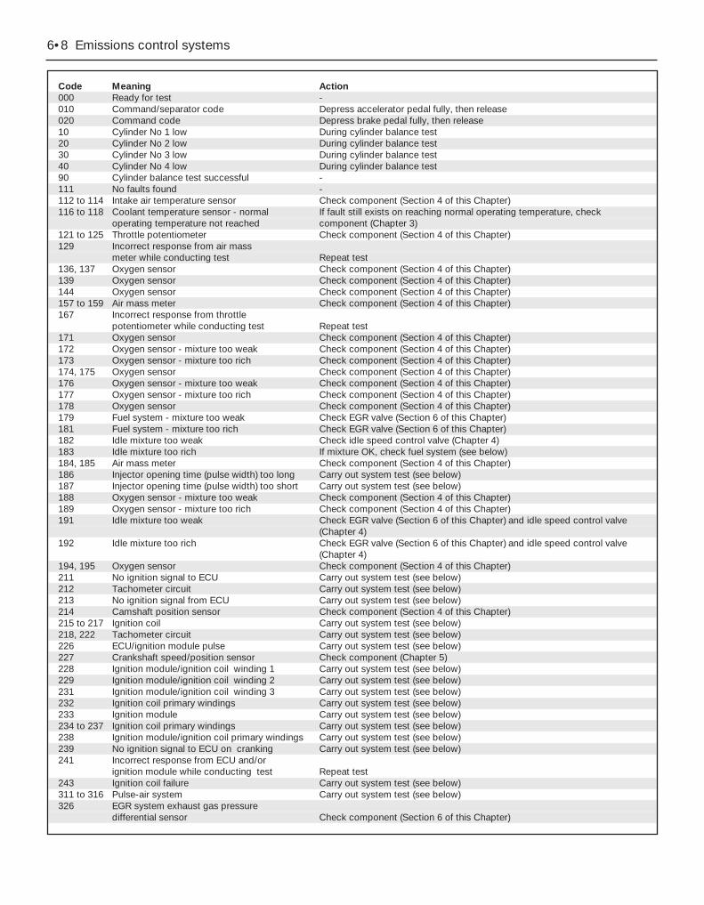
6•8 Emissions control systems
Code Meaning Action000 Ready for test -010 Command/separator code Depress accelerator pedal fully, then release020 Command code Depress brake pedal fully, then release10 Cylinder No 1 low During cylinder balance test20 Cylinder No 2 low During cylinder balance test30 Cylinder No 3 low During cylinder balance test40 Cylinder No 4 low During cylinder balance test90 Cylinder balance test successful -111 No faults found -112 to 114 Intake air temperature sensor Check component (Section 4 of this Chapter)116 to 118 Coolant temperature sensor - normal If fault still exists on reaching normal operating temperature, check
operating temperature not reached component (Chapter 3)121 to 125 Throttle potentiometer Check component (Section 4 of this Chapter)129 Incorrect response from air mass
meter while conducting test Repeat test136, 137 Oxygen sensor Check component (Section 4 of this Chapter)139 Oxygen sensor Check component (Section 4 of this Chapter)144 Oxygen sensor Check component (Section 4 of this Chapter)157 to 159 Air mass meter Check component (Section 4 of this Chapter)167 Incorrect response from throttle
potentiometer while conducting test Repeat test171 Oxygen sensor Check component (Section 4 of this Chapter)172 Oxygen sensor - mixture too weak Check component (Section 4 of this Chapter)173 Oxygen sensor - mixture too rich Check component (Section 4 of this Chapter)174, 175 Oxygen sensor Check component (Section 4 of this Chapter)176 Oxygen sensor - mixture too weak Check component (Section 4 of this Chapter)177 Oxygen sensor - mixture too rich Check component (Section 4 of this Chapter)178 Oxygen sensor Check component (Section 4 of this Chapter)179 Fuel system - mixture too weak Check EGR valve (Section 6 of this Chapter)181 Fuel system - mixture too rich Check EGR valve (Section 6 of this Chapter)182 Idle mixture too weak Check idle speed control valve (Chapter 4)183 Idle mixture too rich If mixture OK, check fuel system (see below)184, 185 Air mass meter Check component (Section 4 of this Chapter)186 Injector opening time (pulse width) too long Carry out system test (see below)187 Injector opening time (pulse width) too short Carry out system test (see below)188 Oxygen sensor - mixture too weak Check component (Section 4 of this Chapter)189 Oxygen sensor - mixture too rich Check component (Section 4 of this Chapter)191 Idle mixture too weak Check EGR valve (Section 6 of this Chapter) and idle speed control valve
(Chapter 4)192 Idle mixture too rich Check EGR valve (Section 6 of this Chapter) and idle speed control valve
(Chapter 4)194, 195 Oxygen sensor Check component (Section 4 of this Chapter)211 No ignition signal to ECU Carry out system test (see below)212 Tachometer circuit Carry out system test (see below)213 No ignition signal from ECU Carry out system test (see below)214 Camshaft position sensor Check component (Section 4 of this Chapter)215 to 217 Ignition coil Carry out system test (see below)218, 222 Tachometer circuit Carry out system test (see below)226 ECU/ignition module pulse Carry out system test (see below)227 Crankshaft speed/position sensor Check component (Chapter 5)228 Ignition module/ignition coil winding 1 Carry out system test (see below)229 Ignition module/ignition coil winding 2 Carry out system test (see below)231 Ignition module/ignition coil winding 3 Carry out system test (see below)232 Ignition coil primary windings Carry out system test (see below)233 Ignition module Carry out system test (see below)234 to 237 Ignition coil primary windings Carry out system test (see below)238 Ignition module/ignition coil primary windings Carry out system test (see below)239 No ignition signal to ECU on cranking Carry out system test (see below)241 Incorrect response from ECU and/or
ignition module while conducting test Repeat test243 Ignition coil failure Carry out system test (see below)311 to 316 Pulse-air system Carry out system test (see below)326 EGR system exhaust gas pressure
differential sensor Check component (Section 6 of this Chapter)

Code Meaning Action327 EGR system exhaust gas pressure
differential sensor or solenoid valve Check components (Section 6 of this Chapter)328 EGR system solenoid valve Check component (Section 6 of this Chapter)332 EGR valve not opening Check component (Section 6 of this Chapter)334 EGR system solenoid valve Check component (Section 6 of this Chapter)335 EGR system exhaust gas pressure
differential sensor Check component (Section 6 of this Chapter)336 Exhaust gas pressure too high Check system (Section 6 of this Chapter)337 EGR system exhaust gas pressure
differential sensor or solenoid valve Check components (Section 6 of this Chapter)338, 339 Coolant temperature sensor Carry out system test (see below)341 Service connector earthed Unplug connector and repeat test - reconnect on completion411 Engine speed too low during test Check for air leaks, then repeat test412 Engine speed too high during test Check for air leaks, then repeat test413 to 416 Idle speed control valve Check component (Chapter 4, Section 16)452 Vehicle speed sensor Check component (Section 4 of this Chapter)511, 512 ECU memory Check whether battery was disconnected, then check fuse 11 - if fault still
exists, renew ECU (Section 6 of this Chapter)513 ECU reference voltage Carry out system test (see below)519, 521 Power steering pressure switch not Check component is fitted and connected, then repeat test - if fault still
operated during test exists, carry out system test (see below)522, 523 Selector lever position sensor Check component (Chapter 7, Part B)536 Brake on/off switch not activated
during test Repeat test538 Operator error during test Repeat test539 Air conditioning switched on during test Switch off and repeat test542, 543 Fuel pump circuit Carry out system test (see below)551 Idle speed control valve circuit Carry out system test (see below)552 Pulse-air system circuit Carry out system test (see below)556 Fuel pump circuit Check fuel pump relay - if fault still exists, carry out system test (see below)558 EGR system solenoid valve circuit Carry out system test (see below)563 Radiator (high-speed) electric
cooling fan relay and/or circuit Carry out system test (see below)564 Radiator electric cooling fan relay
and/or circuit Carry out system test (see below)565 Charcoal canister-purge solenoid valve Check component (Section 5 of this Chapter)573 Radiator electric cooling fan relay
and/or circuit Carry out system test (see below)574 Radiator (high-speed) electric
cooling fan relay and/or circuit Carry out system test (see below)575 Fuel pump and/or fuel cut-off
switch circuits Carry out system test (see below)576, 577 Accelerator pedal not depressed fully during
test procedure - automatic transmission kickdown not activated Repeat test
621 Automatic transmission shift solenoid 1 circuit Refer to Chapter 7, Part B622 Automatic transmission shift solenoid 2 circuit Refer to Chapter 7, Part B624 Automatic transmission electronic
pressure control solenoid Refer to Chapter 7, Part B625 Automatic transmission electronic
pressure control solenoid circuit Refer to Chapter 7, Part B629 Automatic transmission torque
converter clutch solenoid Refer to Chapter 7, Part B634 Selector lever position sensor circuit Check component (Chapter 7, Part B)635, 637 Automatic transmission fluid temperature sensor Refer to Chapter 7, Part B639 Automatic transmission speed sensor Refer to Chapter 7, Part B645 Automatic transmission 1st speed Refer to Chapter 7, Part B646 Automatic transmission 2nd speed Refer to Chapter 7, Part B647 Automatic transmission 3rd speed Refer to Chapter 7, Part B648 Automatic transmission 4th speed Refer to Chapter 7, Part B653 Automatic transmission overdrive
cancel button and “Economy/Sport” mode switch not operated during test Repeat test
998 Warning code Check fault(s) indicated by subsequent code(s)
Emissions control systems 6•9
6

Ignition timing and base idlespeed checkNote: The following procedure is a check only,essentially of the ECU. Both the ignition timingand the base idle speed are controlled by theECU. The ignition timing is not adjustable atall; the base idle speed is set in production,and should not be altered.38 If the fault code read-out (with any checksresulting from it) has not eliminated the fault,the next step is to check the ECU’s control ofthe ignition timing and the base idle speed.This task requires the use of a Ford STARtester (a proprietary fault code reader can beused only if it is capable of inducing the ECUto enter its “Service Adjustment Programme”),coupled with an accurate tachometer and agood-quality timing light. Without thisequipment, the task is not possible; thevehicle must be taken to a Ford dealer forattention.39 To make the check, apply the handbrake,switch off the air conditioning (where fitted)and any other electrical loads (lights, heatedrear window, etc), then select neutral (manualtransmission) or the “P” position (automatictransmission). Start the engine, and warm itup to normal operating temperature. Theradiator electric cooling fan must be runningcontinuously while the check is made; thisshould be activated by the ECU, whenprompted by the tester. Switch off the engine,and connect the test equipment as directedby the manufacturer - refer to paragraph 26above for details of STAR tester connection.40 Raise and support the front of the vehiclesecurely, and remove the auxiliary drivebeltcover (see Chapter 1). Emphasise the twopairs of notches in the inner and outer rims ofthe crankshaft pulley, using white paint. Notethat an ignition timing reference mark is notprovided on the pulley - in the normaldirection of crankshaft rotation (clockwise,seen from the right-hand side of the vehicle)the first pair of notches are irrelevant to thevehicles covered in this manual, while thesecond pair indicate Top Dead Centre (TDC)when aligned with the rear edge of the raisedmark on the sump; when checking the ignitiontiming, therefore, the (rear edge of the) sump
mark should appear just before the TDCnotches (see Part A of Chapter 2, Section 4,for further information if required).41 Start the engine and allow it to idle. Workthrough the engine-running test procedureuntil the ECU enters its “Service AdjustmentProgramme” - see paragraph 35 above.42 Use the timing light to check that thetiming marks appear approximately asoutlined above at idle speed. Do not spendtoo much time on this check; if the timingappears to be incorrect, the system may havea fault, and a full system test must be carriedout (see below) to establish its cause.43 Using the tachometer, check that thebase idle speed is as given in theSpecifications Section of Chapter 4.44 If the recorded speed differs significantlyfrom the specified value, check for air leaks,as described in the preliminary checks(paragraphs 15 to 18 above), or any otherfaults which might cause the discrepancy.45 The base idle speed is set in productionby means of an air bypass screw (located inthe front right-hand corner of the throttlehousing) which controls the amount of air thatis allowed to pass through a bypass passage,past the throttle valve when it is fully closed inthe idle position; the screw is then sealed witha white tamperproof plug (see illustration). Inservice, the idle speed is controlled by theECU, which has the ability to compensate forengine wear, build-up of dirt in the throttlehousing, and other factors which mightrequire changes in idle speed. The air bypassscrew setting should not, therefore, bealtered. If any alterations are made, a bluetamperproof plug must be fitted, and theengine should be allowed to idle for at leastfive minutes on completion, so that the ECUcan re-learn its idle values.46 When both checks have been made andthe “Service Adjustment Programme” iscompleted, follow the tester instructions toreturn to the fault code read-out, andestablish whether the fault has been cured ornot.
Basic check of ignition system47 If the checks so far have not eliminatedthe fault, the next step is to carry out a basiccheck of the ignition system components,using an engine analyser with an oscilloscope- without such equipment, the only testspossible are to remove and check each sparkplug in turn, to check the spark plug (HT) leadconnections and resistances, and to checkthe connections and resistances of theignition coil. Refer to the relevant Sections ofChapters 1 and 5.
Basic check of fuel system48 If the checks so far have not eliminatedthe fault, the next step is to carry out a basiccheck of the fuel system components.49 Assuming that the preliminary checkshave established that the fuel pump isoperating correctly, that the fuel filter is
unlikely to be blocked, and also that there areno leaks in the system, the next step is tocheck the fuel pressure (see Chapter 4). If thisis correct, check the injectors (see Chapter 4)and the Positive Crankcase Ventilation system(see Chapter 1).
System test50 The final element of the Ford testingprocedure is to carry out a system test, usinga break-out box - this is a device that isconnected between the ECU and its electricalconnector, so that the individual circuitsindicated by the fault code read-out can betested while connected to the system, ifnecessary with the engine running. In the caseof many of the system’s components, thisenables their output voltages to be measured- a more accurate means of testing.51 In addition to the break-out box and theadaptors required to connect it, several itemsof specialist equipment are needed tocomplete these tests. This puts them quitebeyond the scope of many smaller dealers, letalone the DIY owner; the vehicle should betaken to a Ford dealer for attention.
Note: This Section is concerned principallywith the sensors which give the ECU theinformation it needs to control the variousengine management sub-systems - for furtherdetails of those systems and their othercomponents, refer to the relevant Chapter ofthis manual.
GeneralECU (Electronic Control Unit)1 This component is the heart of the entireengine management system, controlling thefuel injection, ignition and emissions controlsystems. It also controls sub-systems such asthe radiator cooling fan, air conditioning andautomatic transmission, where appropriate.Refer to Section 2 of this Chapter for anillustration of how it works.
Air mass meter2 This uses a “hot-wire” system, sending theECU a constantly-varying (analogue) voltagesignal corresponding to the mass of airpassing into the engine. Since air mass varieswith temperature (cold air being denser thanwarm), measuring air mass provides the ECUwith a very accurate means of determining thecorrect amount of fuel required to achieve theideal air/fuel mixture ratio.
Crankshaft speed/position sensor3 This is an inductive pulse generator bolted(in a separate bracket) to the cylinderblock/crankcase, to scan the ridges between36 holes machined in the inboard (right-hand)face of the flywheel/driveplate. As each ridge
4 Information sensors - general information, testing,removal and refitting
6•10 Emissions control systems
3.45 Throttle housing air bypass screw issealed on production with a white
tamperproof plug (arrowed)

passes the sensor tip, a signal is generated,which is used by the ECU to determine enginespeed.4 The ridge between the 35th and 36th holes(corresponding to 90° BTDC) is missing - thisstep in the incoming signals is used by theECU to determine crankshaft (ie, piston)position.
Camshaft position sensor5 This is bolted to the rear left-hand end ofthe cylinder head, to register with a lobe onthe inlet camshaft. It functions in the sameway as the crankshaft speed/position sensor,producing a series of pulses (correspondingto No 1 cylinder at 46° ATDC); this gives theECU a reference point, to enable it todetermine the firing order, and operate theinjectors in the appropriate sequence.
Coolant temperature sensor6 This component, which is screwed into thetop of the thermostat housing, is an NTC(Negative Temperature Coefficient) thermistor- that is, a semi-conductor whose electricalresistance decreases as its temperatureincreases. It provides the ECU with aconstantly-varying (analogue) voltage signal,corresponding to the temperature of theengine coolant. This is used to refine thecalculations made by the ECU, whendetermining the correct amount of fuelrequired to achieve the ideal air/fuel mixtureratio.
Intake air temperature sensor7 This component, which is screwed into theunderside of the air intake resonator, is also anNTC thermistor - see the previous paragraph -providing the ECU with a signal correspondingto the temperature of air passing into theengine. This is used to refine the calculationsmade by the ECU, when determining thecorrect amount of fuel required to achieve theideal air/fuel mixture ratio.
Throttle potentiometer8 This is mounted on the end of the throttlevalve spindle, to provide the ECU with aconstantly-varying (analogue) voltage signalcorresponding to the throttle opening. Thisallows the ECU to register the driver’s inputwhen determining the amount of fuel requiredby the engine.
Vehicle speed sensor9 This component is a Hall-effect generator,mounted on the transmission’s speedometerdrive. It supplies the ECU with a series ofpulses corresponding to the vehicle’s roadspeed, enabling the ECU to control featuressuch as the fuel shut-off on the overrun, andto provide information for the trip computer,adaptive damping and cruise control systems(where fitted).
Power steering pressure switch10 This is a pressure-operated switch,screwed into the power steering system’s
high-pressure pipe. Its contacts are normallyclosed, opening when the system reaches thespecified pressure - on receiving this signal,the ECU increases the idle speed, tocompensate for the additional load on theengine.
Exhaust gas pressure differentialsensor11 This component measures the differencein pressure of the exhaust gases across aventuri (restriction) in the Exhaust GasRecirculation (EGR) system’s pipe, and sendsthe ECU a voltage signal corresponding to thepressure difference.
Oxygen sensor12 The oxygen sensor in the exhaust systemprovides the ECU with constant feedback -“closed-loop” control - which enables it toadjust the mixture to provide the best possibleconditions for the catalytic converter tooperate.13 The sensor has a built-in heating elementwhich is controlled by the ECU, in order tobring the sensor’s tip to an efficient operatingtemperature as rapidly as possible. Thesensor’s tip is sensitive to oxygen, and sendsthe ECU a varying voltage depending on theamount of oxygen in the exhaust gases. If theintake air/fuel mixture is too rich, the exhaustgases are low in oxygen, so the sensor sendsa low-voltage signal, the voltage rising as themixture weakens and the amount of oxygen inthe exhaust gases rises. Peak conversionefficiency of all major pollutants occurs if theintake air/fuel mixture is maintained at thechemically-correct ratio for the completecombustion of petrol, of 14.7 parts (by weight)of air to 1 part of fuel (the “stoichiometric”ratio). The sensor output voltage alters sharplyaround this point, the ECU using the signalchange as a reference point, and correctingthe air/fuel mixture by altering the fuel injectorpulse width.
Air conditioning system14 Two pressure-operated switches and thecompressor clutch solenoid are connected tothe ECU, to enable it to determine how thesystem is operating. The ECU can increaseidle speed or switch off the system, asnecessary, so that normal vehicle operationand driveability are not impaired. See Chapter3 for further details, but note that diagnosisand repair should be left to a dealer servicedepartment or air conditioning specialist.
Automatic transmission15 In addition to the driver’s controls, thetransmission has a speed sensor, a fluidtemperature sensor (built into the solenoidvalve unit), and a selector lever positionsensor. All of these are connected to the ECU,to enable it to control the transmissionthrough the solenoid valve unit. See Part B ofChapter 7 for further details.
TestingECU (Electronic Control Unit)16 Do not attempt to “test” the ECU with anykind of equipment. If it is thought to be faulty,take the vehicle to a Ford dealer for the entireelectronic control system to be checked usingthe proper diagnostic equipment. Only if allother possibilities have been eliminated shouldthe ECU be considered at fault, and replaced.
Air mass meter17 Testing of this component is beyond thescope of the DIY mechanic, and should be leftto a Ford dealer.
Crankshaft speed/position sensor18 Unplug the electrical connector from thesensor.19 Using an ohmmeter, measure theresistance between the sensor terminals.Compare this reading to the one listed in theSpecifications Section at the beginning of thisChapter. If the indicated resistance is notwithin the specified range, renew the sensor.20 Plug in the sensor’s electrical connectoron completion.
Camshaft position sensor21 The procedure is as described inparagraphs 18 to 20 above.
Coolant temperature sensor22 Refer to Chapter 3.
Intake air temperature sensor23 Unplug the electrical connector from thesensor.24 Using an ohmmeter, measure theresistance between the sensor terminals.Depending on the temperature of the sensortip, the resistance measured will vary, but itshould be within the broad limits given in theSpecifications Section of this Chapter. If thesensor’s temperature is varied - by placing itin a freezer for a while, or by warming it gently- its resistance should alter accordingly.25 If the results obtained show the sensor tobe faulty, renew it.
Throttle potentiometer26 Remove the plenum chamber (seeChapter 4) and unplug the potentiometer’selectrical connector.27 Using an ohmmeter, measure theresistance between the unit’s terminals - firstbetween the centre terminal and one of theouter two, then from the centre to theremaining outer terminal. The resistanceshould be within the limits given in theSpecifications Section of this Chapter, andshould alter smoothly as the throttle valve ismoved from the fully-closed (idle speed)position to fully open and back again.28 If the resistance measured is significantlydifferent from the specified value, if there areany breaks in continuity, or if the readingfluctuates erratically as the throttle isoperated, the potentiometer is faulty, andmust be renewed.
Emissions control systems 6•11
6

Vehicle speed sensor29 Testing of this component is beyond thescope of the DIY mechanic, and should be leftto a Ford dealer.
Power steering pressure switch30 Unplug the electrical connector from thesensor.31 Using an ohmmeter, measure theresistance between the switch terminals. Withthe engine switched off, or idling with theroadwheels in the straight-ahead position,little or no resistance should be measured.With the engine running and the steering onfull-lock, the pressure increase in the systemshould open the switch contacts, so thatinfinite resistance is now measured.32 If the results obtained show the switch tobe faulty, renew it.
Exhaust gas pressure differentialsensor33 Testing of this component is beyond thescope of the DIY mechanic, and should be leftto a Ford dealer.
Oxygen sensor34 Testing of this component can be doneonly by attaching special diagnosticequipment to the sensor wiring, and checkingthat the voltage varies from low to high valueswhen the engine is running; do not attempt to“test” any part of the system with anythingother than the correct test equipment. This isbeyond the scope of the DIY mechanic, andshould be left to a Ford dealer.
Removal and refittingGeneral35 Before disconnecting any of thesecomponents, always disconnect the power byuncoupling the battery terminals, negative(earth) lead first - see Section 1 of Chapter 5.
ECU (Electronic Control Unit)Note: The ECU is fragile. Take care not todrop it or subject it to any other kind ofimpact, and do not subject it to extremes oftemperature, or allow it to get wet.36 Carefully prise the power steering fluidreservoir upwards out of its clip on thesuspension mounting. Unscrew the ECUconnector’s retaining bolt, and unplug theconnector (see illustrations).37 Working in the passenger compartment,unscrew the retaining bolt and withdraw themounting bracket (see illustration).38 Lifting the ECU to release it from thebulkhead carrier bracket, withdraw the unit(see illustration).39 Refitting is the reverse of the removalprocedure. Whenever the ECU (or battery) isdisconnected, the information relating to idlespeed control and other operating values willbe lost from its memory until the unit has re-programmed itself; until then, there may besurging, hesitation, erratic idle and agenerally-inferior level of performance. Toallow the ECU to re-learn these values, startthe engine and run it as close to idle speed aspossible until it reaches its normal operating
temperature, then run it for approximately twominutes at 1200 rpm. Next, drive the vehicleas far as necessary - approximately 5 miles ofvaried driving conditions is usually sufficient -to complete the re-learning process.
Air mass meter40 Releasing its wire clip, unplug the meter’selectrical connector (see illustration).41 Release the clips and lift the air cleanercover, then release the two smaller clips anddetach the meter from the cover (seeillustration).42 Slacken the clamp securing the meter tothe resonator hose, and withdraw the meter.43 Refitting is the reverse of the removalprocedure. Ensure that the meter and aircleaner cover are seated correctly and securelyfastened, so that there are no air leaks.
Crankshaft speed/position sensor44 Refer to Chapter 5.
Camshaft position sensor45 Remove the air mass meter and resonator(refer to Chapter 4) to gain access to thesensor (see illustration). Release the fuelfeed and return hoses from their clip.46 Releasing its wire clip, unplug thesensor’s electrical connector. Remove theretaining screw, and withdraw the sensor fromthe cylinder head; be prepared for slight oilloss.47 Refitting is the reverse of the removalprocedure, noting the following points:
6•12 Emissions control systems
4.36A Unclip and lift power steering fluidreservoir - take care not to spill fluid . . .
4.36B . . . unscrew bolt (arrowed) torelease ECU’s electrical connector
4.37 Unscrew retaining bolt and withdrawECU’s mounting bracket . . .
4.40 Unplugging the air mass meter’selectrical connector . . .
4.38 . . . then lift ECU to disengage it, andwithdraw it
4.41 . . . release clips to separate meterfrom air cleaner cover

(a) Apply petroleum jelly or clean engine oilto the sensor’s sealing O-ring.
(b) Locate the sensor fully in the cylinderhead, and wipe off any surplus lubricantbefore securing it.
(c) Tighten the screw to the specified torquewrench setting.
Coolant temperature sensor48 Refer to Chapter 3, Section 6.
Intake air temperature sensor49 Remove the air mass meter and resonator(refer to Chapter 4) to gain access to thesensor (see illustration).50 Releasing its clip, unplug the sensor’selectrical connector, then unscrew the sensorfrom the resonator.51 Refitting is the reverse of the removalprocedure. Tighten the sensor to the specifiedtorque wrench setting; if it is overtightened, itstapered thread may crack the resonator.
Throttle potentiometer52 Remove the plenum chamber (seeChapter 4). Releasing its wire clip, unplug thelarge electrical connector (next to the fuelpressure regulator).53 Releasing its wire clip, unplug thepotentiometer’s electrical connector. Removethe retaining screws, and withdraw the unitfrom the throttle housing (see illustration). Donot force the sensor’s centre to rotate past its
normal operating sweep; the unit will beseriously damaged.54 Refitting is the reverse of the removalprocedure, noting the following points:(a) Ensure that the potentiometer is correctly
orientated, by locating its centre on the D-shaped throttle shaft (throttle closed), andaligning the potentiometer body so thatthe bolts pass easily into the throttlehousing.
(b) Tighten the screws evenly and securely(but do not overtighten them, or thepotentiometer body will be cracked).
Vehicle speed sensor55 The sensor is mounted at the base of thespeedometer drive cable, and is removed withthe speedometer drive pinion (seeillustration). Refer to the relevant Section ofChapter 7, Part A or B, as applicable.
Power steering pressure switch56 Releasing its clip, unplug the switch’selectrical connector, then unscrew the switch(see illustration). Place a wad of ragunderneath, to catch any spilt fluid. If asealing washer is fitted, renew it if it is worn ordamaged.57 Refitting is the reverse of the removalprocedure; tighten the switch securely, thentop-up the fluid reservoir (see Chapter 1) toreplace any fluid lost from the system, andbleed out any trapped air (see Chapter 10,Section 33).
Exhaust gas pressure differentialsensorNote: See also Section 6, illustration 6.21.58 If better access is required, remove theresonator (see Chapter 4).59 Releasing its wire clip, unplug thesensor’s electrical connector. Remove thetwo retaining screws, withdraw the unit fromthe bulkhead mounting bracket, thendisconnect the two vacuum hoses. Note thatthe hoses are of different sizes, to ensure thatthey cannot be mixed up on reconnection.60 Check the condition of both hoses, andrenew them if necessary (see Chapter 1).61 Refitting is the reverse of the removalprocedure. Ensure that the hoses are securelyconnected to the correct unions.
Oxygen sensorNote: The sensor is delicate, and will not workif it is dropped or knocked, if its power supplyis disrupted, or if any cleaning materials areused on it.62 Release the sensor’s electrical connectorfrom its bracket on the engine/transmissionfront mounting, and unplug it to disconnectthe sensor (see illustration).63 Raising and supporting the front of thevehicle if required to remove the sensor fromunderneath, unscrew the sensor from theexhaust system front downpipe; collect thesealing washer (where fitted).64 On refitting, clean the sealing washer
Emissions control systems 6•13
6
4.56 Power steering pressure switch isscrewed into pipe at right-hand rear end of
engine
4.62 Oxygen sensor is screwed intoexhaust system front downpipe . . .
4.49 Intake air temperature sensor(arrowed) is screwed into underside of air
intake resonator
4.53 Throttle potentiometer is secured bytwo screws (arrowed)
4.55 Vehicle speed sensor “A”, with itselectrical connector “B”
4.45 Camshaft position sensor is locatedat left-hand rear end of cylinder head

(where fitted) and renew it if it is damaged orworn. Apply a smear of anti-seize compoundto the sensor’s threads, to prevent them fromwelding themselves to the downpipe inservice. Refit the sensor, tightening it to itsspecified torque wrench setting; a slottedsocket will be required to do this (seeillustration). Reconnect the wiring and refitthe connector plug.
General description1 This system is fitted to minimise the escapeof unburned hydrocarbons into theatmosphere. The fuel tank filler cap is sealed,and a charcoal canister is mountedunderneath the tank, to collect and storepetrol vapours generated in the tank when thevehicle is parked. When the engine is running,the vapours are cleared from the canister(under the control of the ECU via the canister-purge solenoid valve) into the inlet tract, to beburned by the engine during normalcombustion - see illustration 2.1A.2 To ensure that the engine runs correctlywhen it is cold and/or idling, and to protectthe catalytic converter from the effects of anover-rich mixture, the canister-purge solenoidvalve is not opened by the ECU until theengine is fully warmed-up and running underpart-load; the solenoid valve is then switchedon and off, to allow the stored vapour to passinto the inlet.
Checking3 Poor idle, stalling and poor driveability canbe caused by an inoperative canister-purgesolenoid valve, a damaged canister, split orcracked hoses, or hoses connected to thewrong fittings. Check the fuel filler cap for adamaged or deformed gasket.4 Fuel loss or fuel odour can be caused byliquid fuel leaking from fuel lines, a cracked ordamaged canister, an inoperative canister-
purge solenoid valve, and disconnected,misrouted, kinked or damaged vapour orcontrol hoses.5 Inspect each hose attached to the canisterfor kinks, leaks and cracks along its entirelength. Repair or renew as necessary.6 Inspect the canister. If it is cracked ordamaged, renew it. Look for fuel leaking fromthe bottom of the canister. If fuel is leaking,renew the canister, and check the hoses andhose routing.7 If the canister-purge solenoid valve isthought to be faulty, unplug its electricalconnector and disconnect its vacuum hoses.Connect a battery directly across the valveterminals. Check that air can flow through thevalve passages when the solenoid is thusenergised, and that nothing can pass when thesolenoid is not energised. Alternatively,connect an ohmmeter to measure theresistance across the solenoid terminals, andcompare this reading to the one listed in theSpecifications Section at the beginning of thisChapter. Renew the solenoid valve if it is faulty.8 Further testing should be left to a dealerservice department.
Component renewalCharcoal canister-purge solenoidvalve9 If better access is required, remove theplenum chamber (see Chapter 4). Disconnectthe battery negative (earth) lead - see Sec-tion 1 of Chapter 5.
10 Unplug the valve’s electrical connector(see illustration). Unclip the valve from thebulkhead, then disconnect its vacuum hosesand withdraw it.11 Refitting is the reverse of the removalprocedure.Charcoal canister - Saloon andHatchback modelsNote: Read through this procedure carefullybefore starting work, and ensure that theequipment is available that is required to carryit out safely and with minimum risk of damage,and to align the crossmember with sufficientaccuracy on reassembly.12 Remove the fuel tank (see Chapter 4).13 Ensure that the rear of the vehicle’s bodyis supported securely on axle stands, thensupport the rear suspension crossmemberwith a jack. Remove the roadwheels andunscrew the rear suspension strut topmounting bolts (two per side - see Chapter10).14 Use white paint or similar (do not use asharp-pointed scriber, which might break theunderbody protective coating and causerusting) to mark the exact relationship of thecrossmember to the underbody. Unscrew thefour mounting bolts (see illustration). Lowerthe crossmember approximately 3 inches (75mm) on the jack, and support it securely.
Warning: DO NOT place any partof your body under the vehiclewhen it is supported only by ajack!
5 EVAPorative emissions control(EVAP) system - general information, checkingand component renewal
6•14 Emissions control systems
4.64 . . . slotted socket will be required totighten sensor with a torque wrench
5.10 Charcoal canister-purge solenoidvalve (arrowed) is clipped to bulkhead
behind engine
5.14 Support rear suspensioncrossmember on jack, and remove
mounting bolts (arrowed) . . .
5.15 . . . lower crossmember by 3 inches,and unscrew charcoal canister assembly
rear retaining bolts (arrowed) . . .5.16 . . . unplug hoses (arrowed) from
canister assembly . . .
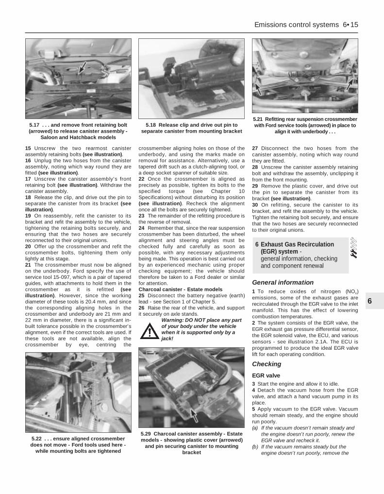
15 Unscrew the two rearmost canisterassembly retaining bolts (see illustration).16 Unplug the two hoses from the canisterassembly, noting which way round they arefitted (see illustration).17 Unscrew the canister assembly’s frontretaining bolt (see illustration). Withdraw thecanister assembly.18 Release the clip, and drive out the pin toseparate the canister from its bracket (seeillustration).19 On reassembly, refit the canister to itsbracket and refit the assembly to the vehicle,tightening the retaining bolts securely, andensuring that the two hoses are securelyreconnected to their original unions.20 Offer up the crossmember and refit thecrossmember bolts, tightening them onlylightly at this stage.21 The crossmember must now be alignedon the underbody. Ford specify the use ofservice tool 15-097, which is a pair of taperedguides, with attachments to hold them in thecrossmember as it is refitted (seeillustration). However, since the workingdiameter of these tools is 20.4 mm, and sincethe corresponding aligning holes in thecrossmember and underbody are 21 mm and22 mm in diameter, there is a significant in-built tolerance possible in the crossmember’salignment, even if the correct tools are used. Ifthese tools are not available, align thecrossmember by eye, centring the
crossmember aligning holes on those of theunderbody, and using the marks made onremoval for assistance. Alternatively, use atapered drift such as a clutch-aligning tool, ora deep socket spanner of suitable size.22 Once the crossmember is aligned asprecisely as possible, tighten its bolts to thespecified torque (see Chapter 10Specifications) without disturbing its position(see illustration). Recheck the alignmentonce all the bolts are securely tightened.23 The remainder of the refitting procedure isthe reverse of removal.24 Remember that, since the rear suspensioncrossmember has been disturbed, the wheelalignment and steering angles must bechecked fully and carefully as soon aspossible, with any necessary adjustmentsbeing made. This operation is best carried outby an experienced mechanic using properchecking equipment; the vehicle shouldtherefore be taken to a Ford dealer or similarfor attention.Charcoal canister - Estate models25 Disconnect the battery negative (earth)lead - see Section 1 of Chapter 5.26 Raise the rear of the vehicle, and supportit securely on axle stands.
Warning: DO NOT place any partof your body under the vehiclewhen it is supported only by ajack!
27 Disconnect the two hoses from thecanister assembly, noting which way roundthey are fitted.28 Unscrew the canister assembly retainingbolt and withdraw the assembly, unclipping itfrom the front mounting.29 Remove the plastic cover, and drive outthe pin to separate the canister from itsbracket (see illustration).30 On refitting, secure the canister to itsbracket, and refit the assembly to the vehicle.Tighten the retaining bolt securely, and ensurethat the two hoses are securely reconnectedto their original unions.
General information1 To reduce oxides of nitrogen (NOx)emissions, some of the exhaust gases arerecirculated through the EGR valve to the inletmanifold. This has the effect of loweringcombustion temperatures.2 The system consists of the EGR valve, theEGR exhaust gas pressure differential sensor,the EGR solenoid valve, the ECU, and varioussensors - see illustration 2.1A. The ECU isprogrammed to produce the ideal EGR valvelift for each operating condition.
Checking
EGR valve3 Start the engine and allow it to idle.4 Detach the vacuum hose from the EGRvalve, and attach a hand vacuum pump in itsplace.5 Apply vacuum to the EGR valve. Vacuumshould remain steady, and the engine shouldrun poorly.(a) If the vacuum doesn’t remain steady and
the engine doesn’t run poorly, renew theEGR valve and recheck it.
(b) If the vacuum remains steady but theengine doesn’t run poorly, remove the
6 Exhaust Gas Recirculation(EGR) system - general information, checkingand component renewal
Emissions control systems 6•15
6
5.22 . . . ensure aligned crossmemberdoes not move - Ford tools used here -
while mounting bolts are tightened
5.29 Charcoal canister assembly - Estatemodels - showing plastic cover (arrowed)
and pin securing canister to mountingbracket
5.17 . . . and remove front retaining bolt(arrowed) to release canister assembly -
Saloon and Hatchback models
5.18 Release clip and drive out pin toseparate canister from mounting bracket
5.21 Refitting rear suspension crossmemberwith Ford service tools (arrowed) in place to
align it with underbody . . .

EGR valve, and check the valve and theinlet manifold for blockage. Clean orrenew parts as necessary, and recheck.
EGR system6 Any further checking of the system requiresspecial tools and test equipment. Take thevehicle to a dealer service department forchecking.
Component renewalNote: These components will be very hotwhen the engine is running. Always allow theengine to cool down fully before starting work,to prevent the possibility of burns.
EGR valve7 Disconnect the battery negative (earth) lead- see Section 1 of Chapter 5.8 Remove the air mass meter and resonator -refer to Chapter 4.9 Detach the vacuum hose, unscrew thesleeve nut securing the EGR pipe to the valve,remove the two valve mounting bolts, andwithdraw the valve from the inlet manifold(see illustrations). Ensure that the end of thepipe is not damaged or distorted as the valveis withdrawn, and note the valve’s gasket; thismust be renewed whenever the valve isdisturbed.10 Note that the metal pipe from the valve tothe manifold itself should not be disturbed - itis not available separately from the manifold.
However, check whenever the manifold isremoved that the pipe’s end fitting is securelyfastened (see illustration).11 Check the valve for sticking and heavycarbon deposits. If such is found, clean thevalve or renew it.12 Refitting is the reverse of the removalprocedure. Apply a smear of anti-seizecompound to the sleeve nut threads, fit a newgasket, and tighten the valve bolts to thespecified torque wrench setting.
EGR pipe13 Disconnect the battery negative (earth)lead - see Section 1 of Chapter 5.14 Remove the air mass meter and resonator- refer to Chapter 4.15 Unbolt the exhaust manifold heat shieldand remove both parts, or move them asideas required to reach the end of the EGR pipe.Unscrew the sleeve nut securing the pipe tothe exhaust manifold (see illustration).16 Undo the two screws securing the pipe tothe ignition coil bracket, then disconnect thetwo vacuum hoses - note that these are ofdifferent sizes, to ensure that they cannot bemixed up on reconnection. Unscrew thesleeve nut securing the EGR pipe to the valve(see illustration). Withdraw the pipe.17 Check the condition of both hoses, andrenew them if necessary (see Chapter 1). Notethat if the exhaust gases have been backfiringexcessively - eg, due to a blocked exhaustsystem - both hoses must be renewed, and
their connections on the pipe must be cleanedthoroughly.18 Refitting is the reverse of the removalprocedure; ensure that the hoses are securelyconnected to the correct unions. Apply asmear of anti-seize compound to the sleevenut threads, tighten the nuts securely, andtighten the two screws to their specifiedtorque wrench setting.
EGR exhaust gas pressure differentialsensor19 Refer to Section 4 of this Chapter.
EGR solenoid valveNote: This component can be identified by itslarger top and its two fastening screws. Do notconfuse it with the adjacent pulse-air solenoidvalve, especially when reconnecting vacuumhoses.20 Disconnect the battery negative (earth)lead - see Section 1 of Chapter 5.21 Remove the air mass meter and resonator- refer to Chapter 4. If better access isrequired, remove the plenum chamber also(see illustration).22 Releasing its wire clip, unplug theelectrical connector from the valve. Removethe two retaining screws, and withdraw thevalve from the bulkhead mounting bracket,then label and disconnect the two vacuumhoses.23 Refitting is the reverse of the removalprocedure; ensure that the hoses are correctlyreconnected.
6•16 Emissions control systems
6.9A Disconnecting vacuum hose fromExhaust Gas Recirculation (EGR) valve . . .
6.9B . . . unscrew EGR pipe sleeve nut andremove bolts (arrowed) to release valve
from inlet manifold
6.10 Check end fitting of EGR pipe intoinlet manifold whenever manifold is
removed, but do not disturb
6.15 Unbolt exhaust manifold heat shield,and unscrew sleeve nut (arrowed) securing
EGR pipe to exhaust manifold . . .
6.16 . . . undo screws “A” and sleeve nut “B”, then disconnect hoses “C” - note
different sizes - to release EGR pipe
6.21 EGR solenoid valve “A” and EGRexhaust gas pressure differential sensor
“B”, located on bulkhead mounting bracket

General information1 This system consists of the pulse-airsolenoid valve, the pulse-air valve itself,contained in the filter housing, and the piping- see illustration 2.1A. It injects filtered airdirectly into the exhaust ports, using thepressure variations in the exhaust gases todraw air through from the filter housing; air willflow into the exhaust only when its pressure isbelow atmospheric. The pulse-air valve canallow gases to flow only one way, so there isno risk of hot exhaust gases flowing back intothe filter.2 The system’s primary function is raiseexhaust gas temperatures on start-up, thusreducing the amount of time taken for theoxygen sensor and catalytic converter toreach operating temperature. Until thishappens, the system reduces emission ofunburned hydrocarbon particles (HC) andcarbon monoxide (CO) by ensuring that aconsiderable proportion of these substancesremaining in the exhaust gases aftercombustion are burned up, either in themanifold itself or in the catalytic converter.3 To ensure that the system does not upsetthe smooth running of the engine undernormal driving conditions, it is linked by thepulse-air solenoid valve to the ECU, so that itonly functions during engine warm-up, whenthe oxygen sensor is not influencing thefuel/air mixture ratio.
Checking4 Poor idle, stalling, backfiring and poordriveability can be caused by a fault in thesystem.5 Inspect the vacuum pipe/hose connectedbetween the filter housing and the solenoidvalve for kinks, leaks and cracks along itsentire length. Repair or renew as necessary.6 Inspect the filter housing and piping. Ifeither is cracked or damaged, renew it.
7 If the pulse-air solenoid valve is thought tobe faulty, unplug its electrical connector anddisconnect its vacuum hoses. Connect abattery directly across the valve terminals,and check that air can flow through the valvepassages when the solenoid is thusenergised, and that nothing can pass whenthe solenoid is not energised. Alternatively,connect an ohmmeter to measure theresistance across the valve terminals, andcompare this reading to the one listed in theSpecifications Section at the beginning of thisChapter. Renew the solenoid valve if it isfaulty.8 Further testing should be left to a dealerservice department.
Component renewalPulse-air solenoid valveNote: This component can be identified by itssmaller top and its clip fastening. Do notconfuse it with the adjacent EGR solenoidvalve, especially when reconnecting vacuumhoses.9 Disconnect the battery negative (earth) lead- see Section 1 of Chapter 5.10 Remove the air mass meter and resonator- refer to Chapter 4. If better access isrequired, remove the plenum chamber also(see illustration).11 Releasing its wire clip, unplug theelectrical connector, then use a smallscrewdriver to release the clip securing thevalve to the bulkhead mounting bracket.
Withdraw the valve, then label and disconnectthe two vacuum hoses.12 Refitting is the reverse of the removalprocedure; ensure that the hoses are correctlyreconnected.
Pulse-air filter housingNote: This component, and those around it,will be very hot when the engine is running.Always allow the engine to cool down fullybefore starting work, to prevent the possibilityof burns.13 Raise the front of the vehicle, and supportit securely on axle stands. Disconnect thevacuum hose from the base of the filterhousing (see illustration).14 Disconnect the battery negative (earth)lead - see Section 1 of Chapter 5.15 Unbolt the resonator support bracketfrom the engine compartment frontcrossmember, slacken the two clamp screwssecuring the resonator to the air mass meterand plenum chamber hoses, then swing theresonator up clear of the thermostat housing(see Chapter 4).16 Remove the screws securing the filterhousing to the piping, unscrew the mountingbolt, then withdraw the housing (seeillustration).17 To dismantle the filter housing, undo thefour screws and separate the top from thebase of the housing; extract the foam filter,and clean it in a suitable solvent (seeillustrations). If any of the housing’s
7 Pulse-air system - general information
Emissions control systems 6•17
6
7.17A Remove four screws to release filterhousing top from base . . .
7.17B . . .and withdraw foam filter forcleaning, if required - note valve in base of
housing
7.10 Pulse-air solenoid valve (arrowed) islocated on bulkhead mounting bracket. Itcan be identified by its smaller top and itsclip fastening - do not confuse it with the
adjacent EGR solenoid valve
7.13 Disconnect vacuum hose from baseof pulse-air filter housing . . .
7.16 . . . undo screws “A” to disconnectpiping from housing, and mounting
bolt “B” to release housing
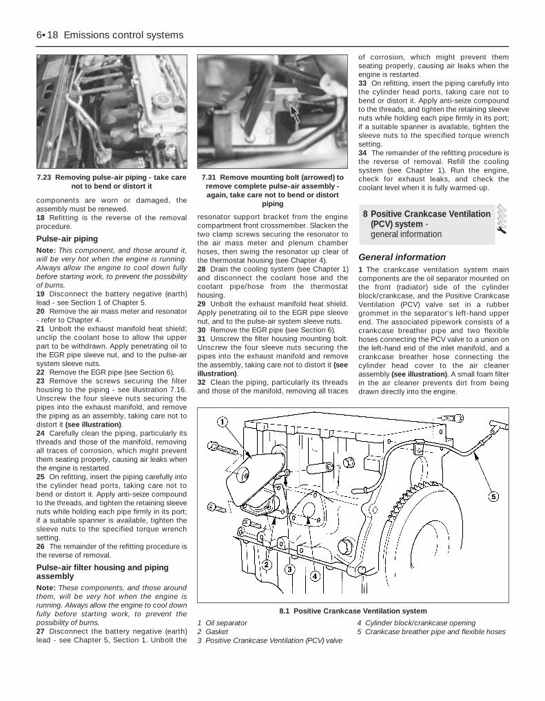
components are worn or damaged, theassembly must be renewed.18 Refitting is the reverse of the removalprocedure.
Pulse-air pipingNote: This component, and those around it,will be very hot when the engine is running.Always allow the engine to cool down fullybefore starting work, to prevent the possibilityof burns.19 Disconnect the battery negative (earth)lead - see Section 1 of Chapter 5.20 Remove the air mass meter and resonator- refer to Chapter 4.21 Unbolt the exhaust manifold heat shield;unclip the coolant hose to allow the upperpart to be withdrawn. Apply penetrating oil tothe EGR pipe sleeve nut, and to the pulse-airsystem sleeve nuts.22 Remove the EGR pipe (see Section 6).23 Remove the screws securing the filterhousing to the piping - see illustration 7.16.Unscrew the four sleeve nuts securing thepipes into the exhaust manifold, and removethe piping as an assembly, taking care not todistort it (see illustration).24 Carefully clean the piping, particularly itsthreads and those of the manifold, removingall traces of corrosion, which might preventthem seating properly, causing air leaks whenthe engine is restarted.25 On refitting, insert the piping carefully intothe cylinder head ports, taking care not tobend or distort it. Apply anti-seize compoundto the threads, and tighten the retaining sleevenuts while holding each pipe firmly in its port;if a suitable spanner is available, tighten thesleeve nuts to the specified torque wrenchsetting.26 The remainder of the refitting procedure isthe reverse of removal.
Pulse-air filter housing and pipingassemblyNote: These components, and those aroundthem, will be very hot when the engine isrunning. Always allow the engine to cool downfully before starting work, to prevent thepossibility of burns.27 Disconnect the battery negative (earth)lead - see Chapter 5, Section 1. Unbolt the
resonator support bracket from the enginecompartment front crossmember. Slacken thetwo clamp screws securing the resonator tothe air mass meter and plenum chamberhoses, then swing the resonator up clear ofthe thermostat housing (see Chapter 4).28 Drain the cooling system (see Chapter 1)and disconnect the coolant hose and thecoolant pipe/hose from the thermostathousing.29 Unbolt the exhaust manifold heat shield.Apply penetrating oil to the EGR pipe sleevenut, and to the pulse-air system sleeve nuts.30 Remove the EGR pipe (see Section 6).31 Unscrew the filter housing mounting bolt.Unscrew the four sleeve nuts securing thepipes into the exhaust manifold and removethe assembly, taking care not to distort it (seeillustration).32 Clean the piping, particularly its threadsand those of the manifold, removing all traces
of corrosion, which might prevent themseating properly, causing air leaks when theengine is restarted.33 On refitting, insert the piping carefully intothe cylinder head ports, taking care not tobend or distort it. Apply anti-seize compoundto the threads, and tighten the retaining sleevenuts while holding each pipe firmly in its port;if a suitable spanner is available, tighten thesleeve nuts to the specified torque wrenchsetting.34 The remainder of the refitting procedure isthe reverse of removal. Refill the coolingsystem (see Chapter 1). Run the engine,check for exhaust leaks, and check thecoolant level when it is fully warmed-up.
General information1 The crankcase ventilation system maincomponents are the oil separator mounted onthe front (radiator) side of the cylinderblock/crankcase, and the Positive CrankcaseVentilation (PCV) valve set in a rubbergrommet in the separator’s left-hand upperend. The associated pipework consists of acrankcase breather pipe and two flexiblehoses connecting the PCV valve to a union onthe left-hand end of the inlet manifold, and acrankcase breather hose connecting thecylinder head cover to the air cleanerassembly (see illustration). A small foam filterin the air cleaner prevents dirt from beingdrawn directly into the engine.
8 Positive Crankcase Ventilation(PCV) system - general information
6•18 Emissions control systems
7.23 Removing pulse-air piping - take carenot to bend or distort it
7.31 Remove mounting bolt (arrowed) toremove complete pulse-air assembly -again, take care not to bend or distort
piping
8.1 Positive Crankcase Ventilation system
1 Oil separator2 Gasket3 Positive Crankcase Ventilation (PCV) valve
4 Cylinder block/crankcase opening5 Crankcase breather pipe and flexible hoses

2 The function of these components is toreduce the emission of unburnedhydrocarbons from the crankcase, and tominimise the formation of oil sludge. Byensuring that a depression is created in thecrankcase under most operating conditions,particularly at idle, and by positively inducingfresh air into the system, the oil vapours and“blow-by” gases collected in the crankcaseare drawn from the crankcase, through the oilseparator, into the inlet tract, to be burned bythe engine during normal combustion.
Checking3 Checking procedures for the systemcomponents are included in Chapter 1.
Component renewal
Cylinder head-to-air cleaner hose4 See Chapter 1.
Positive Crankcase Ventilation (PCV)valve5 The valve is plugged into the oil separator.Depending on the tools available, access tothe valve may be possible once the pulse-airassembly has been removed (see Section 7).If this is not feasible, proceed as outlined inparagraph 6 below.
Oil separator6 Remove the exhaust manifold (see Chap-ter 2, Part A). The Positive CrankcaseVentilation (PCV) valve can now be unpluggedand flushed, or renewed, as required, asdescribed in Chapter 1.7 Unbolt the oil separator from the cylinderblock/crankcase, and withdraw it; remove anddiscard the gasket.8 Flush out or renew the oil separator, asrequired (see Chapter 1).9 On reassembly, fit a new gasket, andtighten the fasteners to the torque wrenchsettings given in the Specifications Section ofChapter 2, Part B.10 The remainder of the refitting procedure isthe reverse of removal. Refill the coolingsystem (see Chapter 1). Run the engine,check for exhaust leaks, and check thecoolant level when it is fully warmed-up.
General information1 The exhaust gases of any petrol engine(however efficient or well-tuned) consistlargely (approximately 99 %) of nitrogen (N2),carbon dioxide (CO2), oxygen (O2), other inertgases and water vapour (H2O). The remaining1 % is made up of the noxious materialswhich are currently seen (CO2 apart) as themajor polluters of the environment: carbonmonoxide (CO), unburned hydrocarbons (HC),
oxides of nitrogen (NOx) and some solidmatter, including a small lead content.2 Left to themselves, most of these pollutantsare thought eventually to break down naturally(CO and NOx, for example, break down in theupper atmosphere to release CO2) having firstcaused ground-level environmental problems.The massive increase world-wide in the use ofmotor vehicles, and the current popularconcern for the environment has caused theintroduction in most countries of legislation, invarying degrees of severity, to combat theproblem.3 The device most commonly used to cleanup vehicle exhausts is the catalytic converter.It is fitted into the vehicle’s exhaust system,and uses precious metals (platinum andpalladium or rhodium) as catalysts to speedup the reaction between the pollutants andthe oxygen in the vehicle’s exhaust gases, COand HC being oxidised to form H2O and CO2
and (in the three-way type of catalyticconverter) NOx being reduced to N2. Note:The catalytic converter is not a filter in thephysical sense; its function is to promote achemical reaction, but it is not itself affectedby that reaction.4 The converter consists of an element (or“substrate”) of ceramic honeycomb, coatedwith a combination of precious metals in sucha way as to produce a vast surface area overwhich the exhaust gases must flow; the wholebeing mounted in a stainless-steel box. Asimple “oxidation” (or “two-way”) catalyticconverter can deal with CO and HC only,while a “reduction” (or “three-way”) catalyticconverter can deal with CO, HC and NOx.Three-way catalytic converters are furthersub-divided into “open-loop” (or“uncontrolled”) converters which can remove50 to 70 % of pollutants and “closed-loop”(also known as “controlled” or “regulated”)converters which can remove over 90 % ofpollutants.5 The catalytic converter fitted to the Mondeomodels covered in this manual is of the three-way closed-loop type.6 The catalytic converter is a reliable andsimple device, which needs no maintenancein itself, but there are some facts of which anowner should be aware if the converter is tofunction properly for its full service life.(a) DO NOT use leaded petrol in a vehicle
equipped with a catalytic converter - thelead will coat the precious metals,reducing their converting efficiency, andwill eventually destroy the converter; it willalso affect the operation of the oxygensensor, requiring its renewal if lead-fouled. Opinions vary as to how muchleaded fuel is necessary to affect theconverter’s performance, and whether itcan recover even if only unleaded petrol isused afterwards; the best course of actionis, therefore, to assume the worst, and toensure that NO leaded petrol is used atany time.
(b) Always keep the ignition and fuel systems
well-maintained in accordance with themanufacturer’s schedule (Chapter 1) -particularly, ensure that the air filterelement, the fuel filter and the spark plugsare renewed at the correct intervals. If theintake air/fuel mixture is allowed tobecome too rich due to neglect, theunburned surplus will enter and burn inthe catalytic converter, overheating theelement and eventually destroying theconverter.
(c) If the engine develops a misfire, do notdrive the vehicle at all (or at least as littleas possible) until the fault is cured - themisfire will allow unburned fuel to enterthe converter, which will result in itsoverheating, as noted above. For thesame reason, do not persist if the enginerefuses to start - either trace the problemand cure it yourself, or have the vehiclechecked immediately by a qualifiedmechanic.
(d) Avoid allowing the vehicle to run out ofpetrol.
(e) DO NOT push- or tow-start the vehicleunless no other alternative exists,especially if the engine and exhaust are atnormal operating temperature. Startingthe engine in this way may soak thecatalytic converter in unburned fuel,causing it to overheat when the enginedoes start - see (b) above.
(f) DO NOT switch off the ignition at highengine speeds, in particular, do not “blip”the throttle immediately before switchingoff. If the ignition is switched off atanything above idle speed, unburned fuelwill enter the (very hot) catalytic converter,with the possible risk of its igniting on theelement and damaging the converter.
(g) Avoid repeated successive cold startsfollowed by short journeys. If theconverter is never allowed to reach itsproper working temperature, it will gatherunburned fuel, allowing some to pass intothe atmosphere and the rest to soak inthe element, causing it to overheat whena long journey is made - see (b) above.
(h) DO NOT use fuel or engine oil additives -these may contain substances harmful tothe catalytic converter. Similarly, DO NOTuse silicone-based sealants on any part ofthe engine or fuel system, and do not useexhaust sealants on any part of theexhaust system upstream of the catalyticconverter. Even if the sealant itself doesnot contain additives harmful to theconverter, pieces of it may break off andfoul the element, causing localoverheating.
(i) DO NOT continue to use the vehicle if theengine burns oil to the extent of leaving avisible trail of blue smoke. Unburnedcarbon deposits will clog the converterpassages and reduce its efficiency; insevere cases, the element will overheat.
(j) Remember that the catalytic converteroperates at very high temperatures -
9 Catalytic converter - general information, checkingand component renewal
Emissions control systems 6•19
6

hence the heat shields on the vehicleunderbody - and the casing will becomehot enough to ignite combustiblematerials which brush against it. DO NOT,therefore, park the vehicle in dryundergrowth, over long grass or piles ofdead leaves.
(k) Remember that the catalytic converter isFRAGILE. Do not strike it with toolsduring servicing work, and take great carewhen working on the exhaust system (seeChapter 4). Ensure that the converter iswell clear of any jacks or other lifting gearused to raise the vehicle. Do not drive thevehicle over rough ground, road humps,etc, in such a way as to “ground” theexhaust system.
(l) In some cases, particularly when thevehicle is new and/or is used forstop/start driving, a sulphurous smell (likethat of rotten eggs) may be noticed from
the exhaust. This is common to manycatalytic converter-equipped vehicles,and seems to be due to the small amountof sulphur found in some petrols reactingwith hydrogen in the exhaust, to producehydrogen sulphide (H2S) gas; while thisgas is toxic, it is not produced in sufficientamounts to be a problem. Once thevehicle has covered a few thousand miles,the problem should disappear - in themeanwhile, a change of driving style, or ofthe brand of petrol used, may effect asolution.
(m) The catalytic converter on a well-maintained and well-driven vehicle shouldlast for between 50 000 and 100 000miles. From this point on, careful checksshould be made at regular intervals toensure that the converter is still operatingefficiently. If the converter is no longereffective, it must be renewed.
Checking7 Checking the operation of a catalyticconverter requires expensive andsophisticated diagnostic equipment, startingwith a high-quality exhaust gas analyser. If thelevel of CO in the exhaust gases is too high, afull check of the engine management systemmust be carried out (see Section 3 of thisChapter) to eliminate all other possibilitiesbefore the converter is suspected of beingfaulty.8 The vehicle should be taken to a Forddealer for this work to be carried out using thecorrect diagnostic equipment; do not wastetime trying to test the system without suchfacilities.
Component renewal9 The catalytic converter is part of theexhaust system front downpipe - see Chap-ter 4 for details of removal and refitting.
6•20 Emissions control systems
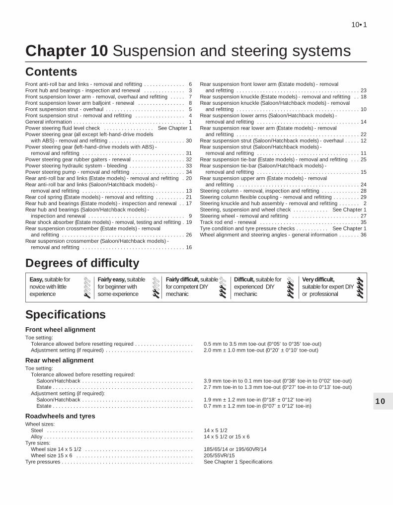
Chapter 10 Suspension and steering systems
Front anti-roll bar and links - removal and refitting . . . . . . . . . . . . . . 6Front hub and bearings - inspection and renewal . . . . . . . . . . . . . . 3Front suspension lower arm - removal, overhaul and refitting . . . . . 7Front suspension lower arm balljoint - renewal . . . . . . . . . . . . . . . . 8Front suspension strut - overhaul . . . . . . . . . . . . . . . . . . . . . . . . . . . 5Front suspension strut - removal and refitting . . . . . . . . . . . . . . . . . 4General information . . . . . . . . . . . . . . . . . . . . . . . . . . . . . . . . . . . . . . 1Power steering fluid level check . . . . . . . . . . . . . . . . . See Chapter 1Power steering gear (all except left-hand-drive models
with ABS) - removal and refitting . . . . . . . . . . . . . . . . . . . . . . . . . . 30Power steering gear (left-hand-drive models with ABS) -
removal and refitting . . . . . . . . . . . . . . . . . . . . . . . . . . . . . . . . . . . 31Power steering gear rubber gaiters - renewal . . . . . . . . . . . . . . . . . . 32Power steering hydraulic system - bleeding . . . . . . . . . . . . . . . . . . . 33Power steering pump - removal and refitting . . . . . . . . . . . . . . . . . . 34Rear anti-roll bar and links (Estate models) - removal and refitting . 20Rear anti-roll bar and links (Saloon/Hatchback models) -
removal and refitting . . . . . . . . . . . . . . . . . . . . . . . . . . . . . . . . . . . 13Rear coil spring (Estate models) - removal and refitting . . . . . . . . . . 21Rear hub and bearings (Estate models) - inspection and renewal . . 17Rear hub and bearings (Saloon/Hatchback models) -
inspection and renewal . . . . . . . . . . . . . . . . . . . . . . . . . . . . . . . . . 9Rear shock absorber (Estate models) - removal, testing and refitting . 19Rear suspension crossmember (Estate models) - removal
and refitting . . . . . . . . . . . . . . . . . . . . . . . . . . . . . . . . . . . . . . . . . . 26Rear suspension crossmember (Saloon/Hatchback models) -
removal and refitting . . . . . . . . . . . . . . . . . . . . . . . . . . . . . . . . . . . 16
Rear suspension front lower arm (Estate models) - removal and refitting . . . . . . . . . . . . . . . . . . . . . . . . . . . . . . . . . . . . . . . . . . 23
Rear suspension knuckle (Estate models) - removal and refitting . . 18Rear suspension knuckle (Saloon/Hatchback models) - removal
and refitting . . . . . . . . . . . . . . . . . . . . . . . . . . . . . . . . . . . . . . . . . . 10Rear suspension lower arms (Saloon/Hatchback models) -
removal and refitting . . . . . . . . . . . . . . . . . . . . . . . . . . . . . . . . . . . 14Rear suspension rear lower arm (Estate models) - removal
and refitting . . . . . . . . . . . . . . . . . . . . . . . . . . . . . . . . . . . . . . . . . . 22Rear suspension strut (Saloon/Hatchback models) - overhaul . . . . . 12Rear suspension strut (Saloon/Hatchback models) -
removal and refitting . . . . . . . . . . . . . . . . . . . . . . . . . . . . . . . . . . . 11Rear suspension tie-bar (Estate models) - removal and refitting . . . 25Rear suspension tie-bar (Saloon/Hatchback models) -
removal and refitting . . . . . . . . . . . . . . . . . . . . . . . . . . . . . . . . . . . 15Rear suspension upper arm (Estate models) - removal
and refitting . . . . . . . . . . . . . . . . . . . . . . . . . . . . . . . . . . . . . . . . . . 24Steering column - removal, inspection and refitting . . . . . . . . . . . . . 28Steering column flexible coupling - removal and refitting . . . . . . . . . 29Steering knuckle and hub assembly - removal and refitting . . . . . . . 2Steering, suspension and wheel check . . . . . . . . . . . . See Chapter 1Steering wheel - removal and refitting . . . . . . . . . . . . . . . . . . . . . . . 27Track rod end - renewal . . . . . . . . . . . . . . . . . . . . . . . . . . . . . . . . . . 35Tyre condition and tyre pressure checks . . . . . . . . . . . See Chapter 1Wheel alignment and steering angles - general information . . . . . . . 36
Front wheel alignmentToe setting:
Tolerance allowed before resetting required . . . . . . . . . . . . . . . . . . . . 0.5 mm to 3.5 mm toe-out (0°05’ to 0°35’ toe-out)Adjustment setting (if required) . . . . . . . . . . . . . . . . . . . . . . . . . . . . . . 2.0 mm ± 1.0 mm toe-out (0°20’ ± 0°10’ toe-out)
Rear wheel alignmentToe setting:
Tolerance allowed before resetting required:Saloon/Hatchback . . . . . . . . . . . . . . . . . . . . . . . . . . . . . . . . . . . . . . 3.9 mm toe-in to 0.1 mm toe-out (0°38’ toe-in to 0°02’ toe-out)Estate . . . . . . . . . . . . . . . . . . . . . . . . . . . . . . . . . . . . . . . . . . . . . . . . 2.7 mm toe-in to 1.3 mm toe-out (0°27’ toe-in to 0°13’ toe-out)
Adjustment setting (if required):Saloon/Hatchback . . . . . . . . . . . . . . . . . . . . . . . . . . . . . . . . . . . . . . 1.9 mm ± 1.2 mm toe-in (0°18’ ± 0°12’ toe-in)Estate . . . . . . . . . . . . . . . . . . . . . . . . . . . . . . . . . . . . . . . . . . . . . . . . 0.7 mm ± 1.2 mm toe-in (0°07’ ± 0°12’ toe-in)
Roadwheels and tyresWheel sizes:
Steel . . . . . . . . . . . . . . . . . . . . . . . . . . . . . . . . . . . . . . . . . . . . . . . . . . 14 x 5 1/2Alloy . . . . . . . . . . . . . . . . . . . . . . . . . . . . . . . . . . . . . . . . . . . . . . . . . . . 14 x 5 1/2 or 15 x 6
Tyre sizes:Wheel size 14 x 5 1/2 . . . . . . . . . . . . . . . . . . . . . . . . . . . . . . . . . . . . . 185/65/14 or 195/60VR/14Wheel size 15 x 6 . . . . . . . . . . . . . . . . . . . . . . . . . . . . . . . . . . . . . . . . 205/55VR/15
Tyre pressures . . . . . . . . . . . . . . . . . . . . . . . . . . . . . . . . . . . . . . . . . . . . . See Chapter 1 Specifications
10•1
Easy, suitable fornovice with littleexperience
Fairly easy, suitablefor beginner withsome experience
Fairly difficult, suitablefor competent DIYmechanic
Difficult, suitable forexperienced DIYmechanic
Very difficult,suitable for expert DIYor professional
Degrees of difficulty
Specifications
Contents
10

Torque wrench settings Nm lbf ft
Front suspensionFront subframe . . . . . . . . . . . . . . . . . . . . . . . . . . . . . . . . . . . . . . . . . . . . 110 to 150 81 to 111Lower arm balljoint to lower arm (service replacement, bolted on) . . . . 58 43Lower arm balljoint-to-steering knuckle clamp bolt . . . . . . . . . . . . . . . 48 to 60 35 to 44Lower arm to subframe:
Stage 1 (used components) . . . . . . . . . . . . . . . . . . . . . . . . . . . . . . . . 50 37Stage 1 (new components) . . . . . . . . . . . . . . . . . . . . . . . . . . . . . . . . . 70 52Stage 2 . . . . . . . . . . . . . . . . . . . . . . . . . . . . . . . . . . . . . . . . . . . . . . . . Slacken completelyStage 3 . . . . . . . . . . . . . . . . . . . . . . . . . . . . . . . . . . . . . . . . . . . . . . . . 50 37Stage 4 . . . . . . . . . . . . . . . . . . . . . . . . . . . . . . . . . . . . . . . . . . . . . . . . Tighten through further 90°
Anti-roll bar . . . . . . . . . . . . . . . . . . . . . . . . . . . . . . . . . . . . . . . . . . . . . . . 24 18Anti-roll bar link . . . . . . . . . . . . . . . . . . . . . . . . . . . . . . . . . . . . . . . . . . . . 41 to 58 30 to 43Suspension strut-to-steering knuckle pinch-bolt . . . . . . . . . . . . . . . . . . 84 62Suspension strut upper mounting nut . . . . . . . . . . . . . . . . . . . . . . . . . . . 46 34Suspension strut thrust bearing retaining nut . . . . . . . . . . . . . . . . . . . . . 59 44Driveshaft/hub retaining nut . . . . . . . . . . . . . . . . . . . . . . . . . . . . . . . . . . 340 251
Rear suspension (Saloon/Hatchback)Crossmember mounting bolts . . . . . . . . . . . . . . . . . . . . . . . . . . . . . . . . 102 to 138 75 to 102Front lower arm to knuckle and to crossmember . . . . . . . . . . . . . . . . . . 70 to 98 52 to 72Rear lower arm to knuckle . . . . . . . . . . . . . . . . . . . . . . . . . . . . . . . . . . . 102 to 138 75 to 102Rear lower arm to crossmember . . . . . . . . . . . . . . . . . . . . . . . . . . . . . . . 70 to 98 52 to 72Anti-roll bar . . . . . . . . . . . . . . . . . . . . . . . . . . . . . . . . . . . . . . . . . . . . . . . 19 to 26 14 to 19Anti-roll bar link . . . . . . . . . . . . . . . . . . . . . . . . . . . . . . . . . . . . . . . . . . . . 30 to 40 22 to 30Suspension strut to knuckle . . . . . . . . . . . . . . . . . . . . . . . . . . . . . . . . . . 70 to 98 52 to 72Drum brake backplate . . . . . . . . . . . . . . . . . . . . . . . . . . . . . . . . . . . . . . . 45 to 54 33 to 40Disc brake splash shield . . . . . . . . . . . . . . . . . . . . . . . . . . . . . . . . . . . . . 90 66Hub nut . . . . . . . . . . . . . . . . . . . . . . . . . . . . . . . . . . . . . . . . . . . . . . . . . . 290 181Tie-bar and tie-bar bracket . . . . . . . . . . . . . . . . . . . . . . . . . . . . . . . . . . . 102 to 138 75 to 102Suspension strut upper mounting bolts . . . . . . . . . . . . . . . . . . . . . . . . . 23 to 30 17 to 22Suspension strut upper nut . . . . . . . . . . . . . . . . . . . . . . . . . . . . . . . . . . . 41 to 58 30 to 43
Rear suspension (Estate)Same as for Saloon/Hatchback, except for the following.Crossmember mounting bolts . . . . . . . . . . . . . . . . . . . . . . . . . . . . . . . . 120 89Front lower arm to knuckle and to crossmember . . . . . . . . . . . . . . . . . . 120 89Upper arm to knuckle . . . . . . . . . . . . . . . . . . . . . . . . . . . . . . . . . . . . . . . 120 89Upper arm to crossmember . . . . . . . . . . . . . . . . . . . . . . . . . . . . . . . . . . 84 62Rear lower arm to knuckle and to crossmember . . . . . . . . . . . . . . . . . . 84 62Anti-roll bar . . . . . . . . . . . . . . . . . . . . . . . . . . . . . . . . . . . . . . . . . . . . . . . 25 19Anti-roll bar link . . . . . . . . . . . . . . . . . . . . . . . . . . . . . . . . . . . . . . . . . . . . 35 26Hub assembly-to-knuckle retaining bolts . . . . . . . . . . . . . . . . . . . . . . . . 65 48Tie-bar to bracket . . . . . . . . . . . . . . . . . . . . . . . . . . . . . . . . . . . . . . . . . . 120 89Tie-bar bracket to underbody . . . . . . . . . . . . . . . . . . . . . . . . . . . . . . . . . 120 89Tie-bar to knuckle . . . . . . . . . . . . . . . . . . . . . . . . . . . . . . . . . . . . . . . . . . 84 62Shock absorber upper mounting bolt . . . . . . . . . . . . . . . . . . . . . . . . . . . 84 62Shock absorber lower mounting bolt . . . . . . . . . . . . . . . . . . . . . . . . . . . 120 89
SteeringSteering gear mounting bolts . . . . . . . . . . . . . . . . . . . . . . . . . . . . . . . . . 114 to 159 84 to 117Track rod end to steering knuckle . . . . . . . . . . . . . . . . . . . . . . . . . . . . . 25 to 30 18 to 22Track rod end locknut . . . . . . . . . . . . . . . . . . . . . . . . . . . . . . . . . . . . . . . 34 to 47 25 to 35Steering wheel . . . . . . . . . . . . . . . . . . . . . . . . . . . . . . . . . . . . . . . . . . . . . 45 to 55 33 to 41Flexible coupling-to-pinion shaft clamp bolt . . . . . . . . . . . . . . . . . . . . . 23 to 32 17 to 24Power steering pipe unions to valve body . . . . . . . . . . . . . . . . . . . . . . . 27 to 35 20 to 26Steering column-to-coupling clamp bolt . . . . . . . . . . . . . . . . . . . . . . . . 20 to 27 14 to 20Steering column mounting bolts . . . . . . . . . . . . . . . . . . . . . . . . . . . . . . . 20 to 27 14 to 20Steering pump mounting bolts . . . . . . . . . . . . . . . . . . . . . . . . . . . . . . . . 21 to 28 15 to 21Steering pump pressure line . . . . . . . . . . . . . . . . . . . . . . . . . . . . . . . . . . 57 to 73 42 to 54
Roadwheel nuts . . . . . . . . . . . . . . . . . . . . . . . . . . . . . . . . . . . . . . . . . . . 85 63
10•2 Suspension and steering systems

The independent front suspension is ofMacPherson strut type, incorporating coilsprings, integral telescopic shock absorbers,and an anti-roll bar. The struts are attached tosteering knuckles at their lower ends, and theknuckles are in turn attached to the lowersuspension arm by balljoints. The anti-roll baris bolted to the rear of the subframe, and isconnected to the front suspension struts bylinks (see illustration).
On Saloon/Hatchback models, theindependent rear suspension is of“Quadralink” type, having four mountingpoints on each side of the vehicle. The twolower arms are attached to the rearsuspension knuckle at their outer ends, and tothe rear crossmember at their inner ends. Atie-bar, located between the bottom of theknuckle and the floor, counteracts brakingand acceleration forces on each side (seeillustration).
On Estate models, the independent rearsuspension is of “SLA” (Short and Long Arm)type. This allows a larger load area, sincethere are no suspension points projecting intothe luggage area. There are three side armson each side: one forged upper arm, and two
1 General information
Suspension and steering systems 10•3
10
1.1 Front suspension components
1 MacPherson strut2 Steering knuckle3 Lower arm
4 Vertical silent bush on lower arm
5 Anti-roll bar
6 Front subframe7 Front subframe rubber bush8 Rear subframe rubber bush
1.2 Rear suspension components onSaloon/Hatchback models
1 Wheel housing2 Upper mounting bracket and coil spring seat3 Strut4 Solenoid valve for adaptive damping5 Rear suspension crossmember6 Eccentric bolt for rear toe setting7 Anti-roll bar8 Link9 Front lower arm10 Rear lower arm11 Knuckle (drum brake models)12 ABS wheel sensor
(drum brake models)13 Tie-bar14 Backplate15 Hub and bearing assembly16 Hub nut17 Grease cap18 Brake drum19 Tie-bar mounting bracket20 Brake disc21 Splash shield (disc brake models)22 Brake caliper (disc brake models)23 Knuckle (disc brake models)24 ABS wheel sensor (disc brake models)
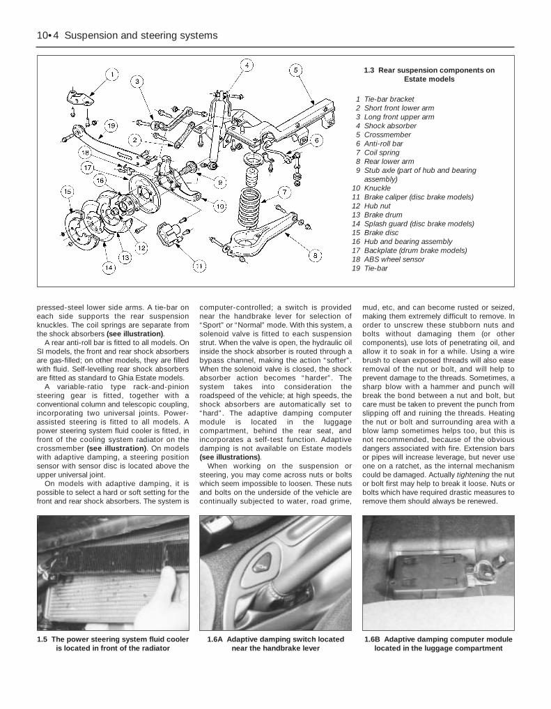
10•4 Suspension and steering systems
pressed-steel lower side arms. A tie-bar oneach side supports the rear suspensionknuckles. The coil springs are separate fromthe shock absorbers (see illustration).
A rear anti-roll bar is fitted to all models. OnSI models, the front and rear shock absorbersare gas-filled; on other models, they are filledwith fluid. Self-levelling rear shock absorbersare fitted as standard to Ghia Estate models.
A variable-ratio type rack-and-pinionsteering gear is fitted, together with aconventional column and telescopic coupling,incorporating two universal joints. Power-assisted steering is fitted to all models. Apower steering system fluid cooler is fitted, infront of the cooling system radiator on thecrossmember (see illustration). On modelswith adaptive damping, a steering positionsensor with sensor disc is located above theupper universal joint.
On models with adaptive damping, it ispossible to select a hard or soft setting for thefront and rear shock absorbers. The system is
computer-controlled; a switch is providednear the handbrake lever for selection of“Sport” or “Normal” mode. With this system, asolenoid valve is fitted to each suspensionstrut. When the valve is open, the hydraulic oilinside the shock absorber is routed through abypass channel, making the action “softer”.When the solenoid valve is closed, the shockabsorber action becomes “harder”. Thesystem takes into consideration theroadspeed of the vehicle; at high speeds, theshock absorbers are automatically set to“hard”. The adaptive damping computermodule is located in the luggagecompartment, behind the rear seat, andincorporates a self-test function. Adaptivedamping is not available on Estate models(see illustrations).
When working on the suspension orsteering, you may come across nuts or boltswhich seem impossible to loosen. These nutsand bolts on the underside of the vehicle arecontinually subjected to water, road grime,
mud, etc, and can become rusted or seized,making them extremely difficult to remove. Inorder to unscrew these stubborn nuts andbolts without damaging them (or othercomponents), use lots of penetrating oil, andallow it to soak in for a while. Using a wirebrush to clean exposed threads will also easeremoval of the nut or bolt, and will help toprevent damage to the threads. Sometimes, asharp blow with a hammer and punch willbreak the bond between a nut and bolt, butcare must be taken to prevent the punch fromslipping off and ruining the threads. Heatingthe nut or bolt and surrounding area with ablow lamp sometimes helps too, but this isnot recommended, because of the obviousdangers associated with fire. Extension barsor pipes will increase leverage, but never useone on a ratchet, as the internal mechanismcould be damaged. Actually tightening the nutor bolt first may help to break it loose. Nuts orbolts which have required drastic measures toremove them should always be renewed.
1.5 The power steering system fluid cooleris located in front of the radiator
1.6A Adaptive damping switch locatednear the handbrake lever
1.6B Adaptive damping computer modulelocated in the luggage compartment
1.3 Rear suspension components onEstate models
1 Tie-bar bracket2 Short front lower arm3 Long front upper arm4 Shock absorber5 Crossmember6 Anti-roll bar7 Coil spring8 Rear lower arm9 Stub axle (part of hub and bearing
assembly)10 Knuckle11 Brake caliper (disc brake models)12 Hub nut13 Brake drum14 Splash guard (disc brake models)15 Brake disc16 Hub and bearing assembly17 Backplate (drum brake models)18 ABS wheel sensor19 Tie-bar
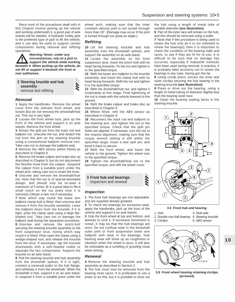
Since most of the procedures dealt with inthis Chapter involve jacking up the vehicleand working underneath it, a good pair of axlestands will be needed. A hydraulic trolley jackis the preferred type of jack to lift the vehicle,and it can also be used to support certaincomponents during removal and refittingoperations.
Warning: Never, under anycircumstances, rely on a jack tosupport the vehicle while working
beneath it. When jacking up the vehicle, donot lift or support it beneath the front orrear subframes.
Removal1 Apply the handbrake. Remove the wheelcover from the relevant front wheel, andloosen (but do not remove) the driveshaft/hubnut. This nut is very tight.2 Loosen the front wheel nuts, jack up thefront of the vehicle and support it on axlestands. Remove the front wheel.3 Extract the split pin from the track rod endballjoint nut. Unscrew the nut, and detach therod from the arm on the steering knuckleusing a conventional balljoint removal tool.Take care not to damage the balljoint seal.4 Remove the ABS sensor (when fitted) asdescribed in Chapter 9.5 Remove the brake caliper and brake disc asdescribed in Chapter 9, but do not disconnectthe flexible hose from the caliper. Suspendthe caliper from a suitable point under thewheel arch, taking care not to strain the hose.6 Unscrew and remove the driveshaft/hubnut. Note that the nut is of special laminateddesign, and should only be re-used amaximum of 5 times. (It is a good idea to file asmall notch on the nut every time it isremoved.) Obtain a new nut if necessary.7 Note which way round the lower armballjoint clamp bolt is fitted, then unscrew andremove it from the knuckle assembly. Leverthe balljoint down from the knuckle; if it istight, prise the clamp open using a large flat-bladed tool. Take care not to damage theballjoint seal during the separation procedure.8 Unscrew and remove the pinch-boltsecuring the steering knuckle assembly to thefront suspension strut, noting which wayround it is fitted. Prise open the clamp using awedge-shaped tool, and release the knucklefrom the strut. If necessary, tap the knuckledownwards with a soft-headed mallet toseparate the two components. Support theknuckle on an axle stand.9 Pull the steering knuckle and hub assemblyfrom the driveshaft splines. If it is tight,connect a universal puller to the hub flange,and withdraw it from the driveshaft. When thedriveshaft is free, support it on an axle stand,or suspend it from a suitable point under the
wheel arch, making sure that the innerconstant velocity joint is not turned throughmore than 18°. (Damage may occur if the jointis turned through too great an angle.)
Refitting10 Lift the steering knuckle and hubassembly onto the driveshaft splines, andsupport the assembly on an axle stand.11 Locate the assembly on the frontsuspension strut. Insert the pinch-bolt with itshead facing forwards. Fit the nut and tighten itto the specified torque.12 Refit the lower arm balljoint to the knuckleassembly, and insert the clamp bolt with itshead facing forwards. Refit the nut and tightenit to the specified torque.13 Refit the driveshaft/hub nut, and tighten itmoderately at this stage. Final tightening ofthe nut is made with the vehicle lowered to theground.14 Refit the brake caliper and brake disc asdescribed in Chapter 9.15 Where fitted, refit the ABS sensor asdescribed in Chapter 9.16 Reconnect the track rod end balljoint tothe steering arm, and tighten the nut to thespecified torque. Check that the split pinholes are aligned; if necessary, turn the nut tothe nearest alignment, making sure that thetorque wrench setting is still within thespecified range. Insert a new split pin, andbend it back to secure.17 Refit the front wheel, and lower thevehicle to the ground. Tighten the wheel nutsto the specified torque.18 Tighten the driveshaft/hub nut to thespecified torque, and refit the wheel cover.
Inspection1 The front hub bearings are non-adjustable,and are supplied already greased.2 To check the bearings for excessive wear,apply the handbrake, jack up the front of thevehicle and support it on axle stands.3 Grip the front wheel at top and bottom, andattempt to rock it. If excessive movement isnoted, it may be that the hub bearings areworn. Do not confuse wear in the driveshaftouter joint or front suspension lower armballjoint with wear in the bearings. Hubbearing wear will show up as roughness orvibration when the wheel is spun; it will alsobe noticeable as a rumbling or growling noisewhen driving.
Renewal4 Remove the steering knuckle and hubassembly as described in Section 2.5 The hub must now be removed from thebearing inner races. It is preferable to use apress to do this, but it is possible to drive out
the hub using a length of metal tube ofsuitable diameter (see illustration).6 Part of the inner race will remain on the hub,and this should be removed using a puller.7 Note that if this procedure is being used torenew the hub only (ie it is not intended torenew the bearings), then it is important tocheck the condition of the bearing balls andraces, to see if they are fit for re-use. It isdifficult to be sure that no damage hasoccurred, especially if makeshift methodshave been used during removal; in practice, itis probably false economy not to renew thebearings in any case, having got this far.8 Using circlip pliers, extract the inner andouter circlips securing the hub bearing in thesteering knuckle (see illustration).9 Press or drive out the bearing, using alength of metal tubing of diameter slightly lessthan the bearing outer race.10 Clean the bearing seating faces in thesteering knuckle.
3 Front hub and bearings -inspection and renewal
2 Steering knuckle and hubassembly - removal and refitting
Suspension and steering systems 10•5
10
3.5 Front hub and bearing
1 Hub 4 Stub axle2 Double-row ball-bearing 5 Steering knuckle3 Circlips 6 ABS sensor
3.8 Front wheel bearing retaining circlips(arrowed)
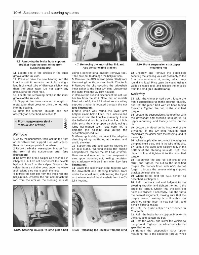
11 Locate one of the circlips in the outergroove of the knuckle.12 Press or drive the new bearing into theknuckle until it contacts the circlip, using alength of metal tube of diameter slightly lessthan the outer race. Do not apply anypressure to the inner race.13 Locate the remaining circlip in the innergroove of the knuckle.14 Support the inner race on a length ofmetal tube, then press or drive the hub fullyinto the bearing.15 Refit the steering knuckle and hubassembly as described in Section 2.
Removal1 Apply the handbrake, then jack up the frontof the vehicle and support it on axle stands.Remove the appropriate front wheel.2 Unbolt the brake hose support bracket fromthe front of the suspension strut (seeillustration).3 Remove the brake caliper as described inChapter 9, but do not disconnect the flexiblehydraulic hose from the caliper. Suspend thecaliper from a suitable point under the wheelarch, taking care not to strain the hose.4 Extract the split pin from the track rod endballjoint nut. Unscrew the nut, and detach therod from the arm on the steering knuckle
using a conventional balljoint removal tool.Take care not to damage the balljoint seal.5 Remove the ABS sensor (when fitted) fromthe steering knuckle, as described in Chapter 9.6 Remove the clip securing the driveshaftinner gaiter to the inner CV joint. Disconnectthe gaiter from the CV joint housing.7 Remove the nut and disconnect the anti-rollbar link from the strut. Note that, on modelsfitted with ABS, the ABS wheel sensor wiringsupport bracket is located beneath the nut(see illustration).8 Note which way round the lower armballjoint clamp bolt is fitted, then unscrew andremove it from the knuckle assembly. Leverthe balljoint down from the knuckle; if it istight, prise the clamp open carefully using alarge flat-bladed tool. Take care not todamage the balljoint seal during theseparation procedure.9 Where applicable, disconnect the adaptivedamping wiring multi-plug at the strut, andunclip the wire.10 Support the strut and steering knuckle onan axle stand. Working inside the enginecompartment, remove the strut cap (if fitted).Unscrew and remove the front suspensionstrut upper mounting nut, holding the pistonrod stationary with an 8 mm Allen key (seeillustration).11 Lower the suspension strut, together withthe driveshaft and steering knuckle, fromunder the wheel arch, withdrawing the tripodon the inner end of the driveshaft from the CVjoint housing.
12 Unscrew and remove the pinch-boltsecuring the steering knuckle assembly to thefront suspension strut, noting which wayround it is fitted. Prise open the clamp using awedge-shaped tool, and release the knucklefrom the strut (see illustrations).
Refitting13 With the clamp prised open, locate thefront suspension strut on the steering knuckle,and refit the pinch-bolt with its head facingforwards. Tighten the bolt to the specifiedtorque.14 Locate the suspension strut (together withthe driveshaft and steering knuckle) in itsupper mounting, and loosely screw on thenut.15 Locate the tripod on the inner end of thedriveshaft in the CV joint housing, thenmanipulate the gaiter onto the housing, and fita new clip.16 Where applicable, reconnect the adaptivedamping multi-plug, and fit the wire in the clip.17 Locate the lower arm balljoint fully in thebottom of the steering knuckle. Refit theclamp bolt and tighten it to the specifiedtorque.18 Reconnect the anti-roll bar link to thestrut, and tighten the nut to the specifiedtorque. On models fitted with ABS, do notforget to locate the sensor wiring supportbracket beneath the nut.19 Where fitted, refit the ABS sensor asdescribed in Chapter 9.20 Refit the track rod end balljoint to thesteering knuckle, and tighten the nut to thespecified torque. Check that the split pinholes are aligned; if necessary, turn the nut tothe nearest alignment, making sure that thetorque wrench setting is still within thespecified range. Insert a new split pin, andbend it back to secure.21 Refit the brake caliper as described inChapter 9.22 Refit the brake hose support bracket tothe strut, and tighten the bolt.23 Refit the wheel, and lower the vehicle tothe ground. Tighten the wheel nuts to thespecified torque.24 Tighten the suspension strut uppermounting nut to the specified torque, while
4 Front suspension strut -removal and refitting
10•6 Suspension and steering systems
4.2 Removing the brake hose supportbracket from the front of the front
suspension strut4.7 Removing the anti-roll bar link and
ABS sensor wiring bracket4.10 Front suspension strut upper
mounting nut
4.12A Steering knuckle-to-strut pinch-bolt 4.12B Releasing the knuckle from the strut

holding the piston rod with an 8 mm Allen key.If the adaptor needed to do this is notavailable, the nut can be tightened initiallywith a ring spanner while the piston rod isheld. Final tightening can then be carried outusing a torque wrench and a conventionalsocket (see illustration).
Warning: Before attempting todismantle the front suspensionstrut, a tool to hold the coil springin compression must be obtained.
Do not attempt to use makeshift methods.Uncontrolled release of the spring couldcause damage and personal injury. Use ahigh-quality spring compressor, andcarefully follow the tool manufacturer’sinstructions provided with it. After removingthe coil spring with the compressor stillfitted, place it in a safe, isolated area.
1 If the front suspension struts exhibit signsof wear (leaking fluid, loss of dampingcapability, sagging or cracked coil springs)then they should be dismantled andoverhauled as necessary. The strutsthemselves cannot be serviced, and shouldbe renewed if faulty, but the springs andrelated components can be renewed. Tomaintain balanced characteristics on bothsides of the vehicle, the components on bothsides should be renewed at the same time.2 With the strut removed from the vehicle, clean
away all external dirt, then mount it in a vice.3 Fit the coil spring compressor tools(ensuring that they are fully engaged), andcompress the spring until all tension is relievedfrom the upper mounting (see illustration).4 Hold the strut piston with an Allen key, and
unscrew the thrust bearing retaining nut with aring spanner (see illustration).5 Withdraw the top mounting, thrust bearing,upper spring seat and spring, followed by thegaiter and the bump stop (see illustrations).6 If a new spring is to be fitted, the original
5 Front suspension strut -overhaul
Suspension and steering systems 10•7
10
5.5A Front suspension strut components
1 Cap2 Nut3 Retainer4 Nut5 Top mounting6 Thrust bearing
7 Upper spring seat8 Spring9 Bump stop
10 Gaiter11 Lower spring seat
12 Strut13 Steering knuckle14 Clamp bolt15 Solenoid valve for models
with adaptive damping
4.24 Final tightening of the frontsuspension strut upper mounting nut
5.3 Coil spring compressor tools fitted tothe coil spring
5.4 Unscrewing the nut from the top of thestrut
5.5B Removing the top mounting from the strut 5.5C Removing the gaiter 5.5D Removing the bump stop

spring must now be carefully released fromthe compressor. If it is to be re-used, thespring can be left in compression.7 With the strut assembly now completelydismantled, examine all the components forwear and damage, and check the bearing forsmoothness of operation. Renew componentsas necessary.8 Examine the strut for signs of fluid leakage.Check the strut piston for signs of pittingalong its entire length, and check the strutbody for signs of damage. Test the operationof the strut, while holding it in an uprightposition, by moving the piston through a fullstroke, and then through short strokes of 50to 100 mm. In both cases, the resistance feltshould be smooth and continuous. If theresistance is jerky, uneven, or if there is anyvisible sign of wear or damage to the strut,renewal is necessary.9 Reassembly is a reversal of dismantling,noting the following points:(a) Make sure that the coil spring ends are
correctly located in the upper and lowerseats before releasing the compressor.
(b) Check that the bearing is correctly fittedto the piston rod seat.
(c) Tighten the thrust bearing retaining nut tothe specified torque.
Removal1 Apply the handbrake, jack up the front ofthe vehicle and support it on axle stands.Remove both front wheels.2 Unscrew the nuts, and disconnect the anti-roll bar links from the front suspension strutson both sides of the vehicle. Note that, onmodels with ABS, the wheel sensor wiringsupport brackets are located beneath the nuts(see illustrations).3 Unscrew and remove the anti-roll barmounting bolts from the engine subframe onboth sides of the vehicle.4 Withdraw the anti-roll bar from one side ofthe vehicle, taking care not to damage thesurrounding components.
5 If necessary, unscrew the nuts and removethe links from the anti-roll bar.
Refitting6 Refitting is a reversal of the removalprocedure.
Removal1 Apply the handbrake, jack up the front ofthe vehicle and support it on axle stands.Remove the appropriate wheel.2 If removing the right-hand side lower arm,remove the auxiliary drivebelt cover wherenecessary.3 Unscrew and remove the nuts and boltssecuring the lower arm to the subframe (seeillustration).4 Unscrew the nuts and disconnect the anti-roll bar links from the anti-roll bar on bothsides. Swivel the anti-roll bar upwards awayfrom the lower arm.5 Extract the split pin from the track rod endballjoint nut. Unscrew the nut, and detach therod from the arm on the steering knuckleusing a conventional balljoint removal tool.Take care not to damage the balljoint seal.6 Remove the clip securing the driveshaftinner gaiter to the inner CV joint, anddisconnect the gaiter from the CV jointhousing. This is necessary to prevent damage
to the gaiter when the steering knuckle ismoved outwards to remove the lower arm.7 Note which way round the front suspensionlower arm balljoint clamp bolt is fitted, thenunscrew and remove it from the knuckleassembly. Lever the balljoint down from theknuckle; if it is tight, prise the joint open carefullyusing a large flat-bladed tool. Take care not todamage the balljoint seal during the separationprocedure. Support the inner end of thedriveshaft on an axle stand (see illustrations).8 Remove the lower arm from the subframe,and withdraw it from the vehicle.
Overhaul9 Examine the rubber bushes and thesuspension lower balljoint for wear anddamage. The balljoint may be renewed asdescribed in Section 8. The rubber bushesmay be removed using a press, or a length ofmetal tubing together with a long bolt,washers and nut.10 Note that the front and rear bushes aredifferent. The front one has a solid rubberbush with a cylindrical inner tube, whereas therear one has a voided rubber bush with abarrel-shaped inner tube (see illustration).11 Press the new bushes into the lower arm,using the same method as used for removal.Note that, when fitting the rear bush, the voidsmust be in line with the front bush location.On later models, a pip on the rear bush mustbe aligned with a triangular alignment mark onthe arm.
7 Front suspension lower arm -removal, overhaul and refitting
6 Front anti-roll bar and links -removal and refitting
10•8 Suspension and steering systems
6.2A Unscrew the nut . . . 6.2B . . . and disconnect the anti-roll barlink and (on ABS models) the sensor wiring
support bracket
7.3 One of the nuts and bolts securing thelower arm to the subframe
7.7A Unscrew the lower arm balljointclamp bolt . . .
7.7B . . . and disconnect the balljoint fromthe knuckle
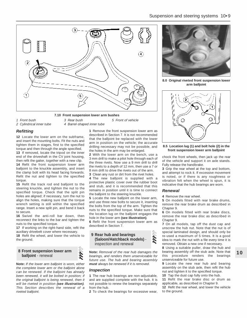
Refitting12 Locate the lower arm on the subframe,and insert the mounting bolts. Fit the nuts andtighten them in stages, first to the specifiedtorque and then through the angle specified.13 If removed, locate the tripod on the innerend of the driveshaft in the CV joint housing,then refit the gaiter, together with a new clip.14 Refit the front suspension lower armballjoint to the knuckle assembly, and insertthe clamp bolt with its head facing forwards.Refit the nut and tighten to the specifiedtorque.15 Refit the track rod end balljoint to thesteering knuckle, and tighten the nut to thespecified torque. Check that the split pinholes are aligned; if necessary, turn the nut toalign the holes, making sure that the torquewrench setting is still within the specifiedrange. Insert a new split pin, and bend it backto secure.16 Swivel the anti-roll bar down, thenreconnect the links to the bar and tighten thenuts to the specified torque.17 If working on the right-hand side, refit theauxiliary drivebelt cover where necessary.18 Refit the wheel, and lower the vehicle tothe ground.
Note: If the lower arm balljoint is worn, eitherthe complete lower arm or the balljoint alonecan be renewed. If the balljoint has alreadybeen renewed, it will be bolted in position; ifthe original balljoint is being renewed, then itwill be riveted in position (see illustration).This Section describes the renewal of ariveted balljoint.
1 Remove the front suspension lower arm asdescribed in Section 7. It is not recommendedthat the balljoint be replaced with the lowerarm in position on the vehicle; the accuratedrilling necessary may not be possible, andthe holes in the arm may be enlarged.2 With the lower arm on the bench, use a 3 mm drill to make a pilot hole through each ofthe three rivets. Now use a 9 mm drill to drillthe rivets to a depth of 12 mm, then use a 7 or8 mm drift to drive the rivets out of the arm.3 Clean any rust or dirt from the rivet holes.4 The new balljoint is supplied with aprotective plastic cover over the rubber bootand stub, and it is recommended that thisremains in position until it is time to connectthe balljoint to the steering knuckle.5 Locate the new balljoint on the lower arm,and use three new bolts to secure it, insertingthe bolts from the top of the arm. Tighten thenuts to the specified torque. Make sure thatthe location lug on the balljoint engages thehole in the lower arm (see illustration).6 Refit the front suspension lower arm asdescribed in Section 7.
Note: Removal of the rear hub damages thebearings, and renders them unserviceable forfuture use. The hub and bearing assemblymust always be renewed if it is removed.
Inspection1 The rear hub bearings are non-adjustable,and are supplied complete with the hub. It isnot possible to renew the bearings separatelyfrom the hub.2 To check the bearings for excessive wear,
chock the front wheels, then jack up the rearof the vehicle and support it on axle stands.Fully release the handbrake.3 Grip the rear wheel at the top and bottom,and attempt to rock it. If excessive movementis noted, or if there is any roughness orvibration felt when the wheel is spun, it isindicative that the hub bearings are worn.
Renewal4 Remove the rear wheel.5 On models fitted with rear brake drums,remove the rear brake drum as described inChapter 9.6 On models fitted with rear brake discs,remove the rear brake disc as described inChapter 9.7 On all models, tap off the dust cap andunscrew the hub nut. Note that the nut is ofspecial laminated design, and should only bere-used a maximum of 5 times. It is a goodidea to mark the nut with a file every time it isremoved. Obtain a new one if necessary.8 Using a suitable puller, draw the hub andbearing assembly off the stub axle. Note thatthis procedure renders the bearingsunserviceable for future use.9 Locate the new rear hub and bearingassembly on the stub axle, then refit the hubnut and tighten it to the specified torque.10 Tap the dust cap fully onto the hub.11 Refit the rear brake disc or drum asapplicable, as described in Chapter 9.12 Refit the rear wheel, and lower the vehicleto the ground.
9 Rear hub and bearings(Saloon/Hatchback models) -inspection and renewal
8 Front suspension lower armballjoint - renewal
Suspension and steering systems 10•9
10
7.10 Front suspension lower arm bushes
1 Front bush2 Cylindrical inner tube
3 Rear bush4 Barrel-shaped inner tube
5 Front of vehicle
8.5 Location lug (1) and bolt hole (2) in thefront suspension lower arm balljoint
8.0 Original riveted front suspension lowerarm balljoint

Note: Removal of the rear hub from theknuckle damages the bearings, and rendersthem unserviceable for future use. The huband bearing assembly must always berenewed if it is removed.
Removal1 Chock the front wheels, then jack up therear of the vehicle and support it on axlestands. Remove the appropriate rear wheel.2 When applicable, remove the ABS sensorfrom the knuckle as described in Chapter 9.3 Remove the rear hub and bearing assemblyas described in Section 9.
Drum brake models4 Fit a brake hose clamp to the flexible brakehose, then release the clip and detach theflexible hose from the strut. Unscrew theunion nut, and detach the rigid brake pipefrom the wheel cylinder. If preferred (toeliminate any bleeding procedure duringrefitting) the rigid brake pipe may remainattached to the wheel cylinder, provided thatcare is taken to prevent damage to both therigid and flexible brake pipes.5 Unbolt the backplate from the rearsuspension knuckle (see illustration), andsupport it to one side on an axle stand. Thebrake shoes and handbrake cable can remainattached.
Disc brake models6 Unbolt the splash shield from the rearsuspension knuckle.
All models7 Unscrew and remove the bolt securing thetie-bar to the bottom of the knuckle, andmove the tie-bar downwards.8 Unscrew and remove the bolts securing thefront and rear lower arms to the knuckle, andmove the arms to one side.9 Support the knuckle on an axle stand, thenunscrew and remove the clamp bolt securingthe knuckle to the strut.10 Prise the top of the knuckle apart carefullyusing a large flat-bladed tool, and withdraw
the knuckle downwards from the strut.Withdraw the knuckle from under the rearwheel arch.
Refitting11 Locate the knuckle fully on the strut, theninsert the clamp bolt and tighten to thespecified torque.12 Refit the front and rear lower arms to theknuckle, and insert the bolts finger-tight atthis stage.13 Refit the tie-bar to the bottom of theknuckle, and insert the bolt finger-tight at thisstage.14 Refit the backplate (or splash shield, asapplicable) to the rear suspension knuckle,and tighten the bolts to the specified torque.
Drum brake models15 Reconnect the rigid brake pipe to thewheel cylinder (if disconnected), and tightenthe union nut.16 Attach the flexible hose to the strut, refitthe clip, and remove the hose clamp.
All models17 Fit a new rear hub and bearing assemblyas described in Section 9.18 Where applicable, refit the ABS sensor asdescribed in Chapter 9.19 Refit the wheel, and lower the vehicle tothe ground.20 With the weight of the vehicle on thesuspension, fully tighten the mounting boltsfor the tie-bar and lower arms.21 Where applicable, bleed the hydraulicbrake circuit as described in Chapter 9.
Note: Before attempting to remove the rearsuspension strut, a tool to hold the coil springin compression must be obtained. Careful useof conventional coil spring compressors willprove satisfactory.
Removal1 In order to remove the rear suspensionstrut, the coil spring must be temporarilycompressed. This will enable the piston rod to
be retracted into the strut, and will provideadditional room for releasing the strut fromthe bump stop on top of the rear suspensioncrossmember.
Warning: It is important to onlyuse a high-quality springcompressor; carefully follow thetool manufacturer’s instructionsprovided with it.
2 Chock the front wheels, then jack up therear of the vehicle and support it on axlestands. Remove the appropriate wheel.3 Where fitted, unclip the ABS sensor wiringfrom the strut, and remove the sensor fromthe knuckle as described in Chapter 9 (seeillustration).4 On models fitted with adaptive damping,unclip the wiring from the strut anddisconnect the multi-plug (see illustration).5 On drum brake models, fit a brake hoseclamp to the rear flexible brake hose, thenunscrew the union nut securing the rigid brakepipe to the flexible hose on the strut. Extractthe clip, and disconnect the flexible hose fromthe strut.6 On models fitted with rear disc brakes,unbolt the caliper from the knuckle asdescribed in Chapter 9, but leave thehydraulic hose attached. Support the caliperon an axle stand, making sure that the flexiblehose is not strained.7 Unscrew the nut securing the rear anti-rollbar link to the front lower arm on theappropriate side. Hold the actual link with anadjustable spanner or grips while unscrewingthe nut, to prevent damage to the link joint.8 Unscrew and remove the bolt securing thetie-bar to the bottom of the knuckle. Move thetie-bar downwards (see illustrations).9 Unscrew and remove the bolts securing thefront and rear lower arms to the knuckle, andmove the arms to one side (see illustrations).10 Support the knuckle on a trolley jack, thenunscrew and remove the clamp bolt securingthe knuckle to the strut (see illustrations).11 Prise the clamp on the knuckle apartusing a large flat-bladed tool. Disconnect theknuckle from the strut, and lower it on thetrolley jack as far as possible, taking care notto damage the handbrake cable (seeillustration).
11 Rear suspension strut(Saloon/Hatchback models) -removal and refitting
10 Rear suspension knuckle(Saloon/Hatchback models) -removal and refitting
10•10 Suspension and steering systems
10.5 Two of the bolts securing the brakebackplate to the rear suspension knuckle
11.3 Unclipping the ABS sensor wiringfrom the strut
11.4 Location of the adaptive dampinglead (1) and multi-plug (2)
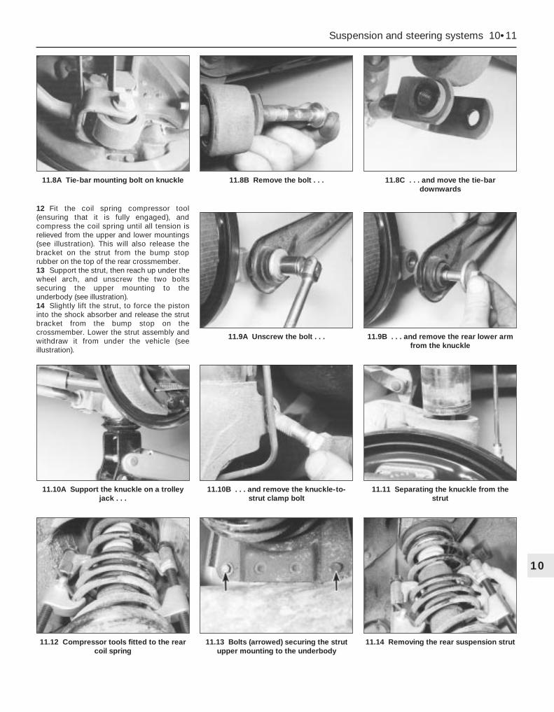
12 Fit the coil spring compressor tool(ensuring that it is fully engaged), andcompress the coil spring until all tension isrelieved from the upper and lower mountings(see illustration). This will also release thebracket on the strut from the bump stoprubber on the top of the rear crossmember.13 Support the strut, then reach up under thewheel arch, and unscrew the two boltssecuring the upper mounting to theunderbody (see illustration).14 Slightly lift the strut, to force the pistoninto the shock absorber and release the strutbracket from the bump stop on thecrossmember. Lower the strut assembly andwithdraw it from under the vehicle (seeillustration).
Suspension and steering systems 10•11
10
11.12 Compressor tools fitted to the rearcoil spring
11.13 Bolts (arrowed) securing the strutupper mounting to the underbody
11.14 Removing the rear suspension strut
11.10A Support the knuckle on a trolleyjack . . .
11.10B . . . and remove the knuckle-to-strut clamp bolt
11.11 Separating the knuckle from thestrut
11.9A Unscrew the bolt . . . 11.9B . . . and remove the rear lower armfrom the knuckle
11.8A Tie-bar mounting bolt on knuckle 11.8B Remove the bolt . . . 11.8C . . . and move the tie-bardownwards

Refitting15 Locate the strut assembly (together withthe coil spring compressor tool) under thewheel arch, and locate the bracket on thebump stop on the rear suspensioncrossmember. Insert the two bolts securingthe upper mounting to the underbody tower,and tighten them to the specified torque.16 Carefully release the coil springcompressor tool, making sure that the springlocates correctly in the upper and lower seats,and that the strut bracket locates on thecrossmember bump stop. The bump stop istapered inwards, and the strut bracket shouldbe fully engaged with it before releasing thecoil spring.17 Raise the knuckle and engage it with thestrut, then insert the clamp bolt and tighten tothe specified torque.18 Reconnect the front and rear lower arms
to the knuckle, and finger-tighten the bolts atthis stage.19 Reconnect the tie-bar to the bottom of theknuckle, and finger-tighten the bolt at thisstage.20 Refit the anti-roll bar link to the lower arm,and tighten the nut to the specified torque.21 On disc brake models, refit the caliperbracket to the knuckle, and tighten themounting bolts to the specified torque (seeChapter 9). Make sure that the flexible brakehose is not twisted.22 On drum brake models, connect theflexible hose to the strut, insert the clip, theninsert the rigid brake line and tighten the unionnut. Remove the brake hose clamp, thenbleed the hydraulic brake circuit as describedin Chapter 9.23 Where applicable, reconnect the wiringmulti-plug for the adaptive damping, and clipthe wiring to the strut.
24 Where applicable, refit the ABS sensor asdescribed in Chapter 9, and clip the wiring tothe strut.25 Refit the wheel, and lower the vehicle tothe ground.26 With the weight of the vehicle on the rearsuspension, fully tighten the lower arm andtie-bar mounting bolts.
1 The procedure is similar to that for the frontsuspension strut, and reference should be madeto Section 5. Note that the spring compressortools will already be in position on the coil springfollowing the removal operation. Refer also tothe accompanying illustrations for details of theseparate components (see illustrations).
Removal1 Chock the front wheels, then jack up therear of the vehicle and support it on axlestands. Remove both rear wheels.2 Unscrew the nuts securing the anti-roll barlinks to the front lower arms on both sides.Hold the upper part of the links with a spannerwhile loosening the nuts. Recover the rubberbushes (see illustrations).
13 Rear anti-roll bar and links(Saloon/Hatchback models) -removal and refitting
12 Rear suspension strut(Saloon/Hatchback models) -overhaul
10•12 Suspension and steering systems
12.1A Rear strut dismantling - unscrewthe upper mounting nut . . .
12.1B . . . remove the cup . . . 12.1C . . . upper mounting bracket andseat . . .
13.2A Loosen the nut . . . 13.2B . . . remove the nut and rubber bush . . .
12.1D . . . gaiter and bump stop . . . 12.1E . . . and coil spring
13.2C . . . and remove the anti-roll bar linkfrom the lower arm

3 Unscrew the bolts securing the anti-roll barmounting clamps to the rear suspensioncrossmember, then unhook the clamps andwithdraw the anti-roll bar from under thevehicle (see illustration).4 Examine the rubber bushes for themounting clamps and links, and if necessaryrenew them. The links are availableindividually.
Refitting5 Locate the anti-roll bar on the rearcrossmember, hook the mounting clamps inposition, and insert the bolts. Tighten thebolts to the specified torque.6 Locate the anti-roll bar links in the frontlower arms on both sides, making sure thatthe rubber bushes are in position. Refit thenuts and tighten them to the specified torque.7 Refit the rear wheels, and lower the vehicleto the ground.
Removal1 Chock the front wheels, then jack up therear of the vehicle and support it on axlestands. Remove the appropriate rear wheel.
Front lower arm2 To remove the front lower arm, it isnecessary to remove the fuel tank first. Referto Chapter 4 for details.3 Unscrew the nut and disconnect the anti-roll bar link from the lower arm. Hold theactual link with an adjustable spanner or gripswhile unscrewing the nut, to prevent damageto the link joint. Recover the rubber bush.4 Unscrew and remove the bolt securing thefront lower arm to the knuckle.5 Unscrew and remove the bolt securing thefront lower arm to the crossmember.6 Withdraw the front lower arm from underthe vehicle.
Rear lower arm7 Unscrew and remove the bolt securing therear lower arm to the knuckle.
8 The bolt securing the rear lower arm to thecrossmember has an eccentric head andspacer, which are used to adjust the rear toesetting. Before removing this bolt, mark itsposition, using a scriber or similar sharpinstrument through the aperture in thecrossmember.9 Unscrew and remove the bolt securing therear lower arm to the crossmember (seeillustration). The bolt may be removedthrough the aperture in the crossmember.Recover the eccentric spacer.10 Withdraw the rear lower arm from underthe vehicle.
Refitting11 Refitting is a reversal of the removalprocedure, but the arm mounting bolts shouldbe finger-tightened initially, and only fullytightened after the vehicle is lowered to theground, so that its weight is on the rearsuspension. Note that the rear lower arm ismarked “TOP” for correct refitting (seeillustration). The rear toe setting should bechecked, and if necessary adjusted, at theearliest opportunity.
Removal1 Chock the front wheels, then jack up therear of the vehicle and support it on axlestands. Remove the appropriate rear wheel.2 Disconnect the handbrake cable from thetie-bar bracket on the underbody.3 Unscrew and remove the bolt securing thetie-bar bracket to the rear suspensionknuckle.4 Unscrew the bolts securing the tie-barbracket to the underbody, and withdraw thebracket from the vehicle (see illustration).5 Mount the bracket in a vice, then unscrewand remove the bolt, and remove the tie-barfrom the bracket.6 It is not possible to renew the rubberbushes - if they are worn excessively, the tie-bar should be renewed complete.
Refitting7 Refitting is a reversal of the removalprocedure. The bracket-to-underbody boltsshould be fully tightened to the specifiedtorque before lowering the vehicle. The boltssecuring the tie-bar to the bracket andknuckle should be finger-tightened initially,and only fully tightened after the vehicle islowered to the ground, so that its weight is onthe rear suspension.
Note: Before attempting to remove the rearsuspension crossmember, tools to hold thecoil springs in compression must be obtained.Careful use of conventional coil springcompressors will prove satisfactory.
Removal1 Chock the front wheels, then jack up therear of the vehicle and support it on axlestands. Remove both rear wheels.2 Remove the complete exhaust system asdescribed in Chapter 4.3 Unscrew and remove the bolts securing thetie-bars to the rear suspension knuckles, anddisconnect the tie-bars.4 Unscrew the nuts securing the rear anti-rollbar links to the front lower arms. Hold the
16 Rear suspensioncrossmember(Saloon/Hatchback models) -removal and refitting
15 Rear suspension tie-bar(Saloon/Hatchback models) -removal and refitting
14 Rear suspension lower arms(Saloon/Hatchback models) -removal and refitting
Suspension and steering systems 10•13
10
14.11 “TOP” marking on the rear lowerarm
15.4 Tie-bar bracket on the underbody
13.3 Rear anti-roll bar mounting clamp 14.9 Bolt securing the rear lower arm tothe crossmember
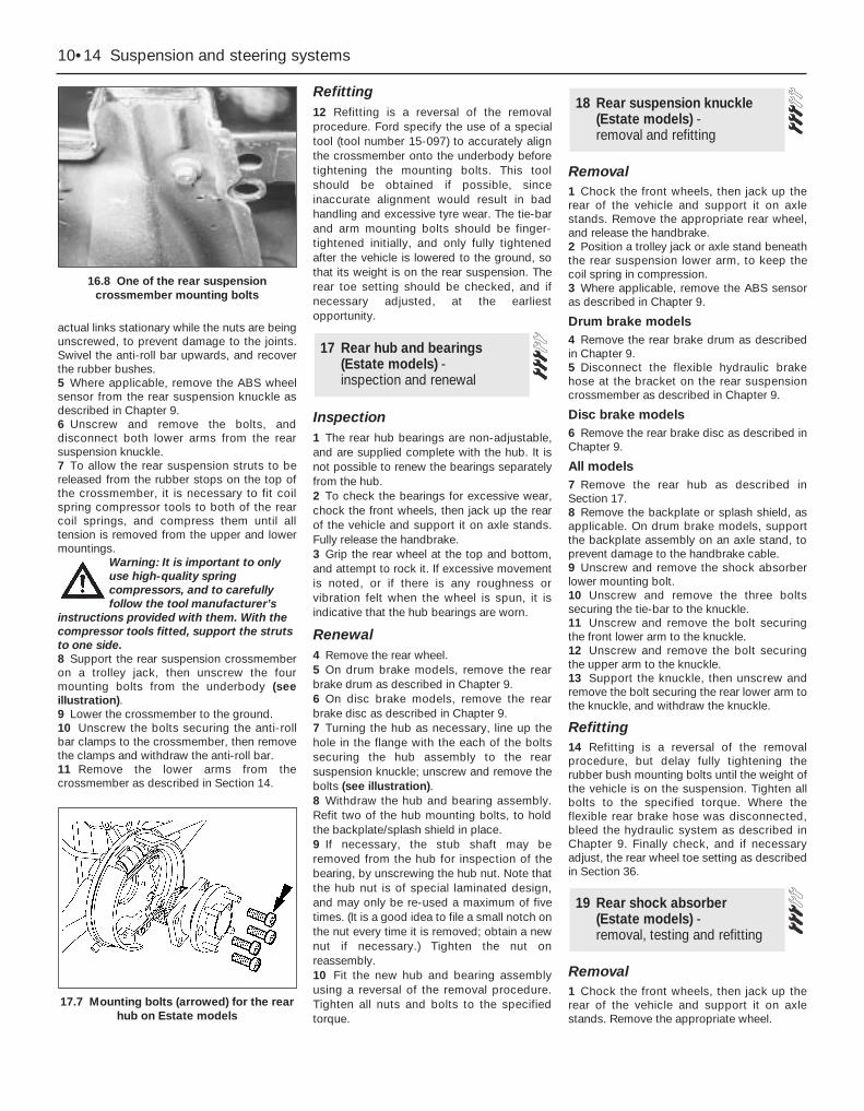
actual links stationary while the nuts are beingunscrewed, to prevent damage to the joints.Swivel the anti-roll bar upwards, and recoverthe rubber bushes.5 Where applicable, remove the ABS wheelsensor from the rear suspension knuckle asdescribed in Chapter 9.6 Unscrew and remove the bolts, anddisconnect both lower arms from the rearsuspension knuckle.7 To allow the rear suspension struts to bereleased from the rubber stops on the top ofthe crossmember, it is necessary to fit coilspring compressor tools to both of the rearcoil springs, and compress them until alltension is removed from the upper and lowermountings.
Warning: It is important to onlyuse high-quality springcompressors, and to carefullyfollow the tool manufacturer’s
instructions provided with them. With thecompressor tools fitted, support the strutsto one side.8 Support the rear suspension crossmemberon a trolley jack, then unscrew the fourmounting bolts from the underbody (seeillustration).9 Lower the crossmember to the ground.10 Unscrew the bolts securing the anti-rollbar clamps to the crossmember, then removethe clamps and withdraw the anti-roll bar.11 Remove the lower arms from thecrossmember as described in Section 14.
Refitting12 Refitting is a reversal of the removalprocedure. Ford specify the use of a specialtool (tool number 15-097) to accurately alignthe crossmember onto the underbody beforetightening the mounting bolts. This toolshould be obtained if possible, sinceinaccurate alignment would result in badhandling and excessive tyre wear. The tie-barand arm mounting bolts should be finger-tightened initially, and only fully tightenedafter the vehicle is lowered to the ground, sothat its weight is on the rear suspension. Therear toe setting should be checked, and ifnecessary adjusted, at the earliestopportunity.
Inspection1 The rear hub bearings are non-adjustable,and are supplied complete with the hub. It isnot possible to renew the bearings separatelyfrom the hub.2 To check the bearings for excessive wear,chock the front wheels, then jack up the rearof the vehicle and support it on axle stands.Fully release the handbrake.3 Grip the rear wheel at the top and bottom,and attempt to rock it. If excessive movementis noted, or if there is any roughness orvibration felt when the wheel is spun, it isindicative that the hub bearings are worn.
Renewal4 Remove the rear wheel.5 On drum brake models, remove the rearbrake drum as described in Chapter 9.6 On disc brake models, remove the rearbrake disc as described in Chapter 9.7 Turning the hub as necessary, line up thehole in the flange with the each of the boltssecuring the hub assembly to the rearsuspension knuckle; unscrew and remove thebolts (see illustration).8 Withdraw the hub and bearing assembly.Refit two of the hub mounting bolts, to holdthe backplate/splash shield in place.9 If necessary, the stub shaft may beremoved from the hub for inspection of thebearing, by unscrewing the hub nut. Note thatthe hub nut is of special laminated design,and may only be re-used a maximum of fivetimes. (It is a good idea to file a small notch onthe nut every time it is removed; obtain a newnut if necessary.) Tighten the nut onreassembly.10 Fit the new hub and bearing assemblyusing a reversal of the removal procedure.Tighten all nuts and bolts to the specifiedtorque.
Removal1 Chock the front wheels, then jack up therear of the vehicle and support it on axlestands. Remove the appropriate rear wheel,and release the handbrake.2 Position a trolley jack or axle stand beneaththe rear suspension lower arm, to keep thecoil spring in compression.3 Where applicable, remove the ABS sensoras described in Chapter 9.
Drum brake models4 Remove the rear brake drum as describedin Chapter 9.5 Disconnect the flexible hydraulic brakehose at the bracket on the rear suspensioncrossmember as described in Chapter 9.
Disc brake models6 Remove the rear brake disc as described inChapter 9.
All models7 Remove the rear hub as described inSection 17.8 Remove the backplate or splash shield, asapplicable. On drum brake models, supportthe backplate assembly on an axle stand, toprevent damage to the handbrake cable.9 Unscrew and remove the shock absorberlower mounting bolt.10 Unscrew and remove the three boltssecuring the tie-bar to the knuckle.11 Unscrew and remove the bolt securingthe front lower arm to the knuckle.12 Unscrew and remove the bolt securingthe upper arm to the knuckle.13 Support the knuckle, then unscrew andremove the bolt securing the rear lower arm tothe knuckle, and withdraw the knuckle.
Refitting14 Refitting is a reversal of the removalprocedure, but delay fully tightening therubber bush mounting bolts until the weight ofthe vehicle is on the suspension. Tighten allbolts to the specified torque. Where theflexible rear brake hose was disconnected,bleed the hydraulic system as described inChapter 9. Finally check, and if necessaryadjust, the rear wheel toe setting as describedin Section 36.
Removal1 Chock the front wheels, then jack up therear of the vehicle and support it on axlestands. Remove the appropriate wheel.
19 Rear shock absorber (Estate models) - removal, testing and refitting
18 Rear suspension knuckle(Estate models) - removal and refitting
17 Rear hub and bearings(Estate models) - inspection and renewal
10•14 Suspension and steering systems
16.8 One of the rear suspensioncrossmember mounting bolts
17.7 Mounting bolts (arrowed) for the rearhub on Estate models
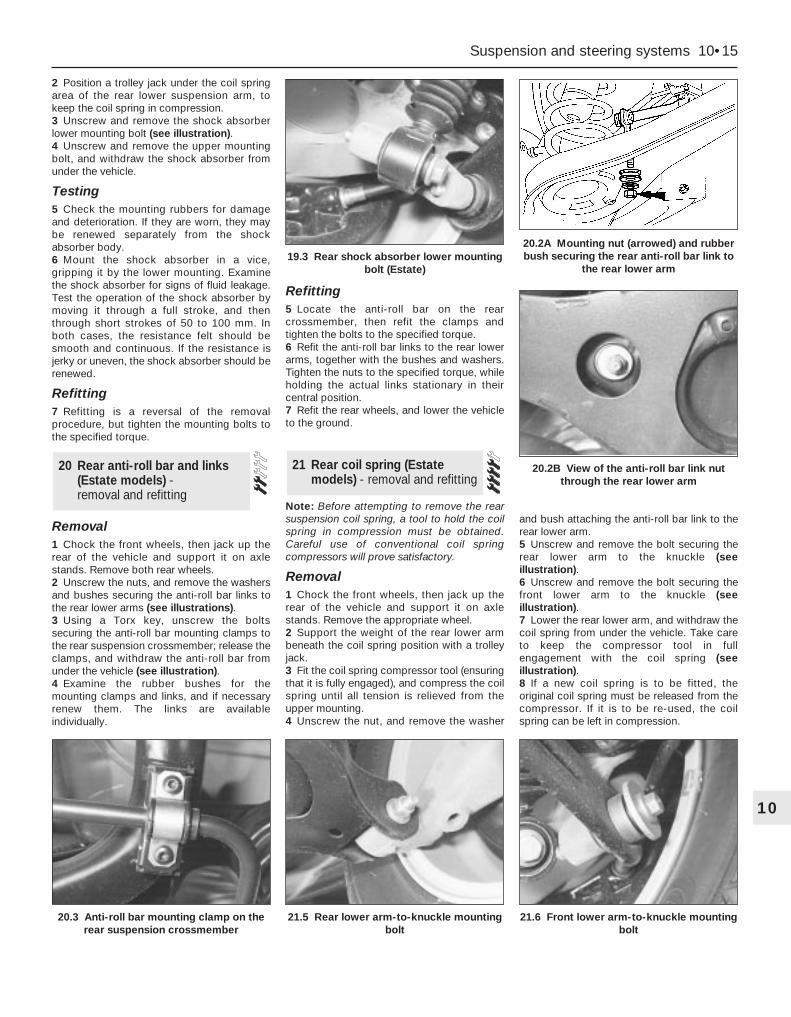
2 Position a trolley jack under the coil springarea of the rear lower suspension arm, tokeep the coil spring in compression.3 Unscrew and remove the shock absorberlower mounting bolt (see illustration).4 Unscrew and remove the upper mountingbolt, and withdraw the shock absorber fromunder the vehicle.
Testing5 Check the mounting rubbers for damageand deterioration. If they are worn, they maybe renewed separately from the shockabsorber body.6 Mount the shock absorber in a vice,gripping it by the lower mounting. Examinethe shock absorber for signs of fluid leakage.Test the operation of the shock absorber bymoving it through a full stroke, and thenthrough short strokes of 50 to 100 mm. Inboth cases, the resistance felt should besmooth and continuous. If the resistance isjerky or uneven, the shock absorber should berenewed.
Refitting7 Refitting is a reversal of the removalprocedure, but tighten the mounting bolts tothe specified torque.
Removal1 Chock the front wheels, then jack up therear of the vehicle and support it on axlestands. Remove both rear wheels.2 Unscrew the nuts, and remove the washersand bushes securing the anti-roll bar links tothe rear lower arms (see illustrations).3 Using a Torx key, unscrew the boltssecuring the anti-roll bar mounting clamps tothe rear suspension crossmember; release theclamps, and withdraw the anti-roll bar fromunder the vehicle (see illustration).4 Examine the rubber bushes for themounting clamps and links, and if necessaryrenew them. The links are availableindividually.
Refitting5 Locate the anti-roll bar on the rearcrossmember, then refit the clamps andtighten the bolts to the specified torque.6 Refit the anti-roll bar links to the rear lowerarms, together with the bushes and washers.Tighten the nuts to the specified torque, whileholding the actual links stationary in theircentral position.7 Refit the rear wheels, and lower the vehicleto the ground.
Note: Before attempting to remove the rearsuspension coil spring, a tool to hold the coilspring in compression must be obtained.Careful use of conventional coil springcompressors will prove satisfactory.
Removal1 Chock the front wheels, then jack up therear of the vehicle and support it on axlestands. Remove the appropriate wheel.2 Support the weight of the rear lower armbeneath the coil spring position with a trolleyjack.3 Fit the coil spring compressor tool (ensuringthat it is fully engaged), and compress the coilspring until all tension is relieved from theupper mounting.4 Unscrew the nut, and remove the washer
and bush attaching the anti-roll bar link to therear lower arm.5 Unscrew and remove the bolt securing therear lower arm to the knuckle (seeillustration).6 Unscrew and remove the bolt securing thefront lower arm to the knuckle (seeillustration).7 Lower the rear lower arm, and withdraw thecoil spring from under the vehicle. Take careto keep the compressor tool in fullengagement with the coil spring (seeillustration).8 If a new coil spring is to be fitted, theoriginal coil spring must be released from thecompressor. If it is to be re-used, the coilspring can be left in compression.
21 Rear coil spring (Estatemodels) - removal and refitting
20 Rear anti-roll bar and links(Estate models) - removal and refitting
Suspension and steering systems 10•15
10
20.3 Anti-roll bar mounting clamp on therear suspension crossmember
21.5 Rear lower arm-to-knuckle mountingbolt
21.6 Front lower arm-to-knuckle mountingbolt
19.3 Rear shock absorber lower mountingbolt (Estate)
20.2A Mounting nut (arrowed) and rubberbush securing the rear anti-roll bar link to
the rear lower arm
20.2B View of the anti-roll bar link nutthrough the rear lower arm
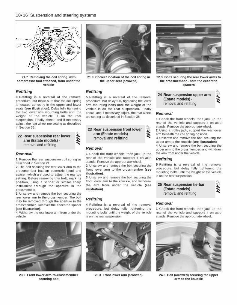
Refitting9 Refitting is a reversal of the removalprocedure, but make sure that the coil springis located correctly in the upper and lowerseats (see illustration). Delay fully tighteningthe two lower arm mounting bolts until theweight of the vehicle is on the rearsuspension. Finally check, and if necessaryadjust, the rear wheel toe setting as describedin Section 36.
Removal1 Remove the rear suspension coil spring asdescribed in Section 21.2 The bolt securing the rear lower arm to thecrossmember has an eccentric head andspacer, which are used to adjust the rear toesetting. Before removing this bolt, mark itsposition, using a scriber or similar sharpinstrument through the aperture in thecrossmember.3 Unscrew and remove the bolt securing therear lower arm to the crossmember. The boltmay be removed through the aperture in thecrossmember. Recover the eccentric spacer(see illustration).4 Withdraw the rear lower arm from under thevehicle.
Refitting5 Refitting is a reversal of the removalprocedure, but delay fully tightening the lowerarm mounting bolts until the weight of thevehicle is on the rear suspension. Finallycheck, and if necessary adjust, the rear wheeltoe setting as described in Section 36.
Removal1 Chock the front wheels, then jack up therear of the vehicle and support it on axlestands. Remove the appropriate wheel.2 Unscrew and remove the bolt securing thefront lower arm to the crossmember (seeillustration).3 Unscrew and remove the bolt securing thefront lower arm to the knuckle, and withdrawthe arm from under the vehicle (seeillustration).
Refitting4 Refitting is a reversal of the removalprocedure, but delay fully tightening themounting bolts until the weight of the vehicleis on the rear suspension.
Removal1 Chock the front wheels, then jack up therear of the vehicle and support it on axlestands. Remove the appropriate wheel.2 Using a trolley jack, support the rear lowerarm beneath the coil spring position.3 Unscrew and remove the bolt securing theupper arm to the knuckle (see illustration).4 Unscrew and remove the bolt securing theupper arm to the crossmember, and withdrawthe arm from under the vehicle.
Refitting5 Refitting is a reversal of the removalprocedure, but delay fully tightening themounting bolts until the weight of the vehicleis on the rear suspension.
Removal1 Chock the front wheels, then jack up therear of the vehicle and support it on axlestands. Remove the appropriate wheel.
25 Rear suspension tie-bar(Estate models) - removal and refitting
24 Rear suspension upper arm(Estate models) - removal and refitting
23 Rear suspension front lowerarm (Estate models) -removal and refitting22 Rear suspension rear lower
arm (Estate models) -removal and refitting
10•16 Suspension and steering systems
21.7 Removing the coil spring, withcompressor tool attached, from under the
vehicle
21.9 Correct location of the coil spring inthe upper seat (arrowed)
22.3 Bolts securing the rear lower arms tothe crossmember - note the eccentric
spacers
23.2 Front lower arm-to-crossmembersecuring bolt
23.3 Front lower arm (arrowed) 24.3 Bolt (arrowed) securing the upperarm to the knuckle

2 Using a trolley jack, support the rear lowerarm beneath the coil spring position.3 Unscrew and remove the bolt securing therear shock absorber to the knuckle.4 Where applicable, release the ABS wheelsensor lead from the tie-bar.5 Detach the handbrake cable from the tie-bar bracket.6 Refer to Chapter 9, and disconnect thehandbrake cable from the rear brake shoes orrear caliper, as applicable. Pass the cablethrough the hole in the tie-bar.7 Unscrew and remove the three boltssecuring the tie-bar to the knuckle (seeillustration).8 Unbolt the tie-bar bracket from theunderbody, and withdraw the assembly fromunder the vehicle (see illustrations).9 Mount the tie-bar in a vice, then unscrewthe bolt, and separate the tie-bar from itsbracket.10 It is not possible to renew the rubber bushin the tie-bar, and if it is excessively worn, thecomplete tie-bar must be renewed.
Refitting11 Refitting is a reversal of the removalprocedure, but delay fully tightening the boltwhich secures the arm to the bracket until theweight of the vehicle is on the rearsuspension. On completion, check theoperation of the handbrake.
Removal1 Chock the front wheels, then jack up therear of the vehicle and support on axlesstands. Remove both rear wheels. Make surethat the vehicle is supported high enough forthe crossmember to be removed.2 Disconnect the handbrake rear cables fromthe front primary cable, as described inChapter 9.3 Where applicable, remove the ABS wheelsensors from the rear knuckles, anddisconnect the wiring leads from the clips asdescribed in Chapter 9.4 Disconnect the flexible brake hoses fromthe brackets on both sides of thecrossmember, as described in Chapter 9.5 Working on each side of the vehicle, unboltthe tie-bar brackets from the underbody.6 Support the rear suspension crossmemberon a trolley jack.7 Unscrew the mounting bolts, and lower thecrossmember to the ground (seeillustrations).8 If necessary, remove the suspensioncomponents from the crossmember asdescribed in the appropriate Sections of thisChapter.
Refitting9 Refitting is a reversal of the removalprocedure, noting the following points:(a) When raising the crossmember, note that
guide pins are provided to ensure correctalignment (see illustration).
(b) Delay fully tightening the suspensionmounting bolts until the weight of thevehicle is on the rear suspension.
(c) Tighten all bolts to the specified torque.(d) Bleed the brake hydraulic system as
described in Chapter 9.(e) Check, and if necessary adjust, the rear
wheel toe setting as described in Section 36.
Warning: All models are equippedwith an air bag system. Makesure that the safety
recommendations given in Chapter 12 arefollowed, to prevent personal injury.
Removal1 Disconnect the battery negative (earth) lead(refer to Chapter 5, Section 1).
Warning: Before proceeding, waita minimum of 15 minutes, as aprecaution against accidentalfiring of the air bag unit. This
period ensures that any stored energy inthe back-up capacitor is dissipated.
27 Steering wheel - removal and refitting
26 Rear suspensioncrossmember (Estatemodels) - removal and refitting
Suspension and steering systems 10•17
10
26.7A Rear suspension crossmember rearmounting bolt
26.7B Rear suspension crossmemberfront mounting bolt
26.9 Guide pin (arrowed) for correctalignment of the rear crossmember
25.7 Bolts (arrowed) securing the rearsuspension tie-bar to the knuckle
25.8A Tie-bar bracket front bolt (arrowed)on the underbody
25.8B Tie-bar bracket rear bolt (arrowed)on the underbody
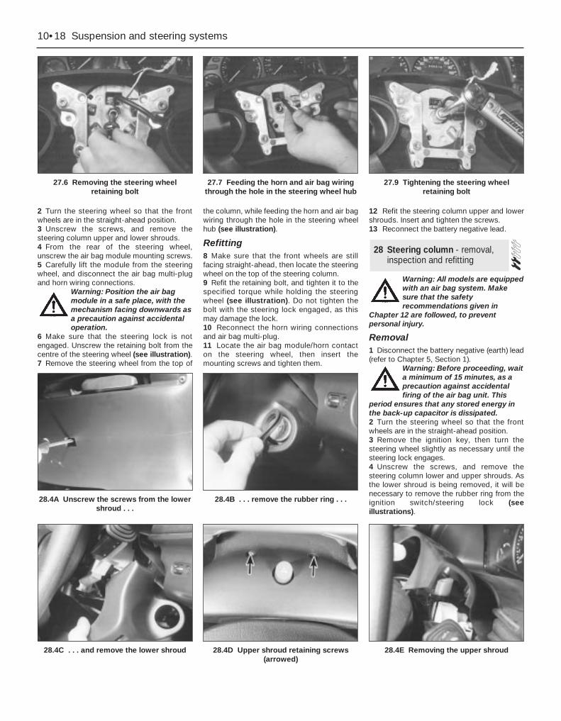
2 Turn the steering wheel so that the frontwheels are in the straight-ahead position.3 Unscrew the screws, and remove thesteering column upper and lower shrouds.4 From the rear of the steering wheel,unscrew the air bag module mounting screws. 5 Carefully lift the module from the steeringwheel, and disconnect the air bag multi-plugand horn wiring connections.
Warning: Position the air bagmodule in a safe place, with themechanism facing downwards asa precaution against accidentaloperation.
6 Make sure that the steering lock is notengaged. Unscrew the retaining bolt from thecentre of the steering wheel (see illustration).7 Remove the steering wheel from the top of
the column, while feeding the horn and air bagwiring through the hole in the steering wheelhub (see illustration).
Refitting8 Make sure that the front wheels are stillfacing straight-ahead, then locate the steeringwheel on the top of the steering column.9 Refit the retaining bolt, and tighten it to thespecified torque while holding the steeringwheel (see illustration). Do not tighten thebolt with the steering lock engaged, as thismay damage the lock.10 Reconnect the horn wiring connectionsand air bag multi-plug.11 Locate the air bag module/horn contacton the steering wheel, then insert themounting screws and tighten them.
12 Refit the steering column upper and lowershrouds. Insert and tighten the screws.13 Reconnect the battery negative lead.
Warning: All models are equippedwith an air bag system. Makesure that the safetyrecommendations given in
Chapter 12 are followed, to preventpersonal injury.
Removal1 Disconnect the battery negative (earth) lead(refer to Chapter 5, Section 1).
Warning: Before proceeding, waita minimum of 15 minutes, as aprecaution against accidentalfiring of the air bag unit. This
period ensures that any stored energy inthe back-up capacitor is dissipated.2 Turn the steering wheel so that the frontwheels are in the straight-ahead position.3 Remove the ignition key, then turn thesteering wheel slightly as necessary until thesteering lock engages.4 Unscrew the screws, and remove thesteering column lower and upper shrouds. Asthe lower shroud is being removed, it will benecessary to remove the rubber ring from theignition switch/steering lock (seeillustrations).
28 Steering column - removal,inspection and refitting
10•18 Suspension and steering systems
27.6 Removing the steering wheelretaining bolt
27.7 Feeding the horn and air bag wiringthrough the hole in the steering wheel hub
27.9 Tightening the steering wheelretaining bolt
28.4C . . . and remove the lower shroud 28.4D Upper shroud retaining screws(arrowed)
28.4A Unscrew the screws from the lowershroud . . .
28.4B . . . remove the rubber ring . . .
28.4E Removing the upper shroud
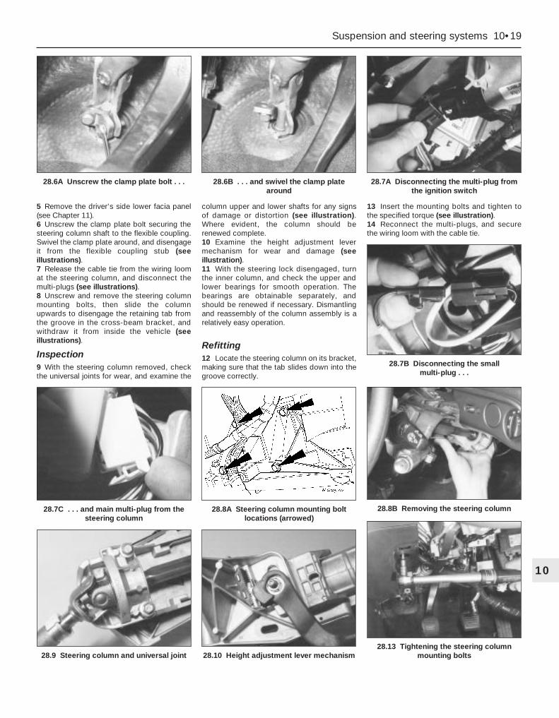
5 Remove the driver’s side lower facia panel(see Chapter 11).6 Unscrew the clamp plate bolt securing thesteering column shaft to the flexible coupling.Swivel the clamp plate around, and disengageit from the flexible coupling stub (seeillustrations).7 Release the cable tie from the wiring loomat the steering column, and disconnect themulti-plugs (see illustrations).8 Unscrew and remove the steering columnmounting bolts, then slide the columnupwards to disengage the retaining tab fromthe groove in the cross-beam bracket, andwithdraw it from inside the vehicle (seeillustrations).
Inspection9 With the steering column removed, checkthe universal joints for wear, and examine the
column upper and lower shafts for any signsof damage or distortion (see illustration).Where evident, the column should berenewed complete.10 Examine the height adjustment levermechanism for wear and damage (seeillustration).11 With the steering lock disengaged, turnthe inner column, and check the upper andlower bearings for smooth operation. Thebearings are obtainable separately, andshould be renewed if necessary. Dismantlingand reassembly of the column assembly is arelatively easy operation.
Refitting12 Locate the steering column on its bracket,making sure that the tab slides down into thegroove correctly.
13 Insert the mounting bolts and tighten tothe specified torque (see illustration).14 Reconnect the multi-plugs, and securethe wiring loom with the cable tie.
Suspension and steering systems 10•19
10
28.9 Steering column and universal joint 28.10 Height adjustment lever mechanism28.13 Tightening the steering column
mounting bolts
28.7C . . . and main multi-plug from thesteering column
28.8A Steering column mounting boltlocations (arrowed)
28.8B Removing the steering column
28.6A Unscrew the clamp plate bolt . . . 28.6B . . . and swivel the clamp platearound
28.7A Disconnecting the multi-plug fromthe ignition switch
28.7B Disconnecting the small multi-plug . . .

15 Locate the steering column shaft on theflexible coupling, swivel the clamp plateround, then insert the bolt and tighten to thespecified torque.16 Refit the driver’s side lower trim panel.17 Refit the steering column upper and lowershrouds.18 Reconnect the battery negative lead.
Removal1 Disconnect the battery negative (earth) lead(refer to Chapter 5, Section 1).2 Turn the steering wheel so that the frontwheels are in the straight-ahead position.Remove the ignition key, then turn thesteering wheel slightly as necessary until thesteering lock engages.3 Unscrew the clamp plate bolt securing thesteering column shaft to the flexible coupling.Swivel the clamp plate around, and disengageit from the flexible coupling stub.4 Carefully prise the rubber boot from thebulkhead, and withdraw it into the passengercompartment. Take care not to damage thesealing lip of the boot.5 Using an Allen key, unscrew the clamp boltsecuring the flexible coupling to the pinionshaft on the steering gear, and withdraw thecoupling from inside the vehicle.
Refitting6 Refitting is a reversal of the removalprocedure, but tighten the clamp bolts to thespecified torque. Make sure that the rubberboot engages correctly in the bulkhead andon the flexible coupling.
Removal1 Remove the steering column flexiblecoupling as described in Section 29.2 Apply the handbrake, then jack up the front
of the vehicle and support it on axle stands.Remove both front wheels.3 Working beneath the vehicle, unbolt therear engine mounting from the transmissionand underbody.4 Extract the split pins from the track rod endballjoint nuts, then unscrew the nuts, anddetach the rods from the arms on the steeringknuckles using a conventional balljointremoval tool. Take care not to damage theballjoint seals.5 Position a suitable container beneath thesteering gear, then unscrew the union nutssecuring the power steering fluid supply,return, and cooler lines to the steering gear.Identify the lines for position, then unbolt theclamps, disconnect the lines, and allow thefluid to drain into the container. Cover theapertures in the steering gear and also theends of the fluid pipes, to prevent the ingressof dust and dirt into the hydraulic circuit.6 Unscrew and remove the steering gearmounting bolts. The bolts are located on topof the steering gear, and are difficult to reach.Ideally, the special U-shaped Ford spannershould be used, but it is just possible to reachthem with a normal spanner (see illustration).7 Withdraw the steering gear through thewheel arch.
Refitting8 If the steering gear is being replaced with anew one, the new unit will be suppliedtogether with union nuts already fitted. Thenew nuts must only be used with new feedand return lines - otherwise, they must beremoved and discarded. If the original linesand union nuts are being used, the Teflonrings on the union nuts must be renewed. Todo this, the rings must be expandedindividually onto a fitting adaptor (seeillustration), then located in the grooves ofthe union nuts.9 Locate the steering gear on the subframe,and insert the two mounting bolts. Tighten thebolts to the specified torque (see illustration).Note that, if the special Ford tool is beingused, the bottom of the tool must be turnedanti-clockwise in order to tighten themounting bolts.
10 Remove the covers from the apertures onthe steering gear, then reconnect the fluidlines and tighten the union nuts to thespecified torque. Refit the clamps and tightenthe bolts.11 Refit the track rod end balljoints to thesteering knuckles, and tighten the nuts to thespecified torque. Check that the split pinholes are aligned; if necessary, turn the nutsto the nearest alignment, making sure that thetorque wrench setting is still within thespecified range. Insert new split pins, andbend them back to secure.12 Refit the rear engine mounting to thetransmission and underbody, and tighten thebolts to the specified torque.13 Refit the front wheels, and lower thevehicle to the ground.14 Refit the steering column flexible couplingwith reference to Section 29.15 Bleed the power steering hydraulicsystem as described in Section 33.16 Have the front wheel alignment checked,and if necessary adjusted, at the earliestopportunity (refer to Section 36).
Removal1 Disconnect the battery negative (earth) lead(refer to Chapter 5, Section 1).2 Working inside the vehicle, unscrew theclamp plate bolt securing the steering columnshaft to the flexible coupling. Swivel the clampplate around, and disengage it from theflexible coupling stub.3 Apply the handbrake, then jack up the frontof the vehicle and support it on axle stands.Remove both wheels.4 On manual transmission models,disconnect the gearchange linkage andsupport rods from the transmission, asdescribed in Chapter 7, Part A.5 Remove the exhaust downpipe complete,as described in Chapter 4.6 Remove the cover from under the radiatorby unscrewing the screws and releasing theclips.
31 Power steering gear (left-hand-drive models withABS) - removal and refitting
30 Power steering gear (all exceptleft-hand-drive models withABS) - removal and refitting
29 Steering column flexiblecoupling - removal and refitting
10•20 Suspension and steering systems
30.6 U-shaped Ford spanner forunscrewing the steering gear mounting
bolts
30.8 Using an adaptor to fit the Teflonrings to the union nuts
1 Adaptor 2 Teflon ring 3 Union nut4 Groove location for the Teflon ring
30.9 Tightening the steering gearmounting bolts using the U-shaped
spanner (arrowed)

7 Support the radiator in its raised position,by inserting split pins through the small holesin the radiator mounting extensions whichprotrude through the upper mountings (seeillustration).8 Unbolt and remove the radiator lowermounting brackets.9 Where applicable, unscrew the boltssecuring the air conditioning accumulator tothe subframe.10 Working beneath the vehicle, unbolt theengine rear mounting from the transmissionand underbody.11 Unscrew the front engine mounting-to-cylinder block bolts, and also the through-bolt.12 Extract the split pins from the track rodend balljoint nuts, then unscrew the nuts, anddetach the rods from the arms on the steeringknuckles using a conventional balljointremoval tool. Take care not to damage theballjoint seals.13 Working on each side in turn, unscrew themounting nuts, and remove the anti-roll barlinks from the front suspension struts. Notethat, on models fitted with ABS, the ABSsensor wiring support brackets are locatedbeneath the nuts.14 Working on each side in turn, note whichway round the front suspension lower armballjoint clamp bolt is fitted, then unscrew andremove it from the knuckle assembly. Leverthe balljoint down from the knuckle - if it istight, prise the joint open carefully using alarge flat-bladed tool. Take care not todamage the balljoint seal during theseparation procedure.15 Support the weight of the front subframeassembly on two trolley jacks (or two scissorjacks).16 Unscrew and remove the subframemounting bolts, then lower the subframesufficiently to gain access to the powersteering fluid pipes on top of the steeringgear. Note that the front subframe mounting
bolts are gold in colour - the rear ones aresilver.17 Position a suitable container beneath thesteering gear, then unscrew the union nutssecuring the power steering fluid supply,return, and cooler lines to the steering gear.Identify the lines for position, then unbolt theclamps, disconnect the lines, and allow thefluid to drain into the container. Cover theapertures in the steering gear and also theends of the fluid pipes, to prevent the ingressof dust and dirt into the hydraulic circuit.18 Lower the subframe, together with thepower steering gear, to the ground.19 Unscrew the mounting bolts and removethe power steering gear from the subframe.20 Using a suitable Allen key, unscrew theclamp bolt securing the flexible coupling tothe pinion shaft on the steering gear, andwithdraw the coupling.21 Refer to Section 30, paragraph 8 fordetails of renewing the Teflon rings.
Refitting22 Refit the flexible coupling to the pinionshaft on the steering gear, then insert andtighten the clamp bolt using an Allen key.23 Locate the power steering gear on thesubframe, then insert the mounting bolts andtighten to the specified torque.24 Raise the subframe until it is possible torefit the fluid lines. Tighten the union nuts andclamps.25 Raise the subframe, making sure that thealignment holes are in line with the holes inthe underbody. At the same time, make surethat the flexible coupling locates correctly onthe steering column. Ford technicians use aspecial tool to ensure that the subframe iscorrectly aligned - refer to Chapter 2 for moredetails of the alignment procedure. With thesubframe aligned, insert and tighten themounting bolts to the specified torque. Notethat the front mounting bolts are gold incolour - the rear bolts are silver.26 Working on each side in turn, refit thefront suspension lower arm balljoint to theknuckle assembly, and insert the clamp boltwith its head facing forwards. Refit the nutand tighten to the specified torque.27 Working on each side in turn, refit theanti-roll bar links and tighten the mountingnuts to the specified torque. On models fittedwith ABS, don’t forget to locate the wheelsensor wiring support brackets beneath thenuts.28 Refit the track rod end balljoints to thesteering knuckles, and tighten the nuts to thespecified torque. Check if the split pin holesare aligned, and if necessary turn the nuts tothe nearest alignment, making sure that thetorque wrench setting is still within thespecified range. Insert new split pins, andbend them back to secure.29 Refit and tighten the engine frontmounting bolts.30 Refit the engine rear mounting and tightenthe bolts.
31 Where applicable, insert and tighten theair conditioning accumulator bolts.32 Refit the radiator lower mounting bracketsand tighten the bolts.33 Remove the split pins supporting theradiator in its raised position.34 Refit the cover under the radiator.35 Refit the exhaust downpipe as describedin Chapter 4.36 On manual transmission models,reconnect the gearchange linkage andsupport rods.37 Refit the front wheels, and lower thevehicle to the ground.38 Working inside the vehicle, reconnect thesteering column clamp plate, then insert thebolt and tighten to the specified torque.39 Reconnect the battery negative lead.40 Bleed the power steering hydraulicsystem as described in Section 33.41 Have the front wheel alignment checked,and if necessary adjusted, at the earliestopportunity (refer to Section 36).
1 Remove the track rod end and its locknutfrom the track rod, as described in Section 35.Make sure that a note is made of the exactposition of the track rod end on the track rod,in order to retain the front wheel alignmentsetting on refitting.2 Release the outer retaining clip and innerplastic clamp band, and disconnect the gaiterfrom the steering gear housing.3 Disconnect the breather from the gaiter,then slide the gaiter off the track rod.4 Scrape off all grease from the old gaiter,and apply to the track rod inner joint. Wipeclean the seating areas on the steering gearhousing and track rod.5 Slide the new gaiter onto the track rod andsteering gear housing, and reconnect thebreather.6 Fit a new inner plastic clamp band andouter retaining clip.7 Refit the track rod end as described inSection 35.8 Have the front wheel alignment checked,and if necessary adjusted, at the earliestopportunity (refer to Section 36).
1 Following any operation in which the powersteering fluid lines have been disconnected,the power steering system must be bled, toremove any trapped air.2 With the front wheels in the straight-aheadposition, check the power steering fluid levelin the reservoir and, if low, add fresh fluid untilit reaches the “MAX” or “MAX COLD” mark.Pour the fluid slowly, to prevent air bubblesforming, and use only the specified fluid (referto Chapter 1 Specifications).
33 Power steering hydraulicsystem - bleeding
32 Power steering gear rubbergaiters - renewal
Suspension and steering systems 10•21
10
31.7 Method of supporting the radiator inits raised position
1 Radiator upper mounting extension2 Small hole3 Pin or split pin inserted through hole
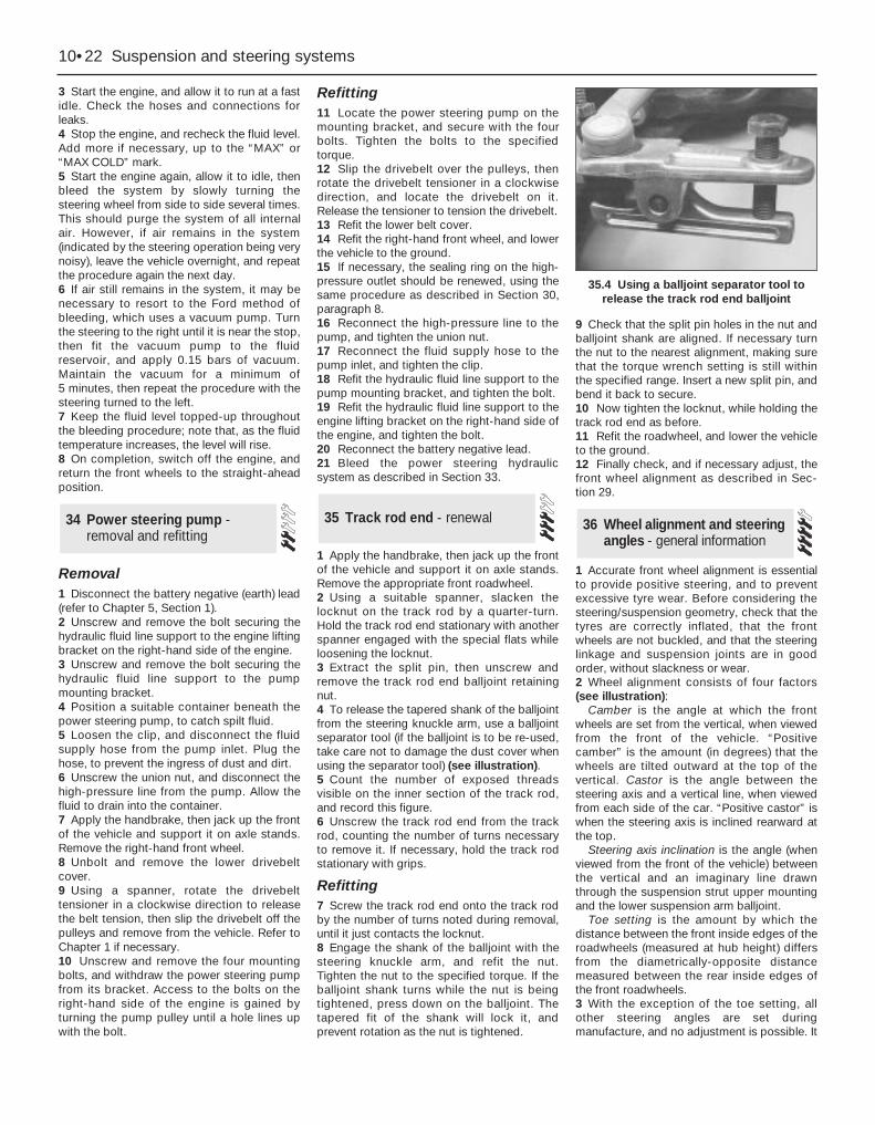
3 Start the engine, and allow it to run at a fastidle. Check the hoses and connections forleaks.4 Stop the engine, and recheck the fluid level.Add more if necessary, up to the “MAX” or“MAX COLD” mark.5 Start the engine again, allow it to idle, thenbleed the system by slowly turning thesteering wheel from side to side several times.This should purge the system of all internalair. However, if air remains in the system(indicated by the steering operation being verynoisy), leave the vehicle overnight, and repeatthe procedure again the next day.6 If air still remains in the system, it may benecessary to resort to the Ford method ofbleeding, which uses a vacuum pump. Turnthe steering to the right until it is near the stop,then fit the vacuum pump to the fluidreservoir, and apply 0.15 bars of vacuum.Maintain the vacuum for a minimum of 5 minutes, then repeat the procedure with thesteering turned to the left.7 Keep the fluid level topped-up throughoutthe bleeding procedure; note that, as the fluidtemperature increases, the level will rise.8 On completion, switch off the engine, andreturn the front wheels to the straight-aheadposition.
Removal1 Disconnect the battery negative (earth) lead(refer to Chapter 5, Section 1).2 Unscrew and remove the bolt securing thehydraulic fluid line support to the engine liftingbracket on the right-hand side of the engine.3 Unscrew and remove the bolt securing thehydraulic fluid line support to the pumpmounting bracket.4 Position a suitable container beneath thepower steering pump, to catch spilt fluid.5 Loosen the clip, and disconnect the fluidsupply hose from the pump inlet. Plug thehose, to prevent the ingress of dust and dirt.6 Unscrew the union nut, and disconnect thehigh-pressure line from the pump. Allow thefluid to drain into the container.7 Apply the handbrake, then jack up the frontof the vehicle and support it on axle stands.Remove the right-hand front wheel.8 Unbolt and remove the lower drivebeltcover.9 Using a spanner, rotate the drivebelttensioner in a clockwise direction to releasethe belt tension, then slip the drivebelt off thepulleys and remove from the vehicle. Refer toChapter 1 if necessary.10 Unscrew and remove the four mountingbolts, and withdraw the power steering pumpfrom its bracket. Access to the bolts on theright-hand side of the engine is gained byturning the pump pulley until a hole lines upwith the bolt.
Refitting11 Locate the power steering pump on themounting bracket, and secure with the fourbolts. Tighten the bolts to the specifiedtorque.12 Slip the drivebelt over the pulleys, thenrotate the drivebelt tensioner in a clockwisedirection, and locate the drivebelt on it.Release the tensioner to tension the drivebelt.13 Refit the lower belt cover.14 Refit the right-hand front wheel, and lowerthe vehicle to the ground.15 If necessary, the sealing ring on the high-pressure outlet should be renewed, using thesame procedure as described in Section 30,paragraph 8.16 Reconnect the high-pressure line to thepump, and tighten the union nut.17 Reconnect the fluid supply hose to thepump inlet, and tighten the clip.18 Refit the hydraulic fluid line support to thepump mounting bracket, and tighten the bolt.19 Refit the hydraulic fluid line support to theengine lifting bracket on the right-hand side ofthe engine, and tighten the bolt.20 Reconnect the battery negative lead.21 Bleed the power steering hydraulicsystem as described in Section 33.
1 Apply the handbrake, then jack up the frontof the vehicle and support it on axle stands.Remove the appropriate front roadwheel.2 Using a suitable spanner, slacken thelocknut on the track rod by a quarter-turn.Hold the track rod end stationary with anotherspanner engaged with the special flats whileloosening the locknut.3 Extract the split pin, then unscrew andremove the track rod end balljoint retainingnut.4 To release the tapered shank of the balljointfrom the steering knuckle arm, use a balljointseparator tool (if the balljoint is to be re-used,take care not to damage the dust cover whenusing the separator tool) (see illustration).5 Count the number of exposed threadsvisible on the inner section of the track rod,and record this figure.6 Unscrew the track rod end from the trackrod, counting the number of turns necessaryto remove it. If necessary, hold the track rodstationary with grips.
Refitting7 Screw the track rod end onto the track rodby the number of turns noted during removal,until it just contacts the locknut.8 Engage the shank of the balljoint with thesteering knuckle arm, and refit the nut.Tighten the nut to the specified torque. If theballjoint shank turns while the nut is beingtightened, press down on the balljoint. Thetapered fit of the shank will lock it, andprevent rotation as the nut is tightened.
9 Check that the split pin holes in the nut andballjoint shank are aligned. If necessary turnthe nut to the nearest alignment, making surethat the torque wrench setting is still withinthe specified range. Insert a new split pin, andbend it back to secure.10 Now tighten the locknut, while holding thetrack rod end as before.11 Refit the roadwheel, and lower the vehicleto the ground.12 Finally check, and if necessary adjust, thefront wheel alignment as described in Sec-tion 29.
1 Accurate front wheel alignment is essentialto provide positive steering, and to preventexcessive tyre wear. Before considering thesteering/suspension geometry, check that thetyres are correctly inflated, that the frontwheels are not buckled, and that the steeringlinkage and suspension joints are in goodorder, without slackness or wear.2 Wheel alignment consists of four factors(see illustration):
Camber is the angle at which the frontwheels are set from the vertical, when viewedfrom the front of the vehicle. “Positivecamber” is the amount (in degrees) that thewheels are tilted outward at the top of thevertical. Castor is the angle between thesteering axis and a vertical line, when viewedfrom each side of the car. “Positive castor” iswhen the steering axis is inclined rearward atthe top.
Steering axis inclination is the angle (whenviewed from the front of the vehicle) betweenthe vertical and an imaginary line drawnthrough the suspension strut upper mountingand the lower suspension arm balljoint.
Toe setting is the amount by which thedistance between the front inside edges of theroadwheels (measured at hub height) differsfrom the diametrically-opposite distancemeasured between the rear inside edges ofthe front roadwheels.3 With the exception of the toe setting, allother steering angles are set duringmanufacture, and no adjustment is possible. It
36 Wheel alignment and steeringangles - general information
35 Track rod end - renewal34 Power steering pump -removal and refitting
10•22 Suspension and steering systems
35.4 Using a balljoint separator tool torelease the track rod end balljoint

can be assumed, therefore, that unless thevehicle has suffered accident damage, all thepreset steering angles will be correct. Shouldthere be some doubt about their accuracy, itwill be necessary to seek the help of a Forddealer, as special gauges are needed tocheck the steering angles.4 Two methods are available to the homemechanic for checking the toe setting. Onemethod is to use a gauge to measure thedistance between the front and rear insideedges of the roadwheels. The other method isto use a scuff plate, in which each front wheelis rolled across a movable plate which recordsany deviation, or scuff, of the tyre from thestraight-ahead position as it moves across theplate. Relatively-inexpensive equipment ofboth types is available from accessory outlets.5 If, after checking the toe setting usingwhichever method is preferable, it is foundthat adjustment is necessary, proceed asfollows.6 Turn the steering wheel onto full-left lock,and record the number of exposed threads onthe right-hand track rod. Now turn thesteering onto full-right lock, and record thenumber of threads on the left-hand track rod.
If there are the same number of threads visibleon both sides, then subsequent adjustmentcan be made equally on both sides. If thereare more threads visible on one side than theother, it will be necessary to compensate forthis during adjustment. After adjustment,there must be the same number of threadsvisible on each track rod. This is mostimportant.7 To alter the toe setting, slacken the locknuton the track rod, and turn the track rod usingself-locking pliers to achieve the desiredsetting. When viewed from the side of the car,turning the rod clockwise will increase thetoe-in, turning it anti-clockwise will increasethe toe-out. Only turn the track rods by aquarter of a turn each time, and then recheckthe setting.8 After adjustment, tighten the locknuts.Reposition the steering gear rubber gaiters, toremove any twist caused by turning the trackrods.9 The rear wheel toe-setting may also bechecked and adjusted, but as this additionallyrequires alignment with the front wheels, itshould be left to a Ford garage or specialisthaving the special equipment required.
Suspension and steering systems 10•23
10
36.2 Wheel alignment and steering angles

Chapter 11 Bodywork and fittings
Body side-trim mouldings and adhesive emblems - removal and refitting . . . . . . . . . . . . . . . . . . . . . . . . . . . . . . . . . . . . . . . . . . 25
Bonnet - removal, refitting and adjustment . . . . . . . . . . . . . . . . . . . . 8Bonnet lock - removal, refitting and adjustment . . . . . . . . . . . . . . . . 10Bonnet release cable and lever - removal and refitting . . . . . . . . . . . 9Boot lid - removal and refitting . . . . . . . . . . . . . . . . . . . . . . . . . . . . . 18Boot lid lock components - removal and refitting . . . . . . . . . . . . . . . 19Bumpers - removal and refitting . . . . . . . . . . . . . . . . . . . . . . . . . . . . 6Central locking system components - testing, removal and refitting . 23Centre console - removal and refitting . . . . . . . . . . . . . . . . . . . . . . . 30Door - removal and refitting . . . . . . . . . . . . . . . . . . . . . . . . . . . . . . . 15Door handle and lock components - removal and refitting . . . . . . . . 14Door inner trim panel - removal and refitting . . . . . . . . . . . . . . . . . . 11Door window glass - removal and refitting . . . . . . . . . . . . . . . . . . . . 12Door window regulator - removal and refitting . . . . . . . . . . . . . . . . . 13Exterior mirror and glass - removal and refitting . . . . . . . . . . . . . . . . 16Facia - removal and refitting . . . . . . . . . . . . . . . . . . . . . . . . . . . . . . . 33General information . . . . . . . . . . . . . . . . . . . . . . . . . . . . . . . . . . . . . . 1
Glovebox - removal and refitting . . . . . . . . . . . . . . . . . . . . . . . . . . . . 32Interior mirror - removal and refitting . . . . . . . . . . . . . . . . . . . . . . . . 17Interior trim panels - removal and refitting . . . . . . . . . . . . . . . . . . . . 29Maintenance - bodywork and underframe . . . . . . . . . . . . . . . . . . . . 2Maintenance - upholstery and carpets . . . . . . . . . . . . . . . . . . . . . . . 3Major body damage - repair . . . . . . . . . . . . . . . . . . . . . . . . . . . . . . . 5Minor body damage - repair . . . . . . . . . . . . . . . . . . . . . . . . . . . . . . . 4Overhead console - removal and refitting . . . . . . . . . . . . . . . . . . . . . 31Radiator grille - removal and refitting . . . . . . . . . . . . . . . . . . . . . . . . 7Seat belts - removal and refitting . . . . . . . . . . . . . . . . . . . . . . . . . . . 28Seats - removal and refitting . . . . . . . . . . . . . . . . . . . . . . . . . . . . . . . 27Sunroof - general information and adjustment . . . . . . . . . . . . . . . . . 26Tailgate - removal and refitting . . . . . . . . . . . . . . . . . . . . . . . . . . . . . 20Tailgate lock components - removal and refitting . . . . . . . . . . . . . . . 22Tailgate support strut - removal and refitting . . . . . . . . . . . . . . . . . . 21Wheel arch liner - removal and refitting . . . . . . . . . . . . . . . . . . . . . . 34Windscreen and fixed windows - removal and refitting . . . . . . . . . . 24
Torque wrench settings Nm lbf ftBonnet and tailgate hinges . . . . . . . . . . . . . . . . . . . . . . . . . . . . . . . . . . . 24 18Boot lid . . . . . . . . . . . . . . . . . . . . . . . . . . . . . . . . . . . . . . . . . . . . . . . . . . 10 7Front seat mounting bolts . . . . . . . . . . . . . . . . . . . . . . . . . . . . . . . . . . . . 38 28Seat belt mounting nuts and bolts . . . . . . . . . . . . . . . . . . . . . . . . . . . . . 38 28Bumper mounting nuts . . . . . . . . . . . . . . . . . . . . . . . . . . . . . . . . . . . . . . 10 7
11•1
Easy, suitable fornovice with littleexperience
Fairly easy, suitablefor beginner withsome experience
Fairly difficult, suitablefor competent DIYmechanic
Difficult, suitable forexperienced DIYmechanic
Very difficult,suitable for expert DIYor professional
Degrees of difficulty
Specifications
Contents
11
The bodyshell and underframe on allmodels is of all-steel welded construction,incorporating progressive crumple zones atthe front and rear, and a rigid centre safetycell. The bulkhead behind the enginecompartment incorporates crash grooveswhich determine its energy-absorptioncharacteristics, and special beams to preventthe intrusion of the front wheels into thepassenger compartment during a seriousaccident. All passenger doors incorporateside impact bars.
All sheet metal surfaces which are prone to
corrosion are galvanized. The paintingprocess includes a base colour which closelymatches the final topcoat, so that any stonedamage is not noticeable.
Hatchback, Saloon and Estate versions areavailable. The front section of the vehicle up tothe “B” pillar is identical on all models.
Automatic seat belts are fitted to all models,and the front seat belt stalks are mounted onautomatic tensioners (also known as“grabbers”) (see illustration). In the event of aserious front impact, a spring mass sensorreleases a coil spring which pulls the stalkbuckle downwards and tensions the seat belt.It is not possible to reset the tensioner oncefired, and it must therefore be renewed.
In the UK, central locking is standard on all
1 General information
1.4 Automatic seat belt tensioner
1 Coil spring 3 Spring mass sensor2 Lever system

models (see illustration). In other countries, itis available on certain models only. Wheredouble-locking is fitted, the lock mechanismis disconnected (when the system is in use)from the interior door handles, making itimpossible to open any of the doors or thetailgate/bootlid from inside the vehicle. Thismeans that, even if a thief should break a sidewindow, he will not be able to open the doorusing the interior handle. Models with thedouble-locking system are fitted with acontrol module located beneath the facia onthe right-hand side. In the event of a seriousaccident, a crash sensor unlocks all doors ifthey were previously locked.
Many of the procedures in this Chapterrequire the battery to be disconnected. Referto Chapter 5, Section 1 first.
The general condition of a vehicle’sbodywork is the one thing that significantlyaffects its value. Maintenance is easy, butneeds to be regular. Neglect, particularly afterminor damage, can lead quickly to furtherdeterioration and costly repair bills. It isimportant also to keep watch on those partsof the vehicle not immediately visible, forinstance the underside, inside all the wheelarches, and the lower part of the enginecompartment.
The basic maintenance routine for thebodywork is washing - preferably with a lot ofwater, from a hose. This will remove all theloose solids which may have stuck to thevehicle. It is important to flush these off insuch a way as to prevent grit from scratchingthe finish. The wheel arches and underframeneed washing in the same way, to remove anyaccumulated mud, which will retain moistureand tend to encourage rust. Paradoxicallyenough, the best time to clean the underframeand wheel arches is in wet weather, when themud is thoroughly wet and soft. In very wetweather, the underframe is usually cleaned oflarge accumulations automatically, and this isa good time for inspection.
Periodically, except on vehicles with a wax-based underbody protective coating, it is agood idea to have the whole of theunderframe of the vehicle steam-cleaned,engine compartment included, so that athorough inspection can be carried out to seewhat minor repairs and renovations arenecessary. Steam-cleaning is available atmany garages, and is necessary for theremoval of the accumulation of oily grime,which sometimes is allowed to become thickin certain areas. If steam-cleaning facilities arenot available, there are some excellent greasesolvents available which can be brush-applied; the dirt can then be simply hosed off.Note that these methods should not be usedon vehicles with wax-based underbody
protective coating, or the coating will beremoved. Such vehicles should be inspectedannually, preferably just prior to Winter, whenthe underbody should be washed down, andany damage to the wax coating repaired.Ideally, a completely fresh coat should beapplied. It would also be worth consideringthe use of such wax-based protection forinjection into door panels, sills, box sections,etc, as an additional safeguard against rustdamage, where such protection is notprovided by the vehicle manufacturer.
After washing paintwork, wipe off with achamois leather to give an unspotted clearfinish. A coat of clear protective wax polishwill give added protection against chemicalpollutants in the air. If the paintwork sheen
has dulled or oxidised, use a cleaner/polishercombination to restore the brilliance of theshine. This requires a little effort, but suchdulling is usually caused because regularwashing has been neglected. Care needs tobe taken with metallic paintwork, as specialnon-abrasive cleaner/polisher is required toavoid damage to the finish. Always check thatthe door and ventilator opening drain holesand pipes are completely clear, so that watercan be drained out. Brightwork should betreated in the same way as paintwork.Windscreens and windows can be kept clearof the smeary film which often appears, by theuse of proprietary glass cleaner. Never useany form of wax or other body or chromiumpolish on glass.
2 Maintenance - bodywork and underframe
11•2 Bodywork and fittings
1.5 Central locking component locations
1 Indicator light2 Buzzer3 Central locking module
4 Infra-red receiver5 Lock motor6 Set/reset switch
7 Ajar switch8 Infra-red transmitter

Mats and carpets should be brushed orvacuum-cleaned regularly, to keep them freeof grit. If they are badly stained, remove themfrom the vehicle for scrubbing or sponging,and make quite sure they are dry beforerefitting. Seats and interior trim panels can bekept clean by wiping with a damp cloth. If theydo become stained (which can be moreapparent on light-coloured upholstery), use alittle liquid detergent and a soft nail brush toscour the grime out of the grain of thematerial. Do not forget to keep the headliningclean in the same way as the upholstery.When using liquid cleaners inside the vehicle,do not over-wet the surfaces being cleaned.Excessive damp could get into the seams andpadded interior, causing stains, offensiveodours or even rot.
Note: For more detailed information aboutbodywork repair, Haynes Publishing producea book by Lindsay Porter called “The CarBodywork Repair Manual”. This incorporatesinformation on such aspects as rust treatment,painting and glass-fibre repairs, as well asdetails on more ambitious repairs involvingwelding and panel beating.
Repairs of minor scratches inbodywork
If the scratch is very superficial, and doesnot penetrate to the metal of the bodywork,repair is very simple. Lightly rub the area ofthe scratch with a paintwork renovator, or avery fine cutting paste, to remove loose paintfrom the scratch, and to clear the surroundingbodywork of wax polish. Rinse the area withclean water.
Apply touch-up paint to the scratch using afine paint brush; continue to apply fine layersof paint until the surface of the paint in thescratch is level with the surroundingpaintwork. Allow the new paint at least twoweeks to harden, then blend it into thesurrounding paintwork by rubbing the scratcharea with a paintwork renovator or a very finecutting paste. Finally, apply wax polish.
Where the scratch has penetrated rightthrough to the metal of the bodywork, causing
the metal to rust, a different repair techniqueis required. Remove any loose rust from thebottom of the scratch with a penknife, thenapply rust-inhibiting paint to prevent theformation of rust in the future. Using a rubberor nylon applicator, fill the scratch withbodystopper paste. If required, this paste canbe mixed with cellulose thinners to provide avery thin paste which is ideal for filling narrowscratches. Before the stopper-paste in thescratch hardens, wrap a piece of smoothcotton rag around the top of a finger. Dip thefinger in cellulose thinners, and quickly sweepit across the surface of the stopper-paste inthe scratch; this will ensure that the surface ofthe stopper-paste is slightly hollowed. Thescratch can now be painted over as describedearlier in this Section.
Repairs of dents in bodyworkWhen deep denting of the vehicle’s
bodywork has taken place, the first task is topull the dent out, until the affected bodyworkalmost attains its original shape. There is littlepoint in trying to restore the original shapecompletely, as the metal in the damaged areawill have stretched on impact, and cannot bereshaped fully to its original contour. It isbetter to bring the level of the dent up to apoint which is about 3 mm below the level ofthe surrounding bodywork. In cases where thedent is very shallow anyway, it is not worthtrying to pull it out at all. If the underside of thedent is accessible, it can be hammered outgently from behind, using a mallet with awooden or plastic head. Whilst doing this,hold a suitable block of wood firmly againstthe outside of the panel, to absorb the impactfrom the hammer blows and thus prevent alarge area of the bodywork from being“belled-out”.
Should the dent be in a section of thebodywork which has a double skin, or someother factor making it inaccessible frombehind, a different technique is called for. Drillseveral small holes through the metal insidethe area - particularly in the deeper section.Then screw long self-tapping screws into theholes, just sufficiently for them to gain a goodpurchase in the metal. Now the dent can bepulled out by pulling on the protruding headsof the screws with a pair of pliers.
The next stage of the repair is the removalof the paint from the damaged area, and froman inch or so of the surrounding “sound”bodywork. This is accomplished most easilyby using a wire brush or abrasive pad on apower drill, although it can be done just aseffectively by hand, using sheets of abrasivepaper. To complete the preparation for filling,score the surface of the bare metal with ascrewdriver or the tang of a file, oralternatively, drill small holes in the affectedarea. This will provide a really good “key” forthe filler paste.
To complete the repair, see the Section onfilling and respraying.
Repairs of rust holes or gashes inbodywork
Remove all paint from the affected area,and from an inch or so of the surrounding“sound” bodywork, using an abrasive pad or awire brush on a power drill. If these are notavailable, a few sheets of abrasive paper willdo the job most effectively. With the paintremoved, you will be able to judge the severityof the corrosion, and therefore decidewhether to renew the whole panel (if this ispossible) or to repair the affected area. Newbody panels are not as expensive as mostpeople think, and it is often quicker and moresatisfactory to fit a new panel than to attemptto repair large areas of corrosion.
Remove all fittings from the affected area,except those which will act as a guide to theoriginal shape of the damaged bodywork (egheadlight shells etc). Then, using tin snips or ahacksaw blade, remove all loose metal and anyother metal badly affected by corrosion.Hammer the edges of the hole inwards, in orderto create a slight depression for the filler paste.
Wire-brush the affected area to remove thepowdery rust from thesurface of the remaining metal. Paint theaffected area with rust-inhibiting paint, if theback of the rusted area is accessible, treatthis also.
Before filling can take place, it will benecessary to block the hole in some way. Thiscan be achieved by the use of aluminium orplastic mesh, or aluminium tape.
Aluminium or plastic mesh, or glass-fibrematting, is probably the best material to usefor a large hole. Cut a piece to theapproximate size and shape of the hole to befilled, then position it in the hole so that itsedges are below the level of the surroundingbodywork. It can be retained in position byseveral blobs of filler paste around itsperiphery.
Aluminium tape should be used for small orvery narrow holes. Pull a piece off the roll, trimit to the approximate size and shape required,then pull off the backing paper (if used) andstick the tape over the hole; it can beoverlapped if the thickness of one piece isinsufficient. Burnish down the edges of thetape with the handle of a screwdriver orsimilar, to ensure that the tape is securelyattached to the metal underneath.
Bodywork repairs - filling andrespraying
Before using this Section, see the Sectionson dent, deep scratch, rust holes and gashrepairs.
Many types of bodyfiller are available, butgenerally speaking, those proprietary kitswhich contain a tin of filler paste and a tube ofresin hardener are best for this type of repair.A wide, flexible plastic or nylon applicator willbe found invaluable for imparting a smoothand well-contoured finish to the surface of thefiller.
4 Minor body damage - repair
3 Maintenance - upholstery and carpets
Bodywork and fittings 11•3
11
If the inside of the vehiclegets wet accidentally, it isworthwhile taking sometrouble to dry it out properly,
particularly where carpets are involved.Do not leave oil or electric heatersinside the vehicle for this purpose.
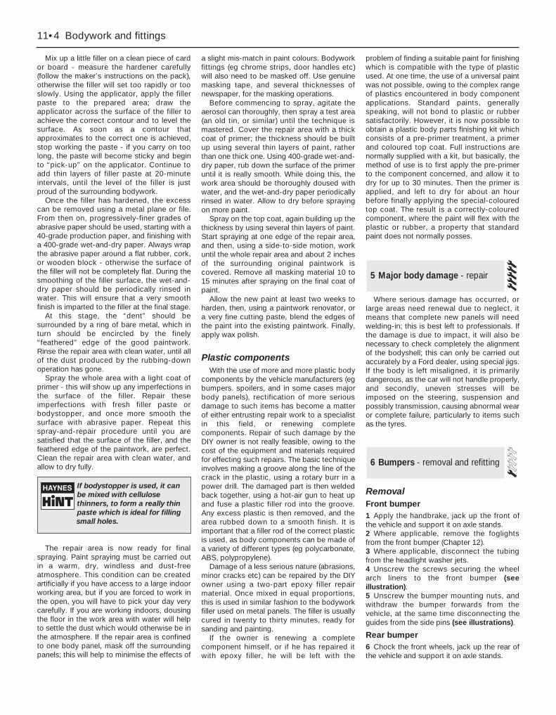
Mix up a little filler on a clean piece of cardor board - measure the hardener carefully(follow the maker’s instructions on the pack),otherwise the filler will set too rapidly or tooslowly. Using the applicator, apply the fillerpaste to the prepared area; draw theapplicator across the surface of the filler toachieve the correct contour and to level thesurface. As soon as a contour thatapproximates to the correct one is achieved,stop working the paste - if you carry on toolong, the paste will become sticky and beginto “pick-up” on the applicator. Continue toadd thin layers of filler paste at 20-minuteintervals, until the level of the filler is justproud of the surrounding bodywork.
Once the filler has hardened, the excesscan be removed using a metal plane or file.From then on, progressively-finer grades ofabrasive paper should be used, starting with a40-grade production paper, and finishing witha 400-grade wet-and-dry paper. Always wrapthe abrasive paper around a flat rubber, cork,or wooden block - otherwise the surface ofthe filler will not be completely flat. During thesmoothing of the filler surface, the wet-and-dry paper should be periodically rinsed inwater. This will ensure that a very smoothfinish is imparted to the filler at the final stage.
At this stage, the “dent” should besurrounded by a ring of bare metal, which inturn should be encircled by the finely“feathered” edge of the good paintwork.Rinse the repair area with clean water, until allof the dust produced by the rubbing-downoperation has gone.
Spray the whole area with a light coat ofprimer - this will show up any imperfections inthe surface of the filler. Repair theseimperfections with fresh filler paste orbodystopper, and once more smooth thesurface with abrasive paper. Repeat thisspray-and-repair procedure until you aresatisfied that the surface of the filler, and thefeathered edge of the paintwork, are perfect.Clean the repair area with clean water, andallow to dry fully.
The repair area is now ready for finalspraying. Paint spraying must be carried outin a warm, dry, windless and dust-freeatmosphere. This condition can be createdartificially if you have access to a large indoorworking area, but if you are forced to work inthe open, you will have to pick your day verycarefully. If you are working indoors, dousingthe floor in the work area with water will helpto settle the dust which would otherwise be inthe atmosphere. If the repair area is confinedto one body panel, mask off the surroundingpanels; this will help to minimise the effects of
a slight mis-match in paint colours. Bodyworkfittings (eg chrome strips, door handles etc)will also need to be masked off. Use genuinemasking tape, and several thicknesses ofnewspaper, for the masking operations.
Before commencing to spray, agitate theaerosol can thoroughly, then spray a test area(an old tin, or similar) until the technique ismastered. Cover the repair area with a thickcoat of primer; the thickness should be builtup using several thin layers of paint, ratherthan one thick one. Using 400-grade wet-and-dry paper, rub down the surface of the primeruntil it is really smooth. While doing this, thework area should be thoroughly doused withwater, and the wet-and-dry paper periodicallyrinsed in water. Allow to dry before sprayingon more paint.
Spray on the top coat, again building up thethickness by using several thin layers of paint.Start spraying at one edge of the repair area,and then, using a side-to-side motion, workuntil the whole repair area and about 2 inchesof the surrounding original paintwork iscovered. Remove all masking material 10 to15 minutes after spraying on the final coat ofpaint.
Allow the new paint at least two weeks toharden, then, using a paintwork renovator, ora very fine cutting paste, blend the edges ofthe paint into the existing paintwork. Finally,apply wax polish.
Plastic componentsWith the use of more and more plastic body
components by the vehicle manufacturers (egbumpers. spoilers, and in some cases majorbody panels), rectification of more seriousdamage to such items has become a matterof either entrusting repair work to a specialistin this field, or renewing completecomponents. Repair of such damage by theDIY owner is not really feasible, owing to thecost of the equipment and materials requiredfor effecting such repairs. The basic techniqueinvolves making a groove along the line of thecrack in the plastic, using a rotary burr in apower drill. The damaged part is then weldedback together, using a hot-air gun to heat upand fuse a plastic filler rod into the groove.Any excess plastic is then removed, and thearea rubbed down to a smooth finish. It isimportant that a filler rod of the correct plasticis used, as body components can be made ofa variety of different types (eg polycarbonate,ABS, polypropylene).
Damage of a less serious nature (abrasions,minor cracks etc) can be repaired by the DIYowner using a two-part epoxy filler repairmaterial. Once mixed in equal proportions,this is used in similar fashion to the bodyworkfiller used on metal panels. The filler is usuallycured in twenty to thirty minutes, ready forsanding and painting.
If the owner is renewing a completecomponent himself, or if he has repaired itwith epoxy filler, he will be left with the
problem of finding a suitable paint for finishingwhich is compatible with the type of plasticused. At one time, the use of a universal paintwas not possible, owing to the complex rangeof plastics encountered in body componentapplications. Standard paints, generallyspeaking, will not bond to plastic or rubbersatisfactorily. However, it is now possible toobtain a plastic body parts finishing kit whichconsists of a pre-primer treatment, a primerand coloured top coat. Full instructions arenormally supplied with a kit, but basically, themethod of use is to first apply the pre-primerto the component concerned, and allow it todry for up to 30 minutes. Then the primer isapplied, and left to dry for about an hourbefore finally applying the special-colouredtop coat. The result is a correctly-colouredcomponent, where the paint will flex with theplastic or rubber, a property that standardpaint does not normally posses.
Where serious damage has occurred, orlarge areas need renewal due to neglect, itmeans that complete new panels will needwelding-in; this is best left to professionals. Ifthe damage is due to impact, it will also benecessary to check completely the alignmentof the bodyshell; this can only be carried outaccurately by a Ford dealer, using special jigs.If the body is left misaligned, it is primarilydangerous, as the car will not handle properly,and secondly, uneven stresses will beimposed on the steering, suspension andpossibly transmission, causing abnormal wearor complete failure, particularly to items suchas the tyres.
RemovalFront bumper1 Apply the handbrake, jack up the front ofthe vehicle and support it on axle stands.2 Where applicable, remove the foglightsfrom the front bumper (Chapter 12).3 Where applicable, disconnect the tubingfrom the headlight washer jets.4 Unscrew the screws securing the wheelarch liners to the front bumper (seeillustration).5 Unscrew the bumper mounting nuts, andwithdraw the bumper forwards from thevehicle, at the same time disconnecting theguides from the side pins (see illustrations).
Rear bumper6 Chock the front wheels, jack up the rear ofthe vehicle and support it on axle stands.
6 Bumpers - removal and refitting
5 Major body damage - repair
11•4 Bodywork and fittings
If bodystopper is used, it canbe mixed with cellulosethinners, to form a really thinpaste which is ideal for fillingsmall holes.
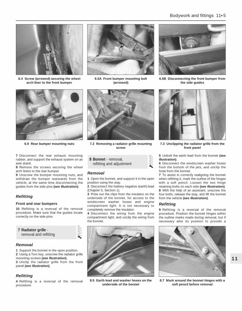
7 Disconnect the rear exhaust mountingrubber, and support the exhaust system on anaxle stand.8 Remove the screws securing the wheelarch liners to the rear bumper.9 Unscrew the bumper mounting nuts, andwithdraw the bumper rearwards from thevehicle, at the same time disconnecting theguides from the side pins (see illustration).
Refitting
Front and rear bumpers10 Refitting is a reversal of the removalprocedure. Make sure that the guides locatecorrectly on the side pins.
Removal1 Support the bonnet in the open position.2 Using a Torx key, unscrew the radiator grillemounting screws (see illustration).3 Unclip the radiator grille from the frontpanel (see illustration).
Refitting4 Refitting is a reversal of the removalprocedure.
Removal1 Open the bonnet, and support it in the openposition using the stay.2 Disconnect the battery negative (earth) lead(Chapter 5, Section 1).3 Prise out the clips from the insulator on theunderside of the bonnet, for access to thewindscreen washer hoses and enginecompartment light. It is not necessary tocompletely remove the insulator.4 Disconnect the wiring from the enginecompartment light, and unclip the wiring fromthe bonnet.
5 Unbolt the earth lead from the bonnet (seeillustration).6 Disconnect the windscreen washer hosesfrom the bottom of the jets, and unclip thehose from the bonnet.7 To assist in correctly realigning the bonnetwhen refitting it, mark the outline of the hingeswith a soft pencil. Loosen the two hingeretaining bolts on each side (see illustration).8 With the help of an assistant, unscrew thefour bolts, release the stay, and lift the bonnetfrom the vehicle (see illustration).
Refitting9 Refitting is a reversal of the removalprocedure. Position the bonnet hinges withinthe outline marks made during removal, but ifnecessary alter its position to provide a
8 Bonnet - removal, refitting and adjustment
7 Radiator grille - removal and refitting
Bodywork and fittings 11•5
11
7.3 Unclipping the radiator grille from thefront panel
8.5 Earth lead and washer hoses on theunderside of the bonnet
6.9 Rear bumper mounting nuts 7.2 Removing a radiator grille mountingscrew
8.7 Mark around the bonnet hinges with asoft pencil before removal
6.4 Screw (arrowed) securing the wheelarch liner to the front bumper
6.5A Front bumper mounting bolt(arrowed)
6.5B Disconnecting the front bumper fromthe side guides
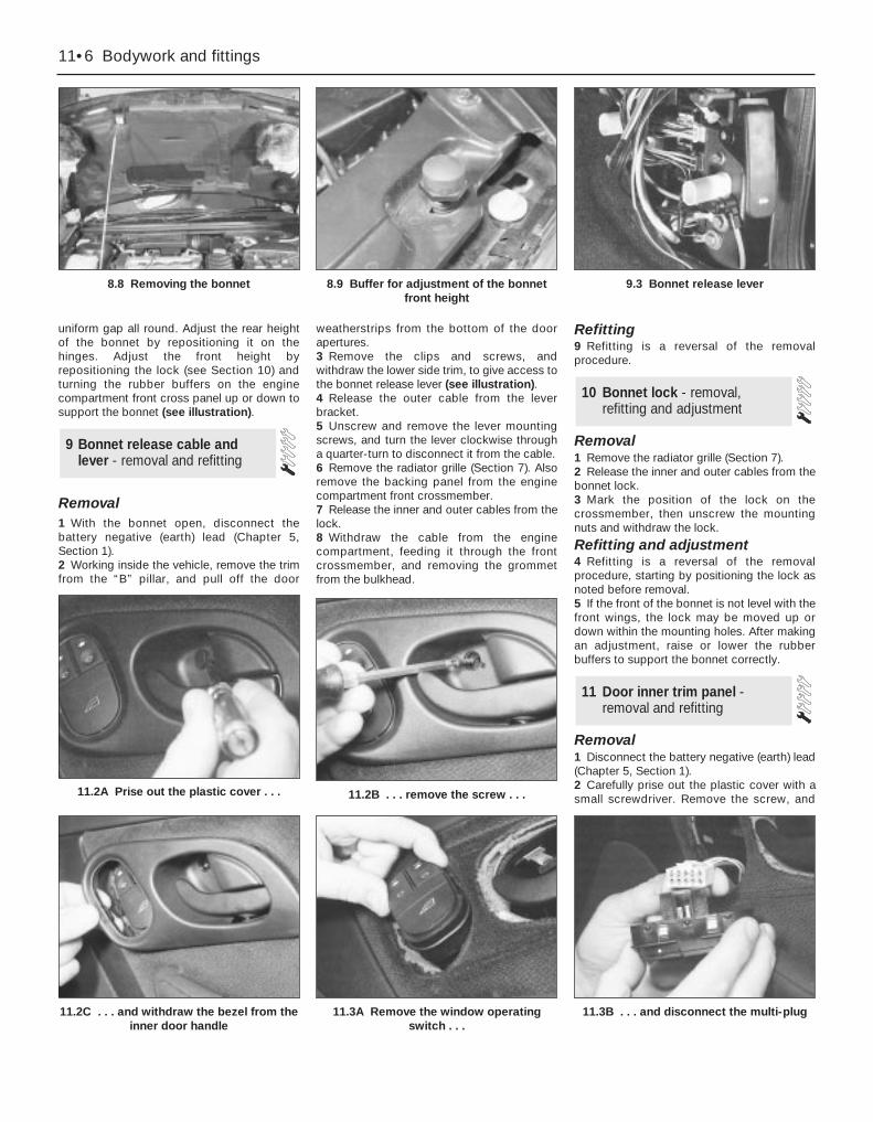
11.3B . . . and disconnect the multi-plug
uniform gap all round. Adjust the rear heightof the bonnet by repositioning it on thehinges. Adjust the front height byrepositioning the lock (see Section 10) andturning the rubber buffers on the enginecompartment front cross panel up or down tosupport the bonnet (see illustration).
Removal1 With the bonnet open, disconnect thebattery negative (earth) lead (Chapter 5,Section 1).2 Working inside the vehicle, remove the trimfrom the “B” pillar, and pull off the door
weatherstrips from the bottom of the doorapertures.3 Remove the clips and screws, andwithdraw the lower side trim, to give access tothe bonnet release lever (see illustration).4 Release the outer cable from the leverbracket.5 Unscrew and remove the lever mountingscrews, and turn the lever clockwise througha quarter-turn to disconnect it from the cable.6 Remove the radiator grille (Section 7). Alsoremove the backing panel from the enginecompartment front crossmember.7 Release the inner and outer cables from thelock.8 Withdraw the cable from the enginecompartment, feeding it through the frontcrossmember, and removing the grommetfrom the bulkhead.
Refitting9 Refitting is a reversal of the removalprocedure.
Removal1 Remove the radiator grille (Section 7).2 Release the inner and outer cables from thebonnet lock.3 Mark the position of the lock on thecrossmember, then unscrew the mountingnuts and withdraw the lock.
Refitting and adjustment4 Refitting is a reversal of the removalprocedure, starting by positioning the lock asnoted before removal.5 If the front of the bonnet is not level with thefront wings, the lock may be moved up ordown within the mounting holes. After makingan adjustment, raise or lower the rubberbuffers to support the bonnet correctly.
Removal1 Disconnect the battery negative (earth) lead(Chapter 5, Section 1).2 Carefully prise out the plastic cover with asmall screwdriver. Remove the screw, and
11 Door inner trim panel -removal and refitting
10 Bonnet lock - removal,refitting and adjustment
9 Bonnet release cable andlever - removal and refitting
11•6 Bodywork and fittings
8.8 Removing the bonnet 8.9 Buffer for adjustment of the bonnetfront height
9.3 Bonnet release lever
11.2B . . . remove the screw . . .11.2A Prise out the plastic cover . . .
11.2C . . . and withdraw the bezel from theinner door handle
11.3A Remove the window operatingswitch . . .
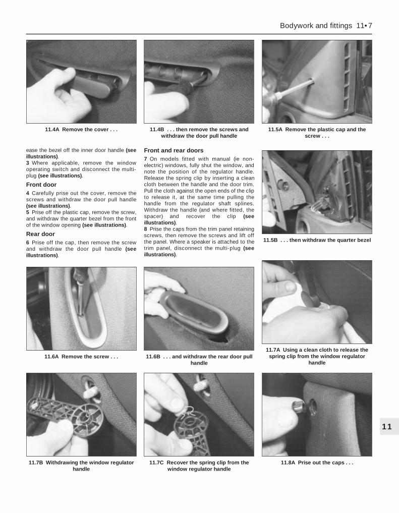
ease the bezel off the inner door handle (seeillustrations).3 Where applicable, remove the windowoperating switch and disconnect the multi-plug (see illustrations).
Front door4 Carefully prise out the cover, remove thescrews and withdraw the door pull handle(see illustrations).5 Prise off the plastic cap, remove the screw,and withdraw the quarter bezel from the frontof the window opening (see illustrations).
Rear door6 Prise off the cap, then remove the screwand withdraw the door pull handle (seeillustrations).
Front and rear doors7 On models fitted with manual (ie non-electric) windows, fully shut the window, andnote the position of the regulator handle.Release the spring clip by inserting a cleancloth between the handle and the door trim.Pull the cloth against the open ends of the clipto release it, at the same time pulling thehandle from the regulator shaft splines.Withdraw the handle (and where fitted, thespacer) and recover the clip (seeillustrations).8 Prise the caps from the trim panel retainingscrews, then remove the screws and lift offthe panel. Where a speaker is attached to thetrim panel, disconnect the multi-plug (seeillustrations).
Bodywork and fittings 11•7
11
11.7B Withdrawing the window regulatorhandle
11.7C Recover the spring clip from thewindow regulator handle
11.8A Prise out the caps . . .
11.6A Remove the screw . . . 11.6B . . . and withdraw the rear door pullhandle
11.7A Using a clean cloth to release thespring clip from the window regulator
handle
11.5A Remove the plastic cap and thescrew . . .
11.5B . . . then withdraw the quarter bezel
11.4A Remove the cover . . . 11.4B . . . then remove the screws andwithdraw the door pull handle

9 If necessary, the foam insulation may beremoved from the door. First remove thespeaker as described in Chapter 12.10 On models with manual windows, removethe foam spacer from the regulator spindle(see illustration).11 On the rear door, unscrew the screws andremove the door pull bracket (seeillustration).12 Carefully cut the adhesive with a knife,and remove the foam insulation (seeillustration).
Refitting13 Refitting is a reversal of the removalprocedure.
RemovalFront (manual/non-electric)1 Disconnect the battery negative (earth) lead(Chapter 5, Section 1).2 Remove the door inner trim panel (Sec-tion 11).3 Remove the door exterior mirror (Sec-tion 16).4 Temporarily refit the regulator handle on itssplines.5 Lower the window until the glass supportbracket is visible through the holes in the doorinner panel. Remove the regulator handle.
12 Door window glass - removal and refitting
11•8 Bodywork and fittings
11.8B . . . remove the inner-facing screws . . .
11.8C . . . and the side screws . . . 11.8D . . . then lift off the trim panel
11.10 Removing the foam spacer 11.11 Removing the door pull bracketfrom a rear door
11.12 Removing the foam insulation
11.8E Door trim panel components
1 Door2 Foam seal3 Trim panel4 Top mounting5 Centre mounting
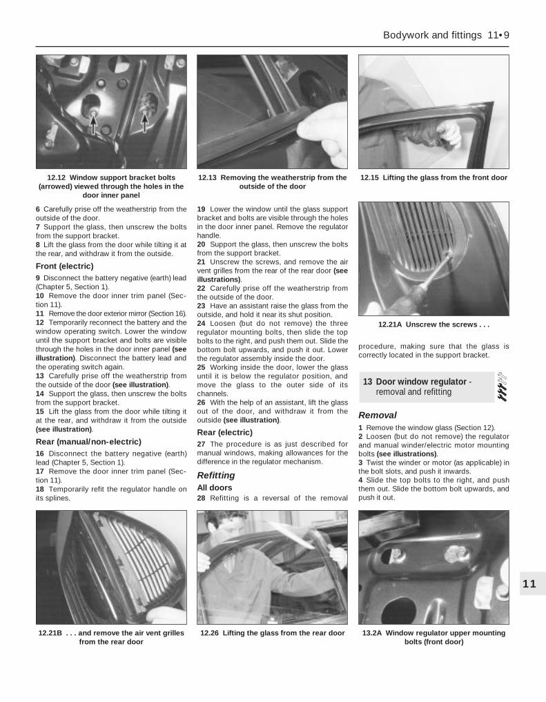
6 Carefully prise off the weatherstrip from theoutside of the door.7 Support the glass, then unscrew the boltsfrom the support bracket.8 Lift the glass from the door while tilting it atthe rear, and withdraw it from the outside.
Front (electric)9 Disconnect the battery negative (earth) lead(Chapter 5, Section 1).10 Remove the door inner trim panel (Sec-tion 11).11 Remove the door exterior mirror (Section 16).12 Temporarily reconnect the battery and thewindow operating switch. Lower the windowuntil the support bracket and bolts are visiblethrough the holes in the door inner panel (seeillustration). Disconnect the battery lead andthe operating switch again.13 Carefully prise off the weatherstrip fromthe outside of the door (see illustration).14 Support the glass, then unscrew the boltsfrom the support bracket.15 Lift the glass from the door while tilting itat the rear, and withdraw it from the outside(see illustration).
Rear (manual/non-electric)16 Disconnect the battery negative (earth)lead (Chapter 5, Section 1).17 Remove the door inner trim panel (Sec-tion 11).18 Temporarily refit the regulator handle onits splines.
19 Lower the window until the glass supportbracket and bolts are visible through the holesin the door inner panel. Remove the regulatorhandle.20 Support the glass, then unscrew the boltsfrom the support bracket.21 Unscrew the screws, and remove the airvent grilles from the rear of the rear door (seeillustrations).22 Carefully prise off the weatherstrip fromthe outside of the door.23 Have an assistant raise the glass from theoutside, and hold it near its shut position.24 Loosen (but do not remove) the threeregulator mounting bolts, then slide the topbolts to the right, and push them out. Slide thebottom bolt upwards, and push it out. Lowerthe regulator assembly inside the door.25 Working inside the door, lower the glassuntil it is below the regulator position, andmove the glass to the outer side of itschannels.26 With the help of an assistant, lift the glassout of the door, and withdraw it from theoutside (see illustration).
Rear (electric)27 The procedure is as just described formanual windows, making allowances for thedifference in the regulator mechanism.
RefittingAll doors28 Refitting is a reversal of the removal
procedure, making sure that the glass iscorrectly located in the support bracket.
Removal1 Remove the window glass (Section 12).2 Loosen (but do not remove) the regulatorand manual winder/electric motor mountingbolts (see illustrations).3 Twist the winder or motor (as applicable) inthe bolt slots, and push it inwards.4 Slide the top bolts to the right, and pushthem out. Slide the bottom bolt upwards, andpush it out.
13 Door window regulator -removal and refitting
Bodywork and fittings 11•9
11
12.21B . . . and remove the air vent grillesfrom the rear door
12.26 Lifting the glass from the rear door 13.2A Window regulator upper mountingbolts (front door)
12.12 Window support bracket bolts(arrowed) viewed through the holes in the
door inner panel
12.13 Removing the weatherstrip from theoutside of the door
12.15 Lifting the glass from the front door
12.21A Unscrew the screws . . .
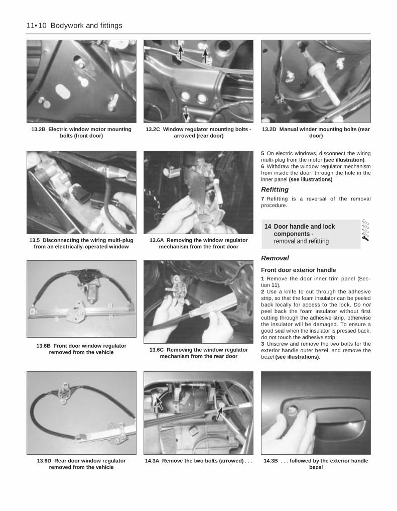
5 On electric windows, disconnect the wiringmulti-plug from the motor (see illustration).6 Withdraw the window regulator mechanismfrom inside the door, through the hole in theinner panel (see illustrations).
Refitting7 Refitting is a reversal of the removalprocedure.
Removal
Front door exterior handle1 Remove the door inner trim panel (Sec-tion 11).2 Use a knife to cut through the adhesivestrip, so that the foam insulator can be peeledback locally for access to the lock. Do notpeel back the foam insulator without firstcutting through the adhesive strip, otherwisethe insulator will be damaged. To ensure agood seal when the insulator is pressed back,do not touch the adhesive strip.3 Unscrew and remove the two bolts for theexterior handle outer bezel, and remove thebezel (see illustrations).
14 Door handle and lockcomponents - removal and refitting
11•10 Bodywork and fittings
13.2B Electric window motor mountingbolts (front door)
13.2C Window regulator mounting bolts -arrowed (rear door)
13.2D Manual winder mounting bolts (reardoor)
13.5 Disconnecting the wiring multi-plugfrom an electrically-operated window
13.6A Removing the window regulatormechanism from the front door
13.6B Front door window regulatorremoved from the vehicle 13.6C Removing the window regulator
mechanism from the rear door
13.6D Rear door window regulatorremoved from the vehicle
14.3A Remove the two bolts (arrowed) . . . 14.3B . . . followed by the exterior handlebezel
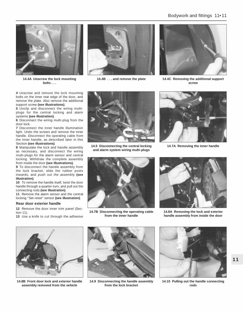
4 Unscrew and remove the lock mountingbolts on the inner rear edge of the door, andremove the plate. Also remove the additionalsupport screw (see illustrations).5 Unclip and disconnect the wiring multi-plugs for the central locking and alarmsystems (see illustration).6 Disconnect the wiring multi-plug from thedoor lock.7 Disconnect the inner handle illuminationlight. Undo the screws and remove the innerhandle. Disconnect the operating cable fromthe inner handle, as described later in thisSection (see illustrations).8 Manipulate the lock and handle assemblyas necessary, and disconnect the wiringmulti-plugs for the alarm sensor and centrallocking. Withdraw the complete assemblyfrom inside the door (see illustrations).9 To disconnect the handle assembly fromthe lock bracket, slide the rubber postsinwards, and push out the assembly (seeillustration).10 To remove the handle itself, twist the doorhandle through a quarter-turn, and pull out theconnecting rods (see illustration).11 Remove the alarm sensor and the centrallocking “Set-reset” sensor (see illustration).
Rear door exterior handle12 Remove the door inner trim panel (Sec-tion 11).13 Use a knife to cut through the adhesive
Bodywork and fittings 11•11
11
14.8B Front door lock and exterior handleassembly removed from the vehicle
14.9 Disconnecting the handle assemblyfrom the lock bracket
14.10 Pulling out the handle connectingrods
14.4A Unscrew the lock mounting bolts . . .
14.4B . . . and remove the plate 14.4C Removing the additional supportscrew
14.5 Disconnecting the central lockingand alarm system wiring multi-plugs
14.7A Removing the inner handle
14.7B Disconnecting the operating cablefrom the inner handle
14.8A Removing the lock and exteriorhandle assembly from inside the door

strip, so that the foam insulator can be peeledback for access to the lock. Do not peel backthe foam insulator without first cutting throughthe adhesive strip. To ensure a good sealwhen the insulator is pressed back, do nottouch the adhesive strip.14 Prise out the plug from the rear edge ofthe door, then unscrew the handle mountingnuts (see illustrations).15 Prise up the clip, and disconnect theoperating rod from the lock (see illustration).16 Withdraw the handle from the outside ofthe door (see illustration).Interior handle17 Remove the door inner trim panel (Sec-tion 11).18 Use a knife to cut through the adhesivestrip, so that the foam insulator can be peeled
back for access to the lock. Do not peel backthe foam insulator without first cutting throughthe adhesive strip. To ensure a good sealwhen the insulator is pressed back, do nottouch the adhesive strip.19 Disconnect the interior handle illuminationlight.20 Undo the screws and remove the interiorhandle.21 To remove the cable, first pull back theplastic outer cable end and blanking piece.Apply light inward pressure to the controllever, with the lever in the locked position,until the inner cable is aligned with the releaseslot in the bottom of the cable holder.22 Push down on the cable ferrule, anddisconnect the inner cable. Remove thehandle assembly.
Lock barrel23 Remove the exterior handle as describedearlier in this Section.24 Prise out the barrel retaining tab from thehandle body, using a small screwdriver (seeillustration).25 Insert the key, turn it so that it engagesthe barrel, then pull out the barrel (seeillustration).Lock motor - front door26 Remove the exterior handle as describedearlier in this Section.27 Extract the clip, and pull out the operatingrod.28 Remove the operating rod from the plasticbush, by turning it through a quarter-turn.29 Release the sensor wiring loom from theclip.
11•12 Bodywork and fittings
14.11 Removing the central locking “Set-reset” sensor
14.14A Prise out the plug . . . 14.14B . . . and unscrew the handlemounting nuts
14.25 . . . and pull out the lock barrel 14.31 Unclipping the door-ajar sensor 14.32 Removing the plastic shield from thelocating post
14.15 Disconnect the operating rod fromthe lock
14.16 Removing the rear door exteriorhandle
14.24 Prise out the barrel retaining tab . . .

30 Detach the mounting plate from the lock.31 Release the door-ajar sensor from the clip(see illustration).32 Prise the plastic shield from the locatingpost (see illustration).33 Slide the outer cable from the lockbracket (see illustration), then turn the innercable through a quarter-turn to remove it fromthe bell crank.34 Unscrew the mounting screws andremove the lock motor (see illustration).
Lock motor - rear door35 Remove the exterior handle as describedearlier in this Section.36 Unscrew and remove the three lockmounting screws.37 Release the sensor wiring loom from theclip on the door.38 Disconnect the wiring multi-plug from thedoor lock.39 Disconnect the interior handle illuminationlight.40 Remove the screws, and remove theinterior handle.41 Remove the lock assembly.42 Release the door-ajar sensor from theclip.43 Prise the plastic shield from the locatingpost.44 Slide the outer cable from the lockbracket, then turn the inner cable through aquarter-turn to remove it from the bell crank.45 Unscrew the mounting screws and
remove the lock motor.
Striker46 Using a pencil, mark the position of thestriker.47 Undo the mounting screws using a Torxkey, and remove the striker.
Check strap48 Disconnect the battery negative (earth)lead (Chapter 5, Section 1).49 Using a Torx key, unscrew and removethe check strap mounting screw(s). On thefront door, there are two screws; on the reardoor, there is only one.50 Prise the rubber grommet from the dooraperture, then unscrew the mounting nuts andwithdraw the check strap from the door.
Refitting
Handles (exterior and interior)51 Refitting is a reversal of the removalprocedure.
Lock barrel52 Check that the retaining clip is fittedcorrectly.53 Align the grooves on the barrel with thegrooves on the body and operating lever, thencarefully push the barrel into the handle until itengages the clip.54 The remaining refitting procedure is areversal of removal.
Lock motor55 Refitting is a reversal of the removalprocedure.
Striker56 Refitting is a reversal of the removalprocedure, but check that the door lockpasses over the striker centrally. If necessary,re-position the striker before fully tighteningthe mounting screws.
Check strap59 Refitting is a reversal of the removalprocedure.
Removal1 Disconnect the battery negative (earth) lead(Chapter 5, Section 1).2 Using a Torx key, unscrew and remove thecheck strap mounting screw(s). On the frontdoor, there are two screws; on the rear door,there is only one (see illustrations).3 Disconnect the wiring connector(s) bytwisting them anti-clockwise. On the frontdoor, there are two connectors; on the reardoor, there is only one (see illustration).4 Extract the small circlips from the top of theupper and lower hinge pins (see illustration).5 Have an assistant support the weight of the
15 Door - removal and refitting
Bodywork and fittings 11•13
11
15.2B Front door check strap removed 15.3 Disconnecting a door wiringconnector
15.4 Extract the small circlips . . .
14.33 Slide the outer cable from the lockbracket
14.34 Removing a lock motor 15.2A Front door check strap mountingscrew removal
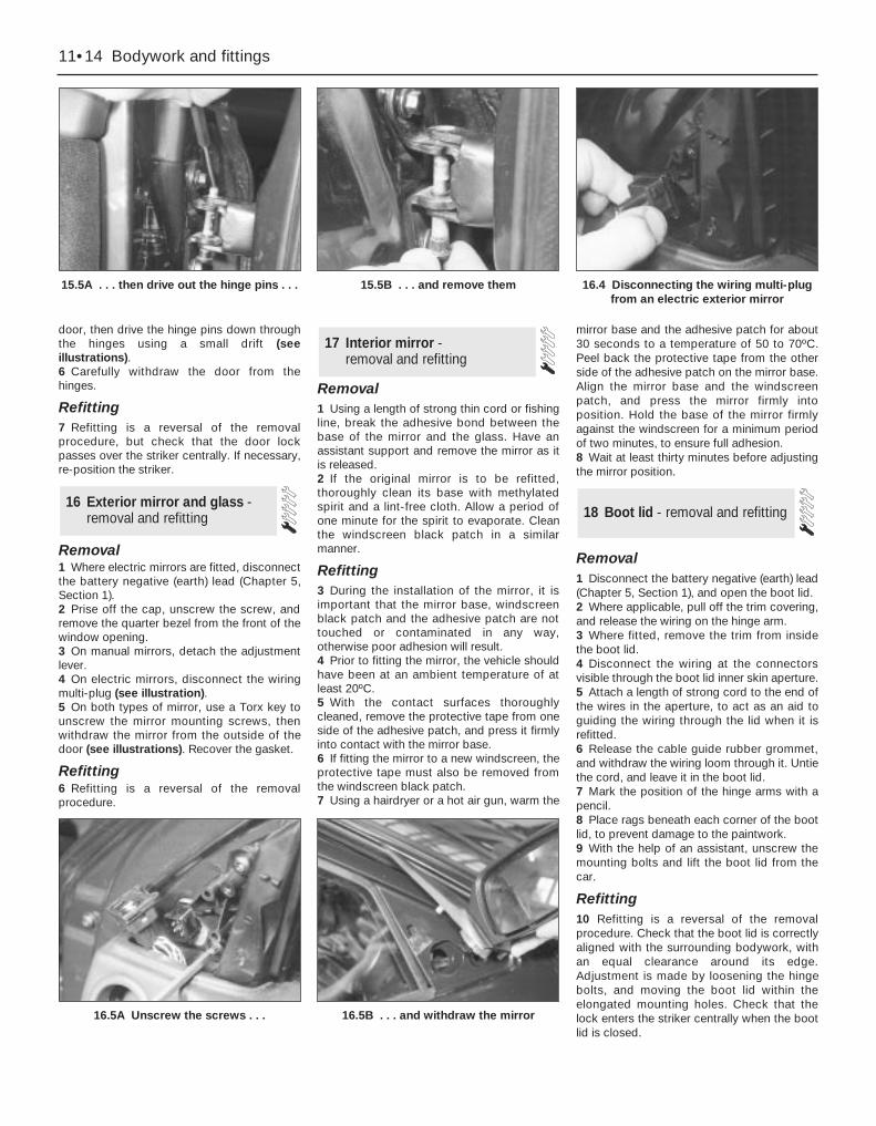
door, then drive the hinge pins down throughthe hinges using a small drift (seeillustrations).6 Carefully withdraw the door from thehinges.
Refitting7 Refitting is a reversal of the removalprocedure, but check that the door lockpasses over the striker centrally. If necessary,re-position the striker.
Removal1 Where electric mirrors are fitted, disconnectthe battery negative (earth) lead (Chapter 5,Section 1).2 Prise off the cap, unscrew the screw, andremove the quarter bezel from the front of thewindow opening.3 On manual mirrors, detach the adjustmentlever.4 On electric mirrors, disconnect the wiringmulti-plug (see illustration).5 On both types of mirror, use a Torx key tounscrew the mirror mounting screws, thenwithdraw the mirror from the outside of thedoor (see illustrations). Recover the gasket.
Refitting6 Refitting is a reversal of the removalprocedure.
Removal1 Using a length of strong thin cord or fishingline, break the adhesive bond between thebase of the mirror and the glass. Have anassistant support and remove the mirror as itis released.2 If the original mirror is to be refitted,thoroughly clean its base with methylatedspirit and a lint-free cloth. Allow a period ofone minute for the spirit to evaporate. Cleanthe windscreen black patch in a similarmanner.
Refitting3 During the installation of the mirror, it isimportant that the mirror base, windscreenblack patch and the adhesive patch are nottouched or contaminated in any way,otherwise poor adhesion will result.4 Prior to fitting the mirror, the vehicle shouldhave been at an ambient temperature of atleast 20ºC.5 With the contact surfaces thoroughlycleaned, remove the protective tape from oneside of the adhesive patch, and press it firmlyinto contact with the mirror base.6 If fitting the mirror to a new windscreen, theprotective tape must also be removed fromthe windscreen black patch.7 Using a hairdryer or a hot air gun, warm the
mirror base and the adhesive patch for about30 seconds to a temperature of 50 to 70ºC.Peel back the protective tape from the otherside of the adhesive patch on the mirror base.Align the mirror base and the windscreenpatch, and press the mirror firmly intoposition. Hold the base of the mirror firmlyagainst the windscreen for a minimum periodof two minutes, to ensure full adhesion.8 Wait at least thirty minutes before adjustingthe mirror position.
Removal1 Disconnect the battery negative (earth) lead(Chapter 5, Section 1), and open the boot lid.2 Where applicable, pull off the trim covering,and release the wiring on the hinge arm.3 Where fitted, remove the trim from insidethe boot lid.4 Disconnect the wiring at the connectorsvisible through the boot lid inner skin aperture.5 Attach a length of strong cord to the end ofthe wires in the aperture, to act as an aid toguiding the wiring through the lid when it isrefitted.6 Release the cable guide rubber grommet,and withdraw the wiring loom through it. Untiethe cord, and leave it in the boot lid.7 Mark the position of the hinge arms with apencil.8 Place rags beneath each corner of the bootlid, to prevent damage to the paintwork.9 With the help of an assistant, unscrew themounting bolts and lift the boot lid from thecar.
Refitting10 Refitting is a reversal of the removalprocedure. Check that the boot lid is correctlyaligned with the surrounding bodywork, withan equal clearance around its edge.Adjustment is made by loosening the hingebolts, and moving the boot lid within theelongated mounting holes. Check that thelock enters the striker centrally when the bootlid is closed.
18 Boot lid - removal and refitting
17 Interior mirror - removal and refitting
16 Exterior mirror and glass -removal and refitting
11•14 Bodywork and fittings
15.5A . . . then drive out the hinge pins . . . 15.5B . . . and remove them 16.4 Disconnecting the wiring multi-plugfrom an electric exterior mirror
16.5A Unscrew the screws . . . 16.5B . . . and withdraw the mirror

Removal
Lock barrel1 Disconnect the battery negative (earth) lead(Chapter 5, Section 1).2 With the boot lid open, remove the luggagespace trim from the right-hand rear corner.3 Remove the screws, and prise out the rearlight trim cover from the guides.4 Release the door-ajar sensor from the clipnear the lock.5 Slide the outer cable from the lock bracket.Raise the inner cable until it is aligned with theslot in the barrel lever, and disconnect it.6 Pull out the lock locating spring clip.7 Detach the cable mounting bracket fromthe barrel, and remove the barrel.
Lock8 Disconnect the battery negative (earth) lead(Chapter 5, Section 1).9 With the boot lid open, prise out the clipsand remove the trim from inside the boot lid.10 Release the door-ajar sensor from the clipnear the lock.11 Using a Torx key, unscrew the lockmounting screws, and withdraw the lock foraccess to the cables.12 Disconnect both the inner and outercables from the lock bracket.
13 Prise open the plastic lip, and remove thecentral locking control rod.14 Withdraw the lock assembly.
Refitting
Lock barrel and lock15 Refitting is a reversal of the removalprocedure.
RemovalHatchback1 Disconnect the battery negative (earth) lead(Chapter 5, Section 1). Open the tailgate.2 The tailgate may be unbolted from thehinges and the hinges left in position, or thehinges may be detached from the roof panelby unscrewing the mounting nuts. In the lattercase, carefully pull down the rear edge of theheadlining for access to the nuts. Take carenot to damage the headlining.3 Remove the parcel shelf left-hand supportbracket as follows. Fold the rear seatforwards, and disconnect the left-hand seatpull cable from the bracket and clips.Unscrew the screws and remove the bracket.4 Pull up the rear seat side bolster, thencarefully remove the side trim from the left-hand side of the luggage area. On low-seriesmodels, the bolster is retained with a screw.
5 Separate the tailgate wiring loom multi-plugs, located on the left-hand side of theluggage compartment, on top of the wheelarch.6 Unclip and remove the upper trim panelfrom the inside of the tailgate. Also removethe rear shelf cord plastic post (seeillustrations).7 Prise out the rubber grommet from the topof the tailgate aperture, and pull the wiringloom out through the hole in the body (seeillustration).8 Disconnect the rear window washer tubefrom the jet.9 Prise out the rubber grommet from theright-hand side of the tailgate aperture, andpull out the washer tube.10 Have an assistant support the tailgate inits open position.11 Using a small screwdriver, prise off theclips securing the struts to the tailgate. Pullthe sockets from the ball-studs, and move thestruts downwards.12 If the headlining has been pulled back,unscrew and remove the hinge nuts from theroof panel. Otherwise, unscrew the boltssecuring the tailgate to the hinges (seeillustration).13 Withdraw the tailgate from the bodyaperture, taking care not to damage thepaintwork.
Estate14 Disconnect the battery negative (earth)lead (Chapter 5, Section 1).15 The tailgate may be unbolted from thehinges and the hinges left in position, or thehinges may be detached from the rear roofpanel by unscrewing the mounting nuts. In thelatter case, carefully pull down the rear edgeof the headlining for access to the nuts. Takecare not to damage the headlining.16 Unscrew the retaining screws, then unclipthe “D” pillar trim panels from both sides (seeillustration).17 Unclip and remove the upper trim panelfrom inside the tailgate.18 Carefully remove the side trim from theleft-hand side of the luggage area, andseparate the tailgate wiring loom multi-plugsin the rear light cluster housing.
20 Tailgate - removal and refitting
19 Boot lid lock components -removal and refitting
Bodywork and fittings 11•15
11
20.12 Unscrewing the bolts securing thetailgate to the hinges
20.16 “D” pillar trim panel retainingscrews (arrowed) - Estate models
20.6A Unclipping the upper trim panelfrom the tailgate
20.6B Shelf cord post removal 20.7 Removing the wiring loom rubbergrommet
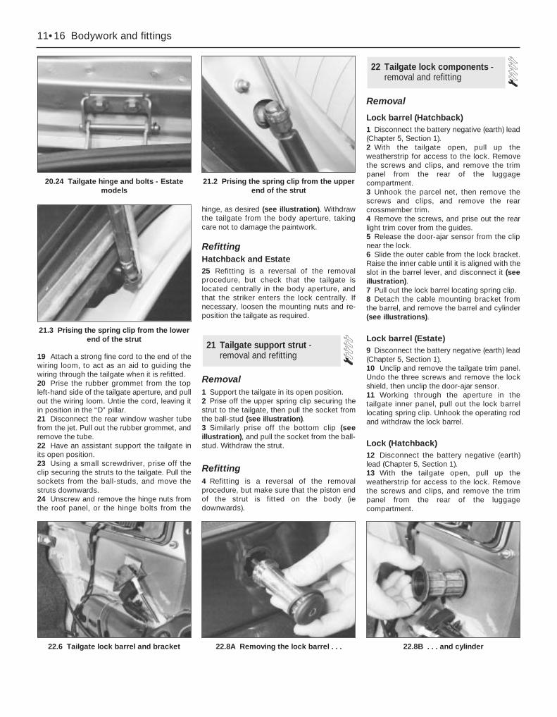
19 Attach a strong fine cord to the end of thewiring loom, to act as an aid to guiding thewiring through the tailgate when it is refitted.20 Prise the rubber grommet from the topleft-hand side of the tailgate aperture, and pullout the wiring loom. Untie the cord, leaving itin position in the “D” pillar.21 Disconnect the rear window washer tubefrom the jet. Pull out the rubber grommet, andremove the tube.22 Have an assistant support the tailgate inits open position.23 Using a small screwdriver, prise off theclip securing the struts to the tailgate. Pull thesockets from the ball-studs, and move thestruts downwards.24 Unscrew and remove the hinge nuts fromthe roof panel, or the hinge bolts from the
hinge, as desired (see illustration). Withdrawthe tailgate from the body aperture, takingcare not to damage the paintwork.
RefittingHatchback and Estate25 Refitting is a reversal of the removalprocedure, but check that the tailgate islocated centrally in the body aperture, andthat the striker enters the lock centrally. Ifnecessary, loosen the mounting nuts and re-position the tailgate as required.
Removal1 Support the tailgate in its open position.2 Prise off the upper spring clip securing thestrut to the tailgate, then pull the socket fromthe ball-stud (see illustration).3 Similarly prise off the bottom clip (seeillustration), and pull the socket from the ball-stud. Withdraw the strut.
Refitting4 Refitting is a reversal of the removalprocedure, but make sure that the piston endof the strut is fitted on the body (iedownwards).
Removal
Lock barrel (Hatchback)1 Disconnect the battery negative (earth) lead(Chapter 5, Section 1).2 With the tailgate open, pull up theweatherstrip for access to the lock. Removethe screws and clips, and remove the trimpanel from the rear of the luggagecompartment.3 Unhook the parcel net, then remove thescrews and clips, and remove the rearcrossmember trim.4 Remove the screws, and prise out the rearlight trim cover from the guides.5 Release the door-ajar sensor from the clipnear the lock.6 Slide the outer cable from the lock bracket.Raise the inner cable until it is aligned with theslot in the barrel lever, and disconnect it (seeillustration).7 Pull out the lock barrel locating spring clip.8 Detach the cable mounting bracket fromthe barrel, and remove the barrel and cylinder(see illustrations).
Lock barrel (Estate)9 Disconnect the battery negative (earth) lead(Chapter 5, Section 1).10 Unclip and remove the tailgate trim panel.Undo the three screws and remove the lockshield, then unclip the door-ajar sensor.11 Working through the aperture in thetailgate inner panel, pull out the lock barrellocating spring clip. Unhook the operating rodand withdraw the lock barrel.
Lock (Hatchback)12 Disconnect the battery negative (earth)lead (Chapter 5, Section 1).13 With the tailgate open, pull up theweatherstrip for access to the lock. Removethe screws and clips, and remove the trimpanel from the rear of the luggagecompartment.
22 Tailgate lock components -removal and refitting
21 Tailgate support strut -removal and refitting
11•16 Bodywork and fittings
20.24 Tailgate hinge and bolts - Estatemodels
21.2 Prising the spring clip from the upperend of the strut
21.3 Prising the spring clip from the lowerend of the strut
22.6 Tailgate lock barrel and bracket 22.8A Removing the lock barrel . . . 22.8B . . . and cylinder

14 Release the door-ajar sensor from the clipnear the lock (see illustration).15 Using a Torx key, unscrew the lockmounting screws, and withdraw the lock foraccess to the cables (see illustration).16 Disconnect both the inner and outercables from the lock bracket (seeillustration).17 Prise open the plastic clip, and removethe central locking control rod.18 Withdraw the lock assembly.
Lock (Estate)19 Disconnect the battery negative (earth)lead (Chapter 5, Section 1).20 Open the tailgate. Undo the screws andremove the inner trim.21 Using a Torx key, unscrew the lockmounting screws, and carefully withdraw thelock (see illustration).22 Release the door-ajar sensor from the clipnear the lock.23 Disconnect the barrel operating rod, andremove the lock.24 If necessary, the lock striker assemblymay be removed by disconnecting the releasecable and unscrewing the mounting bolts (seeillustration).
Refitting
Lock barrel and lock - all models25 Refitting is a reversal of the removalprocedure.
Testing1 The central locking module incorporates aservice-test mode, which is activated byoperating one of the lock position switches 8times within 10 seconds. A buzzer will sound,to indicate that the service-test mode isoperating, and to indicate that no faults havebeen found in the system. If a fault has beenfound, the system should be checked by aFord dealer or electrical specialist. The centrallocking module also incorporates the alarmsystem module.
Removal
Central locking/alarm module2 To remove the module, first remove thelower right-hand facia panel (right-hand-drivemodels) or the glovebox (left-hand-drivemodels).3 Disconnect the battery negative (earth) lead(Chapter 5, Section 1).4 Unscrew the mounting bolts, and removethe module from the bracket beneath thefacia.5 Disconnect the wiring multi-plug, andwithdraw the module from inside the vehicle.
6 Note that a different module is used formodels without an anti-theft alarm.
Central locking set/reset switch7 This procedure is covered in Section 14,under front door handle removal.
Central locking door-ajar switch8 This procedure is covered in Section 14,under front door lock motor removal.
Refitting
Central locking/alarm module9 Refitting is a reversal of the removalprocedure.
Central locking set/reset switch10 Refitting is a reversal of the removalprocedure.
Central locking door-ajar switch11 Refitting is a reversal of the removalprocedure.
1 The windscreen and rear window on allmodels are bonded in place with specialmastic, as are the rear side windows onEstate models. Special tools are required tocut free the old units and fit replacements;special cleaning solutions and primer are alsorequired. It is therefore recommended thatthis work is entrusted to a Ford dealer orwindscreen replacement specialist.2 Note that the windscreen contributestowards the structural strength of the vehicleas a whole, so it is important that it is fittedcorrectly.
Removal1 Insert a length of strong cord (fishing line isideal) behind the moulding or emblemconcerned. With a sawing action, break the
25 Body side-trim mouldingsand adhesive emblems -removal and refitting
24 Windscreen and fixedwindows - removal and refitting
23 Central locking systemcomponents - testing, removal and refitting
Bodywork and fittings 11•17
11
22.21 Tailgate lock - Estate models 22.24 Lock striker assembly - Estatemodels
22.14 Removing the door-ajar sensor fromthe lock
22.15 Removing a lock mounting screw 22.16 Disconnecting the cables from thelock

adhesive bond between the moulding oremblem and the panel (see illustration).2 Thoroughly clean all traces of adhesivefrom the panel usingmethylated spirit, and allow the location todry.
Refitting3 Peel back the protective paper from therear face of the new moulding or emblem.Carefully fit it into position on the panelconcerned, but take care not to touch theadhesive. When in position, apply handpressure to the moulding/emblem for a shortperiod, to ensure maximum adhesion to thepanel.
1 The sunroof should operate freely, withoutsticking or binding, as it is opened andclosed. When in the closed position, checkthat the panel is flush with the surroundingroof panel.2 If adjustment is required, open the sunblind, but leave the glass panel shut. Unscrewand remove the three lower frame-to-glasspanel retaining screws. Slide the lower frameback into the roof.3 Loosen the central and front securingscrews. Adjust the glass roof panel so that it isflush at its front edge with the roof panel, thenretighten the securing screws.4 Pull the lower frame forwards, and insertand tighten its retaining screws to complete.
RemovalFront seat1 Release the seat belt, and slide the seatfully forwards.2 Using a Torx key, undo the screws andremove the rear mounting trims, then unscrewthe rear mounting bolts (see illustrations).3 Slide the seat fully rearwards.4 Where electric seats are fitted, disconnect
the battery negative (earth) lead (Chapter 5,Section 1). Disconnect the seat wiring multi-plugs (see illustration).5 Unscrew the front mounting bolts, andremove the seat from the vehicle (seeillustration).
Rear seat cushion6 Fold the rear seat cushion forwards. (Notethat, on some models, the seat cushion isheld in place by screws which must beremoved first.) Using a Torx key, unscrew andremove the mounting bolts from the hinges oneach side (see illustration).7 Withdraw the seat cushion from the vehicle.
Rear seat backrest8 Fold the rear seat cushion and bothbackrests forwards.9 Unclip the backrest rear trims, where fitted,and raise them.10 Using a Torx key, unscrew the mountingbolts (see illustration).11 Withdraw the backrest from inside thevehicle.
Rear seat side bolster12 Fold the rear seat backrest forwards.13 On low-series models, remove the screwand pull the bolster forwards to disengage theclips. On high-series models, simply pull thebolster upwards to disengage the clips.
Refitting14 Refitting is a reversal of the removalprocedure, but tighten the mounting bolts tothe specified torque.
27 Seats - removal and refitting
26 Sunroof - general information and adjustment
11•18 Bodywork and fittings
25.1 Using a length of cord to remove theemblem from the radiator grille
27.2A Unscrew the Torx-headed screws . . .
27.2B . . . and remove the mounting trimsfor access to the front seat rear mounting
bolts
27.5 Front seat front mounting bolt
27.4 Disconnecting an electric seat multi-plug
27.6 Rear seat cushion hinge bolt 27.10 Rear seat backrest mounting bolts
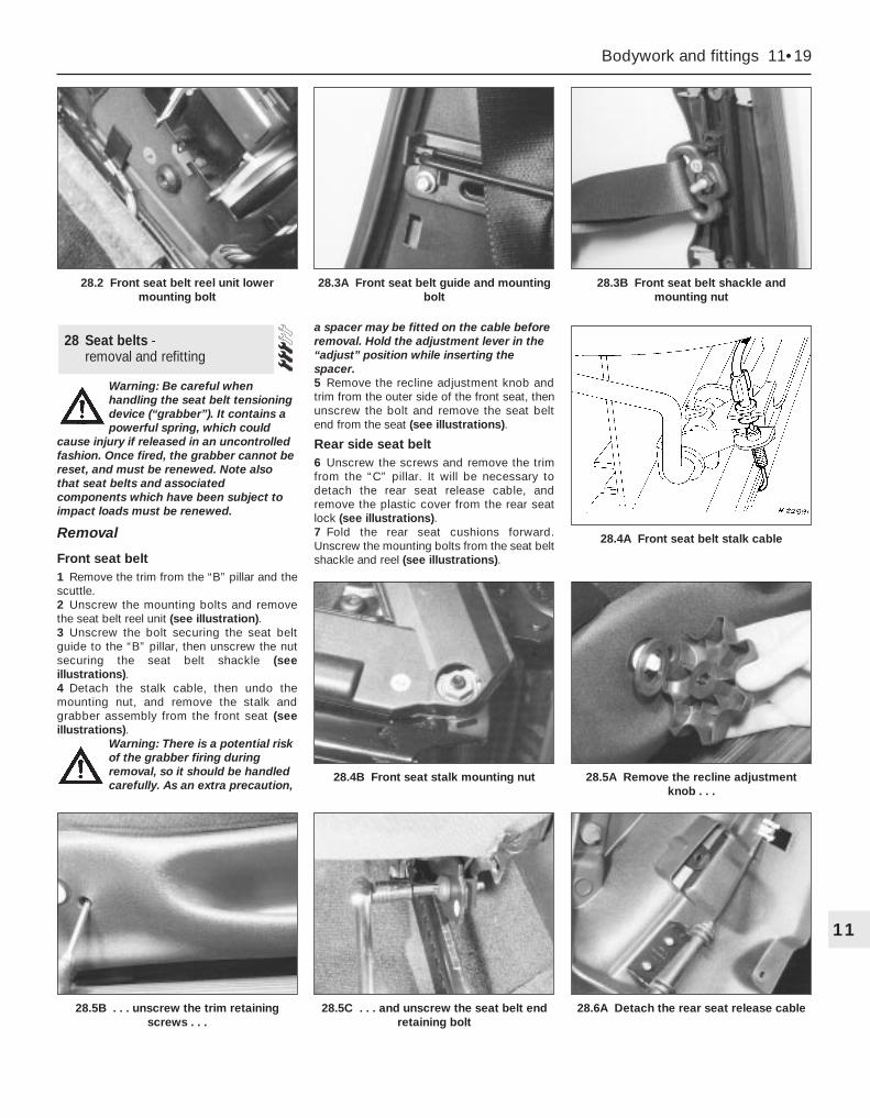
Warning: Be careful whenhandling the seat belt tensioningdevice (“grabber”). It contains apowerful spring, which could
cause injury if released in an uncontrolledfashion. Once fired, the grabber cannot bereset, and must be renewed. Note alsothat seat belts and associatedcomponents which have been subject toimpact loads must be renewed.
Removal
Front seat belt1 Remove the trim from the “B” pillar and thescuttle.2 Unscrew the mounting bolts and removethe seat belt reel unit (see illustration).3 Unscrew the bolt securing the seat beltguide to the “B” pillar, then unscrew the nutsecuring the seat belt shackle (seeillustrations).4 Detach the stalk cable, then undo themounting nut, and remove the stalk andgrabber assembly from the front seat (seeillustrations).
Warning: There is a potential riskof the grabber firing duringremoval, so it should be handledcarefully. As an extra precaution,
a spacer may be fitted on the cable beforeremoval. Hold the adjustment lever in the“adjust” position while inserting thespacer.5 Remove the recline adjustment knob andtrim from the outer side of the front seat, thenunscrew the bolt and remove the seat beltend from the seat (see illustrations).
Rear side seat belt6 Unscrew the screws and remove the trimfrom the “C” pillar. It will be necessary todetach the rear seat release cable, andremove the plastic cover from the rear seatlock (see illustrations).7 Fold the rear seat cushions forward.Unscrew the mounting bolts from the seat beltshackle and reel (see illustrations).
28 Seat belts - removal and refitting
Bodywork and fittings 11•19
11
28.5B . . . unscrew the trim retainingscrews . . .
28.5C . . . and unscrew the seat belt endretaining bolt
28.6A Detach the rear seat release cable
28.4A Front seat belt stalk cable
28.4B Front seat stalk mounting nut 28.5A Remove the recline adjustmentknob . . .
28.2 Front seat belt reel unit lowermounting bolt
28.3A Front seat belt guide and mountingbolt
28.3B Front seat belt shackle andmounting nut
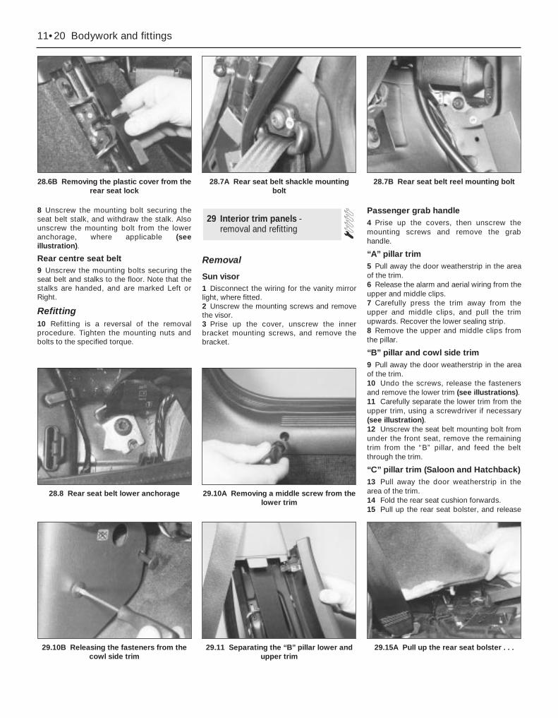
8 Unscrew the mounting bolt securing theseat belt stalk, and withdraw the stalk. Alsounscrew the mounting bolt from the loweranchorage, where applicable (seeillustration).
Rear centre seat belt9 Unscrew the mounting bolts securing theseat belt and stalks to the floor. Note that thestalks are handed, and are marked Left orRight.
Refitting10 Refitting is a reversal of the removalprocedure. Tighten the mounting nuts andbolts to the specified torque.
Removal
Sun visor1 Disconnect the wiring for the vanity mirrorlight, where fitted.2 Unscrew the mounting screws and removethe visor.3 Prise up the cover, unscrew the innerbracket mounting screws, and remove thebracket.
Passenger grab handle4 Prise up the covers, then unscrew themounting screws and remove the grabhandle.
“A” pillar trim5 Pull away the door weatherstrip in the areaof the trim.6 Release the alarm and aerial wiring from theupper and middle clips.7 Carefully press the trim away from theupper and middle clips, and pull the trimupwards. Recover the lower sealing strip.8 Remove the upper and middle clips fromthe pillar.
“B” pillar and cowl side trim9 Pull away the door weatherstrip in the areaof the trim.10 Undo the screws, release the fastenersand remove the lower trim (see illustrations).11 Carefully separate the lower trim from theupper trim, using a screwdriver if necessary(see illustration).12 Unscrew the seat belt mounting bolt fromunder the front seat, remove the remainingtrim from the “B” pillar, and feed the beltthrough the trim.
“C” pillar trim (Saloon and Hatchback)13 Pull away the door weatherstrip in thearea of the trim.14 Fold the rear seat cushion forwards.15 Pull up the rear seat bolster, and release
29 Interior trim panels - removal and refitting
11•20 Bodywork and fittings
28.6B Removing the plastic cover from therear seat lock
28.7A Rear seat belt shackle mountingbolt
28.7B Rear seat belt reel mounting bolt
29.10B Releasing the fasteners from thecowl side trim
29.11 Separating the “B” pillar lower andupper trim
28.8 Rear seat belt lower anchorage 29.10A Removing a middle screw from thelower trim
29.15A Pull up the rear seat bolster . . .
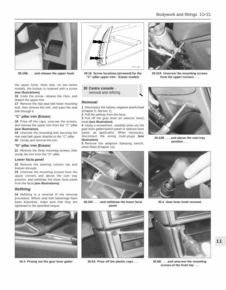
the upper hook. Note that, on low-seriesmodels, the bolster is retained with a screw(see illustrations).16 Undo the screw, release the clips, anddetach the upper trim.17 Remove the rear seat belt lower mountingbolt, then remove the trim, and pass the seatbelt through it.
“C” pillar trim (Estate)18 Prise off the caps, unscrew the screws,and remove the upper trim from the “C” pillar(see illustration).19 Unscrew the mounting bolt securing therear seat belt upper shackle to the “C” pillar.20 Unclip and remove the trim.
“D” pillar trim (Estate)21 Remove the three mounting screws, thenunclip the trim from the “D” pillar.
Lower facia panel22 Remove the steering column top andbottom shrouds.23 Unscrew the mounting screws from theupper corners and above the coin trayposition, and withdraw the lower facia panelfrom the facia (see illustrations).
Refitting24 Refitting is a reversal of the removalprocedure. Where seat belt fastenings havebeen disturbed, make sure that they aretightened to the specified torque.
Removal1 Disconnect the battery negative (earth) lead(Chapter 5, Section 1).2 Pull the ashtray from the facia.3 Pull off the gear lever (or selector lever)knob (see illustration).4 Using a screwdriver, carefully prise out thegear lever gaiter/switch panel or selector leverpanel, as applicable. When necessary,disconnect the wiring multi-plugs (seeillustration).5 Remove the adaptive damping switch,when fitted (Chapter 12).
30 Centre console - removal and refitting
Bodywork and fittings 11•21
11
30.4 Prising out the gear lever gaiter 30.6A Prise off the plastic caps . . . 30.6B . . . and unscrew the mountingscrews at the front top . . .
29.23B . . . and above the coin trayposition . . .
29.23C . . . and withdraw the lower faciapanel
30.3 Gear lever knob removal
29.15B . . . and release the upper hook 29.18 Screw locations (arrowed) for the“C” pillar upper trim - Estate models
29.23A Unscrew the mounting screwsfrom the upper corners . . .
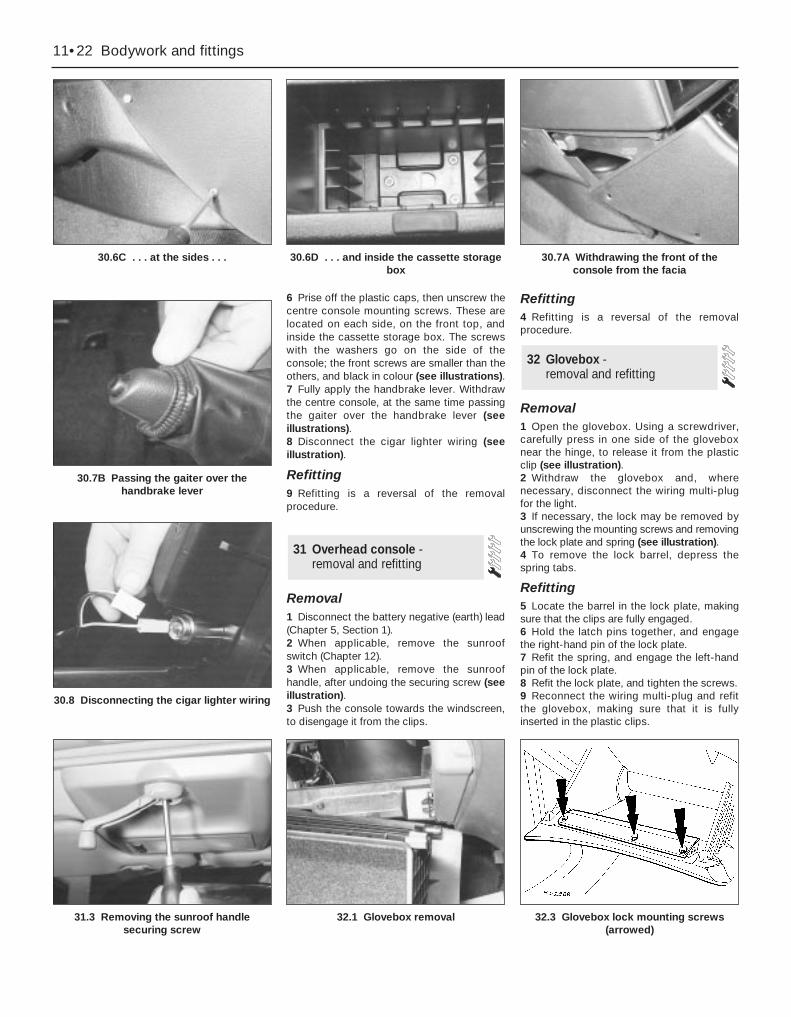
6 Prise off the plastic caps, then unscrew thecentre console mounting screws. These arelocated on each side, on the front top, andinside the cassette storage box. The screwswith the washers go on the side of theconsole; the front screws are smaller than theothers, and black in colour (see illustrations).7 Fully apply the handbrake lever. Withdrawthe centre console, at the same time passingthe gaiter over the handbrake lever (seeillustrations).8 Disconnect the cigar lighter wiring (seeillustration).
Refitting9 Refitting is a reversal of the removalprocedure.
Removal1 Disconnect the battery negative (earth) lead(Chapter 5, Section 1).2 When applicable, remove the sunroofswitch (Chapter 12).3 When applicable, remove the sunroofhandle, after undoing the securing screw (seeillustration).3 Push the console towards the windscreen,to disengage it from the clips.
Refitting4 Refitting is a reversal of the removalprocedure.
Removal1 Open the glovebox. Using a screwdriver,carefully press in one side of the gloveboxnear the hinge, to release it from the plasticclip (see illustration).2 Withdraw the glovebox and, wherenecessary, disconnect the wiring multi-plugfor the light.3 If necessary, the lock may be removed byunscrewing the mounting screws and removingthe lock plate and spring (see illustration).4 To remove the lock barrel, depress thespring tabs.
Refitting5 Locate the barrel in the lock plate, makingsure that the clips are fully engaged.6 Hold the latch pins together, and engagethe right-hand pin of the lock plate.7 Refit the spring, and engage the left-handpin of the lock plate.8 Refit the lock plate, and tighten the screws.9 Reconnect the wiring multi-plug and refitthe glovebox, making sure that it is fullyinserted in the plastic clips.
32 Glovebox - removal and refitting
31 Overhead console - removal and refitting
11•22 Bodywork and fittings
30.6C . . . at the sides . . . 30.6D . . . and inside the cassette storagebox
30.7A Withdrawing the front of theconsole from the facia
31.3 Removing the sunroof handlesecuring screw
32.1 Glovebox removal
30.8 Disconnecting the cigar lighter wiring
30.7B Passing the gaiter over thehandbrake lever
32.3 Glovebox lock mounting screws(arrowed)
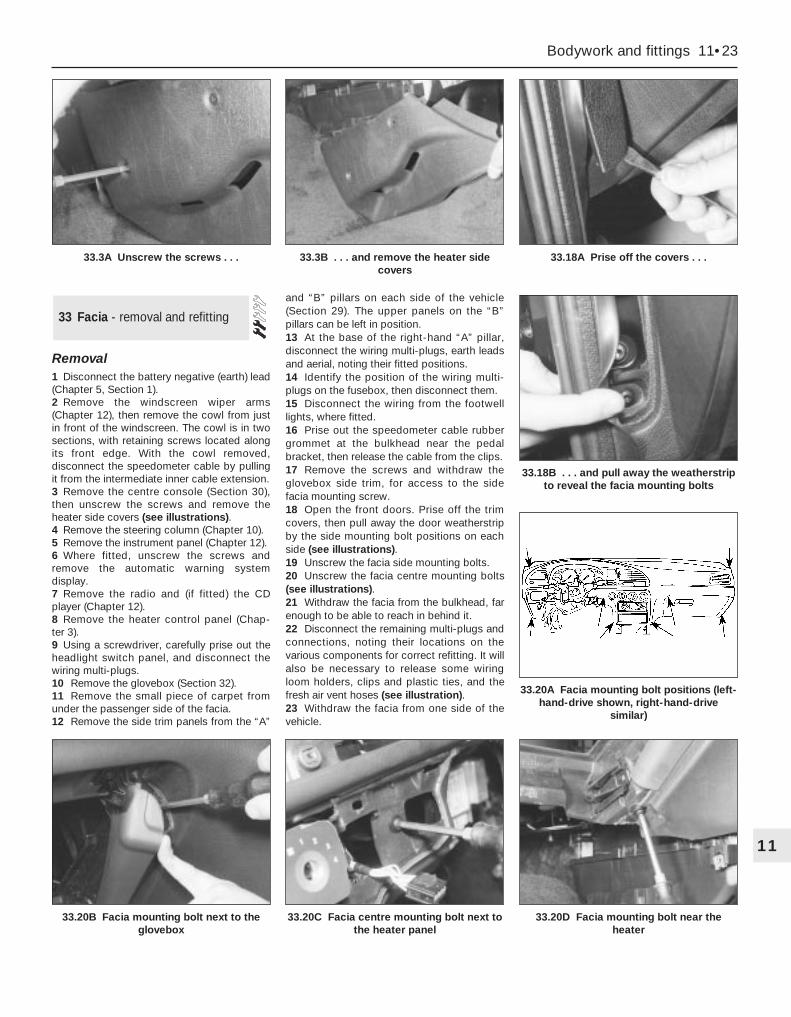
Removal1 Disconnect the battery negative (earth) lead(Chapter 5, Section 1).2 Remove the windscreen wiper arms(Chapter 12), then remove the cowl from justin front of the windscreen. The cowl is in twosections, with retaining screws located alongits front edge. With the cowl removed,disconnect the speedometer cable by pullingit from the intermediate inner cable extension.3 Remove the centre console (Section 30),then unscrew the screws and remove theheater side covers (see illustrations).4 Remove the steering column (Chapter 10).5 Remove the instrument panel (Chapter 12).6 Where fitted, unscrew the screws andremove the automatic warning systemdisplay.7 Remove the radio and (if fitted) the CDplayer (Chapter 12).8 Remove the heater control panel (Chap-ter 3).9 Using a screwdriver, carefully prise out theheadlight switch panel, and disconnect thewiring multi-plugs.10 Remove the glovebox (Section 32).11 Remove the small piece of carpet fromunder the passenger side of the facia.12 Remove the side trim panels from the “A”
and “B” pillars on each side of the vehicle(Section 29). The upper panels on the “B”pillars can be left in position.13 At the base of the right-hand “A” pillar,disconnect the wiring multi-plugs, earth leadsand aerial, noting their fitted positions.14 Identify the position of the wiring multi-plugs on the fusebox, then disconnect them.15 Disconnect the wiring from the footwelllights, where fitted.16 Prise out the speedometer cable rubbergrommet at the bulkhead near the pedalbracket, then release the cable from the clips.17 Remove the screws and withdraw theglovebox side trim, for access to the sidefacia mounting screw.18 Open the front doors. Prise off the trimcovers, then pull away the door weatherstripby the side mounting bolt positions on eachside (see illustrations).19 Unscrew the facia side mounting bolts.20 Unscrew the facia centre mounting bolts(see illustrations).21 Withdraw the facia from the bulkhead, farenough to be able to reach in behind it.22 Disconnect the remaining multi-plugs andconnections, noting their locations on thevarious components for correct refitting. It willalso be necessary to release some wiringloom holders, clips and plastic ties, and thefresh air vent hoses (see illustration).23 Withdraw the facia from one side of thevehicle.
33 Facia - removal and refitting
Bodywork and fittings 11•23
11
33.20B Facia mounting bolt next to theglovebox
33.20C Facia centre mounting bolt next tothe heater panel
33.20D Facia mounting bolt near theheater
33.3A Unscrew the screws . . . 33.3B . . . and remove the heater sidecovers
33.18A Prise off the covers . . .
33.18B . . . and pull away the weatherstripto reveal the facia mounting bolts
33.20A Facia mounting bolt positions (left-hand-drive shown, right-hand-drive
similar)

Refitting24 Refitting is a reversal of the removalprocedure. On completion, check theoperation of all electrical components.
RemovalFront1 Apply the handbrake, jack up the front ofthe vehicle and support it on axle stands. If
wished, remove the wheel to improve access.2 Prise out the stud clip on the front loweredge of the liner.3 Using a Torx key, unscrew the screwssecuring the liner to the inner wheel archpanel (see illustration).4 Remove the screws and clips securing theliner to the outer edge of the wheel arch andbumper. Withdraw the liner from under thevehicle (see illustration).
Rear5 Chock the front wheels, jack up the rear ofthe vehicle and support it on axle stands. Ifwished, remove the wheel to improve access.
6 Unscrew and remove the nuts, located oneither side of the coil spring, securing thecentral section of the liner.7 Using a Torx key, unscrew the screwssecuring the liner to the centre of the innerwheel arch panel.8 Remove the clips securing the liner to theouter edge of the wheel arch, and withdrawthe liner from under the vehicle.
Refitting9 Refitting is a reversal of the removalprocedure. If the wheels were removed,tighten the wheel nuts to the specified torque.
34 Wheel arch liner - removal and refitting
11•24 Bodywork and fittings
33.22 Disconnecting the fresh air hoses 34.3 Removing a wheel arch liner retainingscrew
34.4 Removing a front wheel arch liner
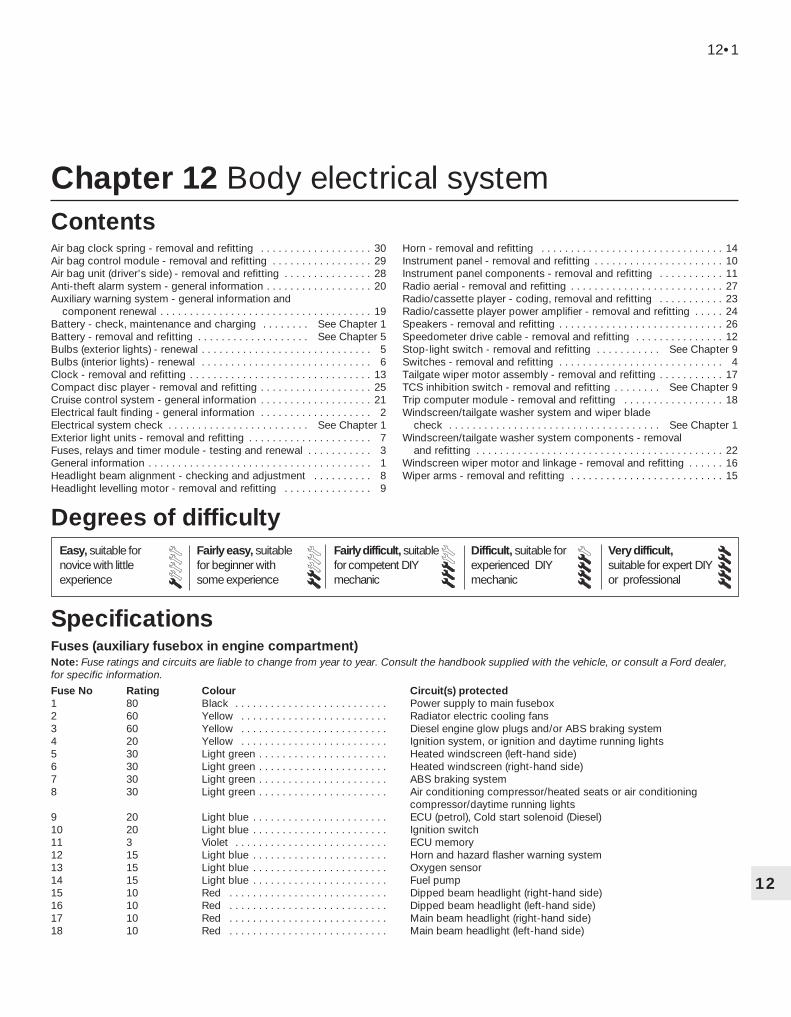
Chapter 12 Body electrical system
Air bag clock spring - removal and refitting . . . . . . . . . . . . . . . . . . . 30Air bag control module - removal and refitting . . . . . . . . . . . . . . . . . 29Air bag unit (driver’s side) - removal and refitting . . . . . . . . . . . . . . . 28Anti-theft alarm system - general information . . . . . . . . . . . . . . . . . . 20Auxiliary warning system - general information and
component renewal . . . . . . . . . . . . . . . . . . . . . . . . . . . . . . . . . . . . 19Battery - check, maintenance and charging . . . . . . . . See Chapter 1Battery - removal and refitting . . . . . . . . . . . . . . . . . . . See Chapter 5Bulbs (exterior lights) - renewal . . . . . . . . . . . . . . . . . . . . . . . . . . . . . 5Bulbs (interior lights) - renewal . . . . . . . . . . . . . . . . . . . . . . . . . . . . . 6Clock - removal and refitting . . . . . . . . . . . . . . . . . . . . . . . . . . . . . . . 13Compact disc player - removal and refitting . . . . . . . . . . . . . . . . . . . 25Cruise control system - general information . . . . . . . . . . . . . . . . . . . 21Electrical fault finding - general information . . . . . . . . . . . . . . . . . . . 2Electrical system check . . . . . . . . . . . . . . . . . . . . . . . . See Chapter 1Exterior light units - removal and refitting . . . . . . . . . . . . . . . . . . . . . 7Fuses, relays and timer module - testing and renewal . . . . . . . . . . . 3General information . . . . . . . . . . . . . . . . . . . . . . . . . . . . . . . . . . . . . . 1Headlight beam alignment - checking and adjustment . . . . . . . . . . 8Headlight levelling motor - removal and refitting . . . . . . . . . . . . . . . 9
Horn - removal and refitting . . . . . . . . . . . . . . . . . . . . . . . . . . . . . . . 14Instrument panel - removal and refitting . . . . . . . . . . . . . . . . . . . . . . 10Instrument panel components - removal and refitting . . . . . . . . . . . 11Radio aerial - removal and refitting . . . . . . . . . . . . . . . . . . . . . . . . . . 27Radio/cassette player - coding, removal and refitting . . . . . . . . . . . 23Radio/cassette player power amplifier - removal and refitting . . . . . 24Speakers - removal and refitting . . . . . . . . . . . . . . . . . . . . . . . . . . . . 26Speedometer drive cable - removal and refitting . . . . . . . . . . . . . . . 12Stop-light switch - removal and refitting . . . . . . . . . . . See Chapter 9Switches - removal and refitting . . . . . . . . . . . . . . . . . . . . . . . . . . . . 4Tailgate wiper motor assembly - removal and refitting . . . . . . . . . . . 17TCS inhibition switch - removal and refitting . . . . . . . . See Chapter 9Trip computer module - removal and refitting . . . . . . . . . . . . . . . . . 18Windscreen/tailgate washer system and wiper blade
check . . . . . . . . . . . . . . . . . . . . . . . . . . . . . . . . . . . . See Chapter 1Windscreen/tailgate washer system components - removal
and refitting . . . . . . . . . . . . . . . . . . . . . . . . . . . . . . . . . . . . . . . . . . 22Windscreen wiper motor and linkage - removal and refitting . . . . . . 16Wiper arms - removal and refitting . . . . . . . . . . . . . . . . . . . . . . . . . . 15
Fuses (auxiliary fusebox in engine compartment)Note: Fuse ratings and circuits are liable to change from year to year. Consult the handbook supplied with the vehicle, or consult a Ford dealer,for specific information.
Fuse No Rating Colour Circuit(s) protected1 80 Black . . . . . . . . . . . . . . . . . . . . . . . . . . Power supply to main fusebox2 60 Yellow . . . . . . . . . . . . . . . . . . . . . . . . . Radiator electric cooling fans3 60 Yellow . . . . . . . . . . . . . . . . . . . . . . . . . Diesel engine glow plugs and/or ABS braking system4 20 Yellow . . . . . . . . . . . . . . . . . . . . . . . . . Ignition system, or ignition and daytime running lights5 30 Light green . . . . . . . . . . . . . . . . . . . . . . Heated windscreen (left-hand side)6 30 Light green . . . . . . . . . . . . . . . . . . . . . . Heated windscreen (right-hand side)7 30 Light green . . . . . . . . . . . . . . . . . . . . . . ABS braking system8 30 Light green . . . . . . . . . . . . . . . . . . . . . . Air conditioning compressor/heated seats or air conditioning
compressor/daytime running lights9 20 Light blue . . . . . . . . . . . . . . . . . . . . . . . ECU (petrol), Cold start solenoid (Diesel)10 20 Light blue . . . . . . . . . . . . . . . . . . . . . . . Ignition switch11 3 Violet . . . . . . . . . . . . . . . . . . . . . . . . . . ECU memory12 15 Light blue . . . . . . . . . . . . . . . . . . . . . . . Horn and hazard flasher warning system13 15 Light blue . . . . . . . . . . . . . . . . . . . . . . . Oxygen sensor14 15 Light blue . . . . . . . . . . . . . . . . . . . . . . . Fuel pump15 10 Red . . . . . . . . . . . . . . . . . . . . . . . . . . . Dipped beam headlight (right-hand side)16 10 Red . . . . . . . . . . . . . . . . . . . . . . . . . . . Dipped beam headlight (left-hand side)17 10 Red . . . . . . . . . . . . . . . . . . . . . . . . . . . Main beam headlight (right-hand side)18 10 Red . . . . . . . . . . . . . . . . . . . . . . . . . . . Main beam headlight (left-hand side)
12•1
Easy, suitable fornovice with littleexperience
Fairly easy, suitablefor beginner withsome experience
Fairly difficult, suitablefor competent DIYmechanic
Difficult, suitable forexperienced DIYmechanic
Very difficult,suitable for expert DIYor professional
Degrees of difficulty
Specifications
Contents
12
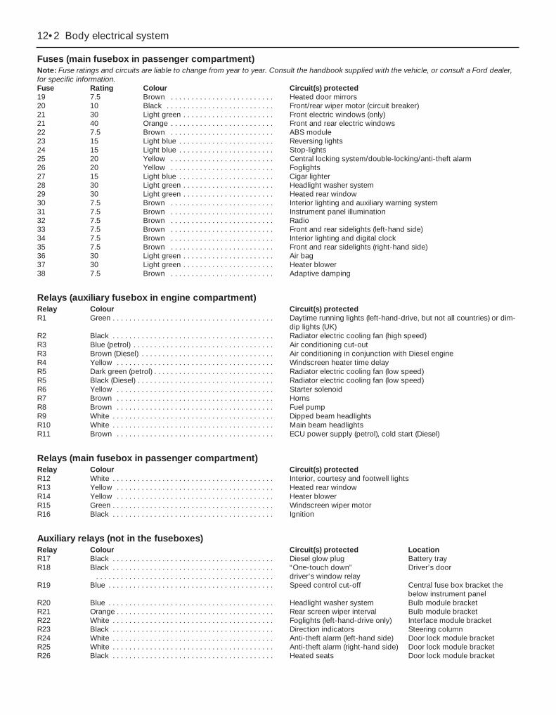
Fuses (main fusebox in passenger compartment)Note: Fuse ratings and circuits are liable to change from year to year. Consult the handbook supplied with the vehicle, or consult a Ford dealer,for specific information.Fuse Rating Colour Circuit(s) protected19 7.5 Brown . . . . . . . . . . . . . . . . . . . . . . . . . Heated door mirrors20 10 Black . . . . . . . . . . . . . . . . . . . . . . . . . . Front/rear wiper motor (circuit breaker)21 30 Light green . . . . . . . . . . . . . . . . . . . . . . Front electric windows (only)21 40 Orange . . . . . . . . . . . . . . . . . . . . . . . . . Front and rear electric windows22 7.5 Brown . . . . . . . . . . . . . . . . . . . . . . . . . ABS module23 15 Light blue . . . . . . . . . . . . . . . . . . . . . . . Reversing lights24 15 Light blue . . . . . . . . . . . . . . . . . . . . . . . Stop-lights25 20 Yellow . . . . . . . . . . . . . . . . . . . . . . . . . Central locking system/double-locking/anti-theft alarm26 20 Yellow . . . . . . . . . . . . . . . . . . . . . . . . . Foglights27 15 Light blue . . . . . . . . . . . . . . . . . . . . . . . Cigar lighter28 30 Light green . . . . . . . . . . . . . . . . . . . . . . Headlight washer system29 30 Light green . . . . . . . . . . . . . . . . . . . . . . Heated rear window30 7.5 Brown . . . . . . . . . . . . . . . . . . . . . . . . . Interior lighting and auxiliary warning system31 7.5 Brown . . . . . . . . . . . . . . . . . . . . . . . . . Instrument panel illumination32 7.5 Brown . . . . . . . . . . . . . . . . . . . . . . . . . Radio33 7.5 Brown . . . . . . . . . . . . . . . . . . . . . . . . . Front and rear sidelights (left-hand side)34 7.5 Brown . . . . . . . . . . . . . . . . . . . . . . . . . Interior lighting and digital clock35 7.5 Brown . . . . . . . . . . . . . . . . . . . . . . . . . Front and rear sidelights (right-hand side)36 30 Light green . . . . . . . . . . . . . . . . . . . . . . Air bag37 30 Light green . . . . . . . . . . . . . . . . . . . . . . Heater blower38 7.5 Brown . . . . . . . . . . . . . . . . . . . . . . . . . Adaptive damping
Relays (auxiliary fusebox in engine compartment)Relay Colour Circuit(s) protectedR1 Green . . . . . . . . . . . . . . . . . . . . . . . . . . . . . . . . . . . . . . . Daytime running lights (left-hand-drive, but not all countries) or dim-
dip lights (UK)R2 Black . . . . . . . . . . . . . . . . . . . . . . . . . . . . . . . . . . . . . . . Radiator electric cooling fan (high speed)R3 Blue (petrol) . . . . . . . . . . . . . . . . . . . . . . . . . . . . . . . . . . Air conditioning cut-outR3 Brown (Diesel) . . . . . . . . . . . . . . . . . . . . . . . . . . . . . . . . Air conditioning in conjunction with Diesel engineR4 Yellow . . . . . . . . . . . . . . . . . . . . . . . . . . . . . . . . . . . . . . Windscreen heater time delay R5 Dark green (petrol) . . . . . . . . . . . . . . . . . . . . . . . . . . . . . Radiator electric cooling fan (low speed)R5 Black (Diesel) . . . . . . . . . . . . . . . . . . . . . . . . . . . . . . . . . Radiator electric cooling fan (low speed)R6 Yellow . . . . . . . . . . . . . . . . . . . . . . . . . . . . . . . . . . . . . . Starter solenoidR7 Brown . . . . . . . . . . . . . . . . . . . . . . . . . . . . . . . . . . . . . . HornsR8 Brown . . . . . . . . . . . . . . . . . . . . . . . . . . . . . . . . . . . . . . Fuel pumpR9 White . . . . . . . . . . . . . . . . . . . . . . . . . . . . . . . . . . . . . . . Dipped beam headlightsR10 White . . . . . . . . . . . . . . . . . . . . . . . . . . . . . . . . . . . . . . . Main beam headlightsR11 Brown . . . . . . . . . . . . . . . . . . . . . . . . . . . . . . . . . . . . . . ECU power supply (petrol), cold start (Diesel)
Relays (main fusebox in passenger compartment)Relay Colour Circuit(s) protectedR12 White . . . . . . . . . . . . . . . . . . . . . . . . . . . . . . . . . . . . . . . Interior, courtesy and footwell lightsR13 Yellow . . . . . . . . . . . . . . . . . . . . . . . . . . . . . . . . . . . . . . Heated rear windowR14 Yellow . . . . . . . . . . . . . . . . . . . . . . . . . . . . . . . . . . . . . . Heater blowerR15 Green . . . . . . . . . . . . . . . . . . . . . . . . . . . . . . . . . . . . . . . Windscreen wiper motorR16 Black . . . . . . . . . . . . . . . . . . . . . . . . . . . . . . . . . . . . . . . Ignition
Auxiliary relays (not in the fuseboxes)Relay Colour Circuit(s) protected LocationR17 Black . . . . . . . . . . . . . . . . . . . . . . . . . . . . . . . . . . . . . . . Diesel glow plug Battery trayR18 Black . . . . . . . . . . . . . . . . . . . . . . . . . . . . . . . . . . . . . . . “One-touch down” Driver’s door
. . . . . . . . . . . . . . . . . . . . . . . . . . . . . . . . . . . . . . . . . . . driver’s window relayR19 Blue . . . . . . . . . . . . . . . . . . . . . . . . . . . . . . . . . . . . . . . . Speed control cut-off Central fuse box bracket the
below instrument panelR20 Blue . . . . . . . . . . . . . . . . . . . . . . . . . . . . . . . . . . . . . . . . Headlight washer system Bulb module bracketR21 Orange . . . . . . . . . . . . . . . . . . . . . . . . . . . . . . . . . . . . . . Rear screen wiper interval Bulb module bracketR22 White . . . . . . . . . . . . . . . . . . . . . . . . . . . . . . . . . . . . . . . Foglights (left-hand-drive only) Interface module bracketR23 Black . . . . . . . . . . . . . . . . . . . . . . . . . . . . . . . . . . . . . . . Direction indicators Steering columnR24 White . . . . . . . . . . . . . . . . . . . . . . . . . . . . . . . . . . . . . . . Anti-theft alarm (left-hand side) Door lock module bracketR25 White . . . . . . . . . . . . . . . . . . . . . . . . . . . . . . . . . . . . . . . Anti-theft alarm (right-hand side) Door lock module bracketR26 Black . . . . . . . . . . . . . . . . . . . . . . . . . . . . . . . . . . . . . . . Heated seats Door lock module bracket
12•2 Body electrical system
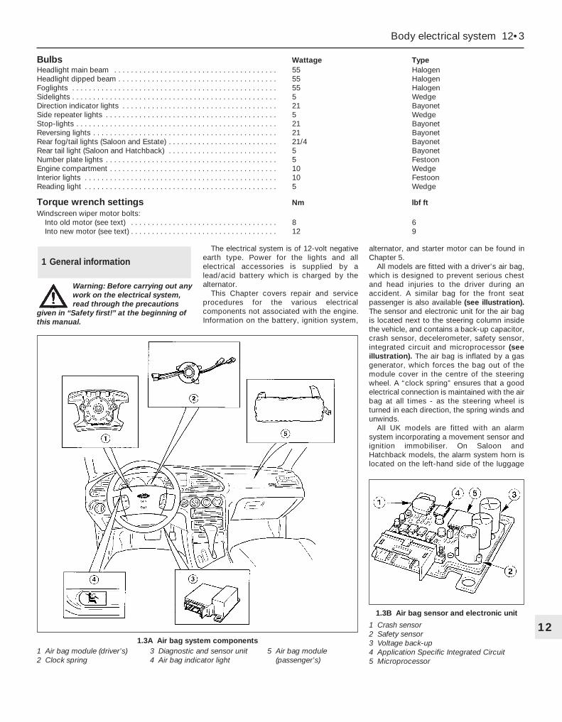
Bulbs Wattage TypeHeadlight main beam . . . . . . . . . . . . . . . . . . . . . . . . . . . . . . . . . . . . . . . 55 HalogenHeadlight dipped beam . . . . . . . . . . . . . . . . . . . . . . . . . . . . . . . . . . . . . . 55 HalogenFoglights . . . . . . . . . . . . . . . . . . . . . . . . . . . . . . . . . . . . . . . . . . . . . . . . . 55 HalogenSidelights . . . . . . . . . . . . . . . . . . . . . . . . . . . . . . . . . . . . . . . . . . . . . . . . . 5 WedgeDirection indicator lights . . . . . . . . . . . . . . . . . . . . . . . . . . . . . . . . . . . . . 21 BayonetSide repeater lights . . . . . . . . . . . . . . . . . . . . . . . . . . . . . . . . . . . . . . . . . 5 WedgeStop-lights . . . . . . . . . . . . . . . . . . . . . . . . . . . . . . . . . . . . . . . . . . . . . . . . 21 BayonetReversing lights . . . . . . . . . . . . . . . . . . . . . . . . . . . . . . . . . . . . . . . . . . . . 21 BayonetRear fog/tail lights (Saloon and Estate) . . . . . . . . . . . . . . . . . . . . . . . . . . 21/4 BayonetRear tail light (Saloon and Hatchback) . . . . . . . . . . . . . . . . . . . . . . . . . . 5 BayonetNumber plate lights . . . . . . . . . . . . . . . . . . . . . . . . . . . . . . . . . . . . . . . . . 5 FestoonEngine compartment . . . . . . . . . . . . . . . . . . . . . . . . . . . . . . . . . . . . . . . . 10 WedgeInterior lights . . . . . . . . . . . . . . . . . . . . . . . . . . . . . . . . . . . . . . . . . . . . . . 10 FestoonReading light . . . . . . . . . . . . . . . . . . . . . . . . . . . . . . . . . . . . . . . . . . . . . . 5 Wedge
Torque wrench settings Nm lbf ftWindscreen wiper motor bolts:
Into old motor (see text) . . . . . . . . . . . . . . . . . . . . . . . . . . . . . . . . . . . 8 6Into new motor (see text) . . . . . . . . . . . . . . . . . . . . . . . . . . . . . . . . . . . 12 9
Body electrical system 12•3
12
Warning: Before carrying out anywork on the electrical system,read through the precautions
given in “Safety first!” at the beginning ofthis manual.
The electrical system is of 12-volt negativeearth type. Power for the lights and allelectrical accessories is supplied by alead/acid battery which is charged by thealternator.
This Chapter covers repair and serviceprocedures for the various electricalcomponents not associated with the engine.Information on the battery, ignition system,
alternator, and starter motor can be found inChapter 5.
All models are fitted with a driver’s air bag,which is designed to prevent serious chestand head injuries to the driver during anaccident. A similar bag for the front seatpassenger is also available (see illustration).The sensor and electronic unit for the air bagis located next to the steering column insidethe vehicle, and contains a back-up capacitor,crash sensor, decelerometer, safety sensor,integrated circuit and microprocessor (seeillustration). The air bag is inflated by a gasgenerator, which forces the bag out of themodule cover in the centre of the steeringwheel. A “clock spring” ensures that a goodelectrical connection is maintained with the airbag at all times - as the steering wheel isturned in each direction, the spring winds andunwinds.
All UK models are fitted with an alarmsystem incorporating a movement sensor andignition immobiliser. On Saloon andHatchback models, the alarm system horn islocated on the left-hand side of the luggage
1 General information
1.3A Air bag system components1 Air bag module (driver’s)2 Clock spring
3 Diagnostic and sensor unit4 Air bag indicator light
5 Air bag module (passenger’s)
1.3B Air bag sensor and electronic unit
1 Crash sensor2 Safety sensor3 Voltage back-up4 Application Specific Integrated Circuit5 Microprocessor
compartment, but on Estate models, it is onthe right-hand side.
Some models are fitted with a headlightlevelling system, which is controlled by a knobon the facia. On position “0”, the headlightsare in their base position, and on position “5”,the headlights are in their maximum inclinedangle.
It should be noted that, when portions ofthe electrical system are serviced, the cableshould be disconnected from the batterynegative terminal, to prevent electrical shortsand fires.
Caution: When disconnecting thebattery for work described in thefollowing Sections, refer toChapter 5, Section 1.
Note: Refer to the precautions given in“Safety first!” and in Section 1 of this Chapterbefore starting work. The following tests relateto testing of the main electrical circuits, andshould not be used to test delicate electroniccircuits (such as engine management systems,anti-lock braking systems, etc), particularlywhere an electronic control module is used.Also refer to the precautions given in Chapter5, Section 1.
General1 A typical electrical circuit consists of anelectrical component, any switches, relays,motors, fuses, fusible links or circuit breakersrelated to that component, and the wiring andconnectors which link the component to boththe battery and the chassis. To help topinpoint a problem in an electrical circuit,wiring diagrams are included at the end of thismanual.2 Before attempting to diagnose an electricalfault, first study the appropriate wiringdiagram, to obtain a complete understandingof the components included in the particularcircuit concerned. The possible sources of afault can be narrowed down by noting if othercomponents related to the circuit areoperating properly. If several components orcircuits fail at one time, the problem is likely tobe related to a shared fuse or earthconnection.3 Electrical problems usually stem fromsimple causes, such as loose or corrodedconnections, a faulty earth connection, ablown fuse, a melted fusible link, or a faultyrelay (refer to Section 3 for details of testingrelays). Visually inspect the condition of allfuses, wires and connections in a problemcircuit before testing the components. Usethe wiring diagrams to determine whichterminal connections will need to be checkedin order to pinpoint the trouble-spot.4 The basic tools required for electrical fault-finding include a circuit tester or voltmeter (a12-volt bulb with a set of test leads can also
be used for certain tests); an ohmmeter (tomeasure resistance and check for continuity);a battery and set of test leads; and a jumperwire, preferably with a circuit breaker or fuseincorporated, which can be used to bypasssuspect wires or electrical components.Before attempting to locate a problem withtest instruments, use the wiring diagram todetermine where to make the connections.5 To find the source of an intermittent wiringfault (usually due to a poor or dirtyconnection, or damaged wiring insulation), a“wiggle” test can be performed on the wiring.This involves wiggling the wiring by hand tosee if the fault occurs as the wiring is moved.It should be possible to narrow down thesource of the fault to a particular section ofwiring. This method of testing can be used inconjunction with any of the tests described inthe following sub-Sections.6 Apart from problems due to poorconnections, two basic types of fault canoccur in an electrical circuit - open-circuit, orshort-circuit.7 Open-circuit faults are caused by a breaksomewhere in the circuit, which preventscurrent from flowing. An open-circuit fault willprevent a component from working.8 Short-circuit faults are caused by a “short”somewhere in the circuit, which allows thecurrent flowing in the circuit to “escape” alongan alternative route, usually to earth. Short-circuit faults are normally caused by abreakdown in wiring insulation, which allows afeed wire to touch either another wire, or anearthed component such as the bodyshell. Ashort-circuit fault will normally cause therelevant circuit fuse to blow.
Finding an open-circuit9 To check for an open-circuit, connect onelead of a circuit tester or the negative lead of avoltmeter either to the battery negativeterminal or to a known good earth.10 Connect the other lead to a connector inthe circuit being tested, preferably nearest tothe battery or fuse. At this point, batteryvoltage should be present, unless the leadfrom the battery or the fuse itself is faulty(bearing in mind that some circuits are liveonly when the ignition switch is moved to aparticular position).11 Switch on the circuit, then connect thetester lead to the connector nearest the circuitswitch on the component side.12 If voltage is present (indicated either bythe tester bulb lighting or a voltmeter reading,as applicable), this means that the section ofthe circuit between the relevant connectorand the switch is problem-free.13 Continue to check the remainder of thecircuit in the same fashion.14 When a point is reached at which novoltage is present, the problem must liebetween that point and the previous test pointwith voltage. Most problems can be traced toa broken, corroded or loose connection.
Finding a short-circuit15 To check for a short-circuit, firstdisconnect the load(s) from the circuit (loadsare the components which draw current froma circuit, such as bulbs, motors, heatingelements, etc).16 Remove the relevant fuse from the circuit,and connect a circuit tester or voltmeter to thefuse connections.17 Switch on the circuit, bearing in mind thatsome circuits are live only when the ignitionswitch is moved to a particular position.18 If voltage is present (indicated either bythe tester bulb lighting or a voltmeter reading,as applicable), this means that there is ashort-circuit.19 If no voltage is present during this test,but the fuse still blows with the load(s)reconnected, this indicates an internal fault inthe load(s).
Finding an earth fault20 The battery negative terminal isconnected to “earth” - the metal of theengine/transmission unit and the vehicle body- and many systems are wired so that theyonly receive a positive feed, the currentreturning via the metal of the car body. Thismeans that the component mounting and thebody form part of that circuit. Loose orcorroded mountings can therefore cause arange of electrical faults, ranging from totalfailure of a circuit, to a puzzling partial failure.In particular, lights may shine dimly (especiallywhen another circuit sharing the same earthpoint is in operation), motors (eg wiper motorsor the radiator cooling fan motor) may runslowly, and the operation of one circuit mayhave an apparently-unrelated effect onanother. Note that on many vehicles, earthstraps are used between certain components,such as the engine/transmission and thebody, usually where there is no metal-to-metal contact between components, due toflexible rubber mountings, etc.21 To check whether a component isproperly earthed, disconnect the battery (referto Chapter 5, Section 1) and connect one leadof an ohmmeter to a known good earth point.Connect the other lead to the wire or earthconnection being tested. The resistancereading should be zero; if not, check theconnection as follows.22 If an earth connection is thought to befaulty, dismantle the connection, and cleanboth the bodyshell and the wire terminal (orthe component earth connection matingsurface) back to bare metal. Be careful toremove all traces of dirt and corrosion, thenuse a knife to trim away any paint, so that aclean metal-to-metal joint is made. Onreassembly, tighten the joint fastenerssecurely; if a wire terminal is being refitted,use serrated washers between the terminaland the bodyshell, to ensure a clean andsecure connection. When the connection is
2 Electrical fault finding -general information
12•4 Body electrical system
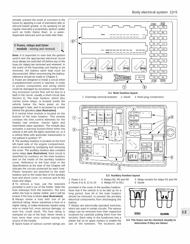
remade, prevent the onset of corrosion in thefuture by applying a coat of petroleum jelly orsilicone-based grease, or by spraying on (atregular intervals) a proprietary ignition sealersuch as Holts Damp Start, or a water-dispersant lubricant such as Holts Wet Start.
Note: It is important to note that the ignitionswitch and the appropriate electrical circuitmust always be switched off before any of thefuses (or relays) are removed and renewed. Inthe event of the fuse/relay unit having to beremoved, the battery earth lead must bedisconnected. When reconnecting the battery,reference should be made to Chapter 5.1 Fuses are designed to break a circuit whena predetermined current is reached, in orderto protect components and wiring whichcould be damaged by excessive current flow.Any excessive current flow will be due to afault in the circuit, usually a short-circuit (seeSection 2). The main fusebox, which alsocarries some relays, is located inside thevehicle below the facia panel on thepassenger’s side, and is accessed by a leverbehind the glovebox (see illustration).2 A central timer module is located on thebottom of the main fusebox. This modulecontains the time control elements for theheated rear window, interior lights andintermittent wiper operation. The module alsoactivates a warning buzzer/chime when thevehicle is left with the lights switched on, or ifa vehicle fitted with automatic transmission isnot parked in position “P”.3 The auxiliary fusebox is located on the frontleft-hand side of the engine compartment,and is accessed by unclipping and removingthe cover. The auxiliary fusebox also containssome relays (see illustration). Each circuit isidentified by numbers on the main fuseboxand on the inside of the auxiliary fuseboxcover. Reference to the fuse chart in theSpecifications at the start of this Chapter willindicate the circuits protected by each fuse.Plastic tweezers are attached to the mainfusebox and to the inside face of the auxiliaryfuse and block cover, to remove and fit thefuses and relays.4 To remove a fuse, use the tweezersprovided to pull it out of the holder. Slide thefuse sideways from the tweezers. The wirewithin the fuse is clearly visible, and it will bebroken if the fuse is blown (see illustration).5 Always renew a fuse with one of anidentical rating. Never substitute a fuse of ahigher rating, or make temporary repairs usingwire or metal foil; more serious damage, oreven fire, could result. The fuse rating isstamped on top of the fuse. Never renew afuse more than once without tracing thesource of the trouble.6 Spare fuses of various current ratings are
provided in the cover of the auxiliary fusebox.Note that if the vehicle is to be laid up for along period, fuse 34 in the main fuseboxshould be removed, to prevent the ancillaryelectrical components from discharging thebattery.7 Relays are electrically-operated switches,which are used in certain circuits. The variousrelays can be removed from their respectivelocations by carefully pulling them from thesockets. Each relay in the fuseboxes has aplastic bar on its upper surface to enable theuse of the tweezers. The locations and
3 Fuses, relays and timermodule - testing and renewal
Body electrical system 12•5
12
3.4 The fuses can be checked visually todetermine if they are blown
3.1 Main fusebox layout
1 Fuse/relay removal tweezers 2 Diode 3 Multi-plug connections
3.3 Auxiliary fusebox layout
1 Fuses 1 to 3 3 Relays R2, R5 and R6 5 Relay sockets for relays R1 and R42 Fuses 4 to 8, 11 to 14 4 Relays R7 to R11 6 Diode
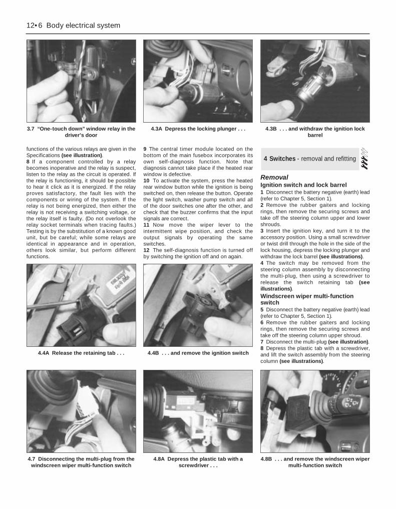
functions of the various relays are given in theSpecifications (see illustration).8 If a component controlled by a relaybecomes inoperative and the relay is suspect,listen to the relay as the circuit is operated. Ifthe relay is functioning, it should be possibleto hear it click as it is energized. If the relayproves satisfactory, the fault lies with thecomponents or wiring of the system. If therelay is not being energized, then either therelay is not receiving a switching voltage, orthe relay itself is faulty. (Do not overlook therelay socket terminals when tracing faults.)Testing is by the substitution of a known goodunit, but be careful; while some relays areidentical in appearance and in operation,others look similar, but perform differentfunctions.
9 The central timer module located on thebottom of the main fusebox incorporates itsown self-diagnosis function. Note thatdiagnosis cannot take place if the heated rearwindow is defective.10 To activate the system, press the heatedrear window button while the ignition is beingswitched on, then release the button. Operatethe light switch, washer pump switch and allof the door switches one after the other, andcheck that the buzzer confirms that the inputsignals are correct.11 Now move the wiper lever to theintermittent wipe position, and check theoutput signals by operating the sameswitches.12 The self-diagnosis function is turned offby switching the ignition off and on again.
RemovalIgnition switch and lock barrel1 Disconnect the battery negative (earth) lead(refer to Chapter 5, Section 1).2 Remove the rubber gaiters and lockingrings, then remove the securing screws andtake off the steering column upper and lowershrouds.3 Insert the ignition key, and turn it to theaccessory position. Using a small screwdriveror twist drill through the hole in the side of thelock housing, depress the locking plunger andwithdraw the lock barrel (see illustrations).4 The switch may be removed from thesteering column assembly by disconnectingthe multi-plug, then using a screwdriver torelease the switch retaining tab (seeillustrations).Windscreen wiper multi-functionswitch5 Disconnect the battery negative (earth) lead(refer to Chapter 5, Section 1).6 Remove the rubber gaiters and lockingrings, then remove the securing screws andtake off the steering column upper shroud.7 Disconnect the multi-plug (see illustration).8 Depress the plastic tab with a screwdriver,and lift the switch assembly from the steeringcolumn (see illustrations).
4 Switches - removal and refitting
12•6 Body electrical system
3.7 “One-touch down” window relay in thedriver’s door
4.3A Depress the locking plunger . . . 4.3B . . . and withdraw the ignition lockbarrel
4.7 Disconnecting the multi-plug from thewindscreen wiper multi-function switch
4.8A Depress the plastic tab with ascrewdriver . . .
4.4A Release the retaining tab . . . 4.4B . . . and remove the ignition switch
4.8B . . . and remove the windscreen wipermulti-function switch
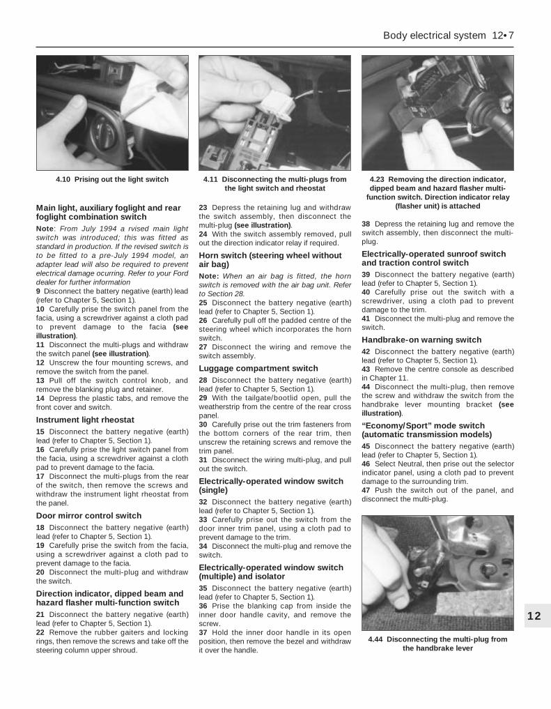
Main light, auxiliary foglight and rearfoglight combination switchNote: From July 1994 a rvised main lightswitch was introduced; this was fitted asstandard in production. If the revised switch isto be fitted to a pre-July 1994 model, anadapter lead will also be required to preventelectrical damage ocurring. Refer to your Forddealer for further information9 Disconnect the battery negative (earth) lead(refer to Chapter 5, Section 1).10 Carefully prise the switch panel from thefacia, using a screwdriver against a cloth padto prevent damage to the facia (seeillustration).11 Disconnect the multi-plugs and withdrawthe switch panel (see illustration).12 Unscrew the four mounting screws, andremove the switch from the panel.13 Pull off the switch control knob, andremove the blanking plug and retainer.14 Depress the plastic tabs, and remove thefront cover and switch.
Instrument light rheostat15 Disconnect the battery negative (earth)lead (refer to Chapter 5, Section 1).16 Carefully prise the light switch panel fromthe facia, using a screwdriver against a clothpad to prevent damage to the facia.17 Disconnect the multi-plugs from the rearof the switch, then remove the screws andwithdraw the instrument light rheostat fromthe panel.
Door mirror control switch18 Disconnect the battery negative (earth)lead (refer to Chapter 5, Section 1).19 Carefully prise the switch from the facia,using a screwdriver against a cloth pad toprevent damage to the facia.20 Disconnect the multi-plug and withdrawthe switch.
Direction indicator, dipped beam andhazard flasher multi-function switch21 Disconnect the battery negative (earth)lead (refer to Chapter 5, Section 1).22 Remove the rubber gaiters and lockingrings, then remove the screws and take off thesteering column upper shroud.
23 Depress the retaining lug and withdrawthe switch assembly, then disconnect themulti-plug (see illustration).24 With the switch assembly removed, pullout the direction indicator relay if required.
Horn switch (steering wheel withoutair bag)Note: When an air bag is fitted, the hornswitch is removed with the air bag unit. Referto Section 28.25 Disconnect the battery negative (earth)lead (refer to Chapter 5, Section 1).26 Carefully pull off the padded centre of thesteering wheel which incorporates the hornswitch.27 Disconnect the wiring and remove theswitch assembly.
Luggage compartment switch28 Disconnect the battery negative (earth)lead (refer to Chapter 5, Section 1).29 With the tailgate/bootlid open, pull theweatherstrip from the centre of the rear crosspanel.30 Carefully prise out the trim fasteners fromthe bottom corners of the rear trim, thenunscrew the retaining screws and remove thetrim panel.31 Disconnect the wiring multi-plug, and pullout the switch.
Electrically-operated window switch(single)32 Disconnect the battery negative (earth)lead (refer to Chapter 5, Section 1).33 Carefully prise out the switch from thedoor inner trim panel, using a cloth pad toprevent damage to the trim.34 Disconnect the multi-plug and remove theswitch.
Electrically-operated window switch(multiple) and isolator35 Disconnect the battery negative (earth)lead (refer to Chapter 5, Section 1).36 Prise the blanking cap from inside theinner door handle cavity, and remove thescrew.37 Hold the inner door handle in its openposition, then remove the bezel and withdrawit over the handle.
38 Depress the retaining lug and remove theswitch assembly, then disconnect the multi-plug.
Electrically-operated sunroof switchand traction control switch39 Disconnect the battery negative (earth)lead (refer to Chapter 5, Section 1).40 Carefully prise out the switch with ascrewdriver, using a cloth pad to preventdamage to the trim.41 Disconnect the multi-plug and remove theswitch.
Handbrake-on warning switch42 Disconnect the battery negative (earth)lead (refer to Chapter 5, Section 1).43 Remove the centre console as describedin Chapter 11.44 Disconnect the multi-plug, then removethe screw and withdraw the switch from thehandbrake lever mounting bracket (seeillustration).
“Economy/Sport” mode switch(automatic transmission models)45 Disconnect the battery negative (earth)lead (refer to Chapter 5, Section 1).46 Select Neutral, then prise out the selectorindicator panel, using a cloth pad to preventdamage to the surrounding trim.47 Push the switch out of the panel, anddisconnect the multi-plug.
Body electrical system 12•7
12
4.44 Disconnecting the multi-plug fromthe handbrake lever
4.10 Prising out the light switch 4.11 Disconnecting the multi-plugs fromthe light switch and rheostat
4.23 Removing the direction indicator,dipped beam and hazard flasher multi-
function switch. Direction indicator relay(flasher unit) is attached

Heated windscreen switch and heatedrear window switch48 Disconnect the battery negative (earth)lead (refer to Chapter 5, Section 1).49 Carefully prise out the switch, using acloth pad to prevent damage to the trim (seeillustration).50 Disconnect the multi-plug and remove theswitch (see illustration).
Electrically-operated seat switch andheated seat switch51 Disconnect the battery negative (earth)lead (refer to Chapter 5, Section 1).52 Carefully prise out the switch, using acloth pad to prevent damage to the trim.53 Disconnect the multi-plug and remove theswitch.
Adaptive damping switch54 Disconnect the battery negative (earth)lead (refer to Chapter 5, Section 1).55 Carefully prise out the switch, using acloth pad to prevent damage to the trim.56 Disconnect the multi-plug and remove theswitch.
Courtesy light door switch57 Open the door, then unscrew the cross-head screw and carefully pull the switch fromthe pillar (see illustrations). Take care not toforce the wire from the switch terminal,otherwise it will be difficult to retrieve it fromthe pillar.58 Disconnect the wire, and tie it in a looseknot to prevent it dropping back into the pillar.
Refitting59 Refitting of all switches is a reversal of theremoval procedure.
Note: Ensure that all exterior lights areswitched off before disconnecting the wiringconnectors from any exterior light bulbs. Donot touch the glass of halogen-type bulbs(headlights, front foglights) with the fingers; ifthe glass is accidentally touched, clean it withmethylated spirit.
Headlight (dipped beam)1 Working under the bonnet, depress theplastic clips and remove the cover from therear of the headlight unit (see illustration).2 Release the spring clip and withdraw thebulb, then disconnect the wiring lead (seeillustrations).3 Fit the new bulb using a reversal of theremoval procedure. Have the headlight beamalignment checked as described later in thisChapter.
Headlight (main beam)4 Working under the bonnet, depress theplastic clips and remove the cover from therear of the headlight unit.5 Turn the bulbholder anti-clockwise, andremove it from the rear of the headlight unit(see illustration).
5 Bulbs (exterior lights) -renewal
12•8 Body electrical system
4.49 Prising out the heated rear windowswitch
4.50 Disconnecting the multi-plug fromthe heated rear window switch
4.57A Unscrew the cross-head screw . . .
5.2A Release the spring clip . . . 5.2B . . . and withdraw the headlight bulb
4.57B . . . and pull out the courtesy lightswitch
5.1 Removing the cover from the rear ofthe headlight
5.5 Removing the headlight (main beam)bulbholder
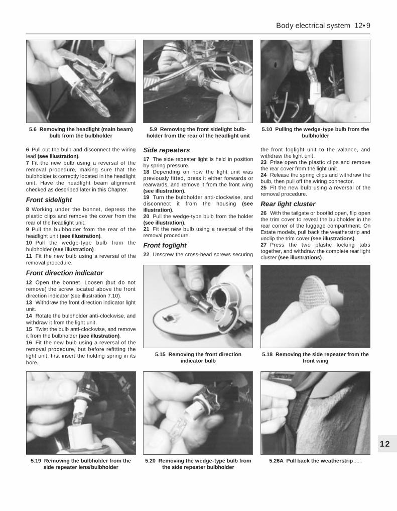
6 Pull out the bulb and disconnect the wiringlead (see illustration).7 Fit the new bulb using a reversal of theremoval procedure, making sure that thebulbholder is correctly located in the headlightunit. Have the headlight beam alignmentchecked as described later in this Chapter.
Front sidelight8 Working under the bonnet, depress theplastic clips and remove the cover from therear of the headlight unit.9 Pull the bulbholder from the rear of theheadlight unit (see illustration).10 Pull the wedge-type bulb from thebulbholder (see illustration).11 Fit the new bulb using a reversal of theremoval procedure.
Front direction indicator12 Open the bonnet. Loosen (but do notremove) the screw located above the frontdirection indicator (see illustration 7.10).13 Withdraw the front direction indicator lightunit.14 Rotate the bulbholder anti-clockwise, andwithdraw it from the light unit.15 Twist the bulb anti-clockwise, and removeit from the bulbholder (see illustration).16 Fit the new bulb using a reversal of theremoval procedure, but before refitting thelight unit, first insert the holding spring in itsbore.
Side repeaters17 The side repeater light is held in positionby spring pressure.18 Depending on how the light unit waspreviously fitted, press it either forwards orrearwards, and remove it from the front wing(see illustration).19 Turn the bulbholder anti-clockwise, anddisconnect it from the housing (seeillustration).20 Pull the wedge-type bulb from the holder(see illustration).21 Fit the new bulb using a reversal of theremoval procedure.
Front foglight22 Unscrew the cross-head screws securing
the front foglight unit to the valance, andwithdraw the light unit.23 Prise open the plastic clips and removethe rear cover from the light unit.24 Release the spring clips and withdraw thebulb, then pull off the wiring connector.25 Fit the new bulb using a reversal of theremoval procedure.
Rear light cluster26 With the tailgate or bootlid open, flip openthe trim cover to reveal the bulbholder in therear corner of the luggage compartment. OnEstate models, pull back the weatherstrip andunclip the trim cover (see illustrations).27 Press the two plastic locking tabstogether, and withdraw the complete rear lightcluster (see illustrations).
Body electrical system 12•9
12
5.19 Removing the bulbholder from theside repeater lens/bulbholder
5.20 Removing the wedge-type bulb fromthe side repeater bulbholder
5.26A Pull back the weatherstrip . . .
5.15 Removing the front directionindicator bulb
5.18 Removing the side repeater from thefront wing
5.6 Removing the headlight (main beam)bulb from the bulbholder
5.9 Removing the front sidelight bulb-holder from the rear of the headlight unit
5.10 Pulling the wedge-type bulb from thebulbholder
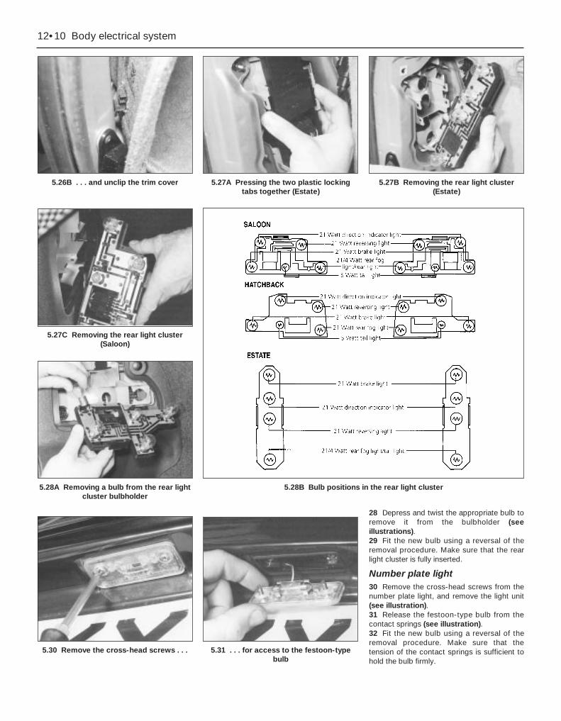
28 Depress and twist the appropriate bulb toremove it from the bulbholder (seeillustrations).29 Fit the new bulb using a reversal of theremoval procedure. Make sure that the rearlight cluster is fully inserted.
Number plate light30 Remove the cross-head screws from thenumber plate light, and remove the light unit(see illustration).31 Release the festoon-type bulb from thecontact springs (see illustration).32 Fit the new bulb using a reversal of theremoval procedure. Make sure that thetension of the contact springs is sufficient tohold the bulb firmly.
12•10 Body electrical system
5.26B . . . and unclip the trim cover 5.27A Pressing the two plastic lockingtabs together (Estate)
5.30 Remove the cross-head screws . . . 5.31 . . . for access to the festoon-typebulb
5.27B Removing the rear light cluster(Estate)
5.28A Removing a bulb from the rear lightcluster bulbholder
5.27C Removing the rear light cluster(Saloon)
5.28B Bulb positions in the rear light cluster

Engine compartment light1 With the bonnet open, pull the wedge-typebulb from the bulbholder.2 Fit the new bulb using a reversal of theremoval procedure.
Interior lights3 Switch off the interior light by locating theswitch in its middle position.4 Using a small screwdriver, carefully priseout the light or bulb cover, as applicable (seeillustration).5 Lift up the reflector, then release thefestoon-type bulb from the contact springs(see illustration).6 Fit the new bulb using a reversal of theremoval procedure. Make sure that thetension of the contact springs is sufficient tohold the bulb firmly.
Reading light7 With the reading light switched off, priseout the light using a small screwdriver.8 Hinge back the contact plate, and releasethe festoon-type bulb from the contactsprings.
9 Fit the new bulb using a reversal of theremoval procedure. Make sure that thetension of the contact springs is sufficient tohold the bulb firmly.
Instrument panel illumination andwarning lights10 Remove the instrument panel asdescribed in Section 10.11 Twist the bulbholder anti-clockwise toremove it (see illustration).12 Fit the new bulbholder using a reversal ofthe removal procedure.
Foglight warning indicator13 Using a screwdriver, prise out theindicator from the facia, and disconnect themulti-plug.14 Twist the bulbholder anti-clockwise withthe screwdriver, and remove it (seeillustration).15 Fit the new bulb using a reversal of theremoval procedure.
Hazard warning light16 Pull the cover directly up from the switch,then remove the bulb (see illustrations).17 Fit the new bulb using a reversal of theremoval procedure.
Glovebox light18 Open the glovebox, then pull out thewedge-type bulb from the light located underthe upper edge.
Heater fan switch illumination19 Pull off the switch knob, then depress andtwist the bulb to remove it.
Automatic transmission selectorpanel illumination20 Disconnect the battery negative (earth)lead (refer to Chapter 5, Section 1).21 Remove the ashtray.22 Select Neutral, then prise out the panelfrom the centre console.23 Disconnect the multi-plug from theoverdrive control switch.24 Disconnect the bulbholder and pull outthe wedge-type bulb.25 Fit the new bulb using a reversal of theremoval procedure.
Interior door handle illumination26 Disconnect the battery negative (earth)lead (refer to Chapter 5, Section 1).27 Remove the door interior trim panel asdescribed in Chapter 11.28 Using a knife, cut free the foamwatershield for access to the rear of theinterior door handle.29 Pull out the bulbholder and remove thebulb.
Clock illumination30 Disconnect the battery negative (earth)lead (refer to Chapter 5, Section 1).31 Remove the clock as described in Sec-tion 13.
6 Bulbs (interior lights) - renewal
Body electrical system 12•11
12
6.14 Removing the bulb from the foglightwarning indicator
6.16A Pull off the hazard warning lightcover . . .
6.16B . . . and remove the bulb
6.4 Prise out the interior light with ascrewdriver
6.5 Lifting the reflector from the interiorlight
6.11 Removing a bulb from the rear of theinstrument panel
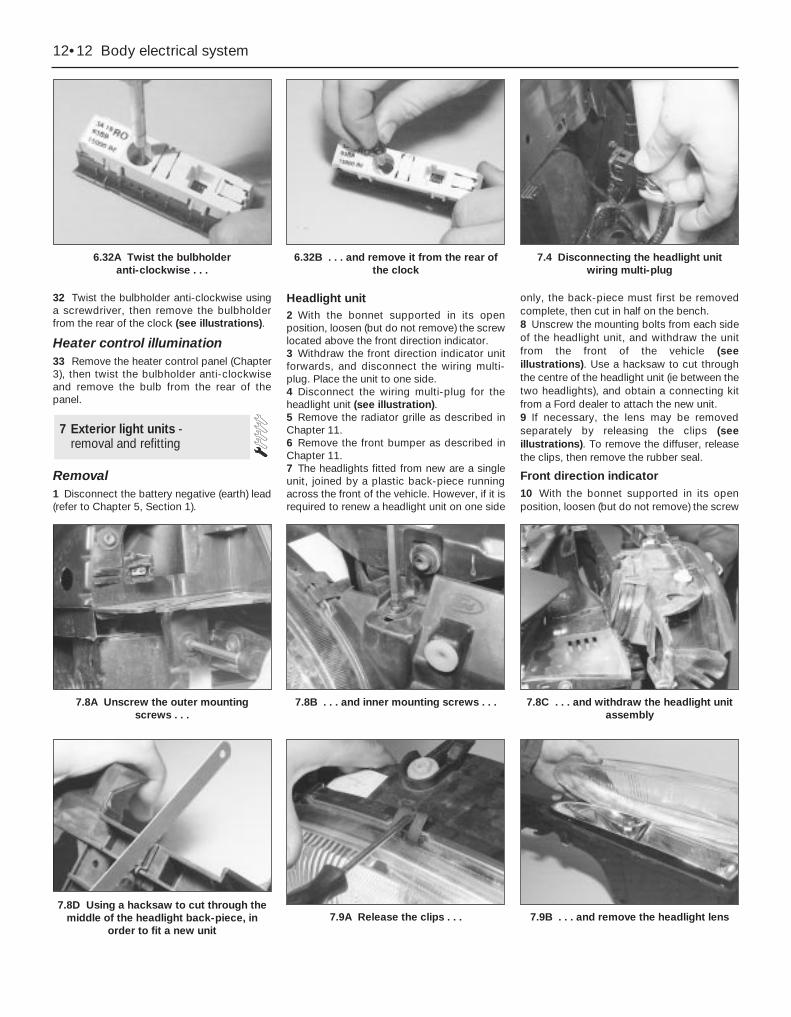
32 Twist the bulbholder anti-clockwise usinga screwdriver, then remove the bulbholderfrom the rear of the clock (see illustrations).
Heater control illumination33 Remove the heater control panel (Chapter3), then twist the bulbholder anti-clockwiseand remove the bulb from the rear of thepanel.
Removal1 Disconnect the battery negative (earth) lead(refer to Chapter 5, Section 1).
Headlight unit2 With the bonnet supported in its openposition, loosen (but do not remove) the screwlocated above the front direction indicator.3 Withdraw the front direction indicator unitforwards, and disconnect the wiring multi-plug. Place the unit to one side.4 Disconnect the wiring multi-plug for theheadlight unit (see illustration).5 Remove the radiator grille as described inChapter 11.6 Remove the front bumper as described inChapter 11.7 The headlights fitted from new are a singleunit, joined by a plastic back-piece runningacross the front of the vehicle. However, if it isrequired to renew a headlight unit on one side
only, the back-piece must first be removedcomplete, then cut in half on the bench.8 Unscrew the mounting bolts from each sideof the headlight unit, and withdraw the unitfrom the front of the vehicle (seeillustrations). Use a hacksaw to cut throughthe centre of the headlight unit (ie between thetwo headlights), and obtain a connecting kitfrom a Ford dealer to attach the new unit.9 If necessary, the lens may be removedseparately by releasing the clips (seeillustrations). To remove the diffuser, releasethe clips, then remove the rubber seal.
Front direction indicator10 With the bonnet supported in its openposition, loosen (but do not remove) the screw
7 Exterior light units - removal and refitting
12•12 Body electrical system
6.32A Twist the bulbholder anti-clockwise . . .
6.32B . . . and remove it from the rear ofthe clock
7.4 Disconnecting the headlight unitwiring multi-plug
7.8D Using a hacksaw to cut through themiddle of the headlight back-piece, in
order to fit a new unit7.9A Release the clips . . . 7.9B . . . and remove the headlight lens
7.8A Unscrew the outer mounting screws . . .
7.8B . . . and inner mounting screws . . . 7.8C . . . and withdraw the headlight unitassembly
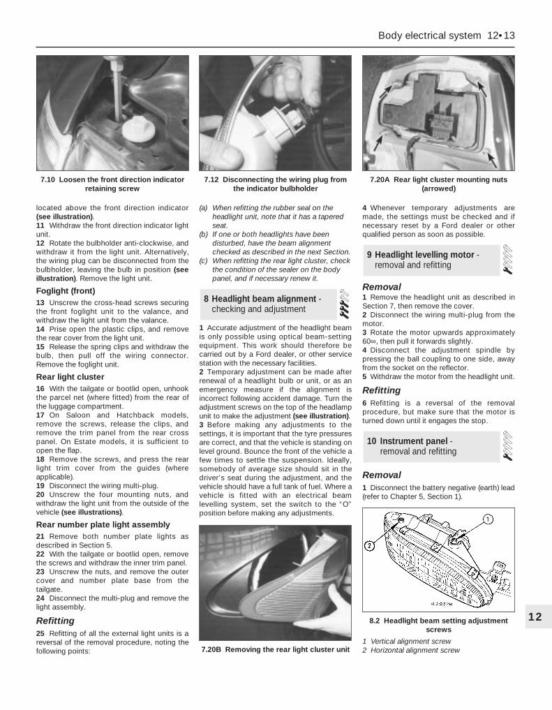
located above the front direction indicator(see illustration).11 Withdraw the front direction indicator lightunit.12 Rotate the bulbholder anti-clockwise, andwithdraw it from the light unit. Alternatively,the wiring plug can be disconnected from thebulbholder, leaving the bulb in position (seeillustration). Remove the light unit.
Foglight (front)13 Unscrew the cross-head screws securingthe front foglight unit to the valance, andwithdraw the light unit from the valance.14 Prise open the plastic clips, and removethe rear cover from the light unit.15 Release the spring clips and withdraw thebulb, then pull off the wiring connector.Remove the foglight unit.
Rear light cluster16 With the tailgate or bootlid open, unhookthe parcel net (where fitted) from the rear ofthe luggage compartment.17 On Saloon and Hatchback models,remove the screws, release the clips, andremove the trim panel from the rear crosspanel. On Estate models, it is sufficient toopen the flap.18 Remove the screws, and press the rearlight trim cover from the guides (whereapplicable).19 Disconnect the wiring multi-plug.20 Unscrew the four mounting nuts, andwithdraw the light unit from the outside of thevehicle (see illustrations).
Rear number plate light assembly21 Remove both number plate lights asdescribed in Section 5.22 With the tailgate or bootlid open, removethe screws and withdraw the inner trim panel.23 Unscrew the nuts, and remove the outercover and number plate base from thetailgate.24 Disconnect the multi-plug and remove thelight assembly.
Refitting25 Refitting of all the external light units is areversal of the removal procedure, noting thefollowing points:
(a) When refitting the rubber seal on theheadlight unit, note that it has a taperedseat.
(b) If one or both headlights have beendisturbed, have the beam alignmentchecked as described in the next Section.
(c) When refitting the rear light cluster, checkthe condition of the sealer on the bodypanel, and if necessary renew it.
1 Accurate adjustment of the headlight beamis only possible using optical beam-settingequipment. This work should therefore becarried out by a Ford dealer, or other servicestation with the necessary facilities.2 Temporary adjustment can be made afterrenewal of a headlight bulb or unit, or as anemergency measure if the alignment isincorrect following accident damage. Turn theadjustment screws on the top of the headlampunit to make the adjustment (see illustration).3 Before making any adjustments to thesettings, it is important that the tyre pressuresare correct, and that the vehicle is standing onlevel ground. Bounce the front of the vehicle afew times to settle the suspension. Ideally,somebody of average size should sit in thedriver’s seat during the adjustment, and thevehicle should have a full tank of fuel. Where avehicle is fitted with an electrical beamlevelling system, set the switch to the “O”position before making any adjustments.
4 Whenever temporary adjustments aremade, the settings must be checked and ifnecessary reset by a Ford dealer or otherqualified person as soon as possible.
Removal1 Remove the headlight unit as described inSection 7, then remove the cover.2 Disconnect the wiring multi-plug from themotor.3 Rotate the motor upwards approximately60∞, then pull it forwards slightly.4 Disconnect the adjustment spindle bypressing the ball coupling to one side, awayfrom the socket on the reflector.5 Withdraw the motor from the headlight unit.
Refitting6 Refitting is a reversal of the removalprocedure, but make sure that the motor isturned down until it engages the stop.
Removal1 Disconnect the battery negative (earth) lead(refer to Chapter 5, Section 1).
10 Instrument panel - removal and refitting
9 Headlight levelling motor -removal and refitting
8 Headlight beam alignment -checking and adjustment
Body electrical system 12•13
12
7.20B Removing the rear light cluster unit
8.2 Headlight beam setting adjustmentscrews
1 Vertical alignment screw2 Horizontal alignment screw
7.10 Loosen the front direction indicatorretaining screw
7.12 Disconnecting the wiring plug fromthe indicator bulbholder
7.20A Rear light cluster mounting nuts(arrowed)

2 Where fitted, remove the clock asdescribed in Section 13.3 Where fitted, remove the trip computermodule as described in Section 18.4 Remove the heated rear window switch asdescribed in Section 4.5 Where fitted, remove the heatedwindscreen switch.6 Where fitted, remove the display assemblywarning indicator for the foglights (seeillustration).7 Remove any blanking covers from theunused switch positions (see illustration).8 Prise out the blanking covers, then unscrewthe retaining screws and remove theinstrument panel surround (see illustrations).9 Unscrew the mounting screws, and
withdraw the instrument panel a little wayfrom the facia (see illustration).10 Disconnect the two multi-plugs from therear of the instrument panel (see illustration).11 Withdraw the instrument panel from thefacia, at the same time releasing thespeedometer intermediate cable.
Refitting12 Refitting is a reversal of the removalprocedure.
Removal1 Remove the warning light and illuminationbulbs by twisting them anti-clockwise (seeillustration).2 Carefully prise off the glass and bezel fromthe front of the instrument panel, noting thepositions of the retaining lugs (seeillustration).3 Note the positions of the five diffusers, thenremove them from the instrument panel.4 To remove the speedometer head, unscrewthe three mounting screws and withdraw thehead from the housing.5 To remove the tachometer, unscrew thesingle screw and withdraw it from thehousing.
11 Instrument panelcomponents - removal and refitting
12•14 Body electrical system
10.6 Removing the foglight warningindicator
10.7 Removing a switch blanking cover 10.8A With the blanking covers removed,unscrew the concealed screws . . .
10.10 Disconnecting the multi-plugs fromthe rear of the instrument panel
11.1 Rear view of the instrument panel,showing bulbholders
11.2 Bezel retaining lug on the instrumentpanel
10.8C . . . and lift out the instrument panelsurround
10.9 Three of the instrument panelmounting screws (arrowed)
10.8B . . . and the remaining screws . . .

6 Similarly remove the fuel gauge andtemperature gauge by unscrewing the singlescrews.7 Remove all the pin contacts.8 Using a small punch, push in the multi-plugsecuring pins, and remove the multi-plugs.9 Carefully lift the printed circuit from thelocation dowels on the housing, taking carenot to damage it.
Refitting10 Refitting is a reversal of the removalprocedure.
Removal1 Remove the windscreen wiper arms asdescribed in Section 15.2 With the bonnet closed, release the grillepanel upper edge from just in front of thewindscreen, by prising off the caps andunscrewing the upper retaining screws.3 Open the bonnet, and support with thestay.4 Pull off the sealing strip from the crosspanel at the rear of the engine compartment.5 Unscrew the lower screws, and remove thegrille panel halves from in front of the
windscreen, withdrawing first one side andthen the other.6 Disconnect the battery negative (earth) lead(refer to Chapter 5, Section 1).7 Reach in behind the bulkhead. Squeeze thecollar on the upper end of the speedometercable, where it is attached to the intermediatecable from the rear of the speedometer head.Disconnect the cable, and withdraw it fromthe bulkhead inner panel, together with therubber grommet (see illustrations).8 Apply the handbrake, jack up the front ofthe vehicle and support it on axle stands.9 Unscrew the nut and disconnect thespeedometer cable from the vehicle speedsensor on the transmission, then withdraw thecable from within the engine compartment.Use two spanners to loosen the nut - one tocounterhold the sensor, and the other tounscrew the cable nut (see illustrations).
Refitting10 Refitting is a reversal of the removalprocedure.
Removal1 Disconnect the battery negative (earth) lead(refer to Chapter 5, Section 1).
2 Using a small screwdriver, prise the clockout of the facia (see illustration). To preventdamage to the facia, place a cloth padbeneath the screwdriver.3 Disconnect the multi-plug from the rear ofthe clock, and withdraw the clock (seeillustration).
Refitting4 Refitting is a reversal of the removalprocedure. Reset the clock on completion.
Removal1 Apply the handbrake, jack up the front ofthe vehicle and support it on axle stands.2 Unscrew the bolts, and release the clipssecuring the radiator lower cover to the frontof the vehicle.3 Disconnect the wiring from the hornterminal.4 Unscrew the mounting bolt, and withdrawthe horn with its mounting bracket from underthe vehicle (see illustration).
Refitting5 Refitting is a reversal of the removalprocedure.
14 Horn - removal and refitting
13 Clock - removal and refitting
12 Speedometer drive cable -removal and refitting
Body electrical system 12•15
1212.9B . . . and disconnect the
speedometer cable from the vehicle speedsensor
13.2 Prising the clock out of the facia 13.3 Disconnecting the multi-plug fromthe rear of the clock
12.7A Squeeze the collar . . . 12.7B . . . and disconnect thespeedometer main cable from the
intermediate cable
12.9A Unscrew the cable nut . . .
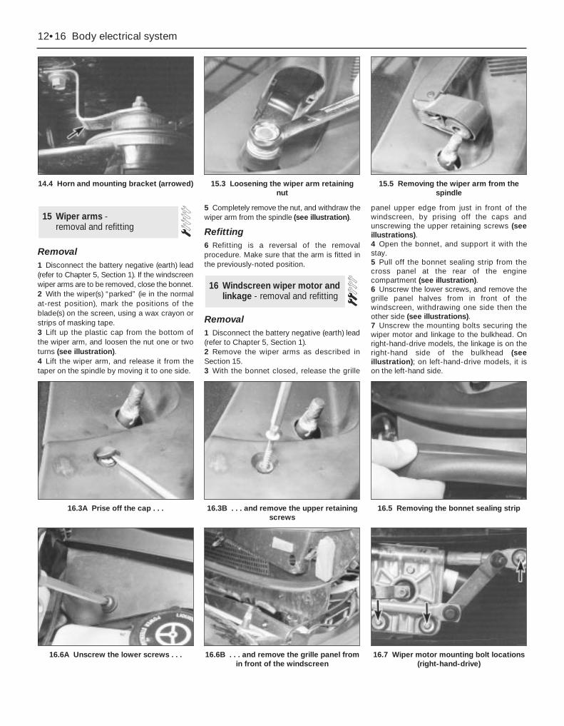
Removal1 Disconnect the battery negative (earth) lead(refer to Chapter 5, Section 1). If the windscreenwiper arms are to be removed, close the bonnet.2 With the wiper(s) “parked” (ie in the normalat-rest position), mark the positions of theblade(s) on the screen, using a wax crayon orstrips of masking tape.3 Lift up the plastic cap from the bottom ofthe wiper arm, and loosen the nut one or twoturns (see illustration).4 Lift the wiper arm, and release it from thetaper on the spindle by moving it to one side.
5 Completely remove the nut, and withdraw thewiper arm from the spindle (see illustration).
Refitting6 Refitting is a reversal of the removalprocedure. Make sure that the arm is fitted inthe previously-noted position.
Removal1 Disconnect the battery negative (earth) lead(refer to Chapter 5, Section 1).2 Remove the wiper arms as described inSection 15.3 With the bonnet closed, release the grille
panel upper edge from just in front of thewindscreen, by prising off the caps andunscrewing the upper retaining screws (seeillustrations).4 Open the bonnet, and support it with thestay.5 Pull off the bonnet sealing strip from thecross panel at the rear of the enginecompartment (see illustration).6 Unscrew the lower screws, and remove thegrille panel halves from in front of thewindscreen, withdrawing one side then theother side (see illustrations).7 Unscrew the mounting bolts securing thewiper motor and linkage to the bulkhead. Onright-hand-drive models, the linkage is on theright-hand side of the bulkhead (seeillustration); on left-hand-drive models, it ison the left-hand side.
16 Windscreen wiper motor andlinkage - removal and refitting
15 Wiper arms - removal and refitting
12•16 Body electrical system
14.4 Horn and mounting bracket (arrowed) 15.3 Loosening the wiper arm retainingnut
15.5 Removing the wiper arm from thespindle
16.6A Unscrew the lower screws . . . 16.6B . . . and remove the grille panel fromin front of the windscreen
16.7 Wiper motor mounting bolt locations(right-hand-drive)
16.3A Prise off the cap . . . 16.3B . . . and remove the upper retainingscrews
16.5 Removing the bonnet sealing strip
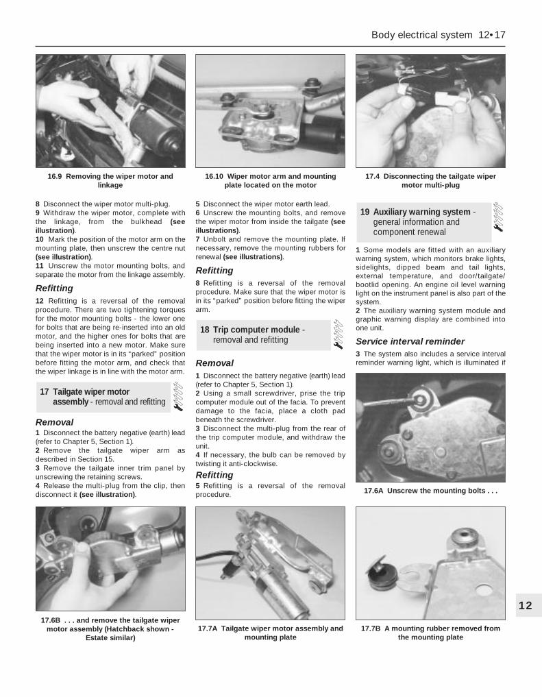
8 Disconnect the wiper motor multi-plug.9 Withdraw the wiper motor, complete withthe linkage, from the bulkhead (seeillustration).10 Mark the position of the motor arm on themounting plate, then unscrew the centre nut(see illustration).11 Unscrew the motor mounting bolts, andseparate the motor from the linkage assembly.
Refitting12 Refitting is a reversal of the removalprocedure. There are two tightening torquesfor the motor mounting bolts - the lower onefor bolts that are being re-inserted into an oldmotor, and the higher ones for bolts that arebeing inserted into a new motor. Make surethat the wiper motor is in its “parked” positionbefore fitting the motor arm, and check thatthe wiper linkage is in line with the motor arm.
Removal1 Disconnect the battery negative (earth) lead(refer to Chapter 5, Section 1).2 Remove the tailgate wiper arm asdescribed in Section 15.3 Remove the tailgate inner trim panel byunscrewing the retaining screws.4 Release the multi-plug from the clip, thendisconnect it (see illustration).
5 Disconnect the wiper motor earth lead.6 Unscrew the mounting bolts, and removethe wiper motor from inside the tailgate (seeillustrations).7 Unbolt and remove the mounting plate. Ifnecessary, remove the mounting rubbers forrenewal (see illustrations).
Refitting8 Refitting is a reversal of the removalprocedure. Make sure that the wiper motor isin its “parked” position before fitting the wiperarm.
Removal1 Disconnect the battery negative (earth) lead(refer to Chapter 5, Section 1).2 Using a small screwdriver, prise the tripcomputer module out of the facia. To preventdamage to the facia, place a cloth padbeneath the screwdriver.3 Disconnect the multi-plug from the rear ofthe trip computer module, and withdraw theunit.4 If necessary, the bulb can be removed bytwisting it anti-clockwise.
Refitting5 Refitting is a reversal of the removalprocedure.
1 Some models are fitted with an auxiliarywarning system, which monitors brake lights,sidelights, dipped beam and tail lights,external temperature, and door/tailgate/bootlid opening. An engine oil level warninglight on the instrument panel is also part of thesystem.2 The auxiliary warning system module andgraphic warning display are combined intoone unit.
Service interval reminder3 The system also includes a service intervalreminder warning light, which is illuminated if
19 Auxiliary warning system -general information andcomponent renewal
18 Trip computer module -removal and refitting
17 Tailgate wiper motor assembly - removal and refitting
Body electrical system 12•17
1217.6B . . . and remove the tailgate wiper
motor assembly (Hatchback shown -Estate similar)
17.7A Tailgate wiper motor assembly andmounting plate
17.7B A mounting rubber removed fromthe mounting plate
17.6A Unscrew the mounting bolts . . .
16.9 Removing the wiper motor andlinkage
16.10 Wiper motor arm and mountingplate located on the motor
17.4 Disconnecting the tailgate wipermotor multi-plug

the specified mileage (or time) since the lastservice has been reached.4 To reset the service interval system andturn off the light, a switch inside the gloveboxmust be depressed for a minimum of 4seconds with the ignition switched on. Thisshould be carried out by a Ford dealer if thevehicle is still in the warranty period.
Component renewal5 The following paragraphs describe briefremoval procedures for the auxiliary warningsystem components. Disconnect the batterynegative (earth) lead before commencingwork (refer to Chapter 5, Section 1). Refittingprocedures are a reversal of removal.
Display warning bulb6 Remove the control assembly.7 Prise off the cover, and pull out the relevantbulb and bulbholder.
Low air temperature warning senderunit8 Remove the front bumper.9 Unclip the sender unit and disconnect themulti-plug (see illustration).
Engine oil level sensor10 Apply the handbrake, jack up the front ofthe vehicle and support it on axle stands.11 Place a container beneath the oil levelsensor, to catch any spilt oil.
12 Unscrew the screws and remove thecover from the sensor.13 Disconnect the multi-plug.14 Unscrew and remove the sensor, andremove the seal (see illustration).
Door ajar sensor15 Remove the door lock as described inChapter 11, Section 14.16 Unclip the sensor and disconnect themulti-plug.
Low coolant warning switch17 Refer to Chapter 3, Section 6.
Low washer fluid switch18 Disconnect the multi-plug from thewasher fluid reservoir.19 Drain or syphon out the fluid from thereservoir.20 Using a screwdriver, lever out the switchfrom the reservoir (see illustration).
Service indicator reset switch21 Remove the glove compartment lid asdescribed in Chapter 11, Section 32.22 Carefully lever out the switch using asmall screwdriver.23 Remove the rear cover and disconnectthe wiring (see illustration).
Control assembly24 Remove the instrument panel surround,referring to Section 10.
25 Unscrew the mounting screws,disconnect the multi-plugs and remove theassembly.
Bulb failure module26 Remove the lower facia panel from underthe steering wheel.27 Unclip the bulb failure module anddisconnect the multi-plug.
Note: From November 1993, for addedsecurity, a complex Bosch immobiliser systemwas fitted to some models. For further details,refer to your Ford dealer.1 All UK models are fitted with an anti-theftalarm system, incorporating movementsensors and an ignition immobiliser. Thesystem is activated when the vehicle islocked.2 The system includes a start inhibitor circuit,which makes it impossible to start the enginewith the system armed.3 The movement sensors consist of twoultrasonic units, located in the “B” pillars,incorporating transmitters and receivers (seeillustrations). The receivers check that theecho frequency matches the originalfrequency. If there is any significantdifference, the system triggers the alarm.
20 Anti-theft alarm system - generalinformation
12•18 Body electrical system
19.9 Low air temperature sender unitremoval
1 Clip 2 Sender unit 3 Multi-plug
19.14 Engine oil level sensor removal
1 Cover 2 Multi-plug 3 Sensor 4 Seal
19.20 Removing the low washer fluidswitch
19.23 Service indicator switch removal
1 Lever out the switch 2 Cover 3 Wiring
20.3A Disconnecting a movement sensormulti-plug
20.3B Removing a movement sensor
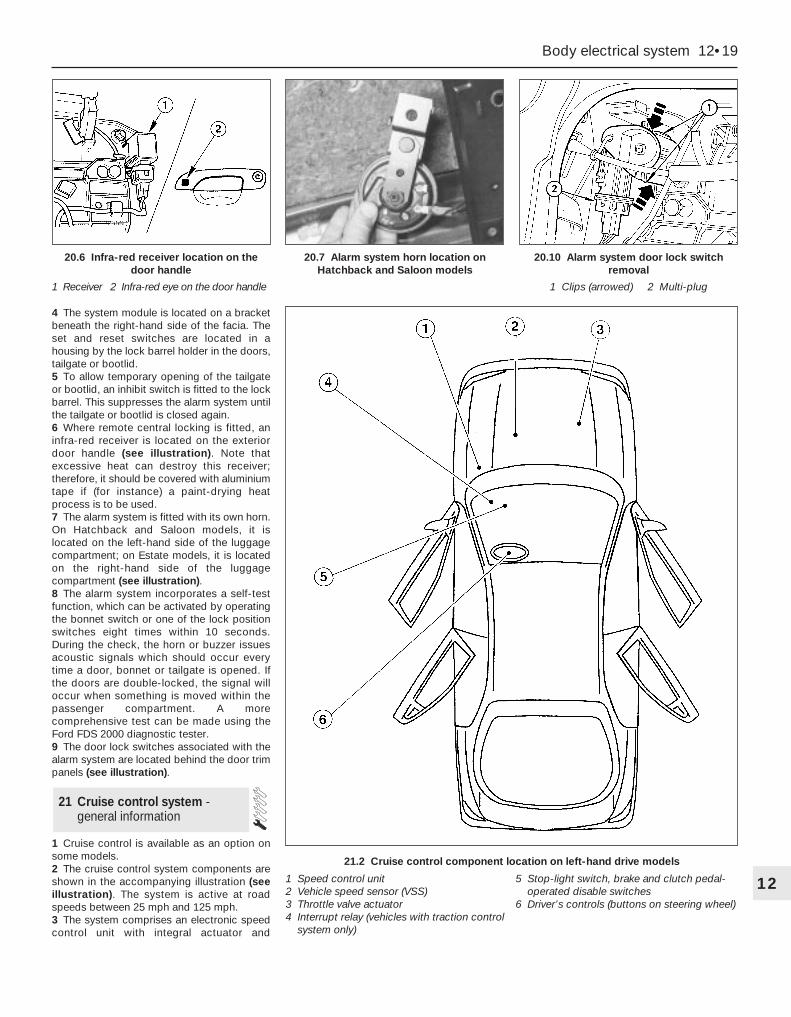
4 The system module is located on a bracketbeneath the right-hand side of the facia. Theset and reset switches are located in ahousing by the lock barrel holder in the doors,tailgate or bootlid.5 To allow temporary opening of the tailgateor bootlid, an inhibit switch is fitted to the lockbarrel. This suppresses the alarm system untilthe tailgate or bootlid is closed again.6 Where remote central locking is fitted, aninfra-red receiver is located on the exteriordoor handle (see illustration). Note thatexcessive heat can destroy this receiver;therefore, it should be covered with aluminiumtape if (for instance) a paint-drying heatprocess is to be used.7 The alarm system is fitted with its own horn.On Hatchback and Saloon models, it islocated on the left-hand side of the luggagecompartment; on Estate models, it is locatedon the right-hand side of the luggagecompartment (see illustration).8 The alarm system incorporates a self-testfunction, which can be activated by operatingthe bonnet switch or one of the lock positionswitches eight times within 10 seconds.During the check, the horn or buzzer issuesacoustic signals which should occur everytime a door, bonnet or tailgate is opened. Ifthe doors are double-locked, the signal willoccur when something is moved within thepassenger compartment. A morecomprehensive test can be made using theFord FDS 2000 diagnostic tester.9 The door lock switches associated with thealarm system are located behind the door trimpanels (see illustration).
1 Cruise control is available as an option onsome models.2 The cruise control system components areshown in the accompanying illustration (seeillustration). The system is active at roadspeeds between 25 mph and 125 mph.3 The system comprises an electronic speedcontrol unit with integral actuator and
21 Cruise control system -general information
Body electrical system 12•19
12
21.2 Cruise control component location on left-hand drive models
1 Speed control unit2 Vehicle speed sensor (VSS)3 Throttle valve actuator4 Interrupt relay (vehicles with traction control
system only)
5 Stop-light switch, brake and clutch pedal-operated disable switches
6 Driver’s controls (buttons on steering wheel)
20.6 Infra-red receiver location on thedoor handle
1 Receiver 2 Infra-red eye on the door handle
20.7 Alarm system horn location onHatchback and Saloon models
20.10 Alarm system door lock switchremoval
1 Clips (arrowed) 2 Multi-plug
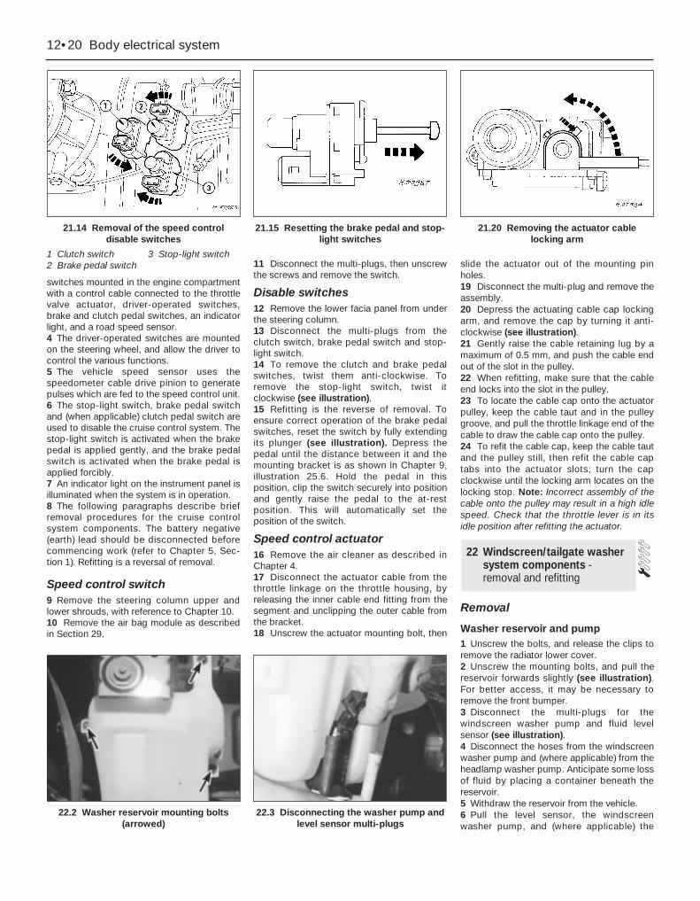
switches mounted in the engine compartmentwith a control cable connected to the throttlevalve actuator, driver-operated switches,brake and clutch pedal switches, an indicatorlight, and a road speed sensor.4 The driver-operated switches are mountedon the steering wheel, and allow the driver tocontrol the various functions.5 The vehicle speed sensor uses thespeedometer cable drive pinion to generatepulses which are fed to the speed control unit.6 The stop-light switch, brake pedal switchand (when applicable) clutch pedal switch areused to disable the cruise control system. Thestop-light switch is activated when the brakepedal is applied gently, and the brake pedalswitch is activated when the brake pedal isapplied forcibly.7 An indicator light on the instrument panel isilluminated when the system is in operation.8 The following paragraphs describe briefremoval procedures for the cruise controlsystem components. The battery negative(earth) lead should be disconnected beforecommencing work (refer to Chapter 5, Sec-tion 1). Refitting is a reversal of removal.
Speed control switch9 Remove the steering column upper andlower shrouds, with reference to Chapter 10.10 Remove the air bag module as describedin Section 29.
11 Disconnect the multi-plugs, then unscrewthe screws and remove the switch.
Disable switches12 Remove the lower facia panel from underthe steering column.13 Disconnect the multi-plugs from theclutch switch, brake pedal switch and stop-light switch.14 To remove the clutch and brake pedalswitches, twist them anti-clockwise. Toremove the stop-light switch, twist itclockwise (see illustration).15 Refitting is the reverse of removal. Toensure correct operation of the brake pedalswitches, reset the switch by fully extendingits plunger (see illustration). Depress thepedal until the distance between it and themounting bracket is as shown in Chapter 9,illustration 25.6. Hold the pedal in thisposition, clip the switch securely into positionand gently raise the pedal to the at-restposition. This will automatically set theposition of the switch.
Speed control actuator16 Remove the air cleaner as described inChapter 4.17 Disconnect the actuator cable from thethrottle linkage on the throttle housing, byreleasing the inner cable end fitting from thesegment and unclipping the outer cable fromthe bracket.18 Unscrew the actuator mounting bolt, then
slide the actuator out of the mounting pinholes.19 Disconnect the multi-plug and remove theassembly.20 Depress the actuating cable cap lockingarm, and remove the cap by turning it anti-clockwise (see illustration).21 Gently raise the cable retaining lug by amaximum of 0.5 mm, and push the cable endout of the slot in the pulley.22 When refitting, make sure that the cableend locks into the slot in the pulley.23 To locate the cable cap onto the actuatorpulley, keep the cable taut and in the pulleygroove, and pull the throttle linkage end of thecable to draw the cable cap onto the pulley.24 To refit the cable cap, keep the cable tautand the pulley still, then refit the cable captabs into the actuator slots; turn the capclockwise until the locking arm locates on thelocking stop. Note: Incorrect assembly of thecable onto the pulley may result in a high idlespeed. Check that the throttle lever is in itsidle position after refitting the actuator.
Removal
Washer reservoir and pump1 Unscrew the bolts, and release the clips toremove the radiator lower cover.2 Unscrew the mounting bolts, and pull thereservoir forwards slightly (see illustration).For better access, it may be necessary toremove the front bumper.3 Disconnect the multi-plugs for thewindscreen washer pump and fluid levelsensor (see illustration).4 Disconnect the hoses from the windscreenwasher pump and (where applicable) from theheadlamp washer pump. Anticipate some lossof fluid by placing a container beneath thereservoir.5 Withdraw the reservoir from the vehicle.6 Pull the level sensor, the windscreenwasher pump, and (where applicable) the
22 Windscreen/tailgate washersystem components -removal and refitting
12•20 Body electrical system
21.14 Removal of the speed controldisable switches
1 Clutch switch 3 Stop-light switch2 Brake pedal switch
21.15 Resetting the brake pedal and stop-light switches
21.20 Removing the actuator cablelocking arm
22.2 Washer reservoir mounting bolts(arrowed)
22.3 Disconnecting the washer pump andlevel sensor multi-plugs
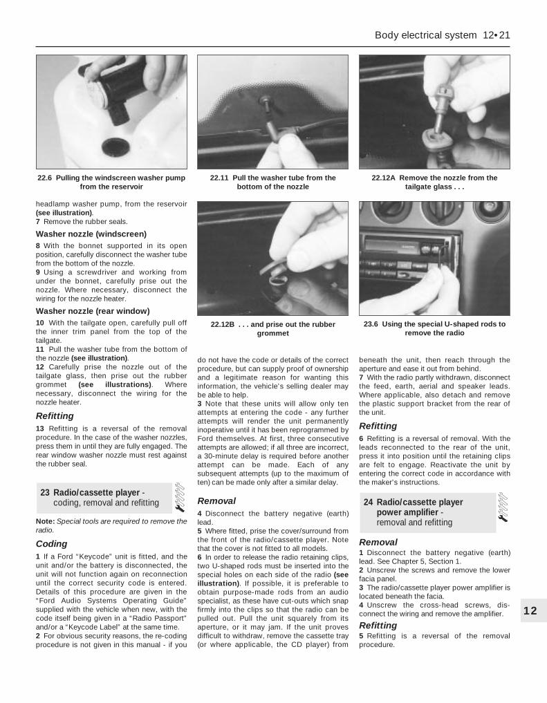
headlamp washer pump, from the reservoir(see illustration).7 Remove the rubber seals.
Washer nozzle (windscreen)8 With the bonnet supported in its openposition, carefully disconnect the washer tubefrom the bottom of the nozzle.9 Using a screwdriver and working fromunder the bonnet, carefully prise out thenozzle. Where necessary, disconnect thewiring for the nozzle heater.
Washer nozzle (rear window)10 With the tailgate open, carefully pull offthe inner trim panel from the top of thetailgate.11 Pull the washer tube from the bottom ofthe nozzle (see illustration).12 Carefully prise the nozzle out of thetailgate glass, then prise out the rubbergrommet (see illustrations). Wherenecessary, disconnect the wiring for thenozzle heater.
Refitting13 Refitting is a reversal of the removalprocedure. In the case of the washer nozzles,press them in until they are fully engaged. Therear window washer nozzle must rest againstthe rubber seal.
Note: Special tools are required to remove theradio.
Coding1 If a Ford “Keycode” unit is fitted, and theunit and/or the battery is disconnected, theunit will not function again on reconnectionuntil the correct security code is entered.Details of this procedure are given in the“Ford Audio Systems Operating Guide”supplied with the vehicle when new, with thecode itself being given in a “Radio Passport”and/or a “Keycode Label” at the same time.2 For obvious security reasons, the re-codingprocedure is not given in this manual - if you
do not have the code or details of the correctprocedure, but can supply proof of ownershipand a legitimate reason for wanting thisinformation, the vehicle’s selling dealer maybe able to help.3 Note that these units will allow only tenattempts at entering the code - any furtherattempts will render the unit permanentlyinoperative until it has been reprogrammed byFord themselves. At first, three consecutiveattempts are allowed; if all three are incorrect,a 30-minute delay is required before anotherattempt can be made. Each of anysubsequent attempts (up to the maximum often) can be made only after a similar delay.
Removal4 Disconnect the battery negative (earth)lead.5 Where fitted, prise the cover/surround fromthe front of the radio/cassette player. Notethat the cover is not fitted to all models.6 In order to release the radio retaining clips,two U-shaped rods must be inserted into thespecial holes on each side of the radio (seeillustration). If possible, it is preferable toobtain purpose-made rods from an audiospecialist, as these have cut-outs which snapfirmly into the clips so that the radio can bepulled out. Pull the unit squarely from itsaperture, or it may jam. If the unit provesdifficult to withdraw, remove the cassette tray(or where applicable, the CD player) from
beneath the unit, then reach through theaperture and ease it out from behind.7 With the radio partly withdrawn, disconnectthe feed, earth, aerial and speaker leads.Where applicable, also detach and removethe plastic support bracket from the rear ofthe unit.
Refitting6 Refitting is a reversal of removal. With theleads reconnected to the rear of the unit,press it into position until the retaining clipsare felt to engage. Reactivate the unit byentering the correct code in accordance withthe maker’s instructions.
Removal1 Disconnect the battery negative (earth)lead. See Chapter 5, Section 1.2 Unscrew the screws and remove the lowerfacia panel.3 The radio/cassette player power amplifier islocated beneath the facia.4 Unscrew the cross-head screws, dis-connect the wiring and remove the amplifier.
Refitting5 Refitting is a reversal of the removalprocedure.
24 Radio/cassette player power amplifier - removal and refitting
23 Radio/cassette player -coding, removal and refitting
Body electrical system 12•21
12
22.12B . . . and prise out the rubbergrommet
23.6 Using the special U-shaped rods toremove the radio
22.6 Pulling the windscreen washer pumpfrom the reservoir
22.11 Pull the washer tube from thebottom of the nozzle
22.12A Remove the nozzle from thetailgate glass . . .
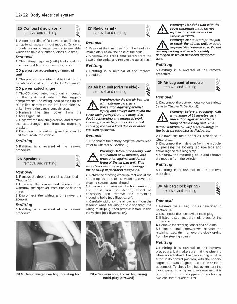
1 A compact disc (CD) player is available asan optional extra on most models. On somemodels, an autochanger version is available,which can hold a number of discs at a time.
Removal2 The battery negative (earth) lead should bedisconnected before commencing work.
CD player, or autochanger controlunit3 The procedure is identical to that for theradio/cassette player described in Section 23.
CD player autochanger4 The CD player autochanger unit is mountedon the right-hand side of the luggagecompartment. The wiring loom passes up the“C” pillar, across to the left-hand side “A”pillar, then to the centre console area.5 Remove the trim cover from theautochanger unit.6 Unscrew the mounting screws, and removethe autochanger unit from its mountingbracket.7 Disconnect the multi-plug and remove theunit from inside the vehicle.
Refitting8 Refitting is a reversal of the removalprocedure.
Removal1 Remove the door trim panel as described inChapter 11.2 Unscrew the cross-head screws, andwithdraw the speaker from the door innerpanel.3 Disconnect the wiring and remove thespeaker.
Refitting4 Refitting is a reversal of the removalprocedure.
Removal1 Prise out the trim cover from the headliningimmediately below the base of the aerial.2 Unscrew the cross-head screw from thebase of the aerial, and remove the aerial mast.
Refitting3 Refitting is a reversal of the removalprocedure.
Warning: Handle the air bag unitwith extreme care, as aprecaution against personalinjury, and always hold it with the
cover facing away from the body. If indoubt concerning any proposed workinvolving the air bag unit or its controlcircuitry, consult a Ford dealer or otherqualified specialist.
Removal1 Disconnect the battery negative (earth) lead(refer to Chapter 5, Section 1).
Warning: Before proceeding, waita minimum of 15 minutes, as aprecaution against accidentalfiring of the air bag unit. This
period ensures that any stored energy inthe back-up capacitor is dissipated.
2 Rotate the steering wheel so that one of themounting bolt holes is visible above thesteering column upper shroud.3 Unscrew and remove the first mountingbolt, then turn the steering wheel asnecessary and remove the remainingmounting bolts (see illustration).4 Carefully withdraw the air bag unit from thesteering wheel far enough to disconnect thewiring multi-plug, then remove it from insidethe vehicle (see illustration).
Warning: Stand the unit with thecover uppermost, and do notexpose it to heat sources inexcess of 100ºC.Warning: Do not attempt to openor repair the air bag unit, or applyany electrical current to it. Do not
use any air bag unit which is visiblydamaged or which has been tamperedwith.
Refitting5 Refitting is a reversal of the removalprocedure.
Removal1 Disconnect the battery negative (earth) lead(refer to Chapter 5, Section 1).
Warning: Before proceeding, waita minimum of 15 minutes, as aprecaution against accidentalfiring of the air bag unit. This
period ensures that any stored energy inthe back-up capacitor is dissipated.
2 Remove the facia panel as described inChapter 11.3 Disconnect the multi-plug from the module,by pressing the locking tab upwards andswivelling the retaining strap.4 Unscrew the mounting bolts and removethe module from the vehicle.
Refitting5 Refitting is a reversal of the removalprocedure.
Removal1 Remove the air bag unit as described inSection 28.2 Disconnect the horn switch multi-plug.3 If fitted, disconnect the multi-plugs for thecruise control.4 Remove the steering wheel and shrouds.5 Using a small screwdriver, release theretaining tabs, then remove the clock springfrom the steering column.
Refitting6 Refitting is a reversal of the removalprocedure, but make sure that the steeringwheel is centralised. The clock spring must befitted in its central position, with the specialalignment marks aligned and the TOP markuppermost. To check for this position, turn theclock spring housing anti-clockwise until it istight, then turn in the opposite direction bytwo-and-three-quarter turns.
30 Air bag clock spring -removal and refitting
29 Air bag control module -removal and refitting28 Air bag unit (driver’s side) -
removal and refitting
27 Radio aerial - removal and refitting
26 Speakers - removal and refitting
25 Compact disc player -removal and refitting
12•22 Body electrical system
28.3 Unscrewing an air bag mounting bolt 28.4 Disconnecting the air bag wiringmulti-plug (arrowed)
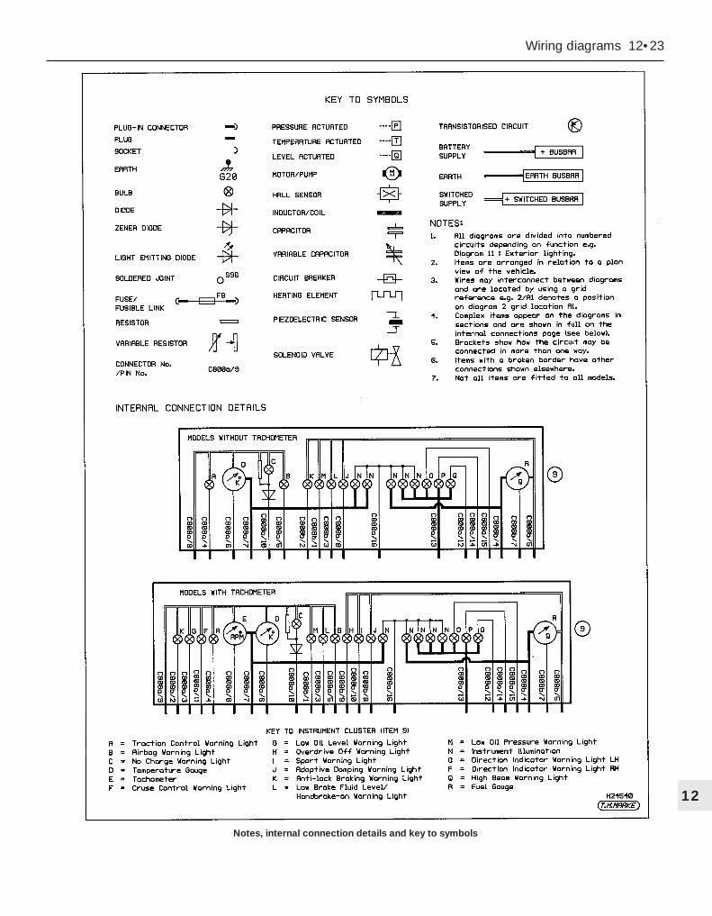
Wiring diagrams 12•23
12
Notes, internal connection details and key to symbols

12•24 Wiring diagrams
Internal connection details continued
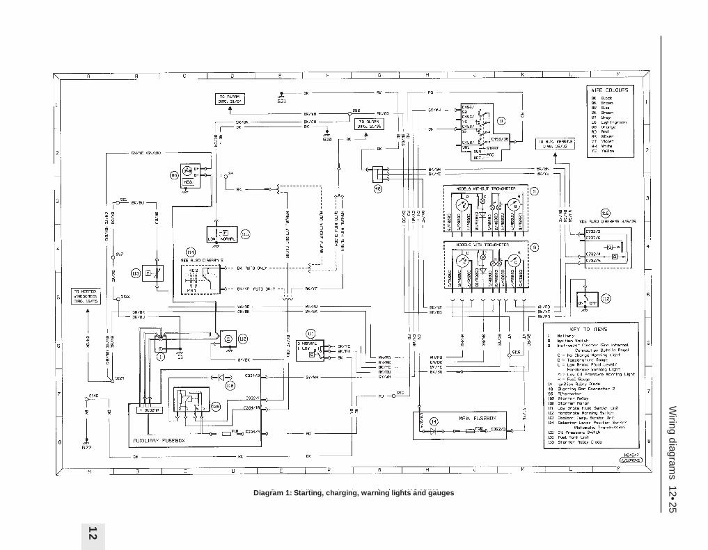
Wiring d
iagrams 12•25
12
Diagram 1: Starting, charging, warning lights and gauges

12•26W
iring diagram
s
Diagram 2: Engine management – sensor inputs (manual transmission models)
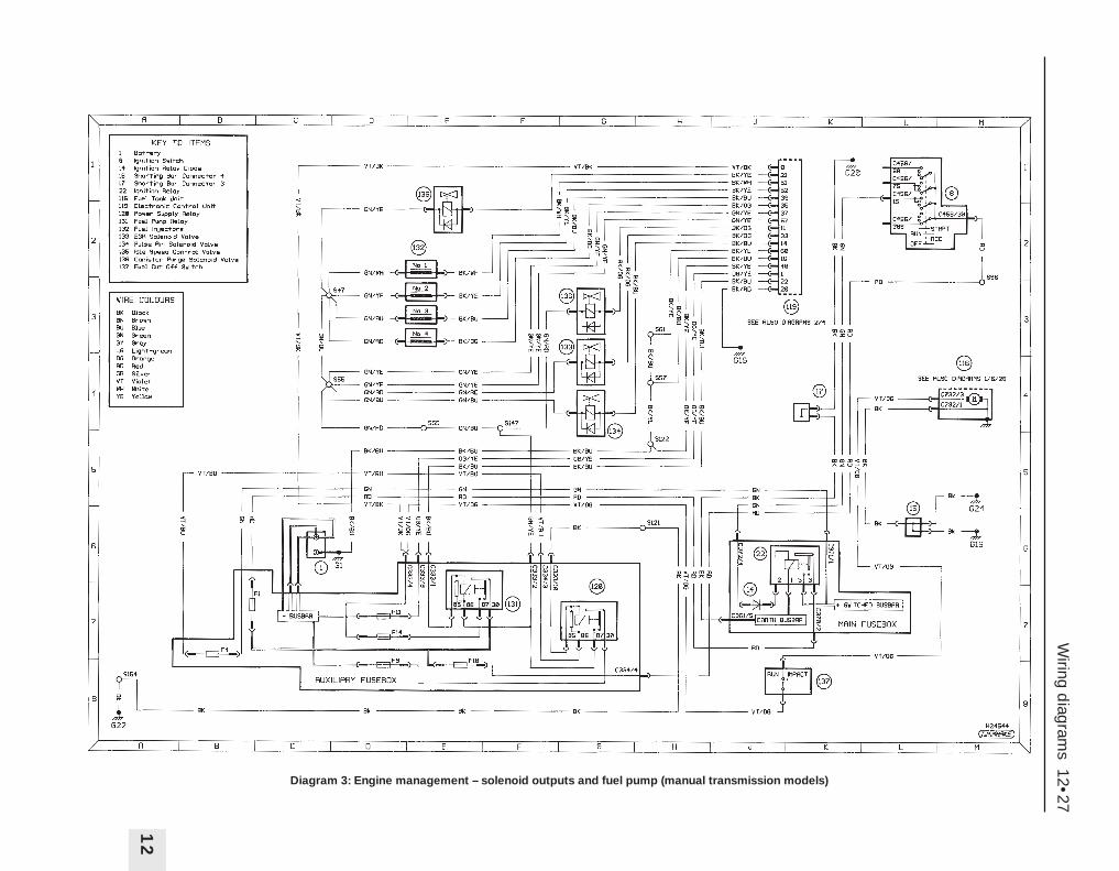
Wiring d
iagrams 12•27
12
Diagram 3: Engine management – solenoid outputs and fuel pump (manual transmission models)
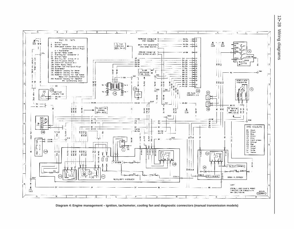
12•28W
iring diagram
s
Diagram 4: Engine management – ignition, tachometer, cooling fan and diagnostic connectors (manual transmission models)

Wiring d
iagrams 12•29
12
Diagram 5: Engine management – sensor inputs (automatic transmission models)

12•30W
iring diagram
s
Diagram 6: Engine management – solenoid outputs, ignition and fuel pump (automatic transmission models)
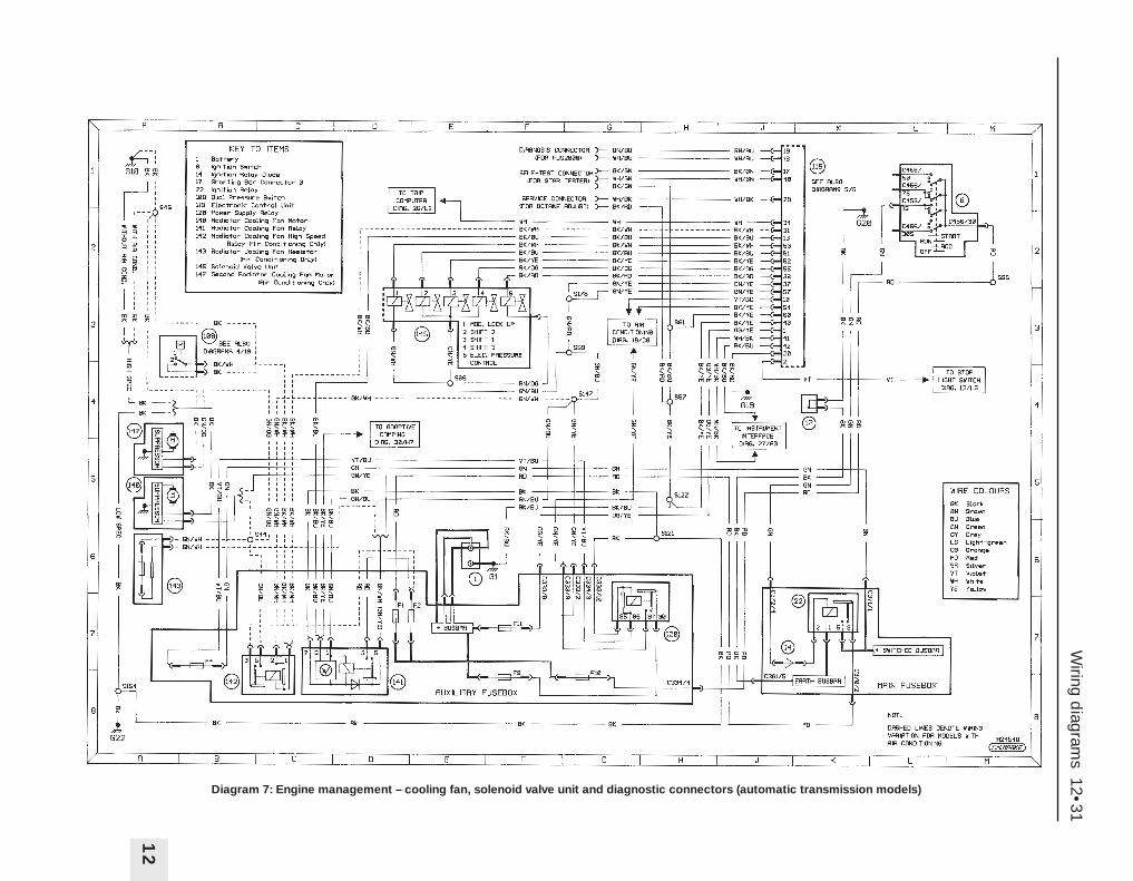
Wiring d
iagrams 12•31
12
Diagram 7: Engine management – cooling fan, solenoid valve unit and diagnostic connectors (automatic transmission models)

12•32W
iring diagram
s
Diagram 8: Exterior lighting – side and headlights (right-hand drive models: dim-dip)

Wiring d
iagrams 12•33
12
Diagram 9: Exterior lighting – side and headlights (left-hand drive models: non dim-dip)

12•34W
iring diagram
s
Diagram 10: Exterior lighting – side and headlights (left-hand drive models: daytime running lights)

Wiring d
iagrams 12•35
12
Diagram 11: Exterior lighting – hazard flasher and direction indicators
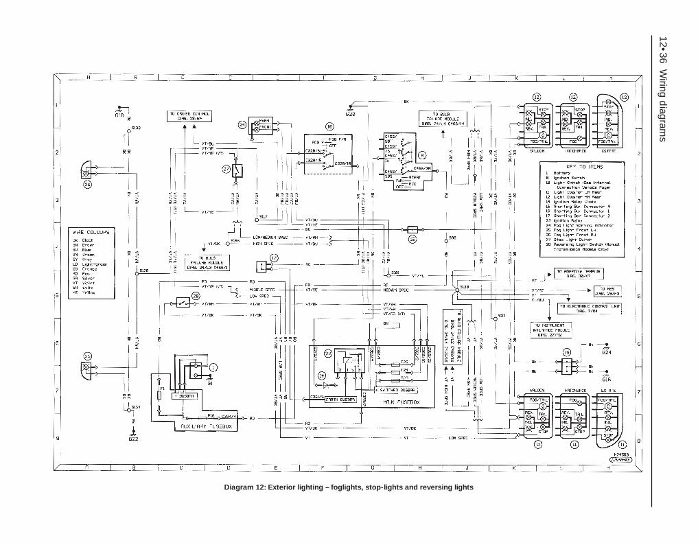
12•36W
iring diagram
s
Diagram 12: Exterior lighting – foglights, stop-lights and reversing lights

Wiring d
iagrams 12•37
12
Diagram 13: Interior lighting – front and rear courtesy, footwell and luggage compartment lights
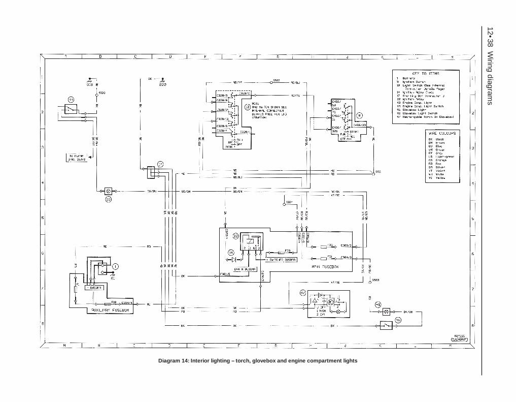
12•38W
iring diagram
s
Diagram 14: Interior lighting – torch, glovebox and engine compartment lights

Wiring d
iagrams 12•39
12
Diagram 15: Interior illumination

12•40W
iring diagram
s
Diagram 16: Wash/wipe and heated washer jets
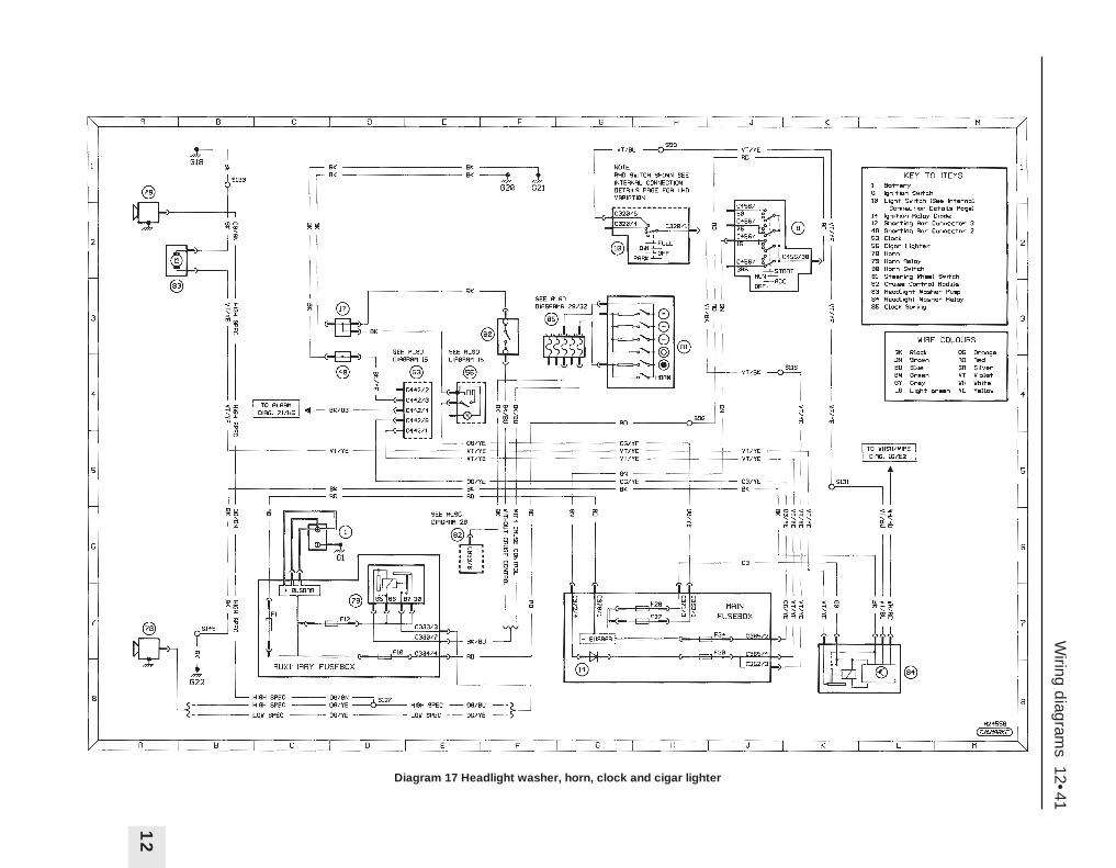
Wiring d
iagrams 12•41
12
Diagram 17 Headlight washer, horn, clock and cigar lighter
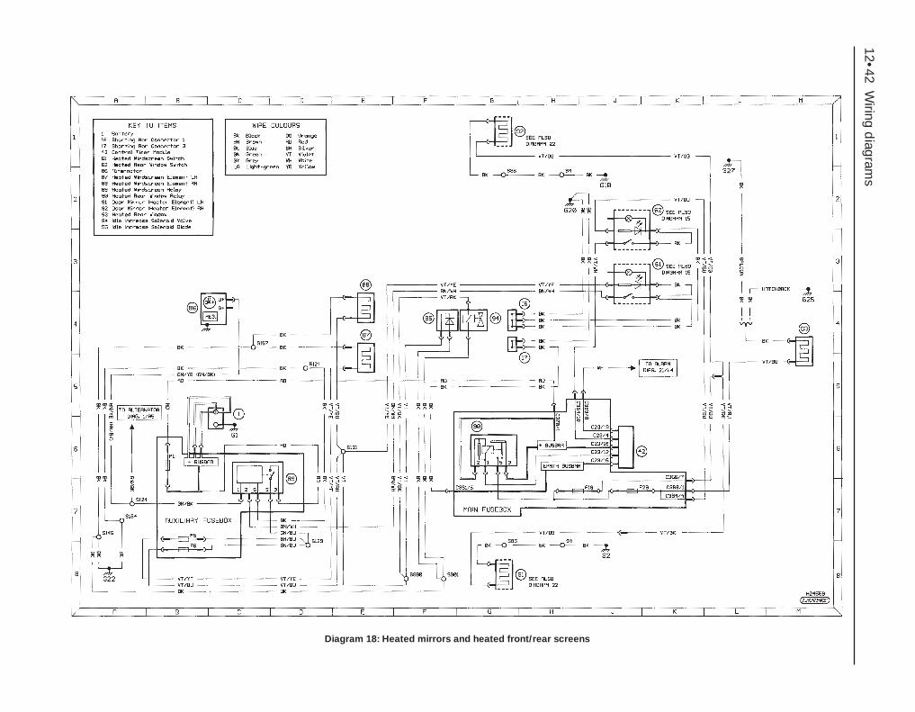
12•42W
iring diagram
s
Diagram 18: Heated mirrors and heated front/rear screens
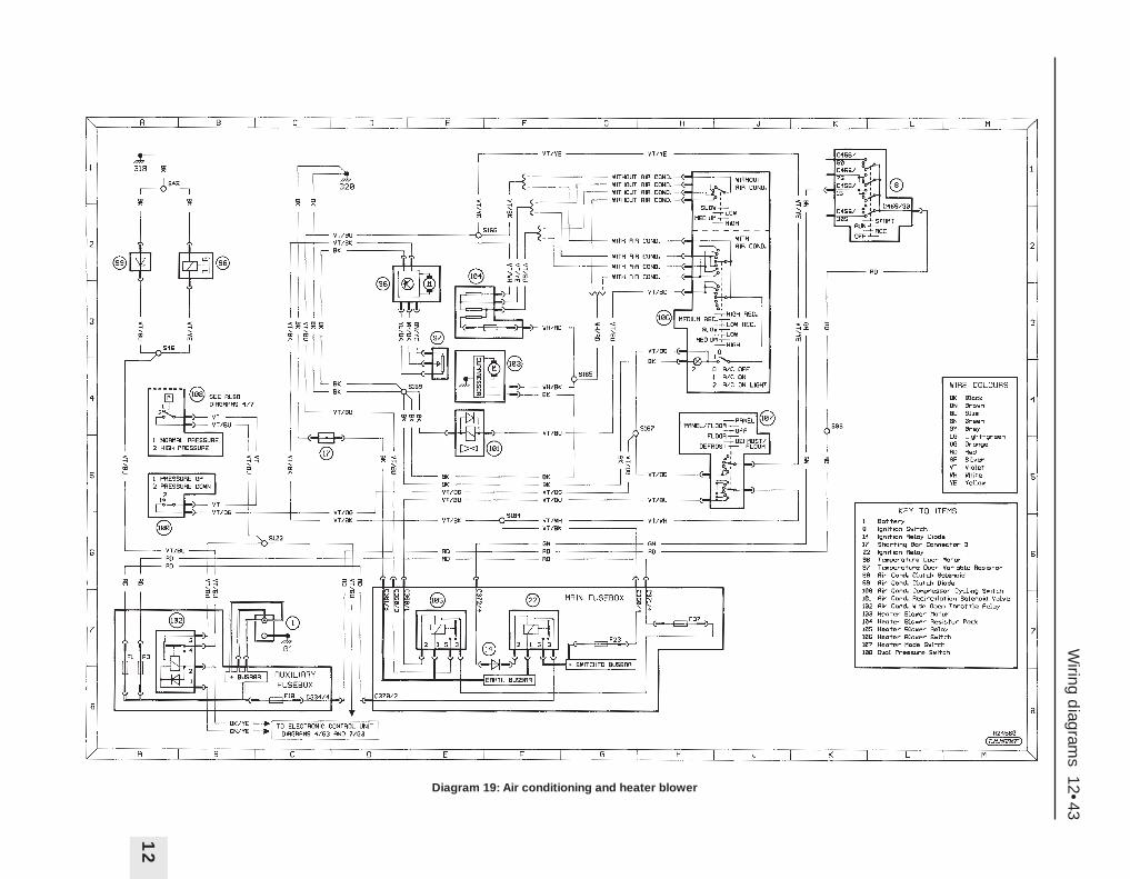
Wiring d
iagrams 12•43
12
Diagram 19: Air conditioning and heater blower
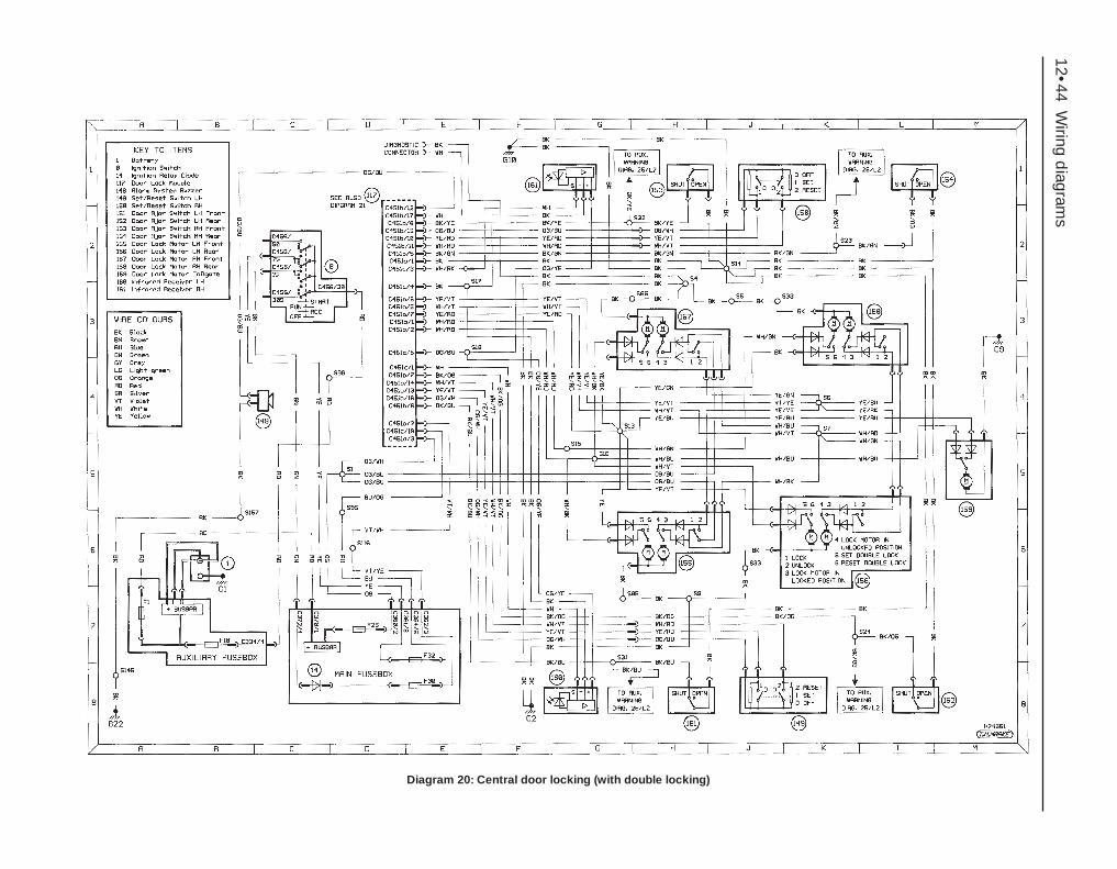
12•44W
iring diagram
s
Diagram 20: Central door locking (with double locking)
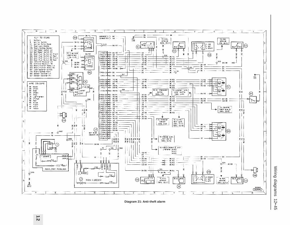
Wiring d
iagrams 12•45
12
Diagram 21: Anti-theft alarm

12•46W
iring diagram
s
Diagram 22: Electric mirrors and (front) electric window
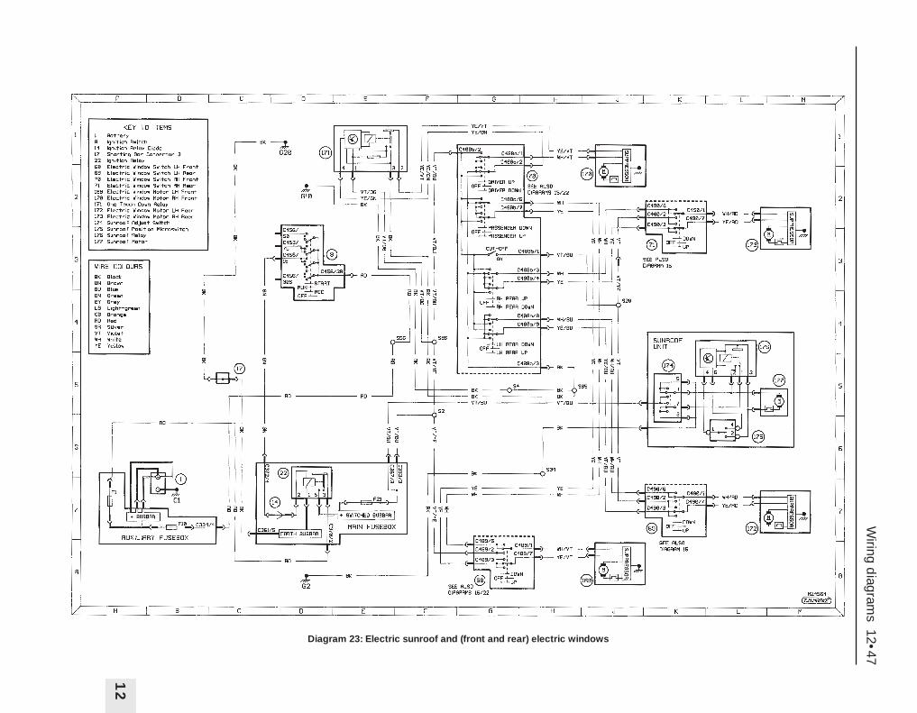
Wiring d
iagrams 12•47
12
Diagram 23: Electric sunroof and (front and rear) electric windows
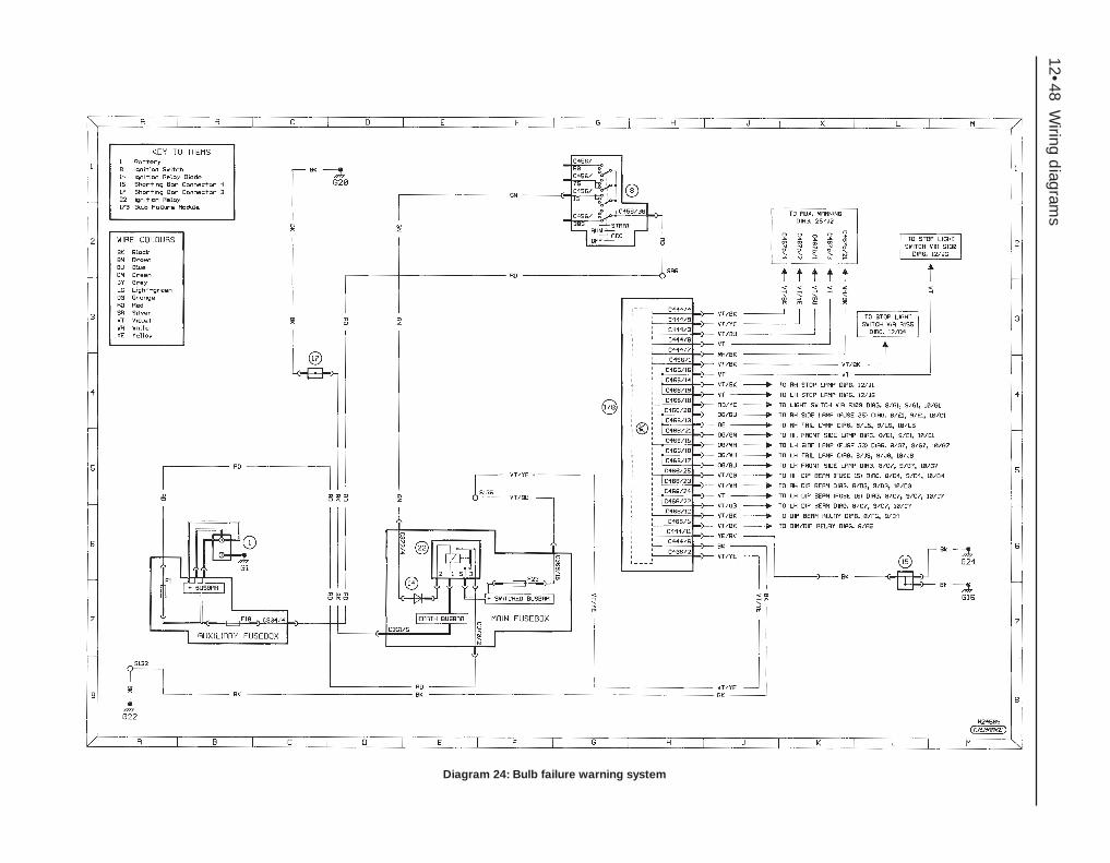
12•48W
iring diagram
s
Diagram 24: Bulb failure warning system
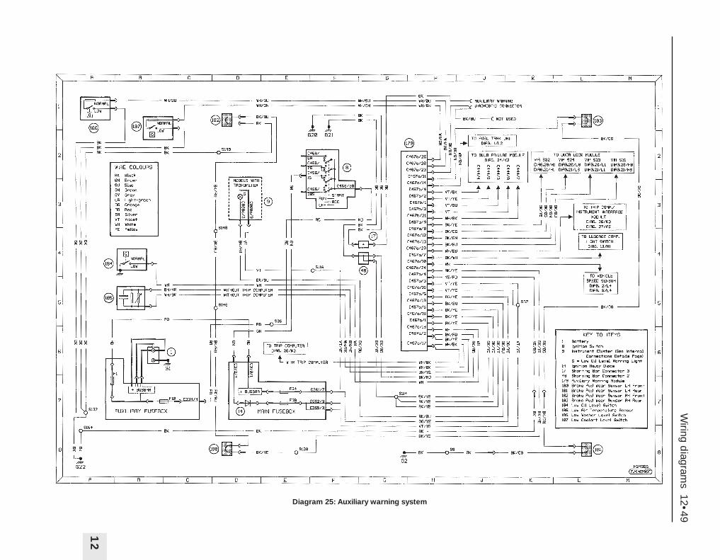
Wiring d
iagrams 12•49
12
Diagram 25: Auxiliary warning system
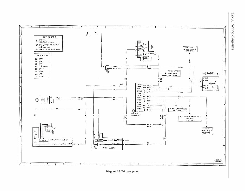
12•50W
iring diagram
s
Diagram 26: Trip computer
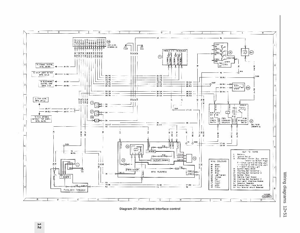
Wiring d
iagrams 12•51
12
Diagram 27: Instrument interface control
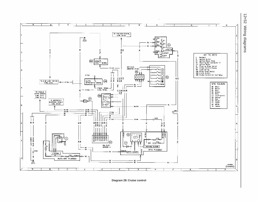
12•52W
iring diagram
s
Diagram 28: Cruise control
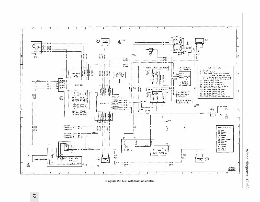
Wiring d
iagrams 12•53
12
Diagram 29: ABS with traction control
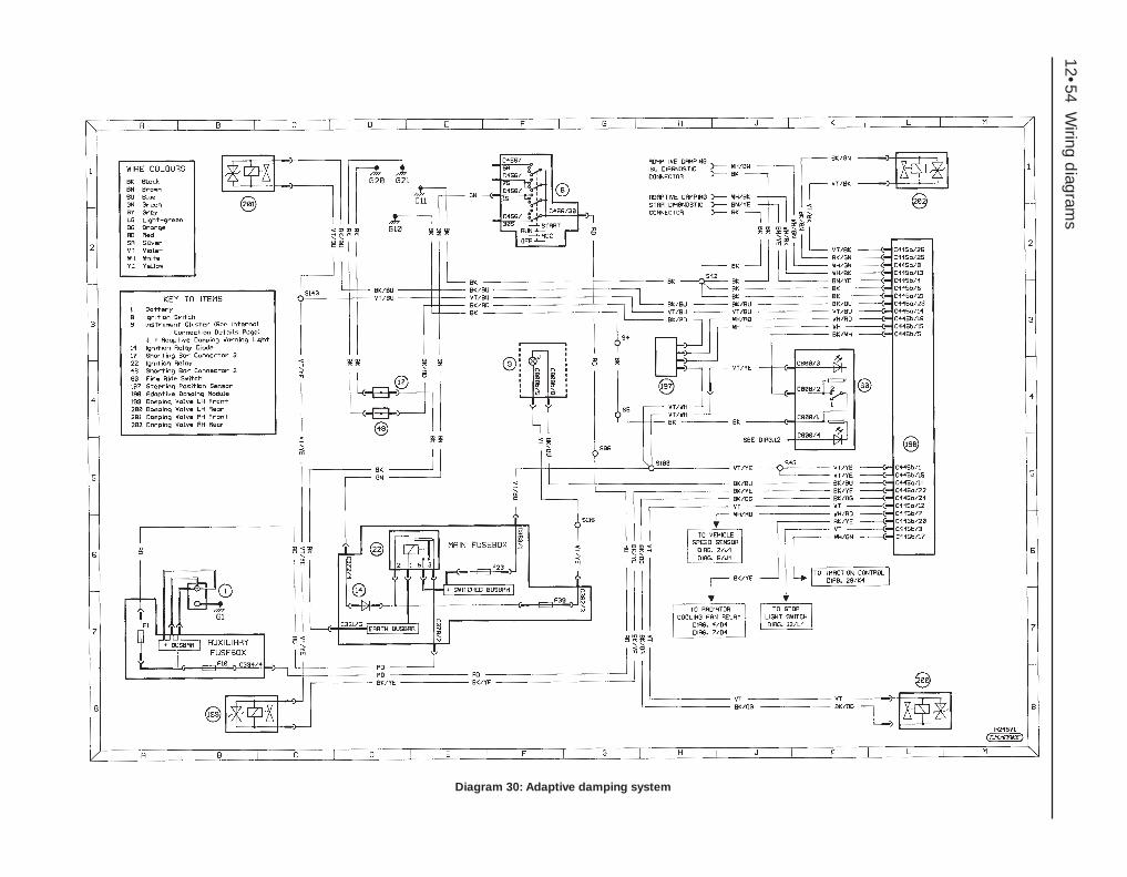
12•54W
iring diagram
s
Diagram 30: Adaptive damping system
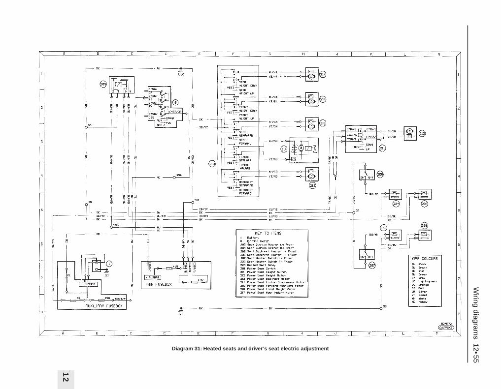
Wiring d
iagrams 12•55
12
Diagram 31: Heated seats and driver’s seat electric adjustment

12•56W
iring diagram
s
Diagram 32: Driver and passenger air bags

Wiring d
iagrams 12•57
12
Diagram 33: Radio/cassette (with amplifier)
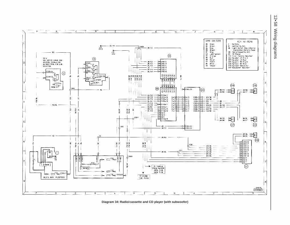
12•58W
iring diagram
s
Diagram 34: Radio/cassette and CD player (with subwoofer)
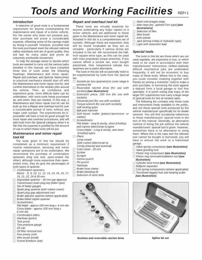
IntroductionA selection of good tools is a fundamental
requirement for anyone contemplating themaintenance and repair of a motor vehicle.For the owner who does not possess any,their purchase will prove a considerableexpense, offsetting some of the savings madeby doing-it-yourself. However, provided thatthe tools purchased meet the relevant nationalsafety standards and are of good quality, theywill last for many years and prove anextremely worthwhile investment.
To help the average owner to decide whichtools are needed to carry out the various tasksdetailed in this manual, we have compiledthree lists of tools under the followingheadings: Maintenance and minor repair,Repair and overhaul, and Special. Newcomersto practical mechanics should start off withthe Maintenance and minor repair tool kit, andconfine themselves to the simpler jobs aroundthe vehicle. Then, as confidence andexperience grow, more difficult tasks can beundertaken, with extra tools being purchasedas, and when, they are needed. In this way, aMaintenance and minor repair tool kit can bebuilt up into a Repair and overhaul tool kit overa considerable period of time, without anymajor cash outlays. The experienced do-it-yourselfer will have a tool kit good enough formost repair and overhaul procedures, and willadd tools from the Special category when it isfelt that the expense is justified by the amountof use to which these tools will be put.
Maintenance and minor repair tool kit
The tools given in this list should beconsidered as a minimum requirement ifroutine maintenance, servicing and minorrepair operations are to be undertaken. Werecommend the purchase of combinationspanners (ring one end, open-ended theother); although more expensive than open-ended ones, they do give the advantages ofboth types of spanner.M Combination spanners:
Metric - 8, 9, 10, 11, 12, 13, 14, 15, 16, 17, 19, 21, 22, 24 & 26 mm
M Adjustable spanner - 35 mm jaw (approx)M Transmission drain plug key (Allen type)M Set of feeler gaugesM Spark plug spanner (with rubber insert)M Spark plug gap adjustment toolM Brake adjuster spanner (where applicable)M Brake bleed nipple spannerM Screwdrivers:
Flat blade - approx 100 mm long x 6 mm diaCross blade - approx 100 mm long x 6 mm dia
M Combination pliersM Hacksaw (junior)M Tyre pumpM Tyre pressure gaugeM Oil canM Oil filter removal toolM Fine emery clothM Wire brush (small)M Funnel (medium size)
Repair and overhaul tool kitThese tools are virtually essential for
anyone undertaking any major repairs to amotor vehicle, and are additional to thosegiven in the Maintenance and minor repair list.Included in this list is a comprehensive set ofsockets. Although these are expensive, theywill be found invaluable as they are soversatile - particularly if various drives areincluded in the set. We recommend the half-inch square-drive type, as this can be usedwith most proprietary torque wrenches. If youcannot afford a socket set, even boughtpiecemeal, then inexpensive tubular boxspanners are a useful alternative.
The tools in this list will occasionally need tobe supplemented by tools from the Speciallist:M Sockets (or box spanners) to cover range in
previous list M Reversible ratchet drive (for use with
sockets) (see illustration)M Extension piece, 250 mm (for use with
sockets)M Universal joint (for use with sockets)M Torque wrench (for use with sockets)M Self-locking gripsM Ball pein hammerM Soft-faced mallet (plastic/aluminium or
rubber)M Screwdrivers:
Flat blade - long & sturdy, short (chubby), and narrow (electrician’s) typesCross blade - Long & sturdy, and short(chubby) types
M Pliers:Long-nosedSide cutters (electrician’s)Circlip (internal and external)
M Cold chisel - 25 mmM ScriberM ScraperM Centre-punchM Pin punchM HacksawM Brake hose clampM Brake bleeding kitM Selection of twist drills
M Steel rule/straight-edgeM Allen keys (inc. splined/Torx type) (see
illustrations)M Selection of filesM Wire brushM Axle standsM Jack (strong trolley or hydraulic type)M Light with extension lead
Special toolsThe tools in this list are those which are not
used regularly, are expensive to buy, or whichneed to be used in accordance with theirmanufacturers’ instructions. Unless relativelydifficult mechanical jobs are undertakenfrequently, it will not be economic to buymany of these tools. Where this is the case,you could consider clubbing together withfriends (or joining a motorists’ club) to make ajoint purchase, or borrowing the tools againsta deposit from a local garage or tool hirespecialist. It is worth noting that many of thelarger DIY superstores now carry a large rangeof special tools for hire at modest rates.
The following list contains only those toolsand instruments freely available to the public,and not those special tools produced by thevehicle manufacturer specifically for its dealernetwork. You will find occasional referencesto these manufacturers’ special tools in thetext of this manual. Generally, an alternativemethod of doing the job without the vehiclemanufacturers’ special tool is given. However,sometimes there is no alternative to usingthem. Where this is the case and the relevanttool cannot be bought or borrowed, you willhave to entrust the work to a franchisedgarage.M Valve spring compressor (see illustration)M Valve grinding toolM Piston ring compressor (see illustration)M Piston ring removal/installation tool (see
illustration)M Cylinder bore hone (see illustration)M Balljoint separatorM Coil spring compressors (where applicable)M Two/three-legged hub and bearing puller
(see illustration)
REF•1
Sockets and reversible ratchet drive Spline bit set
Tools and Working Facilities
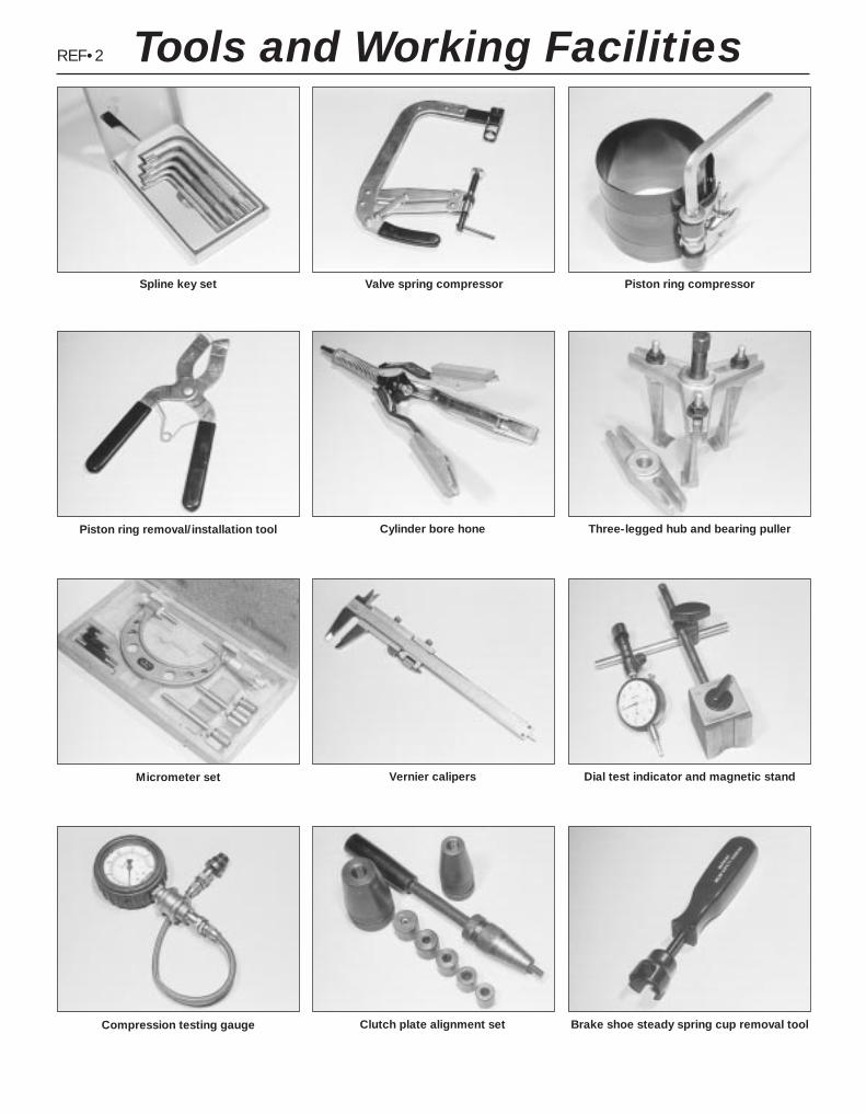
REF•2
Spline key set Valve spring compressor Piston ring compressor
Compression testing gauge Clutch plate alignment set Brake shoe steady spring cup removal tool
Piston ring removal/installation tool Cylinder bore hone Three-legged hub and bearing puller
Micrometer set Vernier calipers Dial test indicator and magnetic stand
Tools and Working Facilities

REF•3
M Impact screwdriverM Micrometer and/or vernier calipers (see
illustrations)M Dial gauge (see illustration)M Universal electrical multi-meterM Cylinder compression gauge
(see illustration)M Clutch plate alignment set (see illustration)M Brake shoe steady spring cup removal tool
(see illustration)M Bush and bearing removal/installation set
(see illustration)M Stud extractors (see illustration)M Tap and die set (see illustration)M Lifting tackleM Trolley jack
Buying toolsFor practically all tools, a tool factor is the
best source, since he will have a verycomprehensive range compared with theaverage garage or accessory shop. Havingsaid that, accessory shops often offerexcellent quality tools at discount prices, so itpays to shop around.
Remember, you don’t have to buy the mostexpensive items on the shelf, but it is alwaysadvisable to steer clear of the very cheaptools. There are plenty of good tools around at
reasonable prices, but always aim to purchaseitems which meet the relevant national safetystandards. If in doubt, ask the proprietor ormanager of the shop for advice before makinga purchase.
Care and maintenance of toolsHaving purchased a reasonable tool kit, it is
necessary to keep the tools in a clean andserviceable condition. After use, always wipeoff any dirt, grease and metal particles using aclean, dry cloth, before putting the tools away.Never leave them lying around after they havebeen used. A simple tool rack on the garageor workshop wall for items such asscrewdrivers and pliers is a good idea. Storeall normal spanners and sockets in a metalbox. Any measuring instruments, gauges,meters, etc, must be carefully stored wherethey cannot be damaged or become rusty.
Take a little care when tools are used.Hammer heads inevitably become marked,and screwdrivers lose the keen edge on theirblades from time to time. A little timelyattention with emery cloth or a file will soonrestore items like this to a good serviceablefinish.
Working facilitiesNot to be forgotten when discussing tools is
the workshop itself. If anything more thanroutine maintenance is to be carried out, someform of suitable working area becomesessential.
It is appreciated that many an owner-mechanic is forced by circumstances toremove an engine or similar item without thebenefit of a garage or workshop. Having donethis, any repairs should always be done underthe cover of a roof.
Wherever possible, any dismantling shouldbe done on a clean, flat workbench or table ata suitable working height.
Any workbench needs a vice; one with ajaw opening of 100 mm is suitable for mostjobs. As mentioned previously, some cleandry storage space is also required for tools, aswell as for any lubricants, cleaning fluids,touch-up paints and so on, which becomenecessary.
Another item which may be required, andwhich has a much more general usage, is anelectric drill with a chuck capacity of at least 8mm. This, together with a good range of twistdrills, is virtually essential for fittingaccessories.
Last, but not least, always keep a supply ofold newspapers and clean, lint-free ragsavailable, and try to keep any working area asclean as possible.
Bush and bearing removal/installation set Stud extractor set Tap and die set
Tools and Working Facilities
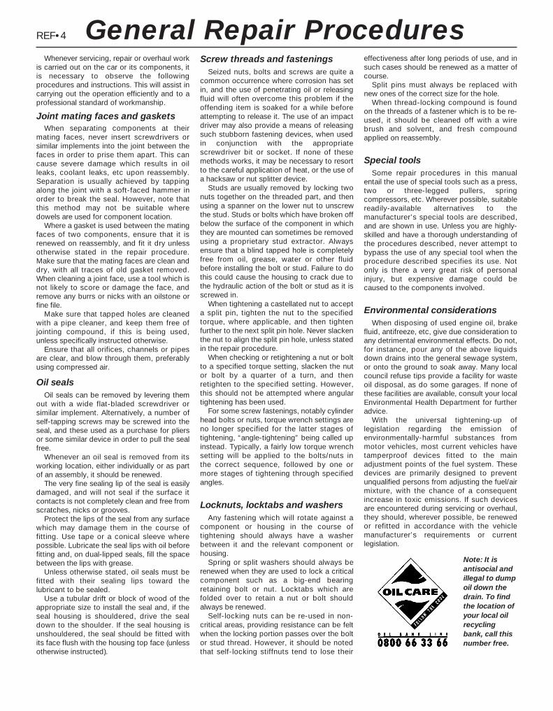
REF•4
Whenever servicing, repair or overhaul workis carried out on the car or its components, itis necessary to observe the followingprocedures and instructions. This will assist incarrying out the operation efficiently and to aprofessional standard of workmanship.
Joint mating faces and gasketsWhen separating components at their
mating faces, never insert screwdrivers orsimilar implements into the joint between thefaces in order to prise them apart. This cancause severe damage which results in oilleaks, coolant leaks, etc upon reassembly.Separation is usually achieved by tappingalong the joint with a soft-faced hammer inorder to break the seal. However, note thatthis method may not be suitable wheredowels are used for component location.
Where a gasket is used between the matingfaces of two components, ensure that it isrenewed on reassembly, and fit it dry unlessotherwise stated in the repair procedure.Make sure that the mating faces are clean anddry, with all traces of old gasket removed.When cleaning a joint face, use a tool which isnot likely to score or damage the face, andremove any burrs or nicks with an oilstone orfine file.
Make sure that tapped holes are cleanedwith a pipe cleaner, and keep them free ofjointing compound, if this is being used,unless specifically instructed otherwise.
Ensure that all orifices, channels or pipesare clear, and blow through them, preferablyusing compressed air.
Oil sealsOil seals can be removed by levering them
out with a wide flat-bladed screwdriver orsimilar implement. Alternatively, a number ofself-tapping screws may be screwed into theseal, and these used as a purchase for pliersor some similar device in order to pull the sealfree.
Whenever an oil seal is removed from itsworking location, either individually or as partof an assembly, it should be renewed.
The very fine sealing lip of the seal is easilydamaged, and will not seal if the surface itcontacts is not completely clean and free fromscratches, nicks or grooves.
Protect the lips of the seal from any surfacewhich may damage them in the course offitting. Use tape or a conical sleeve wherepossible. Lubricate the seal lips with oil beforefitting and, on dual-lipped seals, fill the spacebetween the lips with grease.
Unless otherwise stated, oil seals must befitted with their sealing lips toward thelubricant to be sealed.
Use a tubular drift or block of wood of theappropriate size to install the seal and, if theseal housing is shouldered, drive the sealdown to the shoulder. If the seal housing isunshouldered, the seal should be fitted withits face flush with the housing top face (unlessotherwise instructed).
Screw threads and fasteningsSeized nuts, bolts and screws are quite a
common occurrence where corrosion has setin, and the use of penetrating oil or releasingfluid will often overcome this problem if theoffending item is soaked for a while beforeattempting to release it. The use of an impactdriver may also provide a means of releasingsuch stubborn fastening devices, when usedin conjunction with the appropriatescrewdriver bit or socket. If none of thesemethods works, it may be necessary to resortto the careful application of heat, or the use ofa hacksaw or nut splitter device.
Studs are usually removed by locking twonuts together on the threaded part, and thenusing a spanner on the lower nut to unscrewthe stud. Studs or bolts which have broken offbelow the surface of the component in whichthey are mounted can sometimes be removedusing a proprietary stud extractor. Alwaysensure that a blind tapped hole is completelyfree from oil, grease, water or other fluidbefore installing the bolt or stud. Failure to dothis could cause the housing to crack due tothe hydraulic action of the bolt or stud as it isscrewed in.
When tightening a castellated nut to accepta split pin, tighten the nut to the specifiedtorque, where applicable, and then tightenfurther to the next split pin hole. Never slackenthe nut to align the split pin hole, unless statedin the repair procedure.
When checking or retightening a nut or boltto a specified torque setting, slacken the nutor bolt by a quarter of a turn, and thenretighten to the specified setting. However,this should not be attempted where angulartightening has been used.
For some screw fastenings, notably cylinderhead bolts or nuts, torque wrench settings areno longer specified for the latter stages oftightening, “angle-tightening” being called upinstead. Typically, a fairly low torque wrenchsetting will be applied to the bolts/nuts in the correct sequence, followed by one or more stages of tightening through specifiedangles.
Locknuts, locktabs and washersAny fastening which will rotate against a
component or housing in the course oftightening should always have a washerbetween it and the relevant component orhousing.
Spring or split washers should always berenewed when they are used to lock a criticalcomponent such as a big-end bearingretaining bolt or nut. Locktabs which arefolded over to retain a nut or bolt shouldalways be renewed.
Self-locking nuts can be re-used in non-critical areas, providing resistance can be feltwhen the locking portion passes over the boltor stud thread. However, it should be notedthat self-locking stiffnuts tend to lose their
effectiveness after long periods of use, and insuch cases should be renewed as a matter ofcourse.
Split pins must always be replaced withnew ones of the correct size for the hole.
When thread-locking compound is foundon the threads of a fastener which is to be re-used, it should be cleaned off with a wirebrush and solvent, and fresh compoundapplied on reassembly.
Special toolsSome repair procedures in this manual
entail the use of special tools such as a press,two or three-legged pullers, springcompressors, etc. Wherever possible, suitablereadily-available alternatives to themanufacturer’s special tools are described,and are shown in use. Unless you are highly-skilled and have a thorough understanding ofthe procedures described, never attempt tobypass the use of any special tool when theprocedure described specifies its use. Notonly is there a very great risk of personalinjury, but expensive damage could becaused to the components involved.
Environmental considerationsWhen disposing of used engine oil, brake
fluid, antifreeze, etc, give due consideration toany detrimental environmental effects. Do not,for instance, pour any of the above liquidsdown drains into the general sewage system,or onto the ground to soak away. Many localcouncil refuse tips provide a facility for wasteoil disposal, as do some garages. If none ofthese facilities are available, consult your localEnvironmental Health Department for furtheradvice.
With the universal tightening-up oflegislation regarding the emission ofenvironmentally-harmful substances frommotor vehicles, most current vehicles havetamperproof devices fitted to the mainadjustment points of the fuel system. Thesedevices are primarily designed to preventunqualified persons from adjusting the fuel/airmixture, with the chance of a consequentincrease in toxic emissions. If such devicesare encountered during servicing or overhaul,they should, wherever possible, be renewedor refitted in accordance with the vehiclemanufacturer’s requirements or currentlegislation.
Note: It isantisocial andillegal to dumpoil down thedrain. To findthe location ofyour local oilrecyclingbank, call thisnumber free.
General Repair Procedures

Buying spare partsSpare parts are available from many
sources; for example, Ford garages, othergarages and accessory shops, and motorfactors. Our advice regarding spare partsources is as follows.
Officially-appointed Ford garages - This isthe best source for parts which are peculiar toyour vehicle, and which are not generallyavailable (eg complete cylinder heads, internaltransmission components, badges, interiortrim etc). It is also the only place at which youshould buy parts if the vehicle is still underwarranty. To be sure of obtaining the correctparts, it will be necessary to give the storemanthe full Vehicle Identification Number, and ifpossible, to take the old parts along forpositive identification. Many parts areavailable under a factory exchange scheme -any parts returned should always be clean. Itobviously makes good sense to go straight tothe specialists on your vehicle for this type ofpart, as they are best equipped to supply you.
Other garages and accessory shops - Theseare often very good places to buy materialsand components needed for the maintenanceof your vehicle (eg oil filters, spark plugs,bulbs, drivebelts, oils and greases, touch-uppaint, filler paste, etc). They also sell generalaccessories, usually have convenient openinghours, charge lower prices, and can often befound not far from home.
Motor factors - Good factors will stock allthe more important components which wearout comparatively quickly (eg exhaustsystems, brake pads, seals and hydraulicparts, clutch components, bearing shells,pistons, valves etc). Motor factors will oftenprovide new or reconditioned components ona part-exchange basis - this can save aconsiderable amount of money.
Vehicle identification numbersModifications are a continuing and
unpublicised process in vehicle manufacture,quite apart from major model changes. Spareparts manuals and lists are compiled upon anumerical basis, the appropriate identificationnumber or code being essential to correctidentification of the component concerned.
When ordering spare parts, always give as
much information as possible. Quote thevehicle model, year of manufacture, VehicleIdentification Number and engine numbers, asappropriate.
The vehicle identification plate is located onthe engine compartment front crossmember(see illustration). In addition to many otherdetails, it carries the Vehicle IdentificationNumber, maximum vehicle weightinformation, and codes for interior trim andbody colours.
The Vehicle Identification Number is givenon the vehicle identification plate. It is alsostamped on the engine compartmentbulkhead, behind the air intake plenumchamber, and into the body, so that it can beseen through the bottom left-hand corner ofthe windscreen (see illustrations).
The engine number, consisting of twoletters and five digits, with the three-letterengine code nearby, is stamped into a flat-machined surface on the cylinderblock/crankcase’s forward-facing flange,between the pulse-air filter housing and thetransmission. To read the number withoutremoving the engine compartment air intakeresonator - see Chapter 4 - it is easiest toraise and support the front of the vehicle onaxle stands, so that the number can be seenfrom underneath (see illustration). If thenumber cannot be seen in this location,possible alternative sites are on a lower flangeon the cylinder block’s forward face,immediately above the sump mating surface,or on the left-hand end of the cylinder head,between the oil filler cap and ignition coil.
REF•5
Vehicle identification plate on enginecompartment front crossmember
Vehicle identification number in body,visible through bottom left-hand corner of
windscreen
Vehicle identification number on enginecompartment bulkhead
Engine number (arrowed) on front ofcylinder block/crankcase - seen from
beneath vehicle
Spare Parts/Vehicle Identification
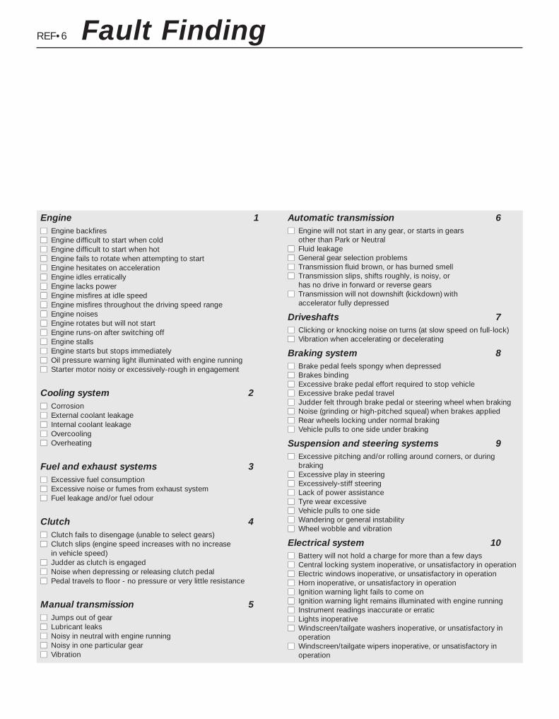
REF•6 Fault Finding
Engine 1mm Engine backfiresmm Engine difficult to start when coldmm Engine difficult to start when hotmm Engine fails to rotate when attempting to startmm Engine hesitates on accelerationmm Engine idles erraticallymm Engine lacks powermm Engine misfires at idle speedmm Engine misfires throughout the driving speed rangemm Engine noisesmm Engine rotates but will not startmm Engine runs-on after switching offmm Engine stallsmm Engine starts but stops immediatelymm Oil pressure warning light illuminated with engine runningmm Starter motor noisy or excessively-rough in engagement
Cooling system 2mm Corrosionmm External coolant leakagemm Internal coolant leakagemm Overcoolingmm Overheating
Fuel and exhaust systems 3mm Excessive fuel consumptionmm Excessive noise or fumes from exhaust systemmm Fuel leakage and/or fuel odour
Clutch 4mm Clutch fails to disengage (unable to select gears)mm Clutch slips (engine speed increases with no increase
in vehicle speed)mm Judder as clutch is engagedmm Noise when depressing or releasing clutch pedalmm Pedal travels to floor - no pressure or very little resistance
Manual transmission 5mm Jumps out of gearmm Lubricant leaksmm Noisy in neutral with engine runningmm Noisy in one particular gearmm Vibration
Automatic transmission 6mm Engine will not start in any gear, or starts in gears
other than Park or Neutralmm Fluid leakagemm General gear selection problemsmm Transmission fluid brown, or has burned smellmm Transmission slips, shifts roughly, is noisy, or
has no drive in forward or reverse gearsmm Transmission will not downshift (kickdown) with
accelerator fully depressed
Driveshafts 7mm Clicking or knocking noise on turns (at slow speed on full-lock)mm Vibration when accelerating or decelerating
Braking system 8mm Brake pedal feels spongy when depressedmm Brakes bindingmm Excessive brake pedal effort required to stop vehiclemm Excessive brake pedal travelmm Judder felt through brake pedal or steering wheel when brakingmm Noise (grinding or high-pitched squeal) when brakes appliedmm Rear wheels locking under normal brakingmm Vehicle pulls to one side under braking
Suspension and steering systems 9mm Excessive pitching and/or rolling around corners, or during
brakingmm Excessive play in steeringmm Excessively-stiff steeringmm Lack of power assistancemm Tyre wear excessivemm Vehicle pulls to one sidemm Wandering or general instabilitymm Wheel wobble and vibration
Electrical system 10mm Battery will not hold a charge for more than a few daysmm Central locking system inoperative, or unsatisfactory in operationmm Electric windows inoperative, or unsatisfactory in operationmm Horn inoperative, or unsatisfactory in operationmm Ignition warning light fails to come onmm Ignition warning light remains illuminated with engine runningmm Instrument readings inaccurate or erraticmm Lights inoperativemm Windscreen/tailgate washers inoperative, or unsatisfactory in
operationmm Windscreen/tailgate wipers inoperative, or unsatisfactory in
operation

REF•7
Engine fails to rotate when attempting to startmm Battery terminal connections loose or corroded (Chapter 5).mm Battery discharged or faulty (Chapter 5).mm Broken, loose or disconnected wiring in the starting circuit
(Chapter 5).mm Defective starter solenoid or switch (Chapter 5).mm Defective starter motor (Chapter 5).mm Starter pinion or flywheel ring gear teeth loose or broken (Chap-
ter 5).mm Engine earth strap broken or disconnected (Chapter 5).mm Automatic transmission not in Park/Neutral position, or selector
lever position sensor faulty (Chapter 7, Part B).
Engine rotates but will not startmm Fuel tank empty.mm Battery discharged (engine rotates slowly) (Chapter 5).mm Battery terminal connections loose or corroded (Chapter 5).mm Ignition components damp or damaged (Chapters 1 and 5).mm Broken, loose or disconnected wiring in the ignition circuit
(Chapters 1 and 5).mm Worn, faulty or incorrectly-gapped spark plugs (Chapter 1).mm Major mechanical failure (eg camshaft drive) (Chapter 2, Part A).
Engine difficult to start when coldmm Battery discharged (Chapter 5).mm Battery terminal connections loose or corroded (Chapter 5).mm Worn, faulty or incorrectly-gapped spark plugs (Chapter 1).mm Other ignition system fault (Chapters 1 and 5).mm Engine management system fault (Chapters 1, 4, 5 and 6)mm Low cylinder compressions (Chapter 2, Part A).
Engine difficult to start when hotmm Air filter element dirty or clogged (Chapter 1).mm Engine management system fault (Chapters 1, 4, 5 and 6)mm Low cylinder compressions (Chapter 2, Part A).mm Faulty hydraulic tappet(s) (Chapter 2, Part A).
Starter motor noisy or excessively-rough inengagementmm Starter pinion or flywheel ring gear teeth loose or broken (Chapter 5).mm Starter motor mounting bolts loose or missing (Chapter 5).mm Starter motor internal components worn or damaged (Chapter 5).
Engine starts but stops immediatelymm Loose or faulty electrical connections in the ignition circuit
(Chapters 1 and 5).mm Engine management system fault (Chapters 1, 4, 5 and 6)mm Vacuum leak at the inlet manifold (Chapters 1, 4 and 6).
Engine idles erraticallymm Idle speed control valve faulty (Chapter 4).mm Engine management system fault (Chapters 1, 4, 5 and 6)mm Air filter element clogged (Chapter 1).mm Vacuum leak at the inlet manifold or associated hoses (Chap-
ters 1, 4 and 6).mm Worn, faulty or incorrectly-gapped spark plugs (Chapter 1).mm Faulty hydraulic tappet(s) (Chapter 2, Part A).mm Uneven or low cylinder compressions (Chapter 2, Part A).mm Camshaft lobes worn (Chapter 2).mm Timing belt incorrectly-tensioned (Chapter 2, Part A).
Engine misfires at idle speedmm Worn, faulty or incorrectly-gapped spark plugs (Chapter 1).mm Faulty spark plug HT leads (Chapter 1).mm Idle speed control valve faulty (Chapter 4).mm Incorrect ignition timing (Chapters 5 and 6).mm Engine management system fault (Chapters 1, 4, 5 and 6)mm Vacuum leak at the inlet manifold or associated hoses (Chap-
ters 1, 4 and 6).mm Faulty hydraulic tappet(s) (Chapter 2, Part A).mm Uneven or low cylinder compressions (Chapter 2, Part A).mm Disconnected, leaking or perished crankcase ventilation hoses
(Chapters 1 and 6).
Fault FindingThe vehicle owner who does his or her own maintenance according
to the recommended service schedules should not have to use thissection of the manual very often. Modern component reliability is suchthat, provided those items subject to wear or deterioration are inspectedor renewed at the specified intervals, sudden failure is comparativelyrare. Faults do not usually just happen as a result of sudden failure, butdevelop over a period of time. Major mechanical failures in particular areusually preceded by characteristic symptoms over hundreds or eventhousands of miles. Those components which do occasionally failwithout warning are often small and easily carried in the vehicle.
With any fault-finding, the first step is to decide where to begininvestigations. Sometimes this is obvious, but on other occasions, alittle detective work will be necessary. The owner who makes half adozen haphazard adjustments or replacements may be successful incuring a fault (or its symptoms), but will be none the wiser if the faultrecurs, and ultimately may have spent more time and money than wasnecessary. A calm and logical approach will be found to be moresatisfactory in the long run. Always take into account any warningsigns or abnormalities that may have been noticed in the periodpreceding the fault - power loss, high or low gauge readings, unusualsmells, etc - and remember that failure of components such as fusesor spark plugs may only be pointers to some underlying fault.
The pages which follow provide an easy reference guide to themore common problems which may occur during the operation of thevehicle. These problems and their possible causes are grouped under
headings denoting various components or systems, such as Engine,Cooling system, etc. The Chapter and/or Section which deals with theproblem is also shown in brackets. Whatever the fault, certain basicprinciples apply. These are as follows:
Verify the fault. This is simply a matter of being sure that you knowwhat the symptoms are before starting work. This is particularlyimportant if you are investigating a fault for someone else, who maynot have described it very accurately.
Don’t overlook the obvious. For example, if the vehicle won’t start, isthere petrol in the tank? (Don’t take anyone else’s word on thisparticular point, and don’t trust the fuel gauge either!) If an electricalfault is indicated, look for loose or broken wires before digging out thetest gear.
Cure the disease, not the symptom. Substituting a flat battery with afully-charged one will get you off the hard shoulder, but if the underlyingcause is not attended to, the new battery will go the same way. Similarly,changing oil-fouled spark plugs for a new set will get you moving again,but remember that the reason for the fouling (if it wasn’t simply anincorrect grade of plug) will have to be established and corrected.
Don’t take anything for granted. Particularly, don’t forget that a“new” component may itself be defective (especially if it’s beenrattling around in the boot for months), and don’t leave componentsout of a fault diagnosis sequence just because they are new orrecently fitted. When you do finally diagnose a difficult fault, you’llprobably realise that all the evidence was there from the start.
1 Engine
Introduction

Engine misfires throughout the driving speed rangemm Fuel filter choked (Chapter 1).mm Fuel pump faulty or delivery pressure low (Chapter 4).mm Fuel tank vent blocked or fuel pipes restricted (Chapter 4).mm Vacuum leak at the inlet manifold or associated hoses (Chap-
ters 1, 4 and 6).mm Worn, faulty or incorrectly-gapped spark plugs (Chapter 1).mm Faulty spark plug HT leads (Chapter 1).mm Faulty ignition coil (Chapter 5).mm Engine management system fault (Chapters 1, 4, 5 and 6)mm Uneven or low cylinder compressions (Chapter 2, Part A).
Engine hesitates on accelerationmm Worn, faulty or incorrectly-gapped spark plugs (Chapter 1).mm Engine management system fault (Chapters 1, 4, 5 and 6).mm Vacuum leak at the inlet manifold or associated hoses (Chap-
ters 1, 4 and 6).
Engine stallsmm Idle speed control valve faulty (Chapter 4).mm Engine management system fault (Chapters 1, 4, 5 and 6).mm Vacuum leak at the inlet manifold or associated hoses (Chap-
ters 1, 4 and 6).mm Fuel filter choked (Chapter 1).mm Fuel pump faulty or delivery pressure low (Chapter 4).mm Fuel tank vent blocked or fuel pipes restricted (Chapter 4).
Engine lacks powermm Incorrect ignition timing (Chapters 5 and 6).mm Engine management system fault (Chapters 1, 4, 5 and 6).mm Timing belt incorrectly fitted or incorrectly tensioned (Chapter 2,
Part A).mm Fuel filter choked (Chapter 1).mm Fuel pump faulty or delivery pressure low (Chapter 4).mm Uneven or low cylinder compressions (Chapter 2, Part A).mm Worn, faulty or incorrectly-gapped spark plugs (Chapter 1).mm Vacuum leak at the inlet manifold or associated hoses (Chap-
ters 1, 4 and 6).mm Brakes binding (Chapters 1 and 9).mm Clutch slipping (Chapter 8).mm Automatic transmission fluid level incorrect (Chapter 1).
Engine runs-on after switching offmm Idle speed excessively high (Chapters 4 and 6).mm Engine management system fault (Chapters 1, 4, 5 and 6).mm Excessive carbon build-up in engine (Chapter 2, Part A).mm High engine operating temperature (Chapter 3).
Engine backfiresmm Ignition timing incorrect (Chapters 5 and 6).mm Engine management system fault (Chapters 1, 4, 5 and 6).mm Timing belt incorrectly fitted or incorrectly tensioned (Chapter 2,
Part A).mm Vacuum leak at the inlet manifold or associated hoses (Chap-
ters 1, 4 and 6).
Oil pressure warning light illuminated with enginerunningmm Low oil level or incorrect oil grade (Chapter 1).mm Faulty oil pressure warning light switch (Chapter 2, Part A).mm Worn engine bearings and/or oil pump (Chapter 2).mm High engine operating temperature (Chapter 3).mm Oil pressure relief valve defective (Chapter 2, Part A).mm Oil pick-up strainer clogged (Chapter 2, Part A).
Engine noises
Pre-ignition (pinking) or knocking during acceleration or underloadmm Ignition timing incorrect (Chapters 5 and 6).mm Incorrect grade of fuel (Chapter 4).mm Vacuum leak at the inlet manifold or associated hoses (Chap-
ters 1, 4 and 6).mm Excessive carbon build-up in engine (Chapter 2, Part A).
Whistling or wheezing noisesmm Leaking inlet manifold gasket (Chapter 2, Part A).mm Leaking exhaust manifold gasket or downpipe-to-manifold joint
(Chapters 1, 2 Part A, and 4).mm Leaking vacuum hose (Chapters 1, 4, 6 and 9).mm Blowing cylinder head gasket (Chapter 2, Part A).
Tapping or rattling noisesmm Faulty hydraulic tappet(s) (Chapter 2, Part A).mm Worn valve gear or camshaft (Chapter 2, Part A).mm Worn timing belt or tensioner (Chapter 2, Part A).mm Ancillary component fault (water pump, alternator, etc) (Chap-
ters 3 and 5).
Knocking or thumping noisesmm Worn big-end bearings (regular heavy knocking, perhaps less
under load) (Chapter 2, Part B).mm Worn main bearings (rumbling and knocking, perhaps worsening
under load) (Chapter 2, Part B).mm Piston slap (most noticeable when cold) (Chapter 2, Part B).mm Ancillary component fault (water pump, alternator, etc) (Chap-
ters 3 and 5).
REF•8 Fault Finding
2 Cooling systemOverheatingmm Insufficient coolant in system (Chapter 1).mm Thermostat faulty (Chapter 3).mm Radiator core blocked or grille restricted (Chapter 3).mm Radiator electric cooling fan(s) or coolant temperature sensor faulty
(Chapter 3).mm Engine management system fault (Chapters 1, 4, 5 and 6).mm Pressure cap faulty (Chapter 3).mm Auxiliary drivebelt worn or slipping (Chapter 1).mm Ignition timing incorrect (Chapters 5 and 6).mm Inaccurate coolant temperature gauge sender (Chapter 3).mm Air-lock in cooling system (Chapter 1).
Overcoolingmm Thermostat faulty (Chapter 3).mm Inaccurate coolant temperature gauge sender (Chapter 3).
External coolant leakagemm Deteriorated or damaged hoses or hose clips (Chapter 1).mm Radiator core or heater matrix leaking (Chapter 3).mm Pressure cap faulty (Chapter 3).mm Water pump seal leaking (Chapter 3).mm Boiling due to overheating (Chapter 3).mm Core plug leaking (Chapter 2, Part B).
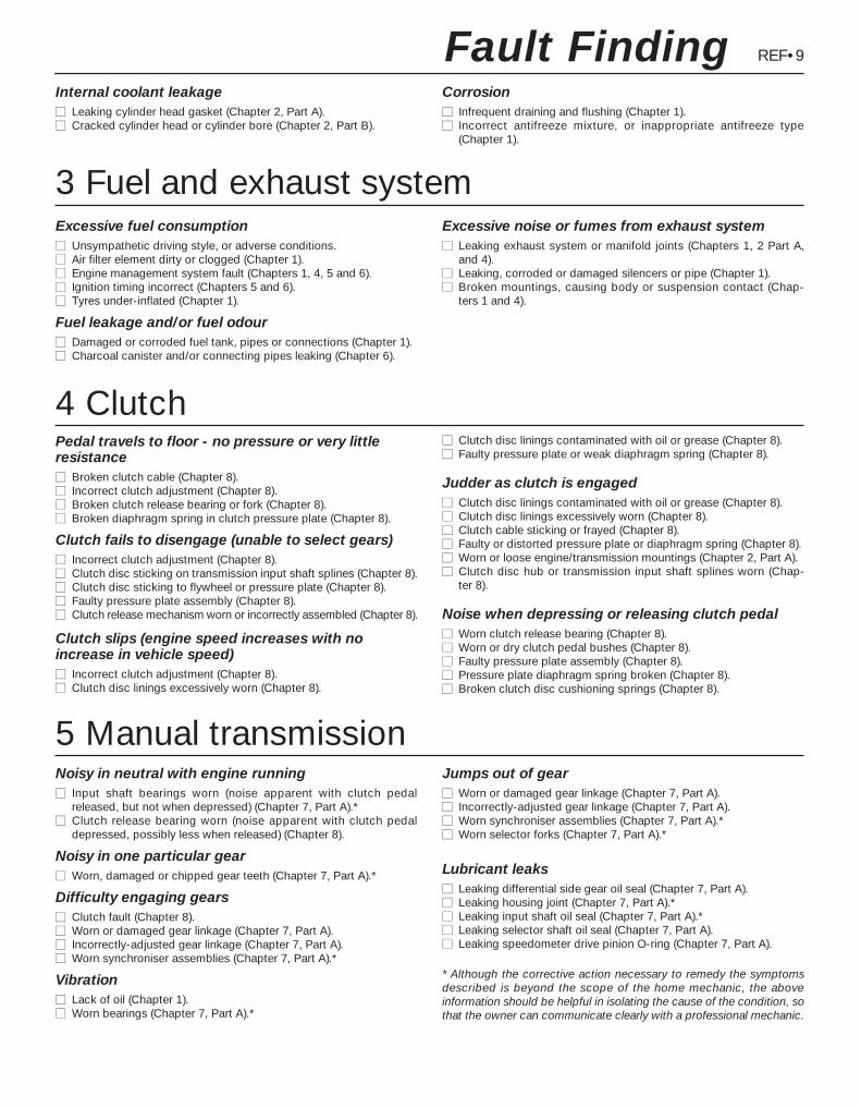
REF•9
Excessive fuel consumptionmm Unsympathetic driving style, or adverse conditions.mm Air filter element dirty or clogged (Chapter 1).mm Engine management system fault (Chapters 1, 4, 5 and 6).mm Ignition timing incorrect (Chapters 5 and 6).mm Tyres under-inflated (Chapter 1).
Fuel leakage and/or fuel odourmm Damaged or corroded fuel tank, pipes or connections (Chapter 1).mm Charcoal canister and/or connecting pipes leaking (Chapter 6).
Excessive noise or fumes from exhaust systemmm Leaking exhaust system or manifold joints (Chapters 1, 2 Part A,
and 4).mm Leaking, corroded or damaged silencers or pipe (Chapter 1).mm Broken mountings, causing body or suspension contact (Chap-
ters 1 and 4).
Fault Finding
3 Fuel and exhaust system
Noisy in neutral with engine runningmm Input shaft bearings worn (noise apparent with clutch pedal
released, but not when depressed) (Chapter 7, Part A).*mm Clutch release bearing worn (noise apparent with clutch pedal
depressed, possibly less when released) (Chapter 8).
Noisy in one particular gearmm Worn, damaged or chipped gear teeth (Chapter 7, Part A).*
Difficulty engaging gearsmm Clutch fault (Chapter 8).mm Worn or damaged gear linkage (Chapter 7, Part A).mm Incorrectly-adjusted gear linkage (Chapter 7, Part A).mm Worn synchroniser assemblies (Chapter 7, Part A).*
Vibrationmm Lack of oil (Chapter 1).mm Worn bearings (Chapter 7, Part A).*
Jumps out of gearmm Worn or damaged gear linkage (Chapter 7, Part A).mm Incorrectly-adjusted gear linkage (Chapter 7, Part A).mm Worn synchroniser assemblies (Chapter 7, Part A).*mm Worn selector forks (Chapter 7, Part A).*
Lubricant leaksmm Leaking differential side gear oil seal (Chapter 7, Part A).mm Leaking housing joint (Chapter 7, Part A).*mm Leaking input shaft oil seal (Chapter 7, Part A).*mm Leaking selector shaft oil seal (Chapter 7, Part A).mm Leaking speedometer drive pinion O-ring (Chapter 7, Part A).
* Although the corrective action necessary to remedy the symptomsdescribed is beyond the scope of the home mechanic, the aboveinformation should be helpful in isolating the cause of the condition, sothat the owner can communicate clearly with a professional mechanic.
4 Clutch
5 Manual transmission
Pedal travels to floor - no pressure or very littleresistancemm Broken clutch cable (Chapter 8).mm Incorrect clutch adjustment (Chapter 8).mm Broken clutch release bearing or fork (Chapter 8).mm Broken diaphragm spring in clutch pressure plate (Chapter 8).
Clutch fails to disengage (unable to select gears)mm Incorrect clutch adjustment (Chapter 8).mm Clutch disc sticking on transmission input shaft splines (Chapter 8).mm Clutch disc sticking to flywheel or pressure plate (Chapter 8).mm Faulty pressure plate assembly (Chapter 8).mm Clutch release mechanism worn or incorrectly assembled (Chapter 8).
Clutch slips (engine speed increases with noincrease in vehicle speed)mm Incorrect clutch adjustment (Chapter 8).mm Clutch disc linings excessively worn (Chapter 8).
mm Clutch disc linings contaminated with oil or grease (Chapter 8).mm Faulty pressure plate or weak diaphragm spring (Chapter 8).
Judder as clutch is engagedmm Clutch disc linings contaminated with oil or grease (Chapter 8).mm Clutch disc linings excessively worn (Chapter 8).mm Clutch cable sticking or frayed (Chapter 8).mm Faulty or distorted pressure plate or diaphragm spring (Chapter 8).mm Worn or loose engine/transmission mountings (Chapter 2, Part A).mm Clutch disc hub or transmission input shaft splines worn (Chap-
ter 8).
Noise when depressing or releasing clutch pedalmm Worn clutch release bearing (Chapter 8).mm Worn or dry clutch pedal bushes (Chapter 8).mm Faulty pressure plate assembly (Chapter 8).mm Pressure plate diaphragm spring broken (Chapter 8).mm Broken clutch disc cushioning springs (Chapter 8).
Internal coolant leakagemm Leaking cylinder head gasket (Chapter 2, Part A).mm Cracked cylinder head or cylinder bore (Chapter 2, Part B).
Corrosionmm Infrequent draining and flushing (Chapter 1).mm Incorrect antifreeze mixture, or inappropriate antifreeze type
(Chapter 1).
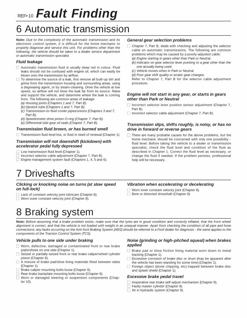
6 Automatic transmission
REF•10 Fault Finding
Note: Due to the complexity of the automatic transmission and itselectronic control system, it is difficult for the home mechanic toproperly diagnose and service this unit. For problems other than thefollowing, the vehicle should be taken to a dealer service departmentor automatic transmission specialist.
Fluid leakagemm Automatic transmission fluid is usually deep red in colour. Fluid
leaks should not be confused with engine oil, which can easily beblown onto the transmission by airflow.
mm To determine the source of a leak, first remove all built-up dirt andgrime from the transmission housing and surrounding areas, usinga degreasing agent, or by steam-cleaning. Drive the vehicle at lowspeed, so airflow will not blow the leak far from its source. Raiseand support the vehicle, and determine where the leak is comingfrom. The following are common areas of leakage:(a) Housing joints (Chapters 1 and 7, Part B).(b) Dipstick tube (Chapters 1 and 7, Part B).(c) Transmission-to-fluid cooler pipes/unions (Chapters 3 and 7,
Part B).(d) Speedometer drive pinion O-ring (Chapter 7, Part B).(e) Differential side gear oil seals (Chapter 7, Part B).
Transmission fluid brown, or has burned smellmm Transmission fluid level low, or fluid in need of renewal (Chapter 1).
Transmission will not downshift (kickdown) withaccelerator pedal fully depressedmm Low transmission fluid level (Chapter 1).mm Incorrect selector cable adjustment (Chapter 7, Part B).mm Engine management system fault (Chapters 1, 4, 5 and 6).
General gear selection problemsmm Chapter 7, Part B, deals with checking and adjusting the selector
cable on automatic transmissions. The following are commonproblems which may be caused by a poorly-adjusted cable:(a) Engine starting in gears other than Park or Neutral.(b) Indicator on gear selector lever pointing to a gear other than the
one actually being used.(c) Vehicle moves when in Park or Neutral.(d) Poor gear shift quality or erratic gear changes.Refer to Chapter 7, Part B for the selector cable adjustmentprocedure.
Engine will not start in any gear, or starts in gearsother than Park or Neutralmm Incorrect selector lever position sensor adjustment (Chapter 7,
Part B).mm Incorrect selector cable adjustment (Chapter 7, Part B).
Transmission slips, shifts roughly, is noisy, or has nodrive in forward or reverse gearsmm There are many probable causes for the above problems, but the
home mechanic should be concerned with only one possibility -fluid level. Before taking the vehicle to a dealer or transmissionspecialist, check the fluid level and condition of the fluid asdescribed in Chapter 1. Correct the fluid level as necessary, orchange the fluid if needed. If the problem persists, professionalhelp will be necessary.
7 DriveshaftsClicking or knocking noise on turns (at slow speedon full-lock)mm Lack of constant velocity joint lubricant (Chapter 8).mm Worn outer constant velocity joint (Chapter 8).
Vibration when accelerating or deceleratingmm Worn inner constant velocity joint (Chapter 8).mm Bent or distorted driveshaft (Chapter 8).
8 Braking systemNote: Before assuming that a brake problem exists, make sure that the tyres are in good condition and correctly inflated, that the front wheelalignment is correct, and that the vehicle is not loaded with weight in an unequal manner. Apart from checking the condition of all pipe and hoseconnections, any faults occurring on the Anti-lock Braking System (ABS) should be referred to a Ford dealer for diagnosis - the same applies to thecomponents of the Traction Control System (TCS).
Vehicle pulls to one side under brakingmm Worn, defective, damaged or contaminated front or rear brake
pads/shoes on one side (Chapter 1).mm Seized or partially-seized front or rear brake caliper/wheel cylinder
piston (Chapter 9).mm A mixture of brake pad/shoe lining materials fitted between sides
(Chapter 1).mm Brake caliper mounting bolts loose (Chapter 9).mm Rear brake backplate mounting bolts loose (Chapter 9).mm Worn or damaged steering or suspension components (Chap-
ter 10).
Noise (grinding or high-pitched squeal) when brakesappliedmm Brake pad or shoe friction lining material worn down to metal
backing (Chapter 1).mm Excessive corrosion of brake disc or drum (may be apparent after
the vehicle has been standing for some time) (Chapter 1).mm Foreign object (stone chipping, etc) trapped between brake disc
and splash shield (Chapter 1).
Excessive brake pedal travelmm Inoperative rear brake self-adjust mechanism (Chapter 9).mm Faulty master cylinder (Chapter 9).mm Air in hydraulic system (Chapter 9).
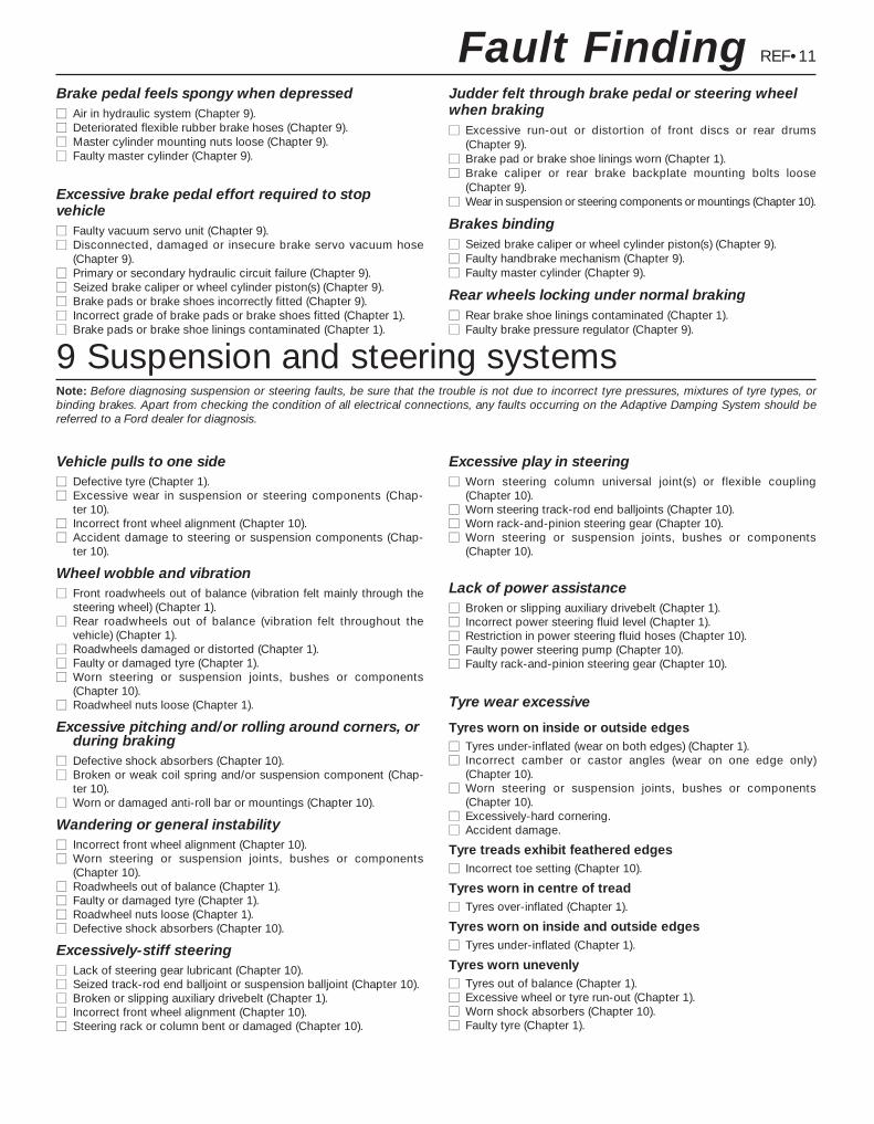
REF•11Fault Finding
9 Suspension and steering systemsNote: Before diagnosing suspension or steering faults, be sure that the trouble is not due to incorrect tyre pressures, mixtures of tyre types, orbinding brakes. Apart from checking the condition of all electrical connections, any faults occurring on the Adaptive Damping System should bereferred to a Ford dealer for diagnosis.
Vehicle pulls to one sidemm Defective tyre (Chapter 1).mm Excessive wear in suspension or steering components (Chap-
ter 10).mm Incorrect front wheel alignment (Chapter 10).mm Accident damage to steering or suspension components (Chap-
ter 10).
Wheel wobble and vibrationmm Front roadwheels out of balance (vibration felt mainly through the
steering wheel) (Chapter 1).mm Rear roadwheels out of balance (vibration felt throughout the
vehicle) (Chapter 1).mm Roadwheels damaged or distorted (Chapter 1).mm Faulty or damaged tyre (Chapter 1).mm Worn steering or suspension joints, bushes or components
(Chapter 10).mm Roadwheel nuts loose (Chapter 1).
Excessive pitching and/or rolling around corners, orduring braking
mm Defective shock absorbers (Chapter 10).mm Broken or weak coil spring and/or suspension component (Chap-
ter 10).mm Worn or damaged anti-roll bar or mountings (Chapter 10).
Wandering or general instabilitymm Incorrect front wheel alignment (Chapter 10).mm Worn steering or suspension joints, bushes or components
(Chapter 10).mm Roadwheels out of balance (Chapter 1).mm Faulty or damaged tyre (Chapter 1).mm Roadwheel nuts loose (Chapter 1).mm Defective shock absorbers (Chapter 10).
Excessively-stiff steeringmm Lack of steering gear lubricant (Chapter 10).mm Seized track-rod end balljoint or suspension balljoint (Chapter 10).mm Broken or slipping auxiliary drivebelt (Chapter 1).mm Incorrect front wheel alignment (Chapter 10).mm Steering rack or column bent or damaged (Chapter 10).
Excessive play in steeringmm Worn steering column universal joint(s) or flexible coupling
(Chapter 10).mm Worn steering track-rod end balljoints (Chapter 10).mm Worn rack-and-pinion steering gear (Chapter 10).mm Worn steering or suspension joints, bushes or components
(Chapter 10).
Lack of power assistancemm Broken or slipping auxiliary drivebelt (Chapter 1).mm Incorrect power steering fluid level (Chapter 1).mm Restriction in power steering fluid hoses (Chapter 10).mm Faulty power steering pump (Chapter 10).mm Faulty rack-and-pinion steering gear (Chapter 10).
Tyre wear excessive
Tyres worn on inside or outside edgesmm Tyres under-inflated (wear on both edges) (Chapter 1).mm Incorrect camber or castor angles (wear on one edge only)
(Chapter 10).mm Worn steering or suspension joints, bushes or components
(Chapter 10).mm Excessively-hard cornering.mm Accident damage.
Tyre treads exhibit feathered edgesmm Incorrect toe setting (Chapter 10).
Tyres worn in centre of treadmm Tyres over-inflated (Chapter 1).
Tyres worn on inside and outside edgesmm Tyres under-inflated (Chapter 1).
Tyres worn unevenlymm Tyres out of balance (Chapter 1).mm Excessive wheel or tyre run-out (Chapter 1).mm Worn shock absorbers (Chapter 10).mm Faulty tyre (Chapter 1).
Brake pedal feels spongy when depressedmm Air in hydraulic system (Chapter 9).mm Deteriorated flexible rubber brake hoses (Chapter 9).mm Master cylinder mounting nuts loose (Chapter 9).mm Faulty master cylinder (Chapter 9).
Excessive brake pedal effort required to stopvehiclemm Faulty vacuum servo unit (Chapter 9).mm Disconnected, damaged or insecure brake servo vacuum hose
(Chapter 9).mm Primary or secondary hydraulic circuit failure (Chapter 9).mm Seized brake caliper or wheel cylinder piston(s) (Chapter 9).mm Brake pads or brake shoes incorrectly fitted (Chapter 9).mm Incorrect grade of brake pads or brake shoes fitted (Chapter 1).mm Brake pads or brake shoe linings contaminated (Chapter 1).
Judder felt through brake pedal or steering wheelwhen brakingmm Excessive run-out or distortion of front discs or rear drums
(Chapter 9).mm Brake pad or brake shoe linings worn (Chapter 1).mm Brake caliper or rear brake backplate mounting bolts loose
(Chapter 9).mm Wear in suspension or steering components or mountings (Chapter 10).
Brakes bindingmm Seized brake caliper or wheel cylinder piston(s) (Chapter 9).mm Faulty handbrake mechanism (Chapter 9).mm Faulty master cylinder (Chapter 9).
Rear wheels locking under normal brakingmm Rear brake shoe linings contaminated (Chapter 1).mm Faulty brake pressure regulator (Chapter 9).
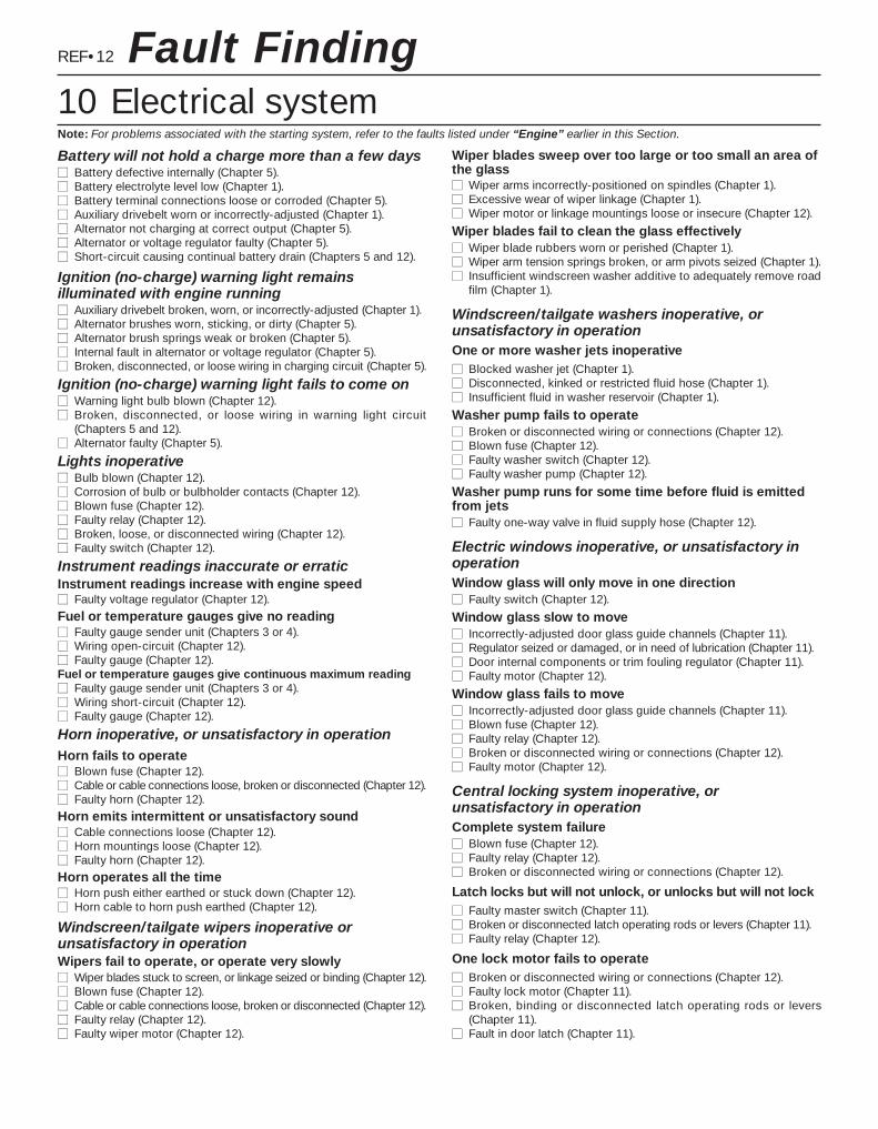
REF•12
Battery will not hold a charge more than a few daysmm Battery defective internally (Chapter 5).mm Battery electrolyte level low (Chapter 1).mm Battery terminal connections loose or corroded (Chapter 5).mm Auxiliary drivebelt worn or incorrectly-adjusted (Chapter 1).mm Alternator not charging at correct output (Chapter 5).mm Alternator or voltage regulator faulty (Chapter 5).mm Short-circuit causing continual battery drain (Chapters 5 and 12).
Ignition (no-charge) warning light remainsilluminated with engine runningmm Auxiliary drivebelt broken, worn, or incorrectly-adjusted (Chapter 1).mm Alternator brushes worn, sticking, or dirty (Chapter 5).mm Alternator brush springs weak or broken (Chapter 5).mm Internal fault in alternator or voltage regulator (Chapter 5).mm Broken, disconnected, or loose wiring in charging circuit (Chapter 5).
Ignition (no-charge) warning light fails to come onmm Warning light bulb blown (Chapter 12).mm Broken, disconnected, or loose wiring in warning light circuit
(Chapters 5 and 12).mm Alternator faulty (Chapter 5).
Lights inoperativemm Bulb blown (Chapter 12).mm Corrosion of bulb or bulbholder contacts (Chapter 12).mm Blown fuse (Chapter 12).mm Faulty relay (Chapter 12).mm Broken, loose, or disconnected wiring (Chapter 12).mm Faulty switch (Chapter 12).
Instrument readings inaccurate or erraticInstrument readings increase with engine speedmm Faulty voltage regulator (Chapter 12).
Fuel or temperature gauges give no readingmm Faulty gauge sender unit (Chapters 3 or 4).mm Wiring open-circuit (Chapter 12).mm Faulty gauge (Chapter 12).Fuel or temperature gauges give continuous maximum readingmm Faulty gauge sender unit (Chapters 3 or 4).mm Wiring short-circuit (Chapter 12).mm Faulty gauge (Chapter 12).
Horn inoperative, or unsatisfactory in operationHorn fails to operatemm Blown fuse (Chapter 12).mm Cable or cable connections loose, broken or disconnected (Chapter 12).mm Faulty horn (Chapter 12).
Horn emits intermittent or unsatisfactory soundmm Cable connections loose (Chapter 12).mm Horn mountings loose (Chapter 12).mm Faulty horn (Chapter 12).
Horn operates all the timemm Horn push either earthed or stuck down (Chapter 12).mm Horn cable to horn push earthed (Chapter 12).
Windscreen/tailgate wipers inoperative orunsatisfactory in operationWipers fail to operate, or operate very slowlymm Wiper blades stuck to screen, or linkage seized or binding (Chapter 12).mm Blown fuse (Chapter 12).mm Cable or cable connections loose, broken or disconnected (Chapter 12).mm Faulty relay (Chapter 12).mm Faulty wiper motor (Chapter 12).
Wiper blades sweep over too large or too small an area ofthe glassmm Wiper arms incorrectly-positioned on spindles (Chapter 1).mm Excessive wear of wiper linkage (Chapter 1).mm Wiper motor or linkage mountings loose or insecure (Chapter 12).
Wiper blades fail to clean the glass effectivelymm Wiper blade rubbers worn or perished (Chapter 1).mm Wiper arm tension springs broken, or arm pivots seized (Chapter 1).mm Insufficient windscreen washer additive to adequately remove road
film (Chapter 1).
Windscreen/tailgate washers inoperative, orunsatisfactory in operationOne or more washer jets inoperativemm Blocked washer jet (Chapter 1).mm Disconnected, kinked or restricted fluid hose (Chapter 1).mm Insufficient fluid in washer reservoir (Chapter 1).
Washer pump fails to operatemm Broken or disconnected wiring or connections (Chapter 12).mm Blown fuse (Chapter 12).mm Faulty washer switch (Chapter 12).mm Faulty washer pump (Chapter 12).
Washer pump runs for some time before fluid is emittedfrom jetsmm Faulty one-way valve in fluid supply hose (Chapter 12).
Electric windows inoperative, or unsatisfactory inoperationWindow glass will only move in one directionmm Faulty switch (Chapter 12).
Window glass slow to movemm Incorrectly-adjusted door glass guide channels (Chapter 11).mm Regulator seized or damaged, or in need of lubrication (Chapter 11).mm Door internal components or trim fouling regulator (Chapter 11).mm Faulty motor (Chapter 12).
Window glass fails to movemm Incorrectly-adjusted door glass guide channels (Chapter 11).mm Blown fuse (Chapter 12).mm Faulty relay (Chapter 12).mm Broken or disconnected wiring or connections (Chapter 12).mm Faulty motor (Chapter 12).
Central locking system inoperative, orunsatisfactory in operationComplete system failuremm Blown fuse (Chapter 12).mm Faulty relay (Chapter 12).mm Broken or disconnected wiring or connections (Chapter 12).
Latch locks but will not unlock, or unlocks but will not lockmm Faulty master switch (Chapter 11).mm Broken or disconnected latch operating rods or levers (Chapter 11).mm Faulty relay (Chapter 12).
One lock motor fails to operatemm Broken or disconnected wiring or connections (Chapter 12).mm Faulty lock motor (Chapter 11).mm Broken, binding or disconnected latch operating rods or levers
(Chapter 11).mm Fault in door latch (Chapter 11).
Fault Finding10 Electrical systemNote: For problems associated with the starting system, refer to the faults listed under “Engine” earlier in this Section.
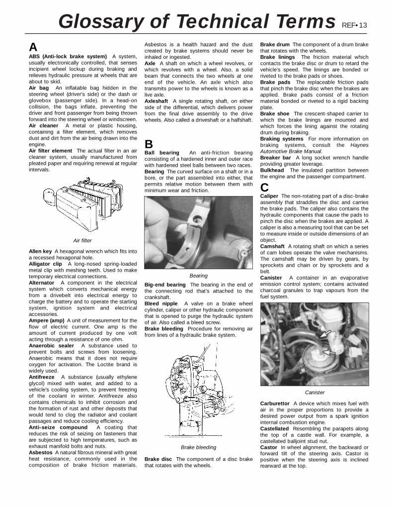
REF•13Glossary of Technical TermsAABS (Anti-lock brake system) A system,usually electronically controlled, that sensesincipient wheel lockup during braking andrelieves hydraulic pressure at wheels that areabout to skid.Air bag An inflatable bag hidden in thesteering wheel (driver’s side) or the dash orglovebox (passenger side). In a head-oncollision, the bags inflate, preventing thedriver and front passenger from being thrownforward into the steering wheel or windscreen.Air cleaner A metal or plastic housing,containing a filter element, which removesdust and dirt from the air being drawn into theengine.Air filter element The actual filter in an aircleaner system, usually manufactured frompleated paper and requiring renewal at regularintervals.
Allen key A hexagonal wrench which fits intoa recessed hexagonal hole.Alligator clip A long-nosed spring-loadedmetal clip with meshing teeth. Used to maketemporary electrical connections.Alternator A component in the electricalsystem which converts mechanical energyfrom a drivebelt into electrical energy tocharge the battery and to operate the startingsystem, ignition system and electricalaccessories. Ampere (amp) A unit of measurement for theflow of electric current. One amp is theamount of current produced by one voltacting through a resistance of one ohm.Anaerobic sealer A substance used toprevent bolts and screws from loosening.Anaerobic means that it does not requireoxygen for activation. The Loctite brand iswidely used.Antifreeze A substance (usually ethyleneglycol) mixed with water, and added to avehicle’s cooling system, to prevent freezingof the coolant in winter. Antifreeze alsocontains chemicals to inhibit corrosion andthe formation of rust and other deposits thatwould tend to clog the radiator and coolantpassages and reduce cooling efficiency.Anti-seize compound A coating thatreduces the risk of seizing on fasteners thatare subjected to high temperatures, such asexhaust manifold bolts and nuts.Asbestos A natural fibrous mineral with greatheat resistance, commonly used in thecomposition of brake friction materials.
Asbestos is a health hazard and the dustcreated by brake systems should never beinhaled or ingested.Axle A shaft on which a wheel revolves, orwhich revolves with a wheel. Also, a solidbeam that connects the two wheels at oneend of the vehicle. An axle which alsotransmits power to the wheels is known as alive axle.Axleshaft A single rotating shaft, on eitherside of the differential, which delivers powerfrom the final drive assembly to the drivewheels. Also called a driveshaft or a halfshaft.
BBall bearing An anti-friction bearingconsisting of a hardened inner and outer racewith hardened steel balls between two races.Bearing The curved surface on a shaft or in abore, or the part assembled into either, thatpermits relative motion between them withminimum wear and friction.
Big-end bearing The bearing in the end ofthe connecting rod that’s attached to thecrankshaft.Bleed nipple A valve on a brake wheelcylinder, caliper or other hydraulic componentthat is opened to purge the hydraulic systemof air. Also called a bleed screw.Brake bleeding Procedure for removing airfrom lines of a hydraulic brake system.
Brake disc The component of a disc brakethat rotates with the wheels.
Brake drum The component of a drum brakethat rotates with the wheels.Brake linings The friction material whichcontacts the brake disc or drum to retard thevehicle’s speed. The linings are bonded orriveted to the brake pads or shoes.Brake pads The replaceable friction padsthat pinch the brake disc when the brakes areapplied. Brake pads consist of a frictionmaterial bonded or riveted to a rigid backingplate.Brake shoe The crescent-shaped carrier towhich the brake linings are mounted andwhich forces the lining against the rotatingdrum during braking.Braking systems For more information onbraking systems, consult the HaynesAutomotive Brake Manual.Breaker bar A long socket wrench handleproviding greater leverage.Bulkhead The insulated partition betweenthe engine and the passenger compartment.
CCaliper The non-rotating part of a disc-brakeassembly that straddles the disc and carriesthe brake pads. The caliper also contains thehydraulic components that cause the pads topinch the disc when the brakes are applied. Acaliper is also a measuring tool that can be setto measure inside or outside dimensions of anobject.Camshaft A rotating shaft on which a seriesof cam lobes operate the valve mechanisms.The camshaft may be driven by gears, bysprockets and chain or by sprockets and abelt.Canister A container in an evaporativeemission control system; contains activatedcharcoal granules to trap vapours from thefuel system.
Carburettor A device which mixes fuel withair in the proper proportions to provide adesired power output from a spark ignitioninternal combustion engine.Castellated Resembling the parapets alongthe top of a castle wall. For example, acastellated balljoint stud nut.Castor In wheel alignment, the backward orforward tilt of the steering axis. Castor ispositive when the steering axis is inclinedrearward at the top.
Canister
Brake bleeding
Bearing
Air filter
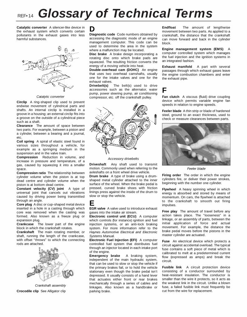
REF•14 Glossary of Technical TermsCatalytic converter A silencer-like device inthe exhaust system which converts certainpollutants in the exhaust gases into lessharmful substances.
Circlip A ring-shaped clip used to preventendwise movement of cylindrical parts andshafts. An internal circlip is installed in agroove in a housing; an external circlip fits intoa groove on the outside of a cylindrical piecesuch as a shaft.Clearance The amount of space betweentwo parts. For example, between a piston anda cylinder, between a bearing and a journal,etc.Coil spring A spiral of elastic steel found invarious sizes throughout a vehicle, forexample as a springing medium in thesuspension and in the valve train.Compression Reduction in volume, andincrease in pressure and temperature, of agas, caused by squeezing it into a smallerspace.Compression ratio The relationship betweencylinder volume when the piston is at topdead centre and cylinder volume when thepiston is at bottom dead centre.Constant velocity (CV) joint A type ofuniversal joint that cancels out vibrationscaused by driving power being transmittedthrough an angle.Core plug A disc or cup-shaped metal deviceinserted in a hole in a casting through whichcore was removed when the casting wasformed. Also known as a freeze plug orexpansion plug. Crankcase The lower part of the engineblock in which the crankshaft rotates.Crankshaft The main rotating member, orshaft, running the length of the crankcase,with offset “throws” to which the connectingrods are attached.
Crocodile clip See Alligator clip
DDiagnostic code Code numbers obtained byaccessing the diagnostic mode of an enginemanagement computer. This code can beused to determine the area in the systemwhere a malfunction may be located.Disc brake A brake design incorporating arotating disc onto which brake pads aresqueezed. The resulting friction converts theenergy of a moving vehicle into heat.Double-overhead cam (DOHC) An enginethat uses two overhead camshafts, usuallyone for the intake valves and one for theexhaust valves.Drivebelt(s) The belt(s) used to driveaccessories such as the alternator, waterpump, power steering pump, air conditioningcompressor, etc. off the crankshaft pulley.
Driveshaft Any shaft used to transmitmotion. Commonly used when referring to theaxleshafts on a front wheel drive vehicle.Drum brake A type of brake using a drum-shaped metal cylinder attached to the innersurface of the wheel. When the brake pedal ispressed, curved brake shoes with frictionlinings press against the inside of the drum toslow or stop the vehicle.
EEGR valve A valve used to introduce exhaustgases into the intake air stream.Electronic control unit (ECU) A computerwhich controls (for instance) ignition and fuelinjection systems, or an anti-lock brakingsystem. For more information refer to theHaynes Automotive Electrical and ElectronicSystems Manual.Electronic Fuel Injection (EFI) A computercontrolled fuel system that distributes fuelthrough an injector located in each intake portof the engine.Emergency brake A braking system,independent of the main hydraulic system,that can be used to slow or stop the vehicle ifthe primary brakes fail, or to hold the vehiclestationary even though the brake pedal isn’tdepressed. It usually consists of a hand leverthat actuates either front or rear brakesmechanically through a series of cables andlinkages. Also known as a handbrake orparking brake.
Endfloat The amount of lengthwisemovement between two parts. As applied to acrankshaft, the distance that the crankshaftcan move forward and back in the cylinderblock.
Engine management system (EMS) Acomputer controlled system which managesthe fuel injection and the ignition systems inan integrated fashion.
Exhaust manifold A part with severalpassages through which exhaust gases leavethe engine combustion chambers and enterthe exhaust pipe.
FFan clutch A viscous (fluid) drive couplingdevice which permits variable engine fanspeeds in relation to engine speeds.
Feeler blade A thin strip or blade of hardenedsteel, ground to an exact thickness, used tocheck or measure clearances between parts.
Firing order The order in which the enginecylinders fire, or deliver their power strokes,beginning with the number one cylinder.
Flywheel A heavy spinning wheel in whichenergy is absorbed and stored by means ofmomentum. On cars, the flywheel is attachedto the crankshaft to smooth out firingimpulses.
Free play The amount of travel before anyaction takes place. The “looseness” in alinkage, or an assembly of parts, between theinitial application of force and actualmovement. For example, the distance thebrake pedal moves before the pistons in themaster cylinder are actuated.
Fuse An electrical device which protects acircuit against accidental overload. The typicalfuse contains a soft piece of metal which iscalibrated to melt at a predetermined currentflow (expressed as amps) and break thecircuit.
Fusible link A circuit protection deviceconsisting of a conductor surrounded byheat-resistant insulation. The conductor issmaller than the wire it protects, so it acts asthe weakest link in the circuit. Unlike a blownfuse, a failed fusible link must frequently becut from the wire for replacement.
Catalytic converter
Crankshaft assembly
Accessory drivebelts
Feeler blade
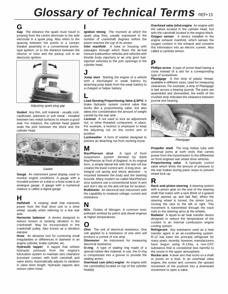
REF•15Glossary of Technical TermsGGap The distance the spark must travel injumping from the centre electrode to the sideelectrode in a spark plug. Also refers to thespacing between the points in a contactbreaker assembly in a conventional points-type ignition, or to the distance between thereluctor or rotor and the pickup coil in anelectronic ignition.
Gasket Any thin, soft material - usually cork,cardboard, asbestos or soft metal - installedbetween two metal surfaces to ensure a goodseal. For instance, the cylinder head gasketseals the joint between the block and thecylinder head.
Gauge An instrument panel display used tomonitor engine conditions. A gauge with amovable pointer on a dial or a fixed scale is ananalogue gauge. A gauge with a numericalreadout is called a digital gauge.
HHalfshaft A rotating shaft that transmitspower from the final drive unit to a drivewheel, usually when referring to a live rearaxle.Harmonic balancer A device designed toreduce torsion or twisting vibration in thecrankshaft. May be incorporated in thecrankshaft pulley. Also known as a vibrationdamper.Hone An abrasive tool for correcting smallirregularities or differences in diameter in anengine cylinder, brake cylinder, etc.Hydraulic tappet A tappet that utiliseshydraulic pressure from the engine’slubrication system to maintain zero clearance(constant contact with both camshaft andvalve stem). Automatically adjusts to variationin valve stem length. Hydraulic tappets alsoreduce valve noise.
IIgnition timing The moment at which thespark plug fires, usually expressed in thenumber of crankshaft degrees before thepiston reaches the top of its stroke.Inlet manifold A tube or housing withpassages through which flows the air-fuelmixture (carburettor vehicles and vehicles withthrottle body injection) or air only (port fuel-injected vehicles) to the port openings in thecylinder head.
JJump start Starting the engine of a vehiclewith a discharged or weak battery byattaching jump leads from the weak battery toa charged or helper battery.
LLoad Sensing Proportioning Valve (LSPV) Abrake hydraulic system control valve thatworks like a proportioning valve, but alsotakes into consideration the amount of weightcarried by the rear axle.Locknut A nut used to lock an adjustmentnut, or other threaded component, in place.For example, a locknut is employed to keepthe adjusting nut on the rocker arm inposition.Lockwasher A form of washer designed toprevent an attaching nut from working loose.
MMacPherson strut A type of frontsuspension system devised by EarleMacPherson at Ford of England. In its originalform, a simple lateral link with the anti-roll barcreates the lower control arm. A long strut - anintegral coil spring and shock absorber - ismounted between the body and the steeringknuckle. Many modern so-called MacPhersonstrut systems use a conventional lower A-armand don’t rely on the anti-roll bar for location.Multimeter An electrical test instrument withthe capability to measure voltage, current andresistance.
NNOx Oxides of Nitrogen. A common toxicpollutant emitted by petrol and diesel enginesat higher temperatures.
OOhm The unit of electrical resistance. Onevolt applied to a resistance of one ohm willproduce a current of one amp.Ohmmeter An instrument for measuringelectrical resistance.O-ring A type of sealing ring made of aspecial rubber-like material; in use, the O-ringis compressed into a groove to provide thesealing action.Overhead cam (ohc) engine An engine withthe camshaft(s) located on top of the cylinderhead(s).
Overhead valve (ohv) engine An engine withthe valves located in the cylinder head, butwith the camshaft located in the engine block.Oxygen sensor A device installed in theengine exhaust manifold, which senses theoxygen content in the exhaust and convertsthis information into an electric current. Alsocalled a Lambda sensor.
PPhillips screw A type of screw head having across instead of a slot for a correspondingtype of screwdriver.Plastigage A thin strip of plastic thread,available in different sizes, used for measuringclearances. For example, a strip of Plastigageis laid across a bearing journal. The parts areassembled and dismantled; the width of thecrushed strip indicates the clearance betweenjournal and bearing.
Propeller shaft The long hollow tube withuniversal joints at both ends that carriespower from the transmission to the differentialon front-engined rear wheel drive vehicles.Proportioning valve A hydraulic controlvalve which limits the amount of pressure tothe rear brakes during panic stops to preventwheel lock-up.
RRack-and-pinion steering A steering systemwith a pinion gear on the end of the steeringshaft that mates with a rack (think of a gearedwheel opened up and laid flat). When thesteering wheel is turned, the pinion turns,moving the rack to the left or right. Thismovement is transmitted through the trackrods to the steering arms at the wheels.Radiator A liquid-to-air heat transfer devicedesigned to reduce the temperature of thecoolant in an internal combustion enginecooling system. Refrigerant Any substance used as a heattransfer agent in an air-conditioning system.R-12 has been the principle refrigerant formany years; recently, however, manufacturershave begun using R-134a, a non-CFCsubstance that is considered less harmful tothe ozone in the upper atmosphere.Rocker arm A lever arm that rocks on a shaftor pivots on a stud. In an overhead valveengine, the rocker arm converts the upwardmovement of the pushrod into a downwardmovement to open a valve.
Adjusting spark plug gap
Plastigage
Gasket
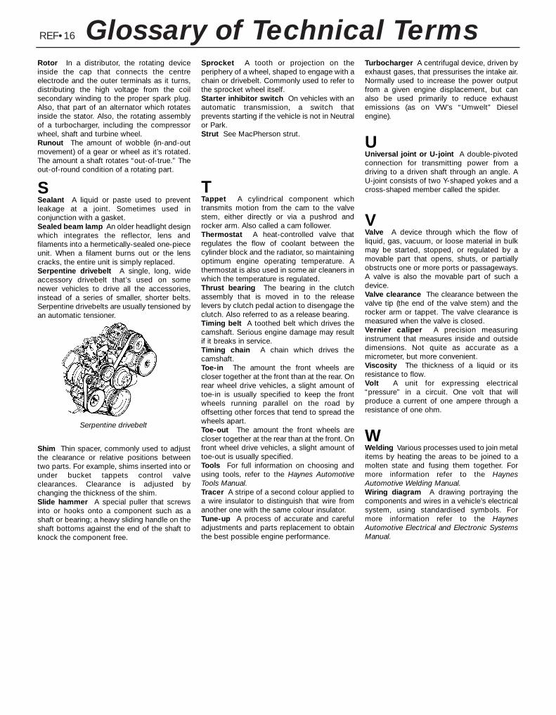
REF•16 Glossary of Technical TermsRotor In a distributor, the rotating deviceinside the cap that connects the centreelectrode and the outer terminals as it turns,distributing the high voltage from the coilsecondary winding to the proper spark plug.Also, that part of an alternator which rotatesinside the stator. Also, the rotating assemblyof a turbocharger, including the compressorwheel, shaft and turbine wheel.Runout The amount of wobble (in-and-outmovement) of a gear or wheel as it’s rotated.The amount a shaft rotates “out-of-true.” Theout-of-round condition of a rotating part.
SSealant A liquid or paste used to preventleakage at a joint. Sometimes used inconjunction with a gasket.Sealed beam lamp An older headlight designwhich integrates the reflector, lens andfilaments into a hermetically-sealed one-pieceunit. When a filament burns out or the lenscracks, the entire unit is simply replaced.Serpentine drivebelt A single, long, wideaccessory drivebelt that’s used on somenewer vehicles to drive all the accessories,instead of a series of smaller, shorter belts.Serpentine drivebelts are usually tensioned byan automatic tensioner.
Shim Thin spacer, commonly used to adjustthe clearance or relative positions betweentwo parts. For example, shims inserted into orunder bucket tappets control valveclearances. Clearance is adjusted bychanging the thickness of the shim.Slide hammer A special puller that screwsinto or hooks onto a component such as ashaft or bearing; a heavy sliding handle on theshaft bottoms against the end of the shaft toknock the component free.
Sprocket A tooth or projection on theperiphery of a wheel, shaped to engage with achain or drivebelt. Commonly used to refer tothe sprocket wheel itself.Starter inhibitor switch On vehicles with anautomatic transmission, a switch thatprevents starting if the vehicle is not in Neutralor Park.Strut See MacPherson strut.
TTappet A cylindrical component whichtransmits motion from the cam to the valvestem, either directly or via a pushrod androcker arm. Also called a cam follower.Thermostat A heat-controlled valve thatregulates the flow of coolant between thecylinder block and the radiator, so maintainingoptimum engine operating temperature. Athermostat is also used in some air cleaners inwhich the temperature is regulated.Thrust bearing The bearing in the clutchassembly that is moved in to the releaselevers by clutch pedal action to disengage theclutch. Also referred to as a release bearing.Timing belt A toothed belt which drives thecamshaft. Serious engine damage may resultif it breaks in service.Timing chain A chain which drives thecamshaft.Toe-in The amount the front wheels arecloser together at the front than at the rear. Onrear wheel drive vehicles, a slight amount oftoe-in is usually specified to keep the frontwheels running parallel on the road byoffsetting other forces that tend to spread thewheels apart.Toe-out The amount the front wheels arecloser together at the rear than at the front. Onfront wheel drive vehicles, a slight amount oftoe-out is usually specified.Tools For full information on choosing andusing tools, refer to the Haynes AutomotiveTools Manual.Tracer A stripe of a second colour applied toa wire insulator to distinguish that wire fromanother one with the same colour insulator.Tune-up A process of accurate and carefuladjustments and parts replacement to obtainthe best possible engine performance.
Turbocharger A centrifugal device, driven byexhaust gases, that pressurises the intake air.Normally used to increase the power outputfrom a given engine displacement, but canalso be used primarily to reduce exhaustemissions (as on VW’s “Umwelt” Dieselengine).
UUniversal joint or U-joint A double-pivotedconnection for transmitting power from adriving to a driven shaft through an angle. AU-joint consists of two Y-shaped yokes and across-shaped member called the spider.
VValve A device through which the flow ofliquid, gas, vacuum, or loose material in bulkmay be started, stopped, or regulated by amovable part that opens, shuts, or partiallyobstructs one or more ports or passageways.A valve is also the movable part of such adevice.Valve clearance The clearance between thevalve tip (the end of the valve stem) and therocker arm or tappet. The valve clearance ismeasured when the valve is closed.Vernier caliper A precision measuringinstrument that measures inside and outsidedimensions. Not quite as accurate as amicrometer, but more convenient.Viscosity The thickness of a liquid or itsresistance to flow.Volt A unit for expressing electrical“pressure” in a circuit. One volt that willproduce a current of one ampere through aresistance of one ohm.
WWelding Various processes used to join metalitems by heating the areas to be joined to amolten state and fusing them together. Formore information refer to the HaynesAutomotive Welding Manual.Wiring diagram A drawing portraying thecomponents and wires in a vehicle’s electricalsystem, using standardised symbols. Formore information refer to the HaynesAutomotive Electrical and Electronic SystemsManual.
Serpentine drivebelt
REF•17Index
AA pillar trim - 11•20ABS - 9•14Accelerator cable - 4•4Accelerator pedal - 4•5Accumulator - 3•9Acknowledgements - 0•4Adaptive damping switch - 12•8Aerial - 12•22Air bag - 0•5, 1•22, 12•22Air cleaner - 4•3, 6•19Air conditioning - 1•15, 3•2, 3•8, 3•9, 6•11Air distribution control - 3•8Air induction system - 4•9Air intake components - 4•3Air mass meter - 4•3, 6•10, 6•11, 6•12Air temperature warning sender unit -
12•18Alarm - 11•17, 12•18Alternator - 5•5, 5•6Amplifier - 12•21Anti-lock Braking System - 9•14Anti-roll bar - 10•8, 10•12, 10•15Anti-theft alarm system - 12•18Antifreeze - 1•2, 1•22, 3•2Asbestos - 0•5ATF - 1•2Automatic transmission - 1•11, 1•17,
2A•24, 2B•3, 2B•4, 6•11, 7B•1 et seq,12•11
Automatic transmission fault finding -REF•10
Automatic transmission fluid - 1•2Auxiliary drivebelt - 1•13Auxiliary warning system - 12•17
BB pillar trim - 11•20Backfire - REF•8Backrest - 11•18Battery - 0•5, 1•8, 1•11, 5•2, 5•3Battery fault - REF•12Big-end bearings - 2B•18, 2B•21Bleeding brakes - 9•12Bleeding power steering - 10•21Blower/air conditioning control - 3•8
Body corrosion - 0•10Body electrical system - 12•1 et seqBodywork and fittings - 11•1 et seqBonnet - 1•20, 11•5, 11•6Booster battery (jump) starting - 0•12Boot - 11•14, 11•15Brake check - 1•19Brake fluid - 1•2, 1•8, 1•26Brake line check - 1•19Braking system - 0•7, 0•8, 0•9, 1•20, 9•1 et
seqBraking system fault finding - REF•10Brush renewal - 5•8Bulb failure module - 12•18Bulbs - 12•8, 12•11, 12•18Bumpers - 11•4, 11•5Burning - 0•5
CC pillar trim - 11•20, 11•21Cables - 4•4, 7B•2, 8•2, 9•16, 11•6, 12•15Calipers - 9•4, 9•9Camshaft - 2A•13, 2A•14, 6•11, 6•12Cassette player - 12•21Catalytic converter - 6•19CD player - 12•22Central locking system - 11•17Central locking system fault - REF•12Centre console - 11•21Charcoal canister - 6•14Charging - 1•12, 5•5Check strap - 11•13Clock - 12•11, 12•15Clutch and driveshafts - 1•17, 1•20, 8•1 et
seqClutch fault finding - REF•9CO emissions (mixture) - 0•10Coil spring - 10•15Compact disc player - 12•22Compression test - 2A•5Compressor - 3•9Condenser - 3•9Connecting rods - 2B•12, 2B•17, 2B•21,
2B•22Console - 11•21, 11•22Contents - 0•2Conversion factors - 0•14
Coolant - 1•2, 1•6, 1•7, 1•21Coolant leakage - REF•9Coolant low level switch - 3•5Coolant temperature gauge sender - 3•4Coolant temperature sensor - 3•5, 6•11,
6•13Coolant warning switch - 12•18Cooling, heating, and air conditioning
systems - 1•22, 3•1 et seqCooling, heating, and air conditioning
systems fault finding - REF•8Corrosion - REF•9Courtesy light - 12•8Crankcase - 2B•13Crankshaft - 2A•9, 2A•13, 2A•22, 2B•13,
2B•18, 2B•20, 5•4, 6•10, 6•11, 6•12Crossmember - 10•13, 10•17Cruise control system - 12•19Crushing - 0•5Cushion - 11•18CV joints - 1•18, 8•7, 8•9Cylinder block - 2B•13Cylinder head - 2A•6, 2A•17, 2B•9, 2B•10,
2B•11, 6•19
DD pillar trim - 11•21Damping switch - 12•8Dehydrator - 3•9Dents in bodywork - 11•3Depressurisation - 4•2Diagnosis system - 6•4Differential - 7A•2, 7B•3Dimensions - 0•6Dipped beam switch - 12•7Direction indicators - 12•7, 12•9, 12•12Discs - 1•19, 9•5, 9•10Display warning bulb - 12•18Doors - 0•8, 1•20, 11•6, 11•7, 11•8, 11•9,
11•10, 11•11, 11•13, 12•7, 12•8, 12•11,12•18
Drivebelts - 1•13Driveplate - 2A•24Driveshafts - 0•9, 1•18, 8•5, 8•6, 8•7, 8•9,
8•10Driveshafts fault finding - REF•10Drivetrain - 1•20Drums - 1•19, 9•6
Note: References throughout this index relate to Chapter•page number
REF•18 IndexEEarth fault - 12•4Economy/Sport mode switch - 12•7ECU (Electronic Control Unit) - 6•10, 6•11,
6•12EGR exhaust gas pressure differential
sensor - 6•16EGR system - 6•15, 6•16Electric shock - 0•5Electric windows fault - REF•12Electrical system - 0•8, 1•11, 1•20Electrical system fault - REF•12Electrically-operated windows - 12•7Electrolyte - 1•8Electronic control system - 4•9, 6•2Emblems - 11•17Emission checks - 0•10Emissions control systems - 6•1Engine compartment light - 12•11Engine electrical systems - 5•1 et seqEngine fault finding - REF•7, REF•8, REF•10Engine management system - 4•8, 4•9Engine oil - 1•2, 1•6, 1•16Engine oil level sensor - 12•18Engine removal and general engine
overhaul procedures - 2B•1 et seqEnvironmental considerations - REF•4Evaporative emissions control (EVAP)
system - 6•14Evaporator - 3•9Exhaust gas pressure differential sensor -
6•11, 6•12, 6•13Exhaust Gas Recirculation (EGR) system -
6•15, 6•16Exhaust manifold - 2A•8Exhaust system - 0•9, 0•10, 1•18, 4•12,
REF•9Expansion tank - 3•5, 3•6
FFacia - 11•21, 11•23Fan(s) - 3•4, 12•11Fault code read-out - 6•6Fault finding - REF•6 et seqFault finding - automatic transmission -
7B•1Fault finding - electrical system - 12•4Filling - 11•3Fire - 0•5Fluid level checks - 1•6Flywheel - 2A•24Foglight - 12•7, 12•9, 12•13Foglight warning indicator - 12•11Fuel and exhaust systems - 0•10, 4•1 et
seqFuel and exhaust system fault finding -
REF•9Fuel consumption high - REF•9Fuel cut-off switch - 4•8Fuel filter - 1•26Fuel gauge - 4•6Fuel gauge fault - REF•12Fuel hoses - 1•15Fuel injection system - 4•8, 4•9Fuel injectors - 4•10Fuel lines - 1•19, 4•2Fuel odour - REF•9
Fuel pressure check - 4•5Fuel pressure regulator - 4•11Fuel pump - 4•5, 4•6Fuel rail - 4•10Fuel system - 4•2Fuel tank - 4•7, 4•8Fume or gas intoxication - 0•5Fumes from exhaust system - REF•9Fuses - 12•5
GGaiters - 1•18, 8•7, 8•9, 10•21Gashes in bodywork - 11•3Gaskets - REF•4Gear lever - 7A•2Gear selection problems - REF•9, REF•10Gearbox oil - 1•2Gearchange linkage - 7A•2Gearchange selector shaft - 7A•3Glossary of technical terms - REF•13Glovebox - 11•22Glovebox light - 12•11Grab handle - 11•20
HHandbrake - 0•7, 9•16, 12•7Handles - 11•10, 11•11, 11•12, 11•13,
12•11Hazard flashers - 12•7, 12•11HC emissions - 0•10Headlight - 1•8, 12•7, 12•8, 12•12, 12•13Heated rear window - 12•8Heated seat - 12•8Heated windscreen - 12•8Heater - 3•2, 3•7, 3•8, 12•11, 12•12Horn - 12•7, 12•15Horn fault - REF•12Hoses - 1•14, 3•2, 9•11HT leads - 1•24Hub and bearings - 10•5, 10•9, 10•14Hydraulic fluid - 1•2Hydraulic pipes and hoses - 9•11Hydraulic system - 9•12Hydraulic tappets - 2A•14Hydrofluoric acid - 0•5
IIdle speed - 4•9, 4•11, 6•10Idle-increase solenoid valve - 4•12Ignition coil - 5•3Ignition module - 5•4Ignition switch - 12•6Ignition system - 5•3Ignition timing - 5•4, 6•10In-car engine repair procedures - 2A•1 et
seqIndicators - 12•7, 12•9, 12•12Information sensors - 6•10Inlet manifold - 2A•7Instrument panel - 12•7, 12•11, 12•14Instruments - 1•20Instruments fault - REF•12Intake air temperature sensor - 6•11, 6•13Introduction to the Ford Mondeo - 0•4
JJacking - 0•11Joint mating faces - REF•4Jump starting - 0•12
KKnuckle - 10•5, 10•10, 10•14
LLeaks - 0•13, 1•14, REF•9Light units - 12•12Lights - 12•7, 12•11Lights inoperative - REF•12Locknuts, locktabs and washers - REF•4Locks - 11•6, 11•10, 11•12, 11•13, 11•15,
11•16, 11•17, 12•6, REF•12Low air temperature warning sender unit -
12•18Low coolant warning switch - 12•18Low washer fluid switch - 12•18Lower suspension arm - 10•8, 10•9, 10•13,
10•16Lubrication system - 2A•4Luggage compartment switch - 12•7
MMain bearings - 2B•18, 2B•20Maintenance - Also see Routine
maintenanceMaintenance - bodywork and underframe -
11•2Maintenance - upholstery and carpets -
11•3Manifolds - 2A•7, 2A•8Manual transmission - 1•17, 2A•24, 2B•3,
2B•4, 7A•1 et seqManual transmission fault finding - REF•9Manual transmission oil - 1•2Master cylinder - 9•10Mirrors - 0•7, 11•14, 12•7Misfire - REF•7, REF•8Mixture - 0•10, 4•9MOT test checks - 0•7 et seqMountings - 2A•24, 7A•7, 7B•5
NNumber plate light - 12•10, 12•13
OOil (transmission) - 1•2Oil (engine) - 1•2, 1•6, 1•16Oil cooler - 2A•22Oil level sensor - 2A•22, 12•18Oil pressure warning light illuminated -
REF•8
REF•19IndexOil pressure warning light switch - 2A•22Oil pump - 2A•21Oil seals - 2A•13, 2A•22, 7A•2, 7B•3, REF•4Oil separator - 6•19Open-circuit - 12•4Overcooling - REF•8Overhead console - 11•22Overheating - REF•8Oxygen sensor - 6•11, 6•12, 6•13
PPads - 9•3, 9•8Pedals - 1•17, 4•5, 8•3, 9•10, 9•11Piston rings - 2B•19Pistons - 2B•12, 2B•17, 2B•21, 2B•22Pitching and/or rolling around corners -
REF•11Plastic components - 11•4Plenum chamber - 4•3Poisonous or irritant substances - 0•5Pollen filter - 1•20, 3•8Position sensor - 5•4, 6•10, 6•11, 6•12Positive Crankcase Ventilation (PCV)
system - 1•23, 6•18, 6•19Power steering - 1•8, 1•10, 6•11, 6•12,
6•13, 10•20, 10•21, 10•22Power steering fluid - 1•2Pressure-control relief valve - 9•13Pressure-cycling and pressure-regulating
switches - 3•10Project vehicles - 0•4Pulse-air - 6•17, 6•18Purge solenoid valve - 6•14
RRadiator - 3•4, 3•5Radiator grille - 11•5Radio - 12•21, 12•22Radio aerial - 12•22Reading light - 12•11Rear light cluster - 12•9, 12•13Rear window - 12•8, 12•21Relays - 12•5Repair procedures - REF•4Resonator (engine compartment) - 4•3Respraying - 11•3Reversing light switch - 7A•3Road test - 1•20Roadwheels - 1•17, 1•18, 1•20Roll-over valves - 4•8Routine maintenance and servicing - 1•1 et
seqRubber gaiters- 1•18, 8•7, 8•9, 10•21Rust holes in bodywork - 11•3
SSafety first! - 0•5Scalding - 0•5Scratches in bodywork - 11•3Screw threads and fastenings - REF•4Seat belts - 0•8, 1•13, 11•19, 11•20
Seats - 0•8, 11•18, 12•8Selector assembly - 7B•2Selector cable - 7B•2Selector lever position sensor - 7B•2Selector panel illumination - 12•11Service indicator - 12•17, 12•18Servo unit - 9•12, 9•13Shock absorbers - 0•8, 0•9, 10•14Shoes - 9•6Short-circuit - 12•4Sidelight - 12•9Solenoid renewal - 5•8Spare parts - REF•5Spark plugs - 1•23Speakers - 12•22Speed control - 12•20Speed sensor - 6•11, 6•12, 6•13Speedometer - 7A•2, 7A•3, 7B•2, 7B•3,
12•15Springs - 0•9Starter motor - 5•7Starter motor fault - REF•7Starting system - 5•6Steering - 0•7, 0•8, 0•9, 1•17, 1•20Steering angles - 10•22Steering column - 10•18, 10•20Steering fault - REF•11Steering knuckle - 10•5Steering wheel - 10•17Stop-light switch - 9•15Striker - 11•13Struts - 10•6, 10•7, 10•10, 10•12Sump - 2A•19Sun visor - 11•20Sunroof - 11•18, 12•7Suspension and steering systems - 0•8,
0•9, 1•17, 1•18, 1•20, 10•1 et seqSuspension and steering systems fault
finding - REF•11Switches - 2A•22, 3•4, 3•5, 3•10, 4•8 -
6•11, 6•12, 6•13, 7A•3, 9•15, 11•17,12•6, 12•7, 12•8, 12•11, 12•18, 12•20
TTailgate - 1•8, 1•10, 11•15, 11•16, 12•17,
12•20, REF•12Tappets - 2A•14TCS inhibitor switch - 9•15TCS throttle actuator - 9•15Temperature gauge fault - REF•12Thermostat - 3•3, 3•4Throttle actuator - 9•15Throttle housing - 4•9Throttle potentiometer - 6•11, 6•13Tie-bar - 10•13, 10•16Timer module - 12•5Timing - 5•4, 6•10Timing belt - 1•26, 2A•10, 2A•13Tools - REF•1, REF•3, REF•4Top Dead Centre (TDC) for No 1 piston -
2A•6Towing - 0•11Track rod end - 10•22
Traction Control System - 9•15, 12•7Transmission - 1•11, 1•17, 2A•24, 2B•3,
2B•4, 7A•1 et seq, 7B•1 et seq, 12•11Trim mouldings - 11•17Trim panels - 11•6, 11•20Trip computer - 12•17Tyre wear - REF•11Tyres - 0•10, 1•8
UUnderbody check - 1•19Upper suspension arm - 10•16
VVacuum hoses - 1•15Vacuum servo unit - 9•12, 9•13Valve clearances - 2A•5Valves - 2B•10, 2B•11Vehicle identification - 0•8, REF•5Vehicle pulls to one side - REF•10, REF•11Vehicle speed sensor - 6•11, 6•12, 6•13Ventilation system - 1•20, 3•7Voltage regulator - 5•6
WWarning lights - 12•11Warning system - 12•17Washer jets fault - REF•12Washer nozzle - 12•21Washer pump fault - REF•12Washer reservoir and pump - 12•20Washer system - 1•8, 1•10, 12•18, 12•20Water pump - 3•6Weights - 0•6Wheel alignment - 10•22Wheel arch liner - 11•24Wheel bearings - 0•9Wheel changing - 0•11Wheel cylinders - 9•8Wheel sensors - 9•14Wheel wobble - REF•11Wheels - 0•10, 1•17, 1•18, 1•20Wheels locking - REF•11Window glass - 11•8Window regulator - 11•9Windows - 11•17, 12•7, 12•8, 12•21,
REF•12Windscreen - 0•7, 1•8, 1•10, 11•17, 12•6,
12•8, 12•16, 12•20, 12•21, REF•12Wiper arms - 12•16Wiper blade - 1•10Wiper blade fault - REF•12Wiper motor - 12•16, 12•17Wipers - 12•6Wiper fault - REF•12Wiring - 1•15Wiring diagrams - 12•23 et seqWorking facilities - REF•3
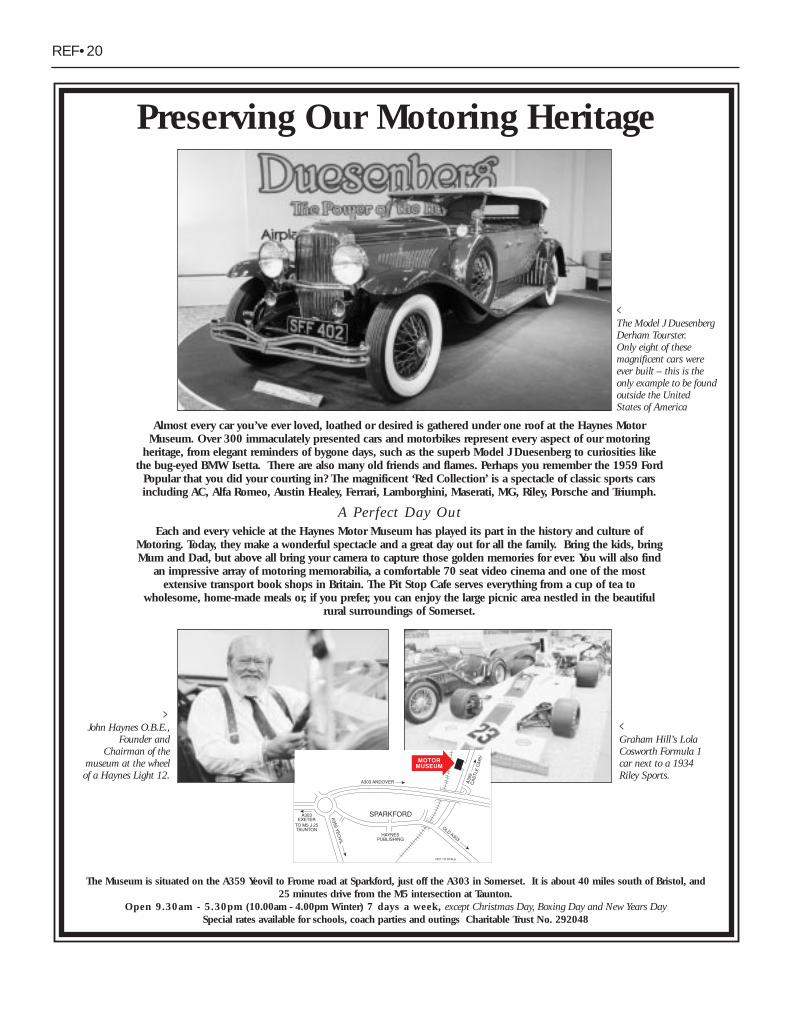
REF•20
Almost every car you’ve ever loved, loathed or desired is gathered under one roof at the Haynes MotorMuseum. Over 300 immaculately presented cars and motorbikes represent every aspect of our motoring
heritage, from elegant reminders of bygone days, such as the superb Model J Duesenberg to curiosities likethe bug-eyed BMW Isetta. There are also many old friends and flames. Perhaps you remember the 1959 Ford
Popular that you did your courting in? The magnificent ‘Red Collection’ is a spectacle of classic sports carsincluding AC, Alfa Romeo, Austin Healey, Ferrari, Lamborghini, Maserati, MG, Riley, Porsche and Triumph.
A Perfect Day OutEach and every vehicle at the Haynes Motor Museum has played its part in the history and culture of
Motoring. Today, they make a wonderful spectacle and a great day out for all the family. Bring the kids, bringMum and Dad, but above all bring your camera to capture those golden memories for ever. You will also find
an impressive array of motoring memorabilia, a comfortable 70 seat video cinema and one of the mostextensive transport book shops in Britain. The Pit Stop Cafe serves everything from a cup of tea to
wholesome, home-made meals or, if you prefer, you can enjoy the large picnic area nestled in the beautifulrural surroundings of Somerset.
The Museum is situated on the A359 Yeovil to Frome road at Sparkford, just off the A303 in Somerset. It is about 40 miles south of Bristol, and 25 minutes drive from the M5 intersection at Taunton.
Open 9.30am - 5.30pm (10.00am - 4.00pm Winter) 7 days a week, except Christmas Day, Boxing Day and New Years DaySpecial rates available for schools, coach parties and outings Charitable Trust No. 292048
>John Haynes O.B.E.,
Founder andChairman of the
museum at the wheelof a Haynes Light 12.
<Graham Hill’s LolaCosworth Formula 1car next to a 1934Riley Sports.
<The Model J DuesenbergDerham Tourster. Only eight of thesemagnificent cars wereever built – this is theonly example to be foundoutside the UnitedStates of America
Preserving Our Motoring Heritage
Related Documents


