3651 N Highway 89 • Chino Valley, AZ 86323 (928) 636-7080 • www.p-a-g.net FORD / MAZDA RANGER / B-SERIES P/U 3” BODY LIFT KIT INSTALLATION INSTRUCTIONS 2001-2011 KIT # 70033 MANUAL TRANSMISSION VEHICLES REQUIRE KIT # 3700 WARNING Installation of a Performance Accessories body lift will change the center of gravity and the handling charac- teristics of the vehicle. Because of the higher center of gravity and larger tires, the vehicle will handle and react differently both on and off road. You must drive it safely! Extreme care must be taken to prevent vehicle rollover or loss of control, which could result in serious injury or death. Avoid sudden sharp turns or abrupt maneuvers and always make sure all vehicle occu- pants have their seat belts fastened. WARNING Read and understand all instructions, warnings, cau- tions, and notes in this sheet and in your owners man- ual before you begin the installation of this body lift kit. CAUTION Proper installation of a Performance Accessories body lift kit requires knowledge of the factory recommended procedures for disassembly and assembly of original equipment components. We recommend that the fac- tory shop manual and any special tools necessary to your vehicle be on hand during the installation. Instal- lation of this body lift kit without proper knowledge of the factory recommended procedures may affect the performance of these components and the safety of your vehicle. We strongly recommend that a certified mechanic familiar with the installation of similar com- ponents install this body lift kit. WARNING This body lift kit should only be installed on vehicles in good working condition. Before installation, the vehi- cle should be thoroughly inspected for evidence of cor- rosion or deformation of the sheet metal around the factory body mounts. This body lift kit should not be installed on any vehicle that is suspected to have been in a collision or misused. Off road use of your vehicle with this body lift installed may increase the stress applied to the factory body mounts. We do not recom- mend that any vehicle with a body lift installed be involved in any extreme off road maneuvers such as jumping. Failure to observe this warning may result in serious personal injury and/or severe damage to your vehicle. WARNING Many states now have laws restricting bumper heights and vehicle lifts. Local laws should be consulted to determine if the changes you intend to make to your vehicle comply with state laws. WARNING The installation of larger wheel and tire combinations may reduce the effectiveness of the Anti-lock Braking System. WARNING Always wear eye protection when operating power tools. WARNING Ensure that your vehicle tires are properly blocked and secured before you begin installation of this lift kit. WARNING The Supplemental Restraint System (SRS, or air bag) must be deactivated during lift kit installation to avoid accidental air bag deployment while working near SRS sensors and wiring. Do not allow anyone near the air bag during lift kit installation. Accidental deployment can result in serious personal injury or death. Refer to your factory service manual/owner’s manual for the recommended procedure to disable the SRS. The SRS must be reactivated before driving the vehicle NOTE Performance Accessories recommends using the Loc- tite® supplied in the kit on all hardware unless noted in the instructions. WARNING DO NOT combine suspension, body, or other lift devices. Use of vehicle with combined lifts may result in unsafe and/or unexpected handling characteristics. 1 Ranger/B-Series - Kit 70033

Welcome message from author
This document is posted to help you gain knowledge. Please leave a comment to let me know what you think about it! Share it to your friends and learn new things together.
Transcript
3651 N Highway 89 • Chino Valley, AZ 86323(928) 636-7080 • www.p-a-g.net
FORD / MAZDARANGER / B-SERIES P/U3” BODY LIFT KITINSTALLATION INSTRUCTIONS2001-2011 KIT # 70033
MANUAL TRANSMISSION VEHICLES REQUIRE KIT # 3700
WARNINGInstallation of a Performance Accessories body lift willchange the center of gravity and the handling charac-teristics of the vehicle. Because of the higher center ofgravity and larger tires, the vehicle will handle andreact differently both on and off road. You must drive itsafely! Extreme care must be taken to prevent vehiclerollover or loss of control, which could result in seriousinjury or death. Avoid sudden sharp turns or abruptmaneuvers and always make sure all vehicle occu-pants have their seat belts fastened.
WARNINGRead and understand all instructions, warnings, cau-tions, and notes in this sheet and in your owners man-ual before you begin the installation of this body lift kit.
CAUTIONProper installation of a Performance Accessories bodylift kit requires knowledge of the factory recommendedprocedures for disassembly and assembly of originalequipment components. We recommend that the fac-tory shop manual and any special tools necessary toyour vehicle be on hand during the installation. Instal-lation of this body lift kit without proper knowledge ofthe factory recommended procedures may affect theperformance of these components and the safety ofyour vehicle. We strongly recommend that a certifiedmechanic familiar with the installation of similar com-ponents install this body lift kit.
WARNINGThis body lift kit should only be installed on vehicles ingood working condition. Before installation, the vehi-cle should be thoroughly inspected for evidence of cor-rosion or deformation of the sheet metal around thefactory body mounts. This body lift kit should not beinstalled on any vehicle that is suspected to have beenin a collision or misused. Off road use of your vehiclewith this body lift installed may increase the stressapplied to the factory body mounts. We do not recom-mend that any vehicle with a body lift installed beinvolved in any extreme off road maneuvers such asjumping. Failure to observe this warning may result inserious personal injury and/or severe damage to yourvehicle.
WARNINGMany states now have laws restricting bumper heightsand vehicle lifts. Local laws should be consulted todetermine if the changes you intend to make to yourvehicle comply with state laws.
WARNINGThe installation of larger wheel and tire combinationsmay reduce the effectiveness of the Anti-lock BrakingSystem.
WARNINGAlways wear eye protection when operating powertools.
WARNINGEnsure that your vehicle tires are properly blocked andsecured before you begin installation of this lift kit.
WARNINGThe Supplemental Restraint System (SRS, or air bag)must be deactivated during lift kit installation to avoidaccidental air bag deployment while working near SRSsensors and wiring. Do not allow anyone near the airbag during lift kit installation. Accidental deploymentcan result in serious personal injury or death. Refer toyour factory service manual/owner’s manual for therecommended procedure to disable the SRS. TheSRS must be reactivated before driving the vehicle
NOTEPerformance Accessories recommends using the Loc-tite® supplied in the kit on all hardware unless noted inthe instructions.
WARNING
DO NOT combine suspension, body, or other liftdevices. Use of vehicle with combined lifts may resultin unsafe and/or unexpected handling characteristics.
1 Ranger/B-Series - Kit 70033
2 Ranger/B-Series - Kit 70033
A. Before you start.
1. Read all warnings and instructions completely andcarefully before you begin.
2. Check to make sure the kit is complete (refer to theParts List, section E).
3. Only install this kit on the vehicle for which it isintended. If anytime during the installation youencounter something different from what is outlinedin the instructions, call technical support at (928)636-7080.
4. Park the vehicle on a clean, dry, flat, level surfaceand block the tires so the vehicle cannot roll in eitherdirection.
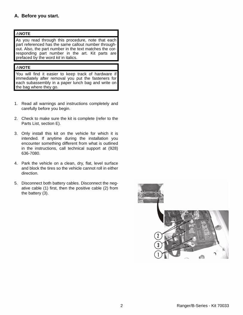
5. Disconnect both battery cables. Disconnect the neg-ative cable (1) first, then the positive cable (2) fromthe battery (3).
NOTEAs you read through this procedure, note that eachpart referenced has the same callout number through-out. Also, the part number in the text matches the cor-responding part number in the art. Kit parts areprefaced by the word kit in italics.
NOTEYou will find it easier to keep track of hardware ifimmediately after removal you put the fasteners foreach subassembly in a paper lunch bag and write onthe bag where they go.
3 Ranger/B-Series - Kit 70033
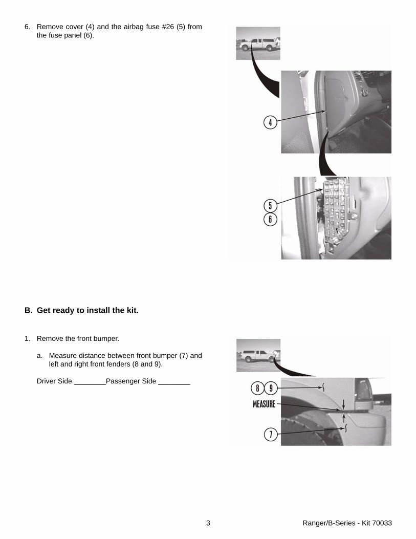
6. Remove cover (4) and the airbag fuse #26 (5) fromthe fuse panel (6).
B. Get ready to install the kit.
1. Remove the front bumper.
a. Measure distance between front bumper (7) andleft and right front fenders (8 and 9).
Driver Side ________Passenger Side ________

4 Ranger/B-Series - Kit 70033
b. If so equipped, remove two connectors (10) fromfog lamps (11).
c. Remove push clip (12) and wire harness (13)from front bumper (7).
d. Remove four nuts (14) and front bumper (7) fromframe (15).
e. Remove six bolts (16) and two tow hooks (17)from frame (15).
5 Ranger/B-Series - Kit 70033
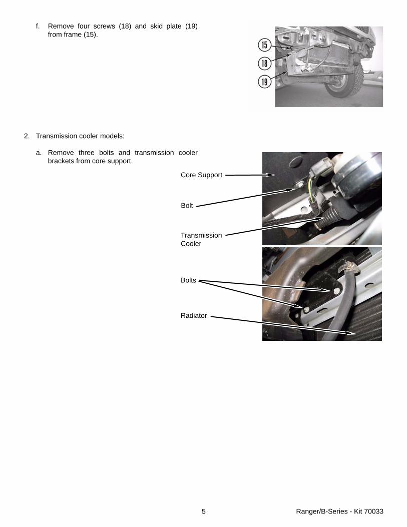
f. Remove four screws (18) and skid plate (19)from frame (15).
2. Transmission cooler models:
a. Remove three bolts and transmission coolerbrackets from core support.
Core Support
Bolt
TransmissionCooler
Bolts
Radiator
6 Ranger/B-Series - Kit 70033
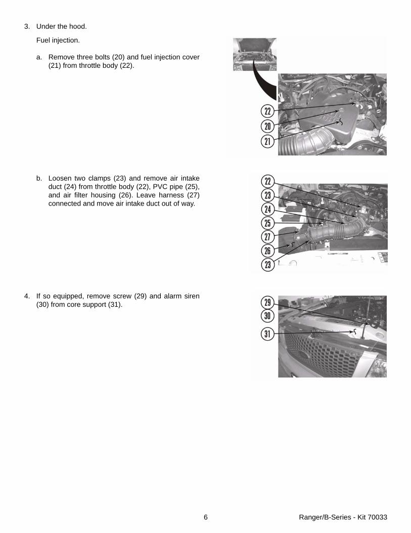
3. Under the hood.
Fuel injection.
a. Remove three bolts (20) and fuel injection cover(21) from throttle body (22).
b. Loosen two clamps (23) and remove air intakeduct (24) from throttle body (22), PVC pipe (25),and air filter housing (26). Leave harness (27)connected and move air intake duct out of way.
4. If so equipped, remove screw (29) and alarm siren(30) from core support (31).
7 Ranger/B-Series - Kit 70033
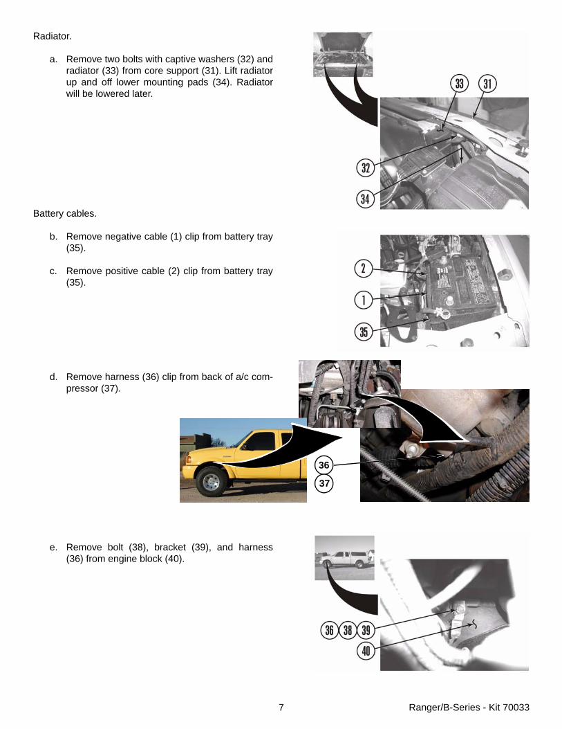
Radiator.
a. Remove two bolts with captive washers (32) andradiator (33) from core support (31). Lift radiatorup and off lower mounting pads (34). Radiatorwill be lowered later.
Battery cables.
b. Remove negative cable (1) clip from battery tray(35).
c. Remove positive cable (2) clip from battery tray(35).
d. Remove harness (36) clip from back of a/c com-pressor (37).
e. Remove bolt (38), bracket (39), and harness(36) from engine block (40).
36
37
8 Ranger/B-Series - Kit 70033
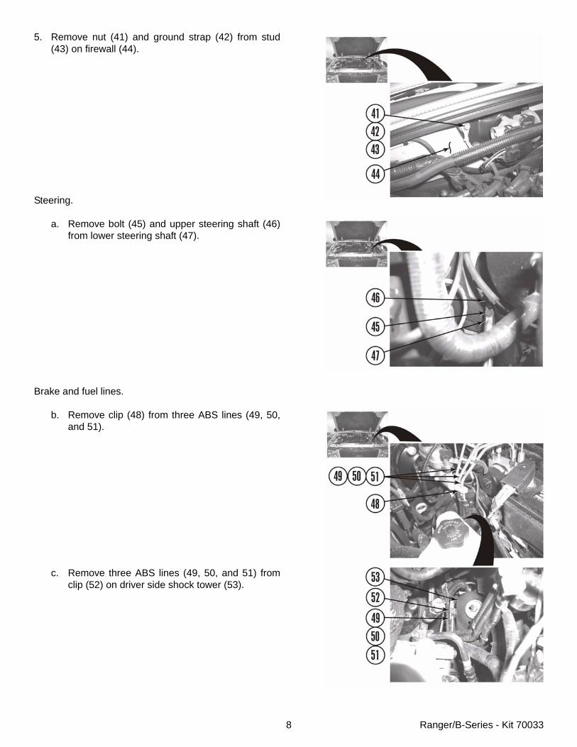
5. Remove nut (41) and ground strap (42) from stud(43) on firewall (44).
Steering.
a. Remove bolt (45) and upper steering shaft (46)from lower steering shaft (47).
Brake and fuel lines.
b. Remove clip (48) from three ABS lines (49, 50,and 51).
c. Remove three ABS lines (49, 50, and 51) fromclip (52) on driver side shock tower (53).
9 Ranger/B-Series - Kit 70033
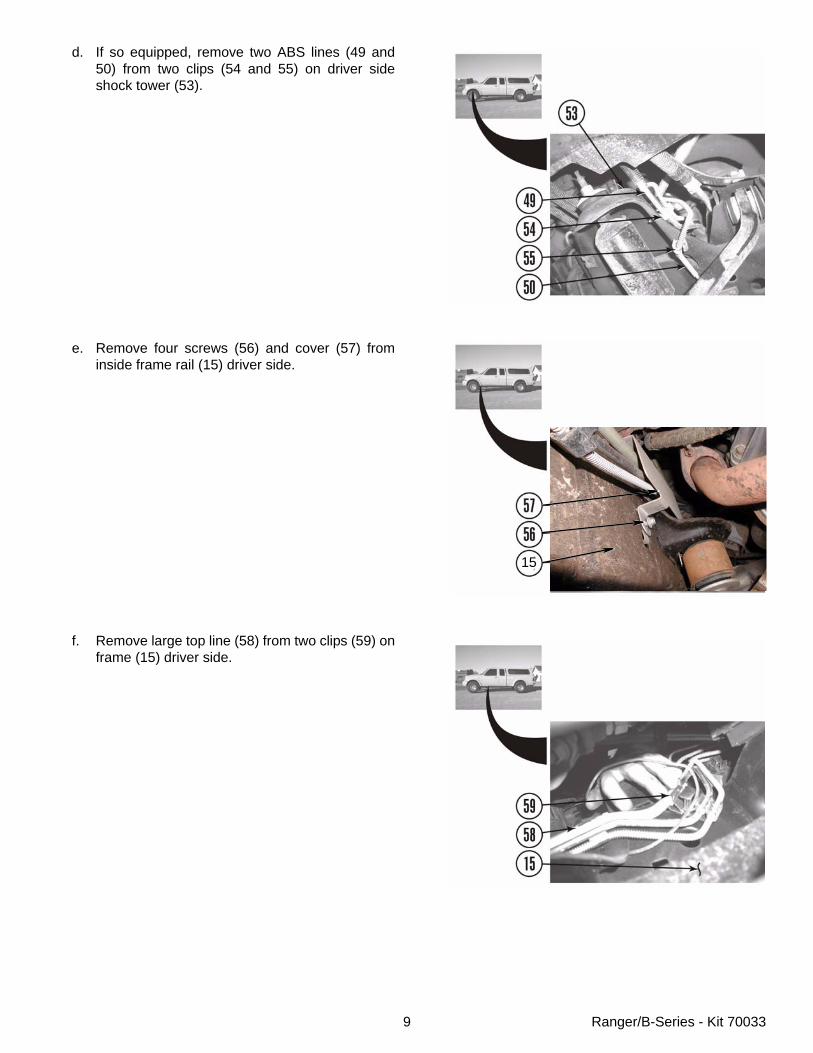
d. If so equipped, remove two ABS lines (49 and50) from two clips (54 and 55) on driver sideshock tower (53).
e. Remove four screws (56) and cover (57) frominside frame rail (15) driver side.
f. Remove large top line (58) from two clips (59) onframe (15) driver side.
15
10 Ranger/B-Series - Kit 70033
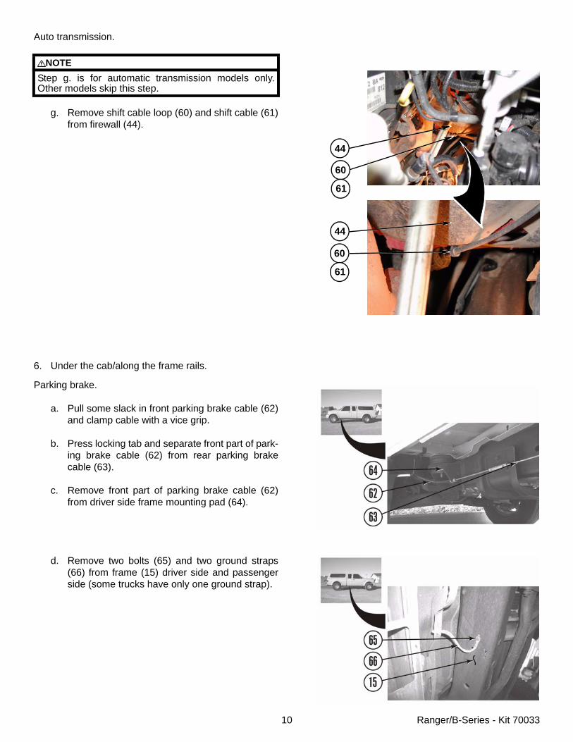
Auto transmission.
g. Remove shift cable loop (60) and shift cable (61)from firewall (44).
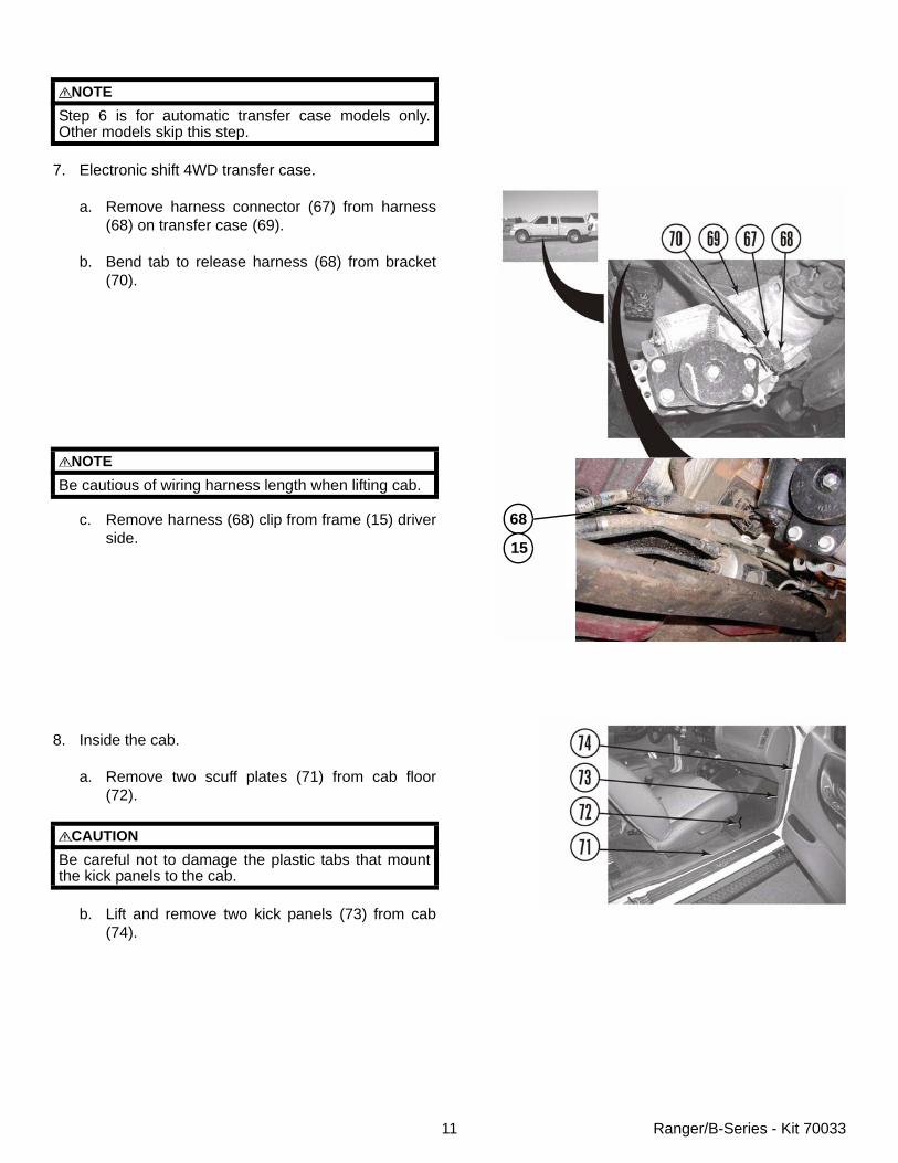
6. Under the cab/along the frame rails.
Parking brake.
a. Pull some slack in front parking brake cable (62)and clamp cable with a vice grip.
b. Press locking tab and separate front part of park-ing brake cable (62) from rear parking brakecable (63).
c. Remove front part of parking brake cable (62)from driver side frame mounting pad (64).
d. Remove two bolts (65) and two ground straps(66) from frame (15) driver side and passengerside (some trucks have only one ground strap).
NOTEStep g. is for automatic transmission models only.Other models skip this step.
44
60
61
44
60
61
11 Ranger/B-Series - Kit 70033
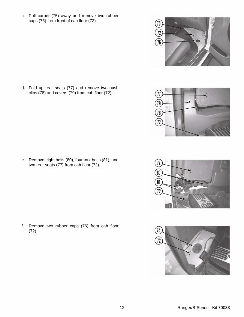
7. Electronic shift 4WD transfer case.
a. Remove harness connector (67) from harness(68) on transfer case (69).
b. Bend tab to release harness (68) from bracket(70).
c. Remove harness (68) clip from frame (15) driverside.
8. Inside the cab.
a. Remove two scuff plates (71) from cab floor(72).
b. Lift and remove two kick panels (73) from cab(74).
NOTEStep 6 is for automatic transfer case models only.Other models skip this step.
NOTEBe cautious of wiring harness length when lifting cab.
CAUTIONBe careful not to damage the plastic tabs that mountthe kick panels to the cab.
68
15
12 Ranger/B-Series - Kit 70033
c. Pull carpet (75) away and remove two rubbercaps (76) from front of cab floor (72).
d. Fold up rear seats (77) and remove two pushclips (78) and covers (79) from cab floor (72).
e. Remove eight bolts (80), four torx bolts (81), andtwo rear seats (77) from cab floor (72).
f. Remove two rubber caps (76) from cab floor(72).
13 Ranger/B-Series - Kit 70033
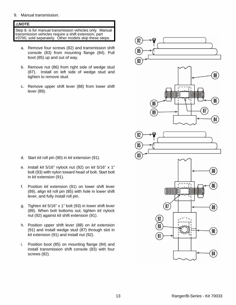
9. Manual transmission.
a. Remove four screws (82) and transmission shiftconsole (83) from mounting flange (84). Pullboot (85) up and out of way.
b. Remove nut (86) from right side of wedge stud(87). Install on left side of wedge stud andtighten to remove stud.
c. Remove upper shift lever (88) from lower shiftlever (89).
d. Start kit roll pin (90) in kit extension (91).
e. Install kit 5/16” nylock nut (92) on kit 5/16” x 1”bolt (93) with nylon toward head of bolt. Start boltin kit extension (91).
f. Position kit extension (91) on lower shift lever(89), align kit roll pin (85) with hole in lower shiftlever, and fully install roll pin.
g. Tighten kit 5/16” x 1” bolt (93) in lower shift lever(89). When bolt bottoms out, tighten kit nylocknut (92) against kit shift extension (91).
h. Position upper shift lever (88) on kit extension(91) and install wedge stud (87) through slot inkit extension (91) and install nut (92).
i. Position boot (85) on mounting flange (84) andinstall transmission shift console (83) with fourscrews (82).
NOTEStep 8. is for manual transmission vehicles only. Manual transmission vehicles require a shift extension, part #3700, sold separately. Other models skip these steps.
14 Ranger/B-Series - Kit 70033
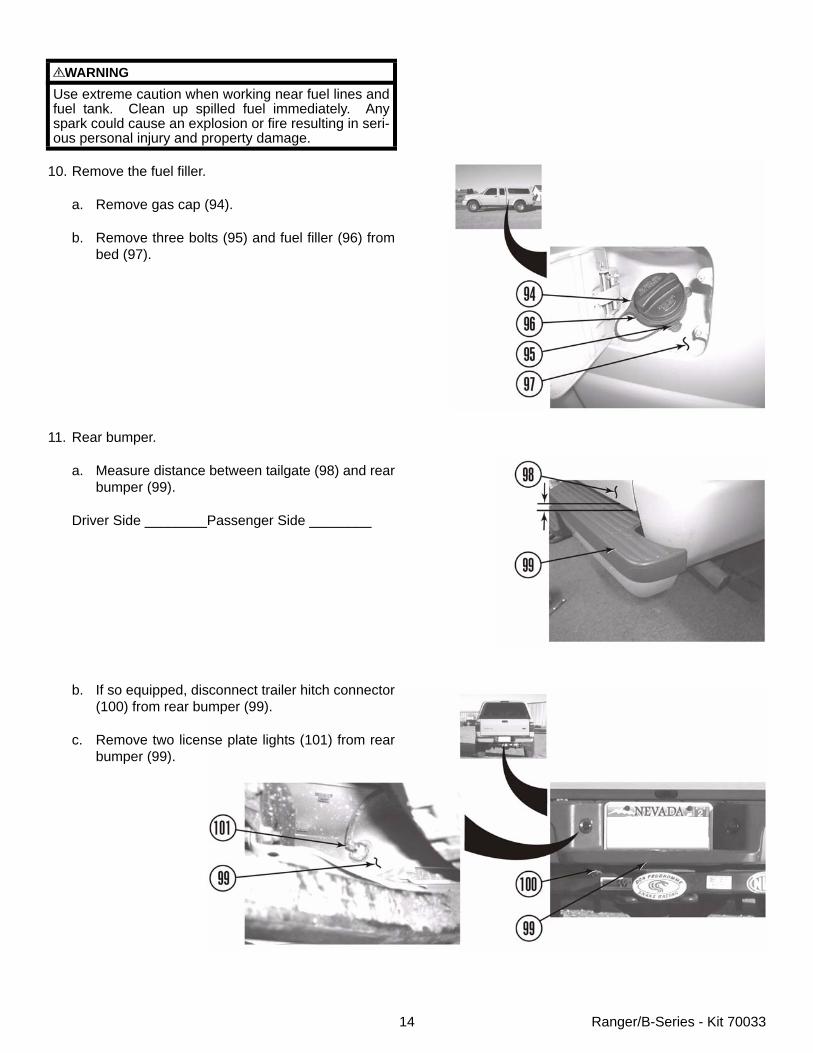
10. Remove the fuel filler.
a. Remove gas cap (94).
b. Remove three bolts (95) and fuel filler (96) frombed (97).
11. Rear bumper.
a. Measure distance between tailgate (98) and rearbumper (99).
Driver Side ________Passenger Side ________
b. If so equipped, disconnect trailer hitch connector(100) from rear bumper (99).
c. Remove two license plate lights (101) from rearbumper (99).
WARNINGUse extreme caution when working near fuel lines andfuel tank. Clean up spilled fuel immediately. Anyspark could cause an explosion or fire resulting in seri-ous personal injury and property damage.
15 Ranger/B-Series - Kit 70033
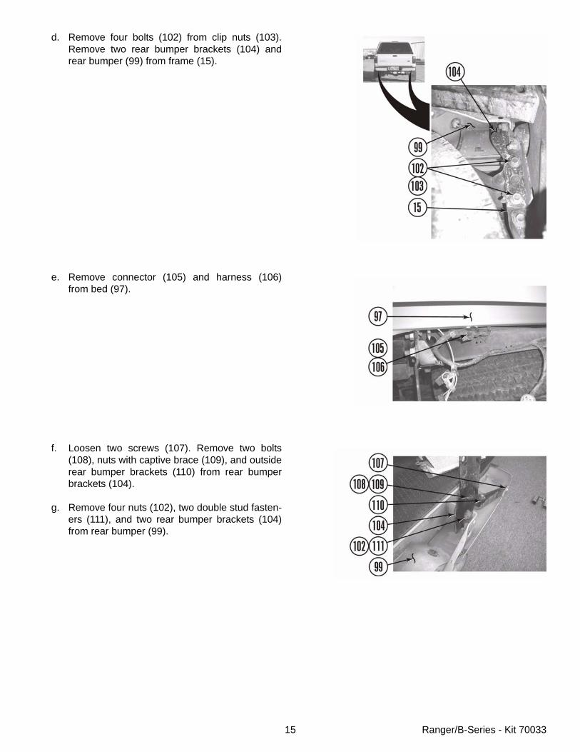
d. Remove four bolts (102) from clip nuts (103).Remove two rear bumper brackets (104) andrear bumper (99) from frame (15).
e. Remove connector (105) and harness (106)from bed (97).
f. Loosen two screws (107). Remove two bolts(108), nuts with captive brace (109), and outsiderear bumper brackets (110) from rear bumperbrackets (104).
g. Remove four nuts (102), two double stud fasten-ers (111), and two rear bumper brackets (104)from rear bumper (99).
16 Ranger/B-Series - Kit 70033
C. Install the kit.
Cab.
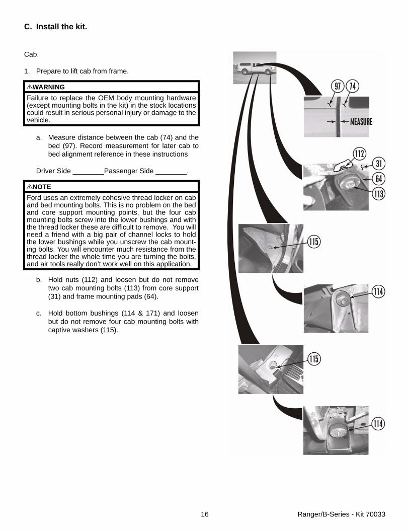
1. Prepare to lift cab from frame.
a. Measure distance between the cab (74) and thebed (97). Record measurement for later cab tobed alignment reference in these instructions
Driver Side ________Passenger Side ________.
b. Hold nuts (112) and loosen but do not removetwo cab mounting bolts (113) from core support(31) and frame mounting pads (64).
c. Hold bottom bushings (114 & 171) and loosenbut do not remove four cab mounting bolts withcaptive washers (115).
WARNINGFailure to replace the OEM body mounting hardware(except mounting bolts in the kit) in the stock locationscould result in serious personal injury or damage to thevehicle.
NOTEFord uses an extremely cohesive thread locker on caband bed mounting bolts. This is no problem on the bedand core support mounting points, but the four cabmounting bolts screw into the lower bushings and withthe thread locker these are difficult to remove. You willneed a friend with a big pair of channel locks to holdthe lower bushings while you unscrew the cab mount-ing bolts. You will encounter much resistance from thethread locker the whole time you are turning the bolts,and air tools really don’t work well on this application.
17 Ranger/B-Series - Kit 70033
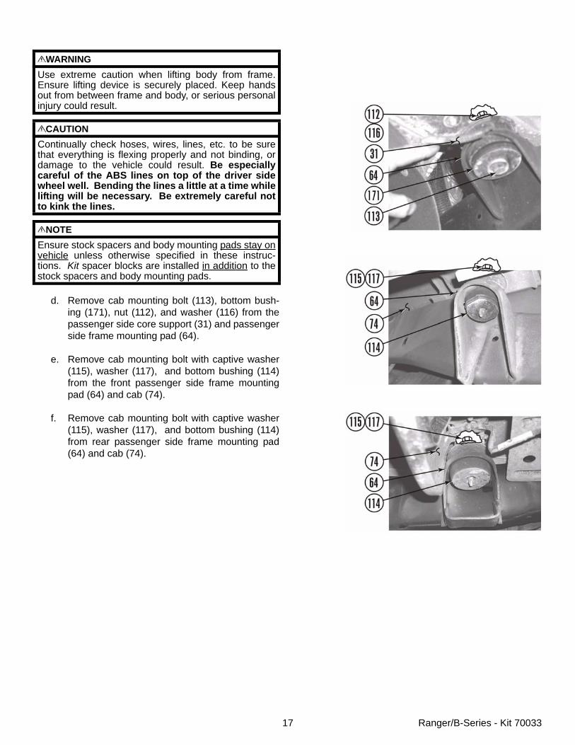
d. Remove cab mounting bolt (113), bottom bush-ing (171), nut (112), and washer (116) from thepassenger side core support (31) and passengerside frame mounting pad (64).
e. Remove cab mounting bolt with captive washer(115), washer (117), and bottom bushing (114)from the front passenger side frame mountingpad (64) and cab (74).
f. Remove cab mounting bolt with captive washer(115), washer (117), and bottom bushing (114)from rear passenger side frame mounting pad(64) and cab (74).
WARNINGUse extreme caution when lifting body from frame.Ensure lifting device is securely placed. Keep handsout from between frame and body, or serious personalinjury could result.
CAUTIONContinually check hoses, wires, lines, etc. to be surethat everything is flexing properly and not binding, ordamage to the vehicle could result. Be especiallycareful of the ABS lines on top of the driver sidewheel well. Bending the lines a little at a time whilelifting will be necessary. Be extremely careful notto kink the lines.
NOTEEnsure stock spacers and body mounting pads stay onvehicle unless otherwise specified in these instruc-tions. Kit spacer blocks are installed in addition to thestock spacers and body mounting pads.
18 Ranger/B-Series - Kit 70033
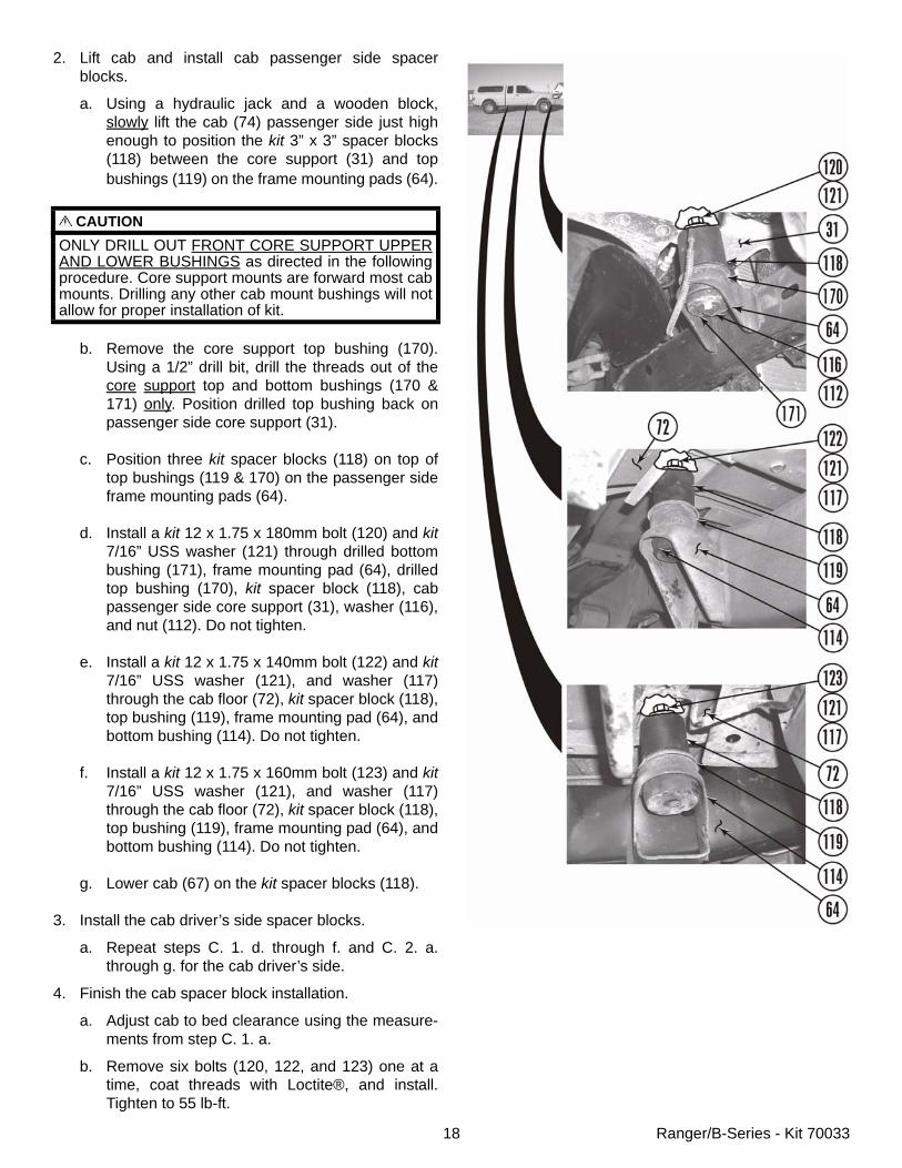
2. Lift cab and install cab passenger side spacerblocks.
a. Using a hydraulic jack and a wooden block,slowly lift the cab (74) passenger side just highenough to position the kit 3” x 3” spacer blocks(118) between the core support (31) and topbushings (119) on the frame mounting pads (64).
b. Remove the core support top bushing (170).Using a 1/2” drill bit, drill the threads out of thecore support top and bottom bushings (170 &171) only. Position drilled top bushing back onpassenger side core support (31).
c. Position three kit spacer blocks (118) on top oftop bushings (119 & 170) on the passenger sideframe mounting pads (64).
d. Install a kit 12 x 1.75 x 180mm bolt (120) and kit7/16” USS washer (121) through drilled bottombushing (171), frame mounting pad (64), drilledtop bushing (170), kit spacer block (118), cabpassenger side core support (31), washer (116),and nut (112). Do not tighten.
e. Install a kit 12 x 1.75 x 140mm bolt (122) and kit7/16” USS washer (121), and washer (117)through the cab floor (72), kit spacer block (118),top bushing (119), frame mounting pad (64), andbottom bushing (114). Do not tighten.
f. Install a kit 12 x 1.75 x 160mm bolt (123) and kit7/16” USS washer (121), and washer (117)through the cab floor (72), kit spacer block (118),top bushing (119), frame mounting pad (64), andbottom bushing (114). Do not tighten.
g. Lower cab (67) on the kit spacer blocks (118).
3. Install the cab driver’s side spacer blocks.
a. Repeat steps C. 1. d. through f. and C. 2. a.through g. for the cab driver’s side.
4. Finish the cab spacer block installation.
a. Adjust cab to bed clearance using the measure-ments from step C. 1. a.
b. Remove six bolts (120, 122, and 123) one at atime, coat threads with Loctite®, and install.Tighten to 55 lb-ft.
CAUTIONONLY DRILL OUT FRONT CORE SUPPORT UPPERAND LOWER BUSHINGS as directed in the followingprocedure. Core support mounts are forward most cabmounts. Drilling any other cab mount bushings will notallow for proper installation of kit.
19 Ranger/B-Series - Kit 70033
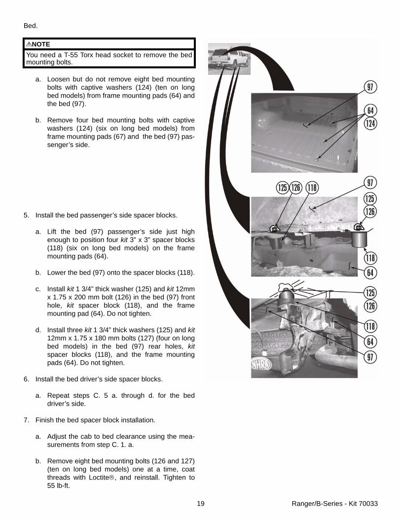
Bed.
a. Loosen but do not remove eight bed mountingbolts with captive washers (124) (ten on longbed models) from frame mounting pads (64) andthe bed (97).
b. Remove four bed mounting bolts with captivewashers (124) (six on long bed models) fromframe mounting pads (67) and the bed (97) pas-senger’s side.
5. Install the bed passenger’s side spacer blocks.
a. Lift the bed (97) passenger’s side just highenough to position four kit 3” x 3” spacer blocks(118) (six on long bed models) on the framemounting pads (64).
b. Lower the bed (97) onto the spacer blocks (118).
c. Install kit 1 3/4” thick washer (125) and kit 12mmx 1.75 x 200 mm bolt (126) in the bed (97) fronthole, kit spacer block (118), and the framemounting pad (64). Do not tighten.
d. Install three kit 1 3/4” thick washers (125) and kit12mm x 1.75 x 180 mm bolts (127) (four on longbed models) in the bed (97) rear holes, kitspacer blocks (118), and the frame mountingpads (64). Do not tighten.
6. Install the bed driver’s side spacer blocks.
a. Repeat steps C. 5 a. through d. for the beddriver’s side.
7. Finish the bed spacer block installation.
a. Adjust the cab to bed clearance using the mea-surements from step C. 1. a.
b. Remove eight bed mounting bolts (126 and 127)(ten on long bed models) one at a time, coatthreads with Loctite®, and reinstall. Tighten to55 lb-ft.
NOTEYou need a T-55 Torx head socket to remove the bedmounting bolts.
20 Ranger/B-Series - Kit 70033
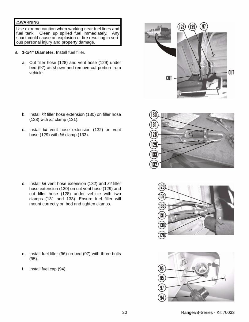
8. 1-1/4” Diameter: Install fuel filler.
a. Cut filler hose (128) and vent hose (129) underbed (97) as shown and remove cut portion fromvehicle.
b. Install kit filler hose extension (130) on filler hose(128) with kit clamp (131).
c. Install kit vent hose extension (132) on venthose (129) with kit clamp (133).
d. Install kit vent hose extension (132) and kit fillerhose extension (130) on cut vent hose (129) andcut filler hose (128) under vehicle with twoclamps (131 and 133). Ensure fuel filler willmount correctly on bed and tighten clamps.
e. Install fuel filler (96) on bed (97) with three bolts(95).
f. Install fuel cap (94).
WARNINGUse extreme caution when working near fuel lines andfuel tank. Clean up spilled fuel immediately. Anyspark could cause an explosion or fire resulting in seri-ous personal injury and property damage.
21 Ranger/B-Series - Kit 70033
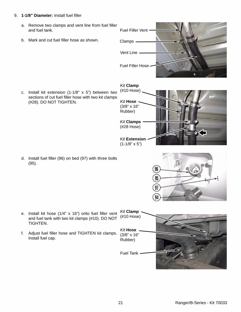
9. 1-1/8” Diameter: Install fuel filler
a. Remove two clamps and vent line from fuel fillerand fuel tank.
b. Mark and cut fuel filler hose as shown.
c. Install kit extension (1-1/8” x 5”) between twosections of cut fuel filler hose with two kit clamps(#28). DO NOT TIGHTEN.
d. Install fuel filler (96) on bed (97) with three bolts(95).
e. Install kit hose (1/4” x 16”) onto fuel filler ventand fuel tank with two kit clamps (#10). DO NOTTIGHTEN.
f. Adjust fuel filler hose and TIGHTEN kit clamps.Install fuel cap.
Fuel Filler Vent
Vent Line
Fuel Filler Hose
Kit Clamp(#10 Hose)
Kit Hose(3/8” x 16”Rubber)
Fuel Tank
Clamps
Kit Clamp(#10 Hose)
Kit Hose(3/8” x 16”Rubber)
Kit Clamps(#28 Hose)
Kit Extension(1-1/8” x 5”)
22 Ranger/B-Series - Kit 70033
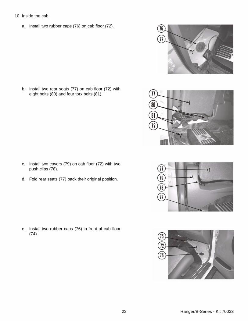
10. Inside the cab.
a. Install two rubber caps (76) on cab floor (72).
b. Install two rear seats (77) on cab floor (72) witheight bolts (80) and four torx bolts (81).
c. Install two covers (79) on cab floor (72) with twopush clips (78).
d. Fold rear seats (77) back their original position.
e. Install two rubber caps (76) in front of cab floor(74).
23 Ranger/B-Series - Kit 70033
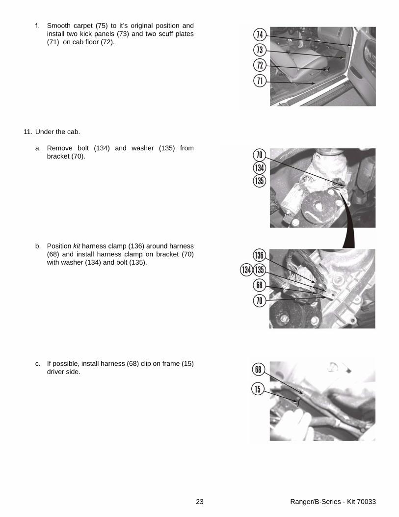
f. Smooth carpet (75) to it’s original position andinstall two kick panels (73) and two scuff plates(71) on cab floor (72).
11. Under the cab.
a. Remove bolt (134) and washer (135) frombracket (70).
b. Position kit harness clamp (136) around harness(68) and install harness clamp on bracket (70)with washer (134) and bolt (135).
c. If possible, install harness (68) clip on frame (15)driver side.
24 Ranger/B-Series - Kit 70033
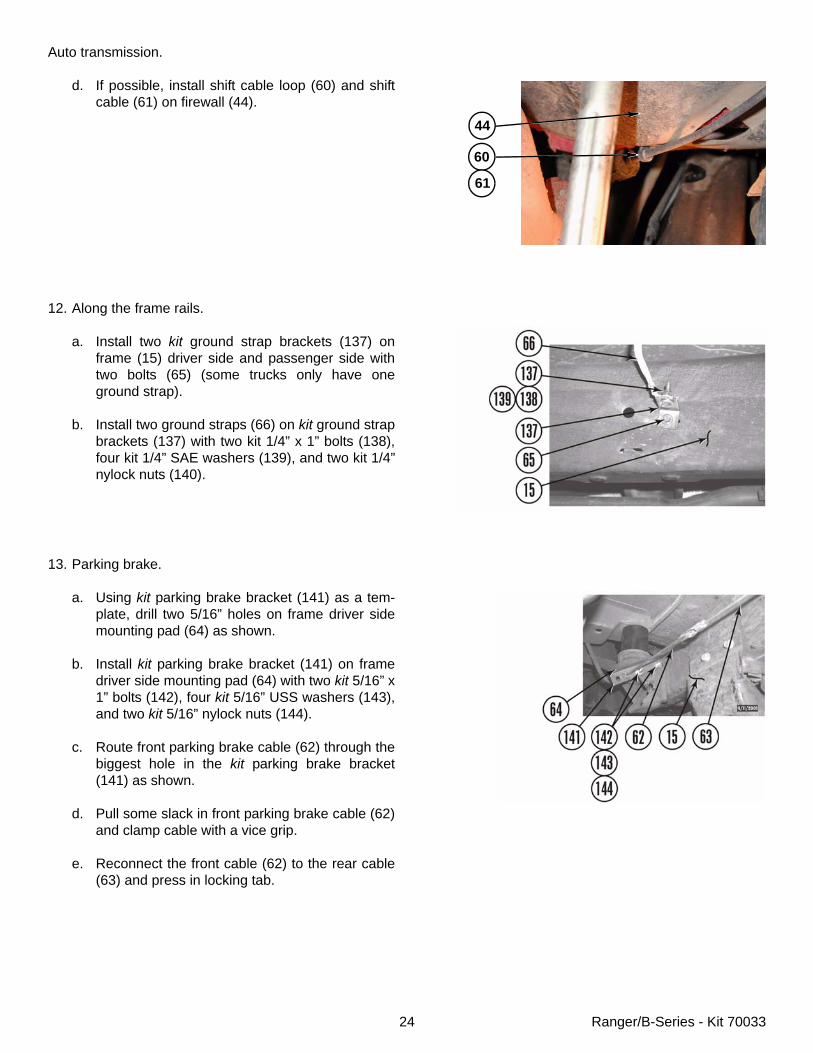
Auto transmission.
d. If possible, install shift cable loop (60) and shiftcable (61) on firewall (44).
12. Along the frame rails.
a. Install two kit ground strap brackets (137) onframe (15) driver side and passenger side withtwo bolts (65) (some trucks only have oneground strap).
b. Install two ground straps (66) on kit ground strapbrackets (137) with two kit 1/4” x 1” bolts (138),four kit 1/4” SAE washers (139), and two kit 1/4”nylock nuts (140).
13. Parking brake.
a. Using kit parking brake bracket (141) as a tem-plate, drill two 5/16” holes on frame driver sidemounting pad (64) as shown.
b. Install kit parking brake bracket (141) on framedriver side mounting pad (64) with two kit 5/16” x1” bolts (142), four kit 5/16” USS washers (143),and two kit 5/16” nylock nuts (144).
c. Route front parking brake cable (62) through thebiggest hole in the kit parking brake bracket(141) as shown.
d. Pull some slack in front parking brake cable (62)and clamp cable with a vice grip.
e. Reconnect the front cable (62) to the rear cable(63) and press in locking tab.
44
60
61
25 Ranger/B-Series - Kit 70033
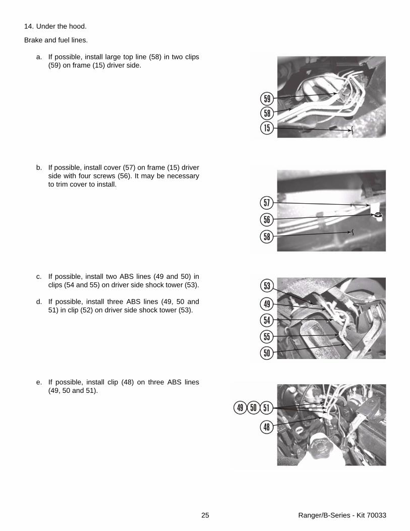
14. Under the hood.
Brake and fuel lines.
a. If possible, install large top line (58) in two clips(59) on frame (15) driver side.
b. If possible, install cover (57) on frame (15) driverside with four screws (56). It may be necessaryto trim cover to install.
c. If possible, install two ABS lines (49 and 50) inclips (54 and 55) on driver side shock tower (53).
d. If possible, install three ABS lines (49, 50 and51) in clip (52) on driver side shock tower (53).
e. If possible, install clip (48) on three ABS lines(49, 50 and 51).
26 Ranger/B-Series - Kit 70033
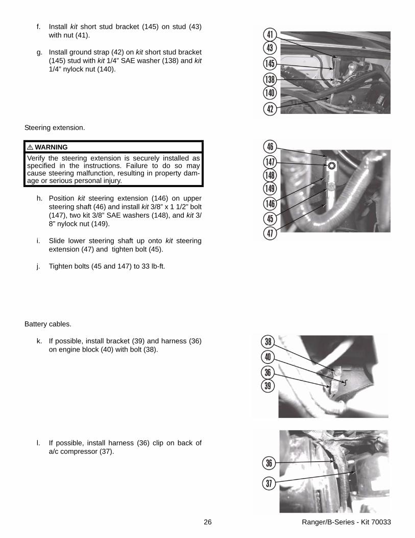
f. Install kit short stud bracket (145) on stud (43)with nut (41).
g. Install ground strap (42) on kit short stud bracket(145) stud with kit 1/4” SAE washer (138) and kit1/4” nylock nut (140).
Steering extension.
h. Position kit steering extension (146) on uppersteering shaft (46) and install kit 3/8” x 1 1/2” bolt(147), two kit 3/8” SAE washers (148), and kit 3/8” nylock nut (149).
i. Slide lower steering shaft up onto kit steeringextension (47) and tighten bolt (45).
j. Tighten bolts (45 and 147) to 33 lb-ft.
Battery cables.
k. If possible, install bracket (39) and harness (36)on engine block (40) with bolt (38).
l. If possible, install harness (36) clip on back ofa/c compressor (37).
WARNINGVerify the steering extension is securely installed asspecified in the instructions. Failure to do so maycause steering malfunction, resulting in property dam-age or serious personal injury.
27 Ranger/B-Series - Kit 70033
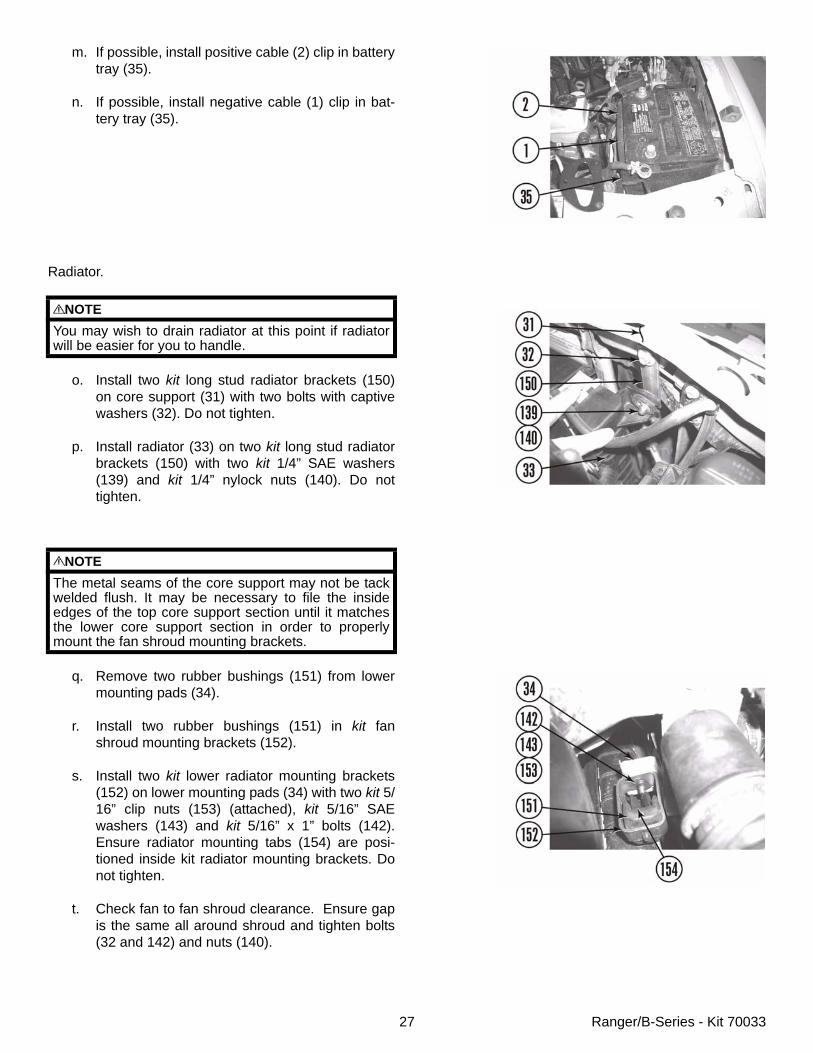
m. If possible, install positive cable (2) clip in batterytray (35).
n. If possible, install negative cable (1) clip in bat-tery tray (35).
Radiator.
o. Install two kit long stud radiator brackets (150)on core support (31) with two bolts with captivewashers (32). Do not tighten.
p. Install radiator (33) on two kit long stud radiatorbrackets (150) with two kit 1/4” SAE washers(139) and kit 1/4” nylock nuts (140). Do nottighten.
q. Remove two rubber bushings (151) from lowermounting pads (34).
r. Install two rubber bushings (151) in kit fanshroud mounting brackets (152).
s. Install two kit lower radiator mounting brackets(152) on lower mounting pads (34) with two kit 5/16” clip nuts (153) (attached), kit 5/16” SAEwashers (143) and kit 5/16” x 1” bolts (142).Ensure radiator mounting tabs (154) are posi-tioned inside kit radiator mounting brackets. Donot tighten.
t. Check fan to fan shroud clearance. Ensure gapis the same all around shroud and tighten bolts(32 and 142) and nuts (140).
NOTEYou may wish to drain radiator at this point if radiatorwill be easier for you to handle.
NOTEThe metal seams of the core support may not be tackwelded flush. It may be necessary to file the insideedges of the top core support section until it matchesthe lower core support section in order to properlymount the fan shroud mounting brackets.
28 Ranger/B-Series - Kit 70033
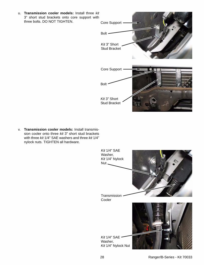
u. Transmission cooler models: Install three kit3” short stud brackets onto core support withthree bolts. DO NOT TIGHTEN.
v. Transmission cooler models: Install transmis-sion cooler onto three kit 3” short stud bracketswith three kit 1/4” SAE washers and three kit 1/4”nylock nuts. TIGHTEN all hardware.
Bolt
Kit 3” ShortStud Bracket
Bolt
Core Support
Kit 1/4” SAEWasher,Kit 1/4” NylockNut
TransmissionCooler
Kit 1/4” SAEWasher,Kit 1/4” Nylock Nut
Kit 3” ShortStud Bracket
Core Support
29 Ranger/B-Series - Kit 70033
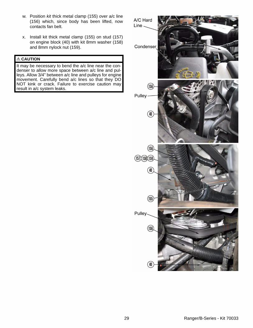
w. Position kit thick metal clamp (155) over a/c line(156) which, since body has been lifted, nowcontacts fan belt.
x. Install kit thick metal clamp (155) on stud (157)on engine block (40) with kit 8mm washer (158)and 8mm nylock nut (159).
CAUTIONIt may be necessary to bend the a/c line near the con-denser to allow more space between a/c line and pul-leys. Allow 3/4” between a/c line and pulleys for enginemovement. Carefully bend a/c lines so that they DONOT kink or crack. Failure to exercise caution mayresult in a/c system leaks.
30 Ranger/B-Series - Kit 70033
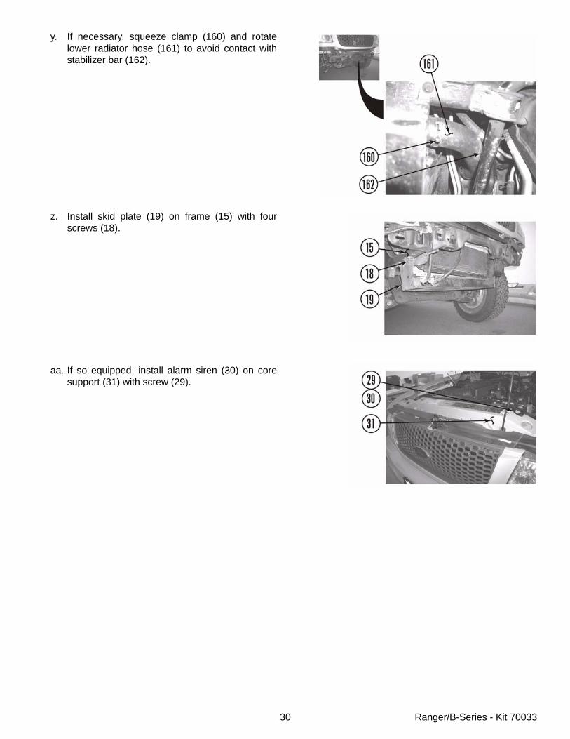
y. If necessary, squeeze clamp (160) and rotatelower radiator hose (161) to avoid contact withstabilizer bar (162).
z. Install skid plate (19) on frame (15) with fourscrews (18).
aa. If so equipped, install alarm siren (30) on coresupport (31) with screw (29).
31 Ranger/B-Series - Kit 70033
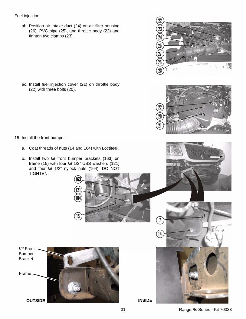
Fuel injection.
ab. Position air intake duct (24) on air filter housing(26), PVC pipe (25), and throttle body (22) andtighten two clamps (23).
ac. Install fuel injection cover (21) on throttle body(22) with three bolts (20).
15. Install the front bumper.
a. Coat threads of nuts (14 and 164) with Loctite®.
b. Install two kit front bumper brackets (163) onframe (15) with four kit 1/2” USS washers (121)and four kit 1/2” nylock nuts (164). DO NOTTIGHTEN.
Kit FrontBumperBracket
OUTSIDE INSIDE
Frame
32 Ranger/B-Series - Kit 70033
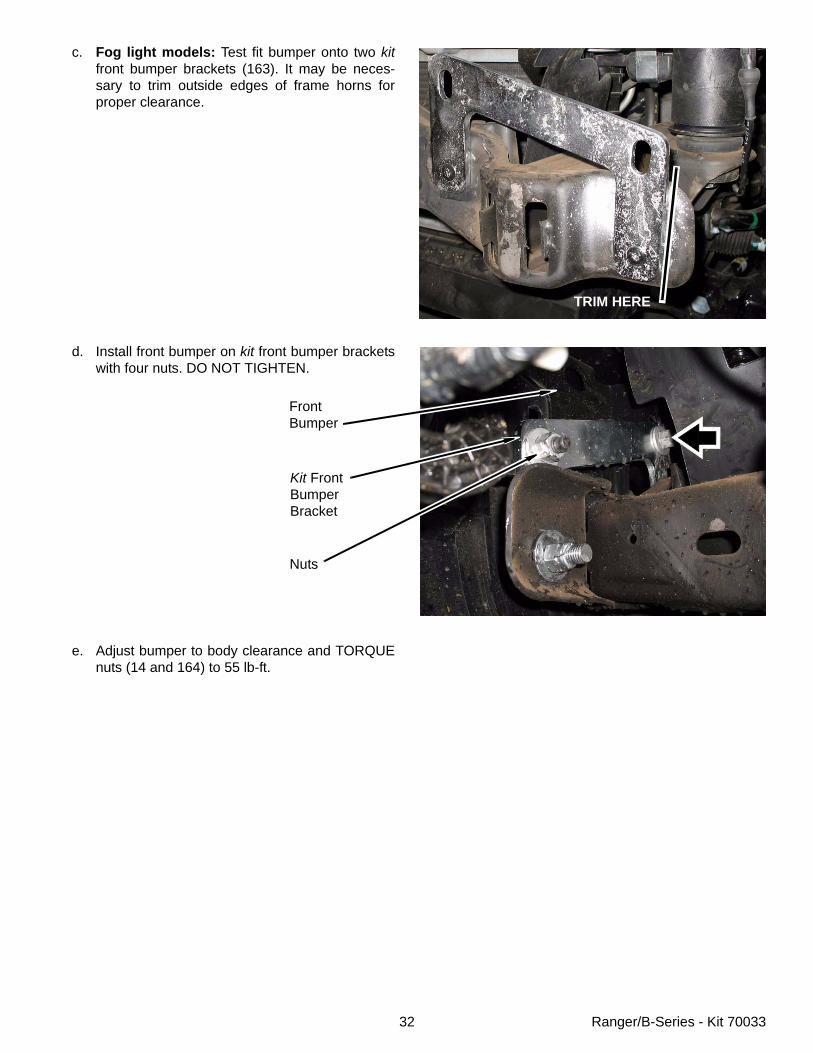
c. Fog light models: Test fit bumper onto two kitfront bumper brackets (163). It may be neces-sary to trim outside edges of frame horns forproper clearance.
d. Install front bumper on kit front bumper bracketswith four nuts. DO NOT TIGHTEN.
e. Adjust bumper to body clearance and TORQUEnuts (14 and 164) to 55 lb-ft.
TRIM HERE
Kit FrontBumperBracket
Nuts
FrontBumper
33 Ranger/B-Series - Kit 70033
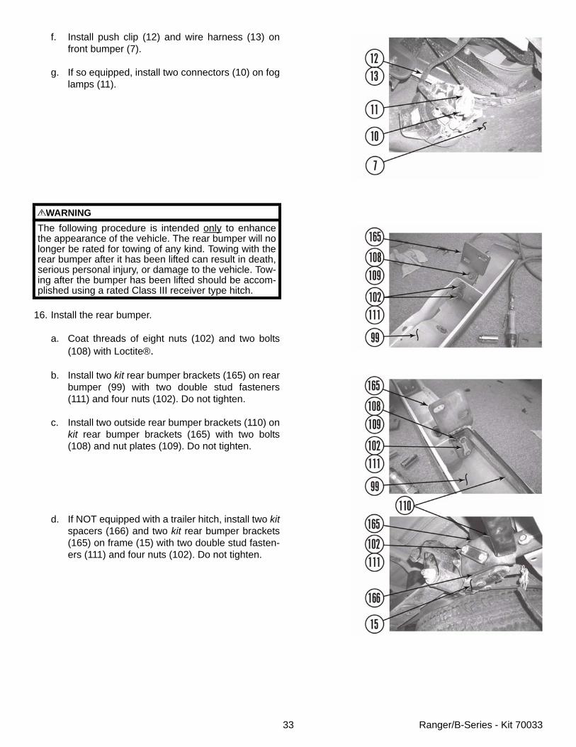
f. Install push clip (12) and wire harness (13) onfront bumper (7).
g. If so equipped, install two connectors (10) on foglamps (11).
16. Install the rear bumper.
a. Coat threads of eight nuts (102) and two bolts(108) with Loctite®.
b. Install two kit rear bumper brackets (165) on rearbumper (99) with two double stud fasteners(111) and four nuts (102). Do not tighten.
c. Install two outside rear bumper brackets (110) onkit rear bumper brackets (165) with two bolts(108) and nut plates (109). Do not tighten.
d. If NOT equipped with a trailer hitch, install two kitspacers (166) and two kit rear bumper brackets(165) on frame (15) with two double stud fasten-ers (111) and four nuts (102). Do not tighten.
WARNINGThe following procedure is intended only to enhancethe appearance of the vehicle. The rear bumper will nolonger be rated for towing of any kind. Towing with therear bumper after it has been lifted can result in death,serious personal injury, or damage to the vehicle. Tow-ing after the bumper has been lifted should be accom-plished using a rated Class III receiver type hitch.
34 Ranger/B-Series - Kit 70033
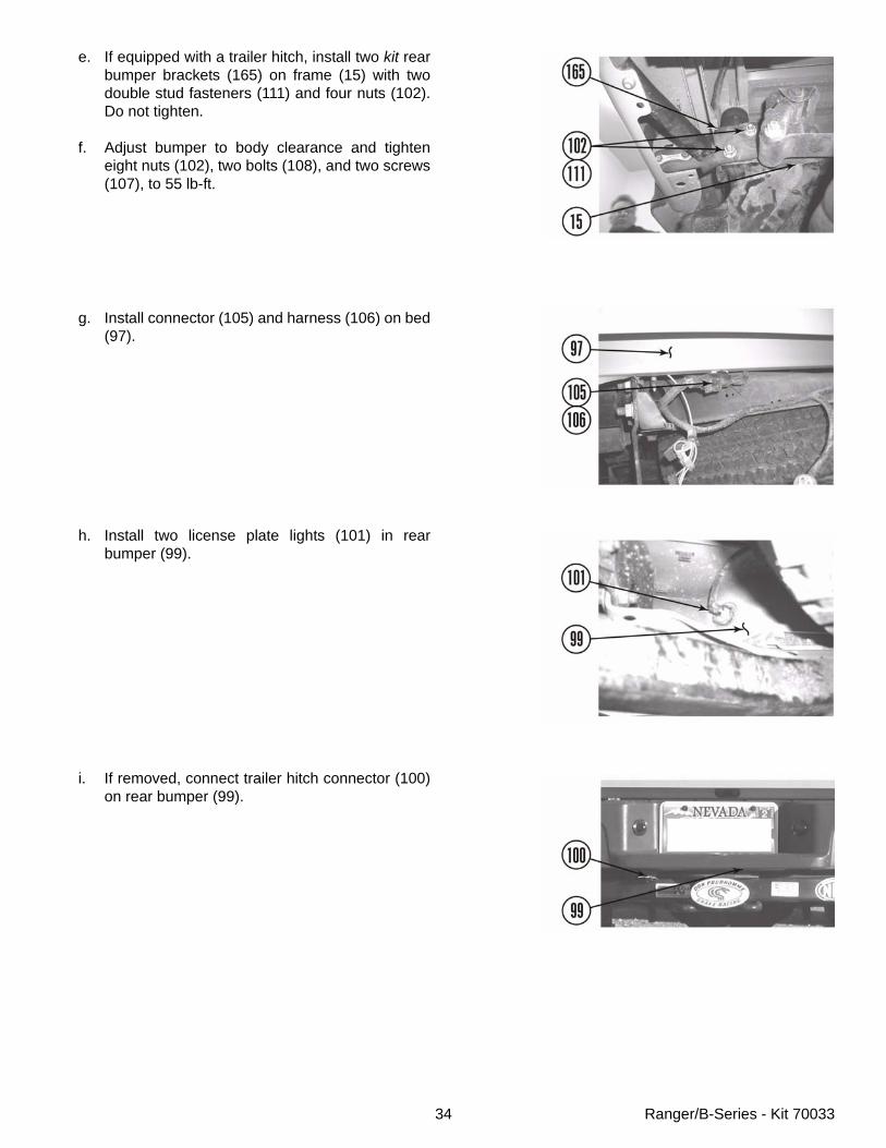
e. If equipped with a trailer hitch, install two kit rearbumper brackets (165) on frame (15) with twodouble stud fasteners (111) and four nuts (102).Do not tighten.
f. Adjust bumper to body clearance and tighteneight nuts (102), two bolts (108), and two screws(107), to 55 lb-ft.
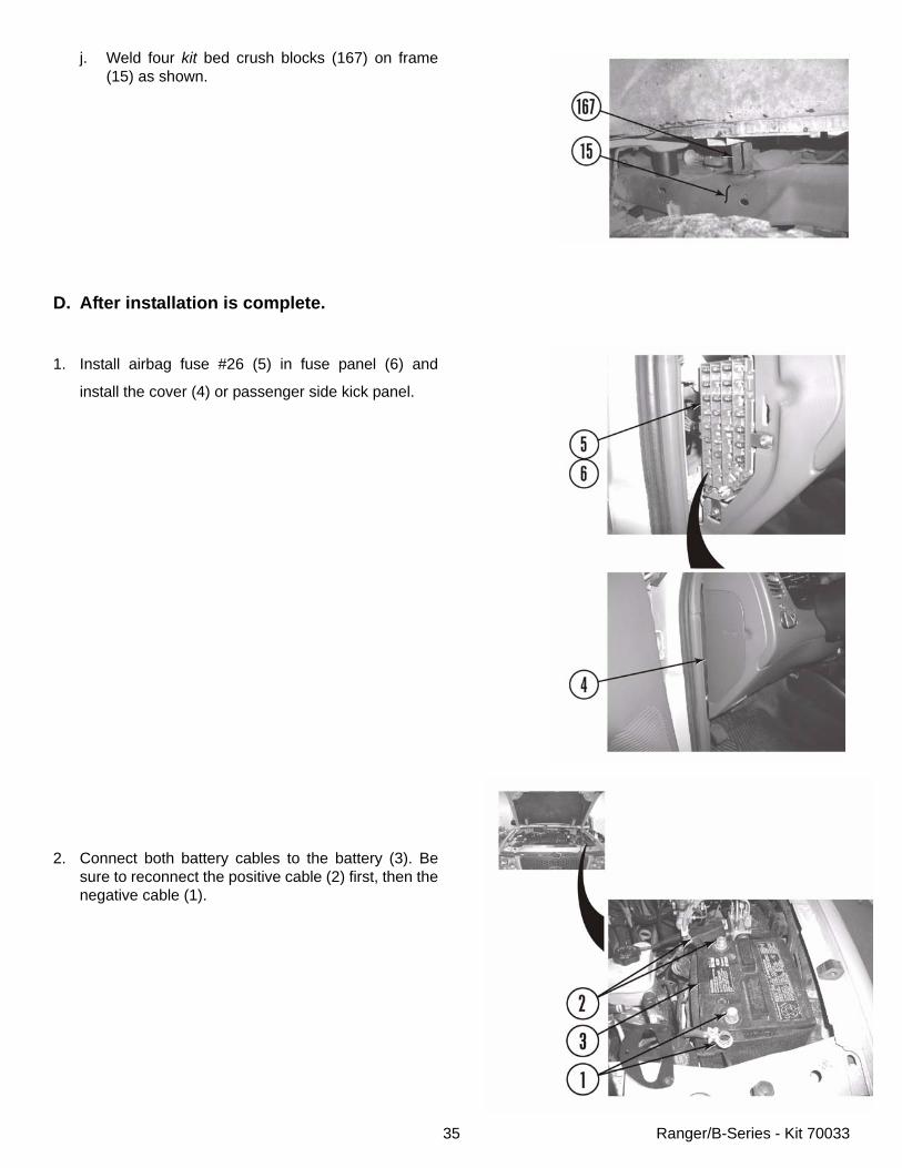
g. Install connector (105) and harness (106) on bed(97).
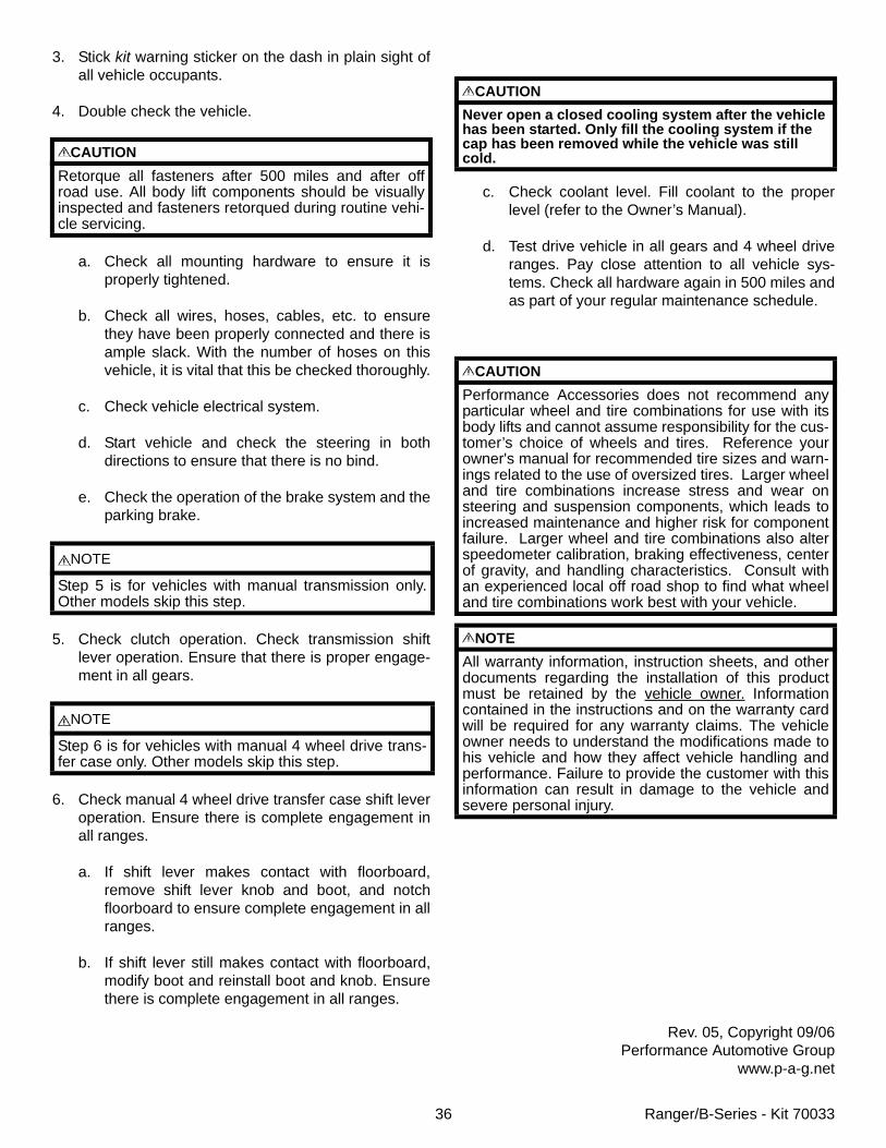
h. Install two license plate lights (101) in rearbumper (99).
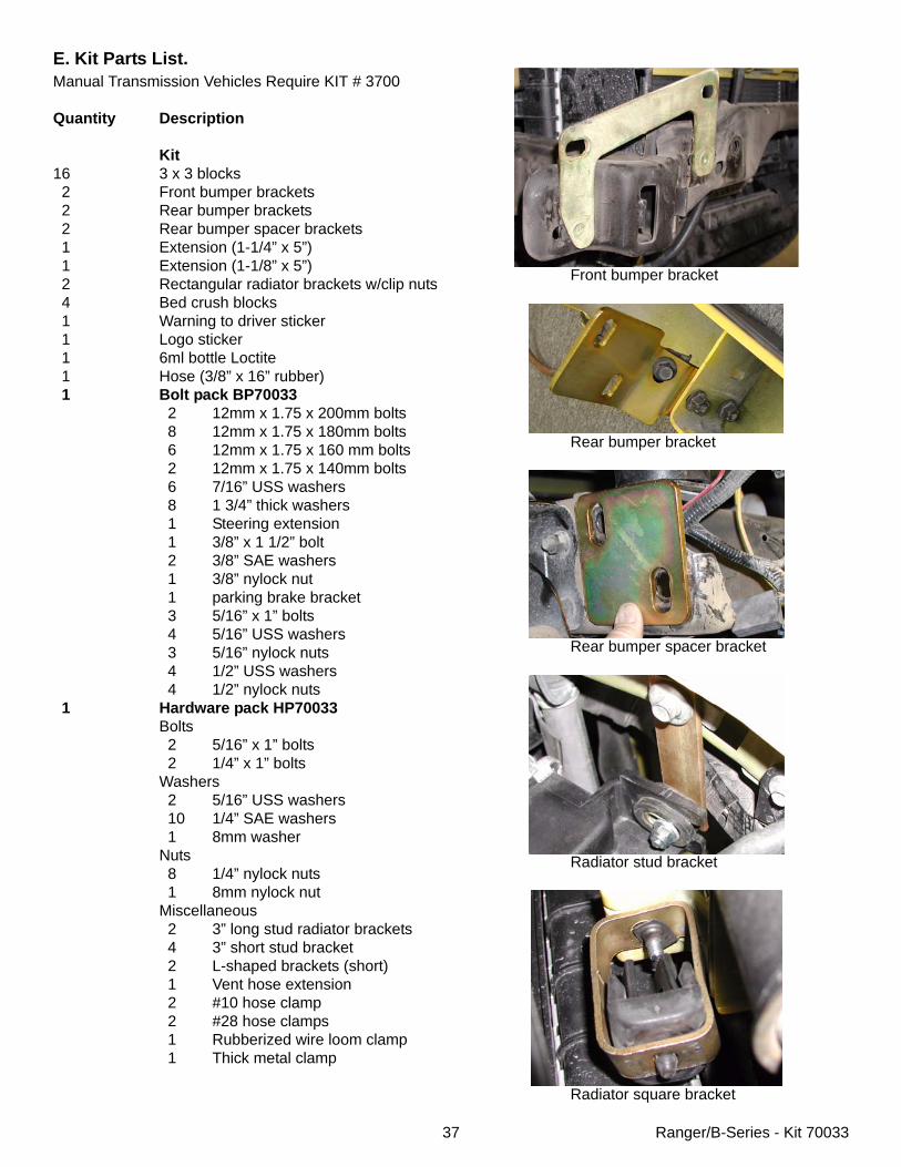
i. If removed, connect trailer hitch connector (100)on rear bumper (99).
35 Ranger/B-Series - Kit 70033
j. Weld four kit bed crush blocks (167) on frame(15) as shown.
D. After installation is complete.
1. Install airbag fuse #26 (5) in fuse panel (6) and
install the cover (4) or passenger side kick panel.
2. Connect both battery cables to the battery (3). Besure to reconnect the positive cable (2) first, then thenegative cable (1).
36 Ranger/B-Series - Kit 70033
3. Stick kit warning sticker on the dash in plain sight ofall vehicle occupants.
4. Double check the vehicle.
a. Check all mounting hardware to ensure it isproperly tightened.
b. Check all wires, hoses, cables, etc. to ensurethey have been properly connected and there isample slack. With the number of hoses on thisvehicle, it is vital that this be checked thoroughly.
c. Check vehicle electrical system.
d. Start vehicle and check the steering in bothdirections to ensure that there is no bind.
e. Check the operation of the brake system and theparking brake.
5. Check clutch operation. Check transmission shiftlever operation. Ensure that there is proper engage-ment in all gears.
6. Check manual 4 wheel drive transfer case shift leveroperation. Ensure there is complete engagement inall ranges.
a. If shift lever makes contact with floorboard,remove shift lever knob and boot, and notchfloorboard to ensure complete engagement in allranges.
b. If shift lever still makes contact with floorboard,modify boot and reinstall boot and knob. Ensurethere is complete engagement in all ranges.
c. Check coolant level. Fill coolant to the properlevel (refer to the Owner’s Manual).
d. Test drive vehicle in all gears and 4 wheel driveranges. Pay close attention to all vehicle sys-tems. Check all hardware again in 500 miles andas part of your regular maintenance schedule.
Rev. 05, Copyright 09/06Performance Automotive Group
www.p-a-g.net
CAUTIONRetorque all fasteners after 500 miles and after offroad use. All body lift components should be visuallyinspected and fasteners retorqued during routine vehi-cle servicing.
NOTE
Step 5 is for vehicles with manual transmission only.Other models skip this step.
NOTE
Step 6 is for vehicles with manual 4 wheel drive trans-fer case only. Other models skip this step.
CAUTIONNever open a closed cooling system after the vehicle has been started. Only fill the cooling system if the cap has been removed while the vehicle was still cold.
CAUTIONPerformance Accessories does not recommend anyparticular wheel and tire combinations for use with itsbody lifts and cannot assume responsibility for the cus-tomer’s choice of wheels and tires. Reference yourowner's manual for recommended tire sizes and warn-ings related to the use of oversized tires. Larger wheeland tire combinations increase stress and wear onsteering and suspension components, which leads toincreased maintenance and higher risk for componentfailure. Larger wheel and tire combinations also alterspeedometer calibration, braking effectiveness, centerof gravity, and handling characteristics. Consult withan experienced local off road shop to find what wheeland tire combinations work best with your vehicle.
NOTEAll warranty information, instruction sheets, and otherdocuments regarding the installation of this productmust be retained by the vehicle owner. Informationcontained in the instructions and on the warranty cardwill be required for any warranty claims. The vehicleowner needs to understand the modifications made tohis vehicle and how they affect vehicle handling andperformance. Failure to provide the customer with thisinformation can result in damage to the vehicle andsevere personal injury.
Front bumper bracket
Rear bumper bracket
Rear bumper spacer bracket
Radiator stud bracket
Radiator square bracket
E. Kit Parts List.Manual Transmission Vehicles Require KIT # 3700
Quantity Description
Kit16 3 x 3 blocks 2 Front bumper brackets 2 Rear bumper brackets 2 Rear bumper spacer brackets 1 Extension (1-1/4” x 5”) 1 Extension (1-1/8” x 5”) 2 Rectangular radiator brackets w/clip nuts 4 Bed crush blocks 1 Warning to driver sticker 1 Logo sticker 1 6ml bottle Loctite 1 Hose (3/8” x 16” rubber) 1 Bolt pack BP70033
2 12mm x 1.75 x 200mm bolts 8 12mm x 1.75 x 180mm bolts 6 12mm x 1.75 x 160 mm bolts 2 12mm x 1.75 x 140mm bolts 6 7/16” USS washers 8 1 3/4” thick washers 1 Steering extension 1 3/8” x 1 1/2” bolt 2 3/8” SAE washers 1 3/8” nylock nut 1 parking brake bracket 3 5/16” x 1” bolts 4 5/16” USS washers 3 5/16” nylock nuts 4 1/2” USS washers 4 1/2” nylock nuts
1 Hardware pack HP70033Bolts 2 5/16” x 1” bolts 2 1/4” x 1” boltsWashers 2 5/16” USS washers 10 1/4” SAE washers 1 8mm washerNuts 8 1/4” nylock nuts 1 8mm nylock nutMiscellaneous 2 3” long stud radiator brackets 4 3” short stud bracket 2 L-shaped brackets (short) 1 Vent hose extension 2 #10 hose clamp 2 #28 hose clamps 1 Rubberized wire loom clamp 1 Thick metal clamp
37 Ranger/B-Series - Kit 70033
Related Documents